Analysis of the USRP2 Firmware: system architecture overview
Upload
khangminh22Category
view
0download
0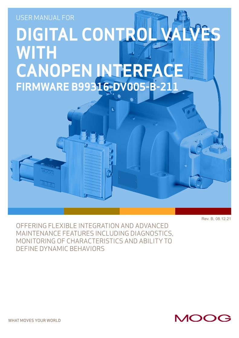
WHAT MOVES YOUR WORLD
Rev. B, 08.12.21
OFFERING FLEXIBLE INTEGRATION AND ADVANCED MAINTENANCE FEATURES INCLUDING DIAGNOSTICS, MONITORING OF CHARACTERISTICS AND ABILITY TO DEFINE DYNAMIC BEHAVIORS
USER MANUAL FOR
DIGITAL CONTROL VALVES WITH CANOPEN INTERFACEFIRMWARE B99316-DV005-B-211
08Rev. B, 08.12.21 A
Copyright© 2021 Moog GmbHHanns-Klemm-Straße 2871034 BoeblingenGermany
All rights reserved.No part of these operating instructions may be reproduced in any form (print, photocopies, microfilm, or by any other means) or edited, duplicated, or dis-tributed with electronic systems without our prior written consent.Offenders will be held liable for the payment of damages.
Subject to change without notice.
Telephone: +49 7031 622-0Fax: +49 7031 622-191E-mail: [email protected]: http://www.moog.com/Industrial
Moog DCV with CANopen bus interface Table of contents
Rev. B, 08.12.21 i
Table of contentsCopyright.......................................................................................................................................................................................... AList of tables.............................................................................................................................................................................. xviiiList of figures ............................................................................................................................................................................. xxii
1 General information ...................................................................................................................................................11.1 About this manual................................................................................................................................................................1
1.1.1 Reservation of changes and validity ................................................................................................................11.1.2 Completeness ...........................................................................................................................................................11.1.3 Place of storage .......................................................................................................................................................11.1.4 Warranty and liability.............................................................................................................................................11.1.5 Typographical conventions..................................................................................................................................2
1.2 Structure of warning notices...........................................................................................................................................31.3 Selection and qualification of personnel ....................................................................................................................31.4 Further documentation for the servo valve ...............................................................................................................41.5 References .............................................................................................................................................................................5
1.5.1 CAN fieldbus..............................................................................................................................................................51.5.2 Device Profile............................................................................................................................................................5
1.6 Definitions..............................................................................................................................................................................51.6.1 Internal resolution (iR)...........................................................................................................................................51.6.2 Volume flow direction............................................................................................................................................51.6.3 Servo valve position and stage names ............................................................................................................6
1.7 Abbreviations........................................................................................................................................................................61.8 Trademarks ............................................................................................................................................................................7
2 Access over CANopen................................................................................................................................................82.1 Introduction ...........................................................................................................................................................................82.2 Device profiles......................................................................................................................................................................82.3 CANopen reference model ...............................................................................................................................................92.4 CANopen objects .............................................................................................................................................................. 10
2.4.1 Parameter value.................................................................................................................................................... 102.4.2 Parameter and their attributes ....................................................................................................................... 102.4.3 Units and prefix parameter............................................................................................................................... 12
2.5 CANopen object dictionary (OD) ................................................................................................................................. 122.6 Electronic data sheet (EDS).......................................................................................................................................... 132.7 CANopen communication protocols .......................................................................................................................... 132.8 Bit rate and Node-ID configuration using Layer Setting Services (LSS) ..................................................... 152.9 Bit rate and Node-ID configuration using service data object (SDO)............................................................ 16
2.9.1 Object 0x100B: Actual module identifier (Node-ID) ............................................................................... 162.9.2 Object 0x3002: Module identifier (Node-ID) ............................................................................................. 172.9.3 Object 0x3003: Bit rate ..................................................................................................................................... 17
Moog DCV with CANopen bus interface Table of contents
Rev. B, 08.12.21 ii
2.10 Network management (NMT) state machine.......................................................................................................... 172.10.1 Object 0x3004: Network management (NMT) state machine status ............................................... 192.10.2 Object 0x3005: Network management (NMT) state machine control.............................................. 202.10.3 Object 0x1029: Network management (NMT) error behavior............................................................. 20
2.11 Network management (NMT) heartbeat .................................................................................................................. 212.11.1 Object 0x1016: Consumer heartbeat time ................................................................................................. 212.11.2 Object 0x1017: Producer heartbeat time ................................................................................................... 21
2.12 Network management (NMT) node guarding.......................................................................................................... 222.12.1 Object 0x100C: Guard time .............................................................................................................................. 222.12.2 Object 0x100D: Life time factor..................................................................................................................... 22
2.13 Process data object (PDO) ............................................................................................................................................ 232.14 Receive process data object (RPDO)......................................................................................................................... 24
2.14.1 Object 0x1400: 1st RPDO configuration..................................................................................................... 252.14.2 Object 0x1401: 2nd RPDO configuration.................................................................................................... 262.14.3 Object 0x1402: 3rd RPDO configuration .................................................................................................... 262.14.4 Object 0x1403: 4th RPDO configuration..................................................................................................... 262.14.5 Object 0x1600: 1st RPDO mapping............................................................................................................... 272.14.6 Object 0x1601: 2nd RPDO mapping.............................................................................................................. 282.14.7 Object 0x1602: 3rd RPDO mapping .............................................................................................................. 282.14.8 Object 0x1603: 4th RPDO mapping............................................................................................................... 292.14.9 Object 0x3012: RPDO counter ........................................................................................................................ 29
2.15 Transmit process data object (TPDO)....................................................................................................................... 302.15.1 Object 0x1800: 1st TPDO configuration ..................................................................................................... 322.15.2 Object 0x1801: 2nd TPDO configuration .................................................................................................... 332.15.3 Object 0x1802: 3rd TPDO configuration..................................................................................................... 332.15.4 Object 0x1803: 4th TPDO configuration..................................................................................................... 332.15.5 Object 0x1A00: 1st TPDO mapping............................................................................................................... 342.15.6 Object 0x1A01: 2nd TPDO mapping.............................................................................................................. 352.15.7 Object 0x1A02: 3rd TPDO mapping .............................................................................................................. 352.15.8 Object 0x1A03: 4th TPDO mapping............................................................................................................... 362.15.9 Object 0x3011: TPDO trigger .......................................................................................................................... 36
2.16 Service data object (SDO) ............................................................................................................................................. 372.16.1 Object 0x1200: SDO client/server parameter .......................................................................................... 38
2.17 Service data object (SDO) gateway ........................................................................................................................... 382.18 Synchronization (SYNC)................................................................................................................................................. 38
2.18.1 Object 0x1005: SYNC protocol COB-ID configuration .......................................................................... 392.18.2 Object 0x1006: Communication cycle period............................................................................................ 392.18.3 Object 0x1007: Synchronous window length............................................................................................. 392.18.4 Object 0x1015: Inhibit time emergency message.................................................................................... 392.18.5 Object 0x1019: SYNC protocol counter overflow value ....................................................................... 40
Moog DCV with CANopen bus interface Table of contents
Rev. B, 08.12.21 iii
2.19 Emergency (EMCY) .......................................................................................................................................................... 402.19.1 Object 0x1014: EMCY protocol COB-ID configuration ......................................................................... 40
3 Device structure .......................................................................................................................................................413.1 Device controller structure........................................................................................................................................... 42
4 Device identification...............................................................................................................................................434.1 Objects of the CANopen communication profile defined by CiA 301........................................................... 43
4.1.1 Object 0x1000: Device Type ............................................................................................................................ 434.1.2 Object 0x1008: Manufacturer device name............................................................................................... 444.1.3 Object 0x1009: Manufacturer hardware version ..................................................................................... 444.1.4 Object 0x100A: Manufacturer software version ..................................................................................... 444.1.5 Object 0x1018: Identity object ....................................................................................................................... 45
4.2 Objects defined by Device Profile Fluid Power ..................................................................................................... 464.2.1 Object 0x6050: Device version ....................................................................................................................... 464.2.2 Object 0x6051: Device code number ............................................................................................................ 464.2.3 Object 0x6052: Device serial number........................................................................................................... 464.2.4 Object 0x6053: Device description ............................................................................................................... 464.2.5 Object 0x6054: Device model description.................................................................................................. 464.2.6 Object 0x6055: Device model URL ................................................................................................................ 474.2.7 Object 0x6056: Device parameter set code............................................................................................... 474.2.8 Object 0x6057: Device vendor name ............................................................................................................ 474.2.9 Object 0x605F: Device capability .................................................................................................................. 47
4.3 Vendor-specific objects................................................................................................................................................. 474.3.1 Object 0x2019: Software Version 1.............................................................................................................. 474.3.2 Object 0x201A: Software Version 2 ............................................................................................................. 484.3.3 Object 0x201B: Software Version 3 ............................................................................................................. 48
5 Device control............................................................................................................................................................495.1 Device state machine (DSM)......................................................................................................................................... 50
5.1.1 DSM states ............................................................................................................................................................. 515.1.2 State transitions................................................................................................................................................... 53
5.1.2.1 DSM state transitions caused by the control word ................................................................... 535.1.2.2 DSM state transitions caused by the #EnableSignal# ............................................................. 545.1.2.3 DSM state transitions caused by internal events ...................................................................... 545.1.2.4 Enable behavior....................................................................................................................................... 54
5.1.2.4.1 DSM state transitions depending on the #EnableSignal# ......................................... 555.1.2.4.2 Fault confirmation with the #EnableSignal#................................................................... 55
5.1.2.5 Error output pin....................................................................................................................................... 555.1.3 DSM control word and status word ............................................................................................................... 56
5.1.3.1 Object 0x6040: Device control word .............................................................................................. 565.1.3.2 Object 0x6041: Status word .............................................................................................................. 57
Moog DCV with CANopen bus interface Table of contents
Rev. B, 08.12.21 iv
5.1.4 DSM control word source selection / local mode ..................................................................................... 585.1.5 Object 0x604F: Device local............................................................................................................................. 595.1.6 Object 0x4040: Local control word ............................................................................................................... 595.1.7 Object 0x403F: Local control word default................................................................................................ 59
5.2 DSM further state registers ......................................................................................................................................... 605.2.1 Object 0x1002: Manufacturer Status Register ........................................................................................ 60
5.3 Bootup of the device ....................................................................................................................................................... 605.3.1 Object 0x200F: Power On Delay ..................................................................................................................... 60
5.4 Status display LEDs......................................................................................................................................................... 605.4.1 Module status LED «MS»................................................................................................................................... 615.4.2 Network status LED «NS» ................................................................................................................................. 61
6 Signal routing and scaling .....................................................................................................................................626.1 Setpoint path...................................................................................................................................................................... 63
6.1.1 Object 0x6042: Device mode........................................................................................................................... 646.1.2 Object 0x4042: Device mode default ........................................................................................................... 646.1.3 Q setpoint path...................................................................................................................................................... 65
6.1.3.1 Object 0x6300: Q setpoint ................................................................................................................. 656.1.3.2 Object 0x3320: Q setpoint source selection parameter ......................................................... 666.1.3.3 Object 0x6314: Q setpoint conditioning hold setpoint............................................................ 666.1.3.4 Object 0x6312: Common spool position setpoint ..................................................................... 67
6.1.4 p setpoint path ...................................................................................................................................................... 676.1.4.1 Object 0x6380: Pressure setpoint .................................................................................................. 686.1.4.2 Object 0x3310: Pressure setpoint source selection parameter .......................................... 686.1.4.3 Object 0x6394: Pressure setpoint conditioning hold setpoint............................................. 69
6.1.5 Flow setpoint path ............................................................................................................................................... 696.1.5.1 Object 0x6700: Flow setpoint........................................................................................................... 706.1.5.2 Object 0x332C: Flow setpoint source selection parameter .................................................. 706.1.5.3 Object 0x6714: Flow setpoint conditioning hold setpoint ..................................................... 716.1.5.4 Object 0x2035: Q setpoint size ........................................................................................................ 716.1.5.5 Object 0x2036: Pressure setpoint size ......................................................................................... 716.1.5.6 Object 0x2037: Flow setpoint size.................................................................................................. 71
6.2 Actual value transducer interface.............................................................................................................................. 726.2.1 Object 0x6110: Actual value conditioning actual value 1 ..................................................................... 736.2.2 Object 0x6111: Actual value conditioning actual value 2 ..................................................................... 736.2.3 Object 0x6112: Actual value conditioning actual value 3 ..................................................................... 736.2.4 Object 0x6113: Actual value conditioning actual value 4 ..................................................................... 74
Moog DCV with CANopen bus interface Table of contents
Rev. B, 08.12.21 v
6.2.5 Transducer interface definition ...................................................................................................................... 746.2.5.1 Object 0x6100: Actual value conditioning max interface number....................................... 746.2.5.2 Object 0x6101: Actual value conditioning interface number ................................................ 746.2.5.3 Object 0x6102: Actual value conditioning type.......................................................................... 756.2.5.4 Object 0x6103: Actual value conditioning sign........................................................................... 756.2.5.5 Object 0x6104: Actual value conditioning actual value........................................................... 756.2.5.6 Object 0x3264: Port.............................................................................................................................. 766.2.5.7 Object 0x3270: Data structure ......................................................................................................... 77
6.2.6 Pressure actual value scaling........................................................................................................................... 776.2.6.1 Object 0x6120: Actual value conditioning min pressure for pressure transducer........ 786.2.6.2 Object 0x6121: Actual value conditioning max pressure for pressure transducer....... 786.2.6.3 Object 0x6124: Actual value conditioning min transducer signal for pressure
transducer................................................................................................................................................. 786.2.6.4 Object 0x6125: Actual value conditioning max transducer signal for pressure
transducer................................................................................................................................................. 786.2.6.5 Object 0x6123: Actual value conditioning pressure offset for pressure ......................... 786.2.6.6 Object 0x6122: Actual value conditioning for pressure transducer................................... 79
6.2.7 General actual value scaling ............................................................................................................................. 796.2.7.1 Object 0x6128: Actual value conditioning min general transducer .................................... 806.2.7.2 Object 0x6129: Actual value conditioning max general transducer ................................... 806.2.7.3 Object 0x612C: Actual value conditioning min general signal transducer 32-bit.......... 806.2.7.4 Object 0x612D: Actual value conditioning max general signal transducer 32-bit ........ 806.2.7.5 Object 0x612B: Actual value conditioning general transducer offset............................... 80
6.2.8 Parameterization examples ............................................................................................................................. 816.2.8.1 Get active transducer interface number and output value..................................................... 816.2.8.2 Example 1: Enable/disable transducer interface ....................................................................... 816.2.8.3 Example 2: Change sign of the transducer signal ....................................................................... 816.2.8.4 Example 3: Adjust transducer interface without scaling......................................................... 816.2.8.5 Example 4: Adjust transducer interface with scaling ............................................................... 82
6.3 Analog inputs...................................................................................................................................................................... 836.3.1 Object 0x32F2: Internal pressure transducer at port P......................................................................... 846.3.2 Object 0x32F3: Internal pressure transducer at port B......................................................................... 846.3.3 Object 0x32F4: Internal pressure transducer at port A ........................................................................ 846.3.4 Object 0x3404: Internal pressure transducer at port A ........................................................................ 856.3.5 Analog input 0 ........................................................................................................................................................ 85
6.3.5.1 Object 0x3200: Input type .................................................................................................................. 856.3.5.2 Object 0x3207: Scaling........................................................................................................................ 866.3.5.3 Object 0x3204: Actual value.............................................................................................................. 86
6.3.6 Analog input 1 ........................................................................................................................................................ 876.3.6.1 Object 0x3208: Input type .................................................................................................................. 876.3.6.2 Object 0x320F: Scaling........................................................................................................................ 876.3.6.3 Object 0x320C: Actual value.............................................................................................................. 88
Moog DCV with CANopen bus interface Table of contents
Rev. B, 08.12.21 vi
6.3.7 Analog input 2 ........................................................................................................................................................ 886.3.7.1 Object 0x3210: Input type .................................................................................................................. 886.3.7.2 Object 0x322A: Scaling........................................................................................................................ 896.3.7.3 Object 0x3214: Actual value.............................................................................................................. 89
6.3.8 Analog input 3 ........................................................................................................................................................ 906.3.8.1 Object 0x3218: Input type .................................................................................................................. 906.3.8.2 Object 0x321F: Scaling........................................................................................................................ 906.3.8.3 Object 0x321C: Actual value.............................................................................................................. 91
6.3.9 Analog input 4 ........................................................................................................................................................ 916.3.9.1 Object 0x3220: Input type .................................................................................................................. 916.3.9.2 Object 0x3229: Scaling........................................................................................................................ 926.3.9.3 Object 0x3224: Actual value.............................................................................................................. 92
6.3.10 Internal pressure transducer offset correction........................................................................................ 936.3.10.1 Object 0x32E6: Offset correction execution .............................................................................. 936.3.10.2 Object 0x32E9: Offset correction mapping parameter........................................................... 946.3.10.3 Object 0x32E8: Offset correction trigger threshold................................................................ 946.3.10.4 Object 0x32E7: Offset correction boundary ............................................................................... 946.3.10.5 Object 0x32E5: Offset correction mode ....................................................................................... 956.3.10.6 Object 0x32F8: Correction offset 0................................................................................................ 956.3.10.7 Object 0x32F9: Correction offset 1................................................................................................ 956.3.10.8 Object 0x32FA: Correction offset 2 ............................................................................................... 95
6.4 Analog outputs................................................................................................................................................................... 966.4.1 Analog output 0..................................................................................................................................................... 97
6.4.1.1 Object 0x3240: Mapping parameter............................................................................................... 976.4.1.2 Object 0x3244: Scaling........................................................................................................................ 986.4.1.3 Object 0x3245: Actual value.............................................................................................................. 986.4.1.4 Object 0x3243: Type............................................................................................................................. 99
6.4.2 Analog output 1..................................................................................................................................................... 996.4.2.1 Object 0x3260: Mapping parameter............................................................................................... 996.4.2.2 Object 0x3265: Scaling..................................................................................................................... 1006.4.2.3 Object 0x3266: Actual value........................................................................................................... 1006.4.2.4 Object 0x3263: Type.......................................................................................................................... 101
6.5 Digital inputs ................................................................................................................................................................... 1016.5.1 Safety function monitoring............................................................................................................................ 102
6.6 Digital outputs ................................................................................................................................................................ 1036.6.1 Object 0x5E42: Digital output values........................................................................................................ 1036.6.2 Object 0x5E41: Digital output configuration.......................................................................................... 1046.6.3 Object 0x5E44: Digital output state .......................................................................................................... 105

Moog DCV with CANopen bus interface Table of contents
Rev. B, 08.12.21 vii
6.7 Local CAN ......................................................................................................................................................................... 1056.7.1 Introduction ......................................................................................................................................................... 1056.7.2 Device profiles.................................................................................................................................................... 1056.7.3 CANopen reference model............................................................................................................................. 1066.7.4 CANopen objects ............................................................................................................................................... 107
6.7.4.1 Parameter value................................................................................................................................... 1076.7.4.2 Parameter and their attributes...................................................................................................... 1076.7.4.3 Units and prefix parameter ............................................................................................................. 109
6.7.5 CANopen object dictionary (OD).................................................................................................................. 1096.7.6 Electronic data sheet (EDS)........................................................................................................................... 1106.7.7 CANopen communication protocols........................................................................................................... 1106.7.8 Bit rate and Node-ID configuration using Layer setting services (LSS) ....................................... 1126.7.9 Bit rate and Node-ID configuration using service data object (SDO) ............................................ 113
6.7.9.1 Object 0x500B: Actual module identifier (Node-ID).............................................................. 1136.7.9.2 Object 0x5102: Module identifier (Node-ID)............................................................................ 1146.7.9.3 Object 0x5103: Bit rate .................................................................................................................... 114
6.7.10 Network management (NMT) state machine........................................................................................... 1146.7.10.1 Object 0x5104: Network management (NMT) state machine status .............................. 1166.7.10.2 Object 0x5105: Network management (NMT) state machine control............................. 1176.7.10.3 Object 0x5029: Network management (NMT) error behavior............................................ 1176.7.10.4 Object 0x5B02: Start remote node .............................................................................................. 118
6.7.11 Network management (NMT) heartbeat................................................................................................... 1186.7.11.1 Object 0x1016: Consumer heartbeat time ................................................................................ 1186.7.11.2 Object 0x5017: Producer heartbeat time.................................................................................. 119
6.7.12 Network management (NMT) node guarding .......................................................................................... 1196.7.12.1 Object 0x500C: Guard time ............................................................................................................. 1196.7.12.2 Object 0x500D: Life time factor ................................................................................................... 119
6.7.13 Process data object (PDO) ............................................................................................................................. 1206.7.13.1 Object 0x5400: 1st RPDO configuration.................................................................................... 1226.7.13.2 Object 0x5401: 2nd RPDO configuration................................................................................... 1236.7.13.3 Object 0x5402: 3rd RPDO configuration ................................................................................... 1236.7.13.4 Object 0x5403: 4th RPDO configuration ................................................................................... 1236.7.13.5 Object 0x5600: 1st RPDO mapping.............................................................................................. 1246.7.13.6 Object 0x5601: 2nd RPDO mapping............................................................................................. 1256.7.13.7 Object 0x5602: 3rd RPDO mapping ............................................................................................. 1256.7.13.8 Object 0x5603: 4th RPDO mapping ............................................................................................. 1266.7.13.9 Object 0x5112: RPDO counter....................................................................................................... 126
6.7.14 Transmit process data object (TPDO)........................................................................................................ 1276.7.14.1 Object 0x5800: 1st TPDO configuration.................................................................................... 1296.7.14.2 Object 0x5801: 2nd TPDO configuration ................................................................................... 1306.7.14.3 Object 0x5802: 3rd TPDO configuration.................................................................................... 130

Moog DCV with CANopen bus interface Table of contents
Rev. B, 08.12.21 viii
6.7.14.4 Object 0x5803: 4th TPDO configuration.................................................................................... 1306.7.14.5 Object 0x5A00: 1st TPDO mapping.............................................................................................. 1316.7.14.6 Object 0x5A01: 2nd TPDO mapping............................................................................................. 1326.7.14.7 Object 0x5A02: 3rd TPDO mapping ............................................................................................. 1326.7.14.8 Object 0x5A03: 4th TPDO mapping ............................................................................................. 1336.7.14.9 Object 0x5111: TPDO trigger......................................................................................................... 133
6.7.15 Service data object (SDO) .............................................................................................................................. 1346.7.15.1 Object 0x5200: SDO client/server parameter......................................................................... 135
6.7.16 Service data object (SDO) gateway ............................................................................................................ 1366.7.16.1 Object 0x5B10: Remote parameter ............................................................................................. 1376.7.16.2 Object 0x5B11: Remote parameter address ............................................................................ 1376.7.16.3 Object 0x5B12: Remote Node-ID.................................................................................................. 1386.7.16.4 Object 0x5B13: Remote transmission ........................................................................................ 138
6.7.17 Synchronization (SYNC).................................................................................................................................. 1386.7.17.1 Object 0x5005: SYNC protocol COB-ID configuration ......................................................... 1396.7.17.2 Object 0x5006: SYNC protocol period ....................................................................................... 1396.7.17.3 Object 0x5019: SYNC protocol counter overflow value ...................................................... 139
6.7.18 Emergency (EMCY) ........................................................................................................................................... 1406.7.18.1 Object 0x5014: EMCY protocol COB-ID configuration ........................................................ 140
6.7.19 CAN Interface features ................................................................................................................................... 1406.7.19.1 Object 0x5B14: Termination resistor.......................................................................................... 140
6.8 Free to use parameters ............................................................................................................................................... 1406.8.1 Object 0x0002: Signed one byte integer.................................................................................................. 1416.8.2 Object 0x0003: Signed two byte integer.................................................................................................. 1416.8.3 Object 0x0004: Signed four byte integer................................................................................................. 1416.8.4 Object 0x0005: Unsigned one byte integer............................................................................................. 1416.8.5 Object 0x0006: Unsigned two byte integer............................................................................................. 1416.8.6 Object 0x0007: Unsigned four byte integer............................................................................................ 1416.8.7 Object 0x0008: Four byte real...................................................................................................................... 1416.8.8 Object 0x0009: Visible string ....................................................................................................................... 1426.8.9 Object 0x001B: Unsigned eight byte integer.......................................................................................... 142
6.8.10 Object 0x290B: Signed one byte integer array ...................................................................................... 1426.8.11 Object 0x290C: Signed two byte integer array...................................................................................... 1426.8.12 Object 0x290D: Signed four byte integer array..................................................................................... 1436.8.13 Object 0x290E: Unsigned one byte integer array ................................................................................. 1436.8.14 Object 0x290F: Unsigned two byte integer array ................................................................................. 1436.8.15 Object 0x2910: Unsigned four byte integer array ................................................................................ 1446.8.16 Object 0x2911: Four byte real array .......................................................................................................... 144
Moog DCV with CANopen bus interface Table of contents
Rev. B, 08.12.21 ix
7 Servo valve functions .......................................................................................................................................... 1457.1 Control modes................................................................................................................................................................. 146
7.1.1 Object 0x6043: Device control mode ........................................................................................................ 1467.1.2 Object 0x4043: Control mode default....................................................................................................... 1477.1.3 Spool position control open loop................................................................................................................. 1487.1.4 Spool position control closed loop ............................................................................................................. 1497.1.5 Pressure control open loop............................................................................................................................ 1507.1.6 Pressure control closed loop......................................................................................................................... 1517.1.7 p/Q control closed loop ................................................................................................................................... 1527.1.8 Flow control closed loop ................................................................................................................................. 1537.1.9 p/flow control closed loop ............................................................................................................................. 153
7.2 Q setpoint conditioning ............................................................................................................................................... 1547.2.1 Object 0x6310: Demand value ..................................................................................................................... 1547.2.2 Object 0x6311: Setpoint conditioning reference value...................................................................... 1547.2.3 Limiting ................................................................................................................................................................. 155
7.2.3.1 Object 0x6320: Setpoint conditioning upper setpoint limit ............................................... 1557.2.3.2 Object 0x6321: Setpoint conditioning lower setpoint limit ............................................... 156
7.2.4 Scaling ................................................................................................................................................................... 1567.2.4.1 Object 0x6322: Setpoint conditioning scaling factor ........................................................... 1577.2.4.2 Object 0x6323: Setpoint conditioning scaling offset ........................................................... 157
7.2.5 Ramp....................................................................................................................................................................... 1587.2.5.1 Object 0x6330: Setpoint conditioning ramp type .................................................................. 1587.2.5.2 One-quadrant ramp (ramp type 1)................................................................................................. 159
7.2.5.2.1 Object 0x6331: Setpoint conditioning ramp acceleration time ........................... 1597.2.5.3 Two-quadrant ramp (ramp type 2) ................................................................................................ 160
7.2.5.3.1 Object 0x6331: Setpoint conditioning ramp acceleration time ........................... 1607.2.5.3.2 Object 0x6334: Setpoint conditioning ramp deceleration time ........................... 161
7.2.5.4 Four-quadrant ramp (ramp type 3) ............................................................................................... 1617.2.5.4.1 Object 0x6332: Setpoint conditioning ramp acceleration time positive .......... 1627.2.5.4.2 Object 0x6333: Setpoint conditioning ramp acceleration time negative......... 1627.2.5.4.3 Object 0x6335: Setpoint conditioning ramp deceleration time positive.......... 1627.2.5.4.4 Object 0x6336: Setpoint conditioning ramp deceleration time negative......... 163
7.3 Spool position controller ............................................................................................................................................ 1637.3.1 Single stage servo valve ................................................................................................................................. 1637.3.2 Dual stage servo valve..................................................................................................................................... 1647.3.3 Spool position / pilot spool position actual value path ....................................................................... 164
7.3.3.1 Object 0x6301: Spool position actual value ............................................................................. 1647.3.3.2 Object 0x3301: Pilot spool position actual value ................................................................... 164
Moog DCV with CANopen bus interface Table of contents
Rev. B, 08.12.21 x
7.3.4 Spool position / main stage spool position actuator conditioning ................................................. 1657.3.4.1 Object 0x6313: Spool position demand value.......................................................................... 1657.3.4.2 Object 0x216D: Main stage spool position demand value................................................... 1657.3.4.3 Directional dependent gain ............................................................................................................. 165
7.3.4.3.1 Object 0x6340: Actuator conditioning directional dependent gain type.......... 1667.3.4.3.2 Object 0x6341: Actuator conditioning directional dependent gain factor ...... 167
7.3.4.4 Characteristic compensation.......................................................................................................... 1687.3.4.4.1 Object 0x6346: Actuator conditioning characteristic compensation type...... 1687.3.4.4.2 Look-up table........................................................................................................................... 169
7.3.4.4.2.1 Object 0x4347: Look-up table ...................................................................... 1697.3.4.4.2.2 Object 0x4348: Look-up table ...................................................................... 1697.3.4.4.2.3 Object 0x4349: Look-up table ...................................................................... 1707.3.4.4.2.4 Object 0x434A: Look-up table...................................................................... 170
7.3.4.5 Dead band compensation ................................................................................................................. 1707.3.4.5.1 Object 0x6342: Actuator conditioning dead band compensation type ............. 1717.3.4.5.2 Object 0x6343: Actuator conditioning dead band compensation A side .......... 1717.3.4.5.3 Object 0x6344: Actuator conditioning dead band compensation B side .......... 1717.3.4.5.4 Object 0x6345: Actuator conditioning dead band compensation threshold ... 172
7.3.4.6 Jump function (dead band compensation type 1).................................................................... 1727.3.4.7 Continuous function (dead band compensation type 2) ....................................................... 1727.3.4.8 Zero correction .................................................................................................................................... 173
7.3.4.8.1 Object 0x6324: Actuator conditioning zero correction offset ............................. 1747.3.5 Pilot spool position actuator conditioning............................................................................................... 174
7.3.5.1 Object 0x3300: Pilot spool position demand value................................................................ 1747.3.5.2 Zero correction .................................................................................................................................... 175
7.3.5.2.1 Object 0x242E: Offset for pilot spool position in dual stage mode.................... 1757.3.6 Spool position / pilot spool position controller ..................................................................................... 175
7.3.6.1 Object 0x6350: Control deviation ................................................................................................ 1767.3.6.2 Object 0x3302: Pilot control deviation....................................................................................... 1767.3.6.3 Object 0x2416: Integrator test value.......................................................................................... 1767.3.6.4 Object 0x241F: Customer Overall Gain ...................................................................................... 176
7.3.7 Main stage spool position actual value path ........................................................................................... 1777.3.7.1 Object 0x215B: Main stage position actual value................................................................... 1777.3.7.2 Object 0x3237: Customer scaling of main stage spool position sensor ........................ 178
7.3.8 Main stage spool position controller ......................................................................................................... 1787.3.8.1 Object 0x215C: Main stage customer overall gain................................................................. 1787.3.8.2 Object 0x2171: Main stage controller integral part output................................................ 1797.3.8.3 Object 0x2158: Main stage controller output.......................................................................... 179
Moog DCV with CANopen bus interface Table of contents
Rev. B, 08.12.21 xi
7.4 p setpoint conditioning................................................................................................................................................ 1797.4.1 Object 0x6390: Setpoint conditioning demand value ......................................................................... 1797.4.2 Object 0x6391: Setpoint conditioning reference value...................................................................... 1807.4.3 Limiting function................................................................................................................................................ 180
7.4.3.1 Object 0x63A0: Setpoint conditioning upper setpoint limit............................................... 1817.4.3.2 Object 0x63A1: Setpoint conditioning lower setpoint limit ............................................... 181
7.4.4 Scaling ................................................................................................................................................................... 1817.4.4.1 Object 0x63A2: Setpoint conditioning scaling factor........................................................... 1827.4.4.2 Object 0x63A3: Setpoint conditioning scaling offset........................................................... 182
7.4.5 Ramp....................................................................................................................................................................... 1837.4.5.1 Object 0x63B0: Setpoint conditioning ramp type .................................................................. 1837.4.5.2 One-quadrant ramp (ramp type 1)................................................................................................. 184
7.4.5.2.1 Object 0x63B1: Setpoint conditioning ramp acceleration time ........................... 1847.4.5.3 Two-quadrant ramp (ramp type 2) ................................................................................................ 185
7.4.5.3.1 Object 0x63B1: Setpoint conditioning ramp acceleration time ........................... 1857.4.5.3.2 Object 0x63B4: Setpoint conditioning deceleration time ...................................... 186
7.4.5.4 Four-quadrant ramp (ramp type 3) ............................................................................................... 1867.4.5.4.1 Object 0x63B2: Setpoint conditioning ramp acceleration time positive.......... 1877.4.5.4.2 Object 0x63B3: Setpoint conditioning ramp acceleration time negative......... 1877.4.5.4.3 Object 0x63B5: Setpoint conditioning ramp deceleration time positive ......... 1877.4.5.4.4 Object 0x63B6: Setpoint conditioning ramp deceleration time negative ........ 188
7.4.6 Pressure demand signal sign......................................................................................................................... 1887.4.6.1 Object 0x586D: Pressure demand sign mode........................................................................... 188
7.5 Pressure controller ....................................................................................................................................................... 1897.5.1 Object 0x6381: Pressure actual value....................................................................................................... 1897.5.2 Object 0x63D0: Pressure control deviation............................................................................................ 1907.5.3 Object 0x2311: Proportional part............................................................................................................... 1907.5.4 Object 0x2310: Integrator part ................................................................................................................... 1907.5.5 Object 0x2312: Differential part 1............................................................................................................. 1907.5.6 Object 0x5862: Differential part 2............................................................................................................. 1907.5.7 Object 0x5872: Pressure controller output ............................................................................................ 1917.5.8 Active parameter set number ....................................................................................................................... 191
7.5.8.1 Object 0x2350: Active parameter set number......................................................................... 1927.5.9 Demand pressure ramp function ................................................................................................................. 192
7.5.9.1 Object 0x2303[N]: Ramp slope....................................................................................................... 193
Moog DCV with CANopen bus interface Table of contents
Rev. B, 08.12.21 xii
7.5.10 Pressure transducer selection ..................................................................................................................... 1937.5.10.1 Object 0x230D[N]: Active transducer interface area A ........................................................ 1947.5.10.2 Object 0x230F[N]: Active transducer interface area B......................................................... 1957.5.10.3 Object 0x585F[N]: Cylinder piston diameter ............................................................................ 1957.5.10.4 Object 0x585D: Cylinder rod diameter A ................................................................................... 1957.5.10.5 Object 0x585E: Cylinder rod diameter B.................................................................................... 1957.5.10.6 Object 0x5219: Cylinder alpha....................................................................................................... 1967.5.10.7 Object 0x233F: Pressure chamber mode switch..................................................................... 1967.5.10.8 Object 0x2344: Absolute pressure actual value ..................................................................... 196
7.5.11 Actual pressure value filter ........................................................................................................................... 1967.5.11.1 Object 0x23F0: Actual pressure value filter coeff B ............................................................. 1977.5.11.2 Object 0x23F1: Actual pressure value filter coeff A ............................................................. 1977.5.11.3 Object 0x23F2: Actual pressure value filter cutoff frequency.......................................... 1977.5.11.4 Object 0x23F3: Actual pressure value filter order................................................................. 197
7.5.12 Proportional first order lag element (PT1) .............................................................................................. 1977.5.12.1 Object 0x2304[N]: Proportional Gain .......................................................................................... 1987.5.12.2 Object 0x230E[N]: Proportional gain time constant .............................................................. 198
7.5.13 Integrator element (I)....................................................................................................................................... 1987.5.13.1 Object 0x2305[N]: Integrator gain................................................................................................ 1987.5.13.2 Object 0x2306[N]: Integrator factor............................................................................................ 1997.5.13.3 Object 0x2307[N]: Integrator control range ............................................................................. 1997.5.13.4 Object 0x231D: Integrator gain status ....................................................................................... 1997.5.13.5 Object 0x5857[N]: Integrator gain switch threshold ............................................................. 1997.5.13.6 Object 0x231A[N]: Integrator upper output limit.................................................................... 2007.5.13.7 Object 0x231B[N]: Integrator lower output limit .................................................................... 2007.5.13.8 Object 0x5861[N]: Integrator proportional part P gain ........................................................ 200
7.5.14 Integrator preload value ................................................................................................................................. 2017.5.14.1 Object 0x586B: Integrator preload mode.................................................................................. 2017.5.14.2 Object 0x5869: Integrator preload gain..................................................................................... 2027.5.14.3 Object 0x586A: Integrator preload parameter........................................................................ 2027.5.14.4 Object 0x5860: Integrator preload values ................................................................................ 202
7.5.15 Derivative element 1 (PD) .............................................................................................................................. 2037.5.15.1 Object 0x2308[N]: Differentiator gain........................................................................................ 2037.5.15.2 Object 0x2309[N]: Differentiator T1 ........................................................................................... 2037.5.15.3 Object 0x2324[N]: Spool position feed forward gain ............................................................ 203
7.5.16 Feedback derivative element 2 (PD) .......................................................................................................... 2047.5.16.1 Object 0x5863[N]: Differentiator gain........................................................................................ 2047.5.16.2 Object 0x5864[N]: Differentiator T1 ........................................................................................... 2047.5.16.3 Object 0x5858[N]: Spool position feed forward gain ............................................................ 204
7.5.17 Alpha correction................................................................................................................................................. 205
Moog DCV with CANopen bus interface Table of contents
Rev. B, 08.12.21 xiii
7.5.18 Signal limitation 1 ............................................................................................................................................. 2057.5.18.1 Object 0x230A[N]: Upper output limit......................................................................................... 2057.5.18.2 Object 0x230B[N]: Lower output limit......................................................................................... 206
7.5.19 Feed forward....................................................................................................................................................... 2067.5.19.1 Object 0x5867[N]: Feed forward gain ......................................................................................... 2067.5.19.2 Object 0x5870[N]: Feed forward offset ..................................................................................... 2067.5.19.3 Object 0x5868[N]: Feed forward parameter............................................................................. 207
7.5.20 Signal limitation 2 ............................................................................................................................................. 2077.5.20.1 Object 0x5865[N]: Upper controller output limit.................................................................... 2077.5.20.2 Object 0x5866[N]: Lower controller output limit.................................................................... 207
7.5.21 Automatic parameterization of the pressure controller .................................................................... 2087.5.21.1 Object 0x230C[N]: Hydraulic capacity......................................................................................... 2097.5.21.2 Object 0x231C: System pressure reference ............................................................................ 209
7.6 Flow setpoint conditioning......................................................................................................................................... 2097.6.1 Object 0x6710: Setpoint conditioning demand value ......................................................................... 2097.6.2 Object 0x6711: Setpoint conditioning reference value...................................................................... 2107.6.3 Limiting function................................................................................................................................................ 210
7.6.3.1 Object 0x6720: Setpoint conditioning upper setpoint limit ............................................... 2117.6.3.2 Object 0x6721: Setpoint conditioning lower setpoint limit ............................................... 211
7.6.4 Flow setpoint scaling ....................................................................................................................................... 2117.6.4.1 Object 0x6722: Setpoint conditioning scaling factor ........................................................... 2127.6.4.2 Object 0x6723: Setpoint conditioning scaling offset ........................................................... 212
7.6.5 Ramp....................................................................................................................................................................... 2137.6.5.1 Object 0x6730: Setpoint conditioning ramp type .................................................................. 2137.6.5.2 One-quadrant ramp (ramp type 1)................................................................................................. 214
7.6.5.2.1 Object 0x6731: Setpoint conditioning ramp acceleration time ........................... 2147.6.5.3 Two-quadrant ramp (ramp type 2) ................................................................................................ 215
7.6.5.3.1 Object 0x6731: Setpoint conditioning ramp acceleration time ........................... 2157.6.5.3.2 Object 0x6734: Setpoint conditioning ramp deceleration time ........................... 216
7.6.5.4 Four-quadrant ramp (ramp type 3) ............................................................................................... 2167.6.5.4.1 Object 0x6732: Setpoint conditioning ramp acceleration time positive .......... 2177.6.5.4.2 Object 0x6733: Setpoint conditioning ramp acceleration time negative......... 2177.6.5.4.3 Object 0x6735: Setpoint conditioning ramp deceleration time positive.......... 2177.6.5.4.4 Object 0x6736: Setpoint conditioning ramp deceleration time negative......... 218
7.7 Flow controller................................................................................................................................................................ 2187.7.1 Object 0x2330: Transducer interface system pressure..................................................................... 2187.7.2 Object 0x532B: Corrected flow demand value ...................................................................................... 2197.7.3 Object 0x5321: Flow demand deadband .................................................................................................. 2197.7.4 Object 0x520F: Flow controller output..................................................................................................... 2197.7.5 Object 0x6701: Flow actual value ............................................................................................................... 2197.7.6 Object 0x6750: Flow control deviation..................................................................................................... 219
Moog DCV with CANopen bus interface Table of contents
Rev. B, 08.12.21 xiv
7.7.7 Flow settings....................................................................................................................................................... 2207.7.7.1 Object 0x5322: Flow reference maximum................................................................................. 2207.7.7.2 Object 0x5317: Flow value maximum.......................................................................................... 2207.7.7.3 Object 0x532A: Flow reference factor value............................................................................ 220
7.7.8 Control edge switching logic ......................................................................................................................... 2217.7.8.1 Object 0x531F: Flow demand threshold factor ....................................................................... 2217.7.8.2 Object 0x5320: Flow demand threshold..................................................................................... 221
7.8 Spool position (Q or flow) / pressure (p) switchover........................................................................................ 2217.8.1 Object 0x586C[N]: p/Q or p/flow switching mode ................................................................................ 222
7.8.1.1 Object 0x23E6: Switch controller output .................................................................................. 2227.8.2 Minimum criterion in positive direction (switching mode 0) ............................................................. 2237.8.3 Minimum criterion in both directions (switching mode 1).................................................................. 2247.8.4 Force exceeded in both directions (switching mode 2)....................................................................... 225
7.9 Monitoring........................................................................................................................................................................ 2267.9.1 Power supply monitoring................................................................................................................................ 226
7.9.1.1 Object 0x2804: Power supply voltage ........................................................................................ 2267.9.2 Analog input cable break monitoring ......................................................................................................... 227
7.9.2.1 Object 0x3250: Lower current border......................................................................................... 2287.9.2.2 Object 0x3251: Analog input monitoring time ......................................................................... 229
7.9.3 Electronic temperature monitoring............................................................................................................ 2297.9.3.1 Object 0x2805: Electronic temperature .................................................................................... 2297.9.3.2 Object 0x2855: Electronic temperature histogram over operating time ...................... 230
7.9.4 Operating time counters................................................................................................................................. 2307.9.4.1 Object 0x2827: Time since last power on .................................................................................. 2307.9.4.2 Object 0x280D: Cumulative power on time since production ............................................ 231
7.9.5 Spool position control deviation monitoring .......................................................................................... 2317.9.5.1 Object 0x6351: Control monitoring type ................................................................................... 2327.9.5.2 Object 0x6352: Control monitoring delay time ....................................................................... 2327.9.5.3 Object 0x6354: Control monitoring upper threshold ............................................................ 2327.9.5.4 Object 0x6355: Control monitoring lower threshold............................................................. 233
7.9.6 Pilot spool position control deviation monitoring ................................................................................ 2337.9.6.1 Object 0x3302: Pilot control deviation....................................................................................... 2347.9.6.2 Object 0x330A: Pilot spool control monitoring type............................................................. 2347.9.6.3 Object 0x330B: Pilot spool control monitoring delay time ................................................. 2347.9.6.4 Object 0x330D: Pilot spool control monitoring upper threshold...................................... 2347.9.6.5 Object 0x330E: Pilot spool control monitoring lower threshold....................................... 235
Moog DCV with CANopen bus interface Table of contents
Rev. B, 08.12.21 xv
7.9.7 Flow control deviation monitoring.............................................................................................................. 2357.9.8 Pressure control deviation monitoring...................................................................................................... 236
7.9.8.1 Object 0x63D1: Control monitoring type................................................................................... 2377.9.8.2 Object 0x63D2: Control monitoring delay time....................................................................... 2377.9.8.3 Object 0x63D4: Control monitoring upper threshold............................................................ 2377.9.8.4 Object 0x63D5: Control monitoring lower threshold ............................................................ 238
7.9.9 Main stage spool position sensor cable break monitoring ................................................................ 2387.9.10 Spool / pilot spool position sensor cable break monitoring.............................................................. 2387.9.11 Current control deviation monitoring ........................................................................................................ 2387.9.12 Actuator over current monitoring ............................................................................................................... 2387.9.13 Failsafe monitoring........................................................................................................................................... 239
7.9.13.1 Object 0x2421: Upper limit............................................................................................................. 2407.9.13.2 Object 0x2422: Lower limit............................................................................................................. 2407.9.13.3 Object 0x3307: Spring Position Minimum ................................................................................. 2407.9.13.4 Object 0x3308: Spring Position Maximum................................................................................ 241
7.9.14 Object 0x2862: Spool distance cumulative............................................................................................. 2417.10 Event handler .................................................................................................................................................................. 241
7.10.1 Event expressions ............................................................................................................................................. 2427.10.1.1 Object 0x2901: Event expression 1 ............................................................................................. 2447.10.1.2 Object 0x2902: Event expression 2 ............................................................................................. 2447.10.1.3 Object 0x2903: Event expression 3 ............................................................................................. 2447.10.1.4 Object 0x2904: Event expression 4 ............................................................................................. 2447.10.1.5 Object 0x2905: Event expression 5 ............................................................................................. 2447.10.1.6 Object 0x2906: Event expression 6 ............................................................................................. 2447.10.1.7 Object 0x2907: Event expression 7 ............................................................................................. 2457.10.1.8 Object 0x2908: Event expression 8 ............................................................................................. 2457.10.1.9 Object 0x2909: Event enable ......................................................................................................... 245
7.10.2 Event handler examples.................................................................................................................................. 2467.11 Data logger....................................................................................................................................................................... 246
7.11.1 Data logger state machine ............................................................................................................................. 2477.11.1.1 Object 0x3180: Control .................................................................................................................... 2487.11.1.2 Object 0x3181: Status ...................................................................................................................... 248
7.11.2 Channel settings ................................................................................................................................................ 2487.11.2.1 Object 0x3185: Channel mapping parameter........................................................................... 2497.11.2.2 Object 0x3184: Enable channel ..................................................................................................... 249
7.11.3 Sample frequency.............................................................................................................................................. 2497.11.3.1 Object 0x3182: Divider..................................................................................................................... 250
Moog DCV with CANopen bus interface Table of contents
Rev. B, 08.12.21 xvi
7.11.4 Trigger settings.................................................................................................................................................. 2507.11.4.1 Object 0x3189: Trigger parameter............................................................................................... 2507.11.4.2 Object 0x3188: Trigger type........................................................................................................... 2517.11.4.3 Object 0x318C: Trigger level or bitmask.................................................................................... 2517.11.4.4 Object 0x318A: Trigger coupling................................................................................................... 2517.11.4.5 Object 0x318B: Trigger slope......................................................................................................... 2527.11.4.6 Object 0x318D: Trigger position................................................................................................... 252
7.11.5 Data memory....................................................................................................................................................... 2537.11.5.1 Object 0x3186: Memory................................................................................................................... 2547.11.5.2 Object 0x3187: Sample start offset............................................................................................ 2547.11.5.3 Object 0x3183: Number of samples............................................................................................. 255
7.12 Function generator........................................................................................................................................................ 2557.12.1 Function generator output signal shapes................................................................................................. 255
7.12.1.1 Rectangular output signal (type 1) ............................................................................................... 2557.12.1.2 Triangle output signal (type 2) ....................................................................................................... 2567.12.1.3 Sawtooth signal (type 3)................................................................................................................... 2567.12.1.4 Trapezoid signal (type 4) .................................................................................................................. 2577.12.1.5 Sine signal (type 5).............................................................................................................................. 2577.12.1.6 Object 0x3100: Type.......................................................................................................................... 2587.12.1.7 Object 0x3104: Magnitude.............................................................................................................. 2587.12.1.8 Object 0x3105: Offset ...................................................................................................................... 2587.12.1.9 Object 0x3107: Sign........................................................................................................................... 258
7.12.2 Function generator output signal frequency........................................................................................... 2587.12.2.1 Object 0x3103: Frequency .............................................................................................................. 2597.12.2.2 Object 0x3108: Frequency prefix ................................................................................................. 259
7.12.3 Function generator output signals.............................................................................................................. 2597.12.3.1 Object 0x3101: Output ..................................................................................................................... 2597.12.3.2 Object 0x3109: Output 32 bit ........................................................................................................ 2607.12.3.3 Object 0x3102: Square ..................................................................................................................... 260
8 Diagnostics.............................................................................................................................................................. 2618.1 Fault reaction .................................................................................................................................................................. 261
8.1.1 Fault reaction flow chart ................................................................................................................................ 2628.1.2 Possible fault codes ......................................................................................................................................... 2638.1.3 Fault reaction...................................................................................................................................................... 275
8.1.3.1 Object 0x2830: Fault reaction ....................................................................................................... 2758.1.4 Error codes depending on fault codes ....................................................................................................... 276
8.1.4.1 Object 0x604E: Last error code..................................................................................................... 2788.1.5 Fault status.......................................................................................................................................................... 278
8.1.5.1 Object 0x2831: Fault status ........................................................................................................... 2788.1.5.2 Object 0x2834: Fault retain status .............................................................................................. 279
Moog DCV with CANopen bus interface Table of contents
Rev. B, 08.12.21 xvii
8.1.6 Error register ...................................................................................................................................................... 2798.1.6.1 Object 0x1001: Error register........................................................................................................ 279
8.1.7 Last eight fault codes and error codes...................................................................................................... 2808.1.7.1 Object 0x1003: Predefined error field........................................................................................ 281
8.1.8 Last eight error message descriptions...................................................................................................... 2818.1.8.1 Object 0x2832: Fault reaction description ............................................................................... 2828.1.8.2 Object 0x2833: Fault history number.......................................................................................... 282
8.1.9 Emergency message......................................................................................................................................... 2828.1.10 Fault disappears ................................................................................................................................................ 2838.1.11 Fault acknowledgment .................................................................................................................................... 283
8.2 Internal errors ................................................................................................................................................................. 2848.2.1 Object 0x2822: Internal error code ............................................................................................................ 2848.2.2 Object 0x2823: Internal error time............................................................................................................. 2848.2.3 Object 0x2824: Internal error additional information......................................................................... 284
8.3 Abort SDO Transfer Protocol.................................................................................................................................... 2858.4 Object 0x300E: CAN driver status .......................................................................................................................... 286
9 Storing / restoring parameters........................................................................................................................ 2879.1 Storing parameters....................................................................................................................................................... 288
9.1.1 Object 0x1010: Store parameters.............................................................................................................. 2889.2 Restoring parameters to factory settings ........................................................................................................... 289
9.2.1 Object 0x1011: Restore default parameters ......................................................................................... 289
10 Object dictionary................................................................................................................................................... 290

Moog DCV with CANopen bus interface List of tables
Rev. B, 08.12.21 xviii
List of tablesTable 1: Abbreviations .................................................................................................................................................................6
Table 2: CANopen reference model.........................................................................................................................................9
Table 3: Fieldbus independent attributes.......................................................................................................................... 11
Table 4: Unit representation ................................................................................................................................................... 12
Table 5: Prefix representation ............................................................................................................................................... 12
Table 6: Structure of the CANopen object dictionary (OD) ......................................................................................... 12
Table 7: CANopen communication objects ........................................................................................................................ 13
Table 8: CANopen bit rates...................................................................................................................................................... 15
Table 9: CANopen bit rates...................................................................................................................................................... 17
Table 10: NMT state transitions .............................................................................................................................................. 19
Table 11: NMT states ................................................................................................................................................................... 19
Table 12: Object 0x3004: Network Management (NMT) state machine status..................................................... 19
Table 13: Object 0x1400: 1st RPDO configuration........................................................................................................... 25
Table 14: Possible values of parameter <1stRPdoCobIdUsedByPdo> (0x1400, sub-index 1) ......................... 25
Table 15: Possible values of parameter <1stRPdoTransmissionType> (0x1400, sub-index 2) ........................ 25
Table 16: Object 0x1600: 1st RPDO mapping..................................................................................................................... 27
Table 17: Value description of mapping parameter <1stRPdo1stApplicationObject>…<1stRPdo8thApplicationObject> ..................................................... 27
Table 18: Object 0x1800: 1st TPDO configuration........................................................................................................... 32
Table 19: Possible values of parameter <1stTPdoCobIdUsedByPdo> (0x1800, sub-index 1).......................... 32
Table 20: Possible values of parameter <1stTPdoTransmissionType> (0x1800, sub-index 2) ........................ 32
Table 21: Object 0x1A00: 1st TPDO mapping..................................................................................................................... 34
Table 22: Possible values of parameter <1stTPdo1stApplicationObject>…<1stTPdo8thApplicationObject>...................................................... 34
Table 23: Object 0x1200: SDO client/server parameter................................................................................................ 38
Table 24: Possible values of parameter <CobIdSyncMessage> (0x1005) ................................................................ 39
Table 25: Possible values of parameter <CobIdEmergencyMessage> (0x1014).................................................... 40
Table 26: Possible values of parameter <DeviceType> (0x1000) ................................................................................ 43
Table 27: Structure of the Identity object (0x1018) ........................................................................................................ 45
Table 28: Possible values of parameter <ControlWord> (0x6040).............................................................................. 56
Table 29: Possible values of parameter <StatusWord> (0x6041)................................................................................ 57
Table 30: Possible values of parameter <Local> (0x604F) ............................................................................................. 59
Table 31: Possible values of parameter <DeviceMode> (0x6042)............................................................................... 64
Table 32: Possible values of parameter <QSetpointMappingParameter> (0x3320) ............................................ 66
Table 33: Possible values of parameter <PrsSetpointMappingParameter> (0x3310) ........................................ 68
Table 34: Possible values of parameter <FlowSetpointMappingParameter> (0x332C) ..................................... 70
Table 35: Possible values of parameter <InterfaceNumber> (0x6101) ..................................................................... 74
Table 36: Possible values of parameter <Type> (0x6102) .............................................................................................. 75

Moog DCV with CANopen bus interface List of tables
Rev. B, 08.12.21 xix
Table 37: Possible values of parameter <Sign> (0x6103) ............................................................................................... 75
Table 38: Possible values of parameter <Port> (0x3264) ............................................................................................... 76
Table 39: Possible values of parameter <AnaInpType0> (0x3200) ............................................................................. 85
Table 40: Possible values of parameter <PressureSensorOffsetCorrectionMappingParameter> (0x32E9) ......................................................... 94
Table 41: Possible values of parameter <PressureSensorOffsetCorrectionMode> (0x32E5) ......................... 95
Table 42: Possible values of parameter <AnaOutMappingParameter0> (0x3240)............................................... 97
Table 43: Possible values of parameter <AnaOutType0> (0x3243) ............................................................................ 99
Table 44: Possible values of parameter <AnaOutMappingParameter1> (0x3260)............................................... 99
Table 45: Possible values of parameter <AnaOutType1> (0x3263) ......................................................................... 101
Table 46: Possible values of parameter <DigitalOutputConfiguration0…2> (0x5E41) ................................... 104
Table 47: CANopen reference model................................................................................................................................... 107
Table 48: Fieldbus independent attributes....................................................................................................................... 108
Table 49: Unit representation ................................................................................................................................................ 109
Table 50: Prefix representation ............................................................................................................................................ 109
Table 51: Structure of the CANopen object dictionary (OD) ...................................................................................... 110
Table 52: CANopen communication objects ..................................................................................................................... 111
Table 53: CANopen bit rates................................................................................................................................................... 112
Table 54: CANopen bit rates................................................................................................................................................... 114
Table 55: NMT state transitions ........................................................................................................................................... 116
Table 56: NMT states ................................................................................................................................................................ 116
Table 57: Object 0x5104: Network Management (NMT) state machine status.................................................. 117
Table 58: Object 0x5400: 1st RPDO configuration........................................................................................................ 122
Table 59: Possible values of parameter <LocalCan1stRPdoCobIdUsedByPdo> (0x5400) ............................. 122
Table 60: Possible values of parameter <LocalCan1stRPdoTransmissionType> (0x5400)............................ 122
Table 61: Object 0x5600: 1st RPDO mapping.................................................................................................................. 124
Table 62: Value description of mapping parameter <LocalCan1stRPdo1stApplicationObject>…<LocalCan1stRPdo8thApplicationObject>............. 124
Table 63: Object 0x5800: 1st TPDO configuration........................................................................................................ 129
Table 64: Possible values of parameter <LocalCan1stTPdoCobIdUsedByPdo> (0x5800).............................. 129
Table 65: Possible values of parameter <LocalCan1stTPdoTransmissionType> (0x5800) ............................ 129
Table 66: Object 0x5A00: 1st TPDO mapping.................................................................................................................. 131
Table 67: Possible values of parameter <LocalCan1stTPdo1stApplicationObject>…<LocalCan1stTPdo8thApplicationObject> ............. 131
Table 68: Object 0x5200: SDO client/server parameter............................................................................................. 135
Table 69: Possible values of parameter <LocalCANRemoteParameter> (0x5B10) ........................................... 137
Table 70: Possible values of parameter <LocalCANRemoteParameterAdress> (0x5B11) ............................. 137
Table 71: Possible values of parameter <LocalCANRemoteTransmission> (0x5B13)...................................... 138
Table 72: Possible values of parameter <LocalCanCobIdSyncMessage> (0x5005)........................................... 139
Table 73: Possible values of parameter <LocalCANSynchronousCounterOverflowValue> (0x5019) ........ 139
Moog DCV with CANopen bus interface List of tables
Rev. B, 08.12.21 xx
Table 74: Possible values of parameter <LocalCanCobIdEmergencyMessage> (0x5014).............................. 140
Table 75: Possible values of parameter <ControlMode> (0x6043) .......................................................................... 147
Table 76: Data structure of the slope factor.................................................................................................................... 157
Table 77: Possible values of parameter <Type> (0x6330) ........................................................................................... 158
Table 78: Definition of the directional dependent gain factor values .................................................................... 166
Table 79: Possible values of parameter <Type> (0x6340) ........................................................................................... 166
Table 80: Data structure of the directional dependent gain factor ......................................................................... 167
Table 81: Possible values of parameter <Type> (0x6346) ........................................................................................... 168
Table 82: Possible values of parameter <Type> (0x6342) ........................................................................................... 171
Table 83: Data structure of the slope factor.................................................................................................................... 182
Table 84: Possible values of parameter <Type> (0x63B0)........................................................................................... 183
Table 85: Possible values of parameter <PressureDemandSignMode> (0x586D).............................................. 188
Table 86: Pressure controller objects contained in a parameter set ...................................................................... 191
Table 87: Possible values of parameter <PressureChamberModeSwitch> (0x233F) ....................................... 196
Table 88: Possible values of parameter <IntegratorPreloadMode> (0x586B)..................................................... 201
Table 89: Behavior of preload output.................................................................................................................................. 202
Table 90: Parameters used in a linear plant model......................................................................................................... 208
Table 91: Data structure of the slope factor.................................................................................................................... 212
Table 92: Possible values of parameter <Type> (0x6730) ........................................................................................... 213
Table 93: Possible values of parameter <pQSwitchingMode> (0x586C)................................................................ 222
Table 94: Fault codes ................................................................................................................................................................ 226
Table 95: Cable break monitoring features ...................................................................................................................... 227
Table 96: Possible fault codes ............................................................................................................................................... 228
Table 97: Fault codes ................................................................................................................................................................ 229
Table 98: Temperature ranges............................................................................................................................................... 230
Table 99: Possible values of parameter <Type> (0x6351) ........................................................................................... 232
Table 100: Possible values of parameter <Type> (0x330A)........................................................................................... 234
Table 101: Possible values of parameter <Type> (0x63D1)........................................................................................... 237
Table 102: States of the data logger state machine ........................................................................................................ 247
Table 103: Transitions of the data logger state machine............................................................................................... 248
Table 104: Possible values of parameter <Control> (0x3180)...................................................................................... 248
Table 105: Possible values of parameter <Status> (0x3181)........................................................................................ 248
Table 106: Possible values of parameter <EnableChannel> (0x3184) ....................................................................... 249
Table 107: Possible values of parameter <Divider> (0x3182) ...................................................................................... 250
Table 108: Possible values of parameter <TriggerType> (0x3188) ............................................................................ 251
Table 109: Possible values of parameter <TriggerCoupling> (0x318A) .................................................................... 251
Table 110: Possible values of parameter <TriggerSlope> (0x318B) .......................................................................... 252
Table 111: Possible values of parameter <TriggerPosition> (0x318D) ..................................................................... 252
Table 112: Possible values of parameter <Type> (0x3100) ........................................................................................... 258

Moog DCV with CANopen bus interface List of tables
Rev. B, 08.12.21 xxi
Table 113: Possible values of parameter <FrequencyPrefix> (0x3108) ................................................................... 259
Table 114: Possible fault codes ............................................................................................................................................... 263
Table 115: Fault reaction settings .......................................................................................................................................... 275
Table 116: Possible error codes depending on fault codes ........................................................................................... 276
Table 117: Possible values of parameter <ErrorRegister> (0x1001) ......................................................................... 279
Table 118: Possible values of parameter <PreDefinedErrorField> (0x1003) ......................................................... 281
Table 119: SDO Abort Codes .................................................................................................................................................... 285
Table 120: Behavior of saveable and volatile parameters............................................................................................. 287
Table 121: Possible values of parameter 0x1010 ............................................................................................................ 288
Table 122: Possible values of parameter 0x1011 ............................................................................................................ 289
Table 123: State changes needed to activate the restored values ............................................................................ 289
Table 124: Object dictionary ..................................................................................................................................................... 290
Moog DCV with CANopen bus interface List of figures
Rev. B, 08.12.21 xxii
List of figuresFigure 1: Structure of a warning notice ...................................................................................................................................3
Figure 2: Servo valve position and stage names ..................................................................................................................6
Figure 3: CANopen reference model.........................................................................................................................................9
Figure 4: Nameplate of the device with identification object address..................................................................... 16
Figure 5: Network management (NMT) state machine ................................................................................................... 18
Figure 6: PDO Real Time Data Transmission ...................................................................................................................... 23
Figure 7: Receive process data object (RPDO) mapping ................................................................................................ 24
Figure 8: Transmit process data object (TPDO) mapping .............................................................................................. 31
Figure 9: Write service data object request ....................................................................................................................... 37
Figure 10: Read service data object request ........................................................................................................................ 37
Figure 11: Typical SDO abort message ................................................................................................................................... 38
Figure 12: Device structure ......................................................................................................................................................... 41
Figure 13: Device controller structure .................................................................................................................................... 42
Figure 14: Nameplate of the device with identification object address..................................................................... 45
Figure 15: Device state machine................................................................................................................................................ 50
Figure 16: Local mode.................................................................................................................................................................... 58
Figure 17: Status display LEDs .................................................................................................................................................. 60
Figure 18: Signal routing............................................................................................................................................................... 62
Figure 19: Q setpoint path............................................................................................................................................................ 65
Figure 20: p setpoint path ............................................................................................................................................................ 67
Figure 21: Flow setpoint path ..................................................................................................................................................... 69
Figure 22: Actual value path ........................................................................................................................................................ 72
Figure 23: Pressure actual value scaling................................................................................................................................. 77
Figure 24: General input scaling................................................................................................................................................. 79
Figure 25: Analog inputs ............................................................................................................................................................... 83
Figure 26: Analog input 0 scaling............................................................................................................................................... 86
Figure 27: Analog input 1 scaling............................................................................................................................................... 87
Figure 28: Analog input 2 scaling............................................................................................................................................... 89
Figure 29: Analog input 3 scaling............................................................................................................................................... 90
Figure 30: Analog input 4 scaling............................................................................................................................................... 92
Figure 31: Internal pressure transducer offset correction.............................................................................................. 93
Figure 32: Analog outputs ............................................................................................................................................................ 96
Figure 33: Analog output scaling ............................................................................................................................................... 96
Figure 34: Analog output 0 scaling............................................................................................................................................ 98
Figure 35: Analog output 1 scaling......................................................................................................................................... 100
Figure 36: Digital inputs............................................................................................................................................................. 101
Figure 37: Safety function monitoring ................................................................................................................................. 102
Figure 38: Digital outputs.......................................................................................................................................................... 103
Moog DCV with CANopen bus interface List of figures
Rev. B, 08.12.21 xxiii
Figure 39: CANopen reference model................................................................................................................................... 106
Figure 40: Nameplate of the device with identification object address.................................................................. 113
Figure 41: Network management (NMT) state machine ................................................................................................ 115
Figure 42: PDO Real Time Data Transmission ................................................................................................................... 120
Figure 43: Receive process data object (RPDO) mapping ............................................................................................. 121
Figure 44: Transmit process data object (TPDO) mapping ........................................................................................... 128
Figure 45: Write service data object request .................................................................................................................... 134
Figure 46: Read service data object request ..................................................................................................................... 134
Figure 47: Typical SDO abort message ................................................................................................................................ 135
Figure 48: Local CAN service data object (SDO) gateway............................................................................................. 136
Figure 49: Servo valve controller and signal conditioning ............................................................................................ 145
Figure 50: Spool position control open loop for single stage valves ........................................................................ 148
Figure 51: Spool position control closed loop for single stage and dual stage valves ....................................... 149
Figure 52: Pressure control open loop.................................................................................................................................. 150
Figure 53: Pressure control closed loop .............................................................................................................................. 151
Figure 54: p/Q control closed loop......................................................................................................................................... 152
Figure 55: Flow control closed loop....................................................................................................................................... 153
Figure 56: p/flow control closed loop ................................................................................................................................... 153
Figure 57: Q setpoint conditioning......................................................................................................................................... 154
Figure 58: Limit function............................................................................................................................................................ 155
Figure 59: Scaling function ....................................................................................................................................................... 156
Figure 60: Ramp function .......................................................................................................................................................... 158
Figure 61: Ramp type 1............................................................................................................................................................... 159
Figure 62: Ramp type 2............................................................................................................................................................... 160
Figure 63: Ramp type 3............................................................................................................................................................... 161
Figure 64: Single stage servo valve ....................................................................................................................................... 163
Figure 65: Dual stage servo valve for closed loop control ............................................................................................ 164
Figure 66: Spool position / main stage spool position actuator conditioning ....................................................... 165
Figure 67: Direction dependent gain ..................................................................................................................................... 166
Figure 68: Characteristic compensation.............................................................................................................................. 168
Figure 69: Dead band compensation ..................................................................................................................................... 170
Figure 70: Dead band compensation type 1 ....................................................................................................................... 172
Figure 71: Dead band compensation type 2 ....................................................................................................................... 173
Figure 72: Zero correction ........................................................................................................................................................ 173
Figure 73: Pilot spool position actuator conditioning .................................................................................................... 174
Figure 74: Zero correction ........................................................................................................................................................ 175
Figure 75: Main stage spool position actual value path................................................................................................. 177
Figure 76: Customer scaling of main stage spool position sensor............................................................................. 178
Figure 77: Pressure setpoint conditioning.......................................................................................................................... 179
Moog DCV with CANopen bus interface List of figures
Rev. B, 08.12.21 xxiv
Figure 78: Limiting function ..................................................................................................................................................... 180
Figure 79: Scaling function ....................................................................................................................................................... 181
Figure 80: Ramp function .......................................................................................................................................................... 183
Figure 81: Ramp type 1............................................................................................................................................................... 184
Figure 82: Ramp type 2............................................................................................................................................................... 185
Figure 83: Ramp type 3............................................................................................................................................................... 186
Figure 84: Pressure demand signal sign............................................................................................................................... 188
Figure 85: Pressure controller................................................................................................................................................. 189
Figure 86: Demand pressure ramp function ....................................................................................................................... 192
Figure 87: Pressure transducer selection ........................................................................................................................... 194
Figure 88: Actual value filter.................................................................................................................................................... 196
Figure 89: Proportional first order lag element (PPT1) ................................................................................................. 197
Figure 90: Integrator element (I)............................................................................................................................................. 198
Figure 91: Integrator preload value....................................................................................................................................... 201
Figure 92: Proportional derivative element 1 (PD) .......................................................................................................... 203
Figure 93: Proportional derivative element 2 (PD) .......................................................................................................... 204
Figure 94: Alpha correction ...................................................................................................................................................... 205
Figure 95: Signal limitation 1 ................................................................................................................................................... 205
Figure 96: Feed forward............................................................................................................................................................. 206
Figure 97: Signal limitation 2 ................................................................................................................................................... 207
Figure 98: Parameterization of the pressure controller................................................................................................ 208
Figure 99: Flow setpoint conditioning .................................................................................................................................. 209
Figure 100: Limiting function ..................................................................................................................................................... 210
Figure 101: Scaling function ....................................................................................................................................................... 211
Figure 102: Ramp function .......................................................................................................................................................... 213
Figure 103: Ramp type 1............................................................................................................................................................... 214
Figure 104: Ramp type 2............................................................................................................................................................... 215
Figure 105: Ramp type 3............................................................................................................................................................... 216
Figure 106: Flow controller ......................................................................................................................................................... 218
Figure 107: Flow settings............................................................................................................................................................. 220
Figure 108: Spool position (Q or flow) / pressure (p) switchover ................................................................................. 221
Figure 109: State machine used to switch between spool position (Q or flow) control and pressure (p) control ................................................................................................................................................ 223
Figure 110: State machine used to switch between spool position (Q or flow) control and pressure (p) control ................................................................................................................................................ 224
Figure 111: State machine used to switch between spool position (Q or flow) control and pressure (p) control ................................................................................................................................................ 225
Figure 112: 4…20 mA analog input signal monitoring ...................................................................................................... 228
Figure 113: Spool position control deviation monitoring ................................................................................................ 231
Figure 114: Pilot spool position control deviation monitoring ...................................................................................... 233
Moog DCV with CANopen bus interface List of figures
Rev. B, 08.12.21 xxv
Figure 115: Pressure control deviation monitoring ........................................................................................................... 236
Figure 116: Failsafe monitoring ................................................................................................................................................ 239
Figure 117: Data logger state machine ................................................................................................................................... 247
Figure 118: Data memory organization .................................................................................................................................. 253
Figure 119: Data memory - mixed channel data .................................................................................................................. 253
Figure 120: Data memory - one channel with INT8 parameter....................................................................................... 254
Figure 121: Data memory - four channels with INT32 parameters .............................................................................. 254
Figure 122: Rectangular output signal (type 1) ................................................................................................................... 255
Figure 123: Triangle output signal (type 2) ........................................................................................................................... 256
Figure 124: Saw signal (type 3) .................................................................................................................................................. 256
Figure 125: Trapezoid signal (type 4) ...................................................................................................................................... 257
Figure 126: Sine signal (type 5).................................................................................................................................................. 257
Figure 127: Trigger signal ............................................................................................................................................................ 260
Figure 128: Fault reaction flow chart ...................................................................................................................................... 262

Moog DCV with CANopen bus interface General informationAbout this manual
Rev. B, 08.12.21 1
1 General information
1.1 About this manualThis document describes the CANopen fieldbus interface of the Moog servo valves.
It describes the general structure of the CANopen fieldbus interface and the device specific CANopen profile of hydraulic valves.
All parameters follow the common CANopen communication profile CiA 301 / CiA 301-1 / CiA 305 and the device specific CANopen profile CiA 408 "Device profile fluid power technology proportional valves and hy-drostatic transmissions", released by the CAN in Automation (CiA) organisation.
This manual is part of the set of documentation available for Moog servo valves. Chapter "1.4 Further documentation for the servo valve", page 4
This manual was prepared with great care and the contents reflect the author’s best knowledge. However, the possibility of errors remains and improvements are possible.
Please feel free to submit your comments regarding errors or improvements to Moog [email protected].
1.1.1 Reservation of changes and validityThe information contained in this manual is valid at the time of this version's release. See footer for version number and release date of this manual.
We reserve the right to make changes to this manual at any time without specified reasons.
1.1.2 CompletenessThis manual is complete only when used in conjunction with the product related hardware and software docu-mentation required for the relevant application.
1.1.3 Place of storageThis manual and all other associated documentation for hardware and software must always be kept in a loca-tion where they will be readily accessible and close to the servo valve or the equipment in which it is installed.
1.1.4 Warranty and liabilityThis manual only describes the functionality and influence of the parameters. The described software func-tionality can be used in various servo valve models, which can be implemented in a vast range of applications. Hence it is not possible to assume liability for the influence of the parameters. Please refer to the safety in-structions and remarks in the related operating instructions.
This document is not a replacement for the CANopen standards as listed in the references. Chapter "1.5 References", page 5

Moog DCV with CANopen bus interface General informationAbout this manual
Rev. B, 08.12.21 2
1.1.5 Typographical conventions
DANGER
Identifies safety instructions that are intended to warn of an immediate and impending danger to life and limb.Failure to observe these safety instructions will inevitably lead to death, serious personal injury (disable-ment)!
WARNING
Identifies safety instructions that are intended to warn of potential danger to life and limb.Failure to observe these safety instructions might lead to death, serious personal injury (disablement)!
CAUTION
Identifies safety instructions that are intended to warn of slight personal injury.Failure to observe these safety instructions might lead to slight personal injury.
NOTICE
Failure to observe this safety notice can result in property damage!
Identifies important information
• / - Identifies listings
Identifies references to another chapter, page, table or figure in this manual
blue text Identifies a hyperlink within the PDF file
1., 2., … Identifies steps in a procedure that should be performed in consecutive order
'STATE' Identifies states of a state machine
«MS» Identifies LEDs of the servo valve (for example, «MS»)
< > Identifies a parameter name
"…" Used for references

Moog DCV with CANopen bus interface General informationStructure of warning notices
Rev. B, 08.12.21 3
1.2 Structure of warning noticesThe warning notices in this user manual have the following structure:
Figure 1: Structure of a warning noticeLegend
1.3 Selection and qualification of personnelOnly qualified users may work with the servo valve. Qualified users are properly trained experts with the re-quired knowledge and experience. In particular, these experts must have the authorization to bring into oper-ation systems and power circuits in accordance with safety engineering standards. They must be familiar with safety concepts common in automation.
DANGER
Moving machine parts!Entrapment hazard!
Do not enter danger zone!
1 2
3
4
5
1 Warning symbol2 Signal word3 Type and source of hazard4 Possible consequences if a potential hazard5 Hazard prevention measures
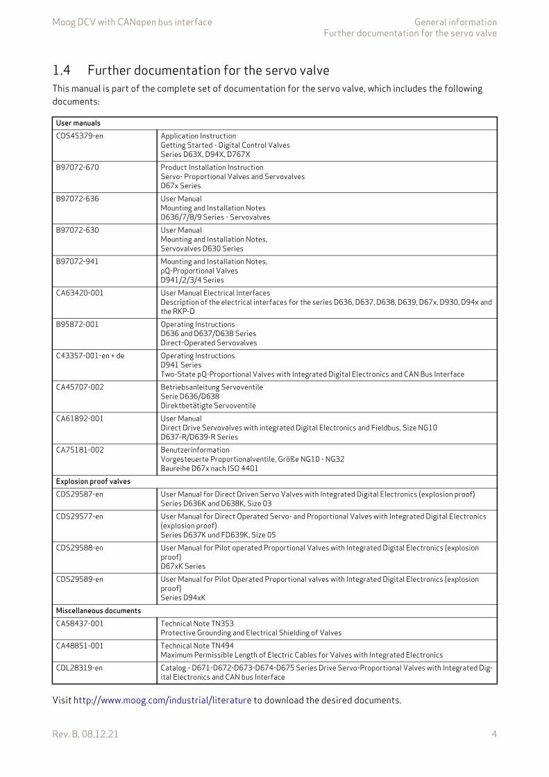
Moog DCV with CANopen bus interface General informationFurther documentation for the servo valve
Rev. B, 08.12.21 4
1.4 Further documentation for the servo valveThis manual is part of the complete set of documentation for the servo valve, which includes the following documents:
Visit http://www.moog.com/industrial/literature to download the desired documents.
User manualsCDS45379-en Application Instruction
Getting Started - Digital Control ValvesSeries D63X, D94X, D767X
B97072-670 Product Installation InstructionServo- Proportional Valves and Servovalves D67x Series
B97072-636 User Manual Mounting and Installation NotesD636/7/8/9 Series - Servovalves
B97072-630 User Manual Mounting and Installation Notes, Servovalves D630 Series
B97072-941 Mounting and Installation Notes,pQ-Proportional ValvesD941/2/3/4 Series
CA63420-001 User Manual Electrical InterfacesDescription of the electrical interfaces for the series D636, D637, D638, D639, D67x, D930, D94x and the RKP-D
B95872-001 Operating InstructionsD636 and D637/D638 Series Direct-Operated Servovalves
C43357-001-en + de Operating InstructionsD941 SeriesTwo-State pQ-Proportional Valves with Integrated Digital Electronics and CAN Bus Interface
CA45707-002 Betriebsanleitung ServoventileSerie D636/D638Direktbetätigte Servoventile
CA61892-001 User Manual Direct Drive Servovalves with integrated Digital Electronics and Fieldbus, Size NG10D637-R/D639-R Series
CA75181-002 Benutzerinformation Vorgesteuerte Proportionalventile, Größe NG10 - NG32Baureihe D67x nach ISO 4401
Explosion proof valvesCDS29587-en User Manual for Direct Driven Servo Valves with Integrated Digital Electronics (explosion proof)
Series D636K and D638K, Size 03CDS29577-en User Manual for Direct Operated Servo- and Proportional Valves with Integrated Digital Electronics
(explosion proof)Series D637K und FD639K, Size 05
CDS29588-en User Manual for Pilot operated Proportional Valves with Integrated Digital Electronics (explosion proof)D67xK Series
CDS29589-en User Manual for Pilot Operated Proportional valves with Integrated Digital Electronics (explosion proof)Series D94xK
Miscellaneous documentsCA58437-001 Technical Note TN353
Protective Grounding and Electrical Shielding of ValvesCA48851-001 Technical Note TN494
Maximum Permissible Length of Electric Cables for Valves with Integrated ElectronicsCDL28319-en Catalog - D671-D672-D673-D674-D675 Series Drive Servo-Proportional Valves with Integrated Dig-
ital Electronics and CAN bus Interface

Moog DCV with CANopen bus interface General informationReferences
Rev. B, 08.12.21 5
1.5 ReferencesIn this chapter you will find information about standards for CANopen and the used device profile. In the fol-lowing table you see all relevant organizations for standardization.
1.5.1 CAN fieldbusThe CANopen fieldbus interface provides a connection to the servo valves using standard CAN frames ac-cording to ISO 11898-1…3 and ISO 11898-5.
1.5.2 Device Profile
1.6 Definitions1.6.1 Internal resolution (iR)The internal resolution is 16384 (0x4000) at 100 % and –16384 (0xC000) at –100 % of the value range.
1.6.2 Volume flow directionA positive spool position demand value will result in a volume flow from connection P to A.
ISO International Organization for Standardization1, ch. de la Voie-Creuse, Case postale 56CH-1211 Geneva 20http://www.iso.org
IEC International Engineering Consortium233 S. Wacker Drive, Suite 8400Chicago, IL 60606-6338 USAhttp://www.iec.org
CiA CAN in AutomationKontumazgarten 3DE-90429 Nürnberghttp://www.can-cia.org
VDMA Verband Deutscher Maschinen- und Anlagenbau e.V.Lyoner Strasse 1860528 Frankfurt/Mainhttp://www.vdma.org
CiA 301 CANopen application layer and communication profileCiA 303-1 Cabling and connector pin assignmentCiA 305 Layer setting services (LSS) and protocolsISO 11898-1 Road vehicles -- Controller area network (CAN) -- Part 1: Data link layer and physicalISO 11898-2 Road vehicles -- Controller area network (CAN) -- Part 2: High-speed medium access unitISO 11898-3 Road vehicles -- Controller area network (CAN) -- Part 3: Low-speed, fault-tolerant, medium-de-
pendent interfaceISO 11898-5 Road vehicles -- Controller area network (CAN) -- Part 5: High-speed medium access unit with low-
power mode
VDMA Profile Fluid Power Device profile for Proportional Valves and Hydrostatic TransmissionsVDMA Profile Fluid Power Technology Version 1.6
CiA 408 or Device Profile Fluid Power
CiA 408 Device profile for fluid power technology proportional valves and hydrostatic transmis-sions, Version 2.0
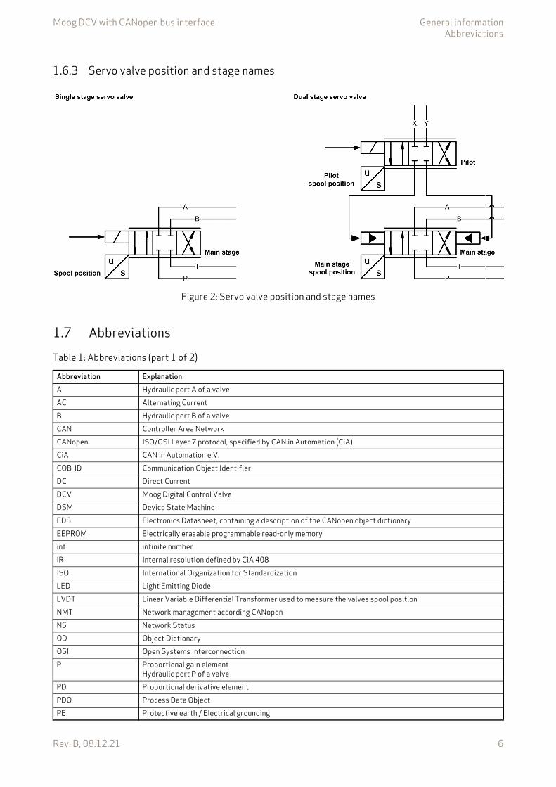
Moog DCV with CANopen bus interface General informationAbbreviations
Rev. B, 08.12.21 6
1.6.3 Servo valve position and stage names
Figure 2: Servo valve position and stage names
1.7 AbbreviationsTable 1: Abbreviations (part 1 of 2)
Abbreviation ExplanationA Hydraulic port A of a valveAC Alternating CurrentB Hydraulic port B of a valveCAN Controller Area NetworkCANopen ISO/OSI Layer 7 protocol, specified by CAN in Automation (CiA)CiA CAN in Automation e.V.COB-ID Communication Object IdentifierDC Direct CurrentDCV Moog Digital Control ValveDSM Device State MachineEDS Electronics Datasheet, containing a description of the CANopen object dictionaryEEPROM Electrically erasable programmable read-only memoryinf infinite numberiR Internal resolution defined by CiA 408ISO International Organization for StandardizationLED Light Emitting DiodeLVDT Linear Variable Differential Transformer used to measure the valves spool positionNMT Network management according CANopenNS Network StatusOD Object DictionaryOSI Open Systems InterconnectionP Proportional gain element
Hydraulic port P of a valvePD Proportional derivative elementPDO Process Data ObjectPE Protective earth / Electrical grounding

Moog DCV with CANopen bus interface General informationTrademarks
Rev. B, 08.12.21 7
1.8 TrademarksMoog and Moog Authentic Repair are registered trademarks of Moog Inc. and its subsidiaries.
PPT1 Proportional first order lag elementro Read onlyrw Read writeRPDO Receive Process Data ObjectSDO Service Data ObjectTR State transition of the valve application state machineTPDO Transmit Process Data ObjectURL Uniform Resource Locator / Internet addressVDMA Verband Deutscher Maschinen- und Anlagenbau e.V. wo Write onlyXn Physical connector n for electrical connection
Table 1: Abbreviations (part 2 of 2)
Abbreviation Explanation
All the product and company names mentioned in this document are possibly proprietary names or trademarks of the respective manufacturers. The use of these names by third parties for their own purposes may infringe the rights of the manufacturers.It cannot be inferred from the absence of the or symbol that the designation is a free brand name.
Moog DCV with CANopen bus interface Access over CANopenIntroduction
Rev. B, 08.12.21 8
2 Access over CANopenMoog servo valves are equipped with a fieldbus for communication with the machine controller. In this case with the standardized open fieldbus CANopen.
The CAN interface is electrically isolated from the servo valve electronics. The CAN network cable must be terminated externally with appropriate bus terminating resistors of 120 .
For operation in a CAN network, a unique node number and a baud rate must be set in the device during initial commissioning.
2.1 IntroductionCANopen is a communication protocol and device profile specification for embedded systems used in auto-mation. In terms of the Open Systems Interconnection (OSI) model, CANopen implements the above layers and the network layer. The CANopen standard consists of an addressing scheme, several communication pro-tocols and an application layer defined by specific device profiles. The communication protocols have support for network management, device monitoring and communication between nodes. The lower level protocol im-plementing the data link and physical layers is usually Controller Area Network (CAN). The basic CANopen ap-plication and communication profiles are given in the CiA 301 specification released by CAN in Automation (CiA). The device profile for the hydraulic valves CiA 408 is built on top of this basic profile.
2.2 Device profilesThe device profiles describe the application parameters and the functional behavior of the devices including the device class-specific state machines.
The German Engineering Federation (VDMA), together with the manufacturers of hydraulic devices, have developed the "profile for fluid power technology". This profile defines common functionality and parameters for the communication of hydraulic components via fieldbus in a standardized, fieldbus independent format across manufacturers. This profile is implemented in all Moog servo valves with fieldbus interface.
The CiA organization transformed this bus-independent device profile from the VDMA to the CANopen specific device profile CiA 408 "Device Profile Fluid Power Technology - proportional valves and hydrostatic transmissions". Other device profiles are for example generic I/O-modules (CiA 401), drives and motion control (CiA 402).
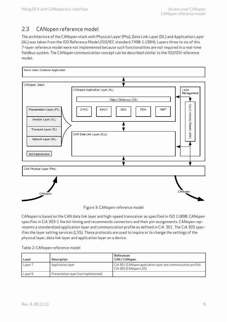
Moog DCV with CANopen bus interface Access over CANopenCANopen reference model
Rev. B, 08.12.21 9
2.3 CANopen reference modelThe architecture of the CANopen stack with Physical Layer (Phy), Data Link Layer (DL) and Application Layer (AL) was taken from the ISO Reference Model (ISO/IEC standard 7498-1:1994). Layers three to six of this 7-layer reference model were not implemented because such functionalities are not required in a real-time fieldbus system. The CANopen communication concept can be described similar to the ISO/OSI reference model.
Figure 3: CANopen reference model
CANopen is based on the CAN data link layer and high-speed transceiver as specified in ISO 11898. CANopen specifies in CiA 303-1 the bit-timing and recommends connectors and their pin-assignments. CANopen rep-resents a standardized application layer and communication profile as defined in CiA 301. The CiA 305 spec-ifies the layer setting services (LSS). These protocols are used to inquire or to change the settings of the physical layer, data link layer and application layer on a device.
Table 2: CANopen reference model
Layer DescriptionReferencesCAN / CANopen
Layer 7 Application layer CiA 301 (CANopen application layer and communication profile)CiA 305 (CANopen LSS)
Layer 6 Presentation layer (not implemented)
Moog DCV with CANopen bus interface Access over CANopenCANopen objects
Rev. B, 08.12.21 10
2.4 CANopen objectsA CANopen object is a set of CANopen parameters with the same index and object name. It consists of one or more parameters and their values. Objects are grouped in thematic blocks.
2.4.1 Parameter valueA parameter value is a real value stored in the servo valve with the attributes of the parameter explained in the next chapter.
2.4.2 Parameter and their attributesA parameter is an abstract representation of a particular parameter value within a CANopen object dictionary in a device. Parameters are described in this document in the following tabular form:
In the parameter list in chapter "Object dictionary" you will find a form like the following one in which the attri-butes are explained in detail. Chapter "10 Object dictionary", page 290
Layer 5 Session layer (not implemented)Layer 4 Transport layer (not implemented)Layer 3 Network layer (not implemented)Layer 2 Data link layer ISO 11898-1 (CAN)
CiA 305 (CANopen LSS)Layer 1 Physical layer ISO 11898-1/2/3/5 (CAN)
CiA 303-1 (CANopen Additional Specification)
Table 2: CANopen reference model
Layer DescriptionReferencesCAN / CANopen
Block nameIndex Sub-index Parameter name Data type Access Persistence Value range Default
IndexSub-index
PDO-mapping Short name Specification
Block, object and parameter name
Data type Access
Per-sistence
Value range Default
Moog DCV with CANopen bus interface Access over CANopenCANopen objects
Rev. B, 08.12.21 11
Table 3: Fieldbus independent attributes
Column name MeaningBlock name Describes the family of the object. If the object does not belong to a block, the object name is taken as
block name.Object name Defined name of the object.Index 16 bit index that addresses the entry in the object dictionary. In case of a simple variable this references
the value of this variable directly. In case of records and arrays, the index addresses the whole data struc-ture. Then the 8 bit sub-index allows access to individual elements in the structure.
Sub-index If the object is defined as a record or array, the sub-index defines an element in the structure.Parameter name Defined name of the parameter.Data type Data type of the parameter.
CiA 301 data type Short name DescriptionINTEGERn INTn Signed integer with n bitsUNSIGNEDn UINTn Unsigned integer with n bitsREAL32 REAL32 Floating point with 32 bit according CiA 301VISIBLE_STRING STRING(n) String of n ASCII charactersDOMAIN DOMAIN Application specific data block
Access Access permission for the parameter.rw Read and write allowedwo Write onlyro Read only
Persistence Defines whether the parameter can be saved in non-volatile memory. If the persistence is set to "Y", the saved value stays in memory even after the device is turned off. Parameters not marked as persistent ("N") lose their settings after the device is turned off. The parameters with the access type "read only" are marked with "-". This means that the parameter cannot be changed by the user.
Value range Allowed value range for the parameter.Default Default values:
The default values in this document are firmware preset values. These values can be changed during cali-bration or set up with model specific parameters during production of the servo valve.Factory settings:The factory settings are values which are set up model specific during production of the servo valve. These parameters no longer contain the firmware default preset values. Chapter "9 Storing / restoring parameters", page 287
Specification Related (fieldbus) standard defining the parameter.Possible entries:CiA 301 Parameters correspond to CiA 301.CiA 408 Parameters correspond to CiA 408.Moog DCV Moog defined parameters for digital control servo valves.
PDO mapping If set to "Y", the parameter can be mapped into a PDO.If set to "N", the parameter cannot be mapped into a PDO.
Short name Unique short name.
The listed default values contain the firmware preset values and not necessarily the configura-tion of the delivered servo valve.
Moog DCV with CANopen bus interface Access over CANopenCANopen object dictionary (OD)
Rev. B, 08.12.21 12
2.4.3 Units and prefix parameterThis chapter describes the coding of units and prefix parameters according to CiA 303-2. Some objects pro-vide unit and prefix in the sub-indices 2 and 3 to allow the master controller the correct visualization.
2.5 CANopen object dictionary (OD)CANopen devices have an object dictionary, which is used for configuration and non-realtime communication with the device. It is essentially a grouping of objects accessible via the network. Each object within the object dictionary is addressed using a 16 bit index and an 8 bit sub-index. So an object can contain 256 parameters which are addressed by the sub-index. The object dictionary is structured in several index ranges. The classifi-cation of the object dictionary is defined in the CiA 301.
Table 4: Unit representation
Name of unit International symbol Notation index (hex) Notation index (dec)none dimensionless or iR 0x00 0meter m 0x01 1second s 0x03 3hertz Hz 0x20 32liter l or L 0x44 68minute (time) min 0x47 71hour h 0x48 72day d 0x49 73year a 0x4A 74bar bar 0x4E 78meter per square second m/s2 0x55 85
Table 5: Prefix representation
Prefix Factor Symbol Notation index (hex) Notation index (dec)none 10–0 0x00 0deci 10–1 d 0xFF –1centi 10–2 c 0xFE –2milli 10–3 m 0xFD –3
10–4 0xFC –4
Table 6: Structure of the CANopen object dictionary (OD)
Index Object Reference0x0000 Not used0x0001…0x001F Data types CiA 3010x0020…0x003F Complex data types (not used) CiA 3010x0040…0x005F Manufacturer-specific complex data types (not used)0x0060…0x025F Device profile specific data types (not used) CiA 4080x0260…0x03FF Reserved for further use0x0400…0x0FFF Reserved for further use0x1000…0x1FFF Communication profile area used for the fieldbus CAN.
Note: For configuring the local CAN interface, the objects 0x5000 and following are used.
CiA 301 / IEC 61158-5-12
0x2000…0x5FFF Manufacturer-specific area Moog DCV

Moog DCV with CANopen bus interface Access over CANopenElectronic data sheet (EDS)
Rev. B, 08.12.21 13
2.6 Electronic data sheet (EDS)Electronic data sheets (EDS) are files which describe the capabilities and the communication objects of a CANopen device. The EDS is essential to configure CANopen master devices. Model-specific EDS files are provided by Moog and can be downloaded from the Moog website http://www.moog.com/industrial.
2.7 CANopen communication protocolsCANopen communication protocols are classified as follows:
• Real-time data are transferred with the process data object (PDO) protocol.• Configuration parameters are transferred with the service data object (SDO) protocol.• Special tasks are realized using application-specific network synchronization (SYNC) protocol, time
stamping and emergency message (EMCY) protocol.• The network management (NMT) protocol provides services for network initialization, error control and
network status control.
0x6000…0x67FF Standardized profile area 1st logical device CiA 4080x6800…0x9FFF Standardized profile area 2nd…8th logical device (not used) CiA 3010xA000…0xAFFF Standardized network variable area (not used)0xB000…0xBFFF Standardized system variable area (not used)0xC000…0xFFFF Reserved for further use
Table 6: Structure of the CANopen object dictionary (OD)
Index Object Reference
Table 7: CANopen communication objects (part 1 of 2)
Protocol COB-ID Description
SDO objects used for proto-col configuration Reference Chapter
NMT 0x000 Network Management (NMT) protocol (Broadcast)
CiA 301 Chapter "2.10 Network manage-ment (NMT) state machine", page 17NMT 0x000+Node-ID Network Management (NMT)
protocolCiA 301
SYNC 0x080 Synchronization (Broadcast) protocol
0x1005, 0x1006, 0x1007, 0x1019
CiA 301 Chapter "2.18 Synchronization (SYNC)", page 38
EMCY 0x080+Node-ID Emergency protocol 0x1014 CiA 301 Chapter "2.19 Emergency (EMCY)", page 40
TPDO 0x180+Node-ID 1st Transmit PDO protocol 0x1800, 0x1A00 CiA 301 Chapter "2.13 Process data ob-ject (PDO)", page 23 Chapter "2.15 Transmit process data object (TPDO)", page 30
RPDO 0x200+Node-ID 1st Receive PDO protocol 0x1400, 0x1600 CiA 301TPDO 0x280+Node-ID 2nd Transmit PDO protocol 0x1801, 0x1A01 CiA 301RPDO 0x300+Node-ID 2nd Receive PDO protocol 0x1401, 0x1601 CiA 301TPDO 0x380+Node-ID 3rd Transmit PDO protocol 0x1802, 0x1A02 CiA 301RPDO 0x400+Node-ID 3rd Receive PDO protocol 0x1402, 0x1602 CiA 301TPDO 0x480+Node-ID 4th Transmit PDO protocol 0x1803, 0x1A03 CiA 301RPDO 0x500+Node-ID 4th Receive PDO protocol 0x1403, 0x1603 CiA 301
Moog DCV with CANopen bus interface Access over CANopenCANopen communication protocols
Rev. B, 08.12.21 14
SDO 0x580+Node-ID Transmit SDO protocol 0x1200 CiA 301 Chapter "2.16 Service data ob-ject (SDO)", page 37SDO 0x600+Node-ID Receive SDO protocol 0x1200 CiA 301
NMT 0x700+Node-ID Network Management (NMT) error control protocol (Bootup, Node Guarding, Heartbeat)
0x100C, 0x100D, 0x1016, 0x1017
CiA 301 Chapter "2.10 Network manage-ment (NMT) state machine", page 17 Chapter "2.12 Network manage-ment (NMT) node guarding", page 22 Chapter "2.11 Network manage-ment (NMT) heartbeat", page 21
LSS 0x7E4 Transmit Layer Setting Services (LSS) protocol
0x1018 CiA 305 Chapter "2.8 Bit rate and Node-ID configuration using Layer Set-ting Services (LSS)", page 15LSS 0x7E5 Receive Layer Setting Services
(LSS) protocol
Table 7: CANopen communication objects (part 2 of 2)
Protocol COB-ID Description
SDO objects used for proto-col configuration Reference Chapter
Moog DCV with CANopen bus interface Access over CANopenBit rate and Node-ID configuration using Layer Setting Services (LSS)
Rev. B, 08.12.21 15
2.8 Bit rate and Node-ID configuration using Layer Setting Services (LSS)The bit rate of the CAN bus communication can be changed to achieve a maximal transmission rate by a given length of the cable. Each node in the network has a unique Node-ID which must be configured before initial operation.
The Node ID and the bit rate can be changed using:
• Layer Setting Service (LSS)• Service Data Objects (SDO)
The following standardized CANopen bit rates and maximum cable lengths can be configured:
For details, see document CA63420 001 "User Manual Electrical Interfaces"
The digital servo valve has a Layer Setting Service (LSS) slave implementation according to CiA 305. With this service, the bit rate and the Node-ID of the digital servo valve can be configured by an LSS master.
To configure the Node-ID of the CANopen fieldbus interface, the LSS protocol must be received via the field-bus connection.
The implemented LSS service provides four methods to change the Node-ID or bit rate of the servo valve:
1. LSS configuration serviceIf a point to point connection has been established between the LSS master and the servo valve, the bit rate and the Node-ID is set in dialog mode.
2. LSS inquiry serviceIf more than one slave nodes are connected to the network at the same time, the bit rate and Node-ID can be changed with the LSS service by selecting this particular slave device by his unique identification ob-ject (0x1018). This node identification object (0x1018) is worldwide unique and will be programmed during production. Information about the identification object (0x1018) is available from the name plate (LSS) of the device or can be inquired by using SDO.
3. LSS identification servicesThe third method corresponds to the second with the possibility to find devices that match a certain VendorID and product code in the identification object (0x1018). This allows newly installed bus devices with changed revision number and serial number to be found.
4. LSS fastscan serviceAs the LSS identify remote slave service, the LSS fastscan service may be used to scan for unconfigured LSS slaves. The value range of the active node-ID is from 0x01 to 0x7F. In addition to this range, the value range for pending Node-ID as well as the persistent Node-ID includes the value 0xFF which indi-cates an invalid setting.
The LSS service itself stores the new settings permanently in the servo valve. It is not necessary to initiate a manual Store command as needed for other configuration parameters of the servo valve.
Table 8: CANopen bit rates
<Bitrate>Bit rate Maximum cable length1000 kBit/s < 25 m500 kBit/s < 100 m250 kBit/s < 250 m125 kBit/s < 500 m50 kBit/s < 1000 m20 kBit/s < 2500 m
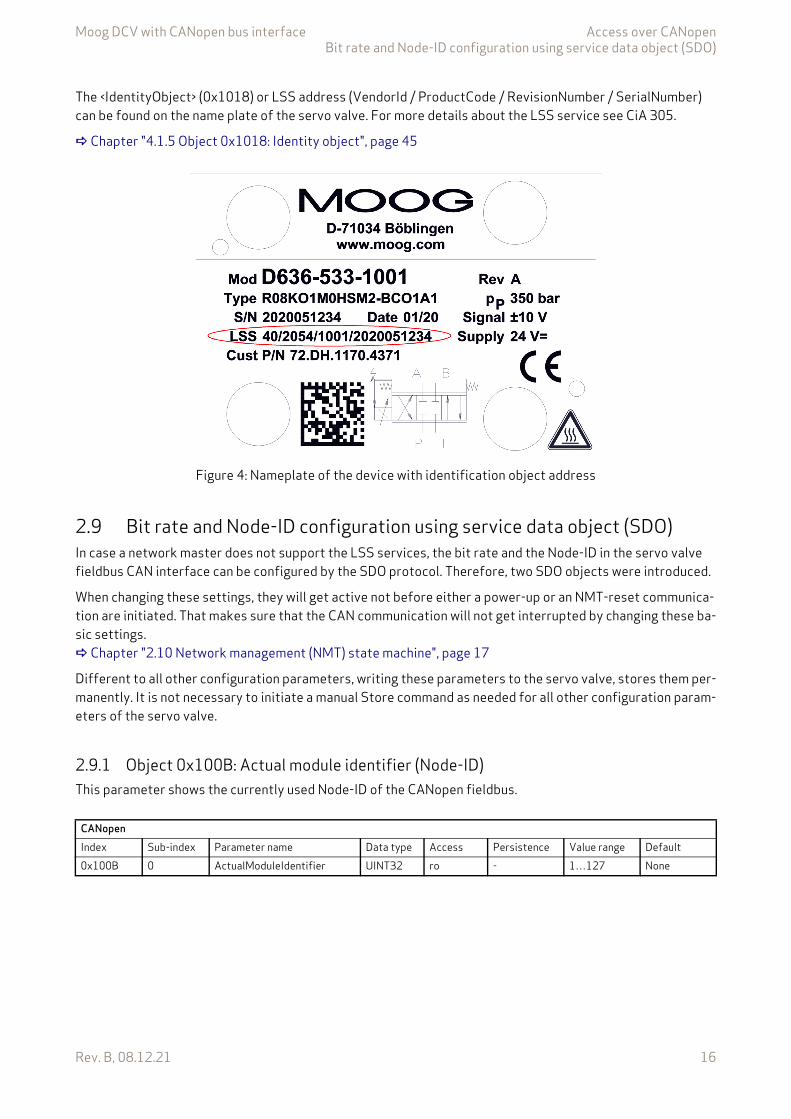
Moog DCV with CANopen bus interface Access over CANopenBit rate and Node-ID configuration using service data object (SDO)
Rev. B, 08.12.21 16
The <IdentityObject> (0x1018) or LSS address (VendorId / ProductCode / RevisionNumber / SerialNumber) can be found on the name plate of the servo valve. For more details about the LSS service see CiA 305.
Chapter "4.1.5 Object 0x1018: Identity object", page 45
Figure 4: Nameplate of the device with identification object address
2.9 Bit rate and Node-ID configuration using service data object (SDO)In case a network master does not support the LSS services, the bit rate and the Node-ID in the servo valve fieldbus CAN interface can be configured by the SDO protocol. Therefore, two SDO objects were introduced.
When changing these settings, they will get active not before either a power-up or an NMT-reset communica-tion are initiated. That makes sure that the CAN communication will not get interrupted by changing these ba-sic settings. Chapter "2.10 Network management (NMT) state machine", page 17
Different to all other configuration parameters, writing these parameters to the servo valve, stores them per-manently. It is not necessary to initiate a manual Store command as needed for all other configuration param-eters of the servo valve.
2.9.1 Object 0x100B: Actual module identifier (Node-ID)This parameter shows the currently used Node-ID of the CANopen fieldbus.
CANopenIndex Sub-index Parameter name Data type Access Persistence Value range Default0x100B 0 ActualModuleIdentifier UINT32 ro - 1…127 None

Moog DCV with CANopen bus interface Access over CANopenNetwork management (NMT) state machine
Rev. B, 08.12.21 17
2.9.2 Object 0x3002: Module identifier (Node-ID)This parameter represents the CAN Node ID of the servo valve. To activate the new Node-ID either a power-up, an NMT-reset communication, or an LSS-command has to be initiated.
2.9.3 Object 0x3003: Bit rateThe bit rate will be configured in bits per second. To activate the new bit rate either a power-up or an NMT-re-set communication has to be initiated.
Value descriptionThe following standardized CANopen bit rates and maximum cable lengths can be configured:
2.10 Network management (NMT) state machineThe CANopen NMT state machine is used to control the network communication of the fieldbus. The network management is node-oriented and follows a master/slave structure. It requires one device in the network, which fulfills the function of the NMT master, the other nodes are NMT slaves.
CANopenIndex Sub-index Parameter name Data type Access Persistence Value range Default0x3002 0 ModuleIdentifier UINT8 rw Y 1…127 127
CANopenIndex Sub-index Parameter name Data type Access Persistence Value range Default0x3003 0 Bitrate UINT32 rw Y 10000…
1000000500000
Table 9: CANopen bit rates
<Bitrate>Bit rate Maximum cable length Parameter value1000 kBit/s < 25 m 1000000500 kBit/s < 100 m 500000250 kBit/s < 250 m 250000125 kBit/s < 500 m 125000100 kBit/s - not supported - -50 kBit/s < 1000 m 5000020 kBit/s < 2500 m 20000
The CANopen network management (NMT) state machine must not be mistaken with the device state machine.
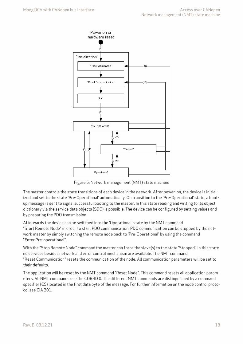
Moog DCV with CANopen bus interface Access over CANopenNetwork management (NMT) state machine
Rev. B, 08.12.21 18
Figure 5: Network management (NMT) state machine
The master controls the state transitions of each device in the network. After power-on, the device is initial-ized and set to the state 'Pre-Operational' automatically. On transition to the 'Pre-Operational' state, a boot-up message is sent to signal successful booting to the master. In this state reading and writing to its object dictionary via the service data objects (SDO) is possible. The device can be configured by setting values and by preparing the PDO transmission.
Afterwards the device can be switched into the 'Operational' state by the NMT command "Start Remote Node" in order to start PDO communication. PDO communication can be stopped by the net-work master by simply switching the remote node back to 'Pre-Operational' by using the command "Enter Pre-operational".
With the "Stop Remote Node" command the master can force the slave(s) to the state 'Stopped'. In this state no services besides network and error control mechanism are available. The NMT command "Reset Communication" resets the communication of the node. All communication parameters will be set to their defaults.
The application will be reset by the NMT command "Reset Node". This command resets all application param-eters. All NMT commands use the COB-ID 0. The different NMT commands are distinguished by a command specifier (CS) located in the first data byte of the message. For further information on the node control proto-col see CiA 301.
Moog DCV with CANopen bus interface Access over CANopenNetwork management (NMT) state machine
Rev. B, 08.12.21 19
NMT state transitions are caused by
• Reception of an NMT node control command from the CANopen bus• Hardware reset, or• Node control services locally initiated by application events.
Services on the listed communication objects may only be executed if the CANopen device is in the appropriate NMT state.
2.10.1 Object 0x3004: Network management (NMT) state machine statusThis parameter contains the network management (NMT) state machine status in bit coded form.
Value description
Table 10: NMT state transitions
Transition Description(1) At Power on the NMT state initialization is entered autonomously.(2) NMT state initialization finished - enter NMT state Pre-operational automatically (Boot-up message will be
sent).(3) Receive NMT command "start remote node" or by local control.(4), (7) Receive NMT command "enter pre-operational".(5), (8) Receive NMT command "stop remote node".(6) Receive NMT command "start remote node".(9) Receive NMT command "reset node".(10) Receive NMT command "reset communication".
Table 11: NMT states
NMT states
Available services
SDO PDO EMCY NMT
NMT Node Guarding and
Heartbeat'STOPPED' x x'Pre-Operational' x x x x'Operational' x x x x x
CANopenIndex Sub-index Parameter name Data type Access Persistence Value range Default0x3004 0 NmtState UINT16 ro - UINT16 None
Table 12: Object 0x3004: Network Management (NMT) state machine status
<NmtState>Status (hex) Status (dec) Status0x0000 0 Invalid State
0x0001 1 State Power On or Hardware Reset
0x0002 2 Reset Application
0x0004 4 Reset Communication
Moog DCV with CANopen bus interface Access over CANopenNetwork management (NMT) state machine
Rev. B, 08.12.21 20
2.10.2 Object 0x3005: Network management (NMT) state machine controlThis parameter is used to control the Network management (NMT) state machine. The possible status change depends on the current status.
Value description Table 12, page 19
2.10.3 Object 0x1029: Network management (NMT) error behaviorIf a serious CANopen device failure is detected in NMT state 'Operational', the CANopen device shall enter by default autonomously the NMT state 'Pre-operational'. The error behavior of the NMT can be changed via this parameter to NMT state 'Stopped' or remain in the current NMT state.
Value description
0x0008 8 Init
0x0010 16 Pre-Operational
0x0020 32 Stopped
0x0040 64 Operational
0x8000 32768 Severe Error State
Table 12: Object 0x3004: Network Management (NMT) state machine status
<NmtState>Status (hex) Status (dec) Status
CANopenIndex Sub-index Parameter name Data type Access Persistence Value range Default0x3005 0 NmtSetState UINT16 rw N 1…130 None
CANopenIndex Sub-index Parameter name Data type Access Persistence Value range Default0x1029 0 ErrorBehavior UINT8 rw Y UINIT8 0
<ErrorBehavior>0 Change to NMT state 'Pre-Operational'
(only if currently in NMT state 'Operational')1 No change of the NMT state2 Change to NMT state 'Stopped'3…256 No change of the NMT state

Moog DCV with CANopen bus interface Access over CANopenNetwork management (NMT) heartbeat
Rev. B, 08.12.21 21
2.11 Network management (NMT) heartbeatThe Heartbeat Protocol consists of two separate services:
1. The monitoring of a periodically received heartbeat message, called consumer heartbeat. The Node-ID of the heartbeat transmitter and the time window until the next heartbeat message must arrive is set by the parameter <ConsumerHeartbeatTime> (0x1016). If the heartbeat transmitter does not respond within the specified time, error code 110 (0x6E) is triggered.
2. Periodically sending a heartbeat message, called producer heartbeat. For this purpose, the interval be-tween two heartbeat messages can be set with the parameter <ProducerHeartbeatTime> (0x1017). The heartbeat protocol starts on the transition from the NMT state 'Initialization' to the NMT state 'Pre-Op-erational'. In this case the boot-up message is regarded as first heartbeat message. With the heartbeat message the servo valve NMT state is transmitted.
2.11.1 Object 0x1016: Consumer heartbeat timeThe parameter <ConsumerHeartbeatTime> (0x1016) defines the expected heartbeat cycle time. It additionally defines the node-ID of the heartbeat producer to be monitored.
To enable the heartbeat message, a time greater zero must be set and a valid node-ID (between 1…127) must be configured. If the heartbeat time is 0 or the node-ID is 0 or greater than 127, the corresponding object entry shall be not used. The heartbeat time shall be given in multiples of 1 ms.
Value description
2.11.2 Object 0x1017: Producer heartbeat timeThe parameter <ProducerHeartbeatTime> (0x1017) specifies the time in ms at which the servo valve sends a heartbeat message. The value 0 disables the producer heartbeat.
It is not allowed to use both error control mechanisms guarding protocol and heartbeat protocol on one NMT slave at the same time.
Even though both Heartbeat and Guarding are disabled by default, it is recommended to use error control mechanisms.
The consumer heartbeat time should be higher than the corresponding producer heartbeattime.
CANopenIndex Sub-index Parameter name Data type Access Persistence Value range Default0x1016 0 ConsumerHeartbeatTime UINT32 rw Y UINT32 0
<ConsumerHeartbeatTime>Bit 31…24 23…16 15…0Description Reserved Node-ID Heartbeat time in ms
CANopenIndex Sub-index Parameter name Data type Access Persistence Value range Default0x1017 0 ProducerHeartbeatTime UINT16 rw Y UINT16 0
Moog DCV with CANopen bus interface Access over CANopenNetwork management (NMT) node guarding
Rev. B, 08.12.21 22
2.12 Network management (NMT) node guardingThe node guarding is the periodical monitoring of certain network nodes. Each node can be checked by the NMT master with a certain period <GuardTime> (0x100C). A second parameter <LifeTimeFactor> (0x100D) de-fines a factor after the connection will be detected as lost. The resolution of the guarding time is 1 ms. To en-able the node guarding on a slave device, the guard time and life time factor must be set. The guarding is started with the first guarding telegram of the master. During node guarding the master sends a remote transmit request (RTR) frame to each guarded slave. The slave answers with its actual NMT state and a toggle bit. This toggle bit alternates in each cycle.
The monitoring time until fault reaction 110 (0x6E) 'CAN life guard error or heartbeat error' is triggered is cal-culated as follows:
If the network master supports the Heartbeat Protocol, this should be preferred to Node Guarding, as it al-lows better monitoring. The guarding protocol is still supported for compatibility reasons.
2.12.1 Object 0x100C: Guard timeThis parameter contains the guarding time in milliseconds. The value 0 disables the life guarding.
2.12.2 Object 0x100D: Life time factorThis parameter contains the life time factor. The value 0 disables the life guarding.
Monitoring time <GuardTime> (0x100C) <LifeTimeFactor> (0x100D)=
It is not allowed to use both error control mechanisms guarding protocol and heartbeat protocol on one NMT slave at the same time.
CANopenIndex Sub-index Parameter name Data type Access Persistence Value range Default0x100C 0 GuardTime UINT16 rw Y UINT16 0
CANopenIndex Sub-index Parameter name Data type Access Persistence Value range Default0x100D 0 LifeTimeFactor UINT8 rw Y UINT8 1

Moog DCV with CANopen bus interface Access over CANopenProcess data object (PDO)
Rev. B, 08.12.21 23
2.13 Process data object (PDO)The process data object (PDO) communication allows cyclic receiving and sending of parameters in real time. Different transmission modes are available: synchronous, event or timer driven transmission.
Four RPDOs and four TPDOs are implemented:
• Receive process data object (RPDO), Chapter "2.14 Receive process data object (RPDO)", page 24• Transmit process data object (TPDO), Chapter "2.15 Transmit process data object (TPDO)", page 30
Figure 6: PDO Real Time Data Transmission
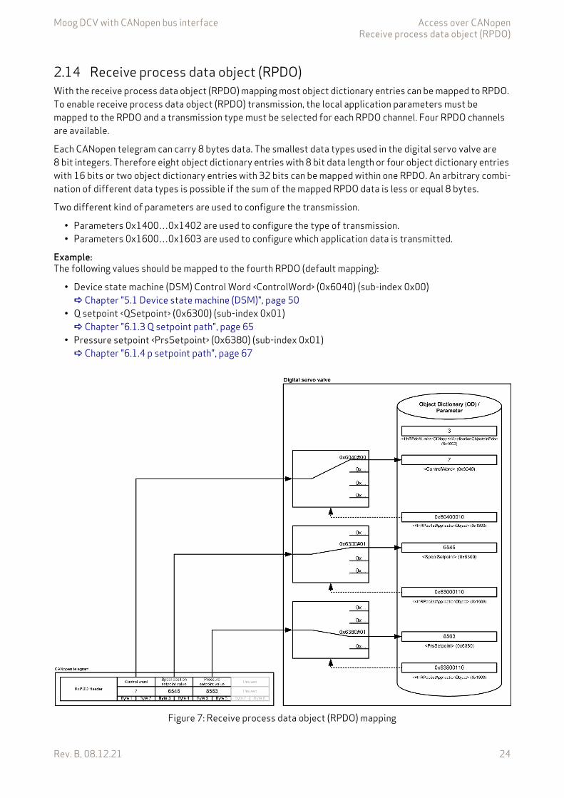
Moog DCV with CANopen bus interface Access over CANopenReceive process data object (RPDO)
Rev. B, 08.12.21 24
2.14 Receive process data object (RPDO)With the receive process data object (RPDO) mapping most object dictionary entries can be mapped to RPDO. To enable receive process data object (RPDO) transmission, the local application parameters must be mapped to the RPDO and a transmission type must be selected for each RPDO channel. Four RPDO channels are available.
Each CANopen telegram can carry 8 bytes data. The smallest data types used in the digital servo valve are 8 bit integers. Therefore eight object dictionary entries with 8 bit data length or four object dictionary entries with 16 bits or two object dictionary entries with 32 bits can be mapped within one RPDO. An arbitrary combi-nation of different data types is possible if the sum of the mapped RPDO data is less or equal 8 bytes.
Two different kind of parameters are used to configure the transmission.
• Parameters 0x1400…0x1402 are used to configure the type of transmission.• Parameters 0x1600…0x1603 are used to configure which application data is transmitted.
Example:The following values should be mapped to the fourth RPDO (default mapping):
• Device state machine (DSM) Control Word <ControlWord> (0x6040) (sub-index 0x00) Chapter "5.1 Device state machine (DSM)", page 50
• Q setpoint <QSetpoint> (0x6300) (sub-index 0x01) Chapter "6.1.3 Q setpoint path", page 65
• Pressure setpoint <PrsSetpoint> (0x6380) (sub-index 0x01) Chapter "6.1.4 p setpoint path", page 67
Figure 7: Receive process data object (RPDO) mapping
Moog DCV with CANopen bus interface Access over CANopenReceive process data object (RPDO)
Rev. B, 08.12.21 25
For example, the parameter <4thRPdoNumberOfMappedApplicationObjectsInPdo> (0x1603) defines the number of mapped values for the fourth RPDO. The second sub-index is a reference to the <ControlWord> (0x6040) (sub-index 0x00). The references to the parameters <QSetpoint> (0x6300) (sub index 0x01) and <PrsSetpoint> (0x6380) (sub-index 0x01) are defined in the same manner.
For detailed information how the PDO protocol is working, please take a look into the actual CiA 301 CANopen application layer and communication profile.
2.14.1 Object 0x1400: 1st RPDO configurationFirst RPDO channel configuration.
Value description
CANopenIndex Sub-index Parameter name Data type Access Per-
sis-tence
Value range Default
0x1400 1 1stRPdoCobIdUsedByPdo UINT32 rw Y 1…0x000007FF|0x80000000
0x0200+127
0x1400 2 1stRPdoTransmissionType UINT8 rw Y UINT8 2550x1400 5 1stRPdoEventTimer UINT16 rw Y UINT16 0
Table 13: Object 0x1400: 1st RPDO configuration
Parameter Description<1stRPdoCobIdUsedByPdo> COB-ID of the 1st RPDO.<1stRPdoTransmissionType> Different trigger can be configured: Table 15, page 25<1stRPdoEventTimer> This parameter defines the timeout in milliseconds for the RPDO time-
out monitoring. The event timer is used to recognize the expiration of the RPDO. If the time elapsed and the PDO was not received within that period, a fault reaction can be initiated. If this parameter is set to 0, the receive timeout monitoring is turned off.
Table 14: Possible values of parameter <1stRPdoCobIdUsedByPdo> (0x1400, sub-index 1)
<1stRPdoCobIdUsedByPdo>Bit 31 30 29…11 10…0Description 0: PDO will be processed/received
1: PDO will not be processed/receivedReserved Reserved 11 bit COB-ID
Table 15: Possible values of parameter <1stRPdoTransmissionType> (0x1400, sub-index 2)
<1stRPdoTransmissionType>0 The last incoming PDO will be processed synchronously to the next in-
coming SYNC telegram.1…240 The last incoming PDO will be processed synchronously to every
<1stRPdoTransmissionType> (0x1400) SYNC telegram.241…253 Reserved254…255 PDO will be processed immediately after reception.
Moog DCV with CANopen bus interface Access over CANopenReceive process data object (RPDO)
Rev. B, 08.12.21 26
2.14.2 Object 0x1401: 2nd RPDO configurationSecond RPDO channel configuration.
Value description Table 13, page 25
2.14.3 Object 0x1402: 3rd RPDO configurationThird RPDO channel configuration.
Value description Table 13, page 25
2.14.4 Object 0x1403: 4th RPDO configurationFourth RPDO channel configuration.
Value description Table 13, page 25
CANopenIndex Sub-index Parameter name Data type Access Per-
sis-tence
Value range Default
0x1401 1 2ndRPdoCobIdUsedByPdo UINT32 rw Y 1…0x000007FF|0x80000000
0x0300+127
0x1401 2 2ndRPdoTransmissionType UINT8 rw Y UINT8 2550x1401 5 2ndRPdoEventTimer UINT16 rw Y UINT16 0
CANopenIndex Sub-index Parameter name Data type Access Per-
sis-tence
Value range Default
0x1402 1 3rdRPdoCobIdUsedByPdo UINT32 rw Y 1…0x000007FF|0x80000000
0x0400+127
0x1402 2 3rdRPdoTransmissionType UINT8 rw Y UINT8 2550x1402 5 3rdRPdoEventTimer UINT16 rw Y UINT16 0
CANopenIndex Sub-index Parameter name Data type Access Per-
sis-tence
Value range Default
0x1403 1 4thRPdoCobIdUsedByPdo UINT32 rw Y 1…0x000007FF|0x80000000
0x0500+127
0x1403 2 4thRPdoTransmissionType UINT8 rw Y UINT8 2550x1403 5 4thRPdoEventTimer UINT16 rw Y UINT16 0
Moog DCV with CANopen bus interface Access over CANopenReceive process data object (RPDO)
Rev. B, 08.12.21 27
2.14.5 Object 0x1600: 1st RPDO mappingWith the parameter <1stRPdoNumberOfMappedApplicParaInPdo> (0x1600) the number of real-time applica-tion parameters to be received can be set. To map the application parameter itself, its index, sub-index and length must be combined to a 32 bit value and written to one of the eight possible positions (corresponding to the sub-indexes 1…8) within the PDO object mapping object.
Value description
This pointer consists of a combination of index, sub-index and length of the parameter to be used.
The example value is 0x60400010, which refers to the <ControlWord> (0x6040), sub-index 0x00 with a length of 16 bit (16=0x10).
CANopenIndex Sub-
indexParameter name Data
typeAccess Per-
sis-tence
Value range
Default
0x1600 0 1stRPdoNumberOfMappedApplicationObjectsInPdo UINT8 rw Y 0…8 10x1600 1 1stRPdo1stApplicationObject UINT32 rw Y UINT32 0x604000100x1600 2 1stRPdo2ndApplicationObject UINT32 rw Y UINT32 00x1600 3 1stRPdo3rdApplicationObject UINT32 rw Y UINT32 00x1600 4 1stRPdo4thApplicationObject UINT32 rw Y UINT32 00x1600 5 1stRPdo5thApplicationObject UINT32 rw Y UINT32 00x1600 6 1stRPdo6thApplicationObject UINT32 rw Y UINT32 00x1600 7 1stRPdo7thApplicationObject UINT32 rw Y UINT32 00x1600 8 1stRPdo8thApplicationObject UINT32 rw Y UINT32 0
Table 16: Object 0x1600: 1st RPDO mapping
Parameter Description<1stRPdoNumberOfMappedApplicationObjectsInPdo> Numbers of mapped application parameters<1stRPdo1stApplicationObject> Mapping of 1st application parameter<1stRPdo2ndApplicationObject> Mapping of 2nd application parameter<1stRPdo3rdApplicationObject> Mapping of 3rd application parameter<1stRPdo4thApplicationObject> Mapping of 4th application parameter<1stRPdo5thApplicationObject> Mapping of 5th application parameter<1stRPdo6thApplicationObject> Mapping of 6th application parameter<1stRPdo7thApplicationObject> Mapping of 7th application parameter<1stRPdo8thApplicationObject> Mapping of 8th application parameter
Table 17: Value description of mapping parameter <1stRPdo1stApplicationObject>…<1stRPdo8thApplicationObject>
<1stRPdo1stApplicationObject>…<1stRPdo8thApplicationObject>Byte 3 2 1 0Description Index MSB Index LSB Sub-index Parameter bit length
0x08 or 0x10 or 0x20Example 0x60 0x40 0x00 0x10

Moog DCV with CANopen bus interface Access over CANopenReceive process data object (RPDO)
Rev. B, 08.12.21 28
2.14.6 Object 0x1601: 2nd RPDO mappingSecond RPDO mapping.
The mapping of this PDO is predefined as default mapping for a standard Q-control servo valve. It maps the <ControlWord> (0x6040) and the <QSetpoint> (0x6300).
Value description Table 16, page 27
2.14.7 Object 0x1602: 3rd RPDO mappingThird RPDO mapping.
The mapping of this PDO is predefined as default mapping for a standard p-control servo valve. It maps the <ControlWord> (0x6040) and the <PrsSetpoint> (0x6380).
Value description Table 16, page 27
CANopenIndex Sub-
indexParameter name Data
typeAccess Per-
sis-tence
Value range
Default
0x1601 0 2ndRPdoNumberOfMappedApplicationObjectsInPdo UINT8 rw Y 0…8 20x1601 1 2ndRPdo1stApplicationObject UINT32 rw Y UINT32 0x604000100x1601 2 2ndRPdo2ndApplicationObject UINT32 rw Y UINT32 0x630001100x1601 3 2ndRPdo3rdApplicationObject UINT32 rw Y UINT32 00x1601 4 2ndRPdo4thApplicationObject UINT32 rw Y UINT32 00x1601 5 2ndRPdo5thApplicationObject UINT32 rw Y UINT32 00x1601 6 2ndRPdo6thApplicationObject UINT32 rw Y UINT32 00x1601 7 2ndRPdo7thApplicationObject UINT32 rw Y UINT32 00x1601 8 2ndRPdo8thApplicationObject UINT32 rw Y UINT32 0
CANopenIndex Sub-
indexParameter name Data
typeAccess Per-
sis-tence
Value range
Default
0x1602 0 3rdRPdoNumberOfMappedApplicationObjectsInPdo UINT8 rw Y 0…8 20x1602 1 3rdRPdo1stApplicationObject UINT32 rw Y UINT32 0x604000100x1602 2 3rdRPdo2ndApplicationObject UINT32 rw Y UINT32 0x638001100x1602 3 3rdRPdo3rdApplicationObject UINT32 rw Y UINT32 00x1602 4 3rdRPdo4thApplicationObject UINT32 rw Y UINT32 00x1602 5 3rdRPdo5thApplicationObject UINT32 rw Y UINT32 00x1602 6 3rdRPdo6thApplicationObject UINT32 rw Y UINT32 00x1602 7 3rdRPdo7thApplicationObject UINT32 rw Y UINT32 00x1602 8 3rdRPdo8thApplicationObject UINT32 rw Y UINT32 0
Moog DCV with CANopen bus interface Access over CANopenReceive process data object (RPDO)
Rev. B, 08.12.21 29
2.14.8 Object 0x1603: 4th RPDO mappingFourth RPDO mapping.
The mapping of this PDO is predefined as default mapping for a standard p/Q-control servo valve. It maps the <ControlWord> (0x6040), the <QSetpoint> (0x6300) and the <PrsSetpoint> (0x6380).
Value description Table 16, page 27
2.14.9 Object 0x3012: RPDO counterThe received process data objects (RPDOs) are counted using the object 0x3012 separately for every RPDO. On each power on the counters will be initialized with zero.
CANopenIndex Sub-
indexParameter name Data
typeAccess Per-
sis-tence
Value range
Default
0x1603 0 4thRPdoNumberOfMappedApplicationObjectsInPdo UINT8 rw Y 0…8 30x1603 1 4thRPdo1stApplicationObject UINT32 rw Y UINT32 0x604000100x1603 2 4thRPdo2ndApplicationObject UINT32 rw Y UINT32 0x630001100x1603 3 4thRPdo3rdApplicationObject UINT32 rw Y UINT32 0x638001100x1603 4 4thRPdo4thApplicationObject UINT32 rw Y UINT32 00x1603 5 4thRPdo5thApplicationObject UINT32 rw Y UINT32 00x1603 6 4thRPdo6thApplicationObject UINT32 rw Y UINT32 00x1603 7 4thRPdo7thApplicationObject UINT32 rw Y UINT32 00x1603 8 4thRPdo8thApplicationObject UINT32 rw Y UINT32 0
CANopenIndex Sub-
indexParameter name Data
typeAccess Per-
sis-tence
Value range
Default
0x3012 1 1stRPdoCounter UINT32 rw N UINT32 00x3012 2 2ndRPdoCounter UINT32 rw N UINT32 00x3012 3 3rdRPdoCounter UINT32 rw N UINT32 00x3012 4 4thRPdoCounter UINT32 rw N UINT32 0
Moog DCV with CANopen bus interface Access over CANopenTransmit process data object (TPDO)
Rev. B, 08.12.21 30
2.15 Transmit process data object (TPDO)The transmit process data object (TPDO) protocol must be configured and the transmit values must be mapped to the local parameters. Four transmit TPDO channels are available. The transmission of the PDOs can be triggered by following events:
• Event timer elapsed.• Synchronization (SYNC) telegram received.
Every event forces a PDO transmission. More than one event type can be active at the same time.
With the transmit process data object (TPDO) mapping the most object dictionary entries can be mapped to a TPDO. A CANopen telegram can carry 8 bytes data in one package. The smallest data types used in the digital servo valve are 8 bit integers. Therefore eight object dictionary entries with 8 bit data length or four object dictionary entries with 16 bits or two object dictionary entries with 32 bit can be mapped within one TPDO. An arbitrary combination of different data types is possible, if the sum of the mapped TPDO data is less or equal 8 bytes.
The default PDO mapping for a hydraulic CANopen device is defined in the device specific profile CiA 408.
Example:The following values should be mapped to the fourth TPDO (default mapping):
• Device state machine (DSM) Status Word <StatusWord> (0x6041) (sub-index 0x00) Chapter "5.1 Device state machine (DSM)", page 50
• Spool position actual value <SpoolActualValue> (0x6301) (sub-index 0x01) Chapter "7.3 Spool position controller", page 163
• Pressure actual value <PrsActualValue> (0x6381) (sub-index 0x01) Chapter "7.5.11 Actual pressure value filter", page 196
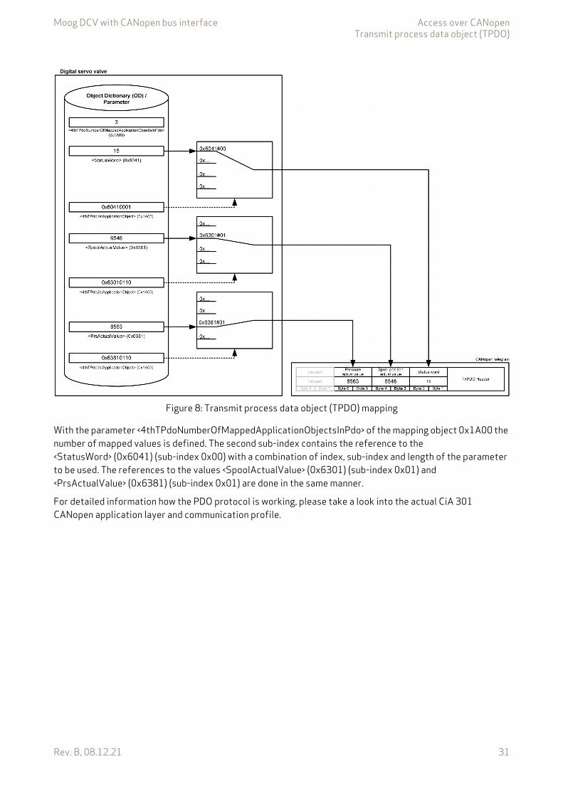
Moog DCV with CANopen bus interface Access over CANopenTransmit process data object (TPDO)
Rev. B, 08.12.21 31
Figure 8: Transmit process data object (TPDO) mapping
With the parameter <4thTPdoNumberOfMappedApplicationObjectsInPdo> of the mapping object 0x1A00 the number of mapped values is defined. The second sub-index contains the reference to the <StatusWord> (0x6041) (sub-index 0x00) with a combination of index, sub-index and length of the parameter to be used. The references to the values <SpoolActualValue> (0x6301) (sub-index 0x01) and <PrsActualValue> (0x6381) (sub-index 0x01) are done in the same manner.
For detailed information how the PDO protocol is working, please take a look into the actual CiA 301 CANopen application layer and communication profile.
Moog DCV with CANopen bus interface Access over CANopenTransmit process data object (TPDO)
Rev. B, 08.12.21 32
2.15.1 Object 0x1800: 1st TPDO configurationFirst TPDO channel configuration.
Value description
CANopenIndex Sub-index Parameter name Data type Access Per-
sis-tence
Value range Default
0x1800 1 1stTPdoCobIdUsedByPdo UINT32 rw Y 1…0x000007FF|0x80000000
0x0180+127
0x1800 2 1stTPdoTransmissionType UINT8 rw Y UINT8 2550x1800 3 1stTPdoInhibitTime UINT16 rw Y UINT16 00x1800 5 1stTPdoEventTimer UINT16 rw Y UINT16 0
Table 18: Object 0x1800: 1st TPDO configuration
Parameter Description<1stTPdoCobIdUsedByPdo> Defines the COB-ID for the 1st TPDO.<1stTPdoTransmissionType> Defines the transmission behavior for the 1st TPDO.<1stTPdoInhibitTime> Not implemented.<1stTPdoEventTimer> This parameter defines the event time in milliseconds.
This time defines the cycle time of the TPDO timer event. If the event time elapsed, a trigger to transmit a TPDO is initiated and the event timer will be restarted.
Table 19: Possible values of parameter <1stTPdoCobIdUsedByPdo> (0x1800, sub-index 1)
<1stTPdoCobIdUsedByPdo>Bit 31 30 29…11 10…0Description 0: PDO will be processed/received
1: PDO will not be processed/receivedReserved Reserved 11 bit COB-ID
Table 20: Possible values of parameter <1stTPdoTransmissionType> (0x1800, sub-index 2)
<1stTPdoTransmissionType>0 The process data for the TPDO will be updated and sent immediately
after the next incoming SYNC telegram.1…240 The process data for the TPDO will be updated and sent immediately
every <1stTPdoTransmissionType> SYNC telegrams.241…253 Reserved254…255 The TPDO will be sent after the event time is elapses (when the event
time is nonzero).
To initiate a single request only, the <1stTPdoEventTimer> (0x1800)…<4thTPdoEventTimer> (0x1803) must be set to 0. The transmission then can be triggered by the parameter <TPdoTrigger> (0x3011). Chapter "2.15.9 Object 0x3011: TPDO trigger", page 36
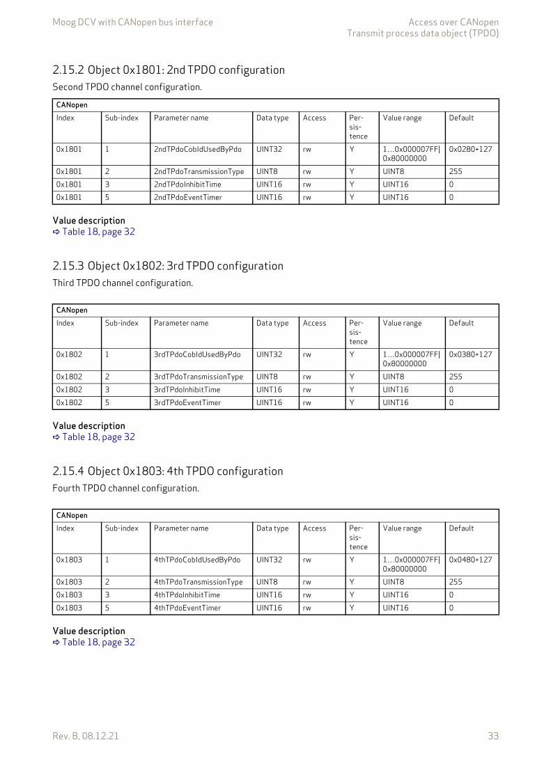
Moog DCV with CANopen bus interface Access over CANopenTransmit process data object (TPDO)
Rev. B, 08.12.21 33
2.15.2 Object 0x1801: 2nd TPDO configurationSecond TPDO channel configuration.
Value description Table 18, page 32
2.15.3 Object 0x1802: 3rd TPDO configurationThird TPDO channel configuration.
Value description Table 18, page 32
2.15.4 Object 0x1803: 4th TPDO configurationFourth TPDO channel configuration.
Value description Table 18, page 32
CANopenIndex Sub-index Parameter name Data type Access Per-
sis-tence
Value range Default
0x1801 1 2ndTPdoCobIdUsedByPdo UINT32 rw Y 1…0x000007FF|0x80000000
0x0280+127
0x1801 2 2ndTPdoTransmissionType UINT8 rw Y UINT8 2550x1801 3 2ndTPdoInhibitTime UINT16 rw Y UINT16 00x1801 5 2ndTPdoEventTimer UINT16 rw Y UINT16 0
CANopenIndex Sub-index Parameter name Data type Access Per-
sis-tence
Value range Default
0x1802 1 3rdTPdoCobIdUsedByPdo UINT32 rw Y 1…0x000007FF|0x80000000
0x0380+127
0x1802 2 3rdTPdoTransmissionType UINT8 rw Y UINT8 2550x1802 3 3rdTPdoInhibitTime UINT16 rw Y UINT16 00x1802 5 3rdTPdoEventTimer UINT16 rw Y UINT16 0
CANopenIndex Sub-index Parameter name Data type Access Per-
sis-tence
Value range Default
0x1803 1 4thTPdoCobIdUsedByPdo UINT32 rw Y 1…0x000007FF|0x80000000
0x0480+127
0x1803 2 4thTPdoTransmissionType UINT8 rw Y UINT8 2550x1803 3 4thTPdoInhibitTime UINT16 rw Y UINT16 00x1803 5 4thTPdoEventTimer UINT16 rw Y UINT16 0
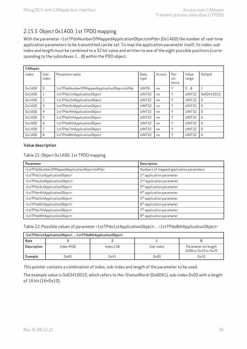
Moog DCV with CANopen bus interface Access over CANopenTransmit process data object (TPDO)
Rev. B, 08.12.21 34
2.15.5 Object 0x1A00: 1st TPDO mappingWith the parameter <1stTPdoNumberOfMappedApplicationObjectsInPdo> (0x1A00) the number of real-time application parameters to be transmitted can be set. To map the application parameter itself, its index, sub-index and length must be combined to a 32 bit value and written to one of the eight possible positions (corre-sponding to the subindexes 1…8) within the PDO object.
Value description
This pointer contains a combination of index, sub-index and length of the parameter to be used.
The example value is 0x63410010, which refers to the <StatusWord> (0x6041), sub-index 0x00 with a length of 16 bit (16=0x10).
CANopenIndex Sub-
indexParameter name Data
typeAccess Per-
sis-tence
Value range
Default
0x1A00 0 1stTPdoNumberOfMappedApplicationObjectsInPdo UINT8 rw Y 0…8 10x1A00 1 1stTPdo1stApplicationObject UINT32 rw Y UINT32 0x604100100x1A00 2 1stTPdo2ndApplicationObject UINT32 rw Y UINT32 00x1A00 3 1stTPdo3rdApplicationObject UINT32 rw Y UINT32 00x1A00 4 1stTPdo4thApplicationObject UINT32 rw Y UINT32 00x1A00 5 1stTPdo5thApplicationObject UINT32 rw Y UINT32 00x1A00 6 1stTPdo6thApplicationObject UINT32 rw Y UINT32 00x1A00 7 1stTPdo7thApplicationObject UINT32 rw Y UINT32 00x1A00 8 1stTPdo8thApplicationObject UINT32 rw Y UINT32 0
Table 21: Object 0x1A00: 1st TPDO mapping
Parameter Description<1stTPdoNumberOfMappedApplicationObjectsInPdo> Numbers of mapped application parameters<1stTPdo1stApplicationObject> 1st application parameter<1stTPdo2ndApplicationObject> 2nd application parameter<1stTPdo3rdApplicationObject> 3rd application parameter<1stTPdo4thApplicationObject> 4th application parameter<1stTPdo5thApplicationObject> 5th application parameter<1stTPdo6thApplicationObject> 6th application parameter<1stTPdo7thApplicationObject> 7th application parameter<1stTPdo8thApplicationObject> 8th application parameter
Table 22: Possible values of parameter <1stTPdo1stApplicationObject>…<1stTPdo8thApplicationObject>
<1stTPdo1stApplicationObject>…<1stTPdo8thApplicationObject>Byte 3 2 1 0Description Index MSB Index LSB Sub-index Parameter bit length
0x08 or 0x10 or 0x20Example 0x60 0x41 0x00 0x10
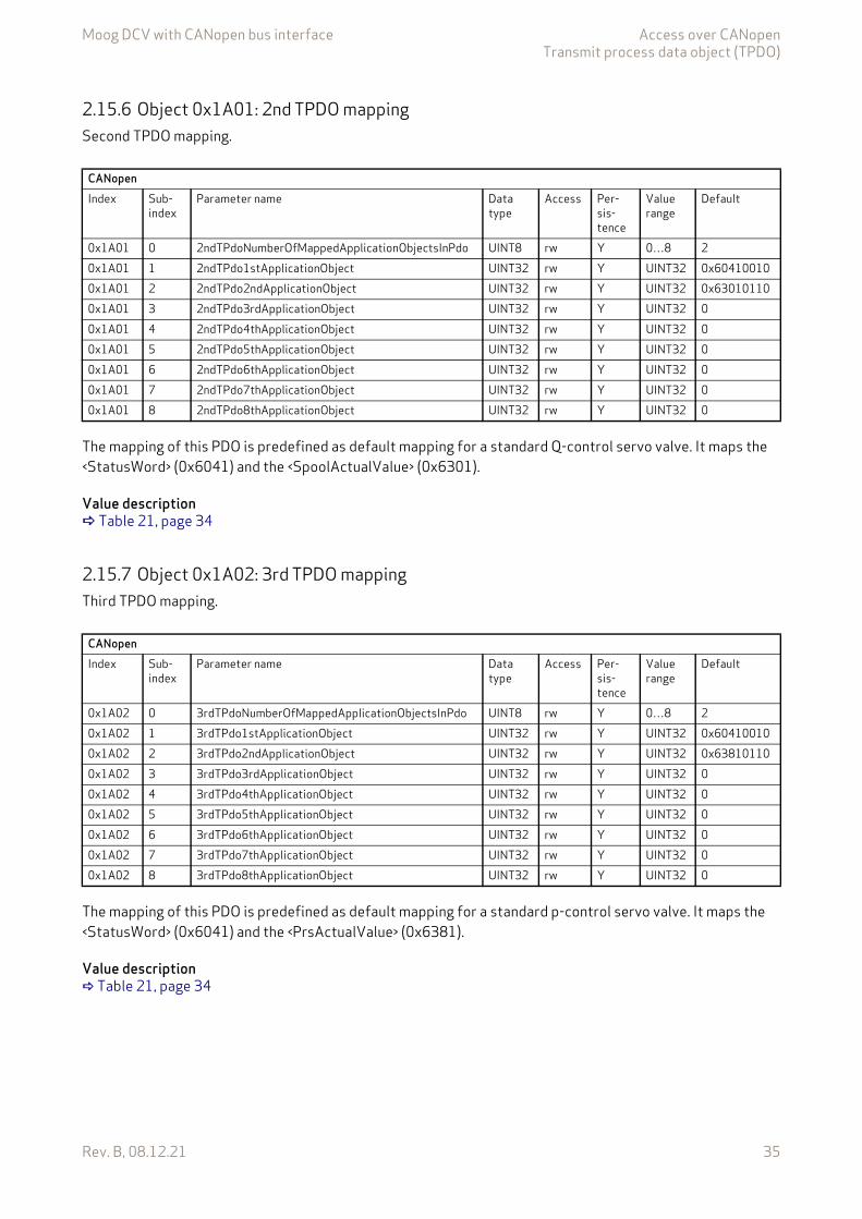
Moog DCV with CANopen bus interface Access over CANopenTransmit process data object (TPDO)
Rev. B, 08.12.21 35
2.15.6 Object 0x1A01: 2nd TPDO mappingSecond TPDO mapping.
The mapping of this PDO is predefined as default mapping for a standard Q-control servo valve. It maps the <StatusWord> (0x6041) and the <SpoolActualValue> (0x6301).
Value description Table 21, page 34
2.15.7 Object 0x1A02: 3rd TPDO mappingThird TPDO mapping.
The mapping of this PDO is predefined as default mapping for a standard p-control servo valve. It maps the <StatusWord> (0x6041) and the <PrsActualValue> (0x6381).
Value description Table 21, page 34
CANopenIndex Sub-
indexParameter name Data
typeAccess Per-
sis-tence
Value range
Default
0x1A01 0 2ndTPdoNumberOfMappedApplicationObjectsInPdo UINT8 rw Y 0…8 20x1A01 1 2ndTPdo1stApplicationObject UINT32 rw Y UINT32 0x604100100x1A01 2 2ndTPdo2ndApplicationObject UINT32 rw Y UINT32 0x630101100x1A01 3 2ndTPdo3rdApplicationObject UINT32 rw Y UINT32 00x1A01 4 2ndTPdo4thApplicationObject UINT32 rw Y UINT32 00x1A01 5 2ndTPdo5thApplicationObject UINT32 rw Y UINT32 00x1A01 6 2ndTPdo6thApplicationObject UINT32 rw Y UINT32 00x1A01 7 2ndTPdo7thApplicationObject UINT32 rw Y UINT32 00x1A01 8 2ndTPdo8thApplicationObject UINT32 rw Y UINT32 0
CANopenIndex Sub-
indexParameter name Data
typeAccess Per-
sis-tence
Value range
Default
0x1A02 0 3rdTPdoNumberOfMappedApplicationObjectsInPdo UINT8 rw Y 0…8 20x1A02 1 3rdTPdo1stApplicationObject UINT32 rw Y UINT32 0x604100100x1A02 2 3rdTPdo2ndApplicationObject UINT32 rw Y UINT32 0x638101100x1A02 3 3rdTPdo3rdApplicationObject UINT32 rw Y UINT32 00x1A02 4 3rdTPdo4thApplicationObject UINT32 rw Y UINT32 00x1A02 5 3rdTPdo5thApplicationObject UINT32 rw Y UINT32 00x1A02 6 3rdTPdo6thApplicationObject UINT32 rw Y UINT32 00x1A02 7 3rdTPdo7thApplicationObject UINT32 rw Y UINT32 00x1A02 8 3rdTPdo8thApplicationObject UINT32 rw Y UINT32 0

Moog DCV with CANopen bus interface Access over CANopenTransmit process data object (TPDO)
Rev. B, 08.12.21 36
2.15.8 Object 0x1A03: 4th TPDO mappingFourth TPDO mapping.
The mapping of this PDO is predefined as default mapping for a standard p/Q-control servo valve. It maps the <StatusWord> (0x6041), the <SpoolActualValue> (0x6301) and the <PrsActualValue> (0x6381).
Value description Table 21, page 34
2.15.9 Object 0x3011: TPDO triggerWriting this parameter triggers a single TPDO. This can be used to transmit a PDO on request only. To trigger one of the four TPDOs, the parameter <TPdoTrigger> (0x3011) value must be set to the number of the PDO channel to be sent.
CANopenIndex Sub-
indexParameter name Data
typeAccess Per-
sis-tence
Value range
Default
0x1A03 0 4thTPdoNumberOfMappedApplicationObjectsInPdo UINT8 rw Y 0…8 20x1A03 1 4thTPdo1stApplicationObject UINT32 rw Y UINT32 0x604100100x1A03 2 4thTPdo2ndApplicationObject UINT32 rw Y UINT32 0x630101100x1A03 3 4thTPdo3rdApplicationObject UINT32 rw Y UINT32 0x638101100x1A03 4 4thTPdo4thApplicationObject UINT32 rw Y UINT32 00x1A03 5 4thTPdo5thApplicationObject UINT32 rw Y UINT32 00x1A03 6 4thTPdo6thApplicationObject UINT32 rw Y UINT32 00x1A03 7 4thTPdo7thApplicationObject UINT32 rw Y UINT32 00x1A03 8 4thTPdo8thApplicationObject UINT32 rw Y UINT32 0
CANopenIndex Sub-
indexParameter name Data
typeAccess Per-
sis-tence
Value range
Default
0x3011 0 TPdoTrigger UINT8 rw N 1…4 None
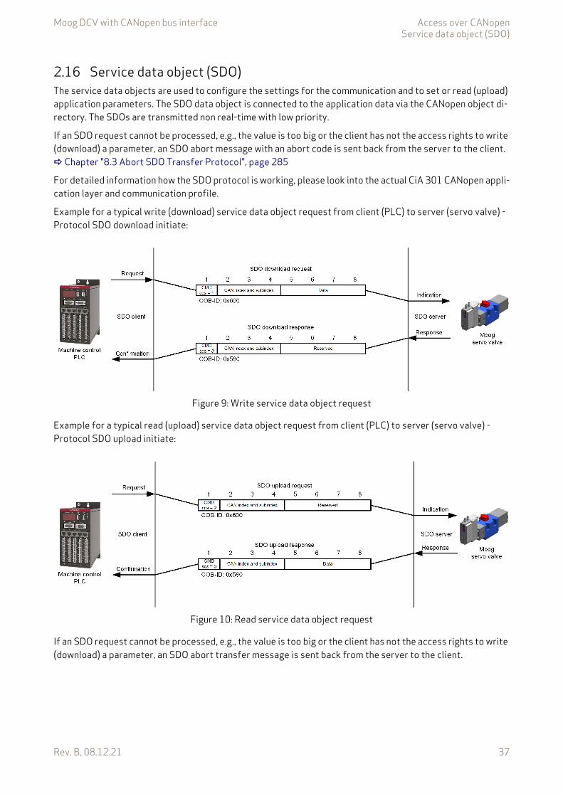
Moog DCV with CANopen bus interface Access over CANopenService data object (SDO)
Rev. B, 08.12.21 37
2.16 Service data object (SDO)The service data objects are used to configure the settings for the communication and to set or read (upload) application parameters. The SDO data object is connected to the application data via the CANopen object di-rectory. The SDOs are transmitted non real-time with low priority.
If an SDO request cannot be processed, e.g., the value is too big or the client has not the access rights to write (download) a parameter, an SDO abort message with an abort code is sent back from the server to the client. Chapter "8.3 Abort SDO Transfer Protocol", page 285
For detailed information how the SDO protocol is working, please look into the actual CiA 301 CANopen appli-cation layer and communication profile.
Example for a typical write (download) service data object request from client (PLC) to server (servo valve) - Protocol SDO download initiate:
Figure 9: Write service data object request
Example for a typical read (upload) service data object request from client (PLC) to server (servo valve) - Protocol SDO upload initiate:
Figure 10: Read service data object request
If an SDO request cannot be processed, e.g., the value is too big or the client has not the access rights to write (download) a parameter, an SDO abort transfer message is sent back from the server to the client.

Moog DCV with CANopen bus interface Access over CANopenService data object (SDO) gateway
Rev. B, 08.12.21 38
Figure 11: Typical SDO abort message
2.16.1 Object 0x1200: SDO client/server parameter
Value description
2.17 Service data object (SDO) gatewayIf an external CAN device is connected to the local CAN interface of the servo valve, the SDO parameters of the external CAN device can be read (upload) and written (download) by the fieldbus master via the SDO gate-way.Information on the local CAN gateway: Chapter "6.7.16 Service data object (SDO) gateway", page 136
2.18 Synchronization (SYNC)The SYNC protocol is a network wide system trigger generated by one CANopen device in the network. The SYNC protocol has a very high priority and has no data in order to guarantee a minimum of jitter. The SYNC protocol is sent by a sync producer and can trigger PDO transmissions in the sync consumer nodes when acti-vated in the corresponding PDO transmission types.
Chapter "2.14.1 Object 0x1400: 1st RPDO configuration", page 25 Chapter "2.15.1 Object 0x1800: 1st TPDO configuration", page 32 Chapter "2.15.9 Object 0x3011: TPDO trigger", page 36
CANopenIndex Sub-
indexParameter name Data
typeAccess Per-
sis-tence
Value range
Default
0x1200 1 CobIdClientServer UINT32 ro - 0x0600+1270x1200 2 CobIdServerClient UINT32 ro - UINT8 0x0580+127
Table 23: Object 0x1200: SDO client/server parameter
Parameter Description<CobIdClientServer> This parameter contains the COB-ID for the Client service data object.<CobIdServerClient> This parameter contains the COB-ID for the Server service data object.

Moog DCV with CANopen bus interface Access over CANopenSynchronization (SYNC)
Rev. B, 08.12.21 39
2.18.1 Object 0x1005: SYNC protocol COB-ID configurationThis parameter defines the COB-ID of the sync object itself.
Value description
2.18.2 Object 0x1006: Communication cycle periodThe value shall be given in multiple of μs. If the value is set to 0, the transmission of SYNC messages is disabled. To activate the sync signal the COB-ID SYNC message, object 0x1005 must be configured accordingly.
2.18.3 Object 0x1007: Synchronous window lengthThis object represents the configured length of the time window for synchronous PDOs. If the synchronous window length expires, all synchronous TPDOs may be discarded and an EMCY message will be transmitted.
The value is given in multiple of μs. If the value is set to 0, the synchronous window shall be disabled.
2.18.4 Object 0x1015: Inhibit time emergency messageThis object indicates the configured inhibit time for the EMCY message. The value is given in multiples of 100 μs. The value 0 shall disable the inhibit time.
CANopenIndex Sub-index Parameter name Data type Access Persistence Value range Default0x1005 0 CobIdSyncMessage UINT32 rw Y 1…0x000007FF|
0x400000000x0080+127
Table 24: Possible values of parameter <CobIdSyncMessage> (0x1005)
<CobIdSyncMessage>Bit 31 30 29…11 10…0
DescriptionReserved 0: SYNC consumer
1: SYNC producerReserved 11 bit COB-ID
CANopenIndex Sub-index Parameter name Data type Access Persistence Value range Default0x1006 0 CommunicationCyclePeriod UINT32 rw Y UINT32 0
CANopenIndex Sub-index Parameter name Data type Access Persistence Value range Default0x1007 0 SynchronousWindowLength UINT32 rw Y UINT32 0
CANopenIndex Sub-index Parameter name Data type Access Persistence Value range Default0x1015 0 InhibitTimeEmergencyMessage UINT16 rw Y UINT16 0
Moog DCV with CANopen bus interface Access over CANopenEmergency (EMCY)
Rev. B, 08.12.21 40
2.18.5 Object 0x1019: SYNC protocol counter overflow valueThis object shall indicate the configured highest value the synchronous counter supports. If the value is greater than 1, the SYNC message shall have a data length of 1 byte. An EMCY message (error code 0x8240) may be transmitted by a SYNC consumer in the case the configured data length of the SYNC message does not meet the data length of a received SYNC message. The value used shall be the least common multiple of all the TPDO transmission types (1 < n <= 240) used. This ensures that periodic SYNC events always happen in the SYNC cycles with the same counter value.
Value description
2.19 Emergency (EMCY)The emergency protocol is a high priority message triggered by an error event in the device. The error codes sent with the emergency message are specified in the CANopen communication profiles CiA 301 and CiA 408. They are described in the chapter Diagnostics.
Chapter "8 Diagnostics", page 261
2.19.1 Object 0x1014: EMCY protocol COB-ID configurationThis object defines the COB-ID of the emergency object itself.
Value description
CANopenIndex Sub-index Parameter name Data
typeAccess Persistence Value range Default
0x1019 0 SynchronousCounterOverflowValue UINT8 rw Y UINT8 0
<SynchronousCounterOverflowValue> Description0 The SYNC message shall be transmitted as a CAN message of
data length 0.1 Reserved2…240 The SYNC message shall be transmitted as a CAN message of
data length 1. The first data byte contains the counter.241…255 Reserved
CANopenIndex Sub-index Parameter name Data type Access Persistence Value range Default0x1014 0 CobIdEmergencyMessage UINT32 rw Y 1…0x000007FF 0x0080+127
Table 25: Possible values of parameter <CobIdEmergencyMessage> (0x1014)
<CobIdEmergencyMessage>Bit 31 30 29…11 10…0Description 0: EMCY exists Reserved Reserved 11 bit COB-ID
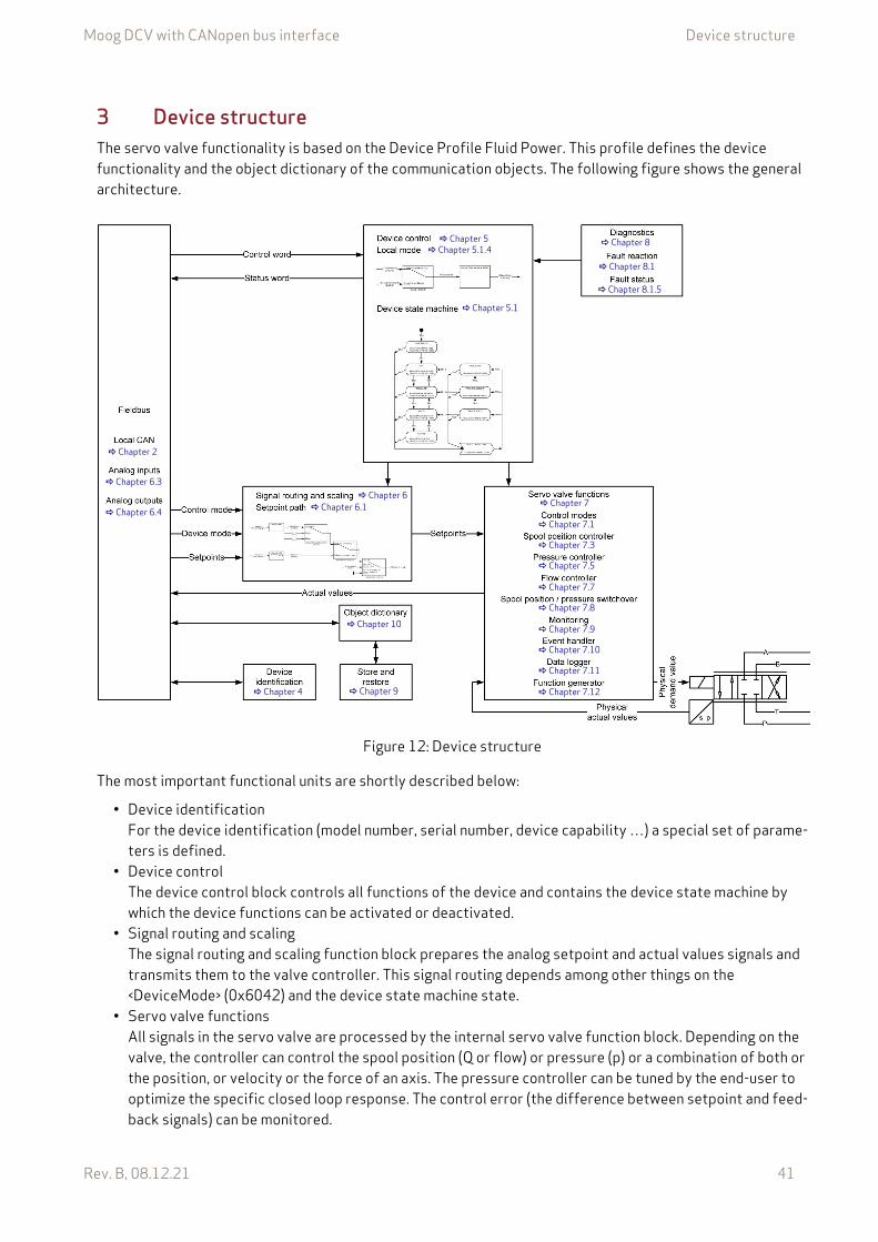
Moog DCV with CANopen bus interface Device structure
Rev. B, 08.12.21 41
3 Device structureThe servo valve functionality is based on the Device Profile Fluid Power. This profile defines the device functionality and the object dictionary of the communication objects. The following figure shows the general architecture.
Figure 12: Device structure
The most important functional units are shortly described below:
• Device identificationFor the device identification (model number, serial number, device capability …) a special set of parame-ters is defined.
• Device controlThe device control block controls all functions of the device and contains the device state machine by which the device functions can be activated or deactivated.
• Signal routing and scalingThe signal routing and scaling function block prepares the analog setpoint and actual values signals and transmits them to the valve controller. This signal routing depends among other things on the <DeviceMode> (0x6042) and the device state machine state.
• Servo valve functionsAll signals in the servo valve are processed by the internal servo valve function block. Depending on the valve, the controller can control the spool position (Q or flow) or pressure (p) or a combination of both or the position, or velocity or the force of an axis. The pressure controller can be tuned by the end-user to optimize the specific closed loop response. The control error (the difference between setpoint and feed-back signals) can be monitored.
Chapter 2
Chapter 6.3
Chapter 6.4
Chapter 6
Chapter 5
Chapter 6.1
Chapter 5.1.4
Chapter 5.1
Chapter 10
Chapter 9 Chapter 4
Chapter 8.1
Chapter 8.1.5
Chapter 7
Chapter 7.1
Chapter 7.5
Chapter 7.7
Chapter 7.8
Chapter 7.9
Chapter 7.10
Chapter 7.11
Chapter 7.12
Chapter 8
Chapter 7.3
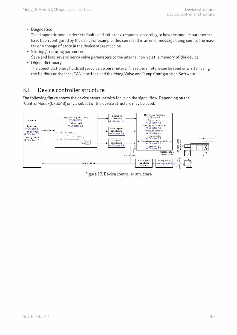
Moog DCV with CANopen bus interface Device structureDevice controller structure
Rev. B, 08.12.21 42
• DiagnosticsThe diagnostic module detects faults and initiates a response according to how the module parameters have been configured by the user. For example, this can result in an error message being sent to the mas-ter or a change of state in the device state machine.
• Storing / restoring parametersSave and load several servo valve parameters to the internal non-volatile memory of the device.
• Object dictionaryThe object dictionary holds all servo valve parameters. These parameters can be read or written using the fieldbus or the local CAN interface and the Moog Valve and Pump Configuration Software.
3.1 Device controller structureThe following figure shows the device structure with focus on the signal flow. Depending on the <ControlMode> (0x6043) only a subset of the device structure may be used.
Figure 13: Device controller structure
Chapter 2
Chapter 6.3
Chapter 6.4
Chapter 6
Chapter 6.3
Chapter 7.9
Chapter 7.8
Chapter 7.7
Chapter 7.5
Chapter 7.3
Chapter 7.1
Chapter 7
Chapter 6.1
Chapter 7.2
Chapter 7.6
Chapter 7.4
Moog DCV with CANopen bus interface Device identificationObjects of the CANopen communication profile defined by CiA 301
Rev. B, 08.12.21 43
4 Device identificationThe device (servo valve) has parameters that both identify the device and configure the device for operation with the specific machine. The following chapter includes the descriptions of the parameters providing this information.
4.1 Objects of the CANopen communication profile defined by CiA 3014.1.1 Object 0x1000: Device TypeThe lower 16 bits of this parameter indicate the code of the underlying device profile. The default value 408 of device profile specifies the device profile CiA 408. The upper 16 bits of this parameter specify the available control modes according CiA 408.
Value description
DeviceIndex Sub-index Parameter name Data type Access Persistence Value range Default0x1000 0 DeviceType UINT32 ro - UINT32 Device-
specific value
Table 26: Possible values of parameter <DeviceType> (0x1000) (part 1 of 2)
Bit Value Description Control mode Drive0…15 0…15 CiA device profile number 408
This number stands for the Device Profile CiA 408 "Device profile for fluid power technology proportional valve and hydrostatic transmissions".
16 0 Open loop movement control not supported 6 x
1 Open loop movement control supported17 0 Velocity control axis not supported 7 x
1 Velocity control axis supported18 0 Pressure (force) control not supported 8 x
1 Pressure (force) control supported19 0 Position control axis not supported 9 x
1 Position control axis supported20 0 Positional dependent deceleration not supported 10 x
1 Positional dependent deceleration supported21 0 Position control axis with pressure (force) override not supported 11 x
1 Position control axis with pressure (force) override supported22 0 Velocity control axis with pressure (force) override not supported 12
1 Velocity control axis with pressure (force) override supported23 0 Spool position control not supported 2
1 Spool position control supported24 0 Pressure (force) control axis not supported 4
1 Pressure (force) control axis supported25 0 pQ control not supported 5
1 pQ control supported26 0 Flow control not supported 13
1 Flow control supported27 0 pFlow control not supported 14
1 pFlow control supported

Moog DCV with CANopen bus interface Device identificationObjects of the CANopen communication profile defined by CiA 301
Rev. B, 08.12.21 44
4.1.2 Object 0x1008: Manufacturer device nameThis parameter indicates the name of the servo valve. It corresponds to the model number as printed on the nameplate.
4.1.3 Object 0x1009: Manufacturer hardware versionThis parameter indicates the current hardware version of the servo valve electronics.
4.1.4 Object 0x100A: Manufacturer software versionThis parameter indicates the current software version of the servo valve.
28 0 pFlow control with power limitation not supported 15
1 pFlow control with power limitation supported29…30 00 Reserved
01 Valve (pump) with 16-bit parameter support; Drive not supported10 Valve (pump) with 32-bit parameter support;
Drive with 32-bit parameter support11 Valve (pump) with 16-bit parameter support;
Drive with 32-bit parameter support31 0 Reserved
Table 26: Possible values of parameter <DeviceType> (0x1000) (part 2 of 2)
Bit Value Description Control mode Drive
Device
Index Sub-index Parameter name Data type AccessPer-sistence Value range Default
0x1008 0 ManufacturerDeviceName STRING(64) ro - STRING(64) ""
Device
Index Sub-index Parameter name Data type AccessPer-sistence Value range Default
0x1009 0 ManufacturerHardwareVersion STRING(64) ro - STRING(64) ""
Device
Index Sub-index Parameter name Data type AccessPer-sistence Value range Default
0x100A 0 ManufacturerSoftwareVersion STRING(64) ro - STRING(64) Device specific value

Moog DCV with CANopen bus interface Device identificationObjects of the CANopen communication profile defined by CiA 301
Rev. B, 08.12.21 45
4.1.5 Object 0x1018: Identity objectThese parameters represent a worldwide unique identification of any CANopen slave device.
The identification object (VendorID, ProductCode, RevisionNumber, SerialNumber) is printed on the nameplate of the servo valve as shown in the following figure.
Figure 14: Nameplate of the device with identification object address
Value description
Device
Index Sub-index Parameter name Data type AccessPer-sistence
Value range Default
0x1018 1 VendorId UINT32 ro - UINT32 400x1018 2 ProductCode UINT32 ro - UINT32 00x1018 3 RevisionNumber UINT32 ro - UINT32 00x1018 4 SerialNumber UINT32 ro - UINT32 0
Table 27: Structure of the Identity object (0x1018)
Sub-index Parameter Meaning1 <VendorId> Unique vendor ID, 0x28 (40) reserved for Moog.2 <ProductCode> Product code of the Moog servo valve.
Each valve model number has its own CANopen product code.3 <RevisionNumber> Revision number of the Moog servo valve.4 <SerialNumber> Serial number of the Moog servo valve as on the nameplate.
Chapter "4.2.3 Object 0x6052: Device serial number", page 46
<VendorId>Description Department (0x00) Company (0x000028)Bit 31 24 23 0
MSB LSB
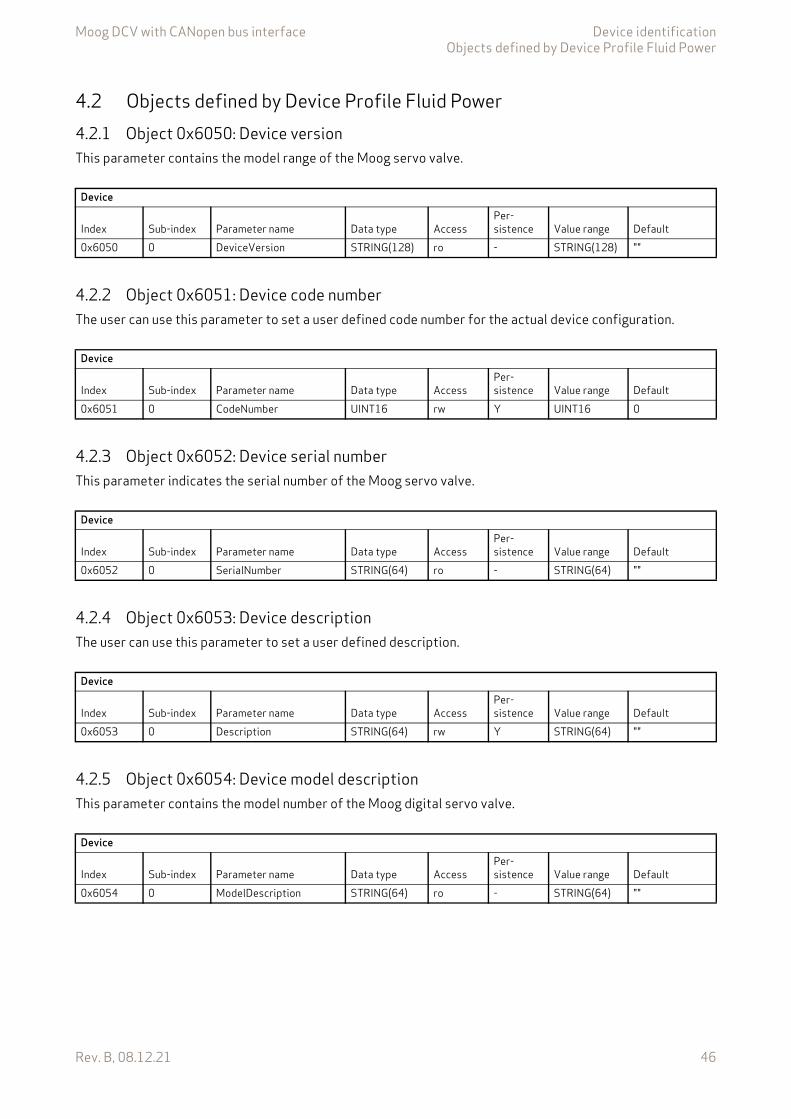
Moog DCV with CANopen bus interface Device identificationObjects defined by Device Profile Fluid Power
Rev. B, 08.12.21 46
4.2 Objects defined by Device Profile Fluid Power4.2.1 Object 0x6050: Device versionThis parameter contains the model range of the Moog servo valve.
4.2.2 Object 0x6051: Device code numberThe user can use this parameter to set a user defined code number for the actual device configuration.
4.2.3 Object 0x6052: Device serial numberThis parameter indicates the serial number of the Moog servo valve.
4.2.4 Object 0x6053: Device descriptionThe user can use this parameter to set a user defined description.
4.2.5 Object 0x6054: Device model descriptionThis parameter contains the model number of the Moog digital servo valve.
Device
Index Sub-index Parameter name Data type AccessPer-sistence Value range Default
0x6050 0 DeviceVersion STRING(128) ro - STRING(128) ""
Device
Index Sub-index Parameter name Data type AccessPer-sistence Value range Default
0x6051 0 CodeNumber UINT16 rw Y UINT16 0
Device
Index Sub-index Parameter name Data type AccessPer-sistence Value range Default
0x6052 0 SerialNumber STRING(64) ro - STRING(64) ""
Device
Index Sub-index Parameter name Data type AccessPer-sistence Value range Default
0x6053 0 Description STRING(64) rw Y STRING(64) ""
Device
Index Sub-index Parameter name Data type AccessPer-sistence Value range Default
0x6054 0 ModelDescription STRING(64) ro - STRING(64) ""
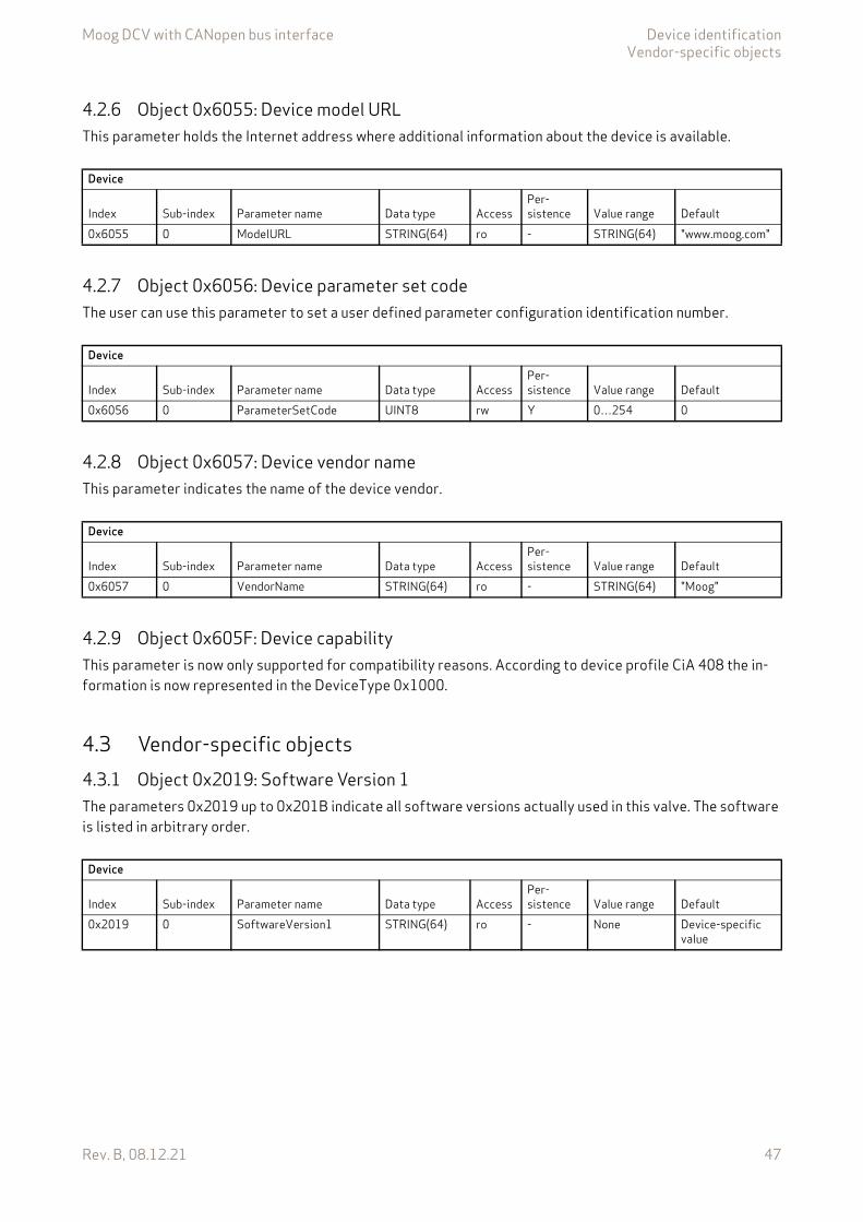
Moog DCV with CANopen bus interface Device identificationVendor-specific objects
Rev. B, 08.12.21 47
4.2.6 Object 0x6055: Device model URLThis parameter holds the Internet address where additional information about the device is available.
4.2.7 Object 0x6056: Device parameter set codeThe user can use this parameter to set a user defined parameter configuration identification number.
4.2.8 Object 0x6057: Device vendor nameThis parameter indicates the name of the device vendor.
4.2.9 Object 0x605F: Device capabilityThis parameter is now only supported for compatibility reasons. According to device profile CiA 408 the in-formation is now represented in the DeviceType 0x1000.
4.3 Vendor-specific objects4.3.1 Object 0x2019: Software Version 1The parameters 0x2019 up to 0x201B indicate all software versions actually used in this valve. The software is listed in arbitrary order.
Device
Index Sub-index Parameter name Data type AccessPer-sistence Value range Default
0x6055 0 ModelURL STRING(64) ro - STRING(64) "www.moog.com"
Device
Index Sub-index Parameter name Data type AccessPer-sistence Value range Default
0x6056 0 ParameterSetCode UINT8 rw Y 0…254 0
Device
Index Sub-index Parameter name Data type AccessPer-sistence Value range Default
0x6057 0 VendorName STRING(64) ro - STRING(64) "Moog"
Device
Index Sub-index Parameter name Data type AccessPer-sistence Value range Default
0x2019 0 SoftwareVersion1 STRING(64) ro - None Device-specific value
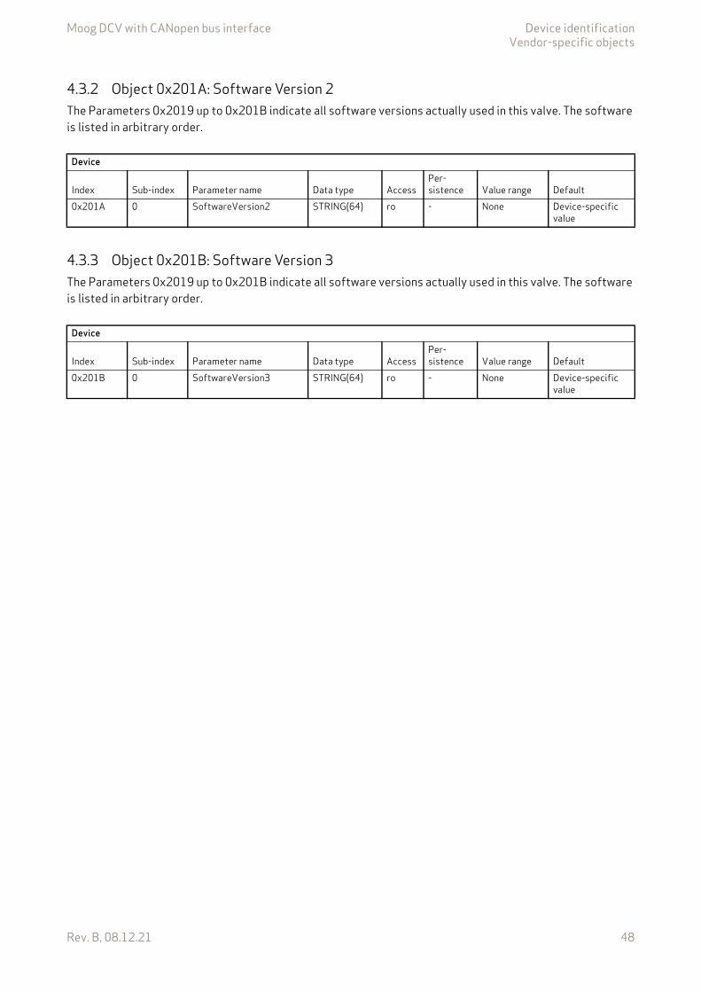
Moog DCV with CANopen bus interface Device identificationVendor-specific objects
Rev. B, 08.12.21 48
4.3.2 Object 0x201A: Software Version 2The Parameters 0x2019 up to 0x201B indicate all software versions actually used in this valve. The software is listed in arbitrary order.
4.3.3 Object 0x201B: Software Version 3The Parameters 0x2019 up to 0x201B indicate all software versions actually used in this valve. The software is listed in arbitrary order.
Device
Index Sub-index Parameter name Data type AccessPer-sistence Value range Default
0x201A 0 SoftwareVersion2 STRING(64) ro - None Device-specific value
Device
Index Sub-index Parameter name Data type AccessPer-sistence Value range Default
0x201B 0 SoftwareVersion3 STRING(64) ro - None Device-specific value

Moog DCV with CANopen bus interface Device control
Rev. B, 08.12.21 49
5 Device controlThe device control contains a device state machine (DSM) which activates or deactivates the servo valve. The states of the DSM can be changed externally by the <ControlWord> (0x6040) which can be set via bus using a PDO or locally by the parameter value <LocalControlWord> (0x4040). It is possible to configure a power on de-lay for the communication. The status LEDs display the current network and device states.
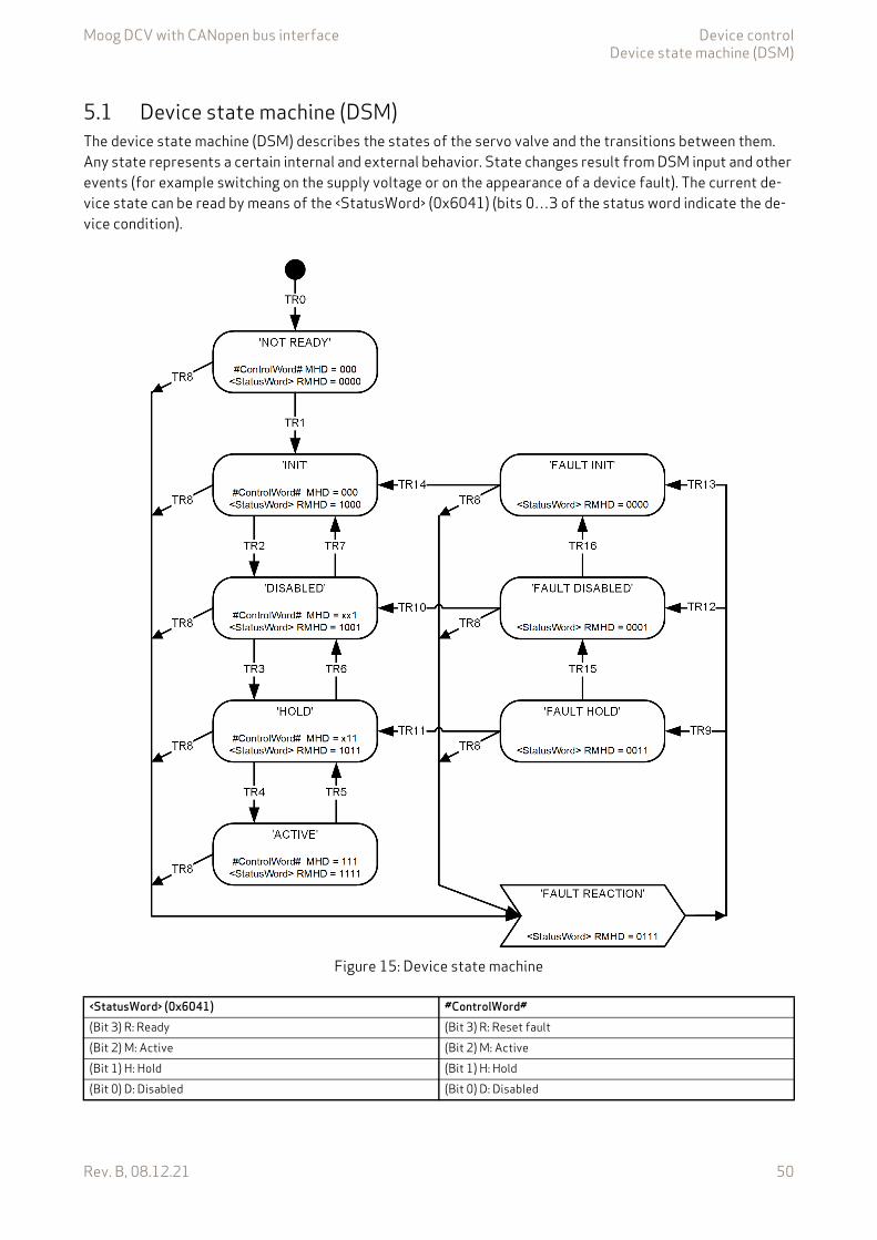
Moog DCV with CANopen bus interface Device controlDevice state machine (DSM)
Rev. B, 08.12.21 50
5.1 Device state machine (DSM)The device state machine (DSM) describes the states of the servo valve and the transitions between them. Any state represents a certain internal and external behavior. State changes result from DSM input and other events (for example switching on the supply voltage or on the appearance of a device fault). The current de-vice state can be read by means of the <StatusWord> (0x6041) (bits 0…3 of the status word indicate the de-vice condition).
Figure 15: Device state machine
<StatusWord> (0x6041) #ControlWord#(Bit 3) R: Ready (Bit 3) R: Reset fault(Bit 2) M: Active (Bit 2) M: Active(Bit 1) H: Hold (Bit 1) H: Hold(Bit 0) D: Disabled (Bit 0) D: Disabled
Moog DCV with CANopen bus interface Device controlDevice state machine (DSM)
Rev. B, 08.12.21 51
5.1.1 DSM states
The <StatusWord> (0x6041) indicates the DSM state. The following DSM states are possible:
'NOT_READY':• The electronics circuit has power.• Device initialization running (e.g. communication interface, hardware, software).• Device function disabled.• Hydraulic failsafe spool position (spool position depends on ordered servo valve model).
'INIT':• Device parameters can be set.• Device function disabled.• Communication enabled.• Hydraulic failsafe spool position (spool position depends on ordered servo valve model).
'DISABLED':• Device parameters can be set.• Device function disabled.• Actual values are available.• Hydraulic failsafe spool position (spool position depends on ordered servo valve model).
'HOLD':• Device parameters can be set.• Actual values are available.• The selected <ControlMode> (0x6043) is active. Chapter "7.1 Control modes", page 146
• The setpoints from the bus or from the analog input according to the chosen <DeviceMode> (0x6042) are not effective. Chapter "6.1.1 Object 0x6042: Device mode", page 64
• The control loop depending on the selected <ControlMode> (0x6043) is active and the corresponding pre-defined hold setpoint is used, for example, the <QHoldSetpoint> (0x6314) for the spool control or the <PrsHoldSetpoint> (0x6394) for the pressure control or the <FlowHoldSetpoint> (0x6314) for the flow control. Chapter "6.1.3.3 Object 0x6314: Q setpoint conditioning hold setpoint", page 66 Chapter "6.1.4.3 Object 0x6394: Pressure setpoint conditioning hold setpoint", page 69 Chapter "6.1.5.3 Object 0x6714: Flow setpoint conditioning hold setpoint", page 71
'ACTIVE':• Device parameters can be set.• Actual values are available.• The setpoints from the bus or from the analog input according to the chosen <DeviceMode> (0x6042) are
active.
'FAULT_INIT':• Device parameters can be set.• Device function disabled.• Communication enabled.• Hydraulic failsafe spool position (spool position depends on ordered servo valve model).
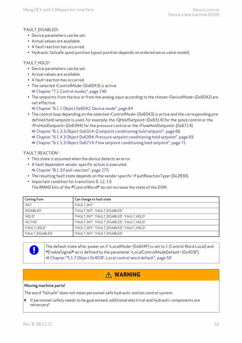
Moog DCV with CANopen bus interface Device controlDevice state machine (DSM)
Rev. B, 08.12.21 52
'FAULT_DISABLED':• Device parameters can be set.• Actual values are available.• A fault reaction has occurred.• Hydraulic failsafe spool position (spool position depends on ordered servo valve model).
'FAULT_HOLD':• Device parameters can be set.• Actual values are available.• A fault reaction has occurred.• The selected <ControlMode> (0x6043) is active. Chapter "7.1 Control modes", page 146
• The setpoints from the bus or from the analog input according to the chosen <DeviceMode> (0x6042) are not effective. Chapter "6.1.1 Object 0x6042: Device mode", page 64
• The control loop depending on the selected <ControlMode> (0x6043) is active and the corresponding pre-defined hold setpoint is used, for example, the <QHoldSetpoint> (0x6314) for the spool control or the <PrsHoldSetpoint> (0x6394) for the pressure control or the <FlowHoldSetpoint> (0x6714). Chapter "6.1.3.3 Object 0x6314: Q setpoint conditioning hold setpoint", page 66 Chapter "6.1.4.3 Object 0x6394: Pressure setpoint conditioning hold setpoint", page 69 Chapter "6.1.5.3 Object 0x6714: Flow setpoint conditioning hold setpoint", page 71
'FAULT_REACTION':• This state is assumed when the device detects an error.• A fault dependent vendor specific action is executed. Chapter "8.1.3 Fault reaction", page 275
• The resulting fault state depends on the vendor specific <FaultReactionType> (0x2830).• Important condition for transitions 9, 12, 13:
The RMHD bits of the #ControlWord# do not increase the state of the DSM.
Coming from Can change to fault state 'INIT' 'FAULT_INIT''DISABLED' 'FAULT_INIT', 'FAULT_DISABLED''HOLD' 'FAULT_INIT', 'FAULT_DISABLED', 'FAULT_HOLD''ACTIVE' 'FAULT_INIT', 'FAULT_DISABLED', 'FAULT_HOLD''FAULT_HOLD' 'FAULT_INIT', 'FAULT_DISABLED', 'FAULT_HOLD''FAULT_DISABLED' 'FAULT_INIT', 'FAULT_DISABLED'
The default state after power on if <LocalMode> (0x604F) is set to 1 (Control Word Local) and #EnableSignal# on is defined by the parameter <LocalControlModeDefault> (0x403F). Chapter "5.1.7 Object 0x403F: Local control word default", page 59
WARNING
Moving machine parts!The word "failsafe" does not mean personnel safe hydraulic motion control system.
If personnel safety needs to be guaranteed, additional electrical and hydraulic components are necessary!
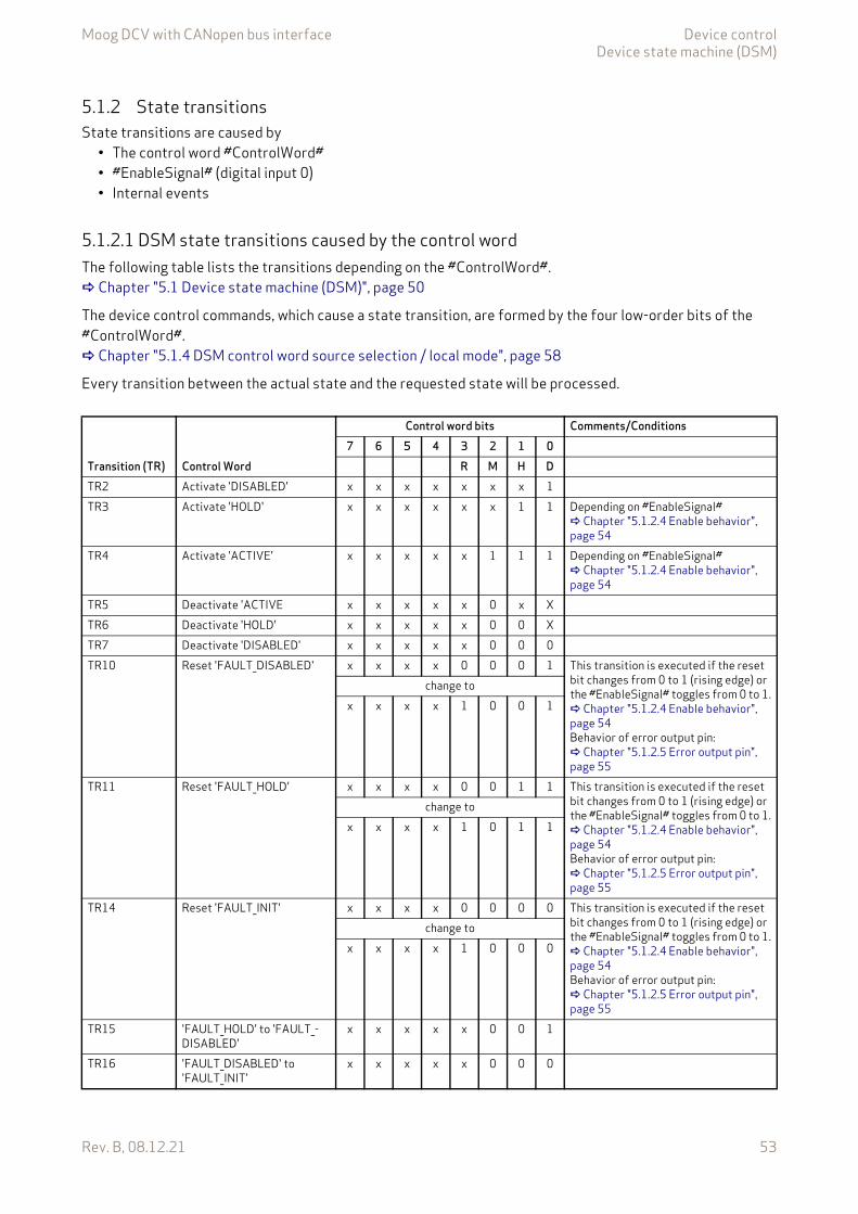
Moog DCV with CANopen bus interface Device controlDevice state machine (DSM)
Rev. B, 08.12.21 53
5.1.2 State transitionsState transitions are caused by
• The control word #ControlWord#• #EnableSignal# (digital input 0)• Internal events
5.1.2.1 DSM state transitions caused by the control wordThe following table lists the transitions depending on the #ControlWord#. Chapter "5.1 Device state machine (DSM)", page 50
The device control commands, which cause a state transition, are formed by the four low-order bits of the #ControlWord#. Chapter "5.1.4 DSM control word source selection / local mode", page 58
Every transition between the actual state and the requested state will be processed.
Transition (TR) Control Word
Control word bits Comments/Conditions7 6 5 4 3 2 1 0
R M H DTR2 Activate 'DISABLED' x x x x x x x 1TR3 Activate 'HOLD' x x x x x x 1 1 Depending on #EnableSignal#
Chapter "5.1.2.4 Enable behavior", page 54
TR4 Activate 'ACTIVE' x x x x x 1 1 1 Depending on #EnableSignal# Chapter "5.1.2.4 Enable behavior", page 54
TR5 Deactivate 'ACTIVE x x x x x 0 x XTR6 Deactivate 'HOLD' x x x x x 0 0 XTR7 Deactivate 'DISABLED' x x x x x 0 0 0TR10 Reset 'FAULT_DISABLED' x x x x 0 0 0 1 This transition is executed if the reset
bit changes from 0 to 1 (rising edge) or the #EnableSignal# toggles from 0 to 1. Chapter "5.1.2.4 Enable behavior", page 54Behavior of error output pin: Chapter "5.1.2.5 Error output pin", page 55
change tox x x x 1 0 0 1
TR11 Reset 'FAULT_HOLD' x x x x 0 0 1 1 This transition is executed if the reset bit changes from 0 to 1 (rising edge) or the #EnableSignal# toggles from 0 to 1. Chapter "5.1.2.4 Enable behavior", page 54Behavior of error output pin: Chapter "5.1.2.5 Error output pin", page 55
change tox x x x 1 0 1 1
TR14 Reset 'FAULT_INIT' x x x x 0 0 0 0 This transition is executed if the reset bit changes from 0 to 1 (rising edge) or the #EnableSignal# toggles from 0 to 1. Chapter "5.1.2.4 Enable behavior", page 54Behavior of error output pin: Chapter "5.1.2.5 Error output pin", page 55
change tox x x x 1 0 0 0
TR15 'FAULT_HOLD' to 'FAULT_-DISABLED'
x x x x x 0 0 1
TR16 'FAULT_DISABLED' to 'FAULT_INIT'
x x x x x 0 0 0
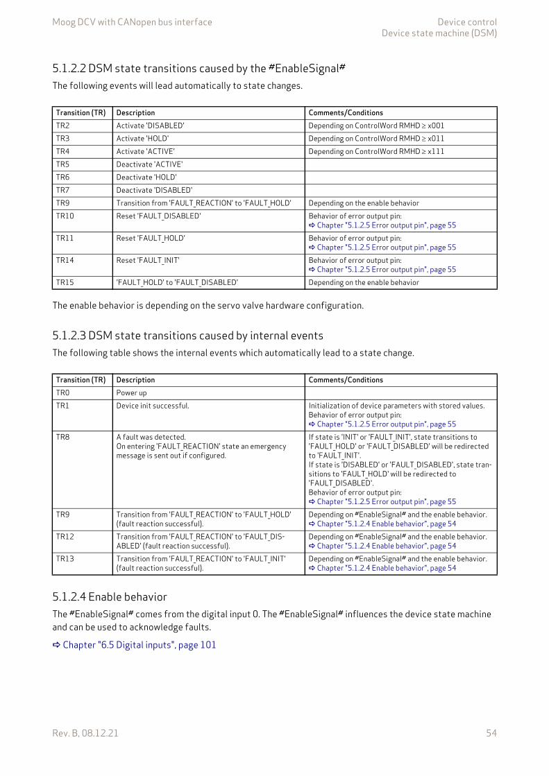
Moog DCV with CANopen bus interface Device controlDevice state machine (DSM)
Rev. B, 08.12.21 54
5.1.2.2 DSM state transitions caused by the #EnableSignal#The following events will lead automatically to state changes.
The enable behavior is depending on the servo valve hardware configuration.
5.1.2.3 DSM state transitions caused by internal eventsThe following table shows the internal events which automatically lead to a state change.
5.1.2.4 Enable behaviorThe #EnableSignal# comes from the digital input 0. The #EnableSignal# influences the device state machine and can be used to acknowledge faults.
Chapter "6.5 Digital inputs", page 101
Transition (TR) Description Comments/ConditionsTR2 Activate 'DISABLED' Depending on ControlWord RMHD x001TR3 Activate 'HOLD' Depending on ControlWord RMHD x011TR4 Activate 'ACTIVE' Depending on ControlWord RMHD x111TR5 Deactivate 'ACTIVE'TR6 Deactivate 'HOLD'TR7 Deactivate 'DISABLED'TR9 Transition from 'FAULT_REACTION' to 'FAULT_HOLD' Depending on the enable behaviorTR10 Reset 'FAULT_DISABLED' Behavior of error output pin:
Chapter "5.1.2.5 Error output pin", page 55TR11 Reset 'FAULT_HOLD' Behavior of error output pin:
Chapter "5.1.2.5 Error output pin", page 55TR14 Reset 'FAULT_INIT' Behavior of error output pin:
Chapter "5.1.2.5 Error output pin", page 55TR15 'FAULT_HOLD' to 'FAULT_DISABLED' Depending on the enable behavior
Transition (TR) Description Comments/ConditionsTR0 Power upTR1 Device init successful. Initialization of device parameters with stored values.
Behavior of error output pin: Chapter "5.1.2.5 Error output pin", page 55
TR8 A fault was detected.On entering 'FAULT_REACTION' state an emergency message is sent out if configured.
If state is 'INIT' or 'FAULT_INIT', state transitions to 'FAULT_HOLD' or 'FAULT_DISABLED' will be redirected to 'FAULT_INIT'.If state is 'DISABLED' or 'FAULT_DISABLED', state tran-sitions to 'FAULT_HOLD' will be redirected to 'FAULT_DISABLED'.Behavior of error output pin: Chapter "5.1.2.5 Error output pin", page 55
TR9 Transition from 'FAULT_REACTION' to 'FAULT_HOLD' (fault reaction successful).
Depending on #EnableSignal# and the enable behavior. Chapter "5.1.2.4 Enable behavior", page 54
TR12 Transition from 'FAULT_REACTION' to 'FAULT_DIS-ABLED' (fault reaction successful).
Depending on #EnableSignal# and the enable behavior. Chapter "5.1.2.4 Enable behavior", page 54
TR13 Transition from 'FAULT_REACTION' to 'FAULT_INIT' (fault reaction successful).
Depending on #EnableSignal# and the enable behavior. Chapter "5.1.2.4 Enable behavior", page 54
Moog DCV with CANopen bus interface Device controlDevice state machine (DSM)
Rev. B, 08.12.21 55
5.1.2.4.1 DSM state transitions depending on the #EnableSignal#The #EnableSignal# can cause different valve responses ('HOLD' or 'DISABLE'). The response to the #EnableSignal# is specified by the ordered servo valve configuration. The configuration is set by Moog during the production and cannot be changed by software. These hardware dependent options are shown in the fol-lowing tables.
Depending on the ordered servo valve configuration, the #EnableSignal# is used to enable the valve. When the #EnableSignal# is switched off the device state machine changes directly to the state 'DISABLED'.
In another possible servo valve configuration, the #EnableSignal# is also used to enable the valve. The device state machine changes to the 'HOLD' state when the #EnableSignal# is switched off.
Chapter "5.1.1 DSM states", page 51 Chapter "6.1.3 Q setpoint path", page 65 Chapter "6.1.4 p setpoint path", page 67
5.1.2.4.2 Fault confirmation with the #EnableSignal#Toggling the #EnableSignal# from low to high causes the device state machine to erase all errors. If no error is pending, the state machine will exit the fault state.
5.1.2.5 Error output pinThe digital outputs 0…2 can be used to indicate fault states (negative logic) according to the Device Profile Fluid Power. To enable a digital output as error output, the corresponding parameter <DigitalOutputConfiguration0…2> (0x5E41) must be set to 2.
• Digital output, configured as error output is set to 1 on power on (TR1) of the servo valve.• When a fault is detected (TR8), the digital output, configured as error output is set to 0 to indicate a fault
(negative logic).• When a fault state is left (TR10, TR11), the digital output, configured as error output is set to 1.
Chapter "6.6.2 Object 0x5E41: Digital output configuration", page 104
State transitions do not necessarily refer to a specific spool position or change of spool posi-tion. The specific spool position also depends on the ordered configuration.
#EnableSignal# Transition (TR) Old DSM state New DSM state Comments/Conditions1 -> 0 TR5, TR6 'HOLD', 'ACTIVE' 'DISABLED' RMHD 1001
TR15 'FAULT_HOLD' 'FAULT_DISABLED'
#EnableSignal# Transition (TR) Old DSM state New DSM state Comments/Conditions1 -> 0 TR5 'ACTIVE' 'HOLD' RMHD 1001
- 'FAULT_HOLD' No change
#EnableSignal# Transition (TR) Old DSM state New DSM state0 -> 1 TR10 'FAULT_DISABLED' Depending on the #ControlWord#
TR11 'FAULT_HOLD' Depending on the #ControlWord#
Moog DCV with CANopen bus interface Device controlDevice state machine (DSM)
Rev. B, 08.12.21 56
5.1.3 DSM control word and status word5.1.3.1 Object 0x6040: Device control wordThe functionality of the <LocalControlWord> (0x4040) and the <ControlWord> (0x6040) needs to be distin-guished. If the parameter <Local> (0x604F) is set, the DSM input #ControlWord# comes from the local param-eter <LocalControlWord> (0x4040) otherwise it comes from <ControlWord> (0x6040). This bit-coded parame-ter controls the DSM states.
Value description
Bits 0, 1, 2, 3: 'DISABLED', 'HOLD', 'ACTIVE', 'RESET FAULTS'The lower four bits within the control word represent the device state machine's (DSM) control command. Chapter "5.1.2.1 DSM state transitions caused by the control word", page 53
Bit 8: Enable pressure controllerThis bit activates the pressure controller in the p/Q or p/flow control mode (<ControlMode> (0x6043) is set to 5 or 14).
Chapter "7.1 Control modes", page 146
Bit 15: Ramp stopIf this bit is set, the ramp function output in the Q, p, and flow setpoint conditioning are frozen, in case of the ramp functions are enabled.
Q setpoint conditioning: Chapter "7.2.5 Ramp", page 158p setpoint conditioning:: Chapter "7.4.5 Ramp", page 183flow setpoint conditioning: Chapter "7.6.5 Ramp", page 213
Device
Index Sub-index Parameter name Data type AccessPer-sistence
Value range Default
0x6040 0 ControlWord UINT16 rw N UINT16 None
Table 28: Possible values of parameter <ControlWord> (0x6040)
<ControlWord>
Bit Description<Control Mode> (0x6043) is set to 1…4
<Control Mode> (0x6043) is set to 5 or 14 (p/Q or p/flow control) Specification
0 Bit Disabled (D) CiA 4081 Bit Hold (H)2 Bit Active (M)3 Bit Reset Faults (R)4…7 Reserved8 <ControlMode> (0x6043) specific Reserved Enable pressure controller CiA 4089…14 Reserved15 Ramp stop Moog DCV
0: Disables the pressure controller1: Enables the pressure controller
Moog DCV with CANopen bus interface Device controlDevice state machine (DSM)
Rev. B, 08.12.21 57
5.1.3.2 Object 0x6041: Status wordThe bit-coded <StatusWord> (0x6041) indicates the current device status.
Value description
Bits 0, 1, 2, 3: 'DISABLED', 'HOLD', 'ACTIVE', 'READY'These bits indicate the state of the device state machine (DSM). Chapter "5.1 Device state machine (DSM)", page 50
Bit 4: Indicates that bit <Local> (0x604F) is setThe <LocalControlWord> (0x4040) is the active control word. Chapter "5.1.4 DSM control word source selection / local mode", page 58
Bit 8: Enable pressure controllerIf the <Control Mode> (0x6043) is set to 5 (p/Q control) or 14 (p/flow control), this bit indicates whether the pressure controller is effective or not. In this case the pressure controller limits the spool position (flow).
Chapter "7.1 Control modes", page 146
Device
Index Sub-index Parameter name Data type AccessPer-sistence
Value range Default
0x6041 0 StatusWord UINT16 ro - UINT16 None
Table 29: Possible values of parameter <StatusWord> (0x6041)
<StatusWord>
Bit <StatusWord> bit<Control Mode> (0x6043) is set to 1…4
<Control Mode> (0x6043) is set to 5 or 14 (p/Q or p/flow control) Specification
0 Bit Disabled (D) CiA 4081 Bit Hold (H)2 Bit Active (M)3 Bit Ready (R)4 Indicates that bit <Local>
(0x604F) is setCiA 408
5…7 Reserved8 <ControlMode> (0x6043)
specificReserved Pressure controller effective CiA 408
9 Ramp running CiA 40810 Limit touched (c) CiA 40811 Control deviation CiA 40812…14 Reserved15 Ramp frozen Moog DCV
0: Output of Q or flow controller limits the flow.1: Output of pressure controller limits the flow.
This bit is only active if the <ControlMode> (0x6043) is set to 5 (p/Q control) or 14 (p/flow control).
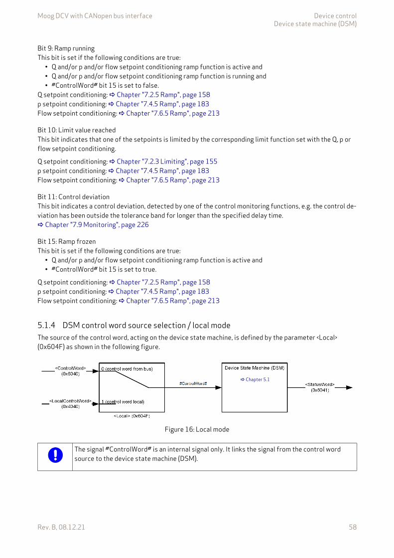
Moog DCV with CANopen bus interface Device controlDevice state machine (DSM)
Rev. B, 08.12.21 58
Bit 9: Ramp runningThis bit is set if the following conditions are true:
• Q and/or p and/or flow setpoint conditioning ramp function is active and• Q and/or p and/or flow setpoint conditioning ramp function is running and • #ControlWord# bit 15 is set to false.
Q setpoint conditioning: Chapter "7.2.5 Ramp", page 158p setpoint conditioning: Chapter "7.4.5 Ramp", page 183Flow setpoint conditioning: Chapter "7.6.5 Ramp", page 213
Bit 10: Limit value reachedThis bit indicates that one of the setpoints is limited by the corresponding limit function set with the Q, p or flow setpoint conditioning.
Q setpoint conditioning: Chapter "7.2.3 Limiting", page 155p setpoint conditioning: Chapter "7.4.5 Ramp", page 183Flow setpoint conditioning: Chapter "7.6.5 Ramp", page 213
Bit 11: Control deviationThis bit indicates a control deviation, detected by one of the control monitoring functions, e.g. the control de-viation has been outside the tolerance band for longer than the specified delay time. Chapter "7.9 Monitoring", page 226
Bit 15: Ramp frozenThis bit is set if the following conditions are true:
• Q and/or p and/or flow setpoint conditioning ramp function is active and• #ControlWord# bit 15 is set to true.
Q setpoint conditioning: Chapter "7.2.5 Ramp", page 158p setpoint conditioning: Chapter "7.4.5 Ramp", page 183Flow setpoint conditioning: Chapter "7.6.5 Ramp", page 213
5.1.4 DSM control word source selection / local modeThe source of the control word, acting on the device state machine, is defined by the parameter <Local> (0x604F) as shown in the following figure.
Figure 16: Local mode
Chapter 5.1
The signal #ControlWord# is an internal signal only. It links the signal from the control word source to the device state machine (DSM).
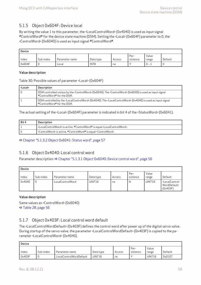
Moog DCV with CANopen bus interface Device controlDevice state machine (DSM)
Rev. B, 08.12.21 59
5.1.5 Object 0x604F: Device localBy writing the value 1 to this parameter, the <LocalControlWord> (0x4040) is used as input signal #ControlWord# for the device state machine (DSM). Setting the <Local> (0x604F) parameter to 0, the <ControlWord> (0x6040) is used as input signal #ControlWord#.
Value description
The actual setting of the <Local> (0x604F) parameter is indicated in bit 4 of the <StatusWord> (0x6041).
Chapter "5.1.3.2 Object 0x6041: Status word", page 57
5.1.6 Object 0x4040: Local control wordParameter description: Chapter "5.1.3.1 Object 0x6040: Device control word", page 56
Value descriptionSame values as <ControlWord> (0x6040) Table 28, page 56
5.1.7 Object 0x403F: Local control word defaultThe <LocalControlWordDefault> (0x403F) defines the control word after power up of the digital servo valve. During startup of the servo valve, the parameter <LocalControlWordDefault> (0x403F) is copied to the pa-rameter <LocalControlWord> (0x4040).
Device
Index Sub-index Parameter name Data type AccessPer-sistence
Value range Default
0x604F 0 Local INT8 rw Y 0…1 0
Table 30: Possible values of parameter <Local> (0x604F)
<Local> Description0 DSM controlled via bus by the <ControlWord> (0x6040). The <ControlWord> (0x6040) is used as input signal
#ControlWord# for the DSM.1 DSM controlled by the <LocalControlWord> (0x4040). The <LocalControlWord> (0x4040) is used as input signal
#ControlWord# for the DSM.
Bit 4 Description1 <LocalControlWord> is active, #ControlWord# is equal <LocalControlWord>.0 <ControlWord> is active, #ControlWord# is equal <ControlWord>.
Device
Index Sub-index Parameter name Data type AccessPer-sistence
Value range Default
0x4040 0 LocalControlWord UINT16 rw N UINT16 <LocalControl-WordDefault> (0x403F)
Device
Index Sub-index Parameter name Data type AccessPer-sistence
Value range Default
0x403F 0 LocalControlWordDefault UINT16 rw Y UINT16 0x0107
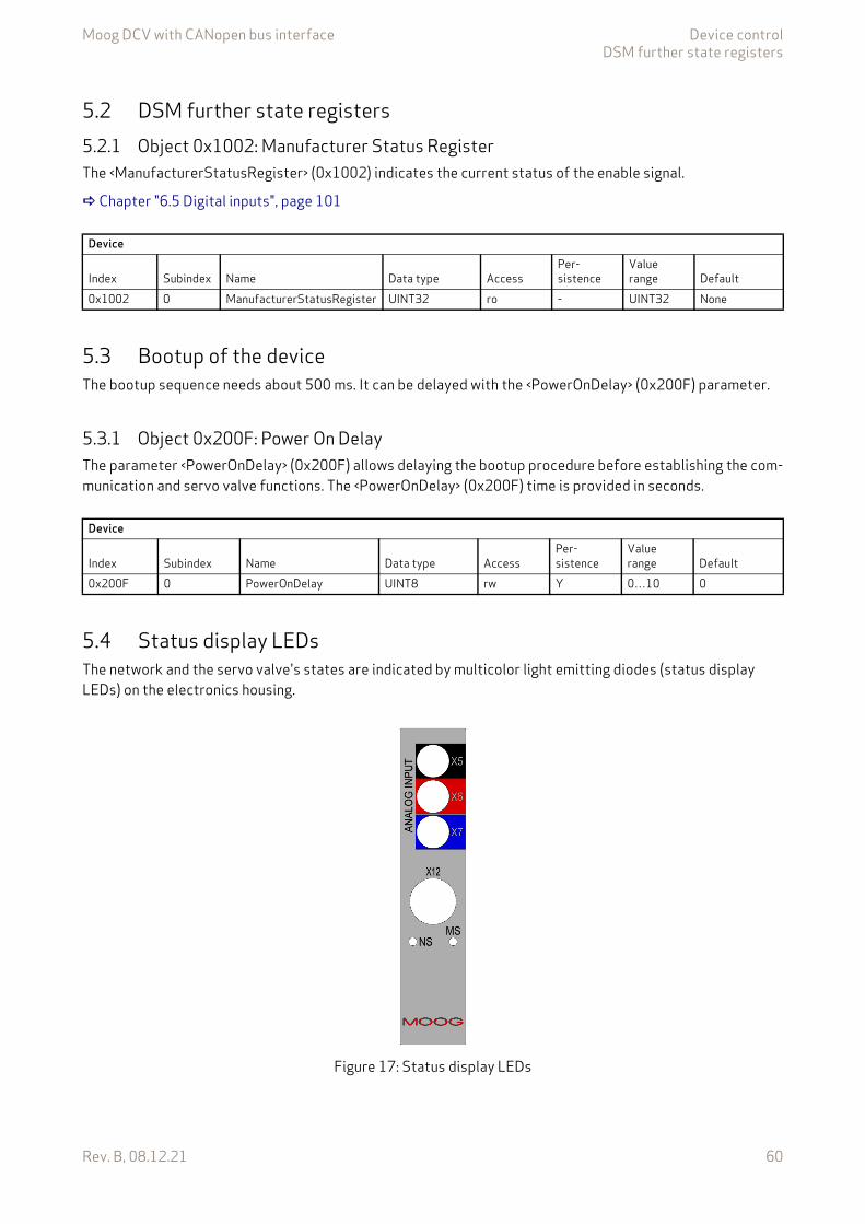
Moog DCV with CANopen bus interface Device controlDSM further state registers
Rev. B, 08.12.21 60
5.2 DSM further state registers5.2.1 Object 0x1002: Manufacturer Status RegisterThe <ManufacturerStatusRegister> (0x1002) indicates the current status of the enable signal.
Chapter "6.5 Digital inputs", page 101
5.3 Bootup of the deviceThe bootup sequence needs about 500 ms. It can be delayed with the <PowerOnDelay> (0x200F) parameter.
5.3.1 Object 0x200F: Power On DelayThe parameter <PowerOnDelay> (0x200F) allows delaying the bootup procedure before establishing the com-munication and servo valve functions. The <PowerOnDelay> (0x200F) time is provided in seconds.
5.4 Status display LEDsThe network and the servo valve's states are indicated by multicolor light emitting diodes (status display LEDs) on the electronics housing.
Figure 17: Status display LEDs
Device
Index Subindex Name Data type AccessPer-sistence
Value range Default
0x1002 0 ManufacturerStatusRegister UINT32 ro - UINT32 None
Device
Index Subindex Name Data type AccessPer-sistence
Value range Default
0x200F 0 PowerOnDelay UINT8 rw Y 0…10 0
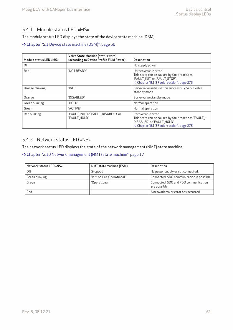
Moog DCV with CANopen bus interface Device controlStatus display LEDs
Rev. B, 08.12.21 61
5.4.1 Module status LED «MS»The module status LED displays the state of the device state machine (DSM).
Chapter "5.1 Device state machine (DSM)", page 50
5.4.2 Network status LED «NS»The network status LED displays the state of the network management (NMT) state machine.
Chapter "2.10 Network management (NMT) state machine", page 17
Module status LED «MS»Valve State Machine (status word) (according to Device Profile Fluid Power) Description
Off No supply powerRed 'NOT READY' Unrecoverable error.
This state can be caused by fault reactions 'FAULT_INIT' or 'FAULT_STOP'. Chapter "8.1.3 Fault reaction", page 275
Orange blinking 'INIT' Servo valve initialisation successful / Servo valve standby mode
Orange 'DISABLED' Servo valve standby modeGreen blinking 'HOLD' Normal operationGreen 'ACTIVE' Normal operationRed blinking 'FAULT_INIT' or 'FAULT_DISABLED' or
'FAULT_HOLD'Recoverable error.This state can be caused by fault reactions 'FAULT_-DISABLED' or 'FAULT_HOLD'. Chapter "8.1.3 Fault reaction", page 275
Network status LED «NS» NMT state machine (ESM) DescriptionOff Stopped No power supply or not connected.Green blinking 'Init' or 'Pre-Operational' Connected. SDO communication is possible.Green 'Operational' Connected. SDO and PDO communication
are possible.Red A network major error has occurred.
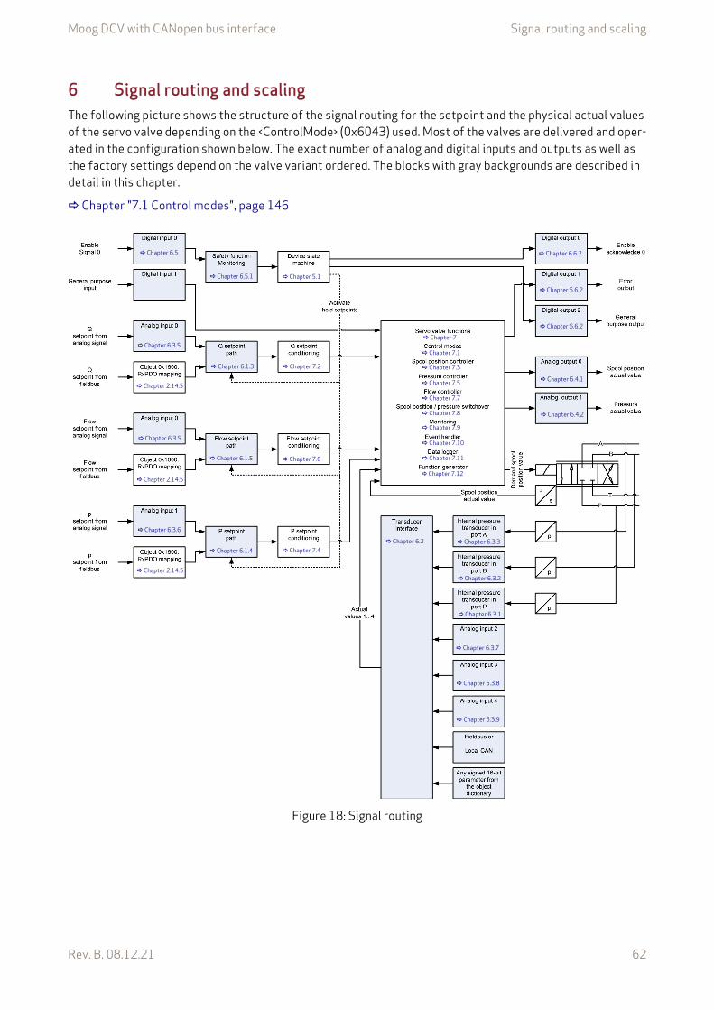
Moog DCV with CANopen bus interface Signal routing and scaling
Rev. B, 08.12.21 62
6 Signal routing and scalingThe following picture shows the structure of the signal routing for the setpoint and the physical actual values of the servo valve depending on the <ControlMode> (0x6043) used. Most of the valves are delivered and oper-ated in the configuration shown below. The exact number of analog and digital inputs and outputs as well as the factory settings depend on the valve variant ordered. The blocks with gray backgrounds are described in detail in this chapter.
Chapter "7.1 Control modes", page 146
Figure 18: Signal routing
Chapter 6.3.5
Chapter 6.3.6
Chapter 2.14.5
Chapter 5.1
Chapter 6.1.5
Chapter 7.2
Chapter 6.2
Chapter 6.3.1
Chapter 6.3.9
Chapter 6.3.7
Chapter 6.6.2
Chapter 6.4.1
Chapter 6.4.2
Chapter 6.6.2
Chapter 6.5.1
Chapter 7.6
Chapter 6.3.5
Chapter 2.14.5
Chapter 6.1.4 Chapter 7.4
Chapter 6.6.2
Chapter 6.3.2
Chapter 6.3.3
Chapter 2.14.5
Chapter 6.1.3
Chapter 6.3.8
Chapter 6.5
Chapter 7
Chapter 7.1
Chapter 7.3
Chapter 7.5
Chapter 7.7
Chapter 7.8
Chapter 7.9
Chapter 7.10
Chapter 7.11
Chapter 7.12
Moog DCV with CANopen bus interface Signal routing and scalingSetpoint path
Rev. B, 08.12.21 63
6.1 Setpoint pathThe setpoint for spool position, pressure and flow can be received via the fieldbus or via the analog inputs. The current configuration of individual models may differ. Which setpoint is in effect depends on the parame-ter <DeviceMode> (0x6042) and the <StatusWord> (0x6041) and <DeviceType> (0x1000). Depending on the device type bits 29…30, the 16 or 32 bit setpoint is used.
Setpoints received via fieldbus:
• The Q setpoint parameter <Q_Setpoint> (0x6300), 16 bit.• The Q setpoint parameter <Q_Setpoint 32 Bit> (0x6308), 32 bit.• The p setpoint parameter <PrsSetpoint> (0x6380), 16 bit.• The p setpoint parameter <PrsSetpoint 32 Bit> (0x6388), 32 bit.• The flow setpoint <FlowSetpoint> (0x6700), 16 bit.• The flow setpoint <FlowSetpoint 32Bit> (0x6708), 32 bit.
Setpoints from local source (analog input):
• The Q setpoint analog input 0 <AnaInpActualValue0> (0x3204), 16 bit.• The p setpoint analog input 1 <AnaInpActualValue1> (0x320C), 16 bit.• The flow setpoint analog input 0 <AnaInpActualValue0> (0x3204), 16 bit.
Examples for 16 bit setpoints:
• <DeviceMode> (0x6042) is set to 1 (setpoint input via bus), <StatusWord> (0x6041) is 0111b ('ACTIVE'):Result: The setpoint received via fieldbus is forwarded to the setpoint conditioning.
• <DeviceMode> (0x6042) is set to 2 (setpoint input locally), <StatusWord> (0x6041) is 0111b ('ACTIVE'):Result: The setpoint coming from the analog input is forwarded to the setpoint conditioning.
• <StatusWord> (0x6041) is 0011b ('HOLD').Result: The hold setpoints are taken as input. These hold setpoints are in effect regardless if the device mode <DeviceMode> (0x6042) is set to 1 (setpoint input via bus) or <DeviceMode> (0x6042) is set to 2 (setpoint input locally).
The Q hold setpoint is stored in the parameter <QHoldSetpoint> (0x6314).The p hold setpoint is stored in the parameter <PrsHoldSetpoint> (0x6394).The flow hold setpoint is stored in the parameter <FlowHoldSetpoint> (0x6714).
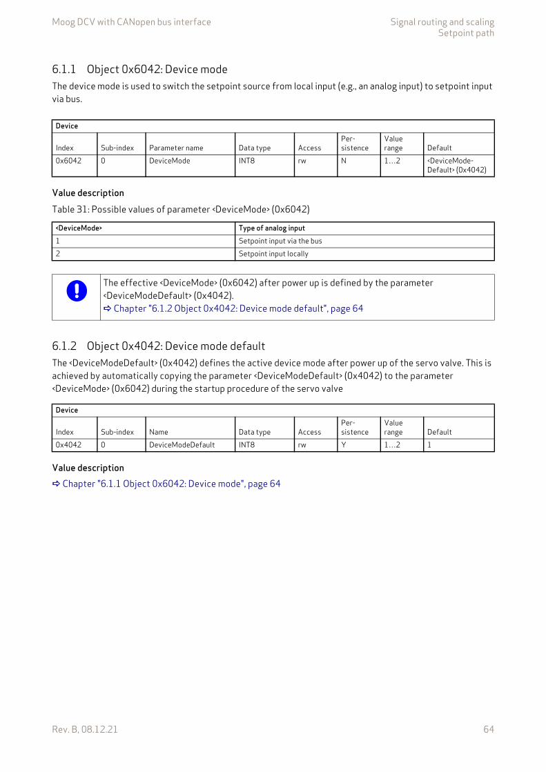
Moog DCV with CANopen bus interface Signal routing and scalingSetpoint path
Rev. B, 08.12.21 64
6.1.1 Object 0x6042: Device modeThe device mode is used to switch the setpoint source from local input (e.g., an analog input) to setpoint input via bus.
Value description
6.1.2 Object 0x4042: Device mode defaultThe <DeviceModeDefault> (0x4042) defines the active device mode after power up of the servo valve. This is achieved by automatically copying the parameter <DeviceModeDefault> (0x4042) to the parameter <DeviceMode> (0x6042) during the startup procedure of the servo valve
Value description Chapter "6.1.1 Object 0x6042: Device mode", page 64
Device
Index Sub-index Parameter name Data type AccessPer-sistence
Value range Default
0x6042 0 DeviceMode INT8 rw N 1…2 <DeviceMode-Default> (0x4042)
Table 31: Possible values of parameter <DeviceMode> (0x6042)
<DeviceMode> Type of analog input1 Setpoint input via the bus2 Setpoint input locally
The effective <DeviceMode> (0x6042) after power up is defined by the parameter <DeviceModeDefault> (0x4042). Chapter "6.1.2 Object 0x4042: Device mode default", page 64
Device
Index Sub-index Name Data type AccessPer-sistence
Value range Default
0x4042 0 DeviceModeDefault INT8 rw Y 1…2 1
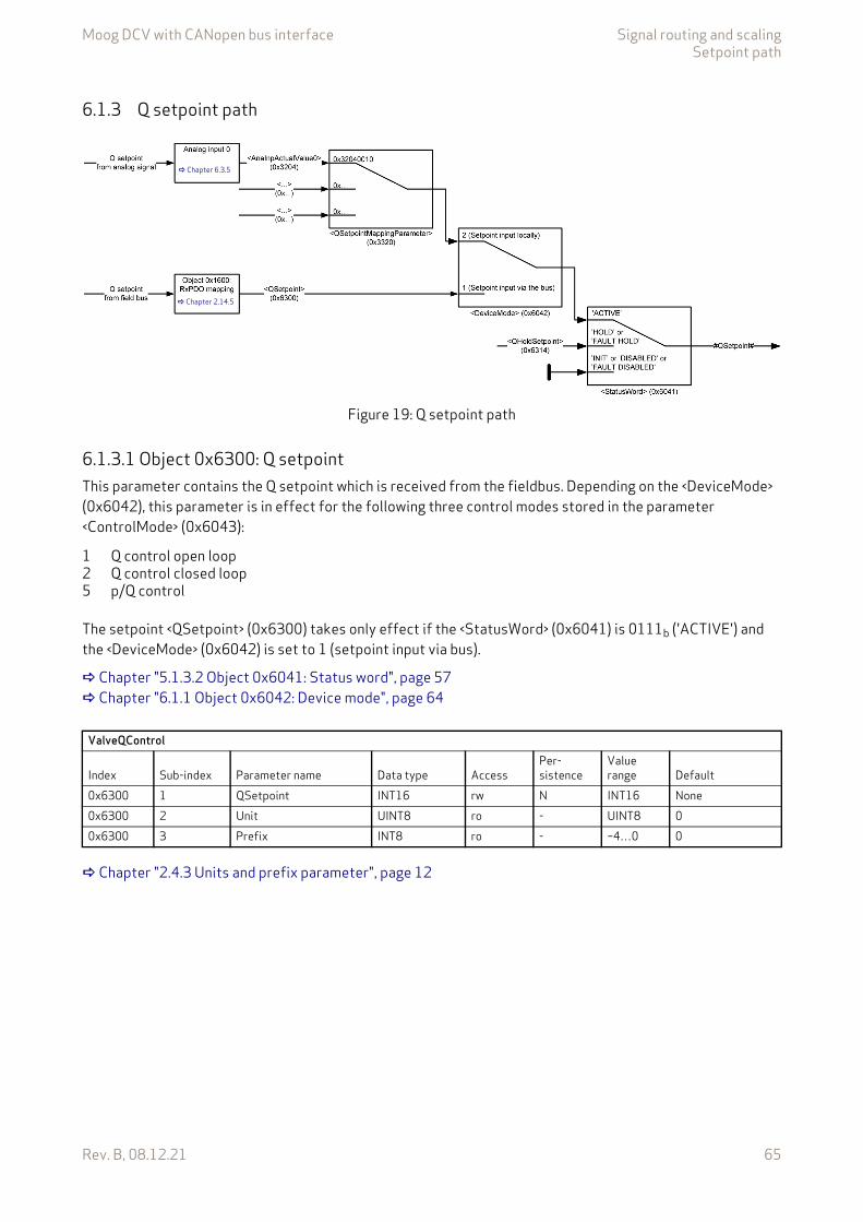
Moog DCV with CANopen bus interface Signal routing and scalingSetpoint path
Rev. B, 08.12.21 65
6.1.3 Q setpoint path
Figure 19: Q setpoint path
6.1.3.1 Object 0x6300: Q setpointThis parameter contains the Q setpoint which is received from the fieldbus. Depending on the <DeviceMode> (0x6042), this parameter is in effect for the following three control modes stored in the parameter <ControlMode> (0x6043):
The setpoint <QSetpoint> (0x6300) takes only effect if the <StatusWord> (0x6041) is 0111b ('ACTIVE') and the <DeviceMode> (0x6042) is set to 1 (setpoint input via bus).
Chapter "5.1.3.2 Object 0x6041: Status word", page 57 Chapter "6.1.1 Object 0x6042: Device mode", page 64
Chapter "2.4.3 Units and prefix parameter", page 12
Chapter 6.3.5
Chapter 2.14.5
1 Q control open loop2 Q control closed loop5 p/Q control
ValveQControl
Index Sub-index Parameter name Data type AccessPer-sistence
Value range Default
0x6300 1 QSetpoint INT16 rw N INT16 None0x6300 2 Unit UINT8 ro - UINT8 00x6300 3 Prefix INT8 ro - –4…0 0
Moog DCV with CANopen bus interface Signal routing and scalingSetpoint path
Rev. B, 08.12.21 66
6.1.3.2 Object 0x3320: Q setpoint source selection parameterThe Q setpoint selection parameter points to the input where the Q setpoint comes from.
The Q setpoint <QSetpoint> (0x6300) is only effective in case the <StatusWord> (0x6041) is 0111b ('ACTIVE') and the <DeviceMode> (0x6042) is set to 1 (setpoint input via bus).
Chapter "5.1.3.2 Object 0x6041: Status word", page 57 Chapter "6.1.1 Object 0x6042: Device mode", page 64
Value description
This reference contains a combination of index, sub-index and length of the parameter to be used. It may only refer to parameters with a bit length of 0x10 or 0x20.
The default value is 0x63000110, which refers to the <QSetpoint> (0x6300), sub-index 0x01 with a length of 16 bit (16=0x10).
6.1.3.3 Object 0x6314: Q setpoint conditioning hold setpointThis parameter defines the Q hold setpoint for the <ControlMode> (0x6043):
Chapter "7.1.1 Object 0x6043: Device control mode", page 146
The <QHoldSetpoint> (0x6314) acts as setpoint in case of <StatusWord> (0x6041) is 1011b ('HOLD') or 0011b ('FAULT_HOLD').
Chapter "5.1.3.2 Object 0x6041: Status word", page 57
Chapter "2.4.3 Units and prefix parameter", page 12
ValveQControl
Index Sub-index Parameter name Data type AccessPer-sistence
Value range Default
0x3320 0 QSetpointMappingParameter UINT32 rw Y UINT32 0x63000110
Table 32: Possible values of parameter <QSetpointMappingParameter> (0x3320)
<QSetpointMappingParameter>Byte 3 2 1 0
DescriptionIndex MSB Index LSB Sub-index Parameter bit length: 0x10
or 0x20Default 0x63 0x00 0x01 0x10
1 Q control open loop2 Q control closed loop5 p/Q control
ValveQControl_SetpointConditioning
Index Sub-index Parameter name Data type AccessPer-sistence
Value range Default
0x6314 1 QHoldSetpoint INT16 rw Y INT16 00x6314 2 Unit UINT8 ro - UINT8 00x6314 3 Prefix INT8 ro - –4…0 0
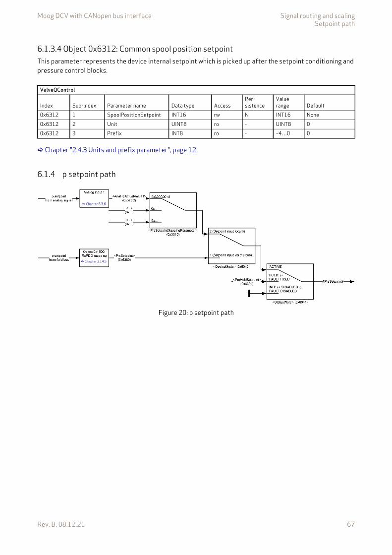
Moog DCV with CANopen bus interface Signal routing and scalingSetpoint path
Rev. B, 08.12.21 67
6.1.3.4 Object 0x6312: Common spool position setpointThis parameter represents the device internal setpoint which is picked up after the setpoint conditioning and pressure control blocks.
Chapter "2.4.3 Units and prefix parameter", page 12
6.1.4 p setpoint path
Figure 20: p setpoint path
ValveQControl
Index Sub-index Parameter name Data type AccessPer-sistence
Value range Default
0x6312 1 SpoolPositionSetpoint INT16 rw N INT16 None0x6312 2 Unit UINT8 ro - UINT8 00x6312 3 Prefix INT8 ro - –4…0 0
Chapter 6.3.6
Chapter 2.14.5
Moog DCV with CANopen bus interface Signal routing and scalingSetpoint path
Rev. B, 08.12.21 68
6.1.4.1 Object 0x6380: Pressure setpointThis parameter contains the p setpoint which is received from the fieldbus. Depending on the <DeviceMode> (0x6042), this parameter is in effect for the following three control modes stored in the parameter <ControlMode> (0x6043):
Chapter "7.1.1 Object 0x6043: Device control mode", page 146
The setpoint takes only effect in case the <StatusWord> (0x6041) is 1111b ('ACTIVE') and the <DeviceMode> (0x6042) is set to 1 (setpoint input via bus).
Chapter "5.1.3.2 Object 0x6041: Status word", page 57 Chapter "6.1.1 Object 0x6042: Device mode", page 64
Chapter "2.4.3 Units and prefix parameter", page 12
6.1.4.2 Object 0x3310: Pressure setpoint source selection parameterThe p setpoint selection parameter points to the input where the p setpoint comes from.
The p setpoint <PrsSetpoint> (0x6380) is only effective in case the <StatusWord> (0x6041) is 1111b ('ACTIVE') and the <DeviceMode> (0x6042) is set to 1 (setpoint input via bus).
Value description
This reference contains a combination of index, sub-index and length of the parameter to be used. It may only refer to parameters with a bit length of 0x10 or 0x20.
The default value is 0x63800110, which refers to the <PrsSetpoint> (0x6380), sub-index 0x01 with the length of 16 bit (16 = 0x10).
3 p open loop4 p closed loop5 p/Q control14 Flow control
ValvePressureControl
Index Sub-index Parameter name Data type AccessPer-sistence
Value range Default
0x6380 1 PrsSetpoint INT16 rw N INT16 None0x6380 2 Unit UINT8 ro - UINT8 00x6380 3 Prefix INT8 ro - –4…0 0
ValvePressureControl
Index Sub-index Parameter name Data type AccessPer-sistence
Value range Default
0x3310 0 PrsSetpointMappingParameter UINT32 rw Y UINT32 0x63800110
Table 33: Possible values of parameter <PrsSetpointMappingParameter> (0x3310)
<PrsSetpointMappingParameter>Byte 3 2 1 0
DescriptionIndex MSB Index LSB Sub-index Parameter bit length: 0x10
or 0x20Default 0x63 0x80 0x01 0x10
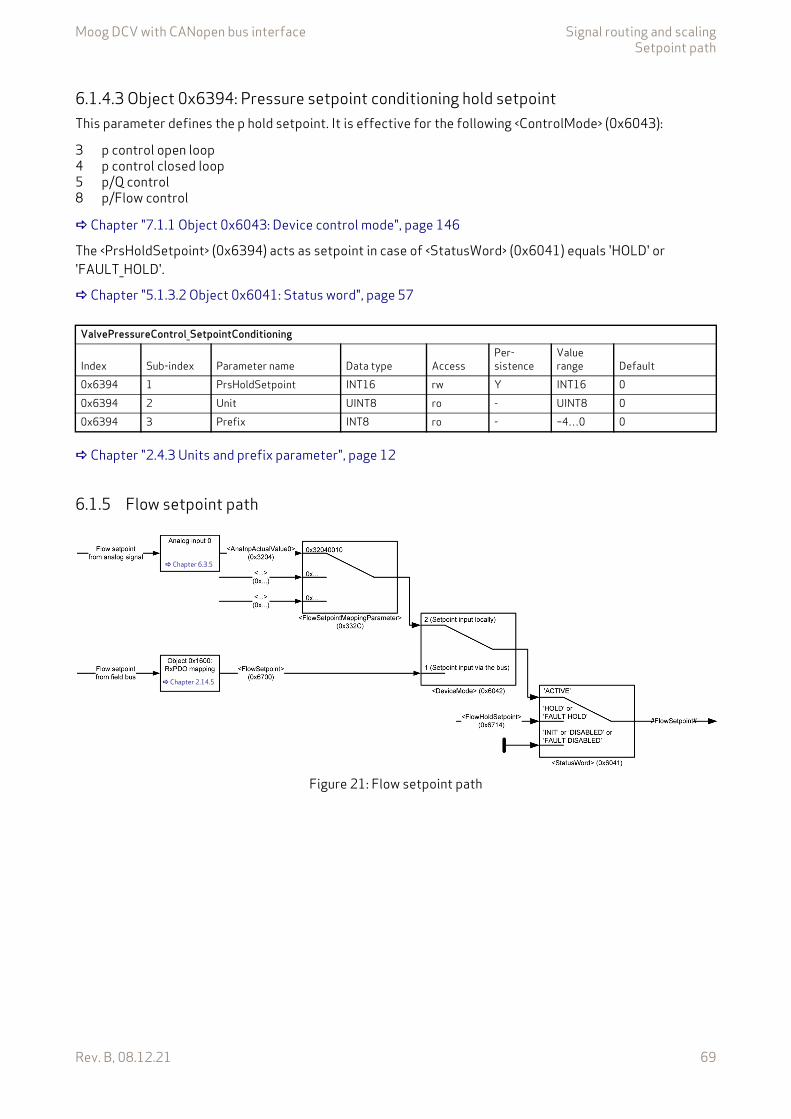
Moog DCV with CANopen bus interface Signal routing and scalingSetpoint path
Rev. B, 08.12.21 69
6.1.4.3 Object 0x6394: Pressure setpoint conditioning hold setpointThis parameter defines the p hold setpoint. It is effective for the following <ControlMode> (0x6043):
Chapter "7.1.1 Object 0x6043: Device control mode", page 146
The <PrsHoldSetpoint> (0x6394) acts as setpoint in case of <StatusWord> (0x6041) equals 'HOLD' or 'FAULT_HOLD'.
Chapter "5.1.3.2 Object 0x6041: Status word", page 57
Chapter "2.4.3 Units and prefix parameter", page 12
6.1.5 Flow setpoint path
Figure 21: Flow setpoint path
3 p control open loop4 p control closed loop5 p/Q control8 p/Flow control
ValvePressureControl_SetpointConditioning
Index Sub-index Parameter name Data type AccessPer-sistence
Value range Default
0x6394 1 PrsHoldSetpoint INT16 rw Y INT16 00x6394 2 Unit UINT8 ro - UINT8 00x6394 3 Prefix INT8 ro - –4…0 0
Chapter 6.3.5
Chapter 2.14.5
Moog DCV with CANopen bus interface Signal routing and scalingSetpoint path
Rev. B, 08.12.21 70
6.1.5.1 Object 0x6700: Flow setpointThis parameter contains the flow setpoint which is received from the fieldbus. Depending on the <DeviceMode> (0x6042), this parameter is in effect for the following control mode stored in the parameter <ControlMode> (0x6043):
Chapter "7.1.1 Object 0x6043: Device control mode", page 146
The setpoint takes only effect in case the <StatusWord> (0x6041) is 1111b ('ACTIVE') and the <DeviceMode> (0x6042) is set to 1 (setpoint input via bus).
Chapter "5.1.3.2 Object 0x6041: Status word", page 57 Chapter "6.1.1 Object 0x6042: Device mode", page 64
Chapter "2.4.3 Units and prefix parameter", page 12
6.1.5.2 Object 0x332C: Flow setpoint source selection parameterThe flow selection mapping parameter points to the input where the flow setpoint comes from.
The flow setpoint <FlowSetpoint> (0x6700) is only effective in case the <StatusWord> (0x6041) is 1111b ('AC-TIVE') and the <DeviceMode> (0x6042) is set to 1 (setpoint input via bus).
Value description
This reference contains a combination of index, sub-index and length of the parameter to be used. It may only refer to parameters with a bit length of 0x10 or 0x20.
The default value is 0x67000110 which refers to the <FlowSetpoint> (0x6700), sub-index 0x01 with the length of 16 bit (16 = 0x10).
13 flow control (not implemented)14 p/Flow control
ValveFlowControl
Index Sub-index Parameter name Data type AccessPer-sistence
Value range Default
0x6700 1 FlowSetpoint INT16 rw N INT16 None0x6700 2 Unit UINT8 ro - UINT8 00x6700 3 Prefix INT8 ro - –4…0 0
ValveFlowControl
Index Sub-index Parameter name Data type AccessPer-sistence
Value range Default
0x332C 0 FlowSetpointMappingParameter UINT32 rw Y UINT32 0x67000110
Table 34: Possible values of parameter <FlowSetpointMappingParameter> (0x332C)
<FlowSetpointMappingParameter>Byte 3 2 1 0
DescriptionIndex MSB Index LSB Sub-index Parameter bit length: 0x10
or 0x20Default 0x63 0x80 0x01 0x10
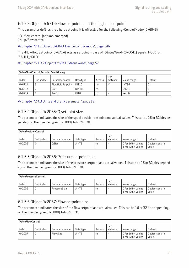
Moog DCV with CANopen bus interface Signal routing and scalingSetpoint path
Rev. B, 08.12.21 71
6.1.5.3 Object 0x6714: Flow setpoint conditioning hold setpointThis parameter defines the p hold setpoint. It is effective for the following <ControlMode> (0x6043):
Chapter "7.1.1 Object 0x6043: Device control mode", page 146
The <FlowHoldSetpoint> (0x6714) acts as setpoint in case of <StatusWord> (0x6041) equals 'HOLD' or 'FAULT_HOLD'.
Chapter "5.1.3.2 Object 0x6041: Status word", page 57
Chapter "2.4.3 Units and prefix parameter", page 12
6.1.5.4 Object 0x2035: Q setpoint sizeThe parameter indicates the size of the spool position setpoint and actual values. This can be 16 or 32 bits de-pending on the <device type> (0x1000), bits 29…30.
6.1.5.5 Object 0x2036: Pressure setpoint sizeThe parameter indicates the size of the pressure setpoint and actual values. This can be 16 or 32 bits depend-ing on the <device type> (0x1000), bits 29…30.
6.1.5.6 Object 0x2037: Flow setpoint sizeThe parameter indicates the size of the flow setpoint and actual values. This can be 16 or 32 bits depending on the <device type> (0x1000), bits 29…30.
13 flow control (not implemented)14 p/flow control
ValveFlowControl_SetpointConditioning
Index Sub-index Parameter name Data type AccessPer-sistence Value range Default
0x6714 1 FlowHoldSetpoint INT16 rw Y INT16 00x6714 2 Unit UINT8 ro - UINT8 00x6714 3 Prefix INT8 ro - –4…0 0
ValvePositionControl
Index Sub-index Parameter name Data type AccessPer-sistence Value range Default
0x2035 0 QSize UINT8 ro - 0 for 16 bit values1 for 32 bit values
Device-specific value
ValvePressureControl
Index Sub-index Parameter name Data type AccessPer-sistence Value range Default
0x2036 0 PressureSize UINT8 ro - 0 for 16 bit values1 for 32 bit values
Device-specific value
ValveFlowControl
Index Sub-index Parameter name Data type AccessPer-sistence Value range Default
0x2037 0 FlowSize UINT8 ro - 0 for 16 bit values1 for 32 bit values
Device-specific value
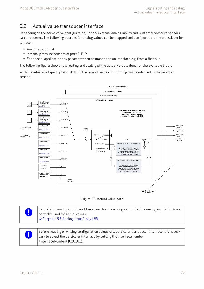
Moog DCV with CANopen bus interface Signal routing and scalingActual value transducer interface
Rev. B, 08.12.21 72
6.2 Actual value transducer interfaceDepending on the servo valve configuration, up to 5 external analog inputs and 3 internal pressure sensors can be ordered. The following sources for analog values can be mapped and configured via the transducer in-terface:
• Analog input 0…4• Internal pressure sensors at port A, B, P• For special application any parameter can be mapped to an interface e.g. from a fieldbus.
The following figure shows how routing and scaling of the actual value is done for the available inputs.
With the interface type <Type> (0x6102), the type of value conditioning can be adapted to the selected sensor.
Figure 22: Actual value path
Chapter 6.3.1
Chapter 6.3.1
Chapter 6.3.5
Chapter 6.3.7
Chapter 6.3.8
Chapter 6.3.9
Chapter 6.3.6
Chapter 6.3.3
Per default, analog input 0 and 1 are used for the analog setpoints. The analog inputs 2…4 are normally used for actual values. Chapter "6.3 Analog inputs", page 83
Before reading or writing configuration values of a particular transducer interface it is neces-sary to select the particular interface by setting the interface number <InterfaceNumber> (0x6101).
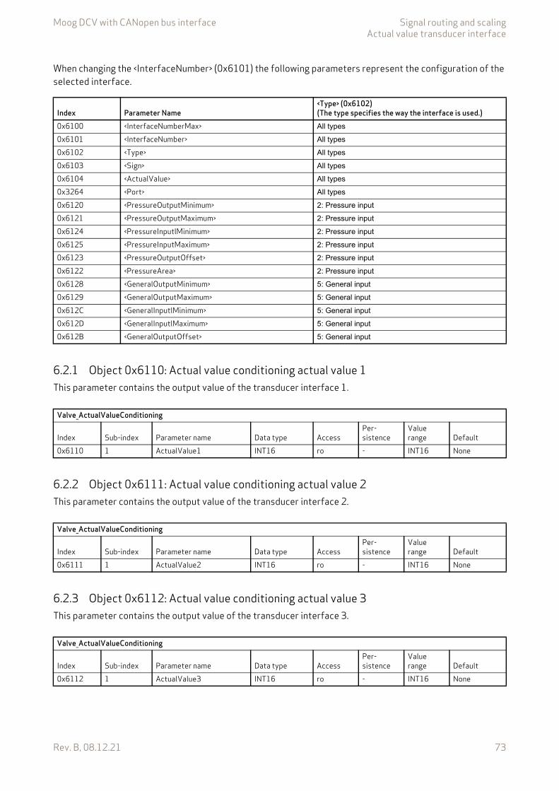
Moog DCV with CANopen bus interface Signal routing and scalingActual value transducer interface
Rev. B, 08.12.21 73
When changing the <InterfaceNumber> (0x6101) the following parameters represent the configuration of the selected interface.
6.2.1 Object 0x6110: Actual value conditioning actual value 1This parameter contains the output value of the transducer interface 1.
6.2.2 Object 0x6111: Actual value conditioning actual value 2This parameter contains the output value of the transducer interface 2.
6.2.3 Object 0x6112: Actual value conditioning actual value 3This parameter contains the output value of the transducer interface 3.
Index Parameter Name<Type> (0x6102)(The type specifies the way the interface is used.)
0x6100 <InterfaceNumberMax> All types
0x6101 <InterfaceNumber> All types
0x6102 <Type> All types
0x6103 <Sign> All types
0x6104 <ActualValue> All types
0x3264 <Port> All types
0x6120 <PressureOutputMinimum> 2: Pressure input
0x6121 <PressureOutputMaximum> 2: Pressure input
0x6124 <PressureInputlMinimum> 2: Pressure input
0x6125 <PressureInputMaximum> 2: Pressure input
0x6123 <PressureOutputOffset> 2: Pressure input
0x6122 <PressureArea> 2: Pressure input
0x6128 <GeneralOutputMinimum> 5: General input
0x6129 <GeneralOutputMaximum> 5: General input
0x612C <GeneralInputlMinimum> 5: General input
0x612D <GeneralInputlMaximum> 5: General input
0x612B <GeneralOutputOffset> 5: General input
Valve_ActualValueConditioning
Index Sub-index Parameter name Data type AccessPer-sistence
Value range Default
0x6110 1 ActualValue1 INT16 ro - INT16 None
Valve_ActualValueConditioning
Index Sub-index Parameter name Data type AccessPer-sistence
Value range Default
0x6111 1 ActualValue2 INT16 ro - INT16 None
Valve_ActualValueConditioning
Index Sub-index Parameter name Data type AccessPer-sistence
Value range Default
0x6112 1 ActualValue3 INT16 ro - INT16 None
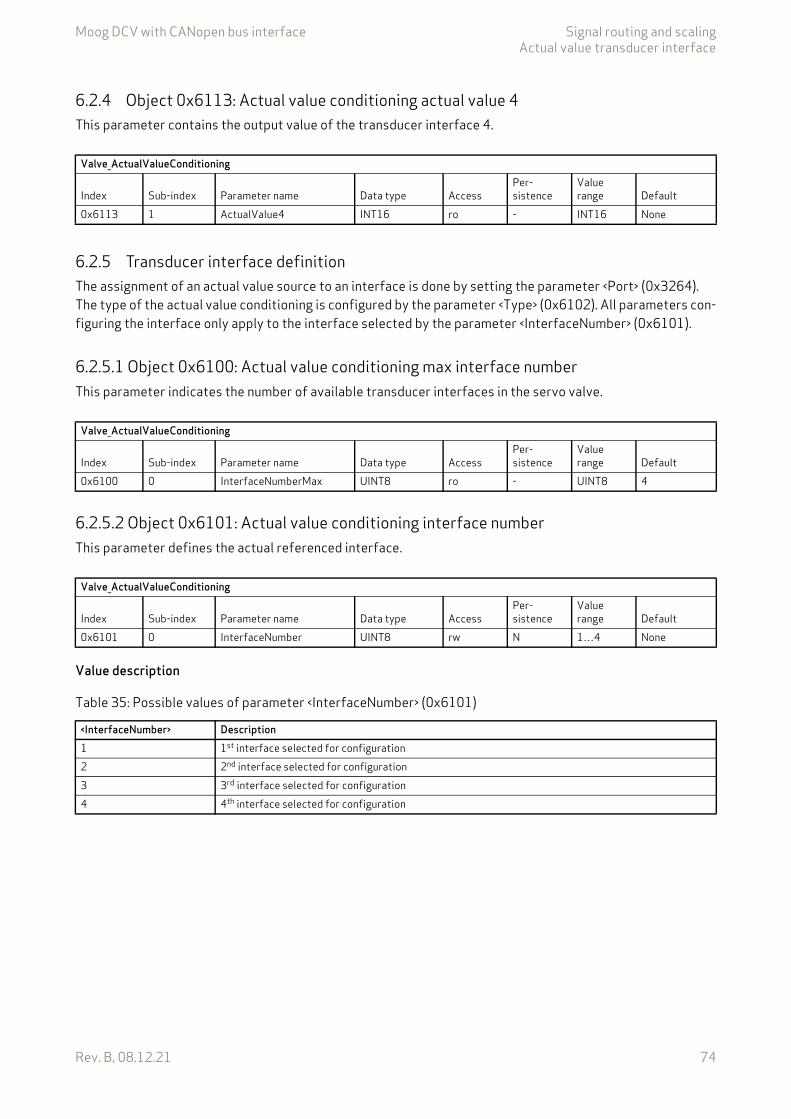
Moog DCV with CANopen bus interface Signal routing and scalingActual value transducer interface
Rev. B, 08.12.21 74
6.2.4 Object 0x6113: Actual value conditioning actual value 4This parameter contains the output value of the transducer interface 4.
6.2.5 Transducer interface definitionThe assignment of an actual value source to an interface is done by setting the parameter <Port> (0x3264). The type of the actual value conditioning is configured by the parameter <Type> (0x6102). All parameters con-figuring the interface only apply to the interface selected by the parameter <InterfaceNumber> (0x6101).
6.2.5.1 Object 0x6100: Actual value conditioning max interface numberThis parameter indicates the number of available transducer interfaces in the servo valve.
6.2.5.2 Object 0x6101: Actual value conditioning interface numberThis parameter defines the actual referenced interface.
Value description
Valve_ActualValueConditioning
Index Sub-index Parameter name Data type AccessPer-sistence
Value range Default
0x6113 1 ActualValue4 INT16 ro - INT16 None
Valve_ActualValueConditioning
Index Sub-index Parameter name Data type AccessPer-sistence
Value range Default
0x6100 0 InterfaceNumberMax UINT8 ro - UINT8 4
Valve_ActualValueConditioning
Index Sub-index Parameter name Data type AccessPer-sistence
Value range Default
0x6101 0 InterfaceNumber UINT8 rw N 1…4 None
Table 35: Possible values of parameter <InterfaceNumber> (0x6101)
<InterfaceNumber> Description1 1st interface selected for configuration2 2nd interface selected for configuration3 3rd interface selected for configuration4 4th interface selected for configuration

Moog DCV with CANopen bus interface Signal routing and scalingActual value transducer interface
Rev. B, 08.12.21 75
6.2.5.3 Object 0x6102: Actual value conditioning typeThis interface type <Type> (0x6102) defines the method of the value conditioning.This parameter setting is effective for the interface selected by <InterfaceNumber> (0x6101).
Value description
6.2.5.4 Object 0x6103: Actual value conditioning signThis parameter defines the sign of the actual value.This parameter setting is effective for the interface selected by <InterfaceNumber> (0x6101).
Value description
6.2.5.5 Object 0x6104: Actual value conditioning actual valueCompared to the objects <Actual value 1…4> (0x6110…0x6113), this parameter contains the output value of the actual selected interface.
Valve_ActualValueConditioning
Index Sub-index Parameter name Data type AccessPer-sistence
Value range Default
0x6102 0 Type INT8 rw N –2, 0, 2, 5 None
Table 36: Possible values of parameter <Type> (0x6102)
<Type> Description0 (no transducer function) Interface deactivated.2 (pressure transducer) Pressure sensor actual value conditioning with INT16 input values.
Chapter "6.2.6 Pressure actual value scaling", page 775 (general transducer) General input actual value conditioning with INT16 or INT32 input values.
Chapter "6.2.7 General actual value scaling", page 79–2 (analog direct) No further scaling active, INT16 input values.
Valve_ActualValueConditioning
Index Sub-index Parameter name Data type AccessPer-sistence
Value range Default
0x6103 0 Sign INT8 rw N –1 or +1 None
Table 37: Possible values of parameter <Sign> (0x6103)
<Sign> Description–1 Negative1 Positive
Valve_ActualValueConditioning
Index Sub-index Parameter name Data type AccessPer-sistence
Value range Default
0x6104 0 ActualValue INT16 ro - INT16 None
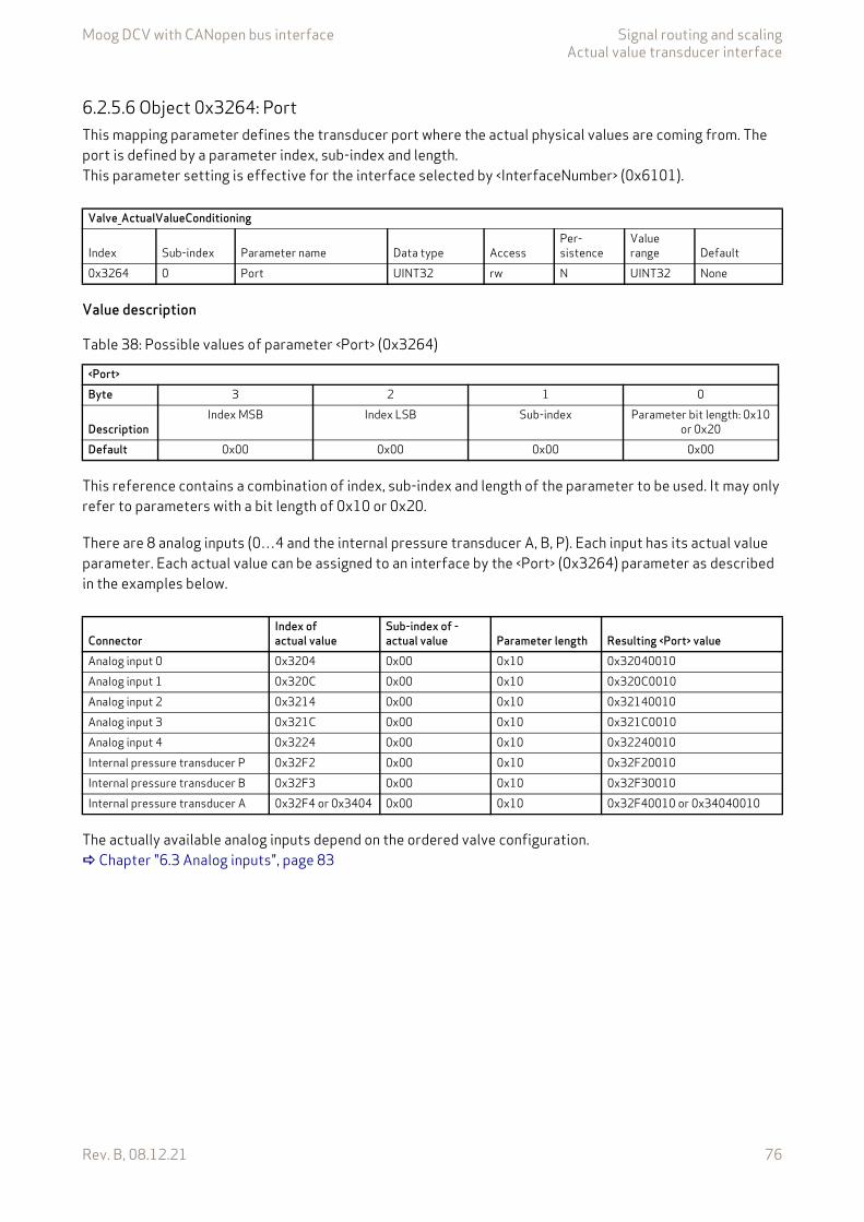
Moog DCV with CANopen bus interface Signal routing and scalingActual value transducer interface
Rev. B, 08.12.21 76
6.2.5.6 Object 0x3264: PortThis mapping parameter defines the transducer port where the actual physical values are coming from. The port is defined by a parameter index, sub-index and length.This parameter setting is effective for the interface selected by <InterfaceNumber> (0x6101).
Value description
This reference contains a combination of index, sub-index and length of the parameter to be used. It may only refer to parameters with a bit length of 0x10 or 0x20.
There are 8 analog inputs (0…4 and the internal pressure transducer A, B, P). Each input has its actual value parameter. Each actual value can be assigned to an interface by the <Port> (0x3264) parameter as described in the examples below.
The actually available analog inputs depend on the ordered valve configuration. Chapter "6.3 Analog inputs", page 83
Valve_ActualValueConditioning
Index Sub-index Parameter name Data type AccessPer-sistence
Value range Default
0x3264 0 Port UINT32 rw N UINT32 None
Table 38: Possible values of parameter <Port> (0x3264)
<Port>Byte 3 2 1 0
DescriptionIndex MSB Index LSB Sub-index Parameter bit length: 0x10
or 0x20Default 0x00 0x00 0x00 0x00
ConnectorIndex of actual value
Sub-index of -actual value Parameter length Resulting <Port> value
Analog input 0 0x3204 0x00 0x10 0x32040010Analog input 1 0x320C 0x00 0x10 0x320C0010Analog input 2 0x3214 0x00 0x10 0x32140010Analog input 3 0x321C 0x00 0x10 0x321C0010Analog input 4 0x3224 0x00 0x10 0x32240010Internal pressure transducer P 0x32F2 0x00 0x10 0x32F20010Internal pressure transducer B 0x32F3 0x00 0x10 0x32F30010Internal pressure transducer A 0x32F4 or 0x3404 0x00 0x10 0x32F40010 or 0x34040010
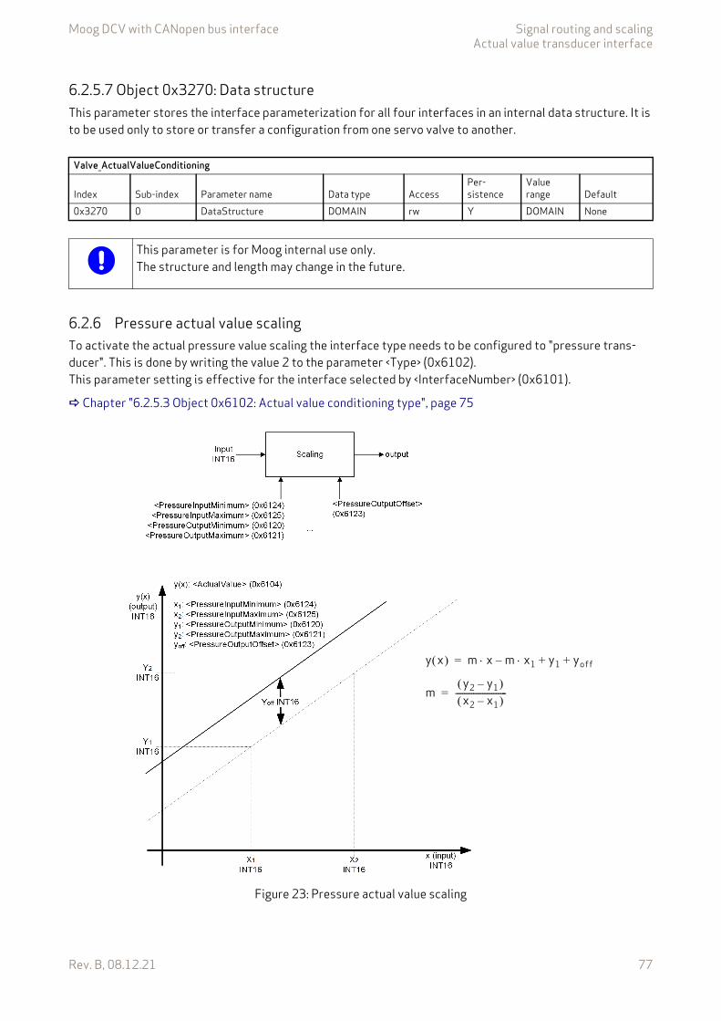
Moog DCV with CANopen bus interface Signal routing and scalingActual value transducer interface
Rev. B, 08.12.21 77
6.2.5.7 Object 0x3270: Data structureThis parameter stores the interface parameterization for all four interfaces in an internal data structure. It is to be used only to store or transfer a configuration from one servo valve to another.
6.2.6 Pressure actual value scalingTo activate the actual pressure value scaling the interface type needs to be configured to "pressure trans-ducer". This is done by writing the value 2 to the parameter <Type> (0x6102).This parameter setting is effective for the interface selected by <InterfaceNumber> (0x6101).
Chapter "6.2.5.3 Object 0x6102: Actual value conditioning type", page 75
Figure 23: Pressure actual value scaling
Valve_ActualValueConditioning
Index Sub-index Parameter name Data type AccessPer-sistence
Value range Default
0x3270 0 DataStructure DOMAIN rw Y DOMAIN None
This parameter is for Moog internal use only.The structure and length may change in the future.
my2 y1– x2 x1– -----------------------=
y x m x m x1 y1 yoff+ +–=
Moog DCV with CANopen bus interface Signal routing and scalingActual value transducer interface
Rev. B, 08.12.21 78
6.2.6.1 Object 0x6120: Actual value conditioning min pressure for pressure transducerThis parameter defines the minimum transducer interface output signal data point y1 of the two-point scaling function (when pressure offset equals 0).
6.2.6.2 Object 0x6121: Actual value conditioning max pressure for pressure transducerThis parameter defines the maximum transducer interface output signal data point y2 of the two-point scal-ing function (when pressure offset equals 0).
6.2.6.3 Object 0x6124: Actual value conditioning min transducer signal for pressure transducerThis parameter defines the transducer interface input signal data point x1 of the two-point scaling function (when pressure offset equals 0).
6.2.6.4 Object 0x6125: Actual value conditioning max transducer signal for pressure transducerThis parameter defines the transducer interface input signal data point x2 of the two-point scaling function (when pressure offset equals 0).
6.2.6.5 Object 0x6123: Actual value conditioning pressure offset for pressureThis parameter defines a pressure offset which is added to the two point scaling function defined by the four parameters before.
Valve_ActualValueConditioning
Index Sub-index Parameter name Data type AccessPer-sistence
Value range Default
0x6120 1 PressureOutputMinimum INT16 rw N INT16 None
Valve_ActualValueConditioning
Index Sub-index Parameter name Data type AccessPer-sistence
Value range Default
0x6121 1 PressureOutputMaximum INT16 rw N INT16 None
Valve_ActualValueConditioning
Index Sub-index Parameter name Data type AccessPer-sistence
Value range Default
0x6124 1 PressureInputMinimum INT16 rw N INT16 None
Valve_ActualValueConditioning
Index Sub-index Parameter name Data type AccessPer-sistence
Value range Default
0x6125 1 PressureInputMaximum INT16 rw N INT16 None
Valve_ActualValueConditioning
Index Sub-index Parameter name Data type AccessPer-sistence
Value range Default
0x6123 1 PressureOutputOffset INT16 rw N INT16 None
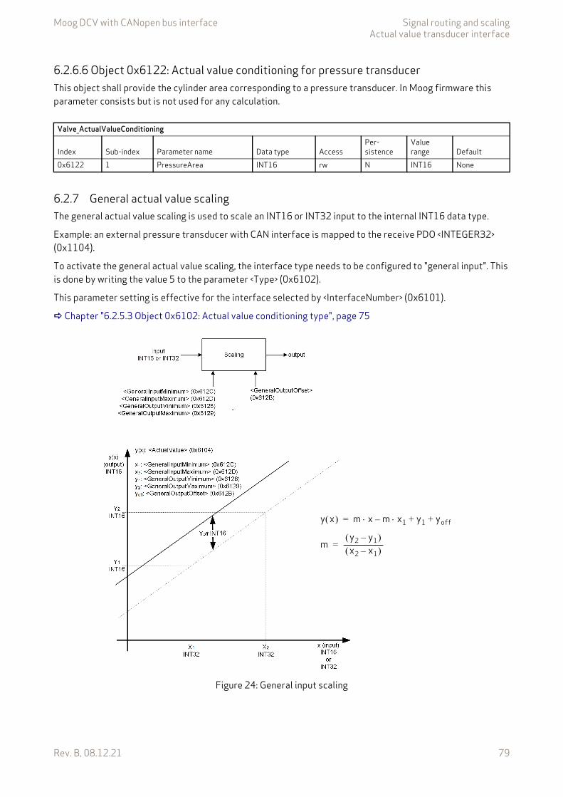
Moog DCV with CANopen bus interface Signal routing and scalingActual value transducer interface
Rev. B, 08.12.21 79
6.2.6.6 Object 0x6122: Actual value conditioning for pressure transducerThis object shall provide the cylinder area corresponding to a pressure transducer. In Moog firmware this parameter consists but is not used for any calculation.
6.2.7 General actual value scalingThe general actual value scaling is used to scale an INT16 or INT32 input to the internal INT16 data type.
Example: an external pressure transducer with CAN interface is mapped to the receive PDO <INTEGER32> (0x1104).
To activate the general actual value scaling, the interface type needs to be configured to "general input". This is done by writing the value 5 to the parameter <Type> (0x6102).
This parameter setting is effective for the interface selected by <InterfaceNumber> (0x6101).
Chapter "6.2.5.3 Object 0x6102: Actual value conditioning type", page 75
Figure 24: General input scaling
Valve_ActualValueConditioning
Index Sub-index Parameter name Data type AccessPer-sistence
Value range Default
0x6122 1 PressureArea INT16 rw N INT16 None
my2 y1– x2 x1– -----------------------=
y x m x m x1 y1 yoff+ +–=
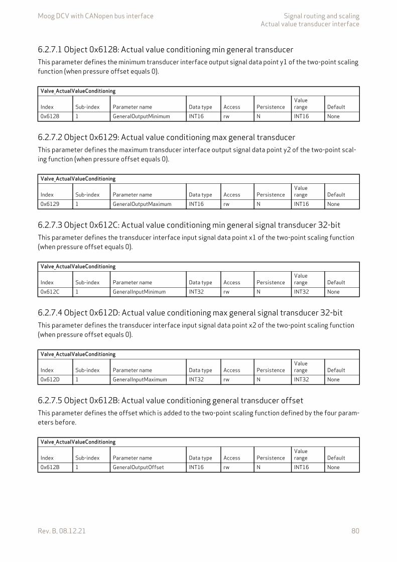
Moog DCV with CANopen bus interface Signal routing and scalingActual value transducer interface
Rev. B, 08.12.21 80
6.2.7.1 Object 0x6128: Actual value conditioning min general transducerThis parameter defines the minimum transducer interface output signal data point y1 of the two-point scaling function (when pressure offset equals 0).
6.2.7.2 Object 0x6129: Actual value conditioning max general transducerThis parameter defines the maximum transducer interface output signal data point y2 of the two-point scal-ing function (when pressure offset equals 0).
6.2.7.3 Object 0x612C: Actual value conditioning min general signal transducer 32-bitThis parameter defines the transducer interface input signal data point x1 of the two-point scaling function (when pressure offset equals 0).
6.2.7.4 Object 0x612D: Actual value conditioning max general signal transducer 32-bitThis parameter defines the transducer interface input signal data point x2 of the two-point scaling function (when pressure offset equals 0).
6.2.7.5 Object 0x612B: Actual value conditioning general transducer offsetThis parameter defines the offset which is added to the two-point scaling function defined by the four param-eters before.
Valve_ActualValueConditioning
Index Sub-index Parameter name Data type Access PersistenceValue range Default
0x6128 1 GeneralOutputMinimum INT16 rw N INT16 None
Valve_ActualValueConditioning
Index Sub-index Parameter name Data type Access PersistenceValue range Default
0x6129 1 GeneralOutputMaximum INT16 rw N INT16 None
Valve_ActualValueConditioning
Index Sub-index Parameter name Data type Access PersistenceValue range Default
0x612C 1 GeneralInputMinimum INT32 rw N INT32 None
Valve_ActualValueConditioning
Index Sub-index Parameter name Data type Access PersistenceValue range Default
0x612D 1 GeneralInputMaximum INT32 rw N INT32 None
Valve_ActualValueConditioning
Index Sub-index Parameter name Data type Access PersistenceValue range Default
0x612B 1 GeneralOutputOffset INT16 rw N INT16 None

Moog DCV with CANopen bus interface Signal routing and scalingActual value transducer interface
Rev. B, 08.12.21 81
6.2.8 Parameterization examplesThis chapter gives an example how to configure one complete pressure transducer interface.
6.2.8.1 Get active transducer interface number and output valueThe <InterfaceNumber> (0x6101) shows the active transducer interface number. The output value of the active transducer interface can be read from the parameter <ActualValue> (0x6104).
6.2.8.2 Example 1: Enable/disable transducer interface1. Select the transducer interface which is intended to be enabled or disabled.
To do this set the <InterfaceNumber> (0x6101).
2. Enable or disable the selected transducer interface and select the method of conditioning.To do this set the interface type <Type> (0x6102) to:0 (no transducer function) or 2 (pressure transducer) or –2 (analog direct)
6.2.8.3 Example 2: Change sign of the transducer signal1. Select the transducer interface which is intended to change the sign.
To do this set the <InterfaceNumber> (0x6101).
2. Change the sign of the transducer interface.To do this set the <Sign> (0x6103) to:1 (positive) or –1 (negative)
6.2.8.4 Example 3: Adjust transducer interface without scaling1. Select the transducer interface which is intended to be adjusted.
Therefore set the <InterfaceNumber> (0x6101).
2. Define the input signal for the transducer interface with the input parameter address.Get the index, sub-index and parameter length in bits from the object dictionary or from the parameter description. For example, the parameter <DummyDataS16> (0x2921) should be used as input:
Build the address value in the following manner:
Write the result 0x29210010 into the parameter <Port> (0x3264).
3. Check the transducer interfaces <Sign> (0x6103) and change the value (1 or –1) if needed.4. Set the transducer interface <Type> (0x6102) to –2 (analog direct).
Index: 0x2921Index MSB: 0x00Index LSB: 0x03Sub-index: 0x00Parameter bit length: 0x10 (Only parameters with a bit length of 0x10 or 0x20 are allowed to be
mapped!)
Byte 3 2 1 0 Result
DescriptionIndex MSB Index LSB Sub-index Parameter length in
bit: 0x10Example 0x29 0x21 0x00 0x10 0x29210010
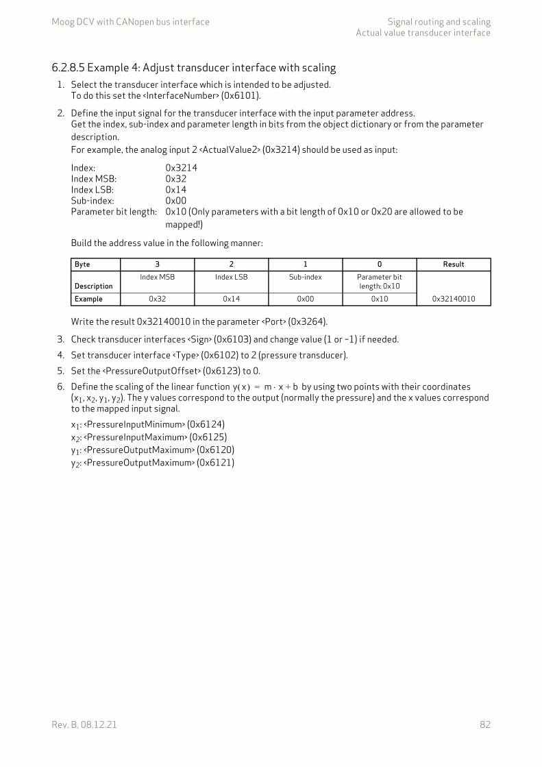
Moog DCV with CANopen bus interface Signal routing and scalingActual value transducer interface
Rev. B, 08.12.21 82
6.2.8.5 Example 4: Adjust transducer interface with scaling1. Select the transducer interface which is intended to be adjusted.
To do this set the <InterfaceNumber> (0x6101).
2. Define the input signal for the transducer interface with the input parameter address.Get the index, sub-index and parameter length in bits from the object dictionary or from the parameter description. For example, the analog input 2 <ActualValue2> (0x3214) should be used as input:
Build the address value in the following manner:
Write the result 0x32140010 in the parameter <Port> (0x3264).
3. Check transducer interfaces <Sign> (0x6103) and change value (1 or –1) if needed.4. Set transducer interface <Type> (0x6102) to 2 (pressure transducer).5. Set the <PressureOutputOffset> (0x6123) to 0.6. Define the scaling of the linear function by using two points with their coordinates
(x1, x2, y1, y2). The y values correspond to the output (normally the pressure) and the x values correspond to the mapped input signal.x1: <PressureInputMinimum> (0x6124)x2: <PressureInputMaximum> (0x6125)y1: <PressureOutputMaximum> (0x6120)y2: <PressureOutputMaximum> (0x6121)
Index: 0x3214Index MSB: 0x32Index LSB: 0x14Sub-index: 0x00Parameter bit length: 0x10 (Only parameters with a bit length of 0x10 or 0x20 are allowed to be
mapped!)
Byte 3 2 1 0 Result
DescriptionIndex MSB Index LSB Sub-index Parameter bit
length: 0x10Example 0x32 0x14 0x00 0x10 0x32140010
y x m x b+=
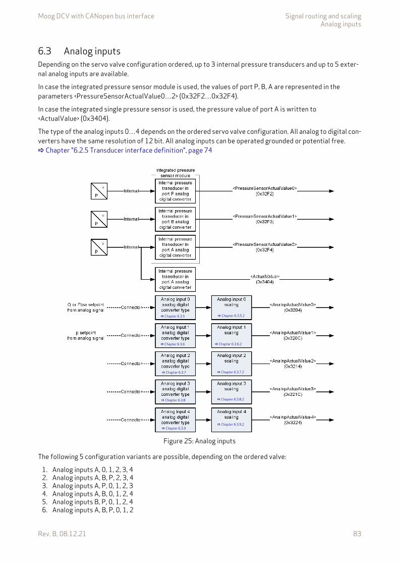
Moog DCV with CANopen bus interface Signal routing and scalingAnalog inputs
Rev. B, 08.12.21 83
6.3 Analog inputsDepending on the servo valve configuration ordered, up to 3 internal pressure transducers and up to 5 exter-nal analog inputs are available.
In case the integrated pressure sensor module is used, the values of port P, B, A are represented in the parameters <PressureSensorActualValue0…2> (0x32F2…0x32F4).
In case the integrated single pressure sensor is used, the pressure value of port A is written to <ActualValue> (0x3404).
The type of the analog inputs 0…4 depends on the ordered servo valve configuration. All analog to digital con-verters have the same resolution of 12 bit. All analog inputs can be operated grounded or potential free. Chapter "6.2.5 Transducer interface definition", page 74
Figure 25: Analog inputs
The following 5 configuration variants are possible, depending on the ordered valve:
1. Analog inputs A, 0, 1, 2, 3, 42. Analog inputs A, B, P, 2, 3, 43. Analog inputs A, P, 0, 1, 2, 34. Analog inputs A, B, 0, 1, 2, 45. Analog inputs B, P, 0, 1, 2, 46. Analog inputs A, B, P, 0, 1, 2
Chapter 6.3.5
Chapter 6.3.6
Chapter 6.3.7
Chapter 6.3.8
Chapter 6.3.9
Chapter 6.3.5.2
Chapter 6.3.6.2
Chapter 6.3.7.2
Chapter 6.3.8.2
Chapter 6.3.9.2
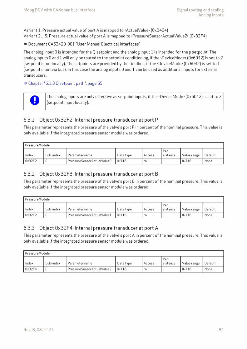
Moog DCV with CANopen bus interface Signal routing and scalingAnalog inputs
Rev. B, 08.12.21 84
Variant 1: Pressure actual value of port A is mapped to <ActualValue> (0x3404)Variant 2…5: Pressure actual value of port A is mapped to <PressureSensorActualValue2> (0x32F4)
Document CA63420-001 "User Manual Electrical Interfaces"
The analog input 0 is intended for the Q setpoint and the analog input 1 is intended for the p setpoint. The analog inputs 0 and 1 will only be routed to the setpoint conditioning, if the <DeviceMode> (0x6042) is set to 2 (setpoint input locally). The setpoints are provided by the fieldbus, if the <DeviceMode> (0x6042) is set to 1 (setpoint input via bus). In this case the analog inputs 0 and 1 can be used as additional inputs for external transducers.
Chapter "6.1.3 Q setpoint path", page 65
6.3.1 Object 0x32F2: Internal pressure transducer at port PThis parameter represents the pressure of the valve's port P in percent of the nominal pressure. This value is only available if the integrated pressure sensor module was ordered.
6.3.2 Object 0x32F3: Internal pressure transducer at port BThis parameter represents the pressure of the valve's port B in percent of the nominal pressure. This value is only available if the integrated pressure sensor module was ordered.
6.3.3 Object 0x32F4: Internal pressure transducer at port AThis parameter represents the pressure of the valve's port A in percent of the nominal pressure. This value is only available if the integrated pressure sensor module was ordered.
The analog inputs are only effective as setpoint inputs, if the <DeviceMode> (0x6042) is set to 2 (setpoint input locally).
PressureModule
Index Sub-index Parameter name Data type AccessPer-sistence Value range Default
0x32F2 0 PressureSensorActualValue0 INT16 ro - INT16 None
PressureModule
Index Sub-index Parameter name Data type AccessPer-sistence Value range Default
0x32F2 0 PressureSensorActualValue1 INT16 ro - INT16 None
PressureModule
Index Sub-index Parameter name Data type AccessPer-sistence Value range Default
0x32F4 0 PressureSensorActualValue2 INT16 ro - INT16 None
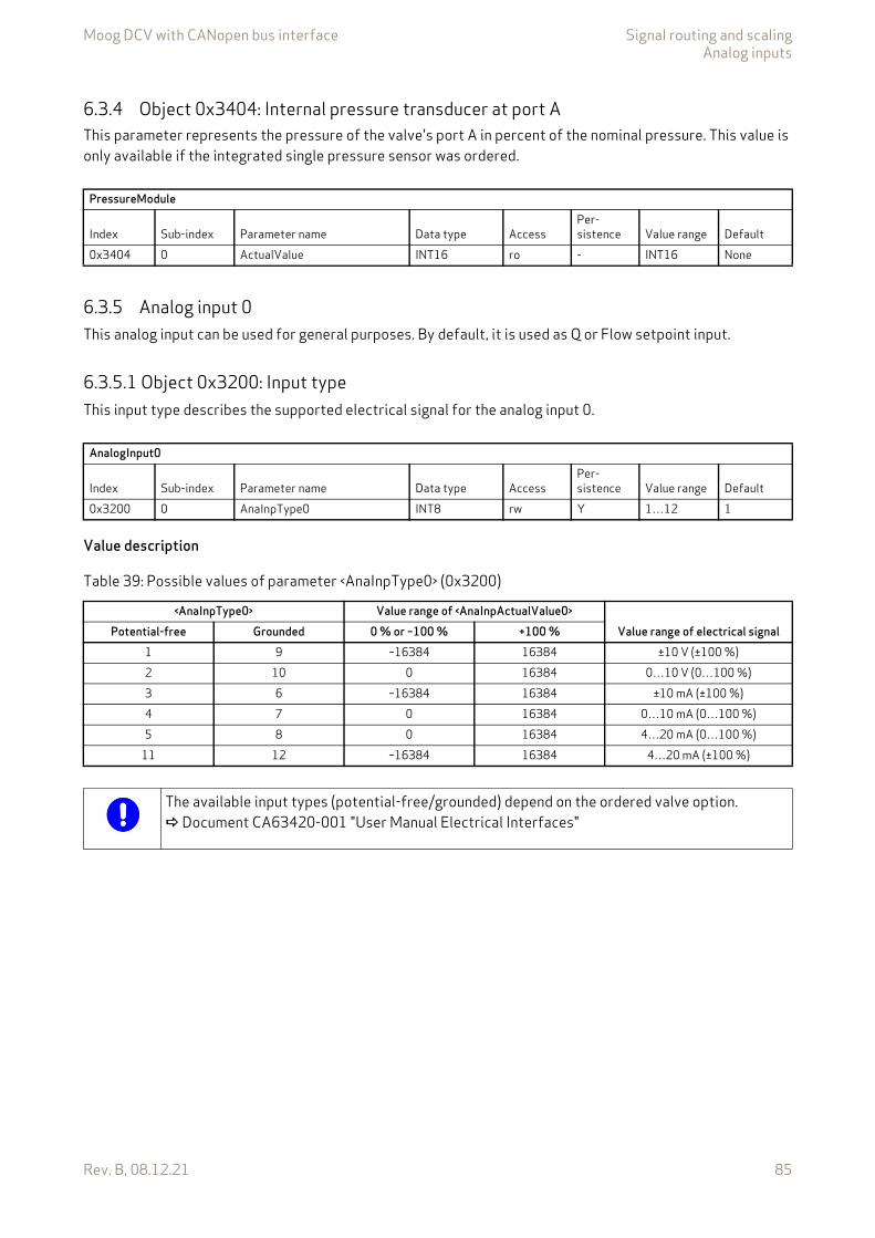
Moog DCV with CANopen bus interface Signal routing and scalingAnalog inputs
Rev. B, 08.12.21 85
6.3.4 Object 0x3404: Internal pressure transducer at port AThis parameter represents the pressure of the valve's port A in percent of the nominal pressure. This value is only available if the integrated single pressure sensor was ordered.
6.3.5 Analog input 0This analog input can be used for general purposes. By default, it is used as Q or Flow setpoint input.
6.3.5.1 Object 0x3200: Input typeThis input type describes the supported electrical signal for the analog input 0.
Value description
PressureModule
Index Sub-index Parameter name Data type AccessPer-sistence Value range Default
0x3404 0 ActualValue INT16 ro - INT16 None
AnalogInput0
Index Sub-index Parameter name Data type AccessPer-sistence Value range Default
0x3200 0 AnaInpType0 INT8 rw Y 1…12 1
Table 39: Possible values of parameter <AnaInpType0> (0x3200)
<AnaInpType0> Value range of <AnaInpActualValue0> Value range of electrical signalPotential-free Grounded 0 % or –100 % +100 %
1 9 –16384 16384 ±10 V (±100 %)2 10 0 16384 0…10 V (0…100 %)3 6 –16384 16384 ±10 mA (±100 %)4 7 0 16384 0…10 mA (0…100 %)5 8 0 16384 4…20 mA (0…100 %)
11 12 –16384 16384 4…20 mA (±100 %)
The available input types (potential-free/grounded) depend on the ordered valve option. Document CA63420-001 "User Manual Electrical Interfaces"

Moog DCV with CANopen bus interface Signal routing and scalingAnalog inputs
Rev. B, 08.12.21 86
6.3.5.2 Object 0x3207: ScalingThe analog input 0 can be scaled directly. If a pressure transducer is connected to analog input 0, the scaling must be selected so that 100 % or 16384 increments corresponds to the ordered nominal pressure of the servo valve.
Figure 26: Analog input 0 scaling
6.3.5.3 Object 0x3204: Actual valueScaled actual value of the analog input 0.
AnalogueInput0
Index Sub-index Parameter name Data type AccessPer-sistence Value range Default
0x3207 1 AnaInpScaNumerator0 INT16 rw Y INT16 163840x3207 2 AnaInpScaDenominator0 INT16 rw Y INT16 163840x3207 3 AnaInpScaOffset0 INT16 rw Y INT16 0
AnalogInput0
Index Sub-index Parameter name Data type AccessPer-sistence Value range Default
0x3204 0 AnaInpActualValue0 INT16 ro - INT16 None

Moog DCV with CANopen bus interface Signal routing and scalingAnalog inputs
Rev. B, 08.12.21 87
6.3.6 Analog input 1Depending on the ordered servo valve, the analog input 1 is available.
6.3.6.1 Object 0x3208: Input typeThis input type describes the supported electrical signal for the analog input 1.
Value description Table 39, page 85
6.3.6.2 Object 0x320F: ScalingThe analog input 1 can be scaled directly. If a pressure transducer is connected to analog input 1, the scaling must be selected so that 100 % or 16384 increments correspond to the ordered nominal pressure of the servo valve.
Figure 27: Analog input 1 scaling
AnalogInput1
Index Sub-index Parameter name Data type AccessPer-sistence Value range Default
0x3208 0 AnaInpType1 INT8 rw Y 1…12 2
AnalogueInput1
Index Sub-index Parameter name Data type AccessPer-sistence Value range Default
0x320F 1 AnaInpScaNumerator1 INT16 rw Y INT16 163840x320F 2 AnaInpScaDenominator1 INT16 rw Y INT16 163840x320F 3 AnaInpScaOffset1 INT16 rw Y INT16 0

Moog DCV with CANopen bus interface Signal routing and scalingAnalog inputs
Rev. B, 08.12.21 88
6.3.6.3 Object 0x320C: Actual valueScaled actual value of the analog input 1.
6.3.7 Analog input 2Depending on the ordered servo valve, the analog input 2 is available.
6.3.7.1 Object 0x3210: Input typeThis input type describes the supported electrical signal for the analog input 2.
Value description Table 39, page 85
AnalogInput1
Index Sub-index Parameter name Data type AccessPer-sistence Value range Default
0x320C 0 AnaInpActualValue1 INT16 ro - INT16 None
AnalogInput2
Index Sub-index Parameter name Data type AccessPer-sistence Value range Default
0x3210 0 AnaInpType2 INT8 rw Y 1…12 2
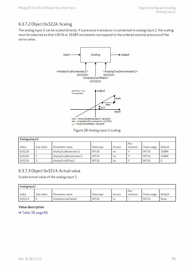
Moog DCV with CANopen bus interface Signal routing and scalingAnalog inputs
Rev. B, 08.12.21 89
6.3.7.2 Object 0x322A: ScalingThe analog input 2 can be scaled directly. If a pressure transducer is connected to analog input 2, the scaling must be selected so that 100 % or 16384 increments correspond to the ordered nominal pressure of the servo valve.
Figure 28: Analog input 2 scaling
6.3.7.3 Object 0x3214: Actual valueScaled actual value of the analog input 2.
Value description Table 39, page 85
AnalogueInput2
Index Sub-index Parameter name Data type AccessPer-sistence Value range Default
0x322A 1 AnaInpScaNumerator2 INT16 rw Y INT16 163840x322A 2 AnaInpScaDenominator2 INT16 rw Y INT16 163840x322A 3 AnaInpScaOffset2 INT16 rw Y INT16 0
AnalogInput2
Index Sub-index Parameter name Data type AccessPer-sistence Value range Default
0x3214 0 AnaInpActualValue2 INT16 ro - INT16 None
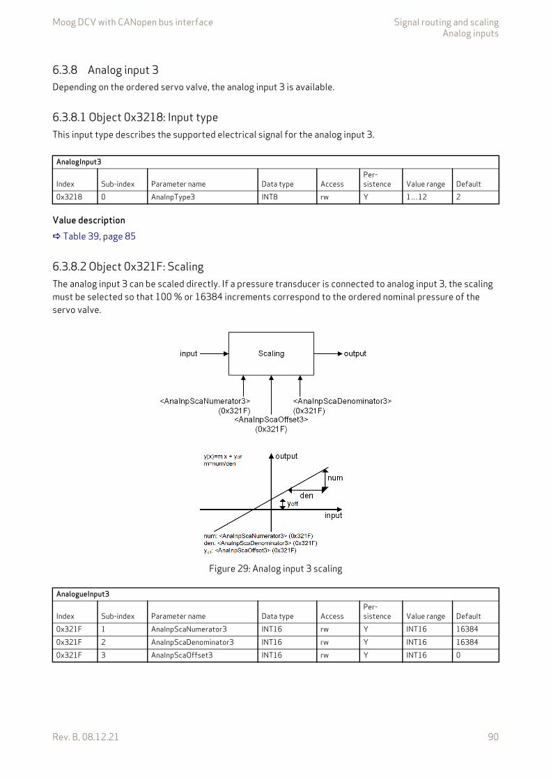
Moog DCV with CANopen bus interface Signal routing and scalingAnalog inputs
Rev. B, 08.12.21 90
6.3.8 Analog input 3Depending on the ordered servo valve, the analog input 3 is available.
6.3.8.1 Object 0x3218: Input typeThis input type describes the supported electrical signal for the analog input 3.
Value description Table 39, page 85
6.3.8.2 Object 0x321F: ScalingThe analog input 3 can be scaled directly. If a pressure transducer is connected to analog input 3, the scaling must be selected so that 100 % or 16384 increments correspond to the ordered nominal pressure of the servo valve.
Figure 29: Analog input 3 scaling
AnalogInput3
Index Sub-index Parameter name Data type AccessPer-sistence Value range Default
0x3218 0 AnaInpType3 INT8 rw Y 1…12 2
AnalogueInput3
Index Sub-index Parameter name Data type AccessPer-sistence Value range Default
0x321F 1 AnaInpScaNumerator3 INT16 rw Y INT16 163840x321F 2 AnaInpScaDenominator3 INT16 rw Y INT16 163840x321F 3 AnaInpScaOffset3 INT16 rw Y INT16 0
Moog DCV with CANopen bus interface Signal routing and scalingAnalog inputs
Rev. B, 08.12.21 91
6.3.8.3 Object 0x321C: Actual valueScaled actual value of the analog input 3.
6.3.9 Analog input 4Depending on the ordered servo valve, the analog input 4 is available.
6.3.9.1 Object 0x3220: Input typeThis input type describes the supported electrical signal for the analog input 4.
Value description Table 39, page 85
AnalogInput3
Index Sub-index Parameter name Data type AccessPer-sistence Value range Default
0x321C 0 AnaInpActualValue3 INT16 ro - INT16 None
AnalogInput4
Index Sub-index Parameter name Data type AccessPer-sistence Value range Default
0x3220 0 AnaInpType4 INT8 rw Y 1…12 2
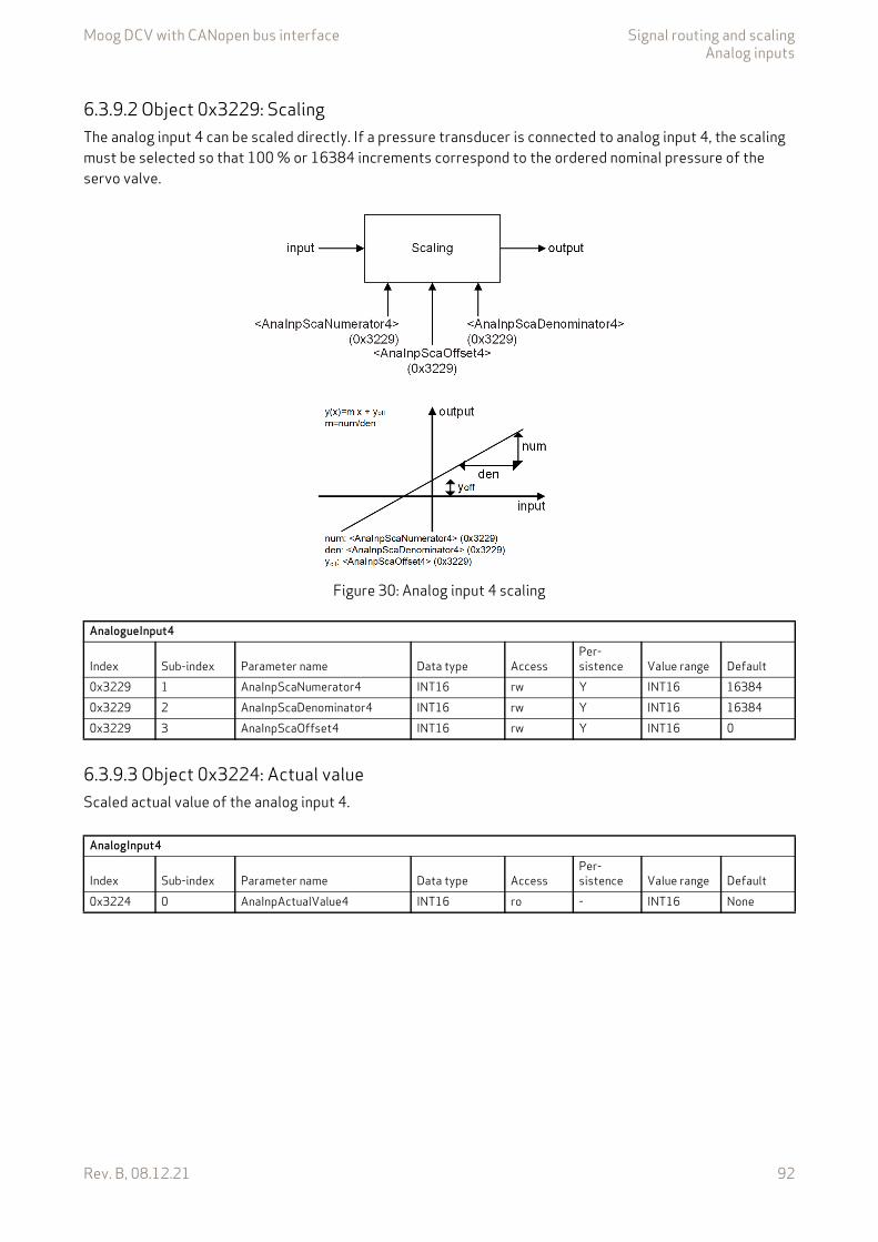
Moog DCV with CANopen bus interface Signal routing and scalingAnalog inputs
Rev. B, 08.12.21 92
6.3.9.2 Object 0x3229: ScalingThe analog input 4 can be scaled directly. If a pressure transducer is connected to analog input 4, the scaling must be selected so that 100 % or 16384 increments correspond to the ordered nominal pressure of the servo valve.
Figure 30: Analog input 4 scaling
6.3.9.3 Object 0x3224: Actual valueScaled actual value of the analog input 4.
AnalogueInput4
Index Sub-index Parameter name Data type AccessPer-sistence Value range Default
0x3229 1 AnaInpScaNumerator4 INT16 rw Y INT16 163840x3229 2 AnaInpScaDenominator4 INT16 rw Y INT16 163840x3229 3 AnaInpScaOffset4 INT16 rw Y INT16 0
AnalogInput4
Index Sub-index Parameter name Data type AccessPer-sistence Value range Default
0x3224 0 AnaInpActualValue4 INT16 ro - INT16 None
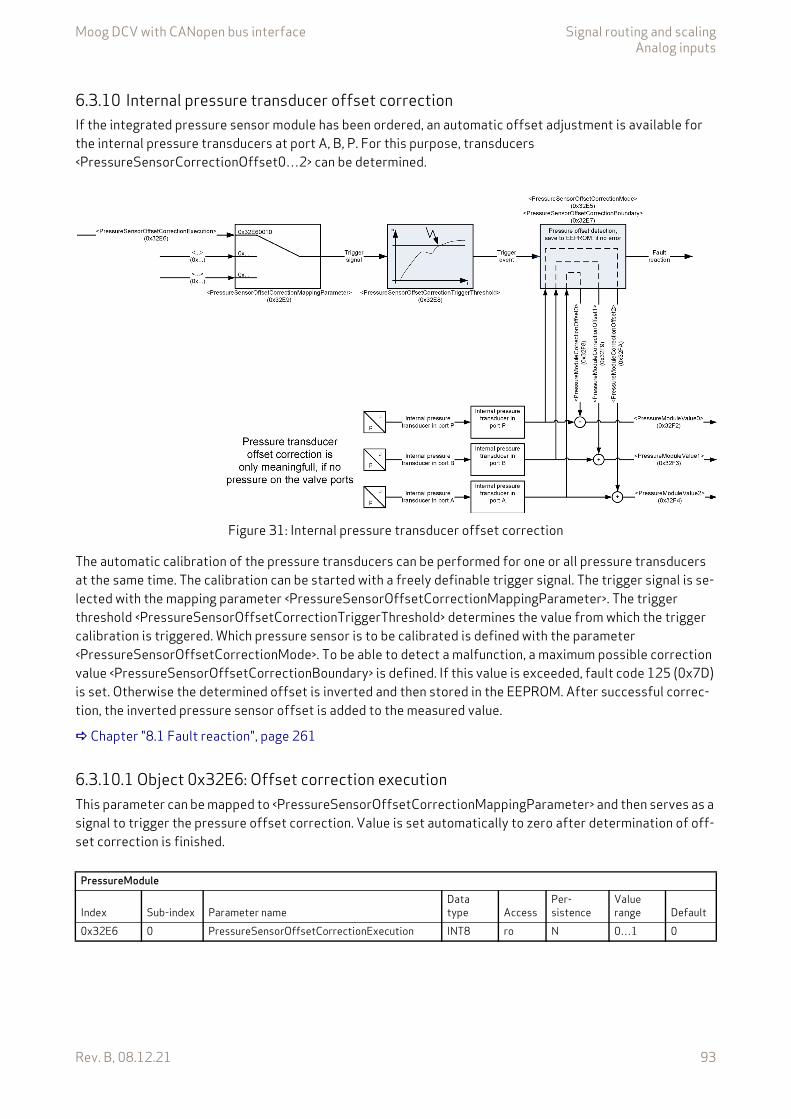
Moog DCV with CANopen bus interface Signal routing and scalingAnalog inputs
Rev. B, 08.12.21 93
6.3.10 Internal pressure transducer offset correctionIf the integrated pressure sensor module has been ordered, an automatic offset adjustment is available for the internal pressure transducers at port A, B, P. For this purpose, transducers <PressureSensorCorrectionOffset0…2> can be determined.
Figure 31: Internal pressure transducer offset correction
The automatic calibration of the pressure transducers can be performed for one or all pressure transducers at the same time. The calibration can be started with a freely definable trigger signal. The trigger signal is se-lected with the mapping parameter <PressureSensorOffsetCorrectionMappingParameter>. The trigger threshold <PressureSensorOffsetCorrectionTriggerThreshold> determines the value from which the trigger calibration is triggered. Which pressure sensor is to be calibrated is defined with the parameter <PressureSensorOffsetCorrectionMode>. To be able to detect a malfunction, a maximum possible correction value <PressureSensorOffsetCorrectionBoundary> is defined. If this value is exceeded, fault code 125 (0x7D) is set. Otherwise the determined offset is inverted and then stored in the EEPROM. After successful correc-tion, the inverted pressure sensor offset is added to the measured value.
Chapter "8.1 Fault reaction", page 261
6.3.10.1 Object 0x32E6: Offset correction executionThis parameter can be mapped to <PressureSensorOffsetCorrectionMappingParameter> and then serves as a signal to trigger the pressure offset correction. Value is set automatically to zero after determination of off-set correction is finished.
PressureModule
Index Sub-index Parameter nameData type Access
Per-sistence
Value range Default
0x32E6 0 PressureSensorOffsetCorrectionExecution INT8 ro N 0…1 0
Moog DCV with CANopen bus interface Signal routing and scalingAnalog inputs
Rev. B, 08.12.21 94
6.3.10.2 Object 0x32E9: Offset correction mapping parameterThis parameter defines source of the trigger signal where the trigger are coming from. The trigger signal is defined by a parameter index, sub-index and length.
Value description
This reference contains a combination of index, sub-index and length of the parameter to be used. It may only refer to parameters with a bit length of 0x10.
The default value is 0x32E60010, which refers to the <PressureSensorOffsetCorrectionExecution> (0x32E6), sub-index 0x00 with a length of 16 bit (16 = 0x10).
6.3.10.3 Object 0x32E8: Offset correction trigger thresholdThis parameter defines the trigger level that the trigger signal must reach in order to start the automatic pressure transducer calibration. For digital signals the parameter must be set to 1.
6.3.10.4 Object 0x32E7: Offset correction boundaryTo avoid incorrect offset corrections, e.g. by a hydraulic system that is not pressureless, the pressure signal correction is limited to the value of this parameter. The unit is given as a percentage of the value range. This means that for a 160 bar (ordered nominal pressure) servo valve 1.5 % corresponds to 2.4 bar. If the deter-mined offset exceeds the value of this parameter in percent, the fault code 125 (0x7D) is set.
Chapter "8.1 Fault reaction", page 261
PressureModule
IndexSub-index Parameter name
Data type Access
Per-sistence
Value range Default
0x32E9 0 PressureSensorOffsetCorrectionMappingParameter UINT32 rw Y UINT32 0x32E60010
Table 40: Possible values of parameter <PressureSensorOffsetCorrectionMappingParameter> (0x32E9)
<PressureSensorOffsetCorrectionMappingParameter>Byte 3 2 1 0Description Index MSB Index LSB Sub-index Parameter bit length: 0x10Default 0x32 0xE6 0x00 0x10
PressureModule
IndexSub-index Parameter name
Data type Access
Per-sistence
Value range Default
0x32E8 0 PressureSensorOffsetCorrectionTriggerThreshold INT16 rw Y INT16 1
PressureModule
IndexSub-index Parameter name
Data type Access
Per-sistence
Value range Default
0x32E7 0 PressureSensorOffsetCorrectionBoundary REAL32 ro - 0.00…100.00
1.50
Moog DCV with CANopen bus interface Signal routing and scalingAnalog inputs
Rev. B, 08.12.21 95
6.3.10.5 Object 0x32E5: Offset correction modeIt can be selected whether the pressure transducer in connection A, B, P or whether all pressure transducers at the same time should be calibrated automatically.
Value description
6.3.10.6 Object 0x32F8: Correction offset 0This read only parameter contains the correction value that was determined by the automatic pressure offset correction for the pressure sensor at port P.
6.3.10.7 Object 0x32F9: Correction offset 1This read only parameter contains the correction value that was determined by the automatic pressure offset correction for the pressure sensor at port B.
6.3.10.8 Object 0x32FA: Correction offset 2This read only parameter contains the correction value that was determined by the automatic pressure offset correction for the pressure sensor at port A.
PressureModule
IndexSub-index Parameter name
Data type Access
Per-sistence
Value range Default
0x32E5 0 PressureSensorOffsetCorrectionMode INT8 rw Y 0…3 None
Table 41: Possible values of parameter <PressureSensorOffsetCorrectionMode> (0x32E5)
<PressureSensorOffsetCorrectionMode> Description0 Automatic offset correction of all internal pressure transducers1 Automatic offset correction of the internal pressure transducer in port P2 Automatic offset correction of the internal pressure transducer in port B3 Automatic offset correction of the internal pressure transducer in port A
PressureModule
IndexSub-index Parameter name
Data type Access
Per-sistence
Value range Default
0x32F8 0 PressureSensorCorrectionOffset0 INT16 ro - INT16 0
PressureModule
IndexSub-index Parameter name
Data type Access
Per-sistence
Value range Default
0x32F9 0 PressureSensorCorrectionOffset1 INT16 ro - INT16 0
PressureModule
IndexSub-index Parameter name
Data type Access
Per-sistence
Value range Default
0x32FA 0 PressureSensorCorrectionOffset2 INT16 ro - INT16 0
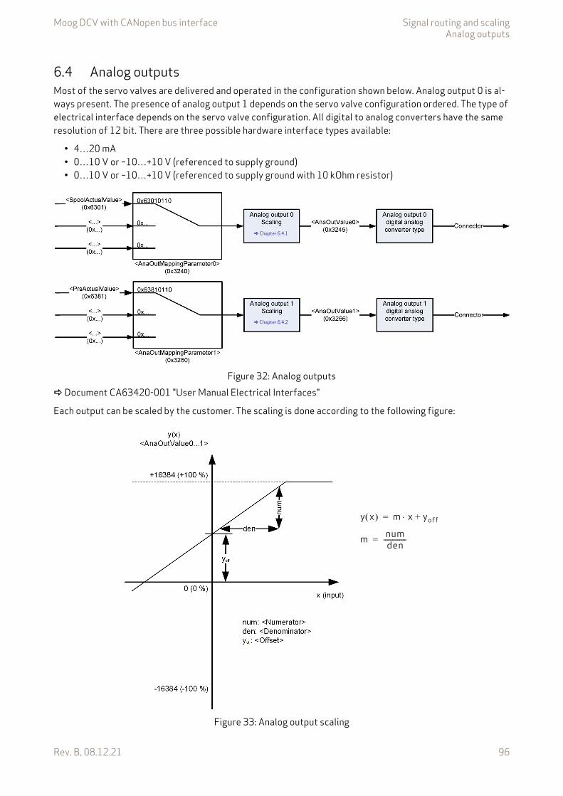
Moog DCV with CANopen bus interface Signal routing and scalingAnalog outputs
Rev. B, 08.12.21 96
6.4 Analog outputsMost of the servo valves are delivered and operated in the configuration shown below. Analog output 0 is al-ways present. The presence of analog output 1 depends on the servo valve configuration ordered. The type of electrical interface depends on the servo valve configuration. All digital to analog converters have the same resolution of 12 bit. There are three possible hardware interface types available:
• 4…20 mA• 0…10 V or –10…+10 V (referenced to supply ground)• 0…10 V or –10…+10 V (referenced to supply ground with 10 kOhm resistor)
Figure 32: Analog outputs Document CA63420-001 "User Manual Electrical Interfaces"
Each output can be scaled by the customer. The scaling is done according to the following figure:
Figure 33: Analog output scaling
Chapter 6.4.1
Chapter 6.4.2
m numden-------------=
y x m x yoff+=
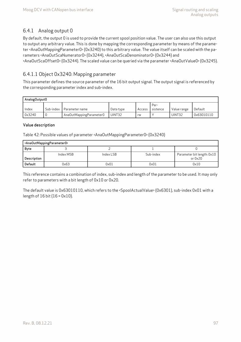
Moog DCV with CANopen bus interface Signal routing and scalingAnalog outputs
Rev. B, 08.12.21 97
6.4.1 Analog output 0By default, the output 0 is used to provide the current spool position value. The user can also use this output to output any arbitrary value. This is done by mapping the corresponding parameter by means of the parame-ter <AnaOutMappingParameter0> (0x3240) to this arbitrary value. The value itself can be scaled with the pa-rameters <AnaOutScaNumerator0> (0x3244), <AnaOutScaDenominator0> (0x3244) and <AnaOutScaOffset0> (0x3244). The scaled value can be queried via the parameter <AnaOutValue0> (0x3245).
6.4.1.1 Object 0x3240: Mapping parameterThis parameter defines the source parameter of the 16 bit output signal. The output signal is referenced by the corresponding parameter index and sub-index.
Value description
This reference contains a combination of index, sub-index and length of the parameter to be used. It may only refer to parameters with a bit length of 0x10 or 0x20.
The default value is 0x63010110, which refers to the <SpoolActualValue> (0x6301), sub-index 0x01 with a length of 16 bit (16 = 0x10).
AnalogOutput0
Index Sub-index Parameter name Data type AccessPer-sistence Value range Default
0x3240 0 AnaOutMappingParameter0 UINT32 rw Y UINT32 0x63010110
Table 42: Possible values of parameter <AnaOutMappingParameter0> (0x3240)
<AnaOutMappingParameter0>Byte 3 2 1 0
DescriptionIndex MSB Index LSB Sub-index Parameter bit length: 0x10
or 0x20Default 0x63 0x01 0x01 0x10
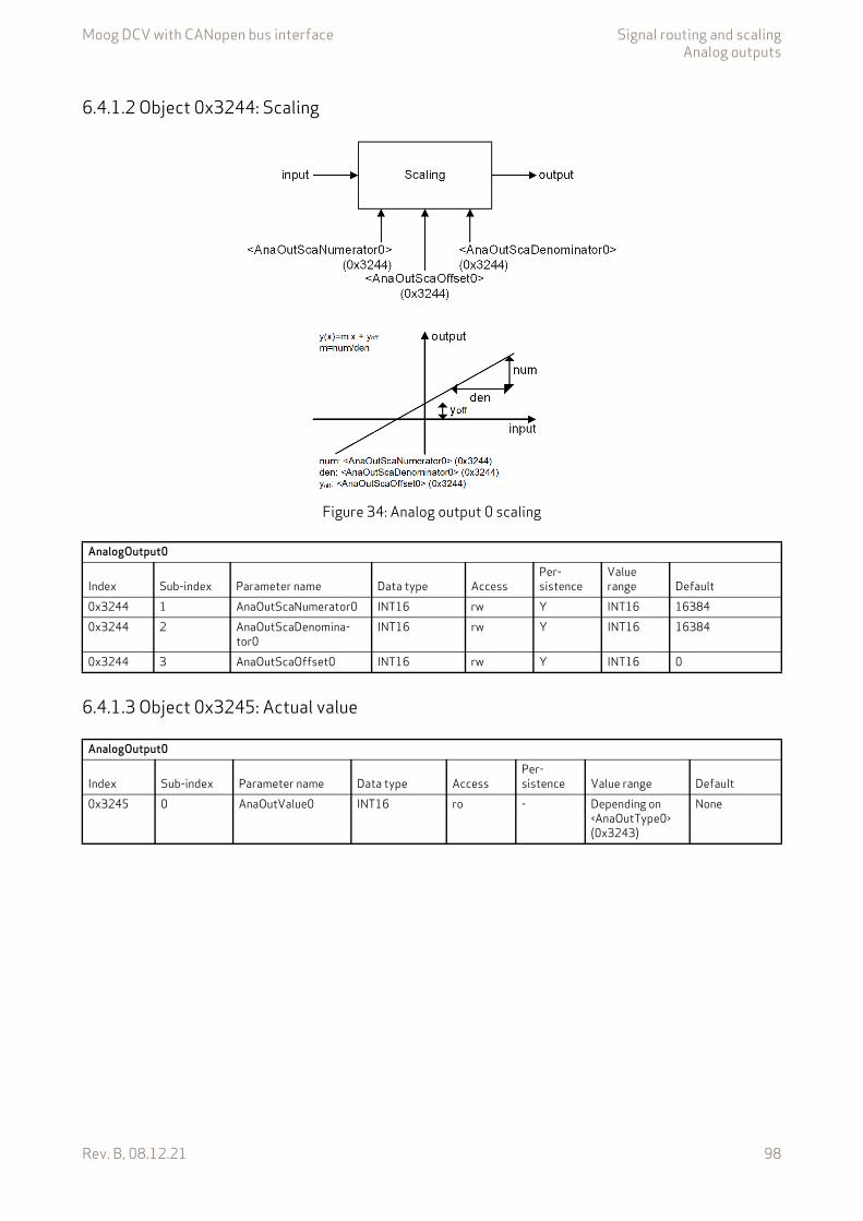
Moog DCV with CANopen bus interface Signal routing and scalingAnalog outputs
Rev. B, 08.12.21 98
6.4.1.2 Object 0x3244: Scaling
Figure 34: Analog output 0 scaling
6.4.1.3 Object 0x3245: Actual value
AnalogOutput0
Index Sub-index Parameter name Data type AccessPer-sistence
Value range Default
0x3244 1 AnaOutScaNumerator0 INT16 rw Y INT16 163840x3244 2 AnaOutScaDenomina-
tor0INT16 rw Y INT16 16384
0x3244 3 AnaOutScaOffset0 INT16 rw Y INT16 0
AnalogOutput0
Index Sub-index Parameter name Data type AccessPer-sistence Value range Default
0x3245 0 AnaOutValue0 INT16 ro - Depending on <AnaOutType0> (0x3243)
None
Moog DCV with CANopen bus interface Signal routing and scalingAnalog outputs
Rev. B, 08.12.21 99
6.4.1.4 Object 0x3243: TypeThe electrical interface type depends on the ordered servo valve configuration. In case the current variant has been ordered, it is reasonable to be switched over as in table 43 described.
Value description
6.4.2 Analog output 1By default, the output 1 is used to provide the current pressure value. The user can also use this output to out-put any arbitrary value. This is done by mapping the corresponding parameter by means of the parameter <AnaOutMappingParameter1> (0x3260) to this arbitrary value. The value itself can be scaled with the param-eters <AnaOutScaNumerator1> (0x3265), <AnaOutScaDenominator1> (0x3265) and <AnaOutScaOffset1> (0x3265). The scaled value can be queried via the parameter <AnaOutValue1> (0x3266).
6.4.2.1 Object 0x3260: Mapping parameterThis parameter defines source of the 16 bit output signal where the output are coming from. The output sig-nal is defined by a parameter index, sub-index.
Value description
This reference contains a combination of index, sub-index and length of the parameter to be used. It may only refer to parameters with a bit length of 0x10 or 0x20.
The default value is 0x63810110, which refers to the <PrsActualValue> (0x6381), sub-index 0x01 with a length of 16 bit (16=0x10).
AnalogOutput0
Index Sub-index Parameter name Data type AccessPer-sistence Value range Default
0x3243 0 AnaOutType0 UINT8 rw - 0…1 0
Table 43: Possible values of parameter <AnaOutType0> (0x3243)
<AnaOutType0> <ActualOutputValue0> (0x3245) range Output signal range0 –16384…16384 4…20 mA / –10…+10 V (depending on hardware version)
1 0…16384 4…20 mA / –10…+10 V (depending on hardware version)
AnalogOutput1
Index Sub-index Parameter name Data type AccessPer-sistence Value range Default
0x3260 0 AnaOutMappingParameter1 UINT32 rw Y UINT32 0x63810110
Table 44: Possible values of parameter <AnaOutMappingParameter1> (0x3260)
<AnaOutMappingParameter1>Byte 3 2 1 0
DescriptionIndex MSB Index LSB Sub-index Parameter bit length: 0x10
or 0x20Default 0x63 0x81 0x01 0x10
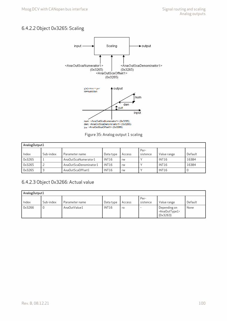
Moog DCV with CANopen bus interface Signal routing and scalingAnalog outputs
Rev. B, 08.12.21 100
6.4.2.2 Object 0x3265: Scaling
Figure 35: Analog output 1 scaling
6.4.2.3 Object 0x3266: Actual value
AnalogOutput1
Index Sub-index Parameter name Data type AccessPer-sistence Value range Default
0x3265 1 AnaOutScaNumerator1 INT16 rw Y INT16 163840x3265 2 AnaOutScaDenominator1 INT16 rw Y INT16 163840x3265 3 AnaOutScaOffset1 INT16 rw Y INT16 0
AnalogOutput1
Index Sub-index Parameter name Data type AccessPer-sistence Value range Default
0x3266 0 AnaOutValue1 INT16 ro - Depending on <AnaOutType1> (0x3263)
None
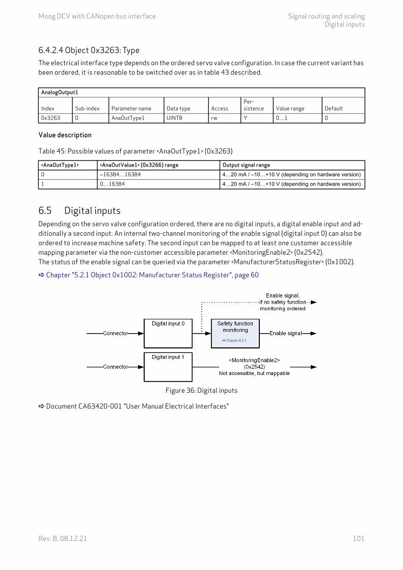
Moog DCV with CANopen bus interface Signal routing and scalingDigital inputs
Rev. B, 08.12.21 101
6.4.2.4 Object 0x3263: TypeThe electrical interface type depends on the ordered servo valve configuration. In case the current variant has been ordered, it is reasonable to be switched over as in table 43 described.
Value description
6.5 Digital inputsDepending on the servo valve configuration ordered, there are no digital inputs, a digital enable input and ad-ditionally a second input. An internal two-channel monitoring of the enable signal (digital input 0) can also be ordered to increase machine safety. The second input can be mapped to at least one customer accessible mapping parameter via the non-customer accessible parameter <MonitoringEnable2> (0x2542).The status of the enable signal can be queried via the parameter <ManufacturerStatusRegister> (0x1002).
Chapter "5.2.1 Object 0x1002: Manufacturer Status Register", page 60
Figure 36: Digital inputs
Document CA63420-001 "User Manual Electrical Interfaces"
AnalogOutput1
Index Sub-index Parameter name Data type AccessPer-sistence Value range Default
0x3263 0 AnaOutType1 UINT8 rw Y 0…1 0
Table 45: Possible values of parameter <AnaOutType1> (0x3263)
<AnaOutType1> <AnaOutValue1> (0x3266) range Output signal range0 –16384…16384 4…20 mA / –10…+10 V (depending on hardware version)
1 0…16384 4…20 mA / –10…+10 V (depending on hardware version)
Chapter 6.5.1

Moog DCV with CANopen bus interface Signal routing and scalingDigital inputs
Rev. B, 08.12.21 102
6.5.1 Safety function monitoringDepending on the ordered servo valve configuration the safety function monitoring is active or not. If safety function monitoring is active, the enable signal (digital input 0) is routed through two separate hardware chan-nels and the signals are monitored.
Figure 37: Safety function monitoringWhen the monitoring of the safety function is active, the error reactions of the following errors are config-ured:
• Different levels on the hardware redundant digital input lines lead to an error reaction with fault code 124 (0x7C) and with the fault response 'FAULT_DISABLED'.
• Different levels on the hardware-redundant H-bridge controls lead to an error response with fault code 45 (0x2D) and with the fault response 'FAULT_DISABLED'.
• Overcurrent in the solenoid coils leads to a fault response with fault code 16 (0x10) and with the fault re-sponse 'FAULT_DISABLED'.
• Excessive system deviation of the current controller leads to a fault response with fault code 66 (0x42) and with the fault response 'FAULT_DISABLED'.
If the safety function monitoring is active and one of the four above-mentioned errors occurs, the device state machine (DSM) changes to the 'FAULT_DISABLED' state and the power supply for the actuator is switched off.
Chapter "5.1.2.4.1 DSM state transitions depending on the #EnableSignal#", page 55
Likewise, the safe state is no longer output at the digital output with a high-level signal, as the safe function of the valve can no longer be guaranteed.
Chapter "6.6 Digital outputs", page 103
The safety function is not certified. However, the safety concept has been implemented in ac-cordance with internal specifications and in coordination with a certification authority.
A valve with a safety function alone does not achieve a safe machine function, but the degree ofsafety (performance level in ISO13849) is determined by the safety concept of the entire ma-chine function.
No personal safety can be guaranteed with the safety concept described in this chapter. With the safety logic of a valve alone, only the requirements for machine safety can be achieved. For personal safety, two redundant valves must be installed and the safe status must be returned to the safety control via the digital outputs
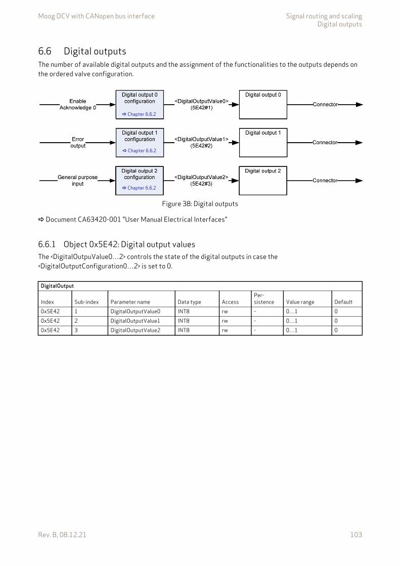
Moog DCV with CANopen bus interface Signal routing and scalingDigital outputs
Rev. B, 08.12.21 103
6.6 Digital outputsThe number of available digital outputs and the assignment of the functionalities to the outputs depends on the ordered valve configuration.
Figure 38: Digital outputs
Document CA63420-001 "User Manual Electrical Interfaces"
6.6.1 Object 0x5E42: Digital output valuesThe <DigitalOutpuValue0…2> controls the state of the digital outputs in case the <DigitalOutputConfiguration0…2> is set to 0.
Chapter 6.6.2
Chapter 6.6.2
Chapter 6.6.2
DigitalOutput
Index Sub-index Parameter name Data type AccessPer-sistence Value range Default
0x5E42 1 DigitalOutputValue0 INT8 rw - 0…1 00x5E42 2 DigitalOutputValue1 INT8 rw - 0…1 00x5E42 3 DigitalOutputValue2 INT8 rw - 0…1 0

Moog DCV with CANopen bus interface Signal routing and scalingDigital outputs
Rev. B, 08.12.21 104
6.6.2 Object 0x5E41: Digital output configurationThis parameter can be used to read the configuration of the digital outputs. Depending on the ordered servo valve the configuration is set at the factory.
Value description
DigitalOutput
Index Sub-index Parameter name Data type AccessPer-sistence Value range Default
0x5E41 1 DigitalOutputConfiguration0 INT8 ro - 0…5 30x5E41 2 DigitalOutputConfiguration1 INT8 ro - 0…5 00x5E41 3 DigitalOutputConfiguration2 INT8 ro - 0…5 3
Table 46: Possible values of parameter <DigitalOutputConfiguration0…2> (0x5E41)
<DigitalOutputConfiguration0…2> Description0 The servo valve's digital outputs are controlled by the parameter <DigitalOutpuValue0…2>
(0x5E42). The pin can be used for special purposes.1 Failsafe spool position monitoring on.
The digital output is controlled by the failsafe monitoring. Chapter "7.9.13 Failsafe monitoring", page 239
2 Error output pin. The servo valve's digital output acts according to the Device Profile Fluid Power. This means it is controlled by the device state machine (fault indication). In this case the digital output is used to indicate fault states (negative logic). Chapter "5.1.2.5 Error output pin", page 55
3 Enable Acknowledge. The digital output gets high (24 V) if the servo valve device state machine (DSM) state is 'ACTIVE' (supply voltage is > 18 V, digital enable input is high, no fault will force the DSM to fault state, …).
4 Control Deviation Monitoring. The digital output gets high (24 V) if the 'control deviation bit 11' of the <StatusWord> (0x6041) is low. That means there is no control error. Chapter "7.9 Monitoring", page 226
5 The digital output gets high (24 V) if the safe state is reached. Low (0 V) on digital output means unsafe state. The safe state is reached, if the enable signal is Low (0 V) and none of the safety function relevant faults occurred. Chapter "6.5.1 Safety function monitoring", page 102
WARNING
Moving machine parts!The word "failsafe" does not mean personnel safe hydraulic motion control system.
If personnel safety needs to be guaranteed, additional electrical and hydraulic components are necessary!
Moog DCV with CANopen bus interface Signal routing and scalingLocal CAN
Rev. B, 08.12.21 105
6.6.3 Object 0x5E44: Digital output stateThe <DigitalOutputState0…2> (0x5E44) shows the state of the digital outputs, independent of the chosen configuration <DigitalOutputConfiguration0…2> (0x5E41).
6.7 Local CANDepending on the valve model, a local CANopen interface is available. This interface is intended to be used to connect the Moog Valve and Pump Service Tool or to be used as a local sensor interface. The Local CAN has implemented the same CANopen protocols as the Fieldbus CAN. Furthermore Local CAN has the same num-ber and access rights of the valve parameters as the Fieldbus CAN.
It is not galvanic isolated from the valves electronic! For bus termination, a valve internal resistor can be activated.
6.7.1 IntroductionCANopen is a communication protocol and device profile specification for embedded systems used in auto-mation. In terms of the Open Systems Interconnection (OSI) model, CANopen implements the above layers and the network layer. The CANopen standard consists of an addressing scheme, several communication pro-tocols and an application layer defined by specific device profiles. The communication protocols have support for network management, device monitoring and communication between nodes. The lower level protocol im-plementing the data link and physical layers is usually Controller Area Network (CAN). The basic CANopen ap-plication and communication profiles are given in the CiA 301 specification released by CAN in Automation (CiA). The device profile for the hydraulic valves CiA 408 is built on top of this basic profile.
6.7.2 Device profilesThe device profiles describe the application parameters and the functional behavior of the devices including the device class-specific state machines.
The German Engineering Federation (VDMA), together with the manufacturers of hydraulic devices, have de-veloped the "profile for fluid power technology". This profile defines common functionality and parameters for the communication of hydraulic components via fieldbus in a standardized, fieldbus independent format across manufacturers. This profile is implemented in all Moog servo valves with fieldbus interface.
The CiA organization transformed this bus-independent device profile from the VDMA to the CANopen spe-cific device profile CiA 408 "Device Profile Fluid Power Technology - proportional valves and hydrostatic transmissions". Other device profiles are for example generic I/O modules (CiA 401), drives and motion con-trol (CiA 402).
DigitalOutput
Index Sub-index Parameter name Data type AccessPer-sistence Value range Default
0x5E44 1 DigitalOutputState0 UINT8 ro - 0…1 None0x5E44 2 DigitalOutputState1 UINT8 ro - 0…1 None0x5E44 2 DigitalOutputState2 UINT8 ro - 0…1 None
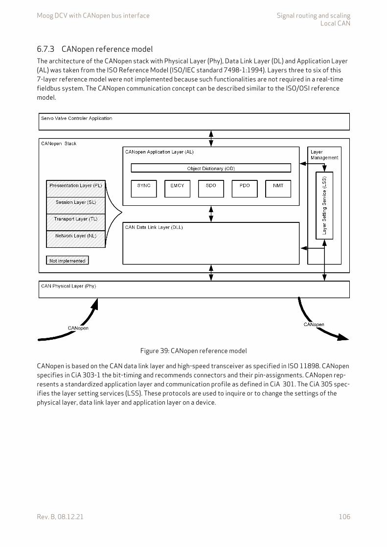
Moog DCV with CANopen bus interface Signal routing and scalingLocal CAN
Rev. B, 08.12.21 106
6.7.3 CANopen reference modelThe architecture of the CANopen stack with Physical Layer (Phy), Data Link Layer (DL) and Application Layer (AL) was taken from the ISO Reference Model (ISO/IEC standard 7498-1:1994). Layers three to six of this 7-layer reference model were not implemented because such functionalities are not required in a real-time fieldbus system. The CANopen communication concept can be described similar to the ISO/OSI reference model.
Figure 39: CANopen reference model
CANopen is based on the CAN data link layer and high-speed transceiver as specified in ISO 11898. CANopen specifies in CiA 303-1 the bit-timing and recommends connectors and their pin-assignments. CANopen rep-resents a standardized application layer and communication profile as defined in CiA 301. The CiA 305 spec-ifies the layer setting services (LSS). These protocols are used to inquire or to change the settings of the physical layer, data link layer and application layer on a device.
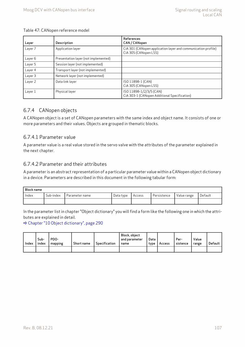
Moog DCV with CANopen bus interface Signal routing and scalingLocal CAN
Rev. B, 08.12.21 107
6.7.4 CANopen objectsA CANopen object is a set of CANopen parameters with the same index and object name. It consists of one or more parameters and their values. Objects are grouped in thematic blocks.
6.7.4.1 Parameter valueA parameter value is a real value stored in the servo valve with the attributes of the parameter explained in the next chapter.
6.7.4.2 Parameter and their attributesA parameter is an abstract representation of a particular parameter value within a CANopen object dictionary in a device. Parameters are described in this document in the following tabular form:
In the parameter list in chapter "Object dictionary" you will find a form like the following one in which the attri-butes are explained in detail. Chapter "10 Object dictionary", page 290
Table 47: CANopen reference model
Layer DescriptionReferencesCAN / CANopen
Layer 7 Application layer CiA 301 (CANopen application layer and communication profile)CiA 305 (CANopen LSS)
Layer 6 Presentation layer (not implemented)Layer 5 Session layer (not implemented)Layer 4 Transport layer (not implemented)Layer 3 Network layer (not implemented)Layer 2 Data link layer ISO 11898-1 (CAN)
CiA 305 (CANopen LSS)Layer 1 Physical layer ISO 11898-1/2/3/5 (CAN)
CiA 303-1 (CANopen Additional Specification)
Block nameIndex Sub-index Parameter name Data type Access Persistence Value range Default
IndexSub-index
PDO-mapping Short name Specification
Block, object and parameter name
Data type Access
Per-sistence
Value range Default

Moog DCV with CANopen bus interface Signal routing and scalingLocal CAN
Rev. B, 08.12.21 108
Table 48: Fieldbus independent attributes
Column name MeaningBlock name Describes the family of the object. If the object does not belong to a block, the object name is taken as
block name.Object name Defined name of the object.Index 16 bit index that addresses the entry in the object dictionary. In case of a simple variable this references
the value of this variable directly. In case of records and arrays, the index addresses the whole data struc-ture. Then the 8 bit sub-index allows access to individual elements in the structure.
Sub-index If the object is defined as a record or array, the sub-index defines an element in the structure.Parameter name Defined name of the parameter.Data type Data type of the parameter.
CiA 301 data type Short name DescriptionINTEGERn INTn Signed integer with n bitsUNSIGNEDn UINTn Unsigned integer with n bitsREAL32 REAL32 Floating point with 32 bit according CiA 301VISIBLE_STRING STRING(n) String of n ASCII charactersDOMAIN DOMAIN Application specific data block
Access Access permission for the parameter.rw Read and write allowedwo Write onlyro Read only
Persistence Defines whether the parameter can be saved in non-volatile memory. If the persistence is set to "Y", the saved value stays in memory even after the device is turned off. Parameters not marked as persistent ("N") lose their settings after the device is turned off. The parameters with the access type "read only" are marked with "-". This means that the parameter cannot be changed by the user.
Value range Allowed value range for the parameter.Default Default values:
The default values in this document are firmware preset values. These values can be changed during cali-bration or set up with model specific parameters during production of the servo valve.Factory settings:The factory settings are values which are set up model specific during production of the servo valve. These parameters no longer contain the firmware default preset values. Chapter "9 Storing / restoring parameters", page 287
Specification Related (fieldbus) standard defining the parameter.Possible entries:CiA 301 Parameters correspond to CiA 301.CiA 408 Parameters correspond to CiA 408.Moog DCV Moog defined parameters for digital control valves.
PDO mapping If set to "Y", the parameter can be mapped into a PDO.If set to "N", the parameter cannot be mapped into a PDO.
Short name Unique short name.
The listed default values contain the firmware preset values and not necessarily the configura-tion of the delivered servo valve.
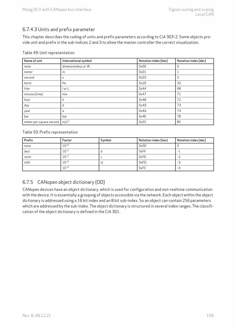
Moog DCV with CANopen bus interface Signal routing and scalingLocal CAN
Rev. B, 08.12.21 109
6.7.4.3 Units and prefix parameterThis chapter describes the coding of units and prefix parameters according to CiA 303-2. Some objects pro-vide unit and prefix in the sub-indices 2 and 3 to allow the master controller the correct visualization.
6.7.5 CANopen object dictionary (OD)CANopen devices have an object dictionary, which is used for configuration and non-realtime communication with the device. It is essentially a grouping of objects accessible via the network. Each object within the object dictionary is addressed using a 16 bit index and an 8 bit sub-index. So an object can contain 256 parameters which are addressed by the sub-index. The object dictionary is structured in several index ranges. The classifi-cation of the object dictionary is defined in the CiA 301.
Table 49: Unit representation
Name of unit International symbol Notation index (hex) Notation index (dec)none dimensionless or iR 0x00 0meter m 0x01 1second s 0x03 3hertz Hz 0x20 32liter l or L 0x44 68minute (time) min 0x47 71hour h 0x48 72day d 0x49 73year a 0x4A 74bar bar 0x4E 78meter per square second m/s2 0x55 85
Table 50: Prefix representation
Prefix Factor Symbol Notation index (hex) Notation index (dec)none 10–0 0x00 0deci 10–1 d 0xFF –1centi 10–2 c 0xFE –2milli 10–3 m 0xFD –3
10–4 0xFC –4
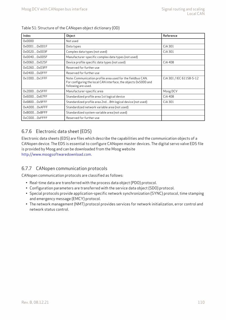
Moog DCV with CANopen bus interface Signal routing and scalingLocal CAN
Rev. B, 08.12.21 110
6.7.6 Electronic data sheet (EDS)Electronic data sheets (EDS) are files which describe the capabilities and the communication objects of a CANopen device. The EDS is essential to configure CANopen master devices. The digital servo valve EDS file is provided by Moog and can be downloaded from the Moog website http://www.moogsoftwaredownload.com.
6.7.7 CANopen communication protocolsCANopen communication protocols are classified as follows:
• Real-time data are transferred with the process data object (PDO) protocol.• Configuration parameters are transferred with the service data object (SDO) protocol.• Special protocols provide application-specific network synchronization (SYNC) protocol, time stamping
and emergency message (EMCY) protocol.• The network management (NMT) protocol provides services for network initialization, error control and
network status control.
Table 51: Structure of the CANopen object dictionary (OD)
Index Object Reference0x0000 Not used0x0001…0x001F Data types CiA 3010x0020…0x003F Complex data types (not used) CiA 3010x0040…0x005F Manufacturer-specific complex data types (not used)0x0060…0x025F Device profile specific data types (not used) CiA 4080x0260…0x03FF Reserved for further use0x0400…0x0FFF Reserved for further use0x1000…0x1FFF Note: Communication profile area used for the fieldbus CAN.
For configuring the local CAN interface, the objects 0x5000 and following are used.
CiA 301 / IEC 61158-5-12
0x2000…0x5FFF Manufacturer-specific area Moog DCV0x6000…0x67FF Standardized profile area 1st logical device CiA 4080x6800…0x9FFF Standardized profile area 2nd…8th logical device (not used) CiA 3010xA000…0xAFFF Standardized network variable area (not used)0xB000…0xBFFF Standardized system variable area (not used)0xC000…0xFFFF Reserved for further use
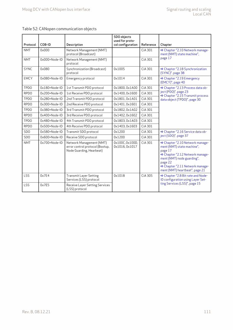
Moog DCV with CANopen bus interface Signal routing and scalingLocal CAN
Rev. B, 08.12.21 111
Table 52: CANopen communication objects
Protocol COB-ID Description
SDO objects used for proto-col configuration Reference Chapter
NMT 0x000 Network Management (NMT) protocol (Broadcast)
CiA 301 Chapter "2.10 Network manage-ment (NMT) state machine", page 17NMT 0x000+Node-ID Network Management (NMT)
protocolCiA 301
SYNC 0x080 Synchronization (Broadcast) protocol
0x1005 CiA 301 Chapter "2.18 Synchronization (SYNC)", page 38
EMCY 0x080+Node-ID Emergency protocol 0x1014 CiA 301 Chapter "2.19 Emergency (EMCY)", page 40
TPDO 0x180+Node-ID 1st Transmit PDO protocol 0x1800, 0x1A00 CiA 301 Chapter "2.13 Process data ob-ject (PDO)", page 23 Chapter "2.15 Transmit process data object (TPDO)", page 30
RPDO 0x200+Node-ID 1st Receive PDO protocol 0x1400, 0x1600 CiA 301TPDO 0x280+Node-ID 2nd Transmit PDO protocol 0x1801, 0x1A01 CiA 301RPDO 0x300+Node-ID 2nd Receive PDO protocol 0x1401, 0x1601 CiA 301TPDO 0x380+Node-ID 3rd Transmit PDO protocol 0x1802, 0x1A02 CiA 301RPDO 0x400+Node-ID 3rd Receive PDO protocol 0x1402, 0x1602 CiA 301TPDO 0x480+Node-ID 4th Transmit PDO protocol 0x1803, 0x1A03 CiA 301RPDO 0x500+Node-ID 4th Receive PDO protocol 0x1403, 0x1603 CiA 301SDO 0x580+Node-ID Transmit SDO protocol 0x1200 CiA 301 Chapter "2.16 Service data ob-
ject (SDO)", page 37SDO 0x600+Node-ID Receive SDO protocol 0x1200 CiA 301NMT 0x700+Node-ID Network Management (NMT)
error control protocol (Bootup, Node Guarding, Hearbeat)
0x100C, 0x100D, 0x1016, 0x1017
CiA 301 Chapter "2.10 Network manage-ment (NMT) state machine", page 17 Chapter "2.12 Network manage-ment (NMT) node guarding", page 22 Chapter "2.11 Network manage-ment (NMT) heartbeat", page 21
LSS 0x7E4 Transmit Layer Setting Services (LSS) protocol
0x1018 CiA 305 Chapter "2.8 Bit rate and Node-ID configuration using Layer Set-ting Services (LSS)", page 15LSS 0x7E5 Receive Layer Setting Services
(LSS) protocol
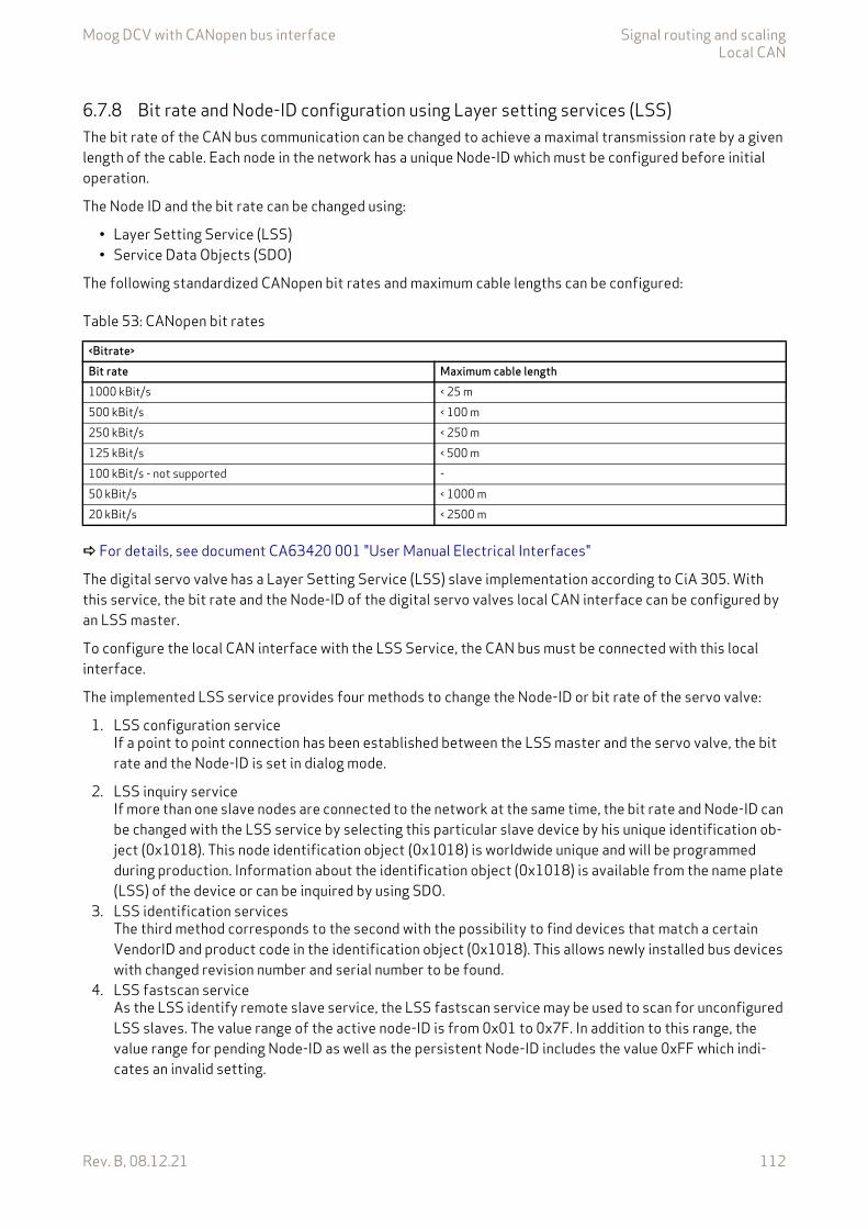
Moog DCV with CANopen bus interface Signal routing and scalingLocal CAN
Rev. B, 08.12.21 112
6.7.8 Bit rate and Node-ID configuration using Layer setting services (LSS)The bit rate of the CAN bus communication can be changed to achieve a maximal transmission rate by a given length of the cable. Each node in the network has a unique Node-ID which must be configured before initial operation.
The Node ID and the bit rate can be changed using:
• Layer Setting Service (LSS)• Service Data Objects (SDO)
The following standardized CANopen bit rates and maximum cable lengths can be configured:
For details, see document CA63420 001 "User Manual Electrical Interfaces"
The digital servo valve has a Layer Setting Service (LSS) slave implementation according to CiA 305. With this service, the bit rate and the Node-ID of the digital servo valves local CAN interface can be configured by an LSS master.
To configure the local CAN interface with the LSS Service, the CAN bus must be connected with this local interface.
The implemented LSS service provides four methods to change the Node-ID or bit rate of the servo valve:
1. LSS configuration serviceIf a point to point connection has been established between the LSS master and the servo valve, the bit rate and the Node-ID is set in dialog mode.
2. LSS inquiry serviceIf more than one slave nodes are connected to the network at the same time, the bit rate and Node-ID can be changed with the LSS service by selecting this particular slave device by his unique identification ob-ject (0x1018). This node identification object (0x1018) is worldwide unique and will be programmed during production. Information about the identification object (0x1018) is available from the name plate (LSS) of the device or can be inquired by using SDO.
3. LSS identification servicesThe third method corresponds to the second with the possibility to find devices that match a certain VendorID and product code in the identification object (0x1018). This allows newly installed bus devices with changed revision number and serial number to be found.
4. LSS fastscan serviceAs the LSS identify remote slave service, the LSS fastscan service may be used to scan for unconfigured LSS slaves. The value range of the active node-ID is from 0x01 to 0x7F. In addition to this range, the value range for pending Node-ID as well as the persistent Node-ID includes the value 0xFF which indi-cates an invalid setting.
Table 53: CANopen bit rates
<Bitrate>Bit rate Maximum cable length1000 kBit/s < 25 m500 kBit/s < 100 m250 kBit/s < 250 m125 kBit/s < 500 m100 kBit/s - not supported -50 kBit/s < 1000 m20 kBit/s < 2500 m
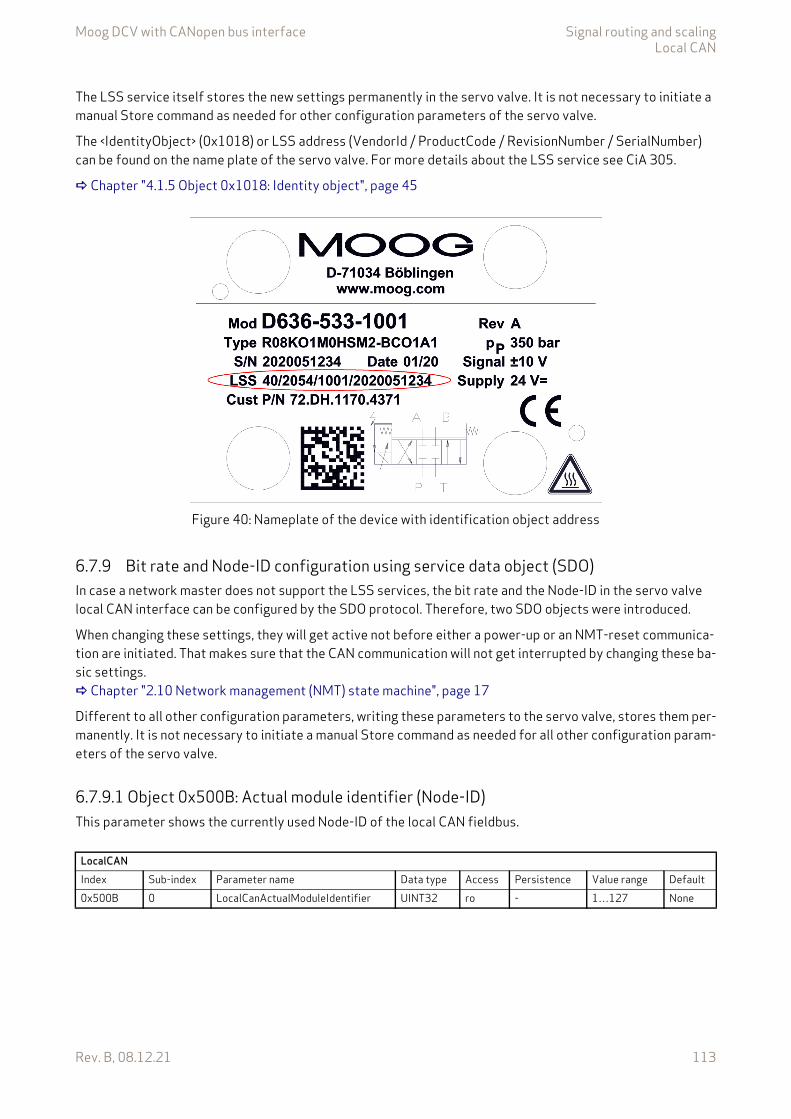
Moog DCV with CANopen bus interface Signal routing and scalingLocal CAN
Rev. B, 08.12.21 113
The LSS service itself stores the new settings permanently in the servo valve. It is not necessary to initiate a manual Store command as needed for other configuration parameters of the servo valve.
The <IdentityObject> (0x1018) or LSS address (VendorId / ProductCode / RevisionNumber / SerialNumber) can be found on the name plate of the servo valve. For more details about the LSS service see CiA 305.
Chapter "4.1.5 Object 0x1018: Identity object", page 45
Figure 40: Nameplate of the device with identification object address
6.7.9 Bit rate and Node-ID configuration using service data object (SDO)In case a network master does not support the LSS services, the bit rate and the Node-ID in the servo valve local CAN interface can be configured by the SDO protocol. Therefore, two SDO objects were introduced.
When changing these settings, they will get active not before either a power-up or an NMT-reset communica-tion are initiated. That makes sure that the CAN communication will not get interrupted by changing these ba-sic settings. Chapter "2.10 Network management (NMT) state machine", page 17
Different to all other configuration parameters, writing these parameters to the servo valve, stores them per-manently. It is not necessary to initiate a manual Store command as needed for all other configuration param-eters of the servo valve.
6.7.9.1 Object 0x500B: Actual module identifier (Node-ID)This parameter shows the currently used Node-ID of the local CAN fieldbus.
LocalCANIndex Sub-index Parameter name Data type Access Persistence Value range Default0x500B 0 LocalCanActualModuleIdentifier UINT32 ro - 1…127 None
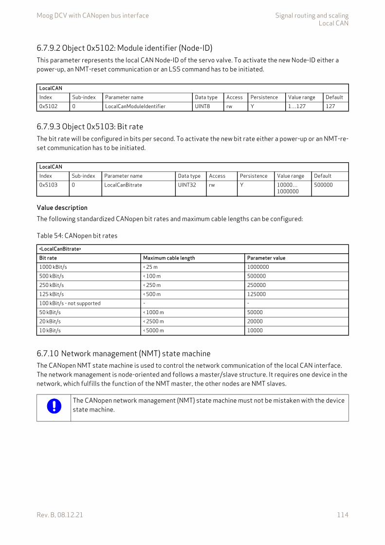
Moog DCV with CANopen bus interface Signal routing and scalingLocal CAN
Rev. B, 08.12.21 114
6.7.9.2 Object 0x5102: Module identifier (Node-ID)This parameter represents the local CAN Node-ID of the servo valve. To activate the new Node-ID either a power-up, an NMT-reset communication or an LSS command has to be initiated.
6.7.9.3 Object 0x5103: Bit rateThe bit rate will be configured in bits per second. To activate the new bit rate either a power-up or an NMT-re-set communication has to be initiated.
Value descriptionThe following standardized CANopen bit rates and maximum cable lengths can be configured:
6.7.10 Network management (NMT) state machineThe CANopen NMT state machine is used to control the network communication of the local CAN interface. The network management is node-oriented and follows a master/slave structure. It requires one device in the network, which fulfills the function of the NMT master, the other nodes are NMT slaves.
LocalCANIndex Sub-index Parameter name Data type Access Persistence Value range Default0x5102 0 LocalCanModuleIdentifier UINT8 rw Y 1…127 127
LocalCANIndex Sub-index Parameter name Data type Access Persistence Value range Default0x5103 0 LocalCanBitrate UINT32 rw Y 10000…
1000000500000
Table 54: CANopen bit rates
<LocalCanBitrate>Bit rate Maximum cable length Parameter value1000 kBit/s < 25 m 1000000500 kBit/s < 100 m 500000250 kBit/s < 250 m 250000125 kBit/s < 500 m 125000100 kBit/s - not supported - -50 kBit/s < 1000 m 5000020 kBit/s < 2500 m 2000010 kBit/s < 5000 m 10000
The CANopen network management (NMT) state machine must not be mistaken with the device state machine.
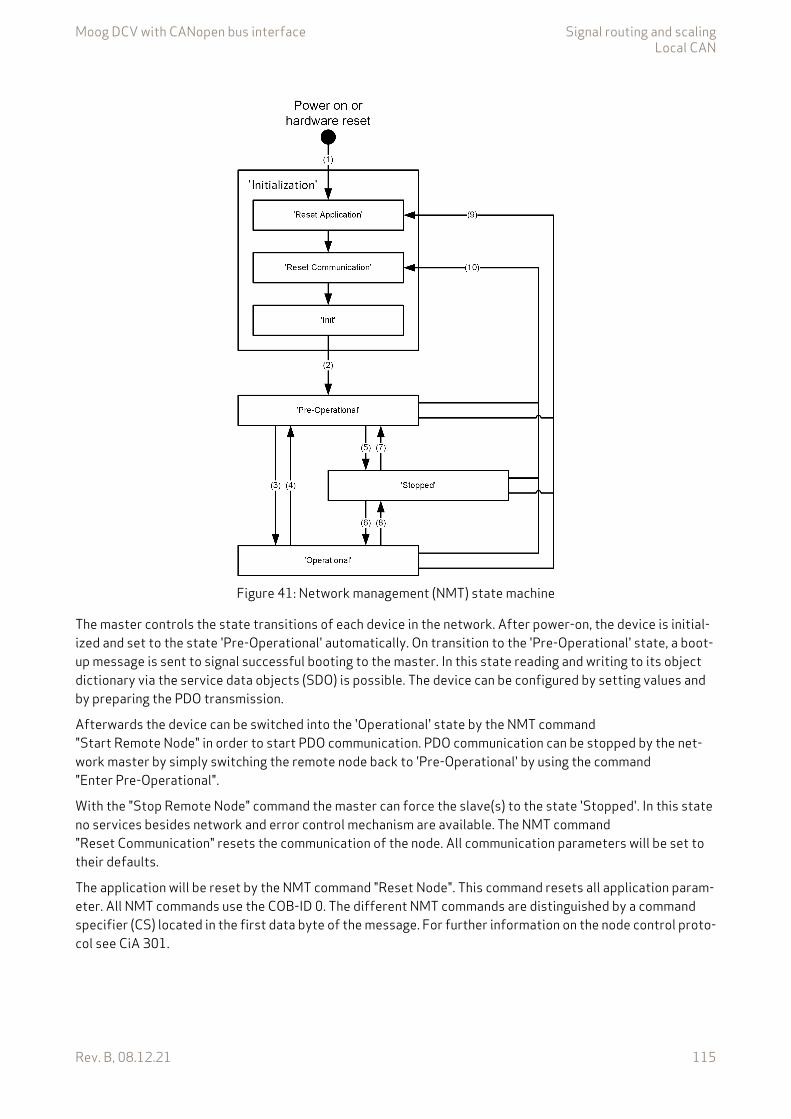
Moog DCV with CANopen bus interface Signal routing and scalingLocal CAN
Rev. B, 08.12.21 115
Figure 41: Network management (NMT) state machine
The master controls the state transitions of each device in the network. After power-on, the device is initial-ized and set to the state 'Pre-Operational' automatically. On transition to the 'Pre-Operational' state, a boot-up message is sent to signal successful booting to the master. In this state reading and writing to its object dictionary via the service data objects (SDO) is possible. The device can be configured by setting values and by preparing the PDO transmission.
Afterwards the device can be switched into the 'Operational' state by the NMT command "Start Remote Node" in order to start PDO communication. PDO communication can be stopped by the net-work master by simply switching the remote node back to 'Pre-Operational' by using the command "Enter Pre-Operational".
With the "Stop Remote Node" command the master can force the slave(s) to the state 'Stopped'. In this state no services besides network and error control mechanism are available. The NMT command "Reset Communication" resets the communication of the node. All communication parameters will be set to their defaults.
The application will be reset by the NMT command "Reset Node". This command resets all application param-eter. All NMT commands use the COB-ID 0. The different NMT commands are distinguished by a command specifier (CS) located in the first data byte of the message. For further information on the node control proto-col see CiA 301.
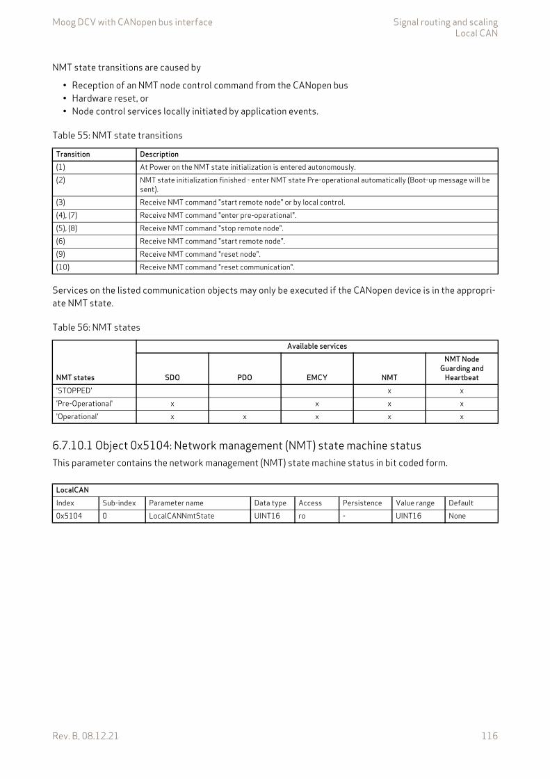
Moog DCV with CANopen bus interface Signal routing and scalingLocal CAN
Rev. B, 08.12.21 116
NMT state transitions are caused by
• Reception of an NMT node control command from the CANopen bus• Hardware reset, or• Node control services locally initiated by application events.
Services on the listed communication objects may only be executed if the CANopen device is in the appropri-ate NMT state.
6.7.10.1 Object 0x5104: Network management (NMT) state machine statusThis parameter contains the network management (NMT) state machine status in bit coded form.
Table 55: NMT state transitions
Transition Description(1) At Power on the NMT state initialization is entered autonomously.(2) NMT state initialization finished - enter NMT state Pre-operational automatically (Boot-up message will be
sent).(3) Receive NMT command "start remote node" or by local control.(4), (7) Receive NMT command "enter pre-operational".(5), (8) Receive NMT command "stop remote node".(6) Receive NMT command "start remote node".(9) Receive NMT command "reset node".(10) Receive NMT command "reset communication".
Table 56: NMT states
NMT states
Available services
SDO PDO EMCY NMT
NMT Node Guarding and
Heartbeat'STOPPED' x x'Pre-Operational' x x x x'Operational' x x x x x
LocalCANIndex Sub-index Parameter name Data type Access Persistence Value range Default0x5104 0 LocalCANNmtState UINT16 ro - UINT16 None
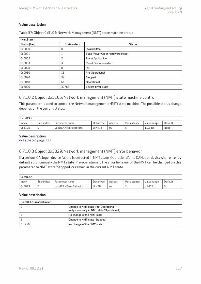
Moog DCV with CANopen bus interface Signal routing and scalingLocal CAN
Rev. B, 08.12.21 117
Value description
6.7.10.2 Object 0x5105: Network management (NMT) state machine controlThis parameter is used to control the Network management (NMT) state machine. The possible status change depends on the current status.
Value description Table 57, page 117
6.7.10.3 Object 0x5029: Network management (NMT) error behaviorIf a serious CANopen device failure is detected in NMT state 'Operational', the CANopen device shall enter by default autonomously the NMT state 'Pre-operational'. The error behavior of the NMT can be changed via this parameter to NMT state 'Stopped' or remain in the current NMT state.
Value description
Table 57: Object 0x5104: Network Management (NMT) state machine status
<NmtState>Status (hex) Status (dec) Status0x0000 0 Invalid State
0x0001 1 State Power On or Hardware Reset
0x0002 2 Reset Application
0x0004 4 Reset Communication
0x0008 8 Init
0x0010 16 Pre-Operational
0x0020 32 Stopped
0x0040 64 Operational
0x8000 32768 Severe Error State
LocalCANIndex Sub-index Parameter name Data type Access Persistence Value range Default0x5105 0 LocalCANNmtSetState UINT16 rw N 1…130 None
LocalCANIndex Sub-index Parameter name Data type Access Persistence Value range Default0x5029 0 LocalCANErrorBehavior UINT8 rw Y UINIT8 0
<LocalCANErrorBehavior>0 Change to NMT state 'Pre-Operational'
(only if currently in NMT state 'Operational')
1 No change of the NMT state
2 Change to NMT state 'Stopped'
3…256 No change of the NMT state

Moog DCV with CANopen bus interface Signal routing and scalingLocal CAN
Rev. B, 08.12.21 118
6.7.10.4 Object 0x5B02: Start remote nodeTo start cyclic communication of the external CAN device (i.e., a pressure transducer with CAN interface), the network management (NMT) state machine of the external CAN device must be changed to the state 'Operational'. To do this, the external CAN device CAN node identifier must be written to the parameter <LocalCanStartRemoteNode> (0x5B02). To change all devices to the state 'Operational', write the node iden-tifier 0 to this parameter.
6.7.11 Network management (NMT) heartbeatThe Heartbeat Protocol consists of two separate services:
1. The monitoring of a periodically received heartbeat message, called consumer heartbeat. The Node-ID of the heartbeat transmitter and the time window until the next heartbeat message must arrive is set by the parameter <LocalCanConsumerHeartbeatTime> (0x5016). If the heartbeat transmitter does not re-spond within the specified time, error code 110 (0x6E) is triggered.
2. Periodically sending a heartbeat message, called producer heartbeat. For this purpose, the interval be-tween two heartbeat messages can be set with the parameter <LocalCanProducerHeartbeatTime> (0x5017). The heartbeat protocol starts on the transition from the NMT state 'Initialization' to the NMT state 'Pre-Operational'. In this case the boot-up message is regarded as first heartbeat message. With the heartbeat message the servo valve NMT state is transmitted.
6.7.11.1 Object 0x1016: Consumer heartbeat timeThe parameter <ConsumerHeartbeatTime> (0x5016) defines the expected heartbeat cycle time. It additionally defines the node-ID of the heartbeat producer to be monitored.
To enable the heartbeat message, a time greater zero must be set and a valid node-ID (between 1…127) must be configured. If the heartbeat time is 0 or the node-ID is 0 or greater than 127, the corresponding object entry shall be not used. The heartbeat time shall be given in multiples of 1 ms.
Value description
LocalCANIndex Sub-index Parameter name Data type Access Persistence Value range Default0x5B02 0 LocalCanStartRemoteNode UINT8 rw Y 0…127 0
It is not allowed to use both error control mechanisms guarding protocol and heartbeat protocol on one NMT slave at the same time.
The consumer heartbeat time should be higher than the corresponding producer heartbeattime.
LocalCANIndex Sub-index Parameter name Data type Access Persistence Value range Default0x5016 1 LocalCanConsumerHeartbeatTime UINT32 rw Y UINT32 0
<LocalCanConsumerHeartbeatTime>Bit 31…24 23…16 15…0Description Reserved Node-Id Heartbeat time in ms
Moog DCV with CANopen bus interface Signal routing and scalingLocal CAN
Rev. B, 08.12.21 119
6.7.11.2 Object 0x5017: Producer heartbeat timeThe parameter <LocalCanProducerHeartbeatTime> (0x5017) specifies the time in ms at which the servo valve sends a heartbeat message. The value 0 disables the producer heartbeat.
6.7.12 Network management (NMT) node guardingThe node guarding is the periodical monitoring of certain network nodes. Each node can be checked by the NMT master with a certain period <LocalCanGuardTime> (0x500C). A second parameter <LocalCanLifeTimeFactor> (0x500D) defines a factor after the connection will be detected as lost. The reso-lution of the guarding time is 1 ms. To enable the node guarding on a slave device, the guard time and life time factor must be set. The guarding is started with the first guarding telegram of the master. During node guard-ing the master sends a remote transmit request (RTR) frame to each guarded slave. The slave answers with its actual NMT state and a toggle bit. This toggle bit alternates in each cycle.
The monitoring time until fault reaction 110 (0x6E) 'CAN life guard error or heartbeat error' is triggered is calculated as follows:
If the network master supports the Heartbeat Protocol, this should be preferred to Node Guarding, as it al-lows better monitoring. The guarding protocol is still supported for compatibility reasons.
6.7.12.1 Object 0x500C: Guard timeThis parameter contains the guarding time in milliseconds. The value 0 disables the life guarding.
6.7.12.2 Object 0x500D: Life time factorThis parameter contains the life time factor. The value 0 disables the life guarding.
LocalCANIndex Sub-index Parameter name Data type Access Persistence Value range Default0x5017 0 LocalCanProducerHeartbeatTime UINT16 rw Y UINT16 0
Monitoring time <LocalCanGuardTime> (0x500C) <LocalCanLifeTimeFactor> (0x500D)=
It is not allowed to use both error control mechanisms guarding protocol and heartbeat protocol on one NMT slave at the same time.
LocalCANIndex Sub-index Parameter name Data type Access Persistence Value range Default0x500C 0 GuardTime UINT16 rw Y UINT16 0
LocalCANIndex Sub-index Parameter name Data type Access Persistence Value range Default0x500D 0 LifeTimeFactor UINT8 rw Y UINT8 1

Moog DCV with CANopen bus interface Signal routing and scalingLocal CAN
Rev. B, 08.12.21 120
6.7.13 Process data object (PDO)The process data object (PDO) communication allows cyclic receiving and sending of parameters in real time. Different transmission modes are available: synchronous, event or timer driven transmission.
Four RPDOs and four TPDOs are implemented:
• Receive process data object (RPDO), described in this chapter.• Transmit process data object (TPDO), Chapter "6.7.14 Transmit process data object (TPDO)",
page 127
Figure 42: PDO Real Time Data Transmission
With the receive process data object (RPDO) mapping most object dictionary entries can be mapped to RPDO. To enable receive process data object (RPDO) transmission, the local application parameters must be mapped to the RPDO and a transmission type must be selected for each RPDO channel. Four RPDO channels are available.
Each CANopen telegram can carry 8 bytes data. The smallest data types used in the digital servo valve are 8 bit integers. Therefore eight object dictionary entries with 8 bit data length or four object dictionary entries with 16 bits or two object dictionary entries with 32 bits can be mapped within one RPDO. An arbitrary combi-nation of different data types is possible if the sum of the mapped RPDO data is less or equal 8 bytes.
Two different kind of parameters are used to configure the transmission.
• Parameters 0x5400…0x5402 are used to configure the type of transmission.• Parameters 0x5600…0x5603 are used to configure which application data is transmitted.
Example:The following values should be mapped to the fourth RPDO (default mapping):
• Device state machine (DSM) Control Word <ControlWord> (0x6040) (sub-index 0x00) Chapter "5.1 Device state machine (DSM)", page 50
• Q setpoint <QSetpoint> (0x6300) (sub-index 0x01) Chapter "6.1.3 Q setpoint path", page 65
• Pressure setpoint <PrsSetpoint> (0x6380) (sub-index 0x01) Chapter "6.1.4 p setpoint path", page 67
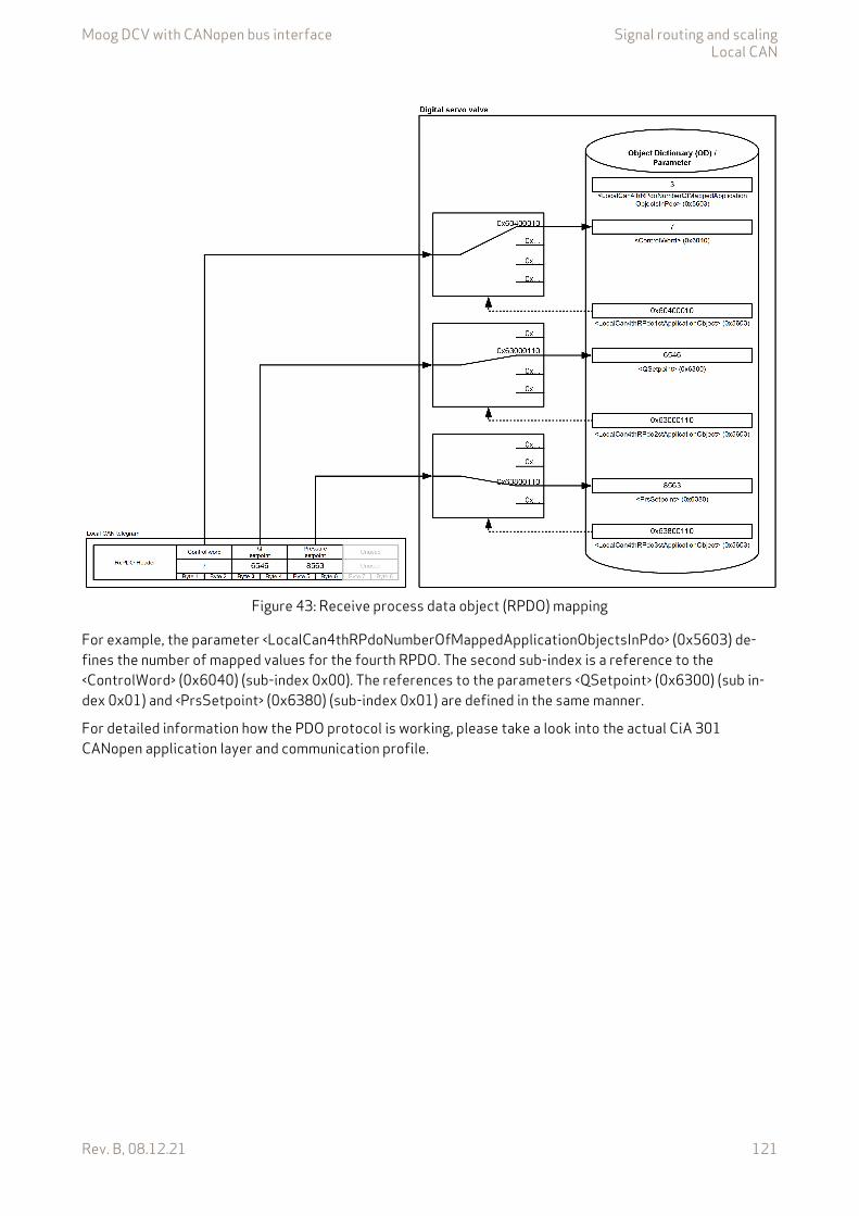
Moog DCV with CANopen bus interface Signal routing and scalingLocal CAN
Rev. B, 08.12.21 121
Figure 43: Receive process data object (RPDO) mapping
For example, the parameter <LocalCan4thRPdoNumberOfMappedApplicationObjectsInPdo> (0x5603) de-fines the number of mapped values for the fourth RPDO. The second sub-index is a reference to the <ControlWord> (0x6040) (sub-index 0x00). The references to the parameters <QSetpoint> (0x6300) (sub in-dex 0x01) and <PrsSetpoint> (0x6380) (sub-index 0x01) are defined in the same manner.
For detailed information how the PDO protocol is working, please take a look into the actual CiA 301 CANopen application layer and communication profile.
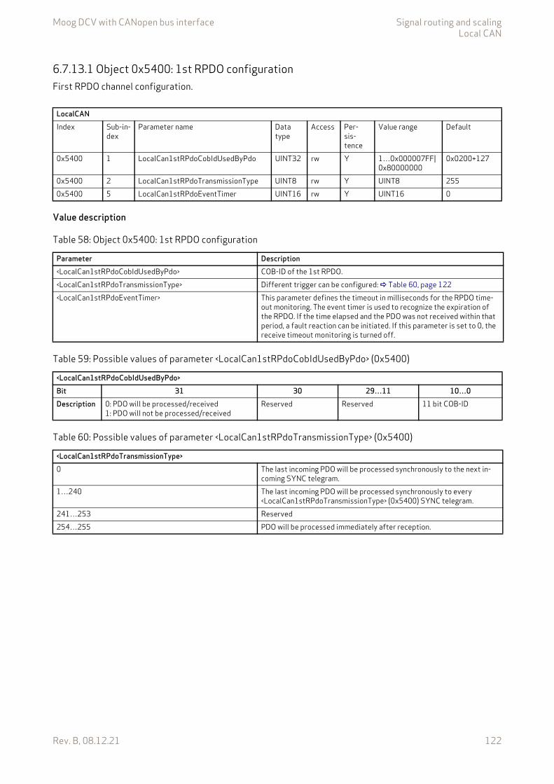
Moog DCV with CANopen bus interface Signal routing and scalingLocal CAN
Rev. B, 08.12.21 122
6.7.13.1 Object 0x5400: 1st RPDO configurationFirst RPDO channel configuration.
Value description
LocalCANIndex Sub-in-
dexParameter name Data
typeAccess Per-
sis-tence
Value range Default
0x5400 1 LocalCan1stRPdoCobIdUsedByPdo UINT32 rw Y 1…0x000007FF|0x80000000
0x0200+127
0x5400 2 LocalCan1stRPdoTransmissionType UINT8 rw Y UINT8 2550x5400 5 LocalCan1stRPdoEventTimer UINT16 rw Y UINT16 0
Table 58: Object 0x5400: 1st RPDO configuration
Parameter Description<LocalCan1stRPdoCobIdUsedByPdo> COB-ID of the 1st RPDO.<LocalCan1stRPdoTransmissionType> Different trigger can be configured: Table 60, page 122<LocalCan1stRPdoEventTimer> This parameter defines the timeout in milliseconds for the RPDO time-
out monitoring. The event timer is used to recognize the expiration of the RPDO. If the time elapsed and the PDO was not received within that period, a fault reaction can be initiated. If this parameter is set to 0, the receive timeout monitoring is turned off.
Table 59: Possible values of parameter <LocalCan1stRPdoCobIdUsedByPdo> (0x5400)
<LocalCan1stRPdoCobIdUsedByPdo>Bit 31 30 29…11 10…0Description 0: PDO will be processed/received
1: PDO will not be processed/receivedReserved Reserved 11 bit COB-ID
Table 60: Possible values of parameter <LocalCan1stRPdoTransmissionType> (0x5400)
<LocalCan1stRPdoTransmissionType>0 The last incoming PDO will be processed synchronously to the next in-
coming SYNC telegram.1…240 The last incoming PDO will be processed synchronously to every
<LocalCan1stRPdoTransmissionType> (0x5400) SYNC telegram.241…253 Reserved254…255 PDO will be processed immediately after reception.

Moog DCV with CANopen bus interface Signal routing and scalingLocal CAN
Rev. B, 08.12.21 123
6.7.13.2 Object 0x5401: 2nd RPDO configurationSecond RPDO channel configuration.
Value description Table 58, page 122
6.7.13.3 Object 0x5402: 3rd RPDO configurationThird RPDO channel configuration.
Value description Table 58, page 122
6.7.13.4 Object 0x5403: 4th RPDO configurationFourth RPDO channel configuration.
Value description Table 58, page 122
LocalCANIndex Sub-in-
dexParameter name Data
typeAccess Per-
sis-tence
Value range Default
0x5401 1 LocalCan2ndRPdoCobIdUsedByPdo UINT32 rw Y 1…0x000007FF|0x80000000
0x0300+127
0x5401 2 LocalCan2ndRPdoTransmissionType UINT8 rw Y UINT8 2550x5401 5 LocalCan2ndRPdoEventTimer UINT16 rw Y UINT16 0
LocalCANIndex Sub-in-
dexParameter name Data
typeAccess Per-
sis-tence
Value range Default
0x5402 1 LocalCan3rdRPdoCobIdUsedByPdo UINT32 rw Y 1…0x000007FF|0x80000000
0x0400+127
0x5402 2 LocalCan3rdRPdoTransmissionType UINT8 rw Y UINT8 2550x5402 5 LocalCan3rdRPdoEventTimer UINT16 rw Y UINT16 0
LocalCanIndex Sub-in-
dexParameter name Data
typeAccess Per-
sis-tence
Value range Default
0x5403 1 LocalCan4thRPdoCobIdUsedByPdo UINT32 rw Y 1…0x000007FF|0x80000000
0x0500+127
0x5403 2 LocalCan4thRPdoTransmissionType UINT8 rw Y UINT8 2550x5403 5 LocalCan4thRPdoEventTimer UINT16 rw Y UINT16 0
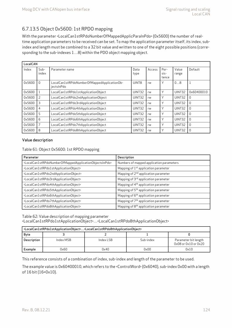
Moog DCV with CANopen bus interface Signal routing and scalingLocal CAN
Rev. B, 08.12.21 124
6.7.13.5 Object 0x5600: 1st RPDO mappingWith the parameter <LocalCan1stRPdoNumberOfMappedApplicParaInPdo> (0x5600) the number of real-time application parameters to be received can be set. To map the application parameter itself, its index, sub-index and length must be combined to a 32 bit value and written to one of the eight possible positions (corre-sponding to the sub-indexes 1…8) within the PDO object mapping object.
Value description
This reference consists of a combination of index, sub-index and length of the parameter to be used.
The example value is 0x60400010, which refers to the <ControlWord> (0x6040), sub-index 0x00 with a length of 16 bit (16=0x10).
LocalCANIndex Sub-
indexParameter name Data
typeAccess Per-
sis-tence
Value range
Default
0x5600 0 LocalCan1stRPdoNumberOfMappedApplicationOb-jectsInPdo
UINT8 rw Y 0…8 1
0x5600 1 LocalCan1stRPdo1stApplicationObject UINT32 rw Y UINT32 0x604000100x5600 2 LocalCan1stRPdo2ndApplicationObject UINT32 rw Y UINT32 00x5600 3 LocalCan1stRPdo3rdApplicationObject UINT32 rw Y UINT32 00x5600 4 LocalCan1stRPdo4thApplicationObject UINT32 rw Y UINT32 00x5600 5 LocalCan1stRPdo5thApplicationObject UINT32 rw Y UINT32 00x5600 6 LocalCan1stRPdo6thApplicationObject UINT32 rw Y UINT32 00x5600 7 LocalCan1stRPdo7thApplicationObject UINT32 rw Y UINT32 00x5600 8 LocalCan1stRPdo8thApplicationObject UINT32 rw Y UINT32 0
Table 61: Object 0x5600: 1st RPDO mapping
Parameter Description<LocalCan1stRPdoNumberOfMappedApplicationObjectsInPdo> Numbers of mapped application parameters<LocalCan1stRPdo1stApplicationObject> Mapping of 1st application parameter<LocalCan1stRPdo2ndApplicationObject> Mapping of 2nd application parameter<LocalCan1stRPdo3rdApplicationObject> Mapping of 3rd application parameter<LocalCan1stRPdo4thApplicationObject> Mapping of 4th application parameter<LocalCan1stRPdo5thApplicationObject> Mapping of 5th application parameter<LocalCan1stRPdo6thApplicationObject> Mapping of 6th application parameter<LocalCan1stRPdo7thApplicationObject> Mapping of 7th application parameter<LocalCan1stRPdo8thApplicationObject> Mapping of 8th application parameter
Table 62: Value description of mapping parameter <LocalCan1stRPdo1stApplicationObject>…<LocalCan1stRPdo8thApplicationObject>
<LocalCan1stRPdo1stApplicationObject>…<LocalCan1stRPdo8thApplicationObject>Byte 3 2 1 0Description Index MSB Index LSB Sub-index Parameter bit length
0x08 or 0x10 or 0x20Example 0x60 0x40 0x00 0x10

Moog DCV with CANopen bus interface Signal routing and scalingLocal CAN
Rev. B, 08.12.21 125
6.7.13.6 Object 0x5601: 2nd RPDO mappingSecond RPDO mapping.
The mapping of this PDO is predefined as default mapping for a standard Q-control valve. It maps the <ControlWord> (0x6040) and the <QSetpoint> (0x6300).
Value description Table 61, page 124
6.7.13.7 Object 0x5602: 3rd RPDO mappingThird RPDO mapping.
The mapping of this PDO is predefined as default mapping for a standard p-control valve. It maps the <ControlWord> (0x6040) and the <PrsSetpoint> (0x6380).
Value description Table 61, page 124
LocalCANIndex Sub-
indexParameter name Data
typeAccess Per-
sis-tence
Value range
Default
0x5601 0 LocalCan2ndRPdoNumberOfMappedApplicationOb-jectsInPdo
UINT8 rw Y 0…8 2
0x5601 1 LocalCan2ndRPdo1stApplicationObject UINT32 rw Y UINT32 0x604000100x5601 2 LocalCan2ndRPdo2ndApplicationObject UINT32 rw Y UINT32 0x630001100x5601 3 LocalCan2ndRPdo3rdApplicationObject UINT32 rw Y UINT32 00x5601 4 LocalCan2ndRPdo4thApplicationObject UINT32 rw Y UINT32 00x5601 5 LocalCan2ndRPdo5thApplicationObject UINT32 rw Y UINT32 00x5601 6 LocalCan2ndRPdo6thApplicationObject UINT32 rw Y UINT32 00x5601 7 LocalCan2ndRPdo7thApplicationObject UINT32 rw Y UINT32 00x5601 8 LocalCan2ndRPdo8thApplicationObject UINT32 rw Y UINT32 0
LocalCANIndex Sub-
indexParameter name Data
typeAccess Per-
sis-tence
Value range
Default
0x5602 0 LocalCan3rdRPdoNumberOfMappedApplicationOb-jectsInPdo
UINT8 rw Y 0…8 2
0x5602 1 LocalCan3rdRPdo1stApplicationObject UINT32 rw Y UINT32 0x604000100x5602 2 LocalCan3rdRPdo2ndApplicationObject UINT32 rw Y UINT32 0x638001100x5602 3 LocalCan3rdRPdo3rdApplicationObject UINT32 rw Y UINT32 00x5602 4 LocalCan3rdRPdo4thApplicationObject UINT32 rw Y UINT32 00x5602 5 LocalCan3rdRPdo5thApplicationObject UINT32 rw Y UINT32 00x5602 6 LocalCan3rdRPdo6thApplicationObject UINT32 rw Y UINT32 00x5602 7 LocalCan3rdRPdo7thApplicationObject UINT32 rw Y UINT32 00x5602 8 LocalCan3rdRPdo8thApplicationObject UINT32 rw Y UINT32 0
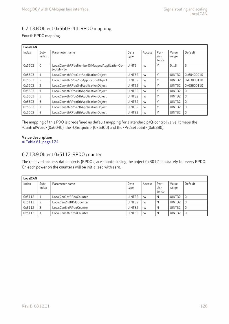
Moog DCV with CANopen bus interface Signal routing and scalingLocal CAN
Rev. B, 08.12.21 126
6.7.13.8 Object 0x5603: 4th RPDO mappingFourth RPDO mapping.
The mapping of this PDO is predefined as default mapping for a standard p/Q-control valve. It maps the <ControlWord> (0x6040), the <QSetpoint> (0x6300) and the <PrsSetpoint> (0x6380).
Value description Table 61, page 124
6.7.13.9 Object 0x5112: RPDO counterThe received process data objects (RPDOs) are counted using the object 0x3012 separately for every RPDO. On each power on the counters will be initialized with zero.
LocalCANIndex Sub-
indexParameter name Data
typeAccess Per-
sis-tence
Value range
Default
0x5603 0 LocalCan4thRPdoNumberOfMappedApplicationOb-jectsInPdo
UINT8 rw Y 0…8 3
0x5603 1 LocalCan4thRPdo1stApplicationObject UINT32 rw Y UINT32 0x604000100x5603 2 LocalCan4thRPdo2ndApplicationObject UINT32 rw Y UINT32 0x630001100x5603 3 LocalCan4thRPdo3rdApplicationObject UINT32 rw Y UINT32 0x638001100x5603 4 LocalCan4thRPdo4thApplicationObject UINT32 rw Y UINT32 00x5603 5 LocalCan4thRPdo5thApplicationObject UINT32 rw Y UINT32 00x5603 6 LocalCan4thRPdo6thApplicationObject UINT32 rw Y UINT32 00x5603 7 LocalCan4thRPdo7thApplicationObject UINT32 rw Y UINT32 00x5603 8 LocalCan4thRPdo8thApplicationObject UINT32 rw Y UINT32 0
LocalCANIndex Sub-
indexParameter name Data
typeAccess Per-
sis-tence
Value range
Default
0x5112 1 LocalCan1stRPdoCounter UINT32 rw N UINT32 00x5112 2 LocalCan2ndRPdoCounter UINT32 rw N UINT32 00x5112 3 LocalCan3rdRPdoCounter UINT32 rw N UINT32 00x5112 4 LocalCan4thRPdoCounter UINT32 rw N UINT32 0
Moog DCV with CANopen bus interface Signal routing and scalingLocal CAN
Rev. B, 08.12.21 127
6.7.14 Transmit process data object (TPDO)The transmit process data object (TPDO) protocol must be configured and the transmit values must be mapped to the local parameters. Four transmit TPDO channels are available. The transmission of the PDOs can be triggered by following events:
• Event timer elapsed.• Synchronization (SYNC) telegram received.
Every event forces a PDO transmission. More than one event type can be active at the same time.
With the transmit process data object (TPDO) mapping the most object dictionary entries can be mapped to a TPDO. A CANopen telegram can carry 8 bytes data in one package. The smallest data types used in the digital servo valve are 8 bit integers. Therefore eight object dictionary entries with 8 bit data length or four object dictionary entries with 16 bits or two object dictionary entries with 32 bit can be mapped within one TPDO. An arbitrary combination of different data types is possible, if the sum of the mapped TPDO data is less or equal 8 bytes.
The default PDO mapping for a hydraulic CANopen device is defined in the device specific profile CiA 408.
Example:The following values should be mapped to the fourth TPDO (default mapping):
• Device state machine (DSM) Status Word <StatusWord> (0x6041) (sub-index 0x00) Chapter "5.1 Device state machine (DSM)", page 50
• Spool position actual value <SpoolActualValue> (0x6301) (sub-index 0x01) Chapter "7.3 Spool position controller", page 163
• Pressure actual value <PrsActualValue> (0x6381) (sub-index 0x01) Chapter "7.5.11 Actual pressure value filter", page 196
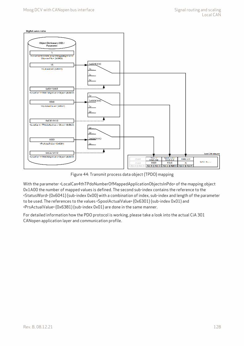
Moog DCV with CANopen bus interface Signal routing and scalingLocal CAN
Rev. B, 08.12.21 128
Figure 44: Transmit process data object (TPDO) mapping
With the parameter <LocalCan4thTPdoNumberOfMappedApplicationObjectsInPdo> of the mapping object 0x1A00 the number of mapped values is defined. The second sub-index contains the reference to the <StatusWord> (0x6041) (sub-index 0x00) with a combination of index, sub-index and length of the parameter to be used. The references to the values <SpoolActualValue> (0x6301) (sub-index 0x01) and <PrsActualValue> (0x6381) (sub-index 0x01) are done in the same manner.
For detailed information how the PDO protocol is working, please take a look into the actual CiA 301 CANopen application layer and communication profile.
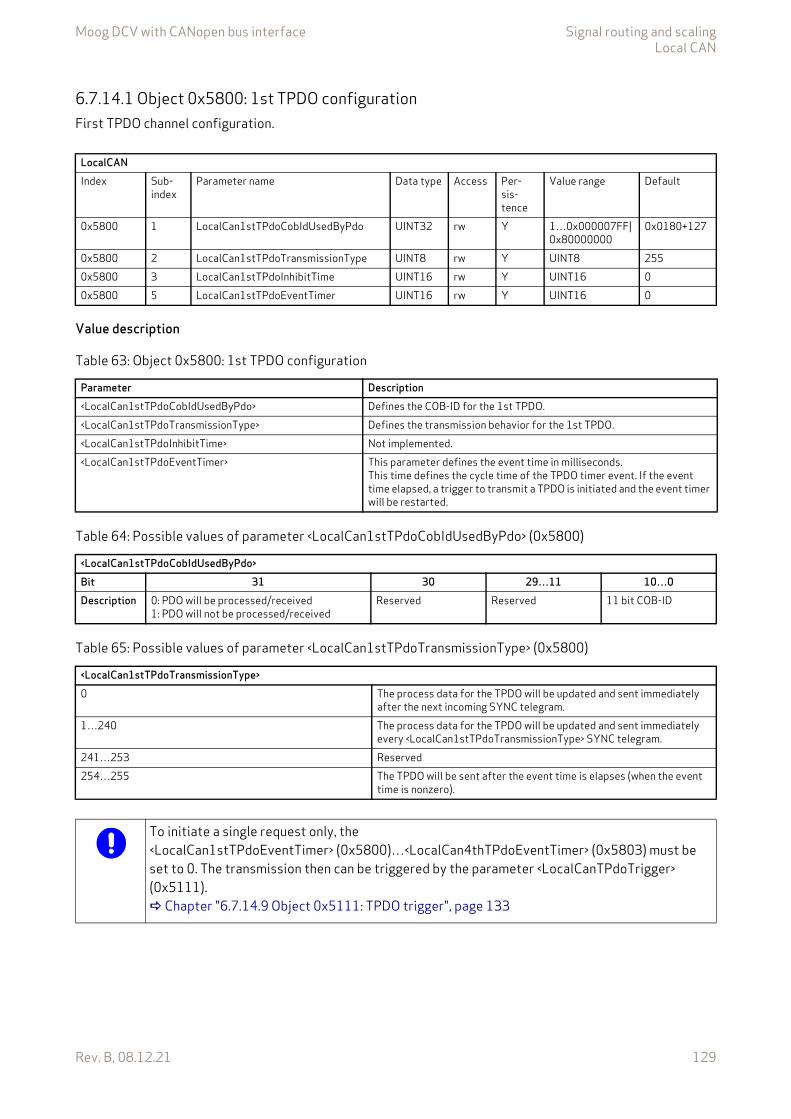
Moog DCV with CANopen bus interface Signal routing and scalingLocal CAN
Rev. B, 08.12.21 129
6.7.14.1 Object 0x5800: 1st TPDO configurationFirst TPDO channel configuration.
Value description
LocalCANIndex Sub-
indexParameter name Data type Access Per-
sis-tence
Value range Default
0x5800 1 LocalCan1stTPdoCobIdUsedByPdo UINT32 rw Y 1…0x000007FF|0x80000000
0x0180+127
0x5800 2 LocalCan1stTPdoTransmissionType UINT8 rw Y UINT8 2550x5800 3 LocalCan1stTPdoInhibitTime UINT16 rw Y UINT16 00x5800 5 LocalCan1stTPdoEventTimer UINT16 rw Y UINT16 0
Table 63: Object 0x5800: 1st TPDO configuration
Parameter Description<LocalCan1stTPdoCobIdUsedByPdo> Defines the COB-ID for the 1st TPDO.<LocalCan1stTPdoTransmissionType> Defines the transmission behavior for the 1st TPDO.<LocalCan1stTPdoInhibitTime> Not implemented.<LocalCan1stTPdoEventTimer> This parameter defines the event time in milliseconds.
This time defines the cycle time of the TPDO timer event. If the event time elapsed, a trigger to transmit a TPDO is initiated and the event timer will be restarted.
Table 64: Possible values of parameter <LocalCan1stTPdoCobIdUsedByPdo> (0x5800)
<LocalCan1stTPdoCobIdUsedByPdo>Bit 31 30 29…11 10…0Description 0: PDO will be processed/received
1: PDO will not be processed/receivedReserved Reserved 11 bit COB-ID
Table 65: Possible values of parameter <LocalCan1stTPdoTransmissionType> (0x5800)
<LocalCan1stTPdoTransmissionType>0 The process data for the TPDO will be updated and sent immediately
after the next incoming SYNC telegram.1…240 The process data for the TPDO will be updated and sent immediately
every <LocalCan1stTPdoTransmissionType> SYNC telegram.241…253 Reserved254…255 The TPDO will be sent after the event time is elapses (when the event
time is nonzero).
To initiate a single request only, the <LocalCan1stTPdoEventTimer> (0x5800)…<LocalCan4thTPdoEventTimer> (0x5803) must be set to 0. The transmission then can be triggered by the parameter <LocalCanTPdoTrigger> (0x5111). Chapter "6.7.14.9 Object 0x5111: TPDO trigger", page 133
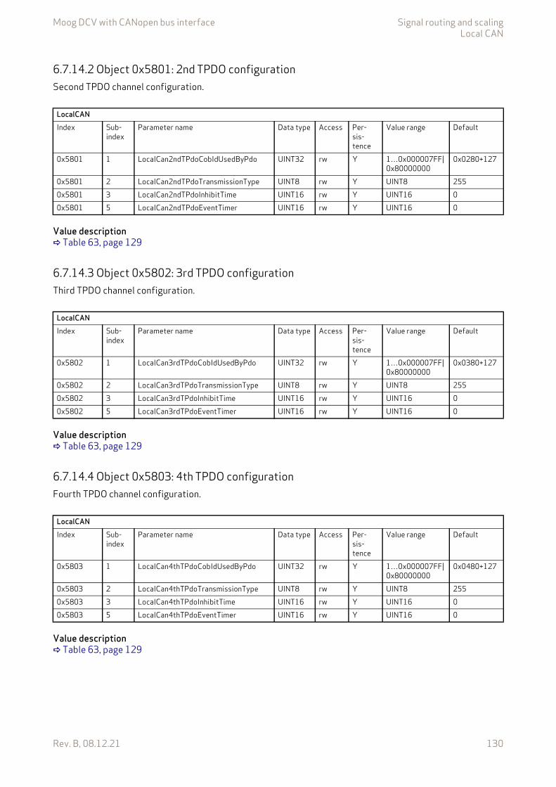
Moog DCV with CANopen bus interface Signal routing and scalingLocal CAN
Rev. B, 08.12.21 130
6.7.14.2 Object 0x5801: 2nd TPDO configurationSecond TPDO channel configuration.
Value description Table 63, page 129
6.7.14.3 Object 0x5802: 3rd TPDO configurationThird TPDO channel configuration.
Value description Table 63, page 129
6.7.14.4 Object 0x5803: 4th TPDO configurationFourth TPDO channel configuration.
Value description Table 63, page 129
LocalCANIndex Sub-
indexParameter name Data type Access Per-
sis-tence
Value range Default
0x5801 1 LocalCan2ndTPdoCobIdUsedByPdo UINT32 rw Y 1…0x000007FF|0x80000000
0x0280+127
0x5801 2 LocalCan2ndTPdoTransmissionType UINT8 rw Y UINT8 2550x5801 3 LocalCan2ndTPdoInhibitTime UINT16 rw Y UINT16 00x5801 5 LocalCan2ndTPdoEventTimer UINT16 rw Y UINT16 0
LocalCANIndex Sub-
indexParameter name Data type Access Per-
sis-tence
Value range Default
0x5802 1 LocalCan3rdTPdoCobIdUsedByPdo UINT32 rw Y 1…0x000007FF|0x80000000
0x0380+127
0x5802 2 LocalCan3rdTPdoTransmissionType UINT8 rw Y UINT8 2550x5802 3 LocalCan3rdTPdoInhibitTime UINT16 rw Y UINT16 00x5802 5 LocalCan3rdTPdoEventTimer UINT16 rw Y UINT16 0
LocalCANIndex Sub-
indexParameter name Data type Access Per-
sis-tence
Value range Default
0x5803 1 LocalCan4thTPdoCobIdUsedByPdo UINT32 rw Y 1…0x000007FF|0x80000000
0x0480+127
0x5803 2 LocalCan4thTPdoTransmissionType UINT8 rw Y UINT8 2550x5803 3 LocalCan4thTPdoInhibitTime UINT16 rw Y UINT16 00x5803 5 LocalCan4thTPdoEventTimer UINT16 rw Y UINT16 0
Moog DCV with CANopen bus interface Signal routing and scalingLocal CAN
Rev. B, 08.12.21 131
6.7.14.5 Object 0x5A00: 1st TPDO mappingWith the parameter <LocalCan1stTPdoNumberOfMappedApplicationObjectsInPdo> (0x5A00) the number of real-time application parameters to be transmitted can be set. To map the application parameter itself, its in-dex, sub-index and length must be combined to a 32 bit value and written to one of the eight possible posi-tions (corresponding to the subindexes 1…8) within the PDO object.
Value description
This reference contains a combination of index, sub-index and length of the parameter to be used.
The example value is 0x63410010, which refers to the <StatusWord> (0x6041), sub-index 0x00 with a length of 16 bit (16=0x10).
LocalCanIndex Sub-
indexParameter name Data
typeAccess Per-
sis-tence
Value range
Default
0x5A00 0 LocalCan1stTPdoNumberOfMappedApplicationOb-jectsInPdo
UINT8 rw Y 0…8 1
0x5A00 1 LocalCan1stTPdo1stApplicationObject UINT32 rw Y UINT32 0x604100100x5A00 2 LocalCan1stTPdo2ndApplicationObject UINT32 rw Y UINT32 00x5A00 3 LocalCan1stTPdo3rdApplicationObject UINT32 rw Y UINT32 00x5A00 4 LocalCan1stTPdo4thApplicationObject UINT32 rw Y UINT32 00x5A00 5 LocalCan1stTPdo5thApplicationObject UINT32 rw Y UINT32 00x5A00 6 LocalCan1stTPdo6thApplicationObject UINT32 rw Y UINT32 00x5A00 7 LocalCan1stTPdo7thApplicationObject UINT32 rw Y UINT32 00x5A00 8 LocalCan1stTPdo8thApplicationObject UINT32 rw Y UINT32 0
Table 66: Object 0x5A00: 1st TPDO mapping
Parameter Description<LocalCan1stTPdoNumberOfMappedApplicationObjectsInPdo> Numbers of mapped application parameters<LocalCan1stTPdo1stApplicationObject> 1st application parameter<LocalCan1stTPdo2ndApplicationObject> 2nd application parameter<LocalCan1stTPdo3rdApplicationObject> 3rd application parameter<LocalCan1stTPdo4thApplicationObject> 4th application parameter<LocalCan1stTPdo5thApplicationObject> 5th application parameter<LocalCan1stTPdo6thApplicationObject> 6th application parameter<LocalCan1stTPdo7thApplicationObject> 7th application parameter<LocalCan1stTPdo8thApplicationObject> 8th application parameter
Table 67: Possible values of parameter <LocalCan1stTPdo1stApplicationObject>…<LocalCan1stTPdo8thApplicationObject>
<LocalCan1stTPdo1stApplicationObject>…<LocalCan1stTPdo8thApplicationObject>Byte 3 2 1 0Description Index MSB Index LSB Sub-index Parameter bit length
0x08 or 0x10 or 0x20Example 0x60 0x41 0x00 0x10
Moog DCV with CANopen bus interface Signal routing and scalingLocal CAN
Rev. B, 08.12.21 132
6.7.14.6 Object 0x5A01: 2nd TPDO mappingSecond TPDO mapping.
The mapping of this PDO is predefined as default mapping for a standard Q-control valve. It maps the <StatusWord> (0x6041) and the <SpoolActualValue> (0x6301).
Value description Table 66, page 131
6.7.14.7 Object 0x5A02: 3rd TPDO mappingThird TPDO mapping.
The mapping of this PDO is predefined as default mapping for a standard p-control valve. It maps the <StatusWord> (0x6041) and the <PrsActualValue> (0x6381).
Value description Table 66, page 131
LocalCANIndex Sub-
indexParameter name Data
typeAccess Per-
sis-tence
Value range
Default
0x5A01 0 LocalCan2ndTPdoNumberOfMappedApplicationOb-jectsInPdo
UINT8 rw Y 0…8 2
0x5A01 1 LocalCan2ndTPdo1stApplicationObject UINT32 rw Y UINT32 0x604100100x5A01 2 LocalCan2ndTPdo2ndApplicationObject UINT32 rw Y UINT32 0x630101100x5A01 3 LocalCan2ndTPdo3rdApplicationObject UINT32 rw Y UINT32 00x5A01 4 LocalCan2ndTPdo4thApplicationObject UINT32 rw Y UINT32 00x5A01 5 LocalCan2ndTPdo5thApplicationObject UINT32 rw Y UINT32 00x5A01 6 LocalCan2ndTPdo6thApplicationObject UINT32 rw Y UINT32 00x5A01 7 LocalCan2ndTPdo7thApplicationObject UINT32 rw Y UINT32 00x5A01 8 LocalCan2ndTPdo8thApplicationObject UINT32 rw Y UINT32 0
LocalCanIndex Sub-
indexParameter name Data
typeAccess Per-
sis-tence
Value range
Default
0x5A02 0 LocalCan3rdTPdoNumberOfMappedApplicationOb-jectsInPdo
UINT8 rw Y 0…8 2
0x5A02 1 LocalCan3rdTPdo1stApplicationObject UINT32 rw Y UINT32 0x604100100x5A02 2 LocalCan3rdTPdo2ndApplicationObject UINT32 rw Y UINT32 0x638101100x5A02 3 LocalCan3rdTPdo3rdApplicationObject UINT32 rw Y UINT32 00x5A02 4 LocalCan3rdTPdo4thApplicationObject UINT32 rw Y UINT32 00x5A02 5 LocalCan3rdTPdo5thApplicationObject UINT32 rw Y UINT32 00x5A02 6 LocalCan3rdTPdo6thApplicationObject UINT32 rw Y UINT32 00x5A02 7 LocalCan3rdTPdo7thApplicationObject UINT32 rw Y UINT32 00x5A02 8 LocalCan3rdTPdo8thApplicationObject UINT32 rw Y UINT32 0
Moog DCV with CANopen bus interface Signal routing and scalingLocal CAN
Rev. B, 08.12.21 133
6.7.14.8 Object 0x5A03: 4th TPDO mappingFourth TPDO mapping.
The mapping of this PDO is predefined as default mapping for a standard p/Q-control valve. It maps the <StatusWord> (0x6041), the <SpoolActualValue> (0x6301) and the <PrsActualValue> (0x6381).
Value description Table 66, page 131
6.7.14.9 Object 0x5111: TPDO triggerWriting this parameter triggers a single TPDO. This can be used to transmit a PDO on request only. To trigger one of the four TPDOs, the parameter <LocalCanTPdoTrigger> (0x5111) value must be set to the number of the PDO channel to be sent.
LocalCANIndex Sub-
indexParameter name Data
typeAccess Per-
sis-tence
Value range
Default
0x5A03 0 LocalCan4thTPdoNumberOfMappedApplicationOb-jectsInPdo
UINT8 rw Y 0…8 2
0x5A03 1 LocalCan4thTPdo1stApplicationObject UINT32 rw Y UINT32 0x604100100x5A03 2 LocalCan4thTPdo2ndApplicationObject UINT32 rw Y UINT32 0x630101100x5A03 3 LocalCan4thTPdo3rdApplicationObject UINT32 rw Y UINT32 0x638101100x5A03 4 LocalCan4thTPdo4thApplicationObject UINT32 rw Y UINT32 00x5A03 5 LocalCan4thTPdo5thApplicationObject UINT32 rw Y UINT32 00x5A03 6 LocalCan4thTPdo6thApplicationObject UINT32 rw Y UINT32 00x5A03 7 LocalCan4thTPdo7thApplicationObject UINT32 rw Y UINT32 00x5A03 8 LocalCan4thTPdo8thApplicationObject UINT32 rw Y UINT32 0
LocalCANIndex Sub-
indexParameter name Data
typeAccess Per-
sis-tence
Value range
Default
0x5111 0 LocalCanTPdoTrigger UINT8 rw N 1…4 None
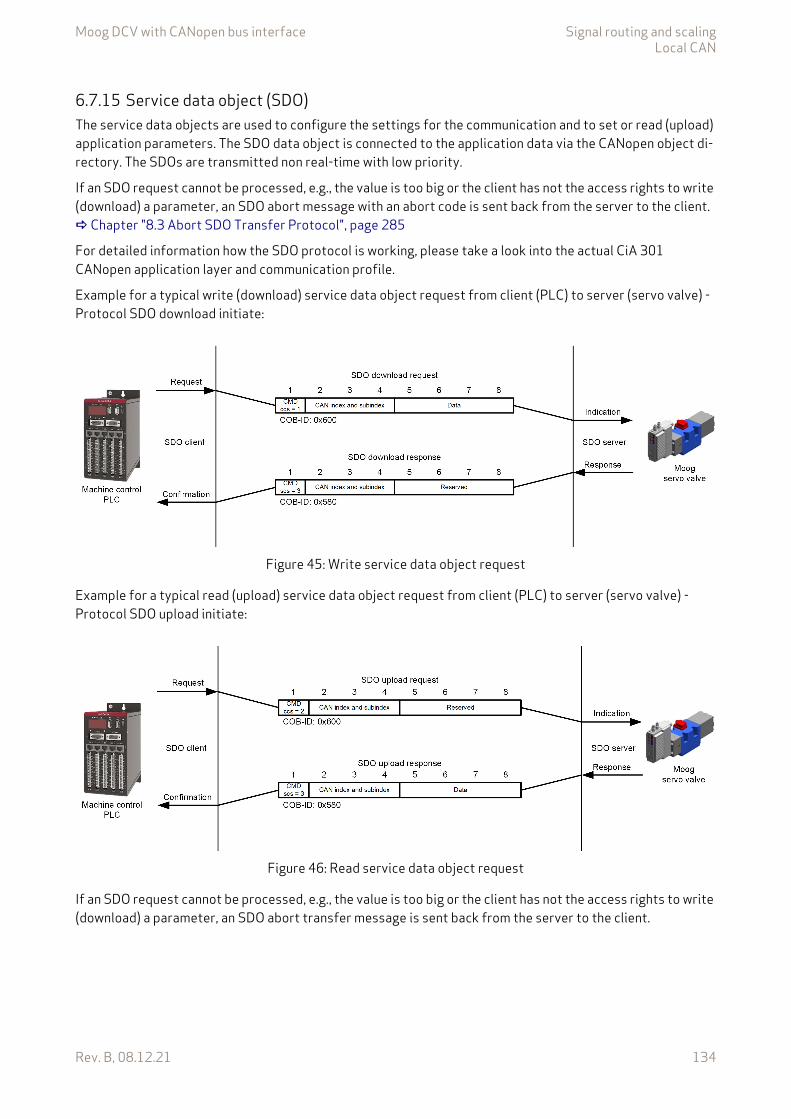
Moog DCV with CANopen bus interface Signal routing and scalingLocal CAN
Rev. B, 08.12.21 134
6.7.15 Service data object (SDO)The service data objects are used to configure the settings for the communication and to set or read (upload) application parameters. The SDO data object is connected to the application data via the CANopen object di-rectory. The SDOs are transmitted non real-time with low priority.
If an SDO request cannot be processed, e.g., the value is too big or the client has not the access rights to write (download) a parameter, an SDO abort message with an abort code is sent back from the server to the client. Chapter "8.3 Abort SDO Transfer Protocol", page 285
For detailed information how the SDO protocol is working, please take a look into the actual CiA 301 CANopen application layer and communication profile.
Example for a typical write (download) service data object request from client (PLC) to server (servo valve) - Protocol SDO download initiate:
Figure 45: Write service data object request
Example for a typical read (upload) service data object request from client (PLC) to server (servo valve) - Protocol SDO upload initiate:
Figure 46: Read service data object request
If an SDO request cannot be processed, e.g., the value is too big or the client has not the access rights to write (download) a parameter, an SDO abort transfer message is sent back from the server to the client.
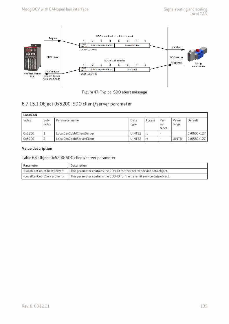
Moog DCV with CANopen bus interface Signal routing and scalingLocal CAN
Rev. B, 08.12.21 135
Figure 47: Typical SDO abort message
6.7.15.1 Object 0x5200: SDO client/server parameter
Value description
LocalCANIndex Sub-
indexParameter name Data
typeAccess Per-
sis-tence
Value range
Default
0x5200 1 LocalCanCobIdClientServer UINT32 ro - 0x0600+1270x5200 2 LocalCanCobIdServerClient UINT32 ro - UINT8 0x0580+127
Table 68: Object 0x5200: SDO client/server parameter
Parameter Description<LocalCanCobIdClientServer> This parameter contains the COB-ID for the receive service data object.<LocalCanCobIdServerClient> This parameter contains the COB-ID for the transmit service data object.
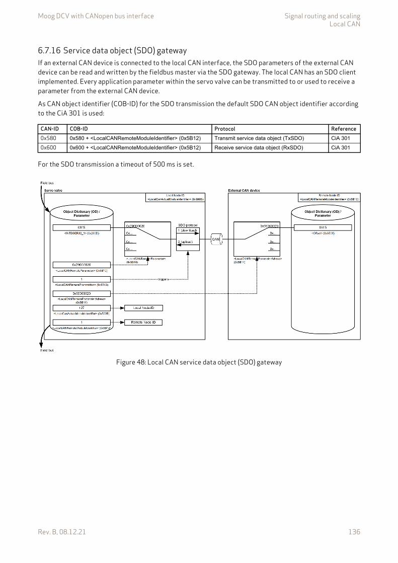
Moog DCV with CANopen bus interface Signal routing and scalingLocal CAN
Rev. B, 08.12.21 136
6.7.16 Service data object (SDO) gatewayIf an external CAN device is connected to the local CAN interface, the SDO parameters of the external CAN device can be read and written by the fieldbus master via the SDO gateway. The local CAN has an SDO client implemented. Every application parameter within the servo valve can be transmitted to or used to receive a parameter from the external CAN device.
As CAN object identifier (COB-ID) for the SDO transmission the default SDO CAN object identifier according to the CiA 301 is used:
For the SDO transmission a timeout of 500 ms is set.
Figure 48: Local CAN service data object (SDO) gateway
CAN-ID COB-ID Protocol Reference0x580 0x580 + <LocalCANRemoteModuleIdentifier> (0x5B12) Transmit service data object (TxSDO) CiA 301
0x600 0x600 + <LocalCANRemoteModuleIdentifier> (0x5B12) Receive service data object (RxSDO) CiA 301
Moog DCV with CANopen bus interface Signal routing and scalingLocal CAN
Rev. B, 08.12.21 137
6.7.16.1 Object 0x5B10: Remote parameterThis parameter defines the SDO index/sub-index in the servo valve to be read or written.
• In case of an SDO download it defines the local source to be transmitted.• In case of an SDO upload it defines the local destination to be written to.
Chapter "6.8 Free to use parameters", page 140
Value description
This reference contains a combination of index, sub-index and length of the parameter to be used. It may only refer to parameters with a bit length of 0x10 or 0x20.
6.7.16.2 Object 0x5B11: Remote parameter addressThis parameter defines the SDO index/sub-index in the external CAN device to be read or written.
• In case of an SDO download it defines the destination parameter within the external CAN device to be written.
• In case of an SDO upload it defines the source parameter within the external CAN device to be transmit-ted.
Value description
This reference contains a combination of index, sub-index and length of the parameter to be used. It may only refer to parameters with a bit length of 0x10 or 0x20.
LocalCANIndex Sub-index Parameter name Data type Access Persistence Value
rangeDefault
0x5B10 0 LocalCANRemoteParameter UINT32 rw N UINT32 None
Table 69: Possible values of parameter <LocalCANRemoteParameter> (0x5B10)
<LocalCANRemoteParameter>Byte 3 2 1 0Description Index MSB Index LSB Sub-index Parameter bit length
0x10 or 0x20Default 0x00 0x00 0x00 0x00
LocalCANIndex Sub-index Parameter name Data type Access Persistence Value
rangeDefault
0x5B11 0 LocalCANRemoteParameterAdress UINT32 rw N UINT32 None
Table 70: Possible values of parameter <LocalCANRemoteParameterAdress> (0x5B11)
<LocalCANRemoteParameterAdress>Byte 3 2 1 0Description Index MSB Index LSB Sub-index Parameter bit length
0x10 or 0x20Default 0x00 0x00 0x00 0x00

Moog DCV with CANopen bus interface Signal routing and scalingLocal CAN
Rev. B, 08.12.21 138
6.7.16.3 Object 0x5B12: Remote Node-IDThis parameter represents the Node-ID of the external device.
This parameter must be different from the Node-ID <LocalCanActualModuleIdentifier> (0x500B) of the local CAN bus of the servo valve.
6.7.16.4 Object 0x5B13: Remote transmissionWriting to the <LocalCANRemoteTransmission> (0x5B13) parameter initiates a read or write SDO transmis-sion. The address of the considered remote parameter will be defined with the parameter <LocalCANRemoteParameterAdress> (0x5B11). If the <LocalCANRemoteTransmission> is set to 1 (down-load), the value of the address <LocalCANRemoteParameterAdress> (0x5B11) will be read and saved in the lo-cal parameter defined by the <LocalCANRemoteParameter> (0x5B100). If <LocalCANRemoteTransmission> (0x5B13) is set to 2 (upload), the local value at the address <LocalCANRemoteParameter> (0x5B10) will be written to the remote parameter referenced by <LocalCANRemoteParameterAdress> (0x5B11).
Value description
6.7.17 Synchronization (SYNC)The SYNC protocol is a network wide system trigger generated by one CANopen device in the network. The SYNC protocol has a very high priority and has no data in order to guarantee a minimum of jitter. The SYNC protocol is sent by a sync producer and can trigger PDO transmissions in the sync consumer nodes when acti-vated in the corresponding PDO transmission types.
Chapter "6.7.13.1 Object 0x5400: 1st RPDO configuration", page 122 Chapter "6.7.14.1 Object 0x5800: 1st TPDO configuration", page 129 Chapter "6.7.14.9 Object 0x5111: TPDO trigger", page 133
LocalCANIndex Sub-index Parameter name Data type Access Persistence Value
rangeDefault
0x5B12 0 LocalCANRemoteModuleIdentifier UINT8 rw N 0…127 None
LocalCANIndex Sub-index Parameter name Data type Access Persistence Value
rangeDefault
0x5B13 0 LocalCANRemoteTransmission INT8 rw N –1…2 None
Table 71: Possible values of parameter <LocalCANRemoteTransmission> (0x5B13)
<LocalCANRemoteTransmission> Description–1 Operation was not successful.0 Operation was successful.1 Execute an SDO download operation from the servo valve to the external CAN device.
If the download operation is successful, the <LocalCANRemoteTransmission> (0x5B13) changes to 0.If the download operation is not successful, the <LocalCANRemoteTransmission> (0x5B13) changes to –1.
2 Execute an SDO upload operation from the external CAN device to the servo valve.If the upload operation is successful, the <LocalCANRemoteTransmission> (0x5B13) changes to 0.If the upload operation is not successful, the <LocalCANRemoteTransmission> (0x5B13) changes to –1.
Moog DCV with CANopen bus interface Signal routing and scalingLocal CAN
Rev. B, 08.12.21 139
6.7.17.1 Object 0x5005: SYNC protocol COB-ID configurationThis object defines the COB-ID of the sync object itself.
Value description
6.7.17.2 Object 0x5006: SYNC protocol periodIf <LocalCanCobIdSyncMessage> (0x5005) is set to 1, a sync signal is produced by the local CAN fieldbus. The cycle time of the sync signal is set with this parameter in milliseconds.
6.7.17.3 Object 0x5019: SYNC protocol counter overflow valueThis object shall indicate the configured highest value the synchronous counter supports. If the value is greater than 1, the SYNC message shall have a data length of 1 byte. An EMCY message (error code 0x8240) may be transmitted by a SYNC consumer in the case the configured data length of the SYNC message does not meet the data length of a received SYNC message. The value used shall be the least common multiple of all the TPDO transmission types (1 < n <= 240) used. This ensures that periodic SYNC events always happen in the SYNC cycles with the same counter value.
Value description
LocalCANIndex Sub-index Parameter name Data type Access Persistence Value range Default0x5005 0 LocalCanCobIdSyncMessage UINT32 rw Y 1…0x000007FF
|0x400000000x0080+127
Table 72: Possible values of parameter <LocalCanCobIdSyncMessage> (0x5005)
<LocalCanCobIdSyncMessage>Bit 31 30 29…11 10…0
DescriptionReserved 0: SYNC consumer
1: SYNC producerReserved 11 bit COB-ID
LocalCANIndex Sub-index Parameter name Data type Access Per-
sistenceValue range Default
0x5006 0 LocalCanCommunicationCyclePeriod UINT32 rw Y UINT32 0
LocalCANIndex Sub-
indexParameter name Data type Access Per-
sistenceValue range
Default
0x5019 0 LocalCANSynchronousCounterOverflowValue UINT8 rw Y UINT8 0
Table 73: Possible values of parameter <LocalCANSynchronousCounterOverflowValue> (0x5019)
<LocalCANSynchronousCounterOverflowValue> Description0 The SYNC message shall be transmitted as a CAN message of data length 0.1 Reserved2…240 The SYNC message shall be transmitted as a CAN message of data length 1. The
first data byte contains the counter.241…255 Reserved
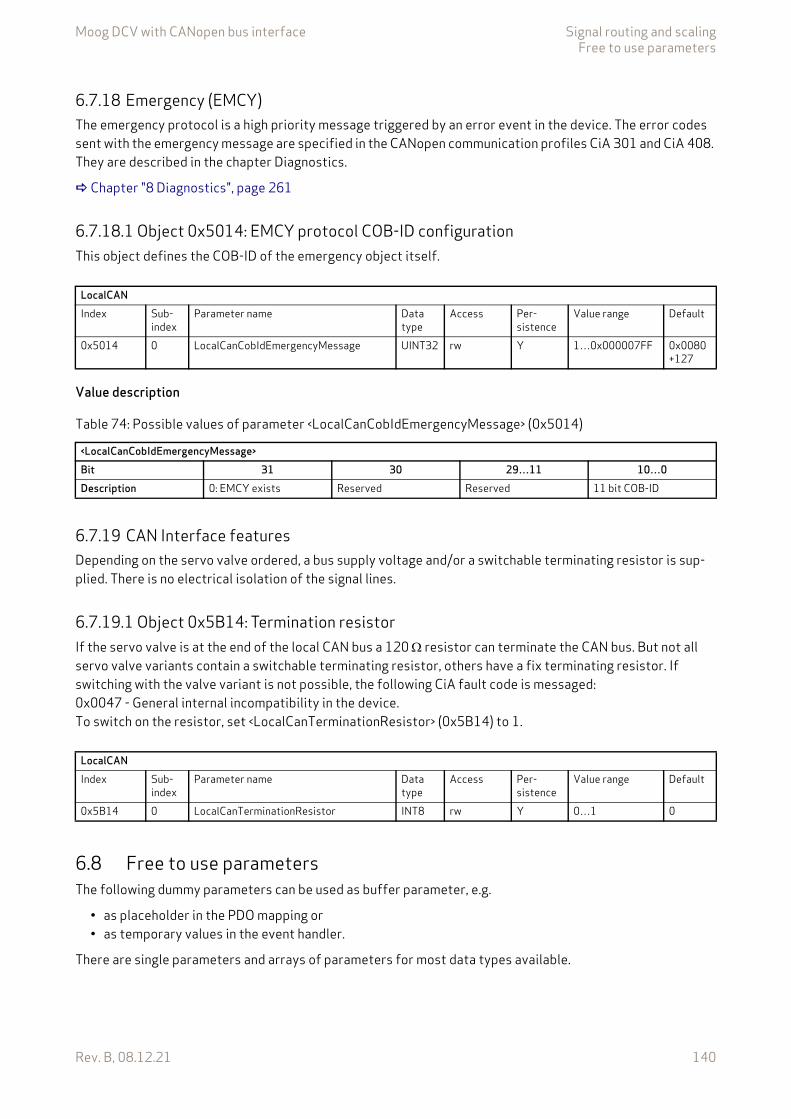
Moog DCV with CANopen bus interface Signal routing and scalingFree to use parameters
Rev. B, 08.12.21 140
6.7.18 Emergency (EMCY)The emergency protocol is a high priority message triggered by an error event in the device. The error codes sent with the emergency message are specified in the CANopen communication profiles CiA 301 and CiA 408. They are described in the chapter Diagnostics.
Chapter "8 Diagnostics", page 261
6.7.18.1 Object 0x5014: EMCY protocol COB-ID configurationThis object defines the COB-ID of the emergency object itself.
Value description
6.7.19 CAN Interface featuresDepending on the servo valve ordered, a bus supply voltage and/or a switchable terminating resistor is sup-plied. There is no electrical isolation of the signal lines.
6.7.19.1 Object 0x5B14: Termination resistorIf the servo valve is at the end of the local CAN bus a 120 resistor can terminate the CAN bus. But not all servo valve variants contain a switchable terminating resistor, others have a fix terminating resistor. If switching with the valve variant is not possible, the following CiA fault code is messaged: 0x0047 - General internal incompatibility in the device. To switch on the resistor, set <LocalCanTerminationResistor> (0x5B14) to 1.
6.8 Free to use parametersThe following dummy parameters can be used as buffer parameter, e.g.
• as placeholder in the PDO mapping or• as temporary values in the event handler.
There are single parameters and arrays of parameters for most data types available.
LocalCANIndex Sub-
indexParameter name Data
typeAccess Per-
sistenceValue range Default
0x5014 0 LocalCanCobIdEmergencyMessage UINT32 rw Y 1…0x000007FF 0x0080+127
Table 74: Possible values of parameter <LocalCanCobIdEmergencyMessage> (0x5014)
<LocalCanCobIdEmergencyMessage>Bit 31 30 29…11 10…0Description 0: EMCY exists Reserved Reserved 11 bit COB-ID
LocalCANIndex Sub-
indexParameter name Data
typeAccess Per-
sistenceValue range Default
0x5B14 0 LocalCanTerminationResistor INT8 rw Y 0…1 0
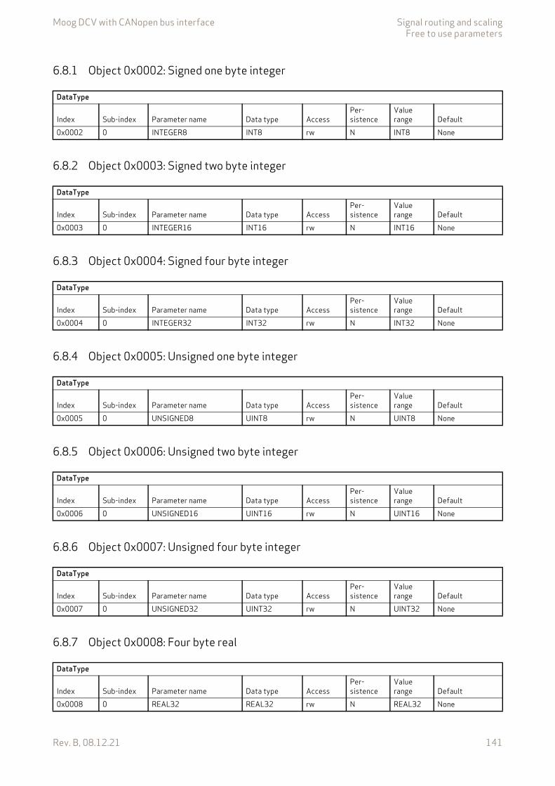
Moog DCV with CANopen bus interface Signal routing and scalingFree to use parameters
Rev. B, 08.12.21 141
6.8.1 Object 0x0002: Signed one byte integer
6.8.2 Object 0x0003: Signed two byte integer
6.8.3 Object 0x0004: Signed four byte integer
6.8.4 Object 0x0005: Unsigned one byte integer
6.8.5 Object 0x0006: Unsigned two byte integer
6.8.6 Object 0x0007: Unsigned four byte integer
6.8.7 Object 0x0008: Four byte real
DataType
Index Sub-index Parameter name Data type AccessPer-sistence
Value range Default
0x0002 0 INTEGER8 INT8 rw N INT8 None
DataType
Index Sub-index Parameter name Data type AccessPer-sistence
Value range Default
0x0003 0 INTEGER16 INT16 rw N INT16 None
DataType
Index Sub-index Parameter name Data type AccessPer-sistence
Value range Default
0x0004 0 INTEGER32 INT32 rw N INT32 None
DataType
Index Sub-index Parameter name Data type AccessPer-sistence
Value range Default
0x0005 0 UNSIGNED8 UINT8 rw N UINT8 None
DataType
Index Sub-index Parameter name Data type AccessPer-sistence
Value range Default
0x0006 0 UNSIGNED16 UINT16 rw N UINT16 None
DataType
Index Sub-index Parameter name Data type AccessPer-sistence
Value range Default
0x0007 0 UNSIGNED32 UINT32 rw N UINT32 None
DataType
Index Sub-index Parameter name Data type AccessPer-sistence
Value range Default
0x0008 0 REAL32 REAL32 rw N REAL32 None
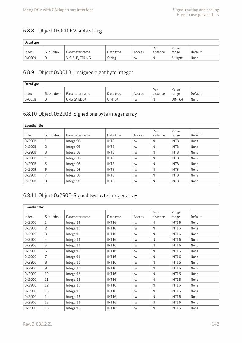
Moog DCV with CANopen bus interface Signal routing and scalingFree to use parameters
Rev. B, 08.12.21 142
6.8.8 Object 0x0009: Visible string
6.8.9 Object 0x001B: Unsigned eight byte integer
6.8.10 Object 0x290B: Signed one byte integer array
6.8.11 Object 0x290C: Signed two byte integer array
DataType
Index Sub-index Parameter name Data type AccessPer-sistence
Value range Default
0x0009 0 VISIBLE_STRING String rw N 64 byte None
DataType
Index Sub-index Parameter name Data type AccessPer-sistence
Value range Default
0x001B 0 UNSIGNED64 UINT64 rw N UINT64 None
Eventhandler
Index Sub-index Parameter name Data type AccessPer-sistence
Value range Default
0x290B 1 Integer08 INT8 rw N INT8 None0x290B 2 Integer08 INT8 rw N INT8 None0x290B 3 Integer08 INT8 rw N INT8 None0x290B 4 Integer08 INT8 rw N INT8 None0x290B 5 Integer08 INT8 rw N INT8 None0x290B 6 Integer08 INT8 rw N INT8 None0x290B 7 Integer08 INT8 rw N INT8 None0x290B 8 Integer08 INT8 rw N INT8 None
Eventhandler
Index Sub-index Parameter name Data type AccessPer-sistence
Value range Default
0x290C 1 Integer16 INT16 rw N INT16 None0x290C 2 Integer16 INT16 rw N INT16 None0x290C 3 Integer16 INT16 rw N INT16 None0x290C 4 Integer16 INT16 rw N INT16 None0x290C 5 Integer16 INT16 rw N INT16 None0x290C 6 Integer16 INT16 rw N INT16 None0x290C 7 Integer16 INT16 rw N INT16 None0x290C 8 Integer16 INT16 rw N INT16 None0x290C 9 Integer16 INT16 rw N INT16 None0x290C 10 Integer16 INT16 rw N INT16 None0x290C 11 Integer16 INT16 rw N INT16 None0x290C 12 Integer16 INT16 rw N INT16 None0x290C 13 Integer16 INT16 rw N INT16 None0x290C 14 Integer16 INT16 rw N INT16 None0x290C 15 Integer16 INT16 rw N INT16 None0x290C 16 Integer16 INT16 rw N INT16 None
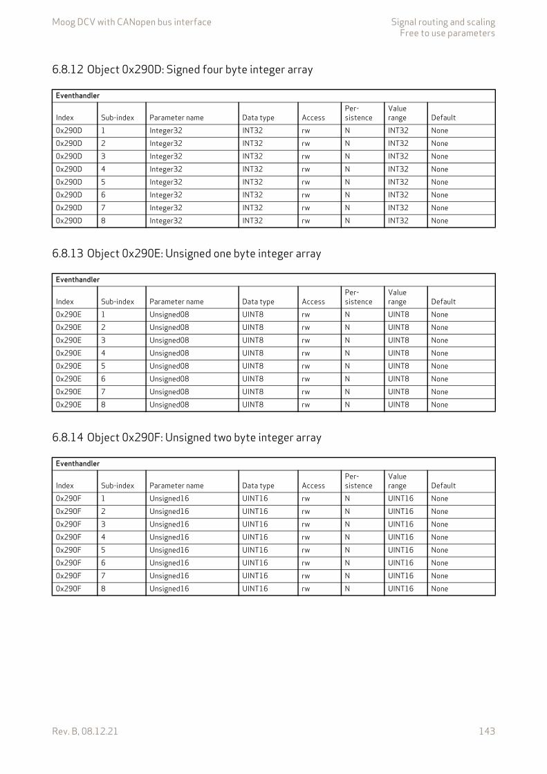
Moog DCV with CANopen bus interface Signal routing and scalingFree to use parameters
Rev. B, 08.12.21 143
6.8.12 Object 0x290D: Signed four byte integer array
6.8.13 Object 0x290E: Unsigned one byte integer array
6.8.14 Object 0x290F: Unsigned two byte integer array
Eventhandler
Index Sub-index Parameter name Data type AccessPer-sistence
Value range Default
0x290D 1 Integer32 INT32 rw N INT32 None0x290D 2 Integer32 INT32 rw N INT32 None0x290D 3 Integer32 INT32 rw N INT32 None0x290D 4 Integer32 INT32 rw N INT32 None0x290D 5 Integer32 INT32 rw N INT32 None0x290D 6 Integer32 INT32 rw N INT32 None0x290D 7 Integer32 INT32 rw N INT32 None0x290D 8 Integer32 INT32 rw N INT32 None
Eventhandler
Index Sub-index Parameter name Data type AccessPer-sistence
Value range Default
0x290E 1 Unsigned08 UINT8 rw N UINT8 None0x290E 2 Unsigned08 UINT8 rw N UINT8 None0x290E 3 Unsigned08 UINT8 rw N UINT8 None0x290E 4 Unsigned08 UINT8 rw N UINT8 None0x290E 5 Unsigned08 UINT8 rw N UINT8 None0x290E 6 Unsigned08 UINT8 rw N UINT8 None0x290E 7 Unsigned08 UINT8 rw N UINT8 None0x290E 8 Unsigned08 UINT8 rw N UINT8 None
Eventhandler
Index Sub-index Parameter name Data type AccessPer-sistence
Value range Default
0x290F 1 Unsigned16 UINT16 rw N UINT16 None0x290F 2 Unsigned16 UINT16 rw N UINT16 None0x290F 3 Unsigned16 UINT16 rw N UINT16 None0x290F 4 Unsigned16 UINT16 rw N UINT16 None0x290F 5 Unsigned16 UINT16 rw N UINT16 None0x290F 6 Unsigned16 UINT16 rw N UINT16 None0x290F 7 Unsigned16 UINT16 rw N UINT16 None0x290F 8 Unsigned16 UINT16 rw N UINT16 None
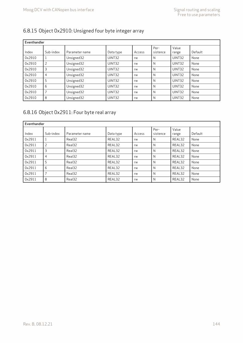
Moog DCV with CANopen bus interface Signal routing and scalingFree to use parameters
Rev. B, 08.12.21 144
6.8.15 Object 0x2910: Unsigned four byte integer array
6.8.16 Object 0x2911: Four byte real array
Eventhandler
Index Sub-index Parameter name Data type AccessPer-sistence
Value range Default
0x2910 1 Unsigned32 UINT32 rw N UINT32 None0x2910 2 Unsigned32 UINT32 rw N UINT32 None0x2910 3 Unsigned32 UINT32 rw N UINT32 None0x2910 4 Unsigned32 UINT32 rw N UINT32 None0x2910 5 Unsigned32 UINT32 rw N UINT32 None0x2910 6 Unsigned32 UINT32 rw N UINT32 None0x2910 7 Unsigned32 UINT32 rw N UINT32 None0x2910 8 Unsigned32 UINT32 rw N UINT32 None
Eventhandler
Index Sub-index Parameter name Data type AccessPer-sistence
Value range Default
0x2911 1 Real32 REAL32 rw N REAL32 None0x2911 2 Real32 REAL32 rw N REAL32 None0x2911 3 Real32 REAL32 rw N REAL32 None0x2911 4 Real32 REAL32 rw N REAL32 None0x2911 5 Real32 REAL32 rw N REAL32 None0x2911 6 Real32 REAL32 rw N REAL32 None0x2911 7 Real32 REAL32 rw N REAL32 None0x2911 8 Real32 REAL32 rw N REAL32 None
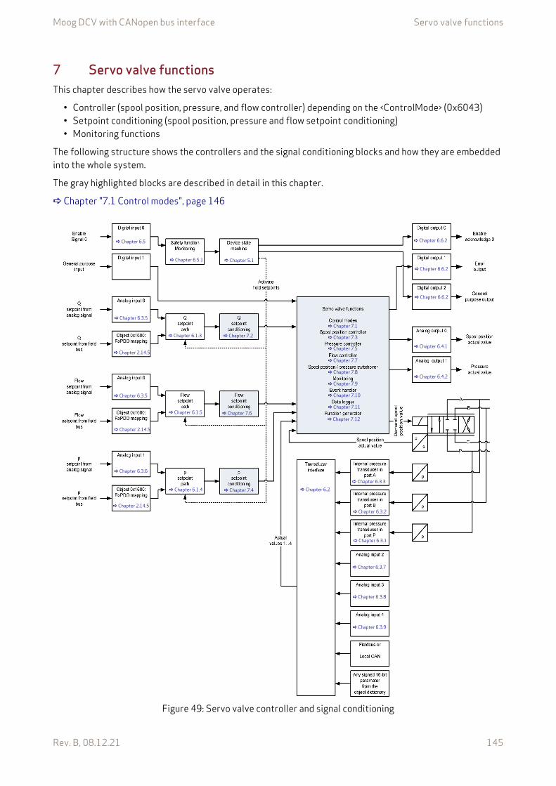
Moog DCV with CANopen bus interface Servo valve functions
Rev. B, 08.12.21 145
7 Servo valve functionsThis chapter describes how the servo valve operates:
• Controller (spool position, pressure, and flow controller) depending on the <ControlMode> (0x6043)• Setpoint conditioning (spool position, pressure and flow setpoint conditioning)• Monitoring functions
The following structure shows the controllers and the signal conditioning blocks and how they are embedded into the whole system.
The gray highlighted blocks are described in detail in this chapter.
Chapter "7.1 Control modes", page 146
Figure 49: Servo valve controller and signal conditioning
Chapter 6.3.5
Chapter 2.14.5
Chapter 5.1 Chapter 6.5.1
Chapter 6.1.4
Chapter 7.2
Chapter 6.2 Chapter 6.3.3
Chapter 6.3.2
Chapter 6.3.1
Chapter 6.4.1
Chapter 6.4.2
Chapter 6.1.5
Chapter 6.1.3
Chapter 7.6
Chapter 7.4
Chapter 6.3.5
Chapter 2.14.5
Chapter 6.3.6
Chapter 2.14.5
Chapter 6.3.7
Chapter 6.3.8
Chapter 6.3.9
Chapter 7.1
Chapter 7.3
Chapter 7.5
Chapter 7.7
Chapter 7.8
Chapter 7.9
Chapter 7.10
Chapter 7.11
Chapter 7.12
Chapter 6.5
Chapter 6.6.2
Chapter 6.6.2
Chapter 6.6.2
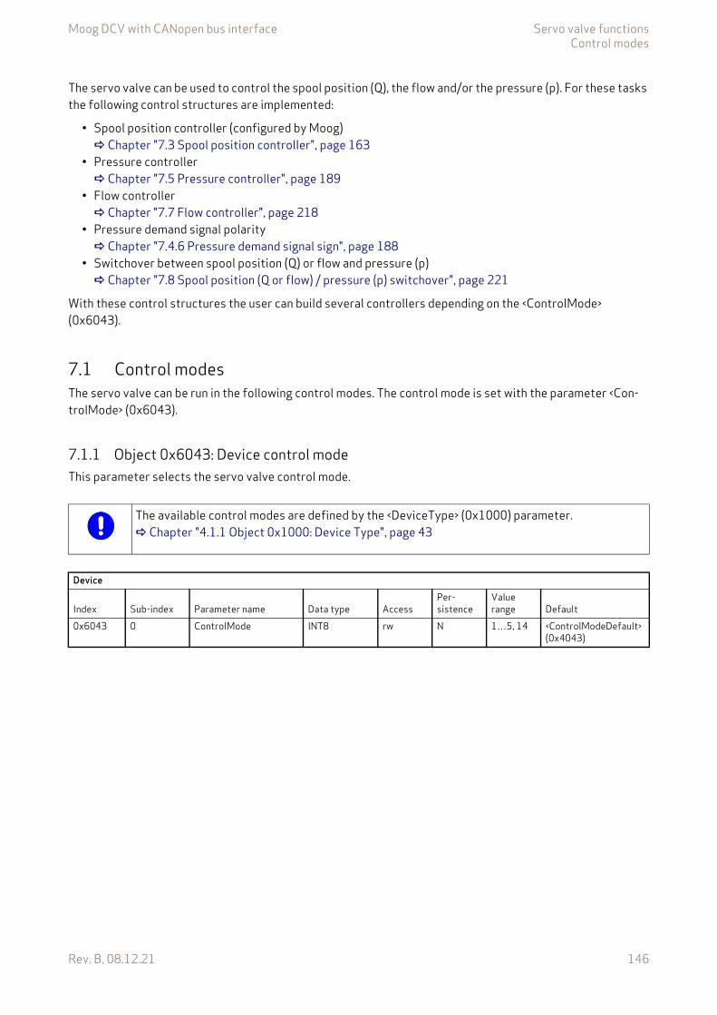
Moog DCV with CANopen bus interface Servo valve functionsControl modes
Rev. B, 08.12.21 146
The servo valve can be used to control the spool position (Q), the flow and/or the pressure (p). For these tasks the following control structures are implemented:
• Spool position controller (configured by Moog) Chapter "7.3 Spool position controller", page 163
• Pressure controller Chapter "7.5 Pressure controller", page 189
• Flow controller Chapter "7.7 Flow controller", page 218
• Pressure demand signal polarity Chapter "7.4.6 Pressure demand signal sign", page 188
• Switchover between spool position (Q) or flow and pressure (p) Chapter "7.8 Spool position (Q or flow) / pressure (p) switchover", page 221
With these control structures the user can build several controllers depending on the <ControlMode> (0x6043).
7.1 Control modesThe servo valve can be run in the following control modes. The control mode is set with the parameter <Con-trolMode> (0x6043).
7.1.1 Object 0x6043: Device control modeThis parameter selects the servo valve control mode.
The available control modes are defined by the <DeviceType> (0x1000) parameter. Chapter "4.1.1 Object 0x1000: Device Type", page 43
Device
Index Sub-index Parameter name Data type AccessPer-sistence
Value range Default
0x6043 0 ControlMode INT8 rw N 1…5, 14 <ControlModeDefault>(0x4043)
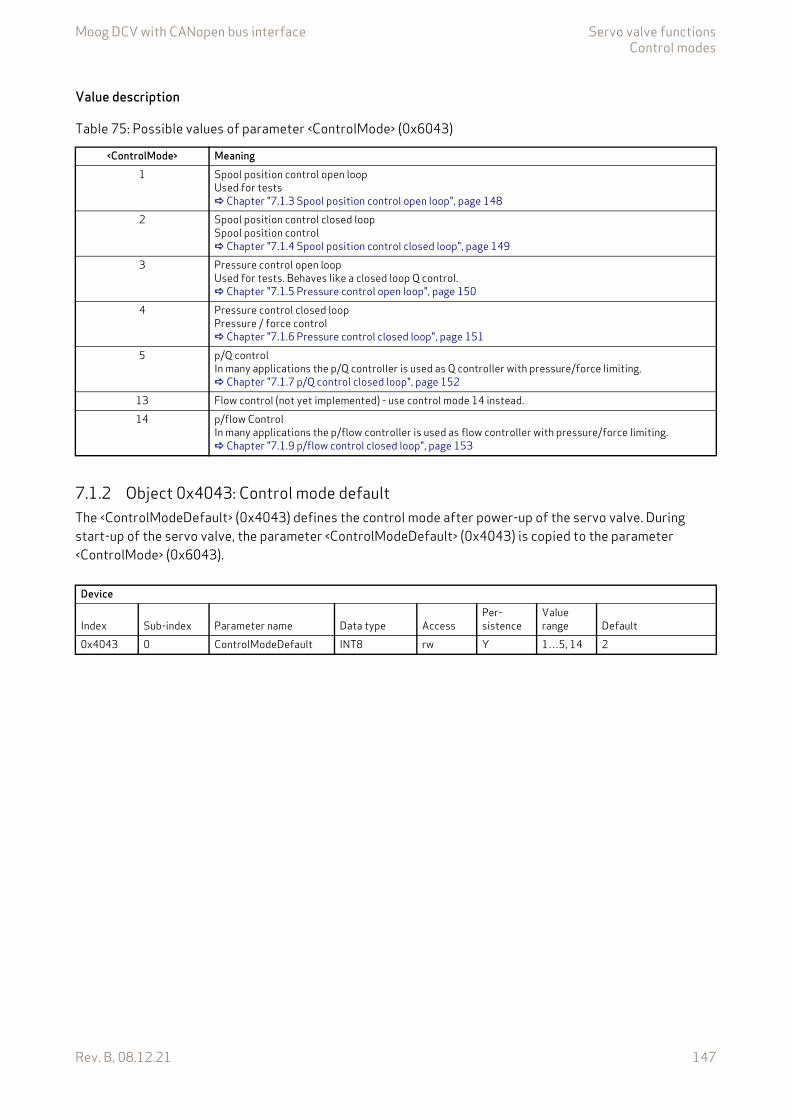
Moog DCV with CANopen bus interface Servo valve functionsControl modes
Rev. B, 08.12.21 147
Value description
7.1.2 Object 0x4043: Control mode defaultThe <ControlModeDefault> (0x4043) defines the control mode after power-up of the servo valve. During start-up of the servo valve, the parameter <ControlModeDefault> (0x4043) is copied to the parameter <ControlMode> (0x6043).
Table 75: Possible values of parameter <ControlMode> (0x6043)
<ControlMode> Meaning1 Spool position control open loop
Used for tests Chapter "7.1.3 Spool position control open loop", page 148
2 Spool position control closed loopSpool position control Chapter "7.1.4 Spool position control closed loop", page 149
3 Pressure control open loopUsed for tests. Behaves like a closed loop Q control. Chapter "7.1.5 Pressure control open loop", page 150
4 Pressure control closed loopPressure / force control Chapter "7.1.6 Pressure control closed loop", page 151
5 p/Q controlIn many applications the p/Q controller is used as Q controller with pressure/force limiting. Chapter "7.1.7 p/Q control closed loop", page 152
13 Flow control (not yet implemented) - use control mode 14 instead.14 p/flow Control
In many applications the p/flow controller is used as flow controller with pressure/force limiting. Chapter "7.1.9 p/flow control closed loop", page 153
Device
Index Sub-index Parameter name Data type AccessPer-sistence
Value range Default
0x4043 0 ControlModeDefault INT8 rw Y 1…5, 14 2

Moog DCV with CANopen bus interface Servo valve functionsControl modes
Rev. B, 08.12.21 148
7.1.3 Spool position control open loopThe spool position open loop mode is selected by setting the parameter <ControlMode> (0x6043) to 1 (spool position control open loop).
Figure 50: Spool position control open loop for single stage valves
Chapter "7.1.1 Object 0x6043: Device control mode", page 146 Chapter "7.2.1 Object 0x6310: Demand value", page 154
In case of a dual stage valve, which is not shown in Figure 50, the pilot valve controller is still active.
Chapter 7.2
This control mode is meant to be used only for commissioning or diagnostic purposes.
The signal #FlowSetpoint# is an internal signal only. It links the signal from the Flow setpoint path to the Flow setpoint conditioning. Chapter "6.1.5 Flow setpoint path", page 69

Moog DCV with CANopen bus interface Servo valve functionsControl modes
Rev. B, 08.12.21 149
7.1.4 Spool position control closed loopThe spool position closed loop mode is selected by setting the parameter <ControlMode> (0x6043) to 2 (spool position control closed loop).
Figure 51: Spool position control closed loop for single stage and dual stage valves
Chapter "7.1.1 Object 0x6043: Device control mode", page 146 Chapter "7.2.1 Object 0x6310: Demand value", page 154
Chapter 7.2
Chapter 7.3
The signal #FlowSetpoint# is an internal signal only. It links the signal from the Flow setpoint path to the Flow setpoint conditioning. Chapter "6.1.5 Flow setpoint path", page 69
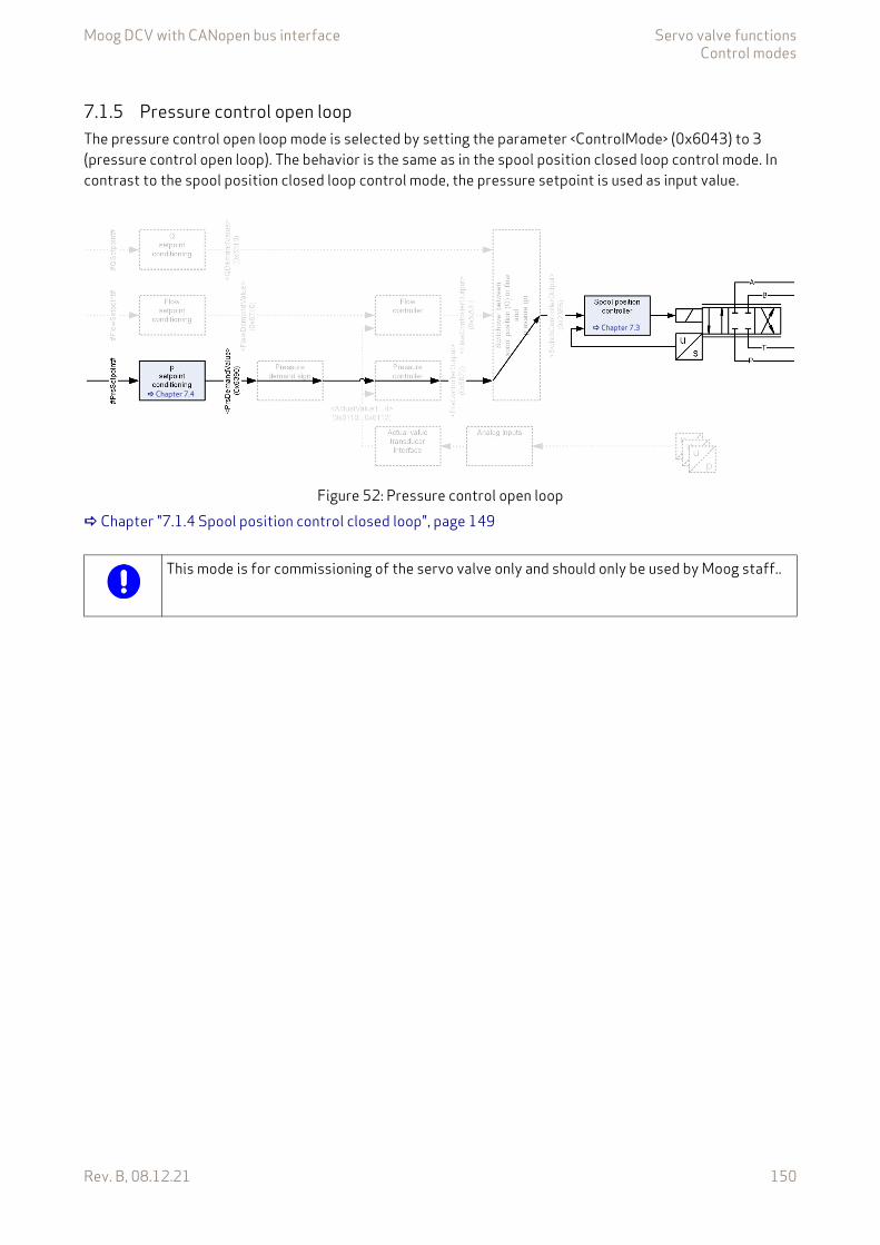
Moog DCV with CANopen bus interface Servo valve functionsControl modes
Rev. B, 08.12.21 150
7.1.5 Pressure control open loopThe pressure control open loop mode is selected by setting the parameter <ControlMode> (0x6043) to 3 (pressure control open loop). The behavior is the same as in the spool position closed loop control mode. In contrast to the spool position closed loop control mode, the pressure setpoint is used as input value.
Figure 52: Pressure control open loop Chapter "7.1.4 Spool position control closed loop", page 149
Chapter 7.4
Chapter 7.3
This mode is for commissioning of the servo valve only and should only be used by Moog staff..
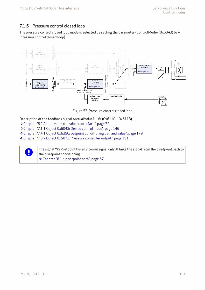
Moog DCV with CANopen bus interface Servo valve functionsControl modes
Rev. B, 08.12.21 151
7.1.6 Pressure control closed loopThe pressure control closed loop mode is selected by setting the parameter <ControlMode> (0x6043) to 4 (pressure control closed loop).
Figure 53: Pressure control closed loop
Description of the feedback signal <ActualValue1…8> (0x6110…0x6113): Chapter "6.2 Actual value transducer interface", page 72 Chapter "7.1.1 Object 0x6043: Device control mode", page 146 Chapter "7.4.1 Object 0x6390: Setpoint conditioning demand value", page 179 Chapter "7.5.7 Object 0x5872: Pressure controller output", page 191
Chapter 7.4
Chapter 7.3
Chapter 7.5
The signal #PrsSetpoint# is an internal signal only. It links the signal from the p setpoint path to the p setpoint conditioning. Chapter "6.1.4 p setpoint path", page 67

Moog DCV with CANopen bus interface Servo valve functionsControl modes
Rev. B, 08.12.21 152
7.1.7 p/Q control closed loopThe p/Q control mode is selected by setting the parameter <ControlMode> (0x6043) to 5 (p/Q control).
Figure 54: p/Q control closed loop
Description of the feedback signal <ActualValue1…4> (0x6110…0x6113): Chapter "6.2 Actual value transducer interface", page 72 Chapter "7.2.1 Object 0x6310: Demand value", page 154 Chapter "7.4.1 Object 0x6390: Setpoint conditioning demand value", page 179 Chapter "7.5.7 Object 0x5872: Pressure controller output", page 191 Chapter "7.8.1.1 Object 0x23E6: Switch controller output", page 222
Chapter 7.3
Chapter 7.5
Chapter 6.3 Chapter 6.2
Chapter 7.4.6
Chapter 7.2
Ch
apte
r7.8
Chapter 7.4
The signal #PrsSetpoint# is an internal signal only. It links the signal from the p setpoint path to the p setpoint conditioning. Chapter "6.1.4 p setpoint path", page 67
The signal #FlowSetpoint# is an internal signal only. It links the signal from the Flow setpoint path to the Flow setpoint conditioning. Chapter "6.1.5 Flow setpoint path", page 69

Moog DCV with CANopen bus interface Servo valve functionsControl modes
Rev. B, 08.12.21 153
7.1.8 Flow control closed loopThe flow control mode is not yet implemented. The control mode p/flow control can be used instead.
Figure 55: Flow control closed loop
7.1.9 p/flow control closed loopThe p/flow control mode is selected by setting the parameter <ControlMode> (0x6043) to 14 (p/flow control).
Figure 56: p/flow control closed loop
Description of the feedback signal <ActualValue1…4> (0x6110…0x6113): Chapter "6.2 Actual value transducer interface", page 72 Chapter "7.6.1 Object 0x6710: Setpoint conditioning demand value", page 209 Chapter "7.4.1 Object 0x6390: Setpoint conditioning demand value", page 179 Chapter "7.5.7 Object 0x5872: Pressure controller output", page 191 Chapter "7.8.1.1 Object 0x23E6: Switch controller output", page 222 Chapter "7.7.4 Object 0x520F: Flow controller output", page 219
Chapter 7.6 Chapter 7.7 Chapter 7.3
Chapter 7.6
Chapter 7.4
Chapter 7.7
Chapter 7.5
Chapter 7.3
The signal #PrsSetpoint# is an internal signal only. It links the signal from the p setpoint path to the p setpoint conditioning. Chapter "6.1.4 p setpoint path", page 67
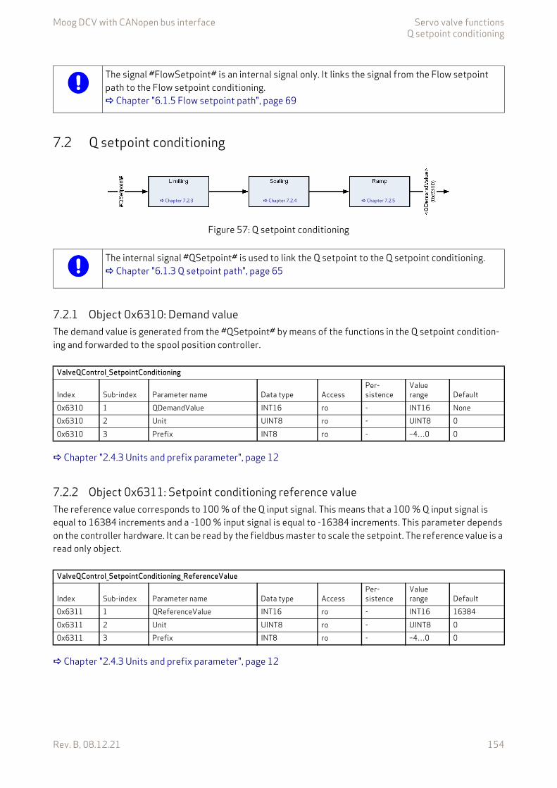
Moog DCV with CANopen bus interface Servo valve functionsQ setpoint conditioning
Rev. B, 08.12.21 154
7.2 Q setpoint conditioning
Figure 57: Q setpoint conditioning
7.2.1 Object 0x6310: Demand valueThe demand value is generated from the #QSetpoint# by means of the functions in the Q setpoint condition-ing and forwarded to the spool position controller.
Chapter "2.4.3 Units and prefix parameter", page 12
7.2.2 Object 0x6311: Setpoint conditioning reference valueThe reference value corresponds to 100 % of the Q input signal. This means that a 100 % Q input signal is equal to 16384 increments and a -100 % input signal is equal to -16384 increments. This parameter depends on the controller hardware. It can be read by the fieldbus master to scale the setpoint. The reference value is a read only object.
Chapter "2.4.3 Units and prefix parameter", page 12
The signal #FlowSetpoint# is an internal signal only. It links the signal from the Flow setpoint path to the Flow setpoint conditioning. Chapter "6.1.5 Flow setpoint path", page 69
Chapter 7.2.3 Chapter 7.2.4 Chapter 7.2.5
The internal signal #QSetpoint# is used to link the Q setpoint to the Q setpoint conditioning. Chapter "6.1.3 Q setpoint path", page 65
ValveQControl_SetpointConditioning
Index Sub-index Parameter name Data type AccessPer-sistence
Value range Default
0x6310 1 QDemandValue INT16 ro - INT16 None0x6310 2 Unit UINT8 ro - UINT8 00x6310 3 Prefix INT8 ro - –4…0 0
ValveQControl_SetpointConditioning_ReferenceValue
Index Sub-index Parameter name Data type AccessPer-sistence
Value range Default
0x6311 1 QReferenceValue INT16 ro - INT16 163840x6311 2 Unit UINT8 ro - UINT8 00x6311 3 Prefix INT8 ro - –4…0 0
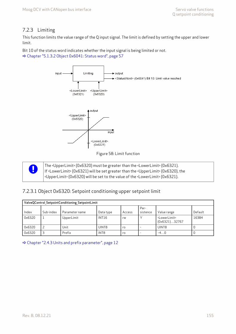
Moog DCV with CANopen bus interface Servo valve functionsQ setpoint conditioning
Rev. B, 08.12.21 155
7.2.3 LimitingThis function limits the value range of the Q input signal. The limit is defined by setting the upper and lower limit.
Bit 10 of the status word indicates whether the input signal is being limited or not. Chapter "5.1.3.2 Object 0x6041: Status word", page 57
Figure 58: Limit function
7.2.3.1 Object 0x6320: Setpoint conditioning upper setpoint limit
Chapter "2.4.3 Units and prefix parameter", page 12
The <UpperLimit> (0x6320) must be greater than the <LowerLimit> (0x6321).If <LowerLimit> (0x6321) will be set greater than the <UpperLimit> (0x6320), the <UpperLimit> (0x6320) will be set to the value of the <LowerLimit> (0x6321).
ValveQControl_SetpointConditioning_SetpointLimit
Index Sub-index Parameter name Data type AccessPer-sistence Value range Default
0x6320 1 UpperLimit INT16 rw Y <LowerLimit>(0x6321)…32767
16384
0x6320 2 Unit UINT8 ro - UINT8 00x6320 3 Prefix INT8 ro - –4…0 0
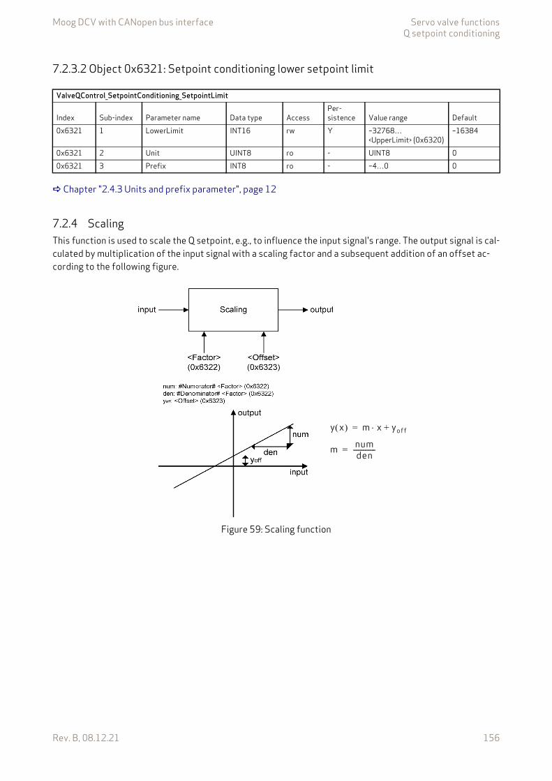
Moog DCV with CANopen bus interface Servo valve functionsQ setpoint conditioning
Rev. B, 08.12.21 156
7.2.3.2 Object 0x6321: Setpoint conditioning lower setpoint limit
Chapter "2.4.3 Units and prefix parameter", page 12
7.2.4 ScalingThis function is used to scale the Q setpoint, e.g., to influence the input signal's range. The output signal is cal-culated by multiplication of the input signal with a scaling factor and a subsequent addition of an offset ac-cording to the following figure.
Figure 59: Scaling function
ValveQControl_SetpointConditioning_SetpointLimit
Index Sub-index Parameter name Data type AccessPer-sistence Value range Default
0x6321 1 LowerLimit INT16 rw Y –32768…<UpperLimit> (0x6320)
–16384
0x6321 2 Unit UINT8 ro - UINT8 00x6321 3 Prefix INT8 ro - –4…0 0
m numden-------------=
y x m x yoff+=

Moog DCV with CANopen bus interface Servo valve functionsQ setpoint conditioning
Rev. B, 08.12.21 157
7.2.4.1 Object 0x6322: Setpoint conditioning scaling factorThis parameter is a slope factor by which the input is multiplied. It is defined by two signed integer values, the numerator (upper 16 bits of the parameter) and the denominator (lower 16 bits of the parameter).
Value description
7.2.4.2 Object 0x6323: Setpoint conditioning scaling offsetThis parameter is the offset of the linear output function.
Chapter "2.4.3 Units and prefix parameter", page 12
ValveQControl_SetpointConditioning_Scaling
Index Sub-index Parameter name Data type AccessPer-sistence Value range Default
0x6322 0 Factor UINT32 rw Y UINT32 0x00010001
Table 76: Data structure of the slope factor
<Factor>Bit 31 16 15 0Description #Numerator# #Denominator#
ValveQControl_SetpointConditioning_Scaling
Index Sub-index Parameter name Data type AccessPer-sistence Value range Default
0x6323 1 Offset INT16 rw Y INT16 00x6323 2 Unit UINT8 ro - UINT8 00x6323 3 Prefix INT8 ro - –4…0 0
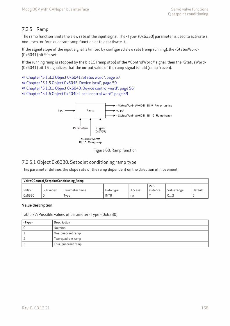
Moog DCV with CANopen bus interface Servo valve functionsQ setpoint conditioning
Rev. B, 08.12.21 158
7.2.5 RampThe ramp function limits the slew rate of the input signal. The <Type> (0x6330) parameter is used to activate a one-, two- or four-quadrant ramp function or to deactivate it.
If the signal slope of the input signal is limited by configured slew rate (ramp running), the <StatusWord> (0x6041) bit 9 is set.
If the running ramp is stopped by the bit 15 (ramp stop) of the #ControlWord# signal, then the <StatusWord> (0x6041) bit 15 signalizes that the output value of the ramp signal is hold (ramp frozen).
Chapter "5.1.3.2 Object 0x6041: Status word", page 57 Chapter "5.1.5 Object 0x604F: Device local", page 59 Chapter "5.1.3.1 Object 0x6040: Device control word", page 56 Chapter "5.1.6 Object 0x4040: Local control word", page 59
Figure 60: Ramp function
7.2.5.1 Object 0x6330: Setpoint conditioning ramp typeThis parameter defines the slope rate of the ramp dependent on the direction of movement.
Value description
ValveQControl_SetpointConditioning_Ramp
Index Sub-index Parameter name Data type AccessPer-sistence Value range Default
0x6330 0 Type INT8 rw Y 0…3 0
Table 77: Possible values of parameter <Type> (0x6330)
<Type> Description0 No ramp1 One-quadrant ramp2 Two-quadrant ramp3 Four-quadrant ramp
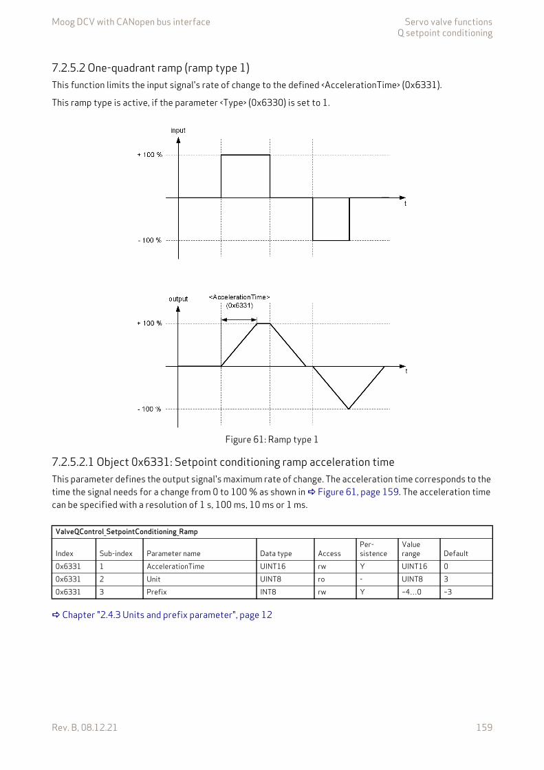
Moog DCV with CANopen bus interface Servo valve functionsQ setpoint conditioning
Rev. B, 08.12.21 159
7.2.5.2 One-quadrant ramp (ramp type 1)This function limits the input signal's rate of change to the defined <AccelerationTime> (0x6331).
This ramp type is active, if the parameter <Type> (0x6330) is set to 1.
Figure 61: Ramp type 1
7.2.5.2.1 Object 0x6331: Setpoint conditioning ramp acceleration timeThis parameter defines the output signal's maximum rate of change. The acceleration time corresponds to the time the signal needs for a change from 0 to 100 % as shown in Figure 61, page 159. The acceleration time can be specified with a resolution of 1 s, 100 ms, 10 ms or 1 ms.
Chapter "2.4.3 Units and prefix parameter", page 12
ValveQControl_SetpointConditioning_Ramp
Index Sub-index Parameter name Data type AccessPer-sistence
Value range Default
0x6331 1 AccelerationTime UINT16 rw Y UINT16 00x6331 2 Unit UINT8 ro - UINT8 30x6331 3 Prefix INT8 rw Y –4…0 –3
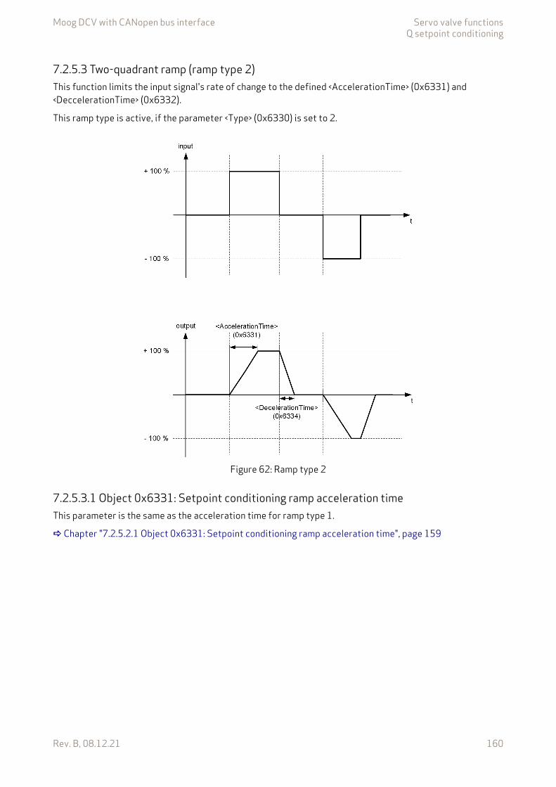
Moog DCV with CANopen bus interface Servo valve functionsQ setpoint conditioning
Rev. B, 08.12.21 160
7.2.5.3 Two-quadrant ramp (ramp type 2)This function limits the input signal's rate of change to the defined <AccelerationTime> (0x6331) and <DeccelerationTime> (0x6332).
This ramp type is active, if the parameter <Type> (0x6330) is set to 2.
Figure 62: Ramp type 2
7.2.5.3.1 Object 0x6331: Setpoint conditioning ramp acceleration timeThis parameter is the same as the acceleration time for ramp type 1.
Chapter "7.2.5.2.1 Object 0x6331: Setpoint conditioning ramp acceleration time", page 159
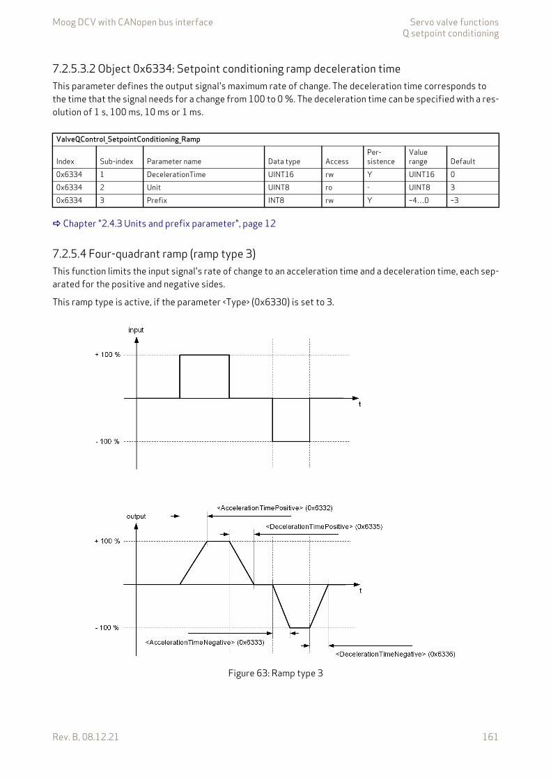
Moog DCV with CANopen bus interface Servo valve functionsQ setpoint conditioning
Rev. B, 08.12.21 161
7.2.5.3.2 Object 0x6334: Setpoint conditioning ramp deceleration timeThis parameter defines the output signal's maximum rate of change. The deceleration time corresponds to the time that the signal needs for a change from 100 to 0 %. The deceleration time can be specified with a res-olution of 1 s, 100 ms, 10 ms or 1 ms.
Chapter "2.4.3 Units and prefix parameter", page 12
7.2.5.4 Four-quadrant ramp (ramp type 3)This function limits the input signal's rate of change to an acceleration time and a deceleration time, each sep-arated for the positive and negative sides.
This ramp type is active, if the parameter <Type> (0x6330) is set to 3.
Figure 63: Ramp type 3
ValveQControl_SetpointConditioning_Ramp
Index Sub-index Parameter name Data type AccessPer-sistence
Value range Default
0x6334 1 DecelerationTime UINT16 rw Y UINT16 00x6334 2 Unit UINT8 ro - UINT8 30x6334 3 Prefix INT8 rw Y –4…0 –3

Moog DCV with CANopen bus interface Servo valve functionsQ setpoint conditioning
Rev. B, 08.12.21 162
7.2.5.4.1 Object 0x6332: Setpoint conditioning ramp acceleration time positiveThis parameter defines the output signal's maximum rate of change on the positive side. The acceleration time corresponds to the time that the signal needs for a change from 0 to 100 %. The acceleration time can be specified with a resolution of 1 s, 100 ms, 10 ms or 1 ms.
Chapter "2.4.3 Units and prefix parameter", page 12
7.2.5.4.2 Object 0x6333: Setpoint conditioning ramp acceleration time negativeThis parameter defines the output signal's maximum rate of change on the negative side. The acceleration time corresponds to the time that the signal needs for a change from 0 to 100 %. The acceleration time can be specified with a resolution of 1 s, 100 ms, 10 ms or 1 ms.
Chapter "2.4.3 Units and prefix parameter", page 12
7.2.5.4.3 Object 0x6335: Setpoint conditioning ramp deceleration time positiveThis parameter defines the output signal's maximum rate of change on the positive side. The deceleration time corresponds to the time that the signal needs for a change from 100 to 0 %. The deceleration time can be specified with a resolution of 1 s, 100 ms, 10 ms or 1 ms.
Chapter "2.4.3 Units and prefix parameter", page 12
ValveQControl_SetpointConditioning_Ramp
Index Sub-index Parameter name Data type AccessPer-sistence
Value range Default
0x6332 1 AccelerationTimePositive UINT16 rw Y UINT16 00x6332 2 Unit UINT8 ro - UINT8 30x6332 3 Prefix INT8 rw Y –4…0 –3
ValveQControl_SetpointConditioning_Ramp
Index Sub-index Parameter name Data type AccessPer-sistence
Value range Default
0x6333 1 AccelerationTimeNegative UINT16 rw Y UINT16 00x6333 2 Unit UINT8 ro - UINT8 30x6333 3 Prefix INT8 rw Y –4…0 –3
ValveQControl_SetpointConditioning_Ramp
Index Sub-index Parameter name Data type AccessPer-sistence
Value range Default
0x6335 1 DecelerationTimePositive UINT16 rw Y UINT16 00x6335 2 Unit UINT8 ro - UINT8 30x6335 3 Prefix INT8 rw Y –4…0 –3

Moog DCV with CANopen bus interface Servo valve functionsSpool position controller
Rev. B, 08.12.21 163
7.2.5.4.4 Object 0x6336: Setpoint conditioning ramp deceleration time negativeThis parameter defines the output signal's maximum rate of change on the negative side. The deceleration time corresponds to the time that the signal needs for a change from 100 to 0 %. The deceleration time can be specified with a resolution of 1 s, 100 ms, 10 ms or 1 ms.
Chapter "2.4.3 Units and prefix parameter", page 12
7.3 Spool position controllerThe spool position controller controls the spool position and thus the flow of the oil. The parameters are set up by Moog during production. Only for the sake of completeness will some details be explained in this sec-tion. The user should understand the difference between a single stage and a dual stage servo valve.
Single stage means one spool position control loop. Dual stage means two (nested) spool position control loops.
7.3.1 Single stage servo valveControl structure of a single stage servo valve closed loop control. For a single stage servo valve, there is only one spool position controller which is the pilot stage controller. If the spool position control open loop is se-lected by setting the parameter <ControlMode> (0x6043) to 1, the spool position actuator conditioning and the spool position controller are bypassed.
Figure 64: Single stage servo valve
ValveQControl_SetpointConditioning_Ramp
Index Sub-index Parameter name Data type AccessPer-sistence
Value range Default
0x6336 1 DecelerationTimeNegative UINT16 rw Y UINT16 00x6336 2 Unit UINT8 ro - UINT8 30x6336 3 Prefix INT8 rw Y –4…0 –3
The spool position controller is configured in the factory and cannot be changed by the user.
Chapter 7.3.4
Chapter 7.3.3
Chapter 7.3
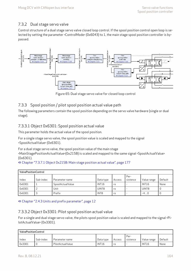
Moog DCV with CANopen bus interface Servo valve functionsSpool position controller
Rev. B, 08.12.21 164
7.3.2 Dual stage servo valveControl structure of a dual stage servo valve closed loop control. If the spool position control open loop is se-lected by setting the parameter <ControlMode> (0x6043) to 1, the main stage spool position controller is by-passed.
Figure 65: Dual stage servo valve for closed loop control
7.3.3 Spool position / pilot spool position actual value pathThe following parameters contain the spool position depending on the servo valve hardware (single or dual stage).
7.3.3.1 Object 0x6301: Spool position actual valueThis parameter holds the actual value of the spool position.
For a single stage servo valve, the spool position value is scaled and mapped to the signal <SpoolActualValue> (0x6301).
For a dual stage servo valve, the spool position value of the main stage <MainStagePositionActualValue>(0x215B) is scaled and mapped to the same signal <SpoolActualValue> (0x6301). Chapter "7.3.7.1 Object 0x215B: Main stage position actual value", page 177
Chapter "2.4.3 Units and prefix parameter", page 12
7.3.3.2 Object 0x3301: Pilot spool position actual valueFor a single and dual stage servo valve, the pilots spool position value is scaled and mapped to the signal <Pi-lotActualValue> (0x3301).
Chapter 7.3.6
Chapter 7.3.3
Chapter 7.3.7
Chapter 7.3.4 Chapter 7.3.8 Chapter 7.3.5
ValvePositionControl
Index Sub-index Parameter name Data type AccessPer-sistence Value range Default
0x6301 1 SpoolActualValue INT16 ro - INT16 None0x6301 2 Unit UINT8 ro - UINT8 00x6301 3 Prefix INT8 ro - –4…0 0
ValvePositionControl
Index Sub-index Parameter name Data type AccessPer-sistence Value range Default
0x3301 0 PilotActualValue INT16 ro - INT16 None

Moog DCV with CANopen bus interface Servo valve functionsSpool position controller
Rev. B, 08.12.21 165
7.3.4 Spool position / main stage spool position actuator conditioningActuator conditioning of a servo valve.
Figure 66: Spool position / main stage spool position actuator conditioning
The following parameters contain the spool position setpoint and demand value depending on the servo valve hardware. Chapter "7.8.1.1 Object 0x23E6: Switch controller output", page 222
7.3.4.1 Object 0x6313: Spool position demand valueThis object provides the output of the actuator conditioning of a single or dual stage servo valve.
Chapter "2.4.3 Units and prefix parameter", page 12
7.3.4.2 Object 0x216D: Main stage spool position demand valueThis object provides the output of the actuator conditioning of the main stage.
7.3.4.3 Directional dependent gainThis function reduces the input signal's gain by a <Factor> (0x6341) depending on the sign of the signal. The function has either an effect on the positive or the negative side of the input signal. This feature provides compensation for the different extend and retract velocities that result from cylinders with unequal area and from some load conditions. For a double rod cylinder this compensation factor is typically 1.0 but can be mod-ified if the load favors one direction. This compensation need only be approximate but it helps ensure that the closed loop response in both extend and retract directions is symmetrical.
Chapter 7.3.4.3 Chapter 7.3.4.4 Chapter 7.3.4.5 Chapter 7.3.4.8
ValvePositionControl
Index Sub-index Parameter name Data type AccessPer-sistence Value range Default
0x6313 1 SplPositionDemandValue INT16 ro - INT16 None0x6313 2 Unit UINT8 ro - UINT8 00x6313 3 Prefix INT8 ro - –4…0 0
ValveMainStageControl
Index Sub-index Parameter name Data type AccessPer-sistence Value range Default
0x216D 1 MainStageSplDemandValue INT16 ro - INT16 None
The actual flow depends not only on servo valve opening but on pressure loss in the servo valve and the system load.

Moog DCV with CANopen bus interface Servo valve functionsSpool position controller
Rev. B, 08.12.21 166
Figure 67: Direction dependent gain
7.3.4.3.1 Object 0x6340: Actuator conditioning directional dependent gain typeThis parameter switches the directional dependent gain function on or off.
Value description
Table 78: Definition of the directional dependent gain factor values
<Factor> Input Resulting outputInput positiveInput negative
Input positiveInput negative
Factor 1 Output Input Factor=
Output Input=
Factor 1 Output Input=
Output InputFactor----------------------=
Valve_ActuatorConditioning_DirectionalDependentGain
Index Sub-index Parameter name Data type AccessPer-sistence Value range Default
0x6340 0 Type INT8 rw Y 0…1 0
Table 79: Possible values of parameter <Type> (0x6340)
<Type> Description0 Directional dependent gain function switched off.1 Directional dependent gain activated.

Moog DCV with CANopen bus interface Servo valve functionsSpool position controller
Rev. B, 08.12.21 167
7.3.4.3.2 Object 0x6341: Actuator conditioning directional dependent gain factorThe factor is calculated from a numerator (upper 16 bits of the parameter) and a denominator (lower 16 bits of the parameter). The value of the parameter <Factor> is only effective, if the parameter <Type> (0x6340) is set to 1 (directional dependent gain function activated). The default value 0x00010001 corresponds to the factor 1.0.
Value description
Valve_ActuatorConditioning_DirectionalDependentGain
Index Sub-index Parameter name Data type AccessPer-sistence Value range Default
0x6341 0 Factor UINT32 rw Y UINT32 0x00010001
Table 80: Data structure of the directional dependent gain factor
<Factor>Bit 31 16 15 0Description #Numerator# #Denominator#
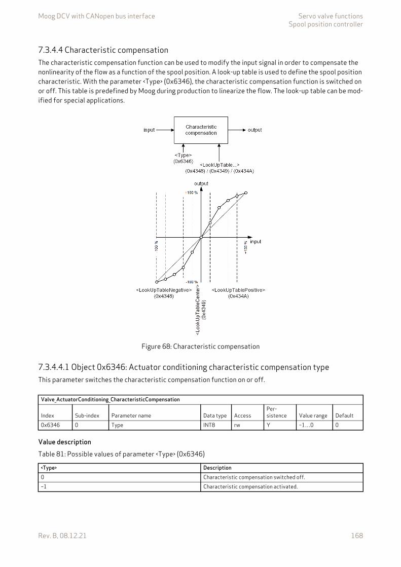
Moog DCV with CANopen bus interface Servo valve functionsSpool position controller
Rev. B, 08.12.21 168
7.3.4.4 Characteristic compensationThe characteristic compensation function can be used to modify the input signal in order to compensate the nonlinearity of the flow as a function of the spool position. A look-up table is used to define the spool position characteristic. With the parameter <Type> (0x6346), the characteristic compensation function is switched on or off. This table is predefined by Moog during production to linearize the flow. The look-up table can be mod-ified for special applications.
Figure 68: Characteristic compensation
7.3.4.4.1 Object 0x6346: Actuator conditioning characteristic compensation typeThis parameter switches the characteristic compensation function on or off.
Value description
Valve_ActuatorConditioning_CharacteristicCompensation
Index Sub-index Parameter name Data type AccessPer-sistence Value range Default
0x6346 0 Type INT8 rw Y –1…0 0
Table 81: Possible values of parameter <Type> (0x6346)
<Type> Description0 Characteristic compensation switched off.–1 Characteristic compensation activated.

Moog DCV with CANopen bus interface Servo valve functionsSpool position controller
Rev. B, 08.12.21 169
7.3.4.4.2 Look-up tableThe look-up table contains 257 sampling points and defines the characteristic curve. Intermediate values are linearly interpolated. The characteristic compensation function is activated with the parameter <Type> (0x6346) set to –1.
The distances between the input values are fixed to 128 increments per step. The possible input value range is –16384…16384 increments.
7.3.4.4.2.1 Object 0x4347: Look-up tableThis parameter is for Moog internal use only.
7.3.4.4.2.2 Object 0x4348: Look-up tableThis object contains the output values corresponding to the negative input values.
Index Sub-index Input values (fixed values)E.g. linear output values (parameter values)
<LookUpTable> (0x4348) 1 –16384 –16384<LookUpTable> (0x4348) 2 –16256 –16256<LookUpTable> (0x4348) 3…127 … …<LookUpTable> (0x4348) 128 –128 –128<LookUpTable> (0x4349) 0 0 0<LookUpTable> (0x434A) 1 128 128<LookUpTable> (0x434A) 2 256 256<LookUpTable> (0x434A) 3…127 … …<LookUpTable> (0x434A) 128 16384 16384
When an input value is less than –16384, the output value equals the value of sampling point <LookUpTable> (0x4348), sub-index 1. When a value is greater than 16384, the output value equals the value of sampling point <LookUpTable> (0x434A), sub-index 128.
Valve_ActuatorConditioning_CharacteristicCompensation
Index Sub-index Parameter name Data type Access
Per-sis-tence Value range Default
0x4347 0 LookUpTable DOMAIN rw Y DOMAIN
Valve_ActuatorConditioning_CharacteristicCompensation
Index Sub-index Parameter name Data type Access
Per-sis-tence Value range Default
0x4348 1…128 LookUpTableNegative INT16 rw Y INT16 0
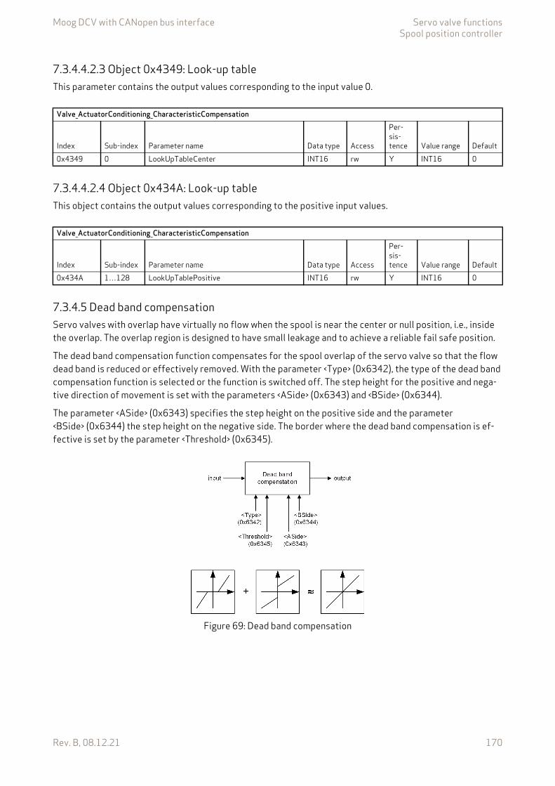
Moog DCV with CANopen bus interface Servo valve functionsSpool position controller
Rev. B, 08.12.21 170
7.3.4.4.2.3 Object 0x4349: Look-up tableThis parameter contains the output values corresponding to the input value 0.
7.3.4.4.2.4 Object 0x434A: Look-up tableThis object contains the output values corresponding to the positive input values.
7.3.4.5 Dead band compensationServo valves with overlap have virtually no flow when the spool is near the center or null position, i.e., inside the overlap. The overlap region is designed to have small leakage and to achieve a reliable fail safe position.
The dead band compensation function compensates for the spool overlap of the servo valve so that the flow dead band is reduced or effectively removed. With the parameter <Type> (0x6342), the type of the dead band compensation function is selected or the function is switched off. The step height for the positive and nega-tive direction of movement is set with the parameters <ASide> (0x6343) and <BSide> (0x6344).
The parameter <ASide> (0x6343) specifies the step height on the positive side and the parameter <BSide> (0x6344) the step height on the negative side. The border where the dead band compensation is ef-fective is set by the parameter <Threshold> (0x6345).
Figure 69: Dead band compensation
Valve_ActuatorConditioning_CharacteristicCompensation
Index Sub-index Parameter name Data type Access
Per-sis-tence Value range Default
0x4349 0 LookUpTableCenter INT16 rw Y INT16 0
Valve_ActuatorConditioning_CharacteristicCompensation
Index Sub-index Parameter name Data type Access
Per-sis-tence Value range Default
0x434A 1…128 LookUpTablePositive INT16 rw Y INT16 0

Moog DCV with CANopen bus interface Servo valve functionsSpool position controller
Rev. B, 08.12.21 171
7.3.4.5.1 Object 0x6342: Actuator conditioning dead band compensation typeThis parameter is used to select the compensation type or to switch off the dead band compensation func-tion.
Value description
7.3.4.5.2 Object 0x6343: Actuator conditioning dead band compensation A sideThis parameter defines the step height of the dead band on the positive side.
Chapter "2.4.3 Units and prefix parameter", page 12
7.3.4.5.3 Object 0x6344: Actuator conditioning dead band compensation B sideThis parameter defines the step height of the dead band on the negative side.
Chapter "2.4.3 Units and prefix parameter", page 12
Valve_ActuatorConditioning_DeadbandCompensation
Index Sub-index Parameter name Data type AccessPer-sistence Value range Default
0x6342 0 Type INT8 rw Y 0…2 0
Table 82: Possible values of parameter <Type> (0x6342)
<Type> Description0 Dead band compensation switched off.1 Dead band jump function.2 Dead band continuous function (recommended).
Valve_ActuatorConditioning_DeadbandCompensation
Index Sub-index Parameter name Data type AccessPer-sistence Value range Default
0x6343 1 ASide INT16 rw Y 0…16384 00x6343 2 Unit UINT8 ro - UINT8 00x6343 3 Prefix INT8 ro - –4…0 0
Valve_ActuatorConditioning_DeadbandCompensation
Index Sub-index Parameter name Data type AccessPer-sistence Value range Default
0x6344 1 BSide INT16 rw Y 0…16384 00x6344 2 Unit UINT8 ro - UINT8 00x6344 3 Prefix INT8 ro - –4…0 0

Moog DCV with CANopen bus interface Servo valve functionsSpool position controller
Rev. B, 08.12.21 172
7.3.4.5.4 Object 0x6345: Actuator conditioning dead band compensation thresholdThis parameter defines the positions of the steps (<ASide> (0x6343) and <BSide> (0x6344)). This determines the starting point of the dead band compensation step.
Chapter "2.4.3 Units and prefix parameter", page 12
7.3.4.6 Jump function (dead band compensation type 1)If the input signals keep within the limits of the threshold value (set with parameter <Threshold>, 0x6345), the output signal will be zero. At the threshold positions the output signal is increased or decreased by the step height defined by the parameter <ASide> (0x6343) or <BSide> (0x6344). The output signal is interpolated in the area between the threshold positions and 100 % of the input signal.
This dead band jump function is activated with the parameter <Type> (0x6342) set to 1 (dead band jump func-tion).
Figure 70: Dead band compensation type 1
7.3.4.7 Continuous function (dead band compensation type 2)If the input signals keep within the range of the threshold value (set with parameter <Threshold>, 0x6345), the output values will be interpolated between zero and the values defined by the parameters <ASide> (0x6343) or <BSide> (0x6344), respectively. At the threshold position the output signal is increased or decreased by the values set for the <ASide> (0x6343) or <BSide> (0x6344). The output signal is interpolated in the area between the threshold limit and 100 % of the input signal.
Valve_ActuatorConditioning_DeadbandCompensation
Index Sub-index Parameter name Data type AccessPer-sistence Value range Default
0x6345 1 Threshold INT16 rw Y 0…16383 00x6345 2 Unit UINT8 ro - UINT8 00x6345 3 Prefix INT8 ro - –4…0 0
This function serves to achieve a continuous transition between the areas that are within and outside of the threshold value.
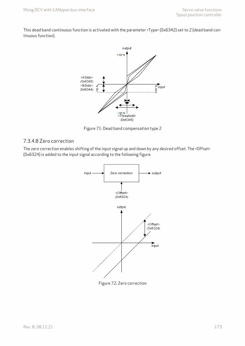
Moog DCV with CANopen bus interface Servo valve functionsSpool position controller
Rev. B, 08.12.21 173
This dead band continuous function is activated with the parameter <Type> (0x6342) set to 2 (dead band con-tinuous function).
Figure 71: Dead band compensation type 2
7.3.4.8 Zero correctionThe zero correction enables shifting of the input signal up and down by any desired offset. The <Offset> (0x6324) is added to the input signal according to the following figure.
Figure 72: Zero correction
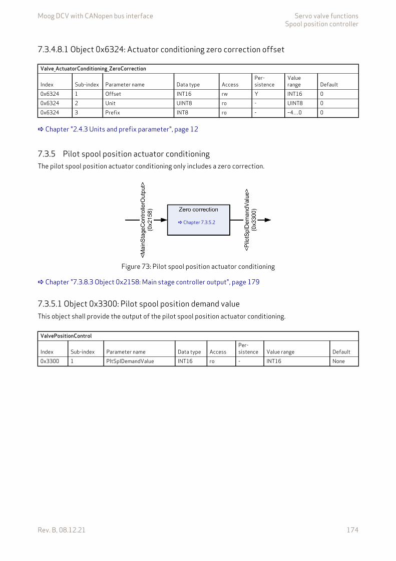
Moog DCV with CANopen bus interface Servo valve functionsSpool position controller
Rev. B, 08.12.21 174
7.3.4.8.1 Object 0x6324: Actuator conditioning zero correction offset
Chapter "2.4.3 Units and prefix parameter", page 12
7.3.5 Pilot spool position actuator conditioningThe pilot spool position actuator conditioning only includes a zero correction.
Figure 73: Pilot spool position actuator conditioning
Chapter "7.3.8.3 Object 0x2158: Main stage controller output", page 179
7.3.5.1 Object 0x3300: Pilot spool position demand valueThis object shall provide the output of the pilot spool position actuator conditioning.
Valve_ActuatorConditioning_ZeroCorrection
Index Sub-index Parameter name Data type AccessPer-sistence
Value range Default
0x6324 1 Offset INT16 rw Y INT16 00x6324 2 Unit UINT8 ro - UINT8 00x6324 3 Prefix INT8 ro - –4…0 0
Chapter 7.3.5.2
ValvePositionControl
Index Sub-index Parameter name Data type AccessPer-sistence Value range Default
0x3300 1 PltSplDemandValue INT16 ro - INT16 None

Moog DCV with CANopen bus interface Servo valve functionsSpool position controller
Rev. B, 08.12.21 175
7.3.5.2 Zero correctionThe zero correction enables shifting of the input signal up and down by any desired offset. The <OffsetForPilotInDualStageMode> (0x242E) is added to the input signal according to the following figure.
Figure 74: Zero correction
7.3.5.2.1 Object 0x242E: Offset for pilot spool position in dual stage modeThis parameter allows an offset to the pilot valve spool position <PilotSplDemandValue> (0x3300). This off-set may help for example in case of a temperature drift or another drift.
7.3.6 Spool position / pilot spool position controllerFor a single stage servo valve this spool position controller controls the spool position. The parameter <SplControlDeviation> (0x6350) holds the spool position control deviation.
For a dual stage servo valve, this spool controller is used to control the pilots spool position. The main stage is controlled by the main stage spool position controller. The parameter <SplControlDeviation> (0x6350) holds the main stage spool position control deviation. The parameter <PilotControlDeviation> (0x3302) holds the pilot stage spool control deviation.
Valve_ActuatorConditioningIndex Sub-index Parameter name Data type Access Persistence Value range Default0x242E 0 OffsetForPilotInDualStageMode INT16 rw Y INT16 0
Moog DCV with CANopen bus interface Servo valve functionsSpool position controller
Rev. B, 08.12.21 176
7.3.6.1 Object 0x6350: Control deviationThe control deviation is the difference between the setpoint and the actual value. In case of a dual stage servo valve this parameter holds the control deviation of the main stage spool position. In case of the single stage servo valve this parameter holds the control deviation of the pilot stage spool position.
Chapter "2.4.3 Units and prefix parameter", page 12
7.3.6.2 Object 0x3302: Pilot control deviationThe pilot control deviation is the difference between the setpoint and the actual value. In case of a dual stage servo valve, this parameter holds the control deviation of the pilot spool position. In case of a single stage valve, this parameter has the same value as <SplControlDeviation> (0x6350).
7.3.6.3 Object 0x2416: Integrator test valueThis parameter holds the controller output of the I-part of the pilot spool position controller.
7.3.6.4 Object 0x241F: Customer Overall GainThis gain is accessible for the customer. It will be multiplied to the output of the pilot spool position control-ler. (Gain over all of this controller.)
ValvePositionControl
Index Sub-index Parameter name Data type AccessPer-sistence Value range Default
0x6350 1 SplControlDeviation INT16 ro - INT16 None0x6350 2 Unit UINT8 ro - UINT8 00x6350 3 Prefix INT8 ro - –4…0 0
ValvePositionControl
Index Sub-index Parameter name Data type AccessPer-sistence Value range Default
0x3302 0 PilotControlDeviation INT16 r Y INT16 -
IntegratorTestValue
Index Sub-index Parameter name Data type AccessPer-sistence Value range Default
0x2416 0 IntegratorTestValue INT32 r Y INT32 -
ValvePositionControl
Index Sub-index Parameter name Data type AccessPer-sistence Value range Default
0x241F 0 CustomerOverallGain REAL32 rw Y 0.0…2.0 1.0

Moog DCV with CANopen bus interface Servo valve functionsSpool position controller
Rev. B, 08.12.21 177
7.3.7 Main stage spool position actual value pathIf a dual stage servo valve is used, the main stage spool position actual value is scaled and mapped to the signal <MainStagePositionActualValue> (0x215B) and the signal <SpoolActualValue> (0x6301).
Figure 75: Main stage spool position actual value path
Chapter "7.3.3.1 Object 0x6301: Spool position actual value", page 164
7.3.7.1 Object 0x215B: Main stage position actual valueThis parameter holds the main stage spool position actual value.
Chapter 7.3.7.2
ValvePositionControl
Index Sub-index Parameter name Data type AccessPer-sistence Value range Default
0x215B 1 MainStagePositionActualValue INT16 ro - INT16 None

Moog DCV with CANopen bus interface Servo valve functionsSpool position controller
Rev. B, 08.12.21 178
7.3.7.2 Object 0x3237: Customer scaling of main stage spool position sensorThis parameter is used to scale the input from the main stage spool position sensor (external LVDT) to the actual main stage spool position.
Figure 76: Customer scaling of main stage spool position sensor
7.3.8 Main stage spool position controllerThe main stage spool position controller will be only used for dual stage servo valves. The main stage spool position control deviation and the main stage spool position controller output can be accessed by corre-sponding output parameters.
Chapter "7.3.6.1 Object 0x6350: Control deviation", page 176
7.3.8.1 Object 0x215C: Main stage customer overall gainThe internal controller output will be multiplied with this gain to get the <ControllerOutput> (0x2158).
ExternalLVDT
Index Sub-index Parameter name Data type AccessPer-sistence Value range Default
0x3237 1 ExternalLvdtScaNumerator INT16 rw Y INT16 163860x3237 2 ExternalLvdtScaDenominator INT16 rw Y INT16 163860x3237 3 ExternalLvdtOffset INT16 rw Y INT16 0
ValveMainStageControl
Index Sub-index Parameter name Data type AccessPer-sistence Value range Default
0x215C 0 MainStageCustomerOverallGain REAL32 rw Y 0.0…2.0 1.0
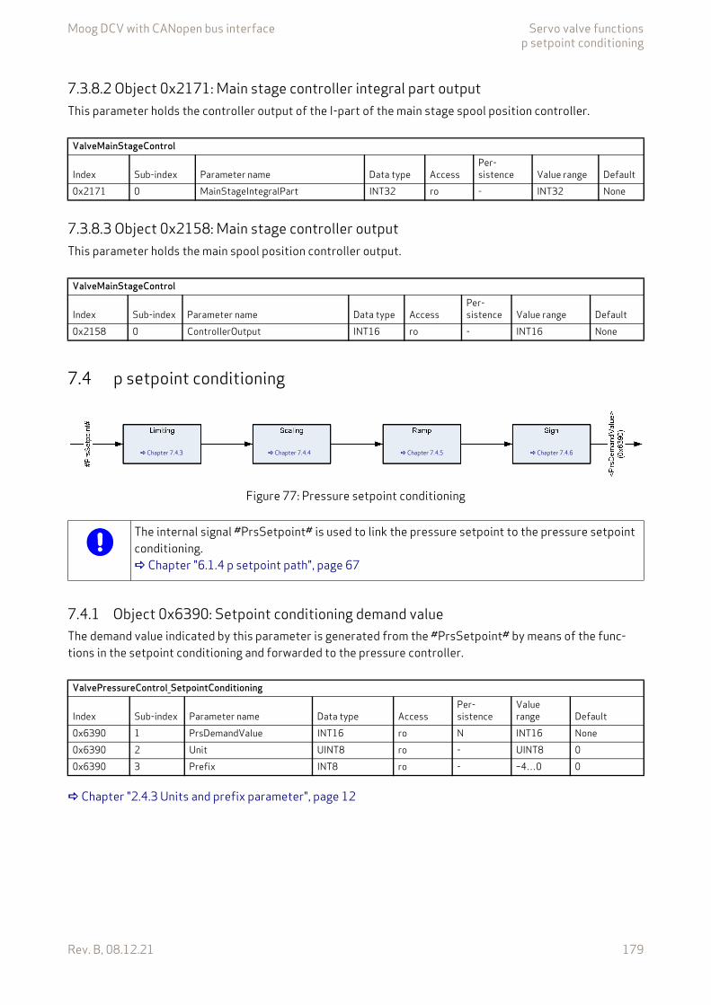
Moog DCV with CANopen bus interface Servo valve functionsp setpoint conditioning
Rev. B, 08.12.21 179
7.3.8.2 Object 0x2171: Main stage controller integral part outputThis parameter holds the controller output of the I-part of the main stage spool position controller.
7.3.8.3 Object 0x2158: Main stage controller outputThis parameter holds the main spool position controller output.
7.4 p setpoint conditioning
Figure 77: Pressure setpoint conditioning
7.4.1 Object 0x6390: Setpoint conditioning demand valueThe demand value indicated by this parameter is generated from the #PrsSetpoint# by means of the func-tions in the setpoint conditioning and forwarded to the pressure controller.
Chapter "2.4.3 Units and prefix parameter", page 12
ValveMainStageControl
Index Sub-index Parameter name Data type AccessPer-sistence Value range Default
0x2171 0 MainStageIntegralPart INT32 ro - INT32 None
ValveMainStageControl
Index Sub-index Parameter name Data type AccessPer-sistence Value range Default
0x2158 0 ControllerOutput INT16 ro - INT16 None
Chapter 7.4.3 Chapter 7.4.4 Chapter 7.4.5 Chapter 7.4.6
The internal signal #PrsSetpoint# is used to link the pressure setpoint to the pressure setpoint conditioning. Chapter "6.1.4 p setpoint path", page 67
ValvePressureControl_SetpointConditioning
Index Sub-index Parameter name Data type AccessPer-sistence
Value range Default
0x6390 1 PrsDemandValue INT16 ro N INT16 None0x6390 2 Unit UINT8 ro - UINT8 00x6390 3 Prefix INT8 ro - –4…0 0
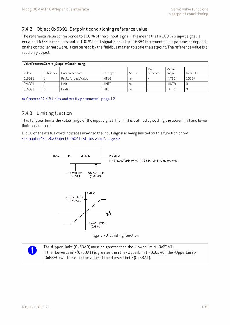
Moog DCV with CANopen bus interface Servo valve functionsp setpoint conditioning
Rev. B, 08.12.21 180
7.4.2 Object 0x6391: Setpoint conditioning reference valueThe reference value corresponds to 100 % of the p input signal. This means that a 100 % p input signal is equal to 16384 increments and a –100 % input signal is equal to –16384 increments. This parameter depends on the controller hardware. It can be read by the fieldbus master to scale the setpoint. The reference value is a read only object.
Chapter "2.4.3 Units and prefix parameter", page 12
7.4.3 Limiting functionThis function limits the value range of the input signal. The limit is defined by setting the upper limit and lower limit parameters.
Bit 10 of the status word indicates whether the input signal is being limited by this function or not. Chapter "5.1.3.2 Object 0x6041: Status word", page 57
Figure 78: Limiting function
ValvePressureControl_SetpointConditioning
Index Sub-index Parameter name Data type AccessPer-sistence
Value range Default
0x6391 1 PrsReferenceValue INT16 ro - INT16 163840x6391 2 Unit UINT8 ro - UINT8 00x6391 3 Prefix INT8 ro - –4…0 0
The <UpperLimit> (0x63A0) must be greater than the <LowerLimit> (0x63A1).If the <LowerLimit> (0x63A1) is greater than the <UpperLimit> (0x63A0), the <UpperLimit> (0x63A0) will be set to the value of the <LowerLimit> (0x63A1).
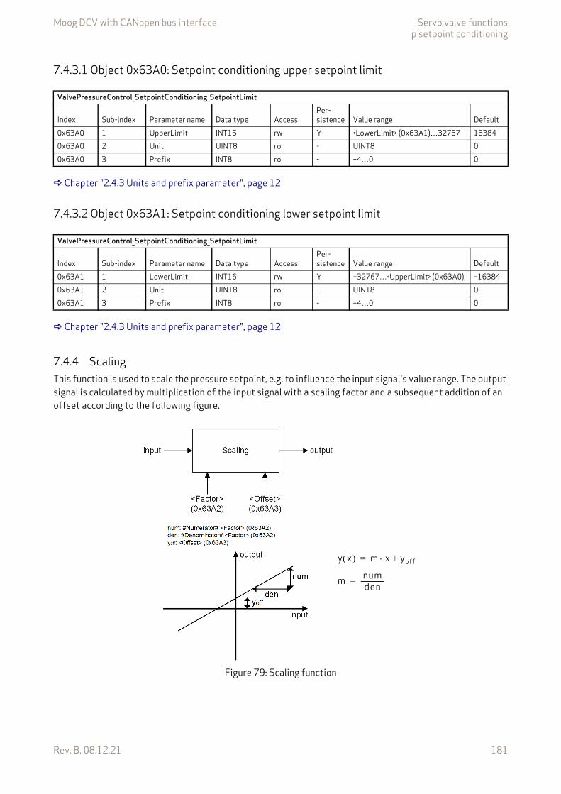
Moog DCV with CANopen bus interface Servo valve functionsp setpoint conditioning
Rev. B, 08.12.21 181
7.4.3.1 Object 0x63A0: Setpoint conditioning upper setpoint limit
Chapter "2.4.3 Units and prefix parameter", page 12
7.4.3.2 Object 0x63A1: Setpoint conditioning lower setpoint limit
Chapter "2.4.3 Units and prefix parameter", page 12
7.4.4 ScalingThis function is used to scale the pressure setpoint, e.g. to influence the input signal's value range. The output signal is calculated by multiplication of the input signal with a scaling factor and a subsequent addition of an offset according to the following figure.
Figure 79: Scaling function
ValvePressureControl_SetpointConditioning_SetpointLimit
Index Sub-index Parameter name Data type AccessPer-sistence Value range Default
0x63A0 1 UpperLimit INT16 rw Y <LowerLimit> (0x63A1)…32767 163840x63A0 2 Unit UINT8 ro - UINT8 00x63A0 3 Prefix INT8 ro - –4…0 0
ValvePressureControl_SetpointConditioning_SetpointLimit
Index Sub-index Parameter name Data type AccessPer-sistence Value range Default
0x63A1 1 LowerLimit INT16 rw Y –32767…<UpperLimit> (0x63A0) –163840x63A1 2 Unit UINT8 ro - UINT8 00x63A1 3 Prefix INT8 ro - –4…0 0
m numden-------------=
y x m x yoff+=

Moog DCV with CANopen bus interface Servo valve functionsp setpoint conditioning
Rev. B, 08.12.21 182
7.4.4.1 Object 0x63A2: Setpoint conditioning scaling factorThis parameter is a slope factor by which the input is multiplied. It is defined by two signed integer values, the numerator (represented by the upper 16 bits of the parameter) and the denominator (represented by the lower 16 bits of the parameter).
Value description
7.4.4.2 Object 0x63A3: Setpoint conditioning scaling offsetThis parameter is the offset of the function.
Chapter "2.4.3 Units and prefix parameter", page 12
ValvePressureControl_SetpointConditioning_Scaling
Index Sub-index Parameter name Data type AccessPer-sistence Value range Default
0x63A2 0 Factor UINT32 rw Y UINT32 0x00010001
Table 83: Data structure of the slope factor
<Factor>Bit 31 16 15 0Description #Numerator# #Denominator#
ValvePressureControl_SetpointConditioning_Scaling
Index Sub-index Parameter name Data type AccessPer-sistence Value range Default
0x63A3 1 Offset INT16 rw Y INT16 00x63A3 2 Unit UINT8 ro - UINT8 00x63A3 3 Prefix INT8 ro - –4…0 0
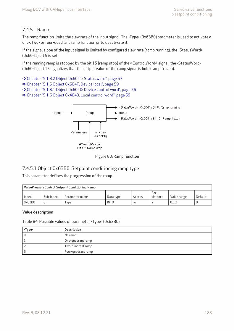
Moog DCV with CANopen bus interface Servo valve functionsp setpoint conditioning
Rev. B, 08.12.21 183
7.4.5 RampThe ramp function limits the slew rate of the input signal. The <Type> (0x63B0) parameter is used to activate a one-, two- or four-quadrant ramp function or to deactivate it.
If the signal slope of the input signal is limited by configured slew rate (ramp running), the <StatusWord> (0x6041) bit 9 is set.
If the running ramp is stopped by the bit 15 (ramp stop) of the #ControlWord# signal, the <StatusWord> (0x6041) bit 15 signalizes that the output value of the ramp signal is hold (ramp frozen).
Chapter "5.1.3.2 Object 0x6041: Status word", page 57 Chapter "5.1.5 Object 0x604F: Device local", page 59 Chapter "5.1.3.1 Object 0x6040: Device control word", page 56 Chapter "5.1.6 Object 0x4040: Local control word", page 59
Figure 80: Ramp function
7.4.5.1 Object 0x63B0: Setpoint conditioning ramp typeThis parameter defines the progression of the ramp.
Value description
ValvePressureControl_SetpointConditioning_Ramp
Index Sub-index Parameter name Data type AccessPer-sistence Value range Default
0x63B0 0 Type INT8 rw Y 0…3 0
Table 84: Possible values of parameter <Type> (0x63B0)
<Type> Description0 No ramp1 One-quadrant ramp2 Two-quadrant ramp3 Four-quadrant ramp

Moog DCV with CANopen bus interface Servo valve functionsp setpoint conditioning
Rev. B, 08.12.21 184
7.4.5.2 One-quadrant ramp (ramp type 1)This function limits the input signal's rate of change to the defined <AccelerationTime> (0x63B1).
This ramp type is active, if the parameter <Type> (0x63B0) is set to 1.
Figure 81: Ramp type 1
7.4.5.2.1 Object 0x63B1: Setpoint conditioning ramp acceleration timeThis parameter defines the output signal's maximum rate of change. The acceleration time corresponds to the time the signal needs for a change from 0 to 100 % as shown in the figure above. The acceleration time can be specified with a resolution of 1 s, 100 ms, 10 ms or 1 ms.
Chapter "2.4.3 Units and prefix parameter", page 12
ValvePressureControl_SetpointConditioning_Ramp
Index Sub-index Parameter name Data type AccessPer-sistence
Value range Default
0x63B1 1 AccelerationTime UINT16 rw Y UINT16 00x63B1 2 Unit UINT8 ro - UINT8 30x63B1 3 Prefix INT8 rw Y –4…0 –3
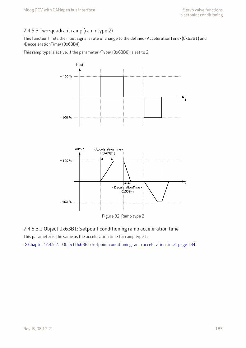
Moog DCV with CANopen bus interface Servo valve functionsp setpoint conditioning
Rev. B, 08.12.21 185
7.4.5.3 Two-quadrant ramp (ramp type 2)This function limits the input signal's rate of change to the defined <AccelerationTime> (0x63B1) and <DeccelerationTime> (0x63B4).
This ramp type is active, if the parameter <Type> (0x63B0) is set to 2.
Figure 82: Ramp type 2
7.4.5.3.1 Object 0x63B1: Setpoint conditioning ramp acceleration timeThis parameter is the same as the acceleration time for ramp type 1.
Chapter "7.4.5.2.1 Object 0x63B1: Setpoint conditioning ramp acceleration time", page 184
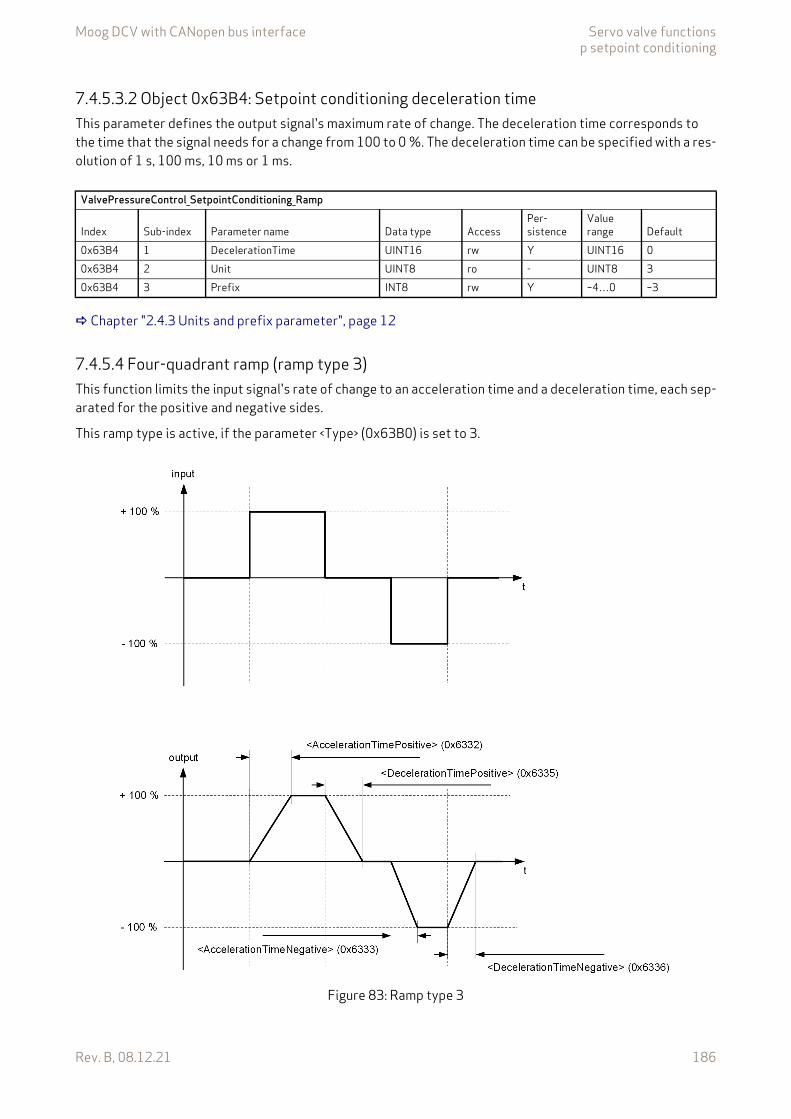
Moog DCV with CANopen bus interface Servo valve functionsp setpoint conditioning
Rev. B, 08.12.21 186
7.4.5.3.2 Object 0x63B4: Setpoint conditioning deceleration timeThis parameter defines the output signal's maximum rate of change. The deceleration time corresponds to the time that the signal needs for a change from 100 to 0 %. The deceleration time can be specified with a res-olution of 1 s, 100 ms, 10 ms or 1 ms.
Chapter "2.4.3 Units and prefix parameter", page 12
7.4.5.4 Four-quadrant ramp (ramp type 3)This function limits the input signal's rate of change to an acceleration time and a deceleration time, each sep-arated for the positive and negative sides.
This ramp type is active, if the parameter <Type> (0x63B0) is set to 3.
Figure 83: Ramp type 3
ValvePressureControl_SetpointConditioning_Ramp
Index Sub-index Parameter name Data type AccessPer-sistence
Value range Default
0x63B4 1 DecelerationTime UINT16 rw Y UINT16 00x63B4 2 Unit UINT8 ro - UINT8 30x63B4 3 Prefix INT8 rw Y –4…0 –3

Moog DCV with CANopen bus interface Servo valve functionsp setpoint conditioning
Rev. B, 08.12.21 187
7.4.5.4.1 Object 0x63B2: Setpoint conditioning ramp acceleration time positiveThis parameter defines the output signal's maximum rate of change on the positive side. The acceleration time corresponds to the time that the signal needs for a change from 0 to 100 %. The acceleration time can be specified with a resolution of 1 s, 100 ms, 10 ms or 1 ms.
Chapter "2.4.3 Units and prefix parameter", page 12
7.4.5.4.2 Object 0x63B3: Setpoint conditioning ramp acceleration time negativeThis parameter defines the output signal's maximum rate of change on the negative side. The acceleration time corresponds to the time that the signal needs for a change from 0 to 100 %. The acceleration time can be specified with a resolution of 1 s, 100 ms, 10 ms or 1 ms.
Chapter "2.4.3 Units and prefix parameter", page 12
7.4.5.4.3 Object 0x63B5: Setpoint conditioning ramp deceleration time positiveThis parameter defines the output signal's maximum rate of change on the positive side. The deceleration time corresponds to the time that the signal needs for a change from 100 to 0 %. The deceleration time can be specified with a resolution of 1 s, 100 ms, 10 ms or 1 ms.
Chapter "2.4.3 Units and prefix parameter", page 12
ValvePressureControl_SetpointConditioning_Ramp
Index Sub-index Parameter name Data type AccessPer-sistence
Value range Default
0x63B2 1 AccelerationTimePositive UINT16 rw Y UINT16 00x63B2 2 Unit UINT8 ro - UINT8 30x63B2 3 Prefix INT8 rw Y –4…0 –3
ValvePressureControl_SetpointConditioning_Ramp
Index Sub-index Parameter name Data type AccessPer-sistence
Value range Default
0x63B3 1 AccelerationTimeNegative UINT16 rw Y UINT16 00x63B3 2 Unit UINT8 ro - UINT8 30x63B3 3 Prefix INT8 rw Y –4…0 –3
ValvePressureControl_SetpointConditioning_Ramp
Index Sub-index Parameter name Data type AccessPer-sistence
Value range Default
0x63B5 1 DecelerationTimePositive UINT16 rw Y UINT16 00x63B5 2 Unit UINT8 ro - UINT8 30x63B5 3 Prefix INT8 rw Y –4…0 –3
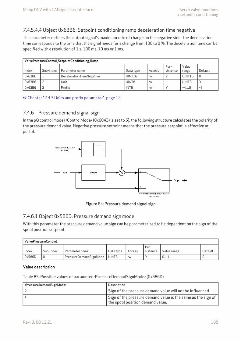
Moog DCV with CANopen bus interface Servo valve functionsp setpoint conditioning
Rev. B, 08.12.21 188
7.4.5.4.4 Object 0x63B6: Setpoint conditioning ramp deceleration time negativeThis parameter defines the output signal's maximum rate of change on the negative side. The deceleration time corresponds to the time that the signal needs for a change from 100 to 0 %. The deceleration time can be specified with a resolution of 1 s, 100 ms, 10 ms or 1 ms.
Chapter "2.4.3 Units and prefix parameter", page 12
7.4.6 Pressure demand signal signIn the pQ control mode (<ControlMode> (0x6043) is set to 5), the following structure calculates the polarity of the pressure demand value. Negative pressure setpoint means that the pressure setpoint is effective at port B.
Figure 84: Pressure demand signal sign
7.4.6.1 Object 0x586D: Pressure demand sign modeWith this parameter the pressure demand value sign can be parameterized to be dependent on the sign of the spool position setpoint.
Value description
ValvePressureControl_SetpointConditioning_Ramp
Index Sub-index Parameter name Data type AccessPer-sistence
Value range Default
0x63B6 1 DecelerationTimeNegative UINT16 rw Y UINT16 00x63B6 2 Unit UINT8 ro - UINT8 30x63B6 3 Prefix INT8 rw Y –4…0 –3
ValvePressureControl
Index Sub-index Parameter name Data type AccessPer-sistence Value range Default
0x586D 0 PressureDemandSignMode UINT8 rw Y 0…1 0
Table 85: Possible values of parameter <PressureDemandSignMode> (0x586D)
<PressureDemandSignMode> Description0 Sign of the pressure demand value will not be influenced.1 Sign of the pressure demand value is the same as the sign of
the spool position demand value.

Moog DCV with CANopen bus interface Servo valve functionsPressure controller
Rev. B, 08.12.21 189
7.5 Pressure controller
Figure 85: Pressure controller
Chapter "7.4.1 Object 0x6390: Setpoint conditioning demand value", page 179 Chapter "7.5.2 Object 0x63D0: Pressure control deviation", page 190 Chapter "7.5.5 Object 0x2312: Differential part 1", page 190 Chapter "7.5.6 Object 0x5862: Differential part 2", page 190 Chapter "7.5.4 Object 0x2310: Integrator part", page 190 Chapter "7.5.3 Object 0x2311: Proportional part", page 190 Chapter "7.5.7 Object 0x5872: Pressure controller output", page 191
Description of the feedback signal <ActualValue1…4> (0x6110…0x6113): Chapter "6.2 Actual value transducer interface", page 72
7.5.1 Object 0x6381: Pressure actual valueThe filter output <PrsActualValue> (0x6381) represents the pressure actual value. This value is used as feed-back input for the pressure controller.
Chapter "2.4.3 Units and prefix parameter", page 12
Chapter 7.5.20
Chapter 7.5.19
Chapter 7.5.18 Chapter 7.5.17
Chapter 7.5.12
Chapter 7.5.14
Chapter 7.5.13
Chapter 7.5.15
Chapter 7.5.16
Chapter 7.5.9
Chapter 7.5.11 Chapter 7.5.10
ValvePressureControl
Index Sub-index Parameter name Data type Access
Per-sis-tence Value range Default
0x6381 1 PrsActualValue INT16 ro - INT16 None0x6381 2 Unit UINT8 ro - UINT8 00x6381 3 Prefix INT8 ro - –4…0 0
Moog DCV with CANopen bus interface Servo valve functionsPressure controller
Rev. B, 08.12.21 190
7.5.2 Object 0x63D0: Pressure control deviationThis parameter holds the deviation between the ramped pressure setpoint and the filtered pressure actual value.
Chapter "2.4.3 Units and prefix parameter", page 12
7.5.3 Object 0x2311: Proportional partThis parameter holds the output of the proportional element of the pressure controller.
7.5.4 Object 0x2310: Integrator partThis parameter holds the output of the integrator element of the pressure controller.
7.5.5 Object 0x2312: Differential part 1This parameter holds the output of the first differential element of the pressure controller.
7.5.6 Object 0x5862: Differential part 2This parameter holds the output of the second differential element of the pressure controller.
ValvePressureControlIndex Sub-index Parameter name Data type Access Persistence Value range Default0x63D0 1 PrsControlDeviation INT16 ro - INT16 None0x63D0 2 Unit UINT8 ro - UINT8 00x63D0 3 Prefix INT8 ro - –4…0 0
ValvePressureControl
Index Sub-index Parameter name Data type AccessPer-sistence Value range Default
0x2311 0 ProportionalPart REAL32 ro - REAL32 None
ValvePressureControl
Index Sub-index Parameter name Data type AccessPer-sistence Value range Default
0x2310 0 IntegratorPart REAL32 ro - REAL32 None
ValvePressureControl
Index Sub-index Parameter name Data type AccessPer-sistence Value range Default
0x2312 0 DifferentialPart1 REAL32 ro - REAL32 None
ValvePressureControl
Index Sub-index Parameter name Data type AccessPer-sistence Value range Default
0x5862 0 DifferentialPart2 REAL32 ro - REAL32 None
Moog DCV with CANopen bus interface Servo valve functionsPressure controller
Rev. B, 08.12.21 191
7.5.7 Object 0x5872: Pressure controller outputThis parameter holds the controller output of the pressure controller.
7.5.8 Active parameter set numberThe pressure controller contains objects to influence the control behavior.To adapt the control behavior to different control conditions within the machine cycle, 16 parameter sets are provided. Within these sets most of the controller parameter can be configured.
Only one of the 16 parameter sets is used at the same time. The parameter set to be used is selected by <ActiveParameterSetNumber> (0x2350). This parameter defines the parameter set number of the objects which is used for the pressure controller. The following table shows all pressure controller objects that are part of one parameter set.
ValvePressureControl
Index Sub-index Parameter name Data type AccessPer-sistence Value range Default
0x5872 0 PrsControllerOutput INT16 ro - INT16 None
Table 86: Pressure controller objects contained in a parameter set
Index Object name0x2303 Ramp slope0x230D Active transducer interface0x230F Transducer interface area B0x2304 Proportional gain0x230E Proportional gain time constant0x2305 Integrator gain0x2306 Integrator factor0x2307 Integrator control range0x231A Integrator upper output limit0x231B Integrator lower output limit0x5861 Integrator proportional part P gain0x2308 Differentiator gain0x2309 Differentiator T10x5863 Differentiator gain 20x5864 Differentiator T1 20x230A Upper output limit0x230B Lower output limit0x5867 Feed forward gain0x5868 Feed forward parameter0x5870 Feed forward offset0x5865 Upper controller output limit0x5866 Lower controller output limit0x586C pQ switching mode0x230C Hydraulic capacity
The objects which are part of the parameter set are signed with a sub-index N (1…16) in brack-ets after the index number. E.g. (0x2304[N]).
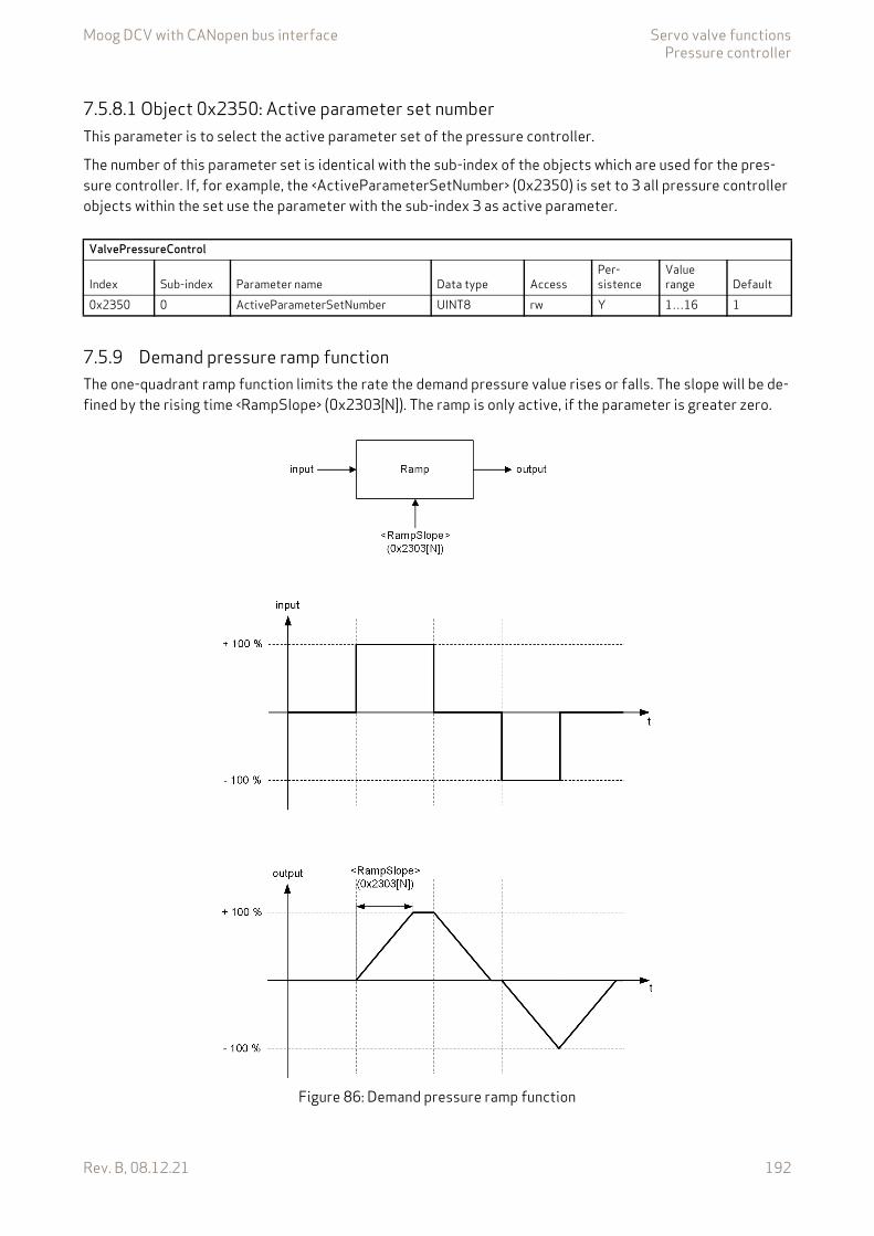
Moog DCV with CANopen bus interface Servo valve functionsPressure controller
Rev. B, 08.12.21 192
7.5.8.1 Object 0x2350: Active parameter set numberThis parameter is to select the active parameter set of the pressure controller.
The number of this parameter set is identical with the sub-index of the objects which are used for the pres-sure controller. If, for example, the <ActiveParameterSetNumber> (0x2350) is set to 3 all pressure controller objects within the set use the parameter with the sub-index 3 as active parameter.
7.5.9 Demand pressure ramp functionThe one-quadrant ramp function limits the rate the demand pressure value rises or falls. The slope will be de-fined by the rising time <RampSlope> (0x2303[N]). The ramp is only active, if the parameter is greater zero.
Figure 86: Demand pressure ramp function
ValvePressureControl
Index Sub-index Parameter name Data type AccessPer-sistence
Value range Default
0x2350 0 ActiveParameterSetNumber UINT8 rw Y 1…16 1
Moog DCV with CANopen bus interface Servo valve functionsPressure controller
Rev. B, 08.12.21 193
7.5.9.1 Object 0x2303[N]: Ramp slopeIf a 100 % step is set as input, the ramp output needs <RampSlope> (0x2303) milliseconds to reach the 100 % ramp output.
7.5.10 Pressure transducer selectionThe actual value, used as feedback signal for the pressure controller, will be routed through the four possible transducer interfaces. Three different actual value pressure calculation, depending on the pressure trans-ducer selection and the pressure chamber mode switch <PressureChamberModeSwitch> (0x233F) are possi-ble:
• Normal pressure controlOnly one pressure signal from the transducer interface <ActiveTransducerInterfaceAreaA> (0x230D[N]) is fed to the pressure controller. The second interface, <ActiveTransducerInterfaceAreaB> (0x230F[N]) is set to zero.
• Differential pressure control with alpha correctionTwo pressure signals from the transducer interfaces used for the alpha correction and fed to the pres-sure controller. For a differential cylinder, the resultant force can be calculated with the port pressures and the bore (A) and annulus (B) areas. For this the parameters <CylinderPistonDiameter> (0x585F), <CylinderRodDiameterA> (0x585D) and <CylinderRodDiameterB> (0x585E) are used.
• Differential pressure control with flow sign depending pressure routingDepending on the sign of the demand flow signal, either the signal from the transducer interface <ActiveTransducerInterfaceAreaA> (0x230D[N]) or the signal from the <ActiveTransducerInterfaceAreaB> (0x230F[N]) negated is used as an input signal for the pressure con-troller. This mode is activated by setting the parameter <PressureChamberModeSwitch> (0x233F) to 1.
ValvePressureControl
Index Sub-index Parameter name Data type AccessPer-sistence Value range Default
0x2303 N=1…16 RampSlope UINT16 rw Y UINT16 0
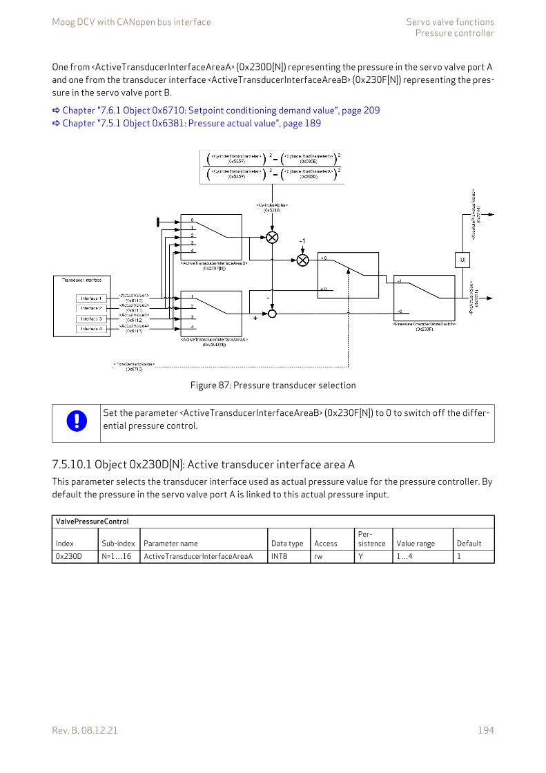
Moog DCV with CANopen bus interface Servo valve functionsPressure controller
Rev. B, 08.12.21 194
One from <ActiveTransducerInterfaceAreaA> (0x230D[N]) representing the pressure in the servo valve port A and one from the transducer interface <ActiveTransducerInterfaceAreaB> (0x230F[N]) representing the pres-sure in the servo valve port B.
Chapter "7.6.1 Object 0x6710: Setpoint conditioning demand value", page 209 Chapter "7.5.1 Object 0x6381: Pressure actual value", page 189
Figure 87: Pressure transducer selection
7.5.10.1 Object 0x230D[N]: Active transducer interface area AThis parameter selects the transducer interface used as actual pressure value for the pressure controller. By default the pressure in the servo valve port A is linked to this actual pressure input.
Chapter 6.2
Set the parameter <ActiveTransducerInterfaceAreaB> (0x230F[N]) to 0 to switch off the differ-ential pressure control.
ValvePressureControl
Index Sub-index Parameter name Data type AccessPer-sistence Value range Default
0x230D N=1…16 ActiveTransducerInterfaceAreaA INT8 rw Y 1…4 1
Moog DCV with CANopen bus interface Servo valve functionsPressure controller
Rev. B, 08.12.21 195
7.5.10.2 Object 0x230F[N]: Active transducer interface area BThis parameter selects the transducer interface used for the second actual pressure value.
If a differential pressure control between the servo valve port A and B is required, this parameter selects the transducer interface used as the second pressure input. Normally the pressure in the servo valve port B is linked to this actual pressure input.If only the pressure in port A is used, the <ActiveTransducerInterfaceAreaB> (0x230F[N]) must be set to zero.
7.5.10.3 Object 0x585F[N]: Cylinder piston diameterThe piston diameter is necessary to calculate the force of the cylinder.
The units used must be consistent with the units of the parameters <CylinderRodDiameterA> (0x585D) and <CylinderRodDiameterB> (0x585E).
7.5.10.4 Object 0x585D: Cylinder rod diameter AThe rod diameter A is necessary to calculate the force of the cylinder.
The units used must be consistent with the units of the parameters <CylinderPistonDiameter> (0x585F) and <CylinderRodDiameterB> (0x585E).
7.5.10.5 Object 0x585E: Cylinder rod diameter BThe rod diameter is necessary to calculate the force of the cylinder.
The units used must be consistent with the parameter units of the parameters <CylinderPistonDiameter> (0x585F) and <CylinderRodDiameterA> (0x585D).
ValvePressureControl
Index Sub-index Parameter name Data type AccessPer-sistence Value range Default
0x230F N=1…16 ActiveTransducerInterfaceAreaB INT8 rw Y 0…4 None
ValvePressureControl
Index Sub-index Parameter name Data type AccessPer-sistence Value range Default
0x585F 0 CylinderPistonDiameter REAL32 rw Y 0.0…+inf 1000000.0
ValvePressureControl
Index Sub-index Parameter name Data type AccessPer-sistence Value range Default
0x585D 0 CylinderRodDiameterA REAL32 rw Y 0.0…<CylinderPistonDiameter>(0x585F)
0.0
ValvePressureControl
Index Sub-index Parameter name Data type AccessPer-sistence Value range Default
0x585E 0 CylinderRodDiameterB REAL32 rw Y 0.0…<CylinderPistonDiameter>(0x585F)
0.0
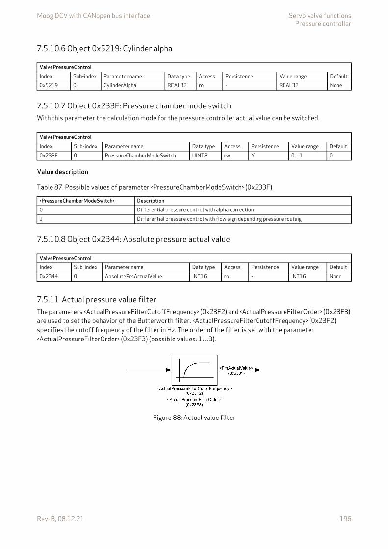
Moog DCV with CANopen bus interface Servo valve functionsPressure controller
Rev. B, 08.12.21 196
7.5.10.6 Object 0x5219: Cylinder alpha
7.5.10.7 Object 0x233F: Pressure chamber mode switchWith this parameter the calculation mode for the pressure controller actual value can be switched.
Value description
7.5.10.8 Object 0x2344: Absolute pressure actual value
7.5.11 Actual pressure value filterThe parameters <ActualPressureFilterCutoffFrequency> (0x23F2) and <ActualPressureFilterOrder> (0x23F3) are used to set the behavior of the Butterworth filter. <ActualPressureFilterCutoffFrequency> (0x23F2) specifies the cutoff frequency of the filter in Hz. The order of the filter is set with the parameter <ActualPressureFilterOrder> (0x23F3) (possible values: 1…3).
Figure 88: Actual value filter
ValvePressureControlIndex Sub-index Parameter name Data type Access Persistence Value range Default0x5219 0 CylinderAlpha REAL32 ro - REAL32 None
ValvePressureControlIndex Sub-index Parameter name Data type Access Persistence Value range Default0x233F 0 PressureChamberModeSwitch UINT8 rw Y 0…1 0
Table 87: Possible values of parameter <PressureChamberModeSwitch> (0x233F)
<PressureChamberModeSwitch> Description0 Differential pressure control with alpha correction1 Differential pressure control with flow sign depending pressure routing
ValvePressureControlIndex Sub-index Parameter name Data type Access Persistence Value range Default0x2344 0 AbsolutePrsActualValue INT16 ro - INT16 None
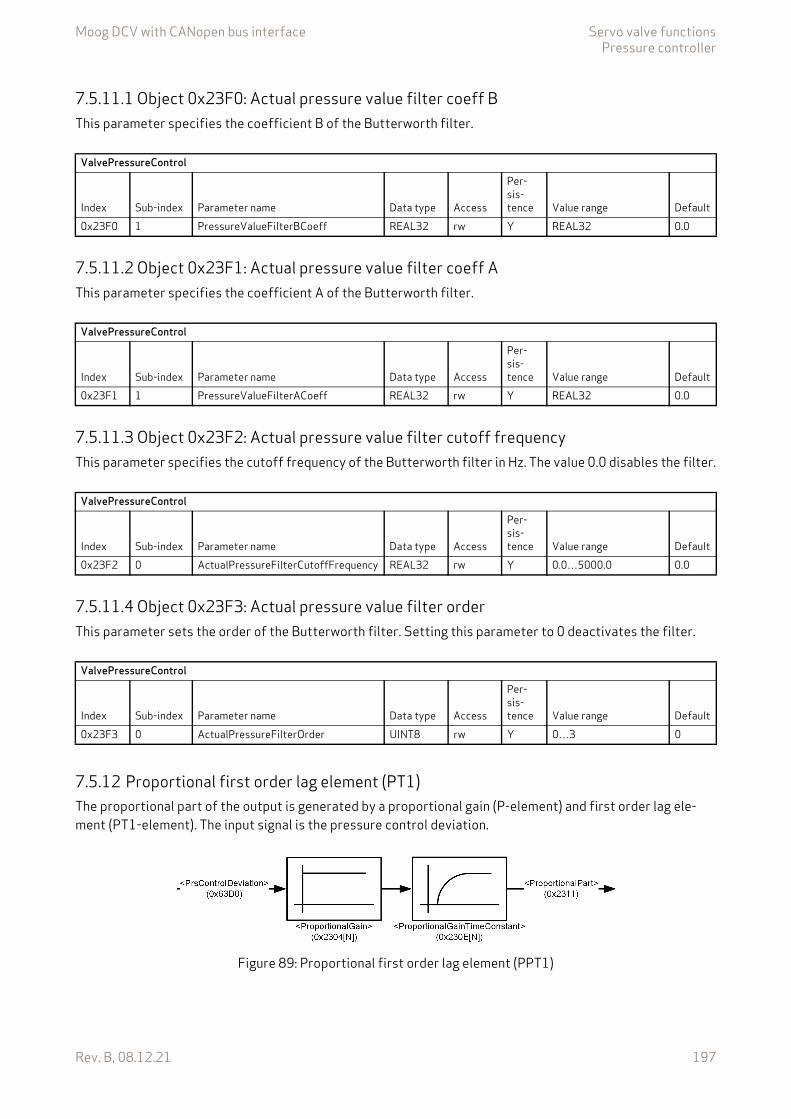
Moog DCV with CANopen bus interface Servo valve functionsPressure controller
Rev. B, 08.12.21 197
7.5.11.1 Object 0x23F0: Actual pressure value filter coeff BThis parameter specifies the coefficient B of the Butterworth filter.
7.5.11.2 Object 0x23F1: Actual pressure value filter coeff AThis parameter specifies the coefficient A of the Butterworth filter.
7.5.11.3 Object 0x23F2: Actual pressure value filter cutoff frequencyThis parameter specifies the cutoff frequency of the Butterworth filter in Hz. The value 0.0 disables the filter.
7.5.11.4 Object 0x23F3: Actual pressure value filter orderThis parameter sets the order of the Butterworth filter. Setting this parameter to 0 deactivates the filter.
7.5.12 Proportional first order lag element (PT1)The proportional part of the output is generated by a proportional gain (P-element) and first order lag ele-ment (PT1-element). The input signal is the pressure control deviation.
Figure 89: Proportional first order lag element (PPT1)
ValvePressureControl
Index Sub-index Parameter name Data type Access
Per-sis-tence Value range Default
0x23F0 1 PressureValueFilterBCoeff REAL32 rw Y REAL32 0.0
ValvePressureControl
Index Sub-index Parameter name Data type Access
Per-sis-tence Value range Default
0x23F1 1 PressureValueFilterACoeff REAL32 rw Y REAL32 0.0
ValvePressureControl
Index Sub-index Parameter name Data type Access
Per-sis-tence Value range Default
0x23F2 0 ActualPressureFilterCutoffFrequency REAL32 rw Y 0.0…5000.0 0.0
ValvePressureControl
Index Sub-index Parameter name Data type Access
Per-sis-tence Value range Default
0x23F3 0 ActualPressureFilterOrder UINT8 rw Y 0…3 0
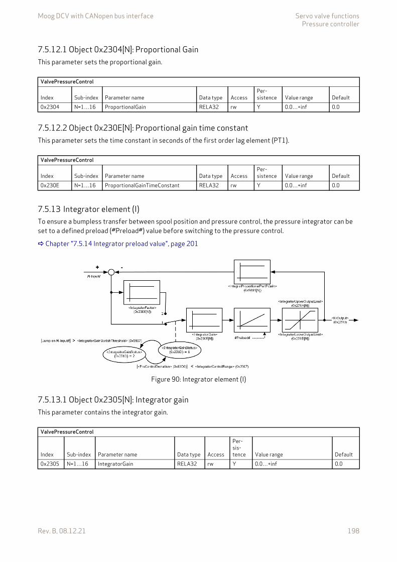
Moog DCV with CANopen bus interface Servo valve functionsPressure controller
Rev. B, 08.12.21 198
7.5.12.1 Object 0x2304[N]: Proportional GainThis parameter sets the proportional gain.
7.5.12.2 Object 0x230E[N]: Proportional gain time constantThis parameter sets the time constant in seconds of the first order lag element (PT1).
7.5.13 Integrator element (I)To ensure a bumpless transfer between spool position and pressure control, the pressure integrator can be set to a defined preload (#Preload#) value before switching to the pressure control.
Chapter "7.5.14 Integrator preload value", page 201
Figure 90: Integrator element (I)
7.5.13.1 Object 0x2305[N]: Integrator gainThis parameter contains the integrator gain.
ValvePressureControl
Index Sub-index Parameter name Data type AccessPer-sistence Value range Default
0x2304 N=1…16 ProportionalGain RELA32 rw Y 0.0…+inf 0.0
ValvePressureControl
Index Sub-index Parameter name Data type AccessPer-sistence Value range Default
0x230E N=1…16 ProportionalGainTimeConstant RELA32 rw Y 0.0…+inf 0.0
ValvePressureControl
Index Sub-index Parameter name Data type Access
Per-sis-tence Value range Default
0x2305 N=1…16 IntegratorGain RELA32 rw Y 0.0…+inf 0.0
Moog DCV with CANopen bus interface Servo valve functionsPressure controller
Rev. B, 08.12.21 199
7.5.13.2 Object 0x2306[N]: Integrator factorThis parameter contains an additional factor which is multiplied to the integrator gain if the control error is larger than the <IntegratorControlRange>.
7.5.13.3 Object 0x2307[N]: Integrator control rangeThis parameter contains the range of the control deviation for the integrator part. If the control deviation is outside the range, the <IntegratorGain> is multiplied with the <IntegratorFactor> (which is zero by default).
7.5.13.4 Object 0x231D: Integrator gain statusThis parameter shows the state of the switch whether the <IntegratorFactor> (0x2306) is multiplied (value = 2) or not (value = 1).
7.5.13.5 Object 0x5857[N]: Integrator gain switch thresholdThis parameter contains the value of the height of the step / jump of the I-Input dx/dt projected of one sec-ond. If a step greater than <IntegratorGainSwitchThreshold> is detected on the I-Input, the I-Input will be mul-tiplied with the smaller <IntegratorFactor> as long as |<PrsControlDeviation>| is less than <IntegratorControlRange>.
This means if a step of 1 bit is detected (if the valve is used with analog inputs we always detect a noise of min. 1 bit), the default value doesn't make really sense, but the default value has to be kept to be compatible to further versions.
The following example shows the calculation:
1 Bit / IRQ -> 1 / 100 ?s -> this means 10,000 / second
ValvePressureControl
Index Sub-index Parameter name Data type Access
Per-sis-tence Value range Default
0x2306 N=1…16 IntegratorFactor RELA32 rw Y 0.0…+inf 0.1
ValvePressureControl
Index Sub-index Parameter name Data type Access
Per-sis-tence Value range Default
0x2307 N=1…16 IntegratorControlRange INT16 rw Y 0…32767 163
ValvePressureControl
Index Sub-index Parameter name Data type Access
Per-sis-tence Value range Default
0x231D 0 IntegratorGainStatus UINT8 ro - 1…2 None
ValvePressureControl
Index Sub-index Parameter name Data type Access
Per-sis-tence Value range Default
0x5857 N=1…16 IntegratorGainSwitchThreshold UINT32 rw Y UINT32 5000

Moog DCV with CANopen bus interface Servo valve functionsPressure controller
Rev. B, 08.12.21 200
7.5.13.6 Object 0x231A[N]: Integrator upper output limitThis parameter contains the upper limit of the integrator output.
7.5.13.7 Object 0x231B[N]: Integrator lower output limitThis parameter contains the lower limit of the integrator output.
7.5.13.8 Object 0x5861[N]: Integrator proportional part P gainUsing this feedback proportional gain, the integrator can be modified to a first order lag element.
ValvePressureControl
Index Sub-index Parameter name Data type Access
Per-sis-tence Value range Default
0x231A N=1…16 IntegratorUpperOutputLimit INT16 rw Y <IntegratorLowerOutputLimit>(0x231B[N])…32767
16384
ValvePressureControl
Index Sub-index Parameter name Data type Access
Per-sis-tence Value range Default
0x231B N=1…16 IntegratorLowerOutputLimit INT16 rw Y –32768…<IntegratorUpperOutputLimit>(0x231A[N])
–16384
ValvePressureControl
Index Sub-index Parameter name Data type Access
Per-sis-tence Value range Default
0x5861 N=1…16 IntegralProportionalPartPGain REAL32 rw Y REAL32 0.0
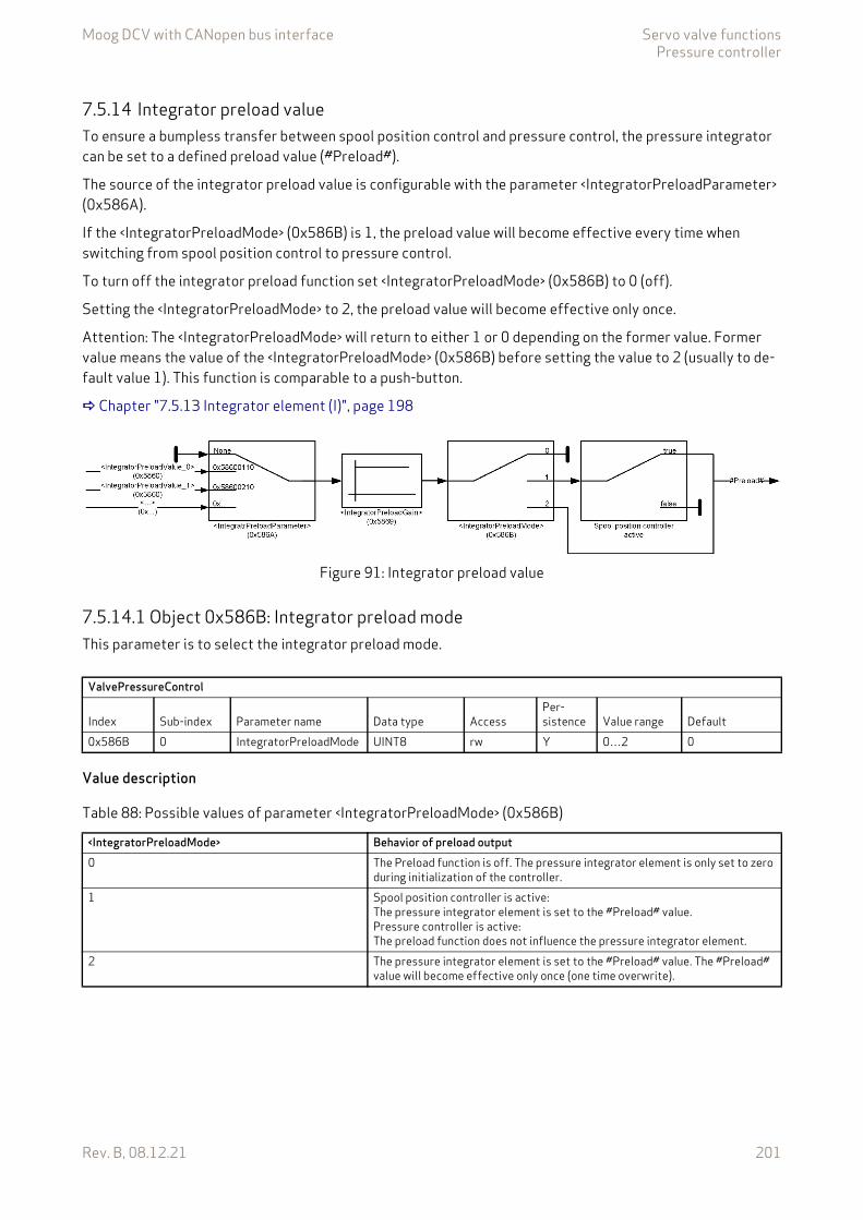
Moog DCV with CANopen bus interface Servo valve functionsPressure controller
Rev. B, 08.12.21 201
7.5.14 Integrator preload valueTo ensure a bumpless transfer between spool position control and pressure control, the pressure integrator can be set to a defined preload value (#Preload#).
The source of the integrator preload value is configurable with the parameter <IntegratorPreloadParameter> (0x586A).
If the <IntegratorPreloadMode> (0x586B) is 1, the preload value will become effective every time when switching from spool position control to pressure control.
To turn off the integrator preload function set <IntegratorPreloadMode> (0x586B) to 0 (off).
Setting the <IntegratorPreloadMode> to 2, the preload value will become effective only once.
Attention: The <IntegratorPreloadMode> will return to either 1 or 0 depending on the former value. Former value means the value of the <IntegratorPreloadMode> (0x586B) before setting the value to 2 (usually to de-fault value 1). This function is comparable to a push-button.
Chapter "7.5.13 Integrator element (I)", page 198
Figure 91: Integrator preload value
7.5.14.1 Object 0x586B: Integrator preload modeThis parameter is to select the integrator preload mode.
Value description
ValvePressureControl
Index Sub-index Parameter name Data type AccessPer-sistence Value range Default
0x586B 0 IntegratorPreloadMode UINT8 rw Y 0…2 0
Table 88: Possible values of parameter <IntegratorPreloadMode> (0x586B)
<IntegratorPreloadMode> Behavior of preload output0 The Preload function is off. The pressure integrator element is only set to zero
during initialization of the controller.1 Spool position controller is active:
The pressure integrator element is set to the #Preload# value.Pressure controller is active:The preload function does not influence the pressure integrator element.
2 The pressure integrator element is set to the #Preload# value. The #Preload# value will become effective only once (one time overwrite).
Moog DCV with CANopen bus interface Servo valve functionsPressure controller
Rev. B, 08.12.21 202
7.5.14.2 Object 0x5869: Integrator preload gainThis parameter contains the integrator preload gain.
7.5.14.3 Object 0x586A: Integrator preload parameterWith this parameter every INT16 application parameter can be mapped as preload input. Per default the pres-sure setpoint <PrsSetpoint> (0x6380) is mapped.
Value description
This reference contains a combination of index, sub-index and length of the parameter to be used. It may only refer to parameters with a bit length of 0x10 or 0x20.
The default value is 0x63800110, which refers to the <PrsSetpoint> (0x6380), sub-index 0x01 with a length of 16 bit (16=0x10).
7.5.14.4 Object 0x5860: Integrator preload valuesThis object contains two pre-calculated preload values.These values can be mapped using the parameter <IntegratorPreloadParameter> (0x586A) to the integrator preload input.
Value description
ValvePressureControl
Index Sub-index Parameter name Data type AccessPer-sistence Value range Default
0x5869 0 IntegratorPreloadGain REAL32 rw Y REAL32 0.0
ValvePressureControl
Index Sub-index Parameter name Data type AccessPer-sistence
Value range Default
0x586A 0 IntegratorPreloadMappingParameter UINT32 rw Y UINT32 0x63800110
<IntegratorPreloadMappingParameter>Byte 3 2 1 0
DescriptionIndex MSB Index LSB Sub-index Parameter bit length: 0x10
or 0x20Default 0x63 0x80 0x01 0x10
ValvePressureControl
Index Sub-index Parameter name Data type AccessPer-sistence Value range Default
0x5860 1 IntegratorPreloadValue1 INT16 ro - INT16 None0x5860 2 IntegratorPreloadValue2 INT16 ro - INT16 None
Table 89: Behavior of preload output
<Parameter> Behavior of preload output<IntegratorPreloadValue1> <SplDemandValue> (0x6310) minus <ProportionalPart> (0x2311)<IntegratorPreloadValue2> <SplDemandValue> (0x6310) minus <ProportionalPart> (0x2311) minus <FeedForwardOffset>
(0x5870[N])
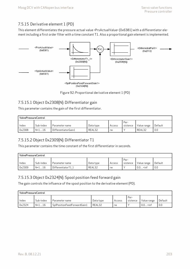
Moog DCV with CANopen bus interface Servo valve functionsPressure controller
Rev. B, 08.12.21 203
7.5.15 Derivative element 1 (PD)This element differentiates the pressure actual value <PrsActualValue> (0x6381) with a differentiator ele-ment including a first order filter with a time constant T1. Also a proportional gain element is implemented.
Figure 92: Proportional derivative element 1 (PD)
7.5.15.1 Object 0x2308[N]: Differentiator gainThis parameter contains the gain of the first differentiator.
7.5.15.2 Object 0x2309[N]: Differentiator T1This parameter contains the time constant of the first differentiator in seconds.
7.5.15.3 Object 0x2324[N]: Spool position feed forward gainThe gain controls the influence of the spool position to the derivative element (PD).
ValvePressureControl
Index Sub-index Parameter name Data type AccessPer-sistence Value range Default
0x2308 N=1…16 DifferentiatorGain1 REAL32 rw Y REAL32 0.0
ValvePressureControl
Index Sub-index Parameter name Data type AccessPer-sistence Value range Default
0x2309 N=1…16 DifferentiatorT1_1 REAL32 rw Y 0.0…+inf 0.0
ValvePressureControl
Index Sub-index Parameter name Data type AccessPer-sistence Value range Default
0x2324 N=1…16 SplPositionFeedForwardGain1 REAL32 rw Y 0.0…+inf 0.0
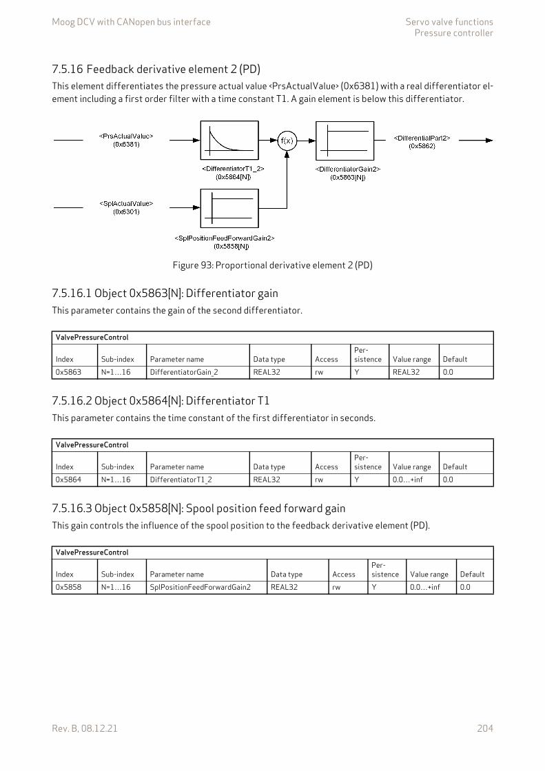
Moog DCV with CANopen bus interface Servo valve functionsPressure controller
Rev. B, 08.12.21 204
7.5.16 Feedback derivative element 2 (PD)This element differentiates the pressure actual value <PrsActualValue> (0x6381) with a real differentiator el-ement including a first order filter with a time constant T1. A gain element is below this differentiator.
Figure 93: Proportional derivative element 2 (PD)
7.5.16.1 Object 0x5863[N]: Differentiator gainThis parameter contains the gain of the second differentiator.
7.5.16.2 Object 0x5864[N]: Differentiator T1This parameter contains the time constant of the first differentiator in seconds.
7.5.16.3 Object 0x5858[N]: Spool position feed forward gainThis gain controls the influence of the spool position to the feedback derivative element (PD).
ValvePressureControl
Index Sub-index Parameter name Data type AccessPer-sistence Value range Default
0x5863 N=1…16 DifferentiatorGain_2 REAL32 rw Y REAL32 0.0
ValvePressureControl
Index Sub-index Parameter name Data type AccessPer-sistence Value range Default
0x5864 N=1…16 DifferentiatorT1_2 REAL32 rw Y 0.0…+inf 0.0
ValvePressureControl
Index Sub-index Parameter name Data type AccessPer-sistence Value range Default
0x5858 N=1…16 SplPositionFeedForwardGain2 REAL32 rw Y 0.0…+inf 0.0
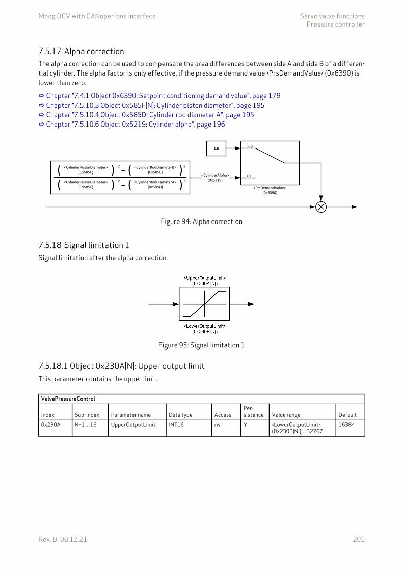
Moog DCV with CANopen bus interface Servo valve functionsPressure controller
Rev. B, 08.12.21 205
7.5.17 Alpha correctionThe alpha correction can be used to compensate the area differences between side A and side B of a differen-tial cylinder. The alpha factor is only effective, if the pressure demand value <PrsDemandValue> (0x6390) is lower than zero.
Chapter "7.4.1 Object 0x6390: Setpoint conditioning demand value", page 179 Chapter "7.5.10.3 Object 0x585F[N]: Cylinder piston diameter", page 195 Chapter "7.5.10.4 Object 0x585D: Cylinder rod diameter A", page 195 Chapter "7.5.10.6 Object 0x5219: Cylinder alpha", page 196
Figure 94: Alpha correction
7.5.18 Signal limitation 1Signal limitation after the alpha correction.
Figure 95: Signal limitation 1
7.5.18.1 Object 0x230A[N]: Upper output limitThis parameter contains the upper limit.
<CylinderAlpha>(0x5219)
<CylinderPistonDiameter>(0x585F)
<CylinderRodDiameterB>(0x585E)
<CylinderRodDiameterA>(0x585D)
<CylinderPistonDiameter>(0x585F)
( ) )))( (
(2 2
2 2
--
1.0 >=0
<0
<PrsDemandValue>(0x6390)
ValvePressureControl
Index Sub-index Parameter name Data type AccessPer-sistence Value range Default
0x230A N=1…16 UpperOutputLimit INT16 rw Y <LowerOutputLimit> (0x230B[N])…32767
16384

Moog DCV with CANopen bus interface Servo valve functionsPressure controller
Rev. B, 08.12.21 206
7.5.18.2 Object 0x230B[N]: Lower output limitThis parameter contains the lower limit.
7.5.19 Feed forwardFor some applications a feed forward control is advantageous. With the feed forward function a selectable signal, e.g., the pressure setpoint, can be forwarded to the output of the controller. The signal can be scaled and an offset can be added.
Figure 96: Feed forward
7.5.19.1 Object 0x5867[N]: Feed forward gainThis parameter contains the feed forward gain.
7.5.19.2 Object 0x5870[N]: Feed forward offsetThis parameter contains the feed forward offset.
ValvePressureControl
Index Sub-index Parameter name Data type AccessPer-sistence Value range Default
0x230B N=1…16 LowerOutputLimit INT16 rw Y 32767… <UpperOutputLimit> (0x230A[N])
–16384
ValvePressureControl
Index Sub-index Parameter name Data type AccessPer-sistence Value range Default
0x5867 N=1…16 FeedForwardGain REAL32 rw Y REAL32 0.0
ValvePressureControl
Index Sub-index Parameter name Data type AccessPer-sistence Value range Default
0x5870 N=1…16 FeedForwardOffset INT16 rw Y INT16 0
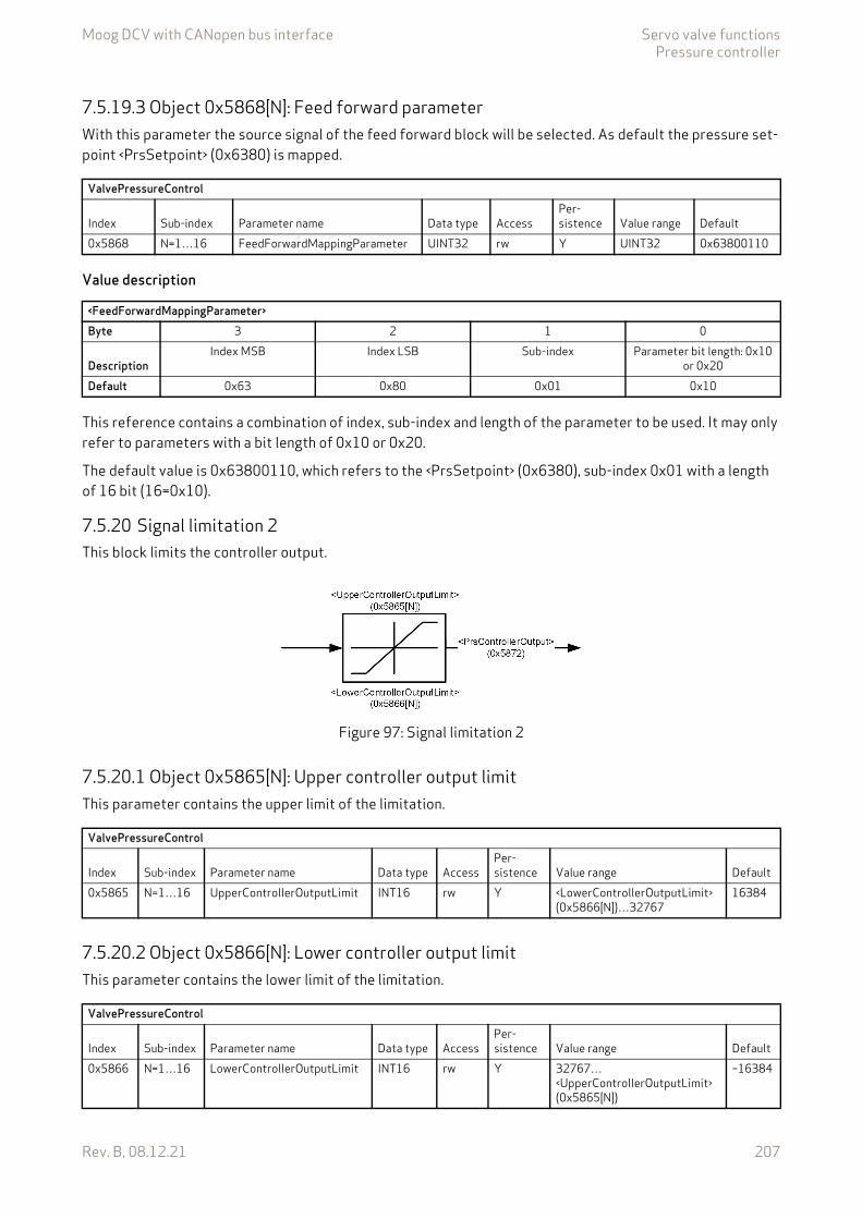
Moog DCV with CANopen bus interface Servo valve functionsPressure controller
Rev. B, 08.12.21 207
7.5.19.3 Object 0x5868[N]: Feed forward parameterWith this parameter the source signal of the feed forward block will be selected. As default the pressure set-point <PrsSetpoint> (0x6380) is mapped.
Value description
This reference contains a combination of index, sub-index and length of the parameter to be used. It may only refer to parameters with a bit length of 0x10 or 0x20.
The default value is 0x63800110, which refers to the <PrsSetpoint> (0x6380), sub-index 0x01 with a length of 16 bit (16=0x10).
7.5.20 Signal limitation 2This block limits the controller output.
Figure 97: Signal limitation 2
7.5.20.1 Object 0x5865[N]: Upper controller output limitThis parameter contains the upper limit of the limitation.
7.5.20.2 Object 0x5866[N]: Lower controller output limitThis parameter contains the lower limit of the limitation.
ValvePressureControl
Index Sub-index Parameter name Data type AccessPer-sistence Value range Default
0x5868 N=1…16 FeedForwardMappingParameter UINT32 rw Y UINT32 0x63800110
<FeedForwardMappingParameter>Byte 3 2 1 0
DescriptionIndex MSB Index LSB Sub-index Parameter bit length: 0x10
or 0x20Default 0x63 0x80 0x01 0x10
ValvePressureControl
Index Sub-index Parameter name Data type AccessPer-sistence Value range Default
0x5865 N=1…16 UpperControllerOutputLimit INT16 rw Y <LowerControllerOutputLimit> (0x5866[N])…32767
16384
ValvePressureControl
Index Sub-index Parameter name Data type AccessPer-sistence Value range Default
0x5866 N=1…16 LowerControllerOutputLimit INT16 rw Y 32767…<UpperControllerOutputLimit> (0x5865[N])
–16384
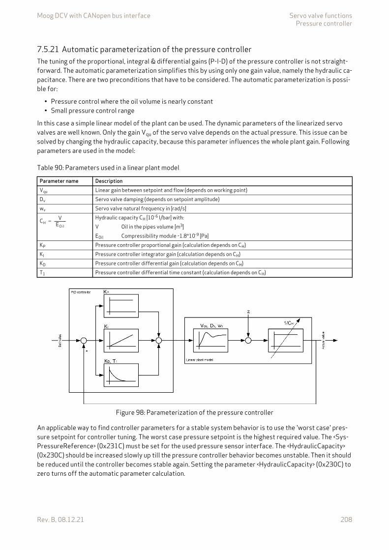
Moog DCV with CANopen bus interface Servo valve functionsPressure controller
Rev. B, 08.12.21 208
7.5.21 Automatic parameterization of the pressure controllerThe tuning of the proportional, integral & differential gains (P-I-D) of the pressure controller is not straight-forward. The automatic parameterization simplifies this by using only one gain value, namely the hydraulic ca-pacitance. There are two preconditions that have to be considered. The automatic parameterization is possi-ble for:
• Pressure control where the oil volume is nearly constant• Small pressure control range
In this case a simple linear model of the plant can be used. The dynamic parameters of the linearized servo valves are well known. Only the gain Vqu of the servo valve depends on the actual pressure. This issue can be solved by changing the hydraulic capacity, because this parameter influences the whole plant gain. Following parameters are used in the model:
Figure 98: Parameterization of the pressure controller
An applicable way to find controller parameters for a stable system behavior is to use the 'worst case' pres-sure setpoint for controller tuning. The worst case pressure setpoint is the highest required value. The <Sys-PressureReference> (0x231C) must be set for the used pressure sensor interface. The <HydraulicCapacity> (0x230C) should be increased slowly up till the pressure controller behavior becomes unstable. Then it should be reduced until the controller becomes stable again. Setting the parameter <HydraulicCapacity> (0x230C) to zero turns off the automatic parameter calculation.
Table 90: Parameters used in a linear plant model
Parameter name DescriptionVqu Linear gain between setpoint and flow (depends on working point)Dv Servo valve damping (depends on setpoint amplitude)wv Servo valve natural frequency in [rad/s]
Hydraulic capacity CH [10-6 l/bar] with:V Oil in the pipes volume [m3]EOil Compressibility module ~1.8*10-9 [Pa]
KP Pressure controller proportional gain (calculation depends on CH)KI Pressure controller integrator gain (calculation depends on CH)KD Pressure controller differential gain (calculation depends on CH)T1 Pressure controller differential time constant (calculation depends on CH)
CHV
EOil------------=
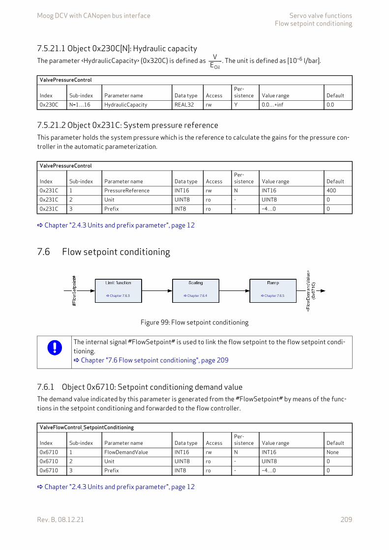
Moog DCV with CANopen bus interface Servo valve functionsFlow setpoint conditioning
Rev. B, 08.12.21 209
7.5.21.1 Object 0x230C[N]: Hydraulic capacityThe parameter <HydraulicCapacity> (0x320C) is defined as . The unit is defined as [10–6 l/bar].
7.5.21.2 Object 0x231C: System pressure referenceThis parameter holds the system pressure which is the reference to calculate the gains for the pressure con-troller in the automatic parameterization.
Chapter "2.4.3 Units and prefix parameter", page 12
7.6 Flow setpoint conditioning
Figure 99: Flow setpoint conditioning
7.6.1 Object 0x6710: Setpoint conditioning demand valueThe demand value indicated by this parameter is generated from the #FlowSetpoint# by means of the func-tions in the setpoint conditioning and forwarded to the flow controller.
Chapter "2.4.3 Units and prefix parameter", page 12
VEOil
-----------
ValvePressureControl
Index Sub-index Parameter name Data type AccessPer-sistence Value range Default
0x230C N=1…16 HydraulicCapacity REAL32 rw Y 0.0…+inf 0.0
ValvePressureControl
Index Sub-index Parameter name Data type AccessPer-sistence Value range Default
0x231C 1 PressureReference INT16 rw N INT16 4000x231C 2 Unit UINT8 ro - UINT8 00x231C 3 Prefix INT8 ro - –4…0 0
Chapter 7.6.3 Chapter 7.6.4 Chapter 7.6.5
The internal signal #FlowSetpoint# is used to link the flow setpoint to the flow setpoint condi-tioning. Chapter "7.6 Flow setpoint conditioning", page 209
ValveFlowControl_SetpointConditioning
Index Sub-index Parameter name Data type AccessPer-sistence Value range Default
0x6710 1 FlowDemandValue INT16 rw N INT16 None0x6710 2 Unit UINT8 ro - UINT8 00x6710 3 Prefix INT8 ro - –4…0 0
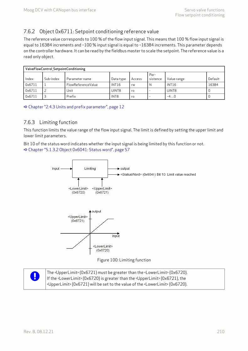
Moog DCV with CANopen bus interface Servo valve functionsFlow setpoint conditioning
Rev. B, 08.12.21 210
7.6.2 Object 0x6711: Setpoint conditioning reference valueThe reference value corresponds to 100 % of the flow input signal. This means that 100 % flow input signal is equal to 16384 increments and –100 % input signal is equal to –16384 increments. This parameter depends on the controller hardware. It can be read by the fieldbus master to scale the setpoint. The reference value is a read only object.
Chapter "2.4.3 Units and prefix parameter", page 12
7.6.3 Limiting functionThis function limits the value range of the flow input signal. The limit is defined by setting the upper limit and lower limit parameters.
Bit 10 of the status word indicates whether the input signal is being limited by this function or not. Chapter "5.1.3.2 Object 0x6041: Status word", page 57
Figure 100: Limiting function
ValveFlowControl_SetpointConditioning
Index Sub-index Parameter name Data type AccessPer-sistence Value range Default
0x6711 1 FlowReferenceValue INT16 rw N INT16 163840x6711 2 Unit UINT8 ro - UINT8 00x6711 3 Prefix INT8 ro - –4…0 0
The <UpperLimit> (0x6721) must be greater than the <LowerLimit> (0x6720).If the <LowerLimit> (0x6720) is greater than the <UpperLimit> (0x6721), the <UpperLimit> (0x6721) will be set to the value of the <LowerLimit> (0x6720).

Moog DCV with CANopen bus interface Servo valve functionsFlow setpoint conditioning
Rev. B, 08.12.21 211
7.6.3.1 Object 0x6720: Setpoint conditioning upper setpoint limit
Chapter "2.4.3 Units and prefix parameter", page 12
7.6.3.2 Object 0x6721: Setpoint conditioning lower setpoint limit
Chapter "2.4.3 Units and prefix parameter", page 12
7.6.4 Flow setpoint scalingThis function is used to scale the flow setpoint, e.g., to influence the input signal's value range. The output sig-nal is calculated by multiplication of the input signal with a scaling factor and a subsequent addition of an off-set according to the following figure.
Figure 101: Scaling function
ValveFlowControl_SetpointConditioning_SetpointLimit
Index Sub-index Parameter name Data type AccessPer-sistence Value range Default
0x6720 1 UpperLimit INT16 rw Y <LowerLimit> (0x6720)…32767 163840x6720 2 Unit UINT8 ro - UINT8 00x6720 3 Prefix INT8 ro - –4…0 0
ValveFlowControl_SetpointConditioning_SetpointLimit
Index Sub-index Parameter name Data type AccessPer-sistence Value range Default
0x6721 1 LowerLimit INT16 rw Y –32767…<UpperLimit> (0x6721) –163840x6721 2 Unit UINT8 ro - UINT8 00x6721 3 Prefix INT8 ro - –4…0 0
m numden-------------=
y x m x yoff+=
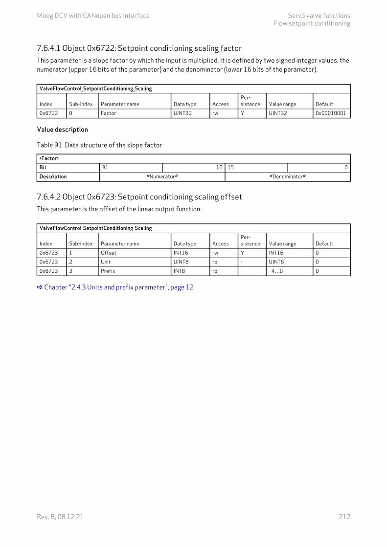
Moog DCV with CANopen bus interface Servo valve functionsFlow setpoint conditioning
Rev. B, 08.12.21 212
7.6.4.1 Object 0x6722: Setpoint conditioning scaling factorThis parameter is a slope factor by which the input is multiplied. It is defined by two signed integer values, the numerator (upper 16 bits of the parameter) and the denominator (lower 16 bits of the parameter).
Value description
7.6.4.2 Object 0x6723: Setpoint conditioning scaling offsetThis parameter is the offset of the linear output function.
Chapter "2.4.3 Units and prefix parameter", page 12
ValveFlowControl_SetpointConditioning_Scaling
Index Sub-index Parameter name Data type AccessPer-sistence Value range Default
0x6722 0 Factor UINT32 rw Y UINT32 0x00010001
Table 91: Data structure of the slope factor
<Factor>Bit 31 16 15 0Description #Numerator# #Denominator#
ValveFlowControl_SetpointConditioning_Scaling
Index Sub-index Parameter name Data type AccessPer-sistence Value range Default
0x6723 1 Offset INT16 rw Y INT16 00x6723 2 Unit UINT8 ro - UINT8 00x6723 3 Prefix INT8 ro - –4…0 0

Moog DCV with CANopen bus interface Servo valve functionsFlow setpoint conditioning
Rev. B, 08.12.21 213
7.6.5 RampThe ramp function limits the slew rate of the input signal. The <Type> (0x6730) parameter is used to activate a one-, two- or four-quadrant ramp function or to deactivate it.
If the signal slope of the input signal is limited by configured slew rate (ramp running), the <StatusWord> (0x6041) bit 9 is set.
If the running ramp is stopped by the bit 15 (ramp stop) of the #ControlWord# signal, then the <StatusWord> (0x6041) bit 15 signalize that the output value of the ramp signal is hold (ramp frozen).
Chapter "5.1.3.2 Object 0x6041: Status word", page 57 Chapter "5.1.5 Object 0x604F: Device local", page 59 Chapter "5.1.3.1 Object 0x6040: Device control word", page 56 Chapter "5.1.6 Object 0x4040: Local control word", page 59
Figure 102: Ramp function
7.6.5.1 Object 0x6730: Setpoint conditioning ramp typeThis parameter defines the progression of the ramp.
Value description
ValveFlowControl_SetpointConditioning_Ramp
Index Sub-index Parameter name Data type AccessPer-sistence Value range Default
0x6730 0 Type INT8 rw Y 0…3 0
Table 92: Possible values of parameter <Type> (0x6730)
<Type> Description0 No ramp1 One-quadrant ramp2 Two-quadrant ramp3 Four-quadrant ramp
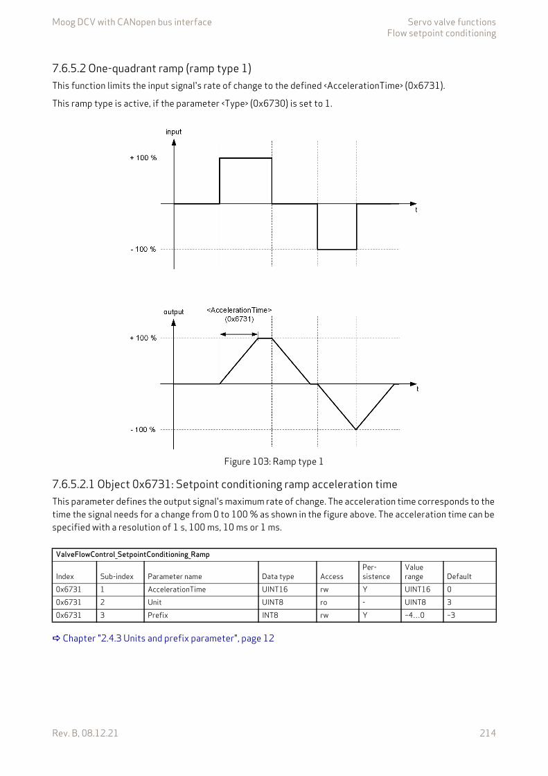
Moog DCV with CANopen bus interface Servo valve functionsFlow setpoint conditioning
Rev. B, 08.12.21 214
7.6.5.2 One-quadrant ramp (ramp type 1)This function limits the input signal's rate of change to the defined <AccelerationTime> (0x6731).
This ramp type is active, if the parameter <Type> (0x6730) is set to 1.
Figure 103: Ramp type 1
7.6.5.2.1 Object 0x6731: Setpoint conditioning ramp acceleration timeThis parameter defines the output signal's maximum rate of change. The acceleration time corresponds to the time the signal needs for a change from 0 to 100 % as shown in the figure above. The acceleration time can be specified with a resolution of 1 s, 100 ms, 10 ms or 1 ms.
Chapter "2.4.3 Units and prefix parameter", page 12
ValveFlowControl_SetpointConditioning_Ramp
Index Sub-index Parameter name Data type AccessPer-sistence
Value range Default
0x6731 1 AccelerationTime UINT16 rw Y UINT16 00x6731 2 Unit UINT8 ro - UINT8 30x6731 3 Prefix INT8 rw Y –4…0 –3
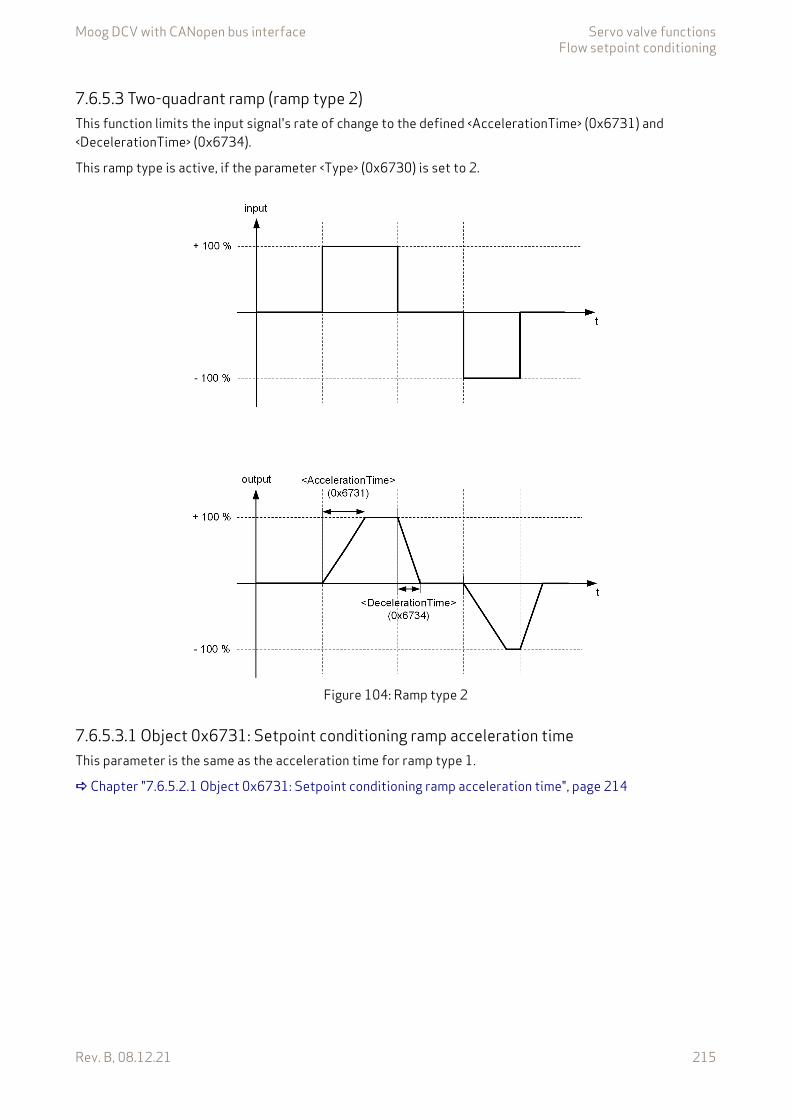
Moog DCV with CANopen bus interface Servo valve functionsFlow setpoint conditioning
Rev. B, 08.12.21 215
7.6.5.3 Two-quadrant ramp (ramp type 2)This function limits the input signal's rate of change to the defined <AccelerationTime> (0x6731) and <DecelerationTime> (0x6734).
This ramp type is active, if the parameter <Type> (0x6730) is set to 2.
Figure 104: Ramp type 2
7.6.5.3.1 Object 0x6731: Setpoint conditioning ramp acceleration timeThis parameter is the same as the acceleration time for ramp type 1.
Chapter "7.6.5.2.1 Object 0x6731: Setpoint conditioning ramp acceleration time", page 214

Moog DCV with CANopen bus interface Servo valve functionsFlow setpoint conditioning
Rev. B, 08.12.21 216
7.6.5.3.2 Object 0x6734: Setpoint conditioning ramp deceleration timeThis parameter defines the output signal's maximum rate of change. The deceleration time corresponds to the time that the signal needs for a change from 100 to 0 %. The deceleration time can be specified with a resolution of 1 s, 100 ms, 10 ms or 1 ms.
Chapter "2.4.3 Units and prefix parameter", page 12
7.6.5.4 Four-quadrant ramp (ramp type 3)This function limits the input signal's rate of change to an acceleration time and a deceleration time, each separated for the positive and negative sides.
This ramp type is active, if the parameter <Type> (0x6730) is set to 3.
Figure 105: Ramp type 3
ValveFlowControl_SetpointConditioning_Ramp
Index Sub-index Parameter name Data type AccessPer-sistence
Value range Default
0x6734 1 DecelerationTime UINT16 rw Y UINT16 00x6734 2 Unit UINT8 ro - UINT8 30x6734 3 Prefix INT8 rw Y –4…0 –3
Moog DCV with CANopen bus interface Servo valve functionsFlow setpoint conditioning
Rev. B, 08.12.21 217
7.6.5.4.1 Object 0x6732: Setpoint conditioning ramp acceleration time positiveThis parameter defines the output signal's maximum rate of change on the positive side. The acceleration time corresponds to the time that the signal needs for a change from 0 to 100 %. The acceleration time can be specified with a resolution of 1 s, 100 ms, 10 ms or 1 ms.
Chapter "2.4.3 Units and prefix parameter", page 12
7.6.5.4.2 Object 0x6733: Setpoint conditioning ramp acceleration time negativeThis parameter defines the output signal's maximum rate of change on the negative side. The acceleration time corresponds to the time that the signal needs for a change from 0 to 100 %. The acceleration time can be specified with a resolution of 1 s, 100 ms, 10 ms or 1 ms.
Chapter "2.4.3 Units and prefix parameter", page 12
7.6.5.4.3 Object 0x6735: Setpoint conditioning ramp deceleration time positiveThis parameter defines the output signal's maximum rate of change on the positive side. The deceleration time corresponds to the time that the signal needs for a change from 100 to 0 %. The deceleration time can be specified with a resolution of 1 s, 100 ms, 10 ms or 1 ms.
Chapter "2.4.3 Units and prefix parameter", page 12
ValveFlowControl_SetpointConditioning_Ramp
Index Sub-index Parameter name Data type AccessPer-sistence
Value range Default
0x6732 1 AccelerationTimePositive UINT16 rw Y UINT16 00x6732 2 Unit UINT8 ro - UINT8 30x6732 3 Prefix INT8 rw Y –4…0 –3
ValveFlowControl_SetpointConditioning_Ramp
Index Sub-index Parameter name Data type AccessPer-sistence
Value range Default
0x6733 1 AccelerationTimeNegative UINT16 rw Y UINT16 00x6733 2 Unit UINT8 ro - UINT8 30x6733 3 Prefix INT8 rw Y –4…0 –3
ValveFlowControl_SetpointConditioning_Ramp
Index Sub-index Parameter name Data type AccessPer-sistence
Value range Default
0x6735 1 DecelerationTimePositive UINT16 rw Y UINT16 00x6735 2 Unit UINT8 ro - UINT8 30x6735 3 Prefix INT8 rw Y –4…0 –3
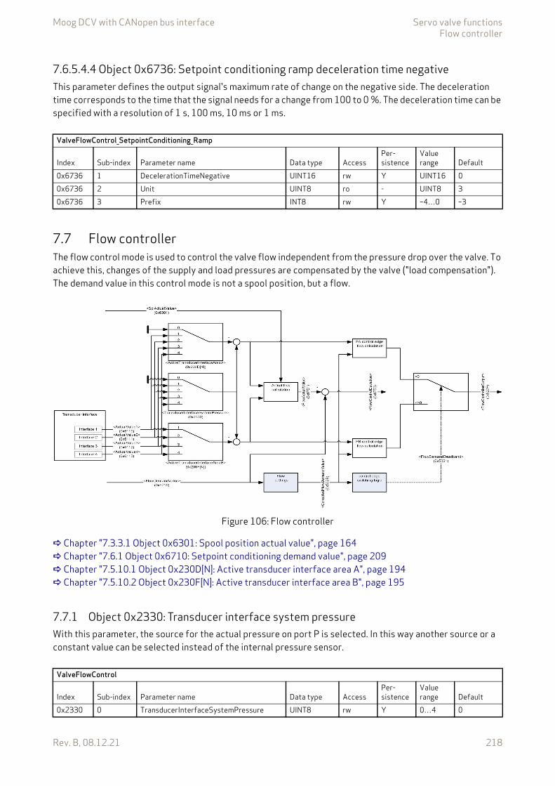
Moog DCV with CANopen bus interface Servo valve functionsFlow controller
Rev. B, 08.12.21 218
7.6.5.4.4 Object 0x6736: Setpoint conditioning ramp deceleration time negativeThis parameter defines the output signal's maximum rate of change on the negative side. The deceleration time corresponds to the time that the signal needs for a change from 100 to 0 %. The deceleration time can be specified with a resolution of 1 s, 100 ms, 10 ms or 1 ms.
7.7 Flow controllerThe flow control mode is used to control the valve flow independent from the pressure drop over the valve. To achieve this, changes of the supply and load pressures are compensated by the valve ("load compensation"). The demand value in this control mode is not a spool position, but a flow.
Figure 106: Flow controller
Chapter "7.3.3.1 Object 0x6301: Spool position actual value", page 164 Chapter "7.6.1 Object 0x6710: Setpoint conditioning demand value", page 209 Chapter "7.5.10.1 Object 0x230D[N]: Active transducer interface area A", page 194 Chapter "7.5.10.2 Object 0x230F[N]: Active transducer interface area B", page 195
7.7.1 Object 0x2330: Transducer interface system pressureWith this parameter, the source for the actual pressure on port P is selected. In this way another source or a constant value can be selected instead of the internal pressure sensor.
ValveFlowControl_SetpointConditioning_Ramp
Index Sub-index Parameter name Data type AccessPer-sistence
Value range Default
0x6736 1 DecelerationTimeNegative UINT16 rw Y UINT16 00x6736 2 Unit UINT8 ro - UINT8 30x6736 3 Prefix INT8 rw Y –4…0 –3
ValveFlowControl
Index Sub-index Parameter name Data type AccessPer-sistence
Value range Default
0x2330 0 TransducerInterfaceSystemPressure UINT8 rw Y 0…4 0
Moog DCV with CANopen bus interface Servo valve functionsFlow controller
Rev. B, 08.12.21 219
7.7.2 Object 0x532B: Corrected flow demand valueThis parameter holds the output of the flow normalization calculation.
7.7.3 Object 0x5321: Flow demand deadbandThis parameter corresponds to the output of the switching calculation. The changeover between the control edges PA and PB is based on the flow direction. If this parameter is less than 0, the calculated flow of control edge A is taken as output of the flow controller, otherwise the calculated flow of control edge B.
7.7.4 Object 0x520F: Flow controller outputThis parameter holds the controller output of the flow controller.
7.7.5 Object 0x6701: Flow actual valueThis parameter holds the calculated actual flow.
7.7.6 Object 0x6750: Flow control deviationThis parameter holds the difference between the flow demand and the calculated actual flow.
Chapter "2.4.3 Units and prefix parameter", page 12
ValveFlowControl
Index Sub-index Parameter name Data type AccessPer-sistence
Value range Default
0x532B 0 CorrectedFlowDemandValue REAL32 ro - REAL32 None
ValveFlowControl
Index Sub-index Parameter name Data type AccessPer-sistence
Value range Default
0x5321 0 FlowDemandDeadband REAL32 ro - REAL32 0.0
ValveFlowControl
Index Sub-index Parameter name Data type AccessPer-sistence
Value range Default
0x520F 0 FlowControllerOutput INT16 ro - INT16 None
ValveFlowControl
Index Sub-index Parameter name Data type AccessPer-sistence
Value range Default
0x6701 1 FlowActualValue INT16 ro - INT16 None0x6701 2 Prefix INT8 ro - –4…0 0
ValveFlowControl
Index Sub-index Parameter name Data type AccessPer-sistence
Value range Default
0x6750 1 FlowControlDeviation INT16 ro - INT16 None0x6750 2 Unit UINT8 ro - UINT8 00x6750 3 Prefix INT8 ro - –4…0 0
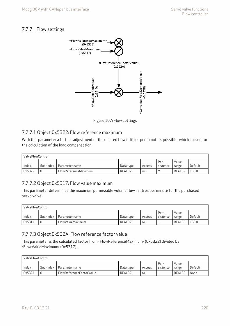
Moog DCV with CANopen bus interface Servo valve functionsFlow controller
Rev. B, 08.12.21 220
7.7.7 Flow settings
Figure 107: Flow settings
7.7.7.1 Object 0x5322: Flow reference maximumWith this parameter a further adjustment of the desired flow in litres per minute is possible, which is used for the calculation of the load compensation.
7.7.7.2 Object 0x5317: Flow value maximumThis parameter determines the maximum permissible volume flow in litres per minute for the purchased servo valve.
7.7.7.3 Object 0x532A: Flow reference factor valueThis parameter is the calculated factor from <FlowReferenceMaximum> (0x5322) divided by <FlowValueMaximum> (0x5317).
ValveFlowControl
Index Sub-index Parameter name Data type AccessPer-sistence
Value range Default
0x5322 0 FlowReferenceMaximum REAL32 rw Y REAL32 180.0
ValveFlowControl
Index Sub-index Parameter name Data type AccessPer-sistence
Value range Default
0x5317 0 FlowValueMaximum REAL32 ro - REAL32 180.0
ValveFlowControl
Index Sub-index Parameter name Data type AccessPer-sistence
Value range Default
0x532A 0 FlowReferenceFactorValue REAL32 ro - REAL32 None
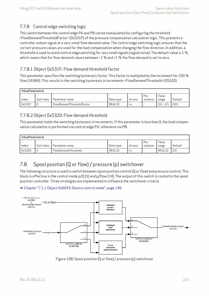
Moog DCV with CANopen bus interface Servo valve functionsSpool position (Q or flow) / pressure (p) switchover
Rev. B, 08.12.21 221
7.7.8 Control edge switching logicThis switch between the control edge PA and PB can be manipulated by configuring the threshold <FlowDemandThresholdFactor> (0x531F) of the pressure compensation calculation logic. This prevents a controller output signal at a very small flow demand value. The control edge switching logic ensures that the correct pressure values are used for the load compensation when changing the flow direction. In addition, a threshold is used to avoid control edge switching for very small signals (signal noise). The default value is 1 %, which means that for flow demand values between –1 % and +1 % the flow demand is set to zero.
7.7.8.1 Object 0x531F: Flow demand threshold factorThis parameter specifies the switching hysteresis factor. This factor is multiplied by the increment for 100 % flow (16384). This results in the switching hysteresis in increments <FlowDemandThreshold> (05320).
7.7.8.2 Object 0x5320: Flow demand thresholdThis parameter holds the switching hysteresis in increments. If this parameter is less than 0, the load compen-sation calculation is performed via control edge PA, otherwise via PB.
7.8 Spool position (Q or flow) / pressure (p) switchoverThe following structure is used to switch between spool position control (Q or flow) and pressure control. This block is effective in the control mode p/Q (5) and p/flow (14). The output of this switch is routed to the spool position controller. Three strategies are implemented to influence the switchover criteria.
Chapter "7.1.1 Object 0x6043: Device control mode", page 146
Figure 108: Spool position (Q or flow) / pressure (p) switchover
ValveFlowControl
Index Sub-index Parameter name Data type AccessPer-sistence
Value range Default
0x531F 0 FlowDemandThresholdFactor REAL32 ro - 0.0…0.5 0.01
ValveFlowControl
Index Sub-index Parameter name Data type AccessPer-sistence
Value range Default
0x5320 0 FlowDemandThreshold REAL32 ro - REAL32 0.0
Moog DCV with CANopen bus interface Servo valve functionsSpool position (Q or flow) / pressure (p) switchover
Rev. B, 08.12.21 222
7.8.1 Object 0x586C[N]: p/Q or p/flow switching modeThis parameter defines the switching mode.
Value description
7.8.1.1 Object 0x23E6: Switch controller outputThis parameter contains the output signal of the p/Q or p/flow switchover function.
ValvePressureControl
Index Sub-index Parameter name Data type AccessPer-sistence Value range Default
0x586C N=1…16 pQSwitchingMode UINT8 rw Y 0…2 0
Table 93: Possible values of parameter <pQSwitchingMode> (0x586C)
<pQSwitchingMode> Description0 Minimum criterion in positive direction.1 Minimum criterion in both directions.2 Force exceeded in both directions.
ValvePressureControl
Index Sub-index Parameter name Data type AccessPer-sistence Value range Default
0x23E6 N=1…16 SwitchControllerOutput INT16 ro - INT16 None
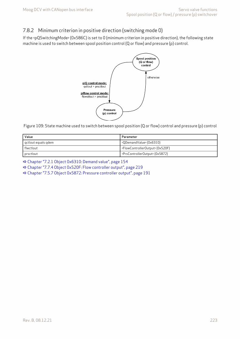
Moog DCV with CANopen bus interface Servo valve functionsSpool position (Q or flow) / pressure (p) switchover
Rev. B, 08.12.21 223
7.8.2 Minimum criterion in positive direction (switching mode 0)If the <pQSwitchingMode> (0x586C) is set to 0 (minimum criterion in positive direction), the following state machine is used to switch between spool position control (Q or flow) and pressure (p) control.
Figure 109: State machine used to switch between spool position (Q or flow) control and pressure (p) control
Chapter "7.2.1 Object 0x6310: Demand value", page 154 Chapter "7.7.4 Object 0x520F: Flow controller output", page 219 Chapter "7.5.7 Object 0x5872: Pressure controller output", page 191
Value Parameterqctlout equals qdem <QDemandValue> (0x6310)flwctlout <FlowControllerOutput> (0x520F)prsctlout <PrsControllerOutput> (0x5872)
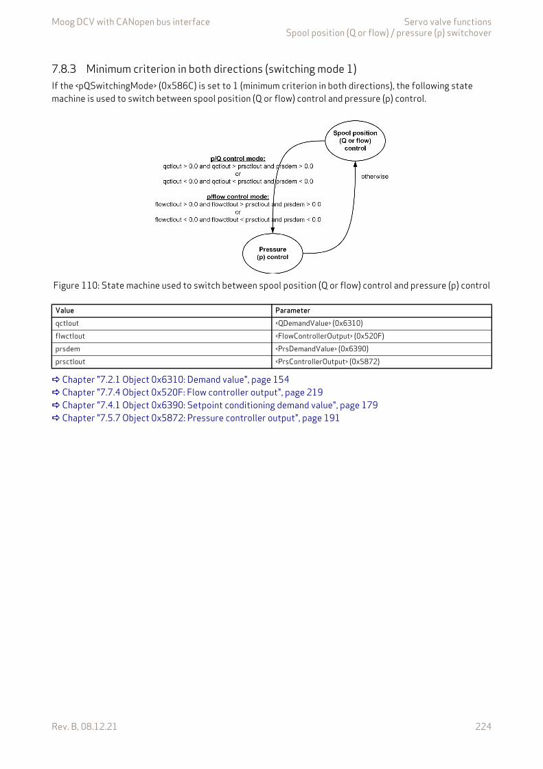
Moog DCV with CANopen bus interface Servo valve functionsSpool position (Q or flow) / pressure (p) switchover
Rev. B, 08.12.21 224
7.8.3 Minimum criterion in both directions (switching mode 1)If the <pQSwitchingMode> (0x586C) is set to 1 (minimum criterion in both directions), the following state machine is used to switch between spool position (Q or flow) control and pressure (p) control.
Figure 110: State machine used to switch between spool position (Q or flow) control and pressure (p) control
Chapter "7.2.1 Object 0x6310: Demand value", page 154 Chapter "7.7.4 Object 0x520F: Flow controller output", page 219 Chapter "7.4.1 Object 0x6390: Setpoint conditioning demand value", page 179 Chapter "7.5.7 Object 0x5872: Pressure controller output", page 191
Value Parameterqctlout <QDemandValue> (0x6310)flwctlout <FlowControllerOutput> (0x520F)prsdem <PrsDemandValue> (0x6390)prsctlout <PrsControllerOutput> (0x5872)
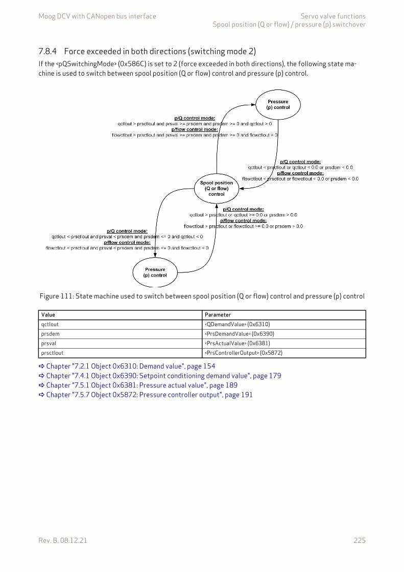
Moog DCV with CANopen bus interface Servo valve functionsSpool position (Q or flow) / pressure (p) switchover
Rev. B, 08.12.21 225
7.8.4 Force exceeded in both directions (switching mode 2)If the <pQSwitchingMode> (0x586C) is set to 2 (force exceeded in both directions), the following state ma-chine is used to switch between spool position (Q or flow) control and pressure (p) control.
Figure 111: State machine used to switch between spool position (Q or flow) control and pressure (p) control
Chapter "7.2.1 Object 0x6310: Demand value", page 154 Chapter "7.4.1 Object 0x6390: Setpoint conditioning demand value", page 179 Chapter "7.5.1 Object 0x6381: Pressure actual value", page 189 Chapter "7.5.7 Object 0x5872: Pressure controller output", page 191
Value Parameterqctlout <QDemandValue> (0x6310)prsdem <PrsDemandValue> (0x6390)prsval <PrsActualValue> (0x6381)prsctlout <PrsControllerOutput> (0x5872)
Moog DCV with CANopen bus interface Servo valve functionsMonitoring
Rev. B, 08.12.21 226
7.9 MonitoringThis chapter describes the monitoring functionalities listed below:
Chapter "7.9.1 Power supply monitoring", page 226 Chapter "7.9.2 Analog input cable break monitoring", page 227 Chapter "7.9.3 Electronic temperature monitoring", page 229 Chapter "7.9.4 Operating time counters", page 230 Chapter "7.9.5 Spool position control deviation monitoring", page 231 Chapter "7.9.7 Flow control deviation monitoring", page 235 Chapter "7.9.8 Pressure control deviation monitoring", page 236 Chapter "7.9.9 Main stage spool position sensor cable break monitoring", page 238 Chapter "7.9.10 Spool / pilot spool position sensor cable break monitoring", page 238 Chapter "7.9.11 Current control deviation monitoring", page 238 Chapter "7.9.12 Actuator over current monitoring", page 238 Chapter "7.9.13 Failsafe monitoring", page 239
7.9.1 Power supply monitoringThe 24 V supply voltage is permanently monitored for over- and undervoltage. A fault is generated if the parameter is outside the range between 16.5 V and 38 V. The normal operating supply voltage range is be-tween 18 V and 36 V.
7.9.1.1 Object 0x2804: Power supply voltageThis parameter holds the actual value of the power supply voltage (in mV).
The power supply is monitored. The following fault reactions can be triggered.
If the power supply voltage is below 16.5 V for more than 5 ms, the undervoltage fault is triggered.
If the power supply voltage is above 38 V for more than 200 ms, the overvoltage fault is triggered.
Fault description
PowerSupplyIndex Sub-index Parameter name Data type Access Persistence Value range Default0x2804 0 PowerSupplyVoltage UINT16 ro - UINT16 None
Table 94: Fault codes
<PowerSupplyVoltage> Indicated fault code Fault descriptionDec Hex
PowerSupplyVoltage < 16.5 V 5 0x05 Power supply voltage too low.PowerSupplyVoltage > 38 V 6 0x06 Power supply voltage too high.
The power supply voltage should be in the range of 18…36 V to ensure proper operation.
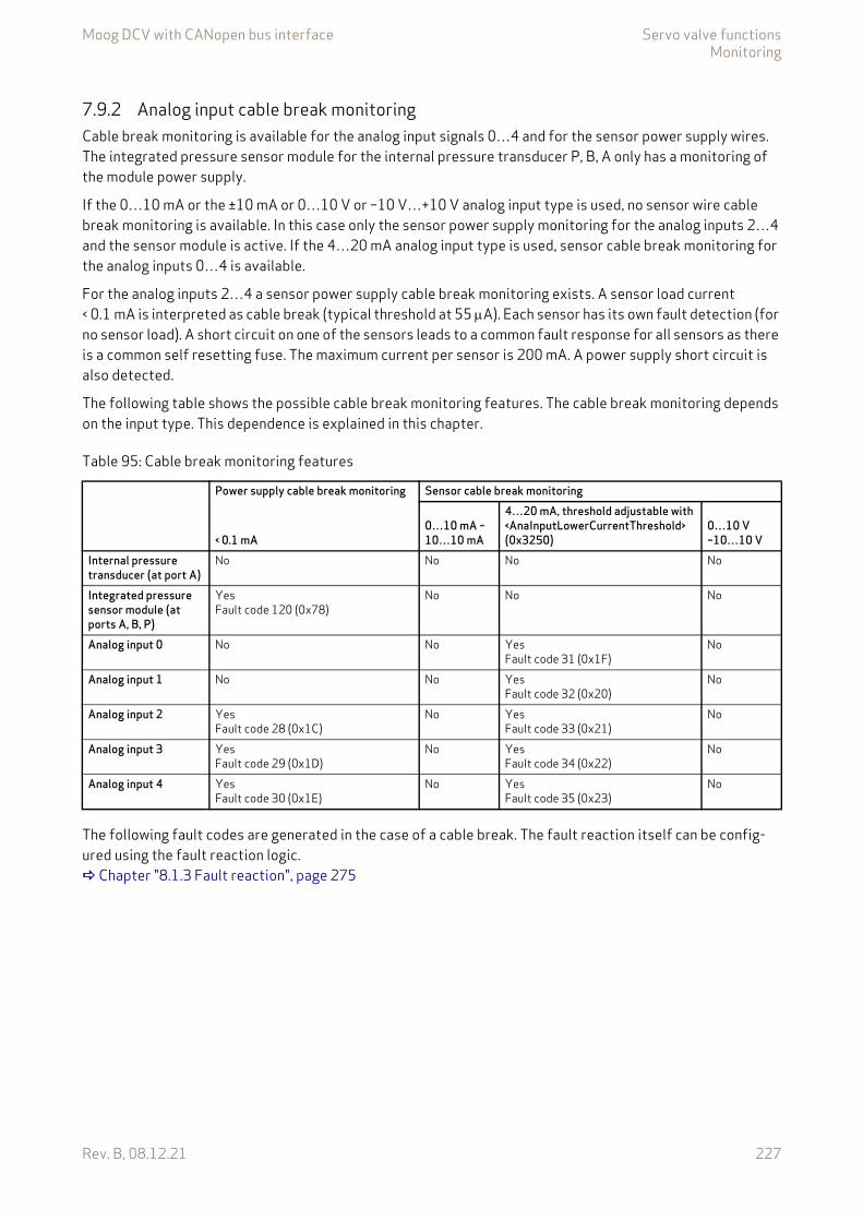
Moog DCV with CANopen bus interface Servo valve functionsMonitoring
Rev. B, 08.12.21 227
7.9.2 Analog input cable break monitoringCable break monitoring is available for the analog input signals 0…4 and for the sensor power supply wires. The integrated pressure sensor module for the internal pressure transducer P, B, A only has a monitoring of the module power supply.
If the 0…10 mA or the ±10 mA or 0…10 V or –10 V…+10 V analog input type is used, no sensor wire cable break monitoring is available. In this case only the sensor power supply monitoring for the analog inputs 2…4 and the sensor module is active. If the 4…20 mA analog input type is used, sensor cable break monitoring for the analog inputs 0…4 is available.
For the analog inputs 2…4 a sensor power supply cable break monitoring exists. A sensor load current < 0.1 mA is interpreted as cable break (typical threshold at 55 A). Each sensor has its own fault detection (for no sensor load). A short circuit on one of the sensors leads to a common fault response for all sensors as there is a common self resetting fuse. The maximum current per sensor is 200 mA. A power supply short circuit is also detected.
The following table shows the possible cable break monitoring features. The cable break monitoring depends on the input type. This dependence is explained in this chapter.
The following fault codes are generated in the case of a cable break. The fault reaction itself can be config-ured using the fault reaction logic. Chapter "8.1.3 Fault reaction", page 275
Table 95: Cable break monitoring features
Power supply cable break monitoring Sensor cable break monitoring
< 0.1 mA0…10 mA –10…10 mA
4…20 mA, threshold adjustable with <AnaInputLowerCurrentThreshold> (0x3250)
0…10 V–10…10 V
Internal pressure transducer (at port A)
No No No No
Integrated pressure sensor module (at ports A, B, P)
YesFault code 120 (0x78)
No No No
Analog input 0 No No YesFault code 31 (0x1F)
No
Analog input 1 No No YesFault code 32 (0x20)
No
Analog input 2 YesFault code 28 (0x1C)
No YesFault code 33 (0x21)
No
Analog input 3 YesFault code 29 (0x1D)
No YesFault code 34 (0x22)
No
Analog input 4 YesFault code 30 (0x1E)
No YesFault code 35 (0x23)
No
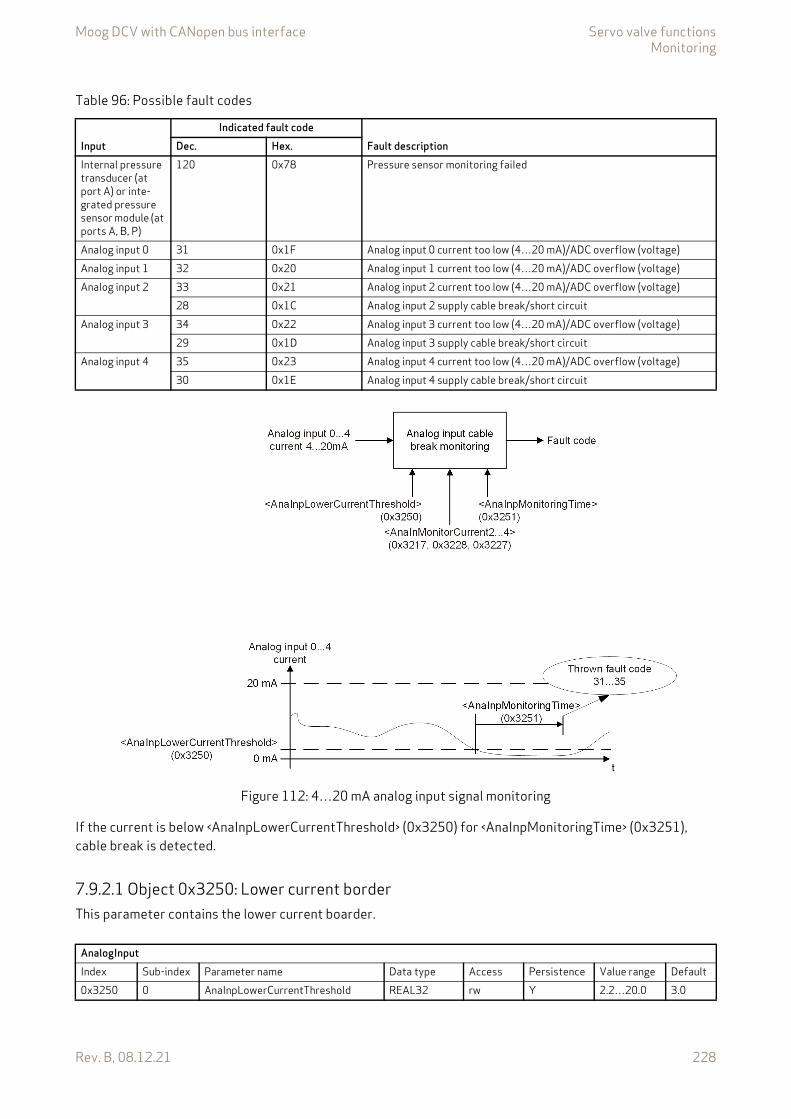
Moog DCV with CANopen bus interface Servo valve functionsMonitoring
Rev. B, 08.12.21 228
Figure 112: 4…20 mA analog input signal monitoring
If the current is below <AnaInpLowerCurrentThreshold> (0x3250) for <AnaInpMonitoringTime> (0x3251), cable break is detected.
7.9.2.1 Object 0x3250: Lower current borderThis parameter contains the lower current boarder.
Table 96: Possible fault codes
InputIndicated fault code
Fault descriptionDec. Hex.Internal pressure transducer (at port A) or inte-grated pressure sensor module (at ports A, B, P)
120 0x78 Pressure sensor monitoring failed
Analog input 0 31 0x1F Analog input 0 current too low (4…20 mA)/ADC overflow (voltage)Analog input 1 32 0x20 Analog input 1 current too low (4…20 mA)/ADC overflow (voltage)Analog input 2 33 0x21 Analog input 2 current too low (4…20 mA)/ADC overflow (voltage)
28 0x1C Analog input 2 supply cable break/short circuitAnalog input 3 34 0x22 Analog input 3 current too low (4…20 mA)/ADC overflow (voltage)
29 0x1D Analog input 3 supply cable break/short circuitAnalog input 4 35 0x23 Analog input 4 current too low (4…20 mA)/ADC overflow (voltage)
30 0x1E Analog input 4 supply cable break/short circuit
AnalogInputIndex Sub-index Parameter name Data type Access Persistence Value range Default0x3250 0 AnaInpLowerCurrentThreshold REAL32 rw Y 2.2…20.0 3.0
Moog DCV with CANopen bus interface Servo valve functionsMonitoring
Rev. B, 08.12.21 229
7.9.2.2 Object 0x3251: Analog input monitoring timeThis parameter contains the delay time (in ms) before generating the fault code.
7.9.3 Electronic temperature monitoringThe temperature on the valve electronics is constantly measured and stored as a temperature histogram. If the temperature falls below or exceeds the maximum permissible temperature, a fault code is generated.
7.9.3.1 Object 0x2805: Electronic temperatureThis parameter contains the temperature (in °C) of the servo valve electronics.
Fault description
AnalogInputIndex Sub-index Parameter name Data type Access Persistence Value range Default0x3251 0 AnaInpMonitoringTime UINT16 rw Y 0…60000 10
TemperatureIndex Sub-index Parameter name Data type Access Persistence Value range Default0x2805 0 PcbTemperature INT16 ro - INT16 None
Table 97: Fault codes
<PcbTemperature > Indicated fault code Fault descriptionDec Hex
PCB temperature < –40 °C 13 0x0D Electronics temperature too low.PCB temperature > 85 °C 14 0x0E Electronics temperature too high.PCB temperature > 105 °C 15 0x0F Electronics temperature exceeded.
The PCB temperature should not exceed the range of –40…85 °C to ensure proper operation. The electronics temperature has a big impact on the electronics lifetime. The service life is in-creased if higher temperatures are avoided.
Moog DCV with CANopen bus interface Servo valve functionsMonitoring
Rev. B, 08.12.21 230
7.9.3.2 Object 0x2855: Electronic temperature histogram over operating timeThis parameter counts the operating time that the device has been operated in different temperature ranges. The operating times for the individual temperature ranges are recorded in separate parameters. The operating time is measured in minutes.
Value description
7.9.4 Operating time countersThe duration of three operating states is recorded.
• Time since last power on• Cumulative power on time since production of valve• Cumulative active time since production of valve
7.9.4.1 Object 0x2827: Time since last power onThis parameter contains the power on time of the device for the current power cycle.
The time is measured in minutes.
TemperatureIndex Sub-index Parameter name Data type Access Persistence Value range Default0x2855 0 RangeMin UINT32 ro - UINT32 00x2855 1 RangeLow UINT32 ro - UINT32 00x2855 2 RangeMid UINT32 ro - UINT32 00x2855 3 RangeHigh UINT32 ro - UINT32 00x2855 4 RangeMax UINT32 ro - UINT32 0
Table 98: Temperature ranges
<Parameter> Temperature range [°C]<RangeMin> < 0<RangeLow> 0 to <65<RangeMid> 65 to <80<RangeHigh> 80 to <95<RangeMax> 95
Hardware_DiagnosticDataIndex Sub-index Parameter name Data type Access Persistence Value range Default0x2827 0 TimeSinceLastPowerOn UINT32 ro - UINT32 0
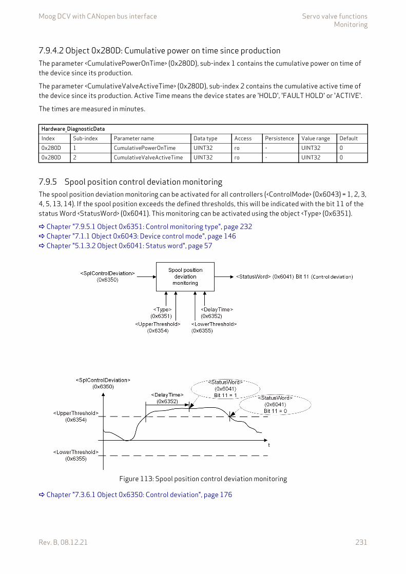
Moog DCV with CANopen bus interface Servo valve functionsMonitoring
Rev. B, 08.12.21 231
7.9.4.2 Object 0x280D: Cumulative power on time since productionThe parameter <CumulativePowerOnTime> (0x280D), sub-index 1 contains the cumulative power on time of the device since its production.
The parameter <CumulativeValveActiveTime> (0x280D), sub-index 2 contains the cumulative active time of the device since its production. Active Time means the device states are 'HOLD', 'FAULT HOLD' or 'ACTIVE'.
The times are measured in minutes.
7.9.5 Spool position control deviation monitoringThe spool position deviation monitoring can be activated for all controllers (<ControlMode> (0x6043) = 1, 2, 3, 4, 5, 13, 14). If the spool position exceeds the defined thresholds, this will be indicated with the bit 11 of the status Word <StatusWord> (0x6041). This monitoring can be activated using the object <Type> (0x6351).
Chapter "7.9.5.1 Object 0x6351: Control monitoring type", page 232 Chapter "7.1.1 Object 0x6043: Device control mode", page 146 Chapter "5.1.3.2 Object 0x6041: Status word", page 57
Figure 113: Spool position control deviation monitoring
Chapter "7.3.6.1 Object 0x6350: Control deviation", page 176
Hardware_DiagnosticDataIndex Sub-index Parameter name Data type Access Persistence Value range Default0x280D 1 CumulativePowerOnTime UINT32 ro - UINT32 00x280D 2 CumulativeValveActiveTime UINT32 ro - UINT32 0

Moog DCV with CANopen bus interface Servo valve functionsMonitoring
Rev. B, 08.12.21 232
7.9.5.1 Object 0x6351: Control monitoring typeThe parameter <Type> (0x6351) is used to activate or deactivate the spool position control deviation moni-toring function.
Value description
7.9.5.2 Object 0x6352: Control monitoring delay timeThe delay time defines the minimal duration of a control deviation before a fault is active. The time is set to zero if the position is inside the window, if the fault is acknowledged or if one of the following parameters is changed: <Type> (0x6351), <UpperThreshold> (0x6354), <LowerThreshold> (0x6355) or <DelayTime> (0x6352).
Chapter "2.4.3 Units and prefix parameter", page 12
7.9.5.3 Object 0x6354: Control monitoring upper thresholdThis parameter defines the upper threshold of the control deviation's tolerance band.
Chapter "2.4.3 Units and prefix parameter", page 12
ValvePositionControl_ControlMonitoringIndex Sub-index Parameter name Data type Access Persistence Value range Default0x6351 0 Type INT8 rw Y 0…1 0
Table 99: Possible values of parameter <Type> (0x6351)
<Type> Description0 Spool position control deviation monitoring off.1 Spool position control deviation monitoring on.
ValvePositionControl_ControlMonitoringIndex Sub-index Parameter name Data type Access Persistence Value range Default0x6352 1 DelayTime UINT16 rw Y UINT16 300x6352 2 Unit UINT8 ro - UINT8 30x6352 3 Prefix INT8 ro - –4…0 –3
ValvePositionControl_ControlMonitoringIndex Sub-index Parameter name Data type Access Persistence Value range Default0x6354 1 UpperThreshold INT16 rw Y INT16 5120x6354 2 Unit UINT8 ro - UINT8 00x6354 3 Prefix INT8 ro - –4…0 0
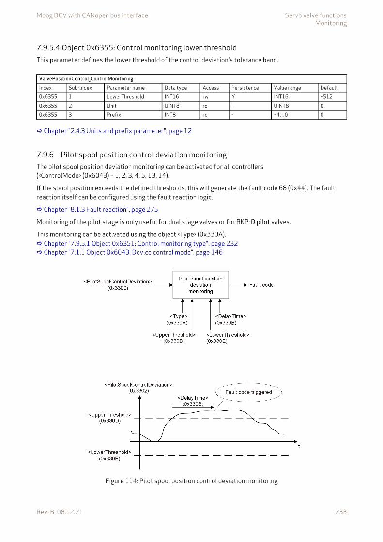
Moog DCV with CANopen bus interface Servo valve functionsMonitoring
Rev. B, 08.12.21 233
7.9.5.4 Object 0x6355: Control monitoring lower thresholdThis parameter defines the lower threshold of the control deviation's tolerance band.
Chapter "2.4.3 Units and prefix parameter", page 12
7.9.6 Pilot spool position control deviation monitoringThe pilot spool position deviation monitoring can be activated for all controllers (<ControlMode> (0x6043) = 1, 2, 3, 4, 5, 13, 14).
If the spool position exceeds the defined thresholds, this will generate the fault code 68 (0x44). The fault reaction itself can be configured using the fault reaction logic.
Chapter "8.1.3 Fault reaction", page 275
Monitoring of the pilot stage is only useful for dual stage valves or for RKP-D pilot valves.
This monitoring can be activated using the object <Type> (0x330A). Chapter "7.9.5.1 Object 0x6351: Control monitoring type", page 232 Chapter "7.1.1 Object 0x6043: Device control mode", page 146
Figure 114: Pilot spool position control deviation monitoring
ValvePositionControl_ControlMonitoringIndex Sub-index Parameter name Data type Access Persistence Value range Default0x6355 1 LowerThreshold INT16 rw Y INT16 –5120x6355 2 Unit UINT8 ro - UINT8 00x6355 3 Prefix INT8 ro - –4…0 0
Moog DCV with CANopen bus interface Servo valve functionsMonitoring
Rev. B, 08.12.21 234
7.9.6.1 Object 0x3302: Pilot control deviation Chapter "7.3.6.2 Object 0x3302: Pilot control deviation", page 176
7.9.6.2 Object 0x330A: Pilot spool control monitoring typeThe parameter <Type> (0x330A) is used to activate or deactivate the pilot spool position control deviation monitoring function.
Value description
7.9.6.3 Object 0x330B: Pilot spool control monitoring delay timeThe delay time defines the minimal duration of a control deviation before a fault is active. The time is set to zero, if the position is inside the window, if the fault is acknowledged or if one of the following parameters is changed: <Type> (0x330A), <UpperThreshold> (0x330D), <LowerThreshold> (0x330E) or <DelayTime> (0x330B).
Chapter "2.4.3 Units and prefix parameter", page 12
7.9.6.4 Object 0x330D: Pilot spool control monitoring upper thresholdThis parameter defines the upper threshold of the tolerance band of the control deviation.
Chapter "2.4.3 Units and prefix parameter", page 12
ValvePositionControl_ControlMonitoringIndex Sub-index Parameter name Data type Access Persistence Value range Default0x330A 0 Type INT8 rw Y 0…1 0
Table 100: Possible values of parameter <Type> (0x330A)
<Type> Description0 Pilot spool position control deviation monitoring off.1 Pilot spool position control deviation monitoring on.
ValvePositionControl_ControlMonitoringIndex Sub-index Parameter name Data type Access Persistence Value range Default0x330B 1 DelayTime UINT16 rw Y UINT16 300x330B 2 Unit UINT8 ro - UINT8 30x330B 3 Prefix INT8 ro - –4…0 –3
ValvePositionControl_ControlMonitoringIndex Sub-index Parameter name Data type Access Persistence Value range Default0x330D 1 UpperThreshold INT16 rw Y INT16 5120x330D 2 Unit UINT8 ro - UINT8 30x330D 3 Prefix INT8 ro - –4…0 –3
Moog DCV with CANopen bus interface Servo valve functionsMonitoring
Rev. B, 08.12.21 235
7.9.6.5 Object 0x330E: Pilot spool control monitoring lower thresholdThis parameter defines the lower threshold of the control deviation's tolerance band.
Chapter "2.4.3 Units and prefix parameter", page 12
7.9.7 Flow control deviation monitoringAs the measured flow actual value isn't available yet, it is recommended to monitor the controller deviation of the spool position controller <SplControlDeviation> (0x6350).
Chapter "7.3.6.1 Object 0x6350: Control deviation", page 176
ValvePositionControl_ControlMonitoringIndex Sub-index Parameter name Data type Access Persistence Value range Default0x330E 1 LowerThreshold INT16 rw Y INT16 –5120x330E 2 Unit UINT8 ro - UINT8 30x330E 3 Prefix INT8 ro - –4…0 –3
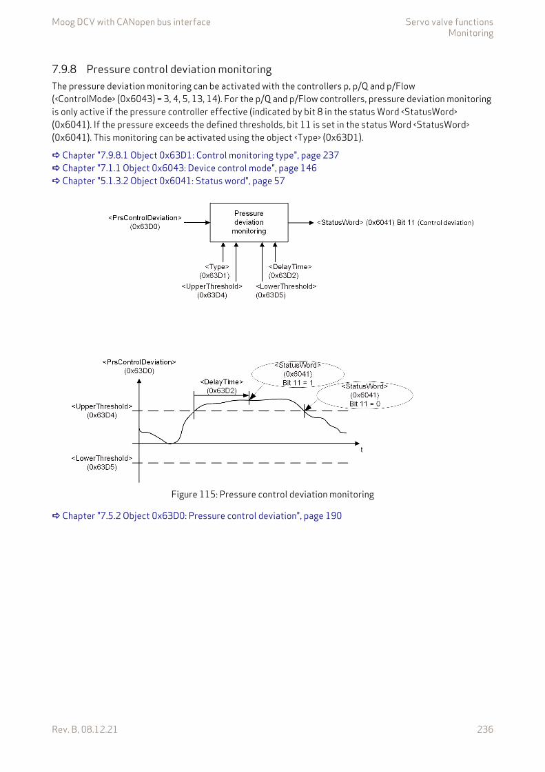
Moog DCV with CANopen bus interface Servo valve functionsMonitoring
Rev. B, 08.12.21 236
7.9.8 Pressure control deviation monitoringThe pressure deviation monitoring can be activated with the controllers p, p/Q and p/Flow (<ControlMode> (0x6043) = 3, 4, 5, 13, 14). For the p/Q and p/Flow controllers, pressure deviation monitoring is only active if the pressure controller effective (indicated by bit 8 in the status Word <StatusWord> (0x6041). If the pressure exceeds the defined thresholds, bit 11 is set in the status Word <StatusWord> (0x6041). This monitoring can be activated using the object <Type> (0x63D1).
Chapter "7.9.8.1 Object 0x63D1: Control monitoring type", page 237 Chapter "7.1.1 Object 0x6043: Device control mode", page 146 Chapter "5.1.3.2 Object 0x6041: Status word", page 57
Figure 115: Pressure control deviation monitoring
Chapter "7.5.2 Object 0x63D0: Pressure control deviation", page 190
Moog DCV with CANopen bus interface Servo valve functionsMonitoring
Rev. B, 08.12.21 237
7.9.8.1 Object 0x63D1: Control monitoring typeThe parameter <Type> (0x63D1) is used to activate or deactivate the standard pressure control deviation monitoring function.
Value description
7.9.8.2 Object 0x63D2: Control monitoring delay timeThe delay time defines the minimal duration of a control deviation before a fault is active. The Time is set to zero if the position is inside the window, if the fault is acknowledged or if one of the following parameters is changed: <Type> (0x63D1), <UpperThreshold> (0x63D4), <LowerThreshold> (0x63D5) or <DelayTime> (0x63D2).
Chapter "2.4.3 Units and prefix parameter", page 12
7.9.8.3 Object 0x63D4: Control monitoring upper thresholdThis parameter defines the upper threshold of the control deviation's tolerance band.
Chapter "2.4.3 Units and prefix parameter", page 12
ValvePressureControl_ControlMonitoringIndex Sub-index Parameter name Data type Access Persistence Value range Default0x63D1 0 Type INT8 rw Y 0…1 0
Table 101: Possible values of parameter <Type> (0x63D1)
<Type> Description0 Pressure control deviation monitoring off.1 Pressure control deviation monitoring on.
ValvePressureControl_ControlMonitoringIndex Sub-index Parameter name Data type Access Persistence Value range Default0x63D2 1 DelayTime UINT16 rw Y UINT16 300x63D2 2 Unit UINT8 ro - UINT8 30x63D2 3 Prefix INT8 ro - –4…0 –3
ValvePressureControl_ControlMonitoringIndex Sub-index Parameter name Data type Access Persistence Value range Default0x63D4 1 UpperThreshold INT16 rw Y INT16 5120x63D4 2 Unit UINT8 ro - UINT8 00x63D4 3 Prefix INT8 ro - –4…0 0
Moog DCV with CANopen bus interface Servo valve functionsMonitoring
Rev. B, 08.12.21 238
7.9.8.4 Object 0x63D5: Control monitoring lower thresholdThis parameter defines the lower threshold of the control deviation's tolerance band.
Chapter "2.4.3 Units and prefix parameter", page 12
7.9.9 Main stage spool position sensor cable break monitoringMonitoring is only active in case of device state greater 'INIT'. In case of a cable break, the fault code 20 (0x14) (Main stage spool position sensor cable break) is generated and the device state machine state changes to 'FAUL INIT'.
7.9.10 Spool / pilot spool position sensor cable break monitoringMonitoring is only active in case of device state greater 'INIT'. In case of a cable break, the fault code 17 (0x11) (Pilot/single stage spool position sensor cable break) is indicated and the device state machine state changes to 'FAULT INIT'.
7.9.11 Current control deviation monitoringThe internal control deviation monitoring of the actuator current leads to fault code 66 (0x42) (Power stage current control monitoring) in case of a fault. This monitoring is always enabled.
7.9.12 Actuator over current monitoringThis function monitors the power stage of the valve actuator. The power stage is switched off by hardware if there is a permanent over current. Actuator over current leads to the fault code 16 (0x10) (Overcurrent of Power Stage) in case of a fault.
ValvePressureControl_ControlMonitoringIndex Sub-index Parameter name Data type Access Persistence Value range Default0x63D5 1 LowerThreshold INT16 rw Y INT16 –5120x63D5 2 Unit UINT8 ro - UINT8 00x63D5 3 Prefix INT8 ro - –4…0 0
The servo valve must be serviced by Moog service technicians.The servo valve may behave unpredictably.
The servo valve must be serviced by Moog service technicians.The servo valve may behave unpredictably.
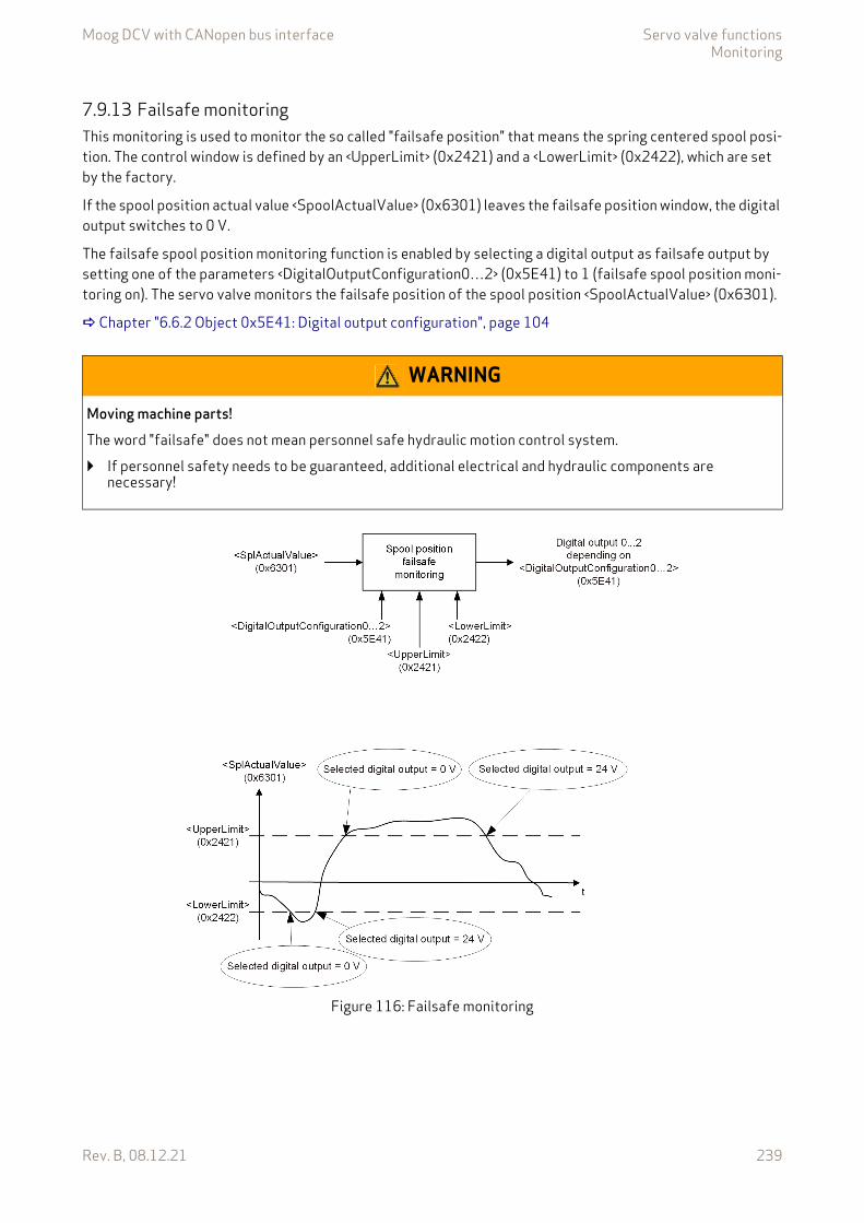
Moog DCV with CANopen bus interface Servo valve functionsMonitoring
Rev. B, 08.12.21 239
7.9.13 Failsafe monitoringThis monitoring is used to monitor the so called "failsafe position" that means the spring centered spool posi-tion. The control window is defined by an <UpperLimit> (0x2421) and a <LowerLimit> (0x2422), which are set by the factory.
If the spool position actual value <SpoolActualValue> (0x6301) leaves the failsafe position window, the digital output switches to 0 V.
The failsafe spool position monitoring function is enabled by selecting a digital output as failsafe output by setting one of the parameters <DigitalOutputConfiguration0…2> (0x5E41) to 1 (failsafe spool position moni-toring on). The servo valve monitors the failsafe position of the spool position <SpoolActualValue> (0x6301).
Chapter "6.6.2 Object 0x5E41: Digital output configuration", page 104
Figure 116: Failsafe monitoring
WARNING
Moving machine parts!The word "failsafe" does not mean personnel safe hydraulic motion control system.
If personnel safety needs to be guaranteed, additional electrical and hydraulic components are necessary!
Moog DCV with CANopen bus interface Servo valve functionsMonitoring
Rev. B, 08.12.21 240
Electrical signal
Failsafe spool position monitoring behavior depending on the device state machine state <StatusWord> (0x6041)
7.9.13.1 Object 0x2421: Upper limitThe parameter <UpperLimit> (0x2421) shows the upper limit of the spool position failsafe monitoring window.
7.9.13.2 Object 0x2422: Lower limitThe parameter <LowerLimit> (0x2422) shows the lower limit of the spool position failsafe monitoring window.
7.9.13.3 Object 0x3307: Spring Position MinimumThis parameter is optionally set on request. It depends on the valve model number. The parameter holds the lower limit of the failsafe position. This position will be valve specific calibrated and stored during produc-tion.
The expected failsafe position of the valve should be between <SpringPositionMinimum> (0x3307) and <SpringPositionMaximum> (0x3308).
Spool position <SpoolActualValue> (0x6301) Electrical signal (negative logic)Actual spool position value is within the failsafe monitoring window
Selected digital output 1 = 24 V
Actual spool position value is outside the failsafe monitoring window
Selected digital output 1 = 0 V
<StatusWord> (0x6041) (DSM state) Failsafe spool position monitoring behavior'INIT' No failsafe spool position monitoring active.'DISABLED', 'HOLD', 'ACTIVE', 'FAULT DISABLED', 'FAULT HOLD'
Failsafe spool position monitoring active if one <DigitalOutputConfiguration0…2> (0x5E41) is set to 1 (failsafe spool position monitoring on).
ValveFailSafeWindowMonitoringIndex Sub-index Parameter name Data type Access Persistence Value range Default0x2421 0 UpperLimit INT16 ro - <LowerLimit>
(0x2422)…3276716384
ValveFailSafeWindowMonitoringIndex Sub-index Parameter name Data type Access Persistence Value range Default0x2422 0 LowerLimit INT16 ro - –32768…
<UpperLimit> (0x2421)
–16384
ValveFailSafeWindowMonitoringIndex Sub-index Parameter name Data type Access Persistence Value range Default0x3307 0 SpringPositionMinimum INT16 ro Y INT16 None

Moog DCV with CANopen bus interface Servo valve functionsEvent handler
Rev. B, 08.12.21 241
7.9.13.4 Object 0x3308: Spring Position MaximumThis parameter is optional set on request and depends on the valve model number. The parameter holds the upper limit of the failsafe position. This position will be valve specific calibrated and stored during produc-tion.
The expected failsafe position of the valve should be between <SpringPositionMinimum> (0x3307) and <SpringPositionMaximum> (0x3308).
7.9.14 Object 0x2862: Spool distance cumulativeThis parameter counts the cumulative distance the spool moves during the whole operating time. It can be used as a measure of spool wear. The different sub-objects represent the same parameter in different units and data types. The sub-object 5 and 6 represent the raw value.
7.10 Event handlerWith the event handler, the user can define expressions to calculate a value depending on internal and exter-nal parameter values and assign it to any parameter.
All actions are based on parameter access, so the behavior of the servo valve can be influenced similar to an external parameter access via the fieldbus. The variables calculated by the event handler can be accessed via the fieldbus. There are in total eight event handlers, which will be configured by eight associated strings pro-cessed by the event expression parser.
After an event handler is configured, it needs to be enabled in order to process its low-level code. The parser processes the expressions according the syntax and the processing order similar to that of the programming language C. All event calculations are processed at least every millisecond.
ValveFailSafeWindowMonitoringIndex Sub-index Parameter name Data type Access Persistence Value range Default0x3308 0 SpringPositionMaximum INT16 ro Y INT16 None
ConditionMonitoringIndex Sub-index Parameter name Data type Access Persistence Value range Default0x2862 1 Spool Distance Cumulative In
FullscaleREAL32 ro Y REAL32 None
0x2862 4 Spool Distance Cumulative In Millimeter
REAL32 ro Y REAL32 None
0x2862 5 Spool Distance Cumulative Least Significant Word
REAL32 ro Y REAL32 None
0x2862 6 Spool Distance Cumulative Most Significant Word
REAL32 ro Y REAL32 None
Moog DCV with CANopen bus interface Servo valve functionsEvent handler
Rev. B, 08.12.21 242
7.10.1 Event expressionsThe event expressions are strings with maximal 192 characters and are built in the following manner:
• The parameters to be used can only be accessed through their short names. The short names of a param-eter can be found in the chapter "Object dictionary". Chapter "10 Object dictionary", page 290
• Integer constants
• Floating point constants are not allowed.
There are groups of operators. Inside a group there is no priority of operation, the expressions are processed from left to right. The groups are listed in order of their priority.
• Operators with one operand
• Mathematical operators high priority
• Mathematical operators low priority
• Shift operators
• Logical compare operators
Prefix DescriptionDecimal integer constants
0x Hexadecimal integer constants
Symbol Description– Negate / negative sign+ Positive sign# Absolute~ Bitwise NOT! Logical NOT
Symbol Description/ Divide* Multiply
Symbol Description– Subtract+ Add
Symbol Description>> Shift right<< Shift left
Symbol Description<, <= Smaller, smaller or equal>, >= Greater, greater or equal

Moog DCV with CANopen bus interface Servo valve functionsEvent handler
Rev. B, 08.12.21 243
• Logical operators for conditions
• Bitwise operator AND
• Bitwise operator OR
• Logical operator AND
• Logical operator OR
• If-then-else command operatorsCondition ? ifstatement : elsestatement '
• Assignment operator
• Expressions can be concatenated using a semicolon
• Brackets are restricted to 3 levels
Symbol Description== Equal!= Not equal
Symbol Description& Bitwise AND
Symbol Description| Bitwise OR
Symbol Description&& Logical AND
Symbol Description|| Logical OR
Symbol Description? If and then operator: Else operator' If-then-else terminators
Symbol Description= Assign
Symbol Description; Separate
Symbol Description( Open bracket) Close bracket
Moog DCV with CANopen bus interface Servo valve functionsEvent handler
Rev. B, 08.12.21 244
7.10.1.1 Object 0x2901: Event expression 1This parameter contains the expression string of the first event handler.
7.10.1.2 Object 0x2902: Event expression 2This parameter contains the expression string of the second event handler.
7.10.1.3 Object 0x2903: Event expression 3This parameter contains the expression string of the third event handler.
7.10.1.4 Object 0x2904: Event expression 4This parameter contains the expression string of the fourth event handler.
7.10.1.5 Object 0x2905: Event expression 5This parameter contains the expression string of the fifth event handler.
7.10.1.6 Object 0x2906: Event expression 6This parameter contains the expression string of the sixth event handler.
EventhandlerIndex Sub-index Parameter name Data type Access Persistence Value range Default0x2901 0 EventExpression1 STRING(192) rw Y STRING(192) ""
EventhandlerIndex Sub-index Parameter name Data type Access Persistence Value range Default0x2902 0 EventExpression2 STRING(192) rw Y STRING(192) ""
EventhandlerIndex Sub-index Parameter name Data type Access Persistence Value range Default0x2903 0 EventExpression3 STRING(192) rw Y STRING(192) ""
EventhandlerIndex Sub-index Parameter name Data type Access Persistence Value range Default0x2904 0 EventExpression4 STRING(192) rw Y STRING(192) ""
EventhandlerIndex Sub-index Parameter name Data type Access Persistence Value range Default0x2905 0 EventExpression5 STRING(192) rw Y STRING(192) ""
EventhandlerIndex Sub-index Parameter name Data type Access Persistence Value range Default0x2906 0 EventExpression6 STRING(192) rw Y STRING(192) ""
Moog DCV with CANopen bus interface Servo valve functionsEvent handler
Rev. B, 08.12.21 245
7.10.1.7 Object 0x2907: Event expression 7This parameter contains the expression string of the seventh event handler.
7.10.1.8 Object 0x2908: Event expression 8This parameter contains the expression string of the eighth event handler.
7.10.1.9 Object 0x2909: Event enableThese parameters switch the event handler on or off.
EventhandlerIndex Sub-index Parameter name Data type Access Persistence Value range Default0x2907 0 EventExpression7 STRING(192) rw Y STRING(192) ""
EventhandlerIndex Sub-index Parameter name Data type Access Persistence Value range Default0x2908 0 EventExpression8 STRING(192) rw Y STRING(192) ""
EventhandlerIndex Sub-index Parameter name Data type Access Persistence Value range Default0x2909 1 EventEnable1 UINT8 rw Y 0…1 00x2909 2 EventEnable2 UINT8 rw Y 0…1 00x2909 3 EventEnable3 UINT8 rw Y 0…1 00x2909 4 EventEnable4 UINT8 rw Y 0…1 00x2909 5 EventEnable5 UINT8 rw Y 0…1 00x2909 6 EventEnable6 UINT8 rw Y 0…1 00x2909 7 EventEnable7 UINT8 rw Y 0…1 00x2909 8 EventEnable8 UINT8 rw Y 0…1 0

Moog DCV with CANopen bus interface Servo valve functionsData logger
Rev. B, 08.12.21 246
7.10.2 Event handler examplesThe following three simple examples explain the event handler behavior. For many event handler tasks, buffer parameters are needed. The parameters with the short names varu[…], vars[…], varf[…], dumu[…], dums[…], and dumf[…] are reserved for these tasks.
Chapter "6.8 Free to use parameters", page 140
Example 1:varu32[1]=varu32[1]+1;qset=varu32[1]*5
• Calculations are processed every main task cycle (no condition).• Increase varu32[1] by one.• Calculates the Q setpoint as five times the varu32[1] variable.
Example 2:splval>10000?qset=0:(splval<1000?qset=11000)
• Two separate events in one expression using a semicolon as separator.• Q setpoint is only changed if the Q actual value meets the condition splval greater 10000 or smaller
1000.
Example 3:Expression 1 <EventExpression_1> (0x2901):prsval>10000?ctlmod=4;evtena[0]=0;evtena[1]=1
Expression 2 <EventExpression_2> (0x2902):qset<1000?ctlmod=2;evtena[0]=1;evtena[1]=0
• Expressions can disable themselves and activate other expressions.• Expression 1 activates pressure control.• Expression 2 activates spool position control.• evtena[0] enables event expression 1, evtena[1] enables event expression 2, etc.
Example 4:Combination of example 1 and example 2:splval>10000?qset=0:(splval<1000?qset=11000)' varu32[1]=varu32[1]+1
• If-then-else in combination with permanently expression.• Two separate events in one expression using a semicolon as separator.
- Q setpoint is only changed if the Q actual value meets the condition splval greater 10000 or smaller 1000.
• Terminate If-then-else-if condition with '.• Additional expression which is executed permanently to increase varu32[1] by one.
7.11 Data loggerThe data logger is a four channel oscilloscope to trace the parameters inside the servo valve. The parameters which are monitored can be chosen. The trigger condition, pre trigger, trigger level, slopes and scaling can be set. The servo valve contains a 2 Kbytes volatile data memory which can be used to sample the data. The data can be downloaded at any time.
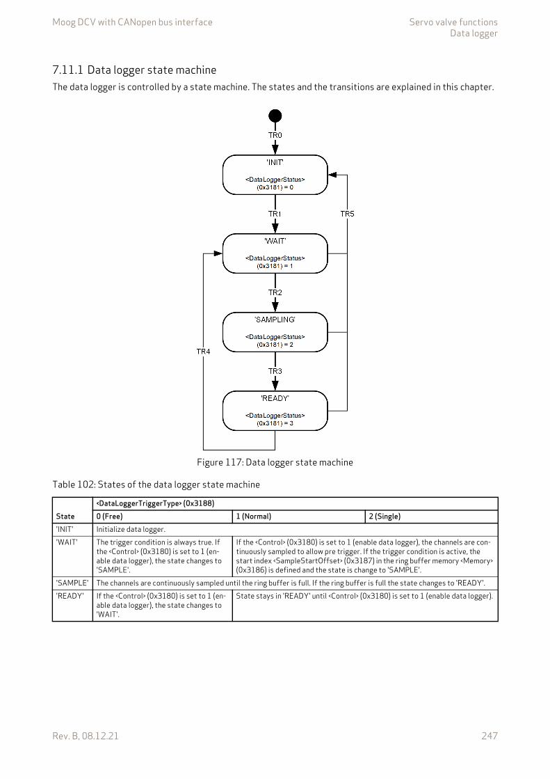
Moog DCV with CANopen bus interface Servo valve functionsData logger
Rev. B, 08.12.21 247
7.11.1 Data logger state machineThe data logger is controlled by a state machine. The states and the transitions are explained in this chapter.
Figure 117: Data logger state machine
Table 102: States of the data logger state machine
State<DataLoggerTriggerType> (0x3188)0 (Free) 1 (Normal) 2 (Single)
'INIT' Initialize data logger.'WAIT' The trigger condition is always true. If
the <Control> (0x3180) is set to 1 (en-able data logger), the state changes to 'SAMPLE'.
If the <Control> (0x3180) is set to 1 (enable data logger), the channels are con-tinuously sampled to allow pre trigger. If the trigger condition is active, the start index <SampleStartOffset> (0x3187) in the ring buffer memory <Memory> (0x3186) is defined and the state is change to 'SAMPLE'.
'SAMPLE' The channels are continuously sampled until the ring buffer is full. If the ring buffer is full the state changes to 'READY'.'READY' If the <Control> (0x3180) is set to 1 (en-
able data logger), the state changes to 'WAIT'.
State stays in 'READY' until <Control> (0x3180) is set to 1 (enable data logger).
Moog DCV with CANopen bus interface Servo valve functionsData logger
Rev. B, 08.12.21 248
7.11.1.1 Object 0x3180: ControlThis parameter enables the data logger.
Value description
7.11.1.2 Object 0x3181: StatusState of the data logger state machine.
Value description
7.11.2 Channel settingsFour channels can be used within the data logger. All readable parameters are available as input for the chan-nels.
Table 103: Transitions of the data logger state machine
Transition (TR) DescriptionTR0 Start program.TR1 Triggered by setting <Control> (0x3180) to 1 (enable data logger).TR2 Trigger condition is active.TR3 Data logger ring buffer is full.TR4 Triggered by setting <Control> (0x3180) to 1 (enable data logger).TR5 One of the following parameters has changed:
<Divider> (0x3182)<EnableChannel1…4> (0x3184)<ChannelParameter1…4> (0x3185)<TriggerType> (0x3188)<TriggerMapppingParameter> (0x3189)
DataLoggerIndex Sub-index Parameter name Data type Access Persistence Value range Default0x3180 0 Control INT8 rw Y 0…1 0
Table 104: Possible values of parameter <Control> (0x3180)
<Control> Description0 Disable data logger.1 Enable data logger.
DataLoggerIndex Sub-index Parameter name Data type Access Persistence Value range Default0x3181 0 Status UINT8 ro - 0…3 None
Table 105: Possible values of parameter <Status> (0x3181)
<Status> Description0 'INIT'1 'WAIT'2 'SAMPLING'3 'READY'

Moog DCV with CANopen bus interface Servo valve functionsData logger
Rev. B, 08.12.21 249
7.11.2.1 Object 0x3185: Channel mapping parameterThe parameters <ChannelMappingParameter1…4> define the parameters which shall be sampled. The values are composed of index, sub-index and bit length of the chosen parameter.
Value description
This reference contains a combination of index, sub-index and length of the parameter to be used.
The example value is 0x63100110, which refers to the <SplDemandValue> (0x6310), sub-index 0x01 with a length of 16 bit (16=0x10).
7.11.2.2 Object 0x3184: Enable channelAny channel can be switched on or off with this parameter.
Value description
7.11.3 Sample frequencyThe maximum sample frequency is limited to 20000 samples per seconds (20k Hz). This sample frequency can be set to a smaller sample frequency with the parameter <Divider> (0x3182).
The measuring time is increased by the factor <Divider> (0x3182).
DataLoggerIndex Sub-index Parameter name Data type Access Persistence Value range Default0x3185 1 ChannelMappingParameter1 UINT32 rw Y UINT32 0x631001100x3185 2 ChannelMappingParameter2 UINT32 rw Y UINT32 0x630101100x3185 3 ChannelMappingParameter3 UINT32 rw Y UINT32 0x639001100x3185 4 ChannelMappingParameter4 UINT32 rw Y UINT32 0x63810110
<ChannelMappingParameter1…4>Byte 3 2 1 0
DescriptionIndex MSB Index LSB Sub-index Parameter bit length 0x10
or 0x20Example 0x63 0x10 0x01 0x10
DataLoggerIndex Sub-index Parameter name Data type Access Persistence Value range Default0x3184 1 EnableChannel1 UINT8 rw Y 0…1 00x3184 2 EnableChannel2 UINT8 rw Y 0…1 00x3184 3 EnableChannel3 UINT8 rw Y 0…1 00x3184 4 EnableChannel4 UINT8 rw Y 0…1 0
Table 106: Possible values of parameter <EnableChannel> (0x3184)
<EnableChannel1…4> Description0 Channel disabled.1 Channel enabled.
New sample frequency Maximum sample frequency<Divider> (0x3182)----------------------------------------------------------------------=
Moog DCV with CANopen bus interface Servo valve functionsData logger
Rev. B, 08.12.21 250
7.11.3.1 Object 0x3182: DividerThis parameter contains an integer number to reduce the sampling frequency.
Value description
7.11.4 Trigger settingsThe trigger settings can be set like on a real oscilloscope.
• Trigger parameter (integer parameter for the trigger).• Trigger type (FREE, NORMAL, SINGLE).• Trigger level or bitmask (trigger level).• Trigger coupling (AC, DC, BITMASK).• Trigger slope (rising, falling, both).• Trigger position (pre trigger, post trigger).
7.11.4.1 Object 0x3189: Trigger parameterThe <TriggerMappingParameter> (0x3189) defines the parameter which is used as trigger signal.
Value description
This reference contains a combination of index, sub-index and length of the parameter to be used.
The default value is 0x63100110, which refers to the <SplDemandValue> (0x6310), sub-index 0x01 with a length of 16 bit (16=0x10).
DataLoggerIndex Sub-index Parameter name Data type Access Persistence Value range Default0x3182 0 Divider UINT16 rw Y 1…65535 1
Table 107: Possible values of parameter <Divider> (0x3182)
<Divider> Description1 20000 samples per second (20 kHz).2…65534 20000/2…20000/65534 samples per second.65535 20000/65535 = 0.3052 samples per second.
DataLoggerIndex Sub-index Parameter name Data type Access Persistence Value range Default0x3189 0 TriggerMappingParameter UINT32 rw Y UINT32 0x63100110
<TriggerMappingParameter>Byte 3 2 1 0
DescriptionIndex MSB Index LSB Sub-index Parameter bit length 0x10
or 0x20Default 0x63 0x10 0x01 0x10
Moog DCV with CANopen bus interface Servo valve functionsData logger
Rev. B, 08.12.21 251
7.11.4.2 Object 0x3188: Trigger typeThis parameter contains the trigger type of the data logger.
Value description
7.11.4.3 Object 0x318C: Trigger level or bitmaskThis parameter contains the trigger level if the <TriggerCoupling> (0x318A) is set to 0 or 1.
This parameter contains the BITMASK if the <TriggerCoupling> (0x318A) is set to 2. The BITMASK selects the bits to be compared with the trigger signal.
7.11.4.4 Object 0x318A: Trigger couplingThis parameter contains the trigger coupling type of the data logger.
Value description
DataLoggerIndex Sub-index Parameter name Data type Access Persistence Value range Default0x3188 0 TriggerType UINT8 rw Y 0…2 1
Table 108: Possible values of parameter <TriggerType> (0x3188)
<TriggerType> Description0 FREE (the trigger condition is always true).1 NORMAL (if the trigger condition matches, the data logger returns to wait state completed).2 SINGLE (if the trigger condition matches, the data logger enters the ready state).
DataLoggerIndex Sub-index Parameter name Data type Access Persistence Value range Default0x318C 0 TriggerLevelOrBitmask INT32 rw Y INT32 0
DataLoggerIndex Sub-index Parameter name Data type Access Persistence Value range Default0x318A 0 TriggerCoupling UINT8 rw Y 0…2 1
Table 109: Possible values of parameter <TriggerCoupling> (0x318A)
<TriggerCoupling> Description0 AC (AC part of the trigger signal is passed and is compared with the trigger level).1 DC (the trigger signal is passed directly and is compared with the trigger level).2 BITMASK (the trigger signal is passed directly and is compared bit-wise with the trigger bitmask).
Moog DCV with CANopen bus interface Servo valve functionsData logger
Rev. B, 08.12.21 252
7.11.4.5 Object 0x318B: Trigger slopeThe <TriggerSlope> (0x318B) defines the edge of the signal which starts the sampling procedure.
Value description
7.11.4.6 Object 0x318D: Trigger positionThe <TriggerPosition> (0x318D) is provided as number of samples which shifts the starting point in the ring buffer.
Value description
DataLoggerIndex Sub-index Parameter name Data type Access Persistence Value range Default0x318B 0 TriggerSlope UINT8 rw Y 1…3 1
Table 110: Possible values of parameter <TriggerSlope> (0x318B)
<TriggerSlope> Description1 Rising (trigger on a rising edge).2 Falling (trigger on a falling edge).3 Both (trigger on both, rising or falling edge).
DataLoggerIndex Sub-index Parameter name Data type Access Persistence Value range Default0x318D 0 TriggerPosition INT32 rw Y INT32 0
Table 111: Possible values of parameter <TriggerPosition> (0x318D)
<TriggerPosition> Description> 0 Post trigger.= 0 No delay.< 0 Pre trigger.

Moog DCV with CANopen bus interface Servo valve functionsData logger
Rev. B, 08.12.21 253
7.11.5 Data memoryThe data logger memory is organized as a ring buffer. After the data logger has finished a sampling task and changed the state from 'SAMPLE' to 'READY', the sampled data are valid. The sampled data start from the byte number <SampleStartOffset> (0x3187) until the byte 2047 and continue from byte 0 to byte <SampleStartOffset> (0x3187) – 1.
Figure 118: Data memory organization
The number of possible samples depends on the channel configuration. The next three examples illustrate the data logger memory management:
Example 1: Sampling three channels with mixed data types, 1, 2 and 4 bytesIn this example three channels are enabled, channels 1, 3 and 4. Each enabled channel contains a different data type with a different length (1, 2 and 4 byte). Channel one samples a one byte parameter, channel 3 a two byte parameter and channel 4 a four byte parameter. In every sample step 7 bytes memory are needed. The available memory is 2048 bytes. The possible number of samples is 2048 bytes/7 bytes per sample, so 292 samples can be saved in the memory. 292 samples multiplied with 7 bytes per sample are equal 2044 bytes. So an empty rest of 4 bytes remains at the end of the ring buffer. If the parameter <Divider> (0x3182) is set to 1 (10000 samples per second), the memory is filled in 292/10000 = 29.2 ms.
Figure 119: Data memory - mixed channel data

Moog DCV with CANopen bus interface Servo valve functionsData logger
Rev. B, 08.12.21 254
Example 2: Sampling one channel with a one byte parameterIn this example only one channel, channel number 3, is enabled. For every sample one byte memory is needed. The available memory is 2048 bytes. The possible number of samples is 2048 bytes divided by 1 byte per sample, so 2048 samples can be taken. No empty rest remains at the end of the ring buffer. If the parameter <Divider> (0x3182) is set to 1 (10000 samples per second), the memory is filled in 2048/10000 = 204.8 ms.
Figure 120: Data memory - one channel with INT8 parameter
Example 3: Sampling four channels with 4 four byte parametersIn this example all four channels are enabled. For every sample 16 bytes memory are needed. The available memory is 2048 bytes. The possible number of samples is 2048 bytes divided by 16 byte per sample, so 128 samples can be saved in the memory. No empty space remains at the end of the ring buffer. If the param-eter <Divider> (0x3182) is set to 1 (10000 samples per second), the memory is filled in 128/10000 = 12.8 ms.
Figure 121: Data memory - four channels with INT32 parameters
7.11.5.1 Object 0x3186: MemoryThe parameter <Memory> (0x3186) contains the sampled information of the four channels. The parameter is an array of UINT8 with 2048 entries/bytes.
7.11.5.2 Object 0x3187: Sample start offsetThe <SampleStartOffset> (0x3187) contains the byte position where the recorded data start. It indicates the position of the first sample point.
DataLoggerIndex Sub-index Parameter name Data type Access Persistence Value range Default0x3186 0 Memory DOMAIN ro - DOMAIN …
DataLoggerIndex Sub-index Parameter name Data type Access Persistence Value range Default0x3187 0 SampleStartOffset UINT32 ro - UINT32 None
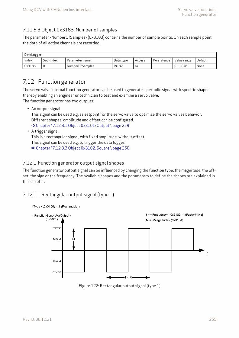
Moog DCV with CANopen bus interface Servo valve functionsFunction generator
Rev. B, 08.12.21 255
7.11.5.3 Object 0x3183: Number of samplesThe parameter <NumberOfSamples> (0x3183) contains the number of sample points. On each sample point the data of all active channels are recorded.
7.12 Function generatorThe servo valve internal function generator can be used to generate a periodic signal with specific shapes, thereby enabling an engineer or technician to test and examine a servo valve.The function generator has two outputs:
• An output signalThis signal can be used e.g. as setpoint for the servo valve to optimize the servo valves behavior. Different shapes, amplitude and offset can be configured. Chapter "7.12.3.1 Object 0x3101: Output", page 259
• A trigger signalThis is a rectangular signal, with fixed amplitude, without offset.This signal can be used e.g. to trigger the data logger. Chapter "7.12.3.3 Object 0x3102: Square", page 260
7.12.1 Function generator output signal shapesThe function generator output signal can be influenced by changing the function type, the magnitude, the off-set, the sign or the frequency. The available shapes and the parameters to define the shapes are explained in this chapter.
7.12.1.1 Rectangular output signal (type 1)
Figure 122: Rectangular output signal (type 1)
DataLoggerIndex Sub-index Parameter name Data type Access Persistence Value range Default0x3183 0 NumberOfSamples INT32 ro - 0…2048 None
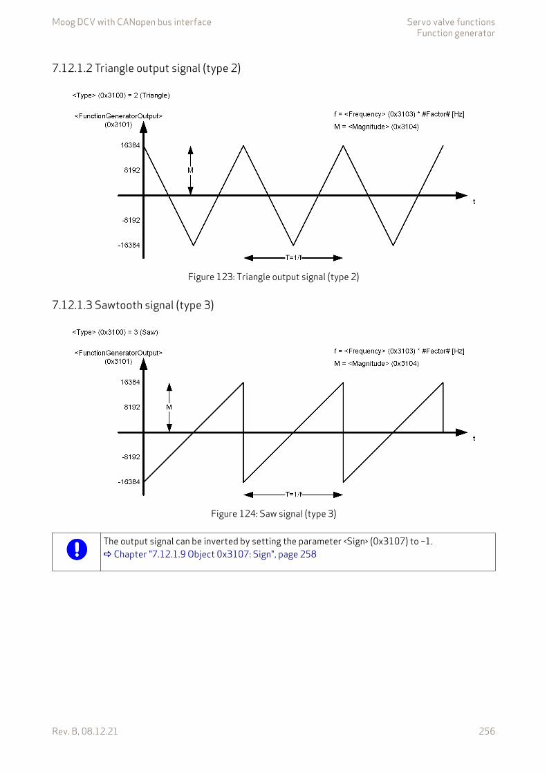
Moog DCV with CANopen bus interface Servo valve functionsFunction generator
Rev. B, 08.12.21 256
7.12.1.2 Triangle output signal (type 2)
Figure 123: Triangle output signal (type 2)
7.12.1.3 Sawtooth signal (type 3)
Figure 124: Saw signal (type 3)
The output signal can be inverted by setting the parameter <Sign> (0x3107) to –1. Chapter "7.12.1.9 Object 0x3107: Sign", page 258
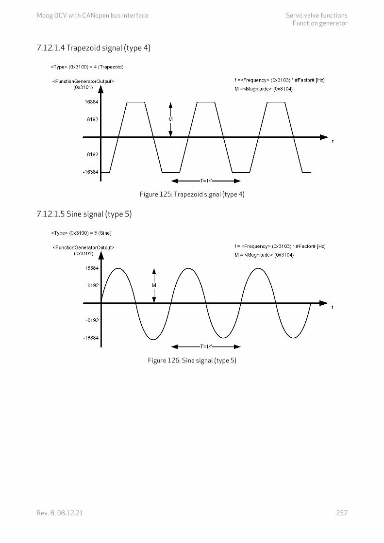
Moog DCV with CANopen bus interface Servo valve functionsFunction generator
Rev. B, 08.12.21 257
7.12.1.4 Trapezoid signal (type 4)
Figure 125: Trapezoid signal (type 4)
7.12.1.5 Sine signal (type 5)
Figure 126: Sine signal (type 5)
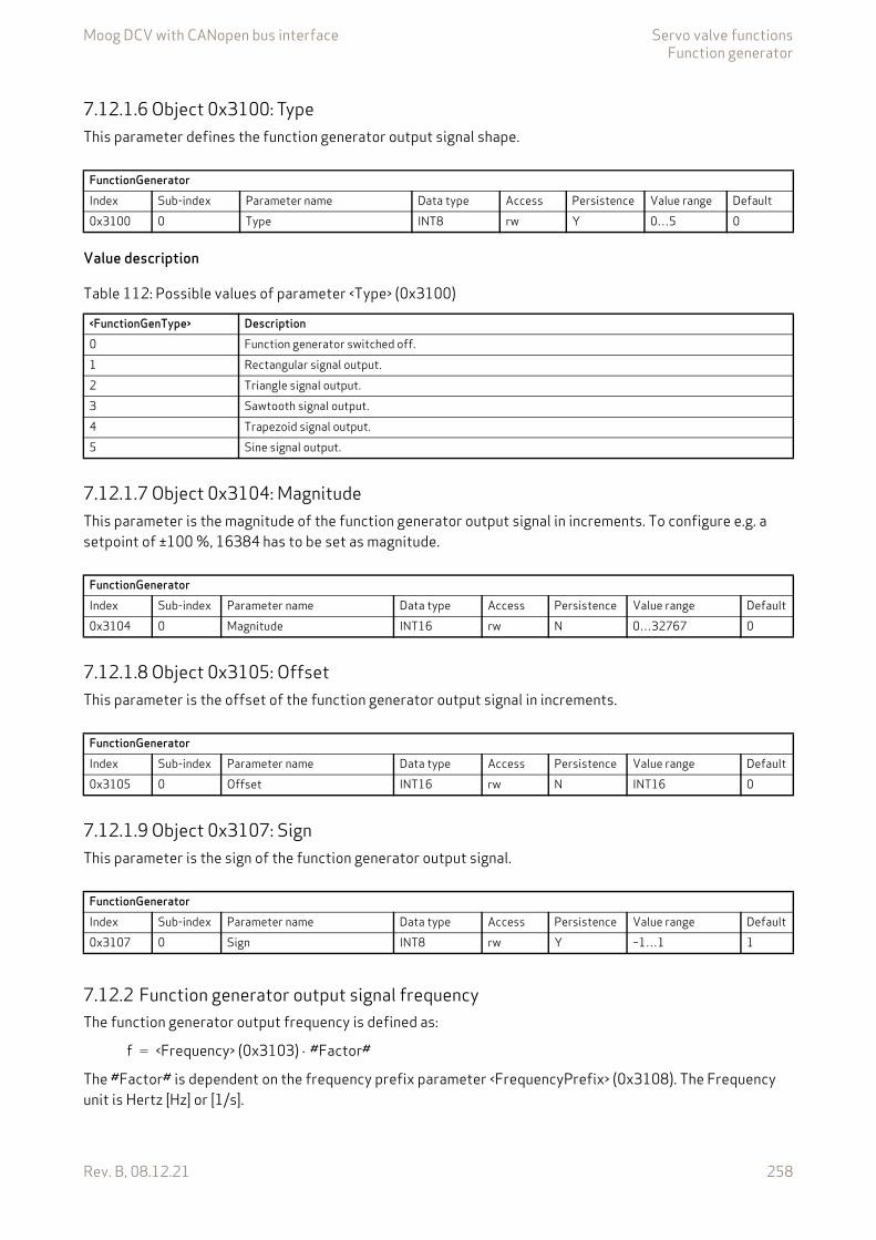
Moog DCV with CANopen bus interface Servo valve functionsFunction generator
Rev. B, 08.12.21 258
7.12.1.6 Object 0x3100: TypeThis parameter defines the function generator output signal shape.
Value description
7.12.1.7 Object 0x3104: MagnitudeThis parameter is the magnitude of the function generator output signal in increments. To configure e.g. a setpoint of ±100 %, 16384 has to be set as magnitude.
7.12.1.8 Object 0x3105: OffsetThis parameter is the offset of the function generator output signal in increments.
7.12.1.9 Object 0x3107: SignThis parameter is the sign of the function generator output signal.
7.12.2 Function generator output signal frequencyThe function generator output frequency is defined as:
The #Factor# is dependent on the frequency prefix parameter <FrequencyPrefix> (0x3108). The Frequency unit is Hertz [Hz] or [1/s].
FunctionGeneratorIndex Sub-index Parameter name Data type Access Persistence Value range Default0x3100 0 Type INT8 rw Y 0…5 0
Table 112: Possible values of parameter <Type> (0x3100)
<FunctionGenType> Description0 Function generator switched off.1 Rectangular signal output.2 Triangle signal output.3 Sawtooth signal output.4 Trapezoid signal output.5 Sine signal output.
FunctionGeneratorIndex Sub-index Parameter name Data type Access Persistence Value range Default0x3104 0 Magnitude INT16 rw N 0…32767 0
FunctionGeneratorIndex Sub-index Parameter name Data type Access Persistence Value range Default0x3105 0 Offset INT16 rw N INT16 0
FunctionGeneratorIndex Sub-index Parameter name Data type Access Persistence Value range Default0x3107 0 Sign INT8 rw Y –1…1 1
f <Frequency> (0x3103) #Factor#=
Moog DCV with CANopen bus interface Servo valve functionsFunction generator
Rev. B, 08.12.21 259
7.12.2.1 Object 0x3103: FrequencyThis parameter defines the function generator output signals frequency which is multiplied with the fre-quency prefix factor to get the function generator output signals frequency in Hertz [Hz] or [1/s].
7.12.2.2 Object 0x3108: Frequency prefixThis parameter defines a factor which is multiplied with the parameter <FunctionGenFrequency> (0x3103) to get the function generator output signals frequency in Hertz [Hz] or [1/s].
Value description
7.12.3 Function generator output signalsThe function generator output signals can be used for several tasks. An important one is the use as the set-point for the servo valve. This can be done by mapping the output signal to one of the following servo valve setpoint inputs:
• Spool position setpoint mapping: <QSetpointMappingParameter> (0x3320) Chapter "6.1.3.2 Object 0x3320: Q setpoint source selection parameter", page 66
• Pressure setpoint mapping: <PrsSetpointMappingParameter> (0x3310) Chapter "6.1.4.2 Object 0x3310: Pressure setpoint source selection parameter", page 68
7.12.3.1 Object 0x3101: OutputThis is the function generator output signal.
FunctionGeneratorIndex Sub-index Parameter name Data type Access Persistence Value range Default0x3103 0 Frequency UINT16 rw Y 1…20000 10
FunctionGeneratorIndex Sub-index Parameter name Data type Access Persistence Value range Default0x3108 0 FrequencyPrefix INT8 rw Y –4…0 0
Table 113: Possible values of parameter <FrequencyPrefix> (0x3108)
<FrequencyPrefix> Resulting #Factor#0 1.0–1 0.1–2 0.01–3 0.001–4 0.0001
FunctionGeneratorIndex Sub-index Parameter name Data type Access Persistence Value range Default0x3101 0 FunctionGeneratorOutput INT16 ro - INT16 None
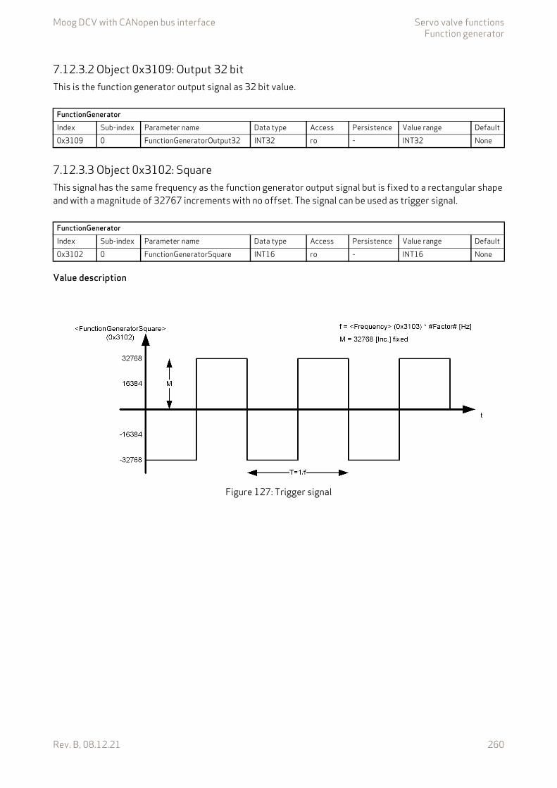
Moog DCV with CANopen bus interface Servo valve functionsFunction generator
Rev. B, 08.12.21 260
7.12.3.2 Object 0x3109: Output 32 bitThis is the function generator output signal as 32 bit value.
7.12.3.3 Object 0x3102: SquareThis signal has the same frequency as the function generator output signal but is fixed to a rectangular shape and with a magnitude of 32767 increments with no offset. The signal can be used as trigger signal.
Value description
Figure 127: Trigger signal
FunctionGeneratorIndex Sub-index Parameter name Data type Access Persistence Value range Default0x3109 0 FunctionGeneratorOutput32 INT32 ro - INT32 None
FunctionGeneratorIndex Sub-index Parameter name Data type Access Persistence Value range Default0x3102 0 FunctionGeneratorSquare INT16 ro - INT16 None
Moog DCV with CANopen bus interface DiagnosticsFault reaction
Rev. B, 08.12.21 261
8 Diagnostics
8.1 Fault reactionIf a malfunction occurs and the fault reaction is enabled, the servo valve software indicates a fault. The corre-sponding fault is set in the fault state <FaultStatus> (0x2831) and <FaultRetainStatus> (0x2834) parameters.
If no fault reaction for this fault is defined within the parameter <FaultReaction> (0x2830) no further fault reaction is done.
If a specific fault occurs and the response is switched on for that fault, the fault is reported in the parameter <ErrorRegister> (0x1001).
Then the fault code and the error code are saved in an array <StandardErrorField> (0x1003)#1…16 which holds the last sixteen faults occurred.
If the configured error response of the reported error requires a change of the device state, the corresponding device state machine transition will be forced.
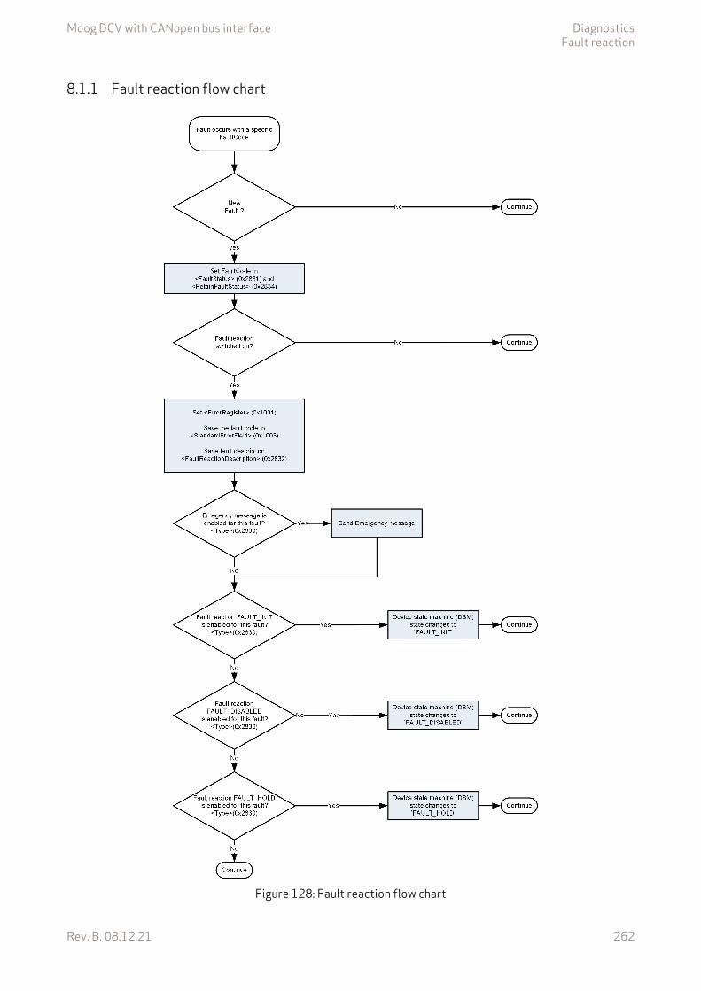
Moog DCV with CANopen bus interface DiagnosticsFault reaction
Rev. B, 08.12.21 262
8.1.1 Fault reaction flow chart
Figure 128: Fault reaction flow chart
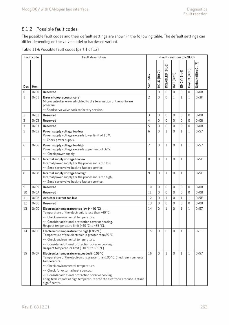
Moog DCV with CANopen bus interface DiagnosticsFault reaction
Rev. B, 08.12.21 263
8.1.2 Possible fault codesThe possible fault codes and their default settings are shown in the following table. The default settings can differ depending on the valve model or hardware variant.
Table 114: Possible fault codes (part 1 of 12)
Fault code Fault description <FaultReaction> (0x2830)
Dec Hex Sub-
Inde
x
HOLD
(Bit
7)
DISA
BLED
(Bit
6)
INIT
(Bit
5)
EMCY
(Bit
4)
On/O
ff (B
it 0)
Defa
ult (
Bits
0…
7)
0 0x00 Reserved 1 0 0 0 0 0 0x081 0x01 Error microprocessor core
Microcontroller error which led to the termination of the software program.=> Send servo valve back to factory service.
2 0 0 1 1 1 0x3F
2 0x02 Reserved 3 0 0 0 0 0 0x083 0x03 Reserved 4 0 0 0 0 0 0x084 0x04 Reserved 5 0 0 0 0 0 0x085 0x05 Power supply voltage too low
Power supply voltage exceeds lower limit of 18 V.=> Check power supply.
6 0 1 0 1 1 0x57
6 0x06 Power supply voltage too highPower supply voltage exceeds upper limit of 32 V.=> Check power supply.
7 0 1 0 1 1 0x57
7 0x07 Internal supply voltage too lowInternal power supply for the processor is too low.=> Send servo valve back to factory service.
8 0 1 0 1 1 0x5F
8 0x08 Internal supply voltage too highInternal power supply for the processor is too high.=> Send servo valve back to factory service.
9 0 1 0 1 1 0x5F
9 0x09 Reserved 10 0 0 0 0 0 0x0810 0x0A Reserved 11 0 0 0 0 0 0x0811 0x0B Actuator current too low 12 0 1 0 1 1 0x5F12 0x0C Reserved 13 0 0 0 0 0 0x0813 0x0D Electronics temperature too low (< –40 °C)
Temperature of the electronic is less than –40 °C.=> Check environmental temperature.=> Consider additional protection cover or heating.Respect temperature limit (–40 °C to +85 °C).
14 0 1 0 1 1 0x57
14 0x0E Electronics temperature too high (> 85?°C)Temperature of the electronic is greater than 85 °C.=> Check environmental temperature.=> Consider additional protection cover or cooling.Respect temperature limit (–40 °C to +85 °C).
15 0 0 0 1 1 0x11
15 0x0F Electronics temperature exceeded (> 105 °C)Temperature of the electronic is greater than 105 °C. Check environmental temperature.=> Check environmental temperature.=> Check for external heat sources.=> Consider additional protection cover or cooling.Long-term impact of high temperature onto the electronics reduce lifetime significantly.
16 0 1 0 1 1 0x57
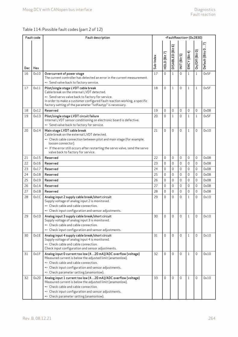
Moog DCV with CANopen bus interface DiagnosticsFault reaction
Rev. B, 08.12.21 264
16 0x10 Overcurrent of power stageThe current controller has detected an error in the current measurement.=> Send valve back to factory service.
17 0 1 0 1 1 0x5F
17 0x11 Pilot/single stage LVDT cable breakCable break on the internal LVDT detected.=> Send servo valve back to factory for service.In order to make a customer configured fault reaction working, a specific factory setting of the parameter "lvdfautyp" is necessary.
18 0 1 0 1 1 0x5F
18 0x12 Reserved 19 0 0 0 0 0 0x0819 0x13 Pilot/single stage LVDT circuit failure
Internal LVDT sensor conditioning on electronic board is defective.=> Send valve back to factory for service.
20 0 1 0 1 1 0x5F
20 0x14 Main stage LVDT cable breakCable break on the external LVDT detected.=> Check cable connection between pilot and main stage (for example,
loosen connector).=> If the error still occurs after restarting the servo valve, send the servo
valve back to factory for service.
21 0 0 0 1 0 0x10
21 0x15 Reserved 22 0 0 0 0 0 0x0822 0x16 Reserved 23 0 0 0 0 0 0x0823 0x17 Reserved 24 0 0 0 0 0 0x0824 0x18 Reserved 25 0 0 0 0 0 0x0825 0x19 Reserved 26 0 0 0 0 0 0x0826 0x1A Reserved 27 0 0 0 0 0 0x0827 0x1B Reserved 28 0 0 0 0 0 0x0828 0x1C Analog input 2 supply cable break/short circuit
Supply voltage of analog input 2 is monitored.=> Check cable and cable connection.=> Check input configuration and sensor adjustments.
29 0 0 0 1 0 0x10
29 0x1D Analog input 3 supply cable break/short circuitSupply voltage of analog input 3 is monitored.=> Check cable and cable connection.=> Check input configuration and sensor adjustments.
30 0 0 0 1 0 0x10
30 0x1E Analog input 4 supply cable break/short circuitSupply voltage of analog input 4 is monitored.=> Check cable and cable connection.Check input configuration and sensor adjustments.
31 0 0 0 1 0 0x10
31 0x1F Analog input 0 current too low (4…20 mA)/ADC overflow (voltage)Measured current is below the adjusted limit (anamonlow).=> Check cable and cable connection.=> Check input configuration and sensor adjustments.=> Check parameter setting (anamonlow).
32 0 0 0 1 0 0x10
32 0x20 Analog input 1 current too low (4…20 mA)/ADC overflow (voltage)Measured current is below the adjusted limit (anamonlow).=> Check cable and cable connection.=> Check input configuration and sensor adjustments.=> Check parameter setting (anamonlow).
33 0 0 0 1 0 0x10
Table 114: Possible fault codes (part 2 of 12)
Fault code Fault description <FaultReaction> (0x2830)
Dec Hex Sub-
Inde
x
HOLD
(Bit
7)
DISA
BLED
(Bit
6)
INIT
(Bit
5)
EMCY
(Bit
4)
On/O
ff (B
it 0)
Defa
ult (
Bits
0…
7)
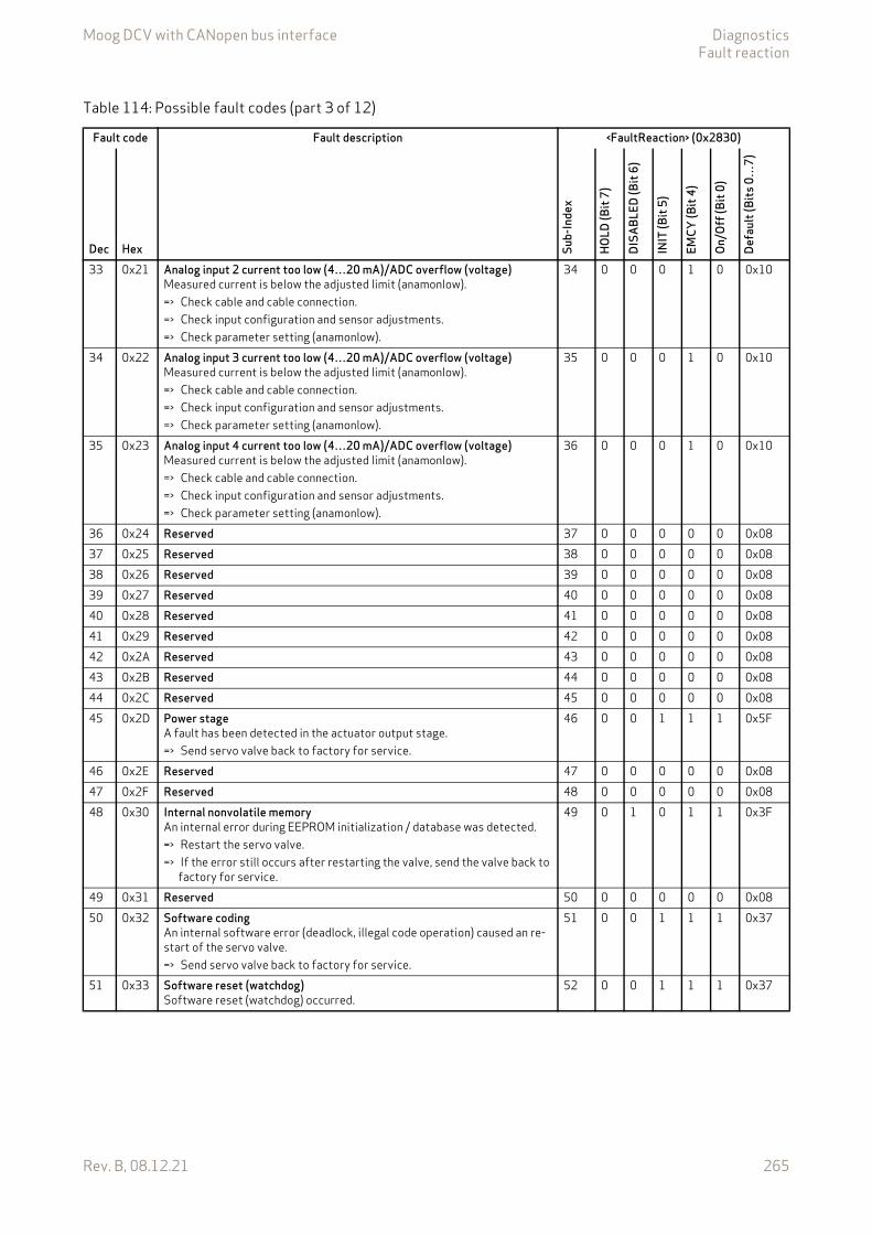
Moog DCV with CANopen bus interface DiagnosticsFault reaction
Rev. B, 08.12.21 265
33 0x21 Analog input 2 current too low (4…20 mA)/ADC overflow (voltage)Measured current is below the adjusted limit (anamonlow).=> Check cable and cable connection.=> Check input configuration and sensor adjustments.=> Check parameter setting (anamonlow).
34 0 0 0 1 0 0x10
34 0x22 Analog input 3 current too low (4…20 mA)/ADC overflow (voltage)Measured current is below the adjusted limit (anamonlow).=> Check cable and cable connection.=> Check input configuration and sensor adjustments.=> Check parameter setting (anamonlow).
35 0 0 0 1 0 0x10
35 0x23 Analog input 4 current too low (4…20 mA)/ADC overflow (voltage)Measured current is below the adjusted limit (anamonlow).=> Check cable and cable connection.=> Check input configuration and sensor adjustments.=> Check parameter setting (anamonlow).
36 0 0 0 1 0 0x10
36 0x24 Reserved 37 0 0 0 0 0 0x0837 0x25 Reserved 38 0 0 0 0 0 0x0838 0x26 Reserved 39 0 0 0 0 0 0x0839 0x27 Reserved 40 0 0 0 0 0 0x0840 0x28 Reserved 41 0 0 0 0 0 0x0841 0x29 Reserved 42 0 0 0 0 0 0x0842 0x2A Reserved 43 0 0 0 0 0 0x0843 0x2B Reserved 44 0 0 0 0 0 0x0844 0x2C Reserved 45 0 0 0 0 0 0x0845 0x2D Power stage
A fault has been detected in the actuator output stage.=> Send servo valve back to factory for service.
46 0 0 1 1 1 0x5F
46 0x2E Reserved 47 0 0 0 0 0 0x0847 0x2F Reserved 48 0 0 0 0 0 0x0848 0x30 Internal nonvolatile memory
An internal error during EEPROM initialization / database was detected.=> Restart the servo valve.=> If the error still occurs after restarting the valve, send the valve back to
factory for service.
49 0 1 0 1 1 0x3F
49 0x31 Reserved 50 0 0 0 0 0 0x0850 0x32 Software coding
An internal software error (deadlock, illegal code operation) caused an re-start of the servo valve.=> Send servo valve back to factory for service.
51 0 0 1 1 1 0x37
51 0x33 Software reset (watchdog)Software reset (watchdog) occurred.
52 0 0 1 1 1 0x37
Table 114: Possible fault codes (part 3 of 12)
Fault code Fault description <FaultReaction> (0x2830)
Dec Hex Sub-
Inde
x
HOLD
(Bit
7)
DISA
BLED
(Bit
6)
INIT
(Bit
5)
EMCY
(Bit
4)
On/O
ff (B
it 0)
Defa
ult (
Bits
0…
7)
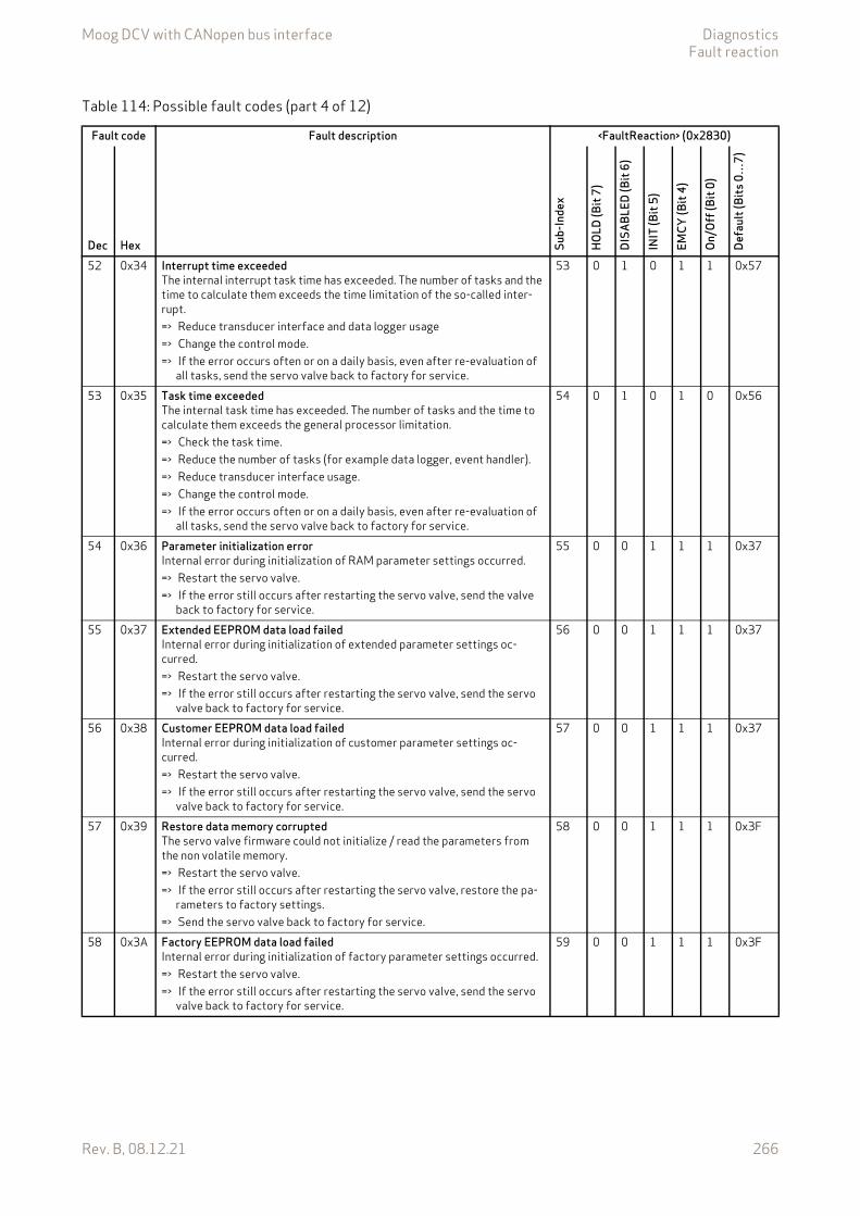
Moog DCV with CANopen bus interface DiagnosticsFault reaction
Rev. B, 08.12.21 266
52 0x34 Interrupt time exceededThe internal interrupt task time has exceeded. The number of tasks and the time to calculate them exceeds the time limitation of the so-called inter-rupt.=> Reduce transducer interface and data logger usage=> Change the control mode.=> If the error occurs often or on a daily basis, even after re-evaluation of
all tasks, send the servo valve back to factory for service.
53 0 1 0 1 1 0x57
53 0x35 Task time exceededThe internal task time has exceeded. The number of tasks and the time to calculate them exceeds the general processor limitation.=> Check the task time.=> Reduce the number of tasks (for example data logger, event handler).=> Reduce transducer interface usage.=> Change the control mode.=> If the error occurs often or on a daily basis, even after re-evaluation of
all tasks, send the servo valve back to factory for service.
54 0 1 0 1 0 0x56
54 0x36 Parameter initialization errorInternal error during initialization of RAM parameter settings occurred.=> Restart the servo valve.=> If the error still occurs after restarting the servo valve, send the valve
back to factory for service.
55 0 0 1 1 1 0x37
55 0x37 Extended EEPROM data load failedInternal error during initialization of extended parameter settings oc-curred.=> Restart the servo valve.=> If the error still occurs after restarting the servo valve, send the servo
valve back to factory for service.
56 0 0 1 1 1 0x37
56 0x38 Customer EEPROM data load failedInternal error during initialization of customer parameter settings oc-curred.=> Restart the servo valve.=> If the error still occurs after restarting the servo valve, send the servo
valve back to factory for service.
57 0 0 1 1 1 0x37
57 0x39 Restore data memory corruptedThe servo valve firmware could not initialize / read the parameters from the non volatile memory.=> Restart the servo valve.=> If the error still occurs after restarting the servo valve, restore the pa-
rameters to factory settings.=> Send the servo valve back to factory for service.
58 0 0 1 1 1 0x3F
58 0x3A Factory EEPROM data load failedInternal error during initialization of factory parameter settings occurred.=> Restart the servo valve.=> If the error still occurs after restarting the servo valve, send the servo
valve back to factory for service.
59 0 0 1 1 1 0x3F
Table 114: Possible fault codes (part 4 of 12)
Fault code Fault description <FaultReaction> (0x2830)
Dec Hex Sub-
Inde
x
HOLD
(Bit
7)
DISA
BLED
(Bit
6)
INIT
(Bit
5)
EMCY
(Bit
4)
On/O
ff (B
it 0)
Defa
ult (
Bits
0…
7)
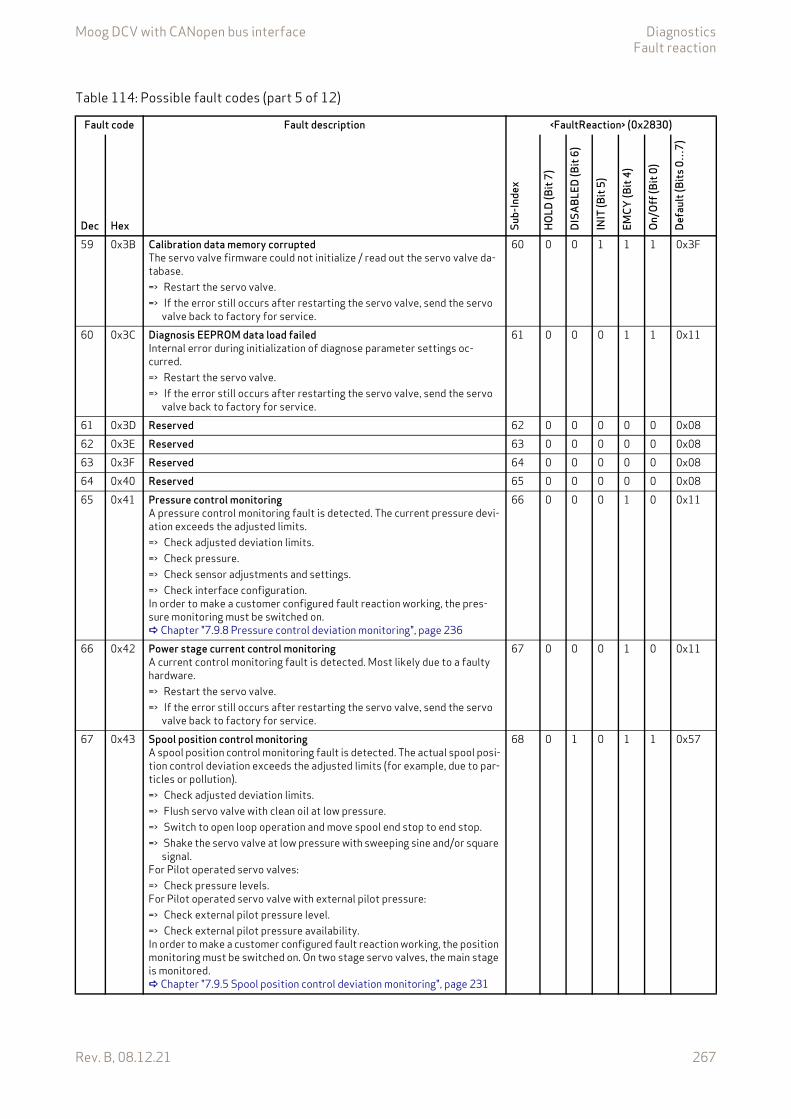
Moog DCV with CANopen bus interface DiagnosticsFault reaction
Rev. B, 08.12.21 267
59 0x3B Calibration data memory corruptedThe servo valve firmware could not initialize / read out the servo valve da-tabase.=> Restart the servo valve.=> If the error still occurs after restarting the servo valve, send the servo
valve back to factory for service.
60 0 0 1 1 1 0x3F
60 0x3C Diagnosis EEPROM data load failedInternal error during initialization of diagnose parameter settings oc-curred.=> Restart the servo valve.=> If the error still occurs after restarting the servo valve, send the servo
valve back to factory for service.
61 0 0 0 1 1 0x11
61 0x3D Reserved 62 0 0 0 0 0 0x0862 0x3E Reserved 63 0 0 0 0 0 0x0863 0x3F Reserved 64 0 0 0 0 0 0x0864 0x40 Reserved 65 0 0 0 0 0 0x0865 0x41 Pressure control monitoring
A pressure control monitoring fault is detected. The current pressure devi-ation exceeds the adjusted limits.=> Check adjusted deviation limits.=> Check pressure.=> Check sensor adjustments and settings.=> Check interface configuration.In order to make a customer configured fault reaction working, the pres-sure monitoring must be switched on. Chapter "7.9.8 Pressure control deviation monitoring", page 236
66 0 0 0 1 0 0x11
66 0x42 Power stage current control monitoringA current control monitoring fault is detected. Most likely due to a faulty hardware.=> Restart the servo valve.=> If the error still occurs after restarting the servo valve, send the servo
valve back to factory for service.
67 0 0 0 1 0 0x11
67 0x43 Spool position control monitoringA spool position control monitoring fault is detected. The actual spool posi-tion control deviation exceeds the adjusted limits (for example, due to par-ticles or pollution).=> Check adjusted deviation limits.=> Flush servo valve with clean oil at low pressure.=> Switch to open loop operation and move spool end stop to end stop.=> Shake the servo valve at low pressure with sweeping sine and/or square
signal.For Pilot operated servo valves:=> Check pressure levels.For Pilot operated servo valve with external pilot pressure:=> Check external pilot pressure level.=> Check external pilot pressure availability.In order to make a customer configured fault reaction working, the position monitoring must be switched on. On two stage servo valves, the main stage is monitored. Chapter "7.9.5 Spool position control deviation monitoring", page 231
68 0 1 0 1 1 0x57
Table 114: Possible fault codes (part 5 of 12)
Fault code Fault description <FaultReaction> (0x2830)
Dec Hex Sub-
Inde
x
HOLD
(Bit
7)
DISA
BLED
(Bit
6)
INIT
(Bit
5)
EMCY
(Bit
4)
On/O
ff (B
it 0)
Defa
ult (
Bits
0…
7)
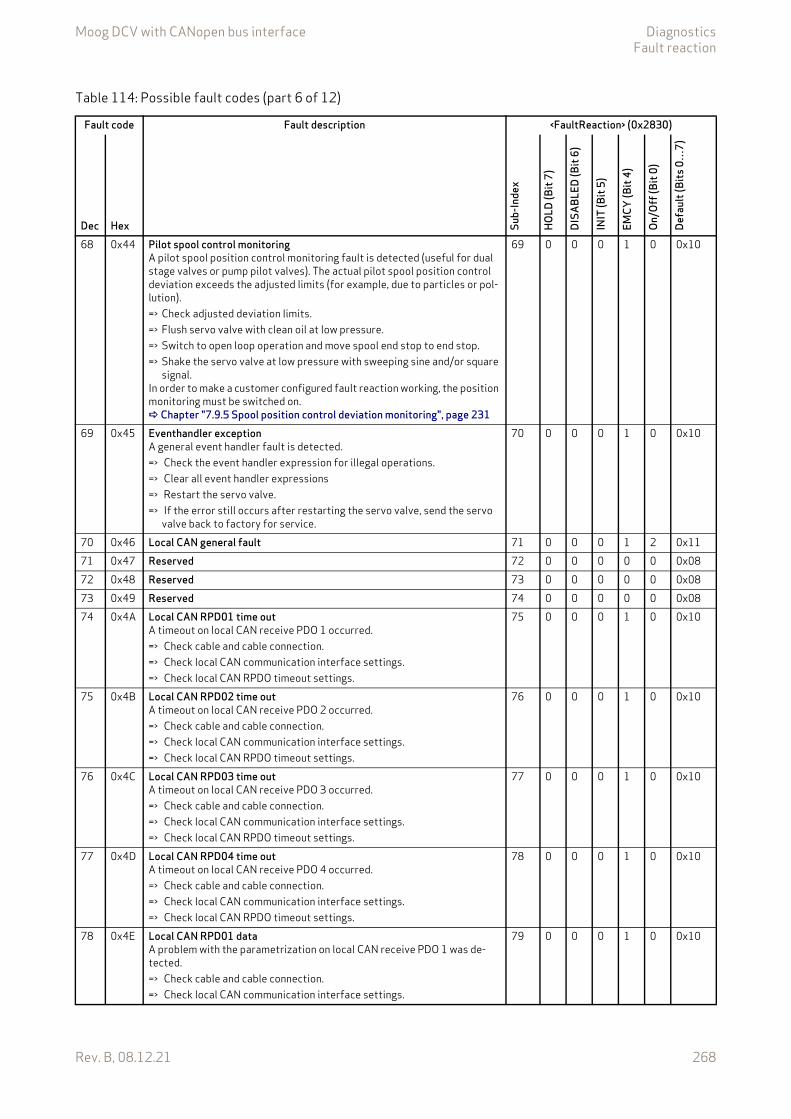
Moog DCV with CANopen bus interface DiagnosticsFault reaction
Rev. B, 08.12.21 268
68 0x44 Pilot spool control monitoringA pilot spool position control monitoring fault is detected (useful for dual stage valves or pump pilot valves). The actual pilot spool position control deviation exceeds the adjusted limits (for example, due to particles or pol-lution).=> Check adjusted deviation limits.=> Flush servo valve with clean oil at low pressure.=> Switch to open loop operation and move spool end stop to end stop.=> Shake the servo valve at low pressure with sweeping sine and/or square
signal.In order to make a customer configured fault reaction working, the position monitoring must be switched on. Chapter "7.9.5 Spool position control deviation monitoring", page 231
69 0 0 0 1 0 0x10
69 0x45 Eventhandler exceptionA general event handler fault is detected.=> Check the event handler expression for illegal operations.=> Clear all event handler expressions=> Restart the servo valve.=> If the error still occurs after restarting the servo valve, send the servo
valve back to factory for service.
70 0 0 0 1 0 0x10
70 0x46 Local CAN general fault 71 0 0 0 1 2 0x1171 0x47 Reserved 72 0 0 0 0 0 0x0872 0x48 Reserved 73 0 0 0 0 0 0x0873 0x49 Reserved 74 0 0 0 0 0 0x0874 0x4A Local CAN RPD01 time out
A timeout on local CAN receive PDO 1 occurred.=> Check cable and cable connection.=> Check local CAN communication interface settings.=> Check local CAN RPDO timeout settings.
75 0 0 0 1 0 0x10
75 0x4B Local CAN RPD02 time outA timeout on local CAN receive PDO 2 occurred.=> Check cable and cable connection.=> Check local CAN communication interface settings.=> Check local CAN RPDO timeout settings.
76 0 0 0 1 0 0x10
76 0x4C Local CAN RPD03 time outA timeout on local CAN receive PDO 3 occurred.=> Check cable and cable connection.=> Check local CAN communication interface settings.=> Check local CAN RPDO timeout settings.
77 0 0 0 1 0 0x10
77 0x4D Local CAN RPD04 time outA timeout on local CAN receive PDO 4 occurred.=> Check cable and cable connection.=> Check local CAN communication interface settings.=> Check local CAN RPDO timeout settings.
78 0 0 0 1 0 0x10
78 0x4E Local CAN RPD01 dataA problem with the parametrization on local CAN receive PDO 1 was de-tected.=> Check cable and cable connection.=> Check local CAN communication interface settings.
79 0 0 0 1 0 0x10
Table 114: Possible fault codes (part 6 of 12)
Fault code Fault description <FaultReaction> (0x2830)
Dec Hex Sub-
Inde
x
HOLD
(Bit
7)
DISA
BLED
(Bit
6)
INIT
(Bit
5)
EMCY
(Bit
4)
On/O
ff (B
it 0)
Defa
ult (
Bits
0…
7)
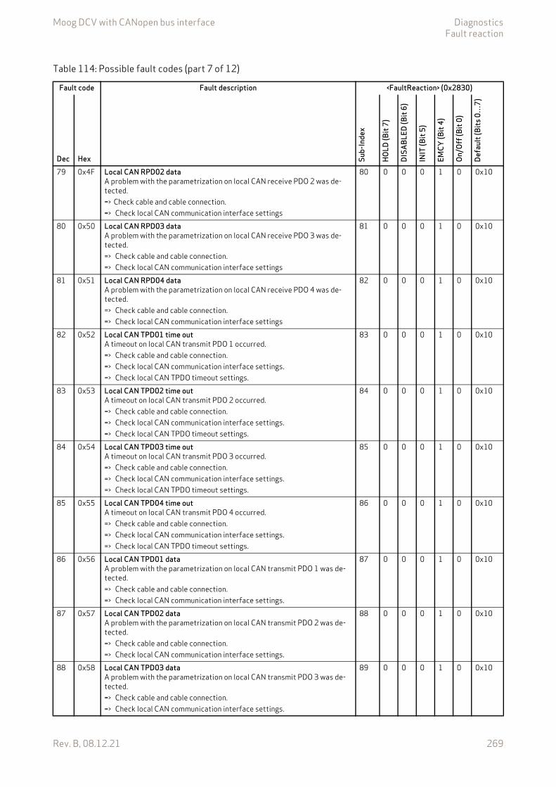
Moog DCV with CANopen bus interface DiagnosticsFault reaction
Rev. B, 08.12.21 269
79 0x4F Local CAN RPD02 dataA problem with the parametrization on local CAN receive PDO 2 was de-tected.=> Check cable and cable connection.=> Check local CAN communication interface settings
80 0 0 0 1 0 0x10
80 0x50 Local CAN RPD03 dataA problem with the parametrization on local CAN receive PDO 3 was de-tected.=> Check cable and cable connection.=> Check local CAN communication interface settings
81 0 0 0 1 0 0x10
81 0x51 Local CAN RPD04 dataA problem with the parametrization on local CAN receive PDO 4 was de-tected.=> Check cable and cable connection.=> Check local CAN communication interface settings
82 0 0 0 1 0 0x10
82 0x52 Local CAN TPD01 time outA timeout on local CAN transmit PDO 1 occurred.=> Check cable and cable connection.=> Check local CAN communication interface settings.=> Check local CAN TPDO timeout settings.
83 0 0 0 1 0 0x10
83 0x53 Local CAN TPD02 time outA timeout on local CAN transmit PDO 2 occurred.=> Check cable and cable connection.=> Check local CAN communication interface settings.=> Check local CAN TPDO timeout settings.
84 0 0 0 1 0 0x10
84 0x54 Local CAN TPD03 time outA timeout on local CAN transmit PDO 3 occurred.=> Check cable and cable connection.=> Check local CAN communication interface settings.=> Check local CAN TPDO timeout settings.
85 0 0 0 1 0 0x10
85 0x55 Local CAN TPD04 time outA timeout on local CAN transmit PDO 4 occurred.=> Check cable and cable connection.=> Check local CAN communication interface settings.=> Check local CAN TPDO timeout settings.
86 0 0 0 1 0 0x10
86 0x56 Local CAN TPD01 dataA problem with the parametrization on local CAN transmit PDO 1 was de-tected.=> Check cable and cable connection.=> Check local CAN communication interface settings.
87 0 0 0 1 0 0x10
87 0x57 Local CAN TPD02 dataA problem with the parametrization on local CAN transmit PDO 2 was de-tected.=> Check cable and cable connection.=> Check local CAN communication interface settings.
88 0 0 0 1 0 0x10
88 0x58 Local CAN TPD03 dataA problem with the parametrization on local CAN transmit PDO 3 was de-tected.=> Check cable and cable connection.=> Check local CAN communication interface settings.
89 0 0 0 1 0 0x10
Table 114: Possible fault codes (part 7 of 12)
Fault code Fault description <FaultReaction> (0x2830)
Dec Hex Sub-
Inde
x
HOLD
(Bit
7)
DISA
BLED
(Bit
6)
INIT
(Bit
5)
EMCY
(Bit
4)
On/O
ff (B
it 0)
Defa
ult (
Bits
0…
7)
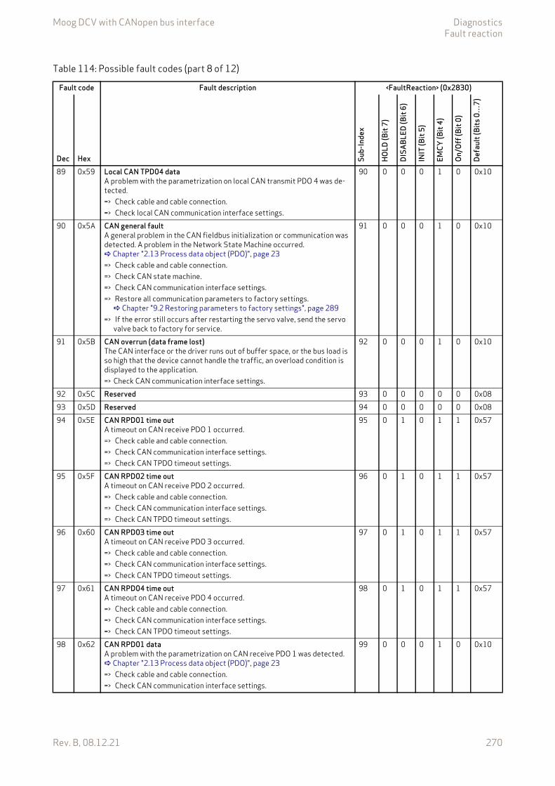
Moog DCV with CANopen bus interface DiagnosticsFault reaction
Rev. B, 08.12.21 270
89 0x59 Local CAN TPD04 dataA problem with the parametrization on local CAN transmit PDO 4 was de-tected.=> Check cable and cable connection.=> Check local CAN communication interface settings.
90 0 0 0 1 0 0x10
90 0x5A CAN general faultA general problem in the CAN fieldbus initialization or communication was detected. A problem in the Network State Machine occurred. Chapter "2.13 Process data object (PDO)", page 23=> Check cable and cable connection.=> Check CAN state machine.=> Check CAN communication interface settings.=> Restore all communication parameters to factory settings. Chapter "9.2 Restoring parameters to factory settings", page 289
=> If the error still occurs after restarting the servo valve, send the servo valve back to factory for service.
91 0 0 0 1 0 0x10
91 0x5B CAN overrun (data frame lost)The CAN interface or the driver runs out of buffer space, or the bus load is so high that the device cannot handle the traffic, an overload condition is displayed to the application.=> Check CAN communication interface settings.
92 0 0 0 1 0 0x10
92 0x5C Reserved 93 0 0 0 0 0 0x0893 0x5D Reserved 94 0 0 0 0 0 0x0894 0x5E CAN RPD01 time out
A timeout on CAN receive PDO 1 occurred.=> Check cable and cable connection.=> Check CAN communication interface settings.=> Check CAN TPDO timeout settings.
95 0 1 0 1 1 0x57
95 0x5F CAN RPD02 time outA timeout on CAN receive PDO 2 occurred.=> Check cable and cable connection.=> Check CAN communication interface settings.=> Check CAN TPDO timeout settings.
96 0 1 0 1 1 0x57
96 0x60 CAN RPD03 time outA timeout on CAN receive PDO 3 occurred.=> Check cable and cable connection.=> Check CAN communication interface settings.=> Check CAN TPDO timeout settings.
97 0 1 0 1 1 0x57
97 0x61 CAN RPD04 time outA timeout on CAN receive PDO 4 occurred.=> Check cable and cable connection.=> Check CAN communication interface settings.=> Check CAN TPDO timeout settings.
98 0 1 0 1 1 0x57
98 0x62 CAN RPD01 dataA problem with the parametrization on CAN receive PDO 1 was detected. Chapter "2.13 Process data object (PDO)", page 23=> Check cable and cable connection.=> Check CAN communication interface settings.
99 0 0 0 1 0 0x10
Table 114: Possible fault codes (part 8 of 12)
Fault code Fault description <FaultReaction> (0x2830)
Dec Hex Sub-
Inde
x
HOLD
(Bit
7)
DISA
BLED
(Bit
6)
INIT
(Bit
5)
EMCY
(Bit
4)
On/O
ff (B
it 0)
Defa
ult (
Bits
0…
7)
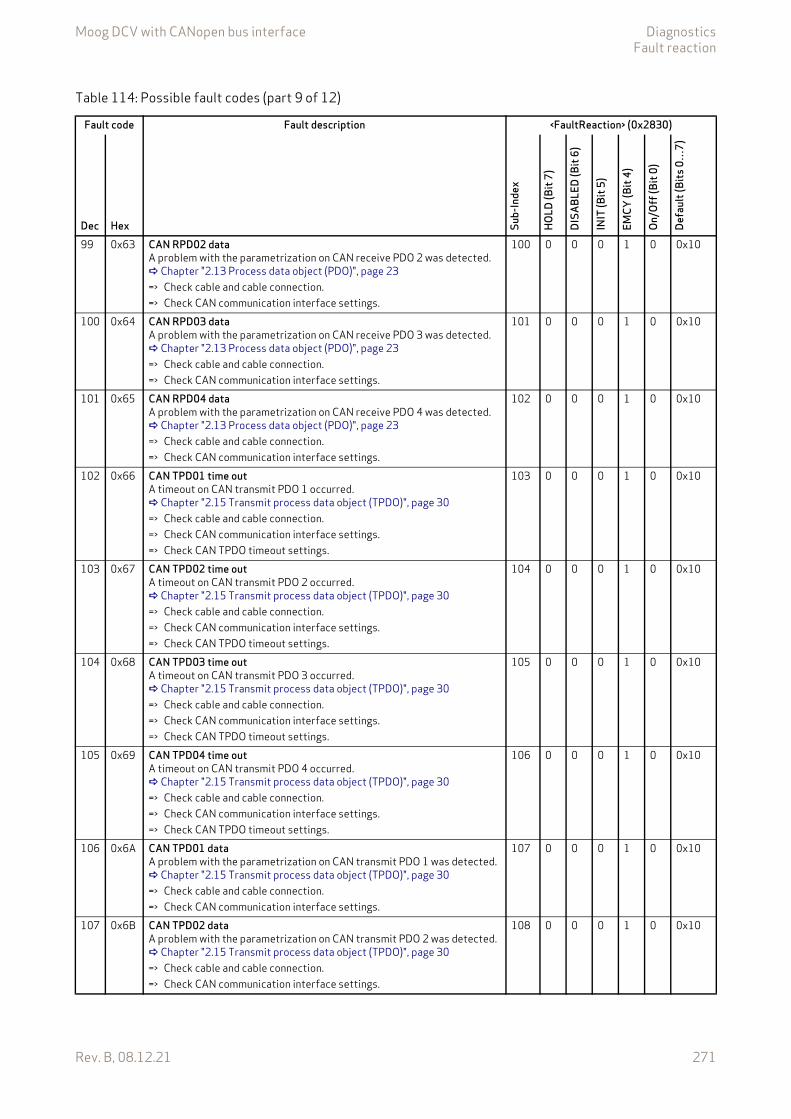
Moog DCV with CANopen bus interface DiagnosticsFault reaction
Rev. B, 08.12.21 271
99 0x63 CAN RPD02 dataA problem with the parametrization on CAN receive PDO 2 was detected. Chapter "2.13 Process data object (PDO)", page 23=> Check cable and cable connection.=> Check CAN communication interface settings.
100 0 0 0 1 0 0x10
100 0x64 CAN RPD03 dataA problem with the parametrization on CAN receive PDO 3 was detected. Chapter "2.13 Process data object (PDO)", page 23=> Check cable and cable connection.=> Check CAN communication interface settings.
101 0 0 0 1 0 0x10
101 0x65 CAN RPD04 dataA problem with the parametrization on CAN receive PDO 4 was detected. Chapter "2.13 Process data object (PDO)", page 23=> Check cable and cable connection.=> Check CAN communication interface settings.
102 0 0 0 1 0 0x10
102 0x66 CAN TPD01 time outA timeout on CAN transmit PDO 1 occurred. Chapter "2.15 Transmit process data object (TPDO)", page 30=> Check cable and cable connection.=> Check CAN communication interface settings.=> Check CAN TPDO timeout settings.
103 0 0 0 1 0 0x10
103 0x67 CAN TPD02 time outA timeout on CAN transmit PDO 2 occurred. Chapter "2.15 Transmit process data object (TPDO)", page 30=> Check cable and cable connection.=> Check CAN communication interface settings.=> Check CAN TPDO timeout settings.
104 0 0 0 1 0 0x10
104 0x68 CAN TPD03 time outA timeout on CAN transmit PDO 3 occurred. Chapter "2.15 Transmit process data object (TPDO)", page 30=> Check cable and cable connection.=> Check CAN communication interface settings.=> Check CAN TPDO timeout settings.
105 0 0 0 1 0 0x10
105 0x69 CAN TPD04 time outA timeout on CAN transmit PDO 4 occurred. Chapter "2.15 Transmit process data object (TPDO)", page 30=> Check cable and cable connection.=> Check CAN communication interface settings.=> Check CAN TPDO timeout settings.
106 0 0 0 1 0 0x10
106 0x6A CAN TPD01 dataA problem with the parametrization on CAN transmit PDO 1 was detected. Chapter "2.15 Transmit process data object (TPDO)", page 30=> Check cable and cable connection.=> Check CAN communication interface settings.
107 0 0 0 1 0 0x10
107 0x6B CAN TPD02 dataA problem with the parametrization on CAN transmit PDO 2 was detected. Chapter "2.15 Transmit process data object (TPDO)", page 30=> Check cable and cable connection.=> Check CAN communication interface settings.
108 0 0 0 1 0 0x10
Table 114: Possible fault codes (part 9 of 12)
Fault code Fault description <FaultReaction> (0x2830)
Dec Hex Sub-
Inde
x
HOLD
(Bit
7)
DISA
BLED
(Bit
6)
INIT
(Bit
5)
EMCY
(Bit
4)
On/O
ff (B
it 0)
Defa
ult (
Bits
0…
7)

Moog DCV with CANopen bus interface DiagnosticsFault reaction
Rev. B, 08.12.21 272
108 0x6C CAN TPD03 dataA problem with the parametrization on CAN transmit PDO 3 was detected. Chapter "2.15 Transmit process data object (TPDO)", page 30=> Check cable and cable connection.=> Check CAN communication interface settings.
109 0 0 0 1 0 0x10
109 0x6D CAN TPD04 dataA problem with the parametrization on CAN transmit PDO 4 was detected. Chapter "2.15 Transmit process data object (TPDO)", page 30=> Check cable and cable connection.=> Check CAN communication interface settings.
110 0 0 0 1 0 0x10
110 0x6E CAN life guard error or heartbeat errorPeriodical monitoring of the device with the node guarding protocol timed out. This happens when the guarding request has not been received by the device within the configured guard time and life time factor. Chapter "2.12 Network management (NMT) node guarding", page 22 Chapter "2.11 Network management (NMT) heartbeat", page 21=> Check cable and cable connection.=> Check CAN communication interface settings.=> Check guarding settings.=> Check NMT state machine.=> Check guard request from PLC (master).
111 0 1 0 1 1 0x57
111 0x6F CAN SYNC producer time outA synchronization problem on CAN occurred. The synchronization signal could not be received within timeout. Chapter "2.18 Synchronization (SYNC)", page 38=> Check cable and cable connection.=> Check CAN communication interface settings.=> Check corresponding receive PDO and Transmission type.
112 0 0 0 1 0 0x10
112 0x70 CAN SYNC consumer time outA synchronization problem on CAN occurred. Chapter "2.18 Synchronization (SYNC)", page 38 Chapter "2.13 Process data object (PDO)", page 23 Chapter "2.15 Transmit process data object (TPDO)", page 30=> Check cable and cable connection.=> Check CAN communication interface settings.=> Check corresponding receive PDO and transmission type.
113 0 0 0 1 0 0x10
113 0x71 EtherCAT communication fault (not implemented) 114 0 0 0 1 0 0x10114 0x72 EtherCAT RPDO time out
A timeout on EtherCAT receive PDO occurred.=> Check cable and cable connection.=> Check EtherCAT communication interface settings.
115 0 1 0 0 1 0x57
115 0x73 EtherCAT RPDO dataA problem with the parametrization on EtherCAT receive PDO was de-tected.=> Check cable and cable connection.=> Check EtherCAT communication interface settings.
116 0 0 0 1 0 0x10
116 0x74 EtherCAT TPDO time out (not implemented)A timeout on EtherCAT transmit PDO occurred.=> Check cable and cable connection.=> Check EtherCAT communication interface settings.
117 0 0 0 0 0 0x08
Table 114: Possible fault codes (part 10 of 12)
Fault code Fault description <FaultReaction> (0x2830)
Dec Hex Sub-
Inde
x
HOLD
(Bit
7)
DISA
BLED
(Bit
6)
INIT
(Bit
5)
EMCY
(Bit
4)
On/O
ff (B
it 0)
Defa
ult (
Bits
0…
7)
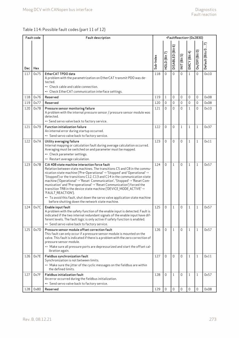
Moog DCV with CANopen bus interface DiagnosticsFault reaction
Rev. B, 08.12.21 273
117 0x75 EtherCAT TPDO dataA problem with the parametrization on EtherCAT transmit PDO was de-tected.=> Check cable and cable connection.=> Check EtherCAT communication interface settings.
118 0 0 0 1 0 0x10
118 0x76 Reserved 119 1 0 0 0 0 0x08119 0x77 Reserved 120 0 0 0 0 0 0x08120 0x78 Pressure sensor monitoring failure
A problem with the internal pressure sensor / pressure sensor module was detected.=> Send servo valve back to factory service.
121 0 0 0 1 0 0x10
121 0x79 Function initialization failureAn internal error during startup occurred.=> Send servo valve back to factory service.
122 0 0 1 1 1 0x37
122 0x7A Utility averaging failureInternal mapping or calculation fault during average calculation occurred. Averaging must be switched on and parameter must be mapped.=> Check parameter settings.=> Restart average calculation.
123 0 0 0 1 1 0x11
123 0x7B CiA 408 state machine interaction force faultRelation between state machines. The transitions C5 and C8 in the commu-nication state machine ('Pre-Operational' -> 'Stopped' and 'Operational' -> 'Stopped') or the transitions C12, C13 and C14 in the communication state machine ('Operational' -> 'Reset Communication', 'Stopped' -> 'Reset Com-munication' and 'Pre-operational' -> 'Reset Communication') forced the transition TR8 in the device state machine ('DEVICE_MODE_ACTIVE' -> 'FAULT_REACTION').=> To avoid this fault, shut down the servo valve application state machine
before shutting down the network state machine.
124 0 1 0 1 1 0x57
124 0x7C Enable input faultA problem with the safety function of the enable input is detected. Fault is indicated if the two internal redundant signals of the enable input have dif-ferent levels. The fault logic is only active if safety function is enabled.=> Send servo valve back to factory service.
125 0 1 0 1 1 0x57
125 0x7D Pressure sensor module offset correction faultThis fault can only occur if a pressure sensor module is mounted on the valve. This fault is indicated if there is a problem with the zero correction of pressure sensor module.=> Make sure all pressure ports are depressurized and start the offset cal-
ibration again.
126 0 1 0 1 1 0x57
126 0x7E Fieldbus synchronization faultSynchronization is not between limits.=> Make sure the jitter of the cyclic messages on the fieldbus are within
the defined limits.
127 0 0 0 1 1 0x11
127 0x7F Fieldbus initialization faultAn error occurred during the fieldbus initialization.=> Send servo valve back to factory service.
128 0 1 0 1 1 0x57
128 0x80 Reserved 129 0 0 0 0 0 0x08
Table 114: Possible fault codes (part 11 of 12)
Fault code Fault description <FaultReaction> (0x2830)
Dec Hex Sub-
Inde
x
HOLD
(Bit
7)
DISA
BLED
(Bit
6)
INIT
(Bit
5)
EMCY
(Bit
4)
On/O
ff (B
it 0)
Defa
ult (
Bits
0…
7)
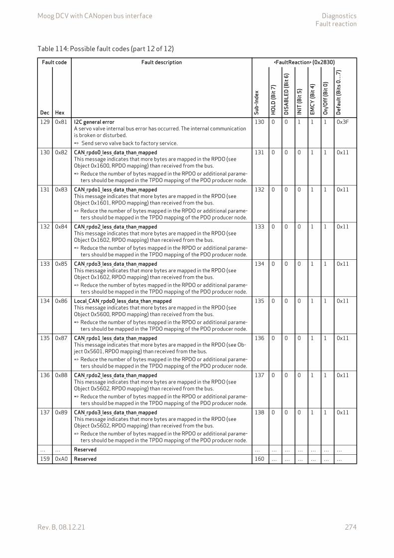
Moog DCV with CANopen bus interface DiagnosticsFault reaction
Rev. B, 08.12.21 274
129 0x81 I2C general errorA servo valve internal bus error has occurred. The internal communication is broken or disturbed.=> Send servo valve back to factory service.
130 0 0 1 1 1 0x3F
130 0x82 CAN_rpdo0_less_data_than_mappedThis message indicates that more bytes are mapped in the RPDO (see Object 0x1600, RPDO mapping) than received from the bus.=> Reduce the number of bytes mapped in the RPDO or additional parame-
ters should be mapped in the TPDO mapping of the PDO producer node.
131 0 0 0 1 1 0x11
131 0x83 CAN_rpdo1_less_data_than_mappedThis message indicates that more bytes are mapped in the RPDO (see Object 0x1601, RPDO mapping) than received from the bus.=> Reduce the number of bytes mapped in the RPDO or additional parame-
ters should be mapped in the TPDO mapping of the PDO producer node.
132 0 0 0 1 1 0x11
132 0x84 CAN_rpdo2_less_data_than_mappedThis message indicates that more bytes are mapped in the RPDO (see Object 0x1602, RPDO mapping) than received from the bus.=> Reduce the number of bytes mapped in the RPDO or additional parame-
ters should be mapped in the TPDO mapping of the PDO producer node.
133 0 0 0 1 1 0x11
133 0x85 CAN_rpdo3_less_data_than_mappedThis message indicates that more bytes are mapped in the RPDO (see Object 0x1602, RPDO mapping) than received from the bus.=> Reduce the number of bytes mapped in the RPDO or additional parame-
ters should be mapped in the TPDO mapping of the PDO producer node.
134 0 0 0 1 1 0x11
134 0x86 Local_CAN_rpdo0_less_data_than_mappedThis message indicates that more bytes are mapped in the RPDO (see Object 0x5600, RPDO mapping) than received from the bus. => Reduce the number of bytes mapped in the RPDO or additional parame-
ters should be mapped in the TPDO mapping of the PDO producer node.
135 0 0 0 1 1 0x11
135 0x87 CAN_rpdo1_less_data_than_mappedThis message indicates that more bytes are mapped in the RPDO (see Ob-ject 0x5601, RPDO mapping) than received from the bus.=> Reduce the number of bytes mapped in the RPDO or additional parame-
ters should be mapped in the TPDO mapping of the PDO producer node.
136 0 0 0 1 1 0x11
136 0x88 CAN_rpdo2_less_data_than_mappedThis message indicates that more bytes are mapped in the RPDO (see Object 0x5602, RPDO mapping) than received from the bus.=> Reduce the number of bytes mapped in the RPDO or additional parame-
ters should be mapped in the TPDO mapping of the PDO producer node.
137 0 0 0 1 1 0x11
137 0x89 CAN_rpdo3_less_data_than_mappedThis message indicates that more bytes are mapped in the RPDO (see Object 0x5602, RPDO mapping) than received from the bus.=> Reduce the number of bytes mapped in the RPDO or additional parame-
ters should be mapped in the TPDO mapping of the PDO producer node.
138 0 0 0 1 1 0x11
… … Reserved … … … … … … …159 0xA0 Reserved 160 … … … … … …
Table 114: Possible fault codes (part 12 of 12)
Fault code Fault description <FaultReaction> (0x2830)
Dec Hex Sub-
Inde
x
HOLD
(Bit
7)
DISA
BLED
(Bit
6)
INIT
(Bit
5)
EMCY
(Bit
4)
On/O
ff (B
it 0)
Defa
ult (
Bits
0…
7)

Moog DCV with CANopen bus interface DiagnosticsFault reaction
Rev. B, 08.12.21 275
8.1.3 Fault reactionThe fault reaction parameter <FaultReaction> (0x2830) can be used to configure the fault behavior for each fault code.
8.1.3.1 Object 0x2830: Fault reactionThe fault reaction for each fault can be configured by selecting different fault reactions.
Value description
To get the sub-index of the fault reaction <FaultReaction> (0x2830), the fault code must be in-cremented by one.<FaultReaction> (0x2830)#[FaultCode+1]
FaultReactionIndex Sub-index Parameter name Data type Access Persistence Value range Default0x2830 1…130 FaultReaction INT8 rw Y Table 114, page 263
Table 115: Fault reaction settings
<FaultReaction> Bit DescriptionBit 0 (0x0001) ON/OFF Switches on/off the fault reaction configuration. This flag must be activated for a configured
fault response to be executed.Bit 1…2 ReservedBit 3 (0x0008) 'CONFIG' This flag indicates that this fault reaction cannot be changed by the user. This flag is read only.Bit 4 (0x0010) 'EMERGENCY' If this flag is set, occurring faults initiate the corresponding Emergency Message on the field-
bus.Bit 5 (0x0020) 'FAULT_INIT' If this flag is set, occurring faults force the device state machine to switch to the 'FAULT_INIT'
state. The power stage of the device is switched off, while almost all device functions are stopped. The device must be re-enabled with the control word or the enable signal in order to return into normal operation.
Bit 6 (0x0040) 'FAULT_DISABLED' If this flag is set, occurring faults force the device state machine to switch to the 'FAULT_DIS-ABLED' state. The power stage of the device is switched off, while all device functions are still alive. The device must be re-enabled with the control word or the enable signal in order to re-turn into normal operation.
Bit 7 (0x0080) 'FAULT_HOLD' If this flag is set, occurring faults force the device state machine to switch to the 'FAULT_HOLD' state. If a malfunction for the monitored fault is detected, the device enters the 'FAULT_HOLD' state. The spool position is controlled to the hold setpoint. The device must be re-enabled with the control word or the enable signal in order to return into normal opera-tion.
Bit 8…15 Reserved for internal use
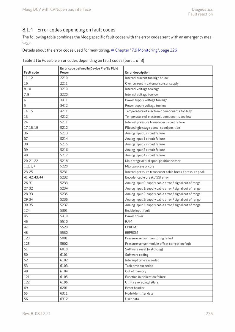
Moog DCV with CANopen bus interface DiagnosticsFault reaction
Rev. B, 08.12.21 276
8.1.4 Error codes depending on fault codesThe following table combines the Moog specific fault codes with the error codes sent with an emergency mes-sage.
Details about the error codes used for monitoring: Chapter "7.9 Monitoring", page 226
Table 116: Possible error codes depending on fault codes (part 1 of 3)
Fault codeError code defined in Device Profile Fluid Power Error description
11, 12 2210 Internal current too high or low16 2211 Over current in external sensor supply8, 10 3210 Internal voltage too high7, 9 3220 Internal voltage too low6 3411 Power supply voltage too high5 3412 Power supply voltage too low14, 15 4211 Temperature of electronic components too high13 4212 Temperature of electronic components too low24 5211 Internal pressure transducer circuit failure17, 18, 19 5212 Pilot/single stage actual spool position36 5213 Analog input 0 circuit failure37 5214 Analog input 1 circuit failure38 5215 Analog input 2 circuit failure39 5216 Analog input 3 circuit failure40 5217 Analog input 4 circuit failure20, 21, 22 5218 Main stage actual spool position sensor1, 2, 3, 4 5220 Microprocessor core23, 25 5231 Internal pressure transducer cable break / pressure peak41, 42, 43, 44 5232 Encoder cable break / SSI error26, 31 5233 Analog input 0: supply cable error / signal out of range 27, 32 5234 Analog input 1: supply cable error / signal out of range 28, 33 5235 Analog input 2: supply cable error / signal out of range 29, 34 5236 Analog input 3: supply cable error / signal out of range 30, 35 5237 Analog input 4: supply cable error / signal out of range 124 5301 Enable input fault45 5410 Power driver46 5510 RAM47 5520 EPROM48 5530 EEPROM120 5801 Pressure sensor monitoring failed125 5802 Pressure sensor module offset correction fault51 6010 Software reset (watchdog)50 6101 Software coding52 6102 Interrupt time exceeded53 6103 Task time exceeded49 6104 Out of memory121 6105 Function initialization failure122 6106 Utility averaging failure69 6201 Event handler55 6311 Node identifier data56 6312 User data
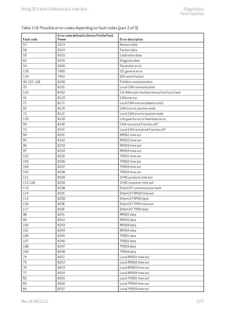
Moog DCV with CANopen bus interface DiagnosticsFault reaction
Rev. B, 08.12.21 277
57 6313 Restore data58 6314 Factory data59 6315 Calibration data60 6316 Diagnosis data54 6320 Parameter error129 7000 I2C general error119 7002 DIP switch failure90, 127, 128 8100 Fieldbus communication70 8101 Local CAN communication123 8102 CiA 408 state machine interaction force fault91 8110 CAN overrun71 8111 Local CAN overrun (objects lost)92 8120 CAN in error passive mode72 8121 Local CAN in error passive mode110 8130 Life guard error or heartbeat error93 8140 CAN recovered from bus off73 8141 Local CAN recovered from bus off94 8231 RPD01 time out95 8232 RPD02 time out96 8233 RPD03 time out97 8234 RPD04 time out102 8235 TPD01 time out103 8236 TPD02 time out104 8237 TPD03 time out105 8238 TPD04 time out111 8239 SYNC producer time out112, 126 823A SYNC consumer time out113 823B EtherCAT communication fault114 823C EtherCAT RPDO time out115 823D EtherCAT RPDO data116 823E EtherCAT TPDO time out117 823F EtherCAT TPDO data98 8241 RPD01 data99 8242 RPD02 data100 8243 RPD03 data101 8244 RPD04 data106 8245 TPD01 data107 8246 TPD02 data108 8247 TPD03 data109 8248 TPD04 data74 8251 Local RPD01 time out75 8252 Local RPD02 time out76 8253 Local RPD03 time out77 8254 Local RPD04 time out82 8255 Local TPD01 time out83 8256 Local TPD02 time out84 8257 Local TPD03 time out
Table 116: Possible error codes depending on fault codes (part 2 of 3)
Fault codeError code defined in Device Profile Fluid Power Error description
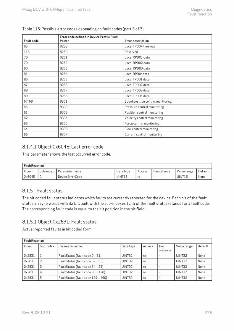
Moog DCV with CANopen bus interface DiagnosticsFault reaction
Rev. B, 08.12.21 278
8.1.4.1 Object 0x604E: Last error codeThis parameter shows the last occurred error code.
8.1.5 Fault statusThe bit coded fault status indicates which faults are currently reported for the device. Each bit of the fault status array (5 words with 32 bit, built with the sub-indexes 1…5 of the fault status) stands for a fault code. The corresponding fault code is equal to the bit position in the bit field.
8.1.5.1 Object 0x2831: Fault statusActual reported faults in bit coded form.
85 8258 Local TPD04 time out118 8260 Reserved78 8261 Local RPD01 data79 8262 Local RPD02 data80 8263 Local RPD03 data81 8264 Local RPD04data86 8265 Local TPD01 data87 8266 Local TPD02 data88 8267 Local TPD03 data89 8268 Local TPD04 data67, 68 8301 Spool position control monitoring65 8302 Pressure control monitoring61 8303 Position control monitoring62 8304 Velocity control monitoring63 8305 Force control monitoring64 8306 Flow control monitoring66 8307 Current control monitoring
Table 116: Possible error codes depending on fault codes (part 3 of 3)
Fault codeError code defined in Device Profile Fluid Power Error description
FaultReactionIndex Sub-index Parameter name Data type Access Persistence Value range Default0x604E 0 DeviceErrorCode UINT16 ro - UINT16 None
FaultReactionIndex Sub-index Parameter name Data type Access Per-
sistenceValue range Default
0x2831 1 FaultStatus (fault code 0…31) UINT32 ro - UINT32 None0x2831 2 FaultStatus (fault code 32…63) UINT32 ro - UINT32 None0x2831 3 FaultStatus (fault code 64…95) UINT32 ro - UINT32 None0x2831 4 FaultStatus (fault code 96…128) UINT32 ro - UINT32 None0x2831 5 FaultStatus (fault code 129…160) UINT32 ro - UINT32 None

Moog DCV with CANopen bus interface DiagnosticsFault reaction
Rev. B, 08.12.21 279
8.1.5.2 Object 0x2834: Fault retain statusAll reported faults in bit coded form since powering on the servo valve.
8.1.6 Error registerThe <ErrorRegister> (0x1001) displays the error information about the last reported fault in bit-coded form. Bit 0 of the <ErrorRegister> (0x1001) is set as soon as an error occurs on the servo valve.
8.1.6.1 Object 0x1001: Error register
This object shall provide error information. The CANopen device maps internal errors into this object. This in-formation is also sent with the emergency object.
Value description
If a specific error occurs, the corresponding bit is set to 1b. The bits are cleared automatically when the error has gone.
FaultReactionIndex Sub-index Parameter name Data type Access Per-
sistenceValue range Default
0x2834 1 FaultRetainStatus (fault code 0…31) UINT32 rw N UINT32 None0x2834 2 FaultRetainStatus (fault code 32…63) UINT32 rw N UINT32 None0x2834 3 FaultRetainStatus (fault code 64…95) UINT32 rw N UINT32 None0x2834 4 FaultRetainStatus (fault code 96…128) UINT32 rw N UINT32 None0x2834 5 FaultRetainStatus (fault code 129…160) UINT32 rw N UINT32 None
The error codes of older faults are stored in the <PredefinedErrorField> (0x1003). Chapter "8.1.7 Last eight fault codes and error codes", page 280
DeviceIndex Sub-index Parameter name Data type Access Persistence Value range Default0x1001 0 ErrorRegister UINT8 ro - UINT8 None
Table 117: Possible values of parameter <ErrorRegister> (0x1001)
<ErrorRegister> DescriptionBit0 Generic error (any error)1 Current error2 Voltage error3 Temperature error4 Communication error5 Reserved6 Reserved7 Reserved
Moog DCV with CANopen bus interface DiagnosticsFault reaction
Rev. B, 08.12.21 280
8.1.7 Last eight fault codes and error codesEvery time, a fault is indicated which trigger a fault reaction, information about the fault is stored to the <StandardErrorField> (0x1003) parameter array. The <StandardErrorField> (0x1003) parameter array con-tains a list of up to 8 entries. This error code provides information about the reason of the error. The parame-ter <NumberOfErrors> (0x1003) holds information about the number of errors currently recorded. Every new error is stored in the first element of the parameter array <StandardErrorField> (0x1003), the older ones move down in the list. If the maximum number of entries is reached and a new fault occurred the oldest fault information will be deleted.
Writing the value 0 to the object <NumberOfErrors> (0x1003), sub-index 0, deletes the entire error code en-tries.
Only the first eight elements of the parameter array <StandardErrorField> (0x1003), sub-index 1…8 are used.
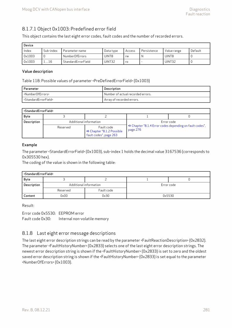
Moog DCV with CANopen bus interface DiagnosticsFault reaction
Rev. B, 08.12.21 281
8.1.7.1 Object 0x1003: Predefined error fieldThis object contains the last eight error codes, fault codes and the number of recorded errors.
Value description
ExampleThe parameter <StandardErrorField> (0x1003), sub-index 1 holds the decimal value 3167536 (corresponds to 0x305530 hex).The coding of the value is shown in the following table:
Result:
8.1.8 Last eight error message descriptionsThe last eight error description strings can be read by the parameter <FaultReactionDescription> (0x2832). The parameter <FaultHistoryNumber> (0x2833) selects one of the last eight error description strings. The newest error description string is shown if the <FaultHistoryNumber> (0x2833) is set to zero and the oldest saved error description string is shown if the <FaultHistoryNumber> (0x2833) is set equal to the parameter <NumberOfErrors> (0x1003).
DeviceIndex Sub-index Parameter name Data type Access Persistence Value range Default0x1003 0 NumberOfErrors UINT8 rw N UINT8 00x1003 1…16 StandardErrorField UINT32 ro - UINT32 0
Table 118: Possible values of parameter <PreDefinedErrorField> (0x1003)
Parameter Description<NumberOfErrors> Number of actual recorded errors.<StandardErrorField> Array of recorded errors.
<StandardErrorField>Byte 3 2 1 0Description Additional information Error code
Chapter "8.1.4 Error codes depending on fault codes", page 276
Reserved Fault code Chapter "8.1.2 Possible fault codes", page 263
<StandardErrorField>Byte 3 2 1 0Description Additional information Error code
Reserved Fault codeContent 0x00 0x30 0x5530
Error code 0x5530:Fault code 0x30:
EEPROM errorInternal non-volatile memory
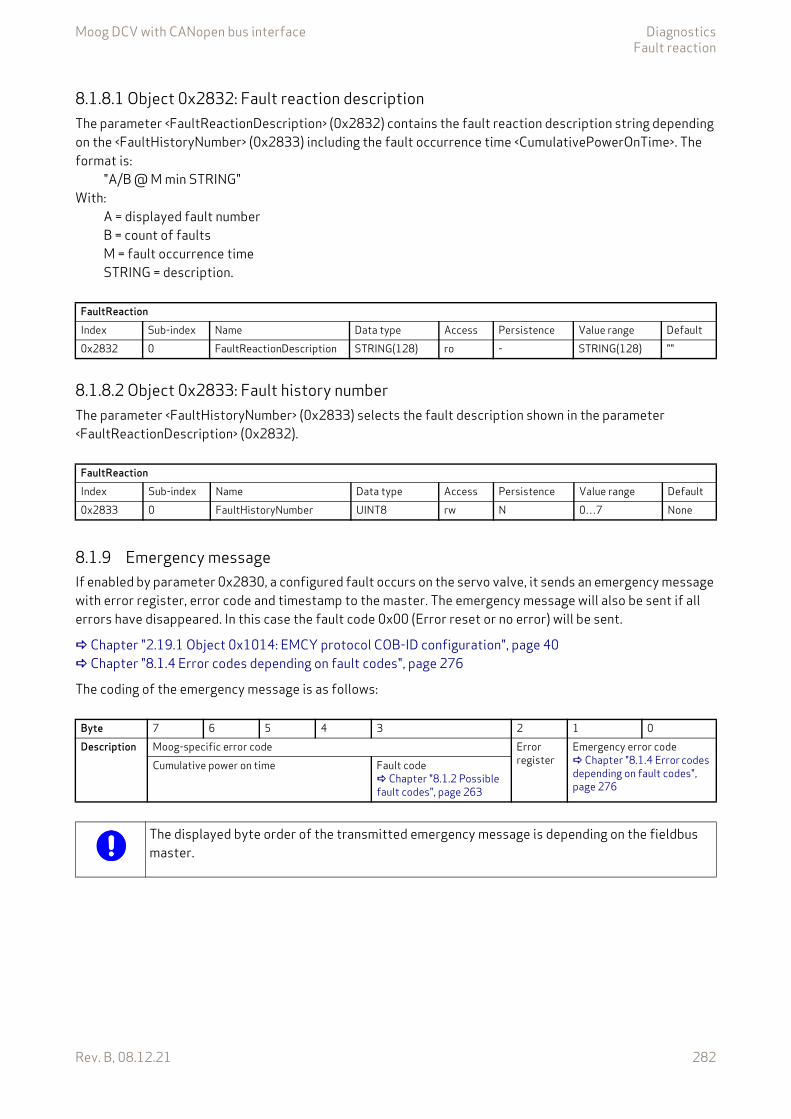
Moog DCV with CANopen bus interface DiagnosticsFault reaction
Rev. B, 08.12.21 282
8.1.8.1 Object 0x2832: Fault reaction descriptionThe parameter <FaultReactionDescription> (0x2832) contains the fault reaction description string depending on the <FaultHistoryNumber> (0x2833) including the fault occurrence time <CumulativePowerOnTime>. The format is:
"A/B @ M min STRING"With:
A = displayed fault numberB = count of faultsM = fault occurrence timeSTRING = description.
8.1.8.2 Object 0x2833: Fault history numberThe parameter <FaultHistoryNumber> (0x2833) selects the fault description shown in the parameter <FaultReactionDescription> (0x2832).
8.1.9 Emergency messageIf enabled by parameter 0x2830, a configured fault occurs on the servo valve, it sends an emergency message with error register, error code and timestamp to the master. The emergency message will also be sent if all errors have disappeared. In this case the fault code 0x00 (Error reset or no error) will be sent.
Chapter "2.19.1 Object 0x1014: EMCY protocol COB-ID configuration", page 40 Chapter "8.1.4 Error codes depending on fault codes", page 276
The coding of the emergency message is as follows:
FaultReactionIndex Sub-index Name Data type Access Persistence Value range Default0x2832 0 FaultReactionDescription STRING(128) ro - STRING(128) ""
FaultReactionIndex Sub-index Name Data type Access Persistence Value range Default0x2833 0 FaultHistoryNumber UINT8 rw N 0…7 None
Byte 7 6 5 4 3 2 1 0Description Moog-specific error code Error
registerEmergency error code Chapter "8.1.4 Error codes depending on fault codes", page 276
Cumulative power on time Fault code Chapter "8.1.2 Possible fault codes", page 263
The displayed byte order of the transmitted emergency message is depending on the fieldbus master.
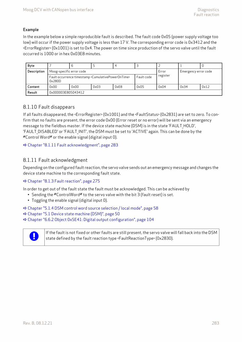
Moog DCV with CANopen bus interface DiagnosticsFault reaction
Rev. B, 08.12.21 283
ExampleIn the example below a simple reproducible fault is described. The fault code 0x05 (power supply voltage too low) will occur if the power supply voltage is less than 17 V. The corresponding error code is 0x3412 and the <ErrorRegister> (0x1001) is set to 0x4. The power on time since production of the servo valve until the fault occurred is 1000 or in hex 0x03E8 minutes.
8.1.10 Fault disappearsIf all faults disappeared, the <ErrorRegister> (0x1001) and the <FaultStatus> (0x2831) are set to zero. To con-firm that no faults are present, the error code 0x00 (Error reset or no error) will be sent via an emergency message to the fieldbus master. If the device state machine (DSM) is in the state 'FAULT_HOLD', 'FAULT_DISABLED' or 'FAULT_INIT', the DSM must be set to 'ACTIVE' again. This can be done by the #Control Word# or the enable signal (digital input 0).
Chapter "8.1.11 Fault acknowledgment", page 283
8.1.11 Fault acknowledgmentDepending on the configured fault reaction, the servo valve sends out an emergency message and changes the device state machine to the corresponding fault state.
Chapter "8.1.3 Fault reaction", page 275
In order to get out of the fault state the fault must be acknowledged. This can be achieved by • Sending the #ControlWord# to the servo valve with the bit 3 (fault reset) is set.• Toggling the enable signal (digital input 0).
Chapter "5.1.4 DSM control word source selection / local mode", page 58 Chapter "5.1 Device state machine (DSM)", page 50 Chapter "6.6.2 Object 0x5E41: Digital output configuration", page 104
Byte 7 6 5 4 3 2 1 0Description Moog-specific error code Error
registerEmergency error code
Fault occurrence timestamp <CumulativePowerOnTime> 0x280D
Fault code
Content 0x00 0x00 0x03 0xE8 0x05 0x04 0x34 0x12Result 0x000003E805043412
If the fault is not fixed or other faults are still present, the servo valve will fall back into the DSM state defined by the fault reaction type <FaultReactionType> (0x2830).
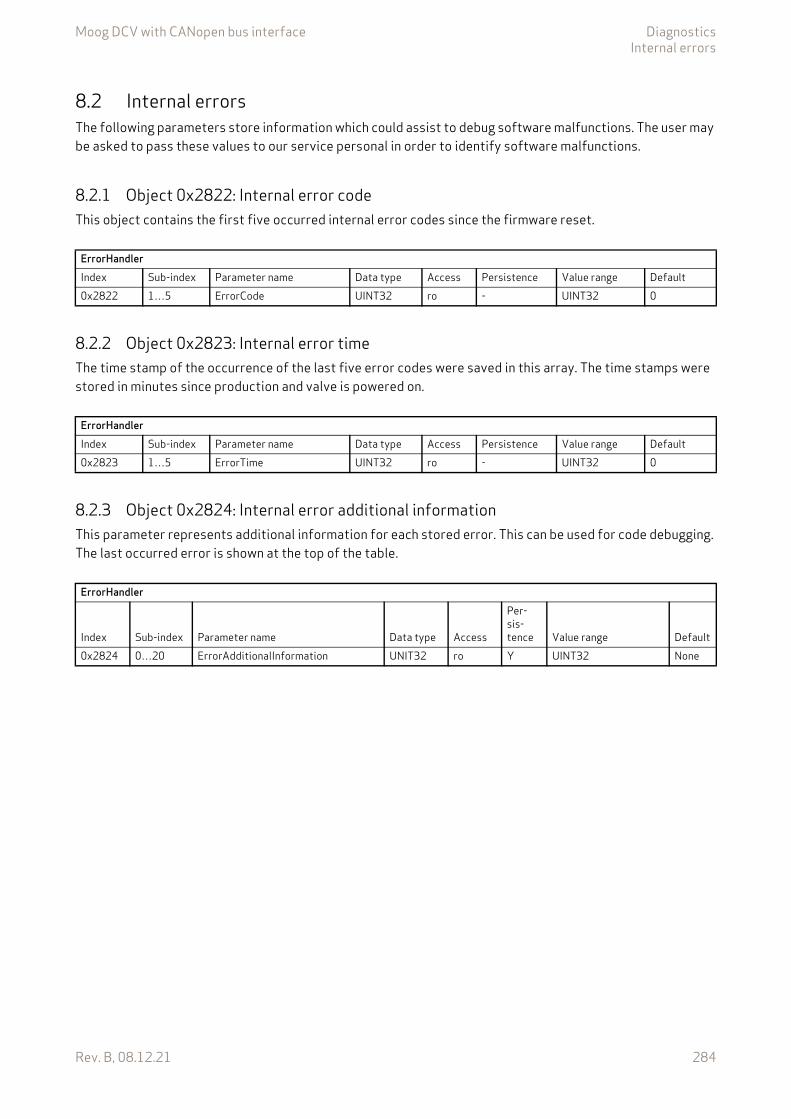
Moog DCV with CANopen bus interface DiagnosticsInternal errors
Rev. B, 08.12.21 284
8.2 Internal errorsThe following parameters store information which could assist to debug software malfunctions. The user may be asked to pass these values to our service personal in order to identify software malfunctions.
8.2.1 Object 0x2822: Internal error codeThis object contains the first five occurred internal error codes since the firmware reset.
8.2.2 Object 0x2823: Internal error timeThe time stamp of the occurrence of the last five error codes were saved in this array. The time stamps were stored in minutes since production and valve is powered on.
8.2.3 Object 0x2824: Internal error additional informationThis parameter represents additional information for each stored error. This can be used for code debugging. The last occurred error is shown at the top of the table.
ErrorHandlerIndex Sub-index Parameter name Data type Access Persistence Value range Default0x2822 1…5 ErrorCode UINT32 ro - UINT32 0
ErrorHandlerIndex Sub-index Parameter name Data type Access Persistence Value range Default0x2823 1…5 ErrorTime UINT32 ro - UINT32 0
ErrorHandler
Index Sub-index Parameter name Data type Access
Per-sis-tence Value range Default
0x2824 0…20 ErrorAdditionalInformation UNIT32 ro Y UINT32 None

Moog DCV with CANopen bus interface DiagnosticsAbort SDO Transfer Protocol
Rev. B, 08.12.21 285
8.3 Abort SDO Transfer ProtocolThe Service Data Object (SDO) is used to transmit / receive parameter values to / from the valve. If the SDO upload or download is not successful, the servo valve will send an Abort SDO Transfer Protocol. The error de-scription is coded in the data bytes.
Table 119: SDO Abort Codes
SDO Abort Code Description0x05030000 Toggle bit not alternated.0x05040000 SDO protocol timeout.0x05040001 Client/server command specifier not valid or unknown.0x05040002 Invalid block size (block mode only).0x05040003 Invalid sequence (block mode only).0x05040004 CRC error (block mode only).0x05040005 Out of memory.0x06010000 Unsupported access to an object.0x06010001 Attempt to read a write only object.0x06010002 Attempt to write a read only object.0x06020000 Object does not exist in the object dictionary.0x06040041 Object cannot be mapped PDO.0x06040042 The number and length of the objects to be mapped would exceed PDO length.0x06040043 General parameter incompatibility reason.0x06040047 General internal incompatibility in the device.0x06060000 Access failed due to hardware error.0x06070010 Data type / length of service data does not match.0x06070012 Data type does not match / length of service data too high.0x06070013 Data type does not match / length of service data too low.0x06090011 Sub index doesn't exist.0x06090030 Value range exceeded / invalid value for parameter (download only). Probably the value range has been ex-
ceeded.0x06090031 Value of parameter written too high (download only).0x06090032 Value of parameter written too low (download only).0x06090036 Maximum value is less than minimum value.0x060A0023 Resource not available: SDO connection0x08000000 General error.0x08000020 Data cannot be transferred or stored to the application.0x08000021 Data cannot be transferred or stored to the application because of local control.0x08000022 Data cannot be transferred or stored to the application because of the present device state.0x08000023 Object dictionary dynamic generation fails or no object dictionary is present.0x08000024 No data available.
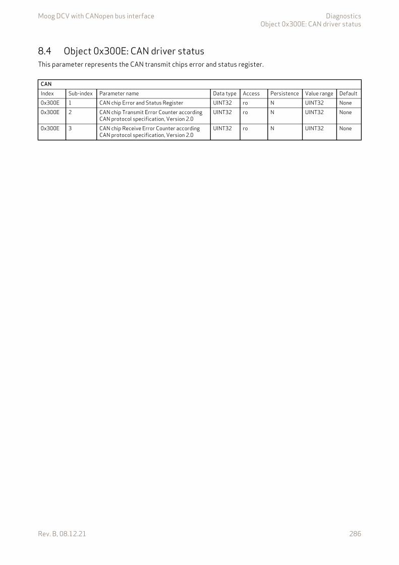
Moog DCV with CANopen bus interface DiagnosticsObject 0x300E: CAN driver status
Rev. B, 08.12.21 286
8.4 Object 0x300E: CAN driver statusThis parameter represents the CAN transmit chips error and status register.
CANIndex Sub-index Parameter name Data type Access Persistence Value range Default0x300E 1 CAN chip Error and Status Register UINT32 ro N UINT32 None0x300E 2 CAN chip Transmit Error Counter according
CAN protocol specification, Version 2.0UINT32 ro N UINT32 None
0x300E 3 CAN chip Receive Error Counter according CAN protocol specification, Version 2.0
UINT32 ro N UINT32 None
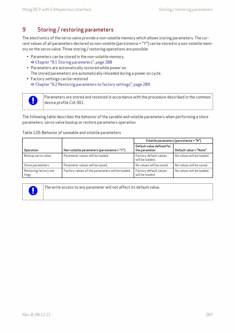
Moog DCV with CANopen bus interface Storing / restoring parameters
Rev. B, 08.12.21 287
9 Storing / restoring parametersThe electronics of the servo valve provide a non-volatile memory which allows storing parameters. The cur-rent values of all parameters declared as non-volatile (persistence = "Y") can be stored in a non-volatile mem-ory on the servo valve. Three storing / restoring operations are possible:
• Parameters can be stored in the non-volatile memory. Chapter "9.1 Storing parameters", page 288
• Parameters are automatically restored while power on. The stored parameters are automatically reloaded during a power on cycle.
• Factory settings can be restored Chapter "9.2 Restoring parameters to factory settings", page 289
The following table describes the behavior of the savable and volatile parameters when performing a store parameters, servo valve bootup or restore parameters operation.
Parameters are stored and restored in accordance with the procedure described in the common device profile CiA 301.
Table 120: Behavior of saveable and volatile parameters
Operation Non-volatile parameters (persistence = "Y")
Volatile parameters (persistence = "N")Default value defined for the parameter Default value = "None"
Bootup servo valve Parameter values will be loaded. Factory default values will be loaded.
No values will be loaded.
Store parameters Parameter values will be saved. No values will be saved. No values will be saved.Restoring factory set-tings
Factory values of the parameters will be loaded. Factory default values will be loaded.
No values will be loaded.
The write access to any parameter will not affect its default value.
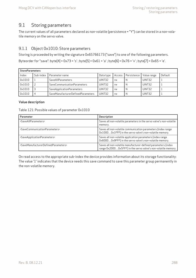
Moog DCV with CANopen bus interface Storing / restoring parametersStoring parameters
Rev. B, 08.12.21 288
9.1 Storing parametersThe current values of all parameters declared as non-volatile (persistence = "Y") can be stored in a non-vola-tile memory on the servo valve.
9.1.1 Object 0x1010: Store parametersStoring is proceeded by writing the signature 0x65766173 ("save") to one of the following parameters.
Byteorder for "save": byte[4] = 0x73 = 's' ; byte[5] = 0x61 = 'a' ; byte[6] = 0x76 = 'v' ; byte[7] = 0x65 = 'e'.
Value description
On read access to the appropriate sub-index the device provides information about its storage functionality: The value '1' indicates that the device needs this save command to save this parameter group permanently in the non-volatile memory.
StoreParametersIndex Sub-index Parameter name Data type Access Persistence Value range Default0x1010 1 SaveAllParameters UINT32 rw N UINT32 10x1010 2 SaveCommunicationParameters UINT32 rw N UINT32 10x1010 3 SaveApplicationParameters UINT32 rw N UINT32 10x1010 4 SaveManufacturerDefinedParameters UINT32 rw N UINT32 1
Table 121: Possible values of parameter 0x1010
Parameter Description<SaveAllParameters> Saves all non-volatile parameters in the servo valve's non-volatile
memory.<SaveCommunicationParameters> Saves all non-volatile communication parameters (index range
0x1000…0x1FFF) in the servo valve's non-volatile memory.<SaveApplicationParameters> Saves all non-volatile application parameters (index range
0x6000…0x9FFF) in the servo valve's non-volatile memory.<SaveManufacturerDefinedParameters> Saves all non-volatile manufacturer-defined parameters (index
range 0x2000…0x5FFF) in the servo valve's non-volatile memory.
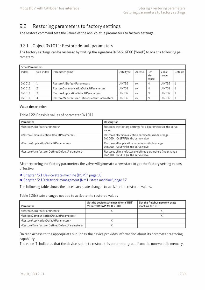
Moog DCV with CANopen bus interface Storing / restoring parametersRestoring parameters to factory settings
Rev. B, 08.12.21 289
9.2 Restoring parameters to factory settingsThe restore command sets the values of the non-volatile parameters to factory settings.
9.2.1 Object 0x1011: Restore default parametersThe factory settings can be restored by writing the signature 0x64616F6C ("load") to one the following pa-rameters.
Value description
After restoring the factory parameters the valve will generate a new start to get the factory setting values effective.
Chapter "5.1 Device state machine (DSM)", page 50 Chapter "2.10 Network management (NMT) state machine", page 17
The following table shows the necessary state changes to activate the restored values.
On read access to the appropriate sub-index the device provides information about its parameter restoring capability: The value '1' indicates that the device is able to restore this parameter group from the non-volatile memory.
StoreParametersIndex Sub-index Parameter name Data type Access Per-
sis-tence
Value range
Default
0x1011 1 RestoreAllDefaultParameters UINT32 rw N UINT32 10x1011 2 RestoreCommunicationDefaultParameters UINT32 rw N UINT32 10x1011 3 RestoreApplicationDefaultParameters UINT32 rw N UINT32 10x1011 4 RestoreManufacturerDefinedDefaultParameters UINT32 rw N UINT32 1
Table 122: Possible values of parameter 0x1011
Parameter Description<RestoreAllDefaultParameters> Restores the factory settings for all parameters in the servo
valve.<RestoreCommunicationDefaultParameters> Restores all communication parameters (index range
0x1000…0x1FFF) in the servo valve.<RestoreApplicationDefaultParameters> Restores all application parameters (index range
0x6000…0x9FFF) in the servo valve.<RestoreManufacturerDefinedDefaultParameters> Restores all manufacturer-defined parameters (index range
0x2000…0x5FFF) in the servo valve.
Table 123: State changes needed to activate the restored values
ParameterSet the device state machine to 'INIT'#ControlWord# MHD = 000
Set the fieldbus network state machine to 'INIT'
<RestoreAllDefaultParameters> X X<RestoreCommunicationDefaultParameters> X<RestoreApplicationDefaultParameters> X<RestoreManufacturerDefinedDefaultParameters> X
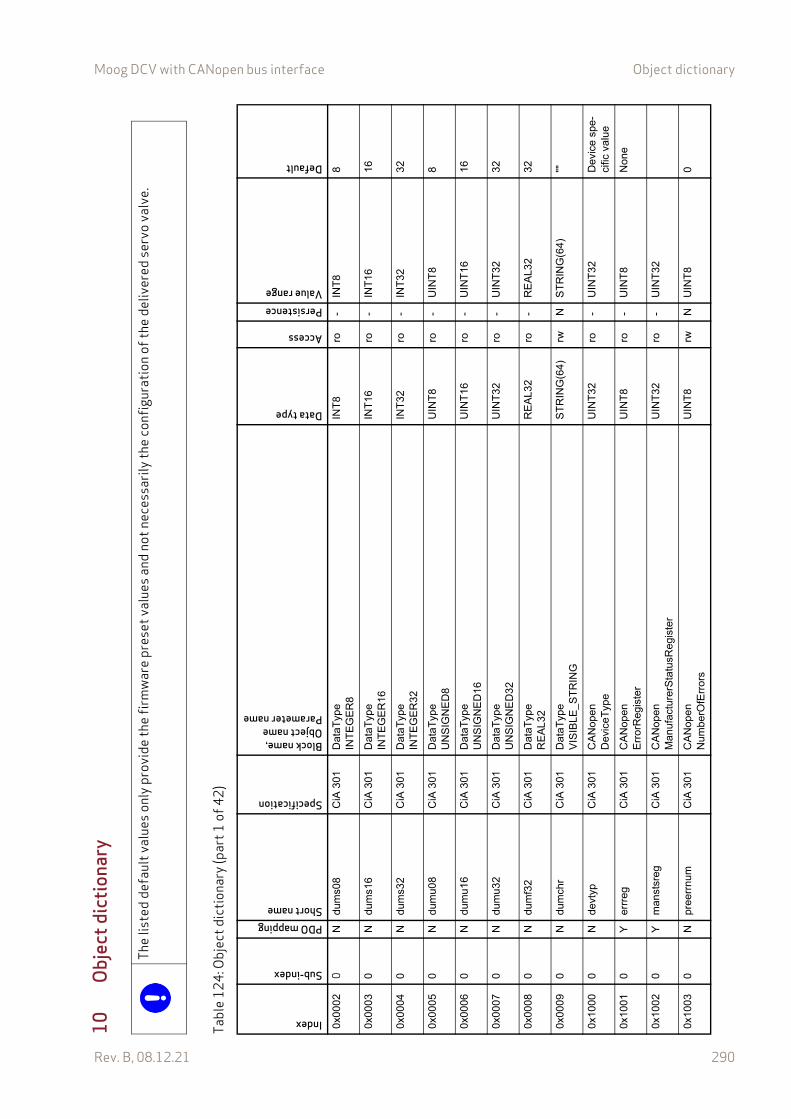
Moog DCV with CANopen bus interface Object dictionary
Rev. B, 08.12.21 290
10 O
bjec
t dic
tiona
ry
The
liste
d de
faul
t val
ues o
nly p
rovi
de th
e fir
mw
are
pres
et va
lues
and
not
nec
essa
rily t
he co
nfig
urat
ion
of th
e de
liver
ed se
rvo
valv
e.
Tabl
e12
4: O
bjec
t dic
tiona
ry (p
art1
of42
)
Index
Sub-index
PDO mappingShort name
Specification
Block name,Object nameParameter name
Data type
Access
PersistenceValue range
Default
0x00
020
Ndu
ms0
8C
iA 3
01D
ataT
ype
INT
EG
ER
8IN
T8
ro-
INT
88
0x00
030
Ndu
ms1
6C
iA 3
01D
ataT
ype
INT
EG
ER
16IN
T16
ro-
INT
1616
0x00
040
Ndu
ms3
2C
iA 3
01D
ataT
ype
INT
EG
ER
32IN
T32
ro-
INT
3232
0x00
050
Ndu
mu0
8C
iA 3
01D
ataT
ype
UN
SIG
NE
D8
UIN
T8
ro-
UIN
T8
8
0x00
060
Ndu
mu1
6C
iA 3
01D
ataT
ype
UN
SIG
NE
D16
UIN
T16
ro-
UIN
T16
16
0x00
070
Ndu
mu3
2C
iA 3
01D
ataT
ype
UN
SIG
NE
D32
UIN
T32
ro-
UIN
T32
32
0x00
080
Ndu
mf3
2C
iA 3
01D
ataT
ype
RE
AL
32R
EA
L32
ro-
RE
AL3
232
0x00
090
Ndu
mch
rC
iA 3
01D
ataT
ype
VIS
IBLE
_ST
RIN
GS
TR
ING
(64)
rwN
ST
RIN
G(6
4)""
0x10
000
Nde
vtyp
CiA
301
CA
Nop
enD
evic
eTyp
eU
INT
32ro
-U
INT
32D
evic
e sp
e-ci
fic v
alu
e
0x10
010
Yer
rreg
CiA
301
CA
Nop
enE
rror
Reg
iste
rU
INT
8ro
-U
INT
8N
one
0x10
020
Ym
anst
sreg
CiA
301
CA
Nop
enM
anu
fact
urer
Sta
tusR
egis
ter
UIN
T32
ro-
UIN
T32
0x10
030
Npr
eerr
num
CiA
301
CA
Nop
enN
umbe
rOfE
rror
sU
INT
8rw
NU
INT
80
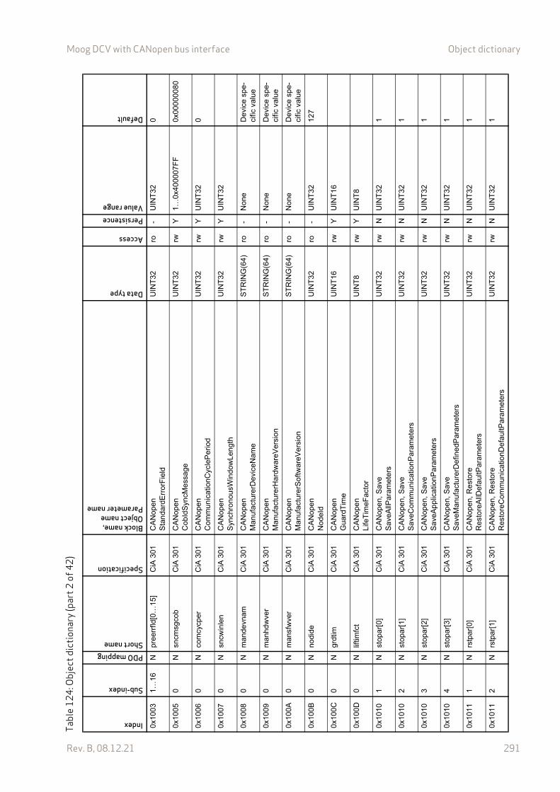
Moog DCV with CANopen bus interface Object dictionary
Rev. B, 08.12.21 291
0x10
031…
16N
pree
rrfld
[0…
15]
CiA
301
CA
Nop
enS
tan
dard
Err
orF
ield
UIN
T32
ro-
UIN
T32
0
0x10
050
Nsn
cmsg
cob
CiA
301
CA
Nop
enC
obId
Syn
cMes
sage
UIN
T32
rwY
1…0x
4000
07F
F0x
0000
0080
0x10
060
Nco
mcy
cper
CiA
301
CA
Nop
enC
omm
unic
atio
nCyc
leP
erio
dU
INT
32rw
YU
INT
320
0x10
070
Nsn
cwin
len
CiA
301
CA
Nop
enS
ynch
rono
usW
indo
wLe
ngth
UIN
T32
rwY
UIN
T32
0x10
080
Nm
ande
vnam
CiA
301
CA
Nop
enM
anu
fact
urer
Dev
iceN
ame
ST
RIN
G(6
4)ro
-N
one
Dev
ice
spe-
cific
va
lue
0x10
090
Nm
anhd
wve
rC
iA 3
01C
AN
open
Ma
nufa
ctur
erH
ardw
areV
ersi
onS
TR
ING
(64)
ro-
Non
eD
evic
e sp
e-ci
fic v
alu
e
0x10
0A0
Nm
ansf
wve
rC
iA 3
01C
AN
open
Ma
nufa
ctur
erS
oftw
areV
ersi
onS
TR
ING
(64)
ro-
Non
eD
evic
e sp
e-ci
fic v
alu
e
0x10
0B0
Nno
dide
CiA
301
CA
Nop
enN
odeI
dU
INT
32ro
-U
INT
3212
7
0x10
0C0
Ngr
dtim
CiA
301
CA
Nop
enG
uard
Tim
eU
INT
16rw
YU
INT
16
0x10
0D0
Nlif
timfc
tC
iA 3
01C
AN
open
Life
Tim
eFac
tor
UIN
T8
rwY
UIN
T8
0x10
101
Nst
opar
[0]
CiA
301
CA
Nop
en, S
ave
Sav
eAllP
aram
eter
sU
INT
32rw
NU
INT
321
0x10
102
Nst
opar
[1]
CiA
301
CA
Nop
en, S
ave
Sav
eCom
mu
nica
tionP
aram
ete
rsU
INT
32rw
NU
INT
321
0x10
103
Nst
opar
[2]
CiA
301
CA
Nop
en, S
ave
Sav
eApp
licat
ionP
aram
ete
rsU
INT
32rw
NU
INT
321
0x10
104
Nst
opar
[3]
CiA
301
CA
Nop
en, S
ave
Sav
eMan
ufac
ture
rDe
fined
Par
amet
ers
UIN
T32
rwN
UIN
T32
1
0x10
111
Nrs
tpar
[0]
CiA
301
CA
Nop
en, R
est
ore
Res
tore
AllD
efa
ultP
aram
eter
sU
INT
32rw
NU
INT
321
0x10
112
Nrs
tpar
[1]
CiA
301
CA
Nop
en, R
est
ore
Res
tore
Com
mun
icat
ionD
efau
ltPar
amet
ers
UIN
T32
rwN
UIN
T32
1
Tabl
e12
4: O
bjec
t dic
tiona
ry (p
art2
of42
)Index
Sub-index
PDO mappingShort name
Specification
Block name,Object nameParameter name
Data type
Access
PersistenceValue range
Default
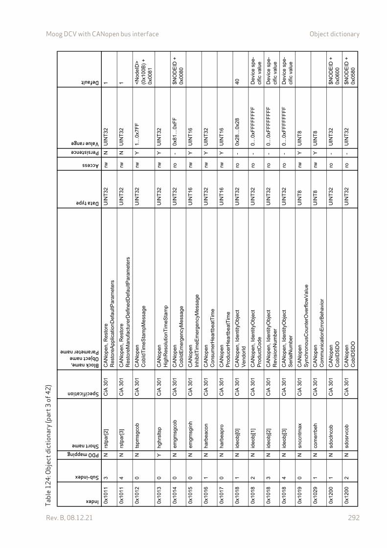
Moog DCV with CANopen bus interface Object dictionary
Rev. B, 08.12.21 292
0x10
113
Nrs
tpar
[2]
CiA
301
CA
Nop
en, R
est
ore
Res
tore
App
licat
ionD
efau
ltPar
ame
ters
UIN
T32
rwN
UIN
T32
1
0x10
114
Nrs
tpar
[3]
CiA
301
CA
Nop
en, R
est
ore
Res
tore
Man
ufac
ture
rDef
ined
Def
aultP
aram
eter
sU
INT
32rw
NU
INT
321
0x10
120
Nts
pmsg
cob
CiA
301
CA
Nop
enC
obId
Tim
eSta
mpM
essa
geU
INT
32rw
Y1…
0x7F
F<
Nod
eID
>
(0x1
00B
) +
0x
0081
0x10
130
Yhg
hrsl
tsp
CiA
301
CA
Nop
enH
ighR
esol
utio
nTim
eSta
mp
UIN
T32
rwY
UIN
T32
0x10
140
Nem
gmsg
cob
CiA
301
CA
Nop
enC
obId
Em
erge
ncyM
essa
geU
INT
32ro
-0x
81…
0xF
F$N
OD
EID
+
0x00
80
0x10
150
Nem
gmsg
inh
CiA
301
CA
Nop
enIn
hibi
tTim
eEm
erg
ency
Mes
sage
UIN
T16
rwY
UIN
T16
0x10
161
Nha
rbea
con
CiA
301
CA
Nop
enC
onsu
mer
Hea
rtbe
atT
ime
UIN
T32
rwY
UIN
T32
0x10
170
Nha
rbea
pro
CiA
301
CA
Nop
enP
rodu
cerH
eart
beat
Tim
eU
INT
16rw
YU
INT
16
0x10
181
Nid
eobj
[0]
CiA
301
CA
Nop
en, I
den
tityO
bjec
tV
endo
rId
UIN
T32
ro-
0x28
…0x
2840
0x10
182
Nid
eobj
[1]
CiA
301
CA
Nop
en, I
den
tityO
bjec
tP
rodu
ctC
ode
UIN
T32
ro-
0…0x
FF
FF
FF
FF
Dev
ice
spe-
cific
va
lue
0x10
183
Nid
eobj
[2]
CiA
301
CA
Nop
en, I
den
tityO
bjec
tR
evis
ionN
umbe
rU
INT
32ro
-0…
0xF
FF
FF
FF
FD
evic
e sp
e-ci
fic v
alu
e
0x10
184
Nid
eobj
[3]
CiA
301
CA
Nop
en, I
den
tityO
bjec
tS
eria
lNum
ber
UIN
T32
ro-
0…0x
FF
FF
FF
FF
Dev
ice
spe-
cific
va
lue
0x10
190
Nsn
ccnt
max
CiA
301
CA
Nop
enS
ynch
rono
usC
ount
erO
verf
low
Val
ueU
INT
8rw
YU
INT
8
0x10
291
Nco
mer
rbeh
CiA
301
CA
Nop
enC
omm
unic
atio
nErr
orB
ehav
ior
UIN
T8
rwY
UIN
T8
0x12
001
Nsd
ocln
cob
CiA
301
CA
Nop
enC
obID
SD
OU
INT
32ro
-U
INT
32$N
OD
EID
+0x
0600
0x12
002
Nsd
osrv
cob
CiA
301
CA
Nop
enC
obID
SD
OU
INT
32ro
-U
INT
32$N
OD
EID
+0x
0580
Tabl
e12
4: O
bjec
t dic
tiona
ry (p
art3
of42
)Index
Sub-index
PDO mappingShort name
Specification
Block name,Object nameParameter name
Data type
Access
PersistenceValue range
Default
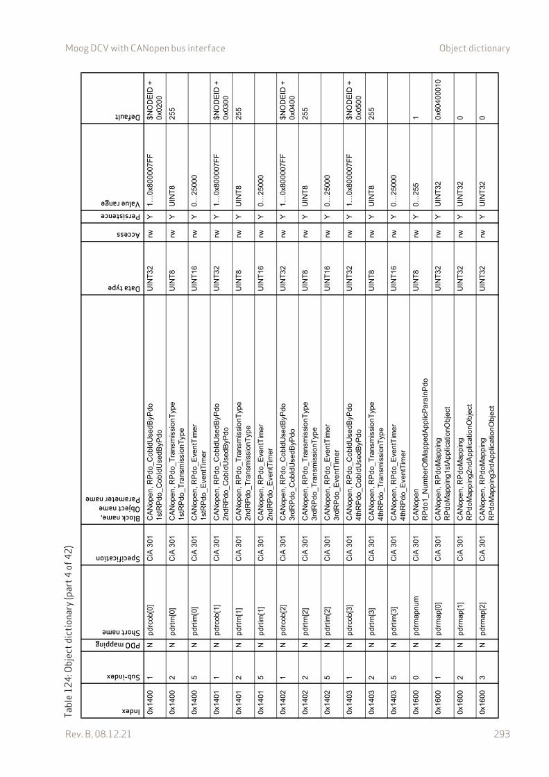
Moog DCV with CANopen bus interface Object dictionary
Rev. B, 08.12.21 293
0x14
001
Npd
rcob
[0]
CiA
301
CA
Nop
en, R
Pdo
_Cob
IdU
sedB
yPdo
1st
RP
do_C
obId
Use
dByP
doU
INT
32rw
Y1…
0x80
0007
FF
$NO
DE
ID +
0x02
00
0x14
002
Npd
rtrn
[0]
CiA
301
CA
Nop
en, R
Pdo
_Tra
nsm
issi
onT
ype
1st
RP
do_T
rans
mis
sion
Typ
eU
INT
8rw
YU
INT
825
5
0x14
005
Npd
rtim
[0]
CiA
301
CA
Nop
en, R
Pdo
_Eve
ntT
ime
r1
stR
Pdo
_Eve
ntT
imer
UIN
T16
rwY
0…25
000
0x14
011
Npd
rcob
[1]
CiA
301
CA
Nop
en, R
Pdo
_Cob
IdU
sedB
yPdo
2nd
RP
do_C
obId
Use
dByP
doU
INT
32rw
Y1…
0x80
0007
FF
$NO
DE
ID +
0x03
00
0x14
012
Npd
rtrn
[1]
CiA
301
CA
Nop
en, R
Pdo
_Tra
nsm
issi
onT
ype
2nd
RP
do_T
rans
mis
sion
Typ
eU
INT
8rw
YU
INT
825
5
0x14
015
Npd
rtim
[1]
CiA
301
CA
Nop
en, R
Pdo
_Eve
ntT
ime
r2
ndR
Pdo
_Eve
ntT
imer
UIN
T16
rwY
0…25
000
0x14
021
Npd
rcob
[2]
CiA
301
CA
Nop
en, R
Pdo
_Cob
IdU
sedB
yPdo
3rd
RP
do_C
obId
Use
dByP
do
UIN
T32
rwY
1…0x
8000
07F
F$N
OD
EID
+
0x04
00
0x14
022
Npd
rtrn
[2]
CiA
301
CA
Nop
en, R
Pdo
_Tra
nsm
issi
onT
ype
3rd
RP
do_T
rans
mis
sio
nTyp
eU
INT
8rw
YU
INT
825
5
0x14
025
Npd
rtim
[2]
CiA
301
CA
Nop
en, R
Pdo
_Eve
ntT
ime
r3
rdR
Pdo
_Eve
ntT
imer
UIN
T16
rwY
0…25
000
0x14
031
Npd
rcob
[3]
CiA
301
CA
Nop
en, R
Pdo
_Cob
IdU
sedB
yPdo
4th
RP
do_C
obId
Use
dByP
doU
INT
32rw
Y1…
0x80
0007
FF
$NO
DE
ID +
0x
0500
0x14
032
Npd
rtrn
[3]
CiA
301
CA
Nop
en, R
Pdo
_Tra
nsm
issi
onT
ype
4th
RP
do_T
rans
mis
sion
Typ
eU
INT
8rw
YU
INT
825
5
0x14
035
Npd
rtim
[3]
CiA
301
CA
Nop
en, R
Pdo
_Eve
ntT
ime
r4
thR
Pdo
_Eve
ntT
imer
UIN
T16
rwY
0…25
000
0x16
000
Npd
rmap
num
CiA
301
CA
Nop
enR
Pdo
1_N
umbe
rOfM
appe
dApp
licP
araI
nP
do
UIN
T8
rwY
0…25
51
0x16
001
Npd
rmap
[0]
CiA
301
CA
Nop
en, R
Pdo
Map
pin
gR
Pdo
Map
ping
1stA
ppl
ica
tionO
bjec
tU
INT
32rw
YU
INT
320x
6040
0010
0x16
002
Npd
rmap
[1]
CiA
301
CA
Nop
en, R
Pdo
Map
pin
gR
Pdo
Map
ping
2ndA
pplic
atio
nObj
ect
UIN
T32
rwY
UIN
T32
0
0x16
003
Npd
rmap
[2]
CiA
301
CA
Nop
en, R
Pdo
Map
pin
gR
Pdo
Map
ping
3rdA
pplic
atio
nObj
ect
UIN
T32
rwY
UIN
T32
0
Tabl
e12
4: O
bjec
t dic
tiona
ry (p
art4
of42
)Index
Sub-index
PDO mappingShort name
Specification
Block name,Object nameParameter name
Data type
Access
PersistenceValue range
Default
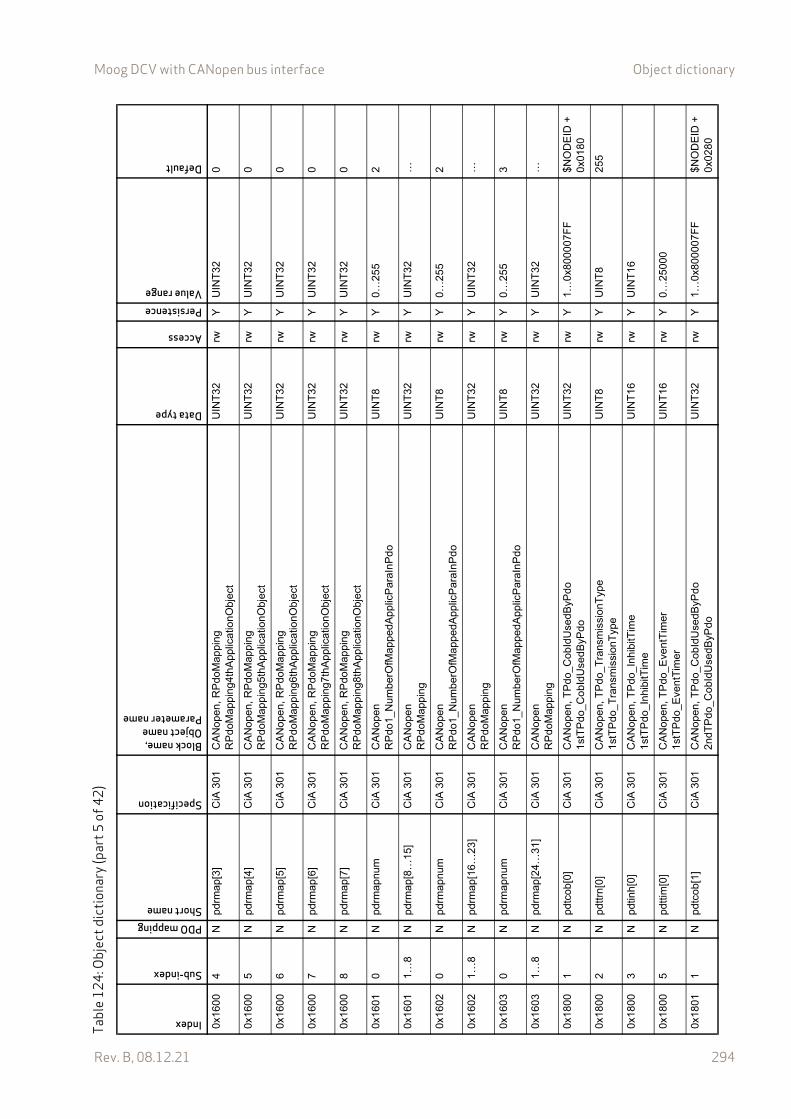
Moog DCV with CANopen bus interface Object dictionary
Rev. B, 08.12.21 294
0x16
004
Npd
rmap
[3]
CiA
301
CA
Nop
en, R
Pdo
Map
pin
gR
Pdo
Map
ping
4thA
pplic
atio
nObj
ect
UIN
T32
rwY
UIN
T32
0
0x16
005
Npd
rmap
[4]
CiA
301
CA
Nop
en, R
Pdo
Map
pin
gR
Pdo
Map
ping
5thA
pplic
atio
nObj
ect
UIN
T32
rwY
UIN
T32
0
0x16
006
Npd
rmap
[5]
CiA
301
CA
Nop
en, R
Pdo
Map
pin
gR
Pdo
Map
ping
6thA
pplic
atio
nObj
ect
UIN
T32
rwY
UIN
T32
0
0x16
007
Npd
rmap
[6]
CiA
301
CA
Nop
en, R
Pdo
Map
pin
gR
Pdo
Map
ping
7thA
pplic
atio
nObj
ect
UIN
T32
rwY
UIN
T32
0
0x16
008
Npd
rmap
[7]
CiA
301
CA
Nop
en, R
Pdo
Map
pin
gR
Pdo
Map
ping
8thA
pplic
atio
nObj
ect
UIN
T32
rwY
UIN
T32
0
0x16
010
Npd
rmap
num
CiA
301
CA
Nop
enR
Pdo
1_N
umbe
rOfM
appe
dApp
licP
araI
nP
do
UIN
T8
rwY
0…25
52
0x16
011…
8N
pdrm
ap[8
…15
]C
iA 3
01C
AN
open
RP
doM
appi
ngU
INT
32rw
YU
INT
32…
0x16
020
Npd
rmap
num
CiA
301
CA
Nop
enR
Pdo
1_N
umbe
rOfM
appe
dApp
licP
araI
nP
do
UIN
T8
rwY
0…25
52
0x16
021…
8N
pdrm
ap[1
6…23
]C
iA 3
01C
AN
open
RP
doM
appi
ngU
INT
32rw
YU
INT
32…
0x16
030
Npd
rmap
num
CiA
301
CA
Nop
enR
Pdo
1_N
umbe
rOfM
appe
dApp
licP
araI
nP
do
UIN
T8
rwY
0…25
53
0x16
031…
8N
pdrm
ap[2
4…31
]C
iA 3
01C
AN
open
RP
doM
appi
ngU
INT
32rw
YU
INT
32…
0x18
001
Npd
tcob
[0]
CiA
301
CA
Nop
en, T
Pdo
_Cob
IdU
sedB
yPdo
1st
TP
do_C
obId
Use
dByP
doU
INT
32rw
Y1…
0x80
0007
FF
$NO
DE
ID +
0x
0180
0x18
002
Npd
ttrn[
0]C
iA 3
01C
AN
open
, TP
do_T
rans
mis
sion
Typ
e1
stT
Pdo
_Tra
nsm
issi
onT
ype
UIN
T8
rwY
UIN
T8
255
0x18
003
Npd
tinh[
0]C
iA 3
01C
AN
open
, TP
do_I
nhib
itTim
e1
stT
Pdo
_Inh
ibitT
ime
UIN
T16
rwY
UIN
T16
0x18
005
Npd
ttim
[0]
CiA
301
CA
Nop
en, T
Pdo
_Eve
ntT
imer
1st
TP
do_E
ven
tTim
erU
INT
16rw
Y0…
2500
0
0x18
011
Npd
tcob
[1]
CiA
301
CA
Nop
en, T
Pdo
_Cob
IdU
sedB
yPdo
2nd
TP
do_C
obId
Use
dByP
doU
INT
32rw
Y1…
0x80
0007
FF
$NO
DE
ID +
0x
0280
Tabl
e12
4: O
bjec
t dic
tiona
ry (p
art5
of42
)Index
Sub-index
PDO mappingShort name
Specification
Block name,Object nameParameter name
Data type
Access
PersistenceValue range
Default
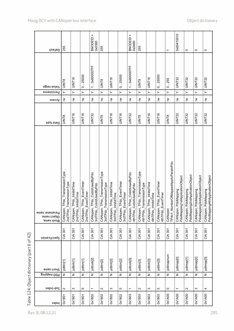
Moog DCV with CANopen bus interface Object dictionary
Rev. B, 08.12.21 295
0x18
012
Npd
ttrn[
1]C
iA 3
01C
AN
open
, TP
do_T
rans
mis
sion
Typ
e2
ndT
Pdo
_Tra
nsm
issi
onT
ype
UIN
T8
rwY
UIN
T8
255
0x18
013
Npd
tinh[
1]C
iA 3
01C
AN
open
, TP
do_I
nhib
itTim
e2
ndT
Pdo
_Inh
ibitT
ime
UIN
T16
rwY
UIN
T16
0x18
015
Npd
ttim
[1]
CiA
301
CA
Nop
en, T
Pdo
_Eve
ntT
imer
2nd
TP
do_E
vent
Tim
erU
INT
16rw
Y0…
2500
0
0x18
021
Npd
tcob
[2]
CiA
301
CA
Nop
en, T
Pdo
_Cob
IdU
sedB
yPdo
3rd
TP
do_C
obId
Use
dByP
doU
INT
32rw
Y1…
0x80
0007
FF
$NO
DE
ID +
0x
0380
0x18
022
Npd
ttrn[
2]C
iA 3
01C
AN
open
, TP
do_T
rans
mis
sion
Typ
e3
rdT
Pdo
_Tra
nsm
issi
onT
ype
UIN
T8
rwY
UIN
T8
255
0x18
023
Npd
tinh[
2]C
iA 3
01C
AN
open
, TP
do_I
nhib
itTim
e3
rdT
Pdo
_Inh
ibitT
ime
UIN
T16
rwY
UIN
T16
0x18
025
Npd
ttim
[2]
CiA
301
CA
Nop
en, T
Pdo
_Eve
ntT
imer
3rd
TP
do_E
vent
Tim
erU
INT
16rw
Y0…
2500
0
0x18
031
Npd
tcob
[3]
CiA
301
CA
Nop
en, T
Pdo
_Cob
IdU
sedB
yPdo
4th
TP
do_C
obId
Use
dByP
doU
INT
32rw
Y1…
0x80
0007
FF
$NO
DE
ID +
0x
0480
0x18
032
Npd
ttrn[
3]C
iA 3
01C
AN
open
, TP
do_T
rans
mis
sion
Typ
e4
thT
Pdo
_Tra
nsm
issi
onT
ype
UIN
T8
rwY
UIN
T8
255
0x18
033
Npd
tinh[
3]C
iA 3
01C
AN
open
, TP
do_I
nhib
itTim
e4
thT
Pdo
_Inh
ibitT
ime
UIN
T16
rwY
UIN
T16
0x18
035
Npd
ttim
[3]
CiA
301
CA
Nop
en, T
Pdo
_Eve
ntT
imer
4th
TP
do_E
vent
Tim
erU
INT
16rw
Y0…
2500
0
0x1A
000
Npd
tmap
num
CiA
301
CA
Nop
enT
Pdo
1_N
umb
erO
fMap
pedA
pplic
Par
aIn
Pdo
UIN
T8
rwY
0…25
51
0x1A
001
Npd
tmap
[0]
CiA
301
CA
Nop
en, P
doM
appi
ngP
doM
appi
ng1
stA
pplic
atio
nObj
ect
UIN
T32
rwY
UIN
T32
0x60
4100
10
0x1A
002
Npd
tmap
[1]
CiA
301
CA
Nop
en, P
doM
appi
ngP
doM
appi
ng2
ndA
pplic
atio
nObj
ect
UIN
T32
rwY
UIN
T32
0
0x1A
003
Npd
tmap
[2]
CiA
301
CA
Nop
en, P
doM
appi
ngP
doM
appi
ng3
rdA
pplic
atio
nObj
ect
UIN
T32
rwY
UIN
T32
0
0x1A
004
Npd
tmap
[3]
CiA
301
CA
Nop
en, P
doM
appi
ngP
doM
appi
ng4
thA
pplic
atio
nObj
ect
UIN
T32
rwY
UIN
T32
0
Tabl
e12
4: O
bjec
t dic
tiona
ry (p
art6
of42
)Index
Sub-index
PDO mappingShort name
Specification
Block name,Object nameParameter name
Data type
Access
PersistenceValue range
Default
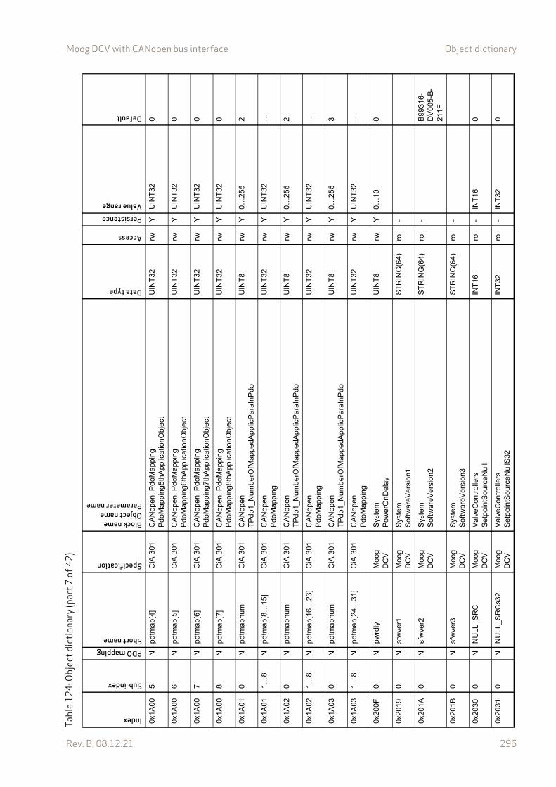
Moog DCV with CANopen bus interface Object dictionary
Rev. B, 08.12.21 296
0x1A
005
Npd
tmap
[4]
CiA
301
CA
Nop
en, P
doM
appi
ngP
doM
appi
ng5
thA
pplic
atio
nObj
ect
UIN
T32
rwY
UIN
T32
0
0x1A
006
Npd
tmap
[5]
CiA
301
CA
Nop
en, P
doM
appi
ngP
doM
appi
ng6
thA
pplic
atio
nObj
ect
UIN
T32
rwY
UIN
T32
0
0x1A
007
Npd
tmap
[6]
CiA
301
CA
Nop
en, P
doM
appi
ngP
doM
appi
ng7
thA
pplic
atio
nObj
ect
UIN
T32
rwY
UIN
T32
0
0x1A
008
Npd
tmap
[7]
CiA
301
CA
Nop
en, P
doM
appi
ngP
doM
appi
ng8
thA
pplic
atio
nObj
ect
UIN
T32
rwY
UIN
T32
0
0x1A
010
Npd
tmap
num
CiA
301
CA
Nop
enT
Pdo
1_N
umb
erO
fMap
pedA
pplic
Par
aIn
Pdo
UIN
T8
rwY
0…25
52
0x1A
011…
8N
pdtm
ap[8
…15
]C
iA 3
01C
AN
open
Pdo
Map
pin
gU
INT
32rw
YU
INT
32…
0x1A
020
Npd
tmap
num
CiA
301
CA
Nop
enT
Pdo
1_N
umb
erO
fMap
pedA
pplic
Par
aIn
Pdo
UIN
T8
rwY
0…25
52
0x1A
021…
8N
pdtm
ap[1
6…23
]C
iA 3
01C
AN
open
Pdo
Map
pin
gU
INT
32rw
YU
INT
32…
0x1A
030
Npd
tmap
num
CiA
301
CA
Nop
enT
Pdo
1_N
umb
erO
fMap
pedA
pplic
Par
aIn
Pdo
UIN
T8
rwY
0…25
53
0x1A
031…
8N
pdtm
ap[2
4…31
]C
iA 3
01C
AN
open
Pdo
Map
pin
gU
INT
32rw
YU
INT
32…
0x20
0F0
Npw
rdly
Mo
og
DC
VS
yste
mP
ower
OnD
elay
UIN
T8
rwY
0…10
0
0x20
190
Nsf
wve
r1M
oog
D
CV
Sys
tem
Sof
twar
eVer
sion
1S
TR
ING
(64)
ro-
0x20
1A0
Nsf
wve
r2M
oog
D
CV
Sys
tem
Sof
twar
eVer
sion
2S
TR
ING
(64)
ro-
B99
316-
DV
005-
B-
211F
0x20
1B0
Nsf
wve
r3M
oog
D
CV
Sys
tem
Sof
twar
eVer
sion
3S
TR
ING
(64)
ro-
0x20
300
NN
ULL
_SR
CM
oog
D
CV
Val
veC
ontr
olle
rsS
etp
oint
Sou
rce
Nul
lIN
T16
ro-
INT
160
0x20
310
NN
ULL
_SR
Cs3
2M
oog
D
CV
Val
veC
ontr
olle
rsS
etp
oint
Sou
rce
Nul
lS32
INT
32ro
-IN
T32
0
Tabl
e12
4: O
bjec
t dic
tiona
ry (p
art7
of42
)Index
Sub-index
PDO mappingShort name
Specification
Block name,Object nameParameter name
Data type
Access
PersistenceValue range
Default

Moog DCV with CANopen bus interface Object dictionary
Rev. B, 08.12.21 297
0x20
350
Nqs
izM
oog
D
CV
Val
veP
ositi
onC
ontr
olQ
Siz
eIN
T8
ro-
INT
8
0x20
360
Npr
ssiz
Mo
og
DC
VV
alve
Pre
ssur
eCon
trol
Pre
ssu
reS
ize
INT
8ro
-IN
T8
0x20
370
Nflw
siz
Mo
og
DC
VV
alve
Flo
wC
ontr
olF
low
Siz
eIN
T8
ro-
INT
8
0x21
581
Yst
gspl
ctlo
utM
oog
D
CV
Val
veM
ain
Sta
geC
ontr
olM
ain
Sta
geC
ontr
olle
rOut
put
INT
16ro
-IN
T16
0x21
5B1
Yst
gspl
val
Mo
og
DC
VV
alve
Mai
nS
tage
Con
trol
Ma
inS
tage
Pos
ition
Act
ualV
alue
INT
16ro
-IN
T16
Non
e
0x21
5C0
Nst
gpos
cuso
gnM
oog
D
CV
Val
veM
ain
Sta
geC
ontr
olC
usto
mer
Ove
rallG
ain
RE
AL3
2rw
Y0.
00…
2.00
1.00
0x21
5D1
Yst
gspl
ctld
vnM
oog
D
CV
Val
veM
ain
Sta
geC
ontr
olM
ain
Sta
geP
ositi
onC
ontr
olD
evia
tion
INT
16ro
-IN
T16
0x21
5E1
Yst
gspl
dem
Mo
og
DC
VV
alve
Mai
nS
tage
Con
trol
Ma
inS
tage
Spl
Dem
andV
alue
INT
16ro
-IN
T16
0x21
710
Yst
gpos
int
Mo
og
DC
VV
alve
Mai
nS
tage
Con
trol
Ma
inS
tage
Inte
gral
Par
tIN
T32
ro-
INT
32
0x23
031…
16N
cmpp
rsrm
p[0…
15]
Mo
og
DC
VV
alve
Pre
ssur
eCon
trol
Ram
pSlo
pe
UIN
T16
rwY
UIN
T16
0
0x23
041…
16N
cmpp
rspg
n[0…
15]
Mo
og
DC
VV
alve
Pre
ssur
eCon
trol
Pro
port
iona
lGai
nR
EA
L32
rwY
0.0…
+in
f0.
00
0x23
051…
16N
cmpp
rsig
n[0…
15]
Mo
og
DC
VV
alve
Pre
ssur
eCon
trol
Inte
grat
orG
ain
RE
AL3
2rw
Y0.
0…+
inf
0.00
0x23
061…
16N
cmpp
rsig
f[0…
15]
Mo
og
DC
VV
alve
Pre
ssur
eCon
trol
Inte
grat
orF
acto
rR
EA
L32
rwY
0.00
…1.
000.
10
0x23
071…
16N
cmpp
rsic
r[0…
15]
Mo
og
DC
VV
alve
Pre
ssur
eCon
trol
Inte
grat
orC
ontr
olR
ange
INT
16rw
Y0…
3276
716
3
0x23
081…
16N
cmpp
rsdg
n[0…
15]
Mo
og
DC
VV
alve
Pre
ssur
eCon
trol
Diff
eren
tiato
rGai
nR
EA
L32
rwY
RE
AL3
20.
00
0x23
091…
16N
cmpp
rsdt
m[0
…15
]M
oog
D
CV
Val
veP
ress
ureC
ontr
olD
iffer
entia
torT
1R
EA
L32
rwY
0.0…
+in
f0.
00
Tabl
e12
4: O
bjec
t dic
tiona
ry (p
art8
of42
)Index
Sub-index
PDO mappingShort name
Specification
Block name,Object nameParameter name
Data type
Access
PersistenceValue range
Default
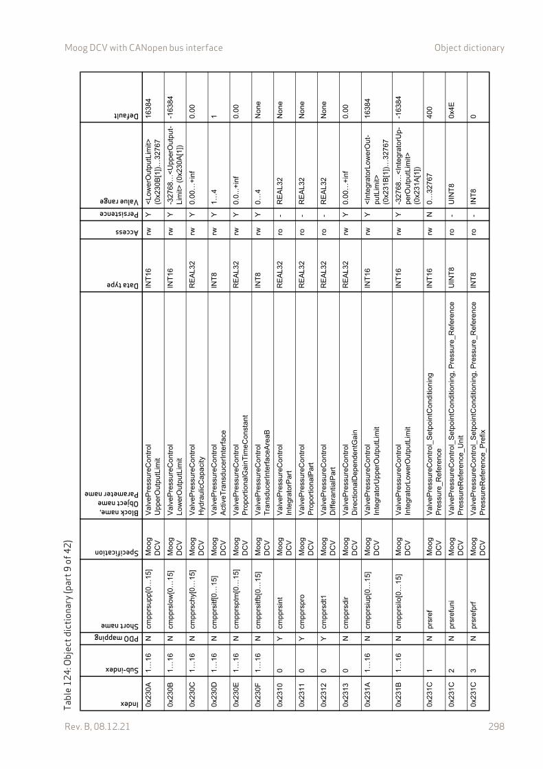
Moog DCV with CANopen bus interface Object dictionary
Rev. B, 08.12.21 298
0x23
0A1…
16N
cmpp
rsup
p[0…
15]
Mo
og
DC
VV
alve
Pre
ssur
eCon
trol
Upp
erO
utpu
tLim
itIN
T16
rwY
<L
ower
Out
putL
imit>
(0
x230
B[1
])…
3276
716
384
0x23
0B1…
16N
cmpp
rslo
w[0
…15
]M
oog
D
CV
Val
veP
ress
ureC
ontr
olL
ower
Out
putL
imit
INT
16rw
Y-3
2768
…<
Upp
erO
utpu
t-Li
mit>
(0x
230A
[1])
-163
84
0x23
0C1…
16N
cmpp
rsch
y[0…
15]
Mo
og
DC
VV
alve
Pre
ssur
eCon
trol
Hyd
raul
icC
apac
ityR
EA
L32
rwY
0.00
…+
inf
0.00
0x23
0D1…
16N
cmpp
rsitf
[0…
15]
Mo
og
DC
VV
alve
Pre
ssur
eCon
trol
Act
iveT
rans
duce
rInt
erf
ace
INT
8rw
Y1…
41
0x23
0E1…
16N
cmpp
rspt
m[0
…15
]M
oog
D
CV
Val
veP
ress
ureC
ontr
olP
ropo
rtio
nalG
ainT
imeC
onst
ant
RE
AL3
2rw
Y0.
0...+
inf
0.00
0x23
0F1…
16N
cmpp
rsitf
b[0…
15]
Mo
og
DC
VV
alve
Pre
ssur
eCon
trol
Tra
nsdu
cerI
nte
rfac
eAre
aBIN
T8
rwY
0…4
Non
e
0x23
100
Ycm
pprs
int
Mo
og
DC
VV
alve
Pre
ssur
eCon
trol
Inte
grat
orP
art
RE
AL3
2ro
-R
EA
L32
Non
e
0x23
110
Ycm
pprs
pro
Mo
og
DC
VV
alve
Pre
ssur
eCon
trol
Pro
port
iona
lPar
tR
EA
L32
ro-
RE
AL3
2N
one
0x23
120
Ycm
pprs
dt1
Mo
og
DC
VV
alve
Pre
ssur
eCon
trol
Diff
eran
tialP
art
RE
AL3
2ro
-R
EA
L32
Non
e
0x23
130
Ncm
pprs
dir
Mo
og
DC
VV
alve
Pre
ssur
eCon
trol
Dire
ctio
nalD
epen
den
tGa
inR
EA
L32
rwY
0.00
…+
inf
0.00
0x23
1A1…
16N
cmpp
rsiu
p[0…
15]
Mo
og
DC
VV
alve
Pre
ssur
eCon
trol
Inte
grat
orU
pper
Out
putL
imit
INT
16rw
Y<
Inte
grat
orLo
wer
Ou
t-pu
tLim
it>
(0x2
31B
[1])
…32
767
1638
4
0x23
1B1…
16N
cmpp
rsilo
[0…
15]
Mo
og
DC
VV
alve
Pre
ssur
eCon
trol
Inte
grat
orLo
wer
Out
putL
imit
INT
16rw
Y-3
2768
…<
Inte
grat
orU
p-pe
rOut
putL
imit>
(0
x231
A[1
])
-163
84
0x23
1C1
Npr
sref
Mo
og
DC
VV
alve
Pre
ssur
eCon
trol
_S
etp
oint
Con
ditio
ning
Pre
ssur
e_R
efer
ence
INT
16rw
N0…
3276
740
0
0x23
1C2
Npr
sref
uni
Mo
og
DC
VV
alve
Pre
ssur
eCon
trol
_S
etp
oint
Con
ditio
ning
, Pre
ssur
e_R
efer
enc
eP
ress
ureR
efer
enc
e_U
nit
UIN
T8
ro-
UIN
T8
0x4E
0x23
1C3
Npr
sref
prf
Mo
og
DC
VV
alve
Pre
ssur
eCon
trol
_S
etp
oint
Con
ditio
ning
, Pre
ssur
e_R
efer
enc
eP
ress
ureR
efer
enc
e_P
refix
INT
8ro
-IN
T8
0
Tabl
e12
4: O
bjec
t dic
tiona
ry (p
art9
of42
)Index
Sub-index
PDO mappingShort name
Specification
Block name,Object nameParameter name
Data type
Access
PersistenceValue range
Default
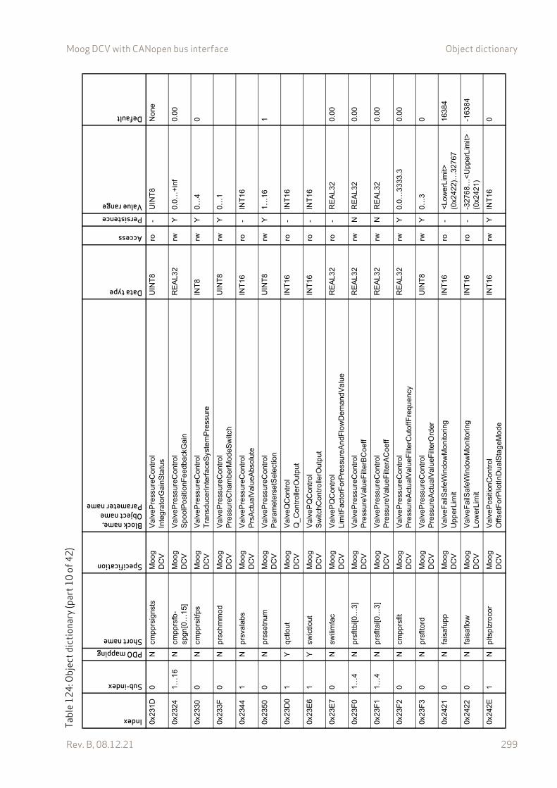
Moog DCV with CANopen bus interface Object dictionary
Rev. B, 08.12.21 299
0x23
1D0
Ncm
pprs
igns
tsM
oog
D
CV
Val
veP
ress
ureC
ontr
olIn
tegr
ator
Gai
nSta
tus
UIN
T8
ro-
UIN
T8
Non
e
0x23
241…
16N
cmpp
rsfb
-sp
gn[0
…1
5]M
oog
D
CV
Val
veP
ress
ureC
ontr
olS
pool
Pos
ition
Fee
dbac
kGai
nR
EA
L32
rwY
0.0…
+in
f0.
00
0x23
300
Ncm
pprs
itfps
Mo
og
DC
VV
alve
Pre
ssur
eCon
trol
Tra
nsdu
cerI
nte
rfac
eSys
tem
Pre
ssur
eIN
T8
rwY
0…4
0
0x23
3F0
Npr
schm
mod
Mo
og
DC
VV
alve
Pre
ssur
eCon
trol
Pre
ssur
eCha
mbe
rMod
eSw
itch
UIN
T8
rwY
0…1
0x23
441
Npr
sval
abs
Mo
og
DC
VV
alve
Pre
ssur
eCon
trol
Prs
Act
ualV
alue
Abs
olut
eIN
T16
ro-
INT
16
0x23
500
Npr
sset
num
Mo
og
DC
VV
alve
Pre
ssur
eCon
trol
Par
amet
erse
tSel
ectio
nU
INT
8rw
Y1…
161
0x23
D0
1Y
qctlo
utM
oog
D
CV
Val
veQ
Con
trol
Q_C
ont
rolle
rOu
tput
INT
16ro
-IN
T16
0x23
E6
1Y
swic
tlout
Mo
og
DC
VV
alve
PQ
Con
trol
Sw
itchC
ontr
olle
rOut
put
INT
16ro
-IN
T16
0x23
E7
0N
swili
mfa
cM
oog
D
CV
Val
veP
QC
ontr
olL
imitF
acto
rFor
Pre
ssur
eA
ndF
low
Dem
and
Va
lue
RE
AL3
2ro
-R
EA
L32
0.00
0x23
F0
1…4
Npr
sfltb
i[0…
3]M
oog
D
CV
Val
veP
ress
ureC
ontr
olP
ress
ureV
alue
Filt
erB
Coe
ffR
EA
L32
rwN
RE
AL3
20.
00
0x23
F1
1…4
Npr
sflta
i[0…
3]M
oog
D
CV
Val
veP
ress
ureC
ontr
olP
ress
ureV
alue
Filt
erA
Coe
ffR
EA
L32
rwN
RE
AL3
20.
00
0x23
F2
0N
cmpp
rsflt
Mo
og
DC
VV
alve
Pre
ssur
eCon
trol
Pre
ssur
eAct
ualV
alue
Filt
erC
utof
fFre
quen
cyR
EA
L32
rwY
0.0…
3333
.30.
00
0x23
F3
0N
prsf
ltord
Mo
og
DC
VV
alve
Pre
ssur
eCon
trol
Pre
ssur
eAct
ualV
alue
Filt
erO
rder
UIN
T8
rwY
0…3
0
0x24
210
Nfa
isa
fupp
Mo
og
DC
VV
alve
Fai
lSaf
eW
indo
wM
oni
torin
gU
pper
Lim
itIN
T16
ro-
<L
ower
Lim
it>
(0x2
422)
…32
767
1638
4
0x24
220
Nfa
isa
flow
Mo
og
DC
VV
alve
Fai
lSaf
eW
indo
wM
oni
torin
gL
ow
erL
imit
INT
16ro
--3
2768
…<
Upp
erL
imit>
(0
x242
1)-1
6384
0x24
2E1
Npl
tsp
lzro
cor
Mo
og
DC
VV
alve
Pos
ition
Con
trol
Offs
etF
orP
ilotIn
Du
alS
tage
Mo
deIN
T16
rwY
INT
160
Tabl
e12
4: O
bjec
t dic
tiona
ry (p
art1
0of
42)
Index
Sub-index
PDO mappingShort name
Specification
Block name,Object nameParameter name
Data type
Access
PersistenceValue range
Default
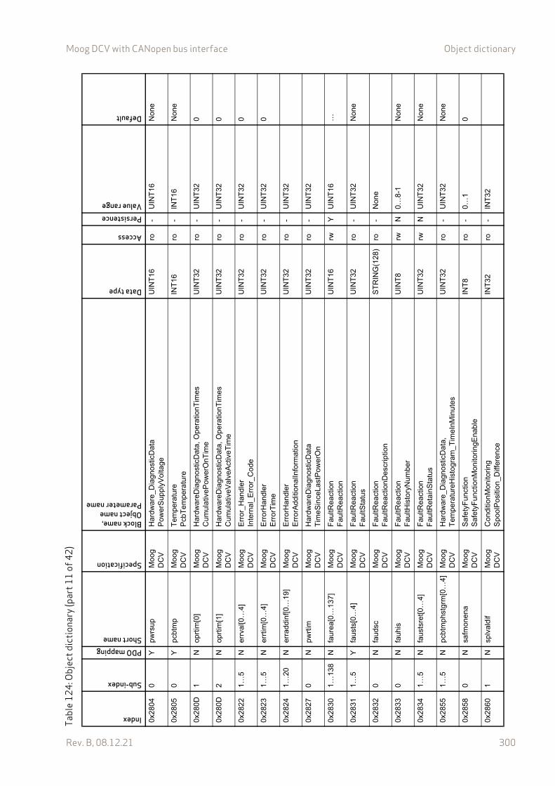
Moog DCV with CANopen bus interface Object dictionary
Rev. B, 08.12.21 300
0x28
040
Ypw
rsu
pM
oog
D
CV
Har
dwa
re_D
iagn
ostic
Da
taP
ower
Sup
plyV
olta
geU
INT
16ro
-U
INT
16N
one
0x28
050
Ypc
btm
pM
oog
D
CV
Tem
pera
ture
Pcb
Te
mpe
ratu
reIN
T16
ro-
INT
16N
one
0x28
0D1
Nop
rtim
[0]
Mo
og
DC
VH
ardw
are
Dia
gnos
ticD
ata
, Ope
ratio
nTim
esC
umul
ativ
ePow
erO
nTim
eU
INT
32ro
-U
INT
320
0x28
0D2
Nop
rtim
[1]
Mo
og
DC
VH
ardw
are
Dia
gnos
ticD
ata
, Ope
ratio
nTim
esC
umul
ativ
eVal
veA
ctiv
eTim
eU
INT
32ro
-U
INT
320
0x28
221…
5N
errv
al[0
…4]
Mo
og
DC
VE
rror
_Han
dler
Inte
rnal
_Err
or_C
ode
UIN
T32
ro-
UIN
T32
0
0x28
231…
5N
errt
im[0
…4]
Mo
og
DC
VE
rror
Han
dler
Err
orT
ime
UIN
T32
ro-
UIN
T32
0
0x28
241…
20N
erra
ddin
f[0…
19]
Mo
og
DC
VE
rror
Han
dler
Err
orA
ddi
tiona
lInfo
rmat
ion
UIN
T32
ro-
UIN
T32
0x28
270
Npw
rtim
Mo
og
DC
VH
ardw
are
Dia
gnos
ticD
ata
Tim
eS
ince
Last
Pow
erO
nU
INT
32ro
-U
INT
32
0x28
301…
138
Nfa
urea
[0…
137]
Mo
og
DC
VF
aultR
eact
ion
Fau
ltRea
ctio
nU
INT
16rw
YU
INT
16…
0x28
311…
5Y
faus
ts[0
…4]
Mo
og
DC
VF
aultR
eact
ion
Fau
ltSta
tus
UIN
T32
ro-
UIN
T32
Non
e
0x28
320
Nfa
udsc
Mo
og
DC
VF
aultR
eact
ion
Fau
ltRea
ctio
nD
escr
iptio
nS
TR
ING
(128
)ro
-N
one
0x28
330
Nfa
uhis
Mo
og
DC
VF
aultR
eact
ion
Fau
ltHis
tory
Nu
mbe
rU
INT
8rw
N0…
8-1
Non
e
0x28
341…
5N
faus
tsre
t[0…
4]M
oog
D
CV
Fau
ltRea
ctio
nF
aultR
etai
nSta
tus
UIN
T32
rwN
UIN
T32
Non
e
0x28
551…
5N
pcbt
mph
stgr
m[0
…4]
Mo
og
DC
VH
ardw
are
_Dia
gnos
ticD
ata
, T
empe
ratu
reH
isto
gram
_T
imeI
nMin
ute
sU
INT
32ro
-U
INT
32N
one
0x28
580
Nsa
fmon
ena
Mo
og
DC
VS
afe
tyF
unct
ion
Saf
ety
Fun
ctio
nMon
itori
ngE
nab
leIN
T8
ro-
0…1
0
0x28
601
Nsp
lval
dif
Mo
og
DC
VC
ondi
tionM
onito
ring
Spo
olP
ositi
on_D
iffer
ence
INT
32ro
-IN
T32
Tabl
e12
4: O
bjec
t dic
tiona
ry (p
art1
1of
42)
Index
Sub-index
PDO mappingShort name
Specification
Block name,Object nameParameter name
Data type
Access
PersistenceValue range
Default

Moog DCV with CANopen bus interface Object dictionary
Rev. B, 08.12.21 301
0x28
610
Nsp
lvel
trs
Mo
og
DC
VC
ondi
tionM
onito
ring
Spo
ol_V
eloc
ity_T
hres
hold
RE
AL3
2ro
-R
EA
L32
0.00
0x28
621
Nsp
ldst
cum
Mo
og
DC
VC
ondi
tionM
onito
ring
Spo
ol D
ista
nce
Cum
ulat
ive
In F
ulls
cale
RE
AL3
2ro
-R
EA
L32
0.00
0x28
624
Nsp
ldst
cum
ipu
Mo
og
DC
VC
ondi
tionM
onito
ring
, S
poo
l Dis
tanc
e C
umul
ativ
e In
Ful
lsca
leS
pool
Dis
tanc
e C
umul
ativ
e In
Mill
imet
erR
EA
L32
ro-
RE
AL3
20.
00
0x28
625
Nsp
ldst
cum
lsw
Mo
og
DC
VC
ondi
tionM
onito
ring
, S
poo
l Dis
tanc
e C
umul
ativ
e In
Ful
lsca
leS
pool
Dis
tanc
e C
umul
ativ
e Le
ast S
igni
fican
t Wor
dU
INT
32ro
-U
INT
320
0x28
626
Nsp
ldst
cum
msw
Mo
og
DC
VC
ondi
tionM
onito
ring
, S
poo
l Dis
tanc
e C
umul
ativ
e In
Ful
lsca
leS
pool
Dis
tanc
e C
umul
ativ
e M
ost S
igni
fican
t Wor
dU
INT
32ro
-U
INT
320
0x28
630
Nsp
lval
dift
rsM
oog
D
CV
Con
ditio
nMon
itori
ngS
pool
Pos
ition
Diff
eren
ce T
hres
hold
INT
16ro
-IN
T16
0x29
000
Ner
rflg
Mo
og
DC
VF
aultR
eact
ion
Cus
tom
erD
efin
edE
rror
Fla
gIN
T8
rwN
0…12
7
0x29
010
Nev
0exp
Mo
og
DC
VE
vent
hand
ler
Exp
ress
ion
_0S
TR
ING
(192
)rw
Y
0x29
020
Nev
1exp
Mo
og
DC
VE
vent
hand
ler
Exp
ress
ion
_1S
TR
ING
(192
)rw
Y
0x29
030
Nev
2exp
Mo
og
DC
VE
vent
hand
ler
Exp
ress
ion
_2S
TR
ING
(192
)rw
Y
0x29
040
Nev
3exp
Mo
og
DC
VE
vent
hand
ler
Exp
ress
ion
_3S
TR
ING
(192
)rw
Y
0x29
050
Nev
4exp
Mo
og
DC
VE
vent
hand
ler
Exp
ress
ion
_4S
TR
ING
(192
)rw
Y
0x29
060
Nev
5exp
Mo
og
DC
VE
vent
hand
ler
Exp
ress
ion
_5S
TR
ING
(192
)rw
Y
0x29
070
Nev
6exp
Mo
og
DC
VE
vent
hand
ler
Exp
ress
ion
_6S
TR
ING
(192
)rw
Y
0x29
080
Nev
7exp
Mo
og
DC
VE
vent
hand
ler
Exp
ress
ion
_7S
TR
ING
(192
)rw
Y
0x29
091…
8Y
evte
na[0
…7]
Mo
og
DC
VE
vent
hand
ler
Ena
ble
INT
8rw
Y0,
1
Tabl
e12
4: O
bjec
t dic
tiona
ry (p
art1
2of
42)
Index
Sub-index
PDO mappingShort name
Specification
Block name,Object nameParameter name
Data type
Access
PersistenceValue range
Default
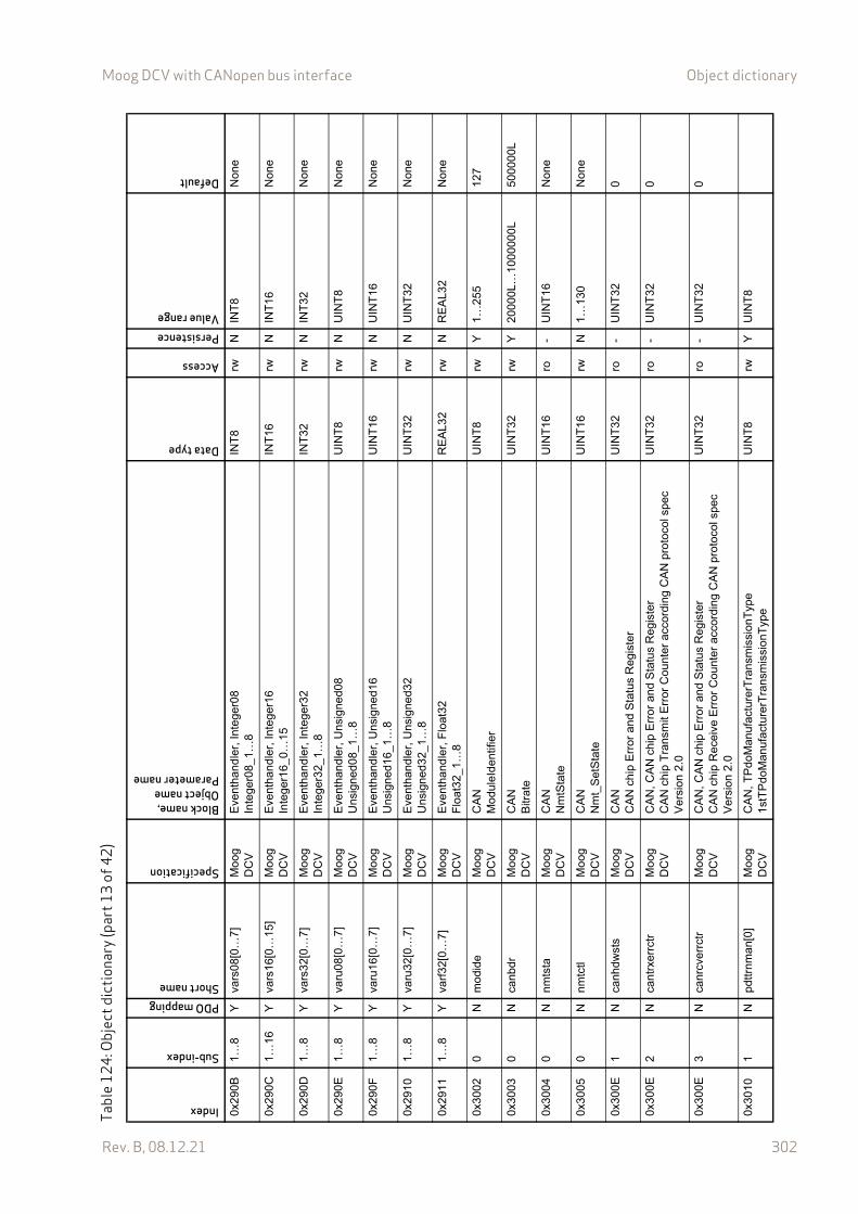
Moog DCV with CANopen bus interface Object dictionary
Rev. B, 08.12.21 302
0x29
0B1…
8Y
vars
08[0
…7
]M
oog
D
CV
Eve
ntha
ndle
r, In
tege
r08
Inte
ger0
8_1…
8IN
T8
rwN
INT
8N
one
0x29
0C1…
16Y
vars
16[0
…1
5]M
oog
D
CV
Eve
ntha
ndle
r, In
tege
r16
Inte
ger1
6_0…
15IN
T16
rwN
INT
16N
one
0x29
0D1…
8Y
vars
32[0
…7
]M
oog
D
CV
Eve
ntha
ndle
r, In
tege
r32
Inte
ger3
2_1…
8IN
T32
rwN
INT
32N
one
0x29
0E1…
8Y
varu
08[0
…7]
Mo
og
DC
VE
vent
hand
ler,
Uns
igne
d08
Uns
igne
d08
_1…
8U
INT
8rw
NU
INT
8N
one
0x29
0F1…
8Y
varu
16[0
…7]
Mo
og
DC
VE
vent
hand
ler,
Uns
igne
d16
Uns
igne
d16
_1…
8U
INT
16rw
NU
INT
16N
one
0x29
101…
8Y
varu
32[0
…7]
Mo
og
DC
VE
vent
hand
ler,
Uns
igne
d32
Uns
igne
d32
_1…
8U
INT
32rw
NU
INT
32N
one
0x29
111…
8Y
varf
32[0
…7]
Mo
og
DC
VE
vent
hand
ler,
Flo
at32
Flo
at32
_1…
8R
EA
L32
rwN
RE
AL3
2N
one
0x30
020
Nm
odid
eM
oog
D
CV
CA
NM
odu
leId
entif
ier
UIN
T8
rwY
1…25
512
7
0x30
030
Nca
nbdr
Mo
og
DC
VC
AN
Bitr
ate
UIN
T32
rwY
2000
0L…
100
0000
L50
0000
L
0x30
040
Nnm
tsta
Mo
og
DC
VC
AN
Nm
tSta
teU
INT
16ro
-U
INT
16N
one
0x30
050
Nnm
tctl
Mo
og
DC
VC
AN
Nm
t_S
etS
tate
UIN
T16
rwN
1…13
0N
one
0x30
0E1
Nca
nhdw
sts
Mo
og
DC
VC
AN
CA
N c
hip
Err
or a
nd S
tatu
s R
egis
ter
UIN
T32
ro-
UIN
T32
0
0x30
0E2
Nca
ntrx
errc
trM
oog
D
CV
CA
N, C
AN
chi
p E
rror
and
Sta
tus
Reg
iste
rC
AN
ch
ip T
rans
mit
Err
or C
ount
er a
ccor
ding
CA
N p
roto
col s
pec
Ver
sion
2.0
UIN
T32
ro-
UIN
T32
0
0x30
0E3
Nca
nrcv
errc
trM
oog
D
CV
CA
N, C
AN
chi
p E
rror
and
Sta
tus
Reg
iste
rC
AN
ch
ip R
ece
ive
Err
or C
ount
er a
ccor
din
g C
AN
pro
toco
l spe
c V
ersi
on 2
.0
UIN
T32
ro-
UIN
T32
0
0x30
101
Npd
ttrnm
an[0
]M
oog
D
CV
CA
N, T
Pdo
Man
ufac
ture
rTra
nsm
issi
onT
ype
1st
TP
doM
anuf
actu
rerT
rans
mis
sion
Typ
eU
INT
8rw
YU
INT
8
Tabl
e12
4: O
bjec
t dic
tiona
ry (p
art1
3of
42)
Index
Sub-index
PDO mappingShort name
Specification
Block name,Object nameParameter name
Data type
Access
PersistenceValue range
Default
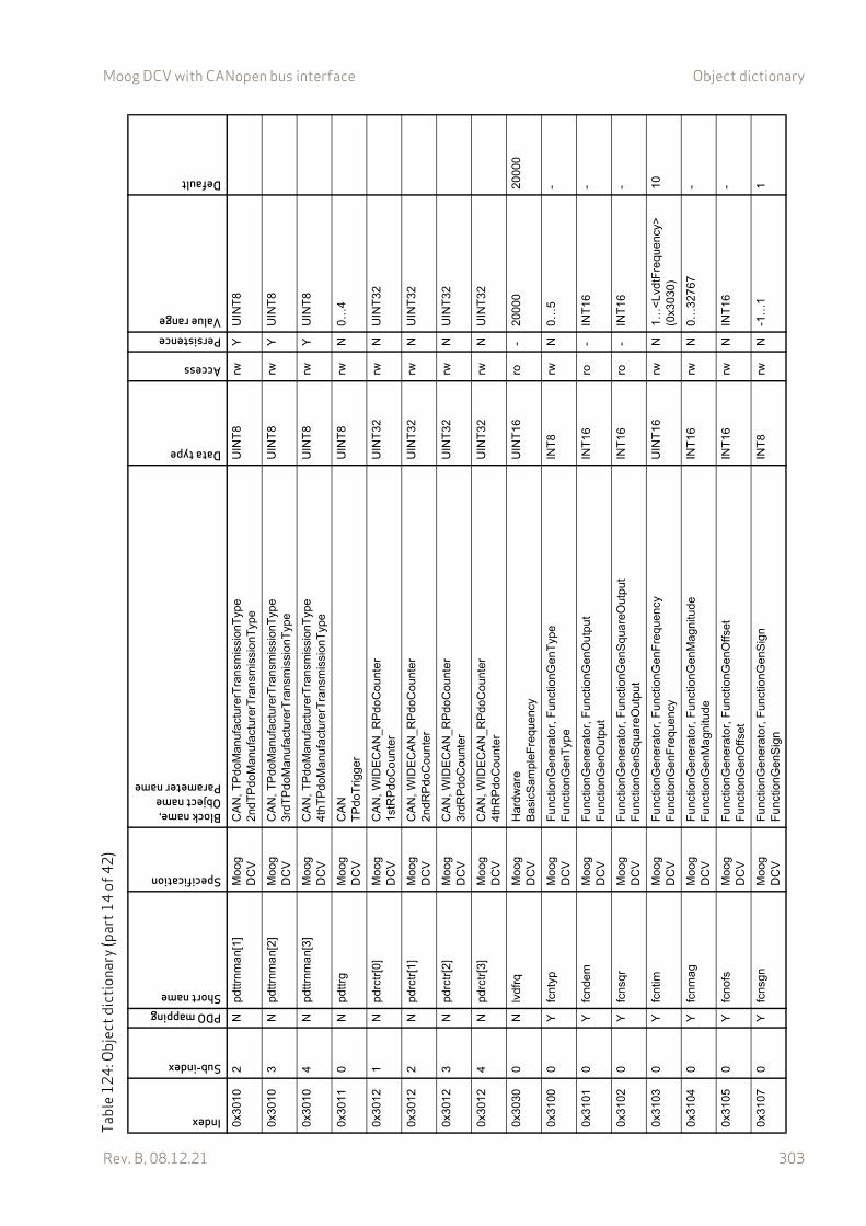
Moog DCV with CANopen bus interface Object dictionary
Rev. B, 08.12.21 303
0x30
102
Npd
ttrnm
an[1
]M
oog
D
CV
CA
N, T
Pdo
Man
ufac
ture
rTra
nsm
issi
onT
ype
2nd
TP
doM
anu
fact
urer
Tra
nsm
issi
onT
ype
UIN
T8
rwY
UIN
T8
0x30
103
Npd
ttrnm
an[2
]M
oog
D
CV
CA
N, T
Pdo
Man
ufac
ture
rTra
nsm
issi
onT
ype
3rd
TP
doM
anuf
actu
rerT
ran
smis
sion
Typ
eU
INT
8rw
YU
INT
8
0x30
104
Npd
ttrnm
an[3
]M
oog
D
CV
CA
N, T
Pdo
Man
ufac
ture
rTra
nsm
issi
onT
ype
4th
TP
doM
anuf
actu
rerT
rans
mis
sion
Typ
eU
INT
8rw
YU
INT
8
0x30
110
Npd
ttrg
Mo
og
DC
VC
AN
TP
doT
rigg
erU
INT
8rw
N0…
4
0x30
121
Npd
rctr
[0]
Mo
og
DC
VC
AN
, WID
EC
AN
_RP
doC
ount
er1
stR
Pdo
Cou
nter
UIN
T32
rwN
UIN
T32
0x30
122
Npd
rctr
[1]
Mo
og
DC
VC
AN
, WID
EC
AN
_RP
doC
ount
er2
ndR
Pdo
Cou
nte
rU
INT
32rw
NU
INT
32
0x30
123
Npd
rctr
[2]
Mo
og
DC
VC
AN
, WID
EC
AN
_RP
doC
ount
er3
rdR
Pdo
Cou
nter
UIN
T32
rwN
UIN
T32
0x30
124
Npd
rctr
[3]
Mo
og
DC
VC
AN
, WID
EC
AN
_RP
doC
ount
er4
thR
Pdo
Cou
nter
UIN
T32
rwN
UIN
T32
0x30
300
Nlv
dfrq
Mo
og
DC
VH
ardw
are
Bas
icS
ampl
eFre
quen
cyU
INT
16ro
-20
000
2000
0
0x31
000
Yfc
ntyp
Mo
og
DC
VF
unct
ion
Gen
erat
or,
Fun
ctio
nGen
Typ
eF
unct
ion
Gen
Typ
eIN
T8
rwN
0…5
-
0x31
010
Yfc
ndem
Mo
og
DC
VF
unct
ion
Gen
erat
or,
Fun
ctio
nGen
Out
put
Fun
ctio
nG
enO
utpu
tIN
T16
ro-
INT
16-
0x31
020
Yfc
nsqr
Mo
og
DC
VF
unct
ion
Gen
erat
or,
Fun
ctio
nGen
Sq
uare
Out
put
Fun
ctio
nG
enS
qua
reO
utpu
tIN
T16
ro-
INT
16-
0x31
030
Yfc
ntim
Mo
og
DC
VF
unct
ion
Gen
erat
or,
Fun
ctio
nGen
Fre
que
ncy
Fun
ctio
nG
enF
requ
enc
yU
INT
16rw
N1…
<Lv
dtF
requ
ency
>
(0x3
030)
10
0x31
040
Yfc
nmag
Mo
og
DC
VF
unct
ion
Gen
erat
or,
Fun
ctio
nGen
Mag
nitu
deF
unct
ion
Gen
Mag
nitu
de
INT
16rw
N0…
3276
7-
0x31
050
Yfc
nofs
Mo
og
DC
VF
unct
ion
Gen
erat
or,
Fun
ctio
nGen
Offs
etF
unct
ion
Gen
Offs
etIN
T16
rwN
INT
16-
0x31
070
Yfc
nsgn
Mo
og
DC
VF
unct
ion
Gen
erat
or,
Fun
ctio
nGen
Sig
nF
unct
ion
Gen
Sig
nIN
T8
rwN
-1…
11
Tabl
e12
4: O
bjec
t dic
tiona
ry (p
art1
4of
42)
Index
Sub-index
PDO mappingShort name
Specification
Block name,Object nameParameter name
Data type
Access
PersistenceValue range
Default
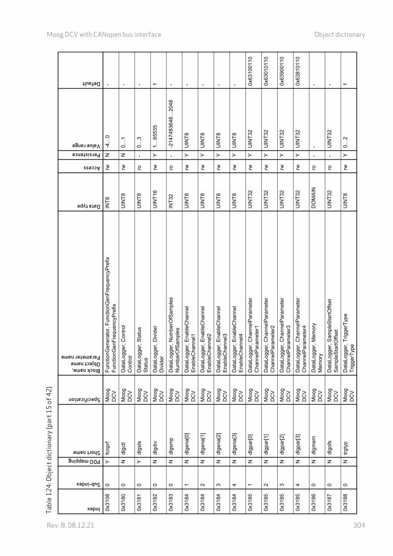
Moog DCV with CANopen bus interface Object dictionary
Rev. B, 08.12.21 304
0x31
080
Yfc
nprf
Mo
og
DC
VF
unct
ion
Gen
erat
or,
Fun
ctio
nGen
Fre
que
ncyP
refix
Fun
ctio
nG
enF
requ
enc
yPre
fixIN
T8
rwN
-4…
0-
0x31
800
Ndl
gctl
Mo
og
DC
VD
ataL
ogge
r, C
ontr
olC
ontr
olU
INT
8rw
N0…
1-
0x31
810
Ydl
gsts
Mo
og
DC
VD
ataL
ogge
r, S
tatu
sS
tatu
sU
INT
8ro
-0…
3-
0x31
820
Ndl
gdiv
Mo
og
DC
VD
ataL
ogge
r, D
ivid
erD
ivid
erU
INT
16rw
Y1…
6553
51
0x31
830
Ndl
gsm
pM
oog
D
CV
Dat
aLog
ger,
Num
berO
fSam
ple
sN
umbe
rOfS
ampl
esIN
T32
ro-
-214
7483
648…
204
8-
0x31
841
Ndl
gena
[0]
Mo
og
DC
VD
ataL
ogge
r, E
nabl
eCha
nnel
Ena
bleC
hann
el1
UIN
T8
rwY
UIN
T8
-
0x31
842
Ndl
gena
[1]
Mo
og
DC
VD
ataL
ogge
r, E
nabl
eCha
nnel
Ena
bleC
hann
el2
UIN
T8
rwY
UIN
T8
-
0x31
843
Ndl
gena
[2]
Mo
og
DC
VD
ataL
ogge
r, E
nabl
eCha
nnel
Ena
bleC
hann
el3
UIN
T8
rwY
UIN
T8
-
0x31
844
Ndl
gena
[3]
Mo
og
DC
VD
ataL
ogge
r, E
nabl
eCha
nnel
Ena
bleC
hann
el4
UIN
T8
rwY
UIN
T8
-
0x31
851
Ndl
gpar
[0]
Mo
og
DC
VD
ataL
ogge
r, C
hann
elP
ara
met
erC
hann
elP
aram
eter
1U
INT
32rw
YU
INT
320x
6310
0110
0x31
852
Ndl
gpar
[1]
Mo
og
DC
VD
ataL
ogge
r, C
hann
elP
ara
met
erC
hann
elP
aram
eter
2U
INT
32rw
YU
INT
320x
6301
0110
0x31
853
Ndl
gpar
[2]
Mo
og
DC
VD
ataL
ogge
r, C
hann
elP
ara
met
erC
hann
elP
aram
eter
3U
INT
32rw
YU
INT
320x
6390
0110
0x31
854
Ndl
gpar
[3]
Mo
og
DC
VD
ataL
ogge
r, C
hann
elP
ara
met
erC
hann
elP
aram
eter
4U
INT
32rw
YU
INT
320x
6381
0110
0x31
860
Ndl
gmem
Mo
og
DC
VD
ataL
ogge
r, M
emor
yM
em
ory
DO
MA
INro
--
-
0x31
870
Ndl
gofs
Mo
og
DC
VD
ataL
ogge
r, S
ampl
eSta
rtO
ffse
tS
amp
leS
tart
Offs
etU
INT
32ro
-U
INT
32-
0x31
880
Ntr
gtyp
Mo
og
DC
VD
ataL
ogge
r, T
rigge
rTyp
eT
rigge
rTyp
eU
INT
8rw
Y0…
21
Tabl
e12
4: O
bjec
t dic
tiona
ry (p
art1
5of
42)
Index
Sub-index
PDO mappingShort name
Specification
Block name,Object nameParameter name
Data type
Access
PersistenceValue range
Default
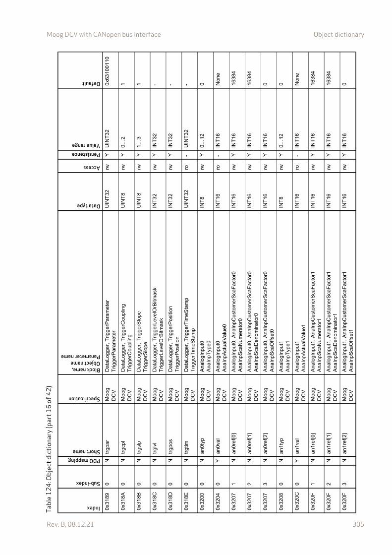
Moog DCV with CANopen bus interface Object dictionary
Rev. B, 08.12.21 305
0x31
890
Ntr
gpar
Mo
og
DC
VD
ataL
ogge
r, T
rigge
rPar
amet
erT
rigge
rPar
amet
erU
INT
32rw
YU
INT
320x
6310
0110
0x31
8A0
Ntr
gcpl
Mo
og
DC
VD
ataL
ogge
r, T
rigge
rCou
plin
gT
rigge
rCou
plin
gU
INT
8rw
Y0…
21
0x31
8B0
Ntr
gslp
Mo
og
DC
VD
ataL
ogge
r, T
rigge
rSlo
pe
Trig
gerS
lope
UIN
T8
rwY
1…3
1
0x31
8C0
Ntr
glvl
Mo
og
DC
VD
ataL
ogge
r, T
rigge
rLev
elO
rBitm
ask
Trig
gerL
evel
OrB
itmas
kIN
T32
rwY
INT
32-
0x31
8D0
Ntr
gpos
Mo
og
DC
VD
ataL
ogge
r, T
rigge
rPos
ition
Trig
gerP
ositi
onIN
T32
rwY
INT
32-
0x31
8E0
Ntr
gtim
Mo
og
DC
VD
ataL
ogge
r, T
rigge
rTim
eSta
mp
Trig
gerT
imeS
tam
pU
INT
32ro
-U
INT
32-
0x32
000
Nan
0typ
Mo
og
DC
VA
nalo
gInp
ut0
Ana
InpT
ype0
INT
8rw
Y0…
120
0x32
040
Yan
0val
Mo
og
DC
VA
nalo
gInp
ut0
Ana
InpA
ctua
lVal
ue0
INT
16ro
-IN
T16
Non
e
0x32
071
Nan
0ref
[0]
Mo
og
DC
VA
nalo
gInp
ut0,
Ana
InpC
ust
omer
Sca
Fac
tor0
Ana
InpS
caN
umer
ator
0IN
T16
rwY
INT
1616
384
0x32
072
Nan
0ref
[1]
Mo
og
DC
VA
nalo
gInp
ut0,
Ana
InpC
ust
omer
Sca
Fac
tor0
Ana
InpS
caD
enom
inat
or0
INT
16rw
YIN
T16
1638
4
0x32
073
Nan
0ref
[2]
Mo
og
DC
VA
nalo
gInp
ut0,
Ana
InpC
ust
omer
Sca
Fac
tor0
Ana
InpS
caO
ffset
0IN
T16
rwY
INT
160
0x32
080
Nan
1typ
Mo
og
DC
VA
nalo
gInp
ut1
Ana
InpT
ype1
INT
8rw
Y0…
120
0x32
0C0
Yan
1val
Mo
og
DC
VA
nalo
gInp
ut1
Ana
InpA
ctua
lVal
ue1
INT
16ro
-IN
T16
Non
e
0x32
0F1
Nan
1ref
[0]
Mo
og
DC
VA
nalo
gInp
ut1,
Ana
InpC
ust
omer
Sca
Fac
tor1
Ana
InpS
caN
umer
ator
1IN
T16
rwY
INT
1616
384
0x32
0F2
Nan
1ref
[1]
Mo
og
DC
VA
nalo
gInp
ut1,
Ana
InpC
ust
omer
Sca
Fac
tor1
Ana
InpS
caD
enom
inat
or1
INT
16rw
YIN
T16
1638
4
0x32
0F3
Nan
1ref
[2]
Mo
og
DC
VA
nalo
gInp
ut1,
Ana
InpC
ust
omer
Sca
Fac
tor1
Ana
InpS
caO
ffset
1IN
T16
rwY
INT
160
Tabl
e12
4: O
bjec
t dic
tiona
ry (p
art1
6of
42)
Index
Sub-index
PDO mappingShort name
Specification
Block name,Object nameParameter name
Data type
Access
PersistenceValue range
Default
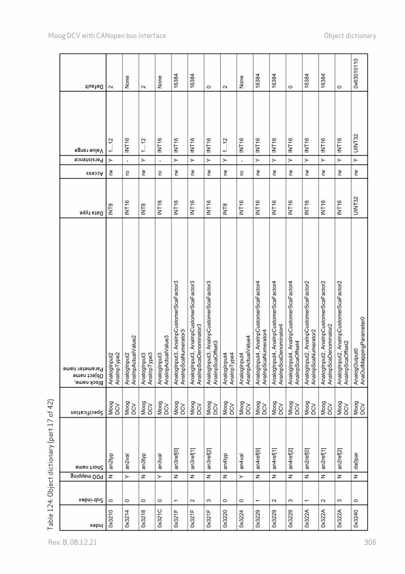
Moog DCV with CANopen bus interface Object dictionary
Rev. B, 08.12.21 306
0x32
100
Nan
2typ
Mo
og
DC
VA
nalo
gInp
ut2
Ana
InpT
ype2
INT
8rw
Y1…
122
0x32
140
Yan
2val
Mo
og
DC
VA
nalo
gInp
ut2
Ana
InpA
ctua
lVal
ue2
INT
16ro
-IN
T16
Non
e
0x32
180
Nan
3typ
Mo
og
DC
VA
nalo
gInp
ut3
Ana
InpT
ype3
INT
8rw
Y1…
122
0x32
1C0
Yan
3val
Mo
og
DC
VA
nalo
gInp
ut3
Ana
InpA
ctua
lVal
ue3
INT
16ro
-IN
T16
Non
e
0x32
1F1
Nan
3ref
[0]
Mo
og
DC
VA
nalo
gInp
ut3,
Ana
InpC
ust
omer
Sca
Fac
tor3
Ana
InpS
caN
umer
ator
3IN
T16
rwY
INT
1616
384
0x32
1F2
Nan
3ref
[1]
Mo
og
DC
VA
nalo
gInp
ut3,
Ana
InpC
ust
omer
Sca
Fac
tor3
Ana
InpS
caD
enom
inat
or3
INT
16rw
YIN
T16
1638
4
0x32
1F3
Nan
3ref
[2]
Mo
og
DC
VA
nalo
gInp
ut3,
Ana
InpC
ust
omer
Sca
Fac
tor3
Ana
InpS
caO
ffset
3IN
T16
rwY
INT
160
0x32
200
Nan
4typ
Mo
og
DC
VA
nalo
gInp
ut4
Ana
InpT
ype4
INT
8rw
Y1…
122
0x32
240
Yan
4val
Mo
og
DC
VA
nalo
gInp
ut4
Ana
InpA
ctua
lVal
ue4
INT
16ro
-IN
T16
Non
e
0x32
291
Nan
4ref
[0]
Mo
og
DC
VA
nalo
gInp
ut4,
Ana
InpC
ust
omer
Sca
Fac
tor4
Ana
InpS
caN
umer
ator
4IN
T16
rwY
INT
1616
384
0x32
292
Nan
4ref
[1]
Mo
og
DC
VA
nalo
gInp
ut4,
Ana
InpC
ust
omer
Sca
Fac
tor4
Ana
InpS
caD
enom
inat
or4
INT
16rw
YIN
T16
1638
4
0x32
293
Nan
4ref
[2]
Mo
og
DC
VA
nalo
gInp
ut4,
Ana
InpC
ust
omer
Sca
Fac
tor4
Ana
InpS
caO
ffset
4IN
T16
rwY
INT
160
0x32
2A1
Nan
2ref
[0]
Mo
og
DC
VA
nalo
gInp
ut2,
Ana
InpC
ust
omer
Sca
Fac
tor2
Ana
InpS
caN
umer
ator
2IN
T16
rwY
INT
1616
384
0x32
2A2
Nan
2ref
[1]
Mo
og
DC
VA
nalo
gInp
ut2,
Ana
InpC
ust
omer
Sca
Fac
tor2
Ana
InpS
caD
enom
inat
or2
INT
16rw
YIN
T16
1638
4
0x32
2A3
Nan
2ref
[2]
Mo
og
DC
VA
nalo
gInp
ut2,
Ana
InpC
ust
omer
Sca
Fac
tor2
Ana
InpS
caO
ffset
2IN
T16
rwY
INT
160
0x32
400
Nda
0par
Mo
og
DC
VA
nalo
gOut
put0
Ana
Out
Map
ping
Par
amet
er0
UIN
T32
rwY
UIN
T32
0x63
0101
10
Tabl
e12
4: O
bjec
t dic
tiona
ry (p
art1
7of
42)
Index
Sub-index
PDO mappingShort name
Specification
Block name,Object nameParameter name
Data type
Access
PersistenceValue range
Default
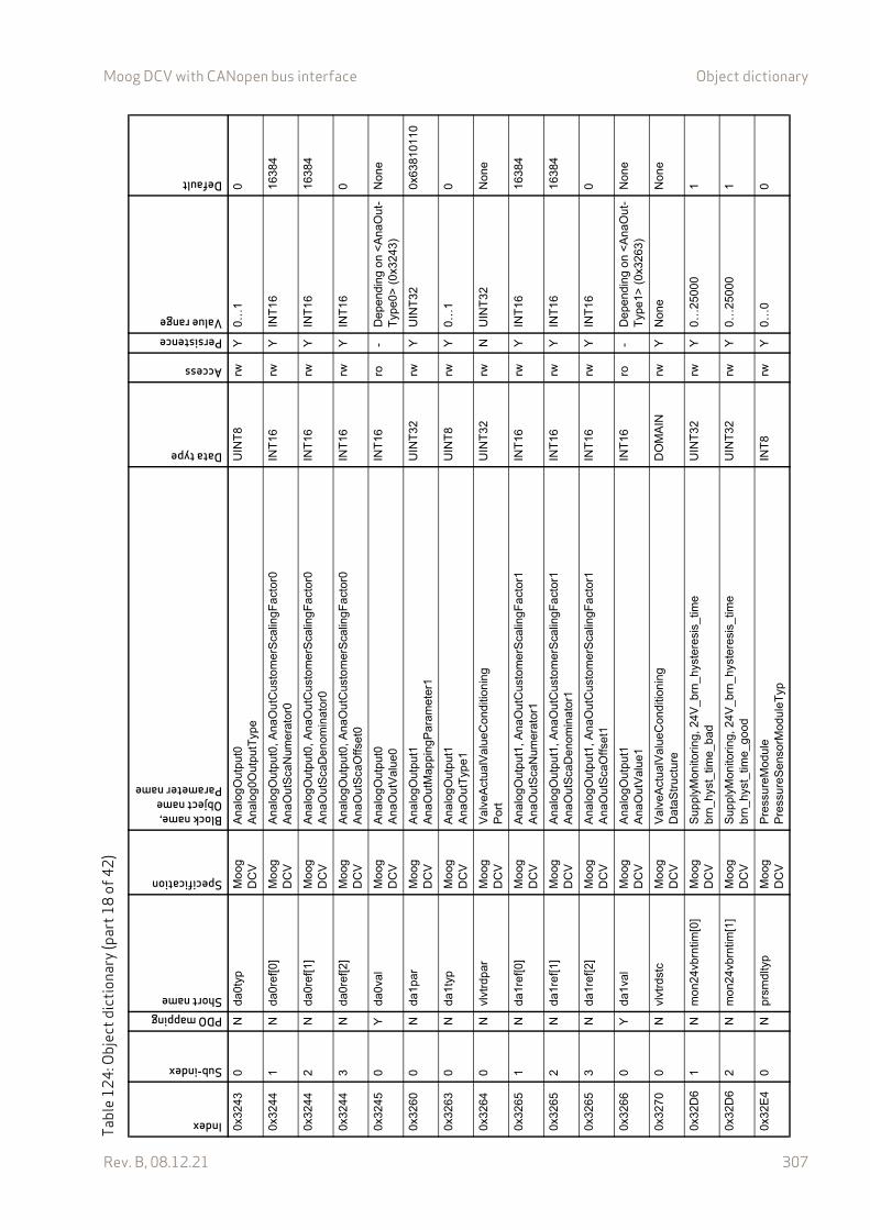
Moog DCV with CANopen bus interface Object dictionary
Rev. B, 08.12.21 307
0x32
430
Nda
0typ
Mo
og
DC
VA
nalo
gOut
put0
Ana
log0
Out
putT
ype
UIN
T8
rwY
0…1
0
0x32
441
Nda
0ref
[0]
Mo
og
DC
VA
nalo
gOut
put0
, A
naO
utC
usto
mer
Sca
lingF
act
or0
Ana
Out
Sca
Num
erat
or0
INT
16rw
YIN
T16
1638
4
0x32
442
Nda
0ref
[1]
Mo
og
DC
VA
nalo
gOut
put0
, A
naO
utC
usto
mer
Sca
lingF
act
or0
Ana
Out
Sca
Den
omin
ator
0IN
T16
rwY
INT
1616
384
0x32
443
Nda
0ref
[2]
Mo
og
DC
VA
nalo
gOut
put0
, A
naO
utC
usto
mer
Sca
lingF
act
or0
Ana
Out
Sca
Offs
et0
INT
16rw
YIN
T16
0
0x32
450
Yda
0val
Mo
og
DC
VA
nalo
gOut
put0
Ana
Out
Val
ue0
INT
16ro
-D
epen
ding
on
<A
naO
ut-
Typ
e0>
(0x
3243
)N
one
0x32
600
Nda
1par
Mo
og
DC
VA
nalo
gOut
put1
Ana
Out
Map
ping
Par
amet
er1
UIN
T32
rwY
UIN
T32
0x63
8101
10
0x32
630
Nda
1typ
Mo
og
DC
VA
nalo
gOut
put1
Ana
Out
Typ
e1U
INT
8rw
Y0…
10
0x32
640
Nvl
vtrd
par
Mo
og
DC
VV
alve
Act
ualV
alue
Con
ditio
ning
Po
rtU
INT
32rw
NU
INT
32N
one
0x32
651
Nda
1ref
[0]
Mo
og
DC
VA
nalo
gOut
put1
, A
naO
utC
usto
mer
Sca
lingF
act
or1
Ana
Out
Sca
Num
erat
or1
INT
16rw
YIN
T16
1638
4
0x32
652
Nda
1ref
[1]
Mo
og
DC
VA
nalo
gOut
put1
, A
naO
utC
usto
mer
Sca
lingF
act
or1
Ana
Out
Sca
Den
omin
ator
1IN
T16
rwY
INT
1616
384
0x32
653
Nda
1ref
[2]
Mo
og
DC
VA
nalo
gOut
put1
, A
naO
utC
usto
mer
Sca
lingF
act
or1
Ana
Out
Sca
Offs
et1
INT
16rw
YIN
T16
0
0x32
660
Yda
1val
Mo
og
DC
VA
nalo
gOut
put1
Ana
Out
Val
ue1
INT
16ro
-D
epen
ding
on
<A
naO
ut-
Typ
e1>
(0x
3263
)N
one
0x32
700
Nvl
vtrd
stc
Mo
og
DC
VV
alve
Act
ualV
alue
Con
ditio
ning
Dat
aStr
uctu
reD
OM
AIN
rwY
Non
eN
one
0x32
D6
1N
mon
24vb
rntim
[0]
Mo
og
DC
VS
uppl
yMon
itorin
g, 2
4V_b
rn_h
yste
resi
s_tim
eb
rn_h
yst_
time_
bad
UIN
T32
rwY
0…25
000
1
0x32
D6
2N
mon
24vb
rntim
[1]
Mo
og
DC
VS
uppl
yMon
itorin
g, 2
4V_b
rn_h
yste
resi
s_tim
eb
rn_h
yst_
time_
goo
dU
INT
32rw
Y0…
2500
01
0x32
E4
0N
prsm
dlty
pM
oog
D
CV
Pre
ssur
eMod
ule
Pre
ssur
eSen
sorM
odul
eTyp
INT
8rw
Y0…
00
Tabl
e12
4: O
bjec
t dic
tiona
ry (p
art1
8of
42)
Index
Sub-index
PDO mappingShort name
Specification
Block name,Object nameParameter name
Data type
Access
PersistenceValue range
Default

Moog DCV with CANopen bus interface Object dictionary
Rev. B, 08.12.21 308
0x32
E5
0N
prsm
dlco
rmod
Mo
og
DC
VP
ress
ureM
odul
eP
ress
ureS
enso
rOffs
etC
orre
ctio
nMod
eIN
T8
rwY
0…3
0
0x32
E6
0N
prsm
dlco
rexc
Mo
og
DC
VP
ress
ureM
odul
eP
ress
ureS
enso
rOffs
etC
orre
ctio
nExe
cutio
nIN
T8
rwN
0…1
0
0x32
E7
0N
prsm
dlco
rupp
Mo
og
DC
VP
ress
ureM
odul
eP
ress
ureS
enso
rOffs
etC
orre
ctio
nBou
ndar
yR
EA
L32
ro-
0.00
…10
0.0
01.
50
0x32
E8
0N
prsm
dlco
rtrs
Mo
og
DC
VP
ress
ureM
odul
eP
ress
ureS
enso
rOffs
etC
orre
ctio
nTrig
ger
Th
resh
old
INT
16rw
Y-3
2767
…32
767
1
0x32
E9
0N
prsm
dlco
rpar
Mo
og
DC
VP
ress
ureM
odul
eP
ress
ureS
enso
rOffs
etC
orre
ctio
nMap
ping
Par
am
eter
UIN
T32
rwY
UIN
T32
0x32
E60
010
0x32
F2
1Y
prsm
d0va
lM
oog
D
CV
Pre
ssur
eMod
ule
Pre
ssur
eSen
sorA
ctua
lVal
ue0
INT
16ro
-IN
T16
Non
e
0x32
F3
1Y
prsm
d1va
lM
oog
D
CV
Pre
ssur
eMod
ule
Pre
ssur
eSen
sorA
ctua
lVal
ue1
INT
16ro
-IN
T16
Non
e
0x32
F4
1Y
prsm
d2va
lM
oog
D
CV
Pre
ssur
eMod
ule
Pre
ssur
eSen
sorA
ctua
lVal
ue2
INT
16ro
-IN
T16
Non
e
0x32
F8
0N
prsm
d0co
rM
oog
D
CV
Pre
ssur
eMod
ule
Pre
ssur
eSen
sorC
orre
ctio
nOffs
et0
INT
16ro
-IN
T16
0
0x32
F9
0N
prsm
d1co
rM
oog
D
CV
Pre
ssur
eMod
ule
Pre
ssur
eSen
sorC
orre
ctio
nOffs
et1
INT
16ro
-IN
T16
0
0x32
FA
0N
prsm
d2co
rM
oog
D
CV
Pre
ssur
eMod
ule
Pre
ssur
eSen
sorC
orre
ctio
nOffs
et2
INT
16ro
-IN
T16
0
0x33
001
Ypl
tsp
ldem
Mo
og
DC
VV
alve
Pos
ition
Con
trol
Pilo
tSpl
De
man
dVal
ueIN
T16
ro-
INT
16
0x33
011
Ypl
tsp
lval
Mo
og
DC
VV
alve
Pos
ition
Con
trol
Pilo
tAct
ualV
alue
INT
16ro
-IN
T16
Non
e
0x33
021
Ypl
tsp
lctld
vnM
oog
D
CV
Val
veP
ositi
onC
ontr
olP
ilotS
pool
Con
trol
Dev
iatio
nIN
T16
ro-
INT
16
0x33
031
Ypl
tsp
lset
Mo
og
DC
VV
alve
Pos
ition
Con
trol
Pilo
tSpo
olP
ositi
onS
etp
oint
INT
16ro
-IN
T16
0x33
070
Nsp
gpos
min
Mo
og
DC
VH
ardw
are
Dia
gnos
ticD
ata
Spr
ing
Po
sitio
nMin
imum
INT
16ro
-IN
T16
Tabl
e12
4: O
bjec
t dic
tiona
ry (p
art1
9of
42)
Index
Sub-index
PDO mappingShort name
Specification
Block name,Object nameParameter name
Data type
Access
PersistenceValue range
Default
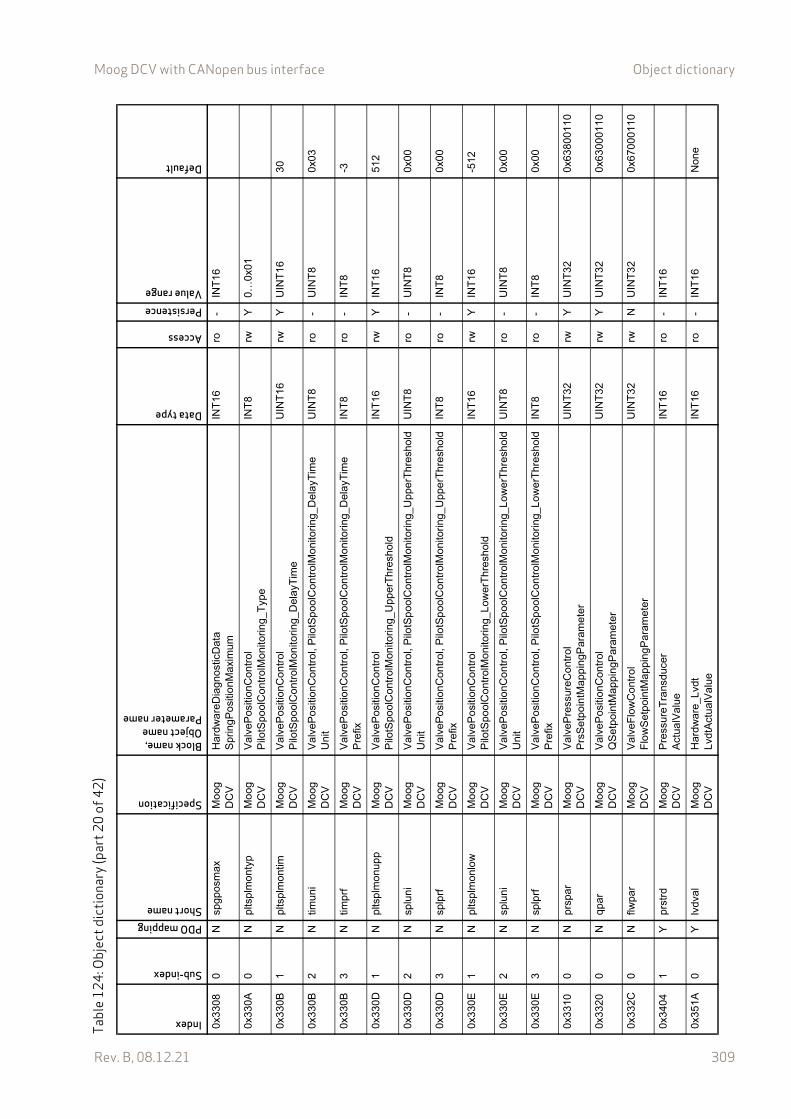
Moog DCV with CANopen bus interface Object dictionary
Rev. B, 08.12.21 309
0x33
080
Nsp
gpos
max
Mo
og
DC
VH
ardw
are
Dia
gnos
ticD
ata
Spr
ing
Po
sitio
nMax
imum
INT
16ro
-IN
T16
0x33
0A0
Npl
tsp
lmon
typ
Mo
og
DC
VV
alve
Pos
ition
Con
trol
Pilo
tSpo
olC
ontr
olM
onito
ring_
Typ
eIN
T8
rwY
0…0x
01
0x33
0B1
Npl
tsp
lmon
timM
oog
D
CV
Val
veP
ositi
onC
ontr
olP
ilotS
pool
Con
trol
Mon
itorin
g_D
elay
Tim
eU
INT
16rw
YU
INT
1630
0x33
0B2
Ntim
uni
Mo
og
DC
VV
alve
Pos
ition
Con
trol
, Pilo
tSp
oolC
ontr
olM
onito
ring_
Del
ayT
ime
Uni
tU
INT
8ro
-U
INT
80x
03
0x33
0B3
Ntim
prf
Mo
og
DC
VV
alve
Pos
ition
Con
trol
, Pilo
tSp
oolC
ontr
olM
onito
ring_
Del
ayT
ime
Pre
fixIN
T8
ro-
INT
8-3
0x33
0D1
Npl
tsp
lmon
upp
Mo
og
DC
VV
alve
Pos
ition
Con
trol
Pilo
tSpo
olC
ontr
olM
onito
ring_
Upp
erT
hre
shol
dIN
T16
rwY
INT
1651
2
0x33
0D2
Nsp
luni
Mo
og
DC
VV
alve
Pos
ition
Con
trol
, Pilo
tSp
oolC
ontr
olM
onito
ring_
Upp
erT
hres
hold
Uni
tU
INT
8ro
-U
INT
80x
00
0x33
0D3
Nsp
lprf
Mo
og
DC
VV
alve
Pos
ition
Con
trol
, Pilo
tSp
oolC
ontr
olM
onito
ring_
Upp
erT
hres
hold
Pre
fixIN
T8
ro-
INT
80x
00
0x33
0E1
Npl
tsp
lmon
low
Mo
og
DC
VV
alve
Pos
ition
Con
trol
Pilo
tSpo
olC
ontr
olM
onito
ring_
Low
erT
hre
shol
dIN
T16
rwY
INT
16-5
12
0x33
0E2
Nsp
luni
Mo
og
DC
VV
alve
Pos
ition
Con
trol
, Pilo
tSp
oolC
ontr
olM
onito
ring_
Low
erT
hres
hold
Uni
tU
INT
8ro
-U
INT
80x
00
0x33
0E3
Nsp
lprf
Mo
og
DC
VV
alve
Pos
ition
Con
trol
, Pilo
tSp
oolC
ontr
olM
onito
ring_
Low
erT
hres
hold
Pre
fixIN
T8
ro-
INT
80x
00
0x33
100
Npr
spar
Mo
og
DC
VV
alve
Pre
ssur
eCon
trol
Prs
Set
poin
tMap
pin
gPar
amet
erU
INT
32rw
YU
INT
320x
6380
0110
0x33
200
Nqp
arM
oog
D
CV
Val
veP
ositi
onC
ontr
olQ
Set
poin
tMap
ping
Par
amet
erU
INT
32rw
YU
INT
320x
6300
0110
0x33
2C0
Nflw
par
Mo
og
DC
VV
alve
Flo
wC
ontr
olF
low
Set
poin
tMap
ping
Par
amet
erU
INT
32rw
NU
INT
320x
6700
0110
0x34
041
Ypr
strd
Mo
og
DC
VP
ress
ureT
rans
duce
rA
ctua
lVal
ueIN
T16
ro-
INT
16
0x35
1A0
Ylv
dval
Mo
og
DC
VH
ardw
are
_Lvd
tL
vdtA
ctua
lVal
ueIN
T16
ro-
INT
16N
one
Tabl
e12
4: O
bjec
t dic
tiona
ry (p
art2
0of
42)
Index
Sub-index
PDO mappingShort name
Specification
Block name,Object nameParameter name
Data type
Access
PersistenceValue range
Default

Moog DCV with CANopen bus interface Object dictionary
Rev. B, 08.12.21 310
0x40
3F0
Nct
llocd
efM
oog
D
CV
Dev
ice
Loc
alC
ontr
olW
ordD
efau
ltU
INT
16rw
YU
INT
16D
evic
e sp
e-ci
fic v
alu
e
0x40
400
Nct
lloc
Mo
og
DC
VD
evic
eL
ocal
Con
trol
Wor
dU
INT
16rw
NU
INT
16<
Loca
l-C
ontr
olW
ord
Def
ault>
(0
x403
F)
0x40
420
Nde
vmod
def
Mo
og
DC
VD
evic
eD
evic
eMod
eDef
ault
INT
8rw
Y1…
2D
evi
ce s
pe
-ci
fic v
alu
e
0x40
430
Nct
lmod
def
Mo
og
DC
VD
evic
eC
ontr
olM
odeD
efa
ult
INT
8rw
Y1…
5, 1
4D
evic
e sp
e-ci
fic v
alu
e
0x43
470
Nsp
lchr
tbl
Mo
og
DC
VA
ctua
torC
ondi
tioni
ng,
Look
UpT
able
Neg
ativ
eL
ookU
pTab
leN
egat
ive
DO
MA
INrw
YN
one
Dev
ice
spe-
cific
va
lue
0x43
481…
128
Nsp
lchr
tbl[0
…12
7]M
oog
D
CV
Act
uato
rCon
ditio
ning
, Lo
okU
pTab
leN
ega
tive
Loo
kUpT
able
Neg
ativ
eIN
T16
rwY
INT
16D
evic
e sp
e-ci
fic v
alu
e
0x43
490
Nsp
lchr
tbl[1
28]
Mo
og
DC
VA
ctua
torC
ondi
tioni
ngL
ookU
pTab
leC
ente
rIN
T16
rwY
INT
16D
evic
e sp
e-ci
fic v
alu
e
0x43
4A1…
128
Nsp
lchr
tbl[1
29…
256]
Mo
og
DC
VA
ctua
torC
ondi
tioni
ng,
Look
UpT
able
Loo
kUpT
able
Pos
itive
INT
16rw
YIN
T16
Dev
ice
spe-
cific
va
lue
0x50
050
Nlo
csnc
msg
cob
Mo
og
DC
VL
ocal
CA
NL
ocal
CA
N_C
obId
Syn
cMes
sage
UIN
T32
rwY
1…0x
4000
07F
F<
Nod
eID
>
(0x1
00B
) +
0x
0001
0x50
060
Nlo
ccom
cycp
erM
oog
D
CV
Loc
alC
AN
Loc
alC
AN
_Com
mun
icat
ionC
ycle
Per
iod
UIN
T32
rwY
UIN
T32
0x50
070
Nlo
csnc
win
len
Mo
og
DC
VL
ocal
CA
NL
ocal
CA
N_S
ynch
rono
usW
indo
wLe
ngth
UIN
T32
rwY
UIN
T32
0x50
0B0
Nlo
cnod
ide
Mo
og
DC
VL
ocal
CA
NL
ocal
CA
N_N
odeI
dU
INT
32ro
-U
INT
3212
7
0x50
0C0
Nlo
cgrd
timM
oog
D
CV
Loc
alC
AN
Loc
alC
AN
_Gua
rdT
ime
UIN
T16
rwY
UIN
T16
0x50
0D0
Nlo
clift
imfc
tM
oog
D
CV
Loc
alC
AN
Loc
alC
AN
_Life
Tim
eFac
tor
UIN
T8
rwY
UIN
T8
Tabl
e12
4: O
bjec
t dic
tiona
ry (p
art2
1of
42)
Index
Sub-index
PDO mappingShort name
Specification
Block name,Object nameParameter name
Data type
Access
PersistenceValue range
Default
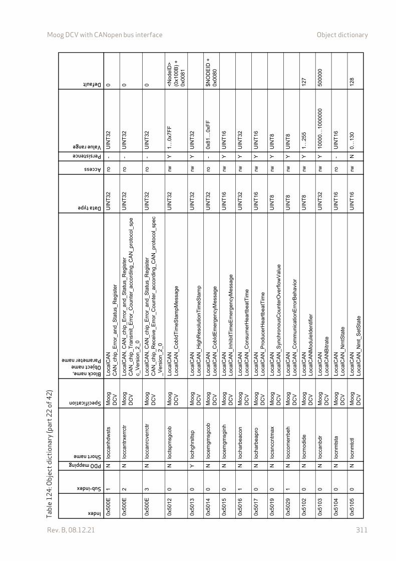
Moog DCV with CANopen bus interface Object dictionary
Rev. B, 08.12.21 311
0x50
0E1
Nlo
ccan
hdw
sts
Mo
og
DC
VL
ocal
CA
NC
AN
_ch
ip_E
rror
_an
d_S
tatu
s_R
egis
ter
UIN
T32
ro-
UIN
T32
0
0x50
0E2
Nlo
ccan
trxe
rrct
rM
oog
D
CV
Loc
alC
AN
, CA
N_c
hip
_Err
or_
and_
Sta
tus_
Reg
iste
rC
AN
_ch
ip_T
rans
mit_
Err
or_C
ount
er_
acco
rdin
g_C
AN
_pro
toco
l_sp
ec_
Ver
sion
_2_0
UIN
T32
ro-
UIN
T32
0
0x50
0E3
Nlo
ccan
rcve
rrct
rM
oog
D
CV
Loc
alC
AN
, CA
N_c
hip
_Err
or_
and_
Sta
tus_
Reg
iste
rC
AN
_ch
ip_R
ecei
ve_E
rro
r_C
oun
ter_
acco
rdin
g_C
AN
_pro
toco
l_sp
ec_
Ve
rsio
n_2
_0
UIN
T32
ro-
UIN
T32
0
0x50
120
Nlo
ctsp
msg
cob
Mo
og
DC
VL
ocal
CA
NL
ocal
CA
N_C
obId
Tim
eSta
mpM
essa
geU
INT
32rw
Y1…
0x7F
F<
Nod
eID
>
(0x1
00B
) +
0x
0081
0x50
130
Ylo
chgh
rslts
pM
oog
D
CV
Loc
alC
AN
Loc
alC
AN
_Hig
hRes
olut
ionT
imeS
tam
pU
INT
32rw
YU
INT
32
0x50
140
Nlo
cem
gmsg
cob
Mo
og
DC
VL
ocal
CA
NL
ocal
CA
N_C
obId
Em
erge
ncy
Mes
sage
UIN
T32
ro-
0x81
…0x
FF
$NO
DE
ID +
0x
0080
0x50
150
Nlo
cem
gmsg
inh
Mo
og
DC
VL
ocal
CA
NL
ocal
CA
N_I
nhi
bitT
imeE
mer
gen
cyM
essa
ge
UIN
T16
rwY
UIN
T16
0x50
161
Nlo
char
beac
onM
oog
D
CV
Loc
alC
AN
Loc
alC
AN
_Con
sum
erH
eart
beat
Tim
eU
INT
32rw
YU
INT
32
0x50
170
Nlo
char
beap
roM
oog
D
CV
Loc
alC
AN
Loc
alC
AN
_Pro
duce
rHea
rtbe
atT
ime
UIN
T16
rwY
UIN
T16
0x50
190
Nlo
csnc
cntm
axM
oog
D
CV
Loc
alC
AN
Loc
alC
AN
_Syn
chro
nous
Cou
nter
Ove
rflo
wV
alu
eU
INT
8rw
YU
INT
8
0x50
291
Nlo
ccom
errb
ehM
oog
D
CV
Loc
alC
AN
Loc
alC
AN
_Com
mun
icat
ionE
rror
Beh
avio
rU
INT
8rw
YU
INT
8
0x51
020
Nlo
cmo
dide
Mo
og
DC
VL
ocal
CA
NL
ocal
CA
NM
odu
leId
entif
ier
UIN
T8
rwY
1…25
512
7
0x51
030
Nlo
ccan
bdr
Mo
og
DC
VL
ocal
CA
NL
ocal
CA
NB
itrat
eU
INT
32rw
Y10
000…
1000
000
5000
00
0x51
040
Nlo
cnm
tsta
Mo
og
DC
VL
ocal
CA
NL
ocal
CA
N_N
mtS
tate
UIN
T16
ro-
UIN
T16
0x51
050
Nlo
cnm
tctl
Mo
og
DC
VL
ocal
CA
NL
ocal
CA
N_N
mt_
Set
Sta
teU
INT
16rw
N0…
130
128
Tabl
e12
4: O
bjec
t dic
tiona
ry (p
art2
2of
42)
Index
Sub-index
PDO mappingShort name
Specification
Block name,Object nameParameter name
Data type
Access
PersistenceValue range
Default

Moog DCV with CANopen bus interface Object dictionary
Rev. B, 08.12.21 312
0x51
101
Nlo
cpdt
trnm
an[0
]M
oog
D
CV
Loc
alC
AN
, Lo
calC
AN
_TP
doM
anuf
actu
rerT
rans
mis
sion
Typ
e1
stLo
cTP
doM
anuf
actu
rerT
rans
mis
sion
Typ
eU
INT
8rw
YU
INT
8
0x51
102
Nlo
cpdt
trnm
an[1
]M
oog
D
CV
Loc
alC
AN
, Lo
calC
AN
_TP
doM
anuf
actu
rerT
rans
mis
sion
Typ
e2
ndLo
cTP
doM
anuf
actu
rerT
rans
mis
sion
Typ
eU
INT
8rw
YU
INT
8
0x51
103
Nlo
cpdt
trnm
an[2
]M
oog
D
CV
Loc
alC
AN
, Lo
calC
AN
_TP
doM
anuf
actu
rerT
rans
mis
sion
Typ
e3
rdLo
cTP
doM
anuf
actu
rerT
rans
mis
sio
nTyp
eU
INT
8rw
YU
INT
8
0x51
104
Nlo
cpdt
trnm
an[3
]M
oog
D
CV
Loc
alC
AN
, Lo
calC
AN
_TP
doM
anuf
actu
rerT
rans
mis
sion
Typ
e4
thLo
cTP
doM
anuf
actu
rerT
rans
mis
sion
Typ
eU
INT
8rw
YU
INT
8
0x51
110
Nlo
cpdt
trg
Mo
og
DC
VL
ocal
CA
NL
ocal
CA
NT
Pdo
Trig
ger
UIN
T8
rwN
0…4
Non
e
0x51
121
Nlo
cpdr
ctr[
0]M
oog
D
CV
Loc
alC
AN
, Lo
calC
AN
_LO
CC
AN
_Loc
RP
doC
ount
er1
stLo
cRP
doC
ount
erU
INT
32rw
NU
INT
32
0x51
122
Nlo
cpdr
ctr[
1]M
oog
D
CV
Loc
alC
AN
, Lo
calC
AN
_LO
CC
AN
_Loc
RP
doC
ount
er2
ndLo
cRP
doC
ount
erU
INT
32rw
NU
INT
32
0x51
123
Nlo
cpdr
ctr[
2]M
oog
D
CV
Loc
alC
AN
, Lo
calC
AN
_LO
CC
AN
_Loc
RP
doC
ount
er3
rdLo
cRP
doC
ount
erU
INT
32rw
NU
INT
32
0x51
124
Nlo
cpdr
ctr[
3]M
oog
D
CV
Loc
alC
AN
, Lo
calC
AN
_LO
CC
AN
_Loc
RP
doC
ount
er4
thLo
cRP
doC
ount
erU
INT
32rw
NU
INT
32
0x52
001
Nlo
csdo
cln
cob
Mo
og
DC
VL
ocal
CA
NL
ocal
CA
N_C
obID
SD
OU
INT
32ro
-U
INT
32$N
OD
EID
+
0x06
00
0x52
002
Nlo
csdo
srvc
obM
oog
D
CV
Loc
alC
AN
Loc
alC
AN
_Cob
IDS
DO
UIN
T32
ro-
UIN
T32
$NO
DE
ID +
0x
0580
0x52
030
Npr
spsn
omM
oog
D
CV
Val
veF
low
Con
trol
Nom
ina
lSup
plyP
ress
ure
INT
16rw
Y1…
3276
735
0
0x52
0F1
Yflw
ctlo
utM
oog
D
CV
Val
veF
low
Con
trol
Flo
wC
ontr
olle
rOut
put
INT
16ro
-IN
T16
0x52
150
Nvl
vqan
Mo
og
DC
VV
alve
Flo
wC
ontr
olR
ated
Val
veF
low
AS
ide
RE
AL3
2rw
Y0.
01…
+in
f14
.43
0x52
160
Nvl
vqbn
Mo
og
DC
VV
alve
Flo
wC
ontr
olR
ated
Val
veF
low
BS
ide
RE
AL3
2rw
Y0.
01…
+in
f14
.59
0x52
190
Nflw
alph
aM
oog
D
CV
Val
veP
ress
ureC
ontr
olC
ylin
derA
lpha
RE
AL3
2ro
-R
EA
L32
0.00
Tabl
e12
4: O
bjec
t dic
tiona
ry (p
art2
3of
42)
Index
Sub-index
PDO mappingShort name
Specification
Block name,Object nameParameter name
Data type
Access
PersistenceValue range
Default
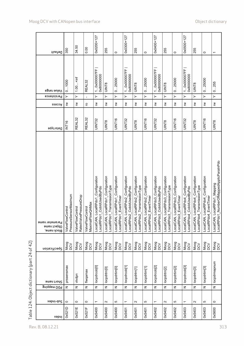
Moog DCV with CANopen bus interface Object dictionary
Rev. B, 08.12.21 313
0x52
1D0
Npr
ssen
smax
Mo
og
DC
VV
alve
Flo
wC
ontr
olP
ress
ureS
enso
rMax
imum
INT
16rw
Y0…
1000
350
0x52
1E0
Nvl
vdpn
Mo
og
DC
VV
alve
Flo
wC
ontr
olR
ated
Val
veP
ress
ureD
rop
RE
AL3
2rw
Y1.
00…
+in
f34
.50
0x52
1F0
Nflw
qam
axM
oog
D
CV
Val
veF
low
Con
trol
Ma
xim
alF
low
QA
Max
RE
AL3
2ro
-R
EA
L32
0.00
0x54
001
Nlo
cpdr
cob[
0]M
oog
D
CV
Loc
alC
AN
, Lo
calR
Pdo
1_C
onfig
ura
tion
Loc
alR
Pdo
1_C
obId
Use
dByP
do
UIN
T32
rwY
1...
0x00
0007
FF
| 0x
8000
0000
0x02
00+
127
0x54
002
Nlo
cpdr
trn
[0]
Mo
og
DC
VL
ocal
CA
N, L
oca
lRP
do1_
Con
figu
ratio
nL
ocal
RP
do1_
Tra
nsm
issi
onT
ype
UIN
T8
rwY
UIN
T8
255
0x54
005
Nlo
cpdr
tim[0
]M
oog
D
CV
Loc
alC
AN
, Lo
calR
Pdo
1_C
onfig
ura
tion
Loc
alR
Pdo
1_E
vent
Tim
erU
INT
16rw
Y0…
2500
00
0x54
011
Nlo
cpdr
cob[
1]M
oog
D
CV
Loc
alC
AN
, Lo
calR
Pdo
2_C
onfig
ura
tion
Loc
alR
Pdo
2_C
obId
Use
dByP
do
UIN
T32
rwY
1...
0x00
0007
FF
| 0x
8000
0000
0x03
00+
127
0x54
012
Nlo
cpdr
trn
[1]
Mo
og
DC
VL
ocal
CA
N, L
oca
lRP
do2_
Con
figu
ratio
nL
ocal
RP
do2_
Tra
nsm
issi
onT
ype
UIN
T8
rwY
UIN
T8
255
0x54
015
Nlo
cpdr
tim[1
]M
oog
D
CV
Loc
alC
AN
, Lo
calR
Pdo
2_C
onfig
ura
tion
Loc
alR
Pdo
2_E
vent
Tim
erU
INT
16rw
Y0…
2500
00
0x54
021
Nlo
cpdr
cob[
2]M
oog
D
CV
Loc
alC
AN
, Lo
calR
Pdo
3_C
onfig
ura
tion
Loc
alR
Pdo
3_C
obId
Use
dByP
do
UIN
T32
rwY
1...
0x00
0007
FF
| 0x
8000
0000
0x04
00+
127
0x54
022
Nlo
cpdr
trn
[2]
Mo
og
DC
VL
ocal
CA
N, L
oca
lRP
do3_
Con
figu
ratio
nL
ocal
RP
do3_
Tra
nsm
issi
onT
ype
UIN
T8
rwY
UIN
T8
255
0x54
025
Nlo
cpdr
tim[2
]M
oog
D
CV
Loc
alC
AN
, Lo
calR
Pdo
3_C
onfig
ura
tion
Loc
alR
Pdo
3_E
vent
Tim
erU
INT
16rw
Y0…
2500
00
0x54
031
Nlo
cpdr
cob[
3]M
oog
D
CV
Loc
alC
AN
, Lo
calR
Pdo
4_C
onfig
ura
tion
Loc
alR
Pdo
4_C
obId
Use
dByP
do
UIN
T32
rwY
1...
0x00
0007
FF
| 0x
8000
0000
0x05
00+
127
0x54
032
Nlo
cpdr
trn
[3]
Mo
og
DC
VL
ocal
CA
N, L
oca
lRP
do4_
Con
figu
ratio
nL
ocal
RP
do4_
Tra
nsm
issi
onT
ype
UIN
T8
rwY
UIN
T8
255
0x54
035
Nlo
cpdr
tim[3
]M
oog
D
CV
Loc
alC
AN
, Lo
calR
Pdo
4_C
onfig
ura
tion
Loc
alR
Pdo
4_E
vent
Tim
erU
INT
16rw
Y0…
2500
00
0x56
000
Nlo
cpdr
map
num
Mo
og
DC
VL
ocal
CA
N, L
oca
lRP
do1_
Map
ping
Loc
alR
Pdo
1_N
umbe
rOfM
appe
dA
ppl
icP
araI
nPdo
UIN
T8
rwY
0…25
51
Tabl
e12
4: O
bjec
t dic
tiona
ry (p
art2
4of
42)
Index
Sub-index
PDO mappingShort name
Specification
Block name,Object nameParameter name
Data type
Access
PersistenceValue range
Default

Moog DCV with CANopen bus interface Object dictionary
Rev. B, 08.12.21 314
0x56
001…
8N
locp
drm
ap[0
…7]
Mo
og
DC
VL
ocal
CA
N, L
oca
lRP
do1_
Map
ping
Loc
alR
Pdo
1_A
pplic
Par
a1…
8U
INT
32rw
YU
INT
32…
0x56
010
Nlo
cpdr
map
num
Mo
og
DC
VL
ocal
CA
N, L
oca
lRP
do1_
Map
ping
Loc
alR
Pdo
1_N
umbe
rOfM
appe
dA
ppl
icP
araI
nPdo
UIN
T8
rwY
0…25
52
0x56
011…
8N
locp
drm
ap[8
…15
]M
oog
D
CV
Loc
alC
AN
, Lo
calR
Pdo
2_M
appi
ngL
ocal
RP
do2_
App
licP
ara1
…8
UIN
T32
rwY
UIN
T32
…
0x56
020
Nlo
cpdr
map
num
Mo
og
DC
VL
ocal
CA
N, L
oca
lRP
do1_
Map
ping
Loc
alR
Pdo
1_N
umbe
rOfM
appe
dA
ppl
icP
araI
nPdo
UIN
T8
rwY
0…25
51
0x56
021…
8N
locp
drm
ap[1
6…23
]M
oog
D
CV
Loc
alC
AN
, Lo
calR
Pdo
3_M
appi
ngL
ocal
RP
do3_
App
licP
ara1
…8
UIN
T32
rwY
UIN
T32
…
0x56
030
Nlo
cpdr
map
num
Mo
og
DC
VL
ocal
CA
N, L
oca
lRP
do1_
Map
ping
Loc
alR
Pdo
1_N
umbe
rOfM
appe
dA
ppl
icP
araI
nPdo
UIN
T8
rwY
0…25
52
0x56
031…
8N
locp
drm
ap[2
4…31
]M
oog
D
CV
Loc
alC
AN
, Lo
calR
Pdo
4_M
appi
ngL
ocal
RP
do4_
App
licP
ara1
…8
UIN
T32
rwY
UIN
T32
…
0x58
001
Nlo
cpdt
cob
[0]
Mo
og
DC
VL
ocal
CA
N, L
oca
lTP
do1_
Con
figur
atio
nL
ocal
TP
do1
_Cob
IdU
sedB
yPdo
UIN
T32
rwY
1…0x
8000
07F
F0x
0180
+12
7
0x58
002
Nlo
cpdt
trn[
0]M
oog
D
CV
Loc
alC
AN
, Lo
calT
Pdo
1_C
onfig
urat
ion
Loc
alT
Pdo
1_T
rans
mis
sion
Typ
eU
INT
8rw
YU
INT
825
5
0x58
005
Nlo
cpdt
tim[0
]M
oog
D
CV
Loc
alC
AN
, Lo
calT
Pdo
1_C
onfig
urat
ion
Loc
alT
Pdo
1_E
vent
Tim
er
UIN
T16
rwY
0…25
000
0
0x58
011
Nlo
cpdt
cob
[1]
Mo
og
DC
VL
ocal
CA
N, L
oca
lTP
do2_
Con
figur
atio
nL
ocal
TP
do2
_Cob
IdU
sedB
yPdo
UIN
T32
rwY
1…0x
8000
07F
F0x
0280
+12
7
0x58
012
Nlo
cpdt
trn[
1]M
oog
D
CV
Loc
alC
AN
, Lo
calT
Pdo
2_C
onfig
urat
ion
Loc
alT
Pdo
2_T
rans
mis
sion
Typ
eU
INT
8rw
YU
INT
825
5
0x58
015
Nlo
cpdt
tim[1
]M
oog
D
CV
Loc
alC
AN
, Lo
calT
Pdo
2_C
onfig
urat
ion
Loc
alT
Pdo
2_E
vent
Tim
er
UIN
T16
rwY
0…25
000
0
0x58
021
Nlo
cpdt
cob
[2]
Mo
og
DC
VL
ocal
CA
N, L
oca
lTP
do3_
Con
figur
atio
nL
ocal
TP
do3
_Cob
IdU
sedB
yPdo
UIN
T32
rwY
1…0x
8000
07F
F0x
0380
+12
7
0x58
022
Nlo
cpdt
trn[
2]M
oog
D
CV
Loc
alC
AN
, Lo
calT
Pdo
3_C
onfig
urat
ion
Loc
alT
Pdo
3_T
rans
mis
sion
Typ
eU
INT
8rw
YU
INT
825
5
0x58
025
Nlo
cpdt
tim[2
]M
oog
D
CV
Loc
alC
AN
, Lo
calT
Pdo
3_C
onfig
urat
ion
Loc
alT
Pdo
3_E
vent
Tim
er
UIN
T16
rwY
0…25
000
0
Tabl
e12
4: O
bjec
t dic
tiona
ry (p
art2
5of
42)
Index
Sub-index
PDO mappingShort name
Specification
Block name,Object nameParameter name
Data type
Access
PersistenceValue range
Default
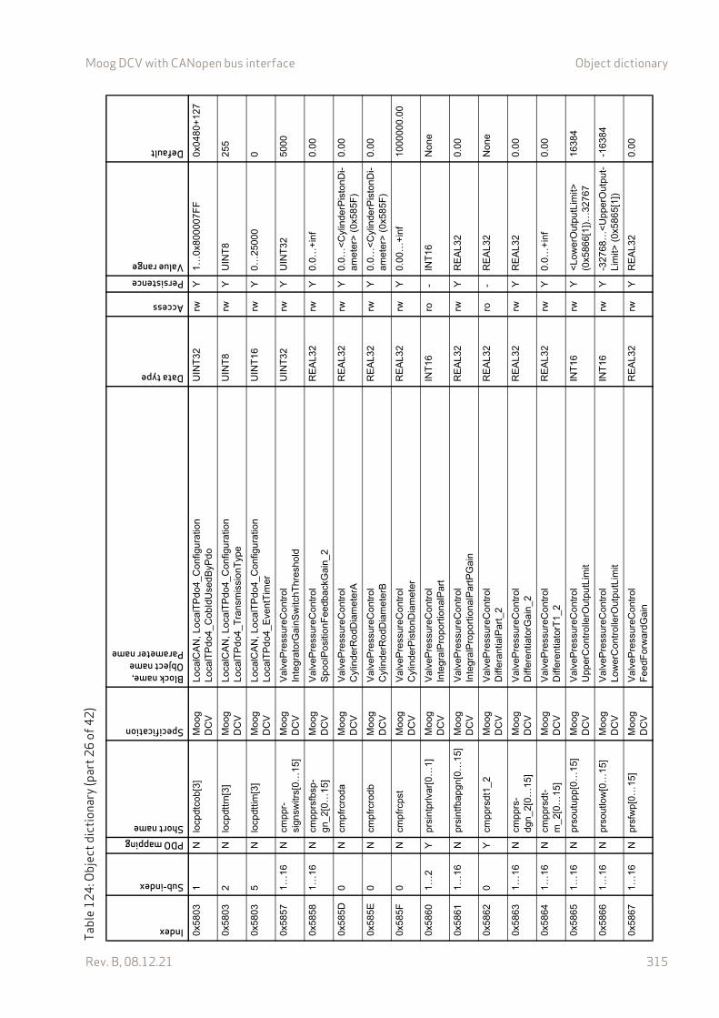
Moog DCV with CANopen bus interface Object dictionary
Rev. B, 08.12.21 315
0x58
031
Nlo
cpdt
cob
[3]
Mo
og
DC
VL
ocal
CA
N, L
oca
lTP
do4_
Con
figur
atio
nL
ocal
TP
do4
_Cob
IdU
sedB
yPdo
UIN
T32
rwY
1…0x
8000
07F
F0x
0480
+12
7
0x58
032
Nlo
cpdt
trn[
3]M
oog
D
CV
Loc
alC
AN
, Lo
calT
Pdo
4_C
onfig
urat
ion
Loc
alT
Pdo
4_T
rans
mis
sion
Typ
eU
INT
8rw
YU
INT
825
5
0x58
035
Nlo
cpdt
tim[3
]M
oog
D
CV
Loc
alC
AN
, Lo
calT
Pdo
4_C
onfig
urat
ion
Loc
alT
Pdo
4_E
vent
Tim
er
UIN
T16
rwY
0…25
000
0
0x58
571…
16N
cmpp
r-si
gnsw
itrs[
0…1
5]M
oog
D
CV
Val
veP
ress
ureC
ontr
olIn
tegr
ator
Gai
nSw
itchT
hres
hold
UIN
T32
rwY
UIN
T32
5000
0x58
581…
16N
cmpp
rsfb
sp-
gn_2
[0…
15]
Mo
og
DC
VV
alve
Pre
ssur
eCon
trol
Spo
olP
ositi
onF
eedb
ackG
ain_
2R
EA
L32
rwY
0.0…
+in
f0.
00
0x58
5D0
Ncm
pfrc
roda
Mo
og
DC
VV
alve
Pre
ssur
eCon
trol
Cyl
inde
rRod
Dia
me
terA
RE
AL3
2rw
Y0.
0…<
Cyl
inde
rPis
tonD
i-am
eter
> (
0x58
5F)
0.00
0x58
5E0
Ncm
pfrc
rodb
Mo
og
DC
VV
alve
Pre
ssur
eCon
trol
Cyl
inde
rRod
Dia
me
terB
RE
AL3
2rw
Y0.
0…<
Cyl
inde
rPis
tonD
i-am
eter
> (
0x58
5F)
0.00
0x58
5F0
Ncm
pfrc
pst
Mo
og
DC
VV
alve
Pre
ssur
eCon
trol
Cyl
inde
rPis
tonD
iam
eter
RE
AL3
2rw
Y0.
00…
+in
f10
0000
0.0
0
0x58
601…
2Y
prsi
ntpr
lvar
[0…
1]M
oog
D
CV
Val
veP
ress
ureC
ontr
olIn
tegr
alP
ropo
rtio
nalP
art
INT
16ro
-IN
T16
Non
e
0x58
611…
16N
prsi
ntfb
apgn
[0…
15]
Mo
og
DC
VV
alve
Pre
ssur
eCon
trol
Inte
gral
Pro
port
iona
lPar
tPG
ain
RE
AL3
2rw
YR
EA
L32
0.00
0x58
620
Ycm
pprs
dt1_
2M
oog
D
CV
Val
veP
ress
ureC
ontr
olD
iffer
antia
lPar
t_2
RE
AL3
2ro
-R
EA
L32
Non
e
0x58
631…
16N
cmpp
rs-
dgn_
2[0…
15]
Mo
og
DC
VV
alve
Pre
ssur
eCon
trol
Diff
eren
tiato
rGai
n_2
RE
AL3
2rw
YR
EA
L32
0.00
0x58
641…
16N
cmpp
rsdt
-m
_2[0
…15
]M
oog
D
CV
Val
veP
ress
ureC
ontr
olD
iffer
entia
torT
1_2
RE
AL3
2rw
Y0.
0…+
inf
0.00
0x58
651…
16N
prso
utu
pp[0
…15
]M
oog
D
CV
Val
veP
ress
ureC
ontr
olU
pper
Con
trol
lerO
utpu
tLim
itIN
T16
rwY
<L
ower
Out
putL
imit>
(0
x586
6[1]
)…32
767
1638
4
0x58
661…
16N
prso
utlo
w[0
…15
]M
oog
D
CV
Val
veP
ress
ureC
ontr
olL
ower
Con
trol
lerO
utpu
tLim
itIN
T16
rwY
-327
68…
<U
pper
Out
put-
Lim
it> (
0x58
65[1
])-1
6384
0x58
671…
16N
prsf
wp
[0…
15]
Mo
og
DC
VV
alve
Pre
ssur
eCon
trol
Fee
dFor
war
dGai
nR
EA
L32
rwY
RE
AL3
20.
00
Tabl
e12
4: O
bjec
t dic
tiona
ry (p
art2
6of
42)
Index
Sub-index
PDO mappingShort name
Specification
Block name,Object nameParameter name
Data type
Access
PersistenceValue range
Default
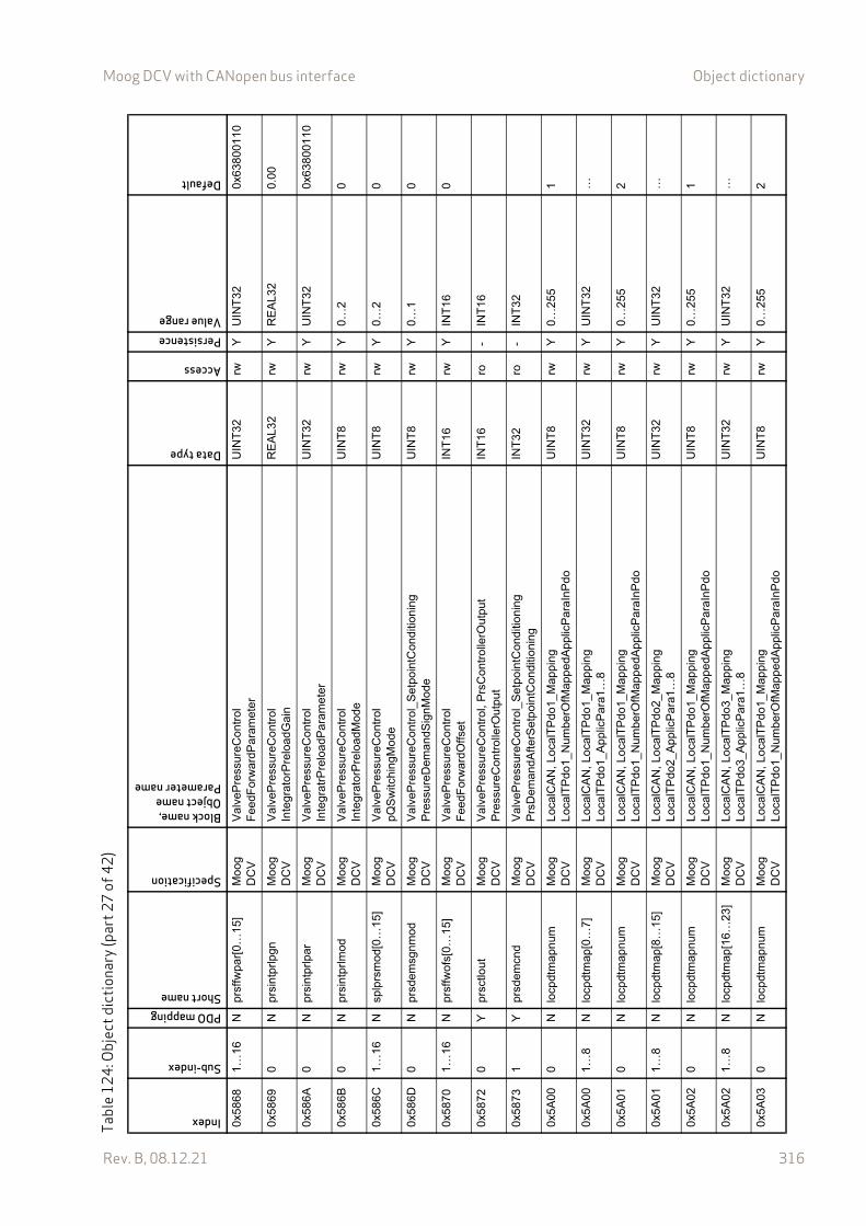
Moog DCV with CANopen bus interface Object dictionary
Rev. B, 08.12.21 316
0x58
681…
16N
prsf
fwpa
r[0…
15]
Mo
og
DC
VV
alve
Pre
ssur
eCon
trol
Fee
dFor
war
dPar
amet
er
UIN
T32
rwY
UIN
T32
0x63
8001
10
0x58
690
Npr
sint
prlp
gnM
oog
D
CV
Val
veP
ress
ureC
ontr
olIn
tegr
ator
Pre
load
Gai
nR
EA
L32
rwY
RE
AL3
20.
00
0x58
6A0
Npr
sint
prlp
arM
oog
D
CV
Val
veP
ress
ureC
ontr
olIn
tegr
atrP
relo
adP
aram
ete
rU
INT
32rw
YU
INT
320x
6380
0110
0x58
6B0
Npr
sint
prlm
odM
oog
D
CV
Val
veP
ress
ureC
ontr
olIn
tegr
ator
Pre
load
Mod
eU
INT
8rw
Y0…
20
0x58
6C1…
16N
splp
rsm
od[0
…15
]M
oog
D
CV
Val
veP
ress
ureC
ontr
olp
QS
witc
hing
Mo
deU
INT
8rw
Y0…
20
0x58
6D0
Npr
sdem
sgnm
odM
oog
D
CV
Val
veP
ress
ureC
ontr
ol_
Se
tpoi
ntC
ondi
tioni
ngP
ress
ureD
eman
dSig
nMod
eU
INT
8rw
Y0…
10
0x58
701…
16N
prsf
fwof
s[0…
15]
Mo
og
DC
VV
alve
Pre
ssur
eCon
trol
Fee
dFor
war
dOffs
etIN
T16
rwY
INT
160
0x58
720
Ypr
sctlo
utM
oog
D
CV
Val
veP
ress
ureC
ontr
ol,
Prs
Con
trol
lerO
utpu
tP
ress
ureC
ontr
olle
rOut
put
INT
16ro
-IN
T16
0x58
731
Ypr
sdem
cnd
Mo
og
DC
VV
alve
Pre
ssur
eCon
trol
_S
etp
oint
Con
ditio
ning
Prs
Dem
andA
fterS
etp
oint
Con
ditio
ning
INT
32ro
-IN
T32
0x5A
000
Nlo
cpdt
map
num
Mo
og
DC
VL
ocal
CA
N, L
oca
lTP
do1_
Map
pin
gL
ocal
TP
do1
_Num
berO
fMap
ped
App
licP
araI
nPdo
UIN
T8
rwY
0…25
51
0x5A
001…
8N
locp
dtm
ap[0
…7]
Mo
og
DC
VL
ocal
CA
N, L
oca
lTP
do1_
Map
pin
gL
ocal
TP
do1
_App
licP
ara
1…8
UIN
T32
rwY
UIN
T32
…
0x5A
010
Nlo
cpdt
map
num
Mo
og
DC
VL
ocal
CA
N, L
oca
lTP
do1_
Map
pin
gL
ocal
TP
do1
_Num
berO
fMap
ped
App
licP
araI
nPdo
UIN
T8
rwY
0…25
52
0x5A
011…
8N
locp
dtm
ap[8
…15
]M
oog
D
CV
Loc
alC
AN
, Lo
calT
Pdo
2_M
appi
ng
Loc
alT
Pdo
2_A
pplic
Pa
ra1…
8U
INT
32rw
YU
INT
32…
0x5A
020
Nlo
cpdt
map
num
Mo
og
DC
VL
ocal
CA
N, L
oca
lTP
do1_
Map
pin
gL
ocal
TP
do1
_Num
berO
fMap
ped
App
licP
araI
nPdo
UIN
T8
rwY
0…25
51
0x5A
021…
8N
locp
dtm
ap[1
6…23
]M
oog
D
CV
Loc
alC
AN
, Lo
calT
Pdo
3_M
appi
ng
Loc
alT
Pdo
3_A
pplic
Pa
ra1…
8U
INT
32rw
YU
INT
32…
0x5A
030
Nlo
cpdt
map
num
Mo
og
DC
VL
ocal
CA
N, L
oca
lTP
do1_
Map
pin
gL
ocal
TP
do1
_Num
berO
fMap
ped
App
licP
araI
nPdo
UIN
T8
rwY
0…25
52
Tabl
e12
4: O
bjec
t dic
tiona
ry (p
art2
7of
42)
Index
Sub-index
PDO mappingShort name
Specification
Block name,Object nameParameter name
Data type
Access
PersistenceValue range
Default
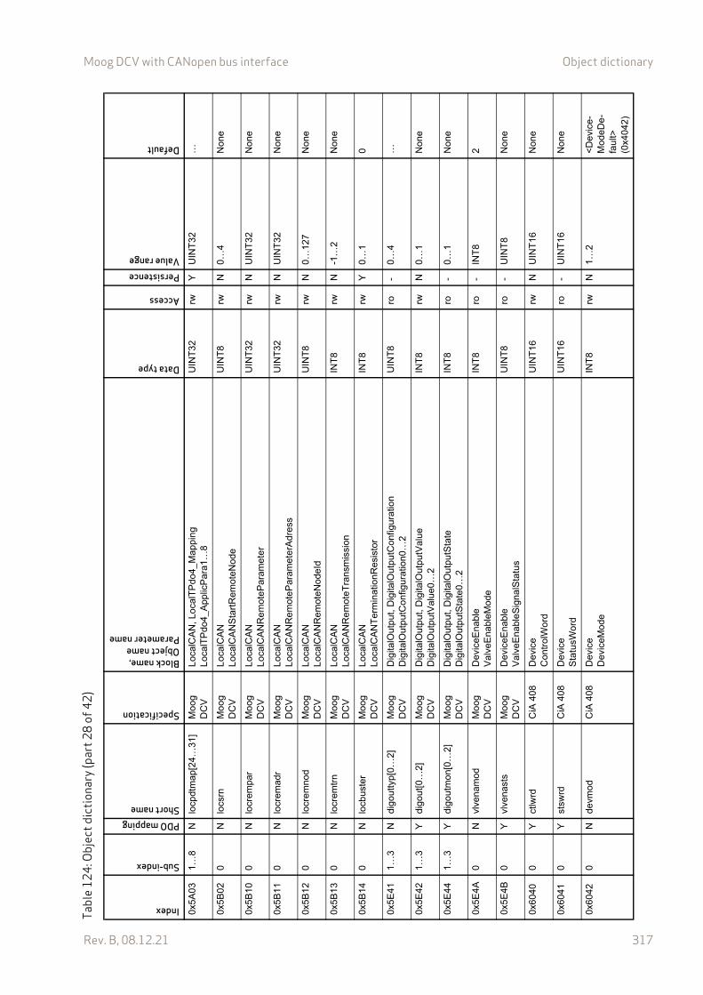
Moog DCV with CANopen bus interface Object dictionary
Rev. B, 08.12.21 317
0x5A
031…
8N
locp
dtm
ap[2
4…31
]M
oog
D
CV
Loc
alC
AN
, Lo
calT
Pdo
4_M
appi
ng
Loc
alT
Pdo
4_A
pplic
Pa
ra1…
8U
INT
32rw
YU
INT
32…
0x5B
020
Nlo
csrn
Mo
og
DC
VL
ocal
CA
NL
ocal
CA
NS
tart
Rem
oteN
ode
UIN
T8
rwN
0…4
Non
e
0x5B
100
Nlo
crem
par
Mo
og
DC
VL
ocal
CA
NL
ocal
CA
NR
em
oteP
aram
ete
rU
INT
32rw
NU
INT
32N
one
0x5B
110
Nlo
crem
adr
Mo
og
DC
VL
ocal
CA
NL
ocal
CA
NR
em
oteP
aram
ete
rAdr
ess
UIN
T32
rwN
UIN
T32
Non
e
0x5B
120
Nlo
crem
nod
Mo
og
DC
VL
ocal
CA
NL
ocal
CA
NR
em
oteN
odeI
dU
INT
8rw
N0…
127
Non
e
0x5B
130
Nlo
crem
trn
Mo
og
DC
VL
ocal
CA
NL
ocal
CA
NR
em
oteT
rans
mis
sion
INT
8rw
N-1
…2
Non
e
0x5B
140
Nlo
cbus
ter
Mo
og
DC
VL
ocal
CA
NL
ocal
CA
NT
erm
inat
ionR
esis
tor
INT
8rw
Y0…
10
0x5E
411…
3N
digo
utty
p[0…
2]M
oog
D
CV
Dig
italO
utp
ut, D
igita
lOut
putC
onfig
urat
ion
Dig
italO
utp
utC
onfig
urat
ion0
…2
UIN
T8
ro-
0…4
…
0x5E
421…
3Y
digo
ut[0
…2]
Mo
og
DC
VD
igita
lOut
put
, Dig
italO
utpu
tVal
ueD
igita
lOut
put
Val
ue0
…2
INT
8rw
N0…
1N
one
0x5E
441…
3Y
digo
utm
on[0
…2]
Mo
og
DC
VD
igita
lOut
put
, Dig
italO
utpu
tSta
teD
igita
lOut
put
Sta
te0…
2IN
T8
ro-
0…1
Non
e
0x5E
4A0
Nvl
vena
mod
Mo
og
DC
VD
evic
eEna
ble
Val
veE
nabl
eMod
eIN
T8
ro-
INT
82
0x5E
4B0
Yvl
vena
sts
Mo
og
DC
VD
evic
eEna
ble
Val
veE
nabl
eSig
nalS
tatu
sU
INT
8ro
-U
INT
8N
one
0x60
400
Yct
lwrd
CiA
408
Dev
ice
Con
trol
Wor
dU
INT
16rw
NU
INT
16N
one
0x60
410
Yst
swrd
CiA
408
Dev
ice
Sta
tusW
ord
UIN
T16
ro-
UIN
T16
Non
e
0x60
420
Nde
vmod
CiA
408
Dev
ice
Dev
iceM
ode
INT
8rw
N1…
2<
Dev
ice-
Mod
eDe-
faul
t>
(0x4
042)
Tabl
e12
4: O
bjec
t dic
tiona
ry (p
art2
8of
42)
Index
Sub-index
PDO mappingShort name
Specification
Block name,Object nameParameter name
Data type
Access
PersistenceValue range
Default
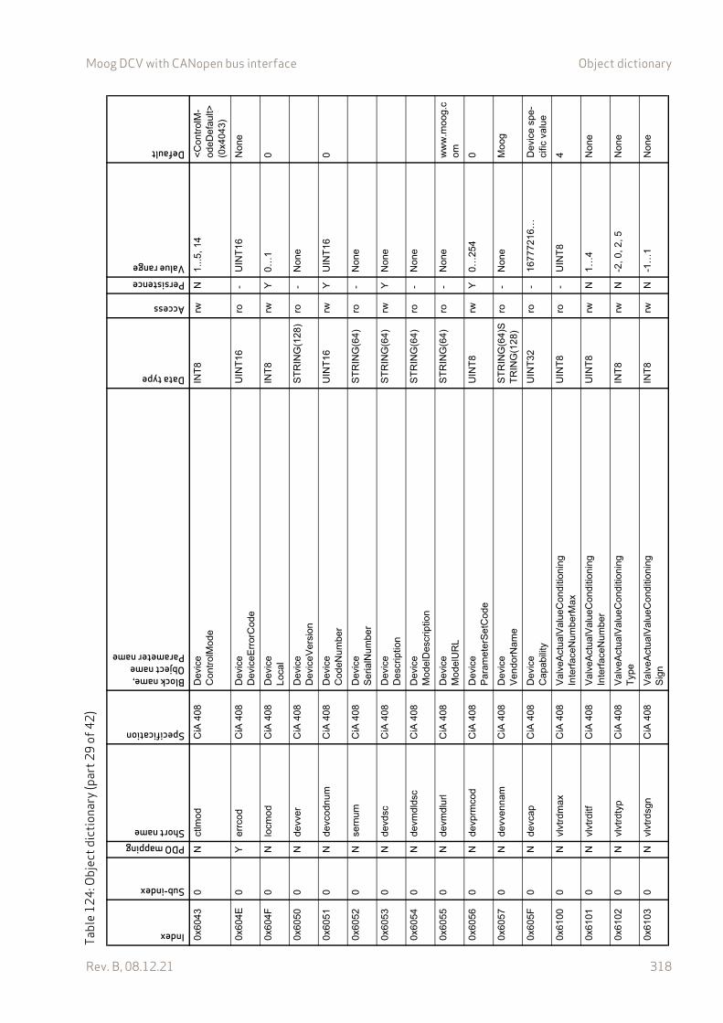
Moog DCV with CANopen bus interface Object dictionary
Rev. B, 08.12.21 318
0x60
430
Nct
lmod
CiA
408
Dev
ice
Con
trol
Mod
eIN
T8
rwN
1...5
, 14
<C
ontr
olM
-od
eDef
ault>
(0
x404
3)
0x60
4E0
Yer
rcod
CiA
408
Dev
ice
Dev
iceE
rror
Cod
eU
INT
16ro
-U
INT
16N
one
0x60
4F0
Nlo
cmo
dC
iA 4
08D
evic
eL
ocal
INT
8rw
Y0…
10
0x60
500
Nde
vver
CiA
408
Dev
ice
Dev
iceV
ersi
onS
TR
ING
(128
)ro
-N
one
0x60
510
Nde
vcod
num
CiA
408
Dev
ice
Cod
eNum
ber
UIN
T16
rwY
UIN
T16
0
0x60
520
Nse
rnum
CiA
408
Dev
ice
Ser
ialN
umbe
rS
TR
ING
(64)
ro-
Non
e
0x60
530
Nde
vdsc
CiA
408
Dev
ice
Des
crip
tion
ST
RIN
G(6
4)rw
YN
one
0x60
540
Nde
vmdl
dsc
CiA
408
Dev
ice
Mo
delD
escr
iptio
nS
TR
ING
(64)
ro-
Non
e
0x60
550
Nde
vmdl
url
CiA
408
Dev
ice
Mo
delU
RL
ST
RIN
G(6
4)ro
-N
one
ww
w.m
oog.
com
0x60
560
Nde
vprm
cod
CiA
408
Dev
ice
Par
amet
erS
etC
ode
UIN
T8
rwY
0…25
40
0x60
570
Nde
vven
nam
CiA
408
Dev
ice
Ven
dorN
ame
ST
RIN
G(6
4)S
TR
ING
(12
8)ro
-N
one
Moo
g
0x60
5F0
Nde
vcap
CiA
408
Dev
ice
Cap
abili
tyU
INT
32ro
-16
7772
16…
Dev
ice
spe-
cific
va
lue
0x61
000
Nvl
vtrd
max
CiA
408
Val
veA
ctua
lVal
ueC
ondi
tioni
ngIn
terf
aceN
umbe
rMax
UIN
T8
ro-
UIN
T8
4
0x61
010
Nvl
vtrd
itfC
iA 4
08V
alve
Act
ualV
alue
Con
ditio
ning
Inte
rfac
eNum
ber
UIN
T8
rwN
1…4
Non
e
0x61
020
Nvl
vtrd
typ
CiA
408
Val
veA
ctua
lVal
ueC
ondi
tioni
ngT
ype
INT
8rw
N-2
, 0, 2
, 5N
one
0x61
030
Nvl
vtrd
sgn
CiA
408
Va
lveA
ctua
lVal
ueC
ondi
tioni
ngS
ign
INT
8rw
N-1
…1
Non
e
Tabl
e12
4: O
bjec
t dic
tiona
ry (p
art2
9of
42)
Index
Sub-index
PDO mappingShort name
Specification
Block name,Object nameParameter name
Data type
Access
PersistenceValue range
Default
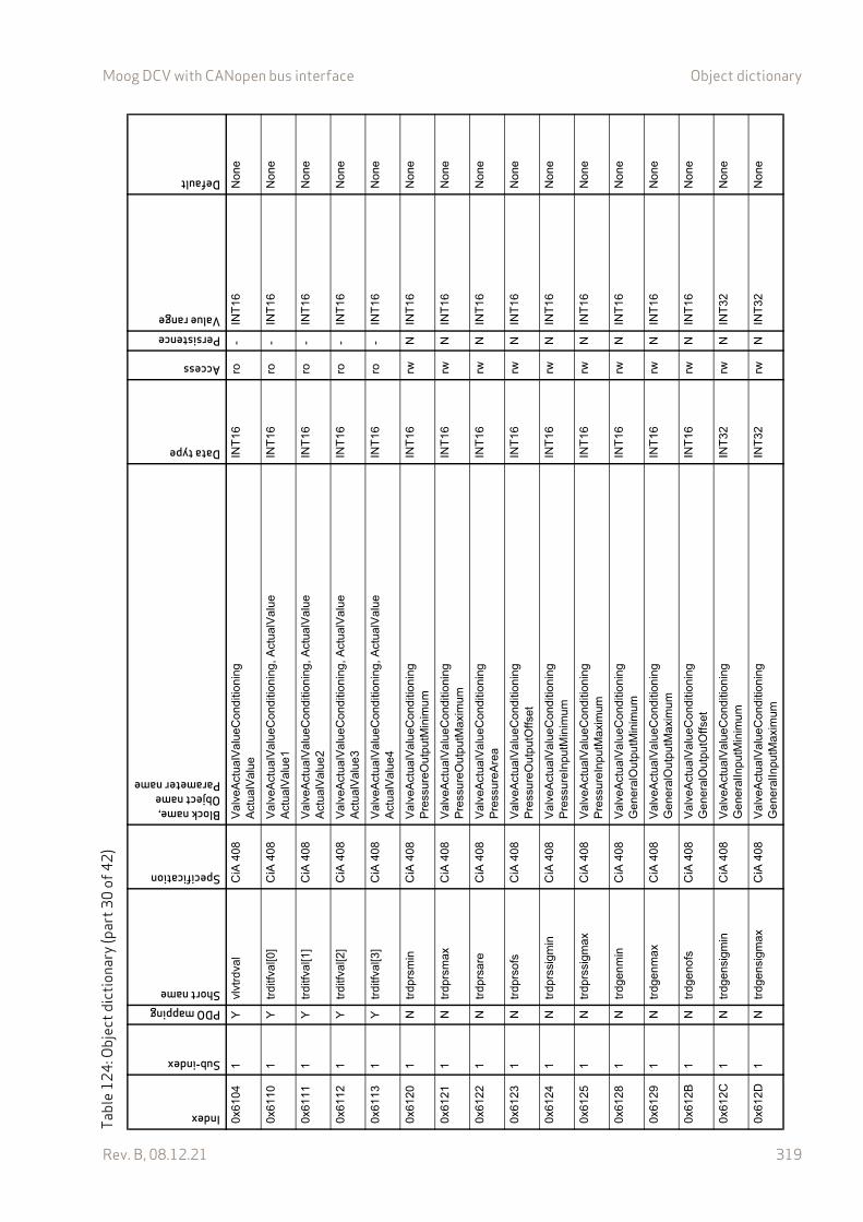
Moog DCV with CANopen bus interface Object dictionary
Rev. B, 08.12.21 319
0x61
041
Yvl
vtrd
val
CiA
408
Va
lveA
ctua
lVal
ueC
ondi
tioni
ngA
ctua
lVal
ueIN
T16
ro-
INT
16N
one
0x61
101
Ytr
ditfv
al[0
]C
iA 4
08V
alve
Act
ualV
alue
Con
ditio
ning
, Act
ualV
alue
Act
ualV
alue
1IN
T16
ro-
INT
16N
one
0x61
111
Ytr
ditfv
al[1
]C
iA 4
08V
alve
Act
ualV
alue
Con
ditio
ning
, Act
ualV
alue
Act
ualV
alue
2IN
T16
ro-
INT
16N
one
0x61
121
Ytr
ditfv
al[2
]C
iA 4
08V
alve
Act
ualV
alue
Con
ditio
ning
, Act
ualV
alue
Act
ualV
alue
3IN
T16
ro-
INT
16N
one
0x61
131
Ytr
ditfv
al[3
]C
iA 4
08V
alve
Act
ualV
alue
Con
ditio
ning
, Act
ualV
alue
Act
ualV
alue
4IN
T16
ro-
INT
16N
one
0x61
201
Ntr
dprs
min
CiA
408
Va
lveA
ctua
lVal
ueC
ondi
tioni
ngP
ress
ureO
utp
utM
inim
umIN
T16
rwN
INT
16N
one
0x61
211
Ntr
dprs
max
CiA
408
Val
veA
ctua
lVal
ueC
ondi
tioni
ngP
ress
ureO
utp
utM
axim
umIN
T16
rwN
INT
16N
one
0x61
221
Ntr
dprs
are
CiA
408
Val
veA
ctua
lVal
ueC
ondi
tioni
ngP
ress
ureA
rea
INT
16rw
NIN
T16
Non
e
0x61
231
Ntr
dprs
ofs
CiA
408
Val
veA
ctua
lVal
ueC
ondi
tioni
ngP
ress
ureO
utp
utO
ffset
INT
16rw
NIN
T16
Non
e
0x61
241
Ntr
dprs
sigm
inC
iA 4
08V
alve
Act
ualV
alue
Con
ditio
ning
Pre
ssur
eInp
utM
inim
umIN
T16
rwN
INT
16N
one
0x61
251
Ntr
dprs
sigm
axC
iA 4
08V
alve
Act
ualV
alue
Con
ditio
ning
Pre
ssur
eInp
utM
axim
umIN
T16
rwN
INT
16N
one
0x61
281
Ntr
dgen
min
CiA
408
Val
veA
ctua
lVal
ueC
ondi
tioni
ngG
ener
alO
utpu
tMin
imum
INT
16rw
NIN
T16
Non
e
0x61
291
Ntr
dgen
max
CiA
408
Val
veA
ctua
lVal
ueC
ondi
tioni
ngG
ener
alO
utpu
tMax
imum
INT
16rw
NIN
T16
Non
e
0x61
2B1
Ntr
dgen
ofs
CiA
408
Val
veA
ctua
lVal
ueC
ondi
tioni
ngG
ener
alO
utpu
tOffs
etIN
T16
rwN
INT
16N
one
0x61
2C1
Ntr
dgen
sigm
inC
iA 4
08V
alv
eAct
ualV
alue
Con
ditio
ning
Gen
eral
Inpu
tMin
imum
INT
32rw
NIN
T32
Non
e
0x61
2D1
Ntr
dgen
sigm
axC
iA 4
08V
alve
Act
ualV
alue
Con
ditio
ning
Gen
eral
Inpu
tMax
imum
INT
32rw
NIN
T32
Non
e
Tabl
e12
4: O
bjec
t dic
tiona
ry (p
art3
0of
42)
Index
Sub-index
PDO mappingShort name
Specification
Block name,Object nameParameter name
Data type
Access
PersistenceValue range
Default
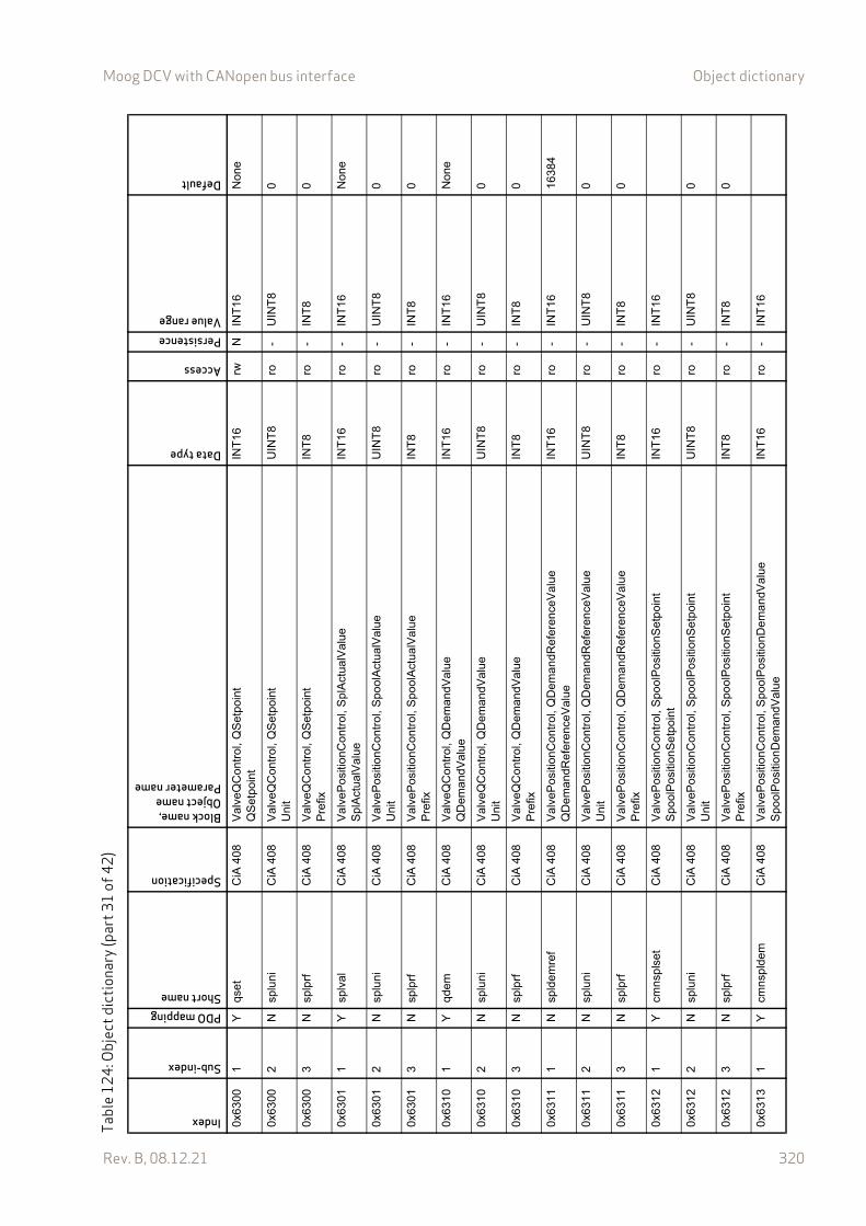
Moog DCV with CANopen bus interface Object dictionary
Rev. B, 08.12.21 320
0x63
001
Yqs
etC
iA 4
08V
alve
QC
ontr
ol, Q
Set
poin
tQ
Set
poin
tIN
T16
rwN
INT
16N
one
0x63
002
Nsp
luni
CiA
408
Val
veQ
Con
trol
, QS
etpo
int
Uni
tU
INT
8ro
-U
INT
80
0x63
003
Nsp
lprf
CiA
408
Val
veQ
Con
trol
, QS
etpo
int
Pre
fixIN
T8
ro-
INT
80
0x63
011
Ysp
lval
CiA
408
Val
veP
ositi
onC
ontr
ol, S
plA
ctua
lVal
ueS
plA
ctua
lVal
ueIN
T16
ro-
INT
16N
one
0x63
012
Nsp
luni
CiA
408
Val
veP
ositi
onC
ontr
ol, S
poo
lAct
ualV
alue
Uni
tU
INT
8ro
-U
INT
80
0x63
013
Nsp
lprf
CiA
408
Val
veP
ositi
onC
ontr
ol, S
poo
lAct
ualV
alue
Pre
fixIN
T8
ro-
INT
80
0x63
101
Yqd
emC
iA 4
08V
alve
QC
ontr
ol, Q
Dem
andV
alue
QD
ema
ndV
alue
INT
16ro
-IN
T16
Non
e
0x63
102
Nsp
luni
CiA
408
Val
veQ
Con
trol
, QD
eman
dVal
ueU
nit
UIN
T8
ro-
UIN
T8
0
0x63
103
Nsp
lprf
CiA
408
Val
veQ
Con
trol
, QD
eman
dVal
ueP
refix
INT
8ro
-IN
T8
0
0x63
111
Nsp
ldem
ref
CiA
408
Val
veP
ositi
onC
ontr
ol, Q
Dem
andR
efer
ence
Val
ueQ
Dem
and
Ref
eren
ceV
alue
INT
16ro
-IN
T16
1638
4
0x63
112
Nsp
luni
CiA
408
Val
veP
ositi
onC
ontr
ol, Q
Dem
andR
efer
ence
Val
ue
Uni
tU
INT
8ro
-U
INT
80
0x63
113
Nsp
lprf
CiA
408
Val
veP
ositi
onC
ontr
ol, Q
Dem
andR
efer
ence
Val
ue
Pre
fixIN
T8
ro-
INT
80
0x63
121
Ycm
nsp
lset
CiA
408
Val
veP
ositi
onC
ontr
ol, S
poo
lPos
ition
Set
poi
ntS
pool
Pos
ition
Set
poin
tIN
T16
ro-
INT
16
0x63
122
Nsp
luni
CiA
408
Val
veP
ositi
onC
ontr
ol, S
poo
lPos
ition
Set
poin
tU
nit
UIN
T8
ro-
UIN
T8
0
0x63
123
Nsp
lprf
CiA
408
Val
veP
ositi
onC
ontr
ol, S
poo
lPos
ition
Set
poin
tP
refix
INT
8ro
-IN
T8
0
0x63
131
Ycm
nsp
ldem
CiA
408
Val
veP
ositi
onC
ontr
ol, S
poo
lPos
ition
Dem
and
Val
ueS
pool
Pos
ition
De
man
dVal
ue
INT
16ro
-IN
T16
Tabl
e12
4: O
bjec
t dic
tiona
ry (p
art3
1of
42)
Index
Sub-index
PDO mappingShort name
Specification
Block name,Object nameParameter name
Data type
Access
PersistenceValue range
Default
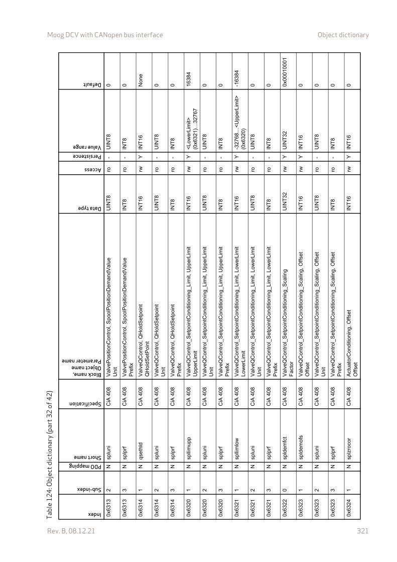
Moog DCV with CANopen bus interface Object dictionary
Rev. B, 08.12.21 321
0x63
132
Nsp
luni
CiA
408
Val
veP
ositi
onC
ontr
ol, S
poo
lPos
ition
Dem
and
Val
ueU
nit
UIN
T8
ro-
UIN
T8
0
0x63
133
Nsp
lprf
CiA
408
Val
veP
ositi
onC
ontr
ol, S
poo
lPos
ition
Dem
and
Val
ueP
refix
INT
8ro
-IN
T8
0
0x63
141
Nqs
ethl
dC
iA 4
08V
alve
QC
ontr
ol, Q
Hol
dSet
poin
tQ
Hol
dSet
Poi
ntIN
T16
rwY
INT
16N
one
0x63
142
Nsp
luni
CiA
408
Val
veQ
Con
trol
, QH
oldS
etpo
int
Uni
tU
INT
8ro
-U
INT
80
0x63
143
Nsp
lprf
CiA
408
Val
veQ
Con
trol
, QH
oldS
etpo
int
Pre
fixIN
T8
ro-
INT
80
0x63
201
Nsp
llim
upp
CiA
408
Val
veQ
Con
trol
_Set
poin
tCon
ditio
nin
g_Li
mit,
Up
perL
imit
Upp
erLi
mit
INT
16rw
Y<
Low
erLi
mit>
(0
x632
1)…
3276
716
384
0x63
202
Nsp
luni
CiA
408
Val
veQ
Con
trol
_Set
poin
tCon
ditio
nin
g_Li
mit,
Up
perL
imit
Uni
tU
INT
8ro
-U
INT
80
0x63
203
Nsp
lprf
CiA
408
Val
veQ
Con
trol
_Set
poin
tCon
ditio
nin
g_Li
mit,
Up
perL
imit
Pre
fixIN
T8
ro-
INT
80
0x63
211
Nsp
llim
low
CiA
408
Val
veQ
Con
trol
_Set
poin
tCon
ditio
nin
g_Li
mit,
Low
erLi
mit
Lo
we
rLim
itIN
T16
rwY
-327
68…
<U
pper
Lim
it>
(0x6
320)
-163
84
0x63
212
Nsp
luni
CiA
408
Val
veQ
Con
trol
_Set
poin
tCon
ditio
nin
g_Li
mit,
Low
erLi
mit
Uni
tU
INT
8ro
-U
INT
80
0x63
213
Nsp
lprf
CiA
408
Val
veQ
Con
trol
_Set
poin
tCon
ditio
nin
g_Li
mit,
Low
erLi
mit
Pre
fixIN
T8
ro-
INT
80
0x63
220
Nsp
ldem
fct
CiA
408
Val
veQ
Con
trol
_Set
poin
tCon
ditio
nin
g_S
calin
gF
acto
rU
INT
32rw
YU
INT
320x
0001
0001
0x63
231
Nsp
ldem
ofs
CiA
408
Val
veQ
Con
trol
_Set
poin
tCon
ditio
nin
g_S
calin
g, O
ffset
Off
set
INT
16rw
YIN
T16
0
0x63
232
Nsp
luni
CiA
408
Val
veQ
Con
trol
_Set
poin
tCon
ditio
nin
g_S
calin
g, O
ffset
Uni
tU
INT
8ro
-U
INT
80
0x63
233
Nsp
lprf
CiA
408
Val
veQ
Con
trol
_Set
poin
tCon
ditio
nin
g_S
calin
g, O
ffset
Pre
fixIN
T8
ro-
INT
80
0x63
241
Nsp
lzro
cor
CiA
408
Act
uato
rCon
ditio
ning
, O
ffset
Off
set
INT
16rw
YIN
T16
0
Tabl
e12
4: O
bjec
t dic
tiona
ry (p
art3
2of
42)
Index
Sub-index
PDO mappingShort name
Specification
Block name,Object nameParameter name
Data type
Access
PersistenceValue range
Default
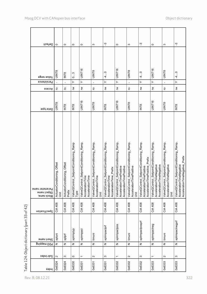
Moog DCV with CANopen bus interface Object dictionary
Rev. B, 08.12.21 322
0x63
242
Nsp
luni
CiA
408
Act
uato
rCon
ditio
ning
, O
ffset
Uni
tU
INT
8ro
-U
INT
80
0x63
243
Nsp
lprf
CiA
408
Act
uato
rCon
ditio
ning
, O
ffset
Pre
fixIN
T8
ro-
INT
80
0x63
300
Nsp
lrm
ptyp
CiA
408
Val
veQ
Con
trol
_Set
poin
tCon
ditio
nin
g_R
amp
Typ
eIN
T8
rwY
0…3
0
0x63
311
Nsp
lrm
pacl
CiA
408
Val
veQ
Con
trol
_Set
poin
tCon
ditio
nin
g_R
amp
, A
cce
lera
tion
Tim
eA
cce
lera
tion
Tim
e
UIN
T16
rwY
UIN
T16
0
0x63
312
Ntim
uni
CiA
408
Val
veQ
Con
trol
_Set
poin
tCon
ditio
nin
g_R
amp,
A
cce
lera
tion
Tim
eU
nit
UIN
T8
ro-
UIN
T8
3
0x63
313
Nsp
lrm
pacl
prf
CiA
408
Val
veQ
Con
trol
_Set
poin
tCon
ditio
nin
g_R
amp,
A
cce
lera
tion
Tim
eA
ccel
erat
ionT
ime_
Pre
fix
INT
8rw
Y-4
…0
-3
0x63
321
Nsp
lrm
pacl
pos
CiA
408
Val
veQ
Con
trol
_Set
poin
tCon
ditio
nin
g_R
amp,
A
ccel
erat
ionT
imeP
ositi
veA
ccel
erat
ionT
imeP
ositi
ve
UIN
T16
rwY
UIN
T16
0
0x63
322
Ntim
uni
CiA
408
Val
veQ
Con
trol
_Set
poin
tCon
ditio
nin
g_R
amp,
A
ccel
erat
ionT
imeP
ositi
veU
nit
UIN
T8
ro-
UIN
T8
3
0x63
323
Nsp
lrm
pacl
posp
rfC
iA 4
08V
alv
eQC
ontr
ol_S
etpo
intC
ondi
tioni
ng_
Ram
p,
Acc
eler
atio
nTim
ePos
itive
Acc
eler
atio
nTim
ePos
itive
_Pre
fix
INT
8rw
Y-4
…0
-3
0x63
331
Nsp
lrm
pacl
neg
CiA
408
Val
veQ
Con
trol
_Set
poin
tCon
ditio
nin
g_R
amp,
A
ccel
erat
ionT
imeN
egat
ive
Acc
eler
atio
nTim
eNeg
ativ
e
UIN
T16
rwY
UIN
T16
0
0x63
332
Ntim
uni
CiA
408
Val
veQ
Con
trol
_Set
poin
tCon
ditio
nin
g_R
amp,
A
ccel
erat
ionT
imeN
egat
ive
Uni
t
UIN
T8
ro-
UIN
T8
3
0x63
333
Nsp
lrm
pacl
neg
prf
CiA
408
Va
lveQ
Con
trol
_Set
poin
tCon
ditio
nin
g_R
amp,
A
ccel
erat
ionT
imeN
egat
ive
Acc
eler
atio
nTim
eNeg
ativ
e_P
refix
INT
8rw
Y-4
…0
-3
Tabl
e12
4: O
bjec
t dic
tiona
ry (p
art3
3of
42)
Index
Sub-index
PDO mappingShort name
Specification
Block name,Object nameParameter name
Data type
Access
PersistenceValue range
Default
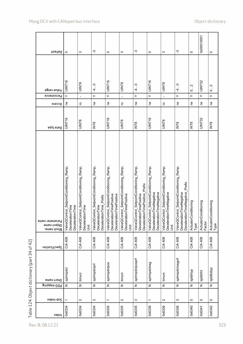
Moog DCV with CANopen bus interface Object dictionary
Rev. B, 08.12.21 323
0x63
341
Nsp
lrm
pdcl
CiA
408
Val
veQ
Con
trol
_Set
poin
tCon
ditio
nin
g_R
amp
, D
ecel
erat
ionT
ime
Dec
eler
atio
nTim
e
UIN
T16
rwY
UIN
T16
0
0x63
342
Ntim
uni
CiA
408
Val
veQ
Con
trol
_Set
poin
tCon
ditio
nin
g_R
amp,
D
ecel
erat
ionT
ime
Uni
t
UIN
T8
ro-
UIN
T8
3
0x63
343
Nsp
lrm
pdcl
prf
CiA
408
Val
veQ
Con
trol
_Set
poin
tCon
ditio
nin
g_R
amp,
D
ecel
erat
ionT
ime
Dec
eler
atio
nTim
e_P
refix
INT
8rw
Y-4
…0
-3
0x63
351
Nsp
lrm
pdcl
pos
CiA
408
Val
veQ
Con
trol
_Set
poin
tCon
ditio
nin
g_R
amp,
D
ecel
erat
ionT
ime
Po
sitiv
eD
ecel
erat
ionT
ime
Po
sitiv
e
UIN
T16
rwY
UIN
T16
0
0x63
352
Ntim
uni
CiA
408
Val
veQ
Con
trol
_Set
poin
tCon
ditio
nin
g_R
amp,
D
ecel
erat
ionT
ime
Po
sitiv
eU
nit
UIN
T8
ro-
UIN
T8
3
0x63
353
Nsp
lrm
pdcl
posp
rfC
iA 4
08V
alv
eQC
ontr
ol_S
etpo
intC
ondi
tioni
ng_
Ram
p,
Dec
eler
atio
nTim
eP
osi
tive
Dec
eler
atio
nTim
eP
osi
tive_
Pre
fix
INT
8rw
Y-4
…0
-3
0x63
361
Nsp
lrm
pdcl
neg
CiA
408
Val
veQ
Con
trol
_Set
poin
tCon
ditio
nin
g_R
amp,
D
ecel
erat
ionT
ime
Neg
ativ
eD
ecel
erat
ionT
ime
Neg
ativ
e
UIN
T16
rwY
UIN
T16
0
0x63
362
Ntim
uni
CiA
408
Val
veQ
Con
trol
_Set
poin
tCon
ditio
nin
g_R
amp,
D
ecel
erat
ionT
ime
Neg
ativ
eU
nit
UIN
T8
ro-
UIN
T8
3
0x63
363
Nsp
lrm
pdcl
neg
prf
CiA
408
Va
lveQ
Con
trol
_Set
poin
tCon
ditio
nin
g_R
amp,
D
ecel
erat
ionT
ime
Neg
ativ
eD
ecel
erat
ionT
ime
Neg
ativ
e_P
refix
INT
8rw
Y-4
…0
-3
0x63
400
Nsp
ldirt
ypC
iA 4
08A
ctua
torC
ondi
tioni
ngT
ype
INT
8rw
Y0…
20
0x63
410
Nsp
ldirf
ctC
iA 4
08A
ctua
torC
ondi
tioni
ngF
acto
rU
INT
32rw
YU
INT
320x
0001
0001
0x63
420
Nsp
ldbd
typ
CiA
408
Act
uato
rCon
ditio
ning
Typ
eIN
T8
rwY
0…2
0
Tabl
e12
4: O
bjec
t dic
tiona
ry (p
art3
4of
42)
Index
Sub-index
PDO mappingShort name
Specification
Block name,Object nameParameter name
Data type
Access
PersistenceValue range
Default
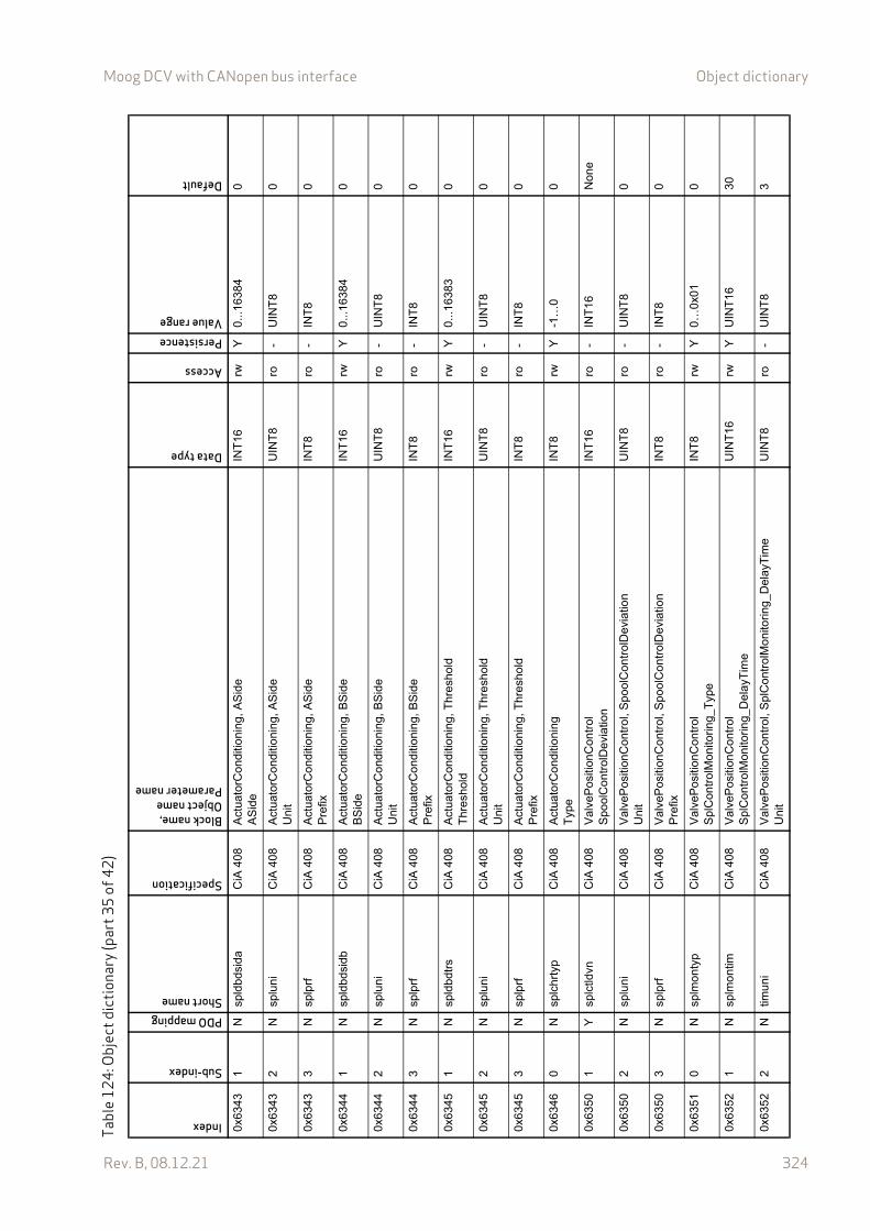
Moog DCV with CANopen bus interface Object dictionary
Rev. B, 08.12.21 324
0x63
431
Nsp
ldbd
sida
CiA
408
Act
uato
rCon
ditio
ning
, A
Sid
eA
Sid
eIN
T16
rwY
0...1
6384
0
0x63
432
Nsp
luni
CiA
408
Act
uato
rCon
ditio
ning
, A
Sid
eU
nit
UIN
T8
ro-
UIN
T8
0
0x63
433
Nsp
lprf
CiA
408
Act
uato
rCon
ditio
ning
, A
Sid
eP
refix
INT
8ro
-IN
T8
0
0x63
441
Nsp
ldbd
sidb
CiA
408
Act
uato
rCon
ditio
ning
, B
Sid
eB
Sid
eIN
T16
rwY
0...1
6384
0
0x63
442
Nsp
luni
CiA
408
Act
uato
rCon
ditio
ning
, B
Sid
eU
nit
UIN
T8
ro-
UIN
T8
0
0x63
443
Nsp
lprf
CiA
408
Act
uato
rCon
ditio
ning
, B
Sid
eP
refix
INT
8ro
-IN
T8
0
0x63
451
Nsp
ldbd
trs
CiA
408
Act
uato
rCon
ditio
ning
, T
hre
shol
dT
hres
hold
INT
16rw
Y0.
..163
830
0x63
452
Nsp
luni
CiA
408
Act
uato
rCon
ditio
ning
, T
hre
shol
dU
nit
UIN
T8
ro-
UIN
T8
0
0x63
453
Nsp
lprf
CiA
408
Act
uato
rCon
ditio
ning
, T
hre
shol
dP
refix
INT
8ro
-IN
T8
0
0x63
460
Nsp
lchr
typ
CiA
408
Act
uato
rCon
ditio
ning
Typ
eIN
T8
rwY
-1…
00
0x63
501
Ysp
lctld
vnC
iA 4
08V
alve
Pos
ition
Con
trol
Spo
olC
ont
rolD
evia
tion
INT
16ro
-IN
T16
Non
e
0x63
502
Nsp
luni
CiA
408
Val
veP
ositi
onC
ontr
ol, S
poo
lCon
trol
Dev
iatio
nU
nit
UIN
T8
ro-
UIN
T8
0
0x63
503
Nsp
lprf
CiA
408
Val
veP
ositi
onC
ontr
ol, S
poo
lCon
trol
Dev
iatio
nP
refix
INT
8ro
-IN
T8
0
0x63
510
Nsp
lmo
ntyp
CiA
408
Val
veP
ositi
onC
ontr
olS
plC
ontr
olM
onito
ring_
Typ
eIN
T8
rwY
0…0x
010
0x63
521
Nsp
lmo
ntim
CiA
408
Val
veP
ositi
onC
ontr
olS
plC
ontr
olM
onito
ring_
Del
ayT
ime
UIN
T16
rwY
UIN
T16
30
0x63
522
Ntim
uni
CiA
408
Val
veP
ositi
onC
ontr
ol, S
plC
ontr
olM
oni
tori
ng_D
elay
Tim
eU
nit
UIN
T8
ro-
UIN
T8
3
Tabl
e12
4: O
bjec
t dic
tiona
ry (p
art3
5of
42)
Index
Sub-index
PDO mappingShort name
Specification
Block name,Object nameParameter name
Data type
Access
PersistenceValue range
Default
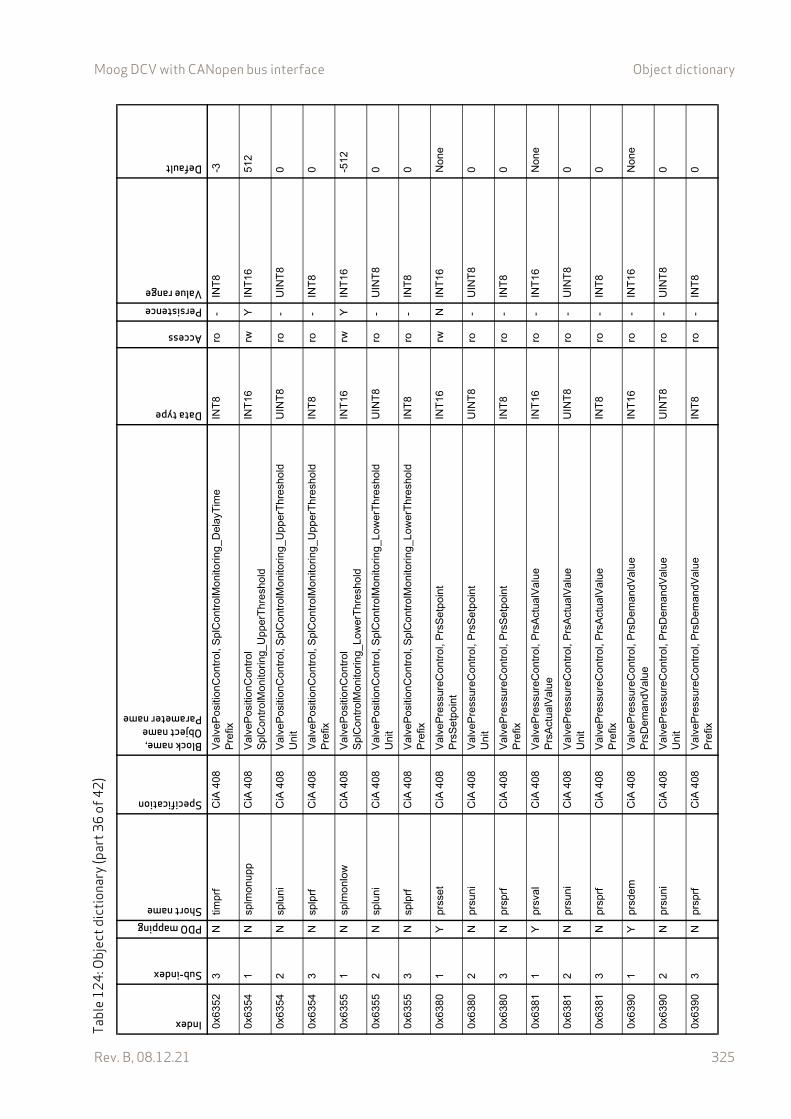
Moog DCV with CANopen bus interface Object dictionary
Rev. B, 08.12.21 325
0x63
523
Ntim
prf
CiA
408
Val
veP
ositi
onC
ontr
ol, S
plC
ontr
olM
oni
tori
ng_D
elay
Tim
eP
refix
INT
8ro
-IN
T8
-3
0x63
541
Nsp
lmo
nupp
CiA
408
Val
veP
ositi
onC
ontr
olS
plC
ontr
olM
onito
ring_
Upp
erT
hre
shol
dIN
T16
rwY
INT
1651
2
0x63
542
Nsp
luni
CiA
408
Val
veP
ositi
onC
ontr
ol, S
plC
ontr
olM
oni
tori
ng_U
pper
Thr
esh
old
Uni
tU
INT
8ro
-U
INT
80
0x63
543
Nsp
lprf
CiA
408
Val
veP
ositi
onC
ontr
ol, S
plC
ontr
olM
oni
tori
ng_U
pper
Thr
esh
old
Pre
fixIN
T8
ro-
INT
80
0x63
551
Nsp
lmo
nlow
CiA
408
Val
veP
ositi
onC
ontr
olS
plC
ontr
olM
onito
ring_
Low
erT
hre
shol
dIN
T16
rwY
INT
16-5
12
0x63
552
Nsp
luni
CiA
408
Val
veP
ositi
onC
ontr
ol, S
plC
ontr
olM
oni
tori
ng_L
ower
Thr
esh
old
Uni
tU
INT
8ro
-U
INT
80
0x63
553
Nsp
lprf
CiA
408
Val
veP
ositi
onC
ontr
ol, S
plC
ontr
olM
oni
tori
ng_L
ower
Thr
esh
old
Pre
fixIN
T8
ro-
INT
80
0x63
801
Ypr
sset
CiA
408
Val
veP
ress
ureC
ontr
ol,
Prs
Set
poi
ntP
rsS
etpo
int
INT
16rw
NIN
T16
Non
e
0x63
802
Npr
suni
CiA
408
Val
veP
ress
ureC
ontr
ol,
Prs
Set
poi
ntU
nit
UIN
T8
ro-
UIN
T8
0
0x63
803
Npr
sprf
CiA
408
Val
veP
ress
ureC
ontr
ol,
Prs
Set
poi
ntP
refix
INT
8ro
-IN
T8
0
0x63
811
Ypr
sval
CiA
408
Val
veP
ress
ureC
ontr
ol,
Prs
Act
ualV
alue
Prs
Act
ualV
alu
eIN
T16
ro-
INT
16N
one
0x63
812
Npr
suni
CiA
408
Val
veP
ress
ureC
ontr
ol,
Prs
Act
ualV
alue
Uni
tU
INT
8ro
-U
INT
80
0x63
813
Npr
sprf
CiA
408
Val
veP
ress
ureC
ontr
ol,
Prs
Act
ualV
alue
Pre
fixIN
T8
ro-
INT
80
0x63
901
Ypr
sdem
CiA
408
Val
veP
ress
ureC
ontr
ol,
Prs
Dem
andV
alue
Prs
Dem
andV
alue
INT
16ro
-IN
T16
Non
e
0x63
902
Npr
suni
CiA
408
Val
veP
ress
ureC
ontr
ol,
Prs
Dem
andV
alue
Uni
tU
INT
8ro
-U
INT
80
0x63
903
Npr
sprf
CiA
408
Val
veP
ress
ureC
ontr
ol,
Prs
Dem
andV
alue
Pre
fixIN
T8
ro-
INT
80
Tabl
e12
4: O
bjec
t dic
tiona
ry (p
art3
6of
42)
Index
Sub-index
PDO mappingShort name
Specification
Block name,Object nameParameter name
Data type
Access
PersistenceValue range
Default
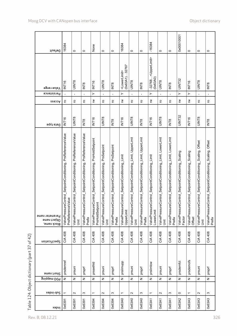
Moog DCV with CANopen bus interface Object dictionary
Rev. B, 08.12.21 326
0x63
911
Npr
sdem
ref
CiA
408
Val
veP
ress
ureC
ontr
ol_
Se
tpoi
ntC
ondi
tioni
ng, P
rsR
efer
ence
Val
ueP
rsR
efer
ence
Val
ueIN
T16
ro-
INT
1616
384
0x63
912
Npr
suni
CiA
408
Val
veP
ress
ureC
ontr
ol_
Se
tpoi
ntC
ondi
tioni
ng,
Prs
Ref
eren
ceV
alue
Uni
tU
INT
8ro
-U
INT
80
0x63
913
Npr
sprf
CiA
408
Val
veP
ress
ureC
ontr
ol_
Se
tpoi
ntC
ondi
tioni
ng,
Prs
Ref
eren
ceV
alue
Pre
fixIN
T8
ro-
INT
80
0x63
941
Npr
sset
hld
CiA
408
Val
veP
ress
ureC
ontr
ol_
Se
tpoi
ntC
ondi
tioni
ng, P
rsH
oldS
etpo
int
Prs
Hol
dSet
poin
tIN
T16
rwY
INT
16N
one
0x63
942
Npr
suni
CiA
408
Val
veP
ress
ureC
ontr
ol_
Se
tpoi
ntC
ondi
tioni
ng,
Prs
Set
poin
tU
nit
UIN
T8
ro-
UIN
T8
0
0x63
943
Npr
sprf
CiA
408
Val
veP
ress
ureC
ontr
ol_
Se
tpoi
ntC
ondi
tioni
ng,
Prs
Set
poin
tP
refix
INT
8ro
-IN
T8
0
0x63
A0
1N
prsl
imu
ppC
iA 4
08V
alve
Pre
ssur
eCon
trol
_S
etp
oint
Con
ditio
ning
_Lim
itU
pper
Lim
itIN
T16
rwY
<L
ower
Lim
it>
(0x6
3A1)
…32
767
1638
4
0x63
A0
2N
prsu
niC
iA 4
08V
alve
Pre
ssur
eCon
trol
_S
etp
oint
Con
ditio
ning
_Li
mit,
Upp
erLi
mit
Uni
tU
INT
8ro
-U
INT
80
0x63
A0
3N
prsp
rfC
iA 4
08V
alve
Pre
ssur
eCon
trol
_S
etp
oint
Con
ditio
ning
_Li
mit,
Upp
erLi
mit
Pre
fixIN
T8
ro-
INT
80
0x63
A1
1N
prsl
imlo
wC
iA 4
08V
alve
Pre
ssur
eCon
trol
_S
etp
oint
Con
ditio
ning
_Lim
itL
ow
erL
imit
INT
16rw
Y-3
2768
…<
Upp
erL
imit>
(0
x63A
0)-1
6384
0x63
A1
2N
prsu
niC
iA 4
08V
alve
Pre
ssur
eCon
trol
_S
etp
oint
Con
ditio
ning
_Li
mit,
Low
erLi
mit
Uni
tU
INT
8ro
-U
INT
80
0x63
A1
3N
prsp
rfC
iA 4
08V
alve
Pre
ssur
eCon
trol
_S
etp
oint
Con
ditio
ning
_Li
mit,
Low
erLi
mit
Pre
fixIN
T8
ro-
INT
80
0x63
A2
0N
prsd
emfc
tC
iA 4
08V
alve
Pre
ssur
eCon
trol
_S
etp
oint
Con
ditio
ning
_Sca
ling
Fac
tor
UIN
T32
rwY
UIN
T32
0x00
0100
01
0x63
A3
1N
prsd
emo
fsC
iA 4
08V
alve
Pre
ssur
eCon
trol
_S
etp
oint
Con
ditio
ning
_Sca
ling
Off
set
INT
16rw
YIN
T16
0
0x63
A3
2N
prsu
niC
iA 4
08V
alve
Pre
ssur
eCon
trol
_S
etp
oint
Con
ditio
ning
_S
calin
g, O
ffse
tU
nit
UIN
T8
ro-
UIN
T8
0
0x63
A3
3N
prsp
rfC
iA 4
08V
alve
Pre
ssur
eCon
trol
_S
etp
oint
Con
ditio
ning
_S
calin
g, O
ffse
tP
refix
INT
8ro
-IN
T8
0
Tabl
e12
4: O
bjec
t dic
tiona
ry (p
art3
7of
42)
Index
Sub-index
PDO mappingShort name
Specification
Block name,Object nameParameter name
Data type
Access
PersistenceValue range
Default
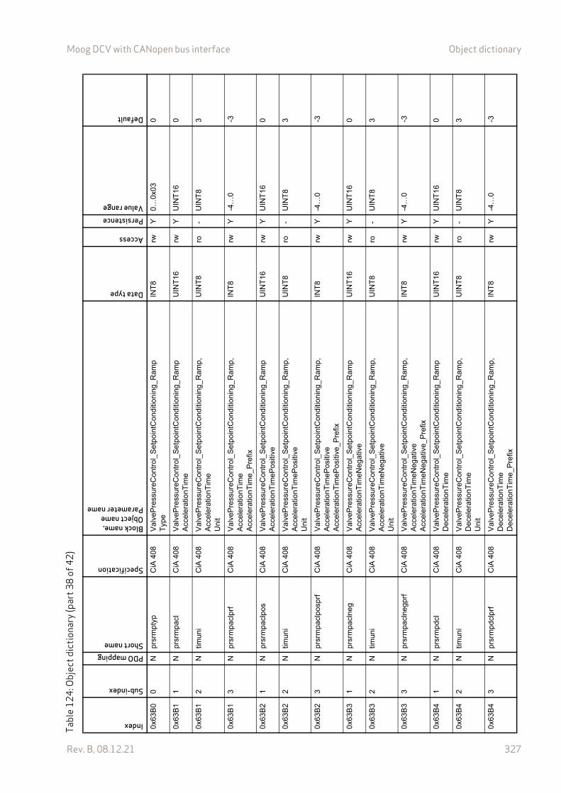
Moog DCV with CANopen bus interface Object dictionary
Rev. B, 08.12.21 327
0x63
B0
0N
prsr
mpt
ypC
iA 4
08V
alve
Pre
ssur
eCon
trol
_S
etp
oint
Con
ditio
ning
_Ram
pT
ype
INT
8rw
Y0…
0x03
0
0x63
B1
1N
prsr
mpa
clC
iA 4
08V
alve
Pre
ssur
eCon
trol
_S
etp
oint
Con
ditio
ning
_Ram
pA
cce
lera
tion
Tim
eU
INT
16rw
YU
INT
160
0x63
B1
2N
timun
iC
iA 4
08V
alve
Pre
ssur
eCon
trol
_S
etp
oint
Con
ditio
ning
_R
amp,
A
cce
lera
tion
Tim
eU
nit
UIN
T8
ro-
UIN
T8
3
0x63
B1
3N
prsr
mpa
clpr
fC
iA 4
08V
alve
Pre
ssur
eCon
trol
_S
etp
oint
Con
ditio
ning
_Ram
p,A
cce
lera
tion
Tim
eA
ccel
erat
ionT
ime_
Pre
fix
INT
8rw
Y-4
…0
-3
0x63
B2
1N
prsr
mpa
clpo
sC
iA 4
08V
alve
Pre
ssur
eCon
trol
_S
etp
oint
Con
ditio
ning
_Ram
pA
ccel
erat
ionT
imeP
ositi
veU
INT
16rw
YU
INT
160
0x63
B2
2N
timun
iC
iA 4
08V
alve
Pre
ssur
eCon
trol
_S
etp
oint
Con
ditio
ning
_R
amp,
A
ccel
erat
ionT
imeP
ositi
veU
nit
UIN
T8
ro-
UIN
T8
3
0x63
B2
3N
prsr
mpa
clpo
sprf
CiA
408
Val
veP
ress
ureC
ontr
ol_
Se
tpoi
ntC
ond
ition
ing_
Ram
p,
Acc
eler
atio
nTim
ePos
itive
Acc
eler
atio
nTim
ePos
itive
_Pre
fix
INT
8rw
Y-4
…0
-3
0x63
B3
1N
prsr
mpa
clne
gC
iA 4
08V
alve
Pre
ssur
eCon
trol
_S
etp
oint
Con
ditio
ning
_Ram
pA
ccel
erat
ionT
imeN
egat
ive
UIN
T16
rwY
UIN
T16
0
0x63
B3
2N
timun
iC
iA 4
08V
alve
Pre
ssur
eCon
trol
_S
etp
oint
Con
ditio
ning
_R
amp,
A
ccel
erat
ionT
imeN
egat
ive
Uni
t
UIN
T8
ro-
UIN
T8
3
0x63
B3
3N
prsr
mpa
clne
gprf
CiA
408
Val
veP
ress
ureC
ontr
ol_
Se
tpoi
ntC
ond
ition
ing_
Ram
p,
Acc
eler
atio
nTim
eNeg
ativ
eA
ccel
erat
ionT
imeN
egat
ive_
Pre
fix
INT
8rw
Y-4
…0
-3
0x63
B4
1N
prsr
mpd
clC
iA 4
08V
alve
Pre
ssur
eCon
trol
_S
etp
oint
Con
ditio
ning
_Ram
pD
ecel
erat
ionT
ime
UIN
T16
rwY
UIN
T16
0
0x63
B4
2N
timun
iC
iA 4
08V
alve
Pre
ssur
eCon
trol
_S
etp
oint
Con
ditio
ning
_R
amp,
D
ecel
erat
ionT
ime
Uni
t
UIN
T8
ro-
UIN
T8
3
0x63
B4
3N
prsr
mpd
clpr
fC
iA 4
08V
alve
Pre
ssur
eCon
trol
_S
etp
oint
Con
ditio
ning
_Ram
p,
Dec
eler
atio
nTim
eD
ecel
erat
ionT
ime
_Pre
fix
INT
8rw
Y-4
…0
-3
Tabl
e12
4: O
bjec
t dic
tiona
ry (p
art3
8of
42)
Index
Sub-index
PDO mappingShort name
Specification
Block name,Object nameParameter name
Data type
Access
PersistenceValue range
Default

Moog DCV with CANopen bus interface Object dictionary
Rev. B, 08.12.21 328
0x63
B5
1N
prsr
mpd
clpo
sC
iA 4
08V
alve
Pre
ssur
eCon
trol
_S
etp
oint
Con
ditio
ning
_Ram
pD
ecel
erat
ionT
ime
Po
sitiv
eU
INT
16rw
YU
INT
160
0x63
B5
2N
timun
iC
iA 4
08V
alve
Pre
ssur
eCon
trol
_S
etp
oint
Con
ditio
ning
_R
amp,
D
ecel
erat
ionT
ime
Po
sitiv
eU
nit
UIN
T8
ro-
UIN
T8
3
0x63
B5
3N
prsr
mpd
clpo
sprf
CiA
408
Val
veP
ress
ureC
ontr
ol_
Se
tpoi
ntC
ond
ition
ing_
Ram
p,
Dec
eler
atio
nTim
eP
osi
tive
Dec
eler
atio
nTim
eP
osi
tive_
Pre
fix
INT
8rw
Y-4
…0
-3
0x63
B6
1N
prsr
mpd
clne
gC
iA 4
08V
alve
Pre
ssur
eCon
trol
_S
etp
oint
Con
ditio
ning
_Ram
pD
ecel
erat
ionT
ime
Neg
ativ
eU
INT
16rw
YU
INT
160
0x63
B6
2N
timun
iC
iA 4
08V
alve
Pre
ssur
eCon
trol
_S
etp
oint
Con
ditio
ning
_R
amp,
D
ecel
erat
ionT
ime
Neg
ativ
eU
nit
UIN
T8
ro-
UIN
T8
3
0x63
B6
3N
prsr
mpd
clne
gprf
CiA
408
Val
veP
ress
ureC
ontr
ol_
Se
tpoi
ntC
ond
ition
ing_
Ram
p,
Dec
eler
atio
nTim
eN
egat
ive
Dec
eler
atio
nTim
eN
egat
ive_
Pre
fix
INT
8rw
Y-4
…0
-3
0x63
D0
1Y
prsc
tldvn
CiA
408
Val
veP
ress
ureC
ontr
olP
rsC
ontr
olD
evia
tion
INT
16ro
-IN
T16
0x63
D0
2N
prsu
niC
iA 4
08V
alve
Pre
ssur
eCon
trol
, P
rsC
ontr
olD
evia
tion
Uni
tU
INT
8ro
-U
INT
80
0x63
D0
3N
prsp
rfC
iA 4
08V
alve
Pre
ssur
eCon
trol
, P
rsC
ontr
olD
evia
tion
Pre
fixIN
T8
ro-
INT
80
0x63
D1
0N
prsm
onty
pC
iA 4
08V
alve
Pre
ssur
eCon
trol
_P
rsC
ontr
olM
onito
ring
Typ
eIN
T8
rwY
0…0x
010
0x63
D2
1N
prsm
ontim
CiA
408
Val
veP
ress
ureC
ontr
ol_
Prs
Con
trol
Mon
itori
ngD
elay
Tim
eU
INT
16rw
YU
INT
1630
0x63
D2
2N
timun
iC
iA 4
08V
alve
Pre
ssur
eCon
trol
_P
rsC
ontr
olM
onito
ring,
Del
ayT
ime
Uni
tU
INT
8ro
-U
INT
83
0x63
D2
3N
timpr
fC
iA 4
08V
alve
Pre
ssur
eCon
trol
_P
rsC
ontr
olM
onito
ring,
Del
ayT
ime
Pre
fixIN
T8
ro-
INT
8-3
0x63
D4
1N
prsm
onu
ppC
iA 4
08V
alve
Pre
ssur
eCon
trol
_P
rsC
ontr
olM
onito
ring
Upp
erT
hres
hold
INT
16rw
YIN
T16
512
Tabl
e12
4: O
bjec
t dic
tiona
ry (p
art3
9of
42)
Index
Sub-index
PDO mappingShort name
Specification
Block name,Object nameParameter name
Data type
Access
PersistenceValue range
Default
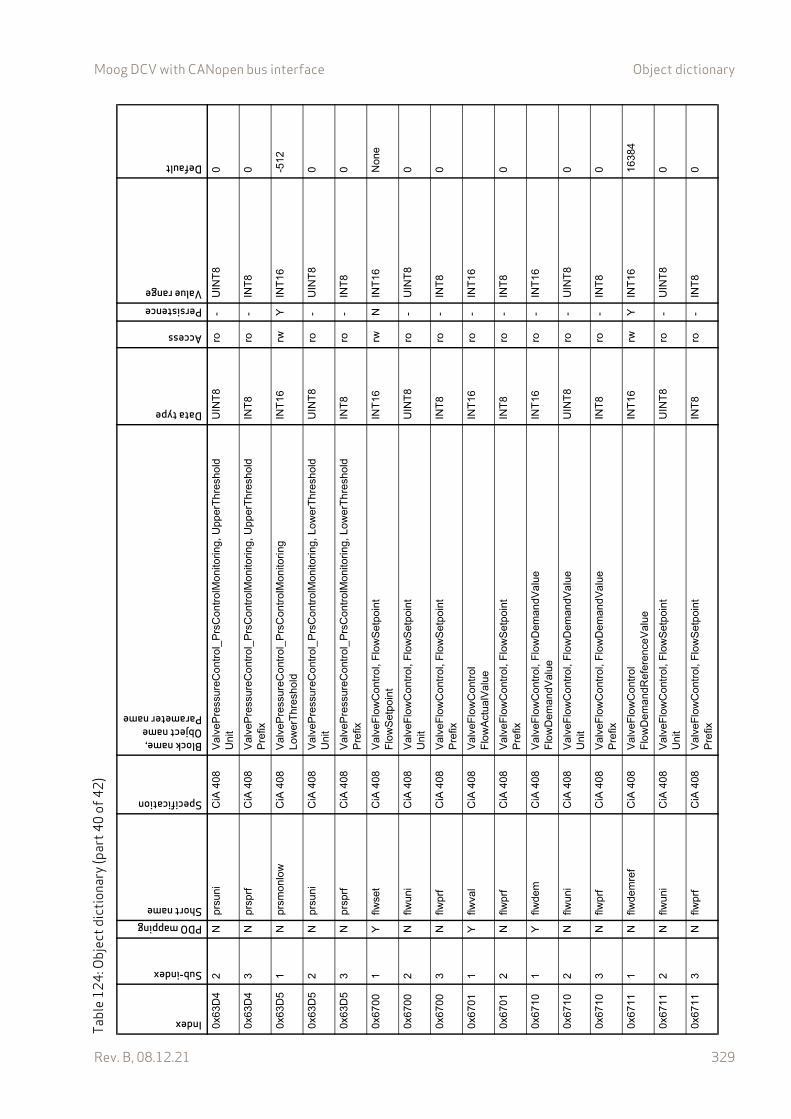
Moog DCV with CANopen bus interface Object dictionary
Rev. B, 08.12.21 329
0x63
D4
2N
prsu
niC
iA 4
08V
alve
Pre
ssur
eCon
trol
_P
rsC
ontr
olM
onito
ring,
Upp
erT
hre
shol
dU
nit
UIN
T8
ro-
UIN
T8
0
0x63
D4
3N
prsp
rfC
iA 4
08V
alve
Pre
ssur
eCon
trol
_P
rsC
ontr
olM
onito
ring,
Upp
erT
hre
shol
dP
refix
INT
8ro
-IN
T8
0
0x63
D5
1N
prsm
onlo
wC
iA 4
08V
alve
Pre
ssur
eCon
trol
_P
rsC
ontr
olM
onito
ring
Low
erT
hres
hold
INT
16rw
YIN
T16
-512
0x63
D5
2N
prsu
niC
iA 4
08V
alve
Pre
ssur
eCon
trol
_P
rsC
ontr
olM
onito
ring,
Low
erT
hre
shol
dU
nit
UIN
T8
ro-
UIN
T8
0
0x63
D5
3N
prsp
rfC
iA 4
08V
alve
Pre
ssur
eCon
trol
_P
rsC
ontr
olM
onito
ring,
Low
erT
hre
shol
dP
refix
INT
8ro
-IN
T8
0
0x67
001
Yflw
set
CiA
408
Val
veF
low
Con
trol
, Flo
wS
etpo
int
Flo
wS
etpo
int
INT
16rw
NIN
T16
Non
e
0x67
002
Nflw
uni
CiA
408
Val
veF
low
Con
trol
, Flo
wS
etpo
int
Uni
tU
INT
8ro
-U
INT
80
0x67
003
Nflw
prf
CiA
408
Val
veF
low
Con
trol
, Flo
wS
etpo
int
Pre
fixIN
T8
ro-
INT
80
0x67
011
Yflw
val
CiA
408
Val
veF
low
Con
trol
Flo
wA
ctua
lVal
ueIN
T16
ro-
INT
16
0x67
012
Nflw
prf
CiA
408
Val
veF
low
Con
trol
, Flo
wS
etpo
int
Pre
fixIN
T8
ro-
INT
80
0x67
101
Yflw
dem
CiA
408
Val
veF
low
Con
trol
, Flo
wD
eman
dVa
lue
Flo
wD
eman
dVal
ueIN
T16
ro-
INT
16
0x67
102
Nflw
uni
CiA
408
Val
veF
low
Con
trol
, Flo
wD
eman
dVa
lue
Uni
tU
INT
8ro
-U
INT
80
0x67
103
Nflw
prf
CiA
408
Val
veF
low
Con
trol
, Flo
wD
eman
dVa
lue
Pre
fixIN
T8
ro-
INT
80
0x67
111
Nflw
dem
ref
CiA
408
Val
veF
low
Con
trol
Flo
wD
eman
dRef
eren
ceV
alue
INT
16rw
YIN
T16
1638
4
0x67
112
Nflw
uni
CiA
408
Val
veF
low
Con
trol
, Flo
wS
etpo
int
Uni
tU
INT
8ro
-U
INT
80
0x67
113
Nflw
prf
CiA
408
Val
veF
low
Con
trol
, Flo
wS
etpo
int
Pre
fixIN
T8
ro-
INT
80
Tabl
e12
4: O
bjec
t dic
tiona
ry (p
art4
0of
42)
Index
Sub-index
PDO mappingShort name
Specification
Block name,Object nameParameter name
Data type
Access
PersistenceValue range
Default
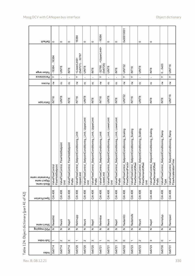
Moog DCV with CANopen bus interface Object dictionary
Rev. B, 08.12.21 330
0x67
141
Nflw
seth
ldC
iA 4
08V
alve
Flo
wC
ontr
olF
low
Hol
dSet
poin
tIN
T16
rwY
-163
84…
1638
40
0x67
142
Nflw
uni
CiA
408
Val
veF
low
Con
trol
, Flo
wH
oldS
etpo
int
Uni
tU
INT
8ro
-U
INT
80
0x67
143
Nflw
prf
CiA
408
Val
veF
low
Con
trol
, Flo
wH
oldS
etpo
int
Pre
fixIN
T8
ro-
INT
80
0x67
201
Nflw
limup
pC
iA 4
08V
alve
Flo
wC
ontr
ol_S
etpo
intC
ondi
tion
ing_
Lim
itU
pper
Lim
itIN
T16
rwY
<L
ower
Lim
it>
(0x6
721)
…32
767
1638
4
0x67
202
Nflw
uni
CiA
408
Val
veF
low
Con
trol
_Set
poin
tCon
ditio
nin
g_L
imit,
Upp
erLi
mit
Uni
tU
INT
8ro
-U
INT
80
0x67
203
Nflw
prf
CiA
408
Val
veF
low
Con
trol
_Set
poin
tCon
ditio
nin
g_L
imit,
Upp
erLi
mit
Pre
fixIN
T8
ro-
INT
80
0x67
211
Nflw
limlo
wC
iA 4
08V
alve
Flo
wC
ontr
ol_S
etpo
intC
ondi
tion
ing_
Lim
itL
ow
erL
imit
INT
16rw
Y-3
2768
…<
Upp
erL
imit>
(0
x672
0)-1
6384
0x67
212
Nflw
uni
CiA
408
Val
veF
low
Con
trol
_Set
poin
tCon
ditio
nin
g_L
imit,
Low
erLi
mit
Uni
tU
INT
8ro
-U
INT
80
0x67
213
Nflw
prf
CiA
408
Val
veF
low
Con
trol
_Set
poin
tCon
ditio
nin
g_L
imit,
Low
erLi
mit
Pre
fixIN
T8
ro-
INT
80
0x67
220
Nflw
dem
fct
CiA
408
Val
veF
low
Con
trol
_Set
poin
tCon
ditio
nin
g_S
calin
gF
low
Dem
andF
acto
rU
INT
32rw
YU
INT
320x
0001
0001
0x67
231
Nflw
dem
ofs
CiA
408
Val
veF
low
Con
trol
_Set
poin
tCon
ditio
nin
g_S
calin
gF
low
Dem
andO
ffset
INT
16rw
YIN
T16
0x67
232
Nflw
uni
CiA
408
Val
veF
low
Con
trol
_Set
poin
tCon
ditio
nin
g_S
calin
g,
Flo
wD
eman
dOffs
etU
nit
UIN
T8
ro-
UIN
T8
0
0x67
233
Nflw
prf
CiA
408
Val
veF
low
Con
trol
_Set
poin
tCon
ditio
nin
g_S
calin
g,
Flo
wD
eman
dOffs
etP
refix
INT
8ro
-IN
T8
0
0x67
300
Nflw
rmpt
ypC
iA 4
08V
alve
Flo
wC
ontr
ol_S
etpo
intC
ondi
tion
ing_
Ram
pT
ype
INT
8rw
Y0…
0x03
0x67
311
Nflw
rmpa
clC
iA 4
08V
alve
Flo
wC
ontr
ol_S
etpo
intC
ondi
tion
ing_
Ram
pF
low
Acc
ele
ratio
nT
ime
UIN
T16
rwY
UIN
T16
Tabl
e12
4: O
bjec
t dic
tiona
ry (p
art4
1of
42)
Index
Sub-index
PDO mappingShort name
Specification
Block name,Object nameParameter name
Data type
Access
PersistenceValue range
Default

Moog DCV with CANopen bus interface Object dictionary
Rev. B, 08.12.21 331
0x67
312
Nflw
rmpa
clpr
fC
iA 4
08V
alve
Flo
wC
ontr
ol_S
etpo
intC
ondi
tion
ing_
Ram
p,
Flo
wA
cce
lera
tion
Tim
eF
low
Acc
eler
atio
nTim
e_P
refix
INT
8rw
Y-4
…0
-3
0x67
321
Nflw
rmpa
clpo
sC
iA 4
08V
alve
Flo
wC
ontr
ol_S
etpo
intC
ondi
tion
ing_
Ram
pF
low
Acc
eler
atio
nTim
ePos
itive
UIN
T16
rwY
UIN
T16
0x67
322
Nflw
rmpa
clpo
sprf
CiA
408
Val
veF
low
Con
trol
_Set
poin
tCon
ditio
nin
g_R
amp,
F
low
Acc
eler
atio
nTim
ePos
itive
Flo
wA
ccel
erat
ionT
imeP
ositi
ve_P
refix
INT
8rw
Y-4
…0
-3
0x67
331
Nflw
rmpa
clne
gC
iA 4
08V
alve
Flo
wC
ontr
ol_S
etpo
intC
ondi
tion
ing_
Ram
pF
low
Acc
eler
atio
nTim
eNeg
ativ
eU
INT
16rw
YU
INT
16
0x67
332
Nflw
rmpa
clne
gprf
CiA
408
Val
veF
low
Con
trol
_Set
poin
tCon
ditio
nin
g_R
amp,
F
low
Acc
eler
atio
nTim
eNeg
ativ
eF
low
Acc
eler
atio
nTim
eNeg
ativ
e_P
refix
INT
8rw
Y-4
…0
-3
0x67
341
Nflw
rmpd
clC
iA 4
08V
alve
Flo
wC
ontr
ol_S
etpo
intC
ondi
tion
ing_
Ram
pF
low
Dec
eler
atio
nTim
eU
INT
16rw
YU
INT
16
0x67
342
Nflw
rmpd
clpr
fC
iA 4
08V
alve
Flo
wC
ontr
ol_S
etpo
intC
ondi
tion
ing_
Ram
p,
Flo
wD
ecel
erat
ionT
ime
Flo
wD
ecel
erat
ionT
ime_
Pre
fix
INT
8rw
Y-4
…0
-3
0x67
351
Nflw
rmpd
clpo
sC
iA 4
08V
alve
Flo
wC
ontr
ol_S
etpo
intC
ondi
tion
ing_
Ram
pF
low
Dec
eler
atio
nTim
ePos
itive
UIN
T16
rwY
UIN
T16
0x67
352
Nflw
rmpd
clpo
sprf
CiA
408
Val
veF
low
Con
trol
_Set
poin
tCon
ditio
nin
g_R
amp,
F
low
Dec
eler
atio
nTim
ePos
itive
Flo
wD
ecel
erat
ionT
imeP
ositi
ve_
Pre
fix
INT
8rw
Y-4
…0
-3
0x67
361
Nflw
rmpd
clne
gC
iA 4
08V
alve
Flo
wC
ontr
ol_S
etpo
intC
ondi
tion
ing_
Ram
pF
low
Dec
eler
atio
nTim
eNeg
ativ
eU
INT
16rw
YU
INT
16
0x67
362
Nflw
rmpd
clne
gprf
CiA
408
Val
veF
low
Con
trol
_Set
poin
tCon
ditio
nin
g_R
amp,
F
low
Dec
eler
atio
nTim
eNeg
ativ
eF
low
Dec
eler
atio
nTim
eNeg
ativ
e_P
refix
INT
8rw
Y-4
…0
-3
0x67
501
Yflw
ctld
vnC
iA 4
08V
alve
Flo
wC
ontr
olF
low
Con
trol
De
viat
ionV
alue
INT
16ro
-IN
T16
0x67
502
Nflw
uni
CiA
408
Val
veF
low
Con
trol
, F
low
Con
trol
De
viat
ionV
alue
Uni
t
UIN
T8
ro-
UIN
T8
0
Tabl
e12
4: O
bjec
t dic
tiona
ry (p
art4
2of
42)
Index
Sub-index
PDO mappingShort name
Specification
Block name,Object nameParameter name
Data type
Access
PersistenceValue range
Default

www.moog.com/industrial
Moog is registered trademark of Moog Inc. and its subsidiaries. All trademarks asindicated herein are the property of Moog Inc. and its subsidiaries.© 2021 Moog GmbH. All rights reserved. All changes reserved.
Moog Literature NameDIGITAL CONTROL VALVES WITH CANOPEN INTERFACE - FirmwareRev. B, 08.12.21, Id. CDS60745-en
WHAT MOVES YOUR WORLD
TAKE A CLOSER LOOK.Moog designs a range of products that complement the performance of those featured in this user manual. Visit our Web site for more information and the Moog facility nearest you.
Australia+61 3 9561 [email protected]
Ireland+353 21 451 [email protected]
South Africa+27 12 653 [email protected]
Brazil+55 11 3572 [email protected]
Italy+39 0332 421 [email protected]
Spain+34 902 133 [email protected]
Canada+1 716 652 [email protected]
Japan+81 46 355 [email protected]
Turkey+90 216 663 [email protected]
China+86 21 2893 [email protected]
Korea+82 31 764 [email protected]
United Kingdom+44 (0) 1684 [email protected]
Finland+358 10 422 [email protected]
Luxembourg+352 40 46 [email protected]
USA+1 716 652 [email protected]
France+33 1 4560 [email protected]
The Netherlands+31 252 462 [email protected]
Germany+49 7031 622 [email protected]
Norway+47 6494 [email protected]
Hong Kong+852 2 635 [email protected]
Russia+7 8 31 713 [email protected]
India+91 80 4057 [email protected]
Singapore+65 677 [email protected]
Copyright © 2022 FDOKUMEN