DB3: Installation Guide. 2007 Toyota Yaris. 403.TL11 1.06 - NET
21
Designed by Installers for Installers INSTALLATION GUIDE DB3 2007 Toyota Yaris. 403.TL11 1.06 © 2018 Directed, Vista CA This product is intended for installation by a professional installer only! Attempts to install this product by a person other than a trained professional may result in severe damage to a vehicle’s electrical system and components.
-
Upload
khangminh22 -
Category
Documents
-
view
4 -
download
0
Transcript of DB3: Installation Guide. 2007 Toyota Yaris. 403.TL11 1.06 - NET

Designed by Installers for Installers
INSTALLATION GUIDE DB3
2007 Toyota Yaris. 403.TL11 1.06
© 2018 Directed, Vista CA
This product is intended for installation by a professional installer only! Attempts to install this product by a person other than a trained professional may result in severe damage to a vehicle’s electrical system and components.

Introduction 4 Vehicle function compatibilities 4 Pre-installation and application warnings 5 Key type 5Wiring diagram 6 Locating components in the vehicle 7Vehicle connections 8Connecting the module 11 Module programming 12 With transponder and CAN 12 With transponder without CAN 12 No transponder with CAN 12 LED diagnostics and troubleshooting 14 Soft reset 16 Hard reset 16Feature programming 17Feature and option list 18Limited one year consumer warranty 19Quick reference guide 20
Contents
3 403.TL11 1.06 2007 Toyota Yaris© 2018-02-14 Directed. All rights reserved.
Warning! Safety firstThe following safety warnings must be observed at all times:
• Due to the complexity of this system, installation of this product must only be performed by an authorized Directed dealer.• When properly installed, this system can start the vehicle via a command signal from the remote control. Therefore, never
operate the system in an area that does not have adequate ventilation.
The following precautions are the sole responsibility of the user; however, authorized Directed dealers should:• Never use a test light or logic probe when installing this unit. Always use a multimeter. • Never operate the system in an enclosed or partially enclosed area without ventilation (such as a garage). • When parking in an enclosed or partially enclosed area or when having the vehicle serviced, the remote start system must
be disabled using the installed toggle switch. It is the user’s sole responsibility to properly handle and keep out of reach from children all remote controls to assure that the system does not unintentionally remote start the vehicle.
• USER MUST INSTALL A CARBON MONOXIDE DETECTOR IN OR ABOUT THE LIVING AREA ADJACENT TO THE VEHICLE. ALL DOORS LEADING FROM ADJACENT LIVING AREAS TO THE ENCLOSED OR PARTIALLY ENCLOSED VEHICLE STORAGE AREA MUST REMAIN CLOSED AT ALL TIMES.
Use of this product in a manner contrary to its intended mode of operation may result in property damage, personal injury, or death. Except when performing the Safety Check outlined in this installation guide, (1) Never remotely start the vehicle with the vehicle in gear, and (2) Never remotely start the vehicle with the keys in the ignition. The user is responsible for having the neutral safety feature of the vehicle periodically checked, wherein the vehicle must not remotely start while the car is in gear. This testing should be performed by an authorized Directed dealer in accordance with the Safety Check outlined in this product installation guide. If the vehicle starts in gear, cease remote start operation immediately and consult with the user to fix the problem immediately.
OPERATION OF THE REMOTE START MODULE IF THE VEHICLE STARTS IN GEAR IS CONTRARY TO ITS INTENDED MODE OF OPERATION. OPERATING THE REMOTE START SYSTEM UNDER THESE CONDITIONS MAY RESULT IN PROPERTY DAMAGE OR PERSONAL INJURY. IMMEDIATELY CEASE THE USE OF THE UNIT AND REPAIR OR DISCONNECT THE INSTALLED REMOTE START MODULE. DIRECTED WILL NOT BE HELD RESPONSIBLE OR PAY FOR INSTALLATION OR REINSTALLATION COSTS.
Remote starters for manual transmission pose significant risks if not properly installed and operated. When testing to ensure the installation is working properly, only remote start the vehicle in neutral gear, on a flat surface and with a functional, fully engaged parking brake. Do not allow anyone to stand in front of or behind the vehicle.
This product should not be installed in any convertible vehicles, soft or hard top with a manual transmission. Installation in such vehicles may pose certain risk.
4 403.TL11 1.06 2007 Toyota Yaris© 2018-02-14 Directed. All rights reserved.
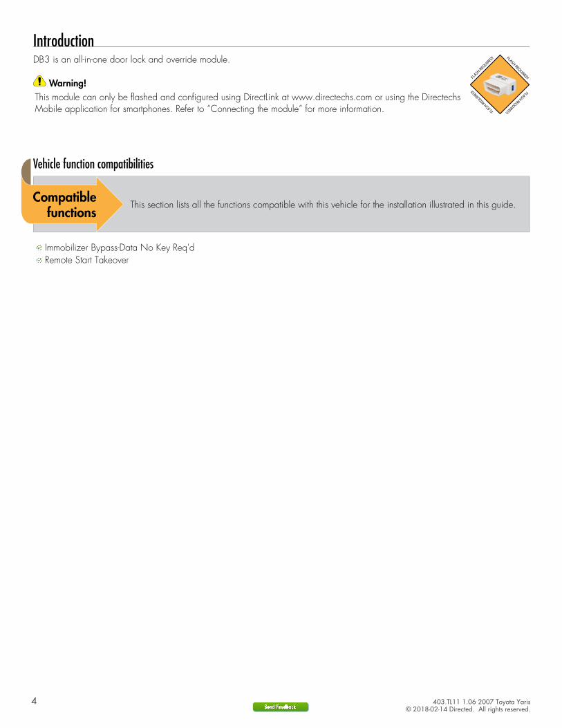
IntroductionDB3 is an all-in-one door lock and override module.
Warning!
This module can only be flashed and configured using DirectLink at www.directechs.com or using the DirectechsMobile application for smartphones. Refer to “Connecting the module” for more information.
Vehicle function compatibilities
This section lists all the functions compatible with this vehicle for the installation illustrated in this guide.
Immobilizer Bypass-Data No Key Req'd Remote Start Takeover
5 403.TL11 1.06 2007 Toyota Yaris© 2018-02-14 Directed. All rights reserved.
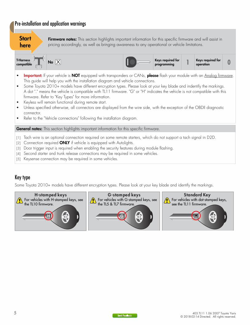
Pre-installation and application warnings
Firmware notes: This section highlights important information for this specific firmware and will assist in pricing accordingly, as well as bringing awareness to any operational or vehicle limitations.
T-Harness compatible
Keys required for programming 1 Keys required for
operation 0
� Important: If your vehicle is NOT equipped with transponders or CANs, please flash your module with an Analog firmware. This guide will help you with the installation diagram and vehicle connections.
� Some Toyota 2010+ models have different encryption types. Please look at your key blade and indentify the markings. A dot "." means the vehicle is compatible with TL11 firmware. "G" or "H" indicates the vehicle is not compatible with this firmware. Refer to "Key Types" for more information.
� Keyless will remain functional during remote start. � Unless specified otherwise, all connectors are displayed from the wire side, with the exception of the OBDII diagnostic
connector. � Refer to the "Vehicle connections" following the installation diagram.
General notes: This section highlights important information for this specific firmware.
[1] Tach wire is an optional connection required on some remote starters, which do not support a tach signal in D2D.[2] Connection required ONLY if vehicle is equipped with Autolights.[3] Door trigger input is required when enabling the security features during module flashing.[4] Second starter and trunk release connections may be required in some vehicles.[5] Keysense connection may be required in some vehicles.
Key typeSome Toyota 2010+ models have different encryption types. Please look at your key blade and identify the markings.
G-stamped keys Standard Key
H-stamped keys
H
For vehicles with H-stamped keys, see the TL10 firmware.
For vehicles with G-stamped keys, see the TL5 & TL7 firmware.
For vehicles with dot-stamped keys, see the TL11 firmware.

6 403.TL11 1.06 2007 Toyota Yaris© 2018-02-14 Directed. All rights reserved.
Refer to "Pre-installation and application warnings" for important information, such as the description of each special note referenced in the diagram ( ).
Wiring diagram
D2D Port
(+) Ignition 1 Output
(+) Brake Input (-) Lock Output (-) Unlock Output (-) Trunk Release Output
(+) Ignition 2 Output
(+) 12V Input
(-) Parking Lights Output
(-) Ground: Brown: 7
(-) Keysense Output: Yellow: 8
1412
104
2
(-) Ground (-) Ground
9: Pink: (+) Ignition Input
(+) Starter 2 Output(+) Accessory Output
(+) Starter 1 Output
XKD2D65
Data TX: Yellow/Black: 10
Data RX: Orange/Black: 11
(AC) Tach Input
Refer to Vehicle connections
for wire and connector details.
Ignition Switch
7
3 4
5 86
1 2
Autolights Interrupt (conn. side): Orange/Red: 10
Autolights Interrupt (vehicle side): Yellow/Red: 11
Refer to ‘Vehicle connections’ for wire and connector details.Parking lights & Autolights are secondary options for Tach.
Cut
Refer to Vehicle Connections for wire and connector details.
Transponder Key Amplifier(black conn. around ignition)
7 403.TL11 1.06 2007 Toyota Yaris© 2018-02-14 Directed. All rights reserved.
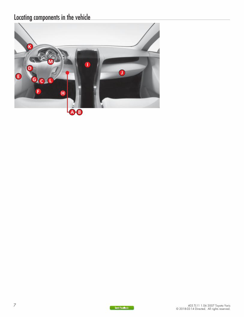
Locating components in the vehicle
8 403.TL11 1.06 2007 Toyota Yaris© 2018-02-14 Directed. All rights reserved.
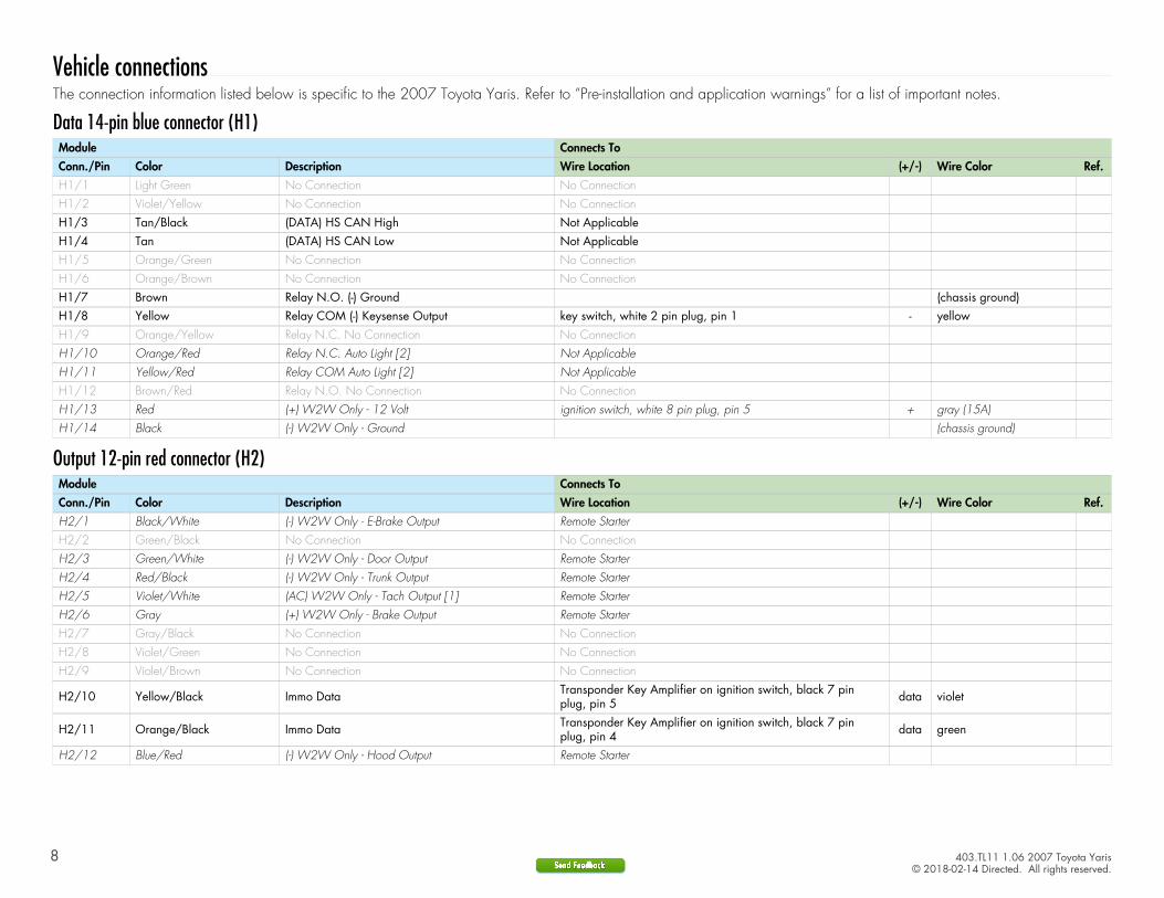
Vehicle connectionsThe connection information listed below is specific to the 2007 Toyota Yaris. Refer to “Pre-installation and application warnings” for a list of important notes.
Data 14-pin blue connector (H1)Module Connects ToConn./Pin Color Description Wire Location (+/-) Wire Color Ref.H1/1 Light Green No Connection No ConnectionH1/2 Violet/Yellow No Connection No Connection
H1/3 Tan/Black (DATA) HS CAN High Not ApplicableH1/4 Tan (DATA) HS CAN Low Not ApplicableH1/5 Orange/Green No Connection No ConnectionH1/6 Orange/Brown No Connection No Connection
H1/7 Brown Relay N.O. (-) Ground (chassis ground)H1/8 Yellow Relay COM (-) Keysense Output key switch, white 2 pin plug, pin 1 - yellowH1/9 Orange/Yellow Relay N.C. No Connection No ConnectionH1/10 Orange/Red Relay N.C. Auto Light [2] Not ApplicableH1/11 Yellow/Red Relay COM Auto Light [2] Not ApplicableH1/12 Brown/Red Relay N.O. No Connection No Connection
H1/13 Red (+) W2W Only - 12 Volt ignition switch, white 8 pin plug, pin 5 + gray (15A)H1/14 Black (-) W2W Only - Ground (chassis ground)
Output 12-pin red connector (H2)Module Connects ToConn./Pin Color Description Wire Location (+/-) Wire Color Ref.H2/1 Black/White (-) W2W Only - E-Brake Output Remote StarterH2/2 Green/Black No Connection No ConnectionH2/3 Green/White (-) W2W Only - Door Output Remote StarterH2/4 Red/Black (-) W2W Only - Trunk Output Remote StarterH2/5 Violet/White (AC) W2W Only - Tach Output [1] Remote StarterH2/6 Gray (+) W2W Only - Brake Output Remote StarterH2/7 Gray/Black No Connection No ConnectionH2/8 Violet/Green No Connection No Connection
H2/9 Violet/Brown No Connection No Connection
H2/10 Yellow/Black Immo Data Transponder Key Amplifier on ignition switch, black 7 pinplug, pin 5 data violet
H2/11 Orange/Black Immo Data Transponder Key Amplifier on ignition switch, black 7 pinplug, pin 4 data green
H2/12 Blue/Red (-) W2W Only - Hood Output Remote Starter
9 403.TL11 1.06 2007 Toyota Yaris© 2018-02-14 Directed. All rights reserved.
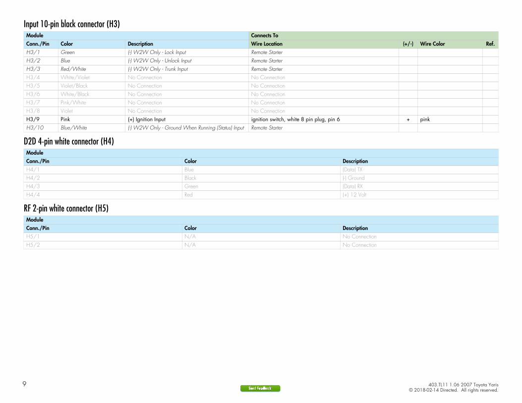
Input 10-pin black connector (H3)Module Connects ToConn./Pin Color Description Wire Location (+/-) Wire Color Ref.H3/1 Green (-) W2W Only - Lock Input Remote StarterH3/2 Blue (-) W2W Only - Unlock Input Remote StarterH3/3 Red/White (-) W2W Only - Trunk Input Remote Starter
H3/4 White/Violet No Connection No ConnectionH3/5 Violet/Black No Connection No Connection
H3/6 White/Black No Connection No ConnectionH3/7 Pink/White No Connection No Connection
H3/8 Violet No Connection No ConnectionH3/9 Pink (+) Ignition Input ignition switch, white 8 pin plug, pin 6 + pinkH3/10 Blue/White (-) W2W Only - Ground When Running (Status) Input Remote Starter
D2D 4-pin white connector (H4)ModuleConn./Pin Color DescriptionH4/1 Blue (Data) TX
H4/2 Black (-) GroundH4/3 Green (Data) RX
H4/4 Red (+) 12 Volt
RF 2-pin white connector (H5)ModuleConn./Pin Color DescriptionH5/1 N/A No ConnectionH5/2 N/A No Connection
10 403.TL11 1.06 2007 Toyota Yaris© 2018-02-14 Directed. All rights reserved.
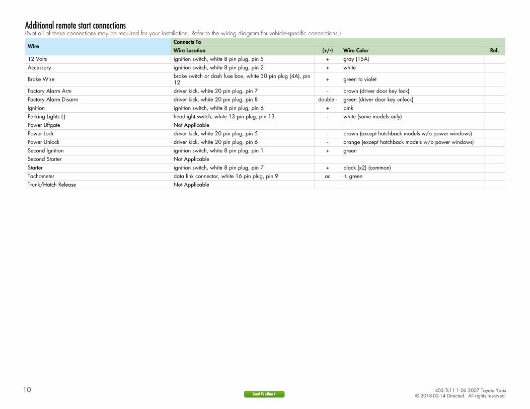
Additional remote start connections(Not all of these connections may be required for your installation. Refer to the wiring diagram for vehicle-specific connections.)
WireConnects ToWire Location (+/-) Wire Color Ref.
12 Volts ignition switch, white 8 pin plug, pin 5 + gray (15A)Accessory ignition switch, white 8 pin plug, pin 2 + white
Brake Wire brake switch or dash fuse box, white 30 pin plug (4A), pin12 + green to violet
Factory Alarm Arm driver kick, white 20 pin plug, pin 7 - brown (driver door key lock)Factory Alarm Disarm driver kick, white 20 pin plug, pin 8 double - green (driver door key unlock)Ignition ignition switch, white 8 pin plug, pin 6 + pinkParking Lights (-) headlight switch, white 13 pin plug, pin 13 - white (some models only)Power Liftgate Not ApplicablePower Lock driver kick, white 20 pin plug, pin 5 - brown (except hatchback models w/o power windows)Power Unlock driver kick, white 20 pin plug, pin 6 - orange (except hatchback models w/o power windows)Second Ignition ignition switch, white 8 pin plug, pin 1 + greenSecond Starter Not ApplicableStarter ignition switch, white 8 pin plug, pin 7 + black (x2) (common)Tachometer data link connector, white 16 pin plug, pin 9 ac lt. greenTrunk/Hatch Release Not Applicable

11 403.TL11 1.06 2007 Toyota Yaris© 2018-02-14 Directed. All rights reserved.
Connecting the module
Important!Make all the required connections to the vehicle, as described in this guide, and double check to ensure everything is correct prior to moving onto programming.
Warning! To take advantage of advanced features, you must use DirectLink 4.5 (and higher) or the Directechs Mobile application.
Flashing a module using your computer:1. Connect the interface module to your computer using the XKLoader2.2. Go to www.directechs.com using Internet Explorer, and select the Flash Module button.3. Follow the instructions to select your vehicle, installation type, and configure your options.4. Once you have configured the firmware options, click on the FLASH button.
Flashing a module using your smartphone or tablet:1. Connect the interface module to your XKLoader3.2. Launch the Directechs Mobile app on your smartphone or tablet.3. Select FLASH YOUR MODULE and follow the on screen instructions.
When the flashing operation is successful, you can proceed with the instructions below.
D2D installationRecommended: Connect the 10-pin, 12-pin and 14-pin harnesses to the module, then connect the 4-pin D2D harness. 3rd
(14-pin)1st
(10-pin)
4th
(D2D)2nd
(12-pin)
OR
W2W installationIf required: Connect the 10-pin and 12-pin harnesses to the module, then connect the 14-pin harness to the module. 3rd
(14-pin)1st
(10-pin)
2nd
(12-pin)
12 403.TL11 1.06 2007 Toyota Yaris© 2018-02-14 Directed. All rights reserved.
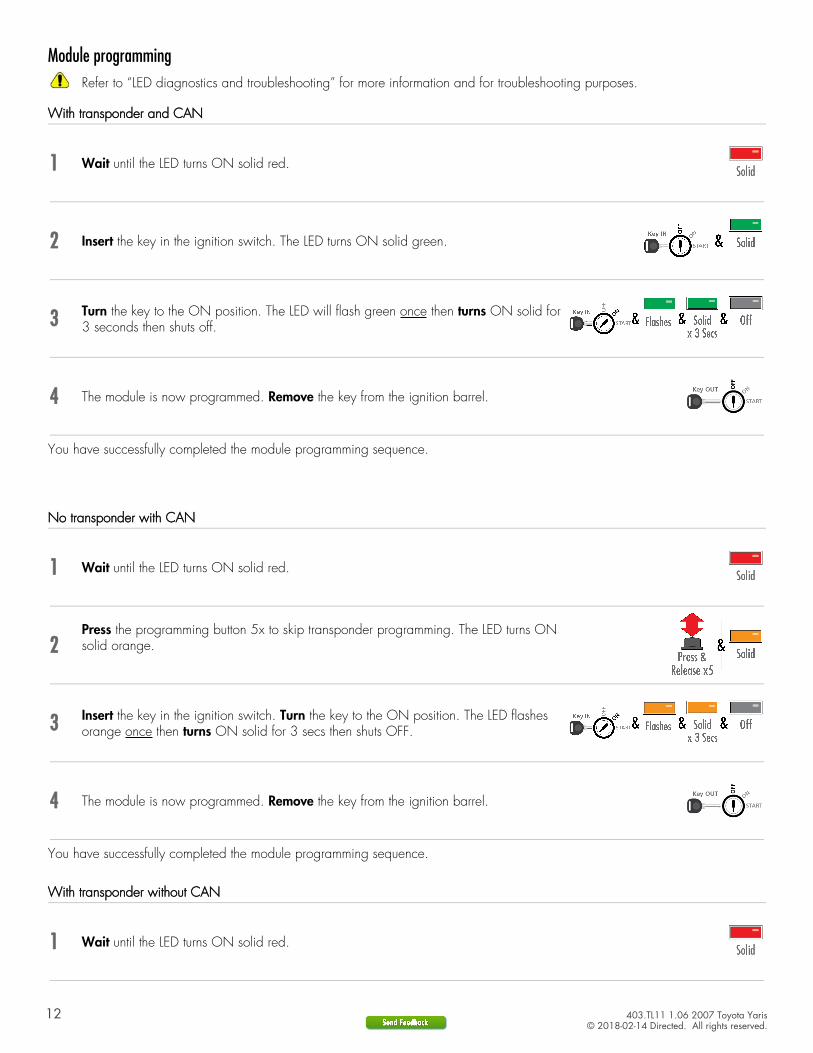
Module programmingRefer to “LED diagnostics and troubleshooting” for more information and for troubleshooting purposes.
With transponder and CAN
1 Wait until the LED turns ON solid red.
2 Insert the key in the ignition switch. The LED turns ON solid green.
3 Turn the key to the ON position. The LED will flash green once then turns ON solid for3 seconds then shuts off.
4 The module is now programmed. Remove the key from the ignition barrel.
You have successfully completed the module programming sequence.
No transponder with CAN
1 Wait until the LED turns ON solid red.
2Press the programming button 5x to skip transponder programming. The LED turns ONsolid orange.
3 Insert the key in the ignition switch. Turn the key to the ON position. The LED flashesorange once then turns ON solid for 3 secs then shuts OFF.
4 The module is now programmed. Remove the key from the ignition barrel.
You have successfully completed the module programming sequence.
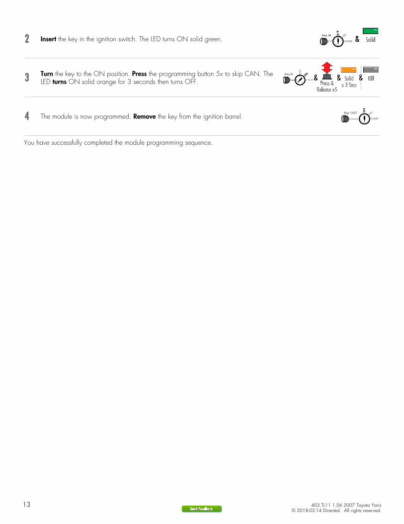
With transponder without CAN
1 Wait until the LED turns ON solid red.
13 403.TL11 1.06 2007 Toyota Yaris© 2018-02-14 Directed. All rights reserved.
2 Insert the key in the ignition switch. The LED turns ON solid green.
3 Turn the key to the ON position. Press the programming button 5x to skip CAN. TheLED turns ON solid orange for 3 seconds then turns OFF.
4 The module is now programmed. Remove the key from the ignition barrel.
You have successfully completed the module programming sequence.
14 403.TL11 1.06 2007 Toyota Yaris© 2018-02-14 Directed. All rights reserved.
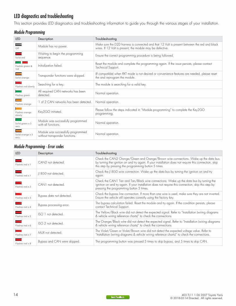
LED diagnostics and troubleshootingThis section provides LED diagnostics and troubleshooting information to guide you through the various stages of your installation.
Module ProgrammingLED Description Troubleshooting
OffModule has no power. Make sure the D2D harness is connected and that 12 Volt is present between the red and black
wires. If 12 Volt is present, the module may be defective.
Solid red
Waiting to begin the programmingsequence. Ensure the correct programming procedure is being followed.
Flashes green &red
Initialization failed. Reset the module and complete the programming again. If the issue persists, please contactTechnical Support.
Solid orangeTransponder functions were skipped. (If compatible) when RXT mode is not desired or convenience features are needed, please reset
the and reprogram the module.
Flashes red slowlySearching for a key. The module is searching for a valid key.
Flashes green
All required CAN networks has beendetected. Normal operation.
Flashes orange1 of 2 CAN networks has been detected. Normal operation.
Flashes orangeslowly
Key2GO initiated. Please follow the steps indicated in “Module programming” to complete the Key2GOprogramming.
Solid green x 3secs
Module was successfully programmedwith all functions. Normal operation.
Solid orange x 3secs
Module was successfully programmedwithout transponder functions. Normal operation.
Module Programming - Error codesLED Description Troubleshooting
Flashes red x 1CAN2 not detected.
Check the CAN2 Orange/Green and Orange/Brown wire connections. Wake up the data busby turning the ignition on and try again. If your installation does not require this connection, skipthis step by pressing the programming button 5 times.
Flashes red x 1J1850 not detected. Check the J1850 wire connection. Wake up the data bus by turning the ignition on and try
again.
Flashes red x 2CAN1 not detected.
Check the CAN1 Tan and Tan/Black wire connections. Wake up the data bus by turning theignition on and try again. If your installation does not require this connection, skip this step bypressing the programming button 5 times.
Flashes red x 3Bypass data not detected. Check the bypass line connection. If more than one wire is used, make sure they are not inverted.
Ensure the vehicle still operates correctly using the factory key.
Flashes red x 4Bypass processing error. The bypass calculation failed. Reset the module and try again. If the condition persists, please
contact Technical Support.
Flashes red x 5ISO 1 not detected. The Yellow/Black wire did not detect the expected signal. Refer to “Installation (wiring diagrams
& vehicle wiring reference charts)” to check the connections.
Flashes red x 6ISO 2 not detected. The Orange/Black wire did not detect the expected signal. Refer to “Installation (wiring diagrams
& vehicle wiring reference charts)” to check the connections.
Flashes red x 7MUX not detected. The Violet/Green or Violet/Brown wire did not detect the expected voltage value. Refer to
“Installation (wiring diagrams & vehicle wiring reference charts)” to check the connections.
Flashes red x 8Bypass and CAN were skipped. The programming button was pressed 5 times to skip bypass, and 5 times to skip CAN.

15 403.TL11 1.06 2007 Toyota Yaris© 2018-02-14 Directed. All rights reserved.
External Module SynchronizationLED Description Troubleshooting
(Flashes red, red,then orange) x 10
OBDII feature not supported. The diagnostic data bus was not detected, therefore the SmartStart features will be limited.
Active Ground When Running (Status)LED Description Troubleshooting
Flashes green
Ground When Running (Status) commandreceived. The module has initialized the remote start sequence.
Flashes red &orange
Ignition ON command received. The module has received the Ignition ON command and is processing the remote start sequence.
Flashes greenquickly
Start ON command received. The module has received the Start ON command and is processing the remote start sequence.
Flashes red x 10PTS shutdown error. The PTS output from the module was not activated due to safety protection.
Flashes red x 21CAN bus incorrectly detected. Verify the CAN1 and CAN2 connections. Refer to “Installation (wiring diagrams & vehicle wiring
reference charts)” to check the connections.
CommandsLED Description Troubleshooting
Flashes orange x 1LOCK command received. If the bypass module fails to flash, it did not receive the signal. Commands can come from RF or
D2D.
Flashes orange x 2UNLOCK command received. If the bypass module fails to flash, it did not receive the signal. Commands can come from RF or
D2D.
Flashes orange x 3TRUNK command received. If the bypass module fails to flash, it did not receive the signal. Commands can come from RF or
D2D.
Flashes orange x 4AUX1 command received. If the bypass module fails to flash, it did not receive the signal. Commands can come from RF or
D2D.
Flashes orange x 5AUX2 command received. If the bypass module fails to flash, it did not receive the signal. Commands can come from RF or
D2D.
Flashes orange x 6AUX3 command received. If the bypass module fails to flash, it did not receive the signal. Commands can come from RF or
D2D.
Shutdown CodesLED Description Troubleshooting
Flashes green x 1Takeover successful. Normal operation.
Flashes red x 1Runsafe was not disabled. No UNLOCK command was received prior to opening the door, or the 45 second timer expired
in takeover mode.
Flashes red x 2Brake was not detected. The brakes were not detected, which prevents the system from shutting down the vehicle.
Flashes red x 3Smart key was not detected. The smart key was not detected, which prevents the system from shutting down the vehicle.
Flashes red x 4Speed was detected. The vehicle was detected as moving, which prevents the system from shutting it down.
16 403.TL11 1.06 2007 Toyota Yaris© 2018-02-14 Directed. All rights reserved.
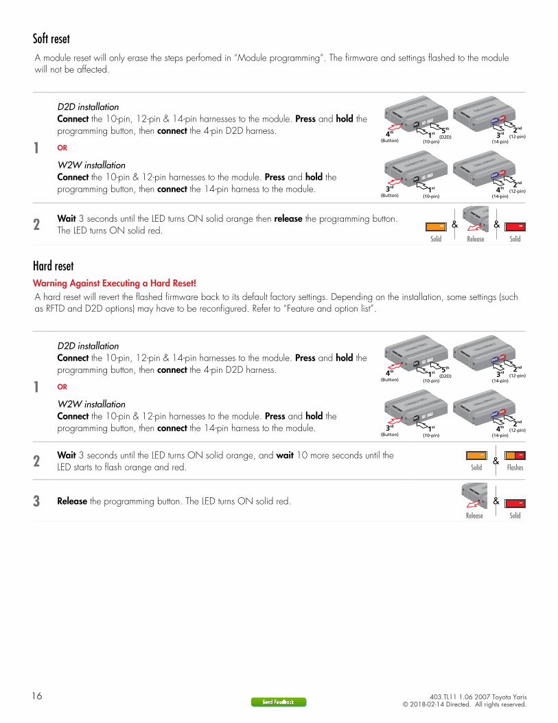
Soft reset
1
D2D installationConnect the 10-pin, 12-pin & 14-pin harnesses to the module. Press and hold the programming button, then connect the 4-pin D2D harness. 3rd
(14-pin)1st
(10-pin)
5th
(D2D)2nd
(12-pin)4th
(Button)
OR
W2W installationConnect the 10-pin & 12-pin harnesses to the module. Press and hold the programming button, then connect the 14-pin harness to the module. 4th
(14-pin)3rd
(Button)1st
(10-pin)
2nd
(12-pin)
2 Wait 3 seconds until the LED turns ON solid orange then release the programming button. The LED turns ON solid red.
&&Solid SolidRelease
A module reset will only erase the steps perfomed in “Module programming”. The firmware and settings flashed to the modulewill not be affected.
Hard resetWarning Against Executing a Hard Reset!
1
D2D installationConnect the 10-pin, 12-pin & 14-pin harnesses to the module. Press and hold the programming button, then connect the 4-pin D2D harness. 3rd
(14-pin)1st
(10-pin)
5th
(D2D)2nd
(12-pin)4th
(Button)
OR
W2W installationConnect the 10-pin & 12-pin harnesses to the module. Press and hold the programming button, then connect the 14-pin harness to the module. 4th
(14-pin)3rd
(Button)1st
(10-pin)
2nd
(12-pin)
2 Wait 3 seconds until the LED turns ON solid orange, and wait 10 more seconds until the LED starts to flash orange and red. Solid Flashes
&
3 Release the programming button. The LED turns ON solid red. &Release Solid
A hard reset will revert the flashed firmware back to its default factory settings. Depending on the installation, some settings (suchas RFTD and D2D options) may have to be reconfigured. Refer to “Feature and option list”.
17 403.TL11 1.06 2007 Toyota Yaris© 2018-02-14 Directed. All rights reserved.
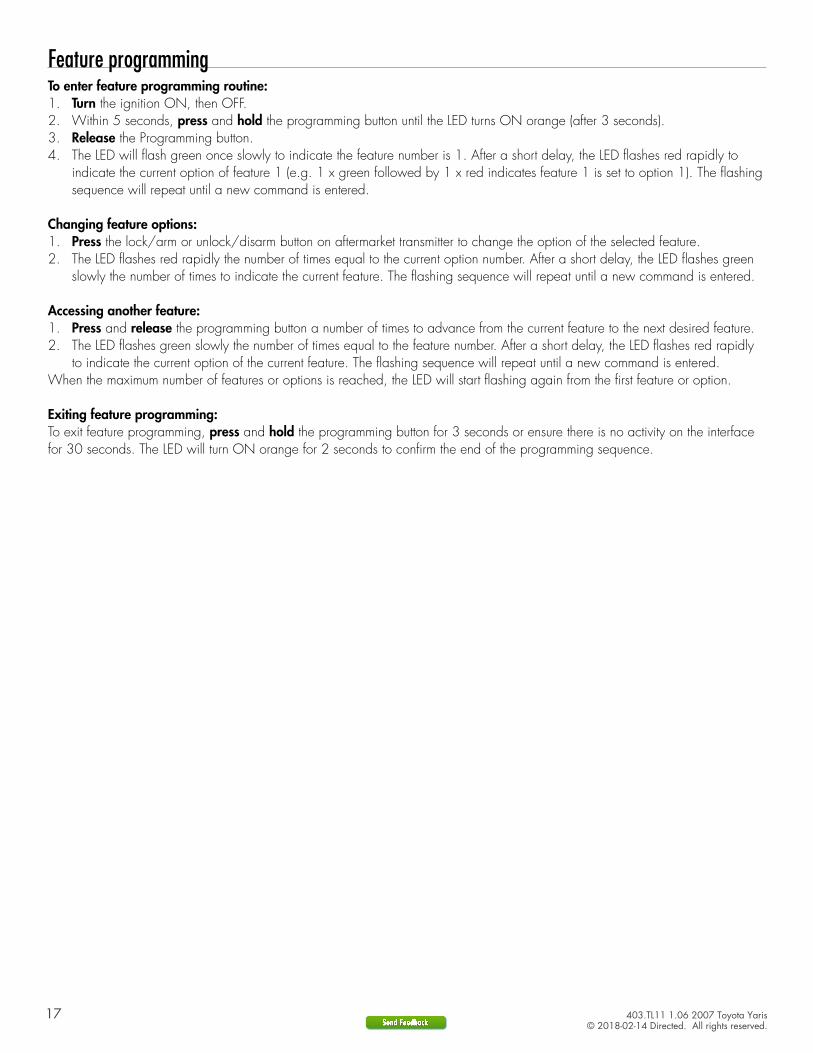
Feature programmingTo enter feature programming routine:1. Turn the ignition ON, then OFF. 2. Within 5 seconds, press and hold the programming button until the LED turns ON orange (after 3 seconds). 3. Release the Programming button.4. The LED will flash green once slowly to indicate the feature number is 1. After a short delay, the LED flashes red rapidly to
indicate the current option of feature 1 (e.g. 1 x green followed by 1 x red indicates feature 1 is set to option 1). The flashing sequence will repeat until a new command is entered.
Changing feature options:1. Press the lock/arm or unlock/disarm button on aftermarket transmitter to change the option of the selected feature. 2. The LED flashes red rapidly the number of times equal to the current option number. After a short delay, the LED flashes green
slowly the number of times to indicate the current feature. The flashing sequence will repeat until a new command is entered.
Accessing another feature:1. Press and release the programming button a number of times to advance from the current feature to the next desired feature. 2. The LED flashes green slowly the number of times equal to the feature number. After a short delay, the LED flashes red rapidly
to indicate the current option of the current feature. The flashing sequence will repeat until a new command is entered.When the maximum number of features or options is reached, the LED will start flashing again from the first feature or option.
Exiting feature programming:To exit feature programming, press and hold the programming button for 3 seconds or ensure there is no activity on the interface for 30 seconds. The LED will turn ON orange for 2 seconds to confirm the end of the programming sequence.
18 403.TL11 1.06 2007 Toyota Yaris© 2018-02-14 Directed. All rights reserved.
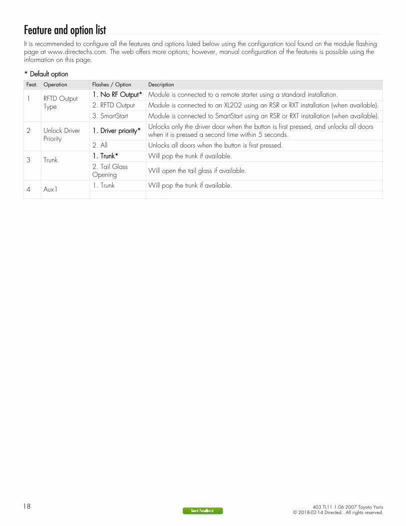
Feature and option listIt is recommended to configure all the features and options listed below using the configuration tool found on the module flashingpage at www.directechs.com. The web offers more options; however, manual configuration of the features is possible using theinformation on this page.
* Default optionFeat. Operation Flashes / Option Description
1 RFTD OutputType
1. No RF Output* Module is connected to a remote starter using a standard installation.
2. RFTD Output Module is connected to an XL202 using an RSR or RXT installation (when available).
3. SmartStart Module is connected to SmartStart using an RSR or RXT installation (when available).
2 Unlock DriverPriority
1. Driver priority* Unlocks only the driver door when the button is first pressed, and unlocks all doorswhen it is pressed a second time within 5 seconds.
2. All Unlocks all doors when the button is first pressed.
3 Trunk 1. Trunk* Will pop the trunk if available.
2. Tail GlassOpening Will open the tail glass if available.
4 Aux1 1. Trunk Will pop the trunk if available.
19 403.TL11 1.06 2007 Toyota Yaris© 2018-02-14 Directed. All rights reserved.
Limited one year consumer warrantyFor a period of ONE YEAR from the date of purchase of a Directed Electronics remote start or security product, Directed Electronics. (“DIRECTED”) promises to the original purchaser, to repair or replace with a comparable reconditioned piece, the security or remote start accessory piece (hereinafter the “Part”), which proves to be defective in workmanship or material under normal use, provided the following conditions are met: the Part was purchased from an authorized DIRECTED dealer; and the Part is returned to DIRECTED, postage prepaid, along with a clear, legible copy of the receipt or bill of sale bearing the following information: consumer’s name, address, telephone number, the authorized licensed dealer’s name and complete product and Part description.
This warranty is nontransferable and is automatically void if the Part has been modified or used in a manner contrary to its intended purpose or the Part has been damaged by accident, unreasonable use, neglect, improper service, installation or other causes not arising out of defect in materials or construction.
TO THE MAXIMUM EXTENT ALLOWED BY LAW, EXCEPT AS STATED ABOVE, ALL WARRANTIES, INCLUDING BUT NOT LIMITED TO EXPRESS WARRANTY, IMPLIED WARRANTY, WARRANTY OF MERCHANTABILITY, FITNESS FOR PARTICULAR PURPOSE AND WARRANTY OF NONINFRINGEMENT OF INTELLECTUAL PROPERTY, ARE EXPRESSLY EXCLUDED; AND DIRECTED NEITHER ASSUMES NOR AUTHORIZES ANY PERSON OR ENTITY TO ASSUME FOR IT ANY DUTY, OBLIGATION OR LIABILITY IN CONNECTION WITH ITS PRODUCTS. DIRECTED HEREBY DISCLAIMS AND HAS ABSOLUTELY NO LIABILITY FOR ANY AND ALL ACTS OF THIRD PARTIES INCLUDING DEALERS OR INSTALLERS. DIRECTED IS NOT OFFERING A GUARANTEE OR INSURANCE AGAINST VANDALISM, DAMAGE, OR THEFT OF THE AUTOMOBILE, ITS PARTS OR CONTENTS, AND DIRECTED HEREBY DISCLAIMS ANY LIABILITY WHATSOEVER, INCLUDING WITHOUT LIMITATION, LIABILITY FOR THEFT, DAMAGE, OR VANDALISM. IN THE EVENT OF A CLAIM OR A DISPUTE INVOLVING DIRECTED OR ITS SUBSIDIARY, THE PROPER VENUE SHALL BE SAN DIEGO COUNTY IN THE STATE OF CALIFORNIA. CALIFORNIA STATE LAWS AND APPLICABLE FEDERAL LAWS SHALL APPLY AND GOVERN THE DISPUTE. THE MAXIMUM RECOVERY UNDER ANY CLAIM AGAINST DIRECTED SHALL BE STRICTLY LIMITED TO THE AUTHORIZED DIRECTED DEALER’S PURCHASE PRICE OF THE PART. DIRECTED SHALL NOT BE RESPONSIBLE FOR ANY DAMAGES WHATSOEVER, INCLUDING BUT NOT LIMITED TO, ANY CONSEQUENTIAL DAMAGES, INCIDENTAL DAMAGES, DAMAGES FOR THE LOSS OF TIME, LOSS OF EARNINGS, COMMERCIAL LOSS, LOSS OF ECONOMIC OPPORTUNITY AND THE LIKE. NOTWITHSTANDING THE ABOVE, THE MANUFACTURER DOES OFFER A LIMITED WARRANTY TO REPLACE OR REPAIR AT DIRECTED’S OPTION THE PART AS DESCRIBED ABOVE.
This warranty only covers Parts sold within the United States of America and Canada. Parts sold outside of the United States of America or Canada are sold “AS-IS” and shall have NO WARRANTY, express or implied. Some states do not allow limitations on how long an implied warranty will last or the exclusion or limitation of incidental or consequential damages. This warranty gives you specific legal rights and you may also have other rights that vary from State to State. DIRECTED does not and has not authorized any person or entity to create for it any other obligation, promise, duty or obligation in connection with this Part.For further details relating to warranty information of Directed products, please visit the support section of DIRECTED’s website at: www.directed.com
920-10012-01 2013-07
This Interface kit / Data Bus Interface part has been tested on the listed vehicles. Other vehicles will be added to the select vehicle list upon completion of compatibility testing. Visit website for latest vehicle application guide. DISCLAIMER: Under no circumstances shall the manufacturer or the distributors of the bypass kit / data bus interface part(s) be held liable for any consequential damages sustained in connection with the part(s) installation. The manufacturer and it’s distributors will not, nor will they authorize any representative or any other individual to assume obligation or liability in relation to the interface kit / data bus interface part(s) other than its replacement. N.B.: Under no circumstances shall the manufacturer and distributors of this product be liable for consequential damages sustained in connection with this product and neither assumes nor authorizes any representative or other person to assume for it any obligation or liability other than the replacement of this product only.
Protected by U.S. Patents: 5,719,551; 6,011,460 B1 *; 6,243,004 B1; 6,249,216 B1; 6,275,147 B1; 6,297,731 B1; 6,346,876 B1; 6,392,534 B1; 6,529,124 B2; 6,696,927 B2; 6,756,885 B1; 6,756,886 B2; 6,771,167 B1; 6,812,829 B1; 6,924,750 B1; 7,010,402 B1; 7,015,830 B1; 7,031,826 B1; 7,046,126 B1; 7,061,137 B1; 7,068,153 B1; 7,205,679 B1; Cdn. Patent: 2,320,248; 2,414,991; 2,415,011; 2,415,023; 2,415,027; 2,415,038; 2,415,041; 2,420,947; 2,426,670; 2,454,089; European Patent: 1,053,128; Pat. Pending: 2,291,306. Made in Canada.
20 403.TL11 1.06 2007 Toyota Yaris© 2018-02-14 Directed. All rights reserved.
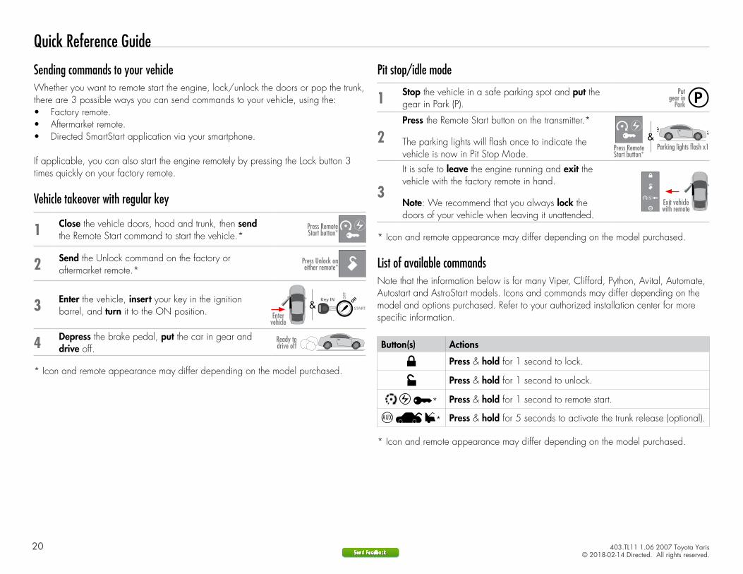
Quick Reference Guide
Pit stop/idle mode
1 Stop the vehicle in a safe parking spot and put the gear in Park (P).
Put gear in
Park
2Press the Remote Start button on the transmitter.*
The parking lights will flash once to indicate the vehicle is now in Pit Stop Mode.
Parking lights flash x1
14:36
Press Remote Start button*
&
3
It is safe to leave the engine running and exit the vehicle with the factory remote in hand.
Note: We recommend that you always lock the doors of your vehicle when leaving it unattended.
14:36Exit vehicle with remote
* Icon and remote appearance may differ depending on the model purchased.
List of available commandsNote that the information below is for many Viper, Clifford, Python, Avital, Automate, Autostart and AstroStart models. Icons and commands may differ depending on the model and options purchased. Refer to your authorized installation center for more specific information.
Button(s) Actions
Press & hold for 1 second to lock.
Press & hold for 1 second to unlock.
* Press & hold for 1 second to remote start.
* Press & hold for 5 seconds to activate the trunk release (optional).
* Icon and remote appearance may differ depending on the model purchased.
Sending commands to your vehicleWhether you want to remote start the engine, lock/unlock the doors or pop the trunk, there are 3 possible ways you can send commands to your vehicle, using the:• Factory remote.• Aftermarket remote.• Directed SmartStart application via your smartphone.
If applicable, you can also start the engine remotely by pressing the Lock button 3 times quickly on your factory remote.
Vehicle takeover with regular key
1 Close the vehicle doors, hood and trunk, then send the Remote Start command to start the vehicle.* 14:36Press Remote
Start button*
2 Send the Unlock command on the factory or aftermarket remote.*
14:36Press Unlock on either remote*
3 Enter the vehicle, insert your key in the ignition barrel, and turn it to the ON position. START
Key OUT ONOFF
START
Key IN ONOFF
START
Key IN ONOFF
START
Key IN ONOFF
Entervehicle
&
4 Depress the brake pedal, put the car in gear and drive off.
Ready to drive off
* Icon and remote appearance may differ depending on the model purchased.
21 403.TL11 1.06 2007 Toyota Yaris© 2018-02-14 Directed. All rights reserved.
Notes