
Data Sheet DB EN R-IB IL PWM/2-PAC - Hidrosistemas
24
Electric Drives and Controls Hydraulics Linear Motion and Assembly Technologies Pneumatics Service 11/2007 Rexroth Inline Terminal for Pulse Width Modulation and Frequency Modulation R-IB IL PWM/2-PAC Two independent channels 5 V or 24 V output signals R911170576 Edition 01 1 Description The terminal is designed for use within an Inline station. It can be used in the four different operating modes listed below: • PWM (pulse width modulation) • Frequency generator • Single shot (single pulse generator) • Pulse direction signal Features • Two independently operating channels • Output signals as 5 V or 24 V signals • Two digital outputs, 5 V DC, 10 mA, 0 Hz to 50 kHz, with an ohmic load capacity, for the connection of high-resistance non-inductive input circuits (e.g., solid-state relays) • Two digital outputs, 24 V DC, 500 mA, 0 Hz to 500 Hz, with an ohmic and inductive load capacity, suitable for the direct control of loads • Short-circuit protected and overload protected outputs • Diagnostic and status indicators This data sheet is only valid in association with the application descriptions for the Rexroth Inline system (see "Documentation" on page 3). Make sure you always use the latest documentation. It can be downloaded at www.boschrexroth.com .
-
Upload
khangminh22 -
Category
Documents
-
view
4 -
download
0
Transcript of Data Sheet DB EN R-IB IL PWM/2-PAC - Hidrosistemas
Electric Drives and Controls Hydraulics
Linear Motion and Assembly Technologies Pneumatics Service
11/2007
Rexroth Inline Terminal for Pulse Width Modulation and Frequency Modulation
R-IB IL PWM/2-PAC
Two independent channels5 V or 24 V output signals
R911170576Edition 01
1 DescriptionThe terminal is designed for use within an Inlinestation. It can be used in the four different operating modeslisted below:• PWM (pulse width modulation)• Frequency generator• Single shot (single pulse generator)• Pulse direction signal
Features• Two independently operating channels • Output signals as 5 V or 24 V signals• Two digital outputs, 5 V DC, 10 mA,
0 Hz to 50 kHz, with an ohmic load capacity, forthe connection of high-resistance non-inductiveinput circuits (e.g., solid-state relays)
• Two digital outputs, 24 V DC, 500 mA, 0 Hz to 500 Hz, with an ohmic and inductive loadcapacity, suitable for the direct control of loads
• Short-circuit protected and overload protectedoutputs
• Diagnostic and status indicators
This data sheet is only valid inassociation with the applicationdescriptions for the Rexroth Inlinesystem (see "Documentation" onpage 3).
Make sure you always use the latestdocumentation. It can be downloaded atwww.boschrexroth.com.
2/24 Bosch Rexroth AG | Electric Drives R-IB IL PWM/2-PAC | Data Sheetand Controls
Table of Contents
1 Description................................................................................................................1
3 Technical Data ..........................................................................................................34.1 Local Diagnostic and Status Indicators ..............................................................................................64.2 Function Identification ........................................................................................................................64.3 Terminal Point Assignment ................................................................................................................6
5 Internal Basic Circuit Diagram ................................................................................7
7 Overview of the Operating Modes...........................................................................87.1 PWM (Pulse Width Modulation) With Variable Duty Cycle.................................................................87.2 Frequency Generator With Constant Duty Cycle .............................................................................87.3 Single Shot (Single Pulse Generator) ..............................................................................................87.4 Pulse Direction Signal .....................................................................................................................87.5 Selecting the Operating Mode............................................................................................................87.6 Changing the Operating Mode ...........................................................................................................8
8 Special Features of the Terminal ............................................................................9
9 Process Data.............................................................................................................99.1 OUT Process Data ...........................................................................................................................109.2 IN Process Data ...............................................................................................................................10
10 Output Word in General .........................................................................................11
12 PWM (Pulse Width Modulation) Mode ........................................................................................................................12
16 Connection Example ..............................................................................................24
17 Programming Data/Configuration Data .................................................................................................24
17.1 Local Bus..........................................................................................................................................2417.2 Other Bus Systems ..........................................................................................................................24

Data Sheet | R-IB IL PWM/2-PAC Electric Drives | Bosch Rexroth AG 3/24 and Controls
2 Ordering Data
3 Technical Data
ProductDescription Type MNR Pcs./Pck.Inline output terminal with pulse width modulation;complete with accessories (connector and labeling field);data rate of 500 kbps
R-IB IL PWM/2-PAC R911170444 1
DocumentationDescription Type MNR Pcs./Pck."Automation Terminals of the Rexroth Inline Product Range" application description
DOK-CONTRL-ILSYSINS***-AW..-EN-P
R911317021 1
"Configuring and Installing the Rexroth Inline Product Range for INTERBUS" application description
DOK-CONTRL-ILSYSPRO***-AW..-EN-P
R911317023 1
For additional ordering data (accessories), please refer to the product catalog atwww.boschrexroth.com.
General DataHousing dimensions (width x height x depth) 24.4 mm x 136 mm x 72 mm (with connectors)Weight 130 g (with connectors)Operating mode Process data mode with 2 wordsData rate 500 kbpsConnection method for actuators 2-wire and 3-wire technologyPermissible temperature (operation) -25°C to +55°CPermissible temperature (storage/transport) -25°C to +85°CPermissible humidity (operation/storage/transport) 10% to 95% according to DIN EN 61131-2Permissible air pressure (operation/storage/transport) 70 kPa to 106 kPa (up to 3000 m above sea level)Degree of protection IP20 according to IEC 60529Protection class Class 3 according to VDE 0106, IEC 60536
InterfaceLocal bus Through data routing
Power ConsumptionCommunications power 7.5 V DCCurrent consumption at UL 130 mA, maximumPower consumption at UL 0.98 W, maximumSegment supply voltage US 24 V DC (nominal value)Nominal current consumption at US 1 A
Supply of the Module Electronics and I/O Through Bus Coupler/Power TerminalConnection method Through potential routing
Digital Outputs24 V DCNumber 2Nominal output voltage UOUT 24 V DC Differential voltage for Inom ≤ 1 VNominal current Inom per channel 0.5 ATolerance of the nominal current +10%
4/24 Bosch Rexroth AG | Electric Drives R-IB IL PWM/2-PAC | Data Sheetand Controls
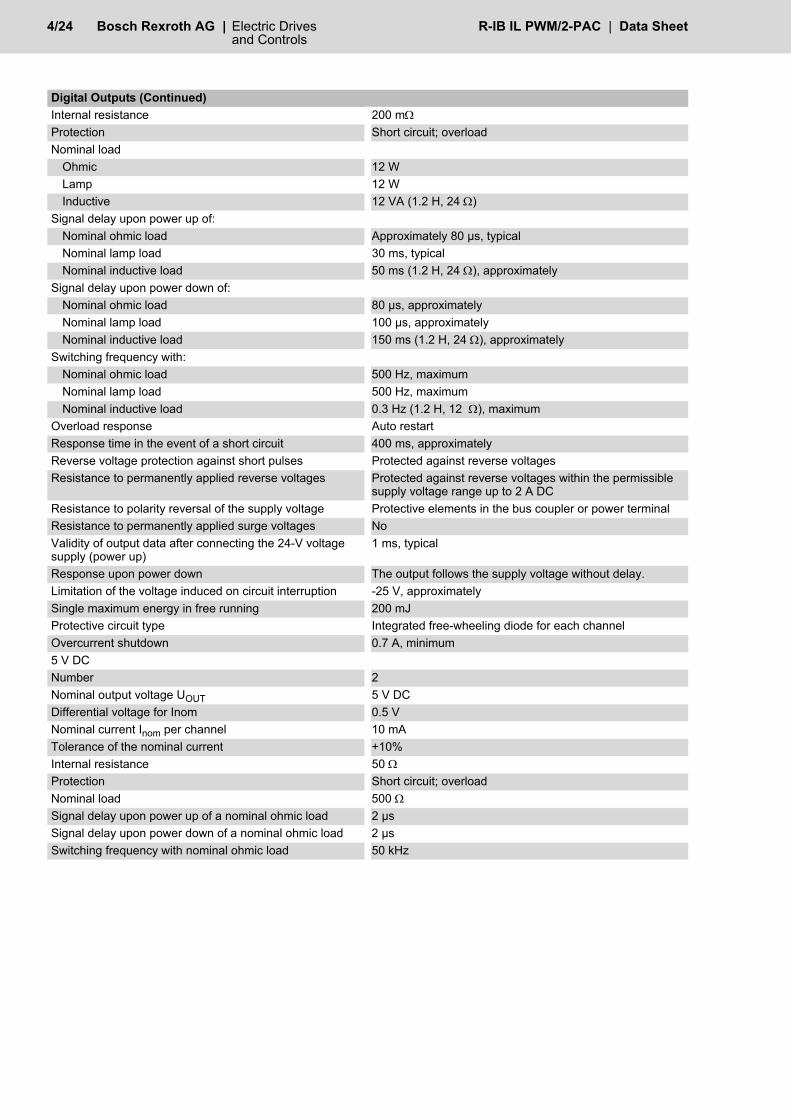
Internal resistance 200 mΩProtection Short circuit; overloadNominal load
Ohmic 12 WLamp 12 WInductive 12 VA (1.2 H, 24 Ω)
Signal delay upon power up of:Nominal ohmic load Approximately 80 µs, typicalNominal lamp load 30 ms, typicalNominal inductive load 50 ms (1.2 H, 24 Ω), approximately
Signal delay upon power down of:Nominal ohmic load 80 µs, approximatelyNominal lamp load 100 µs, approximatelyNominal inductive load 150 ms (1.2 H, 24 Ω), approximately
Switching frequency with: Nominal ohmic load 500 Hz, maximum Nominal lamp load 500 Hz, maximumNominal inductive load 0.3 Hz (1.2 H, 12 Ω), maximum
Overload response Auto restartResponse time in the event of a short circuit 400 ms, approximatelyReverse voltage protection against short pulses Protected against reverse voltagesResistance to permanently applied reverse voltages Protected against reverse voltages within the permissible
supply voltage range up to 2 A DCResistance to polarity reversal of the supply voltage Protective elements in the bus coupler or power terminalResistance to permanently applied surge voltages NoValidity of output data after connecting the 24-V voltage supply (power up)
1 ms, typical
Response upon power down The output follows the supply voltage without delay.Limitation of the voltage induced on circuit interruption -25 V, approximatelySingle maximum energy in free running 200 mJProtective circuit type Integrated free-wheeling diode for each channelOvercurrent shutdown 0.7 A, minimum5 V DCNumber 2Nominal output voltage UOUT 5 V DC Differential voltage for Inom 0.5 VNominal current Inom per channel 10 mATolerance of the nominal current +10% Internal resistance 50 ΩProtection Short circuit; overloadNominal load 500 ΩSignal delay upon power up of a nominal ohmic load 2 µsSignal delay upon power down of a nominal ohmic load 2 µsSwitching frequency with nominal ohmic load 50 kHz
Digital Outputs (Continued)

Data Sheet | R-IB IL PWM/2-PAC Electric Drives | Bosch Rexroth AG 5/24 and Controls
Power DissipationFormula to Calculate the Power Dissipation of the ElectronicsPTOT = PBus + POut5V + POut24VPTOT = 1 W + n x ILi
2 x 0.4 Ω
Where:PTOT Total power dissipation in the terminalPBus Power dissipation in the terminal without set output POut 5V Power dissipation in the terminal through set 5 V outputs
This value is negligible and therefore not included in the calculation.POut 24V Power dissipation in the terminal through set 24 V outputsn Number of set 24 V outputs (n = 1 to 2)ILi Load current of output ii IndexPTOT = PBus + POut5V + POut24VPTOT = 1 W + n x ILi
2 x 0.4 ΩPower Dissipation of the Housing PHOU1.2 W, maximum (within the permissible operating temperature)
Safety EquipmentOverload/short circuit in the segment circuit ElectronicSurge voltage Protective elements in the power terminalPolarity reversal of the supply voltage Protective elements of the power terminal
It is necessary to protect the supply voltage. The power supply unit should be able to supply four times (400%) the nominal current of the fuse.
Reverse voltage of the 24 V output Protected against reverse voltages within the permissible supply voltage range up to 2 A
Electrical Isolation/Isolation of the Voltage Areas
To provide electrical isolation between the logic level and the I/O area, it is necessary to supplythe station bus coupler and the terminal described via the bus coupler or a power terminal fromseparate power supply units. Interconnection of the power supply units in the 24 V area is notpermitted. (See also application description.)
Common PotentialsThe 24 V main voltage, 24 V segment voltage, and GND have the same potential. FE is a separate potential area.Separate Potentials in the System Consisting of Bus Coupler/Power Terminal and I/O Terminal- Test Distance - Test Voltage5 V supply incoming remote bus/7.5 V supply (bus logic) 500 V AC, 50 Hz, 1 min.5 V supply outgoing remote bus/7.5 V supply (bus logic) 500 V AC, 50 Hz, 1 min.7.5 V supply (bus logic)/24 V supply (I/O) 500 V AC, 50 Hz, 1 min.7.5 V supply (bus logic)/5 V supply (I/O) 500 V AC, 50 Hz, 1 min.24 V supply (I/O)/functional earth ground 500 V AC, 50 Hz, 1 min.5 V supply (I/O)/functional earth ground 500 V AC, 50 Hz, 1 min.
CAUTION
Error Messages Sent to the Higher-Level Control or Computer SystemShort circuit/overload of a 24 V output YesShort circuit/overload of a 5 V output NoOperating voltage out of range No
ApprovalsFor the latest approvals, please visit www.boschrexroth.com.

6/24 Bosch Rexroth AG | Electric Drives R-IB IL PWM/2-PAC | Data Sheetand Controls
4 Local Diagnostic and Status Indicators and Terminal Point Assignment
Fig. 1 The terminal with appropriate connectors
4.1 Local Diagnostic and Status Indicators
4.2 Function IdentificationOrange
4.3 Terminal Point Assignment
� � � � �
� � �
� �
��
�
�
� � � �
� �
�
�
�
�
�
�
�
�
� � �
� � �
� � �
� � �
� � �
� � �
� � �
� � ��
� �
�
�
�
�
�
�
�
�
� � �
� � �
� � �
� � �
� � �
� � �
� � �
� � ��
Des. Color MeaningD Green Diagnostics24V (0) Yellow 24 V channel 1 active24V (1) Yellow 24 V channel 2 active5V (0) Yellow 5 V channel 1 active5V (1) Yellow 5 V channel 2 active
Terminal Point AssignmentConnector 11.1, 2.1,1.2, 2.2
Not used
1.3, 2.3 GND for 24 V outputs1.4, 2.4 FE connectionConnector 21.1 24 V output 1 (DO1)2.1 24 V output 2 (DO2)1.2 5 V output 1 (DO1')2.2 5 V output 2 (DO2')1.3, 2.3 GND for 5 V outputs1.4, 2.4 FE connection
Make sure that the corresponding ground is connected for the 24 V outputs and the 5 V outputs.
CAUTION

Data Sheet | R-IB IL PWM/2-PAC Electric Drives | Bosch Rexroth AG 7/24 and Controls
5 Internal Basic Circuit Diagram
Fig. 2 Internal wiring of the terminal points
Other symbols used are explained inthe application descriptions for theRexroth Inline system (see"Documentation" on page 3) or theapplication description for your bussystem.
Key:Protocol chip (bus logic including voltage conditioning)
LED
Microprocessor
DC/DC converter with electrical isolation
Optocoupler
Transistor
Capacitor
Ground for 5 V outputs, electrically isolated from ground of the communications power UL
Electrically isolated area
� � � � � � ���
� � � � � � ���
� � � � � � � � �
�� �
�� �
�� !
" � #
�
$ �
� �
� �
� �
% & � �
�
� �
" � ' � �
�
� �
" � ' � �
� � �
" � ' � �
� � �
" � ' � �
��
� � � %
OPC
$ �
( ( (
) ) )
�

8/24 Bosch Rexroth AG | Electric Drives R-IB IL PWM/2-PAC | Data Sheetand Controls
6 Terms and Abbreviations Used
7 Overview of the Operating ModesThe terminal can be used in four different operatingmodes:
7.1 PWM (Pulse Width Modulation) With Variable Duty Cycle
This operating mode can, for example, be used tocontrol solid-state relays. It is suitable for regulating the drive temperature andspecifying the drive speed.This operating mode supports a frequency of up to10 kHz.
7.2 Frequency Generator With Constant Duty Cycle
This operating mode can, for example, be used tospecify the drive speed.This operating mode supports a frequency of up to50 kHz.
7.3 Single Shot (Single Pulse Generator)In this operating mode, single pulses can begenerated with a variable duration of between 10 µsand 25.5 s. These pulses can, for example, be used to control theopening time of a valve.
7.4 Pulse Direction SignalThis operating mode can, for example, be used tocontrol step motors. A frequency of up to 25 kHz and a target position canbe specified here.
7.5 Selecting the Operating ModeThe terminal does not have to be parameterizedseparately. The operating mode is selected bysending output words.A separate operating mode can be selected for eachchannel, except in pulse direction signal mode. Whenthe terminal is operating in pulse direction signalmode, both outputs are required for this operatingmode.
7.6 Changing the Operating Mode
The following parameters stop the respectiveoperating mode:
PWM: Pulse width modulationDuty cycle: High phase of the periodPeriod: Duration of the signal to be generatedSingle shot: Single pulseLSB: Least significant bit
To change operating mode, disablethe active operating mode beforeselecting the new mode.
PWM: Duty cycle = 0Frequency generator:
Frequency = 0
Single shot: Factor = 0Pulse direction signal:
Frequency = 0 and Reset bit = 0
CAUTION

Data Sheet | R-IB IL PWM/2-PAC Electric Drives | Bosch Rexroth AG 9/24 and Controls
8 Special Features of the TerminalEach of the two output signals is available for one 5 Voutput and one 24 V output. The 5 V outputs support all frequencies. The 24 Voutputs are only operated at up to 500 Hz. At higherfrequencies or for pulses that are shorter than 100 µs,the 24 V outputs are reset to 0.Following a bus reset, all outputs are reset and alloutput activities are stopped.
9 Process DataThe process image of the terminal comprises twodata words: one in the input direction and one in theoutput direction. They may be assigned differentlydepending on the operating mode.In the PWM, frequency generator, and single shot(single pulse generator) modes, each channeloccupies one word and operates independently of theother channel. In this case, the process data isassigned as follows:
The "Word for output of channel 1" applies to both the24 V output of channel 1 and the 5 V output ofchannel 1.The "Word for output of channel 2" applies to both the24 V output of channel 2 and the 5 V output ofchannel 2.In the PWM, frequency generator, and single shot(single pulse generator) modes, the output data ismirrored to the input data, assuming it is valid. If theoutput data contains reserved codes and is thereforeinvalid, the data is not mirrored. In this case, the inputdata contains the last valid values.In pulse direction signal mode, both outputs arecontrolled together and the terminal operates on asingle channel.Terminal parameterization is not required.
Process data word 0 Process data word 1OUT Word for output of
channel 1Word for output of
channel 2
IN Word for output of channel 1 mirrored
Word for output of channel 2 mirrored

10/24 Bosch Rexroth AG | Electric Drives R-IB IL PWM/2-PAC | Data Sheetand Controls
9.1 OUT Process Data
9.2 IN Process Data
(Word.bit) view
Word Word 0
Bit 15 14 13 12 11 10 9 8 7 6 5 4 3 2 1 0
OUT[0] Assignment See assignment in the individual operating modes
(Word.bit) view
Word Word 1
Bit 15 14 13 12 11 10 9 8 7 6 5 4 3 2 1 0
OUT[1] Assignment See assignment in the individual operating modes
(Word.bit) view
Word Word 0
Bit 15 14 13 12 11 10 9 8 7 6 5 4 3 2 1 0
IN[0] Assignment See assignment in the individual operating modes
(Word.bit) view
Word Word 1
Bit 15 14 13 12 11 10 9 8 7 6 5 4 3 2 1 0
IN[1] Assignment See assignment in the individual operating modes
Data Sheet | R-IB IL PWM/2-PAC Electric Drives | Bosch Rexroth AG 11/24 and Controls
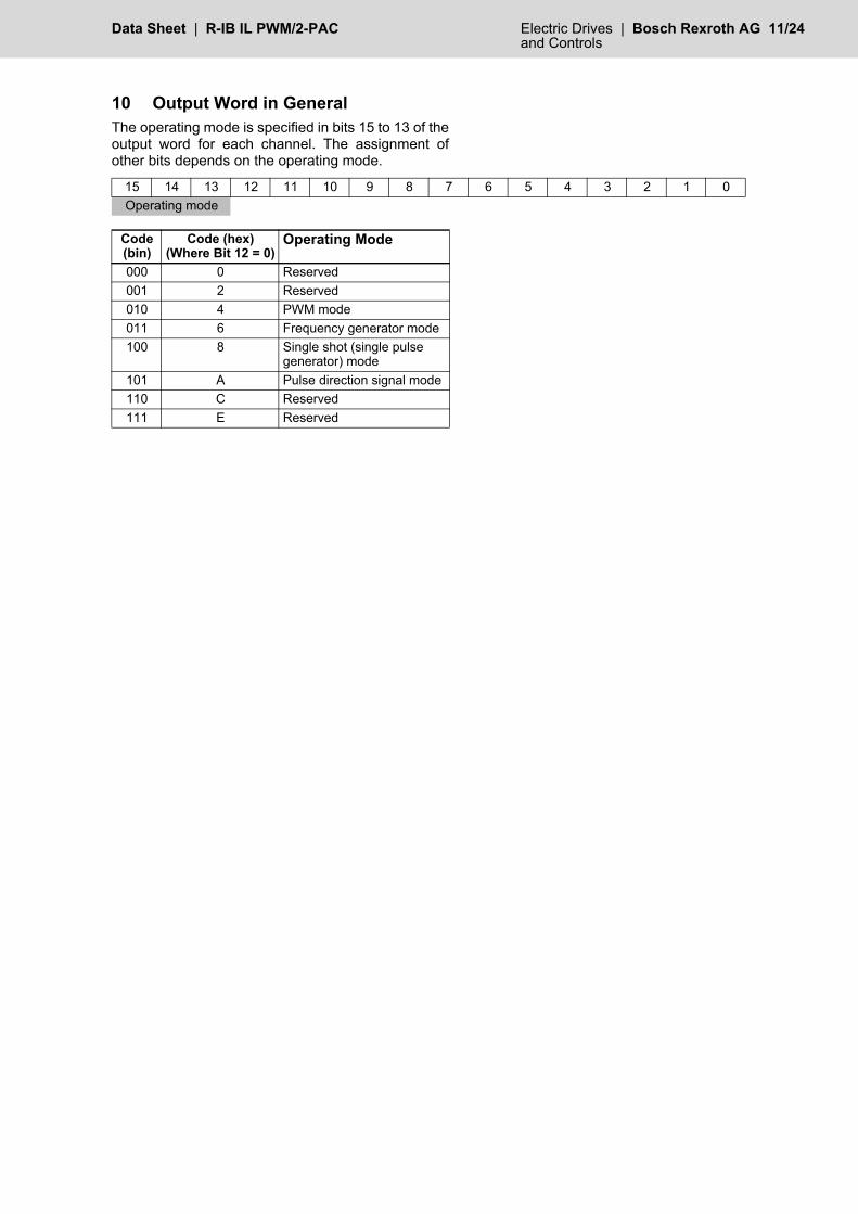
10 Output Word in GeneralThe operating mode is specified in bits 15 to 13 of theoutput word for each channel. The assignment ofother bits depends on the operating mode.
15 14 13 12 11 10 9 8 7 6 5 4 3 2 1 0Operating mode
Code (bin)
Code (hex)(Where Bit 12 = 0)
Operating Mode
000 0 Reserved001 2 Reserved010 4 PWM mode011 6 Frequency generator mode100 8 Single shot (single pulse
generator) mode101 A Pulse direction signal mode110 C Reserved111 E Reserved

12/24 Bosch Rexroth AG | Electric Drives R-IB IL PWM/2-PAC | Data Sheetand Controls
11 Reading the Firmware Version and Module ID
Only output word 0 is used to read the firmwareversion and module ID of the terminal.
Output word 0
Input word 0: Acknowledgment of the output word
Input word 1: Firmware version (e.g., Version 1.23) and module ID (5 for PWM/2 module)
12 PWM (Pulse Width Modulation) Mode
This operating mode is used to specify a pulse/pauseratio in a period. At a set frequency (due to the periodlength specified), specify the changing duty cycle.Continuous pulses are generated. A period length of between 100 µs and 10 s can bespecified. This covers a frequency range of 10 kHz to0.1 Hz. The selected duty cycle can be between0.39% and 99.45%.PWM mode can, for example, be used to controlsolid-state relays. It is suitable for regulating the drivetemperature and specifying the drive speed.
Fig. 3 PWM with constant period (P) and variable duty cycle of 40% or 80%
Bit 15 14 13 12 11 10 9 8 7 6 5 4 3 2 1 0bin 0 0 1 1 1 1 0 0 0 0 0 0 0 0 0 0hex 3 C 0 0
Bit 15 14 13 12 11 10 9 8 7 6 5 4 3 2 1 0bin 0 0 1 1 1 1 0 0 0 0 0 0 0 0 0 0hex 3 C 0 0
Bit 15 14 13 12 11 10 9 8 7 6 5 4 3 2 1 0bin 0 0 0 1 0 0 1 0 0 0 1 1 0 1 0 1hex 1 2 3 5
P
40%
6920B004
P
80%
Data Sheet | R-IB IL PWM/2-PAC Electric Drives | Bosch Rexroth AG 13/24 and Controls
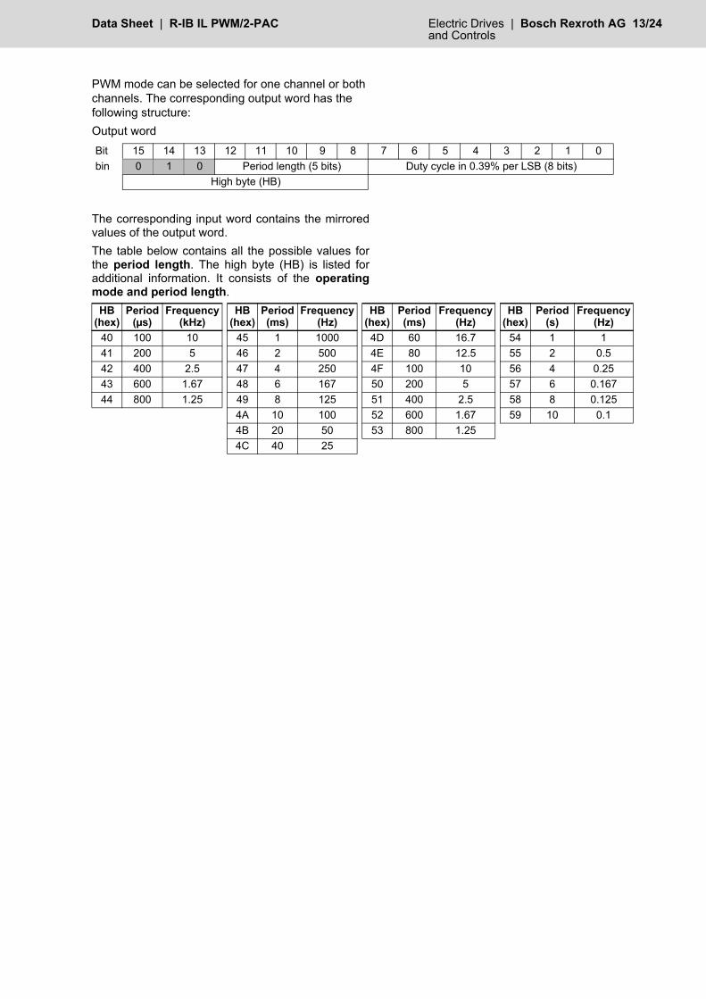
PWM mode can be selected for one channel or both channels. The corresponding output word has the following structure:Output word
The corresponding input word contains the mirroredvalues of the output word.The table below contains all the possible values forthe period length. The high byte (HB) is listed foradditional information. It consists of the operatingmode and period length.
Bit 15 14 13 12 11 10 9 8 7 6 5 4 3 2 1 0bin 0 1 0 Period length (5 bits) Duty cycle in 0.39% per LSB (8 bits)
High byte (HB)
HB(hex)
Period(µs)
Frequency(kHz)
HB(hex)
Period(ms)
Frequency(Hz)
HB(hex)
Period(ms)
Frequency(Hz)
HB(hex)
Period(s)
Frequency(Hz)
40 100 10 45 1 1000 4D 60 16.7 54 1 141 200 5 46 2 500 4E 80 12.5 55 2 0.542 400 2.5 47 4 250 4F 100 10 56 4 0.2543 600 1.67 48 6 167 50 200 5 57 6 0.16744 800 1.25 49 8 125 51 400 2.5 58 8 0.125
4A 10 100 52 600 1.67 59 10 0.14B 20 50 53 800 1.254C 40 25

14/24 Bosch Rexroth AG | Electric Drives R-IB IL PWM/2-PAC | Data Sheetand Controls
Duty CycleThe values for the duty cycle fall within the range from0 (0hex) to 255 (FFhex) at a resolution of 0.39% perLSB.The value 0 stops the PWM function.The values 1 to 255 correspond to between 0.39%and 99.45% of the period.
The minimum duty cycle (high phase ofthe period) must be at least 40 µs, the minimum low phase of the periodmust be at least 80 µs.
The minimum low phase of the period at the 24 Voutput depends on the load:
Example:A signal is to be generated with the followingproperties:• Period length = 200 ms
(Frequency = 1/Period length = 1/200 ms =5 Hz)
• Duty cycle = 40%The code for the operating mode and period length isdetermined using the table and is 50hex.The code for the duty cycle is determined as follows:Code = 40%/0.39% = 102.564; 103 = 1100111bin =67hexThe value of exactly 40% cannot be mapped. Either40.17% (67hex) or 39.78% (66hex) is used.Output word for the example
Further examples for different periods and different duty cycles:
Load Resistance RL Minimum Low Phase of the Period
< 1 kΩ 80 µs< 10 kΩ 200 µs> 10 kΩ 250 µs
Bit 15 14 13 12 11 10 9 8 7 6 5 4 3 2 1 0bin 0 1 0 Period length (5 bits) Duty cycle in 0.39% per LSB (8 bits)bin 0 1 0 1 0 0 0 0 0 1 1 0 0 1 1 1hex 5 0 6 7
Period Length HB Duty Cycle Output Word(According to the Table on page 13) (%) Code (dec) Code (hex) (hex)
400 µs 42 0.39 01 01 420110 ms 4A 5.07 13 0D 4A0D60 ms 4D 10.14 26 1A 4D1A
600 ms 52 19.89 51 33 52331 s 54 24.96 64 40 5440
10 s 59 49.92 128 80 5980200 µs 41 74.88 192 C0 41C0100 ms 4F 99.45 255 FF 4FFF
Data Sheet | R-IB IL PWM/2-PAC Electric Drives | Bosch Rexroth AG 15/24 and Controls
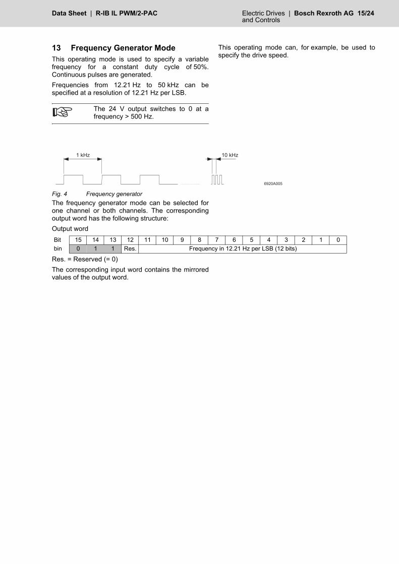
13 Frequency Generator ModeThis operating mode is used to specify a variablefrequency for a constant duty cycle of 50%.Continuous pulses are generated.Frequencies from 12.21 Hz to 50 kHz can bespecified at a resolution of 12.21 Hz per LSB.
The 24 V output switches to 0 at afrequency > 500 Hz.
This operating mode can, for example, be used tospecify the drive speed.
Fig. 4 Frequency generatorThe frequency generator mode can be selected forone channel or both channels. The correspondingoutput word has the following structure:Output word
Res. = Reserved (= 0)The corresponding input word contains the mirroredvalues of the output word.
� � * + ,
� � � �
� � * + ,
Bit 15 14 13 12 11 10 9 8 7 6 5 4 3 2 1 0bin 0 1 1 Res. Frequency in 12.21 Hz per LSB (12 bits)
16/24 Bosch Rexroth AG | Electric Drives R-IB IL PWM/2-PAC | Data Sheetand Controls
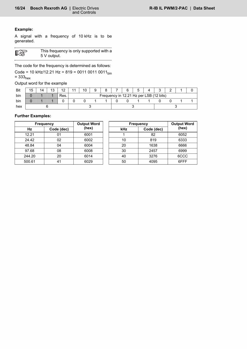
Example:A signal with a frequency of 10 kHz is to begenerated.
This frequency is only supported with a5 V output.
The code for the frequency is determined as follows:Code = 10 kHz/12.21 Hz = 819 = 0011 0011 0011bin= 333hexOutput word for the example
Further Examples:
Bit 15 14 13 12 11 10 9 8 7 6 5 4 3 2 1 0bin 0 1 1 Res. Frequency in 12.21 Hz per LSB (12 bits)bin 0 1 1 0 0 0 1 1 0 0 1 1 0 0 1 1hex 6 3 3 3
Frequency Output Word (hex)
Frequency Output Word (hex)Hz Code (dec) kHz Code (dec)
12.21 01 6001 1 82 605224.42 02 6002 10 819 633348.84 04 6004 20 1638 666697.68 08 6008 30 2457 6999244.20 20 6014 40 3276 6CCC500.61 41 6029 50 4095 6FFF
Data Sheet | R-IB IL PWM/2-PAC Electric Drives | Bosch Rexroth AG 17/24 and Controls
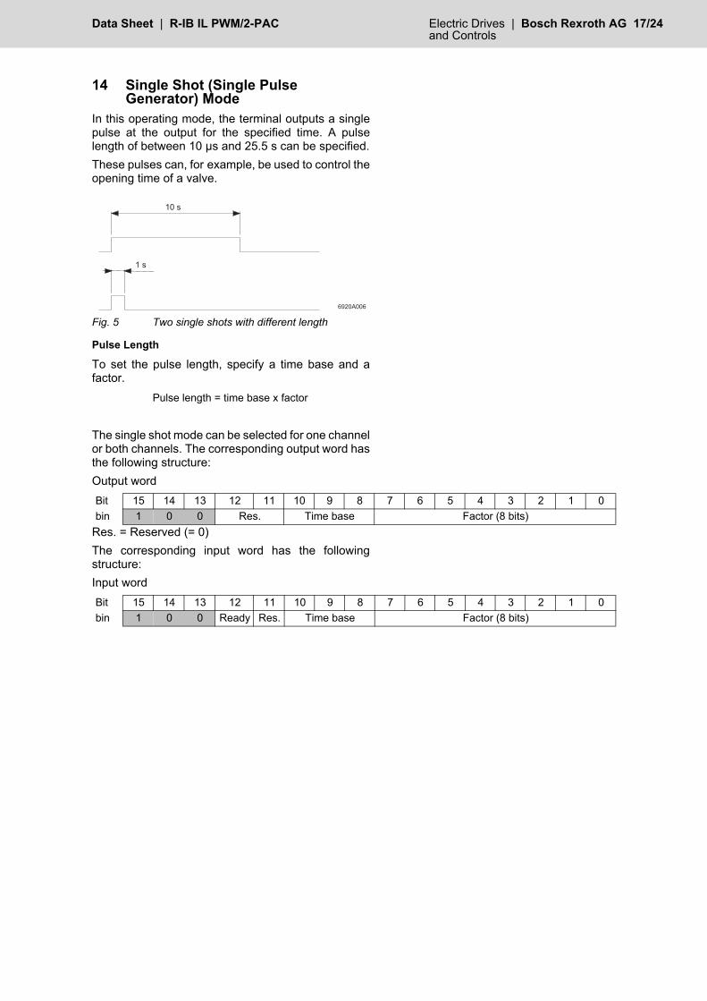
14 Single Shot (Single Pulse Generator) Mode
In this operating mode, the terminal outputs a singlepulse at the output for the specified time. A pulselength of between 10 µs and 25.5 s can be specified.These pulses can, for example, be used to control theopening time of a valve.
Fig. 5 Two single shots with different length
Pulse Length
To set the pulse length, specify a time base and afactor.
The single shot mode can be selected for one channelor both channels. The corresponding output word hasthe following structure:Output word
Res. = Reserved (= 0)The corresponding input word has the followingstructure:Input word
� � �
� � �
� � �
Pulse length = time base x factor
Bit 15 14 13 12 11 10 9 8 7 6 5 4 3 2 1 0bin 1 0 0 Res. Time base Factor (8 bits)
Bit 15 14 13 12 11 10 9 8 7 6 5 4 3 2 1 0bin 1 0 0 Ready Res. Time base Factor (8 bits)
18/24 Bosch Rexroth AG | Electric Drives R-IB IL PWM/2-PAC | Data Sheetand Controls
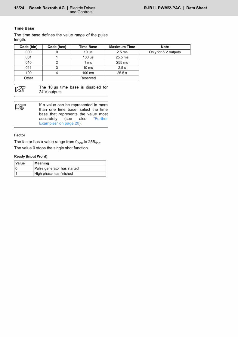
Time BaseThe time base defines the value range of the pulselength.
The 10 µs time base is disabled for24 V outputs.
If a value can be represented in morethan one time base, select the timebase that represents the value mostaccurately (see also "FurtherExamples" on page 20).
Factor
The factor has a value range from 0dec to 255dec.The value 0 stops the single shot function.
Ready (Input Word)
Code (bin) Code (hex) Time Base Maximum Time Note000 0 10 µs 2.5 ms Only for 5 V outputs001 1 100 µs 25.5 ms010 2 1 ms 255 ms011 3 10 ms 2.5 s100 4 100 ms 25.5 s
Other Reserved
Value Meaning0 Pulse generator has started1 High phase has finished

Data Sheet | R-IB IL PWM/2-PAC Electric Drives | Bosch Rexroth AG 19/24 and Controls
Single Shot SequenceThe single shot mode is started by writing the timebase and/or factor. The start is indicated in the inputword by Ready = 0. If the high phase has finished, Ready = 1 is set.
1 Moment at which unit and/or factor weremodified
2 High phaseFig. 6 Sequence for generating a pulse after
specifying a unit and/or factorA new pulse is generated when the time base and/orfactor is modified.
If the pulse length is modified while apulse is being output, the active pulseoutput process is extended by thenewly specified time. The time baseand the factor should therefore only bemodified when Ready = 1.
To generate the same pulse several times insuccession, proceed as follows after each pulsegeneration:• Wait until Ready = 1
(high phase of the pulse has finished)• Set the factor to 0• Wait for confirmation in the form of the input
word being read (factor = 0)• Set the factor to the desired value
Starting the pulse generator whileReady = 0 (i.e., before the previouslystarted single shot has finished) acts asa retrigger, which means the activepulse is extended by the newlyspecified time.
Each pulse at the 5 V output has aconstant error of 5 µs, each pulse at the24 V output has a constant error of100 µs.
6920B009
Process data
DOx
Ready
1
2

20/24 Bosch Rexroth AG | Electric Drives R-IB IL PWM/2-PAC | Data Sheetand Controls
Example:A single shot with a duration of 12 s is to begenerated.
• Time base: 100 ms (time base code = 4hex)• Factor: 12 s/100 ms = 120 = 1111000bin = 78hex
Output word for the example
Further Examples
OUT = Output wordThe gray cells represent values which cannot berepresented in this time base as they are outside thepermissible value range.The values given as "–" are values which cannot berepresented precisely in this time base, despite thefact that they are within the permissible value range ofthe time base. Only a rounded value can berepresented. To represent the value precisely, selecta different time base.
Bit 15 14 13 12 11 10 9 8 7 6 5 4 3 2 1 0bin 1 0 0 Res. Time base Factor (8 bits)bin 1 0 0 0 0 1 0 0 0 1 1 1 1 0 0 0hex 8 4 7 8
Time Base 10 µs (5 V Only) 100 µs 1 ms 10 ms 100 msLength of Single Shot
Factor(dec)
OUT(hex)
Factor(dec)
OUT(hex)
Factor(dec)
OUT(hex)
Factor(dec)
OUT(hex)
Factor(dec)
OUT(hex)
50 µs 5 8005100 µs 10 800A 1 8101250 µs 25 8019 – –500 µs 50 8032 5 81051 ms 100 8064 10 810A 1 82012.5 ms 250 80FA 20 8114 2 82022.55 ms 255 80FF – – – –5 ms 50 8132 5 820510 ms 100 8164 10 820A 1 830125.5 ms 255 81FF – – – –50 ms 50 8232 5 8305100 ms 100 8264 10 830A 1 8401255 ms 255 82FF – – – –500 ms 50 8332 5 84051 s 100 8364 10 840A2 s 200 83C8 20 84142.5 s 250 83FA 25 841910 s 100 846425.5 s 255 84FF
Data Sheet | R-IB IL PWM/2-PAC Electric Drives | Bosch Rexroth AG 21/24 and Controls
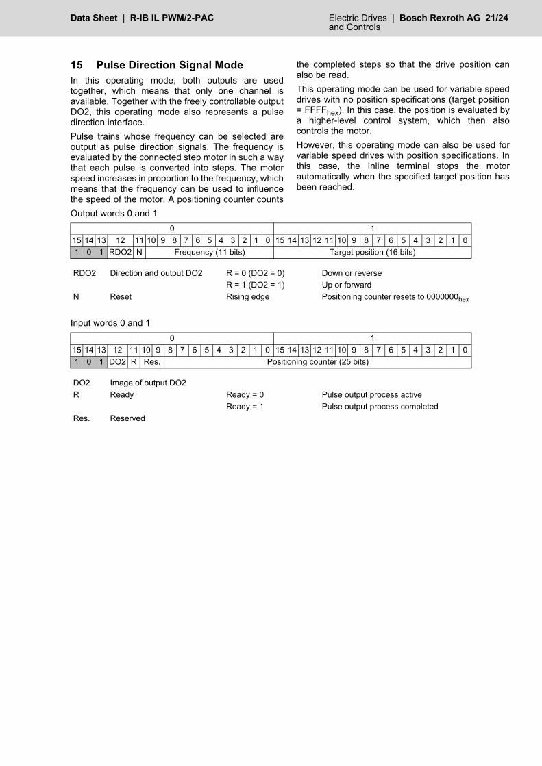
15 Pulse Direction Signal ModeIn this operating mode, both outputs are usedtogether, which means that only one channel isavailable. Together with the freely controllable outputDO2, this operating mode also represents a pulsedirection interface.Pulse trains whose frequency can be selected areoutput as pulse direction signals. The frequency isevaluated by the connected step motor in such a waythat each pulse is converted into steps. The motorspeed increases in proportion to the frequency, whichmeans that the frequency can be used to influencethe speed of the motor. A positioning counter counts
the completed steps so that the drive position canalso be read. This operating mode can be used for variable speeddrives with no position specifications (target position= FFFFhex). In this case, the position is evaluated bya higher-level control system, which then alsocontrols the motor.However, this operating mode can also be used forvariable speed drives with position specifications. Inthis case, the Inline terminal stops the motorautomatically when the specified target position hasbeen reached.
Output words 0 and 1
Input words 0 and 1
0 115 14 13 12 11 10 9 8 7 6 5 4 3 2 1 0 15 14 13 12 11 10 9 8 7 6 5 4 3 2 1 01 0 1 RDO2 N Frequency (11 bits) Target position (16 bits)
RDO2 Direction and output DO2 R = 0 (DO2 = 0) Down or reverseR = 1 (DO2 = 1) Up or forward
N Reset Rising edge Positioning counter resets to 0000000hex
0 115 14 13 12 11 10 9 8 7 6 5 4 3 2 1 0 15 14 13 12 11 10 9 8 7 6 5 4 3 2 1 01 0 1 DO2 R Res. Positioning counter (25 bits)
DO2 Image of output DO2R Ready Ready = 0 Pulse output process active
Ready = 1 Pulse output process completedRes. Reserved
22/24 Bosch Rexroth AG | Electric Drives R-IB IL PWM/2-PAC | Data Sheetand Controls
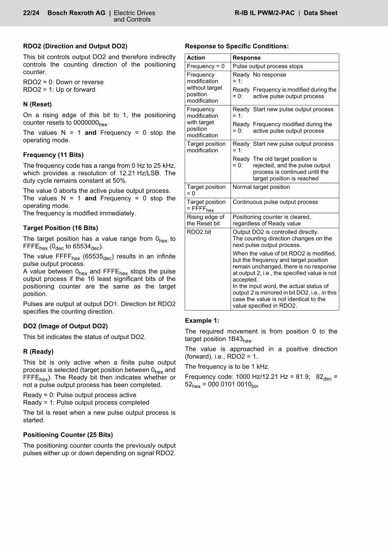
RDO2 (Direction and Output DO2)This bit controls output DO2 and therefore indirectlycontrols the counting direction of the positioningcounter.RDO2 = 0: Down or reverseRDO2 = 1: Up or forward
N (Reset)On a rising edge of this bit to 1, the positioningcounter resets to 0000000hex.The values N = 1 and Frequency = 0 stop theoperating mode.
Frequency (11 Bits)The frequency code has a range from 0 Hz to 25 kHz,which provides a resolution of 12.21 Hz/LSB. Theduty cycle remains constant at 50%.The value 0 aborts the active pulse output process. The values N = 1 and Frequency = 0 stop theoperating mode.The frequency is modified immediately.
Target Position (16 Bits)The target position has a value range from 0hex toFFFEhex (0dec to 65534dec). The value FFFFhex (65535dec) results in an infinitepulse output process. A value between 0hex and FFFEhex stops the pulseoutput process if the 16 least significant bits of thepositioning counter are the same as the targetposition. Pulses are output at output DO1. Direction bit RDO2specifies the counting direction.
DO2 (Image of Output DO2)This bit indicates the status of output DO2.
R (Ready)This bit is only active when a finite pulse outputprocess is selected (target position between 0hex andFFFEhex). The Ready bit then indicates whether ornot a pulse output process has been completed.Ready = 0: Pulse output process activeReady = 1: Pulse output process completedThe bit is reset when a new pulse output process isstarted.
Positioning Counter (25 Bits)The positioning counter counts the previously outputpulses either up or down depending on signal RDO2.
Response to Specific Conditions:
Example 1:The required movement is from position 0 to thetarget position 1B43hex.The value is approached in a positive direction(forward), i.e., RDO2 = 1.The frequency is to be 1 kHz. Frequency code: 1000 Hz/12.21 Hz = 81.9; 82dec =52hex = 000 0101 0010bin
Action ResponseFrequency = 0 Pulse output process stopsFrequency modification without target position modification
Ready = 1:
No response
Ready = 0:
Frequency is modified during the active pulse output process
Frequency modification with target position modification
Ready = 1:
Start new pulse output process
Ready = 0:
Frequency modified during the active pulse output process
Target position modification
Ready = 1:
Start new pulse output process
Ready = 0:
The old target position is rejected, and the pulse output process is continued until the target position is reached
Target position = 0
Normal target position
Target position = FFFFhex
Continuous pulse output process
Rising edge of the Reset bit
Positioning counter is cleared, regardless of Ready value
RDO2 bit Output DO2 is controlled directly. The counting direction changes on the next pulse output process.When the value of bit RDO2 is modified, but the frequency and target position remain unchanged, there is no response at output 2, i.e., the specified value is not accepted.In the input word, the actual status of output 2 is mirrored in bit DO2, i.e., in this case the value is not identical to the value specified in RDO2.
Data Sheet | R-IB IL PWM/2-PAC Electric Drives | Bosch Rexroth AG 23/24 and Controls
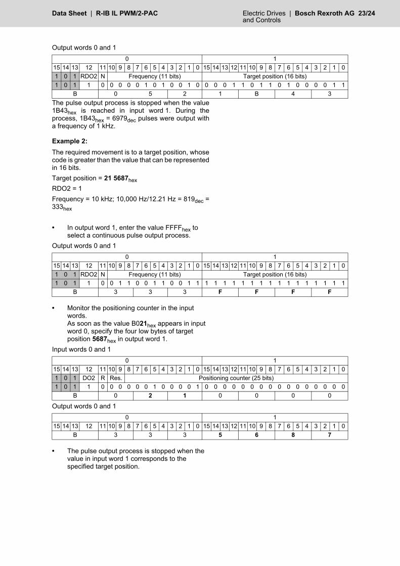
Output words 0 and 1
The pulse output process is stopped when the value1B43hex is reached in input word 1. During theprocess, 1B43hex = 6979dec pulses were output witha frequency of 1 kHz.
Example 2:The required movement is to a target position, whosecode is greater than the value that can be representedin 16 bits.Target position = 21 5687hexRDO2 = 1Frequency = 10 kHz; 10,000 Hz/12.21 Hz = 819dec =333hex
• In output word 1, enter the value FFFFhex to select a continuous pulse output process.
Output words 0 and 1
• Monitor the positioning counter in the input words.As soon as the value B021hex appears in input word 0, specify the four low bytes of target position 5687hex in output word 1.
Input words 0 and 1
Output words 0 and 1
• The pulse output process is stopped when the value in input word 1 corresponds to the specified target position.
0 115 14 13 12 11 10 9 8 7 6 5 4 3 2 1 0 15 14 13 12 11 10 9 8 7 6 5 4 3 2 1 01 0 1 RDO2 N Frequency (11 bits) Target position (16 bits)1 0 1 1 0 0 0 0 0 1 0 1 0 0 1 0 0 0 0 1 1 0 1 1 0 1 0 0 0 0 1 1
B 0 5 2 1 B 4 3
0 115 14 13 12 11 10 9 8 7 6 5 4 3 2 1 0 15 14 13 12 11 10 9 8 7 6 5 4 3 2 1 01 0 1 RDO2 N Frequency (11 bits) Target position (16 bits)1 0 1 1 0 0 1 1 0 0 1 1 0 0 1 1 1 1 1 1 1 1 1 1 1 1 1 1 1 1 1 1
B 3 3 3 F F F F
0 115 14 13 12 11 10 9 8 7 6 5 4 3 2 1 0 15 14 13 12 11 10 9 8 7 6 5 4 3 2 1 01 0 1 DO2 R Res. Positioning counter (25 bits)1 0 1 1 0 0 0 0 0 0 1 0 0 0 0 1 0 0 0 0 0 0 0 0 0 0 0 0 0 0 0 0
B 0 2 1 0 0 0 0
0 115 14 13 12 11 10 9 8 7 6 5 4 3 2 1 0 15 14 13 12 11 10 9 8 7 6 5 4 3 2 1 0
B 3 3 3 5 6 8 7

Bosch Rexroth AGElectric Drives and ControlsP.O.Box 13 5797803 Lohr, GermanyBgm.-Dr.-Nebel-Str. 297816 Lohr, GermanyTel. +49-(0) 93 52 - 40-50 60Fax. +49-(0) 93 52 - 40-49 [email protected]
All rights reserved. No part of this document may be reproduced or stored, processed, duplicated or circulated using electronic systems, in any form or by any means, without the prior written authorization of Bosch Rexroth AG, Electric Drives and Controls. Violations shall give rise to claims for damages.The data specified above only serve to describe the product. They do not indicate any specific condition or suitability for a certain application. The information provided does not release the user from the obligation of own judgment and verification. It must be remembered that our products are subject to natural wear and aging.
Reprint forbidden - subject to modifications
DOK-CONTRL-ILPWM/2****-KB01-EN-P
24/24 Bosch Rexroth AG | Electric Drives R-IB IL PWM/2-PAC | Data Sheetand Controls
7429
_en_
00
16 Connection Example
Fig. 7 Typical connection of a 24 V actuator and a 5 V actuator (not in pulse direction signal mode)
Use a connector with shield connectionwhen connecting the I/O device. Fig. 7shows the connection schematically(without shield connector).
17 Programming Data/Configuration Data
17.1 Local Bus
17.2 Other Bus Systems
For the configuration data of other bussystems, please refer to thecorresponding electronic device datasheet (e.g., GSD, EDS).
� � � -
� �
�
�
�
�
�
�
�
�
� �
� �
��
�
�
� �
�
�
�
�
�
�
�
�
�
� � � � �
' .
"�'�
��
� �
"�'�
���
ID code BFhex (191dec)Length code 02hex Process data channel 32 bitsInput address area 2 wordsOutput address area 2 wordsParameter channel (PCP) 0 bytesRegister length (bus) 2 words


![Pep Pac [1962] - Internet Archive](https://static.fdokumen.com/doc/165x107/6333c77d3108fad7760f3690/pep-pac-1962-internet-archive.jpg)

