
Upgrading the DOCSIS Certificates in Cisco uBR905/uBR925 ...
Upload
khangminh22Category
view
1download
0
Data-Over-Cable Service Interface Specifications DOCSIS 3.1
Cable Modem Operations Support System Interface Specification
CM-SP-CM-OSSIv3.1-I02-141016
ISSUED
Notice
This DOCSIS® specification is the result of a cooperative effort undertaken at the direction of Cable Television Laboratories, Inc. for the benefit of the cable industry and its customers. You may download, copy, distribute, and reference the documents herein only for the purpose of developing products or services in accordance with such documents, and educational use. Except as granted by CableLabs® in a separate written license agreement, no license is granted to modify the documents herein (except via the Engineering Change process), or to use, copy, modify or distribute the documents for any other purpose.
This document may contain references to other documents not owned or controlled by CableLabs. Use and understanding of this document may require access to such other documents. Designing, manufacturing, distributing, using, selling, or servicing products, or providing services, based on this document may require intellectual property licenses from third parties for technology referenced in this document. To the extent this document contains or refers to documents of third parties, you agree to abide by the terms of any licenses associated with such third party documents, including open source licenses, if any.
Cable Television Laboratories, Inc., 2014

CM-SP-CM-OSSIv3.1-I02-141016 DOCSIS 3.1
2 CableLabs 10/16/14
DISCLAIMER
This document is furnished on an "AS IS" basis and neither CableLabs nor its members provides any representation or warranty, express or implied, regarding the accuracy, completeness, noninfringement, or fitness for a particular purpose of this document, or any document referenced herein. Any use or reliance on the information or opinion in this document is at the risk of the user, and CableLabs and its members shall not be liable for any damage or injury incurred by any person arising out of the completeness, accuracy, or utility of any information or opinion contained in the document.
CableLabs reserves the right to revise this document for any reason including, but not limited to, changes in laws, regulations, or standards promulgated by various entities, technology advances, or changes in equipment design, manufacturing techniques, or operating procedures described, or referred to, herein.
This document is not to be construed to suggest that any company modify or change any of its products or procedures, nor does this document represent a commitment by CableLabs or any of its members to purchase any product whether or not it meets the characteristics described in the document. Unless granted in a separate written agreement from CableLabs, nothing contained herein shall be construed to confer any license or right to any intellectual property. This document is not to be construed as an endorsement of any product or company or as the adoption or promulgation of any guidelines, standards, or recommendations.
Cable Modem Operations Support System Interface Specification CM-SP-CM-OSSIv3.1-I02-141016
10/16/14 CableLabs 3
Document Status Sheet
Document Control Number: CM-SP-CM-OSSIv3.1-I02-141016
Document Title: Cable Modem Operations Support System Interface Specification
Revision History: I01 - Released 06/19/2014
I02 - Released 10/16/2014
Date: October 16, 2014
Status: Work in Progress
Draft Issued Closed
Distribution Restrictions: Author Only CL/Member CL/ Member/ Vendor
Public
Key to Document Status Codes:
Work in Progress An incomplete document, designed to guide discussion and generate feedback that may include several alternative requirements for consideration.
Draft A document in specification format considered largely complete, but lacking review by Members and vendors. Drafts are susceptible to substantial change during the review process.
Issued A generally public document that has undergone Member and Technology Supplier review, cross-vendor interoperability, and is for Certification testing if applicable. Issued Specifications are subject to the Engineering Change Process.
Closed A static document, reviewed, tested, validated, and closed to further engineering change requests to the specification through CableLabs.
Trademarks CableLabs® is a registered trademark of Cable Television Laboratories, Inc. Other CableLabs marks are listed at http://www.cablelabs.com/certqual/trademarks. All other marks are the property of their respective owners.

CM-SP-CM-OSSIv3.1-I02-141016 DOCSIS 3.1
4 CableLabs 10/16/14
Contents 1 SCOPE ................................................................................................................................................................ 11
1.1 Introduction and Purpose ............................................................................................................................. 11 1.2 Background .................................................................................................................................................. 11
1.2.1 Broadband Access Network ................................................................................................................. 11 1.2.2 Network and System Architecture ........................................................................................................ 12 1.2.3 Service Goals ....................................................................................................................................... 13 1.2.4 Statement of Compatibility ................................................................................................................... 13 1.2.5 Reference Architecture ........................................................................................................................ 14 1.2.6 DOCSIS 3.1 Documents ....................................................................................................................... 14
1.3 Requirements ............................................................................................................................................... 15 1.4 Conventions ................................................................................................................................................. 15 1.5 Organization of Document ........................................................................................................................... 15
1.5.1 Annexes (Normative)............................................................................................................................ 16 1.5.2 Appendices (Informative) ..................................................................................................................... 16
2 REFERENCES .................................................................................................................................................. 17 2.1 Normative References.................................................................................................................................. 17 2.2 Informative References ................................................................................................................................ 19 2.3 Reference Acquisition.................................................................................................................................. 19
3 TERMS AND DEFINITIONS .......................................................................................................................... 21
4 ABBREVIATIONS AND ACRONYMS .......................................................................................................... 24
5 OVERVIEW....................................................................................................................................................... 29 5.1 DOCSIS 3.1 OSSI Key Features ................................................................................................................. 29
5.1.1 Fault Management Features ................................................................................................................ 29 5.1.2 Configuration Management Features .................................................................................................. 30 5.1.3 Performance Management Features .................................................................................................... 30 5.1.4 Security Management Features ........................................................................................................... 30 5.1.5 Accounting Management Features ...................................................................................................... 30
5.2 Technical Overview ..................................................................................................................................... 30 5.2.1 Architectural Overview ........................................................................................................................ 30 5.2.2 Management Protocols ........................................................................................................................ 32 5.2.3 Information Models.............................................................................................................................. 32
6 OSSI MANAGEMENT PROTOCOLS ........................................................................................................... 34 6.1 SNMP Protocol ............................................................................................................................................ 34
6.1.1 Requirements for IPv6 ......................................................................................................................... 35
7 OSSI MANAGEMENT OBJECTS .................................................................................................................. 36 7.1 SNMP Management Information Bases (MIBS) ......................................................................................... 36
7.1.1 CableLabs MIB Modules ..................................................................................................................... 36 7.1.2 IETF RFC MIB Modules ...................................................................................................................... 37 7.1.3 Managed objects requirements ............................................................................................................ 38
8 OSSI FOR PHY, MAC AND NETWORK LAYERS ..................................................................................... 47 8.1 Fault Management ....................................................................................................................................... 47
8.1.1 SNMP Usage ........................................................................................................................................ 47 8.1.2 Event Notification ................................................................................................................................ 47 8.1.3 Throttling, Limiting and Priority for Event, Trap and Syslog ............................................................. 52 8.1.4 SNMPv3 Notification Receiver config file TLV ................................................................................... 52 8.1.5 Non-SNMP Fault Management Protocols ........................................................................................... 59
Cable Modem Operations Support System Interface Specification CM-SP-CM-OSSIv3.1-I02-141016
10/16/14 CableLabs 5
8.2 Configuration Management ......................................................................................................................... 59 8.2.1 Version Control ................................................................................................................................... 59 8.2.2 System Configuration ........................................................................................................................... 60 8.2.3 Secure Software Download .................................................................................................................. 60 8.2.4 CM configuration files, TLV-11 and MIB OIDs/values ....................................................................... 65
8.3 Accounting Management ............................................................................................................................. 67 8.3.1 Subscriber Usage Billing and class of services ................................................................................... 67
8.4 Performance Management ........................................................................................................................... 68 8.4.1 Treatment and interpretation of MIB counters .................................................................................... 68
8.5 Security Management .................................................................................................................................. 69 8.5.1 CM SNMP Modes of Operation ........................................................................................................... 69 8.5.2 CM SNMP Access Control Configuration ........................................................................................... 69
9 OSSI FOR CMCI ............................................................................................................................................... 81 9.1 SNMP Access via CMCI ............................................................................................................................. 81 9.2 Console Access ............................................................................................................................................ 81 9.3 CM Diagnostic Capabilities ......................................................................................................................... 82 9.4 Protocol Filtering ......................................................................................................................................... 82
10 OSSI FOR LED INDICATORS ................................................................................................................... 83 10.1 CM LED Requirements and Operation ........................................................................................................ 83
10.1.1 Power On, Software Application Image Validation and Self Test ....................................................... 83 10.1.2 Scan for Downstream Channel ............................................................................................................ 83 10.1.3 Resolve CM-SG and Range .................................................................................................................. 84 10.1.4 Operational .......................................................................................................................................... 84 10.1.5 Data Link and Activity ......................................................................................................................... 84
10.2 Additional CM Operational Status Visualization Features .......................................................................... 84 10.2.1 Secure Software Download .................................................................................................................. 85
ANNEX A DETAILED MIB REQUIREMENTS (NORMATIVE) ................................................................. 86 A.1 MIB-Object Details ..................................................................................................................................... 86 A.2 [RFC 2863] ifTable/ifXTable MIB-Object Details.................................................................................... 122
ANNEX B APPLICATION OF IETF MULTICAST MIBS (NORMATIVE) .............................................. 128 B.1 MGMD MIBs ............................................................................................................................................ 128 B.2 CM Support of IGMP-STD-MIB [RFC 2933] .......................................................................................... 128
B.2.1 IGMP Interface Table Objects ........................................................................................................... 128 B.2.2 igmpCacheTable ................................................................................................................................ 130
ANNEX C PROTOCOL FILTERING (NORMATIVE) ................................................................................ 132 C.1 Filtering Mechanisms ................................................................................................................................ 132
C.1.1 LLC Filters......................................................................................................................................... 132 C.1.2 Special filters ..................................................................................................................................... 132 C.1.3 IP Protocol Filtering ......................................................................................................................... 134 C.1.4 Protocol Classification through Upstream Drop Classifiers ............................................................. 134
ANNEX D FORMAT AND CONTENT FOR EVENT, SYSLOG, AND SNMP NOTIFICATION (NORMATIVE) ....................................................................................................................................................... 139
ANNEX E PROACTIVE NETWORK MAINTENANCE REQUIREMENTS (NORMATIVE) ............... 160 E.1 Overview ................................................................................................................................................... 160 E.2 Enhanced Signal Quality Monitoring Object Definitions .......................................................................... 160
E.2.1 Type Definitions ................................................................................................................................. 160 E.2.2 CM Spectrum Analysis Objects .......................................................................................................... 162 E.2.3 CmSymbolCapture Object ................................................................................................................. 166 E.2.4 CmOfdmChanEstimateCoef Object ................................................................................................... 168
CM-SP-CM-OSSIv3.1-I02-141016 DOCSIS 3.1
6 CableLabs 10/16/14
E.2.5 CmDsConstDispMeas Object ............................................................................................................ 171 E.2.6 CmDsOfdmRxMer Object .................................................................................................................. 173 E.2.7 CmDsOfdmSnrMarForProfile Object................................................................................................ 174 E.2.8 CmDsOfdmRequiredQamMer Object ................................................................................................ 176 E.2.9 CmDsHist Object ............................................................................................................................... 177 E.2.10 CmUsEq Object ................................................................................................................................. 180
E.3 CM Bulk Data Transfer ............................................................................................................................. 183 E.3.1 Bulk Data Transfer Requirements ..................................................................................................... 183 E.3.2 Data-File and Storage Requirements ................................................................................................ 183 E.3.3 CM Bulk Data Objects ....................................................................................................................... 184
ANNEX F DOCSIS 3.1 DATA TYPE DEFINITIONS (NORMATIVE) ....................................................... 187 F.1 Overview ................................................................................................................................................... 187 F.2 Data Type Mapping ................................................................................................................................... 187
F.2.1 Data Type Requirements and Classification ...................................................................................... 187 F.2.2 Data Type Mapping Methodology ..................................................................................................... 187 F.2.3 General Data Types ........................................................................................................................... 188 F.2.4 Extended Data Types ......................................................................................................................... 188
ANNEX G CM STATUS REPORTING REQUIREMENTS (NORMATIVE) ............................................. 190 G.1 Overview ................................................................................................................................................... 190 G.2 CM Operational Status Object Definitions ................................................................................................ 190
G.2.1 Overview ............................................................................................................................................ 190 G.2.2 Type Definitions ................................................................................................................................. 190 G.2.3 CM Operational Status Objects ......................................................................................................... 194
G.3 CM Downstream and Upstream Interfaces Information Models ............................................................... 205 G.3.1 DS US Common Data Type Definitions ............................................................................................. 205 G.3.2 CM Downstream Interface Information Model.................................................................................. 206 G.3.3 CM Upstream Interface Information Model ...................................................................................... 215
ANNEX H MAC AND UPPER LAYER PROTOCOLS INTERFACE (MULPI) REQUIREMENTS (NORMATIVE) ....................................................................................................................................................... 224
H.1 Overview ................................................................................................................................................... 224 H.1.1 Cable Modem Service Groups (CM-SGs) .......................................................................................... 224 H.1.2 Downstream Bonding Group (DBG) ................................................................................................. 224 H.1.3 Upstream Bonding Group (UBG) ...................................................................................................... 224
H.2 Object Definitions ...................................................................................................................................... 224 H.2.1 Type Definitions ................................................................................................................................. 224 H.2.2 RCC Status Objects ............................................................................................................................ 227 H.2.3 DOCSIS QoS Objects......................................................................................................................... 230 H.2.4 QoS Statistics Objects ........................................................................................................................ 251 H.2.5 DSID Objects ..................................................................................................................................... 260 H.2.6 CM Provisioning Objects ................................................................................................................... 264
APPENDIX I SPECTRUM ANALYSIS USE CASES (INFORMATIVE) ..................................................... 268 I.1 Normalization of RF Impairment Measurements ...................................................................................... 268
I.1.1 Use Case 1: Figure of Merit Estimation for Logical Upstream Channel .............................................. 269 I.1.2 Use Case 2: Figure of Merit Estimation per CM ................................................................................... 269 I.1.3 Use Case 3: Absolute Noise and Interference Estimation ..................................................................... 270
APPENDIX II INFORMATION MODEL NOTATION (INFORMATIVE) .............................................. 271 II.1 Overview ................................................................................................................................................... 271 II.2 Information Model Diagram ...................................................................................................................... 271
II.2.1 Classes ............................................................................................................................................... 271 II.2.2 Associations ....................................................................................................................................... 271 II.2.3 Generalization ................................................................................................................................... 271

Cable Modem Operations Support System Interface Specification CM-SP-CM-OSSIv3.1-I02-141016
10/16/14 CableLabs 7
II.2.4 Dependencies ..................................................................................................................................... 272 II.2.5 Comment ............................................................................................................................................ 272 II.2.6 Diagram Notation .............................................................................................................................. 272
II.3 Object Instance Diagram ........................................................................................................................... 272 II.4 ObjectA Definition Example ..................................................................................................................... 273
II.4.1 AttributeA1 ......................................................................................................................................... 273 II.4.2 AttributeA2 ......................................................................................................................................... 273 II.4.3 AttributeA3 ......................................................................................................................................... 273
II.5 Common Terms Shortened ........................................................................................................................ 274 II.5.1 Exceptions .......................................................................................................................................... 275
APPENDIX III ACKNOWLEDGEMENTS (INFORMATIVE) .................................................................... 276
APPENDIX IV REVISION HISTORY ............................................................................................................ 277
Figures Figure 1–1 - The DOCSIS Network ............................................................................................................................ 12 Figure 1–2 - Transparent IP Traffic through the Data-Over-Cable System ................................................................. 13 Figure 1–3 - Data-over-Cable Reference Architecture ................................................................................................ 14 Figure 5–1 - CM Management Architecture ................................................................................................................ 31 Figure 7–1 - ifIndex example for CM .......................................................................................................................... 41 Figure 8–1 - Manufacturer control scheme .................................................................................................................. 61 Figure 8–2 - Operator control scheme ......................................................................................................................... 61 Figure E–1 - Proactive Network Maintenance Information Model Diagram ............................................................ 160 Figure E–2 - Bulk Data Upload Information Model Diagram ................................................................................... 184 Figure G–1 - CM Operational Status Information Model Diagram ........................................................................... 194 Figure G–2 - CM Downstream Information Model Diagram .................................................................................... 207 Figure G–3 - CM Upstream Information Model Diagram ......................................................................................... 216 Figure H–1 - RCC Status Information Model Diagram ............................................................................................. 227 Figure H–2 - QoS Configuration Information Model Diagram ................................................................................. 230 Figure H–3 - QoS Statistics Information Model Diagram ......................................................................................... 251 Figure H–4 - DSID Information Model Diagram ...................................................................................................... 260 Figure H–5 - CM MAC Domain Configuration Information Model Diagram .......................................................... 264 Figure II–1 - Information Model UML Class Diagram Notation .............................................................................. 272 Figure II–2 - Object Instance Diagram for ObjectA .................................................................................................. 273
Tables Table 1–1 - DOCSIS 3.1 Series of Specifications ....................................................................................................... 14 Table 1–2 - DOCSIS 3.1 Related Specifications ......................................................................................................... 14 Table 5–1 - Management Feature Requirements for DOCSIS 3.1 .............................................................................. 29 Table 6–1 - IETF SNMP-related RFCs ....................................................................................................................... 34 Table 6–2 - SMIv2 IETF SNMP-related RFCs ........................................................................................................... 34 Table 6–3 - Diffie-Helman IETF SNMP-related RFC................................................................................................. 34 Table 7–1 - CableLabs MIB Modules ......................................................................................................................... 37 Table 7–2 - IETF RFC MIB Modules ......................................................................................................................... 37
CM-SP-CM-OSSIv3.1-I02-141016 DOCSIS 3.1
8 CableLabs 10/16/14
Table 7–3 - CM interface numbering .......................................................................................................................... 41 Table 7–4 - CmStatusValue and ifOperStatus relationship ......................................................................................... 42 Table 7–5 - USB State and ifOperStatus relationship.................................................................................................. 42 Table 8–1 - CM default event reporting mechanism versus priority ........................................................................... 51 Table 8–2 - Event Priority Assignment for CMs ......................................................................................................... 51 Table 8–3 - SNMPv3 Notification Receiver TLV Mapping ........................................................................................ 53 Table 8–4 - snmpNotifyTable ...................................................................................................................................... 53 Table 8–5 - snmpTargetAddrTable.............................................................................................................................. 54 Table 8–6 - snmpTargetAddrExtTable ........................................................................................................................ 55 Table 8–7 - snmpTargetParamsTable .......................................................................................................................... 55 Table 8–8 - snmpNotifyFilterProfileTable .................................................................................................................. 56 Table 8–9 - snmpNotifyFilterTable ............................................................................................................................. 56 Table 8–10 - snmpCommunityTable ........................................................................................................................... 56 Table 8–11 - usmUserTable......................................................................................................................................... 57 Table 8–12 - vacmContextTable ................................................................................................................................. 57 Table 8–13 - vacmSecurityToGroupTable .................................................................................................................. 58 Table 8–14 - vacmAccessTable ................................................................................................................................... 58 Table 8–15 - vacmViewTreeFamilyTable ................................................................................................................... 59 Table 8–16 - sysDescr Format ..................................................................................................................................... 60 Table 8–17 - SNMPv1v2c Coexistence Configuration TLV Mapping........................................................................ 75 Table 8–18 - snmpCommunityTable ........................................................................................................................... 76 Table 8–19 - snmpTargetAddrTable............................................................................................................................ 77 Table 8–20 - snmpTargetAddrExtTable ...................................................................................................................... 77 Table 8–21 - vacmSecurityToGroupTable .................................................................................................................. 78 Table 8–22 - vacmAccessTable ................................................................................................................................... 78 Table 8–23 - SNMPv3 Access View Configuration TLV Mapping ............................................................................ 79 Table 8–24 - vacmViewTreeFamilyTable ................................................................................................................... 80 Table A–1 - MIB Implementation Support .................................................................................................................. 86 Table A–2 - SNMP Access Requirements ................................................................................................................... 86 Table A–3 - MIB Object Details ................................................................................................................................. 87 Table A–4 - [RFC 2863] ifTable/ifXTable MIB-Object Details for Ethernet and USB Interfaces ........................... 123 Table A–5 - [RFC 2863] ifTable/ifXTable MIB-Object Details for MAC and RF Interfaces .................................. 124 Table A–6 - [RFC 2863] ifTable/ifXTable Counter32 and Counter64 MIB-Object Details for Ethernet and USB
Interfaces ........................................................................................................................................................... 125 Table A–7 - [RFC 2863] ifTable/ifXTable Counter32 and Counter64 MIB-Object Details for MAC and RF
Interfaces ........................................................................................................................................................... 125 Table B–1 - IGMP-STD-MIB igmpInterfaceTable Objects ...................................................................................... 128 Table B–2 - IGMP-STD-MIB igmpCacheTable Objects .......................................................................................... 130 Table C–1 - Sample docsDevNmAccessIp Values .................................................................................................... 133 Table C–2 - Mapping of docsDevFilterIpTable [RFC 2669] to UDCs for Layer 3 & 4 Criteria .............................. 136 Table C–3 - Upstream Drop Classification Values for LLC/MAC Classification ..................................................... 137 Table D–1 - Event Format and Content ..................................................................................................................... 141 Table E–1 - Data Type Definitions ............................................................................................................................ 161 Table E–2 - CmSpectrumAnalysisCtrlCmd Object ................................................................................................... 163 Table E–3 - CmSpectrumAnalysisMeas Object ........................................................................................................ 165

Cable Modem Operations Support System Interface Specification CM-SP-CM-OSSIv3.1-I02-141016
10/16/14 CableLabs 9
Table E–4 - CmSymbolCapture Object ..................................................................................................................... 166 Table E–5 - CM Symbol Capture File Format ........................................................................................................... 167 Table E–6 - CmOfdmChanEstimateCoef Object ....................................................................................................... 169 Table E–7 - Channel Estimate Coefficient File Format ............................................................................................. 170 Table E–8 - CmDsConstDispMeas Object ................................................................................................................ 171 Table E–9 - Constellation Display File Format ......................................................................................................... 172 Table E–10 - CmDsOfdmRxMer Object ................................................................................................................... 173 Table E–11 - RxMER File Format ............................................................................................................................ 174 Table E–12 - CmDsOfdmSnrMarForProfile Object .................................................................................................. 174 Table E–13 - CmDsOfdmRequiredQamMer Object ................................................................................................. 176 Table E–14 - CmDsHist Object ................................................................................................................................. 177 Table E–15 - Histogram Bin Centers ......................................................................................................................... 179 Table E–16 - Downstream Histogram File Format .................................................................................................... 180 Table E–17 - CmUsEq Object ................................................................................................................................... 180 Table E–18 - Upstream Equalization File Format ..................................................................................................... 182 Table E–19 - Last EQ Update File Format ................................................................................................................ 182 Table E–20 - CmBulkDataControl Object ................................................................................................................. 184 Table E–21 - CmBulkDataFile Object ....................................................................................................................... 185 Table F–1 - General Data Types ................................................................................................................................ 188 Table F–2 - Extended Data Types ............................................................................................................................. 189 Table G–1 - Data Type Definitions ........................................................................................................................... 190 Table G–2 - Pre-3.0 DOCSIS and DOCSIS 3.0/3.1 CM Registration status mapping .............................................. 192 Table G–3 - CmStatus Object .................................................................................................................................... 195 Table G–4 - CmStatusUs Object ............................................................................................................................... 197 Table G–5 - CmStatusUs Object ............................................................................................................................... 198 Table G–6 - CmCapabilities Object........................................................................................................................... 199 Table G–7 - CmDpvStats Object ............................................................................................................................... 200 Table G–8 - CmEventCtrl Object .............................................................................................................................. 201 Table G–9 - CmEm1x1Stats Object .......................................................................................................................... 201 Table G–10 - CmEmDlsStats Object ......................................................................................................................... 202 Table G–11 - CmEmDlsStatus Object ....................................................................................................................... 203 Table G–12 - CmSystemCfgState Object .................................................................................................................. 204 Table G–13 - CM Downstream Parameter Data Types ............................................................................................. 205 Table G–14 - CM Downstream Parameter Data Types ............................................................................................. 207 Table G–15 - ScQamDownstreamChannel Object Attributes ................................................................................... 208 Table G–16 - ScQamDownstreamChannel Object Associations ............................................................................... 209 Table G–17 - DsOfdmChannel Object Attributes ..................................................................................................... 210 Table G–18 - DsOfdmChannel Object Associations ................................................................................................. 211 Table G–19 - DsOfdmProfileStats Object Attributes ................................................................................................ 212 Table G–20 - DsOfdmProfileStats Object Associations ............................................................................................ 213 Table G–21 - DsOfdmSubcarrierState object Attributes ........................................................................................... 213 Table G–22 - DsOfdmChannelPower Object Attributes ........................................................................................... 214 Table G–23 - DsOfdmChannelPower Object Attributes ........................................................................................... 214 Table G–24 - DsOfdmProfileStats Object Associations ............................................................................................ 215
CM-SP-CM-OSSIv3.1-I02-141016 DOCSIS 3.1
10 CableLabs 10/16/14
Table G–25 - Data Types ........................................................................................................................................... 216 Table G–26 - ScQamUpstream Object Attributes ..................................................................................................... 217 Table G–27 - ScQamUpstream Object Associations ................................................................................................. 218 Table G–28 - UsChExt Object ................................................................................................................................... 220 Table G–29 - UsOfdmaChannel Object Attributes .................................................................................................... 220 Table G–30 - UsOfdmaChannel Object Associations ............................................................................................... 221 Table G–31 - UsOfdmaProfile Object Attributes ...................................................................................................... 222 Table G–32 - UsOfdmaProfile Object Associations .................................................................................................. 222 Table G–33 - UsOfdmaSubcarrierCfgState Object Attributes................................................................................... 222 Table G–34 - UsOfdmaMinislotCfgState Object Attributes ...................................................................................... 223 Table H–1 - Data Type Definitions ........................................................................................................................... 224 Table H–2 - RxModuleStatus Object......................................................................................................................... 227 Table H–3 - RxChStatus Object ................................................................................................................................ 228 Table H–4 - PktClass Object ..................................................................................................................................... 231 Table H–5 - ParamSet Object .................................................................................................................................... 237 Table H–6 - ServiceFlow Object ............................................................................................................................... 247 Table H–7 - ServiceFlowSidCluster Object .............................................................................................................. 249 Table H–8 - ServiceFlowStats Object ....................................................................................................................... 251 Table H–9 - DynamicServiceStats Object ................................................................................................................. 253 Table H–10 - CmServiceUsStats Object ................................................................................................................... 258 Table H–11 - CmDsid Object .................................................................................................................................... 261 Table H–12 - CmDsidStats Object ............................................................................................................................ 262 Table H–13 - CmDsidClient Object .......................................................................................................................... 263 Table H–14 - CmMdCfg Object ................................................................................................................................ 264 Table H–15 - CmEnergyMgt1x1Cfg Object.............................................................................................................. 265 Table H–16 - CmEnergyMgtDlsCfg Object .............................................................................................................. 266 Table H–17 - CmMac Object .................................................................................................................................... 267 Table I–1 - RF Management Statistics Available ...................................................................................................... 268 Table II–1 - ObjectA Example Table Layout ............................................................................................................ 273 Table II–2 - Shortened Common Terms .................................................................................................................... 274
Cable Modem Operations Support System Interface Specification CM-SP-CM-OSSIv3.1-I02-141016
10/16/14 CableLabs 11
1 SCOPE
1.1 Introduction and Purpose This specification is part of the DOCSIS® family of specifications developed by Cable Television Laboratories (CableLabs®). In particular, this specification is part of a series of specifications that define the fourth generation of high-speed data-over-cable systems. This specification was developed for the benefit of the cable industry, and includes contributions by operators and vendors from North America, Europe, and other regions.
This specification defines the Operations Support System Interface (OSSI) requirements for the Cable Modem (CM).
1.2 Background
1.2.1 Broadband Access Network
A coaxial-based broadband access network is assumed. This may take the form of either an all-coax or hybrid-fiber/coax (HFC) network. The generic term "cable network" is used here to cover all cases.
A cable network uses a tree-and-branch architecture with analog transmission. The key functional characteristics assumed in this document are the following:
• Two-way transmission.
• A maximum optical/electrical spacing between the CMTS and the most distant CM of 100 miles in each direction, although typical maximum separation may be 10-15 miles.
• A maximum differential optical/electrical spacing between the CMTS and the closest and most distant modems of 100 miles in each direction, although this would typically be limited to 15 miles.
At a propagation velocity in fiber of approximately 1.5 ns/ft., 100 miles of fiber in each direction results in a round-trip delay of approximately 1.6 ms.
CM-SP-CM-OSSIv3.1-I02-141016 DOCSIS 3.1
12 CableLabs 10/16/14
1.2.2 Network and System Architecture
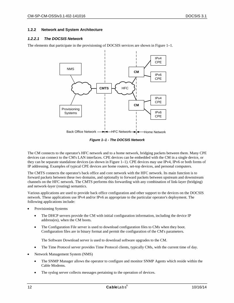
1.2.2.1 The DOCSIS Network The elements that participate in the provisioning of DOCSIS services are shown in Figure 1–1.
Figure 1–1 - The DOCSIS Network
The CM connects to the operator's HFC network and to a home network, bridging packets between them. Many CPE devices can connect to the CM's LAN interfaces. CPE devices can be embedded with the CM in a single device, or they can be separate standalone devices (as shown in Figure 1–1). CPE devices may use IPv4, IPv6 or both forms of IP addressing. Examples of typical CPE devices are home routers, set-top devices, and personal computers.
The CMTS connects the operator's back office and core network with the HFC network. Its main function is to forward packets between these two domains, and optionally to forward packets between upstream and downstream channels on the HFC network. The CMTS performs this forwarding with any combination of link-layer (bridging) and network-layer (routing) semantics.
Various applications are used to provide back office configuration and other support to the devices on the DOCSIS network. These applications use IPv4 and/or IPv6 as appropriate to the particular operator's deployment. The following applications include:
• Provisioning Systems
• The DHCP servers provide the CM with initial configuration information, including the device IP address(es), when the CM boots.
• The Configuration File server is used to download configuration files to CMs when they boot. Configuration files are in binary format and permit the configuration of the CM's parameters. The Software Download server is used to download software upgrades to the CM.
• The Time Protocol server provides Time Protocol clients, typically CMs, with the current time of day.
• Network Management System (NMS)
• The SNMP Manager allows the operator to configure and monitor SNMP Agents which reside within the Cable Modems.
• The syslog server collects messages pertaining to the operation of devices.
ProvisioningSystems
IPv6CPE
IPv4CPE
Back Office Network HFC Network Home Network
CMTS
CM
IPv6CPE
IPv4CPE
CM
NMS
HFC

Cable Modem Operations Support System Interface Specification CM-SP-CM-OSSIv3.1-I02-141016
10/16/14 CableLabs 13
1.2.3 Service Goals
As cable operators have widely deployed high-speed data services on cable television systems, the demand for bandwidth has increased. Additionally, networks have scaled to such a degree that IPv4 address constraints are becoming a burden on network operations. To this end, CableLabs' member companies have decided to add new features to the DOCSIS® specification for the purpose of increasing channel capacity, enhancing network security, expanding addressability of network elements, and deploying new service offerings.
The DOCSIS system allows transparent bi-directional transfer of Internet Protocol (IP) traffic, between the cable system headend and customer locations, over an all-coaxial or hybrid-fiber/coax (HFC) cable network. This is shown in simplified form in Figure 1–2.
Figure 1–2 - Transparent IP Traffic through the Data-Over-Cable System
1.2.4 Statement of Compatibility
This specification defines the DOCSIS 3.1 interface. Prior generations of DOCSIS were commonly referred to as DOCSIS 1.0, 1.1, 2.0 and 3.0 interfaces. DOCSIS 3.1 is backward-compatible with equipment built to the previous specifications with the exception of DOCSIS 1.0 CMs. DOCSIS 3.1-compliant CMs interoperate seamlessly with DOCSIS 3.1 and DOCSIS 3.0 CMTSs. DOCSIS 3.1-compliant CMTSs seamlessly support DOCSIS 3.0, DOCSIS 2.0, and DOCSIS 1.1.
CM-SP-CM-OSSIv3.1-I02-141016 DOCSIS 3.1
14 CableLabs 10/16/14
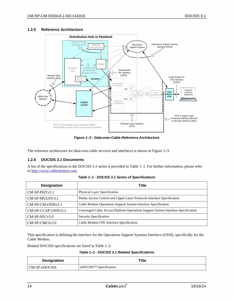
1.2.5 Reference Architecture
Figure 1–3 - Data-over-Cable Reference Architecture
The reference architecture for data-over-cable services and interfaces is shown in Figure 1–3.
1.2.6 DOCSIS 3.1 Documents
A list of the specifications in the DOCSIS 3.1 series is provided in Table 1–1. For further information, please refer to http://www.cablemodem.com.
Table 1–1 - DOCSIS 3.1 Series of Specifications
Designation Title
CM-SP-PHYv3.1 Physical Layer Specification
CM-SP-MULPIv3.1 Media Access Control and Upper Layer Protocols Interface Specification
CM-SP-CM-OSSIv3.1 Cable Modem Operations Support System Interface Specification
CM-SP-CCAP-OSSIv3.1 Converged Cable Access Platform Operations Support System Interface Specification
CM-SP-SECv3.0 Security Specification
CM-SP-CMCIv3.0 Cable Modem CPE Interface Specification
This specification is defining the interface for the Operations Support Systems Interface (OSSI), specifically for the Cable Modem.
Related DOCSIS specifications are listed in Table 1–2.
Table 1–2 - DOCSIS 3.1 Related Specifications
Designation Title
CM-SP-eDOCSIS eDOCSIS™ Specification
RxRx
TxTx FiberNodeFiber
Node
M-CMTS Core
EQAM
UpstreamReceiver
DOCSIS Timing Server
Wide Area Network
Network Side Interface (NSI)
Operations Support System Interface (OSSI)
Cable Modem to CPE Interface
(CMCI)
Downstream External Phy
Interface (DEPI)
DOCSIS Timing Interface (DTI)
Downstream RF Interface
( DRFI)
Cable Modem
(CM)
Operations Support System
Physical Layer Interface (PHY)
Downstream RF Network
Upstream RF Network
Opt.Tx
Opt.Rx
FiberNode
M-CMTS
I-CMTS / CCAP
Distribution Hub or Headend
CoaxDistribution
FiberDistribution
NOTE: Gray-shaded areas represent related functionality, but are out of scope of this document.
MAC & Upper LayerProtocols Interface (MULPI)& Security Interface (SEC)
Customer Premises
Equipment
Cable Modem Operations Support System Interface Specification CM-SP-CM-OSSIv3.1-I02-141016
10/16/14 CableLabs 15
Designation Title
CM-SP-DRFI Downstream Radio Frequency Interface Specification
CM-SP-DTI DOCSIS Timing Interface Specification
CM-SP-DEPI Downstream External PHY Interface Specification
CM-SP-DSG DOCSIS Set-Top Gateway Interface Specification
CM-SP-ERMI Edge Resource Manager Interface Specification
CM-SP-M-OSSI M-CMTS Operations Support System Interface Specification
CM-SP-L2VPN Layer 2 Virtual Private Networks Specification
CM-SP-TEI TDM Emulation Interface Specification
1.3 Requirements Throughout this document, the words that are used to define the significance of particular requirements are capitalized. These words are:
"MUST" This word means that the item is an absolute requirement of this specification.
"MUST NOT" This phrase means that the item is an absolute prohibition of this specification.
"SHOULD" This word means that there may exist valid reasons in particular circumstances to ignore this item, but the full implications should be understood and the case carefully weighed before choosing a different course.
"SHOULD NOT" This phrase means that there may exist valid reasons in particular circumstances when the listed behavior is acceptable or even useful, but the full implications should be understood and the case carefully weighed before implementing any behavior described with this label.
"MAY" This word means that this item is truly optional. One vendor may choose to include the item because a particular marketplace requires it or because it enhances the product, for example; another vendor may omit the same item.
This document defines many features and parameters, and a valid range for each parameter is usually specified. Equipment (CM) requirements are always explicitly stated. Equipment must comply with all mandatory (MUST and MUST NOT) requirements to be considered compliant with this specification. Support of non-mandatory features and parameter values is optional.
1.4 Conventions In this specification the following convention applies any time a bit field is displayed in a figure. The bit field should be interpreted by reading the figure from left to right, then from top to bottom, with the MSB being the first bit so read and the LSB being the last bit so read. SNMP MIB syntax is represented by this code sample font.
Note: Notices and/or Warnings are identified by this style font and label.
1.5 Organization of Document Section 1 provides an overview of the DOCSIS 3.1 series of specifications including the DOCSIS reference architecture and statement of compatibility.
CM-SP-CM-OSSIv3.1-I02-141016 DOCSIS 3.1
16 CableLabs 10/16/14
Section 2 includes a list of normative and informative references used within this specification.
Section 3 defines the terms used throughout this specification.
Section 4 defines the acronyms used throughout this specification.
Section 5 provides a technical overview and lists the DOCSIS 3.1 key features for the functional areas of this specification.
Section 6 defines requirements for the OSSI management protocols.
Section 7 defines the requirements for the OSSI management objects including SNMP MIBs.
Section 8 defines the FCAPS OSSI requirements for the PHY, MAC, and Network Layers.
Section 9 defines the OSSI requirements for the Cable Modem to CPE Interface (CMCI).
Section 10 defines the OSSI requirements for the Cable Modem device including LED operations.
1.5.1 Annexes (Normative)
Annex A includes a detailed list of MIB object requirements for the CM.
Annex B defines the IETF multicast MIB requirements.
Annex C defines protocol filtering requirements.
Annex D includes a detailed list of DOCSIS events and the associated formats.
Annex E defines the information model for the DOCSIS 3.1 Enhanced Signal Quality Monitoring feature.
Annex F defines the DOCSIS 3.1 data type definitions.
Annex G defines the information model for the CM status and interface requirements.
Annex H defines the information model for the CM MULPI requirements.
1.5.2 Appendices (Informative)
Appendix I identifies spectrum analysis use cases.
Appendix II provides an overview of the Information Model Notation using UML.
Appendix III includes acknowledgements and contains a list of contributors.

Cable Modem Operations Support System Interface Specification CM-SP-CM-OSSIv3.1-I02-141016
10/16/14 CableLabs 17
2 REFERENCES
2.1 Normative References In order to claim compliance with this specification, it is necessary to conform to the following standards and other works as indicated, in addition to the other requirements of this specification. Notwithstanding, intellectual property rights may be required to use or implement such normative references.
[CCAP-OSSIv3.1]
DOCSIS Converged Cable Access Platform Operations Support System Interface Specification, CM-SP-CCAP-OSSIv3.1-I01-140808, August 8, 2014, Cable Television Laboratories, Inc.
[CMCIv3.0] DOCSIS Cable Modem to Customer Premise Equipment Interface Specification, CM-SP-CMCIv3.0-I02-140729, July 29, 2014, Cable Television Laboratories, Inc.
[DOCS-IFEXT2-MIB]
CableLabs DOCSIS DOCS-IFEXT2-MIB SNMP MIB Module, DOCS-IFEXT2-MIB, http://www.cablelabs.com/MIBs/DOCSIS/.
[DOCS-IF3-MIB]
CableLabs DOCSIS DOCS-IF3-MIB SNMP MIB Module, DOCS-IF3-MIB, http://www.cablelabs.com/MIBs/DOCSIS/.
[DOCS-QOS3-MIB]
CableLabs DOCSIS DOCS-QOS3-MIB SNMP MIB Module, DOCS-QOS3-MIB, http://www.cablelabs.com/MIBs/DOCSIS/.
[DSG] DOCSIS Set-Top Gateway (DSG) Interface Specification, CM-SP-DSG-I24-130808, August 8, 2013, Cable Television Laboratories, Inc.
[IPDR/SSDG] IPDR Service Specification Design Guide, Version 3.8, TM Forum, October 2009. [IPDR/XDR] IPDR/XDR File Encoding Format, Version 3.5.1, TM Forum, October 2009. [M-OSSI] DOCSIS M-CMTS Operations Support System Interface Specification, CM-SP-M-OSSI-I08-
081209, December 9, 2008, Cable Television Laboratories, Inc. [MULPIv3.1] DOCSIS MAC and Upper Layer Protocols Interface Specification, CM-SP-MULPIv3.1-I03-
140610, June 10, 2014, Cable Television Laboratories, Inc. [PHYv3.1] DOCSIS Physical Layer Specification, CM-SP-PHYv3.1-I03-140610, June 10, 2014, Cable
Television Laboratories, Inc. [RFC 1157] IETF RFC 1157, J. D. Case, et al., A Simple Network Management Protocol (SNMP), May
1990. [RFC 1901] IETF RFC 1901, K. Norseth, Ed. and E. Bell, Ed., Introduction to Community-based SNMPv2,
January 1996. [RFC 2578] IETF RFC 2578, K. McCloghrie, et al., Structure of Management Information Version 2
(SMIv2), April 1999. [RFC 2580] IETF RFC 2580, K. McCloghrie, et al., Conformance Statements for SMIv2, April 1999. [RFC 2669] IETF RFC 2669, M. St. Johns, Ed., DOCSIS Cable Device MIB Cable Device Management
Information Base for DOCSIS compliant Cable Modems and Cable Modem Termination Systems, August 1999.
[RFC 2786] IETF RFC 2786, M. St. Johns, Diffie-Helman [sic] USM Key Management Information Base and Textual Convention, March 2000.
[RFC 2790] IETF RFC 2790, Waldbusser, P. Grillo, Host Resources MIB, March 2000. [RFC 2863] IETF RFC 2863, K. McCloghrie and F. Kastenholz, The Interfaces Group MIB, June 2000. [RFC 2933] IETF RFC 2933, K. McCloghrie et al., Internet Group Management Protocol MIB, October
2000. [RFC 3083] IETF RFC 3083, R. Woundy, Baseline Privacy Interface Management Information Base for
DOCSIS Compliant Cable Modems and Cable Modem Termination Systems, March 2001. [RFC 3164] IETF RFC 3164, C. Lonvick, The BSD syslog Protocol, August 2001.

CM-SP-CM-OSSIv3.1-I02-141016 DOCSIS 3.1
18 CableLabs 10/16/14
[RFC 3410] IETF RFC 3410, J. Case, et al., Introduction and Applicability Statements for Internet-Standard Management Framework, December 2002.
[RFC 3411] IETF RFC 3411/STD0062, D. Harrington, et al., An Architecture for Describing Simple Network Management Protocol (SNMP) Management Frameworks, December 2002.
[RFC 3412] IETF RFC 3412, J. Case, et al., Message Processing and Dispatching for the Simple Network Management Protocol (SNMP), December 2002.
[RFC 3413] IETF RFC 3413/STD0062, D. Levi, et al., Simple Network Management Protocol (SNMP) Applications, December 2002.
[RFC 3414] IETF RFC 3414/STD0062, U. Blumenthal and B. Wijnen, User-based Security Model (USM) for version 3 of the Simple Network Management Protocol (SNMPv3), December 2002.
[RFC 3415] IETF RFC 3415, B. Wijnen, et al., View-based Access Control Model (VACM) for the Simple Network Management Protocol (SNMP), December 2002.
[RFC 3416] IETF RFC 3416, R. Presuhn, Ed., Version 2 of the Protocol Operations for the Simple Network Management Protocol (SNMP), December 2002.
[RFC 3417] IETF RFC 3417, R. Presuhn, Ed., Transport Mappings for the Simple Network Management Protocol (SNMP), December 2002.
[RFC 3418] IETF RFC 3418, R. Presuhn, Ed., Management Information Base (MIB) for the Simple Network Management Protocol (SNMP), December 2002.
[RFC 3419] IETF RFC 3419, M. Daniele, J. Schoenwaelder, Textual Conventions for Transport Addresses, December 2002.
[RFC 3433] IETF RFC 3433, A. Bierman, D. Romascanu, K.C. Norseth, Entity Sensor Management Information Base, December 2002.
[RFC 3584] IETF RFC 3584, R. Frye, et al., Coexistence between Version 1, Version 2, and Version 3 of the Internet-Standard and Network Management Framework, March 2000.
[RFC 3635] IETF RFC 3635, J. Flick, Definitions of Managed Objects for the Ethernet-like Interface Types, September 2003.
[RFC 3826] IETF RFC 3826, U. Blumenthal, et al., The Advanced Encryption Standard (AES) Cipher Algorithm in the SNMP User-based Security Model, June 2004.
[RFC 3927] IETF RFC 3927, G. Klyne, et al., Dynamic Configuration of IPv4 Link-Local Addresses, May 2005.
[RFC 4022] IETF RFC 4022, R. Raghunarayan, Ed., Management Information Base for the Transmission Control Protocol (TCP), March 2005.
[RFC 4113] IETF RFC 4113, B. Fenner and J. Flick, Management Information Base for the User Datagram Protocol (UDP), June 2005.
[RFC 4131] IETF RFC 4131, S. Green et al., Management Information Base for Data Over Cable Service Interface Specification (DOCSIS) Cable Modems and Cable Modem Termination Systems for Baseline Privacy Plus, September 2005.
[RFC 4133] IETF RFC 4133, A. Bierman, K. and McCloghrie, Entity MIB, August 2005. [RFC 4188] IETF RFC 4188, K. Norseth, Ed. and E. Bell, Ed., Definitions of Managed Objects for Bridges,
September 2005. [RFC 4293] IETF RFC 4293, S. Routhier, Ed., Management Information Base for the Internet Protocol (IP),
April 2006. [RFC 4546] IETF RFC 4546, D. Raftus and E. Cardona, Radio Frequency (RF) Interface Management
Information Base for DOCSIS 2.0 Compliant RF Interfaces, June 2006. [RFC 4639] IETF RFC 4639, R. Woundy and K. Marez, Cable Device Management Information Base for
Data-Over-Cable Service Interface Specification (DOCSIS) Compliant Cable Modems and Cable Modem Termination Systems, December 2006.

Cable Modem Operations Support System Interface Specification CM-SP-CM-OSSIv3.1-I02-141016
10/16/14 CableLabs 19
[SECv3.0] DOCSIS Security Specification, CM-SP-SECv3.0-I15-130808, August 8, 2013, Cable Television Laboratories, Inc.
[USB] Universal Serial Bus Specification, Compaq, Hewlett-Packard, Intel, Lucent, Microsoft, NEC, Philips, Revision 2.0, April 27, 2000 (http://www.usb.org)
2.2 Informative References This specification uses the following informative references.
[ISO 11404] ISO/IEC 11404:1996 Information technology--Programming languages, their environments and system software interfaces--Language-independent datatypes, January 2002.
[ISO 19501] ISO/IEC 19501:2005 Information technology -- Open Distributed Processing -- Unified Modeling Language (UML) Version 1.4.2.
[ITU-T X.692] ITU-T Recommendation X.692 (03/2002), Information technology – ASN.1 encoding rules: Specification of Encoding Control Notation (ECN).
[ITU-T M.3400] ITU-T Recommendation M.3400 (02/2000), TMN management functions. [RFC 791] IETF RFC 791, J. Postel. Internet Protocol, September 1981. [RFC 1213] IETF RFC 1213, K. McCloghrie and M. Rose, Management Information Base for Network
Management of TCP/IP-based internets: MIB-II, March 1991. [RFC 1350] IETF RFC 1350, K. Sollins, TFTP Protocol (Revision 2), July 1992. [RFC 2460] IETF RFC 2460, Internet Protocol, Version 6 (IPv6) Specification. S. Deering and R. Hinden,
December 1998. [RFC 2579] IETF RFC 2579, K. McCloghrie, et al., Textual Conventions for SMIv2, April 1999. [RFC 2856] IETF RFC 2856, A. Bierman, et al., Textual Conventions for Additional High Capacity Data
Types, June 2000. [RFC 3168] IETF RFC 3168, K. Ramakrishnan et al., The Addition of Explicit Congestion Notification. [RFC 3260] IETF RFC 3260, D. Grossman, New Terminology and Clarifications for Diffserv, April 2002. [RFC 3289] IETF RFC 3289, F. Baker, K. Chan, A. Smith, Management Information Base for the
Differentiated Services Architecture, May 2002. [RFC 4001] IETF RFC 4001, M. Daniele, et al., Textual Conventions for Internet Network Addresses,
February 2005. [RFC 4181] IETF RFC 4181, C. Heard, Ed. Guidelines for Authors and Reviewers of MIB Documents,
September 2005. [RFC 4291] IETF RFC 4291, R. Hinden and S. Deering, Internet Protocol Version 6 (IPv6) Addressing
Architecture, February 2006. [SCTE RP] SCTE Measurement Recommended Practices for Cable Systems, Fourth Edition, March 2012,
https://www.scte.org/devams/cgi-bin/msascartlist.dll/ProductInfo?productcd=TS46
2.3 Reference Acquisition CableLabs Specifications:
• Cable Television Laboratories, Inc., 858 Coal Creek Circle, Louisville, CO 80027; Phone +1-303-661-9100, Fax +1-303-661-9199; http://www.cablelabs.com
ANSI Specifications:
• American National Standards Institute, Inc. 1819 L Street, NW, 6th floor Washington, DC 20036; Phone +1-202-293-8020; Fax +1-202-293-9287; http://www.ansi.org
CM-SP-CM-OSSIv3.1-I02-141016 DOCSIS 3.1
20 CableLabs 10/16/14
IETF Specifications:
• Internet Engineering Task Force (IETF) Secretariat, 48377 Fremont Blvd., Suite 117, Fremont, California 94538, USA; Phone: +1-510-492-4080, Fax: +1-510-492-4001.
ISO Specifications:
• International Organization for Standardization (ISO), 1, rue de Varembé, Case postale 56, CH-1211 Geneva 20, Switzerland; Phone +41 22 749 01 11, Fax +41 22 733 34 30; http://www.iso.org
ITU Recommendations:
• International Telecommunication Union, Place des Nations, CH-1211, Geneva 20, Switzerland; Phone +41-22-730-51-11; Fax +41-22-733-7256; http://www.itu.int
TM Forum:
• 240 Headquarters Plaza, East Tower, 10th Floor, Morristown, NJ 07960-6628; Phone: +1 973-944-5100, Fax: +1 973-944-5110; http://www.tmforum.org/DownloadCenter/7549/home.html#ipdr
Cable Modem Operations Support System Interface Specification CM-SP-CM-OSSIv3.1-I02-141016
10/16/14 CableLabs 21
3 TERMS AND DEFINITIONS This specification uses the following terms:
Active Queue Management
AQM schemes attempt to maintain low queue occupancy (within Downstream and Upstream service flows) while supporting the ability to absorb a momentary traffic burst.
Allocation A group of contiguous mini-slots in a MAP which constitute a single transmit opportunity.
Burst A single continuous RF signal from the upstream transmitter, from transmitter on to transmitter off.
Cable Modem (CM) A modulator-demodulator at subscriber locations intended for use in conveying data communications on a cable television system.
Cable Modem Termination System (CMTS)
Cable modem termination system, located at the cable television system headend or distribution hub, which provides complementary functionality to the cable modems to enable data connectivity to a wide-area network.
Cable Modem to CPE Interface (CMCI)
The interface, defined in [CMCIv3.0], between a CM and CPE.
Carrier-to-Noise plus Interference Ratio (CNIR)
The ratio of the expected commanded received signal power at the CMTS input to the noise plus interference in the channel.
Channel The frequency spectrum occupied by a signal. Usually specified by center frequency and bandwidth parameters.
Classifier A set of criteria used for packet matching according to TCP, UDP, IP, LLC, and/or 802.1P/Q packet fields. A classifier maps each packet to a Service Flow. A Downstream Classifier is used by the CMTS to assign packets to downstream service flows. An Upstream Classifier is used by the CM to assign packets to upstream service flows.
Customer See End User. Customer Premises Equipment (CPE)
Equipment at the end user's premises; may be provided by the end user or the service provider.
Data Model A Data Model (as opposed to an Information Model) is defined at a lower level of abstraction, intended for implementations, and includes protocol-specific constructs. Since conceptual models can be implemented in different ways, multiple Data Models can be derived from a single Information Model. Data Models are technology specific. The Cable Modem has defined Data Models for SNMP as SNMP MIB modules.
Downstream (DS) In cable television, the direction of transmission from the headend to the subscriber. End User A human being, organization, or telecommunications system that accesses the
network in order to communicate via the services provided by the network. FCAPS A set of principles for managing networks and systems, wherein each letter represents
one principle. F is for Fault, C is for Configuration, A is for Accounting, P is for Performance, S is for Security.
Fiber Node A point of interface between a fiber trunk and the coaxial distribution. Hybrid Fiber/Coax (HFC) System
A broadband bidirectional shared-media transmission system using fiber trunks between the headend and the fiber nodes, and coaxial distribution from the fiber nodes to the customer locations.
Inform A confirmed SNMP message for asynchronous notification of events from an SNMP entity.

CM-SP-CM-OSSIv3.1-I02-141016 DOCSIS 3.1
22 CableLabs 10/16/14
Information Model An Information Model (as opposed to a Data Model) is an abstraction and only provides a high level view of things of interest (i.e., information) to the business. It aids in understanding the scope and breadth of the business, rather than the depth. An Information Model is a way of representing and structuring information that has advantages over other common artifacts such as a glossary, descriptive document, database or source code. A common Information Model will streamline the processes associated with information exchange, both within a business (e.g., Enterprise) and between the business and its external stakeholders.
International Organization for Standardization (ISO)
An international standards body, commonly known as the International Standards Organization.
Local Log A volatile or non-volatile log stored within a network element. Logical Upstream Channel
A MAC entity identified by a unique channel ID and for which bandwidth is allocated by an associated MAP message. A physical upstream channel may support multiple logical upstream channels. The associated UCD and MAP messages completely describe the logical channel.
Media Access Control (MAC) address
The "built-in" hardware address of a device connected to a shared medium.
MAC Domain A subcomponent of the CMTS that provides data forwarding services to a set of downstream and upstream channels.
MAC Domain Downstream Service Group
The subset of a Downstream Service Group (DS-SG) which is confined to the Downstream Channels of a single MAC domain. An MD-DS-SG differs from a DS-SG only when multiple MAC domains are configured per CM-SG.
MAC Domain Upstream Service Group
The subset of an Upstream Service Group (US-SG) which is confined to the Upstream Channels of a single MAC Domain. An MD-US-SG differs from a US-SG only when multiple MAC domains are defined per CM-SG.
Micro-reflections Echoes in the forward or reverse transmission path due to impedance mismatches between the physical plant components. Micro-reflections are distinguished from discrete echoes by having a time difference (between the main signal and the echo) on the order of 1 microsecond. Micro-reflections cause departures from ideal amplitude and phase characteristics for the transmission channel.
Mini-Slot A "mini-slot" is an integer multiple of 6.25-microsecond increments. Network Management The functions related to the management of data link layer and physical layer
resources and their stations across the data network supported by the hybrid fiber/coax system.
Network Management System (NMS)
The hardware and software components used by the Network Provider to manage its networks as a whole. The Network Management System provides an end-to-end network view of the entire network enabling management of the network elements contained in the network.
Notification Information emitted by a managed object relating to an event that has occurred within the managed object.
Open Systems Interconnection (OSI)
A framework of ISO standards for communication between different systems made by different vendors, in which the communications process is organized into seven different categories that are placed in a layered sequence based on their relationship to the user. Each layer uses the layer immediately below it and provides a service to the layer above. Layers 7 through 4 deal with end-to-end communication between the message source and destination, and layers 3 through 1 deal with network functions.
Physical (PHY) Layer Layer 1 in the Open System Interconnection (OSI) architecture; the layer that provides services to transmit bits or groups of bits over a transmission link between open systems and which entails electrical, mechanical and handshaking procedures.
Cable Modem Operations Support System Interface Specification CM-SP-CM-OSSIv3.1-I02-141016
10/16/14 CableLabs 23
Pre-3.0 DOCSIS Versions of CableLabs Data-Over-Cable-Service-Interface-Specifications (DOCSIS) prior to the DOCSIS 3.0 suite of specifications.
Primary Service Flow All CMs have a Primary Upstream Service Flow and a Primary Downstream Service Flow. They ensure that the CM is always manageable and they provide a default path for forwarded packets that are not classified to any other Service Flow.
Proactive Network Maintenance
The process and mechanism of measuring and assessing network conditions of the cable plant to determine error or fault conditions before becoming service impacting.
QoS Parameter Set The set of Service Flow Encodings that describe the Quality of Service attributes of a Service Flow or a Service Class.
Service Class A set of queuing and scheduling attributes that is named and that is configured at the CMTS. A Service Class is identified by a Service Class Name. A Service Class has an associated QoS Parameter Set.
Service Class Name An ASCII string by which a Service Class may be referenced in modem configuration files and protocol exchanges.
Service Flow A MAC-layer transport service which provides unidirectional transport of packets from the upper layer service entity to the RF and shapes, polices, and prioritizes traffic according to QoS traffic parameters defined for the Flow.
Service Flow Identifier (SFID)
A 32-bit identifier assigned to a service flow by the CMTS.
Service Identifier (SID) An 14-bit identifier assigned by the CMTS to an Active or Admitted Upstream Service Flow.
Simple Network Management Protocol (SNMP)
A network management protocol of the IETF.
SNMP Agent The term "agent" is used throughout this document to refer to 1) a SNMPv1/v2 agent or 2) a SNMPv3 entity [RFC 3411] which contains command responder and notification originator applications.
SNMP Manager The term "manager" is used throughout this document to refer to 1) a SNMPv1/v2 manager or 2) a SNMPv3 entity [RFC 3411] which contains command generator and/or notification receiver applications.
Subscriber See End User. Syslog A protocol that provides the transport of event notifications messages across IP
networks. Trap An unconfirmed SNMP message for asynchronous notification of events from an
SNMP entity. Upstream (US) The direction from the subscriber location toward the headend.
CM-SP-CM-OSSIv3.1-I02-141016 DOCSIS 3.1
24 CableLabs 10/16/14
4 ABBREVIATIONS AND ACRONYMS This specification uses the following abbreviations:
ACK Acknowledge ANSI American National Standards Institute AQM Active Queue Management ARP Address Resolution Protocol ASCII American Standard Code for Information Interchange ASN.1 Abstract Syntax Notation 1 BOOTR Boot ROM BPI Baseline Privacy Interface BPI+ Baseline Privacy Interface Plus BPKM Baseline Privacy Key Management BSS Business Support System CableLabs Cable Television Laboratories Inc. CATV Community Access Television, Cable Television CDC Communications Device Class CLI Command Line Interface CM Cable Modem CMCI Cable Modem to CPE Interface CMIM Cable Modem Interface Mask CM-SG Cable Modem Service Group CMTS Cable Modem Termination System CNIR Carrier-to-Noise plus Interference Ratio CoS Class of Service CPE Customer Premises Equipment CPU Central Processing Unit CSR Customer Service Representative CVC Code Verification Certificate dB Decibel DBC Dynamic Bonding Change DBG Downstream Bonding Group DCC Dynamic Channel Change DCID Downstream Channel Identifier DEPI Downstream External Physical layer Interface DFT Discrete Fourier Transform DH Diffie-Hellman DHCP Dynamic Host Configuration Protocol DNS Domain Name Service DOCSIS® Data-Over-Cable Service Interface Specifications DoS Denial of Service

Cable Modem Operations Support System Interface Specification CM-SP-CM-OSSIv3.1-I02-141016
10/16/14 CableLabs 25
DS Downstream DSAP Destination Service Access Point DSCP Differentiated Services Code Point DSID Downstream Service Identifier DTD Document Type Definition EAE Early Authentication and Encryption ERMI Edge Resource Manager Interface eSAFE Embedded Service/Application Functional Entity EUI-64 64-bit Extended Unique Identifier FC Frame Control FCAPS Fault, Configuration, Accounting, Performance, Security FEC Forward Error Correction FFT Fast Fourier Transform FSM Finite State Machine GMAC Group Media Access Control HFC Hybrid Fiber/Coax (HFC) System HMAC Keyed-Hash Message Authentication Code IANA Internet Assigned Numbers Authority ICMP Internet Control Message Protocol ID Identifier IEEE Institute of Electrical and Electronics Engineers IETF Internet Engineering Task Force IGMP Internet Group Management Protocol IM Information model INIT Initialize or Initialization IP Internet Protocol IPv4 Internet Protocol version 4 IPv6 Internet Protocol version 6 IPDR Internet Protocol Detail Record ISO International Standards Organization ITU International Telecommunications Union ITU-T Telecommunication Standardization Sector of the International Telecommunication Union LAN Local Area Network LED Light Emitting Diode LLC Logical Link Control LSB Least Significant Bit MAC Media Access Control MAP Bandwidth Allocation Map M-CMTS Modular Cable Modem Termination System MDD MAC Domain Descriptor MD-DS-SG MAC Domain Downstream Service Group
CM-SP-CM-OSSIv3.1-I02-141016 DOCSIS 3.1
26 CableLabs 10/16/14
MD-US-SG MAC Domain Upstream Service Group MDF Multicast DSID Forwarding MER Modulation Error Ratio MGMD Multicast Group Membership Discovery MIB Management Information Base MP Multipart MSB Most Significant Bit MSO Multiple Systems Operator MTA Multimedia Terminal Adapter MTC Multiple Transmit Channel MULPI MAC and Upper Layer Protocols Interface NACO Network Access Control Object NE Network Element NMS Network Management System NSI Network Side Interface OID Object Identifier OFDM Orthogonal Frequency Division Multiplexing OFDMA Orthogonal Frequency Division Multiple Access OSI Open Systems Interconnection OSS Operations Support System OSSI Operations Support System Interface PC Personal Computer PCMM PacketCable™ Multimedia PDU Protocol Data Unit PHY Physical Layer PIE Proportional Integral controller Enhanced PNM Proactive Network Maintenance QAM Quadrature Amplitude Modulation QoS Quality of Service PHS Payload Header Suppression QPSK Quadrature Phase-Shift Keying RCC Receive Channel Configuration RCP Receive Channel Profile RCP-ID Receive Channel Profile Identifier RCS Receive Channel Set REG Registration RFC Request for Comments RF Radio Frequency RFI Radio Frequency Interface RNG Range or Ranging ROM Read Only Memory
Cable Modem Operations Support System Interface Specification CM-SP-CM-OSSIv3.1-I02-141016
10/16/14 CableLabs 27
SA Security Association or Source Address SAID Security Association Identifier SAMIS Subscriber Accounting Management Interface Specification S-CDMA Synchronous Code Division Multiple Access SCN Service Class Name SC-QAM Single Carrier Quadrature Amplitude Modulation SF Service Flow SFID Service Flow Identifier SG Service Group SID Service Identifier SLA Service Level Agreement SMI Structure of Management Information SMIv1 Structure of Management Information Version 1 SMIv2 Structure of Management Information Version 2 SNAP Sub-network Access Protocol SNMP Simple Network Management Protocol SNMPv1 Version 1 of the Simple Network Management Protocol SNMPv2 Version 2 of the Simple Network Management Protocol SNMPv2c Community-Based Simple Network Management Protocol, version 2 SNMPv3 Version 3 of the Simple Network Management Protocol SNR Signal to Noise Ratio SP Streaming Protocol SSD Secure Software Download STP Spanning Tree Protocol SW Software SYNC Synchronize or Synchronization TBD To Be Determined (or To Be Deferred) TEK Traffic Encryption Key TLV Type/Length/Value TCP Transmission Control Protocol TCS Transmit Channel Set TFTP Trivial File Transfer Protocol TOD Time Of Day TOS Type of Service UBG Upstream Bonding Group UCC Upstream Channel Change UCD Upstream Channel Descriptor UCID Upstream Channel Identifier UDC Upstream Drop Classifier UDP User Datagram Protocol UML Unified Modeling Language

CM-SP-CM-OSSIv3.1-I02-141016 DOCSIS 3.1
28 CableLabs 10/16/14
US Upstream USB Universal Serial Bus USM User-based Security Model VACM View-based Access Control Model VLAN Virtual Local Area Network XDR External Data Representation XML Extensible Markup Language XSD XML Schema Definition
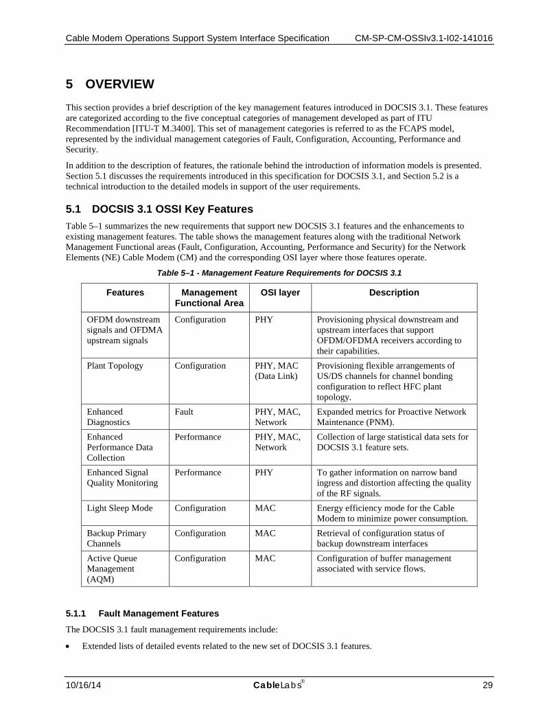
Cable Modem Operations Support System Interface Specification CM-SP-CM-OSSIv3.1-I02-141016
10/16/14 CableLabs 29
5 OVERVIEW This section provides a brief description of the key management features introduced in DOCSIS 3.1. These features are categorized according to the five conceptual categories of management developed as part of ITU Recommendation [ITU-T M.3400]. This set of management categories is referred to as the FCAPS model, represented by the individual management categories of Fault, Configuration, Accounting, Performance and Security.
In addition to the description of features, the rationale behind the introduction of information models is presented. Section 5.1 discusses the requirements introduced in this specification for DOCSIS 3.1, and Section 5.2 is a technical introduction to the detailed models in support of the user requirements.
5.1 DOCSIS 3.1 OSSI Key Features Table 5–1 summarizes the new requirements that support new DOCSIS 3.1 features and the enhancements to existing management features. The table shows the management features along with the traditional Network Management Functional areas (Fault, Configuration, Accounting, Performance and Security) for the Network Elements (NE) Cable Modem (CM) and the corresponding OSI layer where those features operate.
Table 5–1 - Management Feature Requirements for DOCSIS 3.1
Features Management Functional Area
OSI layer Description
OFDM downstream signals and OFDMA upstream signals
Configuration PHY Provisioning physical downstream and upstream interfaces that support OFDM/OFDMA receivers according to their capabilities.
Plant Topology Configuration PHY, MAC (Data Link)
Provisioning flexible arrangements of US/DS channels for channel bonding configuration to reflect HFC plant topology.
Enhanced Diagnostics
Fault PHY, MAC, Network
Expanded metrics for Proactive Network Maintenance (PNM).
Enhanced Performance Data Collection
Performance PHY, MAC, Network
Collection of large statistical data sets for DOCSIS 3.1 feature sets.
Enhanced Signal Quality Monitoring
Performance PHY To gather information on narrow band ingress and distortion affecting the quality of the RF signals.
Light Sleep Mode Configuration MAC Energy efficiency mode for the Cable Modem to minimize power consumption.
Backup Primary Channels
Configuration MAC Retrieval of configuration status of backup downstream interfaces
Active Queue Management (AQM)
Configuration MAC Configuration of buffer management associated with service flows.
5.1.1 Fault Management Features
The DOCSIS 3.1 fault management requirements include:
• Extended lists of detailed events related to the new set of DOCSIS 3.1 features.

CM-SP-CM-OSSIv3.1-I02-141016 DOCSIS 3.1
30 CableLabs 10/16/14
• Expanded metrics for Proactive Network Maintenance (PNM).
5.1.2 Configuration Management Features
The configuration of the DOCSIS protocols for CM/CMTS interactions for configuring features in support of PHY MAC/QoS and Security (BPI) uses the CM configuration file and CMTS policies via MAC messages exchange. The reporting of configuration state information is done via SNMP MIB objects. This model provides a CM standard configuration with minimal operator intervention.
The DOCSIS 3.1 configuration requirements include:
• Updates to CM configuration parameters to support OFDM downstream interfaces, OFDMA upstream interfaces, light sleep mode and Active Queue Management (AQM).
• Retrieval of configuration status information for OFDM downstream interfaces, OFDMA upstream interfaces, light sleep mode, backup primary channels and Active Queue Management (AQM).
5.1.3 Performance Management Features
DOCSIS 3.1 requires an efficient mechanism for collecting large data sets as described above. The identified data sets are:
• Enhanced signal quality monitoring for granular plant status
• Statistics for dropped AQM packets
• Statistics for OFDM and OFMDA interface, subcarrier, profile and mini-slot counters
• Measurement Statistics for Proactive Network Maintenance (PNM)
5.1.4 Security Management Features
Security Management includes both security of management information (e.g., SNMP access control) and management of network security related to authentication, authorization and privacy of data plane communications.
There will be some small changes to the DOCSIS 3.1 Security Management feature set. Those changes are <TBD>.
5.1.5 Accounting Management Features
The DOCSIS 3.1 Accounting Management feature set is unchanged from DOCSIS 3.0.
5.2 Technical Overview The technical overview presented in this section details functional areas of the FCAPS management model addressed by DOCSIS for managing the CM.
5.2.1 Architectural Overview
This section defines the functional areas of network management in terms of FCAPS (Fault, Configuration, Accounting, Performance and Security) as applied to the management of a CM within a DOCSIS network.
The requirements in the previous section were grouped both according to the management functional area and the relevant DOCSIS layer (using the OSI reference model) where they apply. This section provides an overview of the functions supported by each area. Even though specific functions are described for each area, there are interdependencies amongst all these functions to achieve the overall objective of efficient and proactive management of a CM in the DOCSIS network.
Fault management seeks to identify, isolate, correct and record system faults. Configuration management modifies system configuration variables and collects configuration information. Accounting management collects usage statistics for subscribers, sets usage quotas and bills users according to their use of the system. Performance management focuses on the collection of performance metrics, analysis of these metrics and the setting of thresholds and rate limits. Security management encompasses identification and authorization of users and equipment, provides audit logs and alerting functions, as well as providing vulnerability assessment.
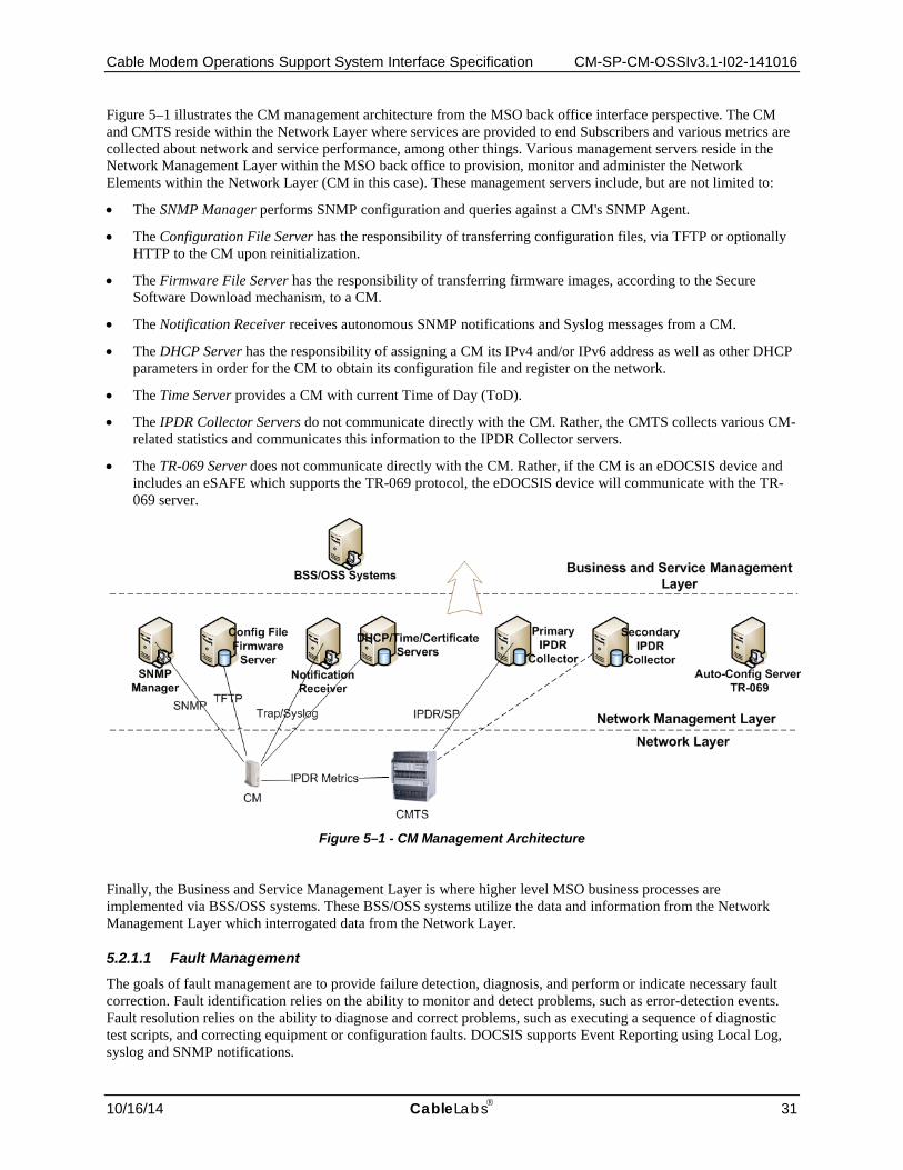
Cable Modem Operations Support System Interface Specification CM-SP-CM-OSSIv3.1-I02-141016
10/16/14 CableLabs 31
Figure 5–1 illustrates the CM management architecture from the MSO back office interface perspective. The CM and CMTS reside within the Network Layer where services are provided to end Subscribers and various metrics are collected about network and service performance, among other things. Various management servers reside in the Network Management Layer within the MSO back office to provision, monitor and administer the Network Elements within the Network Layer (CM in this case). These management servers include, but are not limited to:
• The SNMP Manager performs SNMP configuration and queries against a CM's SNMP Agent.
• The Configuration File Server has the responsibility of transferring configuration files, via TFTP or optionally HTTP to the CM upon reinitialization.
• The Firmware File Server has the responsibility of transferring firmware images, according to the Secure Software Download mechanism, to a CM.
• The Notification Receiver receives autonomous SNMP notifications and Syslog messages from a CM.
• The DHCP Server has the responsibility of assigning a CM its IPv4 and/or IPv6 address as well as other DHCP parameters in order for the CM to obtain its configuration file and register on the network.
• The Time Server provides a CM with current Time of Day (ToD).
• The IPDR Collector Servers do not communicate directly with the CM. Rather, the CMTS collects various CM-related statistics and communicates this information to the IPDR Collector servers.
• The TR-069 Server does not communicate directly with the CM. Rather, if the CM is an eDOCSIS device and includes an eSAFE which supports the TR-069 protocol, the eDOCSIS device will communicate with the TR-069 server.
Figure 5–1 - CM Management Architecture
Finally, the Business and Service Management Layer is where higher level MSO business processes are implemented via BSS/OSS systems. These BSS/OSS systems utilize the data and information from the Network Management Layer which interrogated data from the Network Layer.
5.2.1.1 Fault Management The goals of fault management are to provide failure detection, diagnosis, and perform or indicate necessary fault correction. Fault identification relies on the ability to monitor and detect problems, such as error-detection events. Fault resolution relies on the ability to diagnose and correct problems, such as executing a sequence of diagnostic test scripts, and correcting equipment or configuration faults. DOCSIS supports Event Reporting using Local Log, syslog and SNMP notifications.
CM-SP-CM-OSSIv3.1-I02-141016 DOCSIS 3.1
32 CableLabs 10/16/14
5.2.1.2 Configuration Management Configuration management is concerned with adding, initializing, maintaining and updating network elements. In a DOCSIS environment, network elements include CMs and CMTSs.
Configuration management is primarily concerned with network control via modifying operating parameters on network elements such as the CM and CMTS. Configuration parameters could include both physical resources (for example, an Ethernet interface) and logical objects (for example, QoS parameters for a given service flow).
While the network is in operation, configuration management is responsible for monitoring the configuration state and making changes in response to commands by a management system or some other network management function.
For example, a performance management function may detect that response time is degrading due to a high number of uncorrected frames, and may issue a configuration management change to modify the modulation type from 16-QAM to QPSK. A fault management function may detect and isolate a fault and may issue a configuration change to mitigate or correct that fault.
5.2.1.3 Accounting Management Accounting management, in general, includes collection of usage data and permits billing the customer based on the subscriber's use of network resources. The CMTS is the network element that is responsible for providing the usage statistics to support billing. Billing is outside the scope of this specification.
5.2.1.4 Performance Management Performance management functions include collecting statistics of parameters such as number of frames lost at the MAC layer and number of codeword errors at the PHY layer. These monitoring functions are used to determine the health of the network and whether the offered Quality of Service (QoS) to the subscriber is met. The quality of signal at the PHY layer is an indication of plant conditions.
The previous versions of DOCSIS OSSI specification defines SNMP polling as the collection mechanism for CM and CMTS statistics for performance management. SNMP polling of CMs is scalable and widely deployed with specialized engines that minimize the upstream bandwidth allocated to management during the polling intervals.
5.2.1.5 Security Management Security management is concerned with both security of management information to protect the MSOs operations systems as well as managing the security information. The latter is used to authenticate and secure the traffic on the HFC. Security of the management interface is required to prevent end users from accessing and initiating configuration changes that may provide them with services for which they are not entitled or could result in the degradation or denial of services for other subscribers.
5.2.2 Management Protocols As noted earlier in this section, the DOCSIS OSSI specification uses the Simple Network Management Protocol (SNMP) versions 1, 2c and 3 to define the management information for a CM DOCSIS network element in support of the functional areas mentioned in the previous section. SNMP is primarily a polling based protocol where the management system retrieves data such as counter values and state information. There are events defined as a notification that are used to inform the management systems of fault conditions and security violations. The support for SNMP versions is continued in DOCSIS 3.1.
5.2.3 Information Models
The approach is based on an object oriented modeling approach well known in the industry for capturing requirements and analyzing the data in a protocol independent representation. This approach defines requirements with use cases to describe the interactions between the operations support systems and the network element. The management information is represented in terms of objects along with their attributes and the interactions between these encapsulated objects (or also referred to as entities in some representations). The diagrams developed to capture these managed objects and their attributes and associations are UML Class Diagrams. The collection of

Cable Modem Operations Support System Interface Specification CM-SP-CM-OSSIv3.1-I02-141016
10/16/14 CableLabs 33
UML Class Diagrams and Use Case Diagrams are referred to as the DOCSIS 3.1 Information Models. With the introduction of several new, complex features in DOCSIS 3.0 and DOCSIS 3.1 and the operator needs for a more proactive and efficient approach to management information, information modeling methodologies offer the ability to reuse the same definitions when new protocols are introduced in the future.
The managed objects are then represented in a protocol specific form referred to as a management data model. The management data models when using SNMP are described using the Structure of Management Information Version 2 (SMIv2) [RFC 2578] and the design of these models is determined by the capabilities of the protocol.
Refer to Appendix II for information on the modeling concepts used throughout this specification.

CM-SP-CM-OSSIv3.1-I02-141016 DOCSIS 3.1
34 CableLabs 10/16/14
6 OSSI MANAGEMENT PROTOCOLS
6.1 SNMP Protocol The SNMP protocol has been selected as the communication protocol for management of data-over-cable services.
The CM MUST implement the SNMPv3 protocol.
Although SNMPv3 offers certain security advantages over previous SNMP versions, many existing management systems do not fully support SNMPv3, necessitating support of the theoretically less secure but more ubiquitous SNMPv1 and SNMPv2c protocols.
The CM MUST implement the SNMPv1 and SNMPv2c protocols.
The IETF SNMP-related RFCs listed in Table 6–1 are supported by the CM.
Table 6–1 - IETF SNMP-related RFCs
[RFC 3410] Introduction and Applicability Statements for Internet Standard Management Framework [RFC 3411] An Architecture for Describing Simple Network Management Protocol (SNMP) Management
Frameworks [RFC 3412] Message Processing and Dispatching for the Simple Network Management Protocol (SNMP) [RFC 3413] Simple Network Management Protocol (SNMP) Applications [RFC 3414] User-based Security Model (USM) for version 3 of the Simple Network Management Protocol
(SNMPv3) [RFC 3415] View-based Access Control Model (VACM) for the simple Network Management Protocol
(SNMP) [RFC 3416] Version 2 of the Protocol Operations for the Simple Network Management Protocol (SNMP) [RFC 3417] Transport Mappings for the Simple Network Management Protocol (SNMP) [RFC 3418] Management Information Base for the Simple Network Management Protocol (SNMP) [RFC 3419] Textual Conventions for Transport Addresses [RFC 3584] Coexistence between Version 1, Version 2, and Version 3 of the Internet-standard Network
Management Framework [RFC 3826] The Advanced Encryption Standard (AES) Cipher Algorithm in the SNMP User-based Security
Model [RFC 1901] Introduction to Community-based SNMPv2 (Informational) [RFC 1157] A Simple Network Management Protocol
For support of SMIv2, Table 6–2 lists the IETF SNMP-related RFCs which are supported by the CM.
Table 6–2 - SMIv2 IETF SNMP-related RFCs
[RFC 2578] Structure of Management Information Version 2 (SMIv2) [RFC 2579] Textual Conventions for SMIv2 [RFC 2580] Conformance Statements for SMIv2
For support of Diffie-Helman Key exchange for the User Based Security Model, Table 6–3 lists the IETF SNMP-related RFC which is supported by the CM.
Table 6–3 - Diffie-Helman IETF SNMP-related RFC
[RFC 2786] Diffie-Helman USM Key Management Information Base and Textual Convention

Cable Modem Operations Support System Interface Specification CM-SP-CM-OSSIv3.1-I02-141016
10/16/14 CableLabs 35
6.1.1 Requirements for IPv6
Several transport domains were initially defined for SNMP (see [RFC 3417]). To support IPv6, [RFC 3419] adds a new set of transport domains not only for SNMP but for any application protocol.
The CM MUST support the recommendations of [RFC 3419] to support SNMP over IPv6.

CM-SP-CM-OSSIv3.1-I02-141016 DOCSIS 3.1
36 CableLabs 10/16/14
7 OSSI MANAGEMENT OBJECTS
7.1 SNMP Management Information Bases (MIBS) This section defines the minimum set of managed objects required to support the management of a CM.
The CM MAY augment the required MIBs with objects from other standard or vendor-specific MIBs where appropriate.
The DOCSIS 3.1 Cable Modem OSSI specification has priority over the IETF MIBs and all objects. Though deprecated or optional in the IETF MIB, the object can be required by this specification as mandatory.
The CM MUST implement the MIB requirements in accordance with this specification regardless of the value of an IETF MIB object's status (e.g., deprecated or optional).
If not required by this specification, deprecated objects are optional. If a CM implements a deprecated MIB object, the CM MUST implement the MIB object according to the MIB definition.
If a CM does not implement a deprecated MIB object, the following conditions MUST be met:
• The CM MUST NOT instantiate the deprecated MIB object.
• The CM MUST respond with the appropriate error/exception condition, such as noSuchObject for SNMPv2c, when an attempt to access the deprecated MIB object is made.
If not required by this specification, additional objects are optional. If a CM implements any additional MIB objects, the CM MUST implement the MIB object according to the MIB definition.
If a CM does not implement one or more additional MIB objects, the following conditions MUST be met:
• The CM MUST NOT instantiate the additional MIB object or objects.
• The CM MUST respond with the appropriate error/exception condition, such as noSuchObject for SNMPv2c when an attempt to access the non-existent additional MIB object is made, when the additional MIB object or objects are accessed.
If not required by this specification, obsolete objects are optional. If a CM implements an obsolete MIB object, the CM MUST implement the MIB object according to the MIB definition.
If a CM does not implement an obsolete MIB object, the following conditions MUST be met:
• The CM MUST NOT instantiate the obsolete MIB object.
• The CM MUST respond with the appropriate error/exception condition, such as noSuchObject for SNMPv2c, when an attempt to access the obsolete MIB object is made.
Objects which are not supported by this specification are not implemented by an agent.
• The CM MUST NOT instantiate MIB objects listed as not supported in Annex A.
• The CM MUST respond with the appropriate error/exception condition, such as noSuchObject for SNMPv2c, when an attempt to access a not supported MIB object is made.
Sections 7.1.1 and 7.1.2 include an overview of the MIB modules required for management of the facilities specified in the [MULPIv3.1] and [SECv3.0] specifications.
7.1.1 CableLabs MIB Modules
The following CableLabs MIB Modules are normatively required for CMs by this specification.

Cable Modem Operations Support System Interface Specification CM-SP-CM-OSSIv3.1-I02-141016
10/16/14 CableLabs 37
Table 7–1 - CableLabs MIB Modules
Reference MIB Module
[DOCS-IFEXT2-MIB] DOCSIS Interface Extension 2 MIB Module: DOCS-IFEXT2-MIB
[DOCS-IF3-MIB] DOCSIS Interface 3 MIB Module: DOCS-IF3-MIB
[DOCS-QOS3-MIB] DOCSIS Quality of Service 3 MIB Module: DOCS-QOS3-MIB
7.1.2 IETF RFC MIB Modules Table 7–2 - IETF RFC MIB Modules
Reference MIB Module
[RFC 2786] Diffie-Helman USM Key MIB Module: SNMP-USM-DH-OBJECTS-MIB
[RFC 2790] Host Resources MIB Module: HOST-RESOURCES-MIB
[RFC 2863] Interfaces Group MIB Module: IF-MIB
[RFC 2933] Internet Group Management Protocol MIB Module: IGMP-STD-MIB
[RFC 3083] DOCSIS Baseline Privacy MIB Module: DOCS-BPI-MIB
[RFC 3410] [RFC 3411] [RFC 3412] [RFC 3413] [RFC 3414] [RFC 3415] [RFC 3584]
SNMPv3 MIB Modules: SNMP-FRAMEWORK-MIB, SNMP-MPD-MIB, SNMP-NOTIFICATION-MIB, SNMP-TARGET-MIB, SNMP-USER-BASED-SM-MIB, SNMP-VIEW-BASED-ACM-MIB, SNMP-COMMUNITY-MIB
[RFC 3418] SNMPv2 MIB Module: SNMPv2-MIB
[RFC 3433] Entity Sensor MIB Module: ENTITY-SENSOR-MIB
[RFC 3635] Ethernet Interface MIB Module: EtherLike-MIB
[RFC 4022] Transmission Control Protocol MIB Module: TCP-MIB
[RFC 4113] User Datagram Protocol MIB Module: UDP-MIB
[RFC 4131] DOCSIS Baseline Privacy Plus MIB Module: DOCS-IETF-BPI2-MIB
[RFC 4133] Entity MIB Module: ENTITY-MIB
CM-SP-CM-OSSIv3.1-I02-141016 DOCSIS 3.1
38 CableLabs 10/16/14
Reference MIB Module
[RFC 4188] Bridge MIB Module: BRIDGE-MIB
[RFC 4293] Internet Protocol MIB Module: IP-MIB
[RFC 4546] DOCSIS RF MIB Module: DOCS-IF-MIB
[RFC 4639] DOCSIS Device MIB Module: DOCS-CABLE-DEVICE-MIB
7.1.3 Managed objects requirements
The following sections detail additional implementation requirements for the MIB modules listed.
The CM MUST implement the compliance and syntax of the MIB objects as specified in Annex A.
The CM MUST support a minimum of 10 available SNMP table rows, unless otherwise specified by RFC or DOCSIS specification. The CM minimum number of available SNMP table rows SHOULD mean rows (per table) that are available to support device configuration. The CM used (default) SNMP table row entries MUST NOT apply to the minimum number of available SNMP table rows.
7.1.3.1 Requirements for CableLabs DOCSIS Interface Extension 2 MIB The CM MUST implement DOCS-IFEXT2-MIB, as specified in [DOCS-IFEXT2-MIB].
7.1.3.2 Requirements for CableLabs DOCSIS Interface 3 MIB The CM MUST implement the DOCS-IF3-MIB, as specified in [DOCS-IF3-MIB].
7.1.3.3 Requirements for CableLabs DOCSIS Quality of Service 3 MIB The CM MUST implement the DOCS-QOS3-MIB, as specified in [DOCS-QOS3-MIB].
7.1.3.4 Requirements for DOCSIS Device MIB [RFC 4639] The CM MUST implement [RFC 4639].
Note: [RFC 4639] includes Compliance requirements for DIFFSERV-MIB [RFC 3289] to support IPv6 filtering as a replacement for the deprecated docsDevFilterIpTable. For backwards compatibility, this specification has requirements for docsDevFilterIpTable. IPv6 filtering requirements are specified in Annex A. This specification does not define requirements for [RFC 3289].
Additional requirements affecting [RFC 4639] are also found in Section 9.4, Protocol Filtering.
7.1.3.5 Requirements for DOCSIS RF MIB [RFC 4546] The CM MUST implement [RFC 4546].
The CM MUST implement the docsIfDownChannelPower MIB object with read-only access. The CM MUST report a power value for docsIfDownChannelPower within 3 dB of the actual received channel power when operated at nominal line-voltage, at normal room temperature (refer to [PHYv3.1]).
For any 1 dB change in input power, the CM MUST report a power change in the same direction that is not less than 0.6 dB and not more than 1.4 dB, as specified in [PHYv3.1].
In order to support these changes, the indexing for the docsIfCmtsServiceTable shall be defined as UsChanifIndex (the logical upstream channel the modem registered on) and SID. When a CM registers with a 1.0 Class of Service configuration file, the CMTS uses the Primary SID [MULPIv3.1] as the Service Identifier for the index. If the CM
Cable Modem Operations Support System Interface Specification CM-SP-CM-OSSIv3.1-I02-141016
10/16/14 CableLabs 39
registers with 1.0 Class of Service configuration file and MTC is enabled, the CMTS uses the SID associated with the CM registration request.
The CM MUST extend the MIB Textual-Convention DocsisVersion to include the enumeration 'docsis31'. The extended DocsisVersion Textual-Convention is shown below. DocsisVersion ::= TEXTUAL-CONVENTION STATUS current DESCRIPTION "'docsis10' indicates DOCSIS 1.0. 'docsis11' indicates DOCSIS 1.1. 'docsis20' indicates DOCSIS 2.0. 'docsis30' indicates DOCSIS 3.0. 'docsis31' indicates DOCSIS 3.1." REFERENCE "DOCSIS 3.1 MAC and Upper Layer Protocols Interface Specification CM-SP-MULPIv3.1, DOCSIS Version section of the Common Radio Frequency Interface Encodings Annex." SYNTAX INTEGER { docsis10 (1), docsis11 (2), docsis20 (3), docsis30 (4), docsis31 (5) } The MIB object docsIfDocsisBaseCapability, based on the DocsisVersion Textual-Convention, includes an updated REFERENCE to align with the extended DocsisVersion Textual-Convention. docsIfDocsisBaseCapability OBJECT-TYPE SYNTAX DocsisVersion MAX-ACCESS read-only STATUS current DESCRIPTION "Indication of the DOCSIS capability of the device." REFERENCE "DOCSIS 3.1 MAC and Upper Layer Protocols Interface Specification CM-SP-MULPIv3.1, DOCSIS Version section of the Common Radio Frequency Interface Encodings Annex." ::= { docsIfBaseObjects 5 }
[RFC 4546] defined MIB object docsIfCmStatusCode has the SYNTAX updated to accommodate 7 characters in the status code. docsIfCmStatusCode OBJECT-TYPE SYNTAX OCTET STRING (SIZE( 0 | 5 | 6 | 7 )) MAX-ACCESS read-only STATUS current DESCRIPTION "Status code for a Cable Modem as defined in the OSSI Specification. The status code consists of a single character indicating error groups, followed by a two- or three-digit number indicating the status condition, followed by a decimal. An example of a returned value could be 'T101.0'. The zero-length OCTET STRING indicates no status code yet registered." REFERENCE "Data-Over-Cable Service Interface Specifications: Operations Support System Interface Specification
CM-SP-CM-OSSIv3.1-I02-141016 DOCSIS 3.1
40 CableLabs 10/16/14
SP-OSSIv2.0-C01-081104, Annex D." ::= { docsIfCmStatusEntry 2 }
7.1.3.6 Requirements for Interfaces Group MIB [RFC 2863] The CM MUST implement the interface MIB [RFC 2863].
The ifType object associated with a DOCSIS interface can have the following enumerated values:
• CATV MAC interface: docsCableMacLayer (127)
• CATV downstream channel: docsCableDownstream (128)
• CATV M-CMTS downstream channel: docsCableMCmtsDownstream (229) (See [M-OSSI])
• CATV Downstream OFDM interface: docsOfdmDownstream (277)
• CATV upstream interface: docsCableUpStream (129)
• CATV logical upstream channel: docsCableUpstreamChannel (205)
• Upstream OFDMA interface: docsOfdmaUpstream (278)
7.1.3.6.1 Interface organization and numbering
Assigned interface numbers for CATV-MAC and Ethernet (Ethernet-like interface) are used in both the NMAccessTable and IP/LLC filtering table to configure access and traffic policy at these interfaces. These configurations are generally encoded in the configuration file using TLV encoding.
The following statements define the CM interface-numbering scheme requirements:
The CM MUST implement an instance of ifEntry for each configured CATV-MAC interface, downstream channel, upstream interface, and for all of its LAN interfaces. If a CATV-MAC interface consists of more than one upstream and downstream channel, the CM MUST populate the ifTable with a separate instance of ifEntry for each channel.
The CM MAY fix LAN interfaces during the manufacturing process or determine these dynamically during the operation of the CM based on whether or not an interface has a CPE device attached to it.
If the CM has multiple CPE interfaces, but only one CPE interface that can be enabled at any given time, the CM MUST populate the ifTable to contain only the entry corresponding to the enabled or the default CPE interface.
The CM MUST populate the ifTable as specified in Table A–4 through Table A–7 of Annex A.2. The CM MUST maintain entries in the ifTable for the CATV downstream and CATV upstream interfaces for which the CMTS has configured DS Receive Channels and US Transmit Channels, respectively, for this particular CM, and not for the total number of the CM receivers and transmitters the CM supports. CMTS configured Receive Channels and Transmit Channels for a CM are defined in [MULPIv3.1].
While the CM is registered, the CM SHOULD use a different ifIndex to allocate a new CMTS configured Receive Channel or Transmit Channel, and avoid the reuse of previously assigned IfIndexes that are not currently part of the CMTS configured Receive Channel Set (RCS) or Transmit Channel Set (TCS).
When a CATV DS or US interface is configured as part of a RCS or TCS with a new channel id, the CM MUST update the ifCounterDiscontinuityTime and ifLastChange MIB variables.
The CM MUST populate ifStackTable with an entry for the CATV-MAC interface and include the CATV downstream and CATV upstream interfaces are reported in the ifTable.
The CM MUST implement the MIB variable ifStackLastChange to report the value of sysUpTime where the ifStackTable change as a consequence of an addition or removal of a channel ID from a CM-SG as defined in [MULPIv3.1].
The following example illustrates a MAC interface with four downstream and four upstream interfaces for a CM.
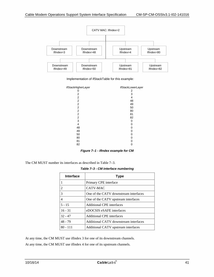
Cable Modem Operations Support System Interface Specification CM-SP-CM-OSSIv3.1-I02-141016
10/16/14 CableLabs 41
Figure 7–1 - ifIndex example for CM
The CM MUST number its interfaces as described in Table 7–3.
Table 7–3 - CM interface numbering
Interface Type
1 Primary CPE interface 2 CATV-MAC 3 One of the CATV downstream interfaces 4 One of the CATV upstream interfaces 5 - 15 Additional CPE interfaces 16 - 31 eDOCSIS eSAFE interfaces 32 - 47 Additional CPE interfaces 48 - 79 Additional CATV downstream interfaces 80 - 111 Additional CATV upstream interfaces
At any time, the CM MUST use ifIndex 3 for one of its downstream channels.
At any time, the CM MUST use ifIndex 4 for one of its upstream channels.
CATV MAC: IfIndex=2
UpstreamIfIndex=4
DownstreamIfIndex=3
Implementation of ifStackTable for this example:
ifStackLowerLayer234
48495080818200000000
ifStackHigherLayer02222222234
484950808182
DownstreamIfIndex=48
UpstreamIfIndex=80
DownstreamIfIndex=49
DownstreamIfIndex=50
UpstreamIfIndex=81
UpstreamIfIndex=82

CM-SP-CM-OSSIv3.1-I02-141016 DOCSIS 3.1
42 CableLabs 10/16/14
For example, if the RCS is configured with channels on ifIndex 3 and 48 and the Dynamic Bonding Change DBC message demands ifIndex 3 be removed, the ifIndex 48 becomes ifIndex 3.
If the CM has more than one CPE interface, the vendor is required to define which of the CPE interfaces is the primary CPE interface. The CM is permitted to have its primary CPE interface fixed during the manufacturing process, or determine it dynamically during operation based on which interface has a CPE device attached to it. Regardless of the number of CPE interfaces the CM has, or how the primary CPE interface is determined, the CM will set the primary interface to interface number 1.
The CM MAY have additional CPE interfaces fixed during the manufacturing process or determined dynamically during operation based on which interface has a CPE device attached to it. Additional CPE interface ifIndexes are described in Table 7–3.
7.1.3.6.2 ifOperStatus Relationships
7.1.3.6.2.1 CmStatusValue and ifOperStatus Relationship
The CM MUST ensure that its CATV-MAC, downstream and upstream interfaces conform to the following relationships of ifOperStatus and CmStatusValue (see Annex G) when ifAdminStatus value of those interfaces is 'up':
Table 7–4 - CmStatusValue and ifOperStatus relationship
IfOperStatus CmStatusValue
'down' 'other', 'notReady' 'dormant' 'notSynchronized', 'phySynchronized', 'usParametersAcquired', 'rangingComplete',
'dhcpV4Complete', 'dhcpV6Complete', 'todEstablished', 'configFileDownloadComplete', 'startRegistration', 'bpiInit', 'accessDenied'
'up' 'registrationComplete', 'securityEstablished', 'operational'
7.1.3.6.2.2 USB state and ifOperStatus Relationships
If the CM supports USBs as CPE interfaces, the CM SHOULD report the value of the MIB object ifOperStatus as follows:
Table 7–5 - USB State and ifOperStatus relationship
IfOperStatus USB states and other conditions (see [USB])
'down' 'Attached', 'Powered', 'Default', and STALL operation 'dormant' 'Suspended', 'Address' 'up' 'Configured'
7.1.3.6.3 ifAdminStatus and Traffic
The CM MUST NOT accept or forward any traffic over an interface whose ifAdminStatus is 'down', (traffic includes data and MAC management traffic where applicable).
7.1.3.6.4 SNMP Notification Control Requirements
If a multi-layer interface model is present in the device, each sub-layer for which there is an entry in the ifTable can generate linkUp/Down traps. Since interface state changes would tend to propagate through the interface stack (from top to bottom, or bottom to top), it is likely that several traps would be generated for each linkUp/Down occurrence. The ifLinkUpDownTrapEnable object allows managers to control SNMP notification generation, and configure only the interface sub-layers of interest.
The CM MUST implement the MIB object ifLinkUpDownTrapEnable specified in [RFC 2863].

Cable Modem Operations Support System Interface Specification CM-SP-CM-OSSIv3.1-I02-141016
10/16/14 CableLabs 43
For linkUp/Down events on CM DOCSIS interfaces, the CM SHOULD generate an SNMP notification for the CM MAC interface and not for any sub-layers of the interface. Therefore, the CM MUST have its default setting of ifLinkUpDownTrapEnable for the CM MAC interface set to 'enabled'. The CM MUST have its default setting of ifLinkUpDownTrapEnable for the RF-Up interface(s) set to 'disabled'. The CM MUST have its default setting of ifLinkUpDownTrapEnable for the RF-Down interface(s) set to 'disabled'. The CM SHOULD have its default setting of ifLinkUpDownTrapEnable for interfaces 1 and 5 through 47 listed in Table 7–3 set to 'disabled'.
If the ifLinkUpDownTrapEnable for the CM MAC interface set to 'enabled', the CM MUST generate a linkUp SNMP notification [RFC 2863].
7.1.3.6.5 ifTable and IfXTable Counters
DOCSIS 3.1 CM OSSI specifications include CM requirements for the ifTable and ifXTable [RFC 2863] interface counter objects that were introduced in DOCSIS 3.0 to accommodate channel bonding.
Application of the [RFC 2863] ifTable and ifXTable MIB counter objects are done on a per-interface basis for DOCSIS 3.0 and DOCSIS 3.1 and are detailed in Table A–6 and Table A–7 of Annex A.2. These tables define specific SNMP Access and MIB requirements for each of the interface counters defined in [RFC 2863]. The CM MUST only count octets on the downstream and upstream interfaces. The CM MAY implement the packet counters from [RFC 2863], but when implemented on these interfaces, the counter object will return a value of zero. The CM ethernet and MAC interfaces count both packet and octet counters. Per the requirements in [RFC 2863] Counter Size section, a given interface may support only 32-bit or 64-bit (High Capacity), or both sets of counters based on interface speed.
The CM MUST implement the ifTable and ifXTable [RFC 2863] Counter32 and Counter64 MIB objects as defined for each interface in Table A–6 and Table A–7 of Annex A.2.
7.1.3.6.6 ifSpeed and ifHighSpeed
The CM MUST report in ifSpeed and ifHighSpeed MIB objects the current configured speed of the interface as stated in [RFC 2863]. See Annex A.2 for details on particular interface types.
7.1.3.6.7 ifDescr
7.1.3.6.7.1 IfDescr for USB interfaces
If the CM support USB as CPE interfaces, the CM MUST report the value of the MIB object ifDescr for these interfaces as follows:
USB <dbcUSB> CDC Ethernet; <any text>
<dbcUSB> corresponds to the USB version in the format JJ.M.N (JJ – major version number, M – minor version number, N – sub-minor version number). See Standard USB Descriptor Definitions from [USB] specification.
For example, if the dbcUSB field in the USB descriptor is 0x0213, <dbcUSB> is presented in ifDescrMIb object as "2.1.3" and a value of 0x2000 in the dbcUSB field of the USB Descriptor is represented as "2.0" in ifDescr MIB object, in both cases without double quotes.
<Any text> indicates a vendor specific text.
A complete example of ifDescr for an USB device is as follows (Assume dbcUBC 0x2000):
USB 2.0 CDC Ethernet; <any text>
7.1.3.7 Requirements for Ethernet Interface MIB [RFC 3635] The CM MUST implement [RFC 3635] if Ethernet interfaces are present.

CM-SP-CM-OSSIv3.1-I02-141016 DOCSIS 3.1
44 CableLabs 10/16/14
7.1.3.8 Requirements for Bridge MIB [RFC 4188] The CM MUST implement the Bridge MIB [RFC 4188] to support the forwarding requirements defined in [MULPIv3.1].
The CM MUST implement a managed object (see docsDevSTPControl in [RFC 4639]) that controls the 802.1d spanning tree protocol (STP) policy in accordance with [MULPIv3.1] requirements.
If STP is enabled for the CM, then the CM implements the dot1dStp scalar group [RFC 4188] and optionally the dot1dStpPortTable [RFC 4188] as specified in Annex A.
7.1.3.9 Requirements for Internet Protocol MIB [RFC 4293] The CMs requirements for [RFC 4293] are defined in the following sections.
7.1.3.9.1 The IP Group
The CM MUST implement the ipv4GeneralGroup.
The CM MUST implement the ipv6GeneralGroup2.
The CM MUST implement the ipv4InterfaceTable.
The CM MUST populate the ipv4InterfaceTable with each Ethernet interface with an assigned IPv4 address. The CM MAY record other interfaces in the ipv4InterfaceTable which have assigned IPv4 addresses.
The CM MUST populate the ipv6InterfaceTable with each Ethernet interface with an assigned IPv6 address. The CM MAY record other interfaces in the ipv6InterfaceTable which have assigned IPv6 addresses.
The CM MAY implement the ipSystemStatsTable.
The CM MAY implement the ipIfStatsTable.
The CM MAY implement the ipAddressPrefixTable.
The CM MAY implement the ipAddressTable.
The CM MAY implement the ipNetToPhysicalTable.
The CM MAY implement the ipDefaultRouterTable.
The CM MUST NOT implement the ipv6RouterAdvertTable.
7.1.3.9.2 The ICMP Group
The CM MUST implement the icmpStatsTable.
The CM MUST implement the icmpMsgStatsTable.
7.1.3.10 Requirements for User Datagram Protocol MIB [RFC 4113] The CM MAY implement the UDP-MIB in [RFC 4113].
7.1.3.11 Requirements for Transmission Control Protocol (TCP) MIB [RFC 4022]
7.1.3.11.1 The TCP Group
The CM MAY implement the TCP group in [RFC 4022].
7.1.3.12 Requirements for SNMPv2 MIB [RFC 3418]
7.1.3.12.1 The System Group
The CM MUST implement the System Group of [RFC 3418].
See Section 8.2.1 for sysDescr requirements details.
Cable Modem Operations Support System Interface Specification CM-SP-CM-OSSIv3.1-I02-141016
10/16/14 CableLabs 45
7.1.3.12.2 The SNMP Group
This group provides SNMP protocol statistics and protocol errors counters.
The CM MUST implement the SNMP Group from [RFC 3418].
7.1.3.13 Requirements for Internet Group Management Protocol MIB [RFC 2933] The CM MUST implement [RFC 2933].
Refer to Annex B for DOCSIS 3.1 IGMP-STD-MIB CM implementation details.
The CM IGMP Passive and Active Modes (see Annex B) are maintained for backward compatibility with pre-3.0 DOCSIS systems, including the support of [RFC 2933]. For CMs operating with DSID Based Forwarding enabled, the CM is not responsible for proxying or snooping Multicast traffic, thus no MGMD or [RFC 2933] MIB requirements are needed on the CM. When CMs operate with DSID Based Multicast forwarding disabled, the CM is required to support [RFC 2933] passive mode. The CM may support [RFC 2933] Active mode per the requirements in Annex B.
7.1.3.14 Requirements for DOCSIS Baseline Privacy Plus MIB [RFC 4131] The CM MUST implement [RFC 4131].
7.1.3.15 Requirements for Diffie-Helman USM Key MIB [RFC 2786] The CM MUST implement [RFC 2786].
7.1.3.16 Requirements for DOCSIS Baseline Privacy MIB [RFC 3083] The CM MUST implement [RFC 3083].
Due to the editorial error in [RFC 3083] documented in the corresponding Errata for [RFC 3083], the CM MUST use the following definition for docsBpiCmAuthState and not the definition in [RFC 3083]: docsBpiCmAuthState OBJECT-TYPE SYNTAX INTEGER { start(1), authWait(2), authorized(3), reauthWait(4), authRejectWait(5) } MAX-ACCESS read-only STATUS current DESCRIPTION "The value of this object is the state of the CM authorization FSM. The start state indicates that FSM is in its initial state." REFERENCE "DOCSIS Baseline Privacy Interface Specification, States Section." ::= { docsBpiCmBaseEntry 3 }
In addition, the CM MAY create new entries in the docsBpiCmTEKTable for any multicast SAID(s) it receives in Auth-Reply messages. If the CM implements multicast SAID(s) in the docsBpiCmTEKTable, the CM MUST use the multicast SAID as an index in the docsBpiCmTEKTable in the docsIfCmServiceId field. If the multicast SAID is used in the docsBpiCmTEKTable, the CM MUST NOT allow a corresponding entry in the docsIfCmServiceTable for the multicast SAID, due to the definition of the docsIfCmServiceId in the DOCS-IF-MIB.
• docsBpiCmtsBaseTable
• docsBpiCmtsAuthTable
• docsBpiCmtsTEKTable
• docsBpiIpMulticastMapTable
CM-SP-CM-OSSIv3.1-I02-141016 DOCSIS 3.1
46 CableLabs 10/16/14
7.1.3.17 Requirements for SNMPv3 MIB Modules The CM MUST implement the MIBs defined in [RFC 3411] through [RFC 3415] and [RFC 3584].
The CM MUST support the default value of 'volatile' for any SNMPv3 object with a StorageType syntax. This overrides the default value specified in [RFC 3411] through [RFC 3415] and [RFC 3584]. The CM MUST only accept the value of 'volatile' for any SNMPv3 object with a StorageType syntax. An attempted set to a value of 'other', 'nonVolatile', 'permanent', or 'readOnly' will result in an "inconsistentValue" error. Values other than the valid range (1-5) would result in a "wrongValue" error.
The CM SHOULD support a minimum of 30 available rows in the vacmViewTreeFamilyTable object.
7.1.3.18 Requirements for Entity MIB [RFC 4133] The CM MAY implement the ENTITY-MIB [RFC 4133].
If the CM implements the ENTITY-SENSOR-MIB [RFC 3433], the CM is required to implement the entPhysicalTable with entries corresponding to any sensors managed in the ENTITY-SENSOR-MIB (e.g., temperature sensors). For sensor entries in the entPhysicalTable, the CM reports a value of 'sensor' for entPhysicalClass.
7.1.3.19 Requirements for Entity Sensor MIB [RFC 3433] The CM MAY implement the Entity Sensor MIB [RFC 3433].
The CM MAY implement the entPhySensorTable for instances which exist in the entPhysicalTable of the ENTITY-MIB [RFC 4133] with an entPhysicalClass of 'sensor'. It is recommended that for temperature sensors, the CM report a value for entPhySensorType of 'celsius'.
7.1.3.20 Requirements for Host Resources MIB [RFC 2790] The CM MAY implement the HOST-RESOURCES-MIB [RFC 2790].
Cable Modem Operations Support System Interface Specification CM-SP-CM-OSSIv3.1-I02-141016
10/16/14 CableLabs 47
8 OSSI FOR PHY, MAC AND NETWORK LAYERS
8.1 Fault Management This section defines requirements for remote monitoring/detection, diagnosis, reporting, and correction of problems. Refer also to Section 7, for requirements for managed objects supporting CM fault management.
8.1.1 SNMP Usage
In the DOCSIS environment, SNMP is used to achieve the goals of fault management: remote detection, diagnosis, reporting, and correction of CM network faults. Therefore, the CM MUST support SNMP management traffic across the CATV MAC interfaces as long as the CM has ranged and registered.
The CM SNMP access might be restricted by configuration parameters to support the operator's policy goals. Cable operators' CM installation personnel can use SNMP queries from a station on the CMCI side to perform on-site CM and diagnostics and fault classification (note that this may require temporary provisioning of the CM from a local DHCP server). Further, CMCI side subscriber applications, using SNMP queries, can diagnose simple post-installation problems, avoiding visits from service personnel and minimizing help desk telephone queries.
The CM sends SNMP notifications to one or more NMSs (subject to operator imposed policy). CM requirements for SNMP notifications are detailed in Section 8.1.2. The CM sends events to a syslog server. CM requirements for syslog events are detailed in Section 8.1.2.
8.1.2 Event Notification
A CM is required to generate asynchronous events that indicate malfunction situations and notify about important events. The methods for reporting events are defined below:
1. Stored in Local Log (docsDevEventTable [RFC 4639]). 2. Reported to SNMP entities as an SNMP notification. 3. Sent as a message to a syslog server.
This specification defines the support of DOCSIS specific events (see Annex B) and IETF events. The former are normally in the form of SNMP notifications. The delivery of IETF Notifications to local log and syslog server is optional.
Event Notifications are enabled and disabled by configuration. IETF SNMP notifications normally define specific controls to enable and disable notifications. For example, see Section 7.1.3.6.4 for requirements on ifLinkUpDownTrapEnable. DOCSIS specific events can be reported to local log and as syslog message and/or SNMNP notification as defined in docsDevEvControlTable [RFC 4639], Section 8.1.2.2, and Annex G, CmEventCtrl, A CM supports event notification functions including local event logging, syslog (limiting/throttling) and SNMP notification (limiting/throttling), as specified in [RFC 4639] and this specification. A CM operating in SNMP v1/v2c NmAccess mode is required to support SNMP trap control as specified in [RFC 4639] and this specification. A CM operating in SNMP Coexistence mode is required to support SNMP notification functions, as specified in [RFC 3416] and [RFC 3413] and this specification.
8.1.2.1 Format of Events Annex B lists all DOCSIS events.
The following sections explain in detail how to report these events by any of the three mechanisms (local event logging, SNMP notification and syslog).
8.1.2.1.1 Local Event Logging
A CM MUST maintain Local Log events, defined in Annex B, in both local-volatile storage and local non-volatile storage. A CM MAY retain in local non-volatile storage events designated for local volatile storage. A CM MAY retain in local volatile storage events designated for local non-volatile storage.

CM-SP-CM-OSSIv3.1-I02-141016 DOCSIS 3.1
48 CableLabs 10/16/14
A CM MUST implement its Local Log as a cyclic buffer with a minimum of ten entries. The CM Local Log non-volatile storage events MUST persist across reboots. The CM MUST provide access to the Local Log events through the docsDevEventTable [RFC 4639].
Aside from the procedures defined in this document, event recording conforms to the requirements of [RFC 4639]. Event descriptions are defined in English. A CM MUST implement event descriptors such that no event descriptor is longer than 255 characters, which is the maximum defined for SnmpAdminString [RFC 3411].
Events are identical if their EventIds are identical. For identical events occurring consecutively, the CM MAY choose to store only a single event. If a CM stores as a single event multiple identical events that occur consecutively, the CM MUST reflect in the event description the most recent event.
The EventId digit is a 32-bit unsigned integer. EventIds ranging [RFC 4639] from 0 to (231 - 1) are reserved by DOCSIS. The CM MUST report in the docsDevEvTable [RFC 4639] the EventId as a 32-bit unsigned integer and convert the EventId from the error codes defined in Annex B to be consistent with this number format.
The CM MUST implement EventIds ranging from 231 to (232 – 1) as vendor-specific EventIds using the following format:
• Bit 31 is set to indicate vendor-specific event
• Bits 30-16 contain the lower 15 bits of the vendor's SNMP enterprise number
• Bits 15-0 are used by the vendor to number events
Section 8.1.2.1.3 describes rules to generate unique EventIds from the error code.
The [RFC 4639] docsDevEvIndex object provides relative ordering of events in the log. The creation of local-volatile and local non-volatile logs necessitates a method for synchronizing docsDevEvIndex values between the two Local Logs after reboot. The CM MUST adhere to the rules listed below for creating local volatile and local non-volatile logs following a re-boot.
The CM MUST clear both the local volatile and local non-volatile event logs when an event log reset is initiated through an SNMP SET of the docsDevEvControl object [RFC 4639].
8.1.2.1.2 SNMP Notifications
A CM MUST implement the generic SNMP notifications according to Annex A.
When any event causes a generic SNMP notification occurrence in the CM, the CM MUST send notifications if throttling/limiting mechanisms defined in [RFC 4639] and other limitations [RFC 3413] do not restrict notification sending.
A CM MUST implement SNMP notifications defined in [DOCS-IF3-MIB].
A CM operating in SNMP v1/v2c NmAccess mode MUST support SNMPv1 and SNMPv2c Traps as defined in [RFC 3416].
A CM operating in SNMP Coexistence mode MUST support SNMP notification type 'trap' and 'inform' as defined in [RFC 3416] and [RFC 3413].
The CM MUST send notifications for any event, if docsDevEvControl object [RFC 4639], throttling/limiting mechanism [RFC 4639] and [RFC 3413] limitations applied later do not restrict notification sending.
The CM MUST NOT report via SNMP notifications vendor-specific events that are not described in instructions submitted with certification testing application documentation.
8.1.2.1.3 Syslog message format
When the CM sends a syslog message for a DOCSIS-defined event, the CM MUST send it in the following format: <level>CABLEMODEM[vendor]: <eventId> text vendor-specific-text
Cable Modem Operations Support System Interface Specification CM-SP-CM-OSSIv3.1-I02-141016
10/16/14 CableLabs 49
Where:
• level is an ASCII representation of the event priority, enclosed in angle brackets, which is constructed as an OR of the default Facility (128) and event priority (0-7). The resulting level ranges between 128 and 135.
• TIMESTAMP and HOSTNAME follow the format of [RFC 3164]. The single space after TIMESTAMP is part of the TIMESTAMP field. The single space after HOSTNAME is part of the HOSTNAME field.
• vendor is the vendor name for the vendor-specific syslog messages or DOCSIS for the standard DOCSIS messages.
• eventId is an ASCII representation of the INTEGER number in decimal format, enclosed in angle brackets, which uniquely identifies the type of event. The CM MUST equate the eventId with the value stored in the docsDevEvId object in docsDevEventTable. For the standard DOCSIS events this number is converted from the error code using the following rules:
• The number is an eight-digit decimal number.
• The first two digits (left-most) are the ASCII code for the letter in the Error code.
• The next four digits are filled by 2 or 3 digits between the letter and the dot in the Error code with zero filling in the gap in the left side.
• The last two digits are filled by the number after the dot in the Error code with zero filling in the gap in the left side.
For example, event D04.2 is converted into 68000402, and Event I114.1 is converted into 73011401. This convention only uses a small portion of available number space reserved for DOCSIS (0 to 231-1). The first letter of an error code is always in upper-case. See Annex B for event definitions.
• text contains the textual description for the standard DOCSIS event message, as defined in Annex B.
• vendor-specific-text contains vendor specific information. This field is optional.
For example, the syslog event for the event D04.2, "ToD Response received - Invalid data format", is as follows: <132>CABLEMODEM[DOCSIS]: <68000402> ToD Response received - Invalid data format
The number 68000402 in the example is the number assigned by DOCSIS to this particular event.
The CM MAY report non-DOCSIS events in the standard syslog message format [RFC 3164] rather than the DOCSIS syslog message format defined above.
When the CM sends a syslog message for an event not defined in this specification, the CM MAY send it according to the format and semantics of the elements defined above.
8.1.2.2 BIT Values for docsDevEvReporting [RFC 4639] Permissible BIT values for [RFC 4639] docsDevEvReporting objects include:
1: local(0)
2: traps(1)
3: syslog(2)
4: localVolatile(8)
5: stdInterface(9)
Bit-0 means non-volatile Local Log storage and bit-8 is used for volatile Local Log storage (see Section 8.1.2.1). Bit-1 means SNMP Notifications which correspond to both SNMP Trap and SNMP Inform.
For backward compatibility with Pre-3.0 DOCSIS devices, the CM MUST support bit-3 in docsDevEvReporting BITS encoding for volatile Local Log storage.

CM-SP-CM-OSSIv3.1-I02-141016 DOCSIS 3.1
50 CableLabs 10/16/14
DOCSIS 3.0 devices need to support bit override mechanisms during SNMP SET operations with either one-byte or two-byte BITS encoding for docsDevEvReporting for backward compatibility with Pre-3.0 DOCSIS behavior.
The CM MUST use the bit-3 value to set both bit-3 and bit-8 for SNMP SET operations on docsDevEvReporting using a one-byte BITS encoded value. Therefore, the CM reports bit-3 and bit-8 with identical values for SNMP GET operations.
The CM MUST use the bit-8 value to set both bit-3 and bit-8 for SNMP SET operations, irrespective of the bit-3 value, on docsDevEvReporting using a two or more byte BITS encoded value.
The CM MAY support bit-9 in docsDevEvReporting BITS encoding in accordance with [RFC 4639] definition.
A CM that reports an event by SNMP Notification or syslog MUST also report the event by a Local Log (volatile or non-volatile).
Combinations of docsDevEvReporting with traps(1) and/or syslog(2) bits with no Local Log bits (bit-0, bit-3 or bit-8) set are known as unacceptable combinations.
The CM MUST reject and report a 'Wrong Value' error for SNMPv2c/v3 PDUs or a 'Bad Value' error for SNMPv1 PDUs for any attempt to set docsDevEvReporting with unacceptable combinations.
The CM MUST accept any SNMP SET operation to docsDevEvReporting different than the unacceptable combinations.
The CM MUST ignore any undefined bits in docsDevEvReporting on SNMP SET operations and report a zero value for those bits.
Refer to Section 8.1.2.1.1 for details on Local Log requirements for the CM.
The CM MUST maintain the non-volatile storage when both non-volatile Local Log and volatile Local Log bits are set for a specific docsDevEvReporting event priority. The CM MAY maintain the volatile storage when both non-volatile Local Log and volatile Local Log bits are set for a specific docsDevEvReporting event priority. When both non-volatile Local Log and volatile Local Log bits are set for a specific docsDevEvReporting event priority, the CM MUST NOT report duplicate events in the docsDevEventTable.
8.1.2.3 Standard DOCSIS events for CMs The DOCS-CABLE-DEVICE-MIB [RFC 4639] defines 8 priority levels and a corresponding reporting mechanism for each level.
Emergency event (priority 1)
Reserved for vendor-specific 'fatal' hardware or software errors that prevent normal system operation and cause the reporting system to reboot.
Every vendor may define their own set of emergency events. Examples of such events might be 'no memory buffers available', 'memory test failure', etc.
Alert event (priority 2)
A serious failure, which causes the reporting system to reboot, but it is not caused by hardware or software malfunctioning.
Critical event (priority 3)
A serious failure that requires attention and prevents the device from transmitting data, but could be recovered without rebooting the system. Examples of such events might be configuration file problems detected by the modem or the inability to get an IP address from the DHCP server.
Error event (priority 4)
A failure occurred that could interrupt the normal data flow, but will not cause the modem to re-register. Error events could be reported in real time by using the trap or syslog mechanism.

Cable Modem Operations Support System Interface Specification CM-SP-CM-OSSIv3.1-I02-141016
10/16/14 CableLabs 51
Warning event (priority 5)
A failure occurred that could interrupt the normal data flow, but will not cause the modem to re-register. 'Warning' level is assigned to events that both CM and CMTS have information about. To prevent sending the same event, both from the CM and the CMTS, the trap and syslog reporting mechanism is disabled by default for the CM for this level.
Notice event (priority 6)
The event is important, but is not a failure and could be reported in real time by using the trap or syslog mechanism. For a CM, an example of a Notice event is any event from 'SW UPGRADE SUCCESS' group.
Informational event (priority 7)
The event is of marginal importance, and is not failure, but could be helpful for tracing the normal modem operation.
Debug event (priority 8)
Reserved for vendor-specific non-critical events.
During CM initialization or reinitialization, the CM MUST support, as a minimum, the default event reporting mechanism shown in Table 8–1.
The CM MAY implement default reporting mechanisms above the minimum requirements listed in Table 8–1.
The reporting mechanism for each priority could be changed from the default reporting mechanism by using docsDevEvReporting object of DOCS-CABLE-DEVICE-MIB [RFC 4639].
The CM MUST populate the code of an event (as defined in Annex B) with Critical or Alert event priority through the docsIf3CmStatusCode SNMP object of DOCS-IF3-MIB before it recovers from the event. The CM MUST persist the docsIf3CmStatusCode across system reinitializations.
Table 8–1 - CM default event reporting mechanism versus priority
Event Priority Local Log Non-volatile
SNMP Notification
Syslog Local Log Volatile
Emergency Yes No No No Alert Yes No No No Critical Yes No No No Error No Yes Yes Yes Warning No No No Yes Notice No Yes Yes Yes Informational No No No No Debug No No No No
The CM MUST format notifications that it generates for standard DOCSIS events as specified in Annex D.
8.1.2.4 Event Priorities for DOCSIS and Vendor Specific Events A CM MUST assign DOCSIS and vendor specific events as indicated in Table 8–2.
Table 8–2 - Event Priority Assignment for CMs
Event Priority CM Event Assignment
Emergency Vendor Specific Alert DOCSIS and Vendor Specific (optional*)
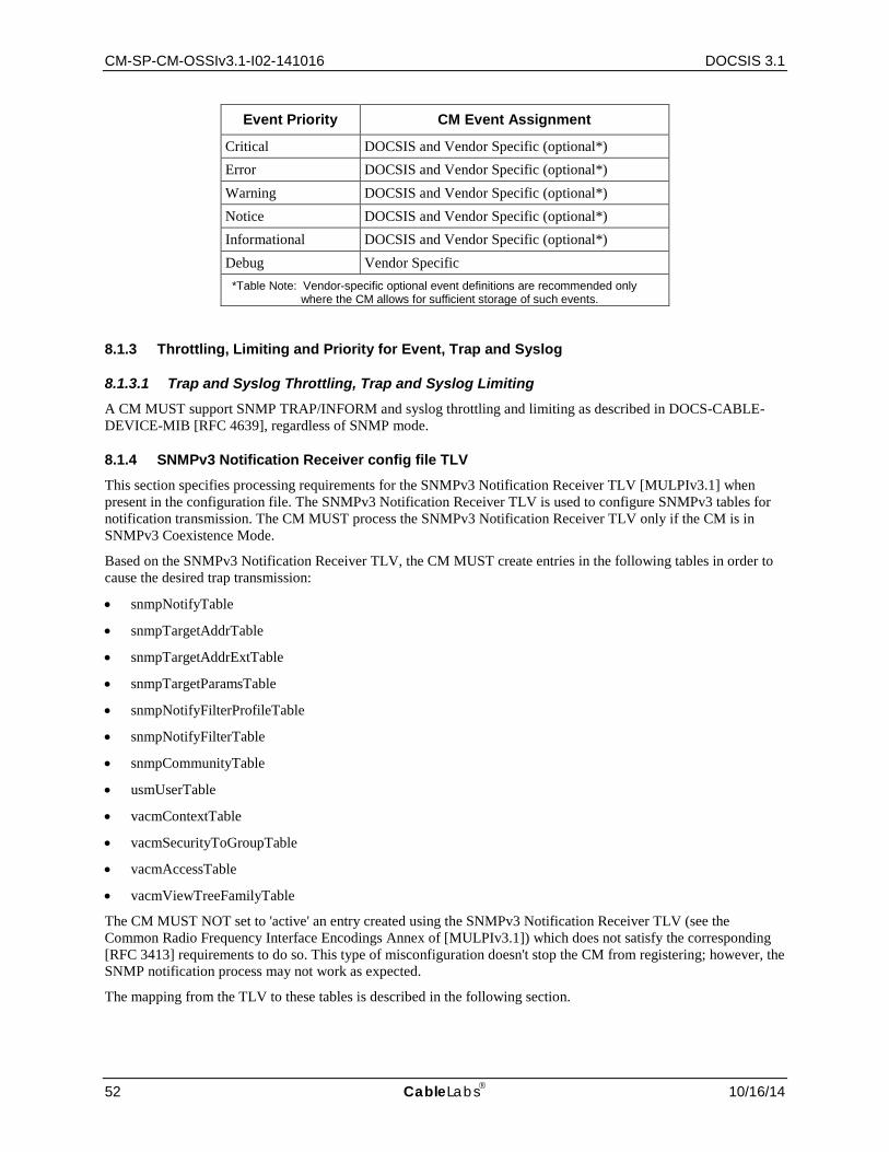
CM-SP-CM-OSSIv3.1-I02-141016 DOCSIS 3.1
52 CableLabs 10/16/14
Event Priority CM Event Assignment
Critical DOCSIS and Vendor Specific (optional*) Error DOCSIS and Vendor Specific (optional*) Warning DOCSIS and Vendor Specific (optional*) Notice DOCSIS and Vendor Specific (optional*) Informational DOCSIS and Vendor Specific (optional*) Debug Vendor Specific
*Table Note: Vendor-specific optional event definitions are recommended only where the CM allows for sufficient storage of such events.
8.1.3 Throttling, Limiting and Priority for Event, Trap and Syslog
8.1.3.1 Trap and Syslog Throttling, Trap and Syslog Limiting A CM MUST support SNMP TRAP/INFORM and syslog throttling and limiting as described in DOCS-CABLE-DEVICE-MIB [RFC 4639], regardless of SNMP mode.
8.1.4 SNMPv3 Notification Receiver config file TLV This section specifies processing requirements for the SNMPv3 Notification Receiver TLV [MULPIv3.1] when present in the configuration file. The SNMPv3 Notification Receiver TLV is used to configure SNMPv3 tables for notification transmission. The CM MUST process the SNMPv3 Notification Receiver TLV only if the CM is in SNMPv3 Coexistence Mode.
Based on the SNMPv3 Notification Receiver TLV, the CM MUST create entries in the following tables in order to cause the desired trap transmission:
• snmpNotifyTable
• snmpTargetAddrTable
• snmpTargetAddrExtTable
• snmpTargetParamsTable
• snmpNotifyFilterProfileTable
• snmpNotifyFilterTable
• snmpCommunityTable
• usmUserTable
• vacmContextTable
• vacmSecurityToGroupTable
• vacmAccessTable
• vacmViewTreeFamilyTable
The CM MUST NOT set to 'active' an entry created using the SNMPv3 Notification Receiver TLV (see the Common Radio Frequency Interface Encodings Annex of [MULPIv3.1]) which does not satisfy the corresponding [RFC 3413] requirements to do so. This type of misconfiguration doesn't stop the CM from registering; however, the SNMP notification process may not work as expected.
The mapping from the TLV to these tables is described in the following section.

Cable Modem Operations Support System Interface Specification CM-SP-CM-OSSIv3.1-I02-141016
10/16/14 CableLabs 53
8.1.4.1 Mapping of TLV fields into created SNMPv3 table rows The following sections illustrate how the fields from the config file SNMPv3 Notification Receiver TLV elements are placed into the SNMPv3 tables. The TLV fields are shown below as:
Table 8–3 - SNMPv3 Notification Receiver TLV Mapping
Sub-TLVs Variable Name Associated MIB Object
SNMPv3 Notification Receiver IPv4 Address TAddress snmpTargetAddrTAddress [RFC 3413] SNMPv3 Notification Receiver IPv6 Address TAddress snmpTargetAddrTAddress [RFC 3413] SNMPv3 Notification Receiver UDP Port Number Port snmpTargetAddrTAddress [RFC 3413] SNMPv3 Notification Receiver Trap Type TrapType see following sections SNMPv3 Notification Receiver Timeout Timeout snmpTargetAddrTimeout [RFC 3413] SNMPv3 Notification Receiver Retries Retries snmpTargetAddrRetryCount [RFC 3413] SNMPv3 Notification Receiver Filtering Parameters FilterOID see following sections SNMPv3 Notification Receiver Security Name SecurityName see following sections
The variable names from Table 8–3 are defined as follows:
<TAddress> A 32-bit IPv4 or IPv6 address of a notification receiver
<Port> A 16-bit UDP Port number on the notification receiver to receive the notifications
<TrapType> Defines the notification type as explained above
<Timeout> 16-bit timeout, in milliseconds to wait before sending a retry of an Inform Notification
<Retries> 16-bit number of times to retry an Inform after the first Inform transmission
<FilterOID> The OID of the snmpTrapOID value that is the root of the MIB subtree that defines all of the notifications to be sent to the Notification Receiver.
<SecurityName> The security name specified on the TLV element, or "@config" if not specified.
Table 8–4 through Table 8–15 are shown in the order that the agent will search down through them when a notification is generated in order to determine to whom to send the notification, and how to fill out the contents of the notification packet.
In configuring entries in these SNMPv3 tables, note the following:
The Community Name for traps in SNMPv1 and SNMPv2 packets is configured as "public". The Security Name in traps and informs in SNMPv3 packets where no security name has been specified is configured as "@config", in which case the security level is "noAuthNoPriv".
Several columnar objects are configured with a value beginning with the string "@config". If these tables are configured through other mechanisms, network operators should not use values beginning with "@config" to avoid conflicts with the mapping process specified here.
8.1.4.1.1 snmpNotifyTable
The snmpNotifyTable is defined in the "Notification MIB Module" section of [RFC 3413].
The CM MUST create two rows with fixed values if one or more SNMPv3 Notification Receiver TLV elements are present in the config file.
Table 8–4 - snmpNotifyTable
Column Name (* = Part of Index) 1st Row Column Value 2nd Row Column Value
* snmpNotifyName "@config_inform" "@config_trap"

CM-SP-CM-OSSIv3.1-I02-141016 DOCSIS 3.1
54 CableLabs 10/16/14
Column Name (* = Part of Index) 1st Row Column Value 2nd Row Column Value
snmpNotifyTag "@config_inform" "@config_trap" snmpNotifyType inform (2) trap (1) snmpNotifyStorageType volatile (2) volatile (2) snmpNotifyRowStatus active (1) active (1)
8.1.4.1.2 snmpTargetAddrTable
The snmpTargetAddrTable is defined in the "Definitions" section of [RFC 3413].
The CM MUST create one row in snmpTargetAddrTable for each entry defined in Table 8–5 - snmpTargetAddrTable.
Thus, two entries are created in this table if both SNMPv3 Notification Receiver IPv4 Address and SNMPv3 Notification Receiver IPv6 Address sub-TLVs are included in the same TLV. All other parameters are the same.
Table 8–5 - snmpTargetAddrTable
Column Name (* = Part of Index) Column Value
* snmpTargetAddrName "@config_n_IPv[4 | 6]" where n is 0..m-1 and m is the number of SNMPv3 Notification Receiver config file TLVs @config_n_IPv4 is for an entry created if SNMPv3 Notification Receiver config file TLV contains <TrapType> of TDomain SnmpUDPAddress @config_n_IPv6 is for an entry created if SNMPv3 Notification Receiver config file TLV contains <TrapType> of TDomain TransportAddressIPv6
snmpTargetAddrTDomain IPv4: snmpUDPDomain [RFC 3417] IPv6: transportDomainUdpIpv6 [RFC 3419]
snmpTargetAddrTAddress (IP Address and UDP Port of the Notification Receiver)
IPv4: SnmpUDPAddress [RFC 3417] OCTET STRING (6) Octets 1-4: <TAddress> Octets 5-6: <Port> IPv6: TransportAddressIPv6 [RFC 3419] OCTET STRING (18) Octets 1-16: <TAddress> Octets 17-18: <Port>
snmpTargetAddrTimeout <Timeout> snmpTargetAddrRetryCount <Retries> snmpTargetAddrTagList "@config_trap" if <TrapType> is 1, 2, or 4
"@config_inform" if <TrapType> is 3 or 5 snmpTargetAddrParams "@config_n" snmpTargetAddrStorageType volatile (2) snmpTargetAddrRowStatus active (1)
8.1.4.1.3 snmpTargetAddrExtTable
The snmpTargetAddrExtTable is defined in the "SNMP Community MIB Module" section of [RFC 3584].
The CM MUST create one row in snmpTargetAddrExtTable for each entry defined in Table 8–5, snmpTargetAddrTable.
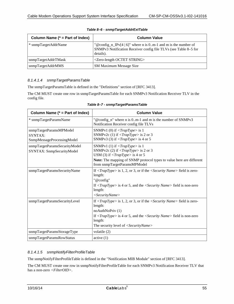
Cable Modem Operations Support System Interface Specification CM-SP-CM-OSSIv3.1-I02-141016
10/16/14 CableLabs 55
Table 8–6 - snmpTargetAddrExtTable
Column Name (* = Part of Index) Column Value
* snmpTargetAddrName "@config_n_IPv[4 | 6]" where n is 0..m-1 and m is the number of SNMPv3 Notification Receiver config file TLVs (see Table 8–5 for details).
snmpTargetAddrTMask <Zero-length OCTET STRING> snmpTargetAddrMMS SM Maximum Message Size
8.1.4.1.4 snmpTargetParamsTable
The snmpTargetParamsTable is defined in the "Definitions" section of [RFC 3413].
The CM MUST create one row in snmpTargetParamsTable for each SNMPv3 Notification Receiver TLV in the config file.
Table 8–7 - snmpTargetParamsTable
Column Name (* = Part of Index) Column Value
* snmpTargetParamsName "@config_n" where n is 0..m-1 and m is the number of SNMPv3 Notification Receiver config file TLVs
snmpTargetParamsMPModel SYNTAX: SnmpMessageProcessingModel
SNMPv1 (0) if <TrapType> is 1 SNMPv2c (1) if <TrapType> is 2 or 3 SNMPv3 (3) if <TrapType> is 4 or 5
snmpTargetParamsSecurityModel SYNTAX: SnmpSecurityModel
SNMPv1 (1) if <TrapType> is 1 SNMPv2c (2) if <TrapType> is 2 or 3 USM (3) if <TrapType> is 4 or 5 Note: The mapping of SNMP protocol types to value here are different from snmpTargetParamsMPModel
snmpTargetParamsSecurityName If <TrapType> is 1, 2, or 3, or if the <Security Name> field is zero-length: "@config" If <TrapType> is 4 or 5, and the <Security Name> field is non-zero length: <SecurityName>
snmpTargetParamsSecurityLevel If <TrapType> is 1, 2, or 3, or if the <Security Name> field is zero-length: noAuthNoPriv (1) If <TrapType> is 4 or 5, and the <Security Name> field is non-zero length: The security level of <SecurityName>
snmpTargetParamsStorageType volatile (2) snmpTargetParamsRowStatus active (1)
8.1.4.1.5 snmpNotifyFilterProfileTable
The snmpNotifyFilterProfileTable is defined in the "Notification MIB Module" section of [RFC 3413].
The CM MUST create one row in snmpNotifyFilterProfileTable for each SNMPv3 Notification Receiver TLV that has a non-zero <FilterOID>.
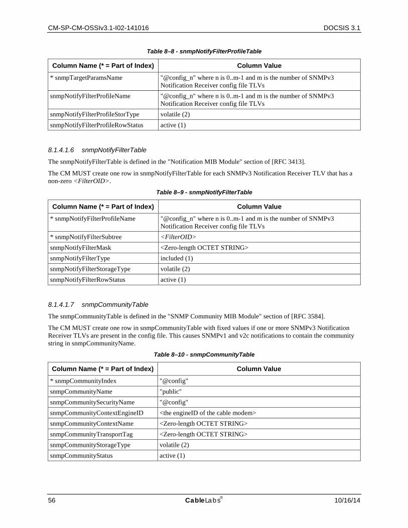
CM-SP-CM-OSSIv3.1-I02-141016 DOCSIS 3.1
56 CableLabs 10/16/14
Table 8–8 - snmpNotifyFilterProfileTable
Column Name (* = Part of Index) Column Value
* snmpTargetParamsName "@config_n" where n is 0..m-1 and m is the number of SNMPv3 Notification Receiver config file TLVs
snmpNotifyFilterProfileName "@config_n" where n is 0..m-1 and m is the number of SNMPv3 Notification Receiver config file TLVs
snmpNotifyFilterProfileStorType volatile (2) snmpNotifyFilterProfileRowStatus active (1)
8.1.4.1.6 snmpNotifyFilterTable
The snmpNotifyFilterTable is defined in the "Notification MIB Module" section of [RFC 3413].
The CM MUST create one row in snmpNotifyFilterTable for each SNMPv3 Notification Receiver TLV that has a non-zero <FilterOID>.
Table 8–9 - snmpNotifyFilterTable
Column Name (* = Part of Index) Column Value
* snmpNotifyFilterProfileName "@config_n" where n is 0..m-1 and m is the number of SNMPv3 Notification Receiver config file TLVs
* snmpNotifyFilterSubtree <FilterOID> snmpNotifyFilterMask <Zero-length OCTET STRING> snmpNotifyFilterType included (1) snmpNotifyFilterStorageType volatile (2) snmpNotifyFilterRowStatus active (1)
8.1.4.1.7 snmpCommunityTable
The snmpCommunityTable is defined in the "SNMP Community MIB Module" section of [RFC 3584].
The CM MUST create one row in snmpCommunityTable with fixed values if one or more SNMPv3 Notification Receiver TLVs are present in the config file. This causes SNMPv1 and v2c notifications to contain the community string in snmpCommunityName.
Table 8–10 - snmpCommunityTable
Column Name (* = Part of Index) Column Value
* snmpCommunityIndex "@config" snmpCommunityName "public" snmpCommunitySecurityName "@config" snmpCommunityContextEngineID <the engineID of the cable modem> snmpCommunityContextName <Zero-length OCTET STRING> snmpCommunityTransportTag <Zero-length OCTET STRING> snmpCommunityStorageType volatile (2) snmpCommunityStatus active (1)
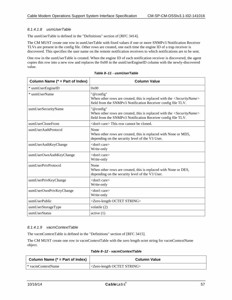
Cable Modem Operations Support System Interface Specification CM-SP-CM-OSSIv3.1-I02-141016
10/16/14 CableLabs 57
8.1.4.1.8 usmUserTable
The usmUserTable is defined in the "Definitions" section of [RFC 3414].
The CM MUST create one row in usmUserTable with fixed values if one or more SNMPv3 Notification Receiver TLVs are present in the config file. Other rows are created, one each time the engine ID of a trap receiver is discovered. This specifies the user name on the remote notification receivers to which notifications are to be sent.
One row in the usmUserTable is created. When the engine ID of each notification receiver is discovered, the agent copies this row into a new row and replaces the 0x00 in the usmUserEngineID column with the newly-discovered value.
Table 8–11 - usmUserTable
Column Name (* = Part of Index) Column Value
* usmUserEngineID 0x00 * usmUserName "@config"
When other rows are created, this is replaced with the <SecurityName> field from the SNMPv3 Notification Receiver config file TLV.
usmUserSecurityName "@config" When other rows are created, this is replaced with the <SecurityName> field from the SNMPv3 Notification Receiver config file TLV.
usmUserCloneFrom <don't care> This row cannot be cloned. usmUserAuthProtocol None
When other rows are created, this is replaced with None or MD5, depending on the security level of the V3 User.
usmUserAuthKeyChange <don't care> Write-only
usmUserOwnAuthKeyChange <don't care> Write-only
usmUserPrivProtocol None When other rows are created, this is replaced with None or DES, depending on the security level of the V3 User.
usmUserPrivKeyChange <don't care> Write-only
usmUserOwnPrivKeyChange <don't care> Write-only
usmUserPublic <Zero-length OCTET STRING> usmUserStorageType volatile (2) usmUserStatus active (1)
8.1.4.1.9 vacmContextTable
The vacmContextTable is defined in the "Definitions" section of [RFC 3415].
The CM MUST create one row in vacmContextTable with the zero length octet string for vacmContextName object.
Table 8–12 - vacmContextTable
Column Name (* = Part of Index) Column Value
* vacmContextName <Zero-length OCTET STRING>
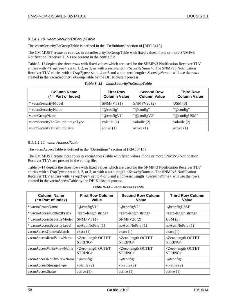
CM-SP-CM-OSSIv3.1-I02-141016 DOCSIS 3.1
58 CableLabs 10/16/14
8.1.4.1.10 vacmSecurityToGroupTable
The vacmSecurityToGroupTable is defined in the "Definitions" section of [RFC 3415].
The CM MUST create three rows in vacmSecurityToGroupTable with fixed values if one or more SNMPv3 Notification Receiver TLVs are present in the config file.
Table 8–13 depicts the three rows with fixed values which are used for the SNMPv3 Notification Receiver TLV entries with <TrapType> set to 1, 2, or 3, or with a zero-length <SecurityName>. The SNMPv3 Notification Receiver TLV entries with <TrapType> set to 4 or 5 and a non-zero length <SecurityName> will use the rows created in the vacmSecurityToGroupTable by the DH Kickstart process.
Table 8–13 - vacmSecurityToGroupTable
Column Name (* = Part of Index)
First Row Column Value
Second Row Column Value
Third Row Column Value
* vacmSecurityModel SNMPV1 (1) SNMPV2c (2) USM (3) * vacmSecurityName "@config" "@config" "@config" vacmGroupName "@configV1" "@configV2" "@configUSM" vacmSecurityToGroupStorageType volatile (2) volatile (2) volatile (2) vacmSecurityToGroupStatus active (1) active (1) active (1)
8.1.4.1.11 vacmAccessTable
The vacmAccessTable is defined in the "Definitions" section of [RFC 3415].
The CM MUST create three rows in vacmAccessTable with fixed values if one or more SNMPv3 Notification Receiver TLVs are present in the config file.
Table 8–14 depicts the three rows with fixed values which are used for the SNMPv3 Notification Receiver TLV entries with <TrapType> set to 1, 2, or 3, or with a zero-length <SecurityName>. The SNMPv3 Notification Receiver TLV entries with <TrapType> set to 4 or 5 and a non-zero length <SecurityName> will use the rows created in the vacmAccessTable by the DH Kickstart process.
Table 8–14 - vacmAccessTable
Column Name (* = Part of Index)
First Row Column Value
Second Row Column Value
Third Row Column Value
* vacmGroupName "@configV1" "@configV2" "@configUSM" * vacmAccessContextPrefix <zero-length string> <zero-length string> <zero-length string> * vacmAccessSecurityModel SNMPV1 (1) SNMPV2c (2) USM (3) * vacmAccessSecurityLevel noAuthNoPriv (1) noAuthNoPriv (1) noAuthNoPriv (1) vacmAccessContextMatch exact (1) exact (1) exact (1) vacmAccessReadViewName <Zero-length OCTET
STRING> <Zero-length OCTET STRING>
<Zero-length OCTET STRING>
vacmAccessWriteViewName <Zero-length OCTET STRING>
<Zero-length OCTET STRING>
<Zero-length OCTET STRING>
vacmAccessNotifyViewName "@config" "@config" "@config" vacmAccessStorageType volatile (2) volatile (2) volatile (2) vacmAccessStatus active (1) active (1) active (1)

Cable Modem Operations Support System Interface Specification CM-SP-CM-OSSIv3.1-I02-141016
10/16/14 CableLabs 59
8.1.4.1.12 vacmViewTreeFamilyTable
The vacmViewTreeFamilyTable is defined in the "Definitions" section of [RFC 3415].
The CM MUST create one row in vacmViewTreeFamilyTable with fixed values if one or more SNMPv3 Notification Receiver TLVs are present in the config file.
This row is used for the SNMPv3 Notification Receiver TLV entries with <TrapType> set to 1, 2, or 3 or with a zero-length <SecurityName>. The SNMPv3 Notification Receiver TLV entries with <TrapType> set to 4 or 5 and a non-zero length <SecurityName> will use the rows created in the vacmViewTreeFamilyTable by the DH Kickstart process.
Table 8–15 - vacmViewTreeFamilyTable
Column Name (* = Part of Index) Column Value
* vacmViewTreeFamilyViewName "@config" * vacmViewTreeFamilySubtree 1.3 vacmViewTreeFamilyMask <default from MIB> vacmViewTreeFamilyType included (1) vacmViewTreeFamilyStorageType volatile (2) vacmViewTreeFamilyStatus active (1)
8.1.5 Non-SNMP Fault Management Protocols
The OSS can use a variety of tools and techniques to examine faults at multiple layers. For the IP layer, useful non-SNMP based tools include ping (ICMP Echo and Echo Reply), and trace route (UDP and various ICMP Destination Unreachable flavors). The CM MUST respond to ICMP Echo Request (ping) messages received through its CMCI [CMCIv3.0] interface(s) to enable local connectivity testing from a subscriber's PC to the modem. The CM MUST support IP end-station generation of ICMP error messages and processing of all ICMP messages.
Syslog requirements are defined in Section 8.1.2.
8.2 Configuration Management The CM is required to support the SNMP protocol interface as specified in Section 6. Section 7 defines the SNMP MIB objects that are required to be supported by a CM.
In addition to the SNMP interface to modify the attribute values stored in the CM, vendors may specify additional methods such as Command Line Interface (CLI) or an HTTP interface, as examples. Irrespective of the method used, it is necessary to assure the data integrity as a result of changes performed using different interfaces. For example, when the attribute value is modified using one management interface, this changed value is reported when that attribute is accessed from any of the other interfaces. When a change in the value of the attribute does not succeed, requesting the same change from another interface should also results in failure (assuming the same level of access control for all those interfaces for the specific operation). If an event is generated as a result of making the change in one management interface, this is reported independent of which method was used to initiate the change.
8.2.1 Version Control
The CM MUST support software revision and operational parameter configuration interrogation.
The CM includes the hardware version, boot ROM image version, vendor name, current software version, and model number in the sysDescr object (from [RFC 3418]).
The CM MUST support docsDevSwCurrentVers MIB object (from [RFC 4639]) and report the current software version of the CM.

CM-SP-CM-OSSIv3.1-I02-141016 DOCSIS 3.1
60 CableLabs 10/16/14
The CM MUST report for the sysDescr object the Type and Value fields identified in Table 8–16:
Table 8–16 - sysDescr Format
Type Value
HW_REV <Hardware Version> VENDOR <Vendor Name> BOOTR <Boot ROM Version>
SW_REV <Software Version> MODEL <Model Number>
The CM MUST report each Type and Value for the sysDescr object identified in Table 8–16; with each Type field and corresponding Value field separated with a colon followed by a single blank space and each Type-Value pair is separated by a semicolon followed by a single blank space. The correct format is illustrated below.
HW_REV: <value>; VENDOR: <value>; BOOTR: <value>; SW_REV: <value>; MODEL: <value>
For instance, a sysDescr of a CM of vendor X, hardware version 5.2, boot ROM image version 1.4, software version 2.2, and model number Z is formatted as follows:
any text<<HW_REV: 5.2; VENDOR: X; BOOTR: 1.4; SW_REV: 2.2; MODEL: Z>>any text
The CM MUST report all of the information necessary in determining what software the CM is capable of being upgraded to. If any fields in Table 8–16 are not applicable, the CM MUST report "NONE" as the value.
For instance, a sysDescr of a CM of vendor X, hardware version 5.2, no boot ROM image information, software version 2.2, and model number Z is formatted as follows:
any text<<HW_REV: 5.2; VENDOR: X; BOOTR: NONE; SW_REV: 2.2; MODEL: Z>>any text
The intent of specifying the format of sysDescr is to define how to report information in a consistent manner so that sysDescr field information can be programmatically parsed. This format specification does not intend to restrict the vendor's hardware version numbering policy.
8.2.2 System Configuration
The CM MUST support system configuration by configuration file, configuration-file-based SNMP encoded object, and SNMP Set operation. The CM MUST support any valid configuration file created in accordance with configuration file size limitations defined in the CM Configuration Interface Specification Annex in [MULPIv3.1].
8.2.3 Secure Software Download
The CM Secure Software Download (SSD) process is documented in detail in the Secure Software Download section of [SECv3.0].
The CM MUST use the Secure Software Download mechanism to perform software upgrade regardless of the DOCSIS specification version the CMTS it is connected to complies with.
There are two available Secure Software Download schemes: the manufacturer control scheme and the operator control scheme.
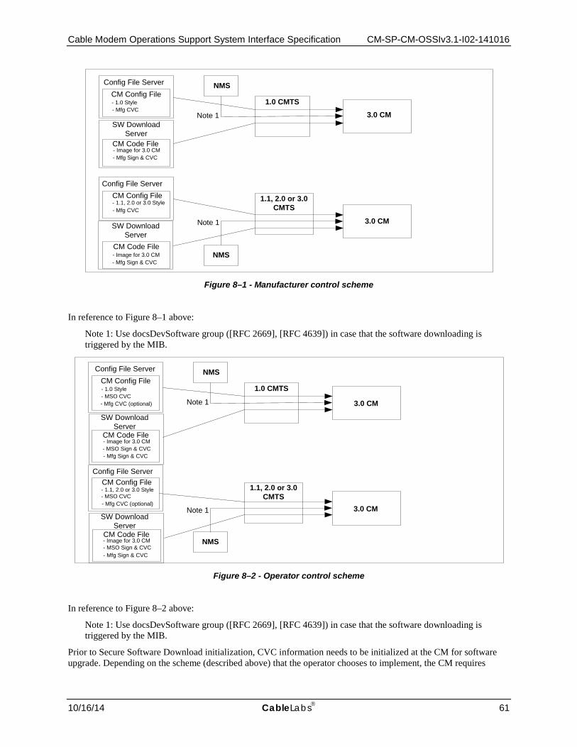
Cable Modem Operations Support System Interface Specification CM-SP-CM-OSSIv3.1-I02-141016
10/16/14 CableLabs 61
Figure 8–1 - Manufacturer control scheme
In reference to Figure 8–1 above:
Note 1: Use docsDevSoftware group ([RFC 2669], [RFC 4639]) in case that the software downloading is triggered by the MIB.
Figure 8–2 - Operator control scheme
In reference to Figure 8–2 above:
Note 1: Use docsDevSoftware group ([RFC 2669], [RFC 4639]) in case that the software downloading is triggered by the MIB.
Prior to Secure Software Download initialization, CVC information needs to be initialized at the CM for software upgrade. Depending on the scheme (described above) that the operator chooses to implement, the CM requires
Config File ServerCM Config File
CM Config File
CM Code File
NMS
1.0 CMTS3.0 CM
NMS
1.1, 2.0 or 3.0 CMTS
- 1.0 Style- Mfg CVC
- 1.1, 2.0 or 3.0 Style
Note 1
Note 1
Config File Server
- Mfg CVC
3.0 CMSW Download Server
- Mfg Sign & CVC- Image for 3.0 CM
SW Download Server
- Mfg Sign & CVC- Image for 3.0 CMCM Code File
Config File ServerCM Config File
CM Config File
CM Code File
NMS
1.0 CMTS
NMS
- 1.0 Style- MSO CVC
- MSO Sign & CVC
Note 1
Note 1
- Mfg CVC (optional)
- Mfg CVC (optional)
- 1.1, 2.0 or 3.0 Style- MSO CVC
Config File Server
3.0 CM
3.0 CM
1.1, 2.0 or 3.0 CMTS
SW Download Server
- Image for 3.0 CM
- Mfg Sign & CVC
SW Download Server
- Image for 3.0 CM
- Mfg Sign & CVC- MSO Sign & CVC
CM Code File
CM-SP-CM-OSSIv3.1-I02-141016 DOCSIS 3.1
62 CableLabs 10/16/14
appropriate CVC information in the configuration file. It is recommended that CVC information always be present in the configuration file so that a device will always have the CVC information initialized and read if the operator decides to use a SNMP-initiated upgrade as a method to trigger a Secure Software Download operation. If the operator decides to use a configuration-file-initiated upgrade as a method to trigger Secure Software Download, CVC information needs to be present in the configuration file at the time the CM is rebooted to get the configuration file that will trigger the upgrade only.
There are two methods to trigger Secure Software Download: SNMP-initiated and configuration-file-initiated. The CM MUST support both SNMP-initiated and configuration-file-initiated methods to trigger Secure Software Download.
The following describes the SNMP-initiated mechanism. Prior to a SNMP-initiated upgrade, a CM MUST have valid X.509-compliant code verification certificate information. From a network management station:
1. Set docsDevSwServerAddressType to 'ipv4' or 'ipv6'. 2. Set docsDevSwServerAddress to the IPv4 or IPv6 address of the Software Download server for software
upgrades. 3. Set docsDevSwFilename to the file path name of the software upgrade image. 4. Set docsDevSwAdminStatus to 'upgradeFromMgt'.
If docsDevSwAdminStatus is set to 'ignoreProvisioningUpgrade', the CM MUST ignore any software download configuration file setting and not attempt a configuration file initiated upgrade.
The CM MUST preserve the value of docsDevSwAdminStatus across reset/reboots until over-written from an SNMP manager or by a TLV-11 [MULPIv3.1] setting in the CM configuration file. That is, the value of docsDevSwAdminStatus is required to persist across CM reboots.
The CM MUST report 'allowProvisioningUpgrade' as the default value of docsDevSwAdminStatus until it is over-written by 'ignoreProvisioningUpgrade', following a successful SNMP-initiated software upgrade or otherwise altered by the management station.
The CM MUST preserve the value of docsDevSwOperStatus across reset/reboots. That is, the value of the CM's docsDevSwOperStatus object is required to persist across resets to report the outcome of the last software upgrade attempt.
After the CM has completed a configuration-file-initiated secure software upgrade, the CM MUST reboot and become operational with the correct software image as specified in [MULPIv3.1]. After the CM is registered following a reboot after a configuration file initiated secure software upgrade, the CM MUST adhere to the following requirements:
• The CM MUST report 'allowProvisioningUpgrade' as the value for docsDevSwAdminStatus.
• The CM MAY report the filename of the software currently operating on the CM as the value for docsDevSwFilename.
• The CM MAY report the IP address of the Software Download server containing the software that is currently operating on the CM as the value for docsDevSwServerAddress.
• The CM MUST report 'completeFromProvisioning' as the value for docsDevSwOperStatus.
• The CM MUST report the current version of the software that is operating on the CM as the value for docsDevSwCurrentVers.
After the CM has completed an SNMP-initiated secure software upgrade, the CM MUST reboot and become operational with the correct software image as specified in [MULPIv3.1]. After the CM is registered following a reboot after an SNMP-initiated secure software upgrade, the CM MUST adhere to the following requirements:
• The CM MUST report 'ignoreProvisioningUpgrade' as the value for docsDevSwAdminStatus.
• The CM MAY report the IP address of the Software Download server containing the software that is currently operating on the CM as the value for docsDevSwServerAddress.
• The CM MUST report 'completeFromMgt' as the value for docsDevOperStatus.

Cable Modem Operations Support System Interface Specification CM-SP-CM-OSSIv3.1-I02-141016
10/16/14 CableLabs 63
• The CM MUST report the current version of the software that is operating on the CM as the value for docsDevSwCurrentVers.
If the value of docsDevSwAdminStatus is 'ignoreProvisioningUpgrade', the CM MUST ignore any software upgrade value that is optionally included in the CM configuration file and become operational with the current software image after the CM is registered. After the CM is registered following a reboot with a software upgrade value in the CM configuration file, the CM MUST adhere to the following requirements:
• The CM MUST report 'ignoreProvisioningUpgrade' as the value for docsDevSwAdminStatus.
• The CM MAY report the filename of the software currently operating on the CM as the value for docsDevSwFilename.
• The CM MAY report the IP address of the Software Download server containing the software that is currently operating on the CM as the value for docsDevSwServerAddress.
• The CM MUST report 'completeFromMgt' as the value for docsDevSwOperStatus.
• The CM MUST report the current version of the software that is operating on the CM as the value for docsDevSwCurrentVers.
Retries due to a power loss or reset are only required for an SNMP-initiated upgrade. If a power loss or reset occurs during a configuration-file-initiated upgrade, the CM will follow the upgrade TLV directives in the configuration file upon reboot. It will not retry the previous upgrade. The config file upgrade TLVs essentially provides a retry mechanism that is not available for an SNMP-initiated upgrade.
If a CM suffers a loss of power or resets during an SNMP-initiated upgrade, the CM MUST resume the upgrade without requiring manual intervention. When the CM resumes the upgrade process after a reset that occurred during an SNMP-initiated software upgrade, the CM MUST adhere to the following requirements:
• The CM MUST report 'upgradeFromMgt' as the value for docsDevSwAdminStatus.
• The CM MUST report the filename of the software image to be upgraded as the value for docsDevSwFilename.
• The CM MUST report the IP address of the Software Download server containing the software upgrade image to be upgraded as the value for docsDevSwServerAddress.
• The CM MUST report 'inProgress' as the value for docsDevSwOperStatus.
• The CM MUST report the current version of software that is operating on the CM as the value for docsDevSwCurrentVers.
In the case where the CM reaches the maximum number of TFTP Download Retries, as specified in the Parameters and Constraints Annex of [MULPIv3.1], resulting from multiple losses of power or resets during an SNMP-initiated upgrade, the CM MUST behave as specified in [MULPIv3.1]. In this case, after the CM is registered, the CM MUST adhere to the following requirements:
• The CM MUST report 'allowProvisioningUpgrade' as the value for docsDevSwAdminStatus.
• The CM MUST report the filename of the software that failed the upgrade process as the value for docsDevSwFilename.
• The CM MUST report the IP address of the Software Download server containing the software that failed the upgrade process as the value for docsDevSwServerAddress.
• The CM MUST report 'other' as the value for docsDevSwOperStatus.
• The CM MUST report the current version of software that is operating on the CM as the value for docsDevSwCurrentVers.
When the CM reboots following a reset that occurred during a configuration file-initiated software download, the CM MUST ignore the fact that a previous upgrade was in progress and either not perform an upgrade if no upgrade TLVs are present in the config file, or if upgrade TLVs are present, take the action described in the requirements in the section "Downloading Cable Modem Operating Software" of [MULPIv3.1], at the time of the reboot.
CM-SP-CM-OSSIv3.1-I02-141016 DOCSIS 3.1
64 CableLabs 10/16/14
In the case where the CM had a configuration-file-initiated upgrade in progress during a reset and if there are no upgrade TLVs in the config file upon reboot, the CM MUST adhere to the following requirements:
• The CM MUST report 'allowProvisioningUpgrade' as the value for docsDevSwAdminStatus.
• The CM MAY report the filename of the current software image as the value for docsDevSwFilename.
• The CM MAY report the IP address of the Software Download server containing the software that is currently operating in the CM as the value for docsDevSwServerAddress.
• The CM MUST report 'other' as the value for docsDevSwOperStatus.
• The CM MUST report the current version of software that is operating on the CM as the value for docsDevSwCurrentVers.
In the case where the CM had a configuration-file-initiated upgrade in progress during a reset, if there are upgrade TLVs in the config file upon reboot, the CM MUST adhere to the following requirements:
• The CM MUST report 'allowProvisioningUpgrade' as the value for docsDevSwAdminStatus.
• The CM MUST report the filename contained in TLV-9 [MULPIv3.1] of the config file as the value for docsDevSwFilename.
• The CM MUST report the IP address of the Software Download server containing the software to be loaded into the CM as the value for docsDevSwServerAddress, per the requirements stated in the section "Downloading Cable Modem Operating Software" of [MULPIv3.1].
• The CM MUST report 'inProgress' as the value for docsDevSwOperStatus.
• The CM MUST report the current version of software that is operating on the CM as the value for docsDevSwCurrentVers.
If a CM exhausts the required number of TFTP Request Retries, as specified in the Parameters and Constraints Annex of [MULPIv3.1], the CM MUST behave as specified in [MULPIv3.1]. If a CM exhausts the maximum number of configured TFTP Request Retries without successfully downloading the specified file, the CM MUST fall back to last known working image and proceed to an operational state. After a CM falls back to the last known working software image after exhausting the maximum number of configured TFTP Request Retries without successfully downloading the specified file, the CM MUST adhere to the following requirements:
• The CM MUST report 'allowProvisioningUpgrade' as the value for docsDevSwAdminStatus.
• The CM MUST report the filename of the software that failed the upgrade process as the value for docDevSwFilename.
• The CM MUST report the IP address of the Software Download server containing the software that failed the upgrade process as the value for docsDevSwServerAddress.
• The CM MUST report 'failed' as the value for docsDevSwOperStatus.
• The CM MUST report the current version of software that is operating on the CM as the value for docsDevSwCurrentVers.
In the case where a CM successfully downloads (or detects during download) an image that is not intended for the CM device, the CM behaves as specified in the section "Downloading Cable Modem Operating Software" of [MULPIv3.1]. If a CM successfully downloads an image that is not intended for it, or detects during the download of a software image that the image is not for itself, the CM MUST adhere to the following requirements:
• The CM MUST report 'allowProvisioningUpgrade' as the value for docsDevSwAdminStatus.
• The CM MUST report the filename of the software that failed the upgrade as the value for docsDevSwFilename.
• The CM MUST report the IP address of the Software Download server containing the software that failed the upgrade process as the value for docsDevSwServerAddress.

Cable Modem Operations Support System Interface Specification CM-SP-CM-OSSIv3.1-I02-141016
10/16/14 CableLabs 65
• The CM MUST report 'other' as the value for docsDevSwOperStatus.
• The CM MUST report the current version of software that is operating on the CM as the value for docsDevSwCurrentVers.
In the case where the CM determines that the download image is damaged or corrupted, the CM MUST reject the newly downloaded image. The CM MAY re-attempt to download if the maximum number of TFTP Download Retries has not been reached, as specified in the Parameters and Constants Annex of [MULPIv3.1]. If the CM chooses not to retry, the CM MUST fall back to the last known working image and proceed to an operational state and generate appropriate event notification as specified in Annex D. If the CM does not retry to download a corrupted software image and falls back to the last known working software image, the CM MUST adhere to the following requirements:
• The CM MUST report 'allowProvisioningUpgrade' as the value for docsDevSwAdminStatus.
• The CM MUST report the filename of the software that failed the upgrade as the value for docsDevSwFilename.
• The CM MUST report the IP address of the Software Download server containing the software that failed the upgrade process as the value for docsDevSwServerAddress.
• The CM MUST report 'other' as the value for docsDevSwOperStatus.
• The CM MUST report the current version of software that is operating on the CM as the value for docsDevSwCurrentVers.
In the case where the CM determines that the image is damaged or corrupted, the CM MAY re-attempt to download the new image if the maximum number of TFTP Download Retries has not been reached, as specified in Parameters and Constraints Annex of [MULPIv3.1]. On the final consecutive failed retry of the CM software download attempt, the CM MUST fall back to the last known working image and proceed to an operational state and generate appropriate event notification as specified in Annex B. If a CM falls back to the last known working software image after failing the defined consecutive retry attempts, the CM MUST send two notifications, one to notify that the max retry limit has been reached, and another to notify that the image is damaged. Immediately after the CM reaches the operational state after failing the defined consecutive retry attempts to download a software image and falling back to the last known working software image, the CM MUST adhere to the following requirements:
• The CM MUST report 'allowProvisioningUpgrade' as the value for docsDevSwAdminStatus.
• The CM MUST report the filename of the software that failed the upgrade as the value for docsDevSwFilename.
• The CM MUST report the IP address of the Software Download server containing the software that failed the upgrade process as the value for docsDevSwServerAddress.
• The CM MUST report 'other' as the value for docsDevSwOperStatus.
• The CM MUST report the current version of software that is operating on the CM as the value for docsDevSwCurrentVers.
8.2.4 CM configuration files, TLV-11 and MIB OIDs/values The following sections define the use of CM configuration file TLV-11 elements and the CM rules for translating TLV-11 elements into SNMP PDU (SNMP MIB OID/instance and MIB OID/instance value combinations; also referred to as SNMP varbinds).
This section also defines the CM behaviors, or state transitions, after either pass or fail of the CM configuration process.
For TLV-11 definitions, refer to the Common Radio Frequency Interface Encodings Annex of [MULPIv3.1].

CM-SP-CM-OSSIv3.1-I02-141016 DOCSIS 3.1
66 CableLabs 10/16/14
8.2.4.1 CM configuration file TLV-11 element translation (to SNMP PDU) TLV-11 translation defines the process used by the CM to convert CM configuration file information (TLV-11 elements) into SNMP PDU (varbinds). The CM is required to translate CM configuration file TLV-11 elements into a single SNMP PDU containing (n) MIB OID/instance and value components (SNMP varbinds). Once a single SNMP PDU is constructed, the CM processes the SNMP PDU and determines the CM configuration pass/fail based on the rules for CM configuration file processing, described below. However, if a CM is not physically capable of processing a potentially large single CM configuration file-generated SNMP PDU, the CM is still required to behave as if all MIB OID/instance and value components (SNMP varbinds) from CM configuration file TLV-11 elements are processed as a single SNMP PDU.
In accordance with [RFC 3416], the single CM configuration file generated SNMP PDU will be treated "as if simultaneous" and the CM MUST behave consistently, regardless of the order in which TLV-11 elements appear in the CM configuration file, or SNMP PDU.
The CM configuration file MUST NOT contain duplicate TLV-11 elements (duplicate means SNMP MIB object has identical OID). If the configuration file received by the CM contains duplicate TLV-11 elements, the CM MUST reject the configuration file.
8.2.4.1.1 Rules for CreateAndGo and CreateAndWait
The CM MUST support 'createAndGo' [RFC 2579] for row creation.
The CM MAY support 'createAndWait' [RFC 2579]. If the CM supports 'createAndWait', there is the constraint that CM configuration file TLV-11 elements MUST NOT be duplicated (all SNMP MIB OID/instance must be unique). If a CM constructs an SNMP PDU from a CM configuration file TLV-11 element that contains an SNMP 'createAndWait' value for a given SNMP MIB OID/instance, the CM MUST NOT also include in that SNMP PDU an SNMP Active value for the same SNMP MIB OID/instance (and vice versa). A CM MAY accept a configuration file that contains a TLV-11 'createAndWait' element if the intended result is to create an SNMP table row which will remain in the SNMP 'notReady' or SNMP 'notInService' state until a non-configuration file SNMP PDU is issued, from an SNMP manager, to update the SNMP table row status.
Both SNMP 'notReady' and SNMP 'notInService' states are valid table row states after an SNMP 'createAndWait' instruction.
8.2.4.2 CM configuration TLV-11 elements not supported by the CM If any CM configuration file TLV-11 elements translate to SNMP MIB OIDs that are not MIB OID elements supported by the CM, then the CM MUST ignore those SNMP varbinds, and treat them as if they had not been present, for the purpose of CM configuration. This means that the CM will ignore SNMP MIB OIDs for other vendors' private MIBs as well as standard MIB elements that the CM does not support.
CMs that do not support SNMP CreateAndWait for a given SNMP MIB table MUST ignore, and treat as if not present, the set of columns associated with the SNMP table row.
If any CM configuration file TLV-11 element(s) are ignored, then the CM MUST report them via the CM configured notification mechanism(s), after the CM is registered. The CM MUST report ignored configuration file TLV-11 elements following the notification method in accordance with Section 8.1.2.3.
8.2.4.3 CM state after CM configuration file processing success After successful CM configuration via CM configuration file, the CM MUST proceed to register with the CMTS and proceed to its operational state.
8.2.4.4 CM state after CM configuration file processing failure If any CM configuration file generated SNMP PDU varbind performs an illegal set operation (illegal, bad, or inconsistent value) to any MIB OID/instance supported by the CM, the CM MUST reject the configuration file. The CM MUST NOT proceed with CM registration if it fails to download and process the configuration file.

Cable Modem Operations Support System Interface Specification CM-SP-CM-OSSIv3.1-I02-141016
10/16/14 CableLabs 67
8.3 Accounting Management [CCAP-OSSIv3.1] defines an accounting management interface for subscriber usage-based applications denominated Subscriber Account Management Interface Specification (SAMIS). SAMIS is defined to enable prospective vendors of Cable Modems and Cable Modem Termination Systems to address the operational requirements of subscriber account management in a uniform and consistent manner.
8.3.1 Subscriber Usage Billing and class of services
The [MULPIv3.1] specification uses the concept of class of service, as the term to indicate the type of data services a CM requests and receives from the CMTS, (see [MULPIv3.1]). From a high level perspective, class of services are observed as subscriber types (e.g., residential or business) and the DOCSIS RFI MAC layer parameters fulfill the subscriber service needs.
8.3.1.1 DOCSIS 1.1 Quality of Service (QoS) The [MULPIv3.1] specification provides a mechanism for a CM to register with its CMTS and to configure itself based on external QoS parameters when it is powered up or reset.
To quote (in part) from the Theory of Operation section of [MULPIv3.1]:
The principal mechanism for providing enhanced QoS is to classify packets traversing the RF MAC interface into a Service Flow. A Service Flow is a unidirectional flow of packets that provide a particular Quality of Service. The CM and the CMTS provide this QoS by shaping, policing, and prioritizing traffic according to the QoS Parameter Set defined for the Service Flow.
The requirements for Quality of Service include:
• A configuration and registration function for pre-configuring CM-based QoS Service Flows and traffic parameters.
• Utilization of QoS traffic parameters for downstream Service Flows.
• Classification of packets arriving from the upper layer service interface to a specific active Service Flow.
• Grouping of Service Flow properties into named Service Classes, so upper layer entities and external applications (at both the CM and the CMTS) can request Service Flows with desired QoS parameters in a globally consistent way.
A Service Class Name (SCN) is defined in the CMTS by provisioning (see Annex H). An SCN provides an association to a QoS Parameter Set. Service Flows that are created using an SCN are considered to be "named" Service Flows. The SCN identifies the service characteristics of a Service Flow to external systems such as a billing system or customer service system. For consistency in billing, operators should ensure that SCNs are unique within an area serviced by the same BSS that utilizes this interface. A descriptive SCN might be something like PrimaryUp, GoldUp, VoiceDn, or BronzeDn to indicate the nature and direction of the Service Flow to the external system.
A Service Package implements a Service Level Agreement (SLA) between the MSO and its Subscribers on the RFI interface. A Service Package might be known by a name such as Gold, Silver, or Bronze. A Service Package is itself implemented by the set of named Service Flows (using SCNs) that are placed into a CM Configuration File1 that is stored on a Config File server. The set of Service Flows defined in the CM Config File are used to create active Service Flows when the CM registers with the CMTS. Note that many Subscribers are assigned to the same Service Package and, therefore, many CMs use the same CM Config File to establish their active Service Flows.
A Service Package has to define at least two Service Flows known as Primary Service Flows that are used by default when a packet matches none of the classifiers for the other Service Flows. A CM Config File that implements a Service Package, therefore, must define the two primary Service Flows using SCNs (e.g., PrimaryUp and PrimaryDn) that are known to the CMTS if these Service Flows are to be visible to external systems by this billing
1 The CM Configuration File contains several kinds of information needed to properly configure the CM and its
relationship with the CMTS, but for the sake of this discussion, only the Service Flow and Quality of Service components are of interest.

CM-SP-CM-OSSIv3.1-I02-141016 DOCSIS 3.1
68 CableLabs 10/16/14
interface. Note that it is often the practice in a usage sensitive billing environment to segregate the operator's own maintenance traffic, to and from the CM, into the primary service flows so that this traffic is not reflected in the traffic counters associated the subscriber's SLA service flows.
The [MULPIv3.1] specification also provides for dynamically created Service Flows. An example could be a set of dynamic Service Flows created by an embedded PacketCable Multimedia Terminal Adapter (MTA) to manage VoIP signaling and media flows. All dynamic Service Flows must be created using an SCN known to the CMTS if they are to be visible to the billing system. These dynamic SCNs do not need to appear in the CM Config File but the MTA may refer to them directly during its own initialization and operation.
During initialization, a CM communicates with a DHCP Server that provides the CM with its assigned IP address and, in addition, receives a pointer to the Config File server that stores the assigned CM Config File for that CM. The CM reads the CM Config File and forwards the set of Service Flow definitions (using SCNs) up to the CMTS. The CMTS then performs a macro-expansion on the SCNs (using its provisioned SCN templates) into QoS Parameter Sets sent in the Registration Response for the CM. Internally, each active Service Flow is identified by a 32-bit SFID assigned by the CMTS to a specific CM (relative to the RFI interface). For billing purposes, however, the SFID is not sufficient as the only identifier of a Service Flow because the billing system cannot distinguish the class of service being delivered by one SFID from another. Therefore, the SCN is necessary, in addition to the SFID, to identify the Service Flow's class of service characteristics to the billing system.
The billing system can then rate the charges differently for each of the Service Flow traffic counts based on its Service Class (e.g., Gold octet counts are likely to be charged more than Bronze octet counts). Thus, the billing system obtains, from the CMTS, the traffic counts for each named Service Flow (identified by SFID and SCN) that a subscriber's CM uses during the billing data collection interval. This is true even if multiple active Service Flows (i.e., SFIDs) are created using the same SCN for a given CM over time. This will result in multiple billing records for the CM for Service Flows that have the same SCN (but different SFIDs). Note that the SFID is the primary key to the Service Flow. When an active Service Flow exists across multiple sequential billing files, the SFID allows the sequence of recorded counter values to be correlated to the same Service Flow instance.
8.4 Performance Management At the CATV MAC and PHY layers, performance management focuses on the monitoring of the effectiveness of cable plant segmentation and rates of upstream traffic and collisions. Instrumentation is provided in the form of the standard interface statistics [RFC 2863] and service queue statistics (from [RFC 4546] and Annex H).
At the LLC layer, the performance management focus is on bridge traffic management. The CM implements the Bridge MIB [RFC 4188] as specified in Section 7.1.3.8 and Annex A.
The DOCS-IF-MIB [RFC 4546] includes variables to track PHY state such as codeword collisions and corruption, signal-to-noise ratios, transmit and receive power levels, propagation delays, micro-reflections, in channel response, and sync loss. The DOCS-IF-MIB [RFC 4546] also includes counters to track MAC state, such as collisions and excessive retries for requests, immediate data transmits, and initial ranging requests. Annex E provides enhanced signal quality monitoring and diagnostic capabilities for detecting cable plant issues.
A final performance concern is the ability to diagnose unidirectional loss. The CM implements the MIB-II [RFC 1213] Interfaces Group [RFC 2863] as specified in Section 7.1.3.6 and Annex A.
8.4.1 Treatment and interpretation of MIB counters Octet and packet counters implemented as Counter32 and Counter64 MIB objects are monotonically increasing positive integers with no specific initial value and a maximum value based on the counter size that will roll-over to zero when it is exceeded. In particular, counters are defined such that the only meaningful value is the difference between counter values as seen over a sequence of counter polls. However, there are two situations that can cause this consistent monotonically increasing behavior to change: 1) resetting the counter due to a system or interface reinitialization or 2) a rollover of the counter when it reaches its maximum value of 232-1 or 264-1. In these situations, it must be clear what the expected behavior of the counters should be.

Cable Modem Operations Support System Interface Specification CM-SP-CM-OSSIv3.1-I02-141016
10/16/14 CableLabs 69
Case 1: The state of an interface changes resulting in an "interface counter discontinuity" as defined in [RFC 2863].
In the case where the state of an interface within the CM changes resulting in an "interface counter discontinuity" [RFC 2863], the CM value of the ifXTable.ifXEntry.ifCounterDiscontinuityTime for the affected interface MUST be set to the current value of sysUpTime and ALL counters for the affected interface set to ZERO. When setting the ifAdminStatus of the affected interface to down(2), the CM MUST NOT consider this as an interface reset.
Case 2: SNMP Agent Reset.
An SNMP Agent Reset is defined as the reinitialization of the SNMP Agent software caused by a device reboot or device reset initiated through SNMP.
In the case of an SNMP Agent Reset within the CM, the CM MUST:
• set the value of sysUpTime to zero (0)
• set all interface ifCounterDiscontinuityTime values to zero (0)
• set all interface counters to zero (0)
• set all other counters maintained by the CM SNMP Agent to zero (0).
Case 3: Counter Rollover.
When a Counter32 object within the CM reaches its maximum value of 4,294,967,295, the next value MUST be ZERO. When a Counter64 object within the CM reaches its maximum value of 18,446,744,073,709,551,615, the next value MUST be ZERO.
Note: Unless a CM vendor provides a means outside of SNMP to preset a Counter64 or Counter32 object to an arbitrary value, it will not be possible to test any rollover scenarios for Counter64 objects (and many Counter32 objects as well). This is because it is not possible for these counters to rollover during the service life of the device (see discussion in section 3.1.6 of [RFC 2863]).
8.5 Security Management The CM is required to provide SNMP responses in accordance with the SNMP framework defined in [RFC 3411] through [RFC 3416] and the guidelines defined in this section.
8.5.1 CM SNMP Modes of Operation The CM MUST support SNMPv1, SNMPv2c, and SNMPv3 as well as SNMP-coexistence [RFC 3584] subject to the requirements in the following sections.
The CM access control configuration supports SNMPv1v2c in NmAccess mode and SNMPv1v2c Coexistence mode as described in [RFC 4639] and Section 8.5.2.7, respectively.
8.5.2 CM SNMP Access Control Configuration
The CM SNMP access control is configured via the CM config file and later updated for an authorized entity. The confidentiality and authenticity of the information in the config file is defined in [MULPIv3.1] and [SECv3.0]. The CM access control configuration supports SNMPv3 configuration through the Diffie-Hellman SNMP Kickstart process defined in Section 8.5.2.6.
8.5.2.1 SNMP operation before CM registration IP connectivity between the CM and the SNMP management station MUST be implemented as described in Section 9.1.
The CM MUST provide read-only access to the following MIB objects prior to CM registration:
• docsIfDownChannelFrequency
• docsIfDownChannelPower
CM-SP-CM-OSSIv3.1-I02-141016 DOCSIS 3.1
70 CableLabs 10/16/14
• docsIf3CmStatusValue
• docsDevEventTable
The CM MAY provide read-only access to the following MIB objects prior to CM registration:
• sysDescr
• sysUptime
• ifXTable
• docsIfUpChannelFrequency
• docsIfSignalQualityTable
• docsIfCmCmtsAddress
• docsIfCmStatusUsTxPower
• docsDevSwCurrentVers
The CM MUST NOT provide access to the following information prior to CM registration:
• CoS and QoS service flow information
• Configuration file contents
• Secure Software Download information
• Key authentication and encryption material
• SNMP management and control
• DOCSIS functional modules statistics and configuration
• Network provisioning hosts and servers IPs addresses
Additionally, prior to registration, the CM MUST adhere to the following requirements:
• The CM MAY provide access to additional information not listed in the statements above.
• The CM MUST NOT provide SNMP access from the RF interface prior to registration.
• The CM MUST accept any SNMPv1/v2c packets regardless of SNMP community string.
• The CM MUST drop all SNMPv3 packets.
The CM MUST NOT complete registration prior to successful processing of all MIB elements in the configuration file.
The CM MUST complete registration prior to beginning calculation of the public values in the usmDHKickstartTable.
If the CM configuration file contains SNMPv3 parameters, the CM MUST drop all SNMPv3 packets prior to calculating the public values in the usmDHKickstartTable.
8.5.2.2 SNMP operation after CM registration After registration, the CM can be in one of the following SNMP operation modes:
• SNMPv1/v2c NmAccess mode
• SNMP Coexistence mode
Note: OpenAccess mode available in pre-3.0 DOCSIS OSSI specifications is not supported in DOCSIS 3.1.
The CM MUST NOT provide SNMP access if the configuration file does not contain SNMP access control TLVs such as docsDevNmAccessTable or SNMP coexistence TLV-11 or TLV-34, TLV-53 or TLV-54.

Cable Modem Operations Support System Interface Specification CM-SP-CM-OSSIv3.1-I02-141016
10/16/14 CableLabs 71
The SNMP mode of the CM is determined by the contents of the CM config file as follows:
• The CM is in SNMPv1/v2c NmAccess mode if the CM configuration file contains docsDevNmAccessTable settings for SNMP access control, does not contain SNMP coexistence TLV-11, TLV-34, TLV-38, TLV-53 or TLV-54 [MULPIv3.1].
• The CM is in SNMP coexistence mode if the CM configuration file contains snmpCommunityTable settings and/or TLV-34.1/34.2 and/or TLV-38. In this case, any entries made to the docsDevNmAccessTable are ignored.
8.5.2.3 SNMP NmAccessMode SNMPv1/v2c NmAccess Mode (using docsDevNmAccess Table)
• The CM MUST implement docsDevNmAccessTable which controls access and trap destinations as described in [RFC 4639] for backward compatibility with pre-3.0 DOCSIS.
• The CM MUST process SNMPv1/v2c packets only in NmAccess mode and drop all SNMPv3 packets.
• The CM MUST NOT allow access to SNMPv3 MIBs as defined in [RFC 3411] through [RFC 3415] and [RFC 3584] while in NmAccess mode.
8.5.2.4 SNMP Coexistence Mode The CM MUST process SNMPv1/v2c/v3 messages for SNMP Access Control and SNMP notifications as described by [RFC 3411] through [RFC 3415] and [RFC 3584] as follows:
• The SNMP-COMMUNITY-MIB controls the translation of SNMPv1/v2c packet community string into security name which select entries in the SNMP-USER-BASED-SM-MIB. Access control is provided by the SNMP-VIEW-BASED-ACM-MIB.
• SNMP-USER-BASED-SM-MIB and SNMP-VIEW-BASED-ACM-MIB controls SNMPv3 packets.
• Notification destinations are specified in the SNMP-TARGET-MIB, SNMP-NOTIFICATION-MIB and SNMP-VIEW-BASED-ACM-MIB.
• The CM MUST NOT provide access to docsDevNmAccessTable.
• When the CM is configured for SNMPv3, the CM MUST NOT allow SNMP access from the RF port during calculation of usmDHKickstartTable public value.
• When the CM is configured for SNMPv3, the CM MAY continue to allow access from the CPE port with the limited access as configured by the SNMP-COMMUNITY-MIB, SNMP-TARGET-MIB, SNMP-VIEW-BASED-ACM-MIB, and SNMP-USER-BASED-SM-MIB during calculation of usmDHKickstartTable public value.
8.5.2.5 SNMPv3 Initialization and Key Changes Note that the SNMPv3 Initialization and Key Change process defined below is based on [RFC 2786] which always configures the SNMP agent with SNMPv3 HMAC-MD5-96 as the authentication protocol and CBC-DES as the privacy protocol, both specified in [RFC 3414]. Therefore, this specification does not provide a mechanism to initialize SNMPv3 using CFB128-AES-128 for privacy key, as defined in [RFC 3826] or any other configuration defined in [RFC 3414] and are left out of scope of this specification.
The DOCSIS 3.1 CM is designated as having a "very-secure" security posture in the context of [RFC 3414] and [RFC 3415], which means that default usmUserTable and VACM tables entries defined in Appendix A of [RFC 3414] and Appendix A of [RFC 3415] MUST NOT be present. The major implication for the CM is that only the config file can be used to provide the initial SNMPv3 security configuration.
[RFC 2786] provides a mechanism to kick start an SNMPv3 agent User-based Security Model [RFC 3414] and extensions to the same model for key change. [RFC 2786] does not define the mechanism to configure the initial key material for the kick start process. This specification defines the configuration requirements to initialize the SNMPv3 KickStart initialization defined in [RFC 2786] to configure SNMPv3 for the CM.
CM-SP-CM-OSSIv3.1-I02-141016 DOCSIS 3.1
72 CableLabs 10/16/14
The CM MUST support the config file TLV-34 as defined in [MULPIv3.1] to configure the initial key material (KickStart Security Name and KickStart Public Number) used for the SNMPv3 agent initialization.
The TLV-34.1 KickStart Security Name corresponds to the SNMPv3 userName [RFC 3414] to be initialized in the CM.
The TLV-34.2 KickStart Public Number is a Diffie-Helman public number generated as described in the description of usmDHKickstartMgrPublic MIB object of [RFC 2786].
The CM MUST support a minimum of 5 entries of TLV-34 in the config file.
The CM MUST provide, by default, pre-defined entries in the USM table and VACM tables to correctly create the userName 'dhKickstart' with security level 'noAuthNoPriv' that has read-only access to system group and usmDHKickstartTable of [RFC 2786].
The CM MUST provide access to TLV-34 [MULPIv3.1] and dhKickstart defined userNames in usmUserTable as follows:
• Access as specified in the config file or the default access if corresponding to usernames defined above
• StorageType is 'permanent'
• Prohibit entry deletion
• Entries do not persist across MAC initialization
8.5.2.5.1 SNMPv3 Initialization
For each of up to five different TLV-34 (KickStart Security Name, KickStart Public Number) [MULPIv3.1] pairs from the configuration file, the CM MUST populate in the usmDHKickstartTable the MIB objects usmDHKickstartSecurityName and usmDHKickstartMgrPublic (each pair as an entry).
When a usmDHKickstartMgrPublic instance is set with a valid value during the initialization, the CM MUST create a corresponding row in the usmUserTable as defined in the clause description of usmDHKickstartMgrPublic MIB object of [RFC 2786].
After the CM has registered with the CMTS:
• The CM MUST populate the usmDHKickstartMyPublic MIB object of the usmDHKickstartTable as defined in [RFC 2786] for each entry that a non-zero length usmDHKickstartSecurityName and usmDHKickstartMgrPublic.
• [RFC 2786] Textual Convention DHKeyChange defines the mechanism to determine the Diffie-Helman shared secret for the CM and the SNMP manager. With the Diffie-Helman shared secret, the CM and other entities can derive the SNMPv3 privacy and authentication keys for the corresponding USM userName.
• The CM MUST derive the USM userName security and authentication keys as described in the description clause of the usmDHKickstartMgrPublic MIB object of [RFC 2786].
At this point the CM has completed its SNMPv3 initialization process.
After SNMPv3 initialization process has been finished, the CM MUST allow appropriate access level to a valid securityName with the correct authentication key and/or privacy key.
The CM MUST properly populate keys to appropriate tables as specified by the SNMPv3-related RFCs and [RFC 2786].
The following describes the process that the manager uses to derive the CM's unique authentication key and privacy key:
• The SNMP manager accesses the contents of the usmDHKickstartTable using the security name of 'dhKickstart' with no authentication.
• The SNMP manager gets the value of the CM's usmDHKickstartMyPublic number associated with the securityName for which the manager wants to derive authentication and privacy keys.
Cable Modem Operations Support System Interface Specification CM-SP-CM-OSSIv3.1-I02-141016
10/16/14 CableLabs 73
• Using the private random number, the manager can calculate the DH shared secret. From that shared secret, the manager can derive operational authentication and confidentiality keys for the securityName that the manager is going to use to communicate with the CM.
8.5.2.5.2 SNMPv3 initialization failure
In case of failure to complete SNMPv3 initialization (i.e., NMS cannot access CM via SNMPv3 PDU), the CM is in the SNMP Coexistence mode and will allow SNMPv1/v2c access if and only if the SNMP-COMMUNITY-MIB entries (and related entries) are configured.
8.5.2.5.3 DH Key Changes
The CMs MUST support the key-change mechanism specified in the textual convention DHKeyChange of [RFC 2786].
8.5.2.6 View-based Access Control Model (VACM) Profile This section addresses the default VACM profile for DOCSIS CMs operating in SNMP Coexistence mode.
The CM MUST support pre-installed entries in VACM tables of [RFC 3415] as follows:
• The system manager, with full read/write/config access:
vacmSecurityModel: 3 (USM) vacmSecurityName: docsisManager vacmGroupName: docsisManager vacmSecurityToGroupStorageType: permanent vacmSecurityToGroupStatus: active
• An operator/CSR with read/reset access to full modem:
vacmSecurityModel: 3 (USM) vacmSecurityName: docsisOperator vacmGroupName: docsisOperator vacmSecurityToGroupStorageType: permanent vacmSecurityToGroupStatus: active
• RF Monitoring with read access to RF plant statistics:
vacmSecurityModel: 3 (USM) vacmSecurityName: docsisMonitor vacmGroupName: docsisMonitor vacmSecurityToGroupStorageType: permanent vacmSecurityToGroupStatus: active
• User debugging with read access to 'useful' variables:
vacmSecurityModel: 3 (USM) vacmSecurityName: docsisUser vacmGroupName: docsisUser vacmSecurityToGroupStorageType: permanent vacmSecurityToGroupStatus: active
• Group name to view translations
vacmGroupName: docsisManager vacmAccessContextPrefix: '' vacmAccessSecurityModel: 3 (USM) vacmAccessSecurityLevel: AuthPriv
CM-SP-CM-OSSIv3.1-I02-141016 DOCSIS 3.1
74 CableLabs 10/16/14
vacmAccessContextMatch: exact vacmAccessReadViewName: docsisManagerView vacmAccessWriteViewName: docsisManagerView vacmAccessNotifyViewName: docsisManagerView vacmAccessStorageType: permanent vacmAccessStatus: active vacmGroupName: docsisOperator vacmAccessContextPrefix: '' vacmAccessSecurityModel: 3 (USM) vacmAccessSecurityLevel: AuthNoPriv and AuthPriv vacmAccessContextMatch: exact vacmAccessReadViewName: docsisManagerView vacmAccessWriteViewName: docsisOperatorWriteView vacmAccessNotifyViewName: docsisManagerView vacmAccessStorageType: permanent vacmAccessStatus: active vacmGroupName: docsisMonitor vacmAccessContextPrefix: '' vacmAccessSecurityModel: 3 (USM) vacmAccessSecurityLevel: AuthNoPriv and AuthPriv vacmAccessContextMatch: exact vacmAccessReadViewName: docsisMonitorView vacmAccessWriteViewName: '' vacmAccessNotifyViewName: docsisMonitorView vacmAccessStorageType: permanent vacmAccessStatus: active vacmGroupName: docsisUser vacmAccessContextPrefix: '' vacmAccessSecurityModel: 3 (USM) vacmAccessSecurityLevel: AuthNoPriv and AuthPriv vacmAccessContextMatch: exact vacmAccessReadViewName: docsisUserView vacmAccessWriteViewName: '' vacmAccessNotifyViewName: '' vacmAccessStorageType: permanent vacmAccessStatus: active
The CM includes, by default, the following views referred from the VACM entries above:
• docsisManagerView
subtree: 1.3.6.1 (internet or entire MIB)
• docsisOperatorWriteView
subtree: docsDevBase subtree: docsDevSoftware object: docsDevEvControl object: docsDevEvThrottleAdminStatus
• docsisMonitorView
subtree: 1.3.6.1.2.1.1 (system) subtree: docsIfBaseObjects

Cable Modem Operations Support System Interface Specification CM-SP-CM-OSSIv3.1-I02-141016
10/16/14 CableLabs 75
subtree: docsIfCmObjects
• docsisUserView
subtree: 1.3.6.1.2.1.1 (system) subtree: docsDevBase object: docsDevSwOperStatus object: docsDevSwCurrentVers object:docsDevServerConfigFile subtree: docsDevEventTable subtree: docsDevCpeInetTable subtree: docsIfUpstreamChannelTable subtree: docsIfDownstreamChannelTable subtree: docsIfSignalQualityTable subtree: docsIfCmStatusTable
The CM MUST also support additional VACM users as they are configured via an SNMP-embedded configuration file.
8.5.2.7 SNMPv1v2c Coexistence Configuration config file TLV This section specifies CM processing requirements for the SNMPv1v2c Coexistence Configuration TLV [MULPIv3.1] when present in the configuration file. The SNMPv1v2c Coexistence Configuration TLV is used to configure SNMPv3 tables for SNMPv1 and v2c access. The CM MUST process SNMPv1v2c Coexistence Configuration TLV in conjunction with SNMP TLV-11 containing SNMPv3 tables, TLV-38, as well as SNMPv3 Access View Configuration TLV (see Section 8.5.2.8).
Based on the SNMPv1v2c Coexistence Configuration TLV, the CM MUST create entries in the following tables in order to cause the desired SNMP Access:
• snmpCommunityTable
• snmpTargetAddrTable
• vacmSecurityToGroupTable
• vacmAccessTable
The mapping from the TLV to these tables is described in the following section.
8.5.2.7.1 Mapping of TLV fields into SNMPv3 tables
The following section describes the mapping of SNMPv1v2c Coexistence Configuration TLV into SNMPv3 entries:
Table 8–17 - SNMPv1v2c Coexistence Configuration TLV Mapping
Sub-TLVs Variable Name Associated MIB Object
SNMPv1v2c Community Name CommunityName snmpCommunityName [RFC 3584] SNMPv1v2c Transport Address Access SNMPv1v2c Transport Address TAddress snmpTargetAddrTAddress [RFC 3413] SNMPv1v2c Transport Address Mask TMask snmpTargetAddrTMask [RFC 3584] SNMPv1v2c Access View Type AccessViewType SNMPv1v2c Access View Name AccessViewName vacmAccessReadViewName and
vacmAccessWriteViewName [RFC 3415]
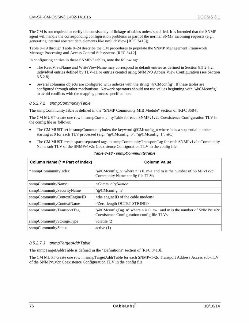
CM-SP-CM-OSSIv3.1-I02-141016 DOCSIS 3.1
76 CableLabs 10/16/14
The CM is not required to verify the consistency of linkage of tables unless specified. It is intended that the SNMP agent will handle the corresponding configuration problems as part of the normal SNMP incoming requests (e.g., generating internal abstract data elements like noSuchView [RFC 3415]).
Table 8–19 through Table 8–24 describe the CM procedures to populate the SNMP Management Framework Message Processing and Access Control Subsystems [RFC 3412].
In configuring entries in these SNMPv3 tables, note the following:
• The ReadViewName and WriteViewName may correspond to default entries as defined in Section 8.5.2.5.2, individual entries defined by TLV-11 or entries created using SNMPv3 Access View Configuration (see Section 8.5.2.8).
• Several columnar objects are configured with indexes with the string "@CMconfig". If these tables are configured through other mechanisms, Network operators should not use values beginning with "@CMconfig" to avoid conflicts with the mapping process specified here.
8.5.2.7.2 snmpCommunityTable
The snmpCommunityTable is defined in the "SNMP Community MIB Module" section of [RFC 3584].
The CM MUST create one row in snmpCommunityTable for each SNMPv1v2c Coexistence Configuration TLV in the config file as follows:
• The CM MUST set in snmpCommunityIndex the keyword @CMconfig_n where 'n' is a sequential number starting at 0 for each TLV processed (e.g., "@CMconfig_0", "@CMconfig_1", etc.)
• The CM MUST create space separated tags in snmpCommunityTransportTag for each SNMPv1v2c Community Name sub-TLV of the SNMPv1v2c Coexistence Configuration TLV in the config file.
Table 8–18 - snmpCommunityTable
Column Name (* = Part of Index) Column Value
* snmpCommunityIndex "@CMconfig_n" where n is 0..m-1 and m is the number of SNMPv1v2c Community Name config file TLVs
snmpCommunityName <CommunityName> snmpCommunitySecurityName "@CMconfig_n" snmpCommunityContextEngineID <the engineID of the cable modem> snmpCommunityContextName <Zero-length OCTET STRING> snmpCommunityTransportTag "@CMconfigTag_n" where n is 0..m-1 and m is the number of SNMPv1v2c
Coexistence Configuration config file TLVs snmpCommunityStorageType volatile (2) snmpCommunityStatus active (1)
8.5.2.7.3 snmpTargetAddrTable
The snmpTargetAddrTable is defined in the "Definitions" section of [RFC 3413].
The CM MUST create one row in snmpTargetAddrTable for each SNMPv1v2c Transport Address Access sub-TLV of the SNMPv1v2c Coexistence Configuration TLV in the config file.
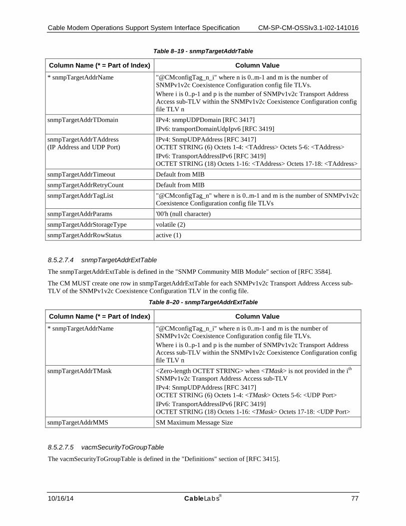
Cable Modem Operations Support System Interface Specification CM-SP-CM-OSSIv3.1-I02-141016
10/16/14 CableLabs 77
Table 8–19 - snmpTargetAddrTable
Column Name (* = Part of Index) Column Value
* snmpTargetAddrName "@CMconfigTag_n_i" where n is 0..m-1 and m is the number of SNMPv1v2c Coexistence Configuration config file TLVs. Where i is 0..p-1 and p is the number of SNMPv1v2c Transport Address Access sub-TLV within the SNMPv1v2c Coexistence Configuration config file TLV n
snmpTargetAddrTDomain IPv4: snmpUDPDomain [RFC 3417] IPv6: transportDomainUdpIpv6 [RFC 3419]
snmpTargetAddrTAddress (IP Address and UDP Port)
IPv4: SnmpUDPAddress [RFC 3417] OCTET STRING (6) Octets 1-4: <TAddress> Octets 5-6: <TAddress> IPv6: TransportAddressIPv6 [RFC 3419] OCTET STRING (18) Octets 1-16: <TAddress> Octets 17-18: <TAddress>
snmpTargetAddrTimeout Default from MIB snmpTargetAddrRetryCount Default from MIB snmpTargetAddrTagList "@CMconfigTag_n" where n is 0..m-1 and m is the number of SNMPv1v2c
Coexistence Configuration config file TLVs snmpTargetAddrParams '00'h (null character) snmpTargetAddrStorageType volatile (2) snmpTargetAddrRowStatus active (1)
8.5.2.7.4 snmpTargetAddrExtTable
The snmpTargetAddrExtTable is defined in the "SNMP Community MIB Module" section of [RFC 3584].
The CM MUST create one row in snmpTargetAddrExtTable for each SNMPv1v2c Transport Address Access sub-TLV of the SNMPv1v2c Coexistence Configuration TLV in the config file.
Table 8–20 - snmpTargetAddrExtTable
Column Name (* = Part of Index) Column Value
* snmpTargetAddrName "@CMconfigTag_n_i" where n is 0..m-1 and m is the number of SNMPv1v2c Coexistence Configuration config file TLVs. Where i is 0..p-1 and p is the number of SNMPv1v2c Transport Address Access sub-TLV within the SNMPv1v2c Coexistence Configuration config file TLV n
snmpTargetAddrTMask <Zero-length OCTET STRING> when <TMask> is not provided in the ith SNMPv1v2c Transport Address Access sub-TLV IPv4: SnmpUDPAddress [RFC 3417] OCTET STRING (6) Octets 1-4: <TMask> Octets 5-6: <UDP Port> IPv6: TransportAddressIPv6 [RFC 3419] OCTET STRING (18) Octets 1-16: <TMask> Octets 17-18: <UDP Port>
snmpTargetAddrMMS SM Maximum Message Size
8.5.2.7.5 vacmSecurityToGroupTable
The vacmSecurityToGroupTable is defined in the "Definitions" section of [RFC 3415].
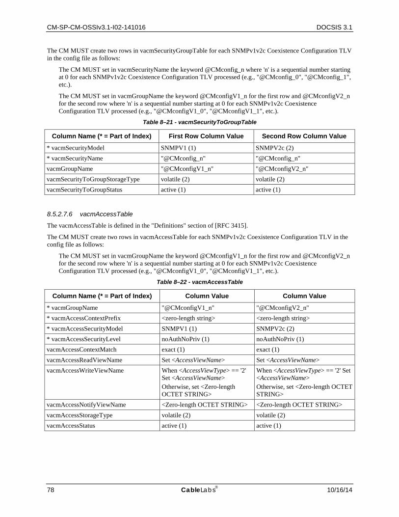
CM-SP-CM-OSSIv3.1-I02-141016 DOCSIS 3.1
78 CableLabs 10/16/14
The CM MUST create two rows in vacmSecurityGroupTable for each SNMPv1v2c Coexistence Configuration TLV in the config file as follows:
The CM MUST set in vacmSecurityName the keyword @CMconfig_n where 'n' is a sequential number starting at 0 for each SNMPv1v2c Coexistence Configuration TLV processed (e.g., "@CMconfig_0", "@CMconfig_1", etc.).
The CM MUST set in vacmGroupName the keyword @CMconfigV1_n for the first row and @CMconfigV2_n for the second row where 'n' is a sequential number starting at 0 for each SNMPv1v2c Coexistence Configuration TLV processed (e.g., "@CMconfigV1_0", "@CMconfigV1_1", etc.).
Table 8–21 - vacmSecurityToGroupTable
Column Name (* = Part of Index) First Row Column Value Second Row Column Value
* vacmSecurityModel SNMPV1 (1) SNMPV2c (2) * vacmSecurityName "@CMconfig_n" "@CMconfig_n" vacmGroupName "@CMconfigV1_n" "@CMconfigV2_n" vacmSecurityToGroupStorageType volatile (2) volatile (2) vacmSecurityToGroupStatus active (1) active (1)
8.5.2.7.6 vacmAccessTable
The vacmAccessTable is defined in the "Definitions" section of [RFC 3415].
The CM MUST create two rows in vacmAccessTable for each SNMPv1v2c Coexistence Configuration TLV in the config file as follows:
The CM MUST set in vacmGroupName the keyword @CMconfigV1_n for the first row and @CMconfigV2_n for the second row where 'n' is a sequential number starting at 0 for each SNMPv1v2c Coexistence Configuration TLV processed (e.g., "@CMconfigV1_0", "@CMconfigV1_1", etc.).
Table 8–22 - vacmAccessTable
Column Name (* = Part of Index) Column Value Column Value
* vacmGroupName "@CMconfigV1_n" "@CMconfigV2_n" * vacmAccessContextPrefix <zero-length string> <zero-length string> * vacmAccessSecurityModel SNMPV1 (1) SNMPV2c (2) * vacmAccessSecurityLevel noAuthNoPriv (1) noAuthNoPriv (1) vacmAccessContextMatch exact (1) exact (1) vacmAccessReadViewName Set <AccessViewName> Set <AccessViewName> vacmAccessWriteViewName When <AccessViewType> == '2'
Set <AccessViewName> Otherwise, set <Zero-length OCTET STRING>
When <AccessViewType> == '2' Set <AccessViewName> Otherwise, set <Zero-length OCTET STRING>
vacmAccessNotifyViewName <Zero-length OCTET STRING> <Zero-length OCTET STRING> vacmAccessStorageType volatile (2) volatile (2) vacmAccessStatus active (1) active (1)
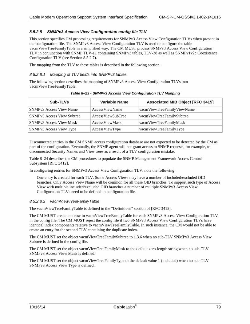
Cable Modem Operations Support System Interface Specification CM-SP-CM-OSSIv3.1-I02-141016
10/16/14 CableLabs 79
8.5.2.8 SNMPv3 Access View Configuration config file TLV This section specifies CM processing requirements for SNMPv3 Access View Configuration TLVs when present in the configuration file. The SNMPv3 Access View Configuration TLV is used to configure the table vacmViewTreeFamilyTable in a simplified way. The CM MUST process SNMPv3 Access View Configuration TLV in conjunction with SNMP TLV-11 containing SNMPv3 tables, TLV-38 as well as SNMPv1v2c Coexistence Configuration TLV (see Section 8.5.2.7).
The mapping from the TLV to these tables is described in the following section.
8.5.2.8.1 Mapping of TLV fields into SNMPv3 tables
The following section describes the mapping of SNMPv3 Access View Configuration TLVs into vacmViewTreeFamilyTable:
Table 8–23 - SNMPv3 Access View Configuration TLV Mapping
Sub-TLVs Variable Name Associated MIB Object [RFC 3415]
SNMPv3 Access View Name AccessViewName vacmViewTreeFamilyViewName SNMPv3 Access View Subtree AccessViewSubTree vacmViewTreeFamilySubtree SNMPv3 Access View Mask AccessViewMask vacmViewTreeFamilyMask SNMPv3 Access View Type AccessViewType vacmViewTreeFamilyType
Disconnected entries in the CM SNMP access configuration database are not expected to be detected by the CM as part of the configuration. Eventually, the SNMP agent will not grant access to SNMP requests, for example, to disconnected Security Names and View trees as a result of a TLV configuration mistake.
Table 8–24 describes the CM procedures to populate the SNMP Management Framework Access Control Subsystem [RFC 3412].
In configuring entries for SNMPv3 Access View Configuration TLV, note the following:
One entry is created for each TLV. Some Access Views may have a number of included/excluded OID branches. Only Access View Name will be common for all these OID branches. To support such type of Access View with multiple included/excluded OID branches a number of multiple SNMPv3 Access View Configuration TLVs need to be defined in configuration file.
8.5.2.8.2 vacmViewTreeFamilyTable
The vacmViewTreeFamilyTable is defined in the "Definitions" section of [RFC 3415].
The CM MUST create one row in vacmViewTreeFamilyTable for each SNMPv3 Access View Configuration TLV in the config file. The CM MUST reject the config file if two SNMPv3 Access View Configuration TLVs have identical index components relative to vacmViewTreeFamilyTable. In such instance, the CM would not be able to create an entry for the second TLV containing the duplicate index.
The CM MUST set the object vacmViewTreeFamilySubtree to 1.3.6 when no sub-TLV SNMPv3 Access View Subtree is defined in the config file.
The CM MUST set the object vacmViewTreeFamilyMask to the default zero-length string when no sub-TLV SNMPv3 Access View Mask is defined.
The CM MUST set the object vacmViewTreeFamilyType to the default value 1 (included) when no sub-TLV SNMPv3 Access View Type is defined.
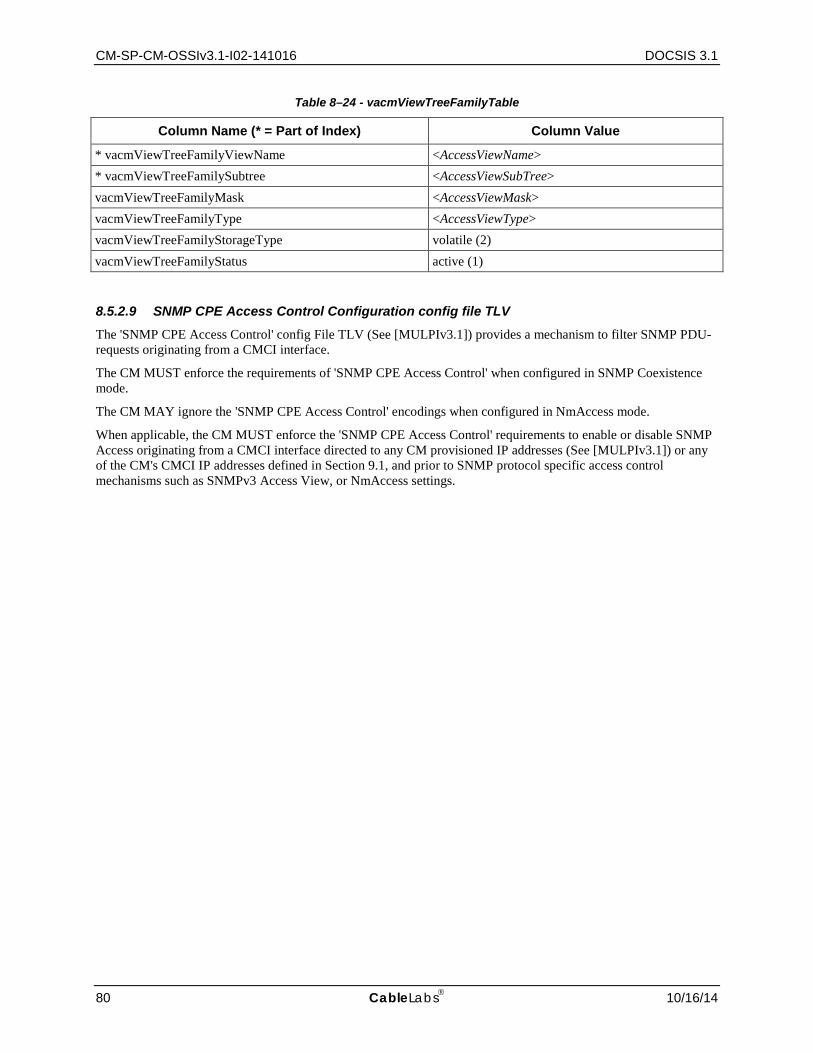
CM-SP-CM-OSSIv3.1-I02-141016 DOCSIS 3.1
80 CableLabs 10/16/14
Table 8–24 - vacmViewTreeFamilyTable
Column Name (* = Part of Index) Column Value
* vacmViewTreeFamilyViewName <AccessViewName> * vacmViewTreeFamilySubtree <AccessViewSubTree> vacmViewTreeFamilyMask <AccessViewMask> vacmViewTreeFamilyType <AccessViewType> vacmViewTreeFamilyStorageType volatile (2) vacmViewTreeFamilyStatus active (1)
8.5.2.9 SNMP CPE Access Control Configuration config file TLV The 'SNMP CPE Access Control' config File TLV (See [MULPIv3.1]) provides a mechanism to filter SNMP PDU-requests originating from a CMCI interface.
The CM MUST enforce the requirements of 'SNMP CPE Access Control' when configured in SNMP Coexistence mode.
The CM MAY ignore the 'SNMP CPE Access Control' encodings when configured in NmAccess mode.
When applicable, the CM MUST enforce the 'SNMP CPE Access Control' requirements to enable or disable SNMP Access originating from a CMCI interface directed to any CM provisioned IP addresses (See [MULPIv3.1]) or any of the CM's CMCI IP addresses defined in Section 9.1, and prior to SNMP protocol specific access control mechanisms such as SNMPv3 Access View, or NmAccess settings.

Cable Modem Operations Support System Interface Specification CM-SP-CM-OSSIv3.1-I02-141016
10/16/14 CableLabs 81
9 OSSI FOR CMCI This section defines the operational mechanisms needed to support the transmission of data over cable services between a Cable Modem (CM) and Customer Premise Equipment (CPE). Specifically, this section outlines the following:
• SNMP access via CMCI
• Console Access
• CM diagnostic capabilities
• Protocol Filtering
• Required MIBs
9.1 SNMP Access via CMCI DOCSIS 3.1 CMs have provisions for dual-stack management or management of the CM using SNMP over IPv4 and IPv6. During provisioning, the management of the CM is determined by the MSO. However, SNMP access from the CMCI port(s) for diagnostic purposes prior to the CM being registered needs to operate in a dual-stack management mode and allow access for both IPv4 and IPv6 hosts. CM SNMP access from the CMCI before completing the CMTS registration process MUST comply with the access requirements specified in Section 8.5.2.1. The CM DHCP-acquired IP MUST ignore SNMP requests from CMCI before registration.
CM SNMP access from the CMCI after completing the CMTS registration process MUST comply with the access requirements specified in Section 8.5.2.2. The CM DHCP-acquired IP MUST accept SNMP requests from CMCI after completing registration.
The CM MUST support SNMP access through the following IP addresses regardless of the CM registration state:
• The CM MUST support 192.168.100.1, as the well-known diagnostic IP address accessible only from the CMCI interfaces. The CM MUST support the well-known diagnostic IP address, 192.168.100.1, on all physical interfaces associated with the CMCI. The CM MUST drop SNMP requests coming from the RF interface targeting the well-known IP address.
• The CM MAY also implement alternative IPv4 interfaces like link-local method described in [RFC 3927]. If implemented, the CM MUST restrict the IP address range described in "Address Selection, Defense and Delivery" of [RFC 3927] to 169.254.1.0 to 169.254.254.255 inclusive.
• The CM MAY support an IPv6 EUI-64 link-local scope address in the format FE80::<vendorId>:FFFE:<remainingMacAddress> of the CMCI port. The CM MUST drop SNMP requests coming from the RF interface targeting this IPv6 address. Refer to [RFC 4291] for additional details.
9.2 Console Access The CM MUST NOT allow access to the CM functions by a console port. In this specification, a console port is defined as a communication path, either hardware or software, that allows a user to issue commands to modify the configuration or operational status of the CM. The CM MUST only allow access using DOCSIS defined RF interfaces and operator-controlled SNMP access by the CMCI.
CM-SP-CM-OSSIv3.1-I02-141016 DOCSIS 3.1
82 CableLabs 10/16/14
9.3 CM Diagnostic Capabilities The CM MAY have a diagnostic interface for debugging and troubleshooting purposes. The CM's diagnostic interface MUST be limited by default to the requirements described in Section 8.5.2 before and after registration. The CM's diagnostic interface SHOULD be disabled by default after registration has been completed. The CM MAY provide additional controls that will enable the MSO to alter or customize the diagnostic interface, such as by the configuration process or management through the setting of a proprietary MIB.
9.4 Protocol Filtering The CM MUST be capable of filtering traffic to and from the host CPE as defined in Annex C.
Cable Modem Operations Support System Interface Specification CM-SP-CM-OSSIv3.1-I02-141016
10/16/14 CableLabs 83
10 OSSI FOR LED INDICATORS The CM SHOULD support standard front-panel LEDs (Light Emitting Diodes) that present straightforward information about the registration state of the CM so as to facilitate efficient customer support operations.
10.1 CM LED Requirements and Operation A CM SHOULD support LEDs which have three states: 1) unlit, 2) flash, 3) lit solid. A CM LED in the 'flash' state SHOULD turn on and off with a 50% duty cycle at a frequency not less than 2 cycles per second. A CM SHOULD support LEDs which light sequentially, following the normal CM initialization procedure specified in [MULPIv3.1]. In this way, the installer can detect a failure that prevents the CM from becoming operational.
A CM SHOULD have a minimum of five externally visible LEDs divided into three functional groups as indicated below:
BOX: This group SHOULD have 1 LED labeled as POWER for the BOX status.
DOCSIS: This group SHOULD have 3 LEDs labeled as DS, US, and ONLINE for the DOCSIS interface status. The LEDs in the DOCSIS group SHOULD be in the order: DS, US, and ONLINE, from left to right, or top to bottom, as appropriate for the orientation of the device.
CPE: This group SHOULD have a minimum of 1 LED labeled as LINK for the LINK status. The CM MAY have multiple LEDs in the CPE group to represent individual CPE interface types and parameters. These CM CPE LEDs MAY be labeled according to their associated interface types.
There is no specific requirement for labeling the functional groups. The overall CM LED distribution SHOULD be in the order: POWER, DS, US, ONLINE, and LINK.
The CM SHOULD use these LEDs to indicate that the following modes of operation are in progress, or have completed successfully:
• Power on, Software Application Image Validation and Self Test
• Scan for Downstream Channel
• Resolve CM-SG and Range
• Operational
• Data Link and Activity
The CM SHOULD operate its LEDs as described in the following sections for each of the above modes of operation.
10.1.1 Power On, Software Application Image Validation and Self Test The CM SHOULD, when turned on, place the LEDs, or at least the DOCSIS Group LEDs (DS, US, ONLINE), in the 'flash' state while the CM performs the system initialization of the Operational System, CM application load, and any proprietary self-tests. Following the successful completion of the steps above, the CM SHOULD place the LEDs, or at least the DOCSIS Group LEDs, in the 'lit solid' state for one second, after which the CM places the POWER LED in the 'lit solid' state. The CM MAY also place the LINK LED in the 'lit solid' state if a CPE device is properly connected (see Section 10.1.5 below). If the system initialization, described above, results in a failure, the CM SHOULD place the LEDs, or at least the DOCSIS Group LEDs in the 'flash' state, in which they should remain.
10.1.2 Scan for Downstream Channel
The CM SHOULD place the DS LED in the 'flash' state as the CM scans for a candidate primary downstream DOCSIS channel. The CM SHOULD place the DS LED in the 'lit solid' state when the CM MAC layer has completed synchronization of MPEG framing of the candidate primary downstream channel, as defined in the "Cable Modem Initialization and Reinitialization" section of [MULPIv3.1]. The CM SHOULD maintain the 'lit

CM-SP-CM-OSSIv3.1-I02-141016 DOCSIS 3.1
84 CableLabs 10/16/14
solid' state of the DS LED as the CM continues the initialization process. The CM SHOULD NOT place the DS LED in the 'flash' state when resolving the CM service groups or performing downstream acquisition of CM receive channels in the registration process as defined in the "Cable Modem Initialization and Reinitialization" section of [MULPIv3.1].
Whenever the CM restarts CM initialization (which can include scanning for a downstream channel and attempting to synchronize to a downstream channel), the CM SHOULD place the DS LED in the 'flash' state and the US LED and ONLINE LED in the 'unlit' state.
10.1.3 Resolve CM-SG and Range
After the CM places the DS LED in the 'lit solid' state, the CM SHOULD place the US LED in the 'flash' state and the ONLINE LED in the 'unlit' state while the CM is determining CM-SGs and performing initial ranging, until the CM receives a ranging response message with a ranging status of 'success' from the CMTS. When the CM receives a ranging response message with a ranging status of 'success' from the CMTS, the CM SHOULD place the US LED in the 'lit solid' state.
The CM SHOULD maintain the 'lit solid' state of the US LED as the CM continues the initialization process. Unless the channel used to transmit the registration request message is not in the TCC received in the registration response message, the CM SHOULD NOT place the US LED in the 'flash' state when performing upstream acquisition of CM transmit channels in the registration process as defined in the "Cable Modem Initialization and Reinitialization" section of [MULPIv3.1]. The CM SHOULD maintain the 'lit solid' state of the US LED when the CM is ranged on one or more upstream channels.
10.1.4 Operational
After the CM places the US LED in the 'lit solid' state, the CM SHOULD place the ONLINE LED in the 'flash' state while the CM continues the process towards become operational (this includes performing early authentication, establishing IP connectivity, and registering with the CMTS, and performing BPI initialization). When the CM is operational, the CM SHOULD place the ONLINE LED in the 'lit solid' state. Operational is defined according to section "Cable Modem Initialization and Reinitialization" in [MULPIv3.1].
If at any point there is a failure in the registration process that causes the CM to lose its operational state, including but not limited to loss of the primary downstream channel, ranging, DHCP, configuration file download, registration, and Baseline Privacy initialization, the CM SHOULD place the ONLINE LED in the 'flash' state.
If the CM becomes operational and the CM configuration file has the Network Access Control Object (NACO) set to zero (0), the CM SHOULD place the ONLINE LED in the 'unlit' state and place both the 'DS and US LEDs in the 'flash' state. Refer to the Common Radio Frequency Interface Encodings Annex of [MULPIv3.1] for details on the Network Access Control Object (NACO).
10.1.5 Data Link and Activity
The CM SHOULD place the LINK LED in the 'lit solid' state when a CPE device is connected and the CM is not bridging data. The CM SHOULD place the LINK LED in the 'flash' state ONLY when the CM is bridging data during the CM operational state and NACO set to one (1). The CM SHOULD NOT place the LINK LED in the 'flash' state for data traffic originating or terminating at the CM device itself.
If LINK is detected with a CPE device, the CM MAY set the LINK LED to the 'lit solid' state any time after the power and self test steps are completed.
10.2 Additional CM Operational Status Visualization Features The CM MAY change the DOCSIS defined LED behavior when the CM is in a vendor proprietary mode of operation. The CM MUST NOT have additional LEDs that reveal DOCSIS specific information about the configuration file content, or otherwise clearly specified (see NACO visualization in Sections 10.1.4 and 10.1.5).

Cable Modem Operations Support System Interface Specification CM-SP-CM-OSSIv3.1-I02-141016
10/16/14 CableLabs 85
10.2.1 Secure Software Download
The CM SHOULD signal that a Secure Software Download [SECv3.0] is in process, by setting the DS LED and the US LED to the 'flash' state, and the ONLINE LED to the 'lit solid' state.

CM-SP-CM-OSSIv3.1-I02-141016 DOCSIS 3.1
86 CableLabs 10/16/14
Annex A Detailed MIB Requirements (Normative) This Annex defines the SNMP MIB modules and MIB variables required for DOCSIS 3.1 CM devices.
Table A–1 - MIB Implementation Support
Requirement Type Table Notation Description Deprecated D Deprecated objects are optional. If a vendor chooses to implement the object, the
object must be implemented correctly according to the MIB definition. If a vendor chooses not to implement the object, an agent must not instantiate such object and must respond with the appropriate error/exception condition (e.g., 'noSuchObject' for SNMPv2c).
Mandatory M The object must be implemented correctly according to the MIB definition.
Not Applicable NA Not applicable to the device.
Not Supported N-Sup An agent must not instantiate such object and must respond with the appropriate error/exception condition (e.g., 'noSuchObject' for SNMPv2c).
Optional O A vendor can choose to implement or not implement the object. If a vendor chooses to implement the object, the object must be implemented correctly according to the MIB definition. If a vendor chooses not to implement the object, an agent must not instantiate such object and must respond with the appropriate error/exception condition (e.g., 'noSuchObject' for SNMPv2c).
Obsolete Ob In SNMP convention, obsolete objects should not be implemented. This specification allows vendors to implement or not implement obsolete objects. If a vendor chooses to implement an obsoleted object, the object must be implemented correctly according to the MIB definition. If a vendor chooses not to implement the obsoleted object, the SNMP agent must not instantiate such object and must respond with the appropriate error/exception condition (e.g., 'noSuchObject' for SNMPv2c).
Table A–2 - SNMP Access Requirements
SNMP Access Type Table Notation Description N-Acc Not Accessible The object is not accessible and is usually an index in a table
Read Create RC The access of the object MUST be implemented as Read-Create
Read Write RW The access of the object MUST be implemented as Read-Write
Read Only RO The access of the object MUST be implemented as Read-Only
Read Create or Read Only
RC/RO The access of the object MUST be implemented as either Read-Create or Read-Only as described in the MIB definition
Read Write / Read Only
RW/RO The access of the object MUST be implemented as either Read-Write or Read-Only as described in the MIB definition
Accessible for SNMP Notifications
Acc-FN These objects are used for SNMP Notifications by the CM SNMP Agent
A.1 MIB-Object Details The CM instantiates SNMP MIB objects based on its configuration and operational parameters acquired during registration. Below are denominations for several Table A–3 columns that indicate modes of operation where a CM has specific management requirements for certain MIB object instantiation and syntax.
The CM always operates in "1.1 QoS Mode".
The CM SNMP access control configuration is either NmAccess Mode or SNMP Coexistence Mode.
The CM upstream channel types can be categorized as "OFDMA upstream", "TDMA/ATDMA upstream" and "SCDMA upstream".
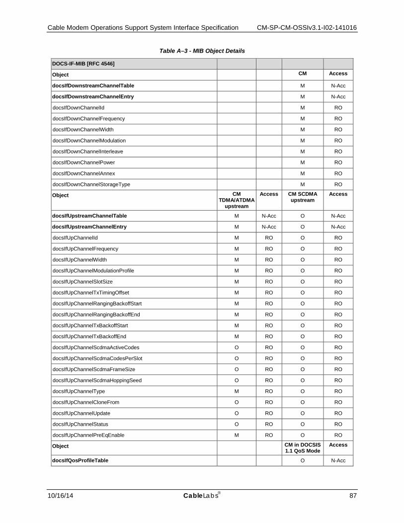
Cable Modem Operations Support System Interface Specification CM-SP-CM-OSSIv3.1-I02-141016
10/16/14 CableLabs 87
Table A–3 - MIB Object Details
DOCS-IF-MIB [RFC 4546]
Object CM Access
docsIfDownstreamChannelTable M N-Acc
docsIfDownstreamChannelEntry M N-Acc
docsIfDownChannelId M RO
docsIfDownChannelFrequency M RO
docsIfDownChannelWidth M RO
docsIfDownChannelModulation M RO
docsIfDownChannelInterleave M RO
docsIfDownChannelPower M RO
docsIfDownChannelAnnex M RO
docsIfDownChannelStorageType M RO
Object CM TDMA/ATDMA
upstream
Access CM SCDMA upstream
Access
docsIfUpstreamChannelTable M N-Acc O N-Acc
docsIfUpstreamChannelEntry M N-Acc O N-Acc
docsIfUpChannelId M RO O RO
docsIfUpChannelFrequency M RO O RO
docsIfUpChannelWidth M RO O RO
docsIfUpChannelModulationProfile M RO O RO
docsIfUpChannelSlotSize M RO O RO
docsIfUpChannelTxTimingOffset M RO O RO
docsIfUpChannelRangingBackoffStart M RO O RO
docsIfUpChannelRangingBackoffEnd M RO O RO
docsIfUpChannelTxBackoffStart M RO O RO
docsIfUpChannelTxBackoffEnd M RO O RO
docsIfUpChannelScdmaActiveCodes O RO O RO
docsIfUpChannelScdmaCodesPerSlot O RO O RO
docsIfUpChannelScdmaFrameSize O RO O RO
docsIfUpChannelScdmaHoppingSeed O RO O RO
docsIfUpChannelType M RO O RO
docsIfUpChannelCloneFrom O RO O RO
docsIfUpChannelUpdate O RO O RO
docsIfUpChannelStatus O RO O RO
docsIfUpChannelPreEqEnable M RO O RO
Object CM in DOCSIS 1.1 QoS Mode
Access
docsIfQosProfileTable O N-Acc
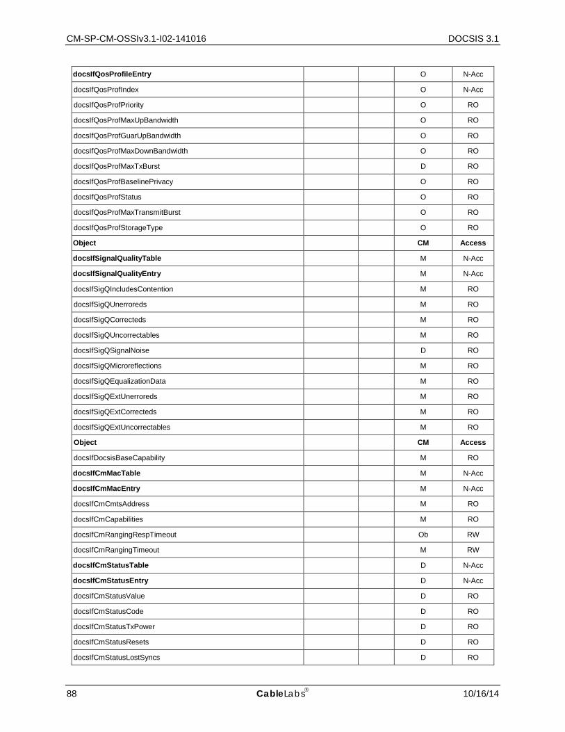
CM-SP-CM-OSSIv3.1-I02-141016 DOCSIS 3.1
88 CableLabs 10/16/14
docsIfQosProfileEntry O N-Acc
docsIfQosProfIndex O N-Acc
docsIfQosProfPriority O RO
docsIfQosProfMaxUpBandwidth O RO
docsIfQosProfGuarUpBandwidth O RO
docsIfQosProfMaxDownBandwidth O RO
docsIfQosProfMaxTxBurst D RO
docsIfQosProfBaselinePrivacy O RO
docsIfQosProfStatus O RO
docsIfQosProfMaxTransmitBurst O RO
docsIfQosProfStorageType O RO
Object CM Access
docsIfSignalQualityTable M N-Acc
docsIfSignalQualityEntry M N-Acc
docsIfSigQIncludesContention M RO
docsIfSigQUnerroreds M RO
docsIfSigQCorrecteds M RO
docsIfSigQUncorrectables M RO
docsIfSigQSignalNoise D RO
docsIfSigQMicroreflections M RO
docsIfSigQEqualizationData M RO
docsIfSigQExtUnerroreds M RO
docsIfSigQExtCorrecteds M RO
docsIfSigQExtUncorrectables M RO
Object CM Access
docsIfDocsisBaseCapability M RO
docsIfCmMacTable M N-Acc
docsIfCmMacEntry M N-Acc
docsIfCmCmtsAddress M RO
docsIfCmCapabilities M RO
docsIfCmRangingRespTimeout Ob RW
docsIfCmRangingTimeout M RW
docsIfCmStatusTable D N-Acc
docsIfCmStatusEntry D N-Acc
docsIfCmStatusValue D RO
docsIfCmStatusCode D RO
docsIfCmStatusTxPower D RO
docsIfCmStatusResets D RO
docsIfCmStatusLostSyncs D RO

Cable Modem Operations Support System Interface Specification CM-SP-CM-OSSIv3.1-I02-141016
10/16/14 CableLabs 89
docsIfCmStatusInvalidMaps D RO
docsIfCmStatusInvalidUcds D RO
docsIfCmStatusInvalidRangingResponses D RO
docsIfCmStatusInvalidRegistrationResponses D RO
docsIfCmStatusT1Timeouts D RO
docsIfCmStatusT2Timeouts D RO
docsIfCmStatusT3Timeouts D RO
docsIfCmStatusT4Timeouts D RO
docsIfCmStatusRangingAborteds D RO
docsIfCmStatusDocsisOperMode D RO
docsIfCmStatusModulationType D RO
docsIfCmStatusEqualizationData D RO
docsIfCmStatusUCCs D RO
docsIfCmStatusUCCFails D RO
Object CM in DOCSIS 1.1 QoS Mode
Access
docsIfCmServiceTable N-Sup
docsIfCmServiceEntry N-Sup
docsIfCmServiceId N-Sup
docsIfCmServiceQosProfile N-Sup
docsIfCmServiceTxSlotsImmed N-Sup
docsIfCmServiceTxSlotsDed N-Sup
docsIfCmServiceTxRetries N-Sup
docsIfCmServiceTxExceededs N-Sup
docsIfCmServiceRqRetries N-Sup
docsIfCmServiceRqExceededs N-Sup
docsIfCmServiceExtTxSlotsImmed N-Sup
docsIfCmServiceExtTxSlotsDed N-Sup
IF-MIB [RFC 2863]
Object CM Access
ifNumber M RO
ifTableLastChange M RO
ifTable Note: The ifTable Counter32 objects are not reflected here, refer to Table A–6 and Table A–7 of Appendix A.2 for details on these objects.
M N-Acc
ifEntry M N-Acc
ifIndex M RO
ifDescr M RO
ifType M RO
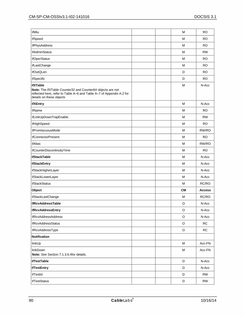
CM-SP-CM-OSSIv3.1-I02-141016 DOCSIS 3.1
90 CableLabs 10/16/14
ifMtu M RO
ifSpeed M RO
ifPhysAddress M RO
ifAdminStatus M RW
ifOperStatus M RO
ifLastChange M RO
ifOutQLen D RO
ifSpecific D RO
ifXTable Note: The ifXTable Counter32 and Counter64 objects are not reflected here, refer to Table A–6 and Table A–7 of Appendix A.2 for details on these objects
M N-Acc
ifXEntry M N-Acc
ifName M RO
ifLinkUpDownTrapEnable M RW
ifHighSpeed M RO
ifPromiscuousMode M RW/RO
ifConnectorPresent M RO
ifAlias M RW/RO
ifCounterDiscontinuityTime M RO
ifStackTable M N-Acc
ifStackEntry M N-Acc
ifStackHigherLayer M N-Acc
ifStackLowerLayer M N-Acc
ifStackStatus M RC/RO
Object CM Access
ifStackLastChange M RC/RO
ifRcvAddressTable O N-Acc
ifRcvAddressEntry O N-Acc
ifRcvAddressAddress O N-Acc
ifRcvAddressStatus O RC
IfRcvAddressType O RC
Notification
linkUp M Acc-FN
linkDown Note: See Section 7.1.3.6.4for details.
M Acc-FN
ifTestTable D N-Acc
ifTestEntry D N-Acc
ifTestId D RW
ifTestStatus D RW

Cable Modem Operations Support System Interface Specification CM-SP-CM-OSSIv3.1-I02-141016
10/16/14 CableLabs 91
ifTestType D RW
ifTestResult D RO
ifTestCode D RO
ifTestOwner D RW
BRIDGE-MIB [RFC 4188]
Object CM Access
dot1dBase
dot1dBaseBridgeAddress M RO
dot1dBaseNumPorts M RO
dot1dBaseType M RO
dot1dBasePortTable M N-Acc
dot1dBasePortEntry M N-Acc
dot1dBasePort M RO
dot1dBasePortIfIndex M RO
dot1dBasePortCircuit M RO
dot1dBasePortDelayExceededDiscards M RO
dot1dBasePortMtuExceededDiscards M RO
dot1dStp
dot1dStpProtocolSpecification M RO
dot1dStpPriority M RW
dot1dStpTimeSinceTopologyChange M RO
dot1dStpTopChanges M RO
dot1dStpDesignatedRoot M RO
dot1dStpRootCost M RO
dot1dStpRootPort M RO
dot1dStpMaxAge M RO
dot1dStpHelloTime M RO
dot1dStpHoldTime M RO
dot1dStpForwardDelay M RO
dot1dStpBridgeMaxAge M RW
dot1dStpBridgeHelloTime M RW
dot1dStpBridgeForwardDelay M RW
dot1dStpPortTable Note: This table is required ONLY if STP is implemented.
O N-Acc
dot1dStpPortEntry O N-Acc
dot1dStpPort O RO
dot1dStpPortPriority O RW
dot1dStpPortState O RO
dot1dStpPortEnable O RW
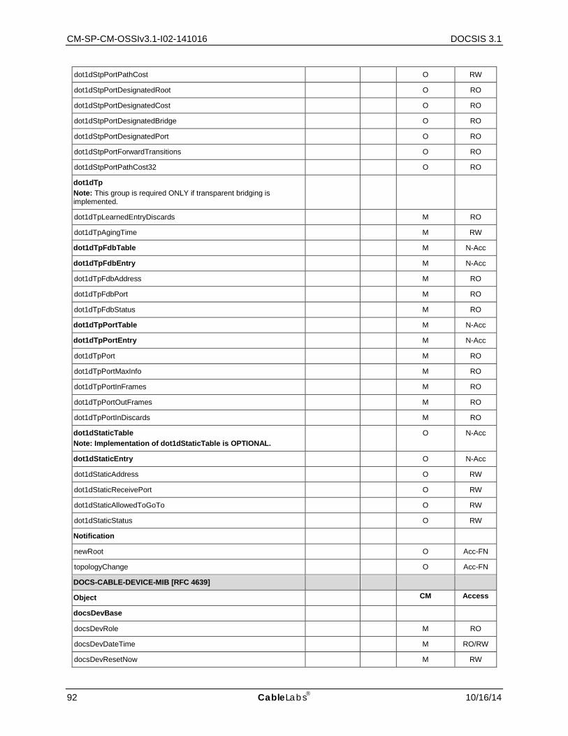
CM-SP-CM-OSSIv3.1-I02-141016 DOCSIS 3.1
92 CableLabs 10/16/14
dot1dStpPortPathCost O RW
dot1dStpPortDesignatedRoot O RO
dot1dStpPortDesignatedCost O RO
dot1dStpPortDesignatedBridge O RO
dot1dStpPortDesignatedPort O RO
dot1dStpPortForwardTransitions O RO
dot1dStpPortPathCost32 O RO
dot1dTp Note: This group is required ONLY if transparent bridging is implemented.
dot1dTpLearnedEntryDiscards M RO
dot1dTpAgingTime M RW
dot1dTpFdbTable M N-Acc
dot1dTpFdbEntry M N-Acc
dot1dTpFdbAddress M RO
dot1dTpFdbPort M RO
dot1dTpFdbStatus M RO
dot1dTpPortTable M N-Acc
dot1dTpPortEntry M N-Acc
dot1dTpPort M RO
dot1dTpPortMaxInfo M RO
dot1dTpPortInFrames M RO
dot1dTpPortOutFrames M RO
dot1dTpPortInDiscards M RO
dot1dStaticTable Note: Implementation of dot1dStaticTable is OPTIONAL.
O N-Acc
dot1dStaticEntry O N-Acc
dot1dStaticAddress O RW
dot1dStaticReceivePort O RW
dot1dStaticAllowedToGoTo O RW
dot1dStaticStatus O RW
Notification
newRoot O Acc-FN
topologyChange O Acc-FN
DOCS-CABLE-DEVICE-MIB [RFC 4639]
Object CM Access
docsDevBase
docsDevRole M RO
docsDevDateTime M RO/RW
docsDevResetNow M RW
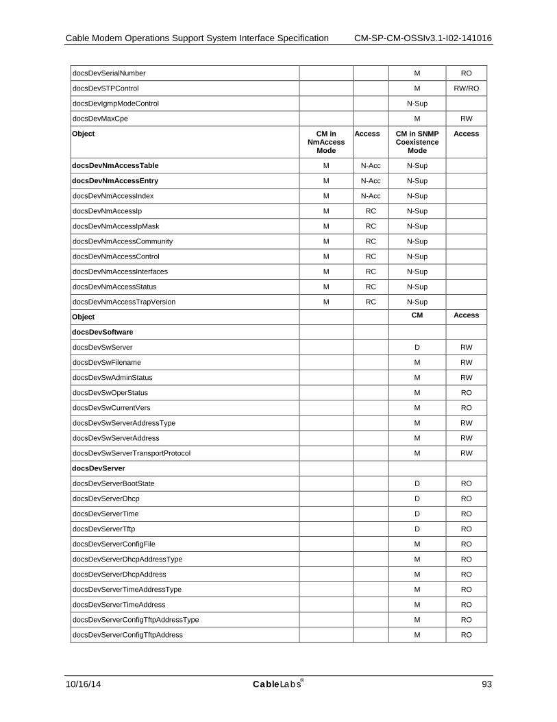
Cable Modem Operations Support System Interface Specification CM-SP-CM-OSSIv3.1-I02-141016
10/16/14 CableLabs 93
docsDevSerialNumber M RO
docsDevSTPControl M RW/RO
docsDevIgmpModeControl N-Sup
docsDevMaxCpe M RW
Object CM in NmAccess
Mode
Access CM in SNMP Coexistence
Mode
Access
docsDevNmAccessTable M N-Acc N-Sup
docsDevNmAccessEntry M N-Acc N-Sup
docsDevNmAccessIndex M N-Acc N-Sup
docsDevNmAccessIp M RC N-Sup
docsDevNmAccessIpMask M RC N-Sup
docsDevNmAccessCommunity M RC N-Sup
docsDevNmAccessControl M RC N-Sup
docsDevNmAccessInterfaces M RC N-Sup
docsDevNmAccessStatus M RC N-Sup
docsDevNmAccessTrapVersion M RC N-Sup
Object CM Access
docsDevSoftware
docsDevSwServer D RW
docsDevSwFilename M RW
docsDevSwAdminStatus M RW
docsDevSwOperStatus M RO
docsDevSwCurrentVers M RO
docsDevSwServerAddressType M RW
docsDevSwServerAddress M RW
docsDevSwServerTransportProtocol M RW
docsDevServer
docsDevServerBootState D RO
docsDevServerDhcp D RO
docsDevServerTime D RO
docsDevServerTftp D RO
docsDevServerConfigFile M RO
docsDevServerDhcpAddressType M RO
docsDevServerDhcpAddress M RO
docsDevServerTimeAddressType M RO
docsDevServerTimeAddress M RO
docsDevServerConfigTftpAddressType M RO
docsDevServerConfigTftpAddress M RO
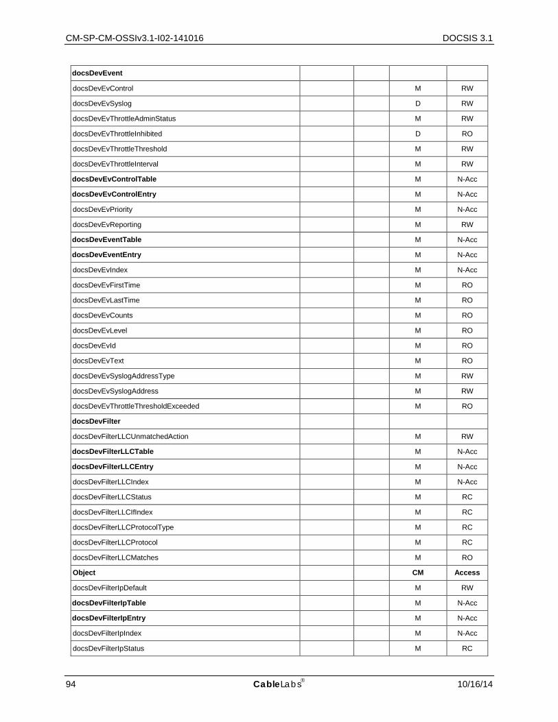
CM-SP-CM-OSSIv3.1-I02-141016 DOCSIS 3.1
94 CableLabs 10/16/14
docsDevEvent
docsDevEvControl M RW
docsDevEvSyslog D RW
docsDevEvThrottleAdminStatus M RW
docsDevEvThrottleInhibited D RO
docsDevEvThrottleThreshold M RW
docsDevEvThrottleInterval M RW
docsDevEvControlTable M N-Acc
docsDevEvControlEntry M N-Acc
docsDevEvPriority M N-Acc
docsDevEvReporting M RW
docsDevEventTable M N-Acc
docsDevEventEntry M N-Acc
docsDevEvIndex M N-Acc
docsDevEvFirstTime M RO
docsDevEvLastTime M RO
docsDevEvCounts M RO
docsDevEvLevel M RO
docsDevEvId M RO
docsDevEvText M RO
docsDevEvSyslogAddressType M RW
docsDevEvSyslogAddress M RW
docsDevEvThrottleThresholdExceeded M RO
docsDevFilter
docsDevFilterLLCUnmatchedAction M RW
docsDevFilterLLCTable M N-Acc
docsDevFilterLLCEntry M N-Acc
docsDevFilterLLCIndex M N-Acc
docsDevFilterLLCStatus M RC
docsDevFilterLLCIfIndex M RC
docsDevFilterLLCProtocolType M RC
docsDevFilterLLCProtocol M RC
docsDevFilterLLCMatches M RO
Object CM Access
docsDevFilterIpDefault M RW
docsDevFilterIpTable M N-Acc
docsDevFilterIpEntry M N-Acc
docsDevFilterIpIndex M N-Acc
docsDevFilterIpStatus M RC
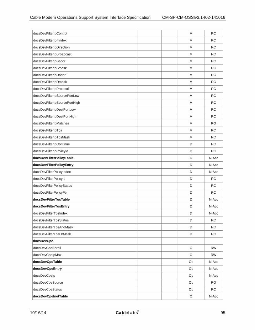
Cable Modem Operations Support System Interface Specification CM-SP-CM-OSSIv3.1-I02-141016
10/16/14 CableLabs 95
docsDevFilterIpControl M RC
docsDevFilterIpIfIndex M RC
docsDevFilterIpDirection M RC
docsDevFilterIpBroadcast M RC
docsDevFilterIpSaddr M RC
docsDevFilterIpSmask M RC
docsDevFilterIpDaddr M RC
docsDevFilterIpDmask M RC
docsDevFilterIpProtocol M RC
docsDevFilterIpSourcePortLow M RC
docsDevFilterIpSourcePortHigh M RC
docsDevFilterIpDestPortLow M RC
docsDevFilterIpDestPortHigh M RC
docsDevFilterIpMatches M RO
docsDevFilterIpTos M RC
docsDevFilterIpTosMask M RC
docsDevFilterIpContinue D RC
docsDevFilterIpPolicyId D RC
docsDevFilterPolicyTable D N-Acc
docsDevFilterPolicyEntry D N-Acc
docsDevFilterPolicyIndex D N-Acc
docsDevFilterPolicyId D RC
docsDevFilterPolicyStatus D RC
docsDevFilterPolicyPtr D RC
docsDevFilterTosTable D N-Acc
docsDevFilterTosEntry D N-Acc
docsDevFilterTosIndex D N-Acc
docsDevFilterTosStatus D RC
docsDevFilterTosAndMask D RC
docsDevFilterTosOrMask D RC
docsDevCpe
docsDevCpeEnroll O RW
docsDevCpeIpMax O RW
docsDevCpeTable Ob N-Acc
docsDevCpeEntry Ob N-Acc
docsDevCpeIp Ob N-Acc
docsDevCpeSource Ob RO
docsDevCpeStatus Ob RC
docsDevCpeInetTable O N-Acc
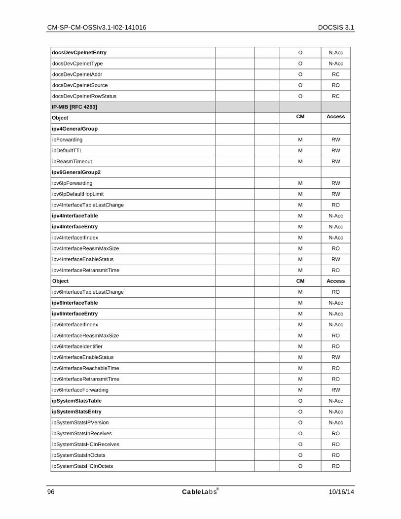
CM-SP-CM-OSSIv3.1-I02-141016 DOCSIS 3.1
96 CableLabs 10/16/14
docsDevCpeInetEntry O N-Acc
docsDevCpeInetType O N-Acc
docsDevCpeInetAddr O RC
docsDevCpeInetSource O RO
docsDevCpeInetRowStatus O RC
IP-MIB [RFC 4293]
Object CM Access
ipv4GeneralGroup
ipForwarding M RW
ipDefaultTTL M RW
ipReasmTimeout M RW
ipv6GeneralGroup2
ipv6IpForwarding M RW
ipv6IpDefaultHopLimit M RW
ipv4InterfaceTableLastChange M RO
ipv4InterfaceTable M N-Acc
ipv4InterfaceEntry M N-Acc
ipv4InterfaceIfIndex M N-Acc
ipv4InterfaceReasmMaxSize M RO
ipv4InterfaceEnableStatus M RW
ipv4InterfaceRetransmitTime M RO
Object CM Access
ipv6InterfaceTableLastChange M RO
ipv6InterfaceTable M N-Acc
ipv6InterfaceEntry M N-Acc
ipv6InterfaceIfIndex M N-Acc
ipv6InterfaceReasmMaxSize M RO
ipv6InterfaceIdentifier M RO
ipv6InterfaceEnableStatus M RW
ipv6InterfaceReachableTime M RO
ipv6InterfaceRetransmitTime M RO
ipv6InterfaceForwarding M RW
ipSystemStatsTable O N-Acc
ipSystemStatsEntry O N-Acc
ipSystemStatsIPVersion O N-Acc
ipSystemStatsInReceives O RO
ipSystemStatsHCInReceives O RO
ipSystemStatsInOctets O RO
ipSystemStatsHCInOctets O RO
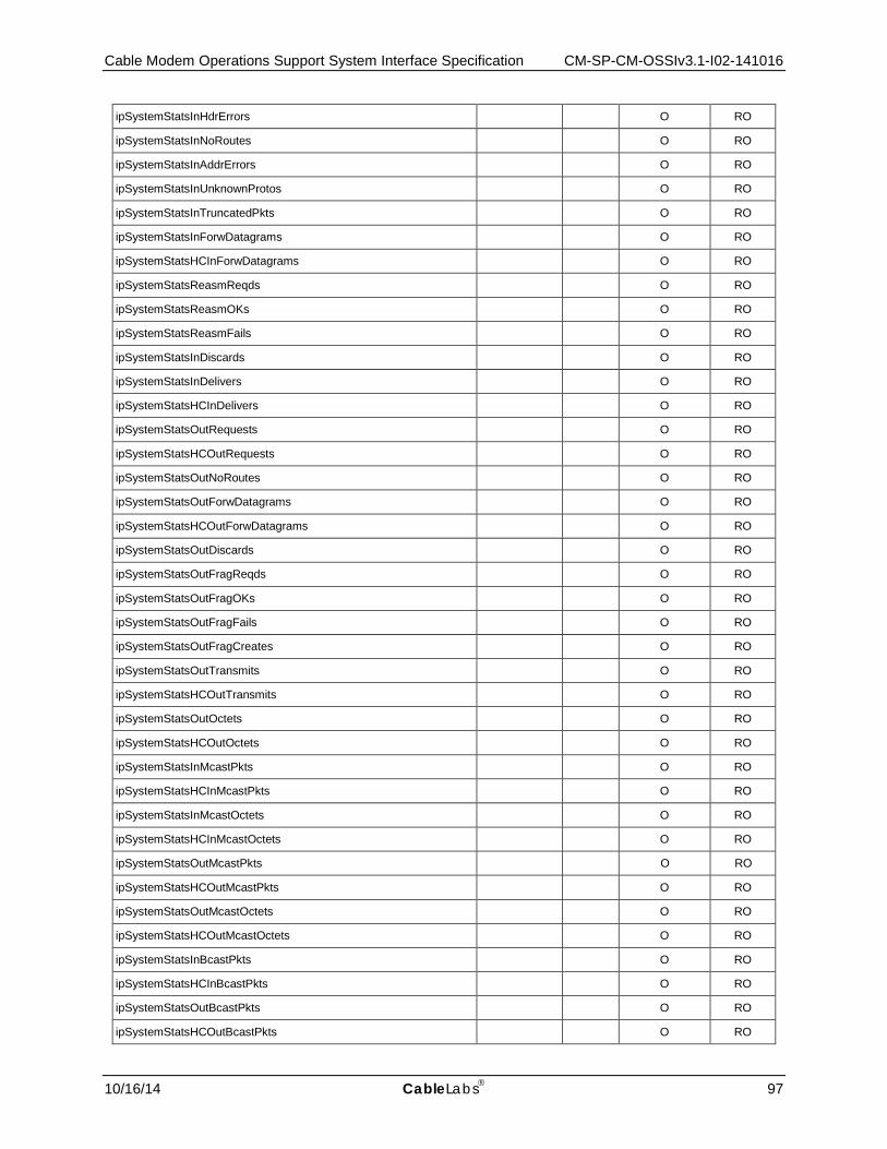
Cable Modem Operations Support System Interface Specification CM-SP-CM-OSSIv3.1-I02-141016
10/16/14 CableLabs 97
ipSystemStatsInHdrErrors O RO
ipSystemStatsInNoRoutes O RO
ipSystemStatsInAddrErrors O RO
ipSystemStatsInUnknownProtos O RO
ipSystemStatsInTruncatedPkts O RO
ipSystemStatsInForwDatagrams O RO
ipSystemStatsHCInForwDatagrams O RO
ipSystemStatsReasmReqds O RO
ipSystemStatsReasmOKs O RO
ipSystemStatsReasmFails O RO
ipSystemStatsInDiscards O RO
ipSystemStatsInDelivers O RO
ipSystemStatsHCInDelivers O RO
ipSystemStatsOutRequests O RO
ipSystemStatsHCOutRequests O RO
ipSystemStatsOutNoRoutes O RO
ipSystemStatsOutForwDatagrams O RO
ipSystemStatsHCOutForwDatagrams O RO
ipSystemStatsOutDiscards O RO
ipSystemStatsOutFragReqds O RO
ipSystemStatsOutFragOKs O RO
ipSystemStatsOutFragFails O RO
ipSystemStatsOutFragCreates O RO
ipSystemStatsOutTransmits O RO
ipSystemStatsHCOutTransmits O RO
ipSystemStatsOutOctets O RO
ipSystemStatsHCOutOctets O RO
ipSystemStatsInMcastPkts O RO
ipSystemStatsHCInMcastPkts O RO
ipSystemStatsInMcastOctets O RO
ipSystemStatsHCInMcastOctets O RO
ipSystemStatsOutMcastPkts O RO
ipSystemStatsHCOutMcastPkts O RO
ipSystemStatsOutMcastOctets O RO
ipSystemStatsHCOutMcastOctets O RO
ipSystemStatsInBcastPkts O RO
ipSystemStatsHCInBcastPkts O RO
ipSystemStatsOutBcastPkts O RO
ipSystemStatsHCOutBcastPkts O RO
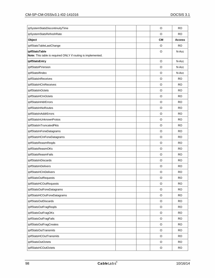
CM-SP-CM-OSSIv3.1-I02-141016 DOCSIS 3.1
98 CableLabs 10/16/14
ipSystemStatsDiscontinuityTime O RO
ipSystemStatsRefreshRate O RO
Object CM Access
ipIfStatsTableLastChange O RO
ipIfStatsTable Note: This table is required ONLY if routing is implemented.
O N-Acc
ipIfStatsEntry O N-Acc
ipIfStatsIPVersion O N-Acc
ipIfStatsIfIndex O N-Acc
ipIfStatsInReceives O RO
ipIfStatsHCInReceives O RO
ipIfStatsInOctets O RO
ipIfStatsHCInOctets O RO
ipIfStatsInHdrErrors O RO
ipIfStatsInNoRoutes O RO
ipIfStatsInAddrErrors O RO
ipIfStatsInUnknownProtos O RO
ipIfStatsInTruncatedPkts O RO
ipIfStatsInForwDatagrams O RO
ipIfStatsHCInForwDatagrams O RO
ipIfStatsReasmReqds O RO
ipIfStatsReasmOKs O RO
ipIfStatsReasmFails O RO
ipIfStatsInDiscards O RO
ipIfStatsInDelivers O RO
ipIfStatsHCInDelivers O RO
ipIfStatsOutRequests O RO
ipIfStatsHCOutRequests O RO
ipIfStatsOutForwDatagrams O RO
ipIfStatsHCOutForwDatagrams O RO
ipIfStatsOutDiscards O RO
ipIfStatsOutFragReqds O RO
ipIfStatsOutFragOKs O RO
ipIfStatsOutFragFails O RO
ipIfStatsOutFragCreates O RO
ipIfStatsOutTransmits O RO
ipIfStatsHCOutTransmits O RO
ipIfStatsOutOctets O RO
ipIfStatsHCOutOctets O RO
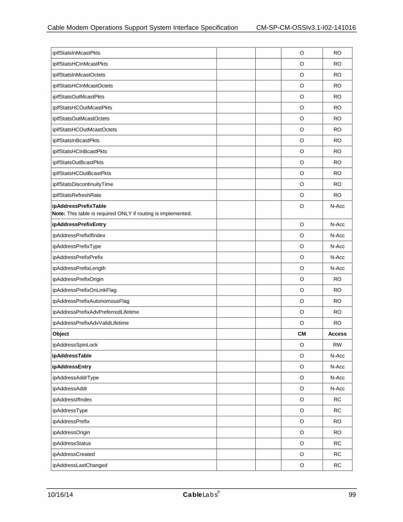
Cable Modem Operations Support System Interface Specification CM-SP-CM-OSSIv3.1-I02-141016
10/16/14 CableLabs 99
ipIfStatsInMcastPkts O RO
ipIfStatsHCInMcastPkts O RO
ipIfStatsInMcastOctets O RO
ipIfStatsHCInMcastOctets O RO
ipIfStatsOutMcastPkts O RO
ipIfStatsHCOutMcastPkts O RO
ipIfStatsOutMcastOctets O RO
ipIfStatsHCOutMcastOctets O RO
ipIfStatsInBcastPkts O RO
ipIfStatsHCInBcastPkts O RO
ipIfStatsOutBcastPkts O RO
ipIfStatsHCOutBcastPkts O RO
ipIfStatsDiscontinuityTime O RO
ipIfStatsRefreshRate O RO
ipAddressPrefixTable Note: This table is required ONLY if routing is implemented.
O N-Acc
ipAddressPrefixEntry O N-Acc
ipAddressPrefixIfIndex O N-Acc
ipAddressPrefixType O N-Acc
ipAddressPrefixPrefix O N-Acc
ipAddressPrefixLength O N-Acc
ipAddressPrefixOrigin O RO
ipAddressPrefixOnLinkFlag O RO
ipAddressPrefixAutonomousFlag O RO
ipAddressPrefixAdvPreferredLifetime O RO
ipAddressPrefixAdvValidLifetime O RO
Object CM Access
ipAddressSpinLock O RW
ipAddressTable O N-Acc
ipAddressEntry O N-Acc
ipAddressAddrType O N-Acc
ipAddressAddr O N-Acc
ipAddressIfIndex O RC
ipAddressType O RC
ipAddressPrefix O RO
ipAddressOrigin O RO
ipAddressStatus O RC
ipAddressCreated O RC
ipAddressLastChanged O RC
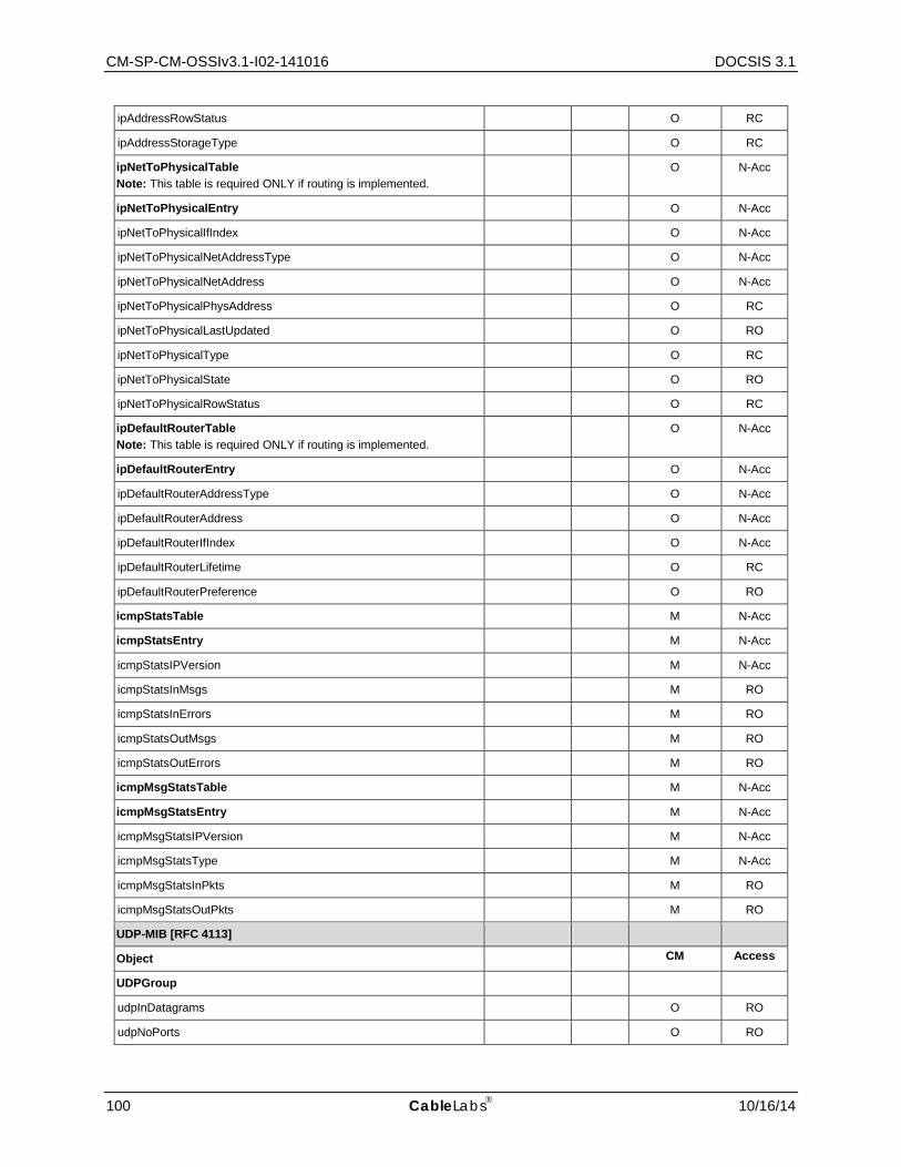
CM-SP-CM-OSSIv3.1-I02-141016 DOCSIS 3.1
100 CableLabs 10/16/14
ipAddressRowStatus O RC
ipAddressStorageType O RC
ipNetToPhysicalTable Note: This table is required ONLY if routing is implemented.
O N-Acc
ipNetToPhysicalEntry O N-Acc
ipNetToPhysicalIfIndex O N-Acc
ipNetToPhysicalNetAddressType O N-Acc
ipNetToPhysicalNetAddress O N-Acc
ipNetToPhysicalPhysAddress O RC
ipNetToPhysicalLastUpdated O RO
ipNetToPhysicalType O RC
ipNetToPhysicalState O RO
ipNetToPhysicalRowStatus O RC
ipDefaultRouterTable Note: This table is required ONLY if routing is implemented.
O N-Acc
ipDefaultRouterEntry O N-Acc
ipDefaultRouterAddressType O N-Acc
ipDefaultRouterAddress O N-Acc
ipDefaultRouterIfIndex O N-Acc
ipDefaultRouterLifetime O RC
ipDefaultRouterPreference O RO
icmpStatsTable M N-Acc
icmpStatsEntry M N-Acc
icmpStatsIPVersion M N-Acc
icmpStatsInMsgs M RO
icmpStatsInErrors M RO
icmpStatsOutMsgs M RO
icmpStatsOutErrors M RO
icmpMsgStatsTable M N-Acc
icmpMsgStatsEntry M N-Acc
icmpMsgStatsIPVersion M N-Acc
icmpMsgStatsType M N-Acc
icmpMsgStatsInPkts M RO
icmpMsgStatsOutPkts M RO
UDP-MIB [RFC 4113]
Object CM Access
UDPGroup
udpInDatagrams O RO
udpNoPorts O RO

Cable Modem Operations Support System Interface Specification CM-SP-CM-OSSIv3.1-I02-141016
10/16/14 CableLabs 101
udpInErrors O RO
udpOutDatagrams O RO
udpEndpointTable O N-Acc
udpEndpointEntry O N-Acc
udpEndpointLocalAddressType O N-Acc
udpEndpointLocalAddress O N-Acc
udpEndpointLocalPort O N-Acc
udpEndpointRemoteAddressType O N-Acc
udpEndpointRemoteAddress O N-Acc
udpEndpointRemotePort O N-Acc
udpEndpointInstance O N-Acc
udpEndpointProcess O RO
TCP-MIB [RFC 4022]
Object CM Access
tcpBaseGroup
tcpRtoAlgorithm O RO
tcpRtoMin O RO
tcpRtoMax O RO
tcpMaxConn O RO
tcpActiveOpens O RO
tcpPassiveOpens O RO
tcpAttemptFails O RO
tcpEstabResets O RO
tcpCurrEstab O RO
tcpInSegs O RO
tcpOutSegs O RO
tcpRetransSegs O RO
tcpInErrs O RO
tcpOutRsts O RO
tcpHCGroup
tcpHCInSegs O RO
tcpHCOutSegs O RO
tcpConnectionTable O N-Acc
tcpConnectionEntry O N-Acc
tcpConnectionLocalAddressType O N-Acc
tcpConnectionLocalAddress O N-Acc
tcpConnectionLocalPort O N-Acc
tcpConnectionRemAddressType O N-Acc
tcpConnectionRemAddress O N-Acc
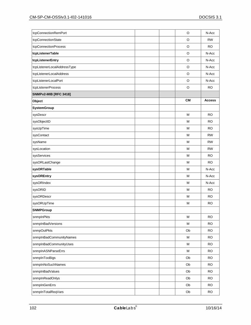
CM-SP-CM-OSSIv3.1-I02-141016 DOCSIS 3.1
102 CableLabs 10/16/14
tcpConnectionRemPort O N-Acc
tcpConnectionState O RW
tcpConnectionProcess O RO
tcpListenerTable O N-Acc
tcpListenerEntry O N-Acc
tcpListenerLocalAddressType O N-Acc
tcpListenerLocalAddress O N-Acc
tcpListenerLocalPort O N-Acc
tcpListenerProcess O RO
SNMPv2-MIB [RFC 3418]
Object CM Access
SystemGroup
sysDescr M RO
sysObjectID M RO
sysUpTime M RO
sysContact M RW
sysName M RW
sysLocation M RW
sysServices M RO
sysORLastChange M RO
sysORTable M N-Acc
sysOREntry M N-Acc
sysORIndex M N-Acc
sysORID M RO
sysORDescr M RO
sysORUpTime M RO
SNMPGroup
snmpInPkts M RO
snmpInBadVersions M RO
snmpOutPkts Ob RO
snmpInBadCommunityNames M RO
snmpInBadCommunityUses M RO
snmpInASNParseErrs M RO
snmpInTooBigs Ob RO
snmpInNoSuchNames Ob RO
snmpInBadValues Ob RO
snmpInReadOnlys Ob RO
snmpInGenErrs Ob RO
snmpInTotalReqVars Ob RO
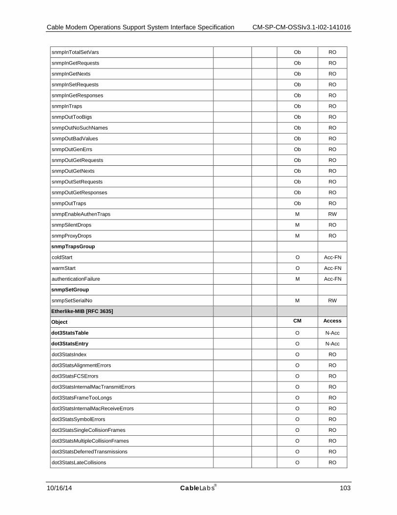
Cable Modem Operations Support System Interface Specification CM-SP-CM-OSSIv3.1-I02-141016
10/16/14 CableLabs 103
snmpInTotalSetVars Ob RO
snmpInGetRequests Ob RO
snmpInGetNexts Ob RO
snmpInSetRequests Ob RO
snmpInGetResponses Ob RO
snmpInTraps Ob RO
snmpOutTooBigs Ob RO
snmpOutNoSuchNames Ob RO
snmpOutBadValues Ob RO
snmpOutGenErrs Ob RO
snmpOutGetRequests Ob RO
snmpOutGetNexts Ob RO
snmpOutSetRequests Ob RO
snmpOutGetResponses Ob RO
snmpOutTraps Ob RO
snmpEnableAuthenTraps M RW
snmpSilentDrops M RO
snmpProxyDrops M RO
snmpTrapsGroup
coldStart O Acc-FN
warmStart O Acc-FN
authenticationFailure M Acc-FN
snmpSetGroup
snmpSetSerialNo M RW
Etherlike-MIB [RFC 3635]
Object CM Access
dot3StatsTable O N-Acc
dot3StatsEntry O N-Acc
dot3StatsIndex O RO
dot3StatsAlignmentErrors O RO
dot3StatsFCSErrors O RO
dot3StatsInternalMacTransmitErrors O RO
dot3StatsFrameTooLongs O RO
dot3StatsInternalMacReceiveErrors O RO
dot3StatsSymbolErrors O RO
dot3StatsSingleCollisionFrames O RO
dot3StatsMultipleCollisionFrames O RO
dot3StatsDeferredTransmissions O RO
dot3StatsLateCollisions O RO
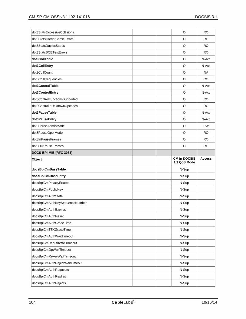
CM-SP-CM-OSSIv3.1-I02-141016 DOCSIS 3.1
104 CableLabs 10/16/14
dot3StatsExcessiveCollisions O RO
dot3StatsCarrierSenseErrors O RO
dot3StatsDuplexStatus O RO
dot3StatsSQETestErrors O RO
dot3CollTable O N-Acc
dot3CollEntry O N-Acc
dot3CollCount O NA
dot3CollFrequencies O RO
dot3ControlTable O N-Acc
dot3ControlEntry O N-Acc
dot3ControlFunctionsSupported O RO
dot3ControlInUnknownOpcodes O RO
dot3PauseTable O N-Acc
dot3PauseEntry O N-Acc
dot3PauseAdminMode O RW
dot3PauseOperMode O RO
dot3InPauseFrames O RO
dot3OutPauseFrames O RO
DOCS-BPI-MIB [RFC 3083]
Object CM in DOCSIS 1.1 QoS Mode
Access
docsBpiCmBaseTable N-Sup
docsBpiCmBaseEntry N-Sup
docsBpiCmPrivacyEnable N-Sup
docsBpiCmPublicKey N-Sup
docsBpiCmAuthState N-Sup
docsBpiCmAuthKeySequenceNumber N-Sup
docsBpiCmAuthExpires N-Sup
docsBpiCmAuthReset N-Sup
docsBpiCmAuthGraceTime N-Sup
docsBpiCmTEKGraceTime N-Sup
docsBpiCmAuthWaitTimeout N-Sup
docsBpiCmReauthWaitTimeout N-Sup
docsBpiCmOpWaitTimeout N-Sup
docsBpiCmRekeyWaitTimeout N-Sup
docsBpiCmAuthRejectWaitTimeout N-Sup
docsBpiCmAuthRequests N-Sup
docsBpiCmAuthReplies N-Sup
docsBpiCmAuthRejects N-Sup
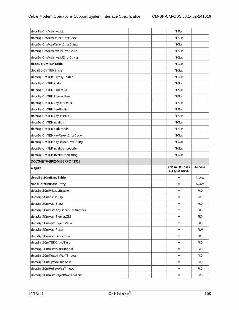
Cable Modem Operations Support System Interface Specification CM-SP-CM-OSSIv3.1-I02-141016
10/16/14 CableLabs 105
docsBpiCmAuthInvalids N-Sup
docsBpiCmAuthRejectErrorCode N-Sup
docsBpiCmAuthRejectErrorString N-Sup
docsBpiCmAuthInvalidErrorCode N-Sup
docsBpiCmAuthInvalidErrorString N-Sup
docsBpiCmTEKTable N-Sup
docsBpiCmTEKEntry N-Sup
docsBpiCmTEKPrivacyEnable N-Sup
docsBpiCmTEKState N-Sup
docsBpiCmTEKExpiresOld N-Sup
docsBpiCmTEKExpiresNew N-Sup
docsBpiCmTEKKeyRequests N-Sup
docsBpiCmTEKKeyReplies N-Sup
docsBpiCmTEKKeyRejects N-Sup
docsBpiCmTEKInvalids N-Sup
docsBpiCmTEKAuthPends N-Sup
docsBpiCmTEKKeyRejectErrorCode N-Sup
docsBpiCmTEKKeyRejectErrorString N-Sup
docsBpiCmTEKInvalidErrorCode N-Sup
docsBpiCmTEKInvalidErrorString N-Sup
DOCS-IETF-BPI2-MIB [RFC 4131]
Object CM in DOCSIS 1.1 QoS Mode
Access
docsBpi2CmBaseTable M N-Acc
docsBpi2CmBaseEntry M N-Acc
docsBpi2CmPrivacyEnable M RO
docsBpi2CmPublicKey M RO
docsBpi2CmAuthState M RO
docsBpi2CmAuthKeySequenceNumber M RO
docsBpi2CmAuthExpiresOld M RO
docsBpi2CmAuthExpiresNew M RO
docsBpi2CmAuthReset M RW
docsBpi2CmAuthGraceTime M RO
docsBpi2CmTEKGraceTime M RO
docsBpi2CmAuthWaitTimeout M RO
docsBpi2CmReauthWaitTimeout M RO
docsBpi2CmOpWaitTimeout M RO
docsBpi2CmRekeyWaitTimeout M RO
docsBpi2CmAuthRejectWaitTimeout M RO

CM-SP-CM-OSSIv3.1-I02-141016 DOCSIS 3.1
106 CableLabs 10/16/14
docsBpi2CmSAMapWaitTimeout M RO
docsBpi2CmSAMapMaxRetries M RO
docsBpi2CmAuthentInfos M RO
docsBpi2CmAuthRequests M RO
docsBpi2CmAuthReplies M RO
docsBpi2CmAuthRejects M RO
docsBpi2CmAuthInvalids M RO
docsBpi2CmAuthRejectErrorCode M RO
docsBpi2CmAuthRejectErrorString M RO
docsBpi2CmAuthInvalidErrorCode M RO
docsBpi2CmAuthInvalidErrorString M RO
docsBpi2CmTEKTable M N-Acc
docsBpi2CmTEKEntry M N-Acc
docsBpi2CmTEKSAId M N-Acc
docsBpi2CmTEKSAType M RO
docsBpi2CmTEKDataEncryptAlg M RO
docsBpi2CmTEKDataAuthentAlg M RO
docsBpi2CmTEKState M RO
docsBpi2CmTEKKeySequenceNumber M RO
docsBpi2CmTEKExpiresOld M RO
docsBpi2CmTEKExpiresNew M RO
docsBpi2CmTEKKeyRequests M RO
docsBpi2CmTEKKeyReplies M RO
docsBpi2CmTEKKeyRejects M RO
docsBpi2CmTEKInvalids M RO
docsBpi2CmTEKAuthPends M RO
docsBpi2CmTEKKeyRejectErrorCode M RO
docsBpi2CmTEKKeyRejectErrorString M RO
docsBpi2CmTEKInvalidErrorCode M RO
docsBpi2CmTEKInvalidErrorString M RO
docsBpi2CmIpMulticastMapTable M N-Acc
docsBpi2CmIpMulticastMapEntry M N-Acc
docsBpi2CmIpMulticastIndex M N-Acc
docsBpi2CmIpMulticastAddressType M RO
docsBpi2CmIpMulticastAddress M RO
docsBpi2CmIpMulticastSAId M RO
docsBpi2CmIpMulticastSAMapState M RO
docsBpi2CmIpMulticastSAMapRequests M RO
docsBpi2CmIpMulticastSAMapReplies M RO
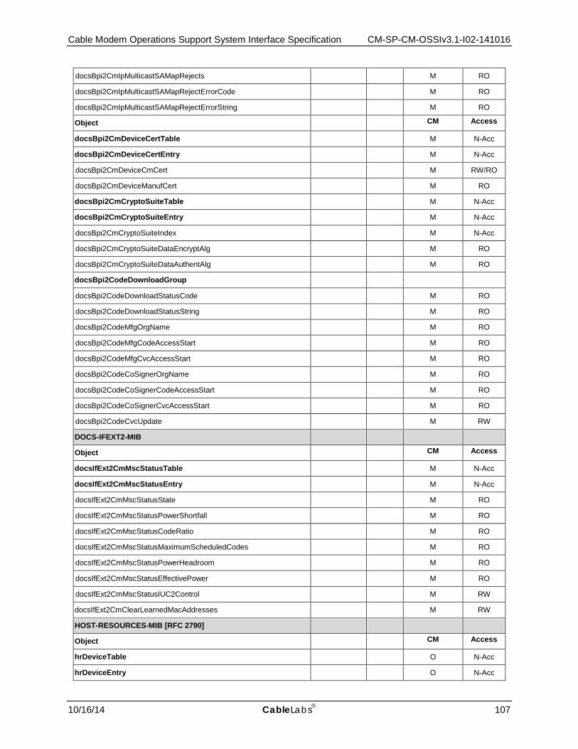
Cable Modem Operations Support System Interface Specification CM-SP-CM-OSSIv3.1-I02-141016
10/16/14 CableLabs 107
docsBpi2CmIpMulticastSAMapRejects M RO
docsBpi2CmIpMulticastSAMapRejectErrorCode M RO
docsBpi2CmIpMulticastSAMapRejectErrorString M RO
Object CM Access
docsBpi2CmDeviceCertTable M N-Acc
docsBpi2CmDeviceCertEntry M N-Acc
docsBpi2CmDeviceCmCert M RW/RO
docsBpi2CmDeviceManufCert M RO
docsBpi2CmCryptoSuiteTable M N-Acc
docsBpi2CmCryptoSuiteEntry M N-Acc
docsBpi2CmCryptoSuiteIndex M N-Acc
docsBpi2CmCryptoSuiteDataEncryptAlg M RO
docsBpi2CmCryptoSuiteDataAuthentAlg M RO
docsBpi2CodeDownloadGroup
docsBpi2CodeDownloadStatusCode M RO
docsBpi2CodeDownloadStatusString M RO
docsBpi2CodeMfgOrgName M RO
docsBpi2CodeMfgCodeAccessStart M RO
docsBpi2CodeMfgCvcAccessStart M RO
docsBpi2CodeCoSignerOrgName M RO
docsBpi2CodeCoSignerCodeAccessStart M RO
docsBpi2CodeCoSignerCvcAccessStart M RO
docsBpi2CodeCvcUpdate M RW
DOCS-IFEXT2-MIB
Object CM Access
docsIfExt2CmMscStatusTable M N-Acc
docsIfExt2CmMscStatusEntry M N-Acc
docsIfExt2CmMscStatusState M RO
docsIfExt2CmMscStatusPowerShortfall M RO
docsIfExt2CmMscStatusCodeRatio M RO
docsIfExt2CmMscStatusMaximumScheduledCodes M RO
docsIfExt2CmMscStatusPowerHeadroom M RO
docsIfExt2CmMscStatusEffectivePower M RO
docsIfExt2CmMscStatusIUC2Control M RW
docsIfExt2CmClearLearnedMacAddresses M RW
HOST-RESOURCES-MIB [RFC 2790]
Object CM Access
hrDeviceTable O N-Acc
hrDeviceEntry O N-Acc
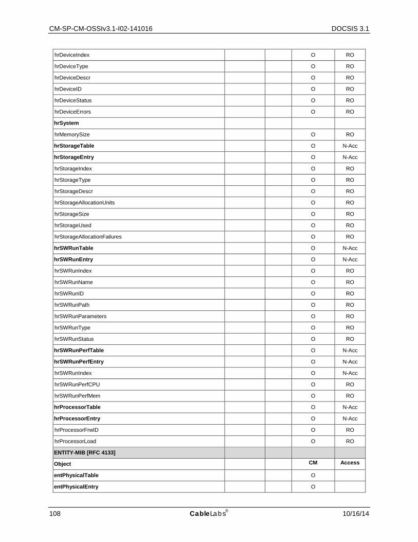
CM-SP-CM-OSSIv3.1-I02-141016 DOCSIS 3.1
108 CableLabs 10/16/14
hrDeviceIndex O RO
hrDeviceType O RO
hrDeviceDescr O RO
hrDeviceID O RO
hrDeviceStatus O RO
hrDeviceErrors O RO
hrSystem
hrMemorySize O RO
hrStorageTable O N-Acc
hrStorageEntry O N-Acc
hrStorageIndex O RO
hrStorageType O RO
hrStorageDescr O RO
hrStorageAllocationUnits O RO
hrStorageSize O RO
hrStorageUsed O RO
hrStorageAllocationFailures O RO
hrSWRunTable O N-Acc
hrSWRunEntry O N-Acc
hrSWRunIndex O RO
hrSWRunName O RO
hrSWRunID O RO
hrSWRunPath O RO
hrSWRunParameters O RO
hrSWRunType O RO
hrSWRunStatus O RO
hrSWRunPerfTable O N-Acc
hrSWRunPerfEntry O N-Acc
hrSWRunIndex O N-Acc
hrSWRunPerfCPU O RO
hrSWRunPerfMem O RO
hrProcessorTable O N-Acc
hrProcessorEntry O N-Acc
hrProcessorFrwID O RO
hrProcessorLoad O RO
ENTITY-MIB [RFC 4133]
Object CM Access
entPhysicalTable O
entPhysicalEntry O
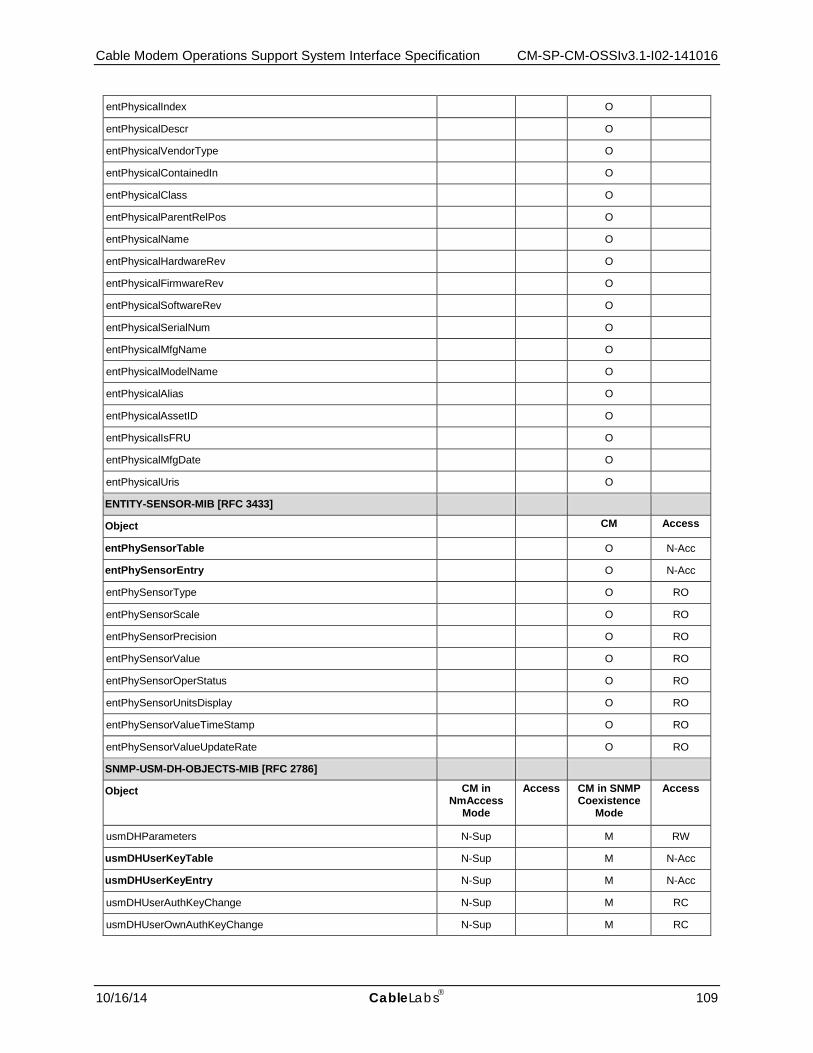
Cable Modem Operations Support System Interface Specification CM-SP-CM-OSSIv3.1-I02-141016
10/16/14 CableLabs 109
entPhysicalIndex O
entPhysicalDescr O
entPhysicalVendorType O
entPhysicalContainedIn O
entPhysicalClass O
entPhysicalParentRelPos O
entPhysicalName O
entPhysicalHardwareRev O
entPhysicalFirmwareRev O
entPhysicalSoftwareRev O
entPhysicalSerialNum O
entPhysicalMfgName O
entPhysicalModelName O
entPhysicalAlias O
entPhysicalAssetID O
entPhysicalIsFRU O
entPhysicalMfgDate O
entPhysicalUris O
ENTITY-SENSOR-MIB [RFC 3433]
Object CM Access
entPhySensorTable O N-Acc
entPhySensorEntry O N-Acc
entPhySensorType O RO
entPhySensorScale O RO
entPhySensorPrecision O RO
entPhySensorValue O RO
entPhySensorOperStatus O RO
entPhySensorUnitsDisplay O RO
entPhySensorValueTimeStamp O RO
entPhySensorValueUpdateRate O RO
SNMP-USM-DH-OBJECTS-MIB [RFC 2786]
Object CM in NmAccess
Mode
Access CM in SNMP Coexistence
Mode
Access
usmDHParameters N-Sup M RW
usmDHUserKeyTable N-Sup M N-Acc
usmDHUserKeyEntry N-Sup M N-Acc
usmDHUserAuthKeyChange N-Sup M RC
usmDHUserOwnAuthKeyChange N-Sup M RC
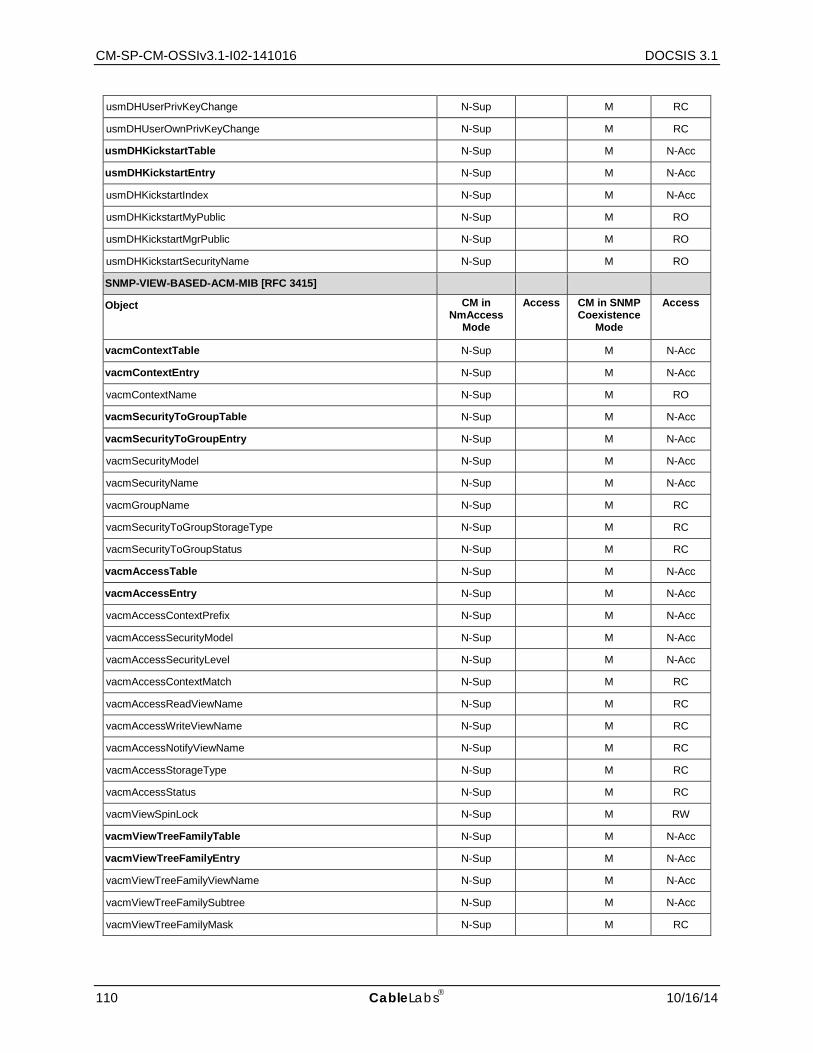
CM-SP-CM-OSSIv3.1-I02-141016 DOCSIS 3.1
110 CableLabs 10/16/14
usmDHUserPrivKeyChange N-Sup M RC
usmDHUserOwnPrivKeyChange N-Sup M RC
usmDHKickstartTable N-Sup M N-Acc
usmDHKickstartEntry N-Sup M N-Acc
usmDHKickstartIndex N-Sup M N-Acc
usmDHKickstartMyPublic N-Sup M RO
usmDHKickstartMgrPublic N-Sup M RO
usmDHKickstartSecurityName N-Sup M RO
SNMP-VIEW-BASED-ACM-MIB [RFC 3415]
Object CM in NmAccess
Mode
Access CM in SNMP Coexistence
Mode
Access
vacmContextTable N-Sup M N-Acc
vacmContextEntry N-Sup M N-Acc
vacmContextName N-Sup M RO
vacmSecurityToGroupTable N-Sup M N-Acc
vacmSecurityToGroupEntry N-Sup M N-Acc
vacmSecurityModel N-Sup M N-Acc
vacmSecurityName N-Sup M N-Acc
vacmGroupName N-Sup M RC
vacmSecurityToGroupStorageType N-Sup M RC
vacmSecurityToGroupStatus N-Sup M RC
vacmAccessTable N-Sup M N-Acc
vacmAccessEntry N-Sup M N-Acc
vacmAccessContextPrefix N-Sup M N-Acc
vacmAccessSecurityModel N-Sup M N-Acc
vacmAccessSecurityLevel N-Sup M N-Acc
vacmAccessContextMatch N-Sup M RC
vacmAccessReadViewName N-Sup M RC
vacmAccessWriteViewName N-Sup M RC
vacmAccessNotifyViewName N-Sup M RC
vacmAccessStorageType N-Sup M RC
vacmAccessStatus N-Sup M RC
vacmViewSpinLock N-Sup M RW
vacmViewTreeFamilyTable N-Sup M N-Acc
vacmViewTreeFamilyEntry N-Sup M N-Acc
vacmViewTreeFamilyViewName N-Sup M N-Acc
vacmViewTreeFamilySubtree N-Sup M N-Acc
vacmViewTreeFamilyMask N-Sup M RC

Cable Modem Operations Support System Interface Specification CM-SP-CM-OSSIv3.1-I02-141016
10/16/14 CableLabs 111
vacmViewTreeFamilyType N-Sup M RC
vacmViewTreeFamilyStorageType N-Sup M RC
vacmViewTreeFamilyStatus N-Sup M RC
SNMP-COMMUNITY-MIB [RFC 3584]
Object CM in NmAccess
Mode
Access CM in SNMP Coexistence
Mode
Access
snmpCommunityTable N-Sup M N-Acc
snmpCommunityEntry N-Sup M N-Acc
snmpCommunityIndex N-Sup M N-Acc
snmpCommunityName N-Sup M RC
snmpCommunitySecurityName N-Sup M RC
snmpCommunityContextEngineID N-Sup M RC
snmpCommunityContextName N-Sup M RC
snmpCommunityTransportTag N-Sup M RC
snmpCommunityStorageType N-Sup M RC
snmpCommunityStatus N-Sup M RC
snmpTargetAddrExtTable N-Sup M N-Acc
snmpTargetAddrExtEntry N-Sup M N-Acc
snmpTargetAddrTMask N-Sup M RC
snmpTargetAddrMMS N-Sup M RC
snmpTrapAddress N-Sup O ACC-FN
snmpTrapCommunity N-Sup O ACC-FN
SNMP-FRAMEWORK-MIB [RFC 3411]
Object CM in NmAccess
Mode
Access CM in SNMP Coexistence
Mode
Access
snmpEngineGroup
snmpEngineID N-Sup M RO
snmpEngineBoots N-Sup M RO
snmpEngineTime N-Sup M RO
snmpEngineMaxMessageSize N-Sup M RO
SNMP-MPD-MIB [RFC 3412]
Object CM in NmAccess
Mode
Access CM in SNMP Coexistence
Mode
Access
snmpMPDStats
snmpUnknownSecurityModels N-Sup M RO
snmpInvalidMsgs N-Sup M RO
snmpUnknownPDUHandlers N-Sup M RO
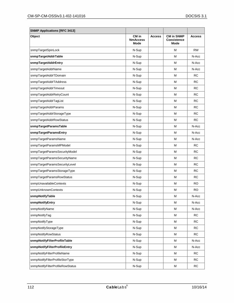
CM-SP-CM-OSSIv3.1-I02-141016 DOCSIS 3.1
112 CableLabs 10/16/14
SNMP Applications [RFC 3413]
Object CM in NmAccess
Mode
Access CM in SNMP Coexistence
Mode
Access
snmpTargetSpinLock N-Sup M RW
snmpTargetAddrTable N-Sup M N-Acc
snmpTargetAddrEntry N-Sup M N-Acc
snmpTargetAddrName N-Sup M N-Acc
snmpTargetAddrTDomain N-Sup M RC
snmpTargetAddrTAddress N-Sup M RC
snmpTargetAddrTimeout N-Sup M RC
snmpTargetAddrRetryCount N-Sup M RC
snmpTargetAddrTagList N-Sup M RC
snmpTargetAddrParams N-Sup M RC
snmpTargetAddrStorageType N-Sup M RC
snmpTargetAddrRowStatus N-Sup M RC
snmpTargetParamsTable N-Sup M N-Acc
snmpTargetParamsEntry N-Sup M N-Acc
snmpTargetParamsName N-Sup M N-Acc
snmpTargetParamsMPModel N-Sup M RC
snmpTargetParamsSecurityModel N-Sup M RC
snmpTargetParamsSecurityName N-Sup M RC
snmpTargetParamsSecurityLevel N-Sup M RC
snmpTargetParamsStorageType N-Sup M RC
snmpTargetParamsRowStatus N-Sup M RC
snmpUnavailableContexts N-Sup M RO
snmpUnknownContexts N-Sup M RO
snmpNotifyTable N-Sup M N-Acc
snmpNotifyEntry N-Sup M N-Acc
snmpNotifyName N-Sup M N-Acc
snmpNotifyTag N-Sup M RC
snmpNotifyType N-Sup M RC
snmpNotifyStorageType N-Sup M RC
snmpNotifyRowStatus N-Sup M RC
snmpNotifyFilterProfileTable N-Sup M N-Acc
snmpNotifyFilterProfileEntry N-Sup M N-Acc
snmpNotifyFilterProfileName N-Sup M RC
snmpNotifyFilterProfileStorType N-Sup M RC
snmpNotifyFilterProfileRowStatus N-Sup M RC
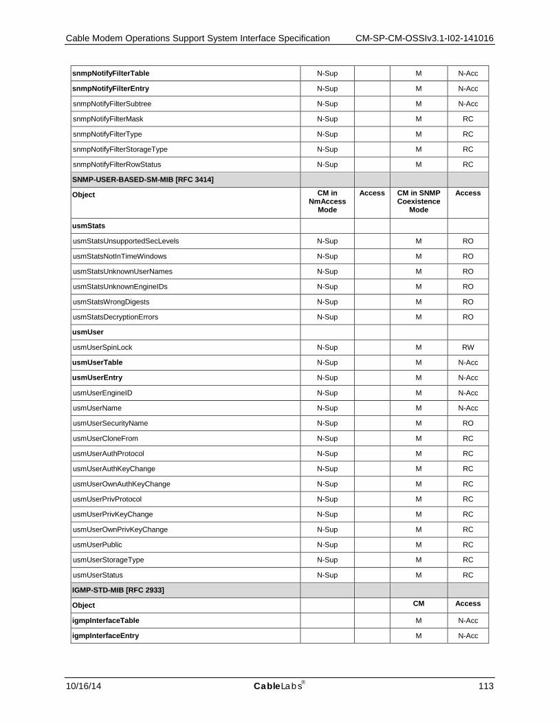
Cable Modem Operations Support System Interface Specification CM-SP-CM-OSSIv3.1-I02-141016
10/16/14 CableLabs 113
snmpNotifyFilterTable N-Sup M N-Acc
snmpNotifyFilterEntry N-Sup M N-Acc
snmpNotifyFilterSubtree N-Sup M N-Acc
snmpNotifyFilterMask N-Sup M RC
snmpNotifyFilterType N-Sup M RC
snmpNotifyFilterStorageType N-Sup M RC
snmpNotifyFilterRowStatus N-Sup M RC
SNMP-USER-BASED-SM-MIB [RFC 3414]
Object CM in NmAccess
Mode
Access CM in SNMP Coexistence
Mode
Access
usmStats
usmStatsUnsupportedSecLevels N-Sup M RO
usmStatsNotInTimeWindows N-Sup M RO
usmStatsUnknownUserNames N-Sup M RO
usmStatsUnknownEngineIDs N-Sup M RO
usmStatsWrongDigests N-Sup M RO
usmStatsDecryptionErrors N-Sup M RO
usmUser
usmUserSpinLock N-Sup M RW
usmUserTable N-Sup M N-Acc
usmUserEntry N-Sup M N-Acc
usmUserEngineID N-Sup M N-Acc
usmUserName N-Sup M N-Acc
usmUserSecurityName N-Sup M RO
usmUserCloneFrom N-Sup M RC
usmUserAuthProtocol N-Sup M RC
usmUserAuthKeyChange N-Sup M RC
usmUserOwnAuthKeyChange N-Sup M RC
usmUserPrivProtocol N-Sup M RC
usmUserPrivKeyChange N-Sup M RC
usmUserOwnPrivKeyChange N-Sup M RC
usmUserPublic N-Sup M RC
usmUserStorageType N-Sup M RC
usmUserStatus N-Sup M RC
IGMP-STD-MIB [RFC 2933]
Object CM Access
igmpInterfaceTable M N-Acc
igmpInterfaceEntry M N-Acc
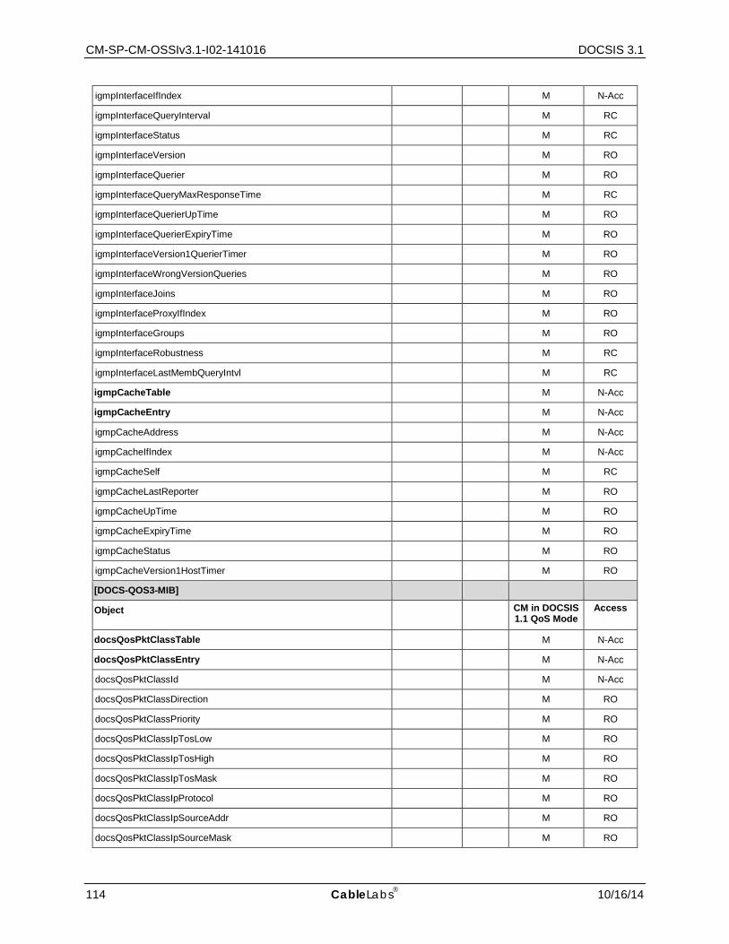
CM-SP-CM-OSSIv3.1-I02-141016 DOCSIS 3.1
114 CableLabs 10/16/14
igmpInterfaceIfIndex M N-Acc
igmpInterfaceQueryInterval M RC
igmpInterfaceStatus M RC
igmpInterfaceVersion M RO
igmpInterfaceQuerier M RO
igmpInterfaceQueryMaxResponseTime M RC
igmpInterfaceQuerierUpTime M RO
igmpInterfaceQuerierExpiryTime M RO
igmpInterfaceVersion1QuerierTimer M RO
igmpInterfaceWrongVersionQueries M RO
igmpInterfaceJoins M RO
igmpInterfaceProxyIfIndex M RO
igmpInterfaceGroups M RO
igmpInterfaceRobustness M RC
igmpInterfaceLastMembQueryIntvl M RC
igmpCacheTable M N-Acc
igmpCacheEntry M N-Acc
igmpCacheAddress M N-Acc
igmpCacheIfIndex M N-Acc
igmpCacheSelf M RC
igmpCacheLastReporter M RO
igmpCacheUpTime M RO
igmpCacheExpiryTime M RO
igmpCacheStatus M RO
igmpCacheVersion1HostTimer M RO
[DOCS-QOS3-MIB]
Object CM in DOCSIS 1.1 QoS Mode
Access
docsQosPktClassTable M N-Acc
docsQosPktClassEntry M N-Acc
docsQosPktClassId M N-Acc
docsQosPktClassDirection M RO
docsQosPktClassPriority M RO
docsQosPktClassIpTosLow M RO
docsQosPktClassIpTosHigh M RO
docsQosPktClassIpTosMask M RO
docsQosPktClassIpProtocol M RO
docsQosPktClassIpSourceAddr M RO
docsQosPktClassIpSourceMask M RO

Cable Modem Operations Support System Interface Specification CM-SP-CM-OSSIv3.1-I02-141016
10/16/14 CableLabs 115
docsQosPktClassIpDestAddr M RO
docsQosPktClassIpDestMask M RO
docsQosPktClassSourcePortStart M RO
docsQosPktClassSourcePortEnd M RO
docsQosPktClassDestPortStart M RO
docsQosPktClassDestPortEnd M RO
docsQosPktClassDestMacAddr M RO
docsQosPktClassDestMacMask M RO
docsQosPktClassSourceMacAddr M RO
docsQosPktClassEnetProtocolType M RO
docsQosPktClassEnetProtocol M RO
docsQosPktClassUserPriLow M RO
docsQosPktClassUserPriHigh M RO
docsQosPktClassVlanId M RO
docsQosPktClassState M RO
docsQosPktClassPkts M RO
docsQosPktClassBitMap M RO
docsQosPktClassIpAddrType M RO
docsQosPktClassFlowLabel M RO
docsQosPktClassIcmpTypeHigh M RO
docsQosPktClassIcmpTypeLow M RO
docsQosPktClassCmInterfaceMask M RO
docsQosParamSetTable M N-Acc
docsQosParamSetEntry M N-Acc
docsQosParamSetServiceClassName M RO
docsQosParamSetPriority M RO
docsQosParamSetMaxTrafficRate M RO
docsQosParamSetMaxTrafficBurst M RO
docsQosParamSetMinReservedRate M RO
docsQosParamSetMinReservedPkt M RO
docsQosParamSetActiveTimeout M RO
docsQosParamSetAdmittedTimeout M RO
docsQosParamSetMaxConcatBurst M RO
docsQosParamSetSchedulingType M RO
docsQosParamSetNomPollInterval M RO
docsQosParamSetTolPollJitter M RO
docsQosParamSetUnsolicitGrantSize M RO
docsQosParamSetNomGrantInterval M RO
docsQosParamSetTolGrantJitter M RO

CM-SP-CM-OSSIv3.1-I02-141016 DOCSIS 3.1
116 CableLabs 10/16/14
docsQosParamSetGrantsPerInterval M RO
docsQosParamSetTosAndMask M RO
docsQosParamSetTosOrMask M RO
docsQosParamSetMaxLatency M RO
docsQosParamSetType M N-Acc
docsQosParamSetRequestPolicyOct M RO
docsQosParamSetBitMap M RO
docsQosParamSetServiceFlowId M N-Acc
docsQosParamSetRequiredAttrMask M RO
docsQosParamSetForbiddenAttrMask M RO
docsQosParamSetAttrAggrRuleMask M RO
docsQosParamSetAppId M RO
docsQosParamSetMultiplierContentionReqWindow M RO
docsQosParamSetMultiplierBytesReq M RO
docsQosParamSetMaxReqPerSidCluster D RO
docsQosParamSetMaxOutstandingBytesPerSidCluster D RO
docsQosParamSetMaxTotBytesReqPerSidCluster D RO
docsQosParamSetMaxTimeInSidCluster D RO
docsQosParamSetPeakTrafficRate M RO
docsQosParamSetDsResequencing M RO
docsQosParamSetMinimumBuffer M RO
docsQosParamSetTargetBuffer M RO
docsQosParamSetMaximumBuffer M RO
docsQosParamSetAqmEnabled M RO
docsQosParamSetAqmLatencyTarget M RO
docsQosParamSetAqmAlgInUse M RO
docsQosServiceFlowTable M N-Acc
docsQosServiceFlowEntry M N-Acc
docsQosServiceFlowId M N-Acc
docsQosServiceFlowSID M RO
docsQosServiceFlowDirection M RO
docsQosServiceFlowPrimary M RO
docsQosServiceFlowParamSetTypeStatus M RO
docsQosServiceFlowChSetId M RO
docsQosServiceFlowAttrAssignSuccess M RO
docsQosServiceFlowDsid M RO
docsQosServiceFlowMaxReqPerSidCluster M RO
docsQosServiceFlowMaxOutstandingBytesPerSidCluster M RO
docsQosServiceFlowMaxTotBytesReqPerSidCluster M RO

Cable Modem Operations Support System Interface Specification CM-SP-CM-OSSIv3.1-I02-141016
10/16/14 CableLabs 117
docsQosServiceFlowMaxTimeInSidCluster M RO
docsQosServiceFlowBufferSize M RO
docsQosServiceFlowStatsTable M N-Acc
docsQosServiceFlowStatsEntry M N-Acc
docsQosServiceFlowPkts M RO
docsQosServiceFlowOctets M RO
docsQosServiceFlowTimeCreated M RO
docsQosServiceFlowTimeActive M RO
docsQosServiceFlowPHSUnknowns M RO
docsQosServiceFlowPolicedDropPkts M RO
docsQosServiceFlowPolicedDelayPkts M RO
docsQosServiceFlowAqmDroppedPkts M RO
Object CM in DOCSIS 1.1 QoS Mode
Access
docsQosDynamicServiceStatsTable M N-Acc
docsQosDynamicServiceStatsEntry M N-Acc
docsQosIfDirection M N-Acc
docsQosDSAReqs M RO
docsQosDSARsps M RO
docsQosDSAAcks M RO
docsQosDSCReqs M RO
docsQosDSCRsps M RO
docsQosDSCAcks M RO
docsQosDSDReqs M RO
docsQosDSDRsps M RO
docsQosDynamicAdds M RO
docsQosDynamicAddFails M RO
docsQosDynamicChanges M RO
docsQosDynamicChangeFails M RO
docsQosDynamicDeletes M RO
docsQosDynamicDeleteFails M RO
docsQosDCCReqs M RO
docsQosDCCRsps M RO
docsQosDCCAcks M RO
docsQosDCCs M RO
docsQosDCCFails M RO
docsQosDCCRspDeparts M RO
docsQosDCCRspArrives M RO
docsQosDbcReqs M RO
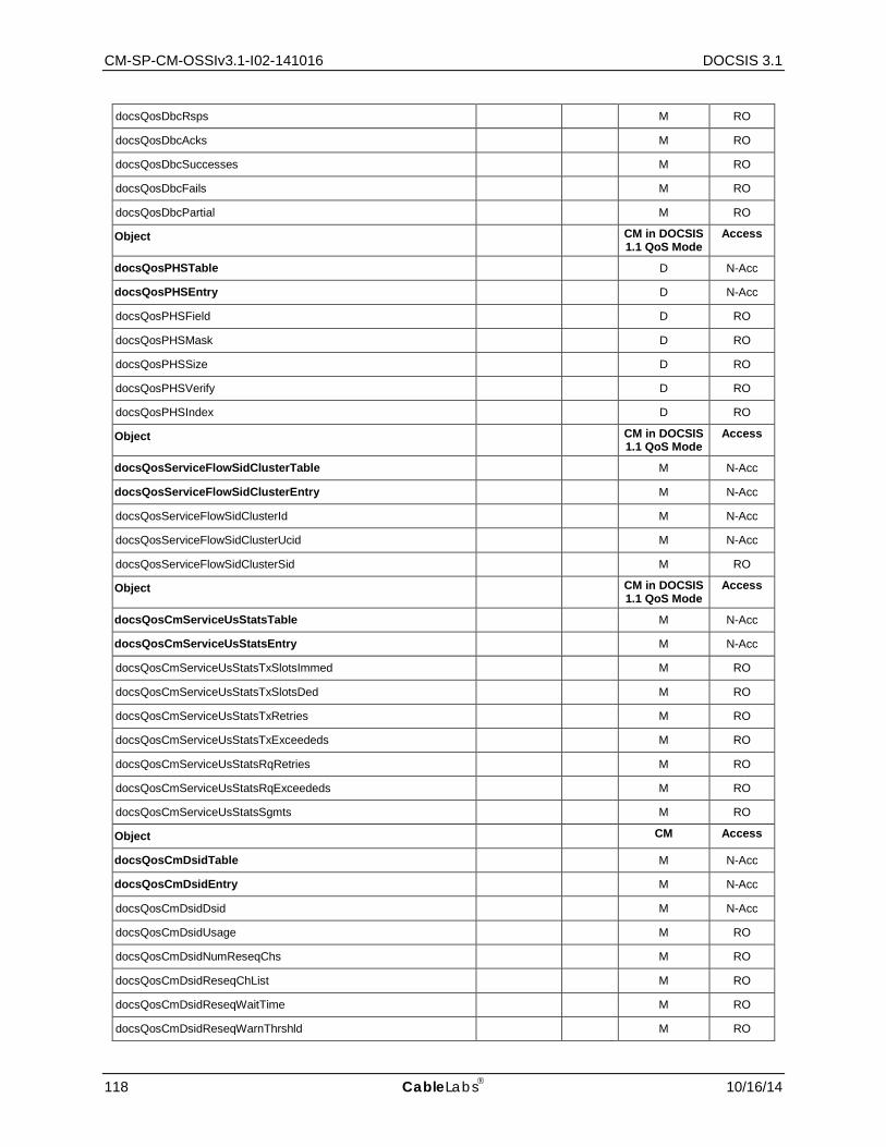
CM-SP-CM-OSSIv3.1-I02-141016 DOCSIS 3.1
118 CableLabs 10/16/14
docsQosDbcRsps M RO
docsQosDbcAcks M RO
docsQosDbcSuccesses M RO
docsQosDbcFails M RO
docsQosDbcPartial M RO
Object CM in DOCSIS 1.1 QoS Mode
Access
docsQosPHSTable D N-Acc
docsQosPHSEntry D N-Acc
docsQosPHSField D RO
docsQosPHSMask D RO
docsQosPHSSize D RO
docsQosPHSVerify D RO
docsQosPHSIndex D RO
Object CM in DOCSIS 1.1 QoS Mode
Access
docsQosServiceFlowSidClusterTable M N-Acc
docsQosServiceFlowSidClusterEntry M N-Acc
docsQosServiceFlowSidClusterId M N-Acc
docsQosServiceFlowSidClusterUcid M N-Acc
docsQosServiceFlowSidClusterSid M RO
Object CM in DOCSIS 1.1 QoS Mode
Access
docsQosCmServiceUsStatsTable M N-Acc
docsQosCmServiceUsStatsEntry M N-Acc
docsQosCmServiceUsStatsTxSlotsImmed M RO
docsQosCmServiceUsStatsTxSlotsDed M RO
docsQosCmServiceUsStatsTxRetries M RO
docsQosCmServiceUsStatsTxExceededs M RO
docsQosCmServiceUsStatsRqRetries M RO
docsQosCmServiceUsStatsRqExceededs M RO
docsQosCmServiceUsStatsSgmts M RO
Object CM Access
docsQosCmDsidTable M N-Acc
docsQosCmDsidEntry M N-Acc
docsQosCmDsidDsid M N-Acc
docsQosCmDsidUsage M RO
docsQosCmDsidNumReseqChs M RO
docsQosCmDsidReseqChList M RO
docsQosCmDsidReseqWaitTime M RO
docsQosCmDsidReseqWarnThrshld M RO
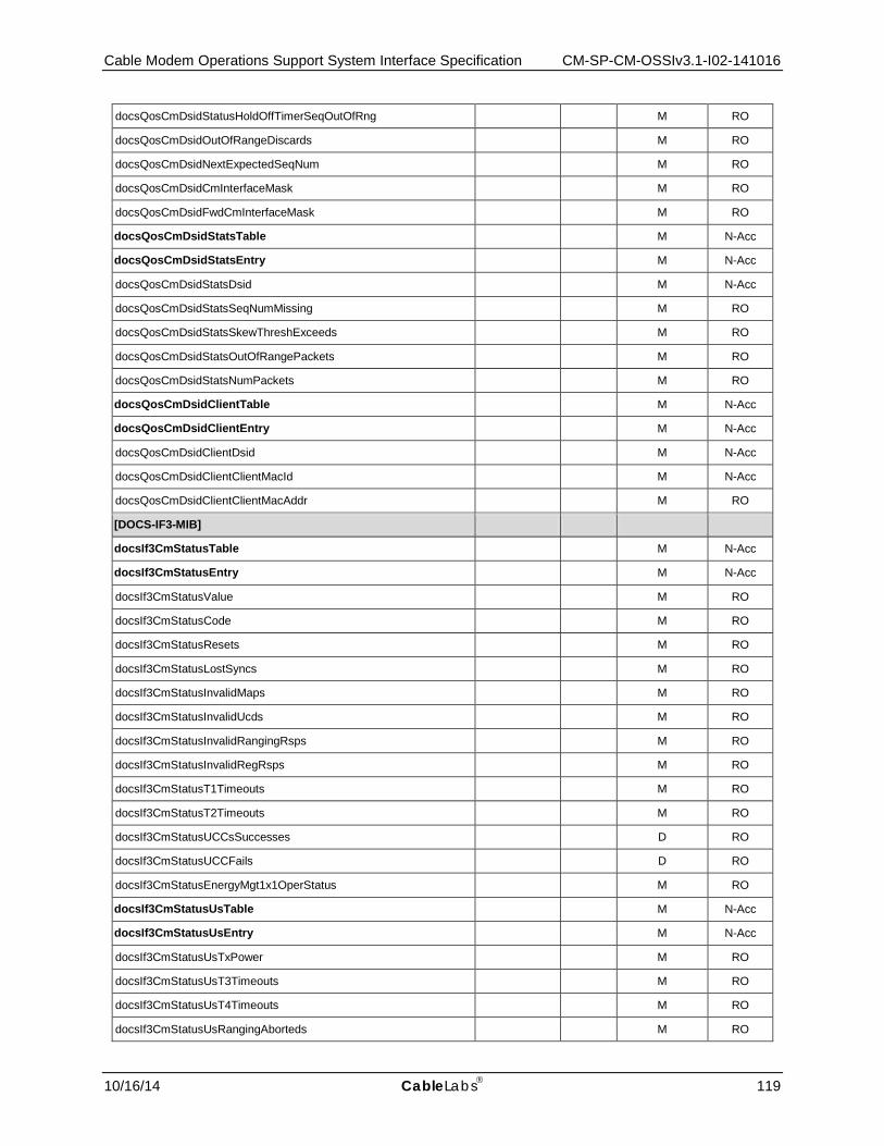
Cable Modem Operations Support System Interface Specification CM-SP-CM-OSSIv3.1-I02-141016
10/16/14 CableLabs 119
docsQosCmDsidStatusHoldOffTimerSeqOutOfRng M RO
docsQosCmDsidOutOfRangeDiscards M RO
docsQosCmDsidNextExpectedSeqNum M RO
docsQosCmDsidCmInterfaceMask M RO
docsQosCmDsidFwdCmInterfaceMask M RO
docsQosCmDsidStatsTable M N-Acc
docsQosCmDsidStatsEntry M N-Acc
docsQosCmDsidStatsDsid M N-Acc
docsQosCmDsidStatsSeqNumMissing M RO
docsQosCmDsidStatsSkewThreshExceeds M RO
docsQosCmDsidStatsOutOfRangePackets M RO
docsQosCmDsidStatsNumPackets M RO
docsQosCmDsidClientTable M N-Acc
docsQosCmDsidClientEntry M N-Acc
docsQosCmDsidClientDsid M N-Acc
docsQosCmDsidClientClientMacId M N-Acc
docsQosCmDsidClientClientMacAddr M RO
[DOCS-IF3-MIB]
docsIf3CmStatusTable M N-Acc
docsIf3CmStatusEntry M N-Acc
docsIf3CmStatusValue M RO
docsIf3CmStatusCode M RO
docsIf3CmStatusResets M RO
docsIf3CmStatusLostSyncs M RO
docsIf3CmStatusInvalidMaps M RO
docsIf3CmStatusInvalidUcds M RO
docsIf3CmStatusInvalidRangingRsps M RO
docsIf3CmStatusInvalidRegRsps M RO
docsIf3CmStatusT1Timeouts M RO
docsIf3CmStatusT2Timeouts M RO
docsIf3CmStatusUCCsSuccesses D RO
docsIf3CmStatusUCCFails D RO
docsIf3CmStatusEnergyMgt1x1OperStatus M RO
docsIf3CmStatusUsTable M N-Acc
docsIf3CmStatusUsEntry M N-Acc
docsIf3CmStatusUsTxPower M RO
docsIf3CmStatusUsT3Timeouts M RO
docsIf3CmStatusUsT4Timeouts M RO
docsIf3CmStatusUsRangingAborteds M RO
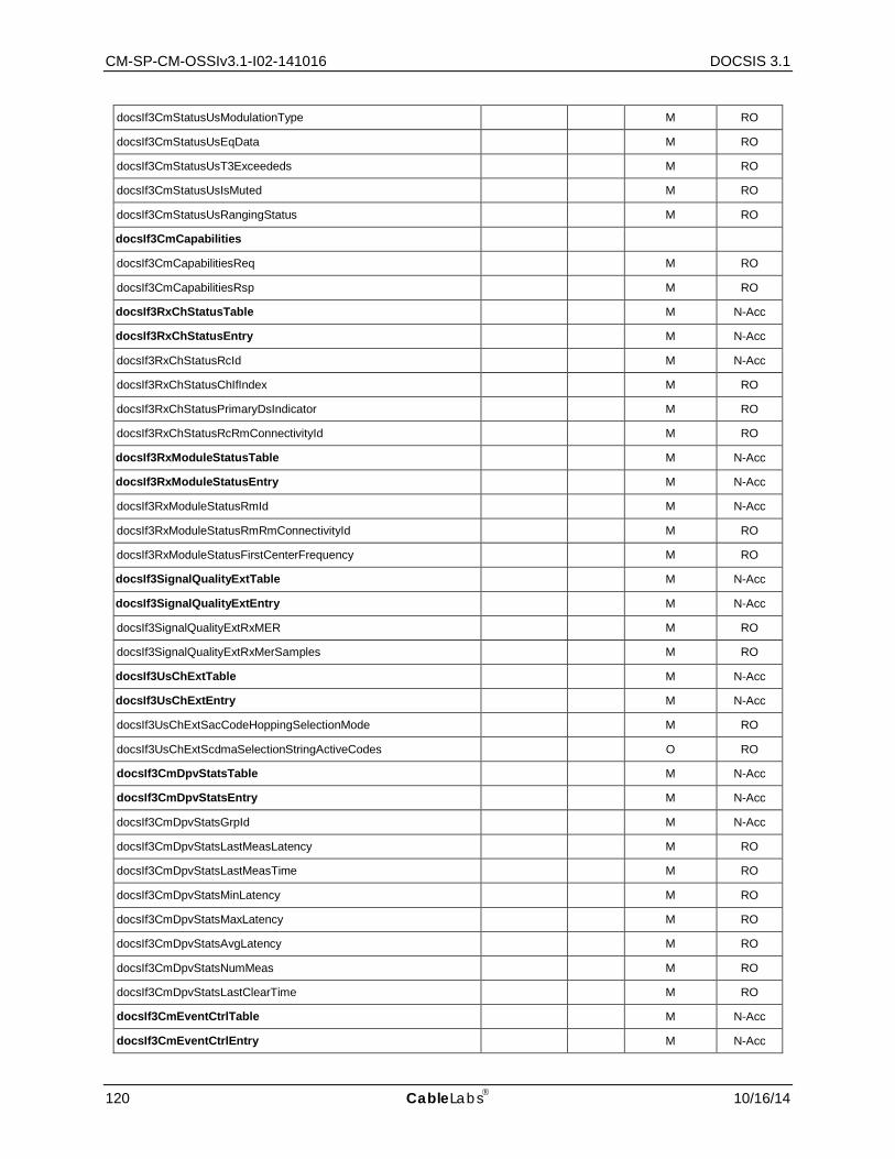
CM-SP-CM-OSSIv3.1-I02-141016 DOCSIS 3.1
120 CableLabs 10/16/14
docsIf3CmStatusUsModulationType M RO
docsIf3CmStatusUsEqData M RO
docsIf3CmStatusUsT3Exceededs M RO
docsIf3CmStatusUsIsMuted M RO
docsIf3CmStatusUsRangingStatus M RO
docsIf3CmCapabilities
docsIf3CmCapabilitiesReq M RO
docsIf3CmCapabilitiesRsp M RO
docsIf3RxChStatusTable M N-Acc
docsIf3RxChStatusEntry M N-Acc
docsIf3RxChStatusRcId M N-Acc
docsIf3RxChStatusChIfIndex M RO
docsIf3RxChStatusPrimaryDsIndicator M RO
docsIf3RxChStatusRcRmConnectivityId M RO
docsIf3RxModuleStatusTable M N-Acc
docsIf3RxModuleStatusEntry M N-Acc
docsIf3RxModuleStatusRmId M N-Acc
docsIf3RxModuleStatusRmRmConnectivityId M RO
docsIf3RxModuleStatusFirstCenterFrequency M RO
docsIf3SignalQualityExtTable M N-Acc
docsIf3SignalQualityExtEntry M N-Acc
docsIf3SignalQualityExtRxMER M RO
docsIf3SignalQualityExtRxMerSamples M RO
docsIf3UsChExtTable M N-Acc
docsIf3UsChExtEntry M N-Acc
docsIf3UsChExtSacCodeHoppingSelectionMode M RO
docsIf3UsChExtScdmaSelectionStringActiveCodes O RO
docsIf3CmDpvStatsTable M N-Acc
docsIf3CmDpvStatsEntry M N-Acc
docsIf3CmDpvStatsGrpId M N-Acc
docsIf3CmDpvStatsLastMeasLatency M RO
docsIf3CmDpvStatsLastMeasTime M RO
docsIf3CmDpvStatsMinLatency M RO
docsIf3CmDpvStatsMaxLatency M RO
docsIf3CmDpvStatsAvgLatency M RO
docsIf3CmDpvStatsNumMeas M RO
docsIf3CmDpvStatsLastClearTime M RO
docsIf3CmEventCtrlTable M N-Acc
docsIf3CmEventCtrlEntry M N-Acc
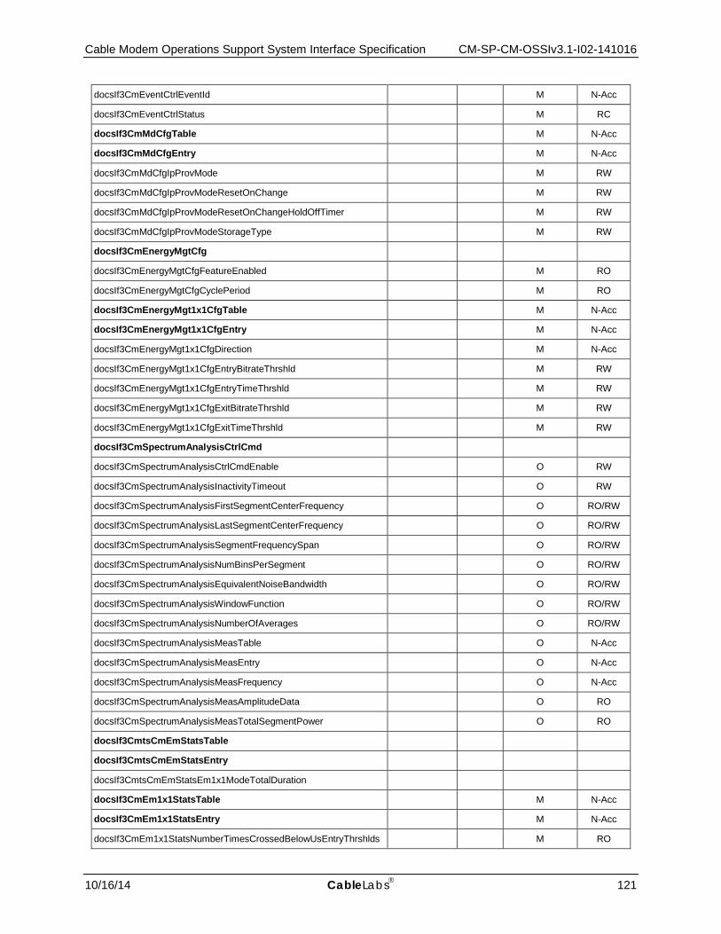
Cable Modem Operations Support System Interface Specification CM-SP-CM-OSSIv3.1-I02-141016
10/16/14 CableLabs 121
docsIf3CmEventCtrlEventId M N-Acc
docsIf3CmEventCtrlStatus M RC
docsIf3CmMdCfgTable M N-Acc
docsIf3CmMdCfgEntry M N-Acc
docsIf3CmMdCfgIpProvMode M RW
docsIf3CmMdCfgIpProvModeResetOnChange M RW
docsIf3CmMdCfgIpProvModeResetOnChangeHoldOffTimer M RW
docsIf3CmMdCfgIpProvModeStorageType M RW
docsIf3CmEnergyMgtCfg
docsIf3CmEnergyMgtCfgFeatureEnabled M RO
docsIf3CmEnergyMgtCfgCyclePeriod M RO
docsIf3CmEnergyMgt1x1CfgTable M N-Acc
docsIf3CmEnergyMgt1x1CfgEntry M N-Acc
docsIf3CmEnergyMgt1x1CfgDirection M N-Acc
docsIf3CmEnergyMgt1x1CfgEntryBitrateThrshld M RW
docsIf3CmEnergyMgt1x1CfgEntryTimeThrshld M RW
docsIf3CmEnergyMgt1x1CfgExitBitrateThrshld M RW
docsIf3CmEnergyMgt1x1CfgExitTimeThrshld M RW
docsIf3CmSpectrumAnalysisCtrlCmd
docsIf3CmSpectrumAnalysisCtrlCmdEnable O RW
docsIf3CmSpectrumAnalysisInactivityTimeout O RW
docsIf3CmSpectrumAnalysisFirstSegmentCenterFrequency O RO/RW
docsIf3CmSpectrumAnalysisLastSegmentCenterFrequency O RO/RW
docsIf3CmSpectrumAnalysisSegmentFrequencySpan O RO/RW
docsIf3CmSpectrumAnalysisNumBinsPerSegment O RO/RW
docsIf3CmSpectrumAnalysisEquivalentNoiseBandwidth O RO/RW
docsIf3CmSpectrumAnalysisWindowFunction O RO/RW
docsIf3CmSpectrumAnalysisNumberOfAverages O RO/RW
docsIf3CmSpectrumAnalysisMeasTable O N-Acc
docsIf3CmSpectrumAnalysisMeasEntry O N-Acc
docsIf3CmSpectrumAnalysisMeasFrequency O N-Acc
docsIf3CmSpectrumAnalysisMeasAmplitudeData O RO
docsIf3CmSpectrumAnalysisMeasTotalSegmentPower O RO
docsIf3CmtsCmEmStatsTable
docsIf3CmtsCmEmStatsEntry
docsIf3CmtsCmEmStatsEm1x1ModeTotalDuration
docsIf3CmEm1x1StatsTable M N-Acc
docsIf3CmEm1x1StatsEntry M N-Acc
docsIf3CmEm1x1StatsNumberTimesCrossedBelowUsEntryThrshlds M RO
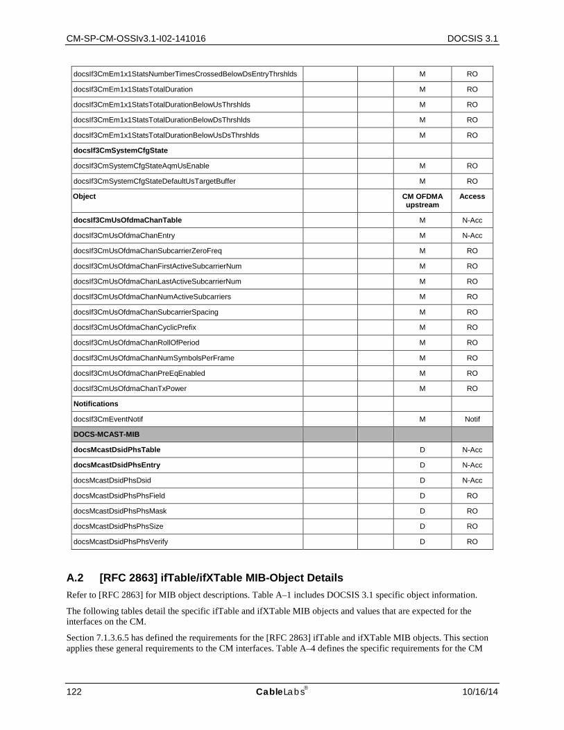
CM-SP-CM-OSSIv3.1-I02-141016 DOCSIS 3.1
122 CableLabs 10/16/14
docsIf3CmEm1x1StatsNumberTimesCrossedBelowDsEntryThrshlds M RO
docsIf3CmEm1x1StatsTotalDuration M RO
docsIf3CmEm1x1StatsTotalDurationBelowUsThrshlds M RO
docsIf3CmEm1x1StatsTotalDurationBelowDsThrshlds M RO
docsIf3CmEm1x1StatsTotalDurationBelowUsDsThrshlds M RO
docsIf3CmSystemCfgState
docsIf3CmSystemCfgStateAqmUsEnable M RO
docsIf3CmSystemCfgStateDefaultUsTargetBuffer M RO
Object CM OFDMA upstream
Access
docsIf3CmUsOfdmaChanTable M N-Acc
docsIf3CmUsOfdmaChanEntry M N-Acc
docsIf3CmUsOfdmaChanSubcarrierZeroFreq M RO
docsIf3CmUsOfdmaChanFirstActiveSubcarrierNum M RO
docsIf3CmUsOfdmaChanLastActiveSubcarrierNum M RO
docsIf3CmUsOfdmaChanNumActiveSubcarriers M RO
docsIf3CmUsOfdmaChanSubcarrierSpacing M RO
docsIf3CmUsOfdmaChanCyclicPrefix M RO
docsIf3CmUsOfdmaChanRollOfPeriod M RO
docsIf3CmUsOfdmaChanNumSymbolsPerFrame M RO
docsIf3CmUsOfdmaChanPreEqEnabled M RO
docsIf3CmUsOfdmaChanTxPower M RO
Notifications
docsIf3CmEventNotif M Notif
DOCS-MCAST-MIB
docsMcastDsidPhsTable D N-Acc
docsMcastDsidPhsEntry D N-Acc
docsMcastDsidPhsDsid D N-Acc
docsMcastDsidPhsPhsField D RO
docsMcastDsidPhsPhsMask D RO
docsMcastDsidPhsPhsSize D RO
docsMcastDsidPhsPhsVerify D RO
A.2 [RFC 2863] ifTable/ifXTable MIB-Object Details Refer to [RFC 2863] for MIB object descriptions. Table A–1 includes DOCSIS 3.1 specific object information.
The following tables detail the specific ifTable and ifXTable MIB objects and values that are expected for the interfaces on the CM.
Section 7.1.3.6.5 has defined the requirements for the [RFC 2863] ifTable and ifXTable MIB objects. This section applies these general requirements to the CM interfaces. Table A–4 defines the specific requirements for the CM

Cable Modem Operations Support System Interface Specification CM-SP-CM-OSSIv3.1-I02-141016
10/16/14 CableLabs 123
ethernet, USB and other interfaces. Table A–5 defines the specific requirements for the CM upstream, downstream and MAC interfaces. Table A–4 and Table A–5 exclude the Counter32 and Counter64 MIB objects as these counter objects are defined in Table A–6 and Table A–7.
In order to simplify and compile all the requirements for the Counter32 and Counter64 MIB objects in a single location, the specific SNMP Access requirements and MIB implementation details that are normally detailed in Annex A.1 are reflected in Table A–6 and Table A–7. The nomenclature for the MIB implementation details can be found in Table A–1 and the SNMP Access Requirements are detailed in Table A–2. Please refer to these tables for the values found for each of the interfaces in Table A–6 and Table A–7.
In addition to the requirements for Ethernet and USB detailed in Table A–6 below, note that the various packet and octet counters from the ifTable and ifXTable MAY exclude LAN-LAN traffic which is not bridged upstream or downstream. From the ifTable, these counters include the following: ifInOctets, ifInUcastPkts, ifOutOctets, and ifOutUcastPkts. From the ifXTable, included counters are ifInMulticastPkts, ifInBroadcastPkts, ifOutMulticastPkts, ifOutBroadcastPkts, ifHCInOctets, ifHCInUcastPkts, ifHCInMulticastPkts, ifHCInBroadcastPkts, ifHCOutOctets, ifHCOutUcastPkts, ifHCOutMulticastPkts, and ifHCOutBroadcastPkts.
Table A–4 - [RFC 2863] ifTable/ifXTable MIB-Object Details for Ethernet and USB Interfaces
MIB Objects CM-Ethernet CM USB CDC
Ethernet
CM-CPE Other Type
IfTable
ifIndex 1 or [4+(n)] 1 or [4+(n)] 1 or [4+(n)]
ifDescr See 7.1.3.6.7.1
ifType 6 160 (IANA num)
ifMtu 1500 1500 Media dependent
ifSpeed 10,000,000, 100,000,000, …
12,000,000, 480,000,000
speed
ifPhysAddress MAC Address of this interface
MAC Address of this interface
Media dependent
ifAdminStatus When a managed system initializes, all interfaces start with ifAdminStatus in the up(1) state. As a result of explicit management action, ifAdminStatus is then changed to either the down(2) or testing(3) states (or remains in the up(1) state). As a result of either explicit management or configuration information saved via other non-SNMP method (i.e., CLI commands) retained by the managed system, ifAdminStatus is then changed to either the down(2) or testing(3) states (or remains in the up(1) state).
up(1), down(2), testing(3)
up(1), down(2), testing(3)
up(1), down(2), testing(3)
ifOperStatus up(1), down(2), testing(3), dormant(5), notPresent(6)
See 7.1.3.6.2.2 up(1), down(2), testing(3), dormant(5), notPresent(6)
ifLastChange
ifXTable
ifName
ifLinkUpDownTrapEnable
Note: See Section 7.1.3.6.4 for details
ifHighSpeed 10, 100, … 12, 480 speed
ifPromiscuousMode true, false true, false true, false
ifConnectorPresent
ifAlias
ifCounterDiscontinuityTime
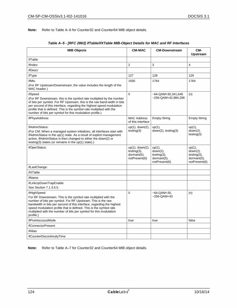
CM-SP-CM-OSSIv3.1-I02-141016 DOCSIS 3.1
124 CableLabs 10/16/14
Note: Refer to Table A–6 for Counter32 and Counter64 MIB object details.
Table A–5 - [RFC 2863] ifTable/ifXTable MIB-Object Details for MAC and RF Interfaces
MIB Objects CM-MAC CM-Downstream CM-Upstream
IfTable
ifIndex 2 3 4
ifDescr
ifType 127 128 129
ifMtu (For RF Upstream/Downstream; the value includes the length of the MAC header.)
1500 1764 1764
ifSpeed (For RF Downstream, this is the symbol rate multiplied by the number of bits per symbol. For RF Upstream, this is the raw band-width in bits per second of this interface, regarding the highest speed modulation profile that is defined. This is the symbol rate multiplied with the number of bits per symbol for this modulation profile.)
0 ~64-QAM=30,341,646 ~256-QAM=42,884,296
(n)
ifPhysAddress: MAC Address of this interface
Empty-String Empty-String
ifAdminStatus: (For CM: When a managed system initializes, all interfaces start with ifAdminStatus in the up(1) state. As a result of explicit management action, ifAdminStatus is then changed to either the down(2) or testing(3) states (or remains in the up(1) state).)
up(1), down(2), testing(3)
up(1), down(2), testing(3)
up(1), down(2), testing(3)
ifOperStatus: up(1), down(2), testing(3), dormant(5), notPresent(6)
up(1), down(2), testing(3), dormant(5), notPresent(6)
up(1), down(2), testing(3), dormant(5), notPresent(6)
ifLastChange:
ifXTable
ifName
ifLinkUpDownTrapEnable See Section 7.1.3.6.5.
ifHighSpeed For RF Downstream; This is the symbol rate multiplied with the number of bits per symbol. For RF Upstream; This is the raw bandwidth in bits per second of this interface, regarding the highest speed modulation profile that is defined. This is the symbol rate multiplied with the number of bits per symbol for this modulation profile.]
0 ~64-QAM=30, ~256-QAM=43
(n)
ifPromiscuousMode true true false
ifConnectorPresent
ifAlias
ifCounterDiscontinuityTime
Note: Refer to Table A–7 for Counter32 and Counter64 MIB object details.
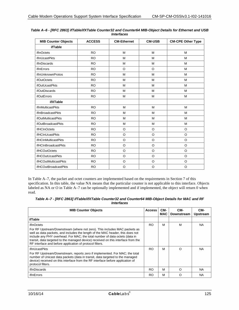
Cable Modem Operations Support System Interface Specification CM-SP-CM-OSSIv3.1-I02-141016
10/16/14 CableLabs 125
Table A–6 - [RFC 2863] ifTable/ifXTable Counter32 and Counter64 MIB-Object Details for Ethernet and USB Interfaces
MIB Counter Objects ACCESS CM-Ethernet CM-USB CM-CPE Other Type ifTable
ifInOctets RO M M M
ifInUcastPkts RO M M M
ifInDiscards RO M M M
ifInErrors RO O O M
ifInUnknownProtos RO M M M
ifOutOctets RO M M M
ifOutUcastPkts RO M M M
ifOutDiscards RO M M M
ifOutErrors RO M M M
ifXTable ifInMulticastPkts RO M M M
ifInBroadcastPkts RO M M M
ifOutMulticastPkts RO M M M
ifOutBroadcastPkts RO M M M
IfHCInOctets RO O O O
ifHCInUcastPkts RO O O O
ifHCInMulticastPkts RO O O O
ifHCInBroadcastPkts RO O O O
ifHCOutOctets RO O O O
ifHCOutUcastPkts RO O O O
ifHCOutMulticastPkts RO O O O
ifHCOutBroadcastPkts RO O O O
In Table A–7, the packet and octet counters are implemented based on the requirements in Section 7 of this specification. In this table, the value NA means that the particular counter is not applicable to this interface. Objects labeled as NA or O in Table A–7 can be optionally implemented and if implemented, the object will return 0 when read.
Table A–7 - [RFC 2863] ifTable/ifXTable Counter32 and Counter64 MIB-Object Details for MAC and RF Interfaces
MIB Counter Objects Access CM-MAC
CM- Downstream
CM- Upstream
ifTable
ifInOctets For RF Upstream/Downstream (where not zero). This includes MAC packets as well as data packets, and includes the length of the MAC header, this does not include any PHY overhead. For MAC; the total number of data octets (data in transit, data targeted to the managed device) received on this interface from the RF interface and before application of protocol filters.
RO M M NA
ifInUcastPkts For RF Upstream/Downstream, reports zero if implemented. For MAC; the total number of Unicast data packets (data in transit, data targeted to the managed device) received on this interface from the RF interface before application of protocol filters.
RO M O NA
ifInDiscards RO M O NA
ifInErrors RO M O NA
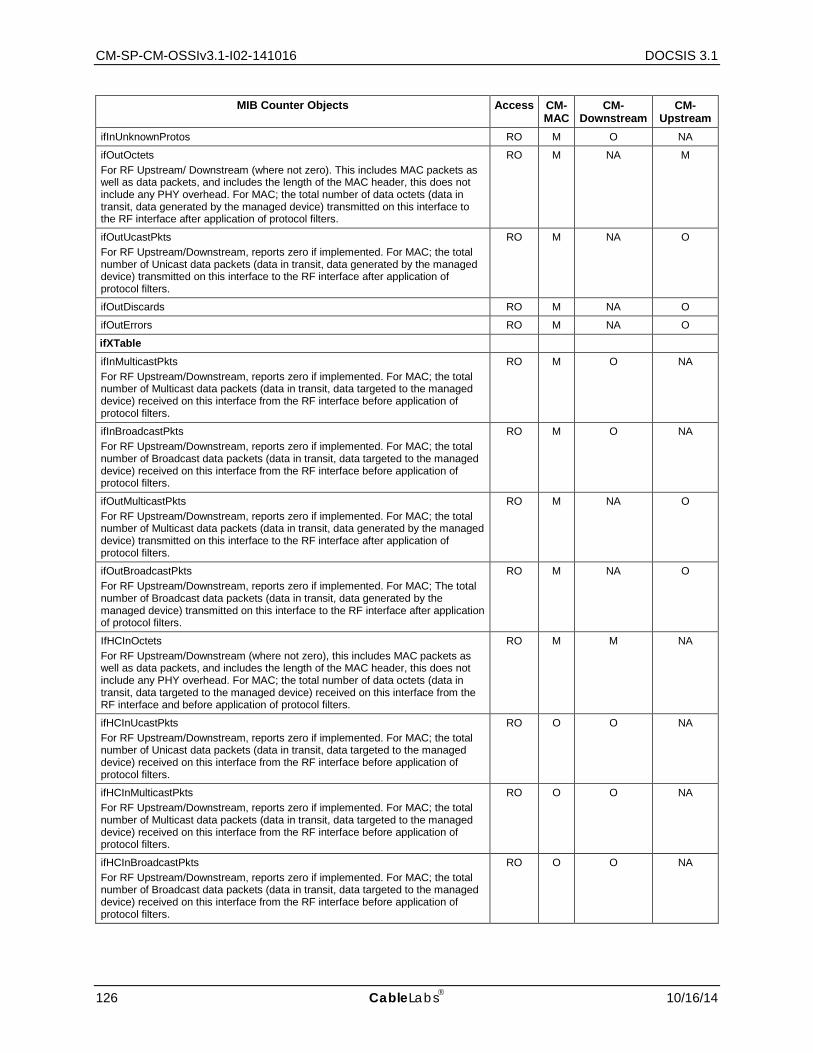
CM-SP-CM-OSSIv3.1-I02-141016 DOCSIS 3.1
126 CableLabs 10/16/14
MIB Counter Objects Access CM-MAC
CM- Downstream
CM- Upstream
ifInUnknownProtos RO M O NA
ifOutOctets For RF Upstream/ Downstream (where not zero). This includes MAC packets as well as data packets, and includes the length of the MAC header, this does not include any PHY overhead. For MAC; the total number of data octets (data in transit, data generated by the managed device) transmitted on this interface to the RF interface after application of protocol filters.
RO M NA M
ifOutUcastPkts For RF Upstream/Downstream, reports zero if implemented. For MAC; the total number of Unicast data packets (data in transit, data generated by the managed device) transmitted on this interface to the RF interface after application of protocol filters.
RO M NA O
ifOutDiscards RO M NA O
ifOutErrors RO M NA O
ifXTable
ifInMulticastPkts For RF Upstream/Downstream, reports zero if implemented. For MAC; the total number of Multicast data packets (data in transit, data targeted to the managed device) received on this interface from the RF interface before application of protocol filters.
RO M O NA
ifInBroadcastPkts For RF Upstream/Downstream, reports zero if implemented. For MAC; the total number of Broadcast data packets (data in transit, data targeted to the managed device) received on this interface from the RF interface before application of protocol filters.
RO M O NA
ifOutMulticastPkts For RF Upstream/Downstream, reports zero if implemented. For MAC; the total number of Multicast data packets (data in transit, data generated by the managed device) transmitted on this interface to the RF interface after application of protocol filters.
RO M NA O
ifOutBroadcastPkts For RF Upstream/Downstream, reports zero if implemented. For MAC; The total number of Broadcast data packets (data in transit, data generated by the managed device) transmitted on this interface to the RF interface after application of protocol filters.
RO M NA O
IfHCInOctets For RF Upstream/Downstream (where not zero), this includes MAC packets as well as data packets, and includes the length of the MAC header, this does not include any PHY overhead. For MAC; the total number of data octets (data in transit, data targeted to the managed device) received on this interface from the RF interface and before application of protocol filters.
RO M M NA
ifHCInUcastPkts For RF Upstream/Downstream, reports zero if implemented. For MAC; the total number of Unicast data packets (data in transit, data targeted to the managed device) received on this interface from the RF interface before application of protocol filters.
RO O O NA
ifHCInMulticastPkts For RF Upstream/Downstream, reports zero if implemented. For MAC; the total number of Multicast data packets (data in transit, data targeted to the managed device) received on this interface from the RF interface before application of protocol filters.
RO O O NA
ifHCInBroadcastPkts For RF Upstream/Downstream, reports zero if implemented. For MAC; the total number of Broadcast data packets (data in transit, data targeted to the managed device) received on this interface from the RF interface before application of protocol filters.
RO O O NA

Cable Modem Operations Support System Interface Specification CM-SP-CM-OSSIv3.1-I02-141016
10/16/14 CableLabs 127
MIB Counter Objects Access CM-MAC
CM- Downstream
CM- Upstream
ifHCOutOctets For RF Upstream/Downstream (where not zero), this includes MAC packets as well as data packets, and includes the length of the MAC header; this does not include any PHY overhead. For MAC; the total number of data octets (data in transit, data generated by the managed device) transmitted on this interface to the RF interface after application of protocol filters.
RO M NA M
ifHCOutUcastPkts For RF Upstream/Downstream, reports zero if implemented. For MAC; the total number of Unicast data packets (data in transit, data generated by the managed device) transmitted on this interface to the RF interface after application of protocol filters.
RO O NA O
ifHCOutMulticastPkts For RF Upstream/Downstream, reports zero if implemented. For MAC; the total number of Multicast data packets (data in transit, data generated by the managed device) transmitted on this interface to the RF interface after application of protocol filters.
RO O NA O
ifHCOutBroadcastPkts For RF Upstream/Downstream, reports zero if implemented. For MAC; the total number of Broadcast data packets (data in transit, data generated by the managed device) transmitted on this interface to the RF interface after application of protocol filters.
RW O NA O
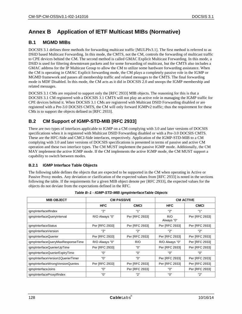
CM-SP-CM-OSSIv3.1-I02-141016 DOCSIS 3.1
128 CableLabs 10/16/14
Annex B Application of IETF Multicast MIBs (Normative)
B.1 MGMD MIBs DOCSIS 3.1 defines three methods for forwarding multicast traffic [MULPIv3.1]. The first method is referred to as DSID based Multicast Forwarding. In this mode, the CMTS, not the CM, controls the forwarding of multicast traffic to CPE devices behind the CM. The second method is called GMAC Explicit Multicast Forwarding. In this mode, a DSID is used for filtering downstream packets and for some forwarding of multicast, but the CMTS also includes a GMAC address for the IP Multicast Group to allow the CM to utilize some hardware forwarding assistance. When the CM is operating in GMAC Explicit forwarding mode, the CM plays a completely passive role in the IGMP or MGMD framework and passes all membership traffic and related messages to the CMTS. The final forwarding mode is MDF Disabled. In this mode, the CM acts as it did in DOCSIS 2.0 and snoops the IGMP membership and related messages.
DOCSIS 3.1 CMs are required to support only the [RFC 2933] MIB objects. The reasoning for this is that a DOCSIS 3.1 CM registered with a DOCSIS 3.1 CMTS will not play an active role in managing the IGMP traffic for CPE devices behind it. When DOCSIS 3.1 CMs are registered with Multicast DSID Forwarding disabled or are registered with a Pre-3.0 DOCSIS CMTS, the CM will only forward IGMPv2 traffic; thus the requirement for these CMs is to support the objects defined in [RFC 2933].
B.2 CM Support of IGMP-STD-MIB [RFC 2933] There are two types of interfaces applicable to IGMP on a CM complying with 3.0 and later versions of DOCSIS specifications when it is registered with Multicast DSID Forwarding disabled or with a Pre-3.0 DOCSIS CMTS. These are the HFC-Side and CMCI-Side interfaces, respectively. Application of the IGMP-STD-MIB to a CM complying with 3.0 and later versions of DOCSIS specifications is presented in terms of passive and active CM operation and these two interface types. The CM MUST implement the passive IGMP mode. Additionally, the CM MAY implement the active IGMP mode. If the CM implements the active IGMP mode, the CM MUST support a capability to switch between modes.
B.2.1 IGMP Interface Table Objects
The following table defines the objects that are expected to be supported in the CM when operating in Active or Passive Proxy modes. Any deviation or clarification of the expected values from [RFC 2933] is noted in the sections following the table. If the requirements for a given MIB object denote per [RFC 2933], the expected values for the objects do not deviate from the expectations defined in the RFC.
Table B–1 - IGMP-STD-MIB igmpInterfaceTable Objects
MIB OBJECT CM PASSIVE CM ACTIVE HFC CMCI HFC CMCI
igmpInterfaceIfIndex "2" "1" "2" "1"
igmpInterfaceQueryInterval R/O Always "0" Per [RFC 2933] R/O Always "0"
Per [RFC 2933]
igmpInterfaceStatus Per [RFC 2933] Per [RFC 2933] Per [RFC 2933] Per [RFC 2933]
igmpInterfaceVersion "2" "2" "2" "2"
igmpInterfaceQuerier Per [RFC 2933] Per [RFC 2933] Per [RFC 2933] Per [RFC 2933]
igmpInterfaceQueryMaxResponseTime R/O Always "0" R/O R/O Always "0" Per [RFC 2933]
igmpInterfaceQuerierUpTime Per [RFC 2933] "0" Per [RFC 2933] Per [RFC 2933]
igmpInterfaceQuerierExpiryTime "0" "0" "0" "0"
igmpInterfaceVersion1QuerierTimer "0" "0" Per [RFC 2933] Per [RFC 2933]
igmpInterfaceWrongVersionQueries Per [RFC 2933] Per [RFC 2933] Per [RFC 2933] Per [RFC 2933]
igmpInterfaceJoins "0" Per [RFC 2933] "0" Per [RFC 2933]
igmpInterfaceProxyIfIndex "0" "2" "0" "2"
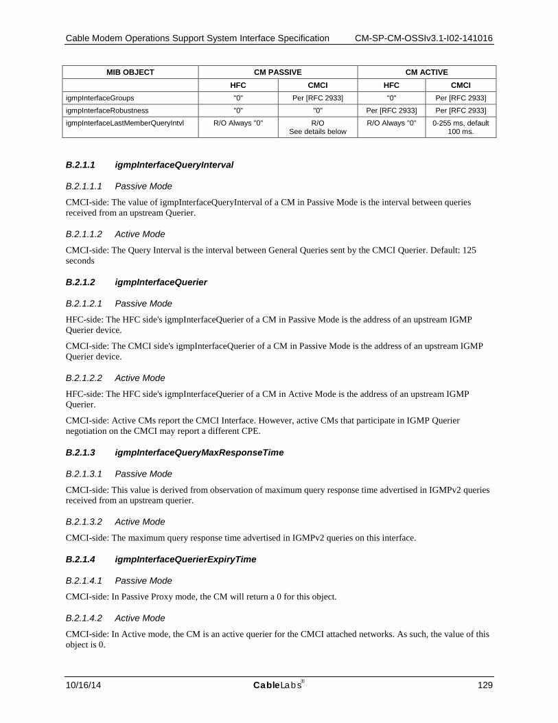
Cable Modem Operations Support System Interface Specification CM-SP-CM-OSSIv3.1-I02-141016
10/16/14 CableLabs 129
MIB OBJECT CM PASSIVE CM ACTIVE HFC CMCI HFC CMCI
igmpInterfaceGroups "0" Per [RFC 2933] "0" Per [RFC 2933]
igmpInterfaceRobustness "0" "0" Per [RFC 2933] Per [RFC 2933]
igmpInterfaceLastMemberQueryIntvl R/O Always "0" R/O See details below
R/O Always "0" 0-255 ms, default 100 ms.
B.2.1.1 igmpInterfaceQueryInterval
B.2.1.1.1 Passive Mode
CMCI-side: The value of igmpInterfaceQueryInterval of a CM in Passive Mode is the interval between queries received from an upstream Querier.
B.2.1.1.2 Active Mode
CMCI-side: The Query Interval is the interval between General Queries sent by the CMCI Querier. Default: 125 seconds
B.2.1.2 igmpInterfaceQuerier
B.2.1.2.1 Passive Mode
HFC-side: The HFC side's igmpInterfaceQuerier of a CM in Passive Mode is the address of an upstream IGMP Querier device.
CMCI-side: The CMCI side's igmpInterfaceQuerier of a CM in Passive Mode is the address of an upstream IGMP Querier device.
B.2.1.2.2 Active Mode
HFC-side: The HFC side's igmpInterfaceQuerier of a CM in Active Mode is the address of an upstream IGMP Querier.
CMCI-side: Active CMs report the CMCI Interface. However, active CMs that participate in IGMP Querier negotiation on the CMCI may report a different CPE.
B.2.1.3 igmpInterfaceQueryMaxResponseTime
B.2.1.3.1 Passive Mode
CMCI-side: This value is derived from observation of maximum query response time advertised in IGMPv2 queries received from an upstream querier.
B.2.1.3.2 Active Mode
CMCI-side: The maximum query response time advertised in IGMPv2 queries on this interface.
B.2.1.4 igmpInterfaceQuerierExpiryTime
B.2.1.4.1 Passive Mode
CMCI-side: In Passive Proxy mode, the CM will return a 0 for this object.
B.2.1.4.2 Active Mode
CMCI-side: In Active mode, the CM is an active querier for the CMCI attached networks. As such, the value of this object is 0.
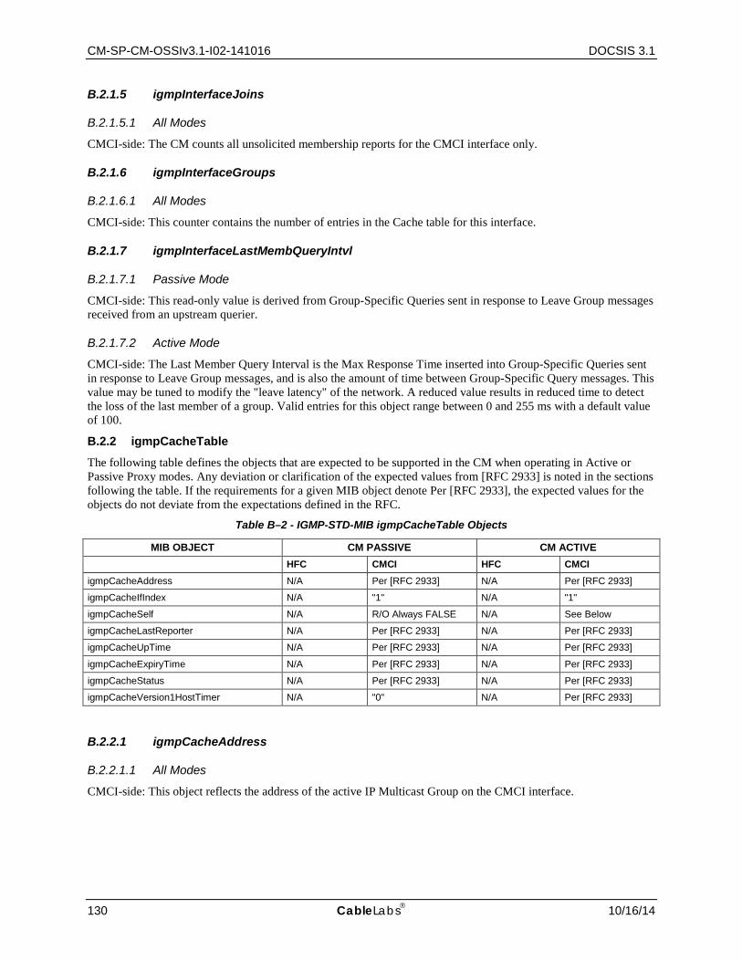
CM-SP-CM-OSSIv3.1-I02-141016 DOCSIS 3.1
130 CableLabs 10/16/14
B.2.1.5 igmpInterfaceJoins
B.2.1.5.1 All Modes
CMCI-side: The CM counts all unsolicited membership reports for the CMCI interface only.
B.2.1.6 igmpInterfaceGroups
B.2.1.6.1 All Modes
CMCI-side: This counter contains the number of entries in the Cache table for this interface.
B.2.1.7 igmpInterfaceLastMembQueryIntvl
B.2.1.7.1 Passive Mode
CMCI-side: This read-only value is derived from Group-Specific Queries sent in response to Leave Group messages received from an upstream querier.
B.2.1.7.2 Active Mode
CMCI-side: The Last Member Query Interval is the Max Response Time inserted into Group-Specific Queries sent in response to Leave Group messages, and is also the amount of time between Group-Specific Query messages. This value may be tuned to modify the "leave latency" of the network. A reduced value results in reduced time to detect the loss of the last member of a group. Valid entries for this object range between 0 and 255 ms with a default value of 100.
B.2.2 igmpCacheTable
The following table defines the objects that are expected to be supported in the CM when operating in Active or Passive Proxy modes. Any deviation or clarification of the expected values from [RFC 2933] is noted in the sections following the table. If the requirements for a given MIB object denote Per [RFC 2933], the expected values for the objects do not deviate from the expectations defined in the RFC.
Table B–2 - IGMP-STD-MIB igmpCacheTable Objects
MIB OBJECT CM PASSIVE CM ACTIVE HFC CMCI HFC CMCI igmpCacheAddress N/A Per [RFC 2933] N/A Per [RFC 2933]
igmpCacheIfIndex N/A "1" N/A "1"
igmpCacheSelf N/A R/O Always FALSE N/A See Below
igmpCacheLastReporter N/A Per [RFC 2933] N/A Per [RFC 2933]
igmpCacheUpTime N/A Per [RFC 2933] N/A Per [RFC 2933]
igmpCacheExpiryTime N/A Per [RFC 2933] N/A Per [RFC 2933]
igmpCacheStatus N/A Per [RFC 2933] N/A Per [RFC 2933]
igmpCacheVersion1HostTimer N/A "0" N/A Per [RFC 2933]
B.2.2.1 igmpCacheAddress
B.2.2.1.1 All Modes
CMCI-side: This object reflects the address of the active IP Multicast Group on the CMCI interface.

Cable Modem Operations Support System Interface Specification CM-SP-CM-OSSIv3.1-I02-141016
10/16/14 CableLabs 131
B.2.2.2 igmpCacheSelf
B.2.2.2.1 Passive Mode
CMCI-side: The CM's igmpCacheSelf is always set to false in passive mode.
B.2.2.2.2 Active Mode
CMCI-side: Implementation specific. If the CM is configured to be a member of the group, then membership reports are sent with the IP Address of the CM but only be sent in proxy for active sessions on the CMCI (e.g., the CM should not be a member of a multicast group that is not active on the CMCI). If the CM is not configured to be a member, then the source IP Address of membership reports should be set to the current value of the igmpCacheLastReporter address.
CM-SP-CM-OSSIv3.1-I02-141016 DOCSIS 3.1
132 CableLabs 10/16/14
Annex C Protocol Filtering (Normative) DOCSIS 3.1 supports two IP protocol filtering methods consisting of the legacy IP filtering mechanism specified in [RFC 4639] and Upstream Drop Classifiers (UDCs) which are an outgrowth of the QoS classification mechanism. IP filtering continues to operate in DOCSIS 3.1 as it has in previous versions of the specification, though the minimum number of filtering rules has been increased from sixteen (16) to sixty-four (64). IP filters are limited to support of IPv4 protocols, while UDCs can be used for IPv4, IPv6, and LLC in a common framework with QoS classification. UDCs and IP filters are mutually exclusive modes and only one filtering method is permitted to operate at a time.
UDCs are modeled on the existing QoS Classifiers that were introduced in DOCSIS 1.1. UDCs apply only to the CM, the RF interface and only in the upstream direction of flow. The use of UDCs facilitates delegation of upstream protocol filtering at the CM through parameters in the configuration file that can be controlled by the CMTS. Any packet classified by the Upstream Drop Classifier rule is discarded, conceptually similarly to directing an IP route to "null 0" or output to /dev/null in a UNIX system.
As with IP filters, UDC rules may be configured through the CM configuration file statically, assigned dynamically from the CMTS through a Group ID reference in the CM configuration file, dynamically added, changed or deleted after registration through a DSC (Dynamic Service Change) MAC management message from the CMTS, or both the static and dynamic configuration methods may be used together. The CMTS alone provides the downstream protocol filtering and can further reinforce the upstream classification policy through Subscriber Management traffic filtering functionality.
Among the specific requirements for classification at the CM, the CM is required to perform protocol filtering from the host CPE(s) to the RF interface when UDCs are enabled, or protocol filtering from any interface to or from the RF interface when IP filtering is enabled. All ICMP (ICMPv4 and ICMPv6) and IP packets will be forwarded from the CMCI interface to the RFI upstream interface based on rules outlined in the Upstream Drop Classifiers section of [MULPIv3.1], unless they are specifically required to be discarded according to applied protocol filtering or classification rules.
It is recommended that to avoid unexpected behavior, consumption of excess local resources and oversized configuration files, the configuration of Upstream Drop Classifiers not be configured simultaneously with the legacy IP filters. It should also be noted that when a DOCSIS 3.1 CM registers with a DOCSIS 3.1 CMTS when UDCs are enabled, only the UDC parameters will be utilized by the CM. When a DOCSIS 3.1 CM registers with a Pre-3.0 DOCSIS CMTS, or a Pre-3.0 DOCSIS CM is registered with a DOCSIS 3.1 CMTS, only the IP filters configured in the CM configuration file are used.
C.1 Filtering Mechanisms The legacy DOCSIS filters are subdivided into two (2) filtering layers (LLC and IP) at the CM. The two legacy classification/filtering layers at the CM are docsDevFilterIpTable and docsDevFilterLlcTable. Classifiers cover both the LLC and IP criteria, matching much of the functionality of the legacy filtering mechanisms. However, classifier LLC criteria are complementary and not designed to fully displace the legacy LLC filtering mechanism. See Annex A for comparisons and other considerations.
C.1.1 LLC Filters
The CM MUST apply LLC filters (from [RFC 4639]), to layer-2 frames entering from any interface. The CM MUST NOT apply LLC filters from docsDevFilterLLCTable (i.e., ARP requests, SNMP responses) for traffic sourced from the CM. The CM MUST support a minimum of 10 LLC protocol filter entries in the docsDevFilterLLCTable.
CMs may have multiple interfaces. If LLC filters are applied to CM IfIndex 1, the CM MUST apply the same filters to the "Additional CPE interfaces" (see Section 7.1.3.6.1).
C.1.2 Special filters
Special filters include IP spoofing filters, inter-eSAFE and eSAFE to CPE communications and SNMP access filters such as SNMPv1/v2c NmAccess mode (see Section 8.5.2.2) and SNMP CPE Access Control (see Section 8.5.2.9).

Cable Modem Operations Support System Interface Specification CM-SP-CM-OSSIv3.1-I02-141016
10/16/14 CableLabs 133
C.1.2.1 IP Spoofing Filters DOCSIS 3.1 CMs MAY implement an IP spoofing filter as specified in [RFC 4639]. IP spoofing filters MUST only be applied to packets entering the CM from CMCI interface(s). If a CM supports the IP spoofing filter functionality specified in [RFC 4639], the CM MUST adhere to the following requirements:
• Implement all MIB objects in the docsDevCpeGroup.
• The default value of docsDevCpeIpMax = -1.
C.1.2.2 Additional requirement on dot1dTpFdbTable [RFC 4188] CM CPE MAC addresses learned via the CM configuration file MUST set the dot1dTpFdbStatus to "mgmt". It is assumed that the number of "mgmt"-configured CM CPE MAC addresses is less than, or equal to, the TLV type-18 value (Maximum Number of CPE).
C.1.2.3 SNMP Access Filter When the CM is operating in SNMPv1/v2c NmAccess mode, the CM MUST apply the SNMP access filters to SNMP packets entering from any interface and destined for the CM. The CM MUST apply SNMP access filters after IP spoofing filters for the packets entering the CM from the CMCI interface. Since SNMP access filter function is controlled by docsDevNmAccessTable, SNMP access filter is available and applies only when the CM is in SNMP v1/v2c NmAccess mode.
When the CM is operating in SNMP Coexistence mode, SNMP access MUST be controlled and specified by the MIB objects in [RFC 3411] through [RFC 3415], and [RFC 3584].
CMs may have multiple interfaces. If SNMP access filters are applied to CM IfIndex 1, the CM MUST apply the same filters to the "Additional CPE interfaces" (see Section 7.1.3.6.1).
C.1.2.3.1 docsDevNmAccessIP and docsDevNmAccessIpMask
A CM that implements docsDevNmAccessTable MUST apply the following rules in order to determine whether to permit SNMP access from a given source IP address (SrcIpAddr):
1. If (docsDevNmAccessIp == "255.255.255.255"), the CM MUST permit the access from any SrcIpAddr.
2. If ((docsDevNmAccessIp AND docsDevNmAccessIpMask) == (SrcIpAddr AND docsDevNmAccessIpMask)), the CM MUST permit the access from SrcIpAddr.
3. If (docsDevNmAccessIp == "0.0.0.0" AND docsDevNmAccessIpMask != '255.255.255.255'), the CM MUST permit access from any SrcIpAddr.
4. If neither #1, #2, or #3 is applied, the CM MUST NOT permit the access from SrcIpAddr.
The CM's default value of the docsDevNmAccessIpMask MUST be set to "0.0.0.0".
The following table contains sample MIB values and the access granted by those values.
Table C–1 - Sample docsDevNmAccessIp Values
docsDevNmAccessIp docsDevNmAccessIpMask Access
255.255.255.255 Any IP Address Mask Any NMS
Any IP Address 0.0.0.0 Any NMS
Any IP Address except 255.255.255.255 255.255.255.255 Single NMS
0.0.0.0 255.255.255.255 No NMS (disables all access)
0.0.0.0 Any IP Address Mask except 255.255.255.255 Any NMS
If the CMTS implements docsDevNmAccessTable, the same rules as stated above for the CM are followed.
CM-SP-CM-OSSIv3.1-I02-141016 DOCSIS 3.1
134 CableLabs 10/16/14
C.1.3 IP Protocol Filtering
The CM MUST support the SNMP table docsDevFilterIpTable for all interfaces. The CM MUST support a minimum of 64 IP filter rules.
If the CMTS enables Upstream Drop Classifiers during registration (see Upstream Drop Classifiers section of [MULPIv3.1]), the CM MUST make the docsDevFilterIpTable inaccessible and report an error 'noSuchName' for SNMPv1 PDU requests or 'inconsistentName' error for SNMPv2 PDU requests.
The objects docsDevFilterIpSourcePortLow, docsDevFilterIpSourcePortHigh, docsDevFilterIpDestPortLow, and docsDevFilterIPDestPortHigh within the CM MUST be applied to TCP or UDP packets, as opposed to applying only when docsDevFilterIpProtocol is set to udp(17) or tcp(6) as specified in [RFC 4639]. Thus, if a packet is TCP or UDP, these MIB objects represent the inclusive lower and upper bounds of the transport-layer source and destination port ranges that are to be matched; otherwise, they are ignored during matching.
To match TCP and UDP packets only, it is recommended to create two filter entries in the docsDevFilterIpTable, one with docsDevFilterIpProtocol set to tcp(6) and one set to udp(17), each with the appropriate docsDevFilterIp*Port* values. Creating a single entry with docsDevFilterIpProtocol set to "any" (using value 256, all 255 IP protocols are affected) and appropriate docsDevFilterIp*Port* values may not lead to the desired behavior as such entry could also match any non-TCP and non-UDP packets.
CMs may have multiple interfaces. If IP filters are applied to CM IfIndex 1, the CM MUST apply the same filters to the "Additional CPE interfaces" (see Section 7.1.3.6.1).
C.1.4 Protocol Classification through Upstream Drop Classifiers
The Upstream Drop Classifier (UDC) is a structural convention re-using the definition of upstream classifiers from [MULPIv3.1]. A unique top-level TLV (Upstream Drop Packet Classification Encoding, TLV 60) defines UDCs and distinguishes this type of classifier from the QoS classifier type (Upstream Packet Classification Encoding, TLV 22). UDCs are used to discard a packet matched to the classifier rule criteria. See the Upstream Drop Packet Classification Encoding section in the Common Radio Frequency Interface Encodings Annex of [MULPIv3.1] for more details.
UDCs are not assigned service flows by the CMTS in the manner that QoS classifiers are, the packet discard function is implicit whenever the top-level TLV (TLV 60) is used. Care needs to be taken to avoid conflicts in the configuration and management of rule order priority due to the use of a common priority numbering space that is shared between QoS and Upstream Drop Classifiers.
The classifier TLVs, 22 and 60, are used to construct a hierarchy of static and/or dynamic rules by priority rule order to classify against L2 (MAC addresses, VLAN tags, Cable Modem Interface Mask (CMIM), etc.), L3 (source/destination IP address or prefix) or L4 criteria (TCP, UDP and other IP protocol types). Classifier rules (UDCs) may be configured on the CM dynamically using the DSC MAC Management Message (MMM).
Further requirements for UDCs as they pertain to the CM are specified in the Upstream Drop Classifiers section of [MULPIv3.1]. For more information regarding DOCSIS 3.0 CMTS requirements with regards to capability signaling in the MDD MAC Management Message, refer to the CMTS Upstream Drop Classifier Capability section of [MULPIv3.1]. For more information regarding DOCSIS 3.0 CM requirements with regards to the capability signaling in the REG-REQ or REG-REQ-MP MAC Management Message, refer to the Upstream Drop Classifiers section of [MULPIv3.1].
The CM MUST support a minimum of 64 UDC rules.
C.1.4.1 Comparison of UDCs to IP Filters (Informative) This (non-normative) section describes similarities in criteria for IP classification between IP filters (docsDevIpFilterTable) and UDC classifiers at the CM.
IP Version and Protocol Type Support:
• IP filters support only IPv4 protocols with support for rules for UDP, TCP (but not both) or all IP protocols.
• UDCs support IPv6, IPv4 and can have rules for TCP, UDP, both TCP and UDP, or all IP protocols.
Cable Modem Operations Support System Interface Specification CM-SP-CM-OSSIv3.1-I02-141016
10/16/14 CableLabs 135
Purposes for IP Filtering:
• IP filters provide limited protection to other customer's CPE within the local IP subnet (IPv4) by virtue of discarding undesirable or disruptive traffic generated by CPE connected to the CM.
• UDCs provide limited protection to other customer's CPE within the local IP subnet and/or prefix (IPv4/IPv6) by virtue of discarding undesirable or disruptive traffic generated by CPE connected to the CM.
Direction of Filtering/Classification:
• IP filters can be configured to operate bi-directionally and are associated with an ifIndex to apply to any interface.
• UDCs primarily protect the operator's network from untrusted customer CPEs and play no role in the downstream (inbound) direction and apply only to the RF interface.
• The CMIM provides the UDC with the ability to filter against specific CPE in the direction of flow to the RF interface.
• Conditional CPE to eSAFE or eSAFE to eSAFE protocol filtering is performed by special filters in either scenario, which is separate and distinct from either IP filters or UDCs.
Filtering of traffic from the CM:
• IP filters do not filter traffic generated from or destined to the CM host stack.
• UDC filters classify traffic generated from the CM host stack, with UDCs behaving like QoS classifiers in this regards as defined in the Service Flows and Classifiers section of [MULPIv3.1].
Other Features Unique to UDCs:
• All L2 LLC/MAC criteria.
• Subscriber Management (delegation) and PCMM Integration (automation and dynamic operation).
C.1.4.2 Comparison of QoS and Upstream Drop Classifiers The primary difference between QoS classifiers and Upstream Drop Classifiers is that QoS classifiers use a reference to a Service Flow with the Service Flow ID actually assigned by the CMTS, while the UDCs are not associated with any service flow at all. UDCs utilize a new top level TLV, TLV 60, which duplicates parameters from TLV 22 (upstream QoS settings) to identify that the classifier is a UDC. The use of these parameters within TLV 60 establishes that all packets matched to the classifier rule will be immediately dropped without further processing or queuing. As a result of this design, the CMTS does not track UDCs and holds no state information as to their operation, which differs significantly from the requirements for a QoS classifier and its associated service flow.
Dynamic reconfiguration of UDC rules is accomplished by the DSC (Dynamic Service Change) MAC Management Message from the CMTS. There is no SNMP writable object within the docsQoSPktClassTable and thus only a MMM message such as DSC can change variables in the table. The method by which a CMTS receives commands to send a DSC message to a given CM is outside of the scope of this specification.
C.1.4.3 Upstream Drop Classifiers The Upstream Drop Classifier configuration structure is strictly designed to discard packets before they reach the output queue of the RFI interface and does not require attributes such as PHS or QoS. Upstream Drop Classifiers have a many-to-one relationship between UDC rules and the packet discard function. UDCs operate only within the local context of the CM. Any packet matched by a classifier rule is immediately discarded.
The CM will ignore UDC parameters which are incompatible with the packet discard function when they are configured in the CM configuration file.
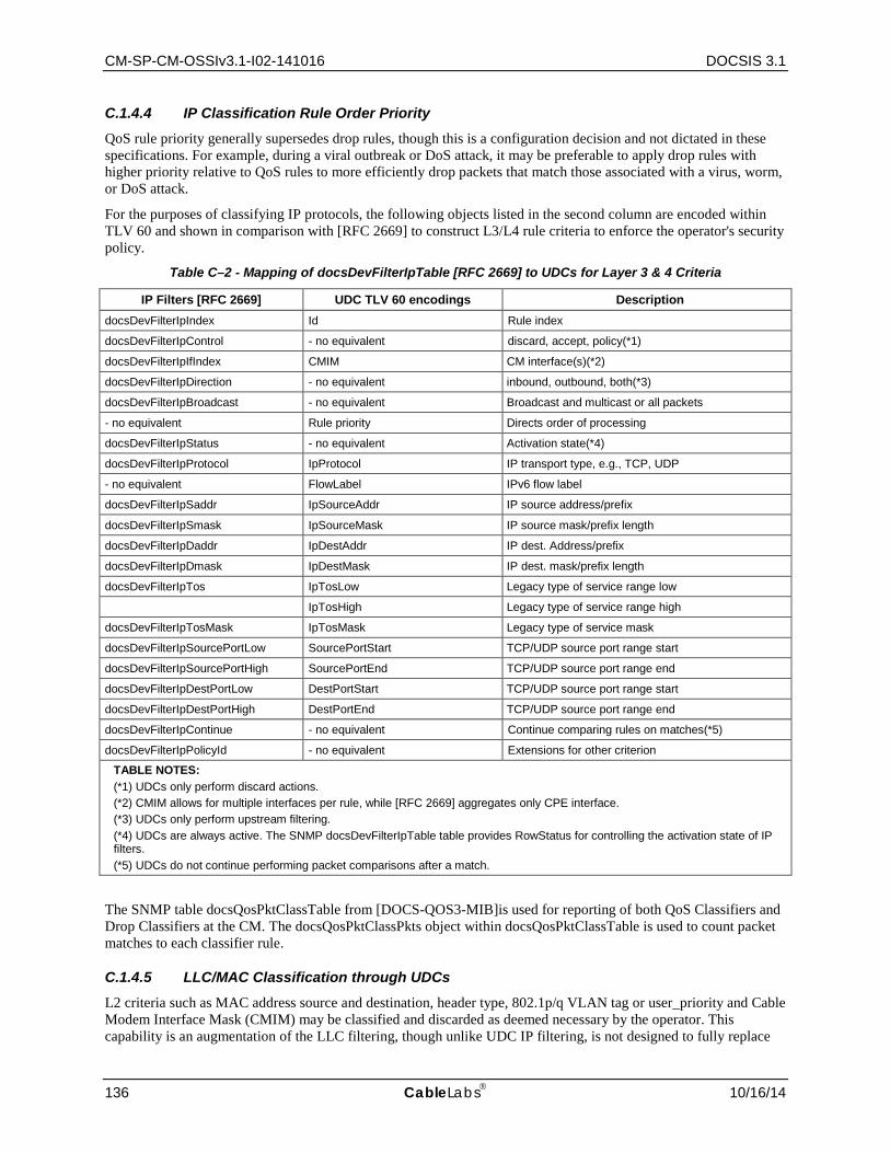
CM-SP-CM-OSSIv3.1-I02-141016 DOCSIS 3.1
136 CableLabs 10/16/14
C.1.4.4 IP Classification Rule Order Priority QoS rule priority generally supersedes drop rules, though this is a configuration decision and not dictated in these specifications. For example, during a viral outbreak or DoS attack, it may be preferable to apply drop rules with higher priority relative to QoS rules to more efficiently drop packets that match those associated with a virus, worm, or DoS attack.
For the purposes of classifying IP protocols, the following objects listed in the second column are encoded within TLV 60 and shown in comparison with [RFC 2669] to construct L3/L4 rule criteria to enforce the operator's security policy.
Table C–2 - Mapping of docsDevFilterIpTable [RFC 2669] to UDCs for Layer 3 & 4 Criteria
IP Filters [RFC 2669] UDC TLV 60 encodings Description docsDevFilterIpIndex Id Rule index
docsDevFilterIpControl - no equivalent discard, accept, policy(*1)
docsDevFilterIpIfIndex CMIM CM interface(s)(*2)
docsDevFilterIpDirection - no equivalent inbound, outbound, both(*3)
docsDevFilterIpBroadcast - no equivalent Broadcast and multicast or all packets
- no equivalent Rule priority Directs order of processing
docsDevFilterIpStatus - no equivalent Activation state(*4)
docsDevFilterIpProtocol IpProtocol IP transport type, e.g., TCP, UDP
- no equivalent FlowLabel IPv6 flow label
docsDevFilterIpSaddr IpSourceAddr IP source address/prefix
docsDevFilterIpSmask IpSourceMask IP source mask/prefix length
docsDevFilterIpDaddr IpDestAddr IP dest. Address/prefix
docsDevFilterIpDmask IpDestMask IP dest. mask/prefix length
docsDevFilterIpTos IpTosLow Legacy type of service range low
IpTosHigh Legacy type of service range high
docsDevFilterIpTosMask IpTosMask Legacy type of service mask
docsDevFilterIpSourcePortLow SourcePortStart TCP/UDP source port range start
docsDevFilterIpSourcePortHigh SourcePortEnd TCP/UDP source port range end
docsDevFilterIpDestPortLow DestPortStart TCP/UDP source port range start
docsDevFilterIpDestPortHigh DestPortEnd TCP/UDP source port range end
docsDevFilterIpContinue - no equivalent Continue comparing rules on matches(*5)
docsDevFilterIpPolicyId - no equivalent Extensions for other criterion
TABLE NOTES: (*1) UDCs only perform discard actions. (*2) CMIM allows for multiple interfaces per rule, while [RFC 2669] aggregates only CPE interface. (*3) UDCs only perform upstream filtering. (*4) UDCs are always active. The SNMP docsDevFilterIpTable table provides RowStatus for controlling the activation state of IP filters. (*5) UDCs do not continue performing packet comparisons after a match.
The SNMP table docsQosPktClassTable from [DOCS-QOS3-MIB]is used for reporting of both QoS Classifiers and Drop Classifiers at the CM. The docsQosPktClassPkts object within docsQosPktClassTable is used to count packet matches to each classifier rule.
C.1.4.5 LLC/MAC Classification through UDCs L2 criteria such as MAC address source and destination, header type, 802.1p/q VLAN tag or user_priority and Cable Modem Interface Mask (CMIM) may be classified and discarded as deemed necessary by the operator. This capability is an augmentation of the LLC filtering, though unlike UDC IP filtering, is not designed to fully replace
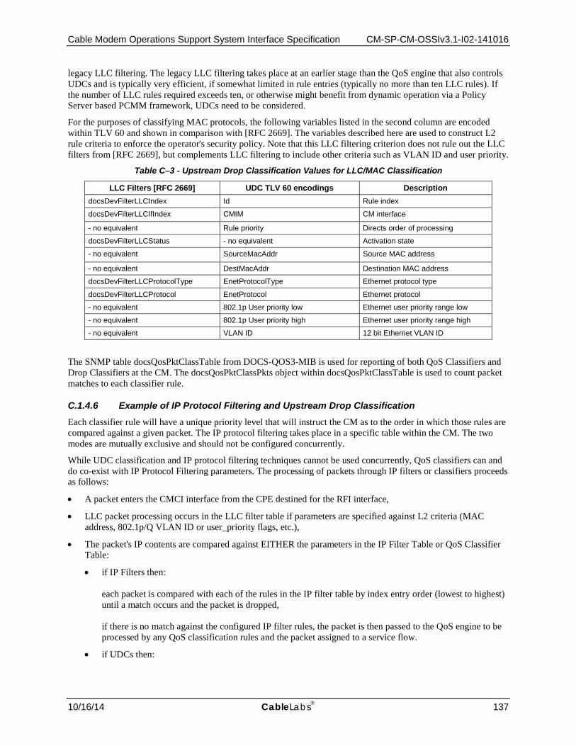
Cable Modem Operations Support System Interface Specification CM-SP-CM-OSSIv3.1-I02-141016
10/16/14 CableLabs 137
legacy LLC filtering. The legacy LLC filtering takes place at an earlier stage than the QoS engine that also controls UDCs and is typically very efficient, if somewhat limited in rule entries (typically no more than ten LLC rules). If the number of LLC rules required exceeds ten, or otherwise might benefit from dynamic operation via a Policy Server based PCMM framework, UDCs need to be considered.
For the purposes of classifying MAC protocols, the following variables listed in the second column are encoded within TLV 60 and shown in comparison with [RFC 2669]. The variables described here are used to construct L2 rule criteria to enforce the operator's security policy. Note that this LLC filtering criterion does not rule out the LLC filters from [RFC 2669], but complements LLC filtering to include other criteria such as VLAN ID and user priority.
Table C–3 - Upstream Drop Classification Values for LLC/MAC Classification
LLC Filters [RFC 2669] UDC TLV 60 encodings Description docsDevFilterLLCIndex Id Rule index
docsDevFilterLLCIfIndex CMIM CM interface
- no equivalent Rule priority Directs order of processing
docsDevFilterLLCStatus - no equivalent Activation state
- no equivalent SourceMacAddr Source MAC address
- no equivalent DestMacAddr Destination MAC address
docsDevFilterLLCProtocolType EnetProtocolType Ethernet protocol type
docsDevFilterLLCProtocol EnetProtocol Ethernet protocol
- no equivalent 802.1p User priority low Ethernet user priority range low
- no equivalent 802.1p User priority high Ethernet user priority range high
- no equivalent VLAN ID 12 bit Ethernet VLAN ID
The SNMP table docsQosPktClassTable from DOCS-QOS3-MIB is used for reporting of both QoS Classifiers and Drop Classifiers at the CM. The docsQosPktClassPkts object within docsQosPktClassTable is used to count packet matches to each classifier rule.
C.1.4.6 Example of IP Protocol Filtering and Upstream Drop Classification Each classifier rule will have a unique priority level that will instruct the CM as to the order in which those rules are compared against a given packet. The IP protocol filtering takes place in a specific table within the CM. The two modes are mutually exclusive and should not be configured concurrently.
While UDC classification and IP protocol filtering techniques cannot be used concurrently, QoS classifiers can and do co-exist with IP Protocol Filtering parameters. The processing of packets through IP filters or classifiers proceeds as follows:
• A packet enters the CMCI interface from the CPE destined for the RFI interface,
• LLC packet processing occurs in the LLC filter table if parameters are specified against L2 criteria (MAC address, 802.1p/Q VLAN ID or user_priority flags, etc.),
• The packet's IP contents are compared against EITHER the parameters in the IP Filter Table or QoS Classifier Table:
• if IP Filters then: each packet is compared with each of the rules in the IP filter table by index entry order (lowest to highest) until a match occurs and the packet is dropped, if there is no match against the configured IP filter rules, the packet is then passed to the QoS engine to be processed by any QoS classification rules and the packet assigned to a service flow.
• if UDCs then:

CM-SP-CM-OSSIv3.1-I02-141016 DOCSIS 3.1
138 CableLabs 10/16/14
each packet is compared with the rules in the QoS classification table by rule priority order (from highest priority to lowest in the range of 0-255): The first classifier rule match against a packet directs the packet to the appropriate service flow or the packet is immediately discarded based on the type of Classifier: a packet matching an Upstream Drop Classifier (TLV type-60) rule will be discarded without queuing or further processing, a packet matching a QoS classifier rule will be directed to a service flow ID assigned by the CMTS and the packet queued for the next upstream burst opportunity.
A packet which does not match any of the static or dynamic classifier rules for either QoS or Upstream Drop Classifiers is directed to the primary service flow and the packet queued for the next upstream burst opportunity.

Cable Modem Operations Support System Interface Specification CM-SP-CM-OSSIv3.1-I02-141016
10/16/14 CableLabs 139
Annex D Format and Content for Event, SYSLOG, and SNMP Notification (Normative) Table D–1 in this annex summarizes the format and content for event, syslog, and SNMP notifications required for a DOCSIS 3.1-compliant CM.
Each row specifies a possible event that may appear in the CM. These events are to be reported by a CM through local event logging, and may be accompanied by syslog or SNMP notification.
The "Process" and "Sub-Process" columns indicate in which stage the event happens. The "CM Priority" column indicates the priority the event is assigned in the CM. The priority is the same as is reported in the docsDevEvLevel object in the cable device MIB [RFC 4639] and in the LEVEL field of the syslog.
The "Event Message" column specifies the event text, which is reported in the docsDevEvText object of the cable device MIB and the text field of the syslog. The "Message Notes And Details" column provides additional information about the event text in the "Event Message" column. Some of the text fields include variable information. The variables are explained in the "Message Notes And Details" column. For some events the "Message Notes And Details" column may include the keyword <Deprecated> to indicate this event is being deprecated and its implementation is optional. For events where the "Event Message" or "Message Notes and Details" column includes either <P1> or <P2>, there is a single space between the value as defined by the <P1> or <P2> and the preceding text.
Example SNMP Notification and Syslog message "Event Message" text string for Event ID 69020900:
SNMP CVC Validation Failure SNMP Manager: 10.50.1.11;CM-MAC=00:22:ce:03:f4:da;CMTS-MAC=00:15:20:00:25:ab;CM-QOS=1.1;CM-VER=3.0;
This specification defines the following keywords as part of the "Event Message" column:
"<TAGS>" (without the quotes) corresponds to: For the CM (without the quotes): ";<CM-MAC>;<CMTS-MAC>;<CM-QOS>;<CM-VER>;"
Where: <CM-MAC>: CM MAC Address; Format*: "CM-MAC=xx:xx:xx:xx:xx:xx" <CMTS-MAC>: CMTS MAC Address; Format*: "CMTS-MAC=xx:xx:xx:xx:xx:xx" <CM-QOS>: CM DOCSIS QOS Version; Format*: "CM-QOS=1.0" or "CM-QOS=1.1" <CM-VER>: CM DOCSIS Version; Format*: "CM-VER=1.0" or| "CM-VER=1.1" or "CM-VER=2.0" or "CM-VER=3.0" (*) without the quotes
The CM MUST format the CM MAC Address field <CM-MAC> of the Event Message text, including such instances of docsDevEvText, using lowercase letters.
The CM MUST format the CMTS MAC Address field <CMTS-MAC> of the Event Message text, including such instances of docsDevEvText, using lower case letters.
Example SNMP Notification and Syslog message "Event Message" text string for Event ID 69010100: SW Download INIT - Via NMS SW file: junk.bin - SW server: 10.50.1.11;CM-MAC=00:22:ce:03:f4:da;CMTS-MAC=00:15:20:00:25:ab;CM-QOS=1.1;CM-VER=3.0;

CM-SP-CM-OSSIv3.1-I02-141016 DOCSIS 3.1
140 CableLabs 10/16/14
The CM MAY append additional vendor-specific text to the end of the event text reported in the docsDevEvText object and the syslog text field.
The "Error Code Set" column specifies the error code. The "Event ID" column indicates a unique identification number for the event, which is assigned to the docsDevEvId object in the cable device MIB and the <eventId> field of the syslog. The "Notification Name" column specifies the SNMP notification, which notifies this event to an SNMP notification receiver.
The syslog format, as well as the rules to uniquely generate an event ID from the error code, are described in Section 8.1.2.1.3 of this specification.
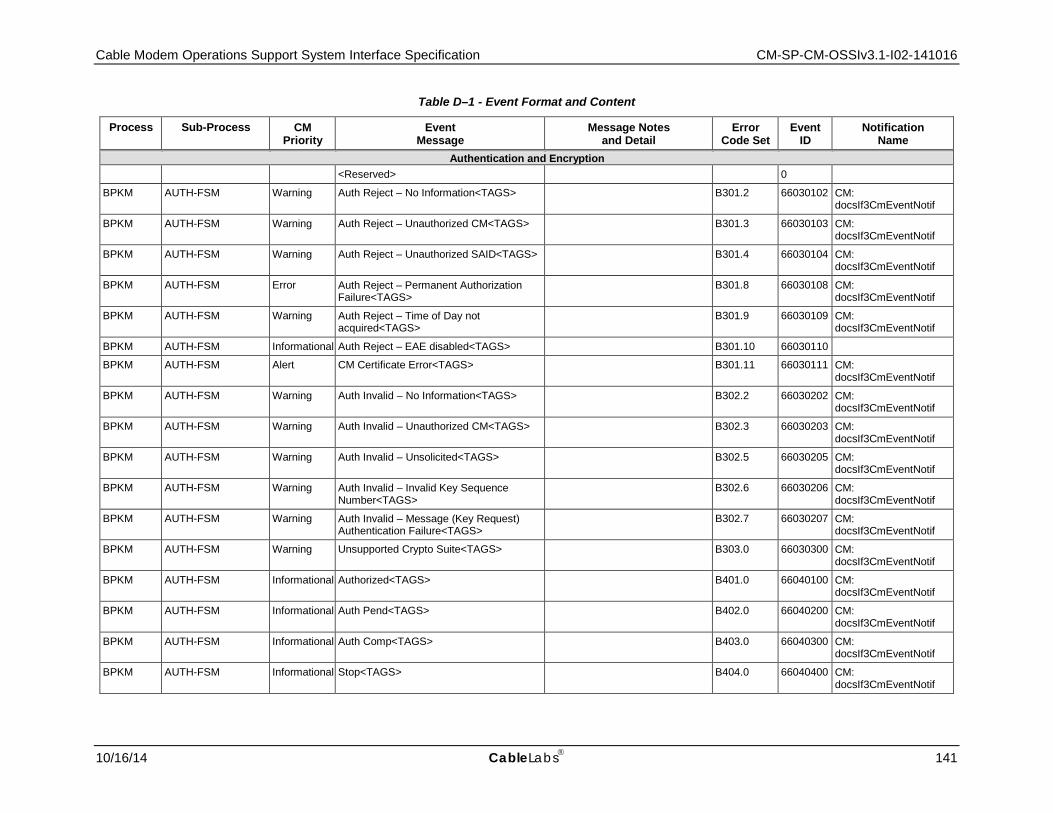
Cable Modem Operations Support System Interface Specification CM-SP-CM-OSSIv3.1-I02-141016
10/16/14 CableLabs 141
Table D–1 - Event Format and Content
Process Sub-Process CM Priority
Event Message
Message Notes and Detail
Error Code Set
Event ID
Notification Name
Authentication and Encryption <Reserved> 0
BPKM AUTH-FSM Warning Auth Reject – No Information<TAGS> B301.2 66030102 CM: docsIf3CmEventNotif
BPKM AUTH-FSM Warning Auth Reject – Unauthorized CM<TAGS> B301.3 66030103 CM: docsIf3CmEventNotif
BPKM AUTH-FSM Warning Auth Reject – Unauthorized SAID<TAGS> B301.4 66030104 CM: docsIf3CmEventNotif
BPKM AUTH-FSM Error Auth Reject – Permanent Authorization Failure<TAGS>
B301.8 66030108 CM: docsIf3CmEventNotif
BPKM AUTH-FSM Warning Auth Reject – Time of Day not acquired<TAGS>
B301.9 66030109 CM: docsIf3CmEventNotif
BPKM AUTH-FSM Informational Auth Reject – EAE disabled<TAGS> B301.10 66030110
BPKM AUTH-FSM Alert CM Certificate Error<TAGS> B301.11 66030111 CM: docsIf3CmEventNotif
BPKM AUTH-FSM Warning Auth Invalid – No Information<TAGS> B302.2 66030202 CM: docsIf3CmEventNotif
BPKM AUTH-FSM Warning Auth Invalid – Unauthorized CM<TAGS> B302.3 66030203 CM: docsIf3CmEventNotif
BPKM AUTH-FSM Warning Auth Invalid – Unsolicited<TAGS> B302.5 66030205 CM: docsIf3CmEventNotif
BPKM AUTH-FSM Warning Auth Invalid – Invalid Key Sequence Number<TAGS>
B302.6 66030206 CM: docsIf3CmEventNotif
BPKM AUTH-FSM Warning Auth Invalid – Message (Key Request) Authentication Failure<TAGS>
B302.7 66030207 CM: docsIf3CmEventNotif
BPKM AUTH-FSM Warning Unsupported Crypto Suite<TAGS> B303.0 66030300 CM: docsIf3CmEventNotif
BPKM AUTH-FSM Informational Authorized<TAGS> B401.0 66040100 CM: docsIf3CmEventNotif
BPKM AUTH-FSM Informational Auth Pend<TAGS> B402.0 66040200 CM: docsIf3CmEventNotif
BPKM AUTH-FSM Informational Auth Comp<TAGS> B403.0 66040300 CM: docsIf3CmEventNotif
BPKM AUTH-FSM Informational Stop<TAGS> B404.0 66040400 CM: docsIf3CmEventNotif
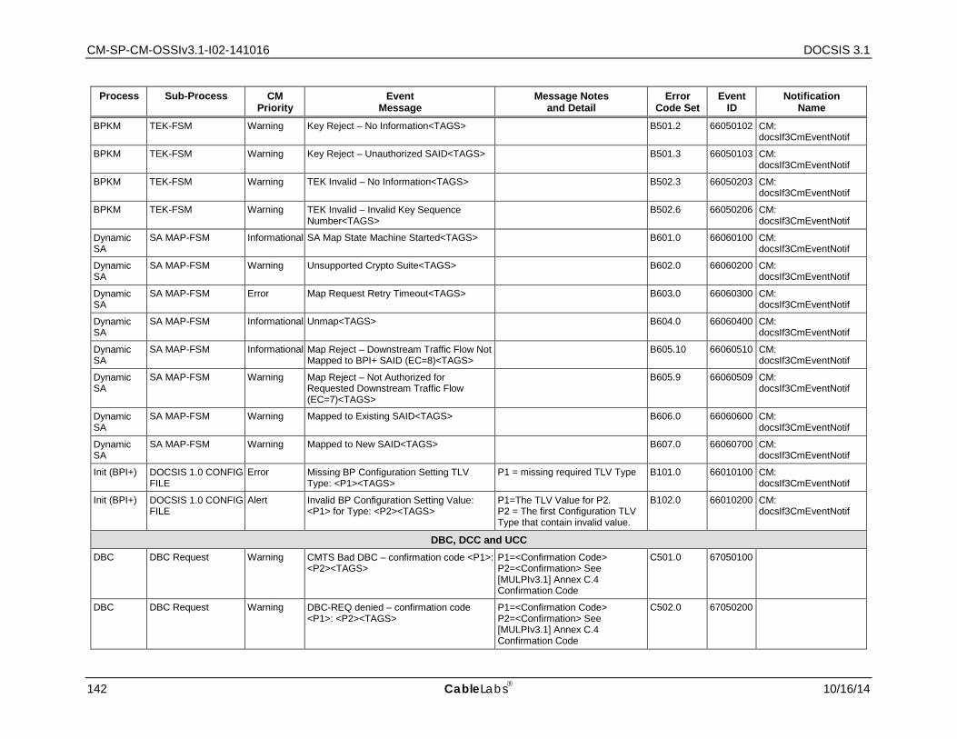
CM-SP-CM-OSSIv3.1-I02-141016 DOCSIS 3.1
142 CableLabs 10/16/14
Process Sub-Process CM Priority
Event Message
Message Notes and Detail
Error Code Set
Event ID
Notification Name
BPKM TEK-FSM Warning Key Reject – No Information<TAGS> B501.2 66050102 CM: docsIf3CmEventNotif
BPKM TEK-FSM Warning Key Reject – Unauthorized SAID<TAGS> B501.3 66050103 CM: docsIf3CmEventNotif
BPKM TEK-FSM Warning TEK Invalid – No Information<TAGS> B502.3 66050203 CM: docsIf3CmEventNotif
BPKM TEK-FSM Warning TEK Invalid – Invalid Key Sequence Number<TAGS>
B502.6 66050206 CM: docsIf3CmEventNotif
Dynamic SA
SA MAP-FSM Informational SA Map State Machine Started<TAGS> B601.0 66060100 CM: docsIf3CmEventNotif
Dynamic SA
SA MAP-FSM Warning Unsupported Crypto Suite<TAGS> B602.0 66060200 CM: docsIf3CmEventNotif
Dynamic SA
SA MAP-FSM Error Map Request Retry Timeout<TAGS> B603.0 66060300 CM: docsIf3CmEventNotif
Dynamic SA
SA MAP-FSM Informational Unmap<TAGS> B604.0 66060400 CM: docsIf3CmEventNotif
Dynamic SA
SA MAP-FSM Informational Map Reject – Downstream Traffic Flow Not Mapped to BPI+ SAID (EC=8)<TAGS>
B605.10 66060510 CM: docsIf3CmEventNotif
Dynamic SA
SA MAP-FSM Warning Map Reject – Not Authorized for Requested Downstream Traffic Flow (EC=7)<TAGS>
B605.9 66060509 CM: docsIf3CmEventNotif
Dynamic SA
SA MAP-FSM Warning Mapped to Existing SAID<TAGS> B606.0 66060600 CM: docsIf3CmEventNotif
Dynamic SA
SA MAP-FSM Warning Mapped to New SAID<TAGS> B607.0 66060700 CM: docsIf3CmEventNotif
Init (BPI+) DOCSIS 1.0 CONFIG FILE
Error Missing BP Configuration Setting TLV Type: <P1><TAGS>
P1 = missing required TLV Type B101.0 66010100 CM: docsIf3CmEventNotif
Init (BPI+) DOCSIS 1.0 CONFIG FILE
Alert Invalid BP Configuration Setting Value: <P1> for Type: <P2><TAGS>
P1=The TLV Value for P2. P2 = The first Configuration TLV Type that contain invalid value.
B102.0 66010200 CM: docsIf3CmEventNotif
DBC, DCC and UCC DBC DBC Request Warning CMTS Bad DBC – confirmation code <P1>:
<P2><TAGS> P1=<Confirmation Code> P2=<Confirmation> See [MULPIv3.1] Annex C.4 Confirmation Code
C501.0 67050100
DBC DBC Request Warning DBC-REQ denied – confirmation code <P1>: <P2><TAGS>
P1=<Confirmation Code> P2=<Confirmation> See [MULPIv3.1] Annex C.4 Confirmation Code
C502.0 67050200

Cable Modem Operations Support System Interface Specification CM-SP-CM-OSSIv3.1-I02-141016
10/16/14 CableLabs 143
Process Sub-Process CM Priority
Event Message
Message Notes and Detail
Error Code Set
Event ID
Notification Name
DBC DBC Acknowledgement
Error DBC-ACK not received<TAGS> C701.0 67070100
DBC DBC Acknowledgement
Notice Bad CMTS DBC-ACK: <P1><TAGS> P1="unspecified reason" | "unknown transaction ID" | "authentication failure" | "msg syntax error"
C702.0 67070200
DCC DCC Request Error DCC rejected already there<TAGS> C201.0 67020100 CM: docsIf3CmEventNotif
DCC DCC Request Informational DCC depart old<TAGS> C202.0 67020200 CM: docsIf3CmEventNotif
DCC DCC Request Informational DCC arrive new<TAGS> C203.0 67020300 CM: docsIf3CmEventNotif
DCC DCC Request Critical DCC aborted unable to acquire new downstream channel<TAGS>
C204.0 67020400
DCC DCC Request Critical DCC aborted no UCD for new upstream channel<TAGS>
C205.0 67020500
DCC DCC Request Critical DCC aborted unable to communicate on new upstream channel<TAGS>
C206.0 67020600
DCC DCC Request Error DCC rejected unspecified reason<TAGS> C207.0 67020700 CM: docsIf3CmEventNotif
DCC DCC Request Error DCC rejected permanent – DCC not supported<TAGS>
C208.0 67020800 CM: docsIf3CmEventNotif
DCC DCC Request Error DCC rejected service flow not found<TAGS>
C209.0 67020900 CM: docsIf3CmEventNotif
DCC DCC Request Error DCC rejected required parameter not present<TAGS>
C210.0 67021000 CM: docsIf3CmEventNotif
DCC DCC Request Error DCC rejected authentication failure<TAGS>
C211.0 67021100 CM: docsIf3CmEventNotif
DCC DCC Request Error DCC rejected multiple errors<TAGS> C212.0 67021200 CM: docsIf3CmEventNotif
DCC DCC Request Error DCC rejected, duplicate SF reference-ID or index in message<TAGS>
C215.0 67021500 CM: docsIf3CmEventNotif
DCC DCC Request Error DCC rejected parameter invalid for context<TAGS>
C216.0 67021600 CM: docsIf3CmEventNotif
DCC DCC Request Error DCC rejected message syntax error<TAGS>
C217.0 67021700 CM: docsIf3CmEventNotif
DCC DCC Request Error DCC rejected message too big<TAGS> C218.0 67021800 CM: docsIf3CmEventNotif
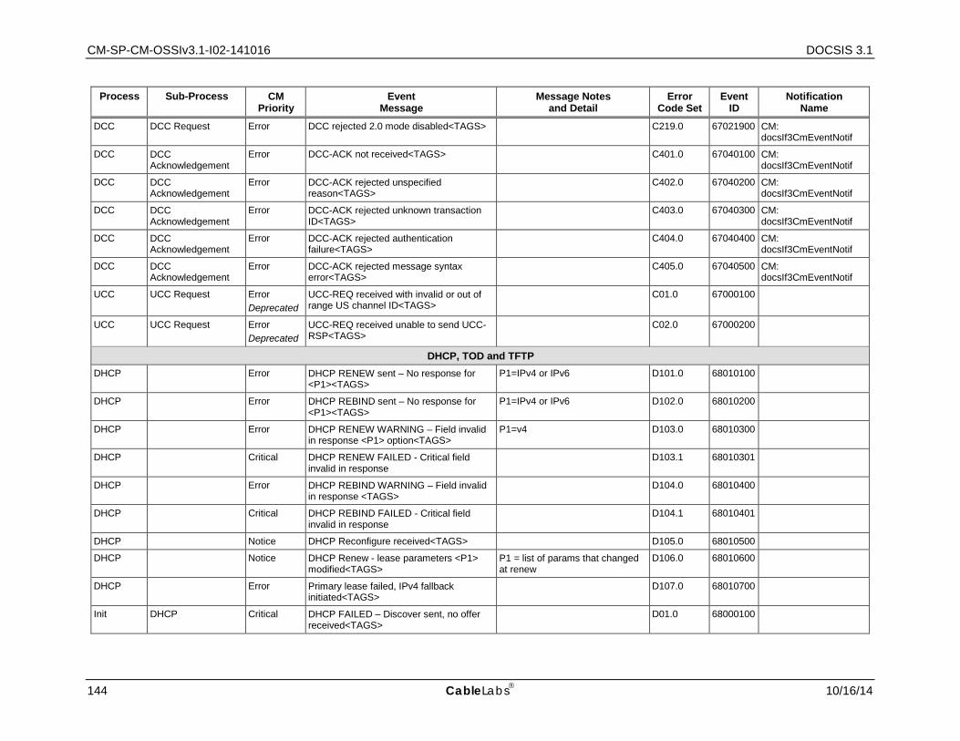
CM-SP-CM-OSSIv3.1-I02-141016 DOCSIS 3.1
144 CableLabs 10/16/14
Process Sub-Process CM Priority
Event Message
Message Notes and Detail
Error Code Set
Event ID
Notification Name
DCC DCC Request Error DCC rejected 2.0 mode disabled<TAGS> C219.0 67021900 CM: docsIf3CmEventNotif
DCC DCC Acknowledgement
Error DCC-ACK not received<TAGS> C401.0 67040100 CM: docsIf3CmEventNotif
DCC DCC Acknowledgement
Error DCC-ACK rejected unspecified reason<TAGS>
C402.0 67040200 CM: docsIf3CmEventNotif
DCC DCC Acknowledgement
Error DCC-ACK rejected unknown transaction ID<TAGS>
C403.0 67040300 CM: docsIf3CmEventNotif
DCC DCC Acknowledgement
Error DCC-ACK rejected authentication failure<TAGS>
C404.0 67040400 CM: docsIf3CmEventNotif
DCC DCC Acknowledgement
Error DCC-ACK rejected message syntax error<TAGS>
C405.0 67040500 CM: docsIf3CmEventNotif
UCC UCC Request Error Deprecated
UCC-REQ received with invalid or out of range US channel ID<TAGS>
C01.0 67000100
UCC UCC Request Error Deprecated
UCC-REQ received unable to send UCC-RSP<TAGS>
C02.0 67000200
DHCP, TOD and TFTP DHCP Error DHCP RENEW sent – No response for
<P1><TAGS> P1=IPv4 or IPv6 D101.0 68010100
DHCP Error DHCP REBIND sent – No response for <P1><TAGS>
P1=IPv4 or IPv6 D102.0 68010200
DHCP Error DHCP RENEW WARNING – Field invalid in response <P1> option<TAGS>
P1=v4 D103.0 68010300
DHCP Critical DHCP RENEW FAILED - Critical field invalid in response
D103.1 68010301
DHCP Error DHCP REBIND WARNING – Field invalid in response <TAGS>
D104.0 68010400
DHCP Critical DHCP REBIND FAILED - Critical field invalid in response
D104.1 68010401
DHCP Notice DHCP Reconfigure received<TAGS> D105.0 68010500
DHCP Notice DHCP Renew - lease parameters <P1> modified<TAGS>
P1 = list of params that changed at renew
D106.0 68010600
DHCP Error Primary lease failed, IPv4 fallback initiated<TAGS>
D107.0 68010700
Init DHCP Critical DHCP FAILED – Discover sent, no offer received<TAGS>
D01.0 68000100

Cable Modem Operations Support System Interface Specification CM-SP-CM-OSSIv3.1-I02-141016
10/16/14 CableLabs 145
Process Sub-Process CM Priority
Event Message
Message Notes and Detail
Error Code Set
Event ID
Notification Name
Init DHCP Critical DHCP FAILED – Request sent, No response<TAGS>
D02.0 68000200
Init DHCP Warning DHCP WARNING - Non-critical field invalid in response <TAGS>
D03.0 68000300
Init DHCP Critical DHCP FAILED – Critical field invalid in response <TAGS>
D03.1 68000301
Init DHCP Critical DHCP failed – RS sent, no RA received<TAGS>
D12.0 68001200
Init DHCP Critical DHCP Failed – Invalid RA<TAGS> D12.1 68001201
Init DHCP Critical DHCP failed – DHCP Solicit sent, No DHCP Advertise received<TAGS>
D12.2 68001202
Init DHCP Critical DHCP failed – DHCP Request sent, No DHCP REPLY received<TAGS>
D12.3 68001203
Init DHCP Error Primary address acquired, secondary failed<TAGS>
D12.4 68001204
Init DHCP Error Primary address failed, secondary active<TAGS>
D12.5 68001205
Init IPv6 Address Acquisition
Critical Link-Local address failed DAD<TAGS> D13.1 68001301
Init IPv6 Address Acquisition
Critical DHCP lease address failed DAD<TAGS> D13.2 68001302
Init TOD Warning ToD request sent – No Response received<TAGS>
D04.1 68000401
Init TOD Warning ToD Response received – Invalid data format<TAGS>
D04.2 68000402
Init TFTP Critical TFTP failed – Request sent – No Response<TAGS>
D05.0 68000500
Init TFTP Critical TFTP failed – configuration file NOT FOUND<TAGS>
For SYSLOG only: append: File name = <P1> P1 = requested file name
D06.0 68000600
Init TFTP Critical TFTP Failed – OUT OF ORDER packets<TAGS>
D07.0 68000700
Init TFTP Critical TFTP file complete – but failed Message Integrity check MIC<TAGS>
For SYSLOG only: append: File name = <P1> P1 = file name of TFTP file
D08.0 68000800
Init TFTP Critical TFTP file complete – but missing mandatory TLV<TAGS>
D09.0 68000900
Init TFTP Critical TFTP Failed – file too big<TAGS> D10.0 68001000
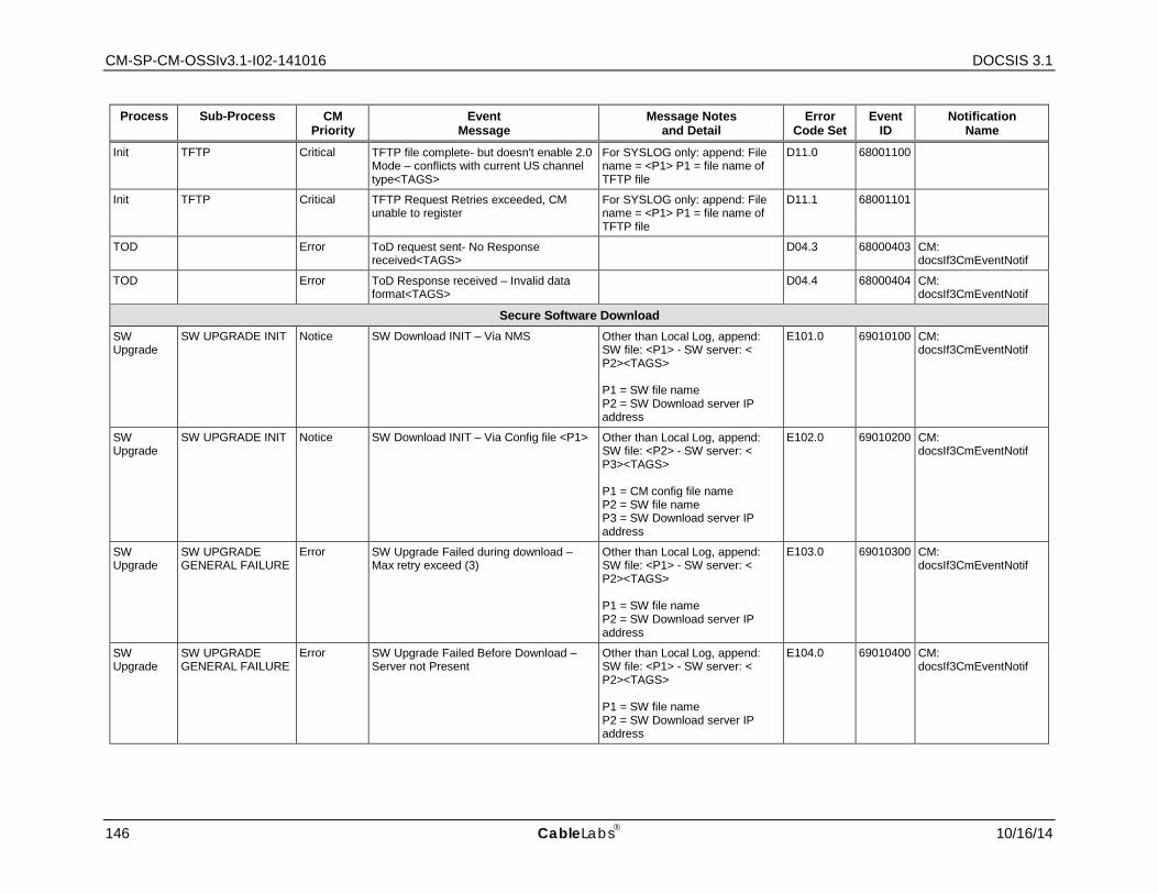
CM-SP-CM-OSSIv3.1-I02-141016 DOCSIS 3.1
146 CableLabs 10/16/14
Process Sub-Process CM Priority
Event Message
Message Notes and Detail
Error Code Set
Event ID
Notification Name
Init TFTP Critical TFTP file complete- but doesn't enable 2.0 Mode – conflicts with current US channel type<TAGS>
For SYSLOG only: append: File name = <P1> P1 = file name of TFTP file
D11.0 68001100
Init TFTP Critical TFTP Request Retries exceeded, CM unable to register
For SYSLOG only: append: File name = <P1> P1 = file name of TFTP file
D11.1 68001101
TOD Error ToD request sent- No Response received<TAGS>
D04.3 68000403 CM: docsIf3CmEventNotif
TOD Error ToD Response received – Invalid data format<TAGS>
D04.4 68000404 CM: docsIf3CmEventNotif
Secure Software Download SW Upgrade
SW UPGRADE INIT Notice SW Download INIT – Via NMS Other than Local Log, append: SW file: <P1> - SW server: < P2><TAGS> P1 = SW file name P2 = SW Download server IP address
E101.0 69010100 CM: docsIf3CmEventNotif
SW Upgrade
SW UPGRADE INIT Notice SW Download INIT – Via Config file <P1> Other than Local Log, append: SW file: <P2> - SW server: < P3><TAGS> P1 = CM config file name P2 = SW file name P3 = SW Download server IP address
E102.0 69010200 CM: docsIf3CmEventNotif
SW Upgrade
SW UPGRADE GENERAL FAILURE
Error SW Upgrade Failed during download – Max retry exceed (3)
Other than Local Log, append: SW file: <P1> - SW server: < P2><TAGS> P1 = SW file name P2 = SW Download server IP address
E103.0 69010300 CM: docsIf3CmEventNotif
SW Upgrade
SW UPGRADE GENERAL FAILURE
Error SW Upgrade Failed Before Download – Server not Present
Other than Local Log, append: SW file: <P1> - SW server: < P2><TAGS> P1 = SW file name P2 = SW Download server IP address
E104.0 69010400 CM: docsIf3CmEventNotif
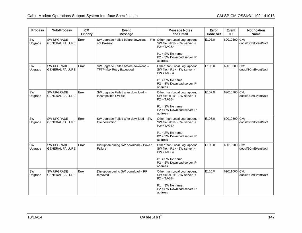
Cable Modem Operations Support System Interface Specification CM-SP-CM-OSSIv3.1-I02-141016
10/16/14 CableLabs 147
Process Sub-Process CM Priority
Event Message
Message Notes and Detail
Error Code Set
Event ID
Notification Name
SW Upgrade
SW UPGRADE GENERAL FAILURE
Error SW upgrade Failed before download – File not Present
Other than Local Log, append: SW file: <P1> - SW server: < P2><TAGS> P1 = SW file name P2 = SW Download server IP address
E105.0 69010500 CM: docsIf3CmEventNotif
SW Upgrade
SW UPGRADE GENERAL FAILURE
Error SW upgrade Failed before download –TFTP Max Retry Exceeded
Other than Local Log, append: SW file: <P1> - SW server: < P2><TAGS> P1 = SW file name P2 = SW Download server IP address
E106.0 69010600 CM: docsIf3CmEventNotif
SW Upgrade
SW UPGRADE GENERAL FAILURE
Error SW upgrade Failed after download –Incompatible SW file
Other than Local Log, append: SW file: <P1> - SW server: < P2><TAGS> P1 = SW file name P2 = SW Download server IP address
E107.0 69010700 CM: docsIf3CmEventNotif
SW Upgrade
SW UPGRADE GENERAL FAILURE
Error SW upgrade Failed after download – SW File corruption
Other than Local Log, append: SW file: <P1> - SW server: < P2><TAGS> P1 = SW file name P2 = SW Download server IP address
E108.0 69010800 CM: docsIf3CmEventNotif
SW Upgrade
SW UPGRADE GENERAL FAILURE
Error Disruption during SW download – Power Failure
Other than Local Log, append: SW file: <P1> - SW server: < P2><TAGS> P1 = SW file name P2 = SW Download server IP address
E109.0 69010900 CM: docsIf3CmEventNotif
SW Upgrade
SW UPGRADE GENERAL FAILURE
Error Disruption during SW download – RF removed
Other than Local Log, append: SW file: <P1> - SW server: < P2><TAGS> P1 = SW file name P2 = SW Download server IP address
E110.0 69011000 CM: docsIf3CmEventNotif
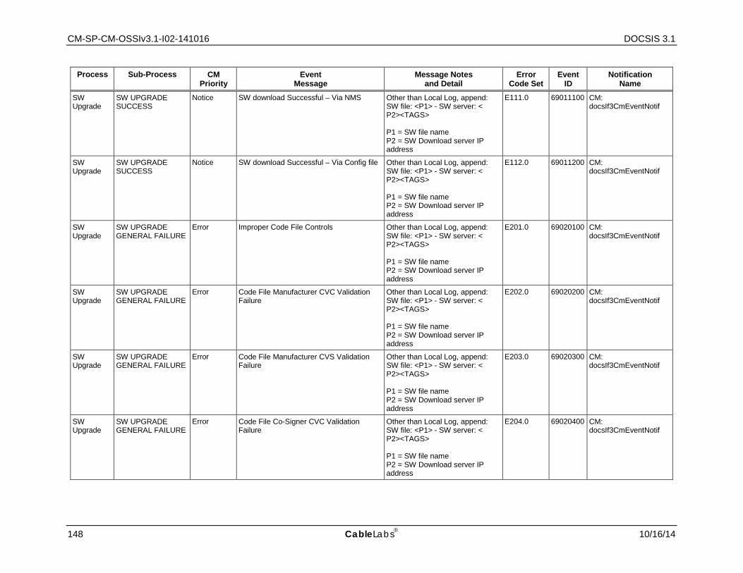
CM-SP-CM-OSSIv3.1-I02-141016 DOCSIS 3.1
148 CableLabs 10/16/14
Process Sub-Process CM Priority
Event Message
Message Notes and Detail
Error Code Set
Event ID
Notification Name
SW Upgrade
SW UPGRADE SUCCESS
Notice SW download Successful – Via NMS Other than Local Log, append: SW file: <P1> - SW server: < P2><TAGS> P1 = SW file name P2 = SW Download server IP address
E111.0 69011100 CM: docsIf3CmEventNotif
SW Upgrade
SW UPGRADE SUCCESS
Notice SW download Successful – Via Config file Other than Local Log, append: SW file: <P1> - SW server: < P2><TAGS> P1 = SW file name P2 = SW Download server IP address
E112.0 69011200 CM: docsIf3CmEventNotif
SW Upgrade
SW UPGRADE GENERAL FAILURE
Error Improper Code File Controls Other than Local Log, append: SW file: <P1> - SW server: < P2><TAGS> P1 = SW file name P2 = SW Download server IP address
E201.0 69020100 CM: docsIf3CmEventNotif
SW Upgrade
SW UPGRADE GENERAL FAILURE
Error Code File Manufacturer CVC Validation Failure
Other than Local Log, append: SW file: <P1> - SW server: < P2><TAGS> P1 = SW file name P2 = SW Download server IP address
E202.0 69020200 CM: docsIf3CmEventNotif
SW Upgrade
SW UPGRADE GENERAL FAILURE
Error Code File Manufacturer CVS Validation Failure
Other than Local Log, append: SW file: <P1> - SW server: < P2><TAGS> P1 = SW file name P2 = SW Download server IP address
E203.0 69020300 CM: docsIf3CmEventNotif
SW Upgrade
SW UPGRADE GENERAL FAILURE
Error Code File Co-Signer CVC Validation Failure
Other than Local Log, append: SW file: <P1> - SW server: < P2><TAGS> P1 = SW file name P2 = SW Download server IP address
E204.0 69020400 CM: docsIf3CmEventNotif
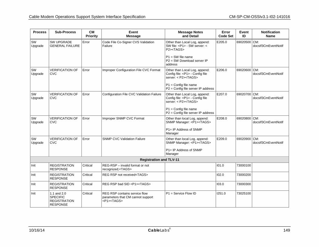
Cable Modem Operations Support System Interface Specification CM-SP-CM-OSSIv3.1-I02-141016
10/16/14 CableLabs 149
Process Sub-Process CM Priority
Event Message
Message Notes and Detail
Error Code Set
Event ID
Notification Name
SW Upgrade
SW UPGRADE GENERAL FAILURE
Error Code File Co-Signer CVS Validation Failure
Other than Local Log, append: SW file: <P1> - SW server: < P2><TAGS> P1 = SW file name P2 = SW Download server IP address
E205.0 69020500 CM: docsIf3CmEventNotif
SW Upgrade
VERIFICATION OF CVC
Error Improper Configuration File CVC Format Other than Local Log, append: Config file: <P1> - Config file server: < P2><TAGS> P1 = Config file name P2 = Config file server IP address
E206.0 69020600 CM: docsIf3CmEventNotif
SW Upgrade
VERIFICATION OF CVC
Error Configuration File CVC Validation Failure Other than Local Log, append: Config file: <P1> - Config file server: < P2><TAGS> P1 = Config file name P2 = Config file server IP address
E207.0 69020700 CM: docsIf3CmEventNotif
SW Upgrade
VERIFICATION OF CVC
Error Improper SNMP CVC Format Other than local Log, append: SNMP Manager: <P1><TAGS> P1= IP Address of SNMP Manager
E208.0 69020800 CM: docsIf3CmEventNotif
SW Upgrade
VERIFICATION OF CVC
Error SNMP CVC Validation Failure Other than local Log, append: SNMP Manager: <P1><TAGS> P1= IP Address of SNMP Manager
E209.0 69020900 CM: docsIf3CmEventNotif
Registration and TLV-11 Init REGISTRATION
RESPONSE Critical REG-RSP – invalid format or not
recognized;<TAGS> I01.0 73000100
Init REGISTRATION RESPONSE
Critical REG RSP not received<TAGS> I02.0 73000200
Init REGISTRATION RESPONSE
Critical REG RSP bad SID <P1><TAGS> I03.0 73000300
Init 1.1 and 2.0 SPECIFIC REGISTRATION RESPONSE
Critical REG RSP contains service flow parameters that CM cannot support <P1><TAGS>
P1 = Service Flow ID I251.0 73025100
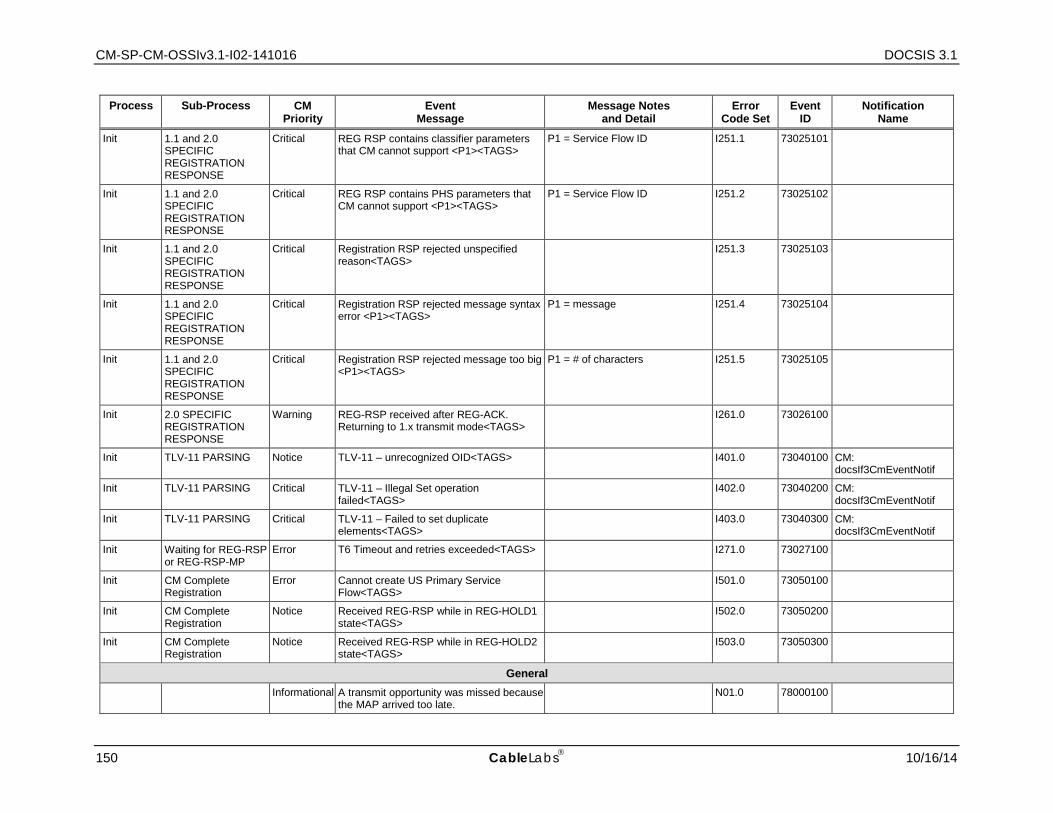
CM-SP-CM-OSSIv3.1-I02-141016 DOCSIS 3.1
150 CableLabs 10/16/14
Process Sub-Process CM Priority
Event Message
Message Notes and Detail
Error Code Set
Event ID
Notification Name
Init 1.1 and 2.0 SPECIFIC REGISTRATION RESPONSE
Critical REG RSP contains classifier parameters that CM cannot support <P1><TAGS>
P1 = Service Flow ID I251.1 73025101
Init 1.1 and 2.0 SPECIFIC REGISTRATION RESPONSE
Critical REG RSP contains PHS parameters that CM cannot support <P1><TAGS>
P1 = Service Flow ID I251.2 73025102
Init 1.1 and 2.0 SPECIFIC REGISTRATION RESPONSE
Critical Registration RSP rejected unspecified reason<TAGS>
I251.3 73025103
Init 1.1 and 2.0 SPECIFIC REGISTRATION RESPONSE
Critical Registration RSP rejected message syntax error <P1><TAGS>
P1 = message I251.4 73025104
Init 1.1 and 2.0 SPECIFIC REGISTRATION RESPONSE
Critical Registration RSP rejected message too big <P1><TAGS>
P1 = # of characters I251.5 73025105
Init 2.0 SPECIFIC REGISTRATION RESPONSE
Warning REG-RSP received after REG-ACK. Returning to 1.x transmit mode<TAGS>
I261.0 73026100
Init TLV-11 PARSING Notice TLV-11 – unrecognized OID<TAGS> I401.0 73040100 CM: docsIf3CmEventNotif
Init TLV-11 PARSING Critical TLV-11 – Illegal Set operation failed<TAGS>
I402.0 73040200 CM: docsIf3CmEventNotif
Init TLV-11 PARSING Critical TLV-11 – Failed to set duplicate elements<TAGS>
I403.0 73040300 CM: docsIf3CmEventNotif
Init Waiting for REG-RSP or REG-RSP-MP
Error T6 Timeout and retries exceeded<TAGS> I271.0 73027100
Init CM Complete Registration
Error Cannot create US Primary Service Flow<TAGS>
I501.0 73050100
Init CM Complete Registration
Notice Received REG-RSP while in REG-HOLD1 state<TAGS>
I502.0 73050200
Init CM Complete Registration
Notice Received REG-RSP while in REG-HOLD2 state<TAGS>
I503.0 73050300
General Informational A transmit opportunity was missed because
the MAP arrived too late. N01.0 78000100
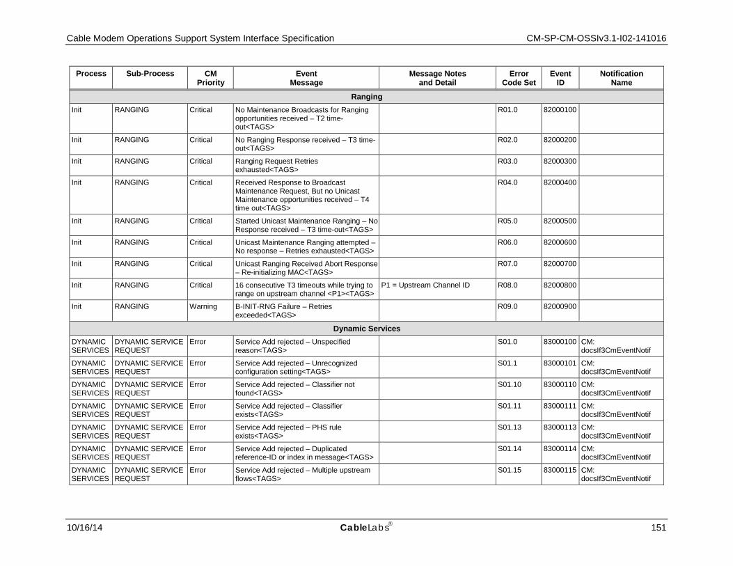
Cable Modem Operations Support System Interface Specification CM-SP-CM-OSSIv3.1-I02-141016
10/16/14 CableLabs 151
Process Sub-Process CM Priority
Event Message
Message Notes and Detail
Error Code Set
Event ID
Notification Name
Ranging Init RANGING Critical No Maintenance Broadcasts for Ranging
opportunities received – T2 time-out<TAGS>
R01.0 82000100
Init RANGING Critical No Ranging Response received – T3 time-out<TAGS>
R02.0 82000200
Init RANGING Critical Ranging Request Retries exhausted<TAGS>
R03.0 82000300
Init RANGING Critical Received Response to Broadcast Maintenance Request, But no Unicast Maintenance opportunities received – T4 time out<TAGS>
R04.0 82000400
Init RANGING Critical Started Unicast Maintenance Ranging – No Response received – T3 time-out<TAGS>
R05.0 82000500
Init RANGING Critical Unicast Maintenance Ranging attempted – No response – Retries exhausted<TAGS>
R06.0 82000600
Init RANGING Critical Unicast Ranging Received Abort Response – Re-initializing MAC<TAGS>
R07.0 82000700
Init RANGING Critical 16 consecutive T3 timeouts while trying to range on upstream channel <P1><TAGS>
P1 = Upstream Channel ID R08.0 82000800
Init RANGING Warning B-INIT-RNG Failure – Retries exceeded<TAGS>
R09.0 82000900
Dynamic Services DYNAMIC SERVICES
DYNAMIC SERVICE REQUEST
Error Service Add rejected – Unspecified reason<TAGS>
S01.0 83000100 CM: docsIf3CmEventNotif
DYNAMIC SERVICES
DYNAMIC SERVICE REQUEST
Error Service Add rejected – Unrecognized configuration setting<TAGS>
S01.1 83000101 CM: docsIf3CmEventNotif
DYNAMIC SERVICES
DYNAMIC SERVICE REQUEST
Error Service Add rejected – Classifier not found<TAGS>
S01.10 83000110 CM: docsIf3CmEventNotif
DYNAMIC SERVICES
DYNAMIC SERVICE REQUEST
Error Service Add rejected – Classifier exists<TAGS>
S01.11 83000111 CM: docsIf3CmEventNotif
DYNAMIC SERVICES
DYNAMIC SERVICE REQUEST
Error Service Add rejected – PHS rule exists<TAGS>
S01.13 83000113 CM: docsIf3CmEventNotif
DYNAMIC SERVICES
DYNAMIC SERVICE REQUEST
Error Service Add rejected – Duplicated reference-ID or index in message<TAGS>
S01.14 83000114 CM: docsIf3CmEventNotif
DYNAMIC SERVICES
DYNAMIC SERVICE REQUEST
Error Service Add rejected – Multiple upstream flows<TAGS>
S01.15 83000115 CM: docsIf3CmEventNotif
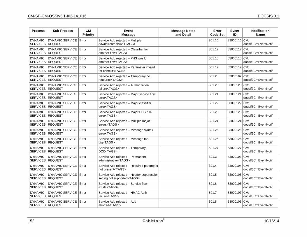
CM-SP-CM-OSSIv3.1-I02-141016 DOCSIS 3.1
152 CableLabs 10/16/14
Process Sub-Process CM Priority
Event Message
Message Notes and Detail
Error Code Set
Event ID
Notification Name
DYNAMIC SERVICES
DYNAMIC SERVICE REQUEST
Error Service Add rejected – Multiple downstream flows<TAGS>
S01.16 83000116 CM: docsIf3CmEventNotif
DYNAMIC SERVICES
DYNAMIC SERVICE REQUEST
Error Service Add rejected – Classifier for another flow<TAGS>
S01.17 83000117 CM: docsIf3CmEventNotif
DYNAMIC SERVICES
DYNAMIC SERVICE REQUEST
Error Service Add rejected – PHS rule for another flow<TAGS>
S01.18 83000118 CM: docsIf3CmEventNotif
DYNAMIC SERVICES
DYNAMIC SERVICE REQUEST
Error Service Add rejected – Parameter invalid for context<TAGS>
S01.19 83000119 CM: docsIf3CmEventNotif
DYNAMIC SERVICES
DYNAMIC SERVICE REQUEST
Error Service Add rejected – Temporary no resource<TAGS>
S01.2 83000102 CM: docsIf3CmEventNotif
DYNAMIC SERVICES
DYNAMIC SERVICE REQUEST
Error Service Add rejected – Authorization failure<TAGS>
S01.20 83000120 CM: docsIf3CmEventNotif
DYNAMIC SERVICES
DYNAMIC SERVICE REQUEST
Error Service Add rejected – Major service flow error<TAGS>
S01.21 83000121 CM: docsIf3CmEventNotif
DYNAMIC SERVICES
DYNAMIC SERVICE REQUEST
Error Service Add rejected – Major classifier error<TAGS>
S01.22 83000122 CM: docsIf3CmEventNotif
DYNAMIC SERVICES
DYNAMIC SERVICE REQUEST
Error Service Add rejected – Major PHS rule error<TAGS>
S01.23 83000123 CM: docsIf3CmEventNotif
DYNAMIC SERVICES
DYNAMIC SERVICE REQUEST
Error Service Add rejected – Multiple major errors<TAGS>
S01.24 83000124 CM: docsIf3CmEventNotif
DYNAMIC SERVICES
DYNAMIC SERVICE REQUEST
Error Service Add rejected – Message syntax error<TAGS>
S01.25 83000125 CM: docsIf3CmEventNotif
DYNAMIC SERVICES
DYNAMIC SERVICE REQUEST
Error Service Add rejected – Message too big<TAGS>
S01.26 83000126 CM: docsIf3CmEventNotif
DYNAMIC SERVICES
DYNAMIC SERVICE REQUEST
Error Service Add rejected – Temporary DCC<TAGS>
S01.27 83000127 CM: docsIf3CmEventNotif
DYNAMIC SERVICES
DYNAMIC SERVICE REQUEST
Error Service Add rejected – Permanent administrative<TAGS>
S01.3 83000103 CM: docsIf3CmEventNotif
DYNAMIC SERVICES
DYNAMIC SERVICE REQUEST
Error Service Add rejected – Required parameter not present<TAGS>
S01.4 83000104 CM: docsIf3CmEventNotif
DYNAMIC SERVICES
DYNAMIC SERVICE REQUEST
Error Service Add rejected – Header suppression setting not supported<TAGS>
S01.5 83000105 CM: docsIf3CmEventNotif
DYNAMIC SERVICES
DYNAMIC SERVICE REQUEST
Error Service Add rejected – Service flow exists<TAGS>
S01.6 83000106 CM: docsIf3CmEventNotif
DYNAMIC SERVICES
DYNAMIC SERVICE REQUEST
Error Service Add rejected – HMAC Auth failure<TAGS>
S01.7 83000107 CM: docsIf3CmEventNotif
DYNAMIC SERVICES
DYNAMIC SERVICE REQUEST
Error Service Add rejected – Add aborted<TAGS>
S01.8 83000108 CM: docsIf3CmEventNotif
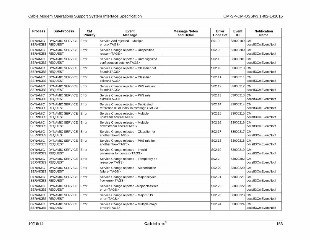
Cable Modem Operations Support System Interface Specification CM-SP-CM-OSSIv3.1-I02-141016
10/16/14 CableLabs 153
Process Sub-Process CM Priority
Event Message
Message Notes and Detail
Error Code Set
Event ID
Notification Name
DYNAMIC SERVICES
DYNAMIC SERVICE REQUEST
Error Service Add rejected – Multiple errors<TAGS>
S01.9 83000109 CM: docsIf3CmEventNotif
DYNAMIC SERVICES
DYNAMIC SERVICE REQUEST
Error Service Change rejected – Unspecified reason<TAGS>
S02.0 83000200 CM: docsIf3CmEventNotif
DYNAMIC SERVICES
DYNAMIC SERVICE REQUEST
Error Service Change rejected – Unrecognized configuration setting<TAGS>
S02.1 83000201 CM: docsIf3CmEventNotif
DYNAMIC SERVICES
DYNAMIC SERVICE REQUEST
Error Service Change rejected – Classifier not found<TAGS>
S02.10 83000210 CM: docsIf3CmEventNotif
DYNAMIC SERVICES
DYNAMIC SERVICE REQUEST
Error Service Change rejected – Classifier exists<TAGS>
S02.11 83000211 CM: docsIf3CmEventNotif
DYNAMIC SERVICES
DYNAMIC SERVICE REQUEST
Error Service Change rejected – PHS rule not found<TAGS>
S02.12 83000212 CM: docsIf3CmEventNotif
DYNAMIC SERVICES
DYNAMIC SERVICE REQUEST
Error Service Change rejected – PHS rule exists<TAGS>
S02.13 83000213 CM: docsIf3CmEventNotif
DYNAMIC SERVICES
DYNAMIC SERVICE REQUEST
Error Service Change rejected – Duplicated reference-ID or index in message<TAGS>
S02.14 83000214 CM: docsIf3CmEventNotif
DYNAMIC SERVICES
DYNAMIC SERVICE REQUEST
Error Service Change rejected – Multiple upstream flows<TAGS>
S02.15 83000215 CM: docsIf3CmEventNotif
DYNAMIC SERVICES
DYNAMIC SERVICE REQUEST
Error Service Change rejected – Multiple downstream flows<TAGS>
S02.16 83000216 CM: docsIf3CmEventNotif
DYNAMIC SERVICES
DYNAMIC SERVICE REQUEST
Error Service Change rejected – Classifier for another flow<TAGS>
S02.17 83000217 CM: docsIf3CmEventNotif
DYNAMIC SERVICES
DYNAMIC SERVICE REQUEST
Error Service Change rejected – PHS rule for another flow<TAGS>
S02.18 83000218 CM: docsIf3CmEventNotif
DYNAMIC SERVICES
DYNAMIC SERVICE REQUEST
Error Service Change rejected – Invalid parameter for context<TAGS>
S02.19 83000219 CM: docsIf3CmEventNotif
DYNAMIC SERVICES
DYNAMIC SERVICE REQUEST
Error Service Change rejected – Temporary no resource<TAGS>
S02.2 83000202 CM: docsIf3CmEventNotif
DYNAMIC SERVICES
DYNAMIC SERVICE REQUEST
Error Service Change rejected – Authorization failure<TAGS>
S02.20 83000220 CM: docsIf3CmEventNotif
DYNAMIC SERVICES
DYNAMIC SERVICE REQUEST
Error Service Change rejected – Major service flow error<TAGS>
S02.21 83000221 CM: docsIf3CmEventNotif
DYNAMIC SERVICES
DYNAMIC SERVICE REQUEST
Error Service Change rejected –Major classifier error<TAGS>
S02.22 83000222 CM: docsIf3CmEventNotif
DYNAMIC SERVICES
DYNAMIC SERVICE REQUEST
Error Service Change rejected – Major PHS error<TAGS>
S02.23 83000223 CM: docsIf3CmEventNotif
DYNAMIC SERVICES
DYNAMIC SERVICE REQUEST
Error Service Change rejected – Multiple major errors<TAGS>
S02.24 83000224 CM: docsIf3CmEventNotif
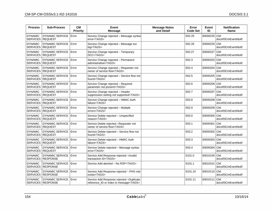
CM-SP-CM-OSSIv3.1-I02-141016 DOCSIS 3.1
154 CableLabs 10/16/14
Process Sub-Process CM Priority
Event Message
Message Notes and Detail
Error Code Set
Event ID
Notification Name
DYNAMIC SERVICES
DYNAMIC SERVICE REQUEST
Error Service Change rejected – Message syntax error<TAGS>
S02.25 83000225 CM: docsIf3CmEventNotif
DYNAMIC SERVICES
DYNAMIC SERVICE REQUEST
Error Service Change rejected – Message too big<TAGS>
S02.26 83000226 CM: docsIf3CmEventNotif
DYNAMIC SERVICES
DYNAMIC SERVICE REQUEST
Error Service Change rejected – Temporary DCC<TAGS>
S02.27 83000227 CM: docsIf3CmEventNotif
DYNAMIC SERVICES
DYNAMIC SERVICE REQUEST
Error Service Change rejected – Permanent administrative<TAGS>
S02.3 83000203 CM: docsIf3CmEventNotif
DYNAMIC SERVICES
DYNAMIC SERVICE REQUEST
Error Service Change rejected – Requester not owner of service flow<TAGS>
S02.4 83000204 CM: docsIf3CmEventNotif
DYNAMIC SERVICES
DYNAMIC SERVICE REQUEST
Error Service Change rejected – Service flow not found<TAGS>
S02.5 83000205 CM: docsIf3CmEventNotif
DYNAMIC SERVICES
DYNAMIC SERVICE REQUEST
Error Service Change rejected – Required parameter not present<TAGS>
S02.6 83000206 CM: docsIf3CmEventNotif
DYNAMIC SERVICES
DYNAMIC SERVICE REQUEST
Error Service Change rejected – Header suppression setting not supported<TAGS>
S02.7 83000207 CM: docsIf3CmEventNotif
DYNAMIC SERVICES
DYNAMIC SERVICE REQUEST
Error Service Change rejected – HMAC Auth failure<TAGS>
S02.8 83000208 CM: docsIf3CmEventNotif
DYNAMIC SERVICES
DYNAMIC SERVICE REQUEST
Error Service Change rejected – Multiple errors<TAGS>
S02.9 83000209 CM: docsIf3CmEventNotif
DYNAMIC SERVICES
DYNAMIC SERVICE REQUEST
Error Service Delete rejected – Unspecified reason<TAGS>
S03.0 83000300 CM: docsIf3CmEventNotif
DYNAMIC SERVICES
DYNAMIC SERVICE REQUEST
Error Service Delete rejected –Requester not owner of service flow<TAGS>
S03.1 83000301 CM: docsIf3CmEventNotif
DYNAMIC SERVICES
DYNAMIC SERVICE REQUEST
Error Service Delete rejected – Service flow not found<TAGS>
S03.2 83000302 CM: docsIf3CmEventNotif
DYNAMIC SERVICES
DYNAMIC SERVICE REQUEST
Error Service Delete rejected – HMAC Auth failure<TAGS>
S03.3 83000303 CM: docsIf3CmEventNotif
DYNAMIC SERVICES
DYNAMIC SERVICE REQUEST
Error Service Delete rejected – Message syntax error<TAGS>
S03.4 83000304 CM: docsIf3CmEventNotif
DYNAMIC SERVICES
DYNAMIC SERVICE RESPONSE
Error Service Add Response rejected –Invalid transaction ID<TAGS>
S101.0 83010100 CM: docsIf3CmEventNotif
DYNAMIC SERVICES
DYNAMIC SERVICE RESPONSE
Error Service Add aborted – No RSP<TAGS> S101.1 83010101 CM: docsIf3CmEventNotif
DYNAMIC SERVICES
DYNAMIC SERVICE RESPONSE
Error Service Add Response rejected – PHS rule exists<TAGS>
S101.10 83010110 CM: docsIf3CmEventNotif
DYNAMIC SERVICES
DYNAMIC SERVICE RESPONSE
Error Service Add Response rejected –Duplicate reference_ID or index in message<TAGS>
S101.11 83010111 CM: docsIf3CmEventNotif

Cable Modem Operations Support System Interface Specification CM-SP-CM-OSSIv3.1-I02-141016
10/16/14 CableLabs 155
Process Sub-Process CM Priority
Event Message
Message Notes and Detail
Error Code Set
Event ID
Notification Name
DYNAMIC SERVICES
DYNAMIC SERVICE RESPONSE
Error Service Add Response rejected –Classifier for another flow<TAGS>
S101.12 83010112 CM: docsIf3CmEventNotif
DYNAMIC SERVICES
DYNAMIC SERVICE RESPONSE
Error Service Add Response rejected –Parameter invalid for context<TAGS>
S101.13 83010113 CM: docsIf3CmEventNotif
DYNAMIC SERVICES
DYNAMIC SERVICE RESPONSE
Error Service Add Response rejected –Major service flow error<TAGS>
S101.14 83010114 CM: docsIf3CmEventNotif
DYNAMIC SERVICES
DYNAMIC SERVICE RESPONSE
Error Service Add Response rejected –Major classifier error<TAGS>
S101.15 83010115 CM: docsIf3CmEventNotif
DYNAMIC SERVICES
DYNAMIC SERVICE RESPONSE
Error Service Add Response rejected –Major PHS Rule error<TAGS>
S101.16 83010116 CM: docsIf3CmEventNotif
DYNAMIC SERVICES
DYNAMIC SERVICE RESPONSE
Error Service Add Response rejected –Multiple major errors<TAGS>
S101.17 83010117 CM: docsIf3CmEventNotif
DYNAMIC SERVICES
DYNAMIC SERVICE RESPONSE
Error Service Add Response rejected –Message too big<TAGS>
S101.18 83010118 CM: docsIf3CmEventNotif
DYNAMIC SERVICES
DYNAMIC SERVICE RESPONSE
Error Service Add Response rejected – HMAC Auth failure<TAGS>
S101.2 83010102 CM: docsIf3CmEventNotif
DYNAMIC SERVICES
DYNAMIC SERVICE RESPONSE
Error Service Add Response rejected – Message syntax error<TAGS>
S101.3 83010103 CM: docsIf3CmEventNotif
DYNAMIC SERVICES
DYNAMIC SERVICE RESPONSE
Error Service Add Response rejected –Unspecified reason<TAGS>
S101.4 83010104 CM: docsIf3CmEventNotif
DYNAMIC SERVICES
DYNAMIC SERVICE RESPONSE
Error Service Add Response rejected –Unrecognized configuration setting<TAGS>
S101.5 83010105 CM: docsIf3CmEventNotif
DYNAMIC SERVICES
DYNAMIC SERVICE RESPONSE
Error Service Add Response rejected –Required parameter not present<TAGS>
S101.6 83010106 CM: docsIf3CmEventNotif
DYNAMIC SERVICES
DYNAMIC SERVICE RESPONSE
Error Service Add Response rejected – Service Flow exists<TAGS>
S101.7 83010107 CM: docsIf3CmEventNotif
DYNAMIC SERVICES
DYNAMIC SERVICE RESPONSE
Error Service Add Response rejected – Multiple errors<TAGS>
S101.8 83010108 CM: docsIf3CmEventNotif
DYNAMIC SERVICES
DYNAMIC SERVICE RESPONSE
Error Service Add Response rejected – Classifier exists<TAGS>
S101.9 83010109 CM: docsIf3CmEventNotif
DYNAMIC SERVICES
DYNAMIC SERVICE RESPONSE
Error Service Change Response rejected – Invalid transaction ID<TAGS>
S102.0 83010200 CM: docsIf3CmEventNotif
DYNAMIC SERVICES
DYNAMIC SERVICE RESPONSE
Error Service Change aborted- No RSP<TAGS> S102.1 83010201 CM: docsIf3CmEventNotif
DYNAMIC SERVICES
DYNAMIC SERVICE RESPONSE
Error Service Change Response rejected – Duplicated reference-ID or index in<TAGS>
S102.10 83010210 CM: docsIf3CmEventNotif
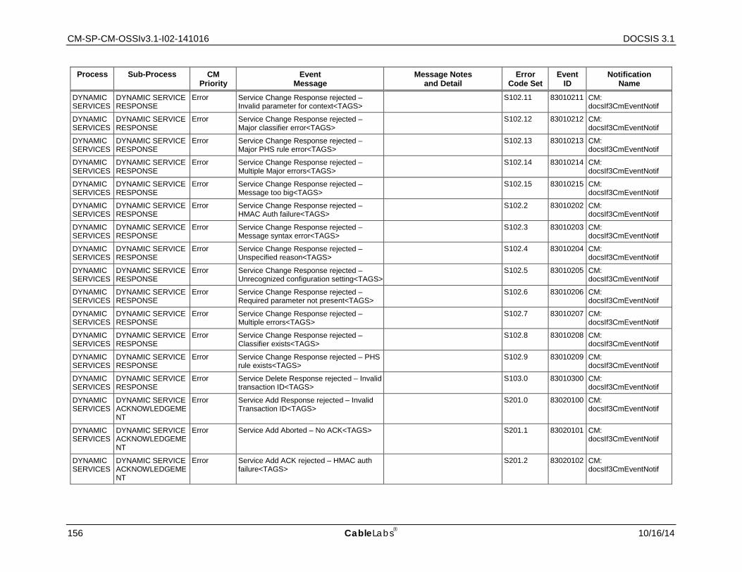
CM-SP-CM-OSSIv3.1-I02-141016 DOCSIS 3.1
156 CableLabs 10/16/14
Process Sub-Process CM Priority
Event Message
Message Notes and Detail
Error Code Set
Event ID
Notification Name
DYNAMIC SERVICES
DYNAMIC SERVICE RESPONSE
Error Service Change Response rejected – Invalid parameter for context<TAGS>
S102.11 83010211 CM: docsIf3CmEventNotif
DYNAMIC SERVICES
DYNAMIC SERVICE RESPONSE
Error Service Change Response rejected – Major classifier error<TAGS>
S102.12 83010212 CM: docsIf3CmEventNotif
DYNAMIC SERVICES
DYNAMIC SERVICE RESPONSE
Error Service Change Response rejected – Major PHS rule error<TAGS>
S102.13 83010213 CM: docsIf3CmEventNotif
DYNAMIC SERVICES
DYNAMIC SERVICE RESPONSE
Error Service Change Response rejected – Multiple Major errors<TAGS>
S102.14 83010214 CM: docsIf3CmEventNotif
DYNAMIC SERVICES
DYNAMIC SERVICE RESPONSE
Error Service Change Response rejected – Message too big<TAGS>
S102.15 83010215 CM: docsIf3CmEventNotif
DYNAMIC SERVICES
DYNAMIC SERVICE RESPONSE
Error Service Change Response rejected – HMAC Auth failure<TAGS>
S102.2 83010202 CM: docsIf3CmEventNotif
DYNAMIC SERVICES
DYNAMIC SERVICE RESPONSE
Error Service Change Response rejected – Message syntax error<TAGS>
S102.3 83010203 CM: docsIf3CmEventNotif
DYNAMIC SERVICES
DYNAMIC SERVICE RESPONSE
Error Service Change Response rejected – Unspecified reason<TAGS>
S102.4 83010204 CM: docsIf3CmEventNotif
DYNAMIC SERVICES
DYNAMIC SERVICE RESPONSE
Error Service Change Response rejected – Unrecognized configuration setting<TAGS>
S102.5 83010205 CM: docsIf3CmEventNotif
DYNAMIC SERVICES
DYNAMIC SERVICE RESPONSE
Error Service Change Response rejected – Required parameter not present<TAGS>
S102.6 83010206 CM: docsIf3CmEventNotif
DYNAMIC SERVICES
DYNAMIC SERVICE RESPONSE
Error Service Change Response rejected – Multiple errors<TAGS>
S102.7 83010207 CM: docsIf3CmEventNotif
DYNAMIC SERVICES
DYNAMIC SERVICE RESPONSE
Error Service Change Response rejected – Classifier exists<TAGS>
S102.8 83010208 CM: docsIf3CmEventNotif
DYNAMIC SERVICES
DYNAMIC SERVICE RESPONSE
Error Service Change Response rejected – PHS rule exists<TAGS>
S102.9 83010209 CM: docsIf3CmEventNotif
DYNAMIC SERVICES
DYNAMIC SERVICE RESPONSE
Error Service Delete Response rejected – Invalid transaction ID<TAGS>
S103.0 83010300 CM: docsIf3CmEventNotif
DYNAMIC SERVICES
DYNAMIC SERVICE ACKNOWLEDGEMENT
Error Service Add Response rejected – Invalid Transaction ID<TAGS>
S201.0 83020100 CM: docsIf3CmEventNotif
DYNAMIC SERVICES
DYNAMIC SERVICE ACKNOWLEDGEMENT
Error Service Add Aborted – No ACK<TAGS> S201.1 83020101 CM: docsIf3CmEventNotif
DYNAMIC SERVICES
DYNAMIC SERVICE ACKNOWLEDGEMENT
Error Service Add ACK rejected – HMAC auth failure<TAGS>
S201.2 83020102 CM: docsIf3CmEventNotif
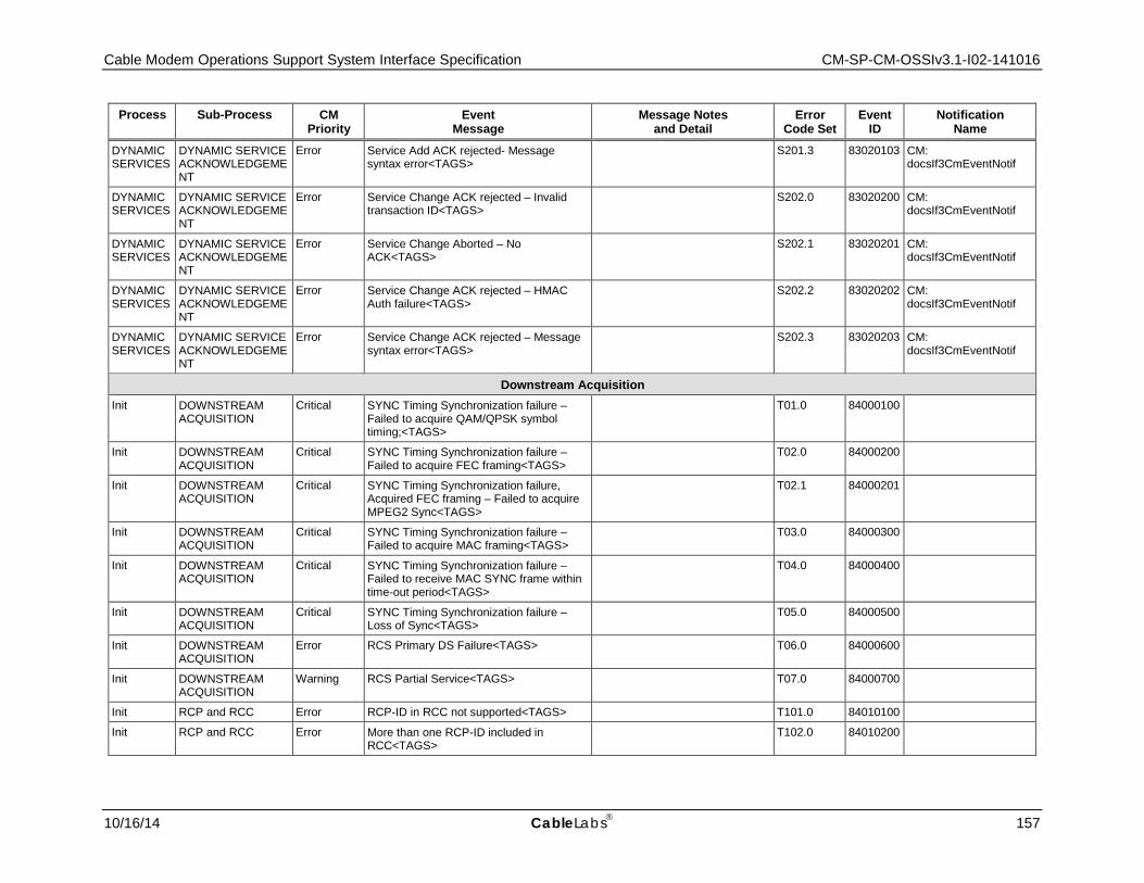
Cable Modem Operations Support System Interface Specification CM-SP-CM-OSSIv3.1-I02-141016
10/16/14 CableLabs 157
Process Sub-Process CM Priority
Event Message
Message Notes and Detail
Error Code Set
Event ID
Notification Name
DYNAMIC SERVICES
DYNAMIC SERVICE ACKNOWLEDGEMENT
Error Service Add ACK rejected- Message syntax error<TAGS>
S201.3 83020103 CM: docsIf3CmEventNotif
DYNAMIC SERVICES
DYNAMIC SERVICE ACKNOWLEDGEMENT
Error Service Change ACK rejected – Invalid transaction ID<TAGS>
S202.0 83020200 CM: docsIf3CmEventNotif
DYNAMIC SERVICES
DYNAMIC SERVICE ACKNOWLEDGEMENT
Error Service Change Aborted – No ACK<TAGS>
S202.1 83020201 CM: docsIf3CmEventNotif
DYNAMIC SERVICES
DYNAMIC SERVICE ACKNOWLEDGEMENT
Error Service Change ACK rejected – HMAC Auth failure<TAGS>
S202.2 83020202 CM: docsIf3CmEventNotif
DYNAMIC SERVICES
DYNAMIC SERVICE ACKNOWLEDGEMENT
Error Service Change ACK rejected – Message syntax error<TAGS>
S202.3 83020203 CM: docsIf3CmEventNotif
Downstream Acquisition Init DOWNSTREAM
ACQUISITION Critical SYNC Timing Synchronization failure –
Failed to acquire QAM/QPSK symbol timing;<TAGS>
T01.0 84000100
Init DOWNSTREAM ACQUISITION
Critical SYNC Timing Synchronization failure – Failed to acquire FEC framing<TAGS>
T02.0 84000200
Init DOWNSTREAM ACQUISITION
Critical SYNC Timing Synchronization failure, Acquired FEC framing – Failed to acquire MPEG2 Sync<TAGS>
T02.1 84000201
Init DOWNSTREAM ACQUISITION
Critical SYNC Timing Synchronization failure – Failed to acquire MAC framing<TAGS>
T03.0 84000300
Init DOWNSTREAM ACQUISITION
Critical SYNC Timing Synchronization failure – Failed to receive MAC SYNC frame within time-out period<TAGS>
T04.0 84000400
Init DOWNSTREAM ACQUISITION
Critical SYNC Timing Synchronization failure – Loss of Sync<TAGS>
T05.0 84000500
Init DOWNSTREAM ACQUISITION
Error RCS Primary DS Failure<TAGS> T06.0 84000600
Init DOWNSTREAM ACQUISITION
Warning RCS Partial Service<TAGS> T07.0 84000700
Init RCP and RCC Error RCP-ID in RCC not supported<TAGS> T101.0 84010100
Init RCP and RCC Error More than one RCP-ID included in RCC<TAGS>
T102.0 84010200
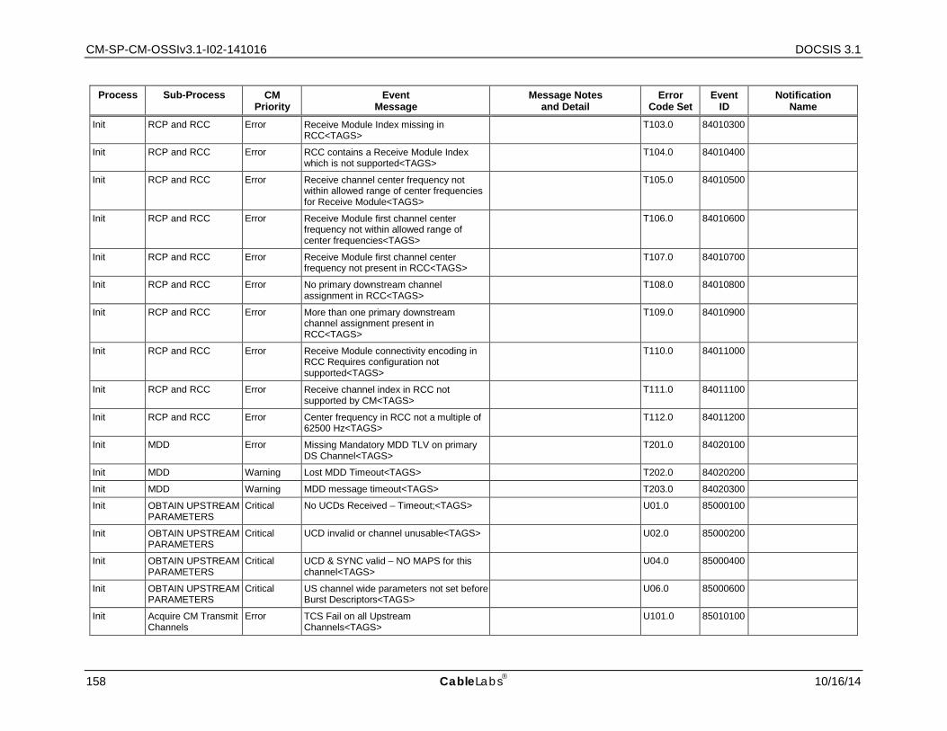
CM-SP-CM-OSSIv3.1-I02-141016 DOCSIS 3.1
158 CableLabs 10/16/14
Process Sub-Process CM Priority
Event Message
Message Notes and Detail
Error Code Set
Event ID
Notification Name
Init RCP and RCC Error Receive Module Index missing in RCC<TAGS>
T103.0 84010300
Init RCP and RCC Error RCC contains a Receive Module Index which is not supported<TAGS>
T104.0 84010400
Init RCP and RCC Error Receive channel center frequency not within allowed range of center frequencies for Receive Module<TAGS>
T105.0 84010500
Init RCP and RCC Error Receive Module first channel center frequency not within allowed range of center frequencies<TAGS>
T106.0 84010600
Init RCP and RCC Error Receive Module first channel center frequency not present in RCC<TAGS>
T107.0 84010700
Init RCP and RCC Error No primary downstream channel assignment in RCC<TAGS>
T108.0 84010800
Init RCP and RCC Error More than one primary downstream channel assignment present in RCC<TAGS>
T109.0 84010900
Init RCP and RCC Error Receive Module connectivity encoding in RCC Requires configuration not supported<TAGS>
T110.0 84011000
Init RCP and RCC Error Receive channel index in RCC not supported by CM<TAGS>
T111.0 84011100
Init RCP and RCC Error Center frequency in RCC not a multiple of 62500 Hz<TAGS>
T112.0 84011200
Init MDD Error Missing Mandatory MDD TLV on primary DS Channel<TAGS>
T201.0 84020100
Init MDD Warning Lost MDD Timeout<TAGS> T202.0 84020200
Init MDD Warning MDD message timeout<TAGS> T203.0 84020300
Init OBTAIN UPSTREAM PARAMETERS
Critical No UCDs Received – Timeout;<TAGS> U01.0 85000100
Init OBTAIN UPSTREAM PARAMETERS
Critical UCD invalid or channel unusable<TAGS> U02.0 85000200
Init OBTAIN UPSTREAM PARAMETERS
Critical UCD & SYNC valid – NO MAPS for this channel<TAGS>
U04.0 85000400
Init OBTAIN UPSTREAM PARAMETERS
Critical US channel wide parameters not set before Burst Descriptors<TAGS>
U06.0 85000600
Init Acquire CM Transmit Channels
Error TCS Fail on all Upstream Channels<TAGS>
U101.0 85010100
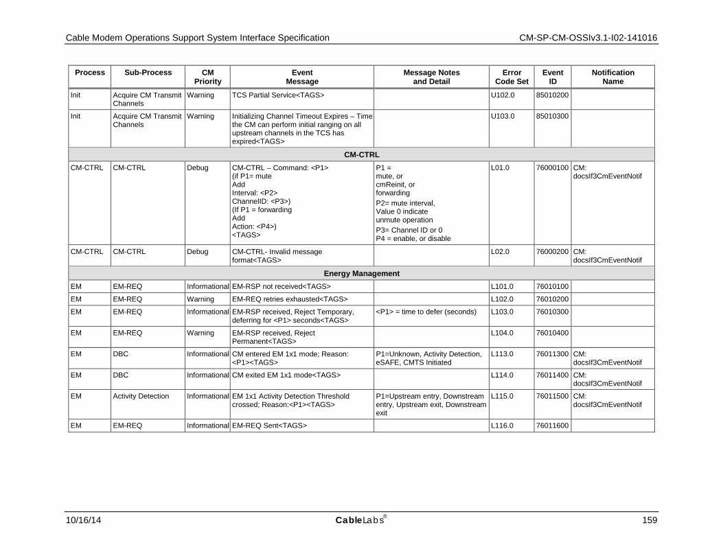
Cable Modem Operations Support System Interface Specification CM-SP-CM-OSSIv3.1-I02-141016
10/16/14 CableLabs 159
Process Sub-Process CM Priority
Event Message
Message Notes and Detail
Error Code Set
Event ID
Notification Name
Init Acquire CM Transmit Channels
Warning TCS Partial Service<TAGS> U102.0 85010200
Init Acquire CM Transmit Channels
Warning Initializing Channel Timeout Expires – Time the CM can perform initial ranging on all upstream channels in the TCS has expired<TAGS>
U103.0 85010300
CM-CTRL CM-CTRL CM-CTRL Debug CM-CTRL – Command: <P1>
(if P1= mute Add Interval: <P2> ChannelID: <P3>) (If P1 = forwarding Add Action: <P4>) <TAGS>
P1 = mute, or cmReinit, or forwarding P2= mute interval, Value 0 indicate unmute operation P3= Channel ID or 0 P4 = enable, or disable
L01.0 76000100 CM: docsIf3CmEventNotif
CM-CTRL CM-CTRL Debug CM-CTRL- Invalid message format<TAGS>
L02.0 76000200 CM: docsIf3CmEventNotif
Energy Management EM EM-REQ Informational EM-RSP not received<TAGS> L101.0 76010100
EM EM-REQ Warning EM-REQ retries exhausted<TAGS> L102.0 76010200
EM EM-REQ Informational EM-RSP received, Reject Temporary, deferring for <P1> seconds<TAGS>
<P1> = time to defer (seconds) L103.0 76010300
EM EM-REQ Warning EM-RSP received, Reject Permanent<TAGS>
L104.0 76010400
EM DBC Informational CM entered EM 1x1 mode; Reason: <P1><TAGS>
P1=Unknown, Activity Detection, eSAFE, CMTS Initiated
L113.0 76011300 CM: docsIf3CmEventNotif
EM DBC Informational CM exited EM 1x1 mode<TAGS> L114.0 76011400 CM: docsIf3CmEventNotif
EM Activity Detection Informational EM 1x1 Activity Detection Threshold crossed; Reason:<P1><TAGS>
P1=Upstream entry, Downstream entry, Upstream exit, Downstream exit
L115.0 76011500 CM: docsIf3CmEventNotif
EM EM-REQ Informational EM-REQ Sent<TAGS> L116.0 76011600
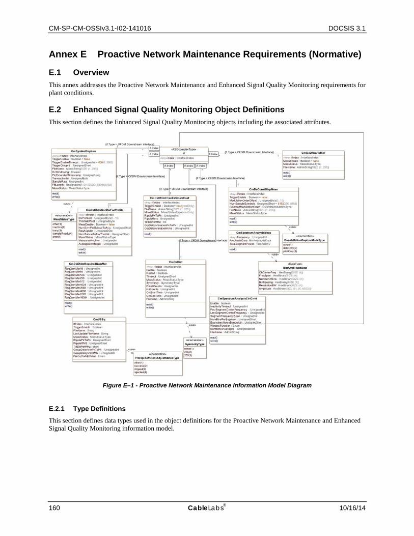
CM-SP-CM-OSSIv3.1-I02-141016 DOCSIS 3.1
160 CableLabs 10/16/14
Annex E Proactive Network Maintenance Requirements (Normative)
E.1 Overview This annex addresses the Proactive Network Maintenance and Enhanced Signal Quality Monitoring requirements for plant conditions.
E.2 Enhanced Signal Quality Monitoring Object Definitions This section defines the Enhanced Signal Quality Monitoring objects including the associated attributes.
Figure E–1 - Proactive Network Maintenance Information Model Diagram
E.2.1 Type Definitions This section defines data types used in the object definitions for the Proactive Network Maintenance and Enhanced Signal Quality Monitoring information model.
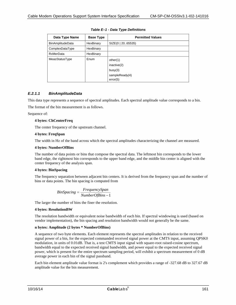
Cable Modem Operations Support System Interface Specification CM-SP-CM-OSSIv3.1-I02-141016
10/16/14 CableLabs 161
Table E–1 - Data Type Definitions
Data Type Name Base Type Permitted Values
BinAmplitudeData HexBinary SIZE(0 | 20..65535)
ComplexDataType HexBinary
RxMerData HexBinary
MeasStatusType Enum other(1) inactive(2) busy(3) sampleReady(4) error(5)
E.2.1.1 BinAmplitudeData This data type represents a sequence of spectral amplitudes. Each spectral amplitude value corresponds to a bin.
The format of the bin measurement is as follows.
Sequence of:
4 bytes: ChCenterFreq
The center frequency of the upstream channel.
4 bytes: FreqSpan
The width in Hz of the band across which the spectral amplitudes characterizing the channel are measured.
4 bytes: NumberOfBins
The number of data points or bins that compose the spectral data. The leftmost bin corresponds to the lower band edge, the rightmost bin corresponds to the upper band edge, and the middle bin center is aligned with the center frequency of the analysis span.
4 bytes: BinSpacing
The frequency separation between adjacent bin centers. It is derived from the frequency span and the number of bins or data points. The bin spacing is computed from
The larger the number of bins the finer the resolution.
4 bytes: ResolutionBW
The resolution bandwidth or equivalent noise bandwidth of each bin. If spectral windowing is used (based on vendor implementation), the bin spacing and resolution bandwidth would not generally be the same.
n bytes: Amplitude (2 bytes * NumberOfBins)
A sequence of two byte elements. Each element represents the spectral amplitudes in relation to the received signal power of a bin, for the expected commanded received signal power at the CMTS input, assuming QPSK0 modulation, in units of 0.01dB. That is, a test CMTS input signal with square-root raised-cosine spectrum, bandwidth equal to the expected received signal bandwidth, and power equal to the expected received signal power, which is present for the entire spectrum sampling period, will exhibit a spectrum measurement of 0 dB average power in each bin of the signal passband.
Each bin element amplitude value format is 2's complement which provides a range of -327.68 dB to 327.67 dB amplitude value for the bin measurement.
1−=
nsNumberOfBipanFrequencySBinSpacing

CM-SP-CM-OSSIv3.1-I02-141016 DOCSIS 3.1
162 CableLabs 10/16/14
E.2.1.2 ComplexDataType This data type is used to represent 16-bit signed I and Q data.
This data type uses 16bit two's complement notation to represent each of the I and Q values. When viewed as a 32-bit number in a file, the I value is the most significant 16 bits and the Q value is the least significant 16 bits.
E.2.1.3 RxMerData This data type represents a sequence of Subcarrier RxMER values. Each Subcarrier RxMER value consists of two bytes which represent the subcarrier index and two bytes which indicate the RxMER value in units of hundredthsDb. In a 32 bit representation of the RxMerData value, the 16 most significant bits contain the Subcarrier Index and the least significant 16 bits contain the RxMer value.
The format of the RxMerData is as follows.
Sequence of:
2 bytes: Subcarrier Index
2 bytes: RxMER value
E.2.1.4 MeasStatusType This data type is used to determine the state of a measurement. The MeasStatusTypes are interpreted as follows:
• other - indicates any state not described below.
• inactive – indicates that a test is not currently in progress.
• busy - indicates that a test has been started and is in progress.
• sampleReady - indicates that a test has completed and that the measurement data is ready.
• error - indicates that there was an error starting or during the test and any test data, if available, may not be valid.
E.2.2 CM Spectrum Analysis Objects
This group of objects provides a CM downstream spectrum analysis function. Each measurement is a data collection event that provides the energy content of the signal at each frequency within a specified range. The result of a measurement is a table consisting of one or more rows. Each row corresponds to a capture of spectral data across a specified segment bandwidth. The frequency range of each segment is divided into bins, which are a discrete set of evenly spaced frequencies across the band. The width of each bin (resolution bandwidth) is generally equal to or slightly greater than the spacing between bins. Each bin has an associated amplitude value in the table, which represents the amount of energy measured in that frequency bin. The segments are constrained to be contiguous; that is, the start frequency of each segment equals the end frequency of the previous segment plus the bin spacing. Thus, the concatenation of all segments results in a wideband spectral analysis. The measurement table is updated at a rate that is vendor specific. The measurement generally occurs prior to the point at which the received signal is demodulated. The measurement spectrum may or may not include the effects of receiver processing such as gain control, RF filtering, and matched filtering.
The CM SHOULD implement the CmSpectrumAnalysisCtrlCmd object.
The CM SHOULD implement the CmSpectrumAnalysisMeas object.
E.2.2.1.1 CmSpectrumAnalysisCtrlCmd Object
This object is used to configure the frequency spectral analysis in the CM.

Cable Modem Operations Support System Interface Specification CM-SP-CM-OSSIv3.1-I02-141016
10/16/14 CableLabs 163
Table E–2 - CmSpectrumAnalysisCtrlCmd Object
Attribute Name Type Access Type Constraints Units Default
Enable Boolean R/W false
InactivityTimeout UnsignedInt R/W 0..86400 seconds 300
FirstSegmentCenterFrequency UnsignedInt R/W Hz 93000000
LastSegmentCenterFrequency UnsignedInt R/W Hz 993000000
SegmentFrequencySpan UnsignedInt R/W 1000000..900000000 Hz 7500000
NumBinsPerSegment UnsignedShort R/W 2..2048 bins-per-segment
256
EquivalentNoiseBandwidth UnsignedShort R/W 50..500 Hundredths of bin spacing
150
WindowFunction Enum R/W other(0), hann(1), blackmanHarris(2), rectangular(3), hamming(4), flatTop(5), gaussian(6), chebyshev(7)
NumberOfAverages UnsignedShort R/W 1..1000 1
FileName AdminString R/W SIZE(1..255)
E.2.2.1.2 Enable
This attribute is used to enable or disable the spectrum analyzer feature. Setting this attribute to true triggers the CM to initiate measurements for the spectrum analyzer feature based on the other configuration attributes for the feature. By default, the feature is disabled unless explicitly enabled. Note that the feature may be disabled by the system under certain circumstances if the spectrum analyzer would affect critical services. In such a case, the attribute will return 'false' when read, and will reject sets to 'true' with an error. Once the feature is enabled, any configuration operations (e.g., write operations to configuration objects) might not be effective until the feature is re-enabled.
E.2.2.1.3 InactivityTimeout
This attribute controls the length of time after the last spectrum analysis measurement before the feature is automatically disabled. If set to a value of 0, the feature will remain enabled until it is explicitly disabled.
E.2.2.1.4 FirstSegmentCenterFrequency
This attribute controls the center frequency of the first segment for the spectrum analysis measurement.
The frequency bins for this segment lie symmetrically to the left and right of this center frequency. If the number of bins in a segment is odd, the segment center frequency lies directly on the center bin. If the number of bins in a segment is even, the segment center frequency lies halfway between two bins.
Changing the value of this object may result in changes to the CmSpectrumAnalysisMeas object, as described in the description field for the object.
Note that if this object is set to an invalid value, the device may return an error of inconsistentValue, or may adjust the value of the object to the closest valid value.
E.2.2.1.5 LastSegmentCenterFrequency
This attribute controls the center frequency of the last segment of the spectrum analysis measurement.

CM-SP-CM-OSSIv3.1-I02-141016 DOCSIS 3.1
164 CableLabs 10/16/14
The frequency bins for this segment lie symmetrically to the left and right of this center frequency. If the number of bins in a segment is odd, the segment center frequency lies directly on the center bin. If the number of bins in a segment is even, the segment center frequency lies halfway between two bins.
The value of the LastSegmentCenterFrequency is typically equal to the FirstSegmentCenterFrequency plus an integer number of segment spans as determined by the SegmentFrequencySpan.
Changing the value of this object may result in changes to the CmSpectrumAnalysisMeas object, as described in the description field for the object.
Note that if this attribute is set to an invalid value, the device may return an error of inconsistentValue, or may adjust the value of the attribute to the closest valid value.
E.2.2.1.6 SegmentFrequencySpan
This attribute controls the frequency span of each segment (instance) of the CmSpectrumAnalysisMeas object. If set to a value of 0, then a default span will be chosen based on the hardware capabilities of the device. Segments are contiguous from the FirstSegementCenterFrequency to the LastSegmentCenterFrequency and the center frequency for each successive segment is incremented by the SegmentFrequencySpan. The number of segments is (LastSegmentCenterFrequency – FirstSegmentCenterFrequency)/SegmentFrequencySpan + 1. A segment is equivalent to an instance in the CmSpectrumAnalysisMeas object. The chosen SegmentFrequencySpan affects the number of instances in the CmSpectrumAnalysisMeas object. A more granular SegmentFrequencySpan may adversely affect the amount of time needed to query the instances in addition to possibly increasing the acquisition time.
Changing the value of this object may result in changes to the CmSpectrumAnalysisMeas object, as described in the description field for the object Note that if this attribute is set to an invalid value, the device may return an error of inconsistentValue, or may adjust the value of the attribute to the closest valid value.
E.2.2.1.7 NumBinsPerSegment
This attribute controls the number of bins collected by the measurement performed for each segment (instance) of the CmSpectrumAnalysisMeas object. Note that if this attribute is set to an invalid value, the device may return an error of inconsistentValue, or may adjust the value of the attribute to the closest valid value.
E.2.2.1.8 EquivalentNoiseBandwidth
This attribute allows the user to request an equivalent noise bandwidth for the resolution bandwidth filter used in the spectrum analysis. This corresponds to the spectral width of the window function used when performing a discrete Fourier transform for the analysis.
The window function which corresponds to a value written to this attribute may be obtained by reading the value of the WindowFunction attribute.
If an unsupported value is requested, the device may return an error of inconsistentValue, or choose the closest valid value to the one which is requested. If the closest value is chosen, then a subsequent read of this attribute will return the actual value that is in use.
E.2.2.1.9 WindowFunction
This attribute controls or indicates the windowing function that will be used when performing the discrete Fourier transform for the analysis. The WindowFunction and the EquivalentNoiseBandwidth are related. If a particular WindowFunction is selected, then the EquivalentNoiseBandwidth for the function in use will be reported by the EquivalentNoiseBandwidth attribute. Alternatively, if an EquivalentNoiseBandwidth value is chosen and a WindowFunction function representing that EquivalentNoiseBandwidth is defined in the CM, that value will be reported in the WindowFunction object, or a value of 'other' will be reported. Use of "modern" windowing functions not yet defined will likely be reported as 'other'.

Cable Modem Operations Support System Interface Specification CM-SP-CM-OSSIv3.1-I02-141016
10/16/14 CableLabs 165
Note that all window functions may not be supported by all devices. If an attempt is made to set the attribute to an unsupported window function, or if writing of the WindowFunction object is not supported by an implementation, an error will be returned.
E.2.2.1.10 NumberOfAverages
This attribute controls the number of averages that will be performed on spectral bins. The average will be computed using the "leaky integrator" method, where reported bin value = alpha*accumulated bin values + (1-alpha)*current bin value. Alpha is one minus the reciprocal of the number of averages. For example, if N=25, then alpha = 0.96. A value of 1 indicates no averaging. Re-writing the number of averages will restart the averaging process. If there are no accumulated values, the accumulators are made equal to the first measured bin amplitudes.
The number of averages will be set by writing NumberOfAverages attribute. If an attempt is made to set the attribute to an unsupported number of averages, an error of inconsistentValue will be returned.
E.2.2.1.11 FileName
This attribute can only be changed while a test is not in progress. An attempt to set this value while the value of Enable is 'true' will return 'inconsistentValue'.
If the value of this object is the default value (empty string), then a default filename value will be used. Otherwise, the value set will be used as the filename.
If a default filename value is used, it is generated as the test name plus the CM MAC Address plus the 'epoch time'. The epoch time (also known as 'unix time') is defined as the number of seconds that have elapsed since midnight Coordinated Universal Time (UTC), Thursday, 1 January 1970. Hence, the format would be:
SpectrumAnalysisAmplitudeData _<CM MAC address>_<epoch>
For example: SpectrumAnalysisAmplitudeData_0010181A2D11_1403405123
E.2.2.2 CmSpectrumAnalysisMeas Object This object provides a list of the spectral amplitude measurements taken across the requested range of center frequencies. The table represents a full scan of the spectrum with each row corresponding to a spectral capture of one segment of the spectrum.
Table E–3 - CmSpectrumAnalysisMeas Object
Attribute Name Type Access Type Constraints Units Default
Frequency UnsignedInt key Hz
AmplitudeData BinAmplitudeData R/O
TotalSegmentPower TenthdBmV R/O TenthdBmV
E.2.2.2.1 Frequency
This key indicates the center frequency of the spectral analysis segment which is represented by this instance.
E.2.2.2.2 AmplitudeData
This attribute provides a list of the spectral amplitudes as measured at the center frequency specified by the Frequency attribute.
The frequency bins are ordered from lowest to highest frequencies covering the frequency span. Information about the center frequency, frequency span, number of bins and resolution bandwidth are included to provide context to the measurement point.
Bin Amplitudes are reported in units of 0.01dB.

CM-SP-CM-OSSIv3.1-I02-141016 DOCSIS 3.1
166 CableLabs 10/16/14
E.2.2.2.3 TotalSegmentPower
This attribute provides the total RF power present in the segment with the center frequency equal to the Frequency index and the span equal to the SegmentFrequencySpan. The value represents the sum of the spectrum power in all of the associated bins. The value is computed by summing power (not dB) values and converting the final sum to TenthdBmV.
E.2.3 CmSymbolCapture Object
The purpose of downstream symbol capture is to provide partial functionality of a network analyzer to analyze the response of the cable plant from the CM's perspective.
At the CM, the received I and Q time-domain samples of one full OFDM symbol before the FFT, not including the guard interval, are captured and made available for analysis. This capture will result in a number of data points equal to the FFT length in use, time aligned for receiver FFT processing. The number of captured samples can be reduced for narrower channels if the sampling rate, which is implementation dependent, is reduced. The capture includes a bit indicating if receiver windowing effects are present in the data. The time domain samples are expressed as 16-bit two's complement numbers using s3.12 format. The CM samples are scaled such that the average power of the samples is approximately 1, in order to avoid excessive clipping and quantization noise.
Capturing the input and output of the cable plant is equivalent to a wideband sweep of the channel, which permits full characterization of the linear and nonlinear response of the downstream plant. The MAC provides signaling via the PLC Trigger Message to ensure that the same symbol is captured at the CMTS and CM.
The Downstream Symbol Capture is controlled by setting the 'TriggerEnable' object. The status of the capture is obtained by reading the value of the 'MeasStatus' attribute.
Table E–4 - CmSymbolCapture Object
Attribute Name Type Access Type Constraints Units Default Value
ifIndex InterfaceIndex Key
TriggerEnable Boolean R/W False
TriggerEnableTimeout UnsignedInt R/W 0..3600 seconds 600
TriggerGroupId UnsignedShort R/W 0
FileName AdminString R/W SIZE (1..255)
RxWindowing Boolean R/O
PlcExtendedTimestamp UnsignedLong R/O
TransactionId UnsignedByte R/O
SampleRate UnsignedInt R/O Hz
FftLength UnsignedInt R/O 512 | 1024 |2048 |4096 | 8192
MeasStatus MeasStatusType R/O
E.2.3.1 ifIndex This attribute is the interface index of the OFDM downstream channel and is a key to provide an index into the table.
E.2.3.2 TriggerEnable This attribute is used to instruct the CM to begin looking for the presence of the Trigger Message Block in the PLC with a Group ID matching the CM's TriggerGroupID. The TriggerEnable is a one-shot enable and the attribute is internally disabled when a PLC containing a Group ID matching the CM's TriggerGroupID in a Trigger Message Block is received.
Setting this object to a value of 'false' instructs the CM to stop looking for the presence of the Trigger Message Block in the PLC with a Group ID matching the CM's TriggerGroupId. In this case, the value of MeasStatus attribute will be set to 'inactive'.

Cable Modem Operations Support System Interface Specification CM-SP-CM-OSSIv3.1-I02-141016
10/16/14 CableLabs 167
When read, this object returns 'true' if the CM is actively looking for the presence of the Trigger Message Block in the PLC with a Group ID matching the CM's TriggerGroupId. Otherwise, it returns 'false'.
This object returns 'inconsistentValue' if set to 'true' while the value of MeasStatus is a value of 'busy' for this row or for any row in the table. That is, only one row in the table is allowed to be 'true' at the same time.
This attribute returns 'inconsistentValue' if set to 'true' while the CM is in DOCSIS Light Sleep (DLS) mode or the CM is in battery-backup mode.
Default values for FileName, TriggerEnableTimeout, and TriggerGroupId attributes are defined; thus, this attribute may be set to 'true' without explicitly setting these values. Care should be taken to ensure these values are correct for the desired test case.
Setting this attribute to a value of 'true' will change the value of the MeasStatus attribute to 'busy'.
E.2.3.3 TriggerEnableTimeout This attribute is used to disable the TriggerEnable if no PLC containing a Group ID matching the CM's TriggerGroupId in a Trigger Message Block is received within the timeout period. The Timeout value used for the test is the value that was present when the TriggerEnable is set to TRUE. A value of 0 indicates that no timeout is enforced, meaning that the trigger could be enabled indefinitely. This value can only be changed while a test is not in progress. An attempt to set this value while the value of 'MeasStatus' is 'busy' will return 'inconsistentValue'.
E.2.3.4 TriggerGroupId This attribute is used associate a CM with a group of CMs expected to perform Symbol Capture measurements for the designated symbol.
This value can only be changed while a test is not in progress. An attempt to set this value while the value of MeasStatus is 'busy' will return 'inconsistentValue'.
E.2.3.5 Filename This attribute is the name of the file with the captured symbol data at the CM that is to be downloaded using TFTP to the PNM server.
This value can only be changed while a test is not in progress. An attempt to set this value while the value of MeasStatus is 'busy' will return 'inconsistentValue'.
If the value of this object is the DEFVAL (empty string), then a default filename value will be used. Otherwise, the value set will be used as the filename.
If a default filename value is used, it is generated as the test name plus the CM MAC Address plus the 'epoch time'. The epoch time (also known as 'unix time') is defined as the number of seconds that have elapsed since midnight Coordinated Universal Time (UTC), Thursday, 1 January 1970.
Hence, the format would be:
PNMSymCap_<CM MAC address>_<epoch>
For example: PNMSymCap_0010181A2D11_1403405123
The data file is composed of a header plus the Symbol Capture Data. The header is composed of ordered fixed-length fields. Unless otherwise specified, the header fields contain hex values that are right-justified within the field. If necessary, the field is left-padded with zero values.
Syntax of the file is as follows:
Table E–5 - CM Symbol Capture File Format
Element Size File type (value = 504E4D01) 4 bytes
Subcarrier zero Frequency in Hz 4 bytes
PlcExtendedTimeStamp 4 bytes
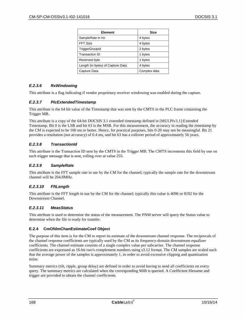
CM-SP-CM-OSSIv3.1-I02-141016 DOCSIS 3.1
168 CableLabs 10/16/14
Element Size SampleRate in Hz 4 bytes
FFT Size 4 bytes
TriggerGroupId 2 bytes
Transaction ID 1 bytes
Reserved byte 1 bytes
Length (in bytes) of Capture Data 4 bytes
Capture Data Complex data
E.2.3.6 RxWindowing This attribute is a flag indicating if vendor proprietary receiver windowing was enabled during the capture.
E.2.3.7 PlcExtendedTimestamp This attribute is the 64 bit value of the Timestamp that was sent by the CMTS in the PLC frame containing the Trigger MB.
This attribute is a copy of the 64-bit DOCSIS 3.1 extended timestamp defined in [MULPIv3.1]:Extended Timestamp. Bit 0 is the LSB and bit 63 is the MSB. For this measurement, the accuracy in reading the timestamp by the CM is expected to be 100 ms or better. Hence, for practical purposes, bits 0-20 may not be meaningful. Bit 21 provides a resolution (not accuracy) of 0.4 ms, and bit 63 has a rollover period of approximately 56 years.
E.2.3.8 TransactionId This attribute is the Transaction ID sent by the CMTS in the Trigger MB. The CMTS increments this field by one on each trigger message that is sent, rolling over at value 255.
E.2.3.9 SampleRate This attribute is the FFT sample rate in use by the CM for the channel; typically the sample rate for the downstream channel will be 204.8MHz.
E.2.3.10 FftLength This attribute is the FFT length in use by the CM for the channel; typically this value is 4096 or 8192 for the Downstream Channel.
E.2.3.11 MeasStatus This attribute is used to determine the status of the measurement. The PNM server will query the Status value to determine when the file is ready for transfer.
E.2.4 CmOfdmChanEstimateCoef Object
The purpose of this item is for the CM to report its estimate of the downstream channel response. The reciprocals of the channel response coefficients are typically used by the CM as its frequency-domain downstream equalizer coefficients. The channel estimate consists of a single complex value per subcarrier. The channel response coefficients are expressed as 16-bit two's complement numbers using s3.12 format. The CM samples are scaled such that the average power of the samples is approximately 1, in order to avoid excessive clipping and quantization noise.
Summary metrics (tilt, ripple, group delay) are defined in order to avoid having to send all coefficients on every query. The summary metrics are calculated when the corresponding MIB is queried. A Coefficient filename and trigger are provided to obtain the channel coefficients.
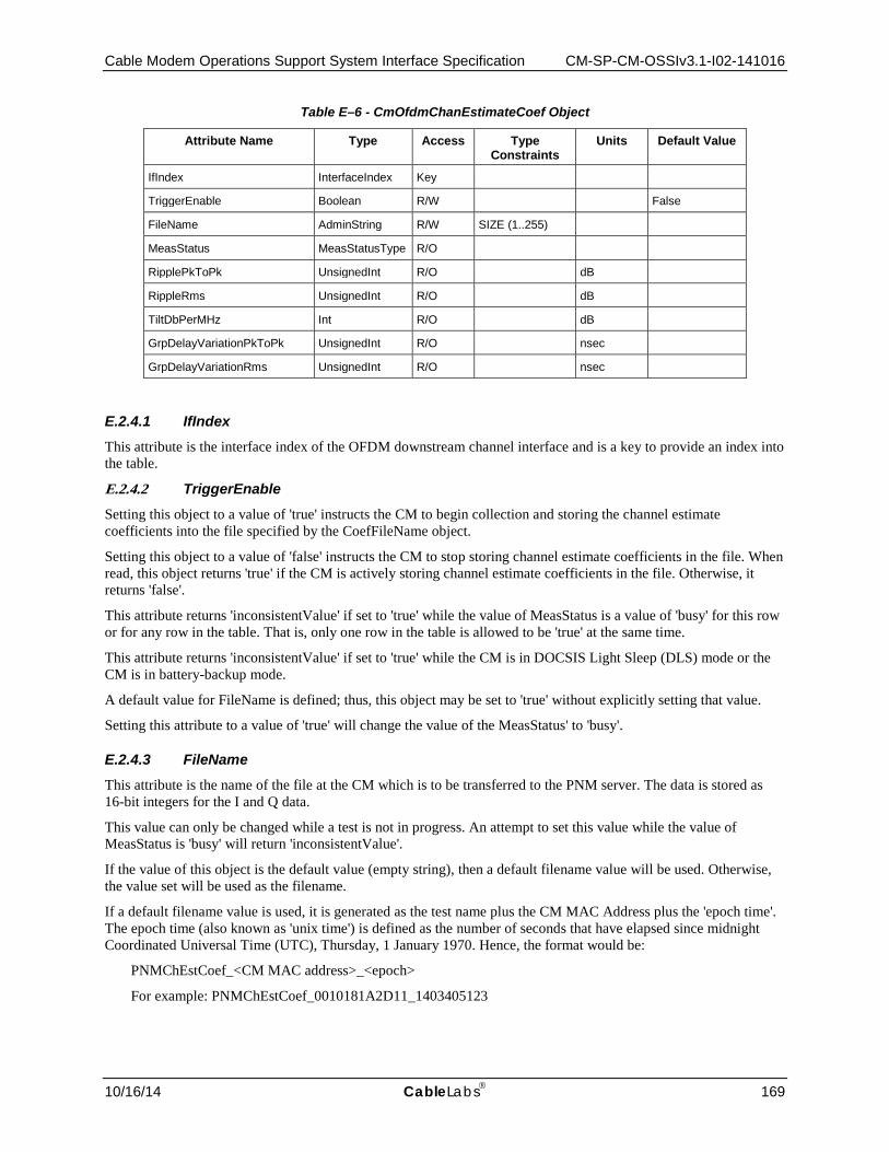
Cable Modem Operations Support System Interface Specification CM-SP-CM-OSSIv3.1-I02-141016
10/16/14 CableLabs 169
Table E–6 - CmOfdmChanEstimateCoef Object
Attribute Name Type Access Type Constraints
Units Default Value
IfIndex InterfaceIndex Key
TriggerEnable Boolean R/W False
FileName AdminString R/W SIZE (1..255)
MeasStatus MeasStatusType R/O
RipplePkToPk UnsignedInt R/O dB
RippleRms UnsignedInt R/O dB
TiltDbPerMHz Int R/O dB
GrpDelayVariationPkToPk UnsignedInt R/O nsec
GrpDelayVariationRms UnsignedInt R/O nsec
E.2.4.1 IfIndex This attribute is the interface index of the OFDM downstream channel interface and is a key to provide an index into the table.
E.2.4.2 TriggerEnable Setting this object to a value of 'true' instructs the CM to begin collection and storing the channel estimate coefficients into the file specified by the CoefFileName object.
Setting this object to a value of 'false' instructs the CM to stop storing channel estimate coefficients in the file. When read, this object returns 'true' if the CM is actively storing channel estimate coefficients in the file. Otherwise, it returns 'false'.
This attribute returns 'inconsistentValue' if set to 'true' while the value of MeasStatus is a value of 'busy' for this row or for any row in the table. That is, only one row in the table is allowed to be 'true' at the same time.
This attribute returns 'inconsistentValue' if set to 'true' while the CM is in DOCSIS Light Sleep (DLS) mode or the CM is in battery-backup mode.
A default value for FileName is defined; thus, this object may be set to 'true' without explicitly setting that value.
Setting this attribute to a value of 'true' will change the value of the MeasStatus' to 'busy'.
E.2.4.3 FileName This attribute is the name of the file at the CM which is to be transferred to the PNM server. The data is stored as 16-bit integers for the I and Q data.
This value can only be changed while a test is not in progress. An attempt to set this value while the value of MeasStatus is 'busy' will return 'inconsistentValue'.
If the value of this object is the default value (empty string), then a default filename value will be used. Otherwise, the value set will be used as the filename.
If a default filename value is used, it is generated as the test name plus the CM MAC Address plus the 'epoch time'. The epoch time (also known as 'unix time') is defined as the number of seconds that have elapsed since midnight Coordinated Universal Time (UTC), Thursday, 1 January 1970. Hence, the format would be:
PNMChEstCoef_<CM MAC address>_<epoch>
For example: PNMChEstCoef_0010181A2D11_1403405123

CM-SP-CM-OSSIv3.1-I02-141016 DOCSIS 3.1
170 CableLabs 10/16/14
The data file is composed of a header plus the Chan Estimate Coefficient Data. The header is composed of ordered fixed-length fields. Unless otherwise specified, the header fields contain hex values that are right-justified within the field. If necessary, the field is left-padded with zero values.
Syntax of the file is as follows:
Table E–7 - Channel Estimate Coefficient File Format
Element Size File type (value = 504E4D02) 4 bytes
Subcarrier zero frequency in Hz 4 bytes
Subcarrier spacing in Hz 4 bytes
FFT Size 4 bytes
Length in bytes of coefficient data 4 bytes
Chan estimate coefficient data Complex data
E.2.4.4 MeasStatus This attribute is used to determine the status of the action by the TriggerEnable object. The PNM server will query the Status value to determine when the file is ready for transfer.
E.2.4.5 RipplePkToPk This attribute represents the value of the peak to peak ripple in the magnitude of the equalizer coefficients [PHYv3.1]. The tilt calculated for the TiltDbPerMHz is subtracted from the frequency domain data and the peak to peak Ripple is calculated from the resultant data. This attribute represents the ripple across the entire OFDM channel.
Note: An algorithm for calculating the ripple and tilt for these measurements is provided in sections 6.5 and 6.6 of [SCTE RP].
E.2.4.6 RippleRms This attribute represents the value of the RMS ripple in the magnitude of the equalizer coefficients. The tilt calculated for the TiltDbPerMHz is subtracted from the frequency domain data and the RMS ripple is calculated from the resultant data. This attribute represents the ripple across the entire OFDM channel.
Note: An algorithm for calculating the ripple and tilt for these measurements is provided in sections 6.5 and 6.6 of [SCTE RP].
E.2.4.7 TiltDbPerMHz This attribute represents the tilt in dB per MHz in the magnitude of the equalizer coefficients. The tilt is calculated as the slope of a linear least squares fit of the frequency domain data. This attribute represents the tilt across the entire OFDM channel.
Note: An algorithm for calculating the ripple and tilt for these measurements is provided in sections 6.5 and 6.6 of [SCTE RP].
E.2.4.8 GroupDelayVariationPkToPk This attribute is represents the peak to peak Group Delay Variation expressed in units of nS. This attribute represents the group delay variation across the entire OFDM channel.
E.2.4.9 GroupDelayVariationRMS This attribute is represents the RMS value of the Group Delay Variation expressed in units of nS. This attribute represents the group delay variation across the entire OFDM channel. This attribute is not stored in the data file.

Cable Modem Operations Support System Interface Specification CM-SP-CM-OSSIv3.1-I02-141016
10/16/14 CableLabs 171
E.2.5 CmDsConstDispMeas Object
The downstream constellation display provides received QAM constellation points for display. Equalized soft decisions (I and Q) at the slicer input are collected over time, possibly subsampling to reduce complexity, and made available for analysis. This measurement is intended for data subcarriers only. Up to 8192 samples are provided for each query; additional queries can be made to further fill in the plot.
The complex Constellation Display values are expressed as 16-bit two's complement numbers using s2.13 format. The CM samples are scaled such that the average power of the QAM constellation is approximately 1, in order to avoid excessive clipping and quantization noise.
The object controls the CM capturing and reporting received soft-decision samples, for a single selected constellation from the set of profiles it is receiving, within a single OFDM downstream channel.
Table E–8 - CmDsConstDispMeas Object
Attribute Name Type Access Type Constraints
Units Default Value
IfIndex InterfaceIndex Key
TriggerEnable Boolean R/W False
ModulationOrderOffset UnsignedByte R/W 0..10
NumSampleSymbols UnsignedShort R/W
SelectedModulationOrder DsOfdmModulationType R/O
FileName AdminString R/W SIZE (1..255)
MeasStatus MeasStatusType R/O
E.2.5.1 IfIndex This attribute is the interface index of the downstream channel and is a key to provide an index into the table.
E.2.5.2 TriggerEnable Setting this attribute to a value of 'true' instructs the CM to begin collection and storing the constellation points into the file specified by the FileName attribute.
Setting this attribute to a value of 'false' instructs the CM to stop storing constellation points in the file.
When read, this attribute returns 'true' if the CM is actively storing constellation points in the file. Otherwise, it returns 'false’.
This attribute returns 'inconsistentValue' if set to 'true' while the value of MeasStatus is a value of 'busy' for this row OR for any row in the table. That is, only one row in the table is allowed to be 'true' at the same time.
This attribute returns 'inconsistentValue' if set to 'true' while the CM is in DOCSIS Light Sleep (DLS) mode or the CM is in battery-backup mode.
A default value for FileName is defined; thus, this attribute may be set to 'true' without explicitly setting the FileName value.
Setting this attribute to a value of 'true' will change the value of the MeasStatus to 'busy'.
E.2.5.3 ModulationOrderOffset This attribute specifies an offset from the lowest order modulation for the data subcarriers in any of the profiles in the downstream channel. If the lowest order modulation order that the CM was receiving was 1024-QAM and the ModulationOrderOffset was zero, then the CM would capture the soft decision samples for all of the subcarriers which were using 1024-QAM modulation order. If the ModulationOrderOffset was 1, then the CM would capture the soft decision samples for all of the subcarriers using the next highest modulation order in use for the profiles in the downstream channel.

CM-SP-CM-OSSIv3.1-I02-141016 DOCSIS 3.1
172 CableLabs 10/16/14
This value can only be changed while a test is not in progress. An attempt to set this value while the value of MeasStatus is 'busy' will return 'inconsistentValue'.
E.2.5.4 NumSampleSymbols This attribute tells the CM how many OFDM symbols including the cyclic prefix, for which soft decision samples of the specified modulation order are captured.
This value can only be changed while a test is not in progress. An attempt to set this value while the value of MeasStatus is 'busy' will return 'inconsistentValue'.
E.2.5.5 SelectedModulationOrder This read-only attribute provides the actual Modulation Order that will be used for the Constellation display based on the selected ModulationOrderOffset.
E.2.5.6 DataFileName This attribute is the name of the file at the CM which is to be transferred to the PNM server. The data is stored as 16-bit integers for the I and Q data.
This value can only be changed while a test is not in progress. An attempt to set this value while the value of MeasStatus is 'busy' will return 'inconsistentValue'.
If the value of this object is the DEFVAL (empty string), then a default filename value will be used. Otherwise, the value set will be used as the filename.
If a default filename value is used, it is generated as the test name plus the CM MAC Address plus the 'epoch time'. The epoch time (also known as 'unix time') is defined as the number of seconds that have elapsed since midnight Coordinated Universal Time (UTC),Thursday, 1 January 1970.
Hence, the format would be:
PNMDSConDisp_<CM MAC address>_<epoch>
For example: PNMDSConDisp_0010181A2D11_1403405123
The data file is composed of a header plus the Chan Estimate Coefficient Data.
Syntax of the file is as follows:
Table E–9 - Constellation Display File Format
Element Size File type (value = 504E4D03) 4 bytes
Subcarrier zero frequency in Hz 4 bytes
Actual modulation order* 2 bytes
Number of sample symbols 2 bytes
Reserved 2 bytes
Subcarrier spacing in Hz 4 bytes
Length in bytes of display data 4 bytes
Constellation display data Complex data
*DsOfdmModulationType
E.2.5.7 MeasStatus This attribute is used to determine the status of the measurement. The PNM server will query the Status value to determine when the file is ready for transfer
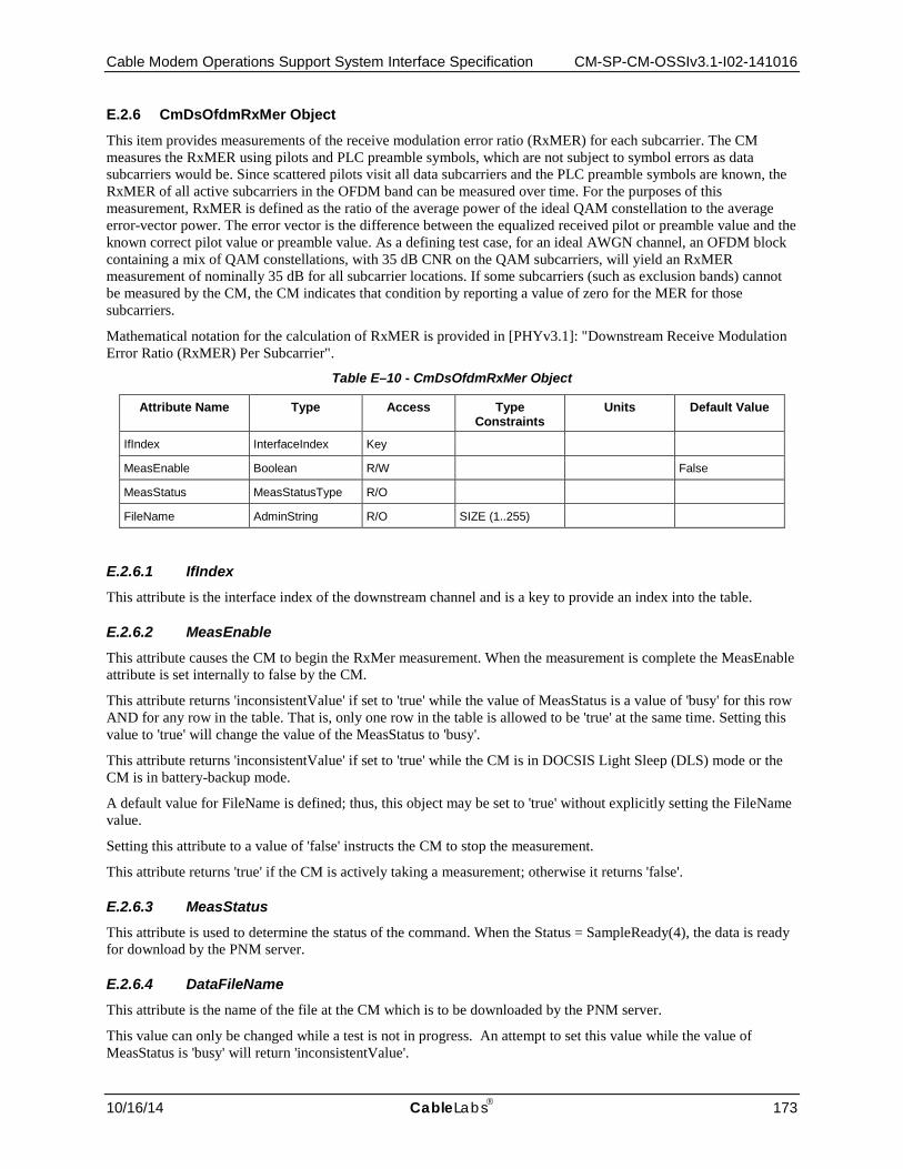
Cable Modem Operations Support System Interface Specification CM-SP-CM-OSSIv3.1-I02-141016
10/16/14 CableLabs 173
E.2.6 CmDsOfdmRxMer Object
This item provides measurements of the receive modulation error ratio (RxMER) for each subcarrier. The CM measures the RxMER using pilots and PLC preamble symbols, which are not subject to symbol errors as data subcarriers would be. Since scattered pilots visit all data subcarriers and the PLC preamble symbols are known, the RxMER of all active subcarriers in the OFDM band can be measured over time. For the purposes of this measurement, RxMER is defined as the ratio of the average power of the ideal QAM constellation to the average error-vector power. The error vector is the difference between the equalized received pilot or preamble value and the known correct pilot value or preamble value. As a defining test case, for an ideal AWGN channel, an OFDM block containing a mix of QAM constellations, with 35 dB CNR on the QAM subcarriers, will yield an RxMER measurement of nominally 35 dB for all subcarrier locations. If some subcarriers (such as exclusion bands) cannot be measured by the CM, the CM indicates that condition by reporting a value of zero for the MER for those subcarriers.
Mathematical notation for the calculation of RxMER is provided in [PHYv3.1]: "Downstream Receive Modulation Error Ratio (RxMER) Per Subcarrier".
Table E–10 - CmDsOfdmRxMer Object
Attribute Name Type Access Type Constraints
Units Default Value
IfIndex InterfaceIndex Key
MeasEnable Boolean R/W False
MeasStatus MeasStatusType R/O
FileName AdminString R/O SIZE (1..255)
E.2.6.1 IfIndex This attribute is the interface index of the downstream channel and is a key to provide an index into the table.
E.2.6.2 MeasEnable This attribute causes the CM to begin the RxMer measurement. When the measurement is complete the MeasEnable attribute is set internally to false by the CM.
This attribute returns 'inconsistentValue' if set to 'true' while the value of MeasStatus is a value of 'busy' for this row AND for any row in the table. That is, only one row in the table is allowed to be 'true' at the same time. Setting this value to 'true' will change the value of the MeasStatus to 'busy'.
This attribute returns 'inconsistentValue' if set to 'true' while the CM is in DOCSIS Light Sleep (DLS) mode or the CM is in battery-backup mode.
A default value for FileName is defined; thus, this object may be set to 'true' without explicitly setting the FileName value.
Setting this attribute to a value of 'false' instructs the CM to stop the measurement.
This attribute returns 'true' if the CM is actively taking a measurement; otherwise it returns 'false'.
E.2.6.3 MeasStatus This attribute is used to determine the status of the command. When the Status = SampleReady(4), the data is ready for download by the PNM server.
E.2.6.4 DataFileName This attribute is the name of the file at the CM which is to be downloaded by the PNM server.
This value can only be changed while a test is not in progress. An attempt to set this value while the value of MeasStatus is 'busy' will return 'inconsistentValue'.
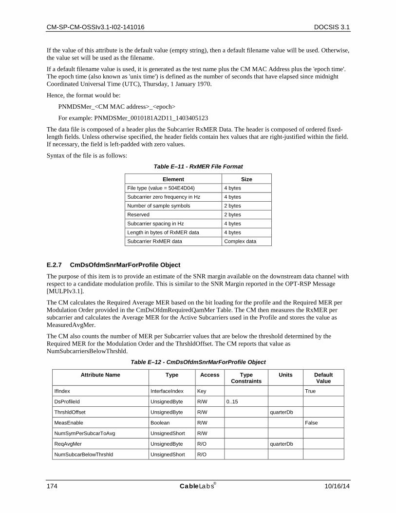
CM-SP-CM-OSSIv3.1-I02-141016 DOCSIS 3.1
174 CableLabs 10/16/14
If the value of this attribute is the default value (empty string), then a default filename value will be used. Otherwise, the value set will be used as the filename.
If a default filename value is used, it is generated as the test name plus the CM MAC Address plus the 'epoch time'. The epoch time (also known as 'unix time') is defined as the number of seconds that have elapsed since midnight Coordinated Universal Time (UTC), Thursday, 1 January 1970.
Hence, the format would be:
PNMDSMer_<CM MAC address>_<epoch>
For example: PNMDSMer_0010181A2D11_1403405123
The data file is composed of a header plus the Subcarrier RxMER Data. The header is composed of ordered fixed-length fields. Unless otherwise specified, the header fields contain hex values that are right-justified within the field. If necessary, the field is left-padded with zero values.
Syntax of the file is as follows:
Table E–11 - RxMER File Format
Element Size File type (value = 504E4D04) 4 bytes
Subcarrier zero frequency in Hz 4 bytes
Number of sample symbols 2 bytes
Reserved 2 bytes
Subcarrier spacing in Hz 4 bytes
Length in bytes of RxMER data 4 bytes
Subcarrier RxMER data Complex data
E.2.7 CmDsOfdmSnrMarForProfile Object
The purpose of this item is to provide an estimate of the SNR margin available on the downstream data channel with respect to a candidate modulation profile. This is similar to the SNR Margin reported in the OPT-RSP Message [MULPIv3.1].
The CM calculates the Required Average MER based on the bit loading for the profile and the Required MER per Modulation Order provided in the CmDsOfdmRequiredQamMer Table. The CM then measures the RxMER per subcarrier and calculates the Average MER for the Active Subcarriers used in the Profile and stores the value as MeasuredAvgMer.
The CM also counts the number of MER per Subcarrier values that are below the threshold determined by the Required MER for the Modulation Order and the ThrshldOffset. The CM reports that value as NumSubcarriersBelowThrshld.
Table E–12 - CmDsOfdmSnrMarForProfile Object
Attribute Name Type Access Type Constraints
Units Default Value
IfIndex InterfaceIndex Key True
DsProfileId UnsignedByte R/W 0..15
ThrshldOffset UnsignedByte R/W quarterDb
MeasEnable Boolean R/W False
NumSymPerSubcarToAvg UnsignedShort R/W
ReqAvgMer UnsignedByte R/O quarterDb
NumSubcarBelowThrshld UnsignedShort R/O
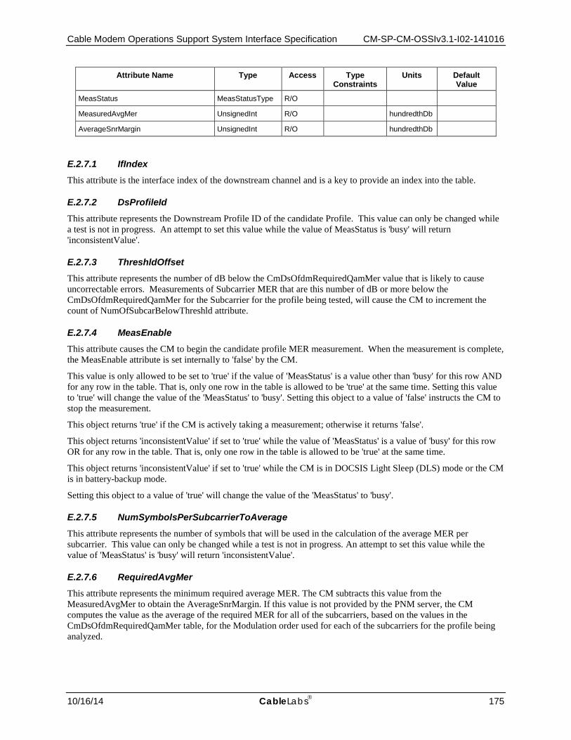
Cable Modem Operations Support System Interface Specification CM-SP-CM-OSSIv3.1-I02-141016
10/16/14 CableLabs 175
Attribute Name Type Access Type Constraints
Units Default Value
MeasStatus MeasStatusType R/O
MeasuredAvgMer UnsignedInt R/O hundredthDb
AverageSnrMargin UnsignedInt R/O hundredthDb
E.2.7.1 IfIndex This attribute is the interface index of the downstream channel and is a key to provide an index into the table.
E.2.7.2 DsProfileId This attribute represents the Downstream Profile ID of the candidate Profile. This value can only be changed while a test is not in progress. An attempt to set this value while the value of MeasStatus is 'busy' will return 'inconsistentValue'.
E.2.7.3 ThreshldOffset This attribute represents the number of dB below the CmDsOfdmRequiredQamMer value that is likely to cause uncorrectable errors. Measurements of Subcarrier MER that are this number of dB or more below the CmDsOfdmRequiredQamMer for the Subcarrier for the profile being tested, will cause the CM to increment the count of NumOfSubcarBelowThreshld attribute.
E.2.7.4 MeasEnable This attribute causes the CM to begin the candidate profile MER measurement. When the measurement is complete, the MeasEnable attribute is set internally to 'false' by the CM.
This value is only allowed to be set to 'true' if the value of 'MeasStatus' is a value other than 'busy' for this row AND for any row in the table. That is, only one row in the table is allowed to be 'true' at the same time. Setting this value to 'true' will change the value of the 'MeasStatus' to 'busy'. Setting this object to a value of 'false' instructs the CM to stop the measurement.
This object returns 'true' if the CM is actively taking a measurement; otherwise it returns 'false'.
This object returns 'inconsistentValue' if set to 'true' while the value of 'MeasStatus' is a value of 'busy' for this row OR for any row in the table. That is, only one row in the table is allowed to be 'true' at the same time.
This object returns 'inconsistentValue' if set to 'true' while the CM is in DOCSIS Light Sleep (DLS) mode or the CM is in battery-backup mode.
Setting this object to a value of 'true' will change the value of the 'MeasStatus' to 'busy'.
E.2.7.5 NumSymbolsPerSubcarrierToAverage This attribute represents the number of symbols that will be used in the calculation of the average MER per subcarrier. This value can only be changed while a test is not in progress. An attempt to set this value while the value of 'MeasStatus' is 'busy' will return 'inconsistentValue'.
E.2.7.6 RequiredAvgMer This attribute represents the minimum required average MER. The CM subtracts this value from the MeasuredAvgMer to obtain the AverageSnrMargin. If this value is not provided by the PNM server, the CM computes the value as the average of the required MER for all of the subcarriers, based on the values in the CmDsOfdmRequiredQamMer table, for the Modulation order used for each of the subcarriers for the profile being analyzed.

CM-SP-CM-OSSIv3.1-I02-141016 DOCSIS 3.1
176 CableLabs 10/16/14
E.2.7.7 NumSubcarriersBelowThrshld This attribute represents the number of subcarriers which were counted due to satisfying the criteria defined for the ThreshldOffset attribute.
E.2.7.8 MeasStatus This attribute is used to determine the status of the command. When the Status = sampleReady(3), the CM MER profile measurement data is ready for evaluation.
E.2.7.9 MeasuredAvgMer This attribute is the average of all MER values measured over all of the subcarriers, calculated in hundredth dB.
E.2.7.10 AverageSnrMargin This attribute represents the difference between the MeasuredAvgMer and the RequiredAverageMer.
E.2.8 CmDsOfdmRequiredQamMer Object
The purpose of this item is to provide a target MER value for each downstream OFDM modulation order to be used in determining the SNR Margin for the Candidate Downstream Profile. The QamMer attributes are expressed in units of a quarter dB.
Table E–13 - CmDsOfdmRequiredQamMer Object
Attribute Name Type Access
Type Constraints
Units Default Value
docsPnmCmReqMerQam16 UnsignedInt R/W quarterDb 60
docsPnmCmReqMerQam64 UnsignedInt R/W quarterDb 84
docsPnmCmReqMerQam128 UnsignedInt R/W quarterDb 96
docsPnmCmReqMerQam256 UnsignedInt R/W quarterDb 108
docsPnmCmReqMerQam512 UnsignedInt R/W quarterDb 122
docsPnmCmReqMerQam1024 UnsignedInt R/W quarterDb 136
docsPnmCmReqMerQam2048 UnsignedInt R/W quarterDb 148
docsPnmCmReqMerQam4096 UnsignedInt R/W quarterDb 164
docsPnmCmReqMerQam8192 UnsignedInt R/W quarterDb 184
docsPnmCmReqMerQam16384 UnsignedInt R/W quarterDb 208
E.2.8.1 docsPnmCmReqMerQam16 This attribute represents the minimum required MER value for this Modulation Order. It is used in determining the SNR Margin for the Candidate Downstream Profile.
E.2.8.2 docsPnmCmReqMerQam64 This attribute represents the minimum required MER value for this Modulation Order. It is used in determining the SNR Margin for the Candidate Downstream Profile.
E.2.8.3 docsPnmCmReqMerQam128 This attribute represents the minimum required MER value for this Modulation Order. It is used in determining the SNR Margin for the Candidate Downstream Profile.
E.2.8.4 docsPnmCmReqMerQam256 This attribute represents the minimum required MER value for this Modulation Order. It is used in determining the SNR Margin for the Candidate Downstream Profile.

Cable Modem Operations Support System Interface Specification CM-SP-CM-OSSIv3.1-I02-141016
10/16/14 CableLabs 177
E.2.8.5 docsPnmCmReqMerQam512 This attribute represents the minimum required MER value for this Modulation Order. It is used in determining the SNR Margin for the Candidate Downstream Profile.
E.2.8.6 docsPnmCmReqMerQam1024 This attribute represents the minimum required MER value for this Modulation Order. It is used in determining the SNR Margin for the Candidate Downstream Profile.
E.2.8.7 docsPnmCmReqMerQam2048 This attribute represents the minimum required MER value for this Modulation Order. It is used in determining the SNR Margin for the Candidate Downstream Profile.
E.2.8.8 docsPnmCmReqMerQam4096 This attribute represents the minimum required MER value for this Modulation Order. It is used in determining the SNR Margin for the Candidate Downstream Profile.
E.2.8.9 docsPnmCmReqMerQam8192 This attribute represents the minimum required MER value for this Modulation Order. It is used in determining the SNR Margin for the Candidate Downstream Profile.
E.2.8.10 docsPnmCmReqMerQam16384 This attribute represents the minimum required MER value for this Modulation Order. It is used in determining the SNR Margin for the Candidate Downstream Profile.
E.2.9 CmDsHist Object
The purpose of the downstream histogram is to provide a measurement of nonlinear effects in the channel such as amplifier compression and laser clipping. For example, laser clipping causes one tail of the histogram to be truncated and replaced with a spike. The CM MUST be capable of capturing the histogram of time domain samples at the wideband front end of the receiver (full downstream band). When it creates a histogram, the CM MUST create a two-sided histogram, such that the histogram encompasses values from far-negative to far-positive values of the samples. When it creates a histogram, the CM MUST create the histogram to have 256 equally spaced bins. These bins typically correspond to the 8 MSBs of the wideband analog-to-digital converter (ADC). The histogram dwell count, a 32-bit unsigned integer, is the number of samples observed while counting hits for a given bin, and may have the same value for all bins. The histogram hit count, a 32-bit unsigned integer, is the number of samples falling in a given bin. The CM MUST be capable of reporting the dwell count per bin and the hit count per bin. When enabled, the CM MUST compute a histogram with a dwell of at least 10 million samples at each bin in 30 seconds or less. The CM MUST continue accumulating histogram samples until it is restarted, disabled or times out. If the highest dwell count approaches its 32-bit overflow value, the CM stops counting and sets the MeasStatus attribute to sampleReady(4). The CM reports the start and end time of the histogram measurement using bits 21-52 of the extended timestamp, which provides a 32-bit timestamp value with resolution of 0.4 ms and range of 20 days.
Table E–14 - CmDsHist Object
Attribute Name Type Access Type Constraints Units Default Value IfIndex InterfaceIndex Key
Enable Boolean R/W false Restart Boolean R/W false
Timeout UnsignedShort R/W Seconds 1800
MeasStatus MeasStatusType R/O Symmetry Boolean R/W false
DwellCnts UnsignedInt R/O 1..256
HitCnts UnsignedInt R/O 1..256

CM-SP-CM-OSSIv3.1-I02-141016 DOCSIS 3.1
178 CableLabs 10/16/14
Attribute Name Type Access Type Constraints Units Default Value CntStartTime UnsignedInt R/O
CntEndTime UnsignedInt R/O FileName AdminString R/O SIZE (1..255)
E.2.9.1 IfIndex This attribute is the interface index of the downstream channel and is a key to provide an index into the table.
E.2.9.2 Enable This attribute causes the CM to begin collection of histogram data and when enabled, the CM continues producing new data at its own rate.
This value is only allowed to be set to 'true' if the value of MeasStatus is a value other than 'busy' for this row and for any row in the table. That is, only one row in the table is allowed to be 'true' at the same time. Setting this value to 'true' will change the value of the MeasStatus to 'busy'. Setting this object to a value of 'false' instructs the CM to stop the collection of histogram data.
This object returns 'true' if the CM is actively collecting histogram data. Otherwise, it returns 'false'.
Interaction with other table rows:
This object returns 'inconsistentValue' if set to 'true' while the value of MeasStatus' is a value of 'busy' for this row or for any row in the table. That is, only one row in the table is allowed to be 'true' at the same time.
This object returns 'inconsistentValue' if set to 'true' while the CM is in DOCSIS Light Sleep (DLS) mode or the CM is in battery-backup mode.
Setting this object to a value of 'true' will change the value of the MeasStatus to 'busy'.
E.2.9.3 Restart This attribute is used to restart collection of histogram data. If the enable is true then the restart clears the old data and starts collecting a new set of histogram data.
Setting this object to a value of 'false' has no action.
This object always returns 'false'.
E.2.9.4 Timeout This attribute sets a seconds time-out timer for capturing histogram data. When the timeout expires, the 'docsPnmCmDsHistEnable' object will be set to 'false' and the capture will stop. Setting this value does not start a capture. Captures can only be started by setting the 'docsPnmCmDsHistEnable' object.
If this attribute is written while the 'docsPnmCmDsHistEnable' object is 'true', the timer is restarted. If this attribute is set to a value of 'zero', there is no timeout and the collection of data will continue indefinitely.
This attribute returns the value with which it was last set.
E.2.9.5 Symmetry This attribute is used to indicate whether 256 or 255 bins were used for the measurement.
When the value is 'false' (default) this indicates Even Symmetry. In this case, the histogram has even symmetry about the origin. There is no bin center lying directly at the origin; rather, two bin centers straddle the origin at 0.5. All bins with indices 0-255 contain valid hit-count data. The histogram bin centers are offset from the corresponding 8-bit two's complement integer values by 1/2, that is, bin center = two's complement value + 0.5.
When the value is 'true' this indicates Odd Symmetry. In this case, the histogram has odd symmetry about the origin. There is a bin center lying at the origin. The bin with index 0 is not used and returns the value 0. The bins with

Cable Modem Operations Support System Interface Specification CM-SP-CM-OSSIv3.1-I02-141016
10/16/14 CableLabs 179
indices 1 to 255 contain valid hit-count data. The histogram bin centers are located on the corresponding 8-bit two's complement integer values.
The following table shows the defined histogram bin centers for the cases of even and odd symmetry.
Table E–15 - Histogram Bin Centers
Bin Index Bin Center Even Symmetry
Bin Center Odd Symmetry
0 -127.5 not used
1 -126.5 -127 2 -125.5 -126
… … …
127 -0.5 -1 128 0.5 0
129 1.5 1
… … … 253 125.5 125
254 126.5 126
255 127.5 127
This object cannot be changed while a capture is in progress. It will return a value of 'inconsistentValue' if set while the value of MeasStatus is set to a value of 'busy'.
E.2.9.6 MeasStatus This attribute is used to determine the status of the command. When the Status is SampleReady(4), the data is ready for download by the PNM server.
E.2.9.7 DwellCnts This attribute is represents the total number Dwell Counts for each bin for the "Current" capture.
E.2.9.8 HitCnts This attribute is represents the total number Hit Counts for each bin for the "Current" capture.
E.2.9.9 CntStartTime This attribute is represents the time when the current collection of histogram data was started.
E.2.9.10 CntEndTime This attribute is represents the time when the current collection of histogram data was stopped.
E.2.9.11 FileName This attribute is the name of the file at the CM which is to be transferred to the PNM server. The data is stored as 32-bit integers for the hit and dwell count values.
This value can only be changed while a test is not in progress. An attempt to set this value while the value of MeasStatus is 'busy' will return 'inconsistentValue'.
If the value of this object is the default value (empty string), then a default filename value will be used. Otherwise, the value set will be used as the filename.
If a default filename value is used, it is generated as the test name plus the CM MAC Address plus the 'epoch time'. The epoch time (also known as 'unix time') is defined as the number of seconds that have elapsed since midnight Coordinated Universal Time (UTC),Thursday, 1 January 1970.
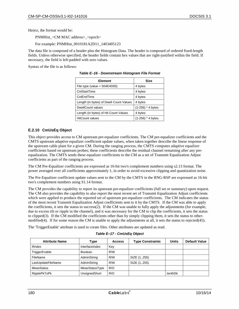
CM-SP-CM-OSSIv3.1-I02-141016 DOCSIS 3.1
180 CableLabs 10/16/14
Hence, the format would be:
PNMHist_<CM MAC address>_<epoch>
For example: PNMHist_0010181A2D11_1403405123
The data file is composed of a header plus the Histogram Data. The header is composed of ordered fixed-length fields. Unless otherwise specified, the header fields contain hex values that are right-justified within the field. If necessary, the field is left-padded with zero values.
Syntax of the file is as follows:
Table E–16 - Downstream Histogram File Format
Element Size File type (value = 504E4D05) 4 bytes
CntStartTime 4 bytes
CntEndTime 4 bytes
Length (in bytes) of Dwell Count Values 4 bytes
DwellCount values (1-256) * 4 bytes
Length (in bytes) of Hit Count Values 4 bytes
HitCount values (1-256) * 4 bytes
E.2.10 CmUsEq Object
This object provides access to CM upstream pre-equalizer coefficients. The CM pre-equalizer coefficients and the CMTS upstream adaptive equalizer coefficient update values, when taken together describe the linear response of the upstream cable plant for a given CM. During the ranging process, the CMTS computes adaptive equalizer coefficients based on upstream probes; these coefficients describe the residual channel remaining after any pre-equalization. The CMTS sends these equalizer coefficients to the CM as a set of Transmit Equalization Adjust coefficients as part of the ranging process.
The CM Pre-Equalizer coefficients are expressed as 16-bit two's complement numbers using s2.13 format. The power averaged over all coefficients approximately 1, in order to avoid excessive clipping and quantization noise.
The Pre-Equalizer coefficient update values sent to the CM by the CMTS in the RNG-RSP are expressed as 16-bit two's complement numbers using S1.14 format.
The CM provides the capability to report its upstream pre-equalizer coefficients (full set or summary) upon request. The CM also provides the capability to also report the most recent set of Transmit Equalization Adjust coefficients which were applied to produce the reported set of upstream pre-equalizer coefficients. The CM indicates the status of the most recent Transmit Equalization Adjust coefficients sent to it by the CMTS. If the CM was able to apply the coefficients, it sets the status to success(2). If the CM was unable to fully apply the adjustments (for example, due to excess tilt or ripple in the channel), and it was necessary for the CM to clip the coefficients, it sets the status to clipped(3). If the CM modified the coefficients other than by simply clipping them, it sets the status to other-modified(4). If for some reason the CM is unable to apply the adjustments at all, it sets the status to rejected(45).
The 'TriggerEnable' attribute is used to create files. Other attributes are updated as read.
Table E–17 - CmUsEq Object
Attribute Name Type Access Type Constraints Units Default Value IfIndex InterfaceIndex Key
TriggerEnable Boolean R/W
FileName AdminString R/W SIZE (1..255)
LastUpdateFileName AdminString R/W SIZE (1..255)
MeasStatus MeasStatusType R/O
RipplePkToPk UnsignedShort R/O tenthDb
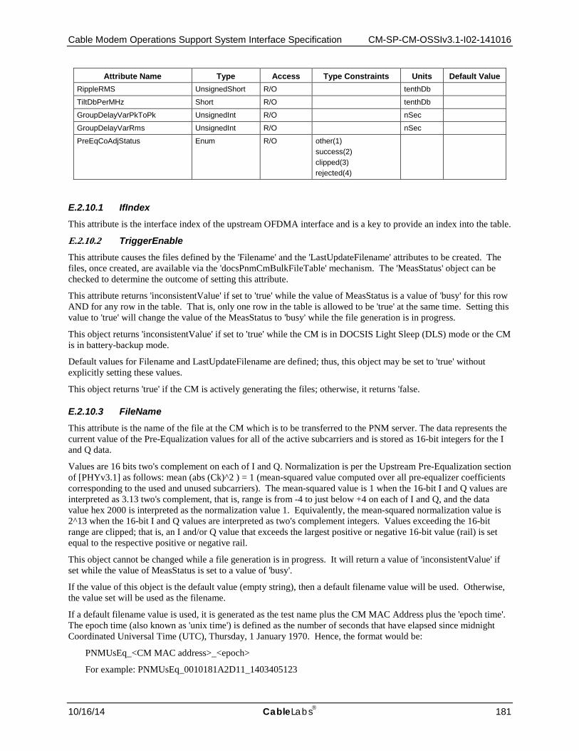
Cable Modem Operations Support System Interface Specification CM-SP-CM-OSSIv3.1-I02-141016
10/16/14 CableLabs 181
Attribute Name Type Access Type Constraints Units Default Value RippleRMS UnsignedShort R/O tenthDb
TiltDbPerMHz Short R/O tenthDb
GroupDelayVarPkToPk UnsignedInt R/O nSec
GroupDelayVarRms UnsignedInt R/O nSec
PreEqCoAdjStatus Enum R/O other(1) success(2) clipped(3) rejected(4)
E.2.10.1 IfIndex This attribute is the interface index of the upstream OFDMA interface and is a key to provide an index into the table.
E.2.10.2 TriggerEnable This attribute causes the files defined by the 'Filename' and the 'LastUpdateFilename' attributes to be created. The files, once created, are available via the 'docsPnmCmBulkFileTable' mechanism. The 'MeasStatus' object can be checked to determine the outcome of setting this attribute.
This attribute returns 'inconsistentValue' if set to 'true' while the value of MeasStatus is a value of 'busy' for this row AND for any row in the table. That is, only one row in the table is allowed to be 'true' at the same time. Setting this value to 'true' will change the value of the MeasStatus to 'busy' while the file generation is in progress.
This object returns 'inconsistentValue' if set to 'true' while the CM is in DOCSIS Light Sleep (DLS) mode or the CM is in battery-backup mode.
Default values for Filename and LastUpdateFilename are defined; thus, this object may be set to 'true' without explicitly setting these values.
This object returns 'true' if the CM is actively generating the files; otherwise, it returns 'false.
E.2.10.3 FileName This attribute is the name of the file at the CM which is to be transferred to the PNM server. The data represents the current value of the Pre-Equalization values for all of the active subcarriers and is stored as 16-bit integers for the I and Q data.
Values are 16 bits two's complement on each of I and Q. Normalization is per the Upstream Pre-Equalization section of [PHYv3.1] as follows: mean (abs (Ck)^2 ) = 1 (mean-squared value computed over all pre-equalizer coefficients corresponding to the used and unused subcarriers). The mean-squared value is 1 when the 16-bit I and Q values are interpreted as 3.13 two's complement, that is, range is from -4 to just below +4 on each of I and Q, and the data value hex 2000 is interpreted as the normalization value 1. Equivalently, the mean-squared normalization value is 2^13 when the 16-bit I and Q values are interpreted as two's complement integers. Values exceeding the 16-bit range are clipped; that is, an I and/or Q value that exceeds the largest positive or negative 16-bit value (rail) is set equal to the respective positive or negative rail.
This object cannot be changed while a file generation is in progress. It will return a value of 'inconsistentValue' if set while the value of MeasStatus is set to a value of 'busy'.
If the value of this object is the default value (empty string), then a default filename value will be used. Otherwise, the value set will be used as the filename.
If a default filename value is used, it is generated as the test name plus the CM MAC Address plus the 'epoch time'. The epoch time (also known as 'unix time') is defined as the number of seconds that have elapsed since midnight Coordinated Universal Time (UTC), Thursday, 1 January 1970. Hence, the format would be:
PNMUsEq_<CM MAC address>_<epoch>
For example: PNMUsEq_0010181A2D11_1403405123

CM-SP-CM-OSSIv3.1-I02-141016 DOCSIS 3.1
182 CableLabs 10/16/14
The data file is composed of a header plus the Pre-EQ Data. The header is composed of ordered fixed-length fields. Unless otherwise specified, the header fields contain hex values that are right-justified within the field. If necessary, the field is left-padded with zero values.
Syntax of the file is as follows:
Table E–18 - Upstream Equalization File Format
Element Size File type (value = 504E4D06) 4 bytes
Subcarrier zero frequency in Hz 4 bytes
Subcarrier spacing in Hz 4 bytes
FFT size 4 bytes
Length in bytes of Pre-EQ data 4 bytes
Pre-EQ coefficient data Complex data
E.2.10.4 LastUpdateFileName This attribute is the name of the file at the CM which is to be transferred to the PNM server. The data represents the values sent to the CM by the CMTS in the last RNG-RSP that contained Pre-Equalization updates and is stored as 16-bit integers for the I and Q data.
This object cannot be changed while a file generation is in progress. It will return a value of 'inconsistentValue' if set while the value of MeasStatus is set to a value of 'busy'.
If the value of this object is the default value (empty string), then a default filename value will be used. Otherwise, the value set will be used as the filename.
If a default filename value is used, it is generated as the test name plus the CM MAC Address plus the 'epoch time'. The epoch time (also known as 'unix time') is defined as the number of seconds that have elapsed since midnight Coordinated Universal Time (UTC), Thursday, 1 January 1970.
Hence, the format would be:
PNMUsLastEqUpdate_<CM MAC address>_<epoch>
For example: PNMUsLastEqUpdate_0010181A2D11_1403405123
The data file is composed of a header plus the Pre-EQ Update Data. The header is composed of ordered fixed-length fields. Unless otherwise specified, the header fields contain hex values that are right-justified within the field. If necessary, the field is left-padded with zero values.
Syntax of the file is as follows:
Table E–19 - Last EQ Update File Format
Element Size File type (value = 504E4D07) 4 bytes
Subcarrier zero frequency in Hz 4 bytes
Subcarrier spacing in Hz 4 bytes
FFT size 4 bytes
Length in bytes of Pre-EQ data 4 bytes
Pre-EQ coefficient data Complex data
E.2.10.5 MeasStatus This attribute is used to determine the status of the test. When the Status = SampleReady(4), the data is ready for download by the PNM server.

Cable Modem Operations Support System Interface Specification CM-SP-CM-OSSIv3.1-I02-141016
10/16/14 CableLabs 183
E.2.10.6 RipplePkToPk This attribute represents the value of the peak to peak ripple in the magnitude of the equalizer coefficients. This attribute represents the ripple across the entire OFDMA channel.
Note: An algorithm for calculating the ripple and tilt for these measurements is provided in sections 6.5 and 6.6 of [SCTE RP].
E.2.10.7 RippleRMS This attribute represents the value of the rms ripple in the magnitude of the equalizer coefficients. This attribute represents the ripple across the entire OFDMA channel.
E.2.10.8 TiltDbPerMHz This attribute represents the tilt in dB per MHz in the magnitude of the equalizer coefficients. This attribute represents the tilt across the entire OFDMA channel.
E.2.10.9 GroupDelayVariationPkToPk This attribute is represents the pk to pk GroupDelayVariation expressed in units of nSec. This attribute represents the group delay variation across the entire OFDMA channel. This attribute is not stored in the data files.
E.2.10.10 GroupDelayVariationRMS This attribute is represents the pk to pk GroupDelayVariation expressed in units of nSec. This attribute represents the group delay variation across the entire OFDMA channel. This attribute is not stored in the data files.
E.2.10.11 PreEquCoAdjStatus This attribute represents whether the last set of Pre-Equalization coefficient adjustments were fully applied or were only partially applied due to excessive ripple or tilt in the Pre-Equalization coefficient values.
E.3 CM Bulk Data Transfer Proactive Network Maintenance, and potentially other applications, may generate data files which need to be transferred off the CM to a server. The Bulk-Data Transfer mechanism defines file storage requirements, destination address and a mechanism to initiate a transfer. The section defines the Bulk-Data capabilities required by the CM.
E.3.1 Bulk Data Transfer Requirements
The CM MUST act as a TFTP client and implement the TFTP protocol over UDP per [RFC 1350] to transfer Bulk-Data files.
The CM MUST initiate the TFTP connection on the standard TFTP-assigned port (69).
The CM MUST use the 'octet' TFTP transfer mode to perform a TFTP ‘write’ to the specified address.
The CM is not required to keep track of which Bulk-Data files have been uploaded to the management system. If the Bulk-Data TFTP transfer process fails, the docsPnmBulkUploadStatus attribute MUST be set to reflect the error. In this case, the CM is only required to report that an error occurred. There are no requirements for the CM to automatically retry the transfer.
E.3.2 Data-File and Storage Requirements
The CM MUST be able to store data files with a minimum size of up to 64 kilobytes. If the CM is commanded to collect data that exceeds its data size capability, the CM MAY stop collecting data and report an error to the application that commanded it to collect data. The application may further report the error if so defined.
The CM MUST be able to store a minimum of four data files.
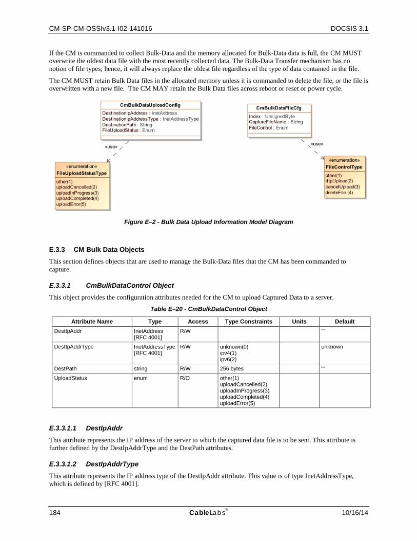
CM-SP-CM-OSSIv3.1-I02-141016 DOCSIS 3.1
184 CableLabs 10/16/14
If the CM is commanded to collect Bulk-Data and the memory allocated for Bulk-Data data is full, the CM MUST overwrite the oldest data file with the most recently collected data. The Bulk-Data Transfer mechanism has no notion of file types; hence, it will always replace the oldest file regardless of the type of data contained in the file.
The CM MUST retain Bulk Data files in the allocated memory unless it is commanded to delete the file, or the file is overwritten with a new file. The CM MAY retain the Bulk Data files across reboot or reset or power cycle.
Figure E–2 - Bulk Data Upload Information Model Diagram
E.3.3 CM Bulk Data Objects This section defines objects that are used to manage the Bulk-Data files that the CM has been commanded to capture.
E.3.3.1 CmBulkDataControl Object This object provides the configuration attributes needed for the CM to upload Captured Data to a server.
Table E–20 - CmBulkDataControl Object
Attribute Name Type Access Type Constraints Units Default DestIpAddr InetAddress
[RFC 4001] R/W ""
DestIpAddrType InetAddressType [RFC 4001]
R/W unknown(0) ipv4(1) ipv6(2)
unknown
DestPath string R/W 256 bytes ""
UploadStatus enum R/O other(1) uploadCancelled(2) uploadInProgress(3) uploadCompleted(4) uploadError(5)
E.3.3.1.1 DestIpAddr This attribute represents the IP address of the server to which the captured data file is to be sent. This attribute is further defined by the DestIpAddrType and the DestPath attributes.
E.3.3.1.2 DestIpAddrType This attribute represents the IP address type of the DestIpAddr attribute. This value is of type InetAddressType, which is defined by [RFC 4001].
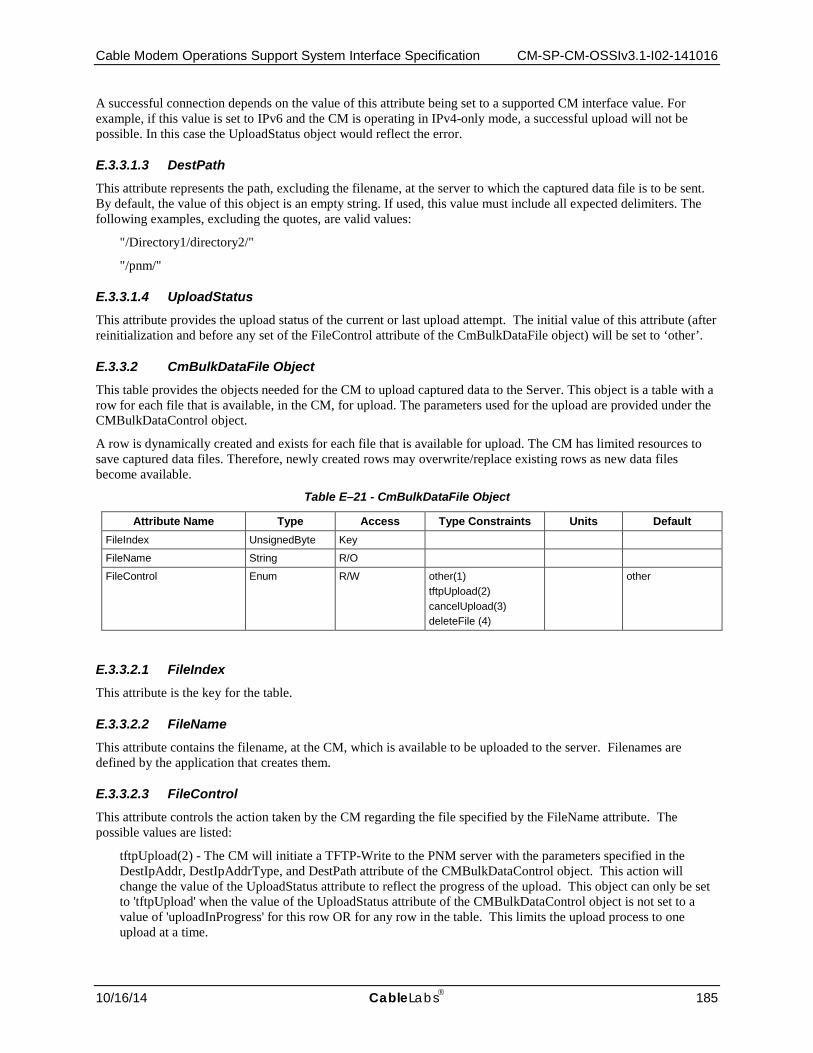
Cable Modem Operations Support System Interface Specification CM-SP-CM-OSSIv3.1-I02-141016
10/16/14 CableLabs 185
A successful connection depends on the value of this attribute being set to a supported CM interface value. For example, if this value is set to IPv6 and the CM is operating in IPv4-only mode, a successful upload will not be possible. In this case the UploadStatus object would reflect the error.
E.3.3.1.3 DestPath This attribute represents the path, excluding the filename, at the server to which the captured data file is to be sent. By default, the value of this object is an empty string. If used, this value must include all expected delimiters. The following examples, excluding the quotes, are valid values:
"/Directory1/directory2/"
"/pnm/"
E.3.3.1.4 UploadStatus This attribute provides the upload status of the current or last upload attempt. The initial value of this attribute (after reinitialization and before any set of the FileControl attribute of the CmBulkDataFile object) will be set to ‘other’.
E.3.3.2 CmBulkDataFile Object This table provides the objects needed for the CM to upload captured data to the Server. This object is a table with a row for each file that is available, in the CM, for upload. The parameters used for the upload are provided under the CMBulkDataControl object.
A row is dynamically created and exists for each file that is available for upload. The CM has limited resources to save captured data files. Therefore, newly created rows may overwrite/replace existing rows as new data files become available.
Table E–21 - CmBulkDataFile Object
Attribute Name Type Access Type Constraints Units Default FileIndex UnsignedByte Key
FileName String R/O
FileControl Enum R/W other(1) tftpUpload(2) cancelUpload(3) deleteFile (4)
other
E.3.3.2.1 FileIndex This attribute is the key for the table.
E.3.3.2.2 FileName This attribute contains the filename, at the CM, which is available to be uploaded to the server. Filenames are defined by the application that creates them.
E.3.3.2.3 FileControl This attribute controls the action taken by the CM regarding the file specified by the FileName attribute. The possible values are listed:
tftpUpload(2) - The CM will initiate a TFTP-Write to the PNM server with the parameters specified in the DestIpAddr, DestIpAddrType, and DestPath attribute of the CMBulkDataControl object. This action will change the value of the UploadStatus attribute to reflect the progress of the upload. This object can only be set to 'tftpUpload' when the value of the UploadStatus attribute of the CMBulkDataControl object is not set to a value of 'uploadInProgress' for this row OR for any row in the table. This limits the upload process to one upload at a time.

CM-SP-CM-OSSIv3.1-I02-141016 DOCSIS 3.1
186 CableLabs 10/16/14
cancelUpload(3) - The CM will cancel any upload currently in progress. The value of the UploadStatus attribute of the CMBulkDataControl object will be changed to 'uploadCancelled'.
deleteFile (4) - The CM will delete the file from its memory. This object cannot be set to deleteFile(4) while an upload is in progress.
Cable Modem Operations Support System Interface Specification CM-SP-CM-OSSIv3.1-I02-141016
10/16/14 CableLabs 187
Annex F DOCSIS 3.1 Data Type Definitions (Normative)
F.1 Overview This specification has requirements for the SNMP protocol for network management functions.
This Annex includes the data type definitions for the information models defined for use in DOCSIS 3.1. The Unified Modeling Language (UML) is used for modeling the management requirements in DOCSIS 3.1. The data types defined in this Annex are mapped for use with SNMP.
Basic UML notation used in this specification and explained in Appendix II.
F.2 Data Type Mapping XML is becoming the standard for data definition models. With XML data transformations can be done with or without a model (DTD or Schema definition). DTDs and XML schemas provides additional data validation layer to the applications exchanging XML data. There are several models to map formal notation constructs like ASN.1 to XML [ITU-T X.692], UML to XML, or XML by itself can be used for modeling purposes.
Each area of data information interest approaches XML and defines data models and/or data containment structures and data types. Similarly, SNMP took and modified a subset of ASN.1 for defining the Structured Management Information SMIv1 and SMIv2.
Due to the lack of a unified data model and data types for Network Management a neutral model would be appropriated to allow capturing specific requirements and methodologies from existing protocols and allow forward or reverse engineering of those standards like SNMP to the general information model and vice versa.
F.2.1 Data Type Requirements and Classification The information model has to provide seamless translation for SMIv2 requirements, in particular when creating MIB modules based on the information model, this specification needs to provide full support of [RFC 2578], [RFC 2579] and the clarifications and recommendations of [RFC 4181].
Thus, there are two data type groups defined for modeling purposes and mapping to protocol data notation roundtrip:
1. General Data types
Required data types to cover all the management syntax and semantic requirement for all OSSI supported data models. In this category are data types defined in SNMP SMIv2 [RFC 2578], [IPDR/XDR], and [IPDR/SSDG].
2. Extended Data types
Management protocols specialization based on frequent usage or special semantics. Required data types to cover all the syntax requirement for all OSSI supported data models. In this category are SNMP TEXTUAL-CONVENTION clauses [RFC 2579] of mandatory or recommended usage by [RFC 2579] and [RFC 4181] when modeling for SNMP MIB modules.
F.2.2 Data Type Mapping Methodology
The specification "XML Schema Part 2: Data types Second Edition" is based on [ISO 11404] which provides a language-independent data types (see XML Schema reference). The mapping proposed below uses a subset of the XML schema data types to cover both SNMP forward and reverse engineering. Any additional protocol being added should be feasible to provide the particular mappings.
SMIv2 has an extensive experience of data types for management purposes, for illustration consider Counter32 and Counter64 SMIv2 types [RFC 2578]. The XML schema data types makes no distinction of derived 'decimal' types and the semantics that are associated to counters, e.g., counters do not necessarily start at 0.
Since the information model needs to cover the mapping of objects to SNMP, the mapping in Section F.2.4 is heavily based on most common SNMP TEXTUAL-CONVENTION descriptors [RFC 2579] and others IETF commonly used type definitions as well as DOCSIS already defined types in MIB modules required by this specification.
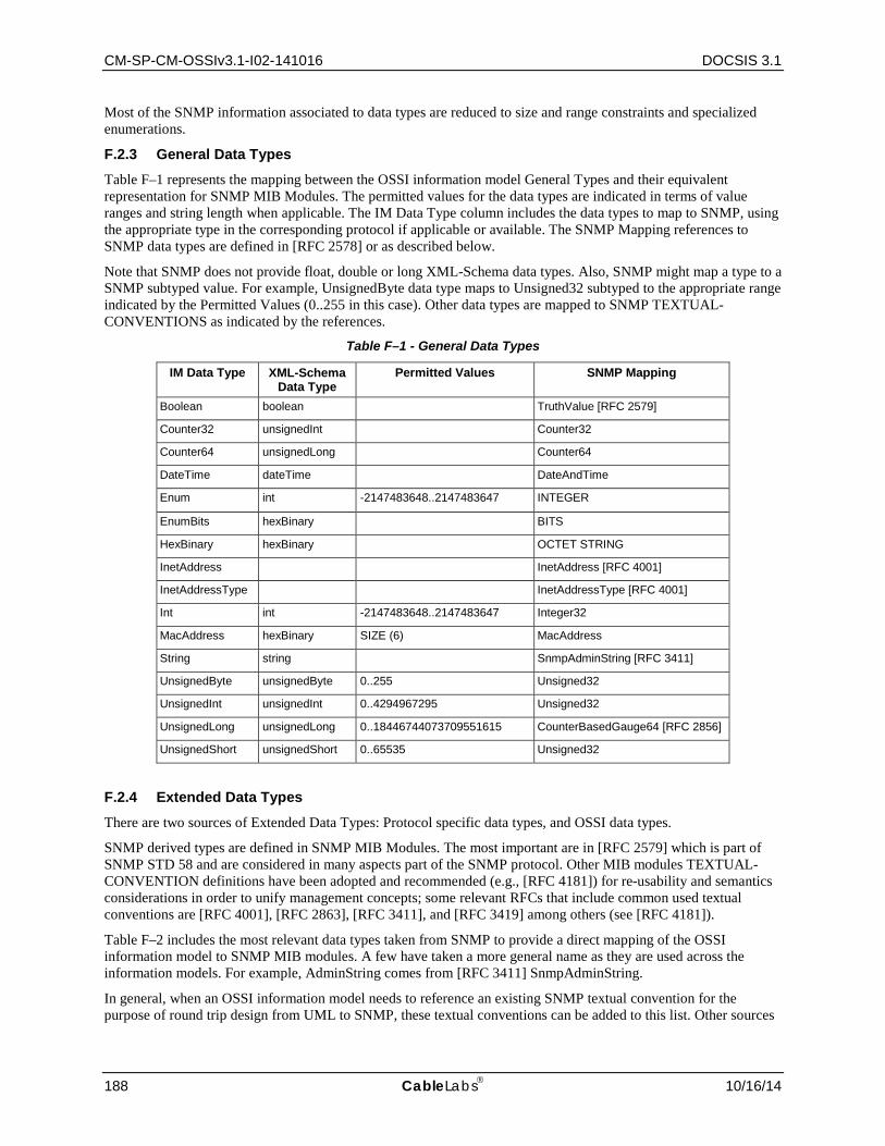
CM-SP-CM-OSSIv3.1-I02-141016 DOCSIS 3.1
188 CableLabs 10/16/14
Most of the SNMP information associated to data types are reduced to size and range constraints and specialized enumerations.
F.2.3 General Data Types Table F–1 represents the mapping between the OSSI information model General Types and their equivalent representation for SNMP MIB Modules. The permitted values for the data types are indicated in terms of value ranges and string length when applicable. The IM Data Type column includes the data types to map to SNMP, using the appropriate type in the corresponding protocol if applicable or available. The SNMP Mapping references to SNMP data types are defined in [RFC 2578] or as described below.
Note that SNMP does not provide float, double or long XML-Schema data types. Also, SNMP might map a type to a SNMP subtyped value. For example, UnsignedByte data type maps to Unsigned32 subtyped to the appropriate range indicated by the Permitted Values (0..255 in this case). Other data types are mapped to SNMP TEXTUAL-CONVENTIONS as indicated by the references.
Table F–1 - General Data Types
IM Data Type XML-Schema Data Type
Permitted Values SNMP Mapping
Boolean boolean TruthValue [RFC 2579]
Counter32 unsignedInt Counter32
Counter64 unsignedLong Counter64
DateTime dateTime DateAndTime
Enum int -2147483648..2147483647 INTEGER
EnumBits hexBinary BITS
HexBinary hexBinary OCTET STRING
InetAddress InetAddress [RFC 4001]
InetAddressType InetAddressType [RFC 4001]
Int int -2147483648..2147483647 Integer32
MacAddress hexBinary SIZE (6) MacAddress
String string SnmpAdminString [RFC 3411]
UnsignedByte unsignedByte 0..255 Unsigned32
UnsignedInt unsignedInt 0..4294967295 Unsigned32
UnsignedLong unsignedLong 0..18446744073709551615 CounterBasedGauge64 [RFC 2856]
UnsignedShort unsignedShort 0..65535 Unsigned32
F.2.4 Extended Data Types
There are two sources of Extended Data Types: Protocol specific data types, and OSSI data types.
SNMP derived types are defined in SNMP MIB Modules. The most important are in [RFC 2579] which is part of SNMP STD 58 and are considered in many aspects part of the SNMP protocol. Other MIB modules TEXTUAL-CONVENTION definitions have been adopted and recommended (e.g., [RFC 4181]) for re-usability and semantics considerations in order to unify management concepts; some relevant RFCs that include common used textual conventions are [RFC 4001], [RFC 2863], [RFC 3411], and [RFC 3419] among others (see [RFC 4181]).
Table F–2 includes the most relevant data types taken from SNMP to provide a direct mapping of the OSSI information model to SNMP MIB modules. A few have taken a more general name as they are used across the information models. For example, AdminString comes from [RFC 3411] SnmpAdminString.
In general, when an OSSI information model needs to reference an existing SNMP textual convention for the purpose of round trip design from UML to SNMP, these textual conventions can be added to this list. Other sources
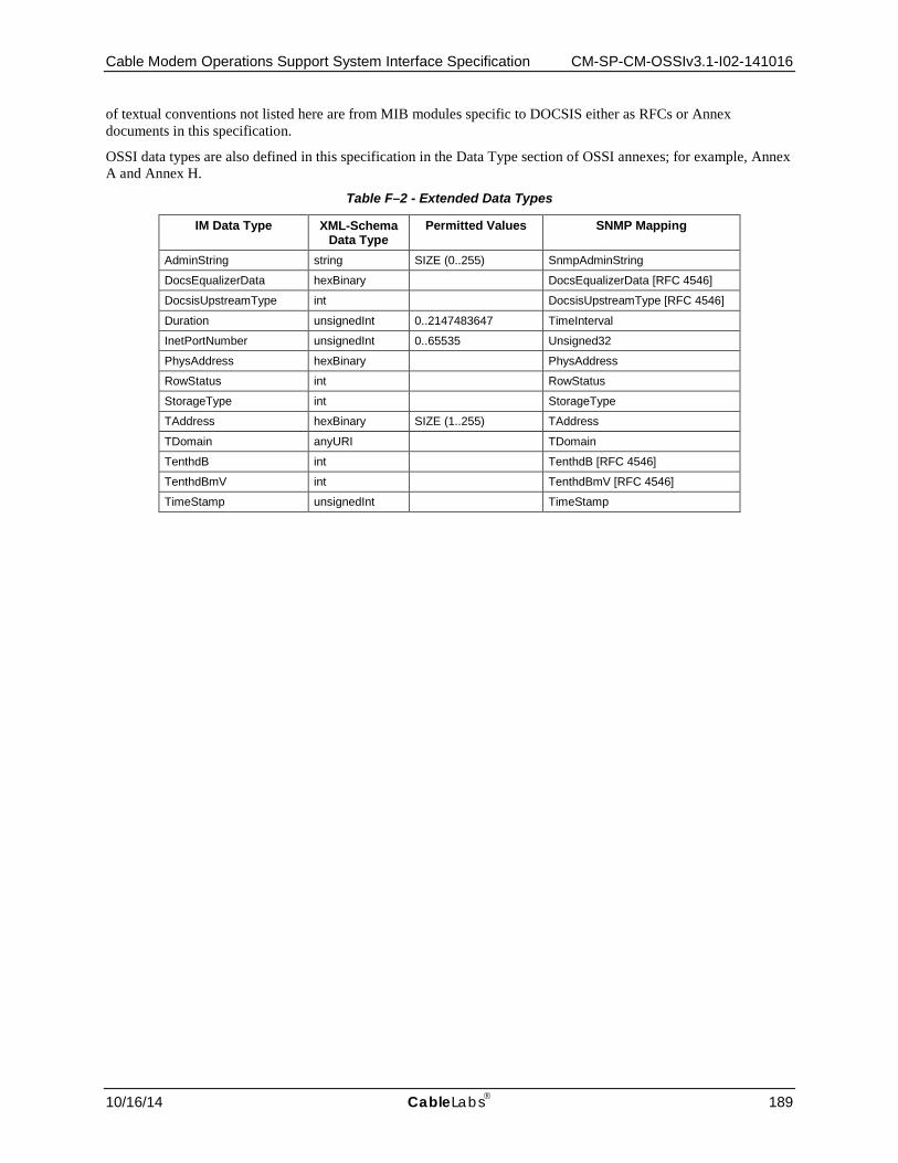
Cable Modem Operations Support System Interface Specification CM-SP-CM-OSSIv3.1-I02-141016
10/16/14 CableLabs 189
of textual conventions not listed here are from MIB modules specific to DOCSIS either as RFCs or Annex documents in this specification.
OSSI data types are also defined in this specification in the Data Type section of OSSI annexes; for example, Annex A and Annex H.
Table F–2 - Extended Data Types
IM Data Type XML-Schema Data Type
Permitted Values SNMP Mapping
AdminString string SIZE (0..255) SnmpAdminString
DocsEqualizerData hexBinary DocsEqualizerData [RFC 4546]
DocsisUpstreamType int DocsisUpstreamType [RFC 4546]
Duration unsignedInt 0..2147483647 TimeInterval
InetPortNumber unsignedInt 0..65535 Unsigned32
PhysAddress hexBinary PhysAddress
RowStatus int RowStatus
StorageType int StorageType
TAddress hexBinary SIZE (1..255) TAddress
TDomain anyURI TDomain
TenthdB int TenthdB [RFC 4546]
TenthdBmV int TenthdBmV [RFC 4546]
TimeStamp unsignedInt TimeStamp
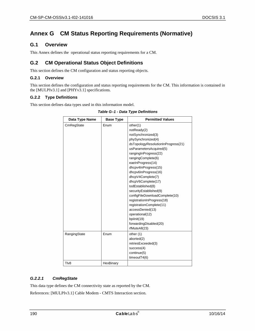
CM-SP-CM-OSSIv3.1-I02-141016 DOCSIS 3.1
190 CableLabs 10/16/14
Annex G CM Status Reporting Requirements (Normative)
G.1 Overview This Annex defines the operational status reporting requirements for a CM.
G.2 CM Operational Status Object Definitions This section defines the CM configuration and status reporting objects.
G.2.1 Overview
This section defines the configuration and status reporting requirements for the CM. This information is contained in the [MULPIv3.1] and [PHYv3.1] specifications.
G.2.2 Type Definitions
This section defines data types used in this information model.
Table G–1 - Data Type Definitions
Data Type Name Base Type Permitted Values CmRegState Enum other(1)
notReady(2) notSynchronized(3) phySynchronized(4) dsTopologyResolutionInProgress(21) usParametersAcquired(5) rangingInProgress(22) rangingComplete(6) eaeInProgress(14) dhcpv4InProgress(15) dhcpv6InProgress(16) dhcpV4Complete(7) dhcpV6Complete(17) todEstablished(8) securityEstablished(9) configFileDownloadComplete(10) registrationInProgress(18) registrationComplete(11) accessDenied(13) operational(12) bpiInit(19) forwardingDisabled(20) rfMuteAll(23)
RangingState Enum other (1) aborted(2) retriesExceeded(3) success(4) continue(5) timeoutT4(6)
Tlv8 HexBinary
G.2.2.1 CmRegState This data type defines the CM connectivity state as reported by the CM.
References: [MULPIv3.1] Cable Modem - CMTS Interaction section.
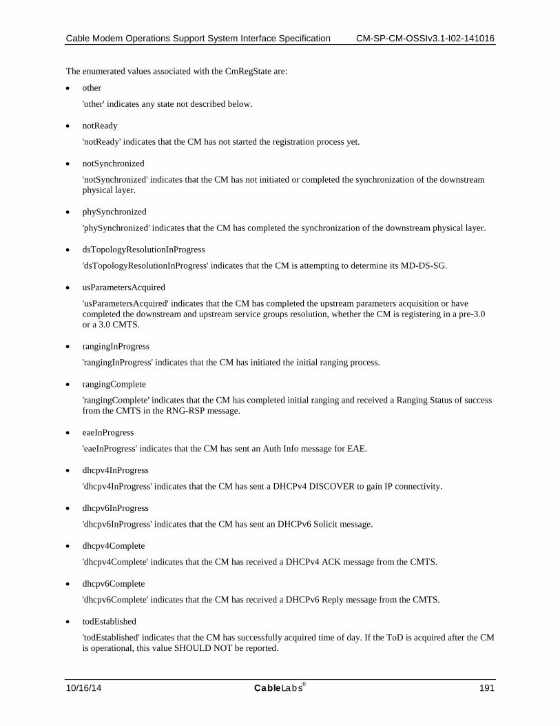
Cable Modem Operations Support System Interface Specification CM-SP-CM-OSSIv3.1-I02-141016
10/16/14 CableLabs 191
The enumerated values associated with the CmRegState are:
• other
'other' indicates any state not described below.
• notReady
'notReady' indicates that the CM has not started the registration process yet.
• notSynchronized
'notSynchronized' indicates that the CM has not initiated or completed the synchronization of the downstream physical layer.
• phySynchronized
'phySynchronized' indicates that the CM has completed the synchronization of the downstream physical layer.
• dsTopologyResolutionInProgress
'dsTopologyResolutionInProgress' indicates that the CM is attempting to determine its MD-DS-SG.
• usParametersAcquired
'usParametersAcquired' indicates that the CM has completed the upstream parameters acquisition or have completed the downstream and upstream service groups resolution, whether the CM is registering in a pre-3.0 or a 3.0 CMTS.
• rangingInProgress
'rangingInProgress' indicates that the CM has initiated the initial ranging process.
• rangingComplete
'rangingComplete' indicates that the CM has completed initial ranging and received a Ranging Status of success from the CMTS in the RNG-RSP message.
• eaeInProgress
'eaeInProgress' indicates that the CM has sent an Auth Info message for EAE.
• dhcpv4InProgress
'dhcpv4InProgress' indicates that the CM has sent a DHCPv4 DISCOVER to gain IP connectivity.
• dhcpv6InProgress
'dhcpv6InProgress' indicates that the CM has sent an DHCPv6 Solicit message.
• dhcpv4Complete
'dhcpv4Complete' indicates that the CM has received a DHCPv4 ACK message from the CMTS.
• dhcpv6Complete
'dhcpv6Complete' indicates that the CM has received a DHCPv6 Reply message from the CMTS.
• todEstablished
'todEstablished' indicates that the CM has successfully acquired time of day. If the ToD is acquired after the CM is operational, this value SHOULD NOT be reported.

CM-SP-CM-OSSIv3.1-I02-141016 DOCSIS 3.1
192 CableLabs 10/16/14
• securityEstablished
'securityEstablished' indicates that the CM has successfully completed the BPI initialization process.
• configFileDownloadComplete
'configFileDownloadComplete' indicates that the CM has completed the config file download process.
• registrationInProgress
'registrationInProgress' indicates that the CM has sent a Registration Request (REG-REQ or REG-REQ-MP)
• registrationComplete
'registrationComplete' indicates that the CM has successfully completed the Registration process with the CMTS.
• accessDenied
'accessDenied' indicates that the CM has received a registration aborted notification from the CMTS.
• operational
'operational' indicates that the CM has completed all necessary initialization steps and is operational.
• bpiInit
'bpiInit' indicates that the CM has started the BPI initialization process as indicated in the CM config file. If the CM already performed EAE, this state is skipped by the CM.
• forwardingDisabled
'forwardingDisabled' indicates that the registration process was completed, but the network access option in the received configuration file prohibits forwarding.
• rfMuteAll
'rfMuteAll' indicates that the CM is instructed to mute all channels in the CM-CTRL-REQ message from CMTS.
The following table provides a mapping of Pre-3.0 DOCSIS and DOCSIS 3.1 registration states as reported by CM.
Table G–2 - Pre-3.0 DOCSIS and DOCSIS 3.0/3.1 CM Registration status mapping
CM Pre-3.0 DOCSIS (from docsIfCmStatusValue)
CM DOCSIS 3.0 and 3.1
other(1) other(1)
notReady(2) notReady(2)
notSynchronized(3) notSynchronized(3)
phySynchronized(4) phySynchronized(4)
dsTopologyResolutionInProgress(21)
usParametersAcquired(5) usParametersAcquired(5)
rangingInProgress(22)
rangingComplete(6) rangingComplete(6)
eaeInProgress(14)
dhcpv4InProgress(15)
dhcpv6InProgress(16)
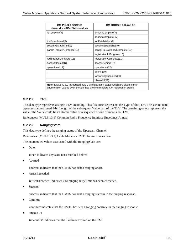
Cable Modem Operations Support System Interface Specification CM-SP-CM-OSSIv3.1-I02-141016
10/16/14 CableLabs 193
CM Pre-3.0 DOCSIS (from docsIfCmStatusValue)
CM DOCSIS 3.0 and 3.1
ipComplete(7) dhcpv4Complete(7)
dhcpv6Complete(17)
todEstablished(8) todEstablished(8)
securityEstablished(9) securityEstablished(9)
paramTransferComplete(10) configFileDownloadComplete(10)
registrationInProgress(18)
registrationComplete(11) registrationComplete(11)
accessDenied(13) accessDenied(13)
operational(12) operational(12)
bpiInit (19)
forwardingDisabled(20)
rfMuteAll(23)
Note: DOCSIS 3.0 introduced new CM registration states which are given higher enumeration values even though they are intermediate CM registration states.
G.2.2.2 Tlv8 This data type represents a single TLV encoding. This first octet represents the Type of the TLV. The second octet represents an unsigned 8-bit Length of the subsequent Value part of the TLV. The remaining octets represent the value. The Value could be an atomic value or a sequence of one or more sub-TLVs.
References: [MULPIv3.1] Common Radio Frequency Interface Encodings Annex.
G.2.2.3 RangingState This data type defines the ranging status of the Upstream Channel.
References: [MULPIv3.1] Cable Modem - CMTS Interaction section
The enumerated values associated with the RangingState are:
• Other 'other' indicates any state not described below.
• Aborted 'aborted' indicates that the CMTS has sent a ranging abort.
• retriesExceeded 'retriesExceeded' indicates CM ranging retry limit has been exceeded.
• Success 'success' indicates that the CMTS has sent a ranging success in the ranging response.
• Continue 'continue' indicates that the CMTS has sent a ranging continue in the ranging response.
• timeoutT4 'timeoutT4' indicates that the T4 timer expired on the CM.
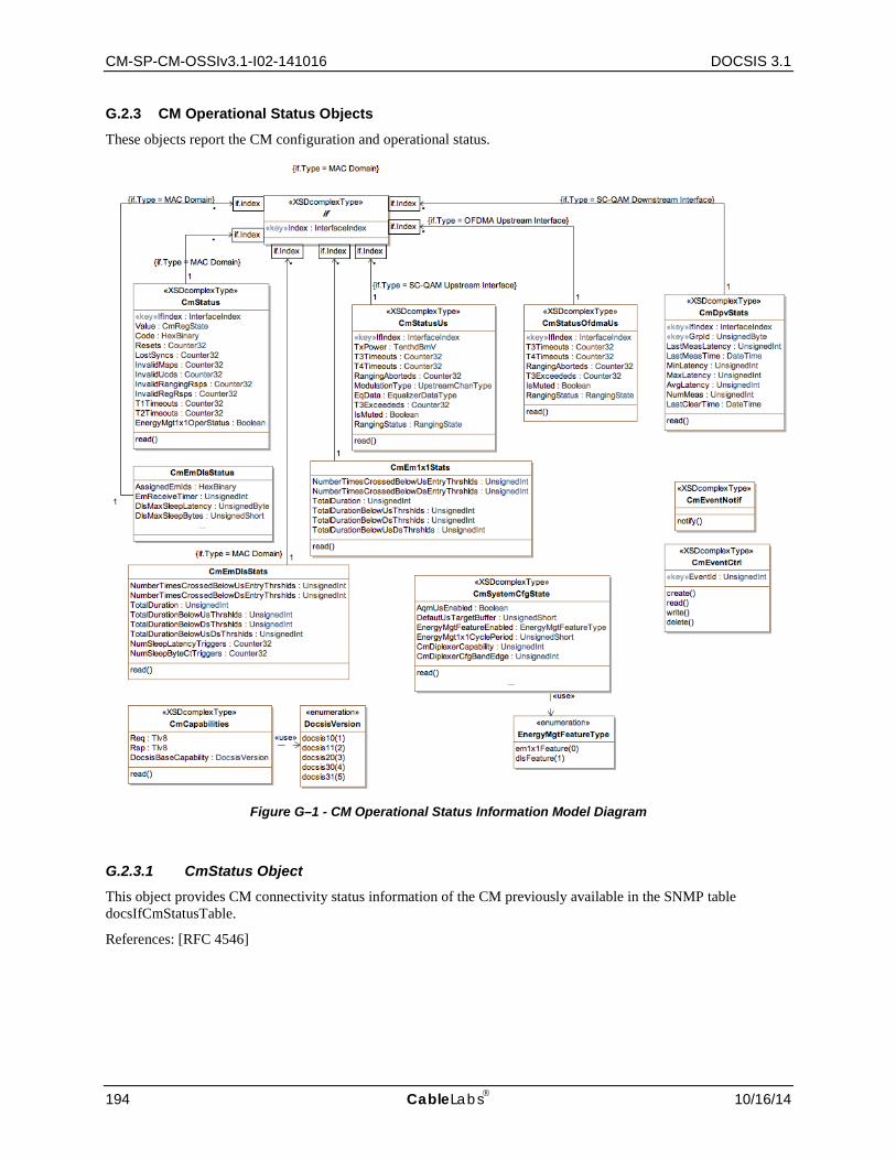
CM-SP-CM-OSSIv3.1-I02-141016 DOCSIS 3.1
194 CableLabs 10/16/14
G.2.3 CM Operational Status Objects
These objects report the CM configuration and operational status.
Figure G–1 - CM Operational Status Information Model Diagram
G.2.3.1 CmStatus Object This object provides CM connectivity status information of the CM previously available in the SNMP table docsIfCmStatusTable.
References: [RFC 4546]
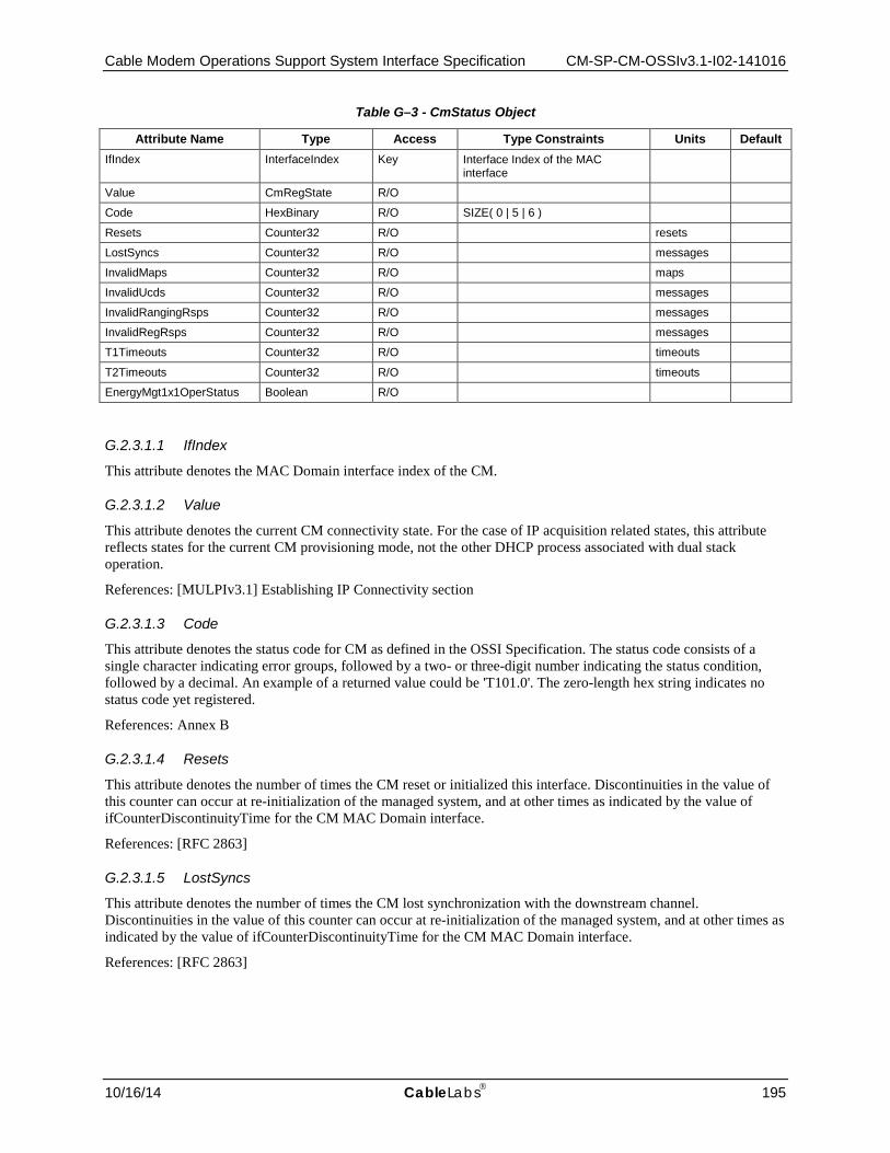
Cable Modem Operations Support System Interface Specification CM-SP-CM-OSSIv3.1-I02-141016
10/16/14 CableLabs 195
Table G–3 - CmStatus Object
Attribute Name Type Access Type Constraints Units Default IfIndex InterfaceIndex Key Interface Index of the MAC
interface
Value CmRegState R/O
Code HexBinary R/O SIZE( 0 | 5 | 6 )
Resets Counter32 R/O resets
LostSyncs Counter32 R/O messages
InvalidMaps Counter32 R/O maps
InvalidUcds Counter32 R/O messages
InvalidRangingRsps Counter32 R/O messages
InvalidRegRsps Counter32 R/O messages
T1Timeouts Counter32 R/O timeouts
T2Timeouts Counter32 R/O timeouts
EnergyMgt1x1OperStatus Boolean R/O
G.2.3.1.1 IfIndex
This attribute denotes the MAC Domain interface index of the CM.
G.2.3.1.2 Value
This attribute denotes the current CM connectivity state. For the case of IP acquisition related states, this attribute reflects states for the current CM provisioning mode, not the other DHCP process associated with dual stack operation.
References: [MULPIv3.1] Establishing IP Connectivity section
G.2.3.1.3 Code
This attribute denotes the status code for CM as defined in the OSSI Specification. The status code consists of a single character indicating error groups, followed by a two- or three-digit number indicating the status condition, followed by a decimal. An example of a returned value could be 'T101.0'. The zero-length hex string indicates no status code yet registered.
References: Annex B
G.2.3.1.4 Resets
This attribute denotes the number of times the CM reset or initialized this interface. Discontinuities in the value of this counter can occur at re-initialization of the managed system, and at other times as indicated by the value of ifCounterDiscontinuityTime for the CM MAC Domain interface.
References: [RFC 2863]
G.2.3.1.5 LostSyncs
This attribute denotes the number of times the CM lost synchronization with the downstream channel. Discontinuities in the value of this counter can occur at re-initialization of the managed system, and at other times as indicated by the value of ifCounterDiscontinuityTime for the CM MAC Domain interface.
References: [RFC 2863]

CM-SP-CM-OSSIv3.1-I02-141016 DOCSIS 3.1
196 CableLabs 10/16/14
G.2.3.1.6 InvalidMaps
This attribute denotes the number of times the CM received invalid MAP messages. Discontinuities in the value of this counter can occur at re-initialization of the managed system, and at other times as indicated by the value of ifCounterDiscontinuityTime for the CM MAC Domain interface.
References: [RFC 2863]
G.2.3.1.7 InvalidUcds
This attribute denotes the number of times the CM received invalid UCD messages. Discontinuities in the value of this counter can occur at re-initialization of the managed system, and at other times as indicated by the value of ifCounterDiscontinuityTime for the CM MAC Domain interface.
References: [RFC 2863]
G.2.3.1.8 InvalidRangingRsps
This attribute denotes the number of times the CM received invalid ranging response messages. Discontinuities in the value of this counter can occur at re-initialization of the managed system, and at other times as indicated by the value of ifCounterDiscontinuityTime for the CM MAC Domain interface.
References: [RFC 2863]
G.2.3.1.9 InvalidRegRsps
This attribute denotes the number of times the CM received invalid registration response messages. Discontinuities in the value of this counter can occur at re-initialization of the managed system, and at other times as indicated by the value of ifCounterDiscontinuityTime for the CM MAC Domain interface.
G.2.3.1.10 T1Timeouts
This attribute denotes the number of times counter T1 expired in the CM. Discontinuities in the value of this counter can occur at re-initialization of the managed system, and at other times as indicated by the value of ifCounterDiscontinuityTime for the CM MAC Domain interface.
References: [RFC 2863]
G.2.3.1.11 T2Timeouts
This attribute denotes the number of times counter T2 expired in the CM. Discontinuities in the value of this counter can occur at re-initialization of the managed system, and at other times as indicated by the value of ifCounterDiscontinuityTime for the CM MAC Domain interface.
References: [RFC 2863]
G.2.3.1.12 EnergyMgt1x1OperStatus
This attribute indicates whether the CM is currently operating in Energy Management 1x1 Mode.2 If this attribute returns true, the CM is operating in Energy Management 1x1 Mode.
References: [MULPIv3.1] Energy Management Mode Indicator section.
G.2.3.2 CmStatusUs Object This object defines PHY and MAC information about the CM's SC-QAM upstream channels. This object provides per-CM Upstream channel information previously available in the SNMP table docsIfCmStatusTable.
2 Note: the object model does not define a CM-resident object for DOCSIS Light Sleep (DLS) Energy Management Mode because the act of querying any such object would result in the CM leaving DLS Mode. For CM-resident information on DLS Energy Management mode utilize the CmEmDlsStats object.

Cable Modem Operations Support System Interface Specification CM-SP-CM-OSSIv3.1-I02-141016
10/16/14 CableLabs 197
Table G–4 - CmStatusUs Object
Attribute Name Type Access Type Constraints Units Default IfIndex InterfaceIndex Key Interface Index of upstream interface
TxPower TenthdBmV R/O TenthdBmV
T3Timeouts Counter32 R/O timeouts
T4Timeouts Counter32 R/O timeouts
RangingAborteds Counter32 R/O attempts
ModulationType DocsisUpstreamType R/O
EqData DocsEqualizerData R/O
T3Exceededs Counter32 R/O timeouts
IsMuted Boolean R/O
RangingStatus RangingState R/O
G.2.3.2.1 IfIndex
This attribute denotes the interface index of the upstream interface to which this instance applies.
G.2.3.2.2 TxPower
This attribute denotes the operational CM transmit power for this upstream channel.
G.2.3.2.3 T3Timeouts
This attribute denotes the number of times counter T3 expired in the CM for this upstream channel. Discontinuities in the value of this counter can occur at re-initialization of the managed system, and at other times as indicated by the value of ifCounterDiscontinuityTime for the associated upstream channel.
References: [RFC 2863]
G.2.3.2.4 T4Timeouts
This attribute denotes the number of times counter T4 expired in the CM for this upstream channel. Discontinuities in the value of this counter can occur at re-initialization of the managed system, and at other times as indicated by the value of ifCounterDiscontinuityTime for the associated upstream channel.
References: [RFC 2863]
G.2.3.2.5 RangingAborteds
This attribute denotes the number of times the ranging process was aborted by the CMTS. Discontinuities in the value of this counter can occur at re-initialization of the managed system, and at other times as indicated by the value of ifCounterDiscontinuityTime for the associated upstream channel.
References: [RFC 2863]
G.2.3.2.6 ModulationType
This attribute denotes the modulation type status currently used by the CM for this upstream channel. Since this object specifically identifies PHY Layer mode, the shared upstream channel type 'tdmaAndAtdma' is not permitted.
References: [RFC 2863]
G.2.3.2.7 EqData
This attribute denotes the pre-equalization data for the specified upstream channel on this CM after convolution with data indicated in the RNG-RSP. This data is valid when docsIfUpChannelPreEqEnable is set to 'true'.
References: [RFC 4546]

CM-SP-CM-OSSIv3.1-I02-141016 DOCSIS 3.1
198 CableLabs 10/16/14
G.2.3.2.8 T3Exceededs
This attribute denotes the number of times for excessive T3 timeouts. Discontinuities in the value of this counter can occur at re-initialization of the managed system, and at other times as indicated by the value of ifCounterDiscontinuityTime for the associated upstream channel.
References: [RFC 2863]
G.2.3.2.9 IsMuted
This attribute denotes whether the upstream channel is muted.
References: [MULPIv3.1] Media Access Control Specification section
G.2.3.2.10 RangingStatus
This attribute denotes ranging status of this upstream channel.
References: [MULPIv3.1] Media Access Control Specification section
G.2.3.3 CmStatusOfdmaUs Object This object defines PHY and MAC information about the CM's OFDMA upstream channels. This object provides per-CM Upstream channel information previously available in the SNMP table docsIfCmStatusTable.
Table G–5 - CmStatusUs Object
Attribute Name Type Access Type Constraints Units Default IfIndex InterfaceIndex Key Interface Index of upstream interface
T3Timeouts Counter32 R/O timeouts
T4Timeouts Counter32 R/O timeouts
RangingAborteds Counter32 R/O attempts
T3Exceededs Counter32 R/O timeouts
IsMuted Boolean R/O
RangingStatus RangingState R/O
G.2.3.3.1 IfIndex
This attribute denotes the interface index of the upstream interface to which this instance applies.
G.2.3.3.2 T3Timeouts
This attribute denotes the number of times counter T3 expired in the CM for this upstream channel. Discontinuities in the value of this counter can occur at re-initialization of the managed system, and at other times as indicated by the value of ifCounterDiscontinuityTime for the associated upstream channel.
References: [RFC 2863]
G.2.3.3.3 T4Timeouts
This attribute denotes the number of times counter T4 expired in the CM for this upstream channel. Discontinuities in the value of this counter can occur at re-initialization of the managed system, and at other times as indicated by the value of ifCounterDiscontinuityTime for the associated upstream channel.
References: [RFC 2863]

Cable Modem Operations Support System Interface Specification CM-SP-CM-OSSIv3.1-I02-141016
10/16/14 CableLabs 199
G.2.3.3.4 RangingAborteds
This attribute denotes the number of times the ranging process was aborted by the CMTS. Discontinuities in the value of this counter can occur at re-initialization of the managed system, and at other times as indicated by the value of ifCounterDiscontinuityTime for the associated upstream channel.
References: [RFC 2863]
G.2.3.3.5 T3Exceededs
This attribute denotes the number of times for excessive T3 timeouts. Discontinuities in the value of this counter can occur at re-initialization of the managed system, and at other times as indicated by the value of ifCounterDiscontinuityTime for the associated upstream channel.
References: [RFC 2863]
G.2.3.3.6 IsMuted
This attribute denotes whether the upstream channel is muted.
References: [MULPIv3.1] Media Access Control Specification section
G.2.3.3.7 RangingStatus
This attribute denotes ranging status of this upstream channel.
References: [MULPIv3.1] Media Access Control Specification section
G.2.3.4 CmCapabilities Object This object defines attributes of the CM capabilities.
Table G–6 - CmCapabilities Object
Attribute Name Type Access Type Constraints Units Default Req Tlv8 R/O
Rsp Tlv8 R/O
DocsisBaseCapability DocsisVersion R/O
G.2.3.4.1 Req
This attribute contains the TLV encoding for TLV-5 sent in a REG-REQ. The first byte of this encoding is expected to be '05'H.
References: [MULPIv3.1] Modem Capabilities Encoding section in the Common Radio Frequency Interface Encodings Annex
G.2.3.4.2 Rsp
This attribute contains the TLV encoding for TLV-5 (see the Modem Capabilities Encoding section in Common Radio Frequency Interface Encodings Annex of [MULPIv3.1]) received in a REG-RSP. The first byte of this encoding is expected to be '05'H.
References: [MULPIv3.1] Modem Capabilities Encoding section in the Common Radio Frequency Interface Encodings Annex
G.2.3.4.3 DocsisBaseCapability
This attribute indicates the DOCSIS capability of the device.
Reference: [RFC 4546]
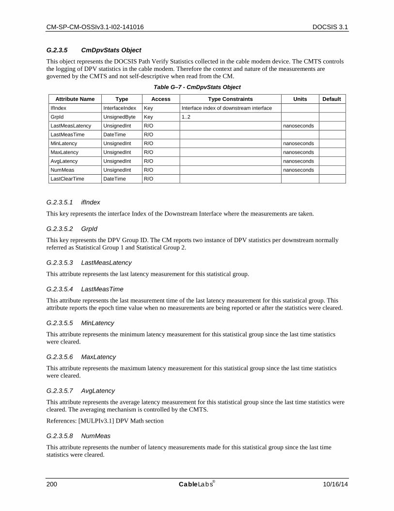
CM-SP-CM-OSSIv3.1-I02-141016 DOCSIS 3.1
200 CableLabs 10/16/14
G.2.3.5 CmDpvStats Object This object represents the DOCSIS Path Verify Statistics collected in the cable modem device. The CMTS controls the logging of DPV statistics in the cable modem. Therefore the context and nature of the measurements are governed by the CMTS and not self-descriptive when read from the CM.
Table G–7 - CmDpvStats Object
Attribute Name Type Access Type Constraints Units Default IfIndex InterfaceIndex Key Interface index of downstream interface
GrpId UnsignedByte Key 1..2
LastMeasLatency UnsignedInt R/O nanoseconds
LastMeasTime DateTime R/O
MinLatency UnsignedInt R/O nanoseconds
MaxLatency UnsignedInt R/O nanoseconds
AvgLatency UnsignedInt R/O nanoseconds
NumMeas UnsignedInt R/O nanoseconds
LastClearTime DateTime R/O
G.2.3.5.1 ifIndex
This key represents the interface Index of the Downstream Interface where the measurements are taken.
G.2.3.5.2 GrpId
This key represents the DPV Group ID. The CM reports two instance of DPV statistics per downstream normally referred as Statistical Group 1 and Statistical Group 2.
G.2.3.5.3 LastMeasLatency
This attribute represents the last latency measurement for this statistical group.
G.2.3.5.4 LastMeasTime
This attribute represents the last measurement time of the last latency measurement for this statistical group. This attribute reports the epoch time value when no measurements are being reported or after the statistics were cleared.
G.2.3.5.5 MinLatency
This attribute represents the minimum latency measurement for this statistical group since the last time statistics were cleared.
G.2.3.5.6 MaxLatency
This attribute represents the maximum latency measurement for this statistical group since the last time statistics were cleared.
G.2.3.5.7 AvgLatency
This attribute represents the average latency measurement for this statistical group since the last time statistics were cleared. The averaging mechanism is controlled by the CMTS.
References: [MULPIv3.1] DPV Math section
G.2.3.5.8 NumMeas
This attribute represents the number of latency measurements made for this statistical group since the last time statistics were cleared.
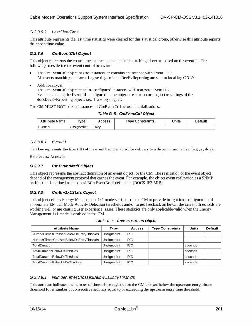
Cable Modem Operations Support System Interface Specification CM-SP-CM-OSSIv3.1-I02-141016
10/16/14 CableLabs 201
G.2.3.5.9 LastClearTime
This attribute represents the last time statistics were cleared for this statistical group, otherwise this attribute reports the epoch time value.
G.2.3.6 CmEventCtrl Object This object represents the control mechanism to enable the dispatching of events based on the event Id. The following rules define the event control behavior:
• The CmEventCtrl object has no instances or contains an instance with Event ID 0. All events matching the Local Log settings of docsDevEvReporting are sent to local log ONLY.
• Additionally, if The CmEventCtrl object contains configured instances with non-zero Event IDs. Events matching the Event Ids configured in the object are sent according to the settings of the docsDevEvReporting object; i.e., Traps, Syslog, etc.
The CM MUST NOT persist instances of CmEventCtrl across reinitializations.
Table G–8 - CmEventCtrl Object
Attribute Name Type Access Type Constraints Units Default EventId UnsignedInt Key
G.2.3.6.1 EventId
This key represents the Event ID of the event being enabled for delivery to a dispatch mechanism (e.g., syslog).
References: Annex B
G.2.3.7 CmEventNotif Object This object represents the abstract definition of an event object for the CM. The realization of the event object depend of the management protocol that carries the event. For example, the object event realization as a SNMP notification is defined as the docsIf3CmEventNotif defined in [DOCS-IF3-MIB].
G.2.3.8 CmEm1x1Stats Object This object defines Energy Management 1x1 mode statistics on the CM to provide insight into configuration of appropriate EM 1x1 Mode Activity Detection thresholds and/or to get feedback on how/if the current thresholds are working well or are causing user experience issues. These statistics are only applicable/valid when the Energy Management 1x1 mode is enabled in the CM.
Table G–9 - CmEm1x1Stats Object
Attribute Name Type Access Type Constraints Units Default NumberTimesCrossedBelowUsEntryThrshlds UnsignedInt R/O
NumberTimesCrossedBelowDsEntryThrshlds UnsignedInt R/O
TotalDuration UnsignedInt R/O seconds
TotalDurationBelowUsThrshlds UnsignedInt R/O seconds
TotalDurationBelowDsThrshlds UnsignedInt R/O seconds
TotalDurationBelowUsDsThrshlds UnsignedInt R/O seconds
G.2.3.8.1 NumberTimesCrossedBelowUsEntryThrshlds
This attribute indicates the number of times since registration the CM crossed below the upstream entry bitrate threshold for a number of consecutive seconds equal to or exceeding the upstream entry time threshold.

CM-SP-CM-OSSIv3.1-I02-141016 DOCSIS 3.1
202 CableLabs 10/16/14
G.2.3.8.2 NumberTimesCrossedBelowDsEntryThrshlds
This attribute indicates the number of times since registration the CM crossed below the downstream entry bitrate threshold for a number of consecutive seconds equal to or exceeding the downstream entry time threshold.
G.2.3.8.3 TotalDuration
This attribute indicates the total time duration, in seconds since registration, the CM has been in Energy Management 1x1 mode, as controlled by the DBC-REQ Energy Management 1x1 Mode Indicator TLV. This attribute differs from TotalDurationBelowUsDsThrshlds because it is dependent on effects of the Energy Management Cycle Period, and processing of EM-REQ/EM-RSP messages and DBC messages that specifically indicate entry into or exit from Energy Management 1x1 mode.
G.2.3.8.4 TotalDurationBelowUsThrshlds
This attribute indicates the total time duration, in seconds since registration, the CM satisfied upstream conditions for entry into or remaining in Energy Management 1x1 mode.
G.2.3.8.5 TotalDurationBelowDsThrshlds
This attribute indicates the total time duration, in seconds since registration, the CM satisfied downstream conditions for entry into or remaining in Energy Management 1x1 mode.
G.2.3.8.6 TotalDurationBelowUsDsThrshlds
This attribute indicates the total time duration, in seconds since registration, the CM, with respect to both upstream and downstream entry and exit thresholds, satisfied conditions for entry into and remaining in Energy Management 1x1 mode. This attribute differs from TotalDuration because it is not dependent on effects of the Energy Management Cycle Period or processing of EM-REQ/EM-RSP messages and DBC messages that specifically indicate entry into or exit from Energy Management 1x1 mode.
G.2.3.9 CmEmDlsStats Object This object defines the DLS Energy Management mode statistics on the CM to provide insight into configuration of appropriate DLS EM Mode Activity Detection thresholds and/or to get feedback on how/if the current thresholds are working well or are causing user experience issues. These statistics are only applicable/valid when the DLS Energy Management mode is enabled in the CM.
Table G–10 - CmEmDlsStats Object
Attribute Name Type Access Type Constraints Units Default NumberTimesCrossedBelowUsEntryThrshlds UnsignedInt R/O
NumberTimesCrossedBelowDsEntryThrshlds UnsignedInt R/O
TotalDuration UnsignedInt R/O seconds
TotalDurationBelowUsThrshlds UnsignedInt R/O seconds
TotalDurationBelowDsThrshlds UnsignedInt R/O seconds
TotalDurationBelowUsDsThrshlds UnsignedInt R/O seconds
NumSleepLatencyTriggers Counter32 R/O
NumSleepByteCtTriggers Counter32 R/O
G.2.3.9.1 NumberTimesCrossedBelowUsEntryThrshlds
This attribute indicates the number of times since registration the CM crossed below the upstream entry bitrate threshold for a number of consecutive seconds equal to or exceeding the upstream entry time threshold.

Cable Modem Operations Support System Interface Specification CM-SP-CM-OSSIv3.1-I02-141016
10/16/14 CableLabs 203
G.2.3.9.2 NumberTimesCrossedBelowDsEntryThrshlds
This attribute indicates the number of times since registration the CM crossed below the downstream entry bitrate threshold for a number of consecutive seconds equal to or exceeding the downstream entry time threshold.
G.2.3.9.3 TotalDuration
This attribute indicates the total time duration, in seconds since registration, the CM has been in DLS Energy Management mode, as controlled by the DBC-REQ Energy Management Mode Indicator TLV. This attribute differs from TotalDurationBelowUsDsThrshlds because it is dependent on effects of the Energy Management Cycle Period, and processing of EM-REQ/EM-RSP messages and DBC messages that specifically indicate entry into or exit from DLS Energy Management mode.
G.2.3.9.4 TotalDurationBelowUsThrshlds
This attribute indicates the total time duration, in seconds since registration, the CM satisfied upstream conditions for entry into or remaining in DLS Energy Management mode.
G.2.3.9.5 TotalDurationBelowDsThrshlds
This attribute indicates the total time duration, in seconds since registration, the CM satisfied downstream conditions for entry into or remaining in DLS Energy Management mode.
G.2.3.9.6 TotalDurationBelowUsDsThrshlds
This attribute indicates the total time duration, in seconds since registration, the CM, with respect to both upstream and downstream entry and exit thresholds, satisfied conditions for entry into and remaining in DLS Energy Management mode. This attribute differs from TotalDuration because it is not dependent on effects of the Energy Management Cycle Period or processing of EM-REQ/EM-RSP messages and DBC messages that specifically indicate entry into or exit from DLS Energy Management mode.
G.2.3.9.7 NumSleepLatencyTriggers
This attribute indicates the number of times since registration the CM transitioned to the DLS wake state due to the DLS Maximum Sleep Latency being exceeded.
G.2.3.9.8 NumSleepByteCtTriggers
This attribute indicates the number of times since registration the CM transitioned to the DLS wake state due to the DLS Maximum Byte Count being exceeded.
G.2.3.10 CmEmDlsStatus Object This object defines the DLS Energy Management mode status on the CM to provide insight into the current configuration of DLS Mode. This information is only applicable/valid when the DLS Energy Management mode is enabled on the CM.
Table G–11 - CmEmDlsStatus Object
Attribute Name Type Access Type Constraints Units Default AssignedEmIds HexBinary R/O SIZE (2 | 4 | 6)
DlsReceiveTimer PlcFrameInterval(1 byte) R/O 0..2 PlcFrame 0
DlsMaxSleepLatency UnsignedByte R/O 1..255 msec 100
DlsMaxSleepBytes UnsignedShort R/O 1..65535 bytes 1Kbytes

CM-SP-CM-OSSIv3.1-I02-141016 DOCSIS 3.1
204 CableLabs 10/16/14
G.2.3.10.1 AssignedEmIds
This attribute reports the set of CMTS-assigned EM-IDs for this cable modem. This attribute is encoded as an array 16-bit binary values with up to 3 elements. The broadcast EM-ID is not included in the list. This is generally displayed as a comma-delimited list of EM-IDS such as: DF13,ABAB,0002.
References: [MULPIv3.1] DOCSIS Light Sleep Feature section.
G.2.3.10.2 DlsReceiveTimer
This attribute specifies how long the CM is required to continue listening on the downstream for traffic, after reception of the EMM with Sleep Time with a non-zero value. The CMTS communicates the EM Receive Timer to the CM during registration or in DBC message.
G.2.3.10.3 DlsMaxSleepLatency
This attribute specifies the amount of time the CM would allow an upstream channel to queue the packets without transitioning to DLS wake state.
G.2.3.10.4 DlsMaxSleepBytes
This attribute specifies the maximum number of bytes a CM would allow an upstream service flow to enqueue without transitioning to DLS wake state.
G.2.3.11 CmSystemCfgState Object This object defines configuration state at the global or system wide level for the CM.
Table G–12 - CmSystemCfgState Object
Attribute Name Type Access Type Constraints Units Default AqmUsEnabled Boolean R/O
DefaultUsTargetBuffer UnsignedShort R/O msec
EnergyMgtFeatureEnabled EnumBits R/O em1x1Feature(0) dls(1)
EnergyMgt1x1CyclePeriod UnsignedShort R/O seconds 900
CmDiplexerCapability UnsignedInt R/O
CmDiplexerCfgBandEdge UnsignedInt R/O
G.2.3.11.1 AqmUsEnabled
If this attribute is set to 'false', the CM disables Active Queue Management (AQM) on all upstream service flows.
G.2.3.11.2 DefaultUsTargetBuffer
This attribute specifies the default upstream service flow target buffer size, in milliseconds, when not specified otherwise in service flow TLV encodings.
References: [MULPIv3.1] Default Upstream Target Buffer Configuration Annex
G.2.3.11.3 EnergyMgtFeatureEnabled
This attribute indicates which energy savings features have been enabled in the Cable Modem. The CM enables use of Energy Management Features only if both the Energy Management Feature Control TLV and Energy Management Modem Capability Response from the CMTS indicate that the feature is enabled. If bit 0 is set, the Energy Management 1x1 Mode feature is enabled. If bit 1 is set, the DOCSIS Light Sleep Mode feature is enabled.
References: [MULPIv3.1] Energy Management Feature Control section

Cable Modem Operations Support System Interface Specification CM-SP-CM-OSSIv3.1-I02-141016
10/16/14 CableLabs 205
G.2.3.11.4 EnergyMgt1x1CyclePeriod
This attribute specifies a minimum time period (in seconds) that must elapse between EM-REQ transactions in certain situations:
• In the case of Energy Management 1x1 Mode, this attribute sets the minimum cycle time that a CM will use for sending requests to enter Energy Management 1x1 Mode.
• In the case that the CM fails to receive an EM-RSP message after the maximum number of retries, this attribute sets the minimum amount of time to elapse before the CM can attempt another EM-REQ transaction.
References: [MULPIv3.1] Energy Management Cycle Period section
G.2.3.11.5 CmDiplexerCapability
This attribute specifies the maximum diplexer upper band edge supported by the CM device. This corresponds to the maximum capability of the CM device itself, independent of its current configuration.
References: [PHYv3.1] Upstream CM Spectrum section
G.2.3.11.6 CmDiplexerCfgBandEdge
This attribute specifies the current configured value for the upper band edge of the diplexer in the CM device. This corresponds to the Diplexer Upper Band Edge Support reported by the CM in its REG-REQ.
References: [MULPIv3.1] Diplexer Upper Band Edge Support section
G.2.3.12 CmService Object This object is only applicable in the DOCSIS 1.0 CoS mode and is therefore deprecated for DOCSIS 3.1.
G.2.3.13 QosProfile Object This object is only applicable in the DOCSIS 1.0 CoS mode and is therefore deprecated for DOCSIS 3.1.
G.2.3.14 (Pre-3.0 DOCSIS) CmStatus Object This object has been reconstituted as CmStatus and CmStatusUs in DOCSIS 3.0 and is only applicable in the Pre-3.0 DOCSIS versions and is therefore deprecated.
G.3 CM Downstream and Upstream Interfaces Information Models
G.3.1 DS US Common Data Type Definitions Table G–13 - CM Downstream Parameter Data Types
Data Type Name Base Type Permitted Values
SubcarrierSpacingType UnsignedByte (25 | 50)
SubcarrierUsageType Enum other(1) dynamic(2) plc(3) continuous_pilot(4) excluded(5) reserved(6)
CM-SP-CM-OSSIv3.1-I02-141016 DOCSIS 3.1
206 CableLabs 10/16/14
G.3.1.1 SubcarrierSpacingType This data type defines the subcarrier spacing for the FFT mode in use. For downstream OFDM channels, if the FFT mode is 4K mode, then spacing is 50 kHz; if it is 8K mode, then the spacing is 25 kHz. These values of subcarrier spacing (for downstream OFDM channels) are defined in the Downstream OFDM Parameters table in [PHYv3.1]. For upstream OFDMA channels, if the FFT mode is 2K mode, then the spacing is 50kHz; if the mode is 4K mode, then the spacing is 25kHz. These values of subcarrier spacing (for upstream OFDMA channels) are defined in the Upstream OFDMA Parameters table in [PHYv3.1].
G.3.1.2 SubcarrierUsageType This data type is defined to specify the usage types of the subcarriers. This type is used to identify whether a subcarrier is used as a dynamic (e.g., data, unused, scattered pilot), plc, continuous pilot subcarrier or is an excluded or reserved (i.e., outside the encompassed spectrum) subcarrier.
G.3.2 CM Downstream Interface Information Model
G.3.2.1 Overview This section defines the configuration and status reporting requirements for the CM Downstream Interfaces. This information is contained in the [PHYv3.1] specification.
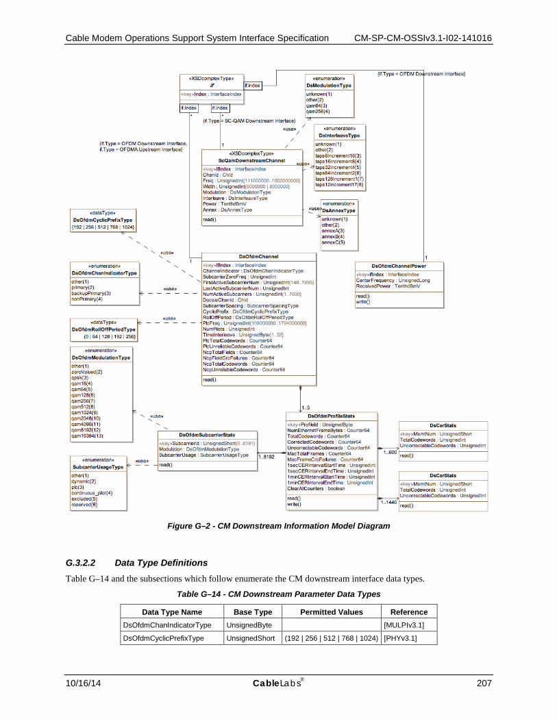
Cable Modem Operations Support System Interface Specification CM-SP-CM-OSSIv3.1-I02-141016
10/16/14 CableLabs 207
Figure G–2 - CM Downstream Information Model Diagram
G.3.2.2 Data Type Definitions Table G–14 and the subsections which follow enumerate the CM downstream interface data types.
Table G–14 - CM Downstream Parameter Data Types
Data Type Name Base Type Permitted Values Reference DsOfdmChanIndicatorType UnsignedByte [MULPIv3.1]
DsOfdmCyclicPrefixType UnsignedShort (192 | 256 | 512 | 768 | 1024) [PHYv3.1]
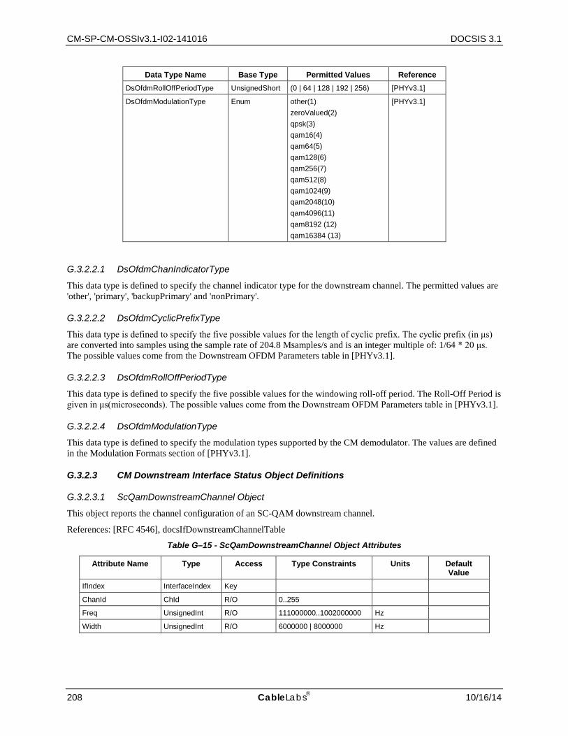
CM-SP-CM-OSSIv3.1-I02-141016 DOCSIS 3.1
208 CableLabs 10/16/14
Data Type Name Base Type Permitted Values Reference DsOfdmRollOffPeriodType UnsignedShort (0 | 64 | 128 | 192 | 256) [PHYv3.1]
DsOfdmModulationType Enum other(1) zeroValued(2) qpsk(3) qam16(4) qam64(5) qam128(6) qam256(7) qam512(8) qam1024(9) qam2048(10) qam4096(11) qam8192 (12) qam16384 (13)
[PHYv3.1]
G.3.2.2.1 DsOfdmChanIndicatorType
This data type is defined to specify the channel indicator type for the downstream channel. The permitted values are 'other', 'primary', 'backupPrimary' and 'nonPrimary'.
G.3.2.2.2 DsOfdmCyclicPrefixType
This data type is defined to specify the five possible values for the length of cyclic prefix. The cyclic prefix (in μs) are converted into samples using the sample rate of 204.8 Msamples/s and is an integer multiple of: 1/64 * 20 μs. The possible values come from the Downstream OFDM Parameters table in [PHYv3.1].
G.3.2.2.3 DsOfdmRollOffPeriodType
This data type is defined to specify the five possible values for the windowing roll-off period. The Roll-Off Period is given in μs(microseconds). The possible values come from the Downstream OFDM Parameters table in [PHYv3.1].
G.3.2.2.4 DsOfdmModulationType
This data type is defined to specify the modulation types supported by the CM demodulator. The values are defined in the Modulation Formats section of [PHYv3.1].
G.3.2.3 CM Downstream Interface Status Object Definitions
G.3.2.3.1 ScQamDownstreamChannel Object
This object reports the channel configuration of an SC-QAM downstream channel.
References: [RFC 4546], docsIfDownstreamChannelTable
Table G–15 - ScQamDownstreamChannel Object Attributes
Attribute Name Type Access Type Constraints Units Default Value
IfIndex InterfaceIndex Key
ChanId ChId R/O 0..255
Freq UnsignedInt R/O 111000000..1002000000 Hz
Width UnsignedInt R/O 6000000 | 8000000 Hz
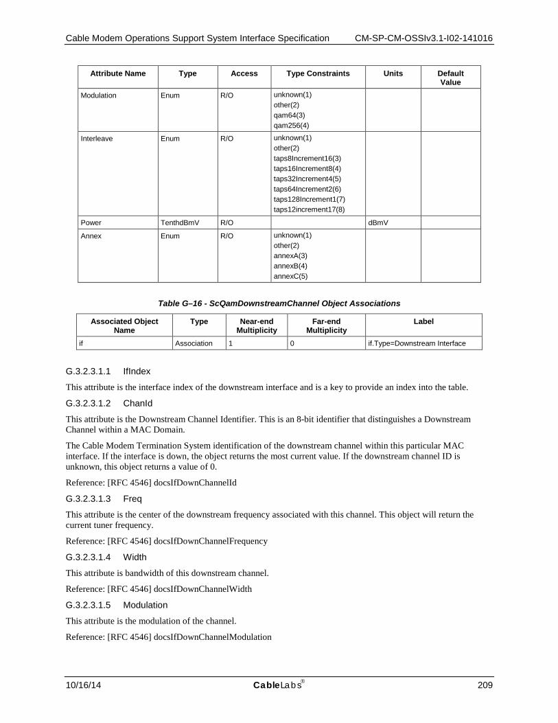
Cable Modem Operations Support System Interface Specification CM-SP-CM-OSSIv3.1-I02-141016
10/16/14 CableLabs 209
Attribute Name Type Access Type Constraints Units Default Value
Modulation Enum R/O unknown(1) other(2) qam64(3) qam256(4)
Interleave Enum R/O unknown(1) other(2) taps8Increment16(3) taps16Increment8(4) taps32Increment4(5) taps64Increment2(6) taps128Increment1(7) taps12increment17(8)
Power TenthdBmV R/O dBmV
Annex Enum R/O unknown(1) other(2) annexA(3) annexB(4) annexC(5)
Table G–16 - ScQamDownstreamChannel Object Associations
Associated Object Name
Type Near-end Multiplicity
Far-end Multiplicity
Label
if Association 1 0 if.Type=Downstream Interface
G.3.2.3.1.1 IfIndex
This attribute is the interface index of the downstream interface and is a key to provide an index into the table.
G.3.2.3.1.2 ChanId
This attribute is the Downstream Channel Identifier. This is an 8-bit identifier that distinguishes a Downstream Channel within a MAC Domain.
The Cable Modem Termination System identification of the downstream channel within this particular MAC interface. If the interface is down, the object returns the most current value. If the downstream channel ID is unknown, this object returns a value of 0.
Reference: [RFC 4546] docsIfDownChannelId
G.3.2.3.1.3 Freq
This attribute is the center of the downstream frequency associated with this channel. This object will return the current tuner frequency.
Reference: [RFC 4546] docsIfDownChannelFrequency
G.3.2.3.1.4 Width
This attribute is bandwidth of this downstream channel.
Reference: [RFC 4546] docsIfDownChannelWidth
G.3.2.3.1.5 Modulation
This attribute is the modulation of the channel.
Reference: [RFC 4546] docsIfDownChannelModulation
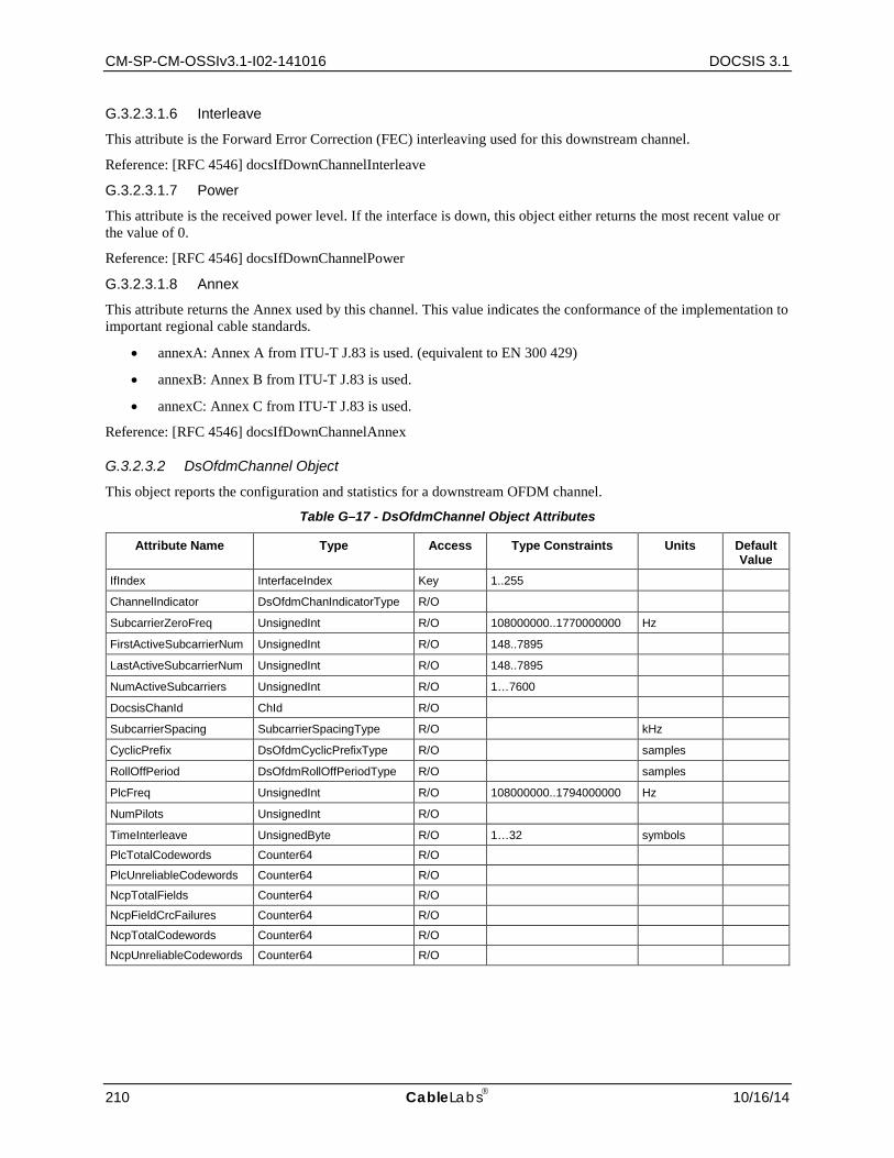
CM-SP-CM-OSSIv3.1-I02-141016 DOCSIS 3.1
210 CableLabs 10/16/14
G.3.2.3.1.6 Interleave
This attribute is the Forward Error Correction (FEC) interleaving used for this downstream channel.
Reference: [RFC 4546] docsIfDownChannelInterleave
G.3.2.3.1.7 Power
This attribute is the received power level. If the interface is down, this object either returns the most recent value or the value of 0.
Reference: [RFC 4546] docsIfDownChannelPower
G.3.2.3.1.8 Annex
This attribute returns the Annex used by this channel. This value indicates the conformance of the implementation to important regional cable standards.
• annexA: Annex A from ITU-T J.83 is used. (equivalent to EN 300 429)
• annexB: Annex B from ITU-T J.83 is used.
• annexC: Annex C from ITU-T J.83 is used.
Reference: [RFC 4546] docsIfDownChannelAnnex
G.3.2.3.2 DsOfdmChannel Object
This object reports the configuration and statistics for a downstream OFDM channel.
Table G–17 - DsOfdmChannel Object Attributes
Attribute Name Type Access Type Constraints Units Default Value
IfIndex InterfaceIndex Key 1..255
ChannelIndicator DsOfdmChanIndicatorType R/O
SubcarrierZeroFreq UnsignedInt R/O 108000000..1770000000 Hz
FirstActiveSubcarrierNum UnsignedInt R/O 148..7895
LastActiveSubcarrierNum UnsignedInt R/O 148..7895
NumActiveSubcarriers UnsignedInt R/O 1…7600
DocsisChanId ChId R/O
SubcarrierSpacing SubcarrierSpacingType R/O kHz
CyclicPrefix DsOfdmCyclicPrefixType R/O samples
RollOffPeriod DsOfdmRollOffPeriodType R/O samples
PlcFreq UnsignedInt R/O 108000000..1794000000 Hz
NumPilots UnsignedInt R/O
TimeInterleave UnsignedByte R/O 1…32 symbols
PlcTotalCodewords Counter64 R/O
PlcUnreliableCodewords Counter64 R/O
NcpTotalFields Counter64 R/O
NcpFieldCrcFailures Counter64 R/O
NcpTotalCodewords Counter64 R/O
NcpUnreliableCodewords Counter64 R/O
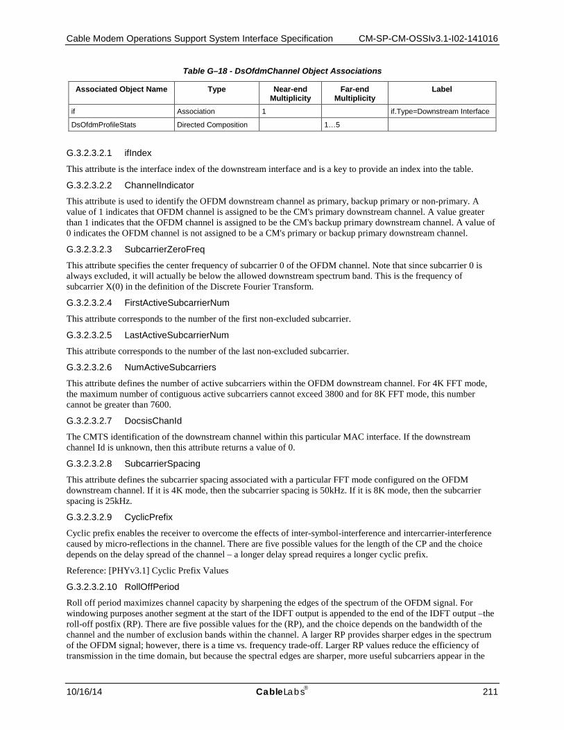
Cable Modem Operations Support System Interface Specification CM-SP-CM-OSSIv3.1-I02-141016
10/16/14 CableLabs 211
Table G–18 - DsOfdmChannel Object Associations
Associated Object Name Type Near-end Multiplicity
Far-end Multiplicity
Label
if Association 1 if.Type=Downstream Interface
DsOfdmProfileStats Directed Composition 1…5
G.3.2.3.2.1 ifIndex
This attribute is the interface index of the downstream interface and is a key to provide an index into the table.
G.3.2.3.2.2 ChannelIndicator
This attribute is used to identify the OFDM downstream channel as primary, backup primary or non-primary. A value of 1 indicates that OFDM channel is assigned to be the CM's primary downstream channel. A value greater than 1 indicates that the OFDM channel is assigned to be the CM's backup primary downstream channel. A value of 0 indicates the OFDM channel is not assigned to be a CM's primary or backup primary downstream channel.
G.3.2.3.2.3 SubcarrierZeroFreq
This attribute specifies the center frequency of subcarrier 0 of the OFDM channel. Note that since subcarrier 0 is always excluded, it will actually be below the allowed downstream spectrum band. This is the frequency of subcarrier X(0) in the definition of the Discrete Fourier Transform.
G.3.2.3.2.4 FirstActiveSubcarrierNum
This attribute corresponds to the number of the first non-excluded subcarrier.
G.3.2.3.2.5 LastActiveSubcarrierNum
This attribute corresponds to the number of the last non-excluded subcarrier.
G.3.2.3.2.6 NumActiveSubcarriers
This attribute defines the number of active subcarriers within the OFDM downstream channel. For 4K FFT mode, the maximum number of contiguous active subcarriers cannot exceed 3800 and for 8K FFT mode, this number cannot be greater than 7600.
G.3.2.3.2.7 DocsisChanId
The CMTS identification of the downstream channel within this particular MAC interface. If the downstream channel Id is unknown, then this attribute returns a value of 0.
G.3.2.3.2.8 SubcarrierSpacing
This attribute defines the subcarrier spacing associated with a particular FFT mode configured on the OFDM downstream channel. If it is 4K mode, then the subcarrier spacing is 50kHz. If it is 8K mode, then the subcarrier spacing is 25kHz.
G.3.2.3.2.9 CyclicPrefix
Cyclic prefix enables the receiver to overcome the effects of inter-symbol-interference and intercarrier-interference caused by micro-reflections in the channel. There are five possible values for the length of the CP and the choice depends on the delay spread of the channel – a longer delay spread requires a longer cyclic prefix.
Reference: [PHYv3.1] Cyclic Prefix Values
G.3.2.3.2.10 RollOffPeriod
Roll off period maximizes channel capacity by sharpening the edges of the spectrum of the OFDM signal. For windowing purposes another segment at the start of the IDFT output is appended to the end of the IDFT output –the roll-off postfix (RP). There are five possible values for the (RP), and the choice depends on the bandwidth of the channel and the number of exclusion bands within the channel. A larger RP provides sharper edges in the spectrum of the OFDM signal; however, there is a time vs. frequency trade-off. Larger RP values reduce the efficiency of transmission in the time domain, but because the spectral edges are sharper, more useful subcarriers appear in the
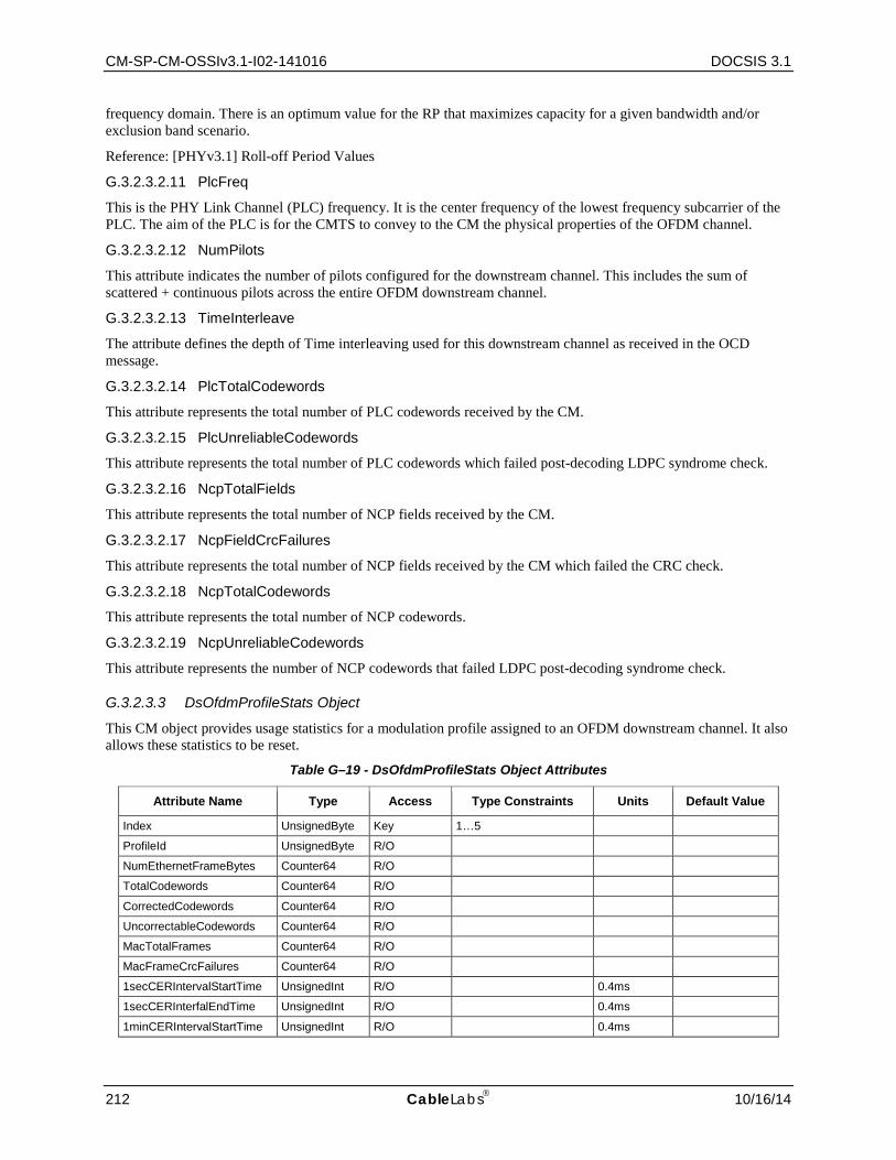
CM-SP-CM-OSSIv3.1-I02-141016 DOCSIS 3.1
212 CableLabs 10/16/14
frequency domain. There is an optimum value for the RP that maximizes capacity for a given bandwidth and/or exclusion band scenario.
Reference: [PHYv3.1] Roll-off Period Values
G.3.2.3.2.11 PlcFreq
This is the PHY Link Channel (PLC) frequency. It is the center frequency of the lowest frequency subcarrier of the PLC. The aim of the PLC is for the CMTS to convey to the CM the physical properties of the OFDM channel.
G.3.2.3.2.12 NumPilots
This attribute indicates the number of pilots configured for the downstream channel. This includes the sum of scattered + continuous pilots across the entire OFDM downstream channel.
G.3.2.3.2.13 TimeInterleave
The attribute defines the depth of Time interleaving used for this downstream channel as received in the OCD message.
G.3.2.3.2.14 PlcTotalCodewords
This attribute represents the total number of PLC codewords received by the CM.
G.3.2.3.2.15 PlcUnreliableCodewords
This attribute represents the total number of PLC codewords which failed post-decoding LDPC syndrome check.
G.3.2.3.2.16 NcpTotalFields
This attribute represents the total number of NCP fields received by the CM.
G.3.2.3.2.17 NcpFieldCrcFailures
This attribute represents the total number of NCP fields received by the CM which failed the CRC check.
G.3.2.3.2.18 NcpTotalCodewords
This attribute represents the total number of NCP codewords.
G.3.2.3.2.19 NcpUnreliableCodewords
This attribute represents the number of NCP codewords that failed LDPC post-decoding syndrome check.
G.3.2.3.3 DsOfdmProfileStats Object
This CM object provides usage statistics for a modulation profile assigned to an OFDM downstream channel. It also allows these statistics to be reset.
Table G–19 - DsOfdmProfileStats Object Attributes
Attribute Name Type Access Type Constraints Units Default Value
Index UnsignedByte Key 1…5
ProfileId UnsignedByte R/O
NumEthernetFrameBytes Counter64 R/O
TotalCodewords Counter64 R/O
CorrectedCodewords Counter64 R/O
UncorrectableCodewords Counter64 R/O
MacTotalFrames Counter64 R/O
MacFrameCrcFailures Counter64 R/O
1secCERIntervalStartTime UnsignedInt R/O 0.4ms
1secCERInterfalEndTime UnsignedInt R/O 0.4ms
1minCERIntervalStartTime UnsignedInt R/O 0.4ms
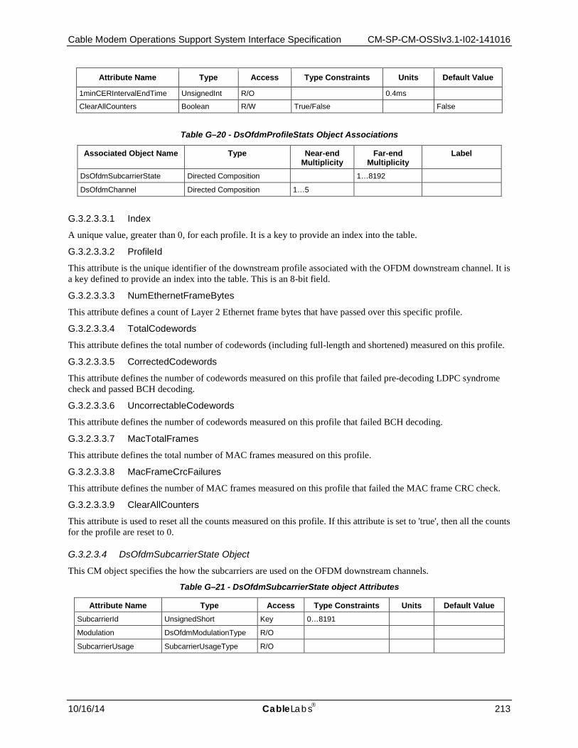
Cable Modem Operations Support System Interface Specification CM-SP-CM-OSSIv3.1-I02-141016
10/16/14 CableLabs 213
Attribute Name Type Access Type Constraints Units Default Value
1minCERIntervalEndTime UnsignedInt R/O 0.4ms
ClearAllCounters Boolean R/W True/False False
Table G–20 - DsOfdmProfileStats Object Associations
Associated Object Name Type Near-end Multiplicity
Far-end Multiplicity
Label
DsOfdmSubcarrierState Directed Composition 1…8192
DsOfdmChannel Directed Composition 1…5
G.3.2.3.3.1 Index
A unique value, greater than 0, for each profile. It is a key to provide an index into the table.
G.3.2.3.3.2 ProfileId
This attribute is the unique identifier of the downstream profile associated with the OFDM downstream channel. It is a key defined to provide an index into the table. This is an 8-bit field.
G.3.2.3.3.3 NumEthernetFrameBytes
This attribute defines a count of Layer 2 Ethernet frame bytes that have passed over this specific profile.
G.3.2.3.3.4 TotalCodewords
This attribute defines the total number of codewords (including full-length and shortened) measured on this profile.
G.3.2.3.3.5 CorrectedCodewords
This attribute defines the number of codewords measured on this profile that failed pre-decoding LDPC syndrome check and passed BCH decoding.
G.3.2.3.3.6 UncorrectableCodewords
This attribute defines the number of codewords measured on this profile that failed BCH decoding.
G.3.2.3.3.7 MacTotalFrames
This attribute defines the total number of MAC frames measured on this profile.
G.3.2.3.3.8 MacFrameCrcFailures
This attribute defines the number of MAC frames measured on this profile that failed the MAC frame CRC check.
G.3.2.3.3.9 ClearAllCounters
This attribute is used to reset all the counts measured on this profile. If this attribute is set to 'true', then all the counts for the profile are reset to 0.
G.3.2.3.4 DsOfdmSubcarrierState Object
This CM object specifies the how the subcarriers are used on the OFDM downstream channels.
Table G–21 - DsOfdmSubcarrierState object Attributes
Attribute Name Type Access Type Constraints Units Default Value SubcarrierId UnsignedShort Key 0…8191
Modulation DsOfdmModulationType R/O
SubcarrierUsage SubcarrierUsageType R/O
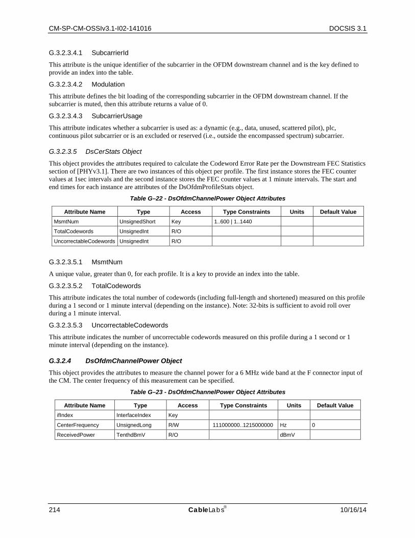
CM-SP-CM-OSSIv3.1-I02-141016 DOCSIS 3.1
214 CableLabs 10/16/14
G.3.2.3.4.1 SubcarrierId
This attribute is the unique identifier of the subcarrier in the OFDM downstream channel and is the key defined to provide an index into the table.
G.3.2.3.4.2 Modulation
This attribute defines the bit loading of the corresponding subcarrier in the OFDM downstream channel. If the subcarrier is muted, then this attribute returns a value of 0.
G.3.2.3.4.3 SubcarrierUsage
This attribute indicates whether a subcarrier is used as: a dynamic (e.g., data, unused, scattered pilot), plc, continuous pilot subcarrier or is an excluded or reserved (i.e., outside the encompassed spectrum) subcarrier.
G.3.2.3.5 DsCerStats Object
This object provides the attributes required to calculate the Codeword Error Rate per the Downstream FEC Statistics section of [PHYv3.1]. There are two instances of this object per profile. The first instance stores the FEC counter values at 1sec intervals and the second instance stores the FEC counter values at 1 minute intervals. The start and end times for each instance are attributes of the DsOfdmProfileStats object.
Table G–22 - DsOfdmChannelPower Object Attributes
Attribute Name Type Access Type Constraints Units Default Value MsmtNum UnsignedShort Key 1..600 | 1..1440
TotalCodewords UnsignedInt R/O
UncorrectableCodewords UnsignedInt R/O
G.3.2.3.5.1 MsmtNum
A unique value, greater than 0, for each profile. It is a key to provide an index into the table.
G.3.2.3.5.2 TotalCodewords
This attribute indicates the total number of codewords (including full-length and shortened) measured on this profile during a 1 second or 1 minute interval (depending on the instance). Note: 32-bits is sufficient to avoid roll over during a 1 minute interval.
G.3.2.3.5.3 UncorrectableCodewords
This attribute indicates the number of uncorrectable codewords measured on this profile during a 1 second or 1 minute interval (depending on the instance).
G.3.2.4 DsOfdmChannelPower Object This object provides the attributes to measure the channel power for a 6 MHz wide band at the F connector input of the CM. The center frequency of this measurement can be specified.
Table G–23 - DsOfdmChannelPower Object Attributes
Attribute Name Type Access Type Constraints Units Default Value ifIndex InterfaceIndex Key
CenterFrequency UnsignedLong R/W 111000000..1215000000 Hz 0
ReceivedPower TenthdBmV R/O dBmV
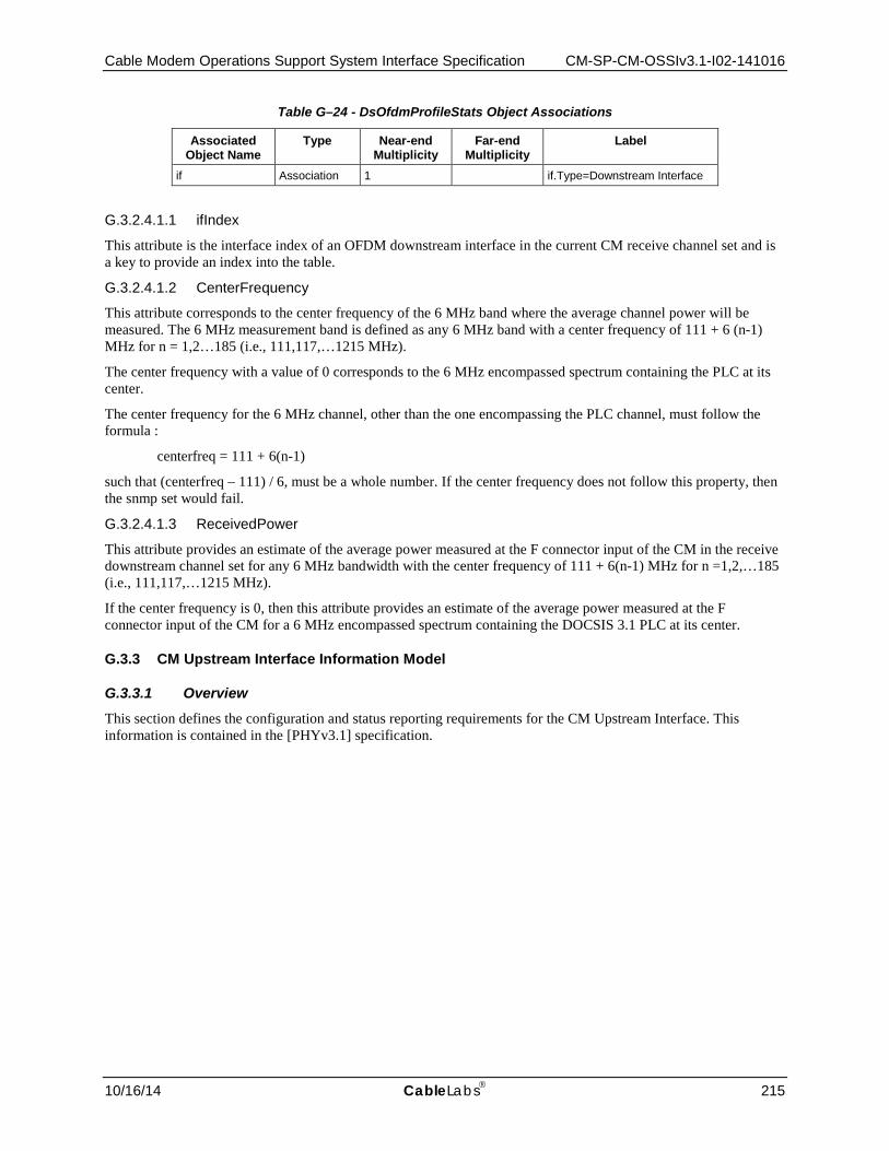
Cable Modem Operations Support System Interface Specification CM-SP-CM-OSSIv3.1-I02-141016
10/16/14 CableLabs 215
Table G–24 - DsOfdmProfileStats Object Associations
Associated Object Name
Type Near-end Multiplicity
Far-end Multiplicity
Label
if Association 1 if.Type=Downstream Interface
G.3.2.4.1.1 ifIndex
This attribute is the interface index of an OFDM downstream interface in the current CM receive channel set and is a key to provide an index into the table.
G.3.2.4.1.2 CenterFrequency
This attribute corresponds to the center frequency of the 6 MHz band where the average channel power will be measured. The 6 MHz measurement band is defined as any 6 MHz band with a center frequency of 111 + 6 (n-1) MHz for n = 1,2…185 (i.e., 111,117,…1215 MHz).
The center frequency with a value of 0 corresponds to the 6 MHz encompassed spectrum containing the PLC at its center.
The center frequency for the 6 MHz channel, other than the one encompassing the PLC channel, must follow the formula :
centerfreq = 111 + 6(n-1)
such that (centerfreq – 111) / 6, must be a whole number. If the center frequency does not follow this property, then the snmp set would fail.
G.3.2.4.1.3 ReceivedPower
This attribute provides an estimate of the average power measured at the F connector input of the CM in the receive downstream channel set for any 6 MHz bandwidth with the center frequency of 111 + 6(n-1) MHz for n =1,2,…185 (i.e., 111,117,…1215 MHz).
If the center frequency is 0, then this attribute provides an estimate of the average power measured at the F connector input of the CM for a 6 MHz encompassed spectrum containing the DOCSIS 3.1 PLC at its center.
G.3.3 CM Upstream Interface Information Model
G.3.3.1 Overview This section defines the configuration and status reporting requirements for the CM Upstream Interface. This information is contained in the [PHYv3.1] specification.

CM-SP-CM-OSSIv3.1-I02-141016 DOCSIS 3.1
216 CableLabs 10/16/14
Figure G–3 - CM Upstream Information Model Diagram
G.3.3.2 Data Type Definitions The following table and subsections define the CM upstream interface data types.
Table G–25 - Data Types
Data Type Name Base Type Permitted Values Reference UsCyclicPrefixType Unsigned Short (96 | 128 | 160 | 192 | 224 |
256 | 288 | 320 | 384 | 512 | 640)
[PHYv3.1]
UsOfdmaRollOffPeriodType UnsignedByte (0 | 32 | 64 | 96 | 128 | 160 | 192 | 224)
[PHYv3.1]
UsOfdmaModulationType Enum other(1) zeroValued(2) bpsk(3) qpsk(4) qam8(5) qam16(6) qam32(7) qam64(8) qam128(9) qam256(10) qam512(11) qam1024(12) qam2048(13) qam4096(14)
[PHYv3.1]
UsOfdmaSubcarrierperMinislotType UnsignedByte (8 | 16) [PHYv3.1]
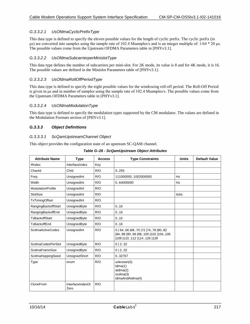
Cable Modem Operations Support System Interface Specification CM-SP-CM-OSSIv3.1-I02-141016
10/16/14 CableLabs 217
G.3.3.2.1 UsOfdmaCyclicPrefixType
This data type is defined to specify the eleven possible values for the length of cyclic prefix. The cyclic prefix (in μs) are converted into samples using the sample rate of 102.4 Msamples/s and is an integer multiple of: 1/64 * 20 μs. The possible values come from the Upstream OFDMA Parameters table in [PHYv3.1].
G.3.3.2.2 UsOfdmaSubcarrierperMinislotType
This data type defines the number of subcarriers per mini-slot. For 2K mode, its value is 8 and for 4K mode, it is 16. The possible values are defined in the Minislot Parameters table of [PHYv3.1].
G.3.3.2.3 UsOfdmaRollOffPeriodType
This data type is defined to specify the eight possible values for the windowing roll-off period. The Roll-Off Period is given in μs and in number of samples using the sample rate of 102.4 Msamples/s. The possible values come from the Upstream OFDMA Parameters table in [PHYv3.1].
G.3.3.2.4 UsOfdmaModulationType
This data type is defined to specify the modulation types supported by the CM modulator. The values are defined in the Modulation Formats section of [PHYv3.1].
G.3.3.3 Object Definitions
G.3.3.3.1 ScQamUpstreamChannel Object
This object provides the configuration state of an upstream SC-QAM channel.
Table G–26 - ScQamUpstream Object Attributes
Attribute Name Type Access Type Constraints Units Default Value IfIndex InterfaceIndex Key
ChanId ChId R/O 0..255
Freq UnsignedInt R/O 111000000..1002000000 Hz
Width UnsignedInt R/O 0..64000000 Hz
ModulationProfile UnsignedInt R/O
SlotSize UnsignedInt R/O ticks
TxTimingOffset UnsignedInt R/O
RangingBackoffStart UnsignedByte R/O 0..16
RangingBackoffEnd UnsignedByte R/O 0..16
TxBackoffStart UnsignedByte R/O 0..16
TxBackoffEnd UnsignedByte R/O 0..16
ScdmaActiveCodes UnsignedInt R/O 0 | 64..66 |68..70 |72 |74..78 |80..82 |84..88 |90..96 |98..100 |102 |104..106 |108 |110..112 |114..126 |128
ScdmaCodesPerSlot UnsignedByte R/O 0 | 2..32
ScdmaFrameSize UnsignedByte R/O 0 | 2..32
ScdmaHoppingSeed UnsignedShort R/O 0..32767
Type enum R/O unknown(0) tdma(1) atdma(2) scdma(3) tdmaAndAtdma(4)
CloneFrom InterfaceIndexOrZero
R/O
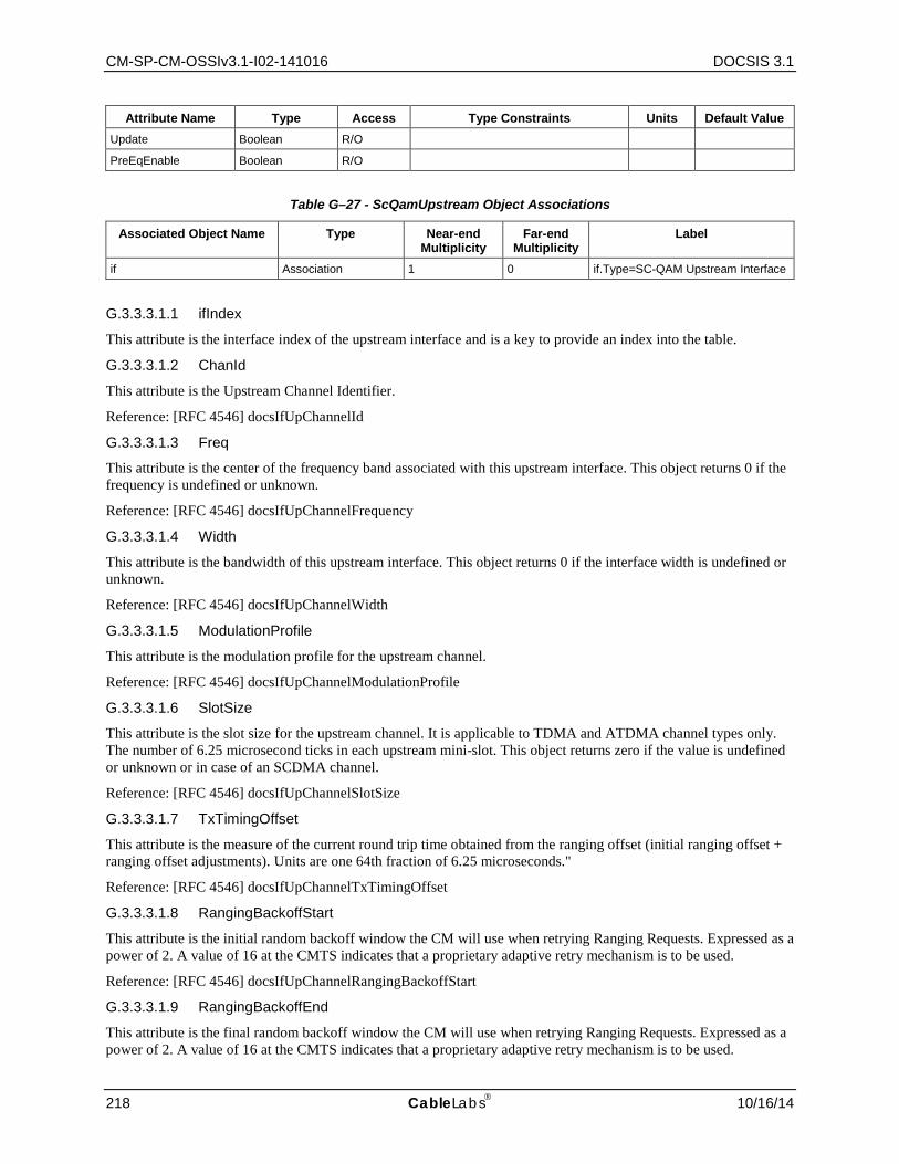
CM-SP-CM-OSSIv3.1-I02-141016 DOCSIS 3.1
218 CableLabs 10/16/14
Attribute Name Type Access Type Constraints Units Default Value Update Boolean R/O
PreEqEnable Boolean R/O
Table G–27 - ScQamUpstream Object Associations
Associated Object Name Type Near-end Multiplicity
Far-end Multiplicity
Label
if Association 1 0 if.Type=SC-QAM Upstream Interface
G.3.3.3.1.1 ifIndex
This attribute is the interface index of the upstream interface and is a key to provide an index into the table.
G.3.3.3.1.2 ChanId
This attribute is the Upstream Channel Identifier.
Reference: [RFC 4546] docsIfUpChannelId
G.3.3.3.1.3 Freq
This attribute is the center of the frequency band associated with this upstream interface. This object returns 0 if the frequency is undefined or unknown.
Reference: [RFC 4546] docsIfUpChannelFrequency
G.3.3.3.1.4 Width
This attribute is the bandwidth of this upstream interface. This object returns 0 if the interface width is undefined or unknown.
Reference: [RFC 4546] docsIfUpChannelWidth
G.3.3.3.1.5 ModulationProfile
This attribute is the modulation profile for the upstream channel.
Reference: [RFC 4546] docsIfUpChannelModulationProfile
G.3.3.3.1.6 SlotSize
This attribute is the slot size for the upstream channel. It is applicable to TDMA and ATDMA channel types only. The number of 6.25 microsecond ticks in each upstream mini-slot. This object returns zero if the value is undefined or unknown or in case of an SCDMA channel.
Reference: [RFC 4546] docsIfUpChannelSlotSize
G.3.3.3.1.7 TxTimingOffset
This attribute is the measure of the current round trip time obtained from the ranging offset (initial ranging offset + ranging offset adjustments). Units are one 64th fraction of 6.25 microseconds."
Reference: [RFC 4546] docsIfUpChannelTxTimingOffset
G.3.3.3.1.8 RangingBackoffStart
This attribute is the initial random backoff window the CM will use when retrying Ranging Requests. Expressed as a power of 2. A value of 16 at the CMTS indicates that a proprietary adaptive retry mechanism is to be used.
Reference: [RFC 4546] docsIfUpChannelRangingBackoffStart
G.3.3.3.1.9 RangingBackoffEnd
This attribute is the final random backoff window the CM will use when retrying Ranging Requests. Expressed as a power of 2. A value of 16 at the CMTS indicates that a proprietary adaptive retry mechanism is to be used.
Cable Modem Operations Support System Interface Specification CM-SP-CM-OSSIv3.1-I02-141016
10/16/14 CableLabs 219
Reference: [RFC 4546] docsIfUpChannelRangingBackoffEnd
G.3.3.3.1.10 TxBackoffStart
This attribute is the initial random backoff window the CM will use when retrying transmissions. Expressed as a power of 2. A value of 16 at the CMTS indicates that a proprietary adaptive retry mechanism is to be used.
Reference: [RFC 4546] docsIfUpChannelTxBackoffStart
G.3.3.3.1.11 TxBackoffEnd
This attribute is the final random backoff window the CM will use when retrying transmissions. Expressed as a power of 2. A value of 16 at the CMTS indicates that a proprietary adaptive retry mechanism is to be used.
Reference: [RFC 4546] docsIfUpChannelTxBackoffEnd
G.3.3.3.1.12 ScdmaActiveCodes
This attribute is the SCDMA Active Codes. It is applicable for SCDMA channel types only. This object returns the number of active codes. It returns zero for non-SCDMA channel types. Note that legal values from 64..128 MUST be non-prime.
Reference: [RFC 4546] docsIfUpChannelScdmaActiveCodes
G.3.3.3.1.13 ScdmaCodesPerSlot
This attribute is the number of SCDMA codes per mini-slot. It is applicable for SCDMA channel types only.
It returns zero if the value is undefined or unknown or in case of a TDMA or ATDMA channel.
Reference: [RFC 4546] docsIfUpChannelScdmaCodesPerSlot
G.3.3.3.1.14 ScdmaFrameSize
This attribute is the SCDMA frame size in units of spreading intervals. It is applicable for SCDMA channel types only. This value returns zero for non-SCDMA Profiles.
Reference: [RFC 4546] docsIfUpChannelScdmaFrameSize
G.3.3.3.1.15 ScdmaHoppingSeed
This attribute is the 15-bit seed used for code hopping sequence initialization. It is applicable for SCDMA channel types only. This objects returns zero for non-SCDMA channel types.
Reference: [RFC 4546] docsIfUpChannelScdmaHoppingSeed
G.3.3.3.1.16 Type
This attribute is reflects the Upstream channel type.
Reference: [RFC 4546] docsIfUpChannelType
G.3.3.3.1.17 CloneFrom
This attribute is meaningless on a Cable Modem.
Reference: [RFC 4546] docsIfUpChannelCloneFrom
G.3.3.3.1.18 Update
This attribute always returns 'false' on a Cable Modem.
Reference: [RFC 4546] docsIfUpChannelUpdate
G.3.3.3.1.19 PreEqEnable
This attribute reflects the status of pre-equalization as represented in the RNG-RSP. Pre-equalization is considered enabled at the CM if a RNG-RSP with pre-equalization data has been received at least once since the last mac reinitialization.
Reference: [RFC 4546] docsIfUpChannelPreEqEnable

CM-SP-CM-OSSIv3.1-I02-141016 DOCSIS 3.1
220 CableLabs 10/16/14
G.3.3.3.2 UsChExt Object
This object defines management extensions for upstream channels, in particular SCDMA parameters.
Table G–28 - UsChExt Object
Attribute Name Type Access Type Constraints Units Default IfIndex InterfaceIndex key InterfaceIndex of MAC Domain
interface
SacCodeHoppingSelectionMode Enum read-only none(0) sac1NoCodeHopping(1) sac1CodeHoppingMode1(2) sac2CodeHoppingMode2(3) sac2NoCodeHopping(4)
ScdmaSelectionStringActiveCodes ScdmaSelectionString read-only
G.3.3.3.2.1 IfIndex
This key represents the interface index of the logical upstream channel to which this instance applies.
G.3.3.3.2.2 SacCodeHoppingSelectionMode
This attribute indicates the selection mode for active codes and code hopping.
• 'none' Non-SCDMA channel
• 'sac1NoCodeHopping' Selectable active codes mode 1 and code hopping disabled
• 'sac1CodeHoppingMode1' Selectable active codes mode 1 and code hopping mode 1
• 'sac2CodeHoppingMode2' Selectable active codes mode 2 and code hopping mode 2
• 'sac2NoCodeHopping' Selectable active codes mode 2 and code hopping disabled
References: [MULPIv3.1] Mini-slot Numbering Parameters in Timing and Synchronization section.
G.3.3.3.2.3 ScdmaSelectionStringActiveCodes
This attribute represents the active codes of the upstream channel and it is applicable only when SacCodeHoppingSelectionMode is 'sac2CodeHoppingMode2'.
References: [MULPIv3.1] Mini-slot Numbering Parameters in Timing and Synchronization section.
G.3.3.3.3 UsOfdmaChannel Object
This object reports the configuration properties of an upstream OFDMA channel.
Table G–29 - UsOfdmaChannel Object Attributes
Attribute Name Type Access Type Constraints Units Default Value
Ifindex InterfaceIndex Key
SubcarrierZeroFreq UnsignedInt R/O 5000000..197600000 Hz
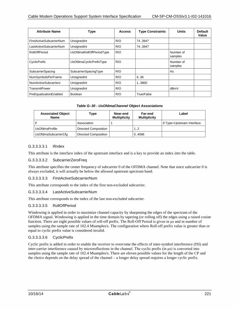
Cable Modem Operations Support System Interface Specification CM-SP-CM-OSSIv3.1-I02-141016
10/16/14 CableLabs 221
Attribute Name Type Access Type Constraints Units Default Value
FirstActiveSubcarrierNum UnsignedInt R/O 74..3947
LastActiveSubcarrierNum UnsignedInt R/O 74..3947
RollOffPeriod UsOfdmaRollOffPeriodType R/O Number of samples
CyclicPrefix UsOfdmaCyclicPrefixType R/O Number of samples
SubcarrierSpacing SubcarrierSpacingType R/O Hz
NumSymbolsPerFrame UnsignedInt R/O 6..36
NumActiveSubcarriers UnsignedInt R/O 1..3800
TransmitPower UnsignedInt R/O dBmV
PreEqualizationEnabled Boolean R/O True/False
Table G–30 - UsOfdmaChannel Object Associations
Associated Object Name
Type Near-end Multiplicity
Far-end Multiplicity
Label
if Association 1 if.Type=Upstream Interface
UsOfdmaProfile Directed Composition 1..2
UsOfdmaSubcarrierCfg Directed Composition 0..4096
G.3.3.3.3.1 ifIndex
This attribute is the interface index of the upstream interface and is a key to provide an index into the table.
G.3.3.3.3.2 SubcarrierZeroFreq
This attribute specifies the center frequency of subcarrier 0 of the OFDMA channel. Note that since subcarrier 0 is always excluded, it will actually be below the allowed upstream spectrum band.
G.3.3.3.3.3 FirstActiveSubcarrierNum
This attribute corresponds to the index of the first non-excluded subcarrier.
G.3.3.3.3.4 LastActiveSubcarrierNum
This attribute corresponds to the index of the last non-excluded subcarrier.
G.3.3.3.3.5 RollOffPeriod
Windowing is applied in order to maximize channel capacity by sharpening the edges of the spectrum of the OFDMA signal. Windowing is applied in the time domain by tapering (or rolling off) the edges using a raised cosine function. There are eight possible values of roll-off prefix. The Roll-Off Period is given in μs and in number of samples using the sample rate of 102.4 Msamples/s. The configuration where Roll-off prefix value is greater than or equal to cyclic prefix value is considered invalid.
G.3.3.3.3.6 CyclicPrefix
Cyclic prefix is added in order to enable the receiver to overcome the effects of inter-symbol interference (ISI) and inter-carrier interference caused by microreflections in the channel. The cyclic prefix (in μs) is converted into samples using the sample rate of 102.4 Msamples/s. There are eleven possible values for the length of the CP and the choice depends on the delay spread of the channel – a longer delay spread requires a longer cyclic prefix.
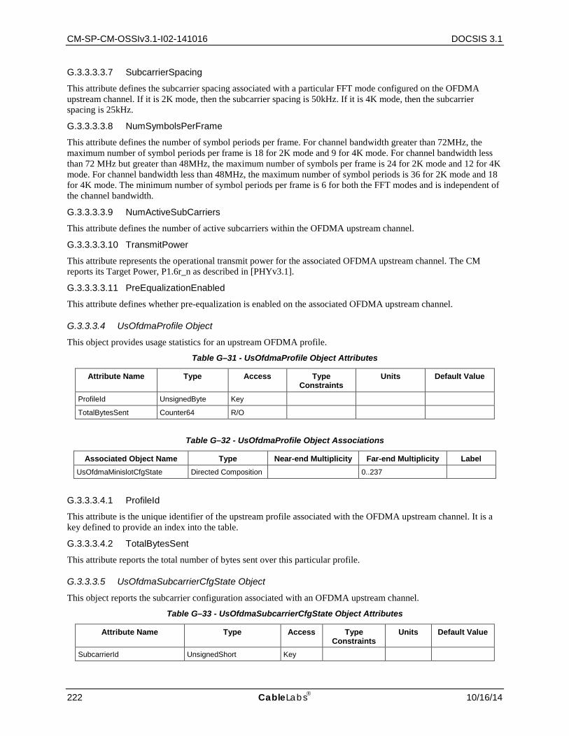
CM-SP-CM-OSSIv3.1-I02-141016 DOCSIS 3.1
222 CableLabs 10/16/14
G.3.3.3.3.7 SubcarrierSpacing
This attribute defines the subcarrier spacing associated with a particular FFT mode configured on the OFDMA upstream channel. If it is 2K mode, then the subcarrier spacing is 50kHz. If it is 4K mode, then the subcarrier spacing is 25kHz.
G.3.3.3.3.8 NumSymbolsPerFrame
This attribute defines the number of symbol periods per frame. For channel bandwidth greater than 72MHz, the maximum number of symbol periods per frame is 18 for 2K mode and 9 for 4K mode. For channel bandwidth less than 72 MHz but greater than 48MHz, the maximum number of symbols per frame is 24 for 2K mode and 12 for 4K mode. For channel bandwidth less than 48MHz, the maximum number of symbol periods is 36 for 2K mode and 18 for 4K mode. The minimum number of symbol periods per frame is 6 for both the FFT modes and is independent of the channel bandwidth.
G.3.3.3.3.9 NumActiveSubCarriers
This attribute defines the number of active subcarriers within the OFDMA upstream channel.
G.3.3.3.3.10 TransmitPower
This attribute represents the operational transmit power for the associated OFDMA upstream channel. The CM reports its Target Power, P1.6r_n as described in [PHYv3.1].
G.3.3.3.3.11 PreEqualizationEnabled
This attribute defines whether pre-equalization is enabled on the associated OFDMA upstream channel.
G.3.3.3.4 UsOfdmaProfile Object
This object provides usage statistics for an upstream OFDMA profile.
Table G–31 - UsOfdmaProfile Object Attributes
Attribute Name Type Access Type Constraints
Units Default Value
ProfileId UnsignedByte Key
TotalBytesSent Counter64 R/O
Table G–32 - UsOfdmaProfile Object Associations
Associated Object Name Type Near-end Multiplicity Far-end Multiplicity Label UsOfdmaMinislotCfgState Directed Composition 0..237
G.3.3.3.4.1 ProfileId
This attribute is the unique identifier of the upstream profile associated with the OFDMA upstream channel. It is a key defined to provide an index into the table.
G.3.3.3.4.2 TotalBytesSent
This attribute reports the total number of bytes sent over this particular profile.
G.3.3.3.5 UsOfdmaSubcarrierCfgState Object
This object reports the subcarrier configuration associated with an OFDMA upstream channel.
Table G–33 - UsOfdmaSubcarrierCfgState Object Attributes
Attribute Name Type Access Type Constraints
Units Default Value
SubcarrierId UnsignedShort Key

Cable Modem Operations Support System Interface Specification CM-SP-CM-OSSIv3.1-I02-141016
10/16/14 CableLabs 223
Attribute Name Type Access Type Constraints
Units Default Value
Modulation USOfdmaModulationType R/O
PreEqualizationCoefficients HexBinary R/O
SubcarrierUsage SubcarrierUsageType R/O
G.3.3.3.5.1 SubcarrierId
This attribute is the unique identifier of the subcarrier in the OFDMA upstream channel. It is a key defined to provide an index into the table.
G.3.3.3.5.2 Modulation
This attribute defines the bit loading of the corresponding subcarrier in the OFDMA upstream channel.
G.3.3.3.5.3 PreEqualizationCoefficients
This attribute defines the pre-equalization coefficients associated with a particular subcarrier. A CM implements a linear pre-equalizer with a single complex coefficient per subcarrier.
G.3.3.3.5.4 SubcarrierUsage
This attribute indicates whether a subcarrier is used as: a dynamic (e.g., data, unused, scattered pilot), plc, continuous pilot subcarrier or is an excluded or reserved (i.e., outside the encompassed spectrum) subcarrier.
G.3.3.3.6 UsOfdmaMinislotCfgState Object
This CM object reports mini-slot configuration as received in the UCD message for a particular OFDMA profile.
Table G–34 - UsOfdmaMinislotCfgState Object Attributes
Attribute Name Type Access Type Constraints Units Default Value StartMinislotNum UnsignedByte Key 1..237
FirstSubcarrierId UnsignedShort R/O 1..4095
NumConsecutiveMinislots UnsignedShort R/O 1..237
MinislotPilotPattern UnsignedByte R/O 1..14
DataSymbolModulation UsOfdmaModulationType R/O
G.3.3.3.6.1 StartMinislotNum
This attribute corresponds to the unique identifier of the mini-slot received by the CM. It is a key defined to provide an index into the table.
G.3.3.3.6.2 FirstSubcarrierId
This attribute corresponds to the index of the first/starting subcarrier in this mini-slot.
G.3.3.3.6.3 NumConsecutiveMinislots
This attribute defines the number of continuous mini-slots which have the same bit loading, starting with the StartMinislotNum, defined in the associated upstream profile.
G.3.3.3.6.4 MinislotPilotPattern
This attribute defines the pilot pattern used for edge and body mini-slots. Pilots are used by the CMTS receiver to adapt to channel conditions and frequency offset. Pilot patterns differ by the number of pilots in a mini-slot, and by their arrangement within the mini-slot. For both 8 and 16 subcarriers mini-slot sizes, seven pilot patterns are defined.
G.3.3.3.6.5 DataSymbolModulation
This attribute defines the bit loading within the mini-slot.
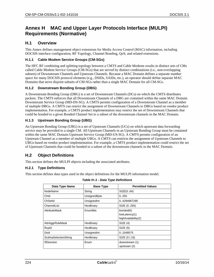
CM-SP-CM-OSSIv3.1-I02-141016 DOCSIS 3.1
224 CableLabs 10/16/14
Annex H MAC and Upper Layer Protocols Interface (MULPI) Requirements (Normative)
H.1 Overview This Annex defines management object extensions for Media Access Control (MAC) information, including DOCSIS interface configuration, RF Topology, Channel Bonding, QoS, and related extensions.
H.1.1 Cable Modem Service Groups (CM-SGs)
The HFC RF combining and splitting topology between a CMTS and Cable Modems results in distinct sets of CMs called Cable Modem Service Groups (CM-SGs) that are served by distinct combinations (i.e., non-overlapping subsets) of Downstream Channels and Upstream Channels. Because a MAC Domain defines a separate number space for many DOCSIS protocol elements (e.g., DSIDs, SAIDs, etc.), an operator should define separate MAC Domains that serve disjoint subsets of CM-SGs rather than a single MAC Domain for all CM-SGs.
H.1.2 Downstream Bonding Group (DBG)
A Downstream Bonding Group (DBG) is a set of Downstream Channels (DCs) on which the CMTS distributes packets. The CMTS enforces that all Downstream Channels of a DBG are contained within the same MAC Domain Downstream Service Group (MD-DS-SG). A CMTS permits configuration of a Downstream Channel as a member of multiple DBGs. A CMTS can restrict the assignment of Downstream Channels to DBGs based on vendor product implementation. For example, a CMTS product implementation may restrict the set of Downstream Channels that could be bonded to a given Bonded Channel Set to a subset of the downstream channels in the MAC Domain.
H.1.3 Upstream Bonding Group (UBG)
An Upstream Bonding Group (UBG) is a set of Upstream Channels (UCs) on which upstream data forwarding service may be provided to a single CM. All Upstream Channels in an Upstream Bonding Group must be contained within the same MAC Domain Upstream Service Group (MD-US-SG). A CMTS permits configuration of an Upstream Channel as a member of multiple UBGs. A CMTS can restricts the assignment of Upstream Channels to UBGs based on vendor product implementation. For example, a CMTS product implementation could restrict the set of Upstream Channels that could be bonded to a subset of the downstream channels in the MAC Domain.
H.2 Object Definitions This section defines the MULPI objects including the associated attributes.
H.2.1 Type Definitions
This section defines data types used in the object definitions for the MULPI information model.
Table H–1 - Data Type Definitions
Data Type Name Base Type Permitted Values NodeName String SIZE(0..64)
ChId UnsignedByte 0..255
ChSetId UnsignedInt 0..4294967295
ChannelList HexBinary SIZE (0..255)
AttributeMask EnumBits bonded(0) lowLatency(1) highAvailability(2)
AttrAggrRuleMask HexBinary SIZE (4)
RcpId HexBinary SIZE (5)
Dsid UnsignedInt 0..1048575
ScdmaSelectionString HexBinary SIZE (0 | 16)
IfDirection Enum downstream (1) upstream (2)
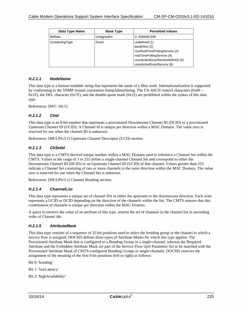
Cable Modem Operations Support System Interface Specification CM-SP-CM-OSSIv3.1-I02-141016
10/16/14 CableLabs 225
Data Type Name Base Type Permitted Values BitRate UnsignedInt 0..4294967295
SchedulingType Enum undefined (1) bestEffort (2) nonRealTimePollingService (3) realTimePollingService (4) unsolicitedGrantServiceWithAD (5) unsolicitedGrantService (6)
H.2.1.1 NodeName This data type is a human readable string that represents the name of a fiber node. Internationalization is supported by conforming to the SNMP textual convention SnmpAdminString. The US-ASCII control characters (0x00 – 0x1F), the DEL character (0x7F), and the double-quote mark (0x22) are prohibited within the syntax of this data type.
References: [RFC 3411].
H.2.1.2 ChId This data type is an 8-bit number that represents a provisioned Downstream Channel ID (DCID) or a provisioned Upstream Channel ID (UCID). A Channel Id is unique per direction within a MAC Domain. The value zero is reserved for use when the channel ID is unknown.
References: [MULPIv3.1] Upstream Channel Descriptor (UCD) section.
H.2.1.3 ChSetId This data type is a CMTS-derived unique number within a MAC Domain used to reference a Channel Set within the CMTS. Values in the range of 1 to 255 define a single-channel Channel Set and correspond to either the Downstream Channel ID (DCID) or an Upstream Channel ID (UCID) of that channel. Values greater than 255 indicate a Channel Set consisting of two or more channels in the same direction within the MAC Domain. The value zero is reserved for use when the Channel Set is unknown.
References: [MULPIv3.1] Channel Bonding section.
H.2.1.4 ChannelList This data type represents a unique set of channel IDs in either the upstream or the downstream direction. Each octet represents a UCID or DCID depending on the direction of the channels within the list. The CMTS ensures that this combination of channels is unique per direction within the MAC Domain.
A query to retrieve the value of an attribute of this type, returns the set of channels in the channel list in ascending order of Channel Ids.
H.2.1.5 AttributeMask This data type consists of a sequence of 32-bit positions used to select the bonding group or the channel to which a service flow is assigned. DOCSIS defines three types of Attribute Masks for which this type applies: The Provisioned Attribute Mask that is configured to a Bonding Group or a single-channel, whereas the Required Attribute and the Forbidden Attribute Mask are part of the Service Flow QoS Parameter Set to be matched with the Provisioned Attribute Mask of CMTS-configured Bonding Groups or single-channels. DOCSIS reserves the assignment of the meaning of the first 8 bit positions (left to right) as follows:
Bit 0: 'bonding'
Bit 1: 'lowLatency'
Bit 2: 'highAvailability'

CM-SP-CM-OSSIv3.1-I02-141016 DOCSIS 3.1
226 CableLabs 10/16/14
Bit positions 3-15 are reserved.
Bit positions 16-31 are freely assigned by operators to represent their own constraints on the channel(s) selection for a particular service flow.
References: [MULPIv3.1] Service Flow Assignment section.
H.2.1.6 AttrAggrRuleMask This data type represents a sequence of 32-bit positions that defines logical (e.g., AND, OR) operations to match against the channel list Provisioned Mask and Service Flow Required Mask bit positions when the CMTS is determining the service flow for assignment to a bonding group not configured by the management system.
References: [MULPIv3.1] Service Flow Assignment section.
H.2.1.7 RcpId This data type defines a 'Receive Channel Profile Identifier' (RCP-ID). An RCP-ID consists of 5-octet length string where the first 3-bytes (from left to right corresponds to the Organizational Unique ID (OUI) followed by a two-byte vendor-maintained identifier to represent multiple versions or models of RCP-IDs.
References: [MULPIv3.1] RCP-ID section in the Common Radio Frequency Interface Encodings Annex.
H.2.1.8 Dsid This data type defines the 20-bit Downstream Service Identifier used by the CM for downstream resequencing, filtering, and forwarding. The value zero is reserved for use when the DSID is unknown or does not apply.
References: [MULPIv3.1] DSID Definition section.
H.2.1.9 ScdmaSelectionString This data type represents the S-CDMA selection string for active codes used with Selectable Active Codes Mode 2.
A 128-bit string indicating which codes are active. The first element in the string corresponds to code 0 (the all-ones code), and the last element in the string corresponds to code 127. A '1' element in the string indicates an active code, and a '0' indicates an unused code. A zero-length string is returned for an unknown or non-applicable value.
References: [MULPIv3.1] Mini-slot Numbering Parameters in Timing and Synchronization section.
H.2.1.10 IfDirection Indicates a direction on an RF MAC interface. The value downstream(1) is from Cable Modem Termination System to Cable Modem. The value upstream(2) is from Cable Modem to Cable Modem Termination System.
Valid enumerations for the data type are:
• downstream(1)
• upstream(2)
Reference: [MULPIv3.1] Terms and Definitions section.
H.2.1.11 BitRate The rate of traffic in units of bits per second. Used to specify traffic rate for QoS.
H.2.1.12 SchedulingType The scheduling service provided by a CMTS for an upstream Service Flow. This parameter must be reported as 'undefined' for downstream QoS Parameter Sets.
Valid enumerations for the data type are:
• undefined(1)
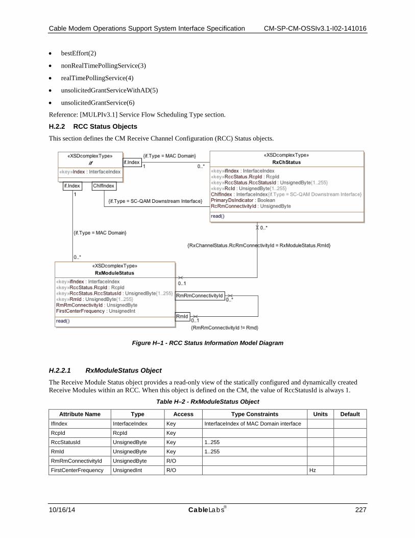
Cable Modem Operations Support System Interface Specification CM-SP-CM-OSSIv3.1-I02-141016
10/16/14 CableLabs 227
• bestEffort(2)
• nonRealTimePollingService(3)
• realTimePollingService(4)
• unsolicitedGrantServiceWithAD(5)
• unsolicitedGrantService(6)
Reference: [MULPIv3.1] Service Flow Scheduling Type section.
H.2.2 RCC Status Objects
This section defines the CM Receive Channel Configuration (RCC) Status objects.
Figure H–1 - RCC Status Information Model Diagram
H.2.2.1 RxModuleStatus Object The Receive Module Status object provides a read-only view of the statically configured and dynamically created Receive Modules within an RCC. When this object is defined on the CM, the value of RccStatusId is always 1.
Table H–2 - RxModuleStatus Object
Attribute Name Type Access Type Constraints Units Default IfIndex InterfaceIndex Key InterfaceIndex of MAC Domain interface
RcpId RcpId Key
RccStatusId UnsignedByte Key 1..255
RmId UnsignedByte Key 1..255
RmRmConnectivityId UnsignedByte R/O
FirstCenterFrequency UnsignedInt R/O Hz

CM-SP-CM-OSSIv3.1-I02-141016 DOCSIS 3.1
228 CableLabs 10/16/14
H.2.2.1.1 IfIndex
This key represents the interface index of the MAC Domain to which this instance applies.
H.2.2.1.2 RcpId
This key represents the RCP-ID to which this instance applies.
H.2.2.1.3 RccStatusId
This key represents an RCC combination for a particular RcpId either from an RCC configuration object or a CMTS determined RCC and is unique per combination of MAC Domain interface index and RcpId. Note that when this attribute is instantiated at the CM, its value will always be 1.
H.2.2.1.4 RmId
This key represents an identifier of a Receive Module instance within the Receive Channel Profile.
References: [MULPIv3.1] Receive Module Index section in the Common Radio Frequency Interface Encodings Annex.
H.2.2.1.5 RmRmConnectivityId
This attribute represents the Receive Module to which this Receive Module connects. Requirements for module connectivity are detailed in the RmRmConnectivityId of the RccCfg object.
H.2.2.1.6 FirstCenterFrequency
This attribute represents the low frequency channel of the Receive Module, or 0 if not applicable to the Receive Module.
H.2.2.2 RxChStatus Object The Receive Channel Status object reports the status of the statically-configured and dynamically-created Receive Channels within an RCC. When this object is defined on the CM, the value of RccStatusId is always 1.
Table H–3 - RxChStatus Object
Attribute Name Type Access Type Constraints Units Default IfIndex InterfaceIndex Key InterfaceIndex of MAC Domain interface
RcpId RcpId Key
RccStatusId UnsignedByte Key 1..255
RcId UnsignedByte Key 1..255
ChIfIndex InterfaceIndex R/O InterfaceIndex of Downstream Channel assigned to the Receive Channel
PrimaryDsIndicator Boolean R/O
RcRmConnectivityId UnsignedByte R/O
H.2.2.2.1 IfIndex
This key represents the interface index of the MAC Domain to which this instance applies.
H.2.2.2.2 RcpId
This key represents the RCP-ID to which this instance applies.

Cable Modem Operations Support System Interface Specification CM-SP-CM-OSSIv3.1-I02-141016
10/16/14 CableLabs 229
H.2.2.2.3 RccStatusId
This key represents an RCC combination for a particular RcpId either from an RCC configuration object or a CMTS determined RCC. It is unique per combination of MAC Domain interface index and RcpId. Note that when this attribute is instantiated at the CM, its value will always be 1.
H.2.2.2.4 RcId
This key represents an identifier for the parameters of the Receive Channel instance within the Receive Channel Profile.
H.2.2.2.5 ChIfIndex
This attribute contains the interface index of the Downstream Channel that this Receive Channel Instance defines.
H.2.2.2.6 PrimaryDsIndicator
If set to 'true', this attribute indicates the Receive Channel is to be the primary-capable downstream channel for the CM receiving this RCC. Otherwise, the downstream channel is to be a non-primary-capable channel.
H.2.2.2.7 RcRmConnectivityId
This attribute identifies the Receive Module to which this Receive Channel connects. A value of zero indicates that the Receive Channel Connectivity TLV is omitted from the RCC.

CM-SP-CM-OSSIv3.1-I02-141016 DOCSIS 3.1
230 CableLabs 10/16/14
H.2.3 DOCSIS QoS Objects
This section defines the reporting of the DOCSIS CM QoS configuration. The model is updated in the DOCSIS 3.1 Cable Modem OSSI specification to include objects to configure the Active Queue Management (AQM) feature introduced in [MULPIv3.1].
Figure H–2 - QoS Configuration Information Model Diagram
H.2.3.1 PktClass This object describes the packet classification configured on the CM or CMTS. The model is that a packet either received as input from an interface or transmitted for output on an interface may be compared against an ordered list of rules pertaining to the packet contents. Each rule is an instance of this object. A matching rule provides a Service Flow ID to which the packet is classified. All rules need to match for a packet to match a classifier. The attributes in this row correspond to a set of Classifier Encoding parameters in a DOCSIS MAC management message. The BitMap attribute indicates which particular parameters were present in the classifier as signaled in the DOCSIS message. If the referenced parameter was not present in the signaled Classifier, the corresponding attribute in this instance reports a value as specified by that attribute description.
References: [MULPIv3.1] Service Flows and Classifiers section.
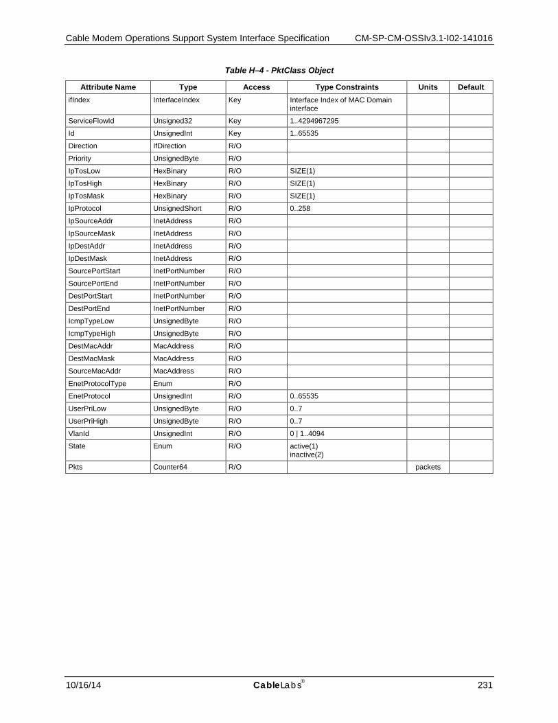
Cable Modem Operations Support System Interface Specification CM-SP-CM-OSSIv3.1-I02-141016
10/16/14 CableLabs 231
Table H–4 - PktClass Object
Attribute Name Type Access Type Constraints Units Default ifIndex InterfaceIndex Key Interface Index of MAC Domain
interface
ServiceFlowId Unsigned32 Key 1..4294967295
Id UnsignedInt Key 1..65535
Direction IfDirection R/O
Priority UnsignedByte R/O
IpTosLow HexBinary R/O SIZE(1)
IpTosHigh HexBinary R/O SIZE(1)
IpTosMask HexBinary R/O SIZE(1)
IpProtocol UnsignedShort R/O 0..258
IpSourceAddr InetAddress R/O
IpSourceMask InetAddress R/O
IpDestAddr InetAddress R/O
IpDestMask InetAddress R/O
SourcePortStart InetPortNumber R/O
SourcePortEnd InetPortNumber R/O
DestPortStart InetPortNumber R/O
DestPortEnd InetPortNumber R/O
IcmpTypeLow UnsignedByte R/O
IcmpTypeHigh UnsignedByte R/O
DestMacAddr MacAddress R/O
DestMacMask MacAddress R/O
SourceMacAddr MacAddress R/O
EnetProtocolType Enum R/O
EnetProtocol UnsignedInt R/O 0..65535
UserPriLow UnsignedByte R/O 0..7
UserPriHigh UnsignedByte R/O 0..7
VlanId UnsignedInt R/O 0 | 1..4094
State Enum R/O active(1) inactive(2)
Pkts Counter64 R/O packets

CM-SP-CM-OSSIv3.1-I02-141016 DOCSIS 3.1
232 CableLabs 10/16/14
Attribute Name Type Access Type Constraints Units Default BitMap EnumBits R/O rulePriority(0),
activationState(1), ipTos(2), ipProtocol(3), ipSourceAddr(4), ipSourceMask(5), ipDestAddr(6), ipDestMask(7), sourcePortStart(8), sourcePortEnd(9), destPortStart(10), destPortEnd(11), destMac(12), sourceMac(13), ethertype(14), userPri(15), vlanId(16), flowLabel(17), cmInterfaceMask(18)
IpAddrType InetAddressType R/O
FlowLabel UnsignedInt R/O 0..1048575
CmInterfaceMask DocsL2vpnIfList R/O
H.2.3.1.1 ifIndex
This key represents the interface index of the MAC Domain of the Service Flow.
H.2.3.1.1 ServiceFlowId
This key represents an identifier assigned to a Service Flow by CMTS within a MAC Domain. The value 0 is used only for the purpose of reporting instances pertaining UDCs and not used for association of QoS classifiers to service flows.
H.2.3.1.1 Id
This key indicates the assigned identifier to the packet classifier instance by the CMTS, which is unique per Service Flow. For UDCs this corresponds to the Service Flow Reference of the classifier.
References: [MULPIv3.1] Classifier Identifier section in the Common Radio Frequency Interface Encodings Annex.
H.2.3.1.1 Direction
This attribute indicates the direction to which the classifier is applied.
H.2.3.1.1 Priority
This attribute specifies the order of evaluation of the classifiers. The higher the value, the higher the priority. The value of 0 is used as default in provisioned Service Flows Classifiers. The default value of 64 is used for dynamic Service Flow Classifiers. If the referenced parameter is not present in a classifier, this attribute reports the default value as defined above.
References: [MULPIv3.1] Rule Priority section in the Common Radio Frequency Interface Encodings Annex.
H.2.3.1.1 IpTosLow
This attribute indicates the low value of a range of TOS byte values. If the referenced parameter is not present in a classifier, this attribute reports the value of 0. The IP TOS octet as originally defined in [RFC 791] has been

Cable Modem Operations Support System Interface Specification CM-SP-CM-OSSIv3.1-I02-141016
10/16/14 CableLabs 233
superseded by the 6-bit Differentiated Services Field (DSField, [RFC 3260]) and the 2-bit Explicit Congestion Notification Field (ECN field, [RFC 3168]). This object is defined as an 8-bit octet as defined by the DOCSIS Specification for packet classification.
References: [MULPIv3.1] IPv4 Type of Service Range and Mask and IPv6 Traffic Class Range and Mask sections in the Common Radio Frequency Interface Encodings Annex.
H.2.3.1.1 IpTosHigh
This attribute indicates the 8-bit high value of a range of TOS byte values. If the referenced parameter is not present in a classifier, this attribute reports the value of 0. The IP TOS octet as originally defined in [RFC 791] has been superseded by the 6-bit Differentiated Services Field (DSField, [RFC 3260]) and the 2-bit Explicit Congestion Notification Field (ECN field, [RFC 3168]). This object is defined as an 8-bit octet as defined by the DOCSIS Specification for packet classification.
References: [MULPIv3.1] IPv4 Type of Service Range and Mask and IPv6 Traffic Class Range and Mask sections in the Common Radio Frequency Interface Encodings Annex.
H.2.3.1.1 IpTosMask
This attribute indicates the mask value is bitwise ANDed with TOS byte in an IP packet, and this value is used for range checking of TosLow and TosHigh. If the referenced parameter is not present in a classifier, this attribute reports the value of 0. The IP TOS octet as originally defined in [RFC 791] has been superseded by the 6-bit Differentiated Services Field (DSField, [RFC 3260]) and the 2-bit Explicit Congestion Notification Field (ECN field, [RFC 3168]). This object is defined as an 8-bit octet per the DOCSIS Specification for packet classification.
References: [MULPIv3.1] IPv4 Type of Service Range and Mask and IPv6 Traffic Class Range and Mask sections in the Common Radio Frequency Interface Encodings Annex.
H.2.3.1.1 IpProtocol
This attribute indicates the value of the IP Protocol field required for IP packets to match this rule. The value 256 matches traffic with any IP Protocol value. The value 257 by convention matches both TCP and UDP. If the referenced parameter is not present in a classifier, this attribute reports the value of 258.
References: [MULPIv3.1] IP Protocol and IPv6 Next Header Type sections in the Common Radio Frequency Interface Encodings Annex.
H.2.3.1.1 IpSourceAddr
This attribute specifies the value of the IP Source Address required for packets to match this rule. An IP packet matches the rule when the packet IP Source Address bitwise ANDed with the IpSourceMask value equals the IpSourceAddr value. The address type of this object is specified by IpAddrType. If the referenced parameter is not present in a classifier, this object reports the value of '00000000'H.
References: [MULPIv3.1] IPv4 Source Address and IPv6 Source Address sections in the Common Radio Frequency Interface Encodings Annex.
H.2.3.1.1 IpSourceMask
This attribute specifies which bits of a packet's IP Source Address are compared to match this rule. An IP packet matches the rule when the packet source address bitwise ANDed with the IpSourceMask value equals the IpSourceAddr value. The address type of this attribute is specified by IpAddrType. If the referenced parameter is not present in a classifier, this attribute reports the value of 'FFFFFFFF'H.
References: [MULPIv3.1] IPv4 Source Mask and IPv6 Source Prefix Length (bits) sections in the Common Radio Frequency Interface Encodings Annex.

CM-SP-CM-OSSIv3.1-I02-141016 DOCSIS 3.1
234 CableLabs 10/16/14
H.2.3.1.1 IpDestAddr
This attribute specifies the value of the IP Destination Address required for packets to match this rule. An IP packet matches the rule when the packet IP Destination Address bitwise ANDed with the IpDestMask value equals the IpDestAddr value. The address type of this attribute is specified by IpAddrType. If the referenced parameter is not present in a classifier, this attribute reports the value of '00000000'H.
References: [MULPIv3.1] IPv4 Destination Address and IPv6 Destination Address sections in the Common Radio Frequency Interface Encodings Annex.
H.2.3.1.1 IpDestMask
This attribute specifies which bits of a packet's IP Destination Address are compared to match this rule. An IP packet matches the rule when the packet destination address bitwise ANDed with the IpDestMask value equals the IpDestAddr value. The address type of this attribute is specified by IpAddrType. If the referenced parameter is not present in a classifier, this attribute reports the value of 'FFFFFFFF'H.
References: [MULPIv3.1] IPv4 Destination Mask and IPv6 Destination Prefix Length (bits) sections in the Common Radio Frequency Interface Encodings Annex.
H.2.3.1.1 SourcePortStart
This attribute specifies the low-end inclusive range of TCP/UDP source port numbers to which a packet is compared. This attribute is irrelevant for non-TCP/UDP IP packets. If the referenced parameter is not present in a classifier, this attribute reports the value of 0.
References: [MULPIv3.1] TCP/UDP Source Port Start section in the Common Radio Frequency Interface Encodings Annex.
H.2.3.1.1 SourcePortEnd
This attribute specifies the high-end inclusive range of TCP/UDP source port numbers to which a packet is compared. This attribute is irrelevant for non-TCP/UDP IP packets. If the referenced parameter is not present in a classifier, this attribute reports the value of 65535.
References: [MULPIv3.1] TCP/UDP Source Port End section in the Common Radio Frequency Interface Encodings Annex.
H.2.3.1.1 DestPortStart
This attribute specifies the low-end inclusive range of TCP/UDP destination port numbers to which a packet is compared. If the referenced parameter is not present in a classifier, this attribute reports the value of 0.
References: [MULPIv3.1] TCP/UDP Destination Port Start section in the Common Radio Frequency Interface Encodings Annex.
H.2.3.1.1 DestPortEnd
This attribute specifies the high-end inclusive range of TCP/UDP destination port numbers to which a packet is compared. If the referenced parameter is not present in a classifier, this attribute reports the value of 65535.
References: [MULPIv3.1] TCP/UDP Destination Port End section in the Common Radio Frequency Interface Encodings Annex.
H.2.3.1.1 IcmpTypeLow
This attribute specifies the low-end inclusive range of the ICMP type numbers to which a packet is compared. If the referenced parameter is not present in a classifier, this attribute reports the value of 0.
References: [MULPIv3.1] TypeLow encodings section of the Common Radio Frequency Interface Annex.
Cable Modem Operations Support System Interface Specification CM-SP-CM-OSSIv3.1-I02-141016
10/16/14 CableLabs 235
H.2.3.1.1 IcmpTypeHigh
This attribute specifies the high-end inclusive range of the ICMP type numbers to which a packet is compared. If the referenced parameter is not present in a classifier, this attribute reports the value of 255.
References: [MULPIv3.1] TypeHigh encodings section of the Common Radio Frequency Interface Annex.
H.2.3.1.1 DestMacAddr
An Ethernet packet matches an entry when its destination MAC address bitwise ANDed with DestMacMask equals the value of DestMacAddr. If the referenced parameter is not present in a classifier, this attribute reports the value of '000000000000'H.
References: [MULPIv3.1] Destination MAC Address section in the Common Radio Frequency Interface Encodings Annex.
H.2.3.1.1 DestMacMask
An Ethernet packet matches an entry when its destination MAC address bitwise ANDed with DestMacMask equals the value of DestMacAddr. If the referenced parameter is not present in a classifier, this attribute reports the value of '000000000000'H.
References: [MULPIv3.1] Destination MAC Address section in the Common Radio Frequency Interface Encodings Annex.
H.2.3.1.1 SourceMacAddr
An Ethernet packet matches this entry when its source MAC address equals the value of this attribute. If the referenced parameter is not present in a classifier, this attribute reports the value of 'FFFFFFFFFFFF'.
References: [MULPIv3.1] Source MAC Address section in the Common Radio Frequency Interface Encodings Annex.
H.2.3.1.1 EnetProtocolType
This attribute indicates the format of the layer 3 protocol ID in the Ethernet packet. A value of 'none' means that the rule does not use the layer 3 protocol type as a matching criteria. A value of 'ethertype' means that the rule applies only to frames that contain an EtherType value. Ethertype values are contained in packets using the Dec-Intel-Xerox (DIX) encapsulation or the RFC1042 Sub-Network Access Protocol (SNAP) encapsulation formats. A value of 'dsap' means that the rule applies only to frames using the IEEE802.3 encapsulation format with a Destination Service Access Point (DSAP) other than 0xAA (which is reserved for SNAP). A value of 'mac' means that the rule applies only to MAC management messages for MAC management messages. A value of 'all' means that the rule matches all Ethernet packets. If the Ethernet frame contains an 802.1P/Q Tag header (i.e., EtherType 0x8100), this attribute applies to the embedded EtherType field within the 802.1P/Q header. If the referenced parameter is not present in a classifier, this attribute reports the value of 0.
References: [MULPIv3.1] Ethertype/DSAP/MacType section in the Common Radio Frequency Interface Encodings Annex.
H.2.3.1.1 EnetProtocol
If EnetProtocolType is 'none', this attribute is ignored when considering whether a packet matches the current rule. If EnetProtocolType is 'ethertype', this attribute gives the 16-bit value of the EtherType that the packet must match in order to match the rule. If EnetProtocolType is 'dsap', the lower 8 bits of this attribute's value must match the DSAP byte of the packet in order to match the rule. If EnetProtocolType is 'mac', the lower 8 bits of this attribute's value represent a lower bound (inclusive) of MAC management message type codes matched, and the upper 8 bits represent the upper bound (inclusive) of matched MAC message type codes. Certain message type codes are excluded from matching, as specified in the reference. If the Ethernet frame contains an 802.1P/Q Tag header (i.e., EtherType 0x8100), this attribute applies to the embedded EtherType field within the 802.1P/Q header. If the referenced parameter is not present in the classifier, the value of this attribute is reported as 0.

CM-SP-CM-OSSIv3.1-I02-141016 DOCSIS 3.1
236 CableLabs 10/16/14
References: [MULPIv3.1] Ethertype/DSAP/MacType section in the Common Radio Frequency Interface Encodings Annex.
H.2.3.1.1 UserPriLow
This attribute applies only to Ethernet frames using the 802.1P/Q tag header (indicated with EtherType 0x8100). Such frames include a 16-bit Tag that contains a 3-bit Priority field and a 12-bit VLAN number. Tagged Ethernet packets must have a 3-bit Priority field within the range of PriLow to PriHigh in order to match this rule. If the referenced parameter is not present in the classifier, the value of this attribute is reported as 0.
References: [MULPIv3.1] IEEE 802.1P User_Priority section in the Common Radio Frequency Interface Encodings Annex.
H.2.3.1.1 UserPriHigh
This attribute applies only to Ethernet frames using the 802.1P/Qtag header (indicated with EtherType 0x8100). Such frames include a 16-bit Tag that contains a 3-bit Priority field and a 12-bit VLAN number. Tagged Ethernet packets must have a 3-bit Priority field within the range of PriLow to PriHigh in order to match this rule. If the referenced parameter is not present in the classifier, the value of this attribute is reported as 7.
References: [MULPIv3.1] IEEE 802.1P User_Priority section in the Common Radio Frequency Interface Encodings Annex.
H.2.3.1.1 VlanId
This attribute applies only to Ethernet frames using the 802.1P/Q tag header. Tagged packets must have a VLAN Identifier that matches the value in order to match the rule. If the referenced parameter is not present in the classifier, the value of this attribute is reported as 0.
References: [MULPIv3.1] IEEE 802.1Q VLAN_ID section in the Common Radio Frequency Interface Encodings Annex.
H.2.3.1.1 State
This attribute indicates whether or not the classifier is enabled to classify packets to a Service Flow. If the referenced parameter is not present in the classifier, the value of this attribute is reported as 'true'.
References: [MULPIv3.1] Classifier Activation State section in the Common Radio Frequency Interface Encodings Annex.
H.2.3.1.1 Pkts
This attribute counts the number of packets that have been classified using this entry. This includes all packets delivered to a Service Flow maximum rate policing function, whether or not that function drops the packets. This counter's last discontinuity is the ifCounterDiscontinuityTime for the same ifIndex that indexes this attribute.
H.2.3.1.1 BitMap
This attribute indicates which parameter encodings were actually present in the DOCSIS packet classifier encoding signaled in the DOCSIS message that created or modified the classifier. Note that Dynamic Service Change messages have replace semantics, so that all non-default parameters must be present whether the classifier is being created or changed. A bit of this attribute is set to 1 if the parameter indicated by the comment was present in the classifier encoding, and to 0 otherwise. Note that BITS are encoded most significant bit first, so that if, for example, bits 6 and 7 are set, this attribute is encoded as the octet string '030000'H.
H.2.3.1.1 IpAddrType
This attribute indicates the type of the Internet address for IpSourceAddr, IpSourceMask, IpDestAddr, and IpDestMask. If the referenced parameter is not present in a classifier, this object reports the value of 'ipv4'.

Cable Modem Operations Support System Interface Specification CM-SP-CM-OSSIv3.1-I02-141016
10/16/14 CableLabs 237
H.2.3.1.1 FlowLabel
This attribute represents the Flow Label field in the IPv6 header to be matched by the classifier. The value zero indicates that the Flow Label is not specified as part of the classifier and is not matched against the packets.
References: [MULPIv3.1] IPv6 Flow Label section in the Common Radio Frequency Interface Encodings Annex.
H.2.3.1.1 CmInterfaceMask
This attribute represents a bit-mask of the CM in-bound interfaces to which this classifier applies. This attribute only applies to QoS upstream Classifiers and upstream Drop Classifiers. For QoS downstream classifiers this object reports the zero-length string.
References: [MULPIv3.1] CM Interface Mask (CMIM) Encoding section in the Common Radio Frequency Interface Encodings Annex.
H.2.3.2 ParamSet Object This object describes the set of QoS parameters defined in a managed device. DOCSIS 1.0 COS service profiles are not represented in this object. Each row corresponds to a DOCSIS QoS Parameter Set as signaled via DOCSIS MAC management messages. Each attribute of an instance of this object corresponds to one or part of one Service Flow Encoding. The BitMap attribute indicates which particular parameters were signaled in the original registration or dynamic service request message that created the QoS Parameter Set. In many cases, even if a QoS Parameter Set parameter was not signaled, the DOCSIS specification calls for a default value to be used. That default value is reported as the value of the corresponding attribute in this object instance. Many attributes are not applicable, depending on the Service Flow direction, upstream scheduling type or Service Flow bonding configuration. The attribute value reported in this case is specified by those attributes descriptions.
References: [MULPIv3.1] Service Flow Encodings section in the Common Radio Frequency Interface Encodings Annex.
Table H–5 - ParamSet Object
Attribute Name Type Access Type Constraints Units Default (See attribute Description)
ifIndex InterfaceIndex Key Interface Index of MAC Domain interface
ServiceClassName AdminString R/O SIZE (0..15)
Priority UnsignedByte R/O 0..7
MaxTrafficRate BitRate R/O bps
MaxTrafficBurst UnsignedInt R/O bytes
MinReservedRate BitRate R/O bps
MinReservedPkt UnsignedShort R/O bytes
ActiveTimeout UnsignedShort R/O seconds
AdmittedTimeout UnsignedShort R/O seconds
MaxConcatBurst UnsignedShort R/O bytes
SchedulingType SchedulingType R/O
NomPollInterval UnsignedInt R/O microseconds
TolPollJitter UnsignedInt R/O microseconds
UnsolicitGrantSize UnsignedShort R/O bytes
NomGrantInterval UnsignedInt R/O microseconds
TolGrantJitter UnsignedInt R/O microseconds
GrantsPerInterval UnsignedByte R/O 0..127 dataGrants
TosAndMask HexBinary R/O SIZE (1)
TosOrMask HexBinary R/O SIZE (1)
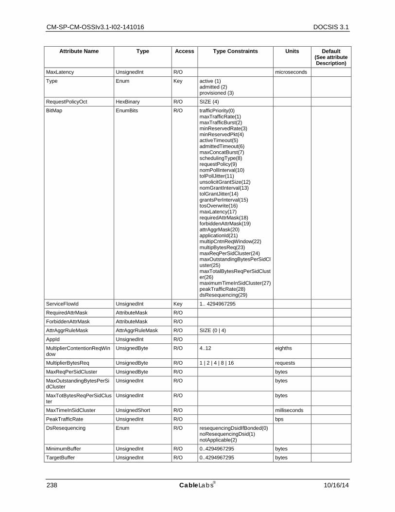
CM-SP-CM-OSSIv3.1-I02-141016 DOCSIS 3.1
238 CableLabs 10/16/14
Attribute Name Type Access Type Constraints Units Default (See attribute Description)
MaxLatency UnsignedInt R/O microseconds
Type Enum Key active (1) admitted (2) provisioned (3)
RequestPolicyOct HexBinary R/O SIZE (4)
BitMap EnumBits R/O trafficPriority(0) maxTrafficRate(1) maxTrafficBurst(2) minReservedRate(3) minReservedPkt(4) activeTimeout(5) admittedTimeout(6) maxConcatBurst(7) schedulingType(8) requestPolicy(9) nomPollInterval(10) tolPollJitter(11) unsolicitGrantSize(12) nomGrantInterval(13) tolGrantJitter(14) grantsPerInterval(15) tosOverwrite(16) maxLatency(17) requiredAttrMask(18) forbiddenAttrMask(19) attrAggrMask(20) applicationId(21) multipCntnReqWindow(22) multipBytesReq(23) maxReqPerSidCluster(24) maxOutstandingBytesPerSidCluster(25) maxTotalBytesReqPerSidCluster(26) maximumTimeInSidCluster(27) peakTrafficRate(28) dsResequencing(29)
ServiceFlowId UnsignedInt Key 1.. 4294967295
RequiredAttrMask AttributeMask R/O
ForbiddenAttrMask AttributeMask R/O
AttrAggrRuleMask AttrAggrRuleMask R/O SIZE (0 | 4)
AppId UnsignedInt R/O
MultiplierContentionReqWindow
UnsignedByte R/O 4..12 eighths
MultiplierBytesReq UnsignedByte R/O 1 | 2 | 4 | 8 | 16 requests
MaxReqPerSidCluster UnsignedByte R/O bytes
MaxOutstandingBytesPerSidCluster
UnsignedInt R/O bytes
MaxTotBytesReqPerSidCluster
UnsignedInt R/O bytes
MaxTimeInSidCluster UnsignedShort R/O milliseconds
PeakTrafficRate UnsignedInt R/O bps
DsResequencing Enum R/O resequencingDsidIfBonded(0) noResequencingDsid(1) notApplicable(2)
MinimumBuffer UnsignedInt R/O 0..4294967295 bytes
TargetBuffer UnsignedInt R/O 0..4294967295 bytes

Cable Modem Operations Support System Interface Specification CM-SP-CM-OSSIv3.1-I02-141016
10/16/14 CableLabs 239
Attribute Name Type Access Type Constraints Units Default (See attribute Description)
MaximumBuffer UnsignedInt R/O 0..4294967295 bytes
AqmEnabled Boolean R/O
AqmLatencyTarget UnsignedShort R/O 0..256 msec
AqmAlgInUse Enum R/O unknown(1) other(2) docsisPIE(3)
H.2.3.2.1 ifIndex
This key represents the interface index of the MAC Domain of the Service Flow.
H.2.3.2.1 ServiceClassName
This attribute represents the Service Class Name from which the parameter set values were derived. If the referenced parameter is not present in the corresponding DOCSIS QoS Parameter Set, this attribute returns the zero-length string.
References: [MULPIv3.1] Service Class Name section in the Common Radio Frequency Interface Encodings Annex.
H.2.3.2.1 Priority
This attribute represents the relative priority of a Service Flow. Higher numbers indicate higher priority. This priority should only be used to differentiate Service Flow from identical parameter sets. This attribute returns 0 if the referenced parameter is not present in the corresponding DOCSIS QoS Parameter Set or if the parameter is not applicable.
References: [MULPIv3.1] Traffic Priority section in the Common Radio Frequency Interface Encodings Annex.
H.2.3.2.1 MaxTrafficRate
This attribute represents the maximum sustained traffic rate allowed for this Service Flow in bits/sec. It counts all MAC frame data PDUs from the bytes following the MAC header HCS to the end of the CRC. The number of bytes forwarded is limited during any time interval. The value 0 means no maximum traffic rate is enforced. This attribute applies to both upstream and downstream Service Flows. This attribute returns 0 if the referenced parameter is not present in the corresponding DOCSIS QoS Parameter Set, or if the parameter is not applicable.
References: [MULPIv3.1] Maximum Sustained Traffic Rate section in the Common Radio Frequency Interface Encodings Annex.
H.2.3.2.1 MaxTrafficBurst
This attribute specifies the token bucket size in bytes for this parameter set. The value is calculated from the byte following the MAC header HCS to the end of the CRC. This object is applied in conjunction with MaxTrafficRate to calculate maximum sustained traffic rate. If the referenced parameter is not present in the corresponding DOCSIS QoS Parameter Set, this attribute returns 3044 for scheduling types 'bestEffort', 'nonRealTimePollingService' and 'realTimePollingService'. If this parameter is not applicable, it is reported as 0.
References: [MULPIv3.1] Maximum Traffic Burst section in the Common Radio Frequency Interface Encodings Annex.
H.2.3.2.1 MinReservedRate
This attribute specifies the guaranteed minimum rate in bits/sec for this parameter set. The value is calculated from the byte following the MAC header HCS to the end of the CRC. The value of 0 indicates that no bandwidth is

CM-SP-CM-OSSIv3.1-I02-141016 DOCSIS 3.1
240 CableLabs 10/16/14
reserved. If the referenced parameter is not present in the corresponding DOCSIS QoS Parameter Set, this attribute returns 0. If the parameter is not applicable, it is reported as 0.
References: [MULPIv3.1] Minimum Reserved Traffic Rate section of the Common Radio Frequency Interface Encodings Annex.
H.2.3.2.1 MinReservedPkt
This attribute specifies an assumed minimum packet size in bytes for which the MinReservedRate will be provided. The value is calculated from the byte following the MAC header HCS to the end of the CRC. If the referenced parameter is omitted from a DOCSIS QoS parameter set, the used and reported value is CMTS implementation and the CM reports a value of 0. If the referenced parameter is not applicable to the direction or scheduling type of the Service Flow, both CMTS and CM report the value 0.
References: [MULPIv3.1] Assumed Minimum Reserved Rate Packet Size, in the Common Radio Frequency Interface Encodings Annex.
H.2.3.2.1 ActiveTimeout
This attribute specifies the maximum duration in seconds that resources remain unused on an active service flow before the CMTS signals that both the active and admitted parameter sets are null. The value 0 signifies an infinite amount of time. If the referenced parameter is not present in the corresponding DOCSIS QoS Parameter Set, this attribute returns 0.
References: [MULPIv3.1] Timeout for Active QoS Parameters section in the Common Radio Frequency Interface Encodings Annex.
H.2.3.2.1 AdmittedTimeout
This attribute specifies the maximum duration in seconds that resources remain in admitted state before resources must be released. The value of 0 signifies an infinite amount of time. If the referenced parameter is not present in the corresponding DOCSIS QoS Parameter Set, this attribute returns 200.
References: [MULPIv3.1] Timeout for Admitted QoS Parameters section in the Common Radio Frequency Interface Encodings Annex.
H.2.3.2.1 MaxConcatBurst
This attribute specifies the maximum concatenated burst in bytes that an upstream Service Flow is allowed. The value is calculated from the FC byte of the Concatenation MAC Header to the last CRC byte of the last concatenated MAC frame, inclusive. The value of 0 specifies no maximum burst. If the referenced parameter is not present in the corresponding DOCSIS QoS Parameter Set, this attribute returns the value of 1522 for scheduling types 'bestEffort', 'nonRealTimePollingService', and 'realTimePollingService'. If the parameter is not applicable, it is reported as 0.
References: [MULPIv3.1] Maximum Concatenated Burst section in the Common Radio Frequency Interface Encodings Annex.
H.2.3.2.1 SchedulingType
This attribute specifies the upstream scheduling service used for upstream Service Flow. If the referenced parameter is not present in the corresponding DOCSIS QoS Parameter Set of an upstream Service Flow, this attribute returns the value of 'bestEffort'. For QoS parameter sets of downstream Service Flows, this attribute's value is reported as 'undefined'.
References: [MULPIv3.1] Service Flow Scheduling Type section in the Common Radio Frequency Interface Encodings Annex.
H.2.3.2.1 NomPollInterval
This attribute specifies the nominal interval in microseconds between successive unicast request opportunities on an upstream Service Flow. This attribute applies only to upstream Service Flows with SchedulingType of value

Cable Modem Operations Support System Interface Specification CM-SP-CM-OSSIv3.1-I02-141016
10/16/14 CableLabs 241
'nonRealTimePollingService', 'realTimePollingService', and 'unsolictedGrantServiceWithAD'. The parameter is mandatory for 'realTimePollingService'. If the parameter is omitted with 'nonRealTimePollingService', the CMTS uses an implementation-dependent value. If the parameter is omitted with 'unsolictedGrantServiceWithAD(5)' the CMTS uses the value of the Nominal Grant Interval parameter. In all cases, the CMTS reports the value it is using when the parameter is applicable. The CM reports the signaled parameter value if it was signaled. Otherwise, it returns 0. If the referenced parameter is not applicable to the direction or scheduling type of the corresponding DOCSIS QoS Parameter Set, both CMTS and CM report this attribute's value as 0.
References: [MULPIv3.1] Polling Interval section in the Common Radio Frequency Interface Encodings Annex.
H.2.3.2.1 TolPollJitter
This attribute specifies the maximum amount of time in microseconds that the unicast request interval may be delayed from the nominal periodic schedule on an upstream Service Flow. This parameter is applicable only to upstream Service Flows with a SchedulingType of 'realTimePollingService' or 'unsolictedGrantServiceWithAD'. If the referenced parameter is applicable but not present in the corresponding DOCSIS QoS Parameter Set, the CMTS uses an implementation-dependent value and reports the value it is using. The CM reports a value of 0 in this case. If the parameter is not applicable to the direction or upstream scheduling type of the Service Flow, both CMTS and CM report this attribute's value as 0.
References: [MULPIv3.1] Tolerated Poll Jitter section in the Common Radio Frequency Interface Encodings Annex.
H.2.3.2.1 UnsolicitGrantSize
This attribute specifies the unsolicited grant size in bytes. The grant size includes the entire MAC frame data PDU from the Frame Control byte to the end of the MAC frame. The referenced parameter is applicable only for upstream flows with a SchedulingType of 'unsolicitedGrantServiceWithAD' or 'unsolicitedGrantService', and it is mandatory when applicable. Both CMTS and CM report the signaled value of the parameter in this case. If the referenced parameter is not applicable to the direction or scheduling type of the corresponding DOCSIS QoS Parameter Set, both CMTS and CM report this attribute's value as 0.
References: [MULPIv3.1] Unsolicited Grant Size section in the Common Radio Frequency Interface Encodings Annex.
H.2.3.2.1 NomGrantInterval
This attribute specifies the nominal interval in microseconds between successive data grant opportunities on an upstream Service Flow. The referenced parameter is applicable only for upstream flows with a SchedulingType of 'unsolicitedGrantServiceWithAD' or 'unsolicitedGrantService(6)', and it is mandatory when applicable. Both CMTS and CM report the signaled value of the parameter in this case. If the referenced parameter is not applicable to the direction or scheduling type of the corresponding DOCSIS QoS Parameter Set, both CMTS and CM report this attribute's value as 0.
References: [MULPIv3.1] Nominal Grant Interval section in the Common Radio Frequency Interface Encodings Annex.
H.2.3.2.1 TolGrantJitter
This attribute specifies the maximum amount of time in microseconds that the transmission opportunities may be delayed from the nominal periodic schedule. The referenced parameter is applicable only for upstream flows with a SchedulingType of 'unsolicitedGrantServiceWithAD' or 'unsolicitedGrantService(6)', and it is mandatory when applicable. Both CMTS and CM report the signaled value of the parameter in this case. If the referenced parameter is not applicable to the direction or scheduling type of the corresponding DOCSIS QoS Parameter Set, both CMTS and CM report this attribute's value as 0.
References: [MULPIv3.1] Tolerated Grant Jitter section in the Common Radio Frequency Interface Encodings Annex.
CM-SP-CM-OSSIv3.1-I02-141016 DOCSIS 3.1
242 CableLabs 10/16/14
H.2.3.2.1 GrantsPerInterval
This attribute specifies the number of data grants per Nominal Grant Interval (NomGrantInterval). The referenced parameter is applicable only for upstream flows with a SchedulingType of 'unsolicitedGrantServiceWithAD' or 'unsolicitedGrantService', and it is mandatory when applicable. Both CMTS and CM report the signaled value of the parameter in this case. If the referenced parameter is not applicable to the direction or scheduling type of the corresponding DOCSIS QoS Parameter Set, both CMTS and CM report this attribute's value as 0.
References: [MULPIv3.1] Grants per Interval section in the Common Radio Frequency Interface Encodings Annex.
H.2.3.2.1 TosAndMask
This attribute specifies the AND mask for the IP TOS byte for overwriting an IPv4 packet's TOS value or IPv6 packet's Traffic Class value. The IP packet TOS byte is bitwise ANDed with TosAndMask, then the result is bitwise ORed with TosORMask and the result is written to the IP packet TOS byte. A value of 'FF'H for TosAndMask and a value of '00'H for TosOrMask means that the IP Packet TOS byte is not overwritten. This combination is reported if the referenced parameter is not present in a QoS Parameter Set. The IP TOS octet as originally defined in [RFC 791] has been superseded by the 6-bit Differentiated Services Field (DSField, [RFC 3260]) and the 2-bit Explicit Congestion Notification Field (ECN field, [RFC 3168]). The IPv6 Traffic Class octet [RFC 2460] is consistent with that new definition. Network operators should avoid specifying values of TosAndMask and TosORMask that would result in the modification of the ECN bits. In particular, operators should not use values of TosAndMask that have either of the least-significant two bits set to 0. Similarly, operators should not use values of TosORMask that have either of the least-significant two bits set to 1. Even though this attribute is only enforced by the CMTS, the CM reports the value as signaled in the referenced parameter.
References: [MULPIv3.1] IP Type Of Service (DSCP) Overwrite section in the Common Radio Frequency Interface Encodings Annex; [RFC 3168]; [RFC 3260]; [RFC 2460]; [RFC 791].
H.2.3.2.1 TosOrMask
This attribute specifies the OR mask for the IPv4 TOS value or IPv6 Traffic Class value. See the description of TosAndMask for further details. The IP TOS octet, as originally defined in [RFC 791] has been superseded by the 6-bit Differentiated Services Field (DSField, [RFC 3260]) and the 2-bit Explicit Congestion Notification Field (ECN field, [RFC 3168]). The IPv6 Traffic Class octet [RFC 2460] is consistent with that new definition. Network operators should avoid specifying values of TosAndMask and TosORMask that would result in the modification of the ECN bits.
References: [MULPIv3.1] IP Type Of Service (DSCP) Overwrite section in the Common Radio Frequency Interface Encodings Annex; [RFC 3168]; [RFC 3260]; [RFC 2460]; [RFC 791].
H.2.3.2.1 MaxLatency
This attribute specifies the maximum latency between the reception of a packet by the CMTS on its NSI and the forwarding of the packet to the RF interface. A value of 0 signifies no maximum latency is enforced. This attribute only applies to downstream Service Flows. If the referenced parameter is not present in the corresponding downstream DOCSIS QoS Parameter Set, this attribute returns 0. This parameter is not applicable to upstream DOCSIS QoS Parameter Sets, so its value is reported as 0 in that case.
References: [MULPIv3.1] Maximum Downstream Latency section in the Common Radio Frequency Interface Encodings Annex.
H.2.3.2.1 Type
This key represents the QoS Parameter Set Type of the Service Flow. The following values are defined: 'active' Indicates the Active QoS parameter set, describing the service currently being provided by the DOCSIS MAC domain to the service flow. 'admitted' Indicates the Admitted QoS Parameter Set, describing services reserved by the DOCSIS MAC domain for use by the service flow. 'provisioned' Indicates the QoS Parameter Set defined in the DOCSIS CM Configuration file for the service flow.
Cable Modem Operations Support System Interface Specification CM-SP-CM-OSSIv3.1-I02-141016
10/16/14 CableLabs 243
References: [MULPIv3.1] Service Flow Scheduling Type section in the Common Radio Frequency Interface Encodings Annex.
H.2.3.2.1 RequestPolicyOct
This attribute specifies which transmit interval opportunities the CM omits for upstream transmission requests and packet transmissions. This object takes its default value for downstream Service Flows. Unless otherwise indicated, a bit value of 1 means that a CM must not use that opportunity for upstream transmission. The format of this string enumerated the bits from 0 to 31 from left to right, for example bit 0 corresponds to the left most bit of the fourth octet. (octets numbered from right to left). The bit positions are defined as follows:
'broadcastReqOpp' - all CMs broadcast request opportunities
'priorityReqMulticastReq' - priority request multicast request opportunities
'reqDataForReq' - request/data opportunities for requests
'reqDataForData' - request/data opportunities for data
'piggybackReqWithData' - piggyback requests with data
'concatenateData' - concatenate data
'fragmentData' - fragment data
'suppressPayloadHeaders' - suppress payload headers
'dropPktsExceedUGSize' - A value of 1 means that the service flow must drop packets that do not fit in the Unsolicited Grant size. If the referenced parameter is not present in a QoS Parameter Set, the value of this object is reported as '00000000'H.
References: [MULPIv3.1] Request/ Transmission Policy section in the Common Radio Frequency Interface Encodings Annex.
H.2.3.2.1 BitMap
This attribute indicates the set of QoS Parameter Set parameters actually signaled in the DOCSIS registration or dynamic service request message that created or modified the QoS Parameter Set. A bit is set to 1 when the associated parameter is present in the original request as follows:
'trafficPriority' Traffic Priority
'maxTrafficRate' Maximum Sustained Traffic Rate
'maxTrafficBurst' Maximum Traffic Burst
'minReservedRate' Minimum Reserved Traffic Rate
'minReservedPkt' Assumed Minimum Reserved Rate Packet Size
'activeTimeout' Timeout for Active QoS Parameters
'admittedTimeout' Timeout for Admitted QoS Parameters
'maxConcatBurst' Maximum Concatenated Burst
'schedulingType' Service Flow Scheduling Type
'requestPolicy' Request/Transmission Policy
'nomPollInterval' Nominal Polling Interval
'tolPollJitter' Tolerated Poll Jitter
'unsolicitGrantSize' Unsolicited Grant Size
'nomGrantInterval' Nominal Grant Interval
'tolGrantJitter' Tolerated Grant Jitter
CM-SP-CM-OSSIv3.1-I02-141016 DOCSIS 3.1
244 CableLabs 10/16/14
'grantsPerInterval' Grants per Interval
'tosOverwrite' IP Type of Service (DSCP) Overwrite
'maxLatency' Maximum Downstream Latency
'requiredAttrMask' Service Flow Required Attribute Mask
'forbiddenAttrMask Service Flow Forbidden Attribute Mask
'attrAggrMask' Service Flow Attribute Aggregation Mask
'applicationId' Application Identifier
'multipCntnReqWindow' Multiplier to Contention Request Backoff Window
'multipBytesReq' Multiplier to Number of Bytes Requested
'maxReqPerSidCluster' Maximum Requests per SID Cluster
'maxOutstandingBytesPerSidCluster' Maximum Outstanding Bytes per SID Cluster
'maxTotalBytesReqPerSidCluster' Maximum Total Bytes Requested per SID Cluster
'maximumTimeInSidCluster' Maximum Time in the SID Cluster
'peakTrafficRate' Peak Traffic Rate
'dsResequencing' - Downstream Resequencing
Note that when Service Class names are expanded, the registration or dynamic response message may contain parameters expanded by the CMTS based on a stored service class. These expanded parameters are not indicated by a 1 bit in this attribute. Note that even though some QoS Parameter Set parameters may not be signaled in a message (so that the parameter's bit in this object is 0), the DOCSIS specification requires that default values be used. These default values are reported as the corresponding attribute.
References: [MULPIv3.1] Service Flow Encodings section in the Common Radio Frequency Interface Encodings Annex.
H.2.3.2.1 ServiceFlowId
This key represents the Service Flow ID for the service flow.
References: [MULPIv3.1] Service Identifier section in the Common Radio Frequency Interface Encodings Annex.
H.2.3.2.1 RequiredAttrMask
This attribute specifies the Required Attribute Mask to compare with the Provisioned Required Attributes when selecting the bonding groups for the service flow.
If the referenced parameter is not present in the corresponding DOCSIS QoS Parameter Set, this attribute returns '00000000'H.
References: [MULPIv3.1] Service Flow Required Attribute Mask section in the Common Radio Frequency Interface Encodings Annex.
H.2.3.2.1 ForbiddenAttrMask
This attribute specifies the Forbidden Attribute Mask to compare with the Provisioned Forbidden Attributes when selecting the bonding groups for the service flow.
References: [MULPIv3.1] Service Flow Forbidden Attribute Mask section in the Common Radio Frequency Interface Encodings Annex.
If the referenced parameter is not present in the corresponding DOCSIS QoS Parameter Set, this attribute returns '00000000'H.
Cable Modem Operations Support System Interface Specification CM-SP-CM-OSSIv3.1-I02-141016
10/16/14 CableLabs 245
H.2.3.2.1 AttrAggrRuleMask
This attribute specifies the Attribute Aggregation Mask to compare the Service Flow Required and Forbidden Attributes with the CMTS dynamically-created bonding group when selecting the bonding groups for the service flow.
References: [MULPIv3.1] Service Flow Attribute Aggregation Mask section in the Common Radio Frequency Interface Encodings Annex.
If the referenced parameter is not present in the corresponding DOCSIS QoS Parameter Set, this attribute returns '00000000'H.
H.2.3.2.1 AppId
This attribute represents the Application Identifier associated with the service flow for purposes beyond the scope of this specification.
If the referenced parameter is not present in the corresponding DOCSIS QoS Parameter Set, this attribute returns 0.
References: [MULPIv3.1] Application Identifier section in the Common Radio Frequency Interface Encodings Annex.
H.2.3.2.1 MultiplierContentionReqWindow
This attribute specifies the multiplier to be applied by a CM when performing contention request backoff for data requests. This attribute only applies to upstream Service Flows in 3.0 operation. if the referenced parameter is not present in the upstream DOCSIS QoS Parameter Set, or is not applicable, this attribute returns 8.
References: [MULPIv3.1] Multiplier to Contention Request Backoff Window section in the Common Radio Frequency Interface Encodings Annex.
H.2.3.2.1 MultiplierBytesReq
This attribute specifies the assumed bandwidth request multiplier. This attribute only applies to upstream Service Flows in 3.0 operation. If the referenced parameter is not present in the upstream DOCSIS QoS Parameter Set, or is not applicable, this attribute returns 4.
References: [MULPIv3.1] Multiplier to Number of Bytes Requested section in the Common Radio Frequency Interface Encodings Annex.
H.2.3.2.1 MaxReqPerSidCluster
This attribute specifies the maximum number of requests that a CM can make within a given SID Cluster before it must switch to a different SID Cluster to make further requests. A value of 0 indicates there is no limit. This attribute only applies to upstream Service Flows in 3.0 operation, in other cases it is reported as 0. If the referenced parameter is not present in the DOCSIS QoS Parameter Set, this attribute returns 0.
Note: This attribute has been deprecated and replaced with MaxReqPerSidCluster in the ServiceFlow object.
References: [MULPIv3.1] Maximum Requests per SID Cluster section in the Common Radio Frequency Interface Encodings Annex.
H.2.3.2.1 MaxOutstandingBytesPerSidCluster
This attribute specifies the maximum number of bytes for which a CM can have requests outstanding on a given SID Cluster. If defined number of bytes are outstanding and further requests are required, the CM must switch to a different SID Cluster if one is available. A value of 0 indicates there is no limit. This attribute only applies to upstream Service Flows in 3.0 operation, in other cases it is reported as 0. If the referenced parameter is not present in the DOCSIS QoS Parameter Set, this attribute returns 0.
Note: This attribute has been deprecated and replaced with MaxOutstandingBytesPerSidCluster in the ServiceFlow object.
CM-SP-CM-OSSIv3.1-I02-141016 DOCSIS 3.1
246 CableLabs 10/16/14
References: [MULPIv3.1] Maximum Outstanding Bytes per SID Cluster section in the Common Radio Frequency Interface Encodings Annex.
H.2.3.2.1 MaxTotBytesReqPerSidCluster
This attribute specifies the maximum total number of bytes a CM can have requested using a given SID Cluster before it must switch to a different SID Cluster to make further requests. A value of 0 indicates there is no limit. This attribute only applies to upstream Service Flows in 3.0 operation, in other cases it is reported as 0. If the referenced parameter is not present in the DOCSIS QoS Parameter Set, this attribute returns 0.
Note: This attribute has been deprecated and replaced with MaxTotBytesReqPerSidCluster in the ServiceFlow object.
References: [MULPIv3.1] Maximum Total Bytes Requested per SID Cluster section in the Common Radio Frequency Interface Encodings Annex.
H.2.3.2.1 MaxTimeInSidCluster
This attribute specifies the maximum time in milliseconds that a CM may use a particular SID Cluster before it must switch to a different SID Cluster to make further requests. A value of 0 indicates there is no limit. This attribute only applies to upstream Service Flows in 3.0 operation, in other cases it is reported as 0. If the referenced parameter is not present in the DOCSIS QoS Parameter Set, this attribute returns 0.
Note: This attribute has been deprecated and replaced with MaxTimeInSidCluster in the ServiceFlow object.
References: [MULPIv3.1] Maximum Time in the SID Cluster section in the Common Radio Frequency Interface Encodings Annex.
H.2.3.2.1 PeakTrafficRate
This attribute specifies the rate parameter 'P' of a token-bucket-based peak rate limiter for packets of a service flow. A value of 0 signifies no Peak Traffic Rate is enforced. If the referenced parameter is not present in the corresponding DOCSIS QoS Parameter Set, this attribute returns 0.
References: [MULPIv3.1] Peak Traffic Rate section in the Common Radio Frequency Interface Encodings Annex.
H.2.3.2.1 DsResequencing
This attribute specifies if a resequencing DSID needs to be allocated to the service flow.
The value 'notApplicable' indicates the value of this attribute is not applicable.
The value 'resequencingDsid' indicates that a resequencing DSID is required if the service flow is assigned to a downstream bonding group
The value 'noResequencingDsid' indicates no resequencing DSID is associated with the service flow.
This attribute only applies to downstream Service Flows in 3.0 operation. If the referenced parameter is not present in the corresponding downstream DOCSIS QoS Parameter Set, this attribute returns 'notApplicable'. This parameter is not applicable to upstream DOCSIS QoS Parameter Sets, so the value 'notApplicable' is reported in that case.
References: [MULPIv3.1] Downstream Resequencing section in the Common Radio Frequency Interface Encodings Annex.
H.2.3.2.2 MinimumBuffer
This attribute represents the configured minimum buffer size for the service flow.
References: [MULPIv3.1] Buffer Control section in the Common Radio Frequency Interface Encodings Annex.
H.2.3.2.3 TargetBuffer
This attribute represents the configured target buffer size for the service flow. The value 0 indicates that no target buffer size was configured, and the device will use a vendor specific value.

Cable Modem Operations Support System Interface Specification CM-SP-CM-OSSIv3.1-I02-141016
10/16/14 CableLabs 247
References: [MULPIv3.1] Buffer Control section in the Common Radio Frequency Interface Encodings Annex.
H.2.3.2.4 MaximumBuffer
This attribute represents the configured maximum buffer size for the service flow. The value 4294967295 indicates that no maximum buffer size was configured, and thus there is no limit to the buffer size.
References: [MULPIv3.1] Buffer Control section in the Common Radio Frequency Interface Encodings Annex.
H.2.3.2.5 AqmEnabled
If this attribute is set to 'false', AQM is disabled on the upstream or downstream service flow specified by ServiceFlowId.
References: [MULPIv3.1] AQM Encodings section in the Common Radio Frequency Interface Encodings Annex.
H.2.3.2.6 AqmLatencyTarget
This attribute provides the latency target to be used for the AQM algorithm for the upstream or downstream Service Flow specified by ServiceFlowId. For downstream service flows, the value 256 indicates an unknown latency target. The units are in milliseconds.
References: [MULPIv3.1] AQM Encodings section in the Common Radio Frequency Interface Encodings Annex.
H.2.3.2.7 AqmAlgInUse
This attribute specifies the AQM algorithm in use for this service flow. If AQM is disabled on the service flow specified by ServiceFlowId, this attribute returns unknown(1).
The value unknown(1) is reported for downstream service flows or when AQM is disabled.
The value other(2) indicates a vendor proprietary algorithm for upstream queue management.
The value docsisPIE(3) indicates the upstream queue management Proportional Integral controller Enhanced (PIE) algorithm.
References: [MULPIv3.1] Proportional-Integral-Enhanced Active Queue Management Algorithm Annex.
H.2.3.3 ServiceFlow Object This object describes the set of DOCSIS-QoS Service Flows in a managed device.
References: [MULPIv3.1] Service Flows and Classifiers section.
Table H–6 - ServiceFlow Object
Attribute Name Type Access Type Constraints Units Default ifIndex InterfaceIndex Key Interface Index of MAC
Domain interface
Id UnsignedInt Key
SID UnsignedShort R/O 0..16383
Direction IfDirection R/O
Primary Boolean R/O
ParamSetTypeStatus EnumBits R/O active(0) admitted(1) provisioned(2)
ChSetId ChSetId R/O
AttrAssignSuccess Boolean R/O
Dsid Dsid R/O
MaxReqPerSidCluster UnsignedByte R/O requests
MaxOutstandingBytesPerSidCluster UnsignedInt R/O bytes
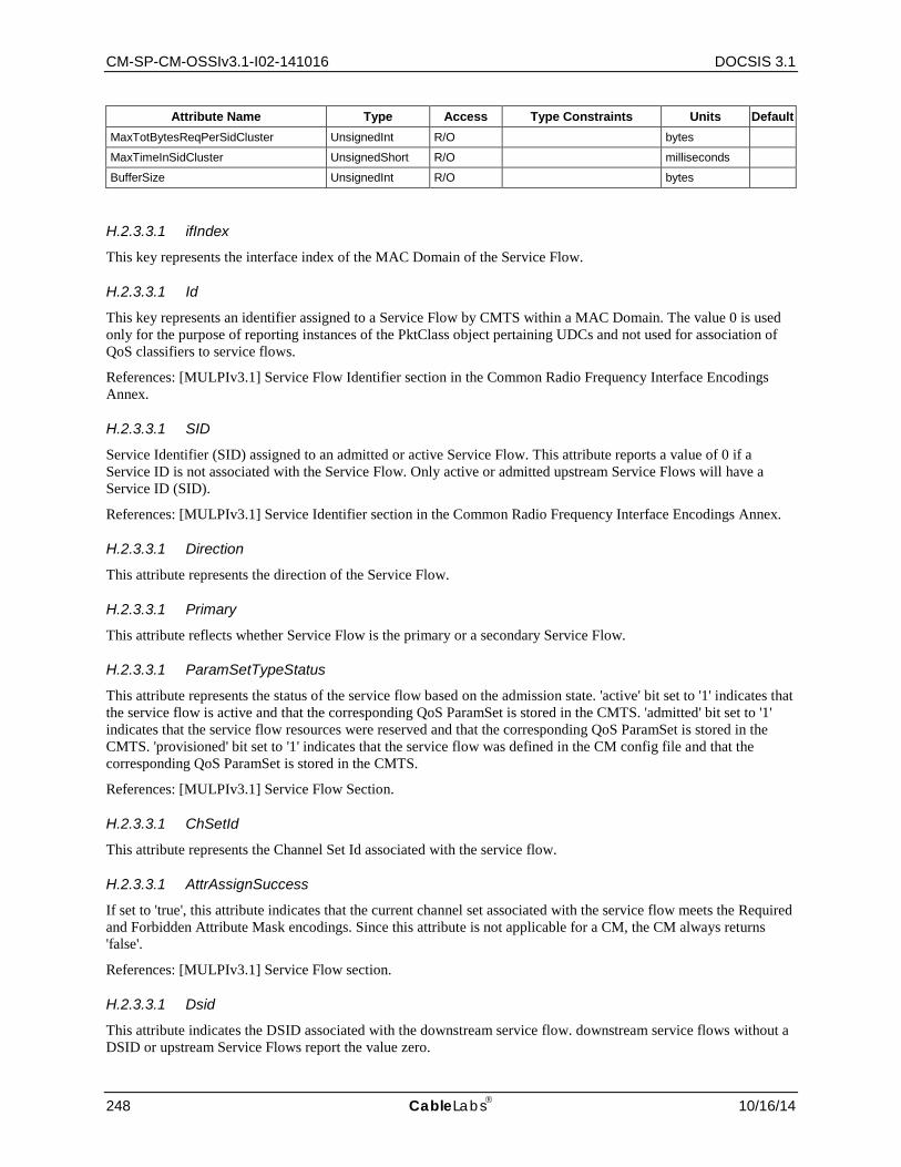
CM-SP-CM-OSSIv3.1-I02-141016 DOCSIS 3.1
248 CableLabs 10/16/14
Attribute Name Type Access Type Constraints Units Default MaxTotBytesReqPerSidCluster UnsignedInt R/O bytes
MaxTimeInSidCluster UnsignedShort R/O milliseconds
BufferSize UnsignedInt R/O bytes
H.2.3.3.1 ifIndex
This key represents the interface index of the MAC Domain of the Service Flow.
H.2.3.3.1 Id
This key represents an identifier assigned to a Service Flow by CMTS within a MAC Domain. The value 0 is used only for the purpose of reporting instances of the PktClass object pertaining UDCs and not used for association of QoS classifiers to service flows.
References: [MULPIv3.1] Service Flow Identifier section in the Common Radio Frequency Interface Encodings Annex.
H.2.3.3.1 SID
Service Identifier (SID) assigned to an admitted or active Service Flow. This attribute reports a value of 0 if a Service ID is not associated with the Service Flow. Only active or admitted upstream Service Flows will have a Service ID (SID).
References: [MULPIv3.1] Service Identifier section in the Common Radio Frequency Interface Encodings Annex.
H.2.3.3.1 Direction
This attribute represents the direction of the Service Flow.
H.2.3.3.1 Primary
This attribute reflects whether Service Flow is the primary or a secondary Service Flow.
H.2.3.3.1 ParamSetTypeStatus
This attribute represents the status of the service flow based on the admission state. 'active' bit set to '1' indicates that the service flow is active and that the corresponding QoS ParamSet is stored in the CMTS. 'admitted' bit set to '1' indicates that the service flow resources were reserved and that the corresponding QoS ParamSet is stored in the CMTS. 'provisioned' bit set to '1' indicates that the service flow was defined in the CM config file and that the corresponding QoS ParamSet is stored in the CMTS.
References: [MULPIv3.1] Service Flow Section.
H.2.3.3.1 ChSetId
This attribute represents the Channel Set Id associated with the service flow.
H.2.3.3.1 AttrAssignSuccess
If set to 'true', this attribute indicates that the current channel set associated with the service flow meets the Required and Forbidden Attribute Mask encodings. Since this attribute is not applicable for a CM, the CM always returns 'false'.
References: [MULPIv3.1] Service Flow section.
H.2.3.3.1 Dsid
This attribute indicates the DSID associated with the downstream service flow. downstream service flows without a DSID or upstream Service Flows report the value zero.
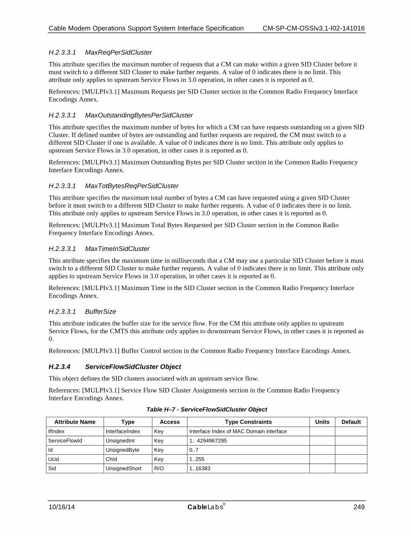
Cable Modem Operations Support System Interface Specification CM-SP-CM-OSSIv3.1-I02-141016
10/16/14 CableLabs 249
H.2.3.3.1 MaxReqPerSidCluster
This attribute specifies the maximum number of requests that a CM can make within a given SID Cluster before it must switch to a different SID Cluster to make further requests. A value of 0 indicates there is no limit. This attribute only applies to upstream Service Flows in 3.0 operation, in other cases it is reported as 0.
References: [MULPIv3.1] Maximum Requests per SID Cluster section in the Common Radio Frequency Interface Encodings Annex.
H.2.3.3.1 MaxOutstandingBytesPerSidCluster
This attribute specifies the maximum number of bytes for which a CM can have requests outstanding on a given SID Cluster. If defined number of bytes are outstanding and further requests are required, the CM must switch to a different SID Cluster if one is available. A value of 0 indicates there is no limit. This attribute only applies to upstream Service Flows in 3.0 operation, in other cases it is reported as 0.
References: [MULPIv3.1] Maximum Outstanding Bytes per SID Cluster section in the Common Radio Frequency Interface Encodings Annex.
H.2.3.3.1 MaxTotBytesReqPerSidCluster
This attribute specifies the maximum total number of bytes a CM can have requested using a given SID Cluster before it must switch to a different SID Cluster to make further requests. A value of 0 indicates there is no limit. This attribute only applies to upstream Service Flows in 3.0 operation, in other cases it is reported as 0.
References: [MULPIv3.1] Maximum Total Bytes Requested per SID Cluster section in the Common Radio Frequency Interface Encodings Annex.
H.2.3.3.1 MaxTimeInSidCluster
This attribute specifies the maximum time in milliseconds that a CM may use a particular SID Cluster before it must switch to a different SID Cluster to make further requests. A value of 0 indicates there is no limit. This attribute only applies to upstream Service Flows in 3.0 operation, in other cases it is reported as 0.
References: [MULPIv3.1] Maximum Time in the SID Cluster section in the Common Radio Frequency Interface Encodings Annex.
H.2.3.3.1 BufferSize
This attribute indicates the buffer size for the service flow. For the CM this attribute only applies to upstream Service Flows, for the CMTS this attribute only applies to downstream Service Flows, in other cases it is reported as 0.
References: [MULPIv3.1] Buffer Control section in the Common Radio Frequency Interface Encodings Annex.
H.2.3.4 ServiceFlowSidCluster Object This object defines the SID clusters associated with an upstream service flow.
References: [MULPIv3.1] Service Flow SID Cluster Assignments section in the Common Radio Frequency Interface Encodings Annex.
Table H–7 - ServiceFlowSidCluster Object
Attribute Name Type Access Type Constraints Units Default IfIndex InterfaceIndex Key Interface Index of MAC Domain interface
ServiceFlowId UnsignedInt Key 1.. 4294967295
Id UnsignedByte Key 0..7
Ucid ChId Key 1..255
Sid UnsignedShort R/O 1..16383
CM-SP-CM-OSSIv3.1-I02-141016 DOCSIS 3.1
250 CableLabs 10/16/14
H.2.3.4.1 IfIndex
This key represents the interface index of the MAC Domain of the Service Flow SID cluster.
H.2.3.4.1 ServiceFlowId
This key represents the Service Flow ID for the service flow.
H.2.3.4.1 Id
This key represents the identifier of the SID Cluster.
References: [MULPIv3.1] SID Cluster ID section in the Common Radio Frequency Interface Encodings Annex.
H.2.3.4.1 Ucid
This key represents the upstream Channel ID mapped to the corresponding SID.
H.2.3.4.1 Sid
This attribute represents the SID assigned to the upstream channel in this SID Cluster.
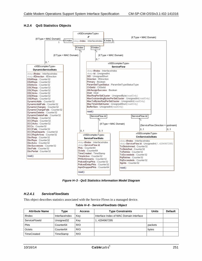
Cable Modem Operations Support System Interface Specification CM-SP-CM-OSSIv3.1-I02-141016
10/16/14 CableLabs 251
H.2.4 QoS Statistics Objects
Figure H–3 - QoS Statistics Information Model Diagram
H.2.4.1 ServiceFlowStats This object describes statistics associated with the Service Flows in a managed device.
Table H–8 - ServiceFlowStats Object
Attribute Name Type Access Type Constraints Units Default ifIndex InterfaceIndex Key Interface Index of MAC Domain interface
ServiceFlowId Unsigned32 Key 1..4294967295
Pkts Counter64 R/O packets
Octets Counter64 R/O bytes
TimeCreated TimeStamp R/O
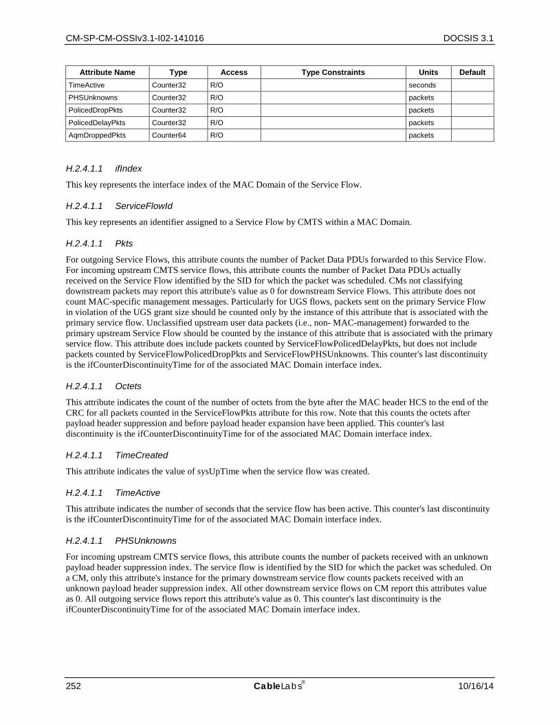
CM-SP-CM-OSSIv3.1-I02-141016 DOCSIS 3.1
252 CableLabs 10/16/14
Attribute Name Type Access Type Constraints Units Default TimeActive Counter32 R/O seconds
PHSUnknowns Counter32 R/O packets
PolicedDropPkts Counter32 R/O packets
PolicedDelayPkts Counter32 R/O packets
AqmDroppedPkts Counter64 R/O packets
H.2.4.1.1 ifIndex
This key represents the interface index of the MAC Domain of the Service Flow.
H.2.4.1.1 ServiceFlowId
This key represents an identifier assigned to a Service Flow by CMTS within a MAC Domain.
H.2.4.1.1 Pkts
For outgoing Service Flows, this attribute counts the number of Packet Data PDUs forwarded to this Service Flow. For incoming upstream CMTS service flows, this attribute counts the number of Packet Data PDUs actually received on the Service Flow identified by the SID for which the packet was scheduled. CMs not classifying downstream packets may report this attribute's value as 0 for downstream Service Flows. This attribute does not count MAC-specific management messages. Particularly for UGS flows, packets sent on the primary Service Flow in violation of the UGS grant size should be counted only by the instance of this attribute that is associated with the primary service flow. Unclassified upstream user data packets (i.e., non- MAC-management) forwarded to the primary upstream Service Flow should be counted by the instance of this attribute that is associated with the primary service flow. This attribute does include packets counted by ServiceFlowPolicedDelayPkts, but does not include packets counted by ServiceFlowPolicedDropPkts and ServiceFlowPHSUnknowns. This counter's last discontinuity is the ifCounterDiscontinuityTime for of the associated MAC Domain interface index.
H.2.4.1.1 Octets
This attribute indicates the count of the number of octets from the byte after the MAC header HCS to the end of the CRC for all packets counted in the ServiceFlowPkts attribute for this row. Note that this counts the octets after payload header suppression and before payload header expansion have been applied. This counter's last discontinuity is the ifCounterDiscontinuityTime for of the associated MAC Domain interface index.
H.2.4.1.1 TimeCreated
This attribute indicates the value of sysUpTime when the service flow was created.
H.2.4.1.1 TimeActive
This attribute indicates the number of seconds that the service flow has been active. This counter's last discontinuity is the ifCounterDiscontinuityTime for of the associated MAC Domain interface index.
H.2.4.1.1 PHSUnknowns
For incoming upstream CMTS service flows, this attribute counts the number of packets received with an unknown payload header suppression index. The service flow is identified by the SID for which the packet was scheduled. On a CM, only this attribute's instance for the primary downstream service flow counts packets received with an unknown payload header suppression index. All other downstream service flows on CM report this attributes value as 0. All outgoing service flows report this attribute's value as 0. This counter's last discontinuity is the ifCounterDiscontinuityTime for of the associated MAC Domain interface index.
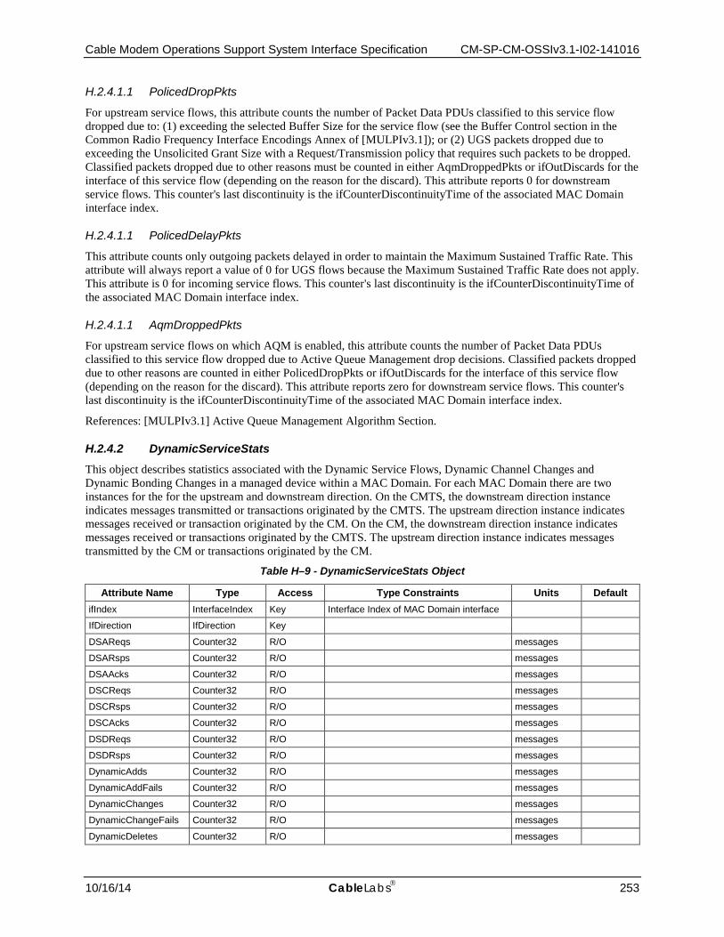
Cable Modem Operations Support System Interface Specification CM-SP-CM-OSSIv3.1-I02-141016
10/16/14 CableLabs 253
H.2.4.1.1 PolicedDropPkts
For upstream service flows, this attribute counts the number of Packet Data PDUs classified to this service flow dropped due to: (1) exceeding the selected Buffer Size for the service flow (see the Buffer Control section in the Common Radio Frequency Interface Encodings Annex of [MULPIv3.1]); or (2) UGS packets dropped due to exceeding the Unsolicited Grant Size with a Request/Transmission policy that requires such packets to be dropped. Classified packets dropped due to other reasons must be counted in either AqmDroppedPkts or ifOutDiscards for the interface of this service flow (depending on the reason for the discard). This attribute reports 0 for downstream service flows. This counter's last discontinuity is the ifCounterDiscontinuityTime of the associated MAC Domain interface index.
H.2.4.1.1 PolicedDelayPkts
This attribute counts only outgoing packets delayed in order to maintain the Maximum Sustained Traffic Rate. This attribute will always report a value of 0 for UGS flows because the Maximum Sustained Traffic Rate does not apply. This attribute is 0 for incoming service flows. This counter's last discontinuity is the ifCounterDiscontinuityTime of the associated MAC Domain interface index.
H.2.4.1.1 AqmDroppedPkts
For upstream service flows on which AQM is enabled, this attribute counts the number of Packet Data PDUs classified to this service flow dropped due to Active Queue Management drop decisions. Classified packets dropped due to other reasons are counted in either PolicedDropPkts or ifOutDiscards for the interface of this service flow (depending on the reason for the discard). This attribute reports zero for downstream service flows. This counter's last discontinuity is the ifCounterDiscontinuityTime of the associated MAC Domain interface index.
References: [MULPIv3.1] Active Queue Management Algorithm Section.
H.2.4.2 DynamicServiceStats This object describes statistics associated with the Dynamic Service Flows, Dynamic Channel Changes and Dynamic Bonding Changes in a managed device within a MAC Domain. For each MAC Domain there are two instances for the for the upstream and downstream direction. On the CMTS, the downstream direction instance indicates messages transmitted or transactions originated by the CMTS. The upstream direction instance indicates messages received or transaction originated by the CM. On the CM, the downstream direction instance indicates messages received or transactions originated by the CMTS. The upstream direction instance indicates messages transmitted by the CM or transactions originated by the CM.
Table H–9 - DynamicServiceStats Object
Attribute Name Type Access Type Constraints Units Default ifIndex InterfaceIndex Key Interface Index of MAC Domain interface
IfDirection IfDirection Key
DSAReqs Counter32 R/O messages
DSARsps Counter32 R/O messages
DSAAcks Counter32 R/O messages
DSCReqs Counter32 R/O messages
DSCRsps Counter32 R/O messages
DSCAcks Counter32 R/O messages
DSDReqs Counter32 R/O messages
DSDRsps Counter32 R/O messages
DynamicAdds Counter32 R/O messages
DynamicAddFails Counter32 R/O messages
DynamicChanges Counter32 R/O messages
DynamicChangeFails Counter32 R/O messages
DynamicDeletes Counter32 R/O messages

CM-SP-CM-OSSIv3.1-I02-141016 DOCSIS 3.1
254 CableLabs 10/16/14
Attribute Name Type Access Type Constraints Units Default DynamicDeleteFails Counter32 R/O messages
DCCReqs Counter32 R/O messages
DCCRsps Counter32 R/O messages
DCCAcks Counter32 R/O messages
DCCs Counter32 R/O messages
DCCFails Counter32 R/O messages
DCCRspDeparts Counter32 R/O messages
DCCRspArrives Counter32 R/O messages
DbcReqs Counter32 R/O messages
DbcRsps Counter32 R/O messages
DbcAcks Counter32 R/O messages
DbcSuccesses Counter32 R/O transactions
DbcFails Counter32 R/O transactions
DbcPartial Counter32 R/O transactions
H.2.4.2.1 ifIndex
This key represents the interface index of the MAC Domain.
H.2.4.2.1 IfDirection
This attribute indicates the interface direction for the instance the statistics are collected.
H.2.4.2.1 DSAReqs
This attribute indicates the number of Dynamic Service Addition Requests, including retries. Discontinuities in the value of this counter can occur at reinitialization of the managed system, and at other times as indicated by the value of ifCounterDiscontinuityTime of the associated MAC Domain interface index.
References: [MULPIv3.1] Dynamic Service Addition section; [RFC 2863]
H.2.4.2.1 DSARsps
The number of Dynamic Service Addition Responses, including retries. Discontinuities in the value of this counter can occur at reinitialization of the managed system, and at other times as indicated by the value of ifCounterDiscontinuityTime of the associated MAC Domain interface index.
References: [MULPIv3.1] Dynamic Service Addition section; [RFC 2863]
H.2.4.2.1 DSAAcks
The number of Dynamic Service Addition Acknowledgements, including retries. Discontinuities in the value of this counter can occur at reinitialization of the managed system, and at other times as indicated by the value of ifCounterDiscontinuityTime of the associated MAC Domain interface index.
References: [MULPIv3.1] Dynamic Service Addition section; [RFC 2863]
H.2.4.2.1 DSCReqs
The number of Dynamic Service Change Requests, including retries. Discontinuities in the value of this counter can occur at reinitialization of the managed system, and at other times as indicated by the value of ifCounterDiscontinuityTime of the associated MAC Domain interface index.
References: [MULPIv3.1] Dynamic Service Change section; [RFC 2863]
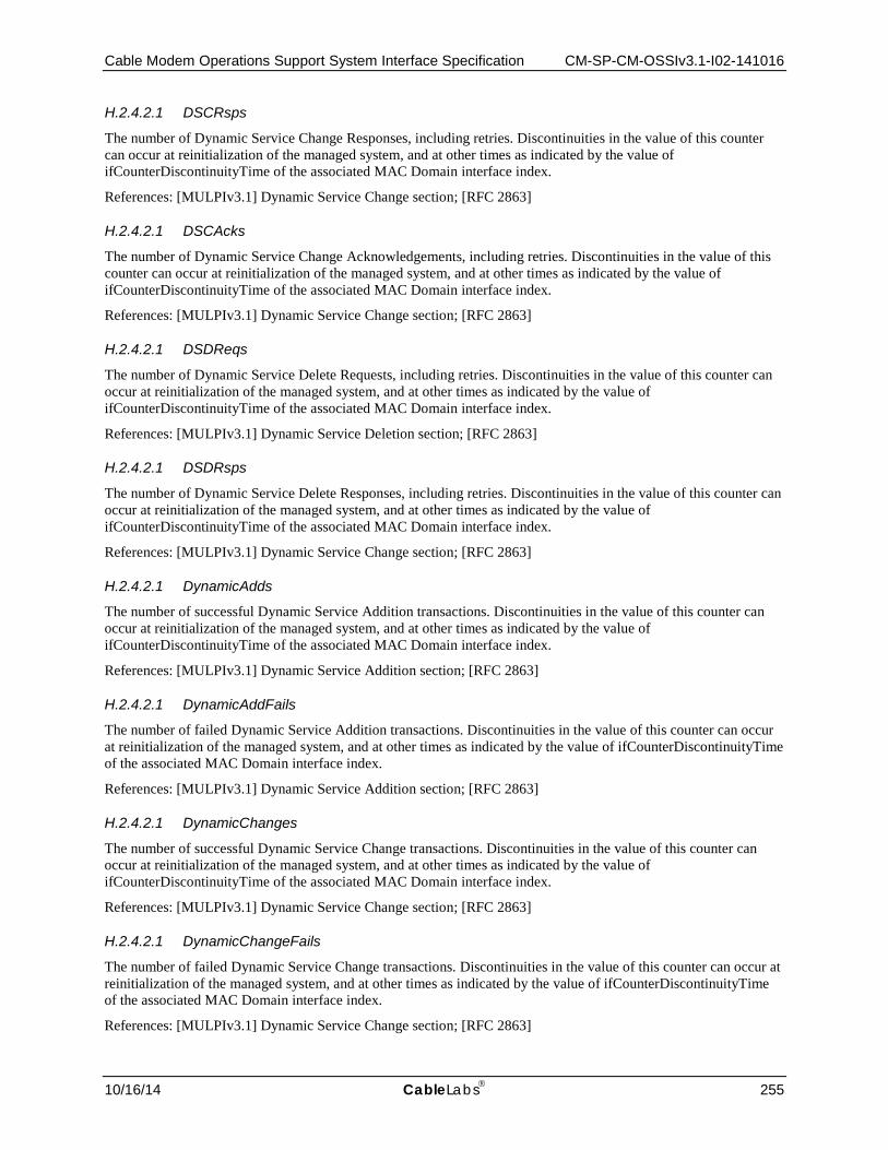
Cable Modem Operations Support System Interface Specification CM-SP-CM-OSSIv3.1-I02-141016
10/16/14 CableLabs 255
H.2.4.2.1 DSCRsps
The number of Dynamic Service Change Responses, including retries. Discontinuities in the value of this counter can occur at reinitialization of the managed system, and at other times as indicated by the value of ifCounterDiscontinuityTime of the associated MAC Domain interface index.
References: [MULPIv3.1] Dynamic Service Change section; [RFC 2863]
H.2.4.2.1 DSCAcks
The number of Dynamic Service Change Acknowledgements, including retries. Discontinuities in the value of this counter can occur at reinitialization of the managed system, and at other times as indicated by the value of ifCounterDiscontinuityTime of the associated MAC Domain interface index.
References: [MULPIv3.1] Dynamic Service Change section; [RFC 2863]
H.2.4.2.1 DSDReqs
The number of Dynamic Service Delete Requests, including retries. Discontinuities in the value of this counter can occur at reinitialization of the managed system, and at other times as indicated by the value of ifCounterDiscontinuityTime of the associated MAC Domain interface index.
References: [MULPIv3.1] Dynamic Service Deletion section; [RFC 2863]
H.2.4.2.1 DSDRsps
The number of Dynamic Service Delete Responses, including retries. Discontinuities in the value of this counter can occur at reinitialization of the managed system, and at other times as indicated by the value of ifCounterDiscontinuityTime of the associated MAC Domain interface index.
References: [MULPIv3.1] Dynamic Service Change section; [RFC 2863]
H.2.4.2.1 DynamicAdds
The number of successful Dynamic Service Addition transactions. Discontinuities in the value of this counter can occur at reinitialization of the managed system, and at other times as indicated by the value of ifCounterDiscontinuityTime of the associated MAC Domain interface index.
References: [MULPIv3.1] Dynamic Service Addition section; [RFC 2863]
H.2.4.2.1 DynamicAddFails
The number of failed Dynamic Service Addition transactions. Discontinuities in the value of this counter can occur at reinitialization of the managed system, and at other times as indicated by the value of ifCounterDiscontinuityTime of the associated MAC Domain interface index.
References: [MULPIv3.1] Dynamic Service Addition section; [RFC 2863]
H.2.4.2.1 DynamicChanges
The number of successful Dynamic Service Change transactions. Discontinuities in the value of this counter can occur at reinitialization of the managed system, and at other times as indicated by the value of ifCounterDiscontinuityTime of the associated MAC Domain interface index.
References: [MULPIv3.1] Dynamic Service Change section; [RFC 2863]
H.2.4.2.1 DynamicChangeFails
The number of failed Dynamic Service Change transactions. Discontinuities in the value of this counter can occur at reinitialization of the managed system, and at other times as indicated by the value of ifCounterDiscontinuityTime of the associated MAC Domain interface index.
References: [MULPIv3.1] Dynamic Service Change section; [RFC 2863]

CM-SP-CM-OSSIv3.1-I02-141016 DOCSIS 3.1
256 CableLabs 10/16/14
H.2.4.2.1 DynamicDeletes
The number of successful Dynamic Service Delete transactions. Discontinuities in the value of this counter can occur at reinitialization of the managed system, and at other times as indicated by the value of ifCounterDiscontinuityTime of the associated MAC Domain interface index.
References: [MULPIv3.1] Dynamic Service Delete section; [RFC 2863]
H.2.4.2.1 DynamicDeleteFails
The number of failed Dynamic Service Delete transactions. Discontinuities in the value of this counter can occur at reinitialization of the managed system, and at other times as indicated by the value of ifCounterDiscontinuityTime of the associated MAC Domain interface index.
References: [MULPIv3.1] Dynamic Service Delete section; [RFC 2863]
H.2.4.2.1 DCCReqs
The number of Dynamic Channel Change Request messages traversing an interface. This count is nonzero only on downstream direction rows. This count should include the number of retries. Discontinuities in the value of this counter can occur at reinitialization of the managed system, and at other times as indicated by the value of ifCounterDiscontinuityTime of the associated MAC Domain interface index.
References: [MULPIv3.1] Dynamic Downstream and/or Upstream Channel Changes section; [RFC 2863]
H.2.4.2.1 DCCRsps
The number of Dynamic Channel Change Response messages traversing an interface. This count is nonzero only on upstream direction rows. This count should include the number of retries. Discontinuities in the value of this counter can occur at reinitialization of the managed system, and at other times as indicated by the value of ifCounterDiscontinuityTime of the associated MAC Domain interface index.
References: [MULPIv3.1] Dynamic Downstream and/or Upstream Channel Changes section; [RFC 2863]
H.2.4.2.1 DCCAcks
The number of Dynamic Channel Change Acknowledgement messages traversing an interface. This count is nonzero only on downstream direction rows. This count should include the number of retries. Discontinuities in the value of this counter can occur at reinitialization of the managed system, and at other times as indicated by the value of ifCounterDiscontinuityTime of the associated MAC Domain interface index.
References: [MULPIv3.1] Dynamic Downstream and/or Upstream Channel Changes section; [RFC 2863]
H.2.4.2.1 DCCs
The number of successful Dynamic Channel Change transactions. This count is nonzero only on downstream direction rows. Discontinuities in the value of this counter can occur at reinitialization of the managed system, and at other times as indicated by the value of ifCounterDiscontinuityTime of the associated MAC Domain interface index.
References: [MULPIv3.1] Dynamic Downstream and/or Upstream Channel Changes section; [RFC 2863]
H.2.4.2.1 DCCFails
The number of failed Dynamic Channel Change transactions. This count is nonzero only on downstream direction rows. Discontinuities in the value of this counter can occur at reinitialization of the managed system, and at other times as indicated by the value of ifCounterDiscontinuityTime of the associated MAC Domain interface index.
References: [MULPIv3.1] Dynamic Downstream and/or Upstream Channel Changes section; [RFC 2863]
H.2.4.2.1 DccRspDeparts
This attribute contains the number of Dynamic Channel Change Response (depart) messages. It only applies to upstream direction. Discontinuities in the value of this counter can occur at reinitialization of the managed system,

Cable Modem Operations Support System Interface Specification CM-SP-CM-OSSIv3.1-I02-141016
10/16/14 CableLabs 257
and at other times as indicated by the value of ifCounterDiscontinuityTime of the associated MAC Domain interface index.
References: [MULPIv3.1] Dynamic Downstream and/or Upstream Channel Changes section; [RFC 2863]
H.2.4.2.1 DccRspArrives
This attribute contains the number of Dynamic Channel Change Response (arrive) messages and should include retries. It only applies to the upstream direction. Discontinuities in the value of this counter can occur at reinitialization of the managed system, and at other times as indicated by the value of ifCounterDiscontinuityTime of the associated MAC Domain interface index.
References: [MULPIv3.1] Dynamic Downstream and/or Upstream Channel Changes section; [RFC 2863]
H.2.4.2.1 DbcReqs
This attribute contains the number of Dynamic Bonding Change Requests, including retries. It only applies to the upstream direction. Discontinuities in the value of this counter can occur at reinitialization of the managed system, and at other times as indicated by the value of ifCounterDiscontinuityTime of the associated MAC Domain interface index.
References: [MULPIv3.1] Dynamic Bonding Change (DBC) section; [RFC 2863]
H.2.4.2.1 DbcRsps
This attribute contains the number of Dynamic Bonding Change Responses, including retries. It only applies to the upstream direction. Discontinuities in the value of this counter can occur at reinitialization of the managed system, and at other times as indicated by the value of ifCounterDiscontinuityTime of the associated MAC Domain interface index.
References: [MULPIv3.1] Dynamic Bonding Change (DBC) section; [RFC 2863]
H.2.4.2.1 DbcAcks
This attribute contains the number of Dynamic Bonding Change Acknowledgements, including retries. It only applies to the downstream direction. Discontinuities in the value of this counter can occur at reinitialization of the managed system, and at other times as indicated by the value of ifCounterDiscontinuityTime of the associated MAC Domain interface index.
References: [MULPIv3.1] Dynamic Bonding Change (DBC) section; [RFC 2863]
H.2.4.2.1 DbcSuccesses
This attribute contains the number of fully successful Dynamic Bonding Change transactions. It only applies to the downstream direction and does not include DBC transactions that result in Partial Service. Discontinuities in the value of this counter can occur at reinitialization of the managed system, and at other times as indicated by the value of ifCounterDiscontinuityTime of the associated MAC Domain interface index.
References: [MULPIv3.1] Dynamic Bonding Change (DBC) section; [RFC 2863]
H.2.4.2.1 DbcFails
This attribute contains the number of failed Dynamic Bonding Change transactions. It only applies to the downstream direction. Note that Partial Service is not considered a failed transaction. Discontinuities in the value of this counter can occur at reinitialization of the managed system, and at other times as indicated by the value of ifCounterDiscontinuityTime of the associated MAC Domain interface index.
References: [MULPIv3.1] Dynamic Bonding Change (DBC) section; [RFC 2863]
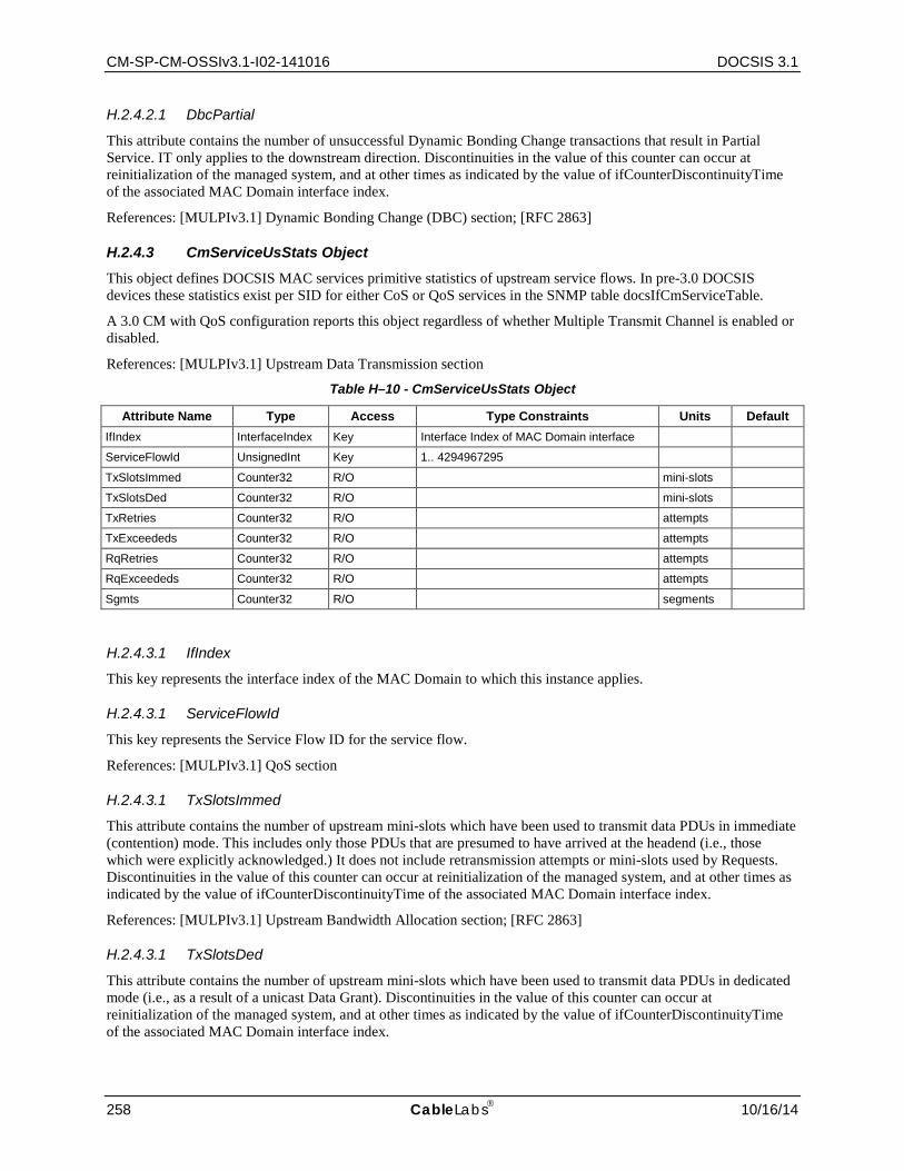
CM-SP-CM-OSSIv3.1-I02-141016 DOCSIS 3.1
258 CableLabs 10/16/14
H.2.4.2.1 DbcPartial
This attribute contains the number of unsuccessful Dynamic Bonding Change transactions that result in Partial Service. IT only applies to the downstream direction. Discontinuities in the value of this counter can occur at reinitialization of the managed system, and at other times as indicated by the value of ifCounterDiscontinuityTime of the associated MAC Domain interface index.
References: [MULPIv3.1] Dynamic Bonding Change (DBC) section; [RFC 2863]
H.2.4.3 CmServiceUsStats Object This object defines DOCSIS MAC services primitive statistics of upstream service flows. In pre-3.0 DOCSIS devices these statistics exist per SID for either CoS or QoS services in the SNMP table docsIfCmServiceTable.
A 3.0 CM with QoS configuration reports this object regardless of whether Multiple Transmit Channel is enabled or disabled.
References: [MULPIv3.1] Upstream Data Transmission section
Table H–10 - CmServiceUsStats Object
Attribute Name Type Access Type Constraints Units Default IfIndex InterfaceIndex Key Interface Index of MAC Domain interface
ServiceFlowId UnsignedInt Key 1.. 4294967295
TxSlotsImmed Counter32 R/O mini-slots
TxSlotsDed Counter32 R/O mini-slots
TxRetries Counter32 R/O attempts
TxExceededs Counter32 R/O attempts
RqRetries Counter32 R/O attempts
RqExceededs Counter32 R/O attempts
Sgmts Counter32 R/O segments
H.2.4.3.1 IfIndex
This key represents the interface index of the MAC Domain to which this instance applies.
H.2.4.3.1 ServiceFlowId
This key represents the Service Flow ID for the service flow.
References: [MULPIv3.1] QoS section
H.2.4.3.1 TxSlotsImmed
This attribute contains the number of upstream mini-slots which have been used to transmit data PDUs in immediate (contention) mode. This includes only those PDUs that are presumed to have arrived at the headend (i.e., those which were explicitly acknowledged.) It does not include retransmission attempts or mini-slots used by Requests. Discontinuities in the value of this counter can occur at reinitialization of the managed system, and at other times as indicated by the value of ifCounterDiscontinuityTime of the associated MAC Domain interface index.
References: [MULPIv3.1] Upstream Bandwidth Allocation section; [RFC 2863]
H.2.4.3.1 TxSlotsDed
This attribute contains the number of upstream mini-slots which have been used to transmit data PDUs in dedicated mode (i.e., as a result of a unicast Data Grant). Discontinuities in the value of this counter can occur at reinitialization of the managed system, and at other times as indicated by the value of ifCounterDiscontinuityTime of the associated MAC Domain interface index.
Cable Modem Operations Support System Interface Specification CM-SP-CM-OSSIv3.1-I02-141016
10/16/14 CableLabs 259
References: [MULPIv3.1] Upstream Data Transmission section; [RFC 2863]
H.2.4.3.1 TxRetries
This attribute contains the number of attempts to transmit data PDUs containing requests for acknowledgment that did not result in acknowledgment. Discontinuities in the value of this counter can occur at reinitialization of the managed system, and at other times as indicated by the value of ifCounterDiscontinuityTime for the associated MAC Domain interface index.
References: [MULPIv3.1] Upstream Bandwidth Allocation section; [RFC 2863]
H.2.4.3.1 TxExceededs
This attribute contains the number of data PDUs transmission failures due to excessive retries without acknowledgment. Discontinuities in the value of this counter can occur at reinitialization of the managed system, and at other times as indicated by the value of ifCounterDiscontinuityTime of the associated MAC Domain interface index.
References: [MULPIv3.1] Upstream Bandwidth Allocation section; [RFC 2863]
H.2.4.3.1 RqRetries
This attribute contains the number of attempts to transmit bandwidth requests which did not result in acknowledgment. Discontinuities in the value of this counter can occur at reinitialization of the managed system, and at other times as indicated by the value of ifCounterDiscontinuityTime of the associated MAC Domain interface index.
References: [MULPIv3.1] Upstream Bandwidth Allocation section; [RFC 2863].
H.2.4.3.1 RqExceededs
This attribute contains the number of requests for bandwidth which failed due to excessive retries without acknowledgment. Discontinuities in the value of this counter can occur at reinitialization of the managed system, and at other times as indicated by the value of ifCounterDiscontinuityTime of the associated MAC Domain interface index.
References: [MULPIv3.1] Upstream Bandwidth Allocation section; [RFC 2863]
H.2.4.3.1 Sgmts
This attribute contains the number of segments transmitted on this service flow. Discontinuities in the value of this counter can occur at reinitialization of the managed system, and at other times as indicated by the value of ifCounterDiscontinuityTime of the associated MAC Domain interface index.
References: [MULPIv3.1] Upstream and Downstream Common Aspects section; [RFC 2863]
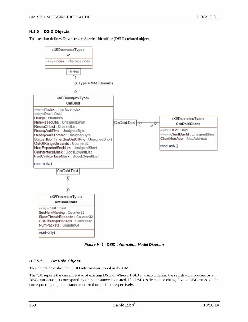
CM-SP-CM-OSSIv3.1-I02-141016 DOCSIS 3.1
260 CableLabs 10/16/14
H.2.5 DSID Objects
This section defines Downstream Service Identifier (DSID) related objects.
Figure H–4 - DSID Information Model Diagram
H.2.5.1 CmDsid Object This object describes the DSID information stored in the CM.
The CM reports the current status of existing DSIDs. When a DSID is created during the registration process or a DBC transaction, a corresponding object instance is created. If a DSID is deleted or changed via a DBC message the corresponding object instance is deleted or updated respectively.
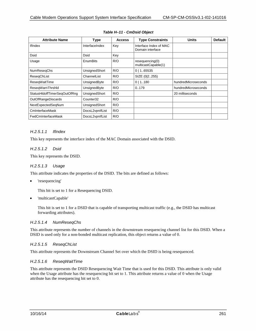
Cable Modem Operations Support System Interface Specification CM-SP-CM-OSSIv3.1-I02-141016
10/16/14 CableLabs 261
Table H–11 - CmDsid Object
Attribute Name Type Access Type Constraints Units Default IfIndex InterfaceIndex Key Interface Index of MAC
Domain interface
Dsid Dsid Key
Usage EnumBits R/O resequencing(0) multicastCapable(1)
NumReseqChs UnsignedShort R/O 0 | 1..65535
ReseqChList ChannelList R/O SIZE (0|2..255)
ReseqWaitTime UnsignedByte R/O 0 | 1..180 hundredMicroseconds
ReseqWarnThrshld UnsignedByte R/O 0..179 hundredMicroseconds
StatusHldoffTimerSeqOutOfRng UnsignedShort R/O 20 milliseconds
OutOfRangeDiscards Counter32 R/O
NextExpectedSeqNum UnsignedShort R/O
CmInterfaceMask DocsL2vpnIfList R/O
FwdCmInterfaceMask DocsL2vpnIfList R/O
H.2.5.1.1 IfIndex
This key represents the interface index of the MAC Domain associated with the DSID.
H.2.5.1.2 Dsid
This key represents the DSID.
H.2.5.1.3 Usage
This attribute indicates the properties of the DSID. The bits are defined as follows:
• 'resequencing' This bit is set to 1 for a Resequencing DSID.
• 'multicastCapable' This bit is set to 1 for a DSID that is capable of transporting multicast traffic (e.g., the DSID has multicast forwarding attributes).
H.2.5.1.4 NumReseqChs
This attribute represents the number of channels in the downstream resequencing channel list for this DSID. When a DSID is used only for a non-bonded multicast replication, this object returns a value of 0.
H.2.5.1.5 ReseqChList
This attribute represents the Downstream Channel Set over which the DSID is being resequenced.
H.2.5.1.6 ReseqWaitTime
This attribute represents the DSID Resequencing Wait Time that is used for this DSID. This attribute is only valid when the Usage attribute has the resequencing bit set to 1. This attribute returns a value of 0 when the Usage attribute has the resequencing bit set to 0.

CM-SP-CM-OSSIv3.1-I02-141016 DOCSIS 3.1
262 CableLabs 10/16/14
H.2.5.1.7 ReseqWarnThrshld
This attribute represents the DSID Resequencing Warning Threshold that is used for this DSID. The value of 0 indicates that the threshold warnings are disabled. This attribute is only valid when the Usage attribute has the resequencing bit set to 1. This attribute returns a value of 0 when the Usage attribute has the resequencing bit set to 0.
H.2.5.1.8 StatusHldoffTimerSeqOutOfRng
This attribute represents the hold-off timer for reporting Out-of-Range Events via the CM-STATUS MAC Management message. This attribute is only valid when the Usage attribute has the resequencing bit set to 1. This attribute returns a value of 0 when the Usage attribute has the resequencing bit set to 0.
H.2.5.1.9 OutOfRangeDiscards
This attribute represents the current count of out-of-range packets discarded by the CM for a given resequencing context since an in-range packet was received. When this count exceeds 1000 and more than two minutes have elapsed since an in-range packet was received, the CM will reacquire sequence numbers for this resequencing context.
H.2.5.1.10 NextExpectedSeqNum
This attribute represents the Next Expected Packet Sequence Number for a given resequencing context. This attribute is only valid when the Usage attribute has the resequencing bit set to 1. This attribute returns a value of 0 when the Usage attribute has the resequencing bit set to 0.
H.2.5.1.11 CmInterfaceMask
This attribute represents the bitmap of the interfaces communicated to the CM in a Multicast DSID encoding.
H.2.5.1.12 FwdCmInterfaceMask
This attribute represents the bitmap of the interfaces to which the CM forwards multicast traffic: a logical OR of interfaces identified in CmInterfaceMask and interfaces associated with the client MAC addresses identified in the instances for this DSID.
H.2.5.2 CmDsidStats Object This object defines a set of statistics the CM collects per DSID.
Table H–12 - CmDsidStats Object
Attribute Name Type Access Type Constraints Units Default IfIndex InterfaceIndex Key
Dsid Dsid Key
SeqNumMissing Counter32 R/O
SkewThreshExceeds Counter32 R/O packets
OutOfRangePackets Counter32 R/O packets
NumPackets Counter64 R/O packets
H.2.5.2.1 IfIndex
This key represents the interface index of the MAC Domain associated with the DSID.
H.2.5.2.2 Dsid
This key represents the DSID.

Cable Modem Operations Support System Interface Specification CM-SP-CM-OSSIv3.1-I02-141016
10/16/14 CableLabs 263
H.2.5.2.3 SeqNumMissing
This attribute counts the number of times the Next Expected Packet Sequence Number is declared lost. In this case one or more data packets are lost. This is generally caused by downstream packet loss.
References: [MULPIv3.1] Downstream Sequencing section
H.2.5.2.4 SkewThreshExceeds
This attribute counts in-range sequenced packets which were successfully received by the CM after a wait time longer than the Resequencing Warning Threshold.
References: [MULPIv3.1] Downstream Sequencing section
H.2.5.2.5 OutOfRangePackets
This attribute counts the number of packets Counter received in a DSID reassembly context where the sequence number which is out of range.
References: [MULPIv3.1] Receive Channels section
H.2.5.2.6 NumPackets
This attribute counts the total number of data packets of a DSID context forwarded for further processing.
H.2.5.3 CmDsidClient Object This object contains the client MAC addresses that the CMTS requests that the CM uses to replicate Multicast DSIDs during registration or during a DBC transaction.
When a DSID is created that includes client MAC addresses, or when client MAC addresses are added to a DSID, new rows are created to indicate the added client MAC addresses. When a Client MAC address is deleted from a DSID, the corresponding row is deleted. When a DSID is deleted, all corresponding rows are deleted, too.
References: [MULPIv3.1] DSID Encodings section in the Common Radio Frequency Interface Encodings Annex.
Table H–13 - CmDsidClient Object
Attribute Name Type Access Type Constraints Units Default Dsid Dsid Key
MacId UnsignedShort Key 1..65535
MacAddr MacAddress R/O
H.2.5.3.1 Dsid
This key defines the DSID with which the client MAC addresses are associated.
H.2.5.3.2 MacId
This key defines a uniquely identified client MAC address associated with the DSID.
H.2.5.3.3 MacAddr
This attribute defines a client MAC address to which multicast traffic labeled with this DSID should be forwarded.

CM-SP-CM-OSSIv3.1-I02-141016 DOCSIS 3.1
264 CableLabs 10/16/14
H.2.6 CM Provisioning Objects
Figure H–5 - CM MAC Domain Configuration Information Model Diagram
H.2.6.1 CmMdCfg Object This object contains MAC domain level control and configuration attributes for the CM.
References: [MULPIv3.1] IP Provisioning Mode Override section.
Table H–14 - CmMdCfg Object
Attribute Name Type Access Type Constraints Units Default ifIndex InterfaceIndex Key InterfaceIndex of MAC
Domain interface
IpProvMode Enum R/W ipv4Only(0) ipv6Only(1) honorMdd(4)
honorMdd
IpProvModeResetOnChange TruthValue R/W true(1) false(2)
false
IpProvModeResetOnChangeHoldOffTimer Unsigned32 R/W 0…300 seconds 0
IpProvModeStorageType StorageType R/W volatile(2) nonVolatile(3)
nonVolatile
H.2.6.1.1 ifIndex
This key represents the interface index of the MAC Domain to which this instance applies.
H.2.6.1.2 IpProvMode
This attribute specifies whether the CM honors or ignores the CMTS MDD TLV 5.1 setting in order to configure its IP provisioning mode. The CM relies upon the CMTS to facilitate the successful IP address acquisition independently of the MDD.
When this attribute is set to 'ipv4Only' the CM will initiate the acquisition of a single IPv4 address for the CM management stack.

Cable Modem Operations Support System Interface Specification CM-SP-CM-OSSIv3.1-I02-141016
10/16/14 CableLabs 265
When this attribute is set to 'ipv6Only' the CM will initiate the acquisition of a single IPv6 address for the CM management stack.
When this attribute is set to 'honorMdd', the CM will initiate the acquisition of an IP address as directed by the MDD message sent by the CMTS.
References: [MULPIv3.1] IP Initialization Parameters TLV section
H.2.6.1.3 IpProvModeResetOnChange
This attribute determines whether the CM is to automatically reset upon a change to the IpProvMode attribute. The IpProvModeResetOnChange attribute has a default value of 'false' which means that the CM does not reset upon change to IpProvMode attribute. When this attribute is set to 'true', the CM resets upon a change to the IpProvMode attribute.
References: [MULPIv3.1] IP Initialization Parameters TLV section
H.2.6.1.4 IpProvModeResetOnChangeHoldOffTimer
This attribute determines how long a CM with IpProvModeResetOnChange set to 'true' waits to reset. When the IpProvModeResetOnChange attribute is set to 'true', the CM will decrement from the configured timer value before resetting. The default value of the IpProvModeResetOnChangeHoldOffTimer is 0 seconds which is equivalent to an immediate reset.
References: [MULPIv3.1] IP Initialization Parameters TLV section
H.2.6.1.5 IpProvModeStorageType
This attribute determines if the CM persists the value of IpProvMode across a single reset or across all resets. The default value of IpProvModeStorageType is 'nonVolatile' which means that the CM persists the value of IpProvMode across all resets. The CM persists the value of IpProvMode across only a single reset when IpProvModeStorageType is set to 'volatile'.
References: [MULPIv3.1] IP Initialization Parameters TLV section
H.2.6.2 CmEnergyMgt1x1Cfg Object This object provides configuration state information on the CM for the Energy Management 1x1 Mode feature.
The values of these attributes are not persisted across reinitialization.
Reference: Energy Management 1x1 Mode Encodings section.
Table H–15 - CmEnergyMgt1x1Cfg Object
Attribute Name Type Access Type Constraints Units Default Direction IfDirection Key
EntryBitrateThrshld unsigned32 R/W bps Vendor-specific
EntryTimeThrshld UnsignedShort R/W 1..65535 seconds Vendor-specific
ExitBitrateThrshld unsigned32 R/W bps Vendor-specific
ExitTimeThrshld UnsignedShort R/W 1..65535 seconds Vendor-specific
H.2.6.2.1 Direction
This key attribute indicates whether the threshold applies to the upstream or downstream.
H.2.6.2.2 EntryBitrateThrshld
This attribute specifies the upstream or downstream bitrate threshold (in bps) below which the CM will request to enter Energy Management 1x1 Mode operation.

CM-SP-CM-OSSIv3.1-I02-141016 DOCSIS 3.1
266 CableLabs 10/16/14
H.2.6.2.3 EntryTimeThrshld
This attribute specifies the number of consecutive seconds that the upstream or downstream data rate needs to remain below the Upstream or Downstream Entry Bitrate Threshold in order to determine that a transition to Energy Management 1x1 Mode is required.
H.2.6.2.4 ExitBitrateThrshld
This attribute specifies the upstream or downstream bitrate threshold (in bps) above which the CM will request to leave Energy Management 1x1 Mode operation.
H.2.6.2.5 ExitTimeThrshld
This attribute specifies the number of consecutive seconds that the upstream or downstream data rate needs to remain above the Upstream or Downstream Exit Bitrate Threshold in order to determine that a transition out of Energy Management 1x1 Mode is required.
H.2.6.3 CmEnergyMgtDlsCfg Object This object provides configuration state information on the CM for the Energy Management DLS Mode feature.
The values of these attributes are not persisted across reinitialization.
Reference: Energy Management DLS Mode Encodings section.
Table H–16 - CmEnergyMgtDlsCfg Object
Attribute Name Type Access Type Constraints Units Default Direction IfDirection Key
EntryBitrateThrshld unsigned32 R/W bps Vendor-specific
EntryTimeThrshld UnsignedShort R/W 1..65535 seconds Vendor-specific
ExitBitrateThrshld unsigned32 R/W bps Vendor-specific
ExitTimeThrshld UnsignedShort R/W 1..65535 seconds Vendor-specific
H.2.6.3.1 Direction
This key attribute indicates whether the threshold applies to the upstream or downstream.
H.2.6.3.2 EntryBitrateThrshld
This attribute specifies the upstream or downstream bitrate threshold (in bps) below which the CM will request to enter Energy Management DLS Mode operation.
H.2.6.3.3 EntryTimeThrshld
This attribute specifies the number of consecutive seconds that the upstream or downstream data rate needs to remain below the Upstream or Downstream Entry Bitrate Threshold in order to determine that a transition to Energy Management DLS Mode is required.
H.2.6.3.4 ExitBitrateThrshld
This attribute specifies the upstream or downstream bitrate threshold (in bps) above which the CM will request to leave Energy Management DLS Mode operation.
H.2.6.3.5 ExitTimeThrshld
This attribute specifies the number of consecutive seconds that the upstream or downstream data rate needs to remain above the Upstream or Downstream Exit Bitrate Threshold in order to determine that a transition out of Energy Management DLS Mode is required.

Cable Modem Operations Support System Interface Specification CM-SP-CM-OSSIv3.1-I02-141016
10/16/14 CableLabs 267
H.2.6.4 CmMac Object This object contains attributes of each CM MAC interface.
References: [RFC 4546] docsIfCmMacTable
Table H–17 - CmMac Object
Attribute Name Type Access Type Constraints Units Default ifIndex InterfaceIndex Key InterfaceIndex of MAC Domain
interface
CmtsAddr MacAddress R/O honorMdd
Capabilities EnumBits R/O atmCells(0) concatenation(1)
false
RangingRespTimeout TimeTicks R/W 20
RangingTimeout TimeInterval R/W HundredOfSeconds 20
H.2.6.4.1 ifIndex
This key represents the interface index of the MAC Domain to which this instance applies.
H.2.6.4.2 CmtsAddr
This attribute identifies the CMTS that is believed to control this MAC domain. At the CM, this will be the source address from SYNC, MAP, and other MAC-layer messages. If the CMTS is unknown, returns 00-00-00-00-00-00.
H.2.6.4.3 Capabilities
This attribute identifies the capabilities of the MAC implementation at this interface. Note that packet transmission is always supported. Therefore, there is no specific bit required to explicitly indicate this capability.
H.2.6.4.4 RangingRespTimeout
This attribute identifies the waiting time for a Ranging Response packet. This attribute has been obsoleted and replaced by RangingTimeout to correct the typing to TimeInterval.
H.2.6.4.5 RangingTimeout
This attribute identifies the waiting time for a Ranging Response packet. This attribute replaces the obsoleted RangingRespTimeout attribute.
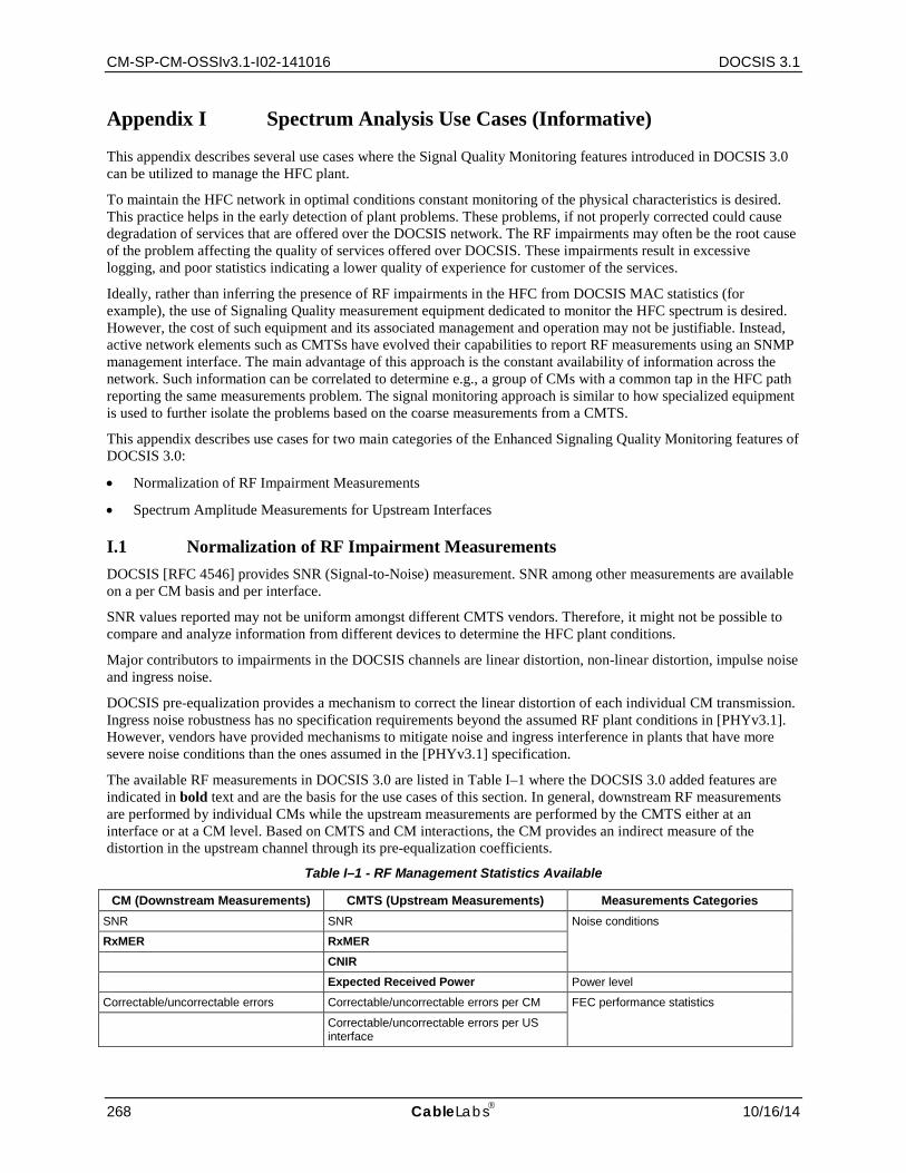
CM-SP-CM-OSSIv3.1-I02-141016 DOCSIS 3.1
268 CableLabs 10/16/14
Appendix I Spectrum Analysis Use Cases (Informative)
This appendix describes several use cases where the Signal Quality Monitoring features introduced in DOCSIS 3.0 can be utilized to manage the HFC plant.
To maintain the HFC network in optimal conditions constant monitoring of the physical characteristics is desired. This practice helps in the early detection of plant problems. These problems, if not properly corrected could cause degradation of services that are offered over the DOCSIS network. The RF impairments may often be the root cause of the problem affecting the quality of services offered over DOCSIS. These impairments result in excessive logging, and poor statistics indicating a lower quality of experience for customer of the services.
Ideally, rather than inferring the presence of RF impairments in the HFC from DOCSIS MAC statistics (for example), the use of Signaling Quality measurement equipment dedicated to monitor the HFC spectrum is desired. However, the cost of such equipment and its associated management and operation may not be justifiable. Instead, active network elements such as CMTSs have evolved their capabilities to report RF measurements using an SNMP management interface. The main advantage of this approach is the constant availability of information across the network. Such information can be correlated to determine e.g., a group of CMs with a common tap in the HFC path reporting the same measurements problem. The signal monitoring approach is similar to how specialized equipment is used to further isolate the problems based on the coarse measurements from a CMTS.
This appendix describes use cases for two main categories of the Enhanced Signaling Quality Monitoring features of DOCSIS 3.0:
• Normalization of RF Impairment Measurements
• Spectrum Amplitude Measurements for Upstream Interfaces
I.1 Normalization of RF Impairment Measurements DOCSIS [RFC 4546] provides SNR (Signal-to-Noise) measurement. SNR among other measurements are available on a per CM basis and per interface.
SNR values reported may not be uniform amongst different CMTS vendors. Therefore, it might not be possible to compare and analyze information from different devices to determine the HFC plant conditions.
Major contributors to impairments in the DOCSIS channels are linear distortion, non-linear distortion, impulse noise and ingress noise.
DOCSIS pre-equalization provides a mechanism to correct the linear distortion of each individual CM transmission. Ingress noise robustness has no specification requirements beyond the assumed RF plant conditions in [PHYv3.1]. However, vendors have provided mechanisms to mitigate noise and ingress interference in plants that have more severe noise conditions than the ones assumed in the [PHYv3.1] specification.
The available RF measurements in DOCSIS 3.0 are listed in Table I–1 where the DOCSIS 3.0 added features are indicated in bold text and are the basis for the use cases of this section. In general, downstream RF measurements are performed by individual CMs while the upstream measurements are performed by the CMTS either at an interface or at a CM level. Based on CMTS and CM interactions, the CM provides an indirect measure of the distortion in the upstream channel through its pre-equalization coefficients.
Table I–1 - RF Management Statistics Available
CM (Downstream Measurements) CMTS (Upstream Measurements) Measurements Categories SNR SNR Noise conditions
RxMER RxMER CNIR Expected Received Power Power level
Correctable/uncorrectable errors Correctable/uncorrectable errors per CM FEC performance statistics
Correctable/uncorrectable errors per US interface

Cable Modem Operations Support System Interface Specification CM-SP-CM-OSSIv3.1-I02-141016
10/16/14 CableLabs 269
CM (Downstream Measurements) CMTS (Upstream Measurements) Measurements Categories Downstream micro-reflections Upstream micro-reflections per CM Linear distortion
CM post-equalization data CM pre-equalization1
Note: 1CM may provide more accurate pre-equalization coefficient than what the CMTS is able to calculate.
The following use cases refer to the noise measurement enhancements for DOCSIS 3.0.
I.1.1 Use Case 1: Figure of Merit Estimation for Logical Upstream Channel
This Use Case defines a Figure of Merit for Logical Upstream Channel measurement that an operator can use to periodically collect information to characterize the performance of the HFC part of the Cable distribution network.
To overcome non-uniform SNR measurements, DOCSIS 3.0 defines two measurements: RxMER (Receive Modulation Error Rate) and CNIR (Carrier to Noise plus Interference Ratio). These provide better indication of the HFC plant impairments and the corrections achieved by the CMTS through compensation techniques. Combining RxMER and CNIR, a Figure of Merit of impairment compensation efficiency can be defined when noise or interference is present.
RxMER measures the average quantization error just prior to FEC, and CNIR measures the carrier to noise plus interference ratio prior to demodulation. A Figure of Merit of how efficiently interference and distortion is compensated in a logical channel can be defined as:
Figure of Merit (logical channel) = RxMER – CNIR
The variables from Annex E to retrieve are:
• RxMER: docsIf3SignalQualityExtRxMER
• CNIR: docsIf3CmtsSignalQualityExtCNIR
The Figure of Merit is relevant when the device is capable of suppressing ingressors, thus increasing the RxMER value with respect to the channel CNIR.
To minimize the uncertainties in measuring the Figure of Merit due to distortion that is unique to individual upstream paths between a CM and CMTS, it is advisable to operate with pre-equalization on (see docsIfUpChannelPreEqEnable of [RFC 4546]).
I.1.2 Use Case 2: Figure of Merit Estimation per CM
This Use Case defines a Figure of Merit per CM transmission. Similar to Use Case 1, the operator can periodically collect information to characterize the performance of CMs in terms of figure of Merit for the given CMTS the CM is attached to.
Unlike RxMER, the SNR parameter is unique for each CM. This allows you to define a Figure of Merit on a per CM basis. A Figure of Merit of how efficiently interference and distortion affecting a CM is compensated can be defined as:
Figure of Merit (CM) = SNR (CM) – CNIR (of the logical upstream channel)
The variables from [DOCS-IF3-MIB] and Annex E to retrieve are:
• SNR: docsIf3CmtsCmUsStatusSignalNoise
• CNIR: docsIf3CmtsSignalQualityExtCNIR
This Figure of Merit indicates if a CM, through its pre-equalization mechanism, is efficiently compensating the linear distortion in its upstream path.
CM-SP-CM-OSSIv3.1-I02-141016 DOCSIS 3.1
270 CableLabs 10/16/14
I.1.3 Use Case 3: Absolute Noise and Interference Estimation
Traditionally CMTSs are expected to command the CMs' power transmission so that the CMTS received power is close to 0 dBmV across all CMs.
This Use Case defines how an operator may derive the absolute value of the noise plus interference (in dBmV) from the reported value (CNIR in dB) which is a relative measure.
For example, CNIR and ExpectedRxSignalPower can be used to estimate noise and interference levels (N+I) across the operator's network in dBmV as:
N + I = CNIR – ExpectedRxSignalPower (CMs of the logical upstream channel)
Operators may determine the difference between the target and the actual received power at the CMTS using the following equation:
CM Offset Power = CM Rx Power – ExpectedRxSignalPower
The variables from [DOCS-IF3-MIB] and Annex E to retrieve are:
• CM Rx Power: docsIf3CmtsCmUsStatusRxPower
• ExpectedRxSignalPower: docsIf3CmtsSignalQualityExtExpectedRxSignalPower
Operators may estimate individual CM CNIR by combining the CNIR obtained for the logical channel and the CM offset power as follows:
CM Estimated CNIR = CM Offset Power + CNIR
CM Offset Power: The difference between the actual received CM power level and the expected commanded received signal power at the CMTS.
The variables from [DOCS-IF3-MIB] and Annex E to retrieve are:
• CNIR: docsIf3CmtsSignalQualityExtCNIR
• CM Rx Power: docsIf3CmtsCmUsStatusRxPower
• Expected Commanded Received Signal Power: docsIf3CmtsSignalQualityExtExpectedRxSignalPower

Cable Modem Operations Support System Interface Specification CM-SP-CM-OSSIv3.1-I02-141016
10/16/14 CableLabs 271
Appendix II Information Model Notation (Informative)
This appendix illustrates the UML notation used throughout this specification to define information models.
II.1 Overview The Unified Modeling Language (UML) is a unified model for object oriented analysis and design (OOA&D). UML is an OMG standard and is an accepted ISO specification [ISO 19501].
UML defines a general-purpose, graphical modeling language that can be applied to any application domain (e.g., communications) and implementation platforms (e.g., J2EE).
II.2 Information Model Diagram The OSSI information model diagram is represented by the UML Class Diagram. The class diagram describes the types of objects existing in a system and their static relationship.
II.2.1 Classes
Classes are generally represented by a square box with three compartments. The top compartment contains the class name (used here as the object name) with the first letter capitalized. The middle compartment contains the list of attributes with the first letter of each attribute capitalized. The bottom compartment contains the list of operations. For the purposes of this specification, the methods section of the class box is not used (suppressed) and the implementation level details of the attributes are omitted.
Attributes also include a visibility notation which precedes the attribute name and is one of the following:
• '+' public (default)
• '-' private
• '#' protected
If the above notation is omitted from the attribute, the default of public is implied. For the purposes of this specification, the protected visibility generally refers to indexes of MIB tables, schema instances, etc.
An interface is represented in the class diagram as an object with the keyword <<interface>> preceding the object name. In general, an interface is a declaration of a set of public features and obligations (such as get methods).
II.2.2 Associations
A class diagram also contains associations which represent relationships between instances of classes. An association has two ends with each end attached to one of the classes. The association end also has a multiplicity indicator which defines how many objects may participate in the relationship. Multiplicity notation is as follows:
• '1' exactly one
• '*' zero or more (default)
• '0..1' zero or one (optional)
• 'm..n' numerically specified
If the above notation is omitted from the association end, the default of '*' is implied.
If one end of the association contains an open arrowhead, this implies navigability in the direction indicated by the arrow.
II.2.3 Generalization
Generalization is the concept of creating subclasses from superclasses and is also known as inheritance within programming languages. Subclasses include (or inherit) all the elements of the superclass and may override inherited methods. Subclasses are more specific classes while superclasses are generalized classes.
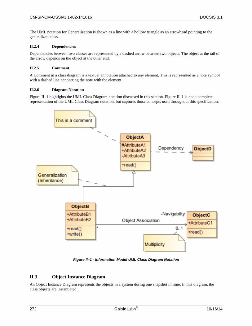
CM-SP-CM-OSSIv3.1-I02-141016 DOCSIS 3.1
272 CableLabs 10/16/14
The UML notation for Generalization is shown as a line with a hollow triangle as an arrowhead pointing to the generalized class.
II.2.4 Dependencies
Dependencies between two classes are represented by a dashed arrow between two objects. The object at the tail of the arrow depends on the object at the other end.
II.2.5 Comment
A Comment in a class diagram is a textual annotation attached to any element. This is represented as a note symbol with a dashed line connecting the note with the element.
II.2.6 Diagram Notation
Figure II–1 highlights the UML Class Diagram notation discussed in this section. Figure II–1 is not a complete representation of the UML Class Diagram notation, but captures those concepts used throughout this specification.
Figure II–1 - Information Model UML Class Diagram Notation
II.3 Object Instance Diagram An Object Instance Diagram represents the objects in a system during one snapshot in time. In this diagram, the class objects are instantiated.

Cable Modem Operations Support System Interface Specification CM-SP-CM-OSSIv3.1-I02-141016
10/16/14 CableLabs 273
Figure II–2 shows an Object Instance Diagram for an instantiation (myObjectA) of ObjectA from Figure II–1.
Figure II–2 - Object Instance Diagram for ObjectA
II.4 ObjectA Definition Example This section defines the details of the object and its associated attributes as defined in the information model diagram. The description of the object includes behavior, persistence requirements (if any), object creation and deletion behavior (if any), etc.
Table II–1 lists the attributes the object defined in the information model. The object table is derived from the information model diagram where each row in the table represents an attribute of the object.
The "Attribute Name" column contains each defined attribute of the object. The naming convention for attributes is to capitalize the first letter and each letter of successive words within the name. Also, attribute names typically do not include any of the object name elements since this would cause duplication when the object and attributes are realized in SNMP.
The "Type" column contains the data type for the attribute. The data type can be a simple type such as UnsignedInt or a defined data type such as EnumBits. DOCSIS 3.1 data types are defined in Annex F.
The "Access" column indicates the attributes accessibility (as mapped to an SNMP object for example). Example values include "key", "read-only", "read-write", and "read-create".
The "Type Constraints" column lists constraints on the normal data type specified in the "Type" column. If there are no defined constraints for the attribute, this column is empty. The example below for AttributeA1 lists a constraint on the UnsignedInt Type where the range starts from 1 instead of normally starting from 0 for an UnsignedInt.
The sections following the table are attribute descriptions which might include behavioral requirements or references.
Table II–1 - ObjectA Example Table Layout
Attribute Name Type Access Type Constraints Units Default AttributeA1 UnsignedInt key 1..4294967295
AttributeA2 AdminString read-write SIZE (1..15)
AttributeA3 UnsignedByte read-create seconds 60
II.4.1 AttributeA1
AttributeA1 is a key defined for…
Note: Objects which represent a table (in an SNMP MIB realization) and have N number of instances need to include at least one "key" attribute which is used to denote the instance or id. Key attributes are typically denoted with a protected visibility whereas all other attributes are denoted with a public visibility.
II.4.2 AttributeA2
AttributeA2 is …
Note: Persistence requirements are documented at the object level, not at the attribute level.
II.4.3 AttributeA3
AttributeA3 is …
AttributeA1 = 20AttributeA2 = TestAttributeA3 = 254
myObjectA : ObjectA

CM-SP-CM-OSSIv3.1-I02-141016 DOCSIS 3.1
274 CableLabs 10/16/14
II.5 Common Terms Shortened The following table lists common terms which have been shortened to allow shorter SNMP MIB names. These shortened names are desired to be used consistently throughout the information models, SNMP MIBs and IPDR schemas. However, in some cases it might not be possible to maintain parity with pre-3.0 DOCSIS requirements.
Table II–2 - Shortened Common Terms
Original Word Shortened Word Address Addr
Aggregate Agg
Algorithm Alg
Application App
Attribute Attr
Authorization Auth
Channel Ch
Command Cmd
Config* Cfg
Control Ctrl
Default Def
Destination Dest
Direction Dir
Downstream Ds
Encryption Encrypt
Equalization Eq
Frequency Freq
Group Grp
Length Len
Maximum Max
Minimum Min
Multicast Mcast
Provision* Prov
Receive Rx
Registration Reg
Replication Repl
Request Req
Resequence Reseq
Resequencing Reseq
Response Rsp
Segment Sgmt
Sequence Seq
Service Svc
ServiceFlow Sf
Session(s) Sess
Source Src
Threshold Thrshld
Total Tot
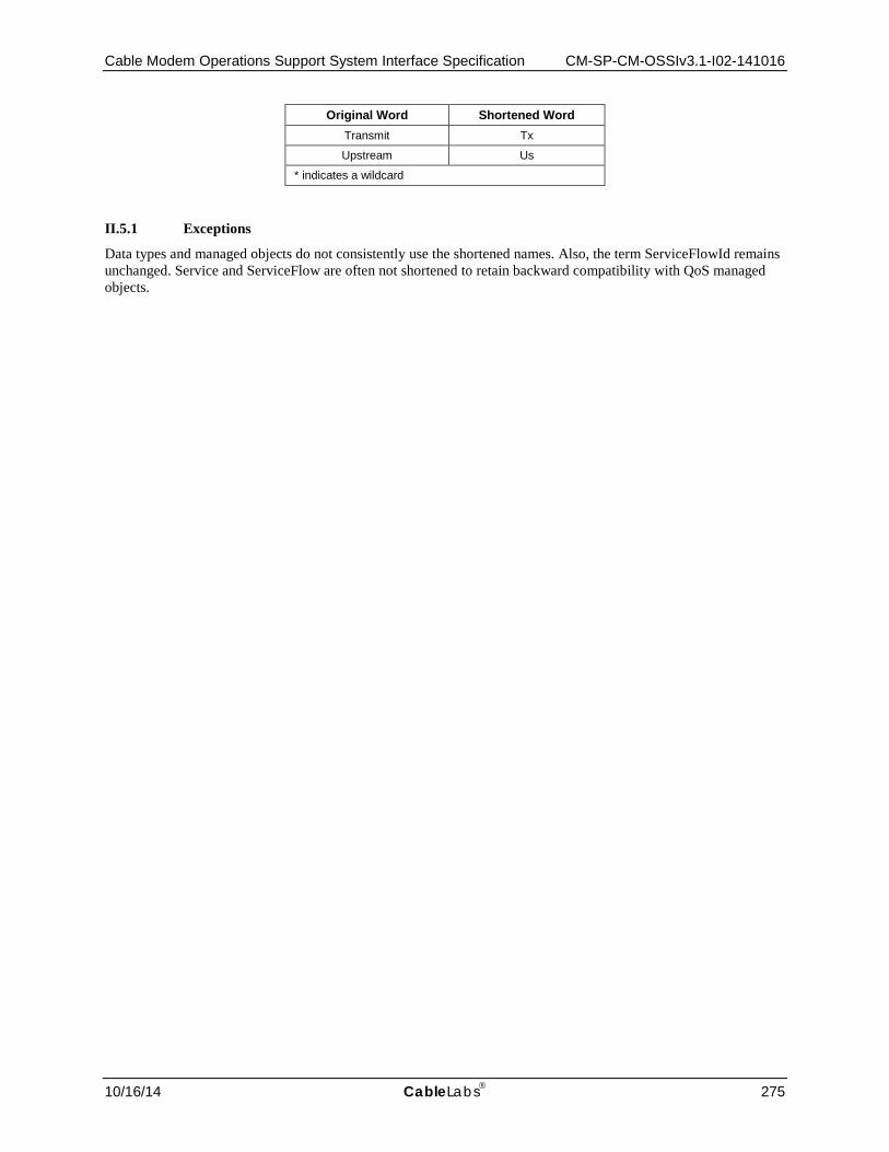
Cable Modem Operations Support System Interface Specification CM-SP-CM-OSSIv3.1-I02-141016
10/16/14 CableLabs 275
Original Word Shortened Word Transmit Tx
Upstream Us
* indicates a wildcard
II.5.1 Exceptions
Data types and managed objects do not consistently use the shortened names. Also, the term ServiceFlowId remains unchanged. Service and ServiceFlow are often not shortened to retain backward compatibility with QoS managed objects.

CM-SP-CM-OSSIv3.1-I02-141016 DOCSIS 3.1
276 CableLabs 10/16/14
Appendix III Acknowledgements (Informative)
On behalf of the cable industry and our member companies, CableLabs would like to thank the following individuals for their contributions to the development of this specification.
Contributor Company Affiliation
Mark Lynch Arris Dan Torbet Arris Bruce Currivan Broadcom Roger Fish Broadcom Thomas Clack Broadcom Niem Dang Time Warner Cable Kirk Erichsen Time Warner Cable Miguel Alvarez CableLabs Brian Hedstrom CableLabs Kevin Luehrs CableLabs Pawel Sowinski Cisco Dan Hegglin Cisco Joe Solomon Comcast John Bevilacqua Comcast Larry Wolcott Comcast Tom Staniec GainSpeed Hesham ElBakoury Huawei Satish Mudugere Intel Mukul Joshi ST Micro

Cable Modem Operations Support System Interface Specification CM-SP-CM-OSSIv3.1-I02-141016
10/16/14 CableLabs 277
Appendix IV Revision History
The following Engineering Change was incorporated into CM-SP-CM-OSSIv3.1-I02-141016.
ECN Identifier Accepted Date Title of EC Author CM-OSSIv3.1-N-14.1189-4 10/8/2014 Omnibus EC with working group spec updates for I02 Alvarez
Copyright © 2022 FDOKUMEN