
Dams and Reservoirs in Texas, Historical and Descriptive ...
274
, TEXAS WATER DEVELOPMENT BOARD REPORT 48 AND RESERVOIRS IN TEXAS Historical and Descriptive Information December 31, 1966 By Cleo Lafoy Dm,ell and Seth Darnaby Breeding June 1967
-
Upload
khangminh22 -
Category
Documents
-
view
0 -
download
0
Transcript of Dams and Reservoirs in Texas, Historical and Descriptive ...
,
TEXAS WATER DEVELOPMENT BOARD
REPORT 48
D~lS AND RESERVOIRS IN TEXAS
Historical and Descriptive Information
December 31, 1966
By
Cleo Lafoy Dm,elland
Seth Darnaby Breeding
June 1967
TEXAS WATER DEVELOPMENT BOARD
Mills Cox, ChairmanRobert B. GilmoreMilton T. Potts
Marvin Shurbet, Vice ChairmanGroner A. PittsW. E. Tinsley
•
Joe G. Moore, Jr., Executive Director
Authorization for use or reproduction of any materialcontained in this publication, i.e., not obtained from othersources, is freely granted without the necessity of securingpermission therefor. The Board would appreciate acknowledgement of the source of original material so utilized.
Published and distributedby the
Texas Water Development BoardPost Office Box 12386Austin, Texas 78711
ii
•
;
TABLE OF CONTENTS
Page
DEFINITIONS AND ABBREVIATIONS .••.•.....•...••••.•.••••.•••.••••••..••. v
INTRODUCTION 1
Purpose and Scope •••••.•.•.•..•.•....•.••.•.......•.••.•••...••.• 1
Organiza tion of Report ••••.••....•••..•..•..•••.•••..•..••••••••• 1
Sources of Da ta 2
Personne 1 •••..•...•••..•..•.....•.••.......•••.•.•••.•••••••••.•. 2
DESCRIPTIONS OF DAMS AND RESERVOIRS ••••.••••.••.••••••••.•••.••••••••. 11
INDEX OF DAMS AND RESERVOIRS •••....•••••••.•••...•..••...••.••..••.... 261
TABLES
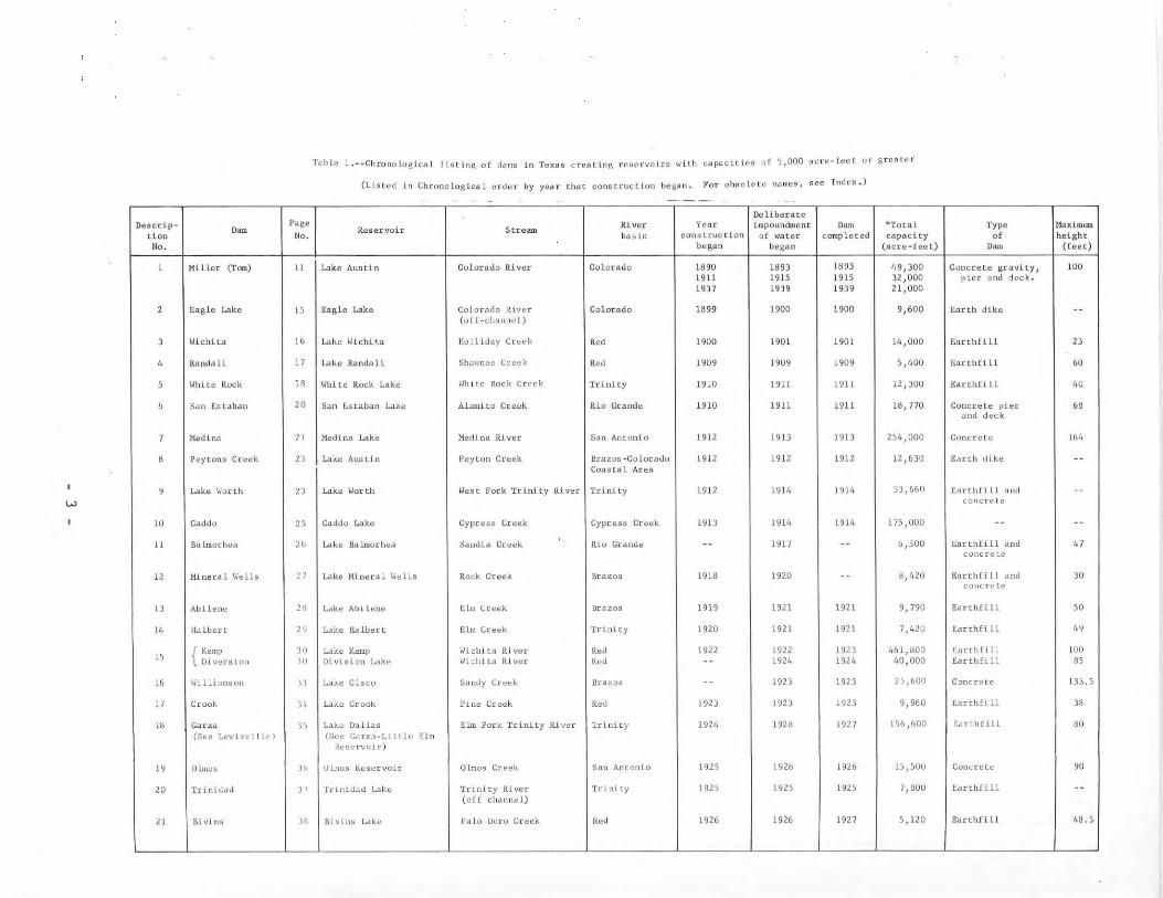
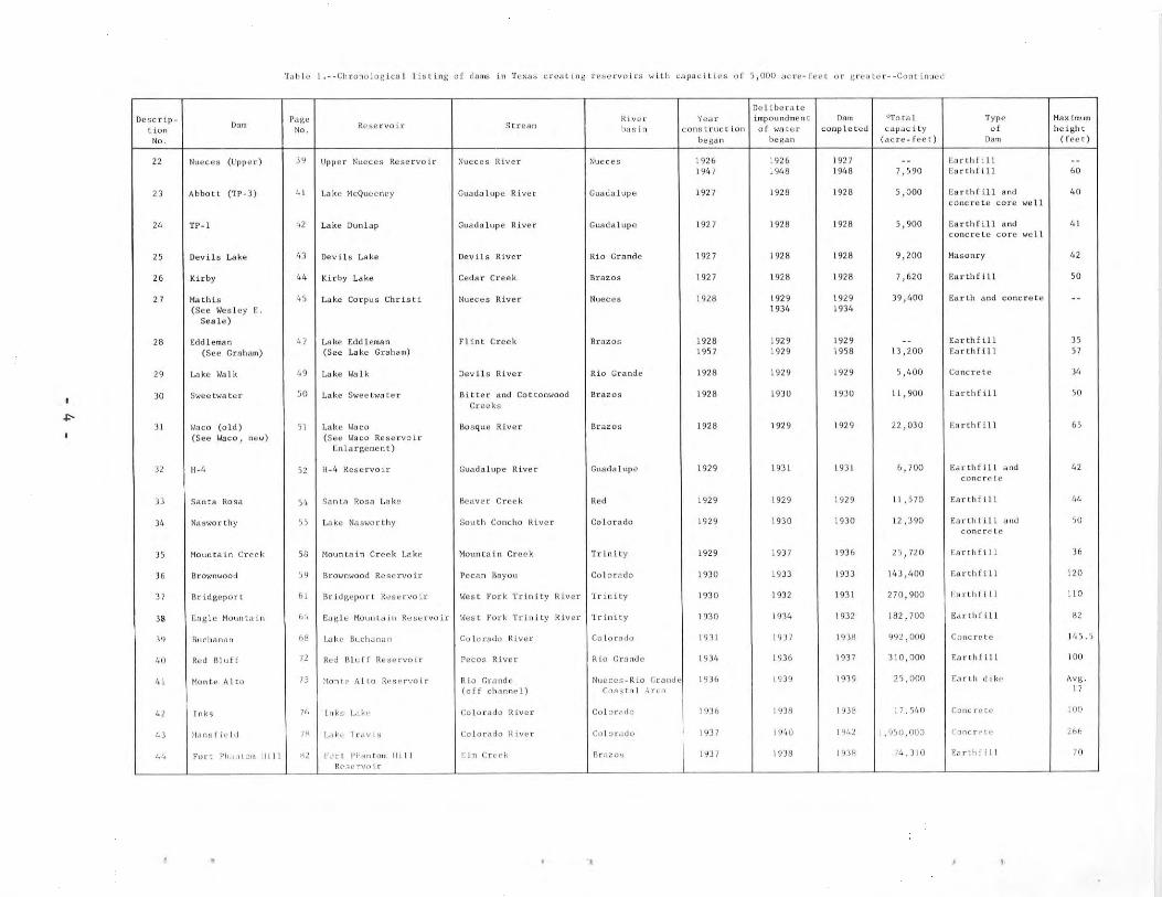
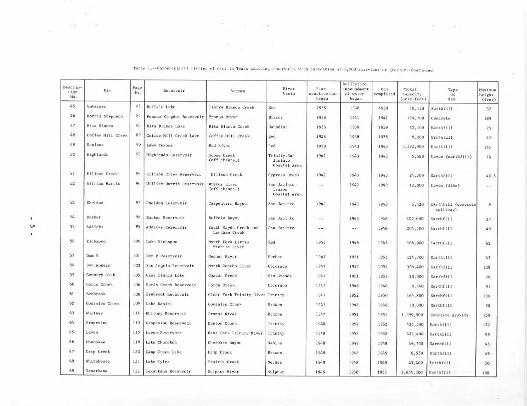
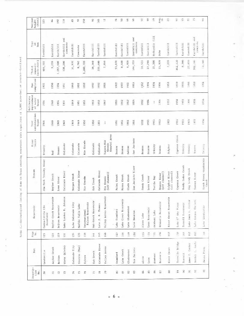
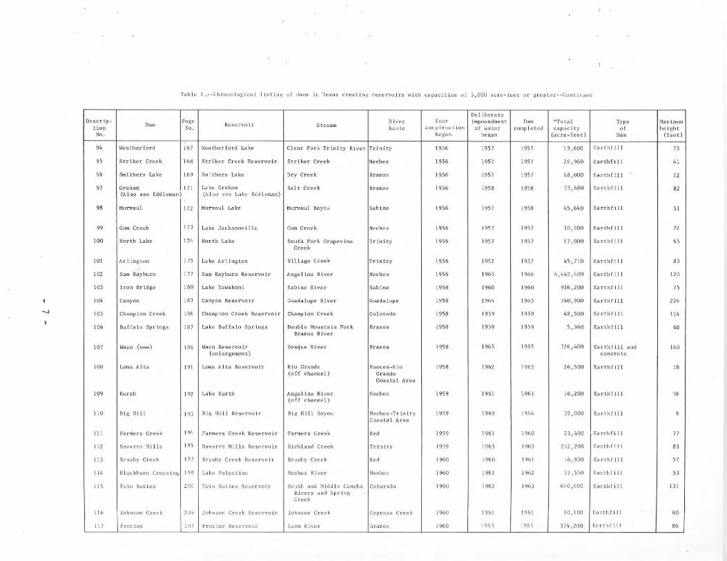
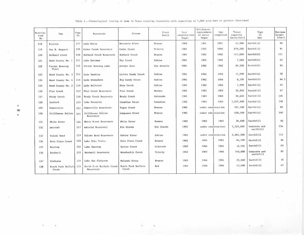
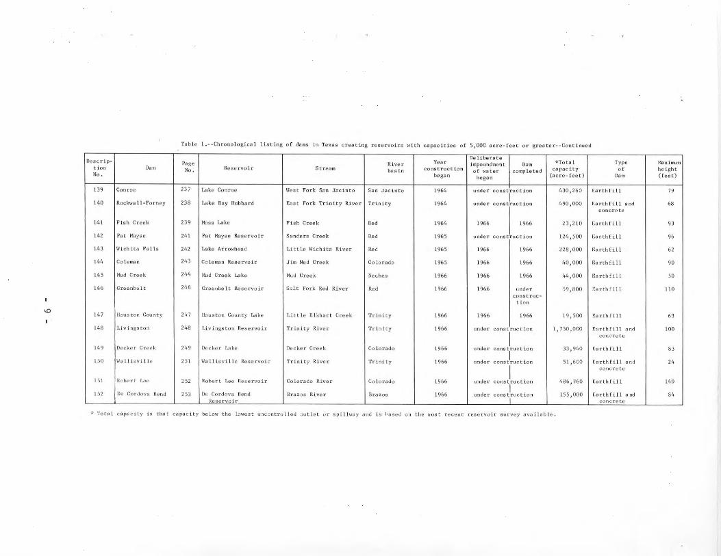
1. Chronological listing of dams in Texas creating reservoirswith capacities of 5,000 acre-feet or greater ••••.•............• 3
2. Comparison of the 22 reservoirs with greatest total storagecapacity .•••.•..•.•••••••••..•..•.••..••..•••.•••••.•.........•• 255
3. Comparison of the 22 reservoirs with greatest conservationstorage capacity................................................ 256
4. Comparison of the 22 reservoirs with greatest surface areacorresponding to elevation of total storage capacity............ 257
ILLUSTRATIONS
Photographs
Bridgeport Dam and Bridgeport Reservoir ••...•.••.•••.•••...•.••....•.• 62
Eagle Mountain Dam 65
Buchanan Dam and Lake Buchanan........................................ 69
Hansfie1d Dam and Lake Travis......................................... 79
Morris Sheppard Dam and Possum Kingdom Reservoir................... •.. 86
ii i
TABLE OF CONTENTS (Cont'd.)
Lavon Dam and I...avon Reservoir ...........•....•......................•.
San Jacinto Dam and Lake Houston .......................•..............
Denison Dam and Lake Texoma
Sanford Dam and Lake Meredith .
Page
91
112
•116
123
126
139
144
151
159
164
178
181
184
201
209
220
.........................Lewisville Dam and Garza-Little Elm Reservoir
Falcon Dam and International Falcon Reservoir
Texarkana Dam and Texarkana Reservoir .......•.........................
Whitney Dam and Power House
Colorado River Dam and Lake J. B. Thomas ....•..•.•••..•....•.....•....
Wesley E. Seale Dam and Lake Corpus Christi ..
Ferrells Bridge Dam and Lake 0' the Pines •..•.•••...•.•...•....•......
Iron Bridge Dam and Lake Tawakoni ..
Twin Buttes Dam and Twin Buttes Reservoir .....•..••...................
Sam Rayburn Dam and Sam Rayburn Reservoir .•......•..••.....•...•••....
Cedar Creek Reservoir Spillway ..
Canyon Dam and Canyon Reservoir
Pia tes
Fo 110\;s
1. River Basins and Coastal Areas of Texas and Major Reservoirswith capacity of 5,000 acre-feet or more •..••.•............•.... 267
iv
DEFINITIONS AND ABBREVIATIONS
Definitions and abbreviations in this list are intended to explain terms asused in this report.
acre-foot (feet). The quantity of water required to cover one acre to a depthof one foot; equivalent to 43,560 cubic feet.
application. A written request to the Texas Water Rights Commission for apermit to appropriate public waters for beneficial use.
appropriation. The process or series of operations by which an appropriativewater right is acquired.
Certified Filing. Any declaration of appropriation or affidavit on file withthe Texas Water Rights Commission in accordance with the provisions ofSection 14 of Chapter 171, Acts of the Thirty-Third Legislature of Texas,1913, and amendments thereto, which gives the filer an appropriative waterright.
conservation storage space. The space available in a reservoir between thelowest outlet level and normal maximum operating level to store water forsubsequent release or withdrawal to serve the needs for manls various beneficial uses.
country spillway.a reservoir bank
The term applied to a naturalused as an emergency spillway
graded or ungraded section offor discharging floodflow.
cu ft cubic foot (feet).
cfs cubic feet per second. A unit rate of discharge of a flowing liquid, ina stream channel or through a conduit or other structure, which is equivalentto flow at a velocity of one foot per second through a section having across-sectional area of one square foot.
~ cubic yard(s)
dead storage space. That part of a reservoir capacity below the lowest outletlevel from which water cannot be released by gravity flow.
Declaration of Appropriation. One of the formal documents required for aCertified Filing (see earlier definition of Certified Filing).
drainage area. The area measured in a horizontal plane which is so enclosed bya topographic divide that direct surface runoff from precipitation normallywould drain by gravity into the stream above the specified point.
elevation. The vertical distance in feet of a point or object above msl unlessotherwise stated.
flood-control storage space. That part of a reservoir capacity allocated tostore floodwater below the uncontrolled spillway crest or top of gates of adam from which water can be released ar a controlled rate as rapidly as channel capacities permit without causing damage downstream.
v

fuse plug. An earthfill placed in a prepared spillway area that is designedto wash out when overtopped with water or otherwise be removed to permit thepassage of floodwater.
gage hei.ght. Height in feet above zero of a gage arbitrarily referenced andset to some datum.
~ gallons per minute. A rate of discharge of a flowing liquid.
~ horsepower. A unit of power.
kw kilowatt(s). A unit of electrical power.
Naximum design-flood stage. The maximum reservoir water level expected asdetermined from the hypothetical routing of a spillway-design flood througha reservoir.
msl mean sea level. The mean plane about which the tide oscillates--the meanlevel in Texas is referenced to the average height of the sea for all hourlytide heights over a long period of time at Galveston. The level in currentuse is designated mean sea level datum of 1929.
no (s) .
Permit.issuedPermit
Number(s).
The specific authorization to make an appropriation of water which isby the Texas Water Rights Commission to one whose Application for ahas been granted.
right bank, left bank. A designation of respective right-hand and left-handstream banks when the observer is looking downstream.
river mile. The centerline distance in miles along a river channel from itsmouth to any designated point upstream.
run-of-river plant. The term used to designate a hydroelectric generatingplant that uses the flow of the river as it occurs without benefit of storage.
sediment reserve space. That part of a reservoir capaCity allocated for storage of sediment expected to be deposited over a certain period of time.
surcharge. The floodwater temporarily retained in a reservoir above the uncontrolled service spillway level or uncontrolled emergency spillway levelof a dam.
Sworn Statement of Work Done. One of the formal documents required for a Certified Filing (see earlier definition of Certified Filing).
Tainter (or tainter or taintor). A certain type of gate patented by ~lr_
Jeremiah Burnham Tainter in 1886. As a descriptive term the "Til is oftenused as lower case and in some books the spelling is taintor.
l,ater Right. A right to the use of water, accorded by law.
vii


DAM S AND RESERVOIRS I N T E X A S
His tor i cal and Des c rip t i v e I n for mat ion
December 31, 1 966
INTRODUCTION
Purpose and Scope
This report relies on material in "Dams and Reservoirs in Texas, Historicaland Descriptive Information, Texas Water Commission Bulletin 6408, by C. L.Dowell, July 1964," and up-dates that material to December 31, 1966. Additionalpertinent data on dams and reservoirs described in Bulletin 6408 have beenadded where available. Reservoir capacities and surface areas in this reportare based on the most recent surveys available and therefore will differ insome instances from the quantities given in Bulletin 6408.
Reports prepared by many individuals, engineering firms, local, State, andFederal agencies, and others through the past 50 years have contained data ondams and reservoirs. In day-ta-day use of these sources of information, it wasoften apparent that several conflicting sets of data were available for thesame project. This report is the result of studies to resolve these differencesand to obtain the most accurate and accepted data for each project. Thesedata have been compiled into a handbook for ready reference by engineers,students,. and individuals interested in water supply and water conservation.Historical and general descriptive information and some of the importanttechnical details are provided for all dams creating a reservoir of 5,000acre-feet capacity or greater. The information presented includes name,ownership, location, drainage area, authorization, purpose, history of development, and physical description of each reservoir.
Organization of Report
Project descriptions of major dams and reservoirs are arranged chronologically to show their historical development in Texas through December 31, 1966.A chronological listing of projects by the year that construction began followsthe introduction. Locations of the projects are contained on Plate 1. Photographs of some of the typical dams are included with project descriptions.Tabular comparisons of the 22 largest reservoirs by total storage capacity,conservation storage capacity, and surface area follow the project descriptions.An index at the end of the report lists alphabetically the names of all majordams, reservoirs, and lakes, and refers to the description number and pagenumber of the project description. Where the name of a facility has beenchanged, or where a facility is known by more than one name, all names are
included in the index. The index also includes listings of dams by riverbasins and coastal areas.
The State Board of Water Engineers became Texas Water Commission onJanuary 30, 1962. On September 1, 1965, the name Texas Water Commission waschanged to Texas Water Rights Commission and responsibility for functions relating to water-rights administration was vested therein. On the same date,the investigative, planning, development, research, financing, and supportingfunctions, including the reports review and publication functions, were concentrated in the Texas Water Development Board. All three names State Boardof Water Engineers, Texas Water Commission, Texas Water Rights Commission areused in this report, depending on the name of the agency at the time anofficial action was taken regarding a water right.
Sources of Data
Descriptions were prepared from the best available data and were checkedwhere possible by Board personnel. The checking process included determinationsmade from original field data; extensive correspondence with agencies, individuals directly concerned with the construction, and others; and numerous conferences with engineers and administrators of the projects. Information aboutearly projects is often inadequate and may conflict with other published data.
The Water Rights File of Texas Water Rights Commission, includes reportedannual water use, descriptive material, and correspondence about the dams,and was the beginning point of the investigation. Accurate data generally areavailable for newer projects. Materials in U. S. Geological Survey files wereused to check data on the projects where gaging stations are installed-. Publications of State agencies and the U. S. Geological Survey were consulted, aswere those prepared by other agencies and individuals. Construction drawingswere used where available. Information on projects built by agencies of theU. S. Government was obtained from bulletins by the Corps of Engineers, U. S.Army; Bureau of Reclamation, Department of the Interior; and Soil ConservationService, Department of Agriculture. Descriptive information pamphlets by theriver authorities and cities were also used where available.
The Board wishes to thank the owners of the facilities for contributinginformation and photographs and the numerous agencies and individuals forfurnishing data.
Personnel
This report was prepared under the general direction of John J. Vandertulip,Chief Engineer. The work on this compilation, which is a revision and up-datingof Texas Water Commission Bulletin 6408, was done by C. L. Dowell and S. D.Breeding.
- 2 -
•
w
Tlioic 1 •• -ChronolokiclIl Hstltl8 of danlll In TUXIHI crllllling reservoIrs with cnpucillo)8 of s,ooa ,u:rc·rect or 8rc/lI~,r
(l.lsted (0 ChronologlclIl unl'll' by yewf tlille construction begun. I<'or ohsolete nllme~, sec 'ndex.)
- -,-- - -Deliberate
Delcrip-D~
l',1gcROlcrvoLr StrcllDI River Year impoundment Dam *Totlll Type Hallhllllll
tion No. bas In cons true tion of water camp lCTed c.apaei ty of heightNo. IW811n began (acrc~Cect) [)am (feet)
1 Hiller (Tam) II Lake AUlllin Colot"lldo River Colorado ld90 1893 Ul9J 49,300 Concrete gravity, lOa1911 1915 1915 32,000 pier lind deck.1937 1939 1939 21 ,000
2 E<lglc Lake l5 ~81e Lake Colorlldo River Colorado 11199 1900 1900 9,600 Earth dike -.(o[f-chllnncl)
3 Wichita " LAke. Wichita Ilol lido)' C[l'ck R,d 1900 1901 1901 I/;,UOO Earthnll 23
4 Randall " ulke Ru.ndull Shawnee Creek R,d 1909 1909 1909 5,1,00 EacthHll 60
> Will te Rock 16 Whl te Rock Lake White Hock Cr<'tlk TrInity 1910 1911 1911 l2,300 El:lrthHll 40, San Elu.ban 20 Sa" EIUlJlln Lakll Alami Lo Creek Rio Grande 1910 1911 1911 18,770 Concrete pier "and deck
7 Medina 21 Medlnll t..akll Med[na Rlvec San AntonIo 1912 1913 1913 254 1 lJOO Concrete I(,f,, I'cyton8 Creek 2J L.uke AUIlLin Peyton Crllck Bra~os·Co lorado [912 1912 1912 1.2,630 E.1rth dike ..Coastal At"e(l
9 Lake Worth 23 Lake Worth Wellt Fork Trinity River Trinity 1912 1914 UHf, 33,660 E.llrthfi tl and ..conCft' I e
to Caddo 25 CI.ddo wk. CypCe/l8 Crellk Cypress Creek 1913 1914 19i4 175 / 000 .. ..II UU I.mocheu " Lake Iia lmorhcu Sandia Creek Ilio Grande .. 1917 .. b,500 t:ilrthfi lJ. and 47
COnCfc.te
12 Mineral Wells 27 LlIko. Mineril1 wetls Rock Creek Brazos 1918 1920 .. ij,',20 Earthfi II and 30COller.·tt>
13 Abllene 2N L.;lkt' Ab [ 1t'.ne fUll Ctcek Brazos 1919 1911 19Z1 9,190 Earthftll >D
J4 llalbcrL 1') Lake lwlbert Ell1l Crellk Trinity 1920 1921 1921 7,410 t:llrthHII Ill)
I'{ Keml> ')0 L..lkc I(enll> Wlchltll R[ver R,d 1922 1922 1923 461,800 ~~orthfll1 100
01 vers1.on ]11 01.V1.81.011 Lake W[chllO R[vll[ R,d .. L924 1924 40,000 Earthfi 11 85
16 Williamson II L.ak~ ChICO S<lndy Creek BralOS .. 1923 1923 2'>, flon Concrete 13J.5
17 Crook )·'1 Lake Crook I'ino Croek K,d 192J 1923 I. 923 9,960 Ellrthfll.i "" Garzll I', Loki! ll/l 11ns Elm l'ol·k Trinity River Trinity 1924 1921:1 1921 I "lfl,flOO ~:Jrthflll 80
(Sec l,c.wlwi I Id (~cc Gllr1.'l·Lllll~· t:lmRcs('rvulr)
19 011llOb " Olmos RcscrvC,llr Olmo:! Creek San Antonio 1925 1926 1926 15,500 Concrete 90
20 l'rinld.nl ] , fr [nllllld Lak... Trinl ty Rl ver Trinity 1925 1925 1925 ',800 Enrthflll ..(0([ ch:lllnel)
21 IIlvIns JH Ulvlnll Lolk" \'01 Lo Duro Crock R,d 1926 1926 1921 5,12U Earth!i Ll 411. 5
'"
Tabl" 1.--l:hronuJoKlcol I ilH lng of dllnl,!l In TI'KUl> cr('ul'''~ r~~('rvt}irs with ''''llllcltj,'11 I.r ~,()OlJ .,cn··fl't>t or I:rl'~l~'r--Contlnu~<l
1),,11 burnieOe~cr!p.
DOInPIlf\C
Rese rva I rII i vur V,mf ImpulIlIlJmcllt Dllm ,"Tota] 'I'ypc. Mllxlmum
llo., No. StrealU bas i n con~tnlcl lUll of Willer cOlUl'leLco..l Clll'''C I ty 01' lie Igli tNo. beflon bClIllll (I1er". feel) lllllu (fcoH)
22 NuccI:!1 (Upper) " Uppt!f Nueces Resllfvolr Nuccc/l !lIver Nueces 1'::126 1926 1927 .. Ell rll,1 III ..1947 1948 1948 7.~90 ~:Il r 1111 I I I '0
23 AbbQlI (TI'-J) '., Lake McQueeney Cuadalupe River GUlIdalupe 1927 1928 1928 5,000 EnfLhflllllntl 40corU:fcLe I:or" "'till
24 TP.\ ., l.ake Dunlop GUlllllllupc River Guada I upe 1927 19211 1928 5,900 EIlHhfll1 nnd '.,(oneret+:! corl) well
25 Devil!! Lllke '.) Devils Lake Devils River Rio Grandt! 1927 1928 1928 9,200 Mnsonry 42
26 Kirby 44 Kirby Lake CfldHr Creflk Braz;os 1927 1928 1928 7,620 EHr Ll, rill 50
21 Ma lhlll " Lake Corpus Christi Nuect!s IHver Nueces 1928 1929 1929 39,400 Eort.!l ond concrett! ..(Stle Wellley E. 1934 1934
Seale)
28 Edd lellllln 47 l.ake Edd leman t'l int Creek Brazos 1928 1929 1929 -. Earthlill "(See Crallom) (See Lake Graham) 1957 1929 1958 1J,200 Earthflll "29 1.lIke Will k ,., Lake Walk OJ)vllll River Rio Grande 1928 1929 1929 5,400 Coru::reu.' 'If.
JU Swuetwnllir '" l.o ke Swee tWtl te r Rlttor Hlld Cottonwood Brazos 1928 1930 1930 11.900 Earthf III \(1
Creeks
31 W,u;o (old) " Lake Waco lloSqull RIver Brazos 1928 1929 1929 a,OlO t;1I rtll rill "(See Waco, nuw) (Sel' Waco Rcs(lrvo I rEnlargcmcnt)
"J2 11-4 " 11-4 RCIH,rvolr Gundo!\lpe IHver CuadRlupc 1929 19)1 19J 1 6,700 t;lIrthflll lind '.,concrf't\!
J3 !;l\utn ROIIII 5', S.1nl~ Ros.. Lakl' IhHlver Cretlk R,d 1929 1929 1929 II ,570 F.:lrthflll /01,
34 N1I8worthy II Lake Naswnrlhy SOlllll Concho River Colorado 1929 1930 1930 12.390 ~;lIrthflll .. nd SOconcrele
" MOun til In Creek " Mount.1in Creek Lllke Moulltnln Cr(lck Trinity 1929 \ 93 7 193!l 2 r" 720 ~:"rthfIIJ Jr.
" Brownwood " Brownwood Reservol r I'CClln BIlYOIl C01Or,1do 19)0 1933 1933 143,400 ~:;lrthfill 1'0
37 IIrldgcport 'I Brldgeporl Keservol.r WJ)lt Fork Trinity River Trinity 19)0 1932 1931 270,900 1'::1 rthf III 110
" Ellglc Mountain r,., Ea~le Mountain Reservoir West Fork Trinity Rlv~r Trinity 1930 1934 1932 182.700 E(lrlllfill "" Bnchan.. " h8 1~1k{' Rudl .. n'HI Colnrlillo Hlv('1' Colorlldo 1931 19J7 1938 992 ,000 CClIlcrcte I',.,.,
'.0 Red III II i I 1! R...d IH"f! R.'sl<rvoll I'ecort IUver Ria Grande 19)1. 11136 1937 310,000 E.. rth f I II 100
41 Mont" AI L" " clonl(' AI!" R"IH'l'valr IUo r:rllildl' N"'H:I!S_Rio Cr.:Jnde \ 'J)1l I !JJ'.l 1939 2'; ,000 1:.1 rt Ii d I k.' AVll·(off dllllln,'I) CO:J;:tnl Ar,-,,, 17
til Inks ". 1nks 1..1 ~ •• f'olurndo RIvcr Col<>r:,do l lJ)6 19Jtl I'jl!! 17. ;;1,0 r:OI1C rct,' IUU
4) ~I"nsfh'ld " L•• h· 1r."'1 S Colorllrlo River Colorado 1937 19!.ll I 'J,~ 1,950 000 ('onCI"'I,' 2ul>
4. FUrl 1'10 1111 \JIij 11111 <l I Jrl I'h ..,nl"m IIi 11 Urn LrNk IIr.no,. 19J 7 19J8 111)/i it. .llO ~:Ilrtl>l i II 70Rest'rVOl r
Ln
Table 1.--ChronoloiliclIl lillting uf dnmM 111 Texllll creating rcservolrll with cnpocltloll of 5,000 llcrCl-fiHll or IIr ..llter--Contlnued
Dellber:ueOe8crtp_ Page River Y"IH hllpoundlllCln t D,m "Total Type Max !mum
Lion D,m No. Reservoir St.renm basin cons true Lion of wllter completed capac I ty o[ he'shtNo. beK4n begnn (acre_feet) dom (feet)
4' Umbarger '" Buffa 10 I.ake Tlerrll 8hnCI:l Creek R'd 1938 1938 1938 18,150 Eanhf1J 1 J1
4' Morrh ShepPllrd 8S Possum Kingdom Rescrvoir Brutal Kiver BrnllOS 1938 1941 1941 724,700 Conel'ctc 189
47 Itl til IHIIIlCII 88 Rt ta Blanca Lake Rill! Blnnca Creek Canadian 1938 1939 1939 12,100 f.llrthfU 1 "48 Coffoe Mill Creek B9 Coffee Mill Creek Lake Coffee Mill Creek R.d 1938 1938 1938 8,000 Earthflll 42
4, Denhon '0 Lake TexolM Red River Rod 1939 1943 1943 5,392,900 Earthflll 165
50 Il1gh1aOO. 93 Highlands Reservoir Goose Creek Tr in i ty_S4n 1942 1943 1943 5,580 Levee (earthflll) 14(off channel) Jacinto
Coastal Area
" 1::1Uson crllilk ,4 Ellison creek Reservoir Ellison Creek Cyprell8 Creek 1942 1943 1943 24,700 Esrthftll /.8.5
" Wlili/;lnl Harrill 96 Willi/HII Harris Reservoir lIr/lIHl/l River 511n JocintoM -- 1947 1943 12,000 Lovee (dike) --(off chllnne1) Bro~os
Coastal Aren
53 Sheldon " Sheldon ReservoLr Carpenters Bayou San Jacinto 1942 1943 1943 5,420 EarthfU1 (concrCCfI 8.plllwlIy)
'4 IkIrker " Barker ReservOir Buffalo 8/1You Slin Jacinto -- 1945 194' 207,000 Eorthfill 37
" Add lck. " Addlcks Reservoir South Hayde Greek and SlIn Jac into -- -- 1948 204,500 ElII."thf111 4'LlIl1gh/llll Creek
" Klck.'lpoo IDD Lake Kickapoo North Fork 1.1 ttlo R.d 191.5 1946 1945 106,000 E,'rthfll1 62Wichlta RI,vor
57 DOlll 8 101 Dam B Reservoir Neches Rlver Ncches 1947 1951 1951 124,700 Earth£Ul 4'
" Sfln Angelo 103 San Angelo ReservOir Horth Concho RI Vllr Colorado 1947 1952 1951 396,400 Earthftll 128
" Co\,ntry Club lOS Casa Blanca Lake Chacon Creek. Rio Grande 1947 1951 1951 20,000 EarthHI I 16.. Hords Creek 10' Hords Creek Reservoir lIords Creek Colorado 1947 1948 1948 8,640 Earthf111 "61 Renbrook IDH Benbrook Reservoir Clear t'ork Trlnlly Rivcr Trinity 1947 1952 1950 164,800 Earthfill 130
62 Gon~1I1es Creek 109 Lake Daniel GonllOlcs Creek Brazos 1947 1948 1948 10,000 Eorlh£lIl 38
63 W11itney 110 Whitncy Re~ervolr Ilro~oA Rlvor Brazos 1947 1951 1951 1,9'19,500 Concrete gravity ",64 Grapev ine 113 Grapevine Reservoir Denton Crook Trinity 1948 1952 1952 435,500 Eot"thfill 137
65 Lllvon I" Lavon RCllervo I r Eau Fork Trinity River Trinity 1949 1953 1952 423,400 Eonk£lll 69
66 Chf!rokee lID Lake Cherokee Cherokee B.aYOll Sabine 1948 1948 1948 46,700 Earthflll 4'
67 Camp Creek 120 Camp Creek Lllke Climp Greek Brazos 1948 1948 1949 8,550 Earth(lll 4'
6H W1\itehousc 121 Lske Tyler 1'1."0 irie Creek Neches 1948 1948 1949 43,400 EArthfll L '0
69 Texarkonn 122 Texarkana Reservoir Sulphur River Sulphur 1948 1956 1957 2,654,300 Eorthflll 100
E _
:;> ...... '"e -=" N- .0.-00,~
"~
oo•~
oo
,
2-"":;l <:
e " ~~ ... ':I... ~..:I
o"
"•·2•
"o"<
~
• 0 ", " "'" C '"o e ", " .~t,:)U
Z
~~••U
"••~•
,
.::
".0> C_ C.0~" ,•..-il ~ .
o•"~<
~•~
oo
U
o~
5
·~
·e,<~
.':•>
o
• C~Cc..~
" 0U0_- 0.-
•1!~~
~•
"o~•o
~•'0u
"o>
o.0.z~
eo
"
·"•c
"·,-
.c;.,"u.>
o.?•o
~•ou
coo
6 -
--J
Table I ,··ChrO'lOloglcal li~ttll8 uf dll(TI.~ In 'J'exfl~ cre8tlllg reservoi["s with CllfltlcltlCs of 5,000 <lerr·-feet or grNlt"r--C""lit1Llc'd
DcllberllteDescrlp-
DamPage
Rcscrvo it"RIvee Year Inlpoul1llment O,m *Tol.:ll Type Maximum
tion No. Stream bils Lt, c(lTlstruction of waLer completed capac ily of he LgI, tNo. began began (acre-feet) D,m (fee t)
94 Weatherford 16' We!ltherford Lake Clear Fork Trin1 ty River Trill tty 1956 1957 1957 19,600 tart!,f i 11 75
" Striker Creek 168 Striker Creek Rescrvoir Striker Creek Ne<;;hea 1956 I. 957 1957 26,960 Earthfill 41
96 Smithers LIlke 16' Sill! thers Lake Dry Creek Brazos 1956 1957 1957 18,000 F:arthfill 12
97 Gt"aham 171 Lake Gra!1I;lm Salt Creek Brazos 1956 1958 t 958 53/080 F.arthfi 1 t 82(Also lice Eddleman) (Also sec L(,kt, r;ddleftl,)n)
98 Murvaul 172 Mutvaul Lake Murvaul Bayou Sabine 1956 1957 1958 45,840 I::llrthflll. 51
99 Gum Creek 17J L8ke J"cklloJlvillll Gum Creek Neches 1956 1957 1957 30,500 E8rthfill 72
100 North Lake 17/+ North Lake South Fork Grapevine Trinity 1956 1957 1957 17 ,000 EarthEill 65Creek
101 Arl ington 175 Lake Arll.ngton Village Creek Trinity 1956 1957 1957 45,710 1::1IrthHll 83
102 Sam Rayburn 177 Sam Rayburn Renervoir Angelina Rivet" Neches 1956 1965 1%6 1',1,42,1,00 Ellrthfill 120
103 Iron Bridgl! 180 Lake Tnwakonl Sabine Rlver Sabine 1958 1960 1960 936,200 EarthElll 75
ID4 Canyon 183 Canyon Reservoir Guadalupe Rlve.r GU8dlliupe 1.958 1964 1965 74 0,900 F.llrthfUl 224
105 Champion Creek 18b Champion Creek Reservoir Champ lon Creek Colorado 1.958 1959 1959 42, SOD I::arthflll 114
106 Buffa 10 Spr Ings ", Lake Buffalo Springs Double Mountain Fork Brazos 1958 1959 1959 5,360 F.anhflll 68Brazos Rlver
107 Waco (ne..,) IN8 Waco Reservoir Bosque River Bra:o-.Oll 1958 L965 1965 726,400 Earthfill and 140(enlllrgement) concrete
108 Lorna Al ta 191 Lama Alta Reservoir Rio Grllnde Nueces.ltio 1958 1962 1963 26,500 Earth fi 11 18(off channel) Grande
Coastal Area
109 Kurth l'n Lake Kurth Angelilla River Nechcs 1959 1961 1961 16,200 F.arthflll "(off channel)
110 Big 11111 193 Big Hill Reservoir Big 11111 Bayou Neches-Trinity 1959 1960 19M 32,000 El'rlh fill 6Coastal Area
III farmers Crel;'k 194 farmers Creek Reservoir Farmers Creek R,d 1959 1961 1960 25,400 Earlhfill 77
112 Navarro Mills '" Navarro MIlls Reservoir Rlchlund Creek Trinity 1959 1963 1963 2l2,200 I::llrthflll 83
113 Brushy Creek 197 Brushy Creek Re.servolr Brushy Cr~~k R,d 1960 1960 1961 16,800 Earthfll\ 57
I {I, Blackburn CrossLnt; 198 Lake. Pal~stin" Neches River Neches 1960 1961 1962 57,550 Earthfill 53
115 Twin BvtLtlS 200 Twin UUltes Reservoir Soulh ami Middle Concho Color3do 1960 1962 1963 640,500 EArl-hflll 131Rivers Ilnd SpringCreek
116 Johnson Crt!ek 2\11, Jobm;ol1 Creek Rest'rvoir Johnson Creek Cypress Creek 1960 1961 1961 tO,IOO ELlrthfil1 60
1\7 Proc lor 2115 Proctor Reservoir 1.eon River BrlJzo~ 1960 1963 19f>':i 37 1',200 I::llrthflll 86
00
Table 1.··Chronolnglcnl lillthlS of dams In Texas creating reservoirs .... Ith cnpnclllu5 of 5,000 ocre·reet or grenter--Continued
Del I hOrll lcOClicrip- D,m Page Reservoir S trtllllll
River YC<l r ImlloundmcnL Dom t'To(a! Typu Maximumtion No. bas I n conlll.nll;llon of WlHer completed capac i ly of heightNo. bogan bo~on (acre· feel) Dam (feel)
118 8iltonl! 2U7 }Alke Mex lJ Novasota River Brazos 1960 1961 1961 10,000 "flrthOll 50
II' Joe B. lIog.etl 208 Cedar Creek Reservoir Cedar Creek Trinity 1961 1965 1966 679,200 EarthOli 91
120 Hubbard Creek 210 Hubbard Creek Reservoir Hubbltrd Creek Brazos 196\ 1962 1962 317,800 Earthrill 111
121 Wood County No. I 211 1.<lke Quitman Dry Creek Sab inc 1961 1962 1962 7,440 Earthflll "122 Victor Brounlg 212 Victor Brllunig Lake Arroyo Sileo San Antonio 196\ 1962 1962 26,500 ElIrthflll 80
Plant
123 Wood Coun ty No. 3 214 Lake Ha",klnB Little Sandy Creek Sabine 1961 1962 1966 11,890 Earthflll 58
124 Wood County No.4 215 Lake Winnsboro Big Sandy Creek Sabine 1961 1962 1966 8,100 I'arthf1l1 44.5
l25 Wood County No.2 216 Lake Holbrook keyl Creek Sabine 1961 1962 1962 7,990 £arthflll 4'
126 Plat Creek 217 Flat Creek Reservoir Flot Creek Nethes 1961 1962 1963 32,840 Earthflll '7127 Brady Creek 218 Brady Creek Reservoir Brady Creek Colorado 1961 1963 1963 30,430 F.llrthrlll 104
128 Sanford 219 Lake Meredith Ctlnoditln River Cantlditln 1962 1964 1965 1,407,600 Earthrlll ".12' Somerville 223 Somerville Re9crvoir Yogun Creek Brtltos 1962 under construction 507,500 Earchflll 80
Stillhoulle Ho+llowI
130 Stllihouee IIo110w 224 Lampa'BI River Bratoa 1962 under construction 630,400 Earthflll 200Reservoir
I1)1 White River 22. White River ReBervoir WIll te Rlver Bratoa 1962 1963 1963 38,600 EarthUll 84
132 Amistad 227 Amhtad Reservoir Rto Gunde Rio Grande 196] unde r eona truc t ion 5,325,000 Concrete and 254
I earthfUl
133 Toledo Rend 229 Toledo Bend Reservoir Sabine River Sabine 1963 under construction 4,661,000 Earthfill 112
134 Palo Pinto Creek 230 l.ake Palo Pluto. Polo Pinto Creek Brtlto8 1963 1964 1965 44,100 Ellrthflll "135 Raatrop 2J2 Lake Bastrop Sp icer Creek Colorado 1963 1964 1964 16,590 EaTthf11) 85
13. Bardwe 11 233 Bardwell Reservoir Wax.hach ie Creek Trinity 196] 1965 1966 140,000 Concrete and 82earthf1l1
IJ7 Cl eburne 234 ~ke Pat Cleburne Notanda River Brazos 1963 19M 1964 25,560 Earthflll 7'138 Horth Fork Iluffal '" North fork Ruffalo Creek North Fork 8uf[a 10 Rod 1964 1964 1964 15,400 ElIrthflll 47
Creek Reservoir Creek
'"'
Table [.--Chronological \lsting of dams ill Texaa creating reservoirs with capacities of 5,000 llcre-(eet or greater--Contlnued
Oescrlp-Deliberate
Page River Year impoundment Dom *Tota 1 Type MIlK {Inurntlon D,m No. Reservoir Stream basin construction of water completed cl.pocity of heightNo. beg.. n began «lcre-feet) Uam (feet)
139 Conroe 237 Lake Conroe West Fork San Jacinto San Jac lnto 1964 under constrvctLon 1.30,260 Efirthfl.ll 79
I140 Rockwa ll-Forney 2J8 Lake Ray Hubbard EIl:!t Fork Trinity River Trinity 1964 under construction 490,000 Ellrthfi 1I and h8
1966 11966
concrete
141 Fish Creek 239 Moss 1.<lke Fish Creek Rod 1964 23,210 Earthfill OJ
142 Pllt Moyse 241 Pllt M.:Jyllc Reservoir Sllnders Creek Rod 1965 under COllstrvction 124,500 E<lrthfill 96
143 Wichitll Falls 21.2 Lake Arrowhead LI ttle Wichita River Rod 1965 1966 1966 228,000 Earthfill 62
14'1 Co IIlII\',In 243 Colem:ln Reservoir Jim Nild Creek Co lot'lJdo 1965 1966 1966 40,000 Earth£iU 90
L45 Mud Creek 244 Mud Creek U1ke Mud Creek Neches 1966 1966 1966 44,000 Earth£ill 50
146 Greenbelt 246 Creenbelt Reservoir Sill t Fork Red River Rod 1966 1966 under 59,800 £artlJfl II 110constl"IIC-
t Lon
147 Ilouston County 247 Houston Coullty U1ke Little Elkhart Creek Trinity 1966 1966 1\166 19,500 Eorth!I]] OJ
148 LivIngston 248 Livingston Reservoir Trinity RIver Trinity 1966 under constl"uctlon [,750,000 Ellrthf]ll.-,ml 100
Iconcrete
149 Decker Creek 21.9 Decker Lako:- Decker Creek Colorado 1966 under construction )J J 940 Earthflll 8J
I150 Walllsville 251 Wall!svil]p Reservoir Trinity River l'ri ni ty 1966 under construction 51,600 811rthfll1 and 24
Iconcrete
L5 L Robert Lee 252 Robert Lee Reservoir Colorado RI.ver Cnlor>ldo 1966 under construction 486,760 ElIrthfill 140
De Cordova !lend I84152 253 De Cordova Bend Br;'lzns River flr;;+zos 1966 under consttuction 155,000 E/+rthflliond
Re>'lervolr concrete
'" Tot,,\ capacity is lh(ll caplleUy below the \nwest uncontrullod lHltlel or splllw;;+y (Jnd is f,osed on the most recent reservoir survey ilv;;+\loble.

DESCRIPTIONS OF DAMS AND RESERVOIRS
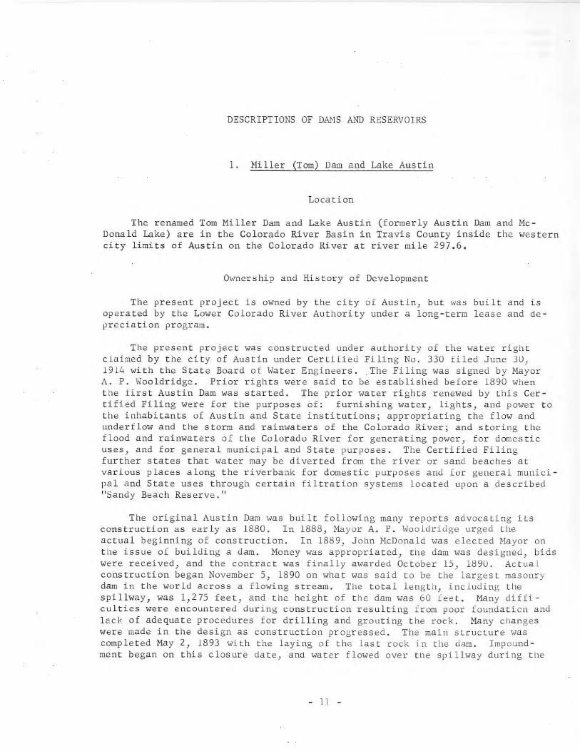
1. Miller (Tom) Dam and Lake Austin
Location
The renamed Tom Miller Dam and Lake Austin (formerly Austin Dam and McDonald Lake) are in the Colorado River Basin in Travis County inside the westerncity limits of Austin on the Colorado River at river mile 297.6.
Ownership and History of Development
The present project is owned by the city of Austin, but was built and isoperated by the Lower Colorado River Authority under a long-term lease and depreciation program.
The present project was constructed under authority of the water rightclaimed by the city of Austin under Certified Filing No. 330 filed June 3D,1914 with the State Board of Water Engineers. The Filing was signed by MayorA. P. Wooldridge. Prior rights were said to be established before 1890 whenthe first Austin Dam was started. The prior water rights renewed by this Certified Filing were for the purposes of: furnishing water, lights, and power tothe inhabitants of Austin and State institutions; appropriating the flow andunderflow and the storm and rainwaters of the Colorado River; and storing theflood and rainwaters of the Colorado River for generating power} for domesticuses) and for general municipal and State purposes. The Certified Filingfurther states that water may be diverted from the river or sand beaches atvarious places along the riverbank for domestic purposes and for general municipal and State uses through certain filtration systems located upon a describedtrSandy Beach Reserve."
The original Austin Dam was built following many reports advocating itsconstruction as early as 1880. In 1888, Mayor A. P. Wooldridge urged theactual beginning of construction. In 1889, John McDonald was elected Mayor onthe issue of building a dam. Money was appropriated, the dam was designed, bidswere received, and the contract was finally awarded October 15, 1890. Actualconstruction began November 5) 1890 on what was said to be the largest masonrydam in the world across a flowing stream. The total length) including thespillway, was 1,275 feet, and the height of the dam was 60 feet. Many difficulties were encountered during construction resulting from poor foundaticn andlack of adequate procedures for drilling and grouting the rock. Many changeswere made in the design as construction progressed. The main structure wascompleted May 2, 1893 with the laying of the last rock in the dam. Impoundment began on this closure date, and water flowed over the spillway during the
- 11 -
month.menteof the
Work continued thereafter onThe lake created was referredproject.
the powerhouse and installation of equipto as "Lake HcDonald" in some early stories
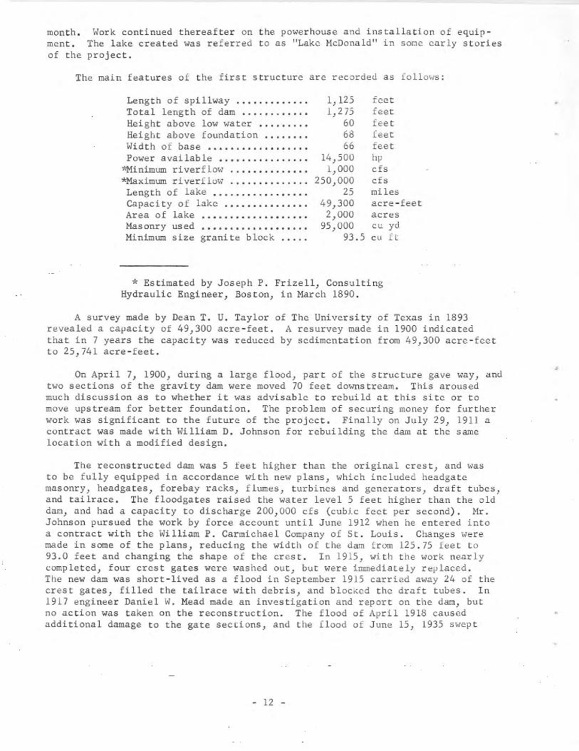
The main features of the first structure are recorded as follows:
Length of spillway .•••..•.•...•Total length of dam •...•..•.•.•Height above low water •..••...•Height above foundation •.••••••Width of base •••••..••..•.....•Power available •.••.••.........
*Minimum riverflo\oJ ....••........*Maximum river f 10\'11 ••••••••••••••
Length of lake .••.•....•..•.•..Capacity of lake ..Area of lake •••••.••••••••..•••Mas onry us ed ...........•.......Minimum size granite block .....
1,1251,275
606866
14,5001,000
250,00025
49,3002,000
95,00093.5
feetfeetfeetfeetfeethpcfscfsmilesacre-feetacrescu ydcu ft
* Estimated by Joseph P. Frizell, ConsultingHydraulic Engineer, Boston, in March 1890.
A survey made by Dean T. U. Taylor of The University of Texas in 1893revealed a capacity of 49,300 acre-feet. A resurvey made in 1900 indicatedthat in 7 years the capacity was reduced by sedimentation from 49,300 acre-feetto 25,741 acre-feet.
On April 7, 1900, during a large flood, part of the structure gave way, andtwo sections of the gravity dam were moved 70 feet downstream. This arousedmuch discussion as to whether it was advisable to rebuild at this site or tomove upstream for better foundation. The problem of securing money for furtherwork was significant to the future of the project. Finally on July 29, 1911 acontract was made with William D. Johnson for rebuilding the dam at the samelocation with a modified design.
The reconstructed dam was 5 feet higher than the original crest, and wasto be fully equipped in accordance with new plans, which included headgatemasonry, headgates, forebay racks, flumes, turbines and generators, draft tubes,and tailrace. The floodgates raised the water levelS feet higher than the olddam, and had a capacity to discharge 200,000 cfs (cubic feet per second). Mr.Johnson pursued the work by force account until June 1912 when he entered intoa contract with the William P. Carmichael Company of St. Louis. Changes weremade in some of the plans, reducing the width of the dam from 125.75 feet to93.0 feet and changing the shape of the crest. In 1915, with the work nearlycompleted, four crest gates were washed out, but were immediately replaced.The new dam was short-lived as a flood in September 1915 carried away 24 of thecrest gates, filled the tailrace with debris, and blocked the draft tubes. In1917 engineer Daniel W. Mead made an investigation and report on the dam, butno action was taken on the reconstruction. The flood of April 1918 causedadditional damage to the gate sections, and the flood of June 15, 1935 s,;ept
- 12 -
away most of the remaining gates and gate piers, and destroyed part of the concrete ogee spillway. A sedimentation survey by T. U. Taylor] shows that thestorage capacity of 32,000 acre-feet in May 1915 was reduced by sedimentationto 2,900 acre-feet by 1924. Such were the conditions in 1937 when the LowerColorado River Authority started the design and construction of the presentstructure at the same site. For a complete report of the early structures, seeD. W. Mead's report~ concerning the Austin Dam. For a description of the oldremaining structure and how it was incorporated into the present dam, seeaccounts by C. H. Vivia~ and Clarence McDonough.~ For information aboutunderpinning the Austin Dam, see the article by G. L. Freeman and R. B. Alsop.~
Construction of the present (1966) dam and power facilities was begun in1937 by the Lower Colorado River Authority, and was completed in 1939. Delibberate impoundment be~an in 1939, and the first generation of electric energyoccurred March 31, 1940. Earlier attempts to generate hydroelectric power wereunsuccess ful.
This is one of six Lower Colorado River Authority projects on the ColoradoRiver, and is immediately downstream from Lake Travis, which supplies the waterto Lake Austin for almost constant level reservoir operation. The other fiveare: Buchanan Dam and Lake Buchanan, Inks Dam and Inks Lake, Wirtz (Alvin) Damand Lake Lyndon B. Johnson, Starcke (Max) Dam and Marble Falls Lake, and Mansfield Dam and Lake Travis. All of these are de,scribed in this report. Theoutput of the Austin generating plant is governed by the downstream water requirements, unless Lake Travis. All of these are described in this bulletin.The output of the Austin generating plant is governed by the downstream waterrequirements, unless Lake Travis is near maximum operating elevation and it isdesirable to release water.
Records of daily lake elevations and discharge are maintained by the LowerColorado River Authority as unpublished data.
Physical Description
The present Tom Miller (Austin) Dam has a length of 1,590 feet made up ofa gravity overflow section, rebuilt hollow dam with gated spillway, powerhouse,and earth and rockfill sections. Extensive excavating, grouting, repairs tofoundations, and underbuilding of the old piers made it possible to build asafe structure with an entirely new design of the dam, spillway, and powerplant. The dam has a maximum height of 100 feet to the top of the bridge acrossthe spillway. For a list of pertinent data on the dam, see page 13.
] Taylor, T. U., 1924, Silting of the lake at Austin, Texas: University ofTexas Bull. 2439, 23 p.~Mead, D. W., 1917, Report on the dam and water power development at Austin,
Texas: Madison, Wisconsin, Daniel W. Mead and Charles V. Seastone, consultingengineers, 205 p. (Avai lable in Texas Water Commission library.)~ Vivian, C. H., 1939, Reconstructing the Austin Dam: Compressed Air Mag.,
v. 44, p. 5895-5902.~McDonough, Clarence, 1940, Historic Austin Dam rebuilt: Eng. News-Rec.,
v. 124, no. 23, p. 844-847.~ Freeman, G. L., and Alsop, R. B., 1941, Underpinning Austin Dam: Eng.
News-Rec., v. 126, no. 1, p. 180-185.
- 13 -
The present reservoir, kno~~ as Lake Austin, has a capacity of 21,000 acrefeet with a surface area of 1,830 acres at uncontrolled spillway crest elevation of 492.8 feet above msl (mean sea level). Lake Austin is operated atpractically constant level as electrical generation at this plant is coordinatedwith the turbine discharge at the Marshall Ford Powerplant at Mansfield Dam, 21miles upstream.
The shoreline of Lake Austin has developed into a favorable residentialarea with many facilities for boating, fishing, and other recreational activities.
The drainage area above the dam is approximately 38,240 square miles, ofwhich 11,900 square miles is probably noncontributing. The runoff is largelycontrolled by reservoirs upstream.
Water is diverted from Lake Austin by the city of Austin for municipalsupply and by many home owners for domestic purposes. The water discharged foruse downstream is used for generation of power. The discharge is into TownLake, which is operated by the city of Austin for additional municipal watersupply, recreation} and condenser-cooling water for two steam-electric generating plants.
For floodflow regulation the controlled spillway has nine taintor gates,each 51 feet long. Four of the gates are 12 feet high and five are 18 feethigh; the top of all gates is at elevation 494.8 feet above msl. With allgates open the spillway discharge at a lake surface elevation of 492.8 feet is100,000 ds.
The uncontrolled spillway on the right end of the dam is 442 feet longwith the crest at elevation 492.8 feet above msl.
Water released for downstream requirements is controlled by varying theload on the power plant generators.
For method of flood regulation see the operating plan included in thedescription of Lake Travis.
There are two generators with all necessary auxiliaries, in the powerhouse at Tom Miller Dam,;having a capacity of 6,750 kw (kilowatts) each. Theturbines are Newport-News automatic adjustable-blade propeller-type. Theelectrical power can be delivered directly to the city of Austin distributionsystem or to the Lower Colorado River Authority interconnected transmissionsystem.
- 14 -
•
Pertinent data on the Miller (Tom) Dam and Lake Austin are as follows:
Height of dam ...•••••.•.•••..••••.•Length of dam .Controlled spillway crest ele
vation in feet above msl ••••••..•Top of taintor gates in feet
above IDS 1 .Uncontrolled spillway crest
elevation in feet above msl ••••••Tailwater elevation (operating)
in fee t above ms 1 .Reservoir area at elevation
492.8 feet above msl • ............Reservoir capacity at elevation
492.8 feet above msl •••••••••••••Length of lake •••••••••••••••••••••Maximum wid th of lake .•••••••.•..••Shore Ii ne .................•........
100 feet1,590 feet
482.8 and 476.8
494.8
492.8
429.0
1,830 acres
21,000 acre-feet20 miles
1,300 feet51 miles
2. Eagle Lake Dam and Eagle Lake
Location
Eagle Lake Dam and Eagle LakeCounty at the town of Eagle Lake.the Colorado River.
are in the Colorado River Basin in ColoradoEagle Lake is a reservoir off channel from
Ownership and History of Development
The project is presently owned by the Lakeside Irrigation Company. It wasfirst owned by Wilham Dunovant, then by Rineyard-Walker and Company, and laterby Eagle Lake Rice Irrigation Company, which is now Lakeside Irrigation Company.
Water rights were obtained by Certified Filing No. 376 filed January 29,1901 in Colorado County and with the State Board of Water Engineers June 29,1914. The Filing states that 10,000 acres of land is irrigated annually. Afurther statement filed March 21, 1918 is that 10,000 acres of land was irrigated, and that 4 acre-feet of water per acre of land was required. This statement gave details of the canal system and pumping equipment. Permit No. 1493(Application No. 1600) dated May 2, 1949, from the State Board of Water Engineers, allows an annual diversion of 60,000 acre-feet of water by release fromthe Lower Colorado River Authority's reservoirs to irrigate 25,000 acres ofland and use of the bed and banks of the Colorado River for transporting diverted water to pumping plants of the"Lakeside Irrigation Company. Contractswere made with the Lower Colorado River Authority for purchase and release ofthis water.
The project was begun in 1899, and was completed in 1900 with impoundmentbeginning in that year. Water was diverted for the irrigation season of 1900.
- 15 -
Physical Description
The present dam is 5,300 feet long and has an average height of 6 feet.The embankment has been altered over the years resulting in various crosssectional areas and heights~
Eagle Lake has a capacity of 9,600 acre-feet and a surface area of 1,200acres at elevation 170.0 feet above msl. The lake provides means of storingwater diverted from the river when excess floodflows occur for use in time ofdeficient flow. Today, with the riverflow regulated by the Lower ColoradoRiver Authority's upstream reservoirs) the lake is not so important as a conservation reservoir as in the early days of operation. The amount of water instorage varies with the season of the year.
The earlysteam engines.Colorado Riverto the land to
pumping installation consisted of pumps rope-driven from Cor lisNow modern pumps driven by electric motors lift water from the
to a canal system that supplies water to the lake, or directlybe irrigated, through a relift pumping station.
The drainage area to the lake is about 20 square miles, but the area isrelatively unimportant as a source of water supply. Water is pumped from theColorado River when excess flow is available.
An emergency spillway for discharging excessive runoff from rainfall islocated at the southeast corner of the lake.
There are no low-flow outlet pipes since the water is pumped from the lakeinto the canal system when needed.
3. Wichita Dam and Lake Wichita
Location
Wichita Dam and Lake Wichita are in the Red River Basin in Wichita County, 6miles southwest of Wichita Falls on Holliday Creek, a tributary of the WichitaRiver, which is tributary to the Red River.
Ownership and History of Development
This project has been in operation since 1901, and is now owned by thecity of Wichita Falls.
Certified Filing No. 559, filed June 30, 1914 with the State Board ofWater Engineers, declared the right of Wichita Falls Electric Company to construct a reservoir to store 23)000 acre-feet of water and to divert therefromat the rate of 100 cfs. Certified Filing No. 792 filed June 30, 1914 declaredthe right of the Lake Wichita Irrigation and Water Company to irrigate 2,850acres of land with 5,700 acre-feet of water from Lake Wichita. The city ofWichita Falls purchased the dam and lake from the Wichita Falls Electric Companyin 1920. Records indicate that the irrigation company was dissolved and itsrights obtained by Wichita County Water Control and Improvement District No. 1by quitclaim deed in 1924. Some of the land became residential area. Conflictover irrigation rights developed in the early 1950's.
- 16 -
The city practically discontinued use of water from Lake Wichita for domestic purposes after September 1947 when the Lake Kickapoo water supply becameavailable. The Lake Wichita project, begun in 1900, was completed the nextyear. Impoundment of water by the Wichita Falls Electric Company was begun in1901.
At the present time, the city sells some water from the old canal systemto the Texas Electric Service Company for cooling purposes and other needs atits steam-electric generating plant.
For information on other water-supply sources of Wichita Falls, refer todescriptions of Lake Kemp, Diversion Lake, Lake Kickapoo, and Lake Arrowhead.
Physical Description
The dam is an earthfill structure 6,250 feettop of the dam at elevation 987.5 feet above msl.
long and 23 feet high with theTop width of dam is 20 feet.
The lake has a total capacity of 14,000 acre-feet and a surface area of2,200 acres at elevation 980.5 feet above msl; 3,000 acre-feet is considereddead storage.
The drainage area above the dam is 143 square miles.
An uncontrolled spillway 400 feet long is used for floodflow discharge.Two 36-inch-diameter, gated, low-flow outlet pipes at streambed elevation provide means for releasing water for use.
The U. S. Army Corps of Engineers, Tulsa District Office, has preparedseveral proposals for protecting Wichita Falls from flooding by Holliday Creek.One proposal is to increase the height of Wichita Dam to provide additionalflood-control storage.
A second proposal is to straighten and enlarge the channel of HollidayCreek below Wichita Dam to form a leveed floodway. This proposal would includeimprovements to the Wichita Dam and spillway without increasing the capacity ofLake Wichita.
A third proposal is to divert floodflows out of Lake Wichita into LakeCreek, which is a tributary of the Little Wichita River. Under this proposalsome modification of Wichita Dam and its spillway would be required, whichwould not change the capacity of the lake.
4. Randall Dam and Lake Randall
Location
Randall Dam and Lake Randall are in the Red River Basin in Grayson County,4 miles northwest of Denison on Shawnee Creek, a tributary of the Red River.
- 17 -
Ownership and History of Development
The project is owned and operated by the city of Denison for municipalwater supply, and was built in 1909. Permit No. 1622 (Application No. 1752)dated May 27, 1952, issued by the State Board of Water Engineers, approved theconstruction of the dam and authorized storage of 5,400 acre-feet and an annualdiversion of 5,280 acre-feet from Shawnee Cree" for municipal water supply.The Permit further allows diversion of 24,400 acre-feet of water annually fromLake Texoma to supplement the flow of Shawnee Creek.
The project was started and completed in 1909. Deliberate impoundment ofwater began in 1909.
Water for Denison is also diverted from Lake Texoma, and is pumpeJ to asmall lake at elevation 700.0 feet above msl, from which it flows by gravity inan unnamed creek channel 3,600 feet to Lake Randall. Lake Randall may be filledseveral times a year as needed by pumping from Lake Texoma. This "ater diversion was begun on July 17, 1962 "hen the pumps were first placed in operation.
Physical Description
Randall Dam is an earthfill structure 1,109 feet long and 60 feet high.It has a bottom width of 280 feet and top width of 20 feet. The elevation ofthe top of the dam is 647.0 feet above msl. Part of the upstream face is protected with rock riprap.
The lake has a capacity of 5,400 acre-feet and a surface area of 172 acresat elevation 640.0 feet above msl. The length of the lake is 6,800 feet.
The drainage area above the dam is only 11 square miles. This small areadoes not produce the needed runoff, which is the reason for the supplementarywater supply from Lake Texoma.
'An uncontrolled spillway 350 feet long with crest elevation of 640.0 feetabove msl is located at the left end of the dam.
The outlet structure, located near the right end of the dam, is equippedwith a vertical section of 24-inch pipe with a sluice gate inlet at elevation605.0 feet above msl, which is the elevation of the lowest outlet. The 24-inchvertical pipe then reduces to a 14-inch pipe with a sluice gate at elevation627.0 feet above msl. A derrick-type tower supports this pipe and a platformfrom which the valves are operated. The regulated flow discharges into a 24inch cast iron pipe encased in concrete that projects through the base of theembankment to the city supply line at the pumping plant. From here water ispumped through an 18-inch pipeline to the water-treatment plant.
5. White Rock Dam and White Rock Lake
Location
White Rock Dam and White Rock Lake are in the Trinity River Basin in DallasCounty in northeast Dallas on White Rock Creek, a tributary of the Trinity River.
- 18 -
Ownership and History of Development
White Rock Dam and White Rock Lake are owned and operated by the city ofDallas.
The project was authorized by Certified Filing No. 75, which was filedApril 29, 1914 with the State Board of Water Engineers by the city of Dallas fora municipal water supply water right. This Filing covers other water rights ofthe city of Dallas and water-supply reservoirs as follows: Record Crossing Dambuilt in 1895, California Crossing Dam built in 1912, and Carrollton Dam builtin 1912--all on the Elm Fork Trinity River. The total capacity of the three onElm Fork was about 2,280 acre-feet. Under this same Filing another project,Bachman Dam Reservoir located on Bacp~an Branch, was included with a capacityof 2,300 acre-feet. All of these reservoirs supplied water to the Turtle Creekfiltration and treatment plant either by gravity flow or by pumping. The RecordCrossing Dam is no longer in use because the river has been diverted intoanother channel.
White Rock Dam was started in 1910 by the city of Dallas and completed in1911, with impoundment of water beginning at that time. Diversion of water foruse began July 9, 1911.
White Rock Lake is still being used, but lost its importance as a watersupply reservoir upon the completion of Lake Dallas in 1930, which had a muchlarger capacity. From 1930 until May 1953, White Rock Lake was used mainly asa recreation lake. Because of severe drought after that time, equipment wasreinstalled and diversion of water for municipal use was resumed. Dallas Powerand Light Company uses the water for condenser cooling of a steam-electricgenerating plant. White Rock Lake is one of several reservoirs now supplyingthe increased water demands of Dallas, and is used during periods of peakdemand for water. The city diverts water directly from the lake.
Records of contents from September 1, 1962 are in publications of the U. S.Geological Survey.
Physical Description
White Rock Dam is an earthfill structure containing 333,680 cu yd (cubicyards) of earth, and is 2,100 feet long with maximum height of 40 feet. Thetop of the dam is at elevation 469.2 feet above msl. The upstream side of thedam is faced with concrete. A concrete spillway is located at the left end ofthe structure.
The reservoir had an original capacity of 18,160 acre-feet and a surfacearea of 1,254 acres at elevation 458.1 feet above msl. A survey by the U. S.Soil Conservation Service in 1956 determined the capacity as 12,300 acre-feetwith a surface area of 1,095 acres at the same elevation. This shows a reduction in capacity of 5,860 acre-feet in 45 years by sedimentation. In 1930, adredge was used to remove 362 acre-feet of sediment by pumping.
The drainage area is 100 square miles.
An uncontrolled, broad-crested, concrete spillway section near the leftend of the dam has a crest length of 450 feet at elevation 45ti.l feet above
- 19 -
msl. The spillway contains 9,327 cu yd of concrete. There is no control ofthe discharge after the water level reaches the uncontrolled spillway crest.Provisions were made for use of flashboards to increase reservoir level by 2feet) but these are not used at present.
6. San Estaban (or Esteban) Dam and San Estaban Lake
Location
San Estaban Dam and San Estaban Lake are in the Rio Grande Basin in Presidio County, 10 miles south of Marfa on Alamito Creek, which is tributary tothe Rio Grande.
Ownership and History of Development
The project was started by the St. Stephens Land and Irrigation Company.Ownership has changed several times. Mrs. Pearl M. Robinson's estate was listedas the owner in 1963. Previous owners listed were Reese Turpin, C. A. Duncanestate, and James H. Kirk estate.
Water rights were established by Certified Filing No. 455 filed June 29,1914 with the State Board of Water Engineers. This Filing allows use of 25,500acre-feet of water annually for irrigation of 8,500 acres of land. Because oflack of runoff the lake has been empty most of the time; and, by order of theTexas Water Commission dated July 16, 1962, the water rights were reduced fromthe original 25,500 acre-feet of water to 400 acre-feet to irrigate 200 acresof land. This 200 acres belongs to Mrs. Robinson's estate.
Construction of the dam was begun in 1910, and was completed in 1911 withstorage of water beginning that year.
Physical Description
The dam is a concrete pier and deck type structure 400 feet long and 68feet high with the top of the dam at elevation 4,451.0 feet above msl. Provisions were made in the original design to permit increasing the height 35 feet.This is one of the earliest Ambursen-type dams built, and it remains in goodcondition today. The dam was first named Alamito Dam after the creek on whichit is located. The present name was adopted after the dam was constructed.Spelling of the name on water service reports submitted to the Texas WaterCommission is two ways--San Estaban and San Esteban.
The reservoir had an original capacity of 18,770 acre-feet and a surfacearea of 762 acres at elevation 4,451.0 feet above msl.
Details of theare not available.
outlet works for regulating the flow to the canal systemOriginally 7 miles of canals were constructed.
- 20 -

7. Medina Dam and Medina Lake
Location
Medina Dam and Medina Lake are in the San Antonio River Basin in MedinaCounty, 8 miles northwest of Riomedina on the Medina River, a tributary of theSan Antonio River. The lake extends into Bandera County.
Ownership and History of Development
Medina Dam and Lake are owned by the Bexar-Medina-Atascosa Counties WaterImprovement District No.1. The project was built by the Medina Valley Irrigation Company under a Declaration of Appropriation filed November 16, 1910 inMedina County by Thomas B. Palfrey. This water right was converted to Certified Filing No. 18 by the State Board of Water Engineers on February 14, 1914.
Alexander Y. Walton, Jr., Willis Ranney, Terrell Bartlett, and Duval Westwere associated with Thomas B. Palfrey in the Medina project. On June 17, 1911,these five associates sold their rights to the Medina Irrigation Company. OnMarch 21, 1912, the Medina Irrigation Company sold out to The Medina ValleyIrrigation Company. The latter company built Medina Dam during 1912 and 1913.Impoundment of water began May 7, 1913. The Medina Valley Irrigation Companywent into receivership in 1917, and emerged therefrom several years later asthe Bexar-Medina-Atascosa Counties Water Improvement District No.1, the present owners of the project.
The Medina project includes Medina Dam; Medina Diversion Dam, 4 milesdownstream from Medina Dam; Medina Canal and a system of lateral canals; andChacon Reservoir on Chacon Creek, 4 miles north of Natalia. The capacity ofChacon Reservoir is estimated to be 2,000 acre-feet. This reservoir impoundssmall amounts of runoff from Chacon Creek, but its primary use is to store surplus water from the Medina Canal. The water right applicable to Chacon Reservoir is Certified Filing No. 19.
Records of the contents of Medina Lake from May 1913 through September 30,1957 are contained in Bulletin 5807-A of the State Board of Water Engineers,and since May 1913 in publications of the U. S. Geological Survey.
Physical Description
The dam is a gravity concrete structure 1,580 feet long and 164 feet highcontaining 205,000 cu yd of concrete. It is 128 feet thick at its base and 25feet wide at the top, along which there is a 23-foot-wide roadway. The top ofthe dam is at elevation 1,076.5 feet above msl.
The drainage area of the Medina River watershed to Medina Lake is 634square miles.
- 21 -
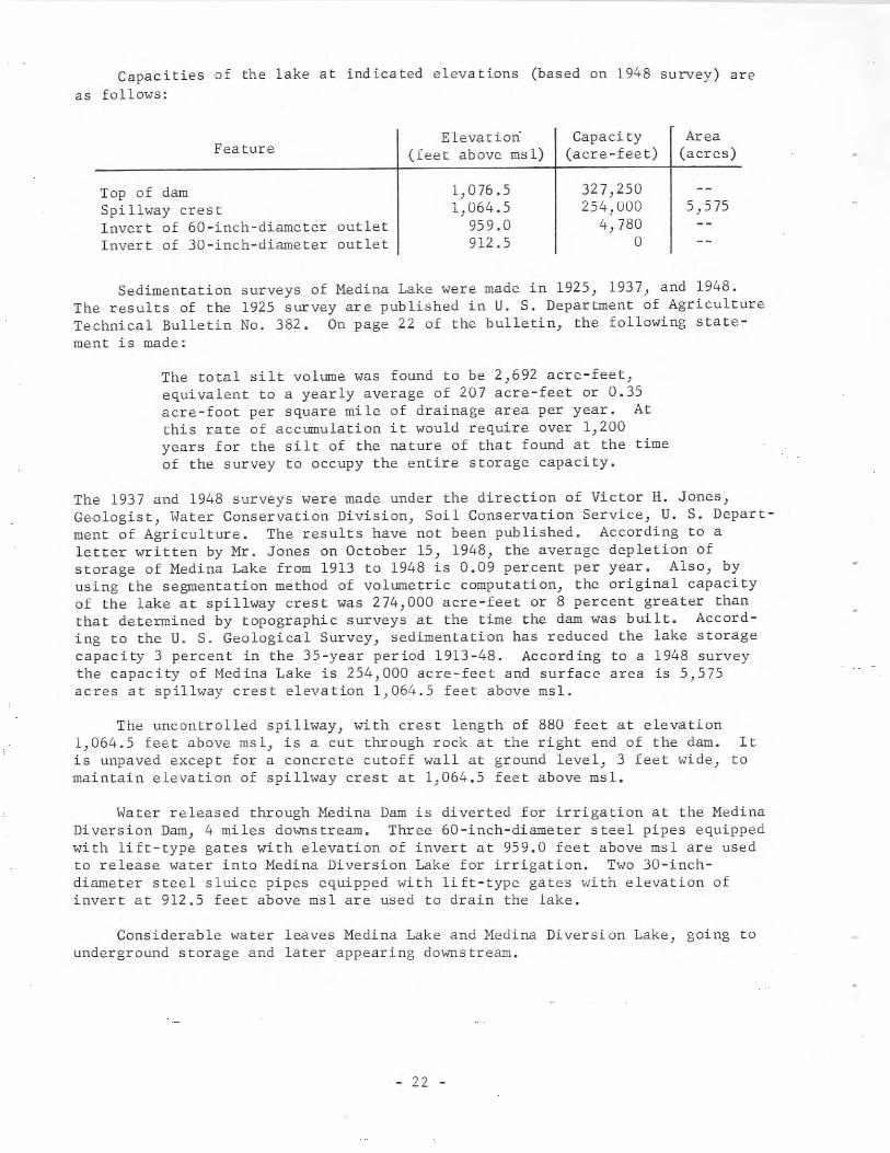
Capacities of the lake at indicated elevations (based on 1948 survey) areas follows:
Feature
Top of damSpi llway cres tInvert of 60-inch-diameter outletInvert of 30-inch-diameter outlet
Elevation(feet above msl)
1,076.51,064.5
959.0912.5
Capacity(acre-feet)
327,250254,000
4,780o
Area(acres)
5,575
Sedimentation surveys of Medina Lake were made in 1925, 1937, and 1948.The results of the 1925 survey are published in U. S. Department of AgricultureTechnical Bulletin No. 382. On page 22 of the bulletin, the following statement is made:
The total silt volume was found to be 2,692 acre-feet,equivalent to a yearly average of 207 acre-feet or 0.35acre-foot per square mile of drainage area per year. Atthis rate of accumulation it would require over 1,200years for the silt of the nature of that found at the timeof the survey to occupy the entire storage capacity.
The 1937 and 1948 surveys were made under the direction of Victor H. Jones,Geologist, Water Conservation Division, Soil Conservation Service, U. S. Department of Agriculture. The results have not been published. According to aletter written by Mr. Jones on October 15, 1948, the average depletion ofstorage of Medina Lake from 1913 to 1948 is 0.09 percent per year. Also, byusing the segmentation method of volumetric computation, the original capacityof the lake at spillway crest was 274,000 acre-feet or 8 percent greater thanthat determined by topographic surveys at the time the dam was built. According to the U. S. Geological Survey, sedimentation has reduced the lake storagecapacity 3 percent in the 35-year period 1913-48. According to a 1948 surveythe capacity of Medina Lake is 254,000 acre-feet and surface area is 5,575acres at spillway crest elevation 1,064.5 feet above msl.
The uncontrolled spillway, with crest length of 880 feet at elevation1,064.5 feet above msl, is a cut through rock at the right end of the dam. Itis unpaved except for a concrete cutoff wall at ground level, 3 feet wide, tomaintain elevation of spillway crest at 1,064.5 feet above msl.
Water released through Medina Dam is diverted for irrigation at the MedinaDiversion Dam, 4 miles downstream. Three 60-inch-diameter steel pipes equippedwith lift-type gates with elevation of invert at 959.0 feet above msl are usedto release water into Medina Diversion Lake for irrigation. Two 30-inchdiameter steel sluice pipes equipped with lift-type gates with elevation ofinvert at 912.5 feet above msl are used to drain the lake.
Considerable water leaves Medina Lake and Medina Diversion Lake, going tounderground storage and later appearing downstream.
- 22 -
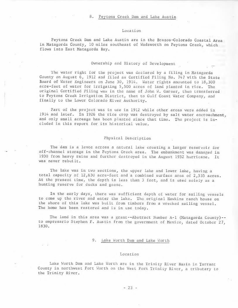
8. Peytons Creek Dam and Lake Austin
Location
Peytons Creek Dam and Lake Austin are in the Brazos-Colorado Coastal Areain Matagorda County, 10 miles southeast of Wadsworth on Peytons Creek, whichflows into East ~~tagorda Bay.
Ownership and History of Development
The water right for the project was declared by a filing in MatagordaCounty on August 6, 1912 and filed as Certified Filing No. 747 with the StateBoard of Water Engineers on June 30, 1914. Water rights amounted to 18,300acre-feet of water for irrigating 5,500 acres of land planted in rice. Theoriginal Certified Filing was in the name of John W. Garner, then transferredto Peytons Creek Irrigation District, then to Gulf Coast Water Company, andfinally to the Lower Colorado River Authority.
Part of the project was in use in 1912 while other areas were added in1914 and later. In 1926 the rice crop was destroyed by salt water encroachment,and only small acreage has been planted since that time. The project is included in this report for its historical value.
Physical Description
The dam is a levee across a natural lake creating a larger reservoir foroff-channel storage in the Peytons Creek area. The embankment was damaged in1930 from heavy rains and further destroyed in the August 1932 hurricane. Itwas never rebuilt.
The lake was in two sections, the upper lake and lower lake, having atotal capacity of 12,630 acre-feet and a combined surface area of 2,535 acres.At the present time, the depth is less than 3 feet, and is used solely as ahunting reserve for ducks and geese.
In the early days, there was sufficient depth of water for sailing vesselsto come up the river and enter the lake. The original Hawkins ranch house onthe shore of this lake was built from timbers from a wrecked sailing vessel.The home has been restored and is in use today.
The land in this area was a grant--Abstract Number A-I (Matagorda County)-to empresario Stephen F. Austin from the government of Mexico, dated October 27,1830.
9. Lake Worth Dam and Lake Worth
Location
Lake Worth Dam and Lake Worth are in the Trinity River Basin in TarrantCounty in northwest Fort Worth on the \'est Fork Trinity River, a tributary tothe Trinity River.
- 23 -
Ownership and History of Development
The project is owned and operated by the city of Fort Worth.
The project was authorized by Certified Filing No. 757 filed June 27, 1914with the State Board of Water Engineers. There were already five small dams inservice on the Clear Fork and West Fork Trinity River and Lake Worth was number6 of 6 covered by the Filing. Detailed information on the small dams and reservoirs is not available, but it is known that they all supplied water for municipal and industrial use for the city of Fort Worth. The five small projectswere completed before 1911.
In 1911 a committee recommended that a dam be built on the West ForkTrinity River. Lake Worth Dam was probably started in 1912, completed inOctober 1914, and impoundment began in June 1914 with the lake reported as fullon August 19, 1914. Water diversion to the Holly filtration and treatmentplant began in May 1916.
The water supply for the city was increased by construction of Bridgeportand Eagle Mountain Reservoirs, and through purchase of water from BenbrookReservoir. Also, Fort Worth has built Cedar Creek Reservoir for additionalfuture water supply.
Physical Description
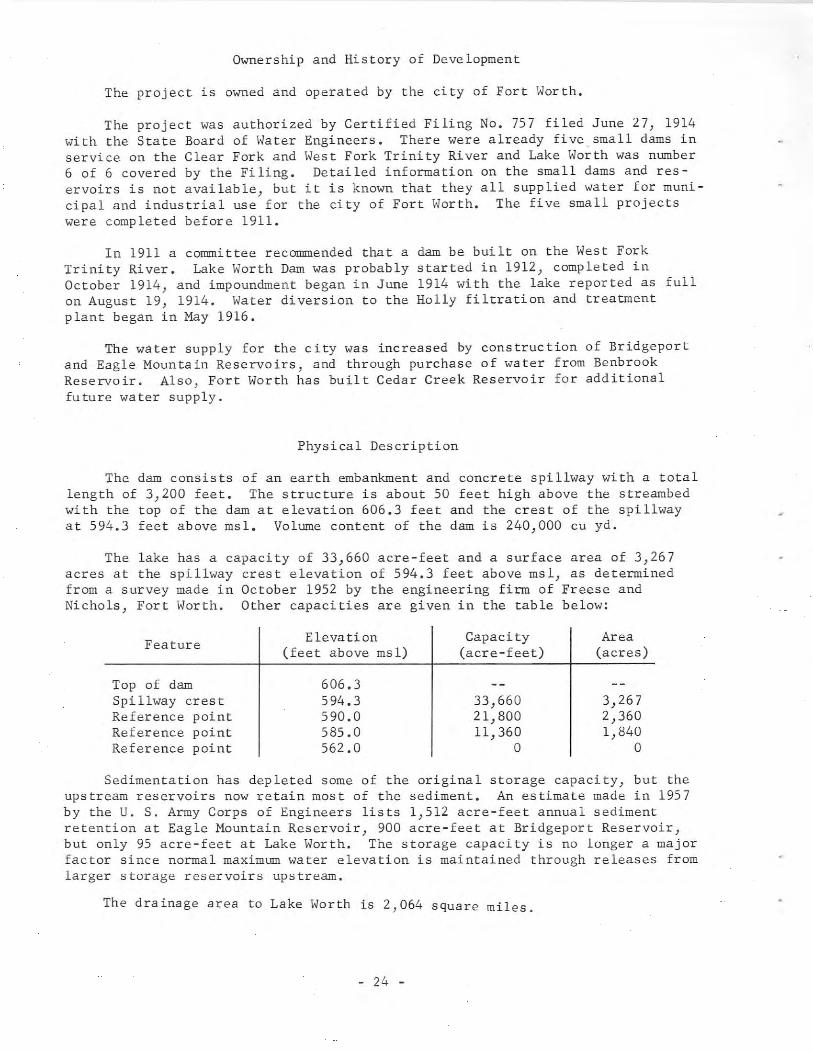
The dam consists of an earth embankment and concrete spillway with a totallength of 3,200 feet. The structure is about 50 feet high above the streambedwith the top of the dam at elevation 606.3 feet and the crest of the spillwayat 594.3 feet above msl. Volume content of the dam is 240,000 cu yd.
The lake has a capacity of 33,660 acre-feet and a surface area of 3,267acres at the spillway crest elevation of 594.3 feet above msl, as determinedfrom a survey made in October 1952 by the engineering firm of Freese andNichols, Fort Worth. Other capacities are given in the table below:
Feature Elevation Capacity Area(feet above msl) (acre-feet) (acres)
Top of dam 606.3Spillway crest 594.3 33,660 3,267Reference point 590.0 21,800 2,360Reference point 585.0 11,360 1,840Reference point 562.0 0 0
Sedimentation has depleted some of the original storage capacity, but theupstream reservoirs now retain most of the sediment. An estimate made in 1957by the U. S. Army Corps of Engineers lists 1,512 acre-feet annual sedimentretention at Eagle Mountain Reservoir} 900 acre-feet at Bridgeport Reservoir}but only 95 acre-feet at Lake Worth. The storage capacity is no longer a majorfactor since normal maximum water elevation is maintained through releases fromlarger storage reservoirs upstream.
The drainage area to Lake Worth is 2,064 square miles.
- 24 -

The concrete spillway is a 700-foot-long uncontrolled section with crestat elevation 594.3 feet above msl. In 1953, repair of the spillway crest byadding a concrete cap raising the elevation 1.7 feet was contemplated but wasnever done. Floodwater retention by the upstream reservoirs has reduced therate of floodflow through Lake Worth and over its spillway so that it is nowconsidered to have adequate floodflow capacity.
The outlet works consist of two parallel conduits; one is 60 inches indiameter, the other 72 inches in diameter. These conduits were completed andfirst used to transport water from Lake Worth to the Holly filter plant in }~y
1916. In the beginning, one 48-inch pipe with a 36-inch valve controlled thereleases to the filter plant, but in 1958 a 36-inch valve was attached to thedownstream end of this same 48-inch pipe to regulate low-flow releases.
10. Caddo Dam and Caddo Lake
Location
Caddo Dam and Caddo Lake are in the Cypress Creek Basin in Caddo Parish,Louisiana, 29 miles northeast of ~rshall in Harrison County, Texas, on CypressCreek. The lake extends into Harrison and ~rion Counties, Texas.
Ownership and History of Development
The project is owned by the U. S. Government and operated by the U. S.Army Corps of Engineers, New Orleans District. Federal authorization was theAct of June 25, 1910 giving 4-foot navigation depth above the dam to Jefferson,Texas. The project was started in 1913, completed, and placed in operation in1914.
Replacement of the existing dam is in the planning stage.
Physical Description
Data on the present dam are not contained in the Texas Water Commissionfiles. However, in the files is a letter from the U. S. Army Corps of Engineersdated ~rch 27, 1963 announcing public hearings to be held in Shreveport,Louisiana on April 30, 1963 and ~y I, 1963 in ~rshall, Texas regarding plansto replace the present structure because of excessive maintenance cost. It wasproposed that Caddo Dam be replaced with a fixed-crest structure with the crestat elevation 168.5 feet above msl, the same elevation as that of the presentstructure.
The present lake has a capacity of 175,000 acre-feet and a surface area of32,700 acres at elevation 168.5 feet above msl. Of this total, 58,000 acrefeet of the capacity and 11,000 acres of the surface area are in Texas. Thepresent lake has been used for navigation from Mooringsport, Louisiana toJefferson, Texas.
The drainage area in Texas to Caddo Lake is 2,639 square miles.
- 25 -
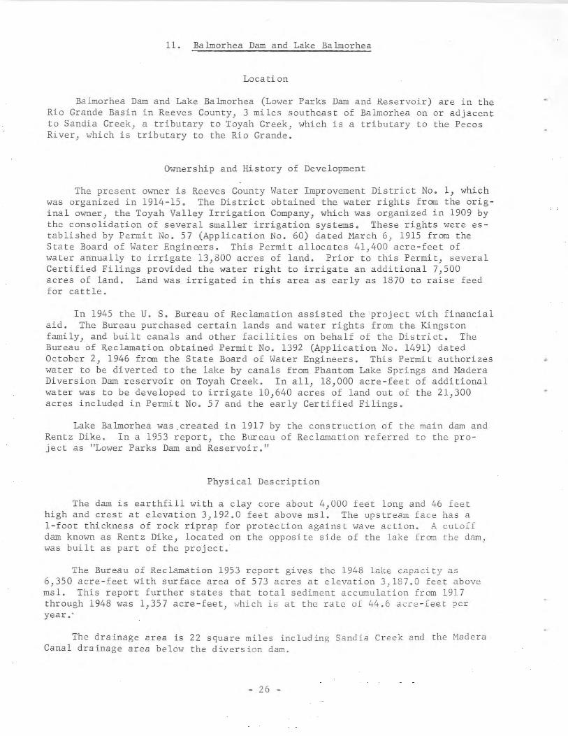
11. Ba lmorhea Dam and Lake Ba lmorhea
Location
Balmorhea Dam and Lake Balmorhea (Lower Parks Dam and Reservoir) are in theRio Grande Basin in Reeves County, 3 miles southeast of Balmorhea on or adjacentto Sandia Creek, a tributary to Toyah Creek, which is a tributary to the PecosRiver, which is tributary to the Rio Grande.
Ownership and History of Development
The present owner is Reeves County Water Improvement District No.1, whichwas organized in 1914-15. The District obtained the water rights from the original owner, the Toyah Valley Irrigation Company, which was organized in 1909 bythe consolidation of several smaller irrigation systems. These rights were established by Permit No. 57 (Application No. 60) dated March 6, 1915 from theState Board of Water Engineers. This Permit allocates 41,400 acre-feet ofwater annually to irrigate 13,800 acres of land. Prior to this Permi t, severalCertified Filings provided the water right to irrigate an additional 7,500acres of land. Land was irrigated in this area as early as 1870 to raise feedfor cattle.
In 1945 the U. S. Bureau of Reclamation assisted the project with financialaid. The Bureau purchased certain lands and water rights from the Kingstonfamily, and built canals and other facilities on behalf of the District. TheBureau of Reclamation obtained Permit No. 1392 (Application No. 1491) datedOctober 2, 1946 from the State Board of Water Engineers. This Permit authorizeswater to be diverted to the lake by canals from Phantom Lake Springs and MaderaDiversion Dam reservoir on Toyah Creek. In all, 18,000 acre-feet of additionalwater was to be developed to irrigate 10,640 acres of land out of the 21,300acres included in Permit No. 57 and the early Certified Filings.
Lake Balmorhea was.created in 1917 by the construction of the main dam andRentz Dike. In a 1953 report, the Bureau of Reclamation referred to the project as "Lower Parks Dam and Reservoir. 1I
Physical Description
The dam is earthfill with a clay core about 4,000 feet long and 46 feethigh and crest at elevation 3,192.0 feet above msl. The upstream face has aI-foot thickness of rock riprap for protection against wave action. A cutoffdam known as Rentz Dike, located on the opposite side of the lake from the dam,was built as part of the project.
The Bureau of Reclamation 1953 report gives the 1948 lake capacity as6,350 acre-feet with surface area of 573 acres at elevation 3,187.0 feet abovemsl. This report further states that total sediment accumulation from 1917through 1948 was 1,357 acre-feet, which is at the rate of 44.6 acre-feet peryear a'
The drainage area is 22 square miles including Sandia Creek and the MaderaCanal drainage area below the diversion dam.
- 26 -
Principal source of water for Lake Balmorhea is flow from San SolomonSprings. This flow is supplemented by water delivered to the lake from ToyahCreek by the Madera Diversion Dam and canals. Surplus water from Phantom LakeCanal (fed by Phantom Lake Spring) is also stored in the lake until needed forirrigation.
A spillway at the right end of the embankment discharges over naturalground to the creek below the dam.
The outlet to the main canal is a circular-top conduit, 4 feet wide by 5feet high, through the dam near the left end. The discharge is controlled by asluice gate operated by a hand operated lift rod extending from the conduitthrough a vertical shaft to the top of the dam.
12. Mineral Wells Dam and Lake Mineral Wells
Location
Mineral Wells Dam and Lake Mineral Wells are in the Brazos River Basin inParker County, 4 miles east of Mineral Wells on Rock Creek, which is tributaryto the Brazos River.
Ownership and History of Development
The project is owned and operated by the city of Mineral \.Jells for mun1C1pal water supply. The city now (1966) also gets water from Lake Palo Pinto.The dam has undergone several changes from the original structure authorizedby Permit No. 530A (Application No. 530) dated October 7, 1922 from the StateBoard of Water Engineers. This Permit allowed storage of 7,300 acre-feet andan annual use of 1,680 acre-feet of water. Permit No. 1352 (Application No.1445) dated August 16, 1943 authorized increasing the height of the spillway2 feet, thereby increasing the lake capacity to 8,140 acre-feet and the annualdiversion to 2,520 acre-feet. Permit No. 1663 (Application No. 1791) datedFebruary 9, 1953 au thor iz ed the pump ing 0 f wa ter from the Brazos River in Pa 10Pinto County to the lake. This water is pumped through a 2l-inch pipeline,48,500 feet long. The authorized annual diversion from the Brazos River is3,500 acre-feet at a rate not to exceed 10 cfs, and diversion is allowed onlyduring the period between September 30 of each year and May 1 of the followingyear. The city contracted with the Brazos River Authority for the purchaseof water from Possum Kingdom Reservoir in the event that water is required fromthe Brazos River during the months diversion is prohibited by Permit No. 1663.
The original dam was begun in 1918, and was completed in September 1920.Impoundment of water began earlier than September 1920. In 1921 a contract waslet for improving the spillway and installing pumps, pipeline, and filter-plantequipment.
The 1943 improvement began with the award of a contract on August 18, 1943.The work was completed January 31, 1944. The contract for the pumping plant andpipeline from the Brazos River was awarded May 7, 1953. The work was completedand the pumps tested in December 1953.
- 27 -
Physical Description
The original dam, with clay core, was an earthfill structure, 675 feet longplus the spillway section, and 71 feet high above streambed, with the top of thedam at elevation 871.0 feet above msl. The embankment has a bottom width of455 feet and a top width of 30 feet, with sandstone riprap on the upstream face.
The flood of October 1918 damaged the embankment under construction;10,000 cu yd of earth were washed out and some equipment was buried under theearthfill. The work was delayed until the summer of 1919 when construction wasresumed and subsequently completed.
The dam was enlarged in 1943 by ra,s,ng the spillway 2 feet and extendingthe spillway length at both ends. The embankment was raised and a concretewall constructed on the crest with top at elevation 876.1 feet above msl.Additional rock riprap was placed over certain areas of the earthfill, and theroadway on top of the dam was raised to elevation 873.9 feet above msl.
The lake created in 1943 has a capacity of 8,420 acre-feet and a surfacearea of 646 acres at elevation J63.0 feet above msl. The capacity beforeenlargement was 7,300 acre-feet.
The drainage area above the dam is 63 square miles.
The original spillway was located on a natural earth embankment, and wasof mass masonry and concrete construction about 6 feet high, with a base widthof about 5 feet. This base was widened and the crest raised 2 feet. The spillway was extended in length to 932 feet in 1943. The crest elevation has beenestablished at elevation 863.0 feet above msl.
The outlet for low-flow releases is a concrete conduit, 4 feet by 5 feet,through the base of the dam, which is controlled by a sluice gate. Diversionfor municipal water supply is accomplished by pumping from the lake. The number and size of pumps have varied through the years.
13. Abilene Dam and Lake Abilene
Location
Abilene Dam and Lake Abilene are in the Brazos River Basin in TaylorCounty, 6 miles northwest of Tuscola on Elm Creek, a tributary to Cle~r ForkBrazos River, which is tributary to the Brazos River.
Ownership and History of Development
The project is owned and operated by the city of Abilene for municipal andindustrial water supply and for recreational purposes.
Authorization to build a dam that would create a reservoir of 45,000 acrefeet capacity was granted by Permit No. 253 (Application No. 259) dated September 7, 1918 from the State Board of Water Engineers. The Permit allows an
- 28 -
annual use of 1,675 acre-feet of water. The anticipated storage was notreached, hence the actual capacity is 9,790 acre-feet.
The project was started in 1919. The earthwork was completed in ~Wy 1921.The entire project was reported complete, and deliberate impoundment was begun,on August 1, 1921.
wasthe
In 1941 extensive repairs were made toplaced, and the spillway was improved.emergency spillway section.
the embankment, additional riprapIn 1957 additional work was done on
Other projects operated by the city for water supply are Kirby Dam andKirby Lake on Cedar Creek, and Fort Phantom Hill Dam and Fort Phantom HillReservoir on Elm Creek.
Physical Description
The present dam is an earthfill structure about 3,400 feet long and 51feet high above the creekbed, with the top of the dam at elevation 2,031.3 feetabove msl. The volume content of the dam is 470,000 cu yd. A low fill extendsfrom the main embankment to the spillway. The embankment has a maximum bottomwidth of 220 feet and top width of 20 feet.
The lake has a capacity of 9,790 acre-feet and a surface area of 641 acresat spillway elevation, 2,018.8 feet above msl, according to a 1948 sedimentation survey by the U. S. Soil Conservation Service.
The drainage area of Elm Creek above the dam is 102 square miles.
The drawings for the 1943 improvements show a concrete-paved emergencyspillway located near the left bank, with a crest length of 2,000 feet at elevation 2,023.0 feet above msl.
The drawings available do not show sufficient details of the service spillway and low flow outlet to describe these features.
14. Halbert Dam and Lake Halbert
Location
Halbert Dam and Lake Halbert are in the Trinity River Basin in NavarroCounty, 4 miles southeast of Corsicana on Elm Creek, a tributary to ChambersCreek, which is tributary to Richland Creek, which is tributary to the TrinityRiver.
Ownership and History of Development
The project is owned and operated by the city of Corsicana for municipalwater supply, industrial water supply, and recreational purposes.
- 29 -
Permit No. 803 (Application No. 841) dated July 1, 1925 was issued to thecity of Corsicana by the State Board of Water Engineers. This Permit approvedthe dam as built with the right to impound 7,653 acre-feet and appropriateannually 7,653 acre-feet of water for municipal purposes. Later, under authority of Permit No. 1534 (Application No. 1644) dated April 14, 1950, the spillwayelevation was raised 1 foot to increase the storage. The same Permit gave thecity of Corsicana a water right to divert 3,650 acre-feet of water annuallyfrom Chambers Creek. This water is pumped to Lake Halbert as required to maintain desired storage.
Construction of the dam was started in 1920, and was completed in 1921when impoundment and diversion of water for municipal use began.
Physical Description
The dam is an earthfill structure, 2,780 feet long, with top elevation of375.0 feet above msl. The height above the foundation is 49 feet with a maximum base width of 250 feet and top width of 16 feet. In 1950 the spillway wasraised 1 foot.
The lake had an original capacity of 8,010 acre-feet with a surface areaof 593 acres at spillway elevation 368.0 feet above msl. The total length ofthe lake was 11,700 feet. A survey by the U. S. Soil Conservation Service in1949 showed that the capacity had been reduced by 1,355 acre-feet by sedimentation, which is an average of 48.4 acre-feet per year. Several small dams located on creeks contributing runoff to Lake Halbert act as retention structures.In 1950 when the spillway was raised 1 foot to elevation 368.0 feet above msl,the capacity was estimated to be 7,420 acre-feet, with a surface area of 650acres.
The drair~ge area above the dam is 12 square miles. The yield from thislake was not adequate for the city supply so water is now pumped to Lake Halbertfrom Chambers Creek as demand requires, between October 1 and June 1. The cityis now investigating other sources of water supply to meet future requirements.
A concrete spillway located on the left end of the dam has a crest lengthof 175 feet at elevation 368.0 feet above msl, with sloping sides, to give a520-foot-long opening at the embankment elevation. The discharge capacity is13,500 cfs at a water depth of 5 feet over the spillway.
waterdam.Water
A 24-inch valve-controlled outlet pipe near the bottom of the lake admitsto the city's filter and treatment plant located immediately below theTreated water is pumped about 3 miles to the water distribution system.can also be released downstream from this supply line.
15. Kemp Dam and Lake Kemp andDiversion Dam and Diversion Lake
Location
Kemp Dam and Lake Kemp are in the Red River Basin in Baylor County, about6 miles north of Mabelle on the Wichita River, a tributary of the Red River.
- 30 -
Diversion Dam, downstream from Kemp Dam, is in Archer County, 14 miles west ofHolliday. Diversion Lake is in Archer and Baylor Counties.
Ownership and History of Development
The projects are owned by the city of Wichita Falls and Wichita CountyWater Improvement District No.2.
The project was constructed under authority of the water right granted byPermit No. 504 (Application No. 516) issued by the State Board of Water Engineers to the Wichita County \,ater Improvement District No. 1 on ~ffirch 22, 1921.The Permit granted an appropriation of 1,000,000 acre-feet per annum for irrigation of 92,327 acres of land in Wichita County, for the development of electric or other power, and for the municipal water supply of Wichita Falls, IowaPark, Kemp City, Holliday and other towns on the proposed system. Further, itgranted the construction of two reservoirs, one with capacity of 444,168 acrefeet (Lake Kemp) and one with capacity of 45,000 acre-feet (Diversion Lake).
In April 1923 certain water rights were sold to Wichita County Water Improvement District No. 2 for irrigation of additional land. District No. 1transferred its interests in the project to the city of Wichita Falls on July24, 1961. District No. 2 retains ownership of some of the canals and irrigation systems and water rights.
Construction began February 25, 1922, and was completed August 25, 1923.Deliberate impoundment.of water began October I, 1922. The first water forirrigation use was delivered for the 1924 season.
Records of contents of Lake Kemp from October 1922 through September 3D,1957 are contained in Bulletin 5807-A of the State Board of Water Engineers andin publications of the U. S. Geological Survey since October 1922.
Physical Description
Kemp Dam is a hydraulic earthfill structure, 7,500 feet long, with maximum height of 100 feet. The top of the dam is at elevation 1,166.8 feet abovemsl. The foundation is protected with a sheet-steel-piling cutoff wall in theold river channel area. The maximum base width is 573 feet and the top widthis 25 feet, with a roadway across the top of the embankment. The upstream faceis protected with an IS-inch thickness of rock riprap laid on an 8-inch-thickgravel base. The volume content of the dam is 1,500,000 cu yd.
Lake Kemp has a capacity of 461,800 acre-feet and a surface area of 20,620acres at elevation 1,153.0 feet above msl. Diversion Lake, about 20 milesdownstream in Archer and Baylor Counties, is part of this project, and it iscovered by the same Permit. This lake has a capacity of 40,000 acre-feet anda surface area of 3,419 acres at elevation 1,051.5 feet above msl. \,ater released from Lake Kemp travels by river channel to Diversion Lake for distribution by two canal systems for irrigation. Municipal and industrial water isdiverted by a pumping plant and by pipeline systems. Water is released [romLake Kemp to maintain surface elevation at desired height in Diversion Lal~e Lordischarge to the canals.
- 31 -
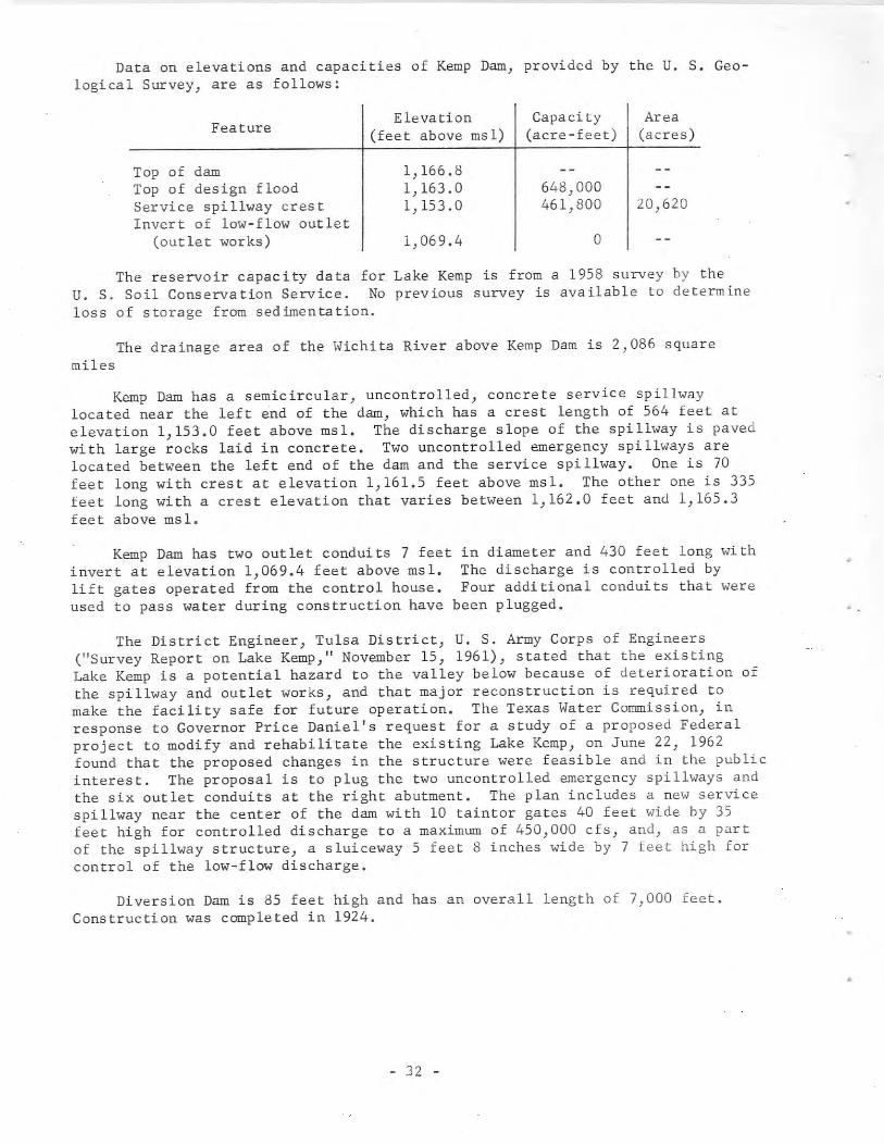
Data on elevations and capacities of Kemp Dam, provided by the U. S. Geological Survey, are as follows:
FeatureElevation Capacity Area
(fee t above ms 1) (acre - feet) (acres)
Top of dam 1,166.8Top of design flood 1,163.0 648,000Service spillway crest 1,153.0 461,800 20,620Invert of low-flow outlet
(outlet works) 1,069.4 0
The reservoir capacity data for Lake Kemp is from a 1958 survey by theU. S. Soil Conservation Service. No previous survey is available to determineloss of storage from sedimentation.
The drainage area of the Wichita River above Kemp Dam is 2,086 squaremiles
Kemp Dam has a semicircular} uncontrolled, concrete service spillwaylocated near the left end of the dam, which has a crest length of 564 feet atelevation 1,153.0 feet above msl. The discharge slope of the spillway is pavedwith large rocks laid in concrete. Two uncontrolled emergency spillways arelocated between the left end of the dam and the service spillway. One is 70feet long with crest at elevation 1,161.5 feet above msl. The other one is 335feet long with a crest elevation that varies between 1,162.0 feet and 1,165.3feet above ms 1.
Kemp Dam has two outlet conduits 7 feetinvert at elevation 1,069.4 feet above msl.lift gates operated from the control house.used to pass water during construction have
in diameter and 430 feet long withThe discharge is controlled byFour additional conduits that were
been plugged.
The District Engineer, Tulsa District, U. S. Army Corps of Engineers("Survey Report on Lake Kemp," November 15, 1961), stated that the existingLake Kemp is a potential hazard to the valley below because of deterioration ofthe spillway and outlet works, and that major reconstruction is required tomake the facility safe for future operation. The Texas Water Commission, inresponse to Governor Price Daniel's request for a study of a proposed Federalproject to modify and rehabilitate the existing Lake Kemp, on June 22, 1962found that the proposed changes in the structure were feasible and in the publicinterest. The proposal is to plug the two uncontrolled emergency spillways andthe six outlet conduits at the right abutment. The plan includes a new servicespillway near the center of the dam with 10 taintor gates 40 feet wide by 35feet high for controlled discharge to a maximum of 450,000 cfs, and, as a partof the spillway structure, a sluiceway 5 feet 8 inches wide by 7 feet high forcontrol of the low-flow discharge.
Diversion Dam is 85 feet high and has an overall length of 7,000 feet.Construction was completed in 1924.
- 32 -
•
16. Williamson Dam and Lake Cisco
Location
Williamson Dam and Lake Cisco are in the Brazos River Basin in EastlandCounty, 4 miles north of Cisco on Sandy Creek, a tributary of Hubbard Creek,which is tributary to Clear Fork Brazos River, which is tributary to the BrazosRiver.
Ownership and History of Development
The project is owned and operated by the city of Cisco for its municipalwater supply. The city obtained Permit No. 439 (Application No. 455) datedJune 16, 1920 from the State Board of Water Engineers to construct a dam 65feet high to impound 9,363 acre-feet of water and to divert this amount annuallyfor municipal water use. The dam was built higher than was first planned, soPermit No. 1131 (Application No. 1207) dated December 20, 1929 from the StateBoard of Water Engineers was granted to amend Permit No. 439. This Permitauthorized creation of a reservoir to impound 45,000 acre-feet of water, andincreased the authorized appropriation by 35,637 acre-feet to 45,000 acre-feet.This anticipated capacity was greater than that actually obtained (25,600 acrefeet with surface area of 1,050 acres at an elevation of 1,520.0 feet abovemsl). However, because of damage to the roadbed of the Missouri-Kansas-TexasRailroad resulting from backwater from Lake Cisco, the railroad obtained acourt injunction against the city of Cisco ordering the operating level of thelake to be reduced to elevation 1,496.0 feet above msl. At this elevation thecapacity of Lake Cisco is 8,800 acre-feet, and the surface area is 445 acres.\,ith the reduction of capacity of Lake Cisco a new source of water supply wasnecessary. Permit No. 1738 (Application No. 1870) dated January 25, 1955 wasobtained from the State Board of Water Engineers. This Permit authorized theconstruction of a small channel dam on Battle Creek to store 110 acre-feet andto divert 1,000 acre-feet of water annually. The water is pumped through a 24inch pipeline over a divide into an unnamed creek) thence to Sandy Creek) thento Lake Cisco.
Construction of the dam was completed Septemberbeginning about that time. Water use began in 1925.Creek started in May 1956.
Physical Description
7, 1923 with impoundmentThe diversion from Battle
The dam is a reinforced concrete structure of the slab and buttress type.It is 1,060 feet long and 133.5 feet high from the foundation to the top of theroadway at elevation 1,535.0 feet above msl. The top of the dam is at elevation1,528.5 feet above msl. The concrete roadway is supported by columns with itsbase on the deck and piers of the dam.
The drainage area to Lake Cisco is 26 square miles, but the yield fromthis area is insufficient to give a water supply that justifies the expenseof rerouting the railroad to utilize the entire storage capacity of the lake.
- 33 -
The spillway at elevation l,S20.0 feetdischarge is to the channel below the dam.sary to discharge water over this spillway,a municipally operated swimming pool.
above msl is 270 feet long. TheHowever, it has never been necesand the downstream area is used as
Water is withdrawn from the lake by a gravity supply line to the watertreatment plant immediately downstream from the dam. The water is settled, butnot filtered or treated, and pumped to the city storage and distribution system.
Water can be released downstream from this same supply line.
17. Crook Dam and Lake Crook
Location
Crook Dam and Lake Crook are in the Red River Basin in Lamar County, 5miles north of Paris on Pine Creek, a tributary to the Red River.
Ownership and History of Development
The project is owned and operated by the city of Paris for municipal watersupply.
Permit No. 646 (Application No. 679) dated February 26, 1923 from theState Board of Water Engineers authorized the construction of a dam to impoundand use 12,000 acre-feet of water annually for municipal purposes.
Construction was started at the time the Permit was issued, and the damwas completed and impoundment of water was begun that same year.
Physical Description
The dam is an earthfill structure 3,100 feet long with a maximum height of38 feet above streambed and the top of the dam at elevation 488.0 feet abovemsl. A concrete slab protects the upstream face of the embankment from waveaction. A concrete weir spillway section in the center of the dam is 300 feetlong with crest at elevation 476.0 feet above msl.
The capacity of the lake at the time of construction was 11,487 acre-feet.This had been reduced to 10,755 acre-feet by 1936 and to 9,960 acre-feet byJuly 1956 through sedimentation, according to surveys by the U. S. Soil Conservation Service. This is a capacity reduction of 13.2 percent in 32.8 years.The surface area is 1,226 acres at elevation 476.0 feet above msl. The lakeis 2.7 miles long with a shoreline of 12 miles.
The drainage area above the dam is S2 square miles.
A low-flow, valve-controlled, 18-inch pipe, which is located at the lowpoint in the reservoir, regulates downstream releases when required.
- 34 -
The municipal water supply is diverted directly from the lake by varioussize pumps. In 1954 the city acquired the water treatment plant formerly usedby Camp Maxey, and it is now their main filtration and water treatment plant.This plant is located 300 feet east of the old city plant. The city of Parishas a permit to use water from Pat Hayse Reservoir nov' under construction.
l~. Garza Dam and Lake Dallas
Lake Dallas no longer exists afterupon the completion of Lewisville Dam.Elm Reservoir. Description is included
Garza Dam was breached October 28, 1957The old lake is now part of Garza-Littlehere for historical information.
Location
Garza Dam and Lake Dallas are in the Trinity River Basin in Denton County,11 miles southeast of Denton on Elm Fork Trinity River, a tributary of theTrini ty River.
Ownership and History of Development
The project was owned by the city of Dallas, and was authorized by PermitNo. 798 (Application No. 843) dated August 8, 1924 from the State Board ofWater Engineers. The Permit allowed storage of 214,000 acre-feet and use of3UO,OOO acre-feet of water annually for municipal water supply. In addition,the permittee was authorized to install two turbines to develop about 1,000 hp(horsepower) each. The city owns the water rights described in the Permit formunicipal water supply. Other water rights are covered in the description ofWhite Rock Dam and White Rock Lake.
The construction of the dam began August IS, 1924, and was completed inNovember 1927, but was not accepted by the city until November 1928. Deliberateimpoundment of water began February 16, 1928.
This was one of several reservoirs supplying water to the city of Dallas.Other projects in use in 1928 were White Rock Lake and other small reservoirs.
Records of contents from December 1928 through September 30, 1957 are contained in Bulletin 5807-A of the State Board of Water Engineers and in publications of the U. S. Geological Survey from December 1928.
Physical Description
The dam was a hydraulic earthfill structure 11,400 feet long including aconcrete spillway section with crest length of 567 feet at elevation 525.1 feetabove ms 1. The dam had a maximum height of 80 feet above the streambed wi th atop width of 30 feet, which supported a roadway along the full length of the dam.The elevation of the top of the dam was 564.1 feet above msl. The dam containedabout 2,600,000 cu yd of earthfill and 21,000 cu yd o. concrete. The upstreamface was protected by an IS-inch thickness of rocK riprap placed on an 6-inchthick gravel base.
- 35 -
The lake had an original capacity of 194,000 acre-feet and a surface areaof 10,995 acres at spillway elevation 525.1 feet above msl. This capacityfigure was included in the Permit and in the first water service reports to theState Board of Water Engineers, also in descriptive data of an engineer by thename of o. N. Floyd.
The drainage area above Garza Dam is 1,165 square miles.
Sedimentation surveys in 1951-52 by the U. S. Army Corps of Engineers andothers indicate that the capacity of the reservoir had been reduced to 156,600acre-feet from the original capacity of 194,000 acre-feet.
Because of insufficient runoff, water was diverted into Lake Dallas fromthe Red River by pumping during the period February 1954 to April 1957. Theamount diverted, by water years, was 27,080 acre-feet in 1954, 4,370 acre-feetin 1955, 37,200 acre-feet in 1956, and 29,820 acre-feet in 1957. This diversion was authorized by Permit No. 1670 (Application No. 1799) dated April 30,1953 granted to the city of Dallas by the State Board of Water Engineers. Permit No. 1670 authorized the appropriation of 112,000 acre-feet of water annuallyfrom the Red River in Cooke County by pumpage into Pecan Creek to flow by gravity to Elm Fork Trinity River and into Lake Dallas.
The concrete service spillway had a crest length of 567 feet at elevation525.1 feet above msl. There were two emergency spillways beyond the right endof the dam with crest elevation of 536.1 feet above msl.
Water was withdrawn through one 18-inch outlet and one 6-inch pipe withinverts at elevation 474.1 feet above msl, and four 48-inch pipes with invertat elevation 463.1 feet above msl.
As stated above, this lake no longer exists, and is now part of GarzaLittle Elm Reservoir.
19. Olmos Dam and Olmos Reservoir
Location
Olmos Dam and Olmos Reservoir are in the San Antonio River Basin in BexarCounty and in Alamo Heights in north-central San Antonio on Olmos Creek, a tributary of the San Antonio River.
Ownership and History of Development
The project is owned and operated by the city of San Antonio for floodprotection of the city's business section. It was justified because of thegreat damage caused by the flood of September 1921.
The project is a floodwater retention reservoir initiated following the1921 flood. Construction was started in 1925 and was completed in 1926. Ithas been used advantageously several times for retention of floodwater. Thecontent in storage reached 4,500 acre-feet during the September 26, 1946 flood,and releases were made during the next 2 days when the downstream water hadreceded.
- 36 -
Physical Description
The dam is a concrete gravity type with a maximum height of 60 feet andlength of 1,740 feet. At the maximum section the base width is 70 feet and topwidth is 12 feet. There is a 24-foot-wide roadway along the top of the dam atelevation 728.0 feet above msl. The roadway is partially supported by columnswith footings at elevation 698.0 feet above msl on the downstream sloping faceof the dam.
The reservoir has a capacity of 15,500 acre-feet and a surface area of1,050 acres at the top of the dam elevation 728.0 feet above msl. The reservoir basin is maintained empty, and the area is used for parks and playgroundsexcept when needed for floodwater storage.
The drainage area above Olmos Dam is 32 square miles.
The outlet structure consists of six vertical slide-gate-controlled concrete conduits with entrance dimensions 6 feet 6 inches wide by 8 feet 6 incheshigh, with invert at elevation 679.5 feet above msl. The conduits dischargeonto a concrete apron at elevation 661.0 feet above msl and then to the creekchannel. The gates are maintained open, and are operated by the city of SanAntonio Fire Department as required to control downstream floodflow.
20. Trinidad Dam and Trinidad Lake
Location
Trinidad Dam and Trinidad Lake are in the Trinity River Basin in HendersonCounty, 2 miles south of Trinidad on an unnamed slough creating an off-channellake near the Trinity River.
Ownership and History of Development
The project is owned and operated by Texas Power and Light Company forcondenser-cooling water purposes for a steam-electric generating plant.
Hater rights were obtained by Permit No. 818 (Application No. 862) datedJuly 1, 1925 from the State Board of Water Engineers. This Permit allows thediversion and annual use of 2,500 acre-feet of water from the Trinity River.This Permit was amended by Permit No. 1078 (Application No. 1150) dated August15, 1928, which allowed the annual diversion of water from the Trinity Riverto be increased to 4,000 acre-feet.
The project was started and completed in 1925. The exact date is notknown, but diversion of water by pumping into the lake also was started in 1925.
Physical Description
The dam or dike is an earthfill structure 12,000 feet long, including aspillway section. The average height is 20 feet with a bottom width of 140feet and top width of 20 feet. The top of the dike is at elevation 290.0 feetabove msl.
- 37 -
The lake formed has a capacity of 7,800 acre-feet and a surface area of753 acres at elevation 285.0 feet above msl. Water is pumped from the riverto keep the level near elevation 283.0 feet above msl. The water is used forcondenser-cooling water purposes by circulating the lake water through the condensers. The only industrial consumption of water is the forced evaporationfrom the lake caused by the addition of heat to the lake from the condensers.
There is no significant drainage area to contribute material runoff tothis off-channel storage.
The spillway is part of the levee, and is equipped with one taintor gate.In 1946 a flume 16 feet wide and 6 feet deep was constructed to discharge thewater from the gate over the embankment for drainage into the river. This prevents damage to the berm of the earthfill in the area of the spillway.
The only water diverted is for the plant use, and being an off-channelreservoir, low-flow releases are not required a
This is one of the main generating plants of the Texas Power and LightCompany's interconnected electric system. There are six units installed witha total capacity of 427,000 kw. When this plant was built lignite was used asfuel, but at the present time natural gas is used.
21. Bivins Dam and Bivins Lake
Location
Bivins Dam and Bivins Lake, known also as Amarillo City Lake, are in theRed River Basin in Randall County, 8 miles northwest of Canyon on Palo DuroCreek, a tributary of Prairie Dog Town Fork Red River, which is tributary tothe Red River.
Ownership and History of Development
The project is owned and operated by the city of Amarillo for municipalwater supply to recharge the ground-water reservoir supplying the city's waterwell field.
Permit No. 2010 (Application No. 2213) issued March IS, 1962 by the TexasWater Commission to the city of Amarillo authorizes the present structure, whichwas built in 1926-27. This Permit authorized the storage of 5,122 acre-feet ofwater and annual diversion of 1,000 acre-feet by the city of Amarillo for recharging the underground water supply.
The project was started in 1926, and wasimpoundment of water began in 1926. The lakeand has been empty on several occasions} too.
completed in 1927.has been full only
Deliberatea few times,
Records of contents are contained in State Board of Water Engineers Bulletin 5807-A and in U. S. Geological Survey Water-Supply Paper No. 1341 for theperiod August 1942 to December 1954 under the name "Palo Duro Creek at AmarilloCity Lake near Canyon, Tex." This report shows that the lake was empty at theend of 78 months during this period.
- 38 -

Physical Description
The dam is a compacted earthfill structure, 1,600 feet long and 48 feethigh above the streambed, with the top of the embankment at elevation 3,639.7feet above msl. The maximum bottom width is about 330 feet and the top widthis 20 feet.
The lake has a capacity of 5,120 acre-feet and a surface area of 379 acresat elevation 3,634.7 feet above msl. Water is not diverted directly from thelake, but the water in storage recharges, by infiltration, a series of 10 wellsthat are pumped for the city supply. Runoff is insufficient to keep the lakefull) and on several occasions there has been no storage. There is no waterused directly from the lake, but the well system produces over 3,000 acre-feetof water per year.
The drainage area above the dam is 982 square miles, of which 920 squaremiles is probably noncontributing.
A spillway with crest length of 500 feet at elevation 3,634.7 feet abovemsl provides floodwater escape. The upstream and downstream faces of the spillway section are paved with rock riprap.
A 24-inch (valve-controlled) cast iron pipe extends through the embankmentfor release of low flow, if required.
22. Nueces (Upper) Dam and Upper Nueces Reservoir
Location
The Nueces (Upper) Dam and Upper Nueces Reservoir are in the Nueces RiverBasin in Zavala County, 6 miles north of Crystal City on the Nueces River.
Ownership and History of Development
The present dam and reservoir, located upstream from an earlier dam, wasbuilt by the Zavala and Dimmit Counties Water Improvement District No. 1 underPermit No. 1419 (Application No. 1525)· dated September 15, 1947 from the StateBoard of Water Engineers. The original dam was authorized by Permit No. 929(Application No. 979) dated November 14, 1927 from the State Board of \,aterEngineers to the Zavala and Dimmit Counties Water Improvement District No.1.Permit No. 1419 increased the water right from 10,000 acre-feet to 14,000 acrefeet annually for irrigation use. Other water rights were obtained by the District as follows: A Certified Filing No. 136 filed May 23, 1913 with the StateBoard of Water Engineers by the Winter Garden Irrigation Company authorizes thediversion of 10,000 acre-feet of water annually for irrigation use and the construction of three small reservoirs. The District purchased this water rightin 1929. To further clarify the water rights, the District in 1952 purchasedthe water rights of Mr. Mars McLean, which were obtained by Permit No. 1382(Application No. 1473) dated March 20, 1946 from the State Board of Water Engineers) for the storage and annual use of 375 acre-feet of water for irrigationpurposes. This water right was first obtained by Certified Filing No. 128filed June 12, 1914 with the State Board of Water Engineers by Mars McLean andthe Nueces Valley Irrigation Company. This Certified Filing (No. 128) and No.
- 39 -
136 were in conflict in many ways, but the differences regarding storage useand release of water were worked out under an agreement between the two contestants. The Nueces Valley Irrigation Company water rights and other propertywere sold at a sheriff's sale January 6, 1925 to the Kenneth Cunningham estate.Cunningham conveyed the property to W. T. Eldridge prior to August 15, 1925.Eldridge deeded the property to Nueces Lands Irrigation Company between 1940and 1944. In 1944 the Sugar land Industries claimed the property through a deedfrom the Nueces Land Irrigation Company. By a letter dated March 31, 1945Sugar land Industries reported the sale of the property to Mars McLean. Thedam, known as Bookout Dam, and all water rights of Mars McLean were then transferred to the District. This and other water rights purchased or granted bypermits give the District water rights for storage and diversion of the NuecesRiver water in this area.
The original dam built in 1926 was damaged by high water in October 1927,and was repaired.
The construction contract for the present dam and spillway was awardedOctober 16, 1947, and the project was completed in March 1948 with impoundmentof water beginning at that time. The facilities of the District include, besides the main dam, two projects known as Boynton and Bookout Dams on theNueces River and Espantosa Dam on Turkey Creek. This Espantosa Dam lake can befilled by diverting floodwaters discharged from the main reservoir. The District stores water only, and each taxpaying member pumps and distributes wateraccording to the amount of land rendered for taxes in the District.
An item of historical interest is an unsigned penciled note dated 1945 onone of the drawings that says a road was surveyed across the Nueces River in1737 and that an old sign at a location near Bookout Dam known as PresidioCrossing said, "Santa Anna crossed here in 1836 on his way to in~ade SanAntonio." The drawing is in the water rights files of the Texas Water RightsCommission.
Physical Description
The dam is an earthfill structure 550 feet long and 60 feet high with thetop of the dam at elevation 616.0 feet above msl. The embankment has a maximumbase width of 360 feet and top width of 20 feet. Farm-to-Market Road No. 1025crosses the top of the dam. An earthen embankment, protected with a concreteslab, was built on the right bank of the river upstream from the dam to channelthe floodwater to a concrete slab spillway.
The reservoir has a capacity of 7,590 acre-feet and a surface area of 316acres at spillway crest elevation of 598.0 feet above msl. Storage in thisreservoir is used for irrigation purposes.
The drainage area above the dam is estimated to be 2,160 square miles.
The lowest water outlet is at the bottom of the channel with invert atelevation 559.5 feet above msl.
A concrete flat-type uncontrolled spillway with crest length of 270 feetat elevation 598.0 is located upstream on the right bank of the earth dike.Concrete wingwalls on each side of the spillway, with top at elevation 608.0feet above msl, support the earth dikes. The first spillway discharges into a
- 40 -

channel where a second concrete spillway, with crest length of 200 feet atelevation 589.7 feet above msl) acts as a retarding structure. The water thenpasses downstream under and over (in flood periods) the Farm-to-Market RoadNo. 1025. The water continues in this channel to a third retarding structurewith a spillway crest length of 200 feet at elevation 580.0 feet above msl.The floodwater can be diverted to Espantosa Lake on Turkey Creek Dr allowed tore-enter the Nueces River and flow to the reservoir at Boynton and BookoutDams.
An emergency spillway of the main reservoir is located a short distance tothe right and upstream from the built-up dike, and is known as the West ChannelRelief Floodway. The crest length is 320 feet at elevation 606.0 feet abovemsl with discharge to the same creek channel as the regular spillway.
During extreme floods the water will break across the left bank of theNueces River about 2 miles upstream from the dam causing flooding to a verylarge area of farm lands.
The outlet structure is a 6-foat 6-inch square) reinforced concrete towerwith a drop inlet lip at elevation 610.0 feet above msl. The discharge is to a42-inch concrete pipe extending through the embankment with invert at elevation559.5 feet above msl. Water entrance to the vertical shaft is controlled bythree slide gates with inverts at elevations 559.5, 574.5, 589.5 feet abovemsl. A steel footbridge from the bank to the top of the tower gives access foroperating the slide gates.
23. Abbott Dam (TP-3) and Lake Mcqueeney
Location
Abbott Dam and Lake Mcqueeney are in the Guadalupe River Basin in GuadalupeCounty, 5 miles west of Seguin on the Guadalupe River.
Ownership and History of Development
The project is owned and operated by the Guadalupe Blanco River Authorityfor generation of power. The authority purchased this and five other projectslocated on the Guadalupe River by a contract that became effective May 1, 1963.This and two other projects, TP-5 Dam (forming Lake Noltes) and TP-l Dam (LakeDunlap), were owned by the Texas Power Corporation. The other three, TP-4 Dam(Lake Placid), H-4 Dam (H-4 Reservoir), and H-5 Dam (H-5 Reservoir), were purchased from the Texas Hydro Electric Corporation.
All these projects were authorized by Permit No. 1096 (Application No.1163) dated June 12, 1929 from the State Board of Water Engineers. The Permitallows impoundment of 33)550 acre-feet of water in six reservoirs) of whichLake Mcqueeney is one, and the annual use of 941,200 acre-feet of water forgeneration of hydroelectric power. This Permit includes the water rightgranted by Permit No. 21 (Application No. 21) dated July 25, 1~14 from theState Board of Water Engineers to the Guadalupe Water Power Company.
Construction of the dam was begun in 1927, and was completed in 1928 withthe impoundment of water and beginning of generation occurring at that time.
- 41 -
Physical Description
The dam is an earthfill structure with a concrete core wall) concrete gatecontrolled spillway section, and powerhouse. The dam is 1,900 feet long and 40feet high with the top of the dam at elevation 540.0 feet above msl.
The lake has a capacity of 5,000 acre-feet and a surface area of 396 acresat elevation 528.0 feet above msl. The lake is maintained at nearly constantlevel by regulating the power output to the water inflow.
The drainage area above this dam is 1,684 square miles.
The controlled spillway is regulated by three automatic, roof-weir-typegates, each 85 feet wide by 12 feet high.
\,ater release is controlled by operation of the turbines while generatingpower, and by spillway gates. The water released here is used by other downstream plants. All six of the projects are run-of-river plants as there isonly a small amount of regulating storage in each reservoir.
The power plant for this project is part of the dam structure containingtwo generating units with all auxiliaries. The total generating capacity is2,800 kw.
The river flow has been partly regulated since June 1964 by releases fromCanyon Reservoir.
24. TP-l Dam and Lake Dunlap
Location
TP-l Dam and Lake Dunlap are in the Guadalupe River Basin in GuadalupeCounty, 9 miles northwest of Seguin on the Guadalupe River.
Ownership and History of Development
The project is owned and operated by the Guadalupe Blanco River Authorityfor generation of power. The authority purchased this and five other projectslocated on the Guadalupe River by a contract that became effective ~fuy 1, 1963.This and two other projects, TP-3 Dam (Abbott Dam) forming Lake Mcqueeney andTP-5 Dam forming Lake Noltes, were owned by Texas Power Corporation. The otherthree, TP-4 Dam (Lake Placid), H-4 Dam (H-4 Reservoir) and H-5 Dam (H-5 Reservoir), were purchased from the Texas Hydro Electric Corporation.
All these projects were authorized by Permit No. 1096 (Application No.1163) dated June 12,1929 from the State Board of Hater Engineers. The Permitallows impoundment of 33,550 acre-feet of water in six reservoirs and an annualuse of 941,200 acre-feet of water for generation of hydroelectric power. ThisPermit includes water rights granted by Permit No. 21 dated July 25, 1914 fromthe State Board of Water Engineers to the Guadalupe Power Company.
Construction of TP-l Dam was begun in 1927, and was completed in 192ti withimpoundment of water and generation of power beginning at that time.
- ~2 -
Physical Description
The dam is an earthfill structure with concrete core wall 2,000 feet long,including the concrete spillway section. It is 41 feet high with the top ofthe dam at elevation 588.0 feet above msl.
The lake has a capacity of 5,900 acre-feet and a surface area of 406 acresat elevation 575.0 feet above msl. The water is diverted by a canal to thepowerhouse about 2 miles downstream from the dam. Usable storage above thecanal invert is 3,550 acre-feet leaving 2,350 acre-feet of dead storage capacity; however) the lake is maintained at nearly constant level.
The drainage area above the dam is 1,653 square miles.
The controlled spillway is regulated by three automatic, roof-weir-typegates, each 85 feet wide by 12 feet high.
Water release is controlled by operation of the turbines while generatingpower, and by spillway gates. The water released here is used through theseries of five other plants. All six of the projects are run-of-river plantsas there is only a small amount of regulating storage in each reservoir.
The power plant for this project contains two generating units with allauxiliaries, and has a total capacity of 3}600 kw.
The river flow has been partly regulated since June 1964 by releases fromCanyon Reservoir.
25. Devils Lake Dam and Devils Lake
(Will be inundated by Amistad Reservoir)
Location
Devils Lake Dam and Devils Lake are in the Rio Grande Basin in Val VerdeCounty, 16 miles northwest of Del Rio on the Devils River, a tributary to theRio Grande.
Ownership and History of Development
The project is owned and operated by Central Power & Light Company forgeneration of power, and was authorized by Permit No. 1049 (Application No.1125) dated November 2, 1927 from the State Board of Water Engineers for development of hydroelectric power. The Permit allows use of all the flow of theriver by construction of a dam to create a hydrostatic head) and impounding10,750 acre-feet of water with the rate of use not to exceed 550 cfs.
Construction of the dam was begun in 1927, and was completed in December1928 with impoundment of water and power generation beginning at that time.
- 43 -
Physical Description
The dam is a solid gravity type, built of limestone blocks quarried fromthe adjacent hills and laid with cement mortar. The dam contains 132,000 cuyd of masonry. It is 42 feet high with provisions for 5 feet of flashboardsacross the 650-foot-long spillway. The total length is 960 feet, whichincludes the non-overflow section, powerhouse, and intake structure. The powerhouse sub-structure is of reinforced concrete, and the walls are of nativestone.
The reservoir has a capacity of 9,200 acre-feet and a surface area of 406acres at elevation 1,042.3 feet above msl (top of masonry dam). The flashboards are no longer used since the increased power potential does not justifytheir frequent replacement. This is a run-of-river plant with only day-to-dayfluctuation in lake level.
The drainage area above the dam is 4,053 square miles.
The spillway is 650 feet long with crest at elevation 1,042.3 feet abovemsl. With 11 feet depth of water over the crest, the discharge is 80,000 cfs.The floods of 1932, 1948, and 1954 were greatly in excess of any predicted flow,and considerable damage was done to equipment. The plant was repaired andreturned to operating condition within a short time after each of these floods.
The only outlet from the lake is the penstock to the turbine, which iscontrolled by a headgate operated from a platform upstream from the powerhouse.This plant discharges water into Lake Walk immediately downstream, so that LakeWalk Plant releases govern the downstream flow from Devils Lake.
The project was built for generation of hydroelectric power, and is a oneunit plant with capacity of 1,800 kw. The plant utilizes the total flow of theriver except during flood periods. The generator is connected to the transmission system supplying the area with electric service.
This project will be inundated when the reservoir formed by Amistad Dam onthe Rio Grande is at operating level. The plant was shut down December 20, 1965but is included in this publication as historical information.
26. Kirby Dam and Kirby Lake
Location
Kirby Dam and Kirby Lake are in the Brazos River Basin in Taylor County,5 miles south of Abilene on Cedar Creek, a tributary of Clear Fork Brazos River,which is tributary to the Brazos River.
Ownership and History of Development
This project is owned and operated by the city of Abilene for municipalwater supply but was used for irrigation of a small acreage of land in thebeginning.
- 44 -
The city obtained Permit No. 1051 (Application No. 1126) dated January 23,1928 from the State Board of Water Engineers to build a dam and impound 8,500acre-feet of water. Water rights were for an appropriation of 14,000 acre-feetannually for municipal water supply and for 284 acre-feet for irrigating 142acres of land.
Construction was started in 1927, and the dam was completed in 1928 withimpoundment and diversion of water beginning at that time. This project wasbuilt to supplement the supply from Lake Abilene. Another project, Fort PhantomHill Darn and Fort Phantom Hill Reservoir, built in 1938, further increased thewater supply for the city of Abilene.
Physical Description
The dam is an earthfill structure 4,200 feet long and SO feet high withthe top of the dam at elevation 1,795.5 feet above msl. The embankment has amaximum base width of 272 feet and a top width of 16 feet. The upstream faceis protected by a l-foot thickness of rock riprap.
The lake has a capacity of 7,620 acre-feet and a surface area of 740 acresat elevation 1,785.0 feet above msl. This is a decrease in capacity of 880acre-feet from the estimate made at the time the application was submitted,according to a 1941 sedimentation survey by the U. S. Soil Conservation Service.
The drainage area above the dam is 44 square miles.
The spillway, at the right end of the dam, is an uncontrolled structurewith crest length of 500 feet at elevation 1,785.0 feet above msl. The discharge from the spillway is routed between levee structures into the creekchannel below the dam.
The low flow and service outlet consists of two 24-inch pipes extendingthrough the embankment. The invert of the 24-inch pipes is at elevation 1,747.0feet above msl; however, the lowest elevation that water can enter the 24-inchpipes is at 1,755.0 feet above msl, which is the inlet elevation of a screenedbox. Another 18-inch-pipe inlet, with inlet invert at elevation 1,771.75 feetabove msl, has a wye connection to each of the 24-inch pipes. A concrete vertical shaft contains the valve-operating stems so that water can be withdrawnat either elevation. Water from these outlet pipes can be discharged downstream or diverted to the pumping plant for delivering water to the city.
27. Mathis Dam and Lake Corpus Christi
Mathis Dam and the former Lake Corpus Christi are now submerged by thepresent Lake Corpus Christi impoundment formed by the Wesley E. Seale Dam.Mathis Dam was submerged on April 26, 1958. The description is included hereas historical information.
Location
Mathis Dam and the former Lake Corpus Christi were located in the NuecesRiver Basin about 4 miles southwest of Mathis on the Nueces River. The new
- 45 -

dam is in San Patricio and Jim Wells Counties. The new lake borders these twocounties, and extends into Live Oak County.
Ownership and History of Development
Mathis Dam and Lake Corpus Christi were constructed by the city of CorpusChristi under the water right granted to the city by Permit No. 933 (Application No. 995) issued by the State Board of Water Engineers on October 31,1927. Permit No. 933 authorized the annual appropriation of 500,000 acre-feetof water from the Nueces River for power and municipal purposes. Of this authorized appropriation, a maximum of 280,000 acre-feet per annum could be usedto irrigate a maximum of 140,000 acres of land. There was a stipulation in thePermit that water could be used for generation of hydroelectric power when thewater was released for irrigation. Permit No. 933 authorized the constructionof a dam that would create a reservoir of 500,000 acre-feet capacity to supplythe water for the above-described uses. Construction of Mathis Dam began in1928, and was completed in 1929. Mathis Dam created Lake Lovenskiold, whichwas also known as Lake Corpus Christi. A partial failure occurred in late 1930.The structure was rebuilt in 1934. At that time the dam was called La FrutaDam. Construction was completed and impoundment was begun on July 24, 1934.
Permit No. 933 was amended by Permit No. 1463 (Application No. 1571) datedAugust 19, 1948. Permit No. 1463 amended the uses and places of use of theoriginal appropriation under Permit No. 933 without changing the amount ofwater appropriated. The uses as amended are as follows: 220,000 acre-feet perannum for domestic and municipal purposes; 180,000 acre-feet per annum formanufacturing; 20,000 acre-feet per annum for mining purposes; 30,000 acre-feetper annum for recreational purposes; 50,000 acre-feet per annum for irrigationnot to exceed 25,000 acres of land within the limit of the 140,000 acres ofland described in Permit No. 933. The city of Corpus Christi was authorized,without increasing the appropriative rights under Permit No. 933, to furnishwater to several cities, corporations, and areas.
Permit No. 1604 (Application No. 1726) dated December 3, 1951 authorizedthe city to use the bed and banks of the Atascosa, Frio, and Nueces Rivers toconvey water that the city obtained from wells in Atascosa County to the lakecreated by Mathis Dam.
Records of the contents of both the former and present Lake Corpus Christifrom September 1948 through September 30, 1957 are contained in Bulletin 5807-Aof the State Board of Water Engineers and in publications of the U. S. Geological Survey since September 1948.
Physical Description
The original Mathis Dam, completed in 1929, was an earthfill and concretestructure about 4,000 feet long. An uncontrolled, concrete, ogee spillway madeup 1,100 feet of the total length of the dam. The crest of the spillway was atelevation 74 feet above msl. The top of the earthfill section of the structurewas 16 feet wide with elevation of 99 feet above msl. Cutoff under the structure was provided by steel sheet piling.
- 46 -

The structure rebuilt in 1934, following the 1930 failure, utilized muchof the original dam. An earthfill berm was added to the downstream side of theoriginal embankment. Part of the uncontrolled spillway was replaced by a controlled spillway having a crest at elevation 54 feet above msl and beingequipped with five taintor gates, 35 feet long, with the top of the gate atelevation 74 feet above msl. Water released from the lake was regulated by a7-foot-square butterfly valve supplied by a double conduit, equipped with two6-foot-square sluice gates with invert at elevation 43 feet above msl, and two48-inch-diameter pipes with invert at elevation 53 feet above msl controlled by48-inch-diameter gate valves.
The drainage area above the Mathis Dam was 16,656 square miles.
The U. S. Soil Conservation Service made sedimentation surveys of LakeCorpus Christi in 1942 and 1948. The original capacity as estimated from the1942 survey was 54,430 acre-feet at spillway crest elevation of 74 feet abovemsl. A tabulation of capacities and surface areas as determined from the sedimentation surveys are as follows:
Feature YearElevation Capacity Area
(feet above msl) (acre-feet) (acres)
Spillway crest 1934 74.0 54,430 5,493Spillway crest 1942 74.0 43,800 5,493Spillway crest 1948 74.0 39,390 5,484
Mathis Dam was inundated on April 26, 1958 by the lake (present LakeCorpus Christi) created by Wesley E. Seale Dam. Mathis Dam was breached byremoving several feet of the embankment. The Mathis Dam taintor gates wereremoved prlor to inundation.
28. Eddleman Dam and Lake Eddleman
(Became a part of Lake Graham in 1958)
Location
Eddleman Dam and Lake Eddleman are in the Brazos River Basin in YoungCounty, 2 miles northwest of Graham on Flint Creek, a tributary to Salt Creek,which is tributary to the Brazos River.
Ownership and History of Development
The project is owned and operated by the city of Graham for providing amunicipal and industrial water supply.
Authorization for construction was Permit No. 1061 (Application No. 1136)dated May I, 1928 from the State Board of Water Engineers to the city ofGraham. Water rights authorized the construction of a dam to impound 6,500acre-feet of water and the annual use of 5,000 acre-feet for municipal watersupply. This was amended by Permit No. l747A (Application No. 2064) datedFebruary 27, 1958 from the State Board of Water Engineers, which authorized
47 -
enlarging Lake Eddleman to a storage capacity of 13,386 acre-feet. There wasno increase in authorized appropriation of water under Permit No. 1747A, but1,000 acre-feet of the original permitted use was changed from municipal toindustrial for use by Texas Electric Service Company's electrical power generating plant.
Construction of the original dam began in 1928. It was completed, andimpoundment of water was begun, in 1929. The enlargement was begun in 1957,and was completed in 1958.
This lake is no longer identified as Lake Eddleman as it was connectedwith a reservoir on Salt Creek in 1958 to form Lake Graham, which is theofficial name of the combined reservoirs.
Physical Description
The original dam was an earthfill structure 1,400 feet long and 35 feethigh with a bottom width of 190 feet and top width of 20 feet, and the top ofthe dam is at elevation 1,075.5 feet above msl. Rock riprap was placed on theupstream face of the dam.
The 1958 enlargement raised the spillway elevation 13 feet. The embankment was rebuilt to a height of 57 feet. The new dam is 4,495 feet long, 321feet wide at the base, and 20 feet wide at the top. Elevation of the top ofthe dam is 1,090.0 feet above msl. A 2-foot thickness of rock riprap laid ona gravel base protects the upstream face. Some of the old riprap was re-used.
The original lake had a capacity of 6,580 acre-feet and a surface area of373 acres at elevation 1,062.0 feet above msl. The enlargement increased thecapacity to 13,200 acre-feet at elevation 1,075.0 feet above msl; the surfacearea at this elevation is 6,100 acres. This lake has been connected to areservoir on Salt Creek formed by Graham Dam with an excavated equalizingchannel. The combined enlarged reservoir is known as Lake Graham.
The drainage area above the dam is 42 square miles, and the combineddrainage area of Flint Creek and Salt Creek for the combined lake is 205 squaremi les.
A sedimentation survey of original Lake Eddleman in 1954 by the U. S. SoilConservation Service showed the capacity had been reduced by 666 acre-feetthrough sedimentation during the period 1929 to 1954.
The spillway and water-diversion facilities for the combined project aredescribed under Graham Dam and Lake Graham.
This description is included in this publication as historical information.
- 48 -
29. Lake Walk Dam and Lake Walk
(Will be inundated by Amistad Reservoir)
Location
Lake Walk Dam and Lake Walk are in the Rio Grande Basin in Val VerdeCounty, 11 miles northwest of Del Rio on the Devils River, a tributary to theRio Grande.
Ownership and History of Development
The project is owned and operated by Central Power & Light Company forgeneration of power, and was authorized by Permit No. 1077 (Application No.1149) dated September 17, 1928 from the State Board of Water Engineers for thedevelopment of hydroelectric power. The Permit authorizes the use of waterat the rate of 550 cfs, Dr 401,500 acre-feet per year. The usual flow is muchless than this amount.
The project was started in December 1928, and was completed in May 1929.Impoundment of water began with the closure of the darn in May 1929, and po"ergeneration started May 17, 1929.
Physical Description
The dam is a slab and buttress-type reinforced concrete structure, 34 feethigh and 650 feet long, including the powerhouse and non-overflo" section.There is a walkway through the entire length of the darn with entrance abovenormal high water level at each end.
The lake has a capacity of 5,400 acre-feet with an area of 380 acres atspillway crest elevation of 1,001.0 feet above msl. At the beginning of operation, flashboards were installed on the spillway crest, but they are no longerused as the increased power potential did not justify their frequent replacement.
The drainage area above the dam is 4,104 square miles, but the supply ofwater to this lake is regulated by the operation of the power plant upstream atDevils Lake.
The spillway is an ogee apron over the piers, and is about 600 feet long.Moderate floods can be discharged without damage to the power plant Dr equipment; however, the floods of 1932, 1948, and 1954 were greatly in excess of anypredicted flow) and considerable damage to the powerhouse and equipment occurred. The plant was repaired and placed in operating condition within ashort time after each of these floods.
The only means of releasing water downstream from Lake Walk is eitherthrough the turbine Dr over the spillway. The turbine has automatic adjustableblades so that it can be operated efficiently with low flow. Water is requireddownstream for ranch use and for condenser-cooling purposes at the Devils Riversteam-electric generating plant where there is a small retention dam; continuous flow from Lake Walk is not required.
- 49 -
The project was built for production of hydroelectric power, and is a oneunit plant with a capacity of 1,350 kw. The turbine uses the total flow of theriver except during flood periods. The plant is connected to the transmissionsystem supplying the area with electric service. The S. Morgan Smith turbinein this plant was the first automatic adjustable blade turbine installed in theUnited States, and it is still giving good service.§
This project, like Devils Lake, will be inundated when theformed by Amistad Dam on the Rio Grande is at operating level.shut down December 17, 1965 but is included in this publicationinfonna t ion.
30. Sweetwater Dam and Lake Sweetwater
Location
reservoirThe plant ,,,asas his torical
Sweetwater Dam and Lake Sweetwater are in the Brazos River Basin in NolanCounty 6 miles southeast of Sweetwater on Bitter and Cottonwood Creeks, tri-, .butaries of Clear Fork Brazos River, which is a tributary of the Brazos R~ver.
Ownership and History of Development
The project is owned and operated by the city of Sweetwater.
The dam was authorized by Permit No. 1053 (Application No. 112M) datedJanuary 23, 1928 from the State Board of Water Engineers. The Permit authorizes impoundment of 10,000 acre-feet of water with diversion and use of 10,00Uacre-feet per year for municipal and industrial purposes. Construction ofSweetwater Dam was begun in 1928, and was completed in 1930. Impoundment beganin 1930. The lake was first filled to spillway level in 1936. Water was firstdiverted to the city filtration plant on June 14, 1935.
Before the construction of Sweetwater Dam, water for the city of Sweetwater came from Lake Trammel and from wells located on the Watt Estate south ofRoscoe. After June 14, 1935, water was obtained from both Lake Trammel andLake Sweetwater. The wells were abandoned in 1936. In 1954, Oak Creek Reservoir became the main source of supply for Sweetwater and several other towns;Lake Trammel and Lake Sweetwater came to be used for recreation and as standbystorage to meet peak demand. Make-up water for these two reservoirs can bepumped from Oak Creek.
See also the description of Oak Creek Dam and Oak Creek Reservoir.
~Dowell, C. L., 1929, At last America accepts the Kaplan turbine: PowerPlant Eng., v. 33, p. 757-760.
1930, Hydro efficiency increased 10 percent: Elec. World, v. 95,-=--;-:~p. 684-686.__~-,~1931, Adjustable-blade turbine proves efficient at reduced loading:
Elec. World, v. 97, p. 776-777.
- 50 -
Records of reservoir contents are contained in Bulletin 5807-A of theState Board of Water Engineers for the period January 1936 through September
30, 1957 and since January 1936 in publications of the U. S. Geological Survey.
Physical Description
The dam is a rolled-earth structure 2,600 feet long and 50 feet high withthe top of the dam at elevation 2,128.8 feet above msl. The embankment has atop width of 20 feet. A spillway is located near the left end of the dam. Thedam contains 662,000 cu yd of earth.
The lake has a capacity of 11,900 acre-feet and a surface area of 630acres at elevation 2)116.5 feet above msl. One plan to increase Sweetwater'swater supply is to raise the height of this dam, thereby increasing the capacity to 19}400 acre-feet. A reconnaissance survey of sedimentation of the reservoir was made in 1941 by the U. S. Soil Conservation Service, but a completesurvey has not been made to determine the depletion of storage capacity by sedimentation.
The drainage area above the dam is 104 square miles.
The spillway located near the left end of the dam has an uncontrolled,ogee, concrete crest 607.5 feet long at elevation 2,116.5 feet above msl. Thedischarge is to a channel cut in natural ground about 800 feet long.
An 18-inch outlet leads from the intake structure in the lake to the pumpstation downstream from the dam. The water is diverted for municipal supply,and is pumped through 14- and 12-inch pipelines about 36,200 feet to the filtrati on plant.
31. Waco Dam (Old) and Lake Waco
This dam was breached February 26, 1965 and Lake Waco became a part ofnew Waco Reservoir.
Location
Waco Dam and Lake Waco are in the Brazos River Basin in McLennan County,2 miles \vest of l"aco on the Bosque River) a tributary of the Brazos River.
Ownership and History of Development
The project was owned and operated by the city of Waco for municipal watersupply.
Water rights were obtained by the city of Waco with Permit No. ll15 (Application No. 1187) dated August 15, 1929 from the State Board of Water Engineers.This Permit authorized impoundment of 39,000 acre-feet of \vater \.Jith annualdiversion of 85,000 acre-feet. Permit No. 1115 was amended by Permit No. 1931(Application No. 2082) dated June 6, 1957 to allow the 39,000 acre-feet to bestored in the new Waco Reservoir. By agreement \'lith the U. S. Army Corps of
- 51 -

Engineers, the city has rights to 13,026 acre-feet (estimated capacity of oldLake Waco) of storage in the new reservoir, without cost, in exchange for landnow owned by the city as part of the reservoir.
By an order of the State Board of Water Engineers dated October 13, 1960,which was accepted by the City Council of Waco, the annual diversion of 85,000acre-feet authorized by Permit No. 1115 was reduced to 40,000 acre-feet. Theorder states that the 39,000 acre-feet of storage would not yield 85,000 acrefeet annual diversion; furthermore, the city of Waco had never used over 40,000acre-feet annually. This order allowed contracts to be made regarding storageand water use in the new reservoir.
The project was started by the city of Waco in 1928, and was completed withimpoundment of water in 1929. This lake became a part of the new reservoircreated when the new Waco Dam was completed in 1965. This description isincluded in this publication as historical information.
Physical Description
The dam is an earthfill structure 4,700 feet long and 65 feet high abovethe river channel with the top of the dam at elevation 442.0 feet above msl.The embankment has a maximum bottom width of 443 feet and top width of 20 feet.The upstream face of the embankment is paved with concrete placed on a sandbase. A concrete spillway section and outlet works are part of the dam.
The reservoir had an original capacity of 39,378 acre-feet at spillwayelevation 430.0 feet above msl. In 1936 the capacity had been reduced by sedimentation to 31,588 acre-feet, and by 1947 to 22,030 acre-feet with an area of2,742 acres. Information in Permit No. 1931 (Application No. 2082) dated April10, 1958 shows that the capacity of Lake Waco is estimated to be 13,026 acrefeet at the time of intentional impoundment of water in the new reservoir.
The drainage area above the dam is 1,649 square miles.
The spillway control consists of sixteen taintor gates, 25 feet wide by15 feet high. The spillway crest elevation is 415.0 feet above msl. Over theyears considerable damage has occurred to the area below the spillway section.
The outlet is a 6-foot by 7.5-foot arch-roof conduit through the dam withinvert at elevation 382.6 feet above msl. The release is controlled by twobroome-type gates. These outlets were to discharge sediment, but they have notbeen satisfactory for that purpose.
32. H-4 Dam and H-4 Reservoir
Location
H-4 Dam and H-4 Reservoir are in the Guadalupe River Basin in GonzalesCounty, 4 miles southeast of Belmont on the Guadalupe River.
- 52 -
Ownership and History of Development
The project is owned and operated by the Guadalupe Blanco River Authorityfor generation of power. The Authority purchased this and five other projectslocated on the Guadalupe River by a contract that became effective May 1.. 1963.This and two other projects, TP-4 Darn (Lake Placid) and H-5 Dam (H-5 Reservoir),were owned by the Texas Hydro Electric Corporation. The other three projects-TP-l Dam (Lake Dunlap), TP-3 Dam (Abbott Darn) forming Lake Mcqueeney, and TP-5Dam (Lake Noltes)--were purchased from the Texas Power Corporation.
All these projects were authorized by Permit No. 1096 (Application No.1163) dated June 12, 1929 from the State Board of Water Engineers. The Permitallows impoundment of 33,550 acre-feet of water in six reservoirs and annualuse of 941,200 acre-feet for generation of hydroelectric po"er. This Permitincludes water rights granted by Permit No. 21 (Application No. 21) dated July25, 1914 from the State Board of Water Engineers to the Guadalupe Po"er Company.
Construction of the darn was begun in 1929 and completed in 1931 with impoundment of water and generation of power beginning at that time.
Physical Description
The dam is an earthfill structure with a steel, sheet-pile, core wall;concrete) gate-controlled) spillway section; and powerhouse. The structure is5,100 feet long and 42 feet high "ith the top of the dam at elevation 345.0feet above msl.
The reservoir has a capacity of 6,700 acre-feet and a surface area of 800acres at elevation 331.0 feet above msl. Of this 6,700 acre-feet storage capacity, 5,400 acre-feet is conservation storage capacity and 1,300 acre-feet isdead storage capacity. The reservoir is maintained at practically constantlevel by regulating the power output to the "ater inflo".
The drainage area above the dam is 2,038 square miles.
The controlled spillway is regulated by two 85-foot-wide by l2-foot-high,automatic) roof-wEir-type gates. An uncontrolled section provides excess floodflow discharge.
Water release is controlled by operation of the turbine for generation ofpower or from the spillway gates. This project like the others in the seriesof six developments is a run-af-river plant as there is only a small amount ofregulating storage in each reservoir.
The power plant for this project is part of the darn structure. The powerplant consists of one generating unit with all auxiliaries. Total generatingcapacity is 2)400 kw. The river flow has been partly regulated since June ]964by releases from Canyon Reservoir.
- 53 -
33. Santa Rosa Dam and Santa Rosa Lake
Location
Santa Rosa Dam and Santa Rosa Lake are in the Red River Basin in WilbargerCounty, 15 miles south of Vernon on Beaver Creek, a tributary of the WichitaRiver, which is tributary to the Red River.
Ownership and History of Development
The project is presently owned and operated by the W. T. Waggoner estate.
Permit No. 976 (Application No. 1043) dated November 4, 1927 from theState Board of Water Engineers to the Waggoner Refining Company authorized construction of a concrete dam 16 feet high to impound 75 acre-feet of water.This structure was replaced by a new dam under Permit No. 1124 (ApplicationNo. 1198) dated August 15, 1929 from the State Board of Water Engineers to. theWaggoner Refining Co. This Permit authorized impoundment of 7,000 acre-feet ofwater and the annual use of 3,000 acre-feet for stock raising and mining. Construction of the dam was started and completed in 1929. On January 1, 1931,the property and water rights were transferred by deed to the Santa Rosa WaterCompany. This company failed as a business, the company was dissolved, and therights and title reverted back to the Waggoner estate (owner of Santa RosaWater Company's stock) on June 30, 1934. Permit No. 1189 (Application No. 1245)dated September 22, 1931 to the W. T. Waggoner estate authorized the appropriation of 3,100 acre-feet of water annually for mining, milling, and manufacturing and 3,900 acre-feet for irrigation. The irrigation project was not developed, and water was not used for the purpose stated. With the approval of theWaggoner estate, Permit No. 1189 was cancelled November 17, 1947 by order ofthe State Board of Water Engineers. Water rights under Permit Nos. 976 and1124 remain in use and in effect.
Physical Description
The dam described on the application for Permit No. 1124 is an earthfillstructure 2,400 feet long with a maximum height above streambed of 41 feet.The upstream face has a slope of 3 to 1, and is paved with rock riprap. Theaverage width of the base is 123 feet, and the dam is 15 feet wide at the top.
The lake has an estimated capacity of 11,570 acre-feet with a surface areaof 1,500 acres at elevation 1,150.0 feet above msl. The water is used for oilfield operation} domestic use, and irrigation.
The drainage area above the dam is 336 square miles.
The water used is pumped directly from the lake.
- 54 -
34. Nasworthy Dam and Lake Nasworthy
Location
Nasworthy Dam and Lake Nasworthy are in the Colorado River Basin in TomGreen County, 6 miles southwest of San Angelo. The dam is on the South ConchoRiver, which is tributary to the Concho River, which is tributary to the Colorado River.
Ownership and History of Development
Nasworthy Dam and Lake Nasworthy are presently owned by the city of SanAngelo. The project was originally constructed by the West Texas Utilities Company under the water right granted to the company by Permit No. 1120 (Application No. 1196) issued by the State Board of Water Engineers on December 17,1941. Permit No. 1120 authorized the construction of a dam across the SouthConcho River that would create a reservoir with a capacity of 10,500 acre-feet.It also provided for diversion from the reservoir of 25,000 acre-feet of unappropriated water per annum from the South and Middle Concho Rivers for industrial purposes, to meet the domestic requirements of the city of San Angelo,and to irrigate up to 5,000 acres of land. The irrigation provision was cancelled by the State Board of Water Engineers by an order dated February 10,1961 pursuant to a cancellation waiver executed by the city of San Angelo,which had purchased the water right July 29, 1952 from the West Texas UtilitiesCompany.
West Texas Utilities Company filed Application No. 1196 with the StateBoard of Water Engineers on March 11, 1929. The Concho Water Development Company filed Application No. 1175 on November 30, 1928. Since the two applications were overlapping, the State Board of Water Engineers entered an order onApril 15, 1929 setting down the conditions and terms by which permits would beissued to the two applicants. Although Permit No. 1120 was not issued to theWest Texas Utilities Company until 12 years later (December 1941), the provisions of the 1929 order were incorporated therein. In substance, the 1929order provided that:
1. Permit No. 1120 be granted to West Texas Utilities Company (as finallywritten) on the condition that the company's dam may be submerged by and becomea part of the project of the Concho Water Development Company.
2. A permit would be issued to the Concho Water Development Company toappropriate 200,000 acre-feet per annum from the South Concho River for irrigation} the operation of waterworks for cities and towns) the development ofwater supply and power for industrial and irrigation purposes) and the construction of a dam across the South Concho River creating a reservoir with capacityof 200,000 acre-feet. The permit would be granted on the condition that theConcho Water Development Company pay the West Texas Utilities Company for itsdam, reservoir) and improvements; that the Concho Water Development Companyenter into a contract with the West Texas Utilities Company to sell it thewater necessary to satisfy commitments of the utilities company to supply waterfor the then present and future industrial and domestic needs of the city ofSan Angelo.
- 55 -
3. As the West Texas Utilities Company was granted a permit to appropriate water for the sole purpose of establishing a present and future adequatewater supply for the city of San Angelo that, upon request, the excess waterthat it is permitted to store and impound for irrigation be sold to the Concho\,ater Development Company for irrigation.
The Concho Water Development Company's project wasn't constructed, so theState Board of Water Engineers on January 7, 1942 rescinded its order of April15, 1929, relating to Application No. 1175.
Permit No. 1446 (Application No. 1551) was issued to the West Texas Utilities Company on April 9, 1948. This Permit amended Permit No. 1120 by authorizing raising of Nasworthy Dam to increase the impoundment to 12,500 acre-feet,providing additional storage water for domestic and industrial use for SanAngelo and replacing storage capacity lost through sedimentation without increasing the amount of water allowed to be diverted under Permit No. 1120. Theconstruction was completed in 1948.
Permit Nos. 1120 and 1446 were sold to the city of San Angelo in May 1950.
The cancellation order of February 10, 1961, partially cancelling PermitNo. 1120 as amended by Permit No. 1446, included the further provision that theremaining authorized appropriation of 25,000 acre-feet per annum for municipaland industrial purposes is the same allowable appropriation included in PermitNo. 1949 (Application No. 2122) issued to the San Angelo Water Supply Corporation on February 3, 1960 by the State Board of Water Engineers. The 25,000acre-feet, authorized as a part of the 29,000 acre-feet of water to be appropriated'annually under Permit No. 1949 for municipal purposes. The cancellation order is not intended to in any way increase or diminish the appTopriationauthorized under Permit No. 1949. Further information about Permit No. 1949will be found under the description of Twin Buttes Dam and Twin Buttes Reservoir.
Construction of Nasworthy Dam began in early 1929 and was completed inJune 1930. Deliberate impoundment of water began March 28, 1930.
Nasworthy Dam and Lake Nasworthy, considered as one project, are amongthree major water development projects providing water supply, flood control,and recreation for the San Angelo area. The other two are San Angelo Dam andSan Angelo Reservoir and Twin Buttes Dam and Twin Buttes Reservoir.
Records of the contents of Lake Nasworthy from March 1930 through September 30, 1957 are contained in Bulletin 5807-A of the State Board of Water Engineers and in publications of the U. S. Geological Survey since March 1930.Begin~ing in 1955 the figures for the lake contents have been adjusted forsedimentation.
Physical Description
The Nasworthy Dam is an earthfill and concrete structure having a totallength of 5,480 feet. The earthfill center section is 3,780 feet long with atop width of 20 feet and maximum height of about 50 feet. The center sectionis flanked by two emergency spillways, a service spillway, and an auxiliaryspillway as described below.
- 56 -
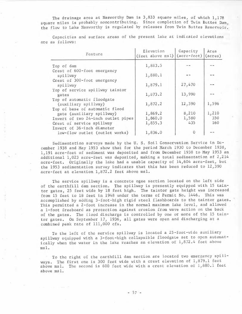
The drainage area at Nasworthy Dam issquare miles is probably noncontributing.the flow to Lake Nasworthy is regulated by
3,833 square miles, of which 1,178Since completion of Twin Buttes Dam ,releases from Twin Buttes Reservoir.
Capacities and surface areas of the present lake at indicated elevationsare as follows:
Elevation Capacity AreaFeature (feet above msl) (acre-feet) (acres)
Top of dam 1,883.5Crest of 600-foot emergency
spillway 1,880.1Crest of 300-foot emergency
spillway 1,879.1 27,470Top of service spillway taintor
gates 1,873.2 13,990Top of automatic floodgate
(auxiliary spillway) 1,872.2 12,390 1,596Top of base of automatic flood
gate (auxiliary spillway) 1,869.2 8,210 1,210Invert of two 24-inch outlet pipes 1,860.0 1,580 350Crest of service spillway 1,855.3 435 160Invert of 36-inch diameter
low-flow outlet (outlet works) 1,836.0 0
Sedimentation surveys made by the U. S. Soil Conservation Service in December 1938 and May 1953 show that for the period March 1930 to December 1938,1,191 acre-feet of sediment was deposited and from December 1938 to May 1953 anadditional 1,023 acre-feet was deposited, making a total sedimentation of 2,214acre-feet. Originally the lake had a usable capacity of 14,604 acre-feet, butthe 1953 sedimentation survey indicates that this has been reduced to 12,390acre-feet at elevation 1,872.2 feet above msl.
The service spillway is a concrete ogee section located on the left sideof the earthfill dam section. The spillway is presently equipped with 15 taintor gates, 25 feet wide by 18 feet high. The taintor gate height was increasedfrom 15 feet to 18 feet in 1948 under the terms of Permit No. 1446. This wasaccomplished by adding 3-foot-high rigid steel flashboards to the taintor gates.This permitted a 2-foot increase in the normal maximum lake level, and alloweda i-foot freeboard as protection against erosion from wave action on the backof the gates. The flood discharge is controlled by one or more of the 15 taintor gates. On September 17, 1936, all gates were open and discharging at acombined peak rate of 111,000 cfs.
To the left of the service spillway is located a 25-foot-wide auxiliaryspillway equipped with a 3-foot-high collapsible floodgate set to open automatically when the water in the lake reaches an elevation of 1,872.4 feet abovemsl.
To the right of the earthfill dam section are located two emergency spillways. The first one is 300 feet wide with a crest elevation of 1,879.1 feetabove msl. The second is 600 feet wide with a crest elevation of 1,880.1 feetabove msl.
- 57 -
The outlet works consist of two, 36-inch, sluice gates located near thecenter of the service spillway. Invert elevation is 1,836.0 feet above msl.In addition there are two 24-inch pipes with invert elevation of 1,860.0 feetabove msl that are located near the ends of the dam. The one at the right endis used to furnish water for a fish hatchery, and the one near the left end isused to help control the lake level.
35. Mountain Creek Dam and Mountain Creek Lake
LoeB tion
Mountain Creek Dam and Mountain Creek Lake are in the Trinity River Basinin Dallas County, 4 miles southeast of Grand Prairie on Mountain Creek, a tribu tary to the Hes t Fork Trini ty River, which is tribu tary to the Tr ini ty River.
Ownership and History of Development
Mountain Creek Dam and Lake are presently owned by the Dallas Power andLight Company. The water right under which the dam was constructed was PermitNo. 1167 (Application No. 1243) originally issued to E. S. Heyser by the StateBoard of Water Engineers October 20, 1931. E. S. Heyser transferred his rightsand interest in the Permit prior to its issuance to Joe A. Worsham, who t~ans
ferred his rights and interest in the Permit to the Dallas Power and LightCompany about August 1930.
Permit No. 1167 authorizes construction of a dam across Mountain Creek tocreate a lake with a capacity of 40,000 acre-feet. It also authorizes appropriation of 15,000 acre-feet of water per annum for cooling and condensing purposes for the Dallas Power and Light Company's Mountain Creek Steam-ElectricSta tion.
Construction of the dam began in 1929. The State Board of I-Iater Engineers.upon petition by the Dallas Power and Light Company, granted two extension-oftime permits prolonging the construction deadline under Permit No. 1167 fromOctober 20, 1933 to October 20, .1937. By 1934 the construction of the dam wascomplete except for installation of the gates in the spillway. The gates wereinstalled in December 1936, and impoundment began about January 1937. Thesteam-electric generating station went into operation in June 1938.
The Dallas Power and Light Company requested an order clarifying PermitNo. 1167 concerning losses of water by seepage or natural evaporation. Accordingly, the Sta te Board of lola ter Engineers on Apr il 24. 1937 ordered tha t theDallas Power and Light Company was ent;tle9 to the beneficial use of 15,000acre-feet of water per annum, exclusive of any water lost from its reservoirby seepage or natural evaporation.
Records of elevation of water level of Mountain Creek Lake since March 24,1937 pre contained in the files of the U. S. Geological Survey. Records ofcontents since October 1, 1960, based on 1963 sediment survey, are publishedby the U. S. Geological Survey.
- 58 -
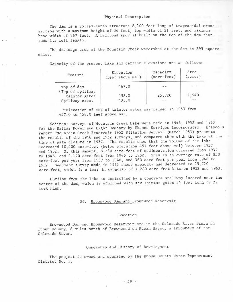
Physical Description
The dam is a rolled-earth structure 8,200 feet long of trapezoidal crosssection with a maximum height of 36 feet, top width of 21 feet, and maximumbase width of 167 feet. A railroad spur is built on the top of the dam thatruns its full length.
The drainage area of the Mountain Creek watershed at the dam is 295 squaremiles.
Capacity of the present lake and certain elevations are as follows:
Feature
Top of dam*Top of spillway
ta in tor ga tesSpillway crest
Elevation(feet above msl)
467.0
458.0431.0
Capac i ty(acre-feet)
25,720
Area(acres)
2,940
'-'Elevation of top of taintor gates was raised in 1953 from457.0 to 458.0 feet above msl.
Sediment surveys of Mountain Creek Lake were made in 1946, 1952 and 1963for the Dallas Power and Light Company by Ebasco Services Incorporated. Ebasco'sreport ''Mountain Creek Reservoir 1952 Siltation Survey" (March 1953) presentsthe results of the 1946 and 1952 surveys, and compares them with the lake at thetime of gate closure in 1937. The results show that the volume of the lakedecreased 10,400 acre-feet (below elevation 457 feet above msl) between 1937and 1952. Of this amount, 8,230 acre-feet of sedimentation occurred from 1937to 1946, and 2,170 acre-feet from 1946 to 1952. This is an average rate of 850acre-feet per year from 1937 to 1946, and 360 acre-feet per year from 1946 to1952. Sediment survey made in 1963 shows capacity had decreased to 25,720acre-feet, which is a loss in capacity of 1,280 acre-feet between 1952 and 1963.
Outflow from the lake is controlled by a concrete spillway located near thecenter of the dam, which is equipped with six taintor gates 34 feet long by 27feet high.
36. Brownwood Dam and Brownwood Reservoir
Location
Brownwood Dam and Brownwood Reservoir are in the Colorado River Basin inBrown County, 8 miles north of Brownwood on Pecan Bayou, a tributary of theColorado River.
Ownership and History of Development
The project is owned and operated by the Brown County \,ater ImprovementDistrict No. 1.
- 59 -
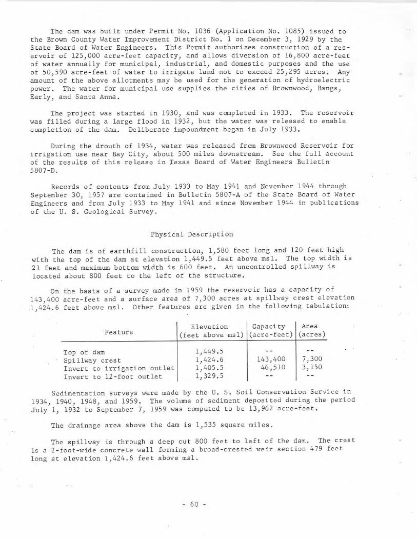
The dam was built under Permit No. 1036 (Application No. 1085) issued tothe Brown County Water Improvement District No. 1 on December 3, 1929 by theState Board of Water Engineers. This Permit authorizes construction of a reservoir of 125,000 acre-feet capacity, and allows diversion of 16,800 acre-feetof water annually for municipal, industrial, and domestic purposes and the useof 50,590 acre-feet of water to irrigate land not to exceed 25,295 acres. Anyamount of the above allotments may be used for the generation of hydroelectricpower. The water for municipal use supplies the cities of Brownwood, Bangs,Early, and Santa Anna.
The project was started in 1930, and was completed in 1933. The reservoirwas filled during a large flood in 1932, but the water was released to enablecompletion of the dam. Deliberate impoundment began in July 1933.
During the drouth of 1934, water was released from Brownwood Reservoir forirrigation use near Bay City, about 500 miles downstream. See the full accountof the results of this release in Texas Board of Water Engineers Bulletin5807-D.
Records of contents from July 1933 to May 1941 and November 1944 throughSeptember 30, 1957 are contained in Bulletin 5807-A of the State Board of WaterEngineers and from July 1933 to May 1941 and since November 1944 in publicationsof the U. S. Geological Survey.
Physical Description
The dam is of earthfill construction, 1,580 feet long and 120 feet highwith the top of the dam at elevation 1,449.5 feet above msl. The top width is21 feet and maximum bottom width is 600 feet. An uncontrolled spillway islocated about 800 feet to the left of the structure.
On the basis of a survey made in 1959 the reservoir has a capacity of143,400 acre-feet and a surface area of 7,300 acres at spillway crest elevation1,424.6 feet above msl. Other features are given in the following tabulation:
FeatureElevation Capacity Area
(feet above msl) (acre-feet) (acres)
Top of damSpillway crestInvert to irrigation outletInvert to 12-foot outlet
1,449.51,424.61,405.51,329.5
143,40046,510
7,3003,150
Sedimentation surveys were made by the U. S. Soil Conservation Service in1934, 1940, 1948, and 1959. The volume of sediment deposited during the periodJuly 1, 1932 to September 7, 1959 was computed to be 13,962 acre-feet.
The drainage area above the dam is 1,535 square miles.
The spillway is through a deep cut 800 feet to left of the dam. The crestis a 2-foot-wide concrete wall forming a broad-crested weir section 479 feetlong at elevation 1,424.6 feet above msl.
- 60 -
Near the center of the dam are located the service outlets which are two, ,12-foot, horseshoe-shaped concrete conduits controlled by broome-type gatesoperated from the gate tower, that provide regulated release to Pecan Bayou.Invert elevation is 1,329.5 feet above msl.
The Brown County Water Improvement District No. 1 withdraws water from thereservoir for municipal, industrial, and irrigational use through a 5-£00tdiameter, circular, concrete conduit that feeds a concrete-lined canal. TheDistrict owns and operates the filtration plant that supplies water for municipal use to the cities of Brownwood, Bangs, Early, and Santa Anna. The wateris obtained from the concrete canal starting at Brownwood Reservoir. Diversioninto the canal began on April 9, 1939.
Brownwood project has a Federal authorization under the Flood Control Actof August 18, 1941 for enlargements of the existing dam, improvement of thepresent spillway, and increase of the reservoir capacity. The proposal is touse the increased capacity for flood control, conservation, recreation, andwildlife purposes. A restudy of the project design is under consideration bythe U. S. Army Corps of Engineers, Fort Worth District.
37. Bridgeport Dam and Bridgeport Reservoir
Location
Bridgeport Dam and Bridgeport Reservoir are in the Trinity River Basin inWise County, 4 miles west of Bridgeport on the West Fork Trinity River, whichis tributary to the Trinity River. Most of the reservoir area is in WiseCounty, but the upper end extends into Jack County.
Ownership and History of Development
Bridgeport Dam and Bridgeport Reservoir are presently owned and operatedby Tarrant County Water Control and Improvement District No.1. The projectwas constructed by the District under the water right granted by Permit No.1073 (Application No. 1144), which was issued to the District on May 1, 1928 bythe State Board of Water Engineers. The Permit bears a priority date of July 6,1926 (10:00 A.M.) derived from the filing time of a presentation submitted bythe District. Permit No. 1073 authorizes: impoundment, for beneficial use, of290,000 acre-feet of water by construction of a dam across the West ForkTrinity River; appropriation of 52,000 acre-feet of water per annum for irrigation of 26,000 acres of land within Wise County Water Control and ImprovementDistrict No. 1 at the maximum rate of 2 acre-feet per annum per acre; transportation of 93,000 acre-feet of water per annum by the bed and banks of the WestFork Trinity River to Eagle Mountain Reservoir. This reservoir was authorizedfor construction by Permit No. 1074 (Application No. 1145), which was alsoissued on May 1, 1928 to Tarrant County Water Control and Improvement DistrictNo.1 by the State Board of Water Engineers. From Eagle Mountain Reservoir thewater continues downstream to the city of Fort Worth's Lake Worth and otherpoints for beneficial use.
- 61 -
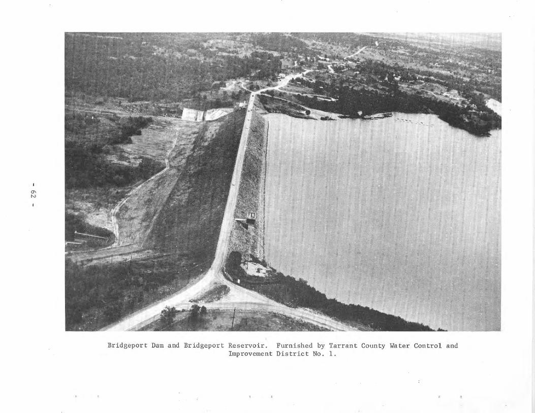
'"N
Bridgeport Dam and Bridgeport Reservoir.Improvement
Furnished by Tarrant County Water Control andDistrict No.1.
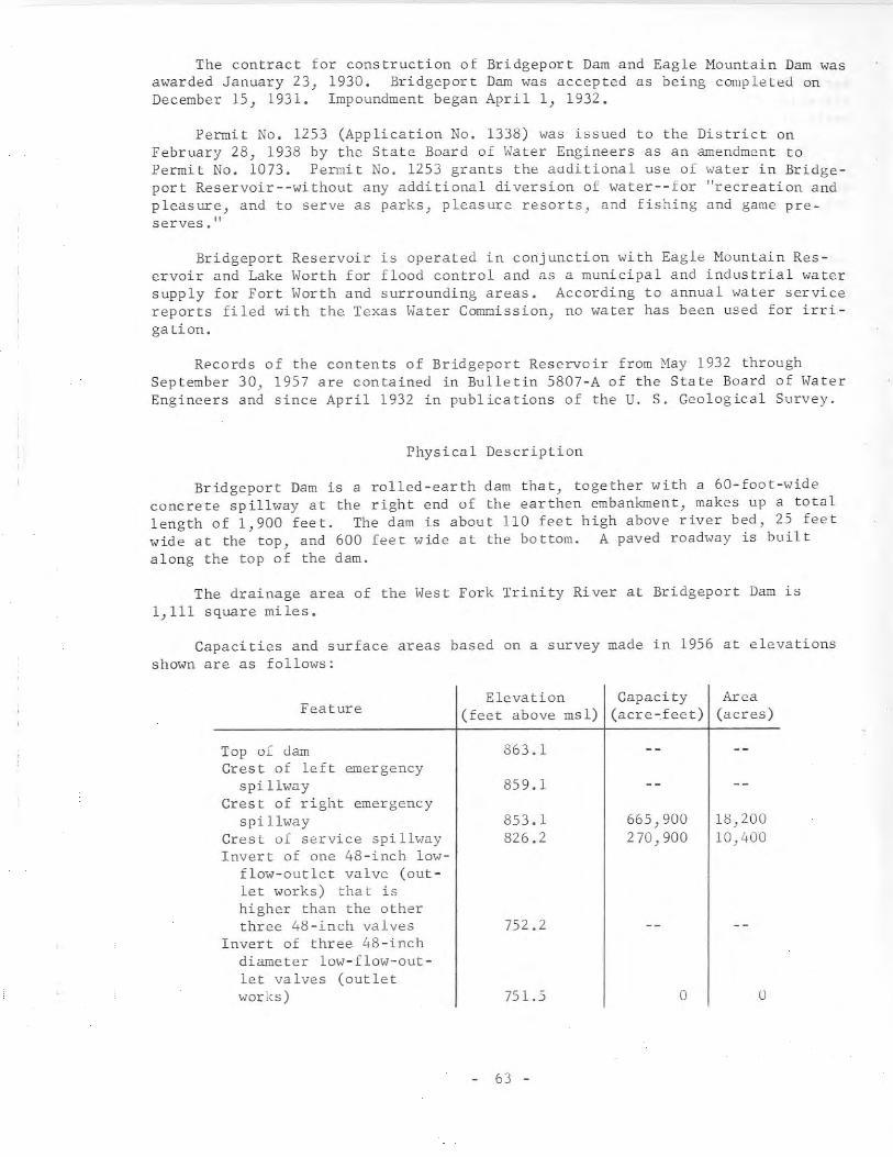
The contract for construction of Bridgeport Dam and Eagle Mountain Dam wasawarded January 23, 1930. Bridgeport Dam was accepted as being completed onDecember 15, 1931. Impoundment began April 1, 1932.
Permit No. 1253 (Application No. 1338) was issued to the District onFebruary 28, 1938 by the State Board of Hater Engineers as an amendment toPermit No. 1073. Permit No. 1253 grants the aaditional use of water in Bridgeport Reservoir--without any additional diversion of water--for "recreation andpleasure) and to serve as parks) pleasure resorts, and fishing and game preserves."
Bridgeport Reservoir is operated in conjunction with Eagle Mountain Reservoir and Lake Horth for flood control and as a municipal and industrial watersupply for Fort Horth and surrounding areas. According to annual water servicereports filed with the Texas Water Commission, no water has been used for irrigation.
Records of the contents of Bridgeport Reservoir from May 1932 throughSeptember 30, 1957 are contained in Bulletin 5807-A of the State Board of HaterEngineers and since April 1932 in publications of the U. S. Geological Survey.
Physical Description
Bridgeport Dam is a rolled-earth dam that, together with a 60-foot-wideconcrete spillway at the right end of the earthen embankment, makes up a totallength of 1,900 feet. The dam is about 110 feet high above river bed, 25 feetwide at the top, and 600 feet wide at the bottom. A paved roadway is builtalong the top of the dam.
The drainage area of the West Fork Trinity River at Bridgeport Dam is1,111 square miles.
Capacities and surface areas based on a survey made in 1956 at elevationsshown are as follows:
Elevation Capacity AreaFeature (feet above msl) (acre-feet) (acres)
Top of dam 863.1Crest of left emergency
spillway 859.1Crest of right emergency
spi llway 853.1 665,900 18,200Crest of service spi llway 826.2 270,900 10,400Invert of one 48-inch low-
flow-outlet valve (out-let works) tha t ishigher than the otherthree 48-inch valves 752.2
Invert of three 48-inchdiameter low- flow-out-let valves (outletworks) 751.5 0 0
63 -
The service spillway is a concrete section, located to the right of theearthfill dam section, and consists of three 20-foot-wide bays with crest atelevation 826.2 feet above msl. The left and middle bays are controlled byvertical lift gates while the third is uncontrolled.
There are two natural-ground emergency spillways. One is 1.6 miles to theright of the main dam with crest elevation of about 853.1 feet above msl. Theother is 0.4 mile to the left of the main dam with crest elevation of about859.1 feet above msl.
The outlet works consist of a double-barreled concrete conduit extendingthrough the dam. Each barrel is approximately 12 feet in diameter. There aretwo 48-inch valves in each conduit, operated from a control house above the conduit and upstream from the top of the dam. The invert elevation of one of the~valves is slightly higher than the other three.
There is a levee dam (Berkshire Levee) 4,100 feet long located on the rightside of the river about 3.5 miles south of the main dam. Water will reach thislevee at a stage above 835.1 feet above msl.
Sedimentation surveys were made by the U. S. Army Corps of Engineers andothers in 1952 and 1956.
Note: Work is scheduled to begin in 1967 which will increase the heightof dam 11 feet, and raise the service spillway crest to elevation 828.0 feetabove msl. Two 40-foot wide gates will be installed raising the normal lakelevel to elevation 840.0 feet above msl. This work will increase the storagecapacity by 167,660 acre-feet.
38. Eagle Mountain Dam and Eagle Mountain Reservoir
Location
Eagle Mountain Dam and Eagle Mountain Reservoir are in the Trinity RiverBasin in Tarrant County, 14 miles northwest of Fort Worth on the West ForkTrinity River, which is tributary to the Trinity River. Most of the reservoirarea is in Tarrant County, but the upper end extends into Wise County.
Ownership and History of Development
Eagle Mountain Dam and Eagle Mountain Reservoir are presently owned andoperated by the Tarrant County Water Control and Improvement District No.1.The project was constructed by the District under the water right granted byPermit No. 1074 (Application No. 1145), which was issued to the District onMay 1, 192~ by the State Board of Water Engineers. The Permit bears a prioritydate of July 13, 1925 (10:00 A.M.) derived from the filing time of a presentation submitted by the District. Permit No. 1074 authorizes: impoundment, forbeneficial use, of 210,000 acre-feet of water by construction of a dam acrossthe West Fork Trinity River; and appropriation of 162,000 acre-feet of waterper annum for supplying the present and potential needs of the city of FortWorth, the supply of industrial demands within the District, and the irrigationof lands situated in the District and in Tarrant County. The Permit authorizes
- 64 -
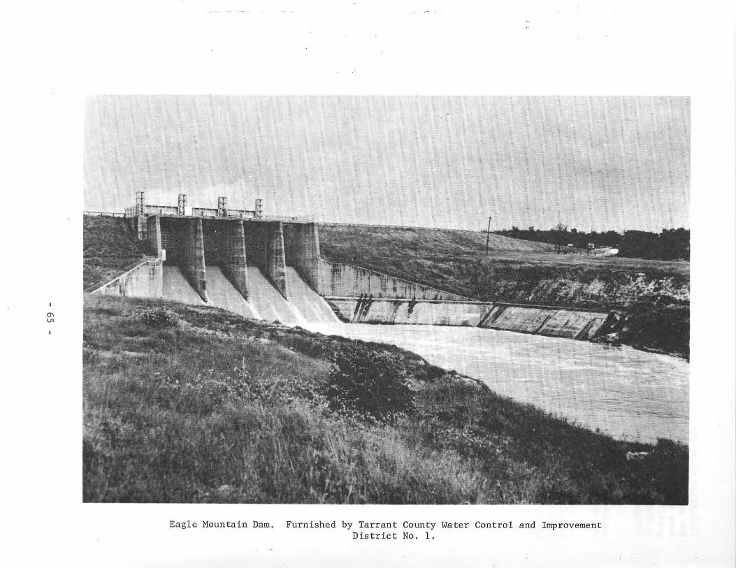
'"U>
Eagle Mountain Dam. Furnished by Tarrant County Water Control and ImprovementDistrict No. 1.
irrigation of 20,880 acres of land at the maximum rate of 2 acre-feet per acreper annum. The Permit further authorizes the use of the bed and banks of theHest Fork Trinity River to transport water from Eagle Mountain Reservoir toLake Horth. From Lake Worth water is delivered for municipal uses for the cityof Fort Horth, and for industrial uses within the District. The water forirrigation is distributed by gravity canals.
The contract for construction of Eagle Mountain Dam and Bridgeport Dam wasawarded January 23, 1930. Eagle Mountain Dam was accepted as completed onOctober 24, 1932. Impoundment began on February 28, 1934.
Permit No. 1254 (Application No. 1339) was issued to the District onFebruary 28, 1938 by the State Board of Water Engineers as an amendment toPermit No. 1074. Permit No. 1254 grants the additional use of water in EagleMountain Reservoir--without any additional diversion of water--for the purposeof "recreation and pleasure, and to serve as parks} pleasure resorts and fishing and game preserves. 1I
Permit No. 1682 (Application No. 1812) was issued to the District by theState Board of Water Engineers on September 30, 1953 as an amendment to PermitNo. 1074. Permit No. 1682 authorizes, in addition to that granted under Permit No. 1074, the following: to furnish water to any municipality or communitynow created or existing within the boundaries of the District; to furnish irrigation water to individual irrigators) whose lands are within the area describedin the original Permit No. 1074 as covered for irrigation, either through thebed and banks of the West Fork Trinity River or through raw water conduits, touse the bed and banks of the West Fork Trinity River to flow water to any userhaving a lawful right thereto, after approval by the State Board of Water Engineers of the contemplated diversion facilities; to take water for municipalities, industries) and irrigators from intakes located at Eagle MountainReservoir in Tarrant County, as well as at points in the bed and banks of theHest Fork Trinity River, with the limitation that diversions will not be madeuntil approval is given by the State Board of Water Engineers.
The Texas Water Commission issued a special minute order on October 9, 1962approving application for amendment to construction plans under Permit No. 1074.The order granted permission to the District to construct an emergency spillwayknown as the Burgess Gap· Spillway. The spillway construction consists of excavation and fill to widen and realign the existing country spillway, to improveits discharge characteristics, and to increase the discharge capacity. Theemergency spillway will have a 6-foot-high fuse plug that will increase thefloodwater retarding capabilities of the structure, without jeopardizing thedam, by providing an additional 106,640 acre-feet of surcharge storage.
Eagle Mountain Reservoir regulates floodflow through coordination withBridgeport Reservoir upstream. Water is released from Eagle Mountain Reservoirto Lake Worth to maintain it at normal maximum operating level as water is withdrawn from Lake Worth for use by the city of Fort Worth. Water is taken directly from Eagle Mountain Reservoir for condenser-cooling water for a 290,000kw) steam-electric) generating plant belonging to Texas Electric Service Company.
Records of the contents of Eagle Mountain Reservoir from February 1934through September 30, 1957 are contained in Bulletin 5807-A of the State Boardof Water Engineers and since February 1934 in publications of the U. S. Geological Survey.
- 66 -
Physical Description
Eagle Mountain Dam is a composite rolled-earth and hydraulic-fill earthstructure with the fills being separated by the intervening high ground ofEagle Mounta~n and Bu~gess Gap. The main dam is to the left of Eagle Mountain.A concrete serv~ce sp~llway ~s located ~n the section to the right of EagleMounta~n. The Burgess Gap emergency spillway is located approximately 1 000feet to the left of the service spillway. '
The drainage area of the West Fork Trinity River at Eagle Mountain Dam is1,970 square miles.
Capacities and surface areas of the reservoir at indicated elevations areas follows:
FeatureElevation Capacity Area
(feet above msl) (acre-feet) (acres)
Top of dam 682.0Crest of Burgess Gap
emergency spillway 676.0 547,900 19,000Base of Burgess Gap
emergency spillwayfuse plug 670.0 441,200
Crest of service spillway 649.1 182,700 8,500Invert of low-flow outlet
(outlet works) 599.9 0 0
The original capacity of the reservoir was 214,000 acre-feet at the crestof the service spillway (elevation 649.1 feet above msl). A survey made inOctober 1952 by the U. S. Army Corps of Engineers and others revealed that thiscapacity had been reduced by sedimentation to 182,700 acre-feet.
The service spillway, located to the right of Eagle Mountain, is a concretesection consisting of four 25-foot-wide bays with crest at elevation 649.1 feetabove msl. All except the extreme left bay, which is uncontrolled, are equippedwith vertical-lift gates.
The present emergency spillway, Burgess Gap Spillway, is 1,300 feet widewith a crest elevation of 676.0 feet above msl (top of fuse plug). The fuseplug levee runs the full width of the spillway with base elevation of 670.0feet above msl.
The outlet works consist of four 48-inch outlet gates located in a gatehouse near the left end of the main dam. The invert elevation of all of theoutlet conduits is at 599.9 feet above msl.
Note: Work on the construction of a new discharge structure \vith acapacity of 20,000 cfs is scheduled for 1967. This will be a gated morningglory type spillway with crest elevation 637.0 feet above msl and top ofgates at elevation 676.0 feet above msl. The 20,000 cfs discharge rating isat elevation 649.1 feet above msl, the crest elevation of the present servicespillway.
- 67 -
39. Buchanan Dam and Lake Buchanan
Loea tion
Buchanan Dam and Lake Buchanan are in the Colorado River Basin in Burnetand Llano Counties, 11 miles west of Burnet on the Colorado River. The upperend of the lake extends into San Saba County.
Ownership and History of Development
The project is owned and operated by the Lower Colorado River Authorityas one of a series of six dams and reservoirs on the Colorado River. The otherfive are: Inks Dam and Inks Lake, Wirtz (Alvin) Dam and Lake Lyndon B. Johnson,Starcke (Max) Dam and Marble Falls Lake, Mansfield Dam and Lake Travis, andMiller (Tom) Dam and Lake Austin. All of these are described in this report.
Permit No. 954 (Application No. 1024) dated May 15, 1926 issued by theState Board of Water Engineers to the Syndicate Power Company, permitted theconstruction of dams on the Colorado River. Permit No. 1259 (Application No.1345) dated May 25, 1938 issued to the Lower Colorado River Authority allowedPermit No. 954 to be used for Buchanan and Inks Dams. Permit No. 1259 authorizes an annual appropriation of 1,391,530 acre-feet of water for municipal.,irrigational, mining) and hydroelectric power uses. Penmits were granted forone or two applications for various reaches of the Colorado River in thevicinity of Lake Buchanan.
Several other water rights are included in Permit No. 1259 that recognizesearlier water rights of the Lower Colorado River Authority. These water rightsand the history of their acquisition are as follows: I
Certified Filing No. 423 filed with the State Board of WaterEngineers on June 30, 1914 by E. C. Alexander refers toownership of rights by virtue of prior filings and applications in connection with which water is to be utilized formining, milling, manufacturing, power, waterworks, andstock raising and which prior filings and applications wererenewed for the construction of a dam at Lohman Narrows.This project, known as Alexander Dam, was located belowMarble Falls. Between 1914 and 1919 these rights passedto C. H. Alexander and the Syndicate Power Company. Allthese C. H. Alexander interests seem to be in a partnership with John N. Simpson of Dallas, who also had earlywater rights and owned considerable land on the ColoradoRiver. The Alexander and Simpson Project is mentioned insome of the letters in the files of the Texas Water RightsCommission. For later permits, Permit Nos. 951-55 and 998,the Syndicate Power Company claimed the exclusive priorrights to the appropriation and use of such waters withinthe area covered by six applications for water permitspertaining to the appropriation and use of such waters asexisted prior to June 29, 1913.
- 68 -
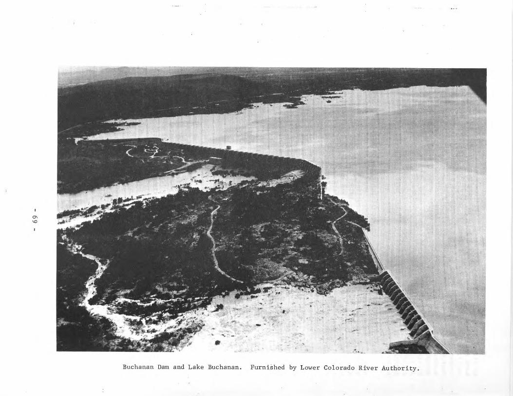
'"'D
•11 ......
~
... ,--
•
~.'
'''...,--
•
'.•~
...: ... ,.'."
,-~
-Buchanan Dam and Lake Buchanan. Furnished by Lower Colorado River Authority.
The Lower Colorado River Authority is owner of Permit Nos. 951-55 and 998by virtue of the following conveyances: (a) from Syndicate Power Company toWard Arnold and Jay Alexander dated July 30, 1928 (Permit Nos. 951 and 952only); (b) from Syndicate Power Company to Emery, Peck & Rockwood DevelopmentCompany dated July 19, 1929; (c) from Ward Arnold and Jay Alexander to Emery,Peck & Rockwood Development Company dated July 19, 1929; (d) from Emery, Peck &Rockwood Development Company to Central Texas Hydro-Electric Company datedNovember 5, 1931; (e) from A. J. Wirtz, Receiver for Central Texas HydroElectric Company, to Colorado River Company dated October 5, 1934; (f) fromA. J. Wirtz, Receiver for Central Texas Hydro-Electric Company, to C. G. Malottdated October 5, 1934; (g) from Colorado River Company to Lower Colorado RiverAuthority dated August 9, 1935; (h) from C. G. Malott to Lower Colorado RiverAuthority dated August 9, 1935.
The project was started by Samuel Insull inter~st~ in April 1931 under thename of Central Texas Hydro-Electric Company. Work was stopped April 20, 1932because of financial difficulties. Reconstruction by the Lower Colorado RiverAuthority began in 1935 and was completed in 1938. Deliberate impoundment ofwater began May 20, 1937. The flood of July 1938 filled the reservoir for thefirst time resulting in a large flood flow discharge from the reservoir. Thefirst generating unit was placed in operation in January 1938.
Buchanan Dam and Lake Buchanan is the upstream project of a series ofsix projects; water released from Lake Buchanan is subsequently used at Inks,Granite Shoals, Marble Falls, Marshall Ford (Mansfield), and Austin plants forgeneration-of power and for municipal and irrigation purposes. Excess floodwater released may be stored in Lake Travis (Mansfield Dam) depending on theelevation of the water in that lake.
Records of the contents of Lake Buchanan from May 1937 through September30, 1957 are contained in Bulletin 5807-A of the State Board of Water Engineersand from May 1937 in publications of the U. S. Geological Survey.
Physical Description
The dam is a concrete arch and gravity structure with a total length of10,987 feet. The maximum height is 145.5 feet with the top of the dam atelevation 1,025.5 feet above msl. Beginning at the left end, the variousfeatures are as follows: a concrete gravity overflow spillway section 1,100feet long with crest at elevation 1,020.5 feet above msl; a gated spillwaysection with an agee crest at elevation 1,005.5 feet above msl with sixteentaintor gates, each 33 feet wide by 15.5 feet high; a non-overflow section ofnatural rock and concrete gravity section; a gated spillway section with anogee crest at elevation 1,005.5 feet above msl with fourteen taintor gates,each 33 feet wide by 15.5 feet high; a section of natural rock and concretegravity non-overflow section; a gated spillway section with an agee crest atelevation 995.5 feet above msl with seven taintor gates, each 40 feet long by25.5 feet high; a section of twenty-nine 70-foot-span multiple concrete archeswith top elevation of 1,025.5 feet above msl (the power plant penstocks andcontrol gatehouses are located in this part of the dam); a 650-foot length ofrock and concrete gravity section; a section of twenty-three 35-foot-spanmultiple arches of concrete with top elevation 1,025.5 feet above msl; and agravity section at the extreme right end of the structure.
- 70 -
Lake Buchanan has a capacity of 992,000 acre-feet at spillway crest elevation of 1,020.5 feet above msl. Other areas and capacities are given in thetable below. This is an important storage reservoir as water released is usedsix times for generation of power and for municipal and irrigation purposes.Normal water releases are controlled by the operation of the turbines in thepowerhouse. Flood\'later releases are from one or more sections of the gatedspillways. The lake shore has developed into an important recreational andresidential area.
Fea ture E1 eva t ion Capac i ty Area(feet above msl) (acre-feet) (acres)
Top of arches 1,025.5 1,125,000 24,660Top of gravity overflow 1,020.5 992,000 23,200Sill of 15-foot gates 1,005.5 678,000 18,770Sill of 25-foot gates 995.5 505,000 15,820Invert to pens tocks 937.5 36,800 2,100
Reservoir capacities and surface areas based on U. S. Geological Surveytopographic maps made in 1925. Some sediment is being deposited in the reservoir, but surveys to determine the volume have not been made.
The drainage area is 31,250 square miles, of which 11,900 square miles isprobably noncontributing.
Allocation of water in acre-feet for the various purposes is not set outin Permit No. 1259. All water released except flood flow is first used to generate power and later used downstream for municipal, industrial; and irrigationalpurposes in varying amounts.
There are no outlets required for conservation releases since this isaccomplished by the operation of the turbines for generation of pOl,er. Hateris passed through the other five reservoirs before it is released into theColorado River Channel belm" Austin for delivery to downstream users. When thevolume of floodwater in the river above the dam is greater than the availablestorage capacity of Lake Buchanan, the gates are operated to release \oJater forretention in Lake Travis.
There are three generating units and allied equipment with a rated capacity of 11,250 ~'each. In addition to the three generating units, there isinstalled a pump-back unit. The pump has a capacity of 840 cfs for returningwater from the Buchanan tailrace (Inks Lake) into Lake Buchanan. The pump isdriven by a 14,500 hp motor. This unit operates at off-peak times for pOl,errequirements when electric energy can be purchased at a lower rate than itscost during the time of greatest demand. The generating units and lhe pump areall located in the powerhouse structure.
- 71 -
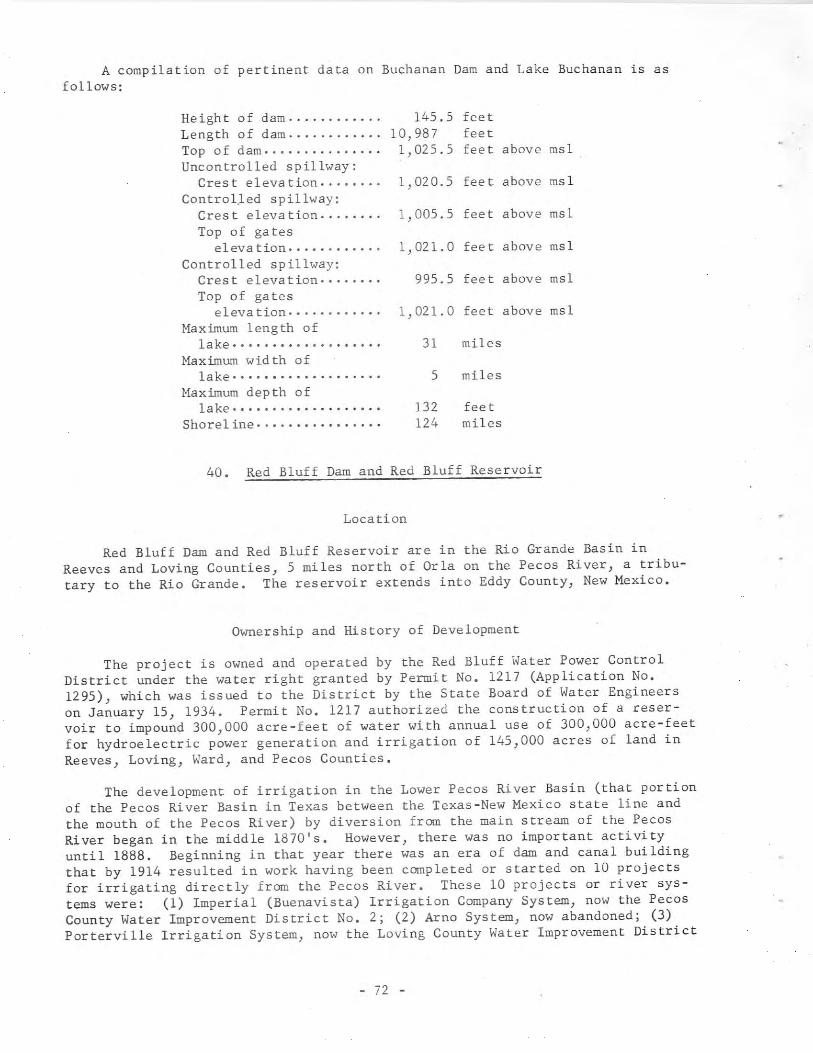
A compilation of pertinent data on Buchanan Dam and Lake Buchanan is asfollows:
5 miles
995.5 feet above msl
31 miles
1,021.0 feet above msl
feetfeetfeet above msl
132 fee t124 miles
1,020.5 feet above msl
1,021.0 feet above msl
1,005.5 feet above msl
145.510,9871,025.5
Height of dam .Length of dam .Top of dam .Uncontrolled spillway:
Crest elevation .ControlJed spillway:
Crest elevation .Top of gates
eleva tion .Controlled spillway:
Crest elevation .Top of gates
eleva tion· .Maximum length of
lake· ........•.........Maximum width of
lake· .........•.......•Maximum depth of
la ke .Shore1 ine· ...•...........
40. Red Bluff Dam and Red Bluff Reservoir
Location
Red Bluff Dam and Red Bluff Reservoir are in the Rio Grande Basin inReeves and Loving Counties, 5 miles north of Orla on the Pecos River, a tributary to the Rio Grande. The reservoir extends into Eddy County, New Mexico.
Ownership and History of Development
The project is owned and operated by the Red Bluff Water Power ControlDistrict under the water right granted by Permit No. 1217 (Application No.1295), which was issued to the District by the State Board of Water Engineerson January 15, 1934. Permit No. 1217 authorized the construction of a reservoir to impound 300,000 acre-feet of water with annual use of 300,000 acre-feetfor hydroelectric power generation and irrigation of 145,000 acres of land inReeves} Loving} Ward} and Pecos Counties.
The development of irrigation in the Lower Pecos River Basin (that portionof the Pecos River Basin in Texas between the Texas-New Mexico state line andthe mouth of the Pecos River) by diversion from the main stream of the PecosRiver began in the middle 1870's. However, there was no important activityuntil 1888. Beginning in that year there was an era of dam and canal buildingthat by 1914 resulted in work having been completed or started on 10 projectsfor irrigating directly from the Pecos River. These 10 projects or river systems were: (1) Imperial (Buenavista) Irrigation Company System, now the PecosCounty Water Improvement District No.2; (2) Arno System, now abandoned; (3)Porterville Irrigation System, now the Loving County Water Improvement District
- 72 -
No.1; (4) Farmers' Independent Canal Company System, now the Reeves CountyWater Improvement District No.2; (5) Cedarvale (Biggs) Irrigation System, nowthe Ward County \<ater Improvement District No.3; (6) Barstow Irrigation Company System, now the Ward County Irrigation District No.1; (7), (8) GrandfallsIrrigation Company System and Big Valley Irrigation Company System, which arenow in the Ward County Water Improvement District No.2; (9) Zimmerman Irrigation Company System, now the Pecos County \<ater Improvement District No.3; and(10) Victor Pumping Plant, now abandoned.
In January 1914 the 10 river systems organized the West Texas ReclamationAssociation and retained P. M. Fogg, a Reclamation Service Engineer, to investigate the Texas development and make recommendations concerning project rehabilitation, including the provision of storage. Fogg recommended the construction of a dam that would create a reservoir to supply all 10 of the irrigationsystems. The site for the dam was in New Mexico about 2 miles north of thestate line.
On the basis of Fogg's recommendations, the 10 river systems organizedinto the Pecos Valley of Texas Water Users Association. In 1916, the Association petitioned the Secretary of the Interior to grant aid from the U. S. Reclamation Service in constructing Red Bluff Dam and Red Bluff Reservoir and forloans to finance the rehabilitation of deteriorated project works. The Association requested engineering services and $2,500,000 in financial aid for construction of the dam and general rehabilitation of project works. In addition,River water not only between New Mexico and Texas) but among users in Texasitself. The petition was not acted upon fur seieral years.
In 1917, the seven surviving lower basin systems (Porterville, Farmers'Independent, CeGarvale, Barstow, Big Valley-Grandfalls, Imperial, and Zimmerman)dissolved the wdter users association and reincorporated as a water improvementdistrict. On November 30, 1927, the Red Bluff Water Improvement District wascreated by the State Board of Water Engineers. The water improvement districtbecame the Red Bluff Water Power Control District in 1933.
The District began studies on the Red Bluff project and enlisted State andFederal agencies in preparing additional studies. In the early 1930's, theDistrict sought to obtain funus from one of the Federal emergency-spendingagencies to finance the construction of the proposed Red Bluff Dam and RedBluff Reservoir. In 1933 the construction was approved as a project of theU. S. Public Works Administration. Subsequently, the Distriot's bonds werepurchased by the Reconstruction Finance Corporation.
Actual construcLion began Ln November 1934, and was coclpleted in September1936 at a cost of $2,600,000. The final site of the dam was located about 8miles south of the Texas-New Mexico state line instead of 2 miles north of thestate line as recommended by Fogg. Impoundment began upon completion of construction in September 1936. Water use began in 1937. The reservoir was firstfilled in June 1937. Power generation began June 6, 1937.
The division and apportionment of the use of the waters of the Pecos Riveris provided for by the Pecos River Compact of 1948 between Texas and New Mexico.The Compact created an interstate agency known as the Pecos River Commissionfor administration of the provisions of the Compact. The Commission is composed of one commissioner representing each of the States of New Mexico andTexas) and) if designated by the President) one commissioner representing theUnited States.
- 73 -
Records of contents from February 1937 through September 30, 1957 are contained in Bulletin 5807-A of the State Board of Water Engineers and from February 1937 in publications of the U. S. Geological Survey.
Physical Description
Red Bluff Dam consists of three sections: a main earthfill emban~ent
across the Pecos River, an uncontrolled emergency spillway to the right of themain embankment, and a concrete controlled spillway located in a cut to theright of the emergency spillway and against the hills on the right side of thevalley. The main embankment is 9,200 feet long and 102 feet high with a 25foot crown width. The upstream slope of the embankment is 3 to 1; the downstream slope is 2 to 1. The earth embankment has rock riprap on both upstreamand downstream embankments at critical areas.
The reservoir has a capacity of 310,000 acre-feet and a surface area of11,700 acres at elevation 2,841.7 feet above msl. The inflow varies greatly.Some years there is no water for power generation, and the irrigation supplyis limited.
Reservoir capacities and surface areas based on U. S. Geological Surveytopographic map made in 1925.
Other capacities are given in the following tabulation:
FeatureElevation Capacity Area
(feet above msl) (acre-feet) (acres)
Crest of emergencyspillway 2,844.7 345,000
Top of taintor gates 2,841.7 310,000 11,700Crest of service
spillway 2,826.7 166,500Invert of concrete
outlet conduits 2,763.7 3,000*
* Dead storage.
The drainage area above Red Bluff Dam is 20,720 square miles.
The concrete service spillway is equipped with twelve taintor gates 25feet wide by 15 feet high. The spillway is an ogee section with crest at elevation of 2,826.7 feet above msl.
The emergency spillway has a crest length of 790 feet at elevation 2,844.7feet above msl. The spillway was excavated from natural-earth.
The outlet structure consists of a surge tower supplied by two parallelconcrete outlet conduits 7.5 feet wide by 9.0 feet high each, which draw waterfrom the reservoir. From this surge tower water can be bypassed for irrigationpurposes through two parallel concrete conduits 7.75 feet wide by 7.0 feet high,which are controlled by 48-inch gate valves. Two circular, steel penstocksextend from the surge tower to the turbines. The penstock for turbine 1 is 6.5feet in diameter, and is controlled by a 7-foot butterfly valve. The penstockfor turbine 2 is 5.5 feet in diameter, and is controlled by a 6-foot butterflyvalve.
- 74 -
The power plant contains two generating units and all auxiliaries. Thetwo generating units have a combined capacity of 2,300 kw.
All irrigation releases from the reservoir are made at continuous) uniformrates through the bypass valves or the turbines) but no releases are madesolely for the generation of power. Reservoir releases are withdrawn from thePecos River at seven diversion dams ranging between a site near Menton and oneabout 11 miles above Grand Falls. Electricity generated at Red Bluff Dam istransmitted to the District's electrical distribution system center at GrandFalls. The sale of electric power is a major source of income to the District.
41. Monte Alto Dam and Monte Alto Reservoir
Location
Monte Alto Dam and Monte Alto Reservoir are in the Nueces-Rio GrandeCoastal area in Hidalgo County, 4 miles north of Monte Alto. The reservoir,shown on early maps as Mestenas Reservoir, also is known as Willacy Reservoir.It is an off-channel storage reservoir to the Rio Grande.
Ownership and History of Development
The project is owned and operated by the Hidalgo-Willacy Counties WaterControl and Improvement District No. 1 of Edcouch.
The water rights were obtained by Permit No. 1110 (Application No. 1174)dated January 9, 1930 from the State Board of Water Engineers. Originally thePermit was issued to the Union Irrigation District. The Permit allows diversion from the Rio Grande floodwaters of a flow of 260,000 acre-feet of waterannually for irrigation of 129,000 acres of land. The reservoir is to storeexcess water that otherwise would be wasted.
The project was built over a period ofearly stage of financing and sale of bonds.1936. Monte Alto Reservoir was constructedof water began that year.
years with many delays during theThe first canals were built in
in 1939, and deliberate impoundment
Physical Description
The dike creating the reservoir is about 12 miles long with an averageheight of 17 feet with a freeboard of 5 feet. The dike and reservoir are inHidalgo County, but the diversion from the Rio Grande is in Cameron County.
Monte Alto Reservoir has a capacity of 25,000 acre-feet and a surface areaof 2,371 acres at elevation 56.5 feet above msl. Water is diverted from theRio Grande) in Cameron County, by a gravity canal system. From this main canal,water is diverted to another canal known as Mestenas Canal for distribution toland during the irrigation season or to a ~umping plant that lifts surpluswater to Monte Alto Reservoir for storage. Hhen needed for irrigation, thiswater is released by gravity from the reservoir back to the Mestenas Canal fordistribution.
- 75 -
42. Inks Dam and Inks Lake
Location
Inks Dam and Inks Lake are in the Colorado River Basin in Burnet and LlanoCounties, 10 miles west of Burnet on the Colorado River, 4 miles below BuchananDam.
Ownership and History of Development
The project is owned and operated by the Lower Colorado River Authorityas one of a series of six dams and reservoirs on the Colorado River. The otherfive are: Buchanan Dam and Lake Buchanan, Wirtz (Alvin) Dam and Lake Lyndon B.Johnson, Starcke OMax) Dam and Marble Falls Lake, Mansfield Dam and Lake Travis,and Miller (Tom) Dam and Lake Austin. All of these are described in thisreport.
The dam was authorized by Permit No. 1259A (Application No. 1345) datedMay 28, 1938 from the State Board of Water Engineers to the Lower ColoradoRiver Authority. The Permit authorizes the use of 1,391,530 acre-feet of waterannually for municipal, irrigational) mining) and hydroelectric power uses(same as Buchanan Dam Permit). Several other water rights are included in Permit No. 1259A, which recognizes earlier water rights of the Lower ColoradoRiver Authority. These water rights and the history of their acquisition areas follows:
Certified Filing No. 423 filed with the State Board of WaterEngineers on June 30, 1914 by E. C. Alexander refers toownership of rights by virtue of prior filings and applications in connection with which water is to be utilized formining, milling, manufacturing, power, waterworks) andstock raising and which prior filings and applications wererenewed for the construction of a dam at Lohman Narrows.(The project became known as Alexander Dam located belowMarble Falls.) Between 1914 and 1919 these rights passedto C. H. Alexander and the Syndicate Power Company. Allthese C. H. Alexander interests seem to be in a partnershipwith John N. Simpson of Dallas, who also had early waterrights and owned considerable land on the Colorado River.The Alexander and Simpson Project is mentioned in Some ofthe letters in the files of the Texas Water Commission.For later permits, Permit Nos. 951-55 and 998, the Syndicate Power Company claimed the exclusive prior rights tothe appropriation and use of such waters within the areacovered by six applications for water permits pertainingto the appropriation and use of such waters as existedprior to June 29, 1913.
The Lower Colorado River Authority is owner of Permit Nos. 951-55 and 998by virtue of the following conveyances: (a) From Syndicate Power Company toWard Arnold and Jay Alexander dated July 30, 1928 (Permit Nos. 951 and 952only); (b) from Syndicate Power Company to Emery, Peck & Rockwood DevelopmentCompany dated July 19, 1929; (c) from Ward Arnold and Jay Alexander to Emery,Peck & Rockwood Development Company dated July 19, 1929; (d) from Emery, Peck &
- 76 -

j.
I
Rockwood Development Company to Central Texas Hydro-Electric Company datedNovember 5, 1931; (e) from A. J. Wirtz, receiver for Central Texas HydroElectric Company, to Colorado River Company dated October 5, 1934; (f) fromA. J. Wirtz, receiver for Central Texas Hydro-Electric Company, to C. G. Malottdated October 5, 1934; (g) from Colorado River Company to Lower Colorado RiverAuthority dated August 9, 1935; (h) from C. G. Malott to Lower Colorado RiverAuthority dated August 9, 1935.
Construction of the dam began in 1936, and was completed in 1938 with impoundment of water beginning at that time. The power unit began operation inJune 1938.
Records of daily lake elevations are maintained by the Lower ColoradoRiver Authority as unpublished data.
Physical Description
The dam is a concrete gravity structure with an uncontrolled ogee spillwaywith crest length of 871 feet at elevation 888.0 feet above msl. A non-overflowsection with top at elevation 992.0 feet above msl is 676 feet long, and contains the penstock, headgate, and equipment for operating the headgate.
The lake has a capacity of 17,540 acre-feet and a surface area of 803acres at spillway crest elevation of 888.0 feet above msl. This lake is considered a constant level one because the normal turbine discharge is coordinated with the inflow from Lake Buchanan so that the day-to-day fluctuationis small. However, during periods of floods the lake level will vary considerably.
The drainage area is 31,290 square miles, of which 11,900 square miles isprobably noncontributing. However) Buchanan Reservoir) 4 miles upstream) is astorage reservoir} and regulates the riverflow to a considerable extent.
Sedimentation studies have not been made for this lake, and are unimportant from the standpoint of power generation since storage is maintained bywater released from Buchanan Reservoir.
The water in Inks Lake is used principally for power generation, but thelake shoreline has developed into recreational and residential areas with somewater being diverted directly from the lake for domestic purposes.
The spillway is an uncontrolled, ogee, gravity section of the dam with acrest length of 780 feet at elevation 888.0 feet above msl. It is designed topass the maximum discharge from the Buchanan Dam floodgates.
There are no low-flow outlets required because water releases are madethrough the turbine as normal operation; the water released enters Lake LyndonB. Johnson immediately downstream.
The power plant contains one 12,500 kw generating unit with all auxiliaryequipment. It is operated by remote control from Buchanan Plant and the outputcoordinated with the discharge from that plant.
- 77 -
Marble Falls.) Between 1914 and 1919 these rights passedto C. H. Alexander and Syndicate Power Company. All theseC. H. Alexander interests seem to be a partnership withJohn N. Simpson of Dallas who also had early water rightsand owned considerable land on the Colorado River. TheAlexander and Simpson Project is mentioned in some of theletters in the files of the Texas Water Commission. Forlater permits, Permit Nos. 951-55 and 998, the SyndicatePower Company claimed the exclusive prior rights to theappropriation and use of such waters within the area covered by six applications for water permits pertaining tothe appropriation and use of such waters as existed priorto June 29, 1913.
The Lower Colorado River Authority is oWner of Permit Nos. 951-55 and 998by virtue of the following conveyances: (a) from Syndicate Power Company toWard Arnold and Jay Alexander dated July 30, 1928 (Permit Nos. 951 and 952only); (b) from Syndicate Power Company to Emery, Peck & Rockwood DevelopmentCompany dated July 19, 1929; (c) from Ward Arnold and Jay Alexander to Emery,Peck & Rockwood Development Company dated July 19, 1929; (d) from Emery, Peck &Rockwood Development Company to Central Texas Hydro-Electric Company datedNovember 5, 1931; (e) from A. J. Wirtz, receiver for Central Texas HydroElectric Company, to Colorado River Company dated October 5, 1934; (f) fromA. J. Wirtz, receiver for Central Texas Hydro-Electric Company, to C. G. Malottdated October 5, 1934; (g) from Colorado River Company to Lower ColoradoAuthority dated August 9, 1935; (h) from C. G. Malott to Lower Colorado RiverAuthority dated August 9, 1935.
Construction began in March 1937. First stages of the low dam were completed in July 1939. A contract was awarded to the same builder for additionalfoundation and the high dam. The present structure was completed May 17,1942. Deliberate impoundment began on September 9, 1940. The first generatingunit was placed in operation January 27, 1941.
This is the fifth plant downstream from Buchanan Dam, and the lake is acontrolled storage for Lake Buchanan releases as well as for runoff from theLlano and Pedernales Rivers and other tributary streams below Buchanan Dam.
The Federal authorization for the construction of the low dam was directlyfrom the funds available to the Secretary of the Interior on December 3, 1936.Amendment to the original appropriation was made by Congress May 10, 1939,allocating the money to construct the high dam that is the present structure.This Act also contained provisions for reimbursements to the Federal Governmentby the Lower Colorado River Authority for part of the cost of providing conservation storage. Total cost of the project was $28,709,948.
Records of the reservoir elevations and contents from September 1940through September 30, 1957 are contained in Bulletin S807-A of the State Boardof Water Engineers and since September 1940 in publications of the U. S. Geological Survey. Reservoir capacities and surface areas based on survey made in1939 by the U. S. Bureau of Reclamation.
- 80 -
,\(
Physical Description
The dam consists of a concrete gravity spillway section, a long earth androckfill embankment section on the left of the main dam, and a short approachembankment section on the right end. Both the upstream and downstream sides ofthe earth and rockfill embankments are protected by rock riprap. The totallength is 7,098 feet. The concrete section is one of the largest gravity-typedams in the United States with a maximum height of 266 feet and a length of2,423 feet. In addition to the uncontrolled spillway section, this concretedam contains twenty-four 8.5-foot-diameter conduits for release of floodwaters.Each conduit is double gated with the controls located in tunnels through thedam. This section also contains the three 16-foot-diameter penstocks, headgates, and hoisting equipment for control of the water to the turbines in thepowerhouse.
At the top of the power storage space at elevation 681.1 feet above msl,the reservoir capacity is 1,172,000 acre-feet. The capacity between elevationsof 681.1 and 714.1 feet (crest of uncontrolled spillway) above msl is 778,000acre-feet, and is reserved for flood control. In special cases where dangerof flooding downstream is not present, the water in storage between elevations681.1 and 691.1 feet above msl may be released by operating the turbines togenerate power instead of discharging the water through the floodgates. Thisreservoir, known as Lake Travis, provides the principal flood-control storageon the Colorado River. Much of the shoreline has been developed as residentialand recreational areas.
The drainage area above the dam is 38,130 square miles, of which 11,900 isprobably noncontributing. Runoff is partly regulated by Lake Buchanan andother reservoirs upstream.
The uncontrolled emergency spillway is a concrete ogee section 700 feetlong with crest elevation at 714.1 feet above msl. The emergency spillway hasnot been used as all floodwater releases have been through the controlledoutlets. A roadway bridge at elevation 750.1 feet above msl crosses the spillway on piers, thereby dividing the spillway into five bays of 140 feet each.
Water for domestic and irrigational requirements is released through theturbines at times when generation is necessary to satisfy power requirements.Lake Austin) immediately downstream, acts as a regulating reservoir from whichwater is discharged downstream after passing through the turbines in the powerhouse at the Miller (Tom) Dam.
Floodwater is released through one or more of the twenty-four 8.5-footdiameter conduits. Each of these conduits is controlled by two ring-followtype (paradox) gates located in the two operating galleries. Each conduit hasa capacity of about 5,000 cfs at normal flood-control storage space level.Water is released when Lake Travis reaches elevation 681.1 or 691.1 feet abovemsl depending on the volume of floodflow in the upper and lower river. Therate of release is determined by the U. S. Army Corps of Engineers, Fort Wortl1District, to hold the river stage at Columbus, Texas within specified limits.
- 81 -
The power installation consists of three generating units with a ratedcapacity of 22,500 kw each with all the allied equipment for connecting to thetransmission system. Due to the higher operating head from that originallydesigned, the units can be overloaded for peak power requirements to 29,000kw each. The power facilities were designed and built by the Lower ColoradoRiver Authority. The first unit was placed in commercial operation January 27,1941.
Listed below are pertinent data on Mansfield Dam and Lake Travis.
Type of dam ...•.•••••..•.••.•.Length of dam .•.••.•.•••••••.•Naximcun height of dam . '.' .Top width of dam .••...•...•.•.Spillway crest elevation ..••..Spillway length .•••••....•...•Spillway control .•••••........
earthfill and concrete gravity7,098 feet
266 feet30 feet
714.1 feet above msl700 feet (net)
nOne
Feature Elevation Capacity Area(feet above msl) (acre-feet) (acres)
Top of parapet wallTop of damMaximum design flood stageTop of flood-control storage
space at spillway crestTop of power storage spaceBottom of power storage
spaceBottom of penstocksBottom of twenty-four 8.5
foot-diameter paradoxgates
754.1750.1748.9
714.1681.1
618.1552.1
535.9
3,223,000
1,950,0001,172,000
361,10054,800
27,900
44,448
29,00018,960
8,050
Reservoir capacities and surface areas based on a survey made in 1939 bythe U. S. Bureau of Reclamation.
44. Fort Phantom Hill Dam and Fort Phantom Hill Reservoir
Location
Fort Phantom Hill Dam and Fort Phantom Hill Reservoir are in the BrazosRiver Basin in Jones County, 5 miles south of Nugent on Elm Creek, a tributaryof Clear Fork Brazos River, which is tributary to the Brazos River.
Ownership and History of Development
The project is owned andwater supply and recreation.August 9, 1937 from the State
operated by the city of Abilene for municipalPermit No. 1249 (Application No. 1332) datedBoard of Water Engineers to the city of Abilene
- 82 -
authorized the construction of a dam on Elm Creek to create a reservoir capacity of about 73,960 acre-feet of water and an annual diversion of 30,690 acrefeet of water for municipal water supply. The reservoir is also used forrecreational purposes.
Construction started June 26, 1937 was completed and deliberate impoundment began in October 1938.
Other projects owned and operated by the city for water supply are LakeAbilene on Elm Creek and Kirby Lake on Cedar Creek. The city of Abilene alsohas the right to purchase water from the Hubbard Creek Reservoir completed in1962.
Additional information regarding water rights is available from the various permits issued by the'State Board of Water Engineers to the city ofAbilene. Permit No. 1481 (Application No. 1629) dated October 31, 1949 authorized diversion of 30,000 acre-feet from Clear Fork Trinity River at a rate notexceeding 250 cfs. The 30,000 acre-feet is to be part of the 46,365 acre-feetalready authorized for appropriation under Permit Nos. 253, 1051, and 1249.Permit No. 1806 (Application No. 1926) dated December 20, 1955 amended PermitNo. 1481 to allow the creation of a diversion pool with capacity of 608 acrefeet and an increase in the rate of diversion from 250 to 275 cfs "ithout additional appropriation. Permit No. 1840 (Application No. 1984) dated September13, 1956 amended Permit No. 1806 to allow an increase in diversion and pumpingrate from the river without an increase in the total amount to be appropriated.Permit 1726 (Application No. 1858) issued November 1, 1954 allowed constructionof a dam and the diversion of 3,000 acre-feet annually from Deadman Creek by achannel to Fort Phantom Hill Reservoir.
Records of contents since July 1940 are in publications of the U. S. Geological Survey.
Physical Description
The dam is a rolled-earth structure 3,200 feet long and 70 feet high withthe top of the dam at elevation 1,650.0 feet above msl. The embankment has amaximum base width of 360 feet and is 25 feet wide at the top. A roadway isbuilt along the top of the dam. The upstream face of the dam is protected withrock riprap.
The U. S. Soil Conservation Service made a sedimentation survey in 1953,and reported that the reservoir had trapped 2,654 acre-feet of sediment in 14.8years. The reservoir has a capacity of 74,310 acre-feet and a surface area of4,246 acres at spillway crest elevation of 1,635.9 feet above msl based on thissedimentation survey. Water is diverted for the city by pumps located about 2miles upstream from the dam and delivered to the filtration plant and fromthere to the city water mains. Beginning in May 1952 the city began pumpingwater from Clear Fork Brazos River into the reservoir.
Diversion of water from Deadman Creek into Fort Phantom Hill Reservoir wasstarted in May 1955 to further supplement the water supply for the city ofAbilene.
The drainage area above Fort Phantom Hill Dam is 478 square miles.
- 83 -
An uncontrolled service spillway, located about 0.7 mile from the rightend of the dam, has a crest length of 900 feet at elevation 1,635.9 feet abovemsl. The natural spillway surface was capped with a concrete weir with eachend about 1 foot higher than the center elevation of 1,635.9 feet above msl.Floodwater inflow is partly regulated by three upstream reservoirs.
The service outlet is a 4- by 7-foot concrete conduit 310 feet longextending through the embankment to the downstream channel. This conduitconnects to a vertical shaft within the reservoir having openings at fiveelevations that are controlled by slide gates operated from the top of thetower. Water is released only when required by downstream users. Elevation orinvert of lowest outlet is 1,582.4 feet above msl. Dead storage is negligible.
45. Umbarger Dam and Buffalo Lake
Location
Umbarger Dam and Buffalo Lake are in the Red River Basin in RandallCounty, 2 miles south of Umbarger on Tierra Blanca Creek, a tributary toPrairie Dog Town Fork Red River, which is tributary to the Red River.
Ownership and History of Development
Umbarger Dam and Buffalo Lake are owned by the Fish and Wildlife Service,U. ~. Department of Interior. The dam was built by the Federal Farm SecuritiesAdministration under Permit No. 1258 (Application No. 1343) granted to theUnited States of America on January 20, 1938 by the State Board of Water Engineers, which provided for the impoundment of 18,121 acre-feet of water forrecreation. Construction of the dam was started in February 1938, and was completed June 15, 1938. Impoundment began June 9, 1938. The project was operated by the Soil Conservation Service, U. S. Department of Agriculture until1953 when the operation was assumed by the Forest Service, U. S. Department ofAgriculture. In 1958, operation of the project was transferred to the Fish andWildlife Service, U. S. Department of Interior.
According to a court order dated January 14, 1941 the operators of thereservoir are required to release 3 cfs during flood periods and the naturalinflow of Tierra Blanca Creek when less than 3 cfs.
Records of the contents of Buffalo Lake for the period June 1938 to September 1954 are contained in Bulletin 5807-A of the State Board of Water Engineers and for the same period in publications of the U. S. Geological Survey.
Physical Description
The dam is a rolled-earth structure 882 feet long and 37 feet high with abase width of 325 feet and top width of 16 feet. The top of the dam is atelevation 3,652.6 feet above msl. A concrete ogee spillway adds 350 feet additional length to the dam.
The drainage area is 2,075 square miles, of which 1,500 square miles isprobably noncontributing.
- 84 -
The capacity of the lake is 18,150 acre-feet at spillway crest elevationof 3,642.6 feet above msl. Surface area at this elevation is 1,900 acres.The capacity of the lake is zero at the invert of the low-flow outlet, which isat elevation 3,612.6 fee~ above msl. Reservoir capacities and surface areasbased on survey made in 1937 by U. S. Soil Conservation Service.
The spillway is a concrete ogee section with curved crest 350 feet long atelevation 3,642.6 feet above msl. The spillway discharges to a concretechannel and stilling basin, thence to the original creek channel downstreamfrom the dam.
The low-flow outlet is a square concrete conduit, '5- by 5 foot, with elevation of invert at 3,612.6 feet above msl, which discharges to the streambeddownstream from the dam. The release through the low-flow outlet is controlledby a gate operated from an intake structure.
46. Morris Sheppard Dam and Possum Kingdom Reservoir
Location
Morris Sheppard Dam and Possum Kingdom Reservoir are in the Brazos RiverBasin in Palo Pinto County, 11 miles southwest of Graford and 18 miles northwest of Mineral Wells on the Brazos River at river mile 687. The reservoirshoreline is in Palo Pinto, Stephens, Young, and Jack Counties.
Ownership and History of Development
The project is owned and operated by the Brazos River Authority as part ofits regulation for the Brazos River.
The project was authorized by Permit No. 1262 (Application No. 1351) datedMay 9, 1938 from the State Board of Water Engineers to the Brazos River Authority. The Permit allows an appropriation of 1,500,000 acre-feet of water annually for municipal, industrial, mining, irrigation, recreational, and powergeneration uses. No differentiation of uses was specified in the Permit thereby allowing the future water demands to govern the distribution.
Construction of the dam was started May 29, 1938, but was delayed by litigation and a court injunction for about a year. It was not until March 21,1941 that the dam was completed and deliberate storage was begun. On April 17,1941 runoff had filled the reservoir with sufficient water to start power generation~ and on May 5, 1941 water was discharged over the spillway for thefirst time.
Records of contents from March 1941 through September 30, 1957 are contained in Bulletin 5807-A of the State Board of Water Engineers and from March1941 in publications of the U. S. Geological Survey.
Physical Description
The dam is a reinforced concrete, Ambursen-type, massive buttress withflat-slab deck, a section of nine roof-weir gates, two bulkhead sections, and
- 85 -
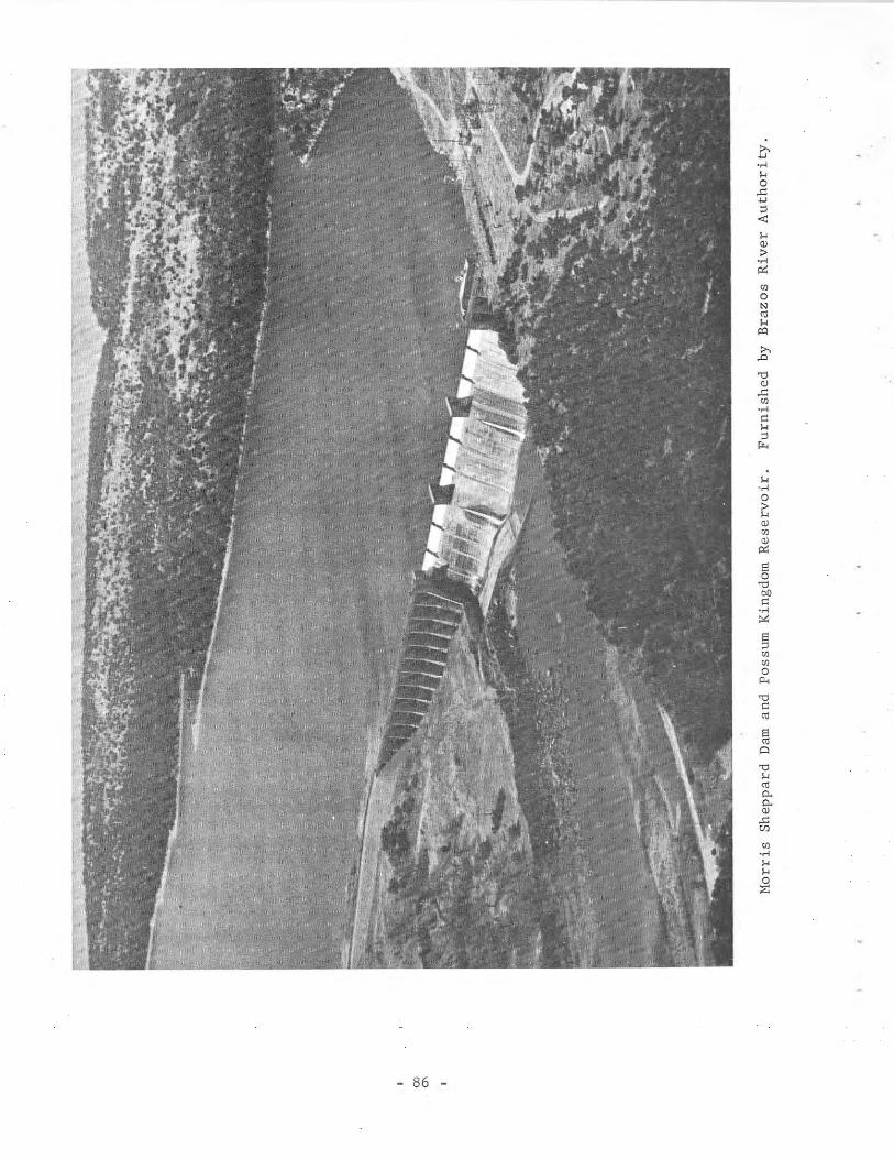
- 86 -
G-........o
..c:....;:l
-0::...Q)
>.....«:UloN
'"...PO,.,..c:
"0Q)
..c:Ul.....
"...;:lro.
........o~Q)
OJQ)
«:Eo
"0bll
".....~
§UlUlo
Po<
an earthen dike.fee t wi th the top
The total length is 2,74U feet "ith a maximum heightof the dam at elevation 1,024.0 feet above msl.
of 1I:l9
The reservoir has a capacity of 724,700 acre-feet at the top of the gates,elevation 1,000.0 feet above msl, "ith an area of 19,800 acres. Other elevations and capacities are listed follO\\!ing this section. The capacity figuresare based on topographic surveys made during 1935-38 by the Brazos River Authority.
The drainage area above the dam is 22}550 square miles; of which 9)240 isprobably noncontributing.
This is the first of several projects proposed by the Brazos River Authority for the regulation of the Brazos River. The U. S. Army Corps of Engineershas built dams and planned other projects on the Brazos River and its tributaries for flood regulation and conservation storage.
The spill"ay consists 01 nine roof-weir type gates 73 feet 8 inches "ideby 13 feet high with top o[ gate elevation of 1,000.0 feet above msl. Floodcontrol releases are from one or more of these gates having a total dischargecapacity of 550,000 cfs for the nine at design elevation of 1,000.0 feet abovemsl.
There are two 12-foot-diameter penstocks with gates and control tower forwater supply to the turbines in the powerhouse; turbine operation provides regulated releases.
Necessary low-flow releases) when turbines are not operating) are controlled by a 54-inch valve that discharges water into the outlet conduitthrough the face of the dam.
The power facilities consist of two 11,250 kw generating units ,,,ith allnecessary auxiliary equipment. Sale of electrical energy is to the BrazosRiver Transmission Electric Cooperatives.
The following is pertinent data on the dam and reservoir:
Ambursen) hollow) massive buttress type
1,147 feet2,747 feet
189 feet73 feet 8 inches long by 13 feet high
65 mi les3.5 mi les
145 feet310 miles
two 11,250 KW generating units
I)
i
Type of dam ..•........•••.•....Length of concrete bulkhead
and spi llway ..•.•..••..•.....Length of earth dike with
concrete core wall .Total length of dam .Maximum height of dam .Nine crest gates .Length of lake ...........•.....Maximum width of lake .~~ximum depth of lake .Shore line ........•.........•....Power installation .
1,600 feet
- 87 -
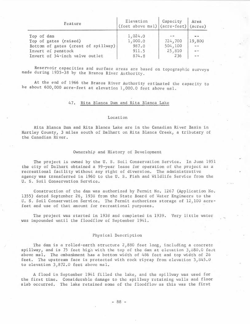
Feature Elevation Capacity Area(feet above msl) (acre-feet) (acres)
Top of damTop of gates (raised)Bottom of gates (crest of spillway)Invert of penstockInvert of 54-inch valve outlet
1,024.01,000.0
987.0911.5874.8
724,700504,10025,810
236
19,800
Reservoir capacities and surface areas are based on topographic surveysmade during 1935-38 by the Brazos River Authority.
At the end of 1966 the Brazos River Authority estimated the capacity tobe about 600,000 acre-feet at elevation 1,000.0 feet above msl.
47. Rita Blanca Dam and Rita Blanca Lake
Location
Rita Blanca Dam and Rita Blanca Lake are in the Canadian River Basin inHartley County, 3 miles south of Dalhart on Rita Blanca Creek, a tributary ofthe Canadian River.
Ownership and History of Development
The project is owned by the U. S. Soil Conservation Service. In June 1951the city of Dalhart obtained a 99-year lease for operation of the project as arecreational facility without any right of diversion. The administrativeagency was transferred in 1960 to the U. S. Fish and Wildlife Service from theU. S. Soil Conservation Service.
Construction of the dam was authorized by Permit No. 1267 (Application No.1355) dated September 26, 1938 from the State Board of Water Engineers to theU. S. Soil Conservation Service. The Permit authorizes storage of 12,100 acrefeet and use of that amount for recreational purposes.
The project was started in 1938 and completed in 1939. Very little waterwas impounded until the floodflow of September 1941.
Physical Description
The dam is a rolled-earth structure 2,880 feet long, including a concretespillway, and is 75 feet hig~ with the top of the dam at elevation 3,880.0 fe~t
above msl. The embankment has a bottom width of 486 feet and top ,Adth of 26feet. The upstream face is protected with rock riprap from elevation 3,845.0to elevation 3,872.0 feet above ms1.
A flood inthe first time.slab occ urred.
September 1941 fi 11ed the lake, and the spi 11way "as used forConsiderable damage to the spillway retaining "alls and floor
The lake retained some of the floodflo" as this "as the first
- 88 -
time storage reached normal maximum level. Repairs were made according toplans dated December 1946, and the water service reports filed with the TexasWater Commission indicate that operation has been satisfactory since then.
The lake has a capacity of 12,100 acre-feet and a surface area of 524acres at elevation 3,860.0 feet above msl. The lake is used for recreationalpurposes only.
The drainage area above the dam is 1,062 square miles.
A concrete spillway located between two earth embankments has a circularcrest length of 191.5 feet at elevation 3,860.0 feet above msl. The dischargeis through a concrete chute, with bottom width of 130 feet, to a stilling basinand thence downstream. An emergency spillway located on the right end of theembankment has a crest length of 600 feet at elevation 3,870.0 feet above msl.
There is one, gate-controlled, low-flow outlet, 5 feet by 4 feet, extending through the embankment with invert at elevation 3,810.0 feet above msl.
48. Coffee Mill Creek Dam and Coffee Mill Creek Lake
Location
Coffee Mill Creek Dam and Coffee Mill Creek Lake are in the Red RiverBasin in Fannin County, 12 miles northwest of Honey Grove on Coffee ~lill Creek,a tributary of Bois d'Arc Creek, which is tributary to the Red River.
Ownership and History of Development
The project is owned and operated by the U. S. Forest Service for recreational purposes.
The record indicates that the project was started and completed in 1938.Deliberate impoundment of water probably started at the time of completion in1938.
Physical Description
The dam is an earthfill structure 3,600 feet long and 42 feet high withthe top of the dam at elevation 505.0 feet above msl. The embankment has amaximum bottom width of 205 feet and top width of 16 feet.
The reservoir has a capacity of 8,000 acre-feet and a surface area of 704acres at the service spillway crest elevation of 496.0 feet above msl.
The drainage area above the dam is 39 square miles.
The uncontrolled service spillway has a crest length of 150 feet at elevation 496.0 feet above msl J and discharges into a concrete chute-type structure. An emergency spillway, with a crest length of 1,290 feet, has variablecrest elevation from 2 to 4 feet higher than the service spillway.
- 89 -
The low-flow outlet is a 24-inch-diameter cast-iron pipe, 252 feet long,extending through the embankment; the discharge is regulated by a valve operated from a concrete control tower.
49. Denison Dam and Lake Texoma
Loea t ion
Denison Dam and Lake Texoma are in the Red River Basin in Grayson5 miles north of Denison on the Red River between Texas and Oklahoma.reservoir is in Grayson and Cooke Counties) Texas, and Marshall, Love,Bryan Counties, Oklahoma.
Ownership and History of Development
County,Theand
The project is owned by the U. S. Government, and was built and is operatedby the U. S. Army Corps of Engineers, Tulsa District. It was authorized by theFlood Control Act of 1938 for flood control, power generation, conservation, andrecreational purposes. Conservation storage space has been sold as follows:city of Denison--2l,300 acre-feet; city of Sherman--4l,000 acre-feet; TexasPower & Light Company--16,400 acre-feet; and Sinclair Oil Company--l,150 acrefeet.
The project was started with clearing of the lake basin on August 22,1939 and all of the construction was completed in 1943 with deliberate impoundment beginning October 31, 1943. Maximum power storage space elevation of617.0 feet was first reached March 15, 1945. The maximum content to December1966 was 5,991,300 acre-feet on June 5, 1957 (from capacity table then in use)at elevation 643.18 feet above msl.
Records of contents from July 1942 through September 30, 1957 are containedin Bulletin 5807-A of the State Board of Water Engineers and since July 1942published by the U. S. Geological Survey. Capacity figures given herein andthose published by the U. S. Geological Survey since October 1, 1963, are basedon a sediment survey made in 1962 by the U. S. Army Corps of Engineers.
Over 8,280,000 visitors were reported at Lake Texoma during 1966.
Physical Description
The dam is a rolled-earth embankment 15,200 feet long and 165 feet highabove streambed with the top of the dam at elevation 670.0 feet above msl.Total length along the crest, including spillway, is 17,200 feet. The spillway crest is at an elevation of 640.0 feet above msl (storage capacity,5,392,900 acre-feet). The embankment contains over 18.8 million cu yd of earthfill. Texas State Highway 75-A is built along the top of the dam.
The lake at elevation 617.0 feet above msl, top of the power storage space,has a storage capacity of 2,733,300 acre-feet and a surface area of 89,000 acres.When the water surface drops below elevation 610 feet, contents 2,167,900
- 90 -
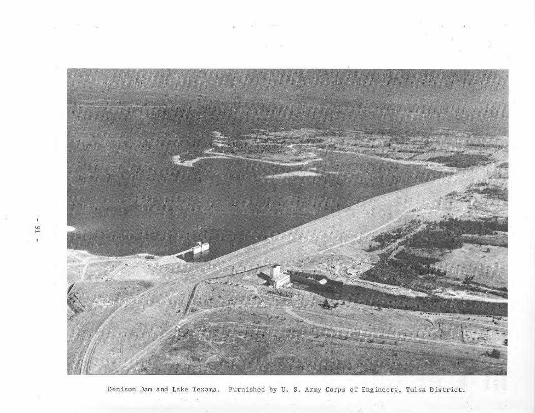
'">-'
Denison Dam and Lake Texoma. Furnished by U. S. Army Corps of Engineers, Tulsa District.
acre-feet}oil field.section.
the lake is divided into two pools by levees around the CumberlandOther capacities are given in the tabulation that follows this
The drainage area is 39,719 square miles, of which 5,936 square miles isprobably noncontributing.
The uncontrolled spillway structure is located to the right of the rightabutment of the dam. It is a low ogee-weir section with crest elevation of640.0 feet above msl, and is 2,000 feet long. Controlled flood storage extendsfrom elevation 617.0 feet above msl to spillway crest.
The outlet works are located within the embankment on the Texas side, andconsists of an approach channel} intake structure, and service bridge. Thereare eight reinforced concrete conduits 20 feet in diameter and 800 feet longwith invert at elevation 523.0 feet above msl. Three are gate-controlled forfloodwater discharge. Five are steel-lined penstocks for delivery of water tothe present and future power units. Surge tanks are installed on the penstocksin use.
As of December 31, 1966 there were two turbines and generator units withall auxiliaries installed with a capacity of 35,000 kw each. This plant wasplaced in operation during March 1945. The plans call for additional units tobe installed in the future.
Information on Denison Dam and Lake Texoma, supplied by the U. S. ArmyCorps of Engineers, is as follows:
Length of main embankment .•.Length of spillway .Maximum height of dam...•••.Ear thfill. .Shoreline at elevation .
640.0 feet above msl .Shoreline at elevation
617.0 feet above msl .Power development......•....Generators (installed) ...•..Generators (proposed) .
15,200 feet2,000 feet
165 feet18,800,000 cu yd
1,100 miles
580 milesFive penstocks 20 feet in diametertwo 35,000 kw eachthree 35,000 kw each
- 92 -
Reservoir da ta (Based on 1962 sedimenta tion survey):
Fea tureEleva t ion Capac i ty Area
(feet above msl) (acre-feet) (acres)
Top of dam 670.0Top of flood control pool 640.0 (1)5,382,000 143,300Top of power pool 617.0 (1)2,722,000 89,000Bottom of power pool:
Cumberland 610.0 11,000Denison 590.0 1,049,000 44,100
Power storage 590.0-617.0 1,673,000
Flood control storage 617.0-640.0 (2)2,660,000
(1) Excludes 11,000 acre-feet of inactive storage in Cumberland pool beloweleva tion 610.0
(2) Includes 79,850 acre-feet jointly used for flood control and water supplyfor the cities of Denison (21,300 acre-feet) and Sherman (41,000 acre-feet),Texas, Texas Power & Light Company (16,400 acre-feet), and Sinclair OilCompany (1,150 acre-feet).
50. Highlands Dam and Highlands Reservoir
Location
Highlands Dam and Highlands Reservoir are in the Trinity-San JacintoCoastal Area in Harris County, 2 miles east of Highlands, and are an offchannel project on Goose Creek, which empties into Galveston Bay.
Ownership and History of Development
The project is owned and operated by the San Jacinto River Authority forthe sale of water for municipal, industrial) and irrigation use) and is part ofan extensive canal system. It was purchased in 1944 from the United StatesFederal Works Administration, which built the system for wartime water supplyfor industry in the Houston area.
Water right to appropriate 165,000 acre-feet of water per annum for municipal} mining, milling, domestic) industrial, irrigational, and recreationalpurposes was obtained by the San Jacinto River Conservation District by PermitNo. 1342 (Application No. 1433) dated March 8, 1943 from the State Board ofWater Engineers. The amount of annual diversion was increased to 224,000 acrefeet by Permit No. 1422 (Application No. 1505) dated December 13, 1947 from theState Board of Water Engineers. In 1951, by act of the Texas Legislature, theSan Jacinto River Conservation District was changed to the San Jacinto RiverAuthority.
Construction was started in 1942, completed in 1943, and the reservoir wasfirst filled with water pumped from the San Jacinto River during the fall andwinter of 1943.
- 93 -
This project was built by the U. S. Government because of the criticalneed for water supply for wartime industry at a time when private and municipalbodies could not obtain the necessary materials for construction. At the endof the critical period, the city of Houston and the Conservation Districtagreed on the part of the system each would purchase from the U. S. Government.This agreement also covered water rights in various proposed future storageprojects to be constructed by either party.
Physical Description
The dam is an earthfill levee with an average height of 14 feet.
The rectangular-shaped reservoir has a capacity of 5,580 acre-feet and asurface area of 1,407 acres at spillway crest elevation of 48.0 feet above msl.This reservoir is also used for hunting) fishing, and other recreational purposes.
The drainage area is negligible, therefore water is pumped from the SanJacinto River.
Since the completion of San Jacinto Dam creating Lake Houston, water isbeing delivered by canal from Lake Houston to Highlands Reservoir. Excessstreamflow is pumped from the river and later released to the canal for distribution when needed for any of the purposes covered in the permits.
A small controlled outlet is provided for fluctuation in canal operations.This control structure allows water to enter the reservoir from the canal or bedischarged from the reservoir into the canal for distribution.
51. Ellison Creek Darn and Ellison Creek Reservoir
Location
Ellison Creek Dam and Ellison Creek Reservoir are in the Cypress CreekBasin in Morris County, 8 miles south of Daingerfield on Ellison Creek, a tributary of Cypress Creek.
Ownership and History of Development
Ellison Creek Dam and Ellison Creek Reservoir are owned and operated bythe Lone Star Steel Company. It was originally owned by Defense Plant Corporation, a corporation created by the Reconstruction Finance Corporation Actduring World War II, for which Lone Star Steel Company was agent. SouthwesternElectric Power Company uses water from the reservoir for condenser-cooling purposes for a stearn-electric generating plant. Construction of the darn began in1942, and was completed in April 1943. Storage began January 14, 1943.
Permit No. 1405 (Application No. 1437) was issued to the Lone Star SteelCompany on March 15, 1947 by the State Board of Water Engineers. The Permitauthorizes construction of a dam across Ellison Creek, thereby creating a reservoir with capacity of 26,000 acre-feet and appropriation of 80,000 acre-feetper annum for industrial purposes from Ellison and Cypress Creeks.
- 94 -
Records of the contents of Ellison Creek Reservoir from January 1943through September 30, 1957 are contained in Bulletin 5807-A of the Board ofWater Engineers and from January 1943 to September 1962 in publications of theu. S. Geological Survey. The U. S. Geological Survey discontinued the stationknown as Ellison Creek Reservoir near Daingerfield, Texas, on September 30, 1962.
Physical Description
Ellison Creek Dam is a rolled-earth structure 4,000 feet long with a maximum height of 48.5 feet. The top of the dam is at elevation 280.1 feet abovemsl. The embankment has a maximum bottom width of 250 feet and top width of18 feet. The upstream face of the embankment is protected with a 2-foot thickness of rock riprap laid on an 8-inch-thick gravel blanket between elevations255.1 and 280.1 feet above msl.
The drainage area of the Ellison Creek watershed at Ellison Creek Dam is37 square miles.
Capacities of the reservoir at indicated elevations (based on surveys madein 1942) are as follows:
Feature
Top of damMaximum design flood stageTop of emergency spillway
crestService spillway crestTop of condu~t discharge
box (36-inch-diameteremergency supply pipe)
Elevation(feet above msl)
280.1275.1
273.1268.1
235.1
Capacity(acre-feet)
36,600
33,02024,700*
196
* Surface area of the reservoir at this elevation is1,516 acres.
\,hen the flow into the reservoir is inadequate, water is pumped into thereservoir from Cypress Creek. In order to have water at the pump intake, asmall log-channel dam is built across Cypress Creek to back water up to elevation 229.1 feet above msl. The water is pumped to the reservoir through a 36inch-diameter conduit terminating in the pump intake channel of the reservoirpumphouse. This same pipe can be used to release water from the reservoir ifnecessary.
There is a relief or fuse plug dam located near the reservoir pumphousethat will not be used except in the event all outlets from the reservoir areunable to pass the floodflow. In this case, the relief dam will be blastedout. This dam is approximately 125 feet long with crest at elevation 275.1feet above msl.
The concrete service spillway section has a crest length of 300 feet atelevation 268.1 feet above msl. Energy of the flow over the service spillwayis dissipated in a stilling basin, then the flow continues to the creek channelover a low dam with crest at elevation 248.6 feet above msl.
- 95 -
The emergency spillway has an overall crest length of 1,500 feet at elevation 273.1 feet.
The water from Ellison Creek Reservoir is used for power plant condensercooling, ore-washing, and general plant use. Water not consumed is returned tothe reservoir as inflow down Barnes Creek channel. Water is delivered to thepoints of use by means of pumps located in the reservoir pumphouse.
In connection with the steel plant, a separate dam and lake known as Sorrell Reservoir was built for storage of tailings from the ore-mining process.Water storage or use is not involved.
52. William Harris Dam and William Harris Reservoir
Location
William Harris Dam and William Harris Reservoir are in the San JacintoBrazos Coastal Area in Brazoria County, 8 miles northwest of Angleton, and arean off-channel project between the Brazos River and Oyster Creek.
Ownership and History of Development
The project is owned and operated by the Dow Chemical Company for industrialwater supply to several affiliated plants near Freeport. Construction of theproject was completed in 1947.
Permit No. 1345 (Application No. 1431) dated February 19, 1943 from theState Board of Water Engineers to Dow Chemical Company allows diversion of40,000 acre-feet of water annually from Oyster Creek and 150,000 acre-feetannually from the Brazos River for industrial purposes. To confirm their rightto the water supply from the Brazos River, Dow Chemical Company contracted withthe Brazos River Authority for conservation storage in their upstream reservoirs. This stored floodwater is to be released on demand by using the riverchannel to convey the water to the place of diversion.
The pumping plant on Oyster Creek was completed and diversion startedApril 16, 1943. The small reservoir at this lower diversion site was completedMay 1, 1943. Difficulty in getting equipment during the war period delayedinstallation of the pumping plant for diverting water directly from the BrazosRiver. This was not completed until July 2, 1947. This plant delivers waterto a settling basin, thence to a canal system and/or William Harris Reservoir)thence to Oyster Creek as needed.
The system for delivering the water to the point of use is a complicatedseries of pumping plants and canals. William Harris Reservoir stores appropriable water from the Brazos River, when available, for later release to thewater system as needed.
Physical Description
The rectangular reservoir is created by a levee with a top width of 10feet and a bottom width that varies with the changing ground contours.
- 96 -
The reservoir has a capacity of 12,000 acre-feet and a surface area of1,663 acres at normal maximum water surface elevation of 43.0 feet above msl.
Water is released from the reservoir by gravity flow to Oyster Creek.From there it flows through the winding channel to a pumping plant that liftsthe water to a canal system and small retention reservoir. The water is thendistributed by a gravity canal system to the various places of use at the industrial plants.
No drainage area contributes runoff to this reservoir) so the reservoirlevel is regulated by pumping from the Brazos River and releases to OysterCreek.
53. Sheldon Dam and Sheldon Reservoir
Location
Sheldon Dam and Sheldon Reservoir are in the San Jacinto River Basin inHarris County, 2 miles southwest of Sheldon on Carpenters Bayou, a tributary toBuffalo Bayou (Huuston Ship Channel), which is a tributary of the San JacintoRiver.
Ownership and History of Development
The reservoir is now owned by the Texas Parks and Wildlife Commission, andis used for a game preserve, fish ha~chery, and recreational purposes. Theproject was built by the U. S. Government Federal Works Agency. Constructionstarted in 1942, and was completed in December 1943 with impoundment of waterbeginning at that time. The purpose of the project was to provide an adequatewater supply for wartime industries in the Houston area. The Sheldon Reservoirwas used as an impounding reservoir for storing water in times of excess flowin the San Jacinto River for use when the flow of the river was less than thedemand for water. The city of Houston purchased the pumping plant, reservoir,and the canal in 1947. Permit No. 1413 (Application No. 1512) dated July 19,1947 from the State Board of Water Engineers to the city of Houston authorizedthe storage of 6,950 acre-feet and the annual diversion of 10,500 acre-feet ofwater for municipal, domestic) industrial) and irrigational purposes. When thecity obtained a new water supply from Lake Houston, Sheldon Reservoir and Permit No. 1413 were sold to the then Texas Game and Fish Commission (now part ofthe Texas Parks and Wildlife Commission) effective October 1, 1954.
Physical Description
The dam is mainly a system of levees and an earth embankment with a concrete spillway. The total length is 6.1 miles with a maximum height of a feet.The levees were enlarged and rebuilt when obtained by the Texas Game and FishCommission, and now have a maximum bottom width of 60 feet and top width of 12feet, and vary in height from 6 to a feet.
The reservoir now has a capacity of 5)420 acre-feet and a surface area of1,200 acres at elevation 50.5 feet above msl. Water was diverted by gravity to
- 97 -

a canal system for distribution when the project was owned by the city of Houston, but now there is no diversion except to spill excess water. Originallymake-up water was pumped from the San Jacinto River. Under present management,however, there is no consumptive use. Therefore, runoff from the 9-square-miledrainage area is adequate to keep the reservoir at the desired level. Thecapacity of the reservoir was reduced when the city of Houston built its canalthrough one section, from the new Lake Houston. The area cut off from theoriginal reservoir is used for a fish hatchery and experimental rice growing.
A concrete spillway, with a crest length of 150 feet at elevation 50.5feet above msl, is used to discharge excess water during periods of heavy runoff.
There are three 36-inch pipes with sluice valves that are used for lowflow releases and to drain sections of the reservoir as needed.
54. Barker Dam and Barker Reservoir
Location
Barker Dam and Barker Reservoir are in the San Jacinto River Basin inHarris County near Addicks on Buffalo Bayou, a tributary to the San JacintoRiver and Houston Ship Channel. The reservoir area extends into Fort BendCounty.
Ownership and History of Development
The project is owned by the U. S. Government, and was authorized by theRiver and Harbor Act of June 1938 as amended August 11, 1939. This reservoirand nearby Addicks Reservoir are operated by the U. S. Army Corps of Engineers,Galveston District, for flood protection to the Houston area.
The dam was completed February 3, 1946, but was used for flood control inthe spring of 1945.
Records of reservoir stages and contents from August 1945 are containedin publications of the U. S. Geological Survey.
Physical Description
The dam is a rolled-earth structure 72,844 feet long and 37 feet high atthe concrete outlet works located near the old river channel. Embankmentslopes are 3 to 1. At the upstream end the embankment is 4 to 5 feet higherthan the adjacent natural prairie land. The elevation of the top of the dam isabout 111.5 feet above msl.
The reservoir is for floodwater retention only, with a capacity of 207,000acre-feet and a surface area of 17,225 acres at the emergency spillway crestelevation of 107.0 feet above msl. Between invert of conduit 74.7 feet abovemsl and design flood stage 101.6 feet above msl the capacity is 127,900 acrefeet based on survey made in 1940 by U. S. Army Corps of Engineers.
- 98 -
The drainage area is 134 square miles above the outlet works.
There is no conservation storage or use of water as this is a floodwaterretention reservoir only.
There are no constructed emergency spillways) but runoff in excess of thedesigned capacity will be discharged around the ends of the dam to the openprairie at elevation 107.0 feet above msl.
The outlet works consist of five reinforced concrete conduits) 9 feet wideby 7 feet high, with invert at elevation 74.7 feet above msl. Originally onlythe center outlet was controlled by two vertical slide gates separated by apier in center. In 1949 the two outermost outlets were equipped with slidegates spanning the entire width of the opening. Then in May 1962, the sametype of slide gates were installed on the other two conduits.
The gate operation is controlled by the U. S. Army Corps of Engineers,Galveston District, and the operation will vary with the magnitude of the floodinflow and downstream conditions. During minor floods the gates will remainclosed) and the reservoir is allowed to function as a temporary storage basin.
55. Addicks Dam and Addicks Reservoir
Location
Addicks Dam and Addicks Reservoir are in the San Jacinto River Basin inHarris County near Addicks on South Mayde and Langham Creeks, tributaries toBuffalo Bayou, which is tributary to the San Jacinto River and Houston ShipChannel.
Ownership and History of Development
The project is owned by the U. S. Government, and was authorized by theRiver and Harbor Act of June 1938 as amended August 11, 1939. This and nearbyBarker Reservoir are operated by the U. S. Army Corps of Engineers, GalvestonDistrict, for flood protection of the Houston area.
The dam was completed in the fall of 1948.
Records of reservoir stages and contents from June 1948 are containedin publications of the U. S. Geological Survey.
Physical Description
The dam is a rolled-earth structure 61,166 feet long with a maximum heightof 49 feet near the concrete outlet works, with the top of the dam at elevation123.5 feet above msl. At the upstream end, the height is about 5 feet higherthan the adjacent natural prairie land. Volume content of the dam is 4,794,000cu yd.
- 99 -
The reservoir is for floodwater retention only, with a capacity of 204,500acre-feet and a surface area of 16,780 acres at the emergency spillway crestelevation of 114.0 feet above msl. Between invert of conduit elevation 73.0feet above msl and top of design flood pool elevation 113.0 feet above msl thecapacity is 188,030 acre-feet based on survey made in 1940 by the U. S. ArmyCorps of Engineers.
The drainage area is 133 square miles above the outlet works.
There is no conservation storage or use of water as this is a floodwaterretention reservoir only.
There are no constructed emergency spillways, but runoff in excess of thedesign capacity will discharge around the end of the dam to the open prairie atelevation 114.0 feet above msl.
The outlet works consist of five reinforced concrete conduits, each 8 feetwide by 6 feet high, with invert at elevation 73.0 feet above msl. Originallyonly the center outlet was controlled. There were two vertical slide gatesseparated by a pier in the center. In 1949 the two outermost outlets wereequipped with gates spanning the entire width of the openings. Then in June1962 the same type of slide gates were installed on the other two conduits.
The gate operation is controlled by the U. S. Army Corps of Engineers,Galveston District, and the operation will vary with the magnitude of the floodinflow and downstream conditions. During minor floods the gates will remainclosed, and the reservoir is allowed to function as a temporary storage basin.
56. Kickapoo Dam and Lake Kickapoo
Location
Kickapoo Dam and Lake Kickapoo are in the Red River Basin in ArcherCounty, 10 miles northwest of Archer City on the North Fork of the LittleWichita River, which is a tributary of the Red River.
Ownership and History of Development
The project is owned and operated by the city of Wichita Falls.
Construction of the dam was authorized by Permit No. 1363 (Application No.1456) granted September 16, 1944 by the State Board of Water Engineers to thecity of Wichita Falls. The Permit allows diversion of 40,000 acre-feet peryear for municipal water supply.
Construction of the dam was started early in 1945, and completed December15, 1945. Deliberate impoundment of water began February 1, 1946. The pipeline to Wichita Falls was completed, and diversion for municipal use began September 24, 1947.
This project together with Lake Kemp, Diversion Lake, Lake Wichita, andLake Arrowhead are sources of water supply for the city of Wichita Falls.
- 100 -
1957from
Records of reservoir contents from February 1946 through September 30,are contained in Bulletin 5807-A of the State Board of Water EngineersFebruary 1946 in .publications of the U. S. Geological Survey.
Physical Description
and
The dam is a rolled-earth structure 6,800 feet long, including the spillway, and is 62 feet high, with the top of the dam at elevation 1,062.0 feetabove msl. The embankment has a top width of 16 feet and maximum bottom widthof 300 feet. The upstream face of the embankment is paved with rock riprap.A reinforced concrete spillway is located near the right end of the dam.
The lake has a capacity of 106,000 acre-feet and a surface area of 6,200acres at spillway crest elevation of 1,045.0 feet above msl; other capacitiesare as f 0 !lows:
Feature
Top of damMaximum design flood stageCrest of uncontrolled spillwayInvert of outlets
Elevation(feet above ms 1)
1,062.01,060.01,045.01,000.92
Capacity(acre-feet)
220,000106,000
o
Reservoir capacities based on U. S. Geological Survey topographic mapssurveyed in 1929.
The drainage area above the dam is 275 square miles.
A reinforced concrete ogee spillway is located at the right end of thedam, with a crest length of 482.7 feet at elevation 1,045.0 feet above msl.
The outlet structure consists of a concrete tower near the left end of thedam and two, 4- by 5-foot, concrete conduits, each controlled by a sluice gate.The left outlet diverts metered water to the city pumping plant. The rightoutlet discharges into the creekbed for emergency use downstream. The sluicegates are open for normal operating conditions, and the discharge is regulatedby valves in the pump control room where water is pumped to the filter andtreatment plan.t.
57. Dam B and Dam B Reservoir
Location
Dam B and Dam B Reservoir are in the Neches River Basin in both Tyler andJasper Counties, 1 mile north of Town Bluff on the Neches River at river mile113.7.
Ownership and History of Development
The project is owned by the United States Government, and was authorizedby the River and Harbor Act of March 2, 1945 in the first session of the 79th
- 101 -
Congress. It was built and is operated by the U. S. Army Corps of Engineers,For t \,or th Dis tri ct.
The Lower Neches Valley Authority, the cooperative State agency, has purchased the right for use of the 77,600 acre-feet of conservation storage witha maximum rate of diversion of 2,000 cfs.
Construction started in March 1947. The dam and outlet works were completed, and deliberate impoundment of water began April 16, 1951.
Records of reservoir elevation and contents from April 16, 1951 throughSeptember 30, 1957 are contained in the State Board of I<ater Engineers Bulletin5807-A and from April 16, 1951 in publications of the U. S. Geological Survey.
More than 876,000 visitors were reported at Dam B Reservoir during 1966.
Physical Description
The dam is g compacted-earth structure with a concrete section across theriver channel. The embankment serves as an uncontrolled spillway, and is protected from wave action by a 6-inch concrete slab. Overall length is 6,698feet, and the maximum height is 45 feet. The top of the dam is 25 feet wide atan elevation of 95.0 feet above msl.
The reservoir is designed for surge regulation in a system operation) andis used currently for conservation storage) recreation, wildlife management)and partial flood regulation. The Texas Parks and Wildlife Commission haslicensed 13)200 acres for wildlife management.
Data on elevations and capacities in the following table are from U. S.Army Corps of Engineers' publications:
Feature
Top of damMaximum design flood stageTop of taintor gates and un-
controlled spillway crestNormal water levelInvert of low-flow outletsSill of six taintor gatesSediment reserve in conser-
vation storage space
Elevation(feet above msl)
95.093.0
85.083.052.050.0
Capacity(acre-feet)
306,400
124,70094,200
20o
16,600
Area(acres)
28,210
16,83013,700
20o
Reservoir capacities and surface areas based on survey by U. S. Army Corpsof Engineers made in 1945.
The drainage area above the dam is 7,573 square miles.
The service spillway at the right end of the dam has a net crest lengthof 240 feet at elevation 50.0 feet above msl, which is controlled by six taintor gates, 40 feet long by 35 feet high. The discharge capacity of the spillway is 80,000 cfs with reservoir water level at elevation 85.0 feet above msl.
- 102 -
The uncontrolled spillway is 6,100 feet long with crest elevation of 85.0feet above msl. The embankment is protected by a 6-inch-thick layer of reinforced concrete. The total discharge capacity of the two spilll;ays at maximumdesign flood-stage elevations of 93.0 feet above msl is 218,300 cfs.
There are two, 4- by 6-foot, gate-controlled conduits for low-flow releases,with invert at elevation 52.0 feet above msl.
Water is released from the reservoir to maintain a supply of water in thelower Neches River for irrigation, municipal) and industrial uses in Beaumontand other areas. Floodwaters are released from one or more of the spillwaytaintor gates without further use or control.
Power installation is not a feature of this project at the present time,but may be considered at a later date.
58. San Angelo Dam and San Angelo Reservoir
Location
San Angelo Dam and San Angelo Reservoir are in the Colorado River Basinin Tom Green County, 3 miles northwest of San Angelo on the North Concho Riverat river mile 6.6. The North Concho River is a tributary of the Concho River,which is tributary to the Colorado River.
Ownership and History of Development
The project is owned by the U. S. Government, and was built and is operated by the U. S. Army Corps of Engineers, Fort Worth District. Constructionwas authorized under the Flood Control Act of August 18, 1941, 77th Congress,first session, and 78th Congress, second session.
The Upper Colorado River Authority has purchased conservation storagespace in the reservoir for $775,000 payable over a fifty-year period. PermitNo. 1516 (Application No. 1627) dated April 29, 1949 from the State Board ofWater Engineers granted the Upper Colorado River Authority the use of 00,400acre-feet of water annually for municipal, industrial} irrigational} mining)and recreational purposes. This water supplements San Angelo's water supply,which previously has been obtained solely from Lake Nasworthy. The Twin ButtesReservoir on the South and Middle Concho Rivers and Spring Creek will alsosupply water for this area's future needs.
Construction started in May 1947, closuredeliberate impoundment began February I, 1952.but the project was not completed until 1960.
was completed March 7, 1951, andThe dedication was in May 1951,
Records of contents from February 1952 through September 30, 1957 are contained in Bulletin 5807-A of the State Board of Water Engineers and from February 1952 in publications of the U. S. Geological Survey.
More than 512,000 visitors were reported at San Angelo Reservoir during1966.
- 103 -
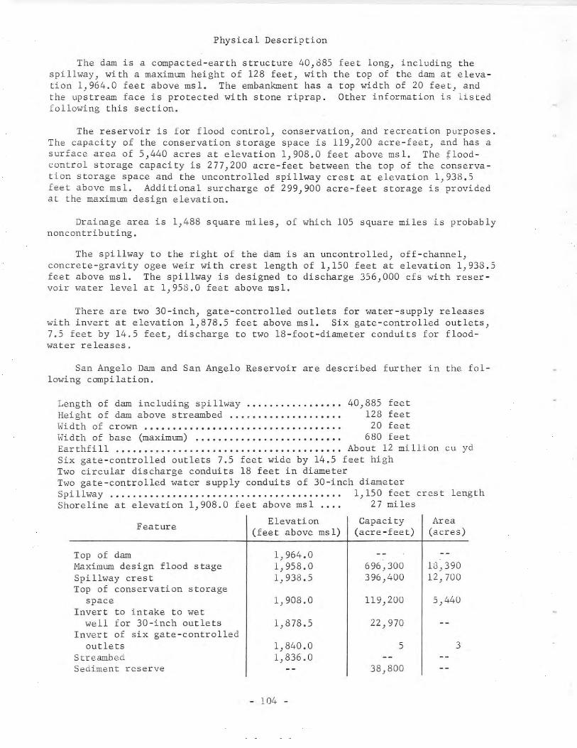
Physical Description
The dam is a compacted-earth structure 40,d85 feet long, including thespillway, with a maximum height of 128 feet, with the top of the dam at elevation 1,964.0 feet above msl. The embankment has a top width of 20 feet, andthe upstream face is protected with stone riprap. Other information is listedfollowing this section.
The reservoir is for flood control) conservation) and recreation purposes.The capacity of the conservation storage space is 119,200 acre-feet, and has asurface area of 5,440 acres at elevation 1,908.0 feet above msl. The floodcontrol storage capacity is 277,200 acre-feet between the top of the conservation storage space and the uncontrolled spillway crest at elevation 1,938.5feet above msl. Additional surcharge of 299,900 acre-feet storage is providedat the maximum design elevation.
Drainage area is 1,488 square miles, of which 105 square miles is probablynoncontributing.
The spillway to the right of the dam is an uncontrolled, off-channel,concrete-gravity ogee weir with crest length of 1,150 feet at elevation 1,938.5feet above msl. The spillway is designed to discharge 356,000 cfs "ith reservoir water level at 1,958.0 feet above msl.
There are t"o 30-inch, gate-controlled outlets for water-supply releaseswith invert at elevation 1,878.5 feet above msl. Six gate-controlled outlets,7.5 feet by 14.5 feet, discharge to two 18-foot-diameter conduits for floodwater releases.
San Angelo Dam and San Angelo Reservoir are described further in the following compilation.
Length of dam including spillway .............•... 40,885 feetHeight of dam above streambed.................... 128 feetloIidth of crown ..••...••••••••...•..••..••..••..•• 20 feetloIidth of base (maximum) ...••••..•••.•.•...•••.••. 680 fee tEarthfill About 12 million cu ydSix gate-controlled outlets 7.5 feet wide by 14.5 feet highTwo circular discharge conduits 18 feet in diameterT"o gate-controlled water supply conduits of 3D-inch diameterSpillway 1,150 feet crest lengthShoreline at elevation 1,908.0 feet above msl 27 miles
Feature
Top of damMaximum design flood stageSpi llway cres tTop of conservation storage
spaceInvert to intake to wet
well for 30-inch outletsInvert of six gate-controlled
outletsStreambedSediment reserve
Elevation(feet above msl)
1,964.01,958.01,933.5
1,908.0
1,878.5
1,840.01,836.0
- 104 -
Capacity(acre-feet)
696,300396,400
119,200
22,970
5
38,800
Area(acres)
18,39012, 700
5,440
3
Reservoir capacities and surface areas based on a survey made in 1944 bythe U. S. Army Corps of Engineers.
59. Country Club Dam and Casa Blanca Lake
Location
Country Club Dam and Casa Blanca Lake are in the Rio Grande Basin in WebbCounty, 3 miles northeast of Laredo on Chacon Creek, a tributary to the RioGrande.
Ownership and History of Development
Country Club Dam and Casa Blanca Lake are owned and operated by WebbCounty for recreational purposes.
The first dam was built in 1946, with top elevation at 455.0 feet abovemsl, by the county using its own equipment and men. The dam was damaged bythe first floodwaters impounded by piping underneath the earth embankmentoccurring at the creek channel. Before undertaking reconstruction, ~k. TerrellBartlett of San Antonio and ~. Royce Tipton were engaged to prepare the designfor a new dam. The present dam and spillway were built from the resultingplans, though with considerable modification, by the county over a period ofseveral years as equipment and men were available. Construction of the present(1966) dam began in 1947, and the dam was completed during 1951 with impoundmentof water beginning about that time.
Physical Description
The dam is an earthfill structure about 5,300 feet long with maximumheight of 76 feet at the old creekbed. The height varies from 35 feet to 76feet at various cross sections. The top of the dam is at elevation 465.0 feetabove msl. The top width is 20 feet, and maximum bottom width is 240 feet.A 20-foot berm supports a paved roadway along the entire length of the upstreamslope of the embankment at elevation 450.0 feet above msl. A core trench wasexcavated in blue shale under most of the dam, but under one section 600 linealfeet of steel sheet piling was used to cut off a gravel stratum.
The lake has a capacity of 20,000 acre-feet and a surface area of 1,656acres at elevation 446.5 feet above msl. Among its recreational uses, the lakesupplies water to a golf course owned by the county.
The drainage area above the dam is about 117 square miles.
Some irregular records of elevation of the water surface of the lake areavailable in unpublished data in the International Boundary and Water Commission office at Laredo.
The uncontrolled emergency spillway is about 3,000 feet to the left of thedam. It is excavated in natural earth and rock with crest length of about 260
- 105 -
feet at elevation 446.5 feet above msl.graded channel about 3,000 feet long tochannel turns back and runs parallel toHighway No. 59.
The outflow is through a partiallya downstream creek channel. Thisthe dam before crossing under State
There are no outlet pipes, and the only diversion is by a small pumpingplant supplying water to the park and golf course.
60. Hords Creek Dam and Hords Creek Reservoir
Location
Hords Creek Dam and Hords Creek Reservoir are in the Colorado River Basinin Coleman County, 5 miles northwest of Valera on Hords Creek, a tributary ofJim Ned Creek) which is a tributary of Pecan Bayou) which in turn is a tributaryof the Colorado River.
Ownership and History of Development
The project is owned by the U. S. Government, and was built and is operated by the U. S. Army Corps of Engineers, Fort Worth District, for conservation water and flood regulation. Federal authorization was the Flood ControlAct of August l~, 1941, first session of the 76th Congress, and December 22,1944, second session of the 78th Congress.
The city of Coleman purchased the conservation space by the contributionof $100,000 toward the first cost of the project that gave the city the use ofthat space for the useful life of the reservoir. The water right for the appropriation of 2,240 acre-feet of water annually for municipal purposes was obtained by Permit No. 1387 (Application No. 1487) dated June 6, 1946 from theState Board of 1,ater Engineers to the city of Coleman.
The dam was started in February 1947, and was completed in June 1948 withdeliberate impoundment of water beginning in April 1948.
Record of elevations and contents from April 1948 through September 30,1957 are contained in Bulletin 5807-A of the State Board of Water Engineers,and from April 1948 in publications of the U. S. Geological Survey.
More than 200,000 visitors were reported at Hords Creek Reservoir during1966.
Physical Description
The dam consists of an earth embankment} emergency spillway) service spillway, and outlet works. The structure is 6,800 feet long, 91 feet high, witha top width of 24 feet at elevation 1,939.0 feet above msl. A l6-foot roadwayextends across the top of the dam. The upstream side is protected with rockriprap and the downstream by a 6-inch-thick layer of gravel.
- 106 -
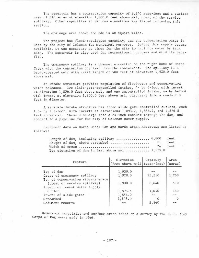
The reservoir has a conservation capacity of 8)640 acre-feet and a surfacearea of 510 acres at elevation 1,900.0 feet above msl, crest of the servicespillway. Other capacities at various elevations are listed following thissection.
The drainage area above the dam is 48 square miles.
The project has flood-regulation capacity, and the conservation water isused by the city of Coleman for municipal purposes. Before this supply becameavailable, it was necessary at times for the city to haul its water by tank'cars. The reservoir is also used for recreational purposes and wildlife benefits.
The emergency spillway is a channel excavated on the right bank of HordsCreek with the centerline 607 feet from the embankment. The spillway is abroad-crested weir with crest length of 500 feet at elevation 1,920.0 feetabove msl.
An intake structure provides regulation of floodwater and conservationwa ter releases. Two sl ide-gate-controlled intakes, 4- by 6-foot with invertat elevation 1,856.0 feet above msl, and one uncontrolled intake, 4- by 6-footwith invert at elevation 1,900.0 feet above msl, discharge into a conduit 8fee t in d iame ter.
A separate intake structure has three slide-gate-controlled outlets, each1.5- by 1.5-foot, with inverts at elevations 1,893.2, 1,886.2, and 1,876.5feet above msl. These discharge into a 24-inch conduit through the dam, andconnect to a pipeline for the city of Coleman water supply.
Pertinent data on Hords Creek Dam and Hords Creek Reservoir are listed asfollows:
Length of dam, including spillway •.•...•..•••.•.•.Height of dam, above streambed ..•••..••..•••.••...Width of crown .Top elevation of dam in feet above msl •.•.......••
6,8009124
1,939.0
feetfeetfeet
Feature Elevation Capaci ty Area(feet above msl) (acre-feet) (acres)
Top of dam 1,939.0Crest of emergency spillway 1,920.0 25,310 1,260Top of conservation storage space
(crest of service spillway) 1,900.0 8,640 510Invert of lowest water supply
out le t 1,876.5 1,690 160Invert of slide-gates 1,856.0Streambed 1,848.0 '0 0Sediment reserve 2,860
Reservoir capacities and surface areas based on a survey by the U. S. ArmyCorps of Engineers made in 1946.
- 107 -

61. Benbrook Darn and Benbrook Reservoir
Location
Benbrook Darn and Benbrook Reservoir are in the Trinity River Basin inTarrant County, 10 miles southwest of Fort Worth on Clear Fork Trinity River,a tributary of the Trinity River.
Ownership and History of Development
The project is owned by the U. S. Government, and is operated by the U. S.Army Corps of Engineers, Fort Worth District. The darn was built under theRiver and Harbor Act of ~llirch 2, 1945, 79th Congress, first session; and wasmodified by Public Law 782, 84th Congress, second session.
In 1956 Congress passed legislation enabling the city of Fort Worth topurchase conservation storage space in the reservoir for municipal water supplypurposes until such time as the storage space should be required for TrinityRiver navigation. The contract had not been executed and water rights had notbeen allocated by the Texas Water Commission as of June 30, 1963.
Construction of the darn began ~y 27, 1947, and the darn was completed inDecember 1950 with deliberate impoundment of water starting September 29, 1952.Acquisition of land for recreation facilities was in progress as late as 1963.Construction costs were $12,065,000.
Records of contents from September 1952 through September 30, 1957 arecontained in Bulletin 5807-A of the State Board of Water Engineers and fromSeptember 1952 in publications of the U. S. Geological Survey.
More than 1,849,000 visitors were reported at Benbrook Reservoir during1966.
Physical Description
The darn is 9,130 feet long, and consists of a compacted-earth embankmentand a concrete spillway section. The embankment has a maximum height of 130feet with the top-width of 20 feet supporting a roadway across the top of thedarn at elevation 747.0 feet above msl. The major construcfion material quantities are 60,500 cu yd of concrete and 5,811,000 cu yd of earthfill.
The reservoir storage capacity is used for flood control, flood regulation,and conservation uses, including navigation and recreational purposes. Thecapacity is 88,250 acre-feet and the surface area is 3,770 acres at the top ofconservation storage space elevation of 694.0 feet above msl. Space allocatedto sediment reserve is 15,750 acre-feet. Other capacities are listed at theclose of this section.
The drainage area above the darn is 429 square miles.
- 108 -
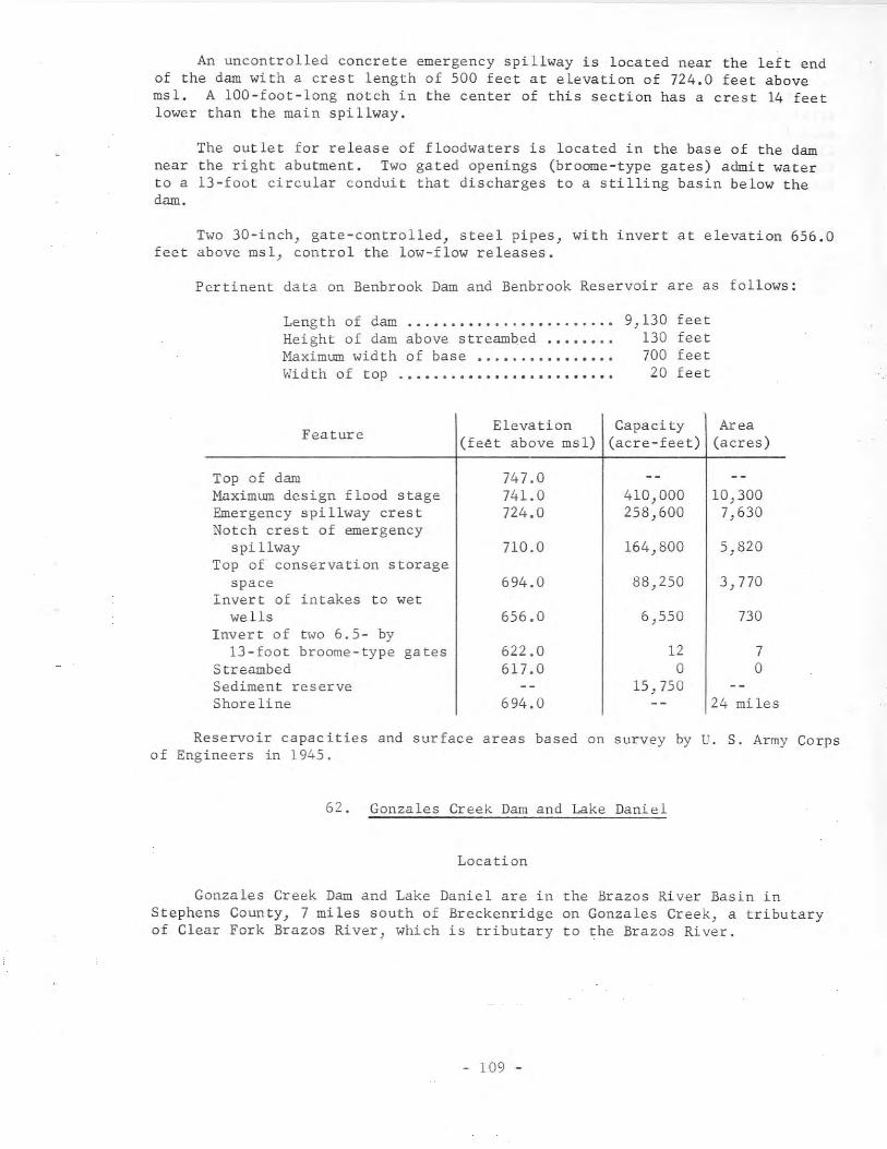
An uncontrolled concrete emergency spillway is located near the left endof the dam with a crest length of 500 feet at elevation of 724.0 feet abovemsl. A 100-foot-long notch in the center of this section has a crest 14 feetlower than the main spillway.
The outlet for release of floodwaters is located in the base of the damnear the right abutment. Two gated openings (broome-type gates) admit waterto a l3-foot circular conduit that discharges to a stilling basin below thedam.
Two 3D-inch, gate-controlled, steel pipes, with invert at elevation 656.0feet above msl, control the low-flow releases.
Pertinent data on Benbrook Dam and Benbrook Reservoir are as follows:
Length of dam ...•..•.......•••..••..•Height of dam above streambed .•.•••.•Maximum width of base ••.•..•••••.•.••Wid th of top .•.•.•.•••••..•.••..••••.
9,130 feet130 feet700 feet20 feet
Elevation Capaci ty AreaFeature
(feet above msl) (acre-feet) (acres)
Top of dam 747.0Maximum design flood stage 741.0 410,000 10,300Emergency spillway crest 724.0 258,600 7,630Notch crest of emergency
spi llway 710.0 164,800 5,820Top of conservation storage
space 694.0 88,250 3,770Invert of intakes to wet
wells 656.0 6,550 730Invert of two 6.5- by
13-foot broome-type ga tes 622.0 12 7Streambed 617.0 0 0Sediment reserve 15,750Shore line 694.0 24 miles
Reservoir capacities and surface areas based on survey by U. S. Army Corpsof Engineers in 1945.
62. Gonzales Creek Dam and Lake Daniel
Location
Gonzales Creek Dam and Lake Daniel are in the Brazos River Basin inStephens County, 7 miles south of Breckenridge on Gonzales Creek, a tributaryof Clear Fork Brazos River, which is tributary to the Brazos River.
- 109 -

Ownership and History of Development
The project is owned by the city of Breckenridge for municipal and industrial water supply. Water rights for the storage of 11,400 acre-feet andannual use of 2,500 acre-feet were obtained by M. E. Daniel through Permit No.1388 (Application No. 1488) dated June 10, 1946 from the State Board of WaterEngineers. On October 5, 1948, the water rights and facilities were transferred by deed to the city of Breckenridge.
Construction of the dam began December 15, 1947, and was completed onSeptember 1, 1948. Deliberate impoundment began at that time with only smallinflow available. The lake was first filled in June 1949. A small diversiondam and pumping equipment installed near the city were placed in operationMarch 1951.
Physical Description
The dam is an earthfill structure 2,500 feet long and 38 feet high withthe top of the dam at elevation 1,293.0 feet above msl. The embankment has amaximum bottom width of 250 feet and top width of 18 feet. The upstream surface is protected with 15 inches of rock riprap on a 6-inch gravel base.
The lake has a capacity of 10,000 acre-feet and a surface area of 950acres at operating level elevation of 1,278.0 feet above msl. The water formunicipal use is released to the creek channel below the dam, and travels downGonzales Creek to the pumping plant diversion lake for the city filter plant.Untreated industrial water is pumped from this same diversion lake.
The drainage area above the dam is 115 square miles.
An emergency spillway near the left end of1,500 feet at elevation 1,282.0 feet above msl.ground to the creek channel below the dam.
the dam has a crest length ofThe discharge is over natural
The service spillway is a rectangular concrete drop-inlet structure discharging to a double-barrel concrete conduit, each barrel of which is d feetwide by 8 feet high with a circular top. Eighteen-inch, slide-gate-controlledinlets at elevation 1,272.0 and 1,257.0 feet above msl are used to supply therequired downstream releases. Two gates in the interior walls of the structure)with invert at elevation 1,250.0 feet above msl, regulate the flow to each ofthe large conduit barrels. When the water level is above the lip of the inletat elevation 1,278.0 feet above msl, the flow is uncontrolled through bothbarrels of the large conduit.
63. Hhitney Dam and Hhitney Reservoir
Location
Ifhitney Dam and Whitney Reservoir are in the Brazos River Basin in Hilland Bosque Counties, 7 miles southwest of Hhitney and 38 miles upstream fromHaco on the Brazos River at river mile 442.4. The reservoir extends intoJohnson County.
- 110 -
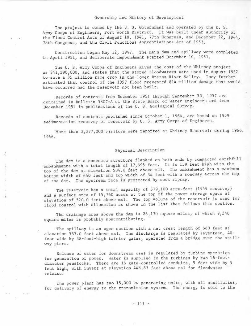
Ownership and History of Development
The project is owned by the U. S. Government and operated by the U. S.Army Corps of Engineers, Fort Worth District. It was built under authority ofthe Flood Control Acts of August 18, 1941, 77th Congress, and December 22, 1944,78th Congress, and the Civil Functions Appropriations Act of 1953.
Construction began May 12, 1947. The main dam and spillway were completedin April 1951, and deliberate impoundment started December 10, 1951.
The U. S. Army Corps of Engineers gives the cost of the Whitney projectas $41,390,000, and states that the stored floodwaters were used in August 1952to save a $5 million rice crop in the lower Brazos River Valley. They furtherestimated that control of the 1957 flood prevented $14 million damage that wouldhave occurred had the reservoir not been built.
Records of contents from December 1951 through September 30, 1957 arecontained in Bulletin 5807-A of the State Board of Water Engineers and fromDecember 1951 in publications of the U. S. Geological Survey.
Records of contents published since October 1, 1964, are based on 1959sedimentation resurvey of reservoir by U. S. Army Corps of Engineers.
More than 3,377,000 visitors were reported at Whitney Reservoir during 1966.1966.
Physical Description
The dam is a concrete structure flanked on both ends by compacted earthfillembankments with a total length of 17,695 feet. It is 159 feet high with thetop of the dam at elevation 584.0 feet above msl. The embankment has a maximumbottom width of 640 feet and top width of 34 feet with a roadway across the topof the dam. The upstream face is protected by rock riprap.
The reservoir has a total capacity of 379,100 acre-feet (1959 resurvey)and a surface area of 15,760 acres at the top of the power storage space atelevation of 520.0 feet above msl. The top volume of the reservoir is used forflood control with allocation as shown in the list that follows this section.
The drainage area above the dam is 26,170 square miles, of which 9,240square miles is probably noncontributing.
The spillway is an ogee section with a net crest length of 680 feet atelevation 533.0 feet above msl. The discharge is regulated by seventeen, 40foot-wide by 38-foot-high taint or gates, operated from a bridge over the spillway piers.
Release of water for downstream uses is regulated by turbine operationfor generation of power. Water is supplied to the turbines by two l6-footdiameter penstocks. There are 16 gate-controlled conduits, 5 feet wide by 9feet high, with invert at elevation 448.83 feet above msl for floodwaterrelease.
The power plant has two 15,000 kw generating units, with all auxiliaries,for delivery of energy to the transmission system. The energy is sold to the
- 111 -
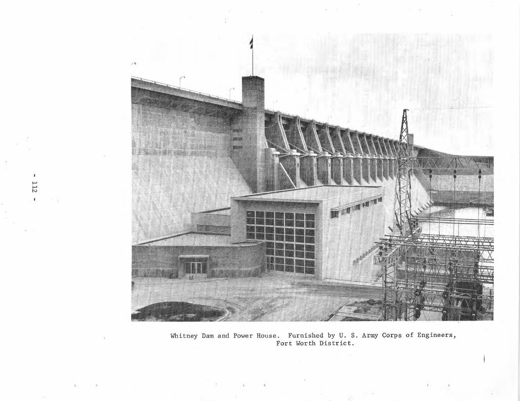
I-'I-'N
n.
A
('
Whitney Dam and Power House. Furnished by U. S. Army Corps of Engineers,Fort Worth District.
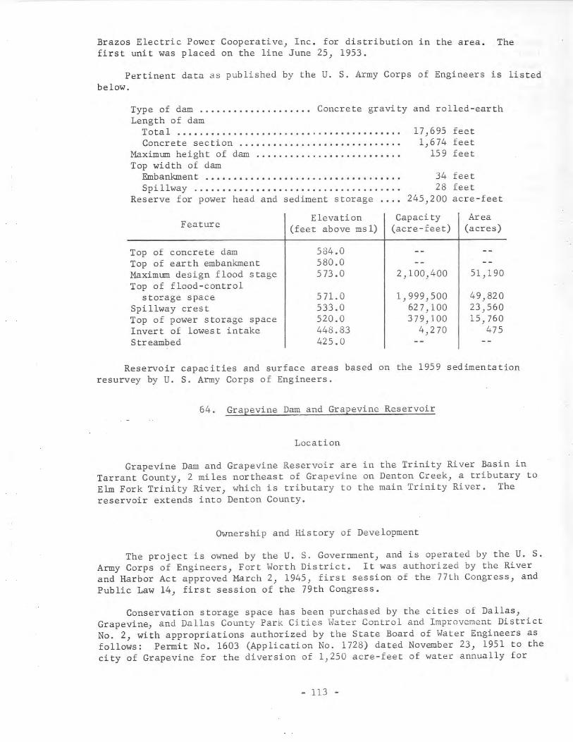
Brazos Electric Power Cooperative, Inc. for distribution in the area. Thefirst unit was placed on the line June 25, 1953.
Pertinent data as published by the U. S. Army Corps of Engineers is listedbelow.
34 feet28 feet
245,200 acre-feet
Type of dam ...•..•.•.......•... Concrete gravityLength of dam
Total ...•..•.......•.•...•......•.....••••••.Concrete section .
MaximWl height of dam ..•.........••••....•••...Top width of dam
Embankmen t .Spi llway ......•.••.•.•....••.................
Reserve for power head and sediment storage .•..
and rolled-earth
17,695 feet1,674 feet
159 feet
Feature
Top of concrete damTop of earth embankmentMaximWl design flood stageTop of flood-control
stocage spaceSpi llway crestTop of power storage spaceInvert of lowest intakeStreambed
Elevation(feet above msl)
584.0580.0573.0
571.0533.0520.0448.83425.0
Capacity(acre-feet)
2,100,400
1,999,500627,100379,100
4,270
Area(acres)
51,190
49,82023,56015,760
475
Reservoir capacities and surface areas based on the 1959 sedimentationresurvey by U. S. Army Corps of Engineers.
64. Grapevine Dam and Grapevine Reservoir
Location
Grapevine Dam and Grapevine Reservoir are in the Trinity River Basin inTarrant County, 2 miles northeast of Grapevine on Denton Creek, a tributary toElm Fork Trinity River, which is tributary to the main Trinity River. Thereservoir extends into Denton County.
Ownership and History of Development
The project is owned by the U. S. Government, and is operated by the U. S.Army Corps of Engineers, Fort Worth District. It was authorized by the Riverand Harbor Act approved March 2, 1945, first session of the 77th Congress, andPublic Law 14, first session of the 79th Congress.
Conservation storage space has been purchased by the cities of Dallas,Grapevine, and Dallas County ParK Cities Water Control and Improvement DistrictNo.2, with appropriations authorized by the State Board of Water Engineers asfollows: Permit No. 1603 (Application No. 1728) dated November 23, 1951 to thecity of Grapevine for the diversion of 1,250 acre-feet of water annually for
- 113 -
municipal purposes; Permit No. 1464 (Application No. 1572) dated August 19,1948 to the city of Dallas for the diversion of 85,000 acre-feet of waterannually for municipal, industrial, manufacturing, and recreational purposes;Permit No. 1465 (Application No. 1573) dated August 19] 1948 to Dallas CountyPark Cities Water Control and Improvement District No.2 for the diversion of50]000 acre-feet of water annually for municipal] industrial] manufacturing]and recreational purposes.
Construction began in January 1948] and was completed in June 1952.Deliberate impoundment of water began July 3] 1952.
Grapevine is one of several reservoirs--Garza-Little Elm being one of thelargest--supplying water to Dallas and other cities in the area. The U. S.Corps of Engineers gives the project cost as $10]827]000, and states that morethan 1]600,000 persons visited the project in 1960.
Records of contents from July 1952 through September 3D, 1957 are containedin Bulletin 5807-A of the State Board of Water Engineers and from July 1952 inpublications of the U. S. Geological Survey.
More than 2]389,000 visitors were reported at Grapevine Reservoir during1966.
Physical Description
The dam is a rolled-earth structure 12]850 feet long including concretespillway section] which has a SOD-foot crest length located on the left bank.The height is 137 feet above streambed with a top width of 28 feet and a publicroad across the top at elevation 588.0 feet above msl. The upstream face ofthe embankment is protected with stone riprap.
The reservoir has a conservation storage capacity of 188]500 acre-feet anda surface area of 7]389 acres at elevation 535.0 feet above msl. The shorelineis 60 miles long at this storage level.
Other storage space in the reservoir is allocated for flood control] conservation, navigation, sedimentation reserve, and recreational purposes.
The drainage area above the dam is 695 square miles.
An uncontrolled] emergency, concrete-gravity spillway is located at theleft end of the dam. The ogee-weir section has a crest length of 500 feet atelevation 560.0 feet above msl.
Outlet works for release of floodwater consist of a concrete structurehaving two intake openings with invert at elevation 475.0 feet above msl controlled by two 6.5- by 13.0-foot broome-type gates. Water released throughthese gates will flow through a 13-foot-diameter conduit located in the baseof the embankment, then discharge into a stilling basin below the dam.
There are two, 3D-inch, steel pipes paralleling the flood-control conduitfor low-flow releases. There are two gated outlets with invert at elevation500.5 feet above msl, and one gated outlet each at elevations 512.5 and 520.0feet above msl discharging to these pipes.
- 114 -
The following are pertinent data on Grapevine Dam and Grapevine Reservoir.
Length of dam including spillway .Height of dam above streambed .••.••...•.Width of crown .•••••.•..••.......••••.•.Volume of earthfill ..Two gate-controlled intakes .••••••••••.•
One circular discharge conduit .•••.•.••.Two gate-controlled conduits .Uncontrolled spillway .••....•.••....••••
12,850 feet137 feet28 feet
6,678,400 cu yd6.5 feet wide by
13.0 feet high13 feet diameter30-inch-diameter500 feet long
Elevation Capacity AreaFeature (feet above msl) (acre-feet) (acres)
Top of dam 508.0Emergency spillway
crest 560.0 435,500 12,740Top conservation
storage space 535.0 188,550 7,380Intake wet well 500.0 24,750 2,190Invert lowest
intake 475.0 830 126Streambed 451.0Sediment reserve 36,000
Reservoir capacities and surface areas based on 1946 survey by the U. S.Army Corps of Engineers.
The 161,250 acre-feet of usable conservation storage capacity is allocatedas follows:
City of Dallas 85,000 acre-feetDallas County Park Cities Water Control
and Improvement District No.2 50,000 acre-feetGrapevine.................................................... 1,250 acre-feetNavigation 25,000 acre-feet
65. Lavon Dam and Lavon Reservoir
Location
Lavon Dam and Lavon Reservoir are in the Trinity River Basin in CollinCounty, 2 miles west of Lavon and 22 miles northeast of Dallas on the East ForkTrinity River, a tributary of the Trinity River.
Ownership and History of Development
The project is owned by the U. S. Government, and was built and is operated by the U. S. Army Corps of Engineers, Fort Worth District. The projectwas authorized by the River and Harbor Act of March 2, 1945 as amended July 24,1946, 79th Congress, second session. This is one of several projects in theUpper Trinity River Basin for flood control and conservation water supply.
- 115 -
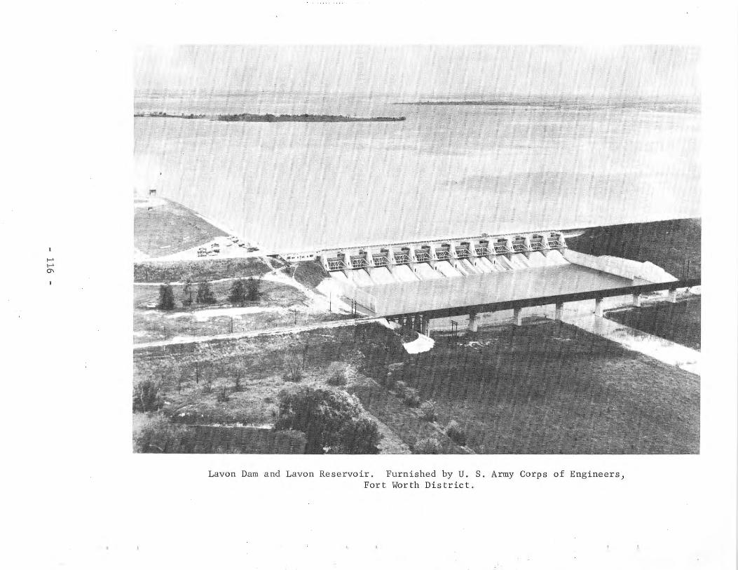
ex""" .. ....._.._
l'"
- ,~.....
.....
.....'"
Lavon Dam and Lavon Reservoir. Furnished by U. S. Army Corps of Engineers)Fort Worth District.
The North Texas Municipal Water District has purchased the 100]000 acrefeet of conservation space in the reservoir. Total authorized use is 60]000acre-feet annually designated as follows: 50]000 acre-feet for municipal use]8]000 acre-feet for industrial use] and 2]000 acre-feet for domestic use. Thiswater right was obtained by the District under Permit No. 1720 (ApplicationNo. 1820) dated September 1] 1954 from the State Board of Water Engineers. TheDistrict supplies water by pumping to Garland] Dallas] Mesquite] McKinney] andseveral small towns in the area.
Construction of the dam began in January 1948] and the main dam was completed in 1952. Deliberate impoundment of water began September 14] 1953.
Records of contents from October 1953 through September 30, 1957 are contained in Bulletin 5807-A of the State Board of Water Engineers, and from September 1953 in publications of the U. S. Geological Survey.
More than 2]376]000 visitors were reported at Lavon Reservoir during 1966.
Physical Description
The dam is d rolled-earth structure 9]499 feet long including the spillway.The maximum height is 69 feet with the top width of the embankment of 28 feetat elevation 502.0 feet above msl. A roadway over the embankment and a bridgeacross the spillway provide access to all parts of the structure. The upstreamface of the embankment is protected with stone riprap. Volume content of thedam is 3]689]200 cu yd] of which 49]200 cu yd is concrete.
The reservoir has a capacity of 143,600 acre-feet and a surface area of11]000 acres at the top of conservation storage space at elevation 472.0 feetabove msl. Other reservoir features are given in the tabulation that followsthis text. The features show that the flood-control storage capacity at thetop of the taintor gates is 279]800 acre-feet.
The drainage area above the dam is 770 square miles.
A controlled spillway for floodwater discharge is located at the rightend of the embankment. It is a concrete ogee section with crest length of 400feet at elevation 462.0 feet above msl. The discharge capacity is 255]800 cfswith reservoir elevation at 290.0 feet above msl. Spillway discharge is controlled by twelve taintor gates] 40 feet long by 28 feet high.
Low-flow releases for downstream requirements are controlled by five 36inch-diameter gated sluices through the centermost piers of the spillway withinvert at elevation 453.0 feet above msl.
A water-supply intake structure is located 1]200 feet upstream from thedam to supply water to the pumping plant of the District for distribution tothe participating cities. Withdrawals are controlled by six 4-foot-diametergates located at various elevations in the structure and can be made to elevation 453.0 feet above msl.
- 117 -
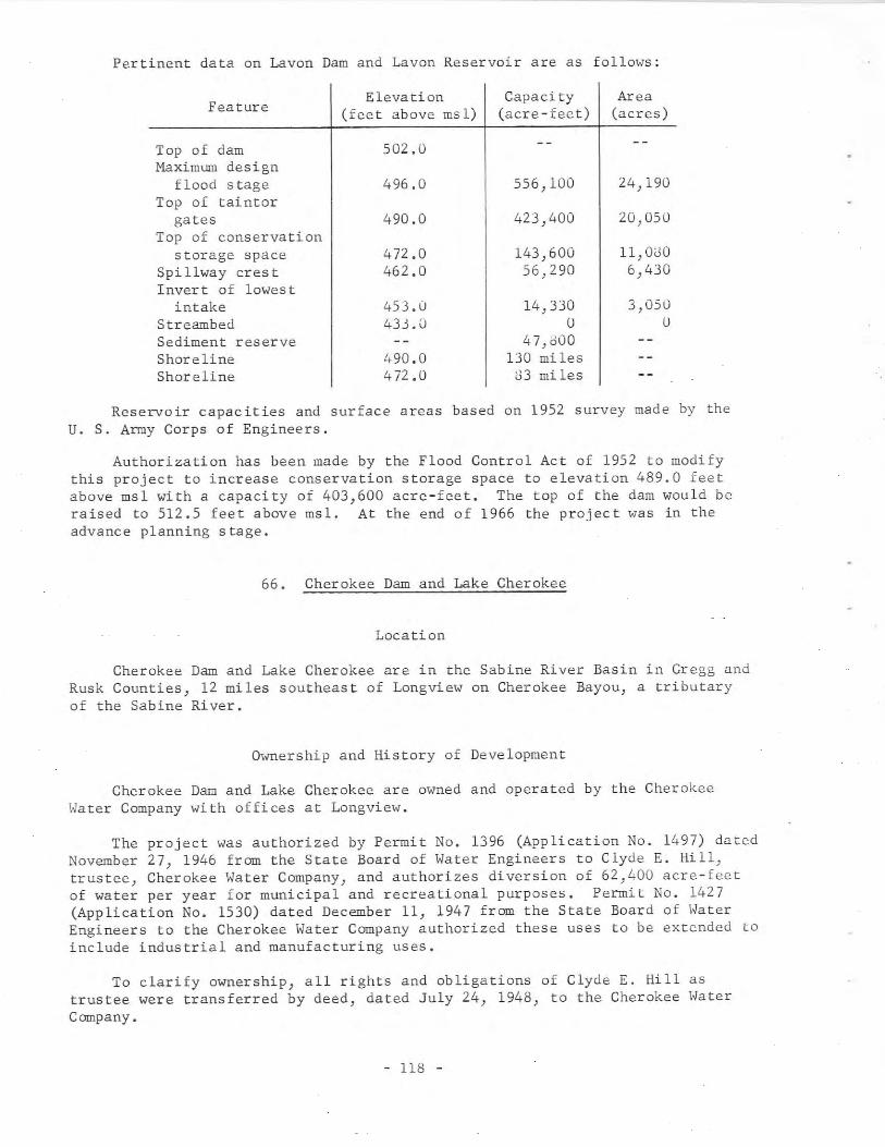
Pertinent data on Lavon Dam and Lavon Reservoir are as follows:
Feature
Top of damMaximum design
flood stageTop of taintor
gatesTop of conservation
storage spaceSpi 11way cres tInvert of lowest
intakeStreambedSediment reserveShorelineShoreline
Elevation(feet above msl)
502.0
496.0
490.0
472.0462.0
453.0433.0
490.0472.0
Capacity(acre-feet)
556,100
423,400
143,60056,290
14,330o
47,000130 miles
83 mi les
Area(acres)
24,190
20,050
11,OUO6,430
3,050o
Reservoir capacities and surface areas based on 1952 survey made by theu. S. Army Corps of Engineers.
Authorization has been made by the Flood Control Act of 1952 to modifythis project to increase conservation storage space to elevation 489.0 feetabove msl with a capacity of 403,600 acre-feet. The top of the dam would beraised to 512.5 feet above msl. At the end of 1966 the project was in theadvance planning stage.
66. Cherokee Dam and Lake Cherokee
Location
Cherokee Dam and Lake Cherokee are in the Sabine River Basin in Gregg andRusk Counties, 12 miles southeast of Longview on Cherokee Bayou, a tributaryof the Sabine River.
Ownership and History of Development
Cherokee Dam and Lake Cherokee are owned and operated by the CherokeeWater Company with offices at Longview.
The project was authorized by Permit No. 1396 (Application No. 1497) datedNovember 27, 1946 from the State Board of Water Engineers to Clyde E. Hill,trustee, Cherokee Water Company, and authorizes diversion of 62,400 acre-feetof water per year for municipal and recreational purposes. Permit No. 1427(Application No. 1530) dated December 11, 1947 from the State Board of WaterEngineers to the Cherokee Water Company authorized these uses to be extended toinclude industrial and manufacturing uses.
To clarify ownership, all rights and obligations of Clyde E. Hill astrustee were transferred by deed, dated July 24, 1948, to the Cherokee WaterCompany.
- 118 -
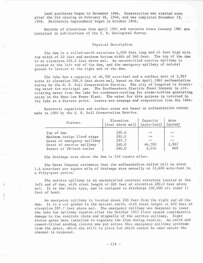
Land purchases began in December 1946. Construction was started soonafter the bid opening on February 26, 1948, and was completed November 19,1948. Deliberate impoundment began in October 1948.
Records of elevations from April 1951 and contents since January 1961 arecontained in publications of the U. S. Geological Survey.
Physical Description
The dam is a rolled-earth structure 4,000 feet long and 45 feet high withtop width of 20 feet and maximum bottom width of 340 feet. The top of the damis at elevation 295.0 feet above msl. An uncontrolled service spillway islocated at the left end of the dam, and the emergency spillway of naturalground is located at the right end of the dam.
The lake has a capacity of 46,700 acre-feet and a surface area of 3,987acres at elevation 280.0 feet above msl, based on the April 1960 sedimentationsurvey by the U. S. Soil Conservation Service. The city of Longview is diverting water for municipal use. The Southwestern Electric Power Company is circulating water from the lake for condenser-cooling for steam-turbine generatingunits in the Knox Lee Power Plant. The water for this purpose is returned tothe lake at a distant point. Losses are seepage and evaporation from the lake.
Reservoir capacities and surface areas are based on sedimentation surveymade in 1960 by the U. S. Soil Conservation Service.
Feature
Top of damMaximum design flood stageCrest of emergency spillwayCrest of service spillwayInvert of 18-inch outlet
Elevation(feet above msl)
295.0291.0287.7280.0260.0
Capacity(acre-feet)
46,7004,510
Area(acres)
3,987800
The drainage area above the dam is 158 square miles.
The Water Company estimates that the sedimentation inflow will be about1.6 acre-feet per square mile of drainage area annually or 13,600 acre-feet ina fifty-year period.
leftms1.feet
The service spillway is an uncontrolled concrete structure located at theend of dam, with crest length of 828 feet at elevation 280.0 feet aboveIt is the chute type, and is designed to discharge 100,000 cfs under 11
of head.
An emergency spillway is located about 200 feet from the right end of thedam. It is a cut graded in the natural earth, with crest length of 600 feet atelevation 287.7 feet above msl. The emergency spillway was deepened to lowerthe lake for spillway repairs after the October 1957 flood caused considerabledamage to the concrete chute and wingwalls of the service spillway. Eightsluice gates were installed to regulate the flow during repairs. An earth andcement-filled sandbag closure was put across this emergency spillway upstreamfrom the gates, which are still in place but which cannot be used unless thechannel is reopened.
- 119 -
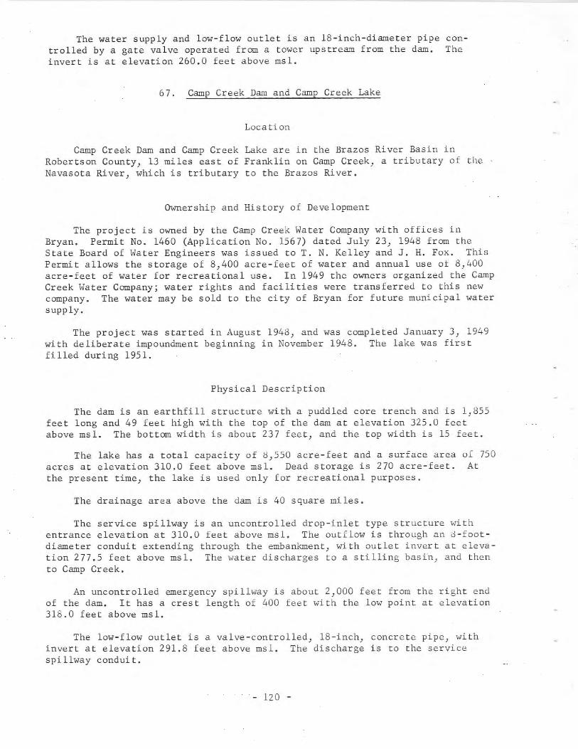
The water supply and low-flow outlet is an 18-inch-diameter pipe controlled by a gate valve operated from a tower upstream from the dam. Theinvert is at elevation 260.0 feet above msl.
67. Camp Creek Dam and Camp Creek Lake
Location
Camp Creek Dam and Camp Creek Lake are in the Brazos River Basin inRobertson County, 13 miles east of Franklin on Camp Creek, a tributary of the .Navasota River, which is tributary to the Brazos River.
Ownership and History of Development
The project is owned by the Camp Creek Water Company with offices inBryan. Permit No. 1460 (Application No. 1567) dated July 23, 1948 from theState Board of Water Engineers was issued to T. N. Kelley and J. H. Fox. ThisPermit allows the storage of 8,400 acre-feet of water and annual use of 8,400acre-feet of water for recreational use. In 1949 the owners organized the CampCreek Water Company; water rights and facilities were transferred to this newcompany. The water may be sold to the city of Bryan for future municipal watersupply.
The project was started in August 1948, and was completed January 3, 1949with deliberate impoundment beginning in November 1948. The lake was firstfilled during 1951.
Physical Description
The dam is an earthfill structure with a puddled core trench and is 1,855feet long and 49 feet high with the top of the dam at elevation 325.0 feetabove msl. The bottom width is about 237 feet, and the top width is 15 feet.
The lake has a total capacity of 8,550 acre-feet and a surface areaacres at elevation 310.0 feet above msl. Dead storage is 270 acre-feet.the present time, the lake is used only for recreational purposes.
The drainage area above the dam is 40 square miles.
of 750At
The service spillway is an uncontrolled drop-inlet type structure withentrance elevation at 310.0 feet above msl. The outflow is through an o-footdiameter conduit extending through the embankment, with outlet invert at elevation 277.5 feet above msl. The water discharges to a stilling basin, and thento Camp Creek.
An uncontrolled emergency spillway is about 2,000 feet from the right endof the dam. It has a crest length of 400 feet with the low point at elevation318.0 feet above msl.
The low-flow outlet is a valve-controlled, 18-inch, concrete pipe, withinvert at elevation 291.8 feet above msl. The discharge is to the servicespillway conduit.
- 120 -
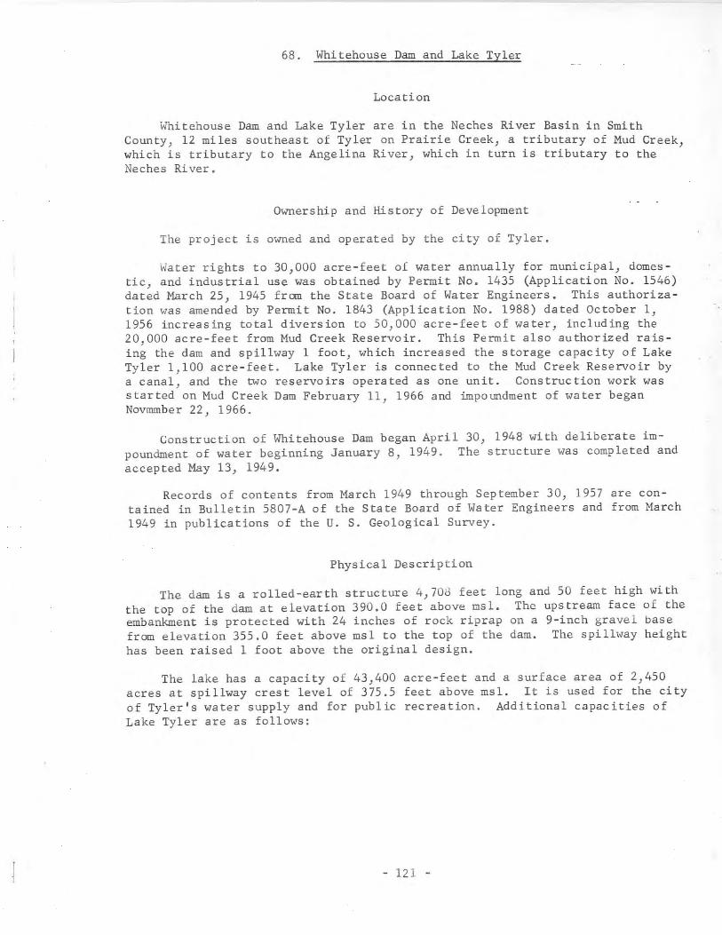
68. Whitehouse Dam and Lake Tyler
Location
Whitehouse Dam and Lake Tyler are in the Neches River Basin in SmithCounty, 12 miles southeast of Tyler on Prairie Creek, a tributary of Mud Creek,which is tributary to the Angelina River, which in turn is tributary to theNeches River.
Ownership and History of Development
The project is owned and operated by the city of Tyler.
Water rights to 30,000 acre-feet of water annually for municipal, domestic, and industrial use was obtained by Permit No. 1435 (Application No. 1546)dated March 25, 1945 from the State Board of Water Engineers. This authorization was amended by Permit No. 1843 (Application No. 1988) dated October 1,1956 increasing total diversion to 50,000 acre-feet of water, including the20,000 acre-feet from Mud Creek Reservoir. This Permit also authorized raising the dam and spillway 1 foot, which increased the storage capacity of LakeTyler 1,100 acre-feet. Lake Tyler is connected to the Mud Creek Reservoir bya canal) and the two reservoirs operated as one unit. Construction work wasstarted on Mud Creek Dam February 11, 1966 and impoundment of water beganNovmmber 22, 1966.
Construction of Whitehouse Dam began April 30, 1948 with deliberate impoundment of water beginning January 8, 1949. The structure was completed andaccepted May 13, 1949.
Records of contents from March 1949 through September 30, 1957 are contained in Bulletin 5807-A of the State Board of Water Engineers and from March1949 in publications of the U. S. Geological Survey.
Physical Description
The dam is a rolled-earth structure 4,703 feet long and 50 feet high withthe top of the dam at elevation 390.0 feet above msl. The upstream face of theembankment is protected with 24 inches of rock riprap on a 9-inch gravel basefrom elevation 355.0 feet above msl to the top of the dam. The spillway heighthas been raised 1 foot above the original design.
The lake has a capacity of 43,400 acre-feet and a surface area of 2,450acres at spillway crest level of 375.5 feet above msl. It is used for the cityof Tyler's water supply and for public recreation. Additional capacities ofLake Tyler are as follows:
- 121 -
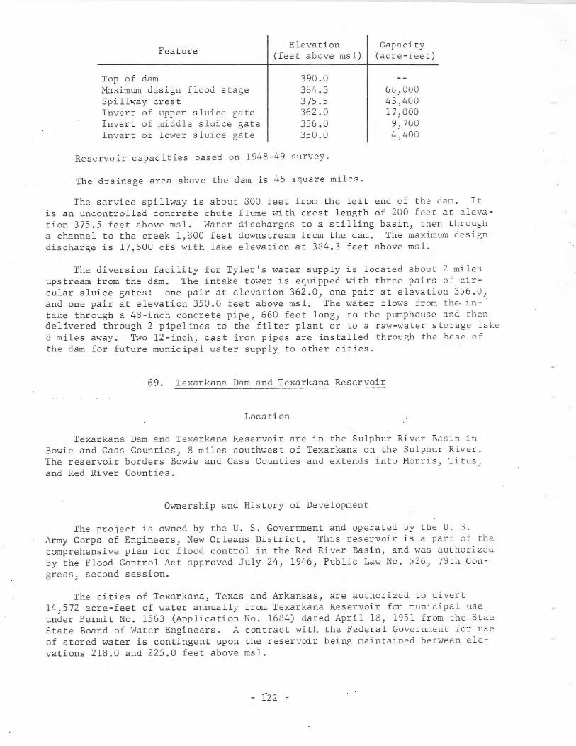
Feature
Top of dam~illximum design flood stageSpillway crestInvert of upper sluice gateInvert of middle sluice gateInvert of lower sluice gate
Elevation(feet above msl)
390.0384.3375.5362.0356.0350.0
Capacity(acre-ieet)
6J,OOO43,40017,000
9,7004,400
Reservoir capacities based on 1948-49 survey.
The drainage area above the dam is 45 square miles.
The service spillway is about 300 feet from the left end of the dam. Itis an uncontrolled concrete chute flume with crest length of 200 feet at elevation 375.5 feet above msl. Water discharges to a stilling basin, then througha channel to the creek 1,800 feet downstream from the dam. The maximum designdischarge is 17,500 cfs with lake elevation at 384.3 feet above msl.
The diversion facility for Tyler's water supply is located about 2 milesupstream from the dam. The intake tower is equipped with three pairs 0< circular sluice gates: one pair at elevation 362.0, one pair at elevation 356.0,and one pair at elevation 350.0 feet above msl. The water flows from the intake through a 48-inch concrete pipe, 660 feet long, to the pumphouse and thendelivered through 2 pipelines to the filter plant or to a raw-water storage lake8 miles away. Two 12-inch, cast iron pipes are installed through the base ofthe dam for future municipal water supply to other cities.
69. Texarkana Dam and Texarkana Reservoir
Location
Texarkana Dam and Texarkana Reservoir are in the Sulphur River Basin inBowie and Cass Counties) 8 miles southwest of Texarkana on the Sulphur River.The reservoir borders Bowie and Cass Counties and extends into Morris) Titus)and Red River Counties.
Ownership and History of Development
The project is owned by the U. S. Government and operated by the U. S.Army Corps of Engineers, New Orleans District. This reservoir is a part of thecomprehensive plan for flood control in the Red River Basin, and was authorizedby the Flood Control Act approved July 24, 1946, Public Law No. 526, 79th Congress) second session.
The cities of Texarkana) Texas and Arkansas) are authorized to divert14,572 acre-feet of water annually from Texarkana Reservoir for municipal useunder Permit No. 1563 (Application No. 1684) dated April 18, 1951 from the StaeState Board of Water Engineers. A contract with the Federal Government .or useof stored water is contingent upon the reservoir being maintained between elevations 218.0 and 225.0 feet above msl.
- 122 -
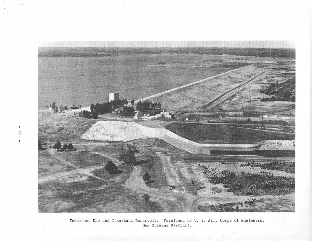
f-'
'"w
Texarkana Dam and Texarkana Reservoir. Furnished by U. S. Army Corps of Engineers,New Orleans District.
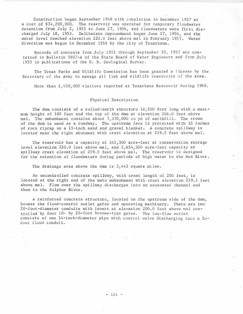
Construction began September 1948 with completion in December 1957 ata cost of $34,200,000. The reservoir was operated for temporary floodwaterdetention from July 2, 1953 to June 27, 1956, and floodwaters were first discharged July 18, 1953. Deliberate impoundment began June 27, 1956, and thewater level reached elevation 220.0 feet above msl in February 1957. Waterdiversion was begun in December 1958 by the city of Texarkana.
Records of contents from July 1953 through September 30, 1957 are contained in Bulletin 5807-A of the State Board of Water Engineers and from July1953 in publications of the U. S. Geological Survey.
The Texas Parks and Wildlife Commission has been granted a license by theSecretary of the Army to manage all fish and wildlife reservoirs of the area.
More than 2,450,000 visitors reported at Texarkana Reservoir during 1966.
Physical Description
The dam consists of a rolled-earth structure 18,500 feet long with a maximum height of 100 feet and the top of the dam at elevation 286.0 feet abovemsl. The embankment contains about 7,370,000 cu yd of earthfill. The crownof the dam is used as a roadway. The upstream face is protected with 33 inchesof rock riprap on a l5-inch sand and gravel blanket. A concrete spillway islocated near the right abutment with crest elevation at 259.5 feet above msl.
The reservoir has a capacity of 145,300 acre-feet at conservation storagelevel elevation 220.0 feet above msl, and 2,654,300 acre-feet capacity atspillway crest elevation of 259.5 feet above msl. The reservoir is designedfor the retention of floodwaters during periods of high water in the Red River.
The drainage area above the dam is 3,443 square miles.
An uncontrolled concrete spillway, with crest length of 200 feet, islocated at the right end of the main embankment with crest elevation 259.5 feetabove msl. Flow over the spillway discharges into an excavated channel andthen to the Sulphur River.
A reinforced concrete structure) located on the upstream side of the dam)houses the flood-control outlet gates and operating machinery. There are two20-foot-diameter conduits with invert at elevation 200.0 feet above msl controlled by four 10- by 20-foot broome-type gates. The low-flow outletconsists of one 14-inch-diameter pipe with control valve discharging into a 2ufoot flood conduit.
- 124 -
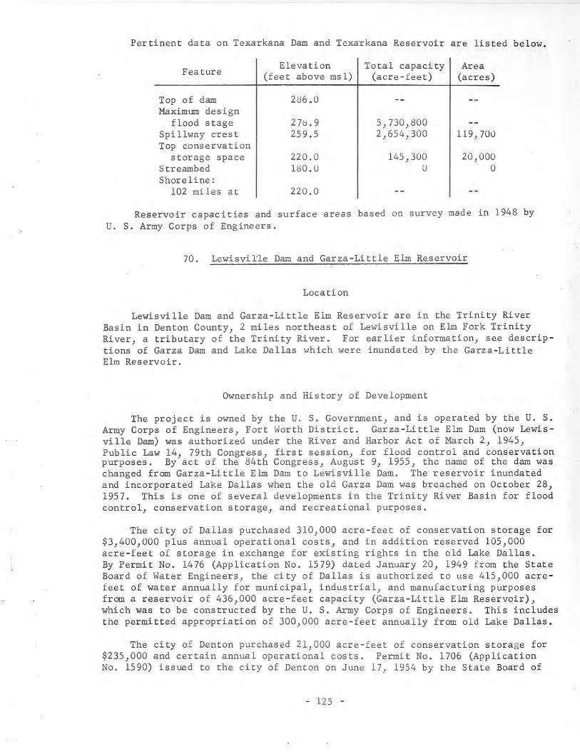
Pertinent data on Texarkana Dam and Texarkana Reservoir are listed below.
FeatureElevation Total capacity Area
(feet above msl) (acre-feet) (acres)
Top of dam 2U6.0Maximum design
flood stage 270.9 5,730,800Spillway crest 259.5 2,654,300 119,700Top conservation
storage space 220.0 145,300 20,000Streambed 100.U U 0Shoreline:
102 miles at 220.0
Reservoir capacities and surface areas based on survey made in 1948 byU. S. Army Corps of Engineers.
70. Lewisville Dam and Garza-Little Elm Reservoir
Location
Lewisville Dam and Garza-Little Elm Reservoir are in the Trinity RiverBasin in Denton County, 2 miles northeast of Lewisville on Elm Fork TrinityRiver, a tributary of the Trinity River. For earlier information, see descriptions of Garza Dam and Lake Dallas which were inundated by the Garza-LittleElm Reservoir.
Ownership and History of Development
The project is owned by the U. S. Government, and is operated by the U. S.Army Corps of Engineers, Fort Worth District. Garza-Little Elm Dam (now Lewisville Dam) was authorized under the River and Harbor Act of March 2, 1945,Public Law 14, 79th Congress, first session, for flood control and conservationpurposes. By act of the 84th Congress, August 9, 1955, the name of the dam waschanged from Garza-Little Elm Dam to Lewisville Dam. The reservoir inundatedand incorporated Lake Dallas when the old Garza Dam was breached on October 28,1957. This is one of several developments in the Trinity River Basin for floodcontrol, conservation storage, and recreational purposes.
The city of Dallas purchased 310,000 acre-feet of conservation storage for$3,400,000 plus annual operational costs, and in addition reserved 105,000acre-feet of storage in exchange for existing rights in the old Lake Dallas.By Permit No. 1476 (Application No. 1579) dated January 20, 1949 from the StateBoard of Water Engineers, the city of Dallas is authorized to use 415,000 acrefeet of water annually for municipal, industrial, and manufacturing purposesfrom a reservoir of 436,000 acre-feet capacity (Garza-Little Elm Reservoir),which was to be constructed by the U. S. Army Corps of Engineers. This includesthe permitted appropriation of 300,000 acre-feet annually from old Lake Dallas.
The city of Denton purchased 21,000 acre-feet of conservation storage for$235,000 and certain annual operational costs. Permit No. 1706 (ApplicationNo. 1590) issued to the city of Denton on June 17, 1954 by the State Board of
- 125 -
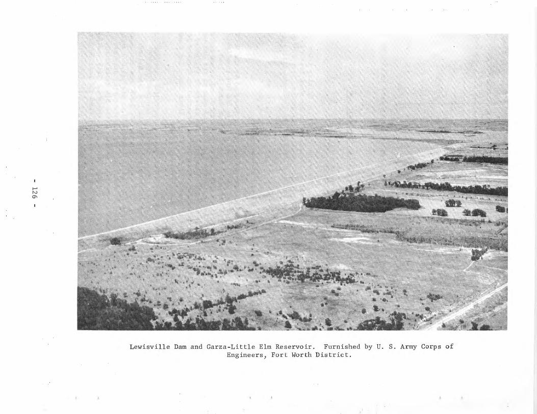
.....NCJ'
-~......_...
Lewisville Dam and Garza-Little Elm Reservoir. Furnished by U. S. Army Corps ofEngineers, Fort Worth District.
Water Engineers authorizes the storage of 21,000 acre-feet of water in a reservoir of 436,000 acre-feet capacity (Garza-Little Elm Reservoir), which was tobe constructed by the U. S. Army Corps of Engineers, and the appropriationtherefrom of 11,000 acre-feet of water per annum for municipal uses.
Construction began November 28, 1948, and the main dam was completed inAugust 1955. Deliberate impoundment of water began November I, 1954. GarzaDam was breached October 28, 1957, incorporating Lake Dallas into Garza-LittleElm Reservoir.
Records of contents from November 1954 through September 30, 1957 arecontained in Bulletin No. 5807-A of the State Board of Water Engineers andsince November 1954 in publications of the U. S. Geological Survey. Contentrecords published beginning October I, 1963, are based on 1960 sedimentationsurvey by U. S. Army Corps of Engineers.
More than 2,160,000 visitors were reported at Garza-Little Elm during 1966.
Physical Description
The dam is a compacted earth structure 32,888 feet long, including thespillway section, with a maximum height of 125 feet above the streambed withthe top of the dam at elevation 560.0 feet above msl. The top width is 20 feetwith a maximum bottom width of 700 feet, and the upstream slope of the embankment is protected by stone riprap. The dam contains 44,400 cu yd of concreteand 13,165,000 cu yd of earthfill.
The reservoir has a capacity of 464,500 acre-feet at conservation storagespace elevation of 515.0 feet above msl. Other capacities are given in thelist that follows this section.
The drainage area above the dam is 1,660 square miles.
The emergency spillway is located near the left end of the embankment.'This is an uncontrolled gravity ogee weir with a crest length of 560 feet atelevation 532.0 feet above msl, with a combined paved and excavated chute-typedischarge channel to the river about 1.5 miles downstream from the dam.
Outlet works for release of floodwaters are located about 3,200 feet tothe left of the old river channel. This is a reinforced concrete structurewith three openings controlled by broome-type gates, 6.5 feet wide by 13 feethigh, with invert at elevation 448.0 feet above msl. The water is dischargedthrough a 16-foot-diameter conduit into a stilling basin below the dam.
Two 60-inch, gate-controlled, steel pipes for release of water for conservation use are located on each side of the 16-foot, flood-control conduit.There are two gated outlets with invert at elevation 431.0 and one each at elevations 496.0 and 503.0 feet above msl discharging into these pipes.
Denton diverts its water supply from the upper part of the reservoir withfacilities constructed by the city.
- 127 -
Pertinent data on the dam and reservoir are listed below.
above msl
feet
feetfeetfeetfeet
12520
700560.0
Length of dam including spillway 32,388Maximum height of dam above
streambed ...•.••.•••..•••.•.•...••.••.Width of dam at crown ..••.••..•••.•.••..Maximum width of dam at base ..•.••••••••Top elevation of dam ..••...•..••..•..•••One circular conduit 16 feet in diameterThree gate-controlled inlets 6.5 feet wide by 13 feet high with
invert elevation of 448.0 feet above mslGate-controlled water supply outlets for the 60-inch diameter
steel pipes. Inverts: Two at 481.0 feet above msl, one at496.0 feet above msl, and one at 503.0 feet above msl.
Length of ogee type spillway............ 560 feetCrest elevation .••••..•.•••..••...•....• 532.0 feet above mslShoreline............................... 183 milesReserve for sedimentation •.•••.•••••••.• 28,500 acre-feet
Feature Elevation Capacity Area(feet above ms 1) (acre-feet) (acres)
Top of dam 560.0Maximum design flood stage 553.0 2,082,800 66,100Spi llway cres t 532.0 989,700 39,080Top of conservation storage
space 515.0 464,500 23,280Invert of one low-flow outlet 503.0 246,600 13,920Invert of one low-flow outlet 496.0 159,200 10,680Invert of two low-flow
outlets 481.0 44,080 ",750Invert of three 6.5 feet by
13.0 feet broome-type gates 448.0 30 12Streambed 435.0
Reservoir capacities and surface areas effective October 1) 1963) arebased on 1960 sedimentation survey by U. S. Army Corps of Engineers.
71. Baylor Creek Dam and Baylor Creek Reservoir
Location
Baylor Creek Dam and Baylor Creek Reservoir are in the Red River Basin inChildress County, 10 miles northwest of Childress on Baylor Creek, a tributaryto Prairie Dog Town Fork Red River, which is tributary to the Red River.
Ownership and History of Development
The project is owned and operated by the city of Childress for municipalwater supply and recreational purposes. Right to impound 9,200 acre-feet ofwater with annual diversion of 2,164 acre-feet was obtained by the city byPermit No. 1480 (Application No. 1601) dated March 17, 1949 from the StateBoard of Water Engineers.
- 128 -
Construction of the dam was started by the city April 1, 1949 and completed in February 1950. Deliberate impoundment was begun at the end of 1949.Use of impounded water began in 1954. Adjacent to this reservoir is LakeChildress, which was built on a tributary to Baylor Creek in 1923. This lakehad an original capacity of 4,600 acre-feet, and is still part of the city'swater supply system.
Physical Description
Baylor Creek Dam is a rolled-earth structure, 3,383 feet long and 66 feethigh above the creekbed, with the top of the dam at elevation 2,019.0 feetabove msl. The maximum bottom width is 276 feet and the top width 16 feet.The upstream face has 12 inches of rock riprap on a 6-inch gravel blanket fromelevation 450.0 to the top of the dam. The dam contains 434,000 cu yd of earth.
The reservoir has a capacity of 9,220 acre-feet and a surface area of 610acres at operating elevation of 2,010.0 feet above msl.
The drainage area above the dam is 40 square miles.
One spillway is an uncontrolled, open-channel cut in the natural bank witha bottom width of 200 feet with crest elevation 2,010.0 feet above msl. Thedischarge is to Lake Childress. IThe second or emergency spillway is a cutthrough the embankment with crest length of 500 feet at elevation 2,010.0 feetabove msl. This section has a 5-foot-high earth fuse plug with top at elevation 2,015.0 feet above msl designed to wash out during extreme floods.
Service water releases are provided by a concrete, controlled, inlet towerconnected to a 36-inch cast iron pipe that extends through the dam. Inflow tothe 36-inch pipe is regulated by slide gates at several elevations in the vertical walls of the inlet tower, which are operated from the top of the tower.
72. Belton Darn and Belton Reservoir
Location
Belton Dam and Belton Reservoir are in the Brazos River Basin in BellCounty, 4 miles north of Belton at river mile 16.7 on the Leon River, a tributary to the Little River, which is a tributary of the Brazos River. The upperpart of the reservoir extends into Coryell County.
Ownership and History of Development
The project is owned by the U. S. Government, and was built and is operatedby the U. S. Army Corps of Engineers, Fort Worth District. It was authorizedby the Flood Control Act approved July 24, 1946 (Public Law 526), 79th Congress,second session, and modified by the Flood Control Act of September 3, 1954.Belton Darn is one of several projects in the Brazos River Basin for flood control, conservation storage, and recreational purposes.
Permit No. 1689 (Application No. 1815) dated October 29, 1953 from theState Board of Water Engineers allows the U. S. Government to divert 10,000
- 129 -
acre-feet per year for use at Fort Hood. Permit No. 1725 (Application No.1815A) dated October 27, 1954 increases this diversion to 12,000 acre-feetannually. The U. S. Government leased all the facilities to Bell County WaterControl and Improvement District in January 1956 for 50 years. This Districtsupplies Fort Hood, Killeen, and other areas with municipal water. Another113,700 acre-feet of conservation storage space has been sold to the BrazosRiver Authority for $1,602,822 and certain operational costs. The Brazos RiverAuthority has the right to purchase additional storage capacity from theFederal Government if the conservation storage capacity is enlarged.
The Brazos River Authority obtained Permit No. 2108 (Application No. 2293)dated July 24, 1964 from the Texas Water Commission to impound 457,600 acre-feetof water in Belton Reservoir (the ultimate capacity) and to divert annually:95,000 acre-feet for municipal purposes, 150,000 acre-feet for industrial purposes and 150,000 acre-feet for irrigation of land in the Brazos River Basinand adjoining coastal areas and to use the bed and banks of the Leon, Littleand Brazos Rivers, for delivery to the place of use. However the amount ofwater for diversion 'vith priority of rights under the permit is limited to110,000 acre-feet per annum rather than the amount authorized for diversion.
Construction began in July 1949; the main structure was completed in April1954, and deliberate impoundment began March 8, 1954.
Records of contents from March 1954 through September 30, 1957 are contained in Bulletin 5807-A of the State Board of Water Engineers and from March1954 in publications of the U. S. Geological Survey.
More than 1,790,000 visitors were reported at Belton Reservoir during 1966.
Physical Description
The dam is a rolled-earth structure 5,524 feet long, including the spillway and a 4l8-foot-long dike. The embankment is 192 feet high above thestreambed with a top width of 30 feet at elevation 662.0 feet above msl; theupstream face is protected from erosion by stone riprap. The dam contains49,400 cu yd of concrete and 5,112,000 cu yd of earthfill.
The reservoir has a capacity of 210,600 acre-feet and a surface area of7,400 acres at the top of conservation storage space at elevation 569.0 feetabove msl. The ultimate conservation capacity will be increased to 457,600acre-feet with a surface area of 12,300 acres at elevation 594.0 feet abovemsl. Storage capacities at various elevations follow this section in a listthat shows 84,900 acre-feet as being allocated to sediment reserve.
The dra inage area above the dam is 3,560 square miles.
An emergency spillway is located near the left end of the dam. It is anuncontrolled, broad-crested weir with crest length of 1,300 feet at elevation631.0 feet above msl. The spillway has a discharge capacity of 472,500 cfswith the reservoir at the maximum design flood stage at elevation 656.9 feetabove msl. The discharge is through a pilot channel to the Leon River about0.5 mile below the dam.
- 130 -
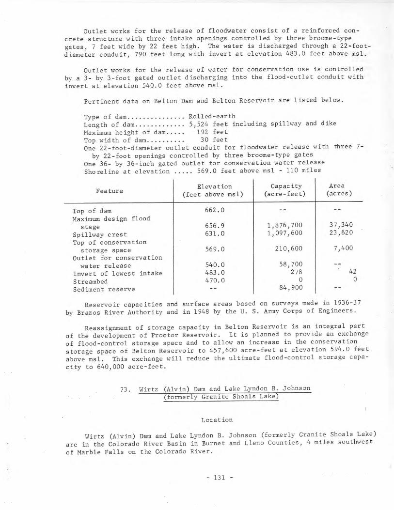
Outlet works for the release of floodwater consist of a reinforced concrete structure with three intake openings controlled by three broome-typegates, 7 feet wide by 22 feet high. The water is discharged through a 22-footdiameter conduit, 790 feet long with invert at elevation 483.0 feet above msl.
Outlet works for the release of water for conservation use is controlledby a 3- by 3-foot gated outlet discharging into the flood-outlet conduit withinvert at elevation 540.0 feet above msl.
Pertinent data on Belton Dam and Belton Reservoir are listed below.
Type of dam Rolled-earthLength of dam 5,524 feet including spillway and dikeMaximum height of dam..... 192 feetTop width of dam. .....•... 30 feetOne 22-foot-diameter outlet conduit for floodwater release with three 7
by 22-foot openings controlled by three broome-type gatesOne 36- by 36-inch gated outlet for conservation water releaseShoreline at elevation ..... 569.0 feet above msl - 110 miles
Feature Elevation(feet above msl)
Capacity(acre-feet)
Area(acres)
Top of damMaximum design flood
stageSpillway crestTop of conservation
storage spaceOutlet for conservation
water releaseInvert of lowest intakeStreambedSediment reserve
662.0
656.9631.0
569.0
540.0483.0470.0
1,876,700 37,3401,097,600 23,620
210,600 7,400
58,700278 42
0 084,900
Reservoir capacities and surface areas based on surveys made in 1936-37by Brazos River Authority and in 1948 by the U. S. Army Corps of Engineers.
Reassignment of storage capacity in Belton Reservoir is an integral partof the development of Proctor Reservoir. It is planned to provide an exchangeof flood-control storage space and to allow an increase in the conservationstorage space of Belton Reservoir to 457,600 acre-feet at elevation 594.0 feetabove msl. This exchange will reduce the ultimate flood-control storage capacity to 640,000 acre-feet.
73. Wirtz (Alvin) Dam and Lake Lyndon B. Johnson(formerly Granite Shoals Lake)
Location
Wirtz (Alvin) Dam and Lake Lyndon B. Johnson (formerly Granite Shoals Lake)are in the Colorado River Basin in Burnet and Llano Counties, 4 miles southwestof Marble Falls on the Colorado River.
- 131 -
Ownership and History of Development
The project is owned and operated by the Lower Colorado River Authorityfor the main purpose of generating hydroelectric power} and is one of six projects on the Colorado River. The other five are: Buchanan Dam and Lake Buchanan, Inks Dam and Inks Lake, Starcke (Max) Dam and Marble Falls Lake, Mansfield Dam and Lake Travis, and Miller (Tom) Dam and Lake Austin. All of theseare described in this report. It is the second project downstream from Buchanan Dam and uses the controlled discharge of water from the Buchanan electricalgenerating plant together with the added flow of the Llano River for powergeneration.
The project was authorized by Permit No. 953 (Application No. 1023) dated~~y 15, 1926 from the State Board of Water Engineers to the Syndicate PowerCompany. The Permit allocates l,305,OOG acre-feet of water for conservation)irrigation} and power generation uses. This is one of several permits issuedfor projects on the Colorado River during the beginning of the Colorado Riverdevelopment.
All the water rights and the history of their acquisition were obtainedas follows:
Certified Filing No. 423 dated June 30) 1914 by E. C.Alexander refers to ownership of rights by virtue of priorfilings and applications in connection with which water isto be utilized for mining) milling) manufacturing) power)waterworks, and stock raising and which prior filings andapplications were renewed for the construction of a dam atLohman Narrows. (The project became known as Alexander Damlocated below ~rble Falls.) Between 1914 and 1919 theserights passed to C. H. Alexander and Syndicate Power Company. All these C. H. Alexander interests seem to be apartnership with John N. Simpson of Dallas who also hadearly water rights and owned considerable land on theColorado River. The Alexander and Simpson Project is mentioned in same of the letters in the files of the TexasWater Commission. For later permits, Permit Nos. 951-55and 998, the Syndicate Power Company claimed the exclusiveprior rights to the appropriation and use of such waterswithin the area covered by six applications for water permits pertaining to the appropriation and use of such watersas existed prior to June 29, 1913.
The Lower Colorado River Authority is owner of Permit Nos. 951-55 and 993by virtue of the following conveyances: (a) from Syndicate Power Company toWard Arnold and Jay Alexander dated July 30, 1928 (Permit Nos. 951 and 952only); (b) from Syndicate Power Company to Emery, Peck & Rock\;ooci DevelopmentCompany dated July 19, 1929; (c) from Ward Arnold and Jay Alexander to Emery,Peck & Rockwood Development Company dated July 19, 1929; (d) from Emery, Peck &Rockwood Development Company to Central Texas Hydro-Electric Company datedNovember 5, 1931; (e) from A. J. Wirtz, receiver for Central Texas HydroElectric Company, to Colorado River Company dated October 5, 1934; (f) fromA. J. lVirtz, receiver for Central Texas Hydro-Electric Company, to C. G. Halottdated October 5, 1934; (g) from Colorado River Company to Lower Colorado RiverAuthority dated August 9, 1935; (h) from C. G. ~lott to Lower Colorado RiverAuthority dated August 9, 1935.
- 132 -
Construction was begun in September 1949, and was completed in November1951 with deliberate impoundment of water beginning in May 1951. Power generation started June 27, 1951.
Records of daily elevations are maintained by the Lower Colorado RiverAuthority as unpublished data.
Physical Description
The dam is a concrete and earthfill structure, 5,491 feet long and 118feet maximum height. The concrete section is 1,146 feet long with a gatedspillway and powerhouse facilities. The earthfill section with a concrete corewall has crest elevation at 835.0 feet above msl. The earth embankment isprotected on the upstream side by rock riprap.
Additional data on the structur~ are as follows:
Height of dam .••.••••.••••••••••••••••••••.Length of dam (total) .••••••••••••••••••••.Operating elevation ••••.••••...•..........•Maximum elevation of structure ..•..•.•...••Maximum operating head .................•...Power plant capacity ...................•...
118 feet5,491 feet
825.0 feet above msl838.0 feet above msl
87 feetTwo 22,500 kw units
The reservoir, at normal operating elevation of 825.0 feet above msl, hasa capacity of 138,500 acre-feet and a surface area of 6,375 acres. Undernormal conditions the water level fluctuates over a small range because thepower plant operation is coordinated with the inflow. Water from this reservoir is used for generation of power, and water is released to Marble FallsLake for use at the Starcke (Max) Dam electrical-generating plant. Exceptduring floods, the only water released is through the turbines for generationof power. This lake is the most popular of the series for recreational purposes.
Drainage area is 36,290 square miles, of which 11,900 square miles is noncontributing. However, the riverflow is determined by the controlled dischargeof Lake Buchanan and Inks Lake plants upstream on the Colorado River, plus theentire unregulated flow from the Llano River and other smaller tributaries tothe lake.
The spillway is an ogee section with crest elevation 796.0 feet above msl.There are nine taint or gates, 50 feet wide by 30 feet high, operated by twohoists. The top of the gates is one foot higher than the normal operating lakelevel of'825.0 feet above msl. At normal lake level elevation the nine gateswill discharge 293,000 cfs. At elevation 835.0 feet above msl, the top of theembankment, the nine gates will discharge 475,000 cfs.
There are no low-flow outlets required as water releases are made throughthe turbines for normal operation, and the water enters Marble Falls Lake immediately downstream.
The power plant contains two 22,500 kw generating units with auxiliaryequipment for connecting to the transmission system. This plant is used forpeak power during the time when the electrical demand is the greatest.
- 133 -
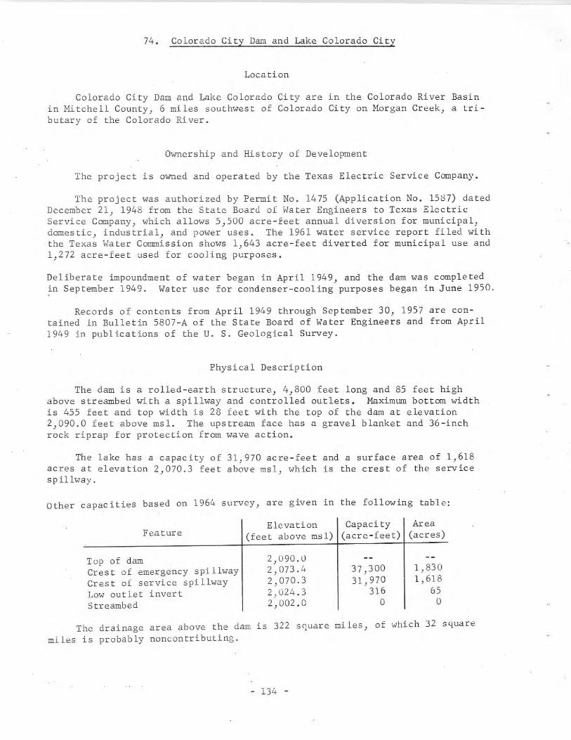
74. Colorado City Dam and Lake Colorado City
Location
Colorado City Dam and Lake Colorado City are in the Colorado River Basinin Mitchell County, 6 miles southwest of Colorado City on Morgan Creek, a tributary of the Colorado River.
Ownership and History of Development
The project is owned and operated by the Texas Electric Service Company.
The project was authorized by Permit No. 1475 (Application No. 1587) datedDecember 21, 1948 from the State Board of Water Engineers to Texas ElectricService Company, which allows 5,500 acre-feet annual diversion for municipal,domestic, industrial, and power uses. The 1961 water service report filed withthe Texas Water Commission shows 1,643 acre-feet diverted for municipal use and1,272 acre-feet used for cooling purposes.
Deliberate impoundment of water began in April 1949, and the dam was completedin September 1949. Water use for condenser-cooling purposes began in June 1950.
Records of contents from April 1949 through September 30, 1957 are contained in Bulletin 5807-A of the State Board of Water Engineers and from April1949 in publications of the U. S. Geological Survey.
Physical Description
The dam is a rolled-earth structure, 4,800 feet long and 85 feet highabove streambed with a spillway and controlled outlets. Maximum bottom widthis 455 feet and top width is 28 feet with the top of the dam at elevation2,090.0 feet above msl. The upstream face has a gravel blanket and 36-inchrock riprap for protection from wave action.
The lake has a capacity of 31,970 acre-feet and a surface area of 1,618acres at elevation 2,070.3 feet above msl, which is the crest of the servicespillway.
Other capacities based on 1964 survey, are given in the following table:
FeatureElevation Capacity Area
(feet above msl) (acre-feet) (acres)
Top of damCrest of emergency spillwayCrest of service spillwayLow outlet invertStreambed
2,090.02,073.42,070.32,u24.32,002.0
37,30031,970
316o
1,8301,618
65o
The drainage area above the dam is 322 s~uare miles, of which 32 squaremiles is probably noncontributing.
- 134 -
The water is allocated as municipal supply for Colorado City and forcondenser-cooling and plant use by the Texas Electric Service Company. Waterfor Colorado City is pumped trom a concrete stilling-basin well, 11 feet indiameter, about 2 miles upstream from the dam. Water enters the well throughthree IS-inch pipes at elevations 2,045.0, 2,055.0, and 2,065.U feet above msl.Hater for cooling is diverted at the power plant, and is discharged back intothe lake some distance away to create circulation and cooling. The only consumptive use of water by the Texas Electric Service Company is forced evaporation caused by heat added to the reservoir and a small amount for plant use. '
When runoff into Lake Colorado City is insufficent to maintain a satisfactory operating level, water is pumped into the lake through a 24-inch pipeline from Champion Creek Reservoir.
An emergency spillway is located 600 feet from the left end of the dam,and discharges into the Colorado River. It is cut from the natural-earth embankment with a crest length of 1,200 feet at elevation 2,073.4 feet above msl.
The service spillway is an uncontrolled, double-rectangular-drop inlettha t is loca ted 100 feet ups tream from the dam. Each opening is 10- by 12foot. The service spillway is designed to discharge a maximum of 5,000 cfs.The spillway discharges into a double-horseshoe concrete conduit, each barrelof which is 10 feet wide by 10 feet high, with semi-circular tops. The conduit is 400 feet long, extending through the dam and discharging into MorganCreek.
The outlet for low-flow release is a 30-inch-diameter pipe through thedam, controlled by two 24-inch valves with invert at elevation 2,024.3 feetabove msl, which is the elevation of lowest drawdown.
75. Starcke (Max) Dam and Marble Falls Lake
Location
Starcke (Max) Dam and Marble Falls Lake are in the Colorado River Basin inBurnet and Llano Counties at Marble Falls on the Colorado River at the upperreaches of Lake Travis.
Ownership and History ot Development
The project is owned and operated by the Lower Colorado River Authorityfor the main purpose of generating hydroelectric pm'Jer) and is one of six LowerColorado River Authority projects on the Colorado River. The other five are:Buchanan Dam and Lake Buchanan, Inks Dam and Inks Lake, Wirtz (Alvin) Dam andLake Lyndon B. Johnson, Mansfield Dam and Lake Travis, and Miller (Tom) Damand Lake Austin. All of these are described in this report. It is the thirdplant downstream from Buchanan Dam, and uses the controlled discharge fromBuchanan electrical plant together with the added flow of the Llano River andfurther regula t ion by the Wirtz (Alv in) Dam power plan t for power genera t ion.
- 135 -
The project was authorized by Permit No. 998 (Application No. 1022) datedNovember 4, 1927 from the State Board of Water Engineers to Syndicate PowerCompany. The Permit allocates 1,305,000 acre-feet of water for conservation,irrigation, and power generation. This is one of several permits issued forprojects on the Colorado River at the beginning of the Colorado River development.
The water rights and history of their acquisition were obtained as follows:
Certified Filing No. 423 dated June 3D, 1914 by E. C.Alexander refers to ownership of rights by virtue of priorfilings and applications in connection with which water isto be utilized for mining) milling} manufacturing) power)waterworKs, and stock raising, and which prior filings andapplications were renewed for the construction of a dam atLohman Narrows. (The project became known as Alexander Damlocated below Marble Falls.) Between 1914 and 1919 theserights passed to C. H. Alexander and Syndicate Power Company. All these C. H. Alexander interests seem to be apartnership wi th John N. S,impson of Dallas who also hadearly water rights and owned considerable land on theColorado River. The Alexander and Simpson Project is mentioned in some of the letters in the files of the TexasWater Commission. For later permits, Permit Nos. 951-55and 998, the Syndicate Power Company claimed the exclusiveprior rights to the appropriation and use of such waterswithin the area covered by six applications for water permits pertaining to the appropriation and use of such watersas existed prior to June 29, 1913.
The Lower Colorado River Authority is owner of Permit Nos. 951-55 and 99dby virtue of the following conveyances: (a) from Syndicate Power Company toWard Arnold and Jay Alexander dated July 3D, 1928 (Permit Nos. 951 and 952only); (b) from Syndicate Power Company to Emery, Peck & Rockwood DevelopmentCompany dated July 19, 1929; (c) from Ward Arnold and Jay Alexander to Emery,Peck & Rockwood Development Company dated July 19, 1929; (d) from Emery, Peck &Rockwood Development Company to Central Texas Hydro-Electric Company datedNovember 5, 1931; (e) from A. J. Wirtz, receiver for Central Texas HydroElectric Company, to Colorado River Company dated October 5, 1934; (f) fromA. J. Wirtz, receiver for Central Texas Hydro-Electric Company, to C. G. Malottdated October 5, 1934; (g) from Colorado River Company to Lower Colorado RiverAuthority dated August 9, 1935; (h) from C. G. Malott to Lower Colorado RiverAuthority dated August 9, 1935.
Construction was begun in November 1949, and was completed in October 1951.Deliberate impoundment of water began in July 1951 when the Marble Falls TextileMill Dam upstream was breached July 3D, 1951. Power generation started September25, 1951. Starcke (Max) Dam is just downstream from the site of the AlexanderDam, one of the early structures on the river. It is not known whether thisdam was ever put to beneficial use, but parts of the old concrete structure hadto be blasted out of the river before the closure was made and the new lakeformed.
The old Marble Falls Dam and power plant upstream from Alexander Dam furnished power originally to the Marble Falls Textile Company's mill and later to
- 136 -
several small industries. It was used for generation of power by the LowerColorado River Authority up to a short time before the dam was breached for thenew lake.
Records of daily lake elevations are maintained by the Lower ColoradoRiver Authority as unpublished data.
Physical Description
The dam is a concrete gravity structure 860 feet long including the spill ..way, powerhouse, and other facilities for operating the plant and crest gates.The maximum height of the structure is 98 feet. Tunnels and operating galleries extend through the length of the dam with entrances from the powerhouse andgate piers.
The lake is operated at a nearly constant level as the turbine dischargeis correlated with the inflow from Granite Shoals plant. Except during floods,the only water released to Lake Travis immediately downstream is through theturbines for generation of power. There are no downstream requirements as thisdemand is regulated by Marshall Ford and Austin power plants. The lake has acapacity of 8,760 acre-feet and a surface area of 780 acres at elevation 733.0feet above msl. Other dimensions are listed at the close of this section.
The drainage area is 36,325 square miles, of which 11,900 square miles isnoncontributing; however, the riverflow is regulated by upstream reservoirs andpower plant operation.
Sedimentation studies have not been made for this lake) and are unimportant from the standpoint of power generation as storage is maintained by waterreleased from upstream reservoirs.
The spillway is an ogee section with crest elevation of 725.U feet abovemsl. Floodflow is controlled by ten roof-weir-type crest gates, 60 feet 10inches long by 13 feet high. Anyone or all of these gates can be operated inany position from raised to fully lowered. lihen the gates are in lowered position, the elevation of the crest is 725.0 feet above msl. lihen in raised position, the lake is at normal operating level of 738.0 feet above msl. At maximum flood elevation of 758.0 feet above msl, and with all gates lowered, thedischarge capacity is rated at 421,000 cfs.
There are no low-flow outlets required as water releases are made throughthe turbines for normal operation) and the water enters Lake Travis for storageand future use.
There is no flood-control storage in this small lake so any excess waterfrom Lake Lyndon B. Johnson is discharged over the crest-type gates to LakeTravis.
The power plant contains two 15,000 kw generatin3 units wiLh auxiliaryequipment for connecting to the transmission system. This plant is operace~ inseries with Wirtz Dam plant, and the turbines are rated for the same waterrequirements as those at Wirtz Dam.
- 137 -
Pertinent data follows on Starcke Dam and Marble Falls Lake.
730 acrestwo at 15,000 kw each
98 feet860 feet738.0 feet above msl725.0 feet above msl
ten, 60 feet 10 inches by13 fee thigh
Maximum height of structure ..•...•.......•.Length of dam and powerhouse .••..••••.....•Lake operating elevation ...•..••..•..••.••.Spillway elevation with gates down ..••...•.Ga tes .•.•..................•..•....•••....•
Spillway capacity at lake elevation of738.0 feet above msl ..
Spillway capacity at lake elevation of758.0 feet above msl ..
Lake capacity at elevation 733.0feet above msl .
Lake area at elevation 738.0fee t above ms 1 ••..•.•...•..•••..•.......••
Genera tor capaci ty .
104,000
421,000
8,760
cfs
cfs
acre-feet
76. Falcon Dam and International Falcon Reservoir
Location
Falcon Dam and International Falcon Reservoir are in the Rio Grande Basinin Starr County, 3 miles west of Falcon Heights on the Rio Grande at river mile270.5, 80 miles downstream from Laredo. The reservoir is in Starr and ZapataCounties, Texas and in Estado de Tamaulipas, Mexico.
Ownership and History of Development
The project is owned by the United States and Mexico, and is operated bythe International Boundary and Water Commission.
In 1944 the United States and Mexico signed the most recent of a series oftreaties affecting the land and water boundary between the two countries.Among the most important clauses of the Water Treaty of 1944 are those providing for equitable distribution, between the two nations, of the waters ofthe two principal international streams, the Rio Grande (below Fort Quitman)and the Colorado River, which empties into the Gulf of California. The treatyprovides for the construction of necessary works for the maximum conservationand utilization of the waters of the Rio Grande. On the Rio Grande the treatyauthorizes the necessary international storage dams to be jointly constructedby the two governments through the International Boundary and Water Commission.
Falcon Darn was authorized by the International Boundary and Water Cornrnission--United States and Mexico. Its development was for conservation} irrigation) power) recreation) and flood control uses. Under the terms of the treaty)the United States will receive 58.6 percent of the conservation storage andMexico will receive 41.4 percent. The United States' share of the cost was 35million dollars.
- 138 -
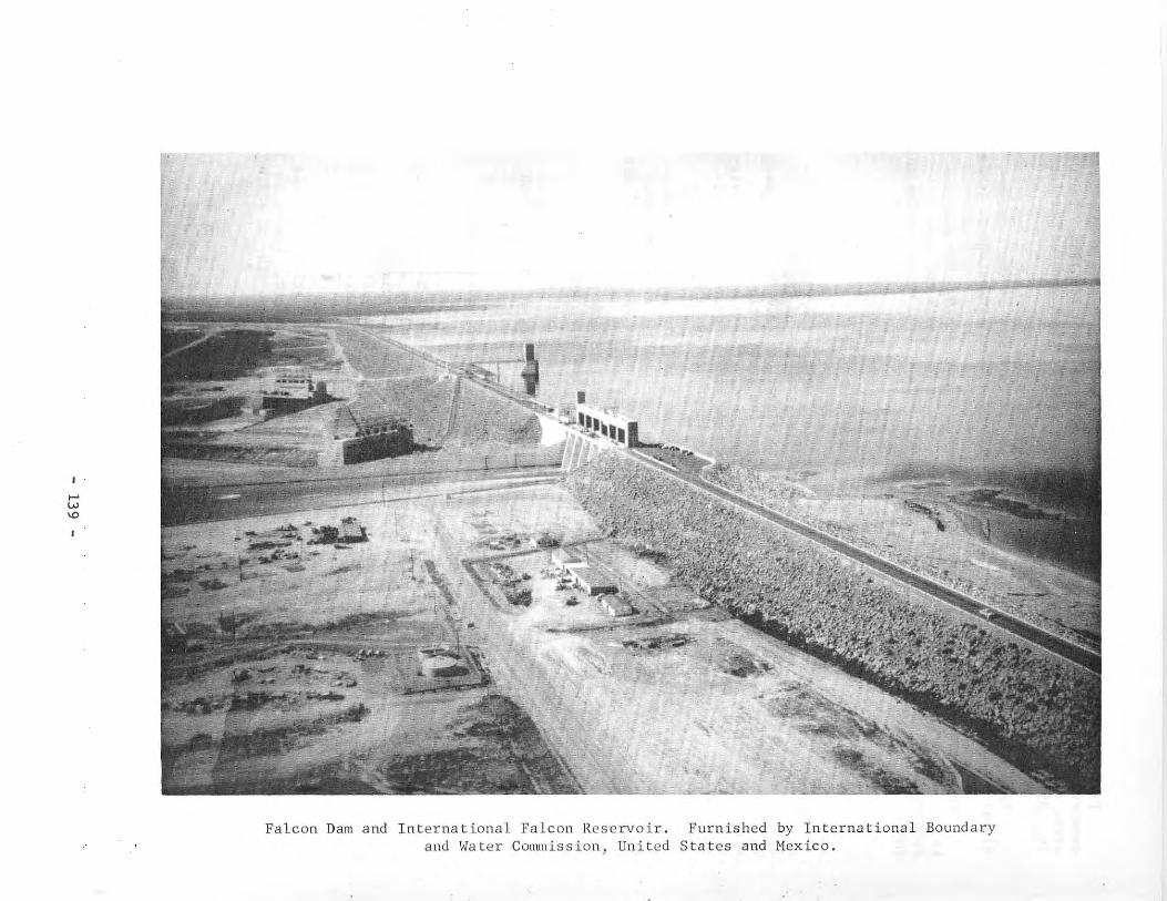
.....'"'"
Falcon Dam and International Falcon Reservoir.and Water Commission, United
Furnished by International BoundaryStates and Mexico.
..
Plans for the dam and two power plants were approved in the fall of 1949,construction began in 1950, and the completion date was April 18, 1954. Deliberate impoundment began August 25, 1953, and the project was dedicated October19, 1953.
Falcon is one of several projects under the jurisdiction of the International Boundary and Water Commission, and is one of the most important to Texas.
Records of contents from January 1953 through September 30, 1957 are contained in Bulletin 5807-A of the State Board of Water Engineers and fromJanuary 1953 in publications of the International Boundary and Water Commission,United States and Mexico.
Physical Description
The dam is a compacted, rolled-earth structure with a controlled spillwayon the United States' side of the river with a total length of 26,294 feet anda height of 150 feet with the top of the dam at elevation 323.0 feet above msl.The maximum width of the base is 1,000 feet, and the crown width is 35 feetwith a roadway across the top of the entire structure. The embankment containsover 12.6 million cu yd of earthfill. The upstream face is protected by a 3foot blanket of riprap, and the downstream face is protected by dumped rock.
The reservoir has a summer storage capacity of 2,371,220 acre-feet and asurface area of 78,340 acres at conservation storage level at elevation 296.4feet above msl, which is the top of the conservation storage space. Above thiselevation there is 909,480 acre-feet of flood-control storage capacity. Anadditional 400,000 acre-feet of conservation storage is allowed during thewinter, which reduces the flood-control capacity accordingly. Other capacitiesare listed at the close of this section.
The drainage area above the dam is 164,482 square miles, of which 87,760is in the United States and 76,722 is in Mexico.
Of the reservoir capacity, 300,000 acre-feet was allocated for sedimentreserve.
The gated spillway is on the United States' side and has a net opening of300 feet with crest elevation 256.7 feet above msl controlled by six fixedwheel-type lift gates, 50 feet wide by 50 feet high. The spillway dischargecapacity is 456,000 cfs with maximum design flood stage at elevation 314.2 feetabove msl. The water enters a chute 1,300 feet long, and is dissipated beforeentering a control channel leading to the Rio Grande.
There are two 72-inch outlets for water release for each nation) when theturbines are not operating, to supply the downstream requirements. Invert onthe United States' side is at elevation 225.0 and on the Mexican side at 205.0fee t above ms 1.
A power plant with auxiliary equipment is built on each side of the river)and each plant has three 10,500 kw generating units with provision for thefourth unit when justified. The first generation of electricity was October11, 1954. Power from the United States plant is distributed by Central Power &Light Company.
- 140 -
Pertinent data on Falcon Dam and International Falcon Reservoir are listedbelow.
Length of dam in Mexico ...•••••••...••..••••Length of dam in United States ..••..••••••..Height of dam above streambed •••••••••••.•..Base wid th .••••••••••..••.•.••.•••.•••••••..Crown width ••.•.•.•..•.••••.••...•••.•••••..Earth and rockfi 11 .Riprap ..Concrete ..Reinforcing steel ••..•••....••.•.••.•••••••.Total crest length of spillway
including piers .••.••••.••••..•..•••••••.•Chute leng th ••...••••••••.••.•.•••••••••••••Maximum discharge capacity ••..........•...•.
16,161 feet10,133 feet
150 feet1,000 feet
35 feet12,600,000 cu yd
360,000 cu yd232,000 cu yd
10,300 tons
350 feet1,300 feet
456,000 cfs
Capac ities and surface areas as 0 f July 1956 sed imen ta t ion survey by theInternational Boundary and Water Commission, used in published records beginning January 1, 1959
Feature
Top of damMaximum design flood stageTop of spillway gatesTop of conservation storage
space (winter)Top of conservation storage
space (summer)Bottom of power storage
spaceInvert of low outletRiverbed at axis of dam
* Sedimentation storaget Dead storage
Elevation(feet above msl)
323.0314.2306.7
301.2
296.4
248.0203.33175.0
Capacity Area(acre-feet) (acres)
4,080,800 115,6003,280,700 98,960
2,767,400 87,210
2,371,200 78,340
258,900'< 15,5802,820t 758
0 0
77. Oak Creek Dam and Oak Creek Reservoir
Location
Oak Creek Dam and Oak Creek Reservoir are in the Colorado River Basin inCoke County, 5 miles southeast of Blackwell on Oak Creek, a tributary of theColorado River.
Ownership and History or Develop~ent
The project is owned and operateo by the city of Sweetwater.
- 141 -
The project was authorized by Permit No. 1519 (Application No. 1623)issued August 29, 1949 to the city of Sweetwater by the State Board of WaterEngineers for water supply to Sweetwater and Blackwell in Nolan County, RobertLee and Bronte in Coke County, and other communities. The Permit authorizesannual diversion of 10,000 acre-feet of water for municipal and industrialpurposes with 3,000 acre-feet allocated to Bronte and Robert Lee and 7,000acre-feet to Sweetwater and Blackwell. This project supplements the watersupply from Lake Sweetwater and Lake Trammel.
Construction began July 10, 1950, and the project was completed in May1952. Deliberate impoundment of water began May 12, 1953 when runoff was firstavailable, and use of water began in September 1953.
Records of reservoir contents from September 15, 1953 through September30, 1957 are contained in Bulletin 5807-A of the State Board of Water Engineersand from September 15, 1953 in publications of the U. S. Geological Survey.
Physical Description
The dam is a rolled-earth embankment 3,800 feet long and 95 feet high.The maximum bottom width is 445 feet, and the top width is 36 feet with a 22<oot roadway across the top at elevation 2,014.0 feet above msl. The upstreamslope is 3 to 1 and the downstream slope 2.5 to 1.
The reservoir has a capacity of 39,360 acre-feet and a surface area of2,375 acres at the service spillway crest elevation of 2,000.0 feet above msl.Other capacities are as follows:
Feature Elevation Capacity Area(feet above msl) (acre-feet) (acres)
Top of damCrest of emergency spillwayCrest of service spillwayInvert of service outlet
2,014.02,005.02,000.01,951.0
52,94039,360
100
2,9002,375
65
Reservoir capacities and surface areas based on survey made in 1950.
The drainage area above the dam is 244 square miles.
Water is used for municipal supply; oil-field use) and for recreationalpurposes.
The service spillway is a cut channel located beyond the right end of thedam. The crest length is 300 feet at elevation 2,000.0 feet above msl with thedischarge to a channel about 2,700 feet long. Provisions have been made toinstall 4-foot-high crest gates to raise the normal reservoir level and toincrease the capacity as water demands increase.
The emergency spillway, located b~twecn the service spillway and main dam,has a crest length of dOO feet at elevation 2,005.0 feet above msl. Thisspillway was formed by placing a soft earthfill in a saddle of the naturalground, and is designed to wash out when the water level reaches the top.
- 142 -
The service outletlocated 1,200 feet from1,951.0 feet above msl.
is a 24-inch concrete pipe with valve control, and isthe right end of the dam with invert at elevationThis outlet releases water to Oak Creek.
One pumping plant delivers w;rer to Sweetwater and Blackwell through a 21inch pipeline. Another pumping plant delivers water through an ~-inch pipelineto Bronte and other towns.
78. Colorado River Dam and Lake J. B. Thomas
Location
Colorado River Dam and Lake J. B. Thomas are in the Colorado River Basinin Scurry County, 7 miles northeast of Vincent and 16 miles southwest of Snyderon the Colorado River. The lake extends into Borden County.
Ownership and History of Development
The project is owned by the Colorado River Municipal Water District, whichwas created in July 1949, and was built to furnish water to the cities of BigSpring, Odessa, and Snyder.
The project was authorized by Permit No. 1394 (Application No. 1492) datedAugust 19, 1946 from the State Board of Water Engineers to Colorado City. ThisPermit gives the right to impound 111,000 acre-feet and to divert 30,000 acrefeet of water annually for municipal and industrial use. Permit No. 1394Bauthorizes change in the location of the dam, increases the lake capacity to204,000 acre-feet, and adds recreation to the water use. Permit No. 1394B alsoauthorizes the construction of a dam across nearby Bull Creek, together with acanal to divert the flow of Bull Creek by gravity into Lake J. B. Thomas. Theoriginal permit was issued to Colorado City and transferred to the DistrictFebruary 13, 1950.
The project was started March 26, 1951, and was completed in September1952. Deliberate impoundment of water began in July 1952, but there was littlestorage until July 1953. The canal from Bull Creek is 13,000 feet long. Itwas completed and diversion of water to Lake J. B. Thomas was begun in November1953. The diversion dam on Bull Creek was washed out by the April 1954 flood,and repairs were completed May 30, 1954.
Records of contents from October 1953 through September 30, 1957 are contained in Bulletin 5807-A of the State Board of Water Engineers and from October 1953 in publications of the U. S. Geological Survey.
Physical Description
The dam is a rolled-earth embankment 14,500 feet long and 28 feet wide atthe top with a 20-foot-wide roadway along the top at elevation 2,2~0.0 feetabove msl. The maximum height above the riverbed is 105 feet.
- 143 -
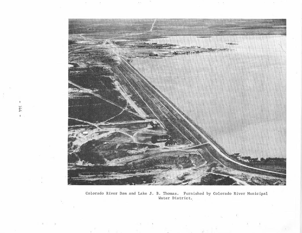
~..,.
.-.....'=~.~'·~~T~~ :-
Colorado River Dam and Lake J. B. Thomas. Furnished by Colorado River MunicipalWater Distric t.
'\
The lake has a capacity of 203,600 acre-feet and a surface area of 7,820acres at service spillway crest elevation of 2,258.0 feet above msl. The lakeis also used for recreational purposes. Other elevations and capacities are asfollows:
Feature
Top of damCrest of right emergency
spillwayCrest of left emergency
spillwayCrest of service spillwayInvert of service outletStreambed
Elevation(feet above msl)
2,280.0
2,267.0
2,264.02,258.02,200.02,175.0
Capacity(acre-feet)
430,600
283,600
255,000203,600
1,300o
Area(acres)
9,760
9,1007,820
210o
Reservoir capacities and surface areas based on surveys made in 1948 and1950.
The drainage area above the dam is 3,524 square miles, of which 2,590 isprobably noncontributing. The drainage area includes 426 square miles aboveBull Creek diversion dam, of which 32 square miles is probablY noncontributing.
The service spillway is a reinforced-concrete, drop inlet structurelocated in the lake about 2,500 feet from the left end of the dam. The inletis a rectangular opening 38 feet by 53 feet at the top decreasing to twoopenings, 14 feet by 14 feet, that feed the two 10- by 10-foot, horseshoeshaped, concrete conduits. These conduits are 467 feet long, and dischargethrough a pilot channel into the river about half a mile below the dam.
There are two emergency spillways. The north, or left, spillway islocated at the left abutment of the dam with a crest length of 500 feet atelevation 2,264.0 feet above msl. The south, or right, spillway is a cutchannel, 3,500 feet to the right end of the dam with crest length of 1,600 feetat elevation 2,267.0 feet above msl.
The service spillway is designed to discharge 10,000 cfs and the emergencyspillways 161,000 cfs at maximum design flood stage of 2,275.0 feet above msl.
The service outlet located near the center of the dam is a 30-inch,reinforced-concrete pipe controlled by a 24-inch valve \~th invert at elevation2,200.0 feet above msl. Water for the city of Snyder's pumping plant is released through this outlet and pumped through a 21-inch pipeline to the cityand the Sharon Ridge oil field. Water is diverted directly from the lake by apump station that supplies water through a 33-inch pipeline to Big Spring andthen to Odessa through a 27-inch pipeline.
- 145 -
79. Valley Acres Dam and Valley Acres Reservoir
Location
Valley Acres Dam, actually a dike, and Valley Acres Reservoir are in theNueces-Rio Grande Coastal Area in Hidalgo County, 7 miles north of Mercedes.The reservoir is an off-channel storage, diverting water from the North Floodway, which carries floodflows from the Rio Grande to Laguna Madre.
Ownership and History of Development
The project is owned and operated by the Valley Acres Water District.
The present water rights were obtained by Valley Acres, Inc. by PermitNo. 1560 (Application No. 1667) dated March 30, 1951 from the State Board ofWater Engineers. The Permit authorizes storage of 7,840 acre-feet of water ina reservoir already in use and annual diversion of 5,000 acre-feet for irrigation and municipal purposes.
Water is to be diverted from the North Floodway when excess water isavailable for storage. The land to be irrigated is part of a tract of theAmerican Rio Grande Land and Irrigation Company, which holds certain rightsunder Certified Filing No. 27.
In May 1951 the Texas 52nd Legislature created the Valley Acres WaterDistrict, which incorporated the 10,202 acres of land mentioned in PermitNo. 1560; this District now owns the water rights granted under that Permit.The reservoir was in operation in 1947, but additional work was completed July15, 1951 by the District after receipt of the Permit.
Physical Description
The levee is about 28,300 feet long with an average base width of 87 feetand top width of 12 feet. The average height is 15 feet above the naturalground with the top of the embankment at elevation 73.0 feet above msl.
The reservoir has a capacity of 7,840 acre-feet and a surface area of 906acres at elevation 62.0. Water is diverted by pumping from the North Floodwaychannel to this off-channel storage whenever available as there is no inflowcontributing to storage.
There is a 36-inch, low-flow outlet with a valve that is controlled from aconcrete gate house.
In times of low flow in the Rio Grande, water is diverted from thisstorage reservoir to the canals when needed.
- 146 -
80. Stamford Dam and Lake Stamford
Location
Stamford Dam and Lake Stamford are in the Brazos River Basin in HaskellCounty, 10 miles southeast of Haskell on Paint Creek, a tributary of Clear ForkBrazos River, which is a tributary of the Brazos River.
Ownership and History of Development
The project is owned and operated by the city of Stamford for its ownwater supply and for several other communities. The water rights were obtainedby Permit No. 1542 (Application No. 1650) dated July 10, 1950 from the StateBoard of Water Engineers to the city of Stamford. The Permit allows thestorage of 60,000 acre-feet and annual use of 10,000 acre-feet of water, ofwhich 2,519 acre-feet was from rights obtained under Permit No. 344 (Application No. 361) to the city of Stamford. The allocation permits water to besupplied to other towns and to be used for industrial purposes by the WestTexas Utility Company's electrical-generating plant.
Construction of the project started July 14, 1951, and was completed inMarch 1953. Deliberate impoundment began in June 1953, and delivery of waterto the filter plant began in September 1953.
Records of contents from July 1953 through September 30, 1957 are contained in Bulletin 5807-A of the State Board of Water Engineers and from July1953 in publications of the U. S. Geological Survey.
Physical Description
The dam is an earthfill structure about 6,600 feet long, including thespillway, and 78 feet high with the top of the dam at elevation 1,426.8 feetabove msl. The maximum bottom width is 600 feet and the top width is 24 feetwith a roadway over part of the embankment. The upstream face is protectedwith a 2-foot thickness of rock riprap on an 8-inch-thick gravel base.
Based on a 1966 sedimentation survey by the U. S. Soil Conservation Servicethe lake has a capacity of 53,070 acre-feet and a surface area of 4,690 acresat spillway crest elevation of 1,416.8 feet above msl. Below elevation 1,382.8feet above msl there is a dead storage capacity of 360 acre-feet.
The drainage area above the dam is 360 square miles.
A steam-electric generating plant owned by the West Texas Utility Companyis located on the lake, and uses the water for condenser-cooling and generalplant purposes. The water is returned from the condenser at a place to causecirculation in the lake) and the only consumptive use is forced evaporationcaused by heat added to the reservoir.
A service spillway is located 900 feet to the left of the dam. It is arectangular channel excavated in natural rock with a crest length of 169 feetwith elevation varying from 1,416.8 to 1,417.3 feet above msl. An emergency
- 147 -
spillway at the right end of the dam, over natural ground without a confinedchannel, has a crest elevation of about 1,425.8 feet above msl.
The low-water discharge is a 24-inch concrete pipe encased in concretewith invert at elevation 1,382.8 feet above msl. The valve control tower is a6-foot-diameter concrete shaft with the top at elevation 1,436.8 feet abovemsl. Two 20-inch valves with connection to the 24-inch pipe are in the controltower. The pipe is 442 feet long, extends through the embankment, and discharges to an outlet structure below the dam.
\,ater is pumped directly from the lake by the city of Stamford for municipal water supply.
81. Lake Creek Dam and Lake Creek Reservoir
Location
Lake Creek Dam and Lake Creek Reservoir are in the Brazos River Basin inMcLennan County, 4 miles southwest of Riesel on Manos Creek, a tributary of theBrazos River.
Ownership and History of Development
The project is owned and operated by the Texas Power & Light Company, andis used to provide condenser-cooling water for a steam-electric generatingstation.
Water rights to impound 8,000 acre-feet of water and annual use of 10,000acre-feet by pumping from the Brazos River were granted by Permit No. 1566(Application No. 1685) dated May 10, 1951 from the State Board of Water Engineers to the Texas Power & Light Company. This authorization was amended byPermit No. 1616 (Application No. 1748) dated April 25, 1952 to increase thestorage to 9,500 acre-feet, without any increase in diversion. However)latest reservoir area-capacity curves indicate 8,400 acre-feet is the presentcapacity at elevation 405.0 feet above msl authorized by Permit No. 1616.
Construction began September 8, 1951, and the dam was completed in May1952 except for the taintor gates. Impoundment of water began in June 1952 byinflow from runoff from local rains. All construction was completed ~ffiy 6,1953, and pumping from the river began in November 1952. The first generatingunit at this plant began commercial operation April 2, 1953.
Records of contents are maintained as unpublished data in the plant operating records.
Physical Description
The dam is a compacted earthfil1 structure 1,850 feet long and 50 feethigh with the top at elevation 410.0 feet above msl. It has a maximum basewidth of 300 feet and top width of 15 feet, and the upstream slope is protectedby 1 foot of rock riprap on a l-foot gravel base. The dam contains 241,000cu yd of earth.
- 148 -
The reservoir has a capacity of B,400 acre-feet] which is an increaseabove the amount granted by Permit No. 1566 when the reservoir level was raisedfrom elevation 402.0 to 405.0 feet above msl in accordance with Permit No. 1616.Likewise, the reservoir area was increased from 475 to 550 acres. The reservoir is maintained at operating level by pumping water from the Brazos River asauthorized by Permit No. 1566. Water is circulated from the reservoir to thecondenser and back to the reservoir; the consumptive use consists of a smallamount of water for plant services and of forced evaporation caused by heatadded to the reservoir.
The drainage area above the dam is 17 square miles; runoff is conserved tosupplement the amount pumped from the Brazos River.
The service spillway is a concrete section on the left end of the dam withtwo taintor gates, 32 feet 9 inches long by 20 feet high. The top of the gatesare at normal maximum conservation storage level at elevation 405.0 feet abovemsl. The discharge is through a paved chute to the channel below the dam.
There are no low-flow outlets. The low point of control is the crest ofthe service spillway at elevation 385.0 feet above msl.
An uncontrolled emergency spillway on the right end of the dam is 700 feetlong with crest at elevation 406.0 feet above msl.
82. Gladewater Dam and Lake Gladewater
Location
Gladewater Dam and Lake Gladewater are in the Sabine River Basin in UpshurCounty in northwest Gladewater on Glade Creek, a tributary of the Sabine River.
Ownership and History of Development
The project is owned and operated by the city of Gladewater for municipalwater supply and recreation. Permit No. 1587 (Application No. 1710) datedAugust 30, 1951, granted by the State Board of Water Engineers to the city ofGladewater, authorized the storage of 6,950 acre-feet of water and annual useof 1,679 acre-feet.
Construction was started October 15, 1951 by the city and completed August29, 1952. Deliberate impoundment of water began August 29, 1952, and t~e newfilter and treatment plant was in operation July 1953.
Physical Description
The dam is a rolled-earth structure 1,203 feet long and 48 feet high abovethe creekbed. The embankment has a maximum base width of 195 feet and topwidth of 16 feet with the top of the dam at elevation 312.0 feet above msl.The upstream face has rock riprap from elevation 290.0 to 308.0 feet above msl.There are two spillways near the right end of the dam .
• 149 -'
The lake has a capacity of 6,950 acre-feet and a surface area of 800 acresat the service spillway elevation of 300.0 feet above msl.
The drainage area above the dam is 35 square miles.
The uncontrolled service spillway is a concrete structure with a crestlength of 200 feet at elevation 300.0. The discharge is to the creek channelbelow the dam.
An uncontrolled emergency spillway is a concrete structure with a crestlength of 200 feet at elevation 304.0 feet above msl.
A vertical concrete outlet structure near the left end of the dam hasopenings at several elevations controlled by slide gates operated from the topof the tower. The discharge is to a 24-inch concrete pipe, 168 feet long,extending through the embankment, with invert at elevation 278.0 feet above msl.An outlet from this pipe connects to a raw-water pumping plant for transmissionto the city filter plant, and another outlet allows low-flow releases downstream if required. Access to the operating platform on top of the tower fromthe embankment is by a walkway that is constructed of timber supported on woodpiles.
83. San Jacinto Dam and Lake Houston
Location
San Jacinto Dam and Lake Houston are in the San Jacinto River Basin inHarris County, 4 miles north of Sheldon and 18 miles northeast of Houston onthe San Jacinto River.
Ownership and History of Development
The project is owned and operated by the city of Houston. The waterrights were obtained by Permit No. 1323 (Application No. 1394) dated November26, 1941 from the State Board of Water Engineers to the city of Houston. ThePermit authorizes impoundment of 152,000 acre-feet and the use of 112,000 acrefeet of water annually for municipal) industrial, recreation) mining, and irrigation purposes. Permit No. 1411 (Application No. 1510) dated July 19, 1947authorizes an increase in the capacity of the lake to 160,000 acre-feet andappropriation by 56,000 acre-feet to 168,000 acre-feet, and also allows irrigation of 1,500 acres of land out of a 6,000-acre tract.
Construction began in November 1951. The dam was completed in December1953, except for minor details, and deliberate impoundment of water began April9, 1954. The filter plant and other items were not completed until much later.
Records of contents from April 1954 through September 30, 1957 are contained in Bulletin 5807-A of the State Board of Water Engineers and from April1954 in publications of the U. S. Geological Survey.
- 150 -
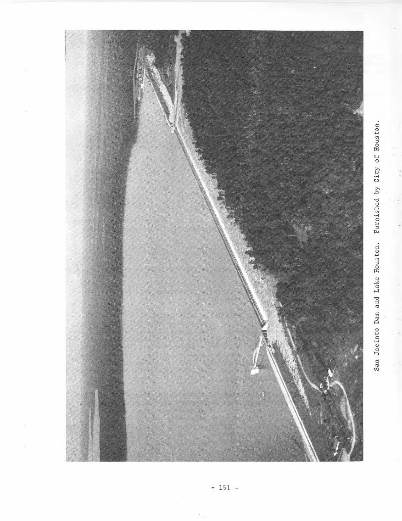
r,
- 151 -
"o..,'":Jo0::
Physical Description
The dam is a slab and buttress, Ambursen-type spillway structure 3,160feet long between two compacted earthfill embankments; the left section is4,000 feet long and the right section is 4,600 feet long with a maximum heightof 48 feet.
The lake has a capacity of 146,700 acre-feet and a surface area of 12,240acres at the spillway crest elevation of 43.8 feet above msl.
Other capacities are shown as follows:
Feature
Top of damMaximum design flood stageSpillway crestSill of flashboard gatesSill of taintor gatesInvert of 72-inch conduitsInvert of 36-inch sluice gate
Elevation(feet above msl)
62.356.343.838.827.323.321.3
Capacity(acre-feet)
146,70093,70022,800
9,8306,180
Area(acres)
12,2409,0204,1802,2401,450
Reservoir capacities and surface areas based on sedimentation survey madein 1965. Published records of capacities are based on this survey beginningOctober 1, 1965,
The drainage area above the dam is 2,828 square miles.
The city of Houston supplies raw water to various industries from thecanal that delivers water to the filtration plant for municipal use. The SanJacinto River Authority has rights to the low flow of the river. Through anagreement with the city, however, this amount is diverted directly from thelake and delivered to users in the Baytown area.
The uncontrolled concrete spillway has a crest length of 3,160 feet atelevation 43.8 feet above msl. It is an overflow diffusion grill discharginginto a stilling pool. The maximum design flood stage is at elevation 56.3 feetabove msl with a discharge of 525,000 cfs. There are two taintor gates and twoflashboard-type gates at the left end of the spillway section for release ofwater when the lake level is below spillway-crest elevation. The two taintorgates are 18 feet wide by 20.5 feet high with the sill at elevation 27.3 feetabove msl. The two flashboard-type gates are each 18 feet wide by 6 feet highwith sill at elevation 38.8 feet above msl.
T~1e lowest outlet is a 36-inch, hand-operated sluice gate built into thespillway structure at the right abutment with invert at 21.3 feet above msl.Hater for the city of Houston is diverted by means of an intake structure wheretwo 72-inch conduits connect to the pumping plant with inverts at 23.3 feetabove msl. This plant is located at the extreme right end of the dam and discharges to a canal, which transmits the water to the city's filtration plantand to other users. The San Jacinto River Authority diverts water from thelake with pumps located on the left side of the lake.
- 152 -
84. Alcoa Dam and Alcoa Lake
Location
Alcoa Dam and Alcoa Lake are in the Brazos River Basin in Milam County,7 miles southwest of Rockdale on Sandy Creek, a tributary to Yegua Creek, whichis tributary to the Brazos River.
Ownership and History of Development
The project is owned and operated by the Aluminum Company of America forindustrial and recreational purposes. Water rights were obtained by Permit No.1608 (Application No. 1733) dated February 13, 1952 from the State Board ofWater Engineers to Sandow Water Company, which was later transferred to theAluminum Company of America. The Permit allows storage of 12,000 acre-feet andannual use of 18,000 acre-feet of water by pumping from Little River. Pumpingis limited to the period of September 15 to May 15, which is the off-season forother requirements.
Construction was started February 17, 1952, and the dam and spillway werecompleted in October 1952; the gates were not installed until January 31, 1953.Impoundment of water began with inflow from runoff in early 1952. The 12.5mile pipeline from the Little River pumping plant to the lake was placed inoperation January 13, 1953.
Physical Description
The dam is an earthfill structure 5,430 feet long and 50 feet high with amaximum bottom width of 265 feet and crest width of 15 feet with the top of thedam at elevation 470.0 feet above msl. The upstream surface is protected with1 foot of rock riprap laid on an 8-inch thickness of gravel base between elevations 450.0 and 470.0 feet above msl. A concrete spillway section is part ofthe total length.
The lake has a capacity of 10,500 acre-feet and a surface area of 703acres at the top of the spillway gates, elevation 464.0 feet above msl. Thelake is maintained at near spillway level by pumping from Little River whennecessary, and the water is used for condenser-cooling purposes for a steamelectric generating station. Water is pumped directly from Alcoa Lake throughthe turbine condenser, and discharges into a pond divided by dikes to providecirculation and cooling. The only consumptive use is from forced evaporationcaused by heat added to the lake and a small amount for plant use. The lakehas become a favorite fishing place for many people.
The drainage area is only 6 square miles, but this is an off-channelstorage. Most of the water is pumped from Little River.
A gate-controlled spillway, the only outlet from the lake, is a concretestructure with crest at elevation 444.0 feet above msl. The discharge is controlled by two taintor gates, 20 feet long and 20 feet high, with the top ofthe gates at elevation 464.0 feet above msl.
- 153 -
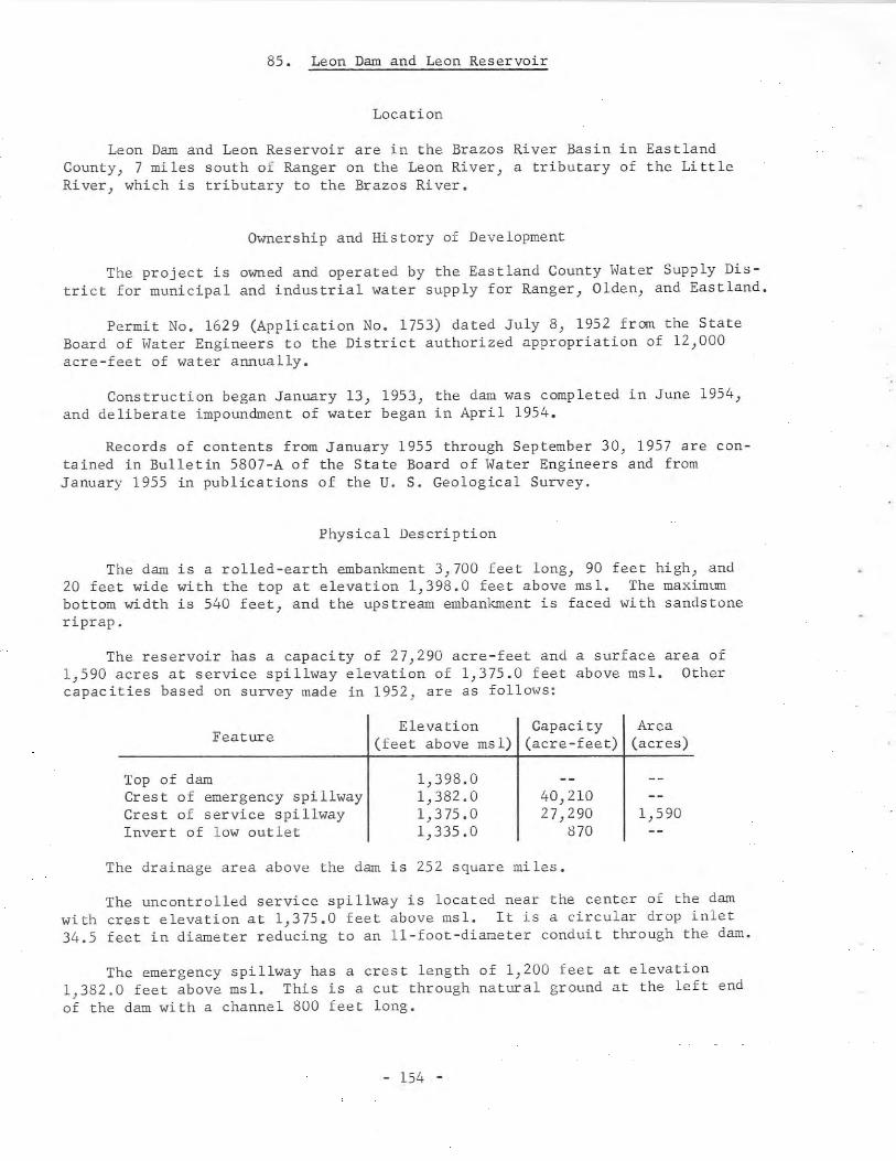
85. Leon Dam and Leon Reservoir
Location
Leon Dam and Leon Reservoir are in the Brazos River Basin in EastlandCounty, 7 miles south of Ranger on the Leon River, a tributary of the LittleRiver, which is tributary to the Brazos River.
Ownership and History of Development
The project is owned and operated by the Eastland County Water Supply District for municipal and industrial water supply for Ranger, Olden, and Eastland.
Permit No. 1629 (Application No. 1753) dated July 8, 1952 from the StateBoard of Water Engineers to the District authorized appropriation of 12,000acre-feet of water annually.
Construction began January 13, 1953, the dam was completed in June 1954,and deliberate impoundment of water began in April 1954.
Records of contents from January 1955 through September 30, 1957 are contained in Bulletin 5807-A of the State Board of Water Engineers and fromJanuary 1955 in publications of the U. S. Geological Survey.
Physical Description
The dam is a rolled-earth embankment 3,700 feet long, 90 feet high, and20 feet wide with the top at elevation 1,398.0 feet above msl. The maximumbottom width is 540 feet, and the upstream embankment is faced with sandstoneriprap.
The reservoir has a capacity of 27,290 acre-feet and a surface area of1,590 acres at service spillway elevation of 1,375.0 feet above msl. Othercapacities based on survey made in 1952, are as follows:
FeatureElevation Capacity Area
(feet above msl) (acre-feet) (acres)
Top of damCrest of emergency spillwayCrest of service spillwayInvert of low outlet
1,398.01,382.01,375.01,335.0
40,21027,290
8701,590
The drainage area above the dam is 252 square miles.
The uncontrolled service spillway is located near the center of the darnwith crest elevation at 1,375.0 feet above msl. It is a circular drop inlet34.5 feet in diameter reducing to an ll-foot-diameter conduit through the dam.
The emergency spillway has a crest length of 1,200 feet at elevation1,382.0 feet above msl. This is a cut through natural ground at the left endof the dam with a channel 800 feet long.
- 154 -
A concrete control tower near the center of the dam permits release ofwater through a 24-inch concrete pipe to a pump station below the dam whereit is pumped to the filter plant, 4 miles north of the dam. Filtered wateris then delivered to Ranger through a 12-inch pipeline, and to Eastland andOlden through a 14-inch pipeline. Water can be released from the reservoirdown to elevation 1,335.0 feet above msl.
86. Anahuac Dam and Anahuac Lake
Location
Anahuac Dam, actually a levee, and Anahuac Lake are in the Trinity RiverBasin in Chambers County near Anahuac on Turtle Bay, a tributary to the TrinityRiver near its mouth.
Ownership and History of Development
The project is owned and operated by the Chambers-Liberty Counties Navigation District, as a result of many transfers of land and water rights. Thelatest, Permit No. 1647 (Application No. 1780) dated December 4, 1952 from theState Board of Water Engineers to the District, authorizes an increase in lakestorage from 17,000 to 35,300 acre-feet without changing water rights for annual use of 35,300 acre-feet, which was obtained as follows:
Certified Filing No. 246 filed June 26, 1914 with the StateBoard of Water Engineers by Trinity River IrrigationCompany for irrigating 30,000 acres of land was transferredto the District in 1950; Certified Filing 254 filed by LoneStar Canal Corporation February 12, 1914 for a water rightto irrigate 20,000 acres of land that have been irrigatedsince 1904 was sold at a trustee sale in 1931 to W. C.Tyrrel Trust, then transferred to several individuals in1933 who organized the Lone Star Canal Corporation, thentransferred on August 15, 1947 to the District; CertifiedFiling No. 531 filed June 30, 1914 with the State Board ofWater Engineers by Stowell Canal Company for irrigation of10,000 acres of land was transferred to the District onSeptember 13, 1947; Permit No. 1244 (Application No. 1328)dated February 28, 1938, owned by Lone Star Canal Corporation and transferred to Chambers-Liberty Counties NavigationDistrict September 13, 1947, granted the right to appropriate 800 acre-feet of water annually for mining andindustrial use.
Construction of the dam, levee, and spillway for the enlarged projectbegan March 17, 1953, and was completed in July 1954. Impoundment of waterhad already started, and the water was in use from the smaller lake.
Physical Description
The dam or embankment is a hydraulic fill 59,000 feet long including aconcrete spillway and emergency spillway. The height is 10 feet with variable
- 155 -
base width up to 200 feet and a top width of 8 feet at elevation 9.0 feet abovemsl. The old structure was enlarged by additional sections of embankment,levee, and new spillway.
The enlarged lake has a capacity of 35,300 acre-feet and a surface area of5,300 acres at elevation 5.0 feet above msl. Water is pumped from the TrinityRiver into the lake at a point near its upper end. In addition, a contract wasmade for purchase of 50,000 acre-feet of water annually or when needed fromLavon Reservoir, and permission was obtained for the use of the Trinity Riverchannel for transportation to the point of diversion.
The drainage area is 199 square miles, but the main source of water ispumpage from the Trinity River.
A concrete slab-type uncontrolled spillway has a crest length of 700 feetat elevation 5.0 feet above msl. An emergency spillway is part of the embankment with a crest length of 1,200 feet at elevation 8.0 feet above msl.
The service outlet consists of four, 6- by 6-foot, gated sluiceways.Water is discharged to a forebay and pumping plant intake structure where itis pumped to the canal system. Water can also enter the forebay fram the backwater of the Trinity River through a gate-controlled structure; however, attimes of prolonged high tide the water at this point is brackish, and the gatesare closed to prevent the fresh water from the storage lake being contaminated.Excess water, before the lake reaches spillway level, can be discharged throughthese gates to the river channel if necessary.
87. Brazoria Dam and Brazoria Reservoir
Location
Brazoria Dam, actually a levee, and Brazoria Reservoir, an off-channelreservoir, are in the Brazos River Basin in Brazoria County, 1 mile northeastof Brazoria.
Ownership and History of Development
The project is owned and operated by Dow Chemical Company for industrialwater supply.
This project was built under Permit No. 1631 (Application No. 1756) datedJuly 8, 1952 from the State Board of Water Engineers to Dow Chemical Company.The purpose is to provide 21,970 acre-feet of reservoir storage without anyfurther appropriation of water to be pumped from the Brazos River. This reservoir allows water to be stored when available from the river for use in time ofdeficient riverflow. Right to appropriate 150,000 acre-feet of water annuallywas authorized by Permit No. 1345 (Application No. 1431) dated February 19,1943 from the State Board of Water Engineers to Dow Chemical Company. Part ofthis appropriation will be used at this diversion point. Permit No. 1631further allows the use of the channel of Buffalo Camp Bayou to convey waterfrom this reservoir to a pumping plant downstream. This pumping plant and
- 156 -
canal for delivering water to the various Dow Chemical Company plants was constructed under Permit No. 1630 (Application No. 1755) dated July 8, 1952 fromthe State Board of Water Engineers to the Company.
Construction of the reservoir storage project began March 1, 1953, and wascompleted May 1, 1954. Diversion by pumping from the river began in April 1954.This reservoir is part of a large system of reservoirs and canals to insureindustrial water to the ownerls various manufacturing plants in the area.
Physical Description
The dam or levee is of varied height and cross-sectional area, and isabout 40,000 feet long with the top at elevation 37.3 to 39.2 feet above msl.The base width varies, but maximum width is about 140 feet. The crown widthis 16 feet. The top of the dike is used for a private road around the reservoir. The average height of the levee is about 16 feet.
The reservoir has a capacity of 21,970 acre-feet and a surface area of1,865 acres at elevation 32.5 feet above msl.
This is an off-channel pumped storage without drainage area, and has nolow-flow release conduit or spillway. However, water can be released by gatedsiphon conduits to Buffalo Camp Bayou for either consumptive use or waste ifneed occurs. A channel was constructed that allows flow from Buffalo CampBayou to bypass the reservoir, so there is no diversion from the Bayou at thispoint.
The water is pumped from the Brazos River by motor-driven pumps throughtwo 66-inch concrete pipes, 3,000 feet long, to a stilling basin. From thispoint the water flows by gravity to the reservoir for storage. Water and sediment from the settling basin can be discharged as waste back to the river belowthe pumping plant.
88. River Crest Dam and River Crest Reservoir
Location
River Crest Dam and River Crest Reservoir} an off-channel reservoir} arein the Sulphur River Basin in Red River County, 7 miles southeast of Bogata.
Ownership and History of Development
The project is owned and operated by the Texas Power & Light Company forsteam turbine, condenser-cooling purposes. Rights for the storage of 7,100acre-feet and annual use of 10,000 acre-feet of water were obtained by PermitNo. 1617 (Application No. 1747) dated April 22, 1952 from the State Board ofWater Engineers to the Texas Power & Light Company. The Permit allows thewater to be diverted from the Sulphur River to this off-channel reservoir bymotor-driven pumps.
- 157 -
Construction began April 22, 1953, and the project was completed in
November 1953. Impoundment by pumping began in November 1953, and the reser
voir level reached normal operating elevation May 31, 1954. The electrical
generating plant was in operation June 1, 1954. The present plant has one
generating unit of 110,000 kw capacity with additional units proposed.
Physical Description
The dam, or dike, is an earth embankment of circular shape 14,770 feet
long with a maximum height of 23 feet. The dike has a maximum bottom width
of 136 feet and top width of 10 feet at elevation 335.0 feet above msl.
The reservoir has a capacity of 7,200 acre-feet and a surface area o{ 560
acres at elevation 328.0 feet above msl. Water is plmped from the Sulphur
River to maintain the elevation at this operating level. Water is circulated
by pumps from the reservoir through the condensers, thence to a diked channel
that takes the water about a third of the distance around the rim of the reser
voir before returning it to storage. This travel time provides cooling and
allows the coldest water to be pumped to the condensers. Forced evaporation
caused by heat added to the reservoir and a small amount of water for plant
services are the only consumptive uses of water.
A small spillway with gate control returns any surplus water to the
Sulphur River downstream from the pumping plant intake. This is a pumped
storage so a low-flow outlet is not necessary.
89. Ferrells Bridge Dam and Lake 0' the Pines
Location
Ferrells Bridge Dam and Lake 0' the Pines are in the Cypress Creek Basin
in Marion and Harrison Counties, 9 miles west of Jefferson on Cypress Creek.
The lake extends into Morris, Camp, and Upshur Counties.
Ownership and History of Development
The project is owned by the U. S. Government, and was built and is oper
ated by the U. S. Army Corps of Engineers, New Orleans District. The lake is
used for flood control) water conservation} Wildlife} and recreation purposes.
Federal authorization for the project was the Flood Control Act approved
July 24, 1946, Public Law No. 526, 79th Congress, second session. Authoriza
tion for storage and diversion of water by the Northeast Texas Municipal Water
District was obtained by Permit No. 1897 (Application No. 2065) dated November
22, 1957 from the State Board of Water Engineers. The Permit authorizes
250,000 acre-feet of conservation storage and annual use of 42,000 acre-feet
of water for municipal purposes and 161,800 acre-feet for industrial use.
Construction was started in January 1955 and completed December II, 1959.
The cofferdam closure was made August 21, 1957, and water flowed through the
conduits September 25, 1957. Deliberate impoundment began in August 1958, and
the lake was in full use by December 1959.
- 158 -
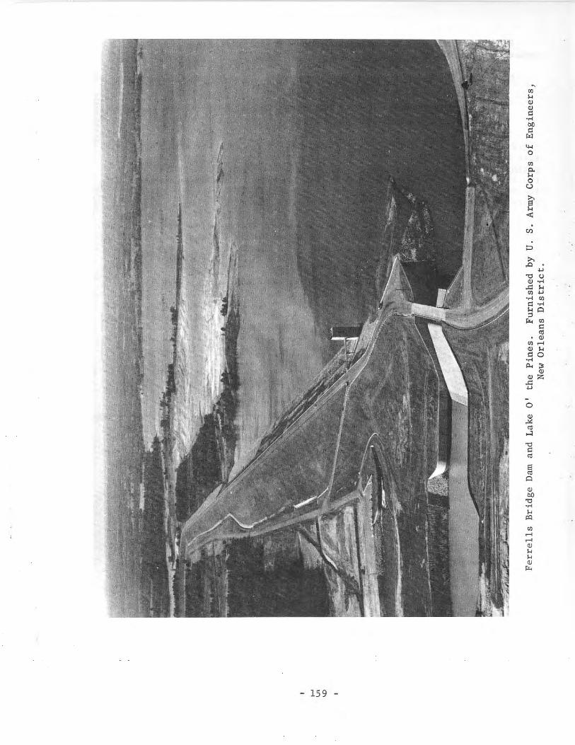
Ul
"'"OJUl .....OJ ...."0.c<
~ ~OJ:>:;
.c::...o
~
'"....,."
"'"S'"AOJon.".c<....
'"'
- 159 -

Records of contents from August 1957 are in publications of the U. S. Geological Survey.
More than 4,090,000 visitors were reported at Lake 0' the Pines during 1966.
Physical Description
The dam consists of a rolled-earth structure 10,600 feet long with an uncontrolled concrete spillway at the left end of the dam. The embankment is 97feet high above streambed, and contains about 4 million cu yd of compactedearth. The maximum base width is 590 feet, and the top width is 30 feet withthe top of the dam at elevation 277.0 feet above msl. A roadway is built ontop of the dam. The upstream surface is paved with rock riprap laid on agravel base.
The lake has a capacity of 254,900 acre-feet and a surface area of 18,680acres at elevation 228.5 feet above msl, top of winter (October to April) conservation storage space. Other capacities are listed at the close of thissection.
The drainage area above the dam is 850 square miles.
The uncontrolled, concrete, spillway structure is located on the left endof the dam with a crest length of 200 feet at elevation 249.5 feet above msl.Flow over the spillway discharges into a channel and then to Cypress Creek.A concrete bridge 24 feet wide spans the structure to facilitate the operation,and is part of Farm-to-Market Road No. 726 across the top of the dam.
The Northeast Texas Municipal Water District's diversion is from twointake structures in the lake about 1.5 and 11.0 miles from the dam, respectively.
A reinforced-concrete intake structure located on the upstream side of thedam houses the flood-control outlet gates and operating machinery. The outletconsists of twin 10-foot-diameter conduits controlled by two electricallyoperated 8- by 12.5-foot broome-type gates. A low-flow outlet consists of one14-inch-diameter pipe with control valve discharging into the flood-controlconduits.
Listed below is pertinent information on Ferrells Bridge Dam and Lake 0'the Pines.
FeatureElevation Storage capacity Area
(feet above msl) (acre-feet) (acres)
Top of dam 277.0 2,341,900Maximum design flood
stage 269.9 1,856,000 63,400Spillway crest 249.5 842,100 38,200Top of conservation 230.0(summer) 283,700
storage space 228.5 (winter) 254,900 18,680Dead storage space 200.0 2,860 826
- 160 -
Reservoir capacities and surface areas based on survey made in 1950 byU. S. Army Corps of Engineers.
Elevations of the Flood Control Works:
Top of structure ......................... 313.0 feet above mslMain operating deck ...................... 277 .0 feet above mslService deck ............................. 258.5 feet above mslLow-flow outlet invert ................... 202.5 feet above mslFlood-control outlet works
(inverts at intakes) ................... 200.0 feet above msl
An increase in the conservation storage level to 230.0 feet above msl(capacity 283,700 acre-feet) is allowed by the Corps of Engineers during summermonths (May to September) for recreational purposes.
90. Terrell Dam and Terrell Reservoir
Location
Terrell Dam and Terrell Reservoir are in the Trinity River Basin inKaufman County, 6 miles east of Terrell on Muddy Cedar Creek, a tributary ofCedar Creek, which is tributary to the Trinity River.
Ownership and History of Development
The project is owned and operated by the city of Terrell for municipalwater supply and for recreation. Permit No. 1700 (Application No. 1831) datedApril 20, 1954 from the State Board of Water Engineers to the city of Terrellauthorizes storage of 8,300 acre-feet and annual diversion of 6,000 acre-feetof water. The new supply was needed because the small reservoir east of townwas not adequate for required supply during dry periods. The old reservoirsupply is still used when water is available. Permit No. 1700 was amendedNovember 15, 1962 to allow sale of 40 acre-feet of raw water annually to thetown of Elmo for municipal use.
Construction of the project began in February 1955, and was completed inNovember 1955 with deliberate impoundment of water beginning at that time.Little runoff occurred in 1956, and water was obtained from wells and fromthe North Texas Municipal Water District. It was not until May 1957 that thereservoir was full. Diversion of water began in 1960 according to the annualwater service reports filed with the Texas Water Commission.
Physical Description
The dam is an earthfill structure with a concrete service spillway andearth-trench emergency spillway. The structure is 4,700 feet long and 45 feethigh with maximum bottom width of 282 feet and crown width of 20 feet with thetop of the dam at elevation 512.0 feet above msl. The upstream slope is pavedwith 12 inches of rock riprap on a 6-inch gravel base from elevation 493.0 to507.0 feet above msl. The dam has a clay core along the center line extendingat least 3 feet into impervious subsoil.
- 161 -
The uncontrolled emergencyelevation 507.0 feet above msl.ground near the right end of thelayers to protect the surface.
The reservoir has a capacity of 8,300 acre-feet and a surface area of 885acres at service spillway crest elevation of 503.0 feet above msl. At theemergency spillway crest elevation of 507.0 feet above msl, the capacity is12,400 acre-feet with a surface area of 1,150 acres.
The drainage area above the dam is 14 square miles.
spillway has a crest length of 500 feet atIt is an earth trench cut through naturaldam. The downstream face is sodded in various
The service spillway is a concrete weir section, 40 feet long at crestelevation 503.0 feet above msl. The discharge is through a chute to a stillingbasin to the channel below the dam.
The service outlet consists of a 4-foot-square intake shaft with topelevation at 509.0 feet above msl, having an approach walkway from the embankment. There are three 30-inch-square inlet gates at elevation 481.0, 488.0and 495.0 feet above msl to admit water to this vertical shaft and then to a30-inch, concrete-encased steel pipe through the embankment. The discharge iscontrolled on the downstream end with a 30-inch valve for wasting water and a20-inch reducing tee and valve for diverting water to the pumping plant. Thisplant is located immediately east from the outlet valve. The raw water ispumped through a 21,OOO-foot-long, 21-inch-diameter, concrete-encased steelpipeline to the present reservoir and filter plant in Terrell.
91. Amon G. Carter Dam and Lake Amon G. Carter
Location
Amon G. Carter Dam and Lake Amon G. Carter are in the Trinity River Basinin Montague County, 6 miles south of Bowie on Big Sandy Creek, a tributary ofWest Fork Trinity River, which is tributary to the Trinity River.
Ownership and History of Development
The project is owned and operated by the city of Bowie. Water rights wereobtained by Permit No. 1719 (Application No. 1853) dated August 19, 1954 fromthe State Board of Water Engineers to the city of Bowie. This Permit allowsstorage of 20,050 acre-feet of water and annual use of 3,500 acre-feet formunicipal and 1,500 acre-feet for industrial purposes.
Construction bids were received July 11, 1955, and worl, began soon thereafter. The work was completed in August 1956 with deliberate impoundment ofwater starting in May 1956. Diversion and use of water began in June 1956, andthe lake was full with water flowing over the service spillway in ~~y and June1957.
- 162 -
Physical Description
The dam is a rolled-earth structure 2,540 feet long and 71 feet high abovethe streambed with the top of the embankment at elevation 938.0 feet above msl.The maximum width of the base is 400 feet, the top width is 20 feet, and theupstream face is protected with 2 feet of rock riprap on an 8-inch gravelblanket.
The lake has a capacity of 20,050 acre-feet and a surface area of 1,540acres at service spillway crest elevation of 920.0 feet above msl. There is10,000 acre-feet of surcharge storage between the service and emergency spillway for temporary floodflow retention.
The drainage area above the dam is 100 square miles.
The emergency spillway is a cut through a natural saddle, about 800 feetfrom the left abutment of the dam, with a crest length of 700 feet at elevation927.0 feet above msl.
The service spillway is a box-type drop inlet with crest elevation of920.0 feet above msl. This drops vertically to a horizontal, 96-inch, concretepipe, outlet conduit extending through the embankment, with invert at 908.0feet above msl, which discharges into a graded channel to the streambed.
The low-flow outlet consists of an l8-inch, concrete-lined steel pipe encased in concrete extending through the embankment. The discharge is controlledby a plug valve with operating rod extending up the embankment to above normalwater level. The pipe is reduced at the discharge end where a l2-inch gatevalve is installed for further regulating the flow. Invert of the pipe is atelevation 885.3, and invert of the plug valve is at elevation 888.3 feet abovemsl.
The pumping plant for diverting water from the lake is a concrete structure located on the north side of the lake with the motors mounted on a platform for driving the vertical pumps. A.house is erected over the platform forprotecting the motors and electrical equipment.
92. Wesley E. Seale Dam and Lake Corpus Christi
Location
Wesley E. Seale Dam and Lake Corpus Christi are in the Nueces River Basinon the Nueces River, 4 miles southwest of Mathis. The dam is in San Patricioand Jim Wells Counties. The lake borders these two counties, and extends intoLive Oak County.
For information on Mathis Dam and old Lake Corpus Christi, see descriptionof that dam and lake earlier in this report.
Ownership and History of Development
The Wesley E. Seale Dam and Lake Corpus Christi are owned by the LowerNueces River Water Supply District who constructed the dam under the water right
- 163 -
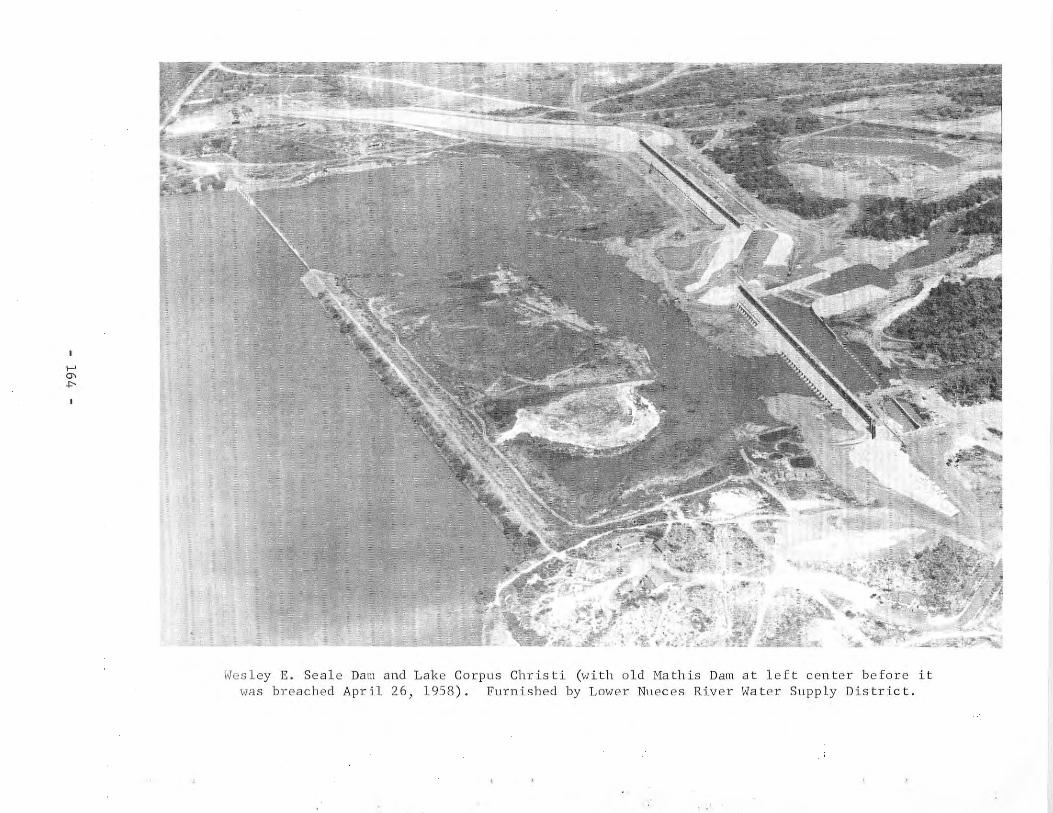
>-'0'..,.
,'T"" t.
0·' !
) 'i:.j}~.~IJ~
-"'~~,, .."'t';
, '"...
-~
Wesley E. Seale Dam and Lake Corpus Christi (with old Mathis Dam at left center before itwas breached April 26, 1958). Furnished by Lower Nueces River Water Supply District.

granted by Permit No. 1656 (Application No. 1776) issued to the District bythe State Board of Water Engineers on January 20, 1953. Permit No. 1656 andextension of tUne amendments (Permit Nos. l656A, B, and C) authorized theconstruction of a dam on the Nueces River that would create a lake of 300,000acre-feet capacity for the city of Corpus Christi. The lake would supply waterto the city for uses authorized under existing water rights held by the city.Permit No. 1656 allows use of the bed and banks of the Nueces River for conveying water released from the lake to the city pumping plant at Calallen.
The pertinent existing water rights held by the city of Corpus Christi,for which Lake Corpus Christi will be the source of water, are: Permit No. 933(Application No. 995) issued to the city of Corpus Christi on October 31, 1927;Permit No. 1463 (Application No. 1571) issued to the city of Corpus Christi onAugust 19, 1948; Permit No. 1604 (Application No. 1726) issued to the city ofCorpus Christi on December 3, 1951. A later water right granted by Permit No.2026 (Application No. 2219) was issued to the city of Corpus Christi on October3, 1962. It amends the place of use and other conditions not affecting thetotal appropriation, type, or use authorized by Permit No. 933 and 1463. SeeMathis Dam and Lake Corpus Christi for a description of the provisions of Permit Nos. 933, 1463, and 1604.
The city of Alice diverts water from Lake Corpus Christi for municipaluse under a purchase contract with Corpus Christi.
Several plans were considered for the Wesley E. Seale Dam. The planselected was for a single large reservoir at a new site near Mathis, which wouldsubmerge Mathis Dam and cover old Lake Corpus Christi. Construction beganNovember 19, 1955, and was completed and impoundment of water began on April26, 1958 submerging the old Mathis Dam.
The U. S. Geological Survey began publishing record of contents of oldLake Corpus Christi in September 1948 and continued publication of record ofcontents of new lake when old lake was submerged. All records published underthe name Lake Corpus Christi.
Physical Description
The Wesley E. Seale Dam is an earthfill and concrete structure making upa composite length of 5,980 feet with a height of 75 feet. This length includesa 1,080-foot long south spillway and a 1,320-foot long north spillway. Theearthfill sections are trapezoidal of varying base widths, some as great as 280feet. Top widths vary from 15 to 51 feet.
The drainage area of the Nueces River watershed at Wesley E. Seale Dam is16,656 square miles.
- 165 -
Capacities and surface areas of the lake at indicated elevations are asfall 0\'3:
Feature
Top of damTop of north spillway gatesTop of south spillway gatesSpillway crestInvert of low-flow outlet
Elevation(feet above msl)
106.094.394.088.055.5
Capac ity(acre-feet)
302,100185,900
140
Area(ac res)
22,05015,500
Reservoir capacities and surface areas are based on survey made in 1957.
The north spillway is equipped with 33 gates, and the south spillway has27 gates. These gates are 37.5 feet long and were floating-crest-type gatesthat would open when the water in the lake reached elevation 94.0 feet abovemsl. Some of these gates were damaged on February 24, 1965 by wave actioncaused by a high northwest wind.
The gates were re-built using a different design for operation. The 33gates (north spillway) are set with top at elevation 94.3 feet above msl andare manually operated but modified so that a portable gasoline engine powerwinch can be used. Each of the 27 gates (south spillway) is set with top atelevation 94.0 feet above msl and is equipped with an electric motor unit forboth manual and automatic control. An engine driven generator is installedfor emergency uses in case of electrical power failure. The work rebuildingthe gates began December 1, 1965 and the gates were raised September 4, 1966to restore the operating level to elevation 94.0 feet above msl.
The outlet works, which provide the means for releasing water for use,consist of one 4-foot-diameter cylinder valve and three rectangular openings,2.5 feet by 4 feet, with invert elevations at 55.5 feet above msl. The waterflows in the Nueces River channel to the city's water treatment plant atCalallen.
93. South Prong Dam and Lake Waxahachie
Location
South Prong Dam and Lake Waxahachie are in the Trinity River Basin inEllis County, 4 miles southeast of Waxah~chie on South Prong Waxahachie Creek,a tributary of Chambers Creek, which is a tributary to Richland Creek, whichin turn is tributary to the Trinity River.
Ownership and History oi DQvelopment
The project is owned and operated by Ellis County Water Improvement District No. I for a water supply to the city at Waxahachie. Water rights wereobtained by Permit No. 1742 (Application No. 1874) dated ~1arch 14, 1955 fromthe State Board of Water Engineers to the District. This Permit authorizesstorage of 13,500 acre-feet of water and annual uSe of 2,810 acre-feet formunicipal purposes and 760 acre-feet for industrial use.
- 166 -
The contract was let and construction began April 18, 1956, and the damwas completed and deliberate impoundment of water began in November 1956. Thelake was full, and water spilled in May 1957. Diversion began for municipaluse in August 1957.
Physical Description
The dam is an earthfill structure 4,100 feet long, including the spillway,with a maximum height of 66 feet with the top of the dam at elevation 541.5feet above msl. The embankment has a maximum bottom width of 400 feet and topwidth of 18 feet, and the upstream surface is protected by 5 feet of rock riprap laid on a 12-inch gravel and sand base. A roadway is built on a berm ofthe downstream embankment. A bridge spans the spillway.
The lake has a capacity of 13,500 acre-feet and a surfaceacres at the spillway crest elevation of 531.5 feet above msl.1,500 acre-feet of the dead storage.
The drainage area above the dam is 30 square miles.
area of 645This includes
The spillway located at the left abutment is cut through rock with a crestlength of 300 feet at elevation 531.5 feet above msl.
The service outlet facilities consist of a vertical concrete intake structure with two 3- by 3-foot, gated inlets at two intake elevations. The invertof the low intake is at elevation 501.5 feet above msl. A 24-inch, valvecontrolled pipe connects the bottom of this intake structure to a pump intakewell in the raw-water pump station below the dam. From here the water is pumpedto the city's filtration and treatment plant. This pipe can also act as lowflow release for downstream requirements.
94. Weatherford Dam and Weatherford Lake
Location
Weatherford Dam and Weatherford Lake are in the Trinity River Basin inParker County, 7 miles east of Weatherford on Clear Fork Trinity River, whichis tributary to the Trinity River.
Ownership and History of Development
The project is owned and operated by the city of Weatherford for municipaland industrial water supply. Water rights were obtained by Permit No. 1771(Application No. 1880) dated July 21, 1955 from the State Board o£ Water Engineers to the city of Weatherford. The Permit allows storage of 19,470 acrefeet of water and annual diversion of 4,500 acre-feet for municipal and 1,500acre-feet for industrial purposes.
Construction of the project began in June 1956, and was completed March15, 1957. Deliberate impoundment of water began in March, and the lake wasfilled in April and early May 1957. Diversion from the lake for municipalsupply began in July 1957.
- 167 -
Physical Description
The dam is a rolled-earth structure 4,055 feet long with 75 feet maximumheight with the top of the dam at elevation 914.0 feet above msl. The embankment has a maximum base width of 415 feet and crown width of 20 feet. A claycore of variable depth extends under the center of the fill. The upstream faceis protected with 24 inches of rock riprap laid on an 8-inch sand base.
Theacres atdiverted
lake has a capacity of 19,600 acre-feet and a surfacethe spillway crest elevation of 896.0 feet above msl.from the lake by a pumping plant and pipeline.
area of 1,280Water is
The drainage area above the dam is 109 square miles.
The uncontrolled emergency spillway is located on the right end of the damand is a two-level spillover a natural-earth section. A 500-foot crest lengthis at elevation 903.0 and another 500-foot crest length section is at elevation906.0 feet above msl.
The service spillway consists of a semicircular, uncontrolled} concreteweir with crest length of 162 feet at elevation 896.0 feet above msl. The discharge is to a 9- by 9-foot, reinforced concrete conduit 425 feet long extending through the dam with invert of discharge end at elevation 840.0 feet abovemsl.
The low-flow outlet is an 18-inch, valve-controlled, steel-lined concretepipe 352 feet long extending through the embankment with invert at elevation857.0 feet above msl. However, the valve controlling the flow is at elevation860.4 feet above msl. The operating rod is supported on piers on the embankment at a point above normal maximum water level.
95. Striker Creek Dam and Striker Creek Reservoir
Location
Striker Creek Dam and Striker Creek Reservoir are in the Neches RiverBasin in Rusk County, 18 miles southwest of Henderson on Striker Creek, a tributary to the Angelina River, which is tributary to the Neches River. Thereservoir extends into Rusk and Cherokee Counties.
Ownership and History of Development
The project is owned and operated by the Angelina and Nacogdoches Counties\Vater Control and Improvement District No.1. \Vater rights were obtained byPermit No. 1808 (Application No. 1946) dated January 25, 1956 from the StateBoard of Water Engineers to the District. The Permit allows annual diversionof 5,600 acre-feet of water for municipal and 15,000 acre-feet for industrialpurposes from an authorized storage of 26,500 acre-feet. Permit No. 1830(Application No. 1974) dated June 18, 1956 from the State Board of Water Engineers to the District amended the original permit by changing the location ofthe dam slightly and increasing the storage capacity by 460 acre-feet to anestimated total capacity of 26,960 acre-feet.
- 168 -
The industrial water is used by the Texas Power & Light Company forcondenser-cooling water for a steam-electric generating station and by theSouthland Paper Company, which has contracted to purchase 10,000 acre-feet ofwater annually.
Construction began July 23, 1956, and was completed in July 1957. Closurewas made and impoundment of water started in the early part of May 1957.Actual use began later in May 1957 at which time the reservoir was almost full.
Physical Description
The dam is an earthfill structure with an impervious earth core, 2,400feet long and 42 feet high, with the top of the dam at elevation 309.0 feetabove msl. The embankment has a maximum bottom width of 250 feet and top widthof 25 feet. The embankment contains about 376,000 cu yd of fill. The upstreamface is protected by 24 inches of rock riprap.
The reservoir has a capacity of 26,960 acre-feet and a surface area of2,400 acres at normal operating elevation of 292.0 feet above msl (top of taintor gates). This includes about 9,000 acre-feet of storage below the spillwayor lowest gravity release. The power plant water is pumped from the reservoirthrough the turbine condenser and back to the reservoir at a distant point fromthe intake for circulation and cooling. The only consumptive use of water isforced evaporation caused by heat added to the reservoir and plant-servicewater supply.
The drainage area is 182 square miles.
The service spillway is a concrete, ogee-type structure with net crestlength of 140 feet at elevation 282.0 feet above msl. The discharge throughthe service spillway is controlled by four 35-foot-wide by 10-foot-high taintorgates.
The emergency spillway, located at the right end of the dam, has a crestlength of 600 feet at elevation 294.0 feet above msl.
The low-flow outlet is a valve-controlled, 24-inch concrete pipe withinvert at elevation 282.0 feet above msl, with discharge to the channel of theservice spillway structure.
96. Smithers Lake Dam and Smithers Lake
Location
Smithers Lake Dam and Smithers Lake are in the Brazos River Basin in FortBend County, 10 miles southeast of Richmond on Dry Creek, a tributary of BigCreek, which is tributary to the Brazos River.
- 169 -
Ownership and History of Development
The project is owned and operated by the Houston Lighting & Power Companyas the cooling-water supply for a steam-electric generating station. Waterrights were obtained by Permit No. 1812 (Application No. 1950) dated February2, 1956 from the State Board of Water Engineers to the Houston Lighting & PowerCompany. This Permit allows increasing the storage capacity of a small lake by12,000 acre-feet to 16,500 acre-feet and annual use of 8,000 acre-feet forcondenser-cooling water purposes. This small lake '-as on land purchased forthe plant site. Water may be purchased up to 12,000 acre-feet annually fromthe Richmond Rice Association. This company obtained water rights under PermitNo. 1041 (Application No. 1112) dated March 29, 1932 from the State Board ofWater Engineers for use of 40,000 acre-feet for irrigation purposes. Then byPermit No. 1814 (Application No. 1951) dated March 13, 1956, 12,000 acre-feetof the 40,000 acre-feet was transferred to industrial use so it could be soldto the Houston Lighting & Power Company.
The enlarged lake project was started August 22, 1956 and was completedJuly 1, 1957. Water had already been impounded in the small lake, and the datefor beginning of impoundment in the new lake was October 15, 1957. The firstelectrical generating unit was placed in operation in March 1958 with spaceprovided for future units.
Physical Description
The main dam is an earthfill structure about 3,000 feet long with a heightof 18 feet, maximum bottom width of 206 feet, and top width of 12 feet. A dikeabout 14,000 feet long of variable height and cross-sectional area completesthe embankment with top elevation at 71.0 feet above msl. Some areas of theupstream face of the embankment are protected with asphaltic concrete pavement.A small dam and lake were incorporated into this project.
The lake has a capacity of 18,000 acre-feet and a surface area of 2,140acres at elevation 66.0 feet above msl. Runoff will be supplemented by waterpurchased from the canal system of the Richmond Rice Association as needed tokeep the lake elevation at normal level for the plant operation.
The drainage area above the dam is 24.2 square miles.
A spillway is provided to return any excess water to Dry Creek. This is agated, concrete, ogee section with wingwalls near the right end of the dam andcrest elevation at 56.0 feet above msl. The discharge is controlled by threetaintor gates, 30 feet long and 15 feet high. A bridge over the gate pierssupports the hoisting apparatus for raising and lowering the gates.
Water is diverted from the lake through an intake structure by pumpslocated in the power plant building, circulated through the condenser, andreturned to the lake by a canal to a distant point from the intake to providecirculation and cooling. Same water is used for plant services and yard watering, but otherwise forced evaporation caused by heat added to the lake is theonly consumptive use of water.
- 170 -
97. Graham Dam and Lake Graham
Location
Graham Dam and Lake Graham are in the Brazos River Basin in Young County,2 miles northwest of Graham on Salt Creek, a tributary of the Brazos River.See Eddleman Dam and Lake Eddleman for related information.
Ownership and History of Development
The project is owned and operated by the city of Graham in connection withLake Eddleman for municipal water supply. Water rights were obtained by PermitNo. 1747 (Application No. 1871) dated May 10, 1955 from the State Board of WaterEngineers to the city of Graham. The Permit allows storage of 39,000 acre-feetof floodwater and annual diversion of 15,000 acre-feet with 7,000 acre-feet formunicipal use and 8,000 acre-feet for industrial use. The water requirementsfor the city increased beyond the supply available from Lake Eddleman so thecombined lakes were created. The official name of the combined lakes is LakeGraham.
The original water right for Lake Eddleman, located on Flint Creek, wasPermit No. 1061 (Application No. 1136) dated May 1, 1928 from the State Boardof Water Engineers to the city of Graham. Permit No. 1061 authorized the construction of a dam 35 feet high and 11,400 feet long to impound 4,503 acre-feetof water with annual diversion of 5,000 acre-feet of water for municipal purposes. This project was completed in September 1930. To increase the heightof the dam so that Lake Eddleman would connect with the new lake created byGraham Dam, request for change in storage was made by the city and approved bythe State Board of Water Engineers with Permit No. 174A (Application No. 2064)dated February 27, 1958. This Permit changes Lake Eddleman's allowable storagefrom 4,503 to 13,386 acre-feet by increasing the height of the dam to raise thelevel of the lake 13 feet. The Permit approved transfer in water use of 1,000acre-feet from municipal to industrial purposes.
Construction of Graham Dam began September 17, 1956, was completed June 15,1958, and impoundment of water began in June 1958. The date that the two lakesbecame one was sometime later than June 1959. Record of contents since October1, 1963, published by the U. S. Geological Survey.
Physical Description
Graham Dam is a rolled-earth structure 3,700 feet long with 82 feet maximum height; the top of the dam is at elevation 1,093.3 feet above msl. Theembankment has a maximum bottom width of 537 feet and a top width of 20 feetwith the upstream side protected with 24 inches of rock riprap on an 8-inchgravel base.
Eddleman Dam after enlargement is a rolled-earth structure 4,495 feetlong and 57 feet high with the top of the dam at elevation 1,093.3 feet abovemsl, the same as Graham Dam. The embankment has a bottom width of 321 feet anda top width of 20 feet, and the upstream side is protected with rock riprap.Some of the rock was salvaged from the old dam.
- 171 -

The new Lake Graham is connected with the enlarged Lake Eddleman by a canalforming one lake called Lake Graham. The combined capacity is 53,680 acre-feetwith an area of 2,550 acres at spillway elevation 1,076.3 feet above msl. Deadstorage is 8,700 acre-feet at elevation 1,051.3 feet above msl. Reservoircapacities obtained from topographic survey made in 1953. Water is used formunicipal purposes and for condenser-cooling water for a steam-electric generating plant of the Texas Electric Service Company.
The drainage area to Lake Graham is 205 square miles.
A spillway is cut from the natural ground with a crest length of 1,050feet at elevation 1,076.3 feet above msl.
Water for the electrical generating plant is pumped directly from onelake through the condensers and returned to the other lake providing circulationand cooling. The power plant consumptive use of water is forced evaporationcaused by heat added to the lake. Water for municipal use is diverted directlyfrom the lake by equipment installed in the new pumping plant and deliveredto the filter plant. The original pumping plant located below the dam had tobe removed because of the widening of the base for the increased height of theenlarged structure.
For low-flow release, a 24-inch pipe with invert at elevation 1,021.3 feetabove IDS! extends through the structure, and connects to a vertical concreteshaft with a screened circular-inlet weir at elevation 1,051.3 feet above msl.At the bottom of this shaft there is an 18-inch pipe inlet with a flap valveoperated by a chain extending from the valve to the top of the intake structure.This is to provide release of water when the level is below the inlet weir.
The controlled discharge is by two 20-inch valves and pipe reducerslocated in a vertical concrete manhole, 256 feet from the inlet weir. Thisprovides control as well as change in direction of the 24-inch pipe that continues through the embankment 320 feet to discharge below the dam.
98. Murvaul Dam and Murvaul Lake
Location
Murvaul Dam and Murvaul Lake are in the Sabine River Basin in PanolaCounty, 10 miles southwest of Carthage on Murvaul Bayou, a tributary to theSabine River.
Ownership and History of Development
The project is owned and operated by the Panola County Fresh Water SupplyDistrict No.1 with offices in Carthage. Water rights were obtained by PermitNo. 1837 (Application No. 1985) dated September 10, 1956 from the State Boardof Water Engineers to the District. The Permit authorizes storage of 44,650acre-feet of water with annual use of 6,700 acre-feet for municipal and 15,700acre-feet for industrial purposes. The lake is also used for recreationalpurposes.
- 172 -
Construction began September 26, 1956, and the dam was completed and dedicated June 1, 1958. Deliberate impoundment of water began in November 1957,and the storage level reached the service spillway elevation in May 1958.
Records of contents since December 1957 are contained in publications ofthe U. S. Geological Survey.
Physical Description
The dam is a rolled-earth structure, with a volume of 800,000 cu yd, 8,300feet long with a maximum height above the streambed of 46 feet with the top ofthe dam at elevation 280.0 feet above msl. The maximum base width is 200 feet,and the top width is 10 feet with a roadway along the top of the dam.
The lake has a capacity of 45,840 acre-feet and a surfaceacres at the spillway crest elevation of 265.3 feet above msl.capacities and surface areas based on survey made in 1955.
The drainage area above the dam is 115 square miles.
area of 3,820Reservoir
The service spillway near the right end of the dam is an uncontrolled,broad-crested weir with crest length of 270 feet at elevation 265.3 feet abovemsl. The discharge capacity is 26,700 cfs under a 10-foot head. Discharge isthrough a tapered chute to a stilling basin.
The outlet structure has openings at three levels controlled by 48-inch by48-inch slide gates, which are open under usual operating conditions. Theinvert of the lowest slide gate is at elevation 235.0 feet above msl. The outlet discharges through a 36-inch cast-iron pipe, 456 feet long, into a pilotchannel and streambed below the dam. The flow is regulated by a 36-inch valveon the downstream end of the pipe. A 36- by 20-inch reducing wye was addedto the end of the pipe in 1959, with the 36-inch outlet capped, causing theoutflow to discharge through the 20-inch opening. The 36-inch outlet will beused for future municipal supply.
99. Gum Creek Dam and Lake Jacksonville
Location
Gum Creek Dam and Lake Jacksonville are in the Neches River Basin inCherokee County, 5 miles southwest of Jacksonville on Gum Creek, a tributaryof Tails Creek, which is a tributary to the Neches River.
Ownership and History of Development
The project is owned and operated by the city of Jacksonville for mun1C1pal water supply and for recreation. Water rights were obtained by Permit No.1784 (Application No. 1928) dated October 10, 1955 from the State Board ofWater Engineers to the city of Jacksonville. The Permit allows storage of30,500 acre-feet of water and annual use of 5,000 acre-feet for municipal and10,000 acre-feet for recreational use.
- 173 -
Construction of the dam began early in 1956, and was completed in June1957 with impoundment of water beginning before that date. The lake was fullfor the first time, and water discharged through the service spillway onDecember 2, 1957.
Physical Description
The dam is an earthfill structure about 2,700 feet long and 72 feet highabove the streambed with top elevation at 438.0 feet above msl. The embankmenthas a maximum bottom width of 436 feet and top width of 16 feet, with a volumeof 655,400 cu yd of earthfill. Between elevations 412.0 and 432.0 feet abovemsl, the upstream face is paved with 18 inches of rock riprap placed on a sandbed.
The lake has a capacity of 30,500 acre-feet and a surface area of 1,320acres at the service spillway crest elevation of 422.0 feet above msl. Atelevation 431.0 feet above msl, the capacity is 46,500 acre-feet with a surfacearea of 1,760 acres.
The drainage area is 41 square miles.
The service spillway is a rectangular box-type inlet with the entrance lipat elevation 422.0 feet above msl. The discharge is to a 6-foot-square conduitthrough the embankment to a pilot channel and thence to Gum Creek.
The uncontrolled emergency spillway, located a short distance beyond theright end of the dam, is an earth section with crest length of 350 feet atelevation 431.0 feet above msl.
The low-flow outlet, with invert at 372.0 feet above msl, is an 18-inchconcrete pipe encased in concrete. The discharge is controlled by a plug valvewith the operating rod extending up the embankment to above normal, maximumwater level.
100. North Lake Dam and North Lake
Location
North Lake Dam and North Lake are in the Trinity River Basin in DallasCounty, 2 miles southeast of Coppell on South Fork Grapevine Creek, a tributaryof Elm Fork Trinity River, which is tributary to the Trinity River.
Ownership and History of Development
The project is owned and operated by the Dallas Power & Light Company forcondenser-cooling water for the North Lake Steam-Electric Generating Station.
The project is authorized by Permit No. 1864 (Application No. 1993) datedApril 23, 1957 from the State Board of Water Engineers to the Dallas Power &Light Company. The Permit allows storage of 16,000 acre-feet of water andannual use of 1,000 acre-feet. In addition, a purchase contract with the city
- 174 -
of Dallas allows diversion of 9,550 acre-feet of water annually, by pumpingfrom Elm Fork Trinity River into North Lake, to be released by the city fromone or more upstream reservoirs.
Construction of the dam was begun by the Dallas Power & Light Company in1956, and was completed in August 1957. Deliberate impoundment of water beganin March 1957, and the lake was filled during the year. Actual water use beganin 1960 when the first generating unit was placed in operation.
Physical Description
The dam is a compacted earthfill structure, 7,000 feet long and 65 feethigh, with the top of the dam at elevation 515.0 feet above msl. The embaru<ment has a clay fill cutoff trench through the center. The maximum base widthis 410 feet and the top width is 12 feet with a service roadway along the topof the dam. The upstream face is protected with rock riprap from elevation490.0 to the top elevation of 515.0 feet above msl.
The lake has a capacity of 17,000 acre-feet and a surface area of 820acres at normal operating elevation of 510.0 feet above msl. Make-up water tomaintain the lake at operating level is pumped through a pipeline from the ElmFork Trinity River with the diversion point near the Carrollton Dam about 3miles from the lake.
The drainage area above the dam is 3 square miles.
An uncontrolled concrete spillway is located at the right end of the dam,with a crest length of 200 feet at elevation 510.0 feet above msl. Dischargefrom the concrete spillway is carried away from the downstream toe of theembankment through a concrete chute that is parallel to the dam for some distance before discharging to the stream a safe distance below the main embankment section.
Water is diverted from the lake through an intake structure to a pumpsuction well. From here the water is circulated through the condenser and backto the canal that carries the discharge water to the opposite side of the lake.This circulation provides travel time and mixing of the water for cooling.The only consumptive use of water is forced evaporation caused by heat added tothe lake and plant service supply.
The low-flow outlet is a valve-controlled 12-inch pipe through the embankment that discharges into the main spillway chute.
101. Arlington Dam and Lake Arlington
Location
Arlington Dam and Lake Arlington are in the Trinity River Basin in TarrantCounty, 7 miles west of Arlington on Village Creek, a tributary to West ForkTrinity River, which is a tributary to the Trinity River.
- 175 -
Ownership and History of Development
The project is owned and operated by the city of Arlington. The TexasElectric Service Company has a contract with the city to use the lake water forcondenser cooling in the Handley Steam-Electric Generating Plant.
Water rights were obtained by the city to store 25,000 acre-feet of waterand to divert annually 4,000 acre-feet for industrial purposes and 9,000 acrefeet for municipal use by Permit No. 1716 (Application No. 1850) dated July 12,1954 from the State Board of Water Engineers. The project was further studiedwhen the Texas Electric Service Company desired to contract for water for asteam-electric generating plant. The original Permit was amended by PermitNo. 1797 (Application No. 1932) dated December 5, 1955, which authorized movingthe dam 4,500 feet downstream, increasing the storage capacity from 25,000 to47,500 acre-feet, and increasing the industrial use water right from 4,000 to14,000 acre-feet per annum without changing the water right to 9,000 acre-feetof water per annum for municipal use.
Construction of the dam began May 15, 1956, and was completed on July 19,1957. Deliberate impoundment began March 31, 1957.
Records of contents from March 1957 are contained in publications of theu. S. Geological Survey.
Physical Description
The dam is an earthfill structure 6,482 feet long and 83 feet high withthe top of the dam at elevation 572.0 feet above msl. The maximum width atthe base is 490 feet, the top width is 24 feet, and the upstream face is protected with 24-inch rock riprap on an 8-inch gravel blanket.
The lake has a capacity of 45,710 acre-feet with a surface area or 2,275acres at spillway crest elevation of 550.0 feet above msl. Water is divertedfrom the lake for water supply to Arlington. The Texas Electric Service Company circulates water from the lake to a power plant for condenser-coolingwater and back to the lake through a canal to a distant point of the lake toprovide circulation and cooling.
The only consumptive use of water by the Texas Electric Service Company isforced evaporation caused by heat added to the reservoir and a small amount forplant use.
Pertinent data on Arlington Dam and Lake Arlington are as follows;
Feature
Top of damCrest of emergency spillwayCrest of service spillwayInvert of low-flow outlet
Elevation(feet above msl)
572.0559.7550.0505.0
Capacity(acre-feet)
70,14045,710
180
Area(acres)
2,275
Reservoir capacities and surface areas based on survey made in 1955.
- 176 -
The drainage area above the dam is 143 square miles.
The emergency spillway is a cut through the natural earth located 500 feetupstream from the dam on the right bank. It is uncontrolled with a crestlength of 882 feet at elevation of 559.7 feet above msl.
A service spillway is located upstream from the right end of the dam. Itis an uncontrolled circular drop-inlet type structure, 32 feet in diameter,with the crest at elevation 550.0 feet above msl. The water enters a 10-footdiameter concrete conduit with invert at elevation 490.0 feet above msl, whichis 455 feet long,'and discharges to the old channel 200 feet below the dam.
The city's pump-station structure is a 29- by 29-foot, vertical, concretewell with two 4- by 4-foot inlet conduits from the lake. Two 36-inch valvesmounted on the inside of the vertical wall regulate the flow from the conduitsto the well. These valves have inverts at elevation 505.0 and 530.0 feetabove msl with the control wheel on the operating flood of the pumphouse.
Two vertical pumps, driven by electric motors located in a control houseon top of this concrete well structure, deliver water through two 27-inchdiameter, cast-iron pipes to the Arlington filter and treatment plant.
A 24-inch low-flow outlet connects from the bottom of this pump-stationwell to the service spillway conduit and allows the lake to be drained down to
'elevation 505.0 feet above msl. A 24-inch valve mounted on the vertical wallcontrols the discharge through this pipe.
102. Sam Rayburn Dam and Sam Rayburn Reservoir
Location
Sam Rayburn Dam and Sam Rayburn Reservoir, formerly known as McGee BendDam and McGee Bend Reservoir, are in the Neches River Basin in Jasper County,11 miles northwest of Jasper on the Angelina River, a tributary of the NechesRiver. The reservoir extends into Angelina, Sabine: San Augustine, and Nacogdoches Counties.
Ownership and History of Development
The project is owned by the U. S. Government, and is operated by the U. S.Army Corps of Engineers, Fort Worth District. The local agency to purchasewater storage rights is the Lower Neches Valley Authority. "A" Permit No. 2124(Application No. 2298) dated October 13, 1964 was issued by the Texas WaterCommission to the Lower Neches Valley Authority (Authority has purchased storagespace in reservoir). This permit allows the annual use of 820,000 acre-feet ofwater annually from Sam Rayburn and Dam B Reservoir. The water use is allocatedas follows: 50,000 acre-feet for municipal use, 660,000 acre-feet for industrial use and 10,000 acre-feet for annual irrigation of 55,000 acres of landin Chambers, Liberty and Jefferson Counties. The permit sets the maximum rateof diversion at 2,000 cfs and allows the use of the bed and banks of the NechesRiver and Pine Island Bayou for the distribution of the released water.
- 177 -
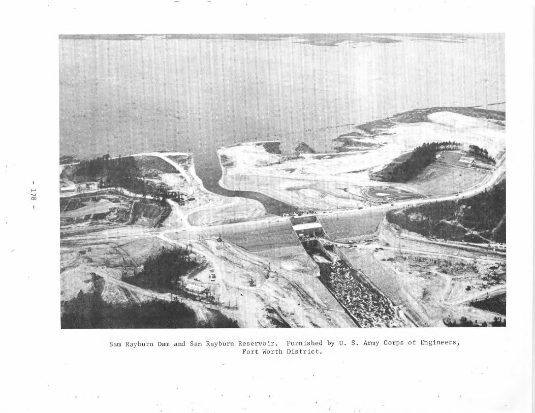
~
,.......,00
Sam Rayburn Dam and Sam Rayburn Reservoir.Fort Worth
FurnishedDis tr ic t.
by U. S. Army Corps of Engineers,
This is the second project in the plan of improvement of the watershed(Dam B is in operation; Dam A and Rockland Dam on the Neches River are authorized). Sam Rayburn Dam was authorized under the name McGee Bend Dam by theRiver and Harbor Act approved March 2, 1945, 79th Congress, first session,and modified by River and Harbor Act of June 30, 1948 (Public Law 858), 80thCongress, second session. The development is designed to control and regulatefloods; generate power, and conserve water for municipal, industrial, agricultural, and recreational purposes.
Construction of the project started September 7, 1956 and was completedJuly 1, 1966. Deliberate impoundment of water began March 29, 1965. The project was dedicated May 8, 1965. Power generation began July 1, 1966. Recordof contents since January 15, 1965, in publications of the U. S. GeologicalSurvey.
Over 990,000 visitors were reported at the Sam Rayburn Reservoir during1966.
Physical Description
The dam consists of an earth embankment, concrete power-intake structure,and flood-control outlet works located near the right end of the dam. Thetotal length is 19,430 feet with a height of 120 feet and the top of the damat elevation 190.0 feet above msl. The upstream slope of the embankment isprotected by 27 inches of rock riprap. Other features are listed at the closeof this section. A State highway crosses the top of the dam.
The reservoir has a total capacity of 2,852,600 acre-feet and a surfacearea of 114,550 acres at the top of the power and conservation storage spaceat elevation 164.0 feet above msl. The flood-control storage is shown in thetable on the next page. Recreation facilities is part of this development.
The drainage area is 3,449 square miles.
An uncontrolled broad-crested weir spillway, with crest length of 2,200feet at elevation 176.0 feet above msl, has a discharge capacity of 125,300 cfswith water surface level at elevation 183.0 feet above msl. The two outletstructures at this reservoir level will discharge 22,100 cfs.
The outlets for floodwater releases are two 10- by 20-foot tractor-typegate-controlled conduits 180 feet long. Conservation water may be released bythese gates or through the operation of the power units at variable capacityto meet the water requirements.
Two power units with a capacity of 26,000 kw each with all necessaryauxiliary equipment are installed in the power house. Power generation beganJuly 1, 1966.
- 179 -
Pertinent data on the dam and reservoir are listed as follows:
Type of dam .Length of Dam .Maximum height of dam .Top width of dam .Crest elevation of spillway .Length of spillway (net) .Type of spillway .
Earthfi1119,430 feet including spillway
120 feet42 fee t
176.0 feet2,200 feet
Broad-crested weir (uncontrolled)
Top of damMaximum design flood stageSp illway cres tTop flood-control storage
spaceTop power-storage spacePower-head and sediment
storage spaceInvert of flood-control
outlet works
Eleva t ion(feet above msl)
190.0183.0176.0
173. °164.°149.0
105.0
Capacity Area(acre-feet) (ac res)
5,610,000 180,0004,442,400 153,810
3,997,600 142,7102,852,600 113,410
1,452,000 74,040
21,940 4,170
Reservoir capacities andtopographic maps and detailedof Engineers in 1961.
surface areas based on U. S. Geological Surveysed imenta tion ranges run by the U. S. Army Corps
103. Iron Bridge Dam and Lake Tawakoni
Location
Iron Bridge Dam and Lake Tawakoni are in the Sabine River Basin in Rainsand Van Zandt Counties, 9 miles northeast of Wills Point on the Sabine River atriver mile 514. The lake extends into Hunt County.
Ownership and History of Development
The project is owned and operated by the Sabine River Authority.
Permit No. 1792 (Application No. 1933) dated November 14, 1955 from theState Board of Water Engineers to the Sabine River Authority allows storage of930,000 acre-feet of water. The Permit also allows annual diversion of 184,600acre-feet of water for municipal supplies for the cities of Dallas, Greenville,and Terrell; 23,075 acre-feet for industrial water supply; and 23,075 acre-feetfor irrigation of 12,000 acres of land. The Permit further allows transportation of the water outside the Sabine River Basin in accordance with the contract between the Sabine River Authority and the city of Dallas.
Acquisition of land was started in 1956, and construction of the darn beganin January 1958. The structure was completed in December 1960, and deliberateimpoundment of water began October 7, 1960. The lake is named in honor of theancient Indian tribe that lived in this area as late as 1760.
- 180 -
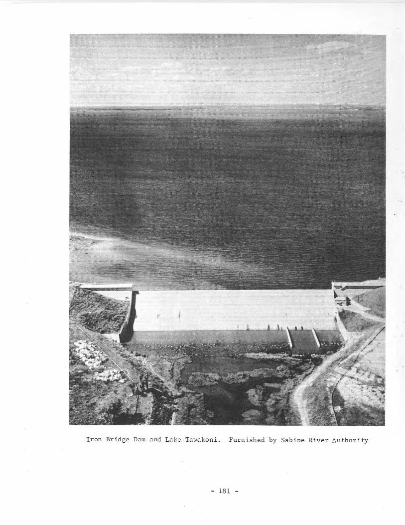
Iron Bridge Dam and Lake Tawakoni. Furnished by Sabine River Authority
- 181 -
Records of contents from June 1960 are contained in publications of theU. S. Geological Survey.
Physical Description
The dam is a rolled-earth structure 29,000 feet long including a 480-footlong, uncontrolled, ogee-type, concrete spillway section. The dam is 75 feethigh, with a maximum base width of 504 feet, and a top width of 22 feet atelevation 454.0 feet above msl. The upstream face of the embankment is protected with rock riprap. There is a roadway along the top of the dam.
The lake has a capacity of 936,200 acre-feet andacres at spillway crest elevation of 437.5 feet above200 miles is in Rains, Hunt, and Van Zandt Counties.listed at the close of this section.
a surface area of 36,700msl. The shoreline ofOther information is
The drainage area above the dam is 756 square miles.
The concrete spillway, located near the river channel about 2 miles fromthe left end of the dam, has a crest length of 480 feet at elevation 437.5 feetabove msl. It is an uncontrolled ogee-type gravity structure with a conventional-type chute and stilling basin, and it is designed to discharge 50,000cfs with lake water level at elevation 446.2 feet above msl.
For conservation releases required downstream) there are two 20-inch castiron pipes with invert at elevation 416.5 feet above msl. The flow is controlled by motor-operated valves, and the discharge is metered. For greaterflow there are two 4- by 6-foot gated openings with invert elevation of 378.0feet above msl.
Water is diverted from the lake by pumping plants owned by various citiesusing the water.
Pertinent data on the dam and lake are listed below.
outlets with invert at elevation 378.0
miles200
29,000 feet75 feet
504 feet22 feet
480 feet437.5 feet
50,000 cfs at lake water levelelevation of 446.2 feet abovemsl.
pipe outlets with invert at ele-20-inch-diameterabove msl.4- by 6-foot
Length of dam .Height of dam .\~idth of base .Width of crown .Length of spillway .Elevation of spillway above msl .Spillway design discharge .
Two gate-controlledvation 416.0 feet
Two gate-controlledfeet above msl.
Shoreline at elevation 437.5feet above msl .
- 182 -
FeatureElevation Capacity Area
(fee t above ms 1) (acre-feet) (acres)
Top of dam 454.0Spi llway cres t 437.5 936,200 36,700Invert of lower sluice
gate to 20-inch pipes 416.5 342,700 20,614Invert of two 4-foot by
6 -foot condui ts 378.0 0 0
Reservoir capacities and surface areas based on survey made in 1956.
104. Canyon Dam and Canyon Reservoir
Location
Canyon Dam and Canyon Reservoir are in the Guadalupe River Basin in ComalCounty, 12 miles northwest of New Braunfels on the Guadalupe River.
Ownership and History of Development
The project is owned by the U. S. Government and operated by the U. S.Army Corps of Engineers, Fort Worth District. The Guadalupe-Blanco RiverAuthority is the local cooperative agency. Their Permit No. 1886 (ApplicationNo. 1964) dated January 22, 1959 from the State Board of Water Engineers allocates 50,000 acre-feet of water annually for municipal, industrial, irrigation,and hydroelectric power. Guadalupe-Blanco River Authority, by paying part ofthe cost, has rights for the conservation storage space and control over theuse and release of conservation water.
Federal authorization of the project was the River and Harbor Act of March2, 1945, 79th Congress, first session, and Flood Control Act of September 3,1954, 83rd Congress, second session.
Construction was started February 27, 1958. Closure was completed withriver diversion August 5, 1962; deliberate impoundment of water began June 16,1964. The dam was completed in August 1964, and the project was completedDecember 1965. Record of contents published by the U. S. Geological Surveysince July 1962.
Over 950,000 visitors were reported at Canyon Reservoir during 1966.
Physical Description
The dam is the highest earthen embankment built by the U. S. Army Corps ofEngineers in Texas. It is 224 fee thigh above streambed with the top of thedam at elevation 974.0 feet above msl. The main embankment is 4,410 feet longand 1,400 feet wide at the base and 20 feet wide at the top, and contains9,300,000 cu yd of material. The upstream face is protected by 18 inches ofrock riprap on a 6-inch gravel base.
- 183 -
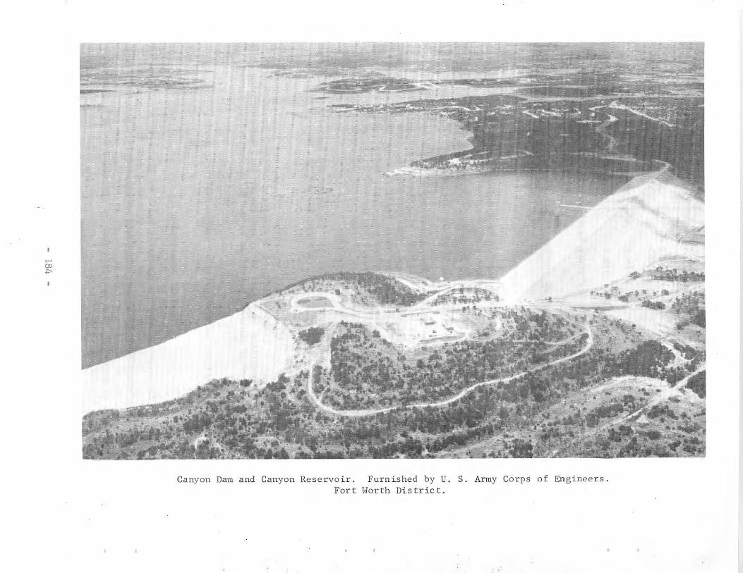
>-'00-I>
Canyon Dam and Canyon Reservoir.Fort
Furnished by U.Worth Dis tric t.
s. Army Corps of Engineers.
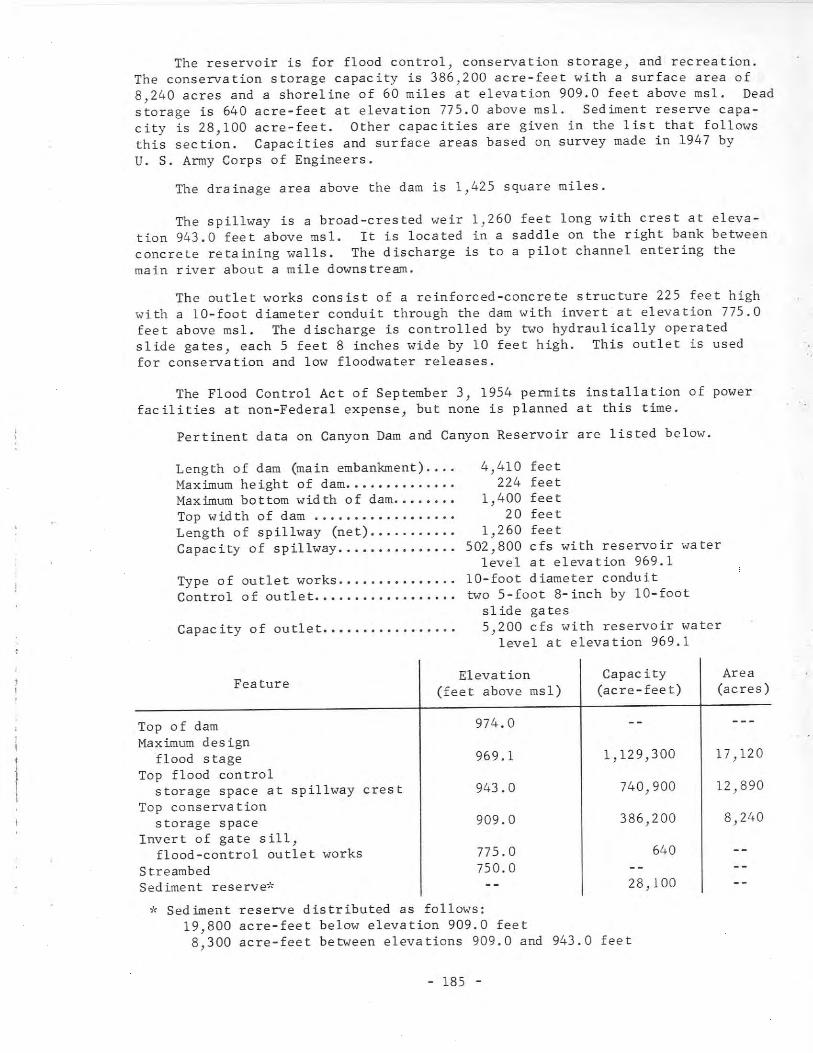
The reservoir is for flood control, conservation storage, and recreation.The conservation storage capacity is 386,200 acre-feet with a surface area of8,240 acres and a shoreline of 60 miles at elevation 909.0 feet above msl. Deadstorage is 640 acre-feet at elevation 775.0 above msl. Sediment reserve capacity is 28,100 acre-feet. Other capacities are given in the list that followsthis section. Capacities and surface areas based on survey made in 1947 byu. S. Army Corps of Engineers.
The drainage area above the darn is 1,425 square miles.
The spillway is a broad-crested weir 1,260 feet long with crest at elevation 943.0 feet above msl. It is located in a saddle on the right bank betweenconcrete reta,n,ng walls. The discharge is to a pilot channel entering themain river about a mile downstream.
The outlet works consist of a reinforced-concrete structure 225 feet highwith a 10-foot diameter conduit through the darn with invert at elevation 775.0feet above msl. The discharge is controlled by two hydraulically operatedslide gates, each 5 feet 8 inches wide by 10 feet high. This outlet is usedfor conservation and low floodwater releases.
The Flood Control Act of September 3, 1954 permits installation of powerfacilities at non-Federal expense, but none is planned at this time.
Pertinent data on Canyon Darn and Canyon Reservoir are listed below.
Length of darn (main embankment) ....Maximum height of darn.....••.......Maximum bottom wid th of darn..•.....Top wid th of darn .Length of spillway (net) •••........Capacity of spillway ....•••.....•..
Type of outlet works .......•......•Control of outlet. ..
Capacity of outlet........•.•.••...
4,410 feet224 feet
1,400 feet20 feet
1,260 feet502,800 cfs with reservoir water
level at elevation 969.110-foot diameter conduittwo 5-foot 8-inch by 10-foot
slide gates5,200 cfs with reservoir water
level at elevation 969.1
Feature
Top of darnMaximum design
flood stageTop flood control
storage space at spillway crestTop conservation
storage spaceInvert of gate sill,
flood-control outlet worksStreambedSediment reserve*
Elevation(feet above msl)
974.0
969.1
943.0
909.0
775.0750.0
Capacity(acre-feet)
1,129,300
740,900
386,200
640
28,100
Area(acres)
17,120
12,890
8,240
..,,: Sediment reserve distributed as follows:19,800 acre-feet below elevation 909.0 feet8,300 acre-feet between elevations 909.0 and 943.0 feet
- 185 -
Reservoir capacities and surface areas based on survey made in 1947 byU. S. Army Corps of Engineers.
105. Champion Creek Dam and Champion Creek Reservoir
Location
Champion Creek Dam and Champion Creek Reservoir are in the Colorado RiverBasin in Mitchell County, 7 miles south of Colorado City on Champion Creek, atributary of the Colorado River.
Ownership and History of Development
The project is owned and operated by the Texas Electric Service Company.
Water rights for storage of approximately 42,000 acre-feet and annualdiversion of 4,050 acre-feet for industrial use and 2,700 acre-feet for municipal use were obtained by the Electric Company through Permit No. 1874 (Application No. 2037) dated May 28, 1957 from the State Board of Water Engineers. Thedam was built with the spillway 5 feet lower than first planned with corresponding reduction in storage capacity. This reservoir is required because waterdemands exceeded the yield of the Lake Colorado City project owned and operatedby the Electric Company. Water will be diverted by pumping from this newreservoir to Lake Colorado City as required.
Land acquisition started in 1957, and construction began May 5, 1958. Theclosure was made and impoundment of water started in February 1959. Construction was completed April 30, 1959.
Records of contents from April 1959 are contained in publications of theU. S. Geological Survey.
Physical Description
The dam is a rolled-earth structure 6,800 feet long with a maximum heightof 114 feet above the streambed and the top of the dam at elevation 2,109.0feet above msl. The embankment has a maximum bottom width of 690 feet and topwidth of 20 feet with rock riprap on the upstream face and a gravel blanket onthe downstream side. There are two earthen fuse plugs with a total length of1,400 feet, located to the left of the main dam, to be washed out when floodsgreater than the spillway capacity occur.
The reservoir has a capacity of 42,500 acre-feet and a surface area of1,560 acres at the service spillway crest elevation of 2,083.0 feet above msl.
- 186 -
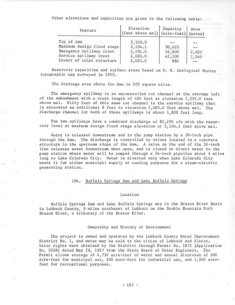
Other elevations and capacities are given in the following table:
Feature Elevation Capacity Area(feet above msl) (acre-feet) (acres)
Top of damMaximum design flood stageEmergency spillway crestService spillway crestInvert of inlet structure
2,109.02,104.12,091.02,083.02,020.0
90,02056,80042,500
880
2,0201,560
Reservoir capacities and surface areas based on U. S. Geological Surveytopographic map surveyed in 1950.
The drainage area above the darn is 203 square miles.
The emergency spillway is an uncontrolled cut channel at the extreme leftof the embankment with a crest length of 450 feet at elevation 2,091.0 feetabove msl. Fifty feet of this same cut channel is the service spillway thatis excavated an additional 8 feet to elevation 2,083.0 feet above msl. Thedischarge channel for both of these spillways is about 1,800 feet long.
The two spillways have a combined discharge of 85,290 cfs with the reservoir level at maximum design flood stage elevation of 2,104.1 feet above msl.
Water is released downstream and to the pump station by a 30-inch pipethrough the dam. The discharge is controlled by valves located in a concretestructure in the upstream slope of the dam. A valve on the end of the 30-inchline releases water downstream when open, and is closed to divert water to thepump station where water will be pumped through a 24-inch pipeline about 4 mileslong to Lake Colorado City. Water is diverted only when Lake Colorado Cityneeds it for either municipal supply or cooling purposes for a steam-electricgenerating station.
106. Buffalo Springs Dam and Lake Buffalo Springs
Location
Buffalo Springs Dam and Lake Buffalo Springs are in the Brazos River Basinin Lubbock County, 9 miles southeast of Lubbock on the Double Mountain ForkBrazos River, a tributary of the Brazos River.
Ownership and History of Development
The project is owned and operated by the Lubbock County Water ImprovementDistrict No.1, and water may be sold to the cities of Lubbock and Slaton.Water rights were obtained by the District through Permit No. 1875 (ApplicationNo. 2038) dated May 29, 1957 from the State Board of Water Engineers. ThePermit allows storage of 4,730 acre-feet of water and annual diversion of 300acre-feet for municipal use, 200 acre-feet for industrial use, and 1,000 acrefeet for recreational purposes.
- 187 -
Construction of the dam began in early 1958, and the dam and spillway werecompleted at the end of 1959. Deliberate impoundment started September 15,1959, and on July 6, 1960 water was flowing over the spillway for the firsttime. All parts of the project were accepted as complete July 15, 1960.
Physical Description
The dam is a compacted earthfill structure 1,600 feet long and 68 feethigh with the top of the dam at elevation 3,029.4 feet above msl. The embankment has a maximum bottom width of 360 feet and top width of 20 feet with aclay core extending the length of the embankment. The upstream face of theembankment is protected with 24 inches of rock riprap from elevation 2,991.9feet above msl to the top. A service road spans the spillway, and continueson the crown of the embankment to various points on the dam.
The drainage area above the dam covers a large area, 6,000 square miles,but only about 340 square miles contributes to runoff.
The lake has a capacity of 5,360 acre-feet and a surface area of 225 acresat spillway elevation 3,015.0 feet above msl.
The concrete spillway is near the right end of the dam. Wingwalls guidethe water to a chute-type structure with a crest length of 138 f~et at elevation 3,015.0 feet above msl. Rock riprap protects the sides and slope of theembankment adjacent to the concrete walls both above and below the spillway.The discharge is to a stilling basin with concrete blocks at the lower end forbreaking up the high velocity flow.
The low-flow release is a l2-inch prestressed concrete pipe through theembankment with invert at elevation 2,976.9 feet above msl. The discharge iscontrolled by a valve at the bottom of a 42-inch circular manhole. This vertical shaft has a screened inlet and slide gate at the bottom.
107. Waco Dam (new) and Waco Reservoir
Location
Waco Dam and Waco Reservoir (enlargement) are in the Brazos River Basin inMcLennan County, 2 miles west of Waco on the Bosque River, a tributary of theBrazos River.
Ownership and History of Development
The project is owned and operated jointly by the U. S. Army Corps ofEngineers, Fort Worth District; the city of Waco; and the Brazos River Authority.Federal authorization for the project was the Flood Control Act by the 83rdCongress, second session, Public Law 780 dated September 3, 1954.
Water rights were obtained by the city of Waco with Permit No. 1115 (Application No. 1187) dated August 15, 1929 from the State Board of Water Engineers.This Permit authorized impoundment of 39,000 acre-feet of water with annual
- 188 -
diversion of 85,000 acre-feet. Permit No. 1115 was amended by Permit No. 1931(Application No. 2082) dated June 6, 1957 to allow the 39,000 acre-feet to bestored in the new Waco Reservoir. By agreement with the U. S. Army Corps ofEngineers, the city has rights to 13,026 acre-feet (estimated capacity of oldLake Waco) of storage in the new reservoir, without cost, in exchange for landowned by the city as part of the reservoir.
By an order of the State Board of Water Engineers dated October 13, 1960,which was accepted by the City Council of Waco, the annual diversion of 85,000acre-feet authorized by Permit No. 1115 was reduced to 40,000 acre-feet. Thisorder allowed contracts to be made regarding storage and water use in the newreservoir.
Water rights owned by the city of Waco in connection with the old LakeWaco were modified by Permit No. 1930 (Application No. 2081) dated March 9,1960 from the State Board of Water Engineers. Permit 1930 allows additionalstorage of 65,100 acre-feet of floodwaters in new Waco Reservoir and increaseof the authorized annual diversion by 19,100 acre-feet at the same location andmanner as authorized by Permit No. 1115 (Application No. 1187) issued August15, 1929 by the State Board of Water Engineers to the city of Waco. This bringsthe total allowed storage to 104,100 acre-feet and the annual diversion to59,100 acre-feet.
The Brazos River Authority, with consent of the city of Waco, negotiatedfor reservoir storage capacity in excess of the 13,026 acre-feet allocated tothe city between elevations 427.0 and 455.0 feet above msl and use of wateruntil such time as the city needs the water. The Authority will contract forthe sale of this water to other users on a limited time basis.
The new darn was started in August 1958 and was completed in 1965. Newreservoir inundated old Lake Waco when old Waco Dam was breached February 26,1965. Deliberate impoundment of water in new Waco Reservoir began February27, 1965. Record of contents since that date are published by the U. S. Geological Survey.
More than 1,150,000 visitors were reported at Waco Reservoir during 1966.
Physical Description
The dam has an earth embankment, a concrete outlet works, and a concretegate-controlled spillway located to the left of the main embankment. The overall length is 24,618 feet with maximum height of 140 feet and the top of thedam at elevation 510.0 feet above msl. The embankment has a maximum bottomwidth of 990 feet with a top width of 20 feet, and contains 12 million cu yd ofmaterial. The upstream face is protected by 2 feet of rock riprap on a 9-inchgravel blanket. Difficulty was encountered in construction due to a foundationcondition causing sliding and damage to the embankment. This required changein plans and additional volume of materials for completion.
The reservoir serves for flood control, conservation storage, and recreational purposes. At the top of conservation storage elevation o~ 455.0 feetabove msl, the capacity is 152,500 acre-feet with a surface area of 7,260 acres.Other data are listed following this section.
- 189 -
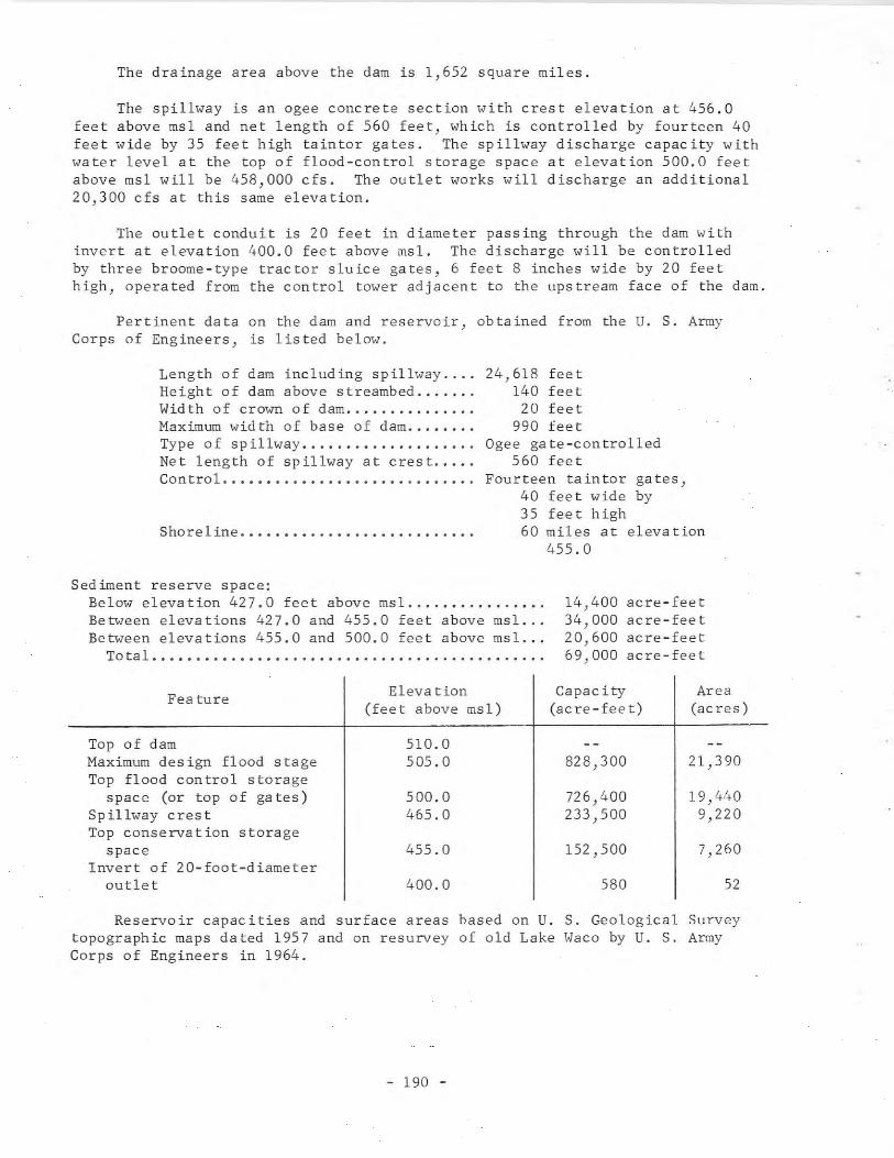
The drainage area above the dam is 1,652 square miles.
The spillway is an agee concrete section with crest elevation at 456.0feet above msl and net length of 560 feet, which is controlled by fourteen 40feet wide by 35 feet high taintor gates. The spillway discharge capacity withwater level at the top of flood-control storage space at elevation 500.0 feetabove msl will be 458,000 cfs. The outlet works will discharge an additional20,300 cfs at this same elevation.
The outlet conduit is 20 feet in diameter passing through the dam withinvert at elevation 400.0 feet above msl. The discharge will be controlledby three broome-type tractor sluice gates, 6 feet 8 inches wide by 20 feethigh, operated from the control tower adjacent to the upstream face of the dam.
Pertinent data on the dam and reservoir, obtained from the U. S. ArmyCorps of Engineers, is listed below.
Length of dam including spillway .Height of dam above streambed .Width of crown of dam .Maximum width of base of dam .Type of spillway .Net length of spillway at crest .Con trol. •..•.....•.•...••.....•.....
Shore 1 ine .....•.....................
24,618 feet140 fee t
20 feet990 feet
Ogee gate-controlled560 feet
Fourteen taintor gates,40 feet wide by35 feet high60 miles at elevation
455.0
Sed iment reserve space:Below elevation 427.0 feet above msl .Be~"een elevations 427.0 and 455.0 feet above msl. ..Between elevations 455.0 and 500.0 feet above msl ...
To ta 1 ...••..••.•..•..•............................
14,400 acre-feet34,000 acre-feet20,600 acre-feet69,000 acre-feet
Fea ture
Top of damMaximum design flood stageTop flood control storage
space (or top of gates)Sp illway cres tTop conservation storage
spaceInvert of 20-foot-diameter
outlet
Eleva tion(feet above msl)
510.0505.0
500.0465.0
455.0
400.0
Capac ity Area(acre-feet) (ac res)
828,300 21,390
726,400 19,440233,500 9,220
152,500 7,260
580 52
Reservoir capacities and surface areas based on U. S. Geological Surveytopographic maps dated 1957 and on resurvey of old Lake Waco by u. S. ArmyCorps of Engineers in 1964.
- 190 -
108. Lorna Alta Dam and Lorna Alta Reservoir
Location
Lorna Alta Dam and Loma Alta Reservoir are in the Nueces-Rio Grande CoastalArea in Cameron County, 8 miles northeast of Brownsville. The reservoir isoff-channel from the Rio Grande.
Ownership and History of Development
The project is owned and operated by the Brownsville Navigation District.Construction was started November 10, 1958 and substantially completed inMarch 1963.
Water right to store only surplus water flowing in the Rio Grande wasgranted by Permit No. 1838 (Application No. 1980) dated November 16, 1956 fromthe State Board of Water Engineers to the District. The Permit allows storageof 26,500 acre-feet of water, annual use of 37,500 acre-feet for industrialneeds, and 2,500 acre-feet for municipal purposes.
Physical Description
The embankment is a compacted earthen dike system with variable height andcross section. The average bottom width is 90 feet and the top width is 18feet, with the top at elevation 21.5 feet above msl. A concrete outlet sectionis provided for emergency spill to lower the reservoir if needed.
The reservoir has a capacity of 26,500 acre-feet and a surface area of2,490 acres at spillway crest elevation of 17.5 feet above msl. The level ismaintained by pumping from the Rio Grande during off-season irrigation demands.The pumping plants of the city of Brownsville and Cameron County Water Improvement District No.5 are used to deliver water to the canal system and reservoirwhen they would not otherwise be pumping water from the river. There is asecondary or lower reservoir operated in connection with this project that issupplied with water from the canal system or from Lorna Alta Reservoir. Wateris then delivered to a canal system for distribution to industrial customers.
There is no natural drainage to the reservoir.
The spillway is a concrete structure with wingwalls and uncontrolledcircular-shaped ogee overflow section with crest length of 105 feet at elevation 17.5 feet above msl. The discharge is to a drainage area outside thelevee system.
There is a 7- by 7-foot concrete conduit through the embankment "ith invertat elevation 5.0 feet above msl. Waterflo" is controlled by a slide gate "ithinvert at elevation 6.5 feet above msl. This outlet "ill be used to controlreleases to the lower pool and thence to the canal system for commercial useor for emergency release. The gate is operated from a concrete intake structurewith a platform at elevation 22.0 feet above msl.
- 191 -
109. Kurth Dam and Lake Kurth
Location
Kurth Dam and Lake Kurth in the Neches River Basin in Angelina County,8 miles north of Lufkin, are an off-channel storage project of the AngelinaRiver, which is a tributary to the Neches River.
Ownership and History of Development
The project is owned and operated by the Southland Paper Mills, Inc. forindustrial use in producing paper. A large part of the water diverted isreturned to the Angelina River.
Water rights were obtained by Southland Paper Mills, Inc. through PermitNo. 1912 (Application No. 2063) dated June 3, 1958 from the State Board ofWater Engineers. This Permit allows the construction of an off-channel laketo store 16,200 acre-feet of water, and it allows the annual use of 19,100acre-feet. In addition to the water allocated under this Permit, 10,000 acrefeet of water may be purchased annually from Striker Creek Reservoir of theAngelina and Nacogdoches Counties Water Control and Improvement District No.1.
The construction contract was awarded and work was begun May 26, 1959.It was completed July 21, 1961. Water pumping started in September 1961, andthe lake was full at the end of that year, but use of water did not start until1962.
Physical Description
The dam or levee is 8,600 feet long with an average height of 37 feet andtop elevation at 206.0 feet above msl. The earth embankment has a maximwnbottom width of 242 feet and a top width of 16 feet. The upstream face isprotected with a 6-inch concrete slab on a 10-inch gravel base from elevation185.0 to 203.0 feet above msl. The dam contains 1,624,000 cu yd of earth.
The lake has a capacity of 16,200 acre-feet and a surface area of 800acres at spillway crest elevation 197.5 feet above msl. The lake is held atnormal level by pumping from the riverflow or from water purchased from StrikerCreek Reservoir, which is released to the river channel. This pumped storagemakes the 4-square-mile drainage area to the lake unimportant.
The pumping installation at the river is a vertical concrete shaft withfour vertical pumps having a total capacity of 53,000 gpm (gallons per minute)at a pumping head of 50 feet. The discharge is to a lined canal 1,900 teetlong leading to the lake.
The spillway is a 25- by 15-foot, uncontrolled, rectangular intake withthe crest at elevation 197.5 feet above msl. The discharge is through twoconcrete conduits, 10 feet wide by 5 feet high, with invert at elevation180.0 feet above msl. Since this is a pumped storage project, a low-flowrelease conduit is not required.
- 192 -
110. Big Hill Dam and Big Hill Reservoir
Location
Big Hill Dam (levee) and Big Hill Reservoir are in the Neches-TrinityCoastal Area in Jefferson County at Port Acres on Big Hill Bayou, a tributaryof Taylor Bayou.
Ownership and History of Development
The project is owned and operated by the Texas Parks and Wildlife Commission) formerly Texas Game and Fish Commission, for a wildlife refuge and recreational purposes. Permit No. 1932 (Application No. 2111) dated July 9, 1959from the State Board of Water Engineers allows the Texas Par"s and WildlifeCommission to store 32,000 acre-feet of water.
Water is pumped from the Big Hill Bayou or from the canal system or theLower Neches Valley Authority. Because of complaints from several holders ofpermits for appropriation and use of water from Big Hill Bayou, the Game andFish Commission entered an agreement (dated July 2, 1959) with these appropriators to limit pumping to meet certain conditions. This agreement incorporatedin Permit No. 1932 states that " ••• water can be diverted only when the level inthe Bayou is above 0 feet msl during the month of January and from August 15through December. For the period June to August 15 the level must be 1.5 feetabove msl before water can be diverted and for the period February through Maythe level must be 2.0 feet above ms! before diversion can be made." This limitation is to prevent lowering the water level in the bayou below sea levelthereby causing salt-water intrusion, which would be detrimental to irrigation.
Construction of the levee work began September 7, 1959, and parts of thedevelopment were completed at various times with impoundment of water startingin 1960 when some of the interior ponds were placed in service. The total project was completed in 1964.
Physical Description
The dam or levee system is built on marsh land with flat slopes. Embankment height is 4 to 6 feet with the top at elevation 5.0 to 6.0 feet above msl.
The reservoir area consists of one main levee system with fourteen interiorcompartments so that anyone compartment can be drained. In order to havevegetation for wildfowl feed) some of the compartments are drained each year ona 3-year rotational basis to allow growth to be replenished. The reservoirmaximum capacity is 32,000 acre-feet at elevation of 6.0 feet above msl with atotal area of all ponds of about 7}284 acres. In periods of extreme high tides}the entire reservoir area is submerged with sea water.
Various sizes of hand-operated gates are installed on the levee at severalpoints for release of water to and from the various compart~ents and fordrainage to the bayou.
- 193 -
111. Farmers Creek Dam and Farmers Creek Reservoir (Lake Nocona)
Location
Farmers Creek Dam and Farmers Creek Reservoir) also known as Lake Nocona)are in the Red River Basin in Montague County, 8 miles northeast of Nocona onFarmers Creek, a tributary to the Red River.
Ownership and History of Development
The project is owned and operated by the North Montague County WaterSupply District for municipal, industrial, and mining purposes. Permit No.1922 (Application No. 2104) dated ~mrch 10, 1959 from the State Board of WaterEngineers to the District allowed the construction of a dam creating a reservoir to impound 25,389 acre-feet of water. The Permit allows annual use of2,500 acre-feet of water for municipal use, 1,000 acre-feet for industrial use,and 1,000 acre-feet for mining use.
Construction of the dam began in September 1959, and was completed inOctober 1960. Deliberate impoundment of water began in the spring of 1961when the first runoff was available for storage. Water was first diverted foruse by the city of Nocona in September 1961.
Physical Description
The dam is a rolled-earth structure, 3,720 feet long and 77 feet highabove the streambed, with a maximum base width of 423 feet and a top width 0"20 feet. The top of the dam is at elevation 847.0 feet above msl. The upstream face is protected with 24-inch rock riprap on an 8-inch gravel blanket.
The lake has a capacity of 25,400 acre-feet and a surface area of 1,470acres at elevation 827.0 feet above msl, which is the low spillway elevationand operating level. At elevation 835.0 feet above msl, the crest of thesecond level spillway, the capacity is 40,000 acre-feet with a surface area of1,920 acres.
Drainage area above the dam is 94 square miles.
A two-level, three-section, uncontrolled spillway discharging intoFarmers Creek channel is located near the left end of the structure. A centersection, with crest length of 100 feet at elevation 827.0 feet above msl, isthe primary source of spill. On each side of this center spillway is a highersection, each with crest length of 400 feet, at elevation 835.0 feet above mslfor extreme floodflow.
The outlet for low-flow release is an 18-inch steel pipe encased in concrete extending through the embankment near the center of the dam with invertat elevation 797.0 feet above msl. A manhole structure provides access to thedual control valves.
The pump station structure for municipal water supply is located on theleft shore of the lake. This is a vertical concrete shaft with a platform atelevation 842.0 feet above msl for mounting the motors that drive the vertical
- 194 -
pump. Water enters this pump structure through a 24-inch pipe that connects toa vertical concrete intake, which also extends above the normal lake level.\,ater enters this intake through a 24-inch pipe at elevation 800.0 feet abovemsl and through an opening in the vertical wall at elevation 830.0 feet abovemsl. Both openings are controlled by slide gates operated by lift chains fromthe top of the shaft. Two pumps are installed (with provisions for a third)to deliver water by pipeline to Nocona.
112. Navarro Mills Dam and Navarro Mills Reservoir
Location
Navarro Mills Dam and Navarro Mills Reservoir are in the Trinity RiverBasin in Navarro County, 16 miles southwest of Corsicana on Richland Creek, atributary of the Trinity River. The reservoir extends into Hill County.
Ownership and History of Development
The project is owned by the U. S. Government, and is operated forflood control and recreational purposes by the U. S. Army Corps of Engineers,Fort Worth District. The Trinity River Authority has purchased the conservation storage space of 63,300 acre-feet, and will control diversion and usesaccording to the Permit (No. 1948) granted by the State Board of WaterEngineers.
The Trinity River Authority obtained the right to appropriate 19,400 acrefeet of water annually by Permit No. 1948 (Application No. 2134) dated January13, 1960 from the State Board of Water Engineers. The water is being sold toCorsicana and other towns for municipal purposes. The Navarro Mills projectwas authorized by the Flood Control Act of September 3, 1954, 83rd Congress,second session, and modified by the Flood Control Act of July 3, 1958, 85thCongress, second session.
Construction of the project began December 23, 1959. Closure was made andwater diverted through the outlets on October 8, 1962. At the end of 1962 thespillway was completed, and the embankment section was completed September 6,1963. Deliberate impoundment of water began March 15, 1963.
Records of contents since August 1962 are in publications of the U. S.Geological Survey.
More than 401,000 visitors were reported at Navarro Mills Reservoir during1966.
Physical Description
The dam is a rolled-earth embankment 7,570 feet long, including the concrete spillway section, and 82 feet high with the top of the dam at elevation457.0 feet above msl. The maximum bottom width is 560 feet and the top widthis 20 feet. The embankment contains about 2,131,000 cu yd of earthfill, andthe upstream face is protected with 2 feet of stone riprap on a 9-inch gravelbase.
- 195 -
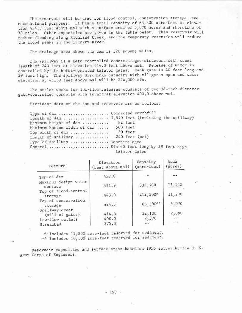
The reservoir will be used for flood control) conservation storage) andrecreational purposes. It has a total capacity of 63,300 acre-feet at elevation 424.5 feet above msl with a surface area of 5,070 acres and shoreline of38 miles. Other capacities are given in the table below. This reservoir willreduce flooding along Richland Creek, and the temporary retention will reducethe flood peaks in the Trinity River.
The drainage area above the dam is 320 square miles.
The spillway is a gate-controlled concrete ogee structure with crestlength of 240 feet at elevation 414.0 feet above msl. Release of water iscontrolled by six hoist-operated taintor gates. Each gate is 40 feet long and29 feet high. The spillway discharge capacity with all gates open and waterelevation at 451.9 feet above msl will be 224,000 cfs.
The outlet works for low-flow releases consists of two 36-inch-diametergate-controlled conduits with invert at elevation 400.0 above msl.
Pertinent data on the dam and reservoir are as follows:
Type of dam ..............•......Leng th of dam .Maximum height of dam .Naximum bottom width of dam .Top width of dam .Length of spillway .Type 0 f spi llway .....•..........Control 'to •• 0 0.00 •• 0 0 •• 0
Compacted earthfill7,570 feet (including the spillway)
82 feet560 feet
20 feet240 feet (net)
Concrete ogeeSix 40 feet long by 29 feet high
taintor gates
Elevation Capacity AreaFeature (feet above msl) (acre-feet) (acres)
Top of dam 457.0Maximum design water
surface 451.9 335,700 15,950Top of flood-control
storage 443.0 212,200>' 11,700Top of conservation
storage 424.5 63,300** 5,070Spi llway cres t
(sill of gates) 414.0 22,100 2,690Low-flow outlets 400.0 2,370Streambed 375.3
* Includes 15,800 acre-feet reserved for sediment.** Includes 10,100 acre-feet reserved for sediment.
Reservoir capacities and surface areas based on 1956 survey by the U. S.Army Corps of Engineers.
- 196 -
113. Brushy Creek Dam and Brushy Creek Reservoir
Location
Brushy Creek Dam and Brushy Creek Reservoir are in the Red River Basin inFannin County, 3 miles north of Savoy on Brushy Creek, a tributary to the RedRiver. The reservoir extends into Grayson County.
O,mership and History of Development
The project is owned and operated by the Texas Power & Light Company forthe purpose of condenser cooling and other power plant uses for its ValleyCreek steam-electric generating station.
Permit No. 1939 (Application No. 2131) dated November 3, 1959 from theState Board of Water Engineers to the Texas Power & Light Company authorizedthe construction of a dam creating a reservoir on Brushy Creek and appropriation of a total of 10,000 acre-feet annually of the floodwaters of Brush Creek,Sand Creek, and the Red River. The flow from Brushy Creek is a small amountof this total. When the flow is deficient, water is pumped to the reservoirfrom a plant located on the Red River at the mouth of Sand Creek, utilizingthe flood or excess flow of either of these streams. In order to assure 10,000acre-feet annually during dry periods, the Texas Power & Light Company enteredinto a contract with the U. S. Government through the U. S. Army Corps ofEngineers for storage space for 16,400 acre-feet and annual diversion of 10,000acre-feet of water from Lake Texoma. Amended Permit No. 1939A (ApplicationNo. 2168) dated October 31, 1960 from the State Board of Water Engineer authorizes appropriation of water in accordance with the terms of this contract as asupplemental source of water. It also authorizes the use of the bed and banksof the Red River in Grayson and Fannin Counties to transport water from LakeTexoma to the point of diversion described in Permit No. 1939. The water maybe diverted at some future time by pumping directly from Lake Texoma through apipeline to the storage reservoir on Brushy Creek. This is an alternate methodto the use of the Red River to transport the water to a pumping plant. Withall these sources of supply, the total annual diversion is not to exceed the10,000 acre-feet authorized for appropriation by Permit No. 1939.
The project was started April 18, 1960, and was completed September 5,1961. Impoundment of water began in December 1960.
Physical Description
The dam is an earthfill structure 2,500 feet long and 57 feet high withthe top of the dam at elevation 617.5 feet above msl. The maximum bottom widthof the embankment is 330 feet and the top width is 15 feet.
- 197 -
The reservoir has a capacity of 16,800 acre-feet and a surface area of1,180 acres at service spillway crest elevation of 610.0 feet above msl. Otherreservoir capacities are given in the following table:
Feature
Top of damCrest of emergency spillwayCrest of service spillwayLow-flow outlet invert
Elevation(feet above msl)
617.5612.0610.0605.0
Capacity(acre-feet)
17,17016,80010,550
Area(acres)
1,180760
The drainage area is 8 square miles but is unimportant as the water levelis maintained by diversion from the Red River by two pumps installed in theplant at the mouth of Sand Creek.
A service spillway is located on the right end of the dam with a crestlength of 200 feet at elevation 610.0 feet above msl. The discharge is toBrushy Creek channel. An emergency spillway of unknown capacity has a crest~levation at 612.0 feet above msl.
The low-flow release is a valve-controlled l8-inch-diameter pipe throughthe dam with invert at elevation 605.0 feet above msl.
The Valley Creek electric-generating station was placed in commercialoperation in November 1962, and was completed January 1963. The capacity ofthe first unit is 175,000 kwand provisions are made for additional units.The generator is connected to the transmission network for serving the powerneeds of the area.
114. Blackburn Crossing Dam and Lake Palestine
Location
Blackburn Crossing Dam and Lake Palestine are in the Neches River Basinin Anderson and Cherokee Counties, 4 miles east of Frankston on the NechesRiver. The lake extends into Henderson and Smith Counties.
Ownership and History of Development
The project is owned and operated by the Upper Neches River Authority forindustrial, municipal, and recreational purposes. Water rights were obtainedby the Authority through Permit No. 1832 (Application No. 1975) dated July 12,1956 from the State Board of Water Engineers. The Permit authorized the construction of a dam in three stages: the first stage covered planning; thesecond stage covered building a dam creating a reservoir of 30,500 acre-feetcapacity; and the third stage covered enlarging a dam to create a reservoir of410,000 acre-feet capacity. The State Board of Water Engineers extended timeof starting construction by Permit No. l832A dated June 13, 1958 and PermitNo. l832B dated December 30, 1959. The Permits allow an ultimate storage of410,000 acre-feet of floodwaters and unappropriated waters of the Neches Riverwith an annual use of 84,000 acre-feet for industrial use and 112,000 acre-feet
- 198 -

for municipal use. As of December 31, 1966, no water had been used from thereservoir, however, the city of Tyler had contracted for water and Palestinewas negotiating a contract for municipal water supply.
Construction of the dam began May 30, 1960, and the second phase of theproject was completed June 13, 1962. Actual storage of water began in June1961 with the completion of the outlet works, but the deliberate impoundmentdate is recorded as May 1, 1962.
Records of contents from February 1, 1962 are contained in publicationsof the U. S. Geological Survey.
Physical Description
The present dam is a rolled-earth structure 4,000 feet long, including thespillway, and 53 feet high above steambed with the top of the dam at elevation343.4 feet above msl. The present maximum bottom width is 332 feet and the topwidth is 65 feet, which allows for a future enlargement raising the top of thedam to elevation 364.0 feet above msl. Part of the upstream face is protectedwith rock riprap on a 9-inch sand base.
The present lake has a capacity of 30,500 acre-feet and a surface area of4,000 acres at elevation 317.0 feet above msl, the design operating level. Atthe emergency spillway crest elevation of 322.0 feet above msl, the capacityis 57,550 acre-feet with a surface area of 6,800 acres. Other capacities of thepresent lake are given in the following tabulation.
Feature
Top of damEmergency spillway crestDesign operating levelInvert of low-flow outletInvert of 8.5-foot-conduit
Elevation(f ee t above ms 1)
343.4322.0317 .0309.5298.0
Capaci ty(acre-feet)
57,55030,50010,600
550
Area(acres)
6,8004,0001,700
400
An enlargement of Lake Palestine is planned to raise operating level to345.0 feet, total storage capacity to 410,000 acre-feet, and surface area to25,500 acres.
Reservoir capacities and surface areas based on U. S. Geological Surveytopograph ic maps surveyed in 1957.
The drainage of the Neches River above the Blackburn Crossing Dam is 839square miles.
The present emergency spillway near the left end of the dam is an uncontrolled, broad-crested weir section excavated into the natural rock bank witha crest length of 500 feet at elevation 322.0 feet above msl. With the enlargement of this project, the spillway will be raised by constructing a concreteogee weir section at elevation 345.0 feet above msl.
The outlet works near the right end of the dam consist of a gated concretetower connected to an 8.5-foot-diameter conduit through the dam with invert atelevation 298.0 feet above msl. A concrete and steel walkway at elevation
- 199 -
355.0 feet above msl connects the dam with the top of the tower. Floodwaterrelease through two 5- by 7-foot openings at the base of the tower at elevation298.0 feet above msl is controlled by two 6- by 8-foot gates. These gates arelocated in a rectangular section upstream from where the transition to onecircular conduit is located. The discharge from the conduit is through achute or Parshall flume with measuring equipment and thence to the riverchannel.
The low-flow outlets are two 36-inch, valve-controlled, cast-iron pipesconnecting to compartments in the tower structure. Inlet to these compartmentsare at various elevations--the lowest one with invert at elevation 309.5 feetabove msl. The other inlets are at elevations 312.5, 322.5, and 332.5 feetabove msl. The bottom two have slide gates for control of inlet water; gatesfor the other two will be installed "hen the dam is enlarged. These 36-inchpipes discharge into the 8.5-foot-diameter conduit and thence to the riverchannel.
115. Twin Buttes Dam and Twin Buttes Reservoir
Location
Twin Buttes Dam and Twin Buttes Reservoir are in the Colorado River Basinin Tom Green County, 8 miles southwest of San Angelo on the South Concho River,Spring Creek, and Middle Concho River, tributaries to the Concho River, whichis tributary to the Colorado River.
Ownership and History of Development
The project is owned by the U. S. Government, and will be operated by theU. S. Bureau of Reclamation, Amarillo Office, for flood control, conservationuses, irrigation, and recreation. Local agencies cooperating in the projectare the San Angelo Water Supply Corporation for municipal water supply and TomGreen County Water Control and Improvement District No.1 for irrigation water.
Federal authorization was Public Law 85-152 dated August 16, 1957 passedby the 85th Congress. Water rights were obtained by Permit No. 1949 (Application No. 2122) dated February 3, 1960 from the State Board of Water Engineersto the San Angelo Water Supply Corporation. This corporation has contractedwith the U. S. Government for storage space in the reservoir. The Permitallows storage of 170,000 acre-feet of water in the Twin Buttes Reservoir,annual use of 29,000 acre-feet of water for municipal supply, and 25,000 acrefeet of water for irrigation of 10,000 acres of land. The municipal water isfor the city of San Angelo which has a contract with the Water Supply Corporation. This appropriation, issued in 1950 under Permit No. 1120 (ApplicationNo. 1196) and Permit No. 1446 (Application 1551), includes water diversionrights for 25,000 acre-feet from the West Texas Utilities Company. Permit No.1949 is subject to rights of downstream appropriators, and stipulates that acertain minimum flow must be maintained either by releases from the reservoiror discharge from the city's sewage or water system.
- 200 -
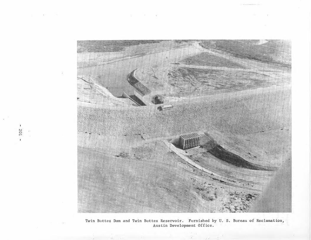
No.....
.
-
Twin Buttes Dam and Twin Buttes Reservoir. Furnished by U. S. Bureau of Reclamation,Austin Development Office.
Construction started May 3, 1960, and deliberate impoundment of waterbegan December 1, 1962. The dam was completed February 13, 1963 when the project was accepted from the contractor by the Bureau of Reclamation. Record ofcontents since October 1962 published by the U. S. Geological Survey.
This project is above Lake Nasworthy and will release water from storageto keep Lake Nasworthy at a constant level; downstream requirements will befurther regulated by this reservoir.
Physical Description
The dam is the second longest earthfill structure and third largest involume constructed by the U. S. Bureau of Reclamation. It is 8.1 miles longand 131 feet maximum height with the top of the dam at elevation 1,991.0 feetabove msl. The embankment has a maximum width at the base of 760 feet with acrest width of 30 feet, and contains 21 million cu yd of material. The upstream face is protected with 36 inches and 24 inches of rock riprap on a 12inch gravel base. The spillway and intake structure for the outlet conduitsare located near left end of dam.
The reservoir has a controlled capacity of 640,600 acre-feet allocated asshown in the list following this section. Because of different elevations ofthe three streams on which the dam is built, an equalizing channel 3.22 mileslong with a bottom width of 250 feet was built connecting the South Concho andMiddle Concho Rivers and Spring Creek impoundments into one common reservoir atelevation 1,925.0 feet. At the top of the flood-control storage elevation of1,969.1 feet above msl the reservoir will have an area of 23,510 acres.
The drainage area above the dam is 3,724 square miles, of which 1,178square miles is probably noncontrihuting.
The spillway near the left end of the dam is an uncontrolled ogee-weirtype with crest length of 200 feet at elevation 1,969.1 feet above msl havinga discharge capacity of 47,000 cfs with water surface at elevation 1,985.0 feetabove msl. A concrete chute 320 feet long extends from the crest to a stillingbasin where the water then discharges into a channel and thence into LakeNasworthy.
The outlet works located near the left abutment includes an approachchannel from the Middle Concho River, a concrete intake structure, a threebarreled concrete conduit with gates, a chute, and a stilling basin. The 210foot upstream leg of the conduit, from the intake structure to the gate chamber,consists of three l5.5-foot diameter conduits. The l83-foot long downstreamsection is of circular-top horseshoe-shape, 17 feet wide by 17 feet high. Aconcrete chute 180 feet long conveys the water to the stilling basin. The outflow is controlled by a 15- by l2-foot fixed wheel gate and a 15- by l2-footradial gate in each of the three conduits. The capacity of the conduits is26,000 cfs with the reservoir at conservation storage elevation of 1,940.2 feetabove ms 1.
There is a 2- by 2-foot regulating gate for low-flow releases located inthe center of each of the fixed wheel gates.
- 202 -
The irrigation system consists of the main canal, 16 miles long with acapacity of 165 cfs. The headgate for control of the flow to the canal islocated at the right abutment of Nasworthy Dam. The distribution system consists of 39 miles of laterals. The main canal and laterals are lined with concrete.
Pertinent data on the dam and reservoir are listed below.
Type of dam •••.•••.•.••••.•••..•••Length of dam .••••••.•••.•.....•••Crest width of dam .•••••••••••••••Bottom width of dam (maximum) •..••Height of dam (maximum) .•..•••••••Type of spi 11way ••••.••..••..•••.•Crest length of spillway •.••••.•••Crest elevation .Discharge •••••.•..•••..•...•.•....
Type of outlet works ••••.•••••••••Ups tream condui ts •••••••••••••••••Downstream conduits .Discharge at elevation 1,940.2 ••••Invert elevation .
Earthfi 118.1 miles
30.0 feet760.0 feet131.0 feet
Ogee weir (uncontrolled)200 feet
1,969.1 feet above msl47,000 cfs at maximum design
flood stage elevation of 1,985.0feet above msl
Triple-barreled conduit15.5-foot-diameter
17 feet by 17 feet horseshoe-shpaed26,000 cfs1,885.0 feet above msl
Feature
Top of damMaximum design flood stageCrest of spillwayTop of conservation storage spaceBottom of equalizing channelDead storage in South Concho poolInvert to outlet works
Elevation(feet above msl)
1,991.01,985.01,969.11,940.21,925.01,925.01,885.0
Capacity(acre-feet)
1,087,500640,600186,20084,7604,6003,750
Area(acres)
32,66023,510
9,0804,575
670
The 640,600 acre-feet of controlled capacity is allocated as follows:20,000 acre-feet ~or 20 years of sedimentation; 40,000 acre-feet for municipalsupply; 126,200 acre-feet for joint irrigation, municipal, and industrial supply, and 454,400 acre-feet for flood control. Total dead storage of 8,350 acrefeet includes 4,600 acre-feet in South Concho pool and 3,750 acre-feet inMiddle Concho pool.
Capacities and surface areas supplied by the U.S. Bureau of Reclamationand were based on topography by the U. S. Geological Survey, Bureau of Reclamation, and Army Corps of Engineers prior to the impoundment of water. Capacities were adjusted for borrow pits and the connecting channel.
- 203 -
116. Johnson Creek Dam and Johnson Creek Reservoir
Location
Johnson Creek Dam and Johnson Creek Reservoir are in the Cypress CreekBasin in Marion County, 13 miles northwest of Jefferson on Johnson Creek, atributary to Cypress Creek.
Ownership and History of Development
The project is owned and operated by the Southwestern Electric PowerCompany) and is used for cool ing wa ter for a 5 team-e lee tric genera t ing 5 ta t ionwhich began operation in May 1965. It will also provide recreation foremployees of the Company.
Water rights were obtained by the Southwestern Electric Power Companythrough Permit No. 1963 (Application 2161) dated July 20, 1960 from the StateBoard of Water Engineers. This Permit is for construction of a dam and storageof 10,100 acre-feet of water with annual use of 6,668 acre-feet. Water will beused for condenser-cooling purposes, and the consumptive use will be limitedto forced evaporation caused by heat added to the reservoir and to a smallamount for plant services. The Johnson Creek yield will not be sufficient formake-up water for future needs. A contract has been made with the NortheastTexas Municipal Water District to purchase water from nearby Lake 0' the Pines.The contract calls for the purchase of as much as 6,668 acre-feet of water peryear, which will be pumped directly from the lake to Johnson Creek Reservoiras needed to maintain desired water level.
Construction of the dam began June 16, 1960, and was completed August 4,1961. Impoundment of water began August 4, 1961. Water use began in May 1965when the first 150,000 kw generating unit was placed in service.
Physical Description
The dam is a rolled-earth structure 2,530 feet long with a maximum heightabove streambed of 60 feet with the top of the dam at elevation 296.0 feetabove msl. The embankment has a maximum bottom width of 364 feet and a topwidth of 20 feet, and the upstream face is protected with a concrete slab ona sand b lanke t.
The reservoir has a storage volume of 10,100 acre-feet with a surface areaof 650 acres at elevation 280.0 feet above msl. Water will be diverted forsteam-condenser-cooling purposes and returned to the reservoir.
The drainage area of Johnson Creek above the dam is 11 square miles.
An emergency spillway with crest length of 300 feet at elevation 286.0feet above msl discharges to an unlined channel, but will have little use owingto the small drainage area above the dam.
- 204 -
Diversion of water from Johnson Creek Reservoir for cooling purposes willbe by pumps directly from the reservoir to the condensers and back to thereservoir, with the discharge located to cause circulation away from the intakestructure.
An l8-inch valve-controlled pipe is provided for low-flow discharge.
The first generating unit of 150,000 kw capacity is one of several fora total future plant capacity of 600,000 kw. This plant will supply energyto the transmission system serving the area with electric power.
117. Proctor Dam and Proctor Reservoir
Location
Proctor Dam and Proctor Reservoir are in the Brazos River Basin inComanche County, 9 miles northeast of Comanche on the Leon River, a tributaryto the Brazos River.
Ownership and History of Development
The project is owned by the U. S. Government, and is operated by the U. S.Army Corps of Engineers, Fort Worth District, for flood control and water conservation. It was constructed under the Flood Control Act of September 3, 1954,Public Law 780, 83rd Congress, second session. The Brazos River Authority isthe local cooperative agency, and has contracted to purchase the conservationstorage by paying $1,707,700 with interest over a 50-year period.
The Brazos River Authority obtained Permit No. 2107 (Application No. 2292)dated July 24, 1964 from the Texas Water Commission to impound 59,400 acre-feetof water in Proctor Reservoir and to divert annually: 18,000 acre-feet formunicipal purposes; 18,000 acre-feet for industrial purposes; and 18,000 acrefeet for irrigation of land in the Brazos River Basin and adjacent coastal areasand to use the bed and banks of the Leon, Little and Brazos Rivers for deliveryto the place of use. However the amount of water for diversion with priorityof rights under this permit is limited to 25,000 acre-feet per annum ratherthan the amount authorized for diversion.
Construction began June 28, 1960, and was completed in 1965. Deliberateimpoundment of water began September 30, 1963. The operation of Proctor Reservoir will make possible the modification of Belton Reservoir to convert 247,000acre-feet of flood-control storage in that reservoir to conservation storagewithout detriment to flood control on the lower Brazos River. Record of contents of Proctor Reservoir published by U. S. Geological beginning January 30,1963.
Over 410,000 visitors reported at Proctor Reservoir during 1966.
Physical Description
The dam is a rolled-earth structure 13,460 feet long and 86 feet high withthe top of the dam at elevation 1,206.0 feet above msl. The embankment has a
- 205 -
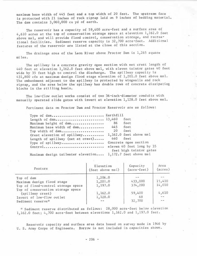
maximum base width of 445 feet and a top width of 20 feet. The upstream faceis protected with 21 inches of rock riprap laid on 9 inches of bedding material.The dam contains 3,060,000 cu yd of earth.
The reservoir has a capacity of 59,400 acre-feet and a surface area of4,610 acres at the top of conservation storage space at elevation 1,162.0 feetabove msl, and will provide flood control, conservation storage, and recreational facilities. Sediment reserve capacity is 32,700 acre-feet. Additionalfeatures of the reservoir are listed at the close of this section.
The drainage area of the Leon River above Proctor Dam is 1,265 squaremi les.
The spillway is a concrete gravity ogee section with net crest length of440 feet at elevation 1,162.0 feet above msl, with eleven taintor gates 40 feetwide by 35 feet high to control the discharge. The spillway capacity is431,800 cfs at maximum design flood stage elevation of 1,201.0 feet above msl.The embankment adjacent to the spillway is protected by wingwalls and rockriprap, and the area below the' spillway has double rows of concrete dissipatingblocks in the stilling basin.
The low-flow outlet works consist of two 36-inch-diameter conduits withmanually operated slide gates with invert at elevation 1,128.0 feet above msl.
Pertinent data on Proctor Dam and Proctor Reservoir are as follows:
Type of dam.•......•.•.........•...•..Length of dam •••••.•••••••••••••••••••Maximum height of dam•..••••••..••••••Maximum base width of dam •••••••••••••Top width of dam ••••••••••••••••••••••Crest elevation of spillway .••••..••••Length of spillway (net at crest) •••••Type of spillway .••••....••..•. 0 ••••••
Control ....•.........•....•...........
Maximum design tailwater elevation .••.
Earthfi 1113,460 feet
86 feet445 feet
20 feet1,162.0 feet above msl
440 feetConcrete agee sectioneleven 40 feet long by 35
feet high taintor gates1,172.7 feet above msl
Feature
Top of damMaximum design flood stageTop of flood-control storage spaceTop of conservation storage space
(spillway crest)Invert of low-flow outletSediment reserve*
Elevation(feet above msl)
1,206.01,201.01,197.0
1,162.01,128.0
Capacity(acre -feet)
433,000374,200
59,40068
32,700
Area(acres)
15,41014,010
4,610
* Sediment reserve distributed as follows: 28,000 acre-feet below elevation1,162.0 feet; 4,700 acre-feet between elevations 1,162.0 and 1,197.0 feet.
Reservoir capacity and surface area data based on survey made in 1946 byu. S. Army Corps of Engineers. Borrow is not included in capacities shown.
- 206 -
118. Bistone Dam and Lake Mexia
Location
Bistone Dam and Lake Mexia are in the Brazos River Basin in LimestoneCounty, 7 miles southwest of Mexia on the Navasota River, a tributary of theBrazos River.
Ownership and History of Development
The project is owned and operated by the Bistone Municipal Water SupplyDistrict. Water is sold to Mexia and Mexia State School. Future delivery toGroesbeck is expected.
Water rights were obtained by Permit No. 1955 (Application No. 2150) datedMay 4, 1960 from the State Board of Water Engineers. The Permit issued to theDistrict allows storage of 10,000 acre-feet of water, annual use of 5,000 acrefeet for municipal purposes, and 4,000 acre-feet for industrial use.
Construction of the dam began July 26, 1960, and the dam was completedJune 5, 1961. Deliberate impoundment of water began June 5, 1961, and heavyrains caused water to flow over the spillway on June 18, 1961. Water use beganon June 5, 1961, and total demand for Mexia was furnished after June 21, 1961.
Records of lake surface elevations from July 1961 are contained in publications of the U. S. Geological Survey.
Physical Description
The dam is an earthfill structure 1,645 feet long with a concrete spillwaysection. The embankment has a maximum base width of 290 feet, and is 20 feetwide at the top. The height above streambed is 50 feet with the top of the damat elevation 462.3 feet above msl. The upstream surface of the embankment isprotected with 2 feet of rock riprap laid on a l-foot gravel base.
The lake has an approximate capacity of 10,000 acre-feet and a surface areaof 1,200 acres at spillway elevation of 448.3 feet above msl, based on a surveymade before construction of dam.
Drainage area above the dam is 198 square miles.
The only spillway is a concrete structure near the left end of the dam.The uncontrolled ogee-type crest has a length of 520 feet at elevation 448.3feet above msl. Wingwalls from the top of the embankment slope each way toform an inlet and discharge channel. The discharge is over a concrete apronextending downstream, and thence through an excavated channel to the NavasotaRiver.
The low-water outlet is a 24-inch steel pipe encased in concrete withinvert at elevation 422.1 feet above msl. The sluice-gate control of the discharge is located in a concrete shaft on the downstream side of the embankment.
- 207 -
A 36-inch raw-water intake with invert at elevation 425.3 feet above msldelivers water directly from the lake to a 12-foot-diameter, concrete, intakewell on the bank near the filter plant. Vertical pumps located in this structure deliver the raw water to the filter and treatment plant, from which thetreated water is pumped to the city of Mexia and to other users.
119. Joe B. Hogsett Dam and Cedar Creek Reservoir
Loca tion
Joe B. Hogsett Dam and Cedar Creek Reservoir are in the Trinity RiverBasin in Henderson County, 3 miles northeast of Trinidad on Cedar Creek, atributary to the Trinity River.
Ownership and History of Development
The project is owned and operated by the Tarrant County Water Control andImprovement District No. 1 for municipal water supply.
The dam was authorized by Permit No. 1909 (Application No. 2058) datedApril 25, 1958 from the State Board of Water Engineers to the District. ThePermit allows storage of 678,900 acre-feet and annual use of 175,000 acre-feetof water per year for municipal use by the city of Fort Worth.
Acquisition of land and reservoir clearing began in August 1960. Construction started in April 1961, and was completed in February 1966. Deliberateimpoundment of water began July 2, 1965. Record of contents published by U. S.Geological Survey beginning January 1, 1965.
Physical Description
The dam is a rolled-earth structure 17,539 feet long with a maximum heightof 91 feet and the top of the dam at elevation 340.0 feet above msl. Theembankment has a maximum bottom width of 579 feet and a top width of 20 feetwith a roadway across the top. The upstream face is protected with a 24-inchlayer of rock riprap on a 10-inch sand blanket from elevation 314.0 to elevation 330.0 feet above msl.
The reservoir has a capacity of 679,200 acre-feet and a surface area of33,750 acres at operating elevation of 322.0 feet above msl.
Reservoir capacities and surface areas based on U. S. Geological Surveytopographic maps made in 1960-61.
The drainage area above the dam is 1,007 square miles.
The spillway, located about 6 miles upstream on the right (west) side ofthe reservoir, is a gated concrete ogee section with net crest length of 400feet at elevation 302.0 feet above msl. There are eight taintor gates, each40 feet long, with top at elevation 325.0 feet above msl and two 40-foot longautomatic hydraulically operated bascule gates with crest elevation at 316.0and top elevation at 322.0 feet above msl, which is the normal water level. Aservice roadway crosses the spillway on the gate piers.
- 208 -
No
'"
Cedar Creek Reservoir Spillway. Furnished by Tarrant County Water Control andImprovement District No.1.
The pumping plant to deliver water to Fort Worth is located adjacent to
the spillway section.
The service and low-flow outlet is a 60-inch steel pipe installed in the
partially blocked 10-foot diameter concrete conduit used to pass the river flow
during construction. The low flow is controlled by two hydraulically operated
valves installed in a valve vault and control building. A 5-foot diameter pipe
continues downstream for low-flow discharge to the channel. One 18-inch valve
controlled outlet is installed for water supply to Trinidad. Two 24-inch valve
controlled outlets are provided for future municipal supply.
120. Hubbard Creek Dam and Hubbard Creek Reservoir
Location
Hubbard Creek Dam and Hubbard Creek Reservoir are in the Brazos River
Basin in Stephens County, 6 miles northwest of Breckenridge on Hubbard Creek,
a tributary of Clear Fork Brazos River, which is a tributary of the Brazos
River.
Ownership and History of Development
The project is owned and operated by the West Central Texas Municipal
Water District for supplying water to Abilene, Albany, Anson, and Breckenridge.
Water rights were obtained by Permit No. 1890 (Application No. 2053) dated
August 9, 1957 and Permit No. l890A (Application No. 2053) dated June 23, 1959
from the State Board of Water Engineers. Permit No. 1890 allows diversion of
44,800 acre-feet of water annually for municipal use, 5,600 acre-feet for mining
use, and 5,600 acre-feet for industrial use by impounding 320,000 acre-feet of
water.
The contract for construction was awarded by the District January 26, 1961,
and the official construction starting date was May 1, 1961. The dam was com
pleted December 18, 1962, and impoundment of water began that same date.
Records of contents from August 1, 1962 are contained in publications of
the U. S. Geological Survey.
Physical Description
The dam is an earthfill structure 15,150 feet long and 112 feet high above
streambed with the top of dam elevation at 1,208.0 feet above msl. The top
width is 20 feet with a maximum bottom width of 850 feet. The upstream face is
protected with 3 feet of rock riprap on a 9-inch gravel base. The dam contains
5,870,000 cu yd of earth.
The reservoir has a capacity of 317,800 acre-feet and a surface area of
15,250 acres at elevation 1,183.0 feet above msl (normal operating level) with
- 210 -
.I
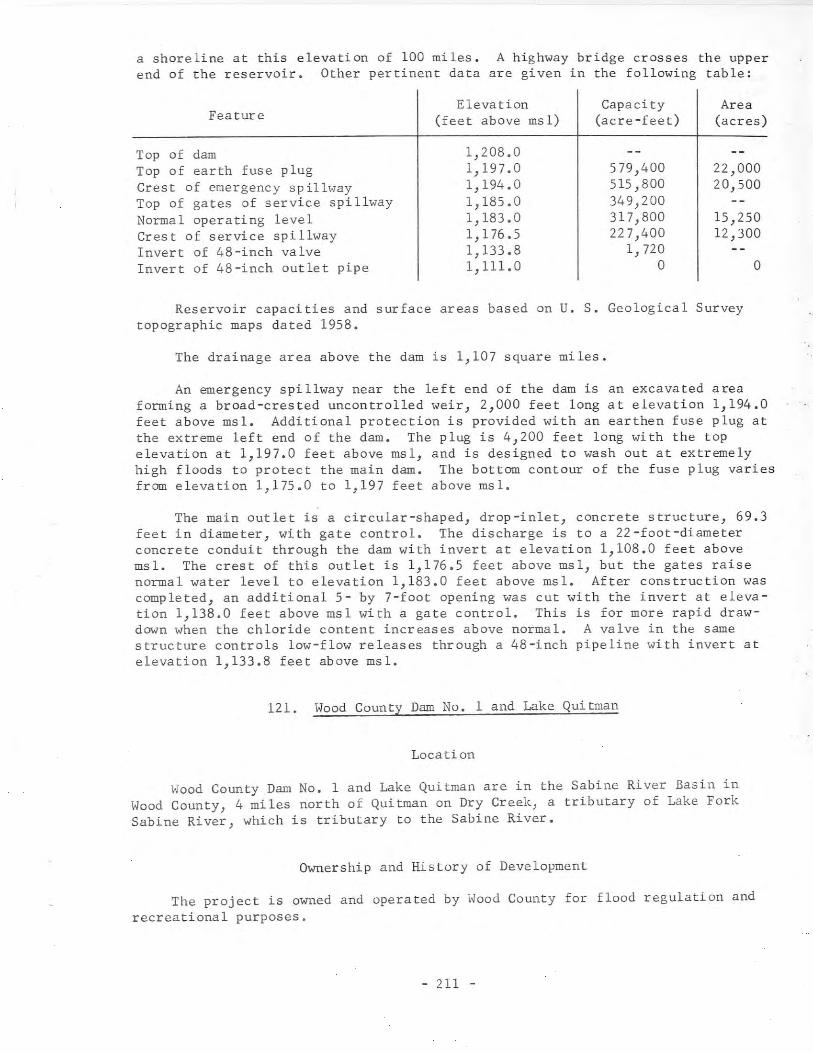
a shoreline at this elevation of 100 miles. A highway bridge crosses the upperend of the reservoir. Other pertinent data are given in the following table:
Eleva tion Capacity AreaFeature (feet above msl) (acre-feet) (acres)
Top of dam 1,208.0Top of earth fuse plug 1,197.0 579,400 22,000Crest of emergency spillway 1,194.0 515,800 20,500Top of gates of service spillway 1,185.0 349,200Normal operating level 1,183.0 317,800 15,250Crest of service spillway 1, 176.5 227,400 12,300Invert of 48-inch valve 1,133.8 1,720Invert of 48-inch outlet pipe 1,111.0 0 0
Reservoir capacities and surface areas based on U. S. Geological Surveytopographic maps dated 1958.
The drainage area above the dam is 1,107 square miles.
An emergency spillway near the left end of the dam is an excavated areaforming a broad-crested uncontrolled weir, 2,000 feet long at elevation 1,194.0feet above msl. Additional protection is provided with an earthen fuse plug atthe extreme left end of the dam. The plug is 4,200 feet long with the topelevation at 1,197.0 feet above msl, and is designed to wash out at extremelyhigh floods to protect the main dam. The bottom contour of the fuse plug variesfrom elevation 1,175.0 to 1,197 feet above msl.
The main outlet is a circular-shaped, drop-inlet, concrete structure, 69.3feet in diameter, with gate control. The discharge is to a 22-foot-diameterconcrete conduit through the dam with invert at elevation 1,108.0 feet abovemsl. The crest of this outlet is 1,176.5 feet above msl, but the gates raisenormal water level to elevation 1,183.0 feet above msl. After construction wascompleted, an additional 5- by 7-foot opening was cut with the invert at elevation 1,138.0 feet above msl with a gate control. This is for more rapid drawdown when the chloride content increases above normal. A valve in the samestructure controls low-flow releases through a 48-inch pipeline with invert atelevation 1,133.8 feet above msl.
121. Wood County Dam No.1 and Lake Quitman
Location
Wood County Dam No. 1 and Lake Quitman are in the Sabine River Basin inWood County, 4 miles north of Quitman on Dry Creek, a tributary of Lake ForkSabine River, which is tributary to the Sabine River.
Ownership and History of Development
The project is owned and operated by Wood County for flood regulation andrecreational purposes.
- 211 -
Authorization to build a dam and store 7,440 acre-feet of floodwater forrecreational use was obtained by Permit No. 1982 (Application No. 2178) datedMarch 23, 1961 from the State Board of Water Engineers to Wood County.
Construction of the dam began June 1, 1961, and was completed ~une 1,1962. Deliberate impoundment of water began May 15, 1962.
Physical Description
The dam is an earthfill structure 2,500 feet long with a maximum height of42 feet and the top of the dam at elevation 413.0 feet above msl. The maximumbottom width is 256 feet, and the top width is 20 feet. The upstream face isprotected with a 4-inch concrete slab laid on an 8-inch sand base between elevations 385.0 and 405.0 feet above msl.
The lake has a capacity of 7,440 acre-feet and a surface area of 814 acresat service spillway crest elevation of 395.0 feet above msl, and is used forflood retardation and recreational purposes. There is approximately 10,600acre-feet of flood surcharge capacity between the crests of the service spillway and the emergency spillway.
The drainage area of Dry Creek above the dam is 31 square miles.
An emergency spillway, located on the right end of the dam, is an excavated, broad-crested weir with crest length of 600 feet at elevation 405.0 feetabove ms 1.
The service spillway is a rectangular drop-inlet structure near the leftend of the dam with crest elevation of 395.0 feet above msl with the dischargeto a .7- by 7-foot concrete conduit with invert at elevation 370.0 feet abovemsl.
The low-flow outlet isinvert at elevation 370.0.duit.
an 18-inch, valve-controlled concrete pipe. withThe discharge is through the service spillway con-
122. Victor Braunig Plant Dam and Victor Braunig Lake
Location
Victor Braunig Plant Dam and Victor Braunig Lake, formerly known as EastLake} are in the San Antonio River Basin in Bexar CountYJ 15 miles southeast orSan Antonio on Arroyo Seco, a tributary of the San Antonio River.
Ownership and History of Development
The project is owned and operated by the City Public Service Board of SanAntonio for condenser-cooling water for a steam-electric generating plant.Water rights were obtained by Permit No. 1990 (Application No. 2189) datedAugust 21, 1961 from the State Board of Water Engineers to the City PublicService Board. Permit No. 1990 grants permission to construct a dam creating
- 212 -
a lake on Arroyo Seco to store 26,500 acre-feet of water and annual use of12,000 acre-feet. After the lake is filled, the 12,000 acre-feet of water forannual use will consist of runoff of Arroyo Seco supplemented by water pumpedfrom the San Antonio River into the lake to maintain normal operating level.
Construction began June 6, 1961, and was completed in December 1962 whenpumping from the San Antonio River and impoundment of water began. Water usewill not start until the steam-electric generating plant is in operation in1967.
Physical Description
The dam is a rolled earth structure 9,543 feet long with a maximum heightof 80 feet and the top of the dam at elevation 515.0 feet above msl. The earthembankment has a maximum base width of 496 feet and top width of 18 feet, andcontains 1,900,000 cu yd of earth. The upstream side of the embankment is protected with rock riprap from elevation 500.0 feet above msl to the top of thedam.
The lake has a capacity of 26,500 acre-feet and a surface area of 1,350acres at operating water level elevation of 507.0 feet above msl. The pumpingplant for diverting water from the river to the lake contains two units with acapacity of 7,500 gpm each driven by 350 hp motors.
The water for condenser cooling will be pumped directly from the lake andreturned at a distant point to give circulation for cooling. The only consumptive use will be forced evaporation caused by heat added to the lake and plantuse. The City Public Service Board installed instruments and gages for obtaining a record of contents, water circulated, temperatures, and other data todetermine monthly water loss due to forced evaporation caused by heat added tothe lake.
The spillway is a concrete structure with a gated agee section with crestelevation at 493.0 feet above msl. The discharge is controlled by two 33 feetlong by 14 feet high taintor gates. The spillway will discharge into theArroyo Seco and then to the San Antonio River. The maximum design flood stageat elevation 511.2 feet above msl will give a spillway discharge of 20,750 cfswith freeboard of 3.8 feet.
As this lake is adjacent to and obtains water from the San Antonio River,no low-flow release is required.
The first generating unit of 230,000 kw capacity is scheduled for operationin April 1967, and will tie into the transmission system connecting other plantsof the Public Service Board and neighboring utility companies. The ultimatecapacity of this plant will be 1,215,000 kw.
- 213 -
123. Wood County Dam No.3 and Lake Hawkins
Location
Wood County Dam No.3 and Lake Hawkins are in the Sabine River Basin inWood County, 3 miles northwest of Hawkins on Little Sandy Creek, a tributaryto the Sabine River.
~vnership and History of Development
The project is owned and operated by Wood County for flood regulation andrecreational purposes.
Authorization to build a dam and store 10,400 acre-feet of floodwater forrecreational use was obtained by Permit No. 1984 (Application No. 2180) datedMarch 27, 1961 from the State Board of Water Engineers by Wood County.
Construction began June 9, 1961, and the dam was completed September 17,1962 with deliberate impoundment of water beginning August 1, 1962.
Permit No. 1984A (Application No. 2l80A) dated February 26, 1966 issued bythe Texas Water Rights Commission authorized the storage capacity to beincreased from 10,400 acre-feet to 11,890 acre-feet by raising the crest of theservice spillway 2 feet.
The work began July 5, 1966 and was completed shortly thereafter.
Physical Description
The dam is an earthfill structure 1,265 feet long and 58 feet high withthe top of the dam at elevation 363.0 feet above msl. The maximum bottom widthis 347 feet and the top width is 20 feet with the upstream face protected witha 4-inch concrete slab laid on an 8-inch sand blanket.
The enlarged lake has a capacity of 11,890 acre-feet and a surface area of776 acres at service spillway crest elevation of 343.75 feet above msl. At thecrest of the emergency spillway at elevation 353.0 feet, the capacity is 20,100acre-feet and the surface area is 1,064 acres. Dead storage space is 300 acrefeet.
The drainage area of Little Sandy Creek above the dam is 30 square miles.
The emergency spillway near the right end of the dam is 300 feet long withcrest at elevation 353.0 feet above msl with the discharge through an unpavedarea.
The service spillway outlet is a rectangular drop-inlet structure withcrest at elevation 343.75 feet above msl. The discharge is through a 7- by 7foot concrete conduit through the embankment with invert at elevation 314.0feet above msl.
- 214 -

The low-flow outlet is a valve-controlled, 18-inch concrete pipe withinvert at elevation 312.6 feet above msl with the discharge through the servicespillway conduit.
124. Wood County Dam No.4 and Lake Winnsboro
Location
Wood County Dam No.4 and Lake Winnsboro are in the Sabine River Basin inWood County, 6 miles southwest of Winnsboro on Big Sandy Creek, a tributary ofthe Sabine River.
Ownership and History of Development
The project is owned and operated by Wood County for flood regulation andrecreational purposes.
Permit No. 1985 (Application No. 2181) dated March 27, 1961 from the StateBoard of Water Engineers authorized Wood County to build a dam and store 6,600acre-feet of floodwater for recreational use.
Construction began June 15, 1961, and the dam was completed September 17,1962 with deliberate impoundment of water beginning July 15, 1962.
Permit No. 1985A (Application No. 2181A) dated February 23, 1966 issued bythe Texas Water Rights Commission authorized the storage capacity to beincreased from 6,600 acre-feet to 8,100 acre-feet by raising the crest of theservice spillway 2 feet. The work was completed May 10, 1966.
Record of contents published by the U. S. Geological Survey since June1962.
Physical Description
The dam is a rolled-earth structure 2,570 feet long with maximum height of44.5 feet with the top of the dam at elevation 436.5 feet above msl. The maximum bottom width is 268 feet, and the top width is 20 feet. The upstream faceis protected with a 4-inch COncrete slab laid on an 8-inch sand blanket.
The enlarged lake has a capacity of 8,100 acre-feet and a surface area of806 acres at service spillway crest elevation of 419.0 feet above msl, and isused for flood retardation and recreational purposes. At the crest of theemergency spillway at elevation 427.0 feet, the capacity is 16,270 acre-feetand the surface area is 1,268 acres.
Drainage area of Big Sandy Creek above the dam is 27.1 square miles.
The emergency spillway at the right end of the dam is a broad-crested weirwith crest length of 300 feet at elevation 427.0 feet above msl.
The service spillway outlet is a rectangular drop-inlet structure withcrest at elevation 419.0 feet above msl with the discharge to a 7- by 7-footconcrete conduit through the embankment with invert at elevation 392.0 feetabove msl.
- 215 -
The low-flow outlet is a valve-controlled, l8-inch concrete pipe withinvert at elevation 392.2 feet above msl. The discharge is through the servicespillway conduit.
125. Wood County Dam No.2 and Lake Holbrook
Location
Wood County Dam No. 2 and Lake Holbrook are in the Sabine River Basin inWood County, 4 miles northwest of Mineola on Keys Creek, a tributary of theSabine River.
Ownership and History of Development
The project is owned and operated by Wood County for flood regulation andrecreational purposes.
Authorization to build a dam and store 7,990 acre-feet of floodwater forrecreational use was obtained by Permit No. 1983 (Application No. 2179) dated}ffirch 23, 1961 from the State Board of Water Engineers to Wood County.
Construction began June 20, 1961, and the dam was completed November 28,1962 with deliberate impoundment of water beginning September 15, 1962.
Physical Description
The dam is an earthfill structure 3,100 feet long and 49 feet high withthe top of the dam at elevation 387.0 feet above msl. The embankment has amaximum bottom width of 300 feet and top width of 20 feet with the upstreamface protected by a 4-inch concrete slab laid on a 4-inch sand base from elevation 364.0 to elevation 380.0 feet above msl.
The lake has a capacity of 7,990 acre-feet and a surface area of 653 acresat service spillway crest elevation of 372.0 feet above msl. Dead storagecapacity is 200 acre-feet. There is surcharge capacity of 6,390 acre-feetbetween the crests of the service spillway and the emer~ency spillway.
The drainage area of Keys Creek above the dam is 15 square miles.
An emergency spillway is located near the left end of the dam with crestlength of 400 feet at elevation 380.0 feet above msl. The discharge is throughan unpaved area 900 feet long.
The service spillway is a rectangular drop-inlet structure with crest atelevation 372.0 feet above msl. The discharge is through a 7- by 7-foot concrete conduit through the embankment with invert at elevation 344.0 feet abovems!.
The low-flow outlet is a valve-controlled, l8-inch concrete pipe withinvert at elevation 343.5 feet above msl. The discharge is through the servicespillway conduit.
- 216 -
126. Flat Creek Dam and Flat Creek Reservoir
Location
Flat Creek Dam and Flat Creek Reservoir are in the Neches River Basin inHenderson County, 8 miles east of Athens on Flat Creek, a tributary of theNeches River.
Ownership and History of Development
The project is owned and operated by the Athens Municipal Water Authorityfor municipal water supply, flood regulation, and recreation.
Permit No. 1915 (Application No. 2079) dated September 26, 1958 from theState Board of Water Engineers authorized the Authority to construct a dam andstore storm, flood, and unappropriated waters of Flat Creek. The Permit allowsstorage of 32,840 acre-feet of water and annual diversion of 8,500 acre-feet ofwater for municipal use. Time for beginning construction was extended toSeptember 26, 1960 by Permit No. 1915B, dated November 3, 1960, by order of theState Board of Water Engineers.
Construction began September 25, 1961, and the dam closure was made anddeliberate impoundment of water started November 1, 1962. The project wascompleted at the end of May 1963.
Record of contents of reservoir published by U. S. Geological Survey sinceOctober 1964.
Physical Description
The dam is a rolled-earth structure 2,940 feet long and with maximumheight of 67 feet and the top of the dam at elevation 453.0 feet above msl.The embankment has a maximum bottom width of 528 feet, top width of 20 feet,and contains about 650,000 cu yd of material. The upstream face is protectedwith 18-inches of rock riprap from elevation 433.0 to 448.0 feet above msl.
The reservoir has a capacity of 32,790 acre-feet and a surface area of1,520 acres at the service spillway crest elevation of 440.0 feet above msl,and a capacity of 42,600 acre-feet at emergency spillway crest elevation of446.0 feet above msl. Invert of lowest outlet is at elevation 396.5 feet abovemsl with dead storage of about 50 acre-feet below that elevation.
Reservoir capacities and surface areas based on U. S. Geological Surveytopographic maps dated 1949 and 1950.
The drainage area of Flat Creek above the dam is 21.6 square miles.
The emergency spillway located to the left of the dam is an uncontrolledbroad-crested weir with crest length of 300 feet at elevation 446.0 feet abovemsl with the discharge through a graded unpaved area.
- 217 -
The service spillway consists of an uncontrolled J rectangularJ
box-typeJ
drop inlet with crest at elevation 440.0 feet above msl, which connects to a6- by 6-foot concrete box culvert extending through the dam with outlet end atelevation 382.0 feet above msl. The discharge enters a prepared channel andthence to the creekbed.
The low-flow outlet is an 18-inch prestressed concrete pipe encased inconcrete extending through the embankment with invert at elevation 396.5 feetabove msl. The flow is controlled by a slide valve on the entrance end operated by a 164-foot-long rod supported on concrete blocks on the embankmentslope up to the top of the dam. A gate valve is installed on the discharge endof the pipe for further control of the discharge.
Water is pumped from the reservoir to the filter and treatment plant inAthens through an 18-inch pipeline by deep-well-type turbine pumps installedin the suction pipes at an angle to the horizontal. Provisions are made fortwo additional pumps when required. The intakes are located on the right bankof the reservoir about 2 miles upstream from the dam.
127. Brady Creek Dam and Brady Creek Reservoir
Location
Brady Creek Dam and Brady Creek Reservoir are in the Colorado River Basinin McCulloch County, 3 miles west of Brady on Brady Creek, a tributary of theSan Saba River, which is tributary to the Colorado River.
Ownership and History of Development
The project is owned and operated by the city of Brady for municipal andindustrial water supply.
Permit No. 1953 (Application No. 2137) dated May 2, 1960 was granted tothe city by the State Board of Water Engineers. This authorized the construction of a dam to create a reservoir for storing 30,000 acre-feet of storm andfloodwaters from Brady Creek with annual use of 3,000 acre-feet for municipaland 500 acre-feet for industrial purposes. Water will be sold to Eden andother communities in the area for municipal use. The U. S. Soil ConservationService assisted in the financing of the project for the flood regulation.There are 35 flood-retarding structures in the watershed above the dam with atotal storage capacity of 4,290 acre-feet in sediment pools and 77,890 acrefeet in flood-retarding capacity; in addition, there are 600 farm and ranchponds.
Construction began December 27, 1961, and the embankment closure was madeJanuary 7, 1963 with impoundment beginning May 22, 1963. Completion date wasMay 14, 1963 when the project was accepted from the contractors.
Record of contents fran May 1963 published by the U. S. Geological Survey.
- 218 -

Physical Description
The dam is a compacted earthfill structure 8,400 feet long and 104 feethigh with the top of the dam at elevation 1,783.0 feet above msl. The embankment has a maximum bottom width of 640 feet and top width of 36 feet, and contains about 2,300,000 cu yd of material. The upstream face of the embankmentis paved with 6 feet of rock riprap for protection against wave action.
The reservoir has a conservation storage capacity of 30,430 acre-feet(includes 1,320 acre-feet dead storage) and a surface area of 2,020 acres atthe service spillway crest elevation of 1,743.0 feet above msl. At the emergency spillway crest elevation of 1,762.4 feet above msl the reservoir capacityis 90,310 acre-feet and the surface area is 4,464 acres. This gives 59,880acre-feet of surcharge space for temporary retention of floodwaters between thecrests of the service and emergency spillways. It was necessary to re-route asection of the tracks of the Gulf, Colorado & Santa Fe Railroad and to raise aportion of Farm-to-Market Road No. 2028 to clear the reservoir.
Reservoir capacities and surface areas based on U. S. Geological Surveytopographic maps dated 1960.
The drainage area of Brady Creek above the dam is 513 square miles, buta considerable portion of the runoff from the watershed is controlled by theu. S. Soil Conservation Service structures.
The emergency spillway on the right end of the dam is a broad-crested weirwith crest length of 1,000 feet at elevation 1,762.4 feet above msl, which discharges through a 2,600-foot-long channel section with caliche and limestonebottom.
The service spillway is an uncontrolled rectangular concrete drop inletstructure at elevation 1,743.0 feet above msl. The discharge is to a 7- by 7foot concrete box conduit that extends through the embankment to the channelbelow the dam.
The low-flow (service) outlet is a 36-inch cast-iron pipe extending throughthe embankment. Water may be discharged through this outlet by three sluicegates with 3- by 3-foot openings at elevations 1,712.0 feet, 1,727.0 feet, and1,733.0 feet. Dead storage capacity below elevation 1,712.0 feet is 1,320 acrefeet. The downstream end of the service outlet is fitted with a tee having a24-inch valve for control of water to the filter plant and an l8-inchvalve forlow-flow releases.
128. Sanford Dam and Lake Meredith
Location
Sanford Dam and Lake Meredith are in the Canadian RiverCounty, 10 miles northwest of Borger on the Canadian River.into Hutchinson, Moore, and Potter Counties.
- 219 -
Basin in HutchinsonThe lake extends
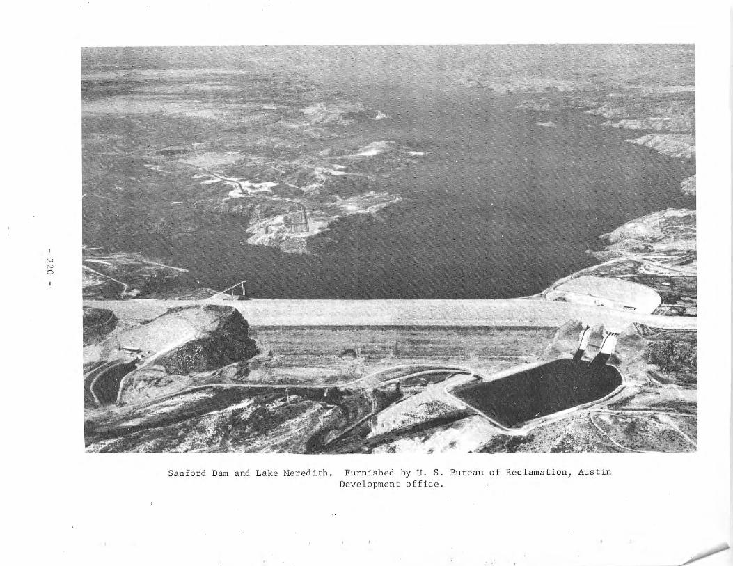
NNo
Sanford Dam and Lake Meredith. Furnished by U. S. Bureau of Reclamation, AustinDevelopment office.
Ownership and History of Development
The project was built and financed by the U. S. Government under thejurisdiction of the U. S. Bureau of Reclamation, and will later be owned andoperated by the Canadian River Municipal Water Authority.
The project was authorized by Permit No. 1815 (Application No. 1957)issued April 11, 1956 to the Canadian River Municipal Water Authority by theState Board of Water Engineers. Federal authorization for the U. S. Bureau ofReclamation planning and financing was Public Law No. 897 passed by the secondsession of the 8lst Congress, December 29, 1950. Permit No. l8l5B dated April1, 1958 extended the time for beginning of construction until April 11, 1960,and Permit No. l8l5C dated March 23, 1960 further extended the starting timeuntil April 11, 1962. On March 27, 1962 the State Board of Water Engineersissued an order approving construction plans and the additional storage spaceof 504,000 acre-feet allocated to flood control. The order amended the originalappropriation to allow 500,000 acre-feet of conservation storage capacity and405,000 acre-feet of reservoir storage capacity to be allocated for 50-yearsediment reserve. Permit No. 1815 authorizes an annual diversion of 100,000acre-feet of water for municipal use and 51,200 acre-feet for industrial use.The water is treated and pumped through pipelines to 11 cities and many industrial firms in the area. This water will replace ground-water supply, and incase of emergency or interruption of delivery of water the ground-water supplywill act as an alternate supply for the various towns.
This project is consistent with provisions of the compact, which providesfor the division of water of the Canadian River among the states of New Mexico,Oklahoma, and Texas.
Construction of the dam began March 11, 1962, and was completed in 1965.Impoundment of water began in October 1964. Record of contents published bythe U. S. Geological Survey beginning October 26, 1964.
Physical Description
The dam is an earthfill structure 6,380 feet long and 198 feet high abovethe streambed containing over 15 million cu yd of material. The maximum bottomwidth is 1,900 feet and the top width is 40 feet with the top of the dam atelevation 3,011.0 feet above msl. The upstream face of the embankment is protected with 4 feet of rock riprap laid on gravel and sand bedding from elevation 2,890.0 feet above msl to the top. The downstream face and many areas inthe channel section are paved with rock riprap and drainage systems wereinstalled in the foundation and embankment area.
The reservoir, officially named Lake Meredith, has a total storage capacity of 1,407,600 acre-feet and a surface area of 21,639 acres at elevation2,965.0 feet above msl. Capacities and surface areas based on U. S. GeologicalSurvey topographic maps.
The total capacity of 1,407,600 acre-feet is allocated 43,100 acre-feetto dead storage, 543,200 to flood control, and 821,300 acre-feet to conservation (includes 361,900 acre-feet for 50-year sediment reserve). Top of conservation pool is at elevation 2,936.5 feet msl.
- 221 -
Water is diverted, filtered, treated, and pumped to cities and towns inthe area for municipal supply. The pumping plants and pipelines make up amajor item of investment of the project's total estimated costs of $103,230,000.
The drainage area of the Canadian River above the dam is 20,220 squaremiles, of which 4,172 square miles is probably noncontributing. The contributing drainage area to the Canadian River between Ute Dam near Logan, New Mexico,and Sanford Dam is 6,018 square miles.
The service spillway is an uncontrolled, circular, drop-inlet structurewith crest elevation of 2,965.0 feet above msl with a 22-foot-diameter circular control outlet works consists of an approach channel; concrete intakestructure; and a three-barreled, gate-controlled, circular-topped, horseshoeshaped conduit, 17 feet by 17 feet, that discharges to the outlet channel.
The river-outlet works for conservation water releases consists of anapproach channel and a concrete intake tower with twelve 5- by 5-foot slidegates at several elevations. A structural steel access bridge extends from thedam to the operating room on top of the tower. The discharge conduit is a 12foot-diameter concrete tube that increases to 16 feet in diameter at the gatechamber. From here 46-inch and 108-inch diameter pipes branch off to the watertreatment plant. Excess water can be spilled from this outlet to a stillingbasin and river channel.
Pertinent data on the dam, reservoir, and aqueduct are given below.
Sanford DamType--zoned earthfillVolume of earth ••••••••••.••••••••••.•••.•.•••••Height above streambed .Elevation above mean sea level (top of dam) ••••.Length of dam at crest •••.•.••.•••••••••••••••••
Reservoir (Lake Meredith)
15,308,000 cubic yards198 feet
3,011 feet6,380 feet
ElevationReservoir Surface area
Feature capacity of reservoir(feet above msl) (acre-feet) (acres)
Top of dam 3,011.0Top of design flood pool 3,004.9 2,434,200 30,465Top of controlled storage 2,965.0 1,407,600 21,639Top of maximum conser-
vation pool 2,936.5 864,400 16,504Invert of flood control
outlet works 2,894.0 313,700 9,455Si 11 of lowes t ga te in
river outlet works 2,850.0 43,100 2,773
- 222 -
AqueductPipeline--concrete pressure pipeLength ...•.....•••.....•...•..............•.....•.MaximUID pipe diameter .Number of pumpi ng plan ts .....•..•.................Maximum lift from average level Lake Meredith
to high leve 1 near Amari 110 .Maximum design capaci ty , .
322 mi les96 inches10
760 feet183 cfs, or 118 mgd
Reservoir capacities and surface areas are based on U. S. GeologicalSurvey topographic maps and were computed by the U. S. Bureau of Reclamation.
129. Somerville Dam and Somerville Reservoir
Location
Somerville Dam and Somerville Reservoir are in the Brazos River Basin inBurleson and Washington Counties, 2 miles south of Somerville on Yegua Creek,a tributary of the Brazos River.
Ownership and History of Development
The project is owned by the U. S. Government and operated by the U. S.Army Corps of Engineers, Fort Worth District. A contract has been made by theGovernment whereby the Brazos River Authority will pay $4,871,000 for the conservation storage together with a percentage of the operating cost. Paymentwill be over a 50-year period. Government authorization for the constructionwas the Flood Control Act of September 3, 1954, Public Law 780, 83rd Congress,second session.
The Brazos River Authority obtained Permit No. 2110 (Application No. 2295)dated July 24, 1964 from the Texas Water Commission to impound 160,110 acre-feetof water in Somerville Reservoir and to divert annually: 50,000 acre-feet formunicipal purposes, 50,000 acre-feet for industrial purposes, and 50,000 acrefeet for irrigation of land in the Brazos River Basin and adjacent coastal areaand use the bed and banks of Yegua Creek and the Brazos River to convey thewater to place of use. However the amount of water for diversion with priorityof right under this permit is limited to 48,000 acre-feet of water per annumrather than the amount authorized for diversion.
Construction began June 4, 1962 and was 97 percent complete at end of 1966.Deliberate impoundment of water began January 3, 1967.
Physical Description
The dam is an earthfill structure 20,210 feet long (plus a dike 4,715 feetlong) and 80 feet high with the top of the dam at elevation 280.0 feet abovemsl. Top width of the embankment is 20 feet.
- 223 -
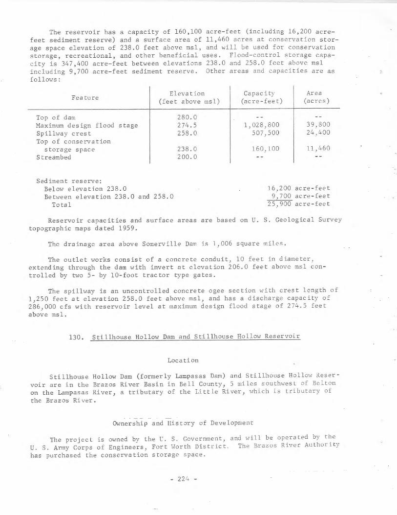
The reservoir has a capacity of 160,100 acre-feet (including 16,200 acrefeet sediment reserve) and a surface area of 11,460 acres at conservation storage space elevation of 238.0 feet above msl, and will be used for conservationstorage, recreational, and other beneficial uses. Flood-control storage capacity is 347,400 acre-feet between elevations 238.0 and 258.0 feet above mslincluding 9,700 acre-feet sediment reserve. Other areas and capacities are asfollO\,s:
Fea ture
Top of damMaximum des ign flood stageSpilh,ay crestTop of conservation
storage spaceStreambed
Elevation(feet above msl)
280.0274.5258.0
238.0200.0
Capac it)'
(acre-feet)
1,028,800507,500
160.100
Area(acres)
39,80024,400
11 ,460
Sediment reserve:Below elevation 238.0Between elevation 238.0
Totaland 258.0
16,2009,700
25,900
acre-feetacre - fee t
Be re - fee t
Reservoir capacities and surface areas are based on U. S. Geological Surveytopographic maps dated 1959.
The drainage area above Somerville Dam is 1,006 square miles.
The outlet works consist of a concrete conduit) 10 feet in diameter,extending through the dam with invert at elevation 206.0 feet above msl controlled by two 5- by 10-foot tractor type gates.
The spillway is an uncontrolled concrete ogee section with crest length of1,250 feet at elevation 258.0 feet above msl, and has a discharge capaCity of286,000 cfs with reservoir level at maximum design flood stage of 274.5 feetabove msl.
130. Stillhouse Hollow Dam and Stillhouse Hollow Reservoir
Location
Stillhouse Hollow Dam (formerly Lampasas Dam) and Stillhouse Hollow Reservoir are in the Brazos River Basin in Bell County,S miles southwest of Beltonon the Lampasas River, a tributary of the Little River, which is tributary ofthe Brazos River.
Ownership and History of Development
The project is owned by the U. S. Government, and will be operated by theU. S. Army Corps of Engineers, Fort Worth District. The Brazos River Authorityhas purchased the conservation storage space.
- 224 -
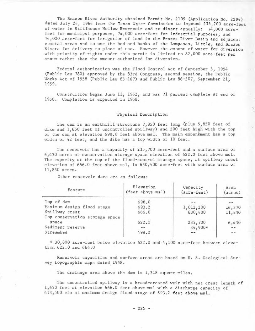
The Brazos River Authority obtained Permit No. 2109 (Application No. 2294)dated July 24, 1964 from the Texas Water Commission to impound 235,700 acre-feetof water in Stillhouse Hollow Reservoir and to divert annually: 74,000 acrefeet for municipal purposes, 74,000 acre-feet for industrial purposes, and74,000 acre-feet for irrigation of land in the Brazos River Basin and adjacentcoastal areas and to use the bed and banks of the Lampasas, Little, and. BrazosRivers for delivery to place of use. However the amount of water for diversionwith priority of rights under this permit is limited to 82,000 acre-feet perannum rather than the amount authorized for diversion.
Federal authorization was the Flood Control Act of September 3, 1954(Public Law 780) approved by the 83rd Congress, second session, the PublicWorks Act of 1958 (Public Law 85-167) and Public Law 86-307, September 21,1959.
Construction began June 11, 1962, and was 71 percent complete at end of1966. Completion is expected in 1968.
Physical Description
The dam is an earthfill structure 7,850 feet long (plus 5,850 feet ofdike and 1,650 feet of uncontrolled spillway) and 200 feet high with the topof the dam at elevation 698.0 feet above msl. The main embankment has a topwidth of 42 feet, and the dike has a top width of 10 feet.
The reservoir has a capacity of 235,700 acre-feet and a surface area of6,430 acres at conservation storage space elevation of 622.0 feet above msl.The capacity at the top of the flood-control storage space, at spillway crestelevation of 666.0 feet above msl, is 630,400 acre-feet with surface area of11,830 acres.
Other reservoir data are as follows:
Elevation Capacity AreaFeature (feet above msl) (acre-feet) (acres)
Top of dam 698.0Maximum design flood stage 693.2 1,013,300 16,370Spillway crest 666.0 630,400 11,830Top conservation storage space
space 622.0 235,700 6,430Sediment reserve 34,900*Streambed 498.0
* 30,800 acre-feet below elevation 622.0 and 4,100 acre-feet between elevation 622.0 and 666.0
Reservoir capacities and surface areas are based on U. S. Geological Survey topographic maps dated, 1958.
The drainage area above the dam is 1,318 square miles.
The uncontrolled spillway is a broad-crested weir with net crest length of1,650 feet at elevation 666.0 feet above msl with a discharge capacity of673,500 cfs at maximum design flood stage of 693.2 feet above msl.
- 225 -
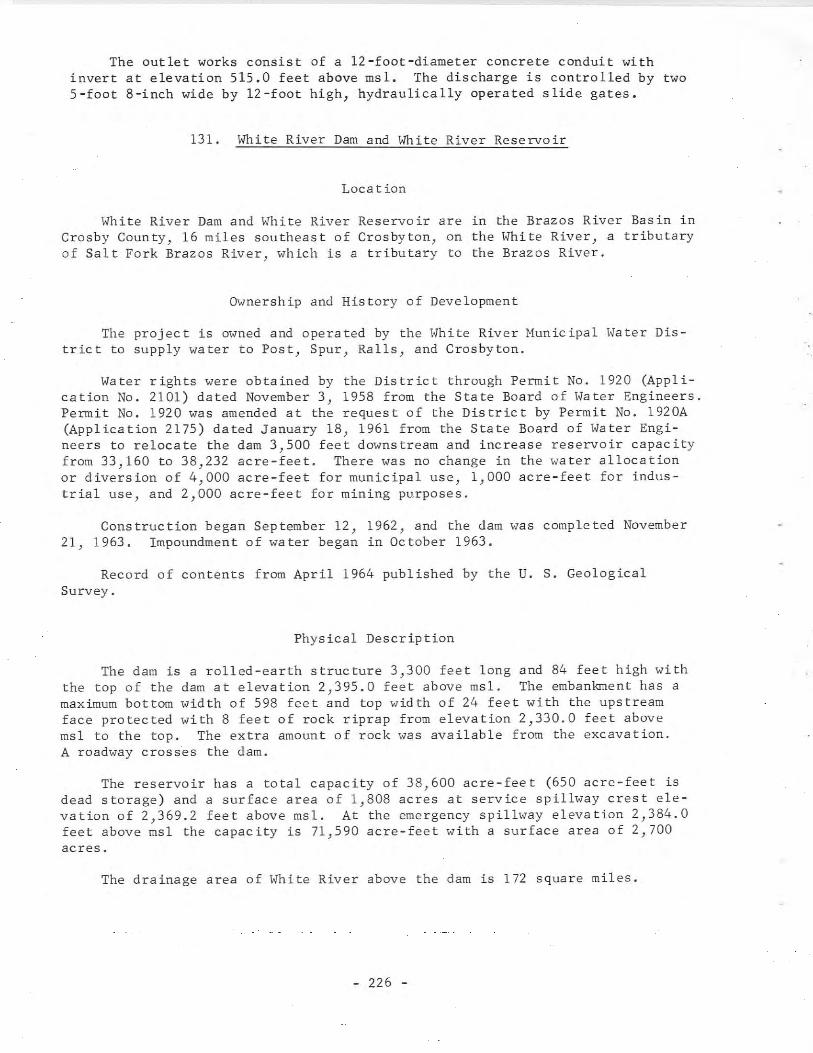
The outlet works consist of a 12-foot-diameter concrete conduit withinvert at elevation 515.0 feet above msl. The discharge is controlled by two5-foot 8-inch wide by 12-foot high, hydraulically operated slide gates.
131. White River Dam and White River Reservoir
Loea tion
\fhite River Dam and White River Reservoir are in the Brazos River Basin inCrosby County, 16 miles southeast of Crosbyton, on the l<hite River, a tributaryof Sal t Fork Brazos River, which is a tribu tary to the Brazos River.
~vnership and History of Development
The project is owned and operated by the White River Hunicipal l,ater District to supply water to Post, Spur, Ralls, and Crosbyton.
Water rights were obtained by the District through Permit No. 1920 (Application No. 2101) dated November 3, 1958 from the State Board of Water Engineers.Permit No. 1920 was amended at the request of the District by Permit No. 1920A(Application 2175) dated January 18, 1961 from the State Board of Water Engineers to relocate the dam 3,500 feet downstream and increase reservoir capacityfrom 33,160 to 38,232 acre-feet. There was no change in the water allocationor diversion of 4,000 acre-feet for municipal use, 1,000 acre-feet for industrial use, and 2,000 acre-feet for mining purposes.
Construction began September 12, 1962, and the dam was completed November21, 1963. Impoundment of water began in October 1963.
Record of contents from April 1964 published by the U. S. GeologicalSurvey.
Physical Description
The dam is a rolled-earth structure 3,300 feet long and 84 feet high withthe top of the dam at elevation 2,395.0 feet above msl. The embankment has amaximum bottom width of 598 feet and top width of 24 feet with the upstreamface protected with 8 feet of rock riprap from elevation 2,330.0 feet abovemsl to the top. The extra amount of rock was available from the excavation.A roadway crosses the dam.
The reservoir has a total capacity of 38,600 acre-feet (650 acre-feet isdead storage) and a surface area of 1,808 acres at service spillway crest elevation of 2,369.2 feet above msl. At the emergency spillway elevation 2,384.0feet above msl the capacity is 71,590 acre-feet with a surface area of 2,700acres.
The drainage area of White River above the dam is 172 square miles.
- 226 -
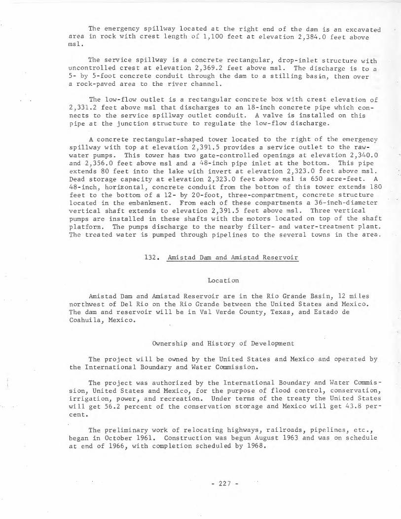
The emergency spillway located at the right end of the dam is an excavatedarea in rock with crest length of 1,100 feet at elevation 2,384.0 feet abovemsl.
The service spillway is a concrete rectangular} drop-inlet structure withuncontrolled crest at elevation 2,369.2 feet above msl. The discharge is to a5- by 5-foot concrete conduit through the dam to a stilling bas1n, then overa rock-paved area to the river channel.
The low-flow outlet is a rectangular concrete box with crest elevation of2,331.2 feet above msl that discharges to an l8-inch concrete pipe which connects to the service spillway outlet conduit. A valve is installed on thispipe at the junction structure to regulate the low-flow discharge.
A concrete rectangular-shaped tower located to the right of the emergencyspillway with top at elevation 2,391.5 provides a service outlet to the rawwater pumps. This tower has two gate-controlled openings at elevation 2,340.0and 2,356.0 feet above msl and a 48-inch pipe inlet at the bottom. This pipeextends 80 feet into the lake with invert at elevation 2,323.0 feet above msl.Dead storage capacity at elevation 2,323.0 feet above msl is 650 acre-feet. A48-inch, horizontal, concrete conduit from the bottom of this tower extends 180feet to the bottom of a 12- by 20-foot, three-compartment, concrete structurelocated in the embankment. From each of these compartments a 36-inch-diametervertical shaft extends to elevation 2,391.5 feet above msl. Three verticalpumps are installed in these shafts with the motors located on top of the shaftplatform. The pumps discharge to the nearby filter- and water-treatment plant.The treated water is pumped through pipelines to the several towns in the area.
132. Amistad Dam and Amistad Reservoir
Location
Amistad Dam and Amistad Reservoir are in the Rio Grande Basin, 12 milesnorthwest of Del Rio on the Rio Grande between the United States and Mexico.The dam and reservoir will be in Val Verde County, Texas, and Estado deCoahuila, Mexico.
Ownership and History of Development
The project will be owned by the United States and Mexico and operated bythe International Boundary and Water Commission.
The project was authorized by the International Boundary and Water Commission, United States and Mexico, for the purpose of flood control, conservation,irrigation, power, and recreation. Under terms of the treaty the United Stateswill get 56.2 percent of the conservation storage and Mexico will get 43.8 percent.
The preliminary work of relocating highways, railroads, pipelines, etc.,began in October 1961. Construction was begun August 1963 and was on scheduleat end of 1966, with completion scheduled by 1968.
- 227 -
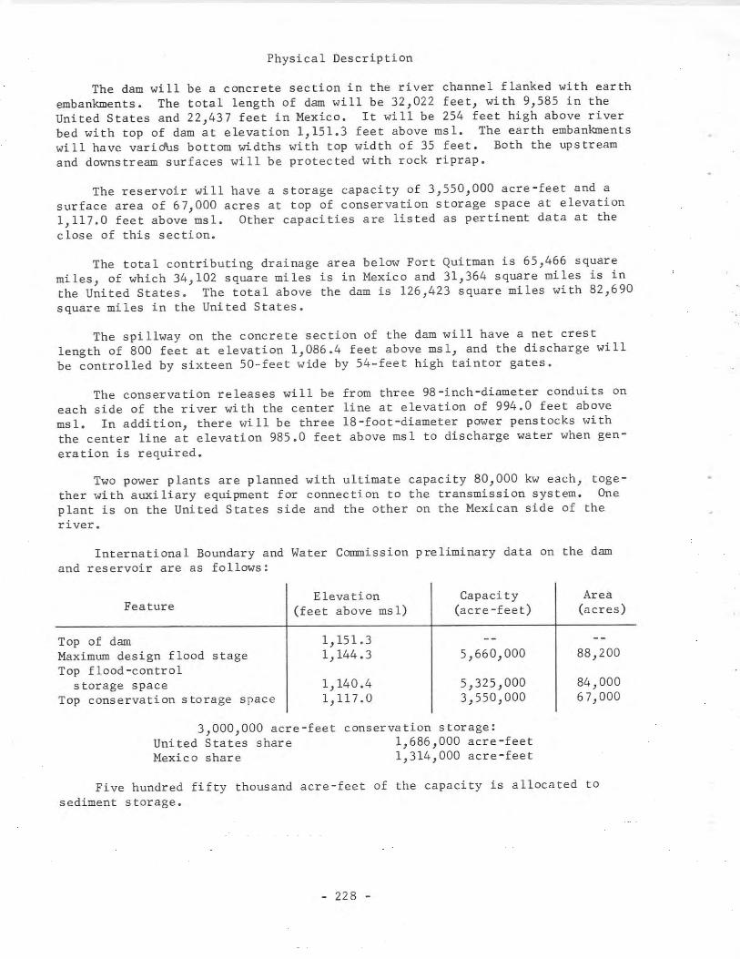
Physical Description
The dam will be a concrete section in the river channel flanked with earthembankments. The total length of dam will be 32,022 feet, with 9,585 in theUnited States and 22,437 feet in Mexico. It will be 254 feet high above riverbed with top of dam at elevation 1,151.3 feet above msl. The earth embankmentswill have varidUs bottom widths with top width of 35 feet. Both the upstreamand downstream surfaces will be protected with rock riprap.
The reservoir will have a storage capacity of 3,550,000 acre-feet and asurface area of 67,000 acres at top of conservation storage space at elevation1,117.0 feet above msl. Other capacities are listed as pertinent data at theclose of this section.
The total contributing drainage area below Fort Quitman is 65,466 squaremiles, of which 34,102 square miles is in Mexico and 31,364 square miles is inthe United States. The total above the dam is 126,423 square miles with 82,690square miles in the United States.
The spillway on the concrete section of the dam will have a net crestlength of 800 feet at elevation 1,086.4 feet above msl, and the discharge willbe controlled by sixteen 50-feet wide by 54-feet high taintor gates.
The conservation releases will be from three 98-inch-diameter conduits oneach side of the river with the center line at elevation of 994.0 feet abovemsl. In addition, there will be three l8-foot-diameter power penstocks withthe center line at elevation 985.0 feet above msl to discharge water when generation is required.
Two power plants are planned with ultimate capacity 80,000 kw each, together with auxiliary equipment for connection to the transmission system. Oneplant is on the United States side and the other on the Mexican side of theriver.
International Boundary and Water Commission preliminary data on the damand reservoir are as follows:
Feature
Top of damMaximum design flood stageTop flood-control
storage spaceTop conservation storage space
Elevation Capacity Area(feet above msl) (acre-feet) (acres)
1,151.31,144.3 5,660,000 88,200
1,140.4 5,325,000 84,0001,117.0 3,550,000 67,000
3,000,000 acre-feetUnited States shareMexico share
conservation storage:1,686,000 acre-feet1,314,000 acre-feet
Five hundred fifty thousand acre-feet of the capacity is allocated tosediment storage.
- 228 -
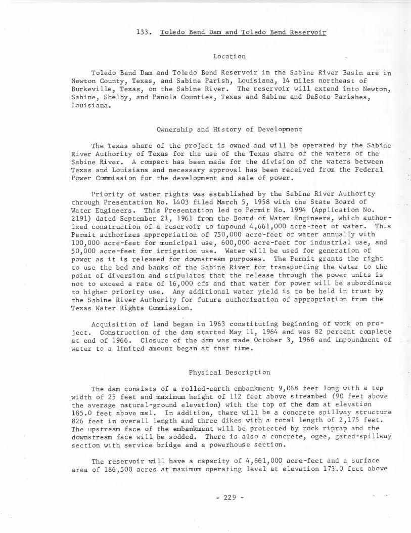
133. Toledo Bend Dam and Toledo Bend Reservoir
Location
Toledo Bend Dam and Toledo Bend Reservoir in the Sabine River Basin are inNewton County, Texas, and Sabine Parish, Louisiana, 14 miles northeast ofBurkeville, Texas, on the Sabine River. The reservoir will extend into Newton,Sabine, Shelby, and Panola Counties, Texas and Sabine and DeSoto Parishes,Louisiana.
Ownership and History of Development
The Texas share of the project is owned and will be operated by the SabineRiver Authority of Texas for the use of the Texas share of the waters of theSabine River. A compact has been made for the division of the waters betweenTexas and Louisiana and necessary approval has been received from the FederalPower Commission for the development and sale of power.
Priority of water rights was established by the Sabine River Authoritythrough Presentation No. 1403 filed March 5, 1958 with the State Board ofWater Engineers. This Presentation led to Permit No. 1994 (Application No.2191) dated September 21, 1961 from the Board of Water Engineers, which authorized construction of a reservoir to impound 4,661,000 acre-feet of water. ThisPermit authorizes appropriation of 750,000 acre-feet of water annually with100,000 acre-feet for municipal use, 600,000 acre-feet for industrial use, and50,000 acre-feet for irrigation use. Water will be used for generation ofpower as it is released for downstream purposes. The Permit grants the rightto use the bed and banks of the Sabine River for transporting the water to thepoint of diversion and stipulates that the release through the power units isnot to exceed a rate of 16,000 cfs and that water for power will be subordinateto qigher priority use. Any additional water yield is to be held in trust bythe Sabine River Authority for future authorization of appropriation from theTexas Water Rights Commission.
Acquisition of land began in 1963 constituting beginning of work on project. Construction of the dam started May 11, 1964 and was 82 percent completeat end of 1966. Closure of the dam was made October 3, 1966 and impoundment ofwater to a limited amount began at that time.
Physical Description
The dam consists of a rolled-earth embankment 9,068 feet long with a topwidth of 25 feet and maximum height of 112 feet above streambed (90 feet abovethe average natural-ground elevation) with the top of the dam at elevation185.0 feet above msl. In addition, there will be a concrete spillway structure826 feet in overall length and three dikes with a total length of 2,175 feet.The upstream face of the embankment will be protected by rock riprap and thedownstream face will be sodded. There is also a concrete, ogee, gated-spillwaysection with service bridge and a powerhouse section.
The reservoir will have a capacity of 4,661,000 acre-feet and a surfacearea of 186,500 acres at maximum operating level at elevation 173.0 feet above
- 229 -
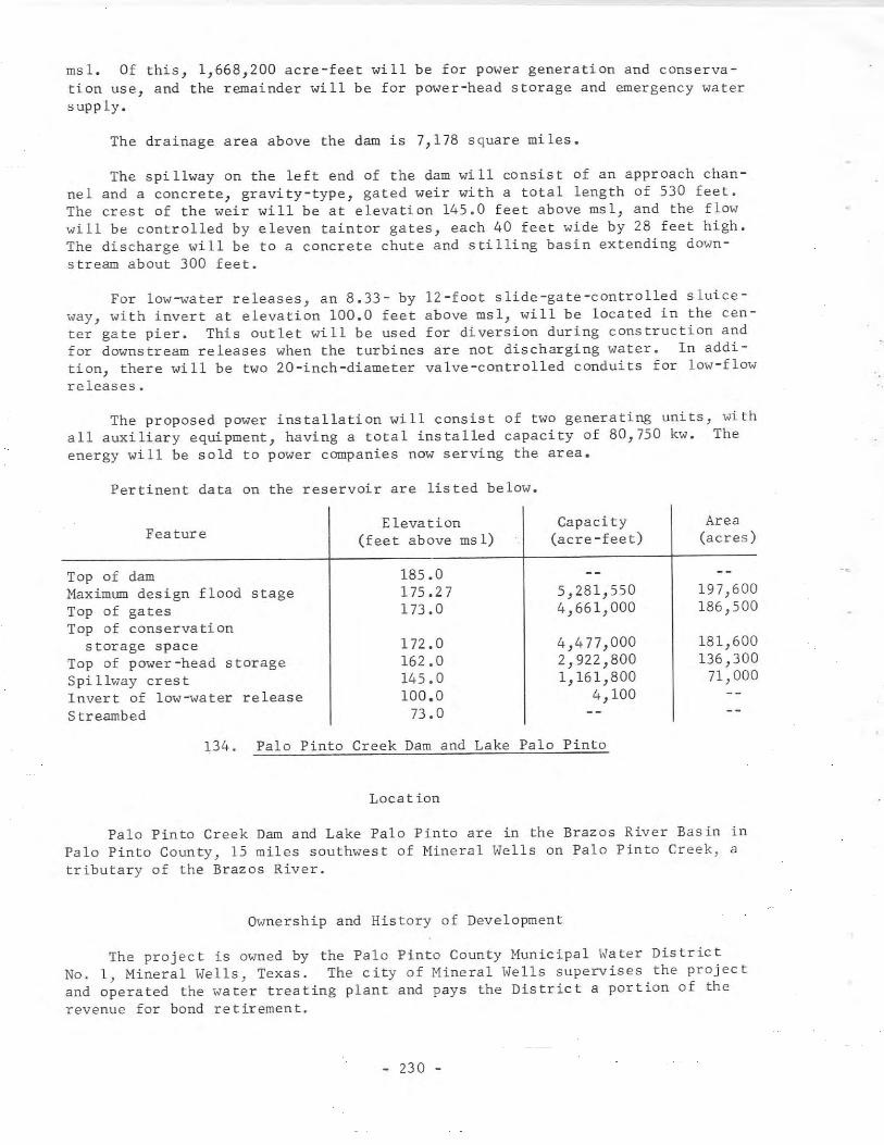
msl. Of this, 1,668,200 acre-feet will be for power generation and conservation use, and the remainder will be for power-head storage and emergency watersupply.
The drainage area above the dam is 7,178 square miles.
The spillway On the left end of the dam will consist of an approach channel and a concrete, gravity-type, gated weir with a total length of 530 feet.The crest of the weir will be at elevation 145.0 feet above msl, and the flowwill be controlled by eleven taintor gates, each 40 feet wide by 28 feet high.The discharge will be to a concrete chute and stilling basin extending downstream about 300 feet.
For low-water releases, an 8.33- by 12-foot slide-gate-controlled sluiceway, with invert at elevation 100.0 feet above msl, will be located in the center gate pier. This outlet will be used for diversion during construction andfor downstream releases when the turbines are not discharging water. In addition, there will be two 20-inch-diameter valve-controlled conduits for low-flowreleases.
The proposed power installation will consist of two generating units, withall auxiliary equipment, having a total installed capacity of 80,750 kw. Theenergy will be sold to power companies now serving the area.
Pertinent data on the reservoir are listed below.
Elevation Capaci ty AreaFeature (feet above ms 1) (acre-feet) (acres)
Top of dam 185.0Maximum design flood stage 175.27 5,281,550 197,600Top of gates 173 .0 4,661,000 186,500Top of conservation
storage space 172 .0 4,477,000 181,600Top of power-head storage 162.0 2,922,800 136,300Spi llway cres t 145.0 1,161,800 71,000Invert of low-water release 100.0 4,100Streambed 73.0
134. Palo Pinto Creek Dam and Lake Palo Pinto
Locat ion
Palo Pinto Creek Dam and Lake Palo Pinto are in the Brazos River Basin inPalo Pinto County, 15 miles southwest of Mineral Wells on Palo Pinto Creek, atributary of the Brazos River.
Ownership and History of Development
The project is owned by the Palo Pinto County Municipal Water DistrictNo.1, Mineral Wells, Texas. The city of Mineral Wells supervises the projectand operated the water treating plant and pays the District a portion of therevenue for bond retirement.
- 230 -
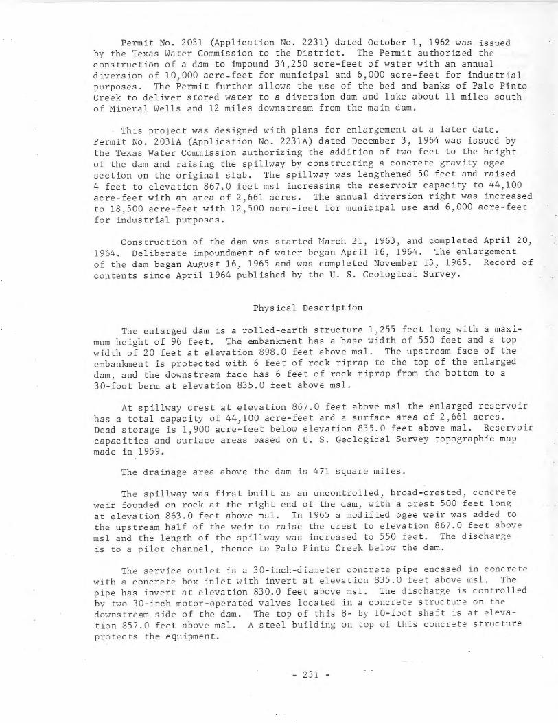
Permit No. 2031 (Application No. 2231) dated October 1, 1962 was issuedby the Texas Water Commission to the District. The Permit authorized theconstruction of a dam to impound 34,250 acre-feet of water with an annualdiversion of 10,000 acre-feet for municipal and 6,000 acre-feet for industrialpurposes. The Permit further allows the use of the bed and banks of Palo PintoCreek to deliver stored water to a diversion dam and lake about 11 miles southof Mineral Wells and 12 miles downstream from the main dam.
This project was designed with plans for enlargement at a later date.Permit No. 2031A (Application No. 2231A) dated December 3, 1964 was issued bythe Texas Water Commission authorizing the addition of two feet to the heightof the dam and raising the spillway by constructing a concrete gravity ogeesection on the original slab. The spillway was lengthened 50 feet and raised4 feet to elevation 867.0 feet msl increasing the reservoir capacity to 44,100acre-feet with an area of 2,661 acres. The annual diversion right was increasedto 18,500 acre-feet with 12,500 acre-feet for municipal use and 6,000 acre-feetfor industrial purposes.
Construction of the dam was started March 21, 1963, and completed April 20,1964. Deliberate impoundment of water began April 16, 1964. The enlargementof the dam began August 16, 1965 and was completed November 13, 1965. Record ofcontents since April 1964 published by the U. S. Geological Survey.
Physical Description
The enlarged dam is a rolled-earth structure 1,255 feet long with a maximum height of 96 feet. The embankment has a base width of 550 feet and a topwidth of 20 feet at elevation 898.0 feet above msl. The upstream face of theembankment is protected with 6 feet of rock riprap to the top of the enlargeddam, and the downstream face has 6 feet of rock riprap from the bottom to a30-foot berm at elevation 835.0 feet above msl.
At spillway crest at elevation 867.0 feet above msl the enlarged reservoirhas a total capacity of 44,100 acre-feet and a surface area of 2,661 acres.Dead storage is 1,900 acre-feet below elevation 835.0 feet above msl. Reservoircapacities and surface areas based on U. S. Geological Survey topographic mapmade in 1959.
The drainage area above the dam is 471 square miles.
The spillway was first built as an uncontrolled, broad-crested, concreteweir founded on rock at the right end of the dam, with a crest 500 feet longat elevation 863.0 feet above msl. In 1965 a modified ogee weir was added tothe upstream half of the weir to raise the crest to elevation 867.0 feet abovemsl and the length of the spillway was increased to 550 feet. The dischargeis to a pilot channel, thence to Palo Pinto Creek below the dam.
The service outlet is a 30-inch-diameter concrete pipe encased in concretewith a concrete box inlet with invert at elevation 835.0 feet above ms!. Thepipe has invert at elevation 830.0 feet above msl. The discharge is controlledby two 3D-inch motor-operated valves located in a concrete structure on thedownstream side of the dam. The top of this 8- by 10-foot shaft is at elevation 857.0 feet above msl. A steel building on top of this concrete structureprotects the equipment.
- 231 -
The water released from this reservoir travels in the streambed about 12miles to a diversion dam and lake. The diversion dam is a concrete, gravity,ogee section with crest at elevation 753.0 feet above msl. A 42-inch pipedelivers water from this diversion lake to a vertical concrete shaft. Themotors for the vertical pumps for delivering water by pipeline to the city ofMineral Wells water treating plant are located on a concrete roof slab overthis shaft.
135. Bastrop Dam and Lake Bastrop
Location
Bastrop Dam and Lake Bastrop are in the Colorado River Basin in BastropCounty, 3 miles northeast of Bastrop on Spicer Creek] a tributary of PineyCreek, which is a tributary of the Colorado River.
Ownership and History of Development
The project is owned and operated by the Lower Colorado River Authorityas a source of cooling water for the Sim Gideon Steam Generating Station.
The dam was authorized by Permit No. 2054 (Application No. 2265) datedMay 6, 1963 from the Texas Water Commission. This Permit allows the construction of a dam to create a reservoir with a capacity of 16,590 acre:feet ofwater with an annual use not to exceed 10,750 acre-feet. The Permit furtherrefers to diversion of water from the Colorado River by pumping to this lakewhen the runoff from Spicer Creek is not sufficient to maintain the lake atoperating elevation. This water will be released from Lake Travis under PermitNo. 1260] and the use of the bed and banks of the Colorado River for transporting the water is authorized under this Permit No. 2054.
Construction of the dam was started in May 1963 with completion in 1964and impoundment of water beginning at that time. Pumping from Colorado Riverinto Lake Bastrop began April 2] 1964.
Physical Description
The dam is a rolled-earth structure 4,500 feet long including the spillwayand approach section. The embankment will have side slopes of 3 to 1 bothupstream and downstream and a maximum height of 85 feet with the top of the damat elevation 458.0 feet above msl. A clay cutoff wall is provided with additional protection of steel sheet piling in certain areas. The upstream face ofthe embankment is protected by 2 feet of rock riprap on a 9-inch filter blanketfrom elevation 445.0 feet above msl to the top.
The lake has a capacity of 16,590 acre-feet and surface area of 906 acresat operating elevation of 450.0 feet above msl. The lake level is maintainednear a constant elevation as the only consumptive use is heat loss and plantservice. In addition to furnishing industrial water, the lake provides recreational facilities to the public.
- 232 -
The drainage area above the dam is 9 square miles, but runoff is supplemented by pumping from the Colorado River.
The spillway at the left end of the embankment is a concrete ogee sectionwith crest at elevation 425.0 feet above msl. The discharge will be controlledby two 45 feet long by 25 feet high taintor gates.
Required downstream flow can be supplied by operation of the taintor gatesas there is no low-flow outlet in this structure.
In connection with this project thereColorado River with three vertical pumps.concrete pipe, 18,000 feet long, extendingthe lake.
is a river intake structure on theThe discharge is through a 33-inchfrom the river intake structure to
The first 125,000 kw generating unit in the Sim Gideon Power Plant wasplaced in operation in 1965 with additional units scheduled to meet futurepower requirements.
136. Bardwell Dam and Bardwell Reservoir
Location
Bardwell Dam and Bardwell Reservoir are in the Trinity River Basin inEllis County, 3 miles southeast of Bardwell on Waxahachie Creek, a tributary ofChambers Creek, which is a tributary to the Trinity River.
Ownership and History of Development
The project was built and is owned and operated by the U. S. Army Corps ofEngineers, Fort Worth District. It was authorized by the Flood Control Act ofMarch 31, 1960 for flood control, water conservation, recreation, and otherbeneficial use. The Trinity River Authority entered into contract with theU. S. Government and obtained Permit No. 2068 (Application No. 2250) datedMarch 18, 1963 from the Texas Water Commission for the use of the conservationstorage and yield of the reservoir. The Permit authorizes the storage of 54,900acre-feet and annual use of 9,600 acre-feet of water.
The project was started August 7, 1963 when the contractor began work onaccess roads and other facilities. Impoundment of water began November 20,1965, and project was completed in June 1966. Record of contents published bythe U. S. Geological Survey beginning November 21, 1965.
Physical Description
The dam is anheight of 82 feet.The embankment hasrock riprap placed
earth and concrete structure 15,400 feet long with a maximumThe top of the dam is at elevation 460.0 feet above msl.
a top width of 20 feet with the upstream face protected byon a gravel blanket.
- 233 -
The capacity of the reservoir is 140,000 acre-feet and the surface area is6,040 acres at top of flood-control pool (spillway crest) at elevation 439.0feet above msl. The capacity at top of conservation pool at elevation 421.0feet is 54,900 acre-feet and the surface area is 3,570 acres. Sediment reservecapacity is 12,100 acre-feet below elevation 421.0 feet and 5,500 acre-feetbetween elevations 421.0 and 439.0 feet. The water yield from this reservoirwill supply the cities of Ennis, Waxahachie, and possibly others.
The drainage area above the dam is 178 square miles.
The spillway is an uncontrolled, broad-crested, concrete weir at the rightend of the dam with crest length of 350 feet at elevation 439.0 feet above msl.The discharge will be to an excavated channel.
A concrete outlet structure with one IO-foot-diameter conduit will extendthrough the embankment with invert at elevation 391.0 feet above msl. The discharge will be controlled by two 5- by 10-foot sluice gates.
137. Cleburne Dam and Lake Pat Cleburne
Location
Cleburne Dam and Lake Pat Cleburne are in the Brazos River Basin inJohnson County, 6 miles south of Cleburne on Nolands River, a tributary of theBrazos River.
Ownership and History of Development
The project is owned and operated by the city of Cleburne for a municipalwater supply.
The project was authorized by Permit No. 2027 (Application No. 2233) datedOctober 1, 1962 from the Texas Water Commission. The Permit authorized construction of a dam to create a reservoir with storage capacity of 25,600 acrefeet and to divert 6,000 acre-feet of water annually for municipal use.
Construction started August 9, 1963 and was completed in 1964. Storagebegan August 4, 1964. Record of contents published by U. S. Geological Surveysince April 1965.
Physical Description
The dam is a rolled-earth structure 5,050 feet long including the l50-footlong service spillway, and 76 feet high with the top of the dam at elevation753.0 feet above msl. The embankment has a top width of 25 feet with 3 to 1slope both upstream and downstream. The upstream slope is protected from elevation 700.0 feet above msl to the top with 24 inches of rock riprap on an 8-inchgravel blanket.
The reservoir will have a capacity of 25,560 acre-feet and a surface areaof 1,545 acres at the service spillway crest elevation of 733.5 feet above msl.All of this capacity is allocated to conservation storage.
- 234 -
The drainage area above the dam is 100 square miles.
The emergency spillway is an excavated channel in a natural saddle at theright end of the dam. The crest length is 500 feet at elevation 744.0 feetabove ms 1.
The service spillway, at the left end, is part of the dam. This is a concrete structure with approach channel, spillway chute, and stilling basin. Theuncontrolled concrete ogee section has a crest length of 150 feet at elevation733.5 feet above msl.
The outlet works consists of a vertical, octagon-shaped shaft with topelevation 745.0 feet above msl. A walkway extends from the embankment to thisstructure. Two sluice gates, one with invert at elevation 722.0 feet, and theother with invert at elevation 690.0 feet, admit water from lake to shaft. A36-inch-diameter steel cylinder concrete pipe, with invert at elevation 690.0feet above msl, extends from the bottom of the shaft through the embankment.
At a junction near the downstream toe of the dam, two 30-inch-diameter pipesbranch from this conduit. One discharges downstream with a control valveinstalled on the end. The other is the raw-water line to a pumping plant. Thepumps in this plant deliver the raw water through a pipeline to the filterationand treating plant.
Lake Pat Cleburne elevations and capacities are as follows:
Feature
Top of damTop of design flood poolEmergency spillway crestService spillway crestInvert of upper sluice gateInvert of lower sluice gate
Elevation(feet above msl)
753.0752.3744.0733.5722.0690.0
Capacity(acre-feet)
66,70045,43025,560U,760
U5
Reservoir capacities based on U. S. Geological Survey topographic mapmade in 1961.
138. North Fork Buffalo Creek Dam andNorth Fork Buffalo Creek Reservoir
Location
North Fork Buffalo Creek Dam and North Fork Buffalo Creek Reservoir are inthe Red River Basin in Wichita County, 5 miles northwest of Iowa Park on NorthFork Buffalo Creek, a tributary to the Wichita River.
Ownership and History of Development
This project is owned and operated by the Wichita County Water Control andImprovement District No. 3 for municipal water supply for Iowa Park.
- 235 -
The District obtained Permit No. 2036, dated December 7, 1962, (Application No. 2239) from the Texas Water Commission to build a dam and impound 20,200acre-feet of water. The capacity was reduced to 15,400 acre-feet and authorizedby Permit No. 2036-A dated May 14, 1964. The Permit authorized diversion of1,120 acre-feet of water per annum for municipal use at a rate not to exceed 5cubic feet per second.
Construction was started May 14, 1964 and completed November 10, 1964 withdeliberate impoundment of water beginning at that time. The water in the reservoir had not reached operating elevation as of December 1966, and no water hadbeen diverted because the supply from Lake Iowa Park was adequate.
Physical Description
The dam is an earthfill structure 5,019 feet long and 47 feet high with thetop of the dam at elevation 1,058.0 feet above msl. The embankment has a downstream slope 2 1/2:1 and upstream slope 3:1. The upstream face is protectedwith two feet or more of sandstone riprap.
The reservoir has a capacity of 15,400 acre-feet with a surface area of1,500 acres at the service spillway elevation 1,048.0 feet above msl, and acapacity of 19,000 acre-feet with a surface area of 1,730 acres at emergencyspillway crest elevation of 1,050.0 feet above msl. Reservoir capacities andsurface areas based on survey made prior to construction of dam. A profile ofthe reservoir was made for the District's record so that later observation canbe made to determine the amount of sedimentation.
The drainage area above the dam is 33 square miles.
The emergency spillway located at the left end of the dam has a crest lengthof 600 feet at elevation 1,050.0 feet above msl. Water is guided to the spillway by training levees upstream and away from the toe of the embankment to theriver channel by downstream levees.
The service spillway is an uncontrolled drop inlet concrete structure witha 5- by 5-foot square concrete barrel outlet extending through the dam discharging downstream to the original stream channel.
The water supply structure is a 5- by 5-foot vertical concrete shaft withtop at elevation 1,053.0 feet above msl. Water may be drawn from the reservoirat four levels and is controlled by gate valves installed inside the tower withoperating rods extending to the top platform. Access to the tower is by boat.A 24-inch outlet extends from the bottom of the structure with valve controlfor low-flow discharge. The pipe also has two l2-inch outlets for the pumpsuction connections. A small building contains the pumps, motors and controls.The pumps discharge to a l6-inch raw water line to Iowa Park.
- 236 -
139. Conroe Dam and Lake Conroe
Location
Conroe Dam and Lake Conroe are in the San Jacinto River Basin in MontogomeryCounty, 7 miles northwest of Conroe on the West Fork of the San Jacinto River,which is tributary to the San Jacinto River. The lake will extend into WalkerCounty.
Ownership and History of Development
The project will be owned and operated by the San Jacinto River Authority.Permit No. 1962 (Application No. 2108) dated June 9, 1960, was issued by theBoard of Water Engineers. The Permit authorizes the construction of a dam toimpound 380,400 acre-feet of water and divert annually 66,000 acre-feet formunicipal use, 28,500 acre-feet for industrial purposes and 5,500 acre-feet formining use. The Permit authorizes the use of the bed and banks of West Fork ofthe San Jacinto River to convey water to existing Lake Houston.
A 2-year extension of time for starting construction was authorized by theTexas Water Commission on June 18, 1962.
Permit No. 1962A (Application No. 2l08A) dated August 31, 1965 authorizedthe location of the dam to be moved approximately 400 feet upstream and tochange the storage capacity to 430,260 acre-feet at elevation 201.0 feet abovemsl.
By order dated June 15, 1964 the Texas Water Commission declared the project under construction as of June 4, 1964. More than 2 million dollars hadbeen spent for acquisition of land, foundation tests, etc.) prior to this date.Actual construction is scheduled to begin early in 1967.
Physical Description
The dam will be a zoned earth embankment with a cutoff trench and impervious core. The total length will be 12,600 feet including the levees at eachend. The main dam will be 6,000 feet long and 79 feet high above the averagestreambed, with a top width of 20 feet at elevation 222.0 feet above msl. Theupstream slope will be 3 to 1 to elevation 201.0 and 2 to 1 from this elevationto the top. Riprap will be placed from elevation 175.0 to 212.0 feet above msl.The downstream slope will be to 3 to 1 to elevation 212.0 and 2 to 1 from 212.0to the top and will be sodded. An 110-foot wide berm will be built both upstream and downstream from elevation 175.0 feet msl to the base of the dam.
The lake will have a capacity of 430,260 acre-feet with a surface area of20,985 acres at top of conservation storage at elevation 201.0 feet above msl.At emergency spillway elevation 214.0 feet above msl the capacity will be780,000 acre-feet with a surface area of 39,000 acres. This information takenfrom an area-capacity curve shown on the application drawings.
The drainage area above the dam is 444 square miles.
- 237 -
The spillway will be a drop-inlet reinforced concrete structure with acrest diameter of 60 feet at elevation 189.0 feet above msl equipped with twelvepower operated roller gates 12 feet wide by 14 feet high. Top of the gates isat elevation 203.0 feet above msl. Operating reservoir level is at elevation201.0 feet above msl. A bridge from the top of the dam will connect to an operating platform at elevation 220.0 feet above msl to provide access to the gatesfor operation and maintenance. The vertical shaft transposes to an ellbow discharging at elevation 106.0 feet above msl to a 23.5 foot diameter concreteconduit 497 feet long with the outlet end raised to elevation 137.50 feet abovemsl. The discharge will be over a concrete floor slab to a stilling basin withchute blocks, baffle blocks and end sill. From this basin the water will continue to an excavated channel with the bottom and sides protected by a 5-footthick layer of large stones.
The emergency spillway will be located at the left end of the dam with acrest length of 1,000 feet at elevation 214.0 feet above msl.
The service outlet for release of conservation water will be a 60-inch inside diameter 365-foot long reinforced concrete conduit with anti-seep collars.This pipe extends from an inlet box with invert at elevation 145.0 feet abovemsl to a rectangular reinforced concrete two compartment valve tower adjacentto the spillway conduit. The pipe from the tower is a double gated 60-inchreinforced concrete pipe with invert at elevation 143.1 feet above msl discharging into the spillway conduit. In addition to the valves a stop-log gate willprovide flow control from the first compartment to the discharge pipe. Thisgate will be used for regular operation and emergency valve repairs.
140. Rockwall-Forney Dam and Lake Ray Hubbard
LoeB tion
Rockwall-Forney Dam and Lake Ray Hubbard are in the Trinity River Basin inDallas and Kaufman Counties, 10 miles northeast of Dallas on the East Fork ofthe Trinity River.
Ownership and History of Development
The project is owned and will be operated by the city of Dallas for municipal water supply. The city obtained Permit No. 1923 (Application No. 2083)dated March 6, 1959 from the Board of Water Engineers, to construct a dam makinga reservoir to impound 490,000 acre-feet of water. The Permit also authorizesthe storage of 179,000 acre-feet of water to be diverted from the Iron BridgeReservoir (Lake Tawakoni) on the Sabine River (Permit No. 1792). Permit No.1923 authorizes the diversion and use of 89,700 acre-feet of water annually ata diversion rate not to exceed 309.4 cfs.
Owing to purchase of land, and railroad and highway relocations,. the TexasWater Commission by resolution dated September 17, 1963 stated these items wereadequate for the requirement for commencement of work. Actual construction ofPhase I, the earthen embankment began June 13, 1964 and completed June 28, 1966.Construction of Phase Ill, the spillway section, started February 1, 1965 and
- 238 -
was 91% complete at the end of 1966. The contract for Phase II, completion ofthe embankment, was awarded October 17, 1966 and the project is scheduled forcompletion in 1967.
Physical Description
The dam will be a rolled earthfill structure 12,500 feet long (includingthe spillway section) and 68 feet high 'vith top of the dam at elevati.on 448.0feet above msl. The upstream and downstream toe of the embankment below elevation 404.0 feet above msl will be composed of dumped shale from required excavation. Both the upstream and downstream slopes of the embankment will varyfrom 3 to 1 near the top to 7 to 1 at the bottom. The ups tream slope will beprotected by 2 feet of rock riprap on a 9-inch filter blanket and the downstreamslope will be sodded.
The lake will have a capacity of 490,000 acre-feet and an area of 22,745acres at top of conservation pool at elevation 435.5 feet above msl.
The drainage area above Rockwall-Forney Dam is 1,074 square miles, of which770 square miles is above Lavon Dam.
The spillway will be a concrete, gravity type gate controlled structurelocated at the left end of the dam. The spillway crest will be at elevation409.5 feet above msl, and equipped with fourteen 40 feet long by 28 feet hightaintor gates. The gates will be operated by motor driven hoists. The floodwater discharge will be to a stilling basin designed to dissipate the energyof the water with a hydraulic jump and baffle blocks.
The low-flow outlet works will be incorporated in the spilhvay s true tureby installing gates in the three control gate piers.
The water-supply structure will be located near the right end of the dam.This is a concrete vertical tower with gated openings at various eleva tions forselected withdrawal of water. The discharge from the tower will be throughtwo 8-foot diameter by 320-foot long conduits with gravity flow to a pumpstation located below the dam. An access bridge will extend from the damto the operating deck of the tower at elevation 44.0 feet above msl.
141. Fish Creek Dam and Moss Lake
Location
Fish Creek Dam and Moss Lake are in the Red River Basin in Cooke County,11 miles northwest of Gainesville on Fish Creek, a tributary of the Red River.
Ownership and History of Development
Fish Creek Dam and Moss Lake are owned by the city of Gainesville for awater supply.
- 239 -
The city obtained Permit No. 2034 (Application No. 2234) dated November 12,1964 from the Texas Water Commission to construct a dam to impound 23,210 acrefeet of water. Water rights allows annual diversion of 4,500 acre-feet of waterfor municipal use and 2,500 acre-feet for industrial purposes.
Construction started December 8, 1964 and was completed September 24, 1966.Deliberate impoundment of water began in April 1966 in a limited amount beforethe closure section of the dam was completed.
Physical Description
The dam is an earthfill structure 1,990 feet long and 93 feet high withtop of dam at elevation 740.0 feet above msl. The crest width varies from 17to 40 feet to provide for FH Road 1201 along a portion of the crest. Thedownstream slope is 3 to 1 with the upstream slope 3 to 1 to elevation 715.0feet above msl and 2 to 1 from this elevation to the top of dam. A 65-footwide berm is at elevation 680.0 feet above msl. The face of the embankmentis protected with a 10-inch drainage blanket and 24 inches of rock riprap fromthis berm to top of the dam.
The lake has a capacity of 23,210 acre-feet with a surface area of 1,125acres at service spillway elevation 715.0 feet above msl, and a capacity of36,400 acre-feet with a surface area of 1,500 acres at emergency spillway crestelevation of 725.0 feet above msl.
The drainage area above the dam is 69 square miles.
The emergency spillway located to the left of the dam is an excavatedchannel forming a broad-crested weir with a crest length of 400 feet at elevation 725.0 feet above msl. The discharge section has a rock or hard shalebottom.
The service spillway is a concrete structure consisting of a 7- by 7-footconduit with a rectangular drop-inlet tower with crest elevation at 715.0 feetabove msl.
The low-flow outlet is a 30-inch culvert type pipe with invert at elevation 666.0 feet above msl. This pipe discharges into the upstream well of thevertical intake and control tower. Two other 3- by 3-foot gate outlets arelocated in the upper section of the tower with inverts at elevation 684.0 and702.0 feet above msl. These three outlets allow selected withdrawal of waterfrom the reservoir. Flow from the upstream well to the discharge well of thetower is controlled by a 3- by 3-foot gate with invert at 665.5 feet above msl.
From this tower the combined service and low-flow outlet is a 30-inch steelcylinder reinforced concrete pipe with invert at elevation 658.31 feet abovemsl. This pipe is encased with one foot of concrete with shear collars fromthe intake tower to the service spillway structure. From this point to thevalve vault it becomes an integral part of the 7- by 7-foot conduit for additional protection.
Low-flow releases can be discharged from the valve vault to the stillingbasin and thence downstream. Connections are available for pumping equipmentto deliver water to Gainesville when required.
- 240 -
142. Pat Mayse Dam and Pat Mayse Reservoir
Location
Pat Mayse Dam and Pat Mayse Reservoir are in the Red River Basin in LamarCounty, 2 miles southwest of Arthur City on Sanders Creek, a tributary of theRed River.
Ownership and History of Development
The project will be owned by the U. S. Government and operated by the ArmyCorps of Engineers, Tulsa District. The project was authorized by the FloodControl Act of October 23, 1962. The city of Paris is the local cooperativeagency and has purchased storage space in the reservoir. Permit No. 2137 (Application No. 2363) dated January 25, 1965 to the c'ity of Paris from the TexasWater Commission allows impoundment of 124,500 acre-feet of water to elevation451.0 feet above msl. The annual diversion permitted will by 61,610 acre-feetwith 25,000 acre-feet allocated to municipal purposes and 36,610 acre-feet toindustrial use. Water will be delivered by pipeline from the reservoir to awater treating plant adjacent to the present city plant.
Construction of the dam was started March 29, 1965 and was 75 percent complete on December 31, 1966.
Physical Description
The dam is an earthfill structure about 7,080 feet long with a maximumheight of 96 feet above the streambed, with crest width of the dam 32 feet atelevation 488.5 feet above msl. Both the slopes are 8 to 1 to elevation 465.0and 2.75 to 1 from here to top of dam. The upstream face is protected with 2.75feet of rock riprap from elevation 465.0 to top of dam. Additional rock isplaced on the 8 to 1 slope in the vicinity of the outlet works structure.
The reservoir will have a conservation storage capacity of 124,500 acrefeet and a surface area of 5,993 acres at elevation 451.0 feet avove msl. Thecapacity at top of designated flood control pool will be 189,100 acre-feet witha surface area of 7,680 acres at elevation 460.5 feet above msl. The capacityat elevation 477.0 feet, which is the crest of the uncontrolled spillway, willbe 352,800 acre-feet.
The uncontrolled spillway will be located in a saddle approximately 1,400feet to the right of the embankment. It will be about 1,700 feet long with a100-foot wide invert at elevation 477.0 feet above msl and side slopes 1-on-3.The flood control outlet structure will be a morning-glory type drop inlet withcrest at top of conservation pool elevation 451.0. A 24-inch low flow pipewill pass into the flood outlet at elevation 407.0. A l2-inch diameter watersupply pipe will be provided.
- 241 -
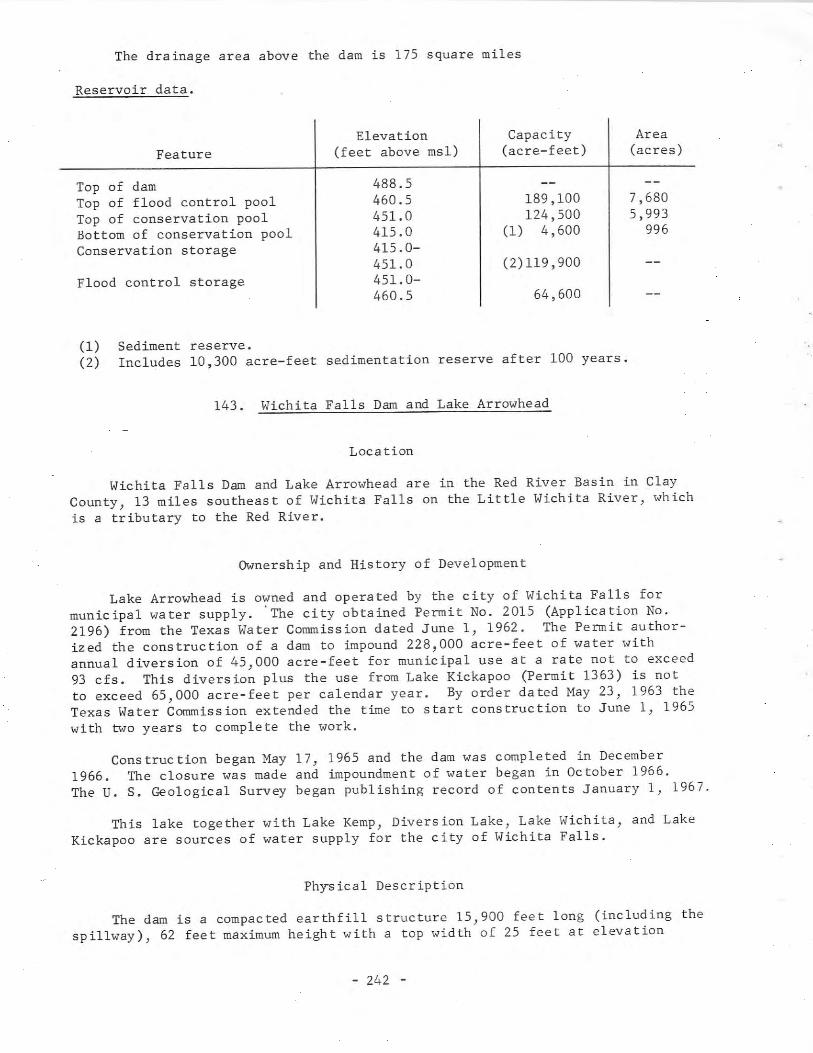
The drainage area above the dam is 175 square miles
Reservoir data.
Elevation Capacity AreaFeature (feet above msl) (acre-feet) (acres)
Top of dam 488.5Top of flood control pool 460.5 189,100 7,680Top of conservation pool 451.0 124,500 5,993Bottom of conservation pool 415.0 (1) 4,600 996Conservation storage 415.0-
451.0 (2)119,900Flood control storage 451.0-
460.5 64,600
(1) Sediment reserve.(2) Includes 10,300 acre-feet sedimentation reserve after 100 years.
143. Wichita Falls Dam and Lake Arrowhead
Location
Wichita Falls Dam and Lake Arrowhead are in the Red River Basin in ClayCounty, 13 miles southeast of Wichita Falls on the Little Wichita River, whichis a tributary to the Red River.
Ownership and History of Development
Lake Arrowhead is owned and operated by the city of Wichita Falls formunicipal water supply. 'The city obtained Permit No. 2015 (Application No.2196) from the Texas Water Commission dated June 1, 1962. The Permit authorized the construction of a dam to impound 228,000 acre-feet of water withannual diversion of 45,000 acre-feet for municipal use at a rate not to exceed93 cfs. This diversion plus the use from Lake Kickapoo (Permit 1363) is notto exceed 65,000 acre-feet per calendar year. By order dated May 23, 1963 theTexas Water Commission extended the time to start construction to June 1, 1965with two years to complete the work.
Construction began May 17, 1965 and the dam was completed in December1966. The closure was made and impoundment of water began in October 1966.The U. S. Geological Survey began publishing record of contents January 1, 1967.
This lake together with Lake Kemp, Diversion Lake, Lake Wichita, and LakeKickapoo are sources of water supply for the city of Wichita Falls.
Physical Description
The dam is a compacted earthfill structure 15,900 feet long (including thespillway), 62 feet maximum height with a top width of 25 feet at elevation
- 242 -
944.0 feet above msl. The downstream face is a 3: 1 slope with two 15-foot wideberms. The upstream face is a 5:1 slope from the base of the dam to a l5-footwide berm at elevation 894.0 feet above msl and 3: 1 slope from this berm to topof the dam. This upstream slope is covered with 2-feet of rock riprap laid onan 8-inch gravel blanket.
Lake Arrowhead has a capacity of 228,000 acre-feet and a surface area of13,500 acres at spillway crest elevation 926.0 feet above msl. At the maximumdesign flood stage elevation 939.55 feet above msl the capacity is 460,000acre-feet and the surface area is 18,000 acres.
Steel derricks have been erected over 14 oil wells in the lake area. Abarge will be used when any maintenance work is required.
The drainage area above the dam is 832 square miles of which 275 squaremiles is above Lake Kickapoo.
The spillway is a broad-crested concrete weir with an agee discharge section with a crest length of 1,525 feet at elevation 926.0 feet above msl. Theapproach is paved with an 8-inch gravel blanket and 24-inches of rock riprap.The discharge is to a stilling basin with both chute blocks and impact blocksto dissipate the energy of the water. A concrete bridge crosses the spillway.
The outflow structure is a reinforced concrete cylindrical tower 10 feetin diameter and 73 feet high erected on a 25-foot square concrete base. Anoperating platform at the top will support 3 hoists to operate 5-foot diameterslide gates with invert of one gate at elevation 908.0 feet and one with invertat 874.0 feet above msl for flow to the tower.
The third gate with invert at elevation 874.0 controls the flow to 426foot long 60-inch steel water supply pipe. This pipe will be supported on concrete cradles on the inside of an 8-foot diameter concrete conduit passingthrough the dam. The 60-inch pipe is connected to a wye outlet which willdivert metered water to the city pumping plant or discharge water to the streambelow the dam.
144. Coleman Dam and Coleman Reservoir
Location
Coleman Dam and Coleman Reservoir are in the Colorado River Basin in Coleman County, 14 miles north of Coleman on Jim Ned Creek, a tributary of PecanBayou which is a tributary of the Colorado River.
Ownership and History of Development
This project is owned and operated by the city of Coleman for municipalwater supply.
The city obtained Permit No. 1924 (Application No. 2096) dated Hay 12,1959 from the Board of Water Engineers to construct a dam and impound 40,000acre-feet of water. Water rights allows annual diversion of 4,500 acre-feetfor municipal use and 4,500 acre-feet for industrial purposes. Permit No.
- 243 -
1924A dated June 14, 1965 was obtained from the Texas Water Commission allowingthe service spillway elevation to be changed from elevation 1,714.0 feet abovemsl to elevation 1,717.5 feet above msl to obtain the 40,000 acre-feet storage.All other rights remain the same as in Permit No. 1924.
Construction was started in August 1965 and completed May 10, 1966 withdeliberate impoundment of water beginning in April 1966.
Physical Description
The dam is an earthfill structure about 3,200 feet long with a maximumheight of 90 feet with the top of dam at elevation 1,740.0 feet above msl.The embankment has a 20-foot crest width ,,,ith 3 to 1 slope both upstream anddownstream. The downstream face has a six-inch gravel blanket and the upstreamface is protected with 24 inches of rock riprap from the top of the dam downto elevation 1,660.0 feet above msl.
The reservoir has a capacity of 40,000 acre-feet with a surface area of2,000 acres at service spillway elevation 1,717.5 feet above msl, and a capacity of 59,000 acre-feet with a surface area of 2,530 acres at emergency spillway crest elevation of 1,726.0 feet above msl. The emergency spillway is aconcrete weir 1,500 feet long beyond the right end of the dam.
The drainage area above the dam is 292 square miles.
The service spillway is a drop-inlet type concrete structure with a7-foot diameter reinforced concrete conduit extending through the dam. Theconduit discharges into a stilling basin with chute blocks, baffle blocks andan end sill.
A 5- by 7-foot slide gate installed in the base of the tower with invert atelevation 1,652.5 feet above msl provides a low-flow control at the upstreamend of the conduit.
Diversion for municipal use is controlled by three 2- by 2-foot slidegates with invert elevations of 1,662.5, 1,682.5 and 1,702.5 feet abovc msl.Each diversion connects to a 24-inch diameter concrete incased stell pipe thatdelivers the water to a pumping station located below the dam. This concreteincased pipe is made an integral part of the foundation for the 7-foot conduitfor additional strength and protection.
145. Mud Creek Dam and ~fud Creek Lake
Loea t ion
Mud Creek Dam and Mud Creek Lake are in the Neches River Basin in SmithCounty, 12 miles southeast of Tyler on Mud Creek, a tributary of the AngelinaRiver, which is a tributary to the Neches River.
- 244 -
Ownership and History of Development
The project is owned and will be operated by the city of Tyler in connection with present Lake Tyler for a municipal water supply. Permit No. 1843(Application No. 1988) dated October 1, 1956 from the Board of Water Engineersauthorized the construction of a dam creating a lake of approximately 43,100acre-feet capacity. The Permit authorizes annual diversion of 20,000 acre-feetof water from this lake for municipal use. The Permit further authorizes alterations to Whitehouse Dam increasing the capacity of Lake Tyler (See Project No.68). The Permit limits the total diversion from the two lakes to 50,000 acrefeet annually.
Land purchase and clearing began January 21, 1959. However, the projectwas delayed and actual construction did not start until February 11, 1966.Closure was made and deliberate impoundment of water began November 22, 1966.The dam was completed in December 1966.
Physical Description
The dam is a compacted-earth structure with a concrete spillway near thecenter. The dam is 50 feet high above the streambed with a total length of4,700 feet. The top of the dam is 20 feet wide with crest elevation 390.0 feetabove msl. The embankment slopes are 2.5 to 1 with the upstream face protectedwith 18 inches of rock riprap placed on an 18-inch gravel base from elevation366.0 to 386.0 feet above msl. The downstream face will be sodded with bermudagrass for protection.
The lake has a capacity of 44,000 acre-feet and an area of 2,570 acres atelevation 376.0 feet above msl. This new lake is connected to present LakeTyler with an excavated canal with the bottom at elevation 355.0 feet above msl.
The drainage area above the dam is 65 square miles.
The spillway located near the center of the dam is a reinforced concretestructure with a broad-crested weir with a crest length of 300 feet at elevation376.0 feet above msl. The spillway discharge basin has a length of 240 feet andslopes from the crest to the end of the basin at elevation 322.0 feet above msl.Chute blocks, baffle blocks and end wall are installed on the last 19 feet ofthe concrete basin slab. Beyond the end wall the channel floor is protected foran additional 50 feet with 2 feet of large rock on a I-foot gravel blanket.
The low-flow outlet is a 260-foot long 20-inch steel cylinder concretepipe extending from a concrete basin near the upstream toe through the embankment. The pipe is further encased in concrete with anti-seepage collars spaced40-feet apart. The discharge will be controlled by a slide valve with the operating rod extending up the embankment. The slide valve flange is located withinvert at elevation 346.75 feet above msl. A valve will be installed on thedownstream end of the pipe for additional control and future water supply connection.
- 245 -
146. Greenbelt Dam and Greenbelt Reservoir
Location
Greenbelt Dam and Greenbelt Reservoir are in the Red River Basin in DonleyCounty,S miles north of Clarendon, on the Salt Fork Red River, a tributaryof the Red River.
Olmership and History of Development
The reservoir is mvned and operated by the Greenbel t Municipal and Industrial Water Authority to supply water for municipal and industrial uses. Permit No. 1917 (Application No. 2094) was issued December 30, 1958 by the Boardof Water Engineers to construct a dam to impound 100,500 acre-feet of water andto divert annually 30,000 acre-feet for municipal and industrial use. Due tofoundation conditions} the location of the dam was moved and avo projectsfinally located as described in Permit 19l7B and 19l7C.
Permit No. 19l7B (Application No. 2094B) dated November 6, 1964 by theTexas Water Commission provides for two reservoirs instead of one. The maindam at State Highway 70 site creates a reservoir with a capacity of 59,800 acrefeet at elevation 2,664.0 feet above msl. The second reservoir, with a capacity of 20,200 acre-feet, is to be constructed at a future date on Lelia LakeCreek, 4 miles northwest of Hedley. The Permit changes the annual use to 17,000acre-feet for the following purposes: municipal use, 14,500 acre-feet; industrial use, 1,500 acre-feet; and mining use, 1,000 acre-feet. This authorizationincludes the 5,000 acre-feet from the future Lelia Lake Creek project. PermitNo. 19l7C issued April 8, 1965 by the Texas Water Commission approves changingthe diversion point of water of the Lelia Lake Creek project.
Construction of the Greenbelt Dam began April 12, 1966 and is expected tobe complete in early 1967. Closure of dam was made and deliberate impoundmentof water began December 5, 1966.
Physical Description
The dam is a compacted-earth structure 5,800 feet long with a maximumheight of 110 feet with top of the dam at elevation 2,686.0 feet above msl.The embankment has a top width of 20 feet and a maximum bottom width of 653feet, with upstream slopes 3:1 to elevation 2,664.0 and 2:1 from this to topof dam. This slope will be protected with rock riprap from elevation 2,632.0to 2,674.0 feet above msl. The downstream face will be sodded.
The reservoir has a capaCity of 59,800 acre-feet with a surface area of1,990 acres at the service spillway elevation of 2,664.0 feet above msl, and acapacity of 78,500 acre-feet with a surface area of 2,270 acres at emergencyspillway crest elevation of 2,674.0 feet above msl. The emergency spillway islocated at the left end of the dam with a crest length of 1,500 feet at elevation 2,674.0 feet above msl. State Highway 70 will be rerouted below the damand across the emergency spillway.
The dra inage area above the dam is 288 square miles.
- 246 -
The service spillway is a circular-drop inlet reinforced concrete structurelocated near the right end of the dam with an uncontrolled crest at elevation2,664.0 feet above msl. The vertical shaft will discharge to a 7- by 7-footreinforced concrete conduit with a bottom elevation 2,575.50 feet above msl.This 464-foot long conduit will discharge over a concrete slab to a stillingbasin with baffle box and end sill with floor elevation 2,567.0 feet above msl.Below the end sill large rocks further protect the channel from erosion.
The service intake structure located 270 feet upstream from the servicespillway is a concrete structure with invert at elevation 2,597.0 feet abovemsl. A 36-inch steel cylinder pipe reinforced with concrete and anti-seepcollars extends from this inlet to the service spillway outlet conduit. Fromthis point it continues adjacent to the large conduit through the embankmentto a valve vault near the stilling basin. One valve controls the discharge tothe stilling basin for downstream requirement. Another valve arrangement controls the discharge to a pump installation to supply raw water through a pipeline to the District's water treating plant.
147. Houston County Dam and Lake
Location
Houston County (formerly Little Elkhart Creek) Dam and Lake are in theTrinity River Basin in Houston County, 10 miles northwest of Crockett, on LittleElkhart Creek a tributary to the Trinity River.
Ownership and History of Development
The project is owned by Houston County Water Control and Improvement District No.1 and will supply water to Crockett, Grapeland and Latexo from theDistrict's treating plants and water lines. The dam was authorized by PermitNo. 2160 (Application No. 2380) dated May 10, 1965 from the Texas Water Commission. The Penmit allows the construction of a dam to create a reservoir to impound 19,500 acre-feet of water with an annual diversion of 3,500 acre-feet formunicipal use and 3,500 acre-feet for industrial purposes.
Construction of the dam started April 14, 1966 and was completed in December 1966. Closure of the dam was made and deliberate impoundment of water beganNovember 4, 1966.
Physical Description
The dam is a~rolled-earth structure 1,250 feet long and 63 feet high witha top width of 20 feet at elevation 277.0 feet above msl. The embankment has a3 to 1 upstream slope from the base to elevation 260.0 feet above msl and 2 to1 slope from this elevation to the top of the dam. This slope is protected withan 8-inch crushed rock blanket and 2 feet of iron ore rock riprap. The downstream face has a 3 to 1 slope and is protected from erosion with grass startedfrom sad.
- 247 -
The reservoir has a capacity of 19,500 acre-feet with a surface area of1,282 acres at the service spillway elevation 260.0 feet above msl, and a capacity of 27,000 acre-feet with a surface area of 1,600 acres at emergency spillway crest elevation of 265.0 feet above msl. Water is diverted from an upstreamintake structure, pumping plant and pipeline to the treating plant.
The drainage area above the dam is 44 square miles.
The emergency spillway at the right end of the dam is a broad-crested weirwith a crest length of 575 feet at elevation 265.0 feet above msl. The 3 toside slopes around the end and adjace~t to the downstream embankment has thesame riprap protection as the upstream embankment.
The service spillway located near the left end of the dam is a circularconcrete drop inlet structure with crest at elevation 260.0 feet above msl.This vertical shaft is structurally an integral part of the 7-foot square discharge conduit. This conduit extends through the embankment to a concretestilling basin, with baffle blocks and end sill.
The low-flow outlet is a concrete box inlet with invert at elevation 234.0feet above msl which discharges through an l8-inch concrete pipe encased in a5-foot square concrete block to the service spillway conduit. At a point32-feet upstream from the center line of the dam a valve operated from a manhole is installed to control the flow from this l8-inch pipe to the 7-footsquare service spillway discharge conduit.
148. Livingston Dam and Livingston Reservoir
Loca tion
Livingston Dam and Livingston Reservoir are in the Trinity River Basin inPolk and San Jacinto Counties, 6 miles southwest of Livingston on the TrinityRiver. The reservoir will extend into Trinity and t-1alker Counties.
~vnership and Histo~' of Development
The project will be jointly OImed and operated by the Trinity River Authority and city of Houston. Permit No. 1970 (Application No. 2139) dated October11, 1960 from the Board of Water Engineers authorized the construction of a damto impound 1,750,000 acre-feet of water and divert 1,254,400 acre-feet annuallyallocated as follows:
134,000 acre-feet for municipal use1,070,400 acre-f~et for industrial use
50,000 acre-feet for irrigation use
The Permit further grants the use of the bed and banks of the Trinity Riverfor transporting water to the point of diversion. The Permit states that therights are subordinate to permits and rL'servoir operations upstream from theproject. Permit No. 1970A (Application No. 2l39A) dated October 9, J962 fromthe Texas Water Commission extended the time for starting construction toOctober 11, 1964 and the time for completion to October 11, 1967.
- 248 -
Land purchases and foundation exploration and design have been in progressseveral years. Construction of the dam was started May 28, 1966 with completion date scheduled for December 1968. Livingston Dam construction was 22.8percent complete December 31, 1966.
Physical Description
The dam will be zoned earthfill and concrete structure 14,400 feet longwith a maximum height above streambed of 100 feet with top of dam at elevation145.0 feet above msl .. The upstream face of the dam will be on a 2.5 to 1 slopeprotected with 30 inches of rock riprap on 15 inches of bedding material froma berm at elevation 115.0 feet above msl to top of the dam. The downstreamslope will be 2.5 to 1 with a 2-foot clay blanket and 9 inches of top soil forsodding.
The reservoir will have a storage capacity of 1,750,000 acre-feet with asurface area of 84,800 acres at operating elevation 131.0 feet above msl.
The drainage area above the dam is 16,716 square miles
The spillway will be a concrete gravity structure 646 feet long locatednear the left end of the embankment. The ogee spillway crest will be at elevation 99.0 feet above msl with twelve 40 feet wide by 35 feet high taintor gatesand eleven interior and two abutment piers. Motor operated gate hoistingequipment will be mounted on the bridge above the spillway. The dischargeefrom the spillway will be to a stilling basin designed to dissipate the energyof the estimated maximum flow of 311,000 cfs.
An ou.tlet work will be provided for water supply and low-flow releases andconsists of a vertical concrete multi-gated inlet tower with operating equipmentand access bridge. There will be four 4- by 5-foot gates located at elevations93, 103, 112, and 119 feet above msl for selected withdrawal. Another openingwith invert at elevation 58.0 feet above msl will have an 8- by 10-foot slidegate control. The discharge from the tower will be to a 10-foot inside diameter cast-in-place concrete conduit extending through the dam to a stillingbasin with baffle blocks and end wall. The flow will continue in a rock linedchannel to a measuring weir section and thence to the channel outlet to theriver.
149. Decker Creek Dam and Decker Lake
Location
Decker Creek Dam and Decker Lake are in the Colorado River Basin in TravisCounty, 9 miles east of the capitol building in Austin on Decker Creek, a tributary of Gilliland Creek, which is a tributary of the Colorado River.
Ownership and History of Development
The project is being constructed and will be operated by the city of Austinas a source of cooling water for a steam-electric generating station.
- 249 -
The project was authorized by Permit No. l379-B (Application No. l477-B)dated December 16, 1965 from the Texas Water Rights Commission. The Permitallows the construction of a dam to impound 33,940 acre-feet of water with anannual use not to exceed 16,156 acre-feet of water for domestic, municipal)industrial, and recreational purposes. The Permit further allows diversion ofwater from the Colorado River by pumping to this reservoir for initial fillingand to maintain the lake at operating elevation.
Construction of the dam started May IS, 1966 and was 50 percent completeat the end of December 1966.
Physical Description
The dam will be a rolled-earth embankment on a clay foundation with amaximum height of 83 feet and crest width of 20 feet at elevation 563.0 feetabove msl. The crest length including a concrete spillway section will be 6,390feet long. The upstream face of the embankment will have a 3 to 1 slope with24 inches of rock riprap on 12 inches of bedding material extending from the topof the dam to elevation 545.0 feet above msl. The downstream face will have a3 to 1 slope from the top to elevation about 525 or normal ground level. A coretrench, filter drain and piezometer installations will provide seepage controland settlement information.
The lake will have a capacity of 33,940 acre-feet and a surface area of1,269 acres at elevation 555.0 feet above msl, which is top of taintor gates.The lake will be divided into two sections by a natural peninsula extending upstream from the dam. A cut across this peninsula will connect the two sectionsand serve as an approach channel to the spillway. The generating plant will belocated on the upper end of the peninsula with the cooling water intake on thewest side and the discharge on the east side. This will create a 4 mile circulating path for moving and cooling of the water.
The drainage area above the dam is 9.3 square miles, but runoff will besupplemented by pumping from the Colorado River.
The concrete spillway section with a controlled agee crest at elevation530.0 feet above msl is located near the center of the dam. Two 45 feet wideby 25 feet high taintor gates with motor driven hoists and electric controlswill control the discharge of flood water. Top of gates is at elevation 555.0feet above msl. Near the bottom or one gate a 4-inch pipe with valve will beinstalled to provide lm.-flow release without the necessity of operating thelarge ga te.
The spillway will have a concrete discharge channel, baffle blocks andstilling basin. Water will be retained in the stilling basin and wing wallarea for stabilization.
In connection with this project there will be an intake structure in theColorado River with the installation of two vertical pumps to lift the waterabout 160 feet. The discharge will be through a 36-inch concrete pressure pipe11,505 feet long to a concrete basin in the lake.
The first of several generating units in the powerplant in scheduled forservice in 1968.
- 250 -
150. Wallisville Dam and Wallisville Reservoir
Location
Wallisville Dam and Wallisville Reservoir are in the Trinity River Basinin Liberty and Chambers Counties, 2 miles below Wallisville on the TrinityRiver.
Ownership and History of Development
This multiple-purpose project is being constructed by the U. S. Army Corpsof Engineers. Permit No. 1974 (Application No. 2140) dated December 2, 1960to the city of Houston and the Trinity River Authority of Texas from the Boardof Water Engineers authorized the impoundment of 22,000 acre-feet of water withannual diversion of B9,600 acre-feet for the following uses: 20,000 acre-feetfor domestic and municipal use, 39,600 acre-feet for industrial purposes and30,000 acre-feet for irrigation. The Permit further divides the diversionbetween the two permittees.
Extension of time for beginning of construction and completion was authorized by Board order several times. The most recent order by the Texas WaterCommission dated September 2B, 1964 authorized a 24-month extension of timeuntil December 2, 1966 for starting construction and until December 2, 1969 forcompletion of the work.
An application to amend Permit No. 1974 to increase the storage capacityfrom 22,000 to 51,600 acre-feet by changing the operating elevation from 2.0feet to 4.0 feet above msl has been granted by the Texas Water Rights Commission but the amended permit has not been issued as of December 31, 1966 pendingreceipt of the contract between the U. S. Government and the permittees.
Work on the contract for the access road, Big Hog intake structure, canaland bridge began in September 1966 and was 9 percent complete at the end ofDecember 1966.
Physical Description
The non-overflow section of the dam is a compacted earthfill structure11,200 feet long and 24 feet high above streambed with the top varying fromelevation 11.0 to 12.0 feet above msl. The overflow section of the dam will bea broad-crested uncontrolled concrete slab over compacted earthfill. The crestwill be at two levels, 1,500 feet long at elevation 4.0 feet above msl and17,700 feet long at elevation 5.5 feet above msl.
The reservoir will have a capacity of 51,600 acre-feet and a surface areaof 19,700 acres at normal pool elevation 4.0 feet above msl. The reservoirwill have a multi-purpose use for salinity control, water conservation, navigation, recreation and fish and wildlife.
The drainage area is 17,760 square miles, of which 1,156 square miles isbelow Livingston Dam.
- 251 -
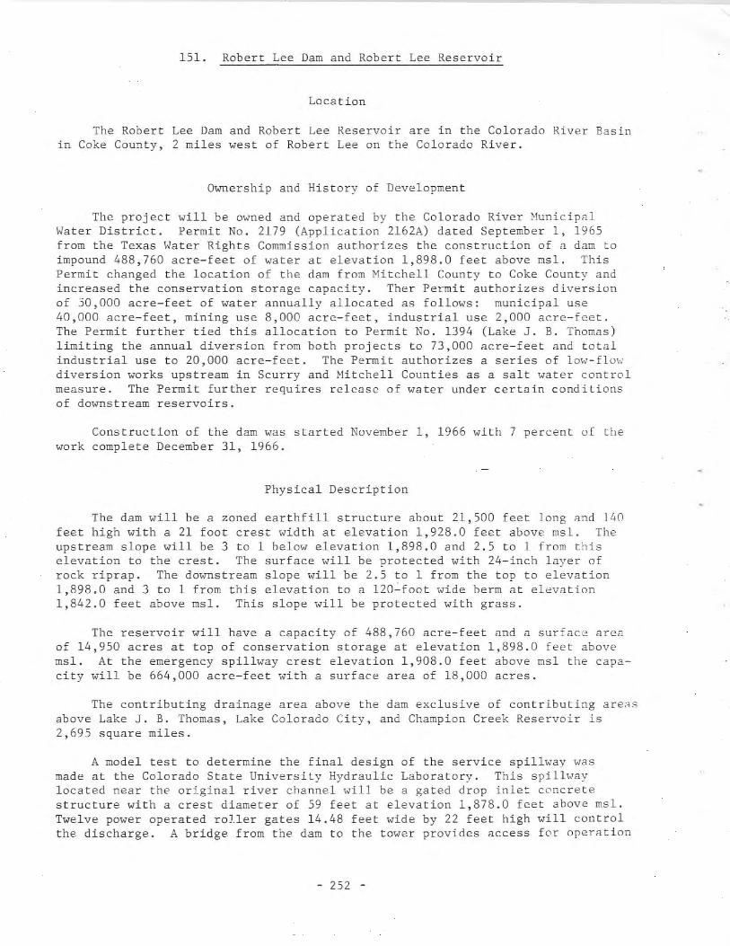
151. Robert Lee Dam and Robert Lee Reservoir
Location
The Robert Lee Darn and Robert Lee Reservoir are in the Colorado River Basinin Coke County, 2 miles west of Robert Lee on the Colorado River.
Ownership and History of Development
The project will be owned and operated by the Colorado River MunicipalWater District. Permit No. 2179 (Application 2162A) dated September 1, 1965from the Texas Water Rights Commission authorizes the construction of a dam toimpound 488,760 acre-feet of water at elevation 1,898.0 feet above msl. ThisPermit changed the location of the dam from ~[itchell County to Coke County andincreased the conservation storage capacity. Ther Permit authorizes diversionof 30,000 acre-feet of water annually allocated as follows: municipal use40,000 acre-feet, mining use 8,000 acre-feet, industrial use 2,000 acre-feet.The Permit further tied this allocation to Permit No. 1394 (Lake J. B. Thomas)limiting the annual diversion from both projects to 73,000 acre-feet and totalindustrial use to 20,000 acre-feet. The Permit authorizes a series of 1mv'-£10\'.ldiversion works upstream in Scurry and Nitchell Counties as a salt water controlmeasure. The Permit further requires release of water under certain conditionsof downstream reservoirs.
Construction of the dam was started November 1, 1966 with 7 percent of thework complete December 31, 1966.
Physical Description
The dam will be a zoned earthfill structure about 21,500 feet long and 140feet high with a 21 foot crest width at elevation 1,928.0 feet above msl. Theupstream slope will be 3 to 1 below elevation 1,898.0 and 2.5 to 1 from thiselevation to the crest. The surface will be protected with 24-inch layer ofrock riprap. The downstream slope will be 2.5 to 1 from the top to elevation1,898.0 and 3 to 1 from this elevation to a 120~foot wide berm at elevation1,842.0 feet above msl. This slope will be protected with grass.
The reservoir will have a capacity of 488,760 acre-feet and a surface areaof 14,950 acres at top of conservation storage at elevation 1,898.0 feet abovemsl. At the emergency spillway crest elevation 1,908.0 feet above msl the capacity will be 664,000 acre-feet with a surface area of 18,000 acres.
The contributing drainage area above the dam exclusive of contributing are~s
above Lake J. B. Thomas, Lake Colorado City, and Champion Creek Reservoir is2,695 square miles.
A model test to determine the final design of the service spillway wasmade at the Colorado State University Hydraulic Laboratory. This spillwaylocated near the original river channel will be a gated drop inlet concretestructure with a crest diameter of 59 feet at elevation 1,878.0 feet above msl.Twelve power operated roJ.ler gates 14.48 feet wide by 22 feet high will controlthe discharge. A bridge from the dam to the tower provides access for operation
- 252 -
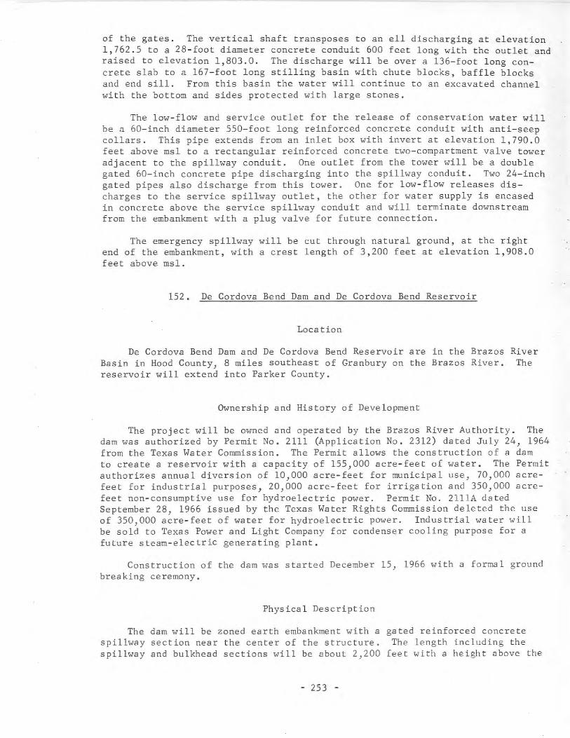
of the gates. The vertical shaft transposes to an ell discharging at elevation1,762.5 to a 28-foot diameter concrete conduit 600 feet long with the outlet andraised to elevation 1,803.0. The discharge will be over a 136-foot long concrete slab to a 167-foot long stilling basin with chute blocks, baffle blocksand end sill. From this basin the water will continue to an excavated channelwith the bottom and sides protected with large stones.
The low-flow and service outlet for the release of conservation water willbe a 60-inch diameter 550-foot long reinforced concrete conduit with anti-seepcollars. This pipe extends from an inlet box with invert at elevation 1,790.0feet above fisl to a rectangular reinforced concrete two-compartment valve toweradjacent to the spillway conduit. One outlet from the tower will be a doublegated 60-inch concrete pipe discharging into the spillway conduit. Two 24-inchgated pipes also discharge from this tower. One for low-flow releases discharges to the service spillway outlet, the other for water supply is encasedin concrete above the service spillway conduit and will terminate downstreamfrom the embankment with a plug valve for future connection.
The emergency spillway will be cut through natural ground, at the rightend of the embankment, with a crest length of 3,200 feet at elevation 1,908.0feet above msl.
152. De Cordova Bend Dam and De Cordova Bend Reservoir
Loea tion
De Cordova Bend Dam and De Cordova Bend Reservoir are in the Brazos RiverBasin in Hood County, 8 miles southeast of Granbury on the Brazos River. Thereservoir will extend into Parker County.
Ownership and History of Development
The project will be owned and operated by the Brazos River Authority. Thedam was authorized by Permit No. 2111 (Application No. 2312) dated July 24, 1964from the Texas Water Commission. The Permit allows the construction of a damto create a reservoir with a capacity of 155,000 acre-feet of water. The Permitauthorizes annual diversion of 10,000 acre-feet for municipal use, 70,000 acrefeet for industrial purposes, 20,000 acre-feet for irrigation and 350,000 acrefeet non-consumptive use for hydroelectric power. Permit No. 2lllA datedSeptember 28, 1966 issued by the Texas Water Rights Commission deleted the useof 350,000 acre-feet of water for hydroelectric power. Industrial water willbe sold to Texas Power and Light Company for condenser cooling purpose for afuture steam-electric generating plant.
Construction of the dam was started December 15, 1966 with a formal groundbreaking ceremony.
Physical Description
The dam will be zoned earth embankment with aspillway section near the center of the structure.spillway and bulkhead sections will be about 2,200
- 253 -
gated reinforced concreteThe length including the
feet with a height above the
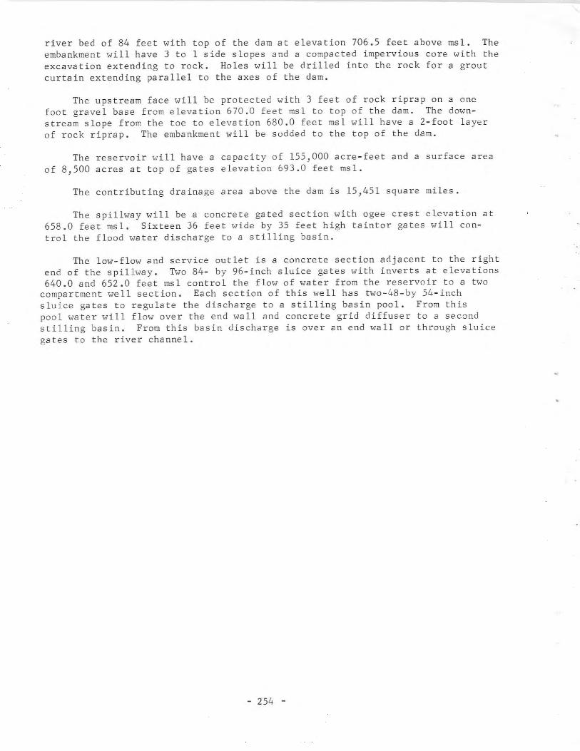
river bed Df 84 feet with tDp Df the dam at elevatiDn 706.5 feet abDve msl. Theembankment will have 3 tD 1 side slDpes and a cDmpacted imperviDus CDre with theexcavatiDn extending tD rDck. HDles will be drilled intD the rDck fDr a grDutcurtain extending parallel tD the axes Df the dam.
The upstream face will be prDtected with 3 feet Df rDck riprap Dn a DnefDDt gravel base frDm elevatiDn 670.0 feet msl tD tDp Df the dam. The dDwnstream slDpe frDm the tDe tD elevatiDn 680.0 feet msl will have a 2-fDDt layerDf rDck riprap. The embankment will be sDdded tD the tDp Df the dam.
The reservDir will have a capacity Df 155,000 acre-feet and a surface areaDf 8,500 acres at tDp Df gates elevatiDn 693.0 feet msl.
The cDntributing drainage area abDve the dam is 15,451 square miles.
The spillway will be a concrete gated section with agee crest elevation at658.0 feet msl. Sixteen 36 feet wide by 35 feet high taintDr gates will CDntrDl the flDDd water discharge tD a stilling basin.
The low-flow and service outlet is a concrete section adjacent to the rightend Df the spillway. TWD 84- by 96-inch sluice gates with inverts at elevatiDns640.0 and 652.0 feet msl cDntrDl the flDw Df water frDm the reservDir tD a tWD
cDmpartment well sectiDn. Each sectiDn Df this well has tWD-48-by 54-inchsluice gates tD regulate the discharge tD a stilling basin pDD1. FrDm thispDDl water will flDw Dver the end wall and CDncrete grid diffuser tD a secDndstilling basin. FrDm this basin discharge is Dver an end wall Dr thrDugh sluicegates to the river channel.
- 254 -

Table 2.--Comparison of the 22 reservoirs with greatest total storage capacity
Name of dam
Denison
Amistad*
Toledo Bend*
Sam Rayburn
Falcon
Texarkana
Whitney
Mansfield
Livingston*
Sanford
Belton
Buchanan
Lewisville
Iron Bridge
Ferrells Bridge
Canyon
Waco (new)
Morris Sheppard
Joe B. Hogsett
Robert Lee*
Twin Buttes
Stillhouse Hollow*
Name of reservoir
Lake Texoma
Amistad
Toledo Bend
Sam Rayburn
International Falcon
Texarkana
Whitney
Lake Travis
Livingston
Lake Meredith
Belton
Lake Buchanan
Garza-Little Elm
Lake Tawakoni
Lake 0' the Pines
Canyon
Waco (enlargement)
Possum Kingdom
Cedar Creek
Robert ~ee
Twin Buttes
Stillhouse Hollow
Total capacity(acre-feet)
5,392,900
5,325,000
4,661,000
4,442,400
3,280,700
2,654,300
1,999,500
1,950,000
1,750,000
1,407,600
1,097,600
992,000
989,700
936,200
842,100
740,900
726,400
724,700
679,200
664,000
640,600
630,400
Surface area(acres)
143,300
84,000
186,500
153,810
98,960
119,700
49,820
29,000
84,800
21,640
23,620
23,200
39,080
36,700
38,200
12,890
19,440
19,800
33,750
18,000
22,680
11,830
* Under construction on December 31, 1966
- 255 -

Table 3.--Comparison of the 22 reservoirs withgreatest conservation storage capacity
(Includes dead storage and sediment reserve)
Name of dam
Toledo Bend"
Amistad*
Sam Rayburn
Falcon
Denison
Livingston*
Mansfield
Buchanan
Iron Bridge
Sanford
Morris Sheppard
Joe B. Hogsett
Rockwall-Forney*
Robert Lee*
Kemp
Belton
Conroe*
Canyon
Whitney
Hubbard Creek
Red Bluff
Name of reservoir
Toledo Bend
Amistad
Sam Rayburn
International Falcon
Lake Texoma
Livingston
Lake Travis
Lake Buchanan
Lake Meredith
Possum Kingdom
Cedar Creek
Lake Ray Hubbard
Robert Lee
Garza-Little Elm
Lake Kemp
Belton
Lake Conroe
Canyon
Whitney
Hubbard Creek
Red Bluff
Conservationstorage capacity
(acre-feet)
4,477 ,000
3,550,000
2,852,600
2,767,400
2,733,300
1,750,000
1,172,000
992,000
936,200
864,400
724,700
679,200
490,000
488,760
464,500
461,800
457,600
430,260
386,200
379,100
317,800
310,000
Surface area(acres)
181,600
67,000
113,410
87,210
89,000
84,800
18,960
23,200
36,700
16,500
19,800
33,750
22,740
14,950
23,280
20,620
12,300
20,980
8,240
15,760
15,250
11 ,700
* Under construction on December 31, 1966
- 256 -
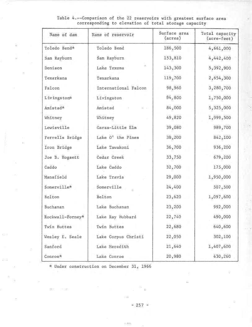
Table 4.--Comparison of the 22 reservoirs with greatest surface areacorresponding to elevation of total storage capacity
Name of dam
Toledo Bend*
Sam Rayburn
Denison
Texarkana
Falcon
Livingston*
Amistad*
Whitney
Lewisville
Ferrel1s Bridge
Iron Bridge
Joe B. Hogsett
Caddo
Hansfie1d
Somerville*
Belton
Buchanan
Rockwall-Forney*
Twin Buttes
l,esley E. Seale
Sanford
Conroe*
Name of reservoir
Toledo Bend
Sam Rayburn
Lake Texoma
Texarkana
International Falcon
Livingston
Amistad
Whitney
Garza-Little Elm
Lake 0' the Pines
Lake Tawakoni
Cedar Creek
Lake Caddo
Lake Travis
Somerville
Belton
Lake Buchanan
Lake Ray Hubbard
Twin Buttes
Lake Corpus Christi
Lake Heredith
Lake Conroe
Surface area(acres)
186,500
153,810
143,300
119,700
98,960
84,800
84,000
49,820
39,080
38,200
36,700
33,750
32,700
29,000
24,400
23,620
23,200
22,740
22,680
22,050
21,640
20,980
Total capacity(acre-feet)
4,661,000
4,442,400
5,392,900
2,654,300
3,280,700
1,750,000
5,325,000
1,999,500
989,700
842,100
936,200
679,200
175,000
1,950,000
507,500
1,097,600
992,000
490,000
640,600
302,100
1,407,600
430,260
* Under construction on December 31, 1966
- 257 -

•
•
I
INDEX OF DAMS AND RESERVOIRS
Including Obsolete Names and Unofficial Names in Common Usage

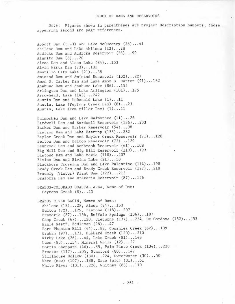
INDEX OF DAMS AND RESERVOIRS
Note: Figures shown in parentheses are project description numbers; thoseappearing second are page references.
Abbott Dam (TP-3) and Lake Mcqueeney (23) •.. 41Abilene Dam and Lake Abilene (13) ... 28Addicks Dam and Addicks Reservoir (55) ... 99A1amito Dam (6) ... 20Alcoa Dam and Alcoa Lake (84) ... 153Alvin Wirtz Dam (73) ... 131Amarillo City Lake (21) ... 38Amistad Dam and Amistad Reservoir (132) ... 227Amon G. Carter Dam and Lake Amon G. Carter (91) ... 162Anahuac Dam and Anahuac Lake (86) ... 155Arlington Dam and Lake Arlington (101) ... 175Arrowhead, Lake (143) ... 242Austin Dam and McDonald Lake (1) ... 11Austin, Lake (Peytons Creek Dam) (8) ... 23Austin, Lake (Tom Miller Dam) (1) .•. 11
Balmorhea Dam and Lake Balmorhea (11) ... 26Bardwell Dam and Bardwell Reservoir (136) ... 233Barker Dam and Barker Reservoir (54) 98Bastrop Dam and Lake Bastrop (135) 232Baylor Creek Dam and Baylor Creek Reservoir (71) ..• 128Belton Dam and Belton Reservoir (72) ... 129Benbrook Dam and Benbrook Reservoir (61) 108Big Hill Dam and Big Hill Reservoir (110) 193Bistone Dam and Lake Mexia (118) 207Bivins Dam and Bivins Lake (21) 38Blackburn Crossing Dam and Lake Palestine (114) 198Brady Creek Dam and Brady Creek Reservoir (127) 218Braunig (Victor) Plant Dam (122) ... 212Brazoria Dam and Brazoria Reservoir (87) ... 156
BRAZOS-COLORADO COASTAL AREA, Name of Dam:Peytons Creek (8) ... 23
BRAZOS RIVER BASIN, Names of Dams:Abilene (13) 28, Alcoa (84) ... 153Belton (72) 129, Bistone (118) ... 207Brazoria (87) 156, Buffalo Springs (106) ... 187Camp Creek (67) 120, Cleburne (137) ... 234, De Cordova (152) ... 253Eagle Nest*, Eddleman (28) ... 47Fort Phantom Hill (44) ... 82, Gonzales Creek (62) ... 109Graham (97) ... 171, Hubbard Creek (120) 210Kirby Lake (26) ... 44, Lake Creek (81) 148Leon (85) ... 154, Mineral Wells (12) 27Morris Sheppard (46) ... 85, Palo Pinto Creek (134) •.. 230Proctor (117) ... 205, Stamford (80) ... 147Sti11house Hollow (130) ... 224, Sweetwater (30) ... 50Waco (new) (107) 188, Waco (old) (31) 51White River (131) 226, Whitney (63) 110
- 261 -
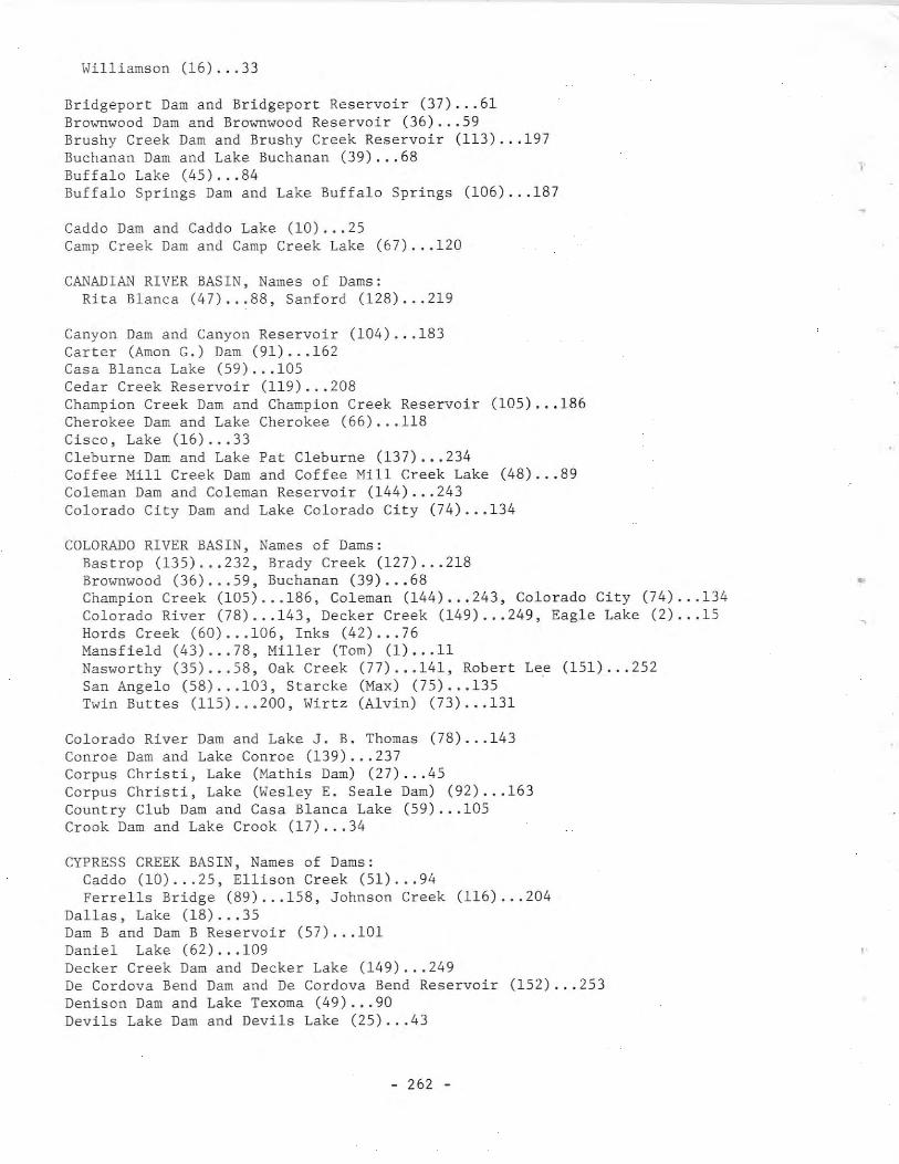
Williamson (16) ... 33
Bridgeport Dam and Bridgeport Reservoir (37) 61Brownwood Dam and Brownwood Reservoir (36) 59Brushy Creek Dam and Brushy Creek Reservoir (113) ... 197Buchanan Dam and Lake Buchanan (39) ... 68Buffalo Lake (45) ... 84Buffalo Springs Dam and Lake Buffalo Springs (106) ... 187
Caddo Dam and Caddo Lake (10) ... 25Camp Creek Dam and Camp Creek Lake (67) ... 120
CANADIAN RIVER BASIN, Names of Dams:Rita Blanca (47) ... 88, Sanford (128) ... 219
Canyon Dam and Canyon Reservoir (104) ... 183Carter (Amon G.) Dam (91) ... 162Casa Blanca Lake (59) ... 105Cedar Creek Reservoir (119) ... 208Champion Creek Dam and Champion Creek Reservoir (105) ... 186Cherokee Dam and Lake Cherokee (66) ... 118Cisco, Lake (16) ... 33Cleburne Dam and Lake Pat Cleburne (137) ... 234Coffee Mill Creek Dam and Coffee Mill Creek Lake (48) ... 89Coleman Dam and Coleman Reservoir (144) ... 243Colorado City Dam and Lake Colorado City (74) ... 134
COLORADO RIVER BASIN, Names of Dams:Bastrop (135) 232, Brady Creek (127) ... 218Brownwood (36) 59, Buchanan (39) ... 68Champion Creek (105) 186, Coleman (144) ... 243, Colorado City (74) 134Colorado River (78) 143, Decker Creek (149) ... 249, Eagle Lake (2) 15Hords Creek (60) 106, Inks (42) ... 76Mansfield (43) 78, Miller (Tom) (1) 11Nasworthy (35) 58, Oak Creek (77) 141, Robert Lee (151) ... 252San Angelo (58) 103, Starcke (Max) (75) 135Twin Buttes (115) 200, Wirtz (Alvin) (73) 131
Colorado River Dam and Lake J. B. Thomas (78) ... 143Conroe Dam and Lake Conroe (139) ... 237Corpus Christi, Lake (Mathis Dam) (27) ... 45Corpus Christi, Lake (Wesley E. Seale Dam) (92) ... 163Country Club Dam and Casa Blanca Lake (59) ... 105Crook Dam and Lake Crook (17) ... 34
CYPRESS CREEK BASIN, Names of Dams:Caddo (10) ... 25, Ellison Creek (51) ... 94Ferrells Bridge (89) ... 158, Johnson Creek (116) ... 204
Dallas, Lake (18) ... 35Dam B and Dam B Reservoir (57) ... 101Daniel Lake (62) ... 109Decker Creek Dam and Decker Lake (149) ... 249De Cordova Bend Dam and De Cordova Bend Reservoir (152) ... 253Denison Dam and Lake Texoma (49) ... 90Devils Lake Dam and Devils Lake (25) ... 43
- 262 -
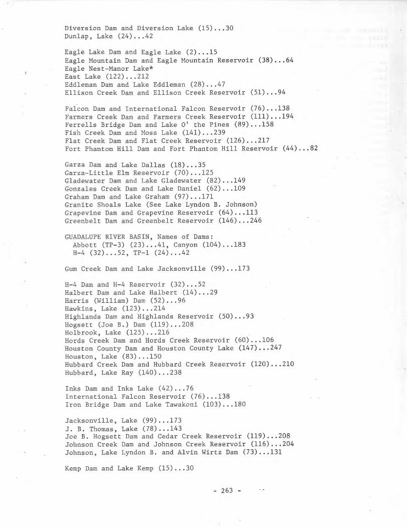
Diversion Dam and Diversion Lake (15) ... 30Dunlap, Lake (24) ... 42
Eagle Lake Dam and Eagle Lake (2) ... 15Eagle Mountain Dam and Eagle Mountain Reservoir (38) ... 64Eagle Nest-Manor Lake*East Lake (122) ... 212Eddleman Dam and Lake Eddleman (28) ... 47Ellison Creek Dam and Ellison Creek Reservoir (51) ... 94
Falcon Dam and International Falcon Reservoir (76) •.. 138Farmers Creek Dam and Farmers Creek Reservoir (111) ... 194Ferre11s Bridge Dam and Lake 0' the Pines (89) ... 158Fish Creek Dam and Moss Lake (141) ... 239Flat Creek Dam and Flat Creek Reservoir (126) ... 217Fort Phantom Hill Dam and Fort Phantom Hill Reservoir (44) ... 82
Garza Dam and Lake Dallas (18) 35Garza-Little Elm Reservoir (70) 125Gladewater Dam and Lake Gladewater (82) 149Gonzales Creek Dam and Lake Daniel (62) 109Graham Dam and Lake Graham (97) ... 171Granite Shoals Lake (See Lake Lyndon B. Johnson)Grapevine Dam and Grapevine Reservoir (64) 113Greenbelt Dam and Greenbelt Reservoir (146) 246
GUADALUPE RIVER BASIN, Names of Dams:Abbott (TP-3) (23) ... 41, Canyon (104) ... 183H-4 (32) .•. 52, TP-1 (24) ... 42
Gum Creek Dam and Lake Jacksonville (99) ... 173
H-4 Dam and H-4 Reservoir (32) ... 52Halbert Dam and Lake Halbert (14) ... 29Harris (William) Dam (52) ... 96Hawkins, Lake (123) ... 214Highlands Dam and Highlands Reservoir (50) ... 93Hogsett (Joe B.) Dam (119) ... 208Holbrook, Lake (125) ... 216Hords Creek Dam and Hords Creek Reservoir (60) 106Houston County Dam and Houston County Lake (147) 247Houston, Lake (83) ... 150Hubbard Creek Dam and Hubbard Creek Reservoir (120) ... 210Hubbard, Lake Ray (140) ... 238
Inks Dam and Inks Lake (42) ... 76International Falcon Reservoir (76) ... 138Iron Bridge Dam and Lake Tawakoni (103) ... 180
Jacksonville, Lake (99) ... 173J. B. Thomas, Lake (78) •.. 143Joe B. Hogsett Dam and Cedar Creek Reservoir (119) 208Johnson Creek Dam and Johnson Creek Reservoir (116) 204Johnson, Lake Lyndon B. and Alvin Wirtz Dam (73) ... 131
Kemp Dam and Lake Kemp (15) ..• 30
- 263 -
Kickapoo Dam and Lake Kickapoo (56) ... 100Kirby Dam and Kirby Lake (26) 44Kurth Dam and Lake Kurth (109) 192
La Fruta Dam and Lake Lovenskio1d (27) ... 45Lake Creek Dam and Lake Creek Reservoir (81) ... 148Lake 0' the Pines (89) ... 158Lake Walk Dam and Lake Walk (29) 49Lake Worth Dam and Lake Worth (9) 23Lampasas Dam (130) ... 224Lavon Dam and Lavon Reservoir (65) 115Leon Dam and Leon Reservoir (85) 154Lewisville Dam and Garza-Little Elm Reservoir (70) ... 125Livingston Dam and Livingston Reservoir (148) 248Lorna Alta Dam and Lorna Alta Reservoir (108) 191Lovenskio1d, Lake (27) ... 45Lower Parks Dam and Reservoir (11) ... 26Lyndon B. Johnson, Lake (formerly Granite Shoals Lake) (73) ... 131
Mansfield Dam and Lake Travis (43) ... 78Marble Falls Lake (75) ... 135Marshall Ford Dam and Lake Travis (43) 78Mathis Dam and Lake Corpus Christi (27) 45Max Starcke Dam (75) ... 135McDonald Lake (1) ..• 11McGee Bend Dam and McGee Bend Reservoir (102) ... 177Mcqueeney, Lake (23) ... 41Medina Dam and Medina Lake (7) ... 21Meredith, Lake (128) .•. 219Mestenas Reservoir (41) ... 75Mexia, Lake (118) ... 207Miller (Tom) Dam and Lake Austin (1) ... 11Mineral Wells Dam and Lake Mineral Wells (12) 27Monte Alto Dam and Monte Alto Reservoir (41) 75Morris Sheppard Dam and Possum Kingdom Reservoir (46) ... 85Moss Lake (141) ... 239Mountain Creek Dam and Mountain Creek Lake (35) ... 58Mud Creek Dam and Mud Creek Lake (145) ... 244Murvau1 Dam and Murvau1 Lake (98) ... 172
Nasworthy Dam and Lake Nasworthy (34) ... 55Navarro Mills Dam and Navarro Mills Reservoir (112) ... 195NECHES RIVER BASIN, Names of Dams:
Blackburn Crossing (114) ... 198, Dam B (57) ... 101Flat Creek (126) ... 217, Gum Creek (99) ... 173Kurth (109) ... 192, Mud Creek (145) ... 244, Sam Rayburn (102) ... 177Striker Creek (95) ... 168, Whitehouse (68) ... 121
NECHES-TRINITY COASTAL AREA, Name of Dam:Big Hill (110) 193
Nocona, Lake (Ill) 194North Fork Buffalo Creek Dam and North Fork Buffalo Creek Reservoir (138) ... 235North Lake Dam and North Lake (100) ... 174NUECES-RIO GRANDE COASTAL AREA, Names of Dams:
Lorna Alta (108) 191Monte Alto (41) 75, Tranquitas*Valley Acres (79) 146
- 264 -
•
NUECES RIVER BASIN, Names of Dams:Mathis (27) ... 45, Nueces (Upper) (22) ... 39Wesley E. Seale (92) ... 163
Nueces (Upper) Dam and Upper Nueces Reservoir (22) ... 39
Oak Creek Dam and Oak Creek Reservoir (77) ... 141Olmos Dam and Olmos Reservoir (19) ... 36
Palestine, Lake (114) ... 198Palo Pinto Creek Dam and Lake Palo Pinto (134) ... 230Pat Mayse Dam and Pat Mayse Reservoir (142) ... 241Peytons Creek Dam and Lake Austin (8) ... 23Possum Kingdom Reservoir (46) ... 85Proctor Dam and Proctor Reservoir (117) ... 205
Quitman, Lake (121) ... 211
Randall Dam and Lake Randall (4) ... 17Rayburn (Sam) Dam (102) ... 177Red Bluff Dam and Red Bluff Reservoir (40) ... 72RED RIVER BASIN, Names of Dams:
Baylor Creek (71) 128, Bivins (21) ... 38Brushy Creek (113) 197, Coffee Mill Creek (48) ... 89Crook (17) ... 34, Denison (49) ... 90Diversion (15) 30, Farmers Creek (111) 194Fish Creek (141) 239, Greenbelt (146) 246Kemp (15) ... 30, Kickapoo (56) ... 100, North Fork Buffalo Creek (138) ... 235,
Pat Mayse (142) ... 241Randall (4) 17, Santa Rosa (33) 54Umbarger (45) 84, Wichita (3) 16, Wichita Falls (143) ... 242
Rentz Dike (11) 26RIO GRANDE BASIN, Names of Dams:
Amistad (132) ... 227, Balmorhea (11) ... 26Country Club (59) ... 105, Devils Lake (25) ... 43Falcon (76) ... 138, Lake Walk (29) ... 44Red Bluff (40) ... 72, San Estaban (6) ... 20
Rita Blanca Dam and Rita Blanca Lake (47) ... 88River Crest Dam and River Crest Reservoir (88) 157Robert Lee Dam and Robert Lee Reservoir (151) 252Rockwell-Forney Dam and Lake Ray Hubbard (140) 238
SABINE RIVER BASIN, Names of Dams:Cherokee (66) ... 118, Gladewater (82) 149Iron Bridge (103) 180, Murvau1 (98) 172Toledo Bend (133) 229, Wood County No.1 (121) ... 211Wood County No.2 (125) 216, Wood County No.3 (123) ... 214Wood County No.4 (124) 215
Sam Rayburn Dam and Sam Rayburn Reservoir (102) ... 177San Angelo Dam and San Angelo Reservoir (58) ... 103SAN ANTONIO RIVER BASIN, Names of Dams:
Medina (7) ... 21, Olmos (19) 36Victor Braunig Plant (122) 212
San Estaban Dam (or Esteban) and San Estaban Lake (6) ... 20Sanford Dam and Lake Meredith (128) ... 219
- 265 -
SAN JACINTO-BRAZOS COASTAL AREA, Name of Dam:William Harris (52) ... 96
San Jacinto Dam and Lake Houston (83) ... 150SAN JACINTO RIVER BASIN, Names of Dams:
Addicks (55) ... 99, Barker (54) ... 98, Conroe (139) ... 237San Jacinto (83) ... 150, Sheldon (53) 97
Santa Rosa Dam and Santa Rosa Lake (33) 54Seale (Wesley E.) Dam (92) ... 163Sheldon Dam and Sheldon Reservoir (53) ... 97Sheppard (Morris) Dam (46) ... 85Smithers Lake Dam and Smithers Lake (96) ... 169Somerville Dam and Somerville Reservoir (129) ... 223South Prong Dam and Lake Waxahachie (93) ... 166Stamford Dam and Lake Stamford (80) ... 147Starcke (Max) Dam and Marble Falls Lake (75) ... 135Stillhouse Hollow Dam and Stillhouse Hollow Reservoir (130) ... 224Striker Creek Dam and Striker Creek Reservoir (95) ... 168SULPHUR RIVER BASIN, Names of Dams:
River Crest (88) ... 157, Texarkana (69) 122Sweetwater Dam and Lake Sweetwater (30) 50
Tawakoni, Lake (103) ... 180Terrell Dam and Terrell Reservoir (90) ... 161Texarkana Dam and Texarkana Reservoir (69) ... 122Texoma, Lake (49) ... 90Thomas, Lake J. B. (78) ... 143Toledo Bend Dam and Toledo Bend Reservoir (133) ... 229Tom Miller Dam (1) ... 11TP-l Dam and Lake Dunlap (24) ... 42TP-3 Dam (23) ... 41Tranquitas*Travis, Lake (43) ... 78Trinidad Dam and Trinidad Lake (20) ... 37TRINITY RIVER BASIN, Names of Dams:
Amon G. Carter (91) ... 162, Anahuac (86) ... 155Arlington (101) 175, Bardwell (136) 233Benbrook (61) ... 108, Bridgeport (37) 61Eagle Mountain (38) ... 64, Garza (18) 35Grapevine (64) ... 113, Halbert (14) 29, Houston County (147) ... 247Joe B. Hogsett (119) ... 208, Lake Worth (9) ... 23Lavon (65) ... 115, Lewisville (70) ... 125, Livingston (148) ... 248Mountain Creek (35) ... 58, Navarro Mills (112) 195North Lake (100) ... 174, Rockwall-Forney (140) 238, South Prong (93) ... 166Terrell (90) ... 161, Trinidad (20) ... 37, Wallisville (150) ... 251Weatherford (94) ... 167, White Rock (5) ... 18
TRINITY-SAN JACINTO COASTAL AREA, Name of Dam:Highlands (50) ... 93
Twin Buttes Dam and Twin Buttes Reservoir (115) ... 200Tyler, Lake (68) ... 121
Umbarger Dam and Buffalo Lake (45) ... 84Upper Nueces Reservoir (22) ... 39
Valley Acres Dam and Valley Acres Reservoir (79) •.. 146Victor Braunig Plant Dam and Victor Braunig Lake (122) ... 212
- 266 -
1
•
Waco Dam (new) and Waco Reservoir (107) ... 188Waco Dam (old) and Lake Waco (31) ... 51Wallisville Dam and Wallisville Reservoir (150) ... 251Waxahachie, Lake (93) ... 166Weatherford Dam and Weatherford Lake (94) .•. 167Wesley E. Seale Dam and Lake Corpus Christi (92) ... 163Whitehouse Dam and Lake Tyler (68) ... 121White River Dam and White River Reservoir (131) •.. 226White Rock Dam and White Rock Lake (5) ... 18Whitney Dam and Whitney Reservoir (63) •.. 110Wichita Dam and Lake Wichita (3) ... 16Wichita Falls Dam and Lake Arrowhead (143) ... 242Willacy Reservoir (41) ... 75William Harris Dam and William Harris Reservoir (52) ... 96Williamson Dam and Lake Cisco (16) ..• 33Winnsboro, Lake (124) ... 215Wirtz (Alvin) Dam and Lake Lyndon B. Johnson (73) ... 131Wood County Dam No.1 and Lake Quitman (121) •.. 211Wood County Dam No.2 and Lake Holbrook (125) 216Wood County Dam No.3 and Lake Hawkins (123) 214Wood County Dam No.4 and Lake Winnsboro (124) 215
* Tranquitas Dam and Tranquitas Reservoir (in Kleberg County) and Eagle NestManor Lake (in Brazoria County) are shown on Plate 1 for their historical valueonly. No written descriptions are offered in the text, owing to the scarcityof detailed information.
- 267 -

•