DAHUA NVR FULL MANUAL
135
1 DAHUA NVR FULL MANUAL Contents 1. Goods Checking............................................................................................................................................... 4 1.1. Device and accessory checking ........................................................................................... 4 1.2. Power supply .................................................................................................................................. 4 1.3. Quick guide ..................................................................................................................................... 4 2. How to add and change the setting of the camera ........................................................................ 5 2.1. How to install HDD ...................................................................................................................... 5 2.2. Cable connection.......................................................................................................................... 6 2.3. Connect to the ground ............................................................................................................... 7 2.4. How to Change the password ............................................................................................... 8 2.5. How to Close the HDD buzzer .............................................................................................. 9 2.6. Startup Wizard ............................................................................................................................ 10 2.7. How to use Navigation Bar................................................................................................... 14 2.8. Main Menu .................................................................................................................................... 14 2.8.1 Dual-screen operation................................................................................................... 15 2.8.2 Output Screen ................................................................................................................... 15 2.8.3 Tour ........................................................................................................................................ 15 2.8.4 PTZ ......................................................................................................................................... 15 2.8.5 Color ....................................................................................................................................... 15 2.8.6 Search ................................................................................................................................... 15 2.8.7 Alarm Status....................................................................................................................... 15 2.8.8 Remote Device ................................................................................................................. 16 2.8.9 Network................................................................................................................................. 16 2.8.10 HDD Manager ................................................................................................................... 16 2.8.11 USB Manager .................................................................................................................... 16 2.9 How to Add the account and set the right .................................................................... 16 2.9.1 How to Add/Modify Group........................................................................................... 18 2.9.2 Add/Modify User .............................................................................................................. 19 2.9.3 How to Change the date, time and time zone .................................................. 20 2.10 How to Use the Remote Controller .................................................................................. 21 3. How to add and change the setting of the camera?................................................................... 23 3.1. NVR/HCVR IP address setting........................................................................................... 23 3.2. How to add the camera .......................................................................................................... 23 3.3. How to add camera(s) in a quick way(Smart add)................................................... 25 3.4. How to set the Resolution of camera.............................................................................. 28 3.5. How to set the bit rate of camera ...................................................................................... 28 3.6. How to set the audio of camera ......................................................................................... 29 3.7. How to set the image parameters of camera.............................................................. 30 3.8. How to set the motion detect of camera........................................................................ 31 3.9. How to set the Tripwire of camera ................................................................................... 32 3.10. How to set the intrusion of camera .................................................................................. 34 3.11. How to set the object abandoned/ object missing of camera............................. 36 3.12. How to set the scene change of camera ...................................................................... 38 3.13. How to set the face detect of camera ............................................................................. 39 3.14. How to set the audio detect of camera .......................................................................... 40 3.15. How to change the camera name..................................................................................... 41 4. Preview .............................................................................................................................................................. 43
-
Upload
khangminh22 -
Category
Documents
-
view
0 -
download
0
Transcript of DAHUA NVR FULL MANUAL
1
DAHUA NVR FULL MANUAL
Contents 1. Goods Checking ............................................................................................................................................... 4
1.1. Device and accessory checking ........................................................................................... 4 1.2. Power supply .................................................................................................................................. 4 1.3. Quick guide ..................................................................................................................................... 4
2. How to add and change the setting of the camera ........................................................................ 5 2.1. How to install HDD ...................................................................................................................... 5 2.2. Cable connection .......................................................................................................................... 6 2.3. Connect to the ground ............................................................................................................... 7 2.4. How to Change the password ............................................................................................... 8 2.5. How to Close the HDD buzzer .............................................................................................. 9 2.6. Startup Wizard ............................................................................................................................ 10 2.7. How to use Navigation Bar ................................................................................................... 14 2.8. Main Menu .................................................................................................................................... 14
2.8.1 Dual-screen operation ................................................................................................... 15 2.8.2 Output Screen ................................................................................................................... 15 2.8.3 Tour ........................................................................................................................................ 15 2.8.4 PTZ ......................................................................................................................................... 15 2.8.5 Color ....................................................................................................................................... 15 2.8.6 Search ................................................................................................................................... 15 2.8.7 Alarm Status ....................................................................................................................... 15 2.8.8 Remote Device ................................................................................................................. 16 2.8.9 Network ................................................................................................................................. 16 2.8.10 HDD Manager ................................................................................................................... 16 2.8.11 USB Manager .................................................................................................................... 16
2.9 How to Add the account and set the right .................................................................... 16 2.9.1 How to Add/Modify Group ........................................................................................... 18 2.9.2 Add/Modify User .............................................................................................................. 19 2.9.3 How to Change the date, time and time zone .................................................. 20
2.10 How to Use the Remote Controller .................................................................................. 21 3. How to add and change the setting of the camera? ................................................................... 23
3.1. NVR/HCVR IP address setting........................................................................................... 23 3.2. How to add the camera .......................................................................................................... 23 3.3. How to add camera(s) in a quick way(Smart add) ................................................... 25 3.4. How to set the Resolution of camera .............................................................................. 28 3.5. How to set the bit rate of camera ...................................................................................... 28 3.6. How to set the audio of camera ......................................................................................... 29 3.7. How to set the image parameters of camera .............................................................. 30 3.8. How to set the motion detect of camera ........................................................................ 31 3.9. How to set the Tripwire of camera ................................................................................... 32 3.10. How to set the intrusion of camera .................................................................................. 34 3.11. How to set the object abandoned/ object missing of camera ............................. 36 3.12. How to set the scene change of camera ...................................................................... 38 3.13. How to set the face detect of camera ............................................................................. 39 3.14. How to set the audio detect of camera .......................................................................... 40 3.15. How to change the camera name..................................................................................... 41
4. Preview .............................................................................................................................................................. 43
2
4.1 How to change the display resolution and adjust the image value ................. 43 4.2 How to adjust the order of the splits ................................................................................ 44 4.3 How to switch from different splits .................................................................................... 45 4.4 How to set tour ........................................................................................................................... 45 4.5 How to set the Favorite Cameras ..................................................................................... 45 4.6 How to set mask ........................................................................................................................ 46 4.7 How to make the digital zoom ............................................................................................ 46 4.8 How to open audio .................................................................................................................... 47 4.9 How to snapshot ........................................................................................................................ 47 4.10 How to enable the zero-channel........................................................................................ 48 4.11 How to set corridor mode ...................................................................................................... 49 4.12 How to use PIP (picture in picture) .................................................................................. 50 4.13 How to use the second HDMI ............................................................................................. 51
5. HDD ..................................................................................................................................................................... 52 5.1 HDD Requirements .................................................................................................................. 52 5.2 How to check the HDD information .................................................................................. 52
5.1.1 HDD type ............................................................................................................................. 52 5.1.2 How to check HDD S.M.A.R.T information ........................................................ 52 5.1.3 How to do HDD detect .................................................................................................. 53
5.2 How to set HDD group setting ............................................................................................ 56 5.3 Redundant Option ..................................................................................................................... 56 5.4 How to set raid 5 ........................................................................................................................ 57
6 Recording ......................................................................................................................................................... 60 6.1 How to change the encode .................................................................................................. 60 6.2 How to set the Manual Recording .................................................................................... 60 6.3 Recording-Schedule (Normal, MD and Alarm) .......................................................... 62
6.3.1 How to set Pre-recording ............................................................................................. 62 6.3.2 How to set Holiday-recording .................................................................................... 62 6.3.3 How to set redundant option ...................................................................................... 64 6.3.4 How to set MD recording plan .................................................................................. 66 6.3.5 How to set alarm recording plan .............................................................................. 68
6.4 How to set snapshot plan...................................................................................................... 70 6.5 How to record into FTP .......................................................................................................... 73
7 Playback and Backup ................................................................................................................................. 74 7.1 How to search and playback ............................................................................................... 74 7.2 How to make the sync playback ........................................................................................ 75 7.3 How to make the picture playback ................................................................................... 75 7.4 How to make the frame by frame playback ................................................................. 75 7.5 How to make the smart search .......................................................................................... 75 7.6 How to playback the mark video ....................................................................................... 76 7.7 How to playback with IVS(face detection) .................................................................... 78 7.8 How to playback with splicing ............................................................................................. 79 7.9 How to make the video cut and back up ....................................................................... 80 7.10 How to lock the recording files ........................................................................................... 81 7.11 How to make quick Backup ................................................................................................. 82 7.12 How to make web backup .................................................................................................... 83 7.13 How to use smart player ........................................................................................................ 85
8 PTZ ...................................................................................................................................................................... 87 8.1 Hardware Connection ............................................................................................................. 87 8.2 Software Setup ........................................................................................................................... 87 8.3 How to Operate PTZ Control............................................................................................... 89 8.4 How to set up Preset and call ............................................................................................. 91 8.5 How to set Tour and call ........................................................................................................ 92 8.6 How to set Pattern and call .................................................................................................. 93
3
8.7 How to set Idle Function and call ...................................................................................... 93 8.8 How to set Privacy Masking and call .............................................................................. 94 8.9 How to use Keyboard to control PTZ .............................................................................. 95
9 Event and Activation.................................................................................................................................. 100 9.1 Explain IPC ext, IPC offline, Net alarm, HDCVI alarm, IVS alarm, Video loss, Tampering 100 9.2 How to set video recording activation ........................................................................... 103 9.3 How to set Snapshot activation ....................................................................................... 105 9.4 How to set Alarm upload ..................................................................................................... 107 9.5 How to Set Email Upload .................................................................................................... 109 9.6 How to set up PTZ activation ............................................................................................ 112 9.7 How to set up Easy Space ................................................................................................. 113 9.8 How to set the local alarm in/out ..................................................................................... 114
9.8.1 Local alarm physical connection: .......................................................................... 114 9.8.2 Alarm Setup on NVR/HCVR/DVR. ....................................................................... 115
10 Network connection ......................................................................................................................... 117 10.1 How to set DHCP .................................................................................................................... 117 10.2 How to use P2P DMSS ........................................................................................................ 117 10.3 How to set DDNS .................................................................................................................... 122 10.4 How to use smart PSS to connect ................................................................................. 123 10.5 How to use Config tool ......................................................................................................... 125 10.6 How to use IE/Chrome/Safari ........................................................................................... 127
11 Device information and upgrade ............................................................................................... 130 11.1 NVR upgrade ............................................................................................................................. 130 11.2 IPC upgrade with NVR ......................................................................................................... 133 11.3 NVR and IPC information checking ............................................................................... 133
4
1. Goods Checking 1.1. Device and accessory checking Be sure to use all the accessories recommended by manufacturer. Before installation, please open the package and check all the components are included. Normally accessories include user manual, mouse, Power cable, Power adapter, CD, Network cable, Screw package. (Take NVR4104 as an example) Contact your local retailer ASAP if something is broken in your package. 1.2. Power supply Make sure the power supply and device is matched. NVR4104 is AC100~240V-12V/2A. 1.3. Quick guide Please refer to the Quick Start Guide which is the general ftp: (User/Password: Dahuaeuro / Dahuaeuro) ftp://54.67.82.60/Product_User_Manuals/01NVR/NVR100_11_4_7_series/ Quick Start Guide/
5
2. How to add and change the setting of the camera 2.1. How to install HDD
Important:
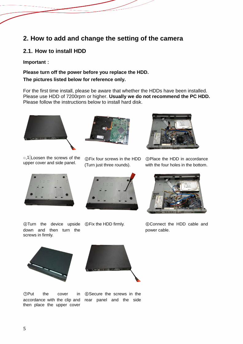
Please turn off the power before you replace the HDD. The pictures listed below for reference only. For the first time install, please be aware that whether the HDDs have been installed. Please use HDD of 7200rpm or higher. Usually we do not recommend the PC HDD. Please follow the instructions below to install hard disk.
○,1 Loosen the screws of the upper cover and side panel.
②Fix four screws in the HDD (Turn just three rounds).
③Place the HDD in accordance with the four holes in the bottom.
④Turn the device upside down and then turn the screws in firmly.
⑤Fix the HDD firmly. ⑥Connect the HDD cable and power cable.
⑦Put the cover in accordance with the clip and then place the upper cover
⑧Secure the screws in the rear panel and the side
6
back. panel.
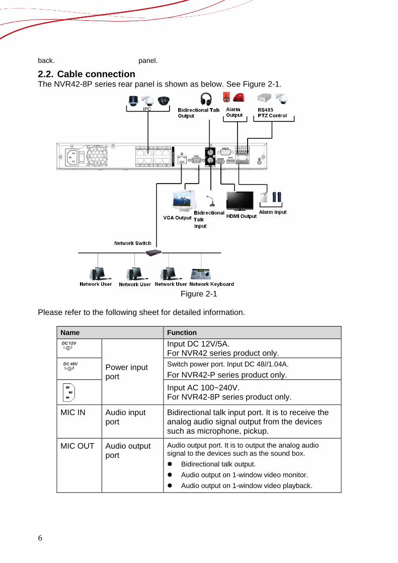
2.2. Cable connection The NVR42-8P series rear panel is shown as below. See Figure 2-1.
Figure 2-1
Please refer to the following sheet for detailed information.
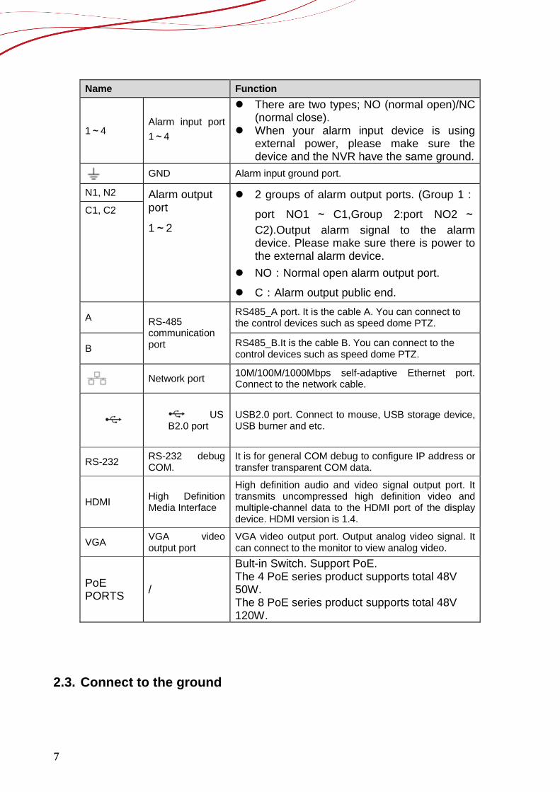
Name Function
Power input port
Input DC 12V/5A. For NVR42 series product only.
Switch power port. Input DC 48//1.04A. For NVR42-P series product only.
Input AC 100~240V. For NVR42-8P series product only.
MIC IN Audio input port
Bidirectional talk input port. It is to receive the analog audio signal output from the devices such as microphone, pickup.
MIC OUT Audio output port
Audio output port. It is to output the analog audio signal to the devices such as the sound box. Bidirectional talk output. Audio output on 1-window video monitor. Audio output on 1-window video playback.
7
Name Function
1~4 Alarm input port 1~4
There are two types; NO (normal open)/NC (normal close).
When your alarm input device is using external power, please make sure the device and the NVR have the same ground.
GND Alarm input ground port.
N1, N2 Alarm output port
1~2
2 groups of alarm output ports. (Group 1:port NO1 ~ C1,Group 2:port NO2 ~C2).Output alarm signal to the alarm device. Please make sure there is power to the external alarm device.
NO:Normal open alarm output port.
C:Alarm output public end.
C1, C2
A RS-485 communication port
RS485_A port. It is the cable A. You can connect to the control devices such as speed dome PTZ.
B RS485_B.It is the cable B. You can connect to the control devices such as speed dome PTZ.
Network port 10M/100M/1000Mbps self-adaptive Ethernet port. Connect to the network cable.
USB2.0 port
USB2.0 port. Connect to mouse, USB storage device, USB burner and etc.
RS-232 RS-232 debug COM.
It is for general COM debug to configure IP address or transfer transparent COM data.
HDMI High Definition Media Interface
High definition audio and video signal output port. It transmits uncompressed high definition video and multiple-channel data to the HDMI port of the display device. HDMI version is 1.4.
VGA VGA video output port
VGA video output port. Output analog video signal. It can connect to the monitor to view analog video.
PoE PORTS /
Bult-in Switch. Support PoE. The 4 PoE series product supports total 48V 50W. The 8 PoE series product supports total 48V 120W.
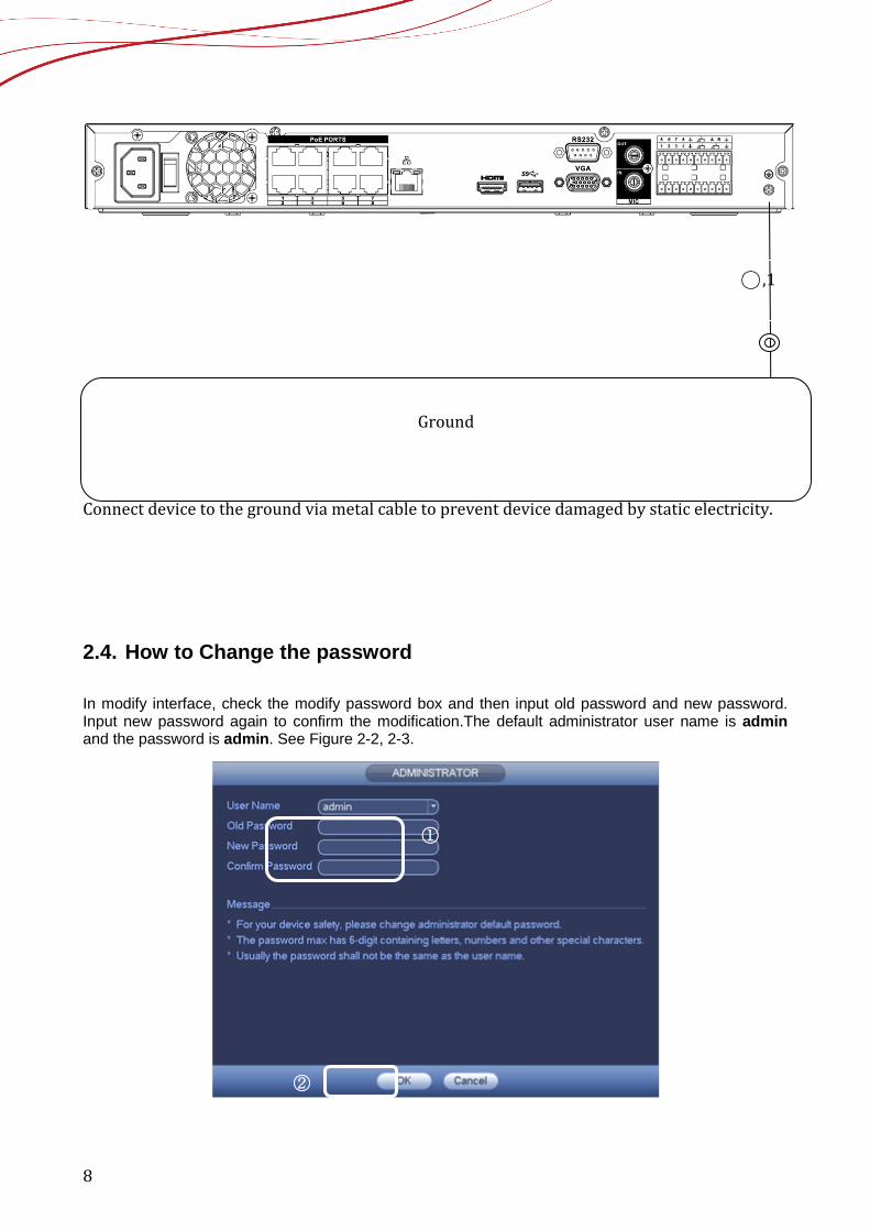
2.3. Connect to the ground
8
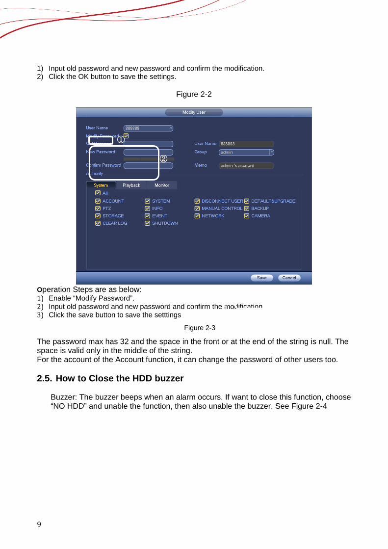
Connect device to the ground via metal cable to prevent device damaged by static electricity. 2.4. How to Change the password In modify interface, check the modify password box and then input old password and new password. Input new password again to confirm the modification.The default administrator user name is admin and the password is admin. See Figure 2-2, 2-3.
○,1
Ground
①
②
9
1) Input old password and new password and confirm the modification. 2) Click the OK button to save the settings.
Figure 2-2
Operation Steps are as below: 1) Enable “Modify Password”. 2) Input old password and new password and confirm the modification. 3) Click the save button to save the setttings
Figure 2-3
The password max has 32 and the space in the front or at the end of the string is null. The space is valid only in the middle of the string. For the account of the Account function, it can change the password of other users too. 2.5. How to Close the HDD buzzer
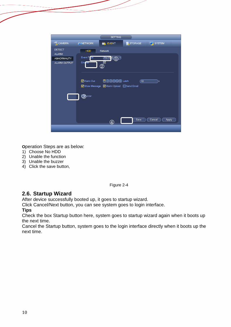
Buzzer: The buzzer beeps when an alarm occurs. If want to close this function, choose “NO HDD” and unable the function, then also unable the buzzer. See Figure 2-4
②
①
③
10
Operation Steps are as below: 1) Choose No HDD 2) Unable the function 3) Unable the buzzer 4) Click the save button,
Figure 2-4
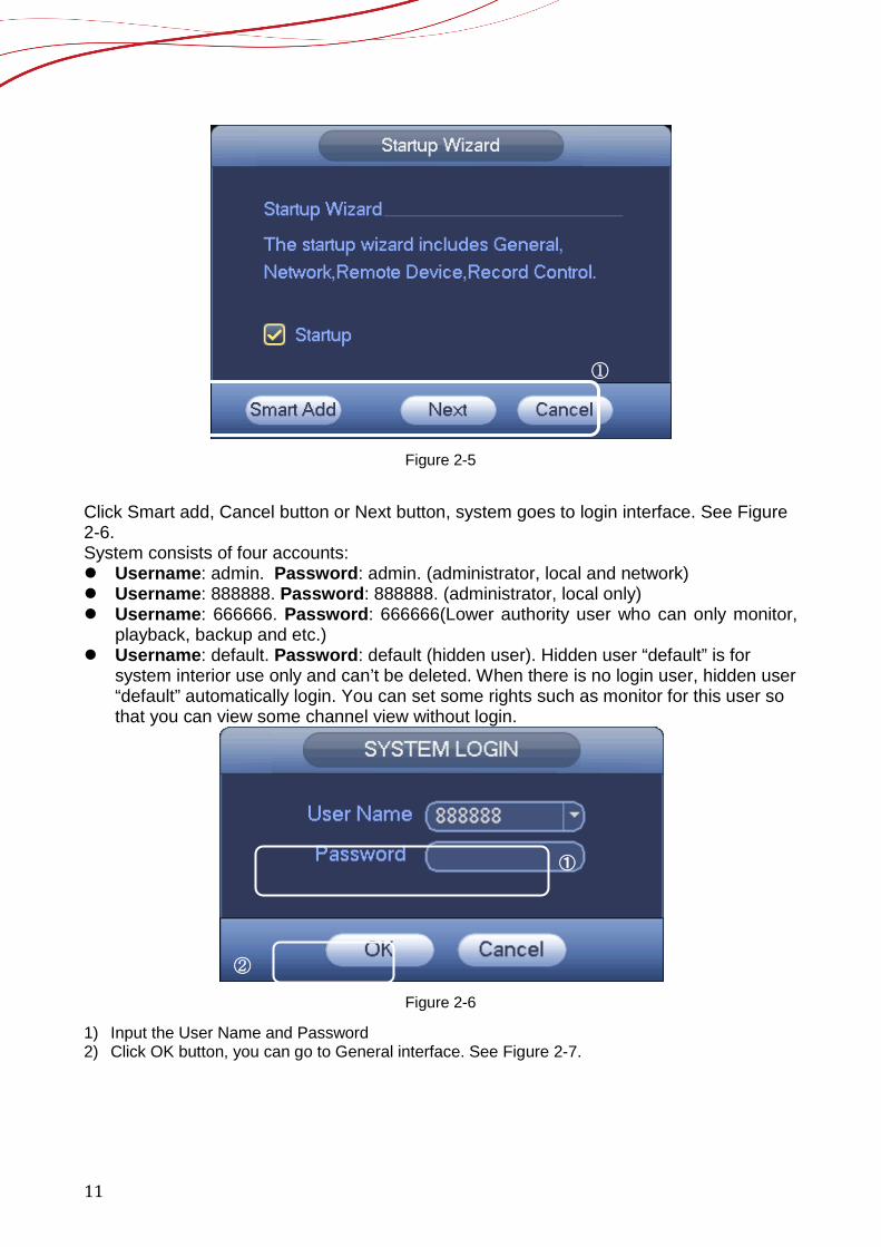
2.6. Startup Wizard After device successfully booted up, it goes to startup wizard. Click Cancel/Next button, you can see system goes to login interface. Tips Check the box Startup button here, system goes to startup wizard again when it boots up the next time. Cancel the Startup button, system goes to the login interface directly when it boots up the next time.
③
② ①
④
11
Figure 2-5
Click Smart add, Cancel button or Next button, system goes to login interface. See Figure 2-6. System consists of four accounts: Username: admin. Password: admin. (administrator, local and network) Username: 888888. Password: 888888. (administrator, local only) Username: 666666. Password: 666666(Lower authority user who can only monitor,
playback, backup and etc.) Username: default. Password: default (hidden user). Hidden user “default” is for
system interior use only and can’t be deleted. When there is no login user, hidden user “default” automatically login. You can set some rights such as monitor for this user so that you can view some channel view without login.
Figure 2-6
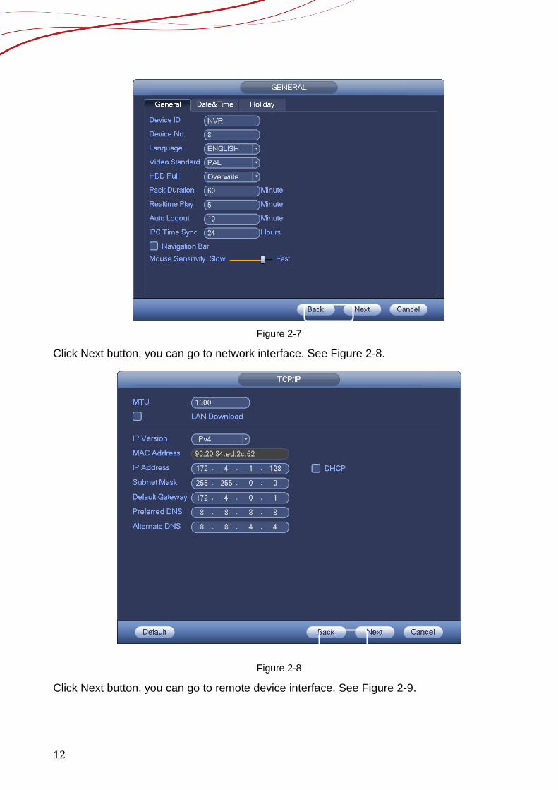
1) Input the User Name and Password 2) Click OK button, you can go to General interface. See Figure 2-7.
①
①
②
12
Figure 2-7
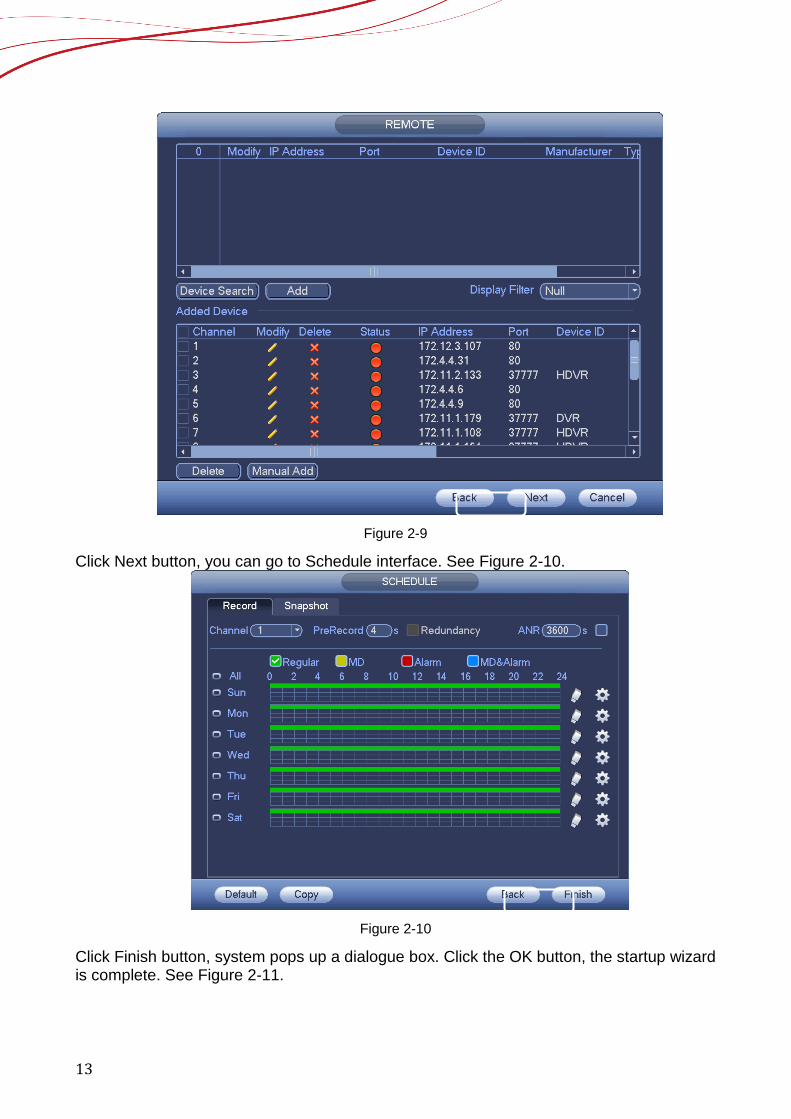
Click Next button, you can go to network interface. See Figure 2-8.
Figure 2-8
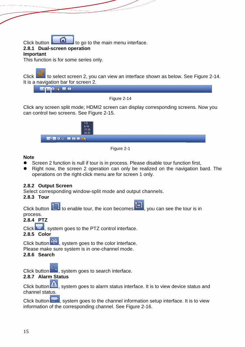
Click Next button, you can go to remote device interface. See Figure 2-9.
13
Figure 2-9
Click Next button, you can go to Schedule interface. See Figure 2-10.
Figure 2-10
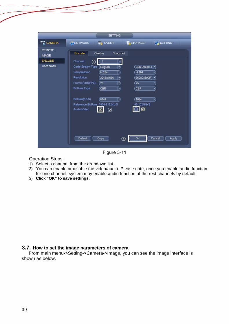
Click Finish button, system pops up a dialogue box. Click the OK button, the startup wizard is complete. See Figure 2-11.

14
Figure 2-11
2.7. How to use Navigation Bar You need to go to the Main menu->Setting->System->General to enable navigation bar function; otherwise you can’t see the following interface.
Figure 2-12
Click and enable the Navigation Bar The navigation bar is shown as below. See Figure 2-13.
Figure 2-13
2.8. Main Menu
①
15
Click button to go to the main menu interface. 2.8.1 Dual-screen operation Important This function is for some series only.
Click to select screen 2, you can view an interface shown as below. See Figure 2-14. It is a navigation bar for screen 2.
Figure 2-14
Click any screen split mode; HDMI2 screen can display corresponding screens. Now you can control two screens. See Figure 2-15.
Figure 2-1
Note Screen 2 function is null if tour is in process. Please disable tour function first, Right now, the screen 2 operation can only be realized on the navigation bard. The
operations on the right-click menu are for screen 1 only. 2.8.2 Output Screen Select corresponding window-split mode and output channels. 2.8.3 Tour
Click button to enable tour, the icon becomes , you can see the tour is in process. 2.8.4 PTZ Click , system goes to the PTZ control interface. 2.8.5 Color
Click button , system goes to the color interface. Please make sure system is in one-channel mode. 2.8.6 Search
Click button , system goes to search interface. 2.8.7 Alarm Status
Click button , system goes to alarm status interface. It is to view device status and channel status.
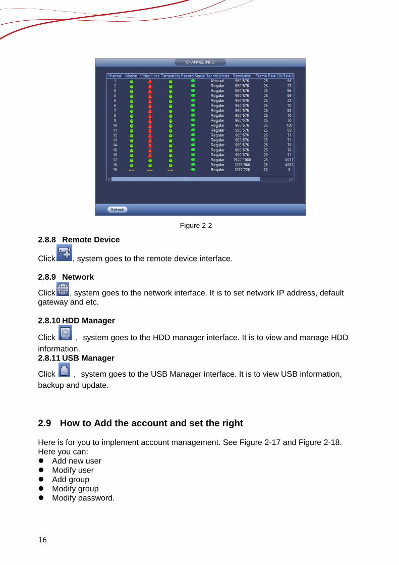
Click button , system goes to the channel information setup interface. It is to view information of the corresponding channel. See Figure 2-16.
16
Figure 2-2
2.8.8 Remote Device
Click , system goes to the remote device interface. 2.8.9 Network
Click , system goes to the network interface. It is to set network IP address, default gateway and etc. 2.8.10 HDD Manager
Click , system goes to the HDD manager interface. It is to view and manage HDD information. 2.8.11 USB Manager
Click , system goes to the USB Manager interface. It is to view USB information, backup and update.
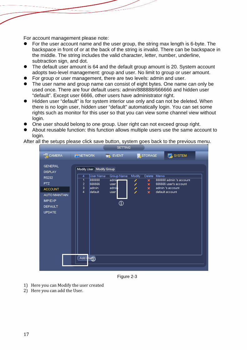
2.9 How to Add the account and set the right Here is for you to implement account management. See Figure 2-17 and Figure 2-18. Here you can: Add new user Modify user Add group Modify group Modify password.
17
For account management please note: For the user account name and the user group, the string max length is 6-byte. The
backspace in front of or at the back of the string is invalid. There can be backspace in the middle. The string includes the valid character, letter, number, underline, subtraction sign, and dot.
The default user amount is 64 and the default group amount is 20. System account adopts two-level management: group and user. No limit to group or user amount.
For group or user management, there are two levels: admin and user. The user name and group name can consist of eight bytes. One name can only be
used once. There are four default users: admin/888888/666666 and hidden user “default”. Except user 6666, other users have administrator right.
Hidden user “default” is for system interior use only and can not be deleted. When there is no login user, hidden user “default” automatically login. You can set some rights such as monitor for this user so that you can view some channel view without login.
One user should belong to one group. User right can not exceed group right. About reusable function: this function allows multiple users use the same account to
login. After all the setups please click save button, system goes back to the previous menu.
Figure 2-3
1) Here you can Modify the user created 2) Here you can add the User.
①
②
18
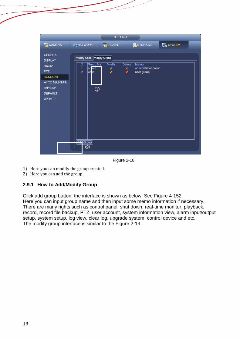
Figure 2-18
1) Here you can modify the group created. 2) Here you can add the group. 2.9.1 How to Add/Modify Group Click add group button, the interface is shown as below. See Figure 4-152. Here you can input group name and then input some memo information if necessary. There are many rights such as control panel, shut down, real-time monitor, playback, record, record file backup, PTZ, user account, system information view, alarm input/output setup, system setup, log view, clear log, upgrade system, control device and etc. The modify group interface is similar to the Figure 2-19.
①
②
19
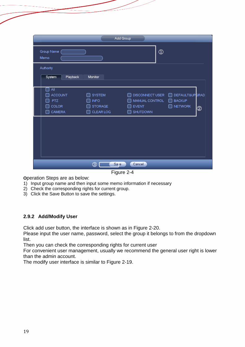
Figure 2-4
Operation Steps are as below: 1) Input group name and then input some memo information if necessary 2) Check the corresponding rights for current group. 3) Click the Save Button to save the settings. 2.9.2 Add/Modify User Click add user button, the interface is shown as in Figure 2-20. Please input the user name, password, select the group it belongs to from the dropdown list. Then you can check the corresponding rights for current user For convenient user management, usually we recommend the general user right is lower than the admin account. The modify user interface is similar to Figure 2-19.
②
①
③

20
Figure 2-20
Operation Steps are as below: 1) Input the user name, pass word, select the group it belongs to from the dropdown list. 2) Check the corresponding rights for current user. 3) Click the Save Button to save the settings.
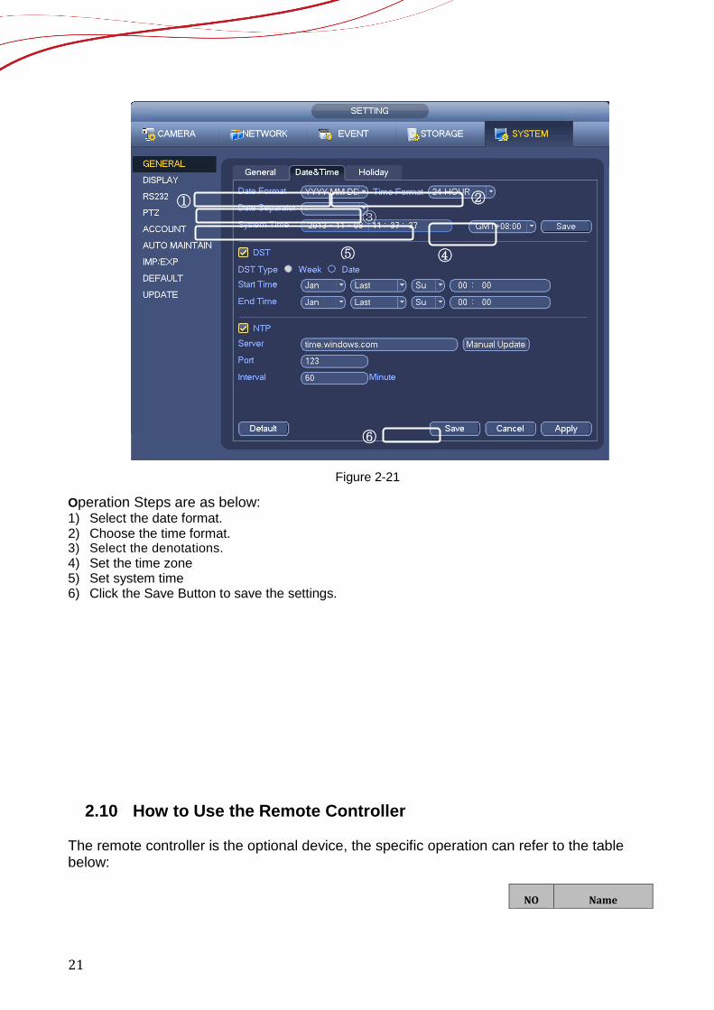
2.9.3 How to Change the date, time and time zone From Main menu->Setting->System->General, you can go to the general interface. See Figure 2-21. System time: Here is for you to set system time Date format: There are three types: YYYYY-MM-DD: MM-DD-YYYYY or DD-MM-YYYY. Date separator: There are three denotations to separate date: dot, beeline and solidus. DST: Here you can set DST time and date by week or by date. Please enable DST function and
then select setup mode. Please input start time and end time and click Save button. Time format: There are two types: 24-hour mode or 12-hour mode. NTP: It is to set NTP server, port and interval.
①
②
③
21
Figure 2-21
Operation Steps are as below: 1) Select the date format. 2) Choose the time format. 3) Select the denotations. 4) Set the time zone 5) Set system time 6) Click the Save Button to save the settings.
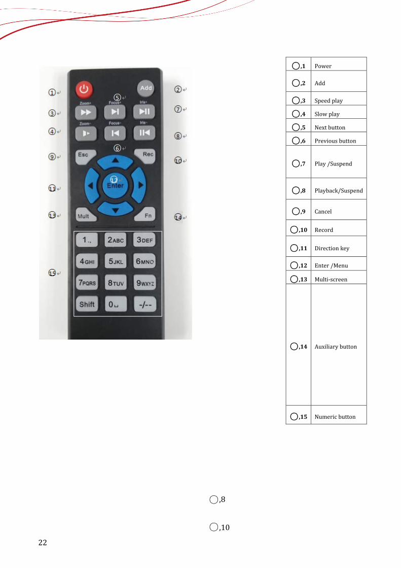
2.10 How to Use the Remote Controller The remote controller is the optional device, the specific operation can refer to the table below:
NO
Name
③
⑤ ④
① ②
⑥
22
○,1 Power
○,2 Add
○,3 Speed play
○,4 Slow play
○,5 Next button
○,6 Previous button
○,7 Play /Suspend
○,8 Playback/Suspend
○,9 Cancel
○,10 Record
○,11 Direction key
○,12 Enter /Menu
○,13 Multi-screen
○,14 Auxiliary button
○,15 Numeric button
○,8
○,10
23
3. How to add and change the setting of the camera?
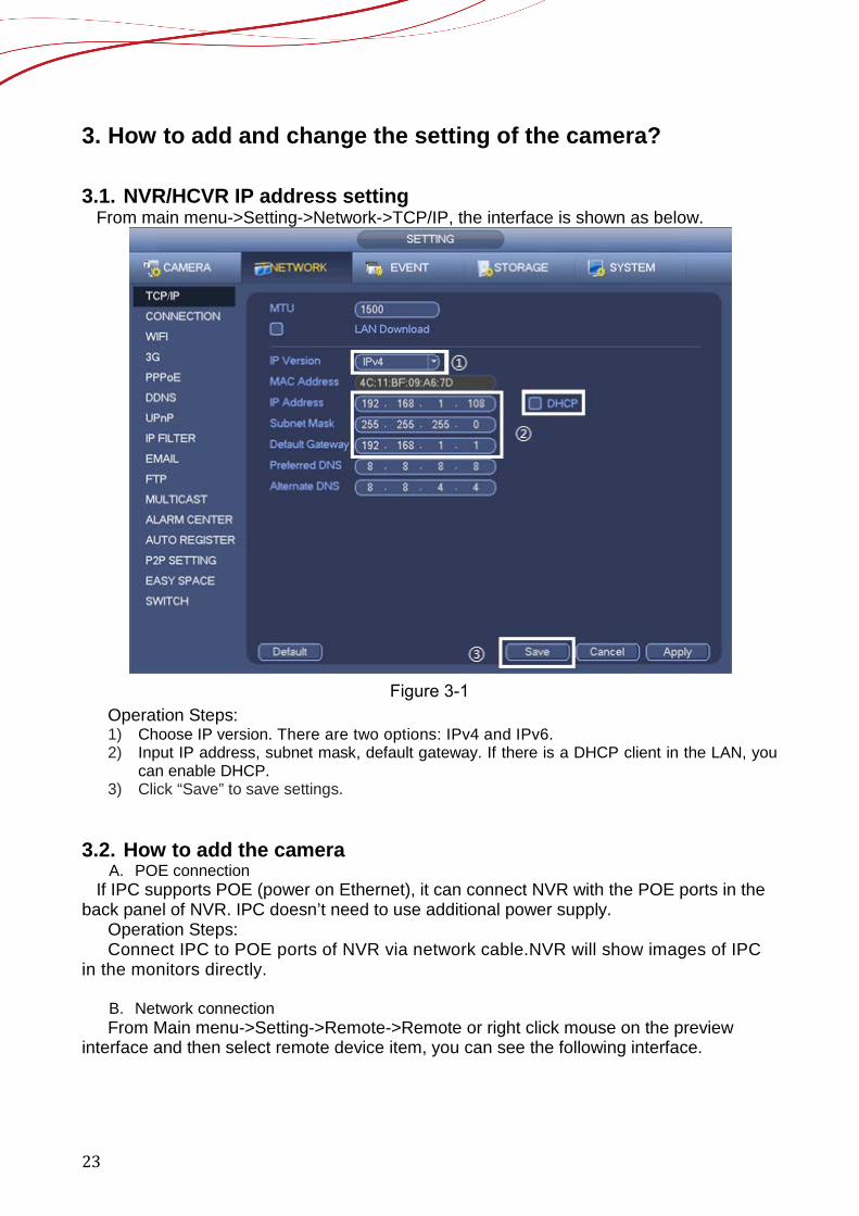
3.1. NVR/HCVR IP address setting From main menu->Setting->Network->TCP/IP, the interface is shown as below.
Figure 3-1
Operation Steps: 1) Choose IP version. There are two options: IPv4 and IPv6. 2) Input IP address, subnet mask, default gateway. If there is a DHCP client in the LAN, you
can enable DHCP. 3) Click “Save” to save settings.
3.2. How to add the camera
A. POE connection If IPC supports POE (power on Ethernet), it can connect NVR with the POE ports in the back panel of NVR. IPC doesn’t need to use additional power supply.
Operation Steps: Connect IPC to POE ports of NVR via network cable.NVR will show images of IPC
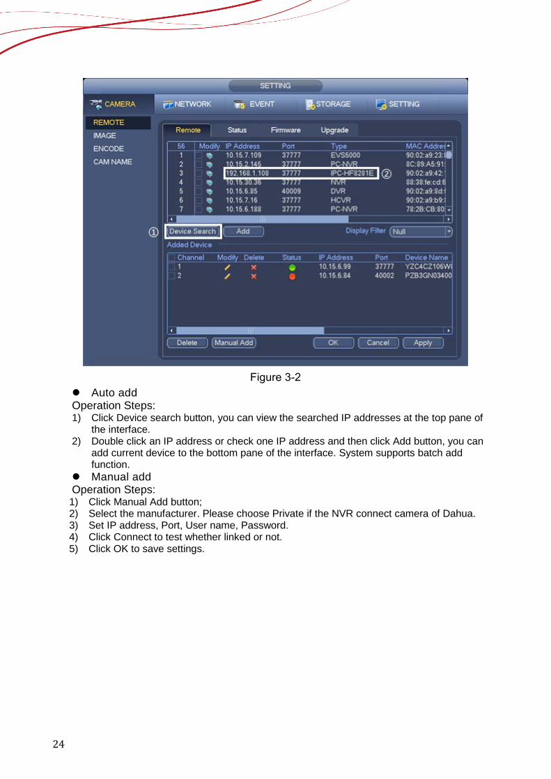
in the monitors directly. B. Network connection From Main menu->Setting->Remote->Remote or right click mouse on the preview
interface and then select remote device item, you can see the following interface.
24
Figure 3-2
Auto add Operation Steps: 1) Click Device search button, you can view the searched IP addresses at the top pane of
the interface. 2) Double click an IP address or check one IP address and then click Add button, you can
add current device to the bottom pane of the interface. System supports batch add function.
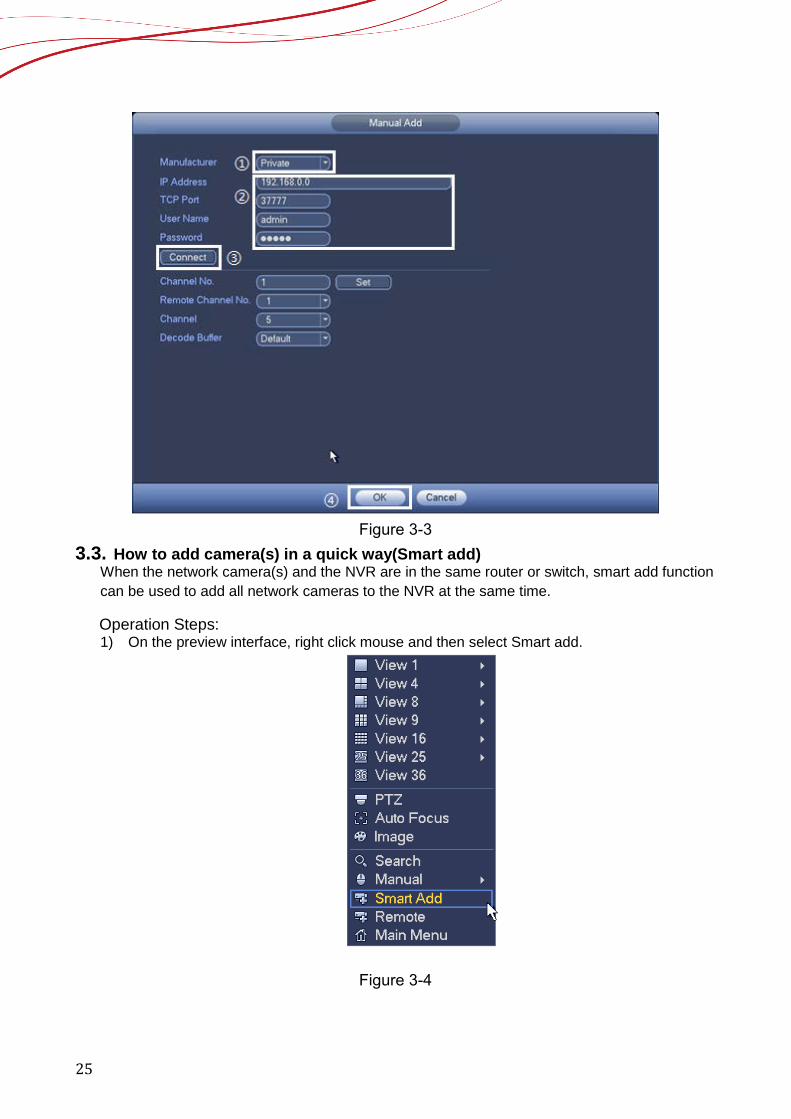
Manual add Operation Steps: 1) Click Manual Add button; 2) Select the manufacturer. Please choose Private if the NVR connect camera of Dahua. 3) Set IP address, Port, User name, Password. 4) Click Connect to test whether linked or not. 5) Click OK to save settings.
25
Figure 3-3
3.3. How to add camera(s) in a quick way(Smart add) When the network camera(s) and the NVR are in the same router or switch, smart add function can be used to add all network cameras to the NVR at the same time.
Operation Steps: 1) On the preview interface, right click mouse and then select Smart add.
Figure 3-4
26
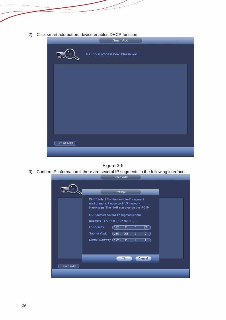
2) Click smart add button, device enables DHCP function.
Figure 3-5 3) Confirm IP information if there are several IP segments in the following interface.
27
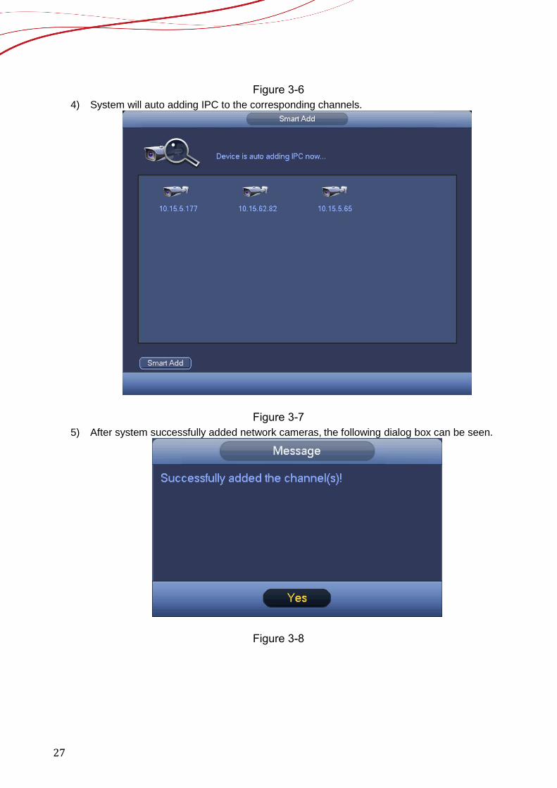
Figure 3-6 4) System will auto adding IPC to the corresponding channels.
Figure 3-7 5) After system successfully added network cameras, the following dialog box can be seen.
Figure 3-8
28
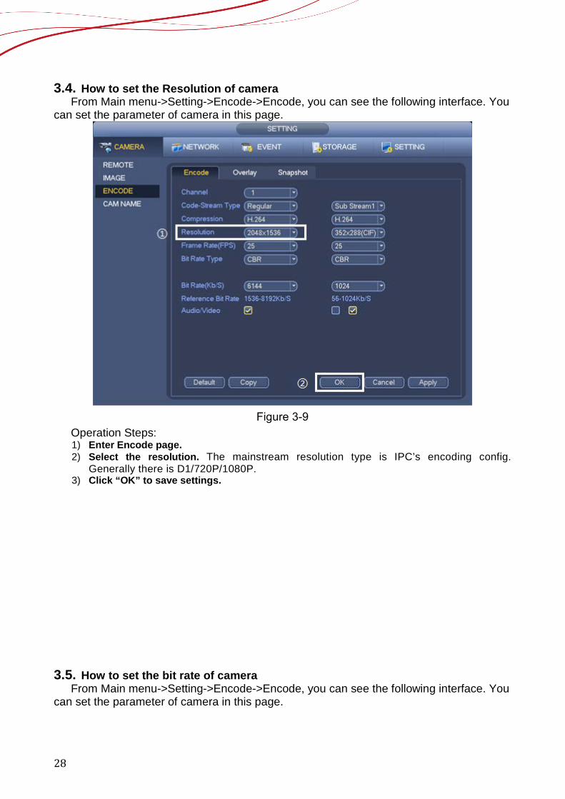
3.4. How to set the Resolution of camera From Main menu->Setting->Encode->Encode, you can see the following interface. You
can set the parameter of camera in this page.
Figure 3-9
Operation Steps: 1) Enter Encode page. 2) Select the resolution. The mainstream resolution type is IPC’s encoding config.
Generally there is D1/720P/1080P. 3) Click “OK” to save settings.
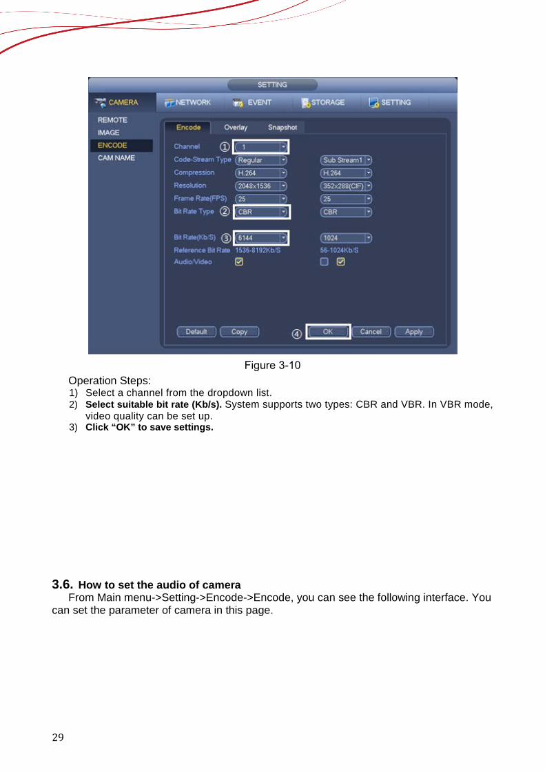
3.5. How to set the bit rate of camera From Main menu->Setting->Encode->Encode, you can see the following interface. You
can set the parameter of camera in this page.
29
Figure 3-10
Operation Steps: 1) Select a channel from the dropdown list. 2) Select suitable bit rate (Kb/s). System supports two types: CBR and VBR. In VBR mode,
video quality can be set up. 3) Click “OK” to save settings.
3.6. How to set the audio of camera
From Main menu->Setting->Encode->Encode, you can see the following interface. You can set the parameter of camera in this page.
30
Figure 3-11
Operation Steps: 1) Select a channel from the dropdown list. 2) You can enable or disable the video/audio. Please note, once you enable audio function
for one channel, system may enable audio function of the rest channels by default. 3) Click “OK” to save settings.
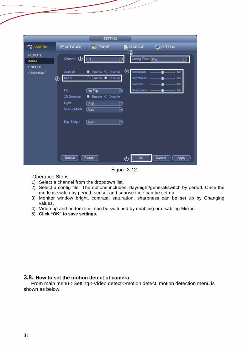
3.7. How to set the image parameters of camera From main menu->Setting->Camera->Image, you can see the image interface is
shown as below.
31
Figure 3-12
Operation Steps: 1) Select a channel from the dropdown list. 2) Select a config file. The options includes: day/night/general/switch by period. Once the
mode is switch by period, sunset and sunrise time can be set up. 3) Monitor window bright, contrast, saturation, sharpness can be set up by Changing
values. 4) Video up and bottom limit can be switched by enabling or disabling Mirror. 5) Click “OK” to save settings.
3.8. How to set the motion detect of camera
From main menu->Setting->Video detect->motion detect, motion detection menu is shown as below.

32
Figure 3-13
Operation Steps: 1) Select a channel from the dropdown list, then click “Enable” button. 2) Working period setting, default it all day. 3) Click “Set” of Region. Select the area to enable or disable motion detect. 4) If alarm Out is enabled, it will trigger alarm out when it occurs. It is the same with the
setting of MD. 5) Click “OK” to save settings.
3.9. How to set the Tripwire of camera
From main menu->Setting->IVS, you can see tripwire, intrusion, object, scene change for selection.
Function Description: Tripwire is to detect if there is any object crossing the warning line, it can support
different direction selection, such as A->B, B->A and bidirectional, and it can activate record , snapshot and alarm according to the judgment result.
33
The interface is as below.
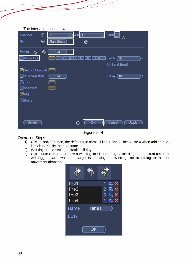
Figure 3-14
Operation Steps: 1) Click “Enable” button, the default rule name is line 1, line 2, line 3, line 4 when adding rule,
it is ok to modify the rule name. 2) Working period setting, default it all day. 3) Click “Rule Setup” and draw a warning line in the image according to the actual needs, it
will trigger alarm when the target is crossing the warning line according to the set movement direction.
34
Figure 3-15
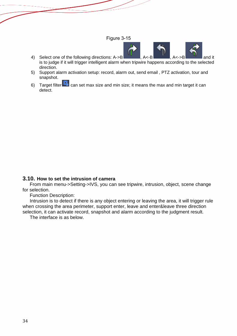
4) Select one of the following directions: A->B , A<-B , A<->B and it is to judge if it will trigger intelligent alarm when tripwire happens according to the selected direction.
5) Support alarm activation setup: record, alarm out, send email , PTZ activation, tour and snapshot.
6) Target filter can set max size and min size; it means the max and min target it can detect.
3.10. How to set the intrusion of camera
From main menu->Setting->IVS, you can see tripwire, intrusion, object, scene change for selection.
Function Description: Intrusion is to detect if there is any object entering or leaving the area, it will trigger rule
when crossing the area perimeter, support enter, leave and enter&leave three direction selection, it can activate record, snapshot and alarm according to the judgment result.
The interface is as below.
35
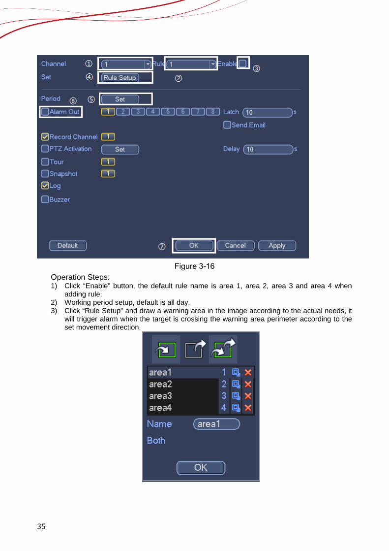
Figure 3-16
Operation Steps: 1) Click “Enable” button, the default rule name is area 1, area 2, area 3 and area 4 when
adding rule. 2) Working period setup, default is all day. 3) Click “Rule Setup” and draw a warning area in the image according to the actual needs, it
will trigger alarm when the target is crossing the warning area perimeter according to the set movement direction.
36
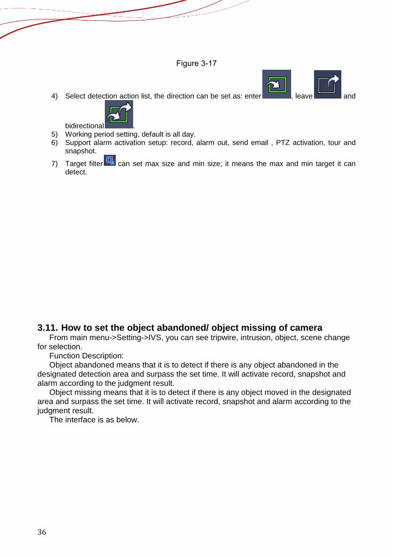
Figure 3-17
4) Select detection action list, the direction can be set as: enter , leave and
bidirectional . 5) Working period setting, default is all day. 6) Support alarm activation setup: record, alarm out, send email , PTZ activation, tour and
snapshot.
7) Target filter can set max size and min size; it means the max and min target it can detect.
3.11. How to set the object abandoned/ object missing of camera
From main menu->Setting->IVS, you can see tripwire, intrusion, object, scene change for selection.
Function Description: Object abandoned means that it is to detect if there is any object abandoned in the
designated detection area and surpass the set time. It will activate record, snapshot and alarm according to the judgment result.
Object missing means that it is to detect if there is any object moved in the designated area and surpass the set time. It will activate record, snapshot and alarm according to the judgment result.
The interface is as below.
37
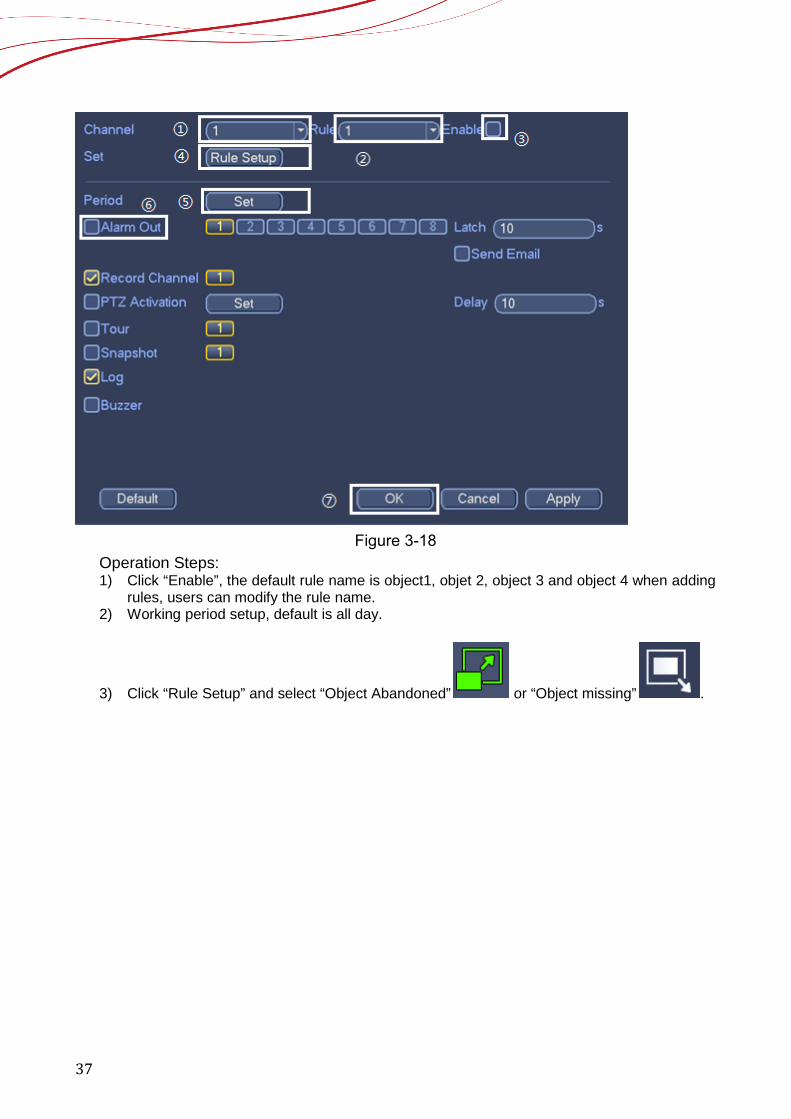
Figure 3-18
Operation Steps: 1) Click “Enable”, the default rule name is object1, objet 2, object 3 and object 4 when adding
rules, users can modify the rule name. 2) Working period setup, default is all day.
3) Click “Rule Setup” and select “Object Abandoned” or “Object missing” .
38
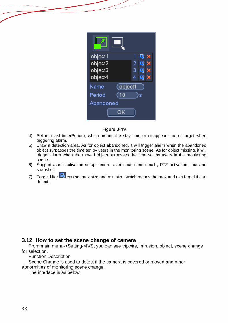
Figure 3-19 4) Set min last time(Period), which means the stay time or disappear time of target when
triggering alarm. 5) Draw a detection area. As for object abandoned, it will trigger alarm when the abandoned
object surpasses the time set by users in the monitoring scene; As for object missing, it will trigger alarm when the moved object surpasses the time set by users in the monitoring scene.
6) Support alarm activation setup: record, alarm out, send email , PTZ activation, tour and snapshot.
7) Target filter can set max size and min size, which means the max and min target it can detect.
3.12. How to set the scene change of camera
From main menu->Setting->IVS, you can see tripwire, intrusion, object, scene change for selection.
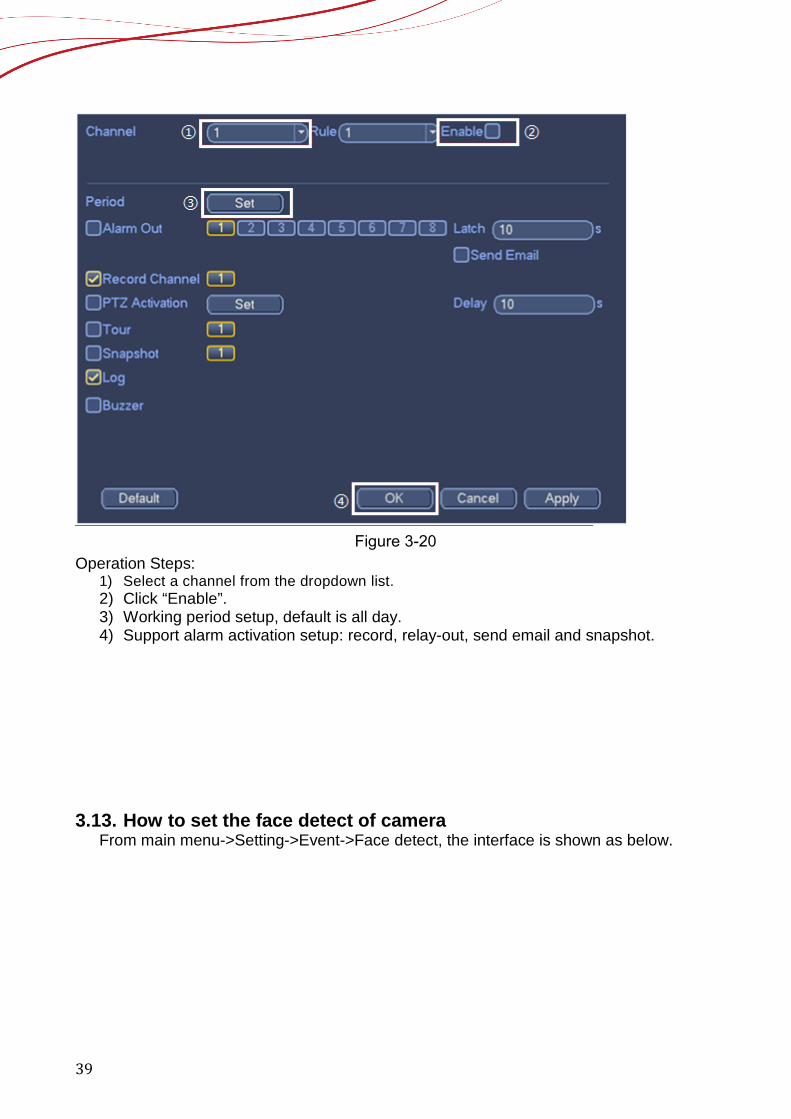
Function Description: Scene Change is used to detect if the camera is covered or moved and other
abnormities of monitoring scene change. The interface is as below.
39
Figure 3-20
Operation Steps: 1) Select a channel from the dropdown list. 2) Click “Enable”. 3) Working period setup, default is all day. 4) Support alarm activation setup: record, relay-out, send email and snapshot.
3.13. How to set the face detect of camera
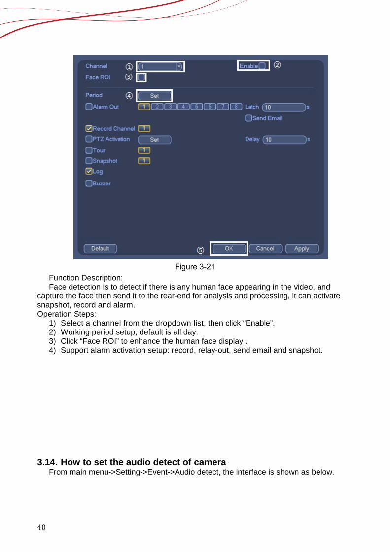
From main menu->Setting->Event->Face detect, the interface is shown as below.
40
Figure 3-21
Function Description: Face detection is to detect if there is any human face appearing in the video, and
capture the face then send it to the rear-end for analysis and processing, it can activate snapshot, record and alarm. Operation Steps:
1) Select a channel from the dropdown list, then click “Enable”. 2) Working period setup, default is all day. 3) Click “Face ROI” to enhance the human face display . 4) Support alarm activation setup: record, relay-out, send email and snapshot.
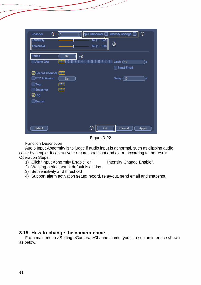
3.14. How to set the audio detect of camera From main menu->Setting->Event->Audio detect, the interface is shown as below.
41
Figure 3-22
Function Description: Audio Input Abnormity is to judge if audio input is abnormal, such as clipping audio
cable by people. It can activate record, snapshot and alarm according to the results. Operation Steps:
1) Click “Input Abnormity Enable” or “ Intensity Change Enable”. 2) Working period setup, default is all day. 3) Set sensitivity and threshold 4) Support alarm activation setup: record, relay-out, send email and snapshot.
3.15. How to change the camera name
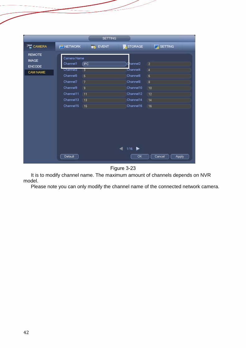
From main menu->Setting->Camera->Channel name, you can see an interface shown as below.
42
Figure 3-23
It is to modify channel name. The maximum amount of channels depends on NVR model.
Please note you can only modify the channel name of the connected network camera.
43
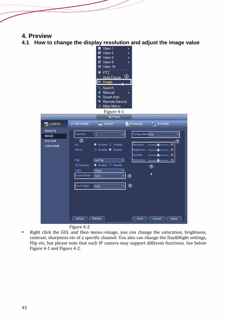
4. Preview 4.1 How to change the display resolution and adjust the image value
Figure 4-1
Figure 4-2
Right click the GUI, and then menu->image, you can change the saturation, brightness, contrast, sharpness etc of a specific channel. You also can change the Day&Night settings, Flip etc, but please note that each IP camera may support different functions. See below Figure 4-1 and Figure 4-2.
44
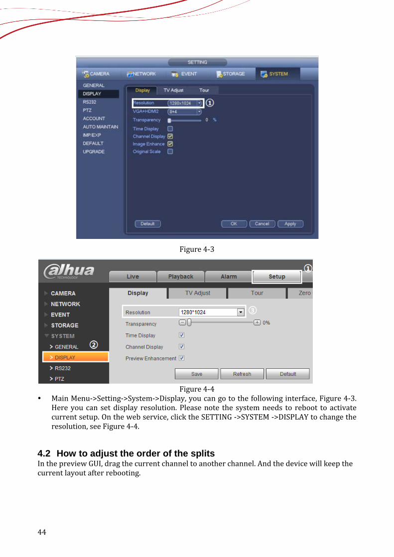
Figure 4-3
Figure 4-4
Main Menu->Setting->System->Display, you can go to the following interface, Figure 4-3. Here you can set display resolution. Please note the system needs to reboot to activate current setup. On the web service, click the SETTING ->SYSTEM ->DISPLAY to change the resolution, see Figure 4-4.
4.2 How to adjust the order of the splits In the preview GUI, drag the current channel to another channel. And the device will keep the current layout after rebooting.
45
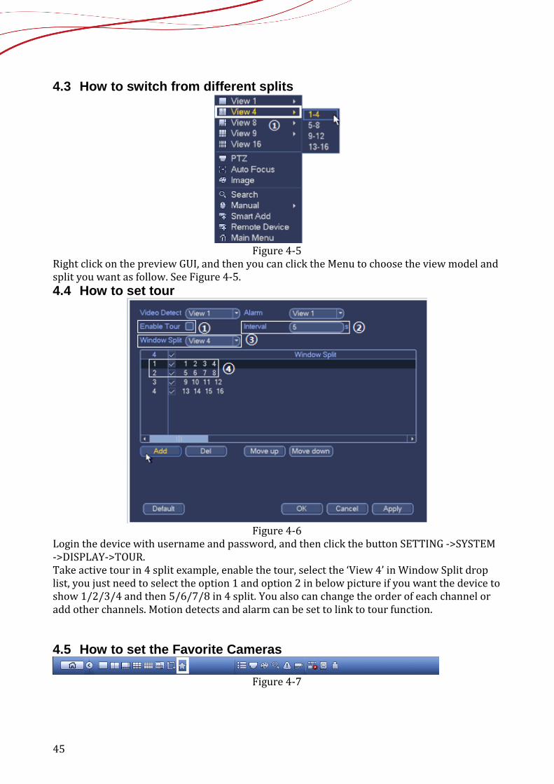
4.3 How to switch from different splits
Figure 4-5
Right click on the preview GUI, and then you can click the Menu to choose the view model and split you want as follow. See Figure 4-5. 4.4 How to set tour
Figure 4-6
Login the device with username and password, and then click the button SETTING ->SYSTEM ->DISPLAY->TOUR. Take active tour in 4 split example, enable the tour, select the ‘View 4’ in Window Split drop list, you just need to select the option 1 and option 2 in below picture if you want the device to show 1/2/3/4 and then 5/6/7/8 in 4 split. You also can change the order of each channel or add other channels. Motion detects and alarm can be set to link to tour function. 4.5 How to set the Favorite Cameras
Figure 4-7

46
Note: Favorites is only available on HCVR74XXL, HCVR78XXS, HCVR5424/32L (-S2), HCVR5824/32S (-S2), DVR7X series and used to save the current layout of the splits. You need to go to the Main menu->Setting->System->General to enable navigation bar function first and then set the favorites. The navigation bar is shown as below. See Figure 4-7.
Figure 4-8
Click , system pops up the following interface. See Figure 4-8. Click one item, you can view saved favorite channel split mode and channel number. You can add the favorites by clicking the “Add to Favorites” and delete them by clicking “Edit Favorites”. Please note, right now the favorite scheme names after the window split mode.
4.6 How to set mask
Figure 4-9
In the main button, from Main menu->camera->encode->overlay button, you can see an interface is shown in the following Figure 4-9.
Cover area: Here is for you to cover area section. You can drag you mouse to set proper section size. In one channel video, system max supports 4 zones in one channel. Preview/monitor: The cover area has two types. Preview and Monitor. Preview
means the privacy mask zone cannot be viewed by user when system is in preview status. Monitor means the privacy mask zone cannot be view by the user when system is in monitor status.
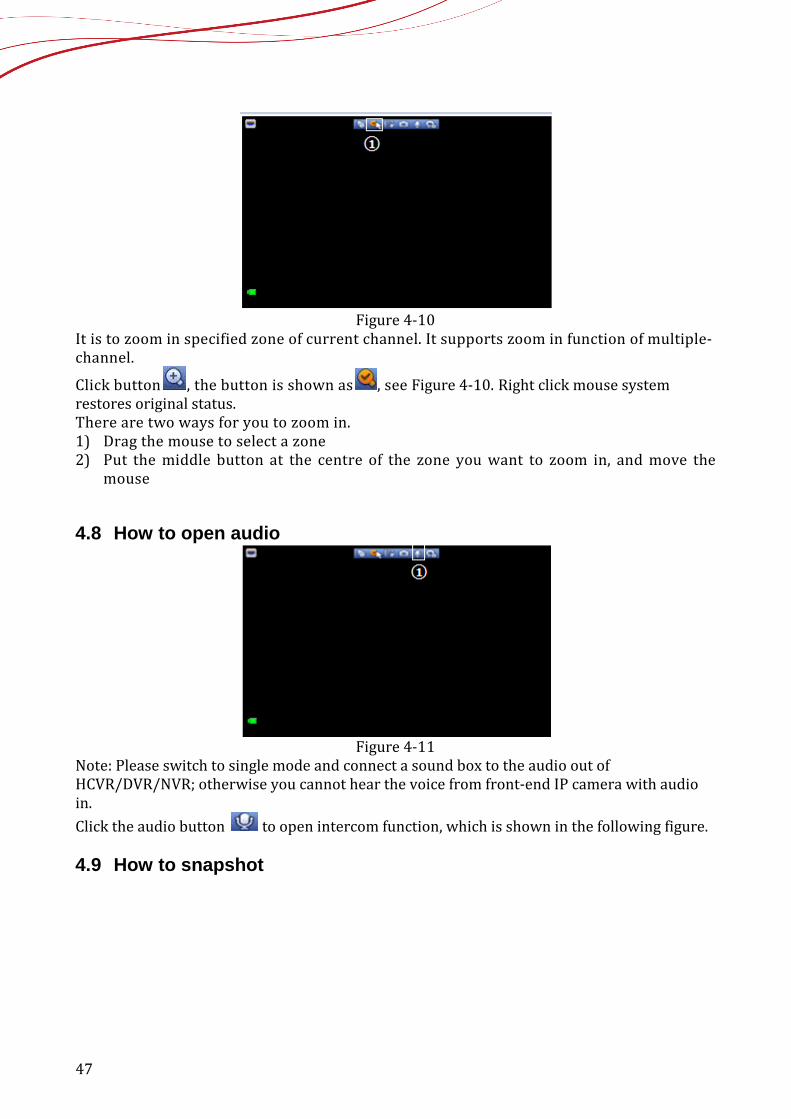
4.7 How to make the digital zoom
47
Figure 4-10
It is to zoom in specified zone of current channel. It supports zoom in function of multiple-channel.
Click button , the button is shown as , see Figure 4-10. Right click mouse system restores original status. There are two ways for you to zoom in. 1) Drag the mouse to select a zone 2) Put the middle button at the centre of the zone you want to zoom in, and move the
mouse
4.8 How to open audio
Figure 4-11
Note: Please switch to single mode and connect a sound box to the audio out of HCVR/DVR/NVR; otherwise you cannot hear the voice from front-end IP camera with audio in. Click the audio button to open intercom function, which is shown in the following figure. 4.9 How to snapshot
48
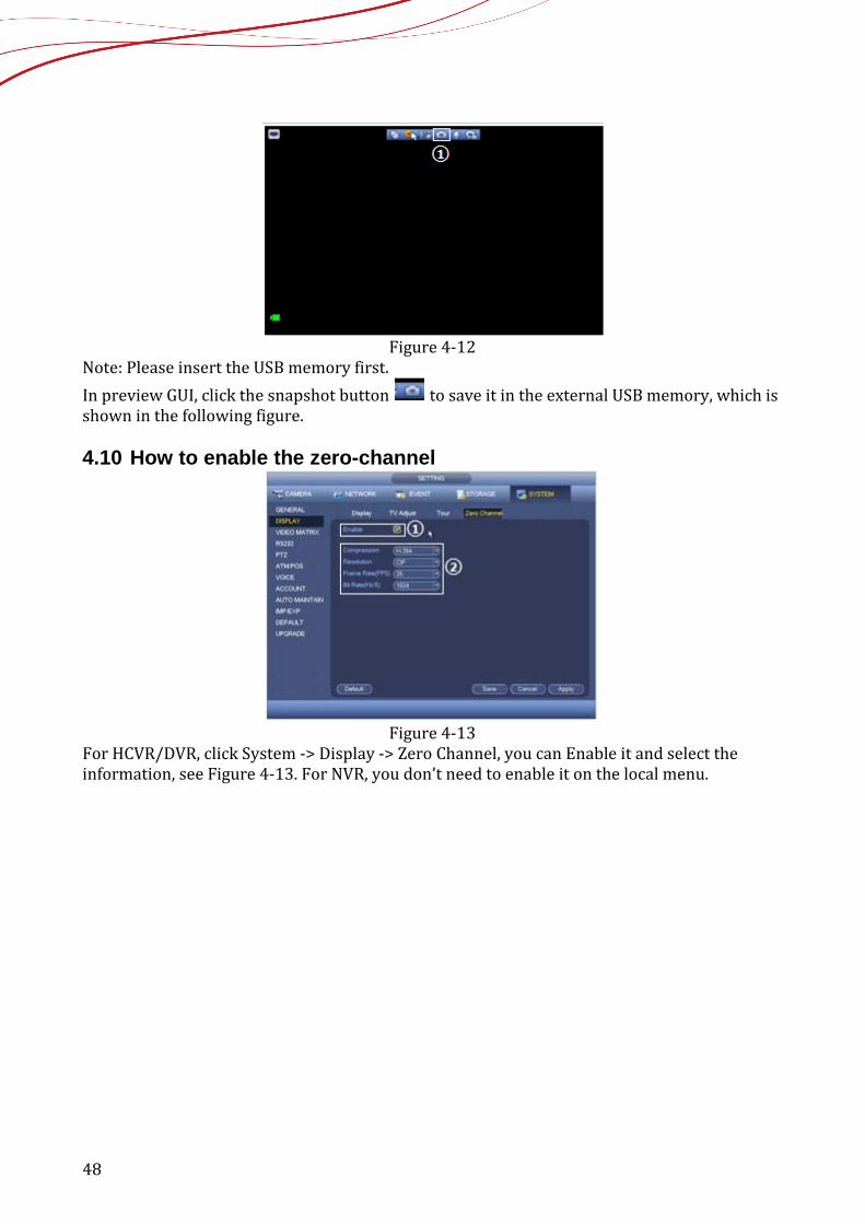
Figure 4-12
Note: Please insert the USB memory first. In preview GUI, click the snapshot button to save it in the external USB memory, which is shown in the following figure. 4.10 How to enable the zero-channel
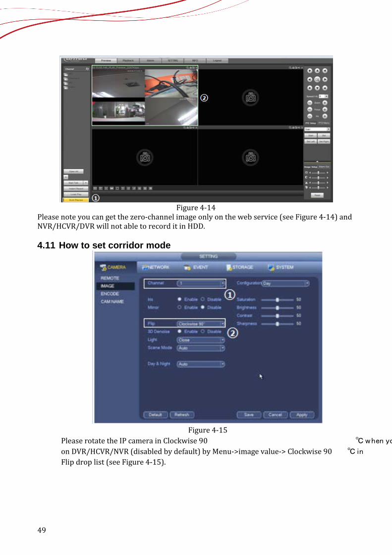
Figure 4-13
For HCVR/DVR, click System -> Display -> Zero Channel, you can Enable it and select the information, see Figure 4-13. For NVR, you don’t need to enable it on the local menu.
49
Figure 4-14
Please note you can get the zero-channel image only on the web service (see Figure 4-14) and NVR/HCVR/DVR will not able to record it in HDD. 4.11 How to set corridor mode
Figure 4-15
Please rotate the IP camera in Clockwise 90 ℃ when yo
on DVR/HCVR/NVR (disabled by default) by Menu->image value-> Clockwise 90 ℃ in
Flip drop list (see Figure 4-15).
50
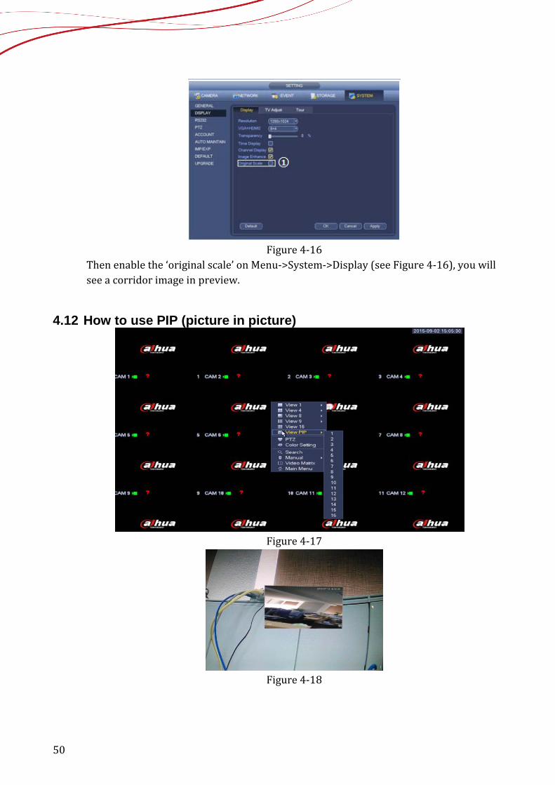
Figure 4-16
Then enable the ‘original scale’ on Menu->System->Display (see Figure 4-16), you will see a corridor image in preview.
4.12 How to use PIP (picture in picture)
Figure 4-17
Figure 4-18
51
Note:This function is available only on DVR7XXX series and HCVR74XXL, HCVR78XXS, HCVR5424/32L (-S2), HCVR5824/32S (-S2). It is to overlay one picture on another picture in 1-window mode. 1) Right click and select “View PIP” in the Menu. You can switch the position of the large
window and the small window. Left click the small window, you can drag it to any position you desire. And move the mouse to the margin, you can drag to zoom in or zoom out.
2) On the preview interface of the channel 1, right click mouse and then select channel 11, you can overlay video from channel 11 on the channel 1. See Figure 4-17 and Figure 4-18.
4.13 How to use the second HDMI
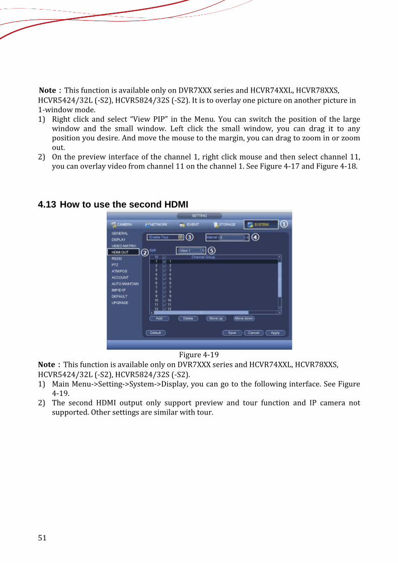
Figure 4-19
Note:This function is available only on DVR7XXX series and HCVR74XXL, HCVR78XXS, HCVR5424/32L (-S2), HCVR5824/32S (-S2). 1) Main Menu->Setting->System->Display, you can go to the following interface. See Figure
4-19. 2) The second HDMI output only support preview and tour function and IP camera not
supported. Other settings are similar with tour.
52
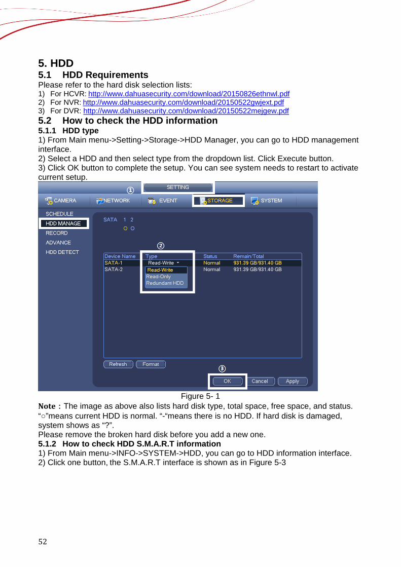
5. HDD 5.1 HDD Requirements Please refer to the hard disk selection lists: 1) For HCVR: http://www.dahuasecurity.com/download/20150826ethnwl.pdf 2) For NVR: http://www.dahuasecurity.com/download/20150522gwjext.pdf 3) For DVR: http://www.dahuasecurity.com/download/20150522mejgew.pdf 5.2 How to check the HDD information 5.1.1 HDD type 1) From Main menu->Setting->Storage->HDD Manager, you can go to HDD management interface. 2) Select a HDD and then select type from the dropdown list. Click Execute button. 3) Click OK button to complete the setup. You can see system needs to restart to activate current setup.
Figure 5- 1
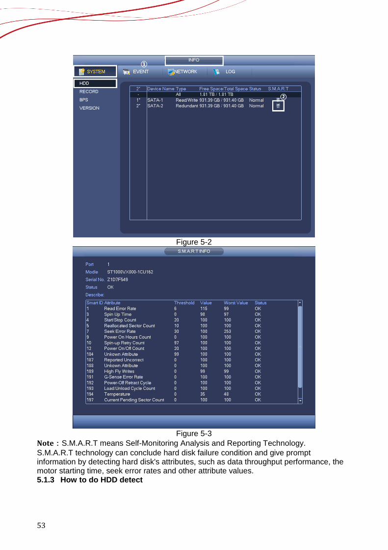
Note:The image as above also lists hard disk type, total space, free space, and status. “○”means current HDD is normal. “-“means there is no HDD. If hard disk is damaged, system shows as “?”. Please remove the broken hard disk before you add a new one. 5.1.2 How to check HDD S.M.A.R.T information 1) From Main menu->INFO->SYSTEM->HDD, you can go to HDD information interface. 2) Click one button, the S.M.A.R.T interface is shown as in Figure 5-3
53
Figure 5-2
Figure 5-3
Note:S.M.A.R.T means Self-Monitoring Analysis and Reporting Technology. S.M.A.R.T technology can conclude hard disk failure condition and give prompt information by detecting hard disk's attributes, such as data throughput performance, the motor starting time, seek error rates and other attribute values. 5.1.3 How to do HDD detect
54
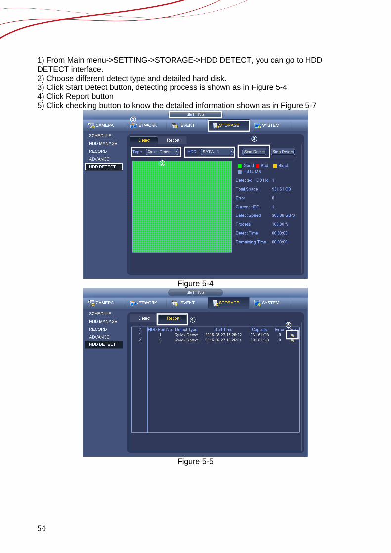
1) From Main menu->SETTING->STORAGE->HDD DETECT, you can go to HDD DETECT interface. 2) Choose different detect type and detailed hard disk. 3) Click Start Detect button, detecting process is shown as in Figure 5-4 4) Click Report button 5) Click checking button to know the detailed information shown as in Figure 5-7
Figure 5-4
Figure 5-5

55
Figure 5-6
56
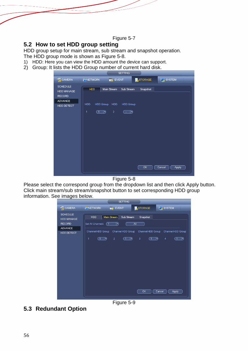
Figure 5-7 5.2 How to set HDD group setting HDD group setup for main stream, sub stream and snapshot operation. The HDD group mode is shown as Figure 5-8. 1) HDD: Here you can view the HDD amount the device can support. 2) Group: It lists the HDD Group number of current hard disk.
Figure 5-8
Please select the correspond group from the dropdown list and then click Apply button. Click main stream/sub stream/snapshot button to set corresponding HDD group information. See images below.
Figure 5-9
5.3 Redundant Option
57
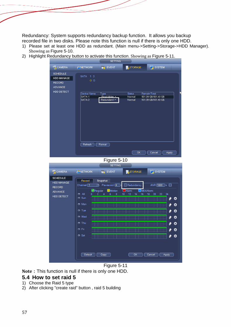
Redundancy: System supports redundancy backup function. It allows you backup recorded file in two disks. Please note this function is null if there is only one HDD. 1) Please set at least one HDD as redundant. (Main menu->Setting->Storage->HDD Manager).
Showing as Figure 5-10. 2) Highlight Redundancy button to activate this function. Showing as Figure 5-11.
Figure 5-10
Figure 5-11
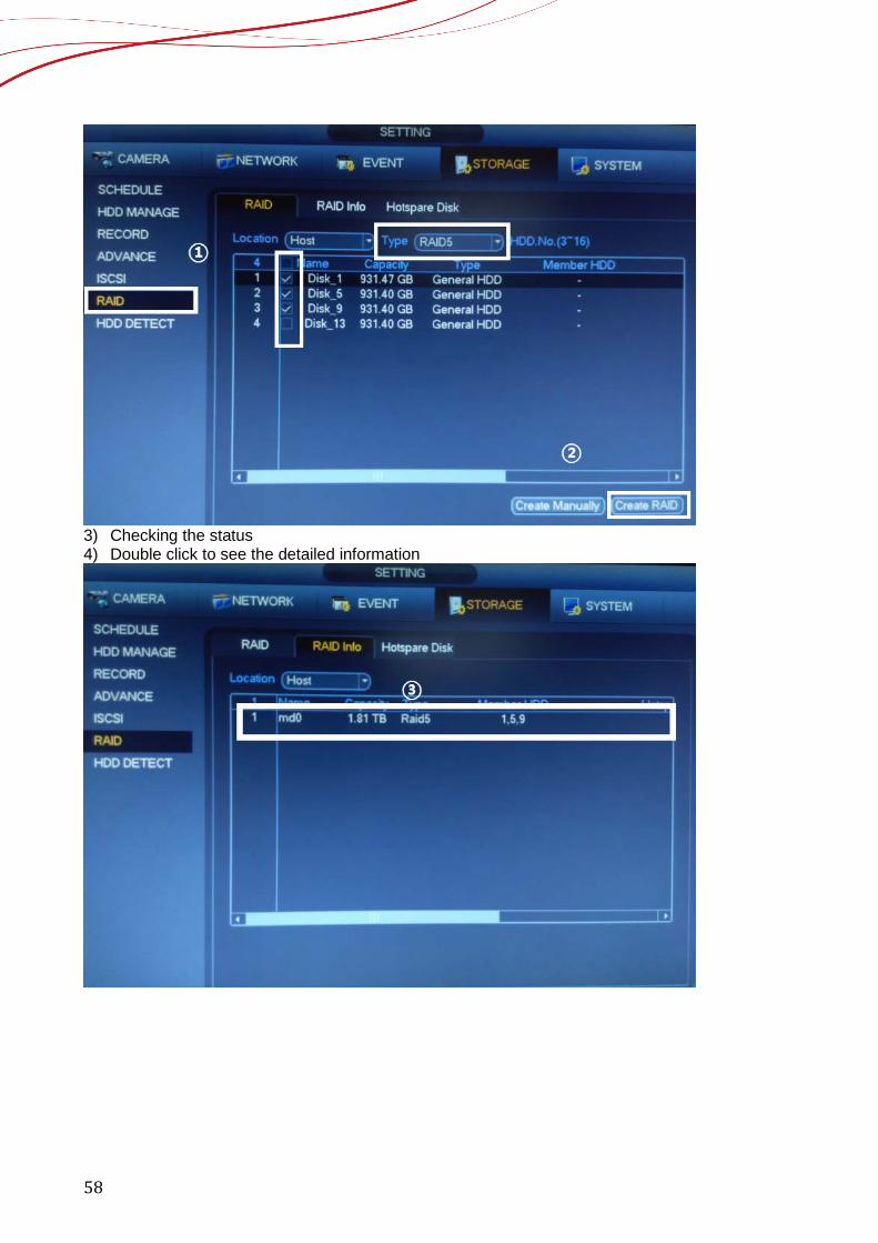
Note:This function is null if there is only one HDD. 5.4 How to set raid 5 1) Choose the Raid 5 type 2) After clicking ”create raid” button , raid 5 building
58
3) Checking the status 4) Double click to see the detailed information
59
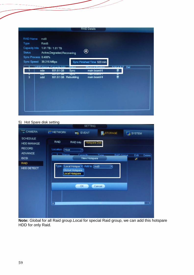
5) Hot Spare disk setting
Note: Global for all Raid group.Local for special Raid group, we can add this hotspare HDD for only Raid.

60
6 Recording 6.1 How to change the encode We can find the menu on “SETTING”-“CAMERA”-“ENCODE”,as figure 6-1 shows.
Figure 6-1
6. For the encode function , the main stream we can set three different stream type.We have “MD” ”Alarm” ”Regular” different type for different stream type. These different type settings only support with Dahua IP cameras.
7. Also, we have the sub-stream settings from the IPC. All the settings can be set as the second encoding option for the channel. It can be used for different function.
8. The resolution depends on the IP camera,so we can change the resolution from the IPC. 9. For the IPC settings, the most important thing is the bit rate. We can change the bandwidth
from the IPC for different network situation. For 1080P,the recommended bitrates is 4096kbps
6.2 How to set the Manual Recording We can find the menu on “SETTING”-“RECORD”-“STORAGE”,as figure 6-2 shows.
① ②
③
④
61
Figure 6-2
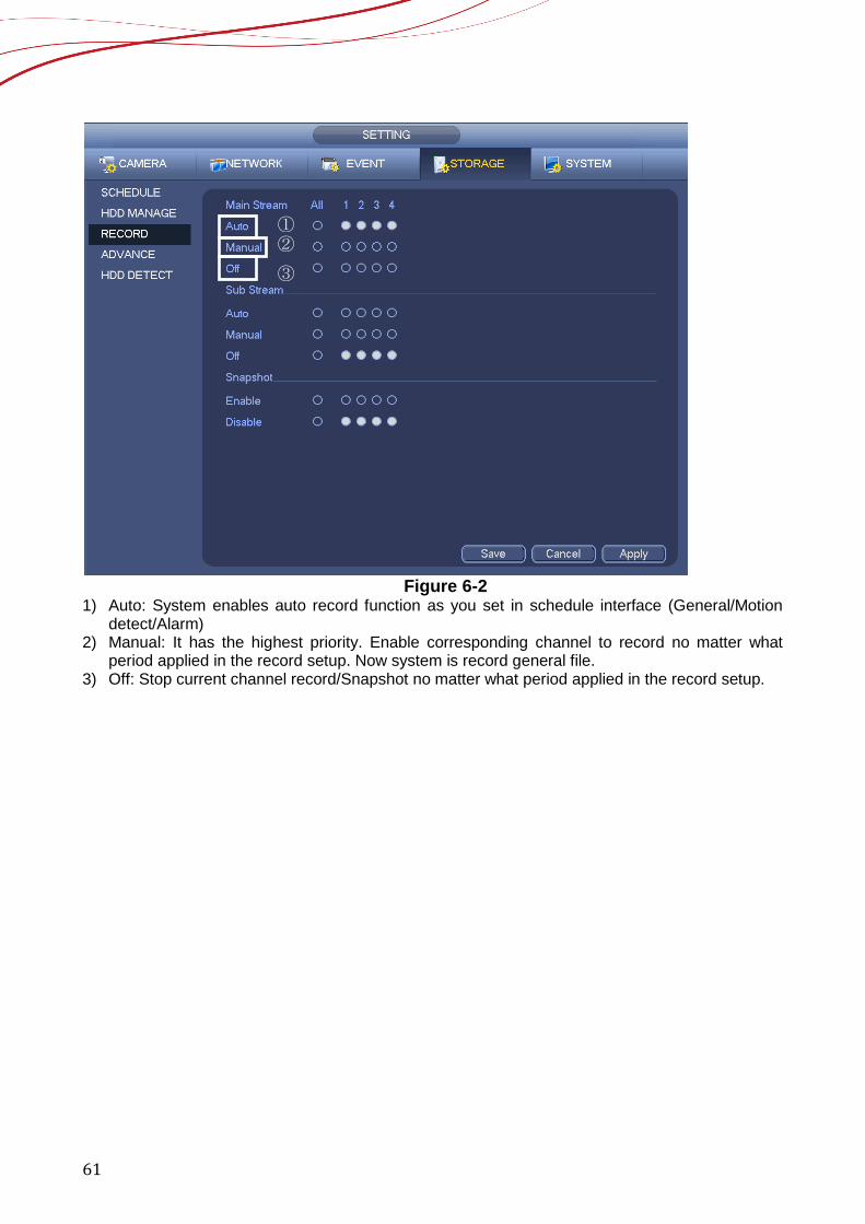
1) Auto: System enables auto record function as you set in schedule interface (General/Motion detect/Alarm)
2) Manual: It has the highest priority. Enable corresponding channel to record no matter what period applied in the record setup. Now system is record general file.
3) Off: Stop current channel record/Snapshot no matter what period applied in the record setup.
① ②
③
62
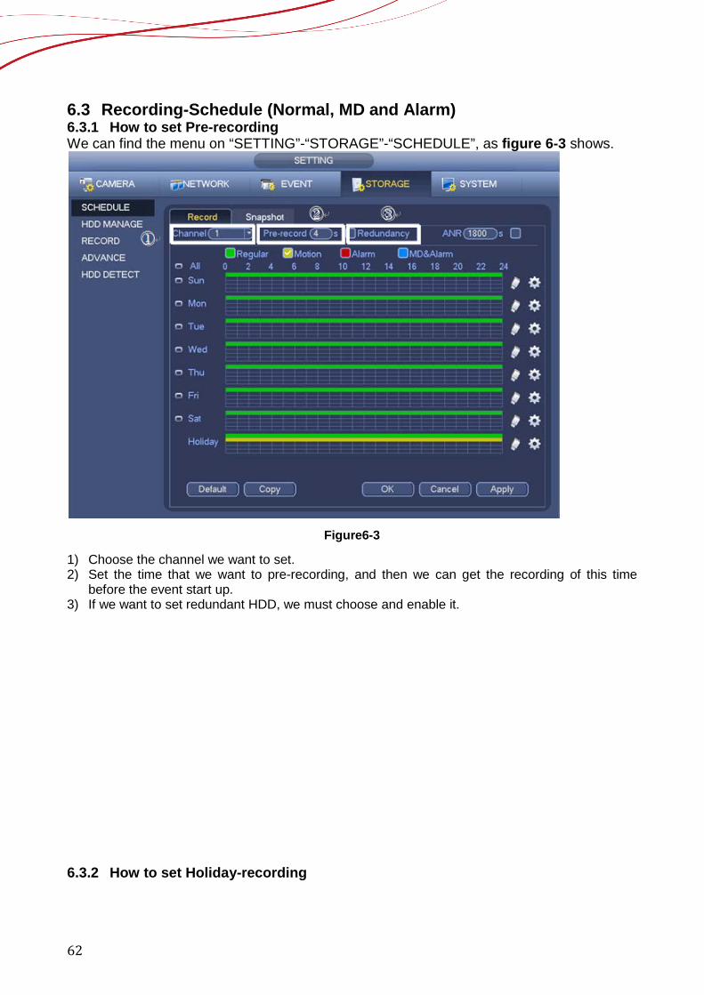
6.3 Recording-Schedule (Normal, MD and Alarm) 6.3.1 How to set Pre-recording We can find the menu on “SETTING”-“STORAGE”-“SCHEDULE”, as figure 6-3 shows.
Figure6-3
1) Choose the channel we want to set. 2) Set the time that we want to pre-recording, and then we can get the recording of this time
before the event start up. 3) If we want to set redundant HDD, we must choose and enable it.
6.3.2 How to set Holiday-recording
①
② ③
63
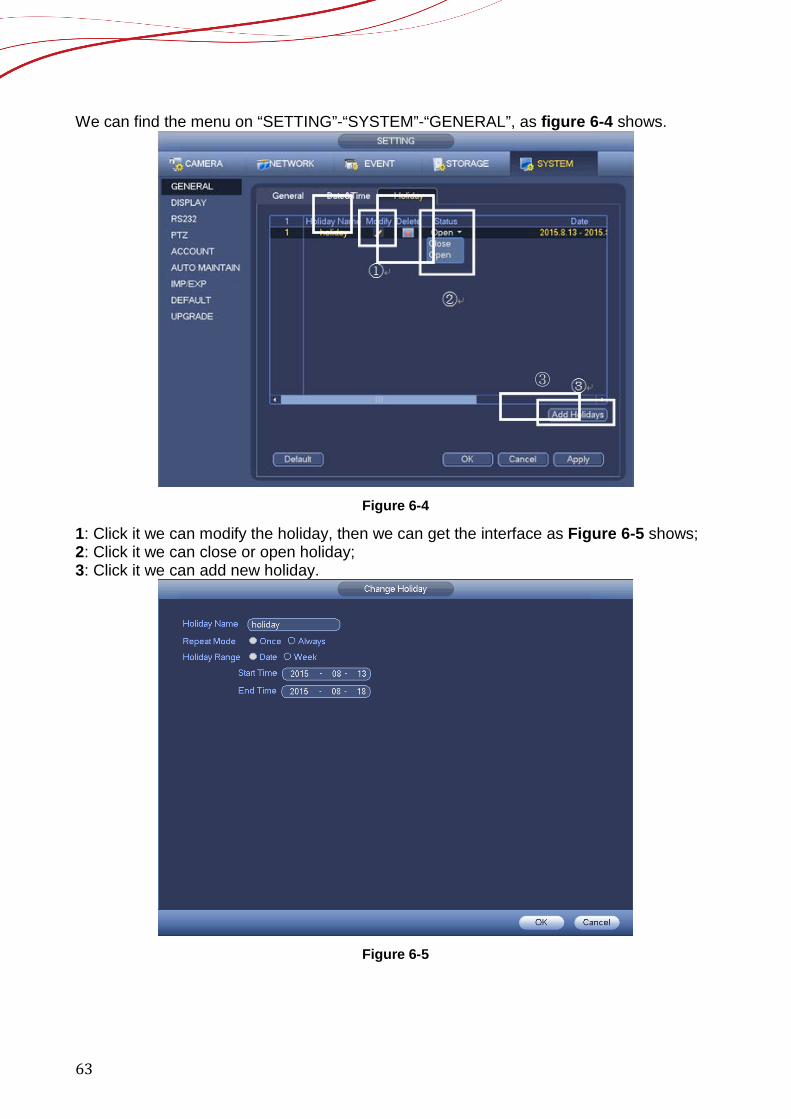
We can find the menu on “SETTING”-“SYSTEM”-“GENERAL”, as figure 6-4 shows.
Figure 6-4
1: Click it we can modify the holiday, then we can get the interface as Figure 6-5 shows; 2: Click it we can close or open holiday; 3: Click it we can add new holiday.
Figure 6-5
③
64
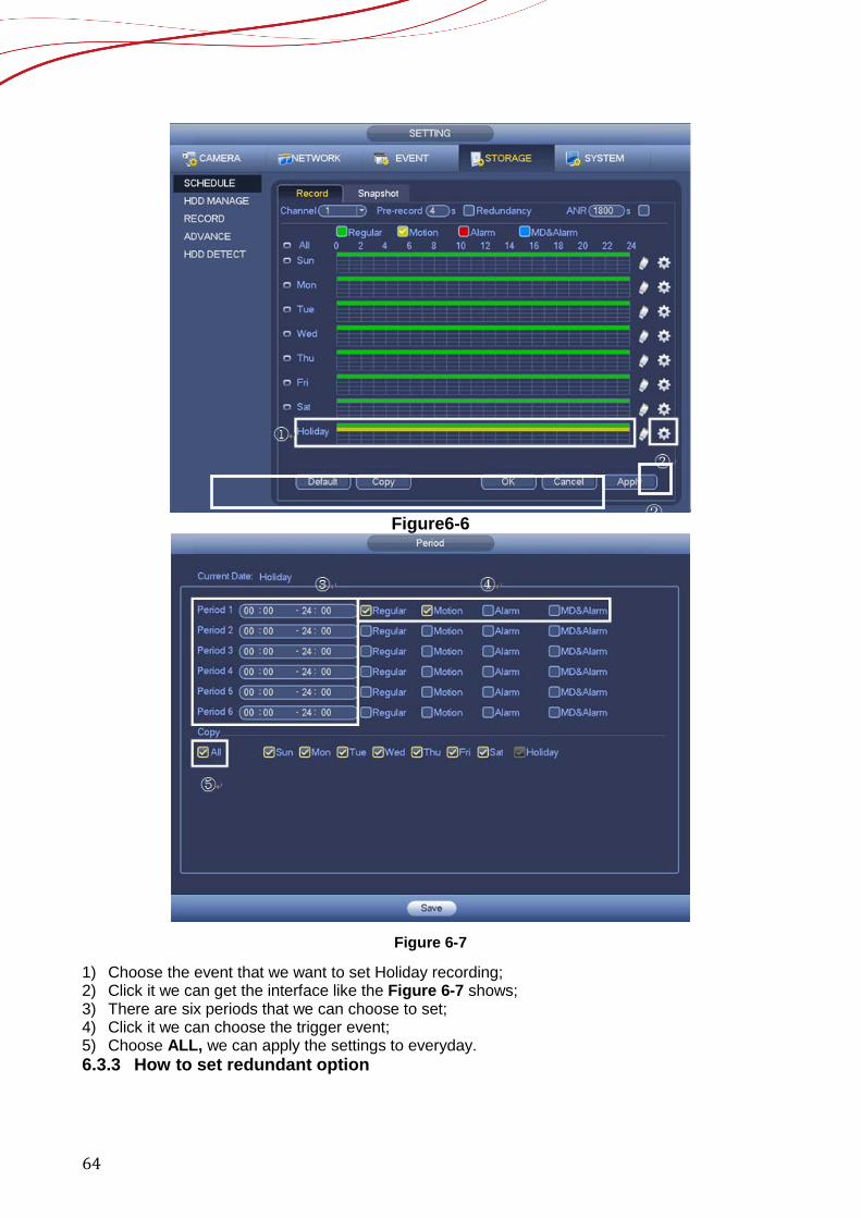
Figure6-6
Figure 6-7
1) Choose the event that we want to set Holiday recording; 2) Click it we can get the interface like the Figure 6-7 shows; 3) There are six periods that we can choose to set; 4) Click it we can choose the trigger event; 5) Choose ALL, we can apply the settings to everyday. 6.3.3 How to set redundant option
②
65
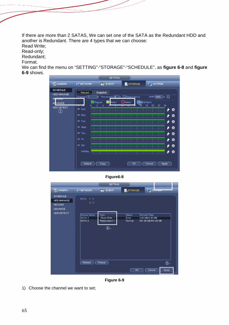
If there are more than 2 SATAS, We can set one of the SATA as the Redundant HDD and another is Redundant. There are 4 types that we can choose: Read Write; Read-only; Redundant; Format. We can find the menu on “SETTING”-“STORAGE”-“SCHEDULE”, as figure 6-8 and figure 6-9 shows.
Figure6-8
Figure 6-9
1) Choose the channel we want to set;
①
②
66
2) If we want to set redundant, we must enable it. 3) Click Apply. 4) Set the type of the SATA. 5) Click Apply.
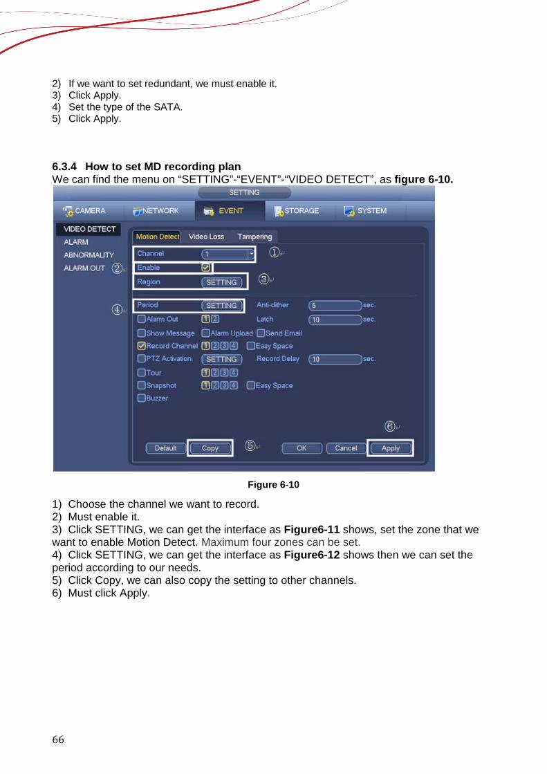
6.3.4 How to set MD recording plan We can find the menu on “SETTING”-“EVENT”-“VIDEO DETECT”, as figure 6-10.
Figure 6-10
1) Choose the channel we want to record. 2) Must enable it. 3) Click SETTING, we can get the interface as Figure6-11 shows, set the zone that we want to enable Motion Detect. Maximum four zones can be set. 4) Click SETTING, we can get the interface as Figure6-12 shows then we can set the period according to our needs. 5) Click Copy, we can also copy the setting to other channels. 6) Must click Apply.

67
Figure 6-11
68
Figure 6-12
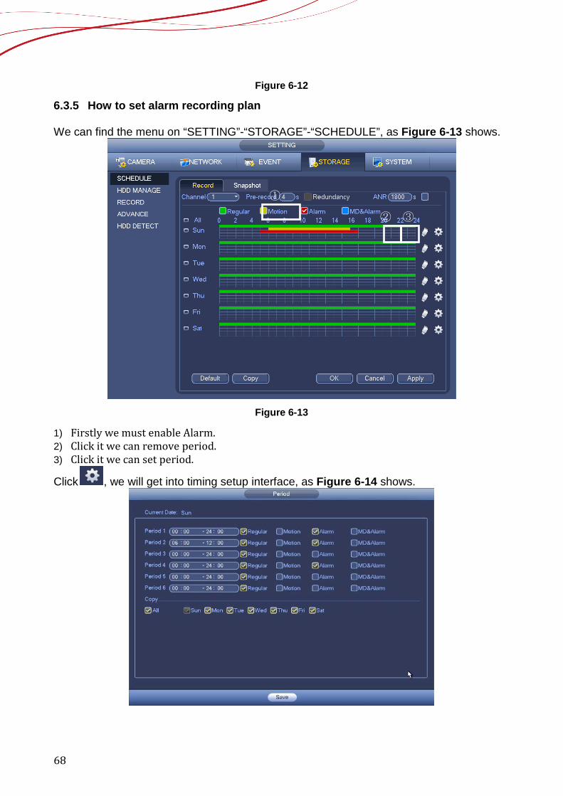
6.3.5 How to set alarm recording plan We can find the menu on “SETTING”-“STORAGE”-“SCHEDULE”, as Figure 6-13 shows.
Figure 6-13
1) Firstly we must enable Alarm. 2) Click it we can remove period. 3) Click it we can set period.
Click , we will get into timing setup interface, as Figure 6-14 shows.
①
② ③
69
Figure 6-14
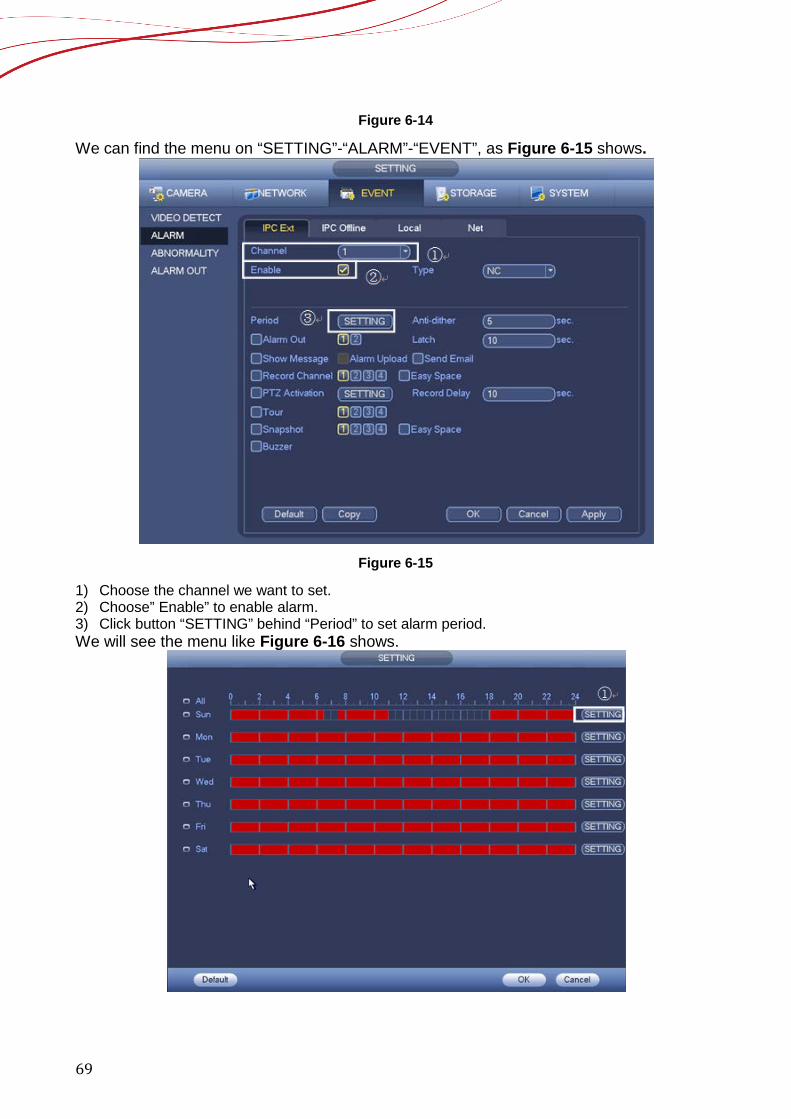
We can find the menu on “SETTING”-“ALARM”-“EVENT”, as Figure 6-15 shows.
Figure 6-15
1) Choose the channel we want to set. 2) Choose” Enable” to enable alarm. 3) Click button “SETTING” behind “Period” to set alarm period. We will see the menu like Figure 6-16 shows.

70
Figure 6-16
1) We can set the period by "setting" or Directly modified in time point as Figure 6-17
shows.
Figure 6-17
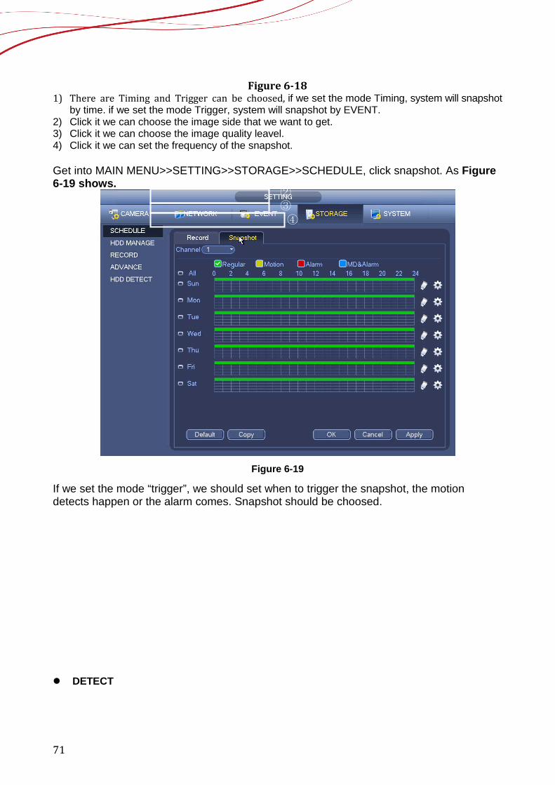
6.4 How to set snapshot plan We can find the menu on “SETTING”-“ENCODE”-“Snapshot”, as Figure 6-18 shows.
71
Figure 6-18 1) There are Timing and Trigger can be choosed, if we set the mode Timing, system will snapshot
by time. if we set the mode Trigger, system will snapshot by EVENT. 2) Click it we can choose the image side that we want to get. 3) Click it we can choose the image quality leavel. 4) Click it we can set the frequency of the snapshot. Get into MAIN MENU>>SETTING>>STORAGE>>SCHEDULE, click snapshot. As Figure 6-19 shows.
Figure 6-19
If we set the mode “trigger”, we should set when to trigger the snapshot, the motion detects happen or the alarm comes. Snapshot should be choosed. DETECT
③ ② ①
④
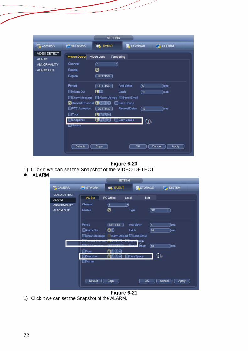
72
Figure 6-20 1) Click it we can set the Snapshot of the VIDEO DETECT. ALARM
Figure 6-21
1) Click it we can set the Snapshot of the ALARM.
①

73
6.5 How to record into FTP We can find the menu on “SETTING”-“FTP”-“NETWORK”, as Figure 6-22 shows.
Figure 6-22
1) Choose the channel we want to set. 2) Please input the FTP server, for example: IP: 10.15.5.100, Port: 21. 3) We can set username by this way, for example: username: 1. 4) We can set password by this way, for example: password: 1.and if we don’t want to set it we
can choose Anonymous. 5) Choose the channel we want to set. 6) Choose the period we want to set. 7) Choose the type of event to record, for example: Alarm, Motion, Regular.
⑤
⑥ ⑦
74
7 Playback and Backup 7.1 How to search and playback
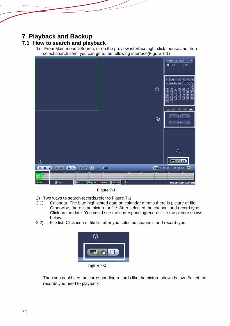
1) From Main menu->Search, or on the preview interface right click mouse and then select search item, you can go to the following interface(Figure 7-1)
Figure 7-1
2) Two ways to search records,refer to Figure 7-1 2.1) Calendar: The blue highlighted date on calendar means there is picture or file.
Otherwise, there is no picture or file. After selected the channel and record type, Click on the date. You could see the correspondingrecords like the picture shows below.
2.2) File list: Click icon of file list after you selected channels and record type.
Figure 7-2
Then you could see the corresponding records like the picture shows below. Select the records you need to playback.
75
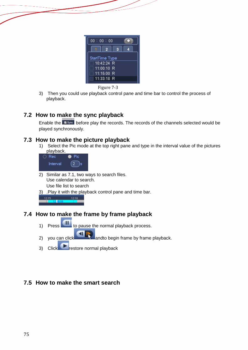
Figure 7-3
3) Then you could use playback control pane and time bar to control the process of playback.
7.2 How to make the sync playback Enable the before play the records. The records of the channels selected would be played synchronously.
7.3 How to make the picture playback 1) Select the Pic mode at the top right pane and type in the interval value of the pictures
playback.
2) Similar as 7.1, two ways to search files.
Use calendar to search. Use file list to search
3) .Play it with the playback control pane and time bar.
7.4 How to make the frame by frame playback
1) Press to pause the normal playback process.
2) you can click andto begin frame by frame playback.
3) Click restore normal playback
7.5 How to make the smart search
76
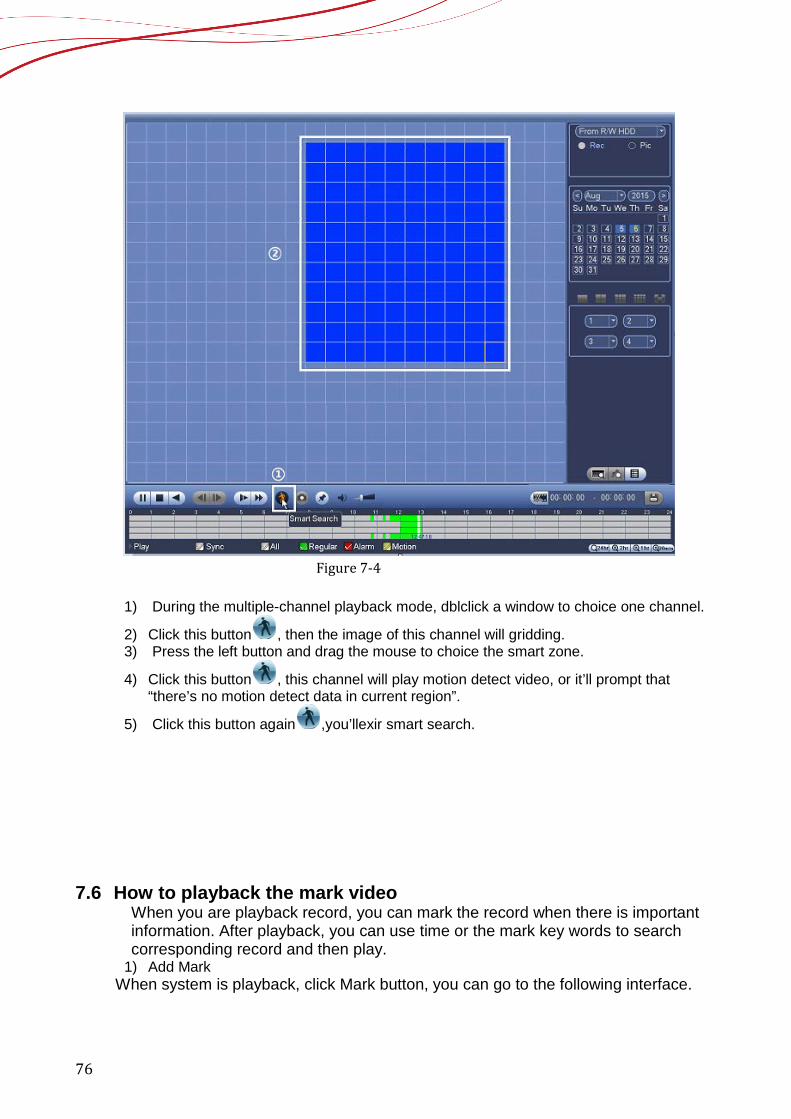
Figure 7-4
1) During the multiple-channel playback mode, dblclick a window to choice one channel.
2) Click this button , then the image of this channel will gridding. 3) Press the left button and drag the mouse to choice the smart zone.
4) Click this button , this channel will play motion detect video, or it’ll prompt that “there’s no motion detect data in current region”.
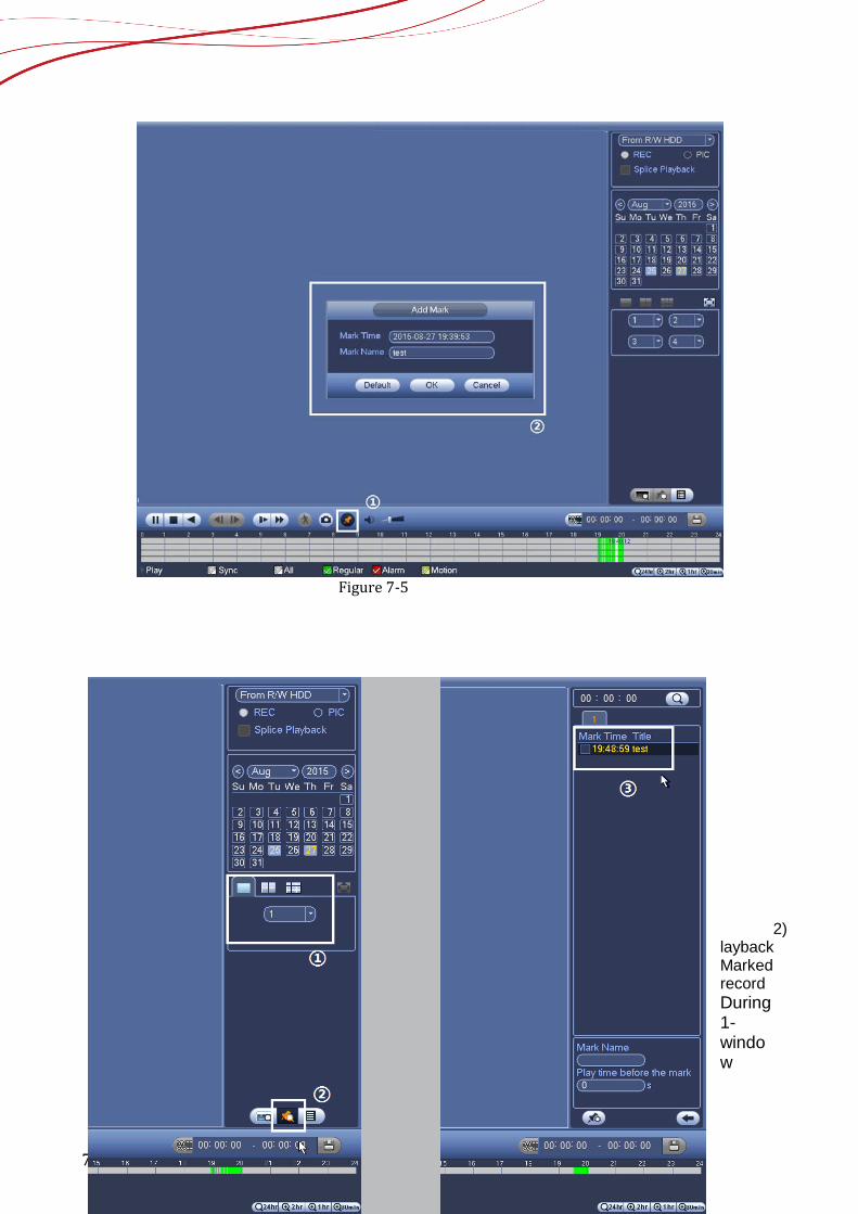
5) Click this button again ,you’llexir smart search. 7.6 How to playback the mark video
When you are playback record, you can mark the record when there is important information. After playback, you can use time or the mark key words to search corresponding record and then play.
1) Add Mark When system is playback, click Mark button, you can go to the following interface.
77
Figure 7-5
2) layback Marked record During 1-window
78
playback mode, click mark file list button, you can go to mark filelist interface. Double click one mark file, you can begin playback from the mark time.
Figure 7-6
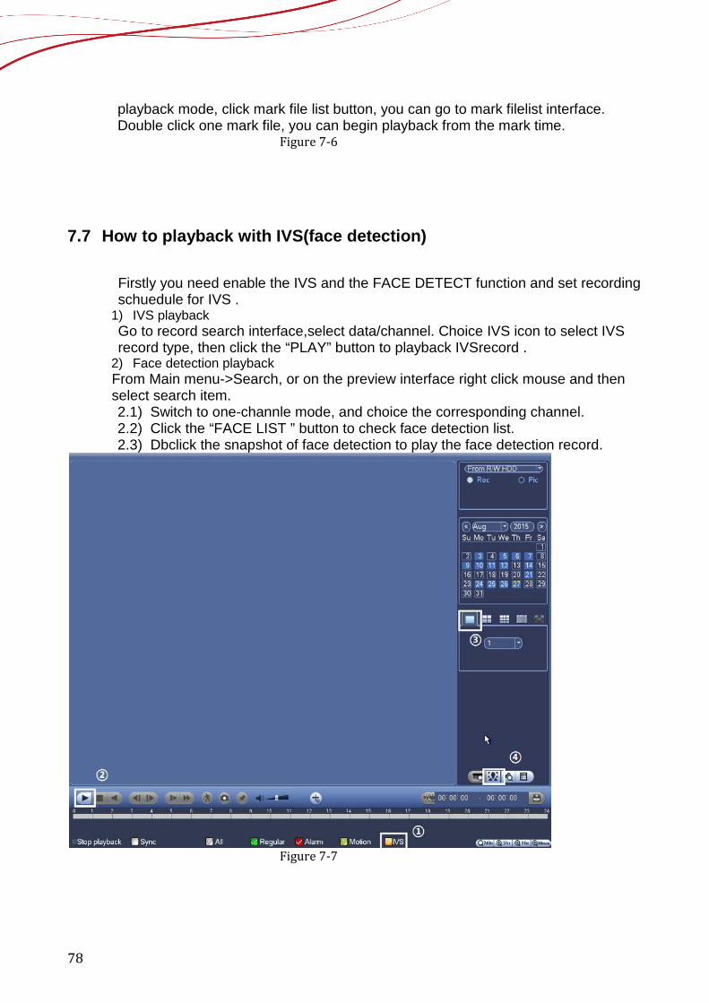
7.7 How to playback with IVS(face detection)
Firstly you need enable the IVS and the FACE DETECT function and set recording schuedule for IVS .
1) IVS playback Go to record search interface,select data/channel. Choice IVS icon to select IVS record type, then click the “PLAY” button to playback IVSrecord .
2) Face detection playback From Main menu->Search, or on the preview interface right click mouse and then select search item. 2.1) Switch to one-channle mode, and choice the corresponding channel. 2.2) Click the “FACE LIST ” button to check face detection list. 2.3) Dbclick the snapshot of face detection to play the face detection record.
Figure 7-7
79
NOTE IVS and face detection supporting models : NVR6XX-4K,NVR724-256, NVR4XXX-4K
7.8 How to playback with splicing This function improves the video query efficiency significantly. For example, if you choose 1 hour, 4 channel playback video, you can see it in only 15minutes. Channel 1 from 0 to 15minute. Channel 2 from 16 to 30, channel 3 from 31 to 45, channel 4 from 46 to 60.
1) Enter in playback page, select a period time of record; 2) Check the “Splice Playback”, it only works at single channel. 3) Select the splits 4 or 9, when choose 9, can only show 8 channels. 4) Click “PLAY” button, it’ll playback with splic

80
Figure 7-8
NOTE: The minimum interval is 5 minutes in each channel. If the time interval is 10-15 minutes, it will be 2 splits; if 16-20,3 splits; above 20,4 splits. Model supporting splicing playback HCVR5X04-V2,HCVR5X08-V2, HCVR5X16-V2,HCVR7X04-V2, HCVR7X08-V2 HCVR4X04-S2, HCVR4X08-S2, HCVR4X16-S2, HCVR5X04-S2, HCVR5X08-S2, HCVR5X16-S2, HCVR7X04-S2, HCVR7X08-S2 NVR6XX-4K
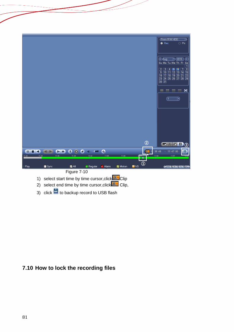
7.9 How to make the video cut and back up
81
Figure 7-10 1) select start time by time cursor,click Clip 2) select end time by time cursor,click Clip,
3) click to backup record to USB flash
7.10 How to lock the recording files
82
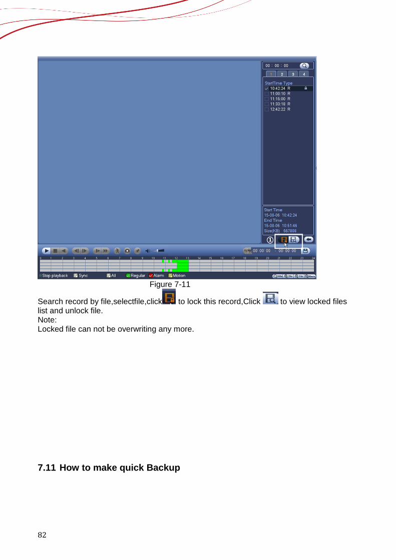
Figure 7-11
Search record by file,selectfile,click to lock this record,Click to view locked files list and unlock file. Note: Locked file can not be overwriting any more. 7.11 How to make quick Backup
83
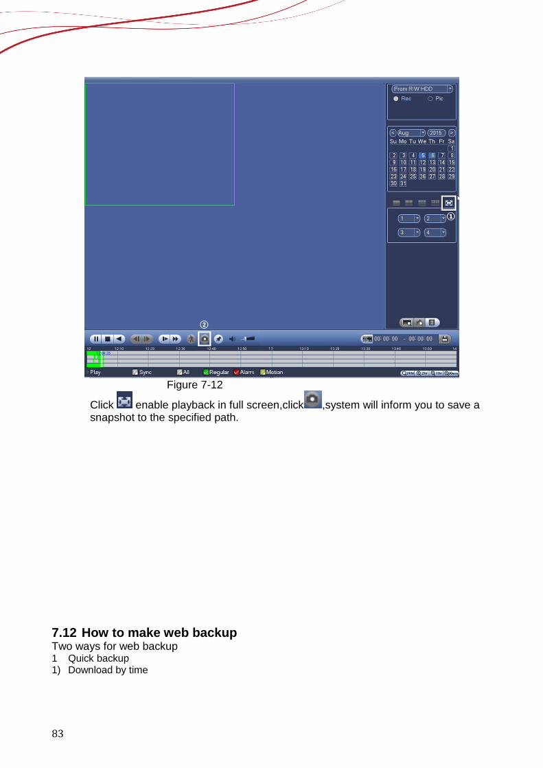
Figure 7-12
Click enable playback in full screen,click ,system will inform you to save a snapshot to the specified path.
7.12 How to make web backup Two ways for web backup 1 Quick backup 1) Download by time
84
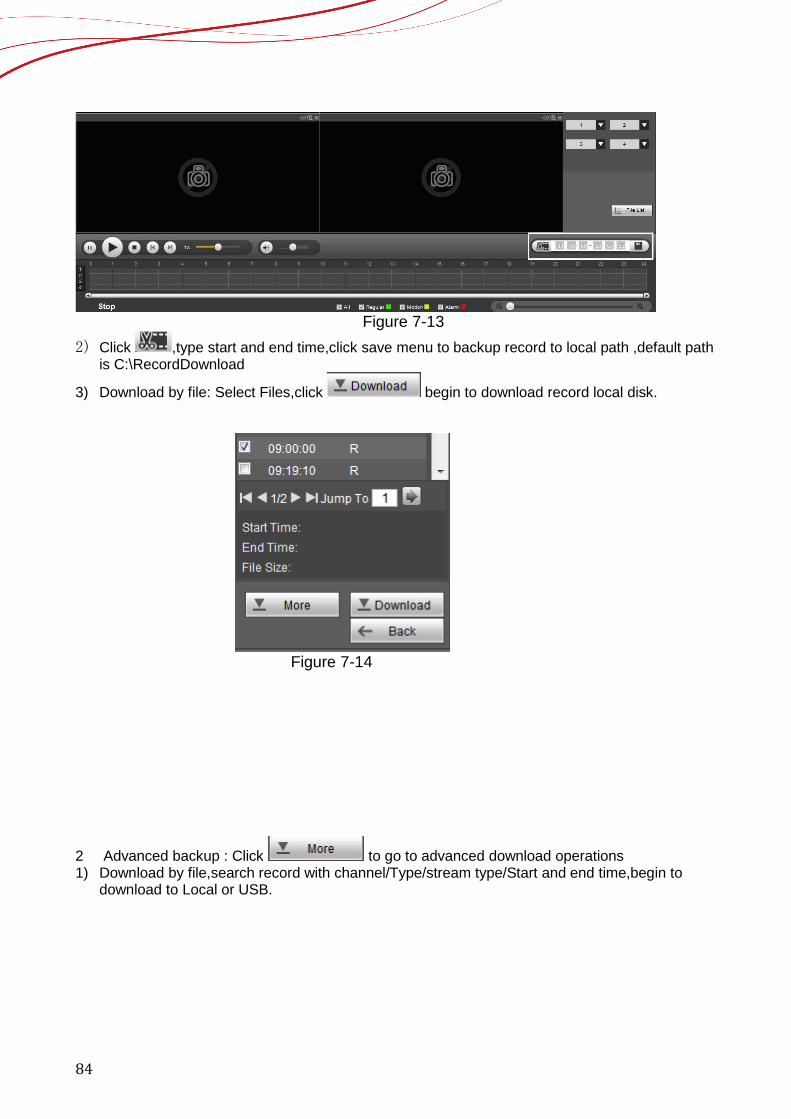
Figure 7-13
2) Click ,type start and end time,click save menu to backup record to local path ,default path is C:\RecordDownload
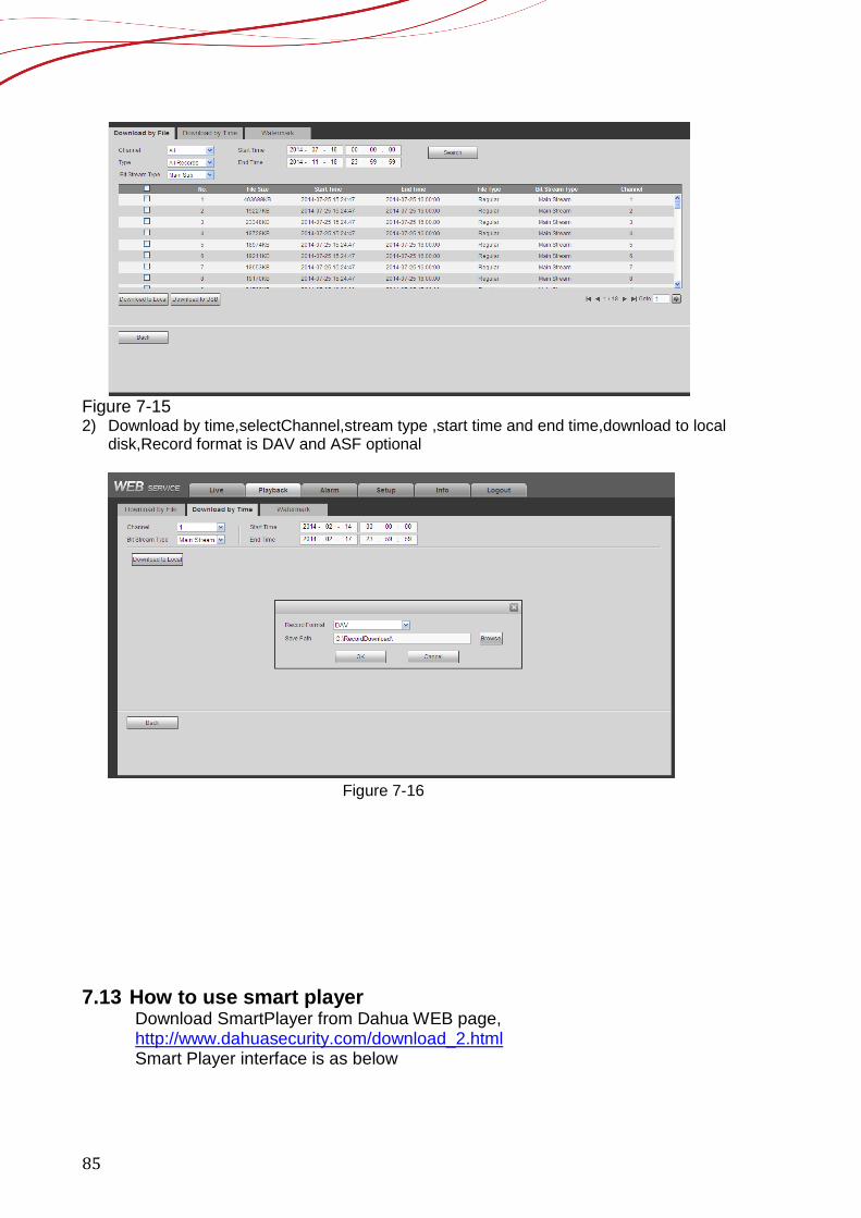
3) Download by file: Select Files,click begin to download record local disk.
Figure 7-14
2 Advanced backup : Click to go to advanced download operations 1) Download by file,search record with channel/Type/stream type/Start and end time,begin to
download to Local or USB.
85
Figure 7-15 2) Download by time,selectChannel,stream type ,start time and end time,download to local
disk,Record format is DAV and ASF optional
Figure 7-16
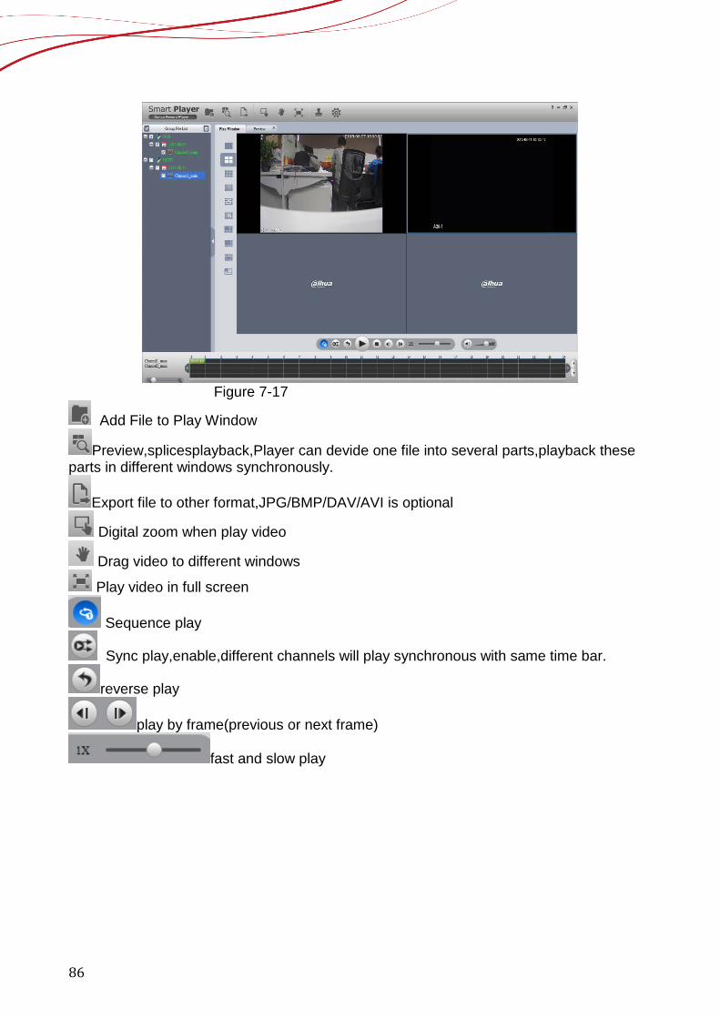
7.13 How to use smart player Download SmartPlayer from Dahua WEB page, http://www.dahuasecurity.com/download_2.html Smart Player interface is as below
86
Figure 7-17
Add File to Play Window
Preview,splicesplayback,Player can devide one file into several parts,playback these parts in different windows synchronously.
Export file to other format,JPG/BMP/DAV/AVI is optional
Digital zoom when play video
Drag video to different windows
Play video in full screen
Sequence play
Sync play,enable,different channels will play synchronous with same time bar.
reverse play
play by frame(previous or next frame)
fast and slow play
87
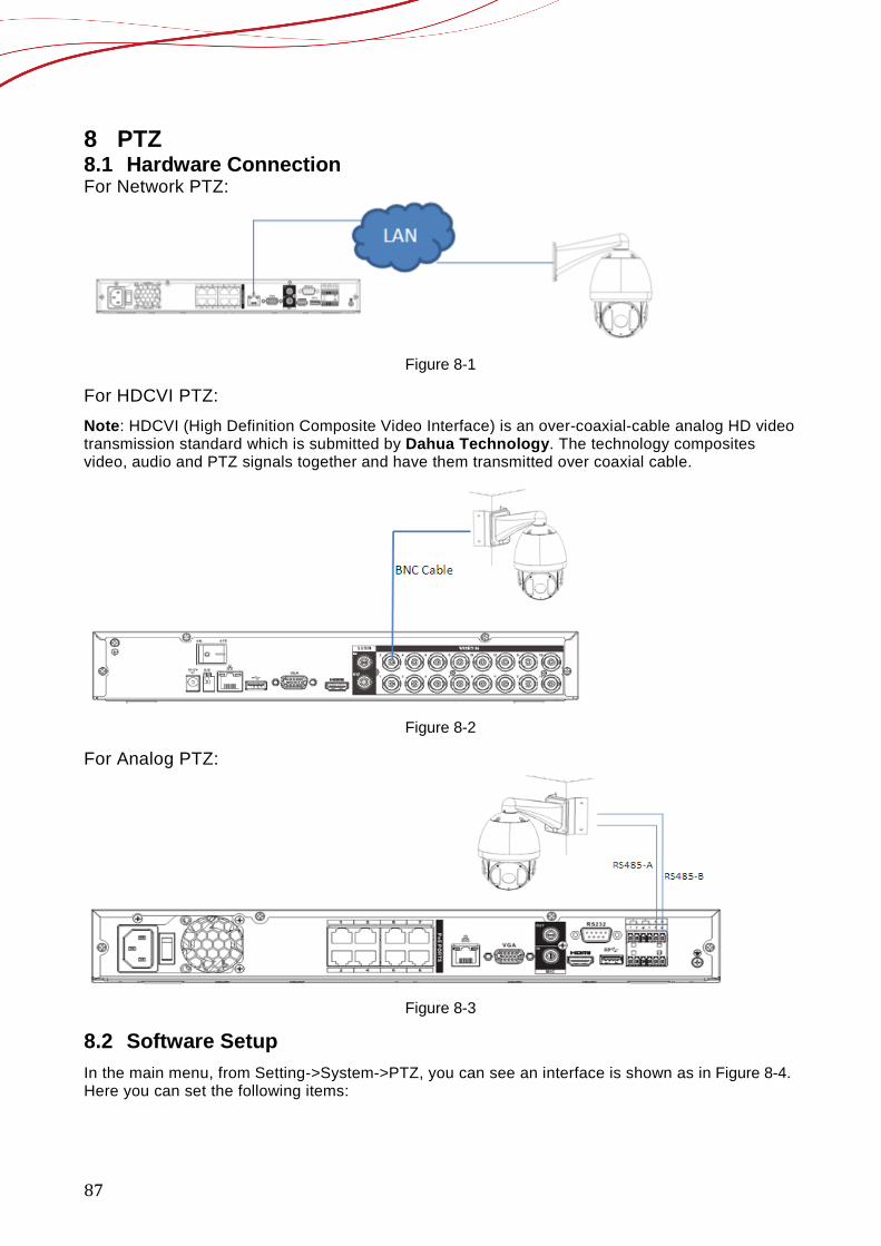
8 PTZ 8.1 Hardware Connection For Network PTZ:
Figure 8-1
For HDCVI PTZ: Note: HDCVI (High Definition Composite Video Interface) is an over-coaxial-cable analog HD video transmission standard which is submitted by Dahua Technology. The technology composites video, audio and PTZ signals together and have them transmitted over coaxial cable.
Figure 8-2
For Analog PTZ:
Figure 8-3
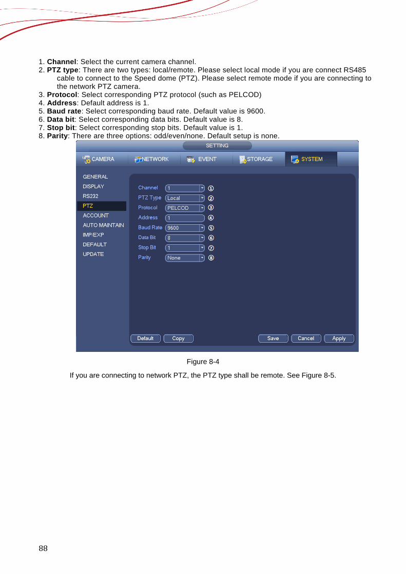
8.2 Software Setup In the main menu, from Setting->System->PTZ, you can see an interface is shown as in Figure 8-4. Here you can set the following items:
88
1. Channel: Select the current camera channel. 2. PTZ type: There are two types: local/remote. Please select local mode if you are connect RS485
cable to connect to the Speed dome (PTZ). Please select remote mode if you are connecting to the network PTZ camera.
3. Protocol: Select corresponding PTZ protocol (such as PELCOD) 4. Address: Default address is 1. 5. Baud rate: Select corresponding baud rate. Default value is 9600. 6. Data bit: Select corresponding data bits. Default value is 8. 7. Stop bit: Select corresponding stop bits. Default value is 1. 8. Parity: There are three options: odd/even/none. Default setup is none.
Figure 8-4
If you are connecting to network PTZ, the PTZ type shall be remote. See Figure 8-5.

89
Figure 8-5
8.3 How to Operate PTZ Control Right click mouse (or click “Fn” Button in the front panel or click “Fn” key in the remote control). The interface is shown as in Figure 8-6. Please note you can only go to the PTZ control interface when you are in 1-window display mode.
Figure 8-6
The PTZ setup is shown as in See Figure 8-7.
90
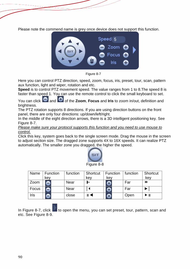
Please note the commend name is grey once device does not support this function.
Figure 8-7
Here you can control PTZ direction, speed, zoom, focus, iris, preset, tour, scan, pattern aux function, light and wiper, rotation and etc. Speed is to control PTZ movement speed. The value ranges from 1 to 8.The speed 8 is faster than speed 1. You can use the remote control to click the small keyboard to set.
You can click and of the Zoom, Focus and Iris to zoom in/out, definition and brightness. The PTZ rotation supports 8 directions. If you are using direction buttons on the front panel, there are only four directions: up/down/left/right. In the middle of the eight direction arrows, there is a 3D intelligent positioning key. See Figure 8-7. Please make sure your protocol supports this function and you need to use mouse to control. Click this key, system goes back to the single screen mode. Drag the mouse in the screen to adjust section size. The dragged zone supports 4X to 16X speeds. It can realize PTZ automatically. The smaller zone you dragged, the higher the speed.
Figure 8-8
Name Function
key function Shortcut
key Function key
function Shortcut key
Zoom
Near Far
Focus
Near │
Far ►│
Iris
close
Open
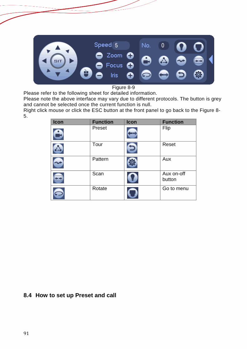
In Figure 8-7, click to open the menu, you can set preset, tour, pattern, scan and etc. See Figure 8-9.
91
Figure 8-9
Please refer to the following sheet for detailed information. Please note the above interface may vary due to different protocols. The button is grey and cannot be selected once the current function is null. Right click mouse or click the ESC button at the front panel to go back to the Figure 8-5.
Icon Function Icon Function Preset Flip
Tour Reset
Pattern Aux
Scan Aux on-off button
Rotate Go to menu
8.4 How to set up Preset and call
92
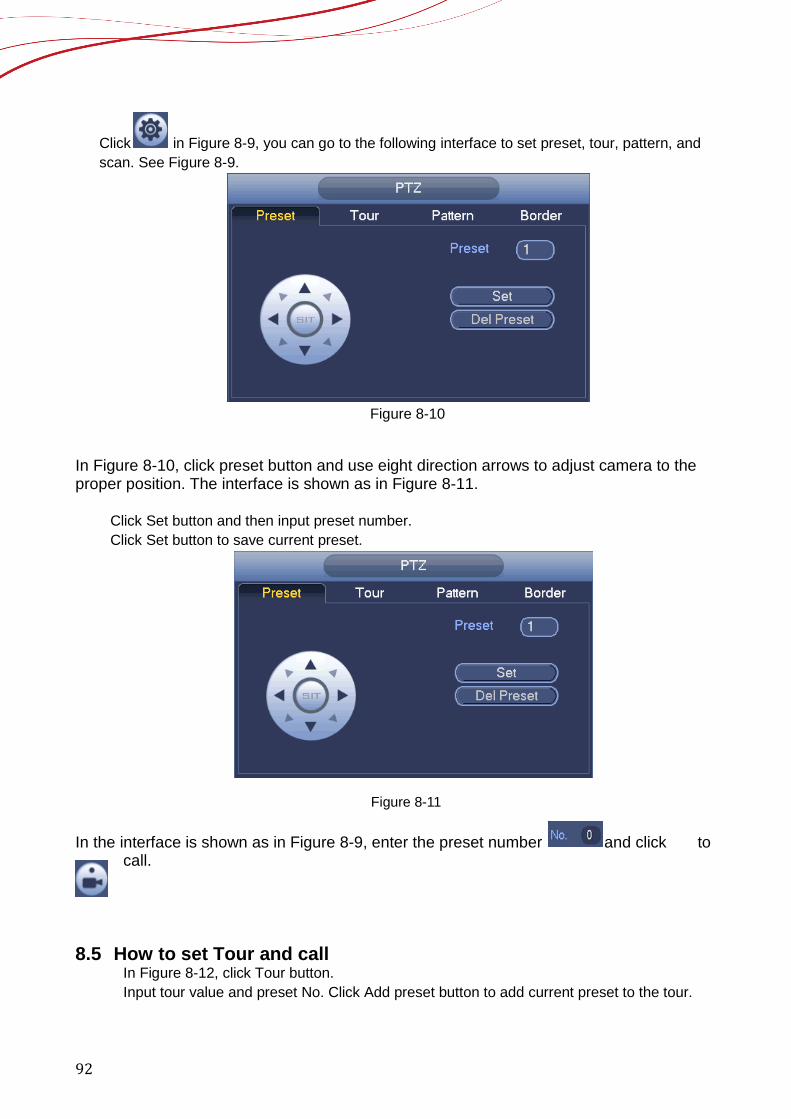
Click in Figure 8-9, you can go to the following interface to set preset, tour, pattern, and scan. See Figure 8-9.
Figure 8-10
In Figure 8-10, click preset button and use eight direction arrows to adjust camera to the proper position. The interface is shown as in Figure 8-11.
Click Set button and then input preset number. Click Set button to save current preset.
Figure 8-11
In the interface is shown as in Figure 8-9, enter the preset number and click to call.
8.5 How to set Tour and call
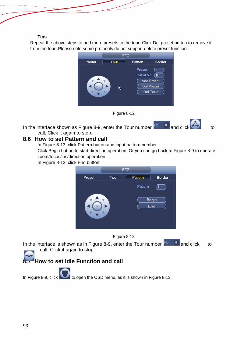
In Figure 8-12, click Tour button. Input tour value and preset No. Click Add preset button to add current preset to the tour.
93
Tips Repeat the above steps to add more presets to the tour. Click Del preset button to remove it from the tour. Please note some protocols do not support delete preset function.
Figure 8-12
In the interface shown as Figure 8-9, enter the Tour number and click to call. Click it again to stop.
8.6 How to set Pattern and call In Figure 8-13, click Pattern button and input pattern number. Click Begin button to start direction operation. Or you can go back to Figure 8-9 to operate zoom/focus/iris/direction operation. In Figure 8-13, click End button.
Figure 8-13
In the interface is shown as in Figure 8-9, enter the Tour number and click to call. Click it again to stop.
8.7 How to set Idle Function and call
In Figure 8-9, click to open the OSD menu, as it is shown in Figure 8-13.
94
Figure 8-14
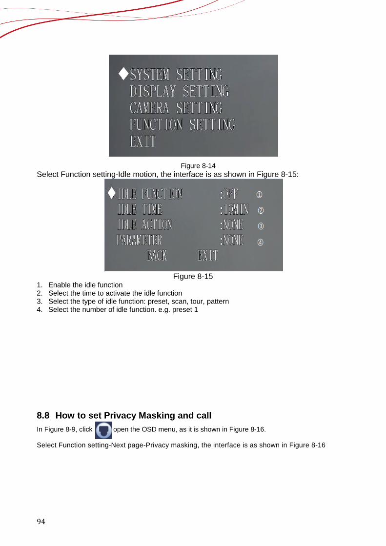
Select Function setting-Idle motion, the interface is as shown in Figure 8-15:
Figure 8-15
1. Enable the idle function 2. Select the time to activate the idle function 3. Select the type of idle function: preset, scan, tour, pattern 4. Select the number of idle function. e.g. preset 1
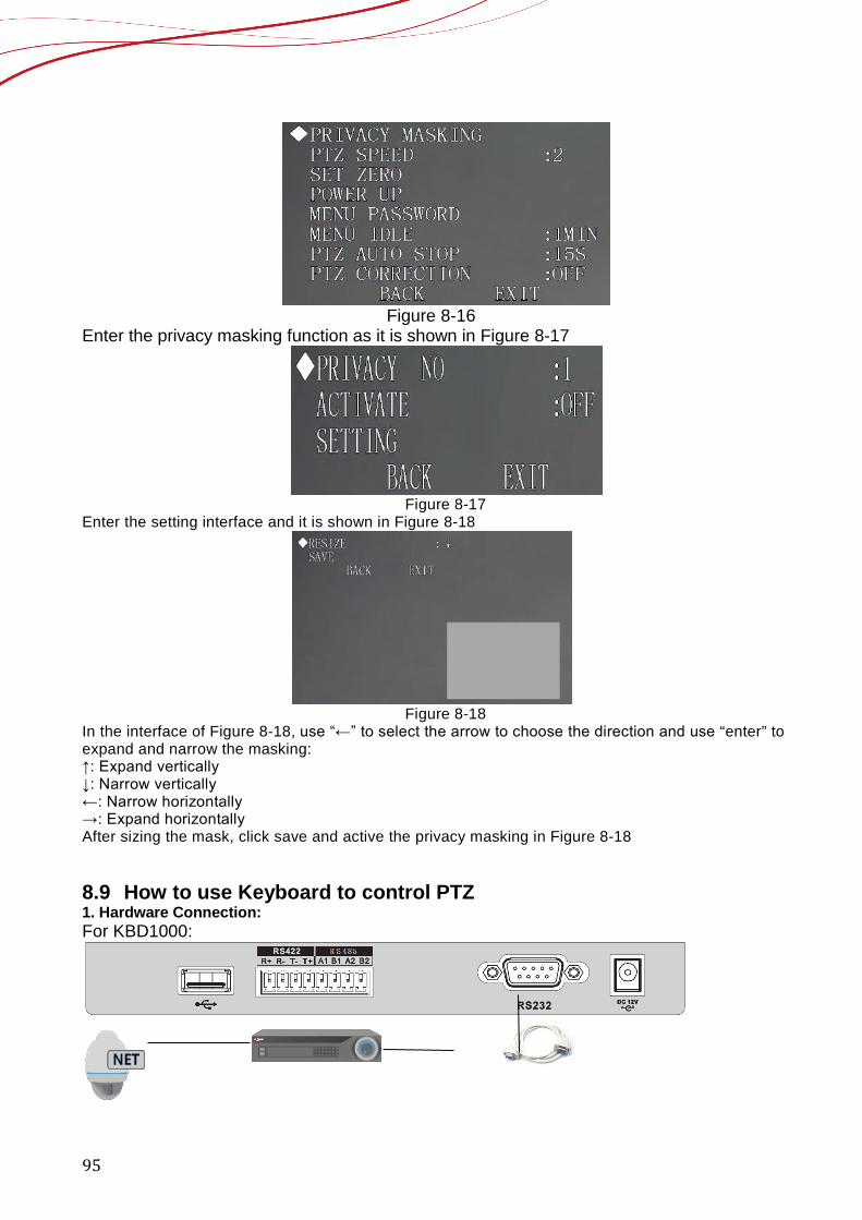
8.8 How to set Privacy Masking and call In Figure 8-9, click to open the OSD menu, as it is shown in Figure 8-16. Select Function setting-Next page-Privacy masking, the interface is as shown in Figure 8-16
95
Figure 8-16
Enter the privacy masking function as it is shown in Figure 8-17
Figure 8-17
Enter the setting interface and it is shown in Figure 8-18
Figure 8-18
In the interface of Figure 8-18, use “←” to select the arrow to choose the direction and use “enter” to expand and narrow the masking: ↑: Expand vertically ↓: Narrow vertically ←: Narrow horizontally →: Expand horizontally After sizing the mask, click save and active the privacy masking in Figure 8-18 8.9 How to use Keyboard to control PTZ 1. Hardware Connection: For KBD1000:
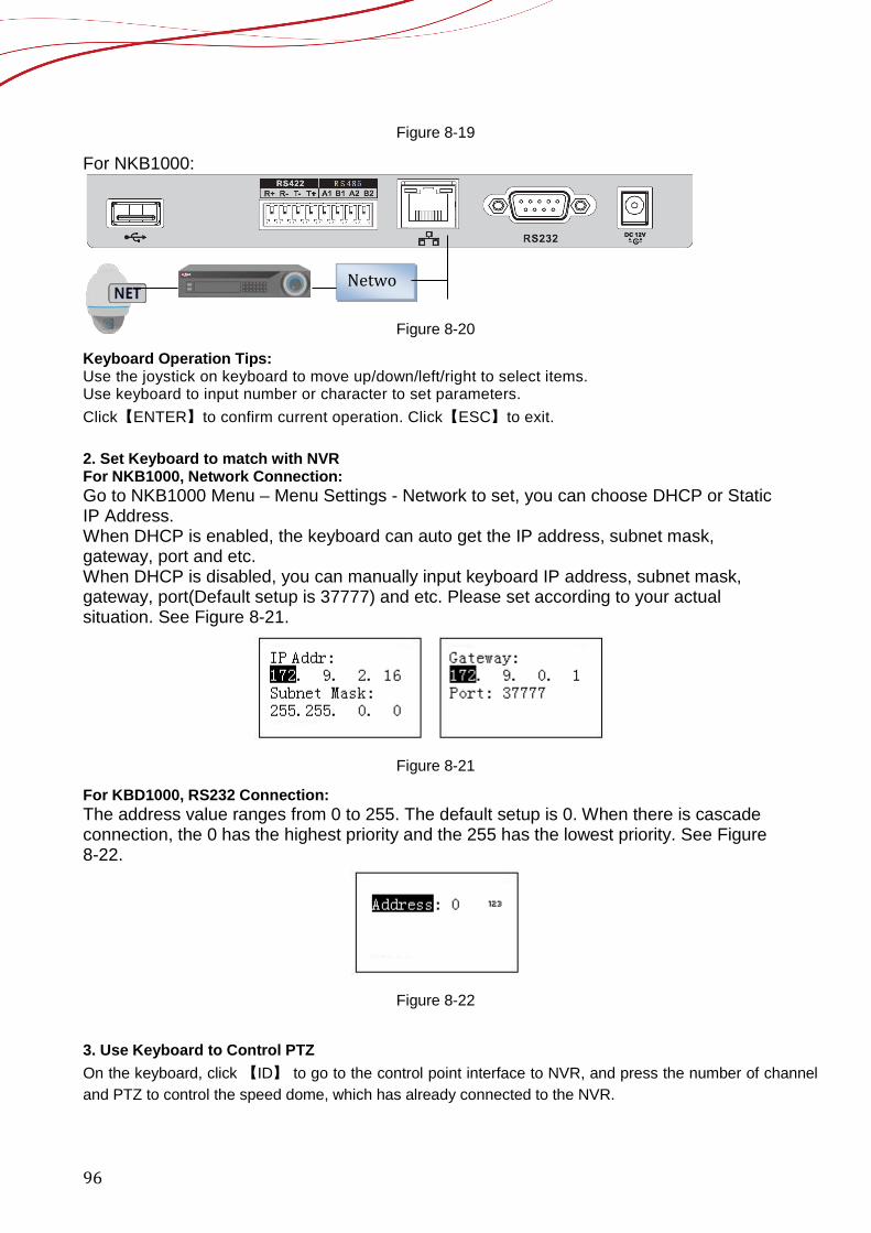
96
Figure 8-19
For NKB1000:
Figure 8-20
Keyboard Operation Tips: Use the joystick on keyboard to move up/down/left/right to select items. Use keyboard to input number or character to set parameters. Click【ENTER】to confirm current operation. Click【ESC】to exit. 2. Set Keyboard to match with NVR For NKB1000, Network Connection: Go to NKB1000 Menu – Menu Settings - Network to set, you can choose DHCP or Static IP Address. When DHCP is enabled, the keyboard can auto get the IP address, subnet mask, gateway, port and etc. When DHCP is disabled, you can manually input keyboard IP address, subnet mask, gateway, port(Default setup is 37777) and etc. Please set according to your actual situation. See Figure 8-21.
Figure 8-21
For KBD1000, RS232 Connection: The address value ranges from 0 to 255. The default setup is 0. When there is cascade connection, the 0 has the highest priority and the 255 has the lowest priority. See Figure 8-22.
Figure 8-22
3. Use Keyboard to Control PTZ On the keyboard, click 【ID】 to go to the control point interface to NVR, and press the number of channel and PTZ to control the speed dome, which has already connected to the NVR.
Netwo
97
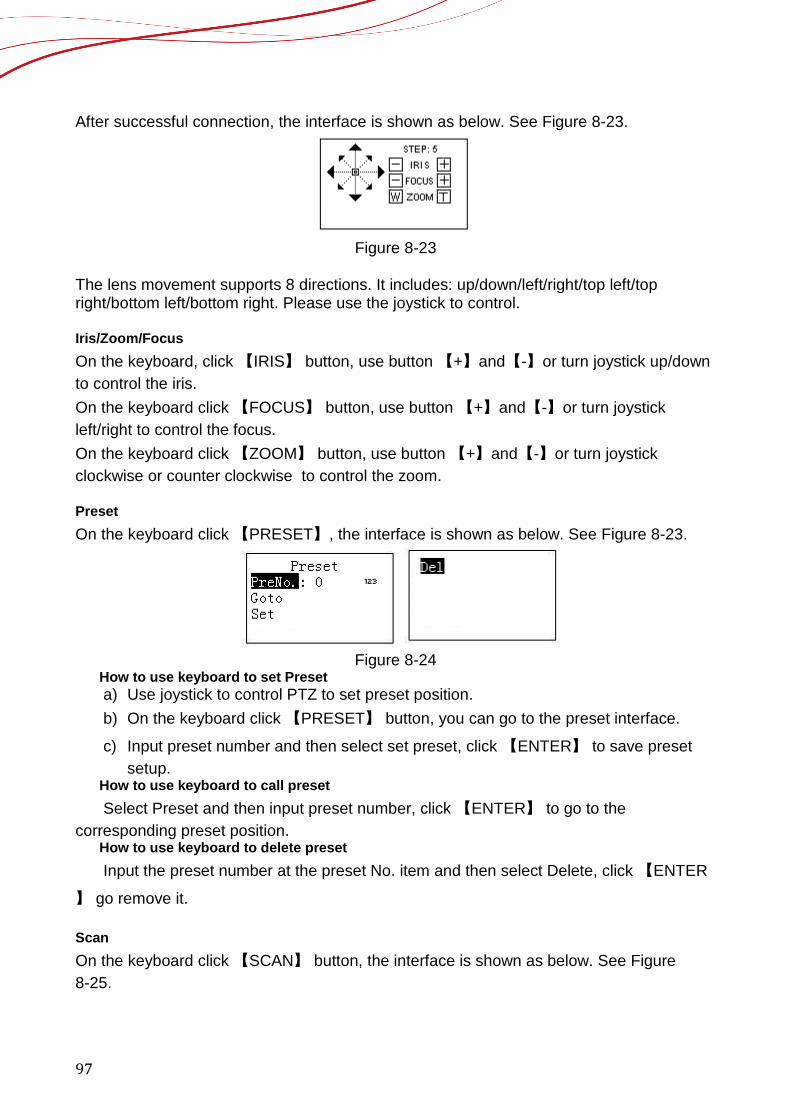
After successful connection, the interface is shown as below. See Figure 8-23.
Figure 8-23
The lens movement supports 8 directions. It includes: up/down/left/right/top left/top right/bottom left/bottom right. Please use the joystick to control. Iris/Zoom/Focus
On the keyboard, click 【IRIS】 button, use button 【+】and【-】or turn joystick up/down to control the iris. On the keyboard click 【FOCUS】 button, use button 【+】and【-】or turn joystick left/right to control the focus. On the keyboard click 【ZOOM】 button, use button 【+】and【-】or turn joystick clockwise or counter clockwise to control the zoom. Preset On the keyboard click 【PRESET】, the interface is shown as below. See Figure 8-23.
Figure 8-24
How to use keyboard to set Preset a) Use joystick to control PTZ to set preset position. b) On the keyboard click 【PRESET】 button, you can go to the preset interface.
c) Input preset number and then select set preset, click 【ENTER】 to save preset setup.
How to use keyboard to call preset Select Preset and then input preset number, click 【ENTER】 to go to the
corresponding preset position. How to use keyboard to delete preset
Input the preset number at the preset No. item and then select Delete, click 【ENTER
】 go remove it. Scan On the keyboard click 【SCAN】 button, the interface is shown as below. See Figure 8-25.

98
Figure 8-25
How to use keyboard to set Scan 1) Select Set and then click 【ENTER】, you can see an interface shown as in Figure 8-26.
Figure 8-26
2) Select left limit and right limit, click 【ENTER】 to set. 3) Use joystick to control PTZ to set limit. How to use keyboard to Start and Stop Scan Select start and then click 【ENTER】,system begins to scan according to the left/right
limit you set. Select stop and then click 【ENTER】, system stops scan.
Pan On the keyboard click 【PAN】 button, the interface is shown as below. See Figure 8-27.
Figure 8-27
How to use keyboard to Start and Stop Pan Select start and then click 【ENTER】button, system begins pan operation.
Select stop and then click 【ENTER】button, system stops pan operation. Tour On the keyboard click 【TOUR】 button, the interface is shown as below. See Figure 8-28.
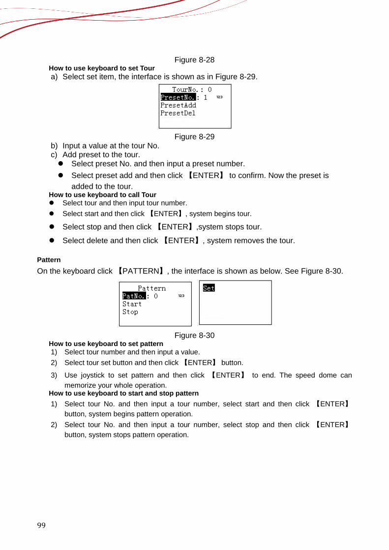
99
Figure 8-28 How to use keyboard to set Tour
a) Select set item, the interface is shown as in Figure 8-29.
Figure 8-29
b) Input a value at the tour No. c) Add preset to the tour. Select preset No. and then input a preset number. Select preset add and then click 【ENTER】 to confirm. Now the preset is
added to the tour. How to use keyboard to call Tour Select tour and then input tour number. Select start and then click 【ENTER】, system begins tour.
Select stop and then click 【ENTER】,system stops tour.
Select delete and then click 【ENTER】, system removes the tour. Pattern On the keyboard click 【PATTERN】, the interface is shown as below. See Figure 8-30.
Figure 8-30
How to use keyboard to set pattern 1) Select tour number and then input a value. 2) Select tour set button and then click 【ENTER】 button.
3) Use joystick to set pattern and then click 【ENTER】 to end. The speed dome can memorize your whole operation.
How to use keyboard to start and stop pattern 1) Select tour No. and then input a tour number, select start and then click 【ENTER】
button, system begins pattern operation. 2) Select tour No. and then input a tour number, select stop and then click 【ENTER】
button, system stops pattern operation.
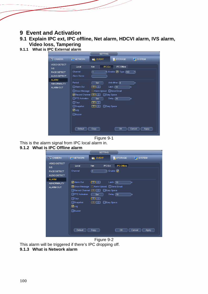
100
9 Event and Activation 9.1 Explain IPC ext, IPC offline, Net alarm, HDCVI alarm, IVS alarm,
Video loss, Tampering 9.1.1 What is IPC External alarm
Figure 9-1
This is the alarm signal from IPC local alarm in. 9.1.2 What is IPC Offline alarm
Figure 9-2
This alarm will be triggered if there’s IPC dropping off. 9.1.3 What is Network alarm
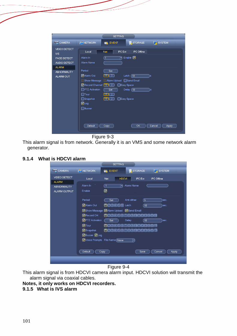
101
Figure 9-3
This alarm signal is from network. Generally it is an VMS and some network alarm generator.
9.1.4 What is HDCVI alarm
Figure 9-4
This alarm signal is from HDCVI camera alarm input. HDCVI solution will transmit the alarm signal via coaxial cables.
Notes, it only works on HDCVI recorders. 9.1.5 What is IVS alarm
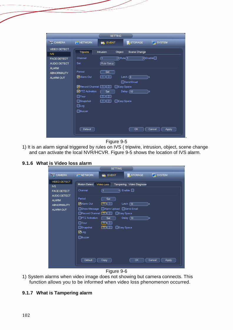
102
. Figure 9-5
1) It is an alarm signal triggered by rules on IVS ( tripwire, intrusion, object, scene change and can activate the local NVR/HCVR. Figure 9-5 shows the location of IVS alarm.
9.1.6 What is Video loss alarm
Figure 9-6
1) System alarms when video image does not showing but camera connects. This function allows you to be informed when video loss phenomenon occurred.
9.1.7 What is Tampering alarm
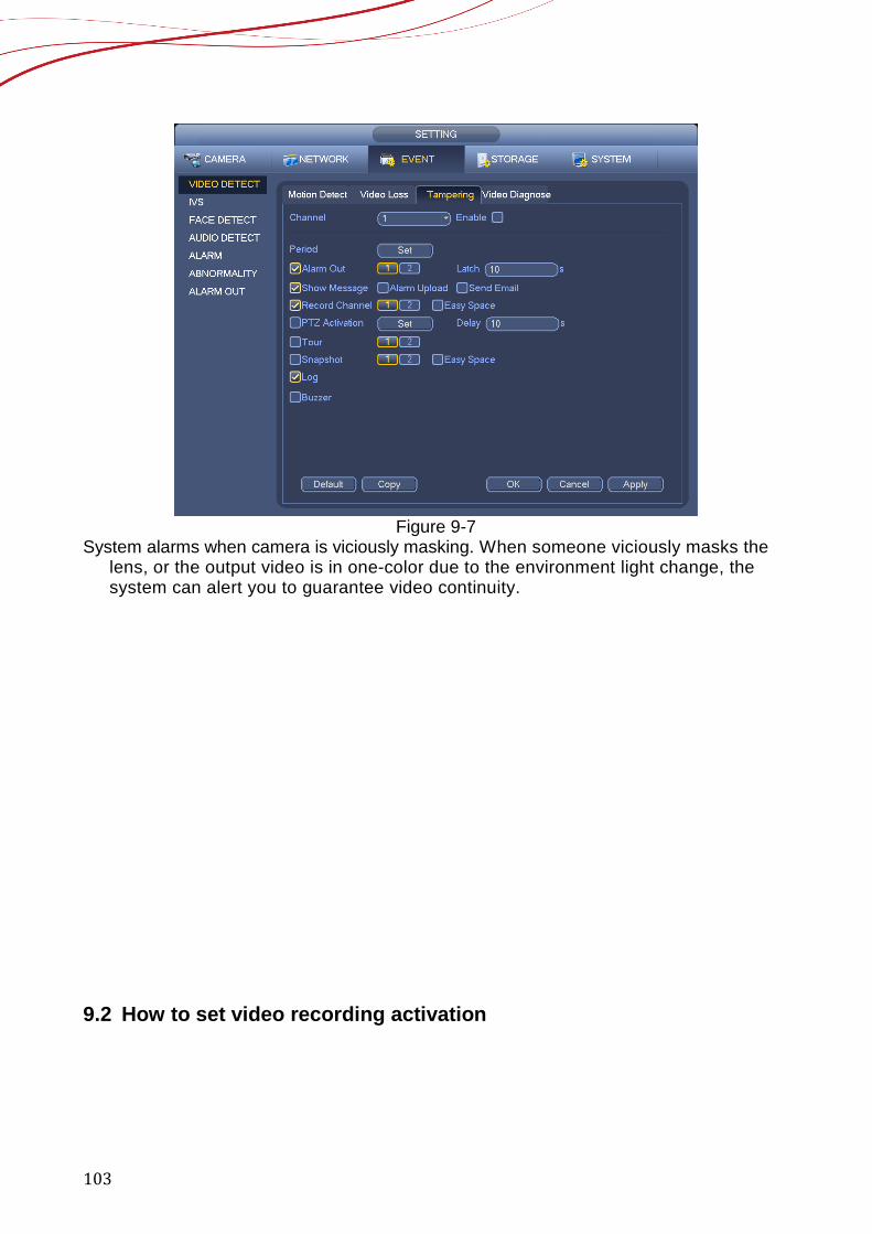
103
Figure 9-7
System alarms when camera is viciously masking. When someone viciously masks the lens, or the output video is in one-color due to the environment light change, the system can alert you to guarantee video continuity.
9.2 How to set video recording activation
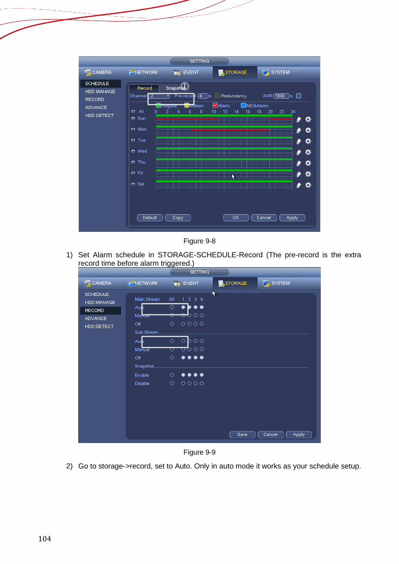
104
Figure 9-8
1) Set Alarm schedule in STORAGE-SCHEDULE-Record (The pre-record is the extra record time before alarm triggered.)
Figure 9-9
2) Go to storage->record, set to Auto. Only in auto mode it works as your schedule setup.
①

105
Figure 9-10
3) Go to setting-> Camera-> Encode->Encode, choose Code-Stream Type to Alarm, if you want to set the recording of alarm different from regular recordings.
Figure 9-11
4) Enable Record Channel in EVENT, Record Delay is the recording time after the event finished.
9.3 How to set Snapshot activation

106
Figure 9-12
1) Set Alarm schedule in STORAGE-SCHEDULE-Snapshot
Figure 9-13
2) Enable Record- Snapshot in STORAGE-RECORD
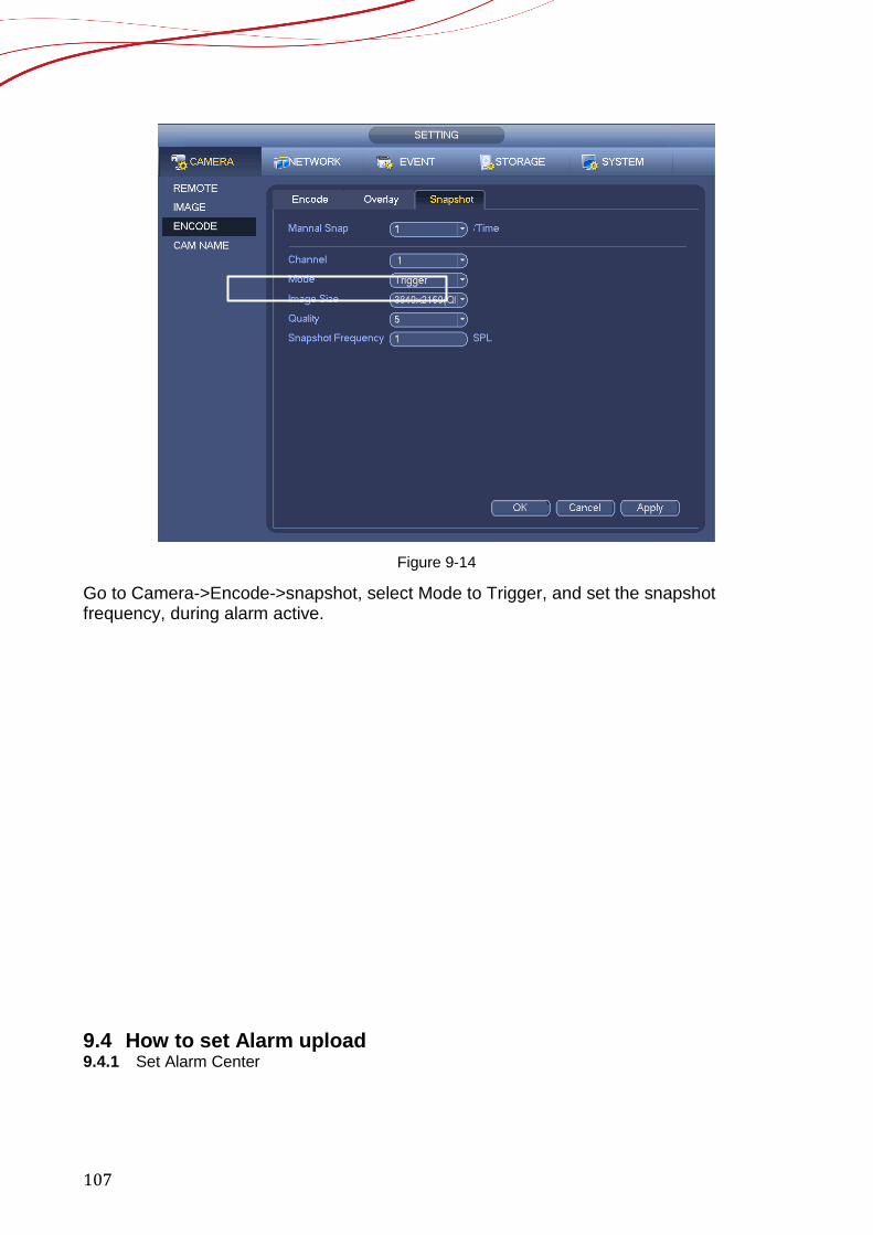
107
Figure 9-14
Go to Camera->Encode->snapshot, select Mode to Trigger, and set the snapshot frequency, during alarm active. 9.4 How to set Alarm upload 9.4.1 Set Alarm Center
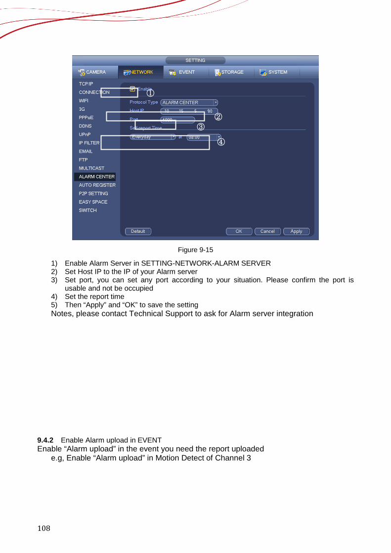
108
Figure 9-15
1) Enable Alarm Server in SETTING-NETWORK-ALARM SERVER 2) Set Host IP to the IP of your Alarm server 3) Set port, you can set any port according to your situation. Please confirm the port is
usable and not be occupied 4) Set the report time 5) Then “Apply” and “OK” to save the setting Notes, please contact Technical Support to ask for Alarm server integration
9.4.2 Enable Alarm upload in EVENT Enable “Alarm upload” in the event you need the report uploaded
e.g, Enable “Alarm upload” in Motion Detect of Channel 3
①
②
③
④
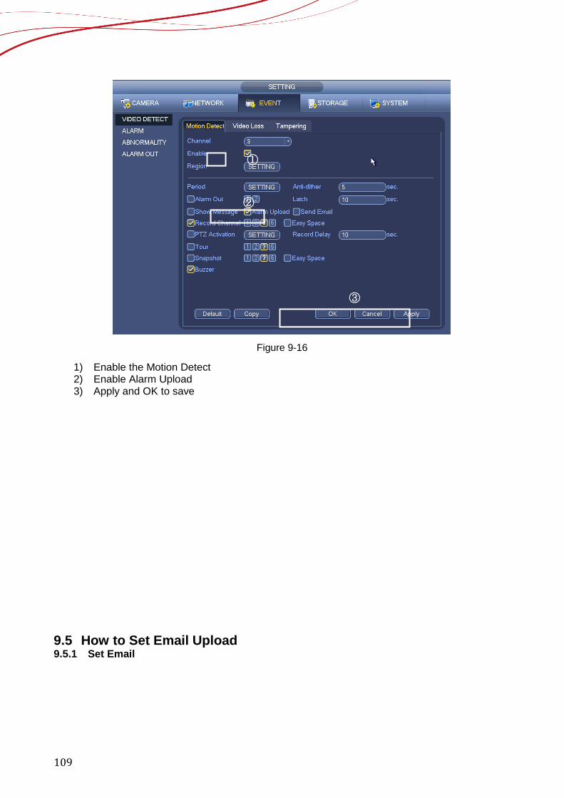
109
Figure 9-16
1) Enable the Motion Detect 2) Enable Alarm Upload 3) Apply and OK to save
9.5 How to Set Email Upload 9.5.1 Set Email
①
②
③
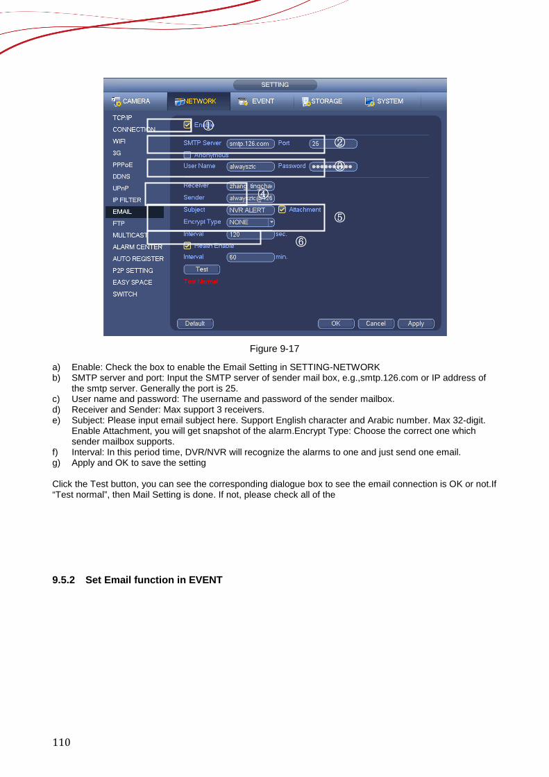
110
Figure 9-17
a) Enable: Check the box to enable the Email Setting in SETTING-NETWORK b) SMTP server and port: Input the SMTP server of sender mail box, e.g.,smtp.126.com or IP address of
the smtp server. Generally the port is 25. c) User name and password: The username and password of the sender mailbox. d) Receiver and Sender: Max support 3 receivers. e) Subject: Please input email subject here. Support English character and Arabic number. Max 32-digit.
Enable Attachment, you will get snapshot of the alarm.Encrypt Type: Choose the correct one which sender mailbox supports.
f) Interval: In this period time, DVR/NVR will recognize the alarms to one and just send one email. g) Apply and OK to save the setting Click the Test button, you can see the corresponding dialogue box to see the email connection is OK or not.If “Test normal”, then Mail Setting is done. If not, please check all of the 9.5.2 Set Email function in EVENT
① ②
③
④
⑤
⑥
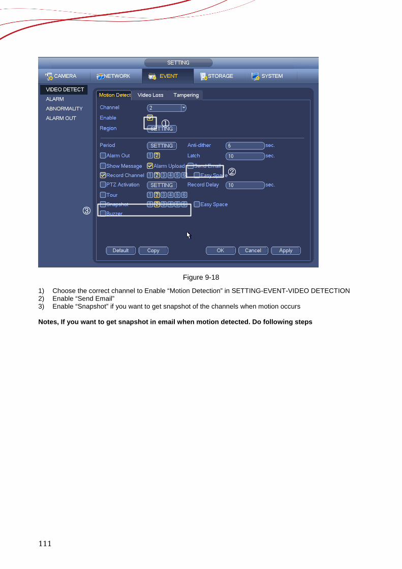
111
Figure 9-18
1) Choose the correct channel to Enable “Motion Detection” in SETTING-EVENT-VIDEO DETECTION 2) Enable “Send Email” 3) Enable “Snapshot” if you want to get snapshot of the channels when motion occurs Notes, If you want to get snapshot in email when motion detected. Do following steps
①
②
③
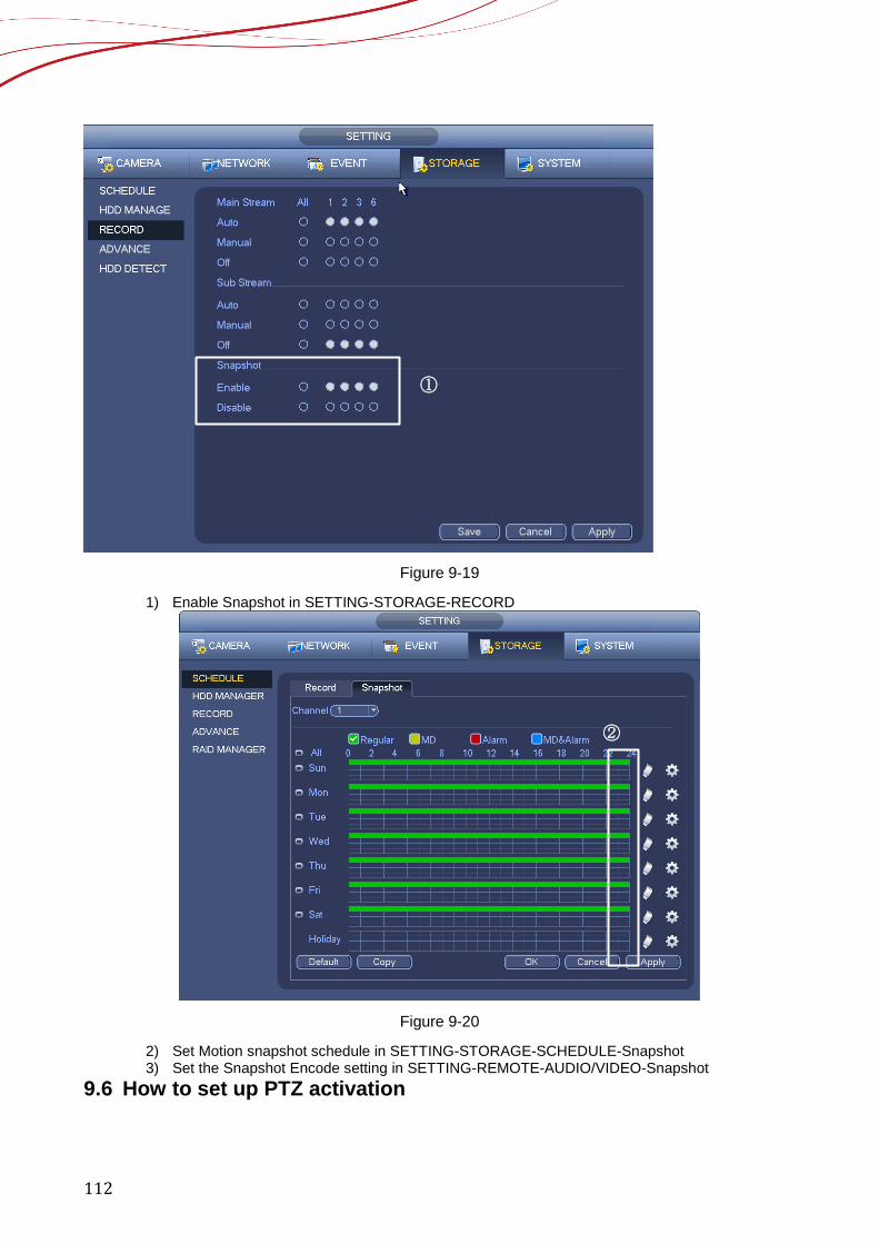
112
Figure 9-19
1) Enable Snapshot in SETTING-STORAGE-RECORD
Figure 9-20
2) Set Motion snapshot schedule in SETTING-STORAGE-SCHEDULE-Snapshot 3) Set the Snapshot Encode setting in SETTING-REMOTE-AUDIO/VIDEO-Snapshot
9.6 How to set up PTZ activation
①
②
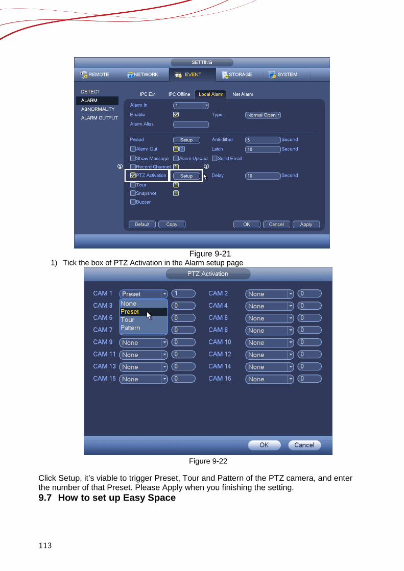
113
Figure 9-21
1) Tick the box of PTZ Activation in the Alarm setup page
Figure 9-22
Click Setup, it’s viable to trigger Preset, Tour and Pattern of the PTZ camera, and enter the number of that Preset. Please Apply when you finishing the setting. 9.7 How to set up Easy Space
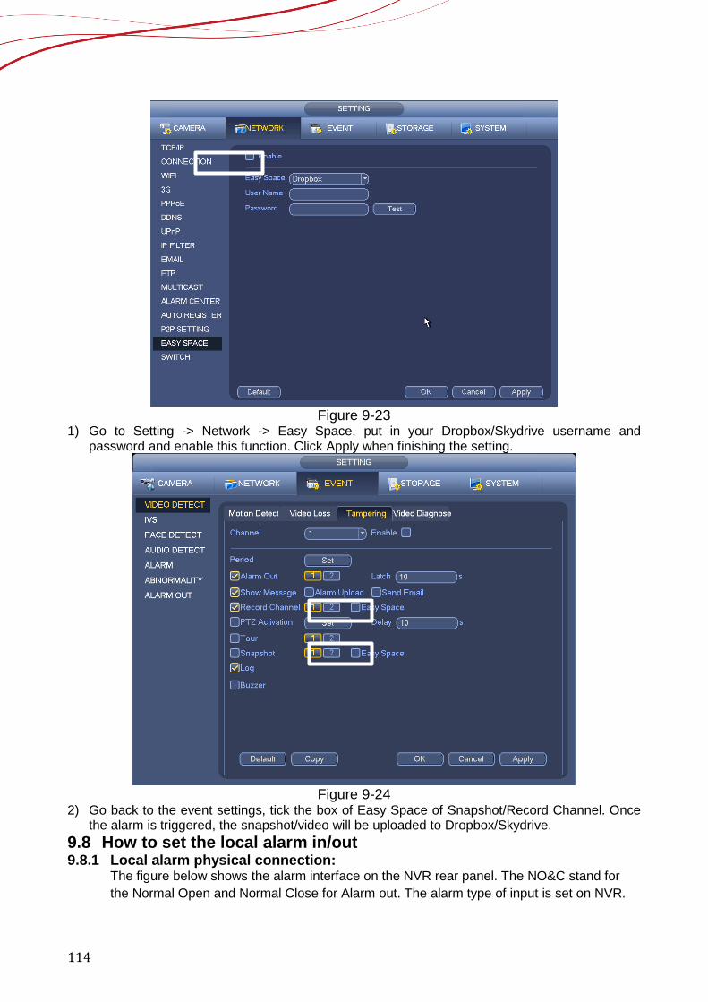
114
Figure 9-23
1) Go to Setting -> Network -> Easy Space, put in your Dropbox/Skydrive username and password and enable this function. Click Apply when finishing the setting.
Figure 9-24
2) Go back to the event settings, tick the box of Easy Space of Snapshot/Record Channel. Once the alarm is triggered, the snapshot/video will be uploaded to Dropbox/Skydrive.
9.8 How to set the local alarm in/out 9.8.1 Local alarm physical connection:
The figure below shows the alarm interface on the NVR rear panel. The NO&C stand for the Normal Open and Normal Close for Alarm out. The alarm type of input is set on NVR.
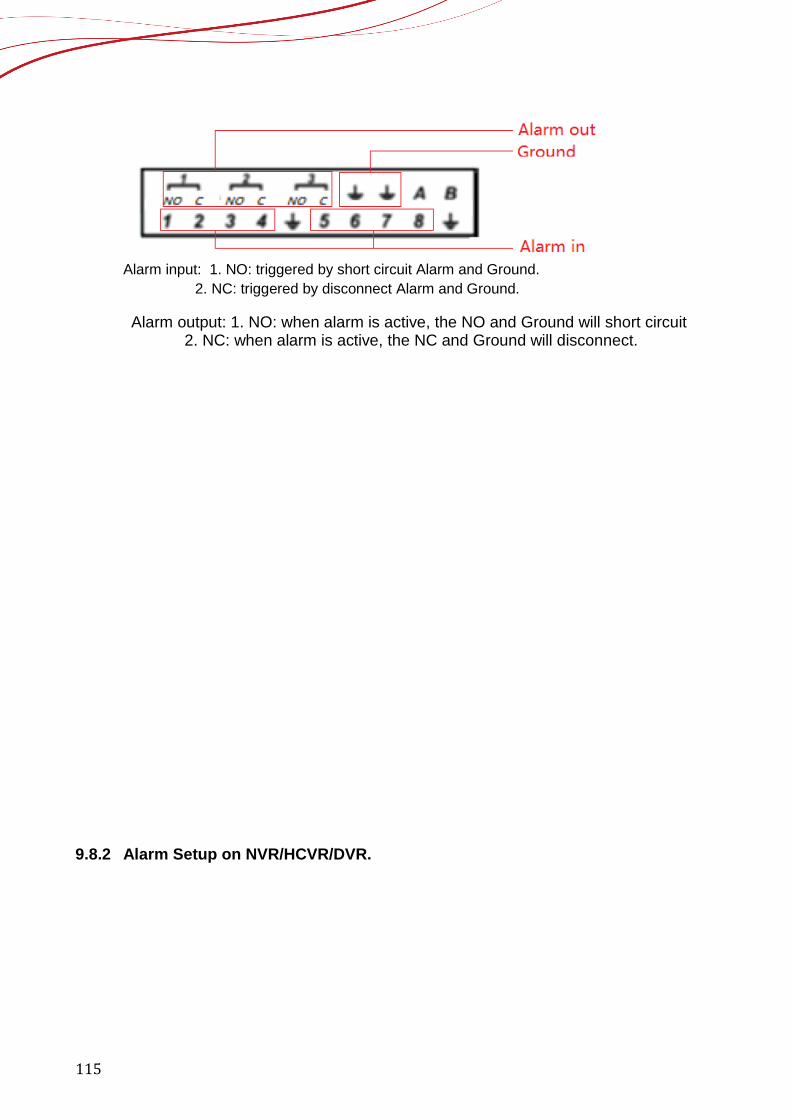
115
Alarm input: 1. NO: triggered by short circuit Alarm and Ground.
2. NC: triggered by disconnect Alarm and Ground.
Alarm output: 1. NO: when alarm is active, the NO and Ground will short circuit 2. NC: when alarm is active, the NC and Ground will disconnect.
9.8.2 Alarm Setup on NVR/HCVR/DVR.
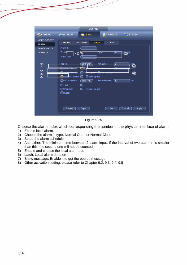
116
Figure 9-25
Choose the alarm index which corresponding the number in the physical interface of alarm 1) Enable local alarm. 2) Choose the alarm in type, Normal Open or Normal Close 3) Setup the alarm schedule 4) Anti-dither: The minimum time between 2 alarm input. If the interval of two alarm in is smaller
than this, the second one will not be counted. 5) Enable and choose the local alarm out. 6) Latch: Local alarm duration 7) Show message: Enable it to get the pop up message 8) Other activation setting, please refer to Chapter 9.2, 9.3, 9.4, 9.5
① ②
③ ④ ⑤ ⑥ ⑦
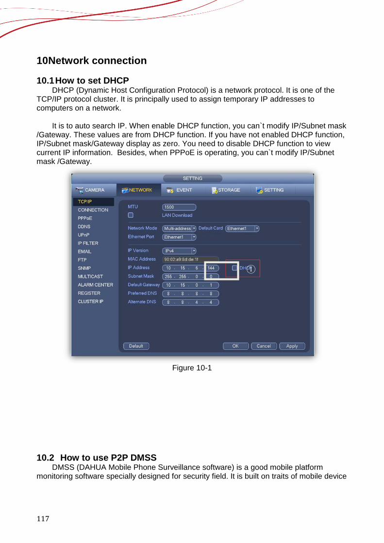
117
10 Network connection 10.1 How to set DHCP
DHCP (Dynamic Host Configuration Protocol) is a network protocol. It is one of the TCP/IP protocol cluster. It is principally used to assign temporary IP addresses to computers on a network.
It is to auto search IP. When enable DHCP function, you can`t modify IP/Subnet mask
/Gateway. These values are from DHCP function. If you have not enabled DHCP function, IP/Subnet mask/Gateway display as zero. You need to disable DHCP function to view current IP information. Besides, when PPPoE is operating, you can`t modify IP/Subnet mask /Gateway.
Figure 10-1
10.2 How to use P2P DMSS
DMSS (DAHUA Mobile Phone Surveillance software) is a good mobile platform monitoring software specially designed for security field. It is built on traits of mobile device
①
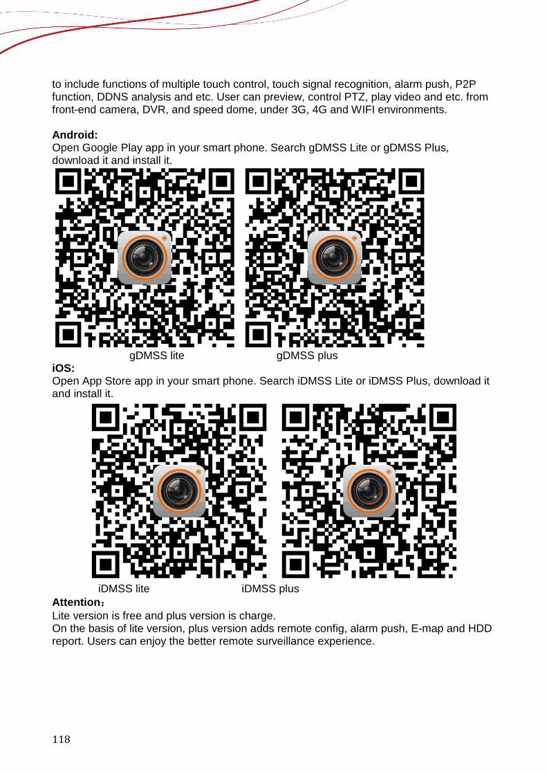
118
to include functions of multiple touch control, touch signal recognition, alarm push, P2P function, DDNS analysis and etc. User can preview, control PTZ, play video and etc. from front-end camera, DVR, and speed dome, under 3G, 4G and WIFI environments. Android: Open Google Play app in your smart phone. Search gDMSS Lite or gDMSS Plus, download it and install it.
gDMSS lite gDMSS plus
iOS: Open App Store app in your smart phone. Search iDMSS Lite or iDMSS Plus, download it and install it.
iDMSS lite iDMSS plus Attention: Lite version is free and plus version is charge. On the basis of lite version, plus version adds remote config, alarm push, E-map and HDD report. Users can enjoy the better remote surveillance experience.
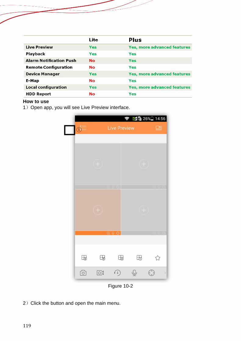
119
How to use 1)Open app, you will see Live Preview interface.
Figure 10-2
2)Click the button and open the main menu.
①
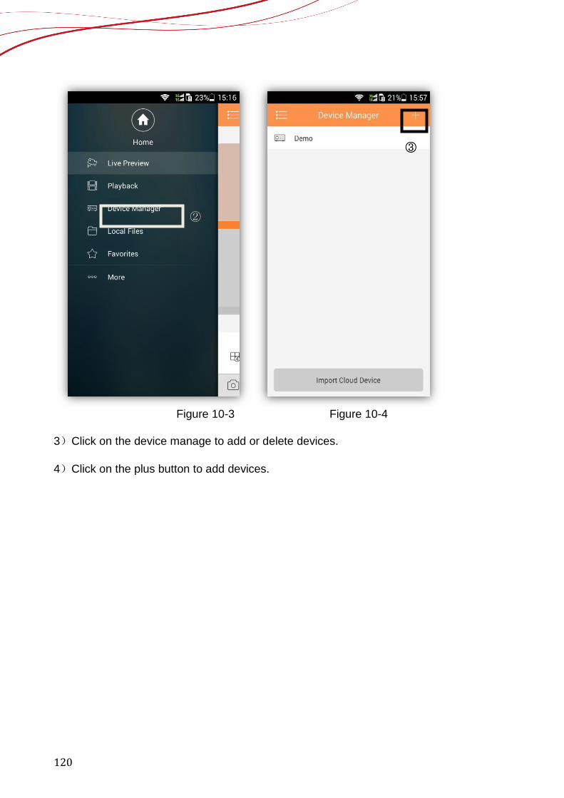
120
Figure 10-3 Figure 10-4
3)Click on the device manage to add or delete devices. 4)Click on the plus button to add devices.
②
③
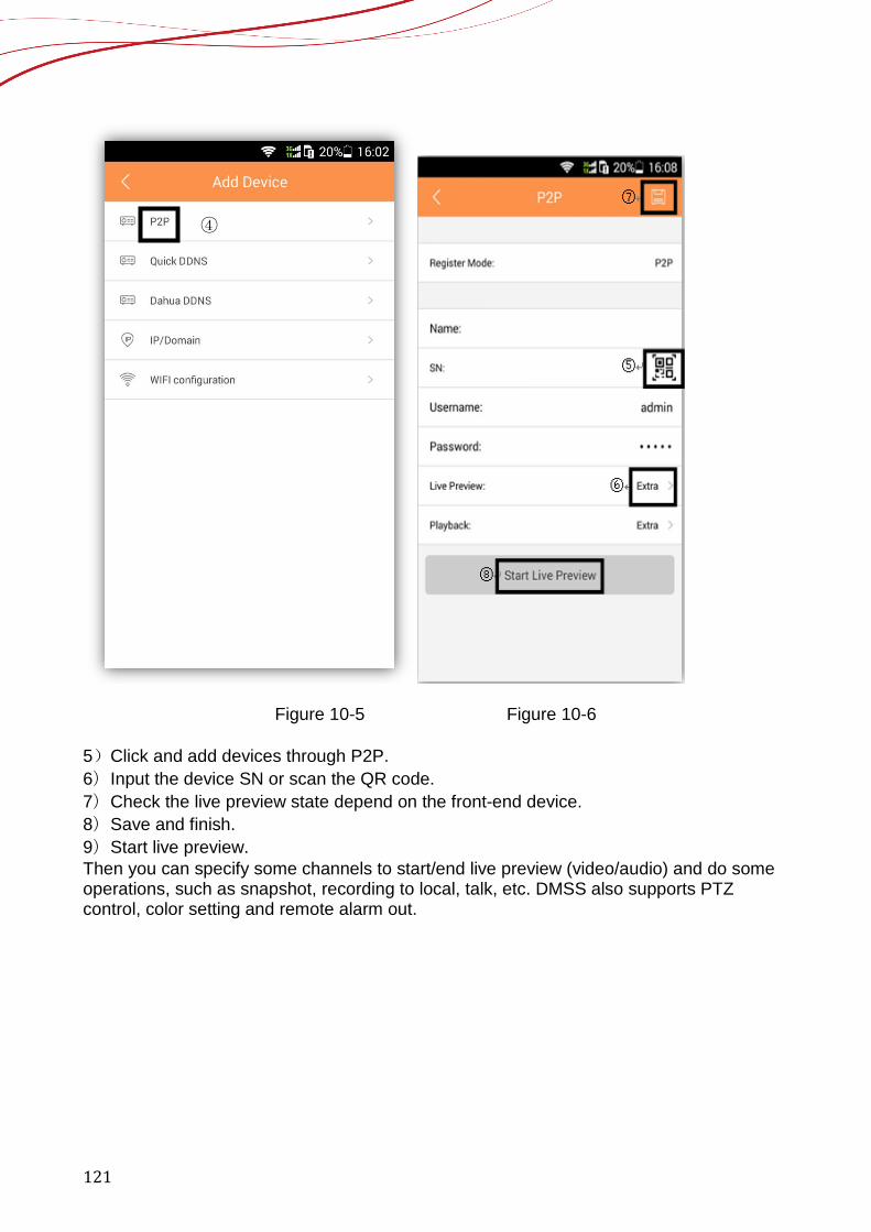
121
Figure 10-5 Figure 10-6
5)Click and add devices through P2P. 6)Input the device SN or scan the QR code. 7)Check the live preview state depend on the front-end device. 8)Save and finish. 9)Start live preview. Then you can specify some channels to start/end live preview (video/audio) and do some operations, such as snapshot, recording to local, talk, etc. DMSS also supports PTZ control, color setting and remote alarm out.
④
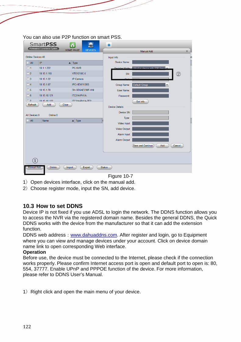
122
You can also use P2P function on smart PSS.
Figure 10-7
1)Open devices interface, click on the manual add. 2)Choose register mode, input the SN, add device. 10.3 How to set DDNS Device IP is not fixed if you use ADSL to login the network. The DDNS function allows you to access the NVR via the registered domain name. Besides the general DDNS, the Quick DDNS works with the device from the manufacturer so that it can add the extension function. DDNS web address:www.dahuaddns.com. After register and login, go to Equipment where you can view and manage devices under your account. Click on device domain name link to open corresponding Web interface. Operation Before use, the device must be connected to the Internet, please check if the connection works properly. Please confirm Internet access port is open and default port to open is: 80, 554, 37777. Enable UPnP and PPPOE function of the device. For more information, please refer to DDNS User’s Manual. 1)Right click and open the main menu of your device.
①
②
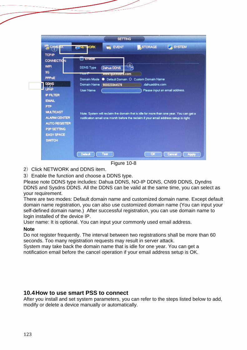
123
Figure 10-8
2)Click NETWORK and DDNS item. 3)Enable the function and choose a DDNS type. Please note DDNS type includes: Dahua DDNS, NO-IP DDNS, CN99 DDNS, Dyndns DDNS and Sysdns DDNS. All the DDNS can be valid at the same time, you can select as your requirement. There are two modes: Default domain name and customized domain name. Except default domain name registration, you can also use customized domain name (You can input your self-defined domain name.) After successful registration, you can use domain name to login installed of the device IP. User name: It is optional. You can input your commonly used email address. Note Do not register frequently. The interval between two registrations shall be more than 60 seconds. Too many registration requests may result in server attack. System may take back the domain name that is idle for one year. You can get a notification email before the cancel operation if your email address setup is OK. 10.4 How to use smart PSS to connect After you install and set system parameters, you can refer to the steps listed below to add, modify or delete a device manually or automatically.
①
②
③
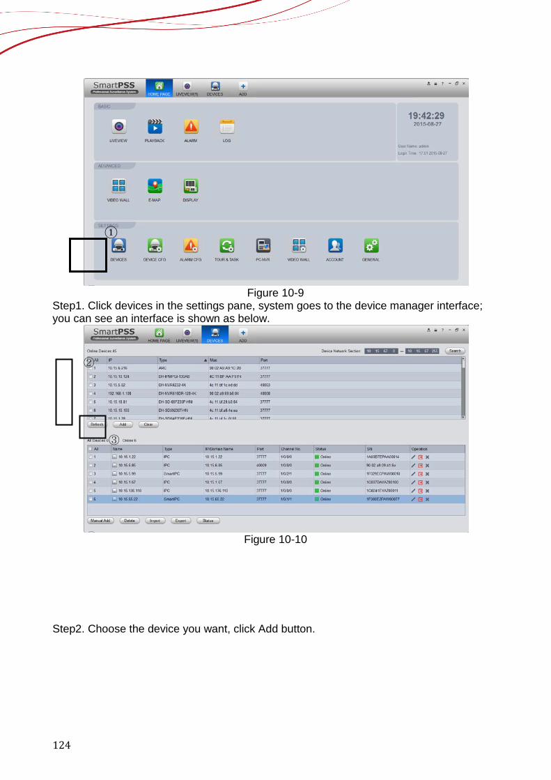
124
Figure 10-9
Step1. Click devices in the settings pane, system goes to the device manager interface; you can see an interface is shown as below.
Figure 10-10
Step2. Choose the device you want, click Add button.
①
③
②
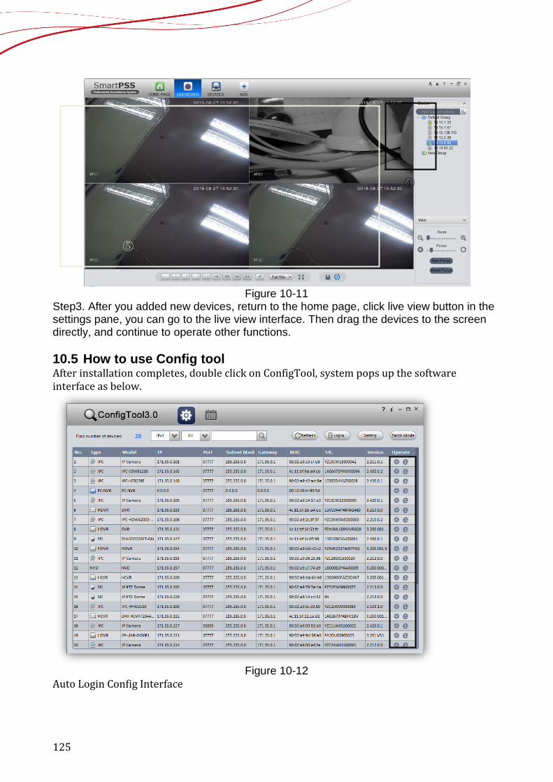
125
Figure 10-11
Step3. After you added new devices, return to the home page, click live view button in the settings pane, you can go to the live view interface. Then drag the devices to the screen directly, and continue to operate other functions. 10.5 How to use Config tool After installation completes, double click on ConfigTool, system pops up the software interface as below.
Figure 10-12
Auto Login Config Interface
④
⑤
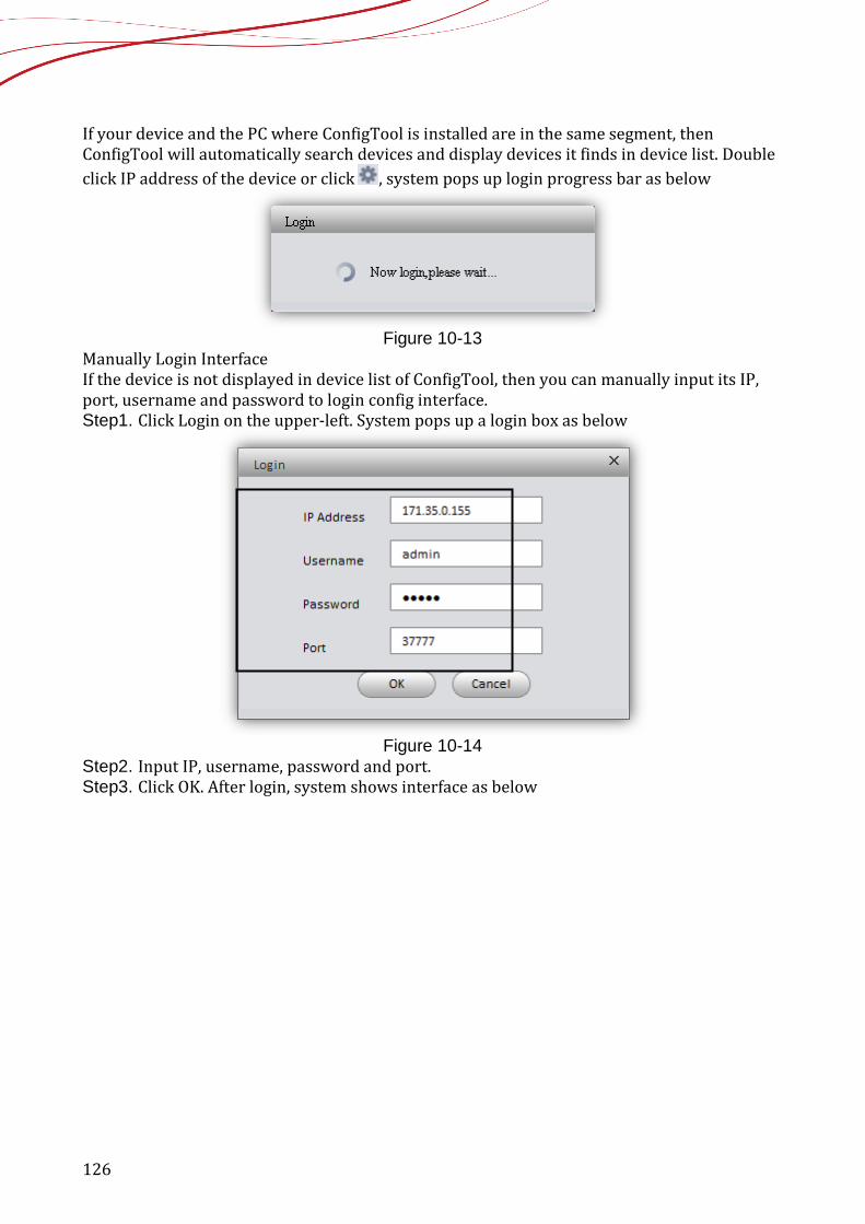
126
If your device and the PC where ConfigTool is installed are in the same segment, then ConfigTool will automatically search devices and display devices it finds in device list. Double click IP address of the device or click , system pops up login progress bar as below
Figure 10-13
Manually Login Interface If the device is not displayed in device list of ConfigTool, then you can manually input its IP, port, username and password to login config interface. Step1. Click Login on the upper-left. System pops up a login box as below
Figure 10-14
Step2. Input IP, username, password and port. Step3. Click OK. After login, system shows interface as below
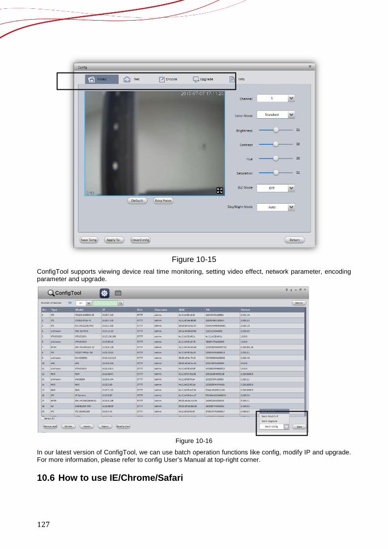
127
Figure 10-15
ConfigTool supports viewing device real time monitoring, setting video effect, network parameter, encoding parameter and upgrade.
Figure 10-16
In our latest version of ConfigTool, we can use batch operation functions like config, modify IP and upgrade. For more information, please refer to config User’s Manual at top-right corner. 10.6 How to use IE/Chrome/Safari
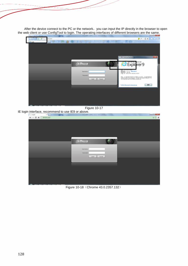
128
After the device connect to the PC or the network,you can input the IP directly in the browser to open the web client or use ConfigTool to login. The operating interfaces of different browsers are the same.
Figure 10-17
IE login interface, recommend to use IE9 or above.
Figure 10-18(Chrome 43.0.2357.132)
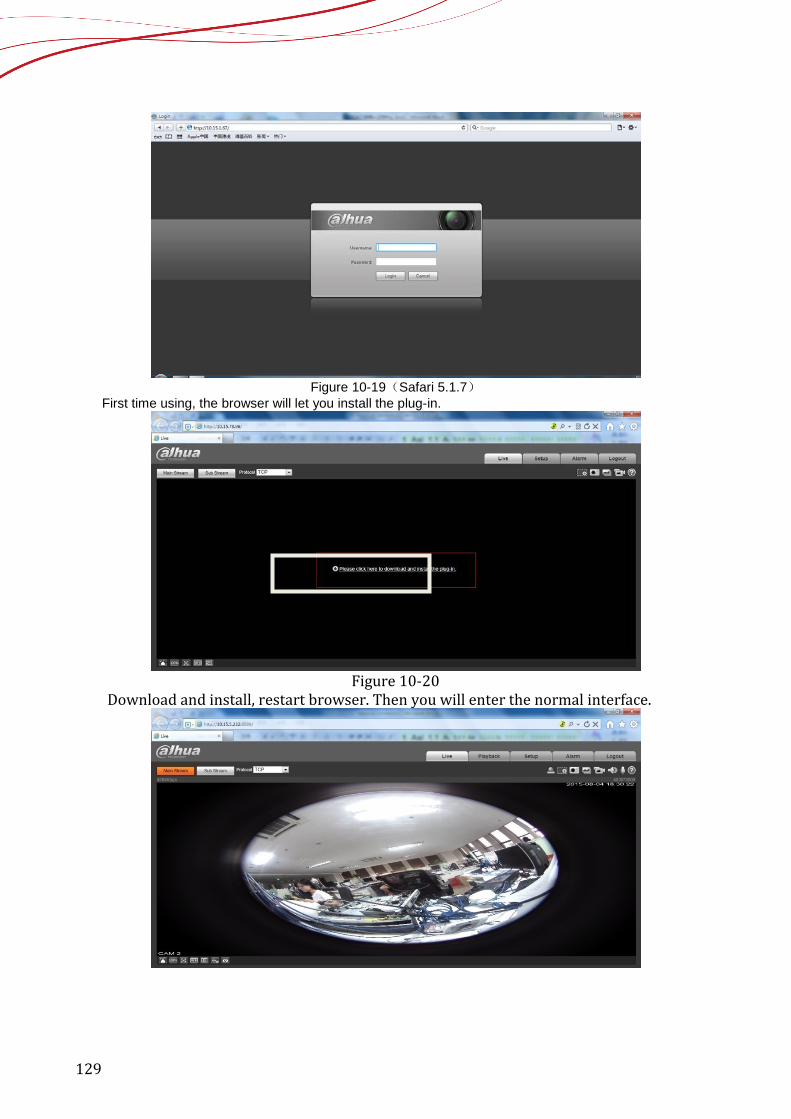
129
Figure 10-19(Safari 5.1.7)
First time using, the browser will let you install the plug-in.
Figure 10-20
Download and install, restart browser. Then you will enter the normal interface.

130
11 Device information and upgrade 11.1 NVR upgrade 11.1.1 USB upgrade 1) Plug the USB disk which included with the upgrading file into the device. 2) From the SETTING ->SYSTEM ->UPGRADE, click Upgrade button, select upgrade file through
USB device to begin update.
Figure 11- 1
11.1.2 network upgrade 1) Login the web of the device 2) From setting->upgrade, you will find the upgrade interface, then choose the file to upgrade
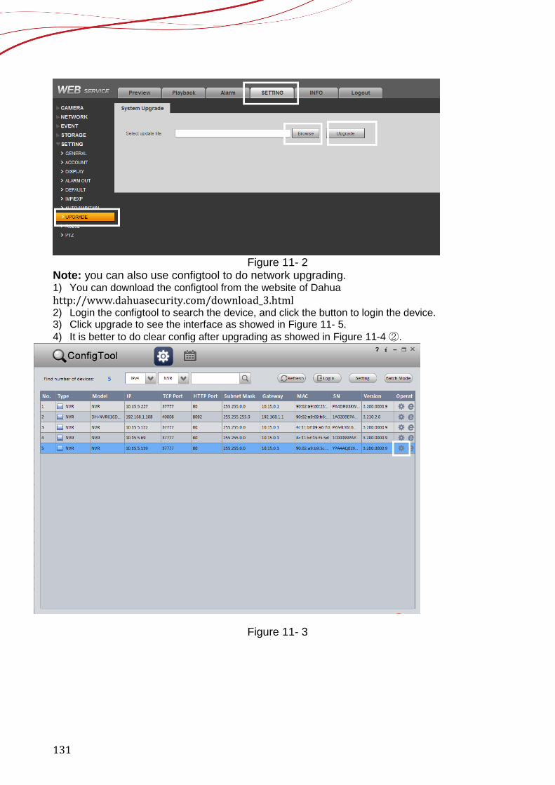
131
Figure 11- 2
Note: you can also use configtool to do network upgrading. 1) You can download the configtool from the website of Dahua http://www.dahuasecurity.com/download_3.html 2) Login the configtool to search the device, and click the button to login the device. 3) Click upgrade to see the interface as showed in Figure 11- 5. 4) It is better to do clear config after upgrading as showed in Figure 11-4 ②.
Figure 11- 3
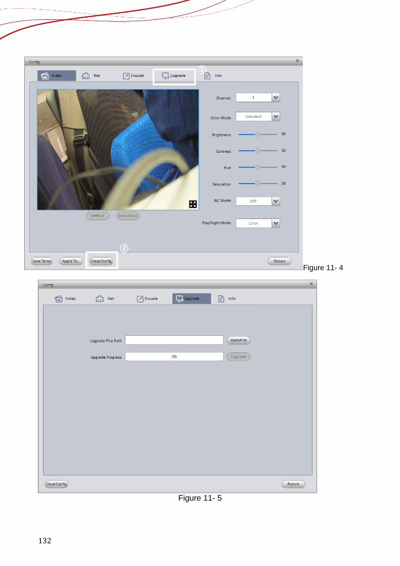
132
Figure 11- 4
Figure 11- 5
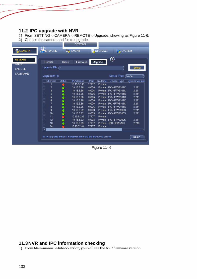
133
11.2 IPC upgrade with NVR 1) From SETTING ->CAMERA ->REMOTE ->Upgrade, showing as Figure 11-6. 2) Choose the camera and file to upgrade.
Figure 11- 6
11.3 NVR and IPC information checking 1) From Main-manual->Info->Version, you will see the NVR firmware version.
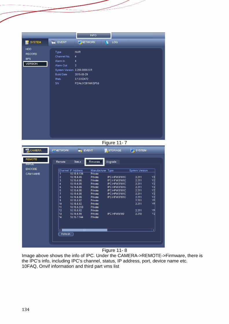
134
Figure 11- 7
Figure 11- 8
Image above shows the info of IPC. Under the CAMERA->REMOTE->Firmware, there is the IPC’s info, including IPC’s channel, status, IP address, port, device name etc. 10FAQ, Onvif information and third part vms list

135


![[mga-nvr ru]-ces-5 0](https://static.fdokumen.com/doc/165x107/631c012dd5372c006e043975/mga-nvr-ru-ces-5-0.jpg)