D4.1 – Intelligent Gateway prototype (initial) - Scene Project
68
This project has received funding from Horizon 2020, European Union’s Framework Programme for Research and Innovation, under grant agreement No.831138 D4.1 – Intelligent Gateway prototype (initial) SCENE Project Grant Agreement No. 831138 Call H2020-EIC-FTI-2018-2020 “Fast Track to Innovation” Topic EIC-FTI-2018-2020– Fast Track to Innovation (FTI) Start date of the project: 1 December 2018 Duration of the project: 24 months Ref. Ares(2019)7910632 - 24/12/2019
-
Upload
khangminh22 -
Category
Documents
-
view
4 -
download
0
Transcript of D4.1 – Intelligent Gateway prototype (initial) - Scene Project

This project has received funding from Horizon 2020, European Union’s Framework
Programme for Research and Innovation, under grant agreement No.831138
D4.1 – Intelligent Gateway prototype (initial)
SCENE Project
Grant Agreement No. 831138
Call H2020-EIC-FTI-2018-2020 “Fast Track to Innovation”
Topic EIC-FTI-2018-2020– Fast Track to Innovation (FTI)
Start date of the project: 1 December 2018
Duration of the project: 24 months
Ref. Ares(2019)7910632 - 24/12/2019

2
Disclaimer This document contains material, which is the copyright of certain SCENE contractors, and may not be
reproduced or copied without permission. All SCENE consortium partners have agreed to the full
publication of this document. The commercial use of any information contained in this document may
require a license from the proprietor of that information. The reproduction of this document or of parts
of it requires an agreement with the proprietor of that information. The document must be referenced if
used in a publication.
The SCENE consortium consists of the following partners.
No. Name Short Name Country
1 VISIONWARE - SISTEMAS DE INFORMAÇÃO, SA VISIONWARE PT
2 JCP-CONNECT SAS JCP-C FR
3 ALMAVIVA - THE ITALIAN INNOVATION COMPANY SPA ALMAVIVA IT
4 COMMISSARIAT A L’ENERGIE ATOMIQUE ET AUX ENERGIES ALTERNATIVES
CEA FR
5 AZIENDA METROPOLITANA TRASPORTI CATANIA SPA CAT IT
3
Document Information
Project short name and number SCENE (AMD-831138-1)
Work package WP4
Number D4.1
Title Intelligent Gateway prototype (initial)
Version V1.0
Responsible partner JCP-Connect
Type1 R
Dissemination level2 CO
Contractual date of delivery 30/11/2019
Last update 10/12/2019
1 Types.R: Document, report (excluding the periodic and final reports); DEM: Demonstrator, pilot, prototype, plan designs; DEC: Websites, patents filing, press & media actions, videos, etc.; OTHER: Software, technical diagram, etc. 2 Dissemination levels.PU: Public, fully open, e.g. web; CO: Confidential, restricted under conditions set out in Model Grant Agreement; CI: Classified, information as referred to in Commission Decision 2001/844/EC.

4
Document History
Version Date Status Authors, Reviewers
Description
v 0.01 21.10.2019 Draft JC POINT Defined SoC, testing & evaluation plan
v 0.02 04.11.2019 Draft JC POINT, R VORA
Requirement, specification,
v 0.03 19.11.2019 Draft S. MUSHTAQ, R.Vora
Initial testing results
v 0.04 03.12.2019 Draft S. MUSHTAQ, R.Vora
Preliminary results (section 5)
v 1.0 06.12.2019 Final S. MUSHTAQ, R.Vora
Ready for review
v 1.0 23/12/2019 Final F. Custódio (VIS)
Final review

5
Acronyms and Abbreviations
Acronym/Abbreviation Description
IGW Intelligent Gateway
IoT Internet of things
Lora WAN Long Range Wide Area Network
Lora Long Rang
SP Service Platform
WIFI Wireless Fidelity
BLE Bluetooth Low Energy
HTTP Hyper Text Transfer Protocol
LTE Long Term Evolution
DC Direct Current
CPU Centre Processing Unit
CC Cache Controller
DHCP Dynamic Host Configuration Protocol
SD card Secure Digital card
GPU Graphics Processing Unit
OS Operating System
LED Light Emitting Diode
HLS HTTP Live Streaming

6
Contents 1. Introduction ..................................................................................................................................... 7
2. IGW hardware requirement specification ......................................................................................... 8
2.1. IGW High level requirements .................................................................................................... 8
2.2. Product requirement .............................................................................................................. 11
3. IGW Hardware block diagram ......................................................................................................... 18
3.1. IGW general block diagram ..................................................................................................... 18
3.2. External Interfaces specification ............................................................................................. 18
3.3. Product technical specification ............................................................................................... 19
4. testing different platforms ............................................................................................................. 21
4.1. Board 1 ................................................................................................................................... 21
4.2. Board 2 ................................................................................................................................... 24
4.3. BOARD 3 ................................................................................................................................. 27
5. preliminary tests results ................................................................................................................. 30
5.1. Hardware testing .................................................................................................................... 30
5.1.1. Testing WIFI (2.4 GHz & 5 GHz) ....................................................................................... 30
5.1.2. Testing Bluetooth Dongle ................................................................................................ 34
5.1.3. Testing Lora Module ....................................................................................................... 39
5.1.4. Testing 4G Dongle ........................................................................................................... 46
5.2. Software Testing ..................................................................................................................... 52
5.2.1. Testing Web Portal ......................................................................................................... 52
5.2.2. Testing Caching ............................................................................................................... 58
5.2.3. Testing Captive Portal ..................................................................................................... 60
5.2.4. Captive-portal Configuration ........................................................................................... 63
6. Conclusion ..................................................................................................................................... 68
7
1. INTRODUCTION This is an initial report related to the Intelligent Gateway (IGW) prototype. Here, we consider the different
level of requirement for the IGW and evaluate three different hardware boards. The information related
to each hardware board is defined in terms of technical detail, specification, and supported external
interface. Each board is evaluated using the developed applications and tools for the Internet of Thing
(IoT) and the content delivery. The hardware board 3 is further evaluated in detail using different IoT
interfaces (WIFI, BLE, Lora WAN), and developed applications to observe its performance for the first pilot
in Catania city, Italy.
8
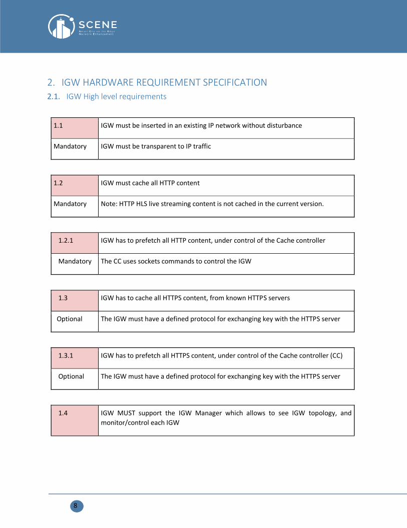
2. IGW HARDWARE REQUIREMENT SPECIFICATION
2.1. IGW High level requirements
1.1 IGW must be inserted in an existing IP network without disturbance
Mandatory IGW must be transparent to IP traffic
1.2 IGW must cache all HTTP content
Mandatory Note: HTTP HLS live streaming content is not cached in the current version.
1.2.1 IGW has to prefetch all HTTP content, under control of the Cache controller
Mandatory The CC uses sockets commands to control the IGW
1.3 IGW has to cache all HTTPS content, from known HTTPS servers
Optional The IGW must have a defined protocol for exchanging key with the HTTPS server
1.3.1 IGW has to prefetch all HTTPS content, under control of the Cache controller (CC)
Optional The IGW must have a defined protocol for exchanging key with the HTTPS server
1.4 IGW MUST support the IGW Manager which allows to see IGW topology, and
monitor/control each IGW

9
Mandatory Note: in the bus or mall use case, the IGW connects directly to an access point or root
IGW, there is no additional level of IGW. So, the IGW has usually child level 1 status
when connecting to another IGW using Wi-Fi, or root status when connecting directly
in the internet using Ethernet or LTE.
1.5 IGW must be able to connect to satellite, LTE, and Wi-Fi with a given order of priority
Mandatory,
bus use-case
satellite is through an external modem.
1.6 IGW must communicate with Cache Controller using any of the available network
connections (LTE, Wi-Fi, Ethernet)
Mandatory Cache controller and IGW must be able to communicate using one or several network
connections. The order of priority is pre-defined.
1.7 IGW MUST be able to pre-fetch content using any of the network connections, with
a pre-defined order of priority
Mandatory
1.8 IGW MUST send the content of their cache upon request from the cache controller,
using any of the network connection (4G, satellite, internet, WIFI)
Mandatory
1.9 IGW MUST send their statistics (hit rate, etc.) to Cache controller under demand

10
Mandatory
1.10 IGW MUST have Dynamic Host Configuration Protocol (DHCP) server capability with
255 addresses
Mandatory
1.12 IGW MUST be plug-and play, i.e. be installed without any configuration.
Mandatory
1.13 IGW MUST have a way to be mechanically attached and locked mechanically
Mandatory
1.14 IGW SHOULD have IoT interfaces to collect data from sensors
optional option called “IoT support.”
1.15 In the case of IoT support, IGW MUST have BLE and 802.15.4 interfaces (European
bands)
Mandatory
1.15 In the case of IoT support, IGW SHOULD have Lora WAN gateway and “5G-IoT”
interfaces

11
Optional
2.2. Product requirement
REQ ID Description Required
POWER SUPPLY / CHARGING / LED
REQ_33
The IGW should be delivered with an external power supply DC 12V
2A, EU Plug and CE marking Option
REQ_35
IGW battery charging from external DC power supply to full charge
when IGW is powered down shall be possible in less than 2h when a
50Wh Lithium-ion battery is connected. Must
REQ_37
External power supply connection to the IGW should be implemented
with a DC Jack connector 2.1mm to allow removal of the external
Power supply. Must
REQ_38
POWER LED should be supported - Visible outside the housing
- RED when ON
- RED blinking when ON but a low battery condition Must
REQ_39
CHARGING LED should be supported (controlled by charger IC) -
Visible outside the housing Must
12
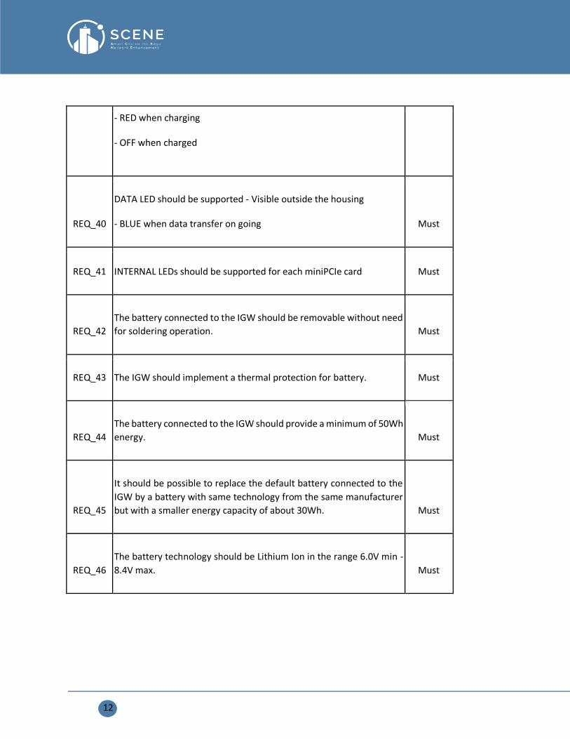
- RED when charging
- OFF when charged
REQ_40
DATA LED should be supported - Visible outside the housing
- BLUE when data transfer on going Must
REQ_41 INTERNAL LEDs should be supported for each miniPCIe card Must
REQ_42
The battery connected to the IGW should be removable without need
for soldering operation. Must
REQ_43 The IGW should implement a thermal protection for battery. Must
REQ_44
The battery connected to the IGW should provide a minimum of 50Wh
energy. Must
REQ_45
It should be possible to replace the default battery connected to the
IGW by a battery with same technology from the same manufacturer
but with a smaller energy capacity of about 30Wh. Must
REQ_46
The battery technology should be Lithium Ion in the range 6.0V min -
8.4V max. Must

13
REQ_47
The IGW should be functional while being used with the external DC
charger (Maximum of 1.5-meter distance separation between the DC
charger and the Hub) and no battery is connected inside the Hub. Must
REQ_48
It should be possible to charge the battery when the external DC
power supply is connected to the IGW and the IGW is powered down. Must
REQ_49
It should be possible to charge the battery when the external DC
power supply is connected to the IGW and the IGW is powered on and
delivering energy to the peripherals connected to the board including
though the USB Type A ports. Must
REQ_50
Energy delivered to its each USB Type A port should be up to 0.8A at
5V. Must
REQ_51
The IGW should provide enough energy to allow running below
configuration:
- Quad CA9 configured in Dual CA9 at 1.2GHz
- 512MB NAND
- 2GB DDR3 volatile memory,
- Simultaneous data transfer on two mini-PCIE wireless cards for a
maximum total power consumption of 9W. Must
EXTERNAL CONNECTORS

14
REQ_100 The IGW should support a power ON/OFF switch Must
REQ_101 The IGW should support a DC Jack connector 2.1mm Must
REQ_102 The IGW should support an ethernet connector for data input Must
REQ_103 The IGW should support 2 USB Host 2.0 port type A Must
REQ_104 The IGW should support 8 x SMA female RF connectors Must
REQ_105 The IGW should support a micro SIM card connector Must
REQ_106
The IGW should support an ethernet connector for data output Must
REQ_107 The IGW should support a USB 3.0 connector Must
INTERNAL CONNECTORS
REQ_150 The IGW should support an UART connector dedicated to debug Must
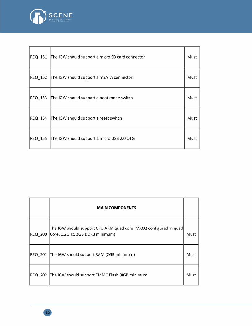
15
REQ_151 The IGW should support a micro SD card connector Must
REQ_152 The IGW should support a mSATA connector Must
REQ_153 The IGW should support a boot mode switch Must
REQ_154 The IGW should support a reset switch Must
REQ_155 The IGW should support 1 micro USB 2.0 OTG Must
MAIN COMPONENTS
REQ_200
The IGW should support CPU ARM quad core (MX6Q configured in quad
Core, 1.2GHz, 2GB DDR3 minimum) Must
REQ_201 The IGW should support RAM (2GB minimum) Must
REQ_202 The IGW should support EMMC Flash (8GB minimum) Must

16
REQ_203
The IGW will use a PCI Express switch GEN 2 to extend the system to 2
mini PCI Express interfaces Must
REQ_204
The IGW should support 2 mini PCIe connectors dedicated to 2 mini PCIe
full size cards (WLAN) Must
REQ_205
It should be possible to connect 1 mini PCIe card 50mm x 48mm (WLAN)
on 1 of the mini PCIe connector Must
REQ_206 It should be possible to connect 1 mini PCIe Wi-Fi 2.4GHz card Must
REQ_207 It should be possible to connect 1 mini PCIe Wi-Fi 5GHz card Must
It should be possible to connect 1 mini PCIe 4G card Must
It should be possible to connect 1 mini PCIe Lora WAN gateway card Must
REQ_208
It should be possible to connect the 1 mSATA mass storage device at mini
PCIe full size Must
REQ_209
An UART to USB FTDI cable converter is required to get the Linux console
on PC Must
The IGW should include a Bluetooth Low Energy module Must
17
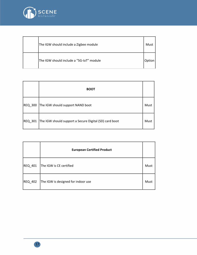
The IGW should include a Zigbee module Must
The IGW should include a “5G-IoT” module Option
BOOT
REQ_300 The IGW should support NAND boot Must
REQ_301 The IGW should support a Secure Digital (SD) card boot Must
European Certified Product
REQ_401 The IGW is CE certified Must
REQ_402 The IGW is designed for indoor use Must

18
3. IGW HARDWARE BLOCK DIAGRAM In this section, we explain the block diagram of the three hardware boards, and provide the information
about interface and technical detail of each board.
3.1. IGW general block diagram
3.2. External Interfaces specification Acronym Denomination Specification
RF in/out 1 Wifi1 interface in/out
interface
Connector: 2 SMA connectors
MIMO: 2x2 AP mode; 1x1 STA mode
Output power: 20 dBm max
Receiver sensitivity:
Network Standards: IEEE 802.11a, 802.11b, 802.11g, 802.11n,
802.11ac
RF in/out 2 Wifi2 interface in/out
interface
Connector: 2 SMA connectors
MIMO: 2x2 AP mode; 1x1 STA mode
Output power: 20 dBm max

19
Receiver sensitivity:
Network Standards: IEEE 802.11a, 802.11b, 802.11g, 802.11n,
802.11ac
RF in/out 3 4G/5G client interface
RF in/out 4 4G/5G IoT Gateway
interface
RF in/out 5 Zigbee
RF in/out 6 BLE
RF in/out 7 Lora WAN gateway
microSD Memory Storage External memory slot for the SD card
JTAG Test PC board
UART Serial Communication Interface to see the console in the serial terminal window
Eth in Ethernet input
Eth out Ethernet Output
PS in Input power supply
3.3. Product technical specification
WAN Input interfaces Gb Ethernet
LAN Output interface Gb Ethernet
Radio interfaces (3) SMA connectors
LAN Output interface WIFI (2.4 GHZ and 5 GHz)
WAN input interface 4G LTE (optional)
Network Standards IEEE 802.11a, 802.11b, 802.11g, 802.11n, 802.11ac
Radio Frequency Bands 2.4GHz and 5GHz (Concurrent)
Ports 1 x Gigabit LAN input Port 1 x Gigabit LAN output Port 1 x 12V/1.5A power port

20
LEDs 1 x System LED
Buttons Reset Button
MIMO 2x2 AP mode
1x1 STA mode
Antenna Type External SMA Antenna
RF Transmit Power High Power PA, 20 dBm minimum
Radio Frequency Channels 2.412 to 2.462 GHz: 11 channels 5.180 to 5.240 GHz: 4 channels
5.745 to 5.825 GHz: 5 channels
Frequency range 2.412 ~ 2.472 GHz, 5.180 ~ 5.825 GHz
Radio frequency bands (IoT) 868 MHz 2.4 GHz
Receive Sensitivity 2.4 GHz: -77 to -94 dBm
5 GHz: -71 to -93 dBm
Dimensions (LxWxH) 9.57 x 9.33 x 1.72 inches
Weight 0.5 kg
Operating Humidity 10% to 85% non-condensing
Storage Humidity 10% to 90% non-condensing
Mounting Ceiling
Wall
Security Features Multiple SSIDs SSID Broadcast SSID to VLAN Mapping
Wi-Fi Protected Access (WPA/WPA Mixed, WPA2)
Personal and Enterprise RADIUS Mac-Based Access Control
802.1X Supplicant

21
4. TESTING DIFFERENT PLATFORMS The boards are selected to evaluate their performance. More than 30 end-users are used to test the ability
of each hardware board platform to provide the connectivity to end-users. In addition, each board is
evaluated using the content delivery applications.
4.1. Board 1 The basic block diagram of Board 1 is given below, and designed layout shows the different elements of
board 1. However, the technical specification is summarized in the table.

22
Product Technical Specification
Board 1
Center Processing Unit (CPU) MediaTek MT7623N, Quad-core ARM Cortex-A7
Graphics Processing Unit (GPU) Mali 450 MP4 GPU
Memory 2G DDR3 SDRAM
Storage Onboard 8GB eMMC Flash, Micro SD-Card slot,
Two SATA 2.0 Port
Network 5 x 10/100/1000 Mbit/s Ethernet (MT7530)

23
WIFI&BT Wi-Fi 802.11 b/g/n 2.4G/5G + Bluetooth
BT4.1(MT6625L)
Display(s) HDMI (Type A) output with HDCP 1.4, resolutions
up 1920x1200; MIPI Display Serial Interface (DSI)
interface (4 data lanes)
Video decoder(s) Multi-format FHD video decoding, including
Mpeg1/2, Mpeg4, H.263, H.264, etc. H.264 high-
profile 1080p@60fps, HEVC/H.265 1080P@60fps
Audio Output(s) HDMI & I2S
USB port USB 3.0 PORT (x2), USB OTG (x1)
mini PCIE 1 mini pcie interface & 1 pcie pin define interface
Remote IR Receiver (x1)
GPIO 40 Pin Header: GPIO (x28) and Power (+5V, +3.3V
and GND). Some of I/O Pin can be used for specific
functions as UART, I2C, SPI or PWM
Switches Reset button, Power button, U-boot button
LED Power Status and 8P8C
Power Source 5 volts @2A via DC Power and/or Micro USB (OTG)
Size & Weight 148 mm × 100.5mm 100g
OS OpenWRT, Debian, Ubuntu, Raspbian and others
OS
Observation:
It is observed that this board does not support more than 10 WIFI users, which limits it's used.

24
4.2. Board 2
Hardware
BOARD 2 uses the latest MTK wireless solution, the MT7621, the clock frequency is as high as 880MHZ,
provide 5 gigabit Auto MDI/MDIX Ethernet port, 1×USB 3.0 port, 1×PCI-E ,1×Micro SD card ,1× SATA 3.0
and so on.
25
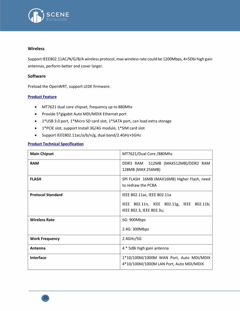
Wireless
Support IEEE802.11AC/N/G/B/A wireless protocol, max wireless rate could be 1200Mbps, 4×5Dbi high gain
antennas, perform better and cover larger.
Software
Preload the OpenWRT, support LEDE firmware.
Product Feature
• MT7621 dual core chipset, frequency up to 880Mhz
• Provide 5*gigabit Auto MDI/MDIX Ethernet port
• 1*USB 3.0 port, 1*Micro SD card slot, 1*SATA port, can load extra storage
• 1*PCIE slot, support Install 3G/4G module, 1*SIM card slot
• Support IEEE802.11ac/a/b/n/g, dual band/2.4GHz+5GHz
Product Technical Specification
Main Chipset MT7621/Dual Core /880Mhz
RAM DDR3 RAM 512MB (MAX512MB)/DDR2 RAM
128MB (MAX 256MB)
FLASH SPI FLASH 16MB (MAX16MB) Higher Flash, need
to redraw the PCBA
Protocol Standard IEEE 802.11ac, IEEE 802.11a
IEEE 802.11n, IEEE 802.11g, IEEE 802.11b;
IEEE 802.3, IEEE 802.3u;
Wireless Rate 5G: 900Mbps
2.4G: 300Mbps
Work Frequency 2.4GHz/5G
Antenna 4 * 5dBi high gain antenna
Interface 1*10/100M/1000M WAN Port, Auto MDI/MDIX
4*10/100M/1000M LAN Port, Auto MDI/MDIX
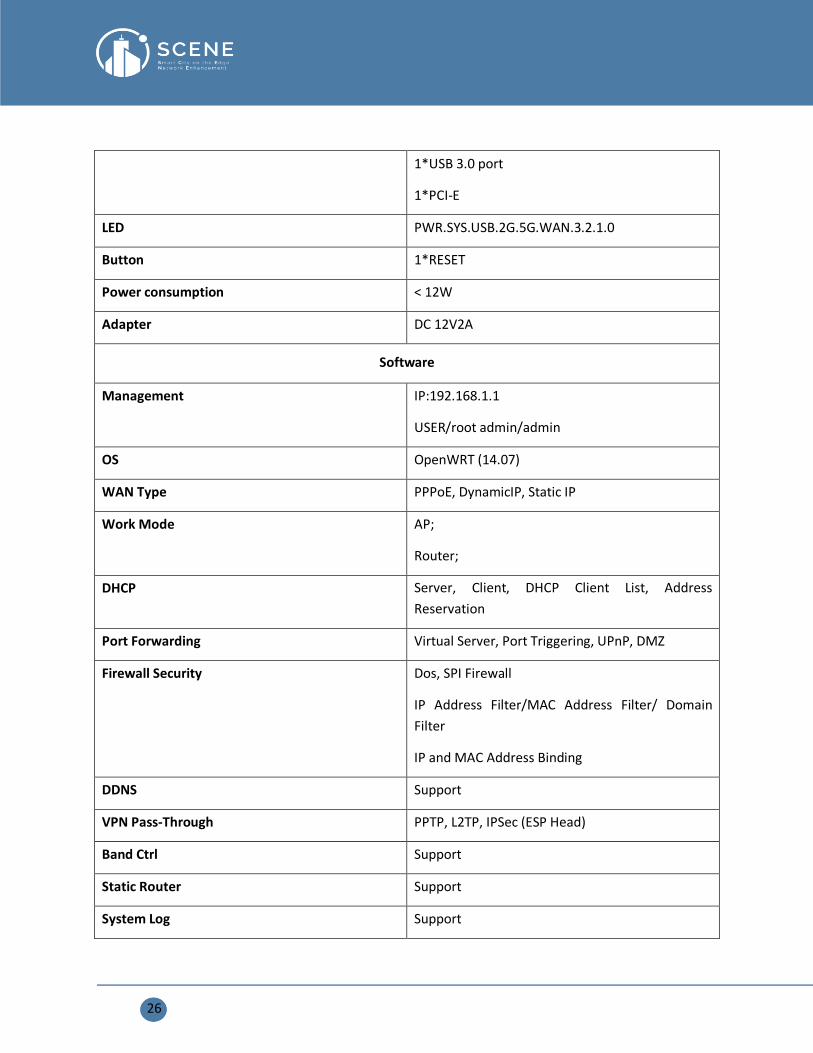
26
1*USB 3.0 port
1*PCI-E
LED PWR.SYS.USB.2G.5G.WAN.3.2.1.0
Button 1*RESET
Power consumption < 12W
Adapter DC 12V2A
Software
Management IP:192.168.1.1
USER/root admin/admin
OS OpenWRT (14.07)
WAN Type PPPoE, DynamicIP, Static IP
Work Mode AP;
Router;
DHCP Server, Client, DHCP Client List, Address
Reservation
Port Forwarding Virtual Server, Port Triggering, UPnP, DMZ
Firewall Security Dos, SPI Firewall
IP Address Filter/MAC Address Filter/ Domain
Filter
IP and MAC Address Binding
DDNS Support
VPN Pass-Through PPTP, L2TP, IPSec (ESP Head)
Band Ctrl Support
Static Router Support
System Log Support
27
Other Function Mac clone
NTP Synchronize
Web firmware upgrade
Others
Work Environments Operating Temperature:0℃ ~ 40℃;
Storage Temperature: -40℃~ 70℃;
Operating Humidity:10%~90% non-condensing
Storage Humidity:10%~90% non-condensing
Authentication CE. FCC, RoHs
Observation:
It is observed that this board support more than 30 users on WiFi networks, but its behaviour is not stable.
It cannot flash image more than 16 MB which is the main disadvantage, also SD card was not stable, which
directly influence improper working of content delivery due to memory issues.
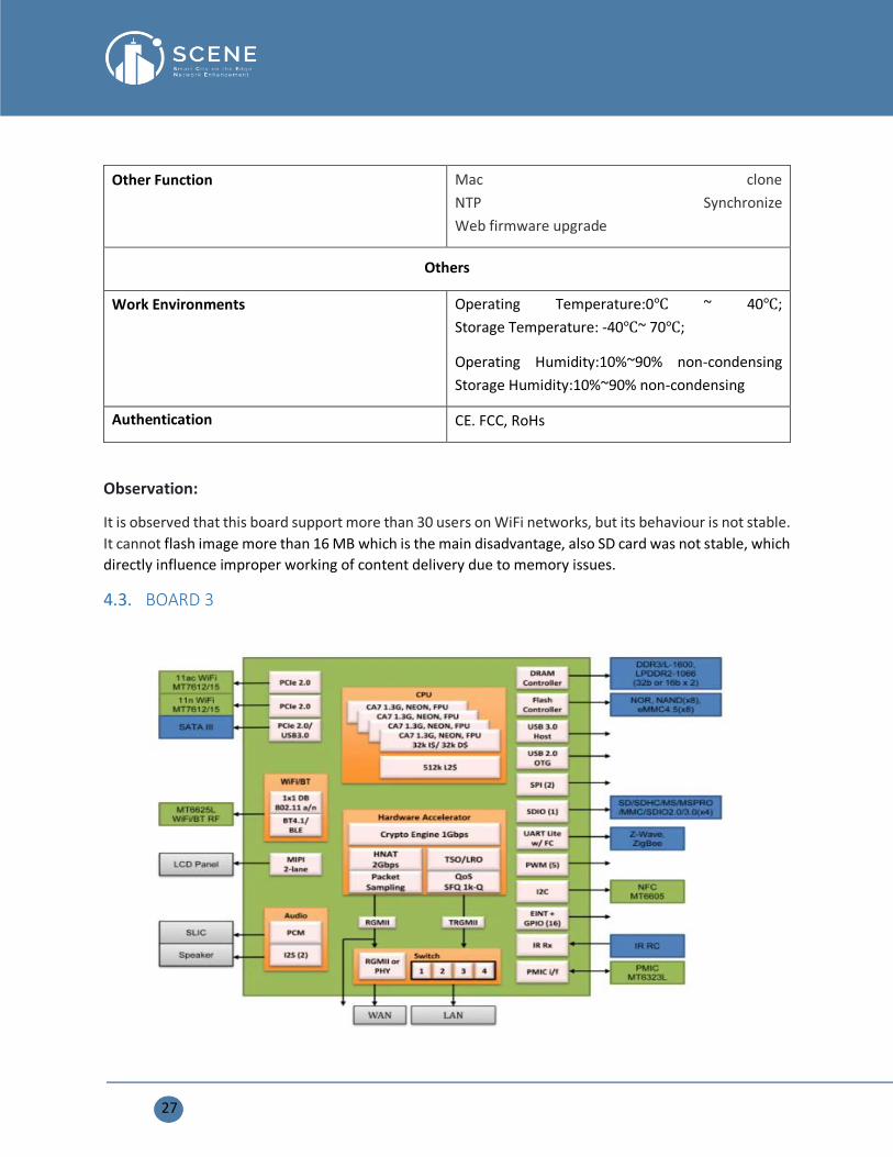
4.3. BOARD 3

28
Product Technical Specification
U7623-06 The CPU incorporates an ARM® Cortex-A7 four cores MPCoreTM operating up to 1.3 GHz and
more DRAM bandwidth. The powerful PROCESSOR is
Suitable for 802.11ac, LTE cat4 / 5, edge, hotspot, VPN, AC (access control). For the new generation
router, the MT7623 card provides several dedicated cards
Hardware engines to speed up NAS, NAT, QoS Samba and VPN traffic. These accelerators release the
processor for other higher layer applications.
Chipset Processor: MTK MT7623A quad-core ARM®
Cortex-A7 (1.3 GHz)
System memory Default DDR3 32Bit 1600 Mbps 512 M Byte
(Optional 1G / 2G Byte)
EMMC EMMC4.5: Default 8G byte (maximum 128G byte)
supports OpenWrt
PCIE 2x PCIE Normal for WIFI module 11ac or 11n
1x PCIE connector for LTE or MSATA module
Interface 5x Gigabit 4 * LAN + 1WAN (MDI-X Automatic)
1x 4 pin serial debug port Connector1
29
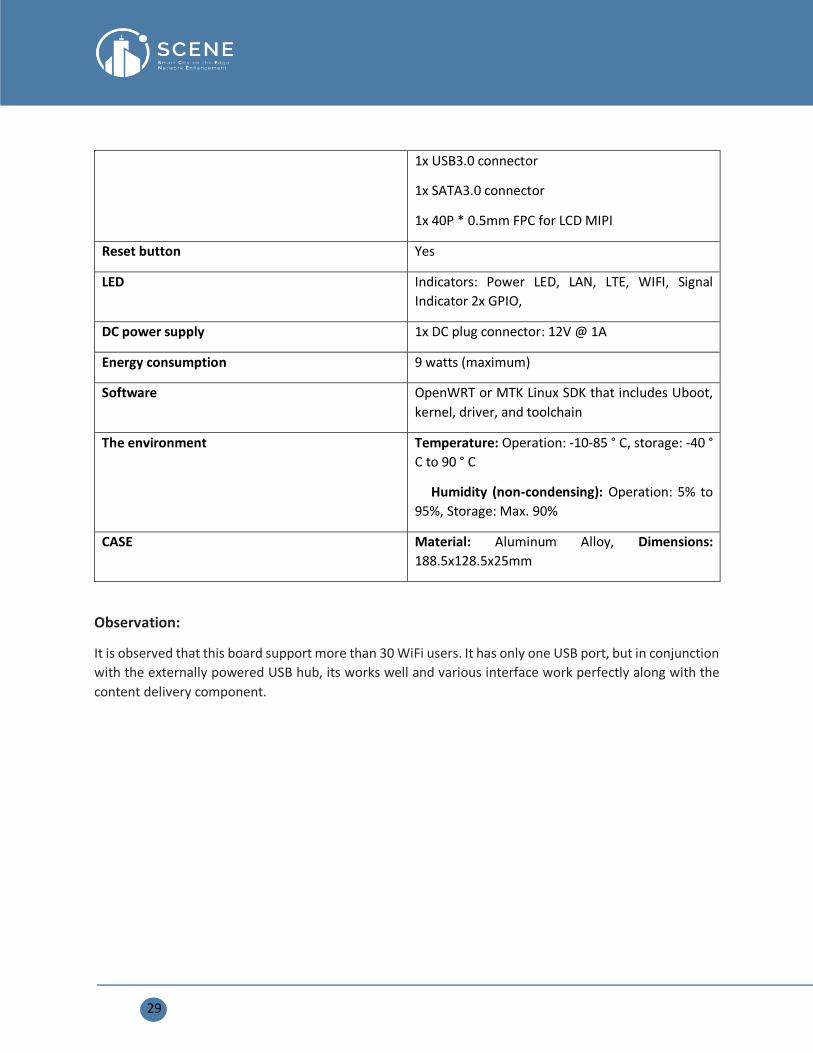
1x USB3.0 connector
1x SATA3.0 connector
1x 40P * 0.5mm FPC for LCD MIPI
Reset button Yes
LED Indicators: Power LED, LAN, LTE, WIFI, Signal
Indicator 2x GPIO,
DC power supply 1x DC plug connector: 12V @ 1A
Energy consumption 9 watts (maximum)
Software OpenWRT or MTK Linux SDK that includes Uboot,
kernel, driver, and toolchain
The environment Temperature: Operation: -10-85 ° C, storage: -40 °
C to 90 ° C
Humidity (non-condensing): Operation: 5% to
95%, Storage: Max. 90%
CASE Material: Aluminum Alloy, Dimensions:
188.5x128.5x25mm
Observation:
It is observed that this board support more than 30 WiFi users. It has only one USB port, but in conjunction
with the externally powered USB hub, its works well and various interface work perfectly along with the
content delivery component.
30
5. PRELIMINARY TESTS RESULTS Based on the evaluation of three hardware boards, it is observed that Board # 3 is best compared to Board
1 and Board 2. We further evaluate the board 3 based on testing the hardware using multiple interfaces
and developed applications and tools.
5.1. Hardware testing Here, we evaluate the different interfaces using the board 3, and provide its behavior and performance.
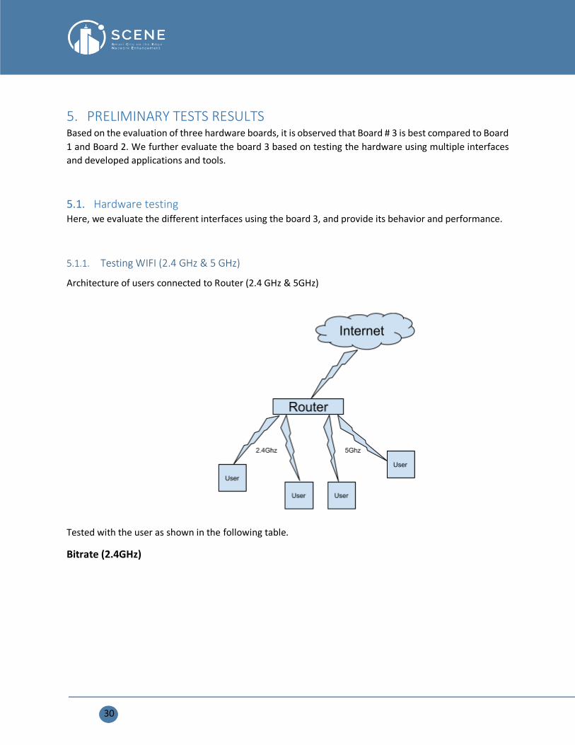
5.1.1. Testing WIFI (2.4 GHz & 5 GHz)
Architecture of users connected to Router (2.4 GHz & 5GHz)
Tested with the user as shown in the following table.
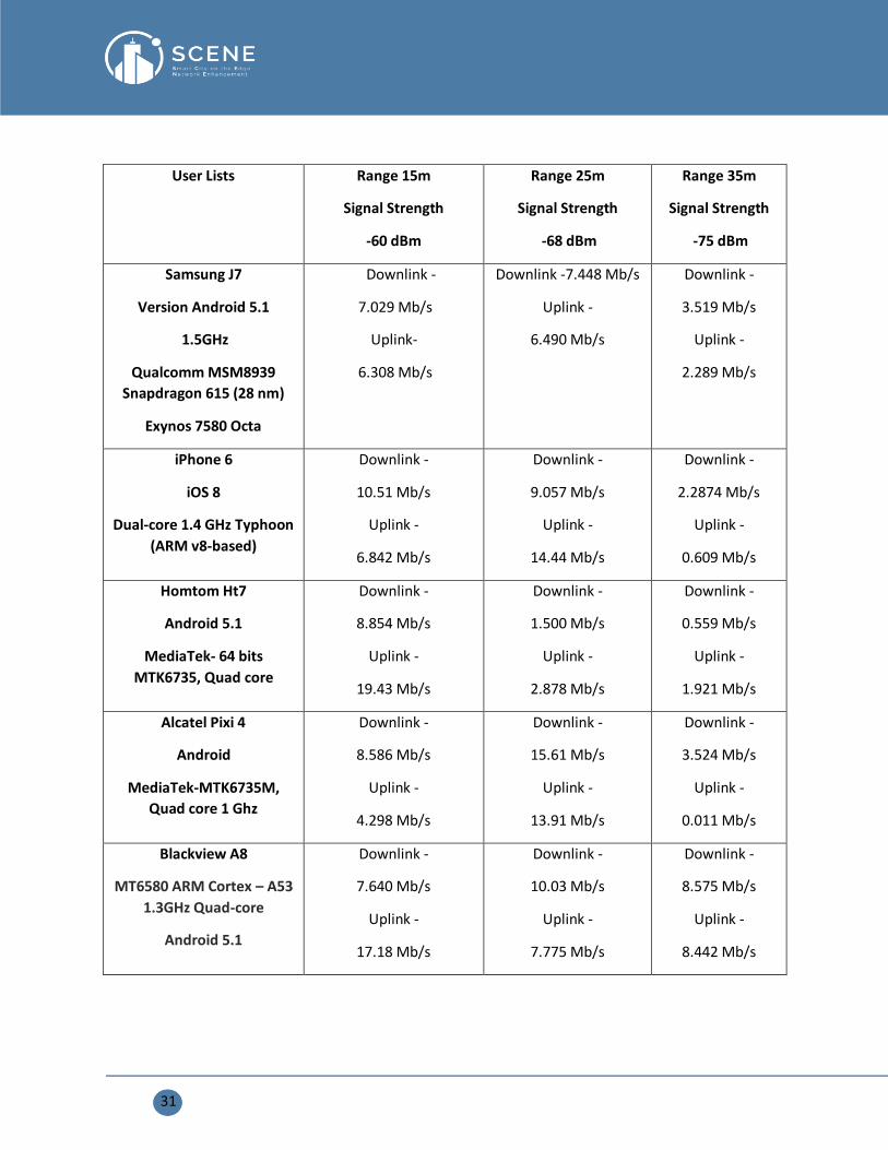
Bitrate (2.4GHz)
31
User Lists Range 15m
Signal Strength
-60 dBm
Range 25m
Signal Strength
-68 dBm
Range 35m
Signal Strength
-75 dBm
Samsung J7
Version Android 5.1
1.5GHz
Qualcomm MSM8939
Snapdragon 615 (28 nm)
Exynos 7580 Octa
Downlink -
7.029 Mb/s
Uplink-
6.308 Mb/s
Downlink -7.448 Mb/s
Uplink -
6.490 Mb/s
Downlink -
3.519 Mb/s
Uplink -
2.289 Mb/s
iPhone 6
iOS 8
Dual-core 1.4 GHz Typhoon
(ARM v8-based)
Downlink -
10.51 Mb/s
Uplink -
6.842 Mb/s
Downlink -
9.057 Mb/s
Uplink -
14.44 Mb/s
Downlink -
2.2874 Mb/s
Uplink -
0.609 Mb/s
Homtom Ht7
Android 5.1
MediaTek- 64 bits
MTK6735, Quad core
Downlink -
8.854 Mb/s
Uplink -
19.43 Mb/s
Downlink -
1.500 Mb/s
Uplink -
2.878 Mb/s
Downlink -
0.559 Mb/s
Uplink -
1.921 Mb/s
Alcatel Pixi 4
Android
MediaTek-MTK6735M,
Quad core 1 Ghz
Downlink -
8.586 Mb/s
Uplink -
4.298 Mb/s
Downlink -
15.61 Mb/s
Uplink -
13.91 Mb/s
Downlink -
3.524 Mb/s
Uplink -
0.011 Mb/s
Blackview A8
MT6580 ARM Cortex – A53
1.3GHz Quad-core
Android 5.1
Downlink -
7.640 Mb/s
Uplink -
17.18 Mb/s
Downlink -
10.03 Mb/s
Uplink -
7.775 Mb/s
Downlink -
8.575 Mb/s
Uplink -
8.442 Mb/s

32
Bitrate (5GHz)
User Lists Range 15m
Signal Strength
-55 dBm
Range 25m
Signal Strength
-65 dBm
Range 35m
Signal Strength
-80 dBm
iPhone 6
iOS 8
Dual-core 1.4 GHz
Typhoon (ARM v8-based)
Downlink -
11.04 Mb/s
Uplink -
12.72 Mb/s
Downlink -
3.403 Mb/s
Uplink -
5.526 Mb/s
Downlink -
4.640 Mb/s
Uplink -
5.430 Mb/s
Xiaomi note 6 pro
Android 8.1 (Oreo),
Qualcomm SDM636
Snapdragon 636 Octa-core
Downlink -
19.14 Mb/s
Uplink -
11.86 Mb/s
Downlink -
10.56 Mb/s
Uplink -
13.18 Mb/s
Downlink -
2.210 Mb/s
Uplink -
3.801 Mb/s
Realme X2 pro
Android 9.0 (Pie),
Qualcomm SDM855
Snapdragon 855 Octa-core
Downlink -
30.83 Mb/s
Uplink -
21.18 Mb/s
Downlink -
12.53 Mb/s
Uplink -
11.39 Mb/s
Downlink -
8.180 Mb/s
Uplink -
8.431 Mb/s
Reference Signal Strength table
Signal Strength Expected Quality Required For
-30 dBm Maximum signal strength, you
are standing right next to the
access point.
-----
-50 dBm Anything down to this level can
be considered excellent signal
strength.
-----
-60 dBm Good, reliable signal strength
-----
33
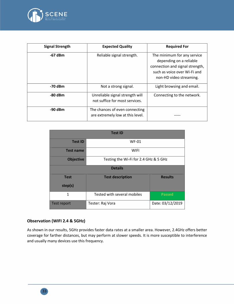
Signal Strength Expected Quality Required For
-67 dBm Reliable signal strength. The minimum for any service
depending on a reliable
connection and signal strength,
such as voice over Wi-Fi and
non-HD video streaming.
-70 dBm Not a strong signal. Light browsing and email.
-80 dBm Unreliable signal strength will
not suffice for most services.
Connecting to the network.
-90 dBm The chances of even connecting
are extremely low at this level.
-----
Test ID
Test ID WF-01
Test name WIFI
Objective Testing the Wi-Fi for 2.4 GHz & 5 GHz
Details
Test
step(s)
Test description Results
1 Tested with several mobiles Passed
Test report Tester: Raj Vora Date: 03/12/2019
Observation (WIFI 2.4 & 5GHz)
As shown in our results, 5GHz provides faster data rates at a smaller area. However, 2.4GHz offers better
coverage for farther distances, but may perform at slower speeds. It is more susceptible to interference
and usually many devices use this frequency.

34
5.1.2. Testing Bluetooth Dongle
Bluetooth Dongle Specification for LogiLink Bluetooth 4.0, Adapter USB 2.0 Micro
• Bluetooth v4.0 (Backward compatible)
• Transmission frequency: 2.402-2.480 ISM Band
• Data transfer-Speed: 3 Mbit/s
• Max. distance: 100 m
• Chipset: CSR / BC8510
• Connector: USB 2.0 (Comp. to USB 3.0 and 1.1)
• Suitable for Win XP, Vista, Win 7, Win 8, Win 10 and Plug&Play
• Size: 23 x 14.2 x 4.5 mm
Specification for JINOU/OEM Bluetooth Low Energy BLE 4.0/4.1 Beacon/iBeacon
• Working frequency: ISM frequency 2.400~2.483GHz
• Bluetooth specification: V4.0BLE
• Spread spectrum method: FHSS
• Voltage: 2.7-3.3V
• Transmitting power: 0dBm
• Transmitting distance: 40m
• Receiving sensitivity: <-93dBm at < 0.1% BER
• Store temperature: -55 °C ~ 125 °C
• Connecting standby power: about 0.2mA
• Antenna standard: 2.4G, 50ohm
• Safety standard: AES 128bit
• Temperature measure range: -40 °C ~ +85 °C
• Temperature measure accuracy: between 15 °C ~ +40 °C, deviation is ±0.5 °C; between-40°C ~
+85 °C, deviation is ±1 °C.
• Relative humidity measure range: 0 ~ 100%
• Humidity measure accuracy: between 20 +80% RH, deviation is ±4.5%
Interface (IGW)
usb 1-1: new full-speed USB device number 3 using xhci-mtk
usb 1-1: config 1 interface 1 altsetting 0 endpoint 0x3 has wMaxPacketSize 0, skipping
usb 1-1: config 1 interface 1 altsetting 0 endpoint 0x83 has wMaxPacketSize 0, skipping
35
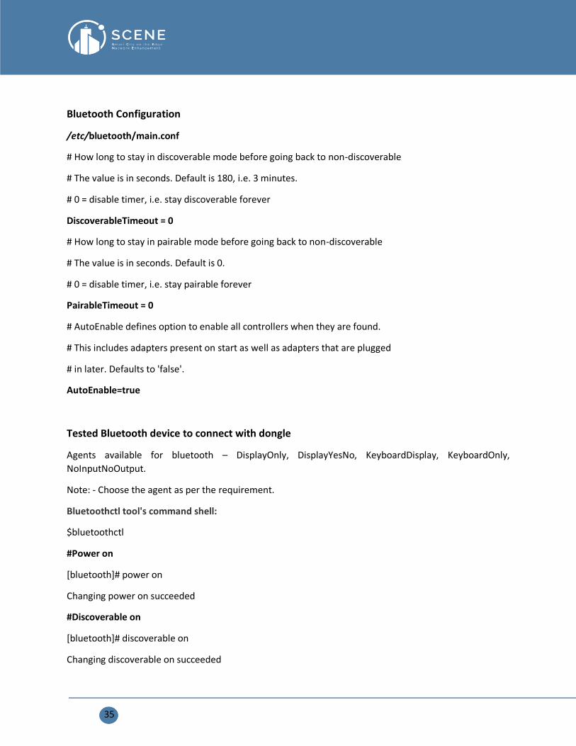
Bluetooth Configuration
/etc/bluetooth/main.conf
# How long to stay in discoverable mode before going back to non-discoverable
# The value is in seconds. Default is 180, i.e. 3 minutes.
# 0 = disable timer, i.e. stay discoverable forever
DiscoverableTimeout = 0
# How long to stay in pairable mode before going back to non-discoverable
# The value is in seconds. Default is 0.
# 0 = disable timer, i.e. stay pairable forever
PairableTimeout = 0
# AutoEnable defines option to enable all controllers when they are found.
# This includes adapters present on start as well as adapters that are plugged
# in later. Defaults to 'false'.
AutoEnable=true
Tested Bluetooth device to connect with dongle
Agents available for bluetooth – DisplayOnly, DisplayYesNo, KeyboardDisplay, KeyboardOnly,
NoInputNoOutput.
Note: - Choose the agent as per the requirement.
Bluetoothctl tool's command shell:
$bluetoothctl
#Power on
[bluetooth]# power on
Changing power on succeeded
#Discoverable on
[bluetooth]# discoverable on
Changing discoverable on succeeded

36
#Pairable on
[bluetooth]# pairable on
Changing pairable on succeeded
# register proper agent
[bluetooth]# agent KeyboardOnly
Agent registered
#Scan on
[bluetooth]# scan on
Discovery started
#Controller is the bluetooth module BD:-Address
[CHG] Controller 70:1A:04:59:69:04 Discovering: yes
#Bluetooth device address to pair
[bluetooth]# pair XX:XX:XX:04:F5:7C
Attempting to pair with XX:XX:XX:04:F5:7C
[CHG] Device XX:XX:XX:04:F5:7C Connected: yes
Request passkey
[agent] Enter passkey (number in 0-999999): 722504
[MoarBacon]# pair XX:XX:XX:04:F5:7C
Attempting to pair with XX:XX:XX:04:F5:7C
[CHG] Device XX:XX:XX:04:F5:7C Paired: yes
Pairing successful
Tools used to retrieve the Sensor Data
Gatt tool’s
The command to start GATT tool's command in shell:
gatttool -I
A command prompt is shown, and we can type help and press enter to see a list of commands.

37
Now we connect to the Bluetooth sensor by issuing a connect command:
connect <bd address>
In our case we ran 'connect 5C:31:3E:F2:16:13' (without quotes) to connect to our Sensor. After a moment,
a 'Connection successful' message should be displayed like below:

38
Once connected to the Sensor some commands can be run to examine the Sensor in more detail. The
primary command will list services exposed by the Sensor like below:
The output of the primary command is a raw list of the characteristic handles and service UUIDs
implemented by the Sensor. This is the same information from earlier when exploring the GATT, but with
a bit lower level of detail.
We can see the characteristic handle 0x0028 falls within the range of the 0x1802 service UUID (for UUIDS
that have the form 0000xxxx-0000-1000-8000-00805f9b34fb they are officially recognized UUIDs and are
abbreviated with the shorter 16-bit UUID). Looking at the Bluetooth services list the 0x1802 service is the
Immediate Alert service, which is typically used for proximity sensors and similar devices and the uuid have
the information of the Sensor like Firmware version, Serial No. Battery level and so on...
These is the command to read the values of the sensor (Temperature & Humidity) in Hexadecimal.
Note: - For the human readable values we must convert it into decimal
--char-read --uuid=a8b3fb43-4834-4051-89d0-3de95cddd318
Output of the above characteristics
handle: 0x003f value: 00 e8 22 02 45 07 00 00 06 40
22 02 – represents Temperature value
45 – represents the Humidity value
40 – represents the Battery level
39
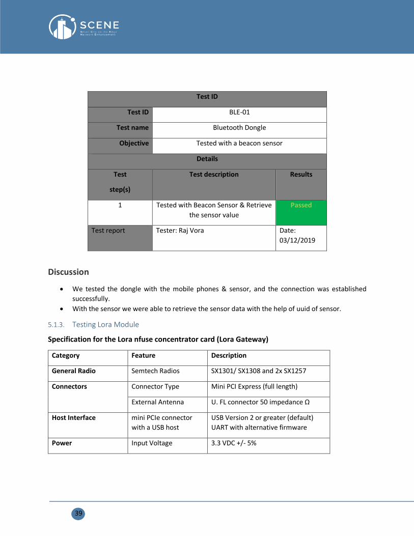
Test ID
Test ID BLE-01
Test name Bluetooth Dongle
Objective Tested with a beacon sensor
Details
Test
step(s)
Test description Results
1 Tested with Beacon Sensor & Retrieve
the sensor value
Passed
Test report Tester: Raj Vora Date:
03/12/2019
Discussion
• We tested the dongle with the mobile phones & sensor, and the connection was established
successfully.
• With the sensor we were able to retrieve the sensor data with the help of uuid of sensor.
5.1.3. Testing Lora Module
Specification for the Lora nfuse concentrator card (Lora Gateway)
Category Feature Description
General Radio Semtech Radios SX1301/ SX1308 and 2x SX1257
Connectors Connector Type Mini PCI Express (full length)
External Antenna U. FL connector 50 impedance Ω
Host Interface mini PCIe connector
with a USB host
USB Version 2 or greater (default)
UART with alternative firmware
Power Input Voltage 3.3 VDC +/- 5%

40
Consumption
TX (max): 450mA
RX (all channels): 340mA
Idle: 40mA
RF Frequency Range
863 to 870 MHz
915 to 928 MHz
Sensitivity
Up to -124 dBm at SF7, BW 125KHz
Up to -138dBm at SF12, BW 125kHz
Up to -125dBm at SF7, BW 125KHz
Up to -139dBm at SF12, BW 125kHz
Max RF Output Power Up to +21dBm
Status Indication LEDs, green Rx
Tx
Operating Conditions. Temperature
(operating)
-40 to +75°C
-40 to +70°C
The Tx power rises with lower
temperatures. It might be necessary
to limiting the TX power to comply
with your regulatory domain
Humidity 10% ~ 90% RH Non-condensing
Physical Properties Dimensions WxHxD 51 x 30 x 4.8mm (device)
51 x 30 x 1mm (PCB)
Specification for Netop Lora WAN temperature and humidity sensor
COMMUNICATION SPECIFICATIONS
• The sensor uses Low Power Wide Area Network-LPWAN technology (Lora) for connectivity
• Compliant with AS923, AU915, EU868, KR920, IN865 or US915 MHz ISM bands
• Low power consumption
• Long range wireless data transmission (up to 15km)
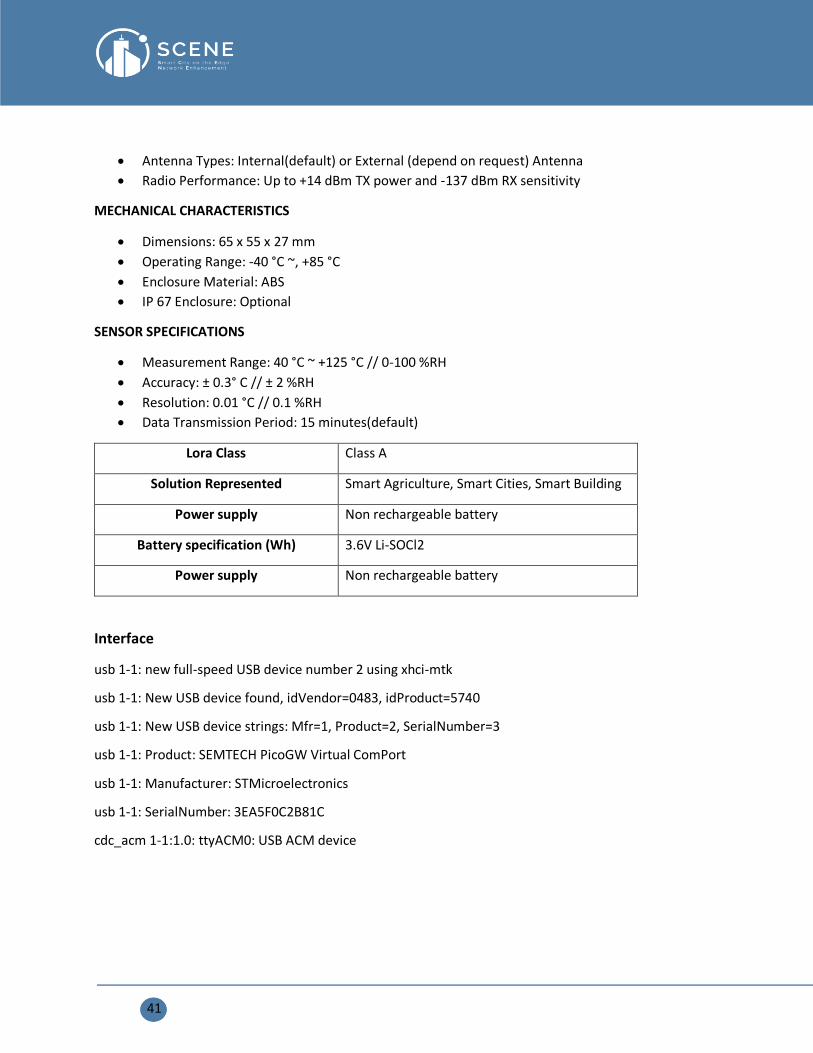
41
• Antenna Types: Internal(default) or External (depend on request) Antenna
• Radio Performance: Up to +14 dBm TX power and -137 dBm RX sensitivity
MECHANICAL CHARACTERISTICS
• Dimensions: 65 x 55 x 27 mm
• Operating Range: -40 °C ~, +85 °C
• Enclosure Material: ABS
• IP 67 Enclosure: Optional
SENSOR SPECIFICATIONS
• Measurement Range: 40 °C ~ +125 °C // 0-100 %RH
• Accuracy: ± 0.3° C // ± 2 %RH
• Resolution: 0.01 °C // 0.1 %RH
• Data Transmission Period: 15 minutes(default)
Lora Class Class A
Solution Represented Smart Agriculture, Smart Cities, Smart Building
Power supply Non rechargeable battery
Battery specification (Wh) 3.6V Li-SOCl2
Power supply Non rechargeable battery
Interface
usb 1-1: new full-speed USB device number 2 using xhci-mtk
usb 1-1: New USB device found, idVendor=0483, idProduct=5740
usb 1-1: New USB device strings: Mfr=1, Product=2, SerialNumber=3
usb 1-1: Product: SEMTECH PicoGW Virtual ComPort
usb 1-1: Manufacturer: STMicroelectronics
usb 1-1: SerialNumber: 3EA5F0C2B81C
cdc_acm 1-1:1.0: ttyACM0: USB ACM device

42
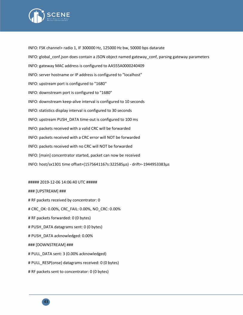
Logread
root@OpenWrt:/# pico_pkt_fwd /dev/ttyACM0 global_conf.json
*** Packet Forwarder for Lora PicoCell Gateway ***
Version: 0
*** Lora concentrator HAL library version info ***
Version: 0;
*** MCU FW version for LoRa PicoCell Gateway ***
Version: 0x010A0006
***
INFO: Little endian host
INFO: found a global configuration file global_conf.json, parsing it
INFO: global_conf.json does contain a JSON object named SX1301_conf, parsing SX1301 parameters
INFO: lorawan_public 1, clksrc 1
INFO: antenna_gain 0 dBi
INFO: Configuring TX LUT with 16 indexes
INFO: radio 0 enabled (type SX1257), center frequency 867500000, RSSI offset -164.000000, tx enabled 1
INFO: radio 1 enabled (type SX1257), center frequency 868500000, RSSI offset -164.000000, tx enabled 0
INFO: Lora multi-SF channel 0> radio 1, IF -400000 Hz, 125 kHz bw, SF 7 to 12
INFO: Lora multi-SF channel 1> radio 1, IF -200000 Hz, 125 kHz bw, SF 7 to 12
INFO: Lora multi-SF channel 2> radio 1, IF 0 Hz, 125 kHz bw, SF 7 to 12
INFO: Lora multi-SF channel 3> radio 0, IF -400000 Hz, 125 kHz bw, SF 7 to 12
INFO: Lora multi-SF channel 4> radio 0, IF -200000 Hz, 125 kHz bw, SF 7 to 12
INFO: Lora multi-SF channel 5> radio 0, IF 0 Hz, 125 kHz bw, SF 7 to 12
INFO: Lora multi-SF channel 6> radio 0, IF 200000 Hz, 125 kHz bw, SF 7 to 12
INFO: Lora multi-SF channel 7> radio 0, IF 400000 Hz, 125 kHz bw, SF 7 to 12
INFO: Lora std channel> radio 1, IF -200000 Hz, 250000 Hz bw, SF 7
43
INFO: FSK channel> radio 1, IF 300000 Hz, 125000 Hz bw, 50000 bps datarate
INFO: global_conf.json does contain a JSON object named gateway_conf, parsing gateway parameters
INFO: gateway MAC address is configured to AA555A0000240409
INFO: server hostname or IP address is configured to "localhost"
INFO: upstream port is configured to "1680"
INFO: downstream port is configured to "1680"
INFO: downstream keep-alive interval is configured to 10 seconds
INFO: statistics display interval is configured to 30 seconds
INFO: upstream PUSH_DATA time-out is configured to 100 ms
INFO: packets received with a valid CRC will be forwarded
INFO: packets received with a CRC error will NOT be forwarded
INFO: packets received with no CRC will NOT be forwarded
INFO: [main] concentrator started, packet can now be received
INFO: host/sx1301 time offset=(1575641167s:322585µs) - drift=-1944953383µs
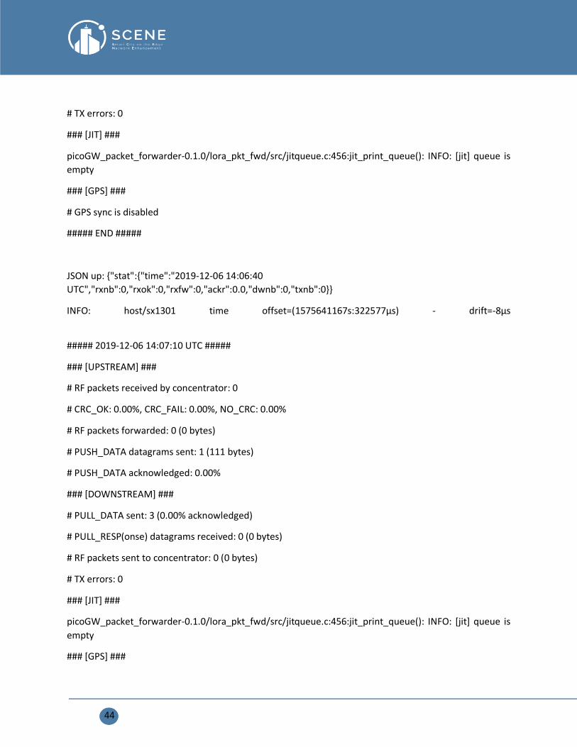
##### 2019-12-06 14:06:40 UTC #####
### [UPSTREAM] ###
# RF packets received by concentrator: 0
# CRC_OK: 0.00%, CRC_FAIL: 0.00%, NO_CRC: 0.00%
# RF packets forwarded: 0 (0 bytes)
# PUSH_DATA datagrams sent: 0 (0 bytes)
# PUSH_DATA acknowledged: 0.00%
### [DOWNSTREAM] ###
# PULL_DATA sent: 3 (0.00% acknowledged)
# PULL_RESP(onse) datagrams received: 0 (0 bytes)
# RF packets sent to concentrator: 0 (0 bytes)
44
# TX errors: 0
### [JIT] ###
picoGW_packet_forwarder-0.1.0/lora_pkt_fwd/src/jitqueue.c:456:jit_print_queue(): INFO: [jit] queue is
empty
### [GPS] ###
# GPS sync is disabled
##### END #####
JSON up: {"stat":{"time":"2019-12-06 14:06:40
UTC","rxnb":0,"rxok":0,"rxfw":0,"ackr":0.0,"dwnb":0,"txnb":0}}
INFO: host/sx1301 time offset=(1575641167s:322577µs) - drift=-8µs
##### 2019-12-06 14:07:10 UTC #####
### [UPSTREAM] ###
# RF packets received by concentrator: 0
# CRC_OK: 0.00%, CRC_FAIL: 0.00%, NO_CRC: 0.00%
# RF packets forwarded: 0 (0 bytes)
# PUSH_DATA datagrams sent: 1 (111 bytes)
# PUSH_DATA acknowledged: 0.00%
### [DOWNSTREAM] ###
# PULL_DATA sent: 3 (0.00% acknowledged)
# PULL_RESP(onse) datagrams received: 0 (0 bytes)
# RF packets sent to concentrator: 0 (0 bytes)
# TX errors: 0
### [JIT] ###
picoGW_packet_forwarder-0.1.0/lora_pkt_fwd/src/jitqueue.c:456:jit_print_queue(): INFO: [jit] queue is
empty
### [GPS] ###
45
# GPS sync is disabled
##### END #####
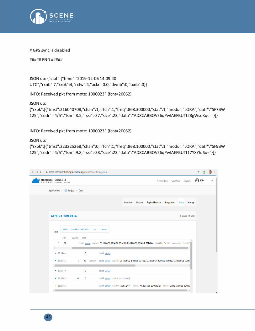
JSON up: {"stat":{"time":"2019-12-06 14:09:40
UTC","rxnb":7,"rxok":4,"rxfw":4,"ackr":0.0,"dwnb":0,"txnb":0}}
INFO: Received pkt from mote: 1000023F (fcnt=20052)
JSON up:
{"rxpk":[{"tmst":216040708,"chan":1,"rfch":1,"freq":868.300000,"stat":1,"modu":"LORA","datr":"SF7BW
125","codr":"4/5","lsnr":8.5,"rssi":-37,"size":23,"data":"AD8CABBQVE6qPwIAEFBUTt28gWsoKqc="}]}
INFO: Received pkt from mote: 1000023F (fcnt=20052)
JSON up:
{"rxpk":[{"tmst":223225268,"chan":0,"rfch":1,"freq":868.100000,"stat":1,"modu":"LORA","datr":"SF9BW
125","codr":"4/5","lsnr":9.8,"rssi":-38,"size":23,"data":"AD8CABBQVE6qPwIAEFBUTt17YXYhJSo="}]}
46
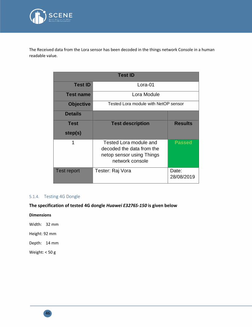
The Received data from the Lora sensor has been decoded in the things network Console in a human
readable value.
Test ID
Test ID Lora-01
Test name Lora Module
Objective Tested Lora module with NetOP sensor
Details
Test
step(s)
Test description Results
1 Tested Lora module and
decoded the data from the
netop sensor using Things
network console
Passed
Test report Tester: Raj Vora Date:
28/08/2019
5.1.4. Testing 4G Dongle
The specification of tested 4G dongle Huawei E3276S-150 is given below
Dimensions
Width: 32 mm
Height: 92 mm
Depth: 14 mm
Weight: < 50 g

47
Model E3276
Form USB Stick
Communication System
• FDD / TDD
• UMTS / HSUPA / HSPA+
• GSM / GPRS / EDGE
Speed
• High-speed LTE FDD packet data a service of up to 150 / 50 Mbit/s
• High-speed LTE TDD packet data a service of up to 112 / 10 Mbit/s
MicroSD Card Slot - Yes
Power supply 4.75V-5.25V / 700mA
E3276s-150 supports the following standards:
Long Term Evolution (LTE)
Dual Carrier High-speed packet access (DC-HSPA+)
High-speed packet access (HSPA+)
Universal Mobile Telecommunications System (UMTS)
Enhanced data rates for global evolution (EDGE)
General packet radio service (GPRS)
Global system for mobile communications (GSM)
The E3276s-150 provides the following services:
LTE packet data service
48
DC-HSPA+ packet data service
HSPA+ packet data service
HSUPA packet data service
HSDPA/UMTS packet data service
EDGE/GPRS packet data service
External Antenna Interface - Yes
Operation System
• Windows XP, Windows Vista, Windows 7
• Windows 8,Mac OS X 10.5,Mac OS X 10.6
• Mac OS X10.7,Mac OS X10.8
Receive Diversity - Yes
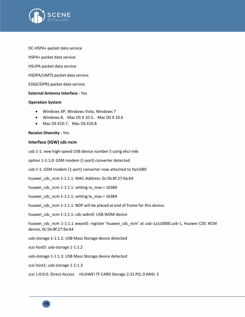
Interface (IGW) cdc-ncm
usb 1-1: new high-speed USB device number 5 using xhci-mtk
option 1-1:1.0: GSM modem (1-port) converter detected
usb 1-1: GSM modem (1-port) converter now attached to ttyUSB0
huawei_cdc_ncm 1-1:1.1: MAC-Address: 0c:5b:8f:27:9a:64
huawei_cdc_ncm 1-1:1.1: setting rx_max = 16384
huawei_cdc_ncm 1-1:1.1: setting tx_max = 16384
huawei_cdc_ncm 1-1:1.1: NDP will be placed at end of frame for this device.
huawei_cdc_ncm 1-1:1.1: cdc-wdm0: USB WDM device
huawei_cdc_ncm 1-1:1.1 wwan0: register 'huawei_cdc_ncm' at usb-1a1c0000.usb-1, Huawei CDC NCM
device, 0c:5b:8f:27:9a:64
usb-storage 1-1:1.2: USB Mass Storage device detected
scsi host0: usb-storage 1-1:1.2
usb-storage 1-1:1.3: USB Mass Storage device detected
scsi host1: usb-storage 1-1:1.3
scsi 1:0:0:0: Direct-Access HUAWEI TF CARD Storage 2.31 PQ: 0 ANSI: 2

49
scsi 0:0:0:0: CD-ROM HUAWEI Mass Storage 2.31 PQ: 0 ANSI: 2
sd 1:0:0:0: [sda] Attached SCSI removable disk
Configuration
config interface 'LTE'
option ifname 'wwan0'
option proto 'ncm'
option apn 'free'
option ipv6 'auto'
option mode 'auto'
option metric '100'
option delegate '0'
option device '/dev/cdc-wdm0'
option pdptype 'IP'
option pincode '0000'
option service 'preferlte'
option delay '20'
Note: -
• Change the apn and pin code according to the sim-card operator.
• It takes 1-2 minutes to configure with IGW.
• The ip address changes every time.
wwan0
Link encap:Ethernet HWaddr 0C:5B:8F:27:9A:64
inet addr:10.104.120.9 Bcast:10.104.120.11 Mask:255.255.255.252
inet6 addr: fe80::e5b:8fff:fe27:9a64/64 Scope:Link
UP BROADCAST RUNNING MULTICAST MTU:1500 Metric:1
RX packets:79 errors:0 dropped:0 overruns:0 frame:0
TX packets:91 errors:0 dropped:0 overruns:0 carrier:0

50
collisions:0 txqueuelen:1000
RX bytes:8571 (8.3 KiB) TX bytes:8734 (8.5 KiB)
Kernel IP routing table
Destination Gateway Genmask Flags Metric Ref Use Iface
0.0.0.0 10.104.120.10 0.0.0.0 UG 100 0 0 wwan0
10.104.120.8 0.0.0.0 255.255.255.252 U 100 0 0 wwan0
192.168.2.0 0.0.0.0 255.255.255.0 U 0 0 0 br-lan
Interface (IGW) cdc-ether
cdc_ether 1-1:1.0 eth2: register 'cdc_ether' at usb-ehci-platform-1, CDC Ethernet Device,
0c:5b:8f:27:9a:64
Network Configuration
config interface 'lte'
option ifname 'eth1'
option proto 'dhcp'
eth1
Link encap:Ethernet HWaddr 0C:5B:8F:27:9A:64
inet addr:192.168.1.100 Bcast:192.168.1.255 Mask:255.255.255.0
inet6 addr: fe80::e5b:8fff:fe27:9a64/64 Scope:Link
UP BROADCAST RUNNING MULTICAST MTU:1500 Metric:1
RX packets:79 errors:0 dropped:0 overruns:0 frame:0
TX packets:91 errors:0 dropped:0 overruns:0 carrier:0
collisions:0 txqueuelen:1000
RX bytes:8571 (8.3 KiB) TX bytes:8734 (8.5 KiB)
Note
• IP address does not change
• Configure the dongle with Computer or Laptop according to the sim card operator.
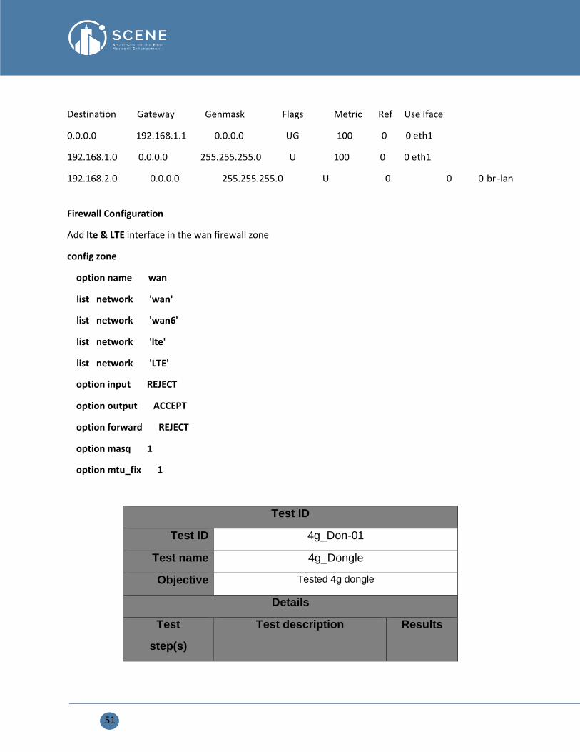
Kernel IP routing table
51
Destination Gateway Genmask Flags Metric Ref Use Iface
0.0.0.0 192.168.1.1 0.0.0.0 UG 100 0 0 eth1
192.168.1.0 0.0.0.0 255.255.255.0 U 100 0 0 eth1
192.168.2.0 0.0.0.0 255.255.255.0 U 0 0 0 br -lan
Firewall Configuration
Add lte & LTE interface in the wan firewall zone
config zone
option name wan
list network 'wan'
list network 'wan6'
list network 'lte'
list network 'LTE'
option input REJECT
option output ACCEPT
option forward REJECT
option masq 1
option mtu_fix 1
Test ID
Test ID 4g_Don-01
Test name 4g_Dongle
Objective Tested 4g dongle
Details
Test
step(s)
Test description Results
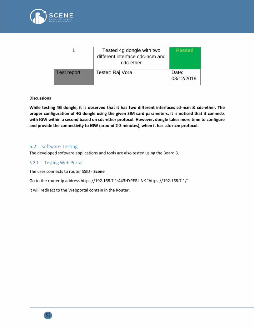
52
1 Tested 4g dongle with two
different interface cdc-ncm and
cdc-ether
Passed
Test report Tester: Raj Vora Date:
03/12/2019
Discussions
While testing 4G dongle, it is observed that it has two different interfaces cd-ncm & cdc-ether. The
proper configuration of 4G dongle using the given SIM card parameters, it is noticed that it connects
with IGW within a second based on cdc-ether protocol. However, dongle takes more time to configure
and provide the connectivity to IGW (around 2-3 minutes), when it has cdc-ncm protocol.
5.2. Software Testing The developed software applications and tools are also tested using the Board 3.
5.2.1. Testing Web Portal
The user connects to router SSID - Scene
Go to the router ip address https://192.168.7.1:443HYPERLINK "https://192.168.7.1/"
it will redirect to the Webportal contain in the Router.

53
Test identification
Test ID WP-01
Test name webportal_access
Objective Verify the Router ip address in the browser to redirect to the webportal.
Details
URLs https://192.168.7.1:443
Prerequisites
Initializations
Step(s) Test description Expected results Results

54
1 Test access with several
mobiles
Webportal main page is
displayed
Passed
Test report Tester: Raj Vora Date: 03/12/2019
Test identification
Test ID WP-02
Test name authentication
Objective Authenticate with portal default users
Details
URLs https://192.168.7.1:443/login
Prerequisites
Initializations
Step(s) Test description Expected results Results
1 Authenticate as a super
administrator
Authentication success Passed
2 Authenticate as an administrator Authentication success Passed
3 Authenticate as a user Authentication success Passed
Test report Tester: Fabrice Dislaire Date: 03/12/2019
Comments:
Test identification
Test ID WP-03
Test name languages_switch

55
Objective Switch displayed language
Details
URLs https://192.168.7.1:443/
Prerequisites Displaying portal main page
Initializations Change current language in main page popup menu
Step(s) Test description Expected results Results
1 Check the main page title
and subtitle
Displayed in the selected language Passed
2 Check categories names Displayed in the selected language Passed
3 Check thumbnails texts Displayed in the selected language Passed
Test report Tester: Fabrice Dislaire Date: 03/12/2019
Comments:
Test identification
Test ID WP-04
Test name content_browsing
Objective Verify content types displaying
Details
URLs https://192.168.7.1:443/
Prerequisites Displaying portal main page
Initializations Click on content thumbnail to open a content display page by type
Step(s) Test description Expected results Results
1 Display content type: video The video player widget is
displayed. Video could be played,
paused, stopped
Passed

56
2 Display content type: audio The audio player widget is
displayed. Audio file could be
played, paused, stopped
Passed
3 Display content type: image Image is displayed Passed
4 Display content type: article Article is displayed Passed
5 Display content type: PDF
file
The pdf file viewer widget is
displayed, pdf content could be
read.
Passed
6 Display content type:
external links to Webpages
The target Web page is displayed Passed
7 Display content type: RSS
feeds
The RSS feed articles could be
read. RSS feed update feature is
working.
Passed
Test report Tester: Fabrice Dislaire Date: 03/12/2019
Comments:
Test identification
Test ID WP-05
Test name content_creation
Objective Create content for each type
Details
URLs https://192.168.7.1:443/login
Prerequisites Log to the portal with administrator account
Initializations Select “Content” in backend interface, then “New item”
Step(s) Test description Expected results Results
1 Create a content type: video The content is created and
could be browsed
Passed
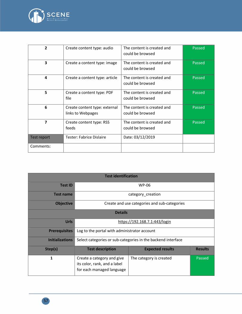
57
2 Create content type: audio The content is created and
could be browsed
Passed
3 Create a content type: image The content is created and
could be browsed
Passed
4 Create a content type: article The content is created and
could be browsed
Passed
5 Create a content type: PDF
file
The content is created and
could be browsed
Passed
6 Create content type: external
links to Webpages
The content is created and
could be browsed
Passed
7 Create content type: RSS
feeds
The content is created and
could be browsed
Passed
Test report Tester: Fabrice Dislaire Date: 03/12/2019
Comments:
Test identification
Test ID WP-06
Test name category_creation
Objective Create and use categories and sub-categories
Details
Urls https://192.168.7.1:443/login
Prerequisites Log to the portal with administrator account
Initializations Select categories or sub-categories in the backend interface
Step(s) Test description Expected results Results
1 Create a category and give
its color, rank, and a label
for each managed language
The category is created Passed

58
2 Create a sub-category and
give it a label for each
managed language
The sub-category is created Passed
3 Affect category to an
element
The element is shown in this
category on the main page
Passed
4 Affect sub-category to an
element
The element could be filtered
by the sub-category in the
category page display
Passed
Test report Tester: Fabrice Dislaire Date: 03/12/2019
Comments:
5.2.2. Testing Caching
Test ID
Test ID Ch-01
Test name Caching-page
Objective Check if the web page is caching
Details
Prerequisite Enter a web page into the Prefetch-list
and for the test: Add the line: http_access allow all in the file
/etc/squid/squid.conf and tmp/squid/squid.conf before the line http_access
deny all and, in those files, change the minimum size to 0 (line 5)
Initialization
Test
step(s)
Test description Expected results Results
1 Connect a phone
and go to the web
page previously
In the access.log file, we can
see if our phone load the
page from the proxy (with
the command MEM-HIT)
Passed

59
enter in the API
Prefetch-list/add
2 Check if videos
chunks are cached
same passed
3 Check if webpages
are cached with
there .CSS
dependence files
same Passed
4 Check if recursive
webpages are
cached
same Passed
5 Check if recursive
webpages are
cached with there
.CSS dependence
files
same
Passed
6 Check if the WEB
portal is NOT cached
No trace of the WEB portal in
access.log
Passed
Test report Tester: Loïck VIGNERON--COUTIN Date: 05/06/2019
Comments: Webpages and videos chuncks are cached from the content server. To see if they are,
use the follow command line:
-access.log path: /nf_cache_dir/cache/access.log
The API prefetch-list/add does not accept the URL of the content server.
For step 3-4, recursive web page and .CSS dependencies are going well, in the access.log there are
MEM_HIT for .CSS files and REFRESH_MODIFIED for .PHP files
For step 5, using Wireshark we see that the Web portal is using port 443 (https port, so cannot be
cached)
Squid configuration

60
To make the caching work, we change some option into the
squid configuration file /etc/config/squid.conf :
First, change the minimum size to 0 KB (line 5)
and add the line 'http_access allow all' before
the line 'http_access deny all'.
Restart squid.
5.2.3. Testing Captive Portal
When the User connect to the router SSID- Scene, it will automatically redirect to the captive portal login
page.
After successful login or register, the user will receive the token for one hour to access the internet and it
will redirect to the jcp home page where the user clicks the web portal link and it will redirect to the Jcp-
Webportal.

61
Test ID
Test ID CP-01
Test name Captive portal
Objective User should redirect to home page after successful login when connects to
Wi-Fi network
Details
Test
step(s)
Test description Expected results Results
1 Tested with
Several Mobiles
Some works as expected and
Some have a problem of page
disappearance.
Passed Partially
Test report Tester: Raj Vora Date: 03/12/2019
Test Results
While testing a captive portal with several mobiles, I had following Test Result
• Some mobiles have a different behavior like after successful login the home page disappear within
a second.

62
• Note: - Received the token for accessing the internet
This is due to the configuration in the mobile browser or the configuration of wifidog. So, we need more
time to investigate these issues.
• Some mobiles work as expected.
• When the user login is successful and the captive portal assign the token for 2 hours to user but
after, when we restart the wifidog server and the same user try to login again it displays the msg
about:blank#blocked.(No internet)
• When the same user tries to login again after 2 hours, the webpage remembers the login details
(figure shown below), the user will click on the start internet button
After the user click on the start internet button there is a display message about:blank#blocked.(figure
shown below) (No internet)

63
5.2.4. Captive-portal Configuration
# Set this to the node ID on the auth server
# This is used to give a customized login page to the clients and for
# monitoring/statistics purpose. If you run multiple gateways on the same
# machine each gateway needs to have a different gateway id.
# If none is supplied, the mac address of the Gateway Interface interface will be used,
# without the: separators
GatewayID JCP-Connect
# Set this to the internal interface (typically your wifi interface).
# Typically br-lan for Openwrt (by default the wifi interface is bridged with wired lan in openwrt)
# and eth1, wlan0, ath0, etc. otherwise
# You can get this interface with the ifconfig command and finding your wifi interface
GatewayInterface br-lan
# Parameter: AuthServer
# Default: NONE
# Mandatory, repeatable
#
# This allows you to configure your auth server(s). Each one will be tried in order, untill one responds.
# Set this to the hostname or IP of your auth server(s), the path where
# WiFiDog-auth resides in and the port it listens on.
#AuthServer {
# Hostname (Mandatory; Default: NONE)
# SSLAvailable (Optional; Default: no; Possible values: yes, no)
# SSLPort (Optional; Default: 443)
# HTTPPort (Optional; Default: 80)
# Path (Optional; Default: /wifidog/ Note: The path must be both prefixed and suffixed by /. Use a
single / for server root.)

64
# LoginScriptPathFragment (Optional; Default: login/? Note: This is the script the user will be sent to
for login.)
# PortalScriptPathFragment (Optional; Default: portal/? Note: This is the script the user will be sent to
after a successfull login.)
# MsgScriptPathFragment (Optional; Default: gw_message.php? Note: This is the script the user will
be sent to upon error to read a readable message.)
# PingScriptPathFragment (Optional; Default: ping/? Note: This is the wifidog-ping protocol. See
http://dev.wifidog.org/wiki/doc/developer/WiFiDogProtocol_V1)
# AuthScriptPathFragment (Optional; Default: auth/? Note: This is the wifidog-auth protocol. See
http://dev.wifidog.org/wiki/doc/developer/WiFiDogProtocol_V1)
#}
# If SSLAvailable is set, then the client will be redirected to the
# auth daemon on its HTTPS port. If Wifidog is compiled with SSL support,
# then Wifidog will also use HTTPS to talk to the auth server instead of
# plain HTTP.
AuthServer {
Hostname wifidog-auth.lan
HTTPPort 2323
Path /
PortalScriptPathFragment /public/index.php?
}
# Parameter: Daemon
# Default: 1
# Optional
#
# Set this to true if you want to run as a daemon
# Daemon 1
# Parameter: GatewayPort

65
# Default: 2060
# Optional
# Redirect http traffic of knowns & probation users
# to a local transparent proxy listening on ProxyPort port
ProxyPort 3128
# Parameter: HTTPDMaxConn
# Default: 10
# Optional
# How many sockets to listen to
HTTPDMaxConn 300
# Parameter: CheckInterval
# Default: 60
# Optional
# How many seconds should we wait between timeout checks. This is also
# how often the gateway will ping the auth server and how often it will
# update the traffic counters on the auth server. Setting this too low
# wastes bandwidth, setting this too high will cause the gateway to take
# a long time to switch to it's backup auth server(s).
# CheckInterval 60
# Set this to the desired of number of CheckInterval of inactivity before a client is logged out
# The timeout will be INTERVAL * TIMEOUT
ClientTimeout 7200
# Check DNS health by querying IPs of these hosts
PopularServers kernel.org,ieee.org
# Comma separated list of MAC addresses who are allowed to pass
# through without authentication.

66
# N.B.: weak security, since MAC addresses are easy to spoof.
#
TrustedMACList B0:38:29:44:77:1Ec
# Rule Set: validating-users
#
# Used for new users validating their account
FirewallRuleSet validating-users {
FirewallRule allow to 0.0.0.0/0
}
# Rule Set: known-users
#
# Used for normal validated users.
FirewallRuleSet known-users {
FirewallRule allow to 0.0.0.0/0
}
# Rule Set: unknown-users
#
# Used for unvalidated users, this is the ruleset that gets redirected.
# XXX The redirect code adds the Default DROP clause.
FirewallRuleSet unknown-users {
# Use to-ipset to block or allow externally specified hosts.
# Ipsets are created with the ipset utility. This is useful to
# block or allow hosts at runtime externally.
# For example, if your auth server requires users to log in
# via Facebook, use the ipset feature built into dnsmasq to
# to populate a list of various IPs used by the Facebook networks.

67
#FirewallRule allow to-ipset fb
FirewallRule allow udp port 53
FirewallRule allow tcp port 53
FirewallRule allow udp port 67
FirewallRule allow tcp port 67
}
# Rule Set: locked-users
#
# Not currently used
FirewallRuleSet locked-users {
FirewallRule block to 0.0.0.0/0
}
Discussions
In this part, we performed several tests on the mobile phone to check the captive portal performance. As
a result, we find that some mobiles work properly as expected but more improvement and time are
needed to figure out some issues on the page disappearance in several mobiles. Specifically, this concern
may be related to either a mobile browser configuration or Wifidog server configuration.
68
6. CONCLUSION
This document presents an initial hardware prototype for the SCENE platform. The block diagrams, and
technical specification of each hardware board is provided. Each board is evaluated based on the different
hardware and software modules. It is observed that board 3 is stable and performs good compared to
other two boards. The third board is further evaluated based on various available interfaces such as Wi-Fi,
BLE, Lora WAN, and 4G. In addition, the developed software applications and tools are also evaluated to
assure that this board 3 is suitable for the first pilot test in Catania city, Italy.