
D-Sub InduCom - Famous Connections
420
05 167 D-Sub D-Sub InduCom 66 63 009 6016 66 63 009 6004 InduCom 9 – Industrial bus interface system Identification Part No. General information CAN Interface The Controller Area Network (CAN)-Interface is specially designed for usage in trains. With this interface it is possible to realise a T-bus structure with which you can disconnect the bus interface from the control unit without any interruption of the complete bus communication. On the PCB you will have a load resistor which can be activated with the switch.* Components of the interface set: ● 1 metal housing with 2 cable entries ● 2 hexagonal screws with UNC 4-40 threads ● 1 PCB with 9 way D-Sub female connector and 2 cage clamps ● 1 blanking piece ● 2 crimp flanges ● 2 crimp ferrules Profibus Interface The Profibus Interface is specially designed for usage in trains and in challenging engineering applications. On the PCB you will have SMD parts which can be activated with solder bridges. The wires are assembled with the proven vibration resistant cage clamp technology.* Components of the interface set: ● 1 metal housing with 2 cable entries ● 2 hexagonal screws with UNC 4-40 threads ● 1 PCB with 9 way D-Sub female connector and 2 cage clamps ● 1 blanking piece Further bus PCBs on request * To check compatibility with cable types and manufacturers, please contact your local HARTING representative.
-
Upload
khangminh22 -
Category
Documents
-
view
0 -
download
0
Transcript of D-Sub InduCom - Famous Connections

05167
D-Su
b
D-Sub InduCom
66 63 009 6016
66 63 009 6004
InduCom 9 – Industrial bus interface system
Identification Part No. General information
CAN Interface The Controller Area Network (CAN)-Interface is specially designed for usage in trains. With this interface it is possible to realise a T-bus structure with which you can disconnect the bus interface from the control unit without any interruption of the complete bus communication. On the PCB you will have a load resistor which can be activated with the switch.*
Components of the interface set:
● 1 metal housing with 2 cable entries
● 2 hexagonal screws with UNC 4-40 threads
● 1 PCB with 9 way D-Sub female connector and 2 cage clamps
● 1 blanking piece
● 2 crimp flanges
● 2 crimp ferrules
Profibus Interface The Profibus Interface is specially designed for usage in trains and in challenging engineering applications.
On the PCB you will have SMD parts which can be activated with solder bridges.
The wires are assembled with the proven vibration resistant cage clamp technology.*
Components of the interface set:● 1 metal housing with 2 cable entries ● 2 hexagonal screws with UNC 4-40 threads● 1 PCB with 9 way D-Sub female connector and
2 cage clamps ● 1 blanking piece
Further bus PCBs on request* To check compatibility with cable types and manufacturers, please contact your local HARTING representative.

05168
D-Su
b
D-Sub InduCom
66 63 009 5017
66 63 009 5018
InduCom 9 – Industrial bus interface system
Identification Part No. General information
FIP Interface middle of the line
FIP Interface end of the line
The FIP (Factory Installation Protocol) Interface is specially designed for applications in trains. It is connected via the D-Sub. The wires are assembled with the proven vibration resistant cage clamp technology.*
Components of the interface set:
l 1 metal housing with 2 cable entries
l 2 hexagonal screws with UNC 4-40 threads
l 1 pcb with 9 way D-Sub female connector and cage clamps
The FIP (Factory Installation Protocol) Interface is specially designed for applications in trains. It is connected via the D-Sub. On the pcb you will have load resistors. The wires are assembled with the proven vibration resistant cage clamp technology.*
Components of the interface set:
l 1 metal housing with 2 cable entries
l 2 hexagonal screws with UNC 4-40 threads
l 1 pcb with 9 way D-Sub female connector and cage clamps
l 1 blanking piece
Further bus PCBs on request* To check compatibility with cable types and manufacturers, please contact your local HARTING representative.

05169
D-Su
b
D-Sub
9-50 09 67 000 99721)
9-50 09 67 000 99741)
9-50 09 67 001 99761)
9-50 09 67 001 99741)
9-50 09 67 001 99411)
9-50 09 67 001 99541)
4-40 UNC 4-40 UNC 4-40 UNC M3
4-40 UNC 4-40 UNC 4-40 UNC M3
M3 4-40 UNC M3 M3
4-40 UNC 4-40 UNC
9-50 09 66 000 99721)2)
9-50 09 66 000 99741)2)
4-40 UNC 4-40 UNC 4-40 UNC M3
9-50 09 67 001 99571)
No. ofIdentification contacts Part No. Drawing Dimensions in mm
Accessories
1) Order 2 for each connector 2) M3 inner thread available on request
Female screw lockswithout nut
Thread UNC/UNC Thread UNC/M3
Thread M3/UNC Thread M3/M3
Thread UNC/UNC Thread UNC/M3
for press-in connectors with grounding-pins or straight solder with grounding-clips.
Thread UNC/UNC
Thread UNC/M3
with captive washer Thread UNC/UNC

05170
D-Su
b
D-Sub
9-37 09 67 001 99691) 50 09 67 001 99701)
9-50 09 67 001 9985
9-50 09 67 002 9120
9-50 09 67 000 99221)
9-50 09 67 000 99241)
9-50 09 67 000 99731)
4-40 UNC 4-40 UNC
4-40 UNC 4-40 UNC
4-40 UNC
4-40 UNC M3
9-50 09 67 001 99281)
9-50 09 67 002 90301)
No. ofIdentification contacts Part No. Drawing Dimensions in mm
Accessories
1) Order 2 for each connector
Female screw lockswith nut
Thread UNC/UNC
Thread UNC/M3
Thread UNC/UNC
Male screw locksfor use without hood
Hex extender
U-Clipwith thread 4-40 UNC
with thread 4-40 UNC and screw-lock
Thread 4-40 UNC
Thread M3M3 or
4-40 UNC

05171
D-Su
b
9 09 67 009 0611 15 09 67 015 0611 25 09 67 025 0611 37 09 67 037 0611
9 09 67 009 0711 15 09 67 015 0711 25 09 67 025 0711 37 09 67 037 0711
9 09 67 009 0612 15 09 67 015 0612 25 09 67 025 0612 37 09 67 037 0612 50 09 67 050 0612
9 09 67 009 0712 15 09 67 015 0712 25 09 67 025 0712 37 09 67 037 0712 50 09 67 050 0712
9 09 67 009 0613 15 09 67 015 0613 25 09 67 025 0613 37 09 67 037 0613 50 09 67 050 0613
9 09 67 009 0713 15 09 67 015 0713 25 09 67 025 0713 37 09 67 037 0713 50 09 67 050 0713
Dust capblack thermoplastic
for male connector
for female connector
anstistaticblack thermoplastic
for male connector
for female connector
UL 94 V0grey thermoplastic
for male connector
for female connector
No. ofIdentification contacts Part No. Drawing Dimensions in mm
Accessories
D-Sub
A B 9 17.0 22.4015 25.3 30.8025 38.9 44.4037 55.4 60.75
A B 9 16.0 22.515 24.4 31.025 37.8 44.337 54.3 60.8
A B C D 9 17.7 21.8 13.2 9.115 26.0 30.0 13.2 9.125 40.0 44.2 13.2 9.137 56.4 59.8 13.2 9.150 53.9 57.8 15.9 11.7
A B C D 9 15.9 20.0 11.8 7.815 24.4 28.5 11.8 7.825 38.3 42.3 11.8 7.837 54.7 58.8 11.8 7.850 52.6 56.2 14.5 10.5
A B C D 9 17.7 21.8 13.2 9.115 26.0 30.0 13.2 9.125 40.0 44.2 13.2 9.137 56.4 59.8 13.2 9.150 53.9 57.8 15.9 11.7
A B C D 9 15.9 20.0 11.8 7.815 24.4 28.5 11.8 7.825 38.3 42.3 11.8 7.837 54.7 58.8 11.8 7.850 52.6 56.2 14.5 10.5

05172
D-Su
b
9 09 67 009 0714 15 09 67 015 0714 25 09 67 025 0714 37 09 67 037 0714 50 09 67 050 0714
9 09 67 009 0715 15 09 67 015 0715 25 09 67 025 0715 37 09 67 037 0715 50 09 67 050 0715
9 09 67 009 0614 15 09 67 015 0614 25 09 67 025 0614 37 09 67 037 0614 50 09 67 050 0614
9 09 67 009 0615 15 09 67 015 0615 25 09 67 025 0615 37 09 67 037 0615 50 09 67 050 0615
Dust capmetallized thermoplastic
No. ofIdentification contacts Part No. Drawing Dimensions in mm
Accessories
D-Sub
A B C D 9 17.7 21.8 13.2 9.115 26.0 30.0 13.2 9.125 40.0 44.2 13.2 9.137 56.4 59.8 13.2 9.150 53.9 57.8 15.9 11.7
A B C D 9 17.5 19.6 11.1 9.215 25.7 27.8 11.1 9.225 39.6 41.8 11.1 9.237 55.7 57.4 11.1 9.250 53.4 55.3 13.8 11.9
A B C D 9 15.9 20.0 11.8 7.815 24.4 28.5 11.8 7.825 38.3 42.3 11.8 7.837 54.7 58.8 11.8 7.850 52.6 56.2 14.5 10.5
A B C D 9 16.2 18.0 9.6 7.815 24.6 26.4 9.6 7.825 38.4 40.2 9.6 7.837 54.4 56.2 9.6 7.850 52.0 53.7 12.2 10.4
metallized thermoplastic with chain
for male connector
for male connector
for female connector
for female connector

05173
D-Su
b
M FM F
M F
M F M F
D-Sub Standard press-in connectors Technical characteristics
Current carrying capacityThe current carrying capacity is limited by maximum temperature of materials for inserts and contacts including terminals.
The current capacity-curve is valid for continuous, not interrupted current-loaded contacts of connectors when simultaneous power on all contacts is given, without exceeding the maximum tempera-ture.
Control and test procedures according to DIN IEC 60 512.
Contact arrangement View from termination side
Mating conditions as per DIN 41 652
M = Male connectorF = Female connector
Wor
king
cur
rent
Ambient temperature
Example: 25 way connector
➀ Stamped contacts
1) Performance level 3, 50 mating cycles, no gas test Performance level 2 as per CECC 75 301-802, 250 mating cycles, 4 days 4 mixed gas test – IEC 60 512 Performance level 1 as per CECC 75 301-802, 500 mating cycles, 10 days 4 mixed gas test – IEC 60 512
37 way 50 way
9 way15 way
25 way
Number of contacts 9, 15, 25, 37, 50 UL recognized
Working currentsee current carrying capacity chart Stamped contacts 6.5 A max.
Test voltage Ur.m.s. 1 kV
Clearance and creepage � 1.0 mm
Contact resistance � 10 m� Insulation resistance � 1010 �
Temperature range -55 OC … +125 OCThe higher temperature limit includes the local ambient and heating effect of the contacts under load
Terminations Recommended PCB through holes
Materials Mouldings and hoods Liquid Crystal Polymer (LCP)
UL 94-V0
Contacts Copper alloy
Contact surface
Contact zone selectively plated acc. to performance level1)
Metal shell Plated steel
Insertion and withdrawal forceConnector on P.C.B. Press-in without grounding pins – insertion max. per contact: � 120 N – withdrawal min. per contact: � 20 N Press-in with grounding pins – insertion max. per grounding pin: � 250 N – withdrawal min. per grounding pin: � 30 N
Mating force 9 way � 30 N 15 way � 50 N 25 way � 83 N
37 way � 123 N 50 way � 167 N
Signal pin Grounding pin
Tin-lead plated PCB Hole 1.15-0.03 3.15±0.025 Cu 25-75 μm 25-75 μm Sn 5-15 μm 4-10 μm Plated hole 0.94-1.09 mm 3.0-3.15 mm
Chemical Hole 1.05-0.03 3.15±0.025 tin-plated PCB Cu 25-50 μm 25-50 μm Sn 0.8-1.0 μm 0.8-1.0 μm Plated hole 1.00-1.10 mm 3.0-3.15 mm
Au / Ni plated PCB Hole 1.15-0.03 3.15±0.025 Cu 25-50 μm 25-50 μm Ni 3-7 μm 4-7 μm Au 0.05-0.12 μm 0.05-0.12 μm Plated hole 1.00-1.10 mm 3.0-3.15 mm
Silver plated PCB Hole 1.15-0.03 3.15±0.025 Cu 25-50 μm 25-50 μm Ag 0.1-0.3 μm 0.1-0.3 μm Plated hole 1.00-1.10 mm 3.0-3.15 mm
OSP Hole 1.15-0.03 3.15±0.025 copper plated PCB Cu 25-50 μm 25-50 μm Plated hole 1.00-1.10 mm 3.0-3.15 mm
PCB board thickness: � 1.6 mm

05174
D-Su
b
D-Sub DIN 41 652 · CECC 75 301-802
9 09 66 164 771 . 09 66 164 671 .
15 09 66 264 771 . 09 66 264 671 .
25 09 66 364 771 . 09 66 364 671 .
9 09 66 154 751 . 09 66 154 651 .
15 09 66 254 751 . 09 66 254 651 .
25 09 66 354 751 . 09 66 354 651 .
37 09 66 454 751 . 09 66 454 651 .
9 09 66 154 751 . 09 66 154 651 .
15 09 66 254 751 . 09 66 254 651 .
25 09 66 354 751 . 09 66 354 651 .
37 09 66 454 751 . 09 66 454 651 .
50 09 66 554 751 . 09 66 554 651 .
Performance levelsExplanations see page 05.173 �Other performance levels on request
Male connectorFlange height x = 5.7 mm
metal shell with dimples
Please insert digit for flange thread or fitted female screw locks
Performance level
3Performance level
2
No. ofIdentification contacts Part No.
Press-in, straight with grounding press-in board locks
Number of contacts
9--50
M3 � 5 4-40 UNC � 6 fitted screw locks 4-40 UNC � 1)71)
Female connectorFlange height x = 5.7 mm
metal shell
Please insert digit for flange thread or fitted female screw locks
M3 � 5 4-40 UNC � 6 fitted screw locks 4-40 UNC � 1)71)
Female connectorFlange height x = 6 mm
metal shell
Please insert digit for flange thread or fitted female screw locks
M3 � 1 4-40 UNC � 2 fitted screw locks 4-40 UNC � 1)31)
1) Fitted screw locks 4-40 UNC not normally kept in stock for performance level 3Connector dimensions see page 05.175. Mating conditions see page 05.173.

05175
D-Su
b
D-Sub DIN 41 652 · CECC 75 301-802
9-37 50
Press-in, straight with grounding press-in board locks
Number of contacts
9--50
Identification Drawing Dimensions in mm
Male connector9 – 25 contacts
Female connector9 – 37 contacts
Board drillings
a b g h
9 31.00 24.90 4 x 2.74 = 10.96 3 x 2.74 = 8.22
15 39.30 33.20 7 x 2.74 = 19.18 6 x 2.74 = 16.44
25 53.10 47.00 12 x 2.76 = 33.12 11 x 2.76 = 30.36
37 69.65 63.55 18 x 2.76 = 49.68 17 x 2.76 = 46.92
50 67.00 61.10 16 x 2.76 = 44.16 15 x 2.76 = 41.40
X Y Z
6.0 ± 0.2 4.20 ± 0.2 3.5 max.
5.7 ± 0.2 4.35 ± 0.2 3.9 max.
Female connector50 contacts
Mating face acc. to: DIN 41 652 · CECC 75 301-802 · IEC 60 807
contact grounding board lock
M3 or 4 - 40 UNC
fitted screw locks4 - 40 UNC
M3 or 4 - 40 UNC
fitted screw locks4 - 40 UNC
M3 or 4 - 40 UNC
fitted screw locks4 - 40 UNC
mark for 5.7 mm version
No. 1 contact
No. 1 contact
contact grounding board lock
Plated through hole

05176
D-Su
b
D-Sub DIN 41 652 · CECC 75 301-802
9 09 66 124 770 . 09 66 124 670 .
15 09 66 224 770 . 09 66 224 670 .
25 09 66 324 770 . 09 66 324 670 .
9 09 66 114 750 . 09 66 114 650 .
15 09 66 214 750 . 09 66 214 650 .
25 09 66 314 750 . 09 66 314 650 .
37 09 66 414 750 . 09 66 414 650 .
9 09 66 114 750 . 09 66 114 650 .
15 09 66 214 750 . 09 66 214 650 .
25 09 66 314 750 . 09 66 314 650 .
37 09 66 414 750 . 09 66 414 650 .
50 09 66 514 750 . 09 66 514 650 .
Performance levelsExplanations see page 05.173 �Other performance levels on request
Male connectorFlange height x = 5.7 mm
metal shell with dimples
Please insert digit for flange thread or fitted female screw locks
Performance level
3Performance level
2
No. ofIdentification contacts Part No.
Press-in, straight without grounding press-in board locks
Number of contacts
9--50
ø 3.1 mm hole � 1)41)
M3 � 5 4-40 UNC � 6 fitted screw locks 4-40 UNC � 1)72)
Female connectorFlange height x = 5.7 mm
metal shell
Please insert digit for flange thread or fitted female screw locks
ø 3.1 mm hole � 1)41)
M3 � 5 4-40 UNC � 6 fitted screw locks 4-40 UNC � 1)72)
Female connectorFlange height x = 6 mm
metal shell
Please insert digit for flange thread or fitted female screw locks
ø 3.1 mm hole � 1)01)
M3 � 1 4-40 UNC � 2 fitted screw locks 4-40 UNC � 1)32)
1) Not normally kept in stock2) Fitted screw locks 4-40 UNC not normally kept in stock for performance level 3Connector dimensions see page 05.177. Mating conditions see page 05.173.

05177
D-Su
b
D-Sub DIN 41 652 · CECC 75 301-802
9-37 50
Press-in, straight without grounding press-in board locks
Number of contacts
9--50
Identification Drawing Dimensions in mm
Male connector9 – 25 contacts
Female connector9 – 37 contacts
Female connector50 contacts
Board drillings
a b g h
9 31.00 24.90 4 x 2.74 = 10.96 3 x 2.74 = 8.22
15 39.30 33.20 7 x 2.74 = 19.18 6 x 2.74 = 16.44
25 53.10 47.00 12 x 2.76 = 33.12 11 x 2.76 = 30.36
37 69.65 63.55 18 x 2.76 = 49.68 17 x 2.76 = 46.92
50 67.00 61.10 16 x 2.76 = 44.16 15 x 2.76 = 41.40
X Y
6.0 ± 0.2 4.20 ± 0.2
5.7 ± 0.2 4.35 ± 0.2
Press-in pins from position 34 to 50 are reversed 180 degrees
M3 or 4 - 40 UNC
fitted screw locks4 - 40 UNC
No. 1 contact
M3 or 4 - 40 UNC
fitted screw locks4 - 40 UNC
M3 or 4 - 40 UNC
fitted screw locks4 - 40 UNC
Mating face acc. to: DIN 41 652 · CECC 75 301-802 · IEC 60 807
Mating face acc. to: DIN 41 652 · CECC 75 301-802 · IEC 60 807
mark for 5.7 mm version
No. 1 contact
mark for 5.7 mm version

05178
D-Su
b
M FM F
M F
M F
D-Sub Standard SMC connectors Technical characteristics
Current carrying capacityThe current carrying capacity is limited by maximum temperature of materials for inserts and contacts including terminals.
The current capacity-curve is valid for continuous, not interrupted current-loaded contacts of connectors when simultaneous power on all contacts is given, without exceeding the maximum tempera-ture.
Control and test procedures according to DIN IEC 60 512.
Contact arrangement View from termination side
Mating conditions as per DIN 41 652
M = Male connectorF = Female connector
37 way
Wor
king
cur
rent
Ambient temperature
Example: 25 way connector
➀ Stamped contacts
1) Performance level 3, 50 mating cycles, no gas test Performance level 2 as per CECC 75 301-802, 250 mating cycles, 4 days 4 mixed gas test – IEC 60 512 Performance level 1 as per CECC 75 301-802, 500 mating cycles, 10 days 4 mixed gas test – IEC 60 512
9 way15 way
25 way
Number of contacts 9, 15, 25, 37 UL recognized
Working currentsee current carrying capacity chart Stamped contacts 6.5 A max.
Test voltage Ur.m.s. 1 kV
Clearance and creepage � 1.0 mm
Contact resistance � 10 m� Insulation resistance � 1010 �
Temperature range -55 OC … +125 OC during reflow soldering max. + 240 OC for 15 s
The higher temperature limit includes the local ambient and heating effect of the contacts under load. All connectors are suitable for standard reflow processes.
Terminations a) Solder pins Ø 0.6 mm for P.C.B. holes Ø 0.8/1 mm
b) Solder pins, angled 90O Ø 0.6 mm for P.C.B. holes Ø 1 mm
Materials Mouldings Thermoplastic resin, glass-
fibre filled (PCT), UL 94-V0
Contacts Copper alloy
Contact surface Contact zone selectively gold-plated
according to performance level1)
Metal shell Plated steel
Insertion and withdrawal forceConnector on P.C.B. Solder, straight with clips – insertion max. per connector: � 60 N – withdrawal min. per connector: � 10 N
Mating force 9 way � 30 N 15 way � 50 N 25 way � 83 N 37 way � 123 N

05179
D-Su
b
D-Sub
7,6
Identification Drawing Dimensions in mm
Mounting details
Standard VersionsMounting height 7.3 mm
9-37 wayfor front panel4 units of width (TE)
for connectors see pages 05.182 – 05.183
Low-Profile VersionsMounting height 3.6 mm
9-37 wayfor front panel3 units of width (TE)
for connectors see pages 05.184 – 05.185
Ø 3.1 ± 0.1
Ø 3.1 ± 0.1
plated through hole
only forsnap-in-clips version
Panel cut out for front/rear mount
Values are taken from the CECC 75 301-802
a±0.2 b±0.13 c±0.2
9 20.5 25.0 11.4 15 28.8 33.3 11.4 25 42.5 47.0 11.4 37 59.1 63.5 11.4 50 56.3 61.1 14.1
a±0.2 b±0.13 c±0.2
9 22.2 25.0 12.3 15 30.5 33.3 12.3 25 44.3 47.0 12.3 37 60.7 63.5 12.3 50 58.3 61.1 15.1
Front mount Rear mount

05180
D-Su
b
D-Sub DIN 41 652 · CECC 75 301-802
9 09 66 115 750 . 09 66 115 650 . 15 09 66 215 750 . 09 66 215 650 . 25 09 66 315 750 . 09 66 315 650 . 37 09 66 415 750 . 09 66 415 650 .
9 09 66 155 751 . 09 66 155 651 . 15 09 66 255 751 . 09 66 255 651 . 25 09 66 355 751 . 09 66 355 651 . 37 09 66 455 751 . 09 66 455 651 .
9 09 65 129 770 . 09 65 129 670 . 15 09 65 229 770 . 09 65 229 670 . 25 09 65 329 770 . 09 65 329 670 . 37 09 65 429 770 . 09 65 429 670 .
9 09 65 169 771 . 09 65 169 671 . 15 09 65 269 771 . 09 65 269 671 . 25 09 65 369 771 . 09 65 369 671 . 37 09 65 469 771 . 09 65 469 671 .
1) Fitted screw locks 4-40 UNC not normally kept in stock for performance level 3Connector dimensions see page 05.181. Mating conditions see page 05.178.
Performance levelsExplanations see page 05.178 �Other performance levels on request
Male connectormetal shell with dimples
Female connectormetal shell
Please insert digit for flange thread or fitted female screw locks
Performance level3
Performance level2
No. ofIdentification contacts Part No.
SMC stamped solder pins, straight with/without grounding board locks
Number of contacts
9--37
Without grounding board locks
With grounding board locks
Without grounding board locks
With grounding board locks
M3 � 1 4-40 UNC � 2 fitted screw locks 4-40 UNC � 3 1)

05181
D-Su
b
D-Sub DIN 41 652 · CECC 75 301-802
Identification Drawing Dimensions in mm
Male connector
Female connector
Board drillings
SMC stamped solder pins, straight with/without grounding board locks
Number of contacts
9--37
a b±0.1 c g h
9 30.9 25.0 12.5 4 x 2.74 = 10.96 3 x 2.74 = 8.22
15 39.2 33.3 12.5 7 x 2.74 = 19.18 6 x 2.74 = 16.44
25 53.1 47.0 12.5 12 x 2.76 = 33.12 11 x 2.76 = 30.36
37 69.4 63.5 12.5 18 x 2.76 = 49.68 17 x 2.76 = 46.92
Mating face acc. to: DIN 41 652 · CECC 75 301-802 IEC 60 807No. 1
contact
Nut thread
Mating face acc. to: DIN 41 652 · CECC 75 301-802 · IEC 60 807
No. 1 contact
Nut thread

05182
D-Su
b
D-Sub DIN 41 652 · CECC 75 301-802
9 09 66 157 761 . 1) 09 66 157 661 . 1)
15 09 66 257 761 . 1) 09 66 257 661 . 1)
25 09 66 357 761 . 1) 09 66 357 661 . 1)
37 09 66 457 761 . 1) 09 66 457 661 . 1)
9 09 66 156 761 . 09 66 156 661 . 15 09 66 256 761 . 09 66 256 661 . 25 09 66 356 761 . 09 66 356 661 . 37 09 66 456 761 . 09 66 456 661 .
9 09 65 167 781 . 1) 09 65 167 681 . 1)
15 09 65 267 781 . 1) 09 65 267 681 . 1)
25 09 65 367 781 . 1) 09 65 367 681 . 1)
37 09 65 467 781 . 1) 09 65 467 681 . 1)
9 09 65 166 781 . 09 65 166 681 . 15 09 65 266 781 . 09 65 266 681 . 25 09 65 366 781 . 09 65 366 681 . 37 09 65 466 781 . 09 65 466 681 .
1) Not normally kept in stock
Performance levelsExplanations see page 05.178 �Other performance levels on request
Male connectormetal shell with dimples
Female connectormetal shell
Please insert digit for flange thread or fitted female screw locks
Performance level3
Performance level2
No. ofIdentification contacts Part No.
SMC stamped solder pins, angled with grounding board locks
Number of contacts
9--37Mounting height
2.84 mm pitch 2.84 mm pitch
2.54 mm pitch 2.54 mm pitch
2.84 mm pitch 2.84 mm pitch
2.54 mm pitch 2.54 mm pitch
Ø 3.1 mm hole � 1)01)
M3 � 1 4-40 UNC � 2 fitted screw locks 4-40 UNC � 3
Standard Versions

05183
D-Su
b
X
X
D-Sub DIN 41 652 · CECC 75 301-802
a b±0.1 c f
9 30.90 25.00 12.50 2.74
15 39.20 33.30 12.50 2.74
25 53.10 47.00 12.50 2.76
37 69.40 63.50 12.50 2.76
Male connector
Female connector
Board drillings
Identification Drawing Dimensions in mm
Mating conditions see page 05.178Mounting details see page 05.179
Mating face acc. to: DIN 41 652 · CECC 75 301-802 IEC 60 807
No. 1 contact
Grounding board lock 0.2 x 0.6
Mating face acc. to: DIN 41 652 · CECC 75 301-802 IEC 60 807
Nut thread
Nut thread
No. 1 contact fitted screw locks
4 - 40 UNC
M3 or 4 - 40 UNC
SMC stamped solder pins, angled with grounding board locks
Standard VersionsNumber of contacts
9--37Mounting height

05184
D-Su
b
9 09 66 156 761 . 09 66 156 661 . 15 09 66 256 761 . 09 66 256 661 . 25 09 66 356 761 . 09 66 356 661 . 37 09 66 456 761 . 09 66 456 661 .
9 09 65 166 781 . 09 65 166 681 . 15 09 65 266 781 . 09 65 266 681 . 25 09 65 366 781 . 09 65 366 681 . 37 09 65 466 781 . 09 65 466 681 .
D-Sub DIN 41 652 · CECC 75 301-802
Performance levelsExplanations see page 05.178 �Other contact surfaces on request
Male connectormetal shell with dimples
Female connectormetal shell
Please insert digit for flange thread or fitted female screw locks
Performance level3
Performance level2
No. ofIdentification contacts Part No.
M3 � 5 4-40 UNC � 6 fitted screw locks 4-40 UNC � 7
SMC stamped solder pins, angled with grounding board locks
Number of contacts
9--37Mounting height
Low-Profile Versions

05185
D-Su
b
D-Sub DIN 41 652 · CECC 75 301-802
X
X
a b±0.1 c f
9 30.90 25.00 12.50 2.74
15 39.20 33.30 12.50 2.74
25 53.10 47.00 12.50 2.76
37 69.40 63.50 12.50 2.76
Male connector
Female connector
Board drillings
Identification Drawing Dimensions in mm
Mating conditions see page 05.178Mounting details see page 05.179
Mating face acc. to: DIN 41 652 · CECC 75 301-802 IEC 60 807
No. 1 contact
Grounding board lock 0.2 x 0.6
Mating face acc. to: DIN 41 652 · CECC 75 301-802 IEC 60 807
Nut thread
Nut thread
No. 1 contact
SMC stamped solder pins, angled with grounding board locks
Number of contacts
9--37Mounting height
Low-Profile Versions
fitted screw locks4 - 40 UNC
M3 or 4 - 40 UNC

05186
D-Su
b
M FM F
M F
M F
D-Sub Standard SMT connectors Technical characteristics
Contact arrangement View from termination side
Mating conditions as per DIN 41 652
1) Performance level 3, 50 mating cycles, no gas test Performance level 2 as per CECC 75 301-802, 250 mating cycles, 4 days 4 mixed gas test – IEC 60 512
M = Male connectorF = Female connector
37 way
9 way15 way
25 way
Number of contacts 9, 15, 25, 37
Mating force 9 way � 30 N 15 way � 50 N 25 way � 83 N 37 way � 123 N
Materials Mouldings LCP black
UL 94-V0
Contacts Phosphorus bronze
Grounding die Zamac
Shell Steel
Contact surface Contact zone selectively plated
acc. to performance level1)
Grounding die Pure tin
Shell Nickel plated
Terminations Solder pins for P.C.B. pads
Temperature range as per profile JEDEC 020 D
Contact resistance < 25 m� Insulation resistance > 5 G�
Clearance and creepage � 1.0 mm
Test voltage Ur.m.s. 1 kV
Working current 5 A

05187
D-Su
b
Notes

05188
D-Su
b
9 09 55 166 78 . . 741 09 55 166 68 . . 741 15 09 55 266 78 . . 741 09 55 266 68 . . 741 25 09 55 366 78 . . 741 09 55 366 68 . . 741 37 09 55 466 78 . . 741 09 55 466 68 . . 741
9 09 55 156 76 . . 741 09 55 156 66 . . 741 15 09 55 256 76 . . 741 09 55 256 66 . . 741 25 09 55 356 76 . . 741 09 55 356 66 . . 741 37 09 55 456 76 . . 741 09 55 456 66 . . 741
Connector dimensions see page 05.189. Mating conditions see page 05.186.
Performance levelsExplanations see page 05.186 �Other performance levels on request
Male connectormetal shell with dimples
Please insert digit for flange thread or fitted female screw locks
No. ofIdentification contacts Part No.
SMT stamped solder pins, angled with grounding board locks
Number of contacts
9–37
M3 � 11 4-40 UNC � 12 non-removable fitted screw locks M3 � 21 non-removable fitted screw locks 4-40 UNC � 22
Female connectormetal shell
Standard Versions
D-Sub
Performance level3
Performance level2

05189
D-Su
b
Identification Drawing Dimensions in mm
Male connector
Female connector
Packaging(1 reel = 140 pieces) Reel diameter = 380 mm
SMT stamped solder pins, angled with grounding board locks
Number of contacts
9–37Standard Versions
pcb layout
M3 or 4-40 UNC non-removable fitted screw locks M3 or 4-40 UNC
M3 or 4-40 UNC
non-removable fitted screw locks M3 or 4-40 UNC
M3 or 4-40 UNC
non-removable fitted screw locks M3 or 4-40 UNC
Mating face acc. to: CECC 75301-802
Mating face acc. to: CECC 75301-802
Last 11 pieces
without connector
140 pieces
with connector
First 10 pieces
without connector
D-Sub
a b c d
9 31.10 24.99 16.60 20.1
15 39.52 33.32 24.90 28.4
25 53.29 47.04 38.64 42.1
37 69.60 63.50 55.10 58.6

05190
D-Su
b
9 09 55 166 78 . . 741 09 55 166 68 . . 741 15 09 55 266 78 . . 741 09 55 266 68 . . 741 25 09 55 366 78 . . 741 09 55 366 68 . . 741 37 09 55 466 78 . . 741 09 55 466 68 . . 741
9 09 55 156 76 . . 741 09 55 156 66 . . 741 15 09 55 256 76 . . 741 09 55 256 66 . . 741 25 09 55 356 76 . . 741 09 55 356 66 . . 741 37 09 55 456 76 . . 741 09 55 456 66 . . 741
Connector dimensions see page 05.191. Mating conditions see page 05.186.
Performance levelsExplanations see page 05.186 �Other performance levels on request
Male connectormetal shell with dimples
Please insert digit for flange thread or fitted female screw locks
No. ofIdentification contacts Part No.
SMT stamped solder pins, angled with grounding board locks
Number of contacts
9–37
M3 � 15 4-40 UNC � 16 non-removable fitted screw locks M3 � 19 non-removable fitted screw locks 4-40 UNC � 20
Female connectormetal shell
Low-Profile Versions
D-Sub
Performance level3
Performance level2

05191
D-Su
b
Identification Drawing Dimensions in mm
Male connector
Female connector
Packaging(1 reel = 160 pieces) Reel diameter = 330 mm
pcb layout
M3 or 4-40 UNCMating face acc. to: CECC 75301-802
Mating face acc. to: CECC 75301-802
Last 11 pieces
without connector
160 pieces
with connector
First 10 pieces
without connector
SMT stamped solder pins, angled with grounding board locks
Number of contacts
9–37Low-Profile Versions
Both holes
M3 or 4-40 UNC
D-Sub
non-removable fitted screw locks M3 or 4-40 UNC
non-removable fitted screw locks M3 or 4-40 UNC
M3 or 4-40 UNC
non-removable fitted screw locks M3 or 4-40 UNC
a b c d
9 31.10 24.99 16.60 20.1
15 39.52 33.32 24.90 28.4
25 53.29 47.04 38.64 42.1
37 69.60 63.50 55.10 58.6

05192
D-Su
b
9 09 55 129 78 . . 741 09 55 129 68 . . 741 15 09 55 229 78 . . 741 09 55 229 68 . . 741 25 09 55 329 78 . . 741 09 55 329 68 . . 741 37 09 55 429 78 . . 741 09 55 429 68 . . 741
9 09 55 115 76 . . 741 09 55 115 66 . . 741 15 09 55 215 76 . . 741 09 55 215 66 . . 741 25 09 55 315 76 . . 741 09 55 315 66 . . 741 37 09 55 415 76 . . 741 09 55 415 66 . . 741
Connector dimensions see page 05.193. Mating conditions see page 05.186.
No. ofIdentification contacts Part No.
SMT stamped solder pins, straight without grounding pins
Number of contacts
9–37
D-Sub
Performance levelsExplanations see page 05.186 �Other performance levels on request
Male connectormetal shell with dimples
Please insert digit for flange thread or fitted female screw locks
Performance level3
M3 � 11 4-40 UNC � 12 fixed screw locks M3 � 21 fixed screw locks 4-40 UNC � 22
Performance level2
Female connectormetal shell

05193
D-Su
b
Identification Drawing Dimensions in mm
Male connector
Female connector
Packaging(1 reel = 140 pieces) Reel diameter = 380 mm
SMT stamped solder pins, straight without grounding pins
Number of contacts
9–37
pcb layout
D-Sub
a b c d
9 31.12 25.00 25.0 31.8
15 39.45 33.33 33.3 40.1
25 53.35 47.04 47.0 53.8
37 69.62 63.50 63.5 70.3
M3 or 4-40 UNC non-removable fitted screw locks M3 or 4-40 UNC

05194
D-Su
b
9 09 55 169 78 . . 741 09 55 169 68 . . 741 15 09 55 269 78 . . 741 09 55 269 68 . . 741 25 09 55 369 78 . . 741 09 55 369 68 . . 741 37 09 55 469 78 . . 741 09 55 469 68 . . 741
9 09 55 155 76 . . 741 09 55 155 66 . . 741 15 09 55 255 76 . . 741 09 55 255 66 . . 741 25 09 55 355 76 . . 741 09 55 355 66 . . 741 37 09 55 455 76 . . 741 09 55 455 66 . . 741
Connector dimensions see page 05.195. Mating conditions see page 05.186.
No. ofIdentification contacts Part No.
SMT stamped solder pins, straight with grounding pins
Number of contacts
9–37
D-Sub
Performance levelsExplanations see page 05.186 �Other performance levels on request
Male connectormetal shell with dimples
Please insert digit for flange thread or fitted female screw locks
Performance level3
M3 � 11 4-40 UNC � 12 fixed screw locks M3 � 21 fixed screw locks 4-40 UNC � 22
Performance level2
Female connectormetal shell

05195
D-Su
b
Identification Drawing Dimensions in mm
Male connector
Female connector
Packaging(1 reel = 140 pieces) Reel diameter = 380 mm
SMT stamped solder pins, straight with grounding pins
Number of contacts
9–37
pcb layout
D-Sub
a b c d
9 31.12 25.00 25.0 31.8
15 39.45 33.33 33.3 40.1
25 53.35 47.04 47.0 53.8
37 69.62 63.50 63.5 70.3
M3 or 4-40 UNC non-removable fitted screw locks M3 or 4-40 UNC

05196
D-Su
b
33 56 212 0050 028 33 56 213 1000 002 33 56 213 2000 016 33 56 212 0500 029 33 56 212 1000 030 33 56 212 2000 031
33 56 213 0500 023 33 56 213 1000 024 33 56 213 1500 022 33 56 213 2000 025 33 56 213 5000 026 33 56 212 1000 027
33 56 212 0050 032 33 56 212 0100 033 33 56 212 0500 034 33 56 212 1000 035 33 56 212 2000 036
Identification Part No. Drawing Dimensions in mm
Cable assemblies
D-Sub
Cable assembly D-Sub HD 78-pole
Hood: shielded plastic hood with side entry, screw 4-40 UNC
Cable: 39 twisted pairs, AWG 26, double shielded, PVC
Wiring: 1:1
Length: L = 0.5 m L = 1.0 m L = 2.0 m L = 5.0 m L = 10.0 m L = 20.0 m
Cable assembly D-Sub HD 44-pole
Hood: shielded plastic hood with side entry, screw 4-40 UNC
Cable: 22 twisted pairs, AWG 26, double shielded, PVC
Wiring: 1:1
Length: L = 0.5 m L = 1.0 m L = 1.5 m L = 2.0 m L = 5.0 m L = 10.0 m
Cable assembly D-Sub HD 44-pole
Hood: metal hood with top entry, screw 4-40 UNC
Cable: 24 twisted pairs, AWG 26, double shielded, PVC
Wiring: 1:1
Length: L = 0.5 m L = 1.0 m L = 5.0 m L = 10.0 m L = 20.0 m

05197
D-Su
b
05197
33 56 224 5000 001 33 56 221 0010 001 33 56 221 0020 001 33 56 221 0050 001
33 66 214 5000 058 33 66 213 1000 059 33 66 213 1500 060 33 66 213 2000 061 33 66 213 5000 062
Identification Part No. Drawing Dimensions in mm
Cable assemblies
D-Sub
Cable assembly D-Sub HD 44-pole
Hood: overmoulded with side entry
Cable: 24 twisted pairs, solid wires, AWG 26, shielded, halogen free
Wiring: 1:1
Length: L = 0.5 m L = 1.0 m L = 2.0 m L = 5.0 m
Cable assembly D-Sub 9-pole
Hood: shielded plastic hood with side entry, screw 4-40 UNC
Cable: 5 twisted pairs, stranded, AWG 24, shielded, PVC
Wiring: 1:1
Length: L = 0.5 m L = 1.0 m L = 1.5 m L = 2.0 m L = 5.0 m

05198
D-Su
b
9 09 18 009 700 15 09 18 015 700 25 09 18 025 700 37 09 18 037 700
Important: always store reel vertically
No. ofIdentification contacts Part No. Drawing Dimensions in mm
Flat cablegreyUL AWM-style 2651CSA
Length per reel
30.48 m (100 feet) 1
100 m 4 (328 feet)
Conductor material _________________ Copper tinned
Gauge ___________________________ AWG 28/7 0.089 mm²
Voltage rating ______________________ 300 Vr.m.s.
Current rating at 25 °C ______________ 2.1 A max.
Capacity unbalanced ________________ 45.9 pF/m
Impedance unbalanced ______________ 105 �
Propagation delay __________________ 4.9 ns/m nominal
Insulation material __________________ PVC
Temperature rating (operating) ________ –20 °C … +105 °C
Temperature rating (static) ____________ –30 °C … +105 °C
Flammability rating _________________ UL: VW-1
Insulation resistance ________________ > 100 M�/km
grey
Edge mark on first conductor
Cables for insulation displacement termination

05199
D-Su
b
9 09 18 009 7005 15 09 18 015 7005 25 09 18 025 7005 37 09 18 037 7005
Important: always store reel vertically
No. ofIdentification contacts Part No. Drawing Dimensions in mm
Flat cablecolour coded
Length per reel30.48 m (100 feet)
UL AWM-style 2651
Conductor material _________________ Copper tinnedGauge ___________________________ AWG 28/7 0.09 mm²Voltage rating ______________________ 300 Vr.m.s.
Current rating at 25 °C ______________ 2.1 A max.Conductor resistance ________________ 221 m�/mCapacity unbalanced ________________ 42.7 pF/mImpedance unbalanced ______________ 105 �Inductance unbalanced ______________ 0.68 μH/mSignal delay _______________________ 4.9 ns/mInsulation material __________________ PVCTemperature rating (operating) ________ –20 °C … +105 °CTemperature rating (static) ____________ –30 °C … +105 °CFlammability rating _________________ UL: VW 1Insulation resistance ________________ 100 M�/km
Colour code sequence (in 10 steps)
brown, red, orange, yellow, green, blue, violet, grey, white, black
colour coded
Cables for insulation displacement termination

05200
D-Su
b
9 09 18 009 70 15 09 18 015 70 25 09 18 025 70 37 09 18 037 70
9 09 18 009 70 15 09 18 015 70 25 09 18 025 70 37 09 18 037 70
* Not normally kept in stockImportant: always store reals vertically
No. ofIdentification contacts Part No. Drawing Dimensions in mm
Round flat cablewith screening (shielding)
UL listed PLCC CL2 CSA certified AWM FT-1
Length per reel
30.48 m (100 feet) 07
100 m 10 * (328 feet)
without screening (shielding)
UL listed PLCC CL2 CSA certified AWM FT-1
Length per reel
30.48 m (100 feet) 08
100 m 11 * (328 feet)
➀ Flat cable, AWG 28/7➁ Clear polyester➂ Outer jacket: black PVC
No. of contacts a b c 9 to 25 19.05 19.05 38.10
37 38.10 19.05 57.15
➀ Flat cable, AWG 28/7➁ Aluminium / Polyester tape (spiral wrap)➂ 85 % minimum coverage tinned copper braid➃ Outer jacket: black PVC
Edge mark on first conductor
AWG 28/7 grey
Slit section
Slit section
6.35 6.86 8.38 9.65
ø max.
6.86 7.62 9.1410.41
Conductor material _________________ Copper tinned
Gauge ___________________________ AWG 28/7 0.089 mm²
Voltage rating ______________________ 300 Vr.m.s.
Conductor resistance ________________ 225 m�/m
Capacity unbalanced ________________ 78.7 pF/m
Impedance unbalanced ______________ 75 �
Signal delay _______________________ 5.25 ns/m nom.
Insulation material __________________ PVC
Temperature rating _________________ –20 °C … +105 °C
Flammability rating _________________ UL: VW 1
Insulation resistance ________________ 104 M�/km
Cables for insulation displacement termination

05201
D-Su
b
Notes

Miniature D connectors are a must in various cable-
to-board applications where space saving and high
data transfer rates are required. For the purposes of
miniaturization and speed, HARTING offers a wide range
of miniature D connectors with 14 to 100-poles.
Available in two contact styles (pin & socket and
bellows), these connectors in 1.27 mm contact pitch
allow data transfer rates up to 600 MHz. The har-mik®
connectors comply with various standards such as
SCSI, IPI, HIPPI, IEEE 1284.
06. har -mik® INTERFACE CONNECTORS
Boardto
Board
Cable/Wire
toBoard
IP 20 IP 65 / IP 67
Data Signal PowerData
transfer rate
Shielding Number of contacts, contact density
Voltage, working current
Cable termination
Han- Quick Lock®
IDC Crimp
Screw Cage clamp
Axial screw
PCB termination
THT SMC SMT
Press-in
Application standard
Separate housing
Integratedhousing
high performance
Housing integration
CONNECTION TYPE ENVIRONMENT APPLICATION
App l icat ion prof i le:
Separate housing
Integratedhousing
Housing integration

har-m
ik
0601
Tooling see chapter 20
06. har -mik® INTERFACE CONNECTORS
CONTENTS PAGE
connector system – introduction 06.02
I/O connectors 06.04
Pin and socket
Technical characteristics 06.06
Connectors with straight pins 06.07
Connectors with right angled solder pins 06.09
Connectors with IDC flat cable termination 06.11
Connectors with IDC discrete wire termination 06.12
Bellows
Technical characteristics 06.13
Connectors with straight solder pins 06.14
Connectors with right angled pins 06.15
Connectors with IDC discrete wire termination 06.16
Hoods
Technical characteristics 06.17
Hoods for pin and socket male connectors 06.18
Hoods for bellows male connectors 06.20
Accessories 06.22
Intra cabinet connectors 06.23
Pin and socket
Technical characteristics 06.24
Connectors with straight pins 06.25
Connectors with IDC flat cable termination 06.26
Cables and cable assemblies 06.27

0602
har-m
ik
06. har -mik® INTERFACE CONNECTORS
har-mik® interface connectors in 1.27 mm pitch
Miniature D connectors are a must in various cable-to-board applications where space saving and high data transfer rates are required. For the purposes of miniaturization and speed, HARTING offers a wide range of miniature D connectors with 14 to 100-poles. Available in two contact styles (pin & socket and bellows), these connectors in 1.27 mm contact pitch allow data transfer rates up to 600 MHz. The har-mik® connectors comply with various standards such as SCSI, IPI, HIPPI, IEEE 1284.
There are the following components available in this range:
connectors with latch or screw fixing for standard wave soldering. The har-mik® connectors are suitable for press-in and SMC and are designed for pick and place assembly.
cables.
cables with large diameter) for all har-mik® sizes.
mounting.

0603
har-m
ikTwo contact styles
IDC cable connectors for round discrete wire cables and flat cables
Space saving connectors in 1.27 mm pitch
SPECIFIC FEATURES OF THE PRODUCT R ANGE

0604
har-m
ik
Certified according to EN ISO 9001in design/development, production,
installation and servicing
Bellowswith leaf contact design
Pin and socketwith blade and fork contact design
male female male female
I/O connectors
for economical and reliable connections
A comprehensive range of high density interface connectors based on two mating design concepts:
– Blade and fork contact in the Pin/Socket range.
– Leaf contact in the Bellows range.
Available in a various number of contacts with options for secure locking of mated connectors in accordance with the following international standards:
UL recognised
For customer specific applications we can design and manufacture solutions to match your requirement.
Sales departmentHARTING components
● Small Computer System Interface SCSI-2 SCSI-2 wide SCSI-3
● Intelligent Peripheral Interface IPI
● High Performance Peripheral Interface HIPPI
● High Speed Serial Interface HSSI
● Media Independent Interface MII
● Bi-directional Parallel Interface IEEE – 1284-C
● EIA – TIA 232-E
● IEC 61 076-3-100
for bellows connectors
● IEC 61 076-3-101
for pin and socket connectors

0605
har-m
ik
Notes

0606
har-m
ik
Technical characteristicsPin and socket
I/O connectors
Number of contacts 20, 26, 50, 68, 100
Pitch 1.27 mm
Working current 1 A
Working voltage 240 V ~
Test voltage Ur.m.s. 750 V
Contact resistance � 30 m�
Insulation resistance � 103 M�
Temperature range -55 OC … +105 OC
during SMC reflow soldering max. 240 °C for 60 s (only for SMC compatible connectors)
Terminations
Solder pins Straight for pcb holes min. Ø 0.74 mm Angled 90o for pcb holes min. Ø 0.74 mm
Insulation displacement Discrete wire AWG 28 to AWG 30 max. section: 0.089 mm² min. section: 0.050 mm² Insulation Ø min. 0.50 mm Insulation Ø max. 0.90 mm Flat cable AWG 30 pitch 0.635 mm
Materials
Moulding Thermoplastic resin glass-fibre filled UL 94-V0
Contacts Copper alloy
Contact surface
Contact zone S4 = 0.76 μm (30 μinch) Au or PdNi equivalent
Metal shell Die cast zamac or stamped steel, nickel-plated
Pin and socketwith blade and fork contact design
male female
Press-in versions
Insertion process Flat rock
Maximum press-in force per contact 100 N
Minimum push out force per contact 15 N
Number of repairs 2
Diameter of pcb plated through holes Ø 0.6 + 0.07
– 0.05 mm
Recommended pcb holes for press-in process Hole : Ø 0.71 – 0.74 mm Cu : 30 – 60 μm Sn : 5 – 20 μm
Pcb thickness 1.6 – 3.2 mm

0607
har-m
ik 20 60 01 020 5102
26 60 01 026 5102
50 60 01 050 5102
68 60 01 068 5102
Pin and socket
Female connectors with straight solder pins
Dimensions
Panel cut out
Board drillings
No. ofIdentification contacts Part No.
Female connectors, straight
Number of contacts
20--68
Dimensions in mm
26, 50 contacts
20, 68 contacts
a b± 0.1 c e f g h 20 33.40 27.43 15.60 9 x 1.27 = 11.43 23.24 23.70 27.45 26 37.21 31.24 19.41 12 x 1.27 = 15.24 27.05 27.50 31.25 50 52.45 46.48 34.65 24 x 1.27 = 30.48 42.29 42.80 46.50 68 63.88 57.91 46.08 33 x 1.27 = 41.91 53.72 54.20 57.90
last
last
last

0608
har-m
ik
68 60 02 068 5120
68 60 02 068 5322
Pin and socket
SMC female connector with straight solder pins
Board drillings(Components side)
Dimensions
No. ofIdentification contacts Part No.
Female connectors, straight
Number of contacts
68
Dimensions in mm
SMC solder
last
last
Female connector with straight press-in pins
press-in
last
SMC solder
press-in

0609
har-m
ik
20 60 01 020 51 . .
26 60 01 026 51 . .
50 60 01 050 51 . .
68 60 01 068 51 . .
Pin and socket
Female connectors with angled solder pins
Panel cut out
Board drillings
Dimensions
No. ofIdentification contacts Part No.
Female connectors, angled
Number of contacts
20--68
Dimensions in mm
M 2.5 M 2.5 32M 2.5 Board lock 40
Panel fixing Board fixing
26, 50 contacts
20, 68 contacts
without board lock with board lock
a b± 0.1 c e f g h 20 33.40 27.40 15.60 9 x 1.27 = 11.43 23.24 23.70 27.45 26 37.21 31.24 19.41 12 x 1.27 = 15.24 27.05 27.50 31.25 50 52.45 46.45 34.65 24 x 1.27 = 30.48 42.29 42.80 46.50 68 63.88 57.88 46.08 33 x 1.27 = 41.91 53.72 54.20 57.90
last
last
last

0610
har-m
ik
68 60 02 068 51 . . 100 60 02 100 51 . .
Pin and socket
Female connectors with angled solder pins
No. ofIdentification contacts Part No.
Female connectors, angled
Dimensions in mm
without screw lock with screw lock
without screw lock
with screw lock
Dimensions
Panel cut out
No. 1 contact
last
Number of contacts
68--100
68 contacts, 100 contacts
With female screw lock 41Without female screw lock 50
Board drillings(Components side)
No. 1 contact without screw lock
with screw lock
a1 b c e 68 54.22 57.91 4.4 33 x 1.27 = 41.91100 74.53 78.23 2.8 49 x 1.27 = 62.23
0611
har-m
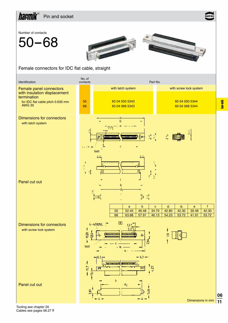
ik 50 60 04 050 5343 60 04 050 5344
68 60 04 068 5343 60 04 068 5344
Pin and socket
Tooling see chapter 20 Cables see pages 06.27 ff
Female panel connectors with insulation displacement termination
for IDC flat cable pitch 0.635 mm AWG 30
Dimensions for connectorswith latch system
Panel cut out
Dimensions for connectorswith screw lock system
Panel cut out
with latch system with screw lock system
No. ofIdentification contacts Part No.
Female connectors for IDC flat cable, straight
Number of contacts
50--68
Dimensions in mm
last
a b c d1 d2 e f 50 52.45 46.48 34.70 42.80 42.30 30.48 42.30 68 63.88 57.91 46.13 54.23 53.72 41.91 53.72
last

0612
har-m
ik
20 60 03 020 52 . .
26 60 03 026 52 . .
50 60 03 050 52 . .
68 60 03 068 52 . .
100 60 03 100 52 . .
Hoods see pages 06.18, 06.19Tooling see chapter 20Cables see pages 06.27 ff
Pin and socket
Male connectors with insulation displacement termination
for discrete wire AWG 28/30
Male connectors for IDC discrete wire, straight
Number of contacts
20--100
Dimensions in mm
Insulation diameter (mm)
Available sizes
No. ofIdentification contacts Part No.
Ø = 0.50–0.65 00 Ø = 0.50–0.75 05 Ø = 0.65–0.80 10 Ø = 0.75–0.90 15 Ø = 0.80–0.88 20
Part No. Ø 20 26 50 68 100
60 03 . . . 5200 0.50–0.65 ● ● ●
60 03 . . . 5205 0.50–0.75 ●
60 03 . . . 5210 0.65–0.80 ● ● ●
60 03 . . . 5215 0.75–0.90 ●
60 03 . . . 5220 0.80–0.88 ● ● ●
● = Available sizes
A manual for the har-mik® connector and cable assembly is available in our online catalogue HARKIS ® or on demand at your local HARTING representative.
Male
comb covers
Comb cover(delivered with connectors)
Dimensions 20 / 26 / 50 / 100 contacts 68 contacts
a c d e 20 21.25 17.00 16.75 11.43 26 25.06 20.81 20.56 15.24 50 40.30 36.05 35.80 30.48100 72.05 67.80 67.55 62.23
last
position 34
position 35 position 68
position 1

0613
har-m
ik
Technical characteristicsBellows
Number of contacts 14, 20, 26, 36, 50, 68
Pitch 1.27 mm
Working current 1 A
Working voltage 240 V ~
Test voltage Ur.m.s. 750 V (standard) 500 V (SMC)
Contact resistance � 40 m� (standard) � 45 m� (SMC)
Insulation resistance � 103 M�
Temperature range -55 OC … +105 OC during SMC reflow soldering max. 240 °C for 60 s
Terminations
Solder pins Straight for pcb holes min. Ø 0.74 mm Angled 90o for pcb holes min. Ø 0.74 mm (wave soldering) min. Ø 0.62 mm (SMC)
Insulation displacement AWG 28 to AWG 30 max. section: 0.089 mm² min. section: 0.050 mm² Insulation Ø min. 0.50 mm Ø max. 0.90 mm
Materials
Moulding Thermoplastic resin glass-fibre filled UL 94-V0
Contacts Copper alloy
Contact surface
Contact zone S4 = 0.76 μm (30 μinch) Au or PdNi equivalent
Metal shell Die cast zamac or stamped steel, nickel-plated
Bellowswith leaf contact design
male female

0614
har-m
ik
26 60 11 026 5102
36 60 11 036 5102
50 60 11 050 5102
68 60 11 068 5102
Bellows
Female connectors with straight solder pins
Panel cut out
Dimensions Board drillings
No. ofIdentification contacts Part No.
Female connectors, straight
Number of contacts
26--68
Dimensions in mm
26, 50 contacts
36, 68 contacts
a b± 0.1 c e f g h 26 37.16 31.26 20.26 12 x 1.27 = 15.24 27.11 27.50 31.25 36 43.51 37.61 26.61 17 x 1.27 = 21.59 33.46 33.90 37.60 50 52.40 46.50 35.50 24 x 1.27 = 30.48 42.35 42.80 46.50 68 63.83 57.93 46.93 33 x 1.27 = 41.91 53.78 54.20 57.90
last
last
last

0615
har-m
ik
14 60 11 014 57 . . 710 60 11 014 57 . . 20 60 11 020 57 . . 710 60 11 020 57 . . 26 60 11 026 57 . . 710 60 11 026 57 . . 36 60 11 036 57 . . 710 60 11 036 57 . . 50 60 11 050 57 . . 710 60 11 050 57 . . 68 60 11 068 57 . . 710 60 11 068 57 . .
SMC female connectors, angled
SMC female connectors with angled solder pins
No. of Part No.Identification contacts for one reel (300 pieces) standard tray packaging
Number of contacts
14--68
Dimensions in mm
Without board lock 32With board lock 40
with board lock without board lock
Dimensions
Board drillings(Components side)
Packaging(1 reel = 300 pieces) Reel diameter = 380 mm
Bellows
a b c d e f g h i j k l m n14 29.54 23.64 9.62 7.62 12.62 17.14 19.54 8 9 7 6 14 13 44.020 33.35 27.45 13.43 11.43 16.43 20.95 23.35 11 12 9 10 19 20 56.526 37.16 31.26 17.24 15.24 20.24 24.76 27.16 14 15 13 12 26 25 56.036 43.51 37.61 23.59 21.59 26.59 31.11 33.51 19 20 17 18 35 36 56.050 52.40 46.50 32.48 30.48 35.48 40.00 42.40 26 27 25 24 50 49 72.568 63.83 57.93 43.91 41.91 46.91 51.43 53.83 35 36 33 34 67 68 88.5

0616
har-m
ik
14 60 13 014 52 . .
20 60 13 020 52 . .
26 60 13 026 52 . .
36 60 13 036 52 . .
50 60 13 050 52 . .
68 60 13 068 52 . .
Hoods see page 06.20, 06.21Tooling see chapter 20Cables see pages 06.27 ff
Bellows
No. ofIdentification contacts Part No.
Male connectors for IDC discrete wire, straight
Number of contacts
14--68
Ø = 0.50–0.65 00Ø = 0.50–0.75 05Ø = 0.75–0.90 15
Male connectors with insulation displacement termination
for discrete wire AWG 28/30
Male connector
Dimensions in mm
Insulation diameter (mm)
Dimensions for male connectors
A manual for the har-mik® connector and cable assembly is available in our online catalogue HARKIS ® or on demand at your local HARTING representative.
Available sizes Part No. Ø 14 20 26 36 50 68
Male
60 13 . . . 5200 0.50–0.65 ● ● ●
60 13 . . . 5205 0.50–0.75 ● ● ●
60 13 . . . 5215 0.75–0.90 ● ● ●
● = Available sizes
20 / 50 / 68 poles
14 / 26 / 36 poles
comb covers
a c e20 21.24 17.55 11.4350 40.29 36.60 30.4868 51.72 48.03 41.91
a b c d e14 17.10 13.84 12.78 9.42 7.6226 24.95 21.46 20.40 17.00 15.2436 31.35 27.81 26.75 23.39 21.59
last

0617
har-m
ik
Technical characteristicsHoods
Hoods for pin and socket male connectors
Number of contacts 20, 26, 36, 50, 68, 100
Surface Die cast zamac, nickel-plated Thermoplastic resin, nickel-plated, steel insert
Hoods for bellows male connectors
Number of contacts 14, 20, 26, 36, 50, 68
Surface Die cast zamac, nickel-plated Thermoplastic resin, nickel-plated, steel insert

0618
har-m
ik
20 60 03 020 0255
26 60 03 026 0255
36 60 03 036 0255
50 60 03 050 0255
68 60 03 068 0255
50 60 03 050 0143
68 60 03 068 0143
100 60 03 100 0143
68 60 03 068 0145
Hoods for pin and socket male connectors
Metal hoodLarge cable entry
No. ofIdentification contacts Part No. Drawing Dimensions in mm
Top entry hoods
For other size, please consult us. 1) Temperature range: -55 °C … +60 °C
a b c20 28.95 21.15 8.00 x 8.5026 32.76 24.96 8.00 x 6.7536 39.11 31.31 9.00 x 10.0050 48.00 40.20 9.00 x 10.0068 59.43 51.63 9.00 x 10.00
Metal hoodTop cable entry
Shell dimensions Cable dimensions a b min. max. 68 65.1 38.2 8.7 10.7
a b c d e 50 54.00 46.48 35.00 10.50 12.00 68 65.41 57.91 38.40 14.00 12.00 100 85.73 78.23 42.00 13.00 12.00
Plastic hood with internal screen1)

0619
har-m
ik
20 60 03 020 0555
26 60 03 026 0555
50 60 03 050 0555
68 60 03 068 0555
68 60 03 068 0655
Hoods for pin and socket male connectors
Metal hoodCable side entry
No. ofIdentification contacts Part No. Drawing Dimensions in mm
Side entry hoods
Large cable side entry
Shell dimensions Cable dimensions a b min. max. 20 29.0 32.9 6.2 8.0 26 32.8 32.9 6.5 8.5 50 48.0 35.6 8.3 10.3 68 59.4 35.6 8.7 10.7
Shell dimensions Cable dimensions a b min. max. 68 59.4 35.6 10.0 12.0

0620
har-m
ik
14 60 13 014 0153 3511)
20 60 13 020 01532)
26 60 13 026 0153 3511)
36 60 13 036 0153 3511)
50 60 13 050 01532)
68 60 13 068 01532)
26 60 13 026 0555
Hoods for bellows male connectors
No. ofIdentification contacts Part No. Drawing Dimensions in mm
Top or side entry hoods
Plastic hood with internal screen
1) Temperature range: - 55 °C ... + 85 °C2) Temperature range: - 55 °C ... + 60 °C
Metal hoodCable side entry
Only compatible with IDC connector 60 13 026 5200
Shell dimensions Cable dimensions a b min. max. 26 33.8 36.8 6.5 8.5
a b c d20 29.65 34.50 19.95 6.8050 48.70 32.00 39.00 8.7068 60.13 32.00 50.43 9.10
a b c d e14 26.00 36.00 21.00 7.20 42.5026 33.70 32.00 25.50 8.00 42.0036 40.05 32.00 31.80 9.20 42.00
20 / 50 / 68 poles
14 / 26 / 36 poles

0621
har-m
ik
14 60 13 014 0146 3511)
26 60 13 026 0146 3511)
36 60 13 036 0146 3511)
14 60 13 014 0146 1101)
26 60 13 026 0146 1101)
36 60 13 036 0146 1101)
Hoods for bellows male connectors
No. ofIdentification contacts Part No. Drawing Dimensions in mm
Top entry hoods
1) Temperature range: - 55 °C ... + 85 °C
Plastic hood with internal screen and knurled screws
Colour: Beige
Colour: Black
a b c d14 31.40 37.00 23.64 7.226 39.00 33.00 31.26 8.036 45.40 33.00 37.61 9.2

0622
har-m
ik
60 01 000 9013
60 01 000 9030
60 01 000 9018
60 01 000 9019
60 01 000 9020
60 01 000 9021
Accessories
Identification Part No. Drawing Dimensions in mm
Female screw lock
Screw lockThread: M 2.5 / 2-56 UNCHeight: 2.9 mm
Screw lockThread: M 2.5 / 4-40 UNCHeight: 4.6 mm
Screw lockThread: 4-40 UNC / 4-40 UNCHeight: 3.99 mm
Screw lockThread: 4-40 UNC / 2-56 UNCHeight: 3.99 mm
Screw lockThread: 4-40 UNC / 2-56 UNCHeight: 5.5 mm
Screw lockThread: 4-40 UNC / 4-40 UNCHeight: 5.5 mm

0623
har-m
ik
Certified according to EN ISO 9001in design/development, production,
installation and servicing
Intra cabinet connectors
for economical and reliable connections
A comprehensive range of high density intra cabinet connectors based on blade and fork contacts.
Available in a various number of contacts according to the following international standards and applications:
UL recognised
For customer specific applications we can design and manufacture solutions to match your requirement.
Sales department
HARTING components
● Small Computer System Interface SCSI-2 SCSI-2 wide SCSI-3
● Internal Bus extension through “Daisy chain” inter-linking via 0.635 mm pitch flat cable. The 4-point design of the IDC contact provides accurate and reliable termination even with teflon cable.

0624
har-m
ik
Technical characteristics
Pitch 1.27 mm
Working current
pcb connector 1 A Flat cable connector 0.5 A
Working voltage
pcb connector 240 V ~ Flat cable connector 100 V ~
Test voltage Ur.m.s.
pcb connector 750 V Flat cable connector 500 V
Contact resistance � 25 m�
Insulation resistance � 103 M�
Temperature range -55 OC … +105 OC during SMC reflow soldering max. 240 °C for 60 s
Terminations
Solder pins Straight for pcb holes min. Ø 0.74 mm
Insulation displacement Flat cable AWG 30 pitch 0.635 mm
Materials
Moulding Thermoplastic resin glass-fibre filled UL 94-V0
Contacts pcb connector Copper alloy Flat cable connector Nickel
Contact surface
Contact zone S4 = 0.76 μm (30 μinch) Au or PdNi equivalent
Pin and socket
Intra cabinet connectors
Press-in versions
Insertion process Flat rock
Maximum press-in force per contact 100 N
Minimum push out force per contact 15 N
Number of repairs 2
Diameter of pcb plated through holes Ø 0.6 + 0.07
– 0.05 mm
Recommended pcb holes for press-in process Hole : Ø 0.71 – 0.74 mm Cu : 30 – 60 μm Sn : 5 – 20 μm
Pcb thickness 1.6 – 3.2 mm

0625
har-m
ik
68 60 05 068 5100
68 60 05 068 5322
Pin and socket
SMC female connector with straight solder pins
Dimensions
Board drillings(Components side)
No. ofIdentification contacts Part No.
Connectors with straight pins
Number of contacts
68
Dimensions in mm
last
last
Female connector with straight press-in pins
SMC solder
press-in
SMC solder
press-in
last

0626
har-m
ik 50 60 06 050 5440 60 06 050 9001 68 60 06 068 5440 60 06 068 9001
Pin and socket
Male connectors with insulation displacement termination
for IDC flat cable pitch 0.635 mm AWG 30 Strain relief order separately
Male connector Strain relief
No. ofIdentification contacts Part No.
Connectors with IDC termination
Number of contacts
50--68
Dimensions
Strain relief
Dimensions in mm
a 50 42.16 68 53.44
Tooling see chapter 20 Cables see pages 06.27 ff
a b c e 50 39.75 34.85 36.19 30.48 68 51.26 46.28 47.62 41.91
No. 1 contact

0627
har-m
ik
33 60 214 5000 102 33 60 213 1000 103 33 60 213 2000 104 33 60 213 5000 105 33 60 212 1000 106 33 60 212 1500 107 33 60 212 2000 108
33 60 214 5000 088 33 60 211 0010 089 33 60 211 0020 090 33 60 211 0050 091 33 60 211 0100 092 33 60 211 0150 093 33 60 211 0200 094
Identification Part No. Drawing Dimensions in mm
Cable assemblies
Cable assembly har-mik® pin and socket, 68-pole
Hood: metal hood with top entry
Cable: 34 twisted pairs, AWG 28, shielded, PVC
Wiring: 1:1
Length: L = 0.5 m L = 1.0 m L = 2.0 m L = 5.0 m L = 10.0 m L = 15.0 m L = 20.0 m
Cable assembly har-mik® bellows, 36-pole
Hood: shielded plastic hood with top entry
Cable: 18 twisted pairs, AWG 28, shielded, PVC
Wiring: 1:1
Length: L = 0.5 m L = 1.0 m L = 2.0 m L = 5.0 m L = 10.0 m L = 15.0 m L = 20.0 m

0628
har-m
ik
33 60 224 5000 191 33 60 223 1000 192 33 60 223 1500 193 33 60 223 2000 194 33 60 223 5000 195
33 60 224 5000 180 33 60 223 1000 181 33 60 223 1500 182 33 60 223 2000 183 33 60 223 5000 184
33 60 224 5000 186 33 60 223 1000 187 33 60 223 1500 188 33 60 223 2000 189 33 60 223 5000 190
Identification Part No. Drawing Dimensions in mm
Cable assemblies
Cable assembly har-mik® bellows, 36-pole, male
Hood: overmoulded with top entry
Cable: 18 twisted pairs, AWG 28, shielded, PVC
Wiring: 1:1
Cable assembly har-mik® bellows, 26-pole, male
Hood: overmoulded with top entry
Cable: 13 twisted pairs, AWG 28, shielded, PVC
Wiring: 1:1
Cable assembly har-mik® bellows, 14-pole, male
Hood: overmoulded with top entry
Cable: 7 twisted pairs, AWG 28, shielded, PVC
Wiring: 1:1
Length: L = 0.5 m L = 1.0 m L = 1.5 m L = 2.0 m L = 5.0 m
Length: L = 0.5 m L = 1.0 m L = 1.5 m L = 2.0 m L = 5.0 m
Length: L = 0.5 m L = 1.0 m L = 1.5 m L = 2.0 m L = 5.0 m

0629
har-m
ik
5 60 90 005 6010 60 90 005 6009 10 60 90 010 6010 13 60 90 013 6010 18 60 90 018 6010 25 60 90 025 6010 34 60 90 034 6010 50 60 90 050 6010
Cables for insulation displacement termination
Twisted pair cable with braid shield
AWG 28AWG 30Length per reel: 100 m
Drawing
No. of Part No.Identification pairs Standard version Halogen free version with screened pairs
Dimensions in mm
No. of pairs
Outside diameterNominal
5101318253450
5.4 6.6 6.8 7.5 8.5 8.911.1
No. of pairs Outside diameter
5 5.5 ± 0.3
Twisted pair
Screened twisted pairs
Separator Shield Jacket PVCJacket FRNC
Technical characteristics
Standard version Halogen free version with screened pairs
Number of pairs 5, 10, 13, 18, 25, 34, 50 5
Voltage rating 30 V (style UL 2789) 100 V
Maximum conductor resistance (20 oC) 233 �/km 350 �/km
Minimum insulation resistance (20 oC) 1 M�/km 10 G �/km
Nominal differential impedance (TDR) 85 �� 95 � ± 5 �
Nominal differential capacitance (1 kHz) 110 pF/m 45 pF/m
Propagation velocity 55 %
Temperature range – 20 OC … +105 OC – 25 OC … + 80 OC
Cable materials Conductor 7 x 0.13 mm stranded tinned copper 7 x 0.1 mm stranded tinned copper
Insulation (except 50 pairs) PVC Ø 0.62 mm Polypropylene Ø 0.74 mm (for 50 pairs) PVC Ø 0.67 mm
Shield Tinned copper braid, Tinned copper braid, covering � 80 % covering � 65 %
Jacket PVC FRNC
Flammability rating Flame tested as per UL style 2789
Sheath marking AWM 2789 60°C 30V AWM 21283 80°C 30V VW1
Thin print: Standard versionItalic print: Halogen free version

0630
har-m
ik
50 60 90 050 6008 68 60 90 068 6008
Cables for insulation displacement termination
Drawing
No. ofIdentification wires Part No.
Dimensions in mm
a b c d ± 0.25 ± 0.05 ± 0.2 ± 0.05
50 31.75 0.635 31.12 0.68
68 43.20 0.635 42.55 0.68
The tolerance b is not cumulative
Technical characteristics
Number of wires 50, 68
Voltage rating 150 V
Current rating 1.5 A max. per conductor
Impedance 75 �
Nominal differential capacitance (1 kHz) 90 pF/m
Pitch 0.635 mm
UL style 2 678
Temperature range – 30 OC … +105 OC
Materials Conductor 7 x 0.102 mm regular tinning or Z-bonding AWG 30 Insulation PVC
Flat cablefor IDC connectorPitch 0.635 mmAWG 30
Length per reel: 100 ft 30.48 m

0631
har-m
ik
Notes

The highest data rates in combination with perfect shielding
characterize the har-link® connector. This way data can be passed
on optimally within the control cabinet. The locking mechanism
ensures a vibration-proof connection and easy-to-install handling
at a minimum size and maximum options for combination with
other units.
HARTING offers assembled system cables with shielded or
unshielded twisted pairs for the har-link® connector family.
07. har - l ink® INTERFACE CONNECTORS
Boardto
Board
Cable/Wire
toBoard
IP 20 IP 65 / IP 67
Data Signal PowerData
transfer rate
Shielding Number of contacts, contact density
Voltage, working current
Cable termination
Han- Quick Lock®
IDC Crimp
Screw Cage clamp
Axial screw
PCB termination
THT SMC SMT
Press-in
Application standard
Separatehousing
Integratedhousing
high performance
Housing integration
CONNECTION TYPE ENVIRONMENT APPLICATION
App l icat ion prof i le:
Separatehousing
Integratedhousing
Housing integration
Application standard

har-l
ink
0701
Tooling see chapter 20
07. har - l ink® INTERFACE CONNECTORS
CONTENTS PAGE
connector system – introduction 07.02
connector system – general information 07.04
Technical characteristics 07.05
Male and female connectors 07.06
Accessories and cable assemblies 07.07

0702
har-l
ink
07. har - l ink® INTERFACE CONNECTORS
METRIC har-link® INTERFACE CONNECTORS IN 2.0 mm PITCH
HARTING‘s modular interface connector system, har-link® in
2.0 mm pitch, allows data transfer rates up to 2 Gbit/s.
The har-link® connector system of HARTING complies with
the requirements of IEC 61076-4-107 and is a compact and
robust PCB-to-cable interface with excellent data transmission
properties.
All dimensions of the har-link® connector are in accordance
with IEC 917 and IEEE P 1301 specifications, allowing an easy
implementation into both metric and inch-based systems.
har-link® also supports hot plugging as required by modern bus
systems such as CompactPCI, S-bus and VME.
har-link® allows data transmission up to 2 Gbit/s per pair and is
therefore perfectly suited for modern transmission protocols such
as Low Voltage Differential Signals (LVDS).
The thorough EMI shielding of the har-link® connector is a
guarantee of its superior performance in the EMI-polluted
environment.
The high temperature resistant material of the female har-link®
connector supports reflow soldering.
In addition, HARTING provides cable assemblies. A crimping tool
range for terminating male har-link® connectors is also available.

har-l
ink
0703
A screening attenuation of more than 50 dB up to 1 GHz
har-link® connector supports reflow soldering
connection withstands a pulling force up to 80 N
Low Voltage Differential Signals (LVDS)
gasket
bracket
SPECIFIC FEATURES OF THE PRODUCT R ANGE

0704
har-l
ink
The connector system of HARTING complies with the requirements of IEC 61 076-4-107 and is a compact and robust pcb-to-cable interface with excellent data transmission properties for high-speed net working and telecommunications.
All dimensions of the connector are in accor-dance with IEC 917 and IEEE P 1301 requirements, which allows for easy implementation into both metric and inch-based systems. In addition, supports hot plugging as required by modern bus systems such as CompactPCI, S-bus and VME.
allows data transmission up to 2 Gbit/s per pair and is therefore perfectly suited for modern trans mission protocols such as Low Voltage Differential Signals (see Fig. 1). The design of the
connector allows differential pairs to be placed horizontally (parallel to the pcb), thus reducing the skew at high frequencies and considering high signal integrity.
Fig. 1: Eye diagram of a 1280 MBit signal (512 Bits)
The metal shells of the connector are a guarantee for its superior performance in the EMI- polluted environment (see Fig. 2).
Fig. 2: 360° screened-can construction with locking levers
To reach a screening attenuation of more than 50 dB up to 1 GHz, HARTING offers brackets covering each connector in conjunction with a gasket, which is compressed between the bracket and the front panel (see Fig. 3).
Fig. 3: 4 cavities bracket and gasket
Once plugged, the mated pair shows excellent mating safety. Due to the locking levers on both sides of the male connector, the connection withstands a pulling force of up to 80 N (see Fig. 2).
The high temperature resistant material of the female connector body supports the safe reflow soldering process. For easy identification of female modules, six different colours are available (see Fig. 4).
Fig. 4: Female modules
In addition to single connectors, HARTING provides cable assemblies with unshielded twisted pairs or with shielded twisted pairs for high speed applications such as IEEE 1355. A crimping tool range for terminating the male connectors is available.
General informationconnector system
Bracket
Gasket

0705
har-l
ink
Technical characteristics
Number of contacts 10
Approvals IEC 61 076-4-107 UL recognized: E102079
Contact pitch 2 mm Connector pitch 6 mm
Working current 1.5 A at 70 OC
Test voltage Ur.m.s. 750 V
Contact resistance � 35 m� Insulation resistance � 1010 �
Temperature range -55 OC … +125 OC during reflow soldering female: max. + 260 OC for 60 s
Mating cycles 250, performance level 2
MaterialsMouldings Male connector: Polyester,
UL 94-V0 Female connector: High temperature plastic material, UL 94-V0
Contacts Copper alloyShells Male connector:
Stainless steel Female connector: Silver nickel
Contact surfaceContact zone Selectively plated according
to performance level
Terminations Insulation displacement (male), AWG 28/7 - 30/7, AWG 30 solid Solder buckets (male), AWG 24-30, outer insulation Ø 5.33 ± 0.25 mm Solder pins for ø 0.6 mm min. (female)
Insertion force 10 N max. / moduleWithdrawal force 2 N min. / module
(without locking levers)
Latching system Locking levers

0706
har-l
ink
10 27 11 161 8001 10 27 11 122 2001
10 27 21 121 8000
10 27 21 121 8002 10 27 21 121 8004 10 27 21 121 8005 10 27 21 121 8006 10 27 21 121 8010
Dimensions [mm]
Male connectors, straightFemale connectors, angled
Male connector for insulation displacement Black with solder buckets Black
Female connector with solder pins Beige (standard)
Red Yellow Green Blue Black
No. of Identification contacts Colour Part No.
Female connectorShielding pins
Nipple location
0.4 x (0.25) for pin z
0.4 x (0.3) for pins a, b, c, d, e
date code
Shielding pins
Tooling see chapter 20
Male connector(delivered in piece parts)
Manuals for the har-link® cable free connector assemblies are available in our online catalogue HARKIS ® or on demand at your local HARTING representative.

0707
har-l
ink
27 71 040 0001
27 71 040 0002
33 27 243 0500 001 33 27 243 1000 002 33 27 243 2000 003
33 27 243 0500 006 33 27 243 1000 007 33 27 243 2000 008
33 27 243 0500 015 33 27 243 1000 016 33 27 243 2000 017
Identification Part No. Drawing Dimensions in mm
Bracketwith four cavities
Accessories and cable assemblies
Connector 1 Connector 22-e 1-a1-e 2-a2-d 1-b1-d 2-b2-c 2-c
Connector 1 Connector 21-c 1-c2-b 1-d1-b 2-d2-a 1-e1-a 2-e
IEEE 1355 wiring
Gasketwith four cavities
Standard har-link® cable assembly
Cable: 5 twisted pairs, AWG 28, shielded, PVC
Wiring: 1:1
Length: L = 0.5 m L = 1.0 m L = 2.0 m
Length: L = 0.5 m L = 1.0 m L = 2.0 m
har·link male IDC connector
High end har-link® cable assembly
Cable: 5 twisted pairs, AWG 30, double shielded, PVC
Wiring: 1:1
Length: L = 0.5 m L = 1.0 m L = 2.0 m
Cable: 5 twisted pairs, AWG 30, double shielded, PVC
Wiring: acc. to IEEE 1355
Board drillings Component side
per bracket

0708
har-l
ink
5 60 90 005 6010 60 90 005 6009
Cables for insulation displacement termination
Twisted pair cable with braid shield
AWG 28AWG 30Length per reel: 100 m*
Drawing
No. of Part No.Identification pairs Standard version Halogen free version with screened pairs
Dimensions in mm
No. of pairs
Outside diameterNominal
5 5.4
No. of pairs Outside diameter
5 5.5 ± 0.3
Twisted pair
Screened twisted pairs
Separator Shield Jacket PVC
Jacket FRNC
Technical characteristics
Standard version Halogen free version with screened pairs
Number of pairs 5 5
Voltage rating 30 V (style UL 2789) 100 V
Maximum conductor resistance (20 oC) 233 �/km 350 �/km
Minimum insulation resistance (20 oC) 1 M�/km 10 G �/km
Nominal differential impedance (TDR) 85 �� 95 � ± 5 �
Nominal differential capacitance (1 kHz) 110 pF/m 45 pF/m
Propagation velocity 55 %
Temperature range -20 OC … +105 OC -25 OC … +80 OC
Cable materials
Conductor 7 x 0.13 mm stranded tinned copper 7 x 0.1 mm stranded tinned copper
Insulation PVC Ø 0.62 mm Polypropylene Ø 0.74 mm
Shield Tinned copper braid, Tinned copper braid, covering � 80 % covering � 65 %
Jacket PVC FRNC
Flammability rating Flame tested as per UL style 2789
Sheath marking AWM 2789 60°C 30V AWM 21283 80°C 30V VW1
Thin print: Standard versionItalic print: Halogen free version

0709
har-l
ink
Notes

08. SEK IDC CONNECTORS
Boardto
Board
Cable/Wire
toBoard
IP 20 IP 65 / IP 67
Data Signal PowerData
transfer rate
Shielding Number of contacts, contact density
Voltage, working current
Cable termination
Han- Quick Lock®
IDC Crimp
Screw Cage clamp
Axial screw
PCB termination
THT SMC SMT
Press-in
Application standard
Separatehousing
Integratedhousing
high performance
Housing integration
CONNECTION TYPE ENVIRONMENT APPLICATION
App l icat ion prof i le:
Separatehousing
Integratedhousing
Housing integration
Application standard
SEK connectors for flat cables enable simple and –, cost-optimized
device configuration. SEK connectors are preferably used for connection
within the device. HARTING offers a broad range of these cable-to-board
connectors.
Assembly on the cable side takes place in one work step for all contacts
via flat conductors. The SEK is an economical and reliable interface
for data and signal applications in industry.

SEK
0801
Tooling see chapter 20
08. SEK IDC CONNECTORS
CONTENTS PAGE
SEK connector system – introduction 08.02
General information 08.05
Solder board connectors 08.06
Male standard connectors 08.08
Male low-profile conncectors 08.16
Accessories 08.18
Wrap post connectors
Male standard connectors 08.19
Accessories 08.22
Cable connectors
Female connectors 08.23
Pcb transition connectors, 2 rows 08.26
Pcb transition connectors, 4 rows 08.28
DIP connectors 08.30
DIN 41 612 connectors 08.32
Press-in connectors
Male standard connectors 08.34
Male low-profile connectors 08.38
SMC solder board connectors
Male standard SMC connectors 08.40
Male low-profile SMC connectors 08.50
Accessories 08.52
Cables and cable assemblies 08.53

SEK
0802
08. SEK IDC CONNECTORS
IDC CONNECTOR SYSTEM [2.54 mm X 2.54 mm PITCH] FOR FLAT CABLESHARTING’s product range of flat cable connectors is designed for
various cable-to-PCB applications. The HARTING SEK insulation
displacement connector technology meets all requirements of the
IEC 60 603-13.
HARTING assembles each SEK connector with the matching cable
type according to customer specifications in order to simplify
customer installation and storage.
The different types of board connectors offer 6 to 64 pins in
various terminations such as solder (manual, wave or reflow) or
press-in.
The cable connectors are equally suited for indoor use
as well as for outdoor applications and harsh environments.

SEK
0803
QUALITY
ensure reliable connections.
HARTING test device.
ECONOMY
manufacturer guarantees a high degree of economy and reliability.
CABLE ASSEMBLIES
specifications.
arrangements constitute the ideal solution to your wiring
problems.
SPECIFIC FEATURES OF THE PRODUCT R ANGE

0804
SEK
Notes

0805
SEK
SEK
10-5014-40
6-64
64646-64
9-37
General information
The HARTING Insulation Displacement Connector system
Economic and reliable connections
The flat cable and connector can be preassembled and used as a component with predetermined functional characteristics.
The HARTING insulation displacement contacts pierce the insulation on the flat cable to provide a durable gastight connection with the wire.
The HARTING insulation displacement technique constitutes the ideal solution to your wiring problems.
For “non standard applications” we can manufacture designs to match your requirements.Please discuss requirements with us.
HARTING SEK connectors incorporate the latest design features and provide the assurance of high quality and reliability with economy.
Cable assemblies
● HARTING can supply cable assemblies to customer specifications.
● A wide range of connector types available with various contact arrange-ments constitute the ideal solution to your wiring problems.
● Cables of all types in economic reel lengths are available.
Quality
● Cables professionally assembled on HARTING work stations ensure reliable connections.
● Finished harnesses are subject to 100% quality checks on a HARTING test device.
● Insulation test.
● Contact resistance test.
Economy
● The tested assembly of connectors and flat cables from one manufacturer guarantees a high degree of economy and reliability.
● Investment for work stations and test devices are not required.
● Stocks of piece parts are reduced.

0806
SEK
SEK Solder board connectors Technical characteristics
1) Performance level 3 as per IEC 60 603-13, � 50 mating cycles, no gas test Performance level 2 as per IEC 60 603-13, � 250 mating cycles, 4 days gas test S4, plating = 0.76 μm (30 μinch) Au or PdNi eqivalent
Number of contacts 6, 10, 14, 16, 20, 24, 26, 30, 34, 40, 50, 60, 64
Contact arrangement straight, angled
Contact length 2.9 mm, 4.5 mm
Approvals IEC 60 603-13 DIN EN 60 603-13 D 2632 BT 224 NFC 93-428 (HE 10)
UL recognized: E102079
Pitch 2.54 mm [0.100“]
Working current 1 A
Working voltage 500 V for pollution degree 1
Test voltage Ur.m.s. 1 kV
Contact resistance � 20 m� Insulation resistance � 109 �
Temperature range -55 OC … +125 OC The maximum temperature
includes heating of contacts and ambient temperature
Terminations For pcb hole Ø 1 ± 0.1 mm DIN IEC 52 141
Diagonal: 0.79 mm
Materials Moulding Thermoplastic resin (PBT)
UL 94-V0
Contact surface Contact zone plated according to
performance level1)
Current carrying capacityThe current carrying capacity is limited by maximum temperature of materials for inserts and contacts including terminals.The current capacity-curve is valid for continuous, not interrupted current-loaded contacts of connectors when simultaneous power on all contacts is given, without exceeding the maximum tempe-rature.
Control and test procedures according to DIN IEC 60 512.
Number of contactsMaximum force [N]
Performance level 1 and 2
Performance level 3
6 12 1810 20 3014 28 4216 32 4820 40 6024 48 7226 52 7830 60 9034 68 10240 80 12050 100 15060 120 18064 128 192
Insertion and withdrawal forces
Wor
king
cur
rent
[A]
Ambient temperature [° C]
Example: 50 way connector➀ Temperature rise➁ Derating➂ Derating curve at Imax. x 0.8 (IEC 60 512-2)

0807
SEK
Notes

0808
SEK
SEK IEC 60 603-13
6 09 18 506 923 09 18 506 913 09 18 506 903
10 09 18 510 923 09 18 510 913 09 18 510 903
14 09 18 514 923 09 18 514 913 09 18 514 903
16 09 18 516 923 09 18 516 913 09 18 516 903
20 09 18 520 923 09 18 520 913 09 18 520 903
24 09 18 524 923 09 18 524 913 09 18 524 903
26 09 18 526 923 09 18 526 913 09 18 526 903
30 09 18 530 923 09 18 530 913 09 18 530 903
34 09 18 534 923 09 18 534 913 09 18 534 903
40 09 18 540 923 09 18 540 913 09 18 540 903
50 09 18 550 923 09 18 550 913 09 18 550 903
60 09 18 560 923 09 18 560 913 09 18 560 903
64 09 18 564 923 09 18 564 913 09 18 564 903
6 09 18 506 921* 09 18 506 911* 09 18 506 901*
10 09 18 510 921* 09 18 510 911* 09 18 510 901*
14 09 18 514 921* 09 18 514 911* 09 18 514 901*
16 09 18 516 921* 09 18 516 911* 09 18 516 901*
20 09 18 520 921* 09 18 520 911* 09 18 520 901*
24 09 18 524 921* 09 18 524 911* 09 18 524 901*
26 09 18 526 921* 09 18 526 911* 09 18 526 901*
30 09 18 530 921* 09 18 530 911* 09 18 530 901*
34 09 18 534 921* 09 18 534 911* 09 18 534 901*
40 09 18 540 921* 09 18 540 911* 09 18 540 901*
50 09 18 550 921* 09 18 550 911* 09 18 550 901*
60 09 18 560 921* 09 18 560 911* 09 18 560 901*
64 09 18 564 921* 09 18 564 911* 09 18 564 901*
7 * 7 7 6 6 6 5 * 5 * 5 *
No. of Part No.
Identification contacts Without levers With short levers With long levers
Male header with angled solder pins
Number of contacts
6--64
Male header with angled solder pins
Length: 2.9 mm
Male header with angled solder pins
Length: 4.5 mm
Kinked version on request
Kinked version on request
For performance level 3 please specify digitFor performance level 2 please specify digitS4 = 0.76 μm (30 μinch) Au or PdNi eqivalent
* Not normally kept in stockFor accessories see page 08.18For dimensions see page 08.09

0809
SEK
SEK IEC 60 603-13
Male header
Board drillings
Identification Drawing Dimensions in mm
For accessories see page 08.18
Male header with angled solder pins
Number of contacts
6--64
No. of A B D E F G contacts 6 26.9 16.76 12.45 2.54 x 2 = 5.08 36.9 40.3 10 32.0 21.84 17.53 2.54 x 4 = 10.16 42.0 45.4 14 37.1 26.92 22.61 2.54 x 6 = 15.24 47.1 50.4 16 39.6 29.46 25.15 2.54 x 7 = 17.78 49.6 53.0 20 44.7 34.54 30.23 2.54 x 9 = 22.86 54.7 58.1 24 49.8 39.62 35.91 2.54 x 11 = 27.94 59.8 63.2 26 52.3 42.16 37.85 2.54 x 12 = 30.48 62.3 65.7 30 57.7 47.24 43.83 2.54 x 14 = 35.56 68.2 68.6 34 62.5 52.32 48.01 2.54 x 16 = 40.64 72.5 75.8 40 70.1 59.94 55.63 2.54 x 19 = 48.26 80.1 83.5 50 82.8 72.64 68.33 2.54 x 24 = 60.96 92.8 96.2 60 95.5 85.34 81.03 2.54 x 29 = 73.66 105.5 108.9 64 100.6 90.42 86.11 2.54 x 31 = 78.74 110.6 113.9
a) Solder pins for 1 ± 0.1 mm dia. hole
Short leversfor use with female connector without strain relief clamp
Long leversfor use with female connector with strain relief clamp
1) No polarization slot for 6, 10 or 14 way male header
2) No polarization slot for 6 way male header3) Pitch tolerance: ± 0.1
Marking No. 1 contact
No. 1 contact
No. 2 contact
No. 1 contact
No. 2 contact
Center of gravity

0810
SEK
6 09 18 506 924 09 18 506 914 09 18 506 904
10 09 18 510 924 09 18 510 914 09 18 510 904
14 09 18 514 924 09 18 514 914 09 18 514 904
16 09 18 516 924 09 18 516 914 09 18 516 904
20 09 18 520 924 09 18 520 914 09 18 520 904
24 09 18 524 924 09 18 524 914 09 18 524 904
26 09 18 526 924 09 18 526 914 09 18 526 904
30 09 18 530 924 09 18 530 914 09 18 530 904
34 09 18 534 924 09 18 534 914 09 18 534 904
40 09 18 540 924 09 18 540 914 09 18 540 904
50 09 18 550 924 09 18 550 914 09 18 550 904
60 09 18 560 924 09 18 560 914 09 18 560 904
64 09 18 564 924 09 18 564 914 09 18 564 904
6 09 18 506 922* 09 18 506 912* 09 18 506 902*
10 09 18 510 922* 09 18 510 912* 09 18 510 902*
14 09 18 514 922* 09 18 514 912* 09 18 514 902*
16 09 18 516 922* 09 18 516 912* 09 18 516 902*
20 09 18 520 922* 09 18 520 912* 09 18 520 902*
24 09 18 524 922* 09 18 524 912* 09 18 524 902*
26 09 18 526 922* 09 18 526 912* 09 18 526 902*
30 09 18 530 922* 09 18 530 912* 09 18 530 902*
34 09 18 534 922* 09 18 534 912* 09 18 534 902*
40 09 18 540 922* 09 18 540 912* 09 18 540 902*
50 09 18 550 922* 09 18 550 912* 09 18 550 902*
60 09 18 560 922* 09 18 560 912* 09 18 560 902*
64 09 18 564 922* 09 18 564 912* 09 18 564 902*
7 * 7 7 6 6 6 5 * 5 * 5 *
SEK IEC 60 603-13
No. of Part No.
Identification contacts Without levers With short levers With long levers
Male header with straight solder pins
Number of contacts
6--64
Male header with straight solder pins
Length: 2.9 mm
Male header with straight solder pins
Length: 4.5 mm
For performance level 3 please specify digitFor performance level 2 please specify digitS4 = 0.76 μm (30 μinch) Au or PdNi eqivalent
* Not normally kept in stockFor accessories see page 08.18For dimensions see page 08.11
Kinked version on request

0811
SEK
SEK IEC 60 603-13
Male header
Board drillings
Identification Drawing Dimensions in mm
For accessories see page 08.18
No. of A C D E F G contacts 6 26.9 22.86 12.45 2.54 x 2 = 5.08 36.9 40.3 10 32.0 27.94 17.53 2.54 x 4 = 10.16 42.0 45.4 14 37.1 33.02 22.61 2.54 x 6 = 15.24 47.1 50.4 16 39.6 35.56 25.15 2.54 x 7 = 17.78 49.6 53.0 20 44.7 40.64 30.23 2.54 x 9 = 22.86 54.7 58.1 24 49.8 45.72 35.91 2.54 x 11 = 27.94 59.8 63.2 26 52.3 48.26 37.85 2.54 x 12 = 30.48 62.3 65.7 30 57.7 53.34 43.83 2.54 x 14 = 35.56 68.2 68.6 34 62.5 58.42 48.01 2.54 x 16 = 40.64 72.5 75.8 40 70.1 66.04 55.63 2.54 x 19 = 48.26 80.1 83.5 50 82.8 78.74 68.33 2.54 x 24 = 60.96 92.8 96.2 60 95.5 91.44 81.03 2.54 x 29 = 73.66 105.5 108.9 64 100.6 96.52 86.11 2.54 x 31 = 78.74 110.6 113.9
Short leversfor use with female connector without strain relief clamp
Long leversfor use with female connector with strain relief clamp
a) Solder pins for 1 ± 0.1 mm dia. hole
Male header with straight solder pins
Number of contacts
6--64
1) No polarization slot for 6, 10 or 14 way male header
2) No polarization slot for 6 way male header3) Pitch tolerance: ± 0.1
Marking No. 1 contact
No. 1 contact
No. 2 contact
No. 1 contact
No. 2 contact

0812
SEK
6 09 18 506 024 09 18 506 014 09 18 506 004
10 09 18 510 024 09 18 510 014 09 18 510 004
14 09 18 514 024 09 18 514 014 09 18 514 004
16 09 18 516 024 09 18 516 014 09 18 516 004
20 09 18 520 024 09 18 520 014 09 18 520 004
24 09 18 524 024 09 18 524 014 09 18 524 004
26 09 18 526 024 09 18 526 014 09 18 526 004
30 09 18 530 024 09 18 530 014 09 18 530 004
34 09 18 534 024 09 18 534 014 09 18 534 004
40 09 18 540 024 09 18 540 014 09 18 540 004
50 09 18 550 024 09 18 550 014 09 18 550 004
60 09 18 560 024 09 18 560 014 09 18 560 004
64 09 18 564 024 09 18 564 014 09 18 564 004
7 * 7 7 6 6 6 5 * 5 * 5 *
SEK IEC 60 603-13
No. of Part No.
Identification contacts Without levers With short levers With long levers
Male header with straight solder pins, kinked
Number of contacts
6--64
Male header with straight solder pins, kinked
Length: 2.9 mm
For performance level 3 please specify digitFor performance level 2 please specify digitS4 = 0.76 μm (30 μinch) Au or PdNi eqivalent
* Not normally kept in stockFor accessories see page 08.18For dimensions see page 08.13

0813
SEK
SEK IEC 60 603-13
Male header
Board drillings
Identification Drawing Dimensions in mm
For accessories see page 08.18
Short leversfor use with female connector without strain relief clamp
Long leversfor use with female connector with strain relief clamp
1) No polarization slot for 6, 10 or 14 way male header
2) No polarization slot for 6 way male header3) Pitch tolerance: ± 0.1
Marking No. 1 contact
No. 1 contact
No. 2 contact
No. 1 contact
No. 2 contact
Male header with straight solder pins, kinked
Number of contacts
6--64
l Kinked contact: pcb thickness from 1.50 to 1.94 mm after Cu + Sn plating with non-remelted through holes ø 0.80 to ø 0.95 mm. Max. insertion force = 125 N. Min. retention force = 3 N.
Non-kinked contact: Solder pins for pcb connections ø 1 ± 0.1 mm as per IEC 60 603-13.
No. of A C D E F G contacts 6 26.9 22.86 12.45 2.54 x 2 = 5.08 36.9 40.3 10 32.0 27.94 17.53 2.54 x 4 = 10.16 42.0 45.4 14 37.1 33.02 22.61 2.54 x 6 = 15.24 47.1 50.4 16 39.6 35.56 25.15 2.54 x 7 = 17.78 49.6 53.0 20 44.7 40.64 30.23 2.54 x 9 = 22.86 54.7 58.1 24 49.8 45.72 35.91 2.54 x 11 = 27.94 59.8 63.2 26 52.3 48.26 37.85 2.54 x 12 = 30.48 62.3 65.7 30 57.7 53.34 43.83 2.54 x 14 = 35.56 68.2 68.6 34 62.5 58.42 48.01 2.54 x 16 = 40.64 72.5 75.8 40 70.1 66.04 55.63 2.54 x 19 = 48.26 80.1 83.5 50 82.8 78.74 68.33 2.54 x 24 = 60.96 92.8 96.2 60 95.5 91.44 81.03 2.54 x 29 = 73.66 105.5 108.9 64 100.6 96.52 86.11 2.54 x 31 = 78.74 110.6 113.9

0814
SEK
SEK IEC 60 603-13
6 09 18 506 973* 09 18 506 963* 09 18 506 953*
10 09 18 510 973* 09 18 510 963* 09 18 510 953*
14 09 18 514 973* 09 18 514 963* 09 18 514 953*
16 09 18 516 973* 09 18 516 963* 09 18 516 953*
20 09 18 520 973* 09 18 520 963* 09 18 520 953*
24 09 18 524 973* 09 18 524 963* 09 18 524 953*
26 09 18 526 973* 09 18 526 963* 09 18 526 953*
30 09 18 530 973* 09 18 530 963* 09 18 530 953*
34 09 18 534 973* 09 18 534 963* 09 18 534 953*
40 09 18 540 973* 09 18 540 963* 09 18 540 953*
50 09 18 550 973* 09 18 550 963* 09 18 550 953*
60 09 18 560 973* 09 18 560 963* 09 18 560 953*
64 09 18 564 973* 09 18 564 963* 09 18 564 953*
7 7 7 6 6 6 5 5 5
No. of Part No.
Identification contacts Without levers With short levers With long levers
Male header with angled solder pins and board lock
Number of contacts
6--64
Male header with angled solder pins and pcb board lock
Length: 2.9 mm for 1.6 mm pcb thickness
To hold the connector on the pcb before the soldering process, two board locks have been added on the male header with angled solder pins.
For performance level 3 please specify digitFor performance level 2 please specify digitS4 = 0.76 μm (30 μinch) Au or PdNi eqivalent
* Not normally kept in stock

0815
SEK
SEK IEC 60 603-13
Male header
Board drillings
Identification Drawing Dimensions in mm
For accessories see page 08.18
Short leversfor use with female connector without strain relief clamp
Long leversfor use with female connector with strain relief clamp
Male header with angled solder pins and board lock
Number of contacts
6--64
Marking No. 1 contact
No. 1 contact
No. 2 contact
No. 1 contact
No. 2 contact
1) No polarization slot for 6, 10 or 14 way male header
2) No polarization slot for 6 way male header3) Pitch tolerance: ± 0.1
Center of gravity
No. of A B D E F G contacts 6 26.9 16.76 12.45 2.54 x 2 = 5.08 36.9 40.3 10 32.0 21.84 17.53 2.54 x 4 = 10.16 42.0 45.4 14 37.1 26.92 22.61 2.54 x 6 = 15.24 47.1 50.4 16 39.6 29.46 25.15 2.54 x 7 = 17.78 49.6 53.0 20 44.7 34.54 30.23 2.54 x 9 = 22.86 54.7 58.1 24 49.8 39.62 35.91 2.54 x 11 = 27.94 59.8 63.2 26 52.3 42.16 37.85 2.54 x 12 = 30.48 62.3 65.7 30 57.7 47.24 43.83 2.54 x 14 = 35.56 68.2 68.6 34 62.5 52.32 48.01 2.54 x 16 = 40.64 72.5 75.8 40 70.1 59.94 55.63 2.54 x 19 = 48.26 80.1 83.5 50 82.8 72.64 68.33 2.54 x 24 = 60.96 92.8 96.2 60 95.5 85.34 81.03 2.54 x 29 = 73.66 105.5 108.9 64 100.6 90.42 86.11 2.54 x 31 = 78.74 110.6 113.9

0816
SEK
7 6 5 *
09 18 000 99054)
SEK IEC 60 603-13
6 09 18 506 323 6
10 09 18 510 323 10
14 09 18 514 323 14
16 09 18 516 323 16
20 09 18 520 323 20
26 09 18 526 323 26
30 09 18 530 323 30
34 09 18 534 323 34
40 09 18 540 323 40
50 09 18 550 323 50
60 09 18 560 323 60
64 09 18 564 323 64
No. ofIdentification contacts Part No. Drawing Dimensions in mm
Low-profile male header, angled solder pins
Number of contacts
6--64
For performance level 3 please specify digitFor performance level 2 please specify digitS4 = 0.76 μm (30 μinch) Au or PdNi eqivalent
Male header with angled solder pins
Length: 2.9 mm
Solder pins for 1 ± 0.1 mm dia. hole
Identification Part No. Drawing Dimensions in mm
Locking lever for female connector with strain relief
in conjunction with low-profile male header
When the security of latching is required and space is a premium, these locking levers can be fitted onto the strain relief of the HARTING female connector.
Strain relief clamp
Female connector
Low-profile male header
No. of A B E contacts
* Not normally kept in stock 1) No polarization slot for 6, 10 or 14 way male header2) No polarization slot for 6 way male header
3) Pitch tolerance: ± 0.14) Order 2 per female connector
Marking No. 1 contact
No. 1 contact
No. 1 contact
No. 2 contact
No. 2 contact
15.2 12.78 2.54 x 2 = 5.08
20.3 17.86 2.54 x 4 = 10.16
25.4 22.94 2.54 x 6 = 15.24
27.9 25.48 2.54 x 7 = 17.78
33.0 30.56 2.54 x 9 = 22.86
40.6 38.18 2.54 x 12 = 30.48
45.72 43.26 2.54 x 14 = 35.56
50.8 48.34 2.54 x 16 = 40.64
58.4 55.96 2.54 x 19 = 48.26
71.3 68.66 2.54 x 24 = 60.96
84.0 81.36 2.54 x 29 = 73.66
89.1 86.44 2.54 x 31 = 78.74

0817
SEK
6 09 18 506 324 6
10 09 18 510 324 10
14 09 18 514 324 14
16 09 18 516 324 16
20 09 18 520 324 20
26 09 18 526 324 26
30 09 18 530 324 30
34 09 18 534 324 34
40 09 18 540 324 40
50 09 18 550 324 50
60 09 18 560 324 60
64 09 18 564 324 64
6 09 18 506 322*
10 09 18 510 322*
14 09 18 514 322*
16 09 18 516 322*
20 09 18 520 322*
26 09 18 526 322*
30 09 18 530 322*
34 09 18 534 322*
40 09 18 540 322*
50 09 18 550 322*
60 09 18 560 322*
64 09 18 564 322*
7 6 5 *
09 18 000 99054)
SEK IEC 60 603-13
No. ofIdentification contacts Part No. Drawing Dimensions in mm
Number of contacts
6--64
For performance level 3 please specify digitFor performance level 2 please specify digitS4 = 0.76 μm (30 μinch) Au or PdNi eqivalent
Male header with straight solder pins
Length: 2.9 mm
Male header with straight solder pins
Length: 4.5 mm
Identification Part No. Drawing Dimensions in mm
Locking lever for female connector with strain relief
in conjunction with low-profile male header
When the security of latching is required and space is a premium, these locking levers can be fitted onto the strain relief of the HARTING female connector.
Strain relief clamp
Female connector
Low-profile male header
Low-profile male header, straight solder pins
Solder pins for 1 ± 0.1 mm dia. hole
No. of A B E contacts
Marking No. 1 contact
No. 1 contact
No. 1 contact
No. 2 contact
No. 2 contact
* Not normally kept in stock 1) No polarization slot for 6, 10 or 14 way male header2) No polarization slot for 6 way male header
3) Pitch tolerance: ± 0.14) Order 2 per female connector
15.2 12.78 2.54 x 2 = 5.08
20.3 17.86 2.54 x 4 = 10.16
25.4 22.94 2.54 x 6 = 15.24
27.9 25.48 2.54 x 7 = 17.78
33.0 30.56 2.54 x 9 = 22.86
40.6 38.18 2.54 x 12 = 30.48
45.72 43.26 2.54 x 14 = 35.56
50.8 48.34 2.54 x 16 = 40.64
58.4 55.96 2.54 x 19 = 48.26
71.3 68.66 2.54 x 24 = 60.96
84.0 81.36 2.54 x 29 = 73.66
89.1 86.44 2.54 x 31 = 78.74

0818
SEK
SEK IEC 60 603-13
09 18 500 99021)
09 18 000 99032)
09 18 000 99042)
09 18 000 99063)
09 99 000 0133
09 18 000 99014)
4) Part No. comprises 6 code pins
Accessories
Identification Part No. Drawing Dimensions in mm
Polarization key
1) Part No. comprises 2 keys
2) Order 2 per male header
3) Part No. comprises 50 pieces
Long:
Short:
Locking lever(snaps into place, can be fitted whenever required)
Fixing screwsfor 1.6 mm P.C. board
Removal tool for
male contacts
Code pin
Coding system with loss of contact
For use with female connector For use with female connector with strain relief clamp without strain relief clamp
To avoid cross-plugging adjacent connectors a coding system is required. A code pin is inserted into the appropriate cavity in the female connector. The corresponding male contact is removed by a special removal tool.
Long Short
BZ 2.9x6.5 (DIN 7981 or DIN 7049)
For connectors with part numbers 09 18 5xx x9xx: screwing torque 0.2 Nm 09 19 5xx x9xx: screwing torque 0.4 – 0.5 Nm
Screw material: Steel (Inox A2)
Plating: Nickel

0819
SEK
SEK Wrap post connectors Technical characteristics
1) Performance level 3 as per IEC 60 603-13, � 50 mating cycles, no gas test Performance level 2 as per IEC 60 603-13, � 250 mating cycles, 4 days gas test S4, plating = 0.76 μm (30 μinch) Au or PdNi eqivalent
Number of contacts 6, 10, 14, 16, 20, 24, 26, 30, 34, 40, 50, 60, 64
Contact arrangement straight, angled
Contact length 15 mm
Approvals IEC 60 603-13 DIN EN 60 603-13 D 2632 BT 224 NFC 93-428 (HE 10)
Pitch 2.54 mm [0.100“]
Working current 1 A
Working voltage 500 V for pollution degree 1
Test voltage Ur.m.s. 1 kV
Contact resistance � 20 m� Insulation resistance � 109 �
Temperature range -55 OC … +125 OC The maximum temperature
includes heating of contacts and ambient temperature
Terminations 0.6 mm x 0.6 mm Diagonal: 0.86 mm
Materials Moulding Thermoplastic resin (PBT)
UL 94-V0
Contact surface Contact zone plated according to
performance level1)

0820
SEK
SEK IEC 60 603-13
6 09 18 506 926* 09 18 506 916* 09 18 506 906*
10 09 18 510 926* 09 18 510 916* 09 18 510 906*
14 09 18 514 926* 09 18 514 916* 09 18 514 906*
16 09 18 516 926* 09 18 516 916* 09 18 516 906*
20 09 18 520 926* 09 18 520 916* 09 18 520 906*
24 09 18 524 926* 09 18 524 916* 09 18 524 906*
26 09 18 526 926* 09 18 526 916* 09 18 526 906*
30 09 18 530 926* 09 18 530 916* 09 18 530 906*
34 09 18 534 926* 09 18 534 916* 09 18 534 906*
40 09 18 540 926* 09 18 540 916* 09 18 540 906*
50 09 18 550 926* 09 18 550 916* 09 18 550 906*
60 09 18 560 926* 09 18 560 916* 09 18 560 906*
64 09 18 564 926* 09 18 564 916* 09 18 564 906*
6 09 18 506 927* 09 18 506 917* 09 18 506 907*
10 09 18 510 927* 09 18 510 917* 09 18 510 907*
14 09 18 514 927* 09 18 514 917* 09 18 514 907*
16 09 18 516 927* 09 18 516 917* 09 18 516 907*
20 09 18 520 927* 09 18 520 917* 09 18 520 907*
24 09 18 524 927* 09 18 524 917* 09 18 524 907*
26 09 18 526 927* 09 18 526 917* 09 18 526 907*
30 09 18 530 927* 09 18 530 917* 09 18 530 907*
34 09 18 534 927* 09 18 534 917* 09 18 534 907*
40 09 18 540 927* 09 18 540 917* 09 18 540 907*
50 09 18 550 927* 09 18 550 917* 09 18 550 907*
60 09 18 560 927* 09 18 560 917* 09 18 560 907*
64 09 18 564 927* 09 18 564 917* 09 18 564 907*
7 7 7 6 6 6 5 5 5
No. of Part No.
Identification contacts Without levers With short levers With long levers
Male header with wrap posts
Number of contacts
6--64
Male header with angled wrap posts
Length: 15 mm 0.6 mm
For performance level 3 please specify digitFor performance level 2 please specify digitS4 = 0.76 μm (30 μinch) Au or PdNi eqivalent
* Not normally kept in stockFor accessories see page 08.22For dimensions see page 08.21
Male header with straight wrap posts
Length: 15 mm 0.6 mm

0821
SEK
SEK IEC 60 603-13
Male header
Board drillings
Identification Drawing Dimensions in mm
For accessories see page 08.22
Number of contacts
6--64
Male header with wrap posts
Angled versions Straight versions
Short leversfor use with female connector without strain relief clamp
Long leversfor use with female connector with strain relief clamp
a) Wrap posts 0.6 mm
a) Wrap posts 0.6 mm
No. of A B C D E F G contacts 6 26.9 16.76 22.86 12.45 2.54 x 2 = 5.08 36.9 40.3 10 32.0 21.84 27.94 17.53 2.54 x 4 = 10.16 42.0 45.4 14 37.1 26.92 33.02 22.61 2.54 x 6 = 15.24 47.1 50.4 16 39.6 29.46 35.56 25.15 2.54 x 7 = 17.78 49.6 53.0 20 44.7 34.54 40.64 30.23 2.54 x 9 = 22.86 54.7 58.1 24 49.8 39.62 45.72 35.91 2.54 x 11 = 27.94 59.8 63.2 26 52.3 42.16 48.26 37.85 2.54 x 12 = 30.48 62.3 65.7 30 57.7 47.24 53.43 43.83 2.54 x 14 = 35.56 68.2 68.6 34 62.5 52.32 58.42 48.01 2.54 x 16 = 40.64 72.5 75.8 40 70.1 59.94 66.04 55.63 2.54 x 19 = 48.26 80.1 83.5 50 82.8 72.64 78.74 68.33 2.54 x 24 = 60.96 92.8 96.2 60 95.5 85.34 91.44 81.03 2.54 x 29 = 73.66 105.5 108.9 64 100.6 90.42 96.52 86.11 2.54 x 31 = 78.74 110.6 113.9
Marking No. 1 contact
No. 1 contact
No. 2 contact
No. 1 contact
No. 2 contact
Marking No. 1 contact
No. 1 contact
No. 2 contact
No. 1 contact
No. 2 contact
1) No polarization slot for 6, 10 or 14 way male header
2) No polarization slot for 6 way male header3) Pitch tolerance: ± 0.1
Center of gravity

0822
SEK
SEK IEC 60 603-13
09 18 500 99021)
09 18 000 99032)
09 18 000 99042)
09 18 000 99063)
09 99 000 0133
09 18 000 99014)
4) Part No. comprises 6 code pins
Accessories
Identification Part No. Drawing Dimensions in mm
Polarization key
1) Part No. comprises 2 keys
2) Order 2 per male header
3) Part No. comprises 50 pieces
Long:
Short:
Locking lever(snaps into place, can be fitted whenever required)
Fixing screwsfor 1.6 mm P.C. board
Removal tool for
male contacts
Code pin
Coding system with loss of contact
For use with female connector For use with female connector with strain relief clamp without strain relief clamp
To avoid cross-plugging adjacent connectors a coding system is required. A code pin is inserted into the appropriate cavity in the female connector. The corresponding male contact is removed by a special removal tool.
Long Short
BZ 2.9x6.5 (DIN 7981 or DIN 7049)
For connectors with part numbers 09 18 5xx x9xx: screwing torque 0.2 Nm 09 19 5xx x9xx: screwing torque 0.4 – 0.5 Nm
Screw material: Steel (Inox A2)
Plating: Nickel

0823
SEK
SEK Cable connectors female Technical characteristics
1) Performance level 3 as per IEC 60 603-13, � 50 mating cycles, no gas test Performance level 2 as per IEC 60 603-13, � 250 mating cycles, 4 days gas test S4, plating = 0.76 μm (30 μinch) Au or PdNi eqivalent
Number of contacts 6, 10, 14, 16, 20, 24, 26, 30, 34, 40, 50, 60, 64
Approvals IEC 60 603-13 DIN EN 60 603-13 D 2632 BT 224 NFC 93-428 (HE 10)
UL recognized: E102079
Pitch 2.54 mm [0.100“]
Working current 1 A
Working voltage 320 V for pollution degree 1
Test voltage Ur.m.s. 1 kV
Contact resistance � 20 m� Insulation resistance � 109 �
Temperature range -55 OC … +125 OC The maximum temperature
includes heating of contacts and ambient temperature
Terminations IDC flat cable 1.27 mm [0.050”] pitch: AWG 26/7 – AWG 28/7
Materials Moulding Thermoplastic resin (PBT)
UL 94-V0
Contact surface Contact zone gold-plated according to
performance level1)
Current carrying capacityThe current carrying capacity is limited by maximum temperature of materials for inserts and contacts including terminals.The current capacity-curve is valid for continuous, not interrupted current-loaded contacts of connectors when simultaneous power on all contacts is given, without exceeding the maximum tempe-rature.
Control and test procedures according to DIN IEC 60 512.
Number of contactsMaximum force [N]
Performance level 1 and 2
Performance level 3
6 12 1810 20 3014 28 4216 32 4820 40 6024 48 7226 52 7830 60 9034 68 10240 80 12050 100 15060 120 18064 128 192
Insertion and withdrawal forces
Wor
king
cur
rent
[A]
Ambient temperature [° C]
Example: 50 way connector➀ Temperature rise➁ Derating➂ Derating curve at Imax. x 0.8 (IEC 60 512-2)

0824
SEK
SEK IEC 60 603-13
6 09 18 506 803 09 18 506 804 10 09 18 510 803 09 18 510 804 14 09 18 514 803 09 18 514 804 16 09 18 516 803 09 18 516 804 20 09 18 520 803 09 18 520 804 24 09 18 524 803 26 09 18 526 803 09 18 526 804 30 09 18 530 803 09 18 530 804 34 09 18 534 803 09 18 534 804 40 09 18 540 803 09 18 540 804 50 09 18 550 803 09 18 550 804 60 09 18 560 803 09 18 560 804 64 09 18 564 803 09 18 564 804
6 09 18 506 803 58U2)
10 09 18 510 803 58U2)
14 09 18 514 803 58U2)
16 09 18 516 803 58U2)
20 09 18 520 803 58U2)
26 09 18 526 803 58U2)
30 09 18 530 803 58U2)
34 09 18 534 803 58U3)
40 09 18 540 803 58U3)
6 09 18 506 813 09 18 506 814* 10 09 18 510 813 09 18 510 814* 14 09 18 514 813 09 18 514 814* 16 09 18 516 813 09 18 516 814* 20 09 18 520 813 09 18 520 814* 24 09 18 524 813 26 09 18 526 813 09 18 526 814* 30 09 18 530 813 09 18 530 814* 34 09 18 534 813 09 18 534 814* 40 09 18 540 813 09 18 540 814* 50 09 18 550 813 09 18 550 814* 60 09 18 560 813 09 18 560 814* 64 09 18 564 813 09 18 564 814*
6 09 18 506 813 58U3)
10 09 18 510 813 58U3)
14 09 18 514 813 58U4)
16 09 18 516 813 58U4)
20 09 18 520 813 58U5)
26 09 18 526 813 58U6)
30 09 18 530 813 58U5)
34 09 18 534 813 58U7)
40 09 18 540 813 58U7)
7 7 * 6 6 5 * 5 *
No. ofIdentification contacts Part No. Drawing Dimensions in mm
Female connector
Number of contacts
6--64
Female connector with central polarization
without strain relief clamp
with strain relief clamp
open end cover
closed end cover
open end cover
option
closed end cover
For performance level 3 please specify digitFor performance level 2 please specify digitS4 = 0.76 μm (30 μinch) Au or PdNi eqivalent
1) Pitch tolerance: ± 0.1* Not normally kept in stock
Strain relief clampoption
Marking No. 1 contact
No. 1 contact
No. 2 contact
without strain relief clampwith bulk packaging
2) Packaging unit (PU) 5,000 pieces
3) PU 3,000 pieces
with strain relief clampwith bulk packaging
3) Packaging unit (PU) 3,000 pieces
4) PU 2,500 pieces5) PU 2,000 pieces6) PU 1,500 pieces7) PU 1,000 pieces
No. of contacts 6 10 14 16 20
A 12.20 17.30 22.40 24.90 30.00B 5.08 10.16 15.24 17.78 22.86
No. of contacts 24 26 30 34 40
A 35.18 37.60 42.70 47.80 55.40B 27.94 30.48 35.56 40.64 48.26
No. of contacts 50 60 64
A 68.10 80.80 85.90B 60.96 73.66 78.74

0825
SEK
SEK IEC 60 603-13
09 18 000 99012)
09 99 000 0133
6 09 18 506 9002 6 10 09 18 510 9002 10 14 09 18 514 9002 14 16 09 18 516 9002 16 20 09 18 520 9002 20 24 09 18 524 9002 24 26 09 18 526 9002 26 30 09 18 530 9002 30 34 09 18 534 9002 34 40 09 18 540 9002 40 50 09 18 550 9002 50 60 09 18 560 9002 60 64 09 18 564 9002 64
6 09 18 506 9002 58U3) 6 10 09 18 510 9002 58U3) 10 14 09 18 514 9002 58U3) 14 16 09 18 516 9002 58U3) 16 20 09 18 520 9002 58U3) 20 26 09 18 526 9002 58U3) 26 30 09 18 530 9002 58U3) 30 34 09 18 534 9002 58U4) 34 40 09 18 540 9002 58U4) 40
09 18 000 99051)5)
09 18 000 9905 58U1)6)
No. ofIdentification contacts Part No. Drawing Dimensions in mm
Strain relief clamp/Locking lever
Number of contacts
6--64
Strain relief clamp
Code pin
Removal tool for male contacts
To avoid cross-plugging adjacent connectors a coding system is required. A code pin is inserted into the appropriate cavity in the female connector. The corresponding male contact is removed by a special removal tool.
No. of A contacts
Locking lever for female connector
Only in conjunction with low-profile male header and strain relief
Strain relief clamp
Female connector
Low-profile male header
Coding system with loss of contact
When the security of latching is required and space is a premium, these locking levers can be fitted onto the strain relief of the HARTING female connector. This can then be used in conjunction with male low-profile headers (see pages 08.16 and 08.17).
1) Order 2 per female connector2) Part No. comprises 6 code pins
with bulk packaging
3) Packaging unit 5,000 pieces
4) Packaging unit 3,000 pieces
12.217.322.424.930.035.1837.642.747.855.468.180.885.9
12.217.322.424.930.037.642.747.855.4
5) Packaging unit 100 pieces
6) Packaging unit 5,000 pieces

0826
SEK
SEK Cable connectors pcb 2 rows Technical characteristics
Number of contacts 4, 6, 8, 10, 14, 16, 20, 24, 26, 30, 34, 40, 50, 60, 64
Pitch On pcb side: 2.54 mm [0.100“] On cable side: 1.27 mm [0.050“]
Working current 1 A
Test voltage Ur.m.s. 1 kV AC – 1 minute
Contact resistance 35 m� max. mated Insulation resistance � 109 �
Temperature range -55 OC … +105 OC The maximum temperature
includes heating of contacts and ambient temperature
Terminations Solder pins: 0.635 mm x 0.3 mm Dimensions for pcb hole: Standard version: Ø 0.9±0.10 mm Kinked version: Ø 1.0±0.05 mm Diagonal: 0.71 mm IDC flat cable 1.27 mm [0.050“] pitch: AWG 28/7
Materials Moulding Thermoplastic resin (PBT)
UL 94-V0

0827
SEK
SEK
4 09 18 104 9622 4
6 09 18 106 9622 6
8 09 18 108 9622 8
10 09 18 110 9622 10
14 09 18 114 9622 14
16 09 18 116 9622 16
20 09 18 120 9622 20
24 09 18 124 9622 24
26 09 18 126 9622 26
30 09 18 130 9622 30
34 09 18 134 9622 34
40 09 18 140 9622 40
50 09 18 150 9622 50
60 09 18 160 9622 60
64 09 18 164 9622 64
4 09 18 104 9422
6 09 18 106 9422
8 09 18 108 9422
10 09 18 110 9422
14 09 18 114 9422
16 09 18 116 9422
20 09 18 120 9422
24 09 18 124 9422
26 09 18 126 9422
30 09 18 130 9422
34 09 18 134 9422
40 09 18 140 9422
50 09 18 150 9422
60 09 18 160 9422
64 09 18 164 9422
No. ofIdentification contacts Part No. Drawing Dimensions in mm
Pcb transition connector, 2 rows, low-profile with 5.5 mm height
Number of contacts
4--64
Pcb transition connector2)
2 rows Standard low-profile version
Board drillings
1) Pitch tolerance: ± 0.052) Not released for halogen free flat cables
Pcb transition connector2)
2 rows Kinked low-profile version 2 kinked pins at each extremity
Kinked pins
Lead No. 1
Lead No. 2
Lead No. 2Ø 0.90±0.10 standard versionØ 1.00±0.05 kinked version
Lead No. 1
Standard versionpre-assembled assembled
Kinked versionpre-
assembledassembled
10.38 2.54 x 1 = 2.54
12.92 2.54 x 2 = 5.08
15.46 2.54 x 3 = 7.62
18.00 2.54 x 4 = 10.16
23.08 2.54 x 6 = 15.24
25.62 2.54 x 7 = 17.78
30.74 2.54 x 9 = 22.86
35.78 2.54 x 11 = 27.94
38.32 2.54 x 12 = 30.48
43.40 2.54 x 14 = 35.56
48.48 2.54 x 16 = 40.64
56.10 2.54 x 19 = 48.26
68.80 2.54 x 24 = 60.96
81.50 2.54 x 29 = 73.66
86.58 2.54 x 31 = 78.74
No. of A±0.38 B±0.10 contacts

0828
SEK
SEK Cable connectors pcb 4 rows Technical characteristics
* Others on request
Number of contacts* 10, 16, 20, 26, 34, 40, 50
Pitch On pcb side: 2.54 mm [0.100“] On cable side: 1.27 mm [0.050“]
Working current 1 A
Test voltage Ur.m.s. 500 V
Contact resistance � 20 m� Insulation resistance � 1012 �
Temperature range -40 OC … +125 OC The maximum temperature includes
heating of contacts and ambient temperature
Terminations Solder pins 0.45 mm x 0.35 mm for pcb hole Ø 0.8 mm Diagonal: 0.58 mm IDC flat cable 1.27 mm [0.050“] pitch: AWG 28/7
Materials Moulding Thermoplastic resin (PC)
UL 94-V0

0829
SEK
SEK
10 09 19 010 9643* 10
16 09 19 016 9643* 16
20 09 19 020 9643* 20
26 09 19 026 9643* 26
34 09 19 034 9643* 34
40 09 19 040 9643* 40
50 09 19 050 9643* 50
No. ofIdentification contacts Part No. Drawing Dimensions in mm
Pcb transition connector, 4 rows
Number of contacts
10--50
Pcb transition connector2)
4 rows 17.78 1.27 x 9 = 11.43
25.40 1.27 x 15 = 19.05
30.48 1.27 x 19 = 24.13
38.10 1.27 x 25 = 31.75
48.26 1.27 x 33 = 41.91
55.88 1.27 x 39 = 49.53
68.58 1.27 x 49 = 62.23
Board drillings
* Not normally kept in stock.1) Pitch tolerance: ± 0.12) Not released for halogen free flat cables
No. of A B contacts
Lead No. 1
Lead No. 2
Lead No. 2 Lead No. 1

0830
SEK
SEK Cable connectors DIP Technical characteristics
* Others on request
Number of contacts* 14, 16, 24, 28, 40
Pitch On pcb side: 2.54 mm [0.100“] On cable side: 1.27 mm [0.050“]
Working current 1 A
Test voltage Ur.m.s. 500 V
Contact resistance � 20 m� Insulation resistance � 1012 �
Temperature range -40 OC … +125 OC The maximum temperature
includes heating of contacts and ambient temperature
Terminations Solder pins 0.45 mm x 0.35 mm for pcb hole Ø 0.8 mm Diagonal: 0.58 mm IDC flat cable 1.27 mm [0.050“] pitch: AWG 28/7
MaterialsMoulding Thermoplastic resin (PC)
UL 94-V0

0831
SEK
SEK
14 09 17 014 9622* 14
16 09 17 016 9622* 16
24 09 17 024 9622* 24
28 09 17 028 9622* 28
40 09 17 040 9622* 40
No. ofIdentification contacts Part No. Drawing Dimensions in mm
DIP connector for IC base or for soldering into pcb
Number of contacts
14--40
DIP connector2)
20.5 2.54 x 6 = 15.24 11,0 7.62
23.0 2.54 x 7 = 17.78 11,0 7.62
33.0 2.54 x 11 = 27.94 18.7 15.24
38.1 2.54 x 13 = 33.02 18.7 15.24
53.3 2.54 x 19 = 48.26 18.7 15.24
Board drillings
* Not normally kept in stock1) Pitch tolerance: ± 0.12) Not released for halogen free flat cables
No. of A B C D contacts
Lead No. 2
Lead No. 1
Lead No. 2Lead No. 1

0832
SEK
DIN 41 612 Cable connectors types B and C Technical characteristics
Number of contacts 64
Pitch 2.54 mm [0.100“]
Working current 1 A max.
Clearance � 1.2 mmCreepage � 1.2 mm
Working voltageThe working voltage also according to the safety depends on the clearance regulations of the equipment and creepage dimensions of the pcb itself, and the associated wiring
Test voltage Ur.m.s. 1 kV
Contact resistance � 20 m�Insulation resistance � 1012 �
Temperature range -55 °C … +125 °C The maximum temperature
includes heating of contacts and ambient temperature
TerminationFemale connector Insulation displacement: AWG 28/7
Insertion and withdrawal force � 60 N
MaterialsMoulding Thermoplastic resin, glass-fibre filled, UL 94-V0Contacts Copper alloy
Contact surface Contact zone selectively plated according to performance level

0833
SEK
DIN 41 612
09 02 264 6828
09 02 264 7828
09 03 264 6828c)09 03 764 6828c)
09 03 264 7828
09 03 000 9940
No. ofIdentification contacts Part No. Drawing Dimensions in mm
Female connectors for insulation displacement
Number of contacts
64
Female connector for insulation displacement
performance level 2
Type B 64
performance level 3
performance level 2
Type C 64
performance level 3
Lead number 1 of flat cable on contact 1 b
Contact arrangement View from termination side
Lead number 1 of flat cable on contact 1 c
Contact arrangement View from termination side
Mateable with 3-row male connector Type C. No female contact in middle row.
Panel cut out
a b Type B 8.3 10.16 Type C 10.8 12.70
Male connectors see DIN 41 612 cataloguec) Connectors with coding
1. contact
1. contact
1. contact
1. contact
Strain relieffor types B and C

0834
SEK
SEK Press-in standard version Technical characteristics
1) Performance level 1 as per IEC 60 603-13, � 500 mating cycles, 10 days gas test
Number of contacts 10, 14, 16, 20, 26, 34, 40, 50, 60, 64
Contact arrangement straight
Contact length 4.5 mm
Approvals IEC 60 603-13
Pitch 2.54 mm [0.100“]
Working current 1 A
Test voltage Ur.m.s. 1 kV
Contact resistance � 20 m� Insulation resistance � 109 �
Temperature range -55 OC … +125 OC The maximum temperature includes heating of contacts
and ambient temperature
Materials Moulding PBT
UL 94-V0Contacts Phosphor bronze
Contact surface
Contact zone plated according to performance level1)
Working voltage 350 V DC or AC peak
Design acc. to D 2632 BT 224 BS 9525 NFC 93-428 (HE 10)
Terminations Recommended PCB through holes
Number of contactsMaximum force [N] Performance level
110 2014 2816 3220 4026 5234 6840 8050 10060 12064 128
Insertion and withdrawal forces
Tin-lead plated PCB
Hole 1.15±0.025
Cu min. 25 μmSn max. 15 μmPlated hole 0.94-1.09 mm
Chemical tin-plated PCB
Hole 1.15±0.025
Cu min. 25 μmSn min. 0.8 μmPlated hole 1.00-1.10 mm
Au / Ni plated PCB
Hole 1.15±0.025
Cu min. 25 μmNi 3-7 μmAu 0.05-0.12 μmPlated hole 1.00-1.10 mm
Silver plated PCB Hole 1.15±0.025
Cu min. 25 μmAg 0.1-0.3 μmPlated hole 1.00-1.10 mm
OSP copper plated PCB
Hole 1.15±0.025
Cu min. 25 μmPlated hole 1.00-1.10 mm
PCB board thickness: ��1.6 mm

0835
SEK
Notes

0836
SEK
10 09 18 510 5929 09 18 510 5919 09 18 510 5909
14 09 18 514 5929 09 18 514 5919 09 18 514 5909
16 09 18 516 5929 09 18 516 5919 09 18 516 5909
20 09 18 520 5929 09 18 520 5919 09 18 520 5909
26 09 18 526 5929 09 18 526 5919 09 18 526 5909
34 09 18 534 5929 09 18 534 5919 09 18 534 5909
40 09 18 540 5929 09 18 540 5919 09 18 540 5909
50 09 18 550 5929 09 18 550 5919 09 18 550 5909
60 09 18 560 5929 09 18 560 5919 09 18 560 5909
64 09 18 564 5929 09 18 564 5919 09 18 564 5909
SEK IEC 60 603-13
No. of Part No.
Identification contacts Without levers With short levers With long levers
Male header, straight press-in pins
Number of contacts
10--64
Male header with straight press-in terminations
Length: 4.5 mm
Performance level 1 as per IEC 60 603-13, other performance levels on requestFor dimensions see page 08.37

0837
SEK
SEK IEC 60 603-13
Male header
Board drillings
Identification Drawing Dimensions in mm
No. of A C D E F G contacts 10 32.11 21.84 17.91 2.54 x 4 = 10.16 45.11 50.11 14 37.19 26.92 22.99 2.54 x 6 = 15.24 50.19 55.19 16 39.73 29.46 25.53 2.54 x 7 = 17.78 52.73 57.73 20 44.81 34.54 30.61 2.54 x 9 = 22.86 57.81 62.81 26 52.43 42.16 38.23 2.54 x 12 = 30.48 65.43 70.43 34 62.59 52.32 48.39 2.54 x 16 = 40.64 75.59 80.59 40 70.21 59.94 56.01 2.54 x 19 = 48.26 83.21 88.21 50 82.91 72.64 68.71 2.54 x 24 = 60.96 95.91 100.91 60 95.61 85.34 81.41 2.54 x 29 = 73.66 108.61 113.61 64 100.69 90.42 86.49 2.54 x 31 = 78.74 113.69 118.69
Short levers
Long levers
Section B-B
1) No polarization slot for 10 or 14 way male header
2) Pitch tolerance: ± 0.1
Marking No. 1 contact
No. 1 contact
Male header, straight press-in pins
Number of contacts
10--64
2 holes Ø
2 holes Ø

0838
SEK
SEK Press-in low-profile version Technical characteristics
Number of contacts 6, 10, 14, 16, 20, 26, 34, 40, 50, 60, 64
Contact arrangement straight
Contact length 5.5 mm
Approvals IEC 60 603-13 DIN EN 60 603-13 D 2632 BT 224 NFC 93-428 (HE 10)
UL recognized: E102079
Pitch 2.54 mm [0.100“]
Working current 1 A
Test voltage Ur.m.s. 1 kV
Contact resistance � 20 m� Insulation resistance � 109 �
Temperature range -55 OC … +105 OC The maximum temperature
includes heating of contacts and ambient temperature
Press-in Diameter of pcb plated through holes Ø 1.0
+ 0.09– 0.060 mm
Recommended pcb holes for press-in process Hole : Ø 1.12 – 1.15 mm Cu : 25 – 75 μm Sn : 5 – 15 μm
Pcb thickness 1.6 – 3.2 mm
1) Performance level 3 as per IEC 60 603-13, � 50 mating cycles, no gas test Performance level 2 as per IEC 60 603-13, � 250 mating cycles, 4 days gas test S4, plating = 0.76 μm (30 μinch) Au or PdNi eqivalent
Materials Moulding Thermoplastic resin (PBT)
UL 94-V0
Contact surface
Contact zone plated according to performance level1)
Number of contactsMaximum force [N]
Performance level 1 and 2
Performance level 3
6 12 1810 20 3014 28 4216 32 4820 40 6026 52 7834 68 10240 80 12050 100 15060 120 18064 128 192
Insertion and withdrawal forces

0839
SEK
SEK IEC 60 603-13
6 09 18 506 329
10 09 18 510 329
14 09 18 514 329
16 09 18 516 329
20 09 18 520 329
26 09 18 526 329
34 09 18 534 329
40 09 18 540 329
50 09 18 550 329
60 09 18 560 329
64 09 18 564 329
7 6 5
all holes
No. ofIdentification contacts Part No. Drawing Dimensions in mm
Low-profile male header, straight press-in pins
Number of contacts
6--64
For Performance Level 3 please specify digitFor Performance Level 2 please specify digitS4 = 0.76 μm (30 μinch) Au or PdNi eqivalent Not normally kept in stock
1) No polarization slot for 6, 10 or 14 way2) No polarization slot for 6 way3) Pitch tolerance: ± 0.1
Low-profile male hea-der with straight press-in terminations
Length: 5.5 mm
Board drillings
6 15.2 12.78 2.54 x 2 = 5.08
10 20.3 17.86 2.54 x 4 = 10.16
14 25.4 22.94 2.54 x 6 = 15.24
16 27.9 25.48 2.54 x 7 = 17.78
20 33.0 30.56 2.54 x 9 = 22.86
26 40.6 38.18 2.54 x 12 = 30.48
34 50.8 48.34 2.54 x 16 = 40.64
40 58.4 55.96 2.54 x 19 = 48.26
50 71.3 68.66 2.54 x 24 = 60.96
60 84.0 81.36 2.54 x 29 = 73.66
64 89.1 86.44 2.54 x 31 = 78.74
No. of A B E contacts
Marking No. 1 contact
No. 1 contact
No. 2 contact
No. 1 contact
No. 2 contact

0840
SEK
New
SEK SMC board connectors Technical characteristics
1) Performance level 3 as per IEC 60 603-13, � 50 mating cycles, no gas test Performance level 2 as per IEC 60 603-13, � 250 mating cycles, 4 days gas test S4, plating = 0.76 μm (30 μinch) Au or PdNi eqivalent
Number of contacts 6, 10, 14, 16, 20, 24, 26, 30, 34, 40, 50, 60, 64
Contact arrangement straight, angled
Contact length 2.9 mm
Approvals IEC 60 603-13 DIN EN 60 603-13 D 2632 BT 224 NFC 93-428 (HE 10)
Pitch 2.54 mm [0.100“]
Working current 1 A
Working voltage 500 V for pollution degree 1
Test voltage Ur.m.s. 1 kV
Contact resistance � 20 m� Insulation resistance � 109 �
Temperature range -55 OC … +125 OC
during reflow soldering max. + 240 OC for 60 s The higher temperature limit includes the local ambient and
heating effect of the contacts under load
Terminations For pcb hole Ø 1 ± 0.1 mm DIN IEC 52 141
Diagonal: 0.79 mm
MaterialsMoulding Thermoplastic resin (PCT)
UL 94-V0
Contact surface Contact zone gold-plated according to
performance level1)
Options on request
Colour of connectors black
For pick & place process Tape & Reel packaging with/without vacuum plate
Tube packaging with/without vacuum plate
Number of contactsMaximum force [N]
Performance level 1 and 2
Performance level 3
6 12 1810 20 3014 28 4216 32 4820 40 6024 48 7226 52 7830 60 9034 68 10240 80 12050 100 15060 120 18064 128 192
Insertion and withdrawal forces
0841
SEK
Notes

0842
SEK
SEK IEC 60 603-13
6 09 19 506 923 09 19 506 913 09 19 506 903
10 09 19 510 923 09 19 510 913 09 19 510 903
14 09 19 514 923 09 19 514 913 09 19 514 903
16 09 19 516 923 09 19 516 913 09 19 516 903
20 09 19 520 923 09 19 520 913 09 19 520 903
24 09 19 524 923 09 19 524 913 09 19 524 903
26 09 19 526 923 09 19 526 913 09 19 526 903
30 09 19 530 923 09 19 530 913 09 19 530 903
34 09 19 534 923 09 19 534 913 09 19 534 903
40 09 19 540 923 09 19 540 913 09 19 540 903
50 09 19 550 923 09 19 550 913 09 19 550 903
60 09 19 560 923 09 19 560 913 09 19 560 903
64 09 19 564 923 09 19 564 913 09 19 564 903
7 * 7 7 6 6 6 5 * 5 * 5 *
No. of Part No.
Identification contacts Without levers With short levers With long levers
SMC male header with angled solder pins
Number of contacts
6--64
SMC male header with angled solder pins
Length: 2.9 mm
Kinked version on request
For performance level 3 please specify digitFor performance level 2 please specify digitS4 = 0.76 μm (30 μinch) Au or PdNi eqivalent
* Not normally kept in stockFor accessories see page 08.52For dimensions see page 08.43

0843
SEK
SEK IEC 60 603-13
SMC male header
Board drillings
Identification Drawing Dimensions in mm
SMC male header with angled solder pins
Number of contacts
6--64
a) Solder pins for 1 ± 0.1 mm dia. hole
Short leversfor use with female connector without strain relief clamp
Long leversfor use with female connector with strain relief clamp
Marking No. 1 contact
No. 1 contact
No. 2 contact
No. 1 contact
No. 2 contact
1) No polarization slot for 6, 10 or 14 way male header
2) No polarization slot for 6 way male header3) Pitch tolerance: ± 0.1
Center of gravity
No. of A B D E F G contacts 6 26.9 16.76 12.45 2.54 x 2 = 5.08 36.9 40.3 10 32.0 21.84 17.53 2.54 x 4 = 10.16 42.0 45.4 14 37.1 26.92 22.61 2.54 x 6 = 15.24 47.1 50.4 16 39.6 29.46 25.15 2.54 x 7 = 17.78 49.6 53.0 20 44.7 34.54 30.23 2.54 x 9 = 22.86 54.7 58.1 24 49.8 39.62 35.91 2.54 x 11 = 27.94 59.8 63.2 26 52.3 42.16 37.85 2.54 x 12 = 30.48 62.3 65.7 30 57.7 47.24 43.83 2.54 x 14 = 35.56 68.2 68.6 34 62.5 52.32 48.01 2.54 x 16 = 40.64 72.5 75.8 40 70.1 59.94 55.63 2.54 x 19 = 48.26 80.1 83.5 50 82.8 72.64 68.33 2.54 x 24 = 60.96 92.8 96.2 60 95.5 85.34 81.03 2.54 x 29 = 73.66 105.5 108.9 64 100.6 90.42 86.11 2.54 x 31 = 78.74 110.6 113.9

0844
SEK
6 09 19 506 924 09 19 506 914 09 19 506 904
10 09 19 510 924 09 19 510 914 09 19 510 904
14 09 19 514 924 09 19 514 914 09 19 514 904
16 09 19 516 924 09 19 516 914 09 19 516 904
20 09 19 520 924 09 19 520 914 09 19 520 904
24 09 19 524 924 09 19 524 914 09 19 524 904
26 09 19 526 924 09 19 526 914 09 19 526 904
30 09 19 530 924 09 19 530 914 09 19 530 904
34 09 19 534 924 09 19 534 914 09 19 534 904
40 09 19 540 924 09 19 540 914 09 19 540 904
50 09 19 550 924 09 19 550 914 09 19 550 904
60 09 19 560 924 09 19 560 914 09 19 560 904
64 09 19 564 924 09 19 564 914 09 19 564 904
7 * 7 7 6 6 6 5 * 5 * 5 *
SEK IEC 60 603-13
No. of Part No.
Identification contacts Without levers With short levers With long levers
SMC male header with straight solder pins
Number of contacts
6--64
SMC male header with straight solder pins
Length: 2.9 mm
For performance level 3 please specify digitFor performance level 2 please specify digitS4 = 0.76 μm (30 μinch) Au or PdNi eqivalent
* Not normally kept in stockFor accessories see page 08.52For dimensions see page 08.45

0845
SEK
SEK IEC 60 603-13
SMC male header
Board drillings
Identification Drawing Dimensions in mm
Short leversfor use with female connector without strain relief clamp
Long leversfor use with female connector with strain relief clamp
a) Solder pins for 1 ± 0.1 mm dia. hole
SMC male header with straight solder pins
Number of contacts
6--64
Marking No. 1 contact
No. 1 contact
No. 2 contact
No. 1 contact
No. 2 contact
1) No polarization slot for 6, 10 or 14 way male header
2) No polarization slot for 6 way male header3) Pitch tolerance: ± 0.1
No. of A C D E F G contacts 6 26.9 22.86 12.45 2.54 x 2 = 5.08 36.9 40.3 10 32.0 27.94 17.53 2.54 x 4 = 10.16 42.0 45.4 14 37.1 33.02 22.61 2.54 x 6 = 15.24 47.1 50.4 16 39.6 35.56 25.15 2.54 x 7 = 17.78 49.6 53.0 20 44.7 40.64 30.23 2.54 x 9 = 22.86 54.7 58.1 24 49.8 45.72 35.91 2.54 x 11 = 27.94 59.8 63.2 26 52.3 48.26 37.85 2.54 x 12 = 30.48 62.3 65.7 30 57.7 53.34 43.83 2.54 x 14 = 35.56 68.2 68.6 34 62.5 58.42 48.01 2.54 x 16 = 40.64 72.5 75.8 40 70.1 66.04 55.63 2.54 x 19 = 48.26 80.1 83.5 50 82.8 78.74 68.33 2.54 x 24 = 60.96 92.8 96.2 60 95.5 91.44 81.03 2.54 x 29 = 73.66 105.5 108.9 64 100.6 96.52 86.11 2.54 x 31 = 78.74 110.6 113.9

0846
SEK
6 09 19 506 024 09 19 506 014 09 19 506 004
10 09 19 510 024 09 19 510 014 09 19 510 004
14 09 19 514 024 09 19 514 014 09 19 514 004
16 09 19 516 024 09 19 516 014 09 19 516 004
20 09 19 520 024 09 19 520 014 09 19 520 004
24 09 19 524 024 09 19 524 014 09 19 524 004
26 09 19 526 024 09 19 526 014 09 19 526 004
30 09 19 530 024 09 19 530 014 09 19 530 004
34 09 19 534 024 09 19 534 014 09 19 534 004
40 09 19 540 024 09 19 540 014 09 19 540 004
50 09 19 550 024 09 19 550 014 09 19 550 004
60 09 19 560 024 09 19 560 014 09 19 560 004
64 09 19 564 024 09 19 564 014 09 19 564 004
7 * 7 7 6 6 6 5 * 5 * 5 *
SEK IEC 60 603-13
No. of Part No.
Identification contacts Without levers With short levers With long levers
SMC male header with straight solder pins, kinked
Number of contacts
6--64
SMC male header with straight solder pins, kinked
Length: 2.9 mm
For performance level 3 please specify digitFor performance level 2 please specify digitS4 = 0.76 μm (30 μinch) Au or PdNi eqivalent
* Not normally kept in stockFor accessories see page 08.52For dimensions see page 08.47

0847
SEK
SEK IEC 60 603-13
SMC male header
Board drillings
Identification Drawing Dimensions in mm
Short leversfor use with female connector without strain relief clamp
Long leversfor use with female connector with strain relief clamp
1) No polarization slot for 6, 10 or 14 way male header
2) No polarization slot for 6 way male header3) Pitch tolerance: ± 0.1
Marking No. 1 contact
No. 1 contact
No. 2 contact
No. 1 contact
No. 2 contact
l Kinked contact: pcb thickness from 1.50 to 1.94 mm after Cu + Sn plating with non-remelted through holes ø 0.80 to ø 0.95 mm. Max. insertion force = 125 N. Min. retention force = 6 N.
Non-kinked contact: Solder pins for pcb connections ø 1 ± 0.1 mm as per IEC 60 603-13.
SMC male header with straight solder pins, kinked
Number of contacts
6--64
No. of A C D E F G contacts 6 26.9 22.86 12.45 2.54 x 2 = 5.08 36.9 40.3 10 32.0 27.94 17.53 2.54 x 4 = 10.16 42.0 45.4 14 37.1 33.02 22.61 2.54 x 6 = 15.24 47.1 50.4 16 39.6 35.56 25.15 2.54 x 7 = 17.78 49.6 53.0 20 44.7 40.64 30.23 2.54 x 9 = 22.86 54.7 58.1 24 49.8 45.72 35.91 2.54 x 11 = 27.94 59.8 63.2 26 52.3 48.26 37.85 2.54 x 12 = 30.48 62.3 65.7 30 57.7 53.34 43.83 2.54 x 14 = 35.56 68.2 68.6 34 62.5 58.42 48.01 2.54 x 16 = 40.64 72.5 75.8 40 70.1 66.04 55.63 2.54 x 19 = 48.26 80.1 83.5 50 82.8 78.74 68.33 2.54 x 24 = 60.96 92.8 96.2 60 95.5 91.44 81.03 2.54 x 29 = 73.66 105.5 108.9 64 100.6 96.52 86.11 2.54 x 31 = 78.74 110.6 113.9

0848
SEK
SEK IEC 60 603-13
6 09 19 506 973* 09 19 506 963* 09 19 506 953*
10 09 19 510 973* 09 19 510 963* 09 19 510 953*
14 09 19 514 973* 09 19 514 963* 09 19 514 953*
16 09 19 516 973* 09 19 516 963* 09 19 516 953*
20 09 19 520 973* 09 19 520 963* 09 19 520 953*
24 09 19 524 973* 09 19 524 963* 09 19 524 953*
26 09 19 526 973* 09 19 526 963* 09 19 526 953*
30 09 19 530 973* 09 19 530 963* 09 19 530 953*
34 09 19 534 973* 09 19 534 963* 09 19 534 953*
40 09 19 540 973* 09 19 540 963* 09 19 540 953*
50 09 19 550 973* 09 19 550 963* 09 19 550 953*
60 09 19 560 973* 09 19 560 963* 09 19 560 953*
64 09 19 564 973* 09 19 564 963* 09 19 564 953*
7 7 7 6 6 6 5 5 5
No. of Part No.
Identification contacts Without levers With short levers With long levers
SMC male header with angled solder pins and board lock
Number of contacts
6--64
SMC male header with angled solder pins and pcb board lock
Length: 2.9 mm for 1.6 mm pcb thickness
To hold the connector on the pcb before the soldering process, two board locks have been added on the male header with angled solder pins.
For performance level 3 please specify digitFor performance level 2 please specify digitS4 = 0.76 μm (30 μinch) Au or PdNi eqivalent
* Not normally kept in stock

0849
SEK
SEK IEC 60 603-13
SMC male header
Board drillings
Identification Drawing Dimensions in mm
For accessories see page 08.52
Short leversfor use with female connector without strain relief clamp
Long leversfor use with female connector with strain relief clamp
SMC male header with angled solder pins and board lock
Number of contacts
6--64
Marking No. 1 contact
No. 1 contact
No. 2 contact
No. 1 contact
No. 2 contact
1) No polarization slot for 6, 10 or 14 way male header
2) No polarization slot for 6 way male header3) Pitch tolerance: ± 0.1
Center of gravity
No. of A B D E F G contacts 6 26.9 16.76 12.45 2.54 x 2 = 5.08 36.9 40.3 10 32.0 21.84 17.53 2.54 x 4 = 10.16 42.0 45.4 14 37.1 26.92 22.61 2.54 x 6 = 15.24 47.1 50.4 16 39.6 29.46 25.15 2.54 x 7 = 17.78 49.6 53.0 20 44.7 34.54 30.23 2.54 x 9 = 22.86 54.7 58.1 24 49.8 39.62 35.91 2.54 x 11 = 27.94 59.8 63.2 26 52.3 42.16 37.85 2.54 x 12 = 30.48 62.3 65.7 30 57.7 47.24 43.83 2.54 x 14 = 35.56 68.2 68.6 34 62.5 52.32 48.01 2.54 x 16 = 40.64 72.5 75.8 40 70.1 59.94 55.63 2.54 x 19 = 48.26 80.1 83.5 50 82.8 72.64 68.33 2.54 x 24 = 60.96 92.8 96.2 60 95.5 85.34 81.03 2.54 x 29 = 73.66 105.5 108.9 64 100.6 90.42 86.11 2.54 x 31 = 78.74 110.6 113.9

0850
SEK
6 09 19 506 323 6 10 09 19 510 323 10 14 09 19 514 323 14 16 09 19 516 323 16 20 09 19 520 323 20 26 09 19 526 323 26 30 09 19 530 323 30 34 09 19 534 323 34 40 09 19 540 323 40 50 09 19 550 323 50 60 09 19 560 323 60 64 09 19 564 323 64
6 09 19 506 323 740 10 09 19 510 323 740 14 09 19 514 323 740 16 09 19 516 323 740 20 09 19 520 323 740 26 09 19 526 323 740 30 09 19 530 323 740 34 09 19 534 323 740 40 09 19 540 323 740
6 09 19 506 323 741 10 09 19 510 323 741 14 09 19 514 323 741 16 09 19 516 323 741 20 09 19 520 323 741 26 09 19 526 323 741 30 09 19 530 323 741 34 09 19 534 323 741 40 09 19 540 323 741
7 6 5 *
09 18 000 99054)
SEK IEC 60 603-13
No. ofIdentification contacts Part No. Drawing Dimensions in mm
SMC low-profile male header, angled solder pins
Number of contacts
6--64
* Not normally kept in stock 1) No polarization slot for 6, 10 or 14 way male header2) No polarization slot for 6 way male header
3) Pitch tolerance: ± 0.14) Order 2 per female connector
Tape & Reel packaging
15.2 12.78 2.54 x 2 = 5.08 20.3 17.86 2.54 x 4 = 10.16 25.4 22.94 2.54 x 6 = 15.24 27.9 25.48 2.54 x 7 = 17.78 33.0 30.56 2.54 x 9 = 22.86 40.6 38.18 2.54 x 12 = 30.48 45.72 43.26 2.54 x 14 = 35.56 50.8 48.34 2.54 x 16 = 40.64 58.4 55.96 2.54 x 19 = 48.26 71.3 68.66 2.54 x 24 = 60.96 84.0 81.36 2.54 x 29 = 73.66 89.1 86.44 2.54 x 31 = 78.74
For performance level 3 please specify digitFor performance level 2 please specify digitS4 = 0.76 μm (30 μinch) Au or PdNi eqivalent
SMC male header with angled solder pins
Length: 2.9 mmColour: BeigePackaging: Carton
Colour: BeigePackaging: Tape
& Reel
Vacuum plate for pick & place process
Colour: BlackPackaging: Tape
& Reel
Vacuum plate for pick & place process
Solder pins for 1 ± 0.1 mm dia. hole
Identification Part No. Drawing Dimensions in mm
Locking lever for female connector with strain relief
in conjunction with low-profile male header
Strain relief clamp
Female connector
Low-profile male header
No. of A B E contacts
Marking No. 1 contact
No. 1 contact
No. 1 contact
No. 2 contact
No. 2 contact
When the security of latching is required and space is a premium, these locking levers can be fitted onto the strain relief of the HARTING female connector.

0851
SEK
6 09 19 506 324 6 10 09 19 510 324 10 14 09 19 514 324 14 16 09 19 516 324 16 20 09 19 520 324 20 26 09 19 526 324 26 30 09 19 530 324 30 34 09 19 534 324 34 40 09 19 540 324 40 50 09 19 550 324 50 60 09 19 560 324 60 64 09 19 564 324 64
6 09 19 506 324 740 10 09 19 510 324 740 14 09 19 514 324 740 16 09 19 516 324 740 20 09 19 520 324 740 26 09 19 526 324 740 30 09 19 530 324 740 34 09 19 534 324 740 40 09 19 540 324 740
6 09 19 506 324 741 10 09 19 510 324 741 14 09 19 514 324 741 16 09 19 516 324 741 20 09 19 520 324 741 26 09 19 526 324 741 30 09 19 530 324 741 34 09 19 534 324 741 40 09 19 540 324 741
7 6 5 *
09 18 000 99054)
SEK IEC 60 603-13
Marking No. 1 contact
No. 1 contact
No. 1 contact
No. 2 contact
No. 2 contact
No. ofIdentification contacts Part No. Drawing Dimensions in mm
SMC low-profile male header, straight solder pins
Number of contacts
6--64
* Not normally kept in stock 1) No polarization slot for 6, 10 or 14 way male header2) No polarization slot for 6 way male header
3) Pitch tolerance: ± 0.14) Order 2 per female connector
Tape & Reel packaging
For performance level 3 please specify digitFor performance level 2 please specify digitS4 = 0.76 μm (30 μinch) Au or PdNi eqivalent
SMC male header with straight solder pins
Length: 2.9 mmColour: BeigePackaging: Carton
Colour: BeigePackaging: Tape
& Reel
Vacuum plate for pick & place process
Colour: BlackPackaging: Tape
& Reel
Vacuum plate for pick & place process
Solder pins for 1 ± 0.1 mm dia. hole
Identification Part No. Drawing Dimensions in mm
Locking lever for female connector with strain relief
in conjunction with low-profile male header
Strain relief clamp
Female connector
Low-profile male header
No. of A B E contacts
When the security of latching is required and space is a premium, these locking levers can be fitted onto the strain relief of the HARTING female connector.
15.2 12.78 2.54 x 2 = 5.08 20.3 17.86 2.54 x 4 = 10.16 25.4 22.94 2.54 x 6 = 15.24 27.9 25.48 2.54 x 7 = 17.78 33.0 30.56 2.54 x 9 = 22.86 40.6 38.18 2.54 x 12 = 30.48 45.72 43.26 2.54 x 14 = 35.56 50.8 48.34 2.54 x 16 = 40.64 58.4 55.96 2.54 x 19 = 48.26 71.3 68.66 2.54 x 24 = 60.96 84.0 81.36 2.54 x 29 = 73.66 89.1 86.44 2.54 x 31 = 78.74

0852
SEK
SEK IEC 60 603-13
09 18 500 99021)
09 19 000 99032)
09 19 000 99042)
09 18 000 99063)
09 99 000 0133
09 18 000 99014)
4) Part No. comprises 6 code pins
Accessories
Identification Part No. Drawing Dimensions in mm
Polarization key
1) Part No. comprises 2 keys
2) Order 2 per male header
3) Part No. comprises 50 pieces
Long:
Short:
Locking lever(snaps into place, can be fitted whenever required)
Fixing screwsfor 1.6 mm P.C. board
Removal tool for
male contacts
Code pin
Coding system with loss of contact
For use with female connector For use with female connector with strain relief clamp without strain relief clamp
To avoid cross-plugging adjacent connectors a coding system is required. A code pin is inserted into the appropriate cavity in the female connector. The corresponding male contact is removed by a special removal tool.
Long Short
BZ 2.9x6.5 (DIN 7981 or DIN 7049)
For connectors with part numbers 09 18 5xx x9xx: screwing torque 0.2 Nm 09 19 5xx x9xx: screwing torque 0.4 – 0.5 Nm
Screw material: Steel (Inox A2)
Plating: Nickel

0853
SEK
33 18 243 0500 060 33 18 243 1000 062 33 18 243 1500 068
33 18 243 0500 055 33 18 243 1000 057 33 18 243 1500 069
33 18 243 0100 063 33 18 243 0200 064 33 18 243 0500 065 33 18 243 0800 066 33 18 243 1000 067
Identification Part No. Drawing Dimensions in mm
Cable assemblies
SEK
Length: L = 0.5 m L = 1.0 m L = 1.5 m
Length: L = 0.5 m L = 1.0 m L = 1.5 m
Length: L = 0.1 m L = 0.2 m L = 0.5 m L = 0.8 m L = 1.0 m
colour coded
Cable assembly SEK 20-pole
Cable: Flat cable, 10 twisted pairs, AWG 28/7, 1.27 mm pitch
Wiring: 1:1
Cable assembly SEK 40-pole
Cable: Flat cable, 20 twisted pairs, AWG 28/7, 1.27 mm pitch
Wiring: 1:1
Cable assembly SEK 10-pole
Cable: Flat cable, grey, 10 wires, AWG 28/7, 1.27 mm pitch
Wiring: 1:1

0854
SEK
6 09 18 006 700 9 09 18 009 700 10 09 18 010 700 14 09 18 014 700 15 09 18 015 700 16 09 18 016 700 18 09 18 018 700 20 09 18 020 700 24 09 18 024 700 25 09 18 025 700 26 09 18 026 700 28 09 18 028 700 30 09 18 030 700 34 09 18 034 700 37 09 18 037 700 40 09 18 040 700 50 09 18 050 700 60 09 18 060 700 64 09 18 064 700
6 09 18 006 700 900 9 09 18 009 700 900 10 09 18 010 700 900 14 09 18 014 700 900 15 09 18 015 700 900 16 09 18 016 700 900 18 09 18 018 700 900 20 09 18 020 700 900 24 09 18 024 700 900 25 09 18 025 700 900 26 09 18 026 700 900 28 09 18 028 700 900 34 09 18 034 700 900 37 09 18 037 700 900 40 09 18 040 700 900 50 09 18 050 700 900 60 09 18 060 700 900 64 09 18 064 700 900
Cables for insulation displacement termination
Important: always store reel vertically
No. ofIdentification contacts Part No. Drawing Dimensions in mm
Flat cablegreyUL AWM-style 2651CSA
Flat cablegreynon-halogenatedUL style 21447 for VW-1
Length per reel
30.48 m (100 feet) 1
100 m 4 (328 feet)
Length per reel
30.48 m (100 feet) 1
Conductor material _________________ Copper tinned
Gauge ___________________________ AWG 28/7 0.089 mm²
Voltage rating ______________________ 300 Vr.m.s.
Current rating at 25 °C ______________ 2.1 A max.
Capacity unbalanced ________________ 45.9 pF/m
Impedance unbalanced ______________ 105 �
Propagation delay __________________ 4.9 ns/m nominal
Insulation material __________________ PVC
Temperature rating (operating) ________ -20 °C … +105 °C
Temperature rating (static) ____________ -30 °C … +105 °C
Flammability rating _________________ UL: VW-1
Insulation resistance ________________ > 100 M�/km
Conductor material _________________ Copper tinned
Gauge ___________________________ AWG 28/7 0.089 mm²
Voltage rating ______________________ 300 Vr.m.s.
Current rating _____________________ 1.3 A
Capacity unbalanced ________________ 42.6 pF/m at 1 MHz
Impedance unbalanced ______________ 100 �
Inductance _______________________ 0.56 μH/m
Propagation delay __________________ 4.8 ns/m
Insulation material __________________ Non-halogenated flame retardent Polyolefin
Temperature rating _________________ -40 °C … +80 °C
Insulation resistance ________________ 10000 M�/km
grey
grey
Edge mark on first conductor
Edge mark on first conductor
SEK · D-Sub · DIN 41 612

0855
SEK
6 09 18 006 7005 9 09 18 009 7005 10 09 18 010 7005 14 09 18 014 7005 15 09 18 015 7005 16 09 18 016 7005 18 09 18 018 7005 20 09 18 020 7005 24 09 18 024 7005 25 09 18 025 7005 26 09 18 026 7005 28 09 18 028 7005 30 09 18 030 7005 34 09 18 034 7005 37 09 18 037 7005 40 09 18 040 7005 50 09 18 050 7005 60 09 18 060 7005 64 09 18 064 7005
10 09 18 010 7006 14 09 18 014 7006 16 09 18 016 7006 20 09 18 020 7006 26 09 18 026 7006 34 09 18 034 7006 40 09 18 040 7006 50 09 18 050 7006 60 09 18 060 7006 64 09 18 064 7006
Cables for insulation displacement termination
Important: always store reel vertically
No. ofIdentification contacts Part No. Drawing Dimensions in mm
Flat cablecolour coded
Length per reel30.48 m (100 feet)
UL AWM-style 2651
Conductor material _________________ Copper tinnedGauge ___________________________ AWG 28/7 0.09 mm²Voltage rating ______________________ 300 Vr.m.s.
Current rating at 25 °C ______________ 2.1 A max.Conductor resistance ________________ 221 m�/mCapacity unbalanced ________________ 42.7 pF/mImpedance unbalanced ______________ 105 �Inductance unbalanced ______________ 0.68 μH/mSignal delay _______________________ 4.9 ns/mInsulation material __________________ PVCTemperature rating (operating) ________ -20 °C … +105 °CTemperature rating (static) ____________ -30 °C … +105 °CFlammability rating _________________ UL: VW 1Insulation resistance ________________ 100 M�/km
Conductor material _________________ Copper tinned
Gauge ___________________________ AWG 28/7 0.089 mm²
Voltage rating ______________________ 300 Vr.m.s.
Conductor resistance ________________ 221 m�/m
Capacity unbalanced ________________ 49 pF/m
Impedance unbalanced ______________ 105 �
Signal delay _______________________ 5.2 ns/m
Insulation material __________________ PVC
Temperature rating _________________ -20 °C … +105 °C
Flammability rating _________________ UL: VW 1
Insulation resistance ________________ 104 M�/km
Colour code sequence (in 10 steps)
brown, red, orange, yellow, green, blue, violet, grey, white, black
colour coded
SEK · D-Sub · DIN 41 612
Flat cabletwisted pair
Length per reel30.48 m (100 feet)
UL AWM-style 20 130
colour coded

0856
SEK
SEK · D-Sub · DIN 41 612
9 09 18 009 70 10 09 18 010 70 14 09 18 014 70 15 09 18 015 70 16 09 18 016 70 20 09 18 020 70 25 09 18 025 70 26 09 18 026 70 34 09 18 034 70 37 09 18 037 70 40 09 18 040 70 50 09 18 050 70 60 09 18 060 70 * 64 09 18 064 70
9 09 18 009 70 10 09 18 010 70 14 09 18 014 70 15 09 18 015 70 16 09 18 016 70 20 09 18 020 70 25 09 18 025 70 26 09 18 026 70 34 09 18 034 70 37 09 18 037 70 40 09 18 040 70 50 09 18 050 70 60 09 18 060 70 * 64 09 18 064 70
Cables for insulation displacement termination
* Not normally kept in stockImportant: always store reals vertically
No. ofIdentification contacts Part No. Drawing Dimensions in mm
Round flat cablewith screening (shielding)
UL listed PLCC CL2 CSA certified AWM FT-1
Length per reel
30.48 m (100 feet) 07
100 m 10 * (328 feet)
without screening (shielding)
UL listed PLCC CL2 CSA certified AWM FT-1
Length per reel
30.48 m (100 feet) 08
100 m 11 * (328 feet)
➀ Flat cable, AWG 28/7➁ Clear polyester➂ Outer jacket: black PVC
No. of contacts a b c 9 to 26 19.05 19.05 38.1034 to 64 38.10 19.05 57.15
➀ Flat cable, AWG 28/7➁ Aluminium / Polyester tape (spiral wrap)➂ 85 % minimum coverage tinned copper braid➃ Outer jacket: black PVC
Edge mark on first conductor
AWG 28/7 grey
Slit section
Slit section
6.35 6.35 6.60 6.86 7.11 7.62 8.38 8.38 9.40 9.6510.1611.4312.4512.70
ø max.
6.86 6.86 7.37 7.62 7.87 8.38 9.14 9.1410.1610.4110.9212.1913.2113.46
Conductor material _________________ Copper tinned
Gauge ___________________________ AWG 28/7 0.089 mm²
Voltage rating ______________________ 300 Vr.m.s.
Conductor resistance ________________ 225 m�/m
Capacity unbalanced ________________ 78.7 pF/m
Impedance unbalanced ______________ 75 �
Signal delay _______________________ 5.25 ns/m nom.
Insulation material __________________ PVC
Temperature rating _________________ -20 °C … +105 °C
Flammability rating _________________ UL: VW 1
Insulation resistance ________________ 104 M�/km

0857
SEK
Notes

Connectors that comply with DIN 41 612 have been in use for years for both board-to-board applications
and cable-to-board applications. Their robustness and universality are legendary. The classic signal connectors
are supplemented by power solutions for allowing insertion of up to 40 A. Plastic, metallized
and full metal housings, used in combination with shielded or unshielded cables with a high number of poles,
are available for cable-to-board connectors. HARTING offers a wide range of DIN 41 612 connectors
and accessories. The following catalogue pages contain an extract from the DIN 41 612 connector program.
The complete DIN 41 612 connector program for data, signals and power can be found in the complete
DIN 41 612 catalogue.
09. DIN 41 612 CONNECTORS
Boardto
Board
Cable/Wire
toBoard
IP 20 IP 65 / IP 67
Data Signal PowerData
transfer rate
Shielding Number of contacts, contact density
Voltage, working current
Cable termination
Han- Quick Lock®
IDC Crimp
Screw Cage clamp
Axial screw
PCB termination
THT SMC SMT
Press-in
Application standard
Separatehousing
Integratedhousing
high performance
Housing integration
CONNECTION TYPE ENVIRONMENT APPLICATION
App l icat ion prof i le:

0901
DIN
41
612
09. DIN 41 612 CONNECTORS
CONTENTS PAGE
Overview DIN Signal 09.04
Overview har-bus® 64 09.06
Application examples 09.07
Overview DIN Power 09.08
Overview shell housings 09.10
Male and female connectors with pcb fixings 09.11

0902
DIN
41
612
In devices for industrial automation and measurement techniques,
the DIN 41 612 connector is the standard for board-to-board and
cable-to-board connections as both data and power connectors.
HARTING offers a wide range of standard connectors complying
with DIN 41 612 and IEC 60 603-2, as well as a great selection of
complementary types and customer specific solutions. Depending
on the application, the 3 to 160 way connectors are offered with
various termination methods, each contact capable of carrying
from 2 A to 40 A.
HARTING differentiates between DIN Signal and DIN Power
connectors depending on the maximum allowed working current
per contact: up to 2 A for DIN Signal and over 2 A for DIN Power
connectors.
HARTING’s range har-bus® 64 features 160 contacts and is an
extension of the 3 row 96 way DIN 41 612 C type range with
2 additional rows. The 5 row har-bus® 64 connector is 100 %
forwards and backwards compatible with the type C connectors
according to DIN 41 612. The design of male and female
connectors allows the mating of any combination of the 5 or the 3
row variants.
09. DIN 41 612 CONNECTORS

0903
DIN
41
612
Variety of DIN 41 612 types
Due to the large variety of complementary types, accessories and
different kinds of shell housings which are available in plastic,
metallized plastic and full metal, DIN 41 612 connector range is
considered to be ideal for your robust, reliable and cost-efficient
connectivity solution.
The special requirements of industrial electronics can be satisfied with
standard types.
The design of the har-bus® 64 female allows mating of any
combinations of the 5 or 3 row standard male connectors. It is
also possible to mate 5 row male connectors with 3 row female
connectors.
This kind of backwards compatibility allows the user the staged
transition to a higher performance category and simultaneous use
of daughter cards in the slots of the previous generation.
Therefore all existing bus systems, for which the 3 row C96 pin
connectors are no longer sufficient, can be adapted to the latest
requirements without a complete system redesign.
SPECIFIC FEATURES OF THE PRODUCT R ANGE

0904
DIN
41
612
DIN Signal overview
For detailed information see catalogue DIN 41 612 or www.HARTING.com
�!`�����������������������
Termination
Type
Max
imum
nu
mbe
r of
cont
acts
Sol
der
\��
��
&��
�� ��
�(S
MC
)
&��
�� �
��
Pre
ss-in
Crim
p
Wire
wra
p
IDC
B 64
male 3.0 mm 3.0 mm
female 2.9 mm 4.5 mm13.0 mm
2.9 mm 4.5 mm X 4.5 mm
13.2 mm X 13.0 mm X
2 B 32
male 3.0 mm 3.0 mm
female 2.9 mm 4.5 mm
2.9 mm 4.5 mm 4.5 mm 13.0 mm
3 B* 20
male 3.0 mm 3.0 mm
female 2.9 mm 4.5 mm 2.9 mm 4.5 mm
C 96
male 3.0 mm 3.0 mm
female 2.9 mm 4.5 mm13.0 mm
2.9 mm 4.5 mm X
4.5 mm13.2 mm17.0 mm
X 13.0 mm X
2 C 48
male 3.0 mm 3.0 mm
female 2.9 mm 4.5 mm13.0 mm
2.9 mm 4.5 mm X 3.7 mm
4.5 mm X 13.0 mm
3 C* 30
male 3.0 mm 3.0 mm
female 2.9 mm 4.5 mm 2.9 mm 4.5 mm X
M
78 + 260 + 442 + 624 + 8
male 3.0 mm
female 2.9 mm 4.5 mm 4.5 mm

0905
DIN
41
612
DIN Signal overview
For detailed information see catalogue DIN 41 612 or www.HARTING.com
�!`�����������������������
Termination
Type
Max
imum
nu
mbe
r of
cont
acts
Sol
der
\��
��
&��
�� ��
�(S
MC
)
&��
�� �
��
Pre
ss-in
Crim
p
Wire
wra
p
IDC
���
78 + 260 + 442 + 624 + 8
female 2.9 mm 4.5 mm 4.5 mm
M inverse
78 + 260 + 442 + 624 + 8
male 2.5 mm 4.0 mm
5.5 mm13.0 mm 13.0 mm
Q 64male
2.5 mm 4.0 mm13.0 mm
5.0 mm13.0 mm
13.0 mm17.0 mm
female 3.0 mm
2 Q 32male
2.5 mm 4.0 mm13.0 mm
5.0 mm 13.0 mm
female 3.0 mm
3 Q* 20 male 2.5 mm 4.0 mm13.0 mm
2.5 mm 4.0 mm13.0 mm
5.0 mm13.0 mm 13.0 mm
R 96male
2.5 mm 4.0 mm13.0 mm
2.5 mm 4.0 mm13.0 mm
5.0 mm13.0 mm 13.0 mm
female 2.8 mm 2.8 mm
R (HE 11) 96male 2.5 mm
4.0 mm 13.0 mm
female 2.9 mm
RM 96 male 5.0 mm13.0 mm
2 R 48male
2.5 mm 4.0 mm13.0 mm
2.5 mm 4.0 mm13.0 mm
5.0 mm13.0 mm 13.0 mm
female 3.0 mm
3 R* 30 male 2.5 mm 4.0 mm13.0 mm
2.5 mm 4.0 mm13.0 mm
5.0 mm13.0 mm 13.0 mm

0906
DIN
41
612
overview
For detailed information see catalogue DIN 41 612 or www.HARTING.com
Number of contacts 16 – 160������������ :%O^=� Z����� �� :! (all contacts are loaded) 1 A for at 70 °C 1 A with insulation displacement 40 A max. type M���`�����~r.m.s 1 KV����� �������� ¢$O�£�� ����� and wire wrap connection ¢:��£�� � ������������ ¢:��£ rows a,b,c ¢���£ rows z,d��������� �������� ¤$�10£ ¤$�12£#��&���������� �� � ���� "^���%%%<$�O�� for press-in connectors -55 °C ... +125 °C ��[%<:^����� $O��� ��� ���������� ���+���z&��;
���� ���������� ������ �� $�"���%¢ $O� ��"���%¢ ��� �:"���%¢ ��� ^/"���%¢ ^O� �^"���%¢ ��� K�"���%¢ K�� $��"���%¢$���Materials ��������� �� �������� ����{ �����"��� �������{~UK^"Q� U�}���� ����'��z�� +U�';{ ~UK^"Q� Poly Cyclohexylene Terephthalate +'��;{~UK^"Q� NFF classification up to F1/I2 Contacts copper alloy
Contact surface ��������� ������`��z��������� ���� to performance level
Technical characteristics DIN Signal /
Termination
Type
Max
imum
nu
mbe
r of
cont
acts
Sol
der
\��
��
&��
�� ��
�(S
MC
)
&��
�� �
��
Pre
ss-in
Crim
p
Wire
wra
p
IDC
160
male 3.0 mm 3.0 mm
female 2.9 mm 3.7 mm 5.0 mm17.0 mm
X
female with switches 4.5 / 5.0 mm

0907
DIN
41
612
09 03 296 6861 09 03 264 6828 09 03 096 321409 03 000 9957 09 03 000 9914
09 03 296 6862 09 73 296 680109 03 000 9953 09 03 000 9913
09 03 296 6861 09 03 096 3214 09 02 000 9902 09 02 000 9903
09 03 096 0501
09 03 000 9957 09 03 000 9921
Application examples
Application 1
Application 2
Application 3
Female connector Backplane Female connector Female connectorPin shroud Locking lever
Female connector Backplane DaughtercardFemale connectorPin shroud Locking lever
Female connector Backplane Female connector Locking levers left right
Shell housing C
Pin shroud Fixing brackets

0908
DIN
41
612
DIN Power overview
For detailed information see catalogue DIN 41 612 or www.HARTING.comTermination
Type
Max
imum
num
ber
of c
onta
cts
Sol
der
\��
��&
����
���
(SM
C)
&��
�� �
��
Pre
ss-in
Crim
p
Wire
wra
p
Fast
on
���
���
���
D 32
male 3.0 mm X
female 2.9 mm 4.5 mm X X 20.0 mm
E 48
male 3.0 mm X
female 2.9 mm 4.5 mm X 11.5 mm X 20.0 mm
Interface connector I 4.0 mm
F 48
male 3.0 mm X
female 3.7 mm 4.5 mm X X 22.0 mm
F U��� ����
48 female 3.7 mm 4.5 mm
4.5 mm13.0 mm
F 48��� ����������� ~ 22.0 mm
Interface connector I 3.5 mm X 22.0 mm
F 9 9male X
female X
FM 45
male 3.0 mm X
female 4.5 mm X 22.0 mm
2 F 24
female X
��� ����������� ~ 22.0 mm
Interface connector I X

0909
DIN
41
612
DIN Power overview
For detailed information see catalogue DIN 41 612 or www.HARTING.com
Number of contacts 3 – 48
������������ O%�/���:%O^��
=� Z����� �� (all contacts are loaded) Type D, E, F, F9, FM, 2F 6 A max. Type H, H 3 15 A max.
���`�����~r.m.s �z��#{*{�{�K{��{:� ¤$%OO¥Q �z��� ¤�%$ ¥Q �z���� ¤:%O ¥Q
����� �������� ¢$O�£&���� ��� Wire wrap connection ¢:��£� ������������
��������� �������� ¤$�12£
����� �� � ���� "^���%%%<$�O�� Press-in connector -55 °C ... +125 °C ��[%<:^����� $O��� ��� ���������� ���+���z&��;
Insertion and withdrawal force �z��#{* �:"���%¢^�� ^/"���%¢@O� �z���{�K{��{:� :^"���%¢�@� �:"���%¢O�� ^O"���%¢@�� ^/"���%¢@O� �z��� ¢K�� �z���� ¢:��
Materials ��������� �� �������� ����{ �����"��� �������{~UK^"Q� Poly Cyclohexylene Terephthalate +'��;{~UK^"Q� NFF classification up to F1/I2 Contacts copper alloy
Contact surface ��������� ������`��z��������� ���� to performance level �� ����`� ������ ���������
Technical characteristics DIN Power
Termination
Type
Max
imum
num
ber
of c
onta
cts
Sol
der
\��
��&
����
���
(SM
C)
&��
�� �
��
Pre
ss-in
Crim
p
Wire
wra
p
Fast
on
���
���
���
H 15
male 3.0 mm X
female
2.7 mm 4.0 mm 5.5 mm 7.0 mm10.0 mm
3.6 mm X X
H 16 male 3,0 mmfemale X
H 3 3male 3.0 mm
female 4.0 mm
MH 24 + 7male 3.0 mm X
female 4.5 mm X 22.0 mm
MH 21 + 5male 3.1 mm
female 3.2 mm

0910
DIN
41
612
Shell housing overview
For detailed information see catalogue DIN 41 612 or www.HARTING.com
Pin shroudsfor types
C 2C R 2R E F�� ����[��� X X X X X� ���"����[��� X X X X X X X
&������������ Open hood Junction element
O
U��Z���lever
OA B C 2C 3C D15 D20 D20 metallized
D20 metal A for 2F 2F G
Number of cable entries 2 4 4 3 3 2 4 4 4 1 2 4 2 2
�� �� ���[��� X X X X X X X X X X X X X�� �[���������Z�����`� X X X X X X X�� � �������������� X X Xfor front side of the rack X X X X X X X X X X X X X X
for pin shrouds X Xfor Interface connector �� ~ X X X X X X X X
EMC X XIP 20 X X X X X X X X X X X X X X���������������� ������������ X X X
for types
B / Q X2C / 2R X3C / 3R XC / R X
XD XE X XF X X X X X X X X X2F X XH X X X X X X XMH X X X X X X X

0911
DIN
41
612
Male and female connectors with pcb fixings
In the soldering process, all component terminations including the snap-in clips are soldered and therefore mechanically secured. This provides mechanical protection for the soldered contacts during mating and unmating of the connector.
Mouldings with snap-in clips offer the following advantages:● Cost reduction when compared with
the screw or rivet assembly methods due to the soldering of the clip along with other components in one process.
● The orientation of the clip after soldering in the plated through hole provides mechanical protection against the tensile forces arising from the mating and unmating of the connector.
It is possible to supply the majority of male and female connectors with solder termination with snap-in clips.
Snap-in clips
Before and during soldering, the connectors are fixed onto the pcb with four kinked contacts located in the rows a and c, e.g. the positions a1, c1, a32 and c32 for a fully loaded connector.
Connectors with kinked pins are a reliable alternative for female connectors with straight terminations because no additional elements like screws, rivets or clips are necessary.
Kinked pins
Cross section of a connector with kinked contacts assembled to a pcb
For pcb thickness1.6 ± 0.2 mmØ = 2.8 + 0.1 mm
Mounting force40 - 60 N
Snap-in clip
For pcb thickness1.6 - 4.0 mmØ = 2.8 + 0.1 mm

The Mini Coax allows multi-pole coaxial data transmission for board-to-board,
cable-to-board and cable-to-cable applications with protection up to
IP 65 / IP 67. At the same time, applications up to 2.5 GHz are open on
the basis of 50 Ohm. Straight and angled contact inserts in press-in technology
are available for device integration.
HARTING assembles Mini Coax connectors with the matching cable type
according to customer specifications in order to guarantee top performance
of the transmission lines. A special feature is the connector overmolding,
which guarantees a top quality and robust connection between the cable and
connector.
10. Mini Coax CONNECTORS
Boardto
Board
Cable/Wire
toBoard
IP 20 IP 65 / IP 67
Data Signal PowerData
transfer rate
Shielding Number of contacts, contact density
Voltage, working current
Cable termination
Han- Quick Lock®
IDC Crimp
Screw Cage clamp
Axial screw
PCB termination
THT SMC SMT
Press-in
Application standard
Separatehousing
Integratedhousing
high performance
Housing integration
CONNECTION TYPE ENVIRONMENT APPLICATION
App l icat ion prof i le:

Min
i Co
ax
1001
Mini Coax tooling see chapter 20
10. Mini Coax CONNECTORS
CONTENTS PAGE
Mini Coax connector system – introduction 10.02
Mini Coax connector system – general information 10.04
Technical characteristics 10.06
Straight Mini Coax Standard modules for backplane assembly 10.08
Angled Mini Coax Standard modules for daughtercard assembly 10.09
Angled Mini Coax single-row modules for daughtercard assembly 10.10
Mini Coax cable assemblies – general information 10.11
Assemblies with standard modules 10.12
Assemblies with single-row modules and with heavy duty hoods/housings 10.14
Accessories 10.15

1002
Min
i Co
ax
MULTI-COAXIAL CONNECTOR SYSTEM MINI COAX
The HARTING multi line Mini Coax connector system for
board-to-backplane RF interconnection includes connectors
for press-in technology with 1 to 10 coaxial lines.
The Mini Coax connector range allows transmission of analogue
signals in various applications like cellular base transceiver stations
(BTS), repeaters and passenger entertainment systems
at radio frequencies up to 2.5 GHz per line at 50 Ohm.
Moreover, these compact and rugged connectors provide a
6 Sigma mating reliability thanks to the closed-entry contact
design. The compact size of Mini Coax modules (minimum pitch
of RF lines is 4.4 mm), combined with excellent RF-performance,
makes this connector system especially suitable for high-end
equipment.
The twin modules are available in metric sizes of 1.00, 1.25 and
1.50 SU (SU = System Unit = 25 mm) for both cable assemblies and
PCBs with 2 to 10 coaxial lines, as well as a single row version with
1 to 3 coaxial lines.
HARTING offers customised cable assemblies including adaptor
cables to the most popular discrete coaxial contacts such as SMA,
SMB, BNC, N-Type, etc. A complete range of accessories and tools
supports the wide product range.
10. Mini Coax CONNECTORS

1003
Min
i Co
ax
CAN BE USED IN MIXED CONFIGURATION
As board-to-board connectors Mini Coax and har-bus® HM
connectors can be used on board in any mixed configuration.
HIGH DATA TRANSMISSION RATE
The press-in termination offers an easy processing with very high
frequency rates up to 2.5 GHz (even 4.5 GHz with the single row
connector).
IP 65 ENVIRONMENT
The combination of a Mini Coax connector with a Han® housing
results in a proper IP 65 Industrial Mini Coax connector.
SPECIFIC FEATURES OF THE PRODUCT R ANGE

1004
Min
i Co
ax
Mini Coax
The Mini Coax connector is a multi line RF connector for blind mating of board-to-board, board-to-cable or cable-to-cable applications. The Mini Coax connector is mainly used in both RF (Radio Frequency) and IF (Intermediate Frequency) signal transmission and is specified for a frequency range from DC to 2.5 GHz and beyond. Thanks to its compact size (a 10 coaxial contacts’ connector is as small as a PC's enter key) and excellent crosstalk features, this connector system is ideal for high end equipment within cellular telecom infrastructure.
The isolated coaxial lines are implemented in a plastic housing that defines the module size in a metric scale from 1.00, 1.25 and 1.50 SU
(SU = System Unit = 25 mm). The Mini Coax connectors are available as straight sockets and right angled plugs. Both types are executed in press-in technology for the PCB (Printed Circuit Board) termination. The straight modules are delivered with an inserted plastic cap that protects the coaxial contacts against dust and dirt, as well as being used as an upper press-in tool. In this way, an easy and safe flat rock process is guaranteed.
The contacts of the Mini Coax single-row connector are single line, as opposed to the standard connector. This delivers enhanced performance, especially in terms of isolation, and is also suitable for slim cabinet applications.
Fig. 2: Cross section of both connector types
Fig. 1: Demo board
cons
tant
mat
ing
dept
h
Mini Coax connector system General information

1005
Min
i Co
ax
Rx TxRx Tx
Fig. 3: Typical pcb configurations
Fig. 4: Mini Coax backplane feed through
Mini Coax connector system General information
Radio device card Cable on the backplane side
Board-to-backplane connection
Backplane frame

1006
Min
i Co
ax
Mini Coax
7,64
Technical characteristics
Number of contacts : 1, 2, 4, 6, 8 or 10 coaxial contacts
Grid pattern : 4.40 x 6.25 mm (within a twin x between twins); 8.80 mm for Mini Coax single-row connectors
Dielectric withstanding Voltage Ur.m.s. : � 1000 V (for 60 s)
DC-contact resistance Centre contact : � 12 m� Ground contact : � 6 m�
Insulation resistance : � 5000 M�
Power : � 40 W (at 2.5 GHz)
Frequency range : DC … 2.5 GHz
Nominal impedance : 50 �
Return loss : < - 20 dB
VSWR : < 1.22
Insertion loss : < 0.25 dB
Near end crosstalk (NEXT) :
Temperature range : -55 °C ... +125 °C
Moulding material : Liquid Cristal Polymer (LCP), UL 94-V0
Contact surface Contact zone : Au Termination area Centre pin : Au Ground pin : Ni
Pin distance Board-to-Board Board-to-Cable Cable-to-Cable
�x = 4.40 mm 50 dB 60 dB 90 dB
�x = 6.25 mm 60 dB 70 dB 90 dB
�x = 7.64 mm 75 dB 80 dB 90 dB
�x = 8.80 mm – 75 dB –
�x = 12.50 mm 90 dB 90 dB 90 dB
Fig. 5: Grid pattern Mini Coax Standard
Fig. 6: Grid pattern Mini Coax single-row
6,25
4,40

1007
Min
i Co
ax
Mini Coax Technical characteristics
Mating cycles : max. 500Recommended configuration of plated through holes :
Mating force : � 10 N/contactWithdrawal force : > 1 N/contactMating distance : 12.5 … 15 mmWiping length : 2.5 mmAcceptable radial mating offset : max. ± 1.5 mm
Tin plated Hole-Ø 1.15±0.025 mm PCB (HAL) Cu min. 25 μm acc. EN 60 352-5 Sn max. 15 μm Plated hole-Ø 0.94-1.09 mm
Chemical Hole-Ø 1.15±0.025 mm tin plated PCB Cu min. 25 μm Sn min. 0.8 μm Plated hole-Ø 1.00-1.10 mm
Au / Ni plated PCB Hole-Ø 1.15±0.025 mm Cu min. 25 μm Ni 3-7 μm Au 0.05-0.12 μm Plated hole-Ø 1.00-1.10 mm
Silver plated PCB Hole-Ø 1.15±0.025 mm Cu min. 25 μm Ag 0.1-0.3 μm Plated hole-Ø 1.00-1.10 mm
OSP Hole-Ø 1.15±0.025 mm copper plated PCB Cu min. 25 μm Plated hole-Ø 1.00-1.10 mm
PCB board thickness: � 1.6 mm

1008
Min
i Co
ax
b
Mini Coax Standard
a
b
c
Straight modules
Dimensions
Mini Coax modules,press-in termination
10 1.50 2, 5, 8, 11, 14 07 11 100 0026 8 1.25 2, 5, 8, 11, 14 07 11 100 0024 6 1.00 2, 5, 8, 11, 14 07 11 100 0023 4 1.00 2, 8, 8, 11, 14 07 11 900 0024 2 1.00 2, 5, 8, 11, 14 07 11 900 0023
Number of loaded Identification contacts SU positions Part number
Board drillings
Dimensions [mm]
Row B, D: position 2, 5, 8, 11, 14 for signal line
Row A, C, E: position 1, 3, 4, 6, 7, 9, position 10, 12, 13, 15 for ground-line
1) Non-metallised drillings
2) Details see page 10.07
Position
Position
Connector center line
Row
View with protection-cap
Straight Dimension [mm] module a b c
1.50 SU 37.30 32.50 25.00
1.25 SU 31.05 26.25 18.75
1.00 SU 24.80 20.00 12.50

1009
Min
i Co
ax
b
a
b
c
Mini Coax Standard
Angled modules
Dimensions
Mini Coax modules,press-in termination
10 1.50 2, 5, 8, 11, 14 07 31 100 0021 8 1.25 2, 5, 8, 11, 14 07 31 100 0020 6 1.00 2, 5, 8, 11, 14 07 31 100 0019 4 1.00 2, 8, 8, 11, 14 07 31 900 0022 2 1.00 2, 5, 8, 11, 14 07 31 900 0021
Number of loaded Identification contacts SU positions Part number
Board drillings
Dimensions [mm]
Row B, D: position 2, 5, 8, 11, 14 for signal line
Row A, C, E: position 1, 3, 4, 6, 7, 9, 10, 12, 13, 15 for ground-line
1) Non-metallised drillings
2) No tracks, except solder eyes
3) Limit area of components (valid for both pcb-sides)
4) Details see page 10.07
5) Press-in zone in any angular position related to it’s longitudinal axis possible
Pcb surface
(View magnified)
Position
Connector centre line
Angled Dimension [mm] module a b c
1.50 SU 35.45 32.50 25.00
1.25 SU 29.15 26.25 18.75
1.00 SU 22.90 20.00 12.50
RowPosition

1010
Min
i Co
ax
3 1 2, 5, 8 07 31 100 0028
Mini Coax single-row
Angled modules
Dimensions
Mini Coax single-row module,press-in termination
Number of loaded Identification contacts SU positions Part number
Board drillings
Dimensions [mm]
Row B: position 2, 5, 8 for signal line
Row A, C: position 1, 3, 4, 6, 7, 9 for ground-line
1) Non-metallised drillings
2) No tracks, except solder eyes
3) Limit area of components (valid for both pcb-sides)
4) Details see page 10.07
5) Press-in zone in any angular position related to it’s longitudinal axis possible
Pcb surface
(View magnified)
Position
RowPosition

1011
Min
i Co
ax
Mini Coax General information
The Mini Coax product range also includes various cable assemblies and accessories, which provide customers with flexible application options.
The Mini Coax cable connector is available as plug and socket and is crimped to a coaxial cable that can be individually assembled with RF-cable connectors (SMA, SMB, N-type …). While delivering high RF transmission performance, the moulded Mini Coax cable assemblies provide robust connections. The various angle mould types meet different cable routing requirements according to the available space.
Thanks to various accessories, such as backplane frame, Han® housing insert and press-in cable housing …, customized connecting requirements can be met.
Remark: The cable assemblies and accessories shown are part of the overall product range. Additional, customized parts are available on request.

1012
Min
i Co
ax
Mini Coax
Cable assemblies
Number ofIdentification contacts Part No. Drawing Dimensions in mm
Cable assembly for mating with the angled standard module 1–10 on request

1013
Min
i Co
ax
33 07 233 0500 109 33 07 233 1500 110 33 07 233 2000 111
33 07 223 0500 112 33 07 223 1500 113 33 07 223 2000 114
Mini Coax
Identification Part No. Drawing Dimensions in mm
Cable assemblies
Cable assembly Mini Coax, 6 position female connector (straight) to SMA crimp connector
Hood: overmoulded with top entry
Wiring: 1:1
Cable assembly Mini Coax, 6 pole, male
Cable: Mini Coax cable
Hood: overmoulded with top entry
Wiring: 1:1
Length: L = 0.5 m L = 1.5 m L = 2.0 m
Length: L = 0.5 m L = 1.5 m L = 2.0 m

1014
Min
i Co
ax
Mini Coax
Assemblies with single-row modules and hoods/housings
Number ofIdentification contacts Part No. Drawing Dimensions in mm
Cable assembly for mating with the angled single-row module 1–3 on request
Cable assembly with heavy duty hoods/housings 1–10 on request

1015
Min
i Co
ax
Mini Coax
07 71 100 0042
Accessories
Identification Part No.
Backplane frame
back
plan
e
Board drillings
Dimensions [mm]
contour for polarization
pin(s) for cold press-in
frame (sectional view) pcb cut-out (window)
all edges
R1.5 max.
from top of pcb (13.65 with clipped cable connector)
1) Non-metallized drillings

1016
Min
i Co
ax
Mini Coax
07 73 000 0394
07 73 000 0393
Accessories
Identification Part No.
Test adapter SMA – Mini Coax
Dimensions [mm]
Male test adapter
Female test adapter
General informationThe Mini Coax-to-SMA Adapter can be directly connected to measurement instrument cables. This allows the precise RF transmission characterization of module cards, backplanes and cable assemblies.
Features:
�
system
Electrical characteristics
Mini Coax test adapter
Impedance values @ 31.5 ps rise time at reference plane
(10% - 90%):
Max. impedance
deviation [�]Max. [�] Min. [�]
SMA to male 52.5 47.5 1.5
SMA to female 53.5 48.0 40.5* 1.0
Connector Electrical length [ps]Mated SMA
to male / female adapter 262.2
Frequency [GHz]
Return loss [dB] mated adapter pairs
Insertion loss [dB] mated adapter pairs
< 1 - 26.9 - 0.17< 2 - 22.5 - 0.24< 3 - 19.9 - 0.26< 4 - 16.4 - 0.34< 5 - 14.4 - 0.42
*: Impedance drop is due to the female Mini Coax connector design.
male for straight modules
female for angled modules

1017
Min
i Co
ax
Notes

har-bus® HM connectors are the basis for configuring
high-performing backplanes for control and industrial
computer systems in 19” technology. These connectors are
standardized for the CompactPCI and the VME64x bus.
All connectors are designed for press-in technology, the female
connectors are also available as a solder version.
11. har -bus® HM CONNECTORS
Boardto
Board
Cable/Wire
toBoard
IP 20 IP 67 Daten Signal PowerDaten-/Übertra-gungs-
rate
Schirmung Polzahl,Kontakt-dichte
Spannung, Strom
Kabelanschlusstechnik
Han- Quick Lock®
IDC Crimp-anschluss
Schraub- anschluß
Käfig-zugfeder
Axial- Schraub- anschluß
Leiterplattenanschlusstechnik
Einlöt SMC SMT
Einpress
Applikationsstandard
seperates Anbaugehäuse
integriertesAnbaugehäuse
hohe Performance
Gehäuseintegration
VERBINDUNGSTYP UMGEBUNG APPLIKATION
Anwendungsprof i l :
Boardto
Board
Cable/Wire
toBoard
IP 20 IP 65 / IP 67
Data Signal PowerData
transfer rate
Shielding Number of contacts, contact density
Voltage, working current
Cable termination
Han- Quick Lock®
IDC Crimp
Screw Cage clamp
Axial screw
PCB termination
THT SMC SMT
Press-in
Application standard
Separate housing
Integratedhousing
high performance
Housing integration
CONNECTION TYPE ENVIRONMENT APPLICATION
App l icat ion prof i le:
Separate housing
Integratedhousing
Housing integration
Cable termination
Han- Quick Lock®
IDC Crimp
Screw Cageclamp
Axialscrew

har-b
us
HM
1101
tooling see chapter 20
11. har -bus® HM CONNECTORS
CONTENTS PAGE
Standard
Introduction 11.02
General information and technical characteristics 11.04
Types A, B, AB, C with 5 + 2 rows
Straight male connectors 11.12
Angled female connectors 11.24
Type Monoblock 47
Straight male connectors 11.28
Angled female connectors 11.30
Types D, E, DE with 8 + 2 rows – Straight male connectors 11.32
Power
General information 11.36
Angled male connectors 11.38
Straight female connectors 11.40
Accessories
Coding keys 11.41
Shrouds 11.42
Guiding system 11.47
Customer request form 11.48
Any possible contact configuration can be requested with the customer request forms (see pages 11.48 ff). Alternatively please contact your local HARTING representative.

1102
har-b
us
HM
11. har -bus® HM CONNECTORS
The high current har-bus® HM Power connector complies with the
OBSAI specification V1.1. This very compact connector can be
loaded with up to four contacts, each contact carrying up to 23 A
at 70 °C (in OBSAI configuration). The connector is offered in four
lengths to allow hot swapping. The right-angled male connectors
are available for press-in and for PiHIR soldering.
Accessories and press-in tooling are available for all connectors.
HARD METRIC CONNECTORS har-bus® HM IN 2.00 mm PITCH
har-bus® HM connectors are the basis for configuring high-
performing backplanes for control and industrial computer
systems in 19” technology.
HARTING offers 5 row and 8 row 2 mm hard metric connectors
har-bus® HM according to IEC 61 076-4-101. The product family
includes all standard types such as all variants for CompactPCI,
inclusive Hot Swap and CTI (Computer Telephony Integration). The
modules are defined as the 5+2 row types A, B, AB and C and the
8+2 row types D, E and DE. All male and female connectors are
available with press-in terminations.

1103
har-b
us
HM
SPECIFIC FEATURES OF THE PRODUCT R ANGE
COMBINED STYLE FOR CompactPCI:
Additional to the standard insulator types according to the
specification there is a Monoblock available, especially for
CompactPCI applications. It unites the type A and the type B22
in one connector. With the Monoblock, only one connector is
necessary for a standard configuration of a 3U module card which
offers a cost advantage in the production process and logistics.
“NEEDLE-EYE” PRESS-IN TECHNOLOGY:
The har-bus® HM press-in zone is based on the industry renowned
needle-eye technology. Its special design allows for compensation
of tolerances of pcb surface properties (e.g. superfluous tin
plating). The excessive material is displaced within the plated
through hole, whereby a gas-tight and corrosion resistant
electrical connection is assured.
INTERNATIONAL STANDARD:
The har-bus® HM connectors are designed to meet the
PICMG 2.x specification and can be used in CompactPCI.
CompactPCI is a common standard e.g. for industrial computers.

1104
har-b
us
HM
Design according : IEC 61 076 - 4 - 101
Approvals
Underwriters Laboratories Inc.® : with their respective ratings documented in file E 102079
Number of contacts : 55 – 220 signal (77 – 308 fully shielded); or customised
Contact spacing : 2.00 mm
Working current : 1 A @ 70 °C (80 % derating)
Test voltage Ur.m.s. : AC 750 V min.
Contact resistance : 20 m� max.
Insulation resistance : 10 G� min.
Temperature range : -55 °C … +125 °C
Durability as per : Performance level 2 = 250 mating cycles in total. IEC 61 076-4-101 First 125 mating cycles, then 4 days gas test using 0.5 ppm SO2
and 0.1 ppm H2S (at 25 ± 2 °C and 75 ± 3 % humidity). Measurement of contact resistance.
The remaining 125 mating cycles are subject to measurement of contact resistance and visual inspection. No abrasion of the contact finish through to the base material. No functional impairment.
Performance level 1 = 500 mating cycles in total.
First 250 mating cycles, then 10 days gas test using 0.5 ppm SO2 and 0.1 ppm H2S (at 25 ± 2 °C and 75 ± 3 % humidity). Measurement of contact resistance.
The remaining 250 mating cycles are subject to measurement of contact resistance and visual inspection. No abrasion of the contact finish through to the base material. No functional impairment.
Termination technique : compliant press-in
Mating force : 0.75 N/pin max.
Withdrawal force : 0.15 N/pin min.
Materials
Mouldings : Thermoplastic resin, glass-fibre filled, UL 94-V0
Contacts : Copper alloy
Contact surface Contact zone male : Au/PdNi/Ni, contacts are treated with Bellcore recommended lubricant (PPE) Contact zone female : Au/Ni, contacts are treated with Bellore recommended lubricant (PPE) Press-in zone : Ni
Packaging : Tube
Technical characteristics

1105
har-b
us
HM
Due to the high deformation capability and resilience of press-in contacts, they can be easily and repeatedly removed in case of repairs without impairment to their functioning.
press-in contacts are extremely versatile and offer a reliable electrical contact, therefore they are especially well suited for applications with these surfaces.
Please contact us for detailed test reports.
Benefits of press-in technology● Thermal shocks associated with the soldering
process and the risk of the board malfunction are avoided.
● No need for the subsequent cleaning of the assembled pcb’s
● Unlimited and efficient processing of partially gold-plated pins for rear I/O - manual soldering is no longer necessary!
Recommended configuration of plated through holes
The press-in zone of the connectors is approved to be used with a plated through hole according EN 60352-5 with a diameter of 0.60±0.05 mm (drilled hole 0.7±0.02 mm).
Based on our experiences regarding the production process of the PCB manufacturer, we recommend a plated through hole configuration like shown in the below spreadsheet. To achieve the recommended plated through hole diameter, it is important to specify especially the drilled hole diameter of 0.7±0.02 mm to your PCB supplier.
Derating curve
Recommended configuration of plated through holes, valid for
Hole-Ø
Cu
e.g. Sn
Plated hole-Ø
Tin plated Hole-Ø 0.7±0.02 mm PCB (HAL) Cu min. 25 μm Sn max. 15 μm Plated hole-Ø 0.60-0.65 mm
Chemical Hole-Ø 0.7±0.02 mm tin plated PCB Cu min. 25 μm Sn min. 0.8 μm Plated hole-Ø 0.60-0.65 mm
Au / Ni plated PCB Hole-Ø 0.7±0.02 mm Cu min. 25 μm Ni 3-7 μm Au 0.05-0.12 μm Plated hole-Ø 0.60-0.65 mm
Silver plated PCB Hole-Ø 0.7±0.02 mm Cu min. 25 μm Ag 0.1-0.3 μm Plated hole-Ø 0.60-0.65 mm
OSP Hole-Ø 0.7±0.02 mm copper plated PCB Cu min. 25 μm Plated hole-Ø 0.60-0.65 mm
PCB board thickness: � 1.4 mm
Recommended configuration of plated through holes

1106
har-b
us
HM
Contacts for male connectors
HARTING offers 13 contact lengths for male connectors: the standard mating length of 8.2 mm, pre-leading contacts with 9.7 mm and extra long contacts preferred for shielding with 11.2 mm mating length.
On the termination side the standard length is 3.7 mm. With the three termination lengths of 13.0, 14.5 and 16.0 mm even for rear I/O applications different mating levels are possible, depending on the pcb thickness and shroud height.
For the standard termination length, an extra short contact for special applications with a mating length of 7.2 mm is available.
The different contact lengths are designated with letters to identify them in the configurations. For special loadings please use the customer request form at the end of this chapter.
All contacts are offered with press-in termination ‘eye of the needle’. In accordance with the application they can be delivered in performance level 1 or 2.
Circuit density
Alignment of male and female connector
When using the specified diameter of the finished through hole according to IEC 61 076-4-101 (0.6 ± 0.05 mm) with an appropriate annular ring, the remaining distance between the rings is about 1 mm. Under the condition that the width of the track and the space between should be equal, two tracks of 0.2 mm width or three tracks of 0.14 mm width can be placed between two rings. Typical designs are shown in the drawing on the right side.
For the alignment of male and female connector, a common reference plane is defined. This reference plane is the top side of the daughtercard pcb and the contact rows "b" of the female and the male connector (see drawing).
Contact dimensions [mm]
daughtercard pcb
row b

1107
har-b
us
HM
50
m
f
94
m
f
94
m
f
100
m
f
213
m
f
226
m
f
226
m
f
Typical configurations on pcb
Type A
Type B Type A
Type Monoblock 47
Type A Type A
Type A Type B Type A Type B Type C
Type B Type A Type B Type B Type A
Type Monoblock 47 Type B Type Monoblock 47
Dimensions [mm]
110 signal contacts
CompactPCI 3U220 signal contacts
CompactPCI 3U220 signal contacts
220 signal contacts
495 signal contacts
CompactPCI 6U535 signal contacts
CompactPCI 6U535 signal contacts
All HARTING connectors can be assembled end to end in any configuration.
General rules:
� Type B connectors should always be used in combination with an A type and/or C type connectors that are fitted with alignment features.
� Type C connectors must be assembled at the end of a connector stack, to achieve polarisation and avoid mismating.
� To ensure the correct slot position of connector stacks coding can be added with type A connectors.
� Starting with an type A module (50 mm) any module can be added within the above recommendation (see typical examples shown in the diagram).
m = male connector f = female connector

1108
har-b
us
HM
AB and AB-friendly connectors
daughtercard backplane rear I/O board
Fig. 3: CompactPCI 6U configuration
Improved guiding with AB-modules:
In accordance with the equipment practice each front side arrangement of connectors shall have at least one A-module per slot to ensure that the connector can accommodate ± 2 mm alignment tolerances in rack systems.
On some rear I/O arrangements the A-module's alignment capability cannot be utilised, because only B-modules are used for feed through. Consequently AB-modules were introduced to ensure guiding capabilities where formerly only B-modules were used. Those AB-modules represent a combination of A- and B-modules and are specified in CompactPCI by PICMG 2.0 Rev. 3.0 for certain rear I/O applications.
The AB-modules have guiding pegs similar (but not mating compatible to prevent mismating) to those
of the A-module providing the same proven mating tolerances of ± 2 mm. The AB-modules have no coding center but are fully equiped with contacts in order to maintain the full density as per the B-modules.
The AB-female connector mates either with an AB-shroud or with AB-male connectors. The centered pin positions of the shielding rows of male connectors are simply equipped with short spill contacts (if standard connector and shroud are used). This prevents that the guiding peg of the female AB-module stubbing on the feed through contacts of the front side's fixed connector. These fixed connector loadings are called AB-friendly.
The AB-male connector will not be equiped with shielded contacts in the centre where the guiding peg will engage.

1109
har-b
us
HM
233.35 mm
100 mm
160 mm
CompactPCI ® – general information
CompactPCI ® as a standard is maintained and enhanced by the PCI Industrial Computer Manu facturers Group (PICMG®). It defines a combination of the electrical and logical specifications of the PCI standard and the mechanical specifications of the IEEE 1101 and IEC 60 297 series of standards. The board connector has been developed from the IEC 61 076-4-101 series of 2.0 mm connectors. The mounting location and dimensions for the 2.0 mm connectors are specified in IEEE 1101.11. Some additional mechanical definitions for 2.0 mm connectors in the Eurocard format are being specified in the VITA 30 draft.
Other international standards are listed in the CompactPCI ® standard for environmental and
Slave or peripheral boards need J1/P1 as a minimum, master or system boards need both J1/P1 and J2/P2 as a minimum. Backplanes should always have the full complement of
connectors to be compatible with any type of board. As opposed
to the CPCI standard (pins numbered from bottom to top), the contact numbers on the connector are numbered from top to bottom (according to the IEC standard).
The front panel of CPCI cards may be equipped with additional keying pegs to code individual board types. There is also an extended pin length to re move any electro static charge before contacts on the rear connnectors mate.
This pin also functions as a mechanical guide to position the board as straight as possible for insertion. This prevents pin bending and lowers the insertion force.
Some applications could require up to 500 pins to be pushed into sockets simultaneously.
Connectors for high availability applications (hot swap) come with 3 different lengths of pins for a staged sequence of mate or break of contact.
Connector J1/P1 carries the signals for a 32 bit PCI bus (see table of contact assignments for J1/P1). Connector J2/P2 on a system card has the additional signals for a 64 bit PCI bus and some user-defined I/O (see table of contact assignments for J2/P2). On slave cards all of J2/P2 might be user-defined I/O except the top row which carries the signals for geographical addressing. J3/P3 should be reserved for other system bus definitions. J4/P4 and J5/P5 are used for I/O or secondary buses, e.g. H.110 in telecom applications or for bridges into other buses like VMEbus.
This is used to accommodate two bus platforms in one card cage on one backplane.
related specifications. This gives CompactPCI ® a solid foundation of international standards and practices for mechanical robustness.
The board format is either a 3U or a 6U Eurocard as defined in IEC 60 297. There are two or five connectors specified for 3U or 6U boards respectively. Connectors are numbered from J1/P1 through J5/P5 (bottom to top) on the board or backplane.
110 Pins, Type B22 J5
110 Pins, Type A J4
95 Pins, Type B19 J3
110 Pins, Type B22 J2
110 Pins, Type A J1

1110
har-b
us
HM
CompactPCI ® – general information
In mechanical terms J1/P1 is a 25x5 matrix of contacts. Three rows of 5 contacts (rows 12 - 14) are not used for electrical contacts. Instead, plastic keys of different orientation and configuration are used to key board locations as to system or peripheral slot, voltage options, etc.
J2/P2 is a shortened connector with only 22 rows of contacts instead of 25 rows for a standard size. HARTING now offers monolithic versions with J1/P1 and J2/P2 combined in one single connector.
This combination together with some space left on the card to fit into guide rails makes maximum use of the 100 mm rear edge of the 3U Eurocard.
On a 6U card this connector setup is repeated on J4/P4 and J5/P5.
The J3/P3 connector is a shortened version of the 2.0 mm connector with 19 rows of 5 signal contacts.
The size results from the height of a 6U board (233 mm) which is more than double the height of a 3U board.
All connectors used for CompactPCI ® are based on a 7 column pitch. The inner 5 columns are used for logic signals and power. The outer columns on either side are reserved for shielding or ground.
Executive Member
Contact assignment on CompactPCI ® system position (J1/P1)
Contact assignment on CompactPCI ® system position (J2/P2)

1111
har-b
us
HM
VME64x – general information
The VMEbus has evolved over a period of more than 25 years to become the leading bus architecture in open industrial applications. The specification is an ANSI norm, the original specification has been extended to become a draft standard VME64x ANSI/VITA 1.1-1997. This draft standard includes the specification for the 5-row DIN compatible connector (IEC 61 076-4-113) and for a centre connector J0/P0 on 6U VME cards, which is identical to J3/P3 in CompactPCI ® systems.
In VMEbus systems it is possible to use custom connectors in the J0/P0 area (e.g. coax connectors). To prevent problems with non-mating backplanes it is strongly recommended to use front panel keying. The IEEE 1101 documents J0/P0 can also be used with rear transition modules for pluggable I/O cabling. As mentioned above, the contacts on this connector may be bussed. One example is the ATM CellBus, which is in the process of being standar dised. The bus on J0/P0 connectors might actually be a plug-on mezzanine backplane rather than conducting traces integrated into the back plane itself.
The 2.0 mm J0/P0 connector in VME64x systems is used for additional I/O, for new high speed sub busses or I/O for mezzanine modules, e.g. IP modules on VMEbus boards. The connector is placed on the Eurocard to work in combination with the non-metric original VMEbus connectors DIN 41 612 type C or the newer 5-row connector har-bus® 64. The mounting location and dimensions for the J0/P0 VMEbus connector (IEC 61 076-4-101) is specified in IEEE 1101.11. The VMEbus 2.0 mm connector uses 5 columns of signal contacts and optional two additional outer columns on either side for shielding. All 95 signal contacts are user defined.

1112
har-b
us
HM
Type A
Number Contact length [mm] of mating terminationIdentification contacts side side Part number Contact configuration
Type A
110 8.2 3.7
17 01 110 1201 17 01 110 2201
Type A
154
/ 8.2/ 3.7
17 01 154 1201 11.2 17 01 154 2201
Male connectors, straight
Type A
110 9.7 3.7
17 01 110 1204 17 01 110 2204
Type A
154
/ 9.7/ 3.7
17 01 154 1205 11.2 17 01 154 2205
Thin print part numbers: performance level 1Bold print part numbers: performance level 2Connector dimensions see page 11.14
Type A
/ 8.2/
3.7/ 17 01 132 1007
132 11.2
13.0/ 17 01 132 2007
16.0/
Type A
132
/ 8.2/ 3.7
17 01 132 1203 11.2 17 01 132 2203

1113
har-b
us
HM
Type A
Number Contact length [mm] of mating terminationIdentification contacts side side Part number Contact configuration
Type A
110 8.2 13.0
17 01 110 1402 17 01 110 2402
Type A
154
/ 9.7/ /14.5/ 17 01 154 1001 11.2 16.0 17 01 154 2001
Male connectors, straight
/ 8.2/ 17 01 154 1203
154 / 9.7/ 3.7 17 01 154 2203
11.2
Type ACompactPCI Position P1
154
/ 9.7/ 17 01 154 1604 11.2
16.0 17 01 154 2604
/ 8.2/ 17 01 154 1603
154 / 9.7/ 16.0 17 01 154 2603
11.2
Type ACompactPCI Position P4
/ 8.2/ 17 01 154 1204
154 / 9.7/ 3.7 17 01 154 2204
11.2
Type ACompactPCI hot swap Position P1
Thin print part numbers: performance level 1Bold print part numbers: performance level 2Connector dimensions see page 11.14
Type ACompactPCI Position P4

1114
har-b
us
HM
Type A
Number Contact length [mm] of mating terminationIdentification contacts side side Part number Contact configuration
Male connectors, straight
/ 8.2/ /13.0/ 100 / 9.7/ /14.5/
17 01 100 1001
11.2 16.0 17 01 100 2001
/ 8.2/ 100 / 9.7/ 3.7
17 01 100 1201
11.2 17 01 100 2201
Type ACompactPCI computer telephonyPosition P4
Type ACompactPCI computer telephonyPosition P4
Row
Position
Row
Position
Row
All holesBoard drillings
Dat
um p
lane
dept
h
Connector dimensions [mm]Contact dimensions [mm]
Thin print part numbers: performance level 1Bold print part numbers: performance level 2

1115
har-b
us
HM
Type B
Number Contact length [mm] of mating terminationIdentification contacts side side Part number Contact configuration
Type B25
125 8.2 3.7
17 02 125 1201 17 02 125 2201
Type B25
175
/ 8.2/ 3.7
17 02 175 1201 11.2 17 02 175 2201
Type B25
125
/ 9.7/ 3.7
17 02 125 1205 11.2 17 02 125 2205
Type B25
150
/ 8.2/ 3.7
17 02 150 1201 11.2 17 02 150 2201
Male connectors, straight
/ 8.2/ 17 02 175 1202
175 / 9.7/ 3.7 17 02 175 2202
11.2
Type B25
175
/ 8.2/ 13.0/ 17 02 175 1006 11.2 16.0/ 17 02 175 2006
Type B25
Thin print part numbers: performance level 1Bold print part numbers: performance level 2Connector dimensions see page 11.18

1116
har-b
us
HM
Type B
Number Contact length [mm] of mating terminationIdentification contacts side side Part number Contact configuration
Type B22
154
/ 8.2/ 3.7
17 04 154 1201 11.2 17 04 154 2201
154
/ 9.7/ 3.7
17 04 154 1203 11.2 17 04 154 2203
Male connectors, straight
/ 8.2/ /13.0/ 132 / 9.7/ /14.5/
17 04 132 1001
11.2 16.0 17 04 132 2001
Thin print part numbers: performance level 1Bold print part numbers: performance level 2Connector dimensions see page 11.18
Type B22
110 8.2 3.7
17 04 110 1201 17 04 110 2201
154
/ 9.7/ / 3.7/ 17 04 154 1010 11.2 16.0 17 04 154 2010
/ 9.7/
/ 3.7/ 17 04 154 1002
154 /14.5/
11.2 16.0
17 04 154 2002
Type B22CompactPCI Position P2
Type B22CompactPCI computer telephony
Type B22CompactPCI AB friendly
Type B22CompactPCI AB friendly

1117
har-b
us
HM
Type B
Number Contact length [mm] of mating terminationIdentification contacts side side Part number Contact configuration
95 8.2 3.7
17 05 095 1201 17 05 095 2201
Male connectors, straight
133
/ 8.2/ 3.7
17 05 133 1201 11.2 17 05 133 2201
133
/ 9.7/ 3.7
17 05 133 1203 11.2 17 05 133 2203
Thin print part numbers: performance level 1Bold print part numbers: performance level 2Connector dimensions see page 11.18
95 8.2 13.0
17 05 095 1401 17 05 095 2401
133
/ 9.7/ / 3.7/ 17 05 133 1005 11.2 16.0 17 05 133 2005
133
/ 8.2/ 16.0
17 05 133 1602 11.2 17 05 133 2602
Type B19VME Position J0
Type B19VME Position J0
Type B19VME Position J0
Type B19VME Position J0
Type B19CompactPCI AB friendly Position P3
Type B19Compact PCI Position P3
VME Position J0

1118
har-b
us
HM
Drawing Dimensions in mm
Position
Row
Position
Row
Row
Board drillingsD
atum
pla
ne
dept
h
Contact dimensions [mm] Connector dimensions [mm]
Type B
Male connectors, straight
Contact positions
x1 x2
19 37.9 18 x 2 (= 36) 22 43.9 21 x 2 (= 42) 25 49.9 24 x 2 (= 48)
All holes

1119
har-b
us
HM
Type AB
Number Contact length [mm] of mating terminationIdentification contacts side side Part number Contact configuration
Type AB25
125 8.2 3.7 17 15 125 1201
17 15 125 2201
Type AB25
169 / 8.2/
3.7 17 15 169 1201
11.2
17 15 169 2201
Type AB25
169 / 8.2/ 13.0/ 17 15 169 1003
11.2 16.0/ 17 15 169 2003
Male connectors, straight
Contact dimensions [mm] Connector dimensions [mm]
Thin print part numbers: performance level 1Bold print part numbers: performance level 2
Dat
um p
lane
dept
h
Row
RowPosition
Row
All holesPosition
Board drillings

1120
har-b
us
HM
Type AB
Number Contact length [mm] of mating terminationIdentification contacts side side Part number Contact configuration
Type AB22
110
8.2
3.7
17 14 110 1201 17 14 110 2201
Type AB22
146
/ 8.2/ 3.7
17 14 146 1201 11.2 17 14 146 2201
Male connectors, straight
Type AB22
146
/ 9.7/ 16.0
17 14 146 1601 11.2 17 14 146 2601
Thin print part numbers: performance level 1Bold print part numbers: performance level 2
Contact dimensions [mm] Connector dimensions [mm]
Position
Position
Board drillings
Row
Row
Dat
um p
lane
dept
h
Row
All holes

1121
har-b
us
HM
Type AB
Number Contact length [mm] of mating terminationIdentification contacts side side Part number Contact configuration
Male connectors, straight
Contact dimensions [mm] Connector dimensions [mm]
Thin print part numbers: performance level 1Bold print part numbers: performance level 2
Position
Position
Row
Row
All holesBoard drillings
Dat
um p
lane
dept
h
Row
Type AB19
95
8.2
3.7
17 13 095 1201 17 13 095 2201
Type AB19
127
/ 8.2/ 3.7
17 13 127 1201 11.2 17 13 127 2201
Type AB19
127
/ 9.7/ 16.0
17 13 127 1601 11.2 17 13 127 2601

1122
har-b
us
HM
Type C
Number Contact length [mm] of mating terminationIdentification contacts side side Part number Contact configuration
Type C
55 8.2 3.7
17 03 055 1201 17 03 055 2201
Type C
77
/ 8.2/ 3.7
17 03 077 1201 11.2 17 03 077 2201
Male connectors, straight
Type C
55 9.7 3.7
17 03 055 1202 17 03 055 2202
Type C
77
/ 9.7/ 3.7
17 03 077 1202 11.2 17 03 077 2202
Thin print part numbers: performance level 1Bold print part numbers: performance level 2Connector dimensions see page 11.23
Type C
55 8.2 13.0
17 03 055 1401 17 03 055 2401
Type C
66
8.2/ 13.0/ 17 03 066 1001 11.2/ 16.0/ 17 03 066 2001

1123
har-b
us
HM
Type C
Number Contact length [mm] of mating terminationIdentification contacts side side Part number Contact configuration
Type C
77
/ 8.2/ / 3.7/ 17 03 077 1001 11.2 13.0 17 03 077 2001
Type C
77
/ 8.2/ 16.0
17 03 077 1601 11.2 17 03 077 2601
Male connectors, straight
Position
Row
Position
Row
Row
All holesBoard drillings
Contact dimensions [mm] Connector dimensions [mm]
Thin print part numbers: performance level 1Bold print part numbers: performance level 2
Dat
um p
lane
dept
h

1124
har-b
us
HM
17 21 000 4102
17 29 000 4102
17 23 000 4102
Type A
Contact length [mm] No. of terminationIdentification contacts side Part number
Female connectors, angled
Type A
Type A with upper shieldCompactPCI Positions J1, J4
Lower shield for type A connectors
Type A with split upper shieldCompactPCI computer telephony Position J4
Lower shield for type A connectors (rows 1 – 5)CompactPCI computer telephony
Lower shield for type A connectors (rows 15 – 25)CompactPCI computer telephony
Without shielding With shieldingDimensions [mm]
Thin print part numbers: performance level 1Bold print part numbers: performance level 2
PositionPosition
Row
Position
Board drillings Board drillings
Row
Position
Row
Row
All holes
* hole on even contact numbers only needed for lower shielding
110 3.4
17 21 110 1101 17 21 110 2101
110 3.4
17 21 110 1102 17 21 110 2102
90 3.4
17 21 090 1103 17 21 090 2103
All holes

1125
har-b
us
HM
Type B
Contact length [mm] No. of terminationIdentification contacts side Part number
Type B19 95 3.4
17 25 095 1101VME, Position P0 17 25 095 2101
Type B19 with upper shield 95 3.4
17 25 095 1102CompactPCI, Position J3 – VME, Position P0 17 25 095 2102
Female connectors, angled
Lower shield for type B19 connectors
17 25 000 4102
Type B22 with upper shield 110 3.4
17 24 110 1102CompactPCI, Positions J2, J5 17 24 110 2102
Type B22 110 3.4
17 24 110 1101 17 24 110 2101
Lower shield for type B22 connectors
17 24 000 4102
Type B25 125 3.4
17 22 125 1101 17 22 125 2101
Without shielding With shielding
Type B25 with upper shield 125 3.4
17 22 125 1102 17 22 125 2102
Lower shield for type B25 connectors
17 22 000 4102
Thin print part numbers: performance level 1Bold print part numbers: performance level 2
Position Position
Row
Position
Board drillings Board drillings
Row
Position
Row
Row
All holes All holes
Contact positions x1 x2
19 37.9 18 x 2 (= 36) 22 43.9 21 x 2 (= 42) 25 49.9 24 x 2 (= 48)
Dimensions [mm]
* hole on even contact numbers only needed for lower shielding

1126
har-b
us
HM
17 33 000 4102
17 34 000 4102
17 21 000 4102
Type AB
Contact length [mm] No. of terminationIdentification contacts side Part number
Female connectors, angled
Without shielding With shielding
Type AB19
Type AB19 with upper shieldCompactPCI, Position RJ3
Lower shield for type AB19 connectors
Lower shield for type AB22 connectors
Lower shield for type AB25 connectors
Type AB22 with upper shieldCompactPCI, Positions RJ2, RJ5
Type AB22
Type AB25
Type AB25 with upper shield
Thin print part numbers: performance level 1Bold print part numbers: performance level 2
Position Position
Row
Position
Board drillings Board drillings
Row
Position
Row
Row
All holes All holes
Contact positions x1 x2
19 37.9 18 x 2 (= 36) 22 43.9 21 x 2 (= 42) 25 49.9 24 x 2 (= 48)
Dimensions [mm]
* hole on even contact numbers only needed for lower shielding
95 3.4 17 33 095 1101 17 33 095 2101
95 3.4 17 33 095 1102 17 33 095 2102
110 3.4 17 34 110 1102 17 34 110 2102
110 3.4 17 34 110 1101 17 34 110 2101
125 3.4 17 35 125 1101 17 35 125 2101
125 3.4 17 35 125 1102 17 35 125 2102

1127
har-b
us
HM
17 23 000 4102
Type C
Contact length [mm] No. of terminationIdentification contacts side Part number
Type C
Type C with upper shield
Female connectors, angled
Lower shield for type C connectors
Without shielding With shielding
Thin print part numbers: performance level 1Bold print part numbers: performance level 2
Position Position
Row
Board drillings Board drillings
Row
Position
Row
Row
All holes All holes
Dimensions [mm]
Position
* hole on even contact numbers only needed for lower shielding
55 3.4
17 23 055 1101 17 23 055 2101
55 3.4
17 23 055 1102 17 23 055 2102

1128
har-b
us
HM
Type Monoblock 47
Number Contact length [mm] of mating terminationIdentification contacts side side Part number Contact configuration
Type Monoblock 47
220 8.2 3.7
17 06 220 1201 17 06 220 2201
Type Monoblock 47
308
/ 8.2/ 3.7
17 06 308 1201 11.2 17 06 308 2201
Male connectors, straight
Type Monoblock 47
220 9.7 3.7
17 06 220 1202 17 06 220 2202
Thin print part numbers: performance level 1Bold print part numbers: performance level 2Connector dimensions see page 11.29
TypeMonoblock 47
CompactPCI / 8.2/Positions P1 308 / 9.7/ 3.7
17 06 308 1202
and P2 11.2 17 06 308 2202
TypeMonoblock 47
CompactPCI / 8.2/ hot swap 308 / 9.7/ 3.7
17 06 308 1203
11.2 17 06 308 2203
TypeMonoblock 47
CompactPCI / 8.2/ computer 232 / 9.7/ 3.7
17 06 232 1201
telephony 11.2 17 06 232 2201

1129
har-b
us
HM
Type Monoblock 47
Number Contact length [mm] of mating terminationIdentification contacts side side Part number Contact configuration
Type Monoblock 47
CompactPCI 308
/ 9.7/ / 3.7/ 17 06 308 1005AB friendly
11.2 16.0 17 06 308 2005Positions P4 and P5
Male connectors, straight
Position
Dat
um p
lane
dept
h
Position
Board drillings
Row
All holes
Row
Contact dimensions [mm] Connector dimensions [mm]
Thin print part numbers: performance level 1Bold print part numbers: performance level 2
Type Monoblock 47
CompactPCI / 8.2/ / 3.7/
I/O 308 / 9.7/
16.0
17 06 308 1001
11.2 17 06 308 2001
Row

1130
har-b
us
HM
17 26 000 4102
17 24 000 4102
17 29 000 4102
17 23 000 4102
All holes
Contact length [mm] No. of terminationIdentification contacts side Part number
Type Monoblock 47
Type Monoblock 47 with upper shield
Female connectors, angled
Without shielding
Dimensions [mm]
With shielding
Lower shield for type Monoblock 47 connectors
Lower shield for type Monoblock 47 connectors (rows 1 – 22)
CompactPCI computer telephony
Type Monoblock 47 with upper shield CompactPCI computer telephony
Lower shield for type Monoblock 47 connectors (rows 23 – 27)
CompactPCI computer telephony
Lower shield for type Monoblock 47 connectors (rows 37 – 47)
CompactPCI computer telephony
Thin print part numbers: performance level 1Bold print part numbers: performance level 2
PositionPosition
Row
Position
Board drillings Board drillings
Row
Position
Row
Row
All holes
Type Monoblock 47
* hole on even contact numbers only needed for lower shielding
220 3.4
17 26 220 1101 17 26 220 2101
220 3.4
17 26 220 1102 17 26 220 2102
200 3.4
17 26 200 1103 17 26 200 2103

1131
har-b
us
HM
Notes

1132
har-b
us
HM
Number Contact length [mm] of mating terminationIdentification contacts side side Part number Contact configuration
Type D
176 8.2 3.7
17 11 176 1201 17 11 176 2201
Type D
220
/ 8.2/ 3.7
17 11 220 1201 11.2 17 11 220 2201
Male connectors, straight
Type D
220
/ 9.7/ /14.5/ 17 11 220 1001 11.2 16.0 17 11 220 2001
Position
Row
Dat
um p
lane
dept
h
Position
Board drillings
Row
All holes
Row
Contact dimensions [mm] Connector dimensions [mm]
Type D
Thin print part numbers: performance level 1Bold print part numbers: performance level 2

1133
har-b
us
HM
Type E
Number Contact length [mm] of mating terminationIdentification contacts side side Part number Contact configuration
Type E
200 8.2 3.7
17 12 200 1201 17 12 200 2201
Type E
250
/ 8.2/ 3.7
17 12 250 1201 11.2 17 12 250 2201
Male connectors, straight
Type E
250
/ 9.7/ /14.5/ 17 12 250 1001 11.2 16.0 17 12 250 2001
Position
Row
Dat
um p
lane
dept
h
Position
Board drillingsAll holes
Row
Contact dimensions [mm] Connector dimensions [mm]
Thin print part numbers: performance level 1Bold print part numbers: performance level 2
Row

1134
har-b
us
HM
Number Contact length [mm] of mating terminationIdentification contacts side side Part number Contact configuration
Type DE
200 8.2 3.7
17 10 200 1201 17 10 200 2201
Type DE
244
/ 8.2/ 3.7
17 10 244 1201 11.2 17 10 244 2201
Male connectors, straight
Type DE
244
/ 9.7/ /14.5/ 17 10 244 1001 11.2 16.0 17 10 244 2001
Position Row
Dat
um p
lane
dept
h
Position
Board drillings
Row
All holes
Row
Contact dimensions [mm] Connector dimensions [mm]
Type DE
Thin print part numbers: performance level 1Bold print part numbers: performance level 2

1135
har-b
us
HM
Notes

1136
har-b
us
HM
➀
➁
➂
*
The Power connector is designed according to the OBSAI Specification V 1.1. It is well-suited to be used in conjunction with 2 mm
connectors. The durability is according to IEC 61 076-4-101 (250 mating cycles).
The straight female connector for the backplane is fitted with press-in contacts, the right angled male connector for daugther cards can be supplied with either, press-in or PIHIR (Pin In Hole Intrusive Reflow) termination.
The compact, high temperature moulding can be loaded with up to four high current contacts. Four different contact lengths are available from 7.4 mm to 12.35 mm. This makes sequenced and non- sequenced loadings possible (e.g. with GND and ENA). Any other contact assignments, also partially loaded, are available on request.
Loaded with four power contacts, each contact can carry up to 20 A @ 70 °C / 80 % derating.
The distance between adjacent contacts is 3 mm, which enables wider pcb traces, larger solder paste areas and an improved heat dissipation. For the female backplane connector no special tooling is necessary due to the flatrock design. For the male connector HARTING offers a special press-in tool (see chapter 20).
HARTING's Signal and Power connectors meet OBSAI (Open Base Station Architecture Initiative) specifications and provide a reliable and cost effective solution for connecting plug-in units to the backplane. The connector solutions available from the HARTING technology group will offer full compa-tibility and intermateability with base station modules.
Benefits:
● Small form factor● High current rating up to 23 A per contact
(OBSAI configuration)● 3 level staggering (or even 4)● Flatrock design● Matched with 2 mm connectors
General informationPower
Cur
rent
[A]
Ambient temperature [°C]
➀ Temperature raise
➁ Derating
➂ Derating curve at Imax x 0.8 (DIN EN 60 512-5-2)
* Type XL on request
With a configuration of two power contacts, GND and ENA, the current carrying capacity is even up to 23 A @ 70 °C / 80 % derating per contact.

1137
har-b
us
HM
Design according : OBSAI System Spezifikation V 1.1
Approvals
Underwriters Laboratories Inc.® : with their respective ratings documented in file E 102079 Number of contacts : up to 4 Contact spacing : 3.00 mm Clearance and creepage distances between contacts : > 2.3 mm Working current : 23 A max. (OBSAI configuration) 20 A max. (fully loaded with power contacts) Test voltage Ur.m.s. : AC 1500 V min. Contact resistance : < 1 m� Insulation resistance: : > 10 G� Temperature range : - 55 °C ... + 125 °C during reflow soldering 220 °C for 2 minutes, 260 °C max. short-term Durability as per IEC 61 076-4-101 : Performance level 2 = 250 mating cycles in total. First 125 mating cycles, then 4 days gas test using 0.5 ppm SO2 and
0.1 ppm H2S (at 25 + 2 °C and 75 + 3 % humidity). Measurement of contact resistance.
The remaining 125 mating cycles are subject to measurement of contact resistance and visual inspection. No abrasion of the contact finish through to the base material. No functional impairment.
Termination technique Male connectors : Press-in or solder termination, suitable for (lead-free) pin-in-hole reflow
soldering Female connectors : Press-in termination Mating force : max. 4 N / contact Withdrawal force : min. 0.5 N / contact Materials Mouldings : Thermoplastic resin, glass-fibre filled, UL 94-V0 Contacts : Copper alloy Contact surface : Selectively gold plated (contact zone) Contact styles : Standard, leading, lagging Packaging Tube : Male and female connectors Tape & Reel : On request for male solder connectors
Technical characteristicsPower

1138
har-b
us
HM
Power
Number Contact length [mm] of terminationIdentification contacts side Part number Contact loading
Connectorwith same sized contacts
4 2.8 17 61 004 2102
Male connectors angled, with press-in termination
Position
Connectorwith same sized contacts
4 2.8 17 61 004 2103
Connectorwith leading/lagging contacts OBSAI configuration 4 2.8 17 61 004 2101
Contact dimensions [mm]
Position
All holes
Board drillings
Connector dimensions [mm]A
ll ho
lesPosition
1) Non-metallized drillings2) Type XL on requestTooling see chapter 20
(View magnified)
Position
Position
Connectorwith leading contact
4 2.8 17 61 004 2104
Position

1139
har-b
us
HM
Power
Number Contact length [mm] of terminationIdentification contacts side Part number Contact loading
Connectorwith same sized contacts
4 2.5 17 61 004 2802
Male connectors angled, with solder (SMC) termination
Position
Connectorwith leading/lagging contacts OBSAI configuration 4 2.5 17 61 004 2801
Contact dimensions [mm]
Position
All holes
Board drillings
Connector dimensions [mm]
All
hole
sPosition
1) Non-metallized drillings2) Type XL on request
(View magnified)
Position

1140
har-b
us
HM
Power
Number Contact length [mm] of terminationIdentification contacts side Part number
Connectorwith same sized contacts
4 3.7 17 66 004 2201
Female connector straight, with press-in termination
Position
All holes
Board drillings
Connector dimensions [mm]A
ll ho
les
Position

1141
har-b
us
HM
Coding keys
Coding keys are used to prevent mismating of boards. They can be inserted into the multifunctional area of male and female connectors with special tooling. This can be easily done after the connectors have been pressed in.
Coding keys have different bright and pre-defined RAL colours to simplify the identification. In the table below the colours and code numbers in acc. with the IEC 61 076-4-101 are listed. They are used for the following applications:
� Cadmium yellow for CompactPCI to identify 3.3 V bus signalling
� Brilliant blue for CompactPCI to identify 5.0 V bus signalling
� Reseda green to prevent accidental board insertion in VME64x on CompactPCI applications
� Strawberry red to prevent accidental board insertion in telephony applications
� Pastel orange for user defined bus
� Nut brown for rear I/O and user I/O
Coding keys for male connectors Coding keys for female connectors
All codings are in acc. with the IEC 61 076-4-101 specification
Coding key
Code number Colour Part
number
3568 Pastel orange RAL 2003 17 79 000 0010
3478 Steel blue RAL 5011 17 79 000 0011
3467 Slate grey RAL 7015 17 79 000 0012
3456Cadmium yellow
RAL 1021 for CPCI, 3.3 V
17 79 000 0013
2578 Reseda green Ral 6011 17 79 000 0014
1567Brilliant blue RAL 5007
for CPCI, 5.0 V17 79 000 0015
1356 Blue lilac RAL 4005 17 79 000 0016
1248 Strawberry red RAL 3018 17 79 000 0018
1236 Nut brown RAL 8011 17 79 000 0019
Coding key
Code number Colour Part
number
1247 Pastel orange RAL 2003 17 79 000 0020
1256 Steel blue RAL 5011 17 79 000 0021
1258 Slate grey RAL 7015 17 79 000 0022
1278Cadmium yellow
RAL 1021 for CPCI, 3.3 V
17 79 000 0023
1346 Reseda green Ral 6011 17 79 000 0024
2348Brilliant blue RAL 5007
for CPCI, 5.0 V17 79 000 0025
2478 Blue lilac RAL 4005 17 79 000 0026
3567 Strawberry red RAL 3018 17 79 000 0028
4578 Nut brown RAL 8011 17 79 000 0029

1142
har-b
us
HM
Shrouds – general information
HARTING's shrouds protect the pins protruding the rear side of the backplane from irregular mating tolerances, thus ensuring a quality connection.
To accommodate pcb thickness, from 1.6 up to 4 mm nominal, the shrouds have integrated standoffs of corresponding height.
Thus forming a one piece solution that reduces assembling cost significantly.
The shroud can be mounted without the additional requirement of spacers to ensure the desired pin lengths on the rear side of the pcb.
Fixing of the component is carried out on the rear post via a smooth friction fit process.
For ease of assembly the same tooling as for the press-in connectors on the front side is utilised for assembly.

1143
har-b
us
HM
Shrouds type A
Identification Board thickness [mm] Part number
Type A shroud25 positions
Dimensions
1.6 ± 0.4 17 70 000 1001 2.4 ± 0.4 17 70 000 1002 3.2 ± 0.4 17 70 000 1003 4.0 ± 0.4 17 70 000 1004
Dimensions [mm]
Row
Position
Board thickness [mm] a [mm] 1.6 ± 0.4 3.1 ± 0.05 2.4 ± 0.4 2.3 ± 0.05 3.2 ± 0.4 1.5 ± 0.05 4.0 ± 0.4 0.7 ± 0.05

1144
har-b
us
HM
Shrouds type B
Identification Board thickness [mm] Part number
Type B shroud25 positions
Dimensions
1.6 ± 0.4 17 70 000 2001 2.4 ± 0.4 17 70 000 2002 3.2 ± 0.4 17 70 000 2003 4.0 ± 0.4 17 70 000 2004
22 positions 1.6 ± 0.4 17 70 000 4001 2.4 ± 0.4 17 70 000 4002 3.2 ± 0.4 17 70 000 4003 4.0 ± 0.4 17 70 000 4004
19 positions 1.6 ± 0.4 17 70 000 5001 2.4 ± 0.4 17 70 000 5002 3.2 ± 0.4 17 70 000 5003 4.0 ± 0.4 17 70 000 5004
Dimensions [mm]
Row
Position
Contact positions x1 [mm] x2 [mm] x3 [mm] 19 18 x 2 (= 36) 38 – 0.2 38.4 – 0.2 22 21 x 2 (= 42) 44 – 0.2 44.4 – 0.2 25 24 x 2 (= 48) 50 – 0.2 50.4 – 0.2
Board thickness [mm] a [mm] 1.6 ± 0.4 3.1 ± 0.05 2.4 ± 0.4 2.3 ± 0.05 3.2 ± 0.4 1.5 ± 0.05 4.0 ± 0.4 0.7 ± 0.05

1145
har-b
us
HM
Shrouds type AB
Identification Board thickness [mm] Part number
Type AB shroud25 positions
Dimensions
1.6 ± 0.4 17 70 000 8001 2.4 ± 0.4 17 70 000 8002 3.2 ± 0.4 17 70 000 8003 4.0 ± 0.4 17 70 000 8004
22 positions 1.6 ± 0.4 17 70 000 7001 2.4 ± 0.4 17 70 000 7002 3.2 ± 0.4 17 70 000 7003 4.0 ± 0.4 17 70 000 7004
19 positions 1.6 ± 0.4 17 70 000 6001 2.4 ± 0.4 17 70 000 6002 3.2 ± 0.4 17 70 000 6003 4.0 ± 0.4 17 70 000 6004
Row
Position
Contact positions x1 [mm] x2 [mm] x3 [mm] x4 [mm] 19 7 x 2 (= 14) 37.9 38.2 4 22 8 x 2 (= 16) 43.9 44.2 3 25 10 x 2 (= 20) 49.9 50.2 4
Board thickness [mm] a [mm] 1.6 ± 0.4 3.1 ± 0.05 2.4 ± 0.4 2.3 ± 0.05 3.2 ± 0.4 1.5 ± 0.05 4.0 ± 0.4 0.7 ± 0.05
Dimensions [mm]

1146
har-b
us
HM
Shrouds type C
Identification Board thickness [mm] Part number
Type C shroud11 positions
Dimensions
1.6 ± 0.4 17 70 000 3001 2.4 ± 0.4 17 70 000 3002 3.2 ± 0.4 17 70 000 3003 4.0 ± 0.4 17 70 000 3004
Dimensions [mm]
Row
Position
Board thickness [mm] a [mm] 1.6 ± 0.4 3.1 ± 0.05 2.4 ± 0.4 2.3 ± 0.05 3.2 ± 0.4 1.5 ± 0.05 4.0 ± 0.4 0.7 ± 0.05

1147
har-b
us
HM
17 79 000 0080
07 73 000 02804)
Guiding system
Part numberIdentification
Guide pin
Dimensions [mm]
Guide pin
Receptacle for guide pin
Board drillings (View-X)
Receptacle for guide pin
1) Non-metallised drillings2) No tracks, except solder eyes3) Limit area of components (valid for both pcb sides)4) Recommended board drilling is 3.5 (-0.05) mm
Recommended accessories: hexagon nut ISO 4032-M3-8 serrated lock washer DIN 6798-A-3.2 FSt
General informationThe guide pin solution from HARTING allows safe mating under sometimes extreme conditions. This might be large and heavy boards that bow under their own weight. Also insufficiently aligned or worn out rack systems can be tolerated better with the use of HARTING's guiding system, which also reduces the potential danger of damaging cards when being forced into flexing racks.The guide pin and receptacle's design solution allows to overcome a 3 mm [.118'] offset between the backplane and the mating daughtercard. The reducing diameter of the pin (from 4.85 mm to 3.4 mm) ensures that its positioning task is smoothly transferred to the connectors as soon as they start to engage. Finally the thin diameter section of the guide pin is no longer positioned by the ferrule of the receptacle, ensuring that the pin is able to freely follow any movement imposed by the engaging connector. This ensures that there is no static stress between the connectors and the guiding system. The rugged metal designed guide pin is screwed to the backplane with standard hexagon screws. Whereas the molded receptacle is designed with four press-in pegs that can be installed to the board together with the connectors.
The tooling can be ordered with the part numbers 07 79 000 0157 (top tool) and 07 79 000 0158 (bottom tool).

1148
har-b
us
HM
* For AB types see page 11.49 For D, E and DE types see page 11.50
HARTING customer request form*
Should you need a specially loaded connector for your application, please use this request form. Fill out the drawing for the desired connector style and mark each position with the required contact length (A, B, …, S, T).
Name:
Company:
Address:
Phone:
Fax:
E-Mail:
Performance level: n 1 n 2
Drawing: n yes n no
Samples: n no n yes, quantity
Volume (pcs./year):
Special requirements:
Type A
Type B (19, 22 or 25 positions) Type C
Type Monoblock 47
Contact dimensions [mm]

1149
har-b
us
HM
HARTING customer request form
Should you need a specially loaded connector for your application, please use this request form. Fill out the drawing for the desired connector style and mark each position with the required contact length (A, B, …, S, T).
Name:
Company:
Address:
Phone:
Fax:
E-Mail:
Performance level: n 1 n 2
Drawing: n yes n no
Samples: n no n yes, quantity
Volume (pcs./year):
Special requirements:
Type AB (19 positions)
Type AB (22 positions)
Type AB (25 positions)
Contact dimensions [mm]

1150
har-b
us
HM
HARTING customer request form
Should you need a specially loaded connector for your application, please use this request form. Fill out the drawing for the desired connector style and mark each position with the required contact length (A, B, …, S, T).
Name:
Company:
Address:
Phone:
Fax:
E-Mail:
Performance level: n 1 n 2
Drawing: n yes n no
Samples: n no n yes, quantity
Volume (pcs./year):
Special requirements:
Type D
Type E
Contact dimensions [mm]
Type DE

1151
har-b
us
HM
Notes

12. TCA CONNECTORS
The TCA connectors have been specifically developed for the next
generation of telecom, medical and industrial applications. The compact
connector allows the transmission of highest data rates. Thanks to the
innovative GuideSpring concept, the direct plug-in of a PCB is possible
without any safety loss. Additionally, a corresponding module connector is
available for robust applications. The power connector offers power contacts
with the current carrying capacity of up to 16 A as well as contacts for signal
transmission. HARTING offers application-specific design-in support for the
connectors, as well as the system analysis support.
Boardto
Board
Cable/Wire
toBoard
IP 20 IP 65 / IP 67
Data Signal PowerData
transfer rate
Shielding Number of contacts, contact density
Voltage, working current
Cable termination
Han- Quick Lock®
IDC Crimp
Screw Cage clamp
Axial screw
PCB termination
THT SMC SMT
Press-in
Application standard
Separate housing
Integratedhousing
high performance
Housing integration
CONNECTION TYPE ENVIRONMENT APPLICATION
App l icat ion prof i le:
Separate housing
Integratedhousing
Housing integration
Cable termination
Han- Quick Lock®
IDC Crimp
Screw Cageclamp
Axialscrew

TCA
1201
12. TCA CONNECTORS
CONTENTS PAGE
Introduction 12.02
General information 12.04
12.06
AdvancedMC™ connectors for AdvancedTCA® 12.08
Power connectors for AdvancedTCA® 12.10
AdvancedMC™ connectors for MicroTCA™ 12.12
Power output connectors for MicroTCA™ 12.14
Plug connectors for AdvancedMC™ modules 12.17
Plug connectors for MCH modules 12.22

1202
TCA
12. TCA CONNECTORS
GuideSpring, which is able to compensate any tolerance
deviations of the AdvancedMC™ printed circuit boards by
centrally positioning the circuit board within the connector slot.
The GuideSpring allows HARTING to ensure the reliable connection
of the circuit boards, which can be manufactured in large-scale
production today.
Other advantages of the “con:card+” technology are the
extremely smooth contact surface and a robust contact coating
which allows the specified 200 mating cycles between the
daughter card and the card edge connector. Especially for rough
environments, HARTING offers supplementary to the specification
a connector for the AdvancedMC™ module. The plug connector
replaces the gold pads of the card edge and offers increased
reliability.
CONNECTORS FOR TCA
The TCA connectors have been developed for the open hardware
standards AdvancedTCA®, AdvancedMC™ and MicroTCA™.
They are specified by the PCI Industrial Computer Manufacturers
Group (PICMG), a consortium of more than 450 product suppliers.
These innovative systems are finding increasing use for industrial
control systems and computer systems.
HARTING is an active member of the PICMG and participated
in the standardization process of the connectors for these
systems. HARTING offers several connectors for signal and power
transmission.
With the new “con:card+” connectors with press-in termination,
HARTING has substantially improved the contact reliability of the
AdvancedMC™ connector for MicroTCA™ and AdvancedTCA®. The
key element of the new “con:card+” connector is the integrated

1203
TCA
INTERNATIONAL STANDARD
The TCA connectors meet the requirements of the PICMG (PCI
Industrial Computers Manufacturers Group) specifications
AdvancedMC™, Advanced TCA® and MicroTCA™ and can be used
for these applications.
HIGH CONTACT RELIABILITY
The “con:card+” technology offers highest contact reliability
as required for industry applications.
AMC/MCH PLUG CONNECTOR
The HARTING Plug connector supplements the exisiting
MicroTCA™ and AdvancedMC™ specification and can replace the
padfield of the AdvancedMC™ module card edge. Thereby the
contact reliability is increased especially in the fields of rough
environments like in industry apllications.
SPECIFIC FEATURES OF THE PRODUCT R ANGE
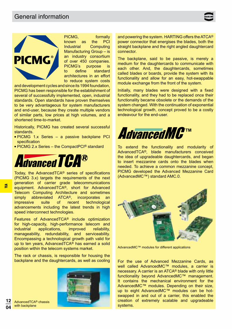
1204
TCA
General information
PICMG, formally known as the PCI Industrial Computing Manufacturing Group – is an industry consortium of over 450 companies. PICMG’s purpose is � ����� ����� �architectures in an effort to reduce system costs
and development cycles and since its 1994 foundation, PICMG has been responsible for the establishment of several of successfully implemented, open, industrial standards. Open standards have proven themselves to be very advantageous for system manufacturers and end-user, because they create multiple vendors of similar parts, low prices at high volumes, and a shortened time-to-market.
Historically, PICMG has created several successful standards. ● PICMG 1.x Series – a passive backplane PCI
�����������● PICMG 2.x Series – the CompactPCI® standard
Today, the AdvancedTCA® �� ��� �� ������������(PICMG 3.x) targets the requirements of the next generation of carrier grade telecommunications equipment. AdvancedTCA®, short for Advanced Telecom Computing Architecture and sometimes simply abbreviated ATCA®, incorporates an impressive suite of recent technological advancements including the latest trends in high speed interconnect technologies.
Features of AdvancedTCA® include optimization for high-capacity, high-performance telecom and industrial applications, improved reliability, manageability, redundability, and serviceability. Encompassing a technological growth path valid for up to ten years, AdvancedTCA® has earned a solid position within the telecom systems market.
The rack or chassis, is responsible for housing the backplane and the daughtercards, as well as cooling
and powering the system. HARTING offers the ATCA® power connector that energises the blades, both the straight backplane and the right angled daughtercard connector.
The backplane, said to be passive, is merely a medium for the daughtercards to communicate with each other. And, the daughtercards, sometimes called blades or boards, provide the system with its functionality and allow for an easy, hot-swappable module exchange from the front of the system.
�������z{ ���z ������ �� � �������� ��� � �[��functionality, and they had to be replaced once their functionality became obsolete or the demands of the system changed. With the continuation of exponential technological growth, concept proved to be a costly endeavour for the end-user.
To extend the functionality and modularity of AdvancedTCA®, blade manufacturers conceived the idea of upgradeable daughtercards, and began to insert mezzanine cards onto the blades when needed. To achieve a common mezzanine concept, PICMG developed the Advanced Mezzanine Card (AdvancedMC™) standard AMC.0.
AdvancedMC™ modules for different applications
For the use of Advanced Mezzanine Cards, as well called AdvancedMC™ modules, a carrier is necessary. A carrier is an ATCA® blade with only little functionality beyond AdvancedMC™ management. It contains the mechanical environment for the AdvancedMC™ modules. Depending on their size, up to eight AdvancedMC™ modules can be hot-swapped in and out of a carrier, this enabled the creation of extremely scalable and upgradeable systems.
AdvancedTCA® chassis with backplane

1205
TCA
General information
AdvancedTCA® carrier board with AdvancedMC™ modules
To connect AdvancedMC™ modules to carrier ��� ��'���>��������������"��������������connector: the AdvancedMC™ connector – a card edge connector mounted on the carrier board. It contacts directly with the module’s PCB gold pads. !������ '���> ������ ��� !�`�������§connector types (B, B+, AB and A+B+), current market developments focus on type B+.
The HARTING AdvancedMC™ B+ connector features a new design element that supplements the standard ¨ �� >����&� ���% ��� >����&� ��� ����������zincreases the mating reliability and prevents contact interruptions and surface wear when subjected to shocks or vibrations.
��� � ���"� � ������� ��������z � �`��������������������� �����z��`�������`� ��� termination technologies. The connector design �������� ������������� ��� ��Z���%�� �� �press-in process control, HARTING offers a special top and bottom tool.
The HARTING AdvancedMC™ Plug Connector can replace the module´s PCB gold pads and increase the contact reliability from the module side. '����� ��� �� � ���� ����� ���� �� �!\���>AdvancedMC™ Plug Connector on page 12.17 ff.
This revolutionary AdvancedMC™-based design concept has led to the recent development of a completely mezzanine-based system – MicroTCA™. MicroTCA™, short for Micro Telecom Computing ! ������ �{ �� � �� � ���"������� ����� �than AdvancedTCA® when dealing with smaller applications, yet powerful enough to address the needs of telecom, enterprise and medical applications.
This newly-implemented PICMG standard, outlined �� �� ���!%� �����������{ � ����� � ������"concept whereby AdvancedMC™s – the same kind used in ATCA® systems – plug directly into a passive backplane; this eliminates the need for carrier boards.
MicroTCA™ double cube system
Naturally the mating face of the AdvancedMC™ connector for MicroTCA™ is the same as for ATCA®, but with a right angled mating direction. It contains the new GuideSpring and is available in press-in termination. PICMG members voted HARTING’s MicroTCA™ connector footprint as the new MicroTCA™ standard ������� �� � ���"�� ���������������z%
AdvancedMC™ and power connectors for MicroTCA™
The MicroTCA™ backplane is typically powered by �������{ ���� ����������{ ��"��������{ �������Power Supply Units (PSU). The PSU connects to the backplane through a MicroTCA™ power connector +� ���"�� �������;�����`�������� ���!\���>%
MicroTCA™ backplane
The module management is performed by a MicroTCA™ Carrier Hub, or MCH. An MCH is connected to the backplane by up to four adjacent card-edge connectors. One MCH can control up to 12 AdvancedMC™ modules, thus depending on redundancy requirements, workload, or both, one or two MCHs may be used within a single system.
For a precise mechnical alignment of the mating tongues HARTING offers the special Plug Connectors according to MTCA.0.
MCH board

1206
TCA
con:card+
PdNi contact coatingIn order better to meet the high requirements placed on the connectors, a palladium-nickel ��������� �������������������������������As a result, wear resistance is increased by ������� �� �� ���� ���� ������� ���� ������! PdNi surfaces offer a quality and corrosion-resistant coating that meets the high requirements placed on the connection far "������������������
Special contact design#���$� ������������ %����� �����%� ���� %��������%�������������!���&�������'()����������!������!�������������������������*�order to ensure a permanently reliable contact, this single contact tongue must press against ��� ���� ��� ���� ���+����� ����� ������������� ������ ������%�� *� ��������! ��� ����$���� ����� &�������'() %������ %�� �������� "� ./���0�%����������������!1&20* 3�����4��������������������������������������5�����for the con:card+����������
What is con:card+?con:card+ is a quality seal for AdvancedMC™ connectors that ����� � ����`� � ���������increase in the reliability of MicroTCATM and AdvancedTCA® systems. In order to reach the target availability of 99.999 %, all system components must be carefully coordinated, and they must function reliably. The selection of suitable connectors is an essential, decisive factor here, as today it is virtually impossible for series production to meet the strict tolerances for the AdvancedMCTM ������� �� ������ �� �� ������`�������������%�����"������>����&� ��� �� ������z ����� �� ������������� �{ ��� �� ����� _�� ������������`�Z�z��`����������con:card+ philosophy. All the advantages are introduced in the following. '���������� �� ���� ���������������� ������%����� �����%���%

1207
TCA
GuideSpring�(6 %������������ ��� ��� ����"�� ��%������ ��� &�������'() %������7tight tolerances with certainty in the series ������� ������ 8��� � ������ ���� ����tolerances slightly larger than allowed by ��� �����+������� ��� ���� �� � �����%"���$�����0�� con:card+ 3����9����� ������������ ��������� ���������� "� ����������pressing the module against the opposite ����� &� ���� �� ��������� ��%�����towards the middle, the slot is optimally ����������� ���&�������'()%�����!and the mating reliability increases ���%���������*� ��������! ��� 3����9����� ������� ���module position in the case of shocks and ��"�������� 0��� �������� ���� �� ����������������������
Smooth contact surface0�������+������������&�������'()�������:�� %����� ������ ��� � %������ ;� ��� �(6!��� ���$��<���� ���� ����� �� ��� ���������� ����copper can only stand up to this high load if the �����������������"���������%�����0��� �� ����������� ���con:card+ ����������=�����������5�������������%����������>��������������4�����������@������%�������%�����������������������������%�������!1&20* 3��������������������%���%�4���������������
������������ � �������@+� ���������� ������� �� � ���@�����!corrosion-resistant, low-ohm quality mechanical connection between the pin and the through ������������ ����(6�0��� ��%���� �����"�� ���������������"��!�������������������������%����������������%�������!��������"������!"������������>������%����������������0���������������������������%����������������������������������������>����'������%����substantiate that the required transmission rates ������������������

1208
TCA
Design according PICMG AMC.0 (RoHS compliance)
Materials Moulded parts Liquid Crystal Polymer
(LCP), UL 94-V0Contacts Copper AlloyContact surface Pd/Ni with Au flash
AdvancedMC™ connectors for AdvancedTCA®
Number of contacts 170Contact spacing 0.75 mmClearance and creepage distance between contacts 0.1 mm min.
Nominal differential impedance 100 �±10 %
Max. crosstalk @ 25 ps risetime Bottom routeAdjacent 0.55 %Basic-to-extended (diagonal) 0.68 %Basic-to-extended (opposite) 0.39 %Multiline (five multi-aggressor differential pairs) 2.74 % max.
extended side
basic side
ground
2.25 0.75
1.5
1.5
1.5
1.5
PCB library on request (PADS/Dx-Designer)
SPICE models and S-Parameter on request
Differential propagation delay Basic side: 125 ps Extended side: 145 psDifferential skew Between basic and extended side: 20 ps Within basic and extended side: ±2 ps
Working current of ~ 2.2 A @ 70 °C power contacts max. 30 °C temp. rise as defined (PICMG requirement min. 1.52 A) in AMC.0 spec.
Test voltage 80 Vr.m.s.
Working voltage typically 3.3 V; 5.0 V; 12.0 V
Initial contact resistance ground contacts 60 m� max. signal, power, general purpose contacts 90 m� max.Initial insulation resistance 100 M��min.
Temperature range -55 °C … +105 °CDurability as per AMC.0 specification 200 mating cycles
Termination technique Press-in terminationMating force 100 N max., typically 65 - 90 N
( depending on AdvancedMC™)Withdrawal force 65 N max., typically 30 - 45 N
( depending on AdvancedMC™)
Packaging Cardboard box (other packaging on request)
Technical characteristics
Recommended plated through hole specification
A Drill hole-Ø 0.64±0.01 mm
B Cu 25 - 35 μm
Tin plated PCB (HAL)
C Sn 5 - 15 μm
D Hole-Ø 0.53 - 0.60 mm
Au / Ni plated PCB
C Ni 3 - 7 μm
Au 0.05 - 0.12 μm
D Hole-Ø 0.55 - 0.60 mm
Chemical tin plated PCB
C Sn 0.8 - 1.5 μm
D Hole-Ø 0.56 - 0.60 mm
OSP copper plated PCB
C --- ---
D Hole-Ø 0.56 - 0.60 mm
E Pad size min. 0.95 mm
The press-in zone of the AdvancedMC™ connector is tested according to Telcordia/Bellcore GR 1217CORE Part7. It is approved to be used with a plated through hole according IEC 60 352-5 with a diameter of 0.55±0.05 mm (drilled hole 0.64±0.01 mm).Based on our experiences regarding the production process of the PCB manufacturer we recommend a plated through hole configuration like shown in the above spreadsheet. To achieve the recommended plated through hole diameter, it is important to specify especially the drilled hole diameter of 0.64±0.01 mm to your PCB supplier.For drillings use e.g. drill bit # 72 (0.025" «�%�^��;%

1209
TCA
Contact length [mm] No. of terminationIdentification contacts side Part number
170 2.0 16 04 170 5104 000AdvancedMC™ connector for ATCA®, type B+
with peg and with GuideSpring
With peg With peg
Dimensions [mm]
170 2.0 16 04 170 5106 000AdvancedMC™ connector for ATCA®, type B+
without peg and with GuideSpring
Without peg Without peg
all holeskeep out area for press in bottom tool
row for ground
Board drillings (view magnified)
AdvancedMC™ connectors for AdvancedTCA®
Card edge connectors, angled
1) fixing-hole optional
2) non-metallized drillings
3) recommended plated through hole specification see page 12.08

1210
TCA
Design according PICMG 3.0 R2.0
Power connectors for AdvancedTCA®
Total number of contacts 30, max. 34
Power contacts 8Signal contacts 22, max. 26
Clearance and creepage distance between contacts
Within group 5–16 0.7 mm min. Within group 17–24 2.5 mm min. 25 to 26 5.5 mm min. Within group 27–34 1.4 mm min. 13–16 to 17–20 3.0 mm min. 21–24 to 25–26 4.0 mm min. 25–26 to 27–29 2.0 mm min.
Sequential contact engagement1st 25, 26, 28, 29, 30, 31 2nd 33 3rd 5–24, 34 4th 27, 32
Working currentPower contacts 16 ASignal contacts 1 A
Test voltageContacts 1–16 1000 Vr.m.s.
Contacts 17–34 2000 Vr.m.s.
Initial contact resistancePower contacts � 2.2 m� Signal contacts � 8.5 m�
Insulation resistance � 1010 �
Temperature range -55 °C … +125 °CDurability 250 mating cycles Termination technique Press-in terminationMating force 67 N max.Withdrawal force 67 N max.
Materials Moulded parts PBT, glass-fibre filled,
UL 94-V0Contacts Copper AlloyContact surface Selectively gold plated
Packaging Tray packaging (other packaging on request)
Technical characteristics
Recommended plated through hole specification
Signal contacts Power contacts
A Drill hole-Ø 1.15±0.025 mm 1.75±0.025 mm
B Cu 25 - 35 μm 25 - 35 μmTin plated PCB
(HAL)C Sn 5 - 15 μm 5 - 15 μmD Hole-Ø 1.00 – 1.10 mm 1.60 – 1.70 mm
Au / Ni plated PCB
C Ni 3 - 7 μm 3 – 7 μmAu 0.05 - 0.12 μm 0.05 - 0.12 μm
D Hole-Ø 1.00 – 1.10 mm 1.60 – 1.70 mmChemical tin plated PCB
C Sn 0.8 - 1.5 μm 0.8 - 1.5 μmD Hole-Ø 1.00 – 1.10 mm 1.60 – 1.70 mm
Silver plated PCB
C Ag 0.1 - 0.3 μm 0.1 - 0.3 μmD Hole-Ø 1.00 – 1.10 mm 1.60 – 1.70 mm
OSP copper plated PCB
C --- --- ---D Hole-Ø 1.00 – 1.10 mm 1.60 – 1.70 mmE Pad size min. 1.4 mm min. 2.0 mm
The press-in zone of the AdvancedTCA® power con-nector is tested according to Telcordia/Bellcore GR 1217CORE Part7. It is approved to be used with a plated through hole according IEC 60 352-5 with a diameter of 1.00 + 0.09
– 0.06 mm for signal contacts and 1.60 + 0.09– 0.06 mm
for power contacts (drilled hole 1.15±0.025 mm resp. 1.75±0.025 mm).Based on our experiences regarding the production process of the PCB manufacturer we recommend a plated through hole configuration like shown in the above spreadsheet. To achieve the recommended plated through hole diameter, it is important to specify especially the drilled hole diameter of 1.15±0.025 mm resp. 1.75±0.025 mm to your PCB supplier.
Derating for ATCA® power contacts Contact loading acc. PICMG 3.0
À Derating
Á Derating @ Imax. x 0.8 (acc. IEC 60 512-5-2) Ambient temperature [° C]
Cur
rent
[A]

1211
TCA
Power connectors for AdvancedTCA®
Contact length [mm] No. of terminationIdentification contacts side Part number
30 4.1 16 32 030 1101 000 34 4.1 16 32 034 1101 000
Power connector for AdvancedTCA®, male
Dimensions [mm]
30 5.3 16 31 030 1201 000 34 5.3 16 31 034 1201 000
Power connector for AdvancedTCA®, female
Board drillings
1) + 2) recommended plated through hole specification see page 12.10
Male connector with 30 contacts Female connector with 30 contacts
Signal contacts position
Dimension A
5–24 6.127, 32 3.8
Power contacts position
Dimension B
25–26 14.328–31 14.3
33 11.334 8.8
position
view X
position
view X
position

1212
TCA
AdvancedMC™ connectors for MicroTCA™
Technical characteristicsDesign according PICMG MTCA.0 R1.0 (RoHS compliance)
Materials Moulded parts Liquid Crystal Polymer
(LCP), UL 94-V0Contacts Copper AlloyContact surface Pd/Ni with Au flash
Au over Ni on request
Number of contacts 170Contact spacing 0.75 mmClearance and creepage distance between contacts 0.1 mm min.
Nominal differential impedance 100 �±10 %
Max. NEXT @ 25 ps risetime Bottom routeAdjacent 0.65 %Basic-to-extended (diagonal) 0.60 %Basic-to-extended (opposite) 0.73 %Multiline (five multi-aggressor differential pairs) 2.88 % max.
extended side
ground
basic side
2.25 0.2
1.5
1.5
1.5
1.5
PCB library on request (PADS/Dx-Designer)
SPICE models and S-Parameter on request
Differential propagation delay Basic side: 70 ps ± 5 ps Extended side: 70 ps ± 5 psDifferential skew Between basic and extended side: ±2 ps Within basic and extended side: ±2 ps
Working current of ~ 2.3 A @ 70 °C power contacts max. 30 °C temp. rise as defined (PICMG requirement min. 1.52 A) in MTCA.0 spec.
Test voltage 80 Vr.m.s.
Working voltage typically 3.3 V; 5.0 V; 12.0 V
Initial contact resistance 25 m� max.Initial insulation resistance 100 M� min.
Temperature range -55 °C … +105 °CDurability as per MTCA.0 spec. 200 mating cycles Termination technique Press-in terminationMating force 100 N max., typically 60 - 80 N
( depending on AdvancedMC™)Withdrawal force 65 N max., typically 40 - 60 N
( depending on AdvancedMC™)
Packaging Cardboard box (other packaging on request)
Recommended plated through hole specification
A Drill hole-Ø 0.64±0.01 mm
B Cu 25 - 35 μm
Tin plated PCB (HAL)
C Sn 5 - 15 μm
D Hole-Ø 0.53 - 0.60 mm
Au / Ni plated PCB
C Ni 3 - 7 μm
Au 0.05 - 0.12 μm
D Hole-Ø 0.55 - 0.60 mm
Chemical tin plated PCB
C Sn 0.8 - 1.5 μm
D Hole-Ø 0.56 - 0.60 mm
OSP copper plated PCB
C --- ---
D Hole-Ø 0.56 - 0.60 mm
E Pad size min. 0.95 mm
The press-in zone of the AdvancedMC™ connector is tested according to Telcordia/Bellcore GR 1217CORE Part7. It is approved to be used with a plated through hole according IEC 60 352-5 with a diameter of 0.55±0.05 mm (drilled hole 0.64±0.01 mm).Based on our experiences regarding the production process of the PCB manufacturer we recommend a plated through hole configuration like shown in the above spreadsheet. To achieve the recommended plated through hole diameter, it is important to specify especially the drilled hole diameter of 0.64±0.01 mm to your PCB supplier.For drillings use e.g. drill bit # 72 (0.025" «�%�^��;%

1213
TCA
I
IIIII
Guide Spring
AdvancedMC™ connectors for MicroTCA™
Contact length [mm] No. of terminationIdentification contacts side Part number
Card edge connectors, straight
Dimensions [mm]
Board drillings (view magnified)
all holes
housing contour
row for groundLc of card slot
with GuideSpring I 170 2.1 16 11 170 5202 000
with GuideSpring and protection shield II 170 2.1 16 11 170 5205 000
with GuideSpring and alignment peg III 170 2.1 16 11 170 5206 000
with GuideSpring, protection shield and alignment peg 170 2.1 16 11 170 5207 000
AdvancedMC™ connectors for MicroTCA™
with alignment peg without alignment peg
alignment peg
without alignment
peg
protection shield
1) recommended plated through hole specification see page 12.12
2) non-metallized drillings optional: for part numbers 16 11 170 5202 000 and 16 11 170 5205 000 mandatory: for part numbers 16 11 170 5206 000 and 16 11 170 5207 000
3) for optional fixing: use self-tapping screws for plastic, 2.2 x length (length = PCB thickness + min. 6.5 mm to max. 10 mm) e.g. HARTING part number 09 06 001 9974 Screwing torque references: PCB + 6.5 mm: 20 cNm PCB + 10 mm: 40 cNm

1214
TCA
Power output connectors for MicroTCA™
Technical characteristicsDesign according PICMG MTCA.0 R1.0 (RoHS compliance)
Temperature range -55 °C … +105 °CDurability 200 mating cycles Termination technique Press-in terminationMating force 145 N max.Withdrawal force 110 N max.
Working currentPower contacts 9.3 A @ 80 % derating
acc. IEC 60 512 and 70 °C ambient temperature and 30 °C temperature rise
Signal contacts 1 A @ 80 % derating acc. IEC 60 512 and 70 °C ambient temperature
Initial contact resistancePower contacts � 5 m�Signal contacts � 25 m�
Initial insulation resistance � 100 M� min.
Total number of contacts 96
Power contacts 24Signal contacts 72
Sequential contact engagement
1st Power 4–112nd Power 1–3, power 12–243rd Signal A2–H94th Signal A1
Materials Moulded parts PBT, glass-fibre filled,
UL 94-V0Contacts Copper AlloyContact surface
Power contacts: selectively gold platedSignal contacts: selectively
PD/Ni plated
Packaging Tray packaging (other packaging on request)
Recommended plated through hole specification
A Drill hole-Ø 0.7±0.02 mm
B Cu 25 - 35 μm
Tin plated PCB (HAL)
C Sn 5 - 15 μm
D Hole-Ø 0.60 - 0.65 mm
Au / Ni plated PCB
C Ni 3 - 7 μm
Au 0.05 - 0.12 μm
D Hole-Ø 0.60 - 0.65 mm
Chemical tin plated PCB
C Sn 0.8 - 1.5 μm
D Hole-Ø 0.60 - 0.65 mm
Silver plated PCBC Ag 0.1 - 0.3 μm
D Hole-Ø 0.60 - 0.65 mm
OSP copper plated PCB
C --- ---
D Hole-Ø 0.60 - 0.65 mm
E Pad size min. 1.0 mm
The press-in zone of the MicroTCA™ power con-nector is tested according to Telcordia/Bellcore GR 1217CORE Part7. It is approved to be used with a plated through hole according IEC 60352-5 with a diameter of 0.60+0.05 mm (drilled hole 0.70±0.02 mm).Based on our experiences regarding the production process of the PCB manufacturer we recommend a plated through hole configuration like shown in the above spreadsheet. To achieve the recommended plated through hole diameter, it is important to specify especially the drilled hole diameter of 0.70±0.02 mm to your PCB supplier.Derating for MicroTCA™ power contacts
Contact loading acc. MTCA.0
À Derating
Á Derating @ Imax. x 0.8 (acc. IEC 60 512-5-2) Ambient temperature [° C]
Cur
rent
[A]

1215
TCA
Contact length [mm] No. of terminationIdentification contacts side Part number
module version 96 2.8 16 34 096 1101 000
backplane version 96 3.7 16 33 096 1201 000
Power output connectors for MicroTCA™
Dimensions [mm]
Board drillings
1) recommended plated through hole specification see page 12.14
Module version Backplane version
all holesposition
all holes
all holesposition
positionposition
all holes
row
row
row
row
view X
Power output connectors for MicroTCA™

1216
TCA
Protection Block for MicroTCA™ backplanes
The MicroTCA™ specification defines modules with the option of multiple mating interfaces like the MCH module for system management and switching. There are four different pitches defined for the module in-terfaces and the backplane connectors respectively, the basic unit is called horizontal pitch (HP) and is 5.08 mm (0.2 inch).
Compact-Size 3 HP 15.24 mm
Mid-Size 4 HP 20.32 mm
Full-Size 6 HP 30.48 mm
MCH 1.5 HP 7.62 mm
Any MCH (or other multiple mating interface modules) with more than two mating interfaces (2x MCH-pitch 1.5 HP = Compact-Size pitch 3 HP) could unintentional mate with connectors of the adjacent slot or could be plugged into the wrong slot. Even though the pin- assignment and e-keying for the MCH is defined, it can cause system failures or even destroy hardware if a MCH is inserted into two adjacent AMC Compact-Size slots. For other multiple mating interface modules, this situation is even worse, because neither e-keying nor pin assignment is specified in MTCA.0.
Identification Part number
MicroTCA™ Protection Block 16 79 000 0010 000
To prevent errors in case of misinsertion, MTCA.0 R1.0 chapter 2.13 outlines protection blocks that occupy the space between two adjacent connectors in a Compact-Size slot. Furthermore this protection block can be used for keying functions of multiple mating interface modules.
HARTING designed a protection block fully in-dependent of the back-plane and sub rack de-sign. The HARTING pro-tection block is clipped between two connec-tors, hence no fixing features (holes, clips...) need to be designed into the backplane or the sub rack mechanics. The assembly is done quick and easy by hand. It can even be installed easily after the backplane is mounted with a simple flat-head screwdriver, an easy removal is possible in a similar way. The keying block can be placed into four different positions, hence a keying of multitongue modules by using tongues with a cutout is possible.
MicroTCA™ backplane with protection blocks
The free space between the backplane connectors is occu-pied by the protection block

1217
TCA
The PICMG specification AMC.0 defined a card edge with gold pads as the mating interface for the
AdvancedMC™ module. As already explained in the chapter “con:card+”, it is very difficult for a PCB manufacturer to produce the tight tolerances required for the AdvancedMC™ module card edge in a consistent process. Furthermore, the quality of the gold pads is only specified in general terms.
Replacing the PCB gold pads with a connector eliminates certain drawbacks of the card edge connection. The HARTING Plug Connector offers the following advantages:
The major advantage is that a solid contact with a band plated surface mates with the backplane connector. The connection is no longer made directly from the card edge to the backplane connector but instead indirectly via a module connector approved from one source. The AdvancedMC™ module with a Plug Connector is still within the dimensional range of the PICMG AMC.0 specification and is fully mating compatible with AdvancedMC™ card edge connectors. Consequently the Plug Connector can be used in both MicroTCA™ and ATCA® environments.
The injection moulding process is much more precise than the PCB production process. While the AMC.0 specification defines a PCB width tolerance of 0.1 mm,
the moulding process has a dimensional tolerance less than 0.03 mm. The lead-in chamfer is milled for the PCB but is realized in the connector as a smooth moulded plastic chamfer. Compared with the rough surface of a PCB chamfer with exposed glass fibre, the smooth Plug chamfer avoids abrasion of the backplane connector contact surface.
The AMC.0 specification defines hard gold to be on the PCB pads. However a common and unique definition of hard gold does not exist today. Additionally, the interruptions of the gold pads (which are necessary for the hot-swap ability) require a selective hard gold process. This is a complex process which is relatively expensive, so commonly just chemical gold with insufficient surface thickness is used. As a result, there are significant differences in the durability of the gold and the surface structure on the modules which are currently available.The contacts of the HARTING AdvancedMC™ Plug Connector are plated all-around and are manufactured in a defined band plating process with controlled quality. There are different performance levels possible as the noble finish thickness can be adapted easily to meet customer demands.
Reduced mating forcesFor the module card edge, the prepads of lagging contacts are required by the Telcordia/Bellcore specification to avoid stress of the connector contact when sliding on the FR4 base material. The Plug Connector does not need prepads. The four mating steps are realized with true lagging contacts. The sophisticated design of the insulator reduces the mating forces of the module significantly.
By using a HARTING AdvancedMC™ Plug Connector, the mating interface of the module is defined by the connector instead of the PCB. This fact leads to clear advantages and provides a wider scope for the module development. The restriction of the PCB thickness of 1.6 mm +/-10% is no longer a limiting factor. A PCB
General information about Plug Connectors

1218
TCA
General information about Plug Connectors
thickness of e.g. 2 mm can be used as this fits in the mechanical environment.
For backplanes press-fit termination is the first choice, however solder termination offers advantages for module cards. The Plug Connector is mounted to the
PCB through “pin-in-hole-reflow” solder technology (PIHR). It can be soldered in the same production process as the other semi finished components on the AdvancedMC™ module. Another advantage
of this mechanically stable technology is, that the connector can be replaced. This can avoid the cost of scrapping a module if the mating interface is damaged during handling.
By offering so many different advantages during the manufacturing process, the use of HARTING Plug Connectors also contributes to keeping costs down. Selective plating increases the cost of producing gold pads. Tight tolerance specifications also cause a large number of rejects. The beveled PCB edge is another
The HARTING Plug Connector is available in two versions. The difference is the mounting direction, i. e. the side of the AdvancedMC™ module PCB on which the Plug Connector is assembled.
The so called basic side refers to the component side 1 as defined in the AMC.0 specification (pins 1 to 85). The main components are mounted on the basic side (sometimes also called top side).During the manufacturing process, a Plug Connector that is mounted from the basic side can be soldered in the same assembly step as the other large components.
Extended sideThe so called extended side refers to the component side 2 as defined in the AMC.0 specification (pins 86 to 170).A Plug Connector mounted on the extended side is “hanging” at the bottom side of the AdvancedMC™ module.
critical area, because damage can occur to the contact pads.
A simple board layout with through-holes is sufficient for the HARTING Plug, and these boards can be
produced inexpensively and with excellent quality control, thus reducing the number of rejects. Furthermore the cost of a reject can be high if a defective PCB edge is not detected until the board is populated with expensive components. A HARTING Plug on a module can be replaced easily, reducing scrapping costs.
This picture shows an AdvancedMC™ module with a Plug Connector mounted on the extended side.
The footprint of a Plug Connector for the basic side is different than that for the extended side. The connectors are not interchangeable. Due to advantages in the assembly of the connector, the basic side version is preferable.For an MCH stack, only connectors having the same mounting direction can be stacked.
Mounting direction
Extended side(Bottom side)
Basic side(Top side)

1219
TCA
Design according PICMG MicroTCA.0 R1.0 PICMG AMC.0 R2.0 (RoHS compliance)
Materials Moulded parts Liquid Crystal Polymer
(LCP), UL 94-V0
Contacts Copper alloy
Contact surface Au over Ni
Nominal differential impedance 100 Ω ± 10 %
Max. crosstalk @ 25 ps risetime Bottom routeAdjacent 0.5 %Basic-to-extended (diagonal) 0.2 %Basic-to-extended (opposite) 0.7 %Multiline (five multi-aggressor differential pairs)
2.1 % max.
Propagation delay Long contact side: 152 ps / 147 ps Short contact side: 121 ps / 129 ps
Skew within differential pairs Long contact side: 5 ps Short contact side: 8 ps
Working current of ~ 2.4 A @ 70 °C power contacts max. 30 °C temp. rise as defined (PICMG requirement min. 1.52 A) in AMC.0 spec., tested with HARTING MicroTCA™ backplane connector
Test voltage 80 Vr.m.s.
Working voltage typically 3.3 V; 5.0 V; 12.0 V
Initial contact resistance 25 m� max. Initial insulation resistance 100 M� min.
Number of contacts 170
Contact spacing 0.75 mm
Clearance and creepage distance between contacts 0.1 mm min.
Temperature range -55 °C … +105 °C during reflow soldering 220 °C for 2 minutes 270 °C max. short-term
Durability as per AMC.0 specification 200 mating cycles in total
Termination technique Solder termination (Pin in Hole Intrusive Reflow)
Mating force 100 N max., typically 40 - 70 N ( depending on backplane connector)
Withdrawal force 65 N max., typically 30 - 50 N ( depending on backplane connector)
The mating and withdrawal force is highly depending on the mating half connector, but typically only 50 % to 70 % of the mating force of a PCB card edge.
Packaging Tray packaging (other packaging on request)
Plated through hole recommendations
A Plated hole-Ø 0.55±0.05 mm
B Drill hole-Ø 0.65±0.01 mm
C Pad size 0.95 mm
Technical characteristics for Plug Connectors
Stencil recommendation (for basic side mounting)
Each termination requires a solder paste volume of 0.5 mm³. Since the stencil can only provide fractions of this volume (0.29 mm³ at 0.15 mm stencil thickness), the remaining solder paste must be pressed into the plated through hole. For a nominal AMC card (1.6 mm PCB thickness, 0.55 mm plated hole diameter) the paste must penetrate the hole by 0.9 mm.

1220
TCA
170 16 23 170 1301 000
Plug Connector for AdvancedMC™ modules
No. ofIdentification contacts Part number
AdvancedMC™ Plug Connectorfor basic side mounting
Dimensions [mm]
Board drillings (view of the basic side / component side 1)
AdvancedMC™ Plug Connector for basic side mounting
For mounting on basic side
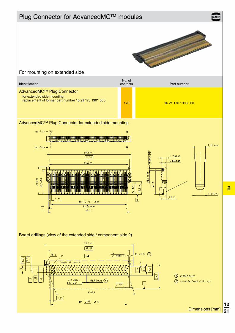
1221
TCA
170 16 21 170 1303 000
Plug Connector for AdvancedMC™ modules
No. ofIdentification contacts Part number
AdvancedMC™ Plug Connectorfor extended side mounting replacement of former part number 16 21 170 1301 000
Dimensions [mm]
Board drillings (view of the extended side / component side 2)
AdvancedMC™ Plug Connector for extended side mounting
For mounting on extended side

1222
TCA
General information about MCH Plug Connectors
An important component of a MicroTCA™ system is the “MicroTCA™ Carrier Hub”, abbreviated MCH. The main functions of an MCH module are hardware platform management and the management of the fabric connectivity. Since the MCH module requires many more connections than a standard AdvancedMC™ module, an MCH may have up to 4 mating tongues each with 170 contacts.
The MTCA.0 specification recommends the use of a special Plug Connector to reduce the insertion force of the module and to solve the tolerance stack-up problem between the multiple tongues and the backplane connectors.
The HARTING Plug Connector system consists of three different Plug Connectors. The
is required for an MCH module and is always used in the MCH1-slot. Furthermore it can be used for any conventional AdvancedMC™ module to replace the pcb gold pads.
AdvancedMC™ Plug, MCH Plug, Piggyback Plug
If more than one mating tongue is needed, the is mated with the backplane MCH
connectors 2 and 3 depending on the MicroTCA™
configuration. Compared to the AdvancedMC™ Plug, the MCH Plug insulator has standoffs ensuring the correct distance for the slot width between two tongues or backplane connectors respectively. The MCH and AdvancedMC™ Plugs have different contact staggering on the basic side, the extended side is equal.
The is designed for the MCH4 slot, but the connector itself is soldered on the PCB3. For a MicroTCA™ system with more than 6 AdvancedMC™ modules using the switched fabric fat pipe, an MCH module with 4 mating tongues must be used. In general the switched fabric is located only on the PCB3, so a high-speed connection is needed between the MCH4 slot and the PCB3.
To build a connector stack for two, three or four mating tongues, the HARTING Plug Connectors are mounted like building blocks via pegs and the holes on the adjacent Plugs. For additional mechanical stability, the connector stack is fixed using metal stacking pins. The complete connector stack can be installed easily without any special tooling.
Exploded view of an MCH stack with four tongues including Piggyback Plug
As with the AdvancedMC™ Plug, HARTING offers the Plug Connectors for MCH modules in versions for basic side or extended side mounting. Only connectors with the same mounting direction can be stacked together. The Piggyback Plug is only available as basic side version, therefore for a MCH module with four tongues, the basic side version is preferred.
MCH stacks in basic side version with 2, 3 and 4 tonguesMCH stack in extended side
version

1223
TCA
170 16 23 170 1301 000
170 16 24 170 1301 000
Plug Connectors for MCH modules
No. ofIdentification contacts Part number
Dimensions [mm]
Board drillings (view of the basic side / component side 1)
Dimensions for AdvancedMC™ Plug Connector for basic side mounting see page 12.20.
MCH Plug Connector for basic side mounting
For mounting on basic side
AdvancedMC™ Plug Connector for basic side mounting
MCH Plug Connector for basic side mounting
AdvancedMC™ – MCH Plug stacking-pin for basic side mounting
double length (for two stacked plugs) 11 mm 16 79 000 0017 000 triple length (for three stacked plugs) 18.5 mm 16 79 000 0019 000 quad length (for four stacked plugs) 22.5 mm 16 79 000 0020 000

1224
TCA
170 16 21 170 1303 000
170 16 22 170 1303 000
Plug Connectors for MCH modules
No. ofIdentification contacts Part number
Dimensions [mm]
Board drillings (view of the extended side / component side 2)
Dimensions for AdvancedMC™ Plug Connector for extended side mounting see page 12.21.
MCH Plug Connector for extended side mounting
For mounting on extended side
AdvancedMC™ Plug Connector for extended side mounting replacement of former part number 16 21 170 1301 000
MCH Plug Connector for extended side mounting replacement of former part number 16 22 170 1301 000
AdvancedMC™ – MCH Plug stacking-pin for extended side mounting
double length (for two stacked plugs) 11.5 mm 16 79 000 0006 000 triple length (for three stacked plugs) 19 mm 16 79 000 0007 000 quad length (for four stacked plugs) 26.5 mm 16 79 000 0008 000

1225
TCA
170 16 25 170 1301 000
Plug Connectors for MCH modules – Piggyback connector
No. ofIdentification contacts Part number
MCH Piggyback Plug Connectorapplicable only in basic side mounting configuration
Dimensions [mm]
Board drillings (view of the basic side / component side 1)
MCH Piggyback Plug Connector
Footprint of Piggyback connector
Footprint of MCH connector

The HARTING Micro Card Edge Connector is available
with 40 and 100 contacts at a pitch of 0.8 mm
and suitable for telecommunications, medical and
industrial high speed applications with data rates up
to 14 Gbps.
13. MICRO CARD EDGE CONNECTORS
Boardto
Board
Cable/Wire
toBoard
IP 20 IP 65 / IP 67
Data Signal PowerData
transfer rate
Shielding Number of contacts, contact density
Voltage, working current
Cable termination
Han- Quick Lock®
IDC Crimp
Screw Cage clamp
Axial screw
PCB termination
THT SMC SMT
Press-in
Application standard
Separate housing
Integratedhousing
high performance
Housing integration
App l icat ion prof i le:
Separate housing
Integratedhousing
Housing integration
Cable termination
Han- Quick Lock®
IDC Crimp
Screw Cageclamp
Axialscrew
Application standard
CONNECTION TYPE ENVIRONMENT APPLICATION

MCE
1301
13. MICRO CARD EDGE CONNECTORS
CONTENTS PAGE
Micro Card Edge connector system – introduction 13.02
Technical characteristics, board dimensions 13.05
40pin connector 13.06
100pin connector 13.07

1302
MCE
13. MICRO CARD EDGE CONNECTORS
MICRO CARD EDGE CONNECTORSHARTING offers the new Micro Card Edge Connector in surface-mounting technology for card gauges of 1.6 mm. It is suitable for board to board mezzanine as well as for small pluggable daughter card applications . The key feature for mezzanine applications is the very flexible stacking height of parallel boards by utilizing a small board between the connectors. This gives flexibility in the mechanical design of the system.The HARTING Micro Card Edge Connector is able to transfer data rates up to 14 Gbps, suitable for telecommunications, medical
and industrial high speed applications. It is available with 40 and 100 contacts at a pitch of 0.8 mm. An extremely smooth contact surface achieved by high performance stamping tools and a special after – treatment ensures low insertion forces and a high contact reliability.HARTING s Micro Card Edge Connector offers excellent manufacturing features like a tape & reel packaging with a pick & place pad for nozzle in high volume productions.

1303
MCE
Flexible stacking height of parallel boards by utilizing a small board
between the connectors.
Excellent manufacturing features for high volume production
High speed data transmission up to 14 Gbps between mezzanine
or daughter card boards in telecom, medical, datacom and
industrial applications.
SPECIFIC FEATURES OF THE PRODUCT R ANGE

1304
MCE
Notes

1305
MCE
min. 20 mm
max. ¬
Micro Card Edge connector Technical characteristics
Contact spacing : 0.8 mm
Working current : 1.7 A at 80 °C ambient Test voltage : 600 V AC
Mating cycles : 200
Number of contacts : 40, 100
Mating card thickness : 1.6 + 0.1 mm
Operating temperature : -55 °C … +125 °C Max processing temperature : 230 °C for 60 sec. or
260 °C for 20 sec.
ROHS-compliance : yes
Materials
Mouldings : LCP, glass-fibre filled, UL 94-V0
Contacts : Copper alloy with Ni plating
Contact surface Contact zone : Pd/Ni plating Termination zone : Sn/Ni plating
Board dimensions
Recommended mating card layout
100pin40pin

1306
MCE
40 15 01 040 4601 040
40 15 01 040 4601 042
40 15 01 040 4601 333
NumberIdentification of contacts Part No. Drawing Dimensions in mm
40pin connector
Board layout
“Tape and Reel” packaging
Micro Card Edge connector
position
position
pick & place pad, self-adhesive
20 empty pockets
trailer
200 pockets with components20 empty pockets
leader
position 1
pin 2 pin 40
pin 1
pin 39
Micro Card Edge connector
2800 pieces in a “Tape and Reel” packaging (14 reels with 200 pcs.)
200 pieces in a “Tape and Reel” packaging
Single connector sample
Reel dimensions
6“ (a
ppr.
Ø 1
50 m
m)
0,5“
(app
r. Ø
13
mm
)
15“ (appr. Ø 380 mm)

1307
MCE
100 15 02 100 4601 040
100 15 02 100 4601 042
100 15 02 100 4601 333
NumberIdentification of contacts Part No. Drawing Dimensions in mm
100pin connector
Board layout
Micro Card Edge connector
“Tape and Reel” packaging
position
position pick & place pad, self-adhesive
20 empty pockets
trailer
200 pockets with components20 empty pockets
leader
position 1
pin 2 pin 100
pin 1pin 99
Micro Card Edge connector
1800 pieces in a “Tape and Reel” packaging (9 reels with 200 pcs.)
200 pieces in a “Tape and Reel” packaging
Single connector sample
Reel dimensions
6“ (a
ppr.
Ø 1
50 m
m)
0,5“
(app
r. Ø
13
mm
)
15“ (appr. Ø 380 mm)

The continuous scalability by an even number of contacts, i.e. from 6 to 100,
of the HARTING‘s har-flex® mezzanine connector series is a special feature
forming an ideal basis for customized applications. The advantage is clearly
evident considering that the connector is always optimized to suit specific
applications on the device PCB, while also covering the medium- and small-
scale volume range that is typical for the production of industrial devices.
14. har - f lex® CONNECTORS
Boardto
Board
Cable/Wire
toBoard
IP 20 IP 65 / IP 67
Data Signal PowerData
transfer rate
Shielding Number of contacts, contact density
Voltage, working current
Cable termination
Han- Quick Lock®
IDC Crimp
Screw Cage clamp
Axial screw
PCB termination
THT SMC SMT
Press-in
Application standard
Separate housing
Integratedhousing
high performance
Housing integration
App l icat ion prof i le:
Separate housing
Integratedhousing
Housing integration
Application standard
CONNECTION TYPE ENVIRONMENT APPLICATION

1401
har -
flex
1401
14. har - f lex® CONNECTORS
CONTENTS PAGE
connector system – introduction 14.02
Technical characteristics 14.04
Male connectors, straight 14.08
Female connectors, straight 14.10
Male connectors, angled 14.12
Female connectors, angled 14.14
Cable assemblies 14.16

1402
har -
flex
14. har - f lex® CONNECTORS
har-flex® CONNECTORSWith har-flex®, HARTING has developed a general-purpose PCB connector series for internal and external Device Connectivity. The continuous scalability by an even number of contacts, i.e. from 6 to 100, of the HARTING‘s har-flex® mezzanine connector series is a special feature forming an ideal basis for customized applications. The advantage is clearly evident considering that the connector is always optimized to suit specific applications on the device PCB, while also covering the medium- and small-scale volume range that is typical for the production of industrial devices.
This flexibility is new – HARTING turns an individual design into a standard component. No special tooling changes are needed for
customer-specific solutions, thus HARTING can realize a short delivery time.
PRODUCT DIVERSITYThe har-flex® product range with SMT termination technology is based on a 1.27 mm grid. With its diverse variants, HARTING provides connectivity solutions for many different board-to-board and cable-to-board applications. For example, two straight connectors are used for the mezzanine application, two angled connectors for PCBs on one level, and a combination allows the well-known pairing of mother and daughter cards. By using an IDC flat band cable, two PCBs with large space between can be connected.

1403
har -
flex
Many pin count options
HARTING has developed a modular tooling concept which offers a
broad choice of configurations between 6 and 100 poles in even
numbered positions. This flexibility in the choice of number of
contacts, combined with high density contact spacing, allow the
designer to maximize the use of PCB real estate, thereby achieving
overall space savings and cost efficiencies.
Flexible board-to-board distances
HARTING covers mezzanine applications with a range of straight
versions for four different stacking heights that can be used
to interconnect PCBs arranged in parallel stacks with spacing
between 8.0 mm and 13.8 mm. Additional stacking heights are in
development. For applications requiring larger spacing between
boards HARTING offers compatible cable assemblies terminated
with insulation displacement technology.
Robust design
The special SMT fixing ensures a robust and enduring connection
to the PCB and helps to absorb mechanical stress on the solder
contacts resulting from insertion and removal forces.
Automated processing features
The har-flex® SMT connectors meet the highest demands in terms
of their processing capabilities. Special blister packaging provides
protection during shipping and handling, while the “pick and place“
pads enable automated assembly of the PCBs. The temperature
resistant materials of the insulating body, in combination with
consistent testing of the coplanarity of contacts, ensure reliable
soldering capabilities of the connectors in the reflow process.
SPECIFIC FEATURES OF THE PRODUCT R ANGE

1404
har -
flex
15 . . . . . . . .2 . . .
15 . . . . . . . .6 . . .
15 . . . . . . . .5 . . .
Derating curve at Imax * 0.8 (IEC 60 512-5-2)
Technical characteristics
Current carrying capacity acc. to IEC 60 512-5-2The current carrying capacity is limited by maximum temperature of materials for inserts and contacts including terminals.The current capacity-curve is valid for continuous, not interrupted current-loaded contacts of connectors when simultaneous power on all contacts is given, without exceeding the maximum temperature.Control and test procedures according to DIN IEC 60 512-5-2.
Durability
Performance level 1 (recommended for majority of applications)
Initial 250 mating cycles, 10 days gas test (25 °C/75 % r.h.) using H2S 10 ppb, NO2 200 ppb, CL2 10 ppb, SO2 200 ppb. Measurement of contact resistance. The remaining 250 mating cycles are subject to measurement of contact resistance and visual inspection. Visual inspection. No abrasion of the contact finish through to the base material. No functional impairment.
Part number definition:
Performance level 2Initial 125 mating cycles, 4 days gas test (25 °C/75% r.h.) using H2S 10 ppb, NO2 200 ppb, CL2 10 ppb, SO2 200 ppb. Measurement of contact resistance. The remaining 125 mating cycles are subject to measurement of contact resistance and visual inspection. Visual inspection. No abrasion of the contact finish through to the base material. No functional impairment.
Part number definition:
Performance level S4Defined contact surface of min. 0.06 μm Au over 0.7+0.2 μm PdNi.
Part number definition:
Number of contacts 6, 8, 10 … 96, 98, 100
Connector pitch 1.27 mm x 1.27 mm [0.050’’ x 0.050’’]
Clearance and creepage distance Board connectors (SMT) min. 0.4 mm Cable connectors (IDC) AWG 30/1 (solid) min. 0.35 mm AWG 30/7 (stranded) min. 0.4 mm
Test voltage Ur.m.s. 500 VContact resistance ·:O��Insulation resistance ¸$�>�
Insertion and withdrawal force approx. 0.5 N / contact
Working temperature range for connectors: – 55 °C … + 125 °C for flat cable assembly: depends on cable type The higher temperature limit
includes the local ambient and heating effects of the contacts under load
Temperature during reflow soldering min. 150 s > 217 °C (acc. to ECA/IPC/JEDEC min. 30 s > 240 °C J-STD-075 Level PSL R0)
Electrical termination Board connectors SMT (Surface Mount Technology) Cable connectors IDC (Insulation
Displacement Connection)
Materials Moulding material LCP UL approval UL 94-V0 CTI value (Comparative Tracking Index) 175
Contacts base material Copper alloy
Contact surface Mating side Board connectors Au over PdNi
(acc. performance level) Cable connectors Au over PdNi
(acc. performance level) Termination side Board connectors (SMT) Sn Cable connectors (IDC) Sn

1405
har -
flex
1 5 X X X X X X X X X X X X
Technical characteristics
Working voltage acc. to IEC 60 664-1
The working voltage depends on user specific operational conditions. Depending on the installation category, the degree of pollution and the entire electrical environment, the working voltage is different. The standard IEC 60 664-1 specifies, in general, the minimum insulation distances for equipment. But it can also be used to determine the maximum working voltage with given requirements.
The following table shows the most common conditions applicable for the har-flex® connectors and exemplary calculations for the working voltage. For installation category, degree of pollution and other requirements which are not shown in the table we refer to the IEC 60 664-1.
Clearance / Creepage distance 0.4 mm
CTI-Value < 400
Isolation group III a/b
Electrical field type Case A (Inhomogeneous field)
Case B (Homogeneous field)
Installation category I II I II
Degree of pollution 1 1 1 1
Working voltage max. 150 V 100 V 150 V 150 V
Explanations:
– CTI value and isolation group are fixed values by the har-flex® connector characteristics.
– Installation category I: Equipment is intended for use only in appliances or installation parts, in which no overvoltages can occur. Equipment in this installation category in normally operated at extra low voltage.
– Installation category II: Equipment is intended for use in installations or parts of installations, in which lightning overvoltages need not be considered. Overvoltages caused by switching must be taken into account.
– Pollution degree 1: No pollution or only dry, non-conductive pollution occurs. The pollution has no influence.
– Pollution degree 2: Only non-conductive pollution occurs. A temporary conductive caused by condensation must be expected occasionally.
Part number definitionThe har-flex® part numbers have 14 digits and are based on the following scheme:
15 har-flex® family
Connector style 11 straight male connector 1.75 mm stacking height 12 straight male connector 3.25 mm stacking height 15 angled male connector 21 straight female connector 6.25 mm stacking height 22 straight female connector 9.05 mm stacking height 25 angled female connector
Number of contacts
Durability 2 performance level 1 5 performance level S4 6 performance level 2
Termination 6 SMT termination
Counting number
Packaging 000 Tape and reel packaging 333 Samples

1406
har -
flex
Technical characteristics
Stacking heights of straight connector versions
The har-flex® connectors cover mezzanine applications with a range of straight versions for four different stacking heights that can be used to interconnect PCBs arranged in parallel stacks with spacing between 8.0 mm and 13.8 mm.
Male 1.75 mm Male 3.25 mm
Female 6.25 mm Female 9.05 mm
Due to the wiping lengths of 1.5 mm, these four connectors cover the distance of 8 mm to 13.8 mm continuously.
Mating options
Mezzanine connection
Extender Card connection
Mother-to-Daughtercard connection
14 mm
13 mm
12 mm
11 mm
10 mm
9 mm
8 mm
stacking heights
male 1.75 mm female 6.25 mm
male 3.25 mm female 6.25 mm
male 1.75 mm female 9.05 mm
male 3.25 mm female 9.05 mm
PCB distance
8 mm - 9.5 mm
9.5 mm - 11 mm
10.8 mm - 12.3 mm
12.3 mm - 13.8 mm
part numbers
15 11 … 15 21 …
15 12 … 15 21 …
15 11 … 15 22 …
15 12 … 15 22 …

1407
har -
flex
Technical characteristics
Mating conditions
Inclination
Mismating
SMT processing notes
The har-flex® SMT con-nectors meet the highest demands in terms of their processing capabilities.
The connectors are delivered in a tape and reel packag-ing optimized for automatic assembly machines. A vacuum cover enables the automatic assembly with a vacuum nozzle.
The insulation body material is high temperature resistant, and due to the black colour a secure camera recognition is ensured.
For a reliable SMT solder process, the termination pins are 100 % checked for coplanarity.
Process / Moisture Sensitivity
During the reflow solder process, the connector has to resist ex-treme variations in temperature. Connectors consist in general of both plastic and metal parts, which have a different behaviour during the solder process. The Process Sensivity and also the Moisture Sensivity are tested according the ECA/IPC/JEDEC J-STD-075 specification.
Process Sensivity:
PSL means Process Sensitivity Level. PSL is a rating used to identify a component that is solder process sensitive. Damages of the connector after three times soldering are not permitted (e.g. melted edges).
Moisture Sensitivity:
MSL means Moisture Sensitivity Level. MSL is a rating indicat-ing a component’s susceptibility to damage due to absorbed moisture during storage. Damages of the connector after stor-age in damp heat and three times soldering are not permitted (e.g. blisters).
The har-flex® connectors are rated with PSL R0 and MSL 1. This is the maximum possible rating in both categories. The har-flex® connector resists three times soldering at the following conditions without damages:
����% $O� � ��z��� :$@ �� +��}����� ���� �� �{ �� ������point of the solder paste)
����%�����z���������������� ���� �� � +:^��� ?:^O��for har-flex®)
������ �� � ����� � ����� ���� ���� � *�!?�'�?]*#*� J-STD-075
��� �&U ��{��� �����$�/��� ��/O�����/O� ��%humidity was carried out
As the result, the har-flex® connectors are not process sensi-tive and not moisture sensitive according to ECA/IPC/JEDEC J-STD-075.
Tape acc. to IEC 60 286-3
Tape dimensions: Epoles 6 to 12 24.4poles 14 to 20 32.4poles 22 to 40 44.4poles 42 to 56 56.4poles 58 to 80 72.4poles 82 to 100 88.4

1408
har -
flex
6 15 1 . 006 . 601 . . . 8 15 1 . 008 . 601 . . . 10 15 1 . 010 . 601 . . . 12 15 1 . 012 . 601 . . . 14 15 1 . 014 . 601 . . . 16 15 1 . 016 . 601 . . . 18 15 1 . 018 . 601 . . . 20 15 1 . 020 . 601 . . . 22 15 1 . 022 . 601 . . . 24 15 1 . 024 . 601 . . . 26 15 1 . 026 . 601 . . . 28 15 1 . 028 . 601 . . . 30 15 1 . 030 . 601 . . . 32 15 1 . 032 . 601 . . . 34 15 1 . 034 . 601 . . . 36 15 1 . 036 . 601 . . . 38 15 1 . 038 . 601 . . . 40 15 1 . 040 . 601 . . . 42 15 1 . 042 . 601 . . . 44 15 1 . 044 . 601 . . . 46 15 1 . 046 . 601 . . . 48 15 1 . 048 . 601 . . . 50 15 1 . 050 . 601 . . . 52 15 1 . 052 . 601 . . . 54 15 1 . 054 . 601 . . . 56 15 1 . 056 . 601 . . . 58 15 1 . 058 . 601 . . . 60 15 1 . 060 . 601 . . . 62 15 1 . 062 . 601 . . . 64 15 1 . 064 . 601 . . . 66 15 1 . 066 . 601 . . . 68 15 1 . 068 . 601 . . . 70 15 1 . 070 . 601 . . . 72 15 1 . 072 . 601 . . . 74 15 1 . 074 . 601 . . . 76 15 1 . 076 . 601 . . . 78 15 1 . 078 . 601 . . . 80 15 1 . 080 . 601 . . . 82 15 1 . 082 . 601 . . . 84 15 1 . 084 . 601 . . . 86 15 1 . 086 . 601 . . . 88 15 1 . 088 . 601 . . . 90 15 1 . 090 . 601 . . . 92 15 1 . 092 . 601 . . . 94 15 1 . 094 . 601 . . . 96 15 1 . 096 . 601 . . . 98 15 1 . 098 . 601 . . . 100 15 1 . 100 . 601 . . .
333000
256
Male connectors, straight
Number Identification of contacts Part No. Dimensions in mm
Male connector, straight, stacking heights 1.75 / 3.25 mm
Please insert digit for stacking height
1.75 mm � 1 3.25 mm � 2
for samplesfor 280 pieces on reel
for performance level 1for performance level S4
for performance level 2
A B C D E F G 2.54 6.96 8.89 5.76 4.76 6.56 1.05 3.81 8.23 10.16 7.03 6.03 7.83 1.69 5.08 9.50 11.43 8.30 7.30 9.10 2.32 6.35 10.77 12.70 9.57 8.57 10.37 2.96 7.62 12.04 13.97 10.84 9.84 11.64 3.59 8.89 13.31 15.24 12.11 11.11 12.91 4.2310.16 14.58 16.51 13.38 12.38 14.18 4.4811.43 15.85 17.78 14.65 13.65 15.45 5.5012.70 17.12 19.05 15.92 14.92 16.72 6.1313.97 18.39 20.32 17.19 16.19 17.99 6.7715.24 19.66 21.59 18.46 17.46 19.26 7.4016.51 20.93 22.86 19.73 18.73 20.53 8.0417.78 22.20 24.13 21.00 20.00 21.80 8.6719.05 23.47 25.40 22.27 21.27 23.07 9.3120.32 24.74 26.67 23.54 22.54 24.34 9.9421.59 26.01 27.94 24.81 23.81 25.61 10.5822.86 27.28 29.21 26.08 25.08 26.88 11.2124.13 28.55 30.48 27.35 26.35 28.15 11.8525.40 29.82 31.75 28.62 27.62 29.42 12.4826.67 31.09 33.02 29.89 28.89 30.69 13.1227.94 32.36 34.29 31.16 30.16 31.96 13.7529.21 33.63 35.56 32.43 31.43 33.23 14.3930.48 34.90 36.83 33.70 32.70 34.50 15.0231.75 36.17 38.10 34.97 33.97 35.77 15.6633.02 37.44 39.37 36.24 35.24 37.04 16.2934.29 38.71 40.64 37.51 36.51 38.31 16.9335.56 39.98 41.91 38.78 37.78 39.58 17.5636.83 41.25 43.18 40.05 39.05 40.85 18.2038.10 42.52 44.45 41.32 40.32 42.12 18.8339.37 43.79 45.72 42.59 41.59 43.39 19.4740.64 45.06 46.99 43.86 42.86 44.66 20.1041.91 46.33 48.26 45.13 44.13 45.93 20.7443.18 47.60 49.53 46.40 45.40 47.20 21.3744.45 48.87 50.80 47.67 46.67 48.47 22.0145.72 50.14 52.07 48.94 47.94 49.74 22.6446.99 51.41 53.34 50.21 49.21 51.01 23.2848.26 52.68 54.61 51.48 50.48 52.28 23.9149.53 53.95 55.88 52.75 51.75 53.55 24.5550.80 55.22 57.15 54.02 53.02 54.82 25.1852.07 56.49 58.42 55.29 54.29 56.09 25.8253.34 57.76 59.69 56.56 55.56 57.36 26.4554.61 59.03 60.96 57.83 56.83 58.63 27.0955.88 60.30 62.23 59.10 58.10 59.90 27.7257.15 61.57 63.50 60.37 59.37 61.17 28.3658.42 62.84 64.77 61.64 60.64 62.44 28.9959.69 64.11 66.04 62.91 61.91 63.71 29.6360.96 65.38 67.31 64.18 63.18 64.98 30.2662.23 66.65 68.58 65.45 64.45 66.25 30.90

1409
har -
flexY
Z
X
Male connectors, straight
Identification Drawing Dimensions in mm
Dimensions
PCB layout
stacking height
Y
height with vacuum cover
X
unmated height
Z
1.75 7.6 6.6
3.25 9.1 8.1

1410
har -
flex
333000
256
6 15 2 . 006 . 601 . . . 8 15 2 . 008 . 601 . . . 10 15 2 . 010 . 601 . . . 12 15 2 . 012 . 601 . . . 14 15 2 . 014 . 601 . . . 16 15 2 . 016 . 601 . . . 18 15 2 . 018 . 601 . . . 20 15 2 . 020 . 601 . . . 22 15 2 . 022 . 601 . . . 24 15 2 . 024 . 601 . . . 26 15 2 . 026 . 601 . . . 28 15 2 . 028 . 601 . . . 30 15 2 . 030 . 601 . . . 32 15 2 . 032 . 601 . . . 34 15 2 . 034 . 601 . . . 36 15 2 . 036 . 601 . . . 38 15 2 . 038 . 601 . . . 40 15 2 . 040 . 601 . . . 42 15 2 . 042 . 601 . . . 44 15 2 . 044 . 601 . . . 46 15 2 . 046 . 601 . . . 48 15 2 . 048 . 601 . . . 50 15 2 . 050 . 601 . . . 52 15 2 . 052 . 601 . . . 54 15 2 . 054 . 601 . . . 56 15 2 . 056 . 601 . . . 58 15 2 . 058 . 601 . . . 60 15 2 . 060 . 601 . . . 62 15 2 . 062 . 601 . . . 64 15 2 . 064 . 601 . . . 66 15 2 . 066 . 601 . . . 68 15 2 . 068 . 601 . . . 70 15 2 . 070 . 601 . . . 72 15 2 . 072 . 601 . . . 74 15 2 . 074 . 601 . . . 76 15 2 . 076 . 601 . . . 78 15 2 . 078 . 601 . . . 80 15 2 . 080 . 601 . . . 82 15 2 . 082 . 601 . . . 84 15 2 . 084 . 601 . . . 86 15 2 . 086 . 601 . . . 88 15 2 . 088 . 601 . . . 90 15 2 . 090 . 601 . . . 92 15 2 . 092 . 601 . . . 94 15 2 . 094 . 601 . . . 96 15 2 . 096 . 601 . . . 98 15 2 . 098 . 601 . . . 100 15 2 . 100 . 601 . . .
Female connectors, straight
Number Identification of contacts Part No. Dimensions in mm
Female connector, straight, stacking heights 6.25 / 9.05 mm
Please insert digit for stacking height
6.25 mm � 1 9.05 mm � 2
for samplesfor 280 pieces on reel
for performance level 1for performance level S4
for performance level 2
A B C D E G 2.54 6.96 8.89 5.56 4.56 1.19 3.81 8.23 10.16 6.83 5.83 1.19 5.08 9.50 11.43 8.10 7.10 2.46 6.35 10.77 12.70 9.37 8.37 2.46 7.62 12.04 13.97 10.64 9.64 3.73 8.89 13.31 15.24 11.91 10.91 3.7310.16 14.58 16.51 13.18 12.18 5.0011.43 15.85 17.78 14.45 13.45 5.0012.70 17.12 19.05 15.72 14.72 6.2713.97 18.39 20.32 16.99 15.99 6.2715.24 19.66 21.59 18.26 17.26 7.5416.51 20.93 22.86 19.53 18.53 7.5417.78 22.20 24.13 20.80 19.80 8.8119.05 23.47 25.40 22.07 21.07 8.8120.32 24.74 26.67 23.34 22.34 10.0821.59 26.01 27.94 24.61 23.61 10.0822.86 27.28 29.21 25.88 24.88 11.3524.13 28.55 30.48 27.15 26.15 11.3525.40 29.82 31.75 28.42 27.42 12.6226.67 31.09 33.02 29.69 28.69 12.6227.94 32.36 34.29 30.96 29.96 13.8929.21 33.63 35.56 32.23 31.23 13.8930.48 34.90 36.83 33.50 32.50 15.1631.75 36.17 38.10 34.77 33.77 15.1633.02 37.44 39.37 36.04 35.04 16.4334.29 38.71 40.64 37.31 36.31 16.4335.56 39.98 41.91 38.58 37.58 17.7036.83 41.25 43.18 39.85 38.85 17.7038.10 42.52 44.45 41.12 40.12 18.9739.37 43.79 45.72 42.39 41.39 18.9740.64 45.06 46.99 43.66 42.66 20.2441.91 46.33 48.26 44.93 43.93 20.2443.18 47.60 49.53 46.20 45.20 21.5144.45 48.87 50.80 47.47 46.47 21.5145.72 50.14 52.07 48.74 47.74 22.7846.99 51.41 53.34 50.01 49.01 22.7848.26 52.68 54.61 51.28 50.28 24.0549.53 53.95 55.88 52.55 51.55 24.0550.80 55.22 57.15 53.82 52.82 25.3252.07 56.49 58.42 55.09 54.09 25.3253.34 57.76 59.69 56.36 55.36 26.5954.61 59.03 60.96 57.63 56.63 26.5955.88 60.30 62.23 58.90 57.90 27.8657.15 61.57 63.50 60.17 59.17 27.8658.42 62.84 64.77 61.44 60.44 29.1359.69 64.11 66.04 62.71 61.71 29.1360.96 65.38 67.31 63.98 62.98 30.4062.23 66.65 68.58 65.25 64.25 30.40

1411
har -
flex
Y
X
Female connectors, straight
Identification Drawing Dimensions in mm
Dimensions
PCB layout
stacking height
Y
height with vacuum cover
X
6.25 7.1
9.05 9.9

1412
har -
flex
333000
256
6 15 15 006 . 601 . . . 8 15 15 008 . 601 . . . 10 15 15 010 . 601 . . . 12 15 15 012 . 601 . . . 14 15 15 014 . 601 . . . 16 15 15 016 . 601 . . . 18 15 15 018 . 601 . . . 20 15 15 020 . 601 . . . 22 15 15 022 . 601 . . . 24 15 15 024 . 601 . . . 26 15 15 026 . 601 . . . 28 15 15 028 . 601 . . . 30 15 15 030 . 601 . . . 32 15 15 032 . 601 . . . 34 15 15 034 . 601 . . . 36 15 15 036 . 601 . . . 38 15 15 038 . 601 . . . 40 15 15 040 . 601 . . . 42 15 15 042 . 601 . . . 44 15 15 044 . 601 . . . 46 15 15 046 . 601 . . . 48 15 15 048 . 601 . . . 50 15 15 050 . 601 . . . 52 15 15 052 . 601 . . . 54 15 15 054 . 601 . . . 56 15 15 056 . 601 . . . 58 15 15 058 . 601 . . . 60 15 15 060 . 601 . . . 62 15 15 062 . 601 . . . 64 15 15 064 . 601 . . . 66 15 15 066 . 601 . . . 68 15 15 068 . 601 . . . 70 15 15 070 . 601 . . . 72 15 15 072 . 601 . . . 74 15 15 074 . 601 . . . 76 15 15 076 . 601 . . . 78 15 15 078 . 601 . . . 80 15 15 080 . 601 . . . 82 15 15 082 . 601 . . . 84 15 15 084 . 601 . . . 86 15 15 086 . 601 . . . 88 15 15 088 . 601 . . . 90 15 15 090 . 601 . . . 92 15 15 092 . 601 . . . 94 15 15 094 . 601 . . . 96 15 15 096 . 601 . . . 98 15 15 098 . 601 . . . 100 15 15 100 . 601 . . .
Male connectors, angled
Number Identification of contacts Part No. Dimensions in mm
Male connector, angled
A B C D E 2.54 6.96 8.89 5.76 4.76 3.81 8.23 10.16 7.03 6.03 5.08 9.50 11.43 8.30 7.30 6.35 10.77 12.70 9.57 8.57 7.62 12.04 13.97 10.84 9.84 8.89 13.31 15.24 12.11 11.1110.16 14.58 16.51 13.38 12.3811.43 15.85 17.78 14.65 13.6512.70 17.12 19.05 15.92 14.9213.97 18.39 20.32 17.19 16.1915.24 19.66 21.59 18.46 17.4616.51 20.93 22.86 19.73 18.7317.78 22.20 24.13 21.00 20.0019.05 23.47 25.40 22.27 21.2720.32 24.74 26.67 23.54 22.5421.59 26.01 27.94 24.81 23.8122.86 27.28 29.21 26.08 25.0824.13 28.55 30.48 27.35 26.3525.40 29.82 31.75 28.62 27.6226.67 31.09 33.02 29.89 28.8927.94 32.36 34.29 31.16 30.1629.21 33.63 35.56 32.43 31.4330.48 34.90 36.83 33.70 32.7031.75 36.17 38.10 34.97 33.9733.02 37.44 39.37 36.24 35.2434.29 38.71 40.64 37.51 36.5135.56 39.98 41.91 38.78 37.7836.83 41.25 43.18 40.05 39.0538.10 42.52 44.45 41.32 40.3239.37 43.79 45.72 42.59 41.5940.64 45.06 46.99 43.86 42.8641.91 46.33 48.26 45.13 44.1343.18 47.60 49.53 46.40 45.4044.45 48.87 50.80 47.67 46.6745.72 50.14 52.07 48.94 47.9446.99 51.41 53.34 50.21 49.2148.26 52.68 54.61 51.48 50.4849.53 53.95 55.88 52.75 51.7550.80 55.22 57.15 54.02 53.0252.07 56.49 58.42 55.29 54.2953.34 57.76 59.69 56.56 55.5654.61 59.03 60.96 57.83 56.8355.88 60.30 62.23 59.10 58.1057.15 61.57 63.50 60.37 59.3758.42 62.84 64.77 61.64 60.6459.69 64.11 66.04 62.91 61.9160.96 65.38 67.31 64.18 63.1862.23 66.65 68.58 65.45 64.45
for samplesfor 560 pieces on reel
for performance level 1for performance level S4
for performance level 2

1413
har -
flex
Male connectors, angled
Identification Drawing Dimensions in mm
Dimensions
PCB layout

1414
har -
flex
333000
256
6 15 25 006 . 601 . . . 8 15 25 008 . 601 . . . 10 15 25 010 . 601 . . . 12 15 25 012 . 601 . . . 14 15 25 014 . 601 . . . 16 15 25 016 . 601 . . . 18 15 25 018 . 601 . . . 20 15 25 020 . 601 . . . 22 15 25 022 . 601 . . . 24 15 25 024 . 601 . . . 26 15 25 026 . 601 . . . 28 15 25 028 . 601 . . . 30 15 25 030 . 601 . . . 32 15 25 032 . 601 . . . 34 15 25 034 . 601 . . . 36 15 25 036 . 601 . . . 38 15 25 038 . 601 . . . 40 15 25 040 . 601 . . . 42 15 25 042 . 601 . . . 44 15 25 044 . 601 . . . 46 15 25 046 . 601 . . . 48 15 25 048 . 601 . . . 50 15 25 050 . 601 . . . 52 15 25 052 . 601 . . . 54 15 25 054 . 601 . . . 56 15 25 056 . 601 . . . 58 15 25 058 . 601 . . . 60 15 25 060 . 601 . . . 62 15 25 062 . 601 . . . 64 15 25 064 . 601 . . . 66 15 25 066 . 601 . . . 68 15 25 068 . 601 . . . 70 15 25 070 . 601 . . . 72 15 25 072 . 601 . . . 74 15 25 074 . 601 . . . 76 15 25 076 . 601 . . . 78 15 25 078 . 601 . . . 80 15 25 080 . 601 . . . 82 15 25 082 . 601 . . . 84 15 25 084 . 601 . . . 86 15 25 086 . 601 . . . 88 15 25 088 . 601 . . . 90 15 25 090 . 601 . . . 92 15 25 092 . 601 . . . 94 15 25 094 . 601 . . . 96 15 25 096 . 601 . . . 98 15 25 098 . 601 . . . 100 15 25 100 . 601 . . .
Female connectors, angled
Number Identification of contacts Part No. Dimensions in mm
Female connector, angled
A B C D E 2.54 6.96 8.89 5.56 4.56 3.81 8.23 10.16 6.83 5.83 5.08 9.50 11.43 8.10 7.10 6.35 10.77 12.70 9.37 8.37 7.62 12.04 13.97 10.64 9.64 8.89 13.31 15.24 11.91 10.9110.16 14.58 16.51 13.18 12.1811.43 15.85 17.78 14.45 13.4512.70 17.12 19.05 15.72 14.7213.97 18.39 20.32 16.99 15.9915.24 19.66 21.59 18.26 17.2616.51 20.93 22.86 19.53 18.5317.78 22.20 24.13 20.80 19.8019.05 23.47 25.40 22.07 21.0720.32 24.74 26.67 23.34 22.3421.59 26.01 27.94 24.61 23.6122.86 27.28 29.21 25.88 24.8824.13 28.55 30.48 27.15 26.1525.40 29.82 31.75 28.42 27.4226.67 31.09 33.02 29.69 28.6927.94 32.36 34.29 30.96 29.9629.21 33.63 35.56 32.23 31.2330.48 34.90 36.83 33.50 32.5031.75 36.17 38.10 34.77 33.7733.02 37.44 39.37 36.04 35.0434.29 38.71 40.64 37.31 36.3135.56 39.98 41.91 38.58 37.5836.83 41.25 43.18 39.85 38.8538.10 42.52 44.45 41.12 40.1239.37 43.79 45.72 42.39 41.3940.64 45.06 46.99 43.66 42.6641.91 46.33 48.26 44.93 43.9343.18 47.60 49.53 46.20 45.2044.45 48.87 50.80 47.47 46.4745.72 50.14 52.07 48.74 47.7446.99 51.41 53.34 50.01 49.0148.26 52.68 54.61 51.28 50.2849.53 53.95 55.88 52.55 51.5550.80 55.22 57.15 53.82 52.8252.07 56.49 58.42 55.09 54.0953.34 57.76 59.69 56.36 55.3654.61 59.03 60.96 57.63 56.6355.88 60.30 62.23 58.90 57.9057.15 61.57 63.50 60.17 59.1758.42 62.84 64.77 61.44 60.4459.69 64.11 66.04 62.71 61.7160.96 65.38 67.31 63.98 62.9862.23 66.65 68.58 65.25 64.25
for samplesfor 560 pieces on reel
for performance level 1for performance level S4
for performance level 2

1415
har -
flex
Female connectors, angled
Identification Drawing Dimensions in mm
Dimensions
PCB layout

1416
har -
flex
33 15 243 0100 001 33 15 243 0200 002 33 15 243 0500 003
33 15 243 0100 004 33 15 243 0200 005 33 15 243 0500 006
33 15 243 0100 007 33 15 243 0200 008 33 15 243 0500 009
Identification Part No. Drawing Dimensions in mm
Cable assemblies
Length: L = 0.1 m L = 0.2 m L = 0.5 m
Length: L = 0.1 m L = 0.2 m L = 0.5 m
Length: L = 0.1 m L = 0.2 m L = 0.5 m
Cable assembly har-flex® 6 pole
Cable: Flat cable, 6 wires, AWG 30, 0.635 mm pitchWiring: 1:1Connectors with strain relief
Cable assembly har-flex® 12 pole
Cable: Flat cable, 12 wires, AWG 30, 0.635 mm pitchWiring: 1:1Connectors with strain relief
Cable assembly har-flex® 26 pole
Cable: Flat cable, 26 wires, AWG 30, 0.635 mm pitchWiring: 1:1Connectors with strain relief

1417
har -
flex
33 15 243 0100 010 33 15 243 0200 011 33 15 243 0500 012
33 15 243 0100 013 33 15 243 0200 014 33 15 243 0500 015
Identification Part No. Drawing Dimensions in mm
Cable assemblies
Length: L = 0.1 m L = 0.2 m L = 0.5 m
Length: L = 0.1 m L = 0.2 m L = 0.5 m
Cable assembly har-flex® 32 pole
Cable: Flat cable, 32 wires, AWG 30, 0.635 mm pitchWiring: 1:1Connectors with strain relief
Cable assembly har-flex® 50 pole
Cable: Flat cable, 50 wires, AWG 30, 0.635 mm pitchWiring: 1:1Connectors with strain relief

har-flexicon® is the robust PCB termination technology for single wires. Components for the termination of industrial devices in the pitches of 1.27 mm, 2.54 mm, 3.50/3.81 mm and 5.00/5.08 mm are available. All components are particularly suited for reflow-soldering on the PCB and offer field assembly with PushIn and insulation displacement termination for single wires.
15. har - f lex icon® CONNECTORS
Boardto
Board
Cable/Wire
toBoard
IP 20 IP 65 / IP 67
Data Signal PowerData
transfer rate
Shielding Number of contacts, contact density
Voltage, working current
Cable termination
Han- Quick Lock®
IDC Crimp
Screw Cage clamp / PushIn
Axial screw
PCB termination
THT SMC SMT
Press-in
Application standard
Separate housing
Integratedhousing
high performance
Housing integration
App l icat ion prof i le:
Separate housing
Integratedhousing
Housing integration
Application standard
CONNECTION TYPE ENVIRONMENT APPLICATION

1501
har -fl
exico
n
15. har - f lex icon® CONNECTORS
CONTENTS PAGE
har-flexicon® connector system – introduction 15.02
Pitches 1.27 mm / 2.54 mm
PCB connectors female with IDC termination 15.04
PCB terminal blocks with push-in-spring-cage termination 15.06
PCB connectors female with push-in-spring-cage termination 15.08
PCB connectors male 15.10
Pitches 3.50 mm / 3.81 mm
PCB terminal blocks with push-in-spring-cage termination 15.12
PCB terminal blocks with screw termination 15.14
PCB connectors female with push-in-spring-cage termination 15.16
PCB connectors female with screw termination 15.18
PCB connectors male 15.20
Pitches 5.00 mm / 5.08 mm
PCB terminal blocks with push-in-spring-cage termination 15.22
PCB terminal blocks with screw termination 15.24
PCB connectors female with push-in-spring-cage termination 15.28
PCB connectors female with screw termination 15.30
PCB connectors male 15.32

1502
har -fl
exico
n
15. har - f lex icon® CONNECTORS
har-flexicon® CONNECTORS
Innovative device connectivity technology for all lifelines of industrial devices - it routes power, data and signals through the side of the device to the PCB.
HARTING har-flexicon® is the miniature SMD connector for the rapid connection of single wires and provides a perfect link between the periphery and PCBs in industrial devices. HARTING is thereby continuing along the path already taken with the har-flex® of rethinking and methodically optimizing device connectivity technology.

1503
har -fl
exico
n
RAPID CONNECTION OF INDIVIDUAL WIRES
har-flexicon® is very easy and quick to use for the smallest of
designs. This, in conjunction with a precise cable manager, is
what the IDC and the push-in spring-cage termination technology
guarantees.
ROBUST SMD DESIGN
The large-area SMT fixings of har-flexicon® provide a sturdy
connection to the PCB. Insertion and withdrawal forces can be
absorbed in order to take the pressure off solder contacts on the
connection side.
FULLY AUTOMATIC PROCESSING
The use of reflow and SMD-solderable components in automated
mount and soldering processes simplifies, and hence optimizes,
the production of PCBs.
SPECIFIC FEATURES OF THE PRODUCT R ANGE

1504
har -fl
exico
n
4 14 31 041 0301 000 50
4 14 11 041 0002 000 560
14 99 000 0002
Packaging unit Identification No. of contacts Part No. (pieces)
PCB connectors with IDC termination for SMT reflow soldering pitch 1.27 mm
har-flexicon®
PCB connectors with IDC termination
Female
Male
Screw driver, 1.5 x 40

1505
har -fl
exico
n
har-flexicon®
Technical characteristics
Drawing Dimensions in mm
Dimensionsfemale male
Technical dataRated current 2 APitch 1.27 mm
Surge voltage category / pollution degree III/3 III/2 II/2
Rated voltage – – 16 VRated surge voltage – – 0.5 kV
Conductor dataConnection technology wire IDC terminationConductor size solid / stranded – / 0.05 - 0.14 mm²Conductor size AWG 28 - 26Stripping length 0 mmConductor diameter max. 1 mm
Material dataGroup of insulation material III aType of insulation material LCPFlammability rating per UL 94 V0Operating temperature -40 °C … +125 °CContact material Copper alloyContact plating Nickel plated
PCB connectors with IDC termination for SMT reflow soldering pitch 1.27 mm

1506
har -fl
exico
n
333000
2 14 01 021 310 . . . . 250 / 500 3 14 01 031 310 . . . . 250 / 500 4 14 01 041 310 . . . . 250 / 500 5 14 01 051 310 . . . . 250 / 500 6 14 01 061 310 . . . . 250 / 500 7 14 01 071 310 . . . . 250 / 500 8 14 01 081 310 . . . . 250 / 500 9 14 01 091 310 . . . . 250 / 500 10 14 01 101 310 . . . . 250 / 500 11 14 01 111 310 . . . . 250 / 500 12 14 01 121 310 . . . . 250 / 500
PCB terminal blocks, vertical/horizontal with push-in-spring-cage termination for SMT reflow soldering pitch 2.54 mm
har-flexicon®
PCB terminal blocks, vertical/horizontal with push-in-spring-cage termination
Please insert digit for
vertical � 1
horizontal � 2
vertical / horizontal
for samplesfor 250/500 pieces on reel
Packaging unit Identification No. of contacts Part No. (pieces)
Suitable screw driver 2.0 x 40: Part No. 14 99 000 0001

1507
har -fl
exico
n
har-flexicon®
Technical characteristicsTechnical data
Rated current 6 APitch 2.54 mm
Surge voltage category / pollution degree III/3 III/2 II/2
Rated voltage 32 V 160 V 160 VRated surge voltage 2.5 kV 2.5 kV 2.5 kV
Conductor dataConnection technology wire push-in-spring-cage
terminationConductor size solid / stranded 0.14 - 0.5 / 0.2 - 0.5 mm²Conductor size AWG 24 - 20Stripping length 6 mm
Material dataGroup of insulation material III aType of insulation material LCPFlammability rating per UL 94 V0Operating temperature -40 °C … +125 °CContact material copper alloyContact plating tin plated
PCB terminal blocks, vertical/horizontal with push-in-spring-cage termination for SMT reflow soldering pitch 2.54 mm
Drawing Dimensions in mm
Dimensionsvertical horizontal

1508
har -fl
exico
n
333000
2 14 31 021 3101 . . . 200 3 14 31 031 3101 . . . 200 4 14 31 041 3101 . . . 200
5 14 31 051 3101 . . . 150 6 14 31 061 3101 . . . 150 7 14 31 071 3101 . . . 150
8 14 31 081 3101 . . . 100 9 14 31 091 3101 . . . 100 10 14 31 101 3101 . . . 100
11 14 31 111 3101 . . . 50 12 14 31 121 3101 . . . 50
PCB connectors female, vertical with push-in-spring-cage termination pitch 2.54 mm
har-flexicon®
PCB connectors female, vertical with push-in-spring-cage termination
Packaging unit Identification No. of contacts Part No. (pieces)
for samplesfor a packaging unit
Suitable screw driver 2.0 x 40: Part No. 14 99 000 0001

1509
har -fl
exico
n
L = pitch x (poles - 1)
har-flexicon®
PCB connectors female, vertical with push-in-spring-cage termination pitch 2.54 mm
Technical characteristicsTechnical data
Rated current 6 APitch 2.54 mm
Surge voltage category / pollution degree III/3 III/2 II/2
Rated voltage 32 V 160 V 160 VRated surge voltage 2.5 kV 2.5 kV 2.5 kV
Conductor dataConnection technology wire push-in-spring-cage
terminationConductor size solid / stranded 0.14 - 0.5 / 0.2 - 0.5 mm²Conductor size AWG 24 - 20Stripping length 6 mm
Material dataGroup of insulation material III aType of insulation material LCPFlammability rating per UL 94 V0Operating temperature -40 °C … +125 °CContact material copper alloyContact plating tin plated
Drawing Dimensions in mm
Dimensions

1510
har -fl
exico
n
333000
2 14 11 021 300 . . . . 500 / 600 3 14 11 031 300 . . . . 500 / 600 4 14 11 041 300 . . . . 500 / 600 5 14 11 051 300 . . . . 500 / 600 6 14 11 061 300 . . . . 500 / 600 7 14 11 071 300 . . . . 500 / 600 8 14 11 081 300 . . . . 500 / 600 9 14 11 091 300 . . . . 500 / 600 10 14 11 101 300 . . . . 500 / 600 11 14 11 111 300 . . . . 500 / 600 12 14 11 121 300 . . . . 500 / 600
PCB connectors male, vertical/horizontal for SMT reflow soldering pitch 2.54 mm
har-flexicon®
PCB connectors male, vertical/horizontal
Please insert digit for
vertical � 1
horizontal � 2
vertical / horizontal
for samplesfor 500/600 pieces on reel
Packaging unit Identification No. of contacts Part No. (pieces)

1511
har -fl
exico
n
L = pitch x (poles - 1)
har-flexicon®
PCB connectors male, vertical/horizontal for SMT reflow soldering pitch 2.54 mm
Technical characteristicsTechnical data
Rated current 6 APitch 2.54 mm
Surge voltage category / pollution degree III/3 III/2 II/2
Rated voltage 32 V 160 V 160 VRated surge voltage 2.5 kV 2.5 kV 2.5 kV
Material dataGroup of insulation material III aType of insulation material LCPFlammability rating per UL 94 V0Operating temperature -40 °C … +125 °CContact material copper alloyContact plating tin plated
Drawing Dimensions in mm
Dimensionsvertical horizontal

1512
har -fl
exico
n
333000
2 14 02 021 . 101 . . . 100 3 14 02 031 . 101 . . . 100
4 14 02 041 . 101 . . . 75 5 14 02 051 . 101 . . . 75
6 14 02 061 . 101 . . . 50 7 14 02 071 . 101 . . . 50 8 14 02 081 . 101 . . . 50 9 14 02 091 . 101 . . . 50 10 14 02 101 . 101 . . . 50 11 14 02 111 . 101 . . . 50 12 14 02 121 . 101 . . . 50 13 14 02 131 . 101 . . . 50 14 14 02 141 . 101 . . . 50 15 14 02 151 . 101 . . . 50 16 14 02 161 . 101 . . . 50
PCB terminal blocks, vertical with push-in-spring-cage termination for reflow soldering pitch 3.50 / 3.81 mm
har-flexicon®
PCB terminal blocks, vertical with push-in-spring-cage termination
Please insert digit for
pitch 3.50 mm � 4
pitch 3.81 mm � 5
Packaging unit Identification No. of contacts Part No. (pieces)
for samplesfor a packaging unit

1513
har -fl
exico
n
L = pitch x polesa = pitch x (poles - 1)
har-flexicon®
PCB terminal blocks, vertical with push-in-spring-cage termination for reflow soldering pitch 3.50 / 3.81 mm
Technical characteristicsTechnical data
Rated current 10 APitch 3.50 mm / 3.81 mm
Surge voltage category / pollution degree III/3 III/2 II/2
Rated voltage 220 V 300 V 600 VRated surge voltage 4 kV 4 kV 4 kV
Conductor and solder pin dataConnection technology wire push-in-spring-cage
terminationConductor size solid / stranded 0.14 - 1.5 / 0.14 - 1.5 mm²Conductor size AWG 30 - 16Stripping length 9 - 10 mmSolder pin: drilled hole diameter 1.4 mm
Material dataGroup of insulation material IType of insulation material PA / PPAFlammability rating per UL 94 V0Operating temperature -40 °C … +110 °CContact material copper alloyContact plating tin plated
Drawing Dimensions in mm
Dimensions

1514
har -fl
exico
n
333000
2 14 02 021 . 402 . . . 100 3 14 02 031 . 402 . . . 100
4 14 02 041 . 402 . . . 75 5 14 02 051 . 402 . . . 75
6 14 02 061 . 402 . . . 50 7 14 02 071 . 402 . . . 50 8 14 02 081 . 402 . . . 50 9 14 02 091 . 402 . . . 50 10 14 02 101 . 402 . . . 50 11 14 02 111 . 402 . . . 50 12 14 02 121 . 402 . . . 50
PCB terminal blocks, horizontal with screw termination for reflow soldering pitch 3.50 / 3.81 mm
har-flexicon®
PCB terminal blocks, horizontal with screw termination
Please insert digit for
pitch 3.50 mm � 4
pitch 3.81 mm � 5
Packaging unit Identification No. of contacts Part No. (pieces)
for samplesfor a packaging unit

1515
har -fl
exico
n
L = pitch x polesa = pitch x (poles - 1)
har-flexicon®
PCB terminal blocks, horizontal with screw termination for reflow soldering pitch 3.50 / 3.81 mm
Technical characteristicsTechnical data
Rated current 12 APitch 3.50 mm / 3.81 mm
Surge voltage category / pollution degree III/3 III/2 II/2
Rated voltage 150 V 150 V 300 VRated surge voltage 2.5 kV 2.5 kV 2.5 kV
Conductor and solder pin dataConnection technology wire screw terminationConductor size solid / stranded 0.05 - 1.5 / 0.05 - 1 mm²Conductor size AWG 28 - 16Screw thread M2Tightening torque 0.2 - 0,25 NmStripping length 5 - 6 mmSolder pin: drilled hole diameter 1.1 mm
Material dataGroup of insulation material IType of insulation material PA / PPAFlammability rating per UL 94 V0Operating temperature -40 °C … +110 °CContact material copper alloyContact plating tin plated
Drawing Dimensions in mm
Dimensions

1516
har -fl
exico
n
333000
2 14 31 021 . 102 . . . 300
3 14 31 031 . 102 . . . 200
4 14 31 041 . 102 . . . 150 5 14 31 051 . 102 . . . 150
6 14 31 061 . 102 . . . 100 7 14 31 071 . 102 . . . 100 8 14 31 081 . 102 . . . 100 9 14 31 091 . 102 . . . 100 10 14 31 101 . 102 . . . 100 11 14 31 111 . 102 . . . 100 12 14 31 121 . 102 . . . 100
13 14 31 131 . 102 . . . 50 14 14 31 141 . 102 . . . 50 15 14 31 151 . 102 . . . 50 16 14 31 161 . 102 . . . 50 17 14 31 171 . 102 . . . 50 18 14 31 181 . 102 . . . 50 19 14 31 191 . 102 . . . 50 20 14 31 201 . 102 . . . 50
21* 14 31 211 . 102 . . . 25 22* 14 31 221 . 102 . . . 25 23* 14 31 231 . 102 . . . 25 24* 14 31 241 . 102 . . . 25 25* 14 31 251 . 102 . . . 25
PCB connectors female, horizontal with push-in-spring-cage termination pitch 3.50 / 3.81 mm
har-flexicon®
PCB connectors female, horizontal with push-in-spring-cage termination
Please insert digit for
pitch 3.50 mm � 4
pitch 3.81 mm � 5
* Pitch 3.50 mm only available with 2-20 contacts
Packaging unit Identification No. of contacts Part No. (pieces)
for samplesfor a packaging unit

1517
har -fl
exico
n
L = pitch x polesa = pitch x (poles - 1)
har-flexicon®
PCB connectors female, horizontal with push-in-spring-cage termination pitch 3.50 / 3.81 mm
Technical characteristicsTechnical data
Rated current 11 APitch 3.50 mm / 3.81 mm
Surge voltage category / pollution degree III/3 III/2 II/2
Rated voltage 150 V 150 V 300 VRated surge voltage 2.5 kV 2.5 kV 2.5 kV
Conductor dataConnection technology wire push-in-spring-cage
terminationConductor size solid / stranded 0.14 - 1.5 / 0.14 - 1.5 mm²Conductor size AWG 30 - 14Stripping length 9 - 10 mm
Material dataGroup of insulation material IType of insulation material PA / PPAFlammability rating per UL 94 V0Operating temperature -40 °C … +110 °CContact material copper alloyContact plating tin plated
Drawing Dimensions in mm
Dimensions

1518
har -fl
exico
n
333000
2 14 31 021 . 40 . . . . 300
3 14 31 031 . 40 . . . . 200
4 14 31 041 . 40 . . . . 150 5 14 31 051 . 40 . . . . 150
6 14 31 061 . 40 . . . . 100 7 14 31 071 . 40 . . . . 100 8 14 31 081 . 40 . . . . 100 9 14 31 091 . 40 . . . . 100 10 14 31 101 . 40 . . . . 100 11 14 31 111 . 40 . . . . 100 12 14 31 121 . 40 . . . . 100
13 14 31 131 . 40 . . . . 50 14 14 31 141 . 40 . . . . 50 15 14 31 151 . 40 . . . . 50 16 14 31 161 . 40 . . . . 50 17* 14 31 171 . 40 . . . . 50 18* 14 31 181 . 40 . . . . 50 19* 14 31 191 . 40 . . . . 50 20* 14 31 201 . 40 . . . . 50
21* 14 31 211 . 40 . . . . 25 22* 14 31 221 . 40 . . . . 25 23* 14 31 231 . 40 . . . . 25 24* 14 31 241 . 40 . . . . 25 25* 14 31 251 . 40 . . . . 25
har-flexicon®
Please insert digit for
pitch 3.50 mm � 4
pitch 3.81 mm � 5
vertical � 1
horizontal � 2
PCB connectors female, vertical/horizontal with screw termination pitch 3.50 / 3.81 mm
PCB connectors female, vertical/horizontal with screw termination
* Pitch 3.81 mm (vertical) only available with 2-16 contacts
Packaging unit Identification No. of contacts Part No. (pieces)
for samplesfor a packaging unit

1519
har -fl
exico
n
L = pitch x polesa = pitch x (poles - 1)
L = pitch x polesa = pitch x (poles - 1)
har-flexicon®
PCB connectors female, vertical/horizontal with screw termination pitch 3.50 / 3.81 mm
Technical characteristicsTechnical data
Rated current 10 APitch 3.50 mm / 3.81 mm
Surge voltage category / pollution degree III/3 III/2 II/2
Rated voltage 150 V 150 V 300 VRated surge voltage 2.5 kV 2.5 kV 2.5 kV
Conductor dataConnection technology wire screw terminationConductor size solid / stranded 0.05 - 1.5 / 0.05 - 1.5 mm²Conductor size AWG 30 - 14Screw thread M2Tightening torque 0.2 - 0.25 NmStripping length 5.0 - 6.0 mm
Material dataGroup of insulation material IType of insulation material PA / PPAFlammability rating per UL 94 V0Operating temperature -40 °C … +110 °CContact material copper alloyContact plating tin plated
Drawing Dimensions in mm
Dimensionsvertical horizontal

1520
har -fl
exico
n
333000
2 14 12 021 . 00 . . . . 100 3 14 12 031 . 00 . . . . 100
4 14 12 041 . 00 . . . . 75 5 14 12 051 . 00 . . . . 75
6 14 12 061 . 00 . . . . 50 7 14 12 071 . 00 . . . . 50 8 14 12 081 . 00 . . . . 50 9 14 12 091 . 00 . . . . 50 10 14 12 101 . 00 . . . . 50 11 14 12 111 . 00 . . . . 50 12 14 12 121 . 00 . . . . 50 13 14 12 131 . 00 . . . . 50 14 14 12 141 . 00 . . . . 50 15 14 12 151 . 00 . . . . 50 16 14 12 161 . 00 . . . . 50 17 14 12 171 . 00 . . . . 50 18 14 12 181 . 00 . . . . 50 19 14 12 191 . 00 . . . . 50 20 14 12 201 . 00 . . . . 50
21 14 12 211 . 00 . . . . 25 22 14 12 221 . 00 . . . . 25 23 14 12 231 . 00 . . . . 25 24 14 12 241 . 00 . . . . 25 25 14 12 251 . 00 . . . . 25
har-flexicon®
Please insert digit for
pitch 3.50 mm � 4
pitch 3.81 mm � 5
vertical � 1
horizontal � 2
PCB connectors male, vertical/horizontal for reflow soldering pitch 3.50 / 3.81 mm
Connectors, male, vertical/horizontal
Packaging unit Identification No. of contacts Part No. (pieces)
for samplesfor a packaging unit

1521
har -fl
exico
n
L = (pitch x poles) + 1a = pitch x (poles - 1)
L = (pitch x poles) + 1a = pitch x (poles - 1)
har-flexicon®
PCB connectors male, vertical/horizontal for reflow soldering pitch 3.50 / 3.81 mm
Technical characteristicsTechnical data
Rated current 11 APitch 3.50 mm / 3.81 mm
Surge voltage category / pollution degree III/3 III/2 II/2
Rated voltage 150 V 150 V 300 VRated surge voltage 2.5 kV 2.5 kV 2.5 kV
Solder pin dataSolder pin: drilled hole diameter 1.2 mm
Material dataGroup of insulation material IType of insulation material PA / PPAFlammability rating per UL 94 V0Operating temperature -40 °C … +110 °CContact material copper alloyContact plating tin plated
Drawing Dimensions in mm
Dimensionsvertical horizontal

1522
har -fl
exico
n
333000
2 14 03 021 6101 . . . 300
3 14 03 031 6101 . . . 200
4 14 03 041 6101 . . . 150 5 14 03 051 6101 . . . 150
6 14 03 061 6101 . . . 100 7 14 03 071 6101 . . . 100 8 14 03 081 6101 . . . 100 9 14 03 091 6101 . . . 100 10 14 03 101 6101 . . . 100 11 14 03 111 6101 . . . 100 12 14 03 121 6101 . . . 100
13 14 03 131 6101 . . . 50 14 14 03 141 6101 . . . 50 15 14 03 151 6101 . . . 50 16 14 03 161 6101 . . . 50 17 14 03 171 6101 . . . 50 18 14 03 181 6101 . . . 50
PCB terminal blocks, vertical with push-in-spring-cage termination for wave soldering pitch 5.00 mm
har-flexicon®
PCB terminal blocks, vertical with push-in-spring-cage termination
Packaging unit Identification No. of contacts Part No. (pieces)
for samplesfor a packaging unit

1523
har -fl
exico
n
L = pitch x polesa = pitch x (poles - 1)
har-flexicon®
PCB terminal blocks, vertical with push-in-spring-cage termination for wave soldering pitch 5.00 mm
Technical characteristicsTechnical data
Rated current 12 APitch 5.00 mm
Surge voltage category / pollution degree III/3 III/2 II/2
Rated voltage 300 V 300 V 600 VRated surge voltage 4 kV 4 kV 4 kV
Conductor and solder pin dataConnection technology wire push-in-spring-cage
terminationConductor size solid / stranded 0.2 - 2.5 / 0.2 - 2.5 mm²Conductor size AWG 30 - 12Stripping length 10 mmSolder pin: drilled hole diameter 1.4 mm
Material dataGroup of insulation material IType of insulation material PAFlammability rating per UL 94 V0Operating temperature -40 °C … +110 °CContact material copper alloyContact plating tin plated
Drawing Dimensions in mm
Dimensions

1524
har -fl
exico
n
333000
2 14 02 021 6404 . . . 100 3 14 02 031 6404 . . . 100
4 14 02 041 6404 . . . 75 5 14 02 051 6404 . . . 75
6 14 02 061 6404 . . . 50 7 14 02 071 6404 . . . 50 8 14 02 081 6404 . . . 50
PCB terminal blocks, horizontal with screw termination for reflow soldering pitch 5.00 mm
har-flexicon®
PCB terminal blocks, horizontal with screw termination
for wire gauge 2.5 mm²
Packaging unit Identification No. of contacts Part No. (pieces)
for samplesfor a packaging unit

1525
har -fl
exico
n
L = pitch x polesa = pitch x (poles - 1)
har-flexicon®
PCB terminal blocks, horizontal with screw termination for reflow soldering pitch 5.00 mm
Technical characteristicsTechnical data
Rated current 17.5 APitch 5.00 mm
Surge voltage category / pollution degree III/3 III/2 II/2
Rated voltage 300 V 300 V 600 VRated surge voltage 4 kV 4 kV 4 kV
Conductor and solder pin dataConnection technology wire screw terminationConductor size solid / stranded 0.05 - 2.5 / 0.05 - 2.5 mm²Conductor size AWG 30 - 12Screw thread M3Tightening torque 0.5 - 0.6 NmStripping length 5.5 - 6.5 mmSolder pin: drilled hole diameter 1.4 mm
Material dataGroup of insulation material IType of insulation material PA / PPAFlammability rating per UL 94 V0Operating temperature -40 °C … +110 °CContact material copper alloyContact plating tin plated
Drawing Dimensions in mm
Dimensions

1526
har -fl
exico
n
333000
2 14 02 021 6402 . . . 100 3 14 03 031 6402 . . . 100
4 14 03 041 6402 . . . 75 5 14 03 051 6402 . . . 75
6 14 03 061 6402 . . . 50 7 14 03 071 6402 . . . 50 8 14 03 081 6402 . . . 50 9 14 03 091 6402 . . . 50 10 14 03 101 6402 . . . 50 11 14 03 111 6402 . . . 50 12 14 03 121 6402 . . . 50
PCB terminal blocks, horizontal with screw termination for reflow soldering pitch 5.00 mm
har-flexicon®
PCB terminal blocks, horizontal with screw termination
for wire gauge 1.5 mm²
Packaging unit Identification No. of contacts Part No. (pieces)
for samplesfor a packaging unit

1527
har -fl
exico
n
L = pitch x polesa = pitch x (poles - 1)
har-flexicon®
PCB terminal blocks, horizontal with screw termination for reflow soldering pitch 5.00 mm
Technical characteristicsTechnical data
Rated current 13.5 APitch 5.00 mm
Surge voltage category / pollution degree III/3 III/2 II/2
Rated voltage 220 V 300 V 600 VRated surge voltage 4 kV 4 kV 4 kV
Conductor and solder pin dataConnection technology wire screw terminationConductor size solid / stranded 0.05 - 1.5 / 0.05 - 1.5 mm²Conductor size AWG 30 - 16Screw thread M3Tightening torque 0.5 - 0.6 NmStripping length 5.0 - 6.0 mmSolder pin: drilled hole diameter 1.1 mm
Material dataGroup of insulation material IType of insulation material PA / PPAFlammability rating per UL 94 V0Operating temperature -40 °C … +110 °CContact material copper alloyContact plating tin plated
Drawing Dimensions in mm
Dimensions

1528
har -fl
exico
n
333000
2 14 31 021 . 102 . . . 300
3 14 31 031 . 102 . . . 200
4 14 31 041 . 102 . . . 150 5 14 31 051 . 102 . . . 150
6 14 31 061 . 102 . . . 100 7 14 31 071 . 102 . . . 100 8 14 31 081 . 102 . . . 100 9 14 31 091 . 102 . . . 100 10 14 31 101 . 102 . . . 100 11 14 31 111 . 102 . . . 100 12 14 31 121 . 102 . . . 100
13 14 31 131 . 102 . . . 50 14 14 31 141 . 102 . . . 50 15 14 31 151 . 102 . . . 50 16 14 31 161 . 102 . . . 50 17 14 31 171 . 102 . . . 50 18 14 31 181 . 102 . . . 50
PCB connectors female, horizontal with push-in-spring-cage termination pitch 5.00 / 5.08 mm
har-flexicon®
PCB connectors female, horizontal with push-in-spring-cage termination
Please insert digit for
pitch 5.00 mm � 6
pitch 5.08 mm � 7
Packaging unit Identification No. of contacts Part No. (pieces)
for samplesfor a packaging unit

1529
har -fl
exico
n
L = pitch x polesa = pitch x (poles - 1)
har-flexicon®
PCB connectors female, horizontal with push-in-spring-cage termination pitch 5.00 / 5.08 mm
Technical characteristicsTechnical data
Rated current 12 APitch 5.00 mm / 5.08 mm
Surge voltage category / pollution degree III/3 III/2 II/2
Rated voltage 250 V 300 V 600 VRated surge voltage 4 kV 4 kV 4 kV
Conductor dataConnection technology wire push-in-spring-cage
terminationConductor size solid / stranded 0.2 - 2.5 / 0.2 - 2.5 mm²Conductor size AWG 30 - 12Stripping length 10 mm
Material dataGroup of insulation material IType of insulation material PA / PPAFlammability rating per UL 94 V0Operating temperature -40 °C … +110 °CContact material copper alloyContact plating tin plated
Drawing Dimensions in mm
Dimensions

1530
har -fl
exico
n
333000
2 14 31 021 . 402 . . . 300
3 14 31 031 . 402 . . . 200
4 14 31 041 . 402 . . . 150 5 14 31 051 . 402 . . . 150
6 14 31 061 . 402 . . . 100 7 14 31 071 . 402 . . . 100 8 14 31 081 . 402 . . . 100 9 14 31 091 . 402 . . . 100 10 14 31 101 . 402 . . . 100 11 14 31 111 . 402 . . . 100 12 14 31 121 . 402 . . . 100
13 14 31 131 . 402 . . . 50 14 14 31 141 . 402 . . . 50 15 14 31 151 . 402 . . . 50 16 14 31 161 . 402 . . . 50 17 14 31 171 . 402 . . . 50 18 14 31 181 . 402 . . . 50 19 14 31 191 . 402 . . . 50 20 14 31 201 . 402 . . . 50
21 14 31 211 . 402 . . . 25 22 14 31 221 . 402 . . . 25 23 14 31 231 . 402 . . . 25 24 14 31 241 . 402 . . . 25 25 14 31 251 . 402 . . . 25
PCB connectors female, horizontal with screw termination pitch 5.00 / 5.08 mm
har-flexicon®
PCB connectors female, horizontal with screw termination
Please insert digit for
pitch 5.00 mm � 6
pitch 5.08 mm � 7
Packaging unit Identification No. of contacts Part No. (pieces)
for samplesfor a packaging unit

1531
har -fl
exico
n
L = pitch x polesa = pitch x (poles - 1)
har-flexicon®
PCB connectors female, horizontal with screw termination pitch 5.00 / 5.08 mm
Technical characteristicsTechnical data
Rated current 15 APitch 5.00 mm / 5.08 mm
Surge voltage category / pollution degree III/3 III/2 II/2
Rated voltage 250 V 300 V 600 VRated surge voltage 4 kV 4 kV 4 kV
Conductor dataConnection technology wire screw terminationConductor size solid / stranded 0.05 - 2.5 / 0.05 - 2.5 mm²Conductor size AWG 30 - 12Screw thread M3Tightening torque 0.5 - 0.6 NmStripping length 6.0 - 7.5 mm
Material dataGroup of insulation material IType of insulation material PA / PPAFlammability rating per UL 94 V0Operating temperature -40 °C … +110 °CContact material copper alloyContact plating tin plated
Drawing Dimensions in mm
Dimensions

1532
har -fl
exico
n
333000
2 14 12 021 . 00 . . . . 100 3 14 12 031 . 00 . . . . 100
4 14 12 041 . 00 . . . . 75 5 14 12 051 . 00 . . . . 75
6 14 12 061 . 00 . . . . 50 7 14 12 071 . 00 . . . . 50 8 14 12 081 . 00 . . . . 50 9 14 12 091 . 00 . . . . 50 10 14 12 101 . 00 . . . . 50 11 14 12 111 . 00 . . . . 50 12 14 12 121 . 00 . . . . 50 13* 14 12 131 . 00 . . . . 50 14* 14 12 141 . 00 . . . . 50 15* 14 12 151 . 00 . . . . 50 16* 14 12 161 . 00 . . . . 50 17* 14 12 171 . 00 . . . . 50 18* 14 12 181 . 00 . . . . 50 19* 14 12 191 . 00 . . . . 50
har-flexicon®
Please insert digit for
pitch 5.00 mm � 6
pitch 5.08 mm � 7
vertical � 1
horizontal � 2
* Only available in pitch 5.00 mm (horizontal)
PCB connectors male, vertical/horizontal for reflow soldering pitch 5.00 / 5.08 mm
PCB connectors male, vertical/horizontal
Packaging unit Identification No. of contacts Part No. (pieces)
for samplesfor a packaging unit

1533
har -fl
exico
n
L = (pitch x poles) + 1.8a = pitch x (poles - 1)
L = (pitch x poles) + 1.8a = pitch x (poles - 1)
har-flexicon®
PCB connectors male, vertical/horizontal for reflow soldering pitch 5.00 / 5.08 mm
Technical characteristicsTechnical data
Rated current 15 APitch 5.00 mm / 5.08 mm
Surge voltage category / pollution degree III/3 III/2 II/2
Rated voltage 250 V 300 V 600 VRated surge voltage 4 kV 4 kV 4 kV
Solder pin dataSolder pin: drilled hole diameter 1.4 mm
Material dataGroup of insulation material IType of insulation material PA / PPAFlammability rating per UL 94 V0Operating temperature -40 °C … +110 °CContact material copper alloyContact plating tin plated
Drawing Dimensions in mm
Dimensionsvertical horizontal

20. TOOLS
Basic element for a reliable connection is besides the quality
of the connector the right choice of the assembly tool.
HARTING offers the corresponding tools to all connectors.
On the following catalogue pages you find information about
tools for crimp, press-in and IDC termination. There are tools
available for different levels of automation. The choice varies
from pure hand tools for small series or service up to fully
automatic assembly tools for high volume series production.

2001
Tool
ing
20. TOOLS
CONTENTS PAGE
Tools for crimp contacts 20.02
Crimp tools for screened hoods 20.25
Tools for press-in contacts 20.26
Tools for insulation displacement contacts 20.41
Tools for FOC contacts 20.45

2002
09 99 000 0021
09 99 000 0001
09 99 000 0311
09 99 000 0379
mm² Ømm² Ømm² Ømm² Ømm² Ømm² Ø
09 99 000 0110
09 99 000 0810
09 99 000 0813
09 99 000 0811
09 99 000 0812
Tool
ing
����������� '� ����� # ����� #�������������
Stock items in bold type1)�� �� �������%$^����%:O���������z����������K$O����$�@ � ������������K$O����:�@%
�!\���>&� `���� ����������������� ���� ���#®{���*® =� ���������#®
�%$^%%%$%O���
�~��!�!�� ���������
=� ������ �%$^%%%:%O���
U���� ���#®
�������� ��������� ������_����������
=� �������%$^ $%��1)
�%:O $%��1)
�%�@ $%���%O%%%$%� $%OO$%O $%/�:%O $%OO
�!\���>� ����������������� �� ���#®{���*®{���® C =� ���������#®
�%$^%%%$%O���
�!\���>'�������� ��������� �'���
� ���������#®{���*®{���® C =� ���������#® �%$^%%%$%O���
��������
������[���
Tools for contacts Han D® (09 15 ...)
Tools for crimp contacts

2003
09 99 000 0059
09 99 000 0012
09 99 000 0004
09 99 000 0052
Tool
ing
����������� '� ����� # ����� #�������������
Stock items in bold type
���� �������� � ���������
�� � �������������� ������������%@O������ �-����������������� ������������%������������������ ��� ������ ������������������������������`����Z����������`��%
\���`������� � ���������
\���`�����
\���������"���� ���`�����
\���`�����
! ���`�������������� z��������� ���� ��������������� %������� ��� �����������������������`� ��������������������������%!��������� ���� ������Z�������������������������� �������%���������� ���-`�����+%%��O:;�������Z���� ������������`���z� ���� �������� �� ��%
Tools for contacts Han D® (09 15 ...)
Tools for crimp contacts

2004
09 99 000 0021
09 99 000 0001
09 99 000 0310
09 99 000 0379
mm² Ømm² Ømm² Ømm² Ø
09 99 000 0110
09 99 000 0810
09 99 000 0813
09 99 000 0811
09 99 000 0812
Tool
ing
����������� '� ����� # ����� #�������������
Stock items in bold type
�!\���>&� `���� ����������������� ���� ���#®{���*® =� ���������*®
�%O%%%:%O���
�~��!�!�� ���������
=� ������ �%$^%%%^���
U���� ���*®
�������� ��������� ������_����������
=� �������%$^%%%�%�@ $%���%O%%%$%� $%OO$%O%%%:%O $%/��%�%%%^%� :%��
�!\���>� ����������������� �� ���#®{���*®{���® C 09 99 000 0110 =� ���������*®
�%O%%%^���
�!\���>'�������� ��������� �'���
� ���������#®{���*®{���® C =� ���������*® �%O%%%^���
��������
������[���
Tools for contacts Han E® (09 33 ...)
Tools for crimp contacts

2005
09 99 000 0059
�KKK������@
09 99 000 0319
Tool
ing
����������� '� ����� # ����� #�������������
Stock items in bold type
���� �������� � ���������
�� � �������������� ������������%@O������ �-����������������� ������������%������������������ ��� ������ ������������������������������`����Z����������`��%
���� �������� ���®*&���� �
\���`������� � ����������� ���®**{���®»O?�{���®»/?�{ ���*®{���"Yellock®������!®
! ���`�������������� z��������� ���� ��������������� %������������ ��� ������ ��������������������������%����� ������� ������������������������� �������������������� %
Tools for contacts Han E® (09 33 ...)
Tools for crimp contacts

2006
09 99 000 0001
09 99 000 0308
09 99 000 0379
mm² Ømm² Ømm² Ø
09 99 000 0110
09 99 000 0303
�KKK������^
09 99 000 0377
09 99 000 0810
�KKK����/$^
09 99 000 0811
09 99 000 0812
09 99 000 0813
Tool
ing
����������� '� ����� # ����� #�������������
Stock items in bold type
�~��!�!�� ���������
=� ������ �%$^%%%^���
U���� ���® C
�������� ��������� ������_����������
=� ������$%O $%/�:%O $%/�^ :%��
�!\���>� ����������������� �� ���#®{���*®{���® C =� ���������® C
$%O%%%^���
�!\���>� ����������������� �� ���® C =� ������
^%%%����
U���� ����� ���
�!\���>� ����������� ���® C
=� ������ �%%%$����
�!\���>'�������� ��������� �'���
� ���������® C =� ���������® C �%%%$����
��������
������[���
=� ���������® C $%O%%%^���
� ���������® C
Tools for contacts Han® C (09 32 ...)
Tools for crimp contacts

2007
09 99 000 030509 99 000 0381
Tool
ing
����������� '� ����� # ����� #�������������
Stock items in bold type
\���`������� � ���������
! ���`�������������� z� ���`���������%�� ����¼�½�������`�z{���������������� ������Z�����`� �� ��� Z�������� ����������������Z� ��%��������������������� �� ��� �z������������������������������������`� �������������z���������� ��������������������� %���������������� ��{������������� ���%����� ������ ������������������������� ������ ��������������� %
�%%%��`� �� Z���
\���`�����
$%O%%%����
10 mm²
Tools for contacts Han® C (09 32 ...)
Tools for crimp contacts

2008
Tool
ing
Features Technical characteristics
❏ Basic unit in compact construction for pre-stripped wire
❏ Simple handling due to ergonomic design
❏ For individual, turned male and female con-tacts
❏ Selective processing of male and female HARTING contacts (wire gauge from 0.14 mm² to 10.0 mm², AWG 26 to AWG 8)
❏ Automatic contact feed
❏ Reproducible, top quality gas-tight crimp connections
❏ Non-slip, anti-vibration adjustable feet for setting the height
❏ Low noise level
❏ Can be transported with carrying handle
❏ Removable electric and pneumatic supply connections
❏ Maintenance interval counter
❏ Minimal setup effort
❏ Crimping depth can be set without tools
❏ Low maintenance costs
❏ Low follow-up costs for maintenance and repair
❏ Easy replacement of wearing components
Dimensions: Height 345 mm Width 230 mm Depth 400 mm
Total weight: app. 24 kg
Local noise level: 62 dB (A)
Electrical connection: 230 V, 50 Hz
Power rating: 0.20 kW
Compressed air connection: 6 bar
Control system: PLC
Work cycle trigger: Footswitch
Machine work cycle: 1 second
Crimp type: Four-point crimping
Contact feed: Vibratory bowl feed
Stroke counters: Resettable daily counter and permanent counter
Crimping machine TC-C01
Tools for crimp contacts

2009
Tool
ing
Crimping machine TC-C01 for Han D ® contacts 09 98 000 9001
Han E ® contacts 09 98 000 9002 Han ® C contacts 09 98 000 9003
Identification Part No.
Stock items in bold type
Included in the delivery Options
❏ Crimping machine TC-C01
– with 2.5 m connection cable and grounding plug
– with 2.5 m pneumatic hose, quick-release coupling and N6 plug-in nipple
❏ Footswitch
❏ Carrying handle
❏ Operating instructions
❏ Declaration of conformity
Pneumatic maintenance unit
Crimping machine TC-C01
Tools for crimp contacts

2010
Tool
ing
Features Technical characteristics
❏ Fast stripping and crimping in one operation
❏ Basic unit in compact construction
❏ Simple handling because of well-arranged construction with touchscreen controlling
❏ For individual, turned male and female contacts (for the HARTING series Han D ®, Han E®)
❏ Selective processing of male and female contacts (Wire gauge from 0.14 mm2 to 4.0 mm2, AWG 26 to AWG 12)
❏ Contact magazine with filling control
❏ Reproducible, top quality gas-tight crimp connections
❏ Infinitely variable adjustment parameters – Stripping depth – Stripping length – Crimping depth – Crimp contact feed rate
❏ Rotatable vibration feeder and actuator in basic unit
❏ Low noise level
❏ For oil-free compressed air
❏ Very low setup effort
❏ Low maintenance costs of the modular con-struction
Dimensions: Height 580 mm Width 470 mm Depth 470 mm
Total weight: Approx. 60 kg
Local noise level: < 75 dB (A)
Drive: Electro-pneumatic
Electrical connection: 230 V, 50 Hz
Power rating: Approx. 0,75 kW
Pneumatic pressure: 6 bar
Compressed air connection: 3 dm³ / work cycle
Control system: PLC
Work cycle trigger: Sensor
Machine work cycle: 1.5 seconds (stripping and crimping)
Crimp type: Four-notch crimping
Contact feed: Vibratory bowl feed
Stroke counters: Resettable daily counter and quantity preselection
Crimping machine TK-M
Tools for crimp contacts

2011
Tool
ing
Identification Part No.
Pack contents Options
❏ Crimping machine TK-M – with one mounted interchangeable unit – with 2.0 m connection cable and grounding
plug – with 2.0 m pneumatic hose with plug-in
nipple N6
❏ Plug gauges for setting the crimping
❏ Centering bush for positioning the plug gauges
❏ Drawer for holding the contacts when the magazine is emptied
❏ Draw for insulation remains
❏ Tool set for setting
❏ 1 set of stripping blades
❏ Operating instructions
❏ Declaration of conformity
Crimping machine TK-M (Basic machine without interchangeable unit) 09 98 000 6900
Interchangeable units for Han D ® 09 98 000 6901 Han E ® 09 98 000 6902
Interchangeable unit
Crimping machine TK-M
Tools for crimp contacts

2012
Tool
ing
Features Technical characteristics
❏ Fast stripping and crimping in one operation
❏ Basic unit in compact construction
❏ Simple handling because of well-arranged construction with touchscreen controlling
❏ For individual, turned male and female contacts (for the HARTING series Han D ®, Han E®, Han® C, Han P®, Han-Yellock®, D- Sub)
❏ Selective processing of male and female contacts (Wire gauge from 0.14 mm2 to 10.0 mm2, AWG 28 to AWG 8)
❏ Contact magazine with filling control
❏ Reproducible, top quality gas-tight crimp connections
❏ Motor-driven variable adjustment parameters – Stripping depth – Stripping length – Crimping depth – Wire position
❏ Infinitely variable adjustment parameters – Wire retention force – Crimp contact feed rate
❏ Low noise level
❏ For oil-free compressed air
❏ Very low setup effort
❏ Low maintenance costs of the modular con-struction
Dimensions: Height 480 mm Width 650 mm Depth 560 mm
Total weight: Approx. 75 kg
Local noise level: < 75 dB (A)
Drive: Electro-pneumatic
Electrical connection: 230 V, 50 Hz
Power rating: 1.0 kW
Pneumatic pressure: 6 bar
Compressed air connection: 3 dm³ / work cycle
Control system: PLC
Work cycle trigger: Sensor
Machine work cycle: 2 seconds (stripping and crimping)
Crimp type: Four-notch crimping
Contact feed: Vibratory bowl feed
Stroke counters: Resettable daily counter and quantity preselection
Crimping machine TC-SC
Tools for crimp contacts

2013
Tool
ing
Identification Part No.
Pack contents Options
❏ Crimping machine TC-SC
– with one mounted interchangeable unit
– with 2.0 m connection cable and grounding plug
– with 2.0 m pneumatic hose with plug-in nipple N6
❏ Tool set for adjustments
❏ 1 set of stripping blades
❏ Operating instructions
❏ Declaration of conformity
Crimping machine TC-SC (Basic machine without interchangeable unit) 09 98 000 8000
Interchangeable units for Han D ® 09 98 000 8101 Han E ® 09 98 000 8102 Han® C 09 98 000 8103 D-Sub 09 98 000 8104 D-Sub 09 98 000 8105 Han P® 09 98 000 8106 Han-Yellock ® 09 98 000 8107
Interchangeable unit
Crimp tool for Han® C 09 98 300 8103
Crimping machine TC-SC
Tools for crimp contacts

2014
Tool
ing
2) !�_�������������¾$%�����$%�����$%OO���$%/����:%����
� ��������� &� ��� '� ����� mm² AWG � ���������� �����
���
���
���
��
�`�
���
��
���
���
���
��
���`
� �
���
�
���
���
���
��
�`�
���
��
���
���
���
��
����
���
��
09 9
9 00
0 00
01
09 9
9 00
0 01
10
09 9
9 00
0 00
21
09 9
9 00
0 03
03
09 9
9 00
0 03
77
:�K
K��
�$�
�O
��_�
��
��
����
� 09
99
000
0379
2)
��
�`��
���
�
���#® &����������� �K$O���%%%%
�$�@ �:�@ �$:@ �::@�%$^"�%:O :�":^
[ $%��
09 9
9 00
0 00
12
�KK
K��
���
O:
�$�^ �:�^ �$:^ �::^ [ [�$�@ �:�@ �$:@ �::@
�%�@ 22[ $%��
�$�^ �:�^ �$:^ �::^ [ [ [ $%���$�� �:�� �$:� �::� �%O 20 [ [ [ $%OO�$�O �:�O �$:O �::O �%@O 18 [ [ [ $%OO�$�: �:�: �$:: �::: $%� 18 [ [ [ $%OO�$�$ �:�$ �$:$ �::$ $%O $� [ [ [ $%/��$�� �:�� �$:� �::� :%O $^ [ $%OO
���#® �%�%������ :�$���$%%%%
��������� 3211
�:$:?�:$�
����������� 3221 3222
$��'�� [
���*® '��� ������ �K�����%%%%
�$:@ �::@ �$$@ �:$@ �%$^"�%�@ :�":: [ $%��
09 9
9 00
0 03
19
�$:$ �::� �$:: �::: �%O 20 [ [ [ $%OO�$$^ �:$^ �$$O �:$O �%@O 18 [ [ [ $%OO�$�O �:�O �$$/ �:$/ $%� 18 [ [ [ $%OO�$�^ �:�^ �$$� �:$� $%O $� [ [ [ $%/��$�: �:�: �$:� �::� :%O $^ [ [ [ $%/��$�� �:�� �%� 12 [ [ :%���$�@ �:�@ �$$K �::$ ^%� 12 [ [ :%��
���*® �%�%������:�$���$%%%%
��������� 3311
����������� 3321 $��'�� [
���® C '��� ������ �K�:���%%%%
�$�^ �:�^ $%O $� [ [ $%/��K
KK
���
���O
09 9
9 00
0 03
81�$�O �:�O :%O $^ [ [ $%/�
�$�@ �:�@ ^%� 12 [ [ [ :%��
�$�/ �:�/ �%� 10 [ [
�$�K �:�K $�%� 8 [
#��� �����
U���� ���#®
09 99 000 0311 [09 99 000 0022 [
U���� ���*®
09 99 000 0310 [09 99 000 0022 [
U���� ���® C
09 99 000 0308 [�KKK������^ [
U���� ���#®, ���*®������® C �KKK�����@� [
Overview Han® crimping tools
Tools for crimp contacts

2015
Tool
ing
1) �� ��������������������KK/����K�$?�K�: ���¥"��������������KK/����K���� �}�� ��%
3) �� �������������������������'���+�KKK����/$�; �� �}�� ��%
^;���z����������O;�� ��������������������KK/���/$�$"/$�@
����"&��������������KK/���/����� �}�� ��%�;��������������� �
� ��������� &� ��� '� ����� mm² AWG � ��������������
���
���
���
��
�`�
���
��
���
���
���
��
���`
� �
���
�
���
���
���
��
�`�
���
��
���
���
���
��
����
���
��
09 9
9 00
0 08
13 3
)
�KK
K��
��/
$^ 3
)
�KK
/��
��K
�$ 1
)
�KK
/��
��K
�: 1
)
09 9
8 00
0 81
01
09 9
8 00
0 81
02
09 9
8 00
0 81
03
09 9
8 00
0 81
07O;
09 9
8 00
0 90
01
09 9
8 00
0 90
02
09 9
8 00
0 90
03
���#® &����������� �K$O���%%%%
�$�@ �:�@ �$:@ �::@�%$^"�%:O :�":^
[�; [�; [�$�^ �:�^ �$:^ �::^ [�$�@ �:�@ �$:@ �::@
�%�@ 22[ [ [
�$�^ �:�^ �$:^ �::^ [ [ [ [�$�� �:�� �$:� �::� �%O 20 [ [ [ [�$�O �:�O �$:O �::O �%@O 18 [ [ [ [�$�: �:�: �$:: �::: $%� 18 [ [ [ [�$�$ �:�$ �$:$ �::$ $%O $� [ [ [ [�$�� �:�� �$:� �::� :%O $^ [ [ [
���*® '��� ������ �K�����%%%%
�$:@ �::@ �$$@ �:$@ �%$^"�%�@ :�":: [�; [�; [�$:$ �::� �$:: �::: �%O 20 [ [ [ [�$$^ �:$^ �$$O �:$O �%@O 18 [ [ [ [�$�O �:�O �$$/ �:$/ $%� 18 [ [ [ [�$�^ �:�^ �$$� �:$� $%O $� [ [ [ [�$�: �:�: �$:� �::� :%O $^ [ [ [ [�$�� �:�� �%� 12 [ [ [ [�$�@ �:�@ �$$K �::$ ^%� 12 [ [ [ [
���® C '��� ������ �K�:���%%%%
�$�^ �:�^ $%O $� [ [ [
�$�O �:�O :%O $^ [ [ [
�$�@ �:�@ ^%� 12 [ [ [
�$�/ �:�/ �%� 10 [ [ [
�$�K �:�K $�%� 8 [ [ [
Overview Han® crimping tools
Tools for crimp contacts

2016
09 99 000 0175
09 99 000 0169
09 99 000 0246
09 99 000 0253
09 99 000 0252
09 99 000 024909 99 000 025009 99 000 0251
09 99 000 0628
09 99 000 0158
09 99 000 0535
09 99 000 0597
09 99 000 0171
09 99 000 0513Tool
ing
Tool
Identification Part No.
Tools for crimp termination – D-Sub-S, D-Sub-HD, DIN 41 612
Service crimp tool
for single D-Sub standard contacts
for single D-Sub high density contacts
�� ����� �������
Assembly of crimp contactsAfter crimping the stranded wire to the contact using a hand tool or automatic crimping device, insert the contact into the chamber with the tool, working from the wiring side. You will hear the contacts snap home and to check that they are securely in place, give the wire a gentle pull.
Removing crimp contactsPosition the tool from the wiring side as shown in the diagram below and insert into the contact chamber. The contact can then easily be removed from the wiring side together with the wire itself and reinserted in a different chamber. The tool is designed for a maximum insulation diameter of Ø 1.7 mm.
Stripping length: 2.5 + 0.5 mm
for 500 bandoliered D-Sub standard contacts
for 500 bandoliered D-Sub high density contacts
HARTING- Crimp tool
HARTING- Semi-automatic crimping device
Main drivefoot-operated220 V / 50 Hz
Crimping head forbandoliered D-Sub standard contacts
for DIN 41 612 contacts, types
BC / har-bus® 64
FC 1FC 2FC 3
BC / har-bus® 64
Reel holder for10 000 contacts
Insertion and removal tool
for single D-Sub standard contacts
for single D-Sub high density contacts
Wire gauge
0.09-0.56 mm² (AWG 28-20)
0.09 - 0.5 mm²
0.09 - 0.25 mm²0.14 - 0.56 mm²0.5 - 1.5 mm²
0.13 mm² (solid wire)
Tools for crimp contacts
�� ���������z������

2017
Tool
ing
Notes

2018
Tool
ing
Features Technical characteristics
❏ Fast stripping and crimping in one operating
❏ Simple handling by quick change tool and stripper
❏ For HARTING crimp contacts D-Sub
❏ Selectives processing of male and female contacts
❏ Wire gauges from 0.09 mm² up to 0.5 mm², AWG 28 up to AWG 20
❏ Hand wheel for manual adjustments
❏ Maintenance-friendly through needle bearing rail
❏ Automatic exhaust of the isolation remainders
❏ Produces consistent high quality gas tight crimp connections
❏ With crimp force monitor
❏ Setting parameters with raster rotary button – Depth of insulation stripping – Length of insulation stripping – Crimping heigth on wire – Crimping heigth on isulation – Wire retainer position – Band thrust – Wire position in the crimp contact
❏ Non slip and anti-vibration feet
❏ Low noise level
❏ For unlubricated compressed air
❏ Low maintenance costs
Dimensions Height 690 mm / 1400 mm with a contact reel Width 420 mm Depth 430 mm
Total weigth approx. 72 kg
Localized noise level 85 dB (A)
Drive electro pneumatic
Power supply 230 V, 50/60 Hz, 2.5 A
Consumption 0.75 kW
Pneumatic pressure 6 bar
Control system PLC
Stripping device Typ 514
Suction apparatus 2000.0900.20
Work cycle trigger Sensor
Work cycle 0.35 s.
Ilumination integrated tool light 20001326
Motor speed 440 –2000 rpm
Stroke counter Daywise and fixed
Crimping machine BK
Tools for crimp contacts

2019
Tool
ing
Identification Part No.
Pack contents Options
Crimping machine BK (without quick change tool) 09 98 000 5000
Quick change tool for D-Sub (AWG 28-24) 09 98 000 3008 D-Sub (AWG 24-20) 09 98 000 3009 D-Sub high density (AWG 26-24) 09 98 000 3012
❏ Crimping machine BK
– with role owner and guide plate
– with 2.0 m connection cable and shockproof plug
– with 2.0 m pneumatic hose with plug-in nipple N9
❏ Oiler bottle for the lubricating of the crimping contacts
❏ Tool set for setting
❏ 1 set of stamps for wire and isolation-crimp
❏ 1 anvil one-piece for wire and isolation-crimp
❏ 1 set of stripping blades
❏ 1 litre of contact oil
❏ Operating instructions
❏ Declaration of conformity
V-Blades for special wires on request
Crimping machine BK
Tools for crimp contacts

2020
09 99 000 0501
09 99 000 0531
Tool
ing
Identification Part No.
Crimp toolfor turned male and female contacts AWG 28-184 indent crimp in acc. to MIL 22 520/2-01
Locator for crimp tool Details see table
Tools for crimp contacts
Tools for crimp termination – D-Sub-S, D-Sub-HD
Contact Part No. Gauge Crimp tool selection No.09 67 000 3x76 AWG 18, 20, 22 6 for AWG 18 and AWG 20, 5 for AWG 2209 67 000 8x76 AWG 20, 22, 24 609 67 000 5x76 AWG 22, 24, 26 609 67 000 7x76 AWG 24, 26, 28 6
printing

2021
09 99 000 0501
09 99 000 0531
09 99 000 0509
09 99 000 0504
09 99 000 0503
09 99 000 0508
09 99 000 0515
09 99 000 0519
09 99 000 0522
09 99 000 0521
Tool
ing
1) Only the outer ferrule is crimped (inner conductor is soldered)
Identification Part No.
Hand crimp toolfor signal contacts
Die (To be ordered separately) Wire gauge AWG 18 – 28
Hand crimp toolfor power contacts
Positioner for male and female contacts (To be ordered separately)
Hand crimp toolfor coaxial contacts, solder/crimp version1)
Die (To be ordered separately)
Die (To be ordered separately)
Contact Part No. Cavity09 69 181 x230 09 69 281 x230 B
09 69 181 x141 09 69 281 x141 C
09 69 181 x140 09 69 281 x140 B
Contact Part No. Cavity09 69 181 x143 09 69 281 x143 A
Contact Part No. Gauge Tool setting09 69 182 x420 AWG 16, 18, 20 3 for AWG 16, 2 for AWG 18 and AWG 2009 69 282 x420 AWG 16, 18, 20 3 for AWG 16, 2 for AWG 18 and AWG 2009 69 182 x421 AWG 12, 14 5 for AWG 12 and 4 for AWG 1409 69 282 x421 AWG 12, 14 5 for AWG 12 and 4 for AWG 1409 69 182 x422 AWG 10, 12 7 for AWG 10 and 6 for AWG 1209 69 282 x422 AWG 10, 12 7 for AWG 10 and 6 for AWG 1209 69 182 x423 AWG 8, 10 7 for AWG 8 and 6 for AWG 1009 69 282 x423 AWG 8, 10 7 for AWG 8 and 6 for AWG 10
Die (To be ordered separately)
Contact Part No. Cavity09 69 181 x233 09 69 281 x233 B
Contact Part No. Gauge Tool setting09 69 282 x821 AWG 12, 14 5 for AWG 12 and 4 for AWG 1409 69 282 x823 AWG 8, 10 7 for AWG 8 and 6 for AWG 10
Positioner for male contacts (To be ordered separately.)
Contact Part No. Gauge Tool setting09 69 182 x821 AWG 12, 14 5 for AWG 12 and 4 for AWG 1409 69 182 x823 AWG 8, 10 7 for AWG 8 and 6 for AWG 10
Positioner for female contacts (To be ordered separately.)
Identification Part No. Drawing
Tools for crimp contacts
Tools for crimp termination – D-Sub-M
printing

2022
09 99 000 0501
09 99 000 0507
09 99 000 0503
09 99 000 0508
09 99 000 0518
09 99 000 0519
Tool
ing
Identification Part No.
Hand crimp toolfor coaxial contacts, crimp/crimp version1), suitable for inner contact
Inner contact die (To be ordered separately)
Hand crimp toolfor coaxial contacts,crimp/crimp version1), suitable for outer ferrule
1) Both inner and outer conductor are crimped
Outer contact die (To be ordered separately)
Outer contact die (To be ordered separately)
Contact Part No.
09 69 182 x140
09 69 282 x140
09 69 182 x230
09 69 282 x230
09 69 182 x232
09 69 282 x232
09 69 182 x233
09 69 282 x233
Contact Part No. Cavity09 69 182 x140 09 69 282 x140 B
09 69 182 x230 09 69 282 x230 B
Contact Part No. Cavity09 69 182 x232 09 69 282 x232 A
Outer contact die (To be ordered separately)
Contact Part No. Cavity09 69 182 x233 09 69 282 x233 B
Tools for crimp contacts
Tools for crimp termination – D-Sub-M

2023
09 99 000 0501
09 99 000 0507
09 99 000 0533
09 99 000 0511
09 99 000 0512 Tool
ing
Identification Part No.
Hand crimp toolfor high voltage contacts
Die for male contacts (To be ordered separately)
Die for female contacts (To be ordered separately)
Insertion and extraction tool
for signal contacts
Extraction toolfor coaxial, power and high voltage contacts
Tools for crimp contacts
Tools for crimp termination – D-Sub-M
Contact Part No. Gauge Tool setting
09 69 182 2550AWG
24, 26, 28, 305 for AWG 24 and 26, 4 for AWG 28
and 3 for AWG 30
09 69 282 2550AWG
24, 26, 28, 305 for AWG 24 and 26, 4 for AWG 28
and 3 for AWG 30

2024
61 03 600 0021
61 03 600 0020
61 03 600 001761 03 600 0018
09 99 000 0171
61 03 000 0179 61 03 000 0180 61 03 000 0098 61 03 000 0099 61 03 000 0100 61 03 000 0101 61 03 000 0102 61 03 000 0103 61 03 000 0104 61 03 000 0105 61 03 000 0174 61 03 000 0172 61 03 000 0168 61 03 000 0169 61 03 000 0175 61 03 000 0176 61 03 000 0177 61 03 000 0178 61 03 000 0173
Tool
ing
Identification Part No.
Hexagonal head screwdriverfor hoods with hexagonal screws
Crimp toolfor flange and ferrule
Inserts for crimp tool
for D-Sub hoods (9-37 contacts)for D-Sub hoods (50 contacts)9-
Mounting toolfor flange
Insertion and removal toolfor contacts
Width of hexagonal nut [mm]
5.0 5.5 6.0 6.5 7.0 7.5 8.0 8.5 9.0 9.510.010.511.011.512.012.513.013.514.0
Tools for crimp contacts
Tools for crimp termination – InduCom

2025
Tool
ing
No. ofIdentification contacts Part No. Drawing Dimensions in mm
Tool / Assembly instructions
Crimp toolfor screened hoods 09 99 000 0233
Assembly instructions for screened hoods
Place the metal screen part (A) on the cable.Prepare the cable for termination.
Place the inner ferrule (B) between conduc-tors and the outer braid (C).
Terminate the D-Sub connector.Put the metal screen part (A) over the braid and crimp directly over the inner ferrule, ensuring that the correct crimp tool die is used.Slide in the other metal screen part (D).
Push back the terminated connector into the assembled screen.Put the assembled connector, screen and knurled screws into the thermoplastic hood and snap closed.
Crimp tool dies 9 09 99 000 0235 15 09 99 000 0235 25 09 99 000 0236 37 09 99 000 0237
Crimp tools for screened hoods

2026
Tool
ing
Tools for press-in contacts
The HARTING modular tooling system
The diversity of connector types with press-in terminations and varying termination styles make it necessary to have a simple, flexible tooling system that can be continuously updated.
The HARTING modular tooling system has significant advantages in terms of economic assem bly of the many connector types with press-in terminations. The basic modules of the tooling system which will always be required are:
● Press
● Top tool
● Bottom tool
● Base plate
To increase automation and productivity the following modules may be added to the basic assem bly:
● Guide frame with base plate for accurate positioning of the pcb up to a length of 600 mm
● Guide frame ”Standard“ for hand bench press and pneumatic press and pcb height of 123.5 up to 309.5 mm
● Guide frame ”Long“ for pneumatic press and pcb height of 123.5 up to 668.5 mm
Modular tooling system for starting connector press-in

2027
Tool
ing
Tools for press-in contacts
When setting up an assembly machine it is not necessary to set the working height of the press and adjust the base plate more than once. There is no need for further adjustments. All the other adaptations for various applications are performed efficiently and are reliant by various combinations of individual modules.
Positioning the bottom tool in relation to the top tool
The ram of the HARTING press is generally provided with a cross-shaped groove which accurately positions the top tool in steps of 90°.
Two guide pins position the bottom tool in relation to the top tool simply and accurately.
These guide pins cannot be used for positioning the pcb or the connector!
Two pairs of pins on the base plate locate the bottom tool in relation to the top tool in steps of 90°.
Height compensation
● Various overall heights of connectors are accommodated by type-specific top tools.
● Various pcb thicknesses are accommodated by the use of spacers between the bottom tool and base plate.
Ram with cross-shaped groove
Positioning the bottom tool in relation to top tool
Base plate with pairs of location pins at 90°
Handling indications

2028
Tool
ing
Tools for press-in contacts
Range of applications for the bottom tool
One bottom tool can be used to assemble connectors with straight or angled press-in terminations.
When pressing in the connectors with angled press-in terminations the positioning pins remain in the bottom tool and serve as guide pins for the connector.
By rotating the bottom tool in steps of 90° and relocating the positioning pins it is possible to assemble half-length connectors with angled press-in terminations.
Bottom tool (narrow version)
In addition to the square bottom tool with multi-functional properties, HARTING offers the alternative of a narrow bottom tool for assembling connectors with straight press-in terminations. This tool supports the pcb within the press-in connector zone and therefore makes it possible to assemble connectors where electronic components are to be placed in close proximity.
Guide frame
The guide frame screwed to the base plate ensures the correct positioning of the pcb in rela tion to the top and bottom tools and permits a much higher rate of assembly.
Both guide rails are adjustable to accommodate various pcb sizes.
A spring-loaded supporting rail lifts the pcb away from the bottom tool after the press-in operation ensuring that no damage occurs to the conductors as it passes through the machine.
Bottom tool set for assembling connectors with angled pins
Bottom tool set for assembling half-length connectors with angled pins
Narrow version of the bottom tool for special applications
Guide frame for positioning the pcb in relation to the top and bottom tools
Handling indications

2029
16 99 000 0005 000
16 99 000 0006 000
16 99 000 0003 000
16 99 000 0004 000
16 99 000 0001 000
16 99 000 0002 000
02 99 000 0002
16 99 000 0011 000
02 99 000 0002 16 99 000 0008 000
16 99 000 0010 00016 99 000 0009 000
16 99 000 0007 000
16 99 000 0012 000
Tool
ing
Tools for press-in contacts
Removal tool for AdvancedTCA® B+
�� � ��������������� ���"��� ������!\���>�����`���������������������z���%*��������������������������� �}�� �������������`������������ ����{�������������������}���Z��_���������� �����%
Repair pliers for MicroTCA™
Removal tool for AdvancedTCA® B+
Top tool for MicroTCA™
Bottom tool for MicroTCA™
Top tool for AdvancedTCA® B+
Bottom tool for AdvancedTCA® B+
Top tool for AdvancedTCA® B+
Bottom tool for AdvancedTCA® B+
Top tool for MicroTCA™
Bottom tool for MicroTCA™
Repair pliers for MicroTCA™
Top tool for AdvancedTCA® Power
Male and female connectorTop tool for AdvancedTCA® Power and MicroTCA™ Power,
module version
Bottom tool for AdvancedTCA® Power
Male and female connector
Top tool for MicroTCA™ Power
Module versionBackplane version
Bottom tool for MicroTCA™ Power
Module versionBackplane version
Bottom tool for AdvancedTCA®
Power
Top tool for MicroTCA™
Power,
backplane version
Bottom tool for MicroTCA™Power,backplane version
Bottom tool for MicroTCA™Power,module version
Identification Part No. Drawing
Removal tool for MicroTCA™
Removal tool for MicroTCA™
Removal tool for MCH Plug stacking-pins
Removal tool for MCH Plug stacking-pins
for extended side version

2030
Tool
ing
Tools for press-in contacts
For economical and safe press-in of connectors with 5+2 and 8+2 rows,
HARTING has developed a discrete tooling system.
Due to its modular structure it can be adapted to any connector configuration that needs to be pressed-in extremely quickly and securely.
Therefore a top and a bottom tool for each connector style is available. These tools are inserted in a top or bottom carrier tool with a groove, thus guaranteeing exact position of the top and bottom tools and the connectors.
To use identical carrier tools for all connector configurations, HARTING offer spacer blocks to fill gaps between adjacent top or bottom tools.
The carrier tool is either completely filled with top or bottom tools or respective spacer blocks, making it possible to press-in single modules.
To press-in female connectors with pre-installed upper shields, separate top and bottom tools are available.
For lower shield press-in the tooling can be changed easily.
For further information please check our operating instructions or contact your HARTING representative.
Top tool carrier
Spacer block
Spacer block
Bottom tool carrier
Part number connector Tool identification Part number tool
17 xx xxx xxxx Top tool carrier 17 99 000 0012
17 xx xxx xxxx Bottom tool carrier 17 99 000 0013
17 xx xxx xxxx Top tool carrier 3U 17 99 000 0073
17 xx xxx xxxx Bottom tool carrier 3U 17 99 000 0074
17 xx xxx xxxx Spacer block 0.67 mm 17 99 000 0057 (CompactPCI)
17 xx xxx xxxx Spacer block 5 mm 17 99 000 0056
Part number connector Tool identification Part number tool
17 xx xxx xxxx Spacer block 25 mm 17 99 000 0055
17 xx xxx xxxx Spacer block 38 mm 17 99 000 0054
17 xx xxx xxxx Spacer block 44 mm 17 99 000 0053
17 xx xxx xxxx Spacer block 50 mm 17 99 000 0052
17 xx xxx xxxx Centering plate female left 17 99 000 0060
17 xx xxx xxxx Centering plate female right 17 99 000 0061
Basis tools for all connector types
Basis tools of the discrete tooling system
Discrete tooling system –

2031
Tool
ing
Part number connector Tool identification Part number tool
17 01 xxx xxxx Top tool, male, type A 17 99 000 0014
17 01 xxx xxxx Bottom tool, male, type A 17 99 000 0026
17 02 xxx xxxx Top tool, male, type B 17 99 000 0020
17 02 xxx xxxx Bottom tool, male, type B 17 99 000 0026
17 04 xxx xxxx Top tool, male, type B 17 99 000 0019
17 04 xxx xxxx Bottom tool, male, type B 17 99 000 0025
17 05 xxx xxxx Top tool, male, type B 17 99 000 0018
17 05 xxx xxxx Bottom tool, male, type B 17 99 000 0024
17 03 xxx xxxx Top tool, male, type C 17 99 000 0021
17 03 xxx xxxx Bottom tool, male, type C 17 99 000 0027
Part number connector Tool identification Part number tool
17 11 xxx xxxx Top tool, male, type D 17 99 000 0022
17 11 xxx xxxx Bottom tool, male, type D 17 99 000 0028
17 12 xxx xxxx Top tool, male, type E 17 99 000 0023
17 12 xxx xxxx Bottom tool, male, type E 17 99 000 0028
17 13 xxx xxxx Top tool, male, type AB 17 99 000 0015
17 13 xxx xxxx Bottom tool, male, type AB 17 99 000 0024
17 14 xxx xxxx Top tool, male, type AB 17 99 000 0016
17 14 xxx xxxx Bottom tool, male, type AB 17 99 000 0025
17 15 xxx xxxx Top tool, male, type AB 17 99 000 0017
17 15 xxx xxxx Bottom tool, male, type AB 17 99 000 0026
Tools for straight male connectors
Top tool carrier
Spacer block
Top tool male
Backplane
Spacer block
Bottom tool male
Bottom tool carrierConfiguration sample for 6U backplane
Tools for press-in contacts
Discrete tooling system –

2032
Tool
ing
Configuration sample for a 6U daughtercard
Top tool carrier
Spacer block
Centering plate
Top tool female
Daughtercard
Spacer block
Bottom tool female
Bottom tool carrier
Part number connector Tool identification Part number tool
17 21 xxx xxxx Top tool, female, type A 17 99 000 002917 21 xxx xxxx Bottom tool, female, type A 17 99 000 004617 22 xxx xxxx Top tool, female, type B 17 99 000 003817 22 xxx xxxx Bottom tool, female, type B 17 99 000 004617 24 xxx xxxx Top tool, female, type B 17 99 000 003617 24 xxx xxxx Bottom tool, female, type B 17 99 000 004517 25 xxx xxxx Top tool, female, type B 17 99 000 003417 25 xxx xxxx Bottom tool, female, type B 17 99 000 004417 23 xxx xxxx Top tool, female, type C 17 99 000 004017 23 xxx xxxx Bottom tool, female, type C 17 99 000 0047
Part number connector Tool identification Part number tool
17 31 xxx xxxx Top tool, female, type D 17 99 000 004217 31 xxx xxxx Bottom tool, female, type D 17 99 000 004817 32 xxx xxxx Top tool, female, type E 17 99 000 004217 32 xxx xxxx Bottom tool, female, type E 17 99 000 004817 33 xxx xxxx Top tool, female, type AB 17 99 000 003217 33 xxx xxxx Bottom tool, female, type AB 17 99 000 004417 34 xxx xxxx Top tool, female, type AB 17 99 000 005817 34 xxx xxxx Bottom tool, female, type AB 17 99 000 004517 35 xxx xxxx Top tool, female, type AB 17 99 000 002917 35 xxx xxxx Bottom tool, female, type AB 17 99 000 0046
Tools for angled female connectors
Part number connector Tool identification Part number tool
17 21 xxx xxxx Top tool, female, 17 99 000 0030 type A upper shield17 21 xxx xxxx Top tool, female, type A divided 17 99 000 0031 shield computer telephony17 22 xxx xxxx Top tool, female, 17 99 000 0039 type B upper shield17 24 xxx xxxx Top tool, female, 17 99 000 0037 type B upper shield17 25 xxx xxxx Top tool, female, 17 99 000 0035 type B upper shield17 23 xxx xxxx Top tool, female, 17 99 000 0041 type C upper shield17 31 xxx xxxx Top tool, female, 17 99 000 0043 type D upper shield17 32 xxx xxxx Top tool, female, 17 99 000 0043 type E upper shield17 33 xxx xxxx Top tool, female, 17 99 000 0033 type AB upper shield
Part number connector Tool identification Part number tool
17 34 xxx xxxx Top tool, female, 17 99 000 0059 type AB upper shield
17 35 xxx xxxx Top tool, female, 17 99 000 0030 type AB upper shield
17 21 xxx xxxx Press-in die lower shield type A 17 99 000 0051
17 22 xxx xxxx Press-in die lower shield type B 17 99 000 0051
17 24 xxx xxxx Press-in die lower shield type B 17 99 000 0050
17 25 xxx xxxx Press-in die lower shield type B 17 99 000 0049
17 31 xxx xxxx Press-in die lower shield type D 17 99 000 0051
17 32 xxx xxxx Press-in die lower shield type E 17 99 000 0051
17 33 xxx xxxx Press-in die lower shield 17 99 000 0049 type AB
17 34 xxx xxxx Press-in die lower shield 17 99 000 0050 type AB
17 35 xxx xxxx Press-in die lower shield 17 99 000 0051 type AB
Tools for angled shielded female connectors
Tools for press-in contacts
Discrete tooling system –

2033
ÀÁ
Â
Tool
ing
Tools for press-in contacts
For 6U backplanes with CompactPCI configuration, HARTING has developed this start-up tooling.
The basis is a top tool carrier with tooth inserts, that are engaged alternately.
Therefore this tooling assembly can be used without any additional set-up time.
The tooth inserts are interchangeable, so that the tooling can be used for other connector configurations as well as for CompactPCI.
The bottom tool should preferably be a loadnest, which carries and aligns the pcb.
For detailed information please contact your local HARTING representative.
Tool Part number identification tool
À Insert top tool 17 99 000 0063 for 6U CompactPCI
Á Insert top tool 17 99 000 0065 for 3U CompactPCI
 Insert top tool on request for rotatable tool changer
Tool Part number identification tool
Tooth insert 17 99 000 0066 for type Monoblock 47
Tooth insert 17 99 000 0068 for type B 19 positions
Tools for straight male connectors
Changeable insert
Loadnest
Pcb
Configuration samples for CompactPCI backplanes
Tooth sheet metal
Tooling for backplanes –

2034
Tool
ing
Part number connector Tool identification Quantity and part number tool
17 01 xxx xxxx Insert block for type A 1 x 17 99 000 0009 or (2 x 17 99 000 0001) 17 04 xxx xxxx Insert block for type B 1 x 17 99 000 0004 17 05 xxx xxxx Insert block for type B 1 x 17 99 000 0002 17 02 xxx xxxx Insert block for type B 1 x 17 99 000 0003 17 03 xxx xxxx Insert block for type C 1 x 17 99 000 0001 17 06 xxx xxxx Insert block for type Monoblock 47 1 x 17 99 000 0008 or (1 x 17 99 000 0001 and 1 x 17 99 000 0005) 17 11 xxx xxxx Insert block for type D 2 x 17 99 000 0006 17 12 xxx xxxx Insert block for type E 1 x 17 99 000 0007 17 13 xxx xxxx Insert block for type AB 1 x 17 99 000 0069 17 14 xxx xxxx Insert block for type AB 1 x 17 99 000 0070 17 15 xxx xxxx Insert block for type AB 1 x 17 99 000 0071 17 10 xxx xxxx Insert block for type DE 1 x 17 99 000 0072
Insert blocks for straight male connectors
Part number connector Tool identification Part number tool
17 xx xxx xxxx Flat rock die for 6U 07 79 000 0155
17 xx xxx xxxx Flat rock die for 3U 07 79 000 0156
Flat rock dies
Tools for press-in contacts
The insert blocks can be used to press-in male connectors without any special top
tool. These blocks will be put into the connectors manually or automatically.
To press-in the connector no precise position is needed and can be done by a simple flat rock die. This will accelerate the cycle time of the press-in process dramatically.Insert blocks are developed for use with a loadnest.
The insert block 17 99 000 0001 e.g. can be used for the types A, C and Monoblock 47.
Flat rock die
Insert block
Pcb
Loadnest
Application samples for insert blocks
Insert blocks for male connectors –

2035
17 99 000 0095
17 99 000 0094
17 99 000 0093
17 99 000 0102
17 99 000 0103
09 99 000 0239
Power
Power
Tool
ing
Tools for press-in contacts
Tool kitshroud removal
Insertion and repair toolfor single contact
Mounting toolfor coding key
Identification for use with Part number Drawing Dimensions in mm
Top toolfor angled male connectors
Identification for use with Part number Drawing Dimensions in mm
Bottom toolfor angled male connectors
Removal toolfor single male contacts
Inserts for shroud
Repair tooling –
Tooling for angled male connectors – Power

2036
Tool
ing
Tools for press-in contacts
Straight Mini Coax connectors can be pressed-in with a flat die and a top tool delivered with the connectors. This top tool can be used as contact protection and remains in the connector until the daughtercard is mated.
Angled Mini Coax connectors will be pressed-in with separate top and bottom tools, which will be mounted into a common body.
Body
Top tool
Bottom tool
Configuration for angled modules
Part number Part number connector Tool identification tool
07 11 xxx xxxx 1 SU Mini Coax Standard on request bottom tool
07 11 xxx xxxx 1.25 SU Mini Coax Standard on request bottom tool
07 11 xxx xxxx 1.50 SU Mini Coax Standard on request bottom tool
Tools for straight modules
Part number Part number connector Tool identification tool
07 31 xxx xxxx Body 07 79 000 0061
07 31 xxx xxxx 1 SU Mini Coax Standard 07 79 000 0045 bottom tool
07 31 xxx xxxx 1 SU Mini Coax Standard 07 79 000 0080 top tool
07 31 xxx xxxx 1.25 SU Mini Coax Standard 07 79 000 0034 bottom tool
07 31 xxx xxxx 1.25 SU Mini Coax Standard 07 79 000 0081 top tool
07 31 xxx xxxx 1.50 SU Mini Coax Standard 07 79 000 0171 bottom tool
07 31 xxx xxxx 1.50 SU Mini Coax Standard 07 79 000 0170 top tool
07 31 xxx xxxx 1 SU Mini Coax single-row 07 79 000 0205 bottom tool
07 31 xxx xxxx 1 SU Mini Coax single-row 07 79 000 0204 top tool
Tools for angled modules
Discrete tooling system – Mini Coax

2037
09 99 000 0201
09 99 000 0282
09 99 000 0279
09 99 000 0244
09 99 000 0261
09 99 000 0255
Tool
ing
Tools for press-in contacts
Identification Part No. Drawing Dimensions in mm
Hand bench press
Technical characteristicsWorking stroke 25 mmPress force 15 kN max.Hole ø in the ram ø 10 mmNet weight approx. 23 kg
Pneumatic press
40 kN
Adaptor for height compensation1)
base plate
Guide frame with base plate
Standard type for pcb size x = 123,5 - 309,5 mm
Long type2) for pcb size x = 123,5 - 668,5 mm
Base plate
1) suitable for 09 99 000 0282 and all CPM machines2) not suitable for hand bench press
Technical characteristicsTotal stroke 48 mmWorking stroke 0-6 mmPress force 40 kN max.Air pressure 6 barHole ø in the ram ø 10.01 mmNet weight 136 kgPower supply 110 V / 220 V AC
Hand bench presses / pneumatic presses

2038
CPM prestige
Tool
ing
Tools for press-in contacts
Built-in features: ● Guiding rails (carbon/spring-loaded) for the secure positioning of the pcb ● Touch-screen and Industrial PC with UPS (uninterruptable power supply) ● Barcode reader for management ease of press-in programs ● All dimensions allow an easy integration into production linesProcess monitoring and quality assurance: ● Touch screen interface with graphical and verbal menus for all machine functions ● Autosense: automated press-in interruption at incorrect press-in forces ● Storage and validation of all press-in parameters via quality assurance software
(press-in force tolerances) ● Continuous high-precision measurement and recording of press-in forces and
distances ● Remote determination of errors and maintenance ● High flexibility through a modular tool range Options: ● Rotatable tool changer ● Insertion removal station
Part No. 09 89 040 0000
Technical characteristics
Drive electro-mechanical, servoPress-in force 100 kNmax. pcb dimensions 600 x 1000 mmFloor space 1200 x 1150 mmWeight 980 kgPower supply 3x 208 / 380 / 400 / 415 VConsumption < 1 kWColour on request
CPM prestige (incl. PC, control software, barcode reader, keyboard, touch screen)
Insertion removal station Power supply 220 V / 50 Hz
Air pressure 6 bar (15-16 l/min.)
Part No. on request
for pcb dimensions of max. 710 mm x 540 mm
Bestseller CPM prestige with insertion removal station, adaptable to all HARTING press-in machines.
CPM press-in machines

2039
60 99 000 0032
09 99 000 060009 99 000 0523
09 99 600 070909 99 600 071509 99 600 0725
60 99 000 0031
09 99 000 0197
09 99 000 0255
Tool
ing
Identification Part No.
Press-out toolfor har-mik
Bottom tool
Bottom toolnarrow for D-Sub
Only one tool for all polarities, with or without grounding pins
Plastic with metal plate insert tool
for D-Sub male
Tools – SEK, D-Sub, har-mik
Bottom toolfor har-mik
Other toolings on request
9 way15 way25 way
9-37 way50 way
Top tool for SEK
Base plate for SEK, D-Sub, har-mik
Top tool
Bottom tool
Base plate
Tools for press-in contacts

2040
09 99 000 0 06 09 99 000 0 10 09 99 000 0 14 09 99 000 0 16 09 99 000 0 20 09 99 000 0 26 09 99 000 0 34 09 99 000 0 40 09 99 000 0 50 09 99 000 0 60 09 99 000 0 64
09 99 000 0220
09 99 000 0218
09 99 000 0710 09 99 000 0714 09 99 000 0716 09 99 000 0720 09 99 000 0726 09 99 000 0734 09 99 000 0740 09 99 000 0750 09 99 000 0760 09 99 000 0764
Tool
ing
Identification Part No. Drawing Dimensions in mm
Top toolincluding insert ➤ 4Modular insert ➤ 5
6 way 10 way 14 way 16 way 20 way 26 way 34 way 40 way 50 way 60 way 64 way
Top toolfor SEK male low-profile connectors
Top tool including insert
Modular insert
Press-out toolfor complete SEK male connectors with 5.5 mm terminations
Support block
X Length depends on number of contacts
* Further versions on request
10 way 14 way 16 way 20 way 26 way 34 way 40 way 50 way 60 way 64 way
Top toolfor SEK standard connectors
X Length depends on number of contacts
Tools – SEK, D-Sub, har-mik
Tools for press-in contacts

2041
27 79 000 0001
27 79 000 0002
27 99 000 0001
60 99 000 0007
Tool
ing
Cable aligner for har-link
Head and table for har-link
Crimping hand tool for har-link
Hand press for har-link
Tools for insulation displacement termination – har-link
Identification Part No.
Tools for insulation displacement contacts
Table
Head
A manual for the har-link® cable free connector assembly is available in our online catalogue HARKIS ® or on demand at your local HARTING representative

2042
60 99 000 0011
60 99 000 0017
60 99 000 0007
60 03 . . . 520060 03 . . . 520560 03 . . . 521060 03 . . . 521560 03 . . . 5220
60 13 . . . 520060 13 . . . 520560 13 . . . 5215
60 99 000 0010
60 99 000 0016
Tool
ing
Tools for insulation displacement termination for Pin and socket and Bellows range
Selection chart for hand assembly
for connector Hand cable aligner Head and table Hand press
Male Pin and socket
Male Bellows
Number of contacts
Tools for insulation displacement termination – har-mik
Tools for insulation displacement contacts

2043
60 99 000 0007
60 99 000 0010
60 99 000 0016
60 99 000 0011
60 99 000 0017
60 99 000 0038
Tool
ing
Tools for insulation displacement termination – har-mik
Tools for insulation displacement contacts
Identification Part No.
Hand press
Table
Head
A manual for the har-mik® connector and cable assembly is available in our online catalogue HARKIS ® or on demand at your local HARTING representative.
Hand press
Head and table for male Pin and socket connector
Head and table for male Bellows connector
Hand cable aligner and press cutter for Pin and socket and female Bellows connector
Hand cable aligner and press cutter for male Bellows connector
Press cutter

2044
09 99 000 0114
09 99 000 013509 99 000 011509 99 000 013409 99 000 013109 99 000 013009 99 000 0150
09 99 600 0201
09 99 000 0149
09 99 000 0116
09 99 000 017909 99 000 0180
60 99 000 0034
Tool
ing
Identification Part No. Drawing Dimensions in mm
Tools for insulation displacement termination – D-Sub, har-mik, SEK
Tools for insulation displacement contacts
Bench pressfor termination of insulation displacement connectors
suitable for D-Sub har-mik SEK
Hand tool with base plates (included in tool kit)
for termination of insulation displacement connectorssuitable for D-Sub
SEK
Cable cutterfor flat cables
suitable for D-Sub har-mik SEK
Cabling toolfor termination of flat cablessuitable for D-Sub SEK female SEK DIP SEK LP, 2 rows SEK LP, 4 rows DIN 41612
Insertfor termination of 37-pole male D-Sub connectors
Spare partsBladeCutting plate
Cabling toolfor termination of flat cables suitable for har-mik

2045
DIN 41 626 20 99 000 1092
20 99 000 1035
20 99 000 1031
20 99 000 1033
20 80 001 9902
Tool
ing
POF1) cable Ø 2.2 20 99 000 1093
Polishing tool
Fibre stripper
20 99 000 1041 0.3 mm 20 99 000 1045 1 mm 20 99 000 1046 0.18/0.3 mm
Crimping toolfor 1 mm POF contacts
– Han D®, Han E®
– DIN 41 626– Ferrule– F-SMA, -ST
for crimping the strain relief to the connector… 1031 FO cable for glass fibre… 1033 POF1) and SERCOS cable Ø 6.0 and 3.6
2 ml EPO-TEK 360 with hardener (10:1), 4 g foil pack
Delivery range:Each part number ordered comprises 2 pieces
HARTING Crimping toolfor FO connector(glass fibre)SW 4.3 mm
3.8 mm 4.95 mm
HARTING Crimping toolfor FO connector(plastic fibre)SW 6.95, 4.95 and 3.0 mm
Epoxy adhesiveglass fibre
Polishing paperfor POF1)-grain size 1000 20 80 001 9911for GI 9 μ-grain size 20 80 001 9912for GI 1 μ-grain size 20 80 001 9913
Tools for FOC contacts
Identification Part No. Drawing Dimensions in mm
1) POF = Polymer optical fibre Stock items in bold type
Tools for FOC contacts

30. HIS – HARTING INTEGR ATED SOLUTIONS
HIS – HARTING Integrated Solutions – represents HARTING’s
harmonized solutions for customers worldwide. We realize your
customized electronic modules, starting with simple interface
boards all the way through to complex backplane applications.
Based on the “Global Footprint” principle, HARTING has set up a
global, standardized development and production infrastructure
in the United States, Great Britain and in China. Wherever in the
world we develop, produce or assemble your products, identical
standards and superior quality embodying a consistent level of
perfection are guaranteed.

3001
HIS
CONTENTS PAGE
A full service range 30.02
Project management and design 30.03
Production 30.04
Signal integrity 30.05
Solution range 30.06
HIS locations 30.07
30. HIS – HARTING INTEGR ATED SOLUTIONS

3002
HIS
FROM IDEAS TO PRODUCTS
and signal integrity
partnerships
manufacturing standards
A FULL SERVICE R ANGE

3003
HIS
PROJECT MANAGEMENT: Our field service is your first contact partner in the realization
of your electronic modules, supported by HARTING application
ensuring professional cooperation throughout all the relevant
project phases.
ranging from development and material procurement, to
production and on to delivery.
PCB DESIGN: HARTING
high performance and quality you expect from your products.
Wherever in the world our expert support is asked for, HARTING
first design phases.
PRODUCTION & ASSEMBLY:HARTING has set up a global standardized manufacturing
art equipment and identical standards guarantee a consistent
level of perfection.
PROJECT MANAGEMENT AND DESIGN

3004
HIS
ASSEMBLY & SOLDERING:HARTING
soldering and automated tests ensure a high degree of reliability
mechanical strength for components such as connectors that
rounds off the range of options HARTING provides.
PRESS-FIT TECHNOLOGY:
backplanes with connectors and delivers extremely high
mechanical strength. HARTING
consistent quality.
HOUSINGS AND MODULE RACKS:HARTING offers complete, single source solutions for the
development and production of standard or custom housings.
Custom design features help reduce costs as well as the number
of components.
INSPECTION AND FUNCTION TEST:
performing fully automated tests on modules and backplanes.
HARTING
accredited laboratory for the qualification of product properties
and for signal integrity analyses in systems.
PRODUCTION

3005
HIS
HARTING counteracts these effects with measurements and
simulations in the course of development in order to improve
vider of connectivity in the telecommunication area, HARTING
enabling highest data transmission rates.
Signal integrity is a decisive quality and functionality factor in
the development of electronic modules.
Continuously rising bandwidths result in a constant increase of
data transmission rates that incur undesired effects such as si
Such effects cause a drastic loss of transmission quality in con
nectors, cables, electronic modules and backplanes.
SIMULATION AND MODELS:
SIGNAL INTEGRITY ANALYSIS
IN THE TIME AND FREQUENCY DOMAIN:
Independent qualification of signal integrity
and of the backplane design.
SIGNAL INTEGRIT Y

3006
HIS
CUSTOM MODULES:
STANDARD PLATFORMS:
platforms. backplanes or systems are realized according
to your requirements.
SOLUTION R ANGE

3007
HIS
ASSOCIATION CONNECTING ELECTRONICS INDUSTRIES
DEVELOPMENT AND PRODUCTION EUROPE
Static safe environment
DEVELOPMENT AND PRODUCTION AMERICA
Static safe environment
DEVELOPMENT AND PRODUCTION ASIAZhuhai, China
Static safe environment
HIS LOCATIONS

31. CUSTOM DEVICE CONNECTIVIT Y
Individual device connectivity tailored to device versatility.
When customized products are called for, you can always rely on
HARTING.
HARTING offers a wide range of series products for data, signal and
power. Most tasks are covered by a convincing solution from the
standard range of board-to-board, cable-to-board or wire-to-board
connectivity offered. In many instances, however, specific tasks
call for the development of a connectivity solution that is tailored
and attuned to specific devices. Requests range from color choices
and labeling to stand-alone customer specific solutions.
We implement the connection technology and its customized
integration into your devices. Our offerings include individual
device connectivity and matching accessories such as cable
assemblies and all the way through to complete connection boxes.

3101
Serv
ices
CONTENTS PAGE
From ideas to the Best Customer Solution 31.02
Production as competitive factor 31.04
Solution spectrum 31.06
31. CUSTOM DEVICE CONNECTIVIT Y

3102
Serv
ices
FROM IDEAS TO THE BEST CUSTOMER SOLUTION

3103
Serv
ices
FROM IDEAS TO THE BEST CUSTOMER SOLUTIONIn cooperation with your product managers and development
engineers, HARTING will generate the ideal connectivity solutions
for your devices.
Project management encompasses all activities required for the
reliable, cost-effective and on-time handling and execution.
An initial concept is created with the help of advanced, leading
edge CAD technologies and inspected in terms of feasibility in
specially equipped test workshops as well as by the accredited
HARTING laboratory.
In order to attune solutions to production requirements, the tool
construction, production and quality management departments
contribute their expertise right from the outset.
FROM IDEAS TO THE BEST CUSTOMER SOLUTION

3104
Serv
ices
PRODUCTION OF DEVICE CONNECTIVITY: Our products are backed by an additional, decisive
competitive factor - namely the production process.
HARTING production performance represents a consequent
supplement to innovative product development. Divided
according to technology areas, and operating with a high
vertical range of manufacture, our state of the art production
locations are based in Germany, England, Romania, USA
and China. At HARTING, the entire range, from smallest
production batches to large-scale automated production, is
subject to consistent QC management.
PUNCHED AND LATHED COMPONENTS: Punching and lathing represent basic technologies used to
produce contacts. Customer requirements such as special
contact materials and dimensions can be implemented
directly through our own production processes.
INJECTION MOLDING: Isolators of connectors and plastic housing are produced
in an injection molding process. HARTING excels in the
production of filigree isolators and the production of
miniature precision parts.
We develop, construct and produce micro precision injection
molding tools along the limits of feasibility.
ALUMINUM DIE-CASTING: HARTING produces its Han® housings in an aluminum die-
casting process. This technology forms the basis for robust
metal housings for a wide range of different applications.
OVERMOLDING AND ENCAPSULATING TECHNOLOGY: HARTING offers overmolded cables and connectors for
cable-to-board connectivity with degree of protection
IP 65 / IP 67. Corresponding tools and production
equipment for overmolding and encapsulating technologies
are available at all our production locations.
PRODUCTION AS COMPETITIVE FACTOR

3105
Serv
ices
CABLE ASSEMBLY:The cable assembly area produces cabling solutions with
standard, hybrid or special cables.
We produce bus cables for Ethernet, Fieldbus systems as
well as for special communication protocols.
We also assemble FOC cables on the basis of plastic, glass
(monomode, gradient and grade index) or HCS fibers.
PRODUCTION AS COMPETITIVE FACTOR
PCB PRODUCTION:We support innovative device configurations with PCB
modules as connectivity interfaces. The offerings include
solutions ranging from simple PCB adapters through to
complex multilayer backplanes.
Based on the Global Footprint principle, HARTING is able to
provide the same production expertise at our companies in
the USA, in England and in China.
PRODUCTION OF COMPLETE MODULES:Our range of Device Connectivity offerings also covers the
development and assembly of complete custom connection
modules, with IP 20 or IP 65 / IP 67 modules for data, signal
and power applications tailored to suit the requirements of
your specific devices. These connection modules combine
our in-depth expertise and competencies in connection, PCB
and housing technologies.

3106
Serv
ices
TAILORED PRODUCTS:HARTING provides a convincing answer to each and every con-
nectivity requirement – whether board-to-board, cable-to-board
or wire-to-board applications. Our customers benefit from our
capability of providing tailored solutions for all applications.
Ready-to-use pre-assembled connector with system cable
Customized connector concept
SOLUTION SPECTRUM

3107
Serv
ices
Decentralized electronic module with high degree of protection
(IP 65 / IP 67)
Decentralized electronic module
Connectivity module for installation in equipment or control
cabinets
SOLUTION SPECTRUM

3108
Serv
ices
Notes

4001
Tech
nica
l Ap
pend
ix
40. TECHNICAL APPENDIX
CONTENTS PAGE
Electrical engineering data 40.02
Termination technologies 40.06
IP protection levels 40.16

4002
I II III IV
V V V V V
Tech
nica
l Ap
pend
ix
Preferred values for the rated impulse voltage kV (1.2/50 μs)Nominal voltage of the supply system
(= rated insulation voltage of equipment)
Voltage line to earth de-rived from
the nominal voltage of the supply system
to the a. c. voltage
(r. m. s. value) or
d. c. voltage
AC voltage (r. m. s. value)
AC voltage (r. m. s. value)
AC voltage (r. m. s. value, d. c. voltage)
AC voltage (r. m. s. value, d. c. voltage)
Input levelLevel for distribution
supply systems
Level for electrical
equipment (household and others)
Special protected
levels
Overvoltage category
100 66/115 66 60 – 0.5 0.8 1.5 2.5 150 ;120/208; ;115; 120; 110; 120 ;220-110; 0.8 1.5 2.5 4.0 127/220 127 240-120 300 ;220/380; ;220; 230; 220 440-220 1.5 2.5 4.0 6.0 ;230/400; ;240; 260; ;240/415; 277 ;260/440; 277/480 600 ;347/600; ;347; 380; 480 960-480 2.5 4.0 6.0 8.0 ;380/660; ;400; 415; ;400/690; ;440; 480; ;415/720; ;500; 577; 480/830 600 1000 ;660; 690; 1000 – 4.0 6.0 8.0 12.0 ;720; 830; 1000
Electrical engineering data
General
The choice of device termination technology and connectors entails more than just considering factors such as functionality, the number of contacts, current and voltage ratings. It is equally important to take account of where the connectors are to be used and the prevailing ambient conditions. This in turn means that, dependent on the conditions under which they are to be installed and pursuant to the relevant standards, different voltage and current ratings may apply for the same connectors.
The most important influencing factors and the corresponding electrical characteristics of the associated connectors are illustrated here in greater detail.
Overvoltage category
The overvoltage category is dependent on the mains voltage and the location at which the equipment is installed. It describes the maximum overvoltage resistance of a device in the event of a power supply system fault, e. g. in the event of a lightening strike.
The overvoltage category affects the dimensioning of components in that it determines the clearance air gap. Pursuant to the relevant standards, there are 4 overvoltage categories.
Extract from DIN VDE 0110-1 and IEC 60 664-1, Para. 2.2.2.1.1
Rated impulse voltages (Table 5 of DIN EN 61 984)
Equipment of overvoltage category I is equipment for connection to circuits in which measures are taken to limit transient overvoltages to an appropriately low level.
Note: Examples are protected electronic circuits.
Equipment of overvoltage category II is energy-consuming equipment to be supplied from the fixed installation.
Note: Examples of such equipment are appliances, portable tools and other household equipment with similar loads.
If such equipment is subjected to special requirements with regard to reliabiliy and availability, overvoltage category III applies.
Equipment of overvoltage category III is equipment in fixed installations and for cases where the reliability and the availability of the equipment is subject to special requirements.Note: Examples of such equipment are switches in the fixed installation and equipment for industrial use with permanent connection to the fixed installation.
Equipment of overvoltage category IV is for use at the origin of the installation.
Note: Examples of such equipment are electricity meters and primary overcurrent protection equipment.

4003
Tech
nica
l Ap
pend
ix
Electrical engineering data
Pollution degreeThe dimensioning of operating equipment is dependent on environmental conditions. Any pollution or contamination may give rise to conductivity that, in combination with moisture, may affect the insulating properties of the surface on which it is deposited. The pollution degree influences the design of components in terms of the creepage distance.
The pollution degree is defined for exposed, unprotected insulation on the basis of environmental conditions.
HARTING products for the device termination (connectors) are designed as standard for Pollution Degree 3.
Pollution degree 1 in air-conditioned or clean, dry rooms, such as computer and measuring instrument rooms, for example.
Pollution degree 2 in residential, sales and other business premises, precision engineering workshops, laboratories, testing bays, rooms used for medical purposes. As a result of occasional moisture condensation, it is to be anticipated that pollution/contamination may be temporarily conductive.
Pollution degree 3 in industrial, commercial and agricultural premises, unheated storage premises, workshops or boiler rooms, also for the electrical components of assembly or mounting equipment and machine tools.
Pollution degree 4 in outdoor or exterior areas such as equipment mounted on the roofs of locomotives or tramcars.
Extract from DIN VDE 0110-1 and IEC 60 664-1, Para. 2.5.1
Pollution degree 1: No pollution or only dry, non-conductive pollution occurs. The pollution has no influence.
Pollution degree 2: Only non-conductive pollution occurs except that occasionally a temporary conductivity caused by condensation is to be excepted.
Pollution degree 3: Conductive pollution occurs or dry non-conductive pollution occurs which becomes conductive due to condensation which is to be excepted.
Pollution degree 4: The pollution generates persistent conductivity caused by conductive dust or by rain or snow.
Special ruling for connectorsSubject to compliance with certain preconditions, the standard for device termination connectors permits a lower pollution degree than that which applies to the installation as a whole. This means that in a pollution degree 3 environment, connectors may be used which are electrically rated for pollution degree 2. The basis for this is contained in DIN EN 61 984, Para. 6.19.2.2.
Extract form DIN EN 61 984, Para. 6.19.2.2
For a connector with a degree of protection IP 54 or higher according to IEC 60 529 the insulating parts inside the enclosure may be dimensioned for a lower pollution degree.
This also applies to mated connectors where enclosure is ensured by the connector housing and which may only be disengaged for test and maintenance purposes.
The conditions fulfills,
● a connector which is protected to at least IP 54 as per IEC 60 529,
● a connector which is installed in a housing and which as described in the standard is disconnected for testing and maintenance purposes only,
● a connector which is installed in a housing and which when disconnected is protected by a cap or cover to at least IP 54,
● a connector located inside a switching cabinet to at least IP 54.
These conditions do not extend to connectors which when dis-connected remain exposed to the industrial atmosphere for an indefinite period.
It should be noted that pollution can affect a connector from the inside of an installation outwards.
Typical applications in which to choose pollution degree 2 connectors:
● A connector serving a drive motor which is disconnected only for the purpose of replacing a defective motor, even when the plant or system otherwise calls for pollution degree 3.
● Connectors serving a machine of modular design which are disconnected for transport purposes only and enable rapid erection and reliable commissioning. In transit, protective covers or adequate packing must be provided to ensure that the connectors are not affected by pollution/contamination.
● Connectors located inside a switching cabinet to IP 54. In such cases, it is even possible to dispense with the IP 54 housings of the connectors themselves.
Specifying electrical data
Electrical data for connectors are specified as per DIN EN 61 984.
This example identifies a connector suitable for use in an unearthed power system or earthed delta circuit (see page 40.02, Table 5 of DIN EN 61 984):
16 A 400 V 6 kV 3 Working current Working voltage Rated impulse voltage Pollution degree
This example identifies a connector suitable exclusively for use in earthed power systems (see page 40.02, Table 5 of DIN EN 61 984):
10 A 230/400 V 4 kV 3 Working current Working voltage conductor – ground Working voltage conductor – conductor Rated impulse voltage Pollution degree

4004
Tech
nica
l Ap
pend
ix
Electrical engineering data
Other terms explained
Clearance air gapThe shortest distance through the air between two conductive elements (see DIN VDE 0110-1, Para. 1.3.3). The air gaps are determined by the surge voltage withstand level.
Creepage distanceShortest distance on the surface of an insulating material between two conductive elements (see DIN VDE 0110-1, Para. 1.3.3). The creepage distances are dependent on the rated voltage, the pollution degree and the characteristics of the insulating material.
Working voltageFixed voltage value on which operating and performance data are based. More than one value for rated voltage or rated voltage range may be specified for the same connector.
Rated impulse voltageThe rated impulse voltage is determined on the basis of the overvoltage category and the nominal power supply voltage. This level in turn directly determines the test voltage for testing the overvoltage resistance of the connector (Waveform voltage in 1.2/50 μs as per IEC 60 060-1).
Working current Fixed current, preferably at an ambient temperature of 40 °C, which the connector can carry on a permanent basis (without interruption), passing simultaneously through all contacts which are in turn connected to the largest possible conductors, without exceeding the upper temperature limit. The dependence of the rated current on ambient temperature is illustrated in the respective derating diagrams.
Transient overvoltages Short-term overvoltage lasting a few milliseconds or less, oscillatory or non-oscillatory, generally heavily damped (see DIN VDE 0110-1, Para. 1.3.7.2). An overvoltage may occur as a result of switching activities, a defect or lightening surge, or may be intentionally created as a necessary function of the equipment or component.
Power-frequency withstand voltage A power-frequency overvoltage (50/60 Hz). Applied for a duration of one minute when testing dielectric strength. For test voltages in association with surge voltage withstand levels, see extract from Table 8, DIN EN 61 984.
Test voltages (Extract from Table 8, DIN EN 61 984)
Impulse withstand voltage RMS withstand voltage kV (1.2/50 μs) kV (50/60 Hz)
0.5 0.37 0.8 0.50 1.5 0.84 2.5 1.39 4.0 2.21 6.0 3.31 8.0 4.26 12.0 6.60
CTI (Comparative Tracking Index) This figure gives an indication of the conductivity of insulating materials and affects the specified creepage distances. The influence of the CTI value on the creepage distance is as follows: the higher the index value, the shorter the creepage distance. The CTI is used to divide plastics into insulation groups.
Breakdown of insulation groups:
I 600 ≤ CTI II 400 ≤ CTI < 600 IIIa 175 ≤ CTI < 400 IIIb 100 ≤ CTI < 175
Protection levels as per IEC 60 529 The protection level describes the leak-proof character of housing, e. g. for electrical equipment. It ranges from IP 00 to IP 68. HARTING heavy duty Han connectors feature a standard protection level of IP 65 (see page 40.16, table based on DIN VDE 0470, DIN EN 60 529, IEC 60 529).
Derating diagram as per DIN IEC 60 512 These diagrams are used to illustrate the maximum current carrying capacity of components. The illustration follows a curve which shows the current in relation to ambient temperature. Current carrying capacity is limited by the thermal characteristics of contacts and insulating elements which have an upper temperature limit which should not be exceeded.
clearance
creepage distance
clearance
creepage distance

4005
Tech
nica
l Ap
pend
ix
Current carrying capacity
Current carrying capacity
The current carrying capacity is determined in tests which are conducted on the basis of the DIN IEC 60 512 part 5. The current carrying capacity is limited by the thermal properties of materials which are used for inserts as well as by the insulating materials. These components have a limiting temperature which should not be exceeded.
The relationship between the current, the temperature rise (loss at the contact resistance) and the ambient temperature of the connector is represented by a curve. On a linear co-ordinate system the current lies on the vertical line (ordinate) and the ambient temperature on the horizontal line (abscissa) which ends at the upper limiting temperature.
In another measurement the self-heating (Δt) at different currents is determined.
At least 3 points are determined which are connected to a parabolic curve, the basic curve.
The corrected current carrying capacity curve is derived from this basic curve. The reasons for the correction are external factors that bring an additional limitation to the current carrying capacity, i.e. connectable wire gauge or an unequal dispersion of current.
Example of a current capacity curve
Definition: The rated current is the continuous, not interrupted current a connector can take when simultaneous power on all contacts is given, without exceeding the maximum temperature.
Example of a current carrying curve
Acc. to IEC 61 984 the sum of ambient temperature and the temperature rise of a connector shall not exceed the upper limiting temperature. The limiting temperature is valid for a complete connector, that means insert plus housing.
As a result the insert gives the limit for the temperature of a complete connector and thus housings as well.
In practice it is not usual to load all terminals simultaneously with the maximum current. In such a case one contact can be loaded with a higher current as permitted by the current capacity curve, if less than 20 % of the whole is loaded.
However, for these cases there are no universal rules. The limits have to be determined individually from case to case. It is recommended to proceed in accordance with the relevant rules of the DIN IEC 60 512 part 5.
Current carrying capacity of copper wires
Ambient temperature
Permissible upper temperature-limit set by applied materials
Permissible upper limiting temperature set by applied materials
basic curve
corrected curve
permissible operation range
Upper current limit set by external factors, i.e. connectable wire gauge, given current limit
Cur
rent
car
ryin
g ca
paci
ty
Diameter [mm²] of single wires in a three-phase system 0.75 1,0 1.5 2.5 4 6 10 16 25 35 Type of installation
B1 Wires in protective tubes and installation conduits 7.60 10.4 13.5 18.3 25 32 44 60 77 97
B2 Cables and wires in protective tubes and installation conduits – 9.6 12,0 16.5 23 29 40 53 67 83
C Cables and wires at walls – 11.7 15.2 21,0 28 36 50 66 84 104
D Cables and wires on a bed – 11.5 16.1 22,0 30 37 52 70 88 114
Depiction in accordance with DIN EN 60 204 for PVC-insulated copper wires in an ambient temperature of + 40 °C under permanent operating conditions.For different conditions and temperatures, installations, insulation materials or conductors the relevant corrections have to be carried out.

4006
Tech
nica
l Ap
pend
ix
Terminations
Press-in technology for printed circuit boards
Crimp contacts for flexible wiring, selective loading and ease of replacement
Insulation displacement contacts for mass termination of flat cable or round cable
Faston blades for higher power discrete wiring
Solder pins for printed circuit boards
Solder pins for reflow soldering
Solder lugs for discrete wiring

4007
➀ ➁ ➂ ➃
Tech
nica
l Ap
pend
ix
Remarks on the axial screw technique
The wire gauges mentioned in the catalogue refer to geometric wire gauges of cables.
Background: According to DIN VDE 0295 for cables and insulated wires the wire gauge will be determined by conductance (Ω/km) and maximum wire diameter. A minimum cable diameter is not specified! (Example: nominal wire gauge 95 mm² ➔ real, geometric wire gauge 89 mm²)
Recommendation: The use of cables with extreme geometric wire gauge deviation should be checked separately with the use of the axial screw ter-mination.
Wire gauge (mm²) 1.5 2.5 4 6 10 16
Screw thread M 3 M 3 M 3.5 M 4 M 4 M 6
Test moment of torque (Nm) 0.5 0.5 0.8 1.2 1.2 1.2*
min. pull-out for 40 50 60 80 90 100stranded wire (N)
with wire protection
* for screws without heads (Han® K 4/8)
One conductor per termination Slot for screwdriver
Screwdriver width: 3.0 x 0.5 mm
Terminations
Screw dimensions and tightening torque for screw terminalsScrew terminal
Screw terminals meet VDE 0609 / EN 60 999. Dimensions and tightening torques for testing are shown opposite.
The relevant regulations state that in the case of
● Terminals with wire protection. – the use of ferrules is not necessary
Cage-clamp terminal
This termination method requires very little preparation of the wire and no special tools, leading to a low installed cost and a high degree of mechanical security.
● For all stranded and solid wires with a cross section 0.14 to 2.5 mm².
● Ease of termination. Conductor and screwdriver are in same plane.
● No special preparation of stripped conductor.
● The larger the conductor the higher the clamping force.
● The termination is vibration-proof.
● Guaranteed constant low resistance connection of the cage-clamp terminal.
● The cage-clamp system is internationally approved. VDE, SEV, CSA, UL, ÖVE, SEMKO, LCIE (France), Germanischer Lloyd, DET Norske Veritas
Axial screw terminal
This termination associates the benefits of screw and crimp terminals.
● Less space required
● Easy handling
● No special tools
The axial screw termination is suitable for fine strands wires.
Solder connection
The term “soldering” is defined in DIN 8505:
“Soldering is a method of connecting metallic materials using an additional melting metal, if necessary with the assistance of a flux and/or protective gas. The melting temperature of the solder must lie beneath the minimum melting temperature of the base metals being connected. These base metals shall be tinned without melting them-selves.”
Soft solders commonly used on electronic equipment are to DIN 1707-100. Todays lead free solders have a melting range between 217 °C and 227 °C depending on the composition of the alloy. For soldering metallic materials the flux is defined in DIN EN 29 454-1. Tests are explained in DIN 8526.

4008
Tech
nica
l Ap
pend
ix
Press-in technology
Solderless termination for connectors has proven to be reliable for decades. Today the use of press-in connectors encompasses all fields of electrical and electronical applications.
Pressing of electrical components, mainly connectors, is characterised through the matching of the connector pin and the plated through hole of the pcb. Whereas the desired electrical characteristics can be attained relatively independant from the design of the press-in zone, the mechanical characteristics of the press-in zone are crucial for the reliable assembly of connectors where pcb's have different surfaces.
Although the scope of requirements at the press-in process is generally defined in time-tested specifications, the novel press-in zones should offer an optimal handling and a reliable termination. Essentially, this is guaranteed through the design of the press-in zone and the meticulous observance of tolerances. HARTING has been using FEM simulations for the calculation and optimisation of press-in zones for a long period of time. This expertise allows us to simulate various pcb configurations very accurate.
Due to the high deformation resistance and resilience of contacts, they can be easily and repeatedly removed in case of repairs without impairment to their functioning.
is extremely versatile and offers a reliable electrical contact, therefore it is especially well suited for applications with these surfaces.
Please contact us for detailed test reports.
Benefits of the press-in technology
● Thermal shocks associated with the soldering process and the risk of the board malfunction are avoided.
● No need for the subsequent cleaning of the assembled pcb’s
● Additional wrap connections are made possible by using connectors with long pins
● Unlimited and efficient processing of partially gold-plated pins for rear I/O - manual soldering is no longer necessary!
bus board with press-in connectors
FEM simulation of the needle eye press-in zone
Board with press-in connectors

4009
Phase 1
Phase 2
Phase 3Te
chni
cal
Appe
ndix
Press-in technology
The processing of press-in connectors can be divided into 3 phases, containing both mechanical and metallurgical operations:
1. Centering and placing of the termination pins
The centering of connectors before pressing is important in order to prevent damage to the pcb and the termination pins. Centering can be omitted when connectors are pressed using a flat rock die.
HARTING offers insert blocks for male connectors to make the centering of connectors unnecessary.
2. Pressing in the pins
In the press-in process the insertion force is continuously transformed into compression force. The resulting friction frees the contacting bars of insulating films. Superfluous plating (tin) is transferred within the plated through hole. A gas-tight connection of fresh non-oxidised metal surfaces is obtained.
3. Obtaining the final position
The press-in operation should be terminated as soon as the connector obtains its final position on the pcb to avoid unnecessary compressive stress. The press-in machines of HARTING feature automatic termination of the press-in operation independant of pcb thickness and surface properties.
The entire dynamic press-in process is characterised through changes of the press-in force that can be statistically evaluated. HARTING records the changes of force with the help of special software. This is an important step towards permanent process control and documented manufacturing data.
The -zone is based on the industry renowned needle eye technology. Its special design allows for compensation of tolerances of pcb surface properties (eg. superfluous tin plating). The excessive material is displaced within the plated through hole, whereby a gas-tight and corrosion resistant electrical connection is assured.
Press die (Flat rock)
Connector
Multilayer pcb
Insert block

4010
Tech
nica
l Ap
pend
ix
Recommended configuration of plated through holes
Sketch: press-in zone in plated through hole
pcb holes for press-in process in acc. to EN 60 352-5
Sn (HAL)
chem. Sn
Au
Ag
pure Cu
Pd
Recommended configuration of plated through holes
In addition to the hot-air-level (HAL) other pcb surfaces are getting more important. Due to their different properties, such as mechanical strength and coefficient of friction we recommend the following configuration of pcb through holes.
Tin-lead plated Hole-Ø 1.15±0.025 mm PCB Cu min. 25 μm (HAL) Sn max. 15 μm acc. EN 60 352-5 Plated hole-Ø 0.94-1.09 mm
Chemical Hole-Ø 1.15±0.025 mm tin-plated PCB Cu min. 25 μm Sn min. 0.8 μm Plated hole-Ø 1.00-1.10 mm
Au / Ni plated PCB Hole-Ø 1.15±0.025 mm Cu min. 25 μm Ni 3-7 μm Au 0.05-0.12 μm Plated hole-Ø 1.00-1.10 mm
Silver plated PCB Hole-Ø 1.15±0.025 mm Cu min. 25 μm Ag 0.1-0.3 μm Plated hole-Ø 1.00-1.10 mm
OSP Hole-Ø 1.15±0.025 mm copper plated PCB Cu min. 25 μm Plated hole-Ø 1.00-1.10 mm
PCB board thickness: ≥ 1.6 mm
Hole-Ø
Cu
e. g. Sn
Plated hole-Ø

4011
Tech
nica
l Ap
pend
ix
Competence in press-in technology
Quality control of the press-in termination
The press-in force correlates with the diameter of the plated through hole and with the friction coefficient of the surface; therefore it can be used for a continuous monitoring of the process.
The retention force, as an indirect measure of the normal force, serves to qualify the process or random tests
HARTING assists you with the most advanced quality assurance methods beyond the usual scope.
The automatic press-in machines of HARTING feature a graphical user interface for monitoring the process and the quality of the press-in termination (see chapter 20).
Typical press-in and retention forces for the D-Sub press-in zone
X-ray photo of a pressed-in connector
Pre
ss-in
forc
e / r
eten
tion
forc
e pe
r pi
n [N
]
Hole diameter [mm]
min./max. retention force
min./max. press-in force

4012
Tech
nica
l Ap
pend
ix
Introduction of the Pin in Hole Intrusive Reflow Process
The continuing trend towards miniaturisation has revolutionised the assembly of electronic components. For the past 15 years, most components have been secured directly to the pcb surface by means of Surface Mount Technology (SMT). By dispensing with drilled holes on the pcb, a space saving of up to 70 percent is achieved.
Today, typical components such as resistors, ICs, capacitors, and connectors with straight terminal pins are almost exclusively fitted using SMD (Surface Mount Device) technology in mass production. In contrast, angled SMD connectors at the edge of the board have not been successful because of tolerance problems (co-planarity) and stresses during mating. Modified solder connectors for assembly with „Pin in Hole Intrusive Reflow“ process offer a better solution. These can be mounted at low cost, utilising existing SMD production lines.
“Pin in Hole Intrusive Reflow“
In this process, the connector is inserted into plated through holes in a comparable way to conventional component mounting. All other components can be assembled on the pcb surface.
The components are positioned using pick-and-place machines. These automatic assembly machines differ according to whether the components are small, lightweight or bulky. Connectors are considered bulky (odd form) because of their comparatively heavy
SMT board with connector for „Pin in Hole Intrusive Reflow“ assembly
weight and large volume which makes them more difficult to grip. Furthermore, machines for odd form components must have higher insertion power to fit the components into pcb holes, which are filled with solder paste. As a rule, modern SMC production lines are equipped with both types of machine, therefore the „Pin in Hole Intrusive Reflow“ process generally entails no extra investment costs for the user.
Conventional assembly process:
1. Application of solder paste
2. Positioning the components
3. Positioning odd form components
4. Reflow soldering
5. Pressing in or partially dip soldering the connector at the board edge
6. Quality inspection
„Pin in Hole Intrusive Reflow“ assembly:
1. Application of solder paste
2. Positioning the components
3. Positioning odd form components
4. Reflow soldering
5. Pressing in or partially dip soldering the connector at the board edge
6. Quality inspection
Pick-and-place machine for odd form components (Courtesy of JOT Automation GmbH)

4013
Tech
nica
l Ap
pend
ix
Solder requirements
Application of solder paste
Before the components are assembled, solder paste must be applied to all the solder pads (for connecting surface-mount components) and the plated through contacts (pcb holes for „Pin in Hole Intrusive Reflow“ insertion). Usually a screen printing process is used for this purpose. A squeegee moves across the pcb, which is masked with screens and presses the solder paste into all unmasked areas. To ensure that the plated through holes are completely filled, significantly more solder paste must be applied than traditional solder pads on the pcb surface. The required quantity can be set exactly via several parameters.
As an alternative to screen printing, the solder paste can be applied by means of a dispenser. A high- precision robot moves the dispenser to all required positions on the pcb. The dispensing method is particularly suitable for small pcb’s or applications which demand high precision and flexibility in dispensing volumes.
Volume of solder paste Connector termination
Dispenser in operation Plated through hole with connector termination
Requirements for the solder connection
There are numerous scientific studies dealing with calculation of the required quantity of solder paste. These studies use various parameters, e.g. the shrinking factor of the paste during soldering or the thickness of the screens used for masking the pcb. Since such calculation methods are complicated to apply, the following rule of thumb has proved valuable in practice:
VPaste = 2(VH – VP)
in which:
VPaste = Required volume of solder paste
VH = Volume of the plated through hole
VP = Volume of the connector termination in the hole
Comment: the multiplier „2“ compensates for solder paste shrinkage during soldering. For this purpose, it was assumed that 50 % of the paste consists of the actual solder, the other 50 % being soldering aids.
At the beginning of a new production batch, the process parameters, such as quantity of solder paste and soldering temperature, can be set by interpreting simple cross-sections of the soldered connection. A reliable measure for achieving optimum parameters is the quantity of solder required to fill the hole. In soldered connections of high quality, the holes are filled to between 75 % and 100 %.
pcb

4014
Tech
nica
l Ap
pend
ix
Requirements for SMC connectors
SMC connectors
SMC (Surface Mount Compatible) connectors have to withstand temperatures of up to 225°C in the reflow oven for 10 to 15 seconds. Therefore, the moulding must be made from a dimensionally stable plastic which expands at the same rate as the pcb material when subjected to heat.
The length of the connector contacts should be such that they protrude by no more than 1.5 millimetres after insertion to the pcb. Each contact collects solder on its tip as it penetrates the solder paste in the hole. So if the contact was too long, this solder would no longer be able to reflow back into the plated through hole by capillary action during the soldering process, therefore the quality of the soldered connection would suffer as a result.
Connector design must permit both automatic assembly with pick-and-place machines and manual positioning for test and pre-production batches. It is also important for the packaging of the connectors to be suitable for automated assembly. Experience shows that deep-drawn film and reel packaging fed into the pick-and-place machines with the aid of a conveyor system is particularly suitable.
Advantages for using SMC connectors are:● Partial dip soldering or press-in
is no longer required● High mechanical stability● Complete compatibility
with Surface Mount Technology● Savings through integration
into the automated assembly process● Reduced floor space in the production plant
HARTING connector mounted in a tape ready for automatic placement.
HARTING SMC technology
HARTING offers its customers a complete system concept for integrating SMC technology into existing production lines. We manufacture a wide range of SMC connectors (3 and 5 row) in compliance with IEC 60 603-2, D-Sub connectors in compliance with IEC 60 807 and connectors from the har-mik® series with contact spacing of 1.27 millimetres. In addition, HARTING supports the market with packaging and processing concepts, which have been developed in collaboration with renowned manufacturers of SMC soldering and assembly plants.
Advantages of the „Pin in Hole Intrusive Reflow“ process:
longer required
Technology
assembly process
HARTING connector mounted in a tape ready for placement using an odd form assembly station.

4015
mm² AWG N
Tech
nica
l Ap
pend
ix
Terminations
Crimp connection
A perfect crimp connection is gastight, therefore corrosion free and amounts to a cold weld of the parts being connected. For this reason, major features in achieving high quality crimp connections are the design of the contact crimping parts and of course the crim-ping tool itself. Wires to be connected must be carefully matched with the correct size of crimp contacts. If these basic requirements are met, users will be assured of highly reliable connections with low contact resistance and high resistance to corrosive attack.
The economic and technical advantages are:
● Constant contact resistance as a result of precisely repeated crimp connection quality
● Corrosion free connections as a result of cold weld action
● Pre-preparation of cable forms with crimp contacts fitted
● Optimum cost cable connection
Requirements for crimp connectors are laid down in DIN IEC 60 352-2, Amend. 2, as illustrated in the table.
Pull out force of stranded wire
The main criterion by which to judge the quality of a crimp con-nection is the retention force achieved by the wire conductor in the terminal section of the contact. DIN IEC 60 352, part 2, defines the extraction force in relation to the cross-section of the conductor.
When fitted using HARTING crimping tools and subject to their utilization in an approved manner, our crimp connectors comply with the required extraction forces.
Crimp-cross section
Crimping toolsCrimping tools (hand operated or automatic) are carefully designed to produce with high pressure forming parts a symmetrical con-nection of the crimping part of the contact and the wire being connected with the minimum increase in size at the connection point. The positioner automatically locates the crimp and wire at the correct point in the tool.
A ratchet in the tool performs 2 functions:
It prevents insertion of the crimp into the tool for crimping before the jaws are fully open
It prevents the tool being opened before the crimping action is completed
Identical, perfectly formed, connections can be produced using this crimping system.
Tensile strength of crimped connections
Conductor cross-section Tensile strength
0.05 30 6 0.08 28 11 0.12 26 15 0.14 18 0.22 24 28 0.25 32 0.32 22 40 0.50 20 60 0.75 85 0.82 18 90 1.00 108 1.30 16 135 1.50 150 2.10 14 200 2.50 230 3.30 12 275 4.00 310 5.30 10 355 6.00 360 8.40 8 370 10.00 380
Extract from DIN IEC 60 352-2, Amend. 2, Table IV
B shape cross section stamped contact
H shape 4 points shape cross section turned contact cross section turned contact

4016
0 0
1 1
2 2
3 3
4 4
5 5
6 6
7
8
Tech
nica
l Ap
pend
ix
Hoods/housings connector insert protection
The connector’s housing, sealing and locking mechanism protect the connection from external influences such as mechanical shocks, foreign bodies, humidity, dust, water or other fluids such as cleansing and cooling agents, oils, etc. The degree of protection the housing offers is explained in the IEC 60 529, DIN EN 60 529, standards that categorize enclosures according to foreign body and water protection.The following table shows the different degrees of protection.
Code letters First Index Figure Second Index Figure (International Protection) (Foreign bodies protection) (Water protection)
IP 6 5
Description according to DIN EN 60 529, IEC 60 529
Index Degree of protection figure Index Degree of protection figure
No protection against accidental contact, no protection against solid foreign bodies
No protection
No protection against water
No protection against water
Protection against contact with any large area by hand and against large solid foreign bodies with Ø > 50 mm
Protection against large foreign bodies
Protection against vertical water drips
Drip-proof
Protection against con-tact with the fingers, protection against solid foreign bodies with Ø > 12 mm
Protection against medium sized foreign bodies
Protection against water drips (up to a 15° angle)
Drip-proof
Protection against tools, wires or similar objects with Ø > 2.5 mm, protection against small foreign solid bodies with Ø > 2.5 mm
Protection against small solid foreign bodies
Protection against diagonal water drips (up to a 60° angle)
Spray-proof
As 3 however Ø > 1 mm
Protection against grain-shaped foreign bodies
Protection against splashed water from all directions
Splash-proof
Full protection against contact. Protection against interior injurious dust deposits
Protection against injurious deposits of dust
Protection against water (out of a nozzle) from all directions
Hose-proof
Total protection against contact. Protection against penetration of dust
Protection against ingress of dust
Protection against strong water (out of a nozzle) from all directions
Strong hose-proof
Protected against temporary immersion
Protected against immersion
Protected against water pressure
Water-tight

Be01
02 99 000 0002 20.29
07 11 100 0023 10.08 07 11 100 0024 10.08 07 11 100 0026 10.08
07 11 900 0023 10.08 07 11 900 0024 10.08
07 31 100 0019 10.09 07 31 100 0020 10.09 07 31 100 0021 10.09 07 31 100 0028 10.10
07 31 900 0021 10.09 07 31 900 0022 10.09
07 71 100 0042 10.15
07 73 000 0280 11.47 07 73 000 0393 10.16 07 73 000 0394 10.16
07 79 000 0034 20.36 07 79 000 0045 20.36 07 79 000 0061 20.36 07 79 000 0080 20.36 07 79 000 0081 20.36 07 79 000 0155 20.34 07 79 000 0156 20.34 07 79 000 0170 20.36 07 79 000 0171 20.36 07 79 000 0204 20.36 07 79 000 0205 20.36
09 00 000 5013 03.71 09 00 000 5020 03.71 09 00 000 5027 03.71 09 00 000 5058 04.43 09 00 000 5059 04.40 09 00 000 5113 03.71 09 00 000 5157 04.40 09 00 000 5158 04.40 09 00 000 5191 03.71
09 02 264 6828 08.33 09 02 264 7828 08.33
09 03 000 9940 08.33
09 03 264 6828 08.33 09 03 264 7828 08.33
09 03 764 6828 08.33
09 12 000 9901 04.32 09 12 000 9902 04.32 09 12 000 9905 04.30 09 12 000 9908 04.32 09 12 000 9912 04.42
09 12 001 2774 04.29 09 12 001 2794 04.29 09 12 001 3071 04.29 09 12 001 3091 04.29
09 12 002 2611 04.23 09 12 002 2701 04.23 09 12 002 3011 04.23 09 12 002 3101 04.23
09 12 003 2770 04.27 09 12 003 2774 04.27 09 12 003 2776 04.27 09 12 003 3011 04.27 09 12 003 3021 04.27 09 12 003 3031 04.27
09 12 004 2601 04.25 09 12 004 2603 04.25 09 12 004 2606 04.25 09 12 004 2611 04.25 09 12 004 2701 04.25 09 12 004 2711 04.25 09 12 004 2713 04.25 09 12 004 2716 04.25 09 12 004 3001 04.25 09 12 004 3003 04.25 09 12 004 3006 04.25 09 12 004 3011 04.23 09 12 004 3011 04.25 09 12 004 3101 04.23 09 12 004 3101 04.25 09 12 004 3111 04.25 09 12 004 3113 04.25 09 12 004 3116 04.25
09 12 005 3001 04.30 09 12 005 3101 04.30
09 12 006 2611 04.22 09 12 006 2611 04.23 09 12 006 2691 04.24 09 12 006 2692 04.24 09 12 006 2694 04.22 09 12 006 2694 04.24 09 12 006 2695 04.22 09 12 006 2695 04.24 09 12 006 2701 04.22 09 12 006 2701 04.23
09 12 006 2791 04.24 09 12 006 2792 04.24 09 12 006 2794 04.22 09 12 006 2794 04.24 09 12 006 2795 04.22 09 12 006 2795 04.24 09 12 006 3001 04.22 09 12 006 3001 04.23 09 12 006 3041 04.36 09 12 006 3111 04.22 09 12 006 3111 04.23 09 12 006 3141 04.36 09 12 006 9901 04.36
09 12 007 3001 04.32 09 12 007 3101 04.32
09 12 008 0301 04.43 09 12 008 0303 04.43 09 12 008 0327 04.36 09 12 008 0327 04.38 09 12 008 0327 04.42 09 12 008 0427 04.40 09 12 008 0428 04.40 09 12 008 0429 04.40 09 12 008 0527 04.40 09 12 008 0727 04.42 09 12 008 0901 04.42 09 12 008 0902 04.42 09 12 008 3001 04.38 09 12 008 3101 04.38 09 12 008 5407 04.41 09 12 008 5408 04.41 09 12 008 9901 04.38
09 12 708 0301 04.43
09 14 000 0304 04.48
09 14 002 2601 04.48 09 14 002 2603 04.48 09 14 002 2701 04.48 09 14 002 2703 04.48
09 14 006 0303 04.48 09 14 006 0313 04.48
09 14 010 0303 04.48 09 14 010 0313 04.48
09 14 012 3001 04.48 09 14 012 3101 04.48
09 14 016 0303 04.48 09 14 016 0313 04.48
09 14 024 0303 04.48 09 14 024 0313 04.48
09 15 000 6190 04.32 09 15 000 6191 04.36 09 15 000 6191 04.44
09 15 000 6191 04.48 09 15 000 6290 04.32 09 15 000 6291 04.44 09 15 000 6291 04.48 09 15 000 6293 04.36
09 15 003 3001 04.26 09 15 003 3101 04.26
09 15 004 3013 04.26 09 15 004 3113 04.26
09 15 200 0301 03.67 09 15 200 0303 03.67 09 15 200 0305 03.67 09 15 200 0311 03.68 09 15 200 0312 03.68 09 15 200 0313 03.68 09 15 200 0314 03.68 09 15 200 0324 03.67 09 15 200 0351 03.68 09 15 200 0402 03.66 09 15 200 0403 03.66 09 15 200 0451 03.66 09 15 200 0603 03.66 09 15 200 0703 03.69 09 15 200 0751 03.69 09 15 200 0901 03.67 09 15 200 5401 03.69 09 15 200 5411 03.69 09 15 200 5421 03.66
09 15 206 2601 03.64 09 15 206 2603 03.64 09 15 206 2604 03.64 09 15 206 2701 03.64 09 15 206 2703 03.64 09 15 206 2704 03.64
09 15 209 2601 03.64 09 15 209 2603 03.64 09 15 209 2604 03.64 09 15 209 2701 03.64 09 15 209 2703 03.64 09 15 209 2704 03.64
09 15 212 2602 03.65 09 15 212 2603 03.65 09 15 212 2604 03.65 09 15 212 2702 03.65 09 15 212 2703 03.65 09 15 212 2704 03.65
09 15 217 2602 03.65 09 15 217 2603 03.65 09 15 217 2604 03.65 09 15 217 2702 03.65 09 15 217 2703 03.65 09 15 217 2704 03.65
09 15 219 2603 03.65 09 15 219 2703 03.65
09 15 300 0301 03.60 09 15 300 0302 03.60 09 15 300 0311 03.60 09 15 300 0312 03.60 09 15 300 0401 03.61 09 15 300 0402 03.61 09 15 300 0412 03.61 09 15 300 0431 03.61 09 15 300 5401 03.61 09 15 300 5411 03.60
09 16 000 9905 04.44 09 16 000 9905 04.48 09 16 000 9908 04.44 09 16 000 9908 04.48
09 16 024 3001 04.44 09 16 024 3101 04.44
09 16 042 3001 04.44 09 16 042 3101 04.44
09 16 072 3001 04.44 09 16 072 3101 04.44
09 16 108 3001 04.44 09 16 108 3101 04.44
09 17 014 9622 08.31
09 17 016 9622 08.31
09 17 024 9622 08.31
09 17 028 9622 08.31
09 17 040 9622 08.31
09 18 000 9901 08.18 09 18 000 9901 08.22 09 18 000 9901 08.25 09 18 000 9901 08.52 09 18 000 9903 08.18 09 18 000 9903 08.22 09 18 000 9904 08.18 09 18 000 9904 08.22 09 18 000 9905 08.16 09 18 000 9905 08.17 09 18 000 9905 08.25 09 18 000 9905 08.50 09 18 000 9905 08.51 09 18 000 9905 58U 08.25 09 18 000 9906 08.18 09 18 000 9906 08.22 09 18 000 9906 08.52
09 18 006 7001 08.54 09 18 006 7001 900 08.54 09 18 006 7004 08.54 09 18 006 7005 08.55
Part
Num
bers
Part No. Page Part No. Page Part No. Page Part No. Page Part No. Page
List of part numbers

Be02
09 18 506 5912 08.10 09 18 506 5913 08.08 09 18 506 5914 08.10 09 18 506 5916 08.20 09 18 506 5917 08.20 09 18 506 5921 08.08 09 18 506 5922 08.10 09 18 506 5923 08.08 09 18 506 5924 08.10 09 18 506 5926 08.20 09 18 506 5927 08.20 09 18 506 5953 08.14 09 18 506 5963 08.14 09 18 506 5973 08.14 09 18 506 6004 08.12 09 18 506 6014 08.12 09 18 506 6024 08.12 09 18 506 6322 08.17 09 18 506 6323 08.16 09 18 506 6324 08.17 09 18 506 6329 08.39 09 18 506 6803 08.24 09 18 506 6803 58U 08.24 09 18 506 6804 08.24 09 18 506 6813 08.24 09 18 506 6813 58U 08.24 09 18 506 6814 08.24 09 18 506 6901 08.08 09 18 506 6902 08.10 09 18 506 6903 08.08 09 18 506 6904 08.10 09 18 506 6906 08.20 09 18 506 6907 08.20 09 18 506 6911 08.08 09 18 506 6912 08.10 09 18 506 6913 08.08 09 18 506 6914 08.10 09 18 506 6916 08.20 09 18 506 6917 08.20 09 18 506 6921 08.08 09 18 506 6922 08.10 09 18 506 6923 08.08 09 18 506 6924 08.10 09 18 506 6926 08.20 09 18 506 6927 08.20 09 18 506 6953 08.14 09 18 506 6963 08.14 09 18 506 6973 08.14 09 18 506 7004 08.12 09 18 506 7014 08.12 09 18 506 7024 08.12 09 18 506 7322 08.17 09 18 506 7323 08.16 09 18 506 7324 08.17 09 18 506 7329 08.39 09 18 506 7803 08.24 09 18 506 7803 58U 08.24 09 18 506 7804 08.24 09 18 506 7813 08.24 09 18 506 7813 58U 08.24
09 18 106 9422 08.27 09 18 106 9622 08.27
09 18 108 9422 08.27 09 18 108 9622 08.27
09 18 110 9422 08.27 09 18 110 9622 08.27
09 18 114 9422 08.27 09 18 114 9622 08.27
09 18 116 9422 08.27 09 18 116 9622 08.27
09 18 120 9422 08.27 09 18 120 9622 08.27
09 18 124 9422 08.27 09 18 124 9622 08.27
09 18 126 9422 08.27 09 18 126 9622 08.27
09 18 130 9422 08.27 09 18 130 9622 08.27
09 18 134 9422 08.27 09 18 134 9622 08.27
09 18 140 9422 08.27 09 18 140 9622 08.27
09 18 150 9422 08.27 09 18 150 9622 08.27
09 18 160 9422 08.27 09 18 160 9622 08.27
09 18 164 9422 08.27 09 18 164 9622 08.27
09 18 500 9902 08.18 09 18 500 9902 08.22 09 18 500 9902 08.52
09 18 506 5004 08.12 09 18 506 5014 08.12 09 18 506 5024 08.12 09 18 506 5322 08.17 09 18 506 5323 08.16 09 18 506 5324 08.17 09 18 506 5329 08.39 09 18 506 5803 08.24 09 18 506 5803 58U 08.24 09 18 506 5813 58U 08.24 09 18 506 5804 08.24 09 18 506 5813 08.24 09 18 506 5814 08.24 09 18 506 5901 08.08 09 18 506 5902 08.10 09 18 506 5903 08.08 09 18 506 5904 08.10 09 18 506 5906 08.20 09 18 506 5907 08.20 09 18 506 5911 08.08
09 18 034 7010 08.56 09 18 034 7011 08.56
09 18 037 7001 05.198 09 18 037 7001 08.54 09 18 037 7001 900 08.54 09 18 037 7004 05.198 09 18 037 7004 08.54 09 18 037 7005 05.199 09 18 037 7005 08.55 09 18 037 7007 05.200 09 18 037 7007 08.56 09 18 037 7008 05.200 09 18 037 7008 08.56 09 18 037 7010 05.200 09 18 037 7010 08.56 09 18 037 7011 05.200 09 18 037 7011 08.56
09 18 040 7001 08.54 09 18 040 7001 900 08.54 09 18 040 7004 08.54 09 18 040 7005 08.55 09 18 040 7006 08.55 09 18 040 7007 08.56 09 18 040 7008 08.56 09 18 040 7010 08.56 09 18 040 7011 08.56
09 18 050 7001 08.54 09 18 050 7001 900 08.54 09 18 050 7004 08.54 09 18 050 7005 08.55 09 18 050 7006 08.55 09 18 050 7007 08.56 09 18 050 7008 08.56 09 18 050 7010 08.56 09 18 050 7011 08.56
09 18 060 7001 08.54 09 18 060 7001 900 08.54 09 18 060 7004 08.54 09 18 060 7005 08.55 09 18 060 7006 08.55 09 18 060 7007 08.56 09 18 060 7008 08.56 09 18 060 7010 08.56 09 18 060 7011 08.56
09 18 064 7001 08.54 09 18 064 7001 900 08.54 09 18 064 7004 08.54 09 18 064 7005 08.55 09 18 064 7006 08.55 09 18 064 7007 08.56 09 18 064 7008 08.56 09 18 064 7010 08.56 09 18 064 7011 08.56
09 18 104 9422 08.27 09 18 104 9622 08.27
09 18 018 7001 08.54 09 18 018 7001 900 08.54 09 18 018 7004 08.54 09 18 018 7005 08.55
09 18 020 7001 08.54 09 18 020 7001 900 08.54 09 18 020 7004 08.54 09 18 020 7005 08.55 09 18 020 7006 08.55 09 18 020 7007 08.56 09 18 020 7008 08.56 09 18 020 7010 08.56 09 18 020 7011 08.56
09 18 024 7001 08.54 09 18 024 7001 900 08.54 09 18 024 7004 08.54 09 18 024 7005 08.55
09 18 025 7001 05.198 09 18 025 7001 08.54 09 18 025 7001 900 08.54 09 18 025 7004 05.198 09 18 025 7004 08.54 09 18 025 7005 05.199 09 18 025 7005 08.55 09 18 025 7007 05.200 09 18 025 7007 08.56 09 18 025 7008 05.200 09 18 025 7008 08.56 09 18 025 7010 05.200 09 18 025 7010 08.56 09 18 025 7011 05.200 09 18 025 7011 08.56
09 18 026 7001 08.54 09 18 026 7001 900 08.54 09 18 026 7004 08.54 09 18 026 7005 08.55 09 18 026 7006 08.55 09 18 026 7007 08.56 09 18 026 7008 08.56 09 18 026 7010 08.56 09 18 026 7011 08.56
09 18 028 7001 08.54 09 18 028 7001 900 08.54 09 18 028 7004 08.54 09 18 028 7005 08.55
09 18 030 7001 08.54 09 18 030 7004 08.54 09 18 030 7005 08.55
09 18 034 7001 08.54 09 18 034 7001 900 08.54 09 18 034 7004 08.54 09 18 034 7005 08.55 09 18 034 7006 08.55 09 18 034 7007 08.56 09 18 034 7008 08.56
09 18 009 7001 05.198 09 18 009 7001 08.54 09 18 009 7001 900 08.54 09 18 009 7004 05.198 09 18 009 7004 08.54 09 18 009 7005 05.199 09 18 009 7005 08.55 09 18 009 7007 05.200 09 18 009 7007 08.56 09 18 009 7008 05.200 09 18 009 7008 08.56 09 18 009 7010 05.200 09 18 009 7010 08.56 09 18 009 7011 05.200 09 18 009 7011 08.56
09 18 010 7001 08.54 09 18 010 7001 900 08.54 09 18 010 7004 08.54 09 18 010 7005 08.55 09 18 010 7006 08.55 09 18 010 7007 08.56 09 18 010 7008 08.56 09 18 010 7010 08.56 09 18 010 7011 08.56
09 18 014 7001 08.54 09 18 014 7001 900 08.54 09 18 014 7004 08.54 09 18 014 7005 08.55 09 18 014 7006 08.55 09 18 014 7007 08.56 09 18 014 7008 08.56 09 18 014 7010 08.56 09 18 014 7011 08.56
09 18 015 7001 05.198 09 18 015 7001 08.54 09 18 015 7001 900 08.54 09 18 015 7004 05.198 09 18 015 7004 08.54 09 18 015 7005 05.199 09 18 015 7005 08.55 09 18 015 7007 05.200 09 18 015 7007 08.56 09 18 015 7008 05.200 09 18 015 7008 08.56 09 18 015 7010 05.200 09 18 015 7010 08.56 09 18 015 7011 05.200 09 18 015 7011 08.56
09 18 016 7001 08.54 09 18 016 7001 900 08.54 09 18 016 7004 08.54 09 18 016 7005 08.55 09 18 016 7006 08.55 09 18 016 7007 08.56 09 18 016 7008 08.56 09 18 016 7010 08.56 09 18 016 7011 08.56
Part
Num
bers
List of part numbers
Part No. Page Part No. Page Part No. Page Part No. Page Part No. Page

Be03
09 18 516 5024 08.12 09 18 516 5322 08.17 09 18 516 5323 08.16 09 18 516 5324 08.17 09 18 516 5329 08.39 09 18 516 5803 08.24 09 18 516 5803 58U 08.24 09 18 516 5804 08.24 09 18 516 5813 08.24 09 18 516 5813 58U 08.24 09 18 516 5814 08.24 09 18 516 5901 08.08 09 18 516 5902 08.10 09 18 516 5903 08.08 09 18 516 5904 08.10 09 18 516 5906 08.20 09 18 516 5907 08.20 09 18 516 5909 08.36 09 18 516 5911 08.08 09 18 516 5912 08.10 09 18 516 5913 08.08 09 18 516 5914 08.10 09 18 516 5916 08.20 09 18 516 5917 08.20 09 18 516 5919 08.36 09 18 516 5921 08.08 09 18 516 5922 08.10 09 18 516 5923 08.08 09 18 516 5924 08.10 09 18 516 5926 08.20 09 18 516 5927 08.20 09 18 516 5929 08.36 09 18 516 5953 08.14 09 18 516 5963 08.14 09 18 516 5973 08.14 09 18 516 6004 08.12 09 18 516 6014 08.12 09 18 516 6024 08.12 09 18 516 6322 08.17 09 18 516 6323 08.16 09 18 516 6324 08.17 09 18 516 6329 08.39 09 18 516 6803 08.24 09 18 516 6803 58U 08.24 09 18 516 6804 08.24 09 18 516 6813 08.24 09 18 516 6813 58U 08.24 09 18 516 6814 08.24 09 18 516 6901 08.08 09 18 516 6902 08.10 09 18 516 6903 08.08 09 18 516 6904 08.10 09 18 516 6906 08.20 09 18 516 6907 08.20 09 18 516 6911 08.08 09 18 516 6912 08.10 09 18 516 6913 08.08 09 18 516 6914 08.10 09 18 516 6916 08.20 09 18 516 6917 08.20
09 18 514 6814 08.24 09 18 514 6901 08.08 09 18 514 6902 08.10 09 18 514 6903 08.08 09 18 514 6904 08.10 09 18 514 6906 08.20 09 18 514 6907 08.20 09 18 514 6911 08.08 09 18 514 6912 08.10 09 18 514 6913 08.08 09 18 514 6914 08.10 09 18 514 6916 08.20 09 18 514 6917 08.20 09 18 514 6921 08.08 09 18 514 6922 08.10 09 18 514 6923 08.08 09 18 514 6924 08.10 09 18 514 6926 08.20 09 18 514 6927 08.20 09 18 514 6953 08.14 09 18 514 6963 08.14 09 18 514 6973 08.14 09 18 514 7004 08.12 09 18 514 7014 08.12 09 18 514 7024 08.12 09 18 514 7322 08.17 09 18 514 7323 08.16 09 18 514 7324 08.17 09 18 514 7329 08.39 09 18 514 7803 08.24 09 18 514 7803 58U 08.24 09 18 514 7804 08.24 09 18 514 7813 08.24 09 18 514 7813 58U 08.24 09 18 514 7814 08.24 09 18 514 7901 08.08 09 18 514 7902 08.10 09 18 514 7903 08.08 09 18 514 7904 08.10 09 18 514 7906 08.20 09 18 514 7907 08.20 09 18 514 7911 08.08 09 18 514 7912 08.10 09 18 514 7913 08.08 09 18 514 7914 08.10 09 18 514 7916 08.20 09 18 514 7917 08.20 09 18 514 7921 08.08 09 18 514 7922 08.10 09 18 514 7923 08.08 09 18 514 7924 08.10 09 18 514 7926 08.20 09 18 514 7927 08.20 09 18 514 7953 08.14 09 18 514 7963 08.14 09 18 514 7973 08.14 09 18 514 9002 08.25 09 18 514 9002 58U 08.25
09 18 516 5004 08.12 09 18 516 5014 08.12
09 18 510 7921 08.08 09 18 510 7922 08.10 09 18 510 7923 08.08 09 18 510 7924 08.10 09 18 510 7926 08.20 09 18 510 7927 08.20 09 18 510 7953 08.14 09 18 510 7963 08.14 09 18 510 7973 08.14 09 18 510 9002 08.25 09 18 510 9002 58U 08.25
09 18 514 5004 08.12 09 18 514 5014 08.12 09 18 514 5024 08.12 09 18 514 5322 08.17 09 18 514 5323 08.16 09 18 514 5324 08.17 09 18 514 5329 08.39 09 18 514 5803 08.24 09 18 514 5803 58U 08.24 09 18 514 5804 08.24 09 18 514 5813 08.24 09 18 514 5813 58U 08.24 09 18 514 5814 08.24 09 18 514 5901 08.08 09 18 514 5902 08.10 09 18 514 5903 08.08 09 18 514 5904 08.10 09 18 514 5906 08.20 09 18 514 5907 08.20 09 18 514 5909 08.36 09 18 514 5911 08.08 09 18 514 5912 08.10 09 18 514 5913 08.08 09 18 514 5914 08.10 09 18 514 5916 08.20 09 18 514 5917 08.20 09 18 514 5919 08.36 09 18 514 5921 08.08 09 18 514 5922 08.10 09 18 514 5923 08.08 09 18 514 5924 08.10 09 18 514 5926 08.20 09 18 514 5927 08.20 09 18 514 5929 08.36 09 18 514 5953 08.14 09 18 514 5963 08.14 09 18 514 5973 08.14 09 18 514 6004 08.12 09 18 514 6014 08.12 09 18 514 6024 08.12 09 18 514 6322 08.17 09 18 514 6323 08.16 09 18 514 6324 08.17 09 18 514 6329 08.39 09 18 514 6803 08.24 09 18 514 6803 58U 08.24 09 18 514 6804 08.24 09 18 514 6813 08.24 09 18 514 6813 58U 08.24
09 18 510 5973 08.14 09 18 510 6004 08.12 09 18 510 6014 08.12 09 18 510 6024 08.12 09 18 510 6322 08.17 09 18 510 6323 08.16 09 18 510 6324 08.17 09 18 510 6329 08.39 09 18 510 6803 08.24 09 18 510 6803 58U 08.24 09 18 510 6804 08.24 09 18 510 6813 08.24 09 18 510 6813 58U 08.24 09 18 510 6814 08.24 09 18 510 6901 08.08 09 18 510 6902 08.10 09 18 510 6903 08.08 09 18 510 6904 08.10 09 18 510 6906 08.20 09 18 510 6907 08.20 09 18 510 6911 08.08 09 18 510 6912 08.10 09 18 510 6913 08.08 09 18 510 6914 08.10 09 18 510 6916 08.20 09 18 510 6917 08.20 09 18 510 6921 08.08 09 18 510 6922 08.10 09 18 510 6923 08.08 09 18 510 6924 08.10 09 18 510 6926 08.20 09 18 510 6927 08.20 09 18 510 6953 08.14 09 18 510 6963 08.14 09 18 510 6973 08.14 09 18 510 7004 08.12 09 18 510 7014 08.12 09 18 510 7024 08.12 09 18 510 7322 08.17 09 18 510 7323 08.16 09 18 510 7324 08.17 09 18 510 7329 08.39 09 18 510 7803 08.24 09 18 510 7803 58U 08.24 09 18 510 7804 08.24 09 18 510 7813 08.24 09 18 510 7813 58U 08.24 09 18 510 7814 08.24 09 18 510 7901 08.08 09 18 510 7902 08.10 09 18 510 7903 08.08 09 18 510 7904 08.10 09 18 510 7906 08.20 09 18 510 7907 08.20 09 18 510 7911 08.08 09 18 510 7912 08.10 09 18 510 7913 08.08 09 18 510 7914 08.10 09 18 510 7916 08.20 09 18 510 7917 08.20
09 18 506 7814 08.24 09 18 506 7901 08.08 09 18 506 7902 08.10 09 18 506 7903 08.08 09 18 506 7904 08.10 09 18 506 7906 08.20 09 18 506 7907 08.20 09 18 506 7911 08.08 09 18 506 7912 08.10 09 18 506 7913 08.08 09 18 506 7914 08.10 09 18 506 7916 08.20 09 18 506 7917 08.20 09 18 506 7921 08.08 09 18 506 7922 08.10 09 18 506 7923 08.08 09 18 506 7924 08.10 09 18 506 7926 08.20 09 18 506 7927 08.20 09 18 506 7953 08.14 09 18 506 7963 08.14 09 18 506 7973 08.14 09 18 506 9002 08.25 09 18 506 9002 58U 08.25
09 18 510 5004 08.12 09 18 510 5014 08.12 09 18 510 5024 08.12 09 18 510 5322 08.17 09 18 510 5323 08.16 09 18 510 5324 08.17 09 18 510 5329 08.39 09 18 510 5803 08.24 09 18 510 5803 58U 08.24 09 18 510 5804 08.24 09 18 510 5813 08.24 09 18 510 5813 58U 08.24 09 18 510 5814 08.24 09 18 510 5901 08.08 09 18 510 5902 08.10 09 18 510 5903 08.08 09 18 510 5904 08.10 09 18 510 5906 08.20 09 18 510 5907 08.20 09 18 510 5909 08.36 09 18 510 5911 08.08 09 18 510 5912 08.10 09 18 510 5913 08.08 09 18 510 5914 08.10 09 18 510 5916 08.20 09 18 510 5917 08.20 09 18 510 5919 08.36 09 18 510 5921 08.08 09 18 510 5922 08.10 09 18 510 5923 08.08 09 18 510 5924 08.10 09 18 510 5926 08.20 09 18 510 5927 08.20 09 18 510 5929 08.36 09 18 510 5953 08.14 09 18 510 5963 08.14
Part
Num
bers
Part No. Page Part No. Page Part No. Page Part No. Page Part No. Page
List of part numbers

Be04
09 18 526 5804 08.24 09 18 526 5813 08.24 09 18 526 5813 58U 08.24 09 18 526 5814 08.24 09 18 526 5901 08.08 09 18 526 5902 08.10 09 18 526 5903 08.08 09 18 526 5904 08.10 09 18 526 5906 08.20 09 18 526 5907 08.20 09 18 526 5909 08.36 09 18 526 5911 08.08 09 18 526 5912 08.10 09 18 526 5913 08.08 09 18 526 5914 08.10 09 18 526 5916 08.20 09 18 526 5917 08.20 09 18 526 5919 08.36 09 18 526 5921 08.08 09 18 526 5922 08.10 09 18 526 5923 08.08 09 18 526 5924 08.10 09 18 526 5926 08.20 09 18 526 5927 08.20 09 18 526 5929 08.36 09 18 526 5953 08.14 09 18 526 5963 08.14 09 18 526 5973 08.14 09 18 526 6004 08.12 09 18 526 6014 08.12 09 18 526 6024 08.12 09 18 526 6322 08.17 09 18 526 6323 08.16 09 18 526 6324 08.17 09 18 526 6329 08.39 09 18 526 6803 08.24 09 18 526 6803 58U 08.24 09 18 526 6804 08.24 09 18 526 6813 08.24 09 18 526 6813 58U 08.24 09 18 526 6814 08.24 09 18 526 6901 08.08 09 18 526 6902 08.10 09 18 526 6903 08.08 09 18 526 6904 08.10 09 18 526 6906 08.20 09 18 526 6907 08.20 09 18 526 6911 08.08 09 18 526 6912 08.10 09 18 526 6913 08.08 09 18 526 6914 08.10 09 18 526 6916 08.20 09 18 526 6917 08.20 09 18 526 6921 08.08 09 18 526 6922 08.10 09 18 526 6923 08.08 09 18 526 6924 08.10 09 18 526 6926 08.20 09 18 526 6927 08.20 09 18 526 6953 08.14
09 18 524 6024 08.12 09 18 524 6803 08.24 09 18 524 6813 08.24 09 18 524 6901 08.08 09 18 524 6902 08.10 09 18 524 6903 08.08 09 18 524 6904 08.10 09 18 524 6906 08.20 09 18 524 6907 08.20 09 18 524 6911 08.08 09 18 524 6912 08.10 09 18 524 6913 08.08 09 18 524 6914 08.10 09 18 524 6916 08.20 09 18 524 6917 08.20 09 18 524 6921 08.08 09 18 524 6922 08.10 09 18 524 6923 08.08 09 18 524 6924 08.10 09 18 524 6926 08.20 09 18 524 6927 08.20 09 18 524 6953 08.14 09 18 524 6963 08.14 09 18 524 6973 08.14 09 18 524 7004 08.12 09 18 524 7014 08.12 09 18 524 7024 08.12 09 18 524 7803 08.24 09 18 524 7813 08.24 09 18 524 7901 08.08 09 18 524 7902 08.10 09 18 524 7903 08.08 09 18 524 7904 08.10 09 18 524 7906 08.20 09 18 524 7907 08.20 09 18 524 7911 08.08 09 18 524 7912 08.10 09 18 524 7913 08.08 09 18 524 7914 08.10 09 18 524 7916 08.20 09 18 524 7917 08.20 09 18 524 7921 08.08 09 18 524 7922 08.10 09 18 524 7923 08.08 09 18 524 7924 08.10 09 18 524 7926 08.20 09 18 524 7927 08.20 09 18 524 7953 08.14 09 18 524 7963 08.14 09 18 524 7973 08.14 09 18 524 9002 08.25
09 18 526 5004 08.12 09 18 526 5014 08.12 09 18 526 5024 08.12 09 18 526 5322 08.17 09 18 526 5323 08.16 09 18 526 5324 08.17 09 18 526 5329 08.39 09 18 526 5803 08.24 09 18 526 5803 58U 08.24
09 18 520 7323 08.16 09 18 520 7324 08.17 09 18 520 7329 08.39 09 18 520 7803 08.24 09 18 520 7803 58U 08.24 09 18 520 7804 08.24 09 18 520 7813 08.24 09 18 520 7813 58U 08.24 09 18 520 7814 08.24 09 18 520 7901 08.08 09 18 520 7902 08.10 09 18 520 7903 08.08 09 18 520 7904 08.10 09 18 520 7906 08.20 09 18 520 7907 08.20 09 18 520 7911 08.08 09 18 520 7912 08.10 09 18 520 7913 08.08 09 18 520 7914 08.10 09 18 520 7916 08.20 09 18 520 7917 08.20 09 18 520 7921 08.08 09 18 520 7922 08.10 09 18 520 7923 08.08 09 18 520 7924 08.10 09 18 520 7926 08.20 09 18 520 7927 08.20 09 18 520 7953 08.14 09 18 520 7963 08.14 09 18 520 7973 08.14 09 18 520 9002 08.25 09 18 520 9002 58U 08.25
09 18 524 5004 08.12 09 18 524 5014 08.12 09 18 524 5024 08.12 09 18 524 5803 08.24 09 18 524 5813 08.24 09 18 524 5901 08.08 09 18 524 5902 08.10 09 18 524 5903 08.08 09 18 524 5904 08.10 09 18 524 5906 08.20 09 18 524 5907 08.20 09 18 524 5911 08.08 09 18 524 5912 08.10 09 18 524 5913 08.08 09 18 524 5914 08.10 09 18 524 5916 08.20 09 18 524 5917 08.20 09 18 524 5921 08.08 09 18 524 5922 08.10 09 18 524 5923 08.08 09 18 524 5924 08.10 09 18 524 5926 08.20 09 18 524 5927 08.20 09 18 524 5953 08.14 09 18 524 5963 08.14 09 18 524 5973 08.14 09 18 524 6004 08.12 09 18 524 6014 08.12
09 18 520 5903 08.08 09 18 520 5904 08.10 09 18 520 5906 08.20 09 18 520 5907 08.20 09 18 520 5909 08.36 09 18 520 5911 08.08 09 18 520 5912 08.10 09 18 520 5913 08.08 09 18 520 5914 08.10 09 18 520 5916 08.20 09 18 520 5917 08.20 09 18 520 5919 08.36 09 18 520 5921 08.08 09 18 520 5922 08.10 09 18 520 5923 08.08 09 18 520 5924 08.10 09 18 520 5926 08.20 09 18 520 5927 08.20 09 18 520 5929 08.36 09 18 520 5953 08.14 09 18 520 5963 08.14 09 18 520 5973 08.14 09 18 520 6004 08.12 09 18 520 6014 08.12 09 18 520 6024 08.12 09 18 520 6322 08.17 09 18 520 6323 08.16 09 18 520 6324 08.17 09 18 520 6329 08.39 09 18 520 6803 08.24 09 18 520 6803 58U 08.24 09 18 520 6804 08.24 09 18 520 6813 08.24 09 18 520 6813 58U 08.24 09 18 520 6814 08.24 09 18 520 6901 08.08 09 18 520 6902 08.10 09 18 520 6903 08.08 09 18 520 6904 08.10 09 18 520 6906 08.20 09 18 520 6907 08.20 09 18 520 6911 08.08 09 18 520 6912 08.10 09 18 520 6913 08.08 09 18 520 6914 08.10 09 18 520 6916 08.20 09 18 520 6917 08.20 09 18 520 6921 08.08 09 18 520 6922 08.10 09 18 520 6923 08.08 09 18 520 6924 08.10 09 18 520 6926 08.20 09 18 520 6927 08.20 09 18 520 6953 08.14 09 18 520 6963 08.14 09 18 520 6973 08.14 09 18 520 7004 08.12 09 18 520 7014 08.12 09 18 520 7024 08.12 09 18 520 7322 08.17
09 18 516 6921 08.08 09 18 516 6922 08.10 09 18 516 6923 08.08 09 18 516 6924 08.10 09 18 516 6926 08.20 09 18 516 6927 08.20 09 18 516 6953 08.14 09 18 516 6963 08.14 09 18 516 6973 08.14 09 18 516 7004 08.12 09 18 516 7014 08.12 09 18 516 7024 08.12 09 18 516 7322 08.17 09 18 516 7323 08.16 09 18 516 7324 08.17 09 18 516 7329 08.39 09 18 516 7803 08.24 09 18 516 7803 58U 08.24 09 18 516 7804 08.24 09 18 516 7813 08.24 09 18 516 7813 58U 08.24 09 18 516 7814 08.24 09 18 516 7901 08.08 09 18 516 7902 08.10 09 18 516 7903 08.08 09 18 516 7904 08.10 09 18 516 7906 08.20 09 18 516 7907 08.20 09 18 516 7911 08.08 09 18 516 7912 08.10 09 18 516 7913 08.08 09 18 516 7914 08.10 09 18 516 7916 08.20 09 18 516 7917 08.20 09 18 516 7921 08.08 09 18 516 7922 08.10 09 18 516 7923 08.08 09 18 516 7924 08.10 09 18 516 7926 08.20 09 18 516 7927 08.20 09 18 516 7953 08.14 09 18 516 7963 08.14 09 18 516 7973 08.14 09 18 516 9002 08.25 09 18 516 9002 58U 08.25
09 18 520 5004 08.12 09 18 520 5014 08.12 09 18 520 5024 08.12 09 18 520 5322 08.17 09 18 520 5323 08.16 09 18 520 5324 08.17 09 18 520 5329 08.39 09 18 520 5803 08.24 09 18 520 5803 58U 08.24 09 18 520 5804 08.24 09 18 520 5813 08.24 09 18 520 5813 58U 08.24 09 18 520 5814 08.24 09 18 520 5901 08.08 09 18 520 5902 08.10
Part
Num
bers
List of part numbers
Part No. Page Part No. Page Part No. Page Part No. Page Part No. Page

Be05
09 18 534 7927 08.20 09 18 534 7953 08.14 09 18 534 7963 08.14 09 18 534 7973 08.14 09 18 534 9002 08.25 09 18 534 9002 58U 08.25
09 18 540 5004 08.12 09 18 540 5014 08.12 09 18 540 5024 08.12 09 18 540 5322 08.17 09 18 540 5323 08.16 09 18 540 5324 08.17 09 18 540 5329 08.39 09 18 540 5803 08.24 09 18 540 5803 58U 08.24 09 18 540 5804 08.24 09 18 540 5813 08.24 09 18 540 5813 58U 08.24 09 18 540 5814 08.24 09 18 540 5901 08.08 09 18 540 5902 08.10 09 18 540 5903 08.08 09 18 540 5904 08.10 09 18 540 5906 08.20 09 18 540 5907 08.20 09 18 540 5909 08.36 09 18 540 5911 08.08 09 18 540 5912 08.10 09 18 540 5913 08.08 09 18 540 5914 08.10 09 18 540 5916 08.20 09 18 540 5917 08.20 09 18 540 5919 08.36 09 18 540 5921 08.08 09 18 540 5922 08.10 09 18 540 5923 08.08 09 18 540 5924 08.10 09 18 540 5926 08.20 09 18 540 5927 08.20 09 18 540 5929 08.36 09 18 540 5953 08.14 09 18 540 5963 08.14 09 18 540 5973 08.14 09 18 540 6004 08.12 09 18 540 6014 08.12 09 18 540 6024 08.12 09 18 540 6322 08.17 09 18 540 6323 08.16 09 18 540 6324 08.17 09 18 540 6329 08.39 09 18 540 6803 08.24 09 18 540 6803 58U 08.24 09 18 540 6804 08.24 09 18 540 6813 08.24 09 18 540 6813 58U 08.24 09 18 540 6814 08.24 09 18 540 6901 08.08 09 18 540 6902 08.10 09 18 540 6903 08.08 09 18 540 6904 08.10
09 18 534 6323 08.16 09 18 534 6324 08.17 09 18 534 6329 08.39 09 18 534 6803 08.24 09 18 534 6803 58U 08.24 09 18 534 6804 08.24 09 18 534 6813 08.24 09 18 534 6813 58U 08.24 09 18 534 6814 08.24 09 18 534 6901 08.08 09 18 534 6902 08.10 09 18 534 6903 08.08 09 18 534 6904 08.10 09 18 534 6906 08.20 09 18 534 6907 08.20 09 18 534 6911 08.08 09 18 534 6912 08.10 09 18 534 6913 08.08 09 18 534 6914 08.10 09 18 534 6916 08.20 09 18 534 6917 08.20 09 18 534 6921 08.08 09 18 534 6922 08.10 09 18 534 6923 08.08 09 18 534 6924 08.10 09 18 534 6926 08.20 09 18 534 6927 08.20 09 18 534 6953 08.14 09 18 534 6963 08.14 09 18 534 6973 08.14 09 18 534 7004 08.12 09 18 534 7014 08.12 09 18 534 7024 08.12 09 18 534 7322 08.17 09 18 534 7323 08.16 09 18 534 7324 08.17 09 18 534 7329 08.39 09 18 534 7803 08.24 09 18 534 7803 58U 08.24 09 18 534 7804 08.24 09 18 534 7813 08.24 09 18 534 7813 58U 08.24 09 18 534 7814 08.24 09 18 534 7901 08.08 09 18 534 7902 08.10 09 18 534 7903 08.08 09 18 534 7904 08.10 09 18 534 7906 08.20 09 18 534 7907 08.20 09 18 534 7911 08.08 09 18 534 7912 08.10 09 18 534 7913 08.08 09 18 534 7914 08.10 09 18 534 7916 08.20 09 18 534 7917 08.20 09 18 534 7921 08.08 09 18 534 7922 08.10 09 18 534 7923 08.08 09 18 534 7924 08.10 09 18 534 7926 08.20
09 18 530 7906 08.20 09 18 530 7907 08.20 09 18 530 7911 08.08 09 18 530 7912 08.10 09 18 530 7913 08.08 09 18 530 7914 08.10 09 18 530 7916 08.20 09 18 530 7917 08.20 09 18 530 7921 08.08 09 18 530 7922 08.10 09 18 530 7923 08.08 09 18 530 7924 08.10 09 18 530 7926 08.20 09 18 530 7927 08.20 09 18 530 7953 08.14 09 18 530 7963 08.14 09 18 530 7973 08.14 09 18 530 9002 08.25 09 18 530 9002 58U 08.25
09 18 534 5004 08.12 09 18 534 5014 08.12 09 18 534 5024 08.12 09 18 534 5322 08.17 09 18 534 5323 08.16 09 18 534 5324 08.17 09 18 534 5329 08.39 09 18 534 5803 08.24 09 18 534 5803 58U 08.24 09 18 534 5804 08.24 09 18 534 5813 08.24 09 18 534 5813 58U 08.24 09 18 534 5814 08.24 09 18 534 5901 08.08 09 18 534 5902 08.10 09 18 534 5903 08.08 09 18 534 5904 08.10 09 18 534 5906 08.20 09 18 534 5907 08.20 09 18 534 5909 08.36 09 18 534 5911 08.08 09 18 534 5912 08.10 09 18 534 5913 08.08 09 18 534 5914 08.10 09 18 534 5916 08.20 09 18 534 5917 08.20 09 18 534 5919 08.36 09 18 534 5921 08.08 09 18 534 5922 08.10 09 18 534 5923 08.08 09 18 534 5924 08.10 09 18 534 5926 08.20 09 18 534 5927 08.20 09 18 534 5929 08.36 09 18 534 5953 08.14 09 18 534 5963 08.14 09 18 534 5973 08.14 09 18 534 6004 08.12 09 18 534 6014 08.12 09 18 534 6024 08.12 09 18 534 6322 08.17
09 18 530 5916 08.20 09 18 530 5917 08.20 09 18 530 5921 08.08 09 18 530 5922 08.10 09 18 530 5923 08.08 09 18 530 5924 08.10 09 18 530 5926 08.20 09 18 530 5927 08.20 09 18 530 5953 08.14 09 18 530 5963 08.14 09 18 530 5973 08.14 09 18 530 6004 08.12 09 18 530 6014 08.12 09 18 530 6024 08.12 09 18 530 6322 08.17 09 18 530 6323 08.16 09 18 530 6324 08.17 09 18 530 6803 08.24 09 18 530 6803 58U 08.24 09 18 530 6804 08.24 09 18 530 6813 08.24 09 18 530 6813 58U 08.24 09 18 530 6814 08.24 09 18 530 6901 08.08 09 18 530 6902 08.10 09 18 530 6903 08.08 09 18 530 6904 08.10 09 18 530 6906 08.20 09 18 530 6907 08.20 09 18 530 6911 08.08 09 18 530 6912 08.10 09 18 530 6913 08.08 09 18 530 6914 08.10 09 18 530 6916 08.20 09 18 530 6917 08.20 09 18 530 6921 08.08 09 18 530 6922 08.10 09 18 530 6923 08.08 09 18 530 6924 08.10 09 18 530 6926 08.20 09 18 530 6927 08.20 09 18 530 6953 08.14 09 18 530 6963 08.14 09 18 530 6973 08.14 09 18 530 7004 08.12 09 18 530 7014 08.12 09 18 530 7024 08.12 09 18 530 7322 08.17 09 18 530 7323 08.16 09 18 530 7324 08.17 09 18 530 7803 08.24 09 18 530 7803 58U 08.24 09 18 530 7804 08.24 09 18 530 7813 08.24 09 18 530 7813 58U 08.24 09 18 530 7814 08.24 09 18 530 7901 08.08 09 18 530 7902 08.10 09 18 530 7903 08.08 09 18 530 7904 08.10
09 18 526 6963 08.14 09 18 526 6973 08.14 09 18 526 7004 08.12 09 18 526 7014 08.12 09 18 526 7024 08.12 09 18 526 7322 08.17 09 18 526 7323 08.16 09 18 526 7324 08.17 09 18 526 7329 08.39 09 18 526 7803 08.24 09 18 526 7803 58U 08.24 09 18 526 7804 08.24 09 18 526 7813 08.24 09 18 526 7813 58U 08.24 09 18 526 7814 08.24 09 18 526 7901 08.08 09 18 526 7902 08.10 09 18 526 7903 08.08 09 18 526 7904 08.10 09 18 526 7906 08.20 09 18 526 7907 08.20 09 18 526 7911 08.08 09 18 526 7912 08.10 09 18 526 7913 08.08 09 18 526 7914 08.10 09 18 526 7916 08.20 09 18 526 7917 08.20 09 18 526 7921 08.08 09 18 526 7922 08.10 09 18 526 7923 08.08 09 18 526 7924 08.10 09 18 526 7926 08.20 09 18 526 7927 08.20 09 18 526 7953 08.14 09 18 526 7963 08.14 09 18 526 7973 08.14 09 18 526 9002 08.25 09 18 526 9002 58U 08.25
09 18 530 5004 08.12 09 18 530 5014 08.12 09 18 530 5024 08.12 09 18 530 5322 08.17 09 18 530 5323 08.16 09 18 530 5324 08.17 09 18 530 5803 08.24 09 18 530 5803 58U 08.24 09 18 530 5804 08.24 09 18 530 5813 08.24 09 18 530 5813 58U 08.24 09 18 530 5814 08.24 09 18 530 5901 08.08 09 18 530 5902 08.10 09 18 530 5903 08.08 09 18 530 5904 08.10 09 18 530 5906 08.20 09 18 530 5907 08.20 09 18 530 5911 08.08 09 18 530 5912 08.10 09 18 530 5913 08.08 09 18 530 5914 08.10
Part
Num
bers
Part No. Page Part No. Page Part No. Page Part No. Page Part No. Page
List of part numbers

Be06
09 18 560 7914 08.10 09 18 560 7916 08.20 09 18 560 7917 08.20 09 18 560 7921 08.08 09 18 560 7922 08.10 09 18 560 7923 08.08 09 18 560 7924 08.10 09 18 560 7926 08.20 09 18 560 7927 08.20 09 18 560 7953 08.14 09 18 560 7963 08.14 09 18 560 7973 08.14 09 18 560 9002 08.25
09 18 564 5004 08.12 09 18 564 5014 08.12 09 18 564 5024 08.12 09 18 564 5322 08.17 09 18 564 5323 08.16 09 18 564 5324 08.17 09 18 564 5329 08.39 09 18 564 5803 08.24 09 18 564 5804 08.24 09 18 564 5813 08.24 09 18 564 5814 08.24 09 18 564 5901 08.08 09 18 564 5902 08.10 09 18 564 5903 08.08 09 18 564 5904 08.10 09 18 564 5906 08.20 09 18 564 5907 08.20 09 18 564 5909 08.36 09 18 564 5911 08.08 09 18 564 5912 08.10 09 18 564 5913 08.08 09 18 564 5914 08.10 09 18 564 5916 08.20 09 18 564 5917 08.20 09 18 564 5919 08.36 09 18 564 5921 08.08 09 18 564 5922 08.10 09 18 564 5923 08.08 09 18 564 5924 08.10 09 18 564 5926 08.20 09 18 564 5927 08.20 09 18 564 5929 08.36 09 18 564 5953 08.14 09 18 564 5963 08.14 09 18 564 5973 08.14 09 18 564 6004 08.12 09 18 564 6014 08.12 09 18 564 6024 08.12 09 18 564 6322 08.17 09 18 564 6323 08.16 09 18 564 6324 08.17 09 18 564 6329 08.39 09 18 564 6803 08.24 09 18 564 6804 08.24 09 18 564 6813 08.24 09 18 564 6814 08.24 09 18 564 6901 08.08
09 18 560 5923 08.08 09 18 560 5924 08.10 09 18 560 5926 08.20 09 18 560 5927 08.20 09 18 560 5929 08.36 09 18 560 5953 08.14 09 18 560 5963 08.14 09 18 560 5973 08.14 09 18 560 6004 08.12 09 18 560 6014 08.12 09 18 560 6024 08.12 09 18 560 6322 08.17 09 18 560 6323 08.16 09 18 560 6324 08.17 09 18 560 6329 08.39 09 18 560 6803 08.24 09 18 560 6804 08.24 09 18 560 6813 08.24 09 18 560 6814 08.24 09 18 560 6901 08.08 09 18 560 6902 08.10 09 18 560 6903 08.08 09 18 560 6904 08.10 09 18 560 6906 08.20 09 18 560 6907 08.20 09 18 560 6911 08.08 09 18 560 6912 08.10 09 18 560 6913 08.08 09 18 560 6914 08.10 09 18 560 6916 08.20 09 18 560 6917 08.20 09 18 560 6921 08.08 09 18 560 6922 08.10 09 18 560 6923 08.08 09 18 560 6924 08.10 09 18 560 6926 08.20 09 18 560 6927 08.20 09 18 560 6953 08.14 09 18 560 6963 08.14 09 18 560 6973 08.14 09 18 560 7004 08.12 09 18 560 7014 08.12 09 18 560 7024 08.12 09 18 560 7322 08.17 09 18 560 7323 08.16 09 18 560 7324 08.17 09 18 560 7329 08.39 09 18 560 7803 08.24 09 18 560 7804 08.24 09 18 560 7813 08.24 09 18 560 7814 08.24 09 18 560 7901 08.08 09 18 560 7902 08.10 09 18 560 7903 08.08 09 18 560 7904 08.10 09 18 560 7906 08.20 09 18 560 7907 08.20 09 18 560 7911 08.08 09 18 560 7912 08.10 09 18 560 7913 08.08
09 18 550 7004 08.12 09 18 550 7014 08.12 09 18 550 7024 08.12 09 18 550 7322 08.17 09 18 550 7323 08.16 09 18 550 7324 08.17 09 18 550 7329 08.39 09 18 550 7803 08.24 09 18 550 7804 08.24 09 18 550 7813 08.24 09 18 550 7814 08.24 09 18 550 7901 08.08 09 18 550 7902 08.10 09 18 550 7903 08.08 09 18 550 7904 08.10 09 18 550 7906 08.20 09 18 550 7907 08.20 09 18 550 7911 08.08 09 18 550 7912 08.10 09 18 550 7913 08.08 09 18 550 7914 08.10 09 18 550 7916 08.20 09 18 550 7917 08.20 09 18 550 7921 08.08 09 18 550 7922 08.10 09 18 550 7923 08.08 09 18 550 7924 08.10 09 18 550 7926 08.20 09 18 550 7927 08.20 09 18 550 7953 08.14 09 18 550 7963 08.14 09 18 550 7973 08.14 09 18 550 9002 08.25
09 18 560 5004 08.12 09 18 560 5014 08.12 09 18 560 5024 08.12 09 18 560 5322 08.17 09 18 560 5323 08.16 09 18 560 5324 08.17 09 18 560 5329 08.39 09 18 560 5803 08.24 09 18 560 5804 08.24 09 18 560 5813 08.24 09 18 560 5814 08.24 09 18 560 5901 08.08 09 18 560 5902 08.10 09 18 560 5903 08.08 09 18 560 5904 08.10 09 18 560 5906 08.20 09 18 560 5907 08.20 09 18 560 5909 08.36 09 18 560 5911 08.08 09 18 560 5912 08.10 09 18 560 5913 08.08 09 18 560 5914 08.10 09 18 560 5916 08.20 09 18 560 5917 08.20 09 18 560 5919 08.36 09 18 560 5921 08.08 09 18 560 5922 08.10
09 18 550 5803 08.24 09 18 550 5804 08.24 09 18 550 5813 08.24 09 18 550 5814 08.24 09 18 550 5901 08.08 09 18 550 5902 08.10 09 18 550 5903 08.08 09 18 550 5904 08.10 09 18 550 5906 08.20 09 18 550 5907 08.20 09 18 550 5909 08.36 09 18 550 5911 08.08 09 18 550 5912 08.10 09 18 550 5913 08.08 09 18 550 5914 08.10 09 18 550 5916 08.20 09 18 550 5917 08.20 09 18 550 5919 08.36 09 18 550 5921 08.08 09 18 550 5922 08.10 09 18 550 5923 08.08 09 18 550 5924 08.10 09 18 550 5926 08.20 09 18 550 5927 08.20 09 18 550 5929 08.36 09 18 550 5953 08.14 09 18 550 5963 08.14 09 18 550 5973 08.14 09 18 550 6004 08.12 09 18 550 6014 08.12 09 18 550 6024 08.12 09 18 550 6322 08.17 09 18 550 6323 08.16 09 18 550 6324 08.17 09 18 550 6329 08.39 09 18 550 6803 08.24 09 18 550 6804 08.24 09 18 550 6813 08.24 09 18 550 6814 08.24 09 18 550 6901 08.08 09 18 550 6902 08.10 09 18 550 6903 08.08 09 18 550 6904 08.10 09 18 550 6906 08.20 09 18 550 6907 08.20 09 18 550 6911 08.08 09 18 550 6912 08.10 09 18 550 6913 08.08 09 18 550 6914 08.10 09 18 550 6916 08.20 09 18 550 6917 08.20 09 18 550 6921 08.08 09 18 550 6922 08.10 09 18 550 6923 08.08 09 18 550 6924 08.10 09 18 550 6926 08.20 09 18 550 6927 08.20 09 18 550 6953 08.14 09 18 550 6963 08.14 09 18 550 6973 08.14
09 18 540 6906 08.20 09 18 540 6907 08.20 09 18 540 6911 08.08 09 18 540 6912 08.10 09 18 540 6913 08.08 09 18 540 6914 08.10 09 18 540 6916 08.20 09 18 540 6917 08.20 09 18 540 6921 08.08 09 18 540 6922 08.10 09 18 540 6923 08.08 09 18 540 6924 08.10 09 18 540 6926 08.20 09 18 540 6927 08.20 09 18 540 6953 08.14 09 18 540 6963 08.14 09 18 540 6973 08.14 09 18 540 7004 08.12 09 18 540 7014 08.12 09 18 540 7024 08.12 09 18 540 7322 08.17 09 18 540 7323 08.16 09 18 540 7324 08.17 09 18 540 7329 08.39 09 18 540 7803 08.24 09 18 540 7803 58U 08.24 09 18 540 7804 08.24 09 18 540 7813 08.24 09 18 540 7813 58U 08.24 09 18 540 7814 08.24 09 18 540 7901 08.08 09 18 540 7902 08.10 09 18 540 7903 08.08 09 18 540 7904 08.10 09 18 540 7906 08.20 09 18 540 7907 08.20 09 18 540 7911 08.08 09 18 540 7912 08.10 09 18 540 7913 08.08 09 18 540 7914 08.10 09 18 540 7916 08.20 09 18 540 7917 08.20 09 18 540 7921 08.08 09 18 540 7922 08.10 09 18 540 7923 08.08 09 18 540 7924 08.10 09 18 540 7926 08.20 09 18 540 7927 08.20 09 18 540 7953 08.14 09 18 540 7963 08.14 09 18 540 7973 08.14 09 18 540 9002 08.25 09 18 540 9002 58U 08.25
09 18 550 5004 08.12 09 18 550 5014 08.12 09 18 550 5024 08.12 09 18 550 5322 08.17 09 18 550 5323 08.16 09 18 550 5324 08.17 09 18 550 5329 08.39
Part
Num
bers
List of part numbers
Part No. Page Part No. Page Part No. Page Part No. Page Part No. Page

Be07
09 19 516 5903 08.42 09 19 516 5904 08.44 09 19 516 5913 08.42 09 19 516 5914 08.44 09 19 516 5923 08.42 09 19 516 5924 08.44 09 19 516 5953 08.48 09 19 516 5963 08.48 09 19 516 5973 08.48 09 19 516 6004 08.46 09 19 516 6014 08.46 09 19 516 6024 08.46 09 19 516 6323 08.50 09 19 516 6323 740 08.50 09 19 516 6323 741 08.50 09 19 516 6324 08.51 09 19 516 6324 740 08.51 09 19 516 6324 741 08.51 09 19 516 6903 08.42 09 19 516 6904 08.44 09 19 516 6913 08.42 09 19 516 6914 08.44 09 19 516 6923 08.42 09 19 516 6924 08.44 09 19 516 6953 08.48 09 19 516 6963 08.48 09 19 516 6973 08.48 09 19 516 7004 08.46 09 19 516 7014 08.46 09 19 516 7024 08.46 09 19 516 7323 08.50 09 19 516 7323 740 08.50 09 19 516 7323 741 08.50 09 19 516 7324 08.51 09 19 516 7324 740 08.51 09 19 516 7324 741 08.51 09 19 516 7903 08.42 09 19 516 7904 08.44 09 19 516 7913 08.42 09 19 516 7914 08.44 09 19 516 7923 08.42 09 19 516 7924 08.44 09 19 516 7953 08.48 09 19 516 7963 08.48 09 19 516 7973 08.48
09 19 520 5004 08.46 09 19 520 5014 08.46 09 19 520 5024 08.46 09 19 520 5323 08.50 09 19 520 5323 740 08.50 09 19 520 5323 741 08.50 09 19 520 5324 08.51 09 19 520 5324 740 08.51 09 19 520 5324 741 08.51 09 19 520 5903 08.42 09 19 520 5904 08.44 09 19 520 5913 08.42 09 19 520 5914 08.44 09 19 520 5923 08.42 09 19 520 5924 08.44
09 19 514 5323 08.50 09 19 514 5323 740 08.50 09 19 514 5323 741 08.50 09 19 514 5324 08.51 09 19 514 5324 740 08.51 09 19 514 5324 741 08.51 09 19 514 5903 08.42 09 19 514 5904 08.44 09 19 514 5913 08.42 09 19 514 5914 08.44 09 19 514 5923 08.42 09 19 514 5924 08.44 09 19 514 5953 08.48 09 19 514 5963 08.48 09 19 514 5973 08.48 09 19 514 6004 08.46 09 19 514 6014 08.46 09 19 514 6024 08.46 09 19 514 6323 08.50 09 19 514 6323 740 08.50 09 19 514 6323 741 08.50 09 19 514 6324 08.51 09 19 514 6324 740 08.51 09 19 514 6324 741 08.51 09 19 514 6903 08.42 09 19 514 6904 08.44 09 19 514 6913 08.42 09 19 514 6914 08.44 09 19 514 6923 08.42 09 19 514 6924 08.44 09 19 514 6953 08.48 09 19 514 6963 08.48 09 19 514 6973 08.48 09 19 514 7004 08.46 09 19 514 7014 08.46 09 19 514 7024 08.46 09 19 514 7323 08.50 09 19 514 7323 740 08.50 09 19 514 7323 741 08.50 09 19 514 7324 08.51 09 19 514 7324 740 08.51 09 19 514 7324 741 08.51 09 19 514 7903 08.42 09 19 514 7904 08.44 09 19 514 7913 08.42 09 19 514 7914 08.44 09 19 514 7923 08.42 09 19 514 7924 08.44 09 19 514 7953 08.48 09 19 514 7963 08.48 09 19 514 7973 08.48
09 19 516 5004 08.46 09 19 516 5014 08.46 09 19 516 5024 08.46 09 19 516 5323 08.50 09 19 516 5323 740 08.50 09 19 516 5323 741 08.50 09 19 516 5324 08.51 09 19 516 5324 740 08.51 09 19 516 5324 741 08.51
09 19 506 7963 08.48 09 19 506 7973 08.48
09 19 510 5004 08.46 09 19 510 5014 08.46 09 19 510 5024 08.46 09 19 510 5323 08.50 09 19 510 5323 740 08.50 09 19 510 5323 741 08.50 09 19 510 5324 08.51 09 19 510 5324 740 08.51 09 19 510 5324 741 08.51 09 19 510 5903 08.42 09 19 510 5904 08.44 09 19 510 5913 08.42 09 19 510 5914 08.44 09 19 510 5923 08.42 09 19 510 5924 08.44 09 19 510 5953 08.48 09 19 510 5963 08.48 09 19 510 5973 08.48 09 19 510 6004 08.46 09 19 510 6014 08.46 09 19 510 6024 08.46 09 19 510 6323 08.50 09 19 510 6323 740 08.50 09 19 510 6323 741 08.50 09 19 510 6324 08.51 09 19 510 6324 740 08.51 09 19 510 6324 741 08.51 09 19 510 6903 08.42 09 19 510 6904 08.44 09 19 510 6913 08.42 09 19 510 6914 08.44 09 19 510 6923 08.42 09 19 510 6924 08.44 09 19 510 6953 08.48 09 19 510 6963 08.48 09 19 510 6973 08.48 09 19 510 7004 08.46 09 19 510 7014 08.46 09 19 510 7024 08.46 09 19 510 7323 08.50 09 19 510 7323 740 08.50 09 19 510 7323 741 08.50 09 19 510 7324 08.51 09 19 510 7324 740 08.51 09 19 510 7324 741 08.51 09 19 510 7903 08.42 09 19 510 7904 08.44 09 19 510 7913 08.42 09 19 510 7914 08.44 09 19 510 7923 08.42 09 19 510 7924 08.44 09 19 510 7953 08.48 09 19 510 7963 08.48 09 19 510 7973 08.48
09 19 514 5004 08.46 09 19 514 5014 08.46 09 19 514 5024 08.46
09 19 020 9643 08.29
09 19 026 9643 08.29
09 19 034 9643 08.29
09 19 040 9643 08.29
09 19 050 9643 08.29
09 19 506 5004 08.46 09 19 506 5014 08.46 09 19 506 5024 08.46 09 19 506 5323 08.50 09 19 506 5323 740 08.50 09 19 506 5323 741 08.50 09 19 506 5324 08.51 09 19 506 5324 740 08.51 09 19 506 5324 741 08.51 09 19 506 5903 08.42 09 19 506 5904 08.44 09 19 506 5913 08.42 09 19 506 5914 08.44 09 19 506 5923 08.42 09 19 506 5924 08.44 09 19 506 5953 08.48 09 19 506 5963 08.48 09 19 506 5973 08.48 09 19 506 6004 08.46 09 19 506 6014 08.46 09 19 506 6024 08.46 09 19 506 6323 08.50 09 19 506 6323 740 08.50 09 19 506 6323 741 08.50 09 19 506 6324 08.51 09 19 506 6324 740 08.51 09 19 506 6324 741 08.51 09 19 506 6903 08.42 09 19 506 6904 08.44 09 19 506 6913 08.42 09 19 506 6914 08.44 09 19 506 6923 08.42 09 19 506 6924 08.44 09 19 506 6953 08.48 09 19 506 6963 08.48 09 19 506 6973 08.48 09 19 506 7004 08.46 09 19 506 7014 08.46 09 19 506 7024 08.46 09 19 506 7323 08.50 09 19 506 7323 740 08.50 09 19 506 7323 741 08.50 09 19 506 7324 08.51 09 19 506 7324 740 08.51 09 19 506 7324 741 08.51 09 19 506 7903 08.42 09 19 506 7904 08.44 09 19 506 7913 08.42 09 19 506 7914 08.44 09 19 506 7923 08.42 09 19 506 7924 08.44 09 19 506 7953 08.48
09 18 564 6902 08.10 09 18 564 6903 08.08 09 18 564 6904 08.10 09 18 564 6906 08.20 09 18 564 6907 08.20 09 18 564 6911 08.08 09 18 564 6912 08.10 09 18 564 6913 08.08 09 18 564 6914 08.10 09 18 564 6916 08.20 09 18 564 6917 08.20 09 18 564 6921 08.08 09 18 564 6922 08.10 09 18 564 6923 08.08 09 18 564 6924 08.10 09 18 564 6926 08.20 09 18 564 6927 08.20 09 18 564 6953 08.14 09 18 564 6963 08.14 09 18 564 6973 08.14 09 18 564 7004 08.12 09 18 564 7014 08.12 09 18 564 7024 08.12 09 18 564 7322 08.17 09 18 564 7323 08.16 09 18 564 7324 08.17 09 18 564 7329 08.39 09 18 564 7803 08.24 09 18 564 7804 08.24 09 18 564 7813 08.24 09 18 564 7814 08.24 09 18 564 7901 08.08 09 18 564 7902 08.10 09 18 564 7903 08.08 09 18 564 7904 08.10 09 18 564 7906 08.20 09 18 564 7907 08.20 09 18 564 7911 08.08 09 18 564 7912 08.10 09 18 564 7913 08.08 09 18 564 7914 08.10 09 18 564 7916 08.20 09 18 564 7917 08.20 09 18 564 7921 08.08 09 18 564 7922 08.10 09 18 564 7923 08.08 09 18 564 7924 08.10 09 18 564 7926 08.20 09 18 564 7927 08.20 09 18 564 7953 08.14 09 18 564 7963 08.14 09 18 564 7973 08.14 09 18 564 9002 08.25
09 19 000 9903 08.52 09 19 000 9904 08.52
09 19 010 9643 08.29
09 19 016 9643 08.29
Part
Num
bers
Part No. Page Part No. Page Part No. Page Part No. Page Part No. Page
List of part numbers

Be08
09 19 540 5024 08.46 09 19 540 5323 08.50 09 19 540 5323 740 08.50 09 19 540 5323 741 08.50 09 19 540 5324 08.51 09 19 540 5324 740 08.51 09 19 540 5324 741 08.51 09 19 540 5903 08.42 09 19 540 5904 08.44 09 19 540 5913 08.42 09 19 540 5914 08.44 09 19 540 5923 08.42 09 19 540 5924 08.44 09 19 540 5953 08.48 09 19 540 5963 08.48 09 19 540 5973 08.48 09 19 540 6004 08.46 09 19 540 6014 08.46 09 19 540 6024 08.46 09 19 540 6323 08.50 09 19 540 6323 740 08.50 09 19 540 6323 741 08.50 09 19 540 6324 08.51 09 19 540 6324 740 08.51 09 19 540 6324 741 08.51 09 19 540 6903 08.42 09 19 540 6904 08.44 09 19 540 6913 08.42 09 19 540 6914 08.44 09 19 540 6923 08.42 09 19 540 6924 08.44 09 19 540 6953 08.48 09 19 540 6963 08.48 09 19 540 6973 08.48 09 19 540 7004 08.46 09 19 540 7014 08.46 09 19 540 7024 08.46 09 19 540 7323 08.50 09 19 540 7323 740 08.50 09 19 540 7323 741 08.50 09 19 540 7324 08.51 09 19 540 7324 740 08.51 09 19 540 7324 741 08.51 09 19 540 7903 08.42 09 19 540 7904 08.44 09 19 540 7913 08.42 09 19 540 7914 08.44 09 19 540 7923 08.42 09 19 540 7924 08.44 09 19 540 7953 08.48 09 19 540 7963 08.48 09 19 540 7973 08.48
09 19 550 5004 08.46 09 19 550 5014 08.46 09 19 550 5024 08.46 09 19 550 5323 08.50 09 19 550 5324 08.51 09 19 550 5903 08.42 09 19 550 5904 08.44 09 19 550 5913 08.42
09 19 530 7953 08.48 09 19 530 7963 08.48 09 19 530 7973 08.48
09 19 534 5004 08.46 09 19 534 5014 08.46 09 19 534 5024 08.46 09 19 534 5323 08.50 09 19 534 5323 740 08.50 09 19 534 5323 741 08.50 09 19 534 5324 08.51 09 19 534 5324 740 08.51 09 19 534 5324 741 08.51 09 19 534 5903 08.42 09 19 534 5904 08.44 09 19 534 5913 08.42 09 19 534 5914 08.44 09 19 534 5923 08.42 09 19 534 5924 08.44 09 19 534 5953 08.48 09 19 534 5963 08.48 09 19 534 5973 08.48 09 19 534 6004 08.46 09 19 534 6014 08.46 09 19 534 6024 08.46 09 19 534 6323 08.50 09 19 534 6323 740 08.50 09 19 534 6323 741 08.50 09 19 534 6324 08.51 09 19 534 6324 740 08.51 09 19 534 6324 741 08.51 09 19 534 6903 08.42 09 19 534 6904 08.44 09 19 534 6913 08.42 09 19 534 6914 08.44 09 19 534 6923 08.42 09 19 534 6924 08.44 09 19 534 6953 08.48 09 19 534 6963 08.48 09 19 534 6973 08.48 09 19 534 7004 08.46 09 19 534 7014 08.46 09 19 534 7024 08.46 09 19 534 7323 08.50 09 19 534 7323 740 08.50 09 19 534 7323 741 08.50 09 19 534 7324 08.51 09 19 534 7324 740 08.51 09 19 534 7324 741 08.51 09 19 534 7903 08.42 09 19 534 7904 08.44 09 19 534 7913 08.42 09 19 534 7914 08.44 09 19 534 7923 08.42 09 19 534 7924 08.44 09 19 534 7953 08.48 09 19 534 7963 08.48 09 19 534 7973 08.48
09 19 540 5004 08.46 09 19 540 5014 08.46
09 19 526 7903 08.42 09 19 526 7904 08.44 09 19 526 7913 08.42 09 19 526 7914 08.44 09 19 526 7923 08.42 09 19 526 7924 08.44 09 19 526 7953 08.48 09 19 526 7963 08.48 09 19 526 7973 08.48
09 19 530 5004 08.46 09 19 530 5014 08.46 09 19 530 5024 08.46 09 19 530 5323 08.50 09 19 530 5323 740 08.50 09 19 530 5323 741 08.50 09 19 530 5324 08.51 09 19 530 5324 740 08.51 09 19 530 5324 741 08.51 09 19 530 5903 08.42 09 19 530 5904 08.44 09 19 530 5913 08.42 09 19 530 5914 08.44 09 19 530 5923 08.42 09 19 530 5924 08.44 09 19 530 5953 08.48 09 19 530 5963 08.48 09 19 530 5973 08.48 09 19 530 6004 08.46 09 19 530 6014 08.46 09 19 530 6024 08.46 09 19 530 6323 08.50 09 19 530 6323 740 08.50 09 19 530 6323 741 08.50 09 19 530 6324 08.51 09 19 530 6324 740 08.51 09 19 530 6324 741 08.51 09 19 530 6903 08.42 09 19 530 6904 08.44 09 19 530 6913 08.42 09 19 530 6914 08.44 09 19 530 6923 08.42 09 19 530 6924 08.44 09 19 530 6953 08.48 09 19 530 6963 08.48 09 19 530 6973 08.48 09 19 530 7004 08.46 09 19 530 7014 08.46 09 19 530 7024 08.46 09 19 530 7323 08.50 09 19 530 7323 740 08.50 09 19 530 7323 741 08.50 09 19 530 7324 08.51 09 19 530 7324 740 08.51 09 19 530 7324 741 08.51 09 19 530 7903 08.42 09 19 530 7904 08.44 09 19 530 7913 08.42 09 19 530 7914 08.44 09 19 530 7923 08.42 09 19 530 7924 08.44
09 19 524 6953 08.48 09 19 524 6963 08.48 09 19 524 6973 08.48 09 19 524 7004 08.46 09 19 524 7014 08.46 09 19 524 7024 08.46 09 19 524 7903 08.42 09 19 524 7904 08.44 09 19 524 7913 08.42 09 19 524 7914 08.44 09 19 524 7923 08.42 09 19 524 7924 08.44 09 19 524 7953 08.48 09 19 524 7963 08.48 09 19 524 7973 08.48
09 19 526 5004 08.46 09 19 526 5014 08.46 09 19 526 5024 08.46 09 19 526 5323 08.50 09 19 526 5323 740 08.50 09 19 526 5323 741 08.50 09 19 526 5324 08.51 09 19 526 5324 740 08.51 09 19 526 5324 741 08.51 09 19 526 5903 08.42 09 19 526 5904 08.44 09 19 526 5913 08.42 09 19 526 5914 08.44 09 19 526 5923 08.42 09 19 526 5924 08.44 09 19 526 5953 08.48 09 19 526 5963 08.48 09 19 526 5973 08.48 09 19 526 6004 08.46 09 19 526 6014 08.46 09 19 526 6024 08.46 09 19 526 6323 08.50 09 19 526 6323 740 08.50 09 19 526 6323 741 08.50 09 19 526 6324 08.51 09 19 526 6324 740 08.51 09 19 526 6324 741 08.51 09 19 526 6903 08.42 09 19 526 6904 08.44 09 19 526 6913 08.42 09 19 526 6914 08.44 09 19 526 6923 08.42 09 19 526 6924 08.44 09 19 526 6953 08.48 09 19 526 6963 08.48 09 19 526 6973 08.48 09 19 526 7004 08.46 09 19 526 7014 08.46 09 19 526 7024 08.46 09 19 526 7323 08.50 09 19 526 7323 740 08.50 09 19 526 7323 741 08.50 09 19 526 7324 08.51 09 19 526 7324 740 08.51 09 19 526 7324 741 08.51
09 19 520 5953 08.48 09 19 520 5963 08.48 09 19 520 5973 08.48 09 19 520 6004 08.46 09 19 520 6014 08.46 09 19 520 6024 08.46 09 19 520 6323 08.50 09 19 520 6323 740 08.50 09 19 520 6323 741 08.50 09 19 520 6324 08.51 09 19 520 6324 740 08.51 09 19 520 6324 741 08.51 09 19 520 6903 08.42 09 19 520 6904 08.44 09 19 520 6913 08.42 09 19 520 6914 08.44 09 19 520 6923 08.42 09 19 520 6924 08.44 09 19 520 6953 08.48 09 19 520 6963 08.48 09 19 520 6973 08.48 09 19 520 7004 08.46 09 19 520 7014 08.46 09 19 520 7024 08.46 09 19 520 7323 08.50 09 19 520 7323 740 08.50 09 19 520 7323 741 08.50 09 19 520 7324 08.51 09 19 520 7324 740 08.51 09 19 520 7324 741 08.51 09 19 520 7903 08.42 09 19 520 7904 08.44 09 19 520 7913 08.42 09 19 520 7914 08.44 09 19 520 7923 08.42 09 19 520 7924 08.44 09 19 520 7953 08.48 09 19 520 7963 08.48 09 19 520 7973 08.48
09 19 524 5004 08.46 09 19 524 5014 08.46 09 19 524 5024 08.46 09 19 524 5903 08.42 09 19 524 5904 08.44 09 19 524 5913 08.42 09 19 524 5914 08.44 09 19 524 5923 08.42 09 19 524 5924 08.44 09 19 524 5953 08.48 09 19 524 5963 08.48 09 19 524 5973 08.48 09 19 524 6004 08.46 09 19 524 6014 08.46 09 19 524 6024 08.46 09 19 524 6903 08.42 09 19 524 6904 08.44 09 19 524 6913 08.42 09 19 524 6914 08.44 09 19 524 6923 08.42 09 19 524 6924 08.44
Part
Num
bers
List of part numbers
Part No. Page Part No. Page Part No. Page Part No. Page Part No. Page

Be09
09 35 002 2102 02.35 09 35 002 3003 02.55 09 35 002 3003 02.58 09 35 002 3004 02.55 09 35 002 3004 02.58 09 35 002 4002 02.46 09 35 002 4002 02.47 09 35 002 4002 02.49 09 35 002 4002 02.50 09 35 002 5401 02.31 09 35 002 5401 02.35 09 35 002 5401 02.44 09 35 002 5401 02.45 09 35 002 5401 02.48 09 35 002 5401 02.55 09 35 002 5401 02.58 09 35 002 5402 02.31 09 35 002 5402 02.35 09 35 002 5402 02.44 09 35 002 5402 02.45 09 35 002 5402 02.48 09 35 002 5402 02.55 09 35 002 5402 02.58 09 35 002 5402 XL 02.44 09 35 002 5403 XL 02.44 09 35 002 5404 02.44 09 35 002 5404 XL 02.44 09 35 002 5411 02.44 09 35 002 5411 02.47 09 35 002 5411 02.50 09 35 002 5411 02.57 09 35 002 5411 02.60 09 35 002 5412 02.44 09 35 002 5412 02.47 09 35 002 5412 02.50 09 35 002 5412 02.57 09 35 002 5412 02.60 09 35 002 5413 02.44
09 35 004 0301 02.65 09 35 004 0321 02.63 09 35 004 3003 02.63 09 35 004 3003 02.65 09 35 004 3004 02.63 09 35 004 3004 02.65 09 35 004 5401 02.63 09 35 004 5401 02.65
09 35 012 0311 02.37 09 35 012 0311 02.53 09 35 012 0312 02.37 09 35 012 0312 02.53 09 35 012 0331 02.32 09 35 012 0331 02.43 09 35 012 0331 02.53
09 35 221 0401 02.40 09 35 221 0421 02.33 09 35 221 0501 02.38
09 35 222 0421 02.33
09 32 000 6180 04.36 09 32 000 6280 04.36 09 32 000 6295 04.48
09 33 000 6180 04.38 09 33 000 6180 04.46 09 33 000 6195 04.30 09 33 000 6280 04.38 09 33 000 6280 04.46 09 33 000 6295 04.30 09 33 000 9996 04.46
09 33 006 2602 04.46 09 33 006 2702 04.46
09 33 010 2602 04.46 09 33 010 2702 04.46
09 33 016 2602 04.46 09 33 016 2702 04.46
09 33 024 2602 04.46 09 33 024 2702 04.46
09 35 000 6103 02.61 09 35 000 6104 02.61 09 35 000 6105 02.61 09 35 000 6106 02.61 09 35 000 6107 02.61 09 35 000 6190 02.55 09 35 000 6190 02.56 09 35 000 6190 02.57 09 35 000 6190 02.58 09 35 000 6190 02.59 09 35 000 6190 02.60 09 35 000 6190 02.61 09 35 000 6190 02.62 09 35 000 6203 02.61 09 35 000 6204 02.61 09 35 000 6205 02.61 09 35 000 6206 02.61 09 35 000 6207 02.61 09 35 000 9913 02.51 09 35 000 9914 02.51
09 35 002 0301 02.35 09 35 002 0303 02.48 09 35 002 0303 02.58 09 35 002 0321 02.31 09 35 002 0323 02.45 09 35 002 0323 02.55 09 35 002 0431 02.43 09 35 002 0431 02.62 09 35 002 0433 02.43 09 35 002 0433 02.62 09 35 002 2101 01.06 09 35 002 2101 02.31 09 35 002 2101 02.35 09 35 002 2102 01.06 09 35 002 2102 02.31
09 20 003 0220 04.22 09 20 003 0227 04.22 09 20 003 0301 04.04 09 20 003 0301 04.22 09 20 003 0301 04.32 09 20 003 0301 04.34 09 20 003 0305 04.34 09 20 003 0306 04.04 09 20 003 0306 04.34 09 20 003 0320 04.22 09 20 003 0320 04.35 09 20 003 0327 04.04 09 20 003 0327 04.22 09 20 003 0327 04.35 09 20 003 0423 04.22 09 20 003 0426 04.22 09 20 003 0623 04.22 09 20 003 0626 04.22 09 20 003 0720 04.22 09 20 003 0727 04.22 09 20 003 0801 04.34 09 20 003 0820 04.35 09 20 003 0827 04.35 09 20 003 1250 04.22 09 20 003 1443 04.22 09 20 003 1643 04.22 09 20 003 1750 04.22 09 20 003 5407 04.35 09 20 003 5408 04.35 09 20 003 5421 04.34 09 20 003 5422 04.17 09 20 003 5422 04.34 09 20 003 5425 04.05 09 20 003 5425 04.16 09 20 003 5425 04.34 09 20 003 5426 04.34 09 20 003 5427 04.34 09 20 003 5428 04.34 09 20 003 5441 04.35 09 20 003 5442 04.17 09 20 003 5442 04.35 09 20 003 5445 04.35 09 20 003 5446 04.35 09 20 003 5447 04.35 09 20 003 5448 04.35 09 20 003 5449 04.05 09 20 003 5449 04.16 09 20 003 5449 04.35
09 30 006 0301 04.44 09 30 006 0301 04.46
09 30 010 0301 04.44 09 30 010 0301 04.46
09 30 016 0301 04.44 09 30 016 0301 04.46
09 30 024 0301 04.44 09 30 024 0301 04.46
09 19 560 6963 08.48 09 19 560 6973 08.48 09 19 560 7004 08.46 09 19 560 7014 08.46 09 19 560 7024 08.46 09 19 560 7323 08.50 09 19 560 7324 08.51 09 19 560 7903 08.42 09 19 560 7904 08.44 09 19 560 7913 08.42 09 19 560 7914 08.44 09 19 560 7923 08.42 09 19 560 7924 08.44 09 19 560 7953 08.48 09 19 560 7963 08.48 09 19 560 7973 08.48
09 19 564 5004 08.46 09 19 564 5014 08.46 09 19 564 5024 08.46 09 19 564 5323 08.50 09 19 564 5324 08.51 09 19 564 5903 08.42 09 19 564 5904 08.44 09 19 564 5913 08.42 09 19 564 5914 08.44 09 19 564 5923 08.42 09 19 564 5924 08.44 09 19 564 5953 08.48 09 19 564 5963 08.48 09 19 564 5973 08.48 09 19 564 6004 08.46 09 19 564 6014 08.46 09 19 564 6024 08.46 09 19 564 6323 08.50 09 19 564 6324 08.51 09 19 564 6903 08.42 09 19 564 6904 08.44 09 19 564 6913 08.42 09 19 564 6914 08.44 09 19 564 6923 08.42 09 19 564 6924 08.44 09 19 564 6953 08.48 09 19 564 6963 08.48 09 19 564 6973 08.48 09 19 564 7004 08.46 09 19 564 7014 08.46 09 19 564 7024 08.46 09 19 564 7323 08.50 09 19 564 7324 08.51 09 19 564 7903 08.42 09 19 564 7904 08.44 09 19 564 7913 08.42 09 19 564 7914 08.44 09 19 564 7923 08.42 09 19 564 7924 08.44 09 19 564 7953 08.48 09 19 564 7963 08.48 09 19 564 7973 08.48
09 19 550 5914 08.44 09 19 550 5923 08.42 09 19 550 5924 08.44 09 19 550 5953 08.48 09 19 550 5963 08.48 09 19 550 5973 08.48 09 19 550 6004 08.46 09 19 550 6014 08.46 09 19 550 6024 08.46 09 19 550 6323 08.50 09 19 550 6324 08.51 09 19 550 6903 08.42 09 19 550 6904 08.44 09 19 550 6913 08.42 09 19 550 6914 08.44 09 19 550 6923 08.42 09 19 550 6924 08.44 09 19 550 6953 08.48 09 19 550 6963 08.48 09 19 550 6973 08.48 09 19 550 7004 08.46 09 19 550 7014 08.46 09 19 550 7024 08.46 09 19 550 7323 08.50 09 19 550 7324 08.51 09 19 550 7903 08.42 09 19 550 7904 08.44 09 19 550 7913 08.42 09 19 550 7914 08.44 09 19 550 7923 08.42 09 19 550 7924 08.44 09 19 550 7953 08.48 09 19 550 7963 08.48 09 19 550 7973 08.48
09 19 560 5004 08.46 09 19 560 5014 08.46 09 19 560 5024 08.46 09 19 560 5323 08.50 09 19 560 5324 08.51 09 19 560 5903 08.42 09 19 560 5904 08.44 09 19 560 5913 08.42 09 19 560 5914 08.44 09 19 560 5923 08.42 09 19 560 5924 08.44 09 19 560 5953 08.48 09 19 560 5963 08.48 09 19 560 5973 08.48 09 19 560 6004 08.46 09 19 560 6014 08.46 09 19 560 6024 08.46 09 19 560 6323 08.50 09 19 560 6324 08.51 09 19 560 6903 08.42 09 19 560 6904 08.44 09 19 560 6913 08.42 09 19 560 6914 08.44 09 19 560 6923 08.42 09 19 560 6924 08.44 09 19 560 6953 08.48
Part
Num
bers
Part No. Page Part No. Page Part No. Page Part No. Page Part No. Page
List of part numbers

Be10
09 45 551 1100 01.04 09 45 551 1100 02.05 09 45 551 1100 04.04 09 45 551 1100 04.16 09 45 551 1101 01.04 09 45 551 1102 01.04 09 45 551 1102 02.05 09 45 551 1102 04.04 09 45 551 1103 01.04 09 45 551 1103 02.05 09 45 551 1110 01.04 09 45 551 1110 02.05 09 45 551 1110 04.04 09 45 551 1110 04.16 09 45 551 1122 01.05 09 45 551 1123 01.05 09 45 551 1124 01.05 09 45 551 1126 01.05 09 45 551 1128 01.05 09 45 551 1130 01.07 09 45 551 1131 01.07 09 45 551 1530 01.07 09 45 551 1531 01.07 09 45 551 1560 01.07
09 45 595 0030 02.04 09 45 595 0031 02.04
09 45 600 0300 04.18 09 45 600 0301 02.18 09 45 600 0302 04.19 09 45 600 0310 04.18 09 45 600 0320 04.18 09 45 600 0321 02.18 09 45 600 0330 04.18 09 45 600 0331 02.18 09 45 600 0332 04.19 09 45 600 0340 04.18 09 45 600 0341 02.18 09 45 600 0342 04.19
09 45 771 0023 01.17 09 45 771 0025 01.17 09 45 771 0027 01.17 09 45 771 0051 01.17 09 45 771 0053 01.17 09 45 771 1123 01.17 09 45 771 1125 01.17 09 45 771 1127 01.17 09 45 771 1151 01.17 09 45 771 1153 01.17 09 45 771 1164 01.17 09 45 771 1166 01.17 09 45 771 1168 01.17 09 45 771 1173 01.17 09 45 771 1175 01.17
09 45 800 0000 01.16 09 45 800 0001 01.16 09 45 800 0002 01.16 09 45 800 0004 01.16 09 45 800 0005 01.16
09 45 452 1924 01.19 09 45 452 1925 01.19
09 45 502 0000 01.21 09 45 502 0001 01.21 09 45 502 0002 01.21 09 45 502 0003 01.21 09 45 502 0004 01.21 09 45 502 0005 01.21
09 45 515 0020 04.04 09 45 515 0022 04.04 09 45 515 0024 04.06
09 45 525 0021 04.16 09 45 525 0040 04.16
09 45 541 1900 02.21 09 45 541 1902 02.21 09 45 541 1903 02.21 09 45 541 1905 02.21 09 45 541 1906 02.21
09 45 545 0021 02.04 09 45 545 0023 02.04 09 45 545 0027 02.04 09 45 545 0028 02.04 09 45 545 0028 02.20 09 45 545 0028 02.30 09 45 545 0029 02.04 09 45 545 0030 02.04 09 45 545 0031 02.04 09 45 545 0032 02.04 09 45 545 0032 02.20 09 45 545 0033 02.04 09 45 545 1120 01.11 09 45 545 1120 02.30 09 45 545 1120 02.32 09 45 545 1120 02.37 09 45 545 1120 02.43 09 45 545 1130 01.08 09 45 545 1134 01.08 09 45 545 1135 01.08 09 45 545 1138 01.08 09 45 545 1300 02.16 09 45 545 1305 02.16 09 45 545 1320 02.16 09 45 545 1325 02.16 09 45 545 1560 01.09 09 45 545 1561 01.11 09 45 545 1561 02.30 09 45 545 1561 02.32 09 45 545 1561 02.37 09 45 545 1561 02.43 09 45 545 1562 01.11 09 45 545 1562 02.30 09 45 545 1562 02.32 09 45 545 1562 02.37 09 45 545 1562 02.43 09 45 545 9010 02.20 09 45 545 9010 02.30 09 45 545 9010 02.52
09 45 215 1102 04.05 09 45 215 1103 04.05 09 45 215 1107 04.05 09 45 215 1108 04.05 09 45 215 1109 04.05 09 45 215 1110 04.05 09 45 215 1301 04.16 09 45 215 1560 04.06 09 45 215 1561 04.06 09 45 215 1562 04.06 09 45 215 1760 04.16 09 45 215 1761 04.16
09 45 225 1100 04.05 09 45 225 1107 04.05 09 45 225 1108 04.05 09 45 225 1300 04.16 09 45 225 1560 04.06
09 45 245 1102 02.06 09 45 245 1130 02.06 09 45 245 1300 02.16 09 45 245 1310 02.16 09 45 245 1320 02.16 09 45 245 1560 02.06 09 45 245 1590 02.06 09 45 245 1902 02.22 09 45 245 1903 02.22 09 45 245 1904 02.22 09 45 245 1905 02.22
09 45 295 1130 02.06
09 45 345 0000 02.30 09 45 345 0001 02.30
09 45 452 0000 01.20 09 45 452 1501 01.20 09 45 452 1502 01.20 09 45 452 1504 01.20 09 45 452 1506 01.20 09 45 452 1509 01.20 09 45 452 1510 01.20 09 45 452 1511 01.20 09 45 452 1513 01.20 09 45 452 1516 01.20 09 45 452 1517 01.20 09 45 452 1518 01.20 09 45 452 1560 01.20 09 45 452 1901 01.19 09 45 452 1902 01.19 09 45 452 1910 01.19 09 45 452 1911 01.19 09 45 452 1912 01.19 09 45 452 1913 01.19 09 45 452 1914 01.19 09 45 452 1915 01.19 09 45 452 1920 01.19 09 45 452 1921 01.19 09 45 452 1922 01.19 09 45 452 1923 01.19
09 45 100 1520 04.08 09 45 100 1560 04.09 09 45 100 1720 04.17 09 45 100 1760 04.17
09 45 115 1100 04.07 09 45 115 1102 04.07 09 45 115 1104 04.07 09 45 115 1106 04.07 09 45 115 1520 04.08 09 45 115 1522 04.08 09 45 115 1560 04.09 09 45 115 1720 04.17 09 45 115 1760 04.17
09 45 125 1100 04.07 09 45 125 1104 04.07 09 45 125 1300 04.17 09 45 125 1520 04.08 09 45 125 1560 04.09 09 45 125 1720 04.17 09 45 125 1760 04.17
09 45 145 1100 02.07 09 45 145 1300 02.17 09 45 145 1520 02.07 09 45 145 1520 XL 02.07 09 45 145 1560 02.08 09 45 145 1560 XL 02.08 09 45 145 1902 02.23 09 45 145 1905 02.23 09 45 145 1912 02.23 09 45 145 1915 02.23 09 45 145 2902 02.23 09 45 145 2905 02.23 09 45 145 2912 02.23 09 45 145 2915 02.23 09 45 145 3902 02.23 09 45 145 3905 02.23 09 45 145 3912 02.23 09 45 145 3915 02.23 09 45 145 9010 02.19
09 45 151 1100 01.12 09 45 151 1108 01.12 09 45 151 1109 01.12 09 45 151 1120 01.13 09 45 151 1121 01.13 09 45 151 1520 01.14 09 45 151 1520 XL 01.14 09 45 151 1525 01.14 09 45 151 1560 01.15 09 45 151 1560 XL 01.15 09 45 151 1561 01.15
09 45 195 1100 02.07 09 45 195 1520 02.07 09 45 195 1560 02.08
09 45 200 1560 04.06
09 45 215 1100 04.05 09 45 215 1101 04.05
09 35 225 0311 02.36 09 35 225 0312 02.36 09 35 225 0331 02.32 09 35 225 0401 02.40 09 35 225 0402 02.41 09 35 225 0403 02.41 09 35 225 0421 02.33
09 35 226 0401 02.40 09 35 226 0402 02.41 09 35 226 0403 02.41 09 35 226 0421 02.33
09 35 227 0401 02.42 09 35 227 0421 02.34
09 35 231 0311 02.59 09 35 231 0312 02.59 09 35 231 0331 02.56 09 35 231 0331 02.62 09 35 231 0401 02.60 09 35 231 0423 02.57
09 35 232 0311 02.59 09 35 232 0312 02.59 09 35 232 0331 02.56 09 35 232 0331 02.62 09 35 232 0401 02.60 09 35 232 0421 02.57 09 35 232 0423 02.57
09 35 234 0311 02.59 09 35 234 0312 02.59 09 35 234 0331 02.56 09 35 234 0331 02.62 09 35 234 0401 02.60 09 35 234 0421 02.57
09 35 241 0401 02.50 09 35 241 0402 02.50 09 35 241 0421 02.47 09 35 241 0422 02.47
09 35 242 0313 02.49 09 35 242 0333 02.46
09 35 261 0401 02.54 09 35 261 0421 02.54
09 35 431 0311 02.65 09 35 431 031� 02.6O 09 35 431 0��1 02.6� 09 35 431 04�1 02.6/ 09 35 431 0^:$ 02.6^
09 37 003 0301 04.04 09 37 003 0306 04.04 09 37 003 5402 04.17 09 37 003 5405 04.05 09 37 003 5405 04.16
Part
Num
bers
List of part numbers
Part No. Page Part No. Page Part No. Page Part No. Page Part No. Page
09 35 431 0501 02.66

Be11
09 47 808 0002 03.41 09 47 808 0003 03.41 09 47 808 0005 03.41 09 47 808 0006 03.41 09 47 808 0011 03.41 09 47 808 0013 03.41 09 47 808 0022 03.41
09 55 115 6611 741 05.192 09 55 115 6612 741 05.192 09 55 115 6621 741 05.192 09 55 115 6622 741 05.192 09 55 115 7611 741 05.192 09 55 115 7612 741 05.192 09 55 115 7621 741 05.192 09 55 115 7622 741 05.192
09 55 129 6811 741 05.192 09 55 129 6812 741 05.192 09 55 129 6821 741 05.192 09 55 129 6822 741 05.192 09 55 129 7811 741 05.192 09 55 129 7812 741 05.192 09 55 129 7821 741 05.192 09 55 129 7822 741 05.192
09 55 155 6611 741 05.194 09 55 155 6612 741 05.194 09 55 155 6621 741 05.194 09 55 155 6622 741 05.194 09 55 155 7611 741 05.194 09 55 155 7612 741 05.194 09 55 155 7621 741 05.194 09 55 155 7622 741 05.194
09 55 156 6611 741 05.188 09 55 156 6612 741 05.188 09 55 156 6615 741 05.190 09 55 156 6616 741 05.190 09 55 156 6619 741 05.190 09 55 156 6620 741 05.190 09 55 156 6621 741 05.188 09 55 156 6622 741 05.188 09 55 156 7611 741 05.188 09 55 156 7612 741 05.188 09 55 156 7615 741 05.190 09 55 156 7616 741 05.190 09 55 156 7619 741 05.190 09 55 156 7620 741 05.190 09 55 156 7621 741 05.188 09 55 156 7622 741 05.188
09 55 166 6811 741 05.188 09 55 166 6812 741 05.188 09 55 166 6815 741 05.190 09 55 166 6816 741 05.190 09 55 166 6819 741 05.190 09 55 166 6820 741 05.190 09 55 166 6821 741 05.188 09 55 166 6822 741 05.188 09 55 166 7811 741 05.188
09 47 060 0067 01.18 09 47 060 0068 01.18 09 47 060 0069 01.18 09 47 060 0070 01.18 09 47 060 0071 01.18 09 47 060 0073 01.18
09 47 220 0002 03.41 09 47 220 0003 03.41 09 47 220 0005 03.41 09 47 220 0006 03.41 09 47 220 0011 03.41 09 47 220 0013 03.41 09 47 220 0022 03.41
09 47 222 2002 03.41 09 47 222 2003 03.41 09 47 222 2005 03.41 09 47 222 2006 03.41 09 47 222 2011 03.41 09 47 222 2013 03.41 09 47 222 2022 03.41
09 47 343 4006 01.17 09 47 343 4009 01.17 09 47 343 4012 01.17 09 47 343 4018 01.17 09 47 343 4020 01.17 09 47 343 4034 01.17 09 47 343 4037 01.17 09 47 343 4040 01.17 09 47 343 4046 01.17 09 47 343 4048 01.17 09 47 343 4090 01.17 09 47 343 4093 01.17 09 47 343 4096 01.17 09 47 343 4102 01.17 09 47 343 4104 01.17
09 47 610 0005 02.18 09 47 610 0010 02.18 09 47 610 0020 02.18 09 47 610 0030 02.18 09 47 610 0050 02.18 09 47 610 0100 02.18 09 47 610 0200 02.18
09 47 616 1005 02.18 09 47 616 1010 02.18 09 47 616 1020 02.18 09 47 616 1030 02.18 09 47 616 1050 02.18 09 47 616 1100 02.18 09 47 616 1200 02.18
09 47 800 0002 03.41 09 47 800 0003 03.41 09 47 800 0005 03.41 09 47 800 0006 03.41 09 47 800 0011 03.41 09 47 800 0013 03.41 09 47 800 0022 03.41
09 47 040 0024 01.18 09 47 040 0025 01.18 09 47 040 0026 01.18 09 47 040 0027 01.18 09 47 040 0029 01.18 09 47 040 0045 01.18 09 47 040 0046 01.18 09 47 040 0047 01.18 09 47 040 0048 01.18 09 47 040 0049 01.18 09 47 040 0051 01.18 09 47 040 0067 01.18 09 47 040 0068 01.18 09 47 040 0069 01.18 09 47 040 0070 01.18 09 47 040 0071 01.18 09 47 040 0073 01.18
09 47 050 0001 01.18 09 47 050 0002 01.18 09 47 050 0003 01.18 09 47 050 0004 01.18 09 47 050 0005 01.18 09 47 050 0007 01.18 09 47 050 0023 01.18 09 47 050 0024 01.18 09 47 050 0025 01.18 09 47 050 0026 01.18 09 47 050 0027 01.18 09 47 050 0029 01.18 09 47 050 0045 01.18 09 47 050 0046 01.18 09 47 050 0047 01.18 09 47 050 0048 01.18 09 47 050 0049 01.18 09 47 050 0051 01.18 09 47 050 0067 01.18 09 47 050 0068 01.18 09 47 050 0069 01.18 09 47 050 0070 01.18 09 47 050 0071 01.18 09 47 050 0073 01.18
09 47 060 0001 01.18 09 47 060 0002 01.18 09 47 060 0003 01.18 09 47 060 0004 01.18 09 47 060 0005 01.18 09 47 060 0007 01.18 09 47 060 0023 01.18 09 47 060 0024 01.18 09 47 060 0025 01.18 09 47 060 0026 01.18 09 47 060 0027 01.18 09 47 060 0029 01.18 09 47 060 0045 01.18 09 47 060 0046 01.18 09 47 060 0047 01.18 09 47 060 0048 01.18 09 47 060 0049 01.18 09 47 060 0051 01.18
09 46 245 4031 02.25 09 46 245 4400 02.25 09 46 245 4430 02.25
09 46 295 4031 02.25 09 46 295 4430 02.25
09 46 500 0401 02.26 09 46 500 0402 02.26 09 46 500 0403 02.26 09 46 500 0404 02.26 09 46 500 0405 02.26 09 46 500 0406 02.26 09 46 500 0407 02.26 09 46 500 0408 02.26 09 46 500 3400 02.27 09 46 500 3401 02.27 09 46 500 4400 02.25 09 46 500 4401 02.25 09 46 500 4402 02.25
09 46 800 0000 02.28 09 46 800 0010 02.28 09 46 800 0098 02.28 09 46 800 0099 02.28
09 46 840 0000 02.26 09 46 840 0000 02.27
09 47 030 0001 01.18 09 47 030 0002 01.18 09 47 030 0003 01.18 09 47 030 0004 01.18 09 47 030 0005 01.18 09 47 030 0007 01.18 09 47 030 0023 01.18 09 47 030 0024 01.18 09 47 030 0025 01.18 09 47 030 0026 01.18 09 47 030 0027 01.18 09 47 030 0029 01.18 09 47 030 0045 01.18 09 47 030 0046 01.18 09 47 030 0047 01.18 09 47 030 0048 01.18 09 47 030 0049 01.18 09 47 030 0051 01.18 09 47 030 0067 01.18 09 47 030 0068 01.18 09 47 030 0069 01.18 09 47 030 0070 01.18 09 47 030 0071 01.18 09 47 030 0073 01.18
09 47 040 0001 01.18 09 47 040 0002 01.18 09 47 040 0003 01.18 09 47 040 0004 01.18 09 47 040 0005 01.18 09 47 040 0007 01.18 09 47 040 0023 01.18
09 45 800 0025 01.14 09 45 800 0520 01.14 09 45 800 0520 01.16 09 45 800 0520 02.07 09 45 800 0520 02.34 09 45 800 0520 02.42 09 45 800 0520 04.08 09 45 800 0520 04.11 09 45 800 0520 04.17 09 45 800 0525 01.16
09 45 820 0000 04.05 09 45 820 0000 04.07 09 45 820 0000 04.08 09 45 820 0000 04.09
09 45 840 0011 02.08 09 45 840 0013 02.08 09 45 840 0017 02.08 09 45 840 0018 02.08 09 45 840 0019 02.08
09 45 845 0003 02.29 09 45 845 0009 02.29 09 45 845 0009 024 02.29 09 45 845 0010 02.29 09 45 845 0011 024 02.29 09 45 845 0013 02.29 09 45 845 0014 02.29 09 45 845 0015 02.29 09 45 845 0020 02.29 09 45 845 1300 02.17
09 45 850 0001 01.13 09 45 850 0001 01.15 09 45 850 0002 01.13 09 45 850 0002 01.15 09 45 850 0003 01.13 09 45 850 0003 01.15 09 45 850 0005 01.13 09 45 850 0005 01.15 09 45 850 0007 01.13 09 45 850 0007 01.15 09 45 850 0008 01.13 09 45 850 0008 01.15 09 45 850 0009 01.13 09 45 850 0009 01.15 09 45 850 0010 01.13 09 45 850 0010 01.15
09 46 145 3410 02.27 09 46 145 3411 02.27 09 46 145 4400 02.26 09 46 145 4401 02.26
09 46 195 4400 02.26
09 46 245 3410 02.27 09 46 245 3430 02.27 09 46 245 4000 02.25 09 46 245 4001 02.25 09 46 245 4030 02.25
Part
Num
bers
Part No. Page Part No. Page Part No. Page Part No. Page Part No. Page
List of part numbers

Be12
09 56 151 5513 05.46 09 56 151 7500 05.45 09 56 151 7512 05.46 09 56 151 7513 05.46
09 56 152 5612 05.42 09 56 152 5613 05.42 09 56 152 7612 05.42 09 56 152 7613 05.42
09 56 161 5700 05.45 09 56 161 5712 05.46 09 56 161 5713 05.46 09 56 161 7700 05.45 09 56 161 7712 05.46 09 56 161 7713 05.46
09 56 162 5812 05.42 09 56 162 5813 05.42 09 56 162 7812 05.42 09 56 162 7813 05.42
09 56 200 4701 05.37 09 56 200 4704 05.40 09 56 200 4715 050 05.40 09 56 200 5601 05.37 09 56 200 5604 05.40 09 56 200 5615 050 05.40
09 56 251 5500 05.45 09 56 251 5512 05.46 09 56 251 5513 05.46 09 56 251 7500 05.45 09 56 251 7512 05.46 09 56 251 7513 05.46
09 56 252 5612 05.42 09 56 252 5613 05.42 09 56 252 7612 05.42 09 56 252 7613 05.42
09 56 261 5700 05.45 09 56 261 5712 05.46 09 56 261 5713 05.46 09 56 261 7700 05.45 09 56 261 7712 05.46 09 56 261 7713 05.46
09 56 262 5812 05.42 09 56 262 5813 05.42 09 56 262 7812 05.42 09 56 262 7813 05.42
09 56 300 4701 05.37 09 56 300 4704 05.40 09 56 300 4715 050 05.40 09 56 300 5601 05.37 09 56 300 5604 05.40 09 56 300 5615 050 05.40
09 56 351 5500 05.45 09 56 351 5512 05.46 09 56 351 5513 05.46 09 56 351 7500 05.45
09 55 456 6619 741 05.190 09 55 456 6620 741 05.190 09 55 456 6621 741 05.188 09 55 456 6622 741 05.188 09 55 456 7611 741 05.188 09 55 456 7612 741 05.188 09 55 456 7615 741 05.190 09 55 456 7616 741 05.190 09 55 456 7619 741 05.190 09 55 456 7620 741 05.190 09 55 456 7621 741 05.188 09 55 456 7622 741 05.188
09 55 466 6811 741 05.188 09 55 466 6812 741 05.188 09 55 466 6815 741 05.190 09 55 466 6816 741 05.190 09 55 466 6819 741 05.190 09 55 466 6820 741 05.190 09 55 466 6821 741 05.188 09 55 466 6822 741 05.188 09 55 466 7811 741 05.188 09 55 466 7812 741 05.188 09 55 466 7815 741 05.190 09 55 466 7816 741 05.190 09 55 466 7819 741 05.190 09 55 466 7820 741 05.190 09 55 466 7821 741 05.188 09 55 466 7822 741 05.188
09 55 469 6811 741 05.194 09 55 469 6812 741 05.194 09 55 469 6821 741 05.194 09 55 469 6822 741 05.194 09 55 469 7811 741 05.194 09 55 469 7812 741 05.194 09 55 469 7821 741 05.194 09 55 469 7822 741 05.194
09 56 000 8155 05.38 09 56 000 8157 05.38 09 56 000 8165 05.38 09 56 000 8167 05.38 09 56 000 8175 05.38 09 56 000 8177 05.38 09 56 000 8255 05.38 09 56 000 8257 05.38 09 56 000 8265 05.38 09 56 000 8267 05.38 09 56 000 8275 05.38 09 56 000 8277 05.38
09 56 100 4701 05.37 09 56 100 4704 05.40 09 56 100 4715 050 05.40 09 56 100 5601 05.37 09 56 100 5604 05.40 09 56 100 5615 050 05.40
09 56 151 5500 05.45 09 56 151 5512 05.46
09 55 356 7616 741 05.190 09 55 356 7619 741 05.190 09 55 356 7620 741 05.190 09 55 356 7621 741 05.188 09 55 356 7622 741 05.188
09 55 366 6811 741 05.188 09 55 366 6812 741 05.188 09 55 366 6815 741 05.190 09 55 366 6816 741 05.190 09 55 366 6819 741 05.190 09 55 366 6820 741 05.190 09 55 366 6821 741 05.188 09 55 366 6822 741 05.188 09 55 366 7811 741 05.188 09 55 366 7812 741 05.188 09 55 366 7815 741 05.190 09 55 366 7816 741 05.190 09 55 366 7819 741 05.190 09 55 366 7820 741 05.190 09 55 366 7821 741 05.188 09 55 366 7822 741 05.188
09 55 369 6811 741 05.194 09 55 369 6812 741 05.194 09 55 369 6821 741 05.194 09 55 369 6822 741 05.194 09 55 369 7811 741 05.194 09 55 369 7812 741 05.194 09 55 369 7821 741 05.194 09 55 369 7822 741 05.194
09 55 415 6611 741 05.192 09 55 415 6612 741 05.192 09 55 415 6621 741 05.192 09 55 415 6622 741 05.192 09 55 415 7611 741 05.192 09 55 415 7612 741 05.192 09 55 415 7621 741 05.192 09 55 415 7622 741 05.192
09 55 429 6811 741 05.192 09 55 429 6812 741 05.192 09 55 429 6821 741 05.192 09 55 429 6822 741 05.192 09 55 429 7811 741 05.192 09 55 429 7812 741 05.192 09 55 429 7821 741 05.192 09 55 429 7822 741 05.192
09 55 455 6611 741 05.194 09 55 455 6612 741 05.194 09 55 455 6621 741 05.194 09 55 455 6622 741 05.194 09 55 455 7611 741 05.194 09 55 455 7612 741 05.194 09 55 455 7621 741 05.194 09 55 455 7622 741 05.194
09 55 456 6611 741 05.188 09 55 456 6612 741 05.188 09 55 456 6615 741 05.190 09 55 456 6616 741 05.190
09 55 266 6815 741 05.190 09 55 266 6816 741 05.190 09 55 266 6819 741 05.190 09 55 266 6820 741 05.190 09 55 266 6821 741 05.188 09 55 266 6822 741 05.188 09 55 266 7811 741 05.188 09 55 266 7812 741 05.188 09 55 266 7815 741 05.190 09 55 266 7816 741 05.190 09 55 266 7819 741 05.190 09 55 266 7820 741 05.190 09 55 266 7821 741 05.188 09 55 266 7822 741 05.188
09 55 269 6811 741 05.194 09 55 269 6812 741 05.194 09 55 269 6821 741 05.194 09 55 269 6822 741 05.194 09 55 269 7811 741 05.194 09 55 269 7812 741 05.194 09 55 269 7821 741 05.194 09 55 269 7822 741 05.194
09 55 315 6611 741 05.192 09 55 315 6612 741 05.192 09 55 315 6621 741 05.192 09 55 315 6622 741 05.192 09 55 315 7611 741 05.192 09 55 315 7612 741 05.192 09 55 315 7621 741 05.192 09 55 315 7622 741 05.192
09 55 329 6811 741 05.192 09 55 329 6812 741 05.192 09 55 329 6821 741 05.192 09 55 329 6822 741 05.192 09 55 329 7811 741 05.192 09 55 329 7812 741 05.192 09 55 329 7821 741 05.192 09 55 329 7822 741 05.192
09 55 355 6611 741 05.194 09 55 355 6612 741 05.194 09 55 355 6621 741 05.194 09 55 355 6622 741 05.194 09 55 355 7611 741 05.194 09 55 355 7612 741 05.194 09 55 355 7621 741 05.194 09 55 355 7622 741 05.194
09 55 356 6611 741 05.188 09 55 356 6612 741 05.188 09 55 356 6615 741 05.190 09 55 356 6616 741 05.190 09 55 356 6619 741 05.190 09 55 356 6620 741 05.190 09 55 356 6621 741 05.188 09 55 356 6622 741 05.188 09 55 356 7611 741 05.188 09 55 356 7612 741 05.188 09 55 356 7615 741 05.190
09 55 166 7812 741 05.188 09 55 166 7815 741 05.190 09 55 166 7816 741 05.190 09 55 166 7819 741 05.190 09 55 166 7820 741 05.190 09 55 166 7821 741 05.188 09 55 166 7822 741 05.188
09 55 169 6811 741 05.194 09 55 169 6812 741 05.194 09 55 169 6821 741 05.194 09 55 169 6822 741 05.194 09 55 169 7811 741 05.194 09 55 169 7812 741 05.194 09 55 169 7821 741 05.194 09 55 169 7822 741 05.194
09 55 215 6611 741 05.192 09 55 215 6612 741 05.192 09 55 215 6621 741 05.192 09 55 215 6622 741 05.192 09 55 215 7611 741 05.192 09 55 215 7612 741 05.192 09 55 215 7621 741 05.192 09 55 215 7622 741 05.192
09 55 229 6811 741 05.192 09 55 229 6812 741 05.192 09 55 229 6821 741 05.192 09 55 229 6822 741 05.192 09 55 229 7811 741 05.192 09 55 229 7812 741 05.192 09 55 229 7821 741 05.192 09 55 229 7822 741 05.192
09 55 255 6611 741 05.194 09 55 255 6612 741 05.194 09 55 255 6621 741 05.194 09 55 255 6622 741 05.194 09 55 255 7611 741 05.194 09 55 255 7612 741 05.194 09 55 255 7621 741 05.194 09 55 255 7622 741 05.194
09 55 256 6611 741 05.188 09 55 256 6612 741 05.188 09 55 256 6615 741 05.190 09 55 256 6616 741 05.190 09 55 256 6619 741 05.190 09 55 256 6620 741 05.190 09 55 256 6621 741 05.188 09 55 256 6622 741 05.188 09 55 256 7611 741 05.188 09 55 256 7612 741 05.188 09 55 256 7615 741 05.190 09 55 256 7616 741 05.190 09 55 256 7619 741 05.190 09 55 256 7620 741 05.190 09 55 256 7621 741 05.188 09 55 256 7622 741 05.188
09 55 266 6811 741 05.188 09 55 266 6812 741 05.188
Part
Num
bers
List of part numbers
Part No. Page Part No. Page Part No. Page Part No. Page Part No. Page

Be13
09 64 124 7210 05.104 09 64 124 7211 05.106 09 64 124 7212 05.108 09 64 124 7213 05.108 09 64 124 7214 05.112 09 64 124 7215 05.112 09 64 124 7216 05.110 09 64 124 7217 05.110 09 64 124 7218 05.114 09 64 124 7219 05.114 09 64 124 7220 05.104 09 64 124 7221 05.106 09 64 124 7222 05.108 09 64 124 7223 05.108 09 64 124 7224 05.112 09 64 124 7225 05.112 09 64 124 7226 05.110 09 64 124 7227 05.110 09 64 124 7228 05.114 09 64 124 7229 05.114 09 64 124 7230 05.104 09 64 124 7231 05.106 09 64 124 7232 05.108 09 64 124 7233 05.108 09 64 124 7234 05.112 09 64 124 7235 05.112 09 64 124 7236 05.110 09 64 124 7237 05.110 09 64 124 7238 05.114 09 64 124 7239 05.114 09 64 124 7240 05.104 09 64 124 7241 05.106 09 64 124 7242 05.108 09 64 124 7243 05.108 09 64 124 7244 05.112 09 64 124 7245 05.112 09 64 124 7246 05.110 09 64 124 7247 05.110 09 64 124 7248 05.114 09 64 124 7249 05.114
09 64 200 7210 05.97 09 64 200 7220 05.97 09 64 200 7230 05.97 09 64 200 7240 05.97
09 64 211 7210 05.116 09 64 211 7217 05.118 09 64 211 7218 05.118 09 64 211 7220 05.116 09 64 211 7227 05.118 09 64 211 7228 05.118 09 64 211 7230 05.116 09 64 211 7237 05.118 09 64 211 7238 05.118 09 64 211 7240 05.116 09 64 211 7247 05.118 09 64 211 7248 05.118 09 64 211 7800 05.94
09 64 212 7210 05.98 09 64 212 7215 05.102
09 64 114 7226 05.110 09 64 114 7227 05.110 09 64 114 7228 05.114 09 64 114 7229 05.114 09 64 114 7230 05.104 09 64 114 7231 05.106 09 64 114 7232 05.108 09 64 114 7233 05.108 09 64 114 7234 05.112 09 64 114 7235 05.112 09 64 114 7236 05.110 09 64 114 7237 05.110 09 64 114 7238 05.114 09 64 114 7239 05.114 09 64 114 7240 05.104 09 64 114 7241 05.106 09 64 114 7242 05.108 09 64 114 7243 05.108 09 64 114 7244 05.112 09 64 114 7245 05.112 09 64 114 7246 05.110 09 64 114 7247 05.110 09 64 114 7248 05.114 09 64 114 7249 05.114
09 64 121 7210 05.116 09 64 121 7217 05.118 09 64 121 7218 05.118 09 64 121 7220 05.116 09 64 121 7227 05.118 09 64 121 7228 05.118 09 64 121 7230 05.116 09 64 121 7237 05.118 09 64 121 7238 05.118 09 64 121 7240 05.116 09 64 121 7247 05.118 09 64 121 7248 05.118 09 64 121 7800 05.94
09 64 122 7210 05.98 09 64 122 7215 05.102 09 64 122 7216 05.102 09 64 122 7217 05.100 09 64 122 7218 05.100 09 64 122 7220 05.98 09 64 122 7225 05.102 09 64 122 7226 05.102 09 64 122 7227 05.100 09 64 122 7228 05.100 09 64 122 7230 05.98 09 64 122 7235 05.102 09 64 122 7236 05.102 09 64 122 7237 05.100 09 64 122 7238 05.100 09 64 122 7240 05.98 09 64 122 7245 05.102 09 64 122 7246 05.102 09 64 122 7247 05.100 09 64 122 7248 05.100 09 64 122 7800 05.92
09 64 123 7802 05.93
09 62 003 0304 04.30
09 64 100 7210 05.97 09 64 100 7220 05.97 09 64 100 7230 05.97 09 64 100 7240 05.97
09 64 111 7210 05.116 09 64 111 7217 05.118 09 64 111 7218 05.118 09 64 111 7220 05.116 09 64 111 7227 05.118 09 64 111 7228 05.118 09 64 111 7230 05.116 09 64 111 7237 05.118 09 64 111 7238 05.118 09 64 111 7240 05.116 09 64 111 7247 05.118 09 64 111 7248 05.118 09 64 111 7800 05.94
09 64 112 7210 05.98 09 64 112 7215 05.102 09 64 112 7216 05.102 09 64 112 7217 05.100 09 64 112 7218 05.100 09 64 112 7220 05.98 09 64 112 7225 05.102 09 64 112 7226 05.102 09 64 112 7227 05.100 09 64 112 7228 05.100 09 64 112 7230 05.98 09 64 112 7235 05.102 09 64 112 7236 05.102 09 64 112 7237 05.100 09 64 112 7238 05.100 09 64 112 7240 05.98 09 64 112 7245 05.102 09 64 112 7246 05.102 09 64 112 7247 05.100 09 64 112 7248 05.100 09 64 112 7800 05.92
09 64 113 7802 05.93
09 64 114 7210 05.104 09 64 114 7211 05.106 09 64 114 7212 05.108 09 64 114 7213 05.108 09 64 114 7214 05.112 09 64 114 7215 05.112 09 64 114 7216 05.110 09 64 114 7217 05.110 09 64 114 7218 05.114 09 64 114 7219 05.114 09 64 114 7220 05.104 09 64 114 7221 05.106 09 64 114 7222 05.108 09 64 114 7223 05.108 09 64 114 7224 05.112 09 64 114 7225 05.112
09 56 552 5612 05.42 09 56 552 5613 05.42 09 56 552 7612 05.42 09 56 552 7613 05.42
09 56 561 5700 05.45 09 56 561 5712 05.46 09 56 561 5713 05.46 09 56 561 7700 05.45 09 56 561 7712 05.46 09 56 561 7713 05.46
09 56 562 5812 05.42 09 56 562 5813 05.42 09 56 562 7812 05.42 09 56 562 7813 05.42
09 57 308 0500 000 04.11 09 57 308 0501 000 04.11
09 57 368 0500 000 04.11 09 57 368 0501 000 04.11
09 57 400 0001 000 02.10 09 57 400 0001 000 04.14 09 57 400 0002 000 02.10 09 57 400 0002 000 04.14 09 57 400 0003 000 02.10 09 57 400 0003 000 04.14 09 57 400 0004 000 02.10 09 57 400 0004 000 04.14
09 57 402 0500 000 02.09 09 57 402 0501 000 02.09
09 57 407 0001 000 04.10 09 57 407 0002 000 04.10
09 57 409 0500 000 02.09 09 57 409 0501 000 02.09
09 57 441 0500 000 02.09 09 57 441 0501 000 02.09
09 57 442 0502 001 02.09 09 57 442 0503 001 02.09
09 57 467 0004 000 04.10 09 57 467 0005 000 04.10
09 57 468 0500 000 02.09 09 57 468 0501 000 02.09
09 57 508 0500 000 04.13 09 57 508 0501 000 04.13 09 57 508 0510 000 04.13 09 57 508 0511 000 04.13
09 57 568 0500 000 04.13 09 57 568 0501 000 04.13 09 57 568 0510 000 04.13 09 57 568 0511 000 04.13
09 56 351 7512 05.46 09 56 351 7513 05.46
09 56 352 5612 05.42 09 56 352 5613 05.42 09 56 352 7612 05.42 09 56 352 7613 05.42
09 56 361 5700 05.45 09 56 361 5712 05.46 09 56 361 5713 05.46 09 56 361 7700 05.45 09 56 361 7712 05.46 09 56 361 7713 05.46
09 56 362 5812 05.42 09 56 362 5813 05.42 09 56 362 7812 05.42 09 56 362 7813 05.42
09 56 400 4701 05.37 09 56 400 4704 05.40 09 56 400 4715 050 05.40 09 56 400 5601 05.37 09 56 400 5604 05.40 09 56 400 5615 050 05.40
09 56 451 5500 05.45 09 56 451 5512 05.46 09 56 451 5513 05.46 09 56 451 7500 05.45 09 56 451 7512 05.46 09 56 451 7513 05.46
09 56 452 5612 05.42 09 56 452 5613 05.42 09 56 452 7612 05.42 09 56 452 7613 05.42
09 56 461 5700 05.45 09 56 461 5712 05.46 09 56 461 5713 05.46 09 56 461 7700 05.45 09 56 461 7712 05.46 09 56 461 7713 05.46
09 56 462 5812 05.42 09 56 462 5813 05.42 09 56 462 7812 05.42 09 56 462 7813 05.42
09 56 500 4701 05.37 09 56 500 4704 05.40 09 56 500 4715 050 05.40 09 56 500 5601 05.37 09 56 500 5604 05.40 09 56 500 5615 050 05.40
09 56 551 5500 05.45 09 56 551 5512 05.46 09 56 551 5513 05.46 09 56 551 7500 05.45 09 56 551 7512 05.46 09 56 551 7513 05.46
Part
Num
bers
Part No. Page Part No. Page Part No. Page Part No. Page Part No. Page
List of part numbers

Be14
09 64 322 7225 05.102 09 64 322 7226 05.102 09 64 322 7227 05.100 09 64 322 7228 05.100 09 64 322 7230 05.98 09 64 322 7235 05.102 09 64 322 7236 05.102 09 64 322 7237 05.100 09 64 322 7238 05.100 09 64 322 7240 05.98 09 64 322 7245 05.102 09 64 322 7246 05.102 09 64 322 7247 05.100 09 64 322 7248 05.100 09 64 322 7800 05.92
09 64 323 7802 05.93
09 64 324 7210 05.104 09 64 324 7211 05.106 09 64 324 7212 05.108 09 64 324 7213 05.108 09 64 324 7214 05.112 09 64 324 7215 05.112 09 64 324 7216 05.110 09 64 324 7217 05.110 09 64 324 7218 05.114 09 64 324 7219 05.114 09 64 324 7220 05.104 09 64 324 7221 05.106 09 64 324 7222 05.108 09 64 324 7223 05.108 09 64 324 7224 05.112 09 64 324 7225 05.112 09 64 324 7226 05.110 09 64 324 7227 05.110 09 64 324 7228 05.114 09 64 324 7229 05.114 09 64 324 7230 05.104 09 64 324 7231 05.106 09 64 324 7232 05.108 09 64 324 7233 05.108 09 64 324 7234 05.112 09 64 324 7235 05.112 09 64 324 7236 05.110 09 64 324 7237 05.110 09 64 324 7238 05.114 09 64 324 7239 05.114 09 64 324 7240 05.104 09 64 324 7241 05.106 09 64 324 7242 05.108 09 64 324 7243 05.108 09 64 324 7244 05.112 09 64 324 7245 05.112 09 64 324 7246 05.110 09 64 324 7247 05.110 09 64 324 7248 05.114 09 64 324 7249 05.114
09 64 400 7210 05.97 09 64 400 7220 05.97
09 64 314 7210 05.104 09 64 314 7211 05.106 09 64 314 7212 05.108 09 64 314 7213 05.108 09 64 314 7214 05.112 09 64 314 7215 05.112 09 64 314 7216 05.110 09 64 314 7217 05.110 09 64 314 7218 05.114 09 64 314 7219 05.114 09 64 314 7220 05.104 09 64 314 7221 05.106 09 64 314 7222 05.108 09 64 314 7223 05.108 09 64 314 7224 05.112 09 64 314 7225 05.112 09 64 314 7226 05.110 09 64 314 7227 05.110 09 64 314 7228 05.114 09 64 314 7229 05.114 09 64 314 7230 05.104 09 64 314 7231 05.106 09 64 314 7232 05.108 09 64 314 7233 05.108 09 64 314 7234 05.112 09 64 314 7235 05.112 09 64 314 7236 05.110 09 64 314 7237 05.110 09 64 314 7238 05.114 09 64 314 7239 05.114 09 64 314 7240 05.104 09 64 314 7241 05.106 09 64 314 7242 05.108 09 64 314 7243 05.108 09 64 314 7244 05.112 09 64 314 7245 05.112 09 64 314 7246 05.110 09 64 314 7247 05.110 09 64 314 7248 05.114 09 64 314 7249 05.114
09 64 321 7210 05.116 09 64 321 7217 05.118 09 64 321 7218 05.118 09 64 321 7220 05.116 09 64 321 7227 05.118 09 64 321 7228 05.118 09 64 321 7230 05.116 09 64 321 7237 05.118 09 64 321 7238 05.118 09 64 321 7240 05.116 09 64 321 7247 05.118 09 64 321 7248 05.118 09 64 321 7800 05.94
09 64 322 7210 05.98 09 64 322 7215 05.102 09 64 322 7216 05.102 09 64 322 7217 05.100 09 64 322 7218 05.100 09 64 322 7220 05.98
09 64 224 7231 05.106 09 64 224 7232 05.108 09 64 224 7233 05.108 09 64 224 7234 05.112 09 64 224 7235 05.112 09 64 224 7236 05.110 09 64 224 7237 05.110 09 64 224 7238 05.114 09 64 224 7239 05.114 09 64 224 7240 05.104 09 64 224 7241 05.106 09 64 224 7242 05.108 09 64 224 7243 05.108 09 64 224 7244 05.112 09 64 224 7245 05.112 09 64 224 7246 05.110 09 64 224 7247 05.110 09 64 224 7248 05.114 09 64 224 7249 05.114
09 64 300 7210 05.97 09 64 300 7220 05.97 09 64 300 7230 05.97 09 64 300 7240 05.97
09 64 311 7210 05.116 09 64 311 7217 05.118 09 64 311 7218 05.118 09 64 311 7220 05.116 09 64 311 7227 05.118 09 64 311 7228 05.118 09 64 311 7230 05.116 09 64 311 7237 05.118 09 64 311 7238 05.118 09 64 311 7240 05.116 09 64 311 7247 05.118 09 64 311 7248 05.118 09 64 311 7800 05.94
09 64 312 7210 05.98 09 64 312 7215 05.102 09 64 312 7216 05.102 09 64 312 7217 05.100 09 64 312 7218 05.100 09 64 312 7220 05.98 09 64 312 7225 05.102 09 64 312 7226 05.102 09 64 312 7227 05.100 09 64 312 7228 05.100 09 64 312 7230 05.98 09 64 312 7235 05.102 09 64 312 7236 05.102 09 64 312 7237 05.100 09 64 312 7238 05.100 09 64 312 7240 05.98 09 64 312 7245 05.102 09 64 312 7246 05.102 09 64 312 7247 05.100 09 64 312 7248 05.100 09 64 312 7800 05.92
09 64 313 7802 05.93
09 64 214 7248 05.114 09 64 214 7249 05.114
09 64 221 7210 05.116 09 64 221 7217 05.118 09 64 221 7218 05.118 09 64 221 7220 05.116 09 64 221 7227 05.118 09 64 221 7228 05.118 09 64 221 7230 05.116 09 64 221 7237 05.118 09 64 221 7238 05.118 09 64 221 7240 05.116 09 64 221 7247 05.118 09 64 221 7248 05.118 09 64 221 7800 05.94
09 64 222 7210 05.98 09 64 222 7215 05.102 09 64 222 7216 05.102 09 64 222 7217 05.100 09 64 222 7218 05.100 09 64 222 7220 05.98 09 64 222 7225 05.102 09 64 222 7226 05.102 09 64 222 7227 05.100 09 64 222 7228 05.100 09 64 222 7230 05.98 09 64 222 7235 05.102 09 64 222 7236 05.102 09 64 222 7237 05.100 09 64 222 7238 05.100 09 64 222 7240 05.98 09 64 222 7245 05.102 09 64 222 7246 05.102 09 64 222 7247 05.100 09 64 222 7248 05.100 09 64 222 7800 05.92
09 64 223 7802 05.93
09 64 224 7210 05.104 09 64 224 7211 05.106 09 64 224 7212 05.108 09 64 224 7213 05.108 09 64 224 7214 05.112 09 64 224 7215 05.112 09 64 224 7216 05.110 09 64 224 7217 05.110 09 64 224 7218 05.114 09 64 224 7219 05.114 09 64 224 7220 05.104 09 64 224 7221 05.106 09 64 224 7222 05.108 09 64 224 7223 05.108 09 64 224 7224 05.112 09 64 224 7225 05.112 09 64 224 7226 05.110 09 64 224 7227 05.110 09 64 224 7228 05.114 09 64 224 7229 05.114 09 64 224 7230 05.104
09 64 212 7216 05.102 09 64 212 7217 05.100 09 64 212 7218 05.100 09 64 212 7220 05.98 09 64 212 7225 05.102 09 64 212 7226 05.102 09 64 212 7227 05.100 09 64 212 7228 05.100 09 64 212 7230 05.98 09 64 212 7235 05.102 09 64 212 7236 05.102 09 64 212 7237 05.100 09 64 212 7238 05.100 09 64 212 7240 05.98 09 64 212 7245 05.102 09 64 212 7246 05.102 09 64 212 7247 05.100 09 64 212 7248 05.100 09 64 212 7800 05.92
09 64 213 7802 05.93
09 64 214 7210 05.104 09 64 214 7211 05.106 09 64 214 7212 05.108 09 64 214 7213 05.108 09 64 214 7214 05.112 09 64 214 7215 05.112 09 64 214 7216 05.110 09 64 214 7217 05.110 09 64 214 7218 05.114 09 64 214 7219 05.114 09 64 214 7220 05.104 09 64 214 7221 05.106 09 64 214 7222 05.108 09 64 214 7223 05.108 09 64 214 7224 05.112 09 64 214 7225 05.112 09 64 214 7226 05.110 09 64 214 7227 05.110 09 64 214 7228 05.114 09 64 214 7229 05.114 09 64 214 7230 05.104 09 64 214 7231 05.106 09 64 214 7232 05.108 09 64 214 7233 05.108 09 64 214 7234 05.112 09 64 214 7235 05.112 09 64 214 7236 05.110 09 64 214 7237 05.110 09 64 214 7238 05.114 09 64 214 7239 05.114 09 64 214 7240 05.104 09 64 214 7241 05.106 09 64 214 7242 05.108 09 64 214 7243 05.108 09 64 214 7244 05.112 09 64 214 7245 05.112 09 64 214 7246 05.110 09 64 214 7247 05.110
Part
Num
bers
List of part numbers
Part No. Page Part No. Page Part No. Page Part No. Page Part No. Page

Be15
09 65 169 6711 05.180 09 65 169 6712 05.180 09 65 169 6713 05.180 09 65 169 7711 05.180 09 65 169 7712 05.180 09 65 169 7713 05.180
09 65 221 6701 05.08 09 65 221 6702 05.08 09 65 221 6703 05.08 09 65 221 7701 05.08 09 65 221 7702 05.08 09 65 221 7703 05.08
09 65 222 6800 05.16 09 65 222 6801 05.16 09 65 222 6802 05.16 09 65 222 6803 05.16 09 65 222 7800 05.16 09 65 222 7801 05.16 09 65 222 7802 05.16 09 65 222 7803 05.16
09 65 223 6800 05.16 09 65 223 6801 05.16 09 65 223 6802 05.16 09 65 223 6803 05.16 09 65 223 7800 05.16 09 65 223 7801 05.16 09 65 223 7802 05.16 09 65 223 7803 05.16
09 65 229 6701 05.180 09 65 229 6702 05.180 09 65 229 6703 05.180 09 65 229 7701 05.180 09 65 229 7702 05.180 09 65 229 7703 05.180
09 65 261 6711 05.08 09 65 261 6712 05.08 09 65 261 6713 05.08 09 65 261 7711 05.08 09 65 261 7712 05.08 09 65 261 7713 05.08
09 65 262 6810 05.14 09 65 262 6811 05.14 09 65 262 6812 05.14 09 65 262 6813 05.14 09 65 262 6815 05.20 09 65 262 6816 05.20 09 65 262 6817 05.20 09 65 262 7810 05.14 09 65 262 7811 05.14 09 65 262 7812 05.14 09 65 262 7813 05.14 09 65 262 7815 05.20 09 65 262 7816 05.20 09 65 262 7817 05.20
09 65 263 6810 05.14 09 65 263 6811 05.14
09 65 129 6701 05.180 09 65 129 6702 05.180 09 65 129 6703 05.180 09 65 129 7701 05.180 09 65 129 7702 05.180 09 65 129 7703 05.180
09 65 161 6711 05.08 09 65 161 6712 05.08 09 65 161 6713 05.08 09 65 161 7711 05.08 09 65 161 7712 05.08 09 65 161 7713 05.08
09 65 162 6810 05.14 09 65 162 6811 05.14 09 65 162 6812 05.14 09 65 162 6813 05.14 09 65 162 6815 05.20 09 65 162 6816 05.20 09 65 162 6817 05.20 09 65 162 7810 05.14 09 65 162 7811 05.14 09 65 162 7812 05.14 09 65 162 7813 05.14 09 65 162 7815 05.20 09 65 162 7816 05.20 09 65 162 7817 05.20
09 65 163 6810 05.14 09 65 163 6811 05.14 09 65 163 6812 05.14 09 65 163 6813 05.14 09 65 163 7810 05.14 09 65 163 7811 05.14 09 65 163 7812 05.14 09 65 163 7813 05.14
09 65 166 6810 05.182 09 65 166 6811 05.182 09 65 166 6812 05.182 09 65 166 6813 05.182 09 65 166 6815 05.184 09 65 166 6816 05.184 09 65 166 6817 05.184 09 65 166 7810 05.182 09 65 166 7811 05.182 09 65 166 7812 05.182 09 65 166 7813 05.182 09 65 166 7815 05.184 09 65 166 7816 05.184 09 65 166 7817 05.184
09 65 167 6810 05.182 09 65 167 6811 05.182 09 65 167 6812 05.182 09 65 167 6813 05.182 09 65 167 7810 05.182 09 65 167 7811 05.182 09 65 167 7812 05.182 09 65 167 7813 05.182
09 64 424 7216 05.110 09 64 424 7217 05.110 09 64 424 7218 05.114 09 64 424 7219 05.114 09 64 424 7220 05.104 09 64 424 7221 05.106 09 64 424 7222 05.108 09 64 424 7223 05.108 09 64 424 7224 05.112 09 64 424 7225 05.112 09 64 424 7226 05.110 09 64 424 7227 05.110 09 64 424 7228 05.114 09 64 424 7229 05.114 09 64 424 7230 05.104 09 64 424 7231 05.106 09 64 424 7232 05.108 09 64 424 7233 05.108 09 64 424 7234 05.112 09 64 424 7235 05.112 09 64 424 7236 05.110 09 64 424 7237 05.110 09 64 424 7238 05.114 09 64 424 7239 05.114 09 64 424 7240 05.104 09 64 424 7241 05.106 09 64 424 7242 05.108 09 64 424 7243 05.108 09 64 424 7244 05.112 09 64 424 7245 05.112 09 64 424 7246 05.110 09 64 424 7247 05.110 09 64 424 7248 05.114 09 64 424 7249 05.114
09 65 121 6701 05.08 09 65 121 6702 05.08 09 65 121 6703 05.08 09 65 121 7701 05.08 09 65 121 7702 05.08 09 65 121 7703 05.08
09 65 122 6800 05.16 09 65 122 6801 05.16 09 65 122 6802 05.16 09 65 122 6803 05.16 09 65 122 7800 05.16 09 65 122 7801 05.16 09 65 122 7802 05.16 09 65 122 7803 05.16
09 65 123 6800 05.16 09 65 123 6801 05.16 09 65 123 6802 05.16 09 65 123 6803 05.16 09 65 123 7800 05.16 09 65 123 7801 05.16 09 65 123 7802 05.16 09 65 123 7803 05.16
09 64 414 7232 05.108 09 64 414 7233 05.108 09 64 414 7234 05.112 09 64 414 7235 05.112 09 64 414 7236 05.110 09 64 414 7237 05.110 09 64 414 7238 05.114 09 64 414 7239 05.114 09 64 414 7240 05.104 09 64 414 7241 05.106 09 64 414 7242 05.108 09 64 414 7243 05.108 09 64 414 7244 05.112 09 64 414 7245 05.112 09 64 414 7246 05.110 09 64 414 7247 05.110 09 64 414 7248 05.114 09 64 414 7249 05.114
09 64 421 7210 05.116 09 64 421 7217 05.118 09 64 421 7218 05.118 09 64 421 7220 05.116 09 64 421 7227 05.118 09 64 421 7228 05.118 09 64 421 7230 05.116 09 64 421 7237 05.118 09 64 421 7238 05.118 09 64 421 7240 05.116 09 64 421 7247 05.118 09 64 421 7248 05.118 09 64 421 7800 05.94
09 64 422 7210 05.98 09 64 422 7215 05.102 09 64 422 7216 05.102 09 64 422 7217 05.100 09 64 422 7218 05.100 09 64 422 7220 05.98 09 64 422 7225 05.102 09 64 422 7226 05.102 09 64 422 7227 05.100 09 64 422 7228 05.100 09 64 422 7230 05.98 09 64 422 7235 05.102 09 64 422 7236 05.102 09 64 422 7237 05.100 09 64 422 7238 05.100 09 64 422 7240 05.98 09 64 422 7245 05.102 09 64 422 7246 05.102 09 64 422 7247 05.100 09 64 422 7248 05.100
09 64 423 7802 05.93
09 64 424 7210 05.104 09 64 424 7211 05.106 09 64 424 7212 05.108 09 64 424 7213 05.108 09 64 424 7214 05.112 09 64 424 7215 05.112
09 64 400 7230 05.97 09 64 400 7240 05.97
09 64 411 7210 05.116 09 64 411 7217 05.118 09 64 411 7218 05.118 09 64 411 7220 05.116 09 64 411 7227 05.118 09 64 411 7228 05.118 09 64 411 7230 05.116 09 64 411 7237 05.118 09 64 411 7238 05.118 09 64 411 7240 05.116 09 64 411 7247 05.118 09 64 411 7248 05.118 09 64 411 7800 05.94
09 64 412 7210 05.98 09 64 412 7215 05.102 09 64 412 7216 05.102 09 64 412 7217 05.100 09 64 412 7218 05.100 09 64 412 7220 05.98 09 64 412 7225 05.102 09 64 412 7226 05.102 09 64 412 7227 05.100 09 64 412 7228 05.100 09 64 412 7230 05.98 09 64 412 7235 05.102 09 64 412 7236 05.102 09 64 412 7237 05.100 09 64 412 7238 05.100 09 64 412 7240 05.98 09 64 412 7245 05.102 09 64 412 7246 05.102 09 64 412 7247 05.100 09 64 412 7248 05.100
09 64 413 7802 05.93
09 64 414 7210 05.104 09 64 414 7211 05.106 09 64 414 7212 05.108 09 64 414 7213 05.108 09 64 414 7214 05.112 09 64 414 7215 05.112 09 64 414 7216 05.110 09 64 414 7217 05.110 09 64 414 7218 05.114 09 64 414 7219 05.114 09 64 414 7220 05.104 09 64 414 7221 05.106 09 64 414 7222 05.108 09 64 414 7223 05.108 09 64 414 7224 05.112 09 64 414 7225 05.112 09 64 414 7226 05.110 09 64 414 7227 05.110 09 64 414 7228 05.114 09 64 414 7229 05.114 09 64 414 7230 05.104 09 64 414 7231 05.106
Part
Num
bers
Part No. Page Part No. Page Part No. Page Part No. Page Part No. Page
List of part numbers

Be16
09 66 113 6603 05.16 09 66 113 7600 05.16 09 66 113 7601 05.16 09 66 113 7602 05.16 09 66 113 7603 05.16
09 66 114 6500 05.176 09 66 114 6501 05.176 09 66 114 6502 05.176 09 66 114 6503 05.176 09 66 114 6504 05.176 09 66 114 6505 05.176 09 66 114 6506 05.176 09 66 114 6507 05.176 09 66 114 7500 05.176 09 66 114 7501 05.176 09 66 114 7502 05.176 09 66 114 7503 05.176 09 66 114 7504 05.176 09 66 114 7505 05.176 09 66 114 7506 05.176 09 66 114 7507 05.176
09 66 115 6501 05.180 09 66 115 6502 05.180 09 66 115 6503 05.180 09 66 115 7501 05.180 09 66 115 7502 05.180 09 66 115 7503 05.180
09 66 118 6500 05.32 09 66 118 6501 05.32 09 66 118 6502 05.32 09 66 118 7500 05.32 09 66 118 7501 05.32 09 66 118 7502 05.32
09 66 121 6701 05.07 09 66 121 6702 05.07 09 66 121 6703 05.07 09 66 121 7701 05.07 09 66 121 7702 05.07 09 66 121 7703 05.07
09 66 122 6801 05.12 09 66 122 6802 05.12 09 66 122 6803 05.12 09 66 122 7801 05.12 09 66 122 7802 05.12 09 66 122 7803 05.12
09 66 123 6801 05.12 09 66 123 6802 05.12 09 66 123 6803 05.12 09 66 123 7801 05.12 09 66 123 7802 05.12 09 66 123 7803 05.12
09 66 124 6704 05.176 09 66 124 6705 05.176 09 66 124 6706 05.176 09 66 124 6707 05.176 09 66 124 7704 05.176
09 65 463 6812 05.14 09 65 463 6813 05.14 09 65 463 7810 05.14 09 65 463 7811 05.14 09 65 463 7812 05.14 09 65 463 7813 05.14
09 65 466 6810 05.182 09 65 466 6811 05.182 09 65 466 6812 05.182 09 65 466 6813 05.182 09 65 466 6815 05.184 09 65 466 6816 05.184 09 65 466 6817 05.184 09 65 466 7810 05.182 09 65 466 7811 05.182 09 65 466 7812 05.182 09 65 466 7813 05.182 09 65 466 7815 05.184 09 65 466 7816 05.184 09 65 466 7817 05.184
09 65 467 6810 05.182 09 65 467 6811 05.182 09 65 467 6812 05.182 09 65 467 6813 05.182 09 65 467 7810 05.182 09 65 467 7811 05.182 09 65 467 7812 05.182 09 65 467 7813 05.182
09 65 469 6711 05.180 09 65 469 6712 05.180 09 65 469 6713 05.180 09 65 469 7711 05.180 09 65 469 7712 05.180 09 65 469 7713 05.180
09 66 000 9972 05.169 09 66 000 9974 05.169
09 66 108 0001 05.32
09 66 111 6501 05.08 09 66 111 6502 05.08 09 66 111 6503 05.08 09 66 111 7501 05.08 09 66 111 7502 05.08 09 66 111 7503 05.08
09 66 112 6600 05.16 09 66 112 6601 05.16 09 66 112 6602 05.16 09 66 112 6603 05.16 09 66 112 7600 05.16 09 66 112 7601 05.16 09 66 112 7602 05.16 09 66 112 7603 05.16
09 66 113 6600 05.16 09 66 113 6601 05.16 09 66 113 6602 05.16
09 65 369 6711 05.180 09 65 369 6712 05.180 09 65 369 6713 05.180 09 65 369 7711 05.180 09 65 369 7712 05.180 09 65 369 7713 05.180
09 65 421 6701 05.08 09 65 421 6702 05.08 09 65 421 6703 05.08 09 65 421 7701 05.08 09 65 421 7702 05.08 09 65 421 7703 05.08
09 65 422 6800 05.16 09 65 422 6801 05.16 09 65 422 6802 05.16 09 65 422 6803 05.16 09 65 422 7800 05.16 09 65 422 7801 05.16 09 65 422 7802 05.16 09 65 422 7803 05.16
09 65 423 6800 05.16 09 65 423 6801 05.16 09 65 423 6802 05.16 09 65 423 6803 05.16 09 65 423 7800 05.16 09 65 423 7801 05.16 09 65 423 7802 05.16 09 65 423 7803 05.16
09 65 429 6701 05.180 09 65 429 6702 05.180 09 65 429 6703 05.180 09 65 429 7701 05.180 09 65 429 7702 05.180 09 65 429 7703 05.180
09 65 461 6711 05.08 09 65 461 6712 05.08 09 65 461 6713 05.08 09 65 461 7711 05.08 09 65 461 7712 05.08 09 65 461 7713 05.08
09 65 462 6810 05.14 09 65 462 6811 05.14 09 65 462 6812 05.14 09 65 462 6813 05.14 09 65 462 6815 05.20 09 65 462 6816 05.20 09 65 462 6817 05.20 09 65 462 7810 05.14 09 65 462 7811 05.14 09 65 462 7812 05.14 09 65 462 7813 05.14 09 65 462 7815 05.20 09 65 462 7816 05.20 09 65 462 7817 05.20
09 65 463 6810 05.14 09 65 463 6811 05.14
09 65 329 6701 05.180 09 65 329 6702 05.180 09 65 329 6703 05.180 09 65 329 7701 05.180 09 65 329 7702 05.180 09 65 329 7703 05.180
09 65 361 6711 05.08 09 65 361 6712 05.08 09 65 361 6713 05.08 09 65 361 7711 05.08 09 65 361 7712 05.08 09 65 361 7713 05.08
09 65 362 6810 05.14 09 65 362 6811 05.14 09 65 362 6812 05.14 09 65 362 6813 05.14 09 65 362 6815 05.20 09 65 362 6816 05.20 09 65 362 6817 05.20 09 65 362 7810 05.14 09 65 362 7811 05.14 09 65 362 7812 05.14 09 65 362 7813 05.14 09 65 362 7815 05.20 09 65 362 7816 05.20 09 65 362 7817 05.20
09 65 363 6810 05.14 09 65 363 6811 05.14 09 65 363 6812 05.14 09 65 363 6813 05.14 09 65 363 7810 05.14 09 65 363 7811 05.14 09 65 363 7812 05.14 09 65 363 7813 05.14
09 65 366 6810 05.182 09 65 366 6811 05.182 09 65 366 6812 05.182 09 65 366 6813 05.182 09 65 366 6815 05.184 09 65 366 6816 05.184 09 65 366 6817 05.184 09 65 366 7810 05.182 09 65 366 7811 05.182 09 65 366 7812 05.182 09 65 366 7813 05.182 09 65 366 7815 05.184 09 65 366 7816 05.184 09 65 366 7817 05.184
09 65 367 6810 05.182 09 65 367 6811 05.182 09 65 367 6812 05.182 09 65 367 6813 05.182 09 65 367 7810 05.182 09 65 367 7811 05.182 09 65 367 7812 05.182 09 65 367 7813 05.182
09 65 263 6812 05.14 09 65 263 6813 05.14 09 65 263 7810 05.14 09 65 263 7811 05.14 09 65 263 7812 05.14 09 65 263 7813 05.14
09 65 266 6810 05.182 09 65 266 6811 05.182 09 65 266 6812 05.182 09 65 266 6813 05.182 09 65 266 6815 05.184 09 65 266 6816 05.184 09 65 266 6817 05.184 09 65 266 7810 05.182 09 65 266 7811 05.182 09 65 266 7812 05.182 09 65 266 7813 05.182 09 65 266 7815 05.184 09 65 266 7816 05.184 09 65 266 7817 05.184
09 65 267 6810 05.182 09 65 267 6811 05.182 09 65 267 6812 05.182 09 65 267 6813 05.182 09 65 267 7810 05.182 09 65 267 7811 05.182 09 65 267 7812 05.182 09 65 267 7813 05.182
09 65 269 6711 05.180 09 65 269 6712 05.180 09 65 269 6713 05.180 09 65 269 7711 05.180 09 65 269 7712 05.180 09 65 269 7713 05.180
09 65 321 6701 05.08 09 65 321 6702 05.08 09 65 321 6703 05.08 09 65 321 7701 05.08 09 65 321 7702 05.08 09 65 321 7703 05.08
09 65 322 6800 05.16 09 65 322 6801 05.16 09 65 322 6802 05.16 09 65 322 6803 05.16 09 65 322 7800 05.16 09 65 322 7801 05.16 09 65 322 7802 05.16 09 65 322 7803 05.16
09 65 323 6800 05.16 09 65 323 6801 05.16 09 65 323 6802 05.16 09 65 323 6803 05.16 09 65 323 7800 05.16 09 65 323 7801 05.16 09 65 323 7802 05.16 09 65 323 7803 05.16
Part
Num
bers
List of part numbers
Part No. Page Part No. Page Part No. Page Part No. Page Part No. Page

Be17
09 66 255 6511 05.180 09 66 255 6512 05.180 09 66 255 6513 05.180 09 66 255 7511 05.180 09 66 255 7512 05.180 09 66 255 7513 05.180
09 66 256 6610 05.182 09 66 256 6611 05.182 09 66 256 6612 05.182 09 66 256 6613 05.182 09 66 256 6615 05.184 09 66 256 6616 05.184 09 66 256 6617 05.184 09 66 256 7610 05.182 09 66 256 7611 05.182 09 66 256 7612 05.182 09 66 256 7613 05.182 09 66 256 7615 05.184 09 66 256 7616 05.184 09 66 256 7617 05.184
09 66 257 6610 05.182 09 66 257 6611 05.182 09 66 257 6612 05.182 09 66 257 6613 05.182 09 66 257 7610 05.182 09 66 257 7611 05.182 09 66 257 7612 05.182 09 66 257 7613 05.182
09 66 262 6811 05.12 09 66 262 6812 05.12 09 66 262 6813 05.12 09 66 262 6815 05.18 09 66 262 6816 05.18 09 66 262 6817 05.18 09 66 262 7811 05.12 09 66 262 7812 05.12 09 66 262 7813 05.12 09 66 262 7815 05.18 09 66 262 7816 05.18 09 66 262 7817 05.18
09 66 263 6811 05.12 09 66 263 6812 05.12 09 66 263 6813 05.12 09 66 263 7811 05.12 09 66 263 7812 05.12 09 66 263 7813 05.12
09 66 264 6715 05.174 09 66 264 6716 05.174 09 66 264 6717 05.174 09 66 264 7715 05.174 09 66 264 7716 05.174 09 66 264 7717 05.174
09 66 308 0001 05.32
09 66 311 6501 05.08 09 66 311 6502 05.08 09 66 311 6503 05.08
09 66 223 7801 05.12 09 66 223 7802 05.12 09 66 223 7803 05.12
09 66 224 6704 05.176 09 66 224 6705 05.176 09 66 224 6706 05.176 09 66 224 6707 05.176 09 66 224 7704 05.176 09 66 224 7705 05.176 09 66 224 7706 05.176 09 66 224 7707 05.176
09 66 228 6700 05.32 09 66 228 6701 05.32 09 66 228 6702 05.32 09 66 228 7700 05.32 09 66 228 7701 05.32 09 66 228 7702 05.32
09 66 251 6511 05.08 09 66 251 6512 05.08 09 66 251 6513 05.08 09 66 251 7511 05.08 09 66 251 7512 05.08 09 66 251 7513 05.08
09 66 252 6610 05.14 09 66 252 6611 05.14 09 66 252 6612 05.14 09 66 252 6613 05.14 09 66 252 6615 05.20 09 66 252 6616 05.20 09 66 252 6617 05.20 09 66 252 7610 05.14 09 66 252 7611 05.14 09 66 252 7612 05.14 09 66 252 7613 05.14 09 66 252 7615 05.20 09 66 252 7616 05.20 09 66 252 7617 05.20
09 66 253 6610 05.14 09 66 253 6611 05.14 09 66 253 6612 05.14 09 66 253 6613 05.14 09 66 253 7610 05.14 09 66 253 7611 05.14 09 66 253 7612 05.14 09 66 253 7613 05.14
09 66 254 6511 05.174 09 66 254 6512 05.174 09 66 254 6513 05.174 09 66 254 6515 05.174 09 66 254 6516 05.174 09 66 254 6517 05.174 09 66 254 7511 05.174 09 66 254 7512 05.174 09 66 254 7513 05.174 09 66 254 7515 05.174 09 66 254 7516 05.174 09 66 254 7517 05.174
09 66 212 6603 05.16 09 66 212 7600 05.16 09 66 212 7601 05.16 09 66 212 7602 05.16 09 66 212 7603 05.16
09 66 213 6600 05.16 09 66 213 6601 05.16 09 66 213 6602 05.16 09 66 213 6603 05.16 09 66 213 7600 05.16 09 66 213 7601 05.16 09 66 213 7602 05.16 09 66 213 7603 05.16
09 66 214 6500 05.176 09 66 214 6501 05.176 09 66 214 6502 05.176 09 66 214 6503 05.176 09 66 214 6504 05.176 09 66 214 6505 05.176 09 66 214 6506 05.176 09 66 214 6507 05.176 09 66 214 7500 05.176 09 66 214 7501 05.176 09 66 214 7502 05.176 09 66 214 7503 05.176 09 66 214 7504 05.176 09 66 214 7505 05.176 09 66 214 7506 05.176 09 66 214 7507 05.176
09 66 215 6501 05.180 09 66 215 6502 05.180 09 66 215 6503 05.180 09 66 215 7501 05.180 09 66 215 7502 05.180 09 66 215 7503 05.180
09 66 218 6500 05.32 09 66 218 6501 05.32 09 66 218 6502 05.32 09 66 218 7500 05.32 09 66 218 7501 05.32 09 66 218 7502 05.32
09 66 221 6701 05.07 09 66 221 6702 05.07 09 66 221 6703 05.07 09 66 221 7701 05.07 09 66 221 7702 05.07 09 66 221 7703 05.07
09 66 222 6801 05.12 09 66 222 6802 05.12 09 66 222 6803 05.12 09 66 222 7801 05.12 09 66 222 7802 05.12 09 66 222 7803 05.12
09 66 223 6801 05.12 09 66 223 6802 05.12 09 66 223 6803 05.12
09 66 156 6610 05.182 09 66 156 6611 05.182 09 66 156 6612 05.182 09 66 156 6613 05.182 09 66 156 6615 05.184 09 66 156 6616 05.184 09 66 156 6617 05.184 09 66 156 7610 05.182 09 66 156 7611 05.182 09 66 156 7612 05.182 09 66 156 7613 05.182 09 66 156 7615 05.184 09 66 156 7616 05.184 09 66 156 7617 05.184
09 66 157 6610 05.182 09 66 157 6611 05.182 09 66 157 6612 05.182 09 66 157 6613 05.182 09 66 157 7610 05.182 09 66 157 7611 05.182 09 66 157 7612 05.182 09 66 157 7613 05.182
09 66 162 6811 05.12 09 66 162 6812 05.12 09 66 162 6813 05.12 09 66 162 6815 05.18 09 66 162 6816 05.18 09 66 162 6817 05.18 09 66 162 7811 05.12 09 66 162 7812 05.12 09 66 162 7813 05.12 09 66 162 7815 05.18 09 66 162 7816 05.18 09 66 162 7817 05.18
09 66 163 6811 05.12 09 66 163 6812 05.12 09 66 163 6813 05.12 09 66 163 7811 05.12 09 66 163 7812 05.12 09 66 163 7813 05.12
09 66 164 6715 05.174 09 66 164 6716 05.174 09 66 164 6717 05.174 09 66 164 7715 05.174 09 66 164 7716 05.174 09 66 164 7717 05.174
09 66 208 0001 05.32
09 66 211 6501 05.08 09 66 211 6502 05.08 09 66 211 6503 05.08 09 66 211 7501 05.08 09 66 211 7502 05.08 09 66 211 7503 05.08
09 66 212 6600 05.16 09 66 212 6601 05.16 09 66 212 6602 05.16
09 66 124 7705 05.176 09 66 124 7706 05.176 09 66 124 7707 05.176
09 66 128 6700 05.32 09 66 128 6701 05.32 09 66 128 6702 05.32 09 66 128 7700 05.32 09 66 128 7701 05.32 09 66 128 7702 05.32
09 66 151 6511 05.08 09 66 151 6512 05.08 09 66 151 6513 05.08 09 66 151 7511 05.08 09 66 151 7512 05.08 09 66 151 7513 05.08
09 66 152 6610 05.14 09 66 152 6611 05.14 09 66 152 6612 05.14 09 66 152 6613 05.14 09 66 152 6615 05.20 09 66 152 6616 05.20 09 66 152 6617 05.20 09 66 152 7610 05.14 09 66 152 7611 05.14 09 66 152 7612 05.14 09 66 152 7613 05.14 09 66 152 7615 05.20 09 66 152 7616 05.20 09 66 152 7617 05.20
09 66 153 6610 05.14 09 66 153 6611 05.14 09 66 153 6612 05.14 09 66 153 6613 05.14 09 66 153 7610 05.14 09 66 153 7611 05.14 09 66 153 7612 05.14 09 66 153 7613 05.14
09 66 154 6511 05.174 09 66 154 6512 05.174 09 66 154 6513 05.174 09 66 154 6515 05.174 09 66 154 6516 05.174 09 66 154 6517 05.174 09 66 154 7511 05.174 09 66 154 7512 05.174 09 66 154 7513 05.174 09 66 154 7515 05.174 09 66 154 7516 05.174 09 66 154 7517 05.174
09 66 155 6511 05.180 09 66 155 6512 05.180 09 66 155 6513 05.180 09 66 155 7511 05.180 09 66 155 7512 05.180 09 66 155 7513 05.180
Part
Num
bers
Part No. Page Part No. Page Part No. Page Part No. Page Part No. Page
List of part numbers

Be18
09 66 421 7701 05.07 09 66 421 7702 05.07 09 66 421 7703 05.07
09 66 422 6801 05.12 09 66 422 6802 05.12 09 66 422 6803 05.12 09 66 422 7801 05.12 09 66 422 7802 05.12 09 66 422 7803 05.12
09 66 423 6801 05.12 09 66 423 6802 05.12 09 66 423 6803 05.12 09 66 423 7801 05.12 09 66 423 7802 05.12 09 66 423 7803 05.12
09 66 428 6700 05.32 09 66 428 6701 05.32 09 66 428 6702 05.32 09 66 428 7700 05.32 09 66 428 7701 05.32 09 66 428 7702 05.32
09 66 451 6511 05.08 09 66 451 6512 05.08 09 66 451 6513 05.08 09 66 451 7511 05.08 09 66 451 7512 05.08 09 66 451 7513 05.08
09 66 452 6610 05.14 09 66 452 6611 05.14 09 66 452 6612 05.14 09 66 452 6613 05.14 09 66 452 6615 05.20 09 66 452 6616 05.20 09 66 452 6617 05.20 09 66 452 7610 05.14 09 66 452 7611 05.14 09 66 452 7612 05.14 09 66 452 7613 05.14 09 66 452 7615 05.20 09 66 452 7616 05.20 09 66 452 7617 05.20
09 66 453 6610 05.14 09 66 453 6611 05.14 09 66 453 6612 05.14 09 66 453 6613 05.14 09 66 453 7610 05.14 09 66 453 7611 05.14 09 66 453 7612 05.14 09 66 453 7613 05.14
09 66 454 6511 05.174 09 66 454 6512 05.174 09 66 454 6513 05.174 09 66 454 6515 05.174 09 66 454 6516 05.174 09 66 454 6517 05.174 09 66 454 7511 05.174
09 66 364 7716 05.174 09 66 364 7717 05.174
09 66 408 0001 05.32
09 66 411 6501 05.08 09 66 411 6502 05.08 09 66 411 6503 05.08 09 66 411 7501 05.08 09 66 411 7502 05.08 09 66 411 7503 05.08
09 66 412 6600 05.16 09 66 412 6601 05.16 09 66 412 6602 05.16 09 66 412 6603 05.16 09 66 412 7600 05.16 09 66 412 7601 05.16 09 66 412 7602 05.16 09 66 412 7603 05.16
09 66 413 6600 05.16 09 66 413 6601 05.16 09 66 413 6602 05.16 09 66 413 6603 05.16 09 66 413 7600 05.16 09 66 413 7601 05.16 09 66 413 7602 05.16 09 66 413 7603 05.16
09 66 414 6500 05.176 09 66 414 6501 05.176 09 66 414 6502 05.176 09 66 414 6503 05.176 09 66 414 6504 05.176 09 66 414 6505 05.176 09 66 414 6506 05.176 09 66 414 6507 05.176 09 66 414 7500 05.176 09 66 414 7501 05.176 09 66 414 7502 05.176 09 66 414 7503 05.176 09 66 414 7504 05.176 09 66 414 7505 05.176 09 66 414 7506 05.176 09 66 414 7507 05.176
09 66 415 6501 05.180 09 66 415 6502 05.180 09 66 415 6503 05.180 09 66 415 7501 05.180 09 66 415 7502 05.180 09 66 415 7503 05.180
09 66 418 6500 05.32 09 66 418 6501 05.32 09 66 418 6502 05.32 09 66 418 7500 05.32 09 66 418 7501 05.32 09 66 418 7502 05.32
09 66 421 6701 05.07 09 66 421 6702 05.07 09 66 421 6703 05.07
09 66 354 6517 05.174 09 66 354 7511 05.174 09 66 354 7512 05.174 09 66 354 7513 05.174 09 66 354 7515 05.174 09 66 354 7516 05.174 09 66 354 7517 05.174
09 66 355 6511 05.180 09 66 355 6512 05.180 09 66 355 6513 05.180 09 66 355 7511 05.180 09 66 355 7512 05.180 09 66 355 7513 05.180
09 66 356 6610 05.182 09 66 356 6611 05.182 09 66 356 6612 05.182 09 66 356 6613 05.182 09 66 356 6615 05.184 09 66 356 6616 05.184 09 66 356 6617 05.184 09 66 356 7610 05.182 09 66 356 7611 05.182 09 66 356 7612 05.182 09 66 356 7613 05.182 09 66 356 7615 05.184 09 66 356 7616 05.184 09 66 356 7617 05.184
09 66 357 6610 05.182 09 66 357 6611 05.182 09 66 357 6612 05.182 09 66 357 6613 05.182 09 66 357 7610 05.182 09 66 357 7611 05.182 09 66 357 7612 05.182 09 66 357 7613 05.182
09 66 362 6811 05.12 09 66 362 6812 05.12 09 66 362 6813 05.12 09 66 362 6815 05.18 09 66 362 6816 05.18 09 66 362 6817 05.18 09 66 362 7811 05.12 09 66 362 7812 05.12 09 66 362 7813 05.12 09 66 362 7815 05.18 09 66 362 7816 05.18 09 66 362 7817 05.18
09 66 363 6811 05.12 09 66 363 6812 05.12 09 66 363 6813 05.12 09 66 363 7811 05.12 09 66 363 7812 05.12 09 66 363 7813 05.12
09 66 364 6715 05.174 09 66 364 6716 05.174 09 66 364 6717 05.174 09 66 364 7715 05.174
09 66 322 7801 05.12 09 66 322 7802 05.12 09 66 322 7803 05.12
09 66 323 6801 05.12 09 66 323 6802 05.12 09 66 323 6803 05.12 09 66 323 7801 05.12 09 66 323 7802 05.12 09 66 323 7803 05.12
09 66 324 6704 05.176 09 66 324 6705 05.176 09 66 324 6706 05.176 09 66 324 6707 05.176 09 66 324 7704 05.176 09 66 324 7705 05.176 09 66 324 7706 05.176 09 66 324 7707 05.176
09 66 328 6700 05.32 09 66 328 6701 05.32 09 66 328 6702 05.32 09 66 328 7700 05.32 09 66 328 7701 05.32 09 66 328 7702 05.32
09 66 351 6511 05.08 09 66 351 6512 05.08 09 66 351 6513 05.08 09 66 351 7511 05.08 09 66 351 7512 05.08 09 66 351 7513 05.08
09 66 352 6610 05.14 09 66 352 6611 05.14 09 66 352 6612 05.14 09 66 352 6613 05.14 09 66 352 6615 05.20 09 66 352 6616 05.20 09 66 352 6617 05.20 09 66 352 7610 05.14 09 66 352 7611 05.14 09 66 352 7612 05.14 09 66 352 7613 05.14 09 66 352 7615 05.20 09 66 352 7616 05.20 09 66 352 7617 05.20
09 66 353 6610 05.14 09 66 353 6611 05.14 09 66 353 6612 05.14 09 66 353 6613 05.14 09 66 353 7610 05.14 09 66 353 7611 05.14 09 66 353 7612 05.14 09 66 353 7613 05.14
09 66 354 6511 05.174 09 66 354 6512 05.174 09 66 354 6513 05.174 09 66 354 6515 05.174 09 66 354 6516 05.174
09 66 311 7501 05.08 09 66 311 7502 05.08 09 66 311 7503 05.08
09 66 312 6600 05.16 09 66 312 6601 05.16 09 66 312 6602 05.16 09 66 312 6603 05.16 09 66 312 7600 05.16 09 66 312 7601 05.16 09 66 312 7602 05.16 09 66 312 7603 05.16
09 66 313 6600 05.16 09 66 313 6601 05.16 09 66 313 6602 05.16 09 66 313 6603 05.16 09 66 313 7600 05.16 09 66 313 7601 05.16 09 66 313 7602 05.16 09 66 313 7603 05.16
09 66 314 6500 05.176 09 66 314 6501 05.176 09 66 314 6502 05.176 09 66 314 6503 05.176 09 66 314 6504 05.176 09 66 314 6505 05.176 09 66 314 6506 05.176 09 66 314 6507 05.176 09 66 314 7500 05.176 09 66 314 7501 05.176 09 66 314 7502 05.176 09 66 314 7503 05.176 09 66 314 7504 05.176 09 66 314 7505 05.176 09 66 314 7506 05.176 09 66 314 7507 05.176
09 66 315 6501 05.180 09 66 315 6502 05.180 09 66 315 6503 05.180 09 66 315 7501 05.180 09 66 315 7502 05.180 09 66 315 7503 05.180
09 66 318 6500 05.32 09 66 318 6501 05.32 09 66 318 6502 05.32 09 66 318 7500 05.32 09 66 318 7501 05.32 09 66 318 7502 05.32
09 66 321 6701 05.07 09 66 321 6702 05.07 09 66 321 6703 05.07 09 66 321 7701 05.07 09 66 321 7702 05.07 09 66 321 7703 05.07
09 66 322 6801 05.12 09 66 322 6802 05.12 09 66 322 6803 05.12
Part
Num
bers
List of part numbers
Part No. Page Part No. Page Part No. Page Part No. Page Part No. Page

Be19
09 67 000 8576 05.27 09 67 000 8576 05.68 09 67 000 8676 05.27 09 67 000 8676 05.68 09 67 000 9907 05.163 09 67 000 9914 05.163 09 67 000 9915 05.163 09 67 000 9916 05.163 09 67 000 9917 05.163 09 67 000 9918 05.163 09 67 000 9922 05.170 09 67 000 9924 05.170 09 67 000 9925 05.155 09 67 000 9930 05.155 09 67 000 9971 05.154 09 67 000 9972 05.169 09 67 000 9973 05.170 09 67 000 9974 05.169
09 67 001 9928 05.170 09 67 001 9941 05.169 09 67 001 9954 05.169 09 67 001 9957 05.169 09 67 001 9965 05.154 09 67 001 9968 05.153 09 67 001 9969 05.170 09 67 001 9970 05.170 09 67 001 9971 05.163 09 67 001 9972 05.163 09 67 001 9973 05.163 09 67 001 9974 05.169 09 67 001 9976 05.169 09 67 001 9977 05.154 09 67 001 9978 05.154 09 67 001 9985 05.170 09 67 001 9997 05.156
09 67 002 9001 05.147 09 67 002 9002 05.147 09 67 002 9003 05.147 09 67 002 9006 05.147 09 67 002 9007 05.147 09 67 002 9008 05.149 09 67 002 9009 05.149 09 67 002 9010 05.149 09 67 002 9011 05.149 09 67 002 9012 05.149 09 67 002 9013 05.149 09 67 002 9017 05.164 09 67 002 9018 05.164 09 67 002 9019 05.164 09 67 002 9020 05.164 09 67 002 9028 05.156 09 67 002 9029 05.156 09 67 002 9030 05.170 09 67 002 9031 05.158 09 67 002 9032 05.158 09 67 002 9040 05.158 09 67 002 9041 05.158 09 67 002 9042 05.158 09 67 002 9044 05.158
09 67 000 7238 05.30 09 67 000 7246 05.30 09 67 000 7247 05.30 09 67 000 7248 05.30 09 67 000 7256 05.30 09 67 000 7257 05.30 09 67 000 7258 05.30 09 67 000 7266 05.30 09 67 000 7267 05.30 09 67 000 7268 05.30 09 67 000 7276 05.30 09 67 000 7277 05.30 09 67 000 7278 05.30 09 67 000 7476 05.27 09 67 000 7476 05.68 09 67 000 7576 05.27 09 67 000 7576 05.68 09 67 000 7676 05.27 09 67 000 7676 05.68 09 67 000 8136 05.28 09 67 000 8137 05.28 09 67 000 8138 05.28 09 67 000 8146 05.28 09 67 000 8147 05.28 09 67 000 8148 05.28 09 67 000 8156 05.28 09 67 000 8157 05.28 09 67 000 8158 05.28 09 67 000 8166 05.28 09 67 000 8167 05.28 09 67 000 8168 05.28 09 67 000 8176 05.28 09 67 000 8177 05.28 09 67 000 8178 05.28 09 67 000 8236 05.30 09 67 000 8237 05.30 09 67 000 8238 05.30 09 67 000 8246 05.30 09 67 000 8247 05.30 09 67 000 8248 05.30 09 67 000 8256 05.30 09 67 000 8257 05.30 09 67 000 8258 05.30 09 67 000 8266 05.30 09 67 000 8267 05.30 09 67 000 8268 05.30 09 67 000 8276 05.30 09 67 000 8277 05.30 09 67 000 8278 02.54 09 67 000 8278 05.30 09 67 000 8476 02.19 09 67 000 8476 02.53 09 67 000 8476 03.30 09 67 000 8476 03.43 09 67 000 8476 05.27 09 67 000 8476 05.68 09 67 000 8576 02.20 09 67 000 8576 02.52 09 67 000 8576 03.30 09 67 000 8576 03.43
09 66 562 6813 05.12 09 66 562 6815 05.18 09 66 562 6816 05.18 09 66 562 6817 05.18 09 66 562 7811 05.12 09 66 562 7812 05.12 09 66 562 7813 05.12 09 66 562 7815 05.18 09 66 562 7816 05.18 09 66 562 7817 05.18
09 66 563 6811 05.12 09 66 563 6812 05.12 09 66 563 6813 05.12 09 66 563 7811 05.12 09 66 563 7812 05.12 09 66 563 7813 05.12
09 67 000 3476 02.19 09 67 000 3476 02.53 09 67 000 3476 02.54 09 67 000 3476 03.30 09 67 000 3476 03.43 09 67 000 3476 05.27 09 67 000 3476 05.68 09 67 000 3576 02.20 09 67 000 3576 02.52 09 67 000 3576 03.30 09 67 000 3576 03.43 09 67 000 3576 05.27 09 67 000 3576 05.68 09 67 000 3676 05.27 09 67 000 3676 05.68 09 67 000 5476 03.30 09 67 000 5476 03.43 09 67 000 5476 05.27 09 67 000 5476 05.68 09 67 000 5576 03.30 09 67 000 5576 03.43 09 67 000 5576 05.27 09 67 000 5576 05.68 09 67 000 5676 05.27 09 67 000 5676 05.68 09 67 000 7136 05.28 09 67 000 7137 05.28 09 67 000 7138 05.28 09 67 000 7146 05.28 09 67 000 7147 05.28 09 67 000 7148 05.28 09 67 000 7156 05.28 09 67 000 7157 05.28 09 67 000 7158 05.28 09 67 000 7166 05.28 09 67 000 7167 05.28 09 67 000 7168 05.28 09 67 000 7176 05.28 09 67 000 7177 05.28 09 67 000 7178 05.28 09 67 000 7236 05.30 09 67 000 7237 05.30
09 66 512 6600 05.16 09 66 512 6601 05.16 09 66 512 6602 05.16 09 66 512 6603 05.16 09 66 512 7600 05.16 09 66 512 7601 05.16 09 66 512 7602 05.16 09 66 512 7603 05.16
09 66 514 6500 05.176 09 66 514 6501 05.176 09 66 514 6502 05.176 09 66 514 6503 05.176 09 66 514 7500 05.176 09 66 514 7501 05.176 09 66 514 7502 05.176 09 66 514 7503 05.176
09 66 521 6701 05.07 09 66 521 6702 05.07 09 66 521 6703 05.07 09 66 521 7701 05.07 09 66 521 7702 05.07 09 66 521 7703 05.07
09 66 522 6801 05.12 09 66 522 6802 05.12 09 66 522 6803 05.12 09 66 522 7801 05.12 09 66 522 7802 05.12 09 66 522 7803 05.12
09 66 523 6801 05.12 09 66 523 6802 05.12 09 66 523 6803 05.12 09 66 523 7801 05.12 09 66 523 7802 05.12 09 66 523 7803 05.12
09 66 552 6610 05.14 09 66 552 6611 05.14 09 66 552 6612 05.14 09 66 552 6613 05.14 09 66 552 6615 05.20 09 66 552 6616 05.20 09 66 552 6617 05.20 09 66 552 7610 05.14 09 66 552 7611 05.14 09 66 552 7612 05.14 09 66 552 7613 05.14 09 66 552 7615 05.20 09 66 552 7616 05.20 09 66 552 7617 05.20
09 66 554 6511 05.174 09 66 554 6512 05.174 09 66 554 6513 05.174 09 66 554 7511 05.174 09 66 554 7512 05.174 09 66 554 7513 05.174
09 66 562 6811 05.12 09 66 562 6812 05.12
09 66 454 7512 05.174 09 66 454 7513 05.174 09 66 454 7515 05.174 09 66 454 7516 05.174 09 66 454 7517 05.174
09 66 455 6511 05.180 09 66 455 6512 05.180 09 66 455 6513 05.180 09 66 455 7511 05.180 09 66 455 7512 05.180 09 66 455 7513 05.180
09 66 456 6610 05.182 09 66 456 6611 05.182 09 66 456 6612 05.182 09 66 456 6613 05.182 09 66 456 6615 05.184 09 66 456 6616 05.184 09 66 456 6617 05.184 09 66 456 7610 05.182 09 66 456 7611 05.182 09 66 456 7612 05.182 09 66 456 7613 05.182 09 66 456 7615 05.184 09 66 456 7616 05.184 09 66 456 7617 05.184
09 66 457 6610 05.182 09 66 457 6611 05.182 09 66 457 6612 05.182 09 66 457 6613 05.182 09 66 457 7610 05.182 09 66 457 7611 05.182 09 66 457 7612 05.182 09 66 457 7613 05.182
09 66 462 6811 05.12 09 66 462 6812 05.12 09 66 462 6813 05.12 09 66 462 6815 05.18 09 66 462 6816 05.18 09 66 462 6817 05.18 09 66 462 7811 05.12 09 66 462 7812 05.12 09 66 462 7813 05.12 09 66 462 7815 05.18 09 66 462 7816 05.18 09 66 462 7817 05.18
09 66 463 6811 05.12 09 66 463 6812 05.12 09 66 463 6813 05.12 09 66 463 7811 05.12 09 66 463 7812 05.12 09 66 463 7813 05.12
09 66 511 6501 05.08 09 66 511 6502 05.08 09 66 511 6503 05.08 09 66 511 7501 05.08 09 66 511 7502 05.08 09 66 511 7503 05.08
Part
Num
bers
Part No. Page Part No. Page Part No. Page Part No. Page Part No. Page
List of part numbers

Be20
09 67 037 0511 05.161 09 67 037 0513 05.161 09 67 037 0538 05.146 09 67 037 0539 05.146 09 67 037 0571 05.154 09 67 037 0573 05.154 09 67 037 0611 05.171 09 67 037 0612 05.171 09 67 037 0613 05.171 09 67 037 0614 05.172 09 67 037 0615 05.172 09 67 037 0711 05.171 09 67 037 0712 05.171 09 67 037 0713 05.171 09 67 037 0714 05.172 09 67 037 0715 05.172 09 67 037 4701 05.26 09 67 037 4704 05.34 09 67 037 4715 05.34 09 67 037 4754 05.06 09 67 037 4755 05.06 09 67 037 5601 05.26 09 67 037 5604 05.34 09 67 037 5615 05.34 09 67 037 5654 05.06 09 67 037 5655 05.06
09 67 050 0322 05.158 09 67 050 0323 05.158 09 67 050 0333 05.156 09 67 050 0334 05.157 09 67 050 0335 05.157 09 67 050 0336 05.156 09 67 050 0343 05.156 09 67 050 0344 05.157 09 67 050 0348 05.156 09 67 050 0349 05.157 09 67 050 0411 05.161 09 67 050 0413 05.161 09 67 050 0423 05.155 09 67 050 0424 05.152 09 67 050 0426 05.152 09 67 050 0438 05.146 09 67 050 0439 05.146 09 67 050 0442 05.155 09 67 050 0443 05.155 09 67 050 0452 05.161 09 67 050 0453 05.161 09 67 050 0511 05.161 09 67 050 0513 05.161 09 67 050 0538 05.146 09 67 050 0539 05.146 09 67 050 0571 05.154 09 67 050 0573 05.154 09 67 050 0612 05.171 09 67 050 0613 05.171 09 67 050 0614 05.172 09 67 050 0615 05.172 09 67 050 0712 05.171 09 67 050 0713 05.171 09 67 050 0714 05.172
09 67 025 0463 05.153 09 67 025 0464 05.153 09 67 025 0465 05.153 09 67 025 0511 05.161 09 67 025 0513 05.161 09 67 025 0538 05.146 09 67 025 0539 05.146 09 67 025 0571 05.154 09 67 025 0573 05.154 09 67 025 0611 05.171 09 67 025 0612 05.171 09 67 025 0613 05.171 09 67 025 0614 05.172 09 67 025 0615 05.172 09 67 025 0711 05.171 09 67 025 0712 05.171 09 67 025 0713 05.171 09 67 025 0714 05.172 09 67 025 0715 05.172 09 67 025 4701 05.26 09 67 025 4704 05.34 09 67 025 4715 05.34 09 67 025 4754 05.06 09 67 025 4755 05.06 09 67 025 5601 05.26 09 67 025 5604 05.34 09 67 025 5615 05.34 09 67 025 5654 05.06 09 67 025 5655 05.06
09 67 037 0322 05.158 09 67 037 0323 05.158 09 67 037 0333 05.156 09 67 037 0334 05.157 09 67 037 0335 05.157 09 67 037 0336 05.156 09 67 037 0343 05.156 09 67 037 0344 05.157 09 67 037 0348 05.156 09 67 037 0349 05.157 09 67 037 0411 05.161 09 67 037 0413 05.161 09 67 037 0421 05.155 09 67 037 0422 05.155 09 67 037 0423 05.155 09 67 037 0424 05.152 09 67 037 0425 05.152 09 67 037 0426 05.152 09 67 037 0427 05.152 09 67 037 0434 05.152 09 67 037 0435 05.152 09 67 037 0438 05.146 09 67 037 0439 05.146 09 67 037 0442 05.155 09 67 037 0443 05.155 09 67 037 0452 05.161 09 67 037 0453 05.161 09 67 037 0462 05.153 09 67 037 0463 05.153 09 67 037 0464 05.153 09 67 037 0465 05.153
09 67 015 0464 05.153 09 67 015 0465 05.153 09 67 015 0511 05.161 09 67 015 0513 05.161 09 67 015 0538 05.146 09 67 015 0539 05.146 09 67 015 0571 05.154 09 67 015 0573 05.154 09 67 015 0611 05.171 09 67 015 0612 05.171 09 67 015 0613 05.171 09 67 015 0614 05.172 09 67 015 0615 05.172 09 67 015 0711 05.171 09 67 015 0712 05.171 09 67 015 0713 05.171 09 67 015 0714 05.172 09 67 015 0715 05.172 09 67 015 4701 05.26 09 67 015 4704 05.34 09 67 015 4715 05.34 09 67 015 4754 05.06 09 67 015 4755 05.06 09 67 015 5601 05.26 09 67 015 5604 05.34 09 67 015 5615 05.34 09 67 015 5654 05.06 09 67 015 5655 05.06
09 67 025 0322 05.158 09 67 025 0323 05.158 09 67 025 0333 05.156 09 67 025 0334 05.157 09 67 025 0335 05.157 09 67 025 0336 05.156 09 67 025 0343 05.156 09 67 025 0344 05.157 09 67 025 0348 05.156 09 67 025 0349 05.157 09 67 025 0411 05.161 09 67 025 0413 05.161 09 67 025 0421 05.155 09 67 025 0422 05.155 09 67 025 0423 05.155 09 67 025 0424 05.152 09 67 025 0425 05.152 09 67 025 0426 05.152 09 67 025 0427 05.152 09 67 025 0430 05.152 09 67 025 0431 05.152 09 67 025 0434 05.152 09 67 025 0435 05.152 09 67 025 0436 05.148 09 67 025 0437 05.148 09 67 025 0438 05.146 09 67 025 0439 05.146 09 67 025 0442 05.155 09 67 025 0443 05.155 09 67 025 0452 05.161 09 67 025 0453 05.161 09 67 025 0462 05.153
09 67 009 0465 05.153 09 67 009 0511 05.161 09 67 009 0513 05.161 09 67 009 0538 05.146 09 67 009 0539 05.146 09 67 009 0571 05.154 09 67 009 0573 05.154 09 67 009 0611 05.171 09 67 009 0612 05.171 09 67 009 0613 05.171 09 67 009 0614 05.172 09 67 009 0615 05.172 09 67 009 0711 05.171 09 67 009 0712 05.171 09 67 009 0713 05.171 09 67 009 0714 05.172 09 67 009 0715 05.172 09 67 009 4701 05.26 09 67 009 4704 05.34 09 67 009 4715 05.34 09 67 009 4754 05.06 09 67 009 4755 05.06 09 67 009 5601 05.26 09 67 009 5604 05.34 09 67 009 5615 05.34 09 67 009 5654 05.06 09 67 009 5655 05.06
09 67 015 0322 05.158 09 67 015 0323 05.158 09 67 015 0333 05.156 09 67 015 0334 05.157 09 67 015 0335 05.157 09 67 015 0336 05.156 09 67 015 0343 05.156 09 67 015 0344 05.157 09 67 015 0348 05.156 09 67 015 0349 05.157 09 67 015 0411 05.161 09 67 015 0413 05.161 09 67 015 0421 05.155 09 67 015 0422 05.155 09 67 015 0423 05.155 09 67 015 0424 05.152 09 67 015 0425 05.152 09 67 015 0426 05.152 09 67 015 0427 05.152 09 67 015 0430 05.152 09 67 015 0431 05.152 09 67 015 0434 05.152 09 67 015 0435 05.152 09 67 015 0436 05.148 09 67 015 0437 05.148 09 67 015 0438 05.146 09 67 015 0439 05.146 09 67 015 0442 05.155 09 67 015 0443 05.155 09 67 015 0452 05.161 09 67 015 0453 05.161 09 67 015 0462 05.153 09 67 015 0463 05.153
09 67 002 9045 05.158 09 67 002 9050 05.147 09 67 002 9051 05.147 09 67 002 9052 05.147 09 67 002 9055 05.147 09 67 002 9056 05.147 09 67 002 9057 05.147 09 67 002 9060 05.147 09 67 002 9061 05.147 09 67 002 9062 05.147 09 67 002 9065 05.147 09 67 002 9066 05.147 09 67 002 9067 05.147 09 67 002 9075 05.153 09 67 002 9081 05.153 09 67 002 9090 05.157 09 67 002 9091 05.157 09 67 002 9092 05.156 09 67 002 9094 05.156 09 67 002 9101 05.156 09 67 002 9102 05.153 09 67 002 9103 05.153 09 67 002 9104 05.153 09 67 002 9105 05.153 09 67 002 9106 05.153 09 67 002 9120 05.170
09 67 009 0322 05.158 09 67 009 0323 05.158 09 67 009 0333 05.156 09 67 009 0334 05.157 09 67 009 0335 05.157 09 67 009 0336 05.156 09 67 009 0343 05.156 09 67 009 0344 05.157 09 67 009 0348 05.156 09 67 009 0349 05.157 09 67 009 0411 05.161 09 67 009 0413 05.161 09 67 009 0421 05.155 09 67 009 0422 05.155 09 67 009 0423 05.155 09 67 009 0424 05.152 09 67 009 0425 05.152 09 67 009 0426 05.152 09 67 009 0427 05.152 09 67 009 0430 05.152 09 67 009 0431 05.152 09 67 009 0434 05.152 09 67 009 0435 05.152 09 67 009 0436 05.148 09 67 009 0437 05.148 09 67 009 0438 05.146 09 67 009 0439 05.146 09 67 009 0442 05.155 09 67 009 0443 05.155 09 67 009 0452 05.161 09 67 009 0453 05.161 09 67 009 0462 05.153 09 67 009 0463 05.153 09 67 009 0464 05.153
Part
Num
bers
List of part numbers
Part No. Page Part No. Page Part No. Page Part No. Page Part No. Page

Be21
09 69 100 0022 05.61 09 69 100 0522 05.60
09 69 101 5051 05.56 09 69 101 7051 05.56
09 69 110 0022 05.61 09 69 110 0522 05.60
09 69 111 5051 05.56 09 69 111 7051 05.56
09 69 181 2550 05.69 09 69 181 5140 05.72 09 69 181 5141 05.72 09 69 181 5143 05.72 09 69 181 5230 05.72 09 69 181 5233 05.72 09 69 181 5420 05.70 09 69 181 5421 05.70 09 69 181 5422 05.70 09 69 181 5423 05.70 09 69 181 5821 05.70 09 69 181 5823 05.70 09 69 181 7140 05.72 09 69 181 7141 05.72 09 69 181 7143 05.72 09 69 181 7230 05.72 09 69 181 7233 05.72 09 69 181 7420 05.70 09 69 181 7421 05.70 09 69 181 7422 05.70 09 69 181 7423 05.70 09 69 181 7821 05.70 09 69 181 7823 05.70
09 69 182 2550 05.69 09 69 182 5140 05.72 09 69 182 5230 05.72 09 69 182 5232 05.72 09 69 182 5233 05.72 09 69 182 5420 05.70 09 69 182 5421 05.70 09 69 182 5422 05.70 09 69 182 5423 05.70 09 69 182 5821 05.70 09 69 182 5823 05.70 09 69 182 7140 05.72 09 69 182 7230 05.72 09 69 182 7232 05.72 09 69 182 7233 05.72 09 69 182 7420 05.70 09 69 182 7421 05.70 09 69 182 7422 05.70 09 69 182 7423 05.70 09 69 182 7821 05.70 09 69 182 7823 05.70
09 69 187 0060 05.75 09 69 187 0061 05.75 09 69 187 0062 05.75 09 69 187 0063 05.75
09 67 850 6715 05.136 09 67 850 7615 05.136 09 67 850 8715 05.136 09 67 850 9615 05.136
09 68 153 5611 05.22 09 68 153 5612 05.22 09 68 153 5613 05.22 09 68 153 7611 05.22 09 68 153 7612 05.22 09 68 153 7613 05.22
09 68 163 5811 05.22 09 68 163 5812 05.22 09 68 163 5813 05.22 09 68 163 7811 05.22 09 68 163 7812 05.22 09 68 163 7813 05.22
09 68 253 5611 05.22 09 68 253 5612 05.22 09 68 253 5613 05.22 09 68 253 7611 05.22 09 68 253 7612 05.22 09 68 253 7613 05.22
09 68 263 5811 05.22 09 68 263 5812 05.22 09 68 263 5813 05.22 09 68 263 7811 05.22 09 68 263 7812 05.22 09 68 263 7813 05.22
09 68 353 5611 05.22 09 68 353 5612 05.22 09 68 353 5613 05.22 09 68 353 7611 05.22 09 68 353 7612 05.22 09 68 353 7613 05.22
09 68 363 5811 05.22 09 68 363 5812 05.22 09 68 363 5813 05.22 09 68 363 7811 05.22 09 68 363 7812 05.22 09 68 363 7813 05.22
09 68 453 5611 05.22 09 68 453 5612 05.22 09 68 453 5613 05.22 09 68 453 7611 05.22 09 68 453 7612 05.22 09 68 453 7613 05.22
09 68 463 5811 05.22 09 68 463 5812 05.22 09 68 463 5813 05.22 09 68 463 7811 05.22 09 68 463 7812 05.22 09 68 463 7813 05.22
09 67 625 9658 05.144 09 67 625 9675 05.140
09 67 637 6715 05.134 09 67 637 6758 05.144 09 67 637 6775 05.140 09 67 637 7615 05.134 09 67 637 7658 05.144 09 67 637 7675 05.140 09 67 637 8715 05.134 09 67 637 8758 05.144 09 67 637 8775 05.140 09 67 637 9615 05.134 09 67 637 9658 05.144 09 67 637 9675 05.140
09 67 650 6715 05.134 09 67 650 6758 05.144 09 67 650 6775 05.140 09 67 650 7615 05.134 09 67 650 7658 05.144 09 67 650 7675 05.140 09 67 650 8715 05.134 09 67 650 8758 05.144 09 67 650 8775 05.140 09 67 650 9615 05.134 09 67 650 9658 05.144 09 67 650 9675 05.140
09 67 709 6715 05.132 09 67 709 7615 05.132 09 67 709 8715 05.132 09 67 709 9615 05.132
09 67 715 6715 05.132 09 67 715 7615 05.132 09 67 715 8715 05.132 09 67 715 9615 05.132
09 67 725 6715 05.132 09 67 725 7615 05.132 09 67 725 8715 05.132 09 67 725 9615 05.132
09 67 809 6715 05.136 09 67 809 7615 05.136 09 67 809 8715 05.136 09 67 809 9615 05.136
09 67 815 6715 05.136 09 67 815 7615 05.136 09 67 815 8715 05.136 09 67 815 9615 05.136
09 67 825 6715 05.136 09 67 825 7615 05.136 09 67 825 8715 05.136 09 67 825 9615 05.136
09 67 837 6715 05.136 09 67 837 7615 05.136 09 67 837 8715 05.136 09 67 837 9615 05.136
09 67 515 6715 05.130 09 67 515 6758 05.142 09 67 515 6775 05.138 09 67 515 7615 05.130 09 67 515 7658 05.142 09 67 515 7675 05.138 09 67 515 8715 05.130 09 67 515 8758 05.142 09 67 515 8775 05.138 09 67 515 9615 05.130 09 67 515 9658 05.142 09 67 515 9675 05.138
09 67 525 6715 05.130 09 67 525 6758 05.142 09 67 525 6775 05.138 09 67 525 7615 05.130 09 67 525 7658 05.142 09 67 525 7675 05.138 09 67 525 8715 05.130 09 67 525 8758 05.142 09 67 525 8775 05.138 09 67 525 9615 05.130 09 67 525 9658 05.142 09 67 525 9675 05.138
09 67 609 6715 05.134 09 67 609 6758 05.144 09 67 609 6775 05.140 09 67 609 7615 05.134 09 67 609 7658 05.144 09 67 609 7675 05.140 09 67 609 8715 05.134 09 67 609 8758 05.144 09 67 609 8775 05.140 09 67 609 9615 05.134 09 67 609 9658 05.144 09 67 609 9675 05.140
09 67 615 6715 05.134 09 67 615 6758 05.144 09 67 615 6775 05.140 09 67 615 7615 05.134 09 67 615 7658 05.144 09 67 615 7675 05.140 09 67 615 8715 05.134 09 67 615 8758 05.144 09 67 615 8775 05.140 09 67 615 9615 05.134 09 67 615 9658 05.144 09 67 615 9675 05.140
09 67 625 6715 05.134 09 67 625 6758 05.144 09 67 625 6775 05.140 09 67 625 7615 05.134 09 67 625 7658 05.144 09 67 625 7675 05.140 09 67 625 8715 05.134 09 67 625 8758 05.144 09 67 625 8775 05.140 09 67 625 9615 05.134
09 67 050 0715 05.172 09 67 050 4701 05.26 09 67 050 4704 05.34 09 67 050 4715 05.34 09 67 050 4754 05.06 09 67 050 4755 05.06 09 67 050 5601 05.26 09 67 050 5604 05.34 09 67 050 5615 05.34 09 67 050 5654 05.06 09 67 050 5655 05.06
09 67 209 4704 05.34 09 67 209 4715 05.34 09 67 209 5604 05.34 09 67 209 5615 05.34
09 67 215 4704 05.34 09 67 215 4715 05.34 09 67 215 5604 05.34 09 67 215 5615 05.34
09 67 225 4704 05.34 09 67 225 4715 05.34 09 67 225 5604 05.34 09 67 225 5615 05.34
09 67 237 4704 05.34 09 67 237 4715 05.34 09 67 237 5604 05.34 09 67 237 5615 05.34
09 67 250 4704 05.34 09 67 250 4715 05.34 09 67 250 5604 05.34 09 67 250 5615 05.34
09 67 409 4715 05.128 09 67 409 5615 05.128
09 67 415 4715 05.128 09 67 415 5615 05.128
09 67 425 4715 05.128 09 67 425 5615 05.128
09 67 437 4715 05.128 09 67 437 5615 05.128
09 67 450 4715 05.128 09 67 450 5615 05.128
09 67 509 6715 05.130 09 67 509 6758 05.142 09 67 509 6775 05.138 09 67 509 7615 05.130 09 67 509 7658 05.142 09 67 509 7675 05.138 09 67 509 8715 05.130 09 67 509 8758 05.142 09 67 509 8775 05.138 09 67 509 9615 05.130 09 67 509 9658 05.142 09 67 509 9675 05.138
Part
Num
bers
Part No. Page Part No. Page Part No. Page Part No. Page Part No. Page
List of part numbers

Be22
09 99 000 0324 03.71 09 99 000 0325 03.71 09 99 000 0326 03.71 09 99 000 0329 02.61 09 99 000 0367 20.05 09 99 000 0377 20.06 09 99 000 0379 02.61 09 99 000 0379 20.02 09 99 000 0379 20.04 09 99 000 0379 20.06 09 99 000 0380 03.20 09 99 000 0381 20.07 09 99 000 0382 03.27 09 99 000 0384 03.27 09 99 000 0395 03.47 09 99 000 0406 20.40 09 99 000 0410 20.40 09 99 000 0414 20.40 09 99 000 0416 20.40 09 99 000 0420 20.40 09 99 000 0426 20.40 09 99 000 0434 20.40 09 99 000 0440 20.40 09 99 000 0450 20.40 09 99 000 0460 20.40 09 99 000 0464 20.40 09 99 000 0501 02.17 09 99 000 0501 02.52 09 99 000 0501 03.30 09 99 000 0501 03.43 09 99 000 0501 20.20 09 99 000 0501 20.21 09 99 000 0501 20.22 09 99 000 0501 20.23 09 99 000 0503 20.21 09 99 000 0503 20.22 09 99 000 0504 20.21 09 99 000 0506 20.40 09 99 000 0507 20.22 09 99 000 0507 20.23 09 99 000 0508 20.21 09 99 000 0508 20.22 09 99 000 0509 20.21 09 99 000 0510 20.40 09 99 000 0511 20.23 09 99 000 0512 20.23 09 99 000 0513 02.17 09 99 000 0513 20.16 09 99 000 0514 20.40 09 99 000 0515 20.21 09 99 000 0516 20.40 09 99 000 0518 20.22 09 99 000 0519 20.21 09 99 000 0519 20.22 09 99 000 0520 20.40 09 99 000 0521 20.21 09 99 000 0522 20.21 09 99 000 0523 20.39 09 99 000 0525 03.43 09 99 000 0526 20.40
09 99 000 0052 20.03 09 99 000 0059 20.03 09 99 000 0059 20.05 09 99 000 0110 20.02 09 99 000 0110 20.04 09 99 000 0110 20.06 09 99 000 0114 20.44 09 99 000 0115 20.44 09 99 000 0116 20.44 09 99 000 0130 20.44 09 99 000 0131 20.44 09 99 000 0133 08.18 09 99 000 0133 08.22 09 99 000 0133 08.25 09 99 000 0133 08.52 09 99 000 0134 20.44 09 99 000 0135 20.44 09 99 000 0149 20.44 09 99 000 0150 20.44 09 99 000 0158 20.16 09 99 000 0169 20.16 09 99 000 0171 02.17 09 99 000 0171 20.16 09 99 000 0171 20.24 09 99 000 0175 02.17 09 99 000 0175 02.52 09 99 000 0175 20.16 09 99 000 0179 20.44 09 99 000 0180 20.44 09 99 000 0197 20.39 09 99 000 0201 20.37 09 99 000 0215 05.154 09 99 000 0216 05.154 09 99 000 0218 20.40 09 99 000 0220 20.40 09 99 000 0233 20.25 09 99 000 0235 20.25 09 99 000 0236 20.25 09 99 000 0237 20.25 09 99 000 0239 20.35 09 99 000 0244 20.37 09 99 000 0246 20.16 09 99 000 0249 20.16 09 99 000 0250 20.16 09 99 000 0251 20.16 09 99 000 0252 20.16 09 99 000 0253 20.16 09 99 000 0255 20.37 09 99 000 0255 20.39 09 99 000 0261 20.37 09 99 000 0279 20.37 09 99 000 0282 20.37 09 99 000 0303 20.06 09 99 000 0304 20.06 09 99 000 0305 20.07 09 99 000 0308 20.06 09 99 000 0310 20.04 09 99 000 0311 20.02 09 99 000 0319 02.61 09 99 000 0319 20.05
09 69 411 7253 05.54 09 69 411 7272 05.53
09 69 412 0214 05.63 09 69 412 0253 05.64 09 69 412 0272 05.63
09 69 501 5247 05.58 09 69 501 5364 05.59 09 69 501 5432 05.59 09 69 501 7247 05.58 09 69 501 7364 05.59 09 69 501 7432 05.59
09 69 502 0364 05.66
09 69 511 5247 05.58 09 69 511 5364 05.59 09 69 511 5432 05.59 09 69 511 7247 05.58 09 69 511 7364 05.59 09 69 511 7432 05.59
09 69 512 0364 05.66
09 69 581 2550 05.69
09 69 681 2550 05.69
09 89 040 0000 20.38
09 98 000 3008 20.19 09 98 000 3009 20.19 09 98 000 3012 20.19 09 98 000 5000 20.19 09 98 000 6900 20.11 09 98 000 6901 20.11 09 98 000 6902 20.11 09 98 000 8000 20.13 09 98 000 8101 20.13 09 98 000 8102 20.13 09 98 000 8103 20.13 09 98 000 8104 20.13 09 98 000 8105 20.13 09 98 000 8106 20.13 09 98 000 8107 20.13 09 98 000 9001 20.09 09 98 000 9002 20.09 09 98 000 9003 20.09
09 98 300 8103 20.13
09 99 000 0001 02.61 09 99 000 0001 20.02 09 99 000 0001 20.04 09 99 000 0001 20.06 09 99 000 0004 20.03 09 99 000 0012 20.03 09 99 000 0021 20.02 09 99 000 0021 20.04
09 69 282 7422 05.70 09 69 282 7423 05.70 09 69 282 7821 05.70 09 69 282 7823 05.70
09 69 287 0060 05.75 09 69 287 0061 05.75 09 69 287 0062 05.75 09 69 287 0063 05.75
09 69 300 0055 05.60
09 69 301 5094 05.54 09 69 301 5133 05.54 09 69 301 5172 05.53 09 69 301 5211 05.56 09 69 301 7094 05.54 09 69 301 7133 05.54 09 69 301 7172 05.53 09 69 301 7211 05.56
09 69 302 0133 05.64 09 69 302 0172 05.63 09 69 302 0211 05.65
09 69 310 0055 05.60
09 69 311 5094 05.54 09 69 311 5133 05.54 09 69 311 5172 05.53 09 69 311 5211 05.56 09 69 311 7094 05.54 09 69 311 7133 05.54 09 69 311 7172 05.53 09 69 311 7211 05.56
09 69 312 0133 05.64 09 69 312 0172 05.63 09 69 312 0211 05.65
09 69 400 0077 05.60 09 69 400 0088 05.60
09 69 401 5136 05.57 09 69 401 5214 05.53 09 69 401 5253 05.54 09 69 401 5272 05.53 09 69 401 7136 05.57 09 69 401 7214 05.53 09 69 401 7253 05.54 09 69 401 7272 05.53
09 69 402 0214 05.63 09 69 402 0253 05.64 09 69 402 0272 05.63
09 69 410 0077 05.60 09 69 410 0088 05.60
09 69 411 5136 05.57 09 69 411 5214 05.53 09 69 411 5253 05.54 09 69 411 5272 05.53 09 69 411 7136 05.57 09 69 411 7214 05.53
09 69 200 0033 05.60 09 69 200 0633 05.62
09 69 201 5072 05.53 09 69 201 5111 05.56 09 69 201 7072 05.53 09 69 201 7111 05.56
09 69 202 0072 05.63 09 69 202 0111 05.65
09 69 210 0033 05.60 09 69 210 0633 05.62
09 69 211 5072 05.53 09 69 211 5111 05.56 09 69 211 7072 05.53 09 69 211 7111 05.56
09 69 212 0072 05.63 09 69 212 0111 05.65
09 69 281 2550 05.69 09 69 281 5140 05.72 09 69 281 5141 05.72 09 69 281 5143 05.72 09 69 281 5230 05.72 09 69 281 5233 05.72 09 69 281 5420 05.70 09 69 281 5421 05.70 09 69 281 5422 05.70 09 69 281 5423 05.70 09 69 281 5821 05.70 09 69 281 5823 05.70 09 69 281 7140 05.72 09 69 281 7141 05.72 09 69 281 7143 05.72 09 69 281 7230 05.72 09 69 281 7233 05.72 09 69 281 7420 05.70 09 69 281 7421 05.70 09 69 281 7422 05.70 09 69 281 7423 05.70 09 69 281 7821 05.70 09 69 281 7823 05.70
09 69 282 2550 05.69 09 69 282 5140 05.72 09 69 282 5230 05.72 09 69 282 5232 05.72 09 69 282 5233 05.72 09 69 282 5420 05.70 09 69 282 5421 05.70 09 69 282 5422 05.70 09 69 282 5423 05.70 09 69 282 5821 05.70 09 69 282 5823 05.70 09 69 282 7140 05.72 09 69 282 7230 05.72 09 69 282 7232 05.72 09 69 282 7233 05.72 09 69 282 7420 05.70 09 69 282 7421 05.70
Part
Num
bers
List of part numbers
Part No. Page Part No. Page Part No. Page Part No. Page Part No. Page

Be23
14 02 141 4101 000 15.12 14 02 141 4101 333 15.12 14 02 141 5101 000 15.12 14 02 141 5101 333 15.12
14 02 151 4101 000 15.12 14 02 151 4101 333 15.12 14 02 151 5101 000 15.12 14 02 151 5101 333 15.12
14 02 161 4101 000 15.12 14 02 161 4101 333 15.12 14 02 161 5101 000 15.12 14 02 161 5101 333 15.12
14 03 021 6101 000 15.22 14 03 021 6101 333 15.22
14 03 031 6101 000 15.22 14 03 031 6101 333 15.22
14 03 041 6101 000 15.22 14 03 041 6101 333 15.22
14 03 051 6101 000 15.22 14 03 051 6101 333 15.22
14 03 061 6101 000 15.22 14 03 061 6101 333 15.22
14 03 071 6101 000 15.22 14 03 071 6101 333 15.22
14 03 081 6101 000 15.22 14 03 081 6101 333 15.22
14 03 091 6101 000 15.22 14 03 091 6101 333 15.22
14 03 101 6101 000 15.22 14 03 101 6101 333 15.22
14 03 111 6101 000 15.22 14 03 111 6101 333 15.22
14 03 121 6101 000 15.22 14 03 121 6101 333 15.22
14 03 131 6101 000 15.22 14 03 131 6101 333 15.22
14 03 141 6101 000 15.22 14 03 141 6101 333 15.22
14 03 151 6101 000 15.22 14 03 151 6101 333 15.22
14 03 161 6101 000 15.22 14 03 161 6101 333 15.22
14 03 171 6101 000 15.22 14 03 171 6101 333 15.22
14 03 181 6101 000 15.22 14 03 181 6101 333 15.22
14 02 081 4101 000 15.12 14 02 081 4101 333 15.12 14 02 081 4402 000 15.14 14 02 081 4402 333 15.14 14 02 081 5101 000 15.12 14 02 081 5101 333 15.12 14 02 081 5402 000 15.14 14 02 081 5402 333 15.14 14 02 081 6402 000 15.26 14 02 081 6402 333 15.26 14 02 081 6404 000 15.24 14 02 081 6404 333 15.24
14 02 091 4101 000 15.12 14 02 091 4101 333 15.12 14 02 091 4402 000 15.14 14 02 091 4402 333 15.14 14 02 091 5101 000 15.12 14 02 091 5101 333 15.12 14 02 091 5402 000 15.14 14 02 091 5402 333 15.14 14 02 091 6402 000 15.26 14 02 091 6402 333 15.26
14 02 101 4101 000 15.12 14 02 101 4101 333 15.12 14 02 101 4402 000 15.14 14 02 101 4402 333 15.14 14 02 101 5101 000 15.12 14 02 101 5101 333 15.12 14 02 101 5402 000 15.14 14 02 101 5402 333 15.14 14 02 101 6402 000 15.26 14 02 101 6402 333 15.26
14 02 111 4101 000 15.12 14 02 111 4101 333 15.12 14 02 111 4402 000 15.14 14 02 111 4402 333 15.14 14 02 111 5101 000 15.12 14 02 111 5101 333 15.12 14 02 111 5402 000 15.14 14 02 111 5402 333 15.14 14 02 111 6402 000 15.26 14 02 111 6402 333 15.26
14 02 121 4101 000 15.12 14 02 121 4101 333 15.12 14 02 121 4402 000 15.14 14 02 121 4402 333 15.14 14 02 121 5101 000 15.12 14 02 121 5101 333 15.12 14 02 121 5402 000 15.14 14 02 121 5402 333 15.14 14 02 121 6402 000 15.26 14 02 121 6402 333 15.26
14 02 131 4101 000 15.12 14 02 131 4101 333 15.12 14 02 131 5101 000 15.12 14 02 131 5101 333 15.12
14 02 031 4402 000 15.14 14 02 031 4402 333 15.14 14 02 031 5101 000 15.12 14 02 031 5101 333 15.12 14 02 031 5402 000 15.14 14 02 031 5402 333 15.14 14 02 031 6402 000 15.26 14 02 031 6402 333 15.26 14 02 031 6404 000 15.24 14 02 031 6404 333 15.24
14 02 041 4101 000 15.12 14 02 041 4101 333 15.12 14 02 041 4402 000 15.14 14 02 041 4402 333 15.14 14 02 041 5101 000 15.12 14 02 041 5101 333 15.12 14 02 041 5402 000 15.14 14 02 041 5402 333 15.14 14 02 041 6402 000 15.26 14 02 041 6402 333 15.26 14 02 041 6404 000 15.24 14 02 041 6404 333 15.24
14 02 051 4101 000 15.12 14 02 051 4101 333 15.12 14 02 051 4402 000 15.14 14 02 051 4402 333 15.14 14 02 051 5101 000 15.12 14 02 051 5101 333 15.12 14 02 051 5402 000 15.14 14 02 051 5402 333 15.14 14 02 051 6402 000 15.26 14 02 051 6402 333 15.26 14 02 051 6404 000 15.24 14 02 051 6404 333 15.24
14 02 061 4101 000 15.12 14 02 061 4101 333 15.12 14 02 061 4402 000 15.14 14 02 061 4402 333 15.14 14 02 061 5101 000 15.12 14 02 061 5101 333 15.12 14 02 061 5402 000 15.14 14 02 061 5402 333 15.14 14 02 061 6402 000 15.26 14 02 061 6402 333 15.26 14 02 061 6404 000 15.24 14 02 061 6404 333 15.24
14 02 071 4101 000 15.12 14 02 071 4101 333 15.12 14 02 071 4402 000 15.14 14 02 071 4402 333 15.14 14 02 071 5101 000 15.12 14 02 071 5101 333 15.12 14 02 071 5402 000 15.14 14 02 071 5402 333 15.14 14 02 071 6402 000 15.26 14 02 071 6402 333 15.26 14 02 071 6404 000 15.24 14 02 071 6404 333 15.24
14 01 031 3102 000 15.06 14 01 031 3102 333 15.06
14 01 041 3101 000 15.06 14 01 041 3101 333 15.06 14 01 041 3102 000 15.06 14 01 041 3102 333 15.06
14 01 051 3101 000 15.06 14 01 051 3101 333 15.06 14 01 051 3102 000 15.06 14 01 051 3102 333 15.06
14 01 061 3101 000 15.06 14 01 061 3101 333 15.06 14 01 061 3102 000 15.06 14 01 061 3102 333 15.06
14 01 071 3101 000 15.06 14 01 071 3101 333 15.06 14 01 071 3102 000 15.06 14 01 071 3102 333 15.06
14 01 081 3101 000 15.06 14 01 081 3101 333 15.06 14 01 081 3102 000 15.06 14 01 081 3102 333 15.06
14 01 091 3101 000 15.06 14 01 091 3101 333 15.06 14 01 091 3102 000 15.06 14 01 091 3102 333 15.06
14 01 101 3101 000 15.06 14 01 101 3101 333 15.06 14 01 101 3102 000 15.06 14 01 101 3102 333 15.06
14 01 111 3101 000 15.06 14 01 111 3101 333 15.06 14 01 111 3102 000 15.06 14 01 111 3102 333 15.06
14 01 121 3101 000 15.06 14 01 121 3101 333 15.06 14 01 121 3102 000 15.06 14 01 121 3102 333 15.06
14 02 021 4101 000 15.12 14 02 021 4101 333 15.12 14 02 021 4402 000 15.14 14 02 021 4402 333 15.14 14 02 021 5101 000 15.12 14 02 021 5101 333 15.12 14 02 021 5402 000 15.14 14 02 021 5402 333 15.14 14 02 021 6402 000 15.26 14 02 021 6402 333 15.26 14 02 021 6404 000 15.24 14 02 021 6404 333 15.24
14 02 031 4101 000 15.12 14 02 031 4101 333 15.12
09 99 000 0531 03.30 09 99 000 0531 03.43 09 99 000 0531 20.20 09 99 000 0531 20.21 09 99 000 0533 20.23 09 99 000 0534 20.40 09 99 000 0535 02.17 09 99 000 0535 20.16 09 99 000 0540 20.40 09 99 000 0550 20.40 09 99 000 0560 20.40 09 99 000 0564 20.40 09 99 000 0597 20.16 09 99 000 0600 20.39 09 99 000 0628 20.16 09 99 000 0710 20.40 09 99 000 0714 20.40 09 99 000 0716 20.40 09 99 000 0720 20.40 09 99 000 0726 20.40 09 99 000 0734 20.40 09 99 000 0740 20.40 09 99 000 0750 20.40 09 99 000 0760 20.40 09 99 000 0764 20.40 09 99 000 0810 20.02 09 99 000 0810 20.04 09 99 000 0810 20.06 09 99 000 0811 20.02 09 99 000 0811 20.04 09 99 000 0811 20.06 09 99 000 0812 20.02 09 99 000 0812 20.04 09 99 000 0812 20.06 09 99 000 0813 20.02 09 99 000 0813 20.04 09 99 000 0813 20.06 09 99 000 0814 20.06
09 99 600 0201 20.44 09 99 600 0709 20.39 09 99 600 0715 20.39 09 99 600 0725 20.39
10 12 005 1002 04.16 10 12 005 1004 04.16 10 12 005 2001 04.17
14 01 021 3101 000 15.06 14 01 021 3101 333 15.06 14 01 021 3102 000 15.06 14 01 021 3102 333 15.06
14 01 031 3101 000 15.06 14 01 031 3101 333 15.06
Part
Num
bers
Part No. Page Part No. Page Part No. Page Part No. Page Part No. Page
List of part numbers

Be24
14 12 131 5001 333 15.20 14 12 131 5002 000 15.20 14 12 131 5002 333 15.20 14 12 131 6002 000 15.32 14 12 131 6002 333 15.32
14 12 141 4001 000 15.20 14 12 141 4001 333 15.20 14 12 141 4002 000 15.20 14 12 141 4002 333 15.20 14 12 141 5001 000 15.20 14 12 141 5001 333 15.20 14 12 141 5002 000 15.20 14 12 141 5002 333 15.20 14 12 141 6002 000 15.32 14 12 141 6002 333 15.32
14 12 151 4001 000 15.20 14 12 151 4001 333 15.20 14 12 151 4002 000 15.20 14 12 151 4002 333 15.20 14 12 151 5001 000 15.20 14 12 151 5001 333 15.20 14 12 151 5002 000 15.20 14 12 151 5002 333 15.20 14 12 151 6002 000 15.32 14 12 151 6002 333 15.32
14 12 161 4001 000 15.20 14 12 161 4001 333 15.20 14 12 161 4002 000 15.20 14 12 161 4002 333 15.20 14 12 161 5001 000 15.20 14 12 161 5001 333 15.20 14 12 161 5002 000 15.20 14 12 161 5002 333 15.20 14 12 161 6002 000 15.32 14 12 161 6002 333 15.32
14 12 171 4001 000 15.20 14 12 171 4001 333 15.20 14 12 171 4002 000 15.20 14 12 171 4002 333 15.20 14 12 171 5001 000 15.20 14 12 171 5001 333 15.20 14 12 171 5002 000 15.20 14 12 171 5002 333 15.20 14 12 171 6002 000 15.32 14 12 171 6002 333 15.32
14 12 181 4001 000 15.20 14 12 181 4001 333 15.20 14 12 181 4002 000 15.20 14 12 181 4002 333 15.20 14 12 181 5001 000 15.20 14 12 181 5001 333 15.20 14 12 181 5002 000 15.20 14 12 181 5002 333 15.20 14 12 181 6002 000 15.32 14 12 181 6002 333 15.32
14 12 191 4001 000 15.20 14 12 191 4001 333 15.20
14 12 091 6002 333 15.32 14 12 091 7001 000 15.32 14 12 091 7001 333 15.32 14 12 091 7002 000 15.32 14 12 091 7002 333 15.32
14 12 101 4001 000 15.20 14 12 101 4001 333 15.20 14 12 101 4002 000 15.20 14 12 101 4002 333 15.20 14 12 101 5001 000 15.20 14 12 101 5001 333 15.20 14 12 101 5002 000 15.20 14 12 101 5002 333 15.20 14 12 101 6001 000 15.32 14 12 101 6001 333 15.32 14 12 101 6002 000 15.32 14 12 101 6002 333 15.32 14 12 101 7001 000 15.32 14 12 101 7001 333 15.32 14 12 101 7002 000 15.32 14 12 101 7002 333 15.32
14 12 111 4001 000 15.20 14 12 111 4001 333 15.20 14 12 111 4002 000 15.20 14 12 111 4002 333 15.20 14 12 111 5001 000 15.20 14 12 111 5001 333 15.20 14 12 111 5002 000 15.20 14 12 111 5002 333 15.20 14 12 111 6001 000 15.32 14 12 111 6001 333 15.32 14 12 111 6002 000 15.32 14 12 111 6002 333 15.32 14 12 111 7001 000 15.32 14 12 111 7001 333 15.32 14 12 111 7002 000 15.32 14 12 111 7002 333 15.32
14 12 121 4001 000 15.20 14 12 121 4001 333 15.20 14 12 121 4002 000 15.20 14 12 121 4002 333 15.20 14 12 121 5001 000 15.20 14 12 121 5001 333 15.20 14 12 121 5002 000 15.20 14 12 121 5002 333 15.20 14 12 121 6001 000 15.32 14 12 121 6001 333 15.32 14 12 121 6002 000 15.32 14 12 121 6002 333 15.32 14 12 121 7001 000 15.32 14 12 121 7001 333 15.32 14 12 121 7002 000 15.32 14 12 121 7002 333 15.32
14 12 131 4001 000 15.20 14 12 131 4001 333 15.20 14 12 131 4002 000 15.20 14 12 131 4002 333 15.20 14 12 131 5001 000 15.20
14 12 061 4001 000 15.20 14 12 061 4001 333 15.20 14 12 061 4002 000 15.20 14 12 061 4002 333 15.20 14 12 061 5001 000 15.20 14 12 061 5001 333 15.20 14 12 061 5002 000 15.20 14 12 061 5002 333 15.20 14 12 061 6001 000 15.32 14 12 061 6001 333 15.32 14 12 061 6002 000 15.32 14 12 061 6002 333 15.32 14 12 061 7001 000 15.32 14 12 061 7001 333 15.32 14 12 061 7002 000 15.32 14 12 061 7002 333 15.32
14 12 071 4001 000 15.20 14 12 071 4001 333 15.20 14 12 071 4002 000 15.20 14 12 071 4002 333 15.20 14 12 071 5001 000 15.20 14 12 071 5001 333 15.20 14 12 071 5002 000 15.20 14 12 071 5002 333 15.20 14 12 071 6001 000 15.32 14 12 071 6001 333 15.32 14 12 071 6002 000 15.32 14 12 071 6002 333 15.32 14 12 071 7001 000 15.32 14 12 071 7001 333 15.32 14 12 071 7002 000 15.32 14 12 071 7002 333 15.32
14 12 081 4001 000 15.20 14 12 081 4001 333 15.20 14 12 081 4002 000 15.20 14 12 081 4002 333 15.20 14 12 081 5001 000 15.20 14 12 081 5001 333 15.20 14 12 081 5002 000 15.20 14 12 081 5002 333 15.20 14 12 081 6001 000 15.32 14 12 081 6001 333 15.32 14 12 081 6002 000 15.32 14 12 081 6002 333 15.32 14 12 081 7001 000 15.32 14 12 081 7001 333 15.32 14 12 081 7002 000 15.32 14 12 081 7002 333 15.32
14 12 091 4001 000 15.20 14 12 091 4001 333 15.20 14 12 091 4002 000 15.20 14 12 091 4002 333 15.20 14 12 091 5001 000 15.20 14 12 091 5001 333 15.20 14 12 091 5002 000 15.20 14 12 091 5002 333 15.20 14 12 091 6001 000 15.32 14 12 091 6001 333 15.32 14 12 091 6002 000 15.32
14 12 021 5002 333 15.20 14 12 021 6001 000 15.32 14 12 021 6001 333 15.32 14 12 021 6002 000 15.32 14 12 021 6002 333 15.32 14 12 021 7001 000 15.32 14 12 021 7001 333 15.32 14 12 021 7002 000 15.32 14 12 021 7002 333 15.32
14 12 031 4001 000 15.20 14 12 031 4001 333 15.20 14 12 031 4002 000 15.20 14 12 031 4002 333 15.20 14 12 031 5001 000 15.20 14 12 031 5001 333 15.20 14 12 031 5002 000 15.20 14 12 031 5002 333 15.20 14 12 031 6001 000 15.32 14 12 031 6001 333 15.32 14 12 031 6002 000 15.32 14 12 031 6002 333 15.32 14 12 031 7001 000 15.32 14 12 031 7001 333 15.32 14 12 031 7002 000 15.32 14 12 031 7002 333 15.32
14 12 041 4001 000 15.20 14 12 041 4001 333 15.20 14 12 041 4002 000 15.20 14 12 041 4002 333 15.20 14 12 041 5001 000 15.20 14 12 041 5001 333 15.20 14 12 041 5002 000 15.20 14 12 041 5002 333 15.20 14 12 041 6001 000 15.32 14 12 041 6001 333 15.32 14 12 041 6002 000 15.32 14 12 041 6002 333 15.32 14 12 041 7001 000 15.32 14 12 041 7001 333 15.32 14 12 041 7002 000 15.32 14 12 041 7002 333 15.32
14 12 051 4001 000 15.20 14 12 051 4001 333 15.20 14 12 051 4002 000 15.20 14 12 051 4002 333 15.20 14 12 051 5001 000 15.20 14 12 051 5001 333 15.20 14 12 051 5002 000 15.20 14 12 051 5002 333 15.20 14 12 051 6001 000 15.32 14 12 051 6001 333 15.32 14 12 051 6002 000 15.32 14 12 051 6002 333 15.32 14 12 051 7001 000 15.32 14 12 051 7001 333 15.32 14 12 051 7002 000 15.32 14 12 051 7002 333 15.32
14 11 021 3001 000 15.10 14 11 021 3001 333 15.10 14 11 021 3002 000 15.10 14 11 021 3002 333 15.10
14 11 031 3001 000 15.10 14 11 031 3001 333 15.10 14 11 031 3002 000 15.10 14 11 031 3002 333 15.10
14 11 041 0002 000 15.04 14 11 041 3001 000 15.10 14 11 041 3001 333 15.10 14 11 041 3002 000 15.10 14 11 041 3002 333 15.10
14 11 051 3001 000 15.10 14 11 051 3001 333 15.10 14 11 051 3002 000 15.10 14 11 051 3002 333 15.10
14 11 061 3001 000 15.10 14 11 061 3001 333 15.10 14 11 061 3002 000 15.10 14 11 061 3002 333 15.10
14 11 071 3001 000 15.10 14 11 071 3001 333 15.10 14 11 071 3002 000 15.10 14 11 071 3002 333 15.10
14 11 081 3001 000 15.10 14 11 081 3001 333 15.10 14 11 081 3002 000 15.10 14 11 081 3002 333 15.10
14 11 091 3001 000 15.10 14 11 091 3001 333 15.10 14 11 091 3002 000 15.10 14 11 091 3002 333 15.10
14 11 101 3001 000 15.10 14 11 101 3001 333 15.10 14 11 101 3002 000 15.10 14 11 101 3002 333 15.10
14 11 111 3001 000 15.10 14 11 111 3001 333 15.10 14 11 111 3002 000 15.10 14 11 111 3002 333 15.10
14 11 121 3001 000 15.10 14 11 121 3001 333 15.10 14 11 121 3002 000 15.10 14 11 121 3002 333 15.10
14 12 021 4001 000 15.20 14 12 021 4001 333 15.20 14 12 021 4002 000 15.20 14 12 021 4002 333 15.20 14 12 021 5001 000 15.20 14 12 021 5001 333 15.20 14 12 021 5002 000 15.20
Part
Num
bers
List of part numbers
Part No. Page Part No. Page Part No. Page Part No. Page Part No. Page

Be25
14 31 091 7402 000 15.30 14 31 091 7402 333 15.30
14 31 101 3101 000 15.08 14 31 101 3101 333 15.08 14 31 101 4102 000 15.16 14 31 101 4102 333 15.16 14 31 101 4401 000 15.18 14 31 101 4401 333 15.18 14 31 101 4402 000 15.18 14 31 101 4402 333 15.18 14 31 101 5102 000 15.16 14 31 101 5102 333 15.16 14 31 101 5401 000 15.18 14 31 101 5401 333 15.18 14 31 101 5402 000 15.18 14 31 101 5402 333 15.18 14 31 101 6102 000 15.28 14 31 101 6102 333 15.28 14 31 101 6402 000 15.30 14 31 101 6402 333 15.30 14 31 101 7102 000 15.28 14 31 101 7102 333 15.28 14 31 101 7402 000 15.30 14 31 101 7402 333 15.30
14 31 111 3101 000 15.08 14 31 111 3101 333 15.08 14 31 111 4102 000 15.16 14 31 111 4102 333 15.16 14 31 111 4401 000 15.18 14 31 111 4401 333 15.18 14 31 111 4402 000 15.18 14 31 111 4402 333 15.18 14 31 111 5102 000 15.16 14 31 111 5102 333 15.16 14 31 111 5401 000 15.18 14 31 111 5401 333 15.18 14 31 111 5402 000 15.18 14 31 111 5402 333 15.18 14 31 111 6102 000 15.28 14 31 111 6102 333 15.28 14 31 111 6402 000 15.30 14 31 111 6402 333 15.30 14 31 111 7102 000 15.28 14 31 111 7102 333 15.28 14 31 111 7402 000 15.30 14 31 111 7402 333 15.30
14 31 121 3101 000 15.08 14 31 121 3101 333 15.08 14 31 121 4102 000 15.16 14 31 121 4102 333 15.16 14 31 121 4401 000 15.18 14 31 121 4401 333 15.18 14 31 121 4402 000 15.18 14 31 121 4402 333 15.18 14 31 121 5102 000 15.16 14 31 121 5102 333 15.16 14 31 121 5401 000 15.18 14 31 121 5401 333 15.18 14 31 121 5402 000 15.18
14 31 071 4402 000 15.18 14 31 071 4402 333 15.18 14 31 071 5102 000 15.16 14 31 071 5102 333 15.16 14 31 071 5401 000 15.18 14 31 071 5401 333 15.18 14 31 071 5402 000 15.18 14 31 071 5402 333 15.18 14 31 071 6102 000 15.28 14 31 071 6102 333 15.28 14 31 071 6402 000 15.30 14 31 071 6402 333 15.30 14 31 071 7102 000 15.28 14 31 071 7102 333 15.28 14 31 071 7402 000 15.30 14 31 071 7402 333 15.30
14 31 081 3101 000 15.08 14 31 081 3101 333 15.08 14 31 081 4102 000 15.16 14 31 081 4102 333 15.16 14 31 081 4401 000 15.18 14 31 081 4401 333 15.18 14 31 081 4402 000 15.18 14 31 081 4402 333 15.18 14 31 081 5102 000 15.16 14 31 081 5102 333 15.16 14 31 081 5401 000 15.18 14 31 081 5401 333 15.18 14 31 081 5402 000 15.18 14 31 081 5402 333 15.18 14 31 081 6102 000 15.28 14 31 081 6102 333 15.28 14 31 081 6402 000 15.30 14 31 081 6402 333 15.30 14 31 081 7102 000 15.28 14 31 081 7102 333 15.28 14 31 081 7402 000 15.30 14 31 081 7402 333 15.30
14 31 091 3101 000 15.08 14 31 091 3101 333 15.08 14 31 091 4102 000 15.16 14 31 091 4102 333 15.16 14 31 091 4401 000 15.18 14 31 091 4401 333 15.18 14 31 091 4402 000 15.18 14 31 091 4402 333 15.18 14 31 091 5102 000 15.16 14 31 091 5102 333 15.16 14 31 091 5401 000 15.18 14 31 091 5401 333 15.18 14 31 091 5402 000 15.18 14 31 091 5402 333 15.18 14 31 091 6102 000 15.28 14 31 091 6102 333 15.28 14 31 091 6402 000 15.30 14 31 091 6402 333 15.30 14 31 091 7102 000 15.28 14 31 091 7102 333 15.28
14 31 041 5402 333 15.18 14 31 041 6102 000 15.28 14 31 041 6102 333 15.28 14 31 041 6402 000 15.30 14 31 041 6402 333 15.30 14 31 041 7102 000 15.28 14 31 041 7102 333 15.28 14 31 041 7402 000 15.30 14 31 041 7402 333 15.30
14 31 051 3101 000 15.08 14 31 051 3101 333 15.08 14 31 051 4102 000 15.16 14 31 051 4102 333 15.16 14 31 051 4401 000 15.18 14 31 051 4401 333 15.18 14 31 051 4402 000 15.18 14 31 051 4402 333 15.18 14 31 051 5102 000 15.16 14 31 051 5102 333 15.16 14 31 051 5401 000 15.18 14 31 051 5401 333 15.18 14 31 051 5402 000 15.18 14 31 051 5402 333 15.18 14 31 051 6102 000 15.28 14 31 051 6102 333 15.28 14 31 051 6402 000 15.30 14 31 051 6402 333 15.30 14 31 051 7102 000 15.28 14 31 051 7102 333 15.28 14 31 051 7402 000 15.30 14 31 051 7402 333 15.30
14 31 061 3101 000 15.08 14 31 061 3101 333 15.08 14 31 061 4102 000 15.16 14 31 061 4102 333 15.16 14 31 061 4401 000 15.18 14 31 061 4401 333 15.18 14 31 061 4402 000 15.18 14 31 061 4402 333 15.18 14 31 061 5102 000 15.16 14 31 061 5102 333 15.16 14 31 061 5401 000 15.18 14 31 061 5401 333 15.18 14 31 061 5402 000 15.18 14 31 061 5402 333 15.18 14 31 061 6102 000 15.28 14 31 061 6102 333 15.28 14 31 061 6402 000 15.30 14 31 061 6402 333 15.30 14 31 061 7102 000 15.28 14 31 061 7102 333 15.28 14 31 061 7402 000 15.30 14 31 061 7402 333 15.30
14 31 071 3101 000 15.08 14 31 071 3101 333 15.08 14 31 071 4102 000 15.16 14 31 071 4102 333 15.16 14 31 071 4401 000 15.18 14 31 071 4401 333 15.18
14 31 021 3101 000 15.08 14 31 021 3101 333 15.08 14 31 021 4102 000 15.16 14 31 021 4102 333 15.16 14 31 021 4401 000 15.18 14 31 021 4401 333 15.18 14 31 021 4402 000 15.18 14 31 021 4402 333 15.18 14 31 021 5102 000 15.16 14 31 021 5102 333 15.16 14 31 021 5401 000 15.18 14 31 021 5401 333 15.18 14 31 021 5402 000 15.18 14 31 021 5402 333 15.18 14 31 021 6102 000 15.28 14 31 021 6102 333 15.28 14 31 021 6402 000 15.30 14 31 021 6402 333 15.30 14 31 021 7102 000 15.28 14 31 021 7102 333 15.28 14 31 021 7402 000 15.30 14 31 021 7402 333 15.30
14 31 031 3101 000 15.08 14 31 031 3101 333 15.08 14 31 031 4102 000 15.16 14 31 031 4102 333 15.16 14 31 031 4401 000 15.18 14 31 031 4401 333 15.18 14 31 031 4402 000 15.18 14 31 031 4402 333 15.18 14 31 031 5102 000 15.16 14 31 031 5102 333 15.16 14 31 031 5401 000 15.18 14 31 031 5401 333 15.18 14 31 031 5402 000 15.18 14 31 031 5402 333 15.18 14 31 031 6102 000 15.28 14 31 031 6102 333 15.28 14 31 031 6402 000 15.30 14 31 031 6402 333 15.30 14 31 031 7102 000 15.28 14 31 031 7102 333 15.28 14 31 031 7402 000 15.30 14 31 031 7402 333 15.30
14 31 041 0301 000 15.04 14 31 041 0301 333 15.04 14 31 041 3101 000 15.08 14 31 041 3101 333 15.08 14 31 041 4102 000 15.16 14 31 041 4102 333 15.16 14 31 041 4401 000 15.18 14 31 041 4401 333 15.18 14 31 041 4402 000 15.18 14 31 041 4402 333 15.18 14 31 041 5102 000 15.16 14 31 041 5102 333 15.16 14 31 041 5401 000 15.18 14 31 041 5401 333 15.18 14 31 041 5402 000 15.18
14 12 191 4002 000 15.20 14 12 191 4002 333 15.20 14 12 191 5001 000 15.20 14 12 191 5001 333 15.20 14 12 191 5002 000 15.20 14 12 191 5002 333 15.20 14 12 191 6002 000 15.32 14 12 191 6002 333 15.32
14 12 201 4001 000 15.20 14 12 201 4001 333 15.20 14 12 201 4002 000 15.20 14 12 201 4002 333 15.20 14 12 201 5001 000 15.20 14 12 201 5001 333 15.20 14 12 201 5002 000 15.20 14 12 201 5002 333 15.20
14 12 211 4001 000 15.20 14 12 211 4001 333 15.20 14 12 211 4002 000 15.20 14 12 211 4002 333 15.20 14 12 211 5001 000 15.20 14 12 211 5001 333 15.20 14 12 211 5002 000 15.20 14 12 211 5002 333 15.20
14 12 221 4001 000 15.20 14 12 221 4001 333 15.20 14 12 221 4002 000 15.20 14 12 221 4002 333 15.20 14 12 221 5001 000 15.20 14 12 221 5001 333 15.20 14 12 221 5002 000 15.20 14 12 221 5002 333 15.20
14 12 231 4001 000 15.20 14 12 231 4001 333 15.20 14 12 231 4002 000 15.20 14 12 231 4002 333 15.20 14 12 231 5001 000 15.20 14 12 231 5001 333 15.20 14 12 231 5002 000 15.20 14 12 231 5002 333 15.20
14 12 241 4001 000 15.20 14 12 241 4001 333 15.20 14 12 241 4002 000 15.20 14 12 241 4002 333 15.20 14 12 241 5001 000 15.20 14 12 241 5001 333 15.20 14 12 241 5002 000 15.20 14 12 241 5002 333 15.20
14 12 251 4001 000 15.20 14 12 251 4001 333 15.20 14 12 251 4002 000 15.20 14 12 251 4002 333 15.20 14 12 251 5001 000 15.20 14 12 251 5001 333 15.20 14 12 251 5002 000 15.20 14 12 251 5002 333 15.20
Part
Num
bers
Part No. Page Part No. Page Part No. Page Part No. Page Part No. Page
List of part numbers

Be26
15 11 006 2601 000 14.08 15 11 006 2601 333 14.08 15 11 006 5601 000 14.08 15 11 006 5601 333 14.08 15 11 006 6601 000 14.08 15 11 006 6601 333 14.08
15 11 008 2601 000 14.08 15 11 008 2601 333 14.08 15 11 008 5601 000 14.08 15 11 008 5601 333 14.08 15 11 008 6601 000 14.08 15 11 008 6601 333 14.08
15 11 010 2601 000 14.08 15 11 010 2601 333 14.08 15 11 010 5601 000 14.08 15 11 010 5601 333 14.08 15 11 010 6601 000 14.08 15 11 010 6601 333 14.08
15 11 012 2601 000 14.08 15 11 012 2601 333 14.08 15 11 012 5601 000 14.08 15 11 012 5601 333 14.08 15 11 012 6601 000 14.08 15 11 012 6601 333 14.08
15 11 014 2601 000 14.08 15 11 014 2601 333 14.08 15 11 014 5601 000 14.08 15 11 014 5601 333 14.08 15 11 014 6601 000 14.08 15 11 014 6601 333 14.08
15 11 016 2601 000 14.08 15 11 016 2601 333 14.08 15 11 016 5601 000 14.08 15 11 016 5601 333 14.08 15 11 016 6601 000 14.08 15 11 016 6601 333 14.08
15 11 018 2601 000 14.08 15 11 018 2601 333 14.08 15 11 018 5601 000 14.08 15 11 018 5601 333 14.08 15 11 018 6601 000 14.08 15 11 018 6601 333 14.08
15 11 020 2601 000 14.08 15 11 020 2601 333 14.08 15 11 020 5601 000 14.08 15 11 020 5601 333 14.08 15 11 020 6601 000 14.08 15 11 020 6601 333 14.08
15 11 022 2601 000 14.08 15 11 022 2601 333 14.08 15 11 022 5601 000 14.08 15 11 022 5601 333 14.08 15 11 022 6601 000 14.08 15 11 022 6601 333 14.08
14 31 221 7402 000 15.30 14 31 221 7402 333 15.30
14 31 231 4401 000 15.18 14 31 231 4401 333 15.18 14 31 231 4402 000 15.18 14 31 231 4402 333 15.18 14 31 231 5102 000 15.16 14 31 231 5102 333 15.16 14 31 231 5402 000 15.18 14 31 231 5402 333 15.18 14 31 231 6402 000 15.30 14 31 231 6402 333 15.30 14 31 231 7402 000 15.30 14 31 231 7402 333 15.30
14 31 241 4401 000 15.18 14 31 241 4401 333 15.18 14 31 241 4402 000 15.18 14 31 241 4402 333 15.18 14 31 241 5102 000 15.16 14 31 241 5102 333 15.16 14 31 241 5402 000 15.18 14 31 241 5402 333 15.18 14 31 241 6402 000 15.30 14 31 241 6402 333 15.30 14 31 241 7402 000 15.30 14 31 241 7402 333 15.30
14 31 251 4401 000 15.18 14 31 251 4401 333 15.18 14 31 251 4402 000 15.18 14 31 251 4402 333 15.18 14 31 251 5102 000 15.16 14 31 251 5102 333 15.16 14 31 251 5402 000 15.18 14 31 251 5402 333 15.18 14 31 251 6402 000 15.30 14 31 251 6402 333 15.30 14 31 251 7402 000 15.30 14 31 251 7402 333 15.30
14 99 000 0001 15.06 14 99 000 0001 15.08 14 99 000 0002 15.04
15 01 040 4601 040 13.06 15 01 040 4601 042 13.06 15 01 040 4601 333 13.06
15 02 100 4601 040 13.07 15 02 100 4601 042 13.07 15 02 100 4601 333 13.07
14 31 181 6102 333 15.28 14 31 181 6402 000 15.30 14 31 181 6402 333 15.30 14 31 181 7102 000 15.28 14 31 181 7102 333 15.28 14 31 181 7402 000 15.30 14 31 181 7402 333 15.30
14 31 191 4102 000 15.16 14 31 191 4102 333 15.16 14 31 191 4401 000 15.18 14 31 191 4401 333 15.18 14 31 191 4402 000 15.18 14 31 191 4402 333 15.18 14 31 191 5102 000 15.16 14 31 191 5102 333 15.16 14 31 191 5402 000 15.18 14 31 191 5402 333 15.18 14 31 191 6402 000 15.30 14 31 191 6402 333 15.30 14 31 191 7402 000 15.30 14 31 191 7402 333 15.30
14 31 201 4102 000 15.16 14 31 201 4102 333 15.16 14 31 201 4401 000 15.18 14 31 201 4401 333 15.18 14 31 201 4402 000 15.18 14 31 201 4402 333 15.18 14 31 201 5102 000 15.16 14 31 201 5102 333 15.16 14 31 201 5402 000 15.18 14 31 201 5402 333 15.18 14 31 201 6402 000 15.30 14 31 201 6402 333 15.30 14 31 201 7402 000 15.30 14 31 201 7402 333 15.30
14 31 211 4401 000 15.18 14 31 211 4401 333 15.18 14 31 211 4402 000 15.18 14 31 211 4402 333 15.18 14 31 211 5102 000 15.16 14 31 211 5102 333 15.16 14 31 211 5402 000 15.18 14 31 211 5402 333 15.18 14 31 211 6402 000 15.30 14 31 211 6402 333 15.30 14 31 211 7402 000 15.30 14 31 211 7402 333 15.30
14 31 221 4401 000 15.18 14 31 221 4401 333 15.18 14 31 221 4402 000 15.18 14 31 221 4402 333 15.18 14 31 221 5102 000 15.16 14 31 221 5102 333 15.16 14 31 221 5402 000 15.18 14 31 221 5402 333 15.18 14 31 221 6402 000 15.30 14 31 221 6402 333 15.30
14 31 151 5402 000 15.18 14 31 151 5402 333 15.18 14 31 151 6102 000 15.28 14 31 151 6102 333 15.28 14 31 151 6402 000 15.30 14 31 151 6402 333 15.30 14 31 151 7102 000 15.28 14 31 151 7102 333 15.28 14 31 151 7402 000 15.30 14 31 151 7402 333 15.30
14 31 161 4102 000 15.16 14 31 161 4102 333 15.16 14 31 161 4401 000 15.18 14 31 161 4401 333 15.18 14 31 161 4402 000 15.18 14 31 161 4402 333 15.18 14 31 161 5102 000 15.16 14 31 161 5102 333 15.16 14 31 161 5401 000 15.18 14 31 161 5401 333 15.18 14 31 161 5402 000 15.18 14 31 161 5402 333 15.18 14 31 161 6102 000 15.28 14 31 161 6102 333 15.28 14 31 161 6402 000 15.30 14 31 161 6402 333 15.30 14 31 161 7102 000 15.28 14 31 161 7102 333 15.28 14 31 161 7402 000 15.30 14 31 161 7402 333 15.30
14 31 171 4102 000 15.16 14 31 171 4102 333 15.16 14 31 171 4401 000 15.18 14 31 171 4401 333 15.18 14 31 171 4402 000 15.18 14 31 171 4402 333 15.18 14 31 171 5102 000 15.16 14 31 171 5102 333 15.16 14 31 171 5402 000 15.18 14 31 171 5402 333 15.18 14 31 171 6102 000 15.28 14 31 171 6102 333 15.28 14 31 171 6402 000 15.30 14 31 171 6402 333 15.30 14 31 171 7102 000 15.28 14 31 171 7102 333 15.28 14 31 171 7402 000 15.30 14 31 171 7402 333 15.30
14 31 181 4102 000 15.16 14 31 181 4102 333 15.16 14 31 181 4401 000 15.18 14 31 181 4401 333 15.18 14 31 181 4402 000 15.18 14 31 181 4402 333 15.18 14 31 181 5102 000 15.16 14 31 181 5102 333 15.16 14 31 181 5402 000 15.18 14 31 181 5402 333 15.18 14 31 181 6102 000 15.28
14 31 121 5402 333 15.18 14 31 121 6102 000 15.28 14 31 121 6102 333 15.28 14 31 121 6402 000 15.30 14 31 121 6402 333 15.30 14 31 121 7102 000 15.28 14 31 121 7102 333 15.28 14 31 121 7402 000 15.30 14 31 121 7402 333 15.30
14 31 131 4102 000 15.16 14 31 131 4102 333 15.16 14 31 131 4401 000 15.18 14 31 131 4401 333 15.18 14 31 131 4402 000 15.18 14 31 131 4402 333 15.18 14 31 131 5102 000 15.16 14 31 131 5102 333 15.16 14 31 131 5401 000 15.18 14 31 131 5401 333 15.18 14 31 131 5402 000 15.18 14 31 131 5402 333 15.18 14 31 131 6102 000 15.28 14 31 131 6102 333 15.28 14 31 131 6402 000 15.30 14 31 131 6402 333 15.30 14 31 131 7102 000 15.28 14 31 131 7102 333 15.28 14 31 131 7402 000 15.30 14 31 131 7402 333 15.30
14 31 141 4102 000 15.16 14 31 141 4102 333 15.16 14 31 141 4401 000 15.18 14 31 141 4401 333 15.18 14 31 141 4402 000 15.18 14 31 141 4402 333 15.18 14 31 141 5102 000 15.16 14 31 141 5102 333 15.16 14 31 141 5401 000 15.18 14 31 141 5401 333 15.18 14 31 141 5402 000 15.18 14 31 141 5402 333 15.18 14 31 141 6102 000 15.28 14 31 141 6102 333 15.28 14 31 141 6402 000 15.30 14 31 141 6402 333 15.30 14 31 141 7102 000 15.28 14 31 141 7102 333 15.28 14 31 141 7402 000 15.30 14 31 141 7402 333 15.30
14 31 151 4102 000 15.16 14 31 151 4102 333 15.16 14 31 151 4401 000 15.18 14 31 151 4401 333 15.18 14 31 151 4402 000 15.18 14 31 151 4402 333 15.18 14 31 151 5102 000 15.16 14 31 151 5102 333 15.16 14 31 151 5401 000 15.18 14 31 151 5401 333 15.18
Part
Num
bers
List of part numbers
Part No. Page Part No. Page Part No. Page Part No. Page Part No. Page

Be27
15 11 096 2601 000 14.08 15 11 096 2601 333 14.08 15 11 096 5601 000 14.08 15 11 096 5601 333 14.08 15 11 096 6601 000 14.08 15 11 096 6601 333 14.08
15 11 098 2601 000 14.08 15 11 098 2601 333 14.08 15 11 098 5601 000 14.08 15 11 098 5601 333 14.08 15 11 098 6601 000 14.08 15 11 098 6601 333 14.08
15 11 100 2601 000 14.08 15 11 100 2601 333 14.08 15 11 100 5601 000 14.08 15 11 100 5601 333 14.08 15 11 100 6601 000 14.08 15 11 100 6601 333 14.08
15 12 006 2601 000 14.08 15 12 006 2601 333 14.08 15 12 006 5601 000 14.08 15 12 006 5601 333 14.08 15 12 006 6601 000 14.08 15 12 006 6601 333 14.08
15 12 008 2601 000 14.08 15 12 008 2601 333 14.08 15 12 008 5601 000 14.08 15 12 008 5601 333 14.08 15 12 008 6601 000 14.08 15 12 008 6601 333 14.08
15 12 010 2601 000 14.08 15 12 010 2601 333 14.08 15 12 010 5601 000 14.08 15 12 010 5601 333 14.08 15 12 010 6601 000 14.08 15 12 010 6601 333 14.08
15 12 012 2601 000 14.08 15 12 012 2601 333 14.08 15 12 012 5601 000 14.08 15 12 012 5601 333 14.08 15 12 012 6601 000 14.08 15 12 012 6601 333 14.08
15 12 014 2601 000 14.08 15 12 014 2601 333 14.08 15 12 014 5601 000 14.08 15 12 014 5601 333 14.08 15 12 014 6601 000 14.08 15 12 014 6601 333 14.08
15 12 016 2601 000 14.08 15 12 016 2601 333 14.08 15 12 016 5601 000 14.08 15 12 016 5601 333 14.08 15 12 016 6601 000 14.08 15 12 016 6601 333 14.08
15 11 078 2601 000 14.08 15 11 078 2601 333 14.08 15 11 078 5601 000 14.08 15 11 078 5601 333 14.08 15 11 078 6601 000 14.08 15 11 078 6601 333 14.08
15 11 080 2601 000 14.08 15 11 080 2601 333 14.08 15 11 080 5601 000 14.08 15 11 080 5601 333 14.08 15 11 080 6601 000 14.08 15 11 080 6601 333 14.08
15 11 082 2601 000 14.08 15 11 082 2601 333 14.08 15 11 082 5601 000 14.08 15 11 082 5601 333 14.08 15 11 082 6601 000 14.08 15 11 082 6601 333 14.08
15 11 084 2601 000 14.08 15 11 084 2601 333 14.08 15 11 084 5601 000 14.08 15 11 084 5601 333 14.08 15 11 084 6601 000 14.08 15 11 084 6601 333 14.08
15 11 086 2601 000 14.08 15 11 086 2601 333 14.08 15 11 086 5601 000 14.08 15 11 086 5601 333 14.08 15 11 086 6601 000 14.08 15 11 086 6601 333 14.08
15 11 088 2601 000 14.08 15 11 088 2601 333 14.08 15 11 088 5601 000 14.08 15 11 088 5601 333 14.08 15 11 088 6601 000 14.08 15 11 088 6601 333 14.08
15 11 090 2601 000 14.08 15 11 090 2601 333 14.08 15 11 090 5601 000 14.08 15 11 090 5601 333 14.08 15 11 090 6601 000 14.08 15 11 090 6601 333 14.08
15 11 092 2601 000 14.08 15 11 092 2601 333 14.08 15 11 092 5601 000 14.08 15 11 092 5601 333 14.08 15 11 092 6601 000 14.08 15 11 092 6601 333 14.08
15 11 094 2601 000 14.08 15 11 094 2601 333 14.08 15 11 094 5601 000 14.08 15 11 094 5601 333 14.08 15 11 094 6601 000 14.08 15 11 094 6601 333 14.08
15 11 060 2601 000 14.08 15 11 060 2601 333 14.08 15 11 060 5601 000 14.08 15 11 060 5601 333 14.08 15 11 060 6601 000 14.08 15 11 060 6601 333 14.08
15 11 062 2601 000 14.08 15 11 062 2601 333 14.08 15 11 062 5601 000 14.08 15 11 062 5601 333 14.08 15 11 062 6601 000 14.08 15 11 062 6601 333 14.08
15 11 064 2601 000 14.08 15 11 064 2601 333 14.08 15 11 064 5601 000 14.08 15 11 064 5601 333 14.08 15 11 064 6601 000 14.08 15 11 064 6601 333 14.08
15 11 066 2601 000 14.08 15 11 066 2601 333 14.08 15 11 066 5601 000 14.08 15 11 066 5601 333 14.08 15 11 066 6601 000 14.08 15 11 066 6601 333 14.08
15 11 068 2601 000 14.08 15 11 068 2601 333 14.08 15 11 068 5601 000 14.08 15 11 068 5601 333 14.08 15 11 068 6601 000 14.08 15 11 068 6601 333 14.08
15 11 070 2601 000 14.08 15 11 070 2601 333 14.08 15 11 070 5601 000 14.08 15 11 070 5601 333 14.08 15 11 070 6601 000 14.08 15 11 070 6601 333 14.08
15 11 072 2601 000 14.08 15 11 072 2601 333 14.08 15 11 072 5601 000 14.08 15 11 072 5601 333 14.08 15 11 072 6601 000 14.08 15 11 072 6601 333 14.08
15 11 074 2601 000 14.08 15 11 074 2601 333 14.08 15 11 074 5601 000 14.08 15 11 074 5601 333 14.08 15 11 074 6601 000 14.08 15 11 074 6601 333 14.08
15 11 076 2601 000 14.08 15 11 076 2601 333 14.08 15 11 076 5601 000 14.08 15 11 076 5601 333 14.08 15 11 076 6601 000 14.08 15 11 076 6601 333 14.08
15 11 042 2601 000 14.08 15 11 042 2601 333 14.08 15 11 042 5601 000 14.08 15 11 042 5601 333 14.08 15 11 042 6601 000 14.08 15 11 042 6601 333 14.08
15 11 044 2601 000 14.08 15 11 044 2601 333 14.08 15 11 044 5601 000 14.08 15 11 044 5601 333 14.08 15 11 044 6601 000 14.08 15 11 044 6601 333 14.08
15 11 046 2601 000 14.08 15 11 046 2601 333 14.08 15 11 046 5601 000 14.08 15 11 046 5601 333 14.08 15 11 046 6601 000 14.08 15 11 046 6601 333 14.08
15 11 048 2601 000 14.08 15 11 048 2601 333 14.08 15 11 048 5601 000 14.08 15 11 048 5601 333 14.08 15 11 048 6601 000 14.08 15 11 048 6601 333 14.08
15 11 050 2601 000 14.08 15 11 050 2601 333 14.08 15 11 050 5601 000 14.08 15 11 050 5601 333 14.08 15 11 050 6601 000 14.08 15 11 050 6601 333 14.08
15 11 052 2601 000 14.08 15 11 052 2601 333 14.08 15 11 052 5601 000 14.08 15 11 052 5601 333 14.08 15 11 052 6601 000 14.08 15 11 052 6601 333 14.08
15 11 054 2601 000 14.08 15 11 054 2601 333 14.08 15 11 054 5601 000 14.08 15 11 054 5601 333 14.08 15 11 054 6601 000 14.08 15 11 054 6601 333 14.08
15 11 056 2601 000 14.08 15 11 056 2601 333 14.08 15 11 056 5601 000 14.08 15 11 056 5601 333 14.08 15 11 056 6601 000 14.08 15 11 056 6601 333 14.08
15 11 058 2601 000 14.08 15 11 058 2601 333 14.08 15 11 058 5601 000 14.08 15 11 058 5601 333 14.08 15 11 058 6601 000 14.08 15 11 058 6601 333 14.08
15 11 024 2601 000 14.08 15 11 024 2601 333 14.08 15 11 024 5601 000 14.08 15 11 024 5601 333 14.08 15 11 024 6601 000 14.08 15 11 024 6601 333 14.08
15 11 026 2601 000 14.08 15 11 026 2601 333 14.08 15 11 026 5601 000 14.08 15 11 026 5601 333 14.08 15 11 026 6601 000 14.08 15 11 026 6601 333 14.08
15 11 028 2601 000 14.08 15 11 028 2601 333 14.08 15 11 028 5601 000 14.08 15 11 028 5601 333 14.08 15 11 028 6601 000 14.08 15 11 028 6601 333 14.08
15 11 030 2601 000 14.08 15 11 030 2601 333 14.08 15 11 030 5601 000 14.08 15 11 030 5601 333 14.08 15 11 030 6601 000 14.08 15 11 030 6601 333 14.08
15 11 032 2601 000 14.08 15 11 032 2601 333 14.08 15 11 032 5601 000 14.08 15 11 032 5601 333 14.08 15 11 032 6601 000 14.08 15 11 032 6601 333 14.08
15 11 034 2601 000 14.08 15 11 034 2601 333 14.08 15 11 034 5601 000 14.08 15 11 034 5601 333 14.08 15 11 034 6601 000 14.08 15 11 034 6601 333 14.08
15 11 036 2601 000 14.08 15 11 036 2601 333 14.08 15 11 036 5601 000 14.08 15 11 036 5601 333 14.08 15 11 036 6601 000 14.08 15 11 036 6601 333 14.08
15 11 038 2601 000 14.08 15 11 038 2601 333 14.08 15 11 038 5601 000 14.08 15 11 038 5601 333 14.08 15 11 038 6601 000 14.08 15 11 038 6601 333 14.08
15 11 040 2601 000 14.08 15 11 040 2601 333 14.08 15 11 040 5601 000 14.08 15 11 040 5601 333 14.08 15 11 040 6601 000 14.08 15 11 040 6601 333 14.08
Part
Num
bers
Part No. Page Part No. Page Part No. Page Part No. Page Part No. Page
List of part numbers
Be28
15 12 090 2601 000 14.08 15 12 090 2601 333 14.08 15 12 090 5601 000 14.08 15 12 090 5601 333 14.08 15 12 090 6601 000 14.08 15 12 090 6601 333 14.08
15 12 092 2601 000 14.08 15 12 092 2601 333 14.08 15 12 092 5601 000 14.08 15 12 092 5601 333 14.08 15 12 092 6601 000 14.08 15 12 092 6601 333 14.08
15 12 094 2601 000 14.08 15 12 094 2601 333 14.08 15 12 094 5601 000 14.08 15 12 094 5601 333 14.08 15 12 094 6601 000 14.08 15 12 094 6601 333 14.08
15 12 096 2601 000 14.08 15 12 096 2601 333 14.08 15 12 096 5601 000 14.08 15 12 096 5601 333 14.08 15 12 096 6601 000 14.08 15 12 096 6601 333 14.08
15 12 098 2601 000 14.08 15 12 098 2601 333 14.08 15 12 098 5601 000 14.08 15 12 098 5601 333 14.08 15 12 098 6601 000 14.08 15 12 098 6601 333 14.08
15 12 100 2601 000 14.08 15 12 100 2601 333 14.08 15 12 100 5601 000 14.08 15 12 100 5601 333 14.08 15 12 100 6601 000 14.08 15 12 100 6601 333 14.08
15 15 006 2601 000 14.12 15 15 006 2601 333 14.12 15 15 006 5601 000 14.12 15 15 006 5601 333 14.12 15 15 006 6601 000 14.12 15 15 006 6601 333 14.12
15 15 008 2601 000 14.12 15 15 008 2601 333 14.12 15 15 008 5601 000 14.12 15 15 008 5601 333 14.12 15 15 008 6601 000 14.12 15 15 008 6601 333 14.12
15 15 010 2601 000 14.12 15 15 010 2601 333 14.12 15 15 010 5601 000 14.12 15 15 010 5601 333 14.12 15 15 010 6601 000 14.12 15 15 010 6601 333 14.12
15 12 072 2601 000 14.08 15 12 072 2601 333 14.08 15 12 072 5601 000 14.08 15 12 072 5601 333 14.08 15 12 072 6601 000 14.08 15 12 072 6601 333 14.08
15 12 074 2601 000 14.08 15 12 074 2601 333 14.08 15 12 074 5601 000 14.08 15 12 074 5601 333 14.08 15 12 074 6601 000 14.08 15 12 074 6601 333 14.08
15 12 076 2601 000 14.08 15 12 076 2601 333 14.08 15 12 076 5601 000 14.08 15 12 076 5601 333 14.08 15 12 076 6601 000 14.08 15 12 076 6601 333 14.08
15 12 078 2601 000 14.08 15 12 078 2601 333 14.08 15 12 078 5601 000 14.08 15 12 078 5601 333 14.08 15 12 078 6601 000 14.08 15 12 078 6601 333 14.08
15 12 080 2601 000 14.08 15 12 080 2601 333 14.08 15 12 080 5601 000 14.08 15 12 080 5601 333 14.08 15 12 080 6601 000 14.08 15 12 080 6601 333 14.08
15 12 082 2601 000 14.08 15 12 082 2601 333 14.08 15 12 082 5601 000 14.08 15 12 082 5601 333 14.08 15 12 082 6601 000 14.08 15 12 082 6601 333 14.08
15 12 084 2601 000 14.08 15 12 084 2601 333 14.08 15 12 084 5601 000 14.08 15 12 084 5601 333 14.08 15 12 084 6601 000 14.08 15 12 084 6601 333 14.08
15 12 086 2601 000 14.08 15 12 086 2601 333 14.08 15 12 086 5601 000 14.08 15 12 086 5601 333 14.08 15 12 086 6601 000 14.08 15 12 086 6601 333 14.08
15 12 088 2601 000 14.08 15 12 088 2601 333 14.08 15 12 088 5601 000 14.08 15 12 088 5601 333 14.08 15 12 088 6601 000 14.08 15 12 088 6601 333 14.08
15 12 054 2601 000 14.08 15 12 054 2601 333 14.08 15 12 054 5601 000 14.08 15 12 054 5601 333 14.08 15 12 054 6601 000 14.08 15 12 054 6601 333 14.08
15 12 056 2601 000 14.08 15 12 056 2601 333 14.08 15 12 056 5601 000 14.08 15 12 056 5601 333 14.08 15 12 056 6601 000 14.08 15 12 056 6601 333 14.08
15 12 058 2601 000 14.08 15 12 058 2601 333 14.08 15 12 058 5601 000 14.08 15 12 058 5601 333 14.08 15 12 058 6601 000 14.08 15 12 058 6601 333 14.08
15 12 060 2601 000 14.08 15 12 060 2601 333 14.08 15 12 060 5601 000 14.08 15 12 060 5601 333 14.08 15 12 060 6601 000 14.08 15 12 060 6601 333 14.08
15 12 062 2601 000 14.08 15 12 062 2601 333 14.08 15 12 062 5601 000 14.08 15 12 062 5601 333 14.08 15 12 062 6601 000 14.08 15 12 062 6601 333 14.08
15 12 064 2601 000 14.08 15 12 064 2601 333 14.08 15 12 064 5601 000 14.08 15 12 064 5601 333 14.08 15 12 064 6601 000 14.08 15 12 064 6601 333 14.08
15 12 066 2601 000 14.08 15 12 066 2601 333 14.08 15 12 066 5601 000 14.08 15 12 066 5601 333 14.08 15 12 066 6601 000 14.08 15 12 066 6601 333 14.08
15 12 068 2601 000 14.08 15 12 068 2601 333 14.08 15 12 068 5601 000 14.08 15 12 068 5601 333 14.08 15 12 068 6601 000 14.08 15 12 068 6601 333 14.08
15 12 070 2601 000 14.08 15 12 070 2601 333 14.08 15 12 070 5601 000 14.08 15 12 070 5601 333 14.08 15 12 070 6601 000 14.08 15 12 070 6601 333 14.08
15 12 036 2601 000 14.08 15 12 036 2601 333 14.08 15 12 036 5601 000 14.08 15 12 036 5601 333 14.08 15 12 036 6601 000 14.08 15 12 036 6601 333 14.08
15 12 038 2601 000 14.08 15 12 038 2601 333 14.08 15 12 038 5601 000 14.08 15 12 038 5601 333 14.08 15 12 038 6601 000 14.08 15 12 038 6601 333 14.08
15 12 040 2601 000 14.08 15 12 040 2601 333 14.08 15 12 040 5601 000 14.08 15 12 040 5601 333 14.08 15 12 040 6601 000 14.08 15 12 040 6601 333 14.08
15 12 042 2601 000 14.08 15 12 042 2601 333 14.08 15 12 042 5601 000 14.08 15 12 042 5601 333 14.08 15 12 042 6601 000 14.08 15 12 042 6601 333 14.08
15 12 044 2601 000 14.08 15 12 044 2601 333 14.08 15 12 044 5601 000 14.08 15 12 044 5601 333 14.08 15 12 044 6601 000 14.08 15 12 044 6601 333 14.08
15 12 046 2601 000 14.08 15 12 046 2601 333 14.08 15 12 046 5601 000 14.08 15 12 046 5601 333 14.08 15 12 046 6601 000 14.08 15 12 046 6601 333 14.08
15 12 048 2601 000 14.08 15 12 048 2601 333 14.08 15 12 048 5601 000 14.08 15 12 048 5601 333 14.08 15 12 048 6601 000 14.08 15 12 048 6601 333 14.08
15 12 050 2601 000 14.08 15 12 050 2601 333 14.08 15 12 050 5601 000 14.08 15 12 050 5601 333 14.08 15 12 050 6601 000 14.08 15 12 050 6601 333 14.08
15 12 052 2601 000 14.08 15 12 052 2601 333 14.08 15 12 052 5601 000 14.08 15 12 052 5601 333 14.08 15 12 052 6601 000 14.08 15 12 052 6601 333 14.08
15 12 018 2601 000 14.08 15 12 018 2601 333 14.08 15 12 018 5601 000 14.08 15 12 018 5601 333 14.08 15 12 018 6601 000 14.08 15 12 018 6601 333 14.08
15 12 020 2601 000 14.08 15 12 020 2601 333 14.08 15 12 020 5601 000 14.08 15 12 020 5601 333 14.08 15 12 020 6601 000 14.08 15 12 020 6601 333 14.08
15 12 022 2601 000 14.08 15 12 022 2601 333 14.08 15 12 022 5601 000 14.08 15 12 022 5601 333 14.08 15 12 022 6601 000 14.08 15 12 022 6601 333 14.08
15 12 024 2601 000 14.08 15 12 024 2601 333 14.08 15 12 024 5601 000 14.08 15 12 024 5601 333 14.08 15 12 024 6601 000 14.08 15 12 024 6601 333 14.08
15 12 026 2601 000 14.08 15 12 026 2601 333 14.08 15 12 026 5601 000 14.08 15 12 026 5601 333 14.08 15 12 026 6601 000 14.08 15 12 026 6601 333 14.08
15 12 028 2601 000 14.08 15 12 028 2601 333 14.08 15 12 028 5601 000 14.08 15 12 028 5601 333 14.08 15 12 028 6601 000 14.08 15 12 028 6601 333 14.08
15 12 030 2601 000 14.08 15 12 030 2601 333 14.08 15 12 030 5601 000 14.08 15 12 030 5601 333 14.08 15 12 030 6601 000 14.08 15 12 030 6601 333 14.08
15 12 032 2601 000 14.08 15 12 032 2601 333 14.08 15 12 032 5601 000 14.08 15 12 032 5601 333 14.08 15 12 032 6601 000 14.08 15 12 032 6601 333 14.08
15 12 034 2601 000 14.08 15 12 034 2601 333 14.08 15 12 034 5601 000 14.08 15 12 034 5601 333 14.08 15 12 034 6601 000 14.08 15 12 034 6601 333 14.08
Part
Num
bers
List of part numbers
Part No. Page Part No. Page Part No. Page Part No. Page Part No. Page

Be29
15 15 084 2601 000 14.12 15 15 084 2601 333 14.12 15 15 084 5601 000 14.12 15 15 084 5601 333 14.12 15 15 084 6601 000 14.12 15 15 084 6601 333 14.12
15 15 086 2601 000 14.12 15 15 086 2601 333 14.12 15 15 086 5601 000 14.12 15 15 086 5601 333 14.12 15 15 086 6601 000 14.12 15 15 086 6601 333 14.12
15 15 088 2601 000 14.12 15 15 088 2601 333 14.12 15 15 088 5601 000 14.12 15 15 088 5601 333 14.12 15 15 088 6601 000 14.12 15 15 088 6601 333 14.12
15 15 090 2601 000 14.12 15 15 090 2601 333 14.12 15 15 090 5601 000 14.12 15 15 090 5601 333 14.12 15 15 090 6601 000 14.12 15 15 090 6601 333 14.12
15 15 092 2601 000 14.12 15 15 092 2601 333 14.12 15 15 092 5601 000 14.12 15 15 092 5601 333 14.12 15 15 092 6601 000 14.12 15 15 092 6601 333 14.12
15 15 094 2601 000 14.12 15 15 094 2601 333 14.12 15 15 094 5601 000 14.12 15 15 094 5601 333 14.12 15 15 094 6601 000 14.12 15 15 094 6601 333 14.12
15 15 096 2601 000 14.12 15 15 096 2601 333 14.12 15 15 096 5601 000 14.12 15 15 096 5601 333 14.12 15 15 096 6601 000 14.12 15 15 096 6601 333 14.12
15 15 098 2601 000 14.12 15 15 098 2601 333 14.12 15 15 098 5601 000 14.12 15 15 098 5601 333 14.12 15 15 098 6601 000 14.12 15 15 098 6601 333 14.12
15 15 100 2601 000 14.12 15 15 100 2601 333 14.12 15 15 100 5601 000 14.12 15 15 100 5601 333 14.12 15 15 100 6601 000 14.12 15 15 100 6601 333 14.12
15 15 066 2601 000 14.12 15 15 066 2601 333 14.12 15 15 066 5601 000 14.12 15 15 066 5601 333 14.12 15 15 066 6601 000 14.12 15 15 066 6601 333 14.12
15 15 068 2601 000 14.12 15 15 068 2601 333 14.12 15 15 068 5601 000 14.12 15 15 068 5601 333 14.12 15 15 068 6601 000 14.12 15 15 068 6601 333 14.12
15 15 070 2601 000 14.12 15 15 070 2601 333 14.12 15 15 070 5601 000 14.12 15 15 070 5601 333 14.12 15 15 070 6601 000 14.12 15 15 070 6601 333 14.12
15 15 072 2601 000 14.12 15 15 072 2601 333 14.12 15 15 072 5601 000 14.12 15 15 072 5601 333 14.12 15 15 072 6601 000 14.12 15 15 072 6601 333 14.12
15 15 074 2601 000 14.12 15 15 074 2601 333 14.12 15 15 074 5601 000 14.12 15 15 074 5601 333 14.12 15 15 074 6601 000 14.12 15 15 074 6601 333 14.12
15 15 076 2601 000 14.12 15 15 076 2601 333 14.12 15 15 076 5601 000 14.12 15 15 076 5601 333 14.12 15 15 076 6601 000 14.12 15 15 076 6601 333 14.12
15 15 078 2601 000 14.12 15 15 078 2601 333 14.12 15 15 078 5601 000 14.12 15 15 078 5601 333 14.12 15 15 078 6601 000 14.12 15 15 078 6601 333 14.12
15 15 080 2601 000 14.12 15 15 080 2601 333 14.12 15 15 080 5601 000 14.12 15 15 080 5601 333 14.12 15 15 080 6601 000 14.12 15 15 080 6601 333 14.12
15 15 082 2601 000 14.12 15 15 082 2601 333 14.12 15 15 082 5601 000 14.12 15 15 082 5601 333 14.12 15 15 082 6601 000 14.12 15 15 082 6601 333 14.12
15 15 048 2601 000 14.12 15 15 048 2601 333 14.12 15 15 048 5601 000 14.12 15 15 048 5601 333 14.12 15 15 048 6601 000 14.12 15 15 048 6601 333 14.12
15 15 050 2601 000 14.12 15 15 050 2601 333 14.12 15 15 050 5601 000 14.12 15 15 050 5601 333 14.12 15 15 050 6601 000 14.12 15 15 050 6601 333 14.12
15 15 052 2601 000 14.12 15 15 052 2601 333 14.12 15 15 052 5601 000 14.12 15 15 052 5601 333 14.12 15 15 052 6601 000 14.12 15 15 052 6601 333 14.12
15 15 054 2601 000 14.12 15 15 054 2601 333 14.12 15 15 054 5601 000 14.12 15 15 054 5601 333 14.12 15 15 054 6601 000 14.12 15 15 054 6601 333 14.12
15 15 056 2601 000 14.12 15 15 056 2601 333 14.12 15 15 056 5601 000 14.12 15 15 056 5601 333 14.12 15 15 056 6601 000 14.12 15 15 056 6601 333 14.12
15 15 058 2601 000 14.12 15 15 058 2601 333 14.12 15 15 058 5601 000 14.12 15 15 058 5601 333 14.12 15 15 058 6601 000 14.12 15 15 058 6601 333 14.12
15 15 060 2601 000 14.12 15 15 060 2601 333 14.12 15 15 060 5601 000 14.12 15 15 060 5601 333 14.12 15 15 060 6601 000 14.12 15 15 060 6601 333 14.12
15 15 062 2601 000 14.12 15 15 062 2601 333 14.12 15 15 062 5601 000 14.12 15 15 062 5601 333 14.12 15 15 062 6601 000 14.12 15 15 062 6601 333 14.12
15 15 064 2601 000 14.12 15 15 064 2601 333 14.12 15 15 064 5601 000 14.12 15 15 064 5601 333 14.12 15 15 064 6601 000 14.12 15 15 064 6601 333 14.12
15 15 030 2601 000 14.12 15 15 030 2601 333 14.12 15 15 030 5601 000 14.12 15 15 030 5601 333 14.12 15 15 030 6601 000 14.12 15 15 030 6601 333 14.12
15 15 032 2601 000 14.12 15 15 032 2601 333 14.12 15 15 032 5601 000 14.12 15 15 032 5601 333 14.12 15 15 032 6601 000 14.12 15 15 032 6601 333 14.12
15 15 034 2601 000 14.12 15 15 034 2601 333 14.12 15 15 034 5601 000 14.12 15 15 034 5601 333 14.12 15 15 034 6601 000 14.12 15 15 034 6601 333 14.12
15 15 036 2601 000 14.12 15 15 036 2601 333 14.12 15 15 036 5601 000 14.12 15 15 036 5601 333 14.12 15 15 036 6601 000 14.12 15 15 036 6601 333 14.12
15 15 038 2601 000 14.12 15 15 038 2601 333 14.12 15 15 038 5601 000 14.12 15 15 038 5601 333 14.12 15 15 038 6601 000 14.12 15 15 038 6601 333 14.12
15 15 040 2601 000 14.12 15 15 040 2601 333 14.12 15 15 040 5601 000 14.12 15 15 040 5601 333 14.12 15 15 040 6601 000 14.12 15 15 040 6601 333 14.12
15 15 042 2601 000 14.12 15 15 042 2601 333 14.12 15 15 042 5601 000 14.12 15 15 042 5601 333 14.12 15 15 042 6601 000 14.12 15 15 042 6601 333 14.12
15 15 044 2601 000 14.12 15 15 044 2601 333 14.12 15 15 044 5601 000 14.12 15 15 044 5601 333 14.12 15 15 044 6601 000 14.12 15 15 044 6601 333 14.12
15 15 046 2601 000 14.12 15 15 046 2601 333 14.12 15 15 046 5601 000 14.12 15 15 046 5601 333 14.12 15 15 046 6601 000 14.12 15 15 046 6601 333 14.12
15 15 012 2601 000 14.12 15 15 012 2601 333 14.12 15 15 012 5601 000 14.12 15 15 012 5601 333 14.12 15 15 012 6601 000 14.12 15 15 012 6601 333 14.12
15 15 014 2601 000 14.12 15 15 014 2601 333 14.12 15 15 014 5601 000 14.12 15 15 014 5601 333 14.12 15 15 014 6601 000 14.12 15 15 014 6601 333 14.12
15 15 016 2601 000 14.12 15 15 016 2601 333 14.12 15 15 016 5601 000 14.12 15 15 016 5601 333 14.12 15 15 016 6601 000 14.12 15 15 016 6601 333 14.12
15 15 018 2601 000 14.12 15 15 018 2601 333 14.12 15 15 018 5601 000 14.12 15 15 018 5601 333 14.12 15 15 018 6601 000 14.12 15 15 018 6601 333 14.12
15 15 020 2601 000 14.12 15 15 020 2601 333 14.12 15 15 020 5601 000 14.12 15 15 020 5601 333 14.12 15 15 020 6601 000 14.12 15 15 020 6601 333 14.12
15 15 022 2601 000 14.12 15 15 022 2601 333 14.12 15 15 022 5601 000 14.12 15 15 022 5601 333 14.12 15 15 022 6601 000 14.12 15 15 022 6601 333 14.12
15 15 024 2601 000 14.12 15 15 024 2601 333 14.12 15 15 024 5601 000 14.12 15 15 024 5601 333 14.12 15 15 024 6601 000 14.12 15 15 024 6601 333 14.12
15 15 026 2601 000 14.12 15 15 026 2601 333 14.12 15 15 026 5601 000 14.12 15 15 026 5601 333 14.12 15 15 026 6601 000 14.12 15 15 026 6601 333 14.12
15 15 028 2601 000 14.12 15 15 028 2601 333 14.12 15 15 028 5601 000 14.12 15 15 028 5601 333 14.12 15 15 028 6601 000 14.12 15 15 028 6601 333 14.12
Part
Num
bers
Part No. Page Part No. Page Part No. Page Part No. Page Part No. Page
List of part numbers

Be30
15 21 078 2601 000 14.10 15 21 078 2601 333 14.10 15 21 078 5601 000 14.10 15 21 078 5601 333 14.10 15 21 078 6601 000 14.10 15 21 078 6601 333 14.10
15 21 080 2601 000 14.10 15 21 080 2601 333 14.10 15 21 080 5601 000 14.10 15 21 080 5601 333 14.10 15 21 080 6601 000 14.10 15 21 080 6601 333 14.10
15 21 082 2601 000 14.10 15 21 082 2601 333 14.10 15 21 082 5601 000 14.10 15 21 082 5601 333 14.10 15 21 082 6601 000 14.10 15 21 082 6601 333 14.10
15 21 084 2601 000 14.10 15 21 084 2601 333 14.10 15 21 084 5601 000 14.10 15 21 084 5601 333 14.10 15 21 084 6601 000 14.10 15 21 084 6601 333 14.10
15 21 086 2601 000 14.10 15 21 086 2601 333 14.10 15 21 086 5601 000 14.10 15 21 086 5601 333 14.10 15 21 086 6601 000 14.10 15 21 086 6601 333 14.10
15 21 088 2601 000 14.10 15 21 088 2601 333 14.10 15 21 088 5601 000 14.10 15 21 088 5601 333 14.10 15 21 088 6601 000 14.10 15 21 088 6601 333 14.10
15 21 090 2601 000 14.10 15 21 090 2601 333 14.10 15 21 090 5601 000 14.10 15 21 090 5601 333 14.10 15 21 090 6601 000 14.10 15 21 090 6601 333 14.10
15 21 092 2601 000 14.10 15 21 092 2601 333 14.10 15 21 092 5601 000 14.10 15 21 092 5601 333 14.10 15 21 092 6601 000 14.10 15 21 092 6601 333 14.10
15 21 094 2601 000 14.10 15 21 094 2601 333 14.10 15 21 094 5601 000 14.10 15 21 094 5601 333 14.10 15 21 094 6601 000 14.10 15 21 094 6601 333 14.10
15 21 060 2601 000 14.10 15 21 060 2601 333 14.10 15 21 060 5601 000 14.10 15 21 060 5601 333 14.10 15 21 060 6601 000 14.10 15 21 060 6601 333 14.10
15 21 062 2601 000 14.10 15 21 062 2601 333 14.10 15 21 062 5601 000 14.10 15 21 062 5601 333 14.10 15 21 062 6601 000 14.10 15 21 062 6601 333 14.10
15 21 064 2601 000 14.10 15 21 064 2601 333 14.10 15 21 064 5601 000 14.10 15 21 064 5601 333 14.10 15 21 064 6601 000 14.10 15 21 064 6601 333 14.10
15 21 066 2601 000 14.10 15 21 066 2601 333 14.10 15 21 066 5601 000 14.10 15 21 066 5601 333 14.10 15 21 066 6601 000 14.10 15 21 066 6601 333 14.10
15 21 068 2601 000 14.10 15 21 068 2601 333 14.10 15 21 068 5601 000 14.10 15 21 068 5601 333 14.10 15 21 068 6601 000 14.10 15 21 068 6601 333 14.10
15 21 070 2601 000 14.10 15 21 070 2601 333 14.10 15 21 070 5601 000 14.10 15 21 070 5601 333 14.10 15 21 070 6601 000 14.10 15 21 070 6601 333 14.10
15 21 072 2601 000 14.10 15 21 072 2601 333 14.10 15 21 072 5601 000 14.10 15 21 072 5601 333 14.10 15 21 072 6601 000 14.10 15 21 072 6601 333 14.10
15 21 074 2601 000 14.10 15 21 074 2601 333 14.10 15 21 074 5601 000 14.10 15 21 074 5601 333 14.10 15 21 074 6601 000 14.10 15 21 074 6601 333 14.10
15 21 076 2601 000 14.10 15 21 076 2601 333 14.10 15 21 076 5601 000 14.10 15 21 076 5601 333 14.10 15 21 076 6601 000 14.10 15 21 076 6601 333 14.10
15 21 042 2601 000 14.10 15 21 042 2601 333 14.10 15 21 042 5601 000 14.10 15 21 042 5601 333 14.10 15 21 042 6601 000 14.10 15 21 042 6601 333 14.10
15 21 044 2601 000 14.10 15 21 044 2601 333 14.10 15 21 044 5601 000 14.10 15 21 044 5601 333 14.10 15 21 044 6601 000 14.10 15 21 044 6601 333 14.10
15 21 046 2601 000 14.10 15 21 046 2601 333 14.10 15 21 046 5601 000 14.10 15 21 046 5601 333 14.10 15 21 046 6601 000 14.10 15 21 046 6601 333 14.10
15 21 048 2601 000 14.10 15 21 048 2601 333 14.10 15 21 048 5601 000 14.10 15 21 048 5601 333 14.10 15 21 048 6601 000 14.10 15 21 048 6601 333 14.10
15 21 050 2601 000 14.10 15 21 050 2601 333 14.10 15 21 050 5601 000 14.10 15 21 050 5601 333 14.10 15 21 050 6601 000 14.10 15 21 050 6601 333 14.10
15 21 052 2601 000 14.10 15 21 052 2601 333 14.10 15 21 052 5601 000 14.10 15 21 052 5601 333 14.10 15 21 052 6601 000 14.10 15 21 052 6601 333 14.10
15 21 054 2601 000 14.10 15 21 054 2601 333 14.10 15 21 054 5601 000 14.10 15 21 054 5601 333 14.10 15 21 054 6601 000 14.10 15 21 054 6601 333 14.10
15 21 056 2601 000 14.10 15 21 056 2601 333 14.10 15 21 056 5601 000 14.10 15 21 056 5601 333 14.10 15 21 056 6601 000 14.10 15 21 056 6601 333 14.10
15 21 058 2601 000 14.10 15 21 058 2601 333 14.10 15 21 058 5601 000 14.10 15 21 058 5601 333 14.10 15 21 058 6601 000 14.10 15 21 058 6601 333 14.10
15 21 024 2601 000 14.10 15 21 024 2601 333 14.10 15 21 024 5601 000 14.10 15 21 024 5601 333 14.10 15 21 024 6601 000 14.10 15 21 024 6601 333 14.10
15 21 026 2601 000 14.10 15 21 026 2601 333 14.10 15 21 026 5601 000 14.10 15 21 026 5601 333 14.10 15 21 026 6601 000 14.10 15 21 026 6601 333 14.10
15 21 028 2601 000 14.10 15 21 028 2601 333 14.10 15 21 028 5601 000 14.10 15 21 028 5601 333 14.10 15 21 028 6601 000 14.10 15 21 028 6601 333 14.10
15 21 030 2601 000 14.10 15 21 030 2601 333 14.10 15 21 030 5601 000 14.10 15 21 030 5601 333 14.10 15 21 030 6601 000 14.10 15 21 030 6601 333 14.10
15 21 032 2601 000 14.10 15 21 032 2601 333 14.10 15 21 032 5601 000 14.10 15 21 032 5601 333 14.10 15 21 032 6601 000 14.10 15 21 032 6601 333 14.10
15 21 034 2601 000 14.10 15 21 034 2601 333 14.10 15 21 034 5601 000 14.10 15 21 034 5601 333 14.10 15 21 034 6601 000 14.10 15 21 034 6601 333 14.10
15 21 036 2601 000 14.10 15 21 036 2601 333 14.10 15 21 036 5601 000 14.10 15 21 036 5601 333 14.10 15 21 036 6601 000 14.10 15 21 036 6601 333 14.10
15 21 038 2601 000 14.10 15 21 038 2601 333 14.10 15 21 038 5601 000 14.10 15 21 038 5601 333 14.10 15 21 038 6601 000 14.10 15 21 038 6601 333 14.10
15 21 040 2601 000 14.10 15 21 040 2601 333 14.10 15 21 040 5601 000 14.10 15 21 040 5601 333 14.10 15 21 040 6601 000 14.10 15 21 040 6601 333 14.10
15 21 006 2601 000 14.10 15 21 006 2601 333 14.10 15 21 006 5601 000 14.10 15 21 006 5601 333 14.10 15 21 006 6601 000 14.10 15 21 006 6601 333 14.10
15 21 008 2601 000 14.10 15 21 008 2601 333 14.10 15 21 008 5601 000 14.10 15 21 008 5601 333 14.10 15 21 008 6601 000 14.10 15 21 008 6601 333 14.10
15 21 010 2601 000 14.10 15 21 010 2601 333 14.10 15 21 010 5601 000 14.10 15 21 010 5601 333 14.10 15 21 010 6601 000 14.10 15 21 010 6601 333 14.10
15 21 012 2601 000 14.10 15 21 012 2601 333 14.10 15 21 012 5601 000 14.10 15 21 012 5601 333 14.10 15 21 012 6601 000 14.10 15 21 012 6601 333 14.10
15 21 014 2601 000 14.10 15 21 014 2601 333 14.10 15 21 014 5601 000 14.10 15 21 014 5601 333 14.10 15 21 014 6601 000 14.10 15 21 014 6601 333 14.10
15 21 016 2601 000 14.10 15 21 016 2601 333 14.10 15 21 016 5601 000 14.10 15 21 016 5601 333 14.10 15 21 016 6601 000 14.10 15 21 016 6601 333 14.10
15 21 018 2601 000 14.10 15 21 018 2601 333 14.10 15 21 018 5601 000 14.10 15 21 018 5601 333 14.10 15 21 018 6601 000 14.10 15 21 018 6601 333 14.10
15 21 020 2601 000 14.10 15 21 020 2601 333 14.10 15 21 020 5601 000 14.10 15 21 020 5601 333 14.10 15 21 020 6601 000 14.10 15 21 020 6601 333 14.10
15 21 022 2601 000 14.10 15 21 022 2601 333 14.10 15 21 022 5601 000 14.10 15 21 022 5601 333 14.10 15 21 022 6601 000 14.10 15 21 022 6601 333 14.10
Part
Num
bers
List of part numbers
Part No. Page Part No. Page Part No. Page Part No. Page Part No. Page

Be31
15 22 072 2601 000 14.10 15 22 072 2601 333 14.10 15 22 072 5601 000 14.10 15 22 072 5601 333 14.10 15 22 072 6601 000 14.10 15 22 072 6601 333 14.10
15 22 074 2601 000 14.10 15 22 074 2601 333 14.10 15 22 074 5601 000 14.10 15 22 074 5601 333 14.10 15 22 074 6601 000 14.10 15 22 074 6601 333 14.10
15 22 076 2601 000 14.10 15 22 076 2601 333 14.10 15 22 076 5601 000 14.10 15 22 076 5601 333 14.10 15 22 076 6601 000 14.10 15 22 076 6601 333 14.10
15 22 078 2601 000 14.10 15 22 078 2601 333 14.10 15 22 078 5601 000 14.10 15 22 078 5601 333 14.10 15 22 078 6601 000 14.10 15 22 078 6601 333 14.10
15 22 080 2601 000 14.10 15 22 080 2601 333 14.10 15 22 080 5601 000 14.10 15 22 080 5601 333 14.10 15 22 080 6601 000 14.10 15 22 080 6601 333 14.10
15 22 082 2601 000 14.10 15 22 082 2601 333 14.10 15 22 082 5601 000 14.10 15 22 082 5601 333 14.10 15 22 082 6601 000 14.10 15 22 082 6601 333 14.10
15 22 084 2601 000 14.10 15 22 084 2601 333 14.10 15 22 084 5601 000 14.10 15 22 084 5601 333 14.10 15 22 084 6601 000 14.10 15 22 084 6601 333 14.10
15 22 086 2601 000 14.10 15 22 086 2601 333 14.10 15 22 086 5601 000 14.10 15 22 086 5601 333 14.10 15 22 086 6601 000 14.10 15 22 086 6601 333 14.10
15 22 088 2601 000 14.10 15 22 088 2601 333 14.10 15 22 088 5601 000 14.10 15 22 088 5601 333 14.10 15 22 088 6601 000 14.10 15 22 088 6601 333 14.10
15 22 054 2601 000 14.10 15 22 054 2601 333 14.10 15 22 054 5601 000 14.10 15 22 054 5601 333 14.10 15 22 054 6601 000 14.10 15 22 054 6601 333 14.10
15 22 056 2601 000 14.10 15 22 056 2601 333 14.10 15 22 056 5601 000 14.10 15 22 056 5601 333 14.10 15 22 056 6601 000 14.10 15 22 056 6601 333 14.10
15 22 058 2601 000 14.10 15 22 058 2601 333 14.10 15 22 058 5601 000 14.10 15 22 058 5601 333 14.10 15 22 058 6601 000 14.10 15 22 058 6601 333 14.10
15 22 060 2601 000 14.10 15 22 060 2601 333 14.10 15 22 060 5601 000 14.10 15 22 060 5601 333 14.10 15 22 060 6601 000 14.10 15 22 060 6601 333 14.10
15 22 062 2601 000 14.10 15 22 062 2601 333 14.10 15 22 062 5601 000 14.10 15 22 062 5601 333 14.10 15 22 062 6601 000 14.10 15 22 062 6601 333 14.10
15 22 064 2601 000 14.10 15 22 064 2601 333 14.10 15 22 064 5601 000 14.10 15 22 064 5601 333 14.10 15 22 064 6601 000 14.10 15 22 064 6601 333 14.10
15 22 066 2601 000 14.10 15 22 066 2601 333 14.10 15 22 066 5601 000 14.10 15 22 066 5601 333 14.10 15 22 066 6601 000 14.10 15 22 066 6601 333 14.10
15 22 068 2601 000 14.10 15 22 068 2601 333 14.10 15 22 068 5601 000 14.10 15 22 068 5601 333 14.10 15 22 068 6601 000 14.10 15 22 068 6601 333 14.10
15 22 070 2601 000 14.10 15 22 070 2601 333 14.10 15 22 070 5601 000 14.10 15 22 070 5601 333 14.10 15 22 070 6601 000 14.10 15 22 070 6601 333 14.10
15 22 036 2601 000 14.10 15 22 036 2601 333 14.10 15 22 036 5601 000 14.10 15 22 036 5601 333 14.10 15 22 036 6601 000 14.10 15 22 036 6601 333 14.10
15 22 038 2601 000 14.10 15 22 038 2601 333 14.10 15 22 038 5601 000 14.10 15 22 038 5601 333 14.10 15 22 038 6601 000 14.10 15 22 038 6601 333 14.10
15 22 040 2601 000 14.10 15 22 040 2601 333 14.10 15 22 040 5601 000 14.10 15 22 040 5601 333 14.10 15 22 040 6601 000 14.10 15 22 040 6601 333 14.10
15 22 042 2601 000 14.10 15 22 042 2601 333 14.10 15 22 042 5601 000 14.10 15 22 042 5601 333 14.10 15 22 042 6601 000 14.10 15 22 042 6601 333 14.10
15 22 044 2601 000 14.10 15 22 044 2601 333 14.10 15 22 044 5601 000 14.10 15 22 044 5601 333 14.10 15 22 044 6601 000 14.10 15 22 044 6601 333 14.10
15 22 046 2601 000 14.10 15 22 046 2601 333 14.10 15 22 046 5601 000 14.10 15 22 046 5601 333 14.10 15 22 046 6601 000 14.10 15 22 046 6601 333 14.10
15 22 048 2601 000 14.10 15 22 048 2601 333 14.10 15 22 048 5601 000 14.10 15 22 048 5601 333 14.10 15 22 048 6601 000 14.10 15 22 048 6601 333 14.10
15 22 050 2601 000 14.10 15 22 050 2601 333 14.10 15 22 050 5601 000 14.10 15 22 050 5601 333 14.10 15 22 050 6601 000 14.10 15 22 050 6601 333 14.10
15 22 052 2601 000 14.10 15 22 052 2601 333 14.10 15 22 052 5601 000 14.10 15 22 052 5601 333 14.10 15 22 052 6601 000 14.10 15 22 052 6601 333 14.10
15 22 018 2601 000 14.10 15 22 018 2601 333 14.10 15 22 018 5601 000 14.10 15 22 018 5601 333 14.10 15 22 018 6601 000 14.10 15 22 018 6601 333 14.10
15 22 020 2601 000 14.10 15 22 020 2601 333 14.10 15 22 020 5601 000 14.10 15 22 020 5601 333 14.10 15 22 020 6601 000 14.10 15 22 020 6601 333 14.10
15 22 022 2601 000 14.10 15 22 022 2601 333 14.10 15 22 022 5601 000 14.10 15 22 022 5601 333 14.10 15 22 022 6601 000 14.10 15 22 022 6601 333 14.10
15 22 024 2601 000 14.10 15 22 024 2601 333 14.10 15 22 024 5601 000 14.10 15 22 024 5601 333 14.10 15 22 024 6601 000 14.10 15 22 024 6601 333 14.10
15 22 026 2601 000 14.10 15 22 026 2601 333 14.10 15 22 026 5601 000 14.10 15 22 026 5601 333 14.10 15 22 026 6601 000 14.10 15 22 026 6601 333 14.10
15 22 028 2601 000 14.10 15 22 028 2601 333 14.10 15 22 028 5601 000 14.10 15 22 028 5601 333 14.10 15 22 028 6601 000 14.10 15 22 028 6601 333 14.10
15 22 030 2601 000 14.10 15 22 030 2601 333 14.10 15 22 030 5601 000 14.10 15 22 030 5601 333 14.10 15 22 030 6601 000 14.10 15 22 030 6601 333 14.10
15 22 032 2601 000 14.10 15 22 032 2601 333 14.10 15 22 032 5601 000 14.10 15 22 032 5601 333 14.10 15 22 032 6601 000 14.10 15 22 032 6601 333 14.10
15 22 034 2601 000 14.10 15 22 034 2601 333 14.10 15 22 034 5601 000 14.10 15 22 034 5601 333 14.10 15 22 034 6601 000 14.10 15 22 034 6601 333 14.10
15 21 096 2601 000 14.10 15 21 096 2601 333 14.10 15 21 096 5601 000 14.10 15 21 096 5601 333 14.10 15 21 096 6601 000 14.10 15 21 096 6601 333 14.10
15 21 098 2601 000 14.10 15 21 098 2601 333 14.10 15 21 098 5601 000 14.10 15 21 098 5601 333 14.10 15 21 098 6601 000 14.10 15 21 098 6601 333 14.10
15 21 100 2601 000 14.10 15 21 100 2601 333 14.10 15 21 100 5601 000 14.10 15 21 100 5601 333 14.10 15 21 100 6601 000 14.10 15 21 100 6601 333 14.10
15 22 006 2601 000 14.10 15 22 006 2601 333 14.10 15 22 006 5601 000 14.10 15 22 006 5601 333 14.10 15 22 006 6601 000 14.10 15 22 006 6601 333 14.10
15 22 008 2601 000 14.10 15 22 008 2601 333 14.10 15 22 008 5601 000 14.10 15 22 008 5601 333 14.10 15 22 008 6601 000 14.10 15 22 008 6601 333 14.10
15 22 010 2601 000 14.10 15 22 010 2601 333 14.10 15 22 010 5601 000 14.10 15 22 010 5601 333 14.10 15 22 010 6601 000 14.10 15 22 010 6601 333 14.10
15 22 012 2601 000 14.10 15 22 012 2601 333 14.10 15 22 012 5601 000 14.10 15 22 012 5601 333 14.10 15 22 012 6601 000 14.10 15 22 012 6601 333 14.10
15 22 014 2601 000 14.10 15 22 014 2601 333 14.10 15 22 014 5601 000 14.10 15 22 014 5601 333 14.10 15 22 014 6601 000 14.10 15 22 014 6601 333 14.10
15 22 016 2601 000 14.10 15 22 016 2601 333 14.10 15 22 016 5601 000 14.10 15 22 016 5601 333 14.10 15 22 016 6601 000 14.10 15 22 016 6601 333 14.10
Part
Num
bers
Part No. Page Part No. Page Part No. Page Part No. Page Part No. Page
List of part numbers

Be32
15 25 066 2601 000 14.14 15 25 066 2601 333 14.14 15 25 066 5601 000 14.14 15 25 066 5601 333 14.14 15 25 066 6601 000 14.14 15 25 066 6601 333 14.14
15 25 068 2601 000 14.14 15 25 068 2601 333 14.14 15 25 068 5601 000 14.14 15 25 068 5601 333 14.14 15 25 068 6601 000 14.14 15 25 068 6601 333 14.14
15 25 070 2601 000 14.14 15 25 070 2601 333 14.14 15 25 070 5601 000 14.14 15 25 070 5601 333 14.14 15 25 070 6601 000 14.14 15 25 070 6601 333 14.14
15 25 072 2601 000 14.14 15 25 072 2601 333 14.14 15 25 072 5601 000 14.14 15 25 072 5601 333 14.14 15 25 072 6601 000 14.14 15 25 072 6601 333 14.14
15 25 074 2601 000 14.14 15 25 074 2601 333 14.14 15 25 074 5601 000 14.14 15 25 074 5601 333 14.14 15 25 074 6601 000 14.14 15 25 074 6601 333 14.14
15 25 076 2601 000 14.14 15 25 076 2601 333 14.14 15 25 076 5601 000 14.14 15 25 076 5601 333 14.14 15 25 076 6601 000 14.14 15 25 076 6601 333 14.14
15 25 078 2601 000 14.14 15 25 078 2601 333 14.14 15 25 078 5601 000 14.14 15 25 078 5601 333 14.14 15 25 078 6601 000 14.14 15 25 078 6601 333 14.14
15 25 080 2601 000 14.14 15 25 080 2601 333 14.14 15 25 080 5601 000 14.14 15 25 080 5601 333 14.14 15 25 080 6601 000 14.14 15 25 080 6601 333 14.14
15 25 082 2601 000 14.14 15 25 082 2601 333 14.14 15 25 082 5601 000 14.14 15 25 082 5601 333 14.14 15 25 082 6601 000 14.14 15 25 082 6601 333 14.14
15 25 048 2601 000 14.14 15 25 048 2601 333 14.14 15 25 048 5601 000 14.14 15 25 048 5601 333 14.14 15 25 048 6601 000 14.14 15 25 048 6601 333 14.14
15 25 050 2601 000 14.14 15 25 050 2601 333 14.14 15 25 050 5601 000 14.14 15 25 050 5601 333 14.14 15 25 050 6601 000 14.14 15 25 050 6601 333 14.14
15 25 052 2601 000 14.14 15 25 052 2601 333 14.14 15 25 052 5601 000 14.14 15 25 052 5601 333 14.14 15 25 052 6601 000 14.14 15 25 052 6601 333 14.14
15 25 054 2601 000 14.14 15 25 054 2601 333 14.14 15 25 054 5601 000 14.14 15 25 054 5601 333 14.14 15 25 054 6601 000 14.14 15 25 054 6601 333 14.14
15 25 056 2601 000 14.14 15 25 056 2601 333 14.14 15 25 056 5601 000 14.14 15 25 056 5601 333 14.14 15 25 056 6601 000 14.14 15 25 056 6601 333 14.14
15 25 058 2601 000 14.14 15 25 058 2601 333 14.14 15 25 058 5601 000 14.14 15 25 058 5601 333 14.14 15 25 058 6601 000 14.14 15 25 058 6601 333 14.14
15 25 060 2601 000 14.14 15 25 060 2601 333 14.14 15 25 060 5601 000 14.14 15 25 060 5601 333 14.14 15 25 060 6601 000 14.14 15 25 060 6601 333 14.14
15 25 062 2601 000 14.14 15 25 062 2601 333 14.14 15 25 062 5601 000 14.14 15 25 062 5601 333 14.14 15 25 062 6601 000 14.14 15 25 062 6601 333 14.14
15 25 064 2601 000 14.14 15 25 064 2601 333 14.14 15 25 064 5601 000 14.14 15 25 064 5601 333 14.14 15 25 064 6601 000 14.14 15 25 064 6601 333 14.14
15 25 030 2601 000 14.14 15 25 030 2601 333 14.14 15 25 030 5601 000 14.14 15 25 030 5601 333 14.14 15 25 030 6601 000 14.14 15 25 030 6601 333 14.14
15 25 032 2601 000 14.14 15 25 032 2601 333 14.14 15 25 032 5601 000 14.14 15 25 032 5601 333 14.14 15 25 032 6601 000 14.14 15 25 032 6601 333 14.14
15 25 034 2601 000 14.14 15 25 034 2601 333 14.14 15 25 034 5601 000 14.14 15 25 034 5601 333 14.14 15 25 034 6601 000 14.14 15 25 034 6601 333 14.14
15 25 036 2601 000 14.14 15 25 036 2601 333 14.14 15 25 036 5601 000 14.14 15 25 036 5601 333 14.14 15 25 036 6601 000 14.14 15 25 036 6601 333 14.14
15 25 038 2601 000 14.14 15 25 038 2601 333 14.14 15 25 038 5601 000 14.14 15 25 038 5601 333 14.14 15 25 038 6601 000 14.14 15 25 038 6601 333 14.14
15 25 040 2601 000 14.14 15 25 040 2601 333 14.14 15 25 040 5601 000 14.14 15 25 040 5601 333 14.14 15 25 040 6601 000 14.14 15 25 040 6601 333 14.14
15 25 042 2601 000 14.14 15 25 042 2601 333 14.14 15 25 042 5601 000 14.14 15 25 042 5601 333 14.14 15 25 042 6601 000 14.14 15 25 042 6601 333 14.14
15 25 044 2601 000 14.14 15 25 044 2601 333 14.14 15 25 044 5601 000 14.14 15 25 044 5601 333 14.14 15 25 044 6601 000 14.14 15 25 044 6601 333 14.14
15 25 046 2601 000 14.14 15 25 046 2601 333 14.14 15 25 046 5601 000 14.14 15 25 046 5601 333 14.14 15 25 046 6601 000 14.14 15 25 046 6601 333 14.14
15 25 012 2601 000 14.14 15 25 012 2601 333 14.14 15 25 012 5601 000 14.14 15 25 012 5601 333 14.14 15 25 012 6601 000 14.14 15 25 012 6601 333 14.14
15 25 014 2601 000 14.14 15 25 014 2601 333 14.14 15 25 014 5601 000 14.14 15 25 014 5601 333 14.14 15 25 014 6601 000 14.14 15 25 014 6601 333 14.14
15 25 016 2601 000 14.14 15 25 016 2601 333 14.14 15 25 016 5601 000 14.14 15 25 016 5601 333 14.14 15 25 016 6601 000 14.14 15 25 016 6601 333 14.14
15 25 018 2601 000 14.14 15 25 018 2601 333 14.14 15 25 018 5601 000 14.14 15 25 018 5601 333 14.14 15 25 018 6601 000 14.14 15 25 018 6601 333 14.14
15 25 020 2601 000 14.14 15 25 020 2601 333 14.14 15 25 020 5601 000 14.14 15 25 020 5601 333 14.14 15 25 020 6601 000 14.14 15 25 020 6601 333 14.14
15 25 022 2601 000 14.14 15 25 022 2601 333 14.14 15 25 022 5601 000 14.14 15 25 022 5601 333 14.14 15 25 022 6601 000 14.14 15 25 022 6601 333 14.14
15 25 024 2601 000 14.14 15 25 024 2601 333 14.14 15 25 024 5601 000 14.14 15 25 024 5601 333 14.14 15 25 024 6601 000 14.14 15 25 024 6601 333 14.14
15 25 026 2601 000 14.14 15 25 026 2601 333 14.14 15 25 026 5601 000 14.14 15 25 026 5601 333 14.14 15 25 026 6601 000 14.14 15 25 026 6601 333 14.14
15 25 028 2601 000 14.14 15 25 028 2601 333 14.14 15 25 028 5601 000 14.14 15 25 028 5601 333 14.14 15 25 028 6601 000 14.14 15 25 028 6601 333 14.14
15 22 090 2601 000 14.10 15 22 090 2601 333 14.10 15 22 090 5601 000 14.10 15 22 090 5601 333 14.10 15 22 090 6601 000 14.10 15 22 090 6601 333 14.10
15 22 092 2601 000 14.10 15 22 092 2601 333 14.10 15 22 092 5601 000 14.10 15 22 092 5601 333 14.10 15 22 092 6601 000 14.10 15 22 092 6601 333 14.10
15 22 094 2601 000 14.10 15 22 094 2601 333 14.10 15 22 094 5601 000 14.10 15 22 094 5601 333 14.10 15 22 094 6601 000 14.10 15 22 094 6601 333 14.10
15 22 096 2601 000 14.10 15 22 096 2601 333 14.10 15 22 096 5601 000 14.10 15 22 096 5601 333 14.10 15 22 096 6601 000 14.10 15 22 096 6601 333 14.10
15 22 098 2601 000 14.10 15 22 098 2601 333 14.10 15 22 098 5601 000 14.10 15 22 098 5601 333 14.10 15 22 098 6601 000 14.10 15 22 098 6601 333 14.10
15 22 100 2601 000 14.10 15 22 100 2601 333 14.10 15 22 100 5601 000 14.10 15 22 100 5601 333 14.10 15 22 100 6601 000 14.10 15 22 100 6601 333 14.10
15 25 006 2601 000 14.14 15 25 006 2601 333 14.14 15 25 006 5601 000 14.14 15 25 006 5601 333 14.14 15 25 006 6601 000 14.14 15 25 006 6601 333 14.14
15 25 008 2601 000 14.14 15 25 008 2601 333 14.14 15 25 008 5601 000 14.14 15 25 008 5601 333 14.14 15 25 008 6601 000 14.14 15 25 008 6601 333 14.14
15 25 010 2601 000 14.14 15 25 010 2601 333 14.14 15 25 010 5601 000 14.14 15 25 010 5601 333 14.14 15 25 010 6601 000 14.14 15 25 010 6601 333 14.14
Part
Num
bers
List of part numbers
Part No. Page Part No. Page Part No. Page Part No. Page Part No. Page

Be33
17 06 308 2202 11.28 17 06 308 2203 11.28
17 10 200 1201 11.34 17 10 200 2201 11.34
17 10 244 1001 11.34 17 10 244 1201 11.34 17 10 244 2001 11.34 17 10 244 2201 11.34
17 11 176 1201 11.32 17 11 176 2201 11.32
17 11 220 1001 11.32 17 11 220 1201 11.32 17 11 220 2001 11.32 17 11 220 2201 11.32
17 12 200 1201 11.33 17 12 200 2201 11.33
17 12 250 1001 11.33 17 12 250 1201 11.33 17 12 250 2001 11.33 17 12 250 2201 11.33
17 13 095 1201 11.21 17 13 095 2201 11.21
17 13 127 1201 11.21 17 13 127 1601 11.21 17 13 127 2201 11.21 17 13 127 2601 11.21
17 14 110 1201 11.20 17 14 110 2201 11.20
17 14 146 1201 11.20 17 14 146 1601 11.20 17 14 146 2201 11.20 17 14 146 2601 11.20
17 15 125 1201 11.19 17 15 125 2201 11.19
17 15 169 1003 11.19 17 15 169 1201 11.19 17 15 169 2003 11.19 17 15 169 2201 11.19
17 21 000 4102 11.24 17 21 000 4102 11.26
17 03 055 2202 11.22 17 03 055 2401 11.22
17 03 066 1001 11.22 17 03 066 2001 11.22
17 03 077 1001 11.23 17 03 077 1201 11.22 17 03 077 1202 11.22 17 03 077 1601 11.23 17 03 077 2001 11.23 17 03 077 2201 11.22 17 03 077 2202 11.22 17 03 077 2601 11.23
17 04 110 1201 11.16 17 04 110 2201 11.16
17 04 132 1001 11.16 17 04 132 2001 11.16
17 04 154 1002 11.16 17 04 154 1010 11.16 17 04 154 1201 11.16 17 04 154 1203 11.16 17 04 154 2002 11.16 17 04 154 2010 11.16 17 04 154 2201 11.16 17 04 154 2203 11.16
17 05 095 1201 11.17 17 05 095 1401 11.17 17 05 095 2201 11.17 17 05 095 2401 11.17
17 05 133 1005 11.17 17 05 133 1201 11.17 17 05 133 1203 11.17 17 05 133 1602 11.17 17 05 133 2005 11.17 17 05 133 2201 11.17 17 05 133 2203 11.17 17 05 133 2602 11.17
17 06 220 1201 11.28 17 06 220 1202 11.28 17 06 220 2201 11.28 17 06 220 2202 11.28
17 06 232 1201 11.28 17 06 232 2201 11.28
17 06 308 1001 11.29 17 06 308 1005 11.29 17 06 308 1201 11.28 17 06 308 1202 11.28 17 06 308 1203 11.28 17 06 308 2001 11.29 17 06 308 2005 11.29 17 06 308 2201 11.28
16 99 000 0008 000 20.29 16 99 000 0009 000 20.29 16 99 000 0010 000 20.29 16 99 000 0011 000 20.29 16 99 000 0012 000 20.29
17 01 100 1001 11.14 17 01 100 1201 11.14 17 01 100 2001 11.14 17 01 100 2201 11.14
17 01 110 1201 11.12 17 01 110 1204 11.12 17 01 110 1402 11.13 17 01 110 2201 11.12 17 01 110 2204 11.12 17 01 110 2402 11.13
17 01 132 1007 11.12 17 01 132 1203 11.12 17 01 132 2203 11.12 17 01 132 2007 11.12
17 01 154 1001 11.13 17 01 154 1201 11.12 17 01 154 1203 11.13 17 01 154 1204 11.13 17 01 154 1205 11.12 17 01 154 1603 11.13 17 01 154 1604 11.13 17 01 154 2001 11.13 17 01 154 2201 11.12 17 01 154 2203 11.13 17 01 154 2204 11.13 17 01 154 2205 11.12 17 01 154 2603 11.13 17 01 154 2604 11.13
17 02 125 1201 11.15 17 02 125 1205 11.15 17 02 125 2201 11.15 17 02 125 2205 11.15
17 02 150 1201 11.15 17 02 150 2201 11.15
17 02 175 1006 11.15 17 02 175 1201 11.15 17 02 175 1202 11.15 17 02 175 2006 11.15 17 02 175 2201 11.15 17 02 175 2202 11.15
17 03 055 1201 11.22 17 03 055 1202 11.22 17 03 055 1401 11.22 17 03 055 2201 11.22
16 04 170 5104 000 12.09 16 04 170 5106 000 12.09
16 11 170 5202 000 12.13 16 11 170 5205 000 12.13 16 11 170 5206 000 12.13 16 11 170 5207 000 12.13
16 21 170 1303 000 12.21 16 21 170 1303 000 12.24
16 22 170 1303 000 12.24
16 23 170 1301 000 12.20 16 23 170 1301 000 12.23
16 24 170 1301 000 12.23
16 25 170 1301 000 12.25
16 31 030 1201 000 12.11
16 31 034 1201 000 12.11
16 32 030 1101 000 12.11
16 32 034 1101 000 12.11
16 33 096 1201 000 12.15
16 34 096 1101 000 12.15
16 79 000 0006 000 12.24 16 79 000 0007 000 12.24 16 79 000 0008 000 12.24 16 79 000 0010 000 12.16 16 79 000 0017 000 12.23 16 79 000 0019 000 12.23 16 79 000 0020 000 12.23
16 99 000 0001 000 20.29 16 99 000 0002 000 20.29 16 99 000 0003 000 20.29 16 99 000 0004 000 20.29 16 99 000 0005 000 20.29 16 99 000 0006 000 20.29 16 99 000 0007 000 20.29
15 25 084 2601 000 14.14 15 25 084 2601 333 14.14 15 25 084 5601 000 14.14 15 25 084 5601 333 14.14 15 25 084 6601 000 14.14 15 25 084 6601 333 14.14
15 25 086 2601 000 14.14 15 25 086 2601 333 14.14 15 25 086 5601 000 14.14 15 25 086 5601 333 14.14 15 25 086 6601 000 14.14 15 25 086 6601 333 14.14
15 25 088 2601 000 14.14 15 25 088 2601 333 14.14 15 25 088 5601 000 14.14 15 25 088 5601 333 14.14 15 25 088 6601 000 14.14 15 25 088 6601 333 14.14
15 25 090 2601 000 14.14 15 25 090 2601 333 14.14 15 25 090 5601 000 14.14 15 25 090 5601 333 14.14 15 25 090 6601 000 14.14 15 25 090 6601 333 14.14
15 25 092 2601 000 14.14 15 25 092 2601 333 14.14 15 25 092 5601 000 14.14 15 25 092 5601 333 14.14 15 25 092 6601 000 14.14 15 25 092 6601 333 14.14
15 25 094 2601 000 14.14 15 25 094 2601 333 14.14 15 25 094 5601 000 14.14 15 25 094 5601 333 14.14 15 25 094 6601 000 14.14 15 25 094 6601 333 14.14
15 25 096 2601 000 14.14 15 25 096 2601 333 14.14 15 25 096 5601 000 14.14 15 25 096 5601 333 14.14 15 25 096 6601 000 14.14 15 25 096 6601 333 14.14
15 25 098 2601 000 14.14 15 25 098 2601 333 14.14 15 25 098 5601 000 14.14 15 25 098 5601 333 14.14 15 25 098 6601 000 14.14 15 25 098 6601 333 14.14
15 25 100 2601 000 14.14 15 25 100 2601 333 14.14 15 25 100 5601 000 14.14 15 25 100 5601 333 14.14 15 25 100 6601 000 14.14 15 25 100 6601 333 14.14
Part
Num
bers
Part No. Page Part No. Page Part No. Page Part No. Page Part No. Page
List of part numbers

Be34
19 20 003 0227 04.22 19 20 003 0227 04.35 19 20 003 0420 04.35 19 20 003 0423 04.22 19 20 003 0427 04.22 19 20 003 0427 04.35 19 20 003 0620 04.35 19 20 003 0623 04.22 19 20 003 0627 04.22 19 20 003 0627 04.35 19 20 003 0720 04.22 19 20 003 0720 04.35 19 20 003 0727 04.22 19 20 003 0727 04.35 19 20 003 1150 04.34 19 20 003 1250 04.22 19 20 003 1250 04.34 19 20 003 1252 04.34 19 20 003 1440 04.34 19 20 003 1443 04.22 19 20 003 1640 04.34 19 20 003 1643 04.22 19 20 003 1750 04.22 19 20 003 1750 04.34
20 10 001 5217 02.46 20 10 001 5217 02.47 20 10 001 5217 02.49 20 10 001 5217 02.50
20 10 125 5211 02.46 20 10 125 5211 02.47 20 10 125 5211 02.49 20 10 125 5211 02.50
20 10 230 5211 02.46 20 10 230 5211 02.47 20 10 230 5211 02.49 20 10 230 5211 02.50
20 80 001 9902 20.45 20 80 001 9911 02.51 20 80 001 9911 20.45 20 80 001 9912 20.45 20 80 001 9913 20.45
20 82 000 0001 01.10 20 82 000 0002 01.10 20 82 000 0003 01.10 20 82 000 9901 01.10 20 82 000 9915 01.10 20 82 000 9916 01.10 20 82 000 9916 01.11
20 82 001 0001 01.10 20 82 001 0001 02.30
17 99 000 0037 20.32 17 99 000 0038 20.32 17 99 000 0039 20.32 17 99 000 0040 20.32 17 99 000 0041 20.32 17 99 000 0042 20.32 17 99 000 0043 20.32 17 99 000 0044 20.32 17 99 000 0045 20.32 17 99 000 0046 20.32 17 99 000 0047 20.32 17 99 000 0048 20.32 17 99 000 0049 20.32 17 99 000 0050 20.32 17 99 000 0051 20.32 17 99 000 0052 20.30 17 99 000 0053 20.30 17 99 000 0054 20.30 17 99 000 0055 20.30 17 99 000 0056 20.30 17 99 000 0057 20.30 17 99 000 0058 20.32 17 99 000 0059 20.32 17 99 000 0060 20.30 17 99 000 0061 20.30 17 99 000 0063 20.33 17 99 000 0065 20.33 17 99 000 0066 20.33 17 99 000 0068 20.33 17 99 000 0069 20.34 17 99 000 0070 20.34 17 99 000 0071 20.34 17 99 000 0072 20.34 17 99 000 0073 20.30 17 99 000 0074 20.30 17 99 000 0093 20.35 17 99 000 0094 20.35 17 99 000 0095 20.35 17 99 000 0102 20.35 17 99 000 0103 20.35
19 12 000 5057 04.41 19 12 000 5058 04.41 19 12 000 5157 04.40 19 12 000 5158 04.40
19 12 008 0426 04.41 19 12 008 0429 04.40 19 12 008 0501 04.41 19 12 008 0502 04.41 19 12 008 0526 04.41 19 12 008 0729 04.42
19 12 708 0501 04.41
19 20 003 0220 04.22 19 20 003 0220 04.35
17 70 000 8002 11.45 17 70 000 8003 11.45 17 70 000 8004 11.45
17 79 000 0010 11.41 17 79 000 0011 11.41 17 79 000 0012 11.41 17 79 000 0013 11.41 17 79 000 0014 11.41 17 79 000 0015 11.41 17 79 000 0016 11.41 17 79 000 0018 11.41 17 79 000 0019 11.41 17 79 000 0020 11.41 17 79 000 0021 11.41 17 79 000 0022 11.41 17 79 000 0023 11.41 17 79 000 0024 11.41 17 79 000 0025 11.41 17 79 000 0026 11.41 17 79 000 0028 11.41 17 79 000 0029 11.41 17 79 000 0080 11.47
17 99 000 0001 20.34 17 99 000 0002 20.34 17 99 000 0003 20.34 17 99 000 0004 20.34 17 99 000 0005 20.34 17 99 000 0006 20.34 17 99 000 0007 20.34 17 99 000 0008 20.34 17 99 000 0009 20.34 17 99 000 0012 20.30 17 99 000 0013 20.30 17 99 000 0014 20.31 17 99 000 0015 20.31 17 99 000 0016 20.31 17 99 000 0017 20.31 17 99 000 0018 20.31 17 99 000 0019 20.31 17 99 000 0020 20.31 17 99 000 0021 20.31 17 99 000 0022 20.31 17 99 000 0023 20.31 17 99 000 0024 20.31 17 99 000 0025 20.31 17 99 000 0026 20.31 17 99 000 0027 20.31 17 99 000 0028 20.31 17 99 000 0029 20.32 17 99 000 0030 20.32 17 99 000 0031 20.32 17 99 000 0032 20.32 17 99 000 0033 20.32 17 99 000 0034 20.32 17 99 000 0035 20.32 17 99 000 0036 20.32
17 33 095 1101 11.26 17 33 095 1102 11.26 17 33 095 2101 11.26 17 33 095 2102 11.26
17 34 000 4102 11.26
17 34 110 1101 11.26 17 34 110 1102 11.26 17 34 110 2101 11.26 17 34 110 2102 11.26
17 35 125 1101 11.26 17 35 125 1102 11.26 17 35 125 2101 11.26 17 35 125 2102 11.26
17 61 004 2101 11.38 17 61 004 2102 11.38 17 61 004 2103 11.38 17 61 004 2104 11.38 17 61 004 2801 11.39 17 61 004 2802 11.39
17 66 004 2201 11.40
17 70 000 1001 11.43 17 70 000 1002 11.43 17 70 000 1003 11.43 17 70 000 1004 11.43 17 70 000 2001 11.44 17 70 000 2002 11.44 17 70 000 2003 11.44 17 70 000 2004 11.44 17 70 000 3001 11.46 17 70 000 3002 11.46 17 70 000 3003 11.46 17 70 000 3004 11.46 17 70 000 4001 11.44 17 70 000 4002 11.44 17 70 000 4003 11.44 17 70 000 4004 11.44 17 70 000 5001 11.44 17 70 000 5002 11.44 17 70 000 5003 11.44 17 70 000 5004 11.44 17 70 000 6001 11.45 17 70 000 6002 11.45 17 70 000 6003 11.45 17 70 000 6004 11.45 17 70 000 7001 11.45 17 70 000 7002 11.45 17 70 000 7003 11.45 17 70 000 7004 11.45 17 70 000 8001 11.45
17 21 090 1103 11.24 17 21 090 2103 11.24
17 21 110 1101 11.24 17 21 110 1102 11.24 17 21 110 2101 11.24 17 21 110 2102 11.24
17 22 000 4102 11.25
17 22 125 1101 11.25 17 22 125 1102 11.25 17 22 125 2101 11.25 17 22 125 2102 11.25
17 23 000 4102 11.24 17 23 000 4102 11.27 17 23 000 4102 11.30
17 23 055 1101 11.27 17 23 055 1102 11.27 17 23 055 2101 11.27 17 23 055 2102 11.27
17 24 000 4102 11.25 17 24 000 4102 11.30
17 24 110 1101 11.25 17 24 110 1102 11.25 17 24 110 2101 11.25 17 24 110 2102 11.25
17 25 000 4102 11.25
17 25 095 1101 11.25 17 25 095 1102 11.25 17 25 095 2101 11.25 17 25 095 2102 11.25
17 26 000 4102 11.30
17 26 200 1103 11.30 17 26 200 2103 11.30
17 26 220 1101 11.30 17 26 220 1102 11.30 17 26 220 2101 11.30 17 26 220 2102 11.30
17 29 000 4102 11.24 17 29 000 4102 11.30
17 33 000 4102 11.26
Part
Num
bers
List of part numbers
Part No. Page Part No. Page Part No. Page Part No. Page Part No. Page

Be35
21 03 515 4403 03.24 21 03 515 4404 03.24 21 03 515 4405 03.24 21 03 515 7401 03.24 21 03 515 7402 03.24 21 03 515 7403 03.24 21 03 515 7404 03.24 21 03 515 7405 03.24
21 03 549 1301 03.34 21 03 549 1302 03.34 21 03 549 1303 03.34 21 03 549 1304 03.34 21 03 549 1305 03.34 21 03 549 2301 03.35 21 03 549 2302 03.35 21 03 549 2303 03.35 21 03 549 2304 03.35 21 03 549 2305 03.35 21 03 549 3301 03.34 21 03 549 3302 03.34 21 03 549 3303 03.34 21 03 549 3304 03.34 21 03 549 3305 03.34 21 03 549 4301 03.35 21 03 549 4302 03.35 21 03 549 4303 03.35 21 03 549 4304 03.35 21 03 549 4305 03.35
21 03 585 1401 03.40 21 03 585 1403 03.40 21 03 585 1405 03.40 21 03 585 1410 03.40 21 03 585 1420 03.40 21 03 585 1451 03.40 21 03 585 1457 03.40 21 03 585 3401 03.40 21 03 585 3403 03.40 21 03 585 3405 03.40 21 03 585 3410 03.40 21 03 585 3420 03.40 21 03 585 3451 03.40 21 03 585 3457 03.40
21 03 812 1405 03.29 21 03 812 1505 03.29 21 03 812 2405 03.29 21 03 812 2505 03.29
21 03 822 1425 03.29 21 03 822 1525 03.29 21 03 822 2425 03.29 21 03 822 2525 03.29 21 03 822 3505 03.30 21 03 822 4505 03.30
21 03 841 1505 03.33 21 03 841 1525 03.33 21 03 841 2505 03.33 21 03 841 2525 03.33
21 03 881 5805 03.05
21 03 381 6405 03.42 21 03 381 6410 03.51 21 03 381 6420 03.51
21 03 415 2401 03.23 21 03 415 2402 03.23 21 03 415 2403 03.23 21 03 415 2404 03.23 21 03 415 2405 03.23 21 03 415 5401 03.23 21 03 415 5402 03.23 21 03 415 5403 03.23 21 03 415 5404 03.23 21 03 415 5405 03.23 21 03 415 7401 03.23 21 03 415 7402 03.23 21 03 415 7403 03.23 21 03 415 7404 03.23 21 03 415 7405 03.23
21 03 449 4301 03.35 21 03 449 4302 03.35 21 03 449 4303 03.35 21 03 449 4304 03.35 21 03 449 4305 03.35 21 03 449 6301 03.35 21 03 449 6302 03.35 21 03 449 6303 03.35 21 03 449 6304 03.35 21 03 449 6305 03.35
21 03 483 1801 03.08 21 03 483 1803 03.08 21 03 483 1805 03.08 21 03 483 1807 03.08 21 03 483 1810 03.08 21 03 483 5801 03.08 21 03 483 5802 03.08 21 03 483 5850 03.08 21 03 483 5851 03.08 21 03 483 5852 03.08
21 03 485 1401 03.40 21 03 485 1403 03.40 21 03 485 1405 03.40 21 03 485 1410 03.40 21 03 485 1420 03.40 21 03 485 1451 03.40 21 03 485 1457 03.40 21 03 485 3401 03.40 21 03 485 3403 03.40 21 03 485 3405 03.40 21 03 485 3410 03.40 21 03 485 3420 03.40 21 03 485 3451 03.40 21 03 485 3457 03.40
21 03 514 1801 03.31 21 03 514 1803 03.31 21 03 514 1805 03.31
21 03 515 4401 03.24 21 03 515 4402 03.24
21 03 301 1000 03.53 21 03 301 1001 03.53 21 03 301 2000 03.53 21 03 301 2001 03.53
21 03 311 1402 03.26 21 03 311 1501 03.26 21 03 311 2400 03.26 21 03 311 2501 03.26 21 03 311 2801 03.31
21 03 321 1410 03.49 21 03 321 1420 03.49 21 03 321 1425 03.28 21 03 321 1510 03.49 21 03 321 1518 03.52 21 03 321 1520 03.49 21 03 321 2425 03.28 21 03 321 2518 03.52 21 03 321 6410 03.49 21 03 321 6420 03.49 21 03 321 6510 03.49 21 03 321 6520 03.49
21 03 330 1300 03.36
21 03 339 1301 03.36 21 03 339 2301 03.36
21 03 341 1425 03.32 21 03 341 1505 03.50 21 03 341 1518 03.52 21 03 341 2425 03.32 21 03 341 2505 03.50 21 03 341 2518 03.52
21 03 371 1400 03.51 21 03 371 1403 03.42 21 03 371 1420 03.42 21 03 371 2403 03.42 21 03 371 2415 03.51
21 03 381 1418 03.52 21 03 381 1425 03.37 21 03 381 2400 03.42 21 03 381 2418 03.52 21 03 381 2425 03.37 21 03 381 2800 03.07 21 03 381 2801 03.05 21 03 381 2802 03.05 21 03 381 2803 03.05 21 03 381 2804 03.06 21 03 381 2805 03.06 21 03 381 4400 03.42 21 03 381 4410 03.54 21 03 381 4411 03.54 21 03 381 4412 03.54 21 03 381 4413 03.54 21 03 381 4430 03.54 21 03 381 4432 03.54 21 03 381 4800 03.07 21 03 381 4802 03.05 21 03 381 4804 03.06
21 02 151 1305 03.16 21 02 151 1405 03.16 21 02 151 2305 03.16 21 02 151 2405 03.16
21 02 159 1305 03.16
21 02 454 5301 03.18 21 02 454 5302 03.18 21 02 454 5303 03.18 21 02 454 5304 03.18 21 02 454 5305 03.18 21 02 454 7301 03.18 21 02 454 7302 03.18 21 02 454 7303 03.18 21 02 454 7304 03.18 21 02 454 7305 03.18
21 02 554 4301 03.19 21 02 554 4302 03.19 21 02 554 4303 03.19 21 02 554 4304 03.19 21 02 554 4305 03.19 21 02 554 7301 03.19 21 02 554 7302 03.19 21 02 554 7303 03.19 21 02 554 7304 03.19 21 02 554 7305 03.19
21 03 030 1300 03.36
21 03 111 1405 03.21 21 03 111 2405 03.21
21 03 121 1801 03.31
21 03 212 1305 03.25 21 03 212 1306 03.25 21 03 212 1400 03.25 21 03 212 1407 03.25 21 03 212 2305 03.25 21 03 212 2306 03.25 21 03 212 2400 03.25 21 03 212 2407 03.25
21 03 216 1505 03.25 21 03 216 2505 03.25
21 03 221 1405 03.28 21 03 221 2405 03.28
21 03 241 1301 03.32 21 03 241 2301 03.32
21 03 272 1505 03.25 21 03 272 2505 03.25
21 03 281 1405 03.37 21 03 281 2405 03.37
21 03 282 1405 03.37 21 03 282 2405 03.37
20 82 001 0001 02.32 20 82 001 0001 02.37 20 82 001 0001 02.43 20 82 001 0002 01.10
20 99 000 1031 20.45 20 99 000 1033 20.45 20 99 000 1035 20.45 20 99 000 1041 20.45 20 99 000 1045 20.45 20 99 000 1046 20.45 20 99 000 1092 20.45 20 99 000 1093 20.45 20 99 000 1099 02.51 20 99 000 3013 02.51 20 99 000 3016 02.51
21 01 000 0003 03.27 21 01 000 0008 03.56 21 01 000 0018 03.43 21 01 000 0020 03.47
21 01 010 0001 03.56 21 01 010 0006 03.56 21 01 010 2001 03.27 21 01 010 2007 03.27 21 01 010 2008 03.20 21 01 010 2011 03.27 21 01 010 2013 03.20 21 01 010 2015 03.27 21 01 010 2016 03.20 21 01 010 2017 03.27 21 01 010 2019 03.27
21 01 100 9014 03.43
21 01 130 1013 03.58 21 01 130 1023 03.58 21 01 130 1223 03.58 21 01 130 3013 03.58 21 01 130 3023 03.58 21 01 130 3233 03.58 21 01 130 4011 03.56 21 01 130 4241 03.56
21 01 140 1023 03.58 21 01 140 1323 03.58 21 01 140 3023 03.58 21 01 140 3333 03.58 21 01 140 4341 03.56 21 01 140 5081 03.21 21 01 140 5091 03.21
21 01 141 1023 03.58 21 01 141 1323 03.58 21 01 141 3023 03.58 21 01 141 3333 03.58
Part
Num
bers
Part No. Page Part No. Page Part No. Page Part No. Page Part No. Page
List of part numbers

Be36
33 60 224 5000 180 06.28 33 60 224 5000 186 06.28 33 60 224 5000 191 06.28
33 66 213 1000 059 05.197 33 66 213 1500 060 05.197 33 66 213 2000 061 05.197 33 66 213 5000 062 05.197
33 66 214 5000 058 05.197
60 01 000 9013 06.22 60 01 000 9018 06.22 60 01 000 9019 06.22 60 01 000 9020 06.22 60 01 000 9021 06.22 60 01 000 9030 06.22
60 01 020 5102 06.07 60 01 020 5132 06.09 60 01 020 5140 06.09
60 01 026 5102 06.07 60 01 026 5132 06.09 60 01 026 5140 06.09
60 01 050 5102 06.07 60 01 050 5132 06.09 60 01 050 5140 06.09
60 01 068 5102 06.07 60 01 068 5132 06.09 60 01 068 5140 06.09
60 02 068 5120 06.08 60 02 068 5141 06.10 60 02 068 5150 06.10 60 02 068 5322 06.08
60 02 100 5141 06.10 60 02 100 5150 06.10
60 03 020 0255 06.18 60 03 020 0555 06.19 60 03 020 5200 06.12 60 03 020 5210 06.12 60 03 020 5220 06.12
60 03 026 0255 06.18 60 03 026 0555 06.19 60 03 026 5200 06.12 60 03 026 5220 06.12
60 03 036 0255 06.18
60 03 050 0143 06.18 60 03 050 0255 06.18 60 03 050 0555 06.19
33 58 231 0200 015 02.13 33 58 231 0200 016 02.11 33 58 231 0200 017 02.12 33 58 231 0400 015 02.13 33 58 231 0400 016 02.11 33 58 231 0400 017 02.12 33 58 231 0500 015 02.13 33 58 231 0500 016 02.11 33 58 231 0500 017 02.12 33 58 231 0600 015 02.13 33 58 231 0600 016 02.11 33 58 231 0600 017 02.12 33 58 231 1000 015 02.13 33 58 231 1000 016 02.11 33 58 231 1000 017 02.12 33 58 231 3000 015 02.13 33 58 231 3000 016 02.11 33 58 231 3000 017 02.12
33 58 751 0100 001 02.11 33 58 751 0100 002 02.13 33 58 751 0100 003 02.12 33 58 751 0200 001 02.11 33 58 751 0200 002 02.13 33 58 751 0200 003 02.12 33 58 751 1000 001 02.11 33 58 751 1000 002 02.13 33 58 751 1000 003 02.12
33 60 211 0010 089 06.27 33 60 211 0020 090 06.27 33 60 211 0050 091 06.27 33 60 211 0100 092 06.27 33 60 211 0150 093 06.27 33 60 211 0200 094 06.27
33 60 212 1000 106 06.27 33 60 212 1500 107 06.27 33 60 212 2000 108 06.27
33 60 213 1000 103 06.27 33 60 213 2000 104 06.27 33 60 213 5000 105 06.27
33 60 214 5000 088 06.27 33 60 214 5000 102 06.27
33 60 223 1000 181 06.28 33 60 223 1000 187 06.28 33 60 223 1000 192 06.28 33 60 223 1500 182 06.28 33 60 223 1500 188 06.28 33 60 223 1500 193 06.28 33 60 223 2000 183 06.28 33 60 223 2000 189 06.28 33 60 223 2000 194 06.28 33 60 223 5000 184 06.28 33 60 223 5000 190 06.28 33 60 223 5000 195 06.28
33 27 243 2000 008 07.07 33 27 243 2000 017 07.07
33 56 212 0050 028 05.196 33 56 212 0050 032 05.196 33 56 212 0100 033 05.196 33 56 212 0500 029 05.196 33 56 212 0500 034 05.196 33 56 212 1000 027 05.196 33 56 212 1000 030 05.196 33 56 212 1000 035 05.196 33 56 212 2000 031 05.196 33 56 212 2000 036 05.196
33 56 213 0500 023 05.196 33 56 213 1000 002 05.196 33 56 213 1000 024 05.196 33 56 213 1500 022 05.196 33 56 213 2000 016 05.196 33 56 213 2000 025 05.196 33 56 213 5000 026 05.196
33 56 221 0010 001 05.197 33 56 221 0020 001 05.197 33 56 221 0050 001 05.197
33 56 224 5000 001 05.197
33 57 111 0010 001 04.12 33 57 111 0010 002 04.12 33 57 111 0050 001 04.12 33 57 111 0050 002 04.12 33 57 111 0100 001 04.12 33 57 111 0100 002 04.12 33 57 111 0200 001 04.12 33 57 111 0200 002 04.12
33 57 211 0010 001 04.12 33 57 211 0010 002 04.12 33 57 211 0050 001 04.12 33 57 211 0050 002 04.12 33 57 211 0100 001 04.12 33 57 211 0100 002 04.12 33 57 211 0200 001 04.12 33 57 211 0200 002 04.12
33 57 851 0100 001 04.12 33 57 851 0200 001 04.12 33 57 851 5000 001 04.12
33 58 231 0010 015 02.13 33 58 231 0010 016 02.11 33 58 231 0010 017 02.12 33 58 231 0050 015 02.13 33 58 231 0050 016 02.11 33 58 231 0050 017 02.12 33 58 231 0100 015 02.13 33 58 231 0100 016 02.11 33 58 231 0100 017 02.12
27 71 040 0001 07.07 27 71 040 0002 07.07
27 79 000 0001 20.41 27 79 000 0002 20.41
27 99 000 0001 20.41
33 07 223 0500 112 10.13 33 07 223 1500 113 10.13 33 07 223 2000 114 10.13
33 07 233 0500 109 10.13 33 07 233 1500 110 10.13 33 07 233 2000 111 10.13
33 15 243 0100 001 14.16 33 15 243 0100 004 14.16 33 15 243 0100 007 14.16 33 15 243 0100 010 14.17 33 15 243 0100 013 14.17 33 15 243 0200 002 14.16 33 15 243 0200 005 14.16 33 15 243 0200 008 14.16 33 15 243 0200 011 14.17 33 15 243 0200 014 14.17 33 15 243 0500 003 14.16 33 15 243 0500 006 14.16 33 15 243 0500 009 14.16 33 15 243 0500 012 14.17 33 15 243 0500 015 14.17
33 18 243 0100 063 08.53 33 18 243 0200 064 08.53 33 18 243 0500 055 08.53 33 18 243 0500 060 08.53 33 18 243 0500 065 08.53 33 18 243 0800 066 08.53 33 18 243 1000 057 08.53 33 18 243 1000 062 08.53 33 18 243 1000 067 08.53 33 18 243 1500 068 08.53 33 18 243 1500 069 08.53
33 27 243 0500 001 07.07 33 27 243 0500 006 07.07 33 27 243 0500 015 07.07 33 27 243 1000 002 07.07 33 27 243 1000 007 07.07 33 27 243 1000 016 07.07 33 27 243 2000 003 07.07
21 03 882 1405 03.38 21 03 882 1415 03.38 21 03 882 1425 03.38 21 03 882 2405 03.38 21 03 882 2425 03.38 21 03 882 3405 03.38
21 04 116 1505 03.44 21 04 116 2505 03.44
21 04 316 1505 03.47 21 04 316 2505 03.47
21 04 416 1501 03.46 21 04 416 1502 03.46 21 04 416 1503 03.46 21 04 416 1504 03.46 21 04 416 1505 03.46 21 04 416 3501 03.46 21 04 416 3502 03.46 21 04 416 3503 03.46 21 04 416 3504 03.46 21 04 416 3505 03.46
21 04 516 2501 03.46 21 04 516 2502 03.46 21 04 516 2503 03.46 21 04 516 2504 03.46 21 04 516 2505 03.46 21 04 516 4501 03.46 21 04 516 4502 03.46 21 04 516 4503 03.46 21 04 516 4504 03.46 21 04 516 4505 03.46
21 83 515 4401 03.24 21 83 515 4402 03.24 21 83 515 4403 03.24 21 83 515 4404 03.24 21 83 515 4405 03.24 21 83 515 7401 03.24 21 83 515 7402 03.24 21 83 515 7403 03.24 21 83 515 7404 03.24 21 83 515 7405 03.24
27 11 122 2001 07.06
27 11 161 8001 07.06
27 21 121 8000 07.06 27 21 121 8002 07.06 27 21 121 8004 07.06 27 21 121 8005 07.06 27 21 121 8006 07.06 27 21 121 8010 07.06
Part
Num
bers
List of part numbers
Part No. Page Part No. Page Part No. Page Part No. Page Part No. Page

Be37
61 03 001 2017 05.159 61 03 001 2018 05.159 61 03 001 2019 05.159 61 03 001 3010 05.159 61 03 001 3010 010 05.159 61 03 001 3013 05.159 61 03 001 3013 010 05.159 61 03 001 3014 05.159 61 03 001 3015 05.159 61 03 001 3016 05.159 61 03 001 3017 05.159 61 03 001 3018 05.159 61 03 001 3019 05.159
61 03 600 0017 20.24 61 03 600 0018 20.24 61 03 600 0020 20.24 61 03 600 0021 20.24 61 03 600 0531 02.17 61 03 600 0531 02.50
61 04 201 1084 02.39 61 04 201 1085 02.67
61 04 600 0182 02.39 61 04 600 0183 02.67
66 63 009 5013 05.166 66 63 009 5014 05.166 66 63 009 5017 05.168 66 63 009 5018 05.168 66 63 009 6004 05.167 66 63 009 6016 05.167
66 67 009 0346 05.159 66 67 009 0347 05.159
61 03 000 0143 05.164 61 03 000 0145 05.164 61 03 000 0165 05.164 61 03 000 0166 05.164 61 03 000 0168 20.24 61 03 000 0169 20.24 61 03 000 0172 20.24 61 03 000 0173 20.24 61 03 000 0174 20.24 61 03 000 0175 20.24 61 03 000 0176 20.24 61 03 000 0177 20.24 61 03 000 0178 20.24 61 03 000 0179 20.24 61 03 000 0180 20.24 61 03 000 5062 05.164 61 03 000 5063 05.164 61 03 000 5064 05.164 61 03 000 5065 05.164 61 03 000 5066 05.164 61 03 000 5067 05.164 61 03 000 5068 05.164 61 03 000 5069 05.164 61 03 000 5070 05.164 61 03 000 5071 05.164 61 03 000 5072 05.164 61 03 000 5165 05.164 61 03 000 5166 05.164
61 03 001 0010 05.159 61 03 001 0010 010 05.159 61 03 001 0011 05.162 61 03 001 0012 05.162 61 03 001 0013 05.159 61 03 001 0013 010 05.159 61 03 001 0014 05.159 61 03 001 0015 05.159 61 03 001 0016 05.159 61 03 001 0017 05.159 61 03 001 0018 05.159 61 03 001 0019 05.159 61 03 001 0020 05.162 61 03 001 0021 05.162 61 03 001 0022 05.162 61 03 001 1010 05.159 61 03 001 1010 010 05.159 61 03 001 1013 05.159 61 03 001 1013 010 05.159 61 03 001 1014 05.159 61 03 001 1015 05.159 61 03 001 1016 05.159 61 03 001 1017 05.159 61 03 001 1018 05.159 61 03 001 1019 05.159 61 03 001 2010 05.159 61 03 001 2010 010 05.159 61 03 001 2013 05.159 61 03 001 2013 010 05.159 61 03 001 2014 05.159 61 03 001 2015 05.159 61 03 001 2016 05.159
60 99 000 0007 20.41 60 99 000 0007 20.42 60 99 000 0007 20.43 60 99 000 0010 20.42 60 99 000 0010 20.43 60 99 000 0011 20.42 60 99 000 0011 20.43 60 99 000 0016 20.42 60 99 000 0016 20.43 60 99 000 0017 20.42 60 99 000 0017 20.43 60 99 000 0031 20.39 60 99 000 0032 20.39 60 99 000 0038 20.43 60 99 000 0034 20.44
61 03 000 0041 05.164 61 03 000 0042 05.164 61 03 000 0044 05.164 61 03 000 0045 05.164 61 03 000 0046 05.164 61 03 000 0047 05.164 61 03 000 0048 05.164 61 03 000 0049 05.164 61 03 000 0050 05.164 61 03 000 0051 05.164 61 03 000 0052 05.164 61 03 000 0053 05.164 61 03 000 0054 05.164 61 03 000 0055 05.164 61 03 000 0056 05.164 61 03 000 0057 05.164 61 03 000 0058 05.164 61 03 000 0059 05.164 61 03 000 0060 05.164 61 03 000 0061 05.164 61 03 000 0062 05.164 61 03 000 0063 05.164 61 03 000 0064 05.164 61 03 000 0065 05.164 61 03 000 0066 05.164 61 03 000 0067 05.164 61 03 000 0068 05.164 61 03 000 0069 05.164 61 03 000 0070 05.164 61 03 000 0071 05.164 61 03 000 0072 05.164 61 03 000 0098 20.24 61 03 000 0099 20.24 61 03 000 0100 20.24 61 03 000 0101 20.24 61 03 000 0102 20.24 61 03 000 0103 20.24 61 03 000 0104 20.24 61 03 000 0105 20.24 61 03 000 0127 05.164 61 03 000 0141 05.164 61 03 000 0142 05.164
60 11 050 5102 06.14 60 11 050 5732 06.15 60 11 050 5732 710 06.15 60 11 050 5740 06.15 60 11 050 5740 710 06.15
60 11 068 5102 06.14 60 11 068 5732 06.15 60 11 068 5732 710 06.15 60 11 068 5740 06.15 60 11 068 5740 710 06.15
60 13 014 0146 110 06.21 60 13 014 0146 351 06.21 60 13 014 0153 351 06.20 60 13 014 5205 06.16 60 13 014 5215 06.16
60 13 020 0153 06.20 60 13 020 5200 06.16
60 13 026 0146 110 06.21 60 13 026 0146 351 06.21 60 13 026 0153 351 06.20 60 13 026 0555 06.20 60 13 026 5205 06.16 60 13 026 5215 06.16
60 13 036 0146 110 06.21 60 13 036 0146 351 06.21 60 13 036 0153 351 06.20 60 13 036 5205 06.16 60 13 036 5215 06.16
60 13 050 0153 06.20 60 13 050 5200 06.16
60 13 068 0153 06.20 60 13 068 5200 06.16
60 13 xxx 5200 20.42 60 13 xxx 5205 20.42 60 13 xxx 5215 20.42
60 90 005 6009 06.29 60 90 005 6009 07.08 60 90 005 6010 06.29 60 90 005 6010 07.08
60 90 010 6010 06.29
60 90 013 6010 06.29
60 90 018 6010 06.29
60 90 025 6010 06.29
60 90 034 6010 06.29
60 90 050 6008 06.30 60 90 050 6010 06.29
60 90 068 6008 06.30
60 03 050 5200 06.12 60 03 050 5210 06.12 60 03 050 5220 06.12
60 03 068 0143 06.18 60 03 068 0145 06.18 60 03 068 0255 06.18 60 03 068 0555 06.19 60 03 068 0655 06.19 60 03 068 5205 06.12 60 03 068 5215 06.12
60 03 100 0143 06.18 60 03 100 5210 06.12
60 03 xxx 5200 20.42 60 03 xxx 5205 20.42 60 03 xxx 5210 20.42 60 03 xxx 5215 20.42 60 03 xxx 5220 20.42
60 04 050 5343 06.11 60 04 050 5344 06.11
60 04 068 5343 06.11 60 04 068 5344 06.11
60 05 068 5100 06.25 60 05 068 5322 06.25
60 06 050 5440 06.26 60 06 050 9001 06.26
60 06 068 5440 06.26 60 06 068 9001 06.26
60 11 014 5732 06.15 60 11 014 5732 710 06.15 60 11 014 5740 06.15 60 11 014 5740 710 06.15
60 11 020 5732 06.15 60 11 020 5732 710 06.15 60 11 020 5740 06.15 60 11 020 5740 710 06.15
60 11 026 5102 06.14 60 11 026 5732 06.15 60 11 026 5732 710 06.15 60 11 026 5740 06.15 60 11 026 5740 710 06.15
60 11 036 5102 06.14 60 11 036 5732 06.15 60 11 036 5732 710 06.15 60 11 036 5740 06.15 60 11 036 5740 710 06.15
Part
Num
bers
Part No. Page Part No. Page Part No. Page Part No. Page Part No. Page
List of part numbers

HARTING Technology GroupMarienwerderstr. 3, 32339 Espelkamp – GermanyP.O. Box 11 33, 32325 Espelkamp – GermanyPhone +49 5772 47-0, Fax +49 5772 [email protected]
MO
/201
3-0
5-3
1/1.
0
98 4
1 00
7 02
01
Ver
sion
07
4
Office: 61 Lerin str. 1680 Sofia, BulgariaCall us: 029731195; 9734626Send us email: [email protected]