
Cyclopedia of Civil Engineering-1920.pdf
533
This is a reproduction of a library book that was digitized by Google as part of an ongoing effort to preserve the information in books and make it universally accessible. https://books.google.com
-
Upload
khangminh22 -
Category
Documents
-
view
1 -
download
0
Transcript of Cyclopedia of Civil Engineering-1920.pdf

This is a reproduction of a library book that was digitized by Google as part of an ongoing effort to preserve the information in books and make it universally accessible.
https://books.google.com

mmmmm

COLLEGE OF AGRICULTURE
DAVIS, CALIFORNIA


H
O
Do
Io
05
II3-z.
u
oo
Cyclopedia
of
Civil Engineering
A General Reference Work on
SURVEYING, HIGHWAY CONSTRUCTION, RAILROAD ENGINEERING, EARTHWORK,
STEEL CONSTRUCTION, SPECIFICATIONS, CONTRACTS, BRIDGE ENGINEERING,
MASONRY AND REINFORCED CONCRETE, MUNICIPAL ENGINEERING.
HYDRAULIC ENGINEERING, RIVER AND HARBOR IMPROVEMENT,
IRRIGATION ENGINEERING, COST ANALYSIS, ETC.
.Prepared by a Corps of
CIVIL AND CONSULTING ENGINEERS AND TECHNICAL EXPERTS OF THE
HIGHEST PROFESSIONAL STANDING
Illustrated uith Two Thousand Engravings
NINE VOLUMES
UNIVERSITY OF CALIFORNIA
LIBRARY
COLLEGE OF AGRICULTURE
DAVIS
AMERICAN TECHNICAL SOCIETY
CHICAGO
1920
COPYRIGHT. 1308, 1909. 1915, 1916, 1920
BT
AMERICAN TECHNICAL SOCIETY
Copyrighted in Great Britain
All Rights Reserved
Authors and Collaborators
FREDERICK E. TURNEAURE, C. E., Dr. Eng.
Dean of the College of Engineering, and Professor of Engineering, Univer
sity of Wisconsin
Member, American Society of Civil Engineers
Joint Author of "Principles of Reinforced Concrete Construction," "Public
Water Supplies," etc.
FRANK O. DUFOTJR, C. E.
With Stone and Webster, Boston, Massachusetts
Formerly Structural Engineer with Interstate Commerce Commission
Formerly Assistant Professor of Structural Engineering, University of Illinois
Member, American Society of Civil Engineers
Member, American Society for Testing Materials
WALTER LORING WEBB, C. E.
Consulting Civil Engineer
Member, American Society of Civil Engineers
Author of "Railroad Construction," "Economics of Railroad Construction,'
etc.
W. G. BLIGH
Inspecting Engineer of Irrigation Works, Department of Interior, Canada
Formerly in Engineering Service of Ills Majesty in India
Member, Institute Civil Engineers (London)
Member, American Society of Civil Engineers
Member, Canadian Society of Civil Engineers
ADOLPH BLACK, C. E.
Civil and Sanitary Engineer, General Chemical Company, New York City
Formerly Adjunct Professor of Civil Engineering, Columbia University
EDWARD R. MAURER, B. C. E.
Professor of Mechanics, University of Wisconsin
Joint Author of "Principles of Reinforced Concrete Construction"
AUSTIN T. BYRNE
Civil Engineer
Author of "Highway Construction," 'Materials and Workmanship"
Authors and Collaborators—Continued
A. MARSTON, C. E.
Dean of Division of Engineering and Professor of Civil Engineering, Iowa
State College
Member, American Society of Civil Engineers
Member, Western Society of Civil Engineers
De "vVITT V. MOORE
Consulting Engineer and Architect
. Formerly District Engineer—Central District Division of Valuation
Interstate Commerce Commission, Chicago
Member, American Society of Engineering Contractors
Member, Indiana Engineering Society
W. HERBERT GIBSON, B. S., C. E.
Civil Engineer
Designer of Reinforced Concrete
JAMES K. FINCH, C. E.
Associate Professor of Civil Engineering, and Director of Summer School of
Surveying, Columbia University, New York
HENRY J. BURT, B. S., C. E.
General Manager for Ilolabird and Roche, Architects
Member, American Society of Civil Engineers
Member, Western Society of Civil Engineers
Member, Society for the Promotion of Engineering Education
RICHARD I. D. ASHBRIDGE
Civil Engineer
Member, American Society of Civil Engineers
HERMAN K. HIGGINS
Civil Engineer
Associate Member, American Society of Civil Engineers
Member, Boston Society of Civil Engineers
Member, New England Water Works Association
Member, American Railway Bridge and Building Association
ALFRED E. PHILLIPS, C. E., Ph. D.
Professor of Civil Engineering, Armour Institute of Technology
Authors and Collaborators—Continued
H. E. MURDOCK, M. E., C. E.
Head of Department of Agricultural Engineering, Montana State College,
Bozeman, Montana
Formerly Irrigation Engineer, U. S. Department of Agriculture
A. B. McDANIEL, B. S.
Formerly Assistant Professor of Civil Engineering, University of Illinois
Member, American Society of Civil Engineers
Member, Society for the Promotion of Engineering Education
Fellow, Association for the Advancement of Science
A-uth6r of "Excavating Machinery"
GLENN M. HOBBS, Ph. D.
Secretary and Educational Director, American School of Correspondence
Formerly Instructor, Department of Physics, University of Chicago
American Physical Society
THOMAS FLEMING, Jr., B. S., C. E.
With Chester & Fleming, Hydraulic and Sanitary Engineers
Associate Member, American Society of Civil Engineers
Member, New England Water Works Association
Member, Engineers' Society of Pennsylvania
CHARLES E. MORRISON, C. E., Ph. D.
Formerly Instructor in Civil Engineering, Columbia University
Associate Member, American Society of Civil Engineers
Author of "Highway Engineering," "High Masonry Dam Design"
EDWARD B. WAITE
Formerly Dean, and Head, Consulting Department, American School of Cor
respondence
American Society of Mechanical Engineers
Boston Society of Civil Engineers
C. A. MILLER, Jr.
Associate Editor, American Technical Society
Affiliated Member, Western Society of Engineers
Member, American Association of Engineers
Member, Illinois Society of Architects
JESSIE M. SHEPHERD, A. B.
Head, Publication Department, American Technical Society
Authorities Consulted
THE editors have freely consulted the standard technical literature of
America and Europe in the preparation of these volumes. They de
sire to express their indebtedness, particularly, to the following
eminent authorities, whose well-known treatises should be in the library of
everyone interested in Civil Engineering.
Grateful acknowledgment is here made also for the invaluable co
operation of the foremost Civil, Structural, Railroad, Hydraulic, and Sanitary
Engineers and Manufacturers in making these volumes thoroughly repre
sentative of the very best and latest practice in every branch of the broad
field of Civil Engineering.
WILLIAM G. RAYMOND, C. E.
Dean of the School of Applied Science and Professor of Civil Engineering in the State
University of Iowa: American Society of Civil Engineers
Author of "A Textbook of Plane Surveying," "The Elements of Railroad Engineering"
JOSEPH P. FRIZELL
Hydraulic Engineer and Water-Power Expert; American Society of Civil Engineers
Author of "Water Power, the Development and Application of the Energy of Flowing
Water"
V
FREDERICK E. TURNEAURE, C. E., Dr. Eng.
Dean of the College of Engineering and Professor of Engineering, University of
Wisconsin
Joint Author of "Public Water Supplies." "Theory and Practice of Modern Framed
Structures," "Principles of Reinforced Concrete Construction"
HENRY N. OGDEN, C. E.
Professor of Sanitary Engineering", Cornell University
Author of "Sewer Design"
DANIEL CARHART, C. E.
Emeritus Professor of Civil Engineering, University of Pittsburgh
Author of "Treatise on Plane Surveying"
HALBERT P. GILLETTE
Editor of Engineering and Contracting; American Society of Civil Engineers; Formerly
Chief Engineer. Washington State Railroad Commission
Author of "Handbook of Cost Data for Contractors and Engineers"
CHARLES E. GREENE, A. M., C. E.
Late Professor of Civil Engineering, University of Michigan
Author of "Trusses and Arches, Graphic Method," "Structural Mechanics"
Authorities Consulted—Continued
A. PRESCOTT FOLWELL
Editor of Municipal Journal and Engineer; Formerly Professor of Municipal Engineer
ing, Lafayette College
Author of "Water Supply Engineering," "Sewerage"
IRVING P. CHURCH, C. E.
Professor of Applied Mechanics and Hydraulics, Cornell University
Author of "Mechanics of Engineering"
PAUL C. NUGENT, A. M., C. E.
Professor of Civil Engineering, Syracuse University
Author of "Plane Surveying"
FRANK W. SKINNER, C. E.
Consulting Engineer; Associate Editor of The Engineering Record
Author of "Types and Details of Bridge Construction"
HANBURY BROWN, K. C. M. G.
Member of the Institution of Civil Engineers
Author of "Irrigation, Its Principles and Practice"
SANFORD E. THOMPSON, S. B., C. E.
American Society of Civil Engineers
Joint Author of "A Treatise on Concrete, Plain and Reinforced"
JOSEPH KENDALL FREITAG, B. S., C. E.
American Society of Civil Engineers
Author of "Architectural Engineering," "Fireproofing of Steel Buildings," "Fire Pre
vention and Fire Protection"
AUSTIN T. BYRNE, C. E.
Civil Engineer
Author of "Highway Construction," "Inspection of Materials and Workmanship Em
ployed in Construction"
JOHN F. HAYFORD, C. E.
Expert Computer and Geodesist, U. S. Coast and Geodetic Survey
Author of "A Textbook of Geodetic Astronomy"
WALTER LORING WEBB, C. E.
Consulting Civil Engineer: American Society of Civil Engineers
Author of "Railroad Construction in Theory and Practice," "Economics of Railroad
Construction," etc.
Authorities Consulted—Continued
EDWARD R. MAURER, B. C. E.
Professor of Mechanics, University of Wisconsin
Joint Author of "Principles of Reinforced Concrete Construction"
HERBERT M. WILSON, C. E.
Geographer and Former Irrigation Engineer, United States Geological Survey; American
Society of Civil Engineers
Author of "Topographic Surveying," "Irrigation Engineering," etc.
MANSFIELD MERRIMAN, C. E., Ph. D.
Consulting Engineer
Formerly Professer of Civil Engineering, Lehigh University
Author of "The Elements of Precise Surveying and Geodesy," "A Treatise on Hy
draulics." "Mechanics of Materials," "Retaining Walls and Masonry Dams,"
"Introduction to Geodetic Surveying," "A Textbook on Roofs and Bridges," "A
Handbook for Surveyors," "American Civil Engineers' Pocket Book"
DAVID M. STAUFFER
American Society of Civil Engineers; Institution of Civil Engineers; Vice-President,
Engineering News Publishing Co.
Author of "Modern Tunnel Practice"
CHARLES L. CRANDALL
Professor of Railroad Engineering and Geodesy in Cornell University
Author of "A Textbook on Geodesy and Least Squares"
N. CLIFFORD RICKER, M. Arch.
Professor of Architecture, University of Illinois; Fellow of the American Institute of
Architects and of the Western Association of Architects
Author of "Elementary Graphic Statics and the Construction of Trussed Roofs"
W. H. SEARLES, C. E.
Author of "Field Engineering" and "Railroad Spiral"
HENRY T. BOVEY
Late Rector of Imperial College of Science and Technology, London, England
Author of "Treatise on Hydraulics"
V
WILLIAM H. BIRKMIRE, C. E.
Author of "Planning and Construction of High Office Buildings," "Architectural Iron
and Steel, and Its Application in the Construction of Buildings," "Compound
Riveted Girders," "Skeleton Structures/' etc.
Authorities Consulted—Continued
IRA O. BAKER, C. E.
Professor of Civil Engineering, University of Illinois
Author of "A Treatise on Masonry Construction," "Engineers' Surveying Instruments,
Their Construction, Adjustment, and Use," "Roads and Pavements"
JOHN CLAYTON TRACY, C. E.
Assistant Professor of Structural Engineering, Sheffield Scientific School, Yale
University
Author of "Plane Surveying: A Textbook and Pocket Manual"
FREDERICK W. TAYLOR, M. E.
Joint Author of "A Treatise on Concrete, Plain and Reinforced"
•>«
J. B. JOHNSON, C. E.
Author of "Materials of Construction;" "Joint Author of "Design of Modern Frame
Structures"
V
FRANK E. KIDDER, C. E., Ph. D.
Consulting Architect and Structural Engineer; Fello^ of the American Institute of
Architects
Author of "Architect's and Builder's Pocketbook," "Building Construction and Super
intendence, Part I, Masons' Work; Part II, Carpenters' Work; Part III, Trussed
Roofs and Roof Trusses," "Strength of Beams, Floors, and Roofs"
WILLIAM H. BURR, C. E.
Professor of Civil Engineering, Columbia University; Consulting Engineer; American
Society of Civil Engineers; Institution of Civil Engineers
Author of "Elasticity and Resistance of the Materials of Engineering;" Joint Author of
"The Design and Construction of Metallic Bridges," "Suspension Bridges, Arch
Ribs, and Cantilevers"
WILLIAM M. GILLESPIE, LL. D.
Formerly Professor of Civil Engineering in Union University
Author of "Land Surveying and Direct Leveling," "Higher Surveying"
GEORGE W. TILLSON, C. E.
Past President of the Brooklyn Engineers' Club; American Society of Civil Engineers;
American Society of Municipal Improvements
Author of "Street Pavements and Street Paving Material"
CHARLES E. FOWLER
Consulting Civil Engineer; Member, American Society of Civil Engineers
Author of "Practical Treatise on Subaqueous Foundations"
W. M. PATTON
Late Professor of Engineering at the Virginia Military Institute
Author of "A Treatise on Civil Engineering"
s«5
BIB l
« g.2 *:
5 ill« fsj
Millg as &
O »2 "2w S^ 3
sailo G o
Q £ 3 3
BallO ^.5 J=
Brfu"
0 SU d
§1
§|
e•-o
For e wor d
OF all the works of man in the various branches of en
gineering, none are so wonderful, so majestic, so awe-
inspiring as the works of the Civil Engineer. It is the Civil
Engineer who throws a great bridge across the yawning chasm
which seemingly forms an impassable obstacle to further
progress. He designs and builds the skeletons of steel to dizzy
heights, for the architect to cover and adorn. He burrows
through a great mountain and reaches the other side within a
fraction of an inch of the spot located by the original survey.
He scales mountain peaks, or traverses dry river beds, survey
ing and plotting hitherto unknown, or at least unsurveyed,
regions. He builds our Panama Canals, our Arrow Rock and
Roosevelt Dams, our water-works, nitration plants, and prac
tically all of our great public works.
^ The importance of all of these immense engineering
projects and the need for a clear, non-technical presentation of
the theoretical and practical developments of the broad field
of Civil Engineering has led the publishers to compile this
great reference work. It has been their aim to fulfill the de
mands of the trained engineer for authoritative material which
will solve the problems in his own and allied lines in Civil
Engineering, as well as to satisfy the desires of the self-taught
practical man who attempts to keep up with modern engineer
ing developments.
^ Books on the several divisions of Civil Engineering are
many and valuable, but their information is too voluminous to
be of the greatest value for ready reference. The Cyclopedia of
Civil Engineering offers more condensed and less technical
treatments of these same subjects from which all unnecessary
duplication has been eliminated; when compiled into nine
handy volumes, with comprehensive indexes to facilitate the
looking up of various topics, they represent a library admirably
adapted to the requirements of either the technical or the
practical reader.
^T The Cyclopedia of Civil Engineering has for years occupied
an enviable place in the field of technical literature as a
standard reference work and the publishers have spared no
expense to make this latest edition even more comprehensive
and instructive.
^ In conclusion, grateful acknowledgment is due to the staff
of authors and collaborators—engineers of wide practical ex
perience, and teachers of well recognized ability — without
whose hearty co-operation this work would have been im
possible.
Table of Contents
• VOLUME IX
By Wi: G. Blight Page *11DAMS AND WEIRS . . .
Introduction—Gravity Dams: General Discussion, Design of Dams (Theoretical
Profile, Practical Profile, Graphical Method, Analytical Method, Haessler's
Method for Pressure Lines), Unusally High Dams, Notable Existing Dams,
(Cheeseman, Roosevelt, New Croton, Assuan, Cross River, Ashokan, Burrin
Juick, Arrow Rock), Special Foundations—Gravity Overfall Dams or Weirs:
Crest Width, Pressures, Illustrations (Dhukwa, Mariquina, Granite Reef, Nira,
Castlewood, St. Maurice River)—Arch Dams: Correct Profile, Examples. (Bear
Valley, Pathfinder, Shoshone, Sweetwater, Barossa, Lithgow, Burrin Juick)—
Multiple Arch or Hollow Arch Buttress Dams: Mir Alam, Belubula, Ogden, Big
Bear Valley—Hellow Slab Buttress Dams: Ambursen Type, Guayabal, Bassano—
Submerged Weirs Founded on Sand: Limiting Velocity of Flow, Percolation,
Fore and Rear Apron, Narora Weir, Khanki, Merala, Dehri, Laguna, Damietta
and Rosetta, Crest Shutters—Open Dams or Barrages: Weir Sluices, Assiut
Barrage, Hindia Barrage, Regulators, Automatic Dams or Regulators
IRRIGATION ENGINEERING Revised by H. E. Murdoch Page 219
Sources of Water: Precipitation, Measurement of Rain and Snow Fall—Run-
Off—Losses of Water: Evaporation, Absorption—Quantity of Water Required:
Definition of Term, Variation in Duty of Water—Irrigation Systems: Gravity
Works (Perennial Canals, Storage Works, Inundation Canals), Pumping or Lift
Irrigation, Parts for Canal System (Main Canal, Headworks, Control Works,
Drainage Works, Distributaries), Storage Reservoirs—Flow of Water in Open
Channels: Velocity Calculation, Measuring Stream Velocity, Measurement of
Canal Water
COST ANALYSIS ENGINEERING By Dewitt V. Moore Page 315
What is Cost Analysis: Definitions, Good Judgment, Simple Methods, Condi
tions Affecting Cost Keeping, Labor Costs, Distribution of Labor, Distribution
of Material, Bonds and Insurance, Estimates, Problem in Cost Distribution—
A Cost Analysis System: Study of Forms and Methods, Outline of Work,
Itemized Quantity Estimate, Itemized Cost Estimate, Factors Affecting Cost,
Bonds, Liability Insurance, General Expense Items, Illustration of Labor Cost
Distribution, General Office and Supervision—What is Gained by Analysis:
Final Cost Analysis, Accurate Record of Work, Illustration of Proper Records
—Cost Analysis in Valuation: Conditions Governing Valuation, What Con
stitutes Proper Values, Forms, Valuation Problems
REVIEW QUESTIONS Page 465
INDEX Page 471
* For page numbers, see foot of pages.
tFor professional standing of authors, see list of Authors and Collaborators at
front of volume.

DAMS AND WEIRS
PART I
INTRODUCTION-
1. Definitions. A dam may be defined as an impervious wall
of masonry, concrete, earth, or loose rock which upholds a mass of
water at its rear, while its face or lower side is free from the pressure
of water to any appreciable extent. The waste water of the reser
voir impounded by the dam is disposed of by means of a waste weir,
or by a spillway clear of the work, or in rare cases, by sluice openings
in the body of the dam.
Weirs, or overfall dams, although often confounded with bulk
head dams, differ from the latter in the following points, first,
that the water overflows the crest, and second, that the tail water
is formed below the dam. These two differences often modify the
conditions of stress which are applicable in the design of dams
proper, and consequently the subject of weirs demands separate
treatment.
2. Classification. Dams and weirs may be classified as
follows:
1 . Gravity Dams
2. Gravity Overfalls, or Weirs
3. Arched Dams
4. Hollow Arch Buttress Dams
5. Hollow Slab Buttress Dams
6. Submerged Weirs
7. Open Dams, or Barrages
The subjects of earth, rock fill, and steel dams will not be
treated in this article, as the matter has been already dealt with in
other volumes. Graphical as well as analytical methods will be
made use of, the former procedure being explained in detail as
occasion demands.
11
2 DAMS AND. WEIRS
GRAVITY DAMS
GENERAL DISCUSSION OF DAMS
A gravity dam is one in which the pressure of the water is
resisted by the weight or "gravity" of the dam itself.
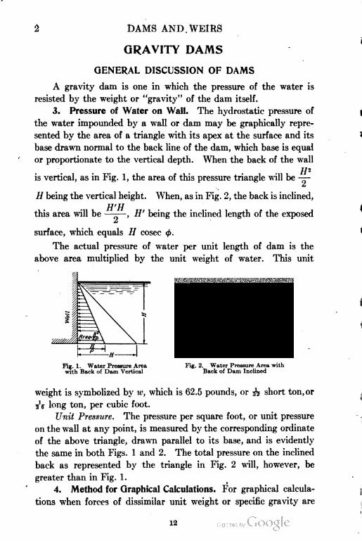
3. Pressure of Water on Wall. The hydrostatic pressure of
the water impounded by a wall or dam may be graphically repre
sented by the area of a triangle with its apex at the surface and its
base drawn normal to the back line of the dam, which base is equal
or proportionate to the vertical depth. When the back of the wall
is vertical, as in Fig. 1, the area of this pressure triangle will be ——
H being the vertical height. When, as in Fig. 2, the back is inclined,
Ufll
this area will be —-—, H' being the inclined length of the exposed
a
surface, which equals // cosec $.
The actual pressure of water per unit length of dam is the
above area multiplied by the unit weight of water. This unit
Fig. 1. Water Pressure Area
with Back of Dam Vertical
Fig. 2. Water Pressure Area with
Back of Dam Inclined
weight is symbolized by w, which is 62.5 pounds, or 3^ short ton, or
3V long ton, per cubic foot.
Unit Pressure. The pressure per square foot, or unit pressure
on the wall at any point, is measured by the corresponding ordinate
of the above triangle, drawn parallel to its base, and is evidently
the same in both Figs. 1 and 2. The total pressure on the inclined
back as represented by the triangle in Fig. 2 will, however, be
greater than in Fig. 1 .
4. Method for Graphical Calculations. For graphical calcula
tions when forces of dissimilar unit weight or specific gravity are
12
DAMS AND WEIRS 3
engaged, as in the case of water and masonry, or earth and masonry,
it is the usual practice to reduce them to one common denominator
by making alterations in the areas of one or the other, the weight of
the masonry being usually taken as a standard. This result is
effected by making the bases of the triangles of water pressure
equal, not to H, but to —, p (rho) being the sign of the specific
P
gravity of the solid material in the wall. The triangle thus reduced
will then represent a weight or area of masonry 1 unit thick, equiva
lent to that of water. This device enables the item of unit weight,
which is w X p to be eliminated as a common factor from the forces
engaged, i. e., of the water pressure and of the weight of the wall.
The factor thus omitted has to be multiplied in again at the close
of the graphical operation, only, however, in cases where actual
pressures in tons or pounds are required to be known.
Value of p. The values ordinarily adopted for p, the specific
gravity of masonry or concrete, are 2| and 2.4, i.e., equivalent to
weights of 141 and 150 pounds, respectively, per cubic foot, while
for brickwork 2 is a sufficiently large value. The value of wp in the
3former case will be .069 ton and in the latter .075, or —- ton.
40
In some cases the actual value of p mounts as high as 2.5 and
even 2.7, when heavy granite or basalt is the material employed.
The reduction thus made in the water pressure areas has further
the convenience of reducing the space occupied by the diagram.
The areas of the reduced triangles of water pressure in Figs. 1 and
H2 H'H2 are —— and —-—, respectively.
2p 2p
5. Conditions of "Middle Third" and Limiting Stress. Sec
tions of gravity dams are designed on the well-known principle of
the "middle third." This expression signifies that the profile of
the wall must be such that the resultant pressure lines or centers of
pressure due first to the weight of the dam considered alone, and
second with the external water pressure in addition, must both
fall within the middle third of the section on any horizontal base.
These two conditions of stress are designated, Reservoir Empty
(R.E.) and Reservoir Full (R.F.). The fulfillment of this condition
insures the following requirement: The maximum compressive ver
13
4 DAMS AND WEIRS
fical unit stress (s), or reaction on the base of a dam, shall not exceed
twice the mean compressive unit stress, or, stated symbolically,
s±2sl
Now the mean vertical compressive unit stress si is the weight of the
structure divided by its base length- i.e.,
W
3l = ~b
2WHence, s, the maximum vertical unit pressure, should not exceed ——
o
Further comments on the distribution of the reaction on the base
of a dam will be made in a later paragraph.
6. Compressive Stress Limit. A second condition imposed is
that of the internal compressive stress limit, that is: The maximum
permissible compressive unit stress which is developed in the interior
of the masonry of the dam, must not be exceeded. This value can be
experimentally found by crushing a cube of the material employed,
and using a factor of safety of 6 or 8. Cement concrete will crush
at about 2000 pounds per square inch, equivalent to 144 tons (of
2000 pounds) per square foot. The safe value of s would then be
144-— = 18 tons per square foot. For ordinary lime concrete as
o
employed in the East, the limit pressure adopted is generally 8
"long" tons, equivalent to 9 tons of 2000 pounds. Ten "long"
tons, or 11.2 "short" tons is also a common value.
DESIGN OF DAMS
7. Theoretical Profile. The theoretically correct profile of a
so-termed "low" masonry dam, i.e., one of such height that the limit
stress is not attained under the conditions above outlined, is that
of a right-angled triangle having its back toward the water vertical,
and its apex at the water surface. It can be proved that the proper
base width b of this triangle is expressed by the formula
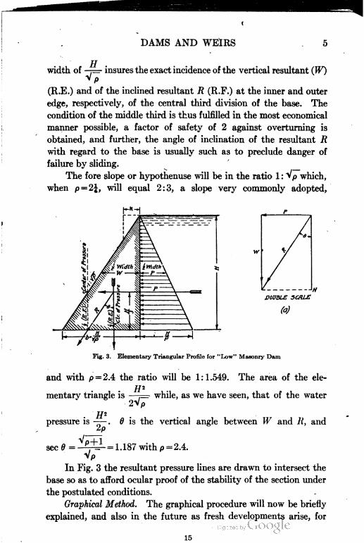
This profile, shown in Fig. 3, will be termed the "elementary trian
gular profile", as on it the design of all profiles of dams is more or
less based. In this expression, // is the vertical height. The base
14
DAMS AND WEIRS
width of ——• insures the exact incidence of the vertical resultant (WO
VP
(R.E.) and of the inclined resultant R (R.F.) at the inner and outer
edge, respectively, of the central third division of the base. The
condition of the middle third is thus fulfilled in the most economical
manner possible, a factor of safety of 2 against overturning is
obtained, and further, the angle of inclination of the resultant R
with regard to the base is usually such as to preclude danger of
failure by sliding.
The fore slope or hypothenuse will be in the ratio 1 : > p which,
when p = 2f, will equal 2:3, a slope very commonly adopted,
DOUBLE SC/U.E
Fig. 3. Elementary Triangular Profile for "Low" Masonry Dam
and with p = 2.4 the ratio will be 1:1.549. The area of the ele
mentary triangle is —p=- while, as we have seen, that of the water
pressure is —— . 6 is the vertical angle between W and R, and
2p
sec0 = -t^-= 1.187 with p = 2.4.
Vp
In Fig. 3 the resultant pressure lines are drawn to intersect the
base so as to afford ocular proof of the stability of the section under
the postulated conditions.
Graphical Method. The graphical procedure will now be briefly
explained, and also in the future as fresh developments arise, for
15
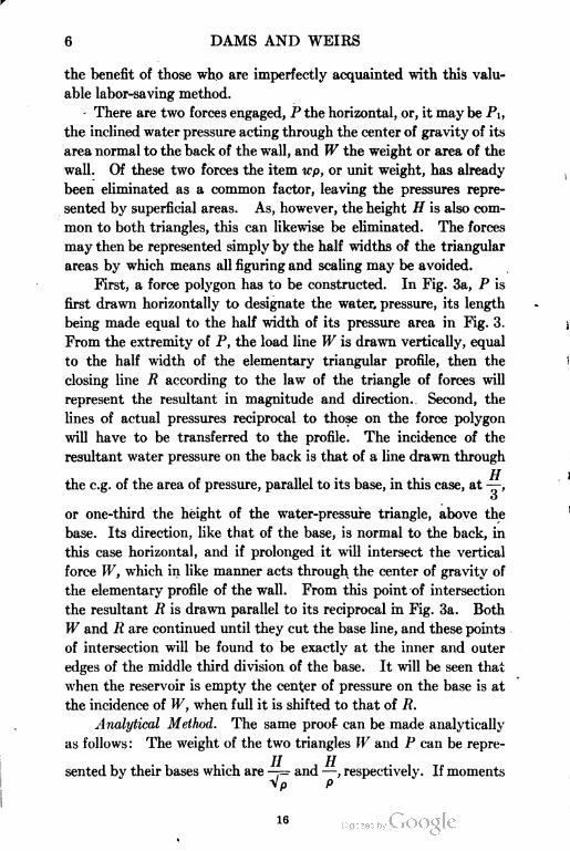
6 DAMS AND WEIRS
the benefit of those who are imperfectly acquainted with this valu
able labor-saving method.
There are two forces engaged, P the horizontal, or, it may be PI,
the inclined water pressure acting through the center of gravity of its
area normal to the back of the wall, and W the weight or area of the
wall. Of these two forces the item wp, or unit weight, has already
been eliminated as a common factor, leaving the pressures repre
sented by superficial areas. As, however, the height H is also com
mon to both triangles, this can likewise be eliminated. The forces
may then be represented simply by the half widths of the triangular
areas by which means all figuring and scaling may be avoided.
First, a force polygon has to be constructed. In Fig. 3a, P is
first drawn horizontally to designate the water- pressure, its length
being made equal to the half width of its pressure area in Fig. 3.
From the extremity of P, the load line W is drawn vertically, equal
to the half width of the elementary triangular profile, then the
closing line 7? according to the law of the triangle of forces will
represent the resultant in magnitude and direction. Second, the
lines of actual pressures reciprocal to those on the force polygon
will have to be transferred to the profile. The incidence of the
resultant water pressure on the back is that of a line drawn through
the e.g. of the area of pressure, parallel to its base, in this case, at —,
o
or one-third the height of the water-pressure triangle, above the
base. Its direction, like that of the base, is normal to the back, in
this case horizontal, and if prolonged it will intersect the vertical
force W, which in like manner acts through the center of gravity of
the elementary profile of the wall. From this point of intersection
the resultant R is drawn parallel to its reciprocal in Fig. 3a. Both
W and Pi are continued until they cut the base line, and these points
of intersection will be found to be exactly at the inner and outer
edges of the middle third division of the base. It will be seen that
when the reservoir is empty the center of pressure on the base is at
the incidence of W, when full it is shifted to that of R.
Analytical Method. The same proof can be made analytically
as follows : The weight of the two triangles W and P can be repre
sented by their bases which are -r= and —, respectively. If moments
Vp p
16
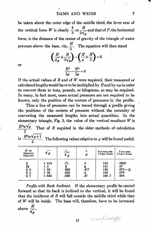
DAMS AND WEIRS 7
be taken about the outer edge of the middle third, the lever arm of
the vertical force W is clearly — or —p and that of P, the horizontal
O 0\p
force, is the distance of the center of gravity of the triangle of water
pressure above the base, viz, — . The equation will then stand
o
or
-
3p 3p
If the actual values of R and of W were required, their measured or
calculated lengths would have to be multiplied by Hand by u-p in order
to convert them to tons, pounds, or kilograms, as may be required.
In many, in fact most, cases actual pressures are not required to be
known, only the position of the centers of pressures in the profile.
Thus a line of pressures can be traced through a profile giving
the positions of the centers of pressure without the necessity of
converting the measured lengths into actual quantities. In the
elementary triangle, Fig. 3, the value of the vertical resultant W is
P . That of R required in the older methods of calculation
IS The following values relative to p will be found useful.
SPECIFIC
GRAVITY
P OR
Vp
i i
P
POUNDS PER
CURIC FOOT
TONS PER
CURIC FOOTVP
2 1.414 .71 .5 125 .0625
2i 1.5 1 4 141 .07
2.4 1.55- .645 .417 150 .075 -A
2.5 1.58 .633 .4 156 .078
2.7 1.643 .609 .37 168.7 .084
Profile with Rack Inclined. If the elementary profile be canted
forward so that its back is inclined to the vertical, it will be found
that the incidence of R will fall outside the middle third while that
of W will be inside. The base will, therefore, have to be increased
u Habove -f=-.
17
8 DAMS AND WEIRS
When the back is overhanging, on the other hand, R will fall
inside and W outside the middle third. The vertically backed
section is consequently the most economical.
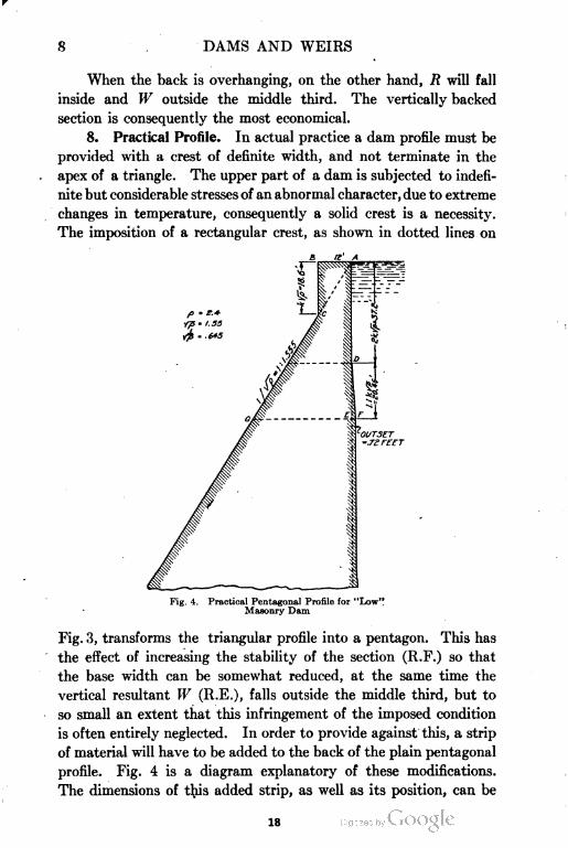
8. Practical Profile. In actual practice a dam profile must be
provided with a crest of definite width, and not terminate in the
apex of a triangle. The upper part of a dam is subjected to indefi
nite but considerable stresses of an abnormal character, due to extreme
changes in temperature, consequently a solid crest is a necessity.
The imposition of a rectangular crest, as shown in dotted lines on
Fig. 4. Practical Pentagonal Profile for "Low"
Masonry Dam
Fig. 3, transforms the triangular profile into a pentagon. This has
the effect of increasing the stability of the section (R.F.) so that
the base width can be somewhat reduced, at the same time the
vertical resultant W (R.E.), falls outside the middle third, but to
so small an extent that this infringement of the imposed condition
is often entirely neglected. In order to provide against this, a strip
of material will have to be added to the back of the plain pentagonal
profile. Fig. 4 is a diagram explanatory of these modifications.
The dimensions of this added strip, as well as its position, can be
18
DAMS AND WEIRS 9
conveniently expressed in terms of (k) the crest width—i.e., AB
in Fig. 4. The line of pressure (R.E.) will begin to leave the middle
third at the depth AD, which is found by calculation which need
not be produced here, to be 2fcVp. Below the point D, the
divergence of the line of pressure will continue for a further depth
DE, the point E, being close upon S.lfcVp below the crest, or
l.l&Vp below D. Below point E, the line of pressure will no
longer diverge outward, but will tend to regain its original position,
consequently no further widening will be necessary, and the added
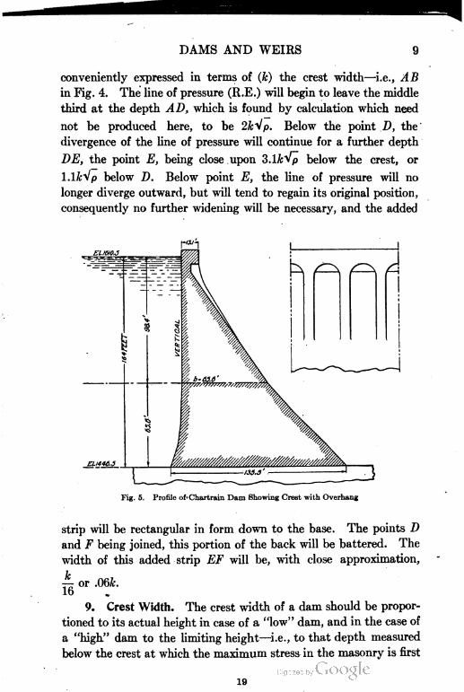
El 1610.3
Fig. 5. Profile of- Chartrain Dam Showing Crest with Overhang
strip will be rectangular in form down to the base. The points D
and F being joined, this portion of the back will be battered. The
width of this added strip EF will be, with close approximation,
Jc
16or .06fc.
9. Crest Width. The crest width of a dam should be propor
tioned to its actual height in case of a "low" dam, and in the case of
a "high" dam to the limiting height—i.e., to that depth measured
below the crest at which the maximum stress in the masonry is first
19
10 DAMS AND WEIRS
reached. Thus in "high" dams the upper part can always be of
the same dimensions except where the requirements of cross com
munication necessitate a wider crest.
The effect of an abnormally wide crest can be modified by
causing it to overhang the fore slope, this widening being carried
by piers and arches. A good example of this construction occurs
in the Chartrain dam, Fig. 5. The arches form a stiff but light
finish to the dam and have a pleasing architectural effect. The
same procedure, but in a less pronounced degree, is carried out in
the Croton dam, Fig. 27.
The formula for crest
width can be expressed
either in terms of the limit
ing height HI, or of the
base b, where the limiting
height is not attained, and
a good proportion is given
by the following empirical
rule:
or
(2)
Fig. 6. Pentagonal Profile—Back Verticalft = .156 (2a)
This latter formula makes
the crest width a function of the specific gravity a-s well as of the
height, which is theoretically sound.
10. Rear Widening. Where the rear widening of a "low"
dam is neglected or where a uniform batter is substituted for the
arrangement shown in Fig. 4, the profile will be pentagonal in out
line. When the back is vertical the two triangles composing the
body of the dam are similar. If the ratio existing between the crest
(k) and the base (b), or — be designated by r, then k = br, and h, the
b
depth of the vertical side in Fig. 6, = Hr and kXh= Hbr*.
In order to find what value the base width b should have, so
that the center of pressure (R.F.) will fall exactly at the edge of the
middle third, the moments of all the forces engaged will have to be
taken about this point and equated to zero. The vertical forces
20
DAMS AND WEIRS 11
consist of W, the lower, and Wi the upper triangle; the horizontal
of P, the water pressure.
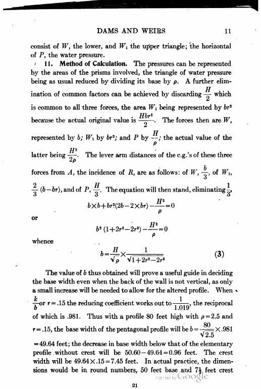
1 1 . Method of Calculation. The pressures can be represented
by the areas of the prisms involved, the triangle of water pressure
being as usual reduced by dividing its base by p. A further elim-
TJ
ination of common factors can be achieved by discarding — which
m
is common to all three forces, the area TFi being represented by br2
because the actual original value is —-—. The forces then are W,
TT
represented by b; Wi by br*; and P by —; the actual value of the
PTTn
latter being ——. The lever arm distances of the c.g.'s of these three
Zp
forces from A, the incidence of R, are as follows: of IV, —, of Wi,
o
or/ i
— (b — br), and of P, — The equation will then stand, eliminating -,
o o o
bXb+br*(2b-2Xbr)-— = 0
P
or
&2(l+2r2-2r3)-— = 0
P
whence
Vp Vl+2r2-2r3
(3)
The value of b thus obtained will prove a useful guide in deciding
the base width even when the back of the wall is not vertical, as only
a small increase will be needed to allow for the altered profile. When <•
k 1—or r = .15 the reducing coefficient works out to-———, the reciprocal
o 1.019
of which is .981. Thus with a profile 80 feet high with p = 2.5 and
80r = .15, the base width of the pentagonal profile will be b = ,—X .981
V2.5
= 49.64 feet; the decrease in base width below that of the elementary
profile without crest will be 50.60-49.64 = 0.96 feet. The crest
width will be 49.64X.15 = 7.45 feet. In actual practice, the dimen
sions would be in round numbers, 50 feet base and 7| feet crest
21
12 DAMS AND WEIRS
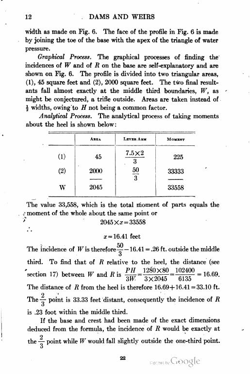
width as made on Fig. 6. The face of the profile in Fig. 6 is made
by joining the toe of the base with the apex of the triangle of water
pressure.
Graphical Process. The graphical processes of finding the
incidences of W and of R on the base are self-explanatory and are
shown on Fig. 6. The profile is divided into two triangular areas,
(1), 45 square feet and (2), 2000 square feet. The two final result
ants fall almost exactly at the middle third boundaries, W, as
might be conjectured, a trifle outside. Areas are taken instead of
| widths, owing to H not being a common factor.
Analytical Process. The analytical process of taking moments
about the heel is shown below:
AREA. LEVER ARM MOMENT
(^} 4.c 7.5X299^
\*j3
50
J
(2) 2000 33333
W 2045 33558
The value 33,558, which is the total moment of parts equals the
moment of the whole about the same point or
>~ 2045 Xx = 33558
z = 16.41 feet
50The incidence of IF is therefore^— — 16.41 = .26 ft. outside the middle
o
third. To find that of R relative to the heel, the distance (see
section 1 7) between W and 7? isPH 1280X80 102400
= 16.69.
3W 3X2045 6135
The distance of R from the heel is therefore 16.69+16.41 =33.10 ft.
2 'The —- point is 33.33 feet distant, consequently the incidence of R
o
is .23 foot within the middle third.
If the base and crest had been made of the exact dimensions
deduced from the formula, the incidence of R would be exactly at
2the — point while W would fall slightly outside the one-third point-
o
22
DAMS AND WEIRS 13
12. Variation of Height. The height of a dam is seldom uni
form throughout; it must vary with the irregularities of the river
bed, so that the maximum section extends for a short length only,
while the remainder is of varying height. This situation will affect
the relationship between the crest width and the height, and also
the base width. To be consistent, the former should vary in width
in proportion to the height. This, however, is hardly practicable,
consequently the width of the crest should be based more on the
average than on the maximum height, and could be made wider
•wherever a dip occurs in the foundation level.
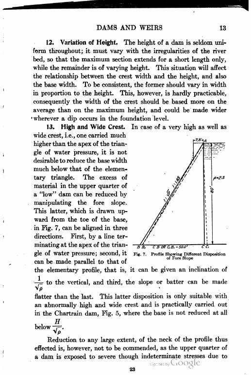
13. High and Wide Crest. In case of a very high as well as
wide crest, i.e., one carried much
higher than the apex of the trian
gle of water pressure, it is not
desirable to reduce the base width
much below that of the elemen
tary triangle. The excess of
material in the upper quarter of
a "low" dam can be reduced by
manipulating the fore slope.
This latter, which is drawn up
ward from the toe of the base,
in Fig. 7, can be aligned in three
directions. First, by a line ter
minating at the apex of the trian
gle of water pressure; second, it
can be made parallel to that of
the elementary profile, that is, it can be given an inclination of
—=• to the vertical, and third, the slope or batter can be made
Vp
flatter than the last. This latter disposition is only suitable with
an abnormally high and wide crest and is practically carried out
in the Chartrain dam, Fig. 5, where the base is not reduced at all
rr
below —]=.Vp
Reduction to any large extent, of the neck of the profile thus
effected is, however, not to be commended, as the upper quarter of
a dam is exposed to severe though indeterminate stresses due to
Profile Showing Different Disposition
of Fore Slope
23
14 DAMS AND WEIRS
changes of temperature, wind pressure, etc., and also probably to
masses of ice put in motion by the wind. The (TOSS River dam,
to be illustrated later, as well as the Ashokan dam, are examples of
an abnormally thick upper quarter being provided on account of
ice. Whatever disposition of the fore slope is adopted, the profile
should be tested graphically or analytically, the line of pressure, if
necessary, being drawn through the profile, as will later be explained.
From the above remarks it will be gathered that the design of
the section of a dam down to the limiting depth can be drawn by a
few lines based on the elementary profile which, if necessary, 'can
be modified by applying the test of ascertaining the exact position
of the centers of pressure on the base. If the incidence of these
resultants falls at or close within the edge of the middle third divi
sion of the base, the section can be pronounced satisfactory; if
otherwise, it can easily be altered to produce the desired result.
Freeboard. The crest has to be raised above actual full reservoir
level by an extent equal to the calculated depth of water passing
over the waste weir or through the spillway, as the case may be.
This extra freeboard, which adds considerably to the cost of a
work, particularly when the dam is of great length and connected
with long embankments, can be avoided by the adoption of auto
matic waste gates by which means full reservoir level and high flood
level are merged into one.
In addition to the above, allowance is made for wave action,
the height of which is obtained by the following formula:
In this expression F is the "fetch", or longest line of exposure of
the water surface to wind action in miles. Thus if F = i miles, the
extra height required over and above maximum flood level will be
(1.5X2) + (2.5-1.4) =4.1 feet. If F = 10 miles, hw will work out to
5| feet. The apex of the triangle of water pressure must be placed
at this higher level; the crest, however, is frequently raised still
higher, so as to prevent the possibility of water washing over it.
14. Example. The working out of an actual example under
assumed conditions will now be given by both graphical and analyti
cal methods. Fig. 8 represents a profile 50 feet in height with crest
level corresponding with the apex of the triangle of water pressure.
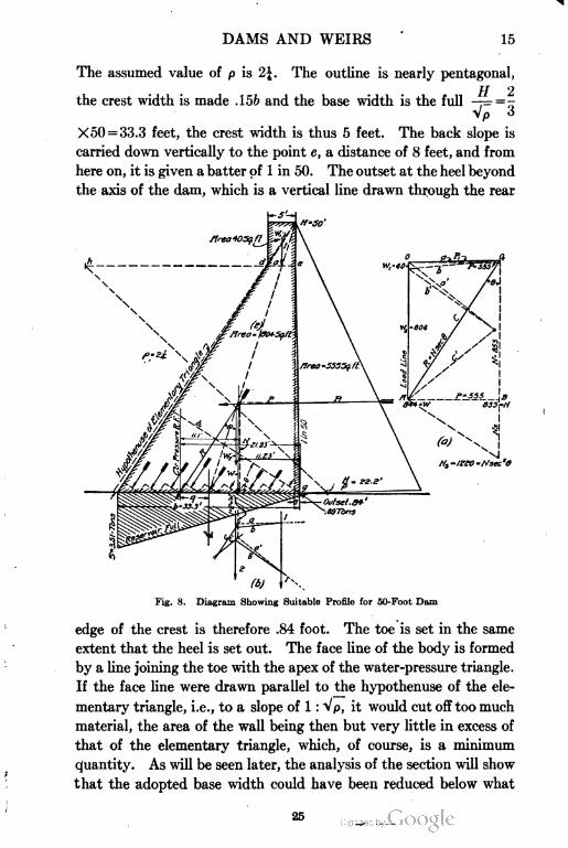
DAMS AND WEIRS 15
The assumed value of p is 2J. The outline is nearly pentagonal,
the crest width is made .156 and the base width is the full -7= = -
Vp <J
X 50 = 33.3 feet, the crest width is thus 5 feet. The back slope is
carried down vertically to the point e, a distance of 8 feet, and from
here on, it is given a batter of 1 in 50. The outset at the heel beyond
the axis of the dam, which is a vertical line drawn through the rear
(b)
Fig. 8. Diagram Showing Suitable Profile for 50-Foot Dam
edge of the crest is therefore .84 foot. The toe is set in the same
extent that the heel is set out. The face line of the body is formed
by a line joining the toe with the apex of the water-pressure triangle.
If the face line were drawn parallel to the hypothenuse of the ele
mentary triangle, i.e., to a slope of 1 : Vp, it would cut off too much
material, the area of the wall being then but very little in excess of
that of the elementary triangle, which, of course, is a minimum
quantity. As will be seen later, the analysis of the section will show
that the adopted base width could have been reduced below what
16 DAMS AND WEIRS
has been provided, to an extent somewhat in excess of that given in
formula (3).
15. Graphical Method. The graphical procedure of drawing
the resultant lines W (R.E.) and jR (R.F.) to their intersection of the
base presents a few differences, from that described in section 7,
page 6, with regard to Fig. 3. Here the profile is necessarily divided
into two parts, the rectangular crest and the trapezoidal body. As
the three areas (1), (2), and PI, are not of equal height, the item //
cannot be eliminated as a common factor, consequently the forces
will have to be represented as in Fig. 6 by their actual superficial
areas, not by the half width of these areas as was previously the case.
In Fig. 8a the vertical load line consists of the areas 1 and 2 totaling
844 square feet, which form W. The water pressure PI is the area
of the inclined triangle whose base is —. This is best set out graph-
P
ically in the force polygon by the horizontal line P, made equal to
H* 2500X2the horizontal water pressure, which is —— = = 555 square
Lp 9
feet. The water-pressure area strictly consists of two parts corre
sponding in depth to (1) and (2) as the upper part is vertical, not
inclined, but the difference is so slight as to be inappreciable, and
so the area of water pressure is considered as it would be if the back of
the wall were in one inclined plane. In Fig. 8 the line PI normal to
the back of the wall is drawn from the point of origin 0 and it is cut
off by a vertical through the extremity of the horizontal line P.
This intercepted length 0 0i is clearly the representative value of
the resultant water pressure, and the line joining this point with the
base of the load line W is R, the resultant of W and of PI. If a
horizontal line AB be drawn from the lower end of the load line W
it will cut off an intercept ( Ar) from a vertical drawn through the
termination of PI. This line AB = P, and N is the vertical com
ponent of R, the latter being the resultant of W and Pi as well as
of N and P. When the back is vertical, N and W are naturally
identical in value, their difference being the weight of water over
lying the inclined rear slope.
The further procedure consists in drawing the reciprocals of
the three forces PI, W, and R on the profile. The first step consists
in finding the centers of gravity of the vertical forces 1 and 2 in which
26
DAMS AND WEIRS 17
the hexagonal profile is divided. That of (1) lies clearly in the
middle of the rectangle whose base is de. The lower division (2) is
a trapezoid. The center of gravity of a trapezoid is best found by
the following extremely simple graphical process. From d draw
dh horizontally equal to the base of the trapezoid fg and from g,
gj is set off equal to de; join hj, then its intersection with the middle
line of the trapezoid gives the exact position of its center of gravity.
Thus a few lines effect graphically what would involve considerable
calculation by analytical methods, as will be shown later.
The next step is to find the combined c. g. of the two parallel
and vertical forces 1 and 2. To effect this for any number of parallel
or non-parallel forces, two diagrams are required, first, a so-termed
force and ray polygon and, second, its reciprocal, the force and
chord, or funicular polygon. The load line in Fig. 8a can be utilized
in the former of these figures. First, a point of origin or nucleus of
rays must be taken. Its position can be anywhere relative to the
load line, a central position on either side being the best. The
point 0] , which is the real origin of the force polygon at the extremity
of PI can be adopted as nucleus and often is so utilized, in which
case the force line PI and R can be used as rays, only one additional
ray being required. For the sake of illustration, both positions for
nucleus have been adopted, thus forming two force and ray poly
gons, both based on the same load line, and two funicular polygons,
the resultants of which are identical. The force and ray polygon is
formed by connecting all the points on the load line with the nucleus
as shown by the dotted line a, b, and c, and a', V, and c'. Among the
former, a and c are the force lines PI and Pi, the third, b, joins the
termination of force (1) on the load line with the nucleus. These
lines a, b, c, are the rays of the polygon. Having formed the force
and ray diagram, in order to construct the reciprocal funicular
polygon 8b the force lines (1) and (2) on the profile Fig. 8 are con
tinued down below the figure. Then a line marked (a) is drawn
anywhere right through (1) parallel to the ray a, from its intersec
tion with the force (1), the chord (b) is drawn parallel to the ray (b)
in Fig. 8b meeting (2); through this latter intersection the third
chord (c) is drawn backward parallel to its reciprocal the ray c.
This latter is the closing line and its intersection with the initial
line (a), gives the position of the e.g. of the two forces.
27
18 DAMS AND WEIRS
A vertical line through this center of pressure, which represents
W, i.e., Wi+ l\\, is continued on to the profile until it intersects
the inclined force PI drawn through the center of gravity of the
water pressure area. This intersection is the starting point of R,
drawn parallel to its reciprocal on the force polygon 80. This
resultant intersects the base at a point within the middle third.
R is the resultant "Reservoir Full", while W, the resultant of the
vertical forces in the masonry wall, is the resultant "Reservoir
Empty". The intersection of the latter is almost exactly at the inner
edge of the middle third—thus the condition of the middle third is
fulfilled. The question of induced pressure and its distribution on
the base will be considered later.
The incidence of N, the vertical component "Reservoir Full",
on the base is naturally not identical with that of W, the resultant
"Reservoir Empty", unless the back of the wall is vertical. The
line R is the resultant of both PI and W, and of P and N. If
it be required to fix the position of N on the profile, a horizontal
line should be drawn through the intersection of PI with the back
of the wall. This will represent the horizontal component of the
water pressure PI, and it will intersect R, produced upward. Then
a line drawn vertically through this latter point will represent N,
the vertical component (Reservoir Full). The position of N is
necessarily outside of W, consequently if N is made to fall at the inner
edge of the middle third of the base, W must fall within the middle
third. This fact will later be made use of when the design of the
lower part of a "high" dam comes under consideration.
16. Analytical Method. The analytical method of ascertain
ing the positions of the incidences of W and of R on the base, which
has just been graphically performed, will now be explained.
The first step is to find the positions of the centers of gravity
of the rectangle and trapezoid of which the profile is composed,
relative to some vertical plane, and then to equate the sum of the
moments of those two forces about any fixed point on the base,
with the moment of their sum.
The most convenient point in most cases is the heel of the base ;
this projects a distance (y) beyond the axis of the dam, which axis
is a vertical line passing through the inner edge of the rectangular
crest.
DAMS AND WEIRS 19
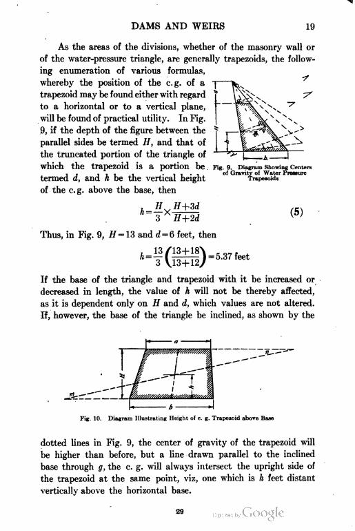
As the areas of the divisions, whether of the masonry wall or
of the water-pressure triangle, are generally trapezoids, the follow
ing enumeration of various formulas,
whereby the position of the e.g. of a
trapezoid may be found either with regard
to a horizontal or to a vertical plane,
will be found of practical utility. In Fig.
9, if the depth of the figure between the
parallel sides be termed //, and that of
the truncated portion of the triangle of
which the trapezoid is a portion be
termed d, and h be the vertical height
of the e.g. above the base, then
Fig. 9. Diagram Showing Centers
of Gravity of Water Pressure
Trapezoida
Thus, in Fig. 9, H = 13 and d = G feet, then
If the base of the triangle and trapezoid with it be increased or
decreased in length, the value of h will not be thereby affected,
as it is dependent only on H and d, which values are not altered.
If, however, the base of the triangle be inclined, as shown by the
Fig. 10. Diagram Illustrating Height of c. g. Trapezoid above Base
dotted lines in Fig. 9, the center of gravity of the trapezoid will
be higher than before, but a line drawn parallel to the inclined
base through g, the c. g. will always intersect the upright side of
the trapezoid at the same point, viz, one which is h feet distant
vertically above the horizontal base.
29
20 DAMS AND WEIRS
The value of h can also be obtained in terms of a and b, the two
parallel sides of the trapezoid, and is
H Sb+2a\ ,, .t6)
For example, in Fig. 10, H = 12, q = 10, and 6 = 16, then
aH
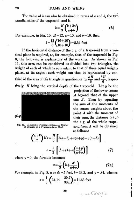
If the horizontal distance of the c. g. of a trapezoid from a ver
tical plane is required, as, for example, that of the trapezoid in Fig.
8, the following is explanatory of the working. As shown in Fig.
11, this area can be considered as divided into two triangles, the
weight of each of which is equivalent to that of three equal weights
placed at its angles; each weight can thus be represented by one-
third of the area of the triangle in question, or by -— and -—, respec
tively, H being the vertical depth of the trapezoid. Let y be the
projection of the lower corner
A beyond that of the upper
one B. Then by equating
the sum of the moments of
the corner weights about the
point A with the moment of
their sum, the distance (x) of
the e.g. of the whole trape
zoid from A will be obtained
as follows:
(7)
(7a)
Fig. 11. Method of Finding Distance of Center
of Gravity of a Trapezoid from Heel
where y = 0, the formula becomes
-4-6+a+b)
For example, in Fig. 8, a or rfe = 5 feet, 6 = 33.3, and 21 = .84, whence
30
DAMS AND WEIRS 21
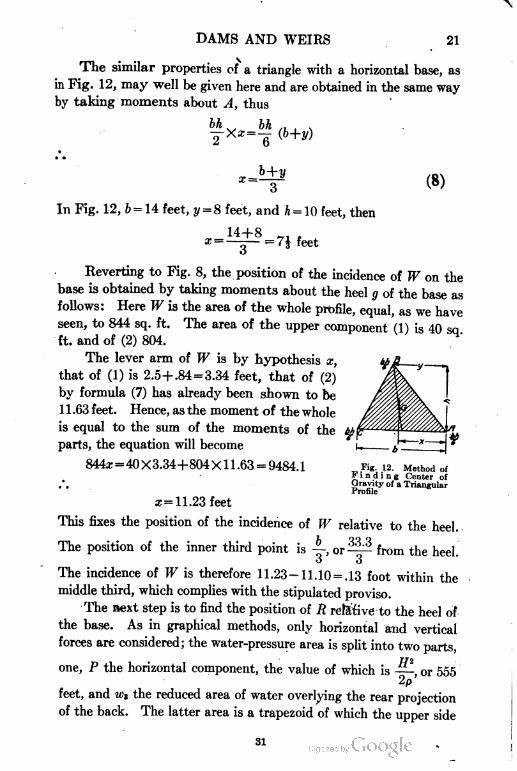
The similar properties of a triangle with a horizontal base, as
in Fig. 12, may well be given here and are obtained in the same way
by taking moments about A, thus
6ft
2 '
bh n. , ^=- (b+y)
(8)
In Fig. 12, 6 = 14 feet, y = 8 feet, and ft = 10 feet, then
,. 14+8x =—~— = ' J feet
Reverting to Fig. 8, the position of the incidence of W on the
base is obtained by taking moments about the heel g of the base as
follows: Here W is the area of the whole profile, equal, as we have
seen, to 844 sq. ft. The area of the upper component (1) is 40 so
ft. and of (2) 804.
The lever arm of W is by hypothesis x,
that of (1) is 2.5+.84=3.34 feet, that of (2)
by formula (7) has already been shown to be
1 1 .63 feet. Hence, as the moment of the whole
is equal to the sum of the moments of the tit
parts, the equation will become
844x=40X3.34+804Xll.63 = 9484.1 Fig. 12. Method ofFinding Center of
Gravity of a Triangular
Profile
a; =11.23 feet
This fixes the position of the incidence of W relative to the heel.
The position of the inner third point is —, or '^.3 from the heel.
o 3
The incidence of W is therefore 11.23- 11. 10 = .13 foot within the
middle third, which complies with the stipulated proviso.
The next step is to find the position of R relative to the heel of
the base. As in graphical methods, only horizontal and vertical
forces are considered; the water-pressure area is split into two parts,
TJ2
one, P the horizontal component, the value of which is —-, or 555
2p'
feet, and w3 the reduced area of water overlying the rear projection
of the back. The latter area is a trapezoid of which the upper side
31
22 DAMS AND WEIRS
(a) is 8 feet long and b, the lower side, 50 feet, the depth being .84
foot, hence the distance of its e.g. inside the heel of the base will be
by formula (6), = .32 foot. Its actual area is -X
.84 = 24.4 feet; this has to be divided by p or 2\ to reduce it to a
masonry base. The reduced area will then be 10.8 square feet,
nearly. The distance of the incidence of W from the heel of the
base has already been determined to be 11.23 ft. and that of w3
being .32 ft., the distance of the c. g. of the latter from W will be
1 1 .23 — .32 = 10.9, nearly. If the distance between the incidences of
W and R be termed x, the equation of moments about the incidence
of R, will stand thus: ,
P~
o
or
Kfl
555X— = 844z+10.8z+ 117.83
o
i.e.
9132.2
R is therefore 10.7+11.23 = 21.93 ft. distant from the heel. The
§ point being 22.2 ft. from the same point, R falls .3 ft. (nearly)
within the middle third. This shows that a small reduction in the
area of the profile could be effected.
17. Vertical Component. If the position of N, the vertical
component of R and PI, is required, as is sometimes the case,
it is obtained by the equation A7Xz= (WX 11.23) + (w3X.32),
x being the distance from the heel of the base. Or in figures,
854.8z = (844 X 1 1 .23) + (10.8 X .32)
a- = 11.1 feet
The incidence of N is, therefore, in this case, exactly on the limit of
the middle third. This of course does not affect the condition of
middle third, which refers to the resultant W (R.E.) not to the com
ponent N (R.F.) but, as will be seen later, when the lower part of a
high dam comes to be designed, one condition commonly imposed
is, that the vertical component N must fall at the inner edge of the
middle third, in which case W will necessarily fall inside thereof.
DAMS AND WEIRS 23
It may here be noted that the space between the location of N and
P 11
R, which will be designated (/), is —— because if moments are taken
o iV
P// P ff
about the incidence of R, then Nf=——; therefore /= —-^. The
o
actual value of W in tons of 2000 pounds will be the superficial area,
or 844 square feet multiplied by the eliminated unit weight, i.e., by
844 X 9 1wp, viz, ——— = 59.3 tons, as w =— ton. That of the inclined
o<i
force R, is obtained from the triangle of forces PNR in which R,
being the hypothenuse = V 2V2+P2. Here N= 855 square feet,
equivalent to 6O tons, nearly, and P = 555 feet, equivalent to 39
tons, whence R = V002-|-392 = 71.5 tons.
18. Pressure Distribution. In the design of the section of a
dam, pier, or retaining wall, the distribution of pressure on a plane
in the section and the relations existing between maximum unit
stress, symbolized by (*), and mean or average unit stress (*i) will
now be considered. The mean unit stress on any plane is that
which acts at its center point and is in amount the resultant stress
acting on the plane (the incidence of which may be at any point)
divided by the width of the lamina acted on. Thus in Figs. 3 or 8
take the resultant W. This acts on the horizontal base and its
Wmean unit stress *i will be -r-. In the same way, with regard to N, the
vertical component of R the mean unit stress produced by it on the
Nhorizontal base will be —. The maximum unit stress occurs at
Li
that extremity of the base nearest to the force in question which is
R. Thus the maximum unit stress due to W is at the heel while
that due to a combination of P and N acting at the incidence of R
is at the toe of the base b. It is evident that the nearer the inci
dence of the center of pressure is to the center point the less is the
maximum stress developed at the outer edge of the section, until
the center of pressure is actually situated at the center point itself.
The maximum pressure at the outer part of the section then equals
the average and is thus at a minimum value. The relation between
maximum and mean unit stress or reaction is expressed in the fol
33
24 DAMS AND WEIRS
lowing formula in which it is assumed that any tension at the heel
can be cared for by the adhesion of the cementing material or of
reinforcement anchored down :
-040or, letting m equal the expression in brackets,
(9)
(9a)
In formula (9a), q is the distance between the center point of the
base and the center of pressure or incidence of whatever resultant
pressure is under considera
tion, and si is the mean stress,
'•—' or the resultant pressure di
vided by the base.
In Fig. 8 as explained in
section 16, the incidence of R,
i.e., the center of pressure
(R.F.), falls .3 ft. within the
middle third of the base, con
sequently the value of q will be
b .,33.3 I . ? ,_ .d...I_ .3= .,-I.,«.,,
in formula (9a)
, , 31.5
6<7
m = 1 + -^
o
= 1.95. The maxi-33.3
mum reaction at the
always designated by * =
toe
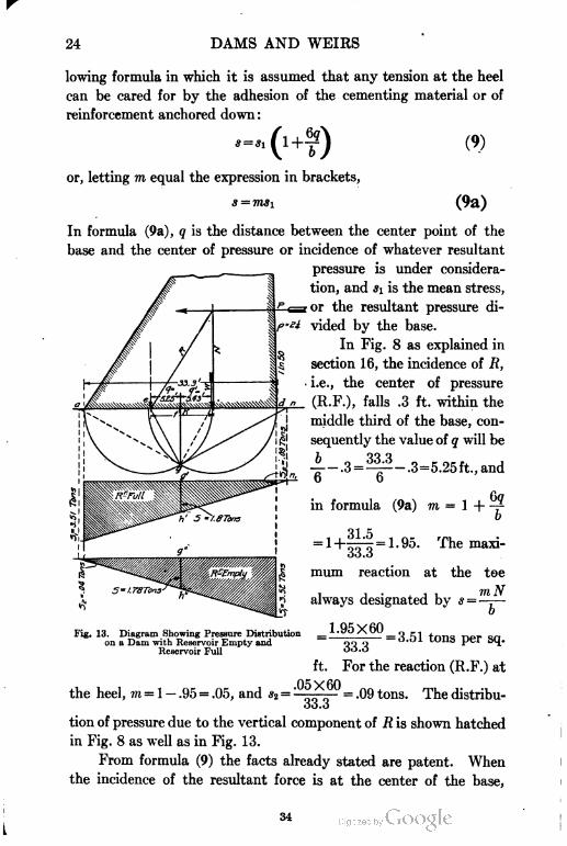
Fig. 13. Diagram Showing Pressure Distribution I
on a Dam with Reservoir Empty and
Reservoir Full
11 .
oo nOO.O
I ,. I ,
-O.J1 UUiib per bq.
ft. For the reaction (R.F.) at
the heel, m = 1 - .95 = .05, and *2 = °* = .09 tons. The distribu-
33.3
tion of pressure due to the vertical component of R is shown hatched
in Fig. 8 as well as in Fig. 13.
From formula (9) the facts already stated are patent. When
the incidence of the resultant force is at the center of the base,
DAMS AND WEIRS 25
g = 0, consequently »z = l and s = si, that is, the maximum is equal
to the mean ; when at one of the third points, q =—, m = 2, and a = 2*i ;
Wwhen at the toe, m = 4, and x = -isi, or 4—.
b
If the material in the dam is incapable of caring for tensile
strain, the maximum vertical compression, or *, obtained by formula
(9) will not apply. Formula (24), section 86, should be used when
ever R falls outside the middle third.
In designing sections it is often necessary to maneuver the
incidence of the resultant stress to a point as close as possible to the
center of the base in order to reduce the maximum stress to the least
possible value, which is that of the mean stress. The condition of the
middle third, insures that the maximum stress cannot exceed twice
the mean, and may be less, and besides insures the absence of tensile
stress at the base.
19. Graphical Method for Distribution of Pressure. The
graphical method of ascertaining the distribution of pressure on the
base of a masonry wall, which has already been dealt with analyti
cally, is exhibited in Fig. 13, which is a reproduction of the base of
Fig. 8. The procedure is as follows: Two semicircles are struck
on the base line, having their centers at the third division points
and their radii equal to —. From the point marked e, that of the
o
incidence of R, the line eg is drawn to g, the point of intersection of
the two semicircles. Again from g a line gn is set off at right
angles to eg cutting the base or its continuation at a point n. This
point is termed the antipole of e, or the neutral point at which pres
sure is nil in either sense—compressive or tensile. Below and
clear of the profile a projection of the base is now made, and from
g a perpendicular is let fall, cutting the new base in g' while, if the
line be continued upward, it will intersect the base at K. This
latter point will, by the construction, be the center point of the base.
The line Kg is continued through g' to h', g'h' being made equal to
the mean unit pressure, =1.8 tons. A perpendicular is let fall
from n cutting the new base line at ni; the points ni and h' are then
joined and the line continued until it intersects another perpendicu
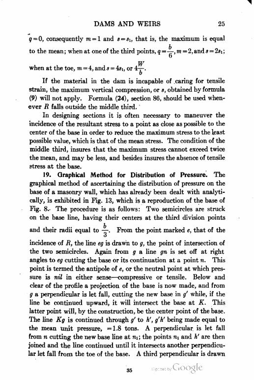
lar let fall from the toe of the base. A third perpendicular is drawn
35
26 DAMS AND WEIRS
from the heel of the base, cutting off a corner of the triangle. The
hatched trapezoid enclosed between the last two lines represents the
distribution of pressure on the base. The maximum stress will
scale close upon 3.51 and the minimum .09 tons. If If be considered,
W 59 3# = -:- =
'
b
=1.78 tons, the maximum stress at the heel will be
3.52 and the minimum .04, at the toe.
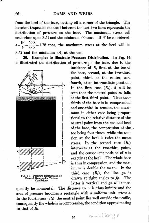
20. Examples to Illustrate Pressure Distribution. In Fig. 14
is illustrated the distribution of pressure on the base, due to the
incidence of lt, first, at the toe of
the base, second, at the two-third
point, third, at the center, and
fourth, at an intermediate position.
In the first case (R\), it will be
seen that the neutral point n\ falls
at the first third point. Thus two-
thirds of the base is in compression
and one-third in tension, the maxi
mum in either case being propor
tional to the relative distance of the
neutral point from the toe and heel
of the base, the compression at the
toe being four times, while the ten
sion at the heel is twice the mean
stress. In the second case (Rz)
intersects at the two-third point,
and the consequent position of n is
exactly at the heel . The whole base
is thus in compression, and the max
imum is double the mean. In the
third case (7?3), the line gn is
drawn at right angles to fg. The
latter is vertical and gn will conse
quently be horizontal. The distance to n is thus infinite and the
area of pressure becomes a rectangle with a uniform unit stress s.
In the fourth case (7?4), the neutral point lies well outside the profile,
consequently the whole is in compression, the condition approximating
to that of R3.
-,.-,4.
Fig. 14, Pressure Distribution on
Base of Dam under Various
Conditions
36
DAMS AND WEIRS 27
21. Maximum Pressure Limit. The maximum pressure
increases with the depth of the profile until a level is reached where
the limit stress or highest admissible stress is arrived at. Down to
this level the design of the section of a dam, as already shown, con
sists simply in a slight modification of the pentagonal profile with
a vertical back, the base width varying between that of the ele
mentary profile or —-=, or its reduced value given in formula (3).
VP
Beyond this limiting depth, which is the base of the so-termed
"low" dam, the pentagonal profile will have to be departed from
and the base widened out on both sides.
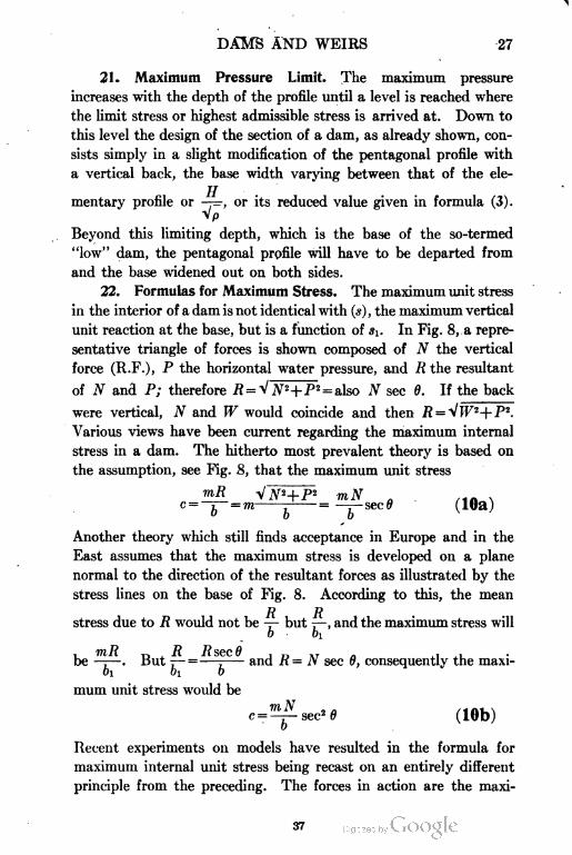
22. Formulas for Maximum Stress. The maximum unit stress
in the interior of a dam is not identical with (s), the maximum vertical
unit reaction at the base, but is a function of s\. In Fig. 8, a repre
sentative triangle of forces is shown composed of N the vertical
force (R.F.), P the horizontal water pressure, and R the resultant
of N and P; therefore R = v^KP2 = also N sec 6. If the back
were vertical, N and W would coincide and then # = Vj
Various views have been current regarding the maximum internal
stress in a dam. The hitherto most prevalent theory is based on
the assumption, see Fig. 8, that the maximum unit stress
mR VJVH-P2 mN
c= 7 =m-:-= —r— sec0
" 00
Another theory which still finds acceptance in Europe and in the
East assumes that the maximum stress is developed on a plane
normal to the direction of the resultant forces as illustrated by the
stress lines on the base of Fig. 8. According to this, the mean
7? 7?stress due to R would not be — but —. and the maximum stress will
0 Oi
. mR „ , R Rsec8 , -, ., ...be —;—. 13ut 7— =—:- and n= N sec 6, consequently the maxi-
bi b\ b '
mum unit stress would be
c = 7^Sec20 (10b)
Recent experiments on models have resulted in the formula for
maximum internal unit stress being recast on an entirely different
principle from the preceding. The forces in action are the maxi
37
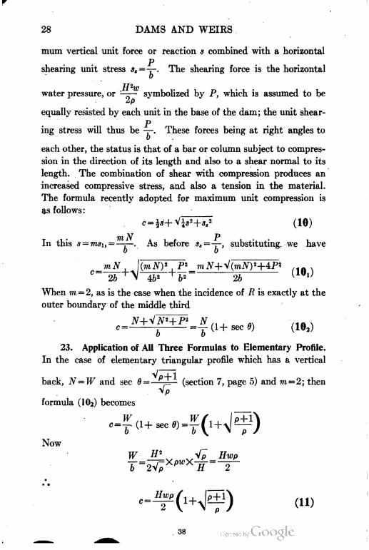
28 DAMS AND WEIRS
mum vertical unit force or reaction s combined with a horizontal
pshearing unit stress *,=-=-. The shearing force is the horizontal
o
H2wwater pressure, or —— symbolized by P, which is assumed to be
2p
equally resisted by each unit in the base of the dam; the unit shear-
Ping stress will thus be -7-. These forces being at right angles to
each other, the status is that of a bar or column subject to compres
sion in the direction of its length and also to a shear normal to its
length. The combination of shear with compression produces an
increased compressive stress, and also a tension in the material.
The formula recently adopted for maximum unit compression is
as follows :
. c=i*+Vp+^ (10)
In this s = msi,=——-. As before *,=-T-, substituting we have
o o
mN
2b
When m = 2, as is the case when the incidence of R is exactly at the
outer boundary of the middle third
in .c = =• =—(l+sec0) (102)
0 0
23. Application of All Three Formulas to Elementary Profile.
In the case of elementary triangular profile which has a vertical
back, N=W and sec 6= I (section 7, page 5) and m — 2; then
Vp
formula (102) becomes
Now
DAMS AND WEIRS 29
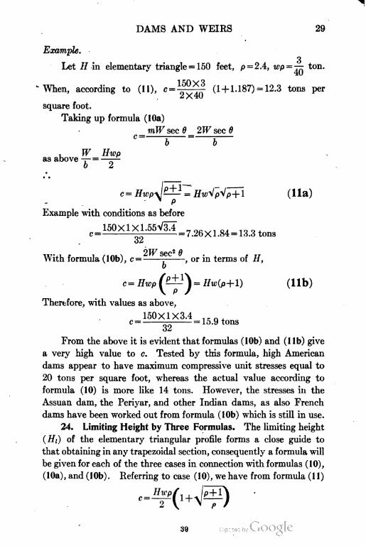
Example.
Let H in elementary triangle = 150 feet, p=2.4, wp =— ton.
i c;ny^
When, according to (11), c= ; ^ (1 + 1.187) = 12.3 tons per
square foot.
Taking up formula (lOa)
mW sec 6 2W sec 6
b
,as above -- =
b 2
' (Ha)p
Example with conditions as before
150X1X1.55V31
32
= 7.26X1.84 = 13.3 tons
2IF sec2 9With formula (lOb), c = ; , or in terms of H,
Therefore, with values as above,
150X1X3.4
c= Hwp — = Hw(p+l) (lib)
= 15.9 tons
32
From the above it is evident that formulas (lOb) and (lib) give
a very high value to c. Tested by this formula, high American
dams appear to have maximum compressive unit stresses equal to
20 tons per square foot, whereas the actual value according to
formula (10) is more like 14 tons. However, the stresses in the
Assuan dam, the Periyar, and other Indian dams, as also French
dams have been worked out from formula (lOb) which is still in use.
24. Limiting Height by Three Formulas. The limiting height
(Hi) of the elementary triangular profile forms a close guide to
that obtaining in any trapezoidal section, consequently a formula will
be given for each of the three cases in connection with formulas (10),
(lOa), and (lOb). Referring to case (10), we have from formula (11)
39
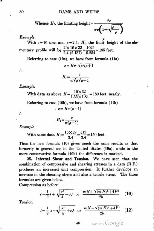
30 DAMS AND WEIRS
2cWhence HI, the limiting height = -
Example. .
With c = 16 tons and p = 2.4, HI, the limit height of the ele-
,., .„ , 2X16X33 1024 ,mentary profile will be - =—=195 feet.
Referring to case (I0a), we have from formula (lla)
c=//w VpVp+ 1
Example.
With
Referring to case (lOb), we have from formula (lib)
With data as above H =———-^—' = 180 feet, nearly.
Example.
With same data //,== = 150 feet.
o,4 o.4
Thus the new formula (10) gives much the same results as that
formerly in general use in the United States (lOa), while in the
more conservative formula (lOb) the difference is marked.
25. Internal Shear and Tension. We have seen that the
combination of compressive and shearing stresses in a dam (R.F.)
produces an increased unit compression. It further develops an
increase in the shearing stress and also a tensile stress. The three
formulas are given below.
Compression as before
- + s,f or
V 1 4
Tension
40
DAMS AND WEIRS 31
Shear
l(m.V)2
\ 2
+4P2
6 (13)
The tensile and shearing stresses are not of sufficient moment to require
any special provision in the case of a gravity dam. The tension is
greatest at the heel, diminishing toward the toe. This fact suggests
that a projection of the heel backward would be of advantage. The
direction (a) of c to the vertical is not that of R but is as follows:
sob
pwhenm = 2, tan 2« =—. In Fig. 8, P = 555 and N = 855. .' . tan 2o =
Wi
—= .649 whence 2a=33° 00' and (a) = 16° 30'. The inclination
8o5
of R to the vertical, or 9, is 33° 50', i.e., twice as large as that
of c. The direction of t is at right angles to that of c, while that of
$h the shear, lies at 45° from the directions of either c or t.
26. Security against Failure by Sliding or Shear. Security
against failure by sliding depends on the inclination of W to P, i.e.,
on the angle 6 between If " and R. Thus tan 6 should be less than the
angle of friction of masonry on masonry, or less than .7. This is the
same as stating that the relation of IF and P must be such that 6
shall not be greater than 35°, or that the complement of 6 be not less
than 55°. The adoption of the middle third proviso generally insures
this. With regard to sliding on the base, this can be further pro
vided against by indentations in the base line or constructing it
inclined upward from heel to toe.
27. Influence Lines. It is sometimes desirable for the purpose
of demonstrating the correctness of a profile for tentative design,
to trace the line of pressures corresponding to the two conditions
of reservoir full and empty, through the profile of a dam. This is
far better effected by the use of graphic statics.
There are two different systems of graphic construction that
give identical results, which will now be explained and illustrated.
The first method, which is most commonly adopted, is exhibited
in Fig. 15, which is the profile of a 100-foot high dam with specific
gravity 2|. It thus lies within the limiting depth, which for the
elementary profile would be 190 feet.
41
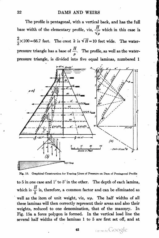
32 DAMS AND WEIRS
The profile is pentagonal, with a vertical back, and has the full
base width of the elementary profile, viz, —— which in this case is
Vp
-X 100 = 66.7 feet. The crest k is V//=10 feet wide. The water-o
pressure triangle has a base of —. The profile, as well as the water-
P
pressure triangle, is divided into five equal laminas, numbered 1
Fig. 15. Graphical Construction for Tracing "Lines of Pressure on Dam of Pentagonal Profile
to 5 in one case and 1' to 5' in the other. The depth of each lamina,
jt
which is — is, therefore, a common factor and can be eliminated as
5
well as the item of unit weight, viz, wp. The half widths of all
these laminas will then correctly represent their areas and also their
weights, reduced to one denomination, that of the masonry. In
Fig. 15a a force polygon is formed. In the vertical load line the
several half widths of the laminas 1 to 5 are first set off, and at
DAMS AND WEIRS 33
right angles to it the force line of water pressure is similarly set
out with the half widths of the areas 1' to 5'. Then the resultant'
lines of the combination of 1 with 1', 1, 2, with 1' 2' and so on marked
Ri to R& are drawn. This completes the force polygon. The next
step is to find the combinations of the vertical forces on the profile,
viz, that of 1 and 2, 1, 2, and 3, etc. This, as usual, is effected by
constructing a force and ray polygon, utilizing the load line in
Fig. loa for the purpose. Then the centers of gravity of the several
individual areas 1 to 5 are found by the graphical process described
in section 15, and verticals drawn through these points are projected
below the profile. On these parallel force lines 1 to 5, the funicular
polygon Fig. lob is constructed, its chords being parallel to their
reciprocal rays in Fig. 15a. The intersection of the closing lines
of the funicular gives the position of the centroid of the five forces
engaged. By producing each chord or intercept backward until it
iiitersects the initial line, a series of fresh points are obtained which
denote the centers of gravity of the combinations of 1 and 2; 1, 2, and
3, and so on. Verticals through these are next drawn up on the profile
so as to intersect the several bases of the corresponding combinations,
thus 1, 2, and 3 will intersect the base of lamina 3; and 1, 2, 3, and
4 will intersect that of lamina 4; and so on. These intersections
are so many points on the line of pressure (R.E.). The next step
is to draw the horizontal forces, i.e., their combinations on to the
profile. The process of finding the centers of gravity of these areas
is rendered easy by the fact that the combinations are all triangles,
not trapezoids, consequently the center of gravity of each is at J
its height from the base. Thus the center of gravity of the com
bination l'+2'+3' is at J the height measured from the base of
3' to the apex, in the same way for any other combination, that of
1', 2', 3', 4', 5', being at J the total height of the profile. The back
being vertical, the direction of all the combined forces will be hori
zontal, and the lines are drawn through, as shown in the figure,
to intersect the corresponding combinations of vertical forces.
Thus 1' intersects 1, 1' 2' intersects 1 2, and so on. From these
several intersections the resultant lines Ri, Rz, to R5 are now drawn
down to the base of the combination to which they belong, these
last intersections giving the incidence of RI, RZ, etc., and are so
many points on the line of pressures (R.F.). The process is simple
43
34 DAMS AND WEIRS
and takes as long to describe as to perform, and it has this advan
tage, that each combination of forces is independent of the
rest, and consequently errors are not perpetuated. This system
can also be used where the back of the profile has one or
several inclinations to the vertical, explanation of which will be
given later.
28. Actual Pressures in Figures. In the whole process above
described, it is noticeable that not a single figure or arithmetical
calculation is required. If the actual maximum unit stress due to
R or to W is required to be known, the following is the procedure.
In Fig. 15a, N scales 174, to reduce this to tons it has to be mul-
TT
tiplied by all the eliminated factors, which are — = 20 and wp =5
9X1 .... „ 174X20X9 ,—-,that,s, N~ =244 tons.
Assuming the incidence of R exactly at the third division,
the value of q is — and that of m is 2; P also scales 112, its
o
value is therefore ————-— = 157 tons. Applying formula
244+V2442+1572 534 0 ,j— = -------^--- =^ = 8 tons per sq. ft.,
roughly. As 8 tons is obviously well below the limiting stress, for
which a value of 16 tons would be more appropriate, this estimation
is practically unnecessary but is given here as an example.
29. Analytical Method. The analytical method of calculation
will now be worked out for the base of the profile only. First the
position of W, the resultant vertical forces (R.E.) relative to the
heel of the base will be calculated and next that of R. The back of
the profile being in one line and vertical the whole area can be con
veniently divided into two right-angled triangles, if the thick
ening of the curvature at the neck be ignored. As the fore slope
has an inclination of 1 : Vp the vertical side of the upper triangle
,.. .,„/.. , . .,. .. . 100X1.5 I.(1) is k\p in length; its area will then be —-—=--—- = 75
2i 2i
sq. feet. The distance of its c. g. from the heel of the base, which
20in this case corresponds with the axis of the dam, is — feet = fif feet.
o
44
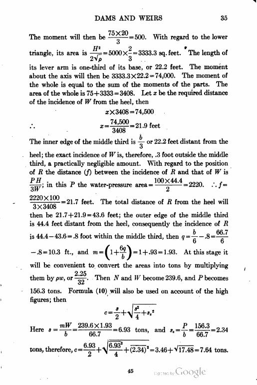
DAMS AND WEIRS 35
75 y 20The moment will then be —-—= 500. With regard to the lower
o
H2 2triangle, its area is —== 5000X- = 3333.3 sq.feet. The length of
2 vp o
its lever arm is one-third of its base, or 22.2 feet. The moment
about the axis will then be 3333.3X22.2 = 74,000. The moment of
the whole is equal to the sum of the moments of the parts. The
area of the whole is 75+3333 = 3408. Let x be the required distance
of the incidence of W from the heel, then
a; X3408 = 74,500
74,500 01-
The inner edge of the middle third is — or 22.2 feet distant from the
O
heel; the exact incidence of W is, therefore, .3 foot outside the middle
third, a practically negligible amount. With regard to the position
of R the distance (/) between the incidence of R and that of W is
PH • +1,- P +1, < 100X44.4 ooon .—— ; in this f the water-pressure area=---=2220. . . f =
6W 2
2220*ic° = 21.7 feet. The total distance of R from the heel will
3 X 3408
then be 21.7+21.9 = 43.6 feet; the outer edge of the middle third
is 44.4 feet distant from the heel, consequently the incidence of R
is 44.4 — 43.6 = .8 foot within the middle third, then g =—— .8 =——
6 6
-.8 = 10.3 ft., and m = ( 1+^) = 1 + .93 = 1.93. At this stage it
will be convenient to convert the areas into tons by multiplying
2 25them by pw, or -i^r- Then N and W become 239.6, and P becomes
156.3 tons. Formula (10) will also be used on account of the high
figures; then
„ mW 239.6X1.93 . no . P 156.3Here s = —r=-—--= 6.93 tons, and ss =—=——~
o ob.7 6 66.7
tons, therefore, c=+\-+(2.34)2 = 3.46+Vl7.48 = 7.64 tons
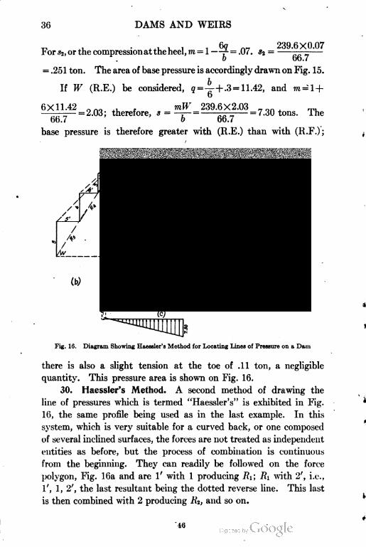
30 DAMS AND WEIRS
, . Gq n7 239.6X0.07r or s2, or the compression at the heel, m = 1—*•= .07. *2 = .. . _
o bo.7
= .251 ton. The area of base pressure is accordingly drawn on Fig. 15.
If W (R.E.) be considered, q =4+ -3 =11.42, and m=l +
6X11.42 , , mW 239.6X2.03 „ Qn ™=2.03; therefore, s = —:— = ——— -7.30 tons, ihe
66.7 o bo.7
base pressure is therefore greater with (R.E.) than with (R.F.);
(a)
Fig. 16. Diagram Showing Haesaler's Method for Locating Lines of Pressure on a Dam
there is also a slight tension at the toe of .11 ton, a negligible
quantity. This pressure area is shown on Fig. 16.
30. Haessler's Method. A second method of drawing the
line of pressures which is termed "Haessler's" is exhibited in Fig.
16, the same profile being used as in the last example. In this
system, which is very suitable for a curved back, or one composed
of several inclined surfaces, the forces are not treated as independent
entities as before, but the process of combination is continuous
from the beginning. They can readily be followed on the force
polygon, Fig. 16a and are 1' with 1 producing RI; RI with 2', i.e.,
1', 1, 2', the last resultant being the dotted reverse line. This last
is then combined with 2 producing R%, and so on.
'46
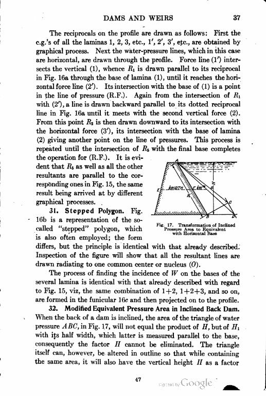
DAMS AND WEIRS 37
The reciprocals on the profile are drawn as follows: First the
c.g.'s of all the laminas 1, 2, 3, etc., 1', 2', 3', etc., are obtained by
graphical process. Next the water-pressure lines, which in this case
are horizontal, are drawn through the profile. Force line (!') inter
sects the vertical (1), whence Ri is drawn parallel to its reciprocal
in Fig. 16a through the base of lamina (1), until it reaches the hori
zontal force line (2')- Its intersection with the base of (1) is a point
in the line of pressure (R.F.). Again from the intersection of RI
with (2') , a line is drawn backward parallel to its dotted reciprocal
line in Fig. 16a until it meets with the second vertical force (2).
From this point RI is then drawn downward to its intersection with
the horizontal force (3'), its intersection with the base of lamina
(2) giving another point on the line of pressures. This process is
repeated until the intersection of Rs with the final base completes
the operation for (R.F.). It is evi
dent that Rs, as well as all the other
resultants are parallel to the cor
responding ones in Fig. 15, the same
result being arrived at by different
graphical processes.
31. Stepped Polygon. Fig.
16b is a representation of the so-
called "stepped" polygon, which
is also often employed; the form
differs, but the principle is identical with that already described.
Inspection of the figure will show that all the resultant lines are
drawn radiating to one common center or nucleus (0).
The process of finding the incidence of W on the bases of the
several lamina is identical with that already described with regard
to Fig. 15, viz, the same combination of 1+2, 1+2+3, and so on,
are formed in the funicular 16c and then projected on to the profile.
32. Modified Equivalent Pressure Area in Inclined Back Dam.
When the back of a dam is inclined, the area of the triangle of water
pressure ABC, in Fig. 17, will not equal the product of //, but of HI
with its half width, which latter is measured parallel to the base,
consequently the factor // cannot be eliminated. The triangle
itself can, however, be altered in outline so that while containing
the same area, it will also have the vertical height // as a factor
Fig. 17. Transformation of Inclined
Pressure Area to Equivalent
with Horizontal Base

38 DAMS AND WEIRS
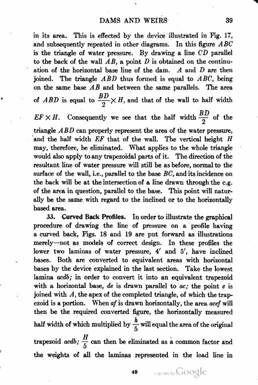
DAMS AND WEIRS 39
in its area. This is effected by the device illustrated in Fig. 17,
and subsequently repeated in other diagrams. In this figure ABC
is the triangle of water pressure. By drawing a line CD parallel
to the back of the wall AB, a point D is obtained on the continu
ation of the horizontal base line of the dam. A and D are then
joined. The triangle ABD thus formed is equal to ABC, being
on the same base AB and between the same parallels. The area
R7)of ABD is equal to ——- X H, and that of the wall to half width
£
-DT)
EF X H. Consequently we see that the half width —- of the
&
triangle ABD can properly represent the area of the water pressure,
and the half width EF that of the wall. The vertical height H
may, therefore, be eliminated. What applies to the whole triangle
would also apply to any trapezoidal parts of it. The direction of the
resultant line of water pressure will still be as before, normal to the
surface of the wall, i.e., parallel to the base BC, and its incidence on
the back will be at the intersection of a line drawn through the e.g.
of the area in question, parallel to the base. This point will natur
ally be the same with regard to the inclined or to the horizontally
based area.
33. Curved Back Profiles. In order to illustrate the graphical
procedure of drawing the line of pressure on a profile having
a curved back, Figs. 18 and 19 are put forward as illustrations
merely—not as models of correct design. In these profiles the
lower two laminas of water pressure, 4' and 5', have inclined
bases. Both are converted to equivalent areas with horizontal
bases by the device explained in the last section. Take the lowest
lamina ocdb; in order to convert it into an equivalent trapezoid
with a horizontal base, de is drawn parallel to ac; the point e is
joined with A, the apex of the completed triangle, of which the trap
ezoid is a portion. When of is drawn horizontally, the area acef will
then be the required converted figure, the horizontally measured
half width of which multiplied by — will equal the area of the original
o
TT
trapezoid acdb; — can then be eliminated as a common factor and
o
the weights of all the laminas represented in the load line in
49
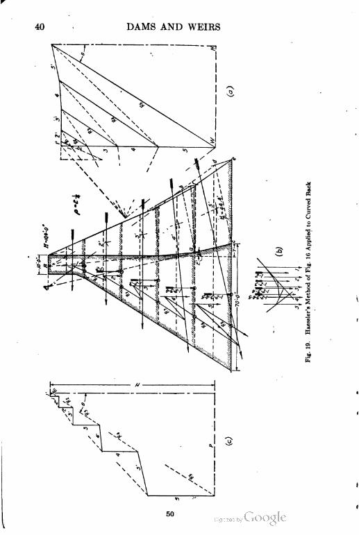
40 DAMS AND WEIRS
e
50
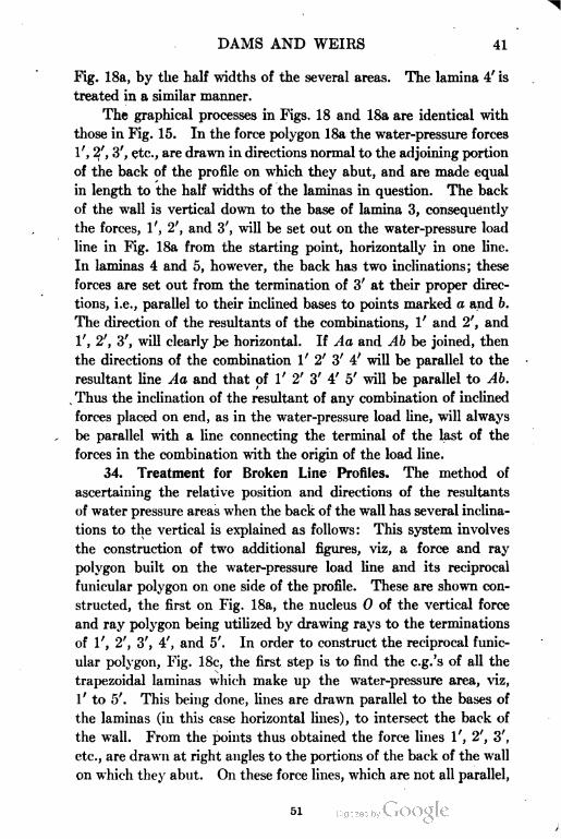
DAMS AND WEIRS 41
Fig. 18a, by the half widths of the several areas. The lamina 4' is
treated in a similar manner.
The graphical processes in Figs. 18 and 18a are identical with
those in Fig. 15. In the force polygon 18a the water-pressure forces
1', 2', 3', etc., are drawn in directions normal to the adjoining portion
of the back of the profile on which they abut, and are made equal
in length to the half widths of the laminas in question. The back
of the wall is vertical down to the base of lamina 3, consequently
the forces, 1', 2', and 3', will be set out on the water-pressure load
line in Fig. 18a from the starting point, horizontally in one line.
In laminas 4 and 5, however, the back has two inclinations; these
forces are set out from the termination of 3' at their proper direc
tions, i.e., parallel to their inclined bases to points marked a and b.
The direction of the resultants of the combinations, 1' and 2', and
1', 2', 3', will clearly .be horizontal. If Aa and Ab be joined, then
the directions of the combination 1' 2' 3' 4' will be parallel to the
resultant line Aa and that of 1' 2' 3' 4' 5' will be parallel to Ab.
Thus the inclination of the resultant of any combination of inclined
forces placed on end, as in the water-pressure load line, will always
be parallel with a line connecting the terminal of the last of the
forces in the combination with the origin of the load line.
34. Treatment for Broken Line Profiles. The method of
ascertaining the relative position and directions of the resultants
of water pressure areas when the back of the wall has several inclina
tions to the vertical is explained as follows: This system involves
the construction of two additional figures, viz, a force and ray
polygon built on the water-pressure load line and its reciprocal
funicular polygon on one side of the profile. These are shown con
structed, the first on Fig. 18a, the nucleus 0 of the vertical force
and ray polygon being utilized by drawing rays to the terminations
of 1', 2', 3', 4', and 5'. In order to construct the reciprocal funic
ular polygon, Fig. 18c, the first step is to find the c.g.'s of all the
trapezoidal laminas which make up the water-pressure area, viz,
1 ' to 5'. This being done, lines are drawn parallel to the bases of
the laminas (in this case horizontal lines), to intersect the back of
the wall. From the points thus obtained the force lines 1', 2', 3',
etc., are drawn at right angles to the portions of the back of the wall
on which they abut. On these force lines, which are not all parallel,
51
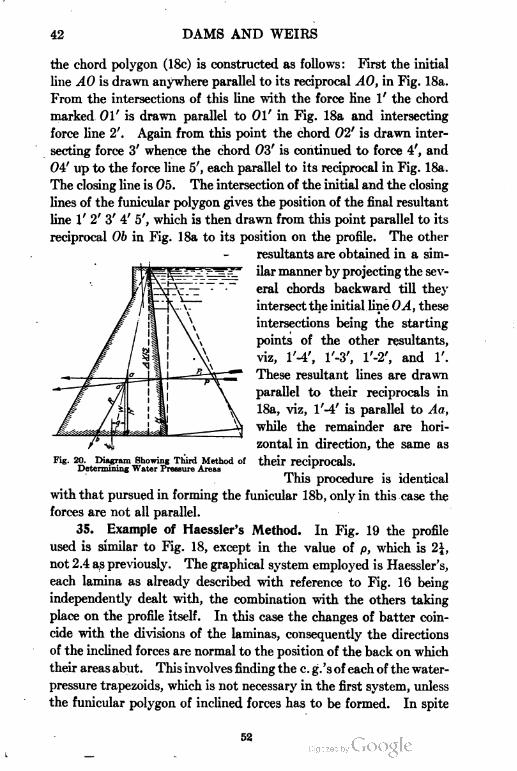
42 DAMS AND WEIRS
die chord polygon (18c) is constructed as follows: First the initial
line A0 is drawn anywhere parallel to its reciprocal A0, in Fig. 18a.
From the intersections of this line with the force line 1' the chord
marked 01' is drawn parallel to 01' in Fig. 18a and intersecting
force line 2'. Again from this point the chord 02' is drawn inter
secting force 3' whence the chord 03' is continued to force 4', and
04' up to the force line 5', each parallel to its reciprocal in Fig. 18a.
The closing line is 05. The intersection of the initial and the closing
lines of the funicular polygon gives the position of the final resultant
line 1' 2' 3' 4' 5', which is then drawn from this point parallel to its
reciprocal 0b in Fig. 18a to its position on the profile. The other
resultants are obtained in a sim
ilar manner by projecting the sev
eral chords backward till they
intersect the initial line 0A, these
intersections being the starting
points of the other resultants,
viz, l'-4', l'-3', l'-2', and 1'.
These resultant lines are drawn
parallel to their reciprocals in
18a, viz, l'-4' is parallel to Aa,
while the remainder are hori
zontal in direction, the same as
their reciprocals.
This procedure is identical
with that pursued in forming the funicular 18b, only in this case the
forces are not all parallel.
35. Example of Haessler's Method. In Fig. 19 the profile
used is similar to Fig. 18, except in the value of p, which is 2\,
not 2.4 as previously. The graphical system employed is Haessler's,
each lamina as already described with reference to Fig. 16 being
independently dealt with, the combination with the others taking
place on the profile itself. In this case the changes of batter coin
cide with the divisions of the laminas, consequently the directions
of the inclined forces are normal to the position of the back on which
their areas abut. This involves finding the c. g.'s of each of the water-
pressure trapezoids, which is not necessary in the first system, unless
the funicular polygon of inclined forces has to be formed. In spite
Fig. 20. Diagram Showing Third Method of
Determining Water Pressure Areas
52
DAMS AND WEIRS 43
of this, in most cases Haessler's method will be found the handiest
to employ, particularly in tentative work.
36. Example of Analytical Treatment. In addition to the
two systems already described, there is yet another corresponding
to the analytical, an illustration of which is given in Fig. 20. In
this the vertical and horizontal components of R, the resultants
(R.F.), viz, N and P are found. In this method the vertical com
ponent of the inclined water pressure PI is added to the vertical
weight of the dam itself, and when areas are used to represent
weights the area of this water overlying the back slope will have to
be reduced to a masonry base by division by the specific gravity of
the masonry.
37. Relations of R. N. and W. The diagram in Fig. 20 is a
further illustration showing the relative positions of R, P, PI, N,
and W. The line R starts from a, the intersection of the horizontal
force P with N, the resultant of all the vertical forces, for the reason
that it is the resultant of the combination of these two forces; but
R is also the resultant of Pi and W, consequently it will pass through
a', the intersection of these latter forces. The points a and ai are
consequently in the resultant R and it follows as well that if the
position of Pi is known, that of N and W can be obtained graphically
by the intersection of P or PI with Pi. These lines have already
been discussed.
UNUSUALLY HIGH DAMS
38. "High" Dams. An example will now be given, Fig. 21, of
the design of a high dam, i.e., one whose height exceeds the limit
before stated. As usual the elementary triangular profile forms
the guide in the design of the upper portion. We have seen in
section 24 that the limiting depth with p = 2.4 and c = 16 tons =
195 feet, whence for 18 tons' limit the depth will be 219 feet. In
Fig. 21 the tentative profile is taken down to a depth of 180 feet.
The crest is made 15 feet wide and the back is battered 1 in 30; the
base width is made 180 X.645 = 116 feet. The heel projects 6 feet
outside the axis line. The graphical procedure requires no special
explanation. It follows the analytical in dealing with the water
pressure as a horizontal force, the weight of the water overlying
the back being added to that of the solid dam. For purposes of
53
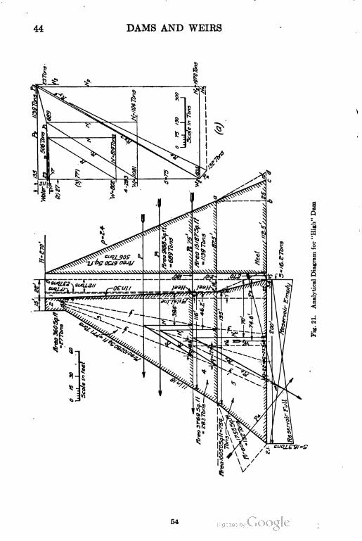
44 DAMS AND WEIRS
DAMS AND WEIRS 45
calculation the load is divided into three parts (1) the water on
the sloping back, the area of which is 540 sq. ft. This has to be
reduced by dividing it by p and so becomes 225 sq. ft. As tons,
not areas, will be used, this procedure is not necessary, but is adopted
for the sake of uniformity in treatment to avoid errors. The e.g.
of (1) is clearly 2 feet distant from the heel of the base of (3), about
which point moments will be taken. That of the crest (2) is 13.3 feet
and that of the main body (3) obtained by using formula (7) comes
to 41.2 feet. The statement of moments is then as follows:
No. AREA TONS LEVER ARM MOMENT
1 225 17 2 34
2 360 27 13.3 359
3 10280 771 41.2 31765
Total 10866 815 32158
32158Then the distance of AT from the heel will be —-=39.4 ft. ; it thus
815
falls 39.4 -38.7 = .7 ft. within the middle third. The distance (/)
P Hbetween N and R is -^rr- Now P = the area of the right angle
IT
triangle whose base is —, or 75 feet, and is 6750 sq. ft. equivalent
P
, 6750X3 --. „, . ., , , 506X180to ———= 506 tons. Ihe expression then becomes j=--———-
40 oXolo
=37.2 feet. The incidence of R will then be 37.2+39.4 = 76.6 feet
2distant from the heel of the base. The — point being 77.3 from the
o
heel, R falls .7 ft. within. Thus far the tentative profile has proved
fairly satisfactory, although a slight reduction in the base width is
possible. The position of W, or the resultant weight of the portions
2 and 3 of the dam is obtained from the moment table already
given, and is the sum of the moments of (2) and (3) divided by (2)
+ (3) or
t \sO
ft. This falls 40.2-38.7 = 1.5 ft. within the
55
46 DAMS AND WEIRS
middle third. The value of q (R.F.) is -^--.7= 19.33 -.7 = 18.6
feet, and m
=K)=Then by formula (Id), N being 815 and P, 506
I 1.96x815+V(1.96x815)2+4 (506)'
" " ~" " " 232
= 1597+ V2551367+ 1024144
232
= 15.03 tons per square foot
Extension of Profile. This value being well below the limit
of 18 tons and both resultants (R.F.) and (R.E.) standing within the
middle third it is deemed that the same profile can be carried down
another 30 ft. in depth without widening. The base length will
now be a trifle over 135 feet. The area of the new portion (4) is
3769 sq. ft. =283 tons. The distance of its e.g. from the heel by
formula (7) is found to be 63.4 feet. The position of W will be
obtained as follows, the center of moments being one foot farther
to right than in last paragraph.
Xo. TONS LEVER ARM MOMENT
2 27 14.3 386
3 771 42.2 32536
4 283 63.4 17942
Total 1081 50864
——
1081
=47.0 feet from heel of new base to W
* 1 oc
As — is -— =45 ft., the incidence of Wi is 2.0 ft. within the base,
o o
which is satisfactory.
To find NI, the moment of the water on whole back can be
added to that of W first obtained. The offset from the axis being
210x7now 7 ft., the area will be —-—= 735 equal to an area of masonry
735of •— = 306 sq. ft. equivalent to 23 tons, nearly. The lever arm
56
DAMS AND WEIRS 47
7being —, or 2.3 feet the moment about the heel will be 23X2.3 = 52.9,
o
say 53.0 ft.-tons. This amount added to the moment of Wi will
represent that of Nt and will be 50,864+53=50,917. The value of
Ni is that of Wi+ the water on back or, 1081+23 = 1104 tons.
The distance of Ni from the heel is then 2^fIL'=46.2 feet. To
1104
fiSQy 210
obtain that of 1^ the value of /= * =43.7 feet; this added
o X 1 104
to 46.2 = 89.9 ft., the incidence of fli is therefore -~^--89.9 =
O
"90-89.9 = .! ft., within the middle third boundary. Then q = -^
-.1=22.5 -.1=22.4" ft., and m = l+^ = l+i||^ = 2.00, nearly.
o loo
To find c, formula (10) will be used, the quantities being less than
. , , ,,.. „ mN 2.00X1104 ,,. , , ,in formula (10i). Here s = -—- =-—- =16.4 tons and s,
o loo
P 689 , , . ™=—=-—= 5. 1 tons. Then
o 135
.7 = 17.9 tons
The limit of 18 tons, being now reached, this profile will have to
be departed from.
39. Pentagonal Profile to Be Widened. The method now to
be adopted is purely tentative and graphic construction will be
found a great aid to its solution. A lamina of a depth of 60 ft.,
will be added to the profile. It is evident that its base width must
be greater than that which would be formed by the profile being
continued down straight to this level. The back batter naturally
will be greater than the fore. From examination of other profiles it
appears that the rear batter varies roughly from about 1 in 5 to 1
in 8 while the fore batter is about 1 to 1. As a first trial an 8 ft.
extra offset at the back was assumed with a base of 200 feet; this
would give the required front projection. Graphical trial lines
showed that N would fall without the middle third, and W as well;
the stress also just exceeded 18 tons (R.E.). A second trial was
now made in which the back batter was increased and the base
shortened to 180 feet. In this case c exceeded the 18 ton limit.
57
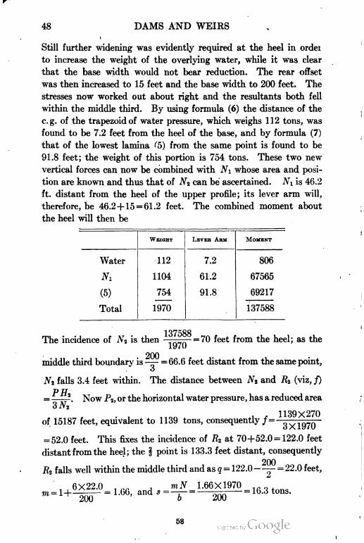
DAMS AND WEIRS
Still further widening was evidently required at the heel in ordei
to increase the weight of the overlying water, while it was clear
that the base width would not bear reduction. The rear offset
was then increased to 15 feet and the base width to 200 feet. The
stresses now worked out about right and the resultants both fell
within the middle third. By using formula (6) the distance of the
e.g. of the trapezoidof water pressure, which weighs 112 tons, was
found to be 7.2 feet from the heel of the base, and by formula (7)
that of the lowest lamina <"5) from the same point is found to be
91.8 feet; the weight of this portion is 754 tons. These two new
vertical forces can now be combined with Ni whose area and posi
tion are known and thus that of Nt can be ascertained. Nt is 46.2
ft. distant from the heel of the upper profile; its lever arm will,
therefore, be 46.2+ 15 = 61.2 feet. The combined moment about
the heel will then be
WEIGHT LEVEK ASM MOMENT
Water 112 7.2 806
A7i 1104 61.2 67565
(5) 754 91.8 69217
Total 1970 137588
The incidence of137588
is then =70 feet from the heel; as the
1970
200middle third boundary is— = 66.6 feet distant from the same point,
o
N2 falls 3.4 feet within. The distance between N2 and .R2 (viz, f)
P H= -, Now P2, or the horizontal water pressure, has a reduced area
3 Jv 2
1139X270of 15187 feet, equivalent to 1139 tons, consequently /=———=—-
= 52.0 feet. This fixes the incidence of R2 at 70+52.0 = 122.0 feet
distant from the heel; the § point is 133.3 feet distant, consequently
200R2 falls well within the middle third and as q = 122.0—— = 22.0 feet,
,,6X22.0 . ,. , mN 1.66X1970m= \-\ = 1.oo, and * =—r— = r^ = lo.o tons.
200 200
58
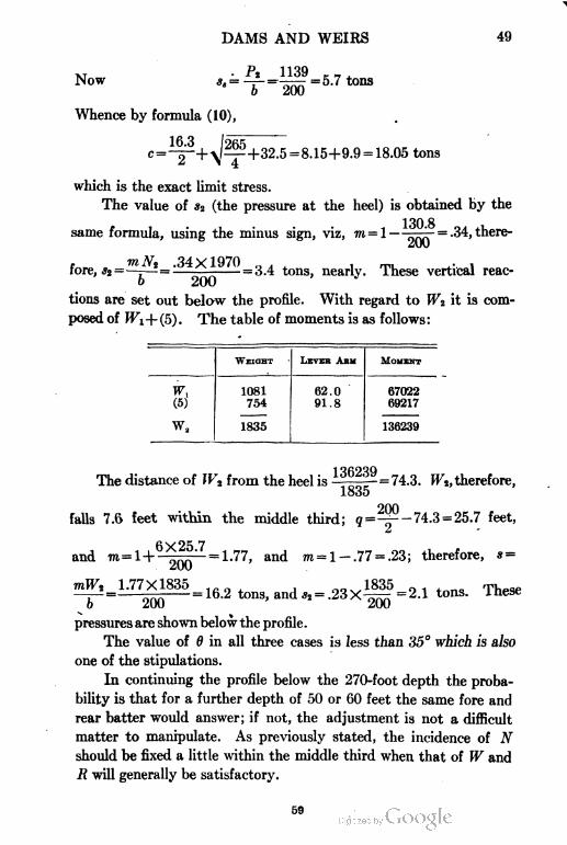
DAMS AND WEIRS 49
Now ss =
Whence by formula (10),
P* 1139 -
16.3
.9 = 18.05 tons
which is the exact limit stress.
The value of s2 (the pressure at the heel) is obtained by the
130 8same formula, using the minus sign, viz, m=l——jr- = .34, there-
fore, *2=—r-^=:—rprpr-=3.4 tons, nearly. These vertical reac
tions are set out below the profile. With regard to W2 it is com
posed of Wi+(5). The table of moments is as follows:
WEIGHT LEVER ARM MOMENT
w, 1081
754
62.0
91.8
67022
69217(5)
wa 1835 136239
The distance of If'2 from the heel is -'/''- = 74.3. Wt, therefore,
1835
falls 7.6 feet within the middle third;
6X25.7. n ,
and m=H200
1.77X1835
= ^'-74.3 = 25.7 feet,
= 1.77, and m= 1 — .77 = .23; therefore, s =
= 16.2 tons, and *2 = .23X~ =2.1 tons. These
b 200
pressures are shown below the profile.
The value of 6 in all three cases is less than 35° which is also
one of the stipulations.
In continuing the profile below the 270-foot depth the proba
bility is that for a further depth of 50 or 60 feet the same fore and
rear batter would answer; if not, the adjustment is not a difficult
matter to manipulate. As previously stated, the incidence of N
should be fixed a little within the middle third when that of W and
R will generally be satisfactory.
59
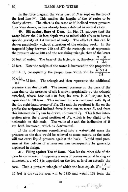
50 DAMS AND WEIRS
In the force diagram the water part of N is kept on the top of
the load line W. This enables the lengths of the N series to be
clearly shown. The effect is the same as if inclined water pressure
lines were drawn, as has already been exhibited in several cases.
40. Silt against Base of Dam. In Fig. 21, suppose that the
water below the 210-foot depth was so mixed with silt as to have a
specific gravity of 1.4 instead of unity. The effect of this can be
shown graphically without alteration of the existing work. In the
trapezoid lying between 210 and 270 the rectangle on ab represents
the pressure above 210 and the remaining triangle that of the lower
60 feet of water. The base of the latter, be is, therefore, — =TT=
p 2.4
25 feet. Now the weight of the water is increased in the proportion
//'Xl 4of 1.4 : 1, consequently the proper base width will be — . =
IA
60X1 4—- ' =35 feet. The triangle acd then represents the additional
pressure area due to silt. The normal pressure on the back of the
dam due to the presence of silt is shown graphically by the triangle
attached, whose base = cd =10 feet; its area is 310 square feet,
equivalent to 23 tons. This inclined force is combined with R2 at
the top right-hand corner of Fig. 21a and the resultant is R3; on the
profile the reciprocal inclined force is run out to meet 7?2 and from
this intersection Rs can be drawn up toward P%. This latter inter
section gives the altered position of N*, which is too slight to be
noticeable on this scale. The value of c and the inclination of R
are both increased, which is detrimental.
If the mud became consolidated into a water-tight mass the
pressure on the dam would be relieved to some extent, as the earth
will not exert liquid pressure against the back. Liquid mud pres
sure at the bottom of a reservoir can consequently be generally
neglected in design.
41. Filling against Toe of Dam. Now let the other side of the
dam be considered. Supposing a mass of porous material having an
immersed §.. g. of 1.8 is deposited on the toe, as is often actually the
1 8case. Then a pressure triangle of which the base equals
m
45 feet is drawn; its area will be 1755 and weight 132 tons; the
60
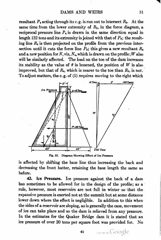
DAMS AND WEIRS 51
resultant PA acting through its c. g. is run out to intersect Rz. At the
same time from the lower extremity of R%, in the force diagram, a
reciprocal pressure line P\ is drawn in the same direction equal in
length 132 tons and its extremity is joined with that of P2; the result
ing line R\ is then projected on the profile from the previous inter
section until it cuts the force line P2; this gives a new resultant R\
and a new position for N, viz, 2V4, which is drawn on the profile ; W also
will be similarly affected. The load on the toe of the dam increases
its stability as the value of 6 is lessened, the position of W is also
improved, but that of 7?4, which is nearer to the toe than R3, is not.
To adjust matters, the c. g. of (5) requires moving to the right which
IS6Tora\
Ice Pressure
Z9Z Tons
Fig. 22. Diagram Showing Effect of Ice Pressure
is affected by shifting the base line thus increasing the back and
decreasing the front batter, retaining the base length the same as
before.
42. Ice Pressure. Ice pressure against the back of a dam
has sometimes to be allowed for in the design of the profile; as a
rule, however, most reservoirs are not full in winter so that the
expansive pressure is exerted not at the summit but at some distance
lower down where the effect is negligible. In addition to this when
the sides of a reservoir are sloping, as is generally the case, movement
of ice can take place and so the dam is relieved from any pressure.
In the estimates for the Quaker Bridge dam it is stated that an
ice pressure of over 20 tons per square foot was provided for. No
61
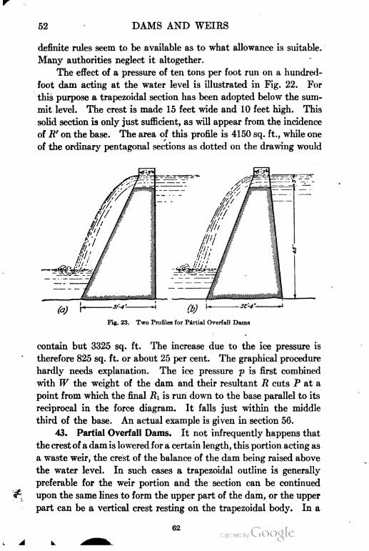
52 DAMS AND WEIRS
definite rules seem to be available as to what allowance is suitable.
Many authorities neglect it altogether.
The effect of a pressure of ten tons per foot run on a hundred-
foot dam acting at the water level is illustrated in Fig. 22. For
this purpose a trapezoidal section has been adopted below the sum
mit level. The crest is made 15 feet wide and 10 feet high. This
solid section is only just sufficient, as will appear from the incidence
of R' on the base. The area of this profile is 4150 sq. ft., while one
of the ordinary pentagonal sections as dotted on the drawing would
Fig. 23. Two Profiles for Partial Overfall Dams
contain but 3325 sq. ft. The increase due to the ice pressure is
therefore 825 sq. ft. or about 25 per cent. The graphical procedure
hardly needs explanation. The ice pressure p is first combined
with W the weight of the dam and their resultant R cuts P at a
point from which the final RI is run down to the base parallel to its
reciprocal in the force diagram. It falls just within the middle
third of the base. An actual example is given in section 56.
43. Partial Overfall Dams. It not infrequently happens that
the crest of a dam is lowered for a certain length, this portion acting as
a waste weir, the crest of the balance of the dam being raised above
the water level. In such cases a trapezoidal outline is generally
preferable for the weir portion and the section can be continued
upon the same lines to form the upper part of the dam, or the upper
part can be a vertical crest resting on the trapezoidal body. In a
62
DAMS AND WEIRS 53
trapezoidal dam, if the ratio of — he r, the correct base width is
obtained by the following formula:
1
This assumes the crest and summit water level to be the same.
In Fig. 23, p is taken as 2.4 and r as .2. The base width with a
vertical back will then be^X-^1 = 50 X.645 X.935 = 31.3
Vp V1 + .2-.04
feet, and the crest width k will be 31.3 X .2 =6.3 feet. In the second
figure the profile is shown canted forward, which is desirable in
weirs, and any loss in stability is generally more than compensated
for by the influence of the reverse pressure of the tail water which
influence increases with the steepness of the fore slope of the weir.
The base width is, however, increased by one foot in the second figure.
As will be seen in the next section, the crest width of a weir
should not be less than V//+ Vd; in this case H = 45 and d= 5.
This would provide a crest width of 6.7+2.2 = 9 feet, which it nearly
scales. .
NOTABLE EXISTING DAMS
44. Cheeseman Lake Dam. Some actual examples of dam
sections will now be exhibited and analyzed. Fig. 24 is the section
of the Cheeseman Lake dam near Denver, Colorado, which is one
of the highest in the world. It is built to a curvature of 400 feet
radius across a narrow canyon. It is considered a gravity dam,
however, and will be analyzed as such. The section can be divided
into three unequal parts 1, 2, and 3, and the lines of pressure (R.F.)
and (R.E.) will be drawn through the bases of these three divisions.
Of the vertical forces (1) has an area of 756 sq. ft., (2) of 3840, and
(3) of 13,356 the total value of W being 17,952 sq. ft. , which is marked
off on the load line in Fig. 24a. With regard to the water-pressure
areas the most convenient method, where half widths are not used,
which can only be done with equal divisions, is to estimate the
areas of the horizontal pressures only and set them off horizontally,
the values of the inclined pressures being obtained by construction.
For this purpose the triangle of horizontal water pressure is shown
adjacent to, but separate from, the profile. The three values of P
63
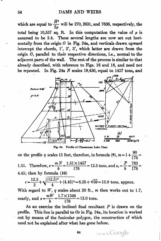
54 DAMS AND WEIRS
which are equal to —— will be 270, 2631, and 7636, respectively, the
2/o
total being 10,537 sq. ft. In this computation the value of p is
assumed to be 2.4. These several lengths are now set out hori
zontally from the origin O in Fig. 24a, and verticals drawn upward
intercept the chords, 1', 2', 3', which latter are drawn from the
origin O, parallel to their respective directions, i.e., normal to the
adjacent parts of the wall. The rest of the process is similar to that
already described, with reference to Figs. 16 and 18, and need not
be repeated. In Fig. 24a N scales 19,450, equal to 1457 tons, and
Radius* 400'
Fig. 24. Profile of Cheeseman Lake Dam
90on the profile q scales 15 feet, therefore, in formula (9), m = 1+-^— =
1 n rp, - mN 1.51X1457 - P 7831.51. iheretore, *=—..—= = 12.5 tons, and .?„ =— =— =
b 1/6 0 176
4.45; then by formula (10)
= 13.9 tons, approx.
With regard to W, q scales about 20 ft., m then works out to 1.7,
nearly, and * =mW 1.7X1346
= 13.0 tons.
b 176
As an exercise the inclined final resultant P is drawn on the
profile. This line is parallel to Oc in Fig. 24a, its location is worked
out by means of the funicular polygon, the construction of which
need not be explained after what has gone before.
DAMS AND WEIRS 55
45. Analytical Check. In order to check this result analyt
ically the procedure will be, first, calculate the position of the c. g. of
the trapezoids (2) and (3) relative to the rear corner of their bases
by formula (7) and also the positions of the resultants of the vertical
components of the water pressure overlying the back with regard
to the same points by formula (6). Second, convert the areas into
tons by multiplying by T\. The statement of moments about the
heel of the base, with the object of finding the position of W is given
below.
Moment of (1) 56.7 X32.5 = 1843
Moment of (2) 288 X47.9 = 13795
Moment of (3) 1001 X75 = 75075
Total W = 1346 tons 90713
90713t.a.nre of W from the heel will then hp fi7 5
1346In
order to obtain N, the moments of the water weights will have to
be added as below.
Moment of W 1346X67.5 = 90713
Moment of w\ 10X21.6 = 216
Moment of Wa 107X9 = 963
Total N = 1463 tons 91892
91892
and
To find the incidence of R and its distance (q) from the center
point, that from the known position of N must be computed from
PH 783X224the formula f=~= 'o""?,«T=40 ft., tnerefore> 1 = (62.8+40.0)
o iV o X 14t)o
1 7fi
——= 14.8 feet. This is close to the value obtained graphically
Im
which was taken as 15 feet. The value of N is also seen to be close
to that obtained graphically. The value of q with regard to W (R.E.)
1 *'*£'
is as follows, q = ——67.5 = 20.5 feet, almost exactly what it scales on
65
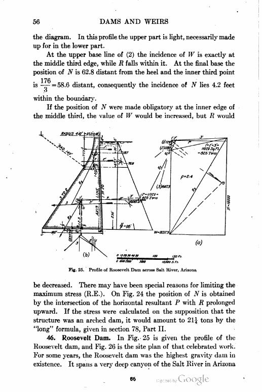
66 DAMS AND WEIRS
the diagram. In this profile the upper part is light, necessarily made
up for in the lower part.
At the upper base line of (2) the incidence of W is exactly at
the middle third edge, while R falls within it. At the final base the
position of N is 62.8 distant from the heel and the inner third point
1 7f*
= 58.6 distant, consequently the incidence of N lies 4.2 feetis
3
within the boundary.
If the position of N were made obligatory at the inner edge of
the middle third, the value of W would be increased, but R would
ommnxa jja, woo s, r,.
Fig. 25. Profile of Roosevelt Dam across Salt River, Arizona
be decreased. There may have been special reasons for limiting the
maximum stress (R.E.). On Fig. 24 the position of N is obtained
by the intersection of the horizontal resultant P with R prolonged
upward. If the stress were calculated on the supposition that the
structure was an arched dam, it would amount to 21 \ tons by the
"long" formula, given in section 78, Part II.
46. Roosevelt Dam. In Fig. 25 is given the profile of the
Roosevelt dam, and Fig. 26 is the site plan of that celebrated work.
For some years, the Roosevelt dam was the highest gravity dam in
existence. It spans a very deep canyon of the Salt River in Arizona
66
DAMS AND WEIRS 57
and impounds the enormous quantity of 1 ^ million acre-feet of water,
which will be utilized for irrigation. This work is part of one of
the greatest of the several large land reclamation projects under
taken by the U. S. Government for the watering and settling of
arid tracts in the dry zone of the western states.
The profile is remarkable for the severe simplicity of its out
line. It closely follows the elementary profile right down to its
extreme base and forms a powerful advocate for this simple style
of design. The graphical procedure is similar to that in the last
example. The section is divided into three divisions. As the
first two are comparatively small, the triangle of forces in Fig. 25a
Fig. 26. Site Plan for Roosevelt Dam
is first plotted a.t a large scale in pencil and the inclinations of the
resultants thus obtained are transferred to the profile; this accounts
for the long projecting lines near the origin of the force diagram
which also appear in some previous examples. A neater method
for overcoming this difficulty is that adopted in the next figure,
when the forces (1) and (2) are first amalgamated into one before
being plotted on the force diagram.
In Fig. 25a, N scales roughly 19,000 sq. ft., equivalent to 1425
120tons, q also measures approximately 20 ft., then m = l-| = 1.75,
160
mN 1425X1.75 .--, P 826 - , Band*=-r-= — = 15.5 tons. *s = —=— =5.1 tons. By
b loU b IbO
formula (10)
67
58 DAMS AND WEIRS
s roughiy
With regard to W, q measures 23 ft. and m works out to 1.86
, , mW 1.86X1378 ,- . fitherefore * =—j— = — = lo tons per sq. ft.
V ' i \s\J
This dam is built on a radius of 410 feet, measured from the
axis; if measured from the extrados of the curve at the base it will
be 420 feet and the arch stress as calculated from the "long" formula
used in "Arched Dams" will amount to 23.3 tons.
The site plan given in Fig. 26 forms an instructive example of the
arrangement of spillways cut in the solid rock out of the shoulders
of the side of the canyon, the material thus obtained being used in
the dam. These spillways are each 200 feet wide and are excavated
down to five feet below the crest of the dwarf waste weir walls which
cross them. This allows of a much greater discharge passing under
a given head than would be the case with a simple channel without
a drop wall and with bed at the weir crest level. The heading up,
or afflux, is by this means diminished and that is a matter affecting
the height given to the dam crest.
47. New Croton Dam. The profile of the New Croton dam
constructed in connection with the water supply of New York City
is given in Fig. 27. This dam has a straight alignment and is 1168
feet long. Waste flood water is accommodated by an overfull weir
1000 ft. in length, which is situated on one flank forming a continua
tion of the dam at right angles to its axis. The surplus water
falls into the Rocky River bed and is conveyed away by a separate
channel. An elevation and plan of this work are given in Figs.
28 and 29.
The system of graphical analysis employed in this case is differ
ent from that in the last two examples and is that illustrated in Fig.
18, where independent combinations of vertical and inclined forces
are used. The profile is divided into four divisions, the first being
a combination of two small upper ones. The further procedure after
the long explanations already given does not require any special
notice except to point out that the directions of the combined forces
1', l'+2', l'+2'+3'etcr in (d) are drawn parallel to their reciprocal
lines on Fig. 27a, namely to the chords Oa, Ob, Oc, and Od, respec
tively. The final resultants are 7?4 (R.F.) and W (R.E.). The
68
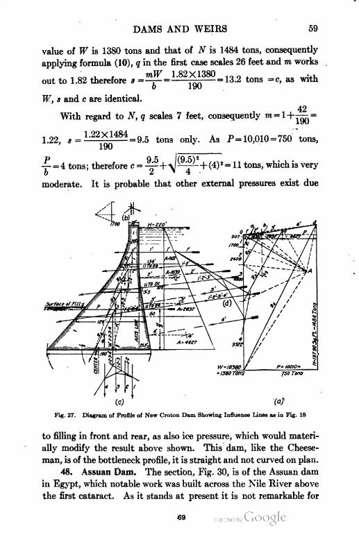
DAMS AND WEIRS
value of W is 1380 tons and that of N is 1484 tons, consequently
applying formula (10), q in the first case scales 26 feet and m works
mW 1.82X1380out to 1.82 therefore * =—r~ =
o 190
- = 13.2 tons =c, as with
42
W, s and c are identical.
With regard to N, q scales 7 feet, consequently m = 1+^,=
1.22X14841.22, a = = 9.5 tons only. As P = 10,010 -750 tons,
y = 4 tons ; therefore c = -^+^&S!+ (4) 2 = 1 1 tons, which is very
moderate. It is probable that other external pressures exist due
\
(c)
Fig. 27. Diagram of Profile of New Croton Dam Showing Influence Lines as in Fig. 18
to filling in front and rear, as also ice pressure, which would materi
ally modify the result above shown. This dam, like the Cheese-
man, is of the bottleneck profile, it is straight and not curved on plan.
48. Assuan Dam. The section, Fig. 30, is of the Assuan dam
in Egypt, which notable work was built across the Nile River above
the first cataract. As it stands at present it is not remarkable for
70
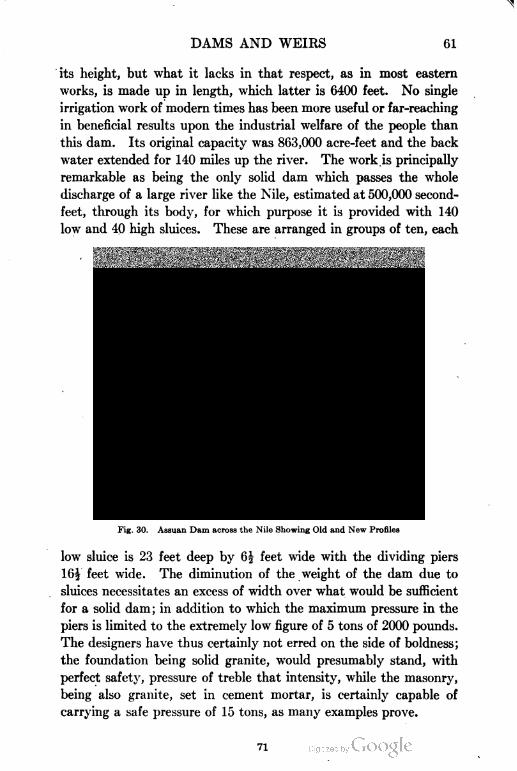
DAMS AND WEIRS 61
its height, but what it lacks in that respect, as in most eastern
works, is made up in length, which latter is 6400 feet. No single
irrigation work of modern times has been more useful or far-reaching
in beneficial results upon the industrial welfare of the people than
this dam. Its original capacity was 863,000 acre-feet and the back
water extended for 140 miles up the river. The work is principally
remarkable as being the only solid dam which passes the whole
discharge of a large river like the Nile, estimated at 500,000 second-
feet, through its body, for which purpose it is provided with 140
low and 40 high sluices. These are arranged in groups of ten, each
3TCCL RODS CONHECT1NG
HEW WORK W1TH OLD
Fig. 30. Assuan Dam across the Nile Showing Old and New Profiles
low sluice is 23 feet deep by 6| feet wide with the dividing piers
16| feet wide. The diminution of the weight of the dam due to
sluices necessitates an excess of width over what would be sufficient
for a solid dam; in addition to which the maximum pressure in the
piers is limited to the extremely low figure of 5 tons of 2000 pounds.
The designers have thus certainly not erred on the side of boldness;
the foundation being solid granite, would presumably stand, with
perfect safety, pressure of treble that intensity, while the masonry,
being also granite, set in cement mortar, is certainly capable of
carrying a safe pressure of 15 tons, as many examples prove.
71
CA5TE.ITH DESERT H1LLS
III!
•-"''W/%.IfK
I ~x"£: ",- ii"""«'w1//, "-«*ffir wyiflj i n
WMPiMM!!!! ";'f}# ^Pfl
'>iiiinii,ii,iiiiilm.^~:".'»iii!ij:iiiiiiii, '.^finvf -
'''""Vl~''""""'"^'/^'""""""""'""WESTCRn DESERT " >////«?
72
DAMS AND WEIRS 63
This dam has proved such a financial success that it has recently
been raised by 23 feet to the height originally projected. The
water thus impounded is nearly doubled in quantity, i.e., to
over 1| million acre-feet; exceeding even that of the Salt River
reservoir in Arizona. As it was decided not to exceed the low unit
pressure previously adopted, the profile has been widened by 16|
feet throughout. A space has been left between the new and the
old work which has been subsequently filled in with cement grout
under pressure, in addition to which a series of steel rods has been let
Fig. 32. View of Assuan Dam before Being Heightened with Sluices in Operation
into the old face by boring, and built into the new work. The enlarge
ment is shown in the figure. The sluices are capable of discharging
500,000 second feet; as their combined area is 25,000 square feet
this will mean a velocity of 20 feet per second. Owing, however, to
the possibility of adjustment of level, by manipulation of the sluice
gates, they will never be put to so severe a test.
A location plan and longitudinal section shown in Fig. 31, a
view of the sluices in operation, Fig. 32, and a view of the new work
in process, Fig. 33, will give a good idea of the construction features.
73

64 DAMS AND WEIRS
74
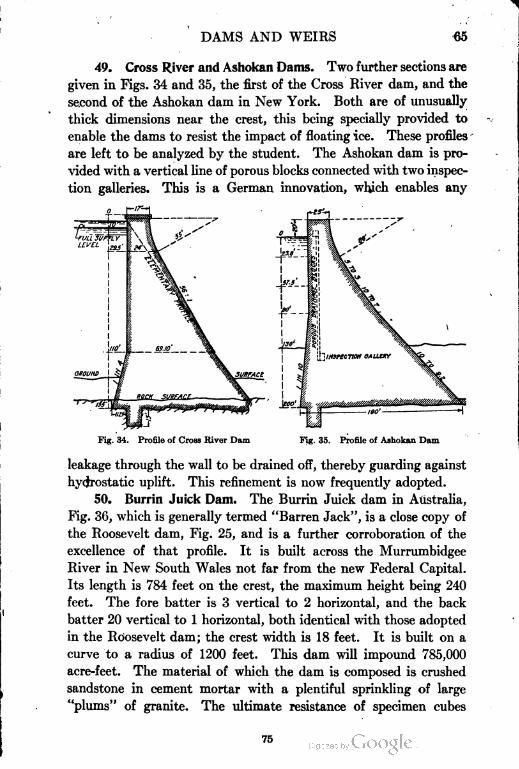
DAMS AND WEIRS
49. Cross River and Ashokan Dams. Two further sections are
given in Figs. 34 and 35, the first of the Cross River dam, and the
second of the Ashokan dam in New York. Both are of unusually
thick dimensions near the crest, this being specially provided to
enable the dams to resist the impact of floating ice. These profiles
are left to be analyzed by the student. The Ashokan dam is pro
vided with a vertical line of porous blocks connected with two inspec
tion galleries. This is a German innovation, which enables any
Fig. 34. Profile of Cross River Dam Fig. 35. Profile of Ashokan Dam
leakage through the wall to be drained off, thereby guarding against
hydrostatic uplift. This refinement is now frequently adopted.
50. Burrin Juick Dam. The Burrin Juick dam in Australia,
Fig. 36, which is generally termed "Barren Jack", is a close copy of
the Roosevelt dam, Fig. 25, and is a further corroboration of the
excellence of that profile. It is built across the Murrumbidgee
River in New South Wales not far from the new Federal Capital.
Its length is 784 feet on the crest, the maximum height being 240
feet. The fore batter is 3 vertical to 2 horizontal, and the back
batter 20 vertical to 1 horizontal, both identical with those adopted
in the Roosevelt dam; the crest width is 18 feet. It is built on a
curve to a radius of 1200 feet. This dam will impound 785,000
acre-feet. The material of which the dam is composed is crushed
sandstone in cement mortar with a plentiful sprinkling of large
"plums" of granite. The ultimate resistance of specimen cubes
75
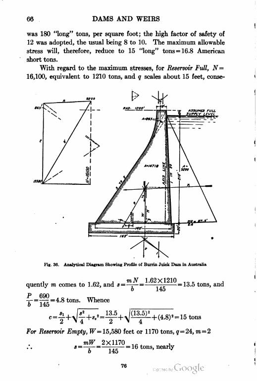
66 DAMS AND WEIRS
was 180 "long" tons, per square foot; the high factor of safety of
12 was adopted, the usual being 8 to 10. The maximum allowable
stress will, therefore, reduce to 15 "long" tons = 16.8 American
short tons.
With regard to the maximum stresses, for Reservoir Full, N=
16,100, equivalent to 1210 tons, and q scales about 15 feet, conse-
Fig. 36. Analytical Diagram Showing Profile of Burrin Juick Dam in Australia
xi , ,. - , ™N 1.62X1210 ..., r J ,quently m comes to 1.62, and s =—r—= —— = 13.5 tons, and
b 145
P 690 ., ,, E,-7- = —77 =4.8 tons. Whenceb 145
:.8)2 = 15 tons> "" 2 ' \ 4
For Reservoir Empty, W= 15,580 feet or 1170 tons, g = 24, m=2
mW 2X1170 ift, .*=—T— =———= 16 tons, nearly
76
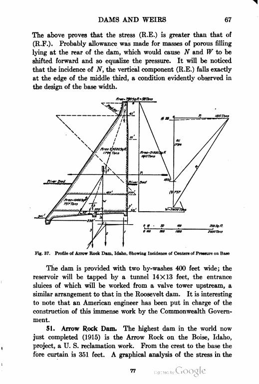
DAMS AND WEIRS 67
The above proves that the stress (R.E.) is greater than that of
(R.F.). Probably allowance was made for masses of porous filling
lying at the rear of the dam, which would cause N and W to be
shifted forward and so equalize the pressure. It will be noticed
that the incidence of N, the vertical component (R.E.) falls exactly
at the edge of the middle third, a condition evidently observed in
the design of the base width.
Fig. 37. Profile of Arrow Rock Dam, Idaho, Showing Incidence of Centers of Pressure on Base
The dam is provided with two by-washes 400 feet wide; the
reservoir will be tapped by a tunnel 14X13 feet, the entrance
sluices of which will be worked from a valve tower upstream, a
similar arrangement to that in the Roosevelt dam. It is interesting
to note that an American engineer has been put in charge of the
construction of this immense work by the Commonwealth Govern
ment.
51. Arrow Rock Dam. The highest dam in the world now
just completed (1915) is the Arrow Rock on the Boise, Idaho,
project, a U. S. reclamation work. From the crest to the base the
fore curtain is 351 feet. A graphical analysis of the stress in the
77
68 DAMS AND WEIRS
base is given in Fig. 37. For Reservoir Empty, fF=2609 tons, and
ooo on/
q measures 38 feet; therefore m = 1 + ^^. = 2 nearly and s = —r- —
222 o
23.5 tons. For Reservoir Full, 9 = 27, and m=l+i|? =
222
1.73X2609
222
^ P 1610tons. ^ = = tons' and c =
20.2
(20.2) 2
+ (7.3) 2 = 22.6 tons. These values are, of course, but
approximate.
Thus the compressive stresses (R.F.) and (R.E.) are practically
equal, and the incidence of W and also of N is close to the edge of
Fig. 38. Location Plan of Arrow Rock Dam
Courtesy of "Engineering Record"
the middle third. The dam is built on a radius of 661 feet at the
crest. The high stresses allowed are remarkable, as the design is on
the gravity principle, arch action being ignored. The curvature
doubtless adds considerably to safety and undoubtedly tends to
reduce the compressive stresses by an indeterminate but substantial
amount. It is evident that formula (10) has been applied to the
78
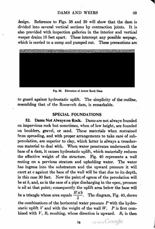
DAMS AND WEIRS 69
design. Reference to Figs. 38 and 39 will show that the dam is
divided into several vertical sections by contraction joints. It is
also provided with inspection galleries in the interior and vertical
weeper drains 10 feet apart. These intercept any possible seepage,
which is carried to a sump and pumped out. These precautions are
Earth Surface-
Diversion Tunnel
Fig. 39. Elevation of Arrow Rock Dam
to guard against hydrostatic uplift. The simplicity of the outline,
resembling that of the Roosevelt dam, is remarkable.
SPECIAL FOUNDATIONS
52. Dams Not Always on Rock. Dams are not always founded
on impervious rock but sometimes, when of low height, are founded
on boulders, gravel, or sand. These materials when restrained
from spreading, and with proper arrangements to take care of sub-
percolation, are superior to clay, which latter is always a treacher
ous material to deal with. When water penetrates underneath the
base of a dam, it causes hydrostatic uplift, which materially reduces
the effective weight of the structure. Fig. 40 represents a wall
resting on a pervious stratum and upholding water. The water
has ingress into the substratum and the upward pressure it will
exert at c against the base of the wall will be that due to its depth,
in this case 30 feet. Now the point of egress of the percolation will
be at b, and, as in the case of a pipe discharging in the open, pressure
is nil at that point; consequently the uplift area below the base will
be a triangle whose area equals —-— . The diagram, Fig. 40, shows
the combinations of the horizontal water pressure P with the hydro
static uplift V and with the weight of the wall W. P is first com
bined with V, Ri resulting, whose direction is upward. Ri is then
79
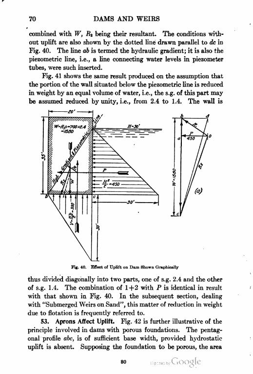
70 DAMS AND WEIRS
combined with W, R2 being their resultant. The conditions with
out uplift are also shown by the dotted line drawn parallel to dc in
Fig. 40. The line ab is termed the hydraulic gradient; it is also the
piezometric line, i.e., a line connecting water levels in piezometer
tubes, were such inserted.
Fig. 41 shows the same result produced on the assumption that
the portion of the wall situated below the piezometric line is reduced
in weight by an equal volume of water, i.e., the s.g. of this part may
be assumed reduced by unity, i.e., from 2.4 to 1.4. The wall is
Fig. 40. Effect of Uplift on Dam Shown Graphically
thus divided diagonally into two parts, one of s.g. 2.4 and the other
of s.g. 1.4. The combination of 1+2 with P is identical in result
with that shown in Fig. 40. In the subsequent section, dealing
with "Submerged Weirs on Sand", this matter of reduction in weight
due to flotation is frequently referred to.
53. Aprons Affect Uplift. Fig. 42 is further illustrative of the
principle involved in dams with porous foundations. The pentag
onal profile abc, is of sufficient base width, provided hydrostatic-
uplift is absent. Supposing the foundation to be porous, the area
80
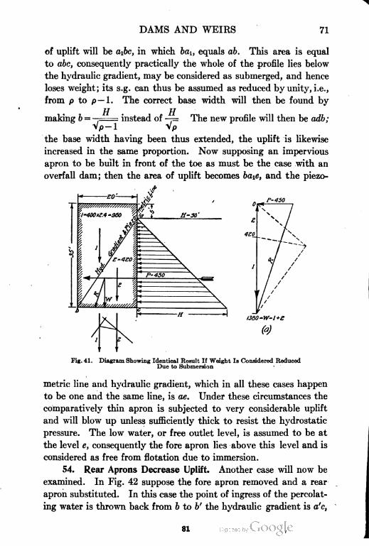
DAMS AND WEIRS 71
of uplift will be ajtc, in which bai, equals ab. This area is equal
to abc, consequently practically the whole of the profile lies below
the hydraulic gradient, may be considered as submerged, and hence
loses weight; its s.g. can thus be assumed as reduced by unity, i.e.,
from p to p — 1 . The correct base width will then be found by
making b =
TT TT
- instead of —= The new profile will then be adb;
Vp-i Vp
the base width having been thus extended, the uplift is likewise
increased in the same proportion. Now supposing an impervious
apron to be built in front of the toe as must be the case with an
overfall dam; then the area of uplift becomes ba\e, and the piezo-
I380-W-1+S
Fig. 41. Diagram Showing Identical Result If Weight la Considered Reduced
Due to Submersion
metric line and hydraulic gradient, which in all these cases happen
to be one and the same line, is ae. Under these circumstances the
comparatively thin apron is subjected to very considerable uplift
and will blow up unless sufficiently thick to resist the hydrostatic
pressure. The low water, or free outlet level, is assumed to be at
the level e, consequently the fore apron lies above this level and is
considered as free from flotation due to immersion.
54. Rear Aprons Decrease Uplift. Another case will now be
examined. In Fig. 42 suppose the fore apron removed and a rear
apron substituted. In this case the point of ingress of the percolat
ing water is thrown back from b to b' the hydraulic gradient is a'c,
81
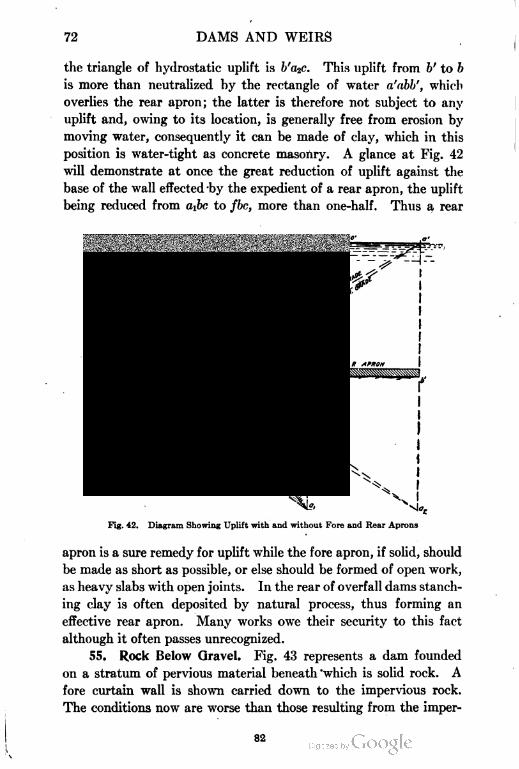
72 DAMS AND WEIRS
the triangle of hydrostatic uplift is b'a2c. This uplift from b' to b
is more than neutralized by the rectangle of water a'abb', which
overlies the rear apron; the latter is therefore not subject to any
uplift and, owing to its location, is generally free from erosion by
moving water, consequently it can be made of clay, which in this
position is water-tight as concrete masonry. A glance at Fig. 42
will demonstrate at once the great reduction of uplift against the
base of the wall effected by the expedient of a rear apron, the uplift
being reduced from ajtc to fbc, more than one-half. Thus a rear
Fig. 42. Diagram Showing Uplift with and without Fore and Rear Aprons
apron is a sure remedy for uplift while the fore apron, if solid, should
be made as short as possible, or else should be formed of open work,
as heavy slabs with open joints. In the rear of overfall dams stanch
ing clay is often deposited by natural process, thus forming an
effective rear apron. Many works owe their security to this fact
although it often passes unrecognized.
55. Rock Below Gravel. Fig. 43 represents a dam founded
on a stratum of pervious material beneath 'which is solid rock. A
fore curtain wall is shown carried down to the impervious rock.
The conditions now are worse than those resulting from the imper
82
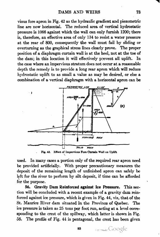
DAMS AND WEIRS 73
vious fore apron in Fig. 42 as the hydraulic gradient and piezometric
line are now horizontal. The reduced area of vertical hydrostatic
pressure is 1066 against which the wall can only furnish 1200; there
is, therefore, an effective area of only 134 to resist a water pressure
at the rear of 800, consequently the wall must fail by sliding or
overturning as the graphical stress lines clearly prove. The proper
position of a diaphragm curtain wall is at the heel, not at the toe of
the dam; in this location it will effectively prevent all uplift. In
the case where an impervious stratum does not occur at a reasonable
depth the remedy is to provide a long rear apron which will reduce
hydrostatic uplift to as small a value as may be desired, or else a
combination of a vertical diaphragm with a horizontal apron can be
LINE H = SO'
30L1O ROCK
Fig. 43. Effect of Impervious Fore Curtain Wall on Uplift
V
used. In many cases a portion only of the required rear apron need
be provided artificially. With proper precautionary measures the
deposit of the remaining length of unfinished apron can safely be
left for the river to perform by silt deposit, if time can be afforded
for the purpose.
56. Gravity Dam Reinforced against Ice Pressure. This sec
tion will be concluded with a recent example of a gravity dam rein
forced against ice pressure, which is given in Fig. 44, viz, that of the
St. Maurice River dam situated in the Province of Quebec. The
ice pressure is taken as 25 tons per foot run, acting at a level corre
sponding to the crest of the spillway, which latter is shown in Fig.
58. The profile of Fig. 44 is pentagonal, the crest has been given
83
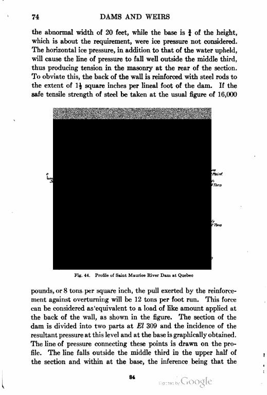
74 DAMS AND WEIRS
the abnormal width of 20 feet, while the base is f of the height,
which is about the requirement, were ice pressure not considered.
The horizontal ice pressure, in addition to that of the water upheld,
will cause the line of pressure to fall well outside the middle third,
thus producing tension in the masonry at the rear of the section.
To obviate this, the back of the wall is reinforced with steel rods to
the extent of 1| square inches per lineal foot of the dam. If the
safe tensile strength of steel be taken at the usual figure of 16,000
Fig. 44. Profile of Saint Maurice River Dam at Quebec
pounds, or 8 tons per square inch, the pull exerted by the reinforce
ment against overturning will be 12 tons per foot run. This force
can be considered as 'equivalent to a load of like amount applied at
the back of the wall, as shown in the figure. The section of the
dam is divided into two parts at El 309 and the incidence of the
resultant pressure at this level and at the base is graphically obtained.
The line of pressure connecting these points is drawn on the pro
file. The line falls outside the middle third in the upper half of
the section and within at the base, the inference being that the
84
DAMS AND WEIRS 75
section would be improved by conversion into a trapezoidal outline
with a narrower crest and with some reinforcement introduced as
has been done in the spillway section, shown in Fig. 58.
It will be noticed that the reinforcement stops short at El
275. This is allowed for by assuming the imposed load of 12 tons
removed at the base of the load line in the force polygon. The
line R& starting from the intersection of Rt with a horizontal through
El 275.0 is the final resultant at the base. This example is most
instructive as illustrating the combination of reinforcement with a
gravity section in caring for ice pressure, thus obviating the undue
enlargement of the profile.
GRAVITY OVERFALL DAMS OR WEIRS
57. Characteristics of Overfalls. When water overflows the
crest of a dam it is termed an overfall dam or weir, and some modi
fication in the design of the section generally becomes necessary.
Not only that, but the kinetic effect of the falling water has to be
provided for by the construction of an apron or floor which in many
cases forms by far the most important part of the general design.
This is so pronounced in the case of dwarf diversion weirs over wide
sandy river beds, that the weir itself forms but an insignificant part
of the whole section. The treatment of submerged weirs with aprons,
will be given elsewhere. At present the section of the weir wall
alone will be dealt with.
Typical Section. Fig. 45 is a typical section of a trapezoidal
weir wall with water passing over the crest. The height of the crest
as before, will be designated by H, that of reservoir level above
crest by d, and that of river below by D. The total height of the
upper still water level, will therefore, be H+d.
The depth of water passing over the crest should be measured
some distance upstream from the overfall just above where the
break takes place; the actual depth over the crest is less by reason
of the velocity of the overfall being always greater than that of
approach. This assumes dead water, as in a reservoir, in the upper
reach. On a river or canal, however, the water is in motion and has
a velocity of approach, which increases the discharge. In order to
V2allow for this, the head (h) corresponding to this velocity, or ——
85
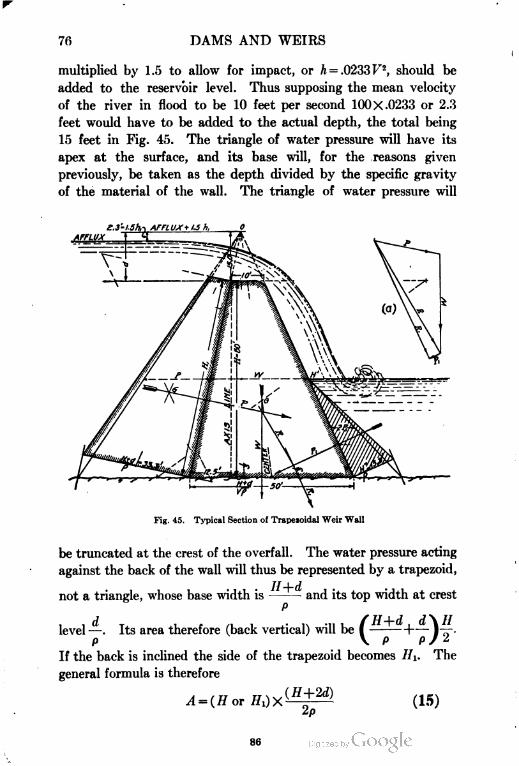
76 DAMS AND WEIRS
multiplied by 1.5 to allow for impact, or /i = .0233T'2, should be
added to the reservoir level. Thus supposing the mean velocity
of the river in flood to be 10 feet per second 100 X.0233 or 2.3
feet would have to be added to the actual depth, the total being
15 feet in Fig. 45. The triangle of water pressure will have its
apex at the surface, and its base will, for the reasons given
previously, be taken as the depth divided by the specific gravity
of the material of the wall. The triangle of water pressure will
S,3'-1.Sh-i AFFtUX + 13 h,
AFFLUX \ <•(
Fig. 45. Typical Section of Trapezoidal Weir Wall
be truncated at the crest of the overfall. The water pressure acting
against the back of the wall will thus be represented by a trapezoid,
not a triangle, whose base width is — - and its top width at crest
level —. Its area therefore (back vertical) will be I
P V
If the back is inclined the side of the trapezoid becomes HI. The
general formula is therefore
, „ ... il,(H+2d)
2p
(15)
86
DAMS AND WEIRS 77
HI being the inclined length of the back of the wall. The vertical
distance of its point of application above the base according to
formula (5) page 19 is h=-—t ——kj I -i"d will be the same
o \ a -\-'2ds
whether the back is vertical or inclined.
58. Approximate Base Width. With regard to the drop wall
itself, owing to the overfall of water and possible impact of floating
timber, ice, or other heavy bodies, a wide crest is a necessity. A
further strengthening is effected by adopting the trapezoidal profile.
The ordinary approximate rule for the base width of a trapezoidal
weir wall will be either
or
b.(H+M)
Vp
The correctness of either will depend on various considerations,
such as the value of d, the depth of the overfall, that of hi or velocity
head and also of D, the depth of the tail water; the inclination given
to the back, and lastly, whether the weir wall is founded on a porous
material and is consequently subject to loss of weight from uplift.
Hence the above formulas may be considered as approximate only
and the base width thus obtained subject to correction, which is
easiest studied by the graphical process of drawing the resultant on
to the base, ascertaining its position relative to the middle third
boundary.
59. Approximate Crest Width. With reference to crest width,
it may be considered to vary from
fr = V//+d (17)
to
i = Vff+Vd (18)
the former gives a width sufficient for canal, or reservoir waste weir
walls, but the latter is more suitable for river weirs, and is quite so
when the weir wall is submerged or drowned.
In many cases, however, the necessity of providing space for
falling shutters or for cross traffic during times when the weir is not
87
78 DAMS AND WEIRS
acting, renders obligatory the provision of an even wider crest.
With a moderate width, a trapezoidal outline has to be adopted, in
order to give the requisite stability to the section. This is formed
by joining the edge of the crest to the toe of the base by a straight
line, the base width of -—^— being adopted, as shown in Fig. 45.
VP
When the crest width exceeds the dimensions given in formula
(18), the face should drop vertically till it meets the hypothenuse
of the elementary profile, as is the case with the pentagonal profile
of dams. An example of this is given in Fig. 52 of the Dhukwa
weir. The tentative section thus outlined should be tested by
graphical process and if necessary the base width altered to conform
with the theory of the middle third.
In Fig. 45 is given a diagram of a trapezoidal weir 60 feet high
with d = 15 feet. According to formula (17) the crest width should
be V75 = 8.7 feet, and according to (18), 7.74+3.87 = 11.01 An aver
age of 10 feet has been adopted, which also equals —- The profile
P
therefore, exactly corresponds with the elementary triangle canted
forward and truncated at the overfall crest.
60. Graphical Process. In graphical diagrams, as has already
been explained, wherever possible half widths of pressure areas are
taken off with the compasses to form load lines, thus avoiding the
arithmetical process of measuring and calculating the areas of the
several trapezoids or triangles, which is always liable to error. There
are, however, in this case, three areas, one of which, that of the
reverse water pressure, has an altitude of only half of the others.
This difficulty is overcome by dividing its half width by 2. If one
height is not an exact multiple, as this is of H, a fractional value
given to the representing line in the polygon will often be found to
obviate the necessity of having to revert to superficial measures.
The application of the reverse pressure Pi here exhibited is similar
to that shown in Fig. 16; it has to be combined with R, which latter
is obtained by the usual process. This combination is effected in
the force polygon by drawing a line Pi equal to the representative
area, or half width of the back pressure, in a reverse direction to P.
The closing line RI is then the final resultant. On the profile itself
the force line PI is continued through its center of gravity till it
88
DAMS AND WEIRS 79
intersects R, from which point Ri is drawn to the base. If this por
tion of the face of the weir is very flat, as is sometimes the case, PI
may be so deflected as to intersect R below the base altogether as
is shown in Fig. 50. In such event, RI is drawn upward instead of
downward to intersect the base. The effect of Pi is to throw the
resultant RI farther inward but not to any great extent. It im
proves the angular direction of R, however.
Reverse Pressure. A dam is usually, but not invariably, exempt
from the effect of reverse pressure. This reverse water pressure is
generally, as in this case, favorable to the stability of the weir, but
there are cases when its action is either too slight to fee of service or
is even detrimental. This occurs when the face of the weir wall is
much inclined, which points to the equiangular profile being most
suitable. An example illustrative of the above remarks is given
later in Fig. 50 of the Folsam dam.
As the moments of the horizontal pressure of water on either
side of the weir wall vary almost with the cubes of their height, it
is evident that a comparatively low depth of tail water will have but
small influence and may well be neglected. When a vertical back
is adopted, the slope is all given to the face; by which the normal
reverse water pressure is given a downward inclination that reduces
its capacity for helping the wall.
61. Pressures Affected by Varying Water Level. Calculations
of the depths of water passing over the weir or rather the height of
reservoir level above the weir crest, designated by d, and of the
corresponding depth D in the tail channel, are often necessary for
the purpose of ascertaining what height of water level upstream,
or value of d, will produce the greatest effect on the weir wall. In
low submerged or drowned weirs, the highest flood level has often
the least effect, as at that time the difference of levels above and
below the weir are reduced to a minimum. This is graphically
shown in Fig. 46, which represents a section of the Narora dwarf
weir wall, to which further reference will be made in section 124,
Part II. In this profile two resultant pressures, R and RI, are
shown, of which RI, due to much lower water level of the two stages
under comparison, falls nearer the toe of the base.
The Narora weir, the section of the weir wall of which is so
insignificant, is built across the Ganges River in Upper India at the
89
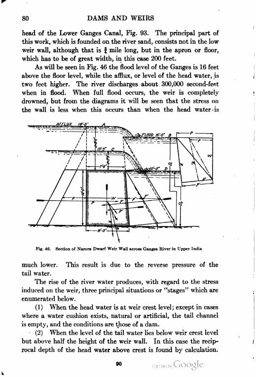
80 DAMS AND WEIRS
head of the Lower Ganges Canal, Fig. 93. The principal part of
this work, which is founded on the river sand, consists not in the low
weir wall, although that is f mile long, but in the apron or floor,
which has to be of great width, in this case 200 feet.
As will be seen in Fig. 46 the flood level of the Ganges is 16 feet
above the floor level, while the afflux, or level of the head water, is
two feet higher. The river discharges about 300,000 second-feet
when in flood. When full flood occurs, the weir is completely
drowned, but from the diagrams it will be seen that the stress on
the wall is less when this occurs than when the head water » is
Fig. 46. Section of Narora Dwarf Weir Wall across Ganges River in Upper India
much lower. This result is due to the reverse pressure of the
tail water.
The rise of the river water produces, with regard to the stress
induced on the weir, three principal situations or "stages" which are
enumerated below.
(1) When the head water is at weir crest level; except in cases
where a water cushion exists, natural or artificial, the tail channel
is empty, and the conditions are those of a dam.
(2) When the level of the tail water lies below weir crest level
but above half the height of the weir wall. In this case the recip
rocal depth of the head water above crest is found by calculation.
90
DAMS AND WEIRS 81
(3) At highest flood level, the difference between the head
and tail water is at a minimum. In an unsubmerged weir or over
fall dam the greatest stress is generally produced during stage (3).
In a submerged weir the greatest stress is produced during stage (2) .
62. Moments of Pressure. The moments of the horizontal
water pressure on either side of a wall are related to each other in
proportion to the cubes of their respective depths. In cases where
the wall is overflowed by the water, the triangle of pressure of the
latter, as we have seen, is truncated at the weir crest. The moment
(M) of this trapezoidal area of pressure will be the product of its
area with h, or the product of the expressions in formula (1) and
formula (5) as follows:
H
2p
or
DhvThat of the opposing tail water will be M =——, the difference of
op
these two being the resultant moment. For example, in the case
shown in Fig. 46, during stage (1) // = 10, D = 0, unbalanced moment
=—=166.6—. In stage (2) // = 10, d=3.5, and Z> = 10. Then
6p p
the unbalanced moment will be — [(100 X 20.5) - 1000] =175^-.
op p
In stage (3) tf=10, Z> = 16; d = 8, and D-H= Q feet. There will
thus be two opposing trapezoids of pressure, and the difference in
their moments will be
w(100X34) w(100X28) 1mw-_---_-= iuu—
op bp p
Thus stage (2) produces the greatest effect, the least being stage
(3). In this expression (w) symbolizes, as before, the unit weight
of water, per cubic foot or, 3^ ton.
In spite of this obvious fact, many weir wall sections have been
designed under the erroneous supposition that the overturning
moment is greatest when the upper water is at crest level and the tail
channel empty, i.e., at a time when the difference of levels above and
91
82 DAMS AND WEIRS
HaU.V1,
below the weir is at a
maximum, or at full
flood when the differ
ence is at a minimum.
63. Method of
Calculating Depth of
Overfall. During the
second stage of the
river the value of d,
the depth of the over
fall, will have to be
calculated. To effect
this the discharge of
the river must first be
estimated when the
surface reaches the
crest level of the weir,
which is done by use
of the formula, Q =
Acy/rs, given in sec
tion 35, page 47 of
"Hydraulics, Ameri
can School of Corre
spondence", A being
the area, equal to d
times length of weir
(c) Kutter's coeffi
cient, (r) the hydraulic
mean radius, and s,
the surface grade or
slope of the river. The
discharge for the whole
river should now be
divided by the length
of the weir crest, the
quotient giving the
unit discharge, or that
per foot run of the weir.
92
DAMS AND WEIRS 83
The depth required to pass this discharge with a free overfall
is found by use of Francis' formula of 3.33ds or a modification of it
for wide crest weirs for which tables are most useful. See "Hydrau
lics", section 24, p. 30.
For example, supposing the river discharge with tail water
up to crest level is 20 second-feet per foot run of the weir. Then
3.33dJ = 20. Whence d1= 6 and d=$P= 3.3 feet. This ignores
velocity of approach, a rough allowance for which would be to
decrease d by (hi) the velocity head, or by .0155 F2.
64. Illustrative Example. Fig. 47 illustrates an assumed case.
Here the weir is 15 feet high, 3 stages are shown:
(1) When head water is at crest level;
(2) When tail water is 7f feet deep, and the reciprocal depth of the
head water is assumed as 4 feet; and
(3) With tail water at crest level and head water assumed 7 feet
deep above crest.
The three resultants have been worked out graphically. From
their location on the base the greatest stress is due to R2, i.e.,
stage (2).
The hydraulic gradients of all three stages have been shown with
an assumed rear and fore apron on floor. In (1) more than half the
weir body lies below the piezometric line, which here corresponds
with the hydraulic gradient, while in (2) nearly the whole lies below
this line and in (3) entirely so.
Owing to this uplift it is well always to assume the s.g. of a weir
wall under these conditions as reduced by immersion to a value of
p — 1. In these cases the triangles of water pressure are shown with
TT TJ JJ
their bases made , or —-, instead of ——. Actually, however, thep—i 1.4 2A
resistance of the weir wall to overturning relative to its base at floor
level is not impaired by flotation, but as weight in these cases is a
desideratum, the weir wall should be designed as if this were the case.
The rear apron is evidently subject to no uplift, but the fore apron is,
and its resisting power, i.e., effective weight, is impaired by flotation.
See section 52 and also the later sections on "Submerged Weirs in
Sand", Part II.
65. Examples of Existing Weirs. Some examples of existing
weirs will now be given. Fig. 48 is a profile of the LaGrange over-
93
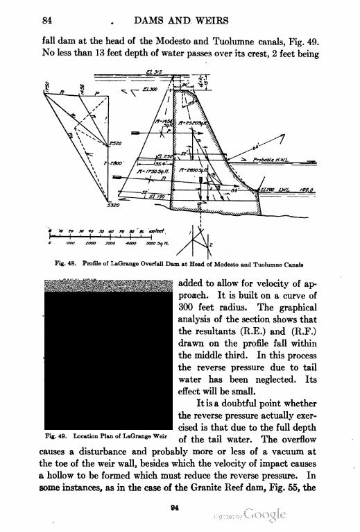
84 DAMS AND WEIRS
fall dam at the head of the Modesto and Tuolumne canals, Fig. 49.
No less than 13 feet depth of water passes over its crest, 2 feet being
Et 315
'1D fo x *o Jo eo TO BO K toofeet
1 1 ' 1 ' I ' 1 ' 1iOOO ZOOO 3OOO 40OO -SOOO 5a ft,
Fig. 48. Profile of LaGrange Overfall Dam at Head of Modesto and Tuolumne Canals
added tQ allow for velocity of ap.
proach. It is built on a curve of
300 feet radius. The graphical
analysis of the section shows that
the resultants (R.E.) and (R.F.)
drawn on the profile fall within
the middle third. In this process
the reverse pressure due to tail
water has been neglected. Its
effect will be small.
It is a doubtful point whether
the reverse pressure actually exer
cised is that due to the full depth
of the tail water. The overflow
causes a disturbance and probably more or less of a vacuum at
the toe of the weir wall, besides which the velocity of impact causes
a hollow to be formed which must reduce the reverse pressure. In
some instances, as in the case of the Granite Reef dam, Fig. 55, the
Fig. 49. Location Plan of LaGrange Weir
DAMS AND WEIRS 85
effective deptb of the tail water is assumed as only equal to that of
the film of overflow. This appears an exaggerated view. How
ever, in a high overfall dam, the effect of the reverse is often so small
that it can well be neglected altogether. In cases where the tail
water rises to f or more of the height of the dam its effect begins to
be considerable, and should be taken into account.
66. Objections to "Ogee" Overfalls. Professional opinion
seems now to be veering round in opposition to the "bucket" or
curved base of the fore slope which is so pronounced a feature in
American overfall dams. Its effects are undoubtedly mischievous,
as the destructive velocity of the falling water instead of being
reduced as would be the case if it fell direct into a cushion of water,
is conserved by the smooth curved surface of the bucket. In the
lately constructed Bassano hollow dam (see Figs. 84 and 85, Part II) ,
the action of the bucket is sought to be nullified by the subsequent
addition of baffles composed of rectangular masses of concrete fixed
on the curved slope. The following remarks in support of this
view are excerpted from "The Principles of Irrigation Engineering"
by Mr. F. H. Newell, formerly Director of United States Reclamation
Service. "Because of the difficulties involved by the standing wave
or whirlpool at the lower toe of overflow dams, this type has been
made in many cases to depart from the conventional curve and to
drop the water more nearly vertically rather than to attempt to
shoot it away from the dam in horizontal lines."
67. Folsam Weir. Fig. 50 is of the Folsam weir at the head
of the canal of that name. It is remarkable for the great depth of
flood water passing over the crest which is stated to be over 30 feet
deep. The stress lines have been put on the profile with the object
of proving that the reverse pressure of the water, although nearly
40 feet deep has a very small effect. This is due to the flat inclina
tion given to the lower part of the weir, which has the effect of
adding a great weight of water on the toe where it is least wanted
and thus the salutary effect of the reverse pressure is more than
neutralized. The section is not too heavy for requirements, but econ
omy would undoubtedly result if it were canted forward to a nearly
equiangular profile, and this applies to all weirs having deep tail water,
and to drowned weirs. It will be noted that a wide crest allows
but very little consequent reduction in the base width in any case.
95
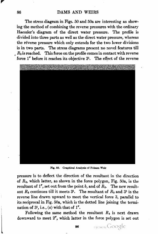
86 DAMS AND WEIRS
The stress diagram in Figs. 50 and 50a are interesting as show
ing the method of combining the reverse pressures with the ordinary
Haessler's diagram of the direct water pressure. The profile is
divided into three parts as well as the direct water pressure, whereas
the reverse pressure which only extends for the two lower divisions
is in two parts. The stress diagrams present no novel features till
RZ is reached. This force on the profile comes in contact with reverse
force 1" before it reaches its objective 31. The effect of the reverse
HEAD WATCH Ht d
Fig. 50. Graphical Analysis of Folsam Weir
pressure is to deflect the direction of the resultant in the direction
of #3, which latter, as shown in the force polygon, Fig. 50a, is the
resultant of 1", set out from the point b, and of 7?2. The new result
ant R3 continues till it meets 31. The resultant of R2 and 31 is the
reverse line drawn upward to meet the vertical force 3, parallel to
its reciprocal in Fig. 50a, which is the dotted line joining the termi
nation of 31, i.e., (a) with that of 1".
Following the same method the resultant RI is next drawn
downward to meet 2", which latter in the force polygon is set out
96
DAMS AND WEIRS 87
from the ternination of the vertical (3) . The resultant of PH and
2" is the final Pi5. This line is drawn upward on the profile inter
secting the base at B. If the reverse pressure were left out of con
sideration, the force RZ would continue on to its intersection with
31 and thence the reverse recovery line drawn to meet (3) will be
parallel to ba (not drawn) in the force polygon. This reverse line
will intersect the line (3) in the profile almost at. the same spot
as before.
The final line will be parallel to its reciprocal ca (not drawn
in Fig. 50a) and will cut the base outside the intersection of Pi5. To
prevent confusion these lines have not been drawn on; this proves
that the effect of the reverse pressure is detrimental to the stability
of the wall, except in the matter of the inclination of Pi6. If the
profile were tilted forward this would not be so. If PI the resultant
water pressure at the rear of the wall be drawn through the profile
to intersect the resultant of all the vertical forces, viz, 1+2+3+fl1
+02, this point will be found to be the same as that obtained by
producing the final Pi5 backwards to meet PI.
Determination of PI. To effect this, the position of Pt has to
be found by the following procedure : The load line db, Fig. 50a, is
continued to I, so as to include the forces 3, vi, and «2. The rays
oc, oj, and ol are drawn; thus a new force polygon dol is formed to
which the funicular, Fig. 50b, is made reciprocal. This decides the
position of W, or of 1+2+3, viz, the center of pressure (R. E.) as
also that of W+Vi+v^ which latter are the reverse pressure loads.
The location of PI is found by means of another funicular polygon C
derived from the force polygon oad, by drawing the rays oa, of, and
oe; PI is then drawn through the profile intersecting the vertical
resultant last mentioned at A. The line AB is then coincident
with Pis on Fig. 50. The vertical line through A is not N, i.e., is
not identical with the vertical in Fig. 50, for the reason that N is
the resultant of all the vertical forces, whereas the vertical in ques
tion is the centroid of pressure of all the vertical force less wi, the
weight of water overlying the rear slope of the wall. The location
of N is found by drawing a horizontal P through the intersection
of PI with a line drawn through the e.g. of the triangle of water
pressure w, this will intersect the back continuation of BA at c.
A vertical CD through this point will correspond with that marked
97
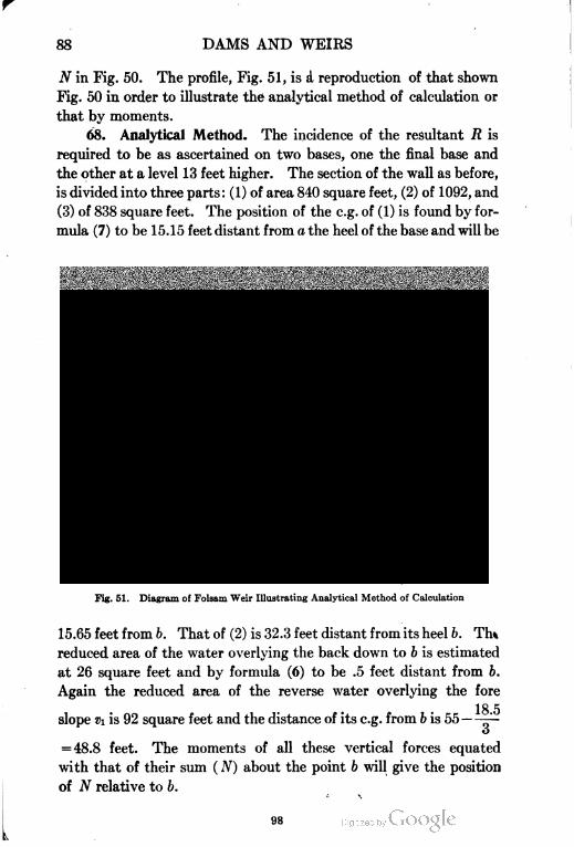
88 DAMS AND WEIRS
N in Fig. 50. The profile, Fig. 51, is a reproduction of that shown
Fig. 50 in order to illustrate the analytical method of calculation or
that by moments.
68. Analytical Method. The incidence of the resultant R is
required to be as ascertained on two bases, one the final base and
the other at a level 13 feet higher. The section of the wall as before,
is divided into three parts: (1) of area 840 square feet, (2) of 1092, and
(3) of 838 square feet. The position of the e.g. of (1) is found by for
mula (7) to be 15.15 feet distant from a the heel of the base and will be
Fig. 51. Diagram of Folsam Weir Illustrating Analytical Method of Calculation
15.65 feet from b. That of (2) is 32.3 feet distant from its heel b. Tin
reduced area of the water overlying the back down to b is estimated
at 26 square feet and by formula (6) to be .5 feet distant from b.
Again the reduced area of the reverse water overlying the fore
18 5slope Vi is 92 square feet and the distance of its e.g. from b is 55 -1-
o
= 48.8 feet. The moments of all these vertical forces equated
with that of their sum ( N) about the point b will give the position
of N relative to b.
98
DAMS AND WEIRS 89
Thus
(1) 840 Xl.r,.65 = 13146
(2) 1092X23.3 =25443
(w) 26 X .5 = 13
(»i) 92X48.8 = 4490
2050 Xx = 43092 =Moment of N
x = 21 feet, nearly
To obtain the distance/ between N and R, / = —^-—"'. Now
the reduced area of P=1257 and the height of the e.g. of the
trapezoid having its base at b, and its crest level with that of the
wall is calculated by formula (6), to be 22.1 feet. Again the reduced
area of the reverse water pressure triangle pi is 120 square feet,
the height of its e.g. above base is 8 feet. Consequently:
J_(1257X22.1)-(120X8)_26820_10,
J~ 2050 "2050
For the lower base, the statement of moments about c is as fol
lows, i'2 being 240, and its distance 65 feet by formula (6).
( N) 2050X (21 + .3) = 43665
(3) 838X32.3 =27067
(w) 10 X .15 = 2
fa) 240X65 =15600
Total 3138X a; =86334
86334x—
3138
= 27.4 feet
Now/i =—Pl pt+n > y, being the distance between NI and RI.
The value of Pi, the trapezoid of water pressure down to the base
c, is 1747 square feet and the height of its e.g. by formula (19) or
(5) is 27 feet, that of (pi+p?) is 285 square feet and its lever arm
07
^' = 12Jfeet. Then
o
f (1747 X 27) - (285 X 12&) _ 47169- 3514 _ 43655 .
h~ 3138 3138 "3138"
The positions of N and NI being obtained, the directions of
R and RI are lines drawn to the intersections of the two verticals
99
90 DAMS AND WEIRS
N and Ni with two lines drawn through the c.g.'s of the trapezoid of
pressure reduced by the moment of the reverse pressure, if any, or by
(P—p). This area will consist, as shown in the diagram, of a trape
zoid superposed on a rectangle; by using formula (5) section 1, the
positions of the e.g. of the upper trapezoid is found to be 12.58 feet
above the base at a, while that of the lower is at half the depth of
the rectangle, then by taking moments of these areas about b, the
height of the e.g. is found to be 23.6 feet above the base at 6, while
the height for the larger area [Pi— (PI+PZ)] down to c is 27 feet.
In the graphical diagram of Fig. 51a the same result would be
obtained by reducing the direct pressure by the reverse pressure
area. Thus in the force diagram the vertical load line would remain
unchanged but the water-pressure load line would be shorter being
P—p and Pi— (pi+p2), respectively. This would clearly make no
difference in the direction of the resultants R and RI and would save
the two calculations for the c.g.'s of P and PI.
This weir is provided with a crest shutter in one piece, 150 feet
long, which is raised and lowered by hydraulic jacks chambered
in the masonry of the crest so that they are covered up by the gate
when it falls. This is an excellent arrangement and could be imi
tated with advantage. The shutter is 5 feet deep. The width
at base of lamina 2 of this weir is 55 feet, or very nearly —r=-,
Vp
formula (16).
69. Dhukwa Weir. A very similar work is the Dhukwa weir
in India, Fig. 52, which has been recently completed.
This overfall dam is of pentagonal section. Owing to the width
of the crest this is obviously the best outline.
The stress resultant lines have been drawn on the profile, which
prove the correctness of the base width adopted. The tail water
does not rise up to half the height of the weir. Consequently the
TT i J
formula —p=- is applicable in stage 3. The effect of the tail water
Vp
is practically nil. According to this formula the base width would
2be 63 X—= 42 feet, which it almost exactly measures—a further
o
demonstration of the correctness of the formula. The crest width
should be, according to formula (18), V50+Vl3 = ll feet. The
100
DAMS AND WEIRS 91
width of 17 feet adopted is necessary for the space required to work
the collapsible gates. These are of steel, are held in position by
struts connected with triggers, and can be released in batches by
chains worked from each end. The gates, 8 feet high, are only 10
feet wide. This involves the raising and lowering of 400 gates, the
weir crest being 4000 feet long. The arrangement adopted in the
Folsam weir of hydraulic jacks operating long gates is far superior.
An excellent feature in this design is the subway with occasional side
chambers and lighted by openings, the outlook of which is under
neath the waterfall, and has the advantage of relieving any vacuum
under the falling water.
AFFtUX f h El, 903
Fig. 52. Graphical Analysis of Profile of Dhukwa Weir in India
The subway could be utilized for pressure pipes and for cross
communication, and the system would be most useful in cases where
the obstruction of the crest by piers is inadvisable. The weir is
4000 feet long and passes 800,000 second-feet, with a depth of 13
feet. The discharge is, therefore, 200 second-feet per foot run of
weir, which is very high. The velocity of the film will be -— = 15.4
1O
feet per second. With a depth of 13 feet still water, the discharge
will be by Francis' formula, 156 second-feet per foot run. To produce
a discharge of 200 feet per second, the velocity of approach must be
about 10 feet per second. This will add 2.3 feet to the actual value
101
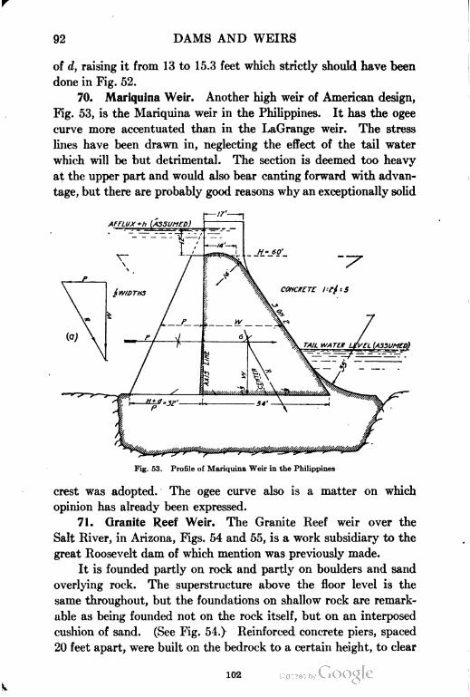
92 DAMS AND WEIRS
of d, raising it from 13 to 15.3 feet which strictly should have been
done in Fig. 52.
70. Mariquina Weir. Another high weir of American design,
Fig. 53, is the Mariquina weir in the Philippines. It has the ogee
curve more accentuated than in the LaGrange weir. The stress
lines have been drawn in, neglecting the effect of the tail water
which will be but detrimental. The section is deemed too heavy
at the upper part and would also bear canting forward with advan
tage, but there are probably good reasons why an exceptionally solid
Fig. 53. Profile of Mariquina Weir in the Philippines
crest was adopted. The ogee curve also is a matter on which
opinion has already been expressed.
71. Granite Reef Weir. The Granite Reef weir over the
Salt River, in Arizona, Figs. 54 and 55, is a work subsidiary to the
great Roosevelt dam of which mention was previously made.
It is founded partly on rock and partly on boulders and sand
overlying rock. The superstructure above the floor level is the
same throughout, but the foundations on shallow rock are remark
able as being founded not on the rock itself, but on an interposed
cushion of sand. (See Fig. 54.) Reinforced concrete piers, spaced
20 feet apart, were built on the bedrock to a certain height, to clear
102
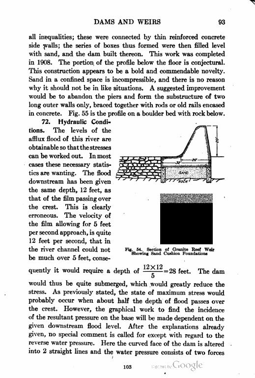
DAMS AND WEIRS 93
all inequalities; these were connected by thin reinforced concrete
side walls; the series of boxes thus formed were then filled level
with sand, and the dam built thereon. This work was completed
in 1908. The portion of the profile below the floor is conjectural.
This construction appears to be a bold and commendable novelty.
Sand in a confined space is incompressible, and there is no reason
why it should not be in like situations. A suggested improvement
would be to abandon the piers and form the substructure of two
long outer walls only, braced together with rods or old rails encased
in concrete. Fig. 55 is the profile on a boulder bed with rock below.
72. Hydraulic Condi=
tions. The levels of the
afflux flood of this river are
obtainable so thatthe stresses
can be worked out. In most
cases these necessary statis
tics are wanting. The flood
downstream has been given
the same depth, 12 feet, as
that of the film passing over
the crest. This is clearly
erroneous. The velocity of
the film allowing for 5 feet
per second approach, is quite
12 feet per second, that in
the river channel could not
be much over 5 feet, conse-
Fig. 54. Section of Granite Reef Weir
Showing Sand Cushion Foundations
quently it would require a depth of12X12
= 28 feet. The dam
would thus be quite submerged, which would greatly reduce the
stress. As previously stated, the state of maximum stress would
probably occur when about half the depth of flood passes over
the crest. However, the graphical work to find the incidence
of the resultant pressure on the base will be made dependent on the
given downstream flood level. After the explanations already
given, no special comment is called for except with regard to the
reverse water pressure. Here the curved face of the dam is altered
into 2 straight lines and the water pressure consists of two forces
103
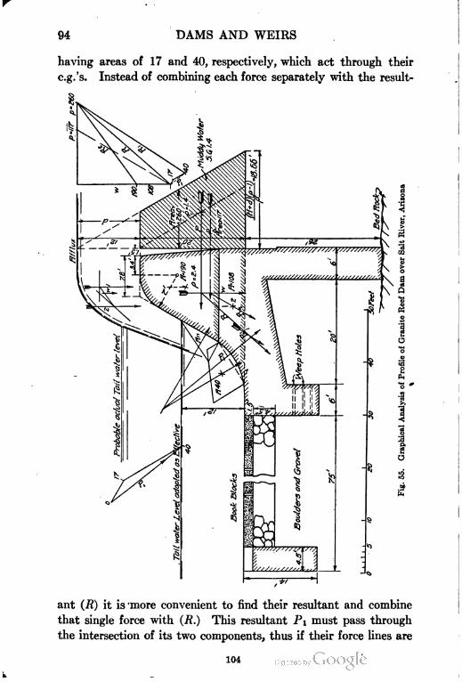
94 DAMS AND WEIRS
areas of 17 and 40, respectively, which act through their
Instead of combining each force separately with the result-
ant (R) it is more convenient to find their resultant and combine
that single force with (R.) This resultant PI must pass through
the intersection of its two components, thus if their force lines are
104
DAMS AND WEIRS 95
run out backward till they intersect, a point in the direction of PI
is found. Pi is then drawn parallel to its reciprocal in the force
polygon which is also shown on a larger scale at the left of the pro
file. The final resultant is RI which falls just within the middle
third of the base. Pi2 is the resultant supposing the water to be
at crest level only. The water in the river is supposed to have
mud in solution with its s.g. 1.4. The base length of the triangle
t , .n ^ u (H+d)X(p-l) 32X1.4 10I-of water pressure will then be • =——— = lo.bb.
The other water-pressure areas are similarly treated. If the rear
curtain reaches rock the dam should not be subject to uplift. It
could, however, withstand sub-percolation, as the hearth of riprap
and boulders will practically form a filter, the material of the river
bed being too large to be disintegrated and carried up between the
interstices of the book blocks. The effective length of travel would
then be 107 feet; add vertical 52 feet, total 159 feet, H being 20 feet,
jf works out to —- = 8 which ratio is a liberal allowance for a boulder
H 20 .^
bed. The fore curtain is wisely provided with weep holes to release
any hydrostatic pressure that might otherwise exist underneath the
dam. The Granite Reef dam has a hearth, or fore apron of about
80 feet in width. A good empirical rule for the least width for a
solid or open work masonry fore apron is the following:
L =2H+d , (20)
in which H is the height of the permanent weir crest above floor,
and d is the depth of flood over crest. In this case # = 20, d = 12;
least width of floor should then be 40+12 = 52 feet. The Bassano
dam is 40 feet high with 14 feet flood over crest, the width of hearth
according to this formula should be 94 feet, its actual width is 80
feet which is admittedly insufficient. With a low submerged weir,
formula (34) , Part II, viz, L = 3Vc H, will apply. Beyond the hearth
a talus of riprap will generally be required, for which no rule can
well be laid down.
73. Nira Weir. Fig. 56 is of the Nira weir, an Indian work.
Considering the great depth of the flood waterdown stream, the pro
vision of so high a subsidiary weir is deemed unnecessary, a water
cushion of 10 feet being ample, as floor is bed rock. The section of
105
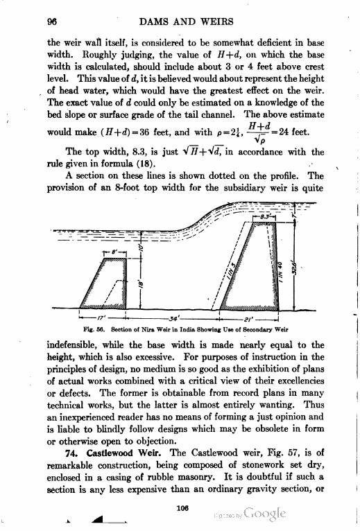
96 DAMS AND WEIRS
the weir wall itself, is considered to be somewhat deficient in base
width. Roughly judging, the value of H+d, on which the base
width is calculated, should include about 3 or 4 feet above crest
level. This value of d, it is believed would about represent the height
of head water, which would have the greatest effect on the weir.
The exact value of d could only be estimated on a knowledge of the
bed slope or surface grade of the tail channel. The above estimate
would make (H+d) =36 feet, and with p = 2-J, - = 24 feet.
_ _ V/»
The top width, 8.3, is just V//+Vrf, in accordance with the
rule given in formula (18).
A section on these lines is shown dotted on the profile. The
provision of an 8-foot top width for the subsidiary weir is quite
Fig. 56. Section of Nira Weir in India Showing Use of Secondary Weir
indefensible, while the base width is made nearly equal to the
height, which is also excessive. For purposes of instruction in the
principles of design, no medium is so good as the exhibition of plans
of actual works combined with a critical view of their excellencies
or defects. The former is obtainable from record plans in many
technical works, but the latter is almost entirely wanting. Thus
an inexperienced reader has no means of forming a just opinion and
is liable to blindly follow designs which may be obsolete in form
or otherwise open to objection.
74. Castlewood Weir. The Castlewood weir, Fig. 57, is of
remarkable construction, being composed of stonework set dry,
enclosed in a casing of rubble masonry. It is doubtful if such a
section is any less expensive than an ordinary gravity section, or
106
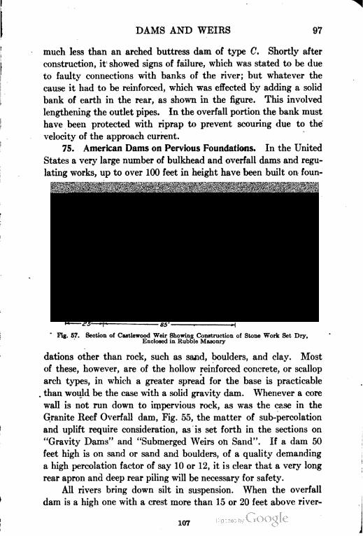
DAMS AND WEIRS 97
much less than an arched buttress dam of type C. Shortly after
construction, it' showed signs of failure, which was stated to be due
to faulty connections with banks of the river; but whatever the
cause it had to be reinforced, which was effected by adding a solid
bank of earth in the rear, as shown in the figure. This involved
lengthening the outlet pipes. In the overfall portion the bank must
have been protected with riprap to prevent scouring due to the
velocity of the approach current.
75. American Dams on Pervious Foundations. In the United
States a very large number of bulkhead and overfall dams and regu
lating works, up to over 100 feet in height have been built on foun-
Fig. 57. Section of Castlewood Weir Showing Construction of Stone Work Set Dry,
Enclosed in Rubble Masonry
dations other than rock, such as sajid, boulders, and clay. Most
of these, however, are of the hollow reinforced concrete, or scallop
arch types, in which a greater spread for the base is practicable
. than would be the case with a solid gravity dam. Whenever a core
wall is not run down to impervious rock, as was the case in the
Granite Reef Overfall dam, Fig. 55, the matter of sub-percolation
and uplift require consideration, as is set forth in the sections on
"Gravity Dams" and "Submerged Weirs on Sand". If a dam 50
feet high is on sand or sand and boulders, of a quality demanding
a high percolation factor of say 10 or 12, it is clear that a very long
rear apron and deep rear piling will be necessary for safety.
All rivers bring down silt in suspension. When the overfall
dam is a high one with a crest more than 15 or 20 feet above river
107
98 DAMS AND WEIRS
bed level, the deposit that is bound to take place in rear of the
obstruction will not be liable to be washed out by the current, and
additional light stanching silt will be deposited in the deep pool of
comparatively still water that must exist at the rear of every high
dam. For a low weir however this does not follow, and i? deposit is
made it will be of the heavier, coarser sand which is not impermeable.
The difficulty and expense of a long rear apron can be sur
mounted by the simple expedient of constructing only a portion of
it of artificial clay, leaving the rest to be deposited by the river
itself. To ensure safety the dam should be constructed and reser
voir filled, in two or three stages, with intervals between of sufficient
length to allow the natural deposit to trke place. Thus only a frac
tion of the protective apron need be actually constructed. Many
works are in existence which owe their safety entirely to the fortu
nate but unrecognized circumstance of natural deposit having
stanched the river bed in their rear, and many failures that have
taken place can only be accounted for from want of provision for
the safety of the work against underneath scour or piping and also
uplift. The author himself once had occasion to report on the fail
ure of a head irrigation work which was designed as if on rock,
whereas it was on a pervious foundation of boulders. When it
failed the designers had no idea of the real cause, but put it down
to a "treacherous river", "ice move", anything but the real reason,
of which they were quite ignorant. Had a rear apron of sufficient
width been constructed, the work would be standing to this day.
76. Base of Dam and Fore Apron. The fore apron and base
of an overfall dam or weir must be of one level throughout its
length, if the foundation is of any other material than rock. The
foundation core walls may have to vary more or less with the surface
of the river bed, which is deep in some places, and shallow in
others, but the apron level should be kept at or about low water
level throughout. When a horizontal wall as an overfall dam is
built across a river bed it obliterates the depressions and channels
in it, the discharge over the weir is the same at all points or nearly
so, consequently the tendency will be to level the bed downstream by
filling the hollows and denuding the higher parts.
Under these conditions it is evidently sheer folly to step up the
apron to coincide with the section of the river bed, as the higher
108
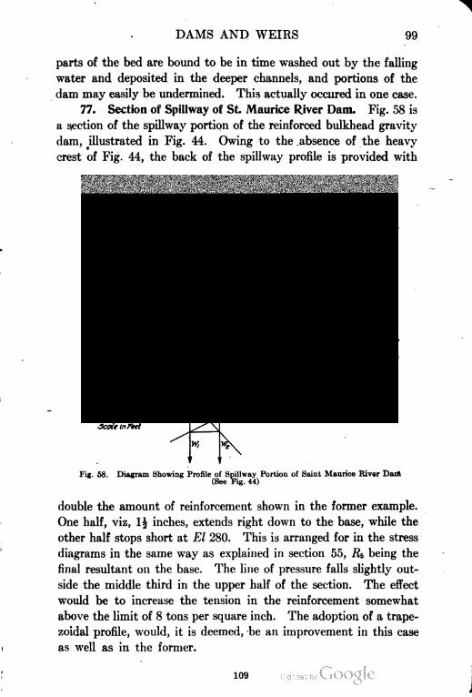
DAMS AND WEIRS 99
parts of the bed are bound to be in time washed out by the falling
water and deposited in the deeper channels, and portions of the
dam may easily be undermined. This actually occured in one case.
77. Section of Spillway of St. Maurice River Dam. Fig. 58 is
a section of the spillway portion of the reinforced bulkhead gravity
dam, illustrated in Fig. 44. Owing to the absence of the heavy
crest of Fig. 44, the back of the spillway profile is provided with
£4 Tons
ffeinf.
Fig. 58. Diagram Showing Profile of Spillway Portion of Saint Maurice River Dart
(See Fig. 44)
double the amount of reinforcement shown in the former example.
One half, viz, 1| inches, extends right down to the base, while the
other half stops short at El 280. This is arranged for in the stress
diagrams in the same way as explained in section 55, R& being the
final resultant on the base. The line of pressure falls slightly out
side the middle third in the upper half of the section. The effect
would be to increase the tension in the reinforcement somewhat
above the limit of 8 tons per square inch. The adoption of a trape
zoidal profile, would, it is deemed, be an improvement in this case
as well as in the former.
109

DAMS AND WEIRS
PART II
ARCHED DAMS
78. General Characteristics. In this type, the whole dam,
being arched in plan, is supposed to be in the statical condition of
an arch under pressure. As, however, the base is immovably fixed
to the foundations by the frictional resistance due to the weight of
the structure, the lowest portion of the dam cannot possess full
freedom of motion nor elasticity, and consequently must act more or
less as a gravity dam subject to oblique pressure.
However this may be, experience has conclusively proved that
if the profile be designed on the supposition that the whole is an
elastic arch, this conflict of stresses near the base can be neglected
by the practical man. The probability is that both actions take
place, true arch action at the crest, gradually merging into transverse
stress near the base; the result being that the safety of the dam is
enhanced by the combination of tangential and vertical stresses on
two planes.
In this type of structure, the weight of the arch itself is conveyed
to the base, producing stress on a horizontal plane, while the water
pressure normal to the extrados, radial in direction, is transmitted
through the arch rings to the abutments. The pressure is, therefore,
distributed along the whole line of contact of the dam with the sides
as well as the ground. In a gravity dam, on the other hand, the whole
pressure is concentrated on the horizontal base.
Arch Stress. The average unit stress developed by the water
pressure is expressed by the formula
"Short" Formula (21)
RHw "Short" Formula (21a)
i11
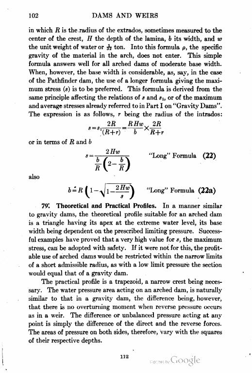
102 DAMS AND WEIES
in which jR is the radius of the extrados, sometimes measured to the
center of the crest, // the depth of the lamina, b its width, and w
the unit weight of water or 3"? ton. Into this formula p, the specific
gravity of the material in the arch, does not enter. This simple
formula answers well for all arched dams of moderate base width.
When, however, the base width is considerable, as, say, in the case
of the Pathfinder dam, the use of a longer formula giving the maxi
mum stress (s) is to be preferred. This formula is derived from the
same principle affecting the relations of s and «i, or of the maximum
and average stresses already referred to in Part I on "Gravity Dams".
The expression is as follows, r being the radius of the intrados:
2R RHw 2R
X(R+r) b "R+r
or in terms of R and /;
s= jHwb^ "Long" Formula (22)
also
"Long" Formula (22a)
79°. Theoretical and Practical Profiles. In a manner similar
to gravity dams, the theoretical profile suitable for an arched dam
is a triangle having its apex at the extreme water level, its base
width being dependent on the prescribed limiting pressure. Success
ful examples have proved that a very high value for s, the maximum
stress, can be adopted with safety. If it were not for this, the profit
able use of arched dams would be restricted within the narrow limits
of a short admissible radius, as with a low limit pressure the section
would equal that of a gravity dam.
The practical profile is a trapezoid, a narrow crest being neces
sary. The water pressure area acting on an arched dam, is naturally
similar to that in a gravity dam, the difference being, however,
that there is no overturning moment when reverse pressure occurs
as in a weir. The difference or unbalanced pressure acting at any
point is simply the difference of the direct and the reverse forces.
The areas of pressure on both sides, therefore, vary with the squares
of their respective depths.
112
DAMS AND WEIRS 103
The water pressure on an arch acts normally to the surface of
its back and is radial in direction; consequently the true line of pres
sure in the arch ring corresponds with the curvature of the arch and
has no tendency to depart from this condition. There is, therefore,
no such tendency to rupture as is the case in a horizontal circular
arch subjected to vertical rather than radial pressure. This prop
erty conduces largely to the stability of an arch under liquid
pressure. This condition is not strictly applicable in its entirety
to the case of a segment of a circle held rigidly between abut
ments as the arch is then partly in the position of a beam. The
complication of stress involved is, however, too abstruse for practical
consideration.
80. Correct Profile. As we have already seen, the correct
profile of the arched dam is a triangle modified into a trapezoid
with a narrow crest. With regard to arch stresses, the most favorable
outline is that with the back of the extrados vertical. The reason for
this is that the vertical stress due to the weight of the arch, although
it acts on a different plane from the tangential stresses in the arch
ring, still has a definable influence on the maximum induced stress
in the arch ring. The vertical pressure produces a transverse expan
sion which may be expressed as WXEXm, in which E is the coeffi
cient of elasticity of the material and m that of transverse dilation.
This tends, when the extrados is vertical, to diminish the maximum
stress in the section; whereas when the intrados is vertical and the
back inclined, the modification of the distribution of pressure is
unfavorable, the maximum stress being augmented. When the
trapezoidal profile is equiangular, an intermediate or neutral condi
tion exists. A profile with vertical extrados should, therefore, be
adopted whenever practicable.
In very high dams, however, the pressure on the horizontal
plane of the base due to the weight of the structure, becomes so
great as to even exceed that in the arch ring; consequently it is
necessary to adopt an equiangular profile in order to bring the center
of pressure at, or near to, the center of the base, so as to reduce the
ratio of maximum pressure to average pressure to a minimum.
As stated in the previous section, when a vertical through the
center of gravity of the profile passes through the center of the base,
the max'mum pressure equals the average, or a = *i.
113
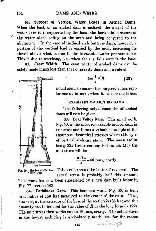
104 DAMS AND WEIRS
81. Support of Vertical Water Loads in Arched Dams.
When the back of an arched dam is inclined, the weight of the
water over it is supported by the base, the horizontal pressure of
the water alone acting on the arch and being conveyed to the"
abutments. In the case of inclined arch buttress dams, however, a
portion of the vertical load is carried by the arch, increasing its
thrust above what is due to the horizontal water pressure alone.
This is due to overhang, i. e., when the e.g. falls outside the base.
82. Crest Width. The crest width of arched dams can be
safely made much less than that of gravity dams and a rule of
*=jV7r (23)
would seem to answer the purpose, unless rein
forcement is used, when it can be made less.
EXAMPLES OF ARCHED DAMS
The following actual examples of arched
dams will now be given.
83. Bear Valley Dam. This small work,
Fig. 59, is the most remarkable arched dam in
existence and forms a valuable example of the
enormous theoretical stresses which this type
of vertical arch can stand. The mean radius
being 335 feet according to formula (21) the
unit stress will be
RHw n ,—=— = (>0 tons, nearly
6
Fig. 59. Section of old Bear This section would be better if reversed. The
actual stress is probably half this amount.
This work has now been superseded by a new dam built below it,
Fig. 77, section 103.
84. Pathfinder Dam. This immense work, Fig. 60, is built
to a radius of 150 feet measured to the center of the crest. That,
however, at the extrados of the base of the section is 186 feet and this
quantity has to be used for the value of R in the long formula (22) .
The unit stress then works out to 18 tons, nearly. The actual stress
in the lowest arch ring is undoubtedly much less, for the reason
1H
DAMS AND WEIRS 105
that the base must absorb so large a proportion of the thrust that
very little is transmitted to the sides of the canyon. The exact
determination of the proportion transmitted in the higher rings
is an indeterminate problem, and the only safe method is to assume
with regard to tangential arch stress that the arch stands clear of
RAD. 1SO'
RAD. 186' J
Fig. 60. Section of Pathfinder Dam
the base. This will leave a large but indeterminate factor of safety
and enable the adoption of a high value for s, the maximum unit
stress.
The profile of the dam is nearly equiangular in outline. This
is necessary in so high a dam in order to bring the vertical resultants
(W) R. E. and (N) R. F. as near the center as possible with the
object of bringing the ratio of maximum to mean stress as low as
possible.
The estimation of the exact positions of W and of N is made
analytically as below.
. J115
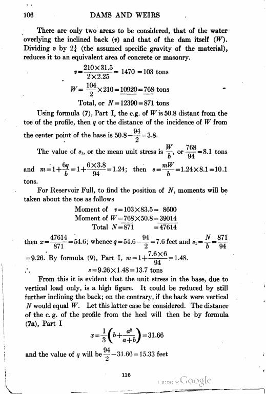
106 DAMS AND WEIRS
There are only two areas to be considered, that of the water
overlying the inclined back (v) and that of the dam itself (W).
Dividing v by 2j (the assumed specific gravity of the material),
reduces it to an equivalent area of concrete or masonry.
210X31.5 ,._A ,,,.,
" = 2X225 =
104W= iX210= 10920 = 768 tons
Total, or Ar = 12390=871 tons
Using formula (7), Part I, the e.g. of W is 50.8 distant from the
toe of the profile, then q or the distance of the incidence of W from
the center point of the base is 50.8—^— = 3.8.
i ^
TT/> **£i O
The value of si, or the mean unit stress is —, or -—- =8.1 tons
b 94
, ",,69 , 6X3.8 , ,, , mW , nt. , , irv rand m = l+-p = H———= 1.24; then *=—=— = 1.24X8.1 =10.1
o 94 b
tons.
For Reservoir Full, to find the positron of N, moments will be
taken about the toe as follows
Moment of r = 103X83.5= 8600
Moment of EF = 768X50.8 = 39014
Total ,V=871 =47614
. 47614 . . . . 94 „ , , AT 871then z =-——-=54.6; whence g = 54.6—— = /.b teet and *i =— = -—
o / J. -^ 0 tj'-i
= 9.26. By formula (9), Part I, m=l+~~.=lM.
J"i
.v = 9.26 XI.48 = 13.7 tons
From this it is evident that the unit stress in the base, due to
vertical load only, is a high figure. It could be reduced by still
further inclining the back; on the contrary, if the back were vertical
N would equal W. Let this latter case be considered. The distance
of the c. g. of the profile from the heel will then be by formula
(7a), Part I
04
and the value of </ will be ^-31.66 = 15.33 feet
£t
116
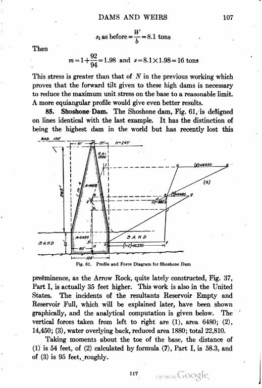
DAMS AND WEIRS 107
Then
Wsi as before =— = 8.1 tons
b
= l+ = 1.98 and s =8.1X1.98 = 16 tons
94
This stress is greater than that of N in the previous working which
proves that the forward tilt given to these high dams is necessary
to reduce the maximum unit stress on the base to a reasonable limit.
A more equiangular profile would give even better results.
85. Shoshone Dam. The Shoshone dam, Fig. 61, is designed
on lines identical with the last example. It has the distinction of
being the highest dam in the world but has recently lost this
IMP. 1SO1
Fig. 61. Profile and Force Diagram for Shoshone Dam
preeminence, as the Arrow Rock, quite lately constructed, Fig. 37,
Part I, is actually 35 feet higher. This work is also in the United
States. The incidents of the resultants Reservoir Empty and
Reservoir Full, which will be explained later, have been shown
graphically, and the analytical computation is given below. The
vertical forces taken from left to right are (1), area 6480; (2),
14,450; (3), water overlying back, reduced area 1880; total 22,810.
Taking moments about the toe of the base, the distance of
(1) is 54 feet, of (2) calculated by formula (7), Part I, is 58.3, and
of (3) is 95 feet, roughly.
117
108 DAMS AND WEIRS
Then (6480 X 54) + (14450 X 58.3) + (1880 X 95) =22810Xz.
.'. x = 60 feet, nearly.
108
The value of q for N then is 60-— =6 feet.
m
AT 22810Now *r-^-o.==2^=211, and by formula (9), Part I, * = 211X
0 lUo I
(108+36) , 281X2.4 01 , .———— =281 square teet= ——= 21 tons, nearly.
luo o2
The maximum arch unit stress by formula (22) is as follows: the
radius of the extrados of the base being 197 feet the fraction — =-^
ATI o/i K +v, * 2HW 2X245X1= .55 and H = 245 therefore s = —
.55X1.45X32
J*\'~Rj
||= 19.2 tons.
Below the level 60 ft. above base, the stress on the arch does
not increase. The arch stress is less than that due to vertical
pressure N. This base should undoubtedly have been widened,
the battered faces being carried down to the base, not cut off by
vertical lines at the 60-foot level.
Center of Pressure—New Graphical Method. In order to find the
center qf pressure in a case like Fig. 61, where the lines of forces (1)
and (2) are close together, the ordinary method of using a force and
funicular polygon involves crowding of the lines so that accuracy is
difficult to attain. Another method now will be explained which is
on the same principle as that of the intersection of cross lines used
for finding the c. g. of a trapezoid.
In Fig. 61, first the c.g.'s of the three forces are found (1) the
water pressure area divided by p or 2.4 which equals 1880 square
feet, (2) the upper trapezoidal part of the dam area 14,450, and (3)
the lower rectangular area 6480. Then (1) is joined to (2) and this
line projected on one side in any location as at b in Fig. 61a.
From a, ac is set off horizontally equal to (2) or 14,450 and
from b, bd is drawn equal to (1) or 1880; cd is then drawn and its
intersection with ab at e gives the position of the resultant 1-2, which ,
can now be projected on the profile at G. To obtain the resultant
of the components (1-2) with (3) the line G-3 is drawn on the profile
118
DAMS AND WEIRS 109
and a parallel to it drawn from e on Fig. 6 la, intersecting the hori
zontal through (3) at /. From e, eg is laid off horizontally equal to
(3) or 6480 and from/, fh equal to (1+2) or 1880+ 14,450=16,330.
kg is then drawn and its intersection with ef at j is the centroid of the
three forces, which projected on the profile to Gi on the line C-3 gives
the location of the vertical resultant of 1+2+3.
86. Sweetwater Dam. The profile of the Sweetwater dam
in California is given in Fig. 62. The original crest of the dam
300 4067dm
El. 153..
, Fig. 62. Graphical Analysis of Sweetwater
Dam, California
was at El. 220, or 95 feet above the base. Under these conditions
the dam depended for its stability on its arched plan. If con
sidered as a gravity dam with allowable tension at the heel, the
vertical pressure area is the triangle abe, here q = 16.5 and m works
out to 3.15.
3.15X226
= 22Q tons and 6 = 46 feet whence s=
46
= 15.5 tons which is set down from a to b.
2NThe tension at the heel = s2 ——= 15.5 - 9.82 = 5.7 tons
o
119
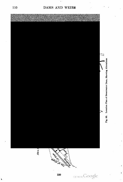
110 DAMS AND WEIRS
120
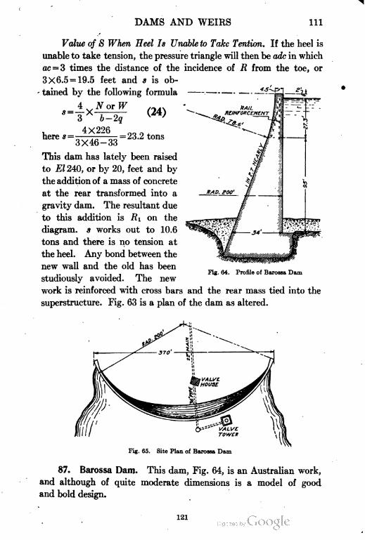
DAMS AND WEIRS 111
Value of S When Heel Is Unable to Take Tention. If the heel is
unable to take tension, the pressure triangle will then be adc in which
etc = 3 times the distance of the incidence of R from the toe, or
3X6.5 = 19.5 feet and s is ob
tained by the following formula
4 . . N or W
here s =4X226
(24)
= 23.2 tons
3X46-33
This dam has lately been raised
to El 240, or by 20, feet and by
the addition of a mass of concrete
at the rear transformed into a
gravity dam. The resultant due
to this addition is R\ on the
diagram- s works out to 10.6
tons and there is no tension at
the heel. Any bond between the
new wall and the old has been
studiously avoided. The new
work is reinforced with cross bars and the rear mass tied into the
superstructure. Fig. 63 is a plan of the dam as altered.
PUB
Fig. 64. Profile of Barossa Dam
Fig. 65. Site Plan of Barossa Dam
87. Barossa Dam. This dam, Fig. 64, is an Australian work,
and although of quite moderate dimensions is a model of good
and bold design.
121
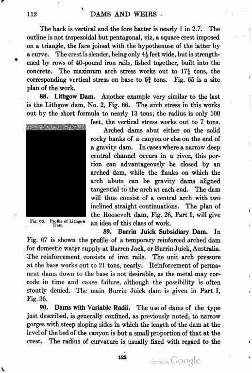
112 DAMS AND WEIRS
The back is vertical and the fore batter is nearly 1 in 2.7. The
outline is not trapezoidal but pentagonal, viz, a square crest imposed
on a triangle, the face joined with the hypothenuse of the latter by
a curve. The crest is slender, being only 4| feet wide, but is strength
ened by rows of 40-pound iron rails, fished together, built into the
concrete. The maximum arch stress works out to 17J tons, the
corresponding vertical stress on base to 6| tons. Fig. 65 is a site
plan of the work.
88. Lithgow Dam. Another example very similar to the last
is the Lithgow dam, No. 2, Fig. 66. The arch stress in this works
out by the short formula to nearly 13 tons; the radius is only 100
feet, the vertical stress works out to 7 tons.
Arched dams abut either on the solid
rocky banks of a canyon or else on the end of
a gravity dam. In cases where a narrow deep
central channel occurs in a river, this por
tion can advantageously be closed by an
arched dam, while the flanks on which the
arch abuts can be gravity dams aligned
tangential to the arch at each end. The dam
will thus consist of a central arch with two
inclined straight continuations. The plan of
the Roosevelt dam, Fig. 26, Part I, will give
an idea of this class of work.
89. Burrin Juick Subsidiary Dam. In
Fig. 67 is shown the profile of a temporary reinforced arched dam
for domestic water supply at Barren Jack, or Burrin Juick, Australia.
The reinforcement consists of iron rails. The unit arch pressure
at the base works out to 21 tons, nearly. Reinforcement of perma
nent dams down to the base is not desirable, as the metal may cor
rode in time and cause failure, although the possibility is often
stoutly denied. The main Burrin Juick dam is given in Part I,
Fig. 36.
90. Dams with Variable Radii. The use of dams of the type
just described, is generally confined, as previously noted, to narrow
gorges with steep sloping sides in which the length of the dam at the
level of the bed of the canyon is but a small proportion of that at the
crest. The radius of curvature is usually fixed with regard to the
Fig. 66. Profile of Lithgow
Dam
122
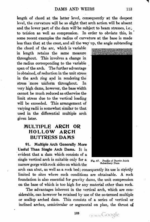
DAMS AND WEIRS 113
length of chord at the latter level, consequently at the deepest
level, the curvature will be so slight that arch action will be absent
and the lower part of the dam will be subject to beam stresses, i.er,
to tension as well as compression. In order to obviate this, in
some recent examples the radius of curvature at the base is made
less than that at the crest, and all the way up, the angle subtending
the chord of the arc, which is variable
in length retains the same measure
throughout. This involves a change in
the radius corresponding to the variable
span of the arch. The further advantage
is obtained, of reduction in the unit stress
in the arch ring and in rendering the
stress more uniform throughout. In
very high dams, however, the base width
cannot be much reduced as otherwise the
limit stress due to the vertical loading
will be exceeded. This arrangement of
varying radii is somewhat similar to that
used in the differential multiple arch
given later.
MULTIPLE ARCH OR
HOLLOW ARCH
BUTTRESS DAMS
91. Multiple Arch Generally More
Useful Than Single Arch Dams. It is
evident that a dam which consists of a
single vertical arch is suitable only for a
narrow gorge with rock sides on which the
arch can abut, as well as a rock bed; consequently its use is strictly
limited to sites where such conditions are obtainable. A rock
foundation is also essential for gravity dams, the unit compression
on the base of which is too high for any material other than rock.
The advantages inherent in the vertical arch, which are con
siderable, can however be retained by use of the so-termed multiple
or scallop arched dam. This consists of a series of vertical or
inclined arches, semicircular or segmental on plan, the thrust oi
Fig. 67. Profile of Burrin Juick
Subsidiary Dam
123
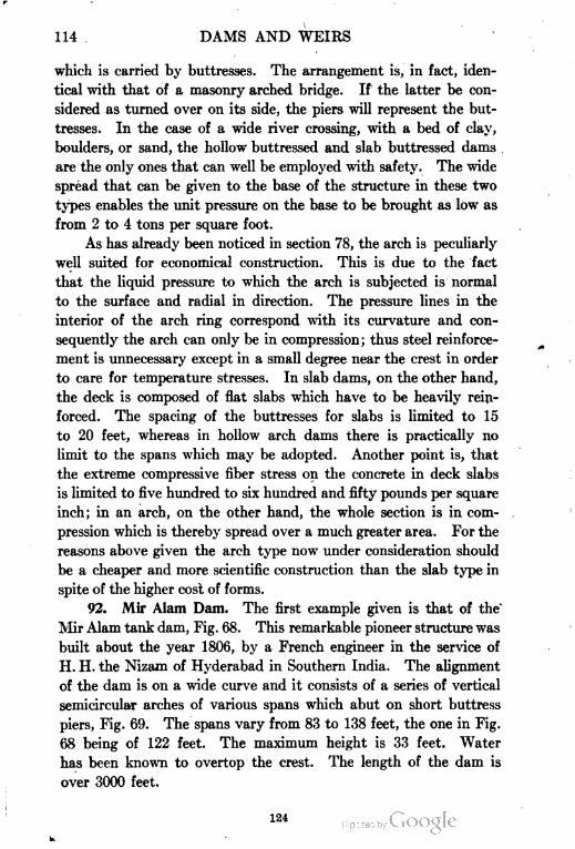
114 DAMS AND WEIRS
which is carried by buttresses. The arrangement is, in fact, iden
tical with that of a masonry arched bridge. If the latter be con
sidered as turned over on its side, the piers will represent the but
tresses. In the case of a wide river crossing, with a bed of clay,
boulders, or sand, the hollow buttressed and slab buttressed dams
are the only ones that can well be employed with safety. The wide
spread that can be given to the base of the structure in these two
types enables the unit pressure on the base to be brought as low as
from 2 to 4 tons per square foot.
As has already been noticed in section 78, the arch is peculiarly
well suited for economical construction. This is due to the fact
that the liquid pressure to which the arch is subjected is normal
to the surface and radial in direction. The pressure lines in the
interior of the arch ring correspond with its curvature and con
sequently the arch can only be in compression; thus steel reinforce
ment is unnecessary except in a small degree near the crest in order
to care for temperature stresses. In slab dams, on the other hand,
the deck is composed of flat slabs which have to be heavily rein
forced. The spacing of the buttresses for slabs is limited to 15
to 20 feet, whereas in hollow arch dams there is practically no
limit to the spans which may be adopted. Another point is, that
the extreme compressive fiber stress on the concrete in deck slabs
is limited to five hundred to six hundred and fifty pounds per square
inch; in an arch, on the other hand, the whole section is in com
pression which is thereby spread over a much greater area. For the
reasons above given the arch type now under consideration should
be a cheaper and more scientific construction than the slab type in
spite of the higher cost of forms.
92. Mir Alam Dam. The first example given is that of the"
Mir Alam tank dam, Fig. 68. This remarkable pioneer structure was
built about the year 1806, by a French engineer in the service of
H. H. the Nizam of Hyderabad in Southern India. The alignment
of the dam is on a wide curve and it consists of a series of vertical
semicircular arches of various spans which abut on short buttress
piers, Fig. 69. The spans vary from 83 to 138 feet, the one in Fig.
68 being of 122 feet. The maximum height is 33 feet. Water
has been known to overtop the crest. The length of the dam is
over 3000 feet.
124
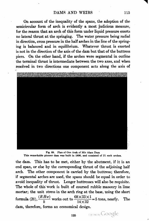
DAMS AND WEIRS 115
On account of the inequality of the spans, the adoption of the
semicircular form of arch is evidently a most judicious measure,
for the reason that an arch of this form under liquid pressure exerts
no lateral thrust at the springing. The water pressure being radial
in direction, cross pressure in the half arches in the line of the spring
ing is balanced and in equilibrium. Whatever thrust is exerted
is not in the direction of the axis of the dam but that of the buttress
piers. On the other hand, if the arches were segmental in outline
the terminal thrust is intermediate between the two axes, and when
resolved in two directions one component acts along the axis of
Fig. 68. Plan of One Arch of Mir Alam Dam
This remarkable pioneer dam was built in 1806, and consisted of 21 such arches.
the dam. This has to be met, either by the abutment, if it is an
end span, or else by the corresponding thrust of the adjoining half
arch. The other component is carried by the buttress; therefore,
if segmental arches are used, the spans should be equal in order to
avoid inequality of thrust. Longer buttresses will also be requisite.
The whole of this work is built of coursed rubble masonry in lime
mortar; the unit stress in the arch ring at the base, using the short
. . ,,,,.. (RHw) , 68X33X1 . . , r™(ormula (21), —; works out to ———-——= 5 tons, nearlv. ihe
o 14X32
dam, therefore, forms an economical design.
125
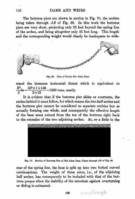
116 DAMS AND WEIRS
The buttress piers are shown in section in Fig. 70, the section
being taken through AB of Fig. 68. In this work the buttress
piers are very short, projecting only 25 feet beyond the spring line
of the arches, and being altogether only 35 feet long. This length
and the corresponding weight would clearly be inadequate to with-
Fig. 69. Plan of Entire Mir Alam Dam
stand the immense
332X1X146
horizontal thrust which is equivalent to
= 2500 tons, nearly.
2 2X32
It is evident that if the buttress pier slides or overturns, the
arches behind it must follow, for which reason the two half arches and
the buttress pier cannot be considered as separate entities but as
actually forming one whole, and consequently the effective length
of the base must extend from the toe of the buttress right back
to the extrados of the two adjoining arches. At, or a little in the
Fig. 70. Section of Buttress Pier of Mir Alam Dam Taken through AB of Fig. 68
rear of the spring line, the base is split up into two forked curved
continuations. The weight of these arms, i.e., of the adjoining
half arches, has consequently to be included with that of the but
tress proper when the stability of the structure against overturning
or sliding is estimated.
126
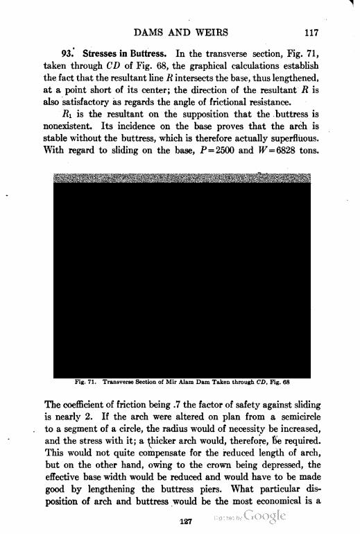
DAMS AND WEIRS 117
93. Stresses in Buttress. In the transverse section, Fig. 71,
taken through CD of Fig. 68, the graphical calculations establish
the fact that the resultant line R intersects the base, thus lengthened,
at a point short of its center; the direction of the resultant R is
also satisfactory as regards the angle of frictional resistance.
Ri is the resultant on the supposition that the buttress is
nonexistent. Its incidence on the base proves that the arch is
stable without the buttress, which is therefore actually superfluous.
With regard to sliding on the base, P = 2500 and 17=6828 tons.
Fig. 71. Transverse Section of Mir Alam Dam Taken through CD, Fig. 68
The coefficient of friction being .7 the factor of safety against sliding
is nearly 2. If the arch were altered on plan from a semicircle
to a segment of a circle, the radius would of necessity be increased,
and the stress with it; a flicker arch would, therefore, 6e required.
This would not quite compensate for the reduced length of arch,
but on the other hand, owing to the crown being depressed, the
effective base width would be reduced and would have to be made
good by lengthening the buttress piers. What particular dis
position of arch and buttress would be the most economical is a
127
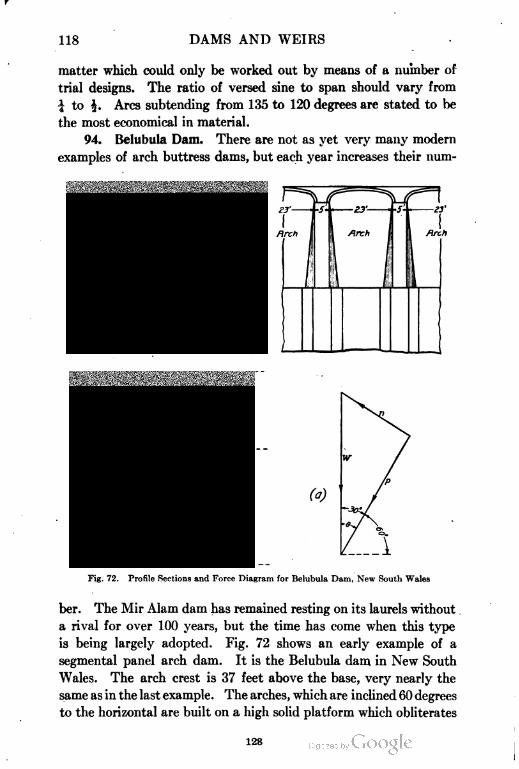
118 DAMS AND WEIRS
matter which could only be worked out by means of a number of
trial designs. The ratio of versed sine to span should vary from
i to |. Arcs subtending from 135 to 120 degrees are stated to be
the most economical in material.
94. Belubula Dam. There are not as yet very many modern
examples of arch buttress dams, but each year increases their num-
L A
Fig. 72. Profile Sections and Force Diagram for Belubula Dam, New South Wales
ber. The Mir Alam dam has remained resting on its laurels without
a rival for over 100 years, but the time has come when this type
is being largely adopted. Fig. 72 shows an early example of a
segmental panel arch dam. It is the Belubula dam in New South
Wales. The arch crest is 37 feet above the base, very nearly the
same as in the last example. The arches, which are inclined 60 degrees
to the horizontal are built on a high solid platform which obliterates
128
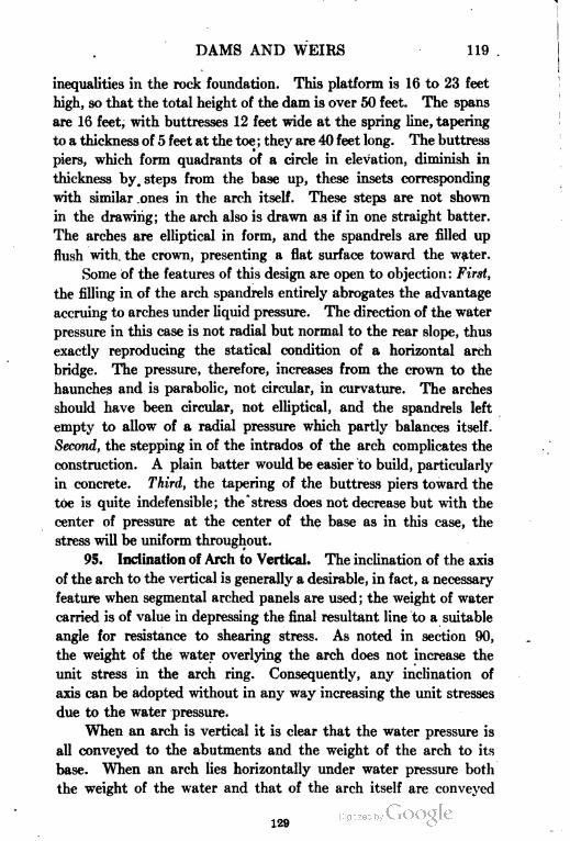
DAMS AND WEIRS 119 .
inequalities in the rock foundation. This platform is 16 to 23 feet
high, so that the total height of the dam is over 50 feet. The spans
are 16 feet, with buttresses 12 feet wide at the spring line, tapering
to a thickness of 5 feet at the toe ; they are 40 feet long. The buttress
piers, which form quadrants of a circle in elevation, diminish in
thickness by. steps from the base up, these insets corresponding
with similar ones in the arch itself. These steps are not shown
in the drawing; the arch also is drawn as if in one straight batter.
The arches are elliptical in form, and the spandrels are filled up
flush with the crown, presenting a flat surface toward the water.
Some of the features of this design are open to objection : First,
the filling in of the arch spandrels entirely abrogates the advantage
accruing to arches under liquid pressure. The direction of the water
pressure in this case is not radial but normal to the rear slope, thus
exactly reproducing the statical condition of a horizontal arch
bridge. The pressure, therefore, increases from the crown to the
haunches and is parabolic, not circular, in curvature. The arches
should have been circular, not elliptical, and the spandrels left
empty to allow of a radial pressure which partly balances itself.
Second, the stepping in of the intrados of the arch complicates the
construction. A plain batter would be easier to build, particularly
in concrete. Third, the tapering of the buttress piers toward the
toe is quite indefensible; the stress does not decrease but with the
center of pressure at the center of the base as in this case, the
stress will be uniform throughout.
95. Inclination of Arch to Vertical. The inclination of the axis
of the arch to the vertical is generally a desirable, in fact, a necessary
feature when segmental arched panels are used; the weight of water
carried is of value in depressing the final resultant line to a suitable
angle for resistance to shearing stress. As noted in section 90,
the weight of the water overlying the arch does not increase the
unit stress in the arch ring. Consequently, any inclination of
axis can be adopted without in any way increasing the unit stresses
due to the water pressure.
When an arch is vertical it is clear that the water pressure is
all conveyed to the abutments and the weight of the arch to its
base. When an arch lies horizontally under water pressure both
the weight of the water and that of the arch itself are conveyed
129
120 DAMS AND WEIRS
to the abutment; when in an intermediate position part of the weight
of the arch is carried to the base and part to the abutments.
With regard to water pressure, the thrust being normal to
the extrados of the arch the whole is carried by the abutments.
In the case of arches which do not overreach their base the weight
of water overlying the inclined back is conveyed to the base. In
any case the unit stress in the arch --- cannot exceed that due
to horizontal thrust. The total water pressure is greater with an
inclined back, as the length of surface acted on is increased. In
the diagram, Fig. 72a, the vertical load line W represents the
weight of one unit or one cubic foot of the arch ring which is equal
to wp. This force is resolved in two directions, one p, parallel
to the axis of the arch, and the other n, normal to the former. The
force n = W sin 6, 6 being the inclination of the arch axis to the
vertical and p = W cos 6. The unit stress developed by the radial
force n is similar to that produced by the water pressure which is
also radial in direction and is Rin; but RI, the radius in this case,
is the mean radius, the pressure being internal, not external. The
unit stress *i will then be
(25)
When e is 30° sin 0=-i-; when 45°, sin 0=-f-
2> o
It will easily be understood that this unit stress due to n does
not accumulate, but is the same at the first foot depth of the arch
as it is at the bottom; the width of the lamina also does not affect
it. However, the component p does accumulate, and the expression
wp cos 6 should be multiplied by the inclined height Hi, lying
above the base under consideration. As //)=// sec 0, the unit
compressive stress at the base will be —-7—- , in which 61 is the mean
width of the arch. If the arch were a rectangle, not a trapezoid,
s would equal 1hcp simply.
96. Ogden Dam. The Ogden dam, the profile and sectional
details of which are shown in Fig. 73, is a notable example of the
arch and buttress type. Its height is 100 feet. The inclination
of the arches is less than | to 1, or about 25 degrees to the vertical.
130
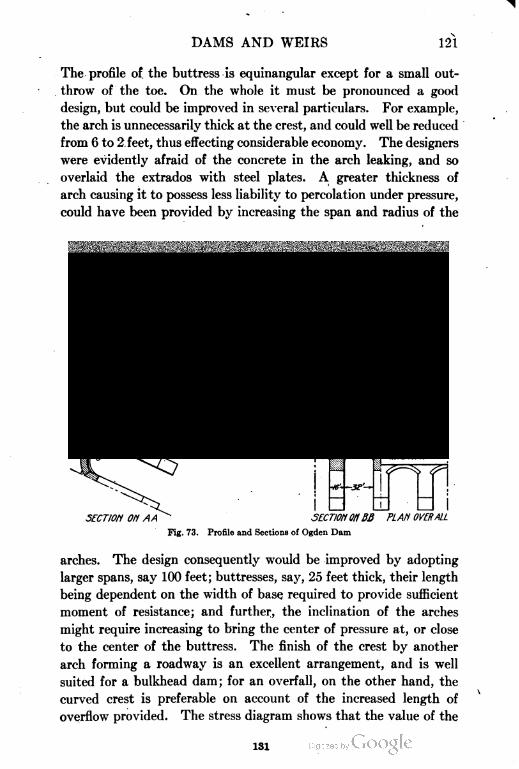
DAMS AND WEIRS 121
The profile of the buttress is equinangular except for a small out-
throw of the toe. On the whole it must be pronounced a good
design, but could be improved in several particulars. For example,
the arch is unnecessarily thick at the crest, and could well be reduced
from 6 to 2 feet, thus effecting considerable economy. The designers
were evidently afraid of the concrete in the arch leaking, and so
overlaid the extrados with steel plates. A greater thickness of
arch causing it to possess less liability to percolation under pressure,
could have been provided by increasing the span and radius of the
p^ s^ 7\
•
SECTI0H 0H AA -- SECT10N OH BB PLAF1 0VERALL
Fig. 73. Profile and Sections of Ogden Dam
arches. The design consequently would be improved by adopting
larger spans, say 100 feet; buttresses, say, 25 feet thick, their length
being dependent on the width of base, required to provide sufficient
moment of resistance; and further, the inclination of the arches
might require increasing to bring the center of pressure at, or close
to the center of the buttress. The finish of the crest by another
arch forming a roadway is an excellent arrangement, and is well
suited for a bulkhead dam; for an overfall, on the other hand, the
curved crest is preferable on account of the increased length of
overflow provided. The stress diagram shows that the value of the
131
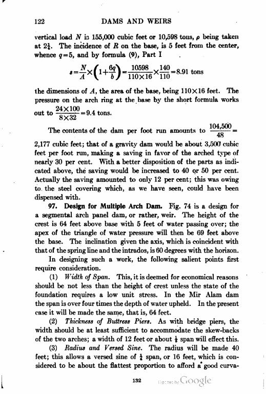
122 DAMS AND WEIRS
vertical load N is 155,000 cubic feet or 10,598 tons, p being taken
at 2\. The incidence of R on the base, is 5 feet from the center,
whence q = 5, and by formula (9), Part I
10598om ,=™1 tons
the dimensions of A, the area of the base, being 1 10X16 feet. The
pressure on the arch ring at the base by the short formula works
. . 24X100 0 . (<™t to -^-=9.4 tons.
104 500The contents of the dam per foot run amounts to —-^— =
2,177 cubic feet; that of a gravity dam would be about 3,500 cubic
feet per foot run, making a saving in favor of the arched type of
nearly 30 per cent. With a better disposition of the parts as indi
cated above, the saving would be increased to 40 or 50 per cent.
Actually the saving amounted to only 12 per cent; this was owing
to the steel covering which, as we have seen, could have been
dispensed with.
97. Design for Multiple Arch Dam. Fig. 74 is a design for
a segmental arch panel dam, or rather, weir. The height of the
crest is 64 feet above base with 5 feet of water passing over; the
apex of the triangle of water pressure will then be 69 feet above
the base. The inclination given the axis, which is coincident with
that of the spring line and the intrados, is 60 degrees with the horizon.
In designing such a work, the following salient points first
require consideration.
(1) Width of Span. This, it is deemed for economical reasons
should be not less than the height of crest unless the state of the
foundation requires a low unit stress. In the Mir Alam dam
the span is over four times the depth of water upheld. In the present
case it will be made the same, that is, 64 feet.
(2) Thickness of Buttress Piers. As with bridge piers, the
width should be at least sufficient to accommodate the skew-backs
of the two arches; a width of 12 feet or about ^ span will effect this.
(3) Radius and Versed Sine. The radius will be made 40
feet; this allows a versed sine of | span, or 16 feet, which is con
sidered to be about the flattest proportion to afford a* good curva-
132
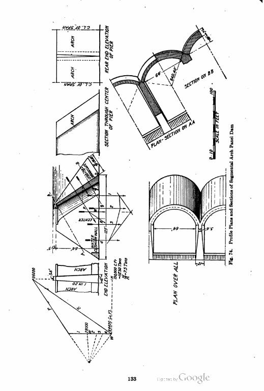
133
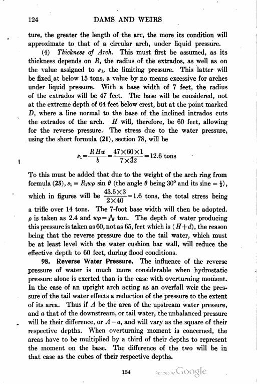
124 DAMS AND WEIRS
ture, the greater the length of the arc, the more its condition will
approximate to that of a circular arch, under liquid pressure.
(4) Thickness of Arch. This must first be assumed, as its
thickness depends on R, the radius of the extrados, as well as on
the value assigned to si, the limiting pressure. This latter will
be fixed, at below 15 tons, a value by no means excessive for arches
under liquid pressure. With a base width of 7 feet, the radius
of the extrados will be 47 feet. The base will be considered, not
at the extreme depth of 64 feet below crest, but at the point marked
D, where a line normal to the base of the inclined intrados cuts
the extrados of the arch. // will, therefore, be 60 feet, allowing
for the reverse pressure. The stress due to the water pressure,
using the short formula (21), section 78, will be
RHw 47X60X1
To this must be added that due to the weight of the arch ring from
formula (25), si — Riwp sin 6 (the angle 6 being 30° and its sine = |),
43 5X3which in figures will be =1.6 tons, the total stress being
—• /N 4U
a trifle over 14 tons. The 7-foot base width will then be adopted.
p is taken as 2.4 and WP = T\ ton. The depth of water producing
this pressure is taken as 60, not as 65, feet which is ( H +d), the reason
being that the reverse pressure due to the tail water, which must
be at least level with the water cushion bar wall, will reduce the
effective depth to 60 feet, during flood conditions.
98. Reverse Water Pressure. The influence of the reverse
pressure of water is much more considerable when hydrostatic
pressure alone is exerted than is the case with overturning moment.
In the case of an upright arch acting as an overfall weir the pres
sure of the tail water effects a reduction of the pressure to the extent
of its area. Thus if A be the area of the upstream water pressure,
and a that of the downstream, or tail water, the unbalanced pressure
will be their difference, or A —a, and will vary as the square of their
respective depths. When overturning moment is concerned, the
areas have to be multiplied by a third of their depths to represent
the moment on the base. The difference of the two will be in
that case as the cubes of their respective depths.
134
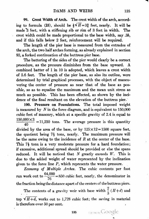
DAMS AND WEIRS 125
99. Crest Width of Arch. The crest width of the arch, accord
ing to formula (23), should be |V// = 3f feet, nearly. It will be
made 3 feet, with a stiffening rib or rim of 3 feet in width. The
crest width could be made proportional to the base width, say .36,
and if this falls below 2 feet, reinforcement will be required.
The length of the pier base is measured from the extrados of
the arch, the two half arches forming, as already explained in section
92, a forked continuation of the buttress pier base.
The battering of the sides of the pier would clearly be a correct
procedure, as the pressure diminishes from the base upward. A
combined batter of 1 in 10 is adopted, which leaves a crest width
of 5.6 feet. The length of the pier base, as also its outline, were
determined by trial graphical processes, with the object of maneu
vering the center of pressure as near that of the base as pos
sible, so as to equalize the maximum and the mean unit stress as
much as possible. This has been effected, as shown by the inci
dence of the final resultant on the elevation of the buttress pier.
100. Pressure on Foundations. The total imposed weight
is measured by N in the force diagram, and is equivalent to 150,000
cubic feet of masonry, which at a specific gravity of 2.4 is equal to
150,000X3 (1 orn , rp, • , •—— =11,250 tons. 1 he average pressure is this quantity
divided by the area of the base, or by 125X12 = 1500 square feet,
the quotient being 7| tons, nearly. The maximum pressure will
be the same owing to the incidence of 7? at the center of the base.
This 1\ tons. is a very moderate pressure for a hard foundation;
if excessive, additional spread should be provided or else the spans
reduced. It will be noticed that N greatly exceeds W. This is
due to the added weight of water represented by the inclination
given to the force line P, which represents the water pressure.
Economy of Multiple Arches. The cubic contents per foot
run work out to —'- =850 cubic feet, nearly, the denominator in
/O
the fraction being the distance apart of the centers of the buttress piers.
2The contents of a gravity weir with base width - (H+d) and
... O
top ^ H+d, works out to 1,728 cubic feet; the saving in material
is therefore over 50 per cent. /
135
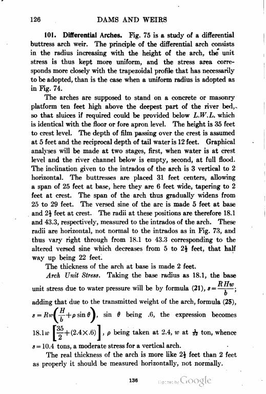
126 DAMS AND WEIRS
101. Differential Arches. Fig. 75 is a study of a differential
buttress arch weir. The principle of the differential arch consists
in the radius increasing with the height of the arch, the unit
stress is thus kept more uniform, and the stress area corre
sponds more closely with the trapezoidal profile that has necessarily
to be adopted, than is the case when a uniform radius is adopted as
in Fig. 74.
The arches are supposed to stand on a concrete or masonry
platform ten feet high above the deepest part of the river bed,
so that sluices if required could be provided below L.W.L. which
is identical with the floor or fore apron level. The height is 35 feet
to crest level. The depth of film passing over the crest is assumed
at 5 feet and the reciprocal depth of tail water is 12 feet. Graphical
analyses will be made at two stages, first, when water is at crest
level and the river channel below is empty, second, at full flood.
The inclination given to the intrados of the arch is 3 vertical to 2
horizontal. The buttresses are placed 31 feet centers, allowing
a span of 25 feet at base, here they are 6 feet wide, tapering to 2
feet at crest. The span of the arch thus gradually widens from
25 to 29 feet. The versed sine of the arc is made 5 feet at base
and 1\ feet at crest. The radii at these positions are therefore 18.1
and 43.3, respectively, measured to the intrados of the arch. These
radii are horizontal, not normal to the intrados as in Fig. 73, and
thus vary right through from 18.1 to 43.3 corresponding to the
altered versed sine which decreases from 5 to 2\ feet, that half
way up being 22 feet.
The thickness of the arch at base is made 2 feet.
Arch Unit Stress. Taking the base radius as 18.1, the base
unit stress due to water pressure will be by formula (21), s = —-— ;
adding that due to the transmitted weight of the arch, formula (25),
* = Rw( —+psin0 I, sin 6 being .(>, the expression becomes
[35 1—+ (2.4X.6) I , p being taken at 2.4, w at & ton, whence
* = 10.4 tons, a moderate stress for a vertical arch.
The real thickness of the arch is more like 2\ feet than 2 feet
as properly it should be measured horizontally, not normally.
136

DAMS AND WEIRS 127
UpperParllobeReinforced
forTsmperafure v
flfflM
Fig. 75. Design Diagrams for Differential Buttress Arch Weir
137
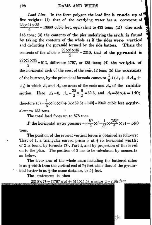
128 DAMS AND WEIRS
Loa<£ Line. In the force polygon the load line is made up of
five weights: (1) that of the overlying water has a content of
^ -- 13860 cubic feet, equivalent to 433 tons; (2) the arch
145 tons; (3) the contents of the pier underlying the arch is found
by taking the contents of the whole as if the sides were vertical
and deducting the pyramid formed by the side batters. Thus the
22 X 6X 35contents of the whole is ——-—— =2310, that of the pyramid is
m
= 513, difference 1797, or 135 tons; (4) the weight of
the horizontal arch of the crest of the weir, 12 tons; (5) the contents
of the buttress, by the prismoidal formula comes to —- 1 (^li+- 4:A.m +
At) in which Ai and A 2 are areas of the ends and Am of the middle
section. Here A= 0, Am = '^X-^- = 52.5, and J2=35X4 = 140;
Z 2t
therefore (5)=-g-X35X[0+ (4X52.5) +140]- 2042 cubic feet equiv
alent to 153 tons.
The total load foots up to 878 tons.
P the horizontal water pressure = «'—-X?=—X X31 = 5932i - > — £
tons.
The position of the several vertical forces is obtained as foliows :
That of 1, a triangular curved prism is at J its horizontal width;
of 2 is found by formula (7), Part I, and by projection of this level
on to the plan. The position of 3 has to be calculated by moments
as below.
The lever arm of the whole mass including the battered sides
is at \ width from the vertical end of 7\ feet while that of the pyram
idal batter is at | the same distance, or 5| feet.
The statement is then
2310x7J = (1797Xz) + (514X5.5) whence z = 7.84 feet
The position of 5, the battered sloping buttress '
taking the center part 2 feet wide and the outer s;
1arately. The e.g. of the former is at —- the length,
o
138
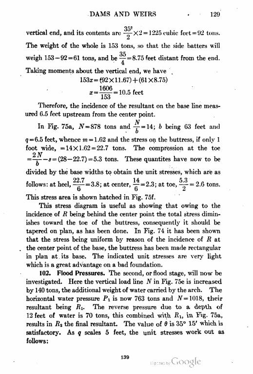
DAMS AND WEIRS . 129
352
vertical end, and its contents are -—- X 2 = 1 225 cubic feet = 92 tons.
a
The weight of the whole is 153 tons, so that the side hatters will
35weigh 153 — 92 = 61 tons, and be — = 8.75 feet distant from the end.
4
Taking moments about the vertical end, we have
= (92Xll.67)+ (61X8.75)
1606 ,II. ,£=——=10.5 feet
Therefore, the incidence of the resultant on the base line meas
ured 6.5 feet upstream from the center point.
NIn Fig. 75a, N=S78 tons and -r- = 14; b being 63 feet and
9 = 6.5 feet, whence in = 1.62 and the stress on the buttress, if only 1
foot wide, =14X1.62 = 22.7 tons. The compression at the toe
2N———s =(28— 22.7) =5.3 tons. These quantites have now to be
divided by the base widths to obtain the unit stresses, which are as
22 7 14 5 3
follows: at heel, —-1- = 3.8; at center, — = 2.3; at toe, '-^— = 2.6 tons.
6 62
This stress area is shown hatched in Fig. 75f.
This stress diagram is useful as showing that owing to the
incidence of R being behind the center point the total stress dimin
ishes toward the toe of the buttress, consequently it should be
tapered on plan, as has been done. In Fig. 74 it has been shown
that the stress being uniform by reason of the incidence of R at
the center point of the base, the buttress has been made rectangular
in plan at its base. The indicated unit stresses are very light
which is a great advantage on a bad foundation.
102. Flood Pressures. The second, or flood stage, will now be
investigated. Here the vertical load line N in Fig. 75e is increased
by 140 tons, the additional weight of water carried by the arch. The
horizontal water pressure PI is now 763 tons and N=1018, their
resultant being RI. The reverse pressure due to a depth. of
12 feet of water is 70 tons, this combined with Ri, in T^g- 75a,
results in R2 the final resultant. The value of 6 is 35° 15' which is
satisfactory. As q scales 5 feet, the unit stresses work out as
follows:
139

140
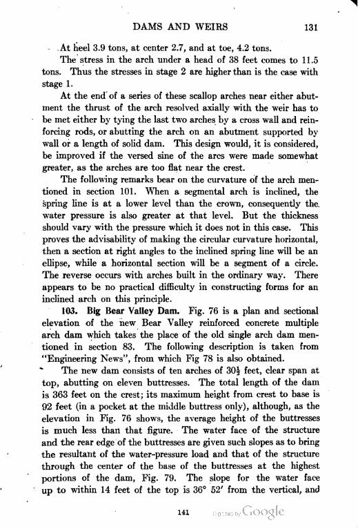
DAMS AND WEIRS 131
. .At heel 3.9 tons, at center 2.7, and at toe, 4.2 tons.
The stress in the arch under a head of 38 feet comes to 11.5
tons. Thus the stresses in stage 2 are higher than is the case with
stage 1.
At the end of a series of these scallop arches near either abut
ment the thrust of the arch resolved axially with the weir has to
be met either by tying the last two arches by a cross wall and rein
forcing rods, or abutting the arch on an abutment supported by
wall or a length of solid dam. This design would, it is considered,
be improved if the versed sine of the arcs were made somewhat
greater, as the arches are too flat near the crest.
The following remarks bear on the curvature of the arch men
tioned in section 101. When a segmental arch is inclined, the
spring line is at a lower level than the crown, consequently the.
water pressure is also greater at that level. But the thickness
should vary with the pressure which it does not in this case. This
proves the advisability of making the circular curvature horizontal,
then a section at right angles to the inclined spring line will be an
ellipse, while a horizontal section will be a segment of a circle.
The reverse occurs with arches built in the ordinary way. There
appears to be no practical difficulty in constructing forms for an
inclined arch on this principle.
103. Big Bear Valley Dam. Fig. 76 is a plan and sectional
elevation of the new Bear Valley reinforced concrete multiple
arch dam which takes the place of the old single arch dam men
tioned in section 83. The following description is taken from
"Engineering News", from which Fig 78 is also obtained.
The new dam consists of ten arches of 30| feet, clear span at
top, abutting on eleven buttresses. The total length of the dam
is 363 feet on the crest; its maximum height from crest to base is
92 feet (in a pocket at the middle buttress only), although, as the
elevation in Fig. 76 shows, the average height of the buttresses
is much less than that figure. The water face of the structure
and the rear edge of the buttresses are given such slopes as to bring
the resultant of the water-pressure load and that of the structure
through the center of the base of the buttresses at the highest
portions of the dam, Fig. 79. The slope for the water face
up to within 14 feet of the top is 36° 52' from the vertical, and
141
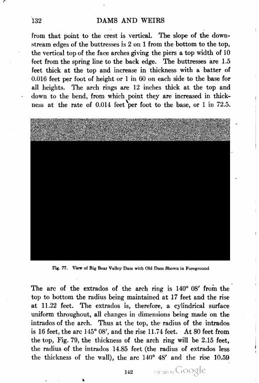
132 DAMS AND WEIRS
from that point to the crest is vertical. The slope of the down
stream edges of the buttresses is 2 on 1 from the bottom to the top,
the vertical top of the face arches giving the piers a top width of 10
feet from the spring line to the back edge. The buttresses are 1.5
feet thick at the top and increase in thickness with a batter of
0.016 feet per foot of height or 1 in 60 on each side to the base for
all heights. The arch rings are 12 inches thick at the top and
down to the bend, from which point they are increased in thick
ness at the rate of 0.014 feet per foot to the base, or 1 in 72.5.
Fig. 77. View of Big Bear Valley Dam with Old Dam Shown in Foreground
The arc of the extrados of the arch ring is 140° 08' from the
top to bottom the radius being maintained at 17 feet and the rise
at 11.22 feet. The extrados is, therefore, a cylindrical surface
uniform throughout, all changes in dimensions being made on the
intrados of the arch. Thus at the top, the radius of the intrados
is 16 feet, the arc 145° 08', and the rise 11.74 feet. At 80 feet from
the top, Fig. 79, the thickness of the arch ring will be 2.15 feet,
the radius of the intrados 14.85 feet (the radius of extrados less
the thickness of the wall), the arc 140° 48' and the rise 10.59
142
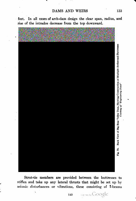
DAMS AND WEIRS 133
feet. In all cases of arch-dam design the clear span, radius, and
rise of the intrados decrease from the top downward.
-Sv
o is
Strut-tie members are provided between the buttresses to
stiffen and take up any lateral thrusts that might be set up by
seismic disturbances or vibrations, these consisting of T-beams
143
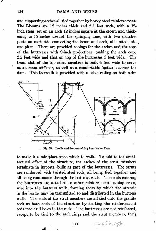
134 DAMS AND WEIRS
and supporting arches all tied together by heavy steel reinforcement.
The T-beams are 12 inches thick and 2.5 feet wide, with a 12-
inch stem, set on an arch 12 inches square at the crown and thick
ening to 15 inches toward the springing lines, with two spandrel
posts on each side connecting the beam and arch, all united into
one piece. There are provided copings for the arches and the tops
of the buttresses with 9-inch projections, making the arch cope
2.5 feet wide and that on top of the buttresses 3 feet wide. The
beam slab of the top strut members is built 4 feet wide to serve
as an extra stiffener, as well as a comfortable footwalk across the
dam. This footwalk is provided with a cable railing on both sides
Fig. 79. Profile and Sections of Big Bear Valley Dam
to make it a safe place upon which to walk. To add to the archi
tectural effect of the structure, the arches of the strut members
terminate in imposts, built as part of the buttresses. The struts
are reinforced with twisted steel rods, all being tied together and
all being continuous through the buttress walls. The ends entering
the buttresses are attached to other reinforcement passing cross
wise into the buttress walls, forming roots by which the stresses
in the beams may be transmitted to and distributed in the buttress
walls. The ends of the strut members are all tied onto the granite
rock at both ends of the structure by hooking the reinforcement
rods into drill holes in the rock. The buttresses are not reinforced,
except to be tied to the arch rings and the strut members, their
144
DAMS AND WEIRS 135
shape and the loads they are to carry making reinforcement super
fluous. The arch ribs are reinforced with f-inch twisted rods hori
zontally disposed 2 inches from the inner surface and variably
spaced. These rods were tied to the rods protruding from the
buttresses. For reinforcing the extrados of the arch ring ribs of
I|Xl|X l^-inch angles were used, to which "ferro-inclave" sheets
were clipped and used both as a concrete form for the outer face
and a base for the plaster surface.
104. Stress Analysis. On Fig. 79 a rough stress analysis
is shown for 80 feet depth of water. As will be seen the resultant
R cuts the base just short of the center point. The value of N
is estimated at 4100 tons, the area of the base ^4 = 110X4.2 = 460
N 4100 , ,,..,,,.sq. reet whence ~T = -T777: ™» tons nearly, evenly distributed (m being
taken as unity). The stress on the arch, 80 feet deep, neglecting
., ... RHv 16X80X1 on , . rp, . , ,its weight is —----—-=20 tons, nearly. Ims shows the
1 .3necessity for the reinforcement provided to take — or — of this stress.
2 (S
The tangent of 6 = ^.; = ''££' = .78. / . 0 = 39°.AV
This is a large value, 35 degrees being the usual limit, 33 degrees
better. If the arch thickness were doubled, reinforcement would not
be necessary except near the crest and the additional load of about
320 tons would bring 6 down to 35 degrees. If not, a greater inclination
given to the arch would increase the load of water on the extrados.
It is quite possible that a thicker arch without reinforcement would
be actually cheaper. The downward thrust acting on the arch
due to its own weight is on a different plane from the arch thrust.
Its effect is to increase the unit stress to a certain extent, as is also
the case with the combination of shearing and compressive stresses
in the interior of a dam as explained in Part I. This increase can,'
however, be neglected. A considerable but undefined proportion
of the water pressure near the base is conveyed to it and not to
the buttresses; this will more than compensate for any increase
due to vertical compression and consequently it can be ignored.
The ribs connecting the buttresses form an excellent provision for
stiffening them against buckling and vibration and are universally
145
136 DAMS AND WEIRS
employed in hollow concrete dams. The buttresses in this instance
are not reinforced.
.
HOLLOW SLAB BUTTRESS DAMS
105. Description of Type. * There is a class of dam and weir
similar in its main principles to the arch buttress type which is
believed to have been first introduced by the Ambursen Hydraulic
Construction Company of Boston. In place of the arch an inclined
flat deck is substituted, which has necessarily to be made of rein
forced concrete. For this reason, the deck slabs cannot exceed a
moderate width, so numerous narrow piers take the place of the
thick buttresses in the former type. A further development is a
thin deck which covers the downstream ends of the buttresses or
piers, forming a rollway. The enclosed box thus formed is occa
sionally utilized as a power house for the installation of turbines,
for which purpose it is well suited.
The inclination given to the flat deck is such that the incidence
of the resultant (R.F.) will fall as near the center of the base as pos
sible and at the same time regulate the inclination of the resultant
to an angle not greater than that of the angle of friction of the
material, i.e., 30 degrees with the vertical. By this means any
tendency to slide on the foundation is obviated.
Ellsworth Dam an Example. A good example of this style of
construction is given in Fig. 80 of the Ellsworth dam in Maine. In
this design the inclination of the deck is 45° or very nearly so; the
piers are 15 feet centers with widened ends, so that the clear span
of the concrete slabs is 9' 1" at the bottom.
The calculations necessary to analyze the thickness of the
slabs and the steel reinforcement at one point, viz, at El. 2.5, will
now be given. In this case the pressure of water on a strip of the
slab, one foot wide, the unsupported span of which is 9' 1", is Hlw.
Here // = 67 feet and w is ^ ton per cubic foot; therefore, W=
67x9.1X^ = 19 tons. To this must be added the weight of the
slab. As this latter lies at an angle with the horizontal its weight
is partly carried by the base and is not entirely supported by the
piers. The diagram in Fig. 80c is the triangle of forces. The weight
of slab w is resolved in two directions, a and b, respectively, parallel
146
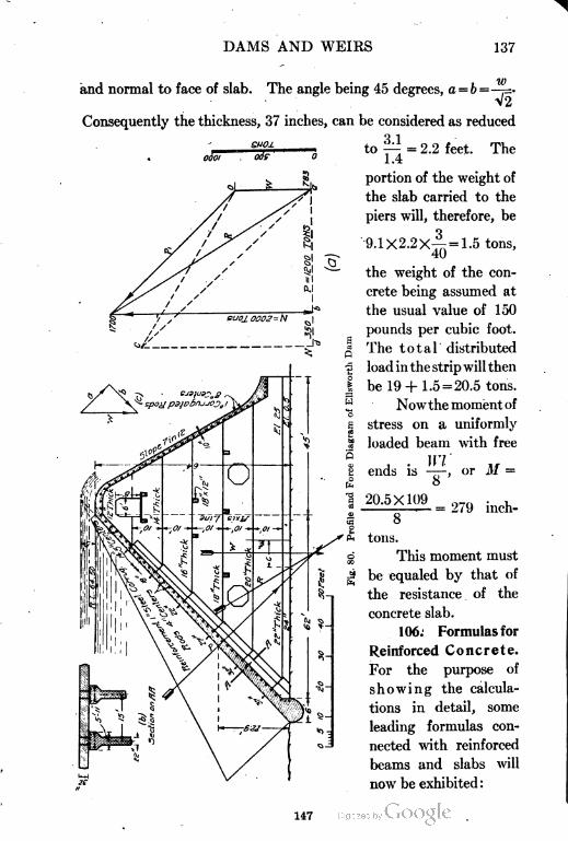
DAMS AND WEIRS 137
SUO-L
0001 00?
and normal to face of slab. The angle being 45 degrees, a = b=—=-
\2
Consequently the thickness, 37 inches, can be considered as reduced
to — = 2.2 feet. The
1.4
portion of the weight of
the slab carried to the
piers will, therefore, be
9. IX2.2x4= 1.5 tons,
40
the weight of the con
crete being assumed at
the usual value of 150
pounds per cubic foot.
The total distributed
load in the strip will then
be 19 + 1.5 = 20.5 tons.
Nowthe momentof
stress on a uniformly
loaded beam with free
H7
8
20.5X10⁹
ends is —, or M =
= 279 inch-
8
tons.
This moment must
be equaled by that of
the resistance . of the
concrete slab.
106. Formulas for
Reinforced Concrete.
For the purpose of
showing the calcula
tions in detail, some
leading formulas con
nected with reinforced
beams and slabs will
now be exhibited :
147
138 DAMS AND WEIRS
M
bffi=-p. (26)
f>p}
or, approximately, bd? = -^- (26a)
or, approximately, bd? = ^f (27a)
B/c
From these are found d, the required thickness of a slab up to
centroid of steel, or M,+MC the bending moments, in which b is
width of beam in inches; d depth of centroid of steel below top
of beam; Mc and M, symbolize the moments of resistance of the
concrete and steel, respectively; fs safe unit fiber stress in steel,
12,000 to 16,000 lb., or 6 to 8 tons per square inch;/,, safe extreme
stress in concrete 500, 0OO, or 650 lb., or .25, .3, or .325 ton per square
Ainch; p steel ratio, or —
bd
Ideal steel ratio p = ——-r (28)
A area of cross-section of steel ; k ratio of depth of neutral axis below
top to depth of beam
p1i (29)
j ratio of arm of resisting couple to d
j=(i-it) (30)
l?n ratio —-, Ea and Ec being the moduli of elasticity, ordinary values
&C
f A12 to 15; r ratio 4r-. As » = rr» when reinforced slabs are analyzed,
fc bd
formulas (26) and (27) can be transposed as below.
From (26) M.=f.Ajd (31)
From (26a) Ma = lfaAd Approximate (31a)
From (27) Me = tfjcjbcl* (32)
From (27a) Mc=^- Approximate (32a)
In the case under review the reinforcement consists of three
one inch square steel rods in each foot width of the slab. Using the
148
DAMS AND WEIRS 139
approximate formulas (31a) and (32a), /, = 8 tons, /c = .3 ton,
rf = 35 inches and b = \2 inches; then
M, = 8X3 X—X35 = 735 inch-tons
O
MC = 77: X 4-X420X35 = 735 inch-tons
10 0 (
the results being identical. As already noted the moment of stress
is but 279 inch-tons. The end shear may have governed the thick
ness. Testing for shear the load on a 12-inch strip of slab is 20.5
tons of which one-half is supported at each end. Allowing 50 lb., or
.025 ton, as a safe stress, the area of concrete required is 10.25 T- .025
= 410 square inches the actual area being 37 X 12 = 444 square inches.
107. Steel in Fore Slope. The reinforcement of the fore slope
is more a matter of judgment than of calculation, this deck having
hardly any weight to support, as the falling water will shoot clear
of it. The piers are not reinforced at all, nor is it necessary, as the
stresses are all compressive and the inclination of the upstream deck
is such that the resultant pressure makes an angle with the vertical
not greater than that of friction, i.e., 30 degrees. Fig. 80a is a. force
diagram of the resultant forces acting on the base at El. 0.00. The
total weight of a 15-foot bay is estimated at 783 tons while that of P,
the trapezoid of water pressure, is 1700 tons. The force line P in Fig.
80 drawn through the e.g. of the water pressure area intersects the
vertical force W below the base line. From this intersection R is
drawn upward parallel to its reciprocal in the force polygon, cutting
the base at a point some 9 feet distant from the center point.
The maximum stress will occur at the heel of the base. A =
107X2 = 214 sq. ft.; = = 9.34 tons; q being 9 ft., m =. .,A 214 1(J7
= 1.5 and * = 9.34xl.5 = 14 tons. Formula (9), Part I. The hori
zontal component of P=1200 tons. The base being 2 ft. wide,
1200
2X107
= 5.6 tons; therefore by formula (10), Part I, c =
V49+31.4 = 16.5 tons, a decidedly high value. The usual limit to
shearing stress is 100 lb. per sq. inch, equivalent to 7.2 tons per
sq. ft., reinforcement is therefore not necessary and is not provided.
There appears to be no reason why a steeper slope should not
have been given to the deck so as to bring the center of pressure up
149
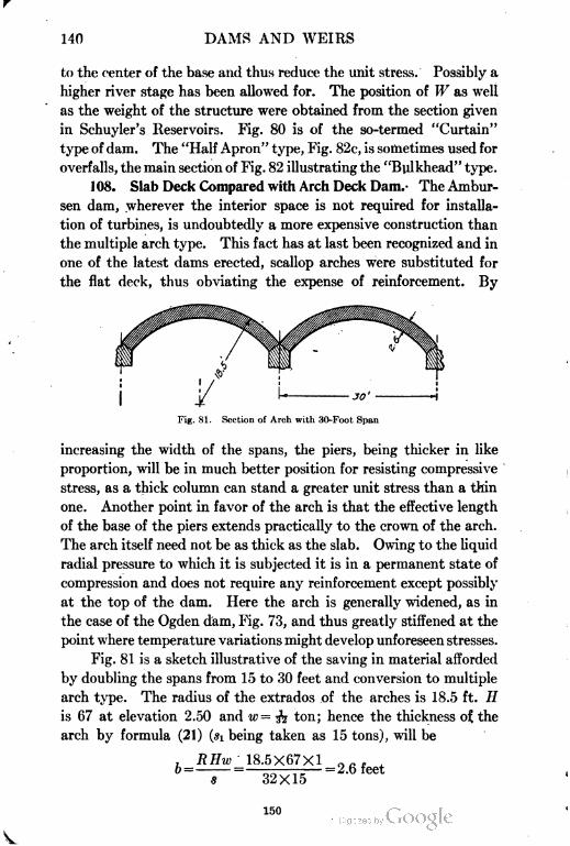
140 DAMS AND WEIRS
to the center of the base and thus reduce the unit stress. Possibly a
higher river stage has been allowed for. The position of W as well
as the weight of the structure were obtained from the section given
in Schuyler's Reservoirs. Fig. 80 is of the so-termed "Curtain"
type of dam. The "Half Apron" type, Fig. 82c, is sometimes used for
overfalls, the main section of Fig. 82 illustrating the "Bulkhead" type.
108. Slab Deck Compared with Arch Deck Dam. The Ambur-
sen dam, wherever the interior space is not required for installa
tion of turbines, is undoubtedly a more expensive construction than
the multiple arch type. This fact has at last been recognized and in
one of the latest dams erected, scallop arches were substituted for
the flat deck, thus obviating the expense of reinforcement. By
Fig. 81. Section of Arch with .'i0-Foot Span
increasing the width of the spans, the piers, being thicker in like
proportion, will be in much better position for resisting compressive
stress, as a thick column can stand a greater unit stress than a thin
one. Another point in favor of the arch is that the effective length
of the base of the piers extends practically to the crown of the arch.
The arch itself need not be as thick as the slab. Owing to the liquid
radial pressure to which it is subjected it is in a permanent state of
compression and does not require any reinforcement except possibly
at the top of the dam. Here the arch is generally widened, as in
the case of the Ogden dam, Fig. 73, and thus greatly stiffened at the
point where temperature variations might develop unforeseen stresses.
Fig. 81 is a sketch illustrative of the saving in material afforded
by doubling the spans from 15 to 30 feet and conversion to multiple
arch type. The radius of the extrados of the arches is 18.5 ft. //
is 67 at elevation 2.50 and w= -fa ton; hence the thickness of the
arch by formula (21) (si being taken as 15 tons), will be
18.5X67X1
32X15
;= 2.6 feet
150
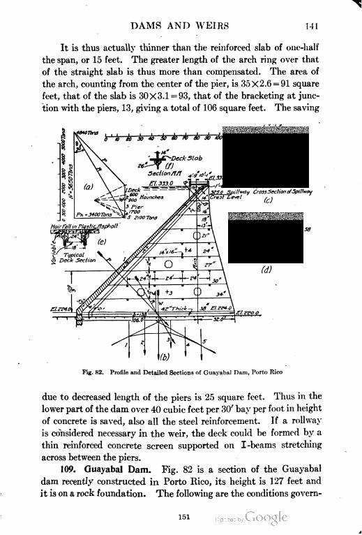
DAMS AND WEIRS 141
It is thus actually thinner than the reinforced slab of one-half
the span, or 15 feet. The greater length of the arch ring over that
of the straight slab is thus more than compensated. The area of
the arch, counting from the center of the pier, is 35X2.6 = 91 square
feet, that of the slab is 30X3.1 =93, that of the bracketing at junc
tion with the piers, 13, giving a total of 106 square feet. The saving
UJeck — =
zfff Haunches
Fig. 82. Profile and Detailed Sections of Guayabal Dam, Porto Rico
due to decreased length of the piers is 25 square feet. Thus in the
lower part of the dam over 40 cubic feet per 30' bay per foot in height
of concrete is saved, also all the steel reinforcement. If a rollway
is considered necessary in the weir, the deck could be formed by a
thin reinforced concrete screen supported on I-beams stretching
across between the piers.
109. Guayabal Dam. Fig. 82 is a section of the Guayabal
dam recently constructed in Porto Rico, its height is 127 feet and
it is on a rock foundation. The following are the conditions govern
151
142 DAMS AND WEIRS
ing the design; maximum pressure on foundation 10 tons per square
foot; compression in buttresses 300 pounds per square inch or 21.6
tons per square foot; shear in buttresses 100 pounds per square
inch, or 7.2 tons per square foot; shear in deck slabs 6O pounds, or
.03 ton per square inch ; fc for deck slabs 600 pounds or .3 ton per
square inch; fs for deck slabs 14,000 pounds, or 7 tons per square
inch.
The concrete in the slabs is in the proportion of 1:2:4, in the
E fbuttresses 1:3:6; n=—s is taken as 15 and r=^s = 23.3. The deck
J'-T Jc ,
slab is 55 inches thick at El. 224, d is taken as 53, allowing 2 inches
for covering the steel, bd or the area of the section one foot wide =
53 X 1 2 = 636 square inches . Now A the area of the steel = pbd. By
formula (28), ^ -- = .01044, hence the
required area of steel will be 636 X.01044 = 6.64 square inches,
provided d is of the correct value. The calculation will now be
made [for the thickness of the slab which is actually 55 inches.
The load on a strip 12 inches wide is
w ,. 109X13 . . .,Water pressure ———= 44.3 tons
o2
To this must be added a portion of the weight of the slab
which latter amounts to I -'-—— 1X1 ^- 1=4.5 tons. Of this
4 5->= 3.2 tons must be added to the 44.3 tons above, 44.3+3.2 = 47.5
V2
™ i if WL 47.5X13X12 no_.tons. lhe bending moment M is —— =--- = 92 / inch-
o o
tons. The depth of the slab can be estimated by using formulas
(26) or (27) or the approximate ones (26a) and (27a). For the
purpose of illustration, all four will be worked out. First the values
of k and j will be found by formulas (29) and (30).
= V.313+.0245-.156 = .582-.156 =
By fOTmu,a CW,f--
152
DAMS AND WEIRS 143
d = Vl234 = 35.07 inches
By formula (27), *--
d= 1406 = 37.5 inches
Now the approximate formulas will be used. By (26a)
7X12X7X.0104 1.53
d = Vl210 = 34.8 inches
by (27a)
rI 6X927 I 5562 I- ~
d= Vl542 = 39.3 inches
The approximate formulas (26a) and (27a) give higher results than
(26) and (27) . The result to select is 37.5 inches, formula (27) , which is
higher than by (26) . The depth of beam would then be 40 or 4 1 inches.
It is actually 55. This discrepancy may be due to the water having
been given a s.g. in excess of unity, owing to the presence of mud
in suspension, say of 1.3 .or 1.5, or shear is the criterion.
The corresponding steel area will be A =pbd = .0104X12X37.5
= 4.7 square inches. 1 ^ " round rods spaced 3 inches would answer.
With regard to direct shear on the slab, W as before = 47.5 tons of
which half acts at each pier, viz, 23.7 tons. The safe resistance is
6dX& = 12X55X.03 = 20 tons, nearlv. The shear = 23.7 =.036
12Xo5
ton = 72 pounds per square inch. This figure exceeds the limit of
60 pounds. The deficiency is made up by adding the shear of the
steel rods. The sectional area of this reinforcement is 4.7 square
inches the safe shearing of which is over 20 tows. These rods are
usually turned up at their ends in order to care for the shear.
Shear in Buttresses. With regard to shear in the buttresses, the
horizontal component of the water pressure as marked on the force
diagram is 3400 tons. The area of the base of the buttress at
El. 224-is 138X3.2 = 441.6, the shearing stress or ss then =|^= 8
tons per square foot, nearly. The allowable stress being only 7.2
tons the difference will have to be made good by reinforcing rods
of which two of f-inch diameter would suffice.
153
144 DAMS AND WEIRS
Now with regard to compressive stresses on the buttresses the
graphical working shows that the resultant R strikes the base at El.
224 almost exactly at the center, the angle
6 also is 30 degrees. The value of N is
5650 tons ; Si the mean and s the maximum
Nstress will both equal-—; and A, the area
A
of the base, equals 138X3.2 = 442 sq. ft.;
5650therefore, s = ——- = 12.78 tons. The com
pression on the foundation itself, which
is 4 feet lower will not be any less for,
although the base width is greater, N as
well as P are also increased. Thus the
pressure on the foundation is in excess
of the limit and widening to a further
extent is required.
The maximum internal stress c, in
the buttress at El. 224, will be by formula
o s
(10), Part I, b+\lj!r+*Y!- Here * = 12.8
and #s as we have seen is 8 tons, therefore,
c = 6.4+ J^+64= 16.6 tons. The limit
3 compression in the buttress is 300 pounds
a per square inch, or 21.6 tons per square
| foot.
In the bulkhead portion of the dam,
£ shown in Fig. 82b, every pier is run up
14 inches thick through the deck to form
a support for a highway bridge, the spans
of which are therefore 16 feet 10 inches
in the clear; the roadway is carried on
slabs which are supported by arches of
reinforced concrete. The buttresses are
laterally supported by several double rein
forced sway beams, 16"Xl4", and below the crest a through road
way is provided. The spillway section is shown on Fig. 82c. The
154
DAMS AND WEIRS145
155
146 DAMS AND WEIRS
ground level is here on a high bench at El. 295. The crest being
El. 325, the fall is 30 feet. The spillway is of the "half apron type".
The roadway here is carried on four reinforced concrete girders, a
very neat construction; the piers are run up every alternate span
and are therefore at 36-foot centers; they are beveled on both faces
to reduce end contraction. The spillway will pass 70,000 second-
feet; its length is 775 feet.
The bulkhead section of the dam (see also Fig. 83) has 51 spans
of 18-foot centers, total length 918 feet; that of the spillway consists
of 21 spans of 36-foot centers. The whole length is 1674 feet. The
depth of the tail water is not known, it would probably be about
20 feet and its effect would be but trifling. This is one of the largest
hollow dams ever constructed. The arrangement of the haunches
or corbels of the buttresses is a better one than that in the older
work of Fig. 80.
110. Bassano Dam. Another important work is the Bassano
dam illustrated in Figs. 84 and 85. This is an overfall dam built over
the Bow River at the head of the eastern section of the Canadian
Pacific Railway Company's irrigation canal and is estimated to pass
100,000 second-feet of water at a depth of 14 feet. Though not so
high nor so long as the Guayabal dam it presents several features of
interest. First its foundations are on a thick blanket of clay some
twelve feet deep which overlies boulders and gravel. This material
is very hard blue clay of excellent quality. The great advantage of
this formation, which extends over 1000 feet upstream from the work,
is that it precludes all uplift, or very nearly so, consequently no
special precautions have to be adopted, such as a long apron to
ensure length of percolation, as would be necessary in case of a
foundation composed of porous and loose materials. It has also
disadvantages. The allowable pressure on the clay is limited to
2| tons per square foot. This influences the design necessitating
a wide spread to the buttresses, laterally as well as longitudinally.
The whole of the dam is an overfall and the general arrangements
are very similar to those prevailing at Guayabal. The hearth or
horizontal fore apron, a provision not necessary in the last example,
is at El. 2512. The crest is at 2549.6 a height of 37.6 feet above
the apron and corresponds with the level of the canal intake floor.
Water is held up to eleven feet above crest level by draw gates
156
DAMS AND WEIRS 147
157
148 DAMS AND WEIRS
r
eleven feet high, and this full supply level is three feet below that of
the estimated afflux, which is fourteen feet above the crest.
For overturning moment the water-pressure area will be a
truncated triangle with its apex at afflux level plus the height h or
a2 •
1.5 — to allow for velocity_of approach, as explained in section
u
57, Part I. This, in the Bow River with a steep boulder bed will be
144about 12 feet per second ; h therefore will equal 1 .5 X-rr = 3.4 feet and
the apex of the truncated triangle will be at a point 14+3.4=17.4
feet above the crest level. The depth of the tail water at full flood
is not known, the ratio — with a steep bed slope will not be under .5,
consequently with d= 14, D will have a value of about 25 to 28 feet,
d being depth over crest and D that of tail water. The overturning
moments direct and reverse can be represented by the cubes of the
depths up- and downstream and the unbalanced moment by their
difference. The upstream head is 37.0+14+3.4 = 55 feet and the
downstream head say 25 feet. Their cubes are 166,375 and 15,625
the difference being 150,750, thus the reverse pressure will not have
much effect in assisting the stability of the structure. The cor
responding representative moment when water is held up to 11 ft.
above crest will be 493 = 117,649, supposing the tail channel empty.
This quantity is less than the 150,750 previously stated, consequently
the afflux level is that which has to be considered when estimating
the overturning moment. In the case of direct water pressure on
the deck slabs, the acting head at full flood will be the difference of
the flood level up- and downstream, which is 30 feet, as the tail
water is allowed access to the rear of the deck slabs. This is less
than the head, 49 feet, which exists when the gates are closed and
water is held up to canal full supply, i.e., to El. 2560.6, consequently
the head that has to be considered is that at this latter stage.
. Analysis of Pressures on Bassano Dam. With this data the
design can be analyzed, the procedure being identical with that
explained in the last example, excepting that the reverse pressure
might be taken into account as it will modify the direction and
incidence of R in a favorable sense though not to any great extent.
The limit stresses are those given in the last example with the fol
158
DAMS AND WEIRS 149
lowing additions: Footings, compression in bending, (>()(( pounds
per square inch, shear, 75 pounds per square inch.
Some explanation will now be given of the method of calcu
lation of the footing to the buttresses and the Guayabal dam will
be referred to, as the pressures on the base of the buttresses are
known quantities. In section 109 the value of N is 5650 tons and
—= =41 tons, nearly. This is the unit pressure per foot run
b loo
on the base of the buttress. Supposing the limit pressure on the
foundation was fixed at 3 tons per square foot, then the requisite
41base width of the footing would be — = 13.7 feet. The footing con-
o
sists of two cantilevers attached to the stem of the buttress. The
bonding moment M at the junction with the buttress of a strip 1
Wlfoot wide will be -^-. The buttress being 3.2 feet wide the pro-
2i
13 7 3 2jeering length of footing on each side will be -^-:—-——= 5.25 feet.
ft
The reaction on a strip one foot wide will be 5.25x3 XI =
15.75 tons. The moment in inch-tons about the edge of the section
... , 12WI 15.75X5.25X12 , . .4of the buttress will be ——= = 498 inch-tons.
According to formula (27a), W2=. .'. d = = V830 =
Jc
28.8 inches. Then bd=28.8X12 = 346 and A the area of the steel
at the base will be pbd=.0104X346 = 3.61 inches, this in a 12-inch
wide strip will take Ij-inch bars 4 inches apart. When the weight
on the buttress is considerable the depth of footing slab thus esti
mated becomes too great for convenience. In such cases, as in Fig.
85, the beam will require reinforcement in compression at the top.
This complicates the calculation and cases of double reinforcement
are best worked out by means of tables prepared for the purpose.
The footings shown in Fig. 85, were thus double reinforced, in fact
through bars were inserted at each step, the lower being in tension
the upper ones in compression. The lower bars were continuous
right through the base of the dam. This reinforcement of the
footing is not shown on the blue print from which Fig. 85 is derived.
111. Pressure on Foundation Foredeck. A great many
159
150 DAMS AND WEIRS
Ambursen dams have been constructed on river beds composed
of boulders and gravel, which require a pressure limit of about
4 tons per square foot. This can always be arranged for by widen
ing the footing of the pier buttresses, the same can of course be
done with arch buttressed dams. The base of the arch itself can
be stepped out in a similar manner. In the Bassano dam the
sloping fore deck is unusually thick and is heavily reinforced in
addition; this is done with the idea of strengthening the structure
against shock from ice, as well as from the falling water, and with
the further idea of assisting the buttresses in carrying the heavy
load of the piers and superstructure. It is doubtful if any calcu
lations can well be made for this; it is a matter more of judgment
than of estimation.
Buttresses. As with the Guayabal spillway, every alternate
buttress is run up to form the piers of the superstructure, which latter
consists of a through bridge which carries the lift gear for manipu
lating the draw gates. The so-termed blind buttresses—that is,
those that do not carry a pier—are of thinner section and are appar
ently not reinforced. Both kinds of buttresses have cross-bracing
as shown on the profile. In hollow dams the location of the center
of pressure moves with the rise of water from the heel toward the
center within the upstream half of the middle third. In solid dams,
on the other hand, the movement is along the whole of the middle
third division, consequently in hollow dams there is no tendency
to turn about the toe as with solid dams, rather the reverse, namely,
to upset backward. This latter tendency must cause tension in
the buttresses which the cross-bracing is intended to care for.
Baffles. As noted already in section 66, baffles have been built
on the curved bucket with the object of neutralizing this mischiev
ous arrangement which it is hoped will soon become as obsolete in
western practice as has long been the case in the East.
Hearth and Anchored Apron. The dam is provided with a solid
horizontal fore apron or hearth 76 feet long and beyond this the
device of an anchored floating apron of timber 30 feet in length has
been added. The apron is undoubtedly too short and should have
been made 100 feet or 2 (H+d) in length, with cribbed riprap
below it. The wooden sheet piling in the rear of the work is con
sidered to be worse than useless; it merely breaks up the good clay
160
DAMS AND WEIRS 151
blanket by cutting it in two. A wide solid curtain of concrete, not
so deep as to penetrate the clay blanket, would have been a superior
arrangement. The inclined piling below the bucket is provided to
guard against sliding. This dam is provided with a number of sluice
openings. Their capacity is such that one half will pass ordinary
floods, allowing the other half of the dam to be cut off from the river
by sheet piling during construction. On completion of the work
these sluices were all closed from the inside by slabs of concrete
deposited in position.
SUBMERGED WEIRS FOUNDED ON SAND
112. Description of Type. There is a certain type of drowned
or submerged diversion weir which is built across wide rivers or
streams whose beds are composed of sand of such depth that a solid
foundation on clay is an impossibility. Consequently, the weir has
to be founded on nothing better than the surface of the river bed,
with perhaps a few lines of hollow curtain walls as an adjunct. Of
this class of weir but one is believed to have been constructed in
the United States, viz, the Laguna weir over the Colorado River
at the head of the Yuma irrigation canals.
This type originated in India and in that country are found
numerous examples of weirs successfully, constructed across very
large rivers of immense flood discharge. For instance, the Goda-
veri River in Southern India has a flood discharge of 1,200,000
second-feet and the weirs across it are nearly 2| miles in length.
Not only is the length great, but as will be seen, the width has to be
very considerable. The Okhla weir, Figs. 101 and 102, situated on
the Jumna below the historic city of Delhi is 250 feet wide and
f mile long. The height of these submerged weirs is seldom over
12 feet, their role being purely diversion, not storage. No doubt
more of this type of low diversion weirs will in the future have to be
constructed in the I'nited States or in Mexico, so that a knowledge
of the subject is a necessity for the irrigation engineer.
Principles of Design. The principles underlying the successful
design of these works are a comparatively recent discovery. Designs
were formerly made on no fixed principles, being but more or less
modified copies of older works. Fortunately some of these works
failed, and it is from the practical experience thus gained that a
161
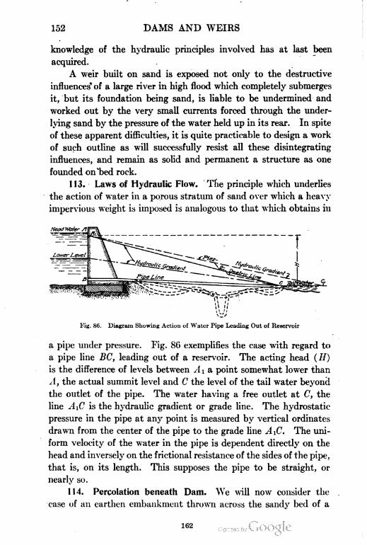
152 DAMS AND WEIRS
knowledge of the hydraulic principles involved has at last been
acquired.
A weir built on sand is exposed not only to the destructive
influences' of a large river in high flood which completely submerges
it, but its foundation being sand, is liable to be undermined and
worked out by the very small currents forced through the under
lying sand by the pressure of the water held up in its rear. In spite
of these apparent difficulties, it is quite practicable to design a work
of such outline as will successfully resist all these disintegrating
influences, and remain as solid and permanent a structure as one
founded on Tied rock.
113. Laws of Hydraulic Flow. The principle which underlies
the action of water in a porous stratum of sand over which a heavy
impervious weight is imposed is analogous to that which obtains in
Head Water
r
Fig. 86. Diagram Showing Action of Water Pipe Leading Out of Reservoir
a pipe under pressure. Fig. 86 exemplifies the case with regard to
a pipe line EC, leading out of a reservoir. The acting head (//)
is the difference of levels between A\ a point somewhat lower than
A, the actual summit level and C the level of the tail water beyond
the outlet of the pipe. The water having a free outlet at C, the
line A\C is the hydraulic gradient or grade line. The hydrostatic
pressure in the pipe at any point is measured by vertical ordinates
drawn from the center of the pipe to the grade line A iC. The uni
form velocity of the water in the pipe is dependent directly on the
head and inversely on the frictional resistance of the sides of the pipe,
that is, on its length. This supposes the pipe to be straight, or
nearly so.
114. Percolation beneath Dam. We will now consider the
case of an earthen embankment thrown across the sandy bed of a
162
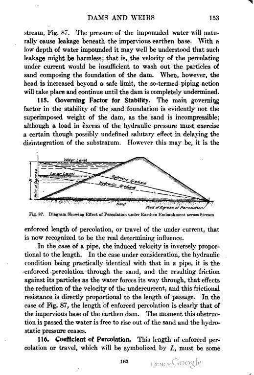
DAMS AND WEIRS 153
stream, Fig. 87. The pressure of the impounded water will natu
rally cause leakage beneath the impervious earthen base. With a
low depth of water impounded it may well be understood that such
leakage might be harmless; that is, the velocity of the percolating
under current would be insufficient to wash out the particles of
sand composing the foundation of the dam. When, however, the
head is increased beyond a safe limit, the so-termed piping action
will take place and continue until the dam is completely undermined.
115. Governing Factor for Stability. The main governing
factor in the stability of the sand foundation is evidently not the
superimposed weight of the dam, as the sand is incompressible;
although a load in excess of the hydraulic pressure must exercise
a certain though possibly undefined salutary effect in delaying the
disintegration of the substratum. However this may be, it is the
Sand
Point ofEgress ofPercolations
Fig. 87. Diagram Showing Effect of Percolation under Earthen Embankment across Stream
enforced length of percolation, or travel of the under current, that
is now recognized to be the real determining influence.
In the case of a pipe, the induced velocity is inversely propor
tional to the length. In the case under consideration, the hydraulic
condition being practically identical with that in a pipe, it is the
enforced percolation through the sand, and the resulting friction
against its particles as the water forces its way through, that effects
the reduction of the velocity of the undercurrent, and this frictional
resistance is directly proportional to the length of passage. In the
case of Fig. 87, the length of enforced percolation is clearly that of
the impervious base of the earthen dam. The moment this obstruc
tion is passed the water is free to rise out of the sand and the hydro
static pressure ceases.
116. Coefficient of Percolation. This length of enforced per
colation or travel, which will be symbolized by L, must be some
163
154 DAMS AND WEIRS
multiple of the head //, and if reliable safe values for this factor can
be found, suitable to particular classes of sand, we shall be enabled
to design any work on a sand foundation, with perfect confidence in
its stability. If the percolation factor be symbolized by c, then L, or
the length of enforced percolation, will equal c H, H being the head of
water. The factor c will vary in value with the quality of the sand.
Fig. 88 represents a case similar in every respect to the last
except, instead of a dam of earth, the obstruction consists of a
vortical wall termed the weir or drop Avail, having a horizontal
impervious floor attached thereto, which appendage is necessary -to
prevent erosion of the bed by the current of falling water.
At the stage of maximum pressure the head water will be
level with the crest, and the level of the tail water that of the floor;
consequently the hydraulic gradient will be HB, which is also the
piezometric line and as in the previous case of the pipe line, Fig.
Sand
Fig. 88. Diagram Showing Design of Profile to Reduce Percolation
86, the ordinates of the triangle HAB will represent the upward
hydrostatic pressure on the base of the weir wall and of the floor.
117. Criterion for Safety of Structure. The safety of the
structure is evidently dependent on the following points:
First, the weir wall must be dimensioned to resist the overturn
ing moment of the horizontal water pressure. This has been dealt
with in a previous section. Second, the thickness, i. e., the weight
of the apron or floor must be such that it will be safe from being
blown up or fractured by the hydrostatic pressure; third, the base
length, or that of the enforced percolation L, must not be less than
eH, the product of the factor c with the head H. Fourth, the
length of the masonry apron and its continuation in riprap or con
crete book blocks must be sufficient to prevent erosion.
It is evident that the value of this factor c, must vary with the
nature of the sand substratum in accordance with its qualities of
164
DAMS AND WEIRS 155
fineness or coarseness. Fine light sand will be closer in texture,
passing less water under a given head than a coarser variety, but at
the same time will be disintegrated and washed out under less
pressure. Reliable values for c, on which the design mainly depends,
can only be obtained experimentally, not from artificial experiments,
but by deduction from actual examples of weirs; among which the
most valuable are the records of failures due to insufficiency in
length of percolation. From these statistics a safe value of the
relation of L to //, the factor c, which is also the sine of the
hydraulic gradient, can be derived.
118. Adopted Values of Percolation Coefficient. The follow
ing values of c have been adopted for the specified classes of sand.
Class I: River beds of light silt and sand, of which GO per cent
passes a 100-mesh sieve, as those of the Nile or Mississippi; percola
tion factor c = 18.
Class II: Fine micaceous sand of which 80 per cent of the
grains pass a 75-mesh sieve, as in Himalayan rivers and in such as
the Colorado ; c = 15.
Class III: Coarse-grained sands, as in Central and South
India ; c = 12.
Class IV: Boulders or shingle and gravel and sand mixed; c
varies from 9 to 5.
In Fig. 88 if the sand extended only up to the level C, the length
of percolation would be CD, the rise from D to B not being counted
in. In that case the area of hydrostatic pressure acting beneath
the floor would be the triangle HA B. As, however, a layer of sand
from A to C interposes, the length will be ACD, and outline IIiB.
The step H HI occurring in the outline is due to the neutralization
of head symbolized by h, effected in the depth AC. Supposing
AC to be 6 feet and the percolation factor to be 12, then the step
in the pressure area, equal to h, will be 6-r-12 = 6 inches. The
resulting gradient HiB will, however, be natter than 1 in 12; conse
quently the termination of the apron can be shifted back to BiDi,
HiBi, being parallel to IIB; in which case the area of hydrostatic
pressure will be HiABt. The pressure at any point on the base is
represented by the ordinates of the triangle or area of pressure.
Thus the upward pressure at E, below the toe of the drop wall,
where the horizontal apron commences, is represented by the line
165
156 DAMS AND WEIRS
FG. Supposing the head HA to be 10 feet, then the total required
length of percolation will be cH= 12X10 = 120 feet. This is the
length ACDi. The neutralization of head, h, effected by the enforced
percolation between // and G is represented by GJ, and supposing
the base width of the drop wall CE to be 9 feet, AC being 6 feet,
fiIl-Q
A = ^±? = ll feet. The upward pressure FG is (H- A) = 10-11
= 81 feet.
The stepped upper line bounding the pressure area as has been
noted in Part I, is termed the piezometric line, as it represents the
level to which water would rise if pipes were inserted in the floor.
It is evident from the above that when no vertical depressions
ocour in the line of travel that the piezometric line will coincide
with the hydraulic gradient or virtual slope; when, however, vertical
depressions exist, reciprocal steps occur in the piezometric line,
which then falls below the hydraulic grade line. The piezometric
line is naturally always parallel to the latter. The commencement
of the floor at E is always a critical point in the design as the pres
sure is greatest here, diminishing to zero at the end.
119. Simplifying the Computations. In the same way that
the water pressure is represented by the head producing it, the
common factor w, or the Unit weight of water, may also be elimi
nated from the opposing weight of the floor. The weight of the
masonry, therefore, is represented by its thickness in the same way
as the pressure, and if t be the thickness of the floor, tp will represent
its weight. Now the floor lies wholly below low water level. Con
sequently, in addition to the external hydrostatic pressure repre
sented by //, due to the head of water upheld, there is the buoyancy
due to immersion. The actual pressure on the base CDi is really
measured by HC, not HA. Thus if a vertical pipe were inserted
in the floor the water would rise up to the piezometric line and be
in depth the ordinate of the pressure area plus the thickness of the
floor. But it is convenient to keep the hydrostatic external pres
sure distinct from the effect of immersion. This latter can be
allowed for by reduction in the Weight of these parts of the struc
ture that lie below L. W. L. See sections 52 and 53, Part I.-
Effect of Immersion. When a body is immersed in a liquid it
loses weight to the extent of the weight of the liquid displaced.
iee
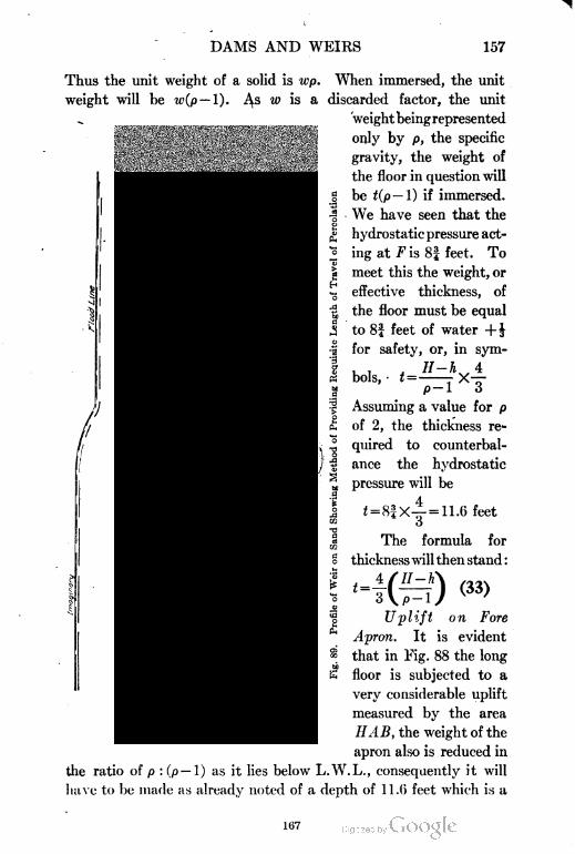
DAMS AND WEIRS 157
Thus the unit weight of a solid is wp. When immersed, the unit
weight will be w(p — 1). As w is a discarded factor, the unit
'weight being represented
only by p, the specific
gravity, the weight of
the floor in question will
be t(p — 1) if immersed.
We have seen that the
hydrostatic pressure act
ing at F is 8f feet. To
meet this the weight, or
effective thickness, of
the floor must be equal
to 8f feet of water + J
for safety, or, in sym-
Vinlc . / — VUOlb, I— 1 *- o
p— 1 3
Assuming a value for p
of 2, the thickness re
quired to counterbal
ance the hydrostatic
pressure will be
c4=ll-6 feet
The formula for
thickness will then stand :
4=
H-h(33)
/
Uplift on Fore
Apron. It is evident
that in Fig. 88 the long
floor is subjected to a
very considerable uplift
measured by the area
HAB, the weight of the
apron also is reduced in
the ratio of p : (p — 1) as it lies below L.W.L., consequently it will
have to be made as already noted of a depth of 11.6 feet which is a
167
158 DAMS AND WEIRS
quite impossible figure. The remedy is either to make the floor porous
in which case the hydraulic gradient will fall below 1 in 12, and failure
will take place by piping, or else to reduce the effective head by the
insertion of a rear apron or a vertical curtain wall as has been already
mentioned in section 53, Part I. In these submerged weirs on
large rivers and in fact in most overfall dams a solid fore apron is
advisable. The length of this should however be limited to abso
lute requirements. This length of floor is a matter more of individual
judgment or following successful precedent than one of precise
estimation.
The following empirical rule which takes into account the nature
of the sand as well as the head of water is believed to be a good guide
in determining the length of fore apron in a weir of this type, it is
L = 3^7JI (34)
In the case of Fig. 89, the head is 10 feet and c is assumed at 12, conse
quently, L = 3Vl2f) = 33 feet, say 36, or 3c. In Fig. 89 this length
of floor has been inserted. Now a total length of percolation of 12
times the head, or 120 feet = 10c is required by hypothesis, of this
3c is used up by the floor leaving Ic to be provided by a rear apron
and curtain. Supposing the curtain is made a depth equal to l|c,
this will dispose of 3 out of the 7 (for reasons to be given later),
leaving 4 to be provided for by the rear apron, the length of which,
counting from the toe of the weir wall, is made 4c or 48 feet. The
hydraulic gradient starts from the point //' which is vertically
above that of ingress A. At the location of the vertical diaphragm
of sheet piling, a step takes place owing to the sudden reduction of
head of 3 feet, the obstruction being 3c in length counting both
sides. From here on, the line is termed the piezometric line and the
pressure area is the space enclosed between it and the floor. The
actual pressure area would include the floor itself, but this has been
already allowed for in reduction of weight, its s.g. being taken as
unity instead of 2.
The uplift on the weir wall is the area enclosed between its
base and the piezometric line. In calculating overturning moment,
if this portion were considered as having lost weight by immersion
it would not quite fully represent the loss of effective weight due to
uplift, because above the floor level the profile of the weir wall is
168
DAMS AND WEIRS 159
not rectangular, while that of the pressure area is more nearly so.
The foundation could he treated this way, the superstructure above
AF being given full s.g. and the uplift treated as a separate vertical
force as was the case in Fig. 40, Part I.
120. Vertical Obstruction to Percolation. Now with regard
to the vertical obstruction, when water percolates under pressure
beneath an impervious platform the particles are impelled upward
by the hydrostatic pressure against the base of the dam and also
there is a slow horizontal current downstream. The line of least
resistance is along the surface of any solid in preference to a shorter
course through the middle of the sand, consequently when a vertical
obstruction as a curtain wall of masonry or a diaphragm of sheet
piling is encountered the current of water is forced downward and
the obstruction being passed it ascends the other side up to the base
line which it again follows. The outer particles follow the lead
of the inner as is shown by the arrows in Fig. 89. The value of a
vertical obstruction is accordingly twice that of a similar horizontal
length of base. Valuable corroboration of the reliability of the
theory of percolation adopted, particularly with regard to reduction
of head caused by vertical obstruction, has been received, while this
article was on the press, from a paper in the proceeedings of the
American Society of Civil Engineers entitled "The Action of Water
under Dams" by J. B. T. Coleman, which appeared in August, 1915.
The practical value of the experiments, however, is somewhat
vitiated by the smallness of the scale of operations and the dispro
portion in the ratio H: L to actual conditions. The length of base
of the dam experimented on should not be less than 50 feet with a
head of 5 feet.
121. Rear Apron. The extension of the floor rearward is
termed the rear apron. Its statical condition is peculiar, not being
subject to any upward hydrostatic pressure as is the case with the
fore apron or floor. Inspection of the diagram, Fig. 89, will show
that the water pressure acting below the floor is the trapezoid enclosed
between the piezometric line and the floor level ; whereas the down
ward pressure is represented by the rectangle HiAiHA, which is
considerably larger. Theoretically no weight is required in the
rear apron, the only proviso being that it must be impervious and
have a water-tight connection with the weir wall, otherwise the
169
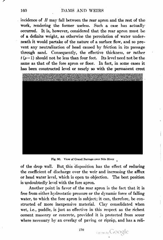
160 DAMS AND WEIRS
incidence of // may fall between the rear apron and the rest of the
work, rendering the former useless. Such a case has actually
occurred. It is, however, considered that the rear apron must be
of a definite weight, as otherwise the percolation of water under
neath it would partake of the nature of a surface flow, and so pre
vent any neutralization of head caused by friction in its passage
through sand. Consequently, the effective thickness, or rather
i (p — 1) should not be less than four feet. Its level need not be the
same as that of the fore apron or floor. In fact, in some cases it
has been constructed level or nearly so with the permanent crest
>~v.-«& -•» - -
,.^<Tf.<..&. 4 -J.',»
wx.^^r
Fig. 90. View of Grand Barrage over Nile River
of the drop wall. But this disposition has the effect of reducing
the coefficient of discharge over the weir and increasing the afflux
or head water level, which is open to objection. The best position
is undoubtedly level with the fore apron.
Another point in favor of the rear apron is the fact that it is
free from either hydrostatic pressure or the dynamic force of falling
water, to which the fore apron is subject; it can, therefore, be con
structed of more inexpensive material. Clay consolidated when
wet, i.e., puddle, is just as effective in this respect as the richest
cement masonry or concrete, provided it is protected from scour
where necessary by an overlay of paving or riprap, and has a reli
170
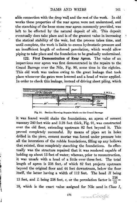
DAMS AND WEIRS 161
able connection with the drop wall and the rest of the work. In old
works these properties of the rear apron were not understood, and
the stanching of the loose stone rear apron commonly provided, was
left to be effected by the natural deposit of silt. This deposit
eventually does take place and is of the greatest value in increasing
the statical stability of the weir, but the process takes time, and
until complete, the work is liable to excess hydrostatic pressure and
an insufficient length of enforced percolation, which would allow
piping to take place and the foundation to be gradually undermined.
122. First Demonstration of Rear Apron. The value of an
impervious rear apron was first demonstrated in the repairs to the
Grand Barrage over the Nile, Fig. 90, some time in the eighties.
This old work was useless owing to the great leakage that took
place whenever the gates were lowered and a head of water applied.
In order to check this leakage, instead of driving sheet piling, which
Fig. 91. Section Showing Repairs Made on the Grand Barrage
it was feared would shake the foundations, an apron of cement
masonry 240 feet wide and 3.28 feet thick, Fig. 91, was constructed
over the old floor, extending upstream 82 feet beyond it. This
proved completely successful. By means of pipes set in holes
drilled in the piers, cement mortar was forced under pressure into
all the interstices of the rubble foundations, filling up any hollows
that existed, thus completely stanching the foundations. So effec
tually was the structure repaired that it was rendered capable of
holding up about 13 feet of water; whereas, prior to reconstruction,
it was unsafe with a head of a little over three feet. The total
length of apron is 238 feet, of which 82 feet projects upstream
beyond the original floor and 44 feet downstream, below the floor
itself, the latter having a width of 112 feet. The head // being
23813 feet, and L being 238 feet, c, or the percolation factor is —7- =
lo
18, which is the exact value assigned for Nile sand in Class I,
171
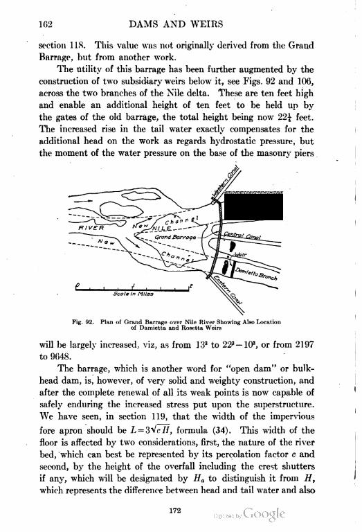
102 DAMS AND WEIRS
section 11$. This value was not originally derived from the Grand
Barrage, but from another work.
The utility of this barrage has been further augmented by the
construction of two subsidiary weirs below it, see Figs. 92 and 100,
across the two branches of the Nile delta. These are ten feet high
and enable an additional height of ten feet to be held up by
the gates of the old barrage, the total height being now T2\ feet.
The increased rise in the tail water exactly compensates for the
additional head on the work as regards hydrostatic pressure, but
the moment of the water pressure on the base of the masonry piers
Fig. 92. Plan of Grand Barrage over Nile River Showing Also Location
of Damietta and Rosetta Weirs
will be largely increased, viz, as from 133 to 22s — 103, or from 2197
to 9648.
The barrage, which is another word for "open dam" or bulk
head dam, is, however, of very solid and weighty construction, and
after the complete renewal of all its weak points is now capable of
safely enduring the increased stress put upon the superstructure.
We have seen, in section 119, that the width of the impervious
fore apron should be L = 3"vW/, formula (34). This width of the
floor is affected by two considerations, first, the nature of the river
bed, 'which can best be represented by its percolation factor c and
second, by the height of the overfall including the crest shutters
if any, which will be designated by Ha to distinguish it from H,
which represents the difference between head and tail water and also
172
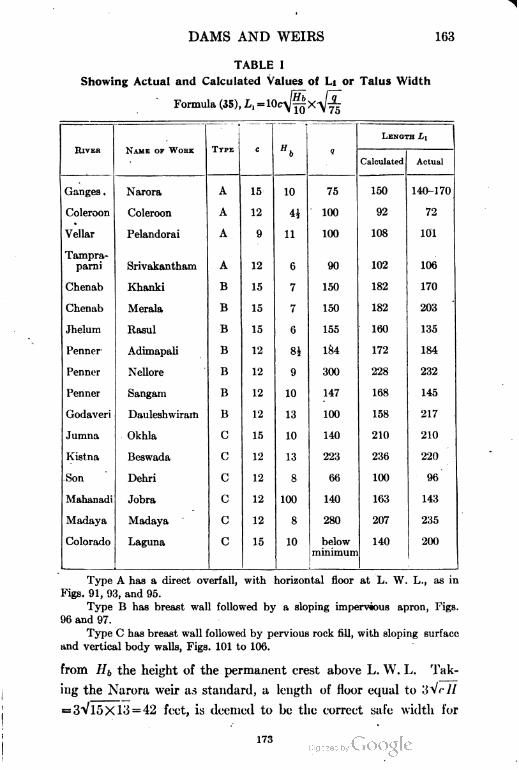
DAMS AND WEIRS 163
TABLE I
Showing Actual and Calculated Values of Li or Talus Width
Formula (35), L, =
RIVER NAME OF WORK TYPE C
»b q
LENGTH LI
Calculated Actual
Ganges . Narora A 15 10 75 150 140-170
Coleroon Coleroon A 12 4i 100 92 72
Vellar Pelandorai A 9 11 100 108 101
Tampra-
parni Srivakantham A 12 6 90 102 106
Chenab Khanki B 15 7 150 182 170
Chenab Merala B 15 7 150 182 203
Jhelum Rasul B 15 6 155 160 135
Penncr Adimapali B 12 81 184 172 184
Penner Nellore B 12 9 300 228 232
Penner Sangam B 12 10 147 168 145
Godaveri Dauleshwiram B 12 13 100 158 217
Jumna Okhla C 15 10 140 210 210
Kistna Bcswada C 12 13 223 236 220
Son Dehri C 12 8 60 100 96
Mahanadi Jobra C 12 100 140 163 143
Madaya Madaya C 12 8 280 207 235
Colorado Laguna C 15 10 below
minimum
140 200
,
Type A has a direct overfall, with horizontal floor at L. W. L., as in
Figs. 91, 93, and 95.
Type B has breast wall followed by a sloping impervious apron, Figs.
96 and 97.
Type C has breast wall followed by pervious rock fill, with sloping surface
and vertical body walls, Figs. 101 to 106.
from Hb the height of the permanent crest above L. W. L. Tak
ing the Narora weir as standard, a length of floor equal to ;>Vr//
= 3Vl5Xlo = 42 feet, is deemed to be the correct safe width for
173
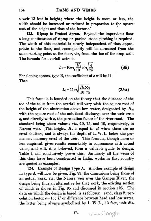
164 DAMS AND WEIRS
a weir 13 feet in height; where the height is more or less, the
width should be increased or reduced in proportion to the square
root of the height and that of the factor c.
123. Riprap to Protect Apron. Beyond the impervious floor
a long continuation of riprap or packed stone pitching is required.
The width of this material is clearly independent of that appro
priate to the floor, and consequently will be measured from the
same starting point as the floor, viz, from the toe of the drop wall.
The formula for overfall weirs is
L (35)
For sloping aprons, type B, the coefficient of c will be 11
Then
Il=l
This formula is founded on the theory that the distance of the
toe of the talus from the overfall will vary with the square root of
the height of the obstruction above low water, designated by Hb,
with the square root of the unit flood discharge over the weir crest
q, and directly with c, the percolation factor of the river sand. The
standard being these values;. viz, 10, 75, and 10, respectively, in
Narora weir. This height, Hb is equal to H when there are no
crest shutters, and is always the depth of L. W. L. below the per
manent masonry crest of the weir. This formula, though more or
less empirical, gives results remarkably in consonance with actual
value, and will, it is believed, form a valuable guide to design.
Table I will conclusively prove this. As nearly all the weirs of
this class have been constructed in India, works in that country
are quoted as examples.
124. Example of Design Type A. Another example of design
in type A will now be given, Fig. 93, the dimensions being those of
an actual work, viz, the Narora weir over the Ganges River, the
design being thus an alternative for that work, the existing section
of which is shown in Fig. 95 and discussed in section 125. The
data on which the design is based, is as follows: sand, class 2; per
colation factor c= 15; // or difference between head and low water,
the latter being always symbolized by L. W. L., 13 feet, unit dis-
174
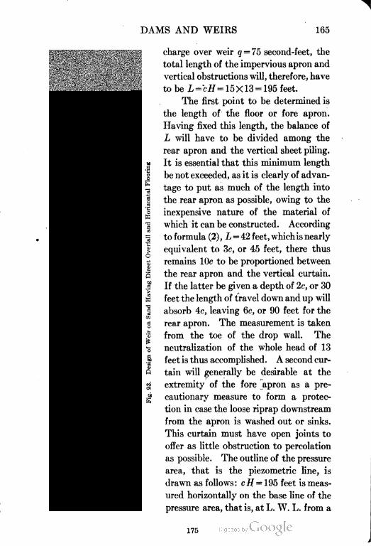
DAMS AND WEIRS 165
£*s-
? «
charge over weir q = 75 second-feet, the
total length of the impervious apron and
vertical obstructions will, therefore, have
to be L = cH = 15X13 = 195 feet.
The first point to be determined is
the length of the floor or fore apron.
Having fixed this length, the balance of
L will have to be divided among the
rear apron and the vertical sheet piling.
It is essential that this minimum length
be not exceeded, as it is clearly of advan
tage to put as much of the length into
the rear apron as possible, owing to the
inexpensive nature of the material of
which it can be constructed. According
to formula (2), L = 42 feet, which is nearly
equivalent to 3c, or 45 feet, there thus
remains lOc to be proportioned between
the rear apron and the vertical curtain.
If the latter be given a depth of 2c, or 30
feet the length of travel down and up will
absorb 4c, leaving 6c, or 90 feet for the
rear apron. The measurement is taken
from the toe of the drop wall. The
neutralization of the whole head of 13
feet is thus accomplished. A second cur
tain will generally be desirable at the
extremity of the fore apron as a pre
cautionary measure to form a protec
tion in case the loose riprap downstream
from the apron is washed out or sinks.
This curtain must have open joints to
offer as little obstruction to percolation
as possible. The outline of the pressure
area, that is the piezometric line, is
drawn as follows: cH = 195 feet is meas
ured horizontally on the base line of the
pressure area, that is, at L. W. L. from a
175

08
A
17G
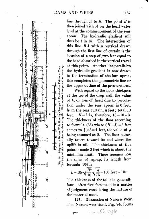
DAMS AND WEIRS 167
l!o a
'". ;
n•
s, s
^1.at
^' "rt
II
1!
line through A to B. The point B is
then joined with A on the head water
level at the commencement of the rear
apron. The hydraulic gradient will
thus be 1 in 15. The intersection of
this line BA with a vertical drawn
through the first line of curtain is the
location of a step of two feet equal to
the head absorbed in the vertical travel
at this point. Another line parallel to
the hydraulic gradient is now drawn
to the termination of the fore apron,
this completes the piezometric line or
the upper outline of the pressure area.
With regard to the floor thickness
at the toe of the drop wall, the value
of /;, or loss of head due to percola
tion under the rear apron, is 6 feet,
from the rear curtain, 4 feet; total 10
feet. H-h is, therefore, 13-10 = 3.
The thickness of the floor according
to formula (33) where ( H — h) = 3 feet
comes to f X 3 = 4 feet, the value of p
being assumed at 2. The floor natur
ally tapers toward its end where the
uplift is nil. The thickness at this
point is made 3 feet which is about the
minimum limit. There remains now
the talus of riprap, its length from
formula (35) is
feet = 10cL = 10c -\l =
' 10 ' 4o
The thickness of the talus is generally
four—often five feet—and is a matter
of judgment considering the nature of
the material used.
125. Discussion of Narora Weir.
The Narora weir itself, Fig. 94, forms
177
168 DAMS AND WEIRS
a most instructive object lesson, demonstrating what is the least
correct base width, or length of percolation consistent with absolute
safety,, that can be adopted for sands of class 2. The system of
analyzing graphically an existing work with regard to hydraulic
gradient is exemplified in Fig. 95 under three separate conditions;
first, as the work originally stood, with a hydraulic gradient of 1 in
11.8; second, at the time of failure, when the floor and the grouted
riprap blew up. On this occasion owing to the rear apron having
been washed away by a flood the hydraulic grade fell to 1 in 8;
third, after the extension of the rear apron and curtailment of the
fore apron had been effected. Under the first conditions the hori
zontal component of the length of travel or percolation L from A
to £ is 123 feet. The total length is made up of three parts: First,
a step down and up in the foundation of the drop wall of 7 feet;
second, a drop down and up of 12 feet either side of the downstream
curtain wall; third, the horizontal distance 123 as above. The rise
at the end of the floor is neglected. The total value of L is then
123+7+12+12 = 154. This is set out on a horizontal line to the
point C. AC is then the hydraulic gradient.
This demonstrates that the hydraulic gradient was originally
something under 1 in 12, and in addition to this the floor is very
deficient in thickness. The hydrostatic pressure on the floor at the
toe of the drop wall is 8 feet. To meet this the floor has a value of
tp of only 5 feet. The specific gravity of the floor will not exceed
2, as it was mostly formed of broken brick concrete in hydraulic
mortar. The value of p — 1 will, therefore, be unity, the floor being
submerged. In spite of this, the work stood intact to all external
appearance for twenty years, when a heavy freshet in the river set
up a cross current which washed out that portion of the rear apron
nearest the drop wall, thus rendering the rest useless, the connection
having been severed.
On this occurrence, failure at once took place, as the floor had
doubtless been on the point of yielding for some time. In fact, this
state of affairs had been suspected, as holes bored in the floor very
shortly before the actual catastrophe took place showed that a large
space existed below it, full, not of sand, but of water. Thus the
floor was actually held up by the hydrostatic pressure; otherwise it
must have collapsed. The removal of the rear apron caused this
178
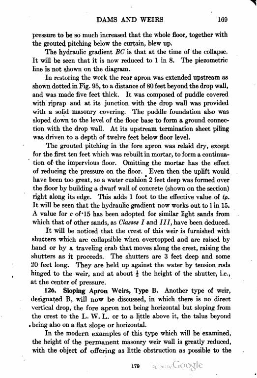
DAMS AND WEIRS 169
pressure to be so much increased that the whole floor, together with
the grouted pitching below the curtain, blew up.
The hydraulic gradient BC is that at the time of the collapse.
It will be seen that it is now reduced to 1 in 8. The piezometric
line is not shown on the diagram.
In restoring the work the rear apron was extended upstream as
shown dotted in Fig. 95, to a distance of 80 feet beyond the drop wall,
and was made five feet thick. It was composed of puddle covered
with riprap and at its junction with the drop wall was provided
with a solid masonry covering. The puddle foundation also was
sloped down to the level of the floor base to form a ground connec
tion with the drop wall. At its upstream termination sheet piling
was driven to a depth of twelve feet below floor level.
The grouted pitching in the fore apron was relaid dry, except
for the first ten feet which was rebuilt in mortar, to form a continua
tion of the impervious floor. Omitting the mortar has the effect
of reducing the pressure on the floor. Even then the uplift would
have been too great, so a water cushion 2 feet deep was formed over
the floor by building a dwarf wall of concrete (shown on the section)
right along its edge. This adds 1 foot to the effective value of tp.
It will be seen that the hydraulic gradient now works out to 1 in 15.
A value for c of' 15 has been adopted for similar light sands from
which that of other sands, as Classes I and III, have been deduced.
It will be noticed that the crest of this weir is furnished with
shutters which are collapsible when overtopped and are raised by
hand or by a traveling crab that moves along the crest, raising the
shutters as it proceeds. The shutters are 3 feet deep and some
20 feet long. They are held up against the water by tension rods
hinged to the weir, and at about | the height of the shutter, i.e.,
at the center of pressure.
126. Sloping Apron Weirs, Type B. Another type of weir,
designated B, will now be discussed, in which there is no direct
vertical drop, the fore apron not being horizontal but sloping from
the crest to the L. W. L. or to a little above it, the talus beyond
. being also on a flat slope or horizontal.
In the modern examples of this type which will be examined,
the height of the permanent masonry weir wall is greatly reduced,
with the object of offering as little obstruction as possible to the
179
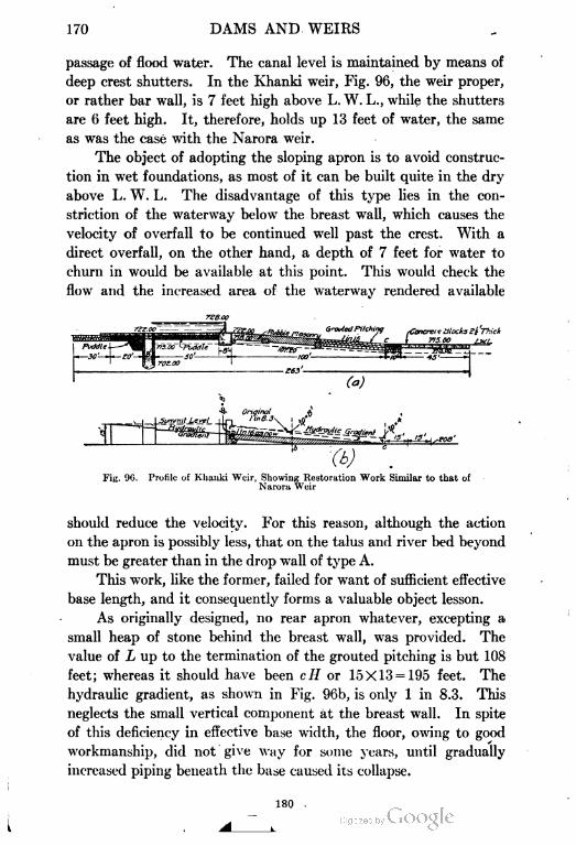
170 DAMS AND. WEIRS
passage of flood water. The canal level is maintained by means of
deep crest shutters. In the Khanki weir, Fig. 96, the weir proper,
or rather bar wall, is 7 feet high above L. W. L., while the shutters
are 6 feet high. It, therefore, holds up 13 feet of water, the same
as was the case with the Narora weir.
The object of adopting the sloping apron is to avoid construc
tion in wet foundations, as most of it can be built quite in the dry
above L. W. L. The disadvantage of this type lies in the con
striction of the waterway below the breast wall, which causes the
velocity of overfall to be continued well past the crest. With a
direct overfall, on the other hand, a depth of 7 feet for water to
churn in would be available at this point. This would check the
flow and the increased area of the waterway rendered available
(t)
Fig. 96. Profile of Khauki Weir, Showing Restoration Work Similar to that of
Narora Wuir
should reduce the velocity. For this reason, although the action
on the apron is possibly less, that on the talus and river bed beyond
must be greater than in the drop wall of type A.
This work, like the former, failed for want of sufficient effective
base length, and it consequently forms a valuable object lesson.
As originally designed, no rear apron whatever, excepting a
small heap of stone behind the breast wall, was provided. The
value of L up to the termination of the grouted pitching is but 108
feet; whereas it should have been c# or 15X13 = 195 feet. The
hydraulic gradient, as shown in Fig. 96b, is only 1 in 8.3. This
neglects the small vertical component at the breast wall. In spite
of this deficiency in effective base width, the floor, owing to good
workmanship, did not give way for some years, until gradually
increased piping beneath the base caused its collapse.
180 .
DAMS AND WEIRS 171
Owing to the raised position of the apron, it is not subject to
high hydrostatic pressure. At its commencement it is ten feet
below the summit level and nine feet of water acts at this point.
This is met by four feet of masonry unsubmerged, of s.g. 2, which
almost balances it. Thus the apron did not blow up, as was the case
with the Narora weir, but collapsed.
Some explanation of the graphical pressure diagram is required,
as it offers some peculiarities, differing from the last examples.
The full head, or //, is 13 feet. Owing, however, to the raised and
sloping position of the apron, the base line of the pressure area will
not be horizontal and so coincide with the L. W. L., but will be an
inclined line from the commencement a to the point b, where the
sloping base coincides with the L. W. L. From b where L. W. L. is
reached onward, the base will be horizontal. With a sloping apron
the pressure is nearly uniform, the water-pressure area is not wedge
shaped but approximates to a rectangle. The apron, therefore, is
also properly rectangular in profile, whereas in the overfall type
the profile is, or should be, that of a truncated wedge.
127. Restoration of Khanki Weir. After the failure of this
work the restoration was on very similar lines to that of the Narora
weir. An impervious rear apron, seventy feet long, was constructed
of puddle covered with concrete slabs, grouted in the joints. A rear
curtain wall consisting of a line of rectangular undersunk blocks
twenty feet deep, was provided. These additions have the effect
of reducing the gradient to 1 in 16. The masonry curtain having
regard to its great cost is of doubtful utility. A- further prolonga
tion of the rear apron or else a line of sheet piling would, it is deemed,
have been equally effective. Reinforced-concrete sheet piling is
very suitable for curtain walls in sand and is bound to supplant the
ponderous and expensive block curtain walls which form so marked
a feature in Indian works.
128. Merala Weir. Another weir on the same principle and
quite recently constructed is the Merala weir at the head of the
same historic river, the Chenab, known as the "Hydaspes" at the
time of Alexander the Great.
This weir, a section of which is given in Fig. 97, is located in the
upper reaches of the river and is subjected to very violent floods;
consequently its construction has to be abnormally strong to resist
181
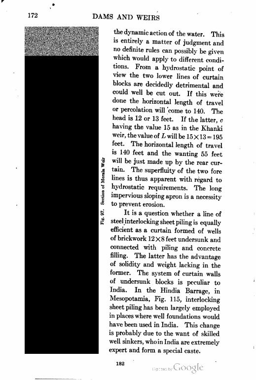
172 DAMS AND WEIRS
Ms-
the dynamic action of the water. This
is entirely a matter of judgment and
no definite rules can possibly be given
which would apply to different condi
tions. From a hydrostatic point of
view the two lower lines of curtain
blocks are decidedly detrimental and
could well be cut out. If this were
done the horizontal length of travel
or percolation will 'come to 140. The
head is 12 or 13 feet. If the latter, c
having the value 15 as in the Khanki
weir, the value of L will be 15x13 = 1 95
feet. The horizontal length of travel
is 140 feet and the wanting 55 feet
will be just made up by the rear cur
tain. The superfluity of the two fore
lines is thus apparent with regard to
hydrostatic requirements. The long
impervious sloping apron is a necessity
to prevent erosion.
It is a question whether a line of
steel interlocking sheet piling is equally
efficient as a curtain formed of wells
of brickwork 12X8 feet undersunk and
connected with piling and concrete
filling. The latter has the advantage
of solidity and weight lacking in the
former. The system of curtain walls
of undersunk blocks is peculiar to
India. In the Hindia Barrage, in
Mesopotamia, Fig. 115, interlocking
sheet piling has been largely employed
in places where well foundations would
have been used in India. This change
is probably due to the want of skilled
well sinkers, who in India are extremely
expert and form a special caste.
182
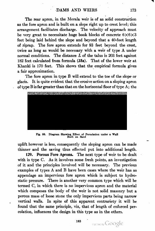
DAMS AND WEIRS 173
The rear apron, in the Merala weir is of as solid construction
as the fore apron and is built on a slope right up to crest level; this
arrangement facilitates discharge. The velocity of approach must
be very great to necessitate huge book blocks of concrete 6X6X3
feet being laid behind the slope and beyond that a 40-foot length
of riprap. The fore apron extends for 93 feet beyond the crest,
twice as long as would be necessary with a weir of type A under
normal conditions. The distance L of the talus is 203 feet against
182 feet calculated from formula (35a). That of the lower weir at
Khanki is 170 feet. This shows that the empirical formula gives
a fair approximation.
The fore apron in type B will extend to the toe of the slope or
glacis. It is quite evident that the erosive action on a sloping apron
of type B is far greater than that on the horizontal floor of type A ; the
Summif Levsl
Tail Wale,
Probable course of waterparticles
underneath wall -—
Fig. 98. Diagram Showing Effect of Percolation under a Wall
Built on Sand
uplift however is less, consequently the sloping apron can be made
thinner and the saving thus effected put into additional length.
129. Porous Fore Aprons. The next type of weir to be dealt
with is type C. As it involves some fresh points, an investigation
of it and the principles involved will be necessary. The previous
examples of types A and B have been cases where the weir has as
appendage an impervious fore apron which is subject to hydro
static pressure. There is another very common type which will be
termed C, in which there is no impervious apron and the material
which composes the body of the weir is not solid masonry but a
porous mass of loose stone the only impervious parts being narrow
vertical walls. In spite of this apparent contrariety it will be
found that the same principle, viz, that of length of enforced per
colation, influences the design in this type as in the others.
183
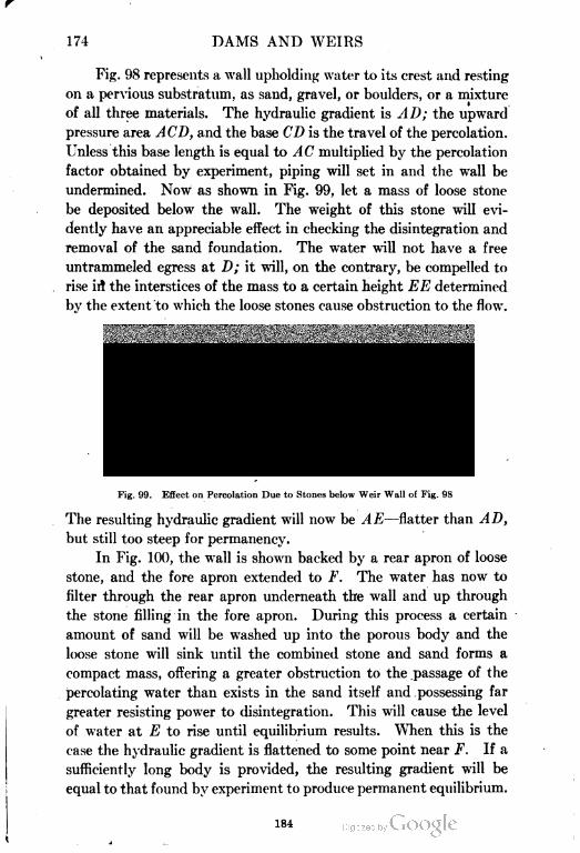
174 DAMS AND WEIRS
Fig. 98 represents a wall upholding water to its crest and resting
on a pervious substratum, as sand, gravel, or boulders, or a mixture
of all three materials. The hydraulic gradient is AD; the upward
pressure area ACD, and the base CD is the travel of the percolation.
Unless this base length is equal to AC multiplied by the percolation
factor obtained by experiment, piping will set in and the wall be
undermined. Now as shown in Fig. 99, let a mass of loose stone
be deposited below the wall. The weight of this stone will evi
dently have an appreciable effect in checking the disintegration and
removal of the sand foundation. The water will not have a free
untrammeled egress at D; it will, on the contrary, be compelled to
rise in" the interstices of the mass to a certain height EE determined
by the extent to which the loose stones cause obstruction to the flow.
Summit Level
Probable course of water particles
Fig. 99. Effect on Percolation Due to Stones below Weir Wall of Fig. 98
The resulting hydraulic gradient will now be AE—flatter than AD,
but still too steep for permanency.
In Fig. 100, the wall is shown backed by a rear apron of loose
stone, and the fore apron extended to F. The water has now to
filter through the rear apron underneath the wall and up through
the stone filling in the fore apron. During this process a certain
amount of sand will be washed up into the porous body and the
loose stone will sink until the combined stone and sand forms a
compact mass, offering a greater obstruction to the passage of the
percolating water than exists in the sand itself and possessing far
greater resisting power to disintegration. This will cause the level
of water at E to rise until equilibrium results. When this is the
case the hydraulic gradient is flattened to some point near F. If a
sufficiently long body is provided, the resulting gradient will be
equal to that found by experiment to produce permanent equilibrium.
184
DAMS AND WEIRS 175
The mass after the sinking process has been
finished is then made good up to the original pro
file by fresh rock filling. At F near the toe of
the slope the stone offers but little resistance
either by its weight or depth ; so it is evident that
the slope of the prism should be flatter than the
hydraulic gradient.
The same action takes place with the rear
apron, which soon becomes so filled with silt, as
to be impervious or nearly so to the passage of
water. But unless silt is deposited in the river
bed behind, as eventually occurs right up to crest
level, the thin portion of the rear slope, as well as
the similar portion of the fore slope, cannot be
counted as effective. Consequently out of the
whole base length this part GF, roughly, about
one-quarter, can be deemed inefficient as regards
length of enforced percolation. As the consoli
dated lower part of the body of the weir gains
in consistency, it can well be subject to hydro
static pressure. Consequently, the value of tp of
the mass should be in excess of that of // — /;, just
as was the case with an impervious floor.
130. Porous Fore Aprons Divided by Core
Walls. In Fig. 101 a still further development is
effected by the introduction of vertical body or
core walls of masonry in the pervious mass of the
fore apron. These impervious obstructions mate
rially assist the stability of the foundation, so
much so that the process of underscour and set
tlement which must precede the balancing of the
opposing forces in the purely loose stone mass
need not occur at all, or to nothing like the same
extent. If the party walls are properly spaced,
the surface slope can be that of the hydraulic-
gradient itself and thus ensure equilibrium. This
is clearly illustrated in the diagram. The water
passing underneath the wall base CD will rise to
-<
£
2£
185
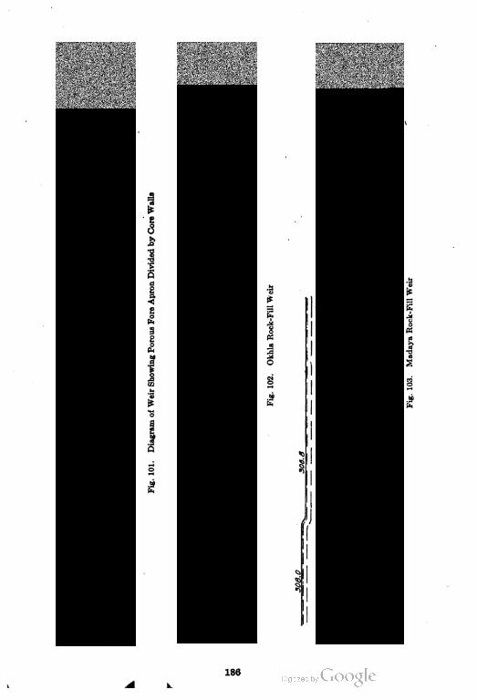
186
DAMS AND WEIRS 177
the level F, the point E being somewhat higher; similar percolation
under the other walls in the substratum will fill all the partitions full
of water. The head AC will, therefore, be split up into four steps.
Value of Rear Apron Very Great. The value of water tightness
in the rear apron is so marked that it should be rendered impervious
by a thick under layer of clay, and not left entirely to more or less
imperfect surface silt stanching, except possibly in the case of high
dams where a still settling pool is formed in rear of the work.
131. Okhla and Madaya Weirs. In Fig. 102 is shown a
detailed section of the Okhla rock-filled weir over the Jumna
River, India. It is remarkable as being the first rock-filled weir
not provided with any lines of curtain walls projecting below
the base line, which has hitherto invariably been adopted. The
stability of its sand foundation is consequently entirely depend
ent on its weight and its effective base length. As will be
seen, the section is provided with two body walls in addition to
the breast wall. The slope of the fore apron is 1 in 20. It is
believed that a slope of 1 in 15 would be equally effective, a hori
zontal talus making up the continuation, as has been done in the
Madaya weir, Fig. 103, which is a similar work but under much
greater stress.
The head of the water in the Okhla weir is 13 feet, with shutters
up and weir body empty of water—a condition that could hardly
exist. This would require an effective base length, L, of 195 feet;
the actual is 250 feet. But, as noted previously, the end parts of
the slopes cannot be included as effective ; consequently the hydraulic
gradient will not be far from 1 in 15. The weight of the stone, or
tp, exactly balances this head at the beginning, as it is 10X1.3 = 13
feet. If the water were at crest level and the weir full of water,
tp would equal 8 feet, or rather a trifle less, owing to the lower level
of the crest of the body wall. The head of 13 feet is broken up
into four steps. The first is 3 feet deep, acting on a part of the
rear apron together with 30 feet of the fore apron, say, 1 in 15; the
rest are 1 in 20. A slope of 1 in 15 for the first party wall would
cut the base at a point 40 feet short of the toe. Theoretically a
fourth party wall is required at this point, but practically the rip
rap below the third dwarf wall is so stanched with sand as not to
afford a free egress for the percolation; consequently the slope may
187
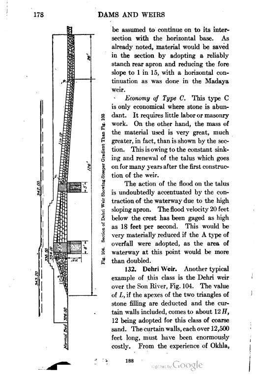
178 DAMS AND WEIRS
be assumed to continue on to its inter
section with the horizontal base. As
already noted, material would be saved
in the section by adopting a reliably
stanch rear apron and reducing the fore
slope to 1 in 15, with a horizontal con
tinuation as was done in the Madaya
weir.
Economy of Type C. This type C
is only economical where stone is abun-
§ dant. It requires little labor or masonry
> work. On the other hand, the mass offe
g the material used is very great, much
H greater, in fact, than is shown by the sec-
s tion. This is owing to the constant sink-
J ing and renewal of the talus which goes
| on for many years after the first construc-
| tion of the weir.
.a The action of the flood on the talus
| is undoubtedly accentuated by the con-
5 traction of the waterway due to the high
•c sloping apron. The flood velocity 20 feet
Q below the crest has been gaged as high
a as 18 feet per second. This would be
1 very materially reduced if the A type of
overfall were adopted, as the area of
2 waterway at this point would be more
£ than doubled.
132. Dehri Weir. Another typical
example of this class is the Dehri weir
over the Son River, Fig. 104. The value
of L, if the apexes of the two triangles of
stone filling are deducted and the cur
tain walls included, comes to about 12 H,
12 being adopted for this class of coarse
sand. The curtain walls, each over 12,500
feet long, must have been enormously
costly. From the experience of Okhla,
188
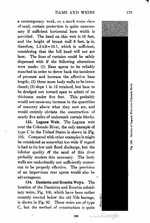
DAMS AND WEIRS 170
a contemporary work, on a much worse class
of sand, curtain protection is quite unneces
sary if sufficient horizontal base width is
provided. The head on this weir is 10 feet,
and the height of breast wall 8 feet, tp is,
therefore, 1.3X8=10.1, which is sufficient,
considering that the full head will not act
here. The lines of curtains could be safely
dispensed with if the following alterations
were made: (1) Rear apron to be reliably
stanched in order to throw back the incidence
of pressure and increase the .effective base
length ; (2) three more body walls to be intro
duced; (3) slope 1 in 12 retained, but base to
be dredged out toward apex to admit of no
thickness under five feet. This probably
would not cause any increase in the quantities
of masonry above what they now are, and
would entirely obviate the construction of
nearly five miles of undersunk curtain blocks.
133. Laguna Weir. The Laguna weir
over the Colorado River, the only example of
type C in the United States is shown in Fig.
105. Compared with other examples it might
be considered as somewhat too wide if regard
is had to its low unit flood discharge, but the
inferior quality df the sand of this river
probably renders this necessary. The body
walls are undoubtedly not sufficiently numer
ous to be properly effective. The provision
of an impervious rear apron would also be
advantageous.
134. Damietta and Rosetta Wejrs. The
location of the Damietta and Rosetta subsid
iary weirs, Fig. 106, which have been rather
recently erected below the old Nile barrage,
is shown in Fig. 92. These weirs are of type
C, but the method of construction is quite
£
I
189
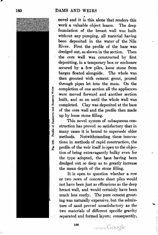
180 DAMS AND WEIRS
i0
*
novel and it is this alone that renders this
work a valuable object lesson. The deep
foundation of the breast wall was built
without any pumping, all material having
been deposited in the water of the Nile
River. First the profile of the base was
dredged out, as shown in the section. Then
the core wall was constructed by first
depositing, in a temporary box or enclosure
secured by a few piles, loose stone from
barges floated alongside. The whole was
then grouted with cement grout, poured
through pipes let into the mass. On the
completion of one section all the appliances
were moved forward and another section
built, and so on until the whole wall was
completed. Clay was deposited at the base
of the core wall and the profile then made
up by loose stone filling.
This novel system of subaqueous con
struction has proved so satisfactory that in
many cases it is bound to supersede older
methods. Notwithstanding these innova
tions in methods of rapid construction, the
' profile of the weir itself is open to the objec
tion of being extravagantly bulky even for
the type adopted, the base having been
dredged out so deep as to greatly increase
the mean depth of the stone filling.
It is open to question whether a row
or two rows of concrete sheet piles would
not have been just as efficacious as the deep
breast wall, and would certainly have been
much less costly. The pure cement grout
ing was naturally expensive, but the admix
ture of sand proved unsatisfactory as the
two materials of different specific gravity
separated and formed layers; consequently,
190
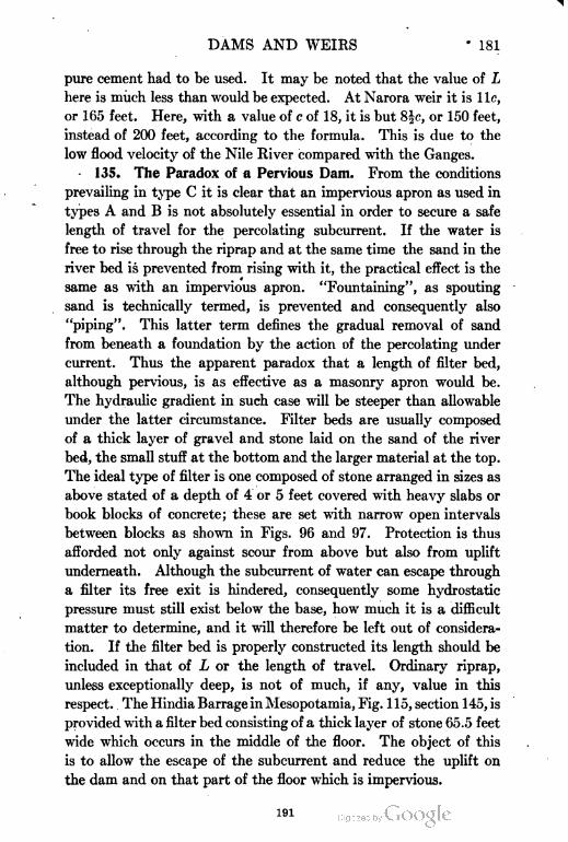
DAMS AND WEIRS • 181
pure cement had to be used. It may be noted that the value of L
here is much less than would be expected. At Narora weir it is lie,
or 165 feet. Here, with a value of c of 18, it is but S|f, or 150 feet,
instead of 200 feet, according to the formula. This is due to the
low flood velocity of the Nile River compared with the Ganges.
135. The Paradox of a Pervious Dam. From the conditions
prevailing in type C it is clear that an impervious apron as used in
types A and B is not absolutely essential in order to secure a safe
length of travel for the percolating subcurrent. If the water is
free to rise through the riprap and at the same time the sand in the
river bed is prevented from rising with it, the practical effect is the
same as with an impervious apron. "Fountaining", as spouting
sand is technically termed, is prevented and consequently also
"piping". This latter term defines the gradual removal of sand
from beneath a foundation by the action of the percolating under
current. Thus the apparent paradox that a length of filter bed,
although pervious, is as effective as a masonry apron would be.
The hydraulic gradient in such case will be steeper than allowable
under the latter circumstance. Filter beds are usually composed
of a thick layer of gravel and stone laid on the sand of the river
bed, the small stuff at the bottom and the larger material at the top.
The ideal type of filter is one composed of stone arranged in sizes as
above stated of a depth of 4 or 5 feet covered with heavy slabs or
book blocks of concrete; these are set with narrow open intervals
between blocks as shown in Figs. 96 and 97. Protection is thus
afforded not only against scour from above but also from uplift
underneath. Although the subcurrent of water can escape through
a filter its free exit is hindered, consequently some hydrostatic
pressure must still exist below the base, how much it is a difficult
matter to determine, and it will therefore be left out of considera
tion. If the filter bed is properly constructed its length should be
included in that of L or the length of travel. Ordinary riprap,
unless exceptionally deep, is not of much, if any, value in this
respect. The Hindia Barrage in Mesopotamia, Fig. 115, section 145, is
provided with a filter bed consisting of a thick layer of stone 65.5 feet
wide which occurs in the middle of the floor. The object of this
is to allow the escape of the subcurrent and reduce the uplift on
the dam and on that part of the floor which is impervious.
191
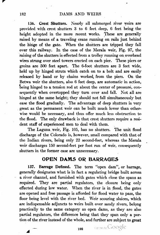
182 DAMS AND WEIRS
136. Crest Shutters. Nearly all submerged river weirs are
provided with crest shutters 3 to 6 feet deep, 6 feet being the
height adopted in the more recent works. These are generally
raised by means of a traveling crane running on rails just behind
the hinge of the gate. When the shutters are tripped they fall
over this railway. In the case of the Merala weir, Fig. 97, the
raising of the shutters is effected from a trolley running on overhead
wires strung over steel towers erected on each pier. These piers or
groins are 500 feet apart. The 6-foot shutters are 3 feet wide,
held up by hinged struts which catch on to a bolt and are easily
released by hand or by chains worked from the piers. On the
Betwa weir the shutters, also 6 feet deep, are automatic in action,
being hinged to a tension rod at about the center of pressure, con
sequently when overtopped they turn over and fall. Not all are
hinged at the same height; they should not fall simultaneously but
ease the flood gradually. The advantage of deep shutters is very
great as the permanent weir can be built much lower than other
wise would be necessary, and thus offer much less obstruction to
the flood. The only drawback is that crest shutters require a resi
dent staff of experienced men to deal with them.
The Laguna weir, Fig. 105, has no shutters. The unit flood
discharge of the Colorado is, however, small compared with that of
the Indian rivers, being only 22 second-feet, whereas the Merala
weir discharges 150 second-feet per foot run of weir, consequently
shutters in the former case are unnecessary.
OPEN DAMS OR BARRAGES
137. Barrage Denned. The term "open dam", or barrage,
generally designates what is in fact a regulating bridge built across
a river channel, and furnished with gates which close the spans as
required. They are partial regulators, the closure being only
effected during low water. When the river is in flood, the gates
are opened and free passage is afforded for flood water to pass, the
floor being level with the river bed. Weir scouring sluices, which
are indispensable adjuncts to weirs built over sandy rivers, belong
practically to the same category as open dams, as they are also
partial regulators, the difference being that they span only a por
tion of the river instead of the whole, and further are subject to great
192
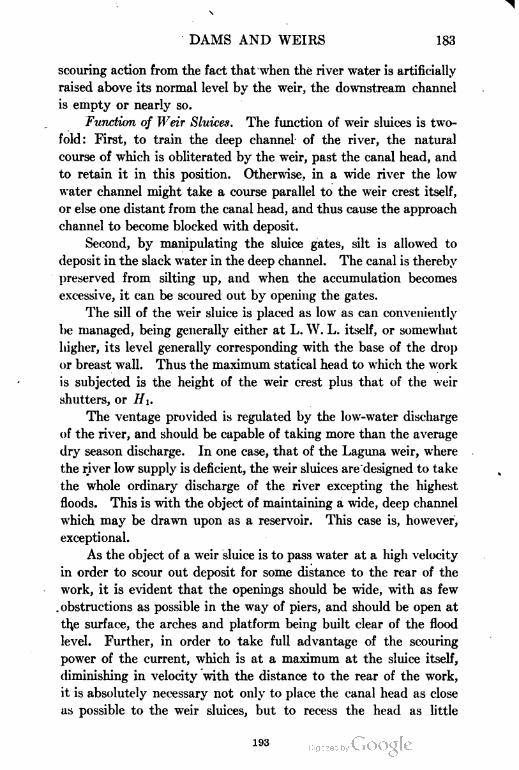
DAMS AND WEIRS 183
scouring action from the fact that when the river water is artificially
raised above its normal level by the weir, the downstream channel
is empty or nearly so.
Function of Weir Sluices. The function of weir sluices is two
fold: First, to train the deep channel of the river, the natural
course of which is obliterated by the weir, past the canal head, and
to retain it in this position. Otherwise, in a wide river the low
water channel might take a course parallel to the weir crest itself,
or else one distant from the canal head, and thus cause the approach
channel to become blocked with deposit.
Second, by manipulating the sluice gates, silt is allowed to
deposit in the slack water in the deep channel. The canal is thereby
preserved from silting up, and when the accumulation becomes
excessive, it can be scoured out by opening the gates.
The sill of the weir sluice is placed as low as can conveniently
be managed, being generally either at L. W. L. itself, or somewhat
higher, its level generally corresponding with the base of the drop
or breast wall. Thus the maximum statical head to which the work
is subjected is the height of the weir crest plus that of the weir
shutters, or HI.
The ventage provided is regulated by the low-water discharge
of the river, and should be capable of taking more than the average
dry season discharge. In one case, that of the Laguna weir, where
the river low supply is deficient, the weir sluices are designed to take
the whole ordinary discharge of the river excepting the highest
floods. This is with the object of maintaining a wide, deep channel
which may be drawn upon as a reservoir. This case is, however,
exceptional.
As the object of a weir sluice is to pass water at a high velocity
in order to scour out deposit for some distance to the rear of the
work, it is evident that the openings should be wide, with as few
obstructions as possible in the way of piers, and should be ojjen at
the surface, the arches and platform being built clear of the flood
level. Further, in order to take full advantage of the scouring
power of the current, which is at a maximum at the sluice itself,
diminishing in velocity with the distance to the rear of the work,
it is absolutely necessary not only to place the canal head as close
as possible to the weir sluices, but to recess the head as little
193
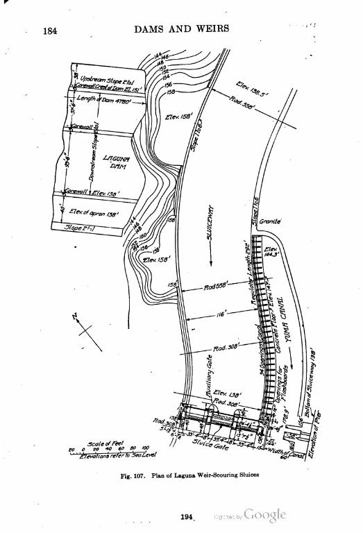
184 DAMS AND WEIRS
Scale of Feet0 ZO 4° 60 SO 1QO
' 'Elevations refer to sea
Fig. 107. Plan of Laguna Weir-Scouring Sluices
194
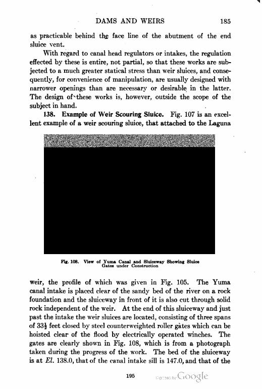
DAMS AND WEIRS 185
as practicable behind the. face line of the abutment of the end
sluice vent.
With regard to canal head regulators or intakes, the regulation
effected by these is entire, not partial, so that these works are sub
jected to a much greater statical stress than weir sluices, and conse
quently, for convenience of manipulation, are usually designed with
narrower openings than are necessary or desirable in the latter.
The design ofsthese works is, however, outside the scope of the
subject in hand.
138. Example of Weir Scouring Sluice. Fig. 107 is an excel
lent example of a weir scouring sluice, that attached to the Laguna
Fig. 108. View of Yuma Canal and Sluiceway Showing Sluice
Gates under Construction
weir, the profile of which was given in Fig. 105. The Yuma
canal intake is placed clear of the sandy bed of the river on a rock
foundation and the sluiceway in front of it is also cut through solid
rock independent of the weir. At the end of this sluiceway and just
past the intake the weir sluices are located, consisting of three spans
of 885 feet closed by steel counterweighted roller gates which can be
hoisted clear' of the flood by electrically operated winches. The
gates are clearly shown in Fig. 108, which is from a photograph
taken during the progress of the work. The bed of the sluiceway
is at El. 138.0, that of the canal intake sill is 147.0, and that of the
195
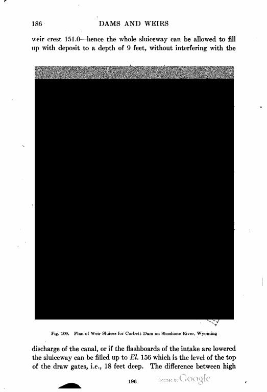
186 DAMS AND WEIRS
weir crest 151.0—hence the whole sluiceway can be allowed to fill
up with deposit to a depth of 9 feet, without interfering with the
Fig. 109. Plan of Weir Sluices for Corbett Dam on Shoshone River, Wyoming
discharge of the canal, or if the flashboards of the intake are lowered
the sluiceway can be filled up to El. 156 which is the level of the top
of the draw gates, i.e., 18 feet deep. The difference between high
196
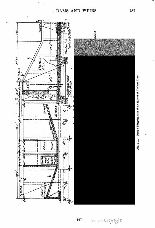
DAMS AND WEIRS 187
197
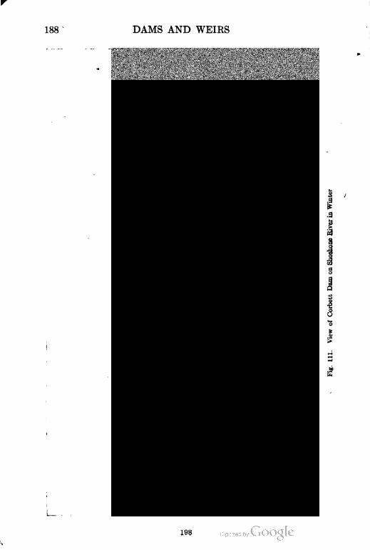
188 DAMS AND WEIRS
i.a
8
a
198
DAMS AND WEIRS 189
s
water above and below the sluice gates
is 11 feet, consequently when the gates
are lifted immense scour must take place
and any deposit be rapidly removed.
The sluiceway is in fact a large silt
trap.
139. Weir Sluices of Corbett Dam.
The weir sluices of the Corbett dam on
the Shoshone River, Wyoming, are given
in Figs. 109, 110, and 111.
The canal takes out through a tun
nel, the head of which has necessarily to
be recessed far behind the location of the
weir sluices. Unless special measures
were adopted, the space between the
sluice gates and the tunnel head would
fill up with sand and deposit and block
the entrance.
To obviate this a wall 8 feet high is
built encircling the entrance. A "divide"
wall is also run out upstream of the weir
sluices, cutting them off from the weir
and its approaches. The space between
these two walls forms a sluiceway which
draws the current of the river in a low
stage past the canal head and further
forms a large silt trap which can be
scoured out when convenient. Only a
thin film of surface water can overflow
the long encircling wall, then it runs down
a paved warped slope which leads it into
the head gates, the heavy silt in suspen
sion being deposited in the sluiceway.
This arrangement is admirable.
The fault of the weir sluices as built
is the narrowness of the openings which
consist of three spans of 5 feet. One
span of 12 feet would be much more
199
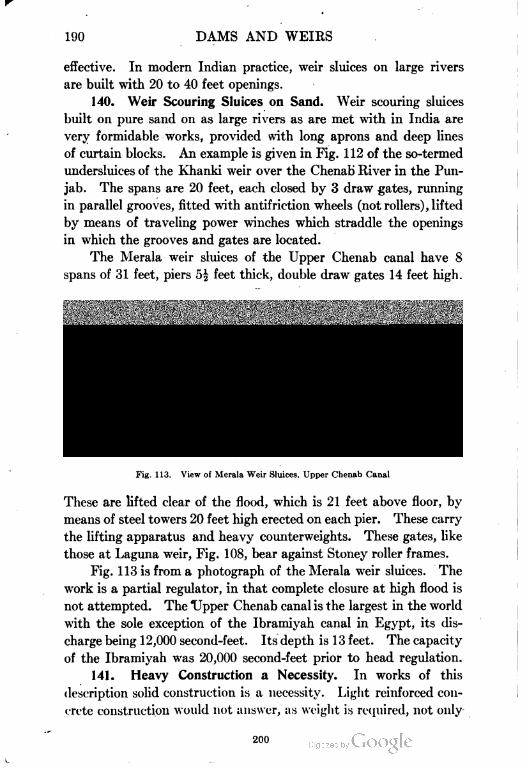
190 DAMS AND WEIRS
effective. In modern Indian practice, weir sluices on large rivers
are built with 20 to 40 feet openings.
140. Weir Scouring Sluices on Sand. Weir scouring sluices
built on pure sand on as large rivers as are met with in India are
very formidable works, provided with long aprons and deep lines
of curtain blocks. An example is given in Fig. 112 of the so-termed
undersluices of the Khanki weir over the Chenab River in the Pun
jab. The spans are 20 feet, each closed by 3 draw gates, running
in parallel grooves, fitted with antifriction wheels (not rollers), lifted
by means of traveling power winches which straddle the openings
in which the grooves and gates are located.
The Merala weir sluices of the Upper Chenab canal have 8
spans of 31 feet, piers 5| feet thick, double draw gates 14 feet high.
Fig. 113. View of Merala Weir Sluices, Upper Chenab Canal
These are lifted clear of the flood, which is 21 feet above floor, by
means of steel towers 20 feet high erected on each pier. These carry
the lifting apparatus and heavy counterweights. These gates, like
those at Laguna weir, Fig. 108, bear against Stoney roller frames.
Fig. 113 is from a photograph of the Merala weir sluices. The
work is a partial regulator, in that complete closure at high flood is
not attempted. The Upper Chenab canal is the largest in the world
with the sole exception of the Ibramiyah canal in Egypt, its dis
charge being 12,000 second-feet. Its depth is 13 feet. The capacity
of the Ibramiyah was 20,000 second-feet prior to head regulation.
141. Heavy Construction a Necessity. In works of this
description solid construction is a necessity. Light reinforced con
crete construction would not answer, as weight is required, not only
200
DAMS AND WEIRS 191
to withstand the hydrostatic pressure but the dynamic effects of
flood water in violent motion. Besides which widely distributed
weight is undoubtedly necessary for works built on the shifting
sand of a river bed, although this is a matter for which no definite
rules can be formed.
201
192 DAMS AND WEIRS
The weir sluices at Laguna and also at the Corbett dam, are
solid concrete structures without reinforcement.
In the East, generally, reinforced concrete is not employed nor
is even cement concrete except in wet foundations, the reason
being that cement, steel, and wood for forms are very expensive
items whereas excellent natural hydraulic lime is generally avail
able, skilled and unskilled labor is also abundant. A skilled mason's
wages are about 10 to 16 cents and a laborer's 6 to 8 cents for a
12-hour day. Under such circumstances the employment of rein
forced cement concrete is entirely confined to siphons where tension
has to be taken care of.
In America, on the other hand, the labor conditions are such
that reinforced concrete which requires only unskilled labor and is
mostly made up by machinery, is by far the most suitable form of \
construction from point of view of cost as well as convenience.
This accounts for the very different appearance of irrigation
works in the East from those in the West. Both are suitable under
the different conditions that severally exist.
142. Large Open Dams across Rivers. Of open dams built
across rivers, several specimens on a large scale exist in Egypt.
These works, like weir sluices are partial regulators and allow free
passage to flood water.
Assiut Barrage. In the Assiut barrage, Figs. 114 and 115,*
constructed across the Nile above the Ibramiyah canal head
in lower Egypt, the foundations are of sand and silt of a worse
quality than is met with in the great Himalayan rivers. The
value of c adopted for the Nile is 18, against 15 for Himalayan rivers.
This dam holds up 5 meters of water, the head or difference of
levels being 3 meters. Having regard to uplift, the head is the
difference of levels but when considering overturning moment, on
the piers, is the moment, // and h being the respective
6 6
depths of water above and below the gates. It is believed that in
the estimation of the length of travel the vertical sheet piling was
left out of consideration. Inspection of the section in Fig. 115
* In Figs. 115 and 116 and in the discussion of these problems in the text, the metric dimen
sions used in the plans of the works have been retained. Meters multiplied by the factor
3.28 will give the proper values in feet.
202
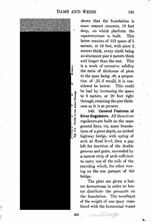
DAMS AND WEIRS 193
shows that the foundation is
mass cement concrete, 10 feet
deep, on which platform the
superstructure is built. This
latter consists of 122 spans of 5
meters, or 16 feet, with piers 2.
meters thick, every ninth being
an abutment pier 4 meters thick
and longer than the rest. This
is a work of excessive solidity
the ratio of thickness of piers
to the span being .48, a propor
tion of .33 S would, it is con
sidered be better. This could
be had by increasing the spans
to 6 meters, or 20 feet right
through, retaining the pier thick
ness as it is at present.
143. General Features of
River Regulators. All these river
regulators are built on the same
general lines, viz, mass founda
tions of a great depth, an arched
highway bridge, with spring of
arch at flood level, then a gap
left for insertion of the double
grooves and gates, succeeded by
a narrow strip of arch sufficient
to carry one of the rails of the
traveling winch,. the other rest
ing on the one parapet of the
bridge.
The piers are given a bat
ter downstream in order to bet
ter distribute the pressure on
the foundation. The resultant
of the weight of one span com
bined with the horizontal water
203
194 DAMS AND WEIRS
pressure must fall within the middle third of the base of the pier,
the length of which can be manipulated to bring this about. In
this case it does so even with increase of the span to 6 meters.
This combined work is of value considered from a military point
of view, as affording a crossing of the Nile River; consequently
the extreme solidity of its construction was probably considered a
necessity.
In some regulators girders are substituted for arches, in others
as we have noted with regard to the Merala weir sluices, the super
structure above the flood line is open steel work of considerable
height.
144. Stability of Assiut Barrage. The hydraulic gradient in
Fig. 115, neglecting the vertical sheet piling, is drawn on the profile
and is the line AB, the horizontal distance is 43 meters while the
head is 3 meters. The slope is therefore 1 in 14£. The uplift is
the area enclosed between AB and a horizontal through B which is
only 1.4 meters at its deepest part near the gates. Upstream of
the gates the uplift is more than balanced by the weight of water
overlying the floor. The horizontal travel of the percolation is from
A to B plus the length of the filter as explained in section 135.
The horizontal travel is therefore 5H meters and the ratio —, or
H
51 5c, is—^- = 17.2. The piezometric line has also been shown, includ-
o
ing in this case the two vertical obstructions. Their effect on the
uplift is very slight, owing to the fore curtain which raises the grade
line. The slope in this case is obtained by adding the vertical to
the horizontal travel, i.e., from B to D, BC and CD being 8 meters
each in length, AD is then the hydraulic gradient which is 1 in 23.
Steps occur at points b and c; for instance the line AB is part of
AD, the line be is parallel to AD drawn up from C, and the line
cB is similarly drawn up from B forming the end step.
This work is the first to be built with a filter downstream,
which has the practical effect of adding to the length of percolation
travel irrespective of the hydraulic grade.
145. The Hindia Barrage. The Hindia barrage, quite recently
erected over the Euphrates River near Bagdad, is given in Fig. 116.
This work, which was designed by Sir William Willocks, bears a
204
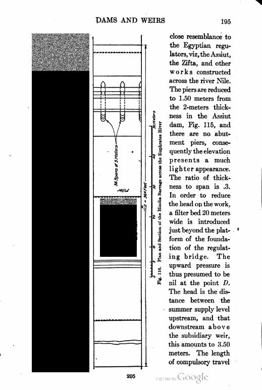
PAMS AND WEIRS 195
Di
I
I*>
Is
close resemblance to
the Egyptian regu
lators, viz, the Assiut,
the Zifta, and other
works constructed
across the river Nile.
The piers are reduced
to 1.50 meters from
the 2-meters thick
ness in the Assiut
dam, Fig. 115, and
there are no abut
ment piers, conse
quently the elevation
presents a much
lighter appearance.
The ratio of thick
ness to span is .3.
In order to reduce
the head on the work,
a filter bed 20 meters
wide is introduced
just beyond the plat
form of the founda
tion of the regulat
ing bridge. The
upward pressure is
thus presumed to be
nil at the point D.
The head is the dis
tance between the
summer supply level
upstream, and that
downstream above
the subsidiary weir,
this amounts to 3.50
meters. The length
of compulsory travel
205
196 DAMS AND WEIRS
from A to B including .50 meter due to the sheet piling is 36.50-
36 5meters. AB is then the hydraulic gradient, which is 1 in —'—
6.5
= 1 in 10.4. The piezometric line DFC is drawn up from D parallel
to AB. The area of uplift is DGHEF; that part of the uplift
below the line DE is however accounted for by assuming all
masonry situated below El. 27.50 as reduced in weight by flota
tion, leaving the area DEF as representing the uplift still unac
counted for.
Beyond the filter is a 21-meter length of impervious apron con
sisting of clay puddle covered by stone paving, which abuts on a
masonry subsidiary weir. This wall holds the water up one meter
in depth and so reduces the head to that extent, with the further
addition of the depth of film passing over the crest at low water
which is .5 meter, total reduction 1.50 meters.
This is the first instance of the use of puddle in a fore apron,
or talus; its object is, by the introduction of an impervious rear
apron 2 1 meters long, to prevent the subsidiary weir wall from being
undermined. The head being 1| meters, the length. of travel
required, taking c as 18, will be 18X1.5 = 27 meters. The actual
length of travel provided is vertical 15, horizontal 41, total 56
meters; more than double what is strictly requisite. The long
hearth of solid masonry which is located below the subsidiary drop
wall is for the purpose of withstanding scour caused by the over
fall. Beyond this is the talus of riprap 20 meters wide and a row
of sheet piling. The total length of the floor of this work is 364
feet, with three rows of sheet piles. That of the Assiut barrage
is 216 feet with two rows of sheeting. The difference in head is
half a meter only, so that certain unknown conditions of flood or
that of the material in the bed must exist to account for the excess.
146. American vs. Indian Treatment. In American regulat
ing works it is generally the fashion where entire closure is required
to locate the draw gates and their grooves inside the panel or bulk
head wall that closes the upper part of the regulator above the
sluice openings. Thus when the gates are raised they are concealed
behind the panel walls. In Indian practice the gate grooves in the
piers are generally located outside the bulkhead wall; thus when
hoisted, the gates are visible and accessible. Fig. 117 is from a
206
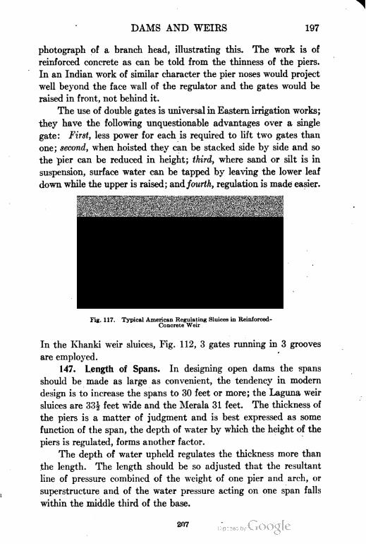
DAMS AND WEIRS 197
photograph of a branch head, illustrating this. The work is of
reinforced concrete as can be told from the thinness of the piers.
In an Indian work of similar character the pier noses would project
well beyond the face wall of the regulator and the gates would be
raised in front, not behind it.
The use of double gates is universal in Eastern irrigation works;
they have the following unquestionable advantages over a single
gate: First, less power for each is required to lift two gates than
one; second, when hoisted they can be stacked side by side and so
the pier can be reduced in height; third, where sand or silt is in
suspension, surface water can be tapped by leaving the lower leaf
down while the upper is raised; and fourth, regulation is made easier.
Fig. 117. Typical American Regulating Sluices in Reinforced-
Concrete Weir
In the Khanki weir sluices, Fig. 112, 3 gates running in 3 grooves
are employed.
147. Length of Spans. In designing open dams the spans
should be made as large as convenient, the tendency in modern
design is to increase the spans to 30 feet or more; the Laguna weir
sluices are 33| feet wide and the Merala 31 feet. The thickness of
the piers is a matter of judgment and is best expressed as some
function of the span, the depth of water by which the height of the
piers is regulated, forms another factor.
The depth of water upheld regulates the thickness more than
the length. The length should be so adjusted that the resultant
line of pressure combined of the weight of one pier and arch, or
superstructure and of the water pressure acting on one span falls
within the middle third of the base.
207
198 DAMS AND WEIRS
For example take the Assiut regulator, Fig. 115. The con
tents of one pier and span allowing for uplift is roughly 390 cubic
meters of masonry, an equivalent to 1000 tons. The incidence of
W is about 2 meters from the middle third downstream boundary.
The moment of the weight about this point is therefore 1000 X
2 = 2000 meter tons. Let H be depth of water upstream, and h
downstream, then the overturning moment is expressed by
o
Here H = 5, h = 2 meters, w = l.l tons per cubic meter, the length I
of one span is 7 meters; then the moment=— —'-——=150
meter tons. The moment of resistance is therefore immensely in excess
of the moment of water pressure. The height of the pier is however
governed by the high flood level, the width by the necessity of a
highway bridge. At full flood nearly the whole of the -pier will be
immersed in water and so lose weight. There is probably some
intermediate stage when the water pressure will be greater than
that estimated, as would be the case if the gates were left closed
while the water topped them by several feet, the water downstream
not having had time to rise to correspond.
148. Moments for Hindia Barrage. In the case of the Hindia
barrage, Fig. 116, 1I = 5 meters, h = 1.5, then
,, (125 -3.4) XI. IX 6.50 ...M = = 145 meter tons
6
The weight of one span is estimated at 180 tons. Its moment
about the toe of the base is about 180X6.5 = 1170 meter tons.
The factor of safety against overturning is therefore —— = 8.
14o
The long base of these piers is required for the purpose of
distributing the load over as wide an area as possible in order to
reduce the unit pressure to about one long ton per square foot.
This is also partly the object of the deep mass foundation. The
same result could doubtless be attained with much less material by
adopting a thin floor say two or three feet thick, reinforced by steel
rods so as to ensure the distribution of the weight of the super
structure evenly over the whole base. It seems to the writer that
the Assiut barrage with its mass foundation having been a success
208
DAMS AND WEIRS 199
^
209
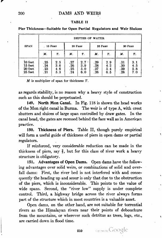
200 DAMS AND WEIRS
TABLE II
Pier Thickness—Suitable for Open Partial Regulators and Weir Sluices
DEPTHS OF WATER
SPAN . 15 FEET 20 FEET 25 FEET 30 FEET
it. T. If. T. M. T. M. T.
lO feet .25 2.5 .27 2.7 .29 2.9 .31 3.1
15 feet .24 3.6 .26 3.9 .28 4.2 .30 4.5
20 feet .23 4.6 .25 5.0 .27 5.4 .29 5.8
25 feet .21 5.3 .24 6.0 .26 6.5 .28 7.0
M is multiplier of span for thickness T.
as regards stability, is no reason why a heavy style of construction
such as this should be perpetuated.
149. North Mon Canal. In Fig. 118 is shown the head works
of the Mon right canal in Burma. The weir is of type A, with crest
shutters and sluices of large span controlled by draw gates. In the
canal head, the gates are recessed behind the face wall as in American
practice.
150. Thickness of Piers. Table II, though purely empirical
will form a useful guide of thickness of piers in open dams or partial
regulators.
If reinforced, very considerable reduction can be made in the
thickness of piers, say §, but for this class of river work a heavy
structure is obligatory.
151. Advantages of Open Dams. Open dams have the follow
ing advantages over solid weirs, or combinations of solid and over
fall dams: First, the river bed is not interfered with and conse
quently the heading up and scour is only that due to the obstruction
of the piers, which is inconsiderable. This points to the value of
wide spans. Second, the "river low" supply is under complete
control. Third, a highway bridge across the river always forms
part of the structure which in most countries is a valuable asset.
Open dams, on the other hand, are not suitable for torrential
rivers as the Himalayan rivers near their points of debouchure
from the mountains, or wherever such detritus as trees, logs, etc.,
are carried down in flood time.
210
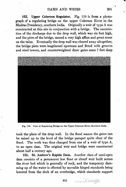
DAMS AND WEIRS 201
152. Upper Coleroon Regulator. Fig. 119 is from a photo
graph of a regulating bridge on the upper Coleroon River in the
Madras Presidency, southern India. Originally a weir of type A was
constructed at this site in conjunction with a bridge. The constric
tion of the discharge due to the drop wall, which was six feet high,
and the piers of the bridge, caused a very high afflux and great scour
on the talus. Eventually the drop wall was cleared away altogether,
the bridge piers were lengthened upstream and fitted with grooves
and steel towers, and counterweighted draw gates some 7 feet deep
Fig. 119. View of Regulating Bridge on the Upper Coleroon River. Southern India
took the place of the drop wall. In the flood season the gates can
be raised up to the level of the bridge parapet quite clear of the
flood. The work was thus changed from one of a weir of type A,
to an open dam. The original weir and bridge were constructed
about half a century ago.
153. St. Andrew's Rapids Dam. Another class of semi-open
dam consists of a permanent low floor or dwarf weir built across
the river bed which is generally of rock, and the temporary dam
ming up of the water is effected by movable hinged standards being
lowered from the deck of an overbridge, which standards support
211
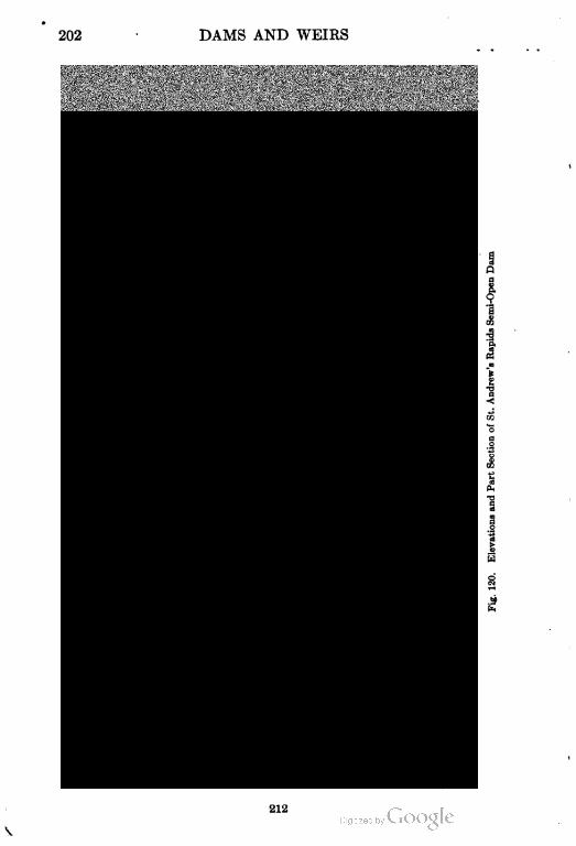
202 DAMS AND WEIRS
212
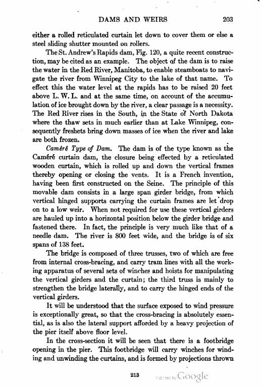
DAMS AND WEIRS 203
either a rolled reticulated curtain let down to cover them or else a
steel sliding shutter mounted on rollers.
The St. Andrew's Rapids dam, Fig. 120, a quite recent construc
tion, may be cited as an example. The object of the dam is to raise
the water in the Red River, Manitoba, to enable steamboats to navi
gate the river from Winnipeg City to the lake of that name. To
effect this the water level at the rapids has to be raised 20 feet
above L. W. L. and at the same time, on account of the accumu
lation of ice brought down by the river, a clear passage is a necessity.
The Red River rises in the South, in the State of North Dakota
where the thaw sets in much earlier than at Lake Winnipeg, con
sequently freshets bring down masses of ice when the river and lake
are both frozen.
Camere Type of Dam. The dam is of the type known as the
Camere curtain dam, the closure being effected by a reticulated
wooden curtain, which is rolled up and down the vertical frames
thereby opening or closing the vents. It is a French invention,
having been first constructed on the Seine. The principle of this
movable dam consists in a large span girder bridge, from which
vertical hinged supports carrying the curtain frames are let drop
on to a low weir. When not required for use these vertical girders
are hauled up into a horizontal position below the girder bridge and
fastened there. In fact, the principle is very much like that of a
needle dam. The river is 800 feet wide, and the bridge is of six
spans of 138 feet.
The bridge is composed of three trusses, two of which are free
from internal cross-bracing, and carry tram lines with all the work
ing apparatus of several sets of winches and hoists for manipulating
the vertical girders and the curtain; the third truss is mainly to
strengthen the bridge laterally, and to carry the hinged ends of the
vertical girders.
It will be understood that the surface exposed to wind pressure
is exceptionally great, so that the cross-bracing is absolutely essen
tial, as is also the lateral support afforded by a heavy projection of
the pier itself above floor level.
In the cross-section it will be seen that there is a footbridge
opening in the pier. This footbridge will carry winches for wind
ing and unwinding the curtains, and is formed by projections thrown
213
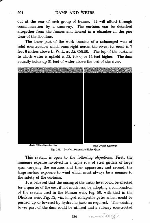
204 DAMS AND WEIRS
out at the rear of each group of frames. It will afford through
communication by a tramway. The curtains can be detached
altogether from the frames and housed in a chamber in the pier
clear of the floodline.
The lower part of the work consists of a submerged weir of
solid construction which runs right across the river; its crest is -7
feet 6 inches above L. W. L. at El. 689.50. The top of the curtains
to which water is upheld is El. 703.6, or 14 feet higher. The dam
actually holds up 31 feet of water above the bed of the river.
Half front Elevation
Fig. 121. Lauchli Automatic Sluice Gate
This system is open to the following objections: First, the
immense expense involved in a triple row of steel girders of large
span carrying the curtains and their apparatus; and second, the
large surface exposure to wind which must always be a menace to
the safety of the curtains.
It is believed that the raising of the water level could be effected
for a quarter of the cost if not much less, by adopting a combination
of the system used in the Folsam weir, Fig. 50, with that in the
Dhukwa weir, Fig. 52, viz, hinged collapsible gates which could be
pushed up or lowered by hydraulic jacks as required. The existing
lower part of the dam could be utilized and a subway constructed
214
DAMS AND WEIRS 205
through it for cross communication and accommodation for the
pressure pipes, as is the case in the Dhukwa weir. This arrange
ment which is quite feasible would, it is deemed, be an improvement
on the expensive, complicated, and slow, Camere curtain system.
154. Automatic Dam or Regulator. Mr. Lauchli of New York,
writing for Engineering News, describes a new design for automatic
regulators, as follows:
In Europe there has been in operation for some time a type of automatic
dam or sluice gate which on account of its simplicity of construction, adapt-
Fig. 122. View of Lauchli Automatic Dam Which Has Been for Several Years
in Successful Operation in Europe
ability to existing structures, exact mathematical treatment, and especially
its successful operation, deserves to attract the attention of the hydraulic engineer
connected with the design of hydroelectric plants or irrigation works. Fig.
121 shows a cross-section and front elevation of one of the above-mentioned
dams now in course of construction, and the view in Fig. 122 gives an idea of
a small automatic dam of the same type which has been in successful operation
for several seasons, including a severe winter, and during high spring floods.
Briefly stated, the automatic dam is composed of a movable part or
panel, resting at the bottom on a knife edge, and fastened at the top to a com
pensating roller made of steel plate and filled with concrete. This roller moves
along a track located at each of its ends, and is so designed as to take, at any
height of water upstream, a position such as will give the apron the inclination
necessary for discharging a known amount of water, and in so doing will keep -
the upper pool at a constant fixed elevation.
With the roller at its highest position the panel lies horizontally, and
the full section is then available for discharging water. Any debris, such as
215
206 DAMS AND WEIRS
trees, or ice cakes, etc., will pass over the dam without any difficulty, even
during excessive floods, as the compensating roller is located high above extreme
flood level.
The dam now in course of construction is located on the river Grafenauer
Ohe, in Bavaria, and will regulate the water level at the intake of a paper mill,
located at some distance from the power house. The dam has a panel 24.27
ft. long, 6.85 ft. high, and during normal water level will discharge 1400 cu. ft.
per sec., while at flood time it will pass 3,530 cu. ft. per sec. of water. As shown
in Fig. 121, the main body of the dam is made of a wooden plank construction
laid on a steel frame. The panel is connected with the compensating roller
at each end by a flexible steel cable wound around the roller end, and then
fastened at the upper part of the roller track to an eyebolt. A simple form of
roof construction protects the roller track from rain and snow. The panel
is made watertight at each extremity by means of galvanized sheet iron held
tight against the abutments by water pressure. This type of construction has
so far proved to be very effective as to watertightness.
It may be needless to point out that this type of dam can also be fitted
to the crest of overflow dam of ordinary cross-section, and then fulfill the duty
of movable flashboards.
The probability is that this type will become largely used in
the future. A suggested improvement would be to abolish the cross
roller having instead separate rollers on each pier or abutment,
working independently. There will then be no practical limit to
the span adopted.
216


TYPICAL IRRIGATING WEIR AND LATERALS FOR ORANGE GROVE AT REDLANDS,
CALIFORNIA
Photo by Underwood and Underwood, New York City
IRRIGATION ENGINEERING
INTRODUCTION
Problem of Irrigation. The control and distribution of water
for irrigation presents to the engineer problems somewhat similar
to those of •the control and distribution of water for domestic and
manufacturing purposes in large cities and towns. The water must
be diverted from a flowing stream at a sufficient elevation to com
mand the territory to be irrigated, or it must be impounded in
reservoirs at a season of floods or of unusual flow due either to the
more-or-less regular recurrence of rainy seasons, or to the melting
of snow and ice. Again, it may be derived from subterranean
sources, either deep or shallow wells, lifted to the proper elevation
by pumps, and applied directly to the land or stored in reservoirs
for future use.
The principal difference between securing a water supply for
domestic and for irrigation purposes is that, in the former case, the
water must be as pure as possible, while in the latter, the impurities
that gather in ponds and streams may not be detrimental for irri
gation purposes. The sewage of many cities, which has a distinct
value as a fertilizer, for example, is used successfully for purposes
of irrigation.
Except where water is scarce and difficult to produce at a rea
sonable cost, and on account of the large quantities of water required
for irrigation, it is not necessary to make such expensive provision
per unit of volume for the distribution of water for irrigation pur
poses as is the case for domestic supply. In the majority of cases
water for irrigation flows in open channels. However, to guard
against loss by evaporation and seepage, it may be necessary to
distribute the water through a system of underground or enclosed
pipes or conduits.
Crude Methods No Longer Adopted. Irrigation works in the
West range from crude and simple ditches, taking their supplies from
mountain brooks where the water has been diverted by means of
small brush dams, to great masonry walls, blocking the outlet of
219
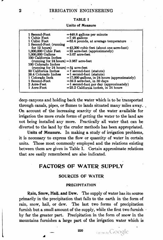
IRRIGATION ENGINEERING
TABLE I
Units of Measure
1 Second-Foot =448.8 gallons per minute
1 Cubic Foot =7.48 gallons
1 Cubic Foot =62.4 pounds, at average temperature
1 Second-Foot (running
for 12 hours) =43,200 cubic feet (about one acre-foot)
1,000,000 Cubic Feet =23 acre-feet (approximately)
1,000,000 Gallons =3.07 acre-feet
100 California Inches
(running for 24 hours) =3.967 acre-feet
100 Colorado Inches
(running for 24 hours) = 5J acre-feet
50 California Inches = 1 second-foot (statute)
38.4 Colorado Inches = 1 second-foot (statute)
1 Colorado Inch = 17,000 gallons, in 24 hours (approximately)
1 Second-Foot =59.5 acre-feet, in 30 days
2 Acre-Feet = 1 second-foot per day (approximately)
1 Acre-Foot =25.2 California inches, in 24 hours
deep canyons and holding back the water which is to be transported
through canals, pipes, or flumes to lands situated many miles away.
On account of the increasing scarcity of the water available for
irrigation the more crude forms of getting the water to the land are
not being installed any more. Practically all water that can be
diverted to the land by the cruder methods has been appropriated.
Units of Measure. In making a study of irrigation problems,
it is necessary to express the flow or quantity of water in certain
units. Those most commonly employed and the relations existing
between them are given in Table I. Certain approximate relations
that are easily remembered are also indicated.
FACTORS OF WATER SUPPLY
SOURCES OF WATER
PRECIPITATION
Rain, Snow, HaiJ, and Dew. The supply of water has its source
primarily in the precipitation that falls to the earth in the form of
rain, snow, hail, or dew. The last two forms of precipitation
furnish but a small amount of the supply, while the first two furnish
by far the greater part. Precipitation in the form of snow in the
mountains furnishes a large part of the irrigation water which is
,
220
IRRIGATION ENGINEERING 3
used directly from the flowing streams, while it also furnishes a good
portion of the water stored for irrigation purposes in the early spring
run-off; and precipitation in the form of rain furnishes the rest of
the storage water.
The moisture of the atmosphere has been evaporated from
water and land areas, and from surfaces of plant foliage and other
objects. The water, after it reaches the earth, may remain for a
time in the form of ice and snow, may run off of the surface directly,
or may soak into the soil and furnish the supply for springs, wells,
and galleries.
Rainfall Influences. In any region where the climate and soil
are adapted to the production of crops, the necessity for irrigation
will depend upon the amount of precipitation available, the season
of the year when this precipitation is available, and the manner in
which the precipitation reaches the earth. The available precipi
tation cannot be judged, however, from the total annual amount.
Where the annual precipitation is less than 20 inches, irrigation is
assumed to be necessary. The arid region of this country is usually
considered as including that area in which the annual precipitation
is below 20 inches—or most of the territory west of the 97th meridian
of longitude. The latitude has considerable influence also. Other
things being equal, it will require a greater amount of precipitation
to produce a crop in the South than in the North. The crops mature
more quickly and the evaporation is less in the North.
As illustrating seasonal influence, irrigation is necessary in Italy,
because, while the annual precipitation averages about 40 inches,
most of this occurs during the winter months or at times other than
the agricultural or cropping season. In certain parts of India, the
rainfall is as high as 100 to 300 inches per annum; and yet nearly all
of this occurs in one or two seasons of the year, and the actual rain
fall during the winter months, when most of the cropping is done,
may be as low as 5 or 10 inches. The cropping season in the arid
West may be taken as occurring between April and August, inclu
sive, and this constitutes the driest season of the year for a large
portion of the West, while it is the wettest for the Northwest.
In referring to the lands of the United States, those of the
extreme West are usually called arid; those between the Mississippi
Valley and the Rocky Mountains, where the rainfall is occasionally
221
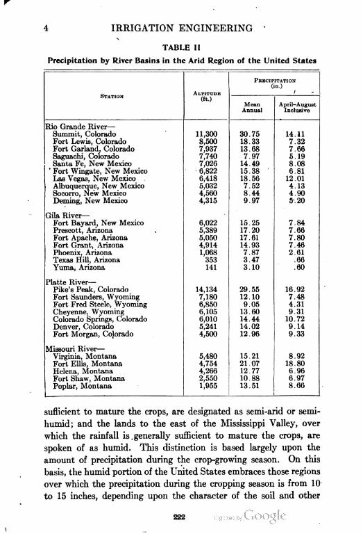
4 IRRIGATION ENGINEERING
-
TABLE II
Precipitation by River Basins in the Arid Region of the United States
STATIONALTITUDE
(ft.)
PRECIPITATION
(in.)
1
Rio Grande River—
Mean
Annual
April-August
Inclusive
Summit, Colorado 11,300 30.75 14.11
Fort Lewis, Colorado 8,500 18.33 7.32
Fort Garland, Colorado 7,937 13.68 7.66
Saguachi, Colorado 7,740 7.97 5.19
Santa Fe, New Mexico 7,026 14.49 8.08
' Fort Wingate, New Mexico 6,822 15.38 6.81
Las Vegas, New Mexico . 6,418 18.56 12.01
Albuquerque, New Mexico 5,032 7.52 4.13
Socorro, New Mexico 4,560 8.44 4.90
Deming, New Mexico 4,315 9.97 fr.20
Gila River-
Fort Bayard, New Mexico 6,022 15.25 7.84
Prescott, Arizona 5,389 17.20 7.66
Fort Apache, Arizona 5,050 17.61 7.80
Fort Grant, Arizona 4,914 14.93 7.46
Phoenix, Arizona 1,068 7.87 2.61
Texas Hill, Arizona 353 3.47 .66
Yuma, Arizona 141 3.10 .60
Platte River-
Pike's Peak, Colorado 14,134 29.55 16.92
Fort Saunders, Wyoming 7,180 12.10 7.48
Fort Fred Steele, Wyoming 6,850 9.05 4.31
Cheyenne, Wyoming 6,105 13.60 9.31
Colorado Springs, Colorado 6,010 14.44 10.72
Denver, Colorado 5,241 14.02 9.14
Fort Morgan, Colorado 4,500 12.96 9.33
Missouri River—
Virginia, Montana 5,480 15.21 8.92
Fort Ellis, Montana 4,754 21.07 18.80
Helena, Montana 4,266 12.77 6.96
Fort Shaw, Montana 2,550 10.88 6.97
Poplar, Montana 1,955 13.51 8.66
i
suflicient to mature the crops, are designated as semi-arid or semi-
humid; and the lands to the east of the Mississippi Valley, over
which the rainfall is generally sufficient to mature the crops, are
spoken of as humid. This distinction is based largely upon the
amount of precipitation during the crop-growing season. On this
basis, the humid portion of the United States embraces those regions
over which the precipitation during the cropping season is from 10
to 15 inches, depending upon the character of the soil and other
222
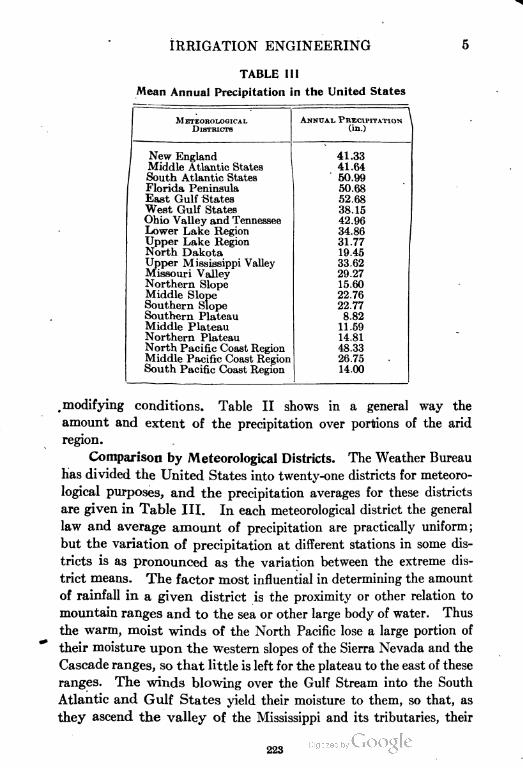
IRRIGATION ENGINEERING
TABLE III
Mean Annual Precipitation in the United States
METEOKOLOGICAL
DISTRICTS
New England
Middle Atlantic States
South Atlantic States
Florida Peninsula
East Gulf States
West Gulf States
Ohio Valley and Tennessee
Lower Lake Region
Upper Lake Region
North Dakota
Upper Mississippi Valley
Missouri Valley
Northern Slope
Middle Slope
Southern Slope
Southern Plateau
Middle Plateau
Northern Plateau
North Pacific Coast Region
Middle Pacific Coast Region
South Pacific Coast Region
ANNUAL, PRECIPITATION
(in.)
41.33
41.64
50.99
50.68
52.68
38.15
42.96
34.86
31.77
19.45
33.62
29.27
15.60
22.76
22.77
8.82
11.59
14.81
48.33
26.75
14.00
, modifying conditions. Table II shows in a general way the
amount and extent of the precipitation over portions of the arid
region.
Comparison by Meteorological Districts. The Weather Bureau
has divided the United States into twenty-one districts for meteoro
logical purposes, and the precipitation averages for these districts
are given in Table III. In each meteorological district the general
law and average amount of precipitation are practically uniform;
but the variation of precipitation at different stations in some dis
tricts is as pronounced as the variation between the extreme dis
trict means. The factor most influential in determining the amount
of rainfall in a given district is the proximity or other relation to
mountain ranges and to the sea or other large body of water. Thus
the warm, moist winds of the North Pacific lose a large portion of
their moisture upon the western slopes of the Sierra Nevada and the
Cascade ranges, so that little is left for the plateau to the east of these
ranges. The winds blowing over the Gulf Stream into the South
Atlantic and Gulf States yield their moisture to them, so that, as
they ascend the valley of the Mississippi and its tributaries, their
223

6 IRRIGATION ENGINEERING
moisture and consequent precipitation decrease. The departure of
the Gulf Stream from the coast north of Cape Hatteras, causes its
influence to be felt to a less extent in precipitation in the North
Atlantic States.
It will be noted that the average rainfall over the northern por
tion of the Pacific Coast would be sufficient for the production of
crops, provided it fell during the proper season of the year. Other
areas may be noted over which the annual rainfall is apparently
sufficient for the maturing of crops. That the amount of precipi
tation is greatly influenced by altitude, is shown by comparing the
relative amounts of precipitation at places having the same latitude.
Thus in the region between Reno, Nevada, and San Francisco,
California, the average annual precipitation in the Sacramento
Valley is about 15 inches; while to the eastward the precipitation
increases in amount with the altitude, until, along the summits of
the mountains, it averages from 50 to 60 inches. Still farther east,
the precipitation again diminishes with the decreasing altitude,
until, in Nevada, it varies from 5 to 10 inches. All through the
West, precipitation in the high mountains is much in excess of that
in the adjacent low valley lands. As a result, while the precipita
tion is often insufficient to mature the crops in the lowlands, suffi
cient precipitation occurs in the mountains to furnish a constant
supply for the perennial discharge of streams or for the filling of
storage reservoirs.
Importance of Consideration. Precipitation, being the primary
source of all water supplies, is the basis of calculation of the amount
of water available from whatever source; and consideration of the
amount and intensity of rainfall is a necessary preliminary to the
design and construction of storage works, whether for purposes of
irrigation or for domestic supply. The amount of rain that will
fall at any one place, in any day, month, or year, cannot be predicted
with certainty by any method known to science. A record of past
rainfalls, however, will afford a guide to our judgment in estimating
the probable amount of future rainfalls, and, in fact, forms practically
the only basis for such judgment. The total annual rainfall is
seldom the same for any two years at the same place, or at any two
places for the same year, and these variations seem to follow no
definite law. A season which is dry at one place, may have con
224
IRRIGATION ENGINEERING 7
ditions entirely the reverse only a few miles away, and the total
annual rainfall of two places only a few miles apart often varies
considerably, especially in a mountainous and arid country.
One of the most important considerations in designing irriga
tion works, and especially storage reservoirs, is the maximum amount
of rainfall which may occur. Great floods are the immediate result
either of heavy, protracted rainstorms, or of the sudden melting of
snow accompanied by rain in the mountains. In nearly all river
valleys, there are periods of maximum rainfall, the recurrence and
effect of which should be given careful study. The following are
. examples of unusual precipitation :
In the neighborhood of Yuma, Arizona, the average annual rainfall is
about 3 inches; but in the last week of February, 1891, 2| inches fell in 24 hours.
In the neighborhood of San Diego, California, the average annual rainfall
is. about 12 inches; but in the storms of 1891, 13 inches fell in 23 hours, and
23| inches in 54 hours.
The average annual discharge of the Salt River in Arizona is about 1000
second-feet, and the average flood discharge is about 10,000 second-feet; yet, as
the result of an unusually violent rainstorm in the spring of 1890, the flood
discharge amounted to 140,000 second-feet. A year later, as the result of a still
more violent storm, the discharge increased to the enormous amount of nearly
300,000 second-feet.
It is of course out of the question to design irrigation works so
that they shall control and safely pass away the flood discharge of
unusual storms such as described above. Such cloudbursts may
occur once in a lifetime, but the increased expenditure necessary to
provide for them is generally unwarranted.
Measurement of Snowfall. Measurements of snow are ordi
narily recorded in inches of fall as found upon a level .surface free
from drifts. It is difficult to obtain an average depth in windy
weather, and the best judgment is essential in ascertaining this.
Generally, besides expressing the depth in inches, a cylinder of snow
of this depth is collected and melted in a tube or can of the same
diameter as the cylinder of snow, and the depth of water resulting
is recorded as precipitation or rainfall.
Measurement of Rainfall. Description of Rain Gage. Meas
urements of rainfall are usually made in this country by means of
the pluviometer, Fig. 1, consisting essentially of a circular cup of
thick brass, its rim brought to a chisel edge, the bottom being cone-
shaped and connected with a deep tube of known diameter into
225
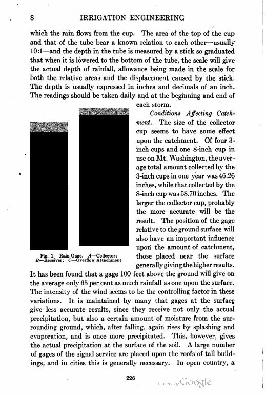
8 IRRIGATION ENGINEERING
'11 Illl
which the rain flows from the cup. The area of the top of the cup
and that of the tube bear a known relation to each other—usually
10:1—and the depth in the tube is measured by a stick so graduated
that when it is lowered to the bottom of the tube, the scale will give
the actual depth of rainfall, allowance being made in the scale for
both the relative areas and the displacement caused by the stick.
The depth is usually expressed in inches and decimals of an inch.
The readings should be taken daily and at the beginning and end of
each storm.
Conditions Affecting Catch
ment.. The size of the collector
cup seems to have some effect
upon the catchment. Of four 3-
inch cups and one 8-inch cup in
use on Mt. Washington, the aver
age total amount collected by the
3-inch cups in one year was 46.26
inches, while that collected by the
8-inch cup was 58.70 inches. The
larger the collector cup, probably
the more accurate will be the
result. The position of the gage
relative to the ground surface will
also have an important influence
upon the amount of catchment,
those placed near the surface
generally giving the higher results.
It has been found that a gage 100 feet above the ground will give on
the average only 65 per cent as much rainfall as one upon the surface.
The intensity of the wind seems to be the controlling factor in these
variations. It is maintained by many that gages at the surface
give less accurate results, since they receive not only the actual
precipitation, but also a certain amount of moisture from the sur
rounding ground, which, after falling, again rises by splashing and
evaporation, and is once more precipitated. This, however, gives
the actual precipitation at the surface of the soil. A large number
of gages of the signal service are placed upon the roofs of tall build
ings, and in cities this is generally necessary. In open country, a
Fig. 1. Rain Gage. A—Collector;
B—Receiver; C—Overflow Attachment
226
IRRIGATION ENGINEERING 9
height of from 3 to 6 feet from the surface will probably give the
most accurate results. The gage should be at least as far from any
building or other obstacle as the top of this is above the gage, and
the rim of the collector cup should be level. The United States
Weather Bureau has for years been taking records of precipitation
in various parts of the country, and many stations are now so oper
ated, records being received from hundreds of voluntary observers
as well.
Self-Recording Gages. For many purposes it is desirable to
know the rate of fall for short intervals of 5 minutes or less ; and for
ascertaining this, self-recording gages are necessary. Several styles
of such gages have been used, one of which, the tipping tank, tips
and empties itself as soon as it has received 0.01 inch of rainfall,
immediately returning to an upright position, the time of each dis
charge being recorded automatically. Another style of gage con-.
sists of a tank suspended by a spring balance, a pencil attached to
the tank continuously recording its vertical position upon a cylinder
revolved by clockwork once in 24 hours. In using any recording
gage, the total water caught should be retained, and measured or
weighed each day as a check upon the record. The records of the
United States Weather Bureau are available to anyone, and should
be freely consulted in the study of the precipitation of any locality.
RUN=OFF
By the yield or run-off of a catchment area, is meant the total
amount of water flowing from a given drainage area, generally as
streams fed by the rainfall upon such area. This is never the whole
of such rainfall.
Surface, River, and Underground Supplies. In the temperate
and frigid zones, rain (including snow) is considered the source of
water. Whether for domestic or manufacturing purposes or for
purposes of irrigation, rain, since it does not fall continuously, must
be caught and stored up to tide over periods of longer or shorter
duration. In a- natural way this is accomplished to a certain extent
through the agency of porous soil and rocks, underground caverns,
lakes and ponds, glaciers, etc. Artificial storage, on the other
hand, is accomplished by means of cisterns and reservoirs. It is
the water flowing from some drainage area, as a watershed of thou
227
10 IRRIGATION ENGINEERING
sands of acres, which gives the greater part of the supply for artificial
storage. If this drainage area is the surface of the ground, the run
off or yield is called surface water.
In falling, some rain is intercepted by the foliage and stems of
trees and smaller plants, to be returned later to the air through
evaporation. Of that which reaches the earth, a portion flows over
the surface, and the remainder enters the soil or evaporates. If
the soil is very porous, almost all the rain falling upon it may be
absorbed; if non-porous, very little may enter it. All soils, even
the densest rocks, are more or less porous, and will absorb water to
some extent.
After a rain has ceased, the small streams carry less and less
water; but those of any size seldom become entirely dry, though
weeks and even months may elapse between rainfalls and the sur
face of the ground may become very dry. During this time the
immediate supply is not the rain, but is that portion of previous rain
falls absorbed by the earth and now being yielded slowly. In
general, the more porous the soil, the more water it will receive for
this purpose during a given rainfall; and the 'finer its grain, the more
slowly will it yield its supply and become exhausted. The under
ground flow need not necessarily reach the same stream as the
surface flow but the dip of the strata may carry it into another
valley. The underground flow frequently emerges as springs; but
the larger portion of it generally reaches the stream through the
banks, and in some cases through the bottom of the channel.
A study of the material and dip of the strata, and of the surface
conditions, such as topographical features, vegetation, location of
ponds, etc., as well as of the rainfall and other meteorological con
ditions, is necessary in forming any estimate of the probable amount
and yield of a given watershed, where this cannot be measured
directly. The total amount of rainfall reaching the ground is not
yielded again by the combined surface and underground flow; a
large part of it is lost by evaporation from the surface of the ground,
and from the surface of ponds or other bodies of water; much is taken
up by vegetation, to be returned to the air by evaporation from the
foliage. A portion is held in the soil by capillary attraction. Prob
ably none of the precipitation settles into the lowest strata which
have no outlet, since these were filled ages ago. If, however, water
228
IRRIGATION ENGINEERING 11
is drawn from these deep strata by wells, the amount thus with
drawn must be replenished, or the supply will ultimately be
exhausted.
The dividing line between surface supplies and river supplies is
indefinite; but when the supply is taken directly from a river or lake
without impounding or storage, it should be called a river supply or
lake supply. The conditions are in many respects similar to those
affecting surface waters ; but the supply is somewhat more constant
and of greater volume, owing to the larger drainage area. Lakes
act as regulators of flow, and take the place of artificial storage reser
voirs. They are generally but enlargements of a river channel,
although some lakes are formed directly from surface flow or from
large springs and from the sources of rivers, while still others have
ground water as both source and outlet. Lakes can, in most cases,
be relied upon as being more constant than rivers in regard to the
quantity of water available.
The ground water, or that flowing subterraneously and consti
tuting the underground supply, may emerge as springs or be inter
cepted by wells dug or bored to the porous stratum through which
it flows. Such water generally fills the porous stratum throughout,
and moves slowly through the interstices down hill. If, in traveling
through such a stratum, the ground water encounters a fault, or
impervious stratum, this may be followed to the surface, where
the water will emerge in the form of springs.
Amount of Run=Off. The run-off of a given catchment area
may be expressed as the number of second-feet of water flowing in
the stream draining that area, or as the number of inches in depth
of a sheet of water spread over the entire catchment, or it may be
expressed volumetrically as so many cubic feet or acre-feet, or in
percentage of the precipitation.
The amount of run-off depends upon the amount of precipita
tion, the manner in which it falls, and many other varying climatic
and topographic factors. Many formulas, none of which gives
uniformly satisfactory results, have been worked out, expressing
the relation between precipitation and run-off. The climatic influ
ences bearing most directly on run-off are the total amount of pre
cipitation, its rate of fall, and the temperature of earth and air.
When most of the precipitation occurs in a few violent showers, the
229
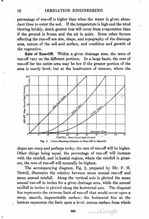
12 IRRIGATION ENGINEERING
percentage of run-off is higher than when the water is given abun
dant time to enter the soil. If the temperature is high and the wind
blowing briskly, much greater loss will occur from evaporation than
if the ground is frozen and the air is quiet. Some other factors
affecting the run-off are size, shape, and topography of the drainage
area, nature of the soil and surface, and condition and growth of
the vegetation.
Rate of Run=Off. Within a given drainage area, the rates of
run-off vary on the different portions. In a large basin, the rate of
run-off for the entire area may be low if the greater portion of the
area is nearly level; but at the headwaters of streams, where the
30
rI..10
e&
Minimum Siorie
10 4015 ZO K 30 IS
ftfllNfTU-L MeanAnnual Depth (inches)
Fig. 2. Curve Showing Relation of Run-Off to Rainfall
slopes are steep and perhaps rocky, the rate of run-off will be higher.
Other things being equal, the percentage of run-off will increase
with the rainfall ; and in humid regions, where the rainfall is great
est, the rate of run-off will naturally be highest.
The accompanying diagram, Fig. 2, prepared by Mr. F. H.
Newell, illustrates the relation between mean annual run-off and
mean annual rainfall. Along the vertical axis is plotted the mean
annual run-off in inches for a given drainage area, while the annual
rainfall in inches is plotted along the horizontal axis. The diagonal
line represents the extreme limit of run-off that would occur upon a
steep, smooth, impenetrable surface; the horizontal line at the
bottom represents the limit upon a level, porous surface from which
230
IRRIGATION ENGINEERING 13
there would be no run-off. The upper curved line represents an aver
age condition in mountainous regions, from which the run-off is large;
the lower curved line represents the condition in a catchment area
consisting of broad valleys and gentle slopes, from which the run
off is relatively small. For instance, in an area of the latter kind
having an annual rainfall of 40 inches, the annual run-off, as indicated
by the diagram, will be 15 inches. However, the relation between
these, two quantities will be largely influenced by the conditions
affecting the run-off as stated above.
Volume of Discharge. The maximum discharge from a catch
ment area tributary to a reservoir is of the utmost importance in
the design of a dam and a spillway. Various formulas, both empir
ical and theoretical, have been devised for expressing the volume of
discharge; but no formula has yet been devised that is generally
applicable to all of the conditions that occur in practice. They
should be used with the utmost discretion, and only after a careful
study*of all the factors, such as topography, nature and depth of
soil, vegetation, average temperature, humidity, etc. The follow
ing are a few of the formulas proposed:
Fanning's formula Q = 200M«
Dredge's formula Q = 1300^
Col. Dicken's formula Q = CM*
in which Q is cubic feet per second yielded from the whole area; M
is area of watershed, in square miles; L is length of watershed, in
miles; and C is 200 in flat country, 250 in mixed country, 300 in hilly
country, for a rainfall of 3.5 to 4 inches, or 300 to 350 for a 6-inch
rainfall.
It is necessary to know the monthly and daily rates of run-off
from a catchment area, as well as the mean annual rate of run-off,
as these will affect the design of the spillway for a dam. The greatest
floods will occur either on barren catchment areas with steep slopes,
or wherever heavy snowfalls are followed by warm, melting rains.
In some portions of the West, sudden flood discharges have been
recorded of 30 second-feet per square mile of catchment area, where
a few days previously the flow was at the rate of iV of a second-foot
per square mile.
231
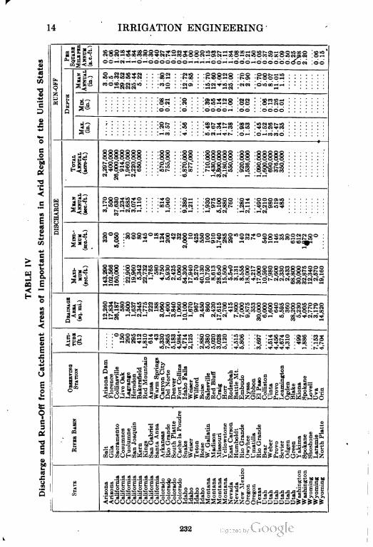
14 IRRIGATION ENGINEERING
I«
I"S3
u
a;
•«
I
Ed
O
BJ
I
a
"s
1£
<
4J
0)
1
O
E
2
•o
a
ib
(5
? X O ' (O >O~l^iiN . O i-H
£OiM :oo
• O iO 00 >-l r-i
oo . .0 . . .oooor-4 ,00 . .0000
oooc
M O .--M
§ooc
ggi
.-1 . -Oi
i-H - 'Ml• -
CO l^.^HMCO •-!
iiOOOO 'O-* 'OOOOiiC
>-i • .oTrH . !.~r IO*M" ^>—.M" ' i-TM
:O; -H^H" " ®O
.o*^*t-*i
^ ^ o «o >c i
" o.o x.x >c">
- ..CO i-Tco •~^o"i-T
cox—lait^^t -xco
-
MMM ---lO ' 'Oi -.-not^--' 'Ci^" ' «5 Ooo-^ -icx • -*o ->ot O « -^x ••^K
---
232
IRRIGATION ENGINEERING 15
Table IV derived from a series of observations over a period of
years up to 1900, shows the discharge and the run-off from catch
ment areas of the more important streams of the arid region.
Compensation by Storage. Frequently, it becomes necessary
to impound enough water to carry over a period of 2 or 3 years of
minimum rainfall. A measurement of the drainage area having
been obtained by surveys, a decision must be made as to the proba
ble average, minimum, and maximum run-offs, both by year and by
cycle of years. An estimate of the consumption of water must also
be made, and from these figures a calculation of the storage to be
provided may be made. If the minimum annual yield is equal
to or greater than the consumption, storage will be required for
only the dry season of one year of drought; if the minimum daily
yield equals the maximum daily consumption, no storage will be
required; if, however, the assumed consumption is nearly or quite
equal to the mean yield, all of the surplus from the years of greatest
rainfall must be stored and carried over until times of drought.
Evaporation and seepage from the reservoir must be considered
and should be added to the consumption, in making the calculation
for storage. A study of the run-off for a series of years at any loca
tion will give the approximate capacity required, that the consump
tion may not exceed the average yield.
The loss from evaporation is discussed later. There will be loss
from seepage through the dam. The loss into the ground may
usually be considered as additional storage; although for some
reservoirs the seepage into the ground is lost, since the water reap
pears in springs too low to be used on the irrigated lands. The loss
from seepage through a masonry dam should be small. The loss
through an earthen embankment may be considerable, and the
amount so lost will depend upon the character of the embankment,
which should be so constructed that the daily seepage shall not
exceed 10 gallons per square foot of vertical longitudinal section of
embankment. With good materials and care in construction, the
loss by seepage may be reduced to 5 gallons, or even as low as 3
gallons, per vertical square foot of embankment.
When irrigation is practiced, all of the water flowing in the
streams is not available for storage, since much of it has already
been appropriated by irrigators, and of course the quantity must be
233
16 IRRIGATION ENGINEERING
deducted from the total water available. A large portion of the
discharge occurs in winter when the streams are covered with ice,
which renders it practically impossible to divert the water for stor
age, though it is available for such reservoirs as may be located on
the main streams. As nearly all of the flow occurring in the irrigat
ing season is appropriated, only the surplus and the flood water are
available for storage.
LOSSES OF WATER
EVAPORATION
Factors Influencing Evaporation. If all precipitation upon a
given area reached the adjacent stream as run-off, the amount of
run-off would simply be the product of the total area of the water
shed times the precipitation. Much of the precipitation, however,
returns to the air by evaporation and transpiration. The rapidity
with which water, snow, and ice are converted into vapor depends
upon the relative temperature of these substances and the atmos
phere, and upon the humidity of the air and the amount of motion
in the latter.
Evaporation is greatest when the atmosphere is driest, when
the water is warm, and when a brisk wind is blowing. It is least
when the humidity is highest, the air quiet, and the temperature of
the water low. In summertime the cool surfaces of deep waters
may condense moisture from the atmosphere, and really gain in
moisture when they are supposed to be losing water by evaporation.
When, however, the reverse conditions exist in the atmosphere, and
the winds are blowing briskly across the water, the resultant wave
motion increases the agitation of the water, and the vapors from it
escape freely into the unsaturated air which is constantly coming
in contact with it and absorbing its vapors. Evaporation is there
fore going on at a rate depending upon the temperature of the sur
face, and condensation may likewise be going on from the vapors
which exist in the atmosphere; and the difference between these two
factors represents the amount of water lost by evaporation or the
amount gained by the water by condensation. Evaporation, there
fore, should be greatest in amount in the desert regions of the South
234
IRRIGATION ENGINEERING 17
west, and the least in the high mountains; and it is known that, in
the same latitude, evaporation differs greatly with the altitude.
Measurement of Evaporation. Different methods have been
devised for measuring evaporation, none of which is wholly satis
factory. Most measurements of evaporation have been made from
water surfaces by an evaporometer, the Piche evaporometer being
the one most used in this country. Water surfaces form but a small
proportion of the total area of most catchment basins; but the
amount of evaporation from these can be ascertained with some
degree of accuracy, while that from the earth and vegetation cannot
be determined very accurately.
Evaporometers. Results with Piche Evaporometer. The Piche
evaporometer and the Richards evaporation gage are thought to
give inaccurate results, since they are affected by the temperature
of the air only, which is seldom the same for any length of time as
that of a near body of water. However, in 1888, a series of observa
tions with a Piche evaporometer were made by Mr. T. Russell, of
the United States Signal Service, to ascertain the amount of evapo
ration in the West; and the results obtained showed such slight dis
crepancies from the results obtained by other methods that they
must be considered reasonably reliable. Observations were made
with this instrument in wind velocities up to 30 miles per hour, from
which it was discovered that with a velocity of 5 miles per hour the
evaporation was 2.2 times that in quiet air; 10 miles per hour, 3.8
times; 15 miles per hour, 4.9 times; 20 miles per hour, 5.7 times; 25
miles per hour, 6.1 times; and 30 miles per hour, 6.3 times. Simi
larly to the. precipitation in regions only a short distance apart, the
evaporation may vary widely. For example, at Berkeley, Cali
fornia, in 1905, the evaporation was 41.6 inches, and at Tulare,
California, it was 62.9 inches.
Floating-Pan Evaporometer. Another method of measuring
evaporation from water surfaces is by measuring the actual loss from
a pan containing water and floating in a lake or other body of water.
Such a pan and scale are shown in Fig. 3. The pan is so placed
that the contained water has as nearly as possible the same tempera
ture and exposure as that of the body of water the evaporation of
which is to be measured. This pan is of galvanized iron; 3 feet
square and 10 inches deep, and is immersed in water and kept from
235
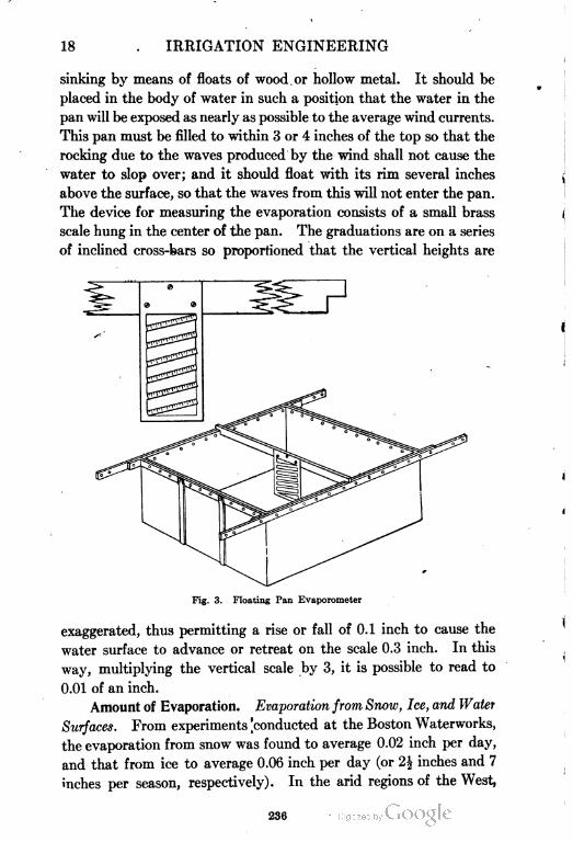
18 IRRIGATION ENGINEERING
sinking by means of floats of wood. or hollow metal. It should be
placed in the body of water in such a position that the water in the
pan will be exposed as nearly as possible to the average wind currents.
This pan must be filled to within 3 or 4 inches of the top so that the
rocking due to the waves produced by the wind shall not cause the
water to slop over; and it should float with its rim several inches
above the surface, so that the waves from this will not enter the pan.
The device for measuring the evaporation consists of a small brass
scale hung in the center of the pan. The graduations are on a series
of inclined cross-bars so proportioned that the vertical heights are
Fig. 3. Floating Pan Evaporometer
exaggerated, thus permitting a rise or fall of 0.1 inch to cause the
water surface to advance or retreat on the scale 0.3 inch. In this
way, multiplying the vertical scale by 3, it is possible to read to
0.01 of an inch.
Amount of Evaporation. Evaporation from Snow, Ice, and Water
Surfaces. From experiments 'conducted at the Boston Waterworks,
the evaporation from snow was found to average 0.02 inch per day,
and that from ice to average 0.06 inch per day (or 2| inches and 7
inches per season, respectively). In the arid regions of the West,
236
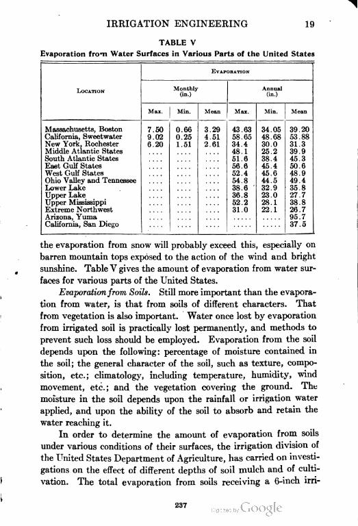
IRRIGATION ENGINEERING 19
TABLE V
Evaporation from Water Surfaces in Various Parts of the United States
LOCATIONMonthly
(in.)
EVAPORATION
Annual
(in.)
Max. Min. Mean Max. Min. Mean
Massachusetts, Boston
California, Sweetwater
New York, Rochester
Middle Atlantic States
South Atlantic States
East Gulf States
West Gulf States
Ohio Valley and Tennessee
Lower Lake
Upper Lake
Upper Mississippi
Extreme Northwest
Arizona, Yuma
California, San Diego
7.50
9.02
6.20
0.66
0.25
1.51
3.29
4 51
2.61
43.63
58.65
34.4
48.1
51.6
56.6
52.4
54.8
38.6
36.8
52.2
31.0
34.05
48.68
30.0
25.2
38.4
45.4
45.6
44.5
32.9
23.0
28.1
22.1
39.20
53.88
31.3
39.9
45.3
50.6
48.9
49.4
35.8
27.7
38.8
26.7
95.7
37.5
the evaporation from snow will probably exceed this, especially on
barren mountain tops exposed to the action of the wind and bright
sunshine. Table V gives the amount of evaporation from water sur
faces for various parts of the United States.
Evaporationfrom Soils. Still more important than the evapora
tion from water, is that from soils of different characters. That
from vegetation is also important. Water once lost by evaporation
from irrigated soil is practically lost permanently, and methods to
prevent such loss should be employed. Evaporation from the soil
depends upon the following: percentage of moisture contained in
the soil; the general character of the soil, such as texture, compo
sition, etc.; climatology, including temperature, humidity, wind
movement, etc.; and the vegetation covering the ground. The
moisture in the soil depends upon the rainfall or irrigation water
applied, and upon the ability of the soil to absorb and retain the
water reaching it.
In order to determine the amount of evaporation from soils
under various conditions of their surfaces, the irrigation division of
the United States Department of Agriculture, has carried on investi
gations on the effect of different depths of soil mulch and of culti
vation. The total evaporation from soils receiving a 6-inch irri
237
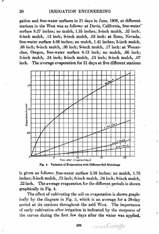
20 IRRIGATION ENGINEERING
gation and free-water surfaces in 21 days in June, 1908, at different
stations in the West was as follows: at Davis, California, free-water'
surface 8.27 inches; no mulch, 1.35 inches; 3-inch mulch, .32 inch;
6-inch mulch, .13 inch; 9-inch mulch, .03 inch: at Reno, Nevada,
free-water surface 4.68 inches; no mulch, 1.41 inches; 3-inch mulch,
.88 inch; 6-inch mulch, .36 inch; 9-inch mulch, .17 inch: at Wenat-
chee, Oregon, free-water surface 6.12 inch; no mulch, .86 inch;
3-inch mulch, .24 inch; 6-inch mulch, .13 inch; 9-inch mulch, .07
inch. The average evaporation for 21 days at five different stations
1.3
0.5
ifife
3 10
Time after 1rrigation(dotj5)
Fig. 4. Variation of Evaporation with Different Soil Mulchings
is given as follows: free-water surface 5.59 inches; no mulch, 1.75
inches; 3-inch mulch, .75 inch; 6-inch mulch, .34 inch; 9-inch mulch,
.22 inch. The average evaporation for the different periods is shown
graphically in Fig. 4.
The effect of cultivating the soil on evaporation is shown graph
ically by the diagram in Fig. 5, which is an average, for a 28-day
period at six stations throughout the arid West. The importance
of early cultivation after irrigation is indicated by the steepness of
the curves during the first few days after the water was applied.
5338
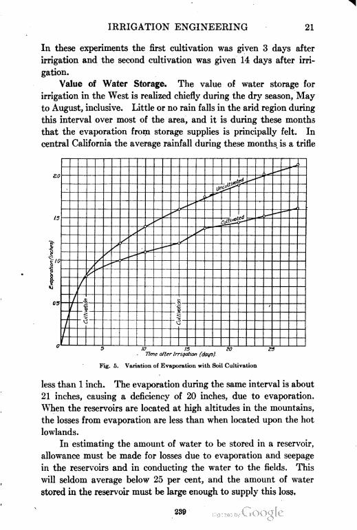
IRRIGATION ENGINEERING 21
In these experiments the first cultivation was given 3 days after
irrigation and the second cultivation was given 14 days after irri
gation.
Value of Water Storage. The value of water storage for
irrigation in the West is realized chiefly during the dry season, May
to August, inclusive. Little or no rain falls in the arid region during
this interval over most of the area, and it is during these months
that the evaporation from storage supplies is principally felt. In
central California the average rainfall during these months is a trifle
5 10 1S
Time after 1rrigation (days).
Fig. 5. Variation of Evaporation with Soil Cultivation
less than 1 inch. The evaporation during the same interval is about
21 inches, causing a deficiency of 20 inches, due to evaporation.
When the reservoirs are located at high altitudes in the mountains,
the losses from evaporation are less than when located upon the hot
lowlands.
In estimating the amount of water to be stored in a reservoir,
allowance must be made for losses due to evaporation and seepage
in the reservoirs and in conducting the water to the fields. This
will seldom average below 25 per cent, and the amount of water
stored in the reservoir must be large enough to supply this loss.
239
22 IRRIGATION ENGINEERING
ABSORPTION
Percolation. In' canals and storage reservoirs the percolation
loss is large and varies according to the soil. The losses due to per
colation alone are difficult to estimate, but, combined with evapo
ration, may vary from a very small amount to 100 per cent of
the amount entering the canal. Actual gains have been noted in
canals associated with drainage areas. The combined losses due
to percolation and evaporation may be most conveniently considered
under the head of absorption.
Losses by Absorption. In considering the losses of water due
to absorption in canals and reservoirs, the nature of the bed must
be taken into account. If the bottom is of sandy soil, the loss
from evaporation is insignificant compared with that of percolation
for most canals. If, however, the bottom is of clayey material,
or if the canal or reservoir is old and the bottom protected by sedi
ment, the loss from percolation will be limited and may not exceed
that due to evaporation.
In new canals and reservoirs the losses due to absorption are
greatest, and in a long line of canal may amount to from 40 to 60
per cent of the volume entering the head, and may be great enough
to cover the whole canal 20 feet deep per day. In shorter canals the
loss will be proportionately less, though rarely falling below 30
per cent. As the canal increases in age, the silt carried in suspension
is gradually deposited upon the banks and bottom, filling up the
interstices and decreasing the amount of percolation. In favorable
soil, old canals varying in length from 30 to 40 miles may not lose
more than 12 per cent, though the loss by main canals of average
length may range from 15 to 40 per cent of the total volume entering
the head, and the loss in laterals may be as much more.
To reduce the losses from percolation, it is recommended by
Mr. J. S. Beresford, of India, that pulverized dry clay be thrown
into canals near their headgates. This will be carried long distances
and be deposited on the sides and bottom of the canal, forming a
clay lining.
The losses by absorption may be greatly increased by giving
the canal a bad cross-section, and in this feature of construction
the attempt should be made to reduce the wetted perimeter and the
surface of the water exposed to the atmosphere.
240
IRRIGATION ENGINEERING 23
Effects of Seepage. In considering the matter of seepage, it
will be of interest to inquire into the effect of irrigation upon the sub
surface water level. Before irrigation becomes universal, the sub
surface water level may be so low that it will frequently be impossible
to derive water from wells. The practice of irrigation, however,
for a considerable time, seems to fill the soil with water so that
the level of the subsurface water is raised and shallow wells often
yield uniform and persistent supplies. It is stated that in Fresno,
California, where the subsurface level was originally at a depth of
from 60 to 80 feet below the surface, the seepage from the canals has
raised this level so that wells 10 to 15 feet in depth now receive con
stant supplies. In "Irrigation Institutions", Mr. Mead says:
Up to a certain limit, irrigation on the headwaters of a river is a benefit
to the users of water below. About one-third of the water diverted returns
to the stream as waste and seepage. The waters diverted during the flood
season, which return as seepage, come back slowly and help swell the stream
when it is low and water is most needed. The exact time of the return varies,
of course, with the location of the lands irrigated and with the character of
the soil; but in a general way the effect of the diversion of floods in irrigation
is to equalize the flow of rivers. They carry less water when high, and more
water when low. Some rivers leaving the eastern slope of the Rocky Moun
tains, which formerly ran dry every year, now have a perennial flow; and on
others, the period every year at which they become dry is traveling eastward
rather than westward.
Up to a certain limit, the storage of water also tends to equalize the flow
of streams. Reservoirs are filled when there is an abundance, and the water is
turned out when there is a scarcity. Hence the people who live along streams
below where the stored water is used derive an indirect benefit from the increased
seepage thereby created. There is, however, a limit beyond which irrigation
on any stream does not improve the supply of those living below. If the irri
gated valley is long enough, and the irrigated district broad enough, the ulti
mate absorption of the water supply is inevitable.
As illustrating the possible effects of seepage, the State Engineer
of Colorado, during the years 1890 to 1893, inclusive, conducted
examinations on the South Platte and Cache la Poudre rivers,
with the object of determining the amount of seepage water returned
to them. In 1893, on the South Platte River, in a distance of 397
miles, there was a gain of 573 second-feet over that found at the
upper measuring station. In 1891 there was a gain of 300 per
cent over the flow at the upper measuring station.
From experiments conducted in 1889 on the Cache la Poudre,
it was found that the discharge at a point considerably down the
241
24 IRRIGATION. ENGINEERING
stream from the canyon was 214.7 second-feet, as against 127.6
second-feet at the canyon—and this, after supplying 15 canals
and without receiving additional supplies from drainage. These
results were borne out by experiments conducted through succeeding
years.
Experiments of a similar nature conducted elsewhere point to
the same results. The amount of water returned by seepage will
depend upon the soil, the nature of the underlying strata, the amount
and direction of slope, and the extent of the drainage area above
and tributary to the streams. It is probable that in many cases the
amount of seepage water returned to the streams will be practically
nothing; and in designing reservoirs it will be safer to assume that
the gains by seepage water will be offset by the losses due to percola
tion, evaporation, etc.
QUANTITY OF WATER REQUIRED
DEFINITION OF TERMS
Duty of Water. It will first be necessary to define the term
duty of water as applied to irrigation, in order to determine, at least
approximately, the amount of water necessary to supply a given
area for a specific purpose. Duty of water may be defined as the
ratio between a given quantity of water and the area of the land which
it will irrigate. On the duty of water depends the financial success
of every irrigation enterprise, as it involves the dimensions and cost
of construction of canals and reservoirs, and the feasibility of fur
nishing a sufficient supply of water at a reasonable cost.
Units of Measure for Water Duty and Flow. In ordinary
hydraulic problems the standard unit is the cubic foot. In irri
gation problems, however, where large volumes of water are to be
considered, the cubic foot is too small a unit and the acre-foot is
the standard adopted by irrigation engineers. An acre-foot is
the amount of water which will cover an acre of land one foot in
depth—or, it is equivalent to 43,560 cubic feet.
In considering irrigation streams, as rivers or canals, the volume
of flow must be coupled with a time factor, both representing the
rate of flow. As in other hydraulic problems, the time unit usually
employed by irrigation engineers is the second, and the unit of
measure of flowing water is the cubic foot per second—or the secand
242
IRRIGATION ENGINEERING 25
foot, as it is termed for brevity. Thus the number of second-feet
flowing in a canal is the number of cubic feet passing a given section
in a second of time.
Another unit still generally employed in the West is the miner's
inch. This differs widely in different localities, and is generally
defined by state statute. In California one second-foot of water
is supposed to be equal to 50 miner's inches. Since the miner's
inch is so variable and the amount actually obtained by its use
in measuring water is questionable, the use of the cubic foot per
second is advised and is generally being adopted by irrigation
engineers and others.
The period of time during one season, determined between
the first watering and the completion of the last watering, is the
irrigating period. This is usually divided into several service periods
—that is, the times during which water is allowed to flow on the
land for any given watering. The irrigation period in most of
the western states, extends from about April 15 to August 15.
The service period, or the duration of one watering, is generally
from 12 to 24 hours, according to soil, crop, and water supply;
and the number of waterings making up the irrigation period varies
between 2 and 5, depending upon the soil, climate, and crop.
VARIATION IN DUTY OF WATER
Affecting Conditions. The duty of water may be expressed
by the number of acres of land which a second-foot of water will
irrigate, by the number of acre-feet of water required to irrigate
an acre of land, or in terms of the total volume of water used during
the season. It is also sometimes expressed in terms of the expendi
ture of water per linear mile of the canal, when the location of
the canal has been previously determined. On account of the
losses of water by evaporation, seepage, etc., while flowing through
the canal, care should be taken to state whether the duty is reckoned
upon the basis of the water entering the canal or upon the amount
of water applied to the land. In a long line of canal, the losses
may be a large portion of the total amount entering the canal,
and the relative duties would vary accordingly.
The duty of water in various portions of the West is variable.
Investigations show that it is rapidly rising; for, as land is irrigated
243
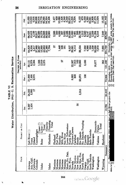
26 IRRIGATION ENGINEERING
^
I
u
««i0iOcOffi>c^CO t-OggOOXNg^ ««0^-gg^ g N0 i!
^ COOcOOOcOt^-COC^^** ^^O^C^liOOOOCO i-H^^OiMcOOOCNO ^•^f
.s >*g3«8SSSS3 - S'^«B3« - .^a-feS 2 5
s^
V 1 i >- S3
3
CO i-H CO 00 i—i iO lO i-H CO i-H CN i—i CO
iHe
I-S^
01 O ^H CD CO GO *O GO GO CO ^ d CO C^l O i—' CO iO Oi *ft 00 >O t^« OO
oo
B Sc-
S3
sCO CNCNi-H-^CO CN CM CO i
p
ITi-H oo ^ co Oi io i>- r-» co iN co o i>. co
1 II8$(Nt^-GOiO'-it— CN CO--iOOOiO t^. CO
^H CO CO CO O CO iO O i—i 00 -^ CO d
^ Ol CO d i—l d CO C-Jt—COiO OO
a
i^ i n *H '•:
2I^Q aJV) «
o: co co oi 01 d o
i illsi
OO 00 b* O CO t-» OOl •* O O GO O i-H
i—i b» iN 00 COCO
o xji
CO iN
£S£
CO iO l>- 1O r~)
jOO C73 i-H i-H
1O Ol CO 0V
tS ^ *o *o£2
5
e
t-.-* o so^ *o co f/1
B
aK»rt-22-u Ol
O!"""
o.Jf S
hO bC o
"3 1 a
^<^— -^ a*? .8 a s 33 4) . *J
Sfelsl^ 3 s 3 |og S« =y-0-H
i£||HO(2 p u i 5 j, §^H
M CM
da-year,."
IROJECTu ,^3 " ,_-— ij «»-:S"dO ^"n bri - v
culturalyeajmmencingi
Ii3f M I 1 1cc>-iOP CO PHfeWSt/iHJ^HOKPH^PWeQO >H OQ
s
16*
ig.S'-H
Jc^ fl ^
2? v jt 4
Q . 88^1 |g a
3C)Datai dataisforcorrespo(»)Octobe
1 fill , , I 1111 1 1 1 f
3;
244
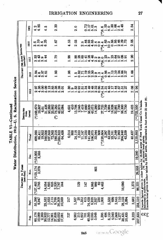
IRRIGATION ENGINEERING 27
iiMOO iO CO O r* i-H O CO CO *O O CO CO 1O Tji iO
iO Ol Ol t-» i—i CO O CO OO "f
I
o
CO CC CO CD i-H TJ4 CM O) rH CO •**i Ol O -^ '-l O O rH Ol CO «-( Ol
O iO l^- CO CO "^ CO >O CO GOiO CO Ol CO *O
I
83c=3 g g SSSSSSw.oar-aSSSS S
ii
Ol
CO iO CO *O i—l i-H i—1 i-H i-H ^H ^ TP Ol O CO i—> Ol i-H i-H i-H CO r-4 Ol
lN
3CM Ol CO Ol 00 Ol O5 iO OO I"— i-H CN iQ Ol CO ^ 00 Ol i-H i-H Ol O Ol CO
&CO ^ CO ^ i-H i-H «H O '-H i-H Ol Ol Ol i-H ifJ O 00 i—1 «-H i-H CO Ol i-H
Ol
cSwSS^oococoo Moi8S£co§^cocococo$£3S£ol o
£
s
oc
13 13
o;i>- occooiiccOTt" >-HOooiQOiOCiiOOoicooiTpoo^HOoo ro
cococo^cooooiooo co^t-ic^coooooioit-t-oioiooF^coh" ^i
s «s?
Q
I
OOOlCO-—'OiOCOCOOl *tfl i?5"oi l>-I>-COCO'^ti t-~.r-H-^!fGOOlI>.COOO OlrkCanalCo. ifootnotes(
||
^
a —
§ iSO
O O100>-HCOO1^OOCOCO Ol " i—i i-H Tf O CO Ol "* Ol -"t i—i O "^ T^
~M^ i-H i^ i—> Ol i-H i—l'—1 Ol
o> o of
a S £
•..i.0
Atlateral1jy23,367ac
Q
2Q
co"co"
CO
iothertable
thertables1(lo)"^ 00 i-H CO
g|j|
t- r^- o
1"ot
a 2.2
|^l> OCOCOCOI^-O1 I—> i—> Ol OO ^f O CO g
o ^*o ^t^ oit- - - eg
gl'l«
«5l
•3 8 *
Ot-» O1COiOOOC:Ol t* fr— OOliOOlOr— OO OOliOOCO"^ Ol
CO ^ CO IO i-^ O O CO *—i iO Ol 1O "-H CO Ol CO CC O 'O Ol "T> i-H Ol Ol GC
Ol Ol >O CO ^-" t— CC O Ol lO CO '**' ^T Ol Ol Ol O tO CO CO i-H '—l O CO
0
u!
i wi.co. CC i-H t- OO'cC O i—> .-T -^"OO Ol i—l *O" CO" GO"*£f CO"
*O Ol CO i-H Ol Ol
IIIcr
p
§§ils§l|g s islgsIS il§ll^sl i €€§;c.-
oc
"* SS^SS^oJS^H ° 501"3 " ' '" «S !?
245
28 IRRIGATION ENGINEERING
through a series of years, it becomes more saturated, and as the
level of the ground water rises, the amount of water necessary for
the production of crops diminishes. The cultivation of the soil
causes it to require less water, and the adoption of more careful
methods in designing and constructing distributaries, and care
and experience in handling water, increase its duty. In the same
state, and even in the same neighborhood, the duty will vary with
the crop, soil, and altitude.
Experiments have shown that a good, heavy rain amounting
to 5| inches soaks into the earth to a depth of from 16 to 18 inches
or more. If this amount of water were applied three times in the
season, it would be equivalent to a total depth of 16| inches to
the crop. An average depth of 3 inches of water on the surface
is sufficient to water an average soil thoroughly. The number of
waterings required in a season depends upon the crop, soil, climate,
etc. For the average crop and soil in a southern arid region four
or more irrigations may be required, while farther to the North,
and where the rainfall comes mostly during the growing season,
one or two irrigations may be ample. The actual amount of water
required to mature the crop depends upon the crop, the soil, the
climatic conditions, the cultivations, the methods of irrigation,
and other factors.
It has been the tendency for the irrigators to apply more water
than necessary, and to make irrigation take the place of cultiva
tion, with the result that many thousands of acres of some of the
most valuable lands of the arid sections have been ruined by seepage
water and alkali. In many places the water-logged lands have
been reclaimed by drainage. In planning a new project the
question of drainage should also be considered, or, better still, the
amount of water applied should be limited to beneficial and eco
nomical use.
Water Distribution and Crop Returns. Extensive investi
gations Have been conducted to determine the actual amounts of
water applied to the crops by the farmers in the irrigated sections,
and other investigations on the economical duty of water have
also been made. Table VI gives the water distribution on the
U. S. Reclamation projects for 1913 as given in the Thirteenth
Annual Report of the Reclamation Service. The amount delivered
246
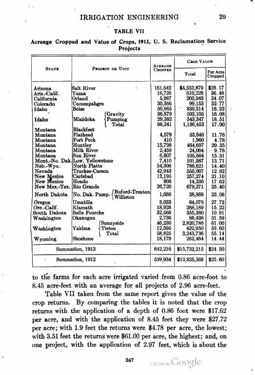
IRRIGATION ENGINEERING 29
TABLE VII
Acreage Cropped and Value of Crops, 1913, U. S. Reclamation Service
Projects
STATE PROJECT OR UNITACREAGE
CHOP VALUE
CROPPED
TotalPer Acre
Cropped
Arizona Salt River 161,642 $4,552,879 $28.17
Ariz.-Calif. Yuma 16,726 610,228 36.48
California Mand 5,987 203,949 34.07
Colorado Qncompahgre 30,366 99,153 32.77
Idaho Boise 50,865 830,314 16.32
[Gravity 36,879 593,105 16.08
Idaho Minidoka \ Pumping 29,362 543,347 18.51
[ Total 66,241 1,136,452 17.00
Montana Blackfeet
Montana Flathead 4,579 53,846 11.76
Montana Fort Peck 410 1,960 4.78
Montana Huntley 15,798 464,697 29.35
Montana Milk River 2,459 24,004 9.76
Montana Sun River 6,807 105,564 15.51
Mont.-No. Dak Low. Yellowstone 7,410 101,587 13.71
Neb.-Wyo. North Platte 54,306 786,621 14.40
Nevada Truckee-Carson 42,943 555,007 12.92
New Mexico Carlsbad 12,195 257,274 21.10
New Mexico Hondo 808 14,236 17.62
New Mex.-Tex. Rio Grande 26,720 679,271 25.40
North DakotaAT Ti i n /Buford-TrentonNo. Dak. Pump. (williston 1,686 38,888 23.06
Oregon Qmatilla 3,033 84,078 27.72
Ore.-Calif. Klamath 18,928 288,189 15.22
South Dakota Belle Fourche 32,568 355,380 10.91
Washington Okanogan 2,736 86,438 31.59
{Sunnyside 46,230 2,820,786 61.00
Washington Tieton 12,595 422,950 33.60
Total 58,825 3,243,736 55.14
Wyoming Shoshone 18,178 262,464 14.44
Summation, 1913 642,216 $15,732,215 $24.50
Summation, 1912 539,934 $13,825,369 $25.60
to the farms for each acre irrigated varied from 0.86 acre-foot to
8.45 acre-feet with an average for all projects of 2.96 acre-feet.
Table VII taken from the same report gives the value of the
crop returns. By comparing the tables it is noted that the crop
returns with the application of a depth of 0.86 foot were $17.62
per acre, and with the application of 8.45 feet they were $27.72
per acre; with 1.9 feet the returns were $4.78 per acre, the lowest;
with 3.51 feet the returns were $61.00 per acre, the highest; and, on
one project, with the application of 2.97 feet, which is about the
247
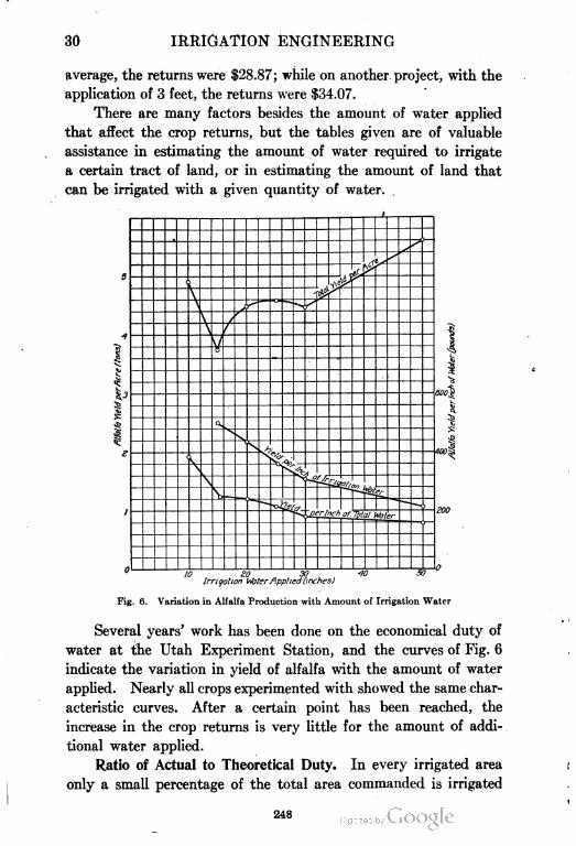
30 IRRIGATION ENGINEERING
average, the returns were $28.87; while on another project, with the
application of 3 feet, the returns were $34.07.
There are many factors besides the amount of water applied
that affect the crop returns, but the tables given are of valuable
assistance in estimating the amount of water required to irrigate
a certain tract of land, or in estimating the amount of land that
can be irrigated with a given quantity of water.
1rrigation Weter ftpplied (inches)
Fig. 6. Variation in Alfalfa Production with Amount of Irrigation Water
Several years' work has been done on the economical duty of
water at the Utah Experiment Station, and the curves of Fig. 6
indicate the variation in yield of alfalfa with the amount of water
applied. Nearly all crops experimented with showed the same char
acteristic curves. After a certain point has been reached, the
increase in the crop returns is very little for the amount of addi
tional water applied.
Ratio of Actual to Theoretical Duty. In every irrigated area
only a small percentage of the total area commanded is irrigated
248
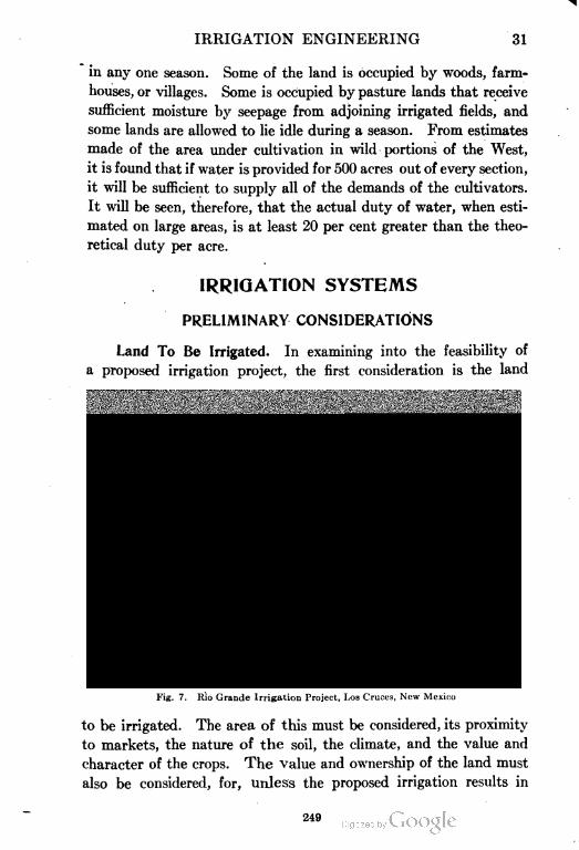
IRRIGATION ENGINEERING 31
in any one season. Some of the land is occupied by woods, farm
houses, or villages. Some is occupied by pasture lands that receive
sufficient moisture by seepage from adjoining irrigated fields, and
some lands are allowed to lie idle during a season. From estimates
made of the area under cultivation in wild portions of the West,
it is found that if water is provided for 500 acres out of every section,
it will be sufficient to supply all of the demands of the cultivators.
It will be seen, therefore, that the actual duty of water, when esti
mated on large areas, is at least 20 per cent greater than the theo
retical duty per acre.
IRRIGATION SYSTEMS
PRELIMINARY CONSIDERATIONS
Land To Be Irrigated. In examining into the feasibility of
a proposed irrigation project, the first consideration is the land
Fig. 7. Rio Grande Irrigation Project, Los Cruces, New Mexico
to be irrigated. The area of this must be considered, its proximity
to markets, the nature of the soil, the climate, and the value and
character of the crops. The value and ownership of the land must
also be considered, for, unless the proposed irrigation results in
249
32 IRRIGATION ENGINEERING
increased quantity and improved quality of the crops, the value
of the land will not be enhanced and the project will result in failure.
In Fig. 7 is shown an experimental irrigation plot.
To determine the area and configuration of the land under
consideration, a topographical survey will be necessary, and a
plot should be made to as large a scale as possible, upon which the
contours should be drawn at intervals of from 5 to 10 feet.
Determining the Source of Supply. Having determined all
the matters relative to the area, quantity, and value of the land,
and the necessity of supplying water for irrigation, the next step
is to determine the source of supply and its location relative to
the lands. This supply may be taken from an adjacent perennial
stream, or it may be necessary to transport it from a neighboring
watershed, or, again, it may be necessary to conserve in reservoirs
the intermittent flow of minor streams. Or the water may be derived
from subterranean sources, from which it may flow under pressure,
or be lifted by pumps. The relation of the water supply to the
land, the extent and value of the latter, and the volume and per
manency of the former, are the vital points to be determined in
the preliminary investigations of an irrigation project.
If the source of supply is a perennial stream, it must be examined
as to its velocity and quantity of flow during high and low stages.
A topographical survey of the watershed may be necessary to
determine its area. The minimum and maximum depth of rainfall,
and the probable run-off should be determined. Minor streams
of more or less intermittent flow may be examined as to the feasi
bility of bringing them together and impounding their supplies
for use over dry seasons. Subterranean supplies can be examined
by driving test wells to determine their source, quantity of flow,
and permanency.
CLASSIFICATION OF WORKS
Having determined the source of water supply and its relation
to the irrigable lands, the next step is the design of the irrigation
works. These may be divided into two great classes: (1) gravity
works and (2) pumping, or lift irrigation.
The sources of supply are perennial streams, intermittent
streams, artesian wells, or the storage of perennial, intermittent,
250
IRRIGATION ENGINEERING 33
or flood waters, for gravity works; and, for lift irrigation, may be
all kinds of wells, canals, storage works, or flowing streams.
The conditions necessary to the development of an irrigation
canal are: first, that it shall be carried at as high a level as possible
when additional irrigable land can be covered, in order to command
as great an area as possible; second, it should be fed by some source
of supply that will maintain the water at a constant level; third,
it should have such a slope and velocity as to prevent as far as
possible the deposition of sediment and the growth of weeds, and
at the same time have such a velocity that the cross-section may
be a minimum for a given discharge, provided that the scouring
action is not so marked as to endanger the canal itself.
Climate, geology, and topography are the determining factors
as to the particular class of works adapted to a particular region.
GRAVITY WORKS
Gravity works cover all those forms of irrigation by which
the water is conducted to the land with the aid of gravity or natural
flow, and includes perennial canals, periodic and Intermittent
canals, artesian-water supplies, inundation canals, storage works,
and subsurface or ground-water supplies.
Perennial Canals. Canals, deriving their supplies from
perennial streams or storage reservoirs, may be divided into the
two following classes, according to the location of the headworks:
highline canals; and low-service or deltaic canals.
Highline Canals. Highline canals are usually designed to
irrigate lands of limited area, and are given the best possible slope
in order tha.t they may be as high as possible, generally, to com
mand the maximum area of land. In such canals the headworks
are usually located high up on the streams, frequently in rocky
canyons where the first portions of the line may encounter heavy
and expensive rock work.
Low-Service Canals. Low-service canals are constructed where
the majority of the lands are situated in low-lying and extensive
valleys, and when the location of the head of the canal depends,
not so much on its being at a relatively high altitude and com
manding a great area, as upon the suitability of the site for purposes
of diversion. Deltaic canals have been constructed in India and
251
34 IRRIGATION ENGINEERING
Egypt at the deltas of some of the great rivers. They are low-
lying canals of relatively large cross-section and low velocity of flow.
Intermittent and Periodic Canals. Intermittent and periodic
canals are usually of small dimensions, commanding relatively
small areas of land, and are generally employed by individual
farmers to eke out a supply for which the annual precipitation is
nearly sufficient.
Storage Works. Storage works may be of almost any capacity,
depending upon the nature of the project, the source of supply,
and the area of the land to be irrigated. They may be built in
connection with perennial canals, and are especially necessary
in connection with intermittent canals, artesian wells, and subsurface
or ground-water supplies.
Inundation Canals. Inundation canals are used almost exclu
sively in India and Egypt, and derive their supply from streams
the beds of which are at a relatively high altitude compared with
the surrounding country. It is only necessary, when the water
in the river is high, to make a cut through its banks and permit
it to flow out into the canals, which distribute it over the surround
ing country. They rarely require any permanent headworks to
control the entrance of the water to the canal.
PUMPING, OR LIFT IRRIGATION
Under pumping or lift irrigation are included those forms of
irrigation in which the water does not reach the land by natural
flow, but is pumped by means of animal power, windmills, steam
power, electric motors, water wheels, elevators, gas engines, or
hydraulic rams. Frequently large volumes of water are found sit
uated at such low levels that the water cannot be distributed by
gravity, and must be raised by pumps or other lifting devices to
be distributed directly over the lands, or stored in reservoirs for
distribution by gravity.
As irrigation is practiced, the subsurface soil becomes saturated,
the ground-water level rises, and much of the water delivered by
gravity may be pumped up and re-employed for irrigation, increasing
thereby the duty of the water supply. In this country rapid prog
ress has been made in recent years along lines of irrigation pumping,
and thousands of acres of land are amenable to cultivation by this
252
IRRIGATION ENGINEERING 35
method, that cannot be irrigated by gravity supplies. It is estimated
that $9,000,000 have already been spent on 250,000 horsepower to
pump water to irrigate 200,000 acres of land.
Of all types of farming, that by irrigation pumping possibly
requires the most skill to make a success of it. Before the installa
tion of a pumping plant is made, the problem should be carefully
Fig. 8. Double-Wheel Windmill and Storage Reservoir for Irrigation Purposes
investigated. The questions to be decided upon are crops to be
raised, markets for the crops, water supply, lift, method of pumping,
kind of power and cost of power, and such others as have any bear
ing on the success of the project.
Power Considerations. Windmills. Windmills have been
extensively used by the individual farmer in portions of the West
for raising water for irrigation. Fig. 8 shows a windmill recently
253
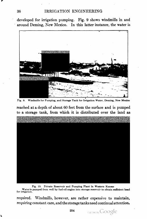
80 IRRIGATION ENGINEERING
developed for irrigation pumping. Fig. 9 shows windmills in and
around Deming, New Mexico. In this latter instance, the water is
Fig. 9. Windmills for Pumping, and Storage Tank for Irrigation Water, Deming, New Mexico
reached at a depth of about 60 feet from the surface and is pumped
to a storage tank, from which it is distributed over the land as
Fig. 10. Private Reservoir and Pumping Plant in Western Kansas
Water is pumped from well by fuel-oil engine into storage reservoir to obtain sufficient head
for irrigation.
required. Windmills, however, are rather expensive to maintain,
requiring constant care, and the storage tanks need continual attention.
254
IRRIGATION ENGINEERING 37
Electric and Gas Power. If the water supply is obtained from
wells, the farmer's individual plant may be preferable to a central
station. This will save main and lateral canal losses and reduce
the draw-down in the wells. The rapid development of the internal-
combustion engine during recent years and the improvement in
the design of pumps have both been factors influencing the develop
ment of pumping irrigation. In places, a low grade of fuel oil costing
but a few cents a gallon can be used for the engine fuel. The actual
amount used in pumping varies between wide limits under different
conditions of installation, but with a well-designed plant the amount
should not be much in excess of half a gallon to raise 1 acre-foot
of water 1 foot. In other places cheap electrical power will help
develop irrigation pumping. Fig. 10 shows a view of a modern
individual pumping plant where a fuel-oil engine is used for power.
Types of Pumps. The pumps commonly used in irrigation
pumping are: centrifugal pumps, both horizontal and vertical,
with open and enclosed impellers; turbine pumps, and deep-well
plunger pumps, used for deep wells with small bore ; water elevators, and
to a small extent, pumping engines, puhometers, and hydraulic rams.
PARTS OF A CANAL SYSTEM
Principal Divisions. Taking up the design of gravity systems,
a great perennial canal consists of the following parts: (1) main
canal; (2) head and regulating works; (3) control and drainage
works; and (4) distributaries and laterals.
The principal units of this system are the headworks, main
canals, and distributaries. Between different canal systems, the
greatest points of difference are found in the headworks and in the
first few miles of diversion line, where numerous difficulties are
frequently encountered, calling for variations in the form and con
struction of drainage works and canal banks.
The headworks usually consist of the diversion weir, with its
scouring sluices, of the head-regulating gates at the canal entrance,
and of the head or first-escape gates. The control works consist of
regulating gates at the head of the branch canals, and of escapes on
the line of the main and branch canals. The drainage works consist
of inlet or drainage dams, flumes or aqueducts, inverted siphons,
and drainage cuts. In addition to these works, there are usually
255
38 IRRIGATION ENGINEERING
constructed falls and rapids for neutralizing the slope of the country,
and tunnels, cuttings, and embankments. Modules or some form
of measuring boxes or weirs are necessary for the measurement of
the discharge.
The headworks of a canal are usually located high up on the
supplying stream in order to command a sufficient area and to tap
the stream where the water is clear and contains the least amount
of silt. By so locating the headworks, it is usually possible to
reach the watersheds with the shortest possible diversion line.
The disadvantages of this class of location are serious, since the
canal line is intersected by hillside drainage, entailing serious
difficulties in construction, and as the adjacent slopes of the country
are heavy, much expensive hillside cutting is required.
Diversion lines are those portions of a canal system that are
required to bring the water to the neighborhood of the irrigable
lands. Since they do not of themselves command any irrigable
land, the endeavor should always be to reduce the length of diversion
lines to a minimum, so that the canal shall command irrigable
land and derive revenue at the earliest possible point in its course.
MAIN CANAL
Alignment. The alignment of the canal should be such that
the canal will reach the highest part of the irrigable lands with the
least length of line and at a minimum expense of construction.
The line of the canal should follow the highest line of the irrigable
lands, skirting the surrounding foothills, and passing down the
summit of the watershed dividing the various streams. The best
alignment can be determined upon only after careful preliminary
and location surveys have been made of the country involved.
These should include a complete topographic survey, and a plot
of it to as large a scale as possible, the contour lines being spaced
at vertical intervals of from 5 to 10 feet. On such a plot it is possible
to lay down, with a close degree of approximation, the final position
of the canal line. Such a plot frequently renders possible an
improved location, saving many miles of canal by the discovery
of some low divide or some place in which a short, deep cut or tunnel
will save a long roundabout location. The final location may now
be made in the field, with the aid, perhaps, of a few short trial lines.
256
IRRIGATION ENGINEERING 39
A direct or straight course is the most economical, as it gives
the greatest freedom of flow with the least erosion of the banks.
It also greatly diminishes the cost of construction, as well as the
losses by seepage and evaporation consequent on the increased
length of a less direct location. It is an error in alignment to adhere
too closely to grade lines following the general contour of the country.
By the insertion of an occasional drop, it may be possible to obtain
a more desirable location and to diminish the cost of construction
by avoiding a natural obstacle.
The careless location of curves is a serious error in alignment,
as the insertion of sharp bends results in the destruction of the
banks, or requires that they be paved to protect them from erosion.
Curvature diminishes the delivering capacity of a canal. As the
cross-section becomes smaller or the velocity increases, the radius
of curvature should be correspondingly increased. To maintain
the discharge of a canal constant throughout its length, either
its cross-section or its grade should be increased in proportion to
the sharpness of the curve.
Such obstacles as streams, gullies, and unfavorable or low-lying
soil or rocky barriers are frequently encountered in canal align
ment, and the best method of passing these must be carefully studied.
It may be cheaper to carry the canal around these obstructions-
or it may be better to cross them at once by aqueducts, flumes
or inverted siphons, or to cut or tunnel through the ridges. Careful
study should be made of each case, and estimates made of the cost
not only of first construction, but of ultimate maintenance. In
crossing swamps or sandy bottom lands, it may be cheaper, because
of the losses due to evaporation and seepage, to 'carry the canal
in an artificial channel.
If water is abundant, it may be the less expensive, on hillside
work, simply to build the canal with an embankment on its lower
side, permitting the water to flood back on the upper side according
to the slope of the country. On account of the growing scarcity
of water, however, any method that would be wasteful of water
should not be adopted without considerable deliberation. The
relative cost of building a hillside canal, wholly in excavation or
partly in embankment should be considered. If the hillside is steep
and rocky, the advisability of tunneling, of building a masonry
257
40 IRRIGATION ENGINEERING
retaining wall on the lower side of the canal, or of carrying the
water in an aqueduct or flume, will have to be considered;
In finally locating an expensive work, borings and trial pits
should be made—the former by means of a light steel rod, and the
latter by simple excavation—in order to discover the nature of the
material to be encountered. In making the final survey of a canal,
it is well to place at convenient intervals permanent benchmarks
of stone or other suitable material. The establishment of these
along the side of the canal in some safe place, will give convenient
datum points to which levels may be referred wherever it may be
necessary to make repairs or new branch lines.
Slope and Cross=Section. Slope and cross-section are dependent
the one upon the other. Having determined the discharge required,
the carrying capacity for this discharge may be obtained by increas
ing the slope and the consequent velocity and diminishing the cross-
sectional area, or by increasing the cross-sectional area and diminish
ing the velocity.
The proper relation between cross-section and slope requires
the exercise of careful judgment. In order to reduce the deposition of
silt and the growth of weeds to the minimum, it is desirable to give
the water as high a velocity as the 'material will stand. This may
result, however, in bringing the water to too low an elevation to
command the area of land desired. Too great -a cross-sectional
area may result in excessive cost, if the material is in rock or for
any other reason is difficult to remove. Other things being equal,
the correct relation of slope to cross-section is that in which the
velocity will neither be too great nor too small, and yet the amount
of material to be removed will be reduced to a minimum.
When the fall will permit, the slope of the bed of the main canal
should be less than that of the branches; and the latter should be
less than that of the bed of the distributaries and laterals, the object
being to secure a nearly uniform velocity throughout the system,
so that sedimentary matter in suspension will not be deposited
until the irrigable lands are reached.
Limiting Velocities. In order that the proper slope may be
chosen—one that will prevent deposit on the one hand and at the
same time not erode the banks—it is necessary to know the limiting
velocities for different materials. In a light, sandy soil, surface
258

IRRIGATION ENGINEERING 41
velocities of from 2.3 to 2.4 feet per second, or mean velocities
of 1.85 to 1.93 feet per second, give the most satisfactory results.
Velocities of from 2 to 3 feet per second are ordinarily sufficient
to prevent the growth of weeds and the deposition of matter in
suspension; and other things being equal, this velocity should be
maintained whenever possible. Ordinary soil and firm, sandy
loam permit velocities of from 3 to 3| feet per second; while in
firm gravel, rock, or hardpan, the velocity may be as high as o
or 7 feet per second. Brickwork or heavy dry-laid paving or
rubble will not stand velocities higher than 15 feet per second;
Fig. 11. Irrigation Canal Showing Berm
and only the most substantial form of masonry construction is
capable of resisting still higher velocities.
The grade required to produce these velocities is dependent
chiefly upon the cross-sectional area of the channel. Much higher
grades are required in canals of small cross-sectional area than in
large, in order to produce the same velocity. The velocity required
being known, the grade may be ascertained from Kutter's or some
similar formula. (See page 79.) Or, on the other hand, if the
grade is limited, the resulting velocity may be determined. In
large canals of 60-foot bed width and upwards, and in sandy or light
soil, grades as low as 6 inches to the mile produce as high velocities
as the material will stand. In firmer soil this grade may be increased
259
42 IRRIGATION ENGINEERING
to 12 to 18 inches to the mile, whereas smaller channels will permit
of slopes of from 2 to 5 feet or more per mile, according to the material
and dimensions of the channel.
Design of Cross=Section. Theoretically, the most economical
form of cross-section of channel is one with vertical sides and a
depth equal to one-half of the bottom width; but of course this form
is applicable only to the firmest rock. The best trapezoidal form is
one in which the width of the water surface is double the bottom
Fig. 12. Portion of Upper Main Canal at Pogue Flats, Okanogan Project, Washington
The Okanogan project by storage of the waters of the northern Salmon River provides for
the irrigation of 8000 acres of fruit lands near Okanogan.
width. The side slopes above water level should be as steep as the
material will permit.
The particular form of cross-section will depend upon the nature
of the material and the topography. The greater the depth, other
things being equal, the greater will be the velocity. Fig. 11 is a
view showing a canal designed to carry a large or a small amount
of water. The object of the berm is to decrease the width for small
quantities and to increase the width for large quantities. Fig. 12
shows a concrete irrigation ditch, on a curve with almost vertical
260
IRRIGATION ENGINEERING 43
sides, and Fig. 13 shows a straight section of a concrete ditch with a
trapezoidal section.
Very large canals, such as some of those in India, have been
given a' proportion of depth to width similar to that of great rivers.
This proportion has been found to be most nearly attained when the
bed width is made from 15 to 16 times the depth. In hillside exca
vation, the greater the proportion of depth to width, the less will
be the cost of construction; and in rock and heavy material it is
Fig. 13. Concrete Canal with Sloping Sides for Carrying Pumped Water in Kansas
desirable to make the bottom width not greater than from 2 to 3
times the depth.
The cross-section of a canal may be so designed that the water
may be wholly in excavation, wholly in embankment, or partly in
both. The conditions that govern the choice of one of these three
forms, are dependent upon the alignment and grade of the canal,
and upon the character of the soil. It may be desirable at times
to keep the canal wholly in cut, provided the topography and con
sequent location will permit of it. For if the material of which
the banks are constructed is light and porous, the water may
filter through and stand in stagnant pools on the surface, causing
261
44 IRRIGATION ENGINEERING
unnecessary waste as well as unsanitary conditions. If the material
is impervious and will form good, firm banks, it may be well to keep
the canal in embankment where possible, although this may neces
sitate the expense of borrowing material. To reduce the cost of
construction, it is desirable, where the location will permit, to keep
a canal about half in cut and half in embankment, thus reducing to
the minimum the amount of material to be handled.
Most main canals follow the slope of the country in grade con
tours running around hillside or mountain slopes. In such cases it
is necessary to build an embankment on one side only, when the cut
ting will be entirely on the upper side. If there is a gentle slope on
the upper side, and consequently an embankment on that side, it is
desirable to run drainage channels at intervals from this embankment
to prevent the water making its way through it to the canal. These
drainage channels may be taken through the embankment into the
canal, or may be led away to some natural watercourse.
In large canals it is always desirable to have a roadbed on at
least one bank, and the width of this will determine the top width
of the bank. The inner surfaces of the canal are usually made
smooth and even; while the top is also made smooth, with a slight
inclination outward to throw drainage water away from the canal.
The inner slopes of the banks vary in soil from 1 : 1 to 4: 1, according
to the character of the material. In firm, clayey gravel or hardpan,
slopes of 1 : 1 may be constructed. In ordinary, firm soil mixed with
gravel, or in coarse, loamy gravel, slopes of 1|:1 are necessary.
In other soils, a slope of 2 : 1 will be required ; and light, sandy soils
will require a slope of 4:1.
Embankment. The top width of the canal bank is generally
from 4 to 10 feet, according to the material and depth, and whether
or not the canal is in embankment. If there is to be no roadway
on the top of the embankment, and the surface of the water does not
rise more than a foot or so above the foot of the embankment, a top
width of 4 feet is sufficient. Where the depth of water on the
embankment is greater, the top width should be 5 or 6 feet, and in
light soil it should be 10 feet.
1t may be necessary to build a puddle wall in the embankment,
or to make a puddle facing on the inner slope in case the material
is particularly pervious. The same effect is obtained by sodding
262
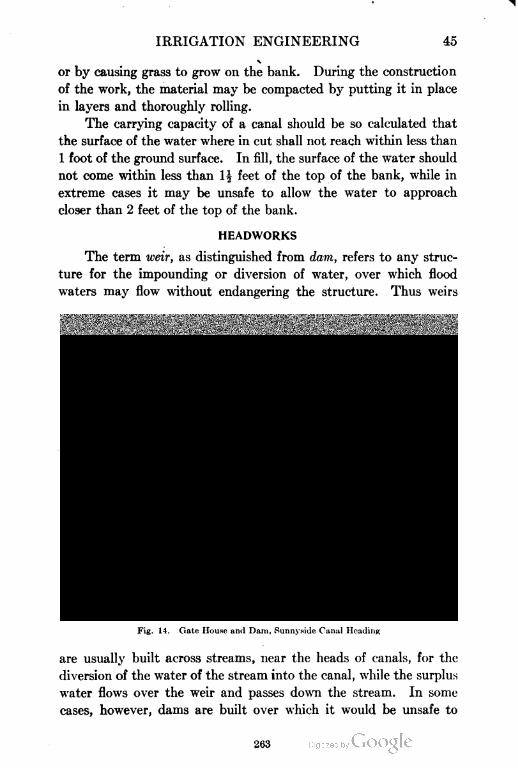
IRRIGATION ENGINEERING 45
or by causing grass to grow on the bank. During the construction
of the work, the material may be compacted by putting it in place
in layers and thoroughly rolling.
The carrying capacity of a canal should be so calculated that
the surface of the water where in cut shall not reach within less than
1 foot of the ground surface. In fill, the surface of the water should
not come within less than I| feet of the top of the bank, while in
extreme cases it may be unsafe to allow the water to approach
closer than 2 feet of the top of the bank.
HEADWORKS
The term weir, as distinguished from dam, refers to any struc
ture for the impounding or diversion of water, over which flood
waters may flow without endangering the structure. Thus weirs
Fig. 14. Gate House and Dam, Sunny.side Canal Heading
are usually built across streams, near the heads of canals, for the
diversion of the water of the stream into the canal, while the surplus
water flows over the weir and passes down the stream. In some
cases, however, dams are built over which it would be unsafe to
263
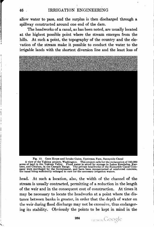
46 IRRIGATION ENGINEERING
allow water to pass, and the surplus is then discharged through a
spillway constructed around one end of the dam.
The headworks of a canal, as has been noted, are usually located
at the highest possible point where the stream emerges from the
hills. At such a point, the topography of the country and the ele
vation of the stream make it possible to conduct the water to the
irrigable lands with the shortest diversion line and the least loss of
Fig. 15. Gate House and Intake Gates, Upstream Face, Sunnyside Canal
A view of the Yakima project, Washington. This project calls for the reclamation of 160,000
acres of land in the Yakima Valley. Flood water is saved by storage in Lakes Keechelus, Kar-
hees, and Clealum, in the Cascade Range. The private headworks of the Sunnyside Canal Com
pany were purchased by the Government, and have been reconstructed of reinforced concrete,
the canal being sufficiently enlarged to care for the necessary irrigation waters.
head. At such a location, also, the width of the channel of the
stream is usually contracted, permitting of a reduction in the length
of the weir and in the consequent cost of construction. At times it
may be necessary to locate the headworks at a point where the dis
tance between banks is greater, in order that the depth of water on
the weir during flood discharge may not be excessive, thus endanger
ing its stability. Obviously the points to be kept in mind in the
264
IRRIGATION ENGINEERING 47
location and design of headworks are: permanency; economic first
cost; cost of maintenance; and the command of the maximum area
of irrigable lands at the least cost of diversion canals. These require
ments may at times be conflicting; and complete surveys, supple
mented by careful study of the problem in all of its details, are
necessary to a satisfactory final conclusion.
The headworks of a canal consist of: (1) diversion weir or dam;
(2) scouring sluices; (3) regulator at head of canal, for its control
(see Figs. 14 and 15); and (4) an escape for relief of canal below.-
Diversion Weirs
Principal Types of Construction. Diversion weirs or dams, as
the term indicates, are structures built for the purpose of backing
up or impounding a body of water in order that it may be diverted
into the proper channels to reach the irrigable lands. They may
be classified as follows, according to the construction material of
the superstructure: (1) brush and bowlder weirs; (2) earthen dams;
(3) masonry dams and weirs; (4) loose rock-fill dams; (5) wooden
dams and weirs; and (6) iron or steel dams and weirs. These
materials are also used in various combinations. The best kind of
dam to build depends upon its size, the character of the foundation,
the topography of the site, the degree of imperviousness required,
materials available, and the cost.
Brush and Bowlder Dams. Brush and bowlder dams require
practically no engineering skill in their design and are of the simplest
construction. They are usually low barriers thrown up across a
stream to raise the water only a few feet. Conditions are sometimes
met under which it is advisable to build such a dam. These dams
are constructed by driving stakes across the stream bed and attach
ing to them bundles of twigs, usually willow and cotton wood, and
weighting the twigs down with rock and gravel. The brush end is
laid upstream. Alternate layers of brush and rock and gravel are
laid in the dam until the height may reach 3 or 4 feet. Fig. 16 is a
view of a brush dam in the Tongue River in southern Montana.
Earthen Dams. The earthen embankment is one of the most
common forms of dam. It can be built on a variety of foundations
and is usually cheap to build and, when properly designed and
constructed, it furnishes a safe and reliable structure. Where water
265
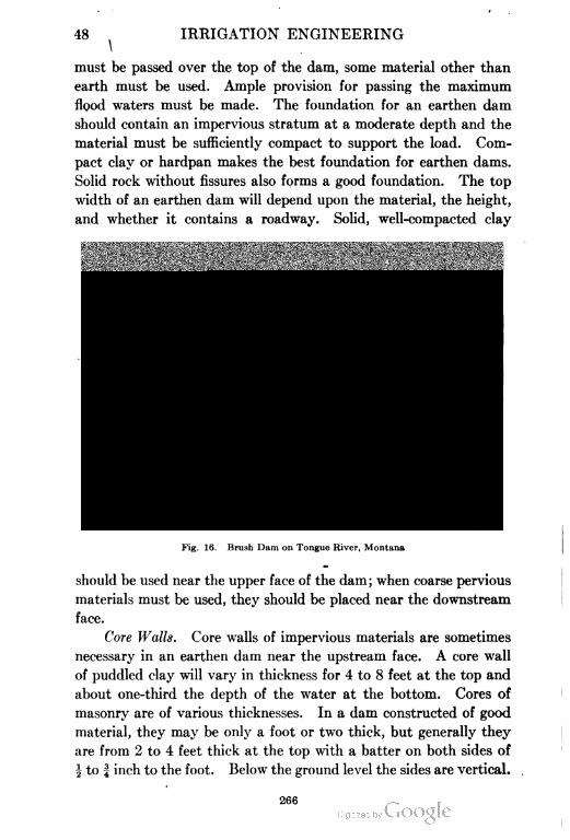
48 IRRIGATION ENGINEERING
i
must be passed over the top of the dam, some material other than
earth must be used. Ample provision for passing the maximum
flood waters must be made. The foundation for an earthen dam
should contain an impervious stratum at a moderate depth and the
material must be sufficiently compact to support the load. Com
pact clay or hardpan makes the best foundation for earthen dams.
Solid rock without fissures also forms a good foundation. The top
width of an earthen dam will depend upon the material, the height,
and whether it contains a roadway. Solid, well-compacted clay
Fig. 16. Brush Dam on Tongue River, Montana
should be used near the upper face of the dam; when coarse pervious
materials must be used, they should be placed near the downstream
face.
Core Walls. Core walls of impervious materials are sometimes
necessary in an earthen dam near the upstream face. A core wall
of puddled clay will vary in thickness for 4 to 8 feet at the top and
about one-third the depth of the water at the bottom. Cores of
masonry are of various thicknesses. In a dam constructed of good
material, they may be only a foot or two thick, but generally they
are from 2 to 4 feet thick at the top with a batter on both sides of
i to f inch to the foot. Below the ground level the sides are vertical.
266
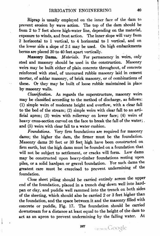
IRRIGATION ENGINEERING 4fl
Riprap is usually employed on the inner face of the dam to
prevent erosion by wave action. The top of the dam should be
from 2 to 7 feet above high-water line, depending on the material,
exposure to winds, and frost action. The inner slope will vary from
2 horizontal to 1 vertical, to 4 horizontal to 1 vertical, and on
the lower side a slope of 2:1 may be used. On high embankments
berms are placed 30 to 40 feet apart vertically.
Masonry Dams. Materials. For permanency in weirs, only
steel and masonry should be used in the construction. Masonry
weirs may be built either of plain concrete throughout, of concrete
reinforced with steel, of uncoursed rubble masonry laid in cement
mortar, of ashlar masonry, of brick masonry, or of combinations of
these. Or they may be built of loose rubble maintained in place
by masonry walls.
Classification. As regards the superstructure, masonry weirs
may be classified according to the method of discharge, as follows:
(1) simple weirs of moderate height and overflow, with a clear fall
to the bed of the stream; (2) simple weirs with clear fall to an arti
ficial apron; (3) weirs with rollerway on lower face; (4) weirs of
heavy cross-section curved on the face to break the fall of the water; .
and (5) weirs with clear fall to a water cushion.
Foundations. Very firm foundations are required for masonry
dams; the higher the dam, the firmer must be the foundation.
Masonry dams 20 feet or 30 feet high have been constructed on
firm earth, but the high dams must be founded on a foundation that
will not be subject to settlement, or cracks will form. Low dams
may be constructed upon heavy-timber foundations resting upon
piles, or a solid hardpan or gravel foundation. Tor such dams the
greatest care must be exercised to prevent undermining of the
foundation.
Close sheet piling should be carried entirely across the upper
end of the foundation, placed in a trench dug down well into hard-
pan or clay, and puddle well rammed into the trench on both sides
of the sheeting, which should also be carried 2 or 3 feet higher than
the foundation, and the space between it and the masonry filled with
concrete or puddle, Fig. 17. The foundation should be carried
downstream for a distance at least equal to the height of the dam to
act as an apron to prevent undermining by the falling water. At
267
50 IRRIGATION ENGINEERING
the end of the apron should be placed sheet piling similar to that
already described.
General Structural Considerations. Theoretical considerations
act as a guide in the design of masonry dams, the three requirements
for safety being stability against sliding on its foundation, stability
against overturning, and maximum stresses within safe limits.
The top width of masonry dams varies from 4 or 5 feet for low dams,
to 15 or 20 feet for very high dams, and the height of crest above
the water line varies from 2 or 3 feet to 8 or 10 feet.
Masonry is practically unpliable, and so an unyielding founda
tion is necessary if there are to be no unknown and unprovided-for
stresses in the structure caused by a yielding and insecure founda
tion. All loose or decomposed rock of the foundation should be
Hard Fan
Fig. 17. Sheet Piling in Weir Construction
removed; and if the foundation rock has a smooth top surface, a
shallow trench should be excavated into it the entire length of the
dam, ,or the bed should be cut in steps to prevent leakage and the
sliding of the dam on its bed. Every square foot of the foundation
should be thoroughly cleaned and washed and covered with a thick
bed of mortar just before the masonry is laid upon it, and the spaces
between the dam and the sides of the excavation should be cleaned
out and filled with concrete. Seams in the rock should be filled
with cement, to prevent the escape of the water behind the dam.
Springs should be diverted or sealed up, to avoid risking the sta
bility of the structure.
The ends of the dam should be carried to bedrock if possible,
and treated in the same manner as the bottom. If rock does not
268
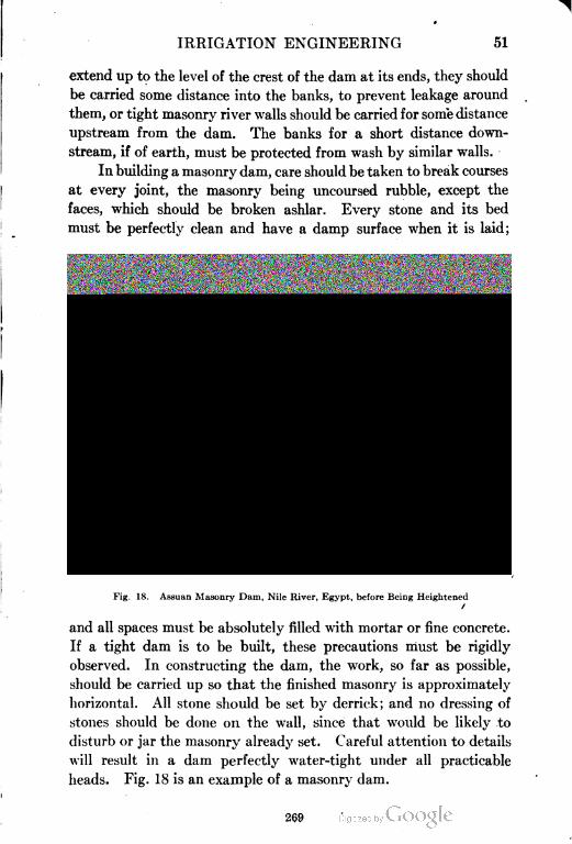
IRRIGATION ENGINEERING 51
extend up to the level of the crest of the dam at its ends, they should
be carried some distance into the banks, to prevent leakage around
them, or tight masonry river walls should be carried for some distance
upstream from the dam. The banks for a short distance down
stream, if of earth, must be protected from wash by similar walls.
In building a masonry dam, care should be taken to break courses
at every joint, the masonry being uncoursed rubble, except the
faces, which should be broken ashlar. Every stone and its bed
must be perfectly clean and have a damp surface when it is laid;
Fig. 18. Assuan Masonry Dam, Nile River, Egypt, before Being Heightened
/
and all spaces must be absolutely filled with mortar or fine concrete.
If a tight dam is to be built, these precautions must be rigidly
observed. In constructing the dam, the work, so far as possible,
should be carried up so that the finished masonry is approximately
horizontal. All stone should be set by derrick; and no dressing of
stones should be done on the wall, since that would be likely to
disturb or jar the masonry already set. Careful attention to details
will result in a dam perfectly water-tight under all practicable
heads. Fig. 18 is an example of a masonry dam.
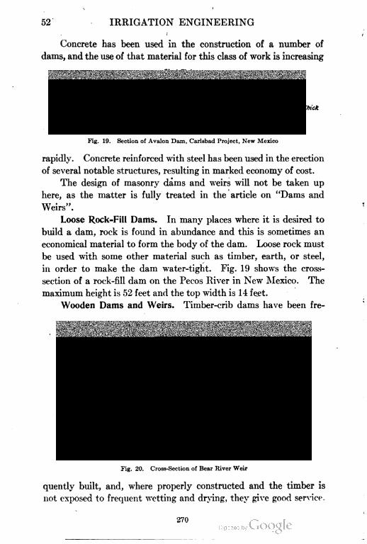
52 IRRIGATION ENGINEERING
Concrete has been used in the construction of a number of
dams, and the use of that material for this class of work is increasing
1 Steel Plate
large Rock forlacfy
-ipRaplc-nick
-- Concrete Core Woll
Fig. 19. Section of Avalon Dam, Carlsbad Project, New Mexico
rapidly. Concrete reinforced with steel has been used in the erection
of several notable structures, resulting in marked economy of cost.
The design of masonry dams and weirs will not be taken up
here, as the matter is fully treated in the article on "Dams and
Weirs".
Loose Rock=Fill Dams. In many places where it is desired to
build a dam, rock is found in abundance and this is sometimes an
economical material to form the body of the dam. Loose rock must
be used with some other material such as timber, earth, or steel,
in order to make the dam water-tight. Fig. 19 shows the cross-
section of a rock-fill dam on the Pecos River in New Mexico. The
maximum height is 52 feet and the top width is 14 feet.
Wooden Dams and Weirs. Timber-crib dams have been fre
Fig. 20. Cross-Section of Bear River Weir
quently built, and, where properly constructed and the timber is
not exposed to frequent wetting and drying, they give good service.
270
IRRIGATION ENGINEERING 53
Fig. 20 is the cross-section of the Bear River weir which is timber
crib.
Wooden crib and rock weirs are generally built when the bed
and banks of the river are of heavy gravel and bowlders or of solid
rock; and they may be employed for diversions of greater height than
is possible with open weirs. Crib weirs consist of a framework of
heavy logs, drift-bolted together, and fitted with broken stones and
rocks to keep them in place. The structures may be founded by
sinking a number of cribs, one on top of the other, to a considerable
depth in the ground, or they may be bolted to the solid rock. They
may consist of separate cribs built side by side across the stream and
fastened firmly together, or they may be built as one continuous weir.
Iron or Steel Dams. Dams of this sort have been built. One
at Ash Fork, Arizona, 70 feet high and 184 feet long on top, is used
for city water supply. It consists of a series of triangular steel
bents, resting on concrete foundations. The face consists of steel
plates -| inch thick, 8 feet lOf inches wide, and 8 feet long, riveted
to 20-inch, 65-pound I-beams.
"Open Weirs and Closed Weirs. Weirs are also classed as open
weirs and as closed weirs. An open weir consists of a series of piers
of wood, iron, or masonry, set at regular intervals across the bed
of the stream, and resting on a masonry or wooden floor constructed
flush with the river bed and protected from scouring by curtain
walls constructed up and down stream. The piers are fitted with
flashboards or movable weirs so constructed that the afflux height
of the river may be controlled. The distance between piers varies
from 3 feet to 10 feet. In a river subjected to sudden floods, the
gates are constructed to drop automatically when the flow overtops
them.
A closed weir consists of an apron built upon a substantial
foundation and carried across the entire width of the stream, flush
with the level of its bed, and protected from erosion by curtain
walls up and down stream. The superstructure may consist of a
solid wall, or may consist in part of upright piers, the interstices
being closed by some temporary construction. This latter portion
of the weir is called a scouring sluice. In a closed weir the barrier
is solid nearly the entire width of the channel, the flood waters
passing over the crest. Such weirs have usually a short open space
271
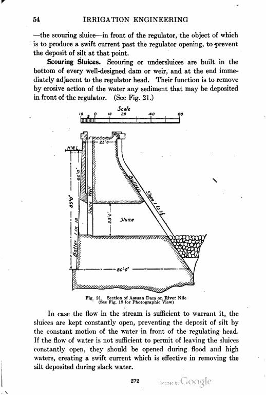
54 IRRIGATION ENGINEERING
—the scouring sluice—in front of the regulator, the object of which
is to produce a swift current past the regulator opening, to prevent
the deposit of silt at that point.
Scouring Sluices. Scouring or undersluices are built in the
bottom of every well-designed dam or weir, and at the end imme
diately adjacent to the regulator head. Their function is to remove
by erosive action of the water any sediment that may be deposited
in front of the regulator. (See Fig. 21.)
Scale
10 , 0 10 2.0 -*0 60
Fig. 21. Section of Assuan Dam on River Nile
' (See Fig. 18 for Photographic View)
In case the flow in the stream is sufficient to warrant it, the
sluices are kept constantly open, preventing the deposit of silt by
the constant motion of the water in front of the regulating head.
If the flow of water is not sufficient to permit of leaving the sluices
constantly open, they should be opened during flood and high
waters, creating a swift current which is effective in removing the
silt deposited during slack water.
272
IRRIGATION ENGINEERING 55
The scouring effect of sluices constructed in the body of the
weir is produced by two classes of structures: open scouring sluices
and undersluices.
0pen Scouring Sluice. The open scouring sluice is practically
identical with the open weir, as the latter consists of scouring sluices
built across the entire width of the channel. When the weir forms
a solid barrier across the channel and is open for only a short portion
of its length adjacent to the canal head, the latter is called a scouring
sluice. The waterway of a scouring sluice is open the entire height
of the weir from crest to bed of stream, and consists of foundation,
floorway, and superstructure. The floor must be deep and well
constructed, and carried for a short distance up and down stream
upon either side of the axis of the weir. On this floor are built piers,
grooved for the insertion of planks or gates that may be opened or
closed at will.
Undersluice. These sluices are more generally constructed
where the weir is of considerable height and the amount of silt
deposited is small. The opening does not extend as high as the
crest of the weir, nor does the sill of the sluiceway necessarily reach
to the level of the stream bed. It is necessary, however, that the
sill be as low as the sill of the regulator head.
CONTROL WORKS
Regulators. Relative Location. A diversion weir retards the
flow of the stream and raises its level to such a height as to enable
it to pass into the head of the canal. The regulator controls the
flow of water, admitting it to the canal when necessary, and at
other times causing it to pass on down the stream over or through
the weir. The regulator should be so located that the water held
back by the weir will pass rapidly, and with the least loss of head,
through it and into the canal. To accomplish this successfully, the
canal head should be placed immediately adjacent to the weir and
continuous with it.
The weir should not be so located and. aligned as to cross the
stream diagonally, either toward or from the regulator head. In
the former case, it tends to force the water against the regulator,
causing unnecessary scour at that point and undue pressure upon
the head. In the latter case, the reverse-action would take place,
273
56 IRRIGATION ENGINEERING
and it would not be effective in directing the water into the canal.
The best alignment for the weir is to have it cross the stream at right
angles to the line of the regulator. This gives a clear, even scour
past the regulating gates and keeps them clear of silt, at the same
time furnishing the required amount of water.
The regulator should not be placed at a distance from the end
of the weir, as thereby dead water, in which deposits of silt occur, is
Fig. 22. Gates at Sharp's Heading
At this point, seven miles east of Calexico, Mexico, the Alamo River drops from the Imperial
Canal.
created between the weir and the regulator, blocking the entrance
to the canal and diminishing the available supply.
Types. The type of regulator employed depends upon the
character of the foundation and the permanency desired. Regu
lators may be classified according to the design of the gate and its
method of operation. With any type of foundation, varying degrees
of permanency may be given to the superstructure, and various
methods employed for operating the gates.
Regulators may be classified as follows: (1) wooden gates in
timber framing; (2) wooden gates in masonry and iron framing; and
(3) iron gates in masonry and iron framing.
274
IRRIGATION ENGINEERING 57
Further classification, according to the method of operating the
gates, is: (a) flashboard gates; (b) gates raised by hand lever; (c)
gates raised by chain and windlass; (d) gates raised by screw gearing;
and (e) hydraulic lift gates.
Simple flashboard gates can be used only when the pressure
upon them is low. When the gates are under great pressure, the
opening is generally closed by a simple sliding gate that may be
raised by hand lever or windlass, Fig. 22. Under high pressures
a double series of gates may be employed, one above the other, each
separately raised by hand lever or windlass.
Arrangement. The regulator should be so designed that the
amount of water admitted to the canal may be .perfectly controlled
at any stage of the stream. To this end, the gates should have such
dimensions that they can be quickly opened or closed as desired.
When the canal is large and its width considerable, the regulator
should be divided into several openings, each closed by a separate
and independent gate.
The channel of the regulator way should consist of a flooring of
timber or masonry, to protect the bottom from the erosive action of
the water; and the side walls or wings should be of the same con
struction, to protect the banks. The various openings will be sepa
rated by piers of wood, iron, or masonry; and the amount of obstruc
tion offered to the channel should be the minimum, so that the width
of the regulator head will be as small as possible for the desired
amount of opening.
For convenience in operating, the regulator should be sur
mounted by arches of masonry or a wooden flooring, so as to provide
an overhead bridge from which the gates may be raised or lowered.
The height of the regulating gates and the height of the gates sur
mounting them must exceed the height of the weir crest by the
amount of the greatest afflux height which the flood water may
attain, so that the flood flow may not top the regulator and destroy
the canal. The regulator must be firmly and substantially built to
withstand the pressure of floods, and a drift fender should be built
immediately in front of, or at a short distance in front of, the gates,
to protect them from floating logs, debris, etc.
The regulator head should be placed as close to the end of the
weir as possible, to prevent the deposit of silt at that point. It is
275
58 IRRIGATION ENGINEERING
sometimes necessary, however, to set the regulator back in the canal
a short distance, owing to the nature of the banks and the consequent
difficulties of construction. Under such circumstances the escape
should be placed in front of and adjacent to the regulator, to relieve
it of undue pressure.
Escapes. Functions. In order to maintain complete control
over the water in a canal, provision should be made for disposal
of any excess flow that may arise from sudden and excessive rains
or floods, or of any water not required for irrigation. This is affected
Fig. 23. Interior of Automatic Spillway for Control of Water Supply in Canal,
Yakima Project, Washington
by means of escapes, or, as they are more commonly called, waste-
ways or spillways. These are usually short cuts from the canal
to some natural drainage channel or stream into which the excess
water may be wasted without fear- of damage, Figs. 23 and 24.
Wasteways may also be utilized for flushing the canal, preventing
the deposit of silt, or scouring it out.
Location. Opening the distributaries relieves the main canal,
and opening the escapes in turn relieves the distributaries. Escapes
should be provided at intervals along the entire canal line, the length
of each interval depending upon the topography of the country,
s
276
IRRIGATION ENGINEERING 59
the danger from floods on inlet drainage, and the dimensions of
the canal. The first or main escape should be located at a distance
from the regulator not exceeding half a mile, so that in case of
accident to the canal the water may be drawn off. This main
escape may also be used as a flushing gate for the prevention and
removal of silt deposits. The slope of the canal between its head
Fig. 24. General View of Wasteway and Portal of Tunnel No. 3 on Huntley Main Canal, and
Passing Northern Pacific Train
The Huntley project, Montana, calls for the irrigation of 26,000 acres of Crow Indian Reser
vation lands' by means of water diverted from the lower Yellowstone River.
and the escape, should be decreased in order that the matter carried
in suspension may be deposited at the head of the escape.
Escapes should be located above weak points, as embankments
flumes, etc., in order that the canal may be quickly emptied in case
of accident. Their channels should be of the shortest possible length,
with sufficient capacity to carry off the whole body of water from
both directions so that the canal below the escape may be emptied
for repairs while the canal above is still in operation.
277
60 IRRIGATION ENGINEERING
Arrangement. The greatest danger to a canal occurs during
local rains when water is not being used for irrigation, leaving the
canal supply full, while the discharge is augmented by the flood
waters. It is essential, where a drainage inlet enters the canal,
that an escape be placed opposite it for the discharge of surplus
water. In order that the escape may act most effectively, the slope
of its bed should be increased by at least a foot immediately below
its head ; besides this, the slope of the remainder of the bed should
be somewhat greater than that of the canal, and it should tail into
the drainage channel with a drop of a few feet.
Fig. 25. Drop on Main Imperial Canal at Sharps in the Imperial Valley, California,
Showing Brush Wing Walls and Height of Drop
Escape heads, and the regulators necessary to their operation,
are similar in design to the regulating gates at the head of the main
canal. They should be as large as can be conveniently operated,
and there should be a sufficient number of them to discharge the
canal without unduly retarding the velocity of flow. The gates may
be of timber or iron, and may be framed between piers of timber,
masonry, or iron. They are operated the same as the gates at the
head of the main canal; but, as the pressure upon them is not so
great, the lifting apparatus need not be so elaborate.
Sand gates are practically escape gates, but they may be so
designed as to be of service only for scouring and the removal of
sediment. The main gates on a canal system should be designed as
much for scouring purposes as for the control of the water in the canal.
278
IRRIGATION ENGINEERING 61
Drops. At places in some canal lines it is necessary to overcome
excessive erosion of the canal bed by introducing drops or chutes s
Fig. 20. Chute in Natural Earth; Bed Protected from
Krosion by Bowlders
through which the water is carried to a lower level in a short dis
tance. These may be constructed of timber or of masonry. Figs.
Fig. 27. Reinforced-Concrete Drops, Comanche Canal, Colorado
From Report of Colorado State Enmneer
25, 26, and 27 show types of drops and chutes. Their capacity
must be sufficient to allow the maximum discharge of the canal
279
62 IRRIGATION ENGINEERING
to pass over them without raising the water upstream above the
normal maximum elevation. The capacity of vertical drops can
be estimated by the use of some weir formula. As in dams there
should be provision made below the drop so that the falling water
will not erode the stream bed. For this, a water cushion with a
depth of one-third to one-half the vertical drop in the water has
Fig. 28. Typical Wyoming Turnout
been found by experience to be satisfactory. The design of a
chute consists of a series of approximations, and the use of Kutter's
or some other satisfactory formula.
Turnouts. The structure at the head of a lateral, used for
the purpose of diverting water from the main canal, is known as
a turnout. Turnouts may be open sluices for large quantities,
280
IRRIGATION ENGINEERING 63
wooden boxes set into the banks of the canal, or closed pipes con
trolled by gates on the canal side. They should be placed so as
to divert the required amount of water with the minimum head
in the canal. Fig. 28 shows a type of wooden turnout used in
Wyoming.
DRAINAGE WORKS
When the diversion line of a canal is carried around a hill or is
located on sloping ground, provision must be made for side drainage;
and this is sometimes one of the most difficult problems encountered
in the design and construction of irrigation works. The higher the
canal heads up on a stream, the more liable it is to encounter side
drainage. On low ground and flat slopes, drainage may be provided
for by diverting the watercourses through cuts into natural drainage
areas. When this cannot be done, the drainage may be passed by
one of the following methods: simple inlet dam, level crossing, flume
or aqueduct, superpassage, and culvert or inverted siphon.
Inlet Dams. In case the drainage is intermittent and its volume
small compared with that of the canal, the water may be admitted
-directly into the canal, and the excess of flow may be discharged
at the first escape along the line of the canal.
Inlet dams may be built of wood, masonry; or loose stone. If
the depth of the canal is small, and the height of the fall from the
crest of the dam to the bed of the canal is also small, a wooden
flooring may be laid in the bed of the canal, and a barrier or dam
of piles and sheet piling built across the upper side. After a time,
the sediment carried by the stream will fill in behind the dam to
the level of its crest, and the water will then simply fall over the
crest of the dam onto the wooden apron.
The inlet dam may be built as a loose-rock retaining wall,
in which case the bed and banks of the canal below, as well as the
opposite side, should be riprapped to protect them from erosion.
If the drainage flow is considerable, more substantial works may
be required, and a masonry inlet dam will be needed, a portion of
the canal channel being built of masonry, and the opposite bank
protected with loose stones.
Level Crossings. When the discharge of the drainage channel
is large and is at the same level as the canal, it may be passed over,
under, or through the latter. In the latter case the water is
281
64 IRRIGATION ENGINEERING
admitted by an inlet dam on one side, and discharged through an
escape in the opposite bank. The discharge capacity of the escape
must be sufficient to pass the greatest volume of flood flow likely
to enter; and a set of regulating gates should be placed in the canal
below the escape, in order properly to control the amount of water
passing down the canal.
Flumes and Aqueducts. The term flume is more generally
applied to a structure intended to carry the waters of a canal around
steep, rocky hillsides or across drainage lines. The term aqueduct
is more generally applied to works of greater magnitude which are
built of rather permanent material, as iron or masonry.
Construction. Flumes may be constructed of timber, steel,
or reinforced concrete. In case the drainage encountered is at a
lower level than the bed of the canal, it may pass under the latter,
the canal passing over the drainage in the form of a flume. The
drainage stream must be carefully studied as to its discharge, in
order that the capacity of the waterway under the flume may be
ample to pass the maximum flood discharge.
Particular attention must be paid to the stability and per
manency of the foundations of the flume; and they should not unneces
sarily obstruct the waterway, as this would cause a high velocity
of flow in the drainage channel, which might result in scouring
the bed and possibly destroying the work. In connecting the ends
of the flume with the canal banks, care must be exercised that
leakage does not occur at such points.
The length of a flume or aqueduct may be shortened by making
the approaches at either end of earth embankments, causing the
canal at the end of the flume to flow on top of an embankment,
which must be of the most careful construction and of sufficient
width so that it will not settle greatly or be washed away. The
embankments should be faced with masonry abutments and wing
walls at their junction with the flume, to protect them from erosion.
The cross-section of the flume may be diminished, and in conse
quence its slope may be made somewhat greater than the canal
at either end, so as to carry the required volume of water. This
will result in a considerable saving in the cost of construction.
Bench Fl-iniies. Bench flumes are built on steep hillsides to
save the cost of canal construction. Structures of this kind should
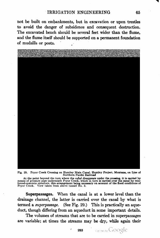
IRRIGATION ENGINEERING 65
not be built on embankments, but in excavation or upon trestles
to avoid the danger of subsidence and consequent destruction.
The excavated bench should be several feet wider than the flume,
and the flume itself should be supported on a permanent foundation
of mudsills or posts.
Fig. 29. Pryor Creek Crossing on Huntley Main Canal, Huntley Project, Montana, on Line of
Northern Pacific Railroad
At the point beyond the turn where the canal disappears under the crossing, it is carried by
means of pressure pipe underneath Pryor Creek, which in turn is carried over the canal by rein-
forced-concrete structure, this arrangement being necessary on account of the flood conditions of
Pryor Creek. View taken from above tunnel No. 3.
Superpassages. When the canal is at a lower level than the
drainage channel, the latter is carried over the canal by what is
termed a superpassage. (See Fig. 29.) This is practically an aque
duct, though differing from an aqueduct in some important details.
The volumes of streams that are to be carried in superpassages
are variable; at times the streams may be dry, while again their
283
66 IRRIGATION ENGINEERING
flood discharges may be enormous. The waterway of the super-
passage must be ample to carry the greatest flood flow that may
occur in the stream; and especial care must be exercised in joining
the superpassage to the stream bed above and below, to prevent
injury by the violent action of flood waters.
Constructing superpassages of wood is not to be recommended,
as the alternate wetting and drying will soon result in decay. They
have occasionally been built of iron, but proper precautions must
then be taken to provide against expansion and contraction, since
at times the amount of water flowing in the channel will not be
sufficient to maintain the temperature constant.
Siphons. The most common practice in the United States is
to carry the canal under the stream by means of an inverted siphon,
though at times it may be more convenient to carry the stream
through the siphon and then build the canal over the siphon in
the form of an aqueduct. The proper dimensions of the siphon
may be computed by means of any one of the numerous formulas
for the flow of water in pipes. Siphons may be of wood—built
up—or they may be of wrought iron, cement, reinforced concrete, or
wooden pipe.
DISTRIBUTARIES
Distributaries bear the same relation to the main canal system
as the service pipes in the city waterworks system do to the city
mains. From the distributaries the irrigator takes his water supply
for irrigating his crops.
Best Location. These minor ditches, or laterals, should
not be diverted from the main canal or from its upper branches,
as these should have as few openings as possible, in order to reduce
the liability of accident to a minimum. The water should be drawn
at proper intervals from the main canal into moderate size branches
so located as to command the greatest area of land and to supply
the laterals and small ditches of the irrigator in the simplest and
most direct manner possible.
Wherever water is plentiful and not particularly valuable, it is
conducted to the lands in open ditches and laterals excavated in
the earth. Where, however, water is scarce and its cost high,
the losses from evaporation and percolation should be reduced
to the minimum. In such a case the laterals should consist of
284
IRRIGATION ENGINEERING 67
wooden flumes, of paved or masonry-lined earth channels, or, in
extreme cases, the supply may be conducted underground in pipes
and applied to the crops from these, instead of being flowed over
the surface. This results in the highest possible duty and the most
effective use of the water.
The most economical location in a main canal is along a ridge,
whence the water may be supplied to its branches and to private
channels on either side. Such a location, however, can seldom be
realized. The distributaries taken from the main lines should
conform to the dividing lines between water courses; and the capacity
of each will then be proportioned to the duty required of it, the
bounding streams limiting the area it will have to serve.
Considerations in Designing. In preparing for the design
of a distributary system, a careful topographical survey should be
made of the entire area to be covered by the system; and the loca
tion should be made only after a thorough study of the topographical
features. Cuts and fills should be balanced as nearly as possible,
and the loss of water by percolation reduced to a minimum as far
as consistent with economy of design and value of water. Provision
should be made for the least mileage of channels consistent with the
command of the greatest area of irrigable land on either side. Atten
tion should be paid to drainage, that it may be secured with the least
possible interference with the proposed channels and distributaries.
For the complete and efficient distribution of water, the engineer
should consider the design and location of the distributaries of as
much importance as the design and location of the main branches.
Besides the alignment, attention should be paid to the character
of the soil and to the safe and permanent crossing of drainage lines,
while the capacity of the channels should be proportioned to the
duty required, the cross-sectional area being reduced as the quantity
of water is decreased by its diversion to private channels.
The bed of the distributary should be above the level of the
bed of the canal, in order to get the clearest water from the canal,
and in order that it may be kept at as high a level as possible and
provide surface irrigation throughout its length. Care should be
taken, in level country, that the drainage lines into which the dis
tributaries tail should have ample capacity to accommodate any
flood flow that it may be necessary to discharge into them, as other
285
68 IRRIGATION ENGINEERING
wise the streams might become clogged and flood the surrounding
country. The slope of the distributary should be as nearly as
possible parallel to the surface of the land it traverses, thus com
manding the maximum area and at the same time avoiding expensive
and heavy construction. To realize this condition, falls may be
frequently introduced, and storm-water escapes into natural channels
may be provided at intervals in the course of the distributary.
In determining the dimensions of distributaries, it must be
borne in mind that the greater the amount of discharge, the smaller
will be the unit cost of maintenance. A single channel the width
of which is equal to that of two separate channels, will have a carry
ing capacity more than double that of each of the smaller channels;
and the cost of patrolling and maintaining the single channel gen
erally will be one-half that of the two smaller channels. Experience
has shown that irrigation can be most profitably carried on from
channels having a width of 18 feet on the bottom and a depth of
about 4 feet of water. The surface of the water should be main
tained at from 1 to 3 feet above the surrounding area, to provide
gravity irrigation and to reduce the loss by absorption.
Details of Construction. Distributary heads should be arranged
much as are the heads of main canals and escapes. They consist
essentially of two parts: a regulator or check below the head on the
main canal, to divert the water into the distributary; and a regulating
gate in the distributary, to admit the proper amount of water.
These heads usually consist of a wooden fluming, built in the form
of an apron to the bed of the distributary, with planking to protect
the banks. In this flume are built the gates, consisting either of
•Dashboards or of simple wooden lifting gates.
Distributary channels are often open channels, but when the
water is conveyed in pipes, these may be of steel, of wood, or of
reinforced concrete. Steel pipe should always be coated with
hot asphaltnm to protect it from erosion. This class of pipe will
bear internal pressures of from 100 to 200 pounds per square inch.
Air valves should be introduced at all high places; blow-off valves
at the proper intervals; and a standpipe air chamber may be placed
at the highest point in the line.
Several types of wooden pipes are in use, but for the larger
conduits, wooden stavepipes are to be preferred. The pipe is built
286
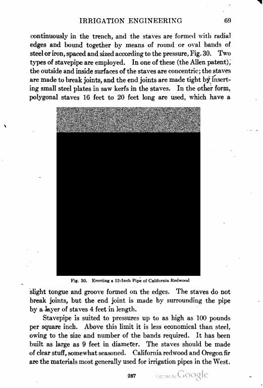
IRRIGATION ENGINEERING 69
continuously in the trench, and the staves are formed with radial
edges and bound together by means of round or oval bands of
steel or iron, spaced and sized according to the pressure, Fig. 30. Two
types of stavepipe are employed. In one of these (the Allen patent),
the outside and inside surfaces of the staves are concentric; the staves
are made to break joints, and the end joints are made tight by insert
ing small steel plates in saw kerfs in the staves. In the other form,
polygonal staves 16 feet to 20 feet long are used, which have a
Fig. 30. Erecting a 12-Inch Pipe of California Redwood
slight tongue and groove formed on the edges. The staves do not
break joints, but the end joint is made by surrounding the pipe
by a layer of staves 4 feet in length.
Stavepipe is suited to pressures up to as high as 100 pounds
per square inch. Above this limit it is less economical than steel,
owing to the size and number of the bands required. It has been
built as large as 9 feet in diameter. The staves should be made
of clear stuff, somewhat seasoned. California redwood and Oregon fir
are the materials most generally used for irrigation pipes in the West.
287
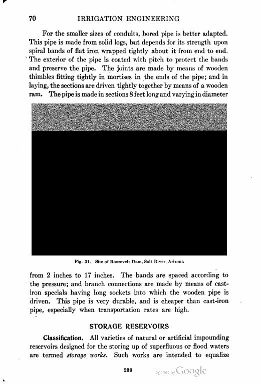
70 IRRIGATION ENGINEERING
For the smaller sizes of conduits, bored pipe is better adapted.
This pipe is made from solid logs, but depends for its strength upon
spiral bands of flat iron wrapped tightly about it from end to end.
The exterior of the pipe is coated with pitch to protect the bands
and preserve the pipe. The joints are made by means of wooden
thimbles fitting tightly in mortises in the ends of the pipe; and in
laying, the sections are driven tightly together by means of a wooden
ram. The pipe is made in sections 8 feet long and varying in diameter
Fig. 31. Site of Roosevelt Dam, Salt River, Arizona
from 2 inches to 17 inches. The bands are spaced according to
the pressure; and branch connections are made by means of cast-
iron specials having long sockets into which the wooden pipe is
driven. This pipe is very durable, and is cheaper than cast-iron
pipe, especially when transportation rates are high.
STORAGE RESERVOIRS
Classification. All varieties of natural or artificial impounding
reservoirs designed for the storing up of superfluous or flood waters
are termed storage works. Such works are intended to equalize
288
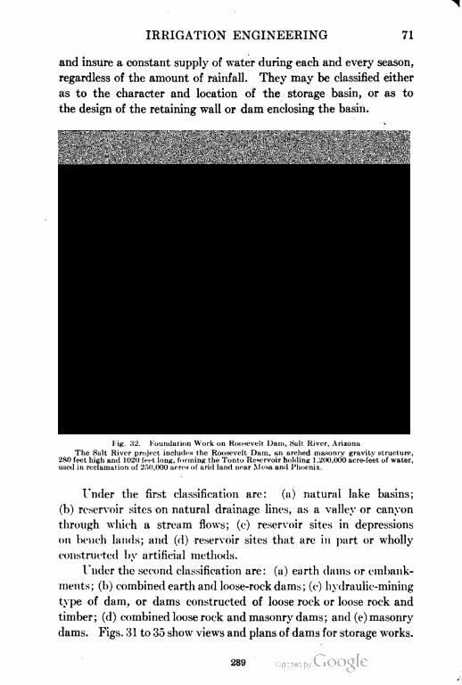
IRRIGATION ENGINEERING 71
and insure a constant supply of water during each and every season,
regardless of the amount of rainfall. They may be classified either
as to the character and location of the storage basin, or as to
the design of the retaining wall or dam enclosing the basin.
Fig. 32. Foundation Work on Roosevelt Uam, Salt River, Arizona
The Salt River project includes the Roosevelt Dam. an arched masonry gravity structure,
280 feet high and 1020 feet long, forming the Tonto Reservoir holding 1 ,200,000 acre-feet of water,
used in reclamation of 250,000 acres of arid land near Mesa and Phoenix.
Under the first classification are: (a) natural lake basins;
(b) reservoir sites on natural drainage lines, as a valley or canyon
through which a stream flows; (c) reservoir sites in depressions
on bench lands; and (d) -reservoir sites that are in part or wholly
constructed by artificial methods.
Under the second classification are: (a) earth dams or embank
ments; (b) combined earth and loose-rock dams; (c) hydraulic-mining
type of dam, or dams constructed of loose rock or loose rock and
timber; (d) combined loose rock and masonry dams; and (e) masonry
dams. Figs. 81 to 35 show views and plans of dams for storage works.
289
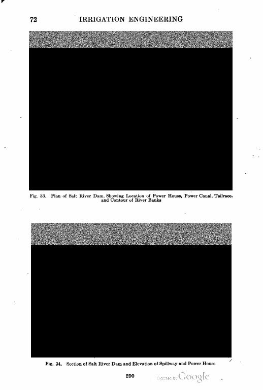
72 IRRIGATION ENGINEERING
Fig. 33. Plan of Salt River Dam, Showing Location of Power House, Power Canal, Tailrace,
and Contour of River Bunks
Fig. 34. Scction ol Salt Itiver Dam and Elevation of Spillway and Power House
290
IRRIGATION ENGINEERING 73
Factors in Locating. Topography. After the position and
extent of the irrigable lands have been determined, a careful pre
liminary survey of the surrounding region should be made in order
to determine the most desirable location for the reservoir. As
much information as is possible should be obtained on a catchment
area, the run-off, and the maximum and- minimum discharge.
The location of the reservoir site having been decided upon
in a general way, a detailed survey of it should be made. This
can best be done with the transit and stadia. If the valley above
the dam site be long and narrow, the reservoir also will be of this
shape, and in many cases two or more valleys of contributing streams
may unite in one reservoir site. It is desirable that the enclosing
hills be steep, and that the valley be narrow at the dam site, to
avoid shallow water and expensive construction. A basin or valley
with little longitudinal slope will provide a given amount of storage
with less height of dam than one with a steep longitudinal slope,
and for that reason is to be preferred. The larger the drainage
area above the dam site, the greater the quantity of yield; and so
the position of the dam with reference to the head of the area is
important. The reservoir must be sufficiently high up the valley
for the water to command the irrigable lands.
In conducting the surveys of the reservoir site, a tentative
location of the dam should be made, and an approximate idea of
its height obtained. The extreme height of the dam should be
taken as the basis of the surveys, and a closed contour run out at
this level around the entire site. A main traverse should be run
through the lowest line of the site, from the dam to the extreme
end, where it will connect with the top contour. Cross-section
lines may now be run with the stadia from this line, and the topog
raphy of the site sketched by means of 5-foot contours and plotted
to a large scale. Such a map will enable the engineer to determine
the capacity of the reservoir for different depths of water. The
dam site should be surveyed with greater care and more in detail,
several possible sites being cross-sectioned and plotted to 1-foot
contour intervals, to a scale of 100 feet to the inch if possible.
In deciding upon the exact location of the dam, the cost will
generally be the controlling consideration. The elevation of the
crest having been fixed, that location is best which requires the least
291
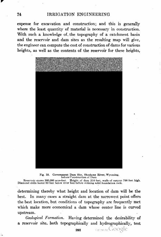
74 IRRIGATION ENGINEERING
expense for excavation and construction; and this is generally
where the least quantity of material is necessary in construction.
With such a knowledge of , the topography of a catchment basin
and the reservoir and dam sites as the resulting map will give,
the engineer can compute the cost of construction of dams for various
heights, as well as the contents of the reservoir for these heights,
Fig. 35. Government Dam Site, Shoshone River, Wyoming,
before Construction of Dam
Reservoir stores 300,000 acre-feet. Height of dam 210 feet, walls of canyon 700 feet high.
Diamond drills bored 80 feet below river bed before striking solid foundation rock.
determining thereby what height and location of dam will be the
best. In many cases a straight dam at the narrowest point offers
the best location, but conditions of topography are frequently met
which make more economical a dam whose center line is curved
upstream.
Geological Formation. Having determined the desirability of
a reservoir site, both topographically and hydrographically, test
292
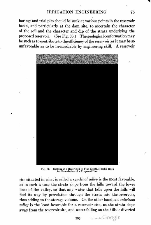
IRRIGATION ENGINEERING 75
borings and trial pits should be sunk at various points in the reservoir
basin, and particularly at the dam site, to ascertain the character
of the soil and the character and dip of the strata underlying the
proposed reservoir. (See Fig. 36.) The geological conformation may
be such as to contribute to the efficiency of the reservoir, or it may be so
unfavorable as to be irremediable by engineering skill. A reservoir
Fig. 36. Drilling in a River Bed to Find Depth of Solid Hock
for Foundation of a Proposed Dam
site situated in what is called a synclinal valley is the most favorable,
as in such a case the strata slope from the hills toward the lower
lines of the valley, so that any water that falls upon the hills will
find its way by percolation through the strata into the reservoir,
thus adding to the storage volume. On the other hand, an anticlinal
valley is the least favorable for a reservoir site, as the strata slope
away from the reservoir site, and water falling on the hills is diverted
293
70 IRRIGATION ENGINEERING
by percolation away from the reservoir site and to other drainage
areas. A third class of geological formation intermediate between
the other two, is that in which the valley has been eroded in the
side of the strata that dip in one direction. In such a case the
upper strata lead water from the adjoining hills into the reservoir,
while the strata on the lower side tend to carry the water away
from the reservoir by percolation.
Fig. 37. Types of Geological Strata for Reservoir Sites
A—Synclinal Valley; B—Anticlinal Valley; C—Intermediate Type
If the surface of the proposed reservoir site is made up of a
deep bed of coarse gravel, sand, or even limestone, crevices in the
last named or between the interstices of the first two named will
tend to diminish the capacity of the reservoir by seepage from it.
On the other hand, the geological formation may be most unfavor
able, yet, if the surface of the reservoir site be covered with a deep
deposit of alluvial sediment or of clay or dirty gravel, or of other
equally impervious material, little danger is to be apprehended
294
IRRIGATION ENGINEERING 77
from seepage. Fig. 37 illustrates the three types of geological
strata described above.
Relation to Irrigable Lands. In considering the relation of
the reservoir site to the irrigable lands, the former should be situ
ated at a sufficient height above the latter to allow of the delivery
of water to them by gravity. The area of these lands should be
sufficient to require the entire amount of water stored, that the
maximum return may be derived from water rates, and the reservoir
should be located as near as possible to the irrigable lands, in order
that the loss in transportation shall be a minimum. It may often
happen, however, that the reservoir is necessarily located at a
considerable distance from the irrigable lands, requiring either a
long supply canal, or that the water be turned back into the natural
channels, down which it flows until diverted in the neighborhood
of the irrigable lands. This is very wasteful of water, since the
losses by percolation and evaporation are large.
Natural and Artificial Locations. If a reservoir is situated
in a natural lake basin, a short drainage cut or a comparatively
cheap dam, or both, may give a large available storage capacity.
The most abundant reservoirs are usually those on natural drainage
lines, though these may be the most expensive in construction owing
to the precautions which are necessary, in building the dam, to
provide for the discharge of flood water. Almost equally abundant
are those reservoir sites found in alkaline basins or depressions
on bench or plain lands. The utilization of such basins as reser
voir sites is comparatively inexpensive, as they can be converted
into reservoirs by the construction of a deep drainage cut or of a
comparatively cheap earth embankment. Scarcely any provision
is necessary for the passage of flood water, and the heaviest item
of expense is the supply canal for filling them from some adjacent
source.
Artificial reservoirs are occasionally constructed where water
is valuable, by the erection of an earth embankment above the
general level of the country, or by the excavation of a reservoir
basin by artificial means. Reservoirs of this kind are usually
of relatively insignificant dimensions, as the expense of building
large reservoirs of the kind would be prohibitive. Shallow reser
voirs should never be constructed. The loss from evaporation
295
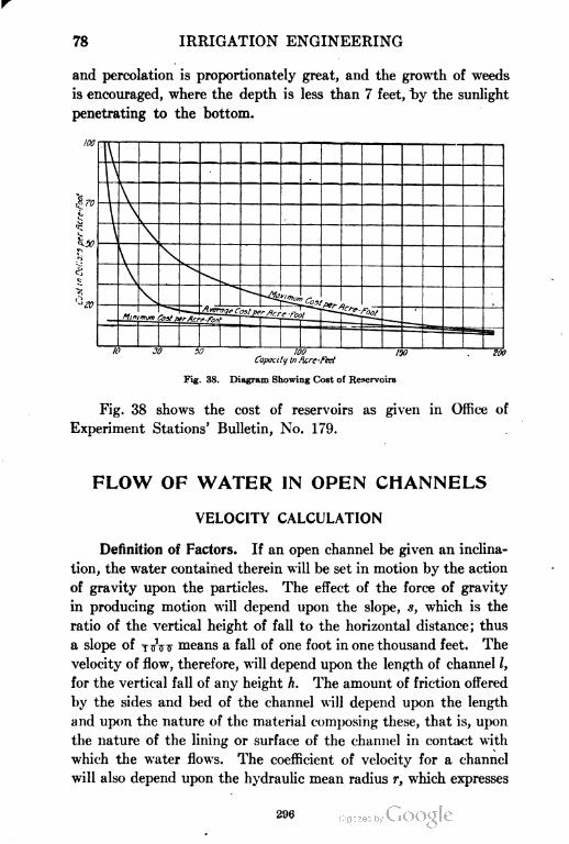
78 IRRIGATION ENGINEERING
and percolation is proportionately great, and the growth of weeds
is encouraged, where the depth is less than 7 feet, by the sunlight
penetrating to the bottom.
Capacity In fare-feet
Fig. 38. Diagram Showing Cost of Reservoirs
Fig. 38 shows the cost of reservoirs as given in Office of
Experiment Stations' Bulletin, No. 179.
FLOW OF WATER IN OPEN CHANNELS
VELOCITY CALCULATION
Definition of Factors. If an open channel be given an inclina
tion, the water contained therein will be set in motion by the action
of gravity upon the particles. The effect of the force of gravity
in producing motion will depend upon the slope, s, which is the
ratio of the vertical height of fall to the horizontal distance; thus
a slope of TtfVtf means a fall of one foot in one thousand feet. The
velocity of flow, therefore, will depend upon the length of channel /,
for the vertical fall of any height h. The amount of friction offered
by the sides and bed of the channel will depend upon the length
and upon the nature of the material composing these, that is, upon
the nature of the lining or surface of the channel in contact with
which the water flows. The coefficient of velocity for a channel
will also depend upon the hydraulic mean radius r, which expresses
296
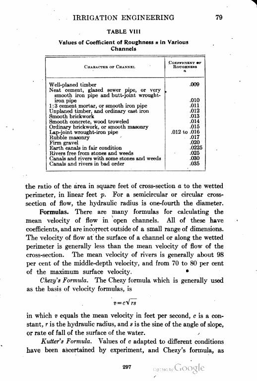
IRRIGATION ENGINEERING 79
TABLE VIII
Values of Coefficient of Roughness n in Various
Channels
CHARACTER op CHANNEL
COEFFICIENT »F
ROUGHNEHS
Well-planed timber
Neat cement, glazed sewer pipe, or very
smooth iron pipe and butt-joint wrought-
iron pipe
1 : 3 cement mortar, or smooth iron pipe
Unplaned timber, and ordinary cast iron
Smooth brickwork
Smooth concrete, wood troweled
Ordinary brickwork, or smooth masonry
Lap-joint wrought-iron pipe
Rubble masonry
Firm gravel
Earth canals in fair condition
Rivers free from stones and weeds
Canals and rivers with some stones and weeds
Canals and rivers in bad order
.009
.010
.011
.012
.013
.014
.015
.012 to .016
.017
.020
.0225
.025
.030
.035
the ratio of the area in square feet of cross-section a to the wetted
perimeter, in linear feet p. For a semicircular or circular cross-
section of flow, the hydraulic radius is one-fourth the diameter.
Formulas. There are many formulas for calculating the
mean velocity of flow in open channels. All of these have
coefficients, and are incorrect outside of a small range of dimensions.
The velocity of flow at the surface of a channel or along the wetted
perimeter is generally less than the mean velocity of flow of the
cross-section. The mean velocity of rivers is generally about 98
per cent of the middle-depth velocity, and from 70 to 80 per cent
of the maximum surface velocity.
Chezy's Formula. The Chezy formula which is generally used
as the basis of velocity formulas, is
v = cV rs
in which v equals the mean velocity in feet per second, c is a con
stant, r is the hydraulic radius, and s is the sine of the angle of slope,
or rate of fall of the surface of the water.
Kutter's Formula. Values of c adapted to different conditions
have been ascertained by experiment, and Chezy's formula, as
297
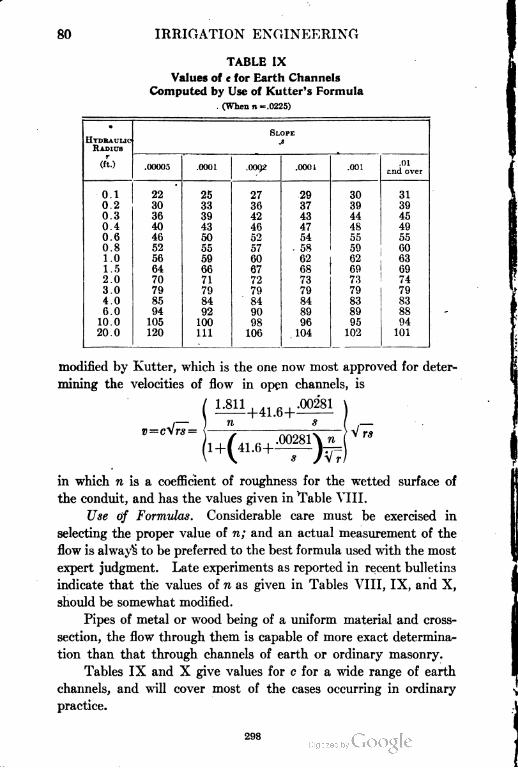
IRRIGATION ENGINEERING
TABLE IX
Values of c for Earth Channels
Computed by Use of Kutter's Formula
. (When n=.0225)
•
SLOPE
HYDRAULIC
RADIUS
JS
(ft.).00005 .0001 .0092 .000i .001
.01
end over
0.1 22 25 27 29 30 31
0.2 30 33 36 37 39 39
0.3 36 39 42 43 44 45
0.4 40 43 46 47 48 49
0.6 46 50 52 54 55 55
0.8 52 55 57 . 58 59 60
1.0 56 59 60 62 62 63
1.5 64 66 67 68 69 69
2.0 70 71 72 73 73 74
3.0 79 79 79 79 79 79
4.0 85 84 ' 84 84 83 83
6.0 94 92 90 89 89 88
10.0 105 100 98 96 95 04
20.0 120 111 106 104 102 101
modified by Kutter, which is the one now most approved for deter
mining the velocities of flow in open channels, is
V rs
in which n is a coefficient of roughness for the wetted surface of
the conduit, and has the values given in Table VIII.
Use of Formulas. Considerable care must be exercised in
selecting the proper value of n; and an actual measurement of the
flow is always to be preferred to the best formula used with the most
expert judgment. Late experiments as reported in recent bulletins
indicate that the values of n as given in Tables VIII, IX, and X,
should be somewhat modified.
Pipes of metal or wood being of a uniform material and cross-
section, the flow through them is capable of more exact determina
tion than that through channels of earth or ordinary masonry.
Tables IX and X give values for c for a wide range of earth
channels, and will cover most of the cases occurring in ordinary
practice.
298
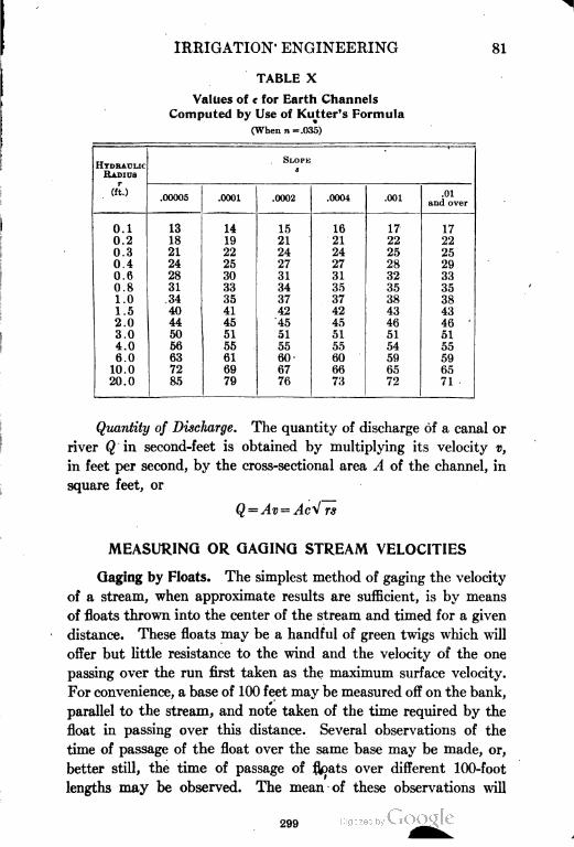
IRRIGATION ENGINEERING 81
TABLE X
Values of c for Earth Channels
Computed by Use of Kutter's Formula
(When n = .035)
HYDRAULIC
RADIUS
SLOPK
s
(ft.).00005 .0001 .0002 .0004 .001
.01
and over
10.1 13 14 15 16 17 17
0.2 18 19 21 21 22 22
0.3 21 22 24 24 25 25
0.4 24 25 27 27 28 29
0.6 28 30 31 31 32 33
0.8 31 33 34 35 35 35
1.0 34 35 37 37 38 38
1.5 40 41 42 42 43 43
2.0 44 45 45 45 46 46 '
3.0 50 51 51 51 51 51
4.0 56 55 55 55 54 55
6.0 63 61 60' 60 59 59
10.0 72 69 67 66 65 65
20.0 85 79 76 73 72 71
Quantity of Discharge. The quantity of discharge of a canal or
river Q in second-feet is obtained by multiplying its velocity v,
in feet per second, by the cross-sectional area A of the channel, in
square feet, or
rs
MEASURING OR GAGING STREAM VELOCITIES
Gaging by Floats. The simplest method of gaging the velocity
of a stream, when approximate results are sufficient, is by means
of floats thrown into the center of the stream and timed for a given
distance. These floats may be a handful of green twigs which will
offer but little resistance to the wind and the velocity of the one
passing over the run first taken as the maximum surface velocity.
For convenience, a base of 100 feet may be measured off on the bank,
parallel to the stream, and note taken of the time required by the
float in passing over this distance. Several observations of the
time of passage of the float over the same base may be made, or,
better still, the time of passage of flpats over different 100-foot
lengths may be observed. The mean of these observations will
299
82 IRRIGATION ENGINEERING
give the rentral or maximum surface velocity. The mean surface
velocity may be determined by the use of floats in different portions
of the width of the streams, and by timing the passage along a
fixed length of base. The resulting velocity in feet per second,
multiplied by 0.8, will give approximately the mean velocity of
the entire cross section of the stream.
Measuring at Various Depths. To determine the velocity
of a stream with great accuracy, the velocity should be determined
not of the surface alone, but of the entire body of the stream. This
may be done by timing upright rods so weighted that their bottoms
float at different depths beneath the surface of the water, or by the
use of current meters. The rods should be of wood or of tin, jointed
so as to be used in different depths of water. Finally, the stream
should be cross-sectioned at various points to determine the average
area; and the quantity of discharge may then be determined.
CURRENT MEASURING METHODS
The following description of the current meter and its use in '
gaging streams is very complete, and is from "Irrigation Engineer
ing", by H. M. Wilson:
Current meters are mechanical contrivances so arranged that by lowering
them into a stream, the velocity of its current can be ascertained with accuracy
by a direct reading of the number of revolutions of a wheel, and a comparison
of this with a table of corresponding velocities.
Various forms of current meters have been designed and used, the three
general classes being the direct-recording meter, in which the number of revolu
tions is indicated on a series of small gear wheels driven directly by a cog and
vane wheel; the electric meter, in which the counting is done by a simple make-
and-break circuit, the registering contrivance being placed at any desired dis
tance from the meter; and the acoustic meter, in which counting is done by hear
ing, through an ear tube, the clicks made by the revolution of a wheel, and
counting the samc.
Direct=Recording Meter. Of direct-acting meters, one which
has been found effective in turbid waters, is the Colorado meter.
In this, the stem is of iron pipe, several lengths of which may be
joined together. This meter is difficult- to handle for depths over
8 feet, or for less than 1 or 2 feet.
Electric Meter. Of the several varieties of electric meters,
one which is chiefly used in the U. S. Coast and Goedetic Survey
and in the U. S. Geological Survey is a modification of the Haskell
300
IRRIGATION ENGINEERING 83
meter. This meter is not so good for very high velocities as that
next described, as the rapidity of revolution is so great as to make
counting difficult. The electric meter which has been found to
work most satisfactorily under nearly all conditions of depth and
velocity by the hydrographers of the U. S. Geological Survey and
the U. S. Engineer Corps, is the small Price electric current meter.
This meter undoubtedly gives the most satisfactory results in large
Fig. 39. An Efficient Type of Current Meter
Registers mechanically in connection with electrical contact every 100 revolutions, two
graduated wheels registering to 1000 revolutions.
Courtesy of Eugene Dietzgen Company, Chicago
streams of high velocity. It is very accurate for streams of nearly
any velocity, and is now exclusively standard with both organiza
tions. Fig. 39 is a cut of an electric meter.
Acoustic Meter. The only acoustic meter now on the mar
ket is the Price meter, a modification of the electric meter, invented
by Mr. W. G. Price, United States Assistant Engineer. This meter
is especially desirable for its portability and the ease with which
it can be handled, as it weighs but little over a pound. In very
301
84 i IRRIGATION ENGINEERING
shallow streams, it gives the most accurate results of any meter.
It is held at the proper depth by a metal rod in the hands of the
observer, as is the Colorado current meter.
This meter is designed especially to stand hard knocks which
may be received in turbid irrigation waters, and it can be used in
high velocities, as revolutions are counted by tens. It consists
of a strong wheel, composed of 6 conical cups, which revolve in
a horizontal plane; its bearings run in 2 cups holding air and oil
in such manner as entirely to exclude water or gritty matter. Above
the upper bearing is a small air chamber, into which the shaft of
the wheel extends. The water cannot rise into this air chamber,
and in it is a small worm gear on the shaft, turning a wheel with
20 teeth. This wheel carries a pin which at every ten revolutions
of the shaft trips a small hammer which strikes against a diaphragm
forming the top of the air chamber; and the sound produced by
the striking hammer is transmitted by the hollow plunger rod
through a connecting rubber tube to the ear of the observer by
an earpiece. The plunger rod is in 2-foot lengths, and is graduated
to feet and tenths of feet, thus rendering it serviceable as a sounding
or gaging rod.
Use of Meter. The current meter may be conveniently used,
either from a boat attached to a wire cable strung a little above a
wire tagged with marks across the stream at a gaging station, or
from a bridge which does not impede the channel so as to make
currents or eddies in the water. Bridges, however, nearly always
impede the water, and caution should be exercised when using one
for a gaging station.
In using the direct-acting meter, the gager holds it in his hands
by the rod, and, inserting it in the water at any desired depth, allows
it to register for a certain number of seconds, or for a given number
of revolutions keeping count of the time and the revolutions. This
information with the use of a table will give the velocity at the given
point. The meter is then held at other points and the velocities
obtained. This method is known as the multiple-point method.
In obtaining the mean velocity of a section at one reading, he plunges
the meter slowly up and down from the bottom of the stream to
its surface a few times for a given length of time, or for a given
number of revolutions, at each section marked on the tagged wire,
302
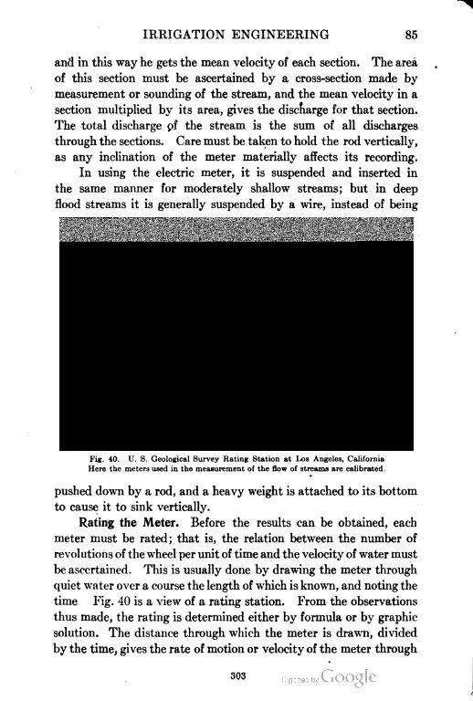
IRRIGATION ENGINEERING 85
and in this way he gets the mean velocity of each section. The area
of this section must be ascertained by a cross-section made by
measurement or sounding of the stream, and the mean velocity in a
section multiplied by its area, gives the discharge for that section.
The total discharge pf the stream is the sum of all discharges
through the sections. Care must be taken to hold the rod vertically,
as any inclination of the meter materially affects its recording.
In using the electric meter, it is suspended and inserted in
the same manner for moderately shallow streams; but in deep
flood streams it is generally suspended by a wire, instead of being
Fig. 40. U. S. Geological Survey Rating Station at Los Angeles, California
Here the meters used in the measurement of the flow of streams are calibrated.
pushed down by a rod, and a heavy weight is attached to its bottom
to cause it to sink vertically.
Rating the Meter. Before the results can be obtained, each
meter must be rated; that is, the relation between the number of
revolutions of the wheel per unit of time and the velocity of water must
be ascertained. This is usually done by drawing the meter through
quiet water over a course the length of which is known, and noting the
time Fig. 40 is a view of a rating station. From the observations
thus made, the rating is determined either by formula or by graphic
solution. The distance through which the meter is drawn, divided
by the time, gives the rate of motion or velocity of the meter through
303
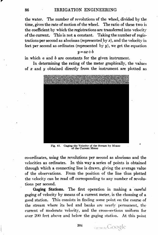
86 IRRIGATION ENGINEERING
the water. The number of revolutions of the wheel, divided by the
time, gives the rate of motion of the wheel. The ratio of these two is
the coefficient by which the registrations are transferred into velocity
of the current. This is not a constant. Taking the number of regis
trations per second as abscissas (represented by x), and the velocity in
feet per second as ordinates (represented by y), we get the equation
in which a and b are constants for the given instrument.
In determining the rating of the meter graphically, the values
of x and y obtained directly from the instrument are plotted as
Fig. 41. Gaging the Velocity of the Stream by Means
of the Current Meter
co-ordinates, using the revolutions per second as abscissas and the
velocities as ordinates. In this way a series of points is obtained
through which a connecting line is drawn, giving the average value
of the observations. From the position of the line thus plotted
the velocity can be read off corresponding to any number of revolu
tions per second.
Gaging Stations. The first operation in making a careful
gaging of velocity by means of a current meter, is the choosing of a
good station. This consists in finding .some point on the course of
the stream where its bed and banks are nearly permanent, the
current of moderate velocity, and the cross-sections uniform for
over 200 feet above and below the gaging station. At this point
304
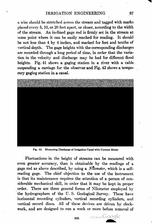
IRRIGATION ENGINEERING 87
a wire should be stretched across the stream and tagged with marks
placed every 5, 10, or 20 feet apart, or closer, according to the width
of the stream. An inclined gage rod is firmly set in the stream at
some point where it can be easily reached for reading. It should
be not less than 4 by 4 inches, and marked for feet and tenths of
vertical depth. The gage heights with the corresponding discharges
are recorded through a long period of time, in order that the varia
tion in the velocity and discharge may be had for different flood
heights. Fig. 41 shows a gaging station in a river with a cable
suspending a carriage for the observer and Fig. 42 shows a tempo
rary gaging station in a canal.
Fig. 42. Measuring Discharge of Irrigation Canal with Current Meter
Fluctuations in the height of streams can be measured with
even greater accuracy, than is obtainable by the readings of a
gage rod as above described, by using a Nilometer, which is a self-
reading gage. The chief objection to the use of the instrument
is that its maintenance requires the attention of a person of con
siderable mechanical skill, in order that it may be kept in proper
order. There are three general forms of Nilometer employed by
the hydrographers of the U. S. Geological Survey. These have
horizontal recording cylinders, vertical recording cylinders, and
vertical record discs. All of these devices are driven by clock
work, and are designed to run a week or more before removal of
305
88 IRRIGATION ENGINEERING
the recording paper. The record of stream height by the Nilom-
eter is on a scale less than the actual range of the water, and the
recording pencil is connected by a suitable reducing device with a
float which rises or falls with the stream. This float is usually
placed in a small well near the stream bank, its bottom communi
cating with the stream bed by a pipe of such size as will not readily
become clogged. The fluctuations of the water in this pipe cor
respond with those of the stream, and turn the recording wheel
through the agency of a cord wound around the wheel and having
its lower end attached to the float.
Rating the Station. After daily readings of the gage height
of the water have been taken at the station for some time, and the
velocity measured by means of the meter at different heights of
stream, the results should be plotted on cross-section paper, with
the gage heights as ordinates and the discharges (obtained by multi
plying the velocities into the cross-sections) as abscissas. These
points generally lie in such a position that a curve drawn through
them somewhat resembles half of a parabolic curve, and represents
the discharge for different heights. Having once plotted this
curve, it bec&mes possible to determine the discharge of the^ stream
, at any time by knowing the height of the water on the gage rod.
Measuring Weirs. The simplest method of measuring the
discharge from canals and streams of moderate size, is by means
of weirs. It is extensively used in Colorado and other portions of
the West, and especially commends itself to the use of irrigators,
because of the simplicity and cheapness of construction of the weir,
its accuracy of measurement, and its ease of operation. The results
of weir measurement are easily interpreted by use of tables giving
quantities of flow directly in second-feet.
By a standard weir is meant one in which the inner face is a
vertical plane, and the edge of the weir, or its crest, is sharp. Weirs
are generally made rectangular; and the crest of such a weir may
extend to the side of the flume or canal conducting the water to it,
or it may be a rectangular notch cut in the weir plate, the vertical
edges being beveled similarly to the horizontal edge. In the
former case, the contractions are said to be suppressed; in the latter,
tlie weir is said to have end contractions. If the contractions are
not suppressed, the weir plate should extend in a plane on each
306
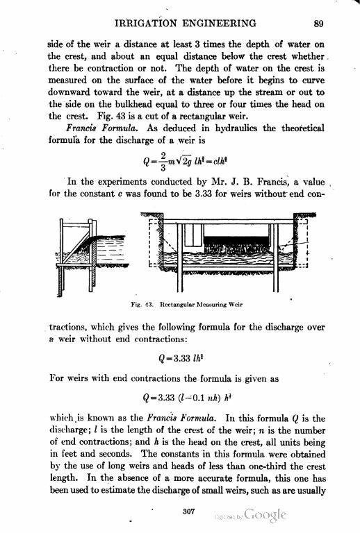
IRRIGATION ENGINEERING 89
side of the weir a distance at least 3 times the depth of water on
the crest, and about an equal distance below the crest whether
there be contraction or not. The depth of water on the crest is
measured on the surface of the water before it begins to curve
downward toward the weir, at a distance up the stream or out to
the side on the bulkhead equal to three or four times the head on
the crest. Fig. 43 is a cut of a rectangular weir.
Francis Formula. As deduced in hydraulics the theoretical
formula for the discharge of a weir is
In the experiments conducted by Mr. J. B. Francis, a value
for the constant c was found to be 3.33 for weirs without end con-
Fig. 43. Rectangular Measuring Weir
tractions, which gives the following formula for the discharge over
a- weir without end contractions:
^ = 3.33 tt»
For weirs with end contractions the formula is given as
Q = 3.33 (1-0.1 nh) A»
which.is known as the Francis Formula. In this formula Q is the
discharge; I is the length of the crest of the weir; n is the number
of end contractions; and h is the head on the crest, all units being
in feet and seconds. The constants in this formula were obtained
by the use of long weirs and heads of less than one-third the crest
length. In the absence of a more accurate formula, this one has
been used to estimate the discharge of small weirs, such as are usually
307
90 IRRIGATION ENGINEERING
found in use for measuring irrigation water. Recent experiments
conducted by the U. S. Department of Agriculture indicate that
the values obtained by the Francis formula for small weirs do not
agree so very closely with actual discharges, but it can be used
for approximate estimates in the absence of a more exact formula
or an exact table.
In using the ordinary weir, it should be placed at right angles
to the direction of flow of the stream, the upstream face being in
a vertical plane. The crest and sides should be chamfered so as
to slope downward on the lower side with an angle of not less than
30 degrees, while the crest itself should be horizontal and the ends
vertical. The dimensions of the notch should be sufficient to carry
the entire stream and still leave the depth of water on the crest
not less than 7 inches.
In the application of the formulas to determining the quantity
of flow over a weir, attention should be paid to the following details:
The water shall not be more than 24 inches, nor less than 7 inches, in depth;
the depth of water on the crest shall not exceed one-third the length of the
weir; there shall be complete contraction and free discharge, the water approach
ing without perceptible velocity and free from cross currents. The distance
from the side walls to the weir opening should be at least three times the depth
of water on the weir; and the height of the crest above the bottom of the channel
should be at least twice the depth of the water flowing over the crest. Air
should have free access under the falling water, and the channel of approach
should be straight and of uniform cross-section.
For some streams it is impossible to comply with all the con
ditions enumerated and only approximate values can be obtained
by the use of the formulas given. More exact data, as yet unpub
lished, will probably be available in the near future.
To determine the depth of water flowing over a weir, a post
should be set in the stream a short distance above it, and to this a
gage rod, suitably marked, should be attached. For very accurate
measurements a hook gage should be employed, consisting of a
hook attached to a divided rod and fitted with a slow-motion screw
and vernier. The hook is below the surface of the water; and by
turning the slow-motion screw it may be raised until the point of
the hook is just in contact with the surface, as indicated by a slight
elevation of the surface at the point of the hook. The difference
of elevation between the hook and the weir may be taken with a
leveling instrument.
308
IRRIGATION ENGINEERING 91
MEASUREMENT OF CANAL WATER
In order that water flowing in open channels may be sold by
quantity, it is necessary that the volume admitted to the canal
shall be readily ascertained at any time, and that the method of
admission shall be so regulated that it cannot be tampered with.
No method has yet been devised for accomplishing this easily and
cheaply; and as a result, water is almost universally disposed of
by canal owners by means other than direct sale by quantity. In
this country, rentals are charged per acre irrigated, rather than by
the amount of water required for the irrigation.
Essentials for a Module. Prof. L. G. Carpenter specifies
the following conditions as most desirable for a module, or apparatus
for measuring water for purposes of irrigation:
Its discharge should be capable of conversion into the common measure,
which is cubic feet per second. The ratio of discharge indicated from two
outlets should be the actual ratio. The same module should give the same
discharge wherever placed; it should be capable of being used on canals of all
sizes, and of being set to discharge any fraction of its capacity for the process
of distributing pro rata. Attempts to tamper with or alter its discharge should
leave traces easy to recognize; and it should be simple enough to be operated
by men of ordinary intelligence, so that calculations should not be required
to regulate the discharge of different modules or to determine the amount thereof.
It should occupy but small space, and the discharge should not be affected by
variations of the water level in the supplying canal. It should be inexpensive,
and cause the least possible loss of head. Nearly all modules attempt to main
tain a constant pressure of water above the opening, the orifice remaining
unchanged.
Factors of Measurement. The following upon the measure
ment of water is from "Irrigation Institutions", by Elwood Mead:
The distribution of water for irrigation is attended by many perplex
ing conditions. Streams vary in volume from day to day. Wells which can
not be lowered in April, often fail in August. The water supply is subject
to continued waste and loss. It sinks through the bottom of the canal by
seepage, and is taken up by the air through evaporation.
When the supply was abundant and the seepage limited, these vicis
situdes were of small importance; but with the growing use of water, changes
in methods and policies are necessary. This is especially true regarding the
care taken in its measurement, and in the attention now being paid to the con
tracts under which it is supplied to irrigators. When streams carried more
than was needed, water was seldom measured. Canal companies took what
they wanted, and the irrigator was charged for the acres irrigated without
any reference to how much he used. The result of this lavishness docs not
warrant its continuance. It led farmers to substitute water for cultivation,
and to injure their land and exhaust streams by wasteful and careless methods.
309
92 IRRIGATION ENGINEERING
Units. The need of a definite unit of measurement for the commodity
bought and sold is now manifest. Without this there can tie no satisfactory
basis for transactions in water, or any intelligent or certain measure of value
for irrigation purposes. In the establishment of such a unit, several things
have to be taken into account. It should be in accordance with the require
ments of agriculture, so that the quantities to be measured can be regulated
by simple and not too costly devices, and be stated in a unit convenient of
computation. Any unit, to be generally adopted and enforced, has to be both
feasible in operation and in accord with the needs or prejudices of water users.
Water cannot be delivered to irrigators by the pound or ton. Three units
of measurement are now in general use; and some one of these three is recognized
in the laws of nearly every arid state, and is nearly always stipulated in water
contracts. They are the inch, the cubic foot per second, and the acre-fool.
In the measurement of water for irrigation, there are two distinct prin
ciples involved which it is desirable to have clearly defined and to keep separate
in the mind. The first is the unit of volume to be employed, wholly apart
from the method by which this unit may be measured in actual practice. Thus,
in irrigation, if we say that the unit of measure is the cubic foot per second,
the character and volume of the unit are not affected whether water is meas
ured by the flow over a wen-, or through a flume, or by the strokes of a pumping
engine. The unit may sometimes be the quantity of water which issues from
an opening of fixed dimensions, with or without pressure; or the unit may be
the acres of land irrigated, under certain conditions.
Measuring by the Inch. In some cases, however, the unit of measurement
is associated with a special device or instrument by which it is to be actually
determined. The form of this apparatus should be in accord with the principles
of Hydraulics, and be determined by scientific considerations. The inch is
such a unit of measurement; it has to be associated with some particular device
or instrument of measurement. Its use is as old as irrigation. In this country
it is older than modern irrigation, having been first used by the placer miner,
and borrowed from him by the irrigator. In both mining and irrigation, it is
the volume of water which will flow through an inch-square orifice under a
uniform and designated pressure. The slope and size of the orifice and the
pressure upon it are fixed by law in a number of states, and in others regulated
by custom.
The ruling custom in the United States is to have the orifice, through
which water is delivered, 6 inches in height and wide enough to deliver the
required number of inches. The pressure on this orifice varies from 4 inches
above the center in some places, to 6 inches above the top in others. In Nevada,
the inch has sometimes an opening 4 inches in height, with a pressure of 6 inches
above the top. Irrigators who are not able to compute the quantity of water
flowing over weirs or through flumes, prefer, as a rule, to have their water meas
ured by the inch. They can tell by looking—or believe they can—whether
or not the quantity contracted for is being delivered; and when the conditions
presented by the statute are complied with, they can tell, with a close approxima
tion to the truth, whether or not they get what they pay for.
The most serious objection to this unit is the name. Men accustomed
to square inches and cubic inches, confuse them with miner's inches and statute
inches. Because of the confusion, they frequently determine the inches of
310
IRRIGATION ENGINEERING 93
water being furnished them, by ascertaining the number of square inches in
the cross-section of their ditch or lateral, and calling this the number of inches
of water received, although in doing so they disregard both the absence of an
orifice, the pressure upon it, and the grade or velocity of the stream measured.
It is the common practice on many streams in Utah, for the water masters to
measure the inches of water in the ditches by taking the cross-section of their
flow, and wholly disregarding pressure and velocity.
A simple device for measuring miner's inches consists of a board 2 inches
thick, 12 inches wide, and about 8 feet long. The opening is 1 inch wide and
50 inches long, and the distance from the top of the board to the center of the
opening is exactly 4 inches on the upstream side. On the downstream side,
the opening is beveled so that the whole presents sharp edges to the stream.
A sliding board is hung upon the top of the first board, with a strip screwed
along its upper edge, this sliding board being wide enough to cover the opening
on the upstream side. In the slot, there is a closely fitting block made to slide
on the beveled edges, and fastened by a screw to the sliding board. When the
sliding board is moved backward or forward by means of its end, which is extended
for a handle, the block moves in the slot and determines the length of the opening.
When used to determine the flow of a stream, the board is placed so as
to dam the flow completely, and the sliding board is moved backward or forward
until the water is all passing through the slot, the water being kept to the top
of the board, or 4 inches above the center of the opening. The length of the
opening measures the number of miner's inches of water flowing through. If
the flow is too great to pass through the opening 1 inch wide, the opening may
be made wider, the water still to be kept 4 inches above the center of the opening.
Many measuring boxes in European canals are constructed in the most
substantial manner, of masonry. The orifice is cut through stone, with edges
of metal, and with the utmost precision in its dimensions. Thus far, in this
country, but little attention has been paid to accuracy, either in the form or
size of openings, although much ingenuity has been shown in designing auto
matic regulators. The pervading practice in the west is to make the measuring
boxes of wood, and to give slight regard either to the freedom of delivery or
to securing uniform pressure. One of the reasons why no more consideration
has been given to the accuracy of measuring devices, is the fact that the con
ditions of water contracts are so often not in accord with the way water has
to be used.
The field of usefulness of the inch is restricted to the measurement of com
paratively small quantities of water. It is well adapted to the distribution
of water to irrigators, from canals or from the main laterals of canals; but it
is not suited to the measurement of rivers or to the distribution of water from
a river. Where large volumes, or widely fluctuating volumes, are to be measured,
the construction of a satisfactory device for measuring by inches is not practical.
There are a number of canals in this country which carry from 50,000 to 125,000
statutory inches. It is manifest that while the width of an orifice can be extended
indefinitely without materially affecting the accuracy of the measurements,
every change in its depths must materially increase the velocity, and hence
the quantity of water discharged by each square inch of its cross-section.
Nearly all of the statutes prescribe a maximum depth for the orifice, and
require that increase in volume delivered shall be secured by extending its
311
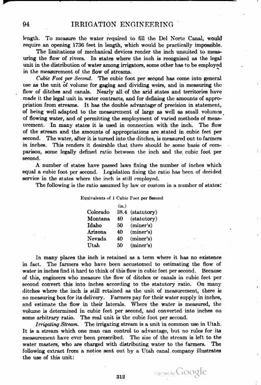
94 IRRIGATION ENGINEERING
length. To mcasuro the water required to fill the Del Norte Canal, would
require an opening 1736 feet in length, which would be practically impossible.
The limitations of mechanical devices render the inch unsuited to meas
uring the flow of rivers. In states where the inch is recognized as the legal
unit in the distribution of water among irrigators, some other has to be employed
in the measurement of the flow of streams.
Cubic Foot per Second. The cubic foot per second has come into general
use as the unit of volume for gaging and dividing weirs, and in measuring the
flow of ditches and canals. Nearly all of the arid states and territories have
made it the legal unit in water contracts, and for defining the amounts of appro
priation from streams. It has the double advantage of precision in statement,
of being well adapted to the measurement of large as well as small volumes
of flowing water, and of permitting the employment of varied methods of meas
urement. In many states it is used in connection with the inch. The flow
of the stream and the amounts of appropriations are stated in cubic feet per
second. The water, after it is turned into the ditches, is measured out to farmers
in inches. This renders it desirable that there should be some basis of com
parison, some legally defined ratio between the inch and the. cubic foot per
second.
A number of states have passed laws fixing the number of inches which
equal a cubic foot per second. Legislation fixing the ratio has been of decided
service in the states where the inch is still employed.
The following is the ratio assumed by law or custom in a number of states:
Equivalents of 1 Cubic Font per Second
(in.)
Colorado 38.4 (statutory)
Montana 40 (statutory)
Idaho 50 (miner's)
Arizona 40 (miner's)
Nevada 40 (miner's)
Utah 50 (miner's)
In many places the inch is retained as a term where it has no existence
in fact. The farmers who have been accustomed to estimating the flow of
water in inches find it hard to think of this flow in cubic feet per second. Because
of this, engineers who measure the flow of ditches or canals in cubic feet per
second convert this into inches according to the statutory ratio. On many
ditches where the inch is still retained as the unit of measurement, there is
no measuring box for its delivery. Farmers pay for their water supply in inches,
and estimate the flow in their laterals. Where the water is measured, the
volume is determined in cubic feet per second, and converted into inches on
some arbitrary ratio. The real unit is the cubic foot per second.
Irrigating Stream. The irrigating stream is a unit in common use in Utah.
It is a stream which one man can control to advantage, but no rules for its
measurement have ever been prescribed. The size of the stream is left to the
water masters, who are charged with distributing water to the farmers. The
following extract from a notice sent out by a Utah canal . company illustrates
the use of this unit:
312
IRRIGATION ENGINEERING 95
"The books of the company show that you are the owner of
shares of stock, and you will therefore be entitled to the use of
an irrigating stream for hours."
The water in this canal is not measured, nor are the diversions. The
water master estimates the number of streams in his canal, and these streams
are used in turn by the farmers. They are supposed to be equal; but meas
urements made upon a canal to determine the accuracy of the judgment of
the water master, gave widely varying results.
The amount of money paid for water each year by irrigators is so large
that it seems surprising that they have not paid more attention to the accuracy
with which it is measured. In transactions involving any other kind of property,
care is taken to see that it is accurately measured; but, although water costs
more than any other commodity used by the irrigator, it i.s bought and paid
for without either buyer or seller knowing how much is delivered. The need
of greater accuracy in water measurements has let! to the passage of a law in
Utah requiring the State Engineer to give information and advice about the
placing of measuring devices. The State Engineers of Colorado and Wyoming
are required to advise irrigators in respect to the measurement of water; and
a recent Colorado statute also provides for the use of registers which will keep
a continuous record of the quantity of water delivered. The introduction of
registers and greater accuracy in the construction of measuring boxes, is one
of the developments of the near future. Their installation will do much To
reform water contracts, prevent the awarding of excessive amounts of water
in decrees, promote economy and efficiency in use, and extend the reclaimed
flrpoarea.
313

--.
CONWAY BUILDING, CHICAGO
1i. H. Rurnham and Company, Architects
Courtesy of Tbi"""aon-Slarrt'lt Company, ,\'cw York City
COST-ANALYSIS ENGINEERING
PART I
WHAT IS COST ANALYSIS?
INTRODUCTION
"For which of you, intending to build a tower, xitteth not dawn first and
counteth the cost, whether he have sufficient to finish it." (Luke, 14: 28.)
Cost Analysis Defined. Cost analysis is proved by this quota
tion to be not a new thing. According to the Century Dictionary,
which defines "cost" quite to the writer's mind, " Nothing has any
cost until it is actually attained or obtained ; while price is the amount
which is asked for a service or thing." Therefore, we estimate the
cost, in doing which we must analyze the particular proposition we
have before us.
Good Judgment a Necessary Element. By the very meaning
of the term, "cost analysis" is, therefore, in ho sense a new idea,
being merely a modern designation for good judgment based upon
experience, or the analysis within the brain of the individual as to
the relative costs of different classes of work, a judgment and decision
which are reached through an intimate acquaintance with costs
and the value of work along various lines of construction. By
consulting the chart, Fig. 1, a good idea may be obtained of how
intimately cost analysis is connected with the other branches of an
engineering contract business and to what extent the cost analyst
draws upon these departments for material to help him form his
good judgment.
Since the days when things were first built, the individual
workman has accumulated a mind full of ideas of relative costs of
work, based upon his own impressions and experiences. Those in
whose brain this judgment has received its highest development are
the ones who have advanced from the position of laborers to fore
men, to superintendents, and finally to the position of employers.
315
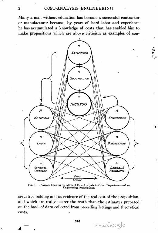
2 COST-ANALYSIS ENGINEERING
Many a man without education has become a successful contractor
or manufacturer because, by years of hard labor and experience
he has accumulated a knowledge of costs that has enabled him to
make propositions which are above criticism as examples of con-
Fig. 1. Diagram Showing Relation of Cost Analysis to Other Departments of an
Engineering Organization
servative bidding and as evidence of the real cost of the proposition,
and which are really nearer the truth than the estimates prepared
on the basis of data collected from preceding lettings and theoretical
costs.
316
COST-ANALYSIS ENGINEERING 3
Too strong emphasis cannot be laid upon this particular point,
for herein lies absolutely all the value of cost analysis". The mere cost
of a proposition when reduced to dollars and cents is of little value,
eycept when used with the good judgment attendant upon actual expe
rience and a personal acquaintance with the nature of the work.
Experience the Teacher. The cost-analysis turn of mind is not
something to be acquired, unless the individual has within himself
an instinctive disposition to ascertain why the results are as recorded.
The laborer, no matter how ignorant and uneducated, who advances
to the position of a business of his own, is a man who grasps this
fundamental point, and he, perhaps unconsciously, gains the best
idea of the value of work in relation to the circumstances surround
ing it. In other words, such a man has the advantage of not being
encumbered with reports which influence his judgment, but of form
ing his conclusions entirely with regard to the circumstances and
conditions under which he must work.
Too often cost records compiled according to the modern idea
as a basis for future operations, obscure these points, costs being
used which are in no sense indicative of the actual work. Under
the method mentioned, in which the laborer, by his own efforts,
advances to the position of employer, and in so doing grounds his
knowledge absolutely on experience, progress for the successful man
is necessarily slow. The individual who begins with insufficient
experience is at a great disadvantage, and unless he meets with very
unusual or fortunate circumstances the result may be discouraging,
or even a failure.
Natural Growth Inadequate for Present Day. In the new or
undeveloped country, or in a country where the development is
slow, such a natural growth is the proper one, and one that is quite
sufficient. The idea of the apprentice, the journeyman, the master
workman, and the employer is one which entirely satisfied the
conditions of the Middle Ages, but is utterly inadequate to meet
the demands of our modern everyday life. In the old days, the
artisan in any special line had accumulated within his brain all the
details necessary successfully to complete any work. In our day
blue prints are supplied to the contractor, and if he cannot read a
plan or estimate quantities from a blue print, he is at a serious
disadvantage. Modern cost analysis demands, therefore, not only
317
4 COST-ANALYSIS ENGINEERING
a record of actual results, but the ability to read and interpret a
plan for the purpose of applying such practical information to the
problem in hand.
Standardizing of Methods Important. In individual work
minor changes may be possible and individual ideas may be incor
porated, but, in general, any uniform system of cost analysis can be
obtained only by the working-out of a standard method of cost
distribution, so that when one job is analyzed and compared with
another, or when the individual making the analysis is not familiar
with either job or at least with only one, there may be a direct
method of comparison and analysis.
RELATION OF COST KEEPING TO COST ANALYSIS
Overlapping of the Two Subjects. Cost analysis is so closely
identified and connected with the subject of cost keeping that, to a
certain extent, the reports will probably overlap at many points.
Any broad comprehensive system of cost keeping will contain certain
elements of cost analysis; on the other hand, cost analysis, being
based upon cost keeping, must necessarily embody suggestions
along the line of proper cost keeping.
The distinction between cost keeping and cost analysis should
be thoroughly understood, and to make this distinction more clear
the following definitions are given:
(1) Cost analysis is the executive mapping-out of new work,
supervision of such work, and compilation of the records obtained through
cost keeping in order to secure comparative values.
(2) Cost analysis is the study of the data obtained by cost keeping
whereby the reasons for the results are determined.
(3) Cost analysis is the executive department of contract work
for the purpose of properly supervising and securing intelligent records,
whereby experience is fortified for future reference.
General Remarks. Cost keeping must involve the preparation
of forms or blanks by which distribution of the pay roll, material,
etc., is properly made to the various accounts; but as this work is
generally in the hands of only ordinary clerical help, and in the
majority of cases is done under adverse conditions, no particularly
intelligent idea is to be expected from such records unless the execu
tive head maps out the work of separating the items to a degree far
318
COST-ANALYSIS ENGINEERING 5
beyond mere forms. For example, concrete work is "concrete
work" to the cost-keeping man, regardless of its character, how it is
done, where it is done, the time of the year, or a hundred other con
ditions which may make the reports misleading. Many maintain
that by adding a complete description of the work, this difficulty
may be overcome. This is true to a certain extent, but if the
description is made long enough to be of any particular value, the
cost record is cumbersome and of little use to the average busy man.
There is connected with every job—no matter how done or where
done, even if under abnormal conditions—a method of so dividing
and subdividing the items that the same items of work on jobs of
entirely different character may accurately be compared, provided,
of course, that a standard method of distribution is used.
Cost analysis is not concerned with what work cost, but is con
cerned with why it cost what it did, and whether this cost is above
or below the average, and if so, why? Cost keeping states certain
absolute facts as such because these facts are records. Cost analysis
goes one step further and states why the work cost a certain sum
and what reasonably could be expected under different circum
stances. Cost analysis begins at the time estimates on new work
are prepared, superintends the adoption of a cost-keeping system
in harmony with the estimates, watches the work during its progress
for all abnormal conditions and segregates them, and finally analyzes
the records.
In successfully carrying out the idea of cost analysis, cost
keeping itself is affected by the character of the records required.
In order to avoid confusion in the cost records all "specials" are
recognized and so recorded with reference to any particular job,
thus separating them from the standard elements which enter into
all work. This means that before operations are actually begun,
estimates and plans must be studied and special distribution provided
for any class of work which is peculiar to this job; furthermore, if
during the progress of the work, any special peculiarities arise, these
must be properly recognized in the records.
Simple Methods. Cost analysis should simplify, rather than
complicate, cost keeping. Cost keeping may be carried to an extreme
in any one general division of the work, being so subdivided as to
make it almost impossible to keep the work up day by day with
319
f, COST-ANALYSIS ENGINEERING
the ordinary clerical force. Such an elaboration of divisions pro
duces misleading distributions and records. Cost analysis does not
contemplate any such method; in fact, it does not contemplate to
any extent the subdivision of the general items of work except
under special circumstances. If the specials and other peculiarities
of any job are recognized and carried under special headings, then
all the remainder may be carried as standard divisions of work.
To illustrate—on a job of concrete we are not interested, except
in special cases, in knowing what it costs to drive nails and draw
nails, or to saw off boards. To carry the point a step further—we
are not interested in knowing what it costs to wreck forms after the
work is done. If we have sufficient information as to what it cost
to make the forms the first time, then, knowing the cost of the form
work for the entire job, and the number of times the forms were
used, we have all the information needed for future estimates and
comparisons, providing that, if there is any special form of con
struction, that has its own unit distribution.
General Conditions Affecting Cost Keeping. The subject of
properly recording cost is a very difficult and complicated one when
applied to construction work; it is not only complicated, but in
some cases it is exasperating and seems almost impossible of
application.
Regarding Shop Labor. The subject of cost recording is not
so difficult in its application to manufacturing plants, where we
have an industry within the limits of the four walls of a building,
and where the men are always in sight and subject to observation
and to a close check upon their output. The mechanic producing
any part of a machine on a lathe or a planer, is probably doing the
same class of work, day in and day out, and can be watched very
closely; the record is, therefore, largely a question of counting the
number of pieces produced and dividing the cost, to ascertain the
cost per unit.
If, in addition, the plant is a large manufacturing concern where
more than one man is employed on the same class of work or on
the same class of machines, the output of the different men can be
ascertained, the less productive operatives weeded out, and the
general average output determined. Labor working under these
conditions is largely independent of the weather, is generally of a
820
COST-ANALYSIS ENGINEERING 7
high grade, and the facilities for a close check upon the actual time
employed are correspondingly increased. -
Regarding Construction Labor. In the case of construction
work, however, a large percentage of the payroll will be made up
of common labor, in many cases of foreigners to whom it is impossible
even to explain what is desired. All labor is exposed to the inclem
encies of the weather, and the output of the men is thereby directly
affected.
Furthermore, the circumstances surrounding the work, and the
very nature of the work itself, make ft difficult to sift out the bad
labor from the good, except through the medium of the foreman,
and the output is measured more from the gang unit than from the
individual unit. As a result, the laborer is not hired for any par
ticular line of work, except in special cases, but is shoved around
from one class of work to another, so that at the best all that can
be expected is an approximate estimate of the distribution of his
time, and the work accomplished. Many times he may be placed
on wo-k where there is absolutely no unit measurement of output.
The character of the work handled, the class of labor, the
numerous large gangs with frequent discharges and additions of
men, serve, therefore, to complicate the work of cost analysis; and
if an attempt is made to reduce the subject to too fine a point, and
too much stress laid upon it, the attention of the superintendent,
foreman, subforeman, and timekeeper is soon distracted, with a con
sequent increase in cost. While it is an excellent thing to have
costs recorded in such shape that they may be analyzed, still, if
the idea is carried to the extreme, there actually results an increased
payroll through lack of proper supervision and attention, and the
added data will hardly make up for the loss of money.
Regarding Material. The foregoing remarks have a special
reference to the cost of labor, but to a very large extent similar con
ditions exist with reference to the cost of material and other items
entering into the cost of construction. Material delivered to the
manufacturing plant can be properly stored and protected, and can
be issued from a storeroom only on written order, thus keeping a
perfect system of reports as to material used.
On construction work, however, such a refinement of record-
keeping is absolutely impossible. Material received can, of course,
321
8 " COST-ANALYSIS ENGINEERING
be checked up and protected to some extent, but nevertheless, all
material is out in the open, subject to damage by the weather or
loss by thieving. The employes have direct access to the material
as it is piled around convenient to the work, and outside of super
vision by the timekeeper or foreman there is only a limited check
upon the material used. A carpenter will invariably saw a short
piece of board from a long, new piece, rather than draw out the nails
and clean up an old, board which would have answered his purpose.
When the size of the gang is considerable, the irresponsibility of
the character of the labor and the difficulty of watching .each man
all the time make it evident that the cost analysis of the material
used in construction work and the cost analysis of material used in
a manufacturing enterprise must be considered from different view
points.
Regarding Expense Items. If cost analysis in construction
work is unsatisfactory so far as labor and material are concerned,
how much more so is it the case in consideration of expense items—
such as fittings and repairs, small tools, boots, tarpaulins, etc.—
which are of just as much importance to the work as the labor and
materials. These items, insignificant in character and few with
reference to the unit, are in the aggregate of tremendous conse
quence. Small tools may be purchased, thrown down, and immedi
ately covered by the excavated material; bolts and small tools may
be stolen by the workmen; large pieces of packing, waste, or the
remaining supply of bolts, nails, or other material may be thrown
aside and lost. These are leaks which apparently should be over
come by the proper kind of supervision, yet if too much attention
is paid to this line of the work, it is both possible and probable
that the construction work itself will be neglected, resulting in a
decreased output or increased cost.
Cost Analysis Requires Dollar Not Cent Policy. Cost analysis,
therefore, in connection with construction work, is a subject which
requires a broad-minded policy, and a system far different from the
one possible in manufacturing concerns. A man who may have just
the right turn of clerical mind, who may be exact in his accounts
and correct in his reports as a payroll clerk, timekeeper, or stock
room clerk for a manufacturing plant, may be an absolute failure
when placed in like position upon construction work.
322
COST-ANALYSIS ENGINEERING 9
It may seem rather a broad statement to make, but the writer
is clearly of the opinion that the construction man in the field—as
superintendent, foreman, material clerk, or timekeeper—must con
sider all accounts as they arise in the guise of dollars, and not cents.
"Penny wise and pmmd foolish" can have no better exemplification
than in construction work, and yet cents must be considered where the
cents occur in such a way as to be cumulative.
COST ANALYSIS AS APPLIED TO LABOR COSTS
Cost Records vs. Individual Impressions. Conceding that cost
analysis is fully as important to the contractor as to the manufac
turer, we must make the attempt to overcome the difficulties and
to obtain the true cost just as nearly as the conditions, character,
and importance of the work, and the cost of securing the information,
will justify.
But in so obtaining costs in construction work, there is a further
difference when we compare the factory, viz : When such recorded
costs do not exist, the mind of the estimator, or contractor is entirely
free from any influence which might tend to make him doubt his
personal recollection or knowledge of the work during the progress
of construction. Where such recorded costs do exist, it is but
natural that they should be referred to in making new estimates,
and the result is to subordinate the personal recollection in favor
of the black-and-white figures actually compiled.
If this is true of the individual who is using his own cost
records, how much more is it true of the one who must base his
decisions, at least to some extent, upon the recorded costs of others.
Every individual who has compiled cost records and has occasion to
refer to them, will, as soon as reference is made to the work, uncon
sciously have a mental picture of it, of all the conditions surround
ing it, and of the circumstances under which the work was done;
but, if the cost data is encumbered with unnecessarily complete
descriptions, it would be of practically no value. It is therefore
essential that any published cost records be accompanied by a brief
pointed description of the kind of work—where and when done, the
weather, the equipment used, the rates of wage paid, the character
of labor, etc.—and even then this information should be used with
discretion.
323
10 COST-ANALYSIS ENGINEERING
Limiting the Number of Distributions. The writer does not
wish to convey the impression that he believes in a complicated and
extensive set of distributions on any one job. It is better to
reduce the number of classifications to the minimum, taking a
general class of work, and letting all of the elements which go to
make up that classification be recorded therein. By giving a
sufficiently complete description of the circumstances and condi
tions, a proper mental picture of the work can be obtained. How
ever, should the class of work carried under the general head be
done under different conditions or methods, then separate distri
butions should be made..
Comparison of Methods. Suppose that we have a contract for
the construction of a main sewer with branches, gradually decreasing
in size from the outfall to the limit of the drainage area. (See Fig.
8, p. 49.)
Mental Conclusion Method. In the case of the "mental-analysis-
only" sort of contractor, the work will be allowed to proceed under
his personal direction, and the cost of the work will be determined
entirely from personal observations from day to day, in connection
with his book expenditures. These mental conclusions, while prob
ably correct, are of value only to himself, and cannot be of service
even to his own organization, except by word-of-mouth instruction.
Cost-Collection Method. In the case of a cost-collection system,
where the costs of the various classes of work are kept separate for
the entire job, the cost of a cubic yard of excavation will be deter
mined as the total cost of this class of work divided by the number
of cubic yards handled ; and the same will be true of concrete, brick,
pipelaying, etc.
Cost-Analysis Method. When the subject is given the proper
study from the point of cost analysis, however, it will be seen that
neither one of the preceding methods is the proper one.
First, the relative proportion of the sheeting and shoring of the
trench to the cubic yards of earth handled, will depend upon the
size and depth of the sewer.
Second, the amount of sheeting and shoring will depend upon
whether the sewer is to be built of brick, concrete, or pipe, for with
pipe the pipelaying can follow the excavation much more closely,
thereby reducing the amount of timber work.
324
COST-ANALYSIS ENGINEERING 11
Third, the size of the sewer has an influence upon the cost,
inasmuch as it fixes the quantities per lineal foot of trench. This,
however, is not as applicable to excavation and pipelaying as it is
to concrete work.
Fourth, there is a vast difference between the handling of
trenches in wet and dry excavation, both of which may have occurred
on the same job; if cost analysis does not distinguish the difference,
the resulting average price is not a true indication of the value of
the work.
Fifth, many sections of the work may be surrounded by special
conditions, such as railroad crossings, interference with existing
sewers, pipes, conduits, etc. Or the same job may include work
in improved and unimproved streets. Unless the distinction is
made in the records, the average cost will be misleading.
Sectional Divisions. The writer has found by a long personal
experience that it is impossible to depend upon the average time
keeper or clerk to make the distinctions just outlined. Generally,
of course, any job that is entered into has already been studied and
some attention given to these points in the preparation of the esti
mate. Therefore, as soon as the actual construction is started, it is
wise to divide the work into as many different sections as may be
necessary, thereafter running such sections as though each were a
separate contract or unit.
While it is true that the collection of cost information is rather
indefinite and hard to obtain when a construction crew is passing
from one section to the next, still there is the advantage of trying as
closely as possible to secure the cost of the individual section, and
a summary may always be obtained by adding the cost of all of the
sections. Where no separation of the costs is made, there is no
possible way of recovering the information lost. Where the costs
are kept, even although in an unsatisfactory manner, some informa
tion can be gleaned from them. The totals and the averages are
always available.
Same Class of Work—Same Job—Different Conditions. Some
times on a straight run of sewer of uniform size, it may be necessary
to cross an intersecting street where there are obstructions such
as street-railroad tracks, sewer pipes, gas pipes, conduits, etc. —and
unless the intersecting street between street lines is considered as a
325
12 COST-ANALYSIS ENGINEERING
section by itself, and a persistent effort made to determine the cost
of the labor in this section, the result will be an increased average
cost over the entire length, a cost which would be misleading if the
information was ever referred to in connection with a proposition of
a like character where there was not an intersecting street.
Use of Record Charts and Tables. Emphasis has just been
laid on the proper study of the layout of the work, and the consider
ation of sections, as being of the utmost importance for the office
work of the analysis of costs. If the information has been secured
in the manner suggested, it is at once available, and tables or charts
may be prepared showing the cost of the same class of work in the
various sections under different circumstances. These costs may
not be absolute, 'nor is it expected that they will be used without
mental reservations, but they do form the basis at least of intelli
gent thought and estimating. Inasmuch as it is extremely difficult
to tabulate these results in a sufficiently clear manner to allow one
to determine at a glance the information required, graphical charts
are preferable. On such a chart can be grouped different classes of
work under different conditions and different jobs under compara
tively similar conditions, thus giving information of great assistance.
There is no one class of work which will not have within it
certain essentials which can be directly compared with other work
of like character. All of the specialties which enter into the par
ticular job should be separated and carried as "specials". By
standardizing the unit quantities and subordinating the individual
idea to the general good, excellent comparative results may be
obtained over a wide range of subjects. The writer's own experi
ence as an engineer and contractor covers such classes of work as
sewers, bridges, streets, railroad grading, railroad construction and
ballasting, dredging, filling, concrete foundation, reinforced-concrete
superstructures, and complete buildings, and yet most of this work
has been handled harmoniously by the same office force and through
the same organization. This has been possible mainly by the use
of a standard form of time sheet (see Figs. 13, 14, and 15) which is
uniform on all different classes of work, thereby making possible the
transfer of a timekeeper or clerk from one job to another without
any previous special instruction. If it has been found entirely pos
sible to carry out such a plan in connection with one's individual
COST-ANALYSIS ENGINEERING 13
experience, then it should be practical to carry out the same idea
with reference to the construction field as a whole.
DISTRIBUTION OF LABOR, MATERIAL, AND EXPENSE
Divisions of Labor, Material, and Expense. In the foregoing
discussion we have considered labor cost principally. Cost analysis
implies far more. Modern writers seem to be agreed upon the
fact that cost is represented by labor plus material plus expense.
This analysis is further elaborated (1) by the division of labor into
"direct labor" and "indirect labor", or "productive labor" and
"non-productive labor"; (2) by the division of material into that
entering directly into the job and material incidental to the con
struction but necessary to the performance thereof; and (3) by the
division of expense into expense items directly connected with the
cost of production, and expense connected with the marketing or
selling of the product.
There can be no argument as to the fact that these items are the
primary elements in any business. However, when it comes to
their application to any one particular line of business, there arise
many different ideas as to method.
How Labor Should Be Distributed. Direct Labor. In construc
tion work, direct labor may be considered as that which is necessary
for the performance of any particular line of work after all materials
have been delivered within reasonable limits of the site of the work.
Indirect Labor. Indirect labor, as its name indicates, includes
such labor charges against the cost of materials, expense, super
vision, etc., etc., as appear proper. For instance, a labor item
representing the cost of the hauling of gravel, stone, or cement, in
a concrete job, should appear as a material item ; that is, the cost of
such labor should be added to the cost of the material in order to
determine the value of the material f. o.b. the site of the work.
On the other hand, the labor items incident to the hauling of an
outfit, or the moving of an outfit from job to job, the hauling of
repairs and fittings, etc., are properly chargeable against the work
as a whole, and therefore should appear as expense items. It 'in
necessary that these divisions be made, or otherwise there will be no
common ground on which comparison can be made between any par
ticular line of work under different conditions and circumstances.
327
14 COST-ANALYSIS ENGINEERING
There is, however, a certain amount of indirect labor which
appears directly upon the job but is of a more or less floating charac
ter. This should be distributed from day to day to different
lines of work; for if it is at all necessary to the job, it is necessary
to each item of work, and therefore should be properly distributed
directly to the item, in a broad sense, so that any charge of indirect
labor immediately upon the work may be avoided. This applies
to engineers, pumpmen, timekeepers, subforemen, and foremen.
How Material Should Be Distributed. In construction work,
there must necessarily be a certain amount of material which does
not directly enter into the finished work and make a part of it, but
which is necessary to its performance. It would be an excellent
plan if a complete record could be made, so that the amount of such
incidental material used for each class of work could be determined;
but all who have had experience know that in construction work it
is absolutely necessary to supply a more or less varied character of
timber, steel, and other material for use as emergencies arise, and
that it is almost impossible to keep any record except for the amount
of material delivered and the amount remaining as salvage at the
end of the work.
Therefore, in the absence of any better method, it seems necessary
to consider all such material as being charged directly against and as
forming a part of the job charging the cost against the class of work
affected, and giving a credit for any salvage.
How Expense Items Should Be Distributed. The item of
expense is a very different problem. It includes not only material
in the way of incidental supplies but also various matters of expense
which cannot be considered as either material or labor. For instance,
the labor expended for commissary quarters for the men, whether
fixed, or movable, as wagons, is a direct expense chargeable against
the work as a whole, and not against any one item. Again, the
purchase of pipe, its installation for water supply, its removal, and
the salvage on the pipe, are all expense items. As a further illus
tration, the bond and liability insurance on any job is a direct-
expense item, its magnitude depending absolutely upon the size of
the work.
Job expense items, therefore, are of two kinds: (/), tliose composed
of material, labor, or expense which are necessary to the performance
328
COST-ANALYSIS ENGINEERING 15
of the work, and the amount of which is irrespective of the size of the job;
(,?) those composed of material, labor, or expense, which, are neccx.tnri(,
but depend absolutely upon the amount of work to be performed.
In addition, we have indirect-expense items to he charged to
each job, the amount, however, being determined by the average
annual amount of business.
Whether or not it is better to distinguish between direct labor
and supervising labor, is a question of individual practice. In the
writer's judgment, it is well established that a certain amount of
direct labor requires a certain amount of supervision, and that
therefore the supervision rendered should be a part of the direct
charge. To distribute these expense items in the proper way is a
matter of great importance. We may have jobs running all the
way from 20 per cent to 100 per cent labor, depending upon the
character of the work and the conditions under which the contract
is awarded.
Items Showing Division of Expense.* It is apparent at once
that on any job, items of expense should not be bunched, but should
rather be. divided among the various principal elements, so that one
job may be compared with others and an intelligent idea formed of
the comparative cost. As an illustration of such classification of
expense items the following general divisions for ordinary construc
tion work are suggested: •
(1) Bond, Insurance, and Interest
(2) Petty Tools
(3) General Expense
(4) Fittings and Repairs
(5) Tools and Machinery
(6) Commissary and Commissary Supplies
(7) Fuel and Oil
(8) Special Incidental Costs
If these various divisions are determined for all jobs and estab
lished as certain percentages of the cost of labor and materials, or of
either, we have a direct basis for comparison. The item, Bond,
Insurance, and Interest needs no comment. To the item of Petty
Tools should be charged such small tools as are easily lost, worn
out, or stolen.
*For complete details, see "A Cost-Analysis System", p. 25.
329
16 COST-ANALYSIS ENGINEERING
To the division, General Expense is to be charged such items as
nails, wire, bolts, and also the items of expense which go to make
up the repairs to petty tools. To the item of Fittings and Repairs
should be charged all work incident to the repairs and fitting up of
tools and machinery.
To the item of Tools and Machinery can be charged only a fair
rental value or annual depreciation for the tools and machinery
employed on the job, it being expected that the Fittings and Repairs
account, if properly kept and carried out, will keep the tools and
machinery in good working condition.
The Commissary item should carry separate accounts for tents,
tarpaulins, boots, lanterns, etc., etc., since the importance of these
various items depends more or less on the character of the work,
and each item is a sort of supplemental expense item. The commis
sary account should also take care of boarding-houses, and the
expenses incident to them, when necessary.
The term Fuel and Oil is self-explanatory, designating the fuel
and oil necessary for the production of power. If electric power is
used the electric-current bills are also a proper charge to this account.
Special items incident to any particular work should be considered
as items of special nature and not allowed to affect the ordinary
divisions.
Methods of Charging Expense Items. If then some such general
division, not too elaborate, is made of the expense items, and their
amount is determined by a percentage against the job as awhole,
we have one method for their proper apportionment. Many manu
facturers, contractors, and writers express a preference for the
method of dividing the cost into the various unit items of work
performed. But no one can claim that this is entirely satisfactory
or exact. The percentage method to all practical purposes accom
plishes the same end, and is simpler of application. To the manu
facturer who is producing articles of uniform value, or articles of a
uniform kind but varying in quality and therefore of different value,
there may be a question as to the method.
In construction work, however, no two jobs are exactly alike,
and they may be widely different; therefore they cannot be carried
as are departments in a manufacturing plant, for this implies
different classes of work under the same executive management.
330
COST-ANALYSIS ENGINEERING 17
These jobs may better be compared to a number of different plants
established in different localities, each under its own management
but reporting to a general executive head. The writer's contention
has always been that the percentage method is just, even under
these circumstances, for the higher the grade of work performed
the greater the corresponding cost of labor, inspection, supervision,
investment, etc., etc. Therefore it is perfectly fair to charge a greater
proportion of the general-expense item against the higher grade of
work, as is the case where the percentage system is used.
A very important point, however, and one that must not be
overlooked if the percentage system is used, is determining whether
the percentage shall be reckoned upon the cost of material, upon
the cost of labor, or upon the sum of these two items. In many
jobs the owner furnishes all the material, the contractor furnishing
only the necessary labor. Again, the proposition may be one where
the cost of materials is very large in comparison with the cost of
the necessary labor.
Use of Percentage System. No better illustration could be made
of these conditions than the cost of tracklaying in the construction of
railways. In the first case, if the owner is to furnish all materials,
and the contractor is to furnish only the labor, the latter's contract
will run 100 per cent labor. On the other hand, if the contractor
is to furnish the material, the contract will run several thousand
dollars per mile, with the labor representing only a small per cent.
Therefore, if the percentage system is used for determination of
the expense portion of cost, three methods may be used; but after
the method of apportionment of the burden has been selected, the
same method must be used for all time thereafter, or the results will
be of no value for comparison with various jobs or for making new
estimates. The following are the three methods:
(1) Apportionment by percentage of the labor only. This method
is good, for the reason that the labor is a fair indication of the
amount and character of the work done, and, unless the rate of
pay or the class of labor is extraordinary, jobs may be directly com
pared on this basis. The method is recommended. However,
since some labor must be directly charged to material, it will be
necessary to deduct this labor before arriving at the actual amount
of labor entering into the work.
331
IS COST-ANALYSIS ENGINEERING
(2) Apportionment by percentage of material. This is not a
successful method for the reason that the cost of the material is no
indication of the work done. The cost of the material may be
standard at the point of production, but its cost to the contractor
includes an additional charge for transportation and delivery.
Therefore no comparison can be made between the job located
close to the shipping point, or directly on a side track, and the same
class of work at a considerable distance from the railroad where all
material must be hauled.
(3) Apportionment by percentage on the cost of material plus
labor. While in a great many ways this method is unsatisfactory,
still it will give fairly comparative averages, and it has the advan
tage of adjusting and averaging to a certain extent the inconsistencies
of labor and material. It has also the advantage of being the most
simple of application. The various elements of expense cost must
be kept separately on each job in order that in any new contract
the various items of expense may be correctly combined.
A sharp distinction should be made between jobs of different
character not coming under the same classification.
Method of Charging Construction Equipment. Depreciation of
machinery has been handled in many different ways by many dif
ferent writers. It has been apportioned as an annual depreciation
and as a fixed percentage. In this problem, it seems to the writer,
distinctions must be recognized between the business conditions of
the construction plant and those of the permanent plant. In the
permanent plant a piece of machinery, once installed, is used for its
definite particular work until worn out unless some improvement
necessitates its discard. In construction work, however, the con
tractor is continually buying, selling, and trading equipment. Equip
ment is purchased for the special requirements of a contract and is
then disposed of. It is suggested, therefore, that if new machinery is
purchased for construction work, a charge be made to the Tools and
Machinery account of its second hand value, and that the difference
between this sum and the original price be charged to the job.
Inasmuch as the Fittings and Repairs account is a direct charge
against any piece of work, the machinery if properly taken care of,
should always be in condition to realize this second hand selling
value.
332
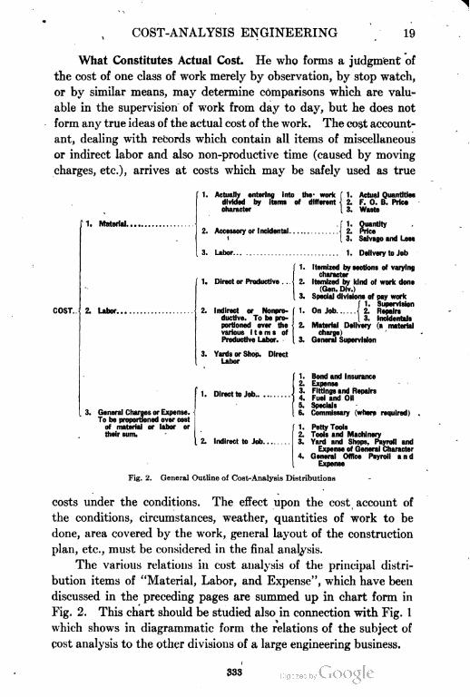
COST-ANALYSIS ENGINEERING 19
What Constitutes Actual Cost. He who forms a judgment of
the cost of one class of work merely by observation, by stop watch,
or by similar means, may determine comparisons which are valu
able in the supervision of work from day to day, but he does not
form any true ideas of the actual cost of the work. The cost account
ant, dealing with records which contain all items of miscellaneous
or indirect labor and also non-productive time (caused by moving
charges, etc.), arrives at costs which may be safely used as true
1. Material..
COST..
1. Actually entering into the- work
divided by Items of different
character
2. Accessory or Incidental.
t
3. Labor
1. Actual Quantities
2. F. 0. B. Price
3. Waste
1. Quantity
3. Salvage and Loss
1. Delivery to Job
2. Labor.
1. Direct or Productive . .
2. Indirect or Nonpro
ductive. To be pro
portioned over the
various items of
Productive Labor.
3. Yards or Shop. Direct
Labor
1. Itemized by sections of varying
character
2. Itemized by kind of work done
(Gen. Dlv.)
3. Special divisions of pay work
f 1. Supervision
1. On Job { 2. Repairs
1 3. Incidentals
2. Material Delivery (a material
charge)
3. General Supervision
General Charges or Expense.
To be proportioned over cost
of material or labor or
their sum.
1. Direct to Job
2. Indirect to Job....
1. Bond and Insurance
2. Expense
3. Fittings and Repairs
4. Fuel and Oil
5. Specials
6. Commissary (where required)
| 1. Petty Tools
2. Tools and Machinery
3. Yard and Shops, Payroll and
Expense of General Character
4. General Office Payroll and
Expense
Fig. 2. General Outline of Cost-Analysis Distributions
costs under the conditions. The effect upon the cost account of
the conditions, circumstances, weather, quantities of work to be
done, area covered by the work, general layout of the construction
plan, etc., must be considered in the final analysis.
The various relations in cost analysis of the principal distri
bution items of "Material, Labor, and Expense", which have been
discussed in the preceding pages are summed up in chart form in
Fig. 2. This chart should be studied also in connection with Fig. 1
which shows in diagrammatic form the relations of the subject of
cost analysis to the other divisions of a large engineering business.
333
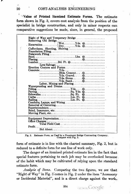
20 COST-ANALYSIS ENGINEERING
Value of Printed Itemized Estimate Forms. The estimate
form shown in Fig. 3, covers cost analysis from the position of the
specialist in bridge construction, and only in minor respects can
comparative suggestions be made, since, in general, the proposed
Right of Way and Temporary Bridge
Removing Old Bridge
Excavation ..{^ ----*£
Cofferdams, Sheeting, Shoring
Foundation Piling
Falsework Piling
Steel Lbs.
Placing
Lumber Bd. Ft. @
Less Salvage
Erection Centers and Forms
Concrete ' Yds
Bbls. Cement. . . .
Yds. Gravel
Yds. Stone
Yds. Sand
Labor, Mixing and Placing
Waterproofing and Drains
Filling Yds
Paving Sq. Yds.
Sidewalks Sq. Ft.
Curbs Lin. Ft.
Railing Lin. Ft.
Conduits, Lamps, and Wiring
Removal of Centering
Superintendence
Bond, Insurance, etc
Moving Plant, etc
Equipment Depreciation
Office Charges
Total Field Cost . . ..
Profit
Bid About
Fig. 3. Estimate Form, as Used by a Prominent Bridge Contracting Company.
Compare with Fig. 2.
form of estimate is in line with the charted summary, Fig. 2, but is
reduced to a definite form for one line of work only.
The danger of an itemized printed estimate lies in the fact that
special features pertaining to each job may be overlooked because
of the habit which may be cultivated of relying upon the standard
estimate form.
Analysis of Items. Comparing the two figures, we see that
"Right of Way" in Fig. 3 comes in Fig. 2 under the item "Accessory
or Incidental Material", and is a direct charge against the work.
33-1
COST-ANALYSIS ENGINEERING 21
Likewise, "Temporary Bridge" comes under the same head, and is
also a direct charge unless salvage is considered. "Removing Old
Bridge" is in the same division. All three of these items are special
ones pertaining to each individual case and require a personal inspec
tion of the site.
The cost of "Wet Excavation", "Dry Excavation", and of
"Cofferdams", depends upon the character of the stream. These
three items should be estimated as nearly as possible on a unit basis
and if the contract is secured a careful survey of the actual quantity
handled should be made from time to time for future reference.
"Piling for Foundations" is a direct charge, since this material
remains in the structure. "Piling for False Work", however, is in
the nature of accessory material, and for purposes of cost analysis
must consequently have a separate classification.
"Reinforcement Steel" is a direct material charge and should
be figured separately for each and every job. In cost analysis it
should be estimated and reported on either a pound or tonnage
basis.
"Lumber" is an accessory material and should always be esti
mated or reported on a basis of feet, board measure, or square feet
of concrete surface covered. Lumber should never be carried as an
element of the unit concrete cost, even in work of like character.
"Salvage" may be best estimated on the basis of percentage of
lumber or cost of lumber. If possible, the lumber and labor items
should be separated on center and form work, as the two have
their distinct differences and such a separation may be of value
where the proportions of the two classes show variation in past work.
"Cement", "Sand", "Stone", and "Gravel" are proportional
to the cubic yards of concrete, but in addition they depend upon the
specified mixture of concrete. The cost of these materials is the
cost on the job, which is made up of a first cost of material plus the
expense of delivery; this latter is a labor item but is to be carried as
a separate item under Material, Fig. 2.
The labor on concrete depends upon the total yardage; and also
on the available labor supply, union or nonunion, and its nationality,
and the accessibility of the work. The latter is important inasmuch
as it may be necessary to conduct boarding-houses or to provide
transportation.
335
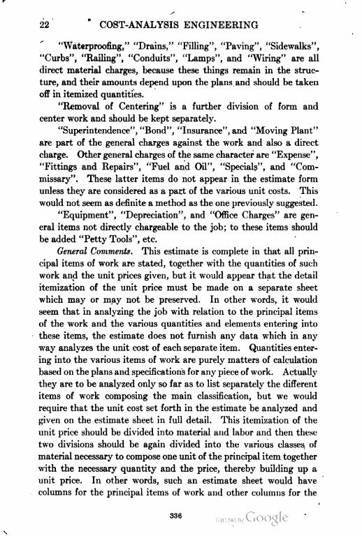
22 COST-ANALYSIS ENGINEERING
"Waterproofing," "Drains," "Filling", "Paving", "Sidewalks",
"Curbs", "Railing", "Conduits", "Lamps", and "Wiring" are all
direct material charges, because these things remain in the struc
ture, and their amounts depend upon the plans and should be taken
off in itemized quantities.
"Removal of Centering" is a further division of form and
center work and should be kept separately.
"Superintendence", "Bond", "Insurance", and "Moving Plant"
are part of the general charges against the work and also a direct
charge. Other general charges of the same character are "Expense",
"Fittings and Repairs", "Fuel and Oil", "Specials", and "Com
missary". These latter items do not appear in the estimate form
unless they are considered as a part of the various unit costs. This
would not seem as definite a method as the one previously suggested.
"Equipment", "Depreciation", and "Office Charges" are gen
eral items not directly chargeable to the job; to these items should
be added "Petty Tools", etc.
General Comments. This estimate is complete in that all prin
cipal items of work are stated, together with the quantities of such
work and the unit prices given, but it would appear that the detail
itemization of the unit price must be made on a separate sheet
which may or may not be preserved. In other words, it would
seem that in analyzing the job with relation to the principal items
of the work and the various quantities and elements entering into
these items, the estimate does not furnish any data which in any
way analyzes the unit cost of each separate item. Quantities enter
ing into the various items of work are purely matters of calculation
based on the plans and specifications for any piece of work. Actually
they are to be analyzed only so far as to list separately the different
items of work composing the main classification, but we would
require that the unit cost set forth in the estimate be analyzed and
given on the estimate sheet in full detail. This itemization of the
unit price should be divided into material and labor and then these
two divisions should be again divided into the various classes, of
material necessary to compose one unit of the principal item together
with the necessary quantity and the price, thereby building up a
unit price. In other words, such an estimate sheet would have
columns for the principal items of work and other columns for the
336
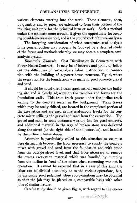
COST-ANALYSIS ENGINEERING 23
various elements entering into the work. These elements, then,
by quantity and by price, are extended to form their portion of the
resulting unit price for the principal item or work. Such a method
makes the estimate more certain, it gives the opportunity for locat
ing possible increases in cost, and is the groundwork of future analyses.
The foregoing consideration of what constitutes cost analysis
in its general outline may properly be followed by a detailed study
of the forms and methods whereby we may obtain a complete cost-
analysis system.
Illustrative Example. Cost Distribution in Connection with
Power-House Contract. It may be of interest and profit to follow
out the difficulties of cost-analysis labor distribution in connec
tion with the building of a power-house structure, Fig. 4, where
the excavation for the foundations was made in good concrete gravel
and sand.
It should be noted that a tram track entirely encircles the build
ing site and is closely adjacent to the trenches and forms for the
foundation walls. This tram track passes under the incline track
leading to the concrete mixer in the background. Tram tracks
which may be easily shifted, are located in the completed portion of
the excavation and are used as material-supply tracks for the con
crete mixer utilizing the gravel and sand from the excavation. The
gravel and sand in some instances was too fine for good concrete,
and additional material in the way of broken stone was delivered
along the street (at the right side of the illustration), and handled
by the inclined chutes shown.
Attention is particularly called to this situation as we must
here distinguish between the labor necessary to supply the concrete
mixer with gravel and sand from the foundation and with stone
from the outside street level, and that labor necessary to remove
the excess excavation material which was handled by dumping
from the incline in front of the mixer when concreting was not in
operation. It cannot be expected that in a case of this kind the
labor can be divided absolutely as to the various operations, but,
by exercising good judgment, close approximations may be obtained
so that the job may be placed on a comparable basis with other
jobs of similar nature.
Careful study should be given Fig. 4, with regard to the ooera-
337

COST-ANALYSIS ENGINEERING
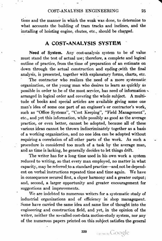
COST-ANALYSIS ENGINEERING 25
tions and the manner in which the work was done, to determine to
what accounts the building of tram tracks and inclines, and the
installing of hoisting engine, chutes, etc., should be charged.
A COST=ANALYSIS SYSTEM
Need of System. Any cost-analysis system to be of value
must stand the test of actual use; therefore, a complete and logical
outline of practice, from the time of preparation of an estimate on
down through the actual construction and ending \with the final
analysis, is presented, together with explanatory forms, charts, etc.
The contractor who realizes the need of a more systematic
organization, or the young man who desires to learn as quickly as
possible in order to be of the most service, has need of information -
arranged in logical order and covering the whole subject. A multi
tude of books and special articles are available giving some one
man's idea of some one part of an engineer's or contractor's work,
such as "Office Systems", "Cost Keeping", "Field Management",
etc., and yet this information, while possibly as good as the average
practice, or even better, cannot be adopted, because all of these
various ideas cannot be thrown indiscriminately together as a basis
of a working organization, and no one idea can be adopted without
requiring a correlation of all other parts of the work. As such a
procedure is considered too much of a task by the average man,
and as time is lacking, he generally decides to let things drift.
The writer has for a long time used in his own work a system
reduced to writing, so that every man employed, no matter in what
capacity, may be referred to a standard practice—and not be depend
ent on verbal instructions repeated time and time again. We have
in consequence secured first, a closer harmony and a greater output;
and, second, a larger opportunity and greater encouragement for
suggestions and improvements.
We are indebted to numerous writers for a systematic study of
industrial organizations and of efficiency in shop management.
Some have carried the same idea and same line of thought into the
engineering and construction field, and yet, in the opinion of the
writer, neither the so-called cost-data motion-study system, nor any
of the numerous papers printed on this subject satisfies the general
339
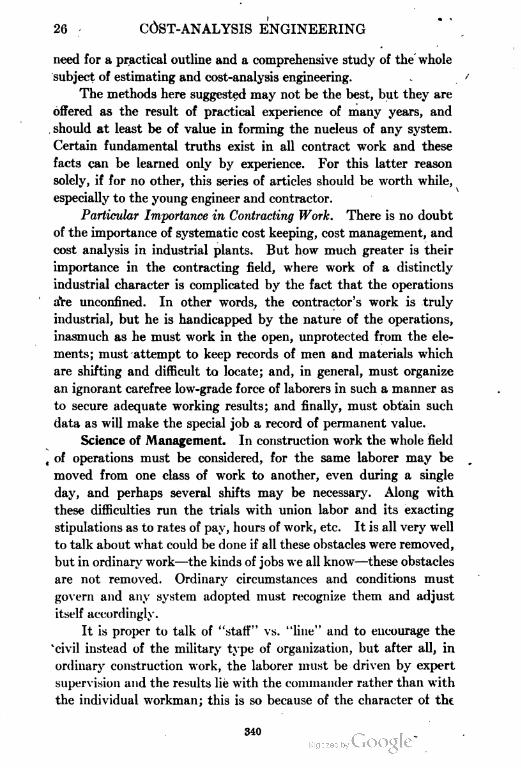
26 COST-ANALYSIS ENGINEERING
need for a practical outline and a comprehensive study of the whole
subject of estimating and cost-analysis engineering.
The methods here suggested may not be the best, but they are
offered as the result of practical experience of many years, and
should at least be of value in forming the nucleus of any system.
Certain fundamental truths exist in all contract work and these
facts can be learned only by experience. For this latter reason
solely, if for no other, this series of articles should be worth while,
especially to the young engineer and contractor.
Particular Importance in Contracting Work. There is no doubt
of the importance of systematic cost keeping, cost management, and
cost analysis in industrial plants. But how much greater is their
importance in the contracting field, where work of a distinctly
industrial character is complicated by the fact that the operations
are unconfined. In other words, the contractor's work is truly
industrial, but he is handicapped by the nature of the operations,
inasmuch as he must work in the open, unprotected from the ele
ments; must attempt to keep records of men and materials which
are shifting and difficult to locate; and, in general, must organize
an ignorant carefree low-grade force of laborers in such a manner as
to secure adequate working results; and finally, must obtain such
data as will make the special job a record of permanent value.
Science of Management. In construction work the whole field
, of operations must be considered, for the same laborer may be
moved from one class of work to another, even during a single
day, and perhaps several shifts may be necessary. Along with
these difficulties run the trials with union labor and its exacting
stipulations as to rates of pay, hours of work, etc. It is all very well
to talk about what could be done if all these obstacles were removed,
but in ordinary work—the kinds of jobs we all know—these obstacles
are not removed. Ordinary circumstances and conditions must
govern and any system adopted must recognize them and adjust
itself accordingly.
It is proper to talk of "staff" vs. "line" and to encourage the
'civil instead of the military type of organization, but after all, in
ordinary construction work, the laborer must be driven by expert
supervision and the results lie with the commander rather than with
the individual workman; this is so because of the character ot tht
340
COST-ANALYSIS ENGINEERING 27
labor available. Under such conditions, all that can be expected is
a fairly accurate checking of the labor employed. Such cost data
is not absolute in fact, but simply characteristic of the kjnd of
work, and sufficiently close for guidance in analysis of like work.
For these reasons, cost data, so styled, can be of no value so far as
assuming to report facts or truths, but it can be made of greater
or less reference value, depending upon the care taken in gathering
information. -
Construction never can be an exact science or subject to exact
rules, all contrary writings as to principles notwithstanding. There
are no five, ten, or twenty principles involved. Construction, like
engineering—or even more so—is a matter of common sense or good
judgment, but an understanding of it may be developed and a mental
analysis encouraged by a proper use of methods, standard forms,
printed records, and analyses. In other words, while preaching
modern methods, while recognizing all that has been written as to
office and field systems, and while advocating some such system as
will be outlined hereafter, still the writer desires to emphasize the
facts that these devices are of use only as developing mental capacity for
accurate analysis, and that records in themselves are of questionable
value. The engineer and the contractor who work the hardest for a
system and adequate records do not profit as much by the actual
records as they do by the development within their own brain cells.
Do not overlook this point. Records are valuable only in their effect
on the judgment, which indicates that the method of treatment of
a new proposition is founded on experience. Experience, however,
may be fortified by a proper system of dividing, itemizing, and record
ing costs of labor and materials. Before discussing the points of
the proposed system, it may be well to study the outline of the
system, and the relation of the different groups to each other.
DETAIL OUTLINE FOR STUDY
Scope of Outline. Our study, then, will cover the items in the
following detailed outline of work, giving prominence to those features
which are most closely related to cost analysis, as shown by Fig. 1 .
Group 1. Estimating the Job. Estimating the job on a basis
of & definite well-considered plan, with reference to execution and
definiteness in final analysis of results, involves:
341
28 COST-ANALYSIS ENGINEERING
(1) The examination of specifications for unusual clauses,
and the preparation of abstracts. See Figs. 5 and 6.
(2) The comparison of plans and specifications, making notes
of special and peculiar features. See Figs. 5 and 6.
(3) A proper method of taking off quantities, including
checking. See Fig. 13.
(4) The form of estimating blanks. See Figs. 14 and 15.
(5) The layout of work and method of operation. See Figs.
8 and 11.
(6) The division of work. See Figs. 7 and 12.
(7) The use of short cuts and approximations in checking.
(8) Consideration as to when quantities are important and
when unit prices are important.
(9) The estimating of labor and material separately.
(10) The estimating of general charges, and how general
charges are affected by character of work. See Tables II and III,
Part II.
(11) Determination of equipment required, and how it is to
be charged out.
(12) Preparation or notes and sketches showing basis of
estimate.
(13) The filing of estimates for future reference.
(14) The value of estimates regardless of execution of work.
(15) The preparation of a personal "dope" book.
Group II. Construction of Job. The construction of the
job following as closely as possible the estimated plan of operation
and, where that is defective and requires modification and change,
revising or extending estimate to cover the changes, involves:
(1) Selection of equipment.
(2) Arrangement of the organization and distribution of
forces.
(3) Preparation of instructions to timekeepers and field
forces.
(4) Preparation of progress plans and instructions to the field
engineers. See Figs. 10 and 12.
(5) Preparation of forms for quantity and cost reports. See
Figs. 13, 14, and 15.
(6) Division of work by sections. See Figs. 7, 8 and 11.
342
COST-ANALYSIS ENGINEERING 29
(7) Selection of units with regard for simplicity of items, and
with essentials separated.
(8) Designation as to direct and indirect labor and materials.
See Fig. 2, p. 19.
(9) Selection of field approximations or unit measurements
for reports.
(10) Supervision over the general office system of purchasing.
(11) Instructions as to the distribution of cost of material and
labor and the making of monthly estimates.
(12) Instructions as to better supervision by use of the daily
reports.
(13) Specific instructions to (1) foremen, (2) timekeepers and
clerks, (3) engineers and firemen, (4) mechanics, (5) yardmen, (6)
general office men, and (7) for weekly cabinet meetings.
Group III. Analysis of Job. This means carrying out the
work so far as possible according to estimate, but with due allowance
for actual reports based on conditions as found during execution,
and requires:
(1) Maintaining cost, quantities, and unit costs strictly up
to date. See Figs. 13, 14, and 15.
(2) A checking of rate of progress. Figs. 10 and 12.
(3) Revision of original estimates from time to time.
(4) Report of discovery of weak points. See progress charts,
Figs. 26 and 27.
(5) Report of daily status of work. See Figs. 26 and 27.
(6) Report of revised estimate as to time of completion. See
Figs. 26 and 27.
• (7) Report of comparisons by selected sections.
(8) Report of efficiency of men and equipment.
(9) Report of comparison with other jobs of like character.
(10) A careful separation of ordinary from unusual units.
(11) The final form for tabulation of results.
(12) The final form of graphical chart.
(13) Notations that results are not absolute but to encourage
mental discipline.
(14) "Care in the copying of data.
(15) Determination of production and establishment of a
standard rate of pay where possible.
343
30 COST-ANALYSIS ENGINEERING
1
(16) Determination of cost of materials f.o.b. job and com
parison with purchase price.
(17) Caution as to the use of stop-watch methods.
(18) Notations as to padded pay rolls.
There may be other ways or methods as good or better than
those suggested; any system 'is good that recognizes the close rela
tionship existing between estimating, construction, and final analysis.
Value of Estimates. A carefully prepared estimate on work
not secured is not valueless but should be preserved and indexed to
form a part of the personal files of the contractor or estimator. In
addition these estimates should be summarized and compared with
others and with those estimates where the job has been actually
constructed. Such a comparison cannot help but be of benefit;
first, by emphasizing the fact that the characteristics and individu
ality of every job require special consideration, and so disabusing
the mind of the idea that any fixed or lump-sum unit prices can be
used indiscriminately; second, by the development of a greater
estimating ability and by the correction of preconceived ideas of
estimating, which will be modified by studying those estimates
which have gone through actual construction. A comparison of
this kind is just as properly a part of analysis as the cost records of
any particular job and, further, if this plan is carried out, the tend
ency is to build up the cost-analysis turn of mind, so that it becomes
almost instinctive.
Suppose the job is secured, then the estimate, if it has been
made in detail, is of still more value for future comparison, since
the opportunity is afforded to check the separate items during the
progress of the construction. The resulting final cost analysis is
truly an analysis, rather than a mere collection of cost records. In
other words, the estimate may be properly designated as a prelimi-
sary plan of attack, to be followed by the filling in of details secured
during construction, until the completed report, developed through
the final analysis, is eventually made.
Analysis of Subdivisions. Before entering upon the detailed
discussion of methods under the divisions suggested, it is probably
well to set forth in a condensed form the logical steps by which the
work advances from the time of the estimate until the time of the
final analysis. These steps, of course, are included under the
344
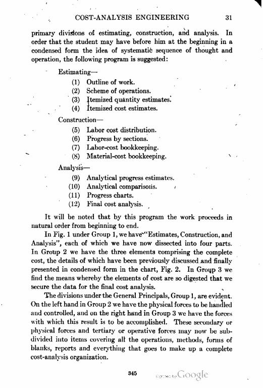
COST-ANALYSIS ENGINEERING 31
primary divisions of estimating, construction, and analysis. In
order that the student may have before him at the beginning in a
condensed form the idea of systemati6 sequence of thought and
operation, the following program is suggested:
Estimating—
(1) Outline of work.
(2) Scheme of operations.
(3) Itemized quantity estimates.
(4) Itemized cost estimates.
Construction—
(5) Labor cost distribution.
(6) Progress by sections.
(7) Labor-cost bookkeeping.
(8) Material-cost bookkeeping.
Analysis—
(9) Analytical progress estimates.
(10) Analytical comparisons.
(11) Progress charts.
(12) Final cost analysis.
It will be noted that by this program the work proceeds in
natural order from beginning to end.
In Fig. 1 under Group 1, we have"" Estimates, Construction, and
Analysis", each of which we have now dissected into four parts.
In Group 2 we have the three elements comprising the complete
cost, the details of which have been previously discussed and finally
presented in condensed form in the chart, Fig. 2. In Group 3 we
find the means whereby the elements of cost are so digested that we
secure the data for the final cost analysis.
The divisions under the General Principals, Group 1, are evident.
On the left hand in Group 2 we have the physical forces to be handled
and controlled, and oil the right hand in Group 3 we have the forces
with which this result is to be accomplished. These secondary or
physical forces and tertiary or operative forces may now be sub
divided into items covering all the operations, methods, forms of
blanks, reports and everything that goes to make up a complete
cost-analysis organization.
345
32 COST-ANALYSIS ENGINEERING
Each one of the Principals, Group 1, is directly concerned with
each one of the three divisions under Physicals, Group 2, and Oper
atives, Group 3, and in addition the Physicals and Operatives are
dependent one upon the other. It requires only a moment's thought
to realize that every line connecting these various divisions repre
sents a distinct systematic line of thought, and that these Principal
connectives represent numerous different viewpoints, which in the
aggregate we may term mental analysis.
This is not in any sense complex, and in reality is no more
than the ordinary unconscious working of the mind of the successful
contractor. It is not necessary that any office be departmentalized
and conducted on an elaborate scale. Every one of the operative
divisions can, in minor practice, be actually conducted and per
formed by the engineer or contractor individually and the same
results in system will be accomplished. Such a contractor will be
his own engineer in the planning and estimating of the work; he
may also be his own superintendent and foreman during construc
tion, and he is certainly going to be his own analyst when the work
is completed.
The "Estimate, Construction, and Analysis" (Group 1), must
each consider "Material, Labor, and General Charges" (Group 2), but
each from a different viewpoint, viz, future, present, or past. Simi
larly Group 3, "Engineering, Bookkeeping and Clerical Work"
involves Group 1 and Group 2. Take the last division of the
Operatives—Clerical. If properly conducted, this division must
consider the original Estimate, the actual Construction, and the
final Analysis and must compare them. It must consider "Material,
Labor, and General Charges" with reference to what was estimated
and what was actually used, and analyze the differences; it itself is
also directly dependent upon the Engineering and Bookkeeping
records in its own Operative class for a consistent, harmonious,
co-operative working. We are using in this article the term Engi
neering to refer to any method whereby reports as to the quantity
of work done or estimated are obtained; and the term Book
keeping to refer to the distribution of money actually expended.
The Clerical organization is therefore, for the purpose of this article,
the analysis man, although in actual practice the analysis may
devolve upon the engineer, the bookkeeper, or the contractor himself.
346
COST-ANALYSIS ENGINEERING 33
The Physicals would seem to be easy of separation and directly
dependent upon the work to be estimated, but it is only by the
closest possible unification of action of the Operatives that this
result is actually accomplished. Material, as before mentioned,
sometimes includes labor, inasmuch as the material charge against
the work is the entire cost delivered on the job.
It would be wrong to include such a labor charge in the labor-
cost distribution of handling this material at the job. Two jobs
exactly alike, where the labor distribution would vary but slightly,
may be so located that the labor cost of delivery of materials to the
one job, located in a city or on a construction railroad siding, is
nothing, whereas cost of delivery to the other job, located at some
distance from a track may double the material cost. Labor some
times includes material or general-charge items—as, for instance,
where a subcontract is made for the furnishing of labor, but where
the subcontractor furnishes all or part of the materials or supplies
necessary in the handling of his class of work.
It therefore rests with the cost-analysis engineer so to train the
various employes that they will have constantly in mind the princi
pal divisions of cost engineering and will facilitate the analysis by
carefully watching and separating and distributing the cost of
material and labor and general charges. When this is done then
the everyday work is more satisfactory, profits are increased during
the construction period, and future estimates are more reliable.
DETAILED STUDY OF FORMS AND MATERIALS
OUTLINE OF WORK
"Outline of Work" Form Standard for AH Jobs. As soon as
the plans and specifications for any new job are received in the
office the first step is to go through the specifications, noting each
requirement, using the standard form, "Outline of Work", illustrated
in Figs. 5 and 6.
This form should be a standard and is to be used for every job.
As a result of practical experience, the form has been found to cover
all working conditions, whether the job is large or small. It can be
-used for bridges, buildings, sewers, earth work, railway construc
tion, pavements, sidewalks, and, in, fact, for every kind of work
coming to the engineer or contractor.
347
34 COST-ANALYSIS ENGINEERING
\
Discussion of General Headings. The benefits to be obtained
from the use of this standard form may be briefly stated as follows :
(1) In filling in the general heading, Figs. 5 and 6, giving the
nature of the work, where located, owner, and architect or engineer,
together with the estimate number, we secure an index for perma
nent record. It is suggested that estimate numbers begin with No. 1
each year, since the estimating labor for each season is thus auto
matically recorded. Knowing the number of jobs secured and being
careful to distribute the cost of labor in estimating all jobs, we may
arrive at a percentage of cost that such estimate bears to the total
cost of our general office charges. Such general office charges
should preferably be kept separately for each calendar year, together
with the total volume of business for the same period.
When times are dull and competition is intense, then estimating
will constitute a larger percentage of these charges than when work-is
plentiful and most of the general office time is spent on actual super
vision. This overhead charge, as a whole, naturally fluctuates, since
it is considered as a percentage on the total volume of business.
Rent, light, heat, etc., together with a certain amount of salaries
(which must be maintained regardless of new work) are all inde
pendent of the volume of business, and so the percentage to be
allowed must really be a matter of good judgment based on extended
past experience. In construction work, one cannot count on a
steady increase or increment each year, since, notwithstanding its
reputation, a company must compete by bidding for every job
secured. Therefore, not to burden any one job when times are dull,
a reasonable amount should be added to each estimate throughout
the year for just such charges. An average over several years is,
of Course, of more value than the actual charges for any one period.
The cost of estimating should also be determined as a percentage of
the total estimated cost of proposed work whether the jobs are or
are not secured. Such records give data upon which to base a
proposition when one is called upon for examination of a promotion
project. From an engineering and estimation standpoint, regard
less of construction, costs of surveys, reports, etc., should be kept,
since many times propositions will arise which are to be used for
promotion purposes and should be paid for by the parties benefited.
(2) Discussion of Secondary Headings. ln filling in the sec-
348

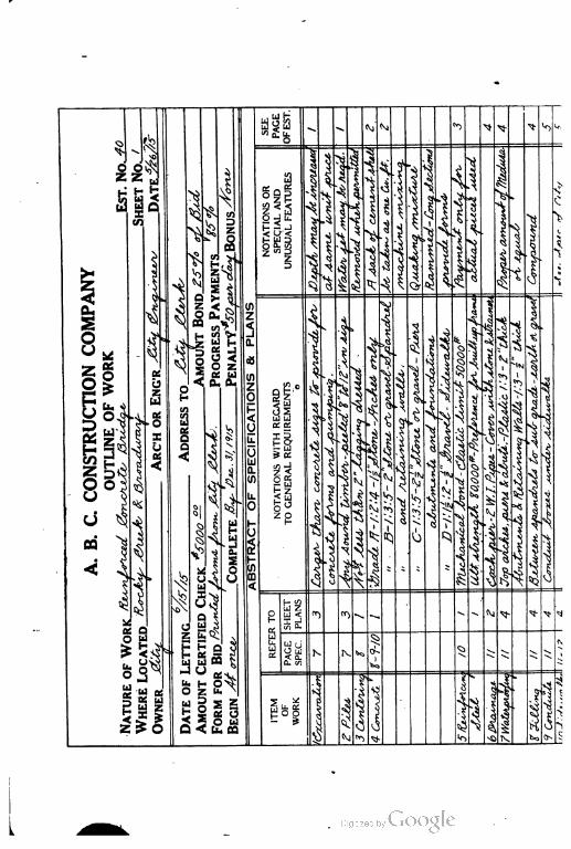
u h-
j J a Ni *o ^. (^\1 ^
«a.fe
„
x§
1 1
f 1 i 1c o
IH s
4
i
aS
| |
iI
u.ALFIATUR
i
1
V
1 5
ATIONAORIALAND
1|
1 j t 1
u
1en
z
,
\
SH UJ
11 J ? 1 I |
**
1 ^ i 3 vS ^ «
i«s •*
i1 t 1 1|
1]
1 i 1
?
|
I
z
1I
1 jt3
z.5 ^
u
N Q *$ 2^ Of *c
*c1
cz
S s \ I j;
x>
, IT. •V, i 1 I
$^ ^
•IJ I% %)
o Ou
w
r
4
«s.
^CO i
s 1•^ 3 J> j
^
S 5 •J •£
o •^ HA
^
*^ '? it
|
CONSTRUCTIONCOUTLINEOFWORK
*=j
<z
OFSPECIFICATIONS&1
1
ice
CC i:
j
1
1£b £ GINERALREQUIRIENTSo
..«
1
I
t
"<!
4
1
OTATIONSWITHREGARD
]
\
1
S
•,•,^,,,,'i
*i
J,
1et•O S
1
1X
ee
B'
iC .ii
4< 8?
N
|
1
S &4
1 ^ iv
^
1
.T)t
4
il
1
•gj
i 1
j
U ^
03 ^
o
4PLETE^
Z
R
t
* c
§ i 1
1•!
1i < i
i
6 •*
i-i >
*1
t
'
S
i *
^ ^ Xs
^l ^c ^
V 1i !tt
L
b|4t
^ 11 il ^> •
^c
^ V^
^ i;
|^Q
4 ^
3
1 VSLJ Z
| |
ecV» *
Ct
\£< IT
«j "^ ^- Xt.
u& t c/j CL
«*^•
»; I
C£
ic
z
li
, UJi<^
I.JS
• F0
Lu U L
N Cs ^ ;-f- K v> V. \ N.• •• • B
'>^p 1t 1 bb Cu c/
b1 ^
^> ^"^J ^oj• c
1 *C
OWNER.
a i *
5
1
b
;£! u ;| ;- <§V^
u •» (Q
Ss>
a :
ii!£
!ct :il
z
(3
1 1t: UJ
Hfel .)A .• '.
<
;£ 0 4Z c IS0><
$ &j "*>l*>
K60 '>S* >«
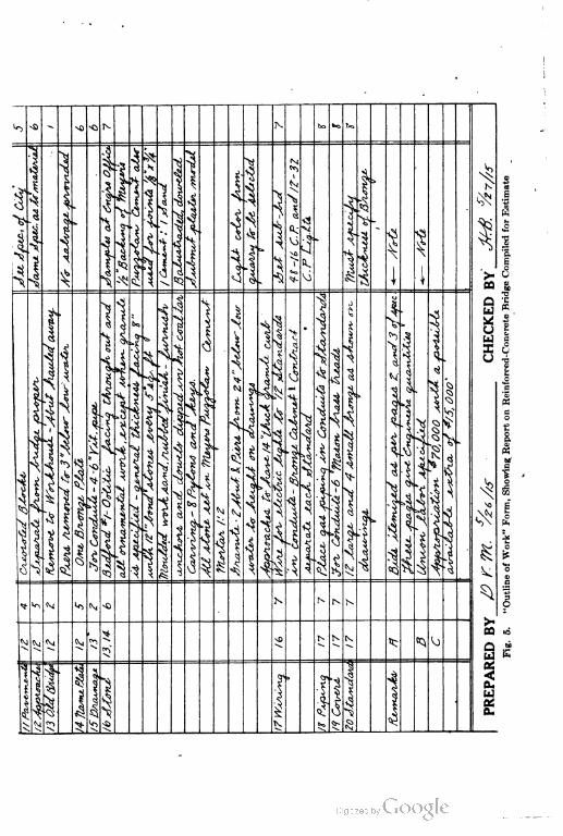
lo
»
1-it
•ft.
:4s.r
: «5 SM
«s
1cd
.?
•i
Jr,
K
a *
iiU c
I £u ^
&
CO
C>u
t*
t
W
E

COST-ANALYSIS ENGINEERING 39
ondary headings with date of letting, name of party or parties to
whom the bid is to be addressed, amount of certified check, amount
of bond, form to be used, amount and manner of payments during
progress, beginning and completion of the work, and penalty and
bonus stipulations, we have all the essentials necessary for the sub
mission of a formal proposition, with due consideration, also, for
the financing of the work. The latter point is of great importance,
since many times the payments, the penalty, and the bonus must
be considered as a part of the cost of the work. For instance, in
some cases weekly estimates are allowed the contractor, and a job
of this kind will finance itself. (Incidentally, it may also be remarked
that under such terms—at least not exceeding monthly estimates—•
the owner secures his work at the minimum of cost.) In other
work, especially in that for some municipalities, no payments are
made until the work is completed and accepted. In a case of this
kind arrangements must be made to secure funds to carry the entire
-cost, and there must be included in the estimate 'the interest on
such funds. As the loaning of money on contract work in these
circumstances must be considered -as a speculation rather than an
investment, money probably cannot be secured for better than the
usual rate of interest plus a bonus, and in the aggregate these two
items will amount to at least 10 or 12 per cent. Under such condi
tions either the owner or the public pays the bill, provided the bid
is properly made.
Sometimes, when the time of completion is the principal element
in awarding the contract, it is wise to include in the cost an allowance
for anticipated penalty, and to set the time for completion at a very
early date. On the other hand, if a bonus is offered, it is probably
advisable to set an early date for completion and to make a cor
responding increase in the unit cost of the work, and to look to the
bonus to repay the extra cost and decreased output caused by over
time and night work. (See description of work shown in Figs. 11
and 12.)
(3) Abstract of Specifications and Plans. The third heading
covers the abstract of the specifications and plans, and serves the
purpose of itemizing the principal work with a reference to the
appropriate page of the specifications and the correct sheet of plans.
The larger space is given to notations with regard to general require
349
40 COST-ANALYSIS ENGINEERING
ments, and a secondary space is allowed for notations of special and
unusual features. This arrangement shows instantly whether the
specifications and plans are normal or abnormal. The fewer the
items that appear in the special column, the greater certainty there
will be in estimating.
By allowing a final column for reference to the page of the esti
mate we not only have the reference, but also the opportunity for
checking off each item so as to be sure nothing is forgotten. A nota
tion should be made as to who prepares such an outline or abstract
of work, and in case of important work it should be checked. The
benefit of such an outline of work is not confined to the foregoing
suggestions, but also exists in the more systematic, intimate acquaint
ance with the subject matter gained b^ the one making the abstract
and checking it.
In any case in making a proposal we read the specifications and
look over the plans. If at the time of doing this a blank form is
used, as suggested, we not only guard against omissions but by con
centrating our mind to produce the concise, condensed abstract, we
gain a more lasting recollection of the requirements. We are also
prompted to differentiate between the normal and abnormal require
ments. It takes but a few minutes longer to go through a set of
plans and specifications in this way, and the result is far more
satisfactory, aside from the fact that such abstracts, whether the
job is secured or not, are of permanent value as a part of the
estimate files.
Such an actual summary of work taken from the individual
specifications is preferable to any standard printed form (see Fig.
3), even if it be a specialist who attempts to list everything on a
standard estimate sheet. Human nature will prompt a close adher
ence to such a form and a slighting of specials pertaining to the par
ticular job. Since the printed form, moreover, is arranged in a
certain order with very little opportunity for interpolations and
additions, the tendency is to condense items or to run specials under
"miscellaneous" or "incidentals", which misleads and makes the
estimate obscure.
Comparisons of Outlines, Figs. 5 and 6. As an illustration,
Fig. 5 shows a standard form of this kind used in estimating a rein-
forced-concrete bridge. The actual size of the blank used for this
350

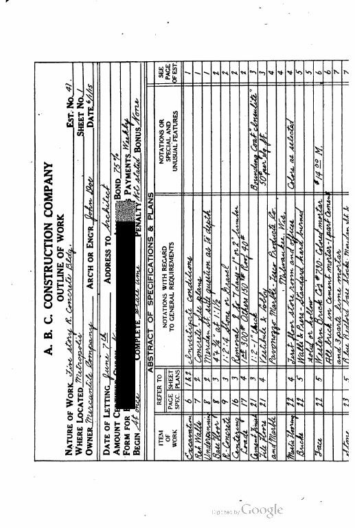
§9
o j tr
< Q <
U!
iv.
</):
*
in
z
0
5
yu.
OLU
D.
U)
U.
O
O<K
ISCD
°i§|UJ UJ
a. a.
h* O
iScn-J
z <
§1
t— i/}
Q zLd <
a
-^^
!\SJ-
J
»i!-
H H O
H pa is
U) <J
O U > K
>
>
I
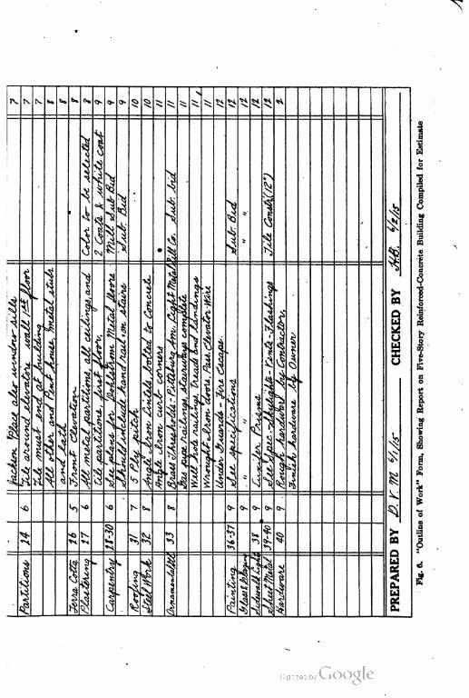

COST-ANALYSIS ENGINEERING 45
work was 8|X14 inches, and the abstract covers but 1 page. The
original specifications for this work covered over 18 pages of the same
size, and yet on this abstract are contained all the essentials for esti
mating, together with page references to the specifications and plans
for any required details. This is one of the Cases where the speci
fications themselves are no't indexed or paged, a condition which is
more often the case than would be expected. The "Outline of
Work" supplies the deficiencies of the specifications, and at the
same time presents the matter to the contractor in the best possible
condensed form for pricing. Special attention is called to the
many notations in the "Special and Unusual Features" column.
Most of these items cannot help but have an effect upon the cost
because of the uncertainty as to the meaning of the specifications
and as to the requirements made upon the engineer.
Compare the use of Fig. 5 with Fig. 6, which is the same
standard form but covers a reinforced-concrete building. Note
how few items appear in the special column. This at once is
an indication that the specifications for the building are definite and
there is no occasion for a misunderstanding. Both Figs. 5 and
G are bona fide abstracts of actual specifications purposely used
as illustrations for the reason that only by using such actual cases
can we show the adaptability of the system to the various sorts of
plans and specifications different architects and engineers may
prepare. This is not a criticism of the architect or engineer. The
minds of all men do not work alike; some prepare strong specifica
tions, with an absolute lack of system in indexing, arrangement,
"and definiteness; others are extremely systematic, but produce
specifications which are unintelligible or inconsistent.
Comparison of Plans and Specifications. The next thing in
order is carefully to inspect the plans, and compare them with the
abstract of specifications. Make such explanatory notes on the
abstract as the plans suggest, and add to the abstract any additional
work shown on the plans not specifically mentioned in the speci
fications. Compare the specifications and plans and note dis
crepancies with a view to securing explanations from the architect
or engineer; failing in this be sure the estimate is on the safe side.
Scheme of Handling. Logically the next step before taking off
any quantities is to decide, carefully and without haste, how the
351
'46 COST-ANALYSIS ENGINEERING
job under consideration ean be handled and just what equipment
and what organization are necessary for the most economical execu
tion of the work.
This first decision is all important. Many times a "guess bid"
is made without any particular thought as to how the job is to be
handled if the bid is successful. This all-important decision is
deferred until time demonstrates whether or not the work is to be
actually carried through. Such a method is foolish. v
An intelligent estimate can be made only after a proper consider
ation of the questions of organization, equipment, and method of
operation—the final proposal being then made with a confidence
that the figures submitted are reasonable and accurate, and with
the expectation of being awarded the contract.
No proposal submitted can result in any satisfaction to either
the recipient or the contractor which does not include such a careful
examination of the plans and specifications and an inspection of the
site of the work. If this study is given the proposition there will
result a plan of operation and a feeling of certainty and promptness
in the beginning of the work which will go a long way toward satis
fying both parties.
Changes in this preliminary plan may be required, and new
ideas and methods adopted during the actual progress of the contract,
but these in no way affect the definite plan which must be the basis
of the estimate in the beginning of the work. Any successful pro
posal requires a definite outline of action and it is better to deter
mine this at the time of making the estimate than to await the
awarding of the contract. Any estimate lacking such a plan of
operation will not bear investigation or examination.
Set of Preliminary Plans of Work. Granting, then, that the
plan of attack has been decided upon, the decision should be made
a matter of record, both by written description and by the prepara
tion of sketch plans showing the general layout of the plant and
method of operation. These plans serve as a basis of the amount
to be included in the estimate for equipment and the labor of instal
lation, and, in case the job is secured, as a reminder and guide in the
actual moving in on the work.
It is true that many times improvements are made on the
preliminary plans, but in the majority of cases such changes are
352
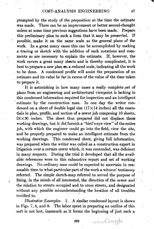
COST-ANALYSIS ENGINEERING 47
prompted by the study of the proposition at the time the estimate
was made. There can be no improvement or better second-thought
unless at some time previous suggestions have been made. Prepare
this preliminary plan in such a form that it may be preserved. If
possible, make it on the same scale as the general plans of the
work. In a great many cases this can be accomplished by making
a -tracing or sketch with the addition of such notations and com
ments as are necessary to explain the estimate. If, however, the
work covers a great many sheets and is thereby complicated, it is
best to prepare a new plan on a reduced scale, indicating all the work
to be done. A condensed profile will assist the preparation of an
estimate and its value be far in excess of the value of the time taken
to prepare it.
It is astonishing in how many cases a really complete ,set of
plans from an engineering and architectural viewpoint is lacking in
this condensed information required for inspection and an intelligent
estimate by the construction man. In one day the writer con
densed on a sheet of double legal size (17X14 inches) all the essen
tials in plan, profile, and section of a sewer job composing 10 sheets,
24X36 indies. The sheet thus prepared did not displace these
working drawings, but it did furnish a "bird's-eye view" of the entire
job, with which the engineer could go into the field, view the site,
and be properly prepared to make an intelligent estimate from the
working drawings. This condensed sheet, giving full information,
was prepared when the writer was called as a construction expert in
litigation over a certain sewer which, it was contended, was deficient
in many respects. During the trial it developed that all the avail
able references were to this exhaustive report and set of working
drawings. No ordinary man could be expected to ascertain in rea
sonable time to what particular part of the work a witness' testimony
referred. The simple sketch-map referred to served the purpose of
fixing, in the minds of all interested, the direction of the sewer and
the relation to streets occupied and to cross streets, and designated
without any possible misunderstanding the location of all troubles
testified to.
1llustrative Examples. 1. .A similar condensed layout is shown
in Figs. 7, 8, and 9. The labor spent in preparing an outline of this
sort is not lost, inasmuch as it forms the beginning of just such a
353
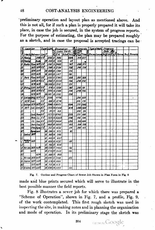
48 COST-ANALYSIS ENGINEERING
preliminary operation and layout plan as mentioned above. And
this is not all, for if such a plan is properly prepared it will take its
place, in case the job is secured, in the system of progress reports.
For the purpose of estimating, the plan may be prepared roughly
as a .sketch, and in case the proposal is accepted tracings can be
S Loca ion Tupe L'qth Excavation )S * Can:relc Typeoftiocti fToiire35
$ 1nler't* I
Cubic Yards ^« Yds
S
Date
I^1Betrreen Cm P Est. nclaat 5i*F& "i fact Tabu £xcav Concm 03 Co* fewnu ftrd Remark.
fl Ftenvg «» 6'J K65 8 3186 Z0Z4 .519 657
Hlfleviry iu,.u. M 3S0 K 454 6? , •
B fix1tie Flea X'J! 3'f 1310 9 Z40Z 747 £85 373
Bl 30"! 3£^f:6' 1345 3 Z194 531 ,148 334
52 X™33^ tl 665 16 1380 126
S3 33^Mtt 1t 645 16 lit? 105
C Pork Flem 301* 3'4 USD 10 Z343 656 .ess 3l»
a 30U 3^z!Z-6 1340 3 ZZ33 590 .146 33Z
Ct 3fd 34 tt to 1X0 a I33Z 151
D 8hi*y. za(f 30t* 3'f 670 3 1ZZ8 m .Z85 191
\D1 30lt3SM z-6 1350 10 Z500 594. .Z46 336
Dl 3Z™ 34iJ> eo 1315 e 1332 £50
E College Brfy 3Z^ 3'-0 Z3t5 4736 ,Z85 663
F 3£zi Coll. 5-0 4oo 1Z 1Z78 .441 176
Z045S Mlige 3f^ 13tJ>
Cent.
60 3940 13 16IZ!> 530t .519
\n 3a>± f»//. e'-o 13!5 t4
13
12956 3679 1.048 1319
81 '- 73 S5 416 .441 29
m Cent Fern, b'-ff I3K ?1 8743 mo .519 666
S3 Fern Hi. 50 I3Z5 13 6993 I53H .441 584
ff4 111. Sen. 4-0 1335 17 5464 1335 - 363 434
m Sen. Choj 31 1005 18 5851 603 ,304 306
H6 Chos.Syran 3-0 H0 14 145Z en ,185 145
a? tyrm Consr in 100 l5 373 35
! Central JS'-t 15 345 14 540
11 11 345 14 447
r WolHflaa
1 Bl?d.36ii a 690 16 143Z 100
11 1^ 700 /£ 404
Kieri** JB« 46t 20 1330 Zl 3365 130
Kl 4atj, li K70 zz 3105 100
n «a IS 600 13 866
L Kenwood 3i!t 1C'-" 20 1185 l£ Z000 115
H Copilot lett JSts10 570 14 1000
H1 33": iU'J! 11 715 14 1113
flf ^oulono .«« ao!>: I8 1Z85 14 £053 100
Fig. 7. Outline and Progress Chart of Sewer Job Shown in Plan Form in Fig. 8
made and blue prints secured which will serve to illustrate in the
best possible manner the field reports.
Fig. 8 illustrates a sewer job for which there was prepared a
"Scheme of Operation", shown in Fig. 7, and a profile, Fig. 9,
of the work contemplated. This first rough sketch was used in
inspecting the site, in making notes and in planning the organization
and mode of operation. In its preliminary stage the sketch was
354
COST-ANALYSIS ENGINEERING 40
not nearly so elaborate, as shown in the plate, but it answered the
needs of the moment. When the job was secured the sketch was
completed and traced in a neat and complete shape, as shown, to
Fig. 8.
rremno..^$x?e'
Layout fdr College Avenue Sewer Contract. For Details of Section A See Fig. 10
form the basis of all working thereafter. Additions were made to
harmonize with the progress charts, as will be explained later.
Object of Having Sections. It will be noted that this sewer
355
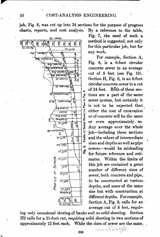
50 COST-ANALYSIS ENGINEERING
job, Fig. 8, was cut up into 34 sections for the purpose of progress
charts, reports, and cost analysis. By a reference to the table,
Fig. 7, the need of such a
method is suggested, not only
for this particular job, but for
any work.
For example, Section A,
Fig. 8, is a 6-foot circular
concrete sewer in an average
cut of 8 feet (see Fig. 10).
Section H, Fig. 8, is an 8-foot
circular concrete sewer in a cut
of 24 feet. Both of these sec
tions are a part of the same
sewer system, but certainly it
is not to be expected that
either the cost of excavation
or of concrete will be the same
or even approximately, so.
Any average over the whole
job—including these sections
and the others of intermediate
sizes and depths as well as pipe
sewers—would be misleading
for future reference and esti
mates. Within the limits of
this job are contained a great
number of different sizes of
sewer, both concrete and pipe,
to be constructed at various
depths, and some of the same
size but with construction at
different depths. For example,
Section A, Fig. 8, calls for an
average cut of 8 feet, requir
ing only occasional shoring of banks and no solid sheeting. Section
H2 calls for a 21-foot cut, requiring solid sheeting in two sections of
approximately 12 feet each. While the sizes of sewer are the same,
356
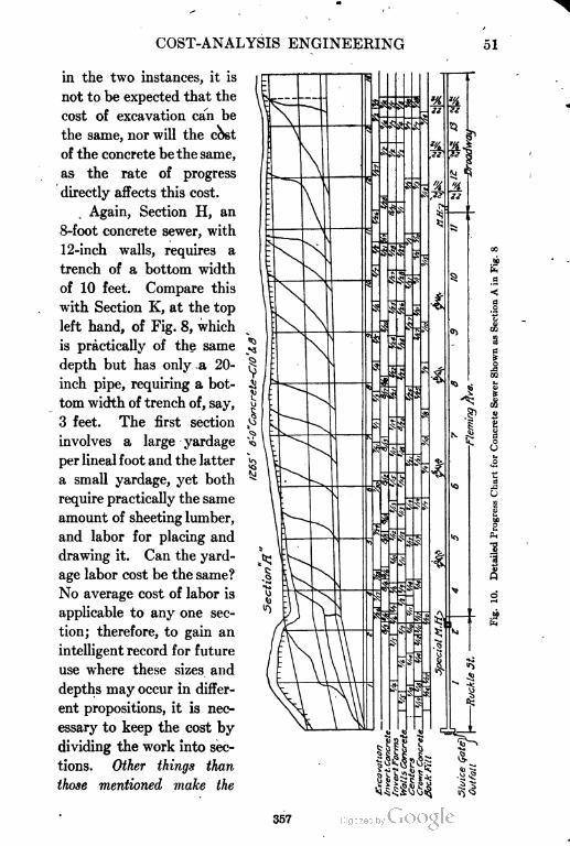
COST-ANALYSIS ENGINEERING 51
in the two instances, it is
not to be expected that the
cost of excavation can be
the same, nor will the cost
of the concrete be the same,
as the rate of progress
directly affects this cost.
Again, Section H, an
8-foot concrete sewer, with
12-inch walls, requires a
trench of a bottom width
of 10 feet. Compare this
with Section K, at the top
left hand, of Fig. 8, which
is practically of the same
depth but has only a 20-
inch pipe, requiring a bot
tom width of trench of, say,
3 feet. The first section
involves a large yardage
per lineal foot and the latter
a small yardage, yet both
require practically the same
amount of sheeting lumber,
and labor for placing and
drawing it. Can the yard
age labor cost be the same?
No average cost of labor is
applicable to any one sec
tion; therefore, to gain an
intelligent record for future
use where these sizes and
depths may occur in differ
ent propositions, it is nec
essary to keep the cost by
dividing the work into sec
tions. Other things than
those mentioned make the
I
aPk
357
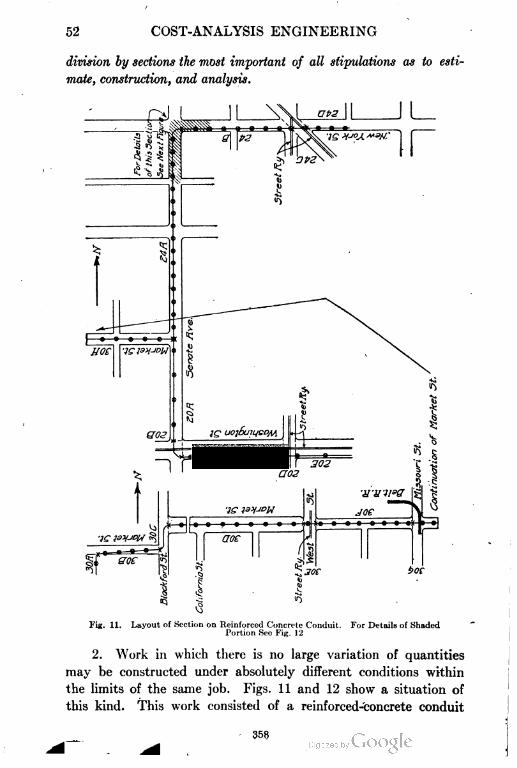
52 COST-ANALYSIS ENGINEERING
division by sections the most important of all stipulations as to esti
mate, construction, and analysis.
joe "j^7^-y-w
1~jft-
1
1«l
1
aoe
(
ej
•vi (Sl ^
; soe $oc
3
k
Fig. 11. Layout of Section on Reinforced Concrete Conduit. For Details of Shaded
Portion See Fig. 12
2. Work in which there is no large variation of quantities
may be constructed under absolutely different conditions within
the limits of the same job. Figs. 11 and 12 show a situation of
this kind. This work consisted of a reinforced-concrete conduit
35?
WEST New YORK
6 Ifas Main
Timber Supports for Pi
Sewer Chaned \
Supposed Crack^y J
/li
Timber Supports for Pipes,
3"tjasMainf 17N
15 "Sener Changed Support) for Pip
-Ducts "Supported
Abandoned Excavation
- Crfit-k Varies 9 tt 10
- Io'Sewer Lowered
-Supports for $os Main
Lowered
Support for $05 Main
Fig. 12. Details of Reinforced Concrete Conduit Shown in Fig. 11. Enlarged View Shown
to Indicate Complications of Water and Gaa Mains and Crossings
359
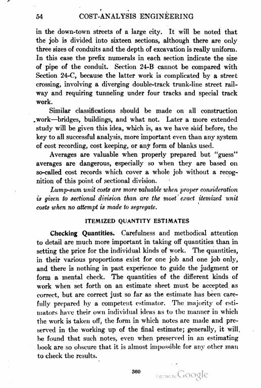
54 COST-ANALYSIS ENGINEERING
in the down-town streets of a large city. It will be noted that
the job is divided into sixteen sections, although there are only
three sizes of conduits and the depth of excavation is really uniform.
In this case the prefix numerals in each section indicate the size
of pipe of the conduit. Section 24-B cannot be compared with
Section 24-C, because the latter work is complicated by a street
crossing, involving a diverging double-track trunk-line street rail
way and requiring tunneling under four tracks and special track
work.
Similar classifications should be made on all construction
work—bridges, buildings, and what not. Later a more extended
study will be given this idea, which is, as we have s'aid before, the
key to all successful analysis, more important even than any system
of cost recording, cost keeping, or any form of blanks used.
Averages are valuable when properly prepared but "guess"
averages are dangerous, especially so when they are based on
so-called cost records which cover a whole job without a recog
nition of this point of sectional division.
Lump-sum unit costs are more valuable when proper consideration
is given to sectional division than are the most exact itemized unit
costs when no attempt is made to segregate.
ITEMIZED QUANTITY ESTIMATES
Checking Quantities. Carefulness and methodical attention
to detail are much more important in taking off quantities than in
setting the price for the individual kinds of work. The quantities,
in their various proportions exist for one job and one job only,
and there is nothing in past experience to guide the judgment or
form a mental check. The quantities of the different kinds of
work when set forth on an estimate sheet must be accepted as
correct, but are correct just so far as the estimate has been care
fully prepared by a competent estimator. The majority of esti
mators have their own individual ideas as to the manner in which
the work is taken off, the form in which notes are made and pre
served in the working up of the final estimate; generally, it will,
be found that such notes, even when preserved in an estimating
book are so obscure that it is almost impossible for any other man
to check the results.
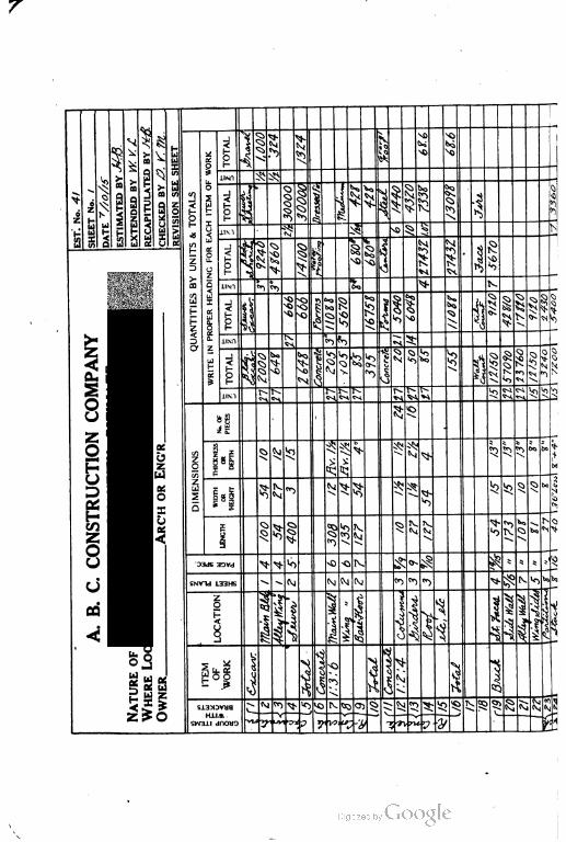
DATA~f//0//5~\
ASTIMAAD".~Mff.\
RAIAIITULAAD"YJ.frS.\
CHEI•D,.,..7?'',
sRAVIAIONSAEAHEET
OTALA\
TOTAL
||j
1l
1 3 ik 0 4 X
£
1
fUNO ^ ^
i
illWIAIIOPAIHAADIGFORAACHIAIO
TOTAL
J|i
§ 1 5• ^
1•^
e
e2
2b
P
Xu
> iTl >\
Z H
QUANTITIISBYUNITS«c ^ ^ F
1u
11M ^ 5i ^>
I,
I1 ll
1 §{
1 \ 1£
t B
LlM», t
^
&>
!l!
•*
1
K
\42WO
, .
NATIIRFOF\,oRicC'i•m•,•t•••COTT&VL&-,•ferZii-----i--$->
TOTAL A-
\\
•^ Vj bi
^i i N
ilk
S5
•<?§
A.B.C.CONSTRUCTIONCOMPANY UW fe.
"^ Q S
i^VO
t-
l
j
._
'5
17ZOO
ITEMIZEDQUANTITYESTIMATE
I|i
J
>Q 'n. l•*
? ^ o2 \ «j s"
1
0\ittso3Z4Q
S.
:s
t^
1iMt^ T^
j C-M. ^ ~' ^i »i !^> «5 «CDIMINAIONSj
it
^s
et
(3
I • la^^5
'
> ^ t^
X ^5 ^00 bo*
etO
11
^ ^^
j (xj^.^ ^ i^
r
'Q ^^}&o £
\ M
X
I)BE S
|^§
Qi ^r> \^ iiV N.
^ Cv % vJJ
^ f"Q
"D3JS 3OVd > ^-^ 0 ~O JV, ^x ^>- J?; ^s *
5 »'!§
SNVHd L33HS ^ -(Vj M CM (Vj > i$5 1^ l»,V,b,
P
at
ll 1 h^
|
*
]lii
1
i |
\ O oj
J
H
i
b 1
o
1 siV
•;
b!
£a H
I N W5 ^3-^>0 VOC; o- c> i SiJ
^ •**c «> ViC i?s
85 i55 (vl\lS
c M M.l\ .
SVM30-1 dnOMO
V
-.{> * HyL*!^
y y /2lU " 'i?\
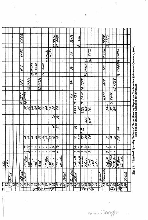
S
s
"n
s
s
* as
s- si s. s-
.«<>
Sill ^
N
•yr

COST-ANALYSIS ENGINEERING 59
The checking of the cost estimate is, as mentioned before,
much more certain; mistakes can lie discovered for the reason
that all branches of work have certain unit prices, varying between
usual limits. Any seeming inconsistency is at once apparent to
the eye and can be investigated and either confirmed or revised.
We must, therefore, establish some system of recording the
quantities as they are taken oft', part by part, in order that we
may have the opportunity of independently checking and preserving
the notes in complete detail. This is preferably done by such a
blank form as is shown in Fig. 13. If a form of this kind is used
we secure all these advantages, and in addition we have on file
a complete statement of the job so itemized and in such form that,
should the job be secured, changes or corrections in any of the work
ing plans over the preliminary plans on which the work is based
can be estimated and noted. In cases where preliminary plans
are returned—with possibly, a delay before awarding the contract—
and then working plans are furnished, it is well to check off at once
on the "Itemized Quantity Estimate" the quantities shown by the
working plan. Many times, the preliminary plans are not made
complete in all details, with the result that when the working plans
are prepared and all details worked out, revisions and changes
will be necessary in the general plans. If, as is usual, the pre
liminary plans have been returned, the only record remaining in
the hands of the contractor is this itemized quantity estimate.
Identification of Plans. It may be well, at this point, to lay
all the stress possible upon the fact that any contractor receiving
a set of plans and specifications should at once mark on each sheet
the date and his name in ink (rubber stamp preferred), so that in
case the work should be awarded to him he may call for the exact
set of plans and specifications which were in his possession at the
time of making his bid. This is not advocated because we must
be suspicious of dishonesty or manipulation; but it is a fact that
in the preparation of various sets of plans and specifications there
is always the opportunity for typographical errors, failure to bind in
all the sheets, omission of details, and neglect to make revisions and
corrections on some of the sets. Besides, when many revisions
have been made (and especially where the letting of the work is
delayed from time to time, because of such revisions and the receipt
361 '
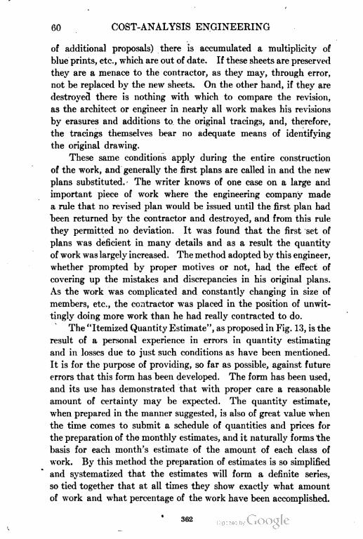
60 COST-ANALYSIS ENGINEERING
of additional proposals) there is accumulated a multiplicity of
blue prints, etc., which are out of date. If these sheets are preserved
they are a menace to the contractor, as they may, through error,
not be replaced by the new sheets. On the other hand, if they are
destroyed there is nothing with which to compare the revision,
as the architect or engineer in nearly all work makes his revisions
by erasures and additions to. the original tracings, and, therefore,
the tracings themselves bear no adequate means of identifying
the original drawing.
These same conditions apply during the entire construction
of the work, and generally the first plans are called in and the new
plans substituted. The writer knows of one case on a large and
important piece of work where the engineering company made
a rule that no revised plan would be issued until the first plan had
been returned by the contractor and destroyed, and from this rule
they permitted no deviation. It was found that the first set of
plans was deficient in many details and as a result the quantity
of work was largely increased. The method adopted by this engineer,
whether prompted by proper motives or not, had the effect of
covering up the mistakes and discrepancies in his original plans.
As the work was complicated and constantly changing in size of
members, etc., the contractor was placed in the position of unwit
tingly doing more work than he had really contracted to do.
The "Itemized Quantity Estimate", as proposed in Fig. 13, is the
result of a personal experience in errors in quantity estimating
and in losses due to just such conditions as have been mentioned.
It is for the purpose of providing, so far as possible, against future
errors that this form has been developed. The form has been used,
and its use has demonstrated that with proper care a reasonable
amount of certainty may be expected. The quantity estimate,
when prepared in the manner suggested, is also of great value when
the time comes to submit a schedule of quantities and prices for
the preparation of the monthly estimates, and it naturally forms the
basis for each month's estimate of the amount of each class of
work. By this method the preparation of estimates is so simplified
and systematized that the estimates will form a definite series,
so tied together that at all times they show exactly what amount
of work and what percentage of the work have been accomplished.
' 362
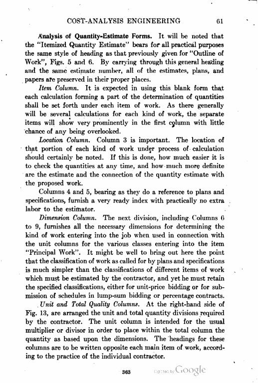
COST-ANALYSIS ENGINEERING 61
Analysis of Quantity=Estimate Forms. It will be noted that
the "Itemized Quantity Estimate" bears for all practical purposes
the same style of heading as that previously given for "Outline of
Work", Figs. 5 and 6. By carrying through this general heading
and the same estimate number, all of the estimates, plans, and
papers afe preserved in their proper places.
Item Column. It is expected in using this blank form that
each calculation forming a part of the determination of quantities
shall be set forth under each item of work. As there generally
will be several calculations for each kind of work, the separate
items will show very prominently in the first cplumn with little
chance of any being overlooked.
Location Column. Column 3 is important. The location of
that, portion of each kind of work under process of- calculation
should certainly be noted. If this is done, how much easier it is
to check the quantities at any time, and how much more definite
are the estimate and the connection of the quantity estimate with
the proposed work.
Columns 4 and 5, bearing as they do a reference to plans and
specifications, furnish a very ready index with practically no extra
labor to the estimator.
Dimension Column. The next division, including Columns 6
to 9, furnishes all the necessary dimensions for determining the
kind of work entering into the job when used in connection with
the unit columns for the various classes entering into the item
"Principal Work". It might be well to bring out here the point
that the classification of work as called for by plans and specifications
is much simpler than the classifications of different items of work
which must be estimated by the contractor, and yet he must retain
the specified classifications, either for unit-price bidding or for sub
mission of schedules in lump-sum bidding or percentage contracts.
Unit and Total Quality Columns. At the right-hand side of
Fig. 13, are arranged the unit and total quantity divisions required
by the contractor. The unit column is intended for the usual
multiplier or divisor in order to place within the total column the
quantity as based upon the dimensions. The headings for these
columns are to be written opposite each main item of work, accord
ing to the practice of the individual contractor.
363
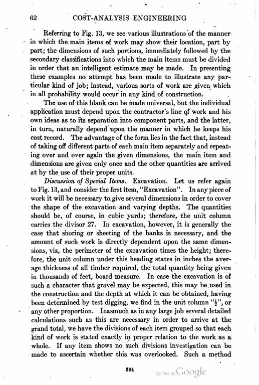
62 COST-ANALYSIS ENGINEERING
Referring to Fig. 13, we see various illustrations of the manner
in which the main items of work may show their location, part by
part; the dimensions of such portions, immediately followed by the
secondary classifications into which the main items must be divided
in order that an intelligent estimate may be made. In presenting
these examples no attempt has been made to illustrate any par
ticular kind of job; instead, various sorts of work are given which
in all probability would occur in any kind of construction.
The use of this blank can be made universal, but the individual
application must depend upon the contractor's line qf work and his
own ideas as to i.ts separation into component parts, and the latter,
in turn, naturally depend upon the manner in which he keeps his
cost record. The advantage of the form lies in the fact that, instead
of taking off different parts of each main item separately and repeat
ing over and over again the given dimensions, the main item and
dimensions are given only once and the other quantities are arrived
at by the use of their proper units.
Discussion of Special Items. Excavation. Let us refer again
to Fig. 13, and consider the first item, "Excavation". In any piece of
work it will be necessary to give several dimensions in order to cover
the shape of the excavation and varying depths. The quantities
should be, of course, in cubic yards; therefore, the unit column
carries the divisor 27. In excavation, however, it is generally the
case that shoring or sheeting of the banks is necessary, and the
amount of such work is directly dependent upon the same dimen
sions, viz, the perimeter of the excavation times the height; there
fore, the unit column under this heading states in inches the aver
age thickness of all timber required, the total quantity being given
in thousands of feet, board measure. In case the excavation is of
such a character that gravel may be expected, this may be used in
the construction and the depth at which it can be obtained, having
been determined by test digging, we find in the unit column "|", or
any other proportion. Inasmuch as in any large job several detailed
calculations such as this are necessary in order to arrive at the
grand total, we have the divisions of each item grouped so that each
kind of work is stated exactly in proper relation to the work as a
whole. If any item shows no such divisions investigation can be
made to ascertain whether this was overlooked. Such a method
364
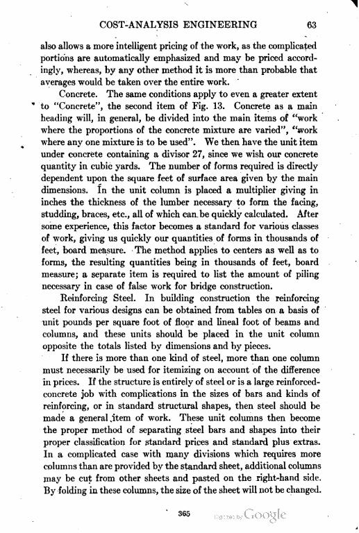
COST-ANALYSIS ENGINEERING 63
also allows a more intelligent pricing of the work, as the complicated
portions are automatically emphasized and may be priced accord
ingly, whereas, by any other method it is more than probable that
averages would be taken over the entire work.
Concrete. The same conditions apply to even a greater extent
" to "Concrete", the second item of Fig. 13. Concrete as a main
heading will, in general, be divided into the main items of "work
where the proportions of the concrete mixture are varied", "work
where any one mixture is to be used". We then have the unit item
under concrete containing a divisor 27, since we wish our concrete
quantity in cubic yards. The number of forms required is directly
dependent upon the square feet of surface area given by the main
dimensions. In the unit column is placed a multiplier giving in
inches the thickness of the lumber necessary to form the facing,
studding, braces, etc., all of which can. be quickly calculated. After
some experience, this factor becomes a standard for various classes
of work, giving us quickly our quantities of forms in thousands of
feet, board measure. The method applies to centers as well as to
forms, the resulting quantities being in thousands of feet, board
measure; a separate item is required to list the amount of piling
necessary in case of false work for bridge construction.
Reinforcing Steel. In building construction the reinforcing
steel for various designs can be obtained from tables on a basis of
unit pounds per square foot of floor and lineal foot of beams and
columns, and these units should be placed in the unit column
opposite the totals listed by dimensions and by pieces.
If there is more than one kind of steel, more than one column
must necessarily be used for itemizing on account of the difference
in prices. If the structure is entirely of steel or is a large reinforced-
concrete job with complications in the sizes of bars and kinds of
reinforcing, or in standard structural shapes, then steel should be
made a general, item of work. These unit columns then become
the proper method of separating steel bars and shapes into their
proper classification for standard prices and standard plus extras.
In a complicated case with many divisions which requires more
columns than are provided by the standard sheet, additional columns
may be cut from other sheets and pasted on the right-hand side.
By folding in these columns, the size of the sheet will not be changed.
365
64 COST-ANALYSIS ENGINEERING
Waterproofing. Similar extensions for concrete work are at
once apparent. For instance, waterproofing, if incorporated in
the mass, is an element of the cubic yardage and should be listed
opposite that portion of the work where waterproofing is required.
If waterproofing is of the sheet or surface application type, its
quantity naturally depends upon the square feet of surface covered,
which is shown by the dimensions of that part of the work. The
unit column for waterproofing would, therefore, show unit pounds
of compound per cubic yard, or thickness in fractions of a foot to
give results in cubic feet.
Cement Finish, Floors, etc. The same conditions apply to
cement finish, filling, wood floors, marble floors, painting, plastering,
etc., as all these items will appear opposite the portion of work
where they are to be used. As the dimensions of such parts of the
work are clearly stated, it is only necessary to place in the proper
unit column unit multipliers or divisors to secure the results on the
desired quantity basis. This unit is naturally preserved along
with the other complete data, and if, for instance, it is desired to
ascertain the additional cost when the cement finish in certain
portions of the work is changed from | inch in thickness to f inch,
the information is obtainable almost instantly; if this method
has not been followed, it will be necessary to refigure the plans.
Timber and Lumber. Timber and lumber can be taken off in
the same manner, using the columns for the different sizes of timber
at the various prices, and using the unit column for unit feet, board
measure. If the structure is a large one and many different-sized
pieces are called for, all that is necessary is to provide additional
columns, as explained above, under steel.
Brickwork. Brick work is peculiarly adapted to this method
of estimating. The various portions of the work are stated in the
"location" and "dimensions given" column; we then use our second
ary columns to obtain the quantities of common brick, face brick,
special brick, and in each case the separation is made directly
opposite the respective locations, but the total is reached just as
accurately. The opportunity is also afforded for the statement,
in parallel columns, of the amount of brick by "wall measure"
and "kiln count".
Remember that this should be an axiom of the engineer or
366
COST-ANALYSIS ENGINEERING 65
contractor, that any estimate must be made by detailed calculations.
If such detailed calculations are recorded as provided for by a standard
form, the totals are readily obtained; but a lump-sum quantity
estimate obtained from scratch-pad calculations can never be sep
arated without recalculation and uncertainty.
Check on Totals. The extreme left-hand column "Group
Items with Brackets" makes doubly sure the obtaining of correct
totals and adds materially to the clearness of the estimate. If,
for instance, we have in the "Item of Work" column the heading
"Concrete" and then follow on down the sheet with numerous
items filling out the right-hand columns, then by the addition of
a bracket inclosing these items down to the total, the eye is enabled
at a glance to read the results without confusion.
The illustrations given are sufficient to show the wide applica
tion of the method suggested. The advantage of this form of
detail quantity sheet is not limited to the estimate, for, in case
the contract is secured, the sheet is relied upon for the ordering
of material and the order in which it is to be delivered—all because
each class of work is given by its location, by the unit applying
to such work, and by the quantity required for each portion. In
any lump-sum estimate this information could not be obtained
without recalculation.
The quantity sheet also works directly with the methods of
cost analysis and the office and field system connected therewith.
Above all it is of importance, during the period of construction
and analysis, in the division by sections and the recognition of them.
In taking off the quantities from the plans, use common white
crayon to check each item and each portion of the work as the
quantity estimate is tabulated. When the estimate is completed
and the plans are to be returned to the architect or engineer, or
forwarded to a competitor, wash the prints with a soft rag soaked
in gasoline and all defacement will be removed.
Calculating Machines. In the preparation of the itemized
quantity estimate where many extensions are required, some form
of a non-listing calculating machine is almost indispensable. Such
a machine insures accuracy and saves time and extra help, and,
because of its speed, an estimate can be prepared, checked during
preparation, and delivered in a fraction of the time required by
367
66 COST-ANALYSIS ENGINEERING
ordinary methods. The cost of such a machine is not excessive
and it is well adapted to all forms of work in a small office. In
the larger office there should be in addition a listing adding machine,
in order to check the totals.
Slide Rule. The slide rule should not be used in estimating
quantities or in multiplications and extensions. This is not said
with the idea of underrating the slide rule; but in cost analysis the
latter serves a far better purpose in connection with the engineer's
practice, and for this purpose it is indispensable if time is any object.
ITEMIZED COST ESTIMATE
Comparison with Previous Forms. Passing to the "Itemized
Cost Estimate", which is directly dependent on the "Itemized Quan
tity Estimate" and the next and final step in the estimate depart
ment, we propose the forms shown in Figs. 14 and 15. The form
shown in Fig. 14 is to be used where all the work contemplated is
to be performed by the contractor's own organization and where,
as a result, it is necessary to enter into full detail as to the costs of
each and every item of work. The form shown in Fig. 15 is to be
used for the tabulation of those portions of the work where the
contractor accepts sub-bids in lieu of making his own estimates,
or in addition thereto.
The headings of these forms are practically the same as for
the Itemized Quantity Estimate, except that the estimate is made
more definite by stating "for whom" the bid is prepared and the
"work included in estimate". This is good information, especially
if only a portion of the work is included and figures are made for
general contractors. Perhaps the same work may be the subject
of two or more estimates—for example, a preliminary one to the
owner or architect and a final one to them or to the general con
tractors—and the notation explains any discrepancies.
Analysis of Cost Estimate Forms. Referring again to Fig. 14,
we see that Columns 1 and 2 are taken directly from the "Itemized
Quantity Estimate" recapitulation of totals, Fig. 13. These prin
cipal items are now dissected to analyze the cost which in all cases
demands the separation of material and labor, and also generally
requires several items for materials which go to make up the prin
cipal item. Moreover the labor must many times be separated
368

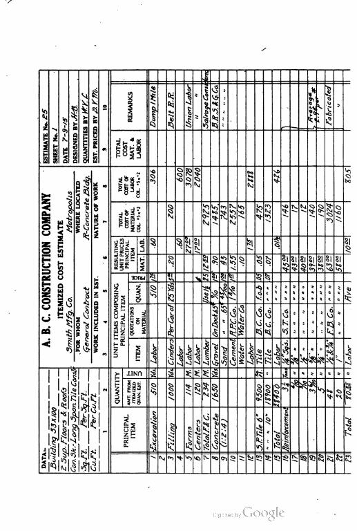
1
DumpIMite UnionLabor] SalvageCons^vS fabricated
QUANTITIES>frf.£
AMARKSft:
iu
vs
1ESTIMATDNo.£5
1
e
01
k *
N
>a
£S
4
ieb
\
t
•
1
TOTALCOST
s5
\
Q
|
*> 15
t5GeneralContract7f-ConcreteSidq. TOTAL
COSTOF
A.B.C.CONSTRUCTIONCOMPANYSmithMfg.Co.Metropolis
.FORDOMDARELOCATED DORKINCLUDDDINDST.NATUAOFDORK
34SS78
o
1 §^
5r
1V
i 1
CM
1
1
j 7
S
k>rC?
1
Q>
ITEMIZEDCOSTESTIMATE
^18
VsJ
R
~~
RESULTINGUNITPRICES
PRINCIPAL
5 * s
\
tel -QS J
8
-^
^ s ^ ^ §j §1 SI §) SI1- |_;
M S%
SIa-.
55
33IWH ^ U \•»
ol §1 -J. ^ ^UNITITEMSCOMPOSING
PRINCIPALITEM1
^
-jj.
^i!S
0. . ?
£^'\
Q * * ' *
1 <
PerCarofb ^
WalerCo.
'•s 4
6 *
I Vj vS k «
Vj
^.
E
111
|
Lumber
1
^^
Cement
i.«i
Ig g |1 1
H
1 ^.voN --J ^\
«1S
1>- JJND g j^ §: S; 5: 35 «
IEE > i * *
QUANTI"
ts
^
»
IEMIZED QUEN.EST.
* 1 5 ^ 51 I
-1* v ^>
•*)\ZSup.Floors&:Koofs^
N
1
nr>*-i
$
I
\k\
CaTT.FerCu.rt.£K
\Building33X/OO
1
1
PRINCIPAL
Totalf&"
Concrete 4
t
fteinfortemenl
EH
1 1I
Centers
N| |
^
1
1
^ ^ ^ t E^
" (V «*> ^ >0 '^- 00 c»> ^- ^ 5 5: -^ ss 93 85NI
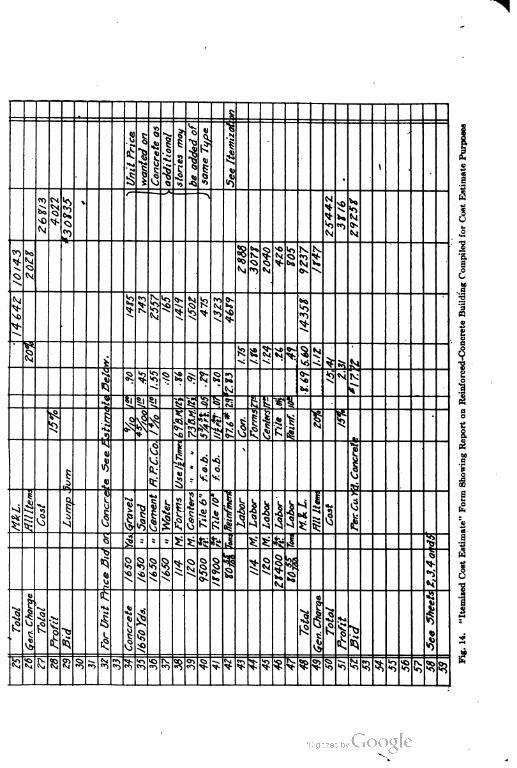
ex
Q
N
"*> N
§••^>
SI
[VJ
Ias vjl
-o
e
^ ^
>r>

COST-ANALYSIS ENGINEERING 71*
into the different operations entering into the complete handling of
the materials. Columns 3, 4, and 5 are used for this dissection by
stating first the items; second, any quotations received; third, the.
quantity and price of enough of the secondary materials and labor
to form one unit quantity of the principal item. The result is
Column f>, the resulting unit price per unit of quantity given in
Column 2. Columns 7 and 8 give the totals for materials and labor
and should be totaled separately before carrying to the "Total Cost
Material and Labor", unless for some reason it is necessary to sepa
rate the work into sections, when intermediate grand totals are
given.
The labor column must, however, be footed independently,
and the same is true for the complete work in order to provide for
"General Charges". This will be explained later.
Such an estimate is just as adaptable for unit-price bids as for
lump-sum bids, the only difference being that for lump sums the
total of Column 9 is used, whereas for unit bids the various totals
in Column 6 for items in Column 1 are used with the general charges,
profits being added to each unit price for each item as the estimate
proceeds, and totals extended to Columns 7, 8, and 9. For lump-
sum bids, the estimator not only has a tabulated record of his bid
prices, but also his estimated quantities and the amount of materials,
labor, and total.
Method of Using Form. Every class of work to be performed
by the contractor should be treated as a principal item, regardless
of the classification of the specifications.
For instance, forms for concrete should be given in feet, board
measure, and not added as a guess amount per cubic yard of con
crete, as is too often done. To illustrate—a wall 12 inches thick
requires practically as much form work per lineal foot of wall as a
wall 27 feet thick; on the cubic yard basis the first wall would show
54 square feet of surface per cubic yard as against 2 square feet for
the second wall. This is an extreme example, but in practice a
large difference will be found. The same thought applies to rein
forcing steel for concrete.
In brick work practically the same cost is incurred in preparing
for work, whether the wall is 12 inches thick or 36 inches. Surely,
the cost per thousand is different.
72 COST-ANALYSIS ENGINEERING
The labor cost of pile driving is made up of two labor charges,
viz, (1) (a) rigging and (b) removing outfit; (2) driving. Let
us assume a cost to rig and remove outfit of §300, and two jobs—
one of 3000 lineal feet and one of 30,000 lineal feet. When it comes
to the actual driving, the cost should not vary to any great extent,
yet the rigging and removing in the first case is 10 cents per lineal
foot and in the second case 1 cent. Wild bids can many times be
explained this way.
Be sure to analyze each item, and, following through the job
in imagination, determine all the elements which enter into each
operation. Build the job step by step in your own mind and there
after you will never set down any guess costs or make snap judgment
as to the cost because it agrees with the cost on another job.
As an illustration of this form of estimate, suppose we take a
concrete job of any character requiring excavation, piling, foundation
concrete, superstructure concrete, forms and centers, reinforcement,
and cement finish. This estimate is carried to completion in two
ways: (1) For lump-sum bid; and (2) for unit-price bid. General
charges are included, but for the present we will pass the detail
determination of them. A special discussion will be given to this
element of the cost, which, in its insidious way, eats into the antici
pated profits, sometimes to their final annihilation. Upon the
face of the estimate sheet we have every detail calculation of the
cost and why. By simply referring to the Itemized Quantity
Estimate, Fig. 13, we have detail calculation of the quantities and
why. There is no guesswork about such a system, for, even if
some items are uncertain of determination from the plans, yet
these stand by themselves and can be verified or mention may be
made in the proposal that a certain amount has been estimated.
Any questions by the owner or architect can be answered at once
and definitely. Any eliminated items can be deducted without
recalculation.
Unit=Price Bidding. On the lower half of the Itemized Cost
Estimate, Fig. 14, an illustration is given of estimating a job for
unit-price bidding. It may be well to go into some detail in
the analysis of concrete work as the estimator must do before
itemizing. The itemization given is sufficient for all practical
purposes but back of this statement of quantities and units lies
370

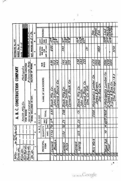
5 J ^« *» «< «
XT1 W)Q
---)
D *-» *
£"> -M i ^u M
B
IS §
. LU
U U CO s ^
^
*L §1
^
I
" s a
V>05J "1
^
«^
M* ^ Jz ° sa|SK
•
O^ 1^0) I
5> ^(2 -? 3 P
Z
°,^
*"^
5<
Si 5 fe i- UJ ffl U. i(y^
a
^;* n < 'J ^u H
§<
Q
u
aa a a
§^CJ
^5? 5 iQ
*r> $ ^^
Q
OS
1§*
UJ
r>
S«sX is '0 Nl ^"*
ivj «i1
2>--
0 m^
3 "«!u-< ft
-%
DAA/-MetropolisLumberC
1ntractff-Conc
MetropolisLumberCo.Useflveraqe/fc3!
c
« 3
Z
NAMEOFSUBBIDDAS
JCementDlocKCo. CemenlBlockCo.
CemenlS--.Co-
|
f-Jnnes&Brown.6
E Ci
t Ho
t£i -H If
1 —.
m X
V
<
-J
£>
<*
V)
4
3 C*
C
t
as
•••
/a
I
<;
1
j
IT IT ir
c Z
Q
A;C; ^
u
^>
d
V <:V. W)
(
(j'l*i
^
J.1 r; J >T( ri^
^^
U
Z«i "C
^r
9Q ?1»
:
^(•;:
i
^I
No ^j<"
0 ^o
00 t d (i10 ^ >0
E
R * g ^^ ^J ivj *
t ^ 3? ^ $:1
o >- ?
E
1 CO t
H«>\
. ^
1*
< ^*
N w-V^
<VjN
^f*"< ^
\1
Cf
A
d
^ ^V J
'^E
i
*}\
E. -*-*«\ t- \
\
Hi
1
\Cemei
Q" PRINC c
ivS v2
V v: i£i
t " J^ ii;- ^ fc!jj 8*K
JJ•-.
Nc*> \ ^ V5 IV. 00 Ol
!^ ^ S; 5 2 -ti^ijj
s:
OIcj
-- c^ i-g
1)
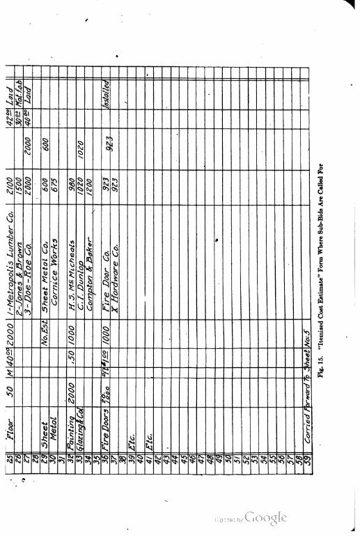
U
$
|' V^
^ 1§i
11
^I
^s.
Q J
11 | 1 J5 1 1
18 §
ifi
1
2-Jones&Brown
i0
cs
SheetMetalCo,
CorniceWorks H.5,M^MicheatsComotonfrBake•-
j!i
"?
]\ iC
Q)
t*>
4•N. |
|
1
3o
SJ>.
§; ^ 15A
S% •c
|^ «i5l
bJ» m
|
\Sheet "o\Paintinq *0
\rireDoor .Carried
I4
ii
!3 \i 5 8J & •5 s? "> 5R $ ^ 81 ^«^^ S "* ^* § ^ •5 <Vj
5? ? 58 5? ^^ ^5
st- st- IT

COST-ANALYSIS ENGINEERING 77
the basis of their determination or selection. The Outline of Work,
Figs. 4, 5, and 6, and the "Itemized Quantity Estimate", Fig. 13,
furnish the basis from which we proceed to study the concrete
work for each particular job, somewhat along the following line :
(1) Cost of Materials: The cost of the aggregate will depend
upon whether the concrete is to be made of natural mixture of
gravel, stone, or sand in various proportions. The amount of
cement depends upon the proportions of the concrete; this is also
true of the amount of gravel, stone, and sand. The cost of water
for proper manipulation should not be overlooked. In cities the
cost of water is determined by standard rates. Outside of cities the
cost depends upon the labor and equipment necessary to secure a
sufficient supply.
(2) ( "ost Affected by Locality : Concrete work constructed at
a remote distance from populous centers cannot be done at the same
price as that which is in or near urban communities, unless the
work is so remote that a permanent camp can be constructed and
the laborers held by their very isolation. Work at some distance
from the point of supply must bear a charge for .transportation, for
the handling and hauling of raw materials. This is a labor item
chargeable to material inasmuch as the material should be con
sidered as f. o. b. the job; nevertheless, the cost is increased per
cubic yard in the proposal.
(3) Cost Affected by Character of Labor and Character of
Work: Good American labor will accomplish more per day than
foreign labor. American labor, however, is scarce and preferential.
American labor differentiates between clean-cut concrete work
under favorable conditions and concrete work under unfavorable
conditions—adverse weather, excessive water, or other disadvan
tages. The same work may cost a great deal more when built under
unpropitious and unsatisfactory conditions than when built in
the city or town.
(4) Cost of Work as Affected by Forms: A wall of concrete
27 feet thick may be retained by the same forms and the same
amount of form labor as is necessary for a wall 1 foot thick. In the
latter case the form-labor cost per cubic yard of concrete is 27 times
as great. It is, therefore, not safe to estimate the cost of forms on
a basis of "guess" price per cubic yard of concrete. The timber work
371
78 COST-ANALYSIS ENGINEERING
in each individual job should be estimated as carefully as for any other
item. It does not matter whether the cost is estimated on the basis of
floor or of concrete surface, or upon a basis of feet, board measure,
of lumber; the result is the same just so long as this important
branch of concrete construction receives individual consideration.
(5) Cost of Work as Affected by Centers : There may be a mis
understanding as to. the necessity of separating forms and centers.
"Forms", properly speaking, consist of the timber work to form
those members of concrete construction—columns, girders, etc.—
which must possess a certain regularity of shape and evenness of
outline. "Centers", properly speaking, consist of timber supports
for floor slabs, bridge centers, etc. Where the great amount of
labor on timber work is expended solely for the purpose of support
ing the mass at a uniform or definite height the unit cost is much
less than where it is expended for forming for individual members.
(6) Cost of Work as Affected by Reinforcement: Fabricated
reinforcement will cost much more delivered to the job than will
loose bars; but, on the other hand, it will cost less to place in posi
tion. It is to be expected that a job where the reinforcement is
made up of small bars of less than f inch, will cost much more per
ton for labor than where the sections are larger. Good judgment
must prevail in this particular. It is very seldom that an estimate
will be made based on the labor and the tonnage of each size of bar.
It is the better way to strike an average labor- price with reference
to the proportion of different sizes of reinforcement to be encoun
tered in the work. It is well to remember, in making the estimate,
however, that it takes practically as long for the steel man to place
and wire a f inch bar as a f inch bar, whereas the tonnage is only
one-quarter as great.
(7) Cost of Work as Affected by General Charge Items:
There are a great many items of the cost of concrete work which
are not included in the cost of material, labor, forms and centers,
reinforcement, etc. These costs consist of installation of machin
ery, and its removal, coal, oil, repairs and fittings to machinery,
general charge items such as rope, bolts, etc., and the loss on petty
tools such as shovels, etc. Such costs on the basis of so much per
cubic yard, are to be determined from the percentage of labor on
different classes of work.
372
COST-ANALYSIS ENGINEERING 79
Cost-Estimate Form for Sub-Bidders. Fig. 15 contemplates that
when any portion of the work is to be sublet, the contractor will yet
make his own estimate of the quantity of such work and the fair
unit price. This method serves as a check on the sub-bidders and
also provides a basis for determining the unit prices at which the
various sub-bidders are estimating.
The first three columns are used for the contractor's own check
estimate, while the balance of the sheet is for tabulation of sub-bids.
Relation of Cost Estimates to Previous Forms. Both forms,
Figs. 14 and 15, should measure 8|X14 inches, as this size is just as
convenient for filing and the extra length saves labor in forwarding
totals.
The Outline of Work, Figs. 5 and 6, the Itemized Quantity Esti
mate, Fig. 13, and the two forms of Itemized Cost Estimate, Figs.
14 and 15, should be bound together in order, preferably on the side,
in a loose-leaf binder. Each estimate as made should be placed in
this binder in the order of the estimate number, and an index should
be made. In a large office it is better to file the Outline of Work
and Itemized Quantity Estimate in one binder in the estimating or
engineering department, while the Itemized Cost Estimate is per
sonally in the hands of the engineer, contractor, or of a strictly
confidential employe.
Estimated Cost of Equipment. The amount to be added to
the estimate for rental or depreciation of plant and equipment
depends upon the "scheme of operation". It is suggested that in
construction work, there should be added to the estimate the differ
ence between the cost price of new equipment and its second hand
sale value; good judgment must be used to determine this depreci
ation with regard to the character and probable wear and tear of
each class. The depreciation, however, usually will vary from 40
to 60 per cent. In the case of equipment on hand, it is a matter of
choice whether we add a rental in addition to profit or whether
we consider the use of such a plant as included in the added profit
and thus presumably gain an advantage over less fortunate com
petitors.
Maintenance of Equipment. The subject of "Maintenance of
Equipment" is, however, a separate charge over and above any
rental or depreciation and is a true cost to be charged to each job.
373
80 COST-ANALYSIS ENGINEERING
Various methods have been suggested, but for simplicity the writer
advocates a Repair Account which forms a part of the General
Charge. This subject will be treated in detail later when all of the
proper charges to this account will be listed. Properly speaking,
this is "Material-Cost Bookkeeping" and should be treated under
Construction.
Rental or Depreciation of Equipment. Only in exceptional cases
should rentals or depreciation be added as part of the unit cost of
any item. If they are added to this cost, a fictitious idea is obtained
of the estimated cost of the item, and moreover the total amount
set aside for this cost can be obtained only by recalculation. This
method is, besides, cumbersome and indefinite and will not stand
investigation and analysis as will the percentage method of General
Charge. The method of charging out the difference between the
cost and second hand selling value in the case of new equipment is
based on the theory that the repair account is charged to the job
and that if the plant is properly looked after the machinery is always
in good second hand condition and may be carried so on the
inventories. If a rental is charged—or if equipment is leased to
others—10 per cent per month, or a life of ten months on the first
cost, is not unreasonable, except for rolling and heavy equipment,
or on large contracts. This theory is based on the idea that the
plant is a profit-making investment, and repairs and upkeep are
worth the price.
Summary of Points in Making Estimate. In making the esti
mate, arrange the items in the logical order of sequence, as they
would naturally occur in the actual construction. If the estimate
is built up in this way there is little chance of overlooking items.
A contractor who lacks imagination is certainly in the wrong line of
work. The process of visualizing the proposition step by step will
many times call attention to items which do not appear in the plans
and specifications. We cannot anticipate all contingencies, but it
is possible to build in the mind a model of the particular proposition.
Cost Data Subject to Wide Variation. Throughout the presen
tation of this cost-analysis system, the author has consistently
refrained from stating any cost data based on actual experience, be
lieving that such costs are of little value, except to the individual
with whom they occur, and that they apply to his locality only.
374
COST-ANALYSIS ENGINEERING 81
The purpose has been to emphasize the , methods whereby each
individual in any locality can analyze and develop his own system.
Material costs are readily obtainable. Labor costs are uncer
tain, depending as they do on character, class, nationality, and
environment of men employed, and the circumstances and diffi
culties surrounding the work. We are writing for the man of
experience who will accept suggestions as to methods, and for the
young man who desires the groundwork upon which to build up an
organization. The contractor knows his labor and what he can
expect as a day's work. The young man should serve his time with
an established organization, keeping his own notes and forming
conclusions which, if supplemented by system and proper considera
tion for overhead and general-charge expenses, should enable him to
start well prepared for prosperous experience. The young man can
gain ideas of the efficiency of men by service as a timekeeper or sub-
foreman, but will, in the majority of cases, miss many items of cost
which do not appear in the field and which are confidential with his
employer. It is to supply a lack of information on this subject that
this paper will include actual results on costs other than material
and labor.
375

MANHATTAN SUSPENSION BRIDGE, NEW YORK CITY, IN COURSE OF
CONSTRUCTION
Photo by Brown Brothers, New York City
COST-ANALYSIS ENGINEERING
PART II
A COST=ANALYSIS SYSTEM (Continued)
GENERAL=CHARGE OR EXPENSE ITEMS
N Importance of General-Expense Items. The items which go
to make up the General-Charge division of cost may be designated
by various titles and may be proportioned to the estimate in different
ways, but, regardless of their divisions in the schedule, their presence
in connection with any work is as sure as the forces of nature. They
are just as sure and certain a cost as material and labor and are
really more destructive to profits, because of their insidious accumu
lation through gradual and apparently trivial daily expenditures.
For our personal convenience we choose to 'apportion these items
to labor, although this is proposed not as a rule but as a suggestion.
They must be considered in the estimate, and yet, to a large extent,
they cannot be determined except as the result of actual experience.
The author well remembers that when he first began esti
mating in construction work it was a matter of surprise and bewilder
ment to him why jobs, which in cost of material and labor fully
realized the estimate, still proved a loss—or nearly so. It was a
considerable time before it was recognized that the many small
purchases were, in the end, the destroyers of profits, and that it
was not safe to pass them by with the expectation that they would
not be important enough to justify consideration in estimating.
Some do not or cannot understand this but look on these items as
contingent expenses unnecessary to include in the estimate. This
is very far from the truth, for such expenses are as truly cost
items as are material and labor.
Methods of Application. Some engineers and contractors
advocate an allowance per unit of work, as per yard of excavation,
concrete, etc., to take care of these charges. Others add an amount
to the estimate, sufficient in their judgment to cover the total item.
377 ;,A
84 COST-ANALYSIS ENGINEERING
Errors in Unit-Allowance Method. The first method is alto
gether wrong for the following reasons:
(1) The addition of any such amount to a price per unit of
work is deceptive in its after-effects. ,
(2) Such a method can never arrive at anything-but a "guess".
(3) The estimator is yet unborn who can differentiate the
cost per unit for general-charge items on several classes of work
and secure an intelligent result.
Suppose we imagine an excavation for a pier foundation for a
bridge requiring excavation, pile driving, and concrete. To do
this work requires pumping, and a great deal of it if the pier is
located out in the stream. Invoices accumulate at the office for
coal and oil, and the actual coal and oil is delivered to the job and
used as occasion demands. Excavating, pile driving, and con
creting proceed practically simultaneously. Under these circum
stances, how can we arrive at any fair cost per unit for fuel and oil? If
the attempt is made to distribute the cost in any proportion to the
various kinds of work it can only be done by arbitrary methods,
which will not bear analysis.
Take another item—for example, tetty Tools. In this classi
fication belong shovels. What contractor is wise enough or
sufficiently in touch with his work to say what proportion of this
cost should go to excavation and what to concrete?
Take the Fittings and Repairs account. Who can say with
any certainty how much of the repairs to pumping machinery
should be charged to excavation and how much to pile driving
or to concrete?
The fact is that all these charges are directly dependent upon
the kind of work under construction, and the various jobs will show
a greater or less cost along this line in direct relation to the diffi
culties encountered.
Distribution by Percentage Method. Therefore it follows that
the various kinds of work should be separated, according to each
contractor's experience, into definite classifications, with respect to
the difficulties surrounding construction; from these the percent
ages to be added to the estirrtated cost should be ascertained to
take care of all the items of general charge. Such classifications
have been prepared by the author for his own work, and it has
378
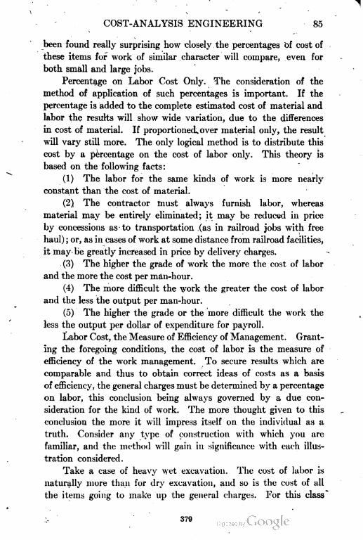
COST-ANALYSIS ENGINEERING 85
been found really surprising how closely the percentages of cost of
these items for work of similar character will compare, even for
both small and large jobs.
Percentage on Labor Cost Only. The consideration of the
method of application of such percentages is important. If the
percentage is added to the complete estimated cost of material and
labor the results will show wide variation, due to the differences
in cost of material. If proportioned^ over material only, the result
will vary still more. The only logical method is to distribute this
cost by a percentage on the cost of labor only. This theory is
based on the following facts:
(1) The labor for the same kinds of work is more nearly
constant than the cost of material.
(2) The contractor must always furnish labor, whereas
material may be entirely eliminated; it may be reduced in price
by concessions as to transportation (as in railroad jobs with free
haul) ; or, as in cases of work at some distance from railroad facilities,
it may be greatly increased in price by delivery charges.
(3) The higher the grade of work the more the cost of labor
and the more the cost per man-hour.
(4) The more difficult the work the greater the cost of labor
and the less the output per man-hour.
(5) The higher the grade or the more difficult the work the
less the output per dollar of expenditure for payroll.
Labor Cost, the Measure of Efficiency of Management. Grant
ing the foregoing conditions, the cost of labor is the measure of
efficiency of the work management. To secure results which are
comparable and thus to obtain correct ideas of costs as a basis
of efficiency, the general charges must be determined by a percentage
on labor, this conclusion being always governed by a due con
sideration for the kind of work. The more thought given to this
conclusion the more it will impress itself on the individual as a
truth. Consider any type of construction with which you are
familiar, and the method will gain in significance with each illus
tration considered.
Take a case of heavy wet excavation. The cost of labor is
naturally more than for dry excavation, and so is the cost of all
the items going to make up the general charges. For this class
379
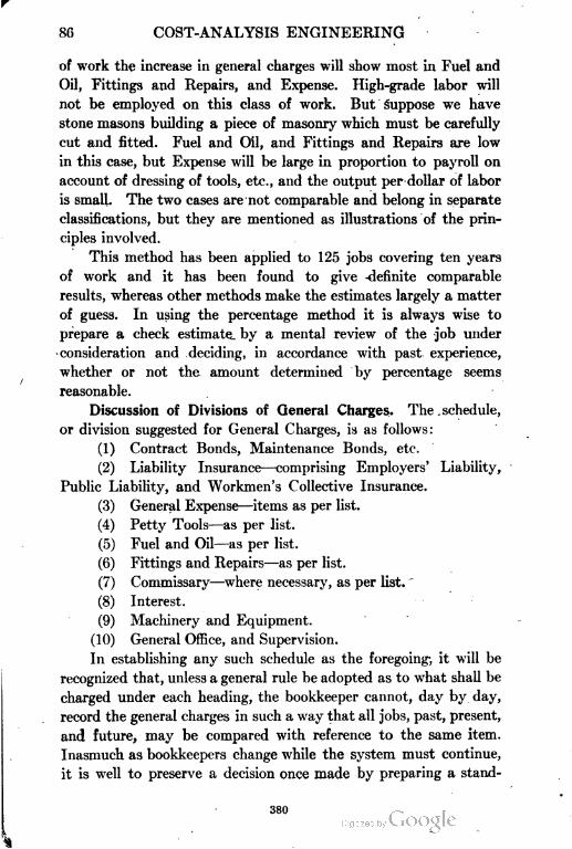
86 COST-ANALYSIS ENGINEERING
of work the increase in general charges will show most in Fuel and
Oil, Fittings and Repairs, and Expense. High-grade labor will
not be employed on this class of work. But suppose we have
stone masons building a piece of masonry which must be carefully
cut and fitted. Fuel and Oil, and Fittings and Repairs are low
in this case, but Expense will be large in proportion to payroll on
account of dressing of tools, etc., and the output per dollar of labor
is small. The two cases are not comparable and belong in separate
classifications, but they are mentioned as illustrations of the prin
ciples involved.
This method has been applied to 125 jobs covering ten years
of work and it has been found to give definite comparable
results, whereas other methods make the estimates largely a matter
of guess. In using the percentage method it is always wise to
prepare a check estimate by a mental review of the job under
consideration and deciding, in accordance with past experience,
whether or not the amount determined by percentage seems
reasonable.
Discussion of Divisions of General Charges. The schedule,
or division suggested for General Charges, is as follows:
(1) Contract Bonds, Maintenance Bonds, etc.
(2) Liability Insurance—comprising Employers' Liability,
Public Liability, and Workmen's Collective Insurance.
(3) General Expense—items as per list.
(4) Petty Tools—as per list.
(5) Fuel and Oil—as per list.
(6) Fittings and Repairs—as per list.
(7) Commissary—where necessary, as per list.
(8) Interest.
(9) Machinery and Equipment.
(10) General Office, and Supervision.
In establishing any such schedule as the foregoing-, it will be
recognized that, unless a general rule be adopted as to what shall be
charged under each heading, the bookkeeper cannot, day by day,
record the general charges in such a way that all jobs, past, present,
and future, may be compared with reference to the same item.
Inasmuch, as bookkeepers change while the system must continue,
it is well to preserve a decision once made by preparing a stand
380
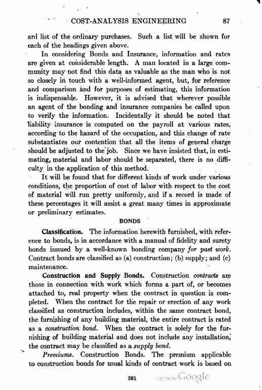
COST-ANALYSIS ENGINEERING 87
arll list of the ordinary purchases. Such a list will be shown for
each of the headings given above.
In considering Bonds and Insurance, information and rates
are given at considerable length. A man located in a large com
munity may not find this data as valuable as the man who is not
so closely in touch with a well-informed agent, but, for reference
and comparison and for purposes of estimating, this information
is indispensable. However, it is advised that wherever possible
an agent of the bonding and insurance companies be called upon
to verify the information. Incidentally it should be noted that
liability insurance is computed on the payroll at various rates,
according to the hazard of the occupation, and this change of rate
substantiates our contention that all the items of general charge
should be adjusted to the job. Since we have insisted that, in esti
mating, material and labor should be separated, there is no diffi
culty in the application of this method.
It will be found that for different kinds of work under various
conditions, the proportion of cost of labor with respect to the cost
of material will run pretty uniformly, and if a record is made of
these percentages it will assist a great many times in approximate
or preliminary estimates.
BONDS
Classification. The information herewith furnished, with refer
ence to bonds, is in accordance with a manual of fidelity and surety
bonds isssued by a well-known bonding company for past work.
Contract bonds are classified as (a) construction; (b) supply; and (c)
maintenance.
Construction and Supply Bonds. Construction contracts are
those in connection with work which forms a part of, or becomes
attached to, real property when the contract in question is com
pleted. When the contract for the repair or erection of any work
classified as construction includes, within the same contract bond,
the furnishing of any building material, the entire contract is rated
as a construction bond. When the contract is solely for the fur
nishing of building material and does not include any installation,
the contract may be classified as a supply bond.
Premiums. Construction Bonds. The premium applicable
to construction bonds for usual kinds of contract work is based on
381
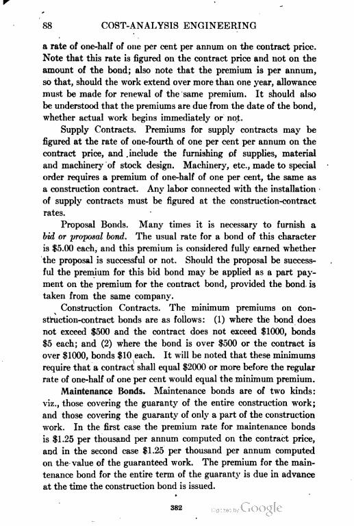
88 COST-ANALYSIS ENGINEERING
a rate of one-half of one per cent per annum on the contract price.
Note that this rate is figured on the contract price and not on the
amount of the bond; also note that the premium is per annum,
so that, should the work extend over more than one year, allowance
must be made for renewal of the same premium. It should also
be understood that the premiums are due from the date of the bond,
whether actual work begins immediately or not.
Supply Contracts. Premiums for supply contracts may be
figured at the rate of one-fourth of one per cent per annum on the
contract price, and .include the furnishing of supplies, material
and machinery of stock design. Machinery, etc., made to special
order requires a premium of one-half of one per cent, the same as
a construction contract. Any labor connected with the installation
of supply contracts must be figured at the construction-contract
rates.
Proposal Bonds. Many times it is necessary to furnish a
bid or yropofsal bond. The usual rate for a bond of this character
is $5.00 each, and this premium is considered fully earned whether
the proposal is successful or not. Should the proposal be success
ful the premium for this bid bond may be applied as a part pay
ment on the premium for the contract bond, provided the bond is
taken from the same company.
Construction Contracts. The minimum premiums on Con
struction-contract bonds are as follows: (1) where the bond does
not exceed $500 and the contract does not exceed $1000, bonds
$5 each; and (2) where the bond is over $500 or the contract is
over $1000, bonds $10 each. It will be noted that these minimums
require that a contract shall equal $2000 or more before the regular
rate of one-half of one per cent would equal the minimum premium.
Maintenance Bonds. Maintenance bonds are of two kinds:
viz., those covering the guaranty of the entire construction work;
and those covering the guaranty of only a part of the construction
work. In the first case the premium rate for maintenance bonds
is $1.25 per thousand per annum computed on the contract price,
and in the second case $1.25 per thousand per annum computed
on the value of the guaranteed work. The premium for the main
tenance bond for the entire term of the guaranty is due in advance
at the time the construction bond is issued.
382
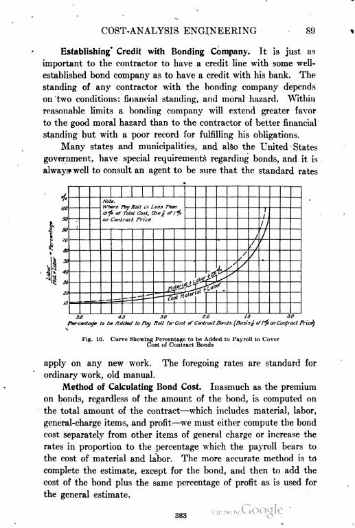
COST-ANALYSIS ENGINEERING 89
Establishing' Credit with Bonding Company. It is just as
important to the contractor to have a credit line with some well-
established bond company as to have a credit with his bank. The
standing of any contractor with the bonding company depends
on two conditions: financial standing, and moral hazard. Within
reasonable limits a bonding company will extend greater favor
to the good moral hazard than to the contractor of better financial
standing but with a poor record for fulfilling his obligations.
Many states and municipalities, and also the United States
government, have special requirements regarding bonds, and it is
always well to consult an agent to be sure that the standard rates
100
Hote.
Where Fay Roll lS Lens Than
1O*/° of Total Coil, £bej ofl°/t
on Contract Price
5.0 4.0 3.0 Z.O 1.0 0.0
Percentage to be Added 1ff fay Roll far Coot of Contract Sands. (Basis£ of1 °/e on Conlracl Price}
\
Fig. 16. Curve Showing Percentage to be Added to Payroll to Cover
Cost of Contract Bonds
apply on any new work. The foregoing rates are standard for
ordinary work, old manual.
Method of Calculating Bond Cost. Inasmuch as the premium
on bonds, regardless of the amount of the bond, is computed on
the total amount of the contract—which includes material, labor,
general-charge items, and profit—we must either compute the bond
cost separately from other items of general charge or increase the
rates in proportion to the percentage which the payroll bears to
the cost of material and labor. The more accurate method is to
complete the estimate, except for the bond, and then to add the
cost of the bond plus the same percentage of profit as is used for
the general estimate.
383
90 COST-ANALYSIS ENGINEERING
For all practical purposes, however, sufficiently accurate
results are obtained by including the bond cost along with other
items of general charge. As our system requires that material
and labor be separated in the estimate, we are able to arrive at
once at the percentage the payroll bears to material and labor.
By referring then to chart, Fig. 10, the proper per cent to be included
in the general charge and added to the payroll may be ascertained.
For instance, if the labor represents 50 per cent of the cost of
material and labor, the percentage to be included in the general
charge and added to the payroll is 1 per cent. If the labor repre
sents 20 per cent, or one-fifth of the cost of material and 'labor,
the percentage to be included in. the general charge and added to
the payroll is 2| per cent. Naturally, if the contract is all labor
and therefore all payroll, representing 100 per cent of the cost,
the rate will be one-half of one per cent. At 10 per cent labor
the per cent to be added to the payroll increases to 5 per cent;
but a, contract with such a small amount of labor is unusual, and
it is recommended that jobs of this character with 10 per cent or
less labor be calculated by the method first suggested. When
we have a job with 10 per cent or less labor we are verging on a
supply contract, and it is probable that the cost of the bond can
be decreased by a proper division of the work under the headings
of construction and supply.
LIABILITY INSURANCE
Features of Liability Insurance. Liability insurance is not
accident insurance, as some employes seem to understand. Con
tractors' liability insurance (briefly known as E. L. policies) is
essentially insurance against the contractor's liability for damages
because of accidents to any of his employes. It is, in fact, a con
tract between the contractor and the liability company whereby,
in consideration of a certain fee to be paid by the contractor, the
liability company agrees to furnish the first or emergency medical
aid and to save the contractor from any and all claims for damages
up to the limits of the policy. The usual limits of the policy are
$5,000 and $10,000, meaning thereby $5,000 for any one individual
judgment or $10,000 for any one accident—the latter being the
limit for an accident when a number are insured and where the
384
COST-ANALYSIS ENGINEERING 91
aggregate amount of judgments does not exceed the amount named.
Almost any limits will be accepted by the liability-insurance com
panies but the ones given are usual. Any increase of the limits
is naturally accompanied by an increase in the rate of premium.
The contractor should consider that his rating or credit with
his liability-insurance company is almost as important as his credit
with his bank or bonding company. Both the bank and the bonding
company gage the contractor by his financial standing and by his
general reputation for fulfilling and satisfying his obligations. The
liability-insurance company judges the riskr in light of its past
experience on similar work, but tempers its decision by the standing
of the contractor and what is known of his experience, methods,
and disposition to assist the company to secure reports, records, and
settlements. A contractor, by establishing a good reputation may
gain the advantage of a close rate, while one with a poor record may
even be refused by one company after another. The interests of
the contractor and the liability company are identical and there
should be close co-operation.
Liability Premiums. The minimum premium for liability
insurance is $50, and the only way to avoid an increase in cost on
this account, when many small contracts are handled, is to secure
a general, annual, or blanket policy covering all work of any char
acter. Naturally on large work this feature is of no consequence.
Public=Liability Insurance. The possibility of accidents to the
public and to the employes of others must be considered, especially
when the work is located in a city or town where others are working
on the same contract. To provide for this contingency public
liability insurance (P. L. policies) is furnished at a somewhat less
rate than is employe insurance.
Workmen's Collective Insurance. Workmen's collective insur
ance is now required in some states and is a feature of the insurance
cost which will require more consideration in the future. Briefly,
this class of insurance may be considered as accident insurance.
The rates vary with the class of work. The benefits are :
(1) In the event of death within 90 days, a sum equal to,
but not exceeding 1 year's wages, sometimes limited to $1500.
(2) For the loss of two limbs or two eyes a sum equal to the
amount payable under the policy at death.
385
92 COST-ANALYSIS ENGINEERING
(3) For the loss of one limb, a sum equal to one-third the
amount payable under the policy at death.
(4) For the loss of one eye a sura equal to one-eighth the
amount payable under the policy at death.
(5) In the event of temporary total disability, a sum equal
to, but not exceeding, one-half the weekly wages for a period not
exceeding 26 weeks, such sum not to exceed $750 in respect of any
one person injured during the policy year.
These benefits are for accidents occurring only during working
hours, but by an additional charge of 15 per cent the policy may be
written to cover the whole 24 hours.
Discussion of Rates of Insurance. The brief abstract of
standard rates, Table I, gives a general idea of the cost of employers'-
liability, public-liability, and workmen's collective insurance. This
table is not intended to cover the entire field of contracting work,
and has been prepared from a manual of recent but hot current date.
The examples are given to serve only as a guide in general con
struction work.
The rates in the table do not include the hazard due to blasting,
unless specifically mentioned. The rates given are for Illinois,
Iowa, Missouri, and Nebraska, and for all other states by use of
the proper differentials.
How Cost of Liability Insurance is Borne. Many states, by
legislative enactment, have very materially increased the cost
of liability insurance. The intention has been to protect the inter
ests of the workman, but it must be remembered that the public
pays the bill in the increased cost of all building operations. The
workman is indeed deserving of a certain protection in his work,
and the economic interest of the community at large justifies a
recompense to him or his family for injuries or loss of life, but this
result cannot be obtained without a corresponding increase in cost of
every building project.
In other words, every contract carries, in addition to the cost
of material, labor, and supplies, the possible cost of human effort
expressed in loss of time and suffering due to injury and death.
This cost is just as true a one as are the others, is more far-reaching,
and should receive its proper recognition; but only by legislative
action can this cost be distributed over the entire community and
386
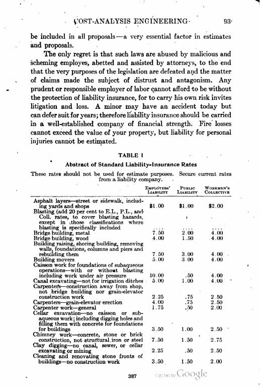
t!OST-ANALYSIS ENGINEERING- 93-
be included in all proposals—a very essential factor in estimates
and proposals.
The only regret is that such laws are abused by malicious and
scheming employes, abetted and assisted by attorneys, to the end
that the very purposes of the legislation are defeated and the matter
of claims made the subject of distrust and antagonism. Any
prudent or responsible employer of labor cannot afford to be without
the protection of liability insurance, for to carry his own risk invites
litigation and loss. A minor may have an accident today but
can defer suit for years; therefore liability insurance should be carried
in a well-established company of financial strength. Fire losses
cannot exceed the value of your property, but liability for personal
injuries cannot be estimated.
TABLE I
Abstract of Standard Liability-Insurance Rates
These rates should not be used for estimate purposes. Secure current rates
from a liability company.
EMPLOYERS' PUBLIC WORKMEN'S
LIABILITY LIABILITY COLLECTIVE
Asphalt layers—street or sidewalk, includ
ing yards and shops $1.00 $1.00 $2.00
Blasting (add 20 per cent to E.L., P.L., and-
Coll. rates, to cover blasting hazards, 1
except in .those classifications where
blasting is specifically included
Bridge building, metal 7.50 2.66 4.00
Bridge building, wood 4.00 1.50 4.00
Building raising, shoring building, removing
walls, foundations, columns and piers and
rebuilding them 7 . ;j() 3.00 4 . 00
Building movers 5.00 3 00 4.00
Caisson work for foundations of subaqueous
operations—with or without blasting
including work under air pressure 10.00 .50 4.00
Canal excavating—not for irrigation ditches 5.00 1.00 4 . 00
Carpenters—construction away from shop,
not bridge building nor grain-elevator
construction work 2.25 .75 2.50
Carpenters—grain-elevator erection 4.00 .75 2 . 50
Carpenter work—general 1.75 .50 2.00
Cellar excavation—no caisson or sub
aqueous work; including digging holes and
filling them with concrete for foundations
for buildings 3.50 1.00 2.50
Chimney work—concrete, stone or brick
construction, not structural iron or steel 7.50 1.50 2.75
Clay digging—no canal, sewer, or cellar
excavating or mining 2.25 .50 2.50
Cleaning and renovating stone fronts of
buildings—no construction work 3.50 1.50 2.00
387
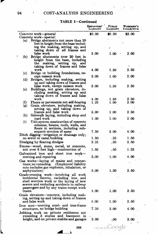
94 COST-ANALYSIS ENGINEERING
TABLE I—Continued
EMPLOYKHS' PUBLIC WORKMEN'S
LIABILITY LIABILITY COLLECTIVE
Concrete work—general $3.00 $0.50 $2.00
Concrete work—special:
(a) Bridge abutments not more than 20
feet in height from the base includ
ing the making, setting up, and . /
taking down of all frames and
falsework 3.00 1.00 2.00
.(b) Bridge abutments over 20 feet in
height from the base, including
the making, setting up, and
taking down of frames and false
work 4.00 1.50 2.50
(c) Bridge or building foundations, ex
cept caisson work 3.00 1.00 2.00
(d) Bridges, including making, setting
up and t aking down of frames and
false work, except caisson work 5.00 1.50 2.50
(e) Buildings, not grain elevators, in
cluding making, setting up and
taking down of frames and false
work 4.00 1.50 2.50
(f ) Floors or pavements not self-bearing 1 2i> 1 . 00 2 . 00
(g) Grain elevators, including making,
setting up, and taking down of
frames and false work 5 . 00 1 . 00 2 . 50
Sidewalk laying, including shop and
yard work 1.00 1.00 2.00
Unit-system construction of concrete
columns, beams, roofs, walls, and
floors in sections, including sub
sequent erection of same 7 . 50 3 . 00 4 . 00
Ditch digging—irrigation or drainage only;
no sewer or canal building 1 . 50 . 25 1 . 50
Dredging by floating dredges 2 . 25 .50 2 . 50
Fences—wood, stone, metal, or concrete,
not over 6 feet high—construction of 1.50 .50 1.25
Galvanized iron and sheet iron work—
erecting and repairing 3.00 1.00 4.00
Gas works—laying of mains and connec
tions ; no tunneling. (Employers' liabilit y
rate excludes gas explosion, inhalation, or
asphyxiation) 3.00 1.50 2.50
Grade-crossing work—involving all work
incidental thereto, excluding iron and
steel erection work or the laying of new
sewers and excluding accidents to railway
passengers and by any trains except work
trains 4.00 1.00 2.50
Grain elevators—concrete, including mak
ing, setting up and taking down of frames
and false work , 5.00 1.00 2.50
Iron men—erecting steel- and iron-frame
structures, no bridge building 7.50 3.00 4.00
Jobbing work on private residences not
exceeding 3 stories and basement in -
height, and on private stables and garages 2.00 .50 2.00
388
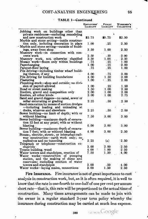
COST-ANALYSIS ENGINEERING 95
TABLE I—Continued
EMPLOYERS' PUBLIC WORKMEN'S
LIABILITY LIABILITY COLLECTIVE
Jobbing work on buildings other than
private residences—excluding remodeling •
and new construction work $2 .75 $0 . 75 $2 . 50
Marble and stone setting—inside construc
tion only, including decoration in place 1.00 .25 2.50
Marble and stone setting—outside of build
ings, away from shop 3 . 50 1 . 00 2.50
Masonry work—in connection with con
crete work 2.50 .50 2 .00
Masonry work, not otherwise classified 3.50 1.00 .. 2.50
Mosaic work—floors only within buildings .75 .25 1.00
Paperhanging 1.00 ,25 2.00
Parquet-floor laying .75 .25 1 . 00
Pile driving—including timber wharf build
ing thereon, if any 4.00 .75 3.00
Pile driving for building foundations 4.00 1.50 3.00
Plastering 1.00 • .25 2.00
Plumbing-work—shop and outside; no divi
sion of payroll allowed . 1.00 .25 1.50
Road or street making 1 . 50 1 . (X) 2 . 50
Roofers, gravel and composition only 2.00 l.(X) 2.00
Roofers, all other kinds 3 . 00 1 . 00 2 . 75
Sand and gravel diggers—no canal, sewer or
cellar excavating or grading 2 . 25 .50 . 2 . 50
Sand excavation by means of suction dredges
—including loading and unloading at
docks, wharves and elsewhere 2 . 25 .50 2 . 00
Sewer building—no limit of depth; with or
without blasting 7.50 3.00 3.00
Sewer building—maximum depth of excava
tion 12 feet at any point; with or without
blasting (i.OO 3.00 3.00
Sewer building—maximum depth of excava
tion 7 feet; with or without blasting 4.00 3.00 2.50
Steam-, electric-, street-, or interurban-rail-
way construction—earth work only; no^
explosives and no tunneling 2 . 25 (a) 2 . 50
Telegraph or telephone—construction ex
clusively 3.00 2.00 2.50
Trestle building, wood 4.00 1.00 2.50
Water towers and standptpes, erection of 7.50 1.50 4.00
Water works—construction of pumping
station, and the making of dams and
reservoirs; excluding erection of water
towers and standpipes 3.00 .50 4.00
Waterworks—laying mains, connections 3.00 1.50 2.50
Fire Insurance. Fire insurance is not of great importance to cost
analysis in construction work, but, as it is often required, it is well to
know that the rate is one-fourth to one-half of one per cent per annum
short rate—that is, this rate will be proportioned to the actual time of
construction. Many times arrangements can be made to join with
the owner in a regular standard 3-year term policy whereby the
insurance during construction may be carried at much less expense.
389
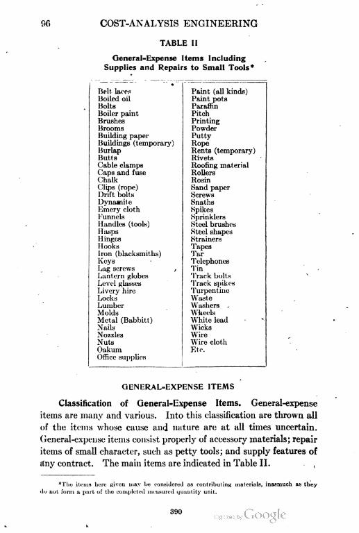
r.fl COST-ANALYSIS ENGINEERING
TABLE II
General Hxpense Items Including
Supplies and Repairs to Small Tools*
Belt laces
Boiled oil
Bolts
Boiler paint
Brushes
Brooms
Building paper
Buildings (temporary)
Burlap
Butts
Cable clamps
Caps and fuse
Chalk
Clips (rope)
Drift bolts
Dynamite
Emery cloth
Funnels
Handles (tools)
Hasps
Hinges
Hooks
lron (blacksmiths)
Keys
Lag screws ,
Lantern globes
Level glasses
Livery hire
Locks
Lumber
Molds
Metal (Babbitt)
Nails
Nozzles
Nuts
Oakum
Office supplies
Paint (all kinds)
Paint pots
Paraffin
Pitch
Printing
Powder
Putty
Rope
Rents (temporary)
Rivets
Roofing material
Rollers
Rosin
Sand paper
Screws
Snaths
Spikes
Sprinklers
Steel brushes
Steel shapes
Strainers
Tapes
Tar
Telephones
Tin
Track bolts
Track spikes
Turpentine
Waste
Washers ,
Wheels
White lead
Wicks
Wire
Wire cloth
Etc.
QENERAL=EXPENSE ITEMS
Classification of GeneraI=Expense Items. General-expense
items are many and various. Into this classification are thrown all
of the items whose cause and nature are at all times uncertain.
General-expense items consist properly of accessory materials; repair
items of small character, such as petty tools; and supply features of
Any contract. The main items are indicated in Table II.
*Tho items here Riven may be considered as contributing materials, inasmuch as they
do not form a part of the completed measured quantity unit.
390
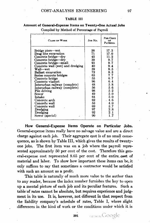
COST-ANALYSIS ENGINEERING 97
TABLE III
Amount of General-Expense Items on Twenty-One Actual Jobs
Compiled by Method of Percentage of Payroll
PER CENT
CLASS OF WORK JOB N.o.
PAYROLL
OF
Bridge piers—wet 38 17.3
Drag line excavation 71 17.0
Concrete bridge—dry 45 11.2
Concrete bridge—dry 39 9.7
Concrete bridge—small 93 9.7
Concrete wall (wet) and dredging 40 9.4
Wall—wet 39 8.5
Ballast excavation 72 8.3
Series concrete bridges 63 7.7
Concrete bridge 55 6.7
Concrete viaduct 96 6.4
Interurban railway (complete) 48 5.8
Interurban railway (complete) 56 5.6
Pile driving 98 5.2
Sewer 4!) 5.0
Intake 64 5.0
Concrete arch 62 . 4.6
Concrete wall 53 4.0
Concrete wall 69 3.7
Dredging 97 2.8
Dredging 92 2.1
Sewer (special) 90 1.7
How General=Expense Items Operate on Particular Jobs.
General-expense items really have no salvage value and are a direct
charge against each job. Their aggregate cost is of no small conse
quence, as is shown by Table III, which gives the results of twenty-
one jobs. The first item was on a job where the payroll repre
sented approximately 50 per cent of the cost. Therefore this gen
eral-expense cost represented 8.65 per cent of the entire cest of
material and labor. To show how important these items can be, it
only suffices to say that sometimes a contractor would be satisfied
with such an amount as a profit.
This table is naturally of much more value to the author than
to any reader, because the index number furnishes the key to open
up a mental picture of each job and its peculiar features. Such a
table of rates cannot be absolute, but requires experience and judg
ment in its use. It is, however, not different in that respect from
the liability company's schedule of rates, Table I, where slight
differences in the kind of work or the conditions under which it is
391
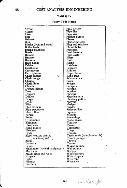
98 COST-ANALYSIS ENGINEERING
TABLE IV
Petty-Tool Items
Anvils' Pipe cutters
Augers Pipe dies
Axes Pipe vise
Bars Pitcher pumps
Bellows Planes
Bits Plastering tools
Blocks (iron and wood) Plug and feathers
Boiler tools Plumb bobs
Boring machines Punchers
Brads Push brooms
Brooms Push carts
Brushes Pliers
Buckets Rail
Bush hooks Hasps
Cables Ratchets
Canthooks Reamers
Car movers Riddles
Car replacers Rope blocks
Chain blocks Rope guys
Chain tongs Salamanders
Chains Haws
Chalk lines Scoops
Chisels Scrapers
Derrick blocks Screens
Dies Scythes
Dippers Sheaves
Dollies
Drags
Sheeting caps
Sheeting pullers
Drills Shovels
Files Sledges
Flue cleaners Spades
Flue expanders Spike pullers
Flue rollers Squares
Forges Stencils
Forks Stone dogs
Grindstones Stone hooks
Hammers Tampers
Hand axes Tanks
Hand pumps Templates
Hatchets Tongs
Hods Torches
Hose (water; steam; Track tools (complete outfit)
. (suction; air) Trench pumps
Jacks Trowels
Lanterns Trucks
Levels Wagon pumps
Machinery (special equipment Well pumps
Mattocks Wedges
Mauls (iron and wood) Wheelbarrows
Nippers Wire clippers
Picks \Vire rope
Pilecaps Wrenches
Pinchers
392
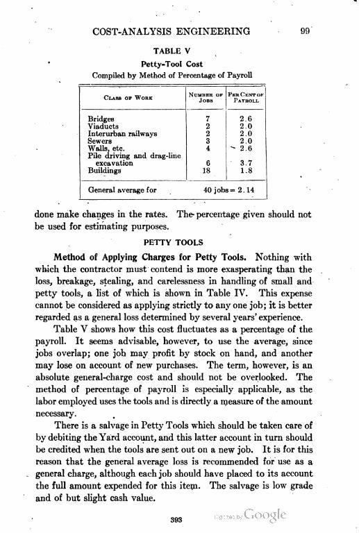
COST-ANALYSIS ENGINEERING
TABLE V
Petty-Tool Cost
Compiled by Method of Percentage of Payroll
CLASS OF WORKNUMBER OF
JOBS
PEHC'KNTOF
PAYROLL
Bridges 7 2.6
Viaducts 2 2.0
Interurban railways 2 2.0
Sewers 3 2.0
Walls, etc. 4• 2.6
Pile driving and drag-line
excavation 6 3.7
Buildings 18 1.8
General average for 40 jobs = 2 . 14
done make changes in the rates. The- percentage given should not
be used for estimating purposes.
PETTY TOOLS
Method of Applying Charges for Petty Tools. Nothing with
which the contractor must contend is more exasperating than the
loss, breakage, stealing, and carelessness in handling of small and
petty tools, a list of which is shown in Table IV. This expense
cannot be considered as applying strictly to any one job; it is better
regarded as a general loss determined by several years' experience.
Table V shows how this cost fluctuates as a percentage of the
payroll. It seems advisable, however, to use the average, since
jobs overlap; one job may profit by stock on hand, and another
may lose on account of new purchases. The term, however, is an
absolute general-charge cost and should not be overlooked. The
method of percentage of payroll is especially applicable, as the
labor employed uses the tools and is directly a measure of the amount
necessary.
There is a salvage in Petty Tools which should be taken care of
by debiting the Yard account, and this latter account in turn should
be credited when the tools are sent out on a new job. It is for this
reason that the general average loss is recommended for use as a
general charge, although each job should have placed to its account
the full amount expended for this item. The salvage is low grade
and of but slight cash value.
393
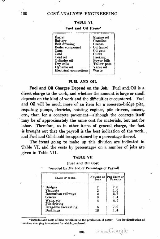
COST-ANALYSIS ENGINEERING
TABLE VI
Fuel and Oil Items*
Barrel Engine oil
Battery Gasoline
Belt dressing (irease
Boiler compound - Oil faucet
Cans Oil gate
Coal Oilers
Coal oil Packing
Cylinder oil Power bills
Dry cells Tallow pots
Dynamo oil Valve oil
Electrical connections ', Waste
FUEL AND OIL
Fuel and Oil Charges Depend on the Job. Fuel and Oil is a
direct charge to the work, and whether the amount is large or small
depends on the kind of work and the difficulties encountered. Fuel
and Oil will be much more of an item for a concrete-bridge pier,
requiring pumps, derricks, hoisting engines, pile drivers, mixers,
etc., than for a concrete pavement—although the concrete itself
may be of approximately the same cost for materials, but not for
labor. Therefore, as in other items of general charge, the fact
is brought out that the payroll is the best indication of the work,
and Fuel and Oil should be apportioned by a percentage thereof.
The items going to make up this division are indicated in
Table VI, and the costs by percentages on a number of jobs are
given in Table VII.
CLASS OF WORKNUMRER OF
JORS
PER CENT OF
PAYROLL
• Bridges7 7.0
Viaducts 2 1.6
Interurban railways 2 5.7
Sewers 3 1.4
Walls, etc. 4 4.5
Pile driving
Drag-line excavating 6 7.2
Buildings 18 1.4
TABLE VII
Fuel and Oil Cost
Compiled by Method of Percentage of Payroll
* Includes any costs of bills pertaining to the production of power. Use for distribution of
invoices, charging to contract for which purchased.
394
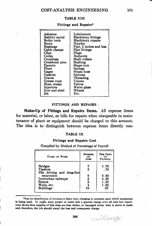
COST-ANALYSIS ENGINEERING 101
TABLE VIII
Fittings and Repairs*
Asbestos
Babbitt metal
Boiler tools
Boots
Bushings
Cable clamps
Clips
Cocks
Couplings
Crosshead pins
Faucets
Flues
Gages
Gaskets
Grates
Grease cups
Hose, steam
Injectors
Iron and steel
Jet
Lubricators
Machinery fittings
Machinery repairs
Nipples
Pipe, 3 inches and less
Pipe fittings
Plugs
Reducers
Shaft collars
Shafting
Shape iron
Springs
Steam hose
Siphons
Threading
Unions
Valves
Water glass
Wheels
Etc.
FITTINGS AND REPAIRS
Make=Up of Fittings and Repairs Items. All expense items
for material, or labor, or bills for repairs when chargeable to main
tenance of plant or equipment should be charged to this account.
The idea is to distinguish between expense items directly con
NUMREK
OF
PER CENT
CLASS OF WORK
JORS PAYROLL
OF
Bridges
Viadicts
7 1.70
Pile driving and drag-line
2 .70
excavation 6 4.40
Interurban railways 2 4.20
Sewers 2 1.30
Walls, etc. 4 1.50
Buildings 18 .67
TABLE IX
Fittings and Repairs Cost
Compiled by Method of Percentage of Payroll
*Use for distribution of invoices or labor cost, charging to contract upon which equipment
is being used. It might seem proper to make this a general charge over all jobs but experi
ence shows that supplies of this class are lost, stolen, or damaged every time a move is made
and, therefore, the job should stand the loss and consequent charge.
395
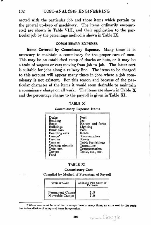
102 COST-ANALYSIS ENGINEERING
nected with the particular job and those items which pertain to
the general up-keep of machinery. The items ordinarily encount
ered are shown in Table VIII, and their application to the par
ticular job by the percentage method is shown in Table IX.
COMMISSARY EXPENSE
Items Covered by Commissary Expense. Many times it is
necessary to maintain a commissary for the proper care of men.
This may be an established camp of shacks or huts, or it may be
a train of wagons or cars moving from job to job. The latter sort
is suitable for jobs along a railway line. The items to be charged
to this account will appear many times in jobs where a job com
missary is not existent. For this reason and because of the par
ticular character of the items it would seem desirable to maintain
a commissary charge on all work. The items are shown in Table X
and the percentage charge to the payroll is given in Table XI.
TYPE OF CAMP AVERAGE PER CENT OP
PAYBOLL
Permanent Camps
Moveable Camps
3.5
7.0
TABLE X
Commissary Expense Items
Desks
Bedding
Boots
Buildings
Bunk cars
Boarding cars
Camps*
Candles
Canvas
Cooking utensils
Cots, etc.
Covers
Food
Fuel
Ice
Knives and forks
Lighting
Pots
Rents
Store supplies
Stoves
Table furnishings
Tarpaulins
Transportation
Tents, etc., etc.
TABLE XI
Commissary Cost
Compiled by Method of Percentage of Payroll
* Where men must be cared for in camps there is, many times, an extra cost to the work
due to installation of camp and losses in operation,
COST-ANALYSIS ENGINEERING 103
INTEREST
Method of Handling Interest Charges. Assume a contract of
$100,000 to be completed in 10 months, that is, at the average rate
of $10,000 per month. Payments are to be made during the progress
of the work to the extent of 85 per cent, payable the 15th of the
month following that within which work is done, final payment
to be made 60 days after completion. Assume also that profit
is at the rate of 10 per cent on cost. »
In the first place, at the rate of $10,000 of work per month
the actual average cost is approximately $9000; the contractor
receives $8500, and $1500 per month remains in the hands of the
client. Then since one-half month's work on the current month
elapses before payment is made for the preceding month, $4500 is
expended for cost of work. Since his payroll comes weekly and
his average time for bills due is 30 days, the contractor, under these
conditions, even if he can buy material on 60 days, is always in
arrears and must pay interest on the amount held up in excess of
profit and for work done and not yet payable. This charge will
amount to a percentage on the total cost, depending on the con
tractor's credit in the purchase of materials.
The maximum cost in interest is reached where no work is paid
for until the whole is completed and accepted. In such a case full
interest plus a bonus or fee should be added to the estimate, as no
capitalist can afford to speculate on financing work of this kind with
out receiving at least double the ordinary legal interest for money.
The time necessary to complete work or during which payment
is withheld will naturally affect the charge.
MACHINERY AND EQUIPMENT
Division of Construction=Equipment Item. Machinery and
equipment can be considered as either an investment or an expense
item. -In the first case a reasonable interest or rental return should
be expected, which may be included in profit. In the second case a
rental or depreciation should be charged directly to the job.
Since the Fittings and Repairs account, Tables VIII and IX,
is supposed to take care of the wear and tear due directly to the
particular job, general depreciation is to be considered under the
present heading. If machinery is purchased for any job, one-third
397
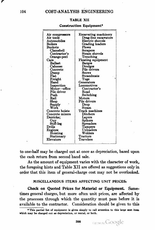
104 COST-ANALYSIS ENGINEERING
TABLE XII
Construction Equipment*
Air compressors
Air tools
Automobiles
Boilers
Buckets
Clamshell
Contractor's
Orange-peel
Cars
Ballast
Caboose
Concrete
Dump
Flat
Freight
Hand
Inspection
Motors-office
Pile driver
Push
Rail
Shop
Supply
Work
Concrete hoists
Concrete mixers
Derricks;
Guy
Stiff-leg
Drills
Engines
Hoisting
Stationary
Elevators
Excavating machinery
Drag-line excavators
Electric shovels
Grading loaders
Plows
Scrapers
Steam shovels
Trenching
Floating equipment
Barges
Dredges
Pile drivers
Scows
Steamboats
Tugs
Generators
Locomotives
Contractor's
Road
Switching
Motors
Pile drivers
Drop
Steam
Track machines
Ditchers
Layers
Spikers
Spreaders
Tampers
Unloaders
Welders
Tractors
Travelers
to one-half may be charged out at once as depreciation, based upon
the cash return from second hand sale.
As the amount of equipment varies with the character of work,
the foregoing hints and Table XII are offered as suggestions only in
order that this item of general-charge cost may not be overlooked.
MISCELLANEOUS ITEMS AFFECTING UNIT PRICES-
Check on Quoted Prices for Material or Equipment. Some
times general charges, but more often unit prices, are affected by
the processes through which the quantity must pass before it is
available to the contractor. Consideration should be given to this
* This partial list of equipment is given simply to call attention to this large tost item
which may be charged out as depreciation, or rental, or both.
398
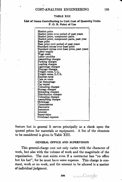
COST-ANALYSIS ENGINEERING 105
TABLE XI II
List of Items Contributing to Unit Cost of Quantity Units
F. O. B. Point of Use
Market price
Market price over period of past years
Market price, component parts
Market price, component parts, past year
Base price
Base price over period of past years
Standard extras over base price
Standard extras over base price, past years
Labor supply
Wage scale
Labor troubles
Assembling charges
Packing charges
Loading charges
Lighterage charges
Drayage charges
Freight rates, C.L.
Freight rates, L.C.L.
Express rates
Care en route
Car demurrage
Car rental
Unloading charges
Storage charges
Reloading charges
Distribution charges
Unloading charges
Assembling charges
Shrinkage
Commissions
Discounts
Insurance
Interest
Supervision
Overhead expense
feature but in general it serves principally as a check upon the
quoted prices for materials or equipment. A list of the elements
to be considered is given in Table XIII.
GENERAL OFFICE AND SUPERVISION
This general-charge cost not only varies with the character of
work, but also with the volume of work and the magnitude of the
organization. The cost exists even if a contractor has "no office
but his hat", for he must have some expense. This charge is con
stant, work or no work, and the amount to be allowed is a matter
of individual judgment.
399
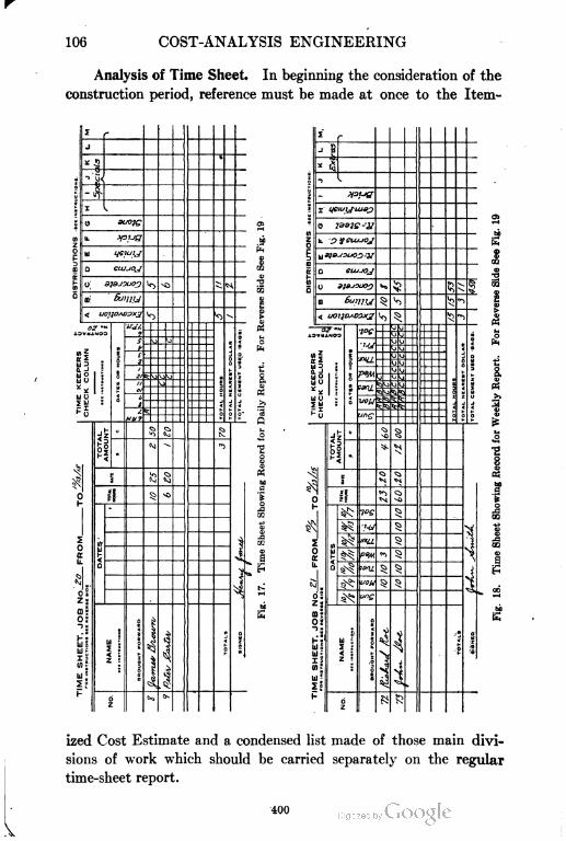
106 COST-ANALYSIS ENGINEERING
Analysis of Time Sheet. In beginning the consideration of the
construction period, reference must be made at once to the Item-
"' ^tc2
w 3
n-^y O
ujU
Ul U
^5
Ss•!ui-
l!h
c ?u^Q. -J
'11 O
Su
li1 U
IS
1!
I
ized Cost Estimate and a condensed list made of those main divi
sions of work which should be carried separately on the regular
time-sheet report.
400

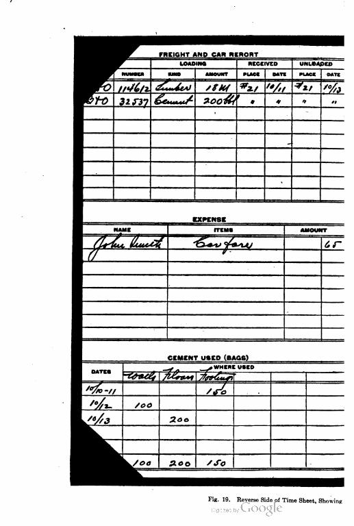
FREIGHT AND CAR REPORT
Fig. 19. Reverse Side of Time Sheet, Showing

It 1B lntended that this sheet shall be uoed for all j. .be, whether timekeeper makes report to par-foil clerk
*11T. weekly, or monthly, and is to be used also for making summary reports. In using tune eheet aide, aJwayt
ilacadate at head of column and when making out summary aheet. place daily dates in the name column. In a* ing
be distribution side, the « olumn marked "Timekeeper'a check column" must hare dates placed at the bead
- to the time sbeet aide, and each column represents one day. the distribution being" taken four
,ay and marked inside of the four littl* square*, using distribution letter. However, for daily sheets, each
• hirci. represent^ one hour, and separation of time must be checked to the hour. Distribution column:
leaded by rubber alamp for each job and each man's time must be distributed under the proper col
reduced to dollara and fchown at foot of eheet. eircept that for nummary eheeta. total for each
ites&me. Timekeepere roust keep rareful record at cars received expense and cement and 1'll
ptXMite pa^e, Timeheep*re and engineers will co-operate to insure that summary sheets ait coi
iistribution and amoimt of work done. Daily time sheets must be turned in to the office at the rl
ire*kly time sheets each T bursday evening end bi-monthly or monthly aheets will be separated
DB«t one* each week. No change of rete of pay will be allowed between paj-roll periods
No deviation from tbeee injtrucuoon wi)t be iJhJWwJ OD
.istribution Items, Expense, and Material Report

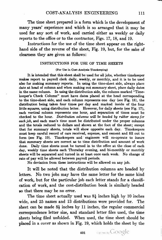
COST-ANALYSIS ENGINEERING 111
The time sheet prepared is a form which is the development of
many years' experience and which is so arranged that it may be
used for any sort of work, and carried either as weekly or daily
reports to the office or to the contractor, Figs. 17, 18, and 19.
Instructions for the use of the time sheet appear on the right-
hand side of the reverse of the sheet, Fig. 19, but, for the sake of
clearness they are given as follows:
INSTRUCTIONS FOR USE OF TIME SHEETS
(For Use in Cost-Analysis Timekeeping)
It is intended that this sheet shall be used for all jobs, whether timekeeper
makes report to payroll clerk daily, weekly, or monthly, and it is to be used
also for making summary reports. In using the time-sheet side, always place
date at head of column and when making out summary sheet, place daily dates
in the name column. In using the distribution side, the column marked "Time
keeper's Check Column" must have dates placed at the head corresponding
to the time-sheet side, and each column represents one day (see Fig. 18), the
distribution being taken four times per day and marked inside of the four
little squares, using distribution letter. However, for daily sheets (see Fig. 17),
each vertical column represents one hour, and separation of times must be
checked to the hour. Distribution columns will be headed by rubber stamp for
each job, and each man's time must be distributed under the proper columns
and the totals reduced to dollars and shown at the foot of the sheet; except
that for summary sheets, totals will show opposite each day. Timekeepers
must keep careful record of cars received, expense, and cement and fill out to
form (see Fig. 19). Timekeepers and engineers will co-operate to insure
that summary sheets are correct as to time distribution and amount of work
done. Daily time sheets must be turned in to the office at the close of each
day, weekly time sheets each Thursday evening, and bi-monthly or monthly
sheets will be separated and turned in at least once each week. No change of
rate of pay will be allowed between payroll periods.
No deviation from these instructions will be allowed on any job.
It will be noted that the distribution columns are headed by
letters. No two jobs may have the same letter for the same kind
of work, but for the particular job each letter stands for a classifi
cation of work, and the cost-distribution book is similarly headed
so that there may be no error.
The time sheet actually used was 8| inches high by 10 inches
wide, and 25 names and 13 distributions were provided for. The
sheet can be made 8| inches by 11 inches, the regular commercial
correspondence letter size, and standard letter files used, the time
sheets being filed unfolded. When used, the time sheet should be
placed in a cover as shown in Fig. 19, which holds the sheet by the
401
112 COST-ANALYSIS ENGINEERING
corners in the same manner as an ordinary desk pad, and folds on
the vertical center line. The covers, as shown, can be placed in
the side pocket of the coat, being 5| inches by 85 inches. Fig. 17
shows the front or timekeeping side of the time sheet arranged for
daily reports. Fig. 18 shows the same form of time sheet arranged
for weekly reports. The top and bottom only of these sheets are
shown; the number of lines between can be estimated from Fig. 19.
In Fig. 19 showing the reverse side of the time sheet, special
notice is called to the right-hand side where a continuous record is
obtained of the job from its beginning to its completion.
Checking the Men. In beginning a job under this system, all
the men are given numbers, commencing with the superintendent
as No. 1, and identification cards are issued. These cards are
retained until the end of the payroll period, generally one week,
and surrendered in exchange for the payroll envelope containing
wages. Each week new cards of different color should be issued in
such rotation that one color will not be used again for" at least a
month. This scheme avoids the disadvantages of the brass-check
system while fulfilling the same purpose. The cards can be expected
to remain in good condition for a reasonable period, they serve the
purpose of absolute identification, and are receipts beyond question
when in the hands of the paymaster.
By using the different colors, there can be no duplication or
errors due to the numbers assigned to the men. For instance,
No. 72 for the week yellow cards are used may not be the same man
as No. 72 the next week when blue cards are issued. This arrange
ment also makes it possible for the men older in period of employ
ment to be moved forward from time to time, so that the higher
numbers will be indicative of new untried men; this groups the
steady employes in the tabulation on the payroll. The colors
to be used are red, blue, yellow, and green. The men generally
wear the cards in their hat bands. The simplification of work to
the timekeeper and paymaster is beyond computation.
Payrolls. The time sheets are filled out from day to day
and handed to the paymaster, who prepares the payroll. A pay
roll should be prepared day by day. One hour's work per day
will mean seven hours or a whole day by the end of the week, but
procrastination may result in failure to complete the payroll on
402
COST-ANALYSIS ENGINEERING 113
time, or at least may increase the chance for many careless and
unnecessary errors.
The payroll envelopes are then prepared, using the payroll
as a basis and these envelopes are made in colors the same as the
identification cards; a man who calls for his money several days
or weeks after pay day cannot then be confused with any other
man of possibly the same number or name working during a different
payroll period. During the interval of payroll periods it is neces
sary to discharge many men, and this proceeding is brought into
harmony with the general system by the use of "discharge blanks".
Tracing Employes through Timekeeping System. Let us
trace regular and floating employes through their introduction to
this system, using both daily and weekly reports.
We will suppose we have two jobs under construction, one
on a basis of daily reports and one of weekly. In both cases all
men employed have been assigned numbers and cards. The hours,
rate, and amount are not filled out on cards unless it is particularly
desired to obtain a definite receipt. The time sheets, Figs. 17 and
18, show the men and the time made by them and the character
of work upon which they were placed.
Note by Fig. 17 that James Brown, No. 8, worked 10 hours—
from 7 a.m. until 12 m., and from 12:30 until 5:30 p.m.—of which
5 were on excavation, distribution letter A, and 5 on concrete,
distribution letter C. Peter Carter, No. 9, came on at 11 a.m.,
and worked one hour until 12 m. on concrete (C), then began again
at 12:30 p.m., worked until 5:30, making 6 hours in all. It will be
seen that the time spacing at the head of the timekeeper's column
means one hour for each division, the upper half denoting the hour
and the lower half the half-hour. It is not necessary to mark the
distribution letter in each column as it is understood that the man
continues on the same work, until by a distribution-letter change
at the closest hour or half-hour he is placed on other work.
Assuming at the same time that we have job No. 21 running
on a basis of weekly reports, we see Richard Roe, No. 72, Fig. 18,
worked Monday to Wednesday, being discharged on the latter
day after having made 23 hours as distributed under A, B, and C.
His time for Monday and Tuesday having been turned in to the
paymaster (possibly the contractor himself), the timekeeper made
403
114 COST-ANALYSIS ENGINEERING
out his discharge check for the three hours on Wednesday, and
the paymaster added the amount for Monday and Tuesday and
paid him $4.60 upon surrender of his card, properly signed. Upon
the payroll, the paymaster then writes in the extreme right-hand
column "Paid by discharge, No. 72". John Doe, No. 73, on the
other hand, having completed a full week's work, is paid, upon
surrender of his card, by a payroll envelope of the same name,
number, and color, with all proper deductions made.
Ordinarily, it is assumed that large and important work requires
daily reports while small work, or jobs where there is little shifting
of men, can be reported weekly. In the first case, changes in the
distribution may be made to the closest half-hour. In the latter
case, changes four times a day would seem sufficient.
This system is flexible and can be applied to any organization,
large or small. The cost of installation is not great, and the cost-
analysis results more than justify the expense. The rubber stamp
used for distribution of time is made so the same stamp can be
used on the reverse side of the time sheet, Fig. 19, where the oppor
tunity is given to carry out the total quantities, total payroll,
and unit cost for each period, for the previous periods, and for
the total to date.
OPERATION OF LABOR-COST DISTRIBUTION SYSTEM
The methods outlined cover briefly the field end of the con
struction department and its connection with the office, in order
to secure cost analysis as to labor distribution. To make the
analysis more clear, a view of a reinforced-concrete office building
during the construction is given in Fig. 20, and should be studied
carefully in order that the proper idea may be had of the many
problems presented to the cost-analysis engineer.
Forms and Centers. The view shows seven completed floors
of a 12-story office building. The three lower floors have been
entirely completed and all the forms and centers removed. The
fourth floor is completed but it has been necessary to retain struts
under the center of the beams in order to protect them from possible
overloading while green. It should be noted that the placing of
struts is done after the forms and centers have been removed, and
is, therefore, an additional labor charge to Forms and Centers.
404
COST-ANALYSIS ENGINEERING 115
405

116 COST-ANALYSIS ENGINEERING
On the fifth floor the forms and centers still remain, but a part
of the supports for centers have been removed in anticipation of
the removal of all timber work. On the sixth floor level the timber
work is all in place and braced so as to be prepared for the con
struction of the seventh floor. On the seventh floor forms and
centers are completed and concrete work is in progress on the front
portion of the building.
In the rear, where the centering work is of extra height, there
is to be an assembly hall two stories in height, and for this reason
we have a special feature of construction which must be taken into
consideration in the final cost analysis.
Checking Labor on Different Classes of Work. The limestone
facing of the two lower stories of the building is in progress, and so
the timekeeper, in checking up the labor that is employed, must
check up the labor of stone masons on the first and second floors;
the electric-light workmen and plumbers on the second and third
floors; the carpenters removing the forms and centers on the fourth
and fifth floors; the carpenters on the seventh and eighth floors;
and the concrete workmen in the basement where material is deliv
ered, and on the eighth floor where the concreting is in progress.
In connection with this checking of labor he must check invoices
and wagon receipts for delivery of reinforcing steel, lumber, tile,
cement, and other materials, which may be seen in the material yard
in front of the building.
Derrick and Small Hoist. The erection of the small stiff-leg
derrick might be considered as a charge against forms and centers
inasmuch as it is used principally for the hoisting of timber removed
from the floors below. However, since this derrick is used for
hoisting reinforcing steel also, the cost of erection and operation of
the derrick must be proportioned. In this particular case an electric
motor was installed for the operation of the concrete mixer and
hoist. On account of mechanical difficulties the motor was aban
doned after the fifth-floor level and a contractor's standard double-
drum steam hoisting engine was introduced, which may be seen in
the right foreground. This engine was used to operate both the
concrete hoist and the derrick. Since the concrete hoist was used
to raise not only concrete but also tile, brick, and other materials
entering into the construction of the building, the cost of these two
406
COST-ANALYSIS ENGINEERING 117
installations and their operation must be apportioned against the
various classes of work.
Daily Time Sheet. The labor on this building was checked
four times a day as to distribution, with the use of the form of tune
sheet shown in Fig. 18. As the common labor was very largely
of foreign character, each man was carried by number—having a
numbered card as previously described which was checked at the
office in the morning, and brass checks hung on a hook-board with
corresponding numbers.
Instructions to Timekeepers. In this case as well as in the
case of other complicated structures, the engineer in charge of the
cost analysis should issue very definite instructions to the timekeep
ers and clerks on the job so that proper distributions may be obtained.
For example, the ordinary timekeeper cannot be expected to dis
tinguish between that part of the carpenters' work which is desig
nated as Forms and that part designated as Centers, unless the cost-
analysis engineer furnishes a detail description of what constitutes
each on the particular piece of work under construction. As a
further illustration, it will be noted that the concrete on the first
two floors, which is very nearly masked by the cut-stone work, has
been given a coat of asphalt paint in order that the concrete may not
in the course of time stain the stone work. The timekeeper should
know whether this painting is a charge against concrete or a charge
against stone work. The writer would charge this painting to stone
work but others might decide otherwise. If so charged it is an
indirect material-and-labor charge against stone work. However
charged, the same system should be followed throughout and nota
tions made so that proper comparisons may be drawn with other
jobs of like character.
Cost-Analysis Bookkeeping
The independent work of the office contemplates the completion
of the records just discussed by the bookkeeping system described
as follows:
Ledger Entry System. In the first place, we must have the
common double-entry ledger system, such as is used in any ordinary
mercantile business. In this ledger are carried the personal accounts
of all individuals with whom the concern may be dealing. The
407
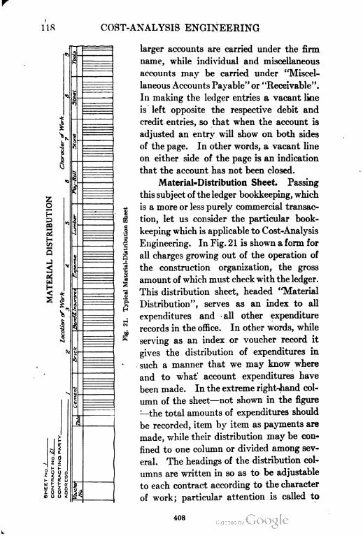
COST-ANALYSIS ENGINEERING
§H
-
D
s
HU h
U Z
£8
1
o
Fo «< SK U
I- IT
Z 0
9 Q
I
I%
1
larger accounts are carried under the firm
name, while individual and miscellaneous
accounts may be carried under "Miscel
laneous Accounts Payable" or "Receivable".
In making the ledger entries a vacant line
is left opposite the respective debit and
credit entries, so that when the account is
adjusted an entry will show on both sides
of the page. In other words, a vacant line
on either side of the page is an indication
that the account has not been closed.
Material=Distribution Sheet. Passing
this subject of the ledger bookkeeping, which
is a more or less purely commercial transac
tion, let us consider the particular book
keeping which is applicable to Cost-Analysis
Engineering. In Fig. 21 is shown a form for
all charges growing out of the operation of
the construction organization, the gross
amount of which must check with the ledger.
This distribution sheet, headed "Material
Distribution", serves as an index to all
expenditures and -all other expenditure
records in the office. In other words, while
serving as an index or voucher record it
gives the distribution of expenditures in
such a manner that we may know where
and to what' account expenditures have
been made. In the extreme right-hand col
umn of the sheet—not shown in the figure
—the total amounts of expenditures should
be recorded, item by item as payments are
made, while their distribution may be con
fined to one column or divided among sev
eral. The headings of the distribution col
umns are written in so as to be adjustable
to each contract according to the character
of work; particular attention is called to
ins
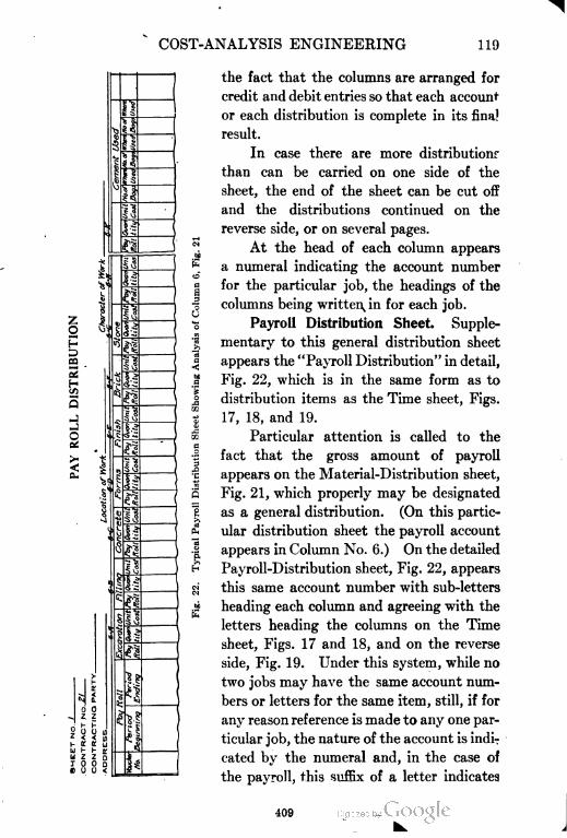
COST-ANALYSIS ENGINEERING 119
I
CO
12
fe
oet
1I
erofWor
.£.
EH
the fact that the columns are arranged for
credit and debit entries so that each account
or each distribution is complete in its final
result.
In case there are more distribution
than can be carried on one side of the
sheet, the end of the sheet can be cut off
and the distributions continued on the
reverse side, or on several pages.
At the head of each column appears
a numeral indicating the account number
for the particular job, the headings of the
columns being written^ in for each job.
Payroll Distribution Sheet. Supple
mentary to this general distribution sheet
appears the "Payroll Distribution" in detail,
Fig. 22, which is in the same form as to
distribution items as the Time sheet, Figs.
17, 18, and 19.
Particular attention is called to the
fact that the gross amount of payroll
appears on the Material-Distribution sheet,
Fig. 21, which properly may be designated
as a general distribution. (On this partic
ular distribution sheet the payroll account
appears in Column No. 6.) On the detailed
Payroll-Distribution sheet, Fig. 22, appears
this same account number with sub-letters
heading each column and agreeing with the
letters heading the columns on the Time
sheet, Figs. 17 and 18, and on the reverse
side, Fig. 19. Under this system, while no
two jobs may have the same account num
bers or letters for the same item, still, if for
any reason reference is made to any one par
ticular job, the nature of the account is indi
cated by the numeral and, in the case of
the payroll, this suffix of a letter indicates
i09
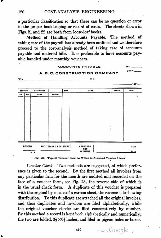
120 COST-ANALYSIS ENGINEERING
a particular classification so that there can be no question or error
in the proper bookkeeping or record of costs. The sheets shown in
Figs. 21 and 22 are both from loose-leaf books.
Method of Handling Accounts Payable. The method of
taking care of the payroll has already been outlined and we therefore
proceed to the cost-analysis method of taking care of accounts
payable and material bills. It is preferable to have accounts pay
able handled under monthly vouchers.
ACCOUNTS PAYABLE
A. B. C. CONSTRUCTION COMPANY
-DR.
NO
CHK..
101
CONTRACT DiSTRiBUTlON DATE lTEMS AMOUNT TOTAL
NO. ACT. lTEMS AMOUNT
POSTED AUDlTED AND REGISTERED APPROVED 1 SEC-V
FOR }•
Fig. 23. Typical Voucher Form to Which Is Attached Voucher Check
/
Voucher Check. Two methods are suggested, of which prefer
ence is given to the second. By the first method all invoices from
any particular firm for the month are audited and recorded on the
face of a voucher form, see Fig. 23, the reverse side of which is
in the usual check form. A duplicate of this voucher is prepared
with the original by means of a carbon sheet, the reverse side showing
distribution. To this duplicate are attached all the original invoices,
and thus duplicates and invoices are filed alphabetically, while
the original voucher checks are filed consecutively by number.
By this method a record is kept both alphabetically and numerically;
the two are folded, 3JX6| inches, and filed in pigeon holes or boxes.
410
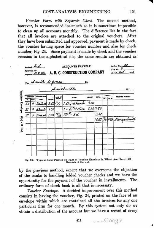
COST-ANALYSIS ENGINEERING 121
Voucher Form with Separate Check. The second method,
however, is recommended inasmuch as it is sometimes impossible
to clean up all accounts monthly. The difference lies in the fact
that all invoices are attached to the original vouchers. After
they have been submitted and approved, payment is made by check,
the voucher having space for voucher number and also for check
number, Fig. 24. Since payment is made by check and the voucher
remains in the alphabetical file, the same results are obtained as
ACCOUNTS PAYABLE
Approved for
payment-^.
Ledger Page-
File M>- "*
A. B. C. CONSTRUCTION COMPANY M^-^
Or.
-101.
? 20
Zl
Jlattut. 3.4Z
1.00
Z.Z5
»/?- 0.
f.00
I. £5
3AZ
'4.67 '%, t116
RCCEIVED PAYMENT
Fig. 24. Typical Form Printed on Face of Voucher Envelope in Which Are Placed All
Records of the Job
by the previous method, except that we overcome the objection
of the banks to handling folded voucher checks and we have the
opportunity for the payment of the voucher in installments. The
ordinary form of check book is all that is necessary.
Voucher Envelope. A decided improvement over this method
consists in having the voucher, Fig. 24, printed on the face of an
envelope within which are contained all the invoices for any one
particular firm for one month. By this system not only do we
obtain a distribution of the account but we have a record of every
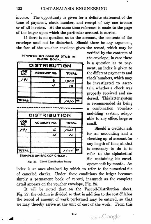
122 COST-ANALYSIS ENGINEERING
CHECK
invoice. The opportunity is given for a definite statement of the
time of payment, check number, and receipt of any one invoice
or of all invoices. At the same time reference is made to the page
of the ledger upon which the particular account is carried.
If there is no question as to the account, the contents of the
envelope need not be disturbed. Should there be any argument,
the face of the voucher envelope gives the record, which may be
verified by the contents of^TAMPED ON BACK OF STUB ,N the envelope; in case there
is a question as to pay
ment, an index is given to
the different payments and
check numbers, which may
be investigated to ascer
tain whether a check was
properly received and en
dorsed. This latter system
is recommended as being
a combination voucher-
and-filing system, adapt
able to any office, large or
small.
Should a creditor ask
for an accounting and a
checking up of account for
any length of time, all that
is necessary to do is to
refer to the alphabetical
file containing his envel
opes month by month. An
DISTRIBUTION
JOB
NO.ACCOUNT NO. TOTAU
/f/ 6 tooo
•/ /o
TIRTAU/o/O
•0
DISTRIBUTION
OOB
NO.ACCOUNT NO. TOTAJ.
CZL £ /ooo
// /o
TOTAL. /e>/oOw
STAMPED ON BACK OF CHECK .
Fig. 25. Check Distribution Stamp
index is at once obtained by which to refer to the numerical file
of canceled checks. Under these conditions the ledger becomes
simply a permanent book of record, inasmuch as the complete
detail appears on the voucher envelope, Fig. 24.
It will be noted that on the Payroll-Distribution sheet,
Fig. 22, the column is divided so that in addition to the cost of labor
the record of amount of work performed may be entered, so that
we may thereby arrive at the unit of cost of the work. From this
412
COST-ANALYSIS ENGINEERING 123
record, in connection with the material distribution, we are able
to prepare statements at any time showing how the work is pro
ceeding with reference to the original estimate. The necessary
information relative to the quantity of work performed is taken
from the reverse side of the Time sheet, Fig. 19, supplemented
by office records and information not obtainable in the field.
Payment of Accounts. In the payment of accounts the ordi
nary form of check book may be used, upon the reverse side of the
stub and check being stamped a form similar to Fig. 25. At the
time a payment is made this form is filled out with the job number
and the account number, using the numerical index at the head
of the column on the distribution sheets. If necessary, additional
information may be shown by indicating under "Items", what
the payment is for. Such a check becomes a voucher check which
is explained by the voucher envelope on file in the office, and the
endorsement of such a check is not only a receipt for payment,
but indicates at once the account for which payment was made.
Inasmuch as upon the reverse side of the stub appears the cor
responding distribution record, the distribution sheets may be posted
from the stub book.
This system is not in any sense complicated and may be devel
oped at a trifling expense for printing and rubber stamps; since it is
adaptable to any job, large or small, and to any number of jobs, it
is deserving of consideration.
The voucher envelope bearing as it does a file number which is
the job number, the files for each job may be kept separate. On
the other hand, the system may be used alphabetically and all
accounts filed accordingly. The latter method is probably prefer
able, because the information is more readily obtainable and, when
the distribution at the left-hand side carries the job numbers, any
one account may be carried together for the month, regardless
of how many jobs are in progress.
Special Distribution Accounts. Liability Insurance. Liability
insurance, already discussed fully, requires a detailed payroll
distribution, such as Fig. 22, inasmuch as the various classifications
of labor are rated differently. The contractor will more than pay for
the extra time, trouble, and cost necessary to keep a set of distribu
tion books by securing the benefit of a closer classification of rates.
413
124 COST-ANALYSIS ENGINEERING
At any time the liability company's auditor appears, a complete
summary of the payroll is shown, with the members of each class
of work grouped in the proper columns. By lumping the payroll,
it may bear the maximum rate, whereas, if classified, a reduction is
secured in the total premiums paid.
Separate Account for Each Section of Work. In case of large
construction, the division of the work by sections is of the utmost
importance, and it is recommended that each section be considered
as a subcontract and the material and payroll costs distributed
accordingly. In other words, instead of carrying a job as a com
plete whole, we divide the total into sections in accordance with the
original Outline of Work, and Itemized Estimate, and maintain a
separate account for each section so that we have distinct time and
work reports and separate distribution sheets.
By adopting this method, the work of the field forces and of the
office are harmoniously adjusted and the work of the cost analysis
at the completion of the contract is very much simplified.
Cost-Analysis Progress and Final Charts
We wTill next take up the question of the analysis of the result
as shown by the field and office bookkeeping system, with the idea of
using progress estimates and progress charts.
Value of Progress Study. Analytical progress study is not only
intensely interesting but is of the greatest importance to the up-to-
date superintendent, inasmuch as, through the information furnished
by the proper recording of the results of the work, he is able to dis
cover the weak points and to direct his best attention to them
instead of considering the whole work. Without such detailed
information the superintendent is absolutely at a loss to prepare
any record; he may be intelligent enough to recognize that certain
parts of the work are not proceeding properly, but he cannot be as
strong a man as he would be if the record and every part of the
work were so tabulated that day by day he could adjust his forces
and revise his methods to gain the lowest cost.
Progress Charts. In beginning the construction we have as
a basis for our cost keeping and cost analysis the Itemized Quan
tity Estimate, Fig. 13, and Itemized Cost Estimate, Figs. 14 and
15. In connection with these estimates we have our sketch plans
414
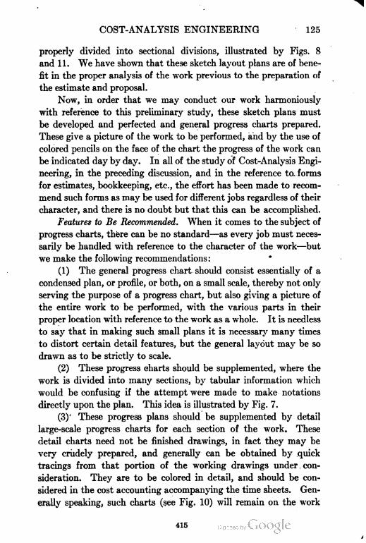
COST-ANALYSIS ENGINEERING 125
properly divided into sectional divisions, illustrated by Figs. 8
and 11. We have shown that these sketch layout plans are of bene
fit in the proper analysis of the work previous to the preparation of
the estimate and proposal.
Now, in order that we may conduct our work harmoniously
with reference to this preliminary study, these sketch plans must
be developed and perfected and general progress charts prepared.
These give a picture of the work to be performed, and by the use of
colored pencils on the face of the chart the progress of the work can
be indicated day by day. In all of the study of Cost-Analysis Engi
neering, in the preceding discussion, and in the reference to forms
for estimates, bookkeeping, etc., the effort has been made to recom
mend such forms as may be used for different jobs regardless of their
character, and there is no doubt but that this can be accomplished.
Features to Be Recommended. When it comes to the subject of
progress charts, there can be no standard—as every job must neces
sarily be handled with reference to the character of the work—but
we make the following recommendations:
(1) The general progress chart should consist essentially of a
condensed plan, or profile, or both, on a small scale, thereby not only
serving the purpose of a progress chart, but also giving a picture of
the entire work to be performed, with the various parts in their
proper location with reference to the work as a whole. It is needless
to say that in making such small plans it is necessary many times
to distort certain detail features, but the general layout may be so
drawn as to be strictly to scale.
(2) These progress charts should be supplemented, where the
work is divided into many sections, by tabular information which
would be confusing if the attempt were made to make notations
directly upon the plan. This idea is illustrated by Fig. 7.
(3) These progress plans should be supplemented by detail
large-scale progress charts for each section of the work. These
detail charts need not be finished drawings, in fact they may be
very crudely prepared, and generally can be obtained by quick
tracings from that portion of the working drawings under. con
sideration. They are to be colored in detail, and should be con
sidered in the cost accounting accompanying the time sheets. Gen
erally speaking, such charts (see Fig. 10) will remain on the work
415
126 COST-ANALYSIS ENGINEERING
for inspection during the week and will be sent to the bookkeeper
at the end of the payroll - period, for a recording of quantities on
the payroll distribution book. These detail charts not only serve
the purpose indicated of supplying the data for the computing of
quantities, but they also serve as a permanent record of the work
accomplished during any period; and this information is a great
many times of the utmost importance in financial settlement of
the contract, especially where the latter goes into litigation.
Analysis of Typical Progress Charts. Sewer Contract. The
preparation of the progress chart depends entirely upon the char
acter of the work. Figs. 7 and 8 give an example of the method
of handling a sewer proposition. Fig. 10 shows the preparation
of the detail progress chart, covering section A, shown in Fig. 8.
From time to time the progress of this section is marked by the
use of the colored pencils, indirating the advancement of the exca
vation, concrete forms, back fill, etc. The chart is nothing more
nor less than a quick tracing from the working plans and profile
with the addition of the 10-foot station lines and the horizontal
lines below the base line of the profile for the purpose of providing
space to indicate the dates of advancement of each class of work.
These sheets also offer the opportunity for notation as to the exact
point at which special difficulties or extra work were encountered.
From time to time, as these progress reports are turned in at pay
roll intervals, the general progress chart is so colored as to indicate
the advancement of the contract as an entirety.
Reinforced-Concrete Conduit. Fig. 11, in its final form, was
supplemented by profiles and tabular information, the same as
Fig. 8, but, since in this case the work was of very nearly uniform
depth, the width of cut, and character of excavation, different forms
of detail sectional progress charts were adopted.
As this conduit was to be built through the principal portion
of a large city, it was known that interferences and complications
would arise, due to sewers, water and gas pipes, street railways,
etc., and that many modifications, changes, and special work would
be required. Sheets were therefore prepared, showing the work
in plan on a scale of 1 inch to equal 20 feet, Fig. 12, and upon this
sheet was indicated the location of these complications as they
were encountered.
416
COST-ANALYSIS ENGINEERING 127
When the work was completed these detail progress charts,
with the accumulation of notes made thereon, became a very valuable
source of information. They were not only valuable in the final
adjustment of the contract, but a copy was furnished the client
and served as a permanent record, showing the work as actually
constructed in its position with reference to all of the previous
underground and surface work.
Miscellaneous Contracts. In the case of a building it is generally
possible to combine on one sheet the foundations, floors, and roof
by separate sketch plans. These sketch plans may be distorted
in scale to show columns clearly, and by a multiplicity of lines
around the exterior of the building indicating progress of walls,
facing, etc. It is also sometimes advisable to sketch longitudinal
transverse sections which constitute in a sense the general progress
chart. Naturally, any work such as a building, which is almost
entirely above ground, need not be treated as elaborately as under
ground work where, unless the records are taken during construction,
the completed work is covered and concealed for all time.
Bridge work may be treated the same as building work, except
that all that is necessary is a plan and a longitudinal section.
Street paving—sidewalk work—yields itself successfully to the
method employed for sewer construction, Figs. 8 and 11.
Progress Photographs. At this point it is well to call attention
to the fact that no work of any consequence should be constructed
without progress photographs. These photographs should be
taken at regular intervals, coincident with the end of the payroll
period and the coloring of the progress chart. Under this system
we thus have a thorough field record of the job: viz, by the time
sheet we have a record of the forces employed, the cost thereof,
and where such labor was employed; by the colored detail progress
chart we have payroll dates, a complete record of the work accom
plished, and the progress of the various kinds of work; and by
the photographs we have a pictorial record substantiating the
first two records.
These photographs should preferably be 8X10 inches and
should have marked on the plate the file number, date, name
of work, name of contractor, and name of photographer. They
should be kept in consecutive order in a binder. In case of
417
128 COST-ANALYSIS ENGINEERING
trouble or litigation in making a statement, these photographs
may be identified by notations on the back with reference to plans
of the work and with reference to time sheets and progress charts.
Progress Estimates. Material in Hand. At the end of the
payroll period we have in the office, therefore, the time sheets and
our progress chart, showing the completed work. The quantities
of work to date, as shown by the progress report, are computed,
and this may be done very quickly if the Itemized Quantity Esti
mate, Fig. 13, has been properly prepared in detail. Emphasis
is again laid on the fact that this Itemized Quantity Estimate is
of constant value as a reference sheet during the progress of the
construction, and saves many an hour in supplementary recalcula
tions. The labor cost and these quantities of work are now recorded
in the "Payroll-Distribution Book", Fig. 22.
Continuously during the progress of the work the invoices
for material purchased have been received; and, where there is
any question as to what the material is to be used for, such informa
tion has been obtained from the field forces. It is customary to
mark invoices as soon as received with a stamp calling for approval,
and provided with- a space for the information, "For What Used".
This detail distribution of material is now posted on the "Material-
Distribution Book", Fig. 21.
Final Form of Estimate. From this information we may now
proceed to make a progress estimate which should follow the same
form as the Itemized Cost Estimate used for the original proposals
(see Fig. 14), making changes only in the quantity of work to be done
(in case it has been demonstrated that the preliminary estimate
was wrong) and in the unit prices in line with the contract prices
for material, and the cost of labor as shown by the timekeeper's
report. Such a progress estimate serves as an analysis of the work
to be done in the light of growing experience on the work itself.
The method will give a better idea, than will the regular books, of
the actual condition of the work from time to time with reference
to its money-making or losing status and the probable outcome.
Vahtc of Progress Estimates. These progress estimates fur
nish the information as to the probable final outcome, but they
also show in detail just where the modifications have occurred,
and in what work the gains or losses are being made. This
418
COST-ANALYSIS ENGINEERING 129
knowledge is valuable, as it enables us to put our best efforts on
the losing parts.
To one familiar with the work, it takes but a short time to
prepare such progress estimates; and the one making them will
be many times surprised to find that a careful analysis of the work
shows his personal observation in the field to have been in error.
If the work in the field is proceeding satisfactorily, and excavation
is being crowded to keep ahead of other classes of work in which
we are possibly more interested, we may lose sight of the cost of
this excavation work; but, a study of the progress cost-estimates,
may change the methods of excavation or even readjust the progress
of the work, in order to keep the cost within reason. In other
words, it is possible that a loss on the heavy bulk of excavation,
at a few cents per yard, is more than can be overcome by a large
decrease in unit cost of the relatively smaller quantities of concrete
work which we are pushing at the expense of the excavation cost.
These progress estimates are essential; they are to be prepared
in the office, and kept for office records. Construction work is
always in a rush; and the activity gives no time for the study of a
long column of figures, in order to refresh the mind as to the con
ditions on any one class of work, or in one section.
Progressive Summary Charts. For this reason, as a last step
in the line of progress charts, after the progress sheet has been
prepared, a "Progressive Summary Chart" should be made, as
shown in Fig. 26. In concise form it furnishes quantities, costs,
and dates. It shows on one small sheet how the work is running
with reference to the estimate, and what the outcome will probably
be. In other words, it is a complete summary of the job, and it
may be condensed on a chart so small that one can be carried in
the vest pocket. It serves to jog the memory as to conditions.
The chart cannot lie, and will not allow the superintendent to
deceive himself or to gloss over conditions and make excuses as
to costs, either to himself or to his employer. This form of pro
gressive summary along the lines suggested by the writer appeared
in its first crude form some time ago in Gillette and Dana's Cost
Keeping and Management Engineering, and was printed with
modifications in Handbook of Cost Data. The foregoing outline of
progress charts and estimates may seem complicated, but in reality
419
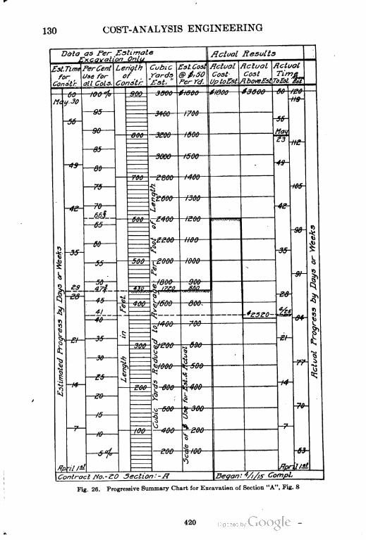
130COST-ANALYSIS ENGINEERING
Data as Per Estimate flclual Results
Esl, Time
for
PerCent
se for
11 Cols.
englh
of ,
Gon$tf~
Cubic
Yards
£st. "
st Cost
G>f,50
Per re/.
Hclual
Cost
ptoEst.
dual
Cost
boveEsi
cluol
Time
&i. j&
.30
—100 "fo
—35—
—90
900 —3600- $1800 6>&&0—if\
Me
3406— (700
<y
1 *i
00-*f-
800 3EOO i&OO
f500—
ttom
—B$
t3
-*9-—36
700 2800
'*•,,» ,„
itf-00
"T*r
~"i
^£600
>)j
<1
i30Q
4£—r& -4?-
66i£400 (£QQ—
—65 iQfl
«
IS
&EstimatedProgressbyJDaysorWeeks—I
t? 15 135
^9
5dd^>f]f\fl
1000 b—3?^.JOJ
^ «5°~,
1
*
50 ,.'800
. 4?i 4-30 &jm» ggji
-e&-45 v v 1.3
41 £400 ^fOOO 300
-*£5ZO- H
\
^—
-M-
^00 700
-ff- —3$.£
H«
•91
tj^ 600—-3W- t^/cOO—
tj s
\
1^) i
^
%>IOOO
"s'*
1
i4
s 15
t^ 400—-t4-
£00g 800.5
4;>-,
u 600 &Jua ~?&-
1C
1
% ^*n^
\
c erj
o*
-il 1-
3 i»
^
*P IIS.
Contract ffo.-ZO Section:-fl Began: 4/i/is Compl,
Fig. 26. Progressive Summary Chart for Excavation of Section "A", Fig. 8
420
COST-ANALYSIS ENGINEERING 131
that is not the case. It is not expected that finished drawings
be prepared. During the progress of the work calculations must
be made continuously; if they are put on scraps of paper, or in a
notebook, none of these records are in such shape when the job
is completed that they are really valuable for reference; in fact,
nine times out of ten they cannot even be found. But by the
simple system of progress charts the information is obtained and a
record preserved for all time; and it is just as easy to make the
notes on a proper sheet as on the back of an old envelope.
Analysis of Progressive Summary Chart on Excavation Job.
The Progressive Summary Chart, illustrated in Fig. 26, covers
the subject of excavation only, since it is desired to make the explana
tion of the chart's use as simple as possible. The chart, however,
can be extended so as to cover several lines of work on the same or
separate sheets. Its use is essential to a complete summary of the
work as estimated, and as a record of actual progress. The unique
feature, and always the most important one, is the percentage
column, by means of which the progress in time, length, quantity,
and cost may be compared with the estimate. For instance, in the
illustration given, we have in construction a piece of excavation
work 900 feet in length, amounting to 3600 cubic yards, which, at
an average price of 50 cents per cubic yard, amounts to $1800;
and the work can be done in 60 days. All of these items are so
adjusted in their divisions by the scale of their corresponding
columns that the total appears posted on the 100 per cent line.
The chart is divided into "Data as per Estimate", and "Actual
Results". Referring to this, let us consider a certain stage, April
25, when 430 feet in length of the work, begun April 1, have been
completed as per the notation made on the chart to this effect. These
figures correspond with 1720 cubic yards, which should cost, accord
ing to estimate, $860. By referring to the percentage column, we
note that this is 47f per cent of the entire work, and that, according
to schedule, we should have been employed upon the work 29 days.
The right-hand side, Actual Results, shows us that actual cost has
been $1200, or approximately 70 cents per yard; but that only
25 days have been expended. Turning to the percentage column,
we note we have expended 66§ per cent of our estimate, 41 per cent
of our time limit, and accomplished 47| per cent of the work.
421
132 COST-ANALYSIS ENGINEERING
The right-hand side double columns are for the cost and time
and are so arranged that, in case the estimate is exceeded, there
will be opportunity for the recording. The illustration just given
from the chart, makes it apparent that the cost is exceeding the
estimate and will result, if continued, in a final cost of $2520, instead
of $1800; at the same time it is also demonstrated that at the rate
of progress shown the work will be completed in 53 days, or 7
days less than the schedule. By using the percentage column as
a schedule for the comparison of time, quantity, and cost, a complete
record is available at all times, together with indications of the
probable final result.
The chart may be arranged so as to meet any condition; for
instance, instead of length of construction, square feet, or any
other unit of measurement may be substituted. The cubic-yard
column may be divided in any convenient unit of measurement.
Attention should be called to the fact that the column used for
cubic yards, Fig. 26, is shown as an average uniform quantity
over the entire length of the work. Where the work is very uneven
it is perfectly feasible to divide this column, so that the proportions
of heavy and light work shall be located exactly as they appear.
In other words, this column may be made in a sense a miniature
profile of the work, so adjusted that the same results may be
attained. This suggestion is deserving of study to the erid that the
individual student of cost analysis may adapt it to his line of work.
The foregoing description and chart cover only one kind of
work, but treat of all elements of that one line. On large and
important work such a chart should be made for each classification.
On small work several branches can be placed on one sheet, thereby
taking care of the entire job.
Final Progressive Summary Chart. The cost of the work is,
after all, the main item; and a "Final Progressive Summary Chart",
Fig. 27, should always be added to the records, especially for pocket
reference. This chart is of slightly different form, in that the
quantities are not incorporated; instead, each branch of the work
and the total are carried at their estimated cost equal to 100 per
cent, with a provision for an increase in actual cost of 50 per cent.
The chart shows constantly how each line of work is progressing,
and, upon completion of the entire job, shows detail results.
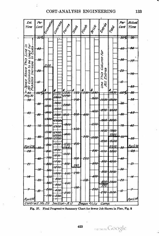
COST-ANALYSIS ENGINEERING 133
Eat, Per
Cent -//
/
/ /if/ /
,$$#
Per
Cent
actual
TimeTime
I e I
*-SpaceflboveTfrisLinein }MlColumnstobeUsedforPossibleIncreaseinCosts
50%
—
E
50% —96—
— — — UseThisColumnfor
JJltExtras
f.f
30
2t,
30—r2?2—
10
——
'z>ty--f
in
— —
10
VJ -
t J If-.to. *5
# tinnoj
SO-J f t'L' R r^ r\(i $d yf-;. infi V
May30?fy
M-tt? w-
fin
90
ffi nn
-34 90-
1fi
-89—
T&-T£
3i f\{\
-f4
&
—49— an96-
£$Mi
f w-
H
SO—49—
—4S— £& )W-
If
E >0- S4 06-
»
-4, V>-&M- iV
65
9t>-
00££
Irt no
35
Rpril3I.
60
' rtr
3 ofi-
iff nn e?r nn
-& T&-
sy inJg 90-
'5
/i w-<"\ tr HprilSO
50
1*
1t
£8 -&
f-h 'Y! -f& W- -50 9&
'7-4
yi
40
i£ W V
titi
1*a rtfi *n
r 00"
.y7ftft
toc
^u2
&&-
IK
1-3
J
no
-tth -A .M-4E
E003f1 nn
'4
—so—W-
-& 90-
-^m-
i -}f\.f f\n
-e -fffl-
£
W-
w-00
"j ro
IIS
—f
'z> on tn f\n
Aprittt
60- -*
90,
flpril1?!
Contract ffo. £0 Section-ft // Beqan 4////s Comp.
Fig. 27. Final Progressive Summary Chart for Sewer Job Shown in Plan, Fig. 8
423
134 COST-ANALYSIS ENGINEERING
Analysis of Chart. Let. us suppose the job opened Aprifc 1,
and that we examine the conditions on April 30. On this date it
should be 50 per cent completed; and our cost, to conform to the
estimate, should not exceed $5315. We know, however, that our
cost is S0500, or 60j per cent. Why? Referring to the conditions
as of April 30, noted on our chart, Fig. 27, we find the excavation
complete at a cost of $2100 exceeding our estimate by $400 or
approximately 22 per cent. Sixty-two per cent of the concrete has
been placed at a cost of $2800, when, according to the estimate, it
should have been done for $2250—increase of cost over the estimate
for this item of approximately 23 per cent. The cost of forms
we find to be running properly with the estimate, at $1125. Fifty
per cent of steel labor is estimated at $375. Our cost is only $240—
a saving of $135—or approximately 22| per cent of the cost of
constructing 50 per cent of this work. We find that there has
developed $370 in extras. Omitting the extras this leaves a net
balance of excess cost over estimate of $815.
Readjusting Estimate. Now, assuming at this date that
the branches not yet started can be built for the estimate, we make
our progress estimate, allowing for increases and decreases, and
find as follows:
ITEMS
COST
1. Time O. K.
Increase Decrease
2. Excavation, complete $400
3. Concrete, new estimate 917
4. Forms O. K.
5.
6.
Steel, new estimate
Finish, assumed O. K.
$270
7. Brick, assumed O. K.
Net increase $ 1047
Total first estimate 10630
New estimate $11677
The chart enables one to read all this information at a glance,
and such detail readings as just given are not necessary in actual
use. Differently colored pencils are used for successive dates.
The charts can be made on any size sheet, inasmuch as each column
is of a different scale in order to reach the 100 per cent line.
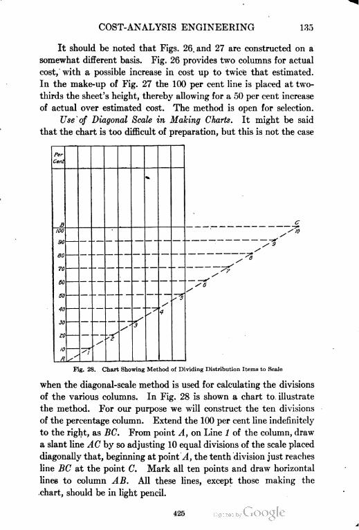
COST-ANALYSIS ENGINEERING 135
It should be noted that Figs. 26. and 27 are constructed on a
somewhat different basis. Fig. 26 provides two columns for actual
cost, with a possible increase in cost up to twice that estimated.
In the make-up of Fig. 27 the 100 per cent line is placed at two-
thirds the sheet's height, thereby allowing for a 50 per cent increase
of actual over estimated cost. The method is open for selection.
Use of Diagonal Scale in Making Charts. It might be said
that the chart is too difficult of preparation, but this is not the case
Fig. 28. Chart Showing Method of Dividing Distribution Items to Scale
when the diagonal-scale method is used for calculating the divisions
of the various columns. In Fig. 28 is shown a chart to illustrate
the method. For our purpose we will construct the ten. divisions
of the percentage column. Extend the 100 per cent line indefinitely
to the right, as BC. From point A, on Line 1 of the column, draw
a slant line AC by so adjusting 10 equal divisions of the scale placed
diagonally that, beginning at point A, the tenth division just reaches
line BC at the point C. Mark all ten points and draw horizontal
lines to column AB. All these lines, except those making the
chart, should be in light pencil.
425

136
COST-ANALYSIS ENGINEERING
426
COST-ANALYSIS ENGINEERING 137
138 COST-ANALYSIS ENGINEERING
Similar Jobs Requiring Different Cost Distribution. In closing
the section on the construction end of our cost-analysis work, it
might be well to illustrate how jobs which are more or less similar
in appearance, Figs. 29 and 30, radically differ in cost-analysis
distribution of labor and material. In Fig. 29 is shown a long-span
flat-slab construction, where the amount of forms for the proper
construction of the columns and girders is reduced to the minimum',
but there is heavy work in connection with the centers to support
the long-span slabs forming the floors. In Fig. 30, we have a lighter
construction where the forms are largely increased because of the
many columns, main girders, and floor beams. In the latter case the
timber work necessary to build the forms furnishes to a very large
extent the support for the centers.
Both of these buildings were of reinforced-concrete construc
tion, very nearly the same in external appearance, and, so far as the
cost bookkeeping was concerned, each would have the same charges
for lumber, cement, stone, gravel, sand, tile work, etc. The cost
engineer with his system of distribution must analyze these costs
and record them in the proper way so that accurate analyses can
be provided and future comparisons made.
WHAT IS GAINED BY ANALYSIS?
What Cost Analysis Means. We have reached the point where,
in the logical sequence of actual work, our records are completed
and we are ready to make a final analysis and summary of
our results and experiences. It would seem that few have a
proper idea of the meaning of the phrase "Cost Analysis". Time
and time again articles on cost analysis have been called to our
attention which were nothing more or less than a bare statement
of cost records; and although in a great many cases these cost
records were divided in an intelligent manner to form the basis
of cost analysis, still in no sense could they be said to be real cost
analysis. The name implies such a systematic study of results
secured on each job, that all forms of digest or cataloging informa
tion—as illustrated by differences or inconsistencies—are harmonized,
and all jobs brought to a comparable basis. In other words, coSt
analysis in this final summary eliminates nonessentials, individuali
ties, and specialties; reduces to a uniform basis the pay, hours of
428
COST-ANALYSIS ENGINEERING 139
work, etc., to the end that we may reach a point where the results
can be tabulated on a comparative scale.
Analysis on Foot=Pound of Work Basis. Such a cost-analysis
summary implies also a study of the work accomplished in a broader
sense than simply as so many cubic yards of earth excavation,
cubic yards of concrete, thousands of brick laid, or feet board
measure of lumber. Such an analysis takes into consideration
the conditions under which the work was done, giving due credit
for location of raw material and methods of operation, extent of
work under construction, and the average unit of work.
We are, in reality, approaching the ideal which is to reduce
our cost to a basis of foot-pounds of work, although we are doing
so only in a very crude manner, since we use ordinary standards
of measurement in order to introduce comparisons. It is cer
tainly true that the ordinary laborer is capable of so many foot
pounds of work per day. If his time is expended in doing work
at a long distance from the point of supply his energy will be
expended in distance at the expense of actual quantities handled.
If, on the other hand, the work is arranged either naturally or by
proper supervision, so that large quantities can be handled with the
minimum of effort, the cost per unit of quantity is correspondingly
decreased.
If we should attempt to analyze completely every job within
the limits of practical supervision so that we might trace the foot
pounds of work of each operation for each class of labor, we should
be doing nothing of real value because of the difficulty and cost
of securing information; but it is entirely possible to estimate on
a basis of arbitrary units for the different classes of work, and so
to secure the same relative comparisons without difficulty. Such
arbitrary assumptions, based upon our familiarity with the work
in question, furnish a definite basis for recording the information
obtained.
ANALYSIS OF ACTUAL WORK
Reinforced=Concrete Building. As an illustration of our idea
in this connection, let us consider a job in reinforced concrete.
The cubic feet of concrete to be placed in the building, bridge, or
other structure, divided by the square-foot area covered, give
429
140 COST-ANALYSIS ENGINEERING
the average thickness in feet, of concrete. This is an arbitrary
indication of foot-pounds of work necessary, since it indicates,
without any direct statement of distance or haul, the foot-pounds
of work and energy expended in order to place certain work. We
are, of course, assuming that the locations of material supply,
equipment, etc., are normal, that is, as closely connected with the
actual work as may be usually expected. (Conditions other than
this should be specially noted.) The results for reinforced-concrete
building work are shown in graphical form in Fig. 31, indicating
1a 3°°
Dollars Per Cubic Yard
Fig. 31. Curve Showing Variation of Cost per Cubic Yard of Reinforced-Concrete
Building Work with Thickness of Concrete in Inches
increase in cost of work accomplished, due to distance and to decrease
of thickness. The same style of chart may be used for bridge
work, pavements, sewers, sidewalks, etc.
Sewer Contract. Fig. 32 gives such a form of analysis car
ried through the construction of the sewer job shown by Fig. 8, with
special reference to the concrete work. The arbitrary unit in this
case is the cubic yards of concrete per lineal foot of sewer; in the
job there are many different sizes of sewers.
Applying this idea to the construction and placing of steel
centers or forms, it is insufficient to say that this cost is so much
per lineal foot, inasmuch as we are certain that the cost depends upon
the size of the sewer; the next job we have for estimating may give
430
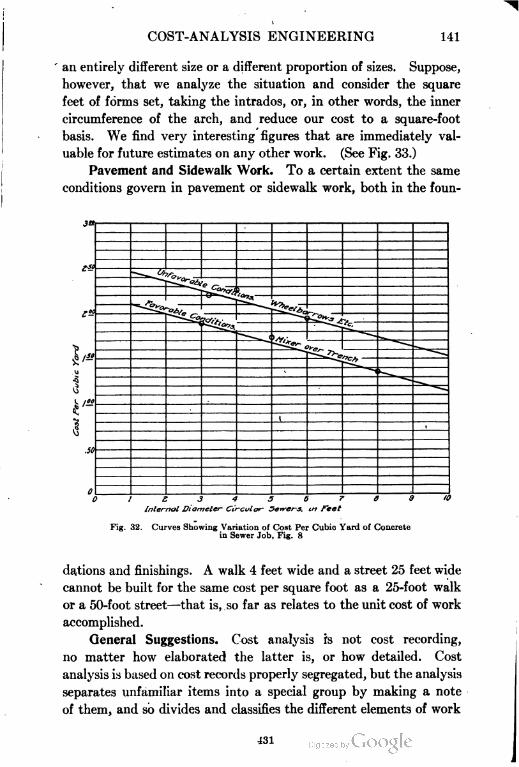
COST-ANALYSIS ENGINEERING 141
an entirely different size or a different proportion of sizes. Suppose,
however, that we analyze the situation and consider the square
feet of forms set, taking the intrados, or, in other words, the inner
circumference of the arch, and reduce our cost to a square-foot
basis. We find very interesting figures that are immediately val
uable for future estimates on any other work. (See Fig. 33.)
Pavement and Sidewalk Work. To a certain extent the same
conditions govern in pavement or sidewalk work, both in the foun-
/ £ 3 4 5 6
Internal Diameter Circular Sewers, in feel
Fig. 32. Curves Showing Variation of Cost Per Cubic Yard of Concrete
in Sewer Job, Fig. 8
dations and finishings. A walk 4 feet wide and a street 25 feet wide
cannot be built for the same cost per square foot as a 25-foot walk
or a 50-foot street—that is, so far as relates to the unit cost of work
accomplished.
General Suggestions. Cost analysis is not cost recording,
no matter how elaborated the latter is, or how detailed. Cost
analysis is based on cost records properly segregated, but the analysis
separates unfamiliar items into a special group by making a note
of them, and so divides and classifies the different elements of work
431
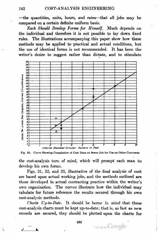
142 COST-ANALYSIS ENGINEERING
—the quantities, units, hours, and rates—that all jobs may be
compared on a certain definite uniform basis.
Each Should Develop Forms for Himself. Much depends on
the individual and therefore it is not possible to lay down fixed
rules. The illustrations accompanying this paper show how these
methods may be applied to practical and actual conditions, but
the use of identical forms is not recommended. It has been the
writer's desire to suggest rather than dictate, and to stimulate
ae
SI
si
X
50
4S
46
44
It
90
M
36
3>
X
z
z1^
JZ2
z^
) /(
JZ£
eszz
2£4
K zto
n zS"
1t
1t
14
1t
,>
z
J^1
a
e
/ (
o
1
6
4
e
°i11 1343073910
1nternal Diameter Circular- 5e*-crs, in feet.
Fig. 33. Curve Showing Compilation of Cost Data on Sewer Job for Use on Other Contracts
the cost-analysis turn of mind, which will prompt each man to
develop his own forms.
Figs. 31, 32, and 33, illustrative of the final analysis of cost
are based upon actual working jobs, and the methods outlined are
those developed in actual contracting practice within the writer's
own organization. The curves illustrate how the individual may
tabulate for future reference the results secured through his own
cost-analysis methods.
Charts Up-to-Date. It should be borne in mind that these
cost-analysis charts must be kept up-to-date; that is, as fast as new
records are secured, they should be plotted upon the charts for
432
COST-ANALYSIS ENGINEERING 143
comparison with past work. Either confirming or modifying
such experience, they will better qualify the estimator for new
work.
Reducing Wages to Uniform Wage Scale. It should also be
borne in mind that such a cost-analysis chart must be necessarily
reduced to a uniform scale of wages, but this in no way makes it
difficult either to prepare or to use in estimating. It is not
expected that any job can be carried through at a uniform or definite
scale .of wages. There will be many rates of pay, and men of different
trades, rates, and hours, but in the operation of the payroll the
charge of the hours should be carried forward the same as the total
dollars, and in this way the average rate of pay is again determined.
Every contractor familiar with his own work has a very certain
idea about his average rate of pay for labor per hour. However,
the payrolls should be totaled for work-hours as well as dollars,
thereby giving the average rate for labor.
It is best to prepare the charts on a basis of, say, 20 or 25 cents
per hour and then reduce or increase this rate as the case may be.
This is, of course, for work of ordinary labor and for very few skilled
artisans. To reduce the reading in the chart to a 17|-cent-per-
hour basis from the average of the 20-cent-per-hour basis, all
that is necessary to do is to deduct J. Fig. 31 shows the results
of numerous jobs of reinforced-concrete building work. These
jobs covered all designs and classes of structures, viz, light and
heavy reinforced-concrete slabs, with and without beams and
columns. The average of all concrete over the entire area is indi
cated by the scale, giving the thickness in inches.
Plotting upon this chart the actual cost per cubic yard of jobs
of various character, we arrive at a very satisfactory curve line,
indicating what may be reasonably expected in new work. Natu
rally there are a few abnormal cases, generally caused by special
conditions. It should be noted that the average conditions are
found between the limits of 5 inches and 8 inches, or an average
of 65 inches at the apex of our curve. Above this limit, as the
thickness increases, the cost decreases very slowly. Below this
limit, as the thickness decreases, the cost increases very rapidly.
This is logical and is an example of the foot-pounds of work accom
plished by the laborer.
433
144 COST-ANALYSIS ENGINEERING
Discriminating between Classes of Work. In Fig. 32 is
another example of sewer construction in which various sizes of the
concrete work determine a fluctuating price of labor on concrete
per cubic yard. In this case an attempt has also been made to
discriminate between (1) that class of work which can be handled
over the trench as the work proceeds, the concrete operations being
advanced as the work is completed; and (2) work in which the
operation must be handled from some little distance and the material
wheeled, the plant advancing only at intervals.
On no one of these charts can we expect to arrive accurately
at foot-pounds of work. But this is not necessary, for as has been
mentioned, we are working along a certain definite line of information,
wherein, from the time of the preparation of the estimate until
the final cost summary of the job, our methods have been harmonious
and on a certain definite basis. To the individual contractor the
information compiled is of the most value, as the moment a certain
job is called to attention, reference to these charts presents to his
mind a picture of the particular job, which is explanatory of the
results. For this reason it has been brought out time and time
again in this article that the value of the methods suggested lies
in their constant adaptation to the individual man's work.
Any System Must Be Consistent. Ruskin says "The crime
which bankrupts man and nation is job work, declining from the
main design, to serve a turn here and there." Certainly no really
good results can be expected from any system of estimating, book
keeping, operating cost keeping, and analysis which is not entirely
consistent in all its parts.
Fig. 33 shows the analysis of the cost of installation of steel
centers in a number of concrete-sewer jobs. This chart is based
upon a table from which we arrive at a nearly uniform price per
square foot for centers of any size of sewer within reasonable limits.
The square foot is arbitrarily taken as the complete internal cir
cumference of the sewer, the sewers in this illustration being all
circular. In order to reduce our figures to as comparable a working
basis for estimating as possible, and also to present to the eye as
clearly as we can a complete summary, we prepare a chart from
which we may take directly in cents per lineal foot the cost for
labor on centers for sewers of this character.
434

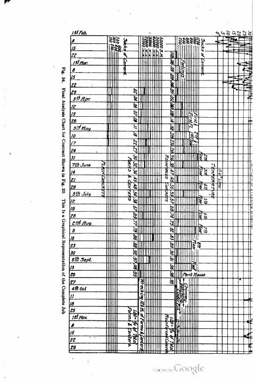
tjtfeb.

Precipitation ^

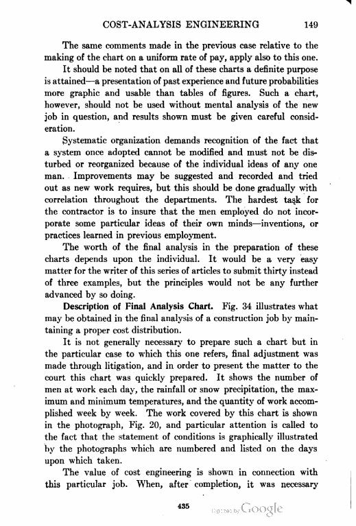
COST-ANALYSIS ENGINEERING 149
The same comments made in the previous case relative to the
making of the chart on a uniform rate of pay, apply also to this one.
It should be noted that on all of these charts a definite purpose
is attained—a presentation of past experience and future probabilities
more graphic and usable than tables of figures. Such a chart,
however, should not be used without mental analysis of the new
job in question, and results shown must be given careful consid
eration.
Systematic organization demands recognition of the fact that
a system once adopted cannot be modified and must not be dis
turbed or reorganized because of the individual ideas of any one
man. Improvements may be suggested and recorded and tried
out as new work requires, but this should be done gradually with
correlation throughout the departments. The hardest task for
the contractor is to insure that the men employed do not incor
porate some particular ideas of their own minds—inventions, or
practices learned in previous employment.
The worth of the final analysis in the preparation of these
charts depends upon the individual. It would be a very easy
matter for the writer of this series of articles to submit thirty instead
of three examples, but the principles would not be any further
advanced by so doing.
Description of Final Analysis Chart. Fig. 34 illustrates what
may be obtained in the final analysis of a construction job by main
taining a proper cost distribution.
It is not generally necessary to prepare such a chart but in
the particular case to which this one refers, final adjustment was
made through litigation, and in order to present the matter to the
court this chart was quickly prepared. It shows the number of
men at work each day, the rainfall or snow precipitation, the max
imum and minimum temperatures, and the quantity of work accom
plished week by week. The work covered by this chart is shown
in the photograph, Fig. 20, and particular attention is called to
the fact that the statement of conditions is graphically illustrated
by the photographs which are numbered and listed on the days
upon which taken.
The value of cost engineering is shown in connection with
this particular job. When, after completion, it was necessary
435
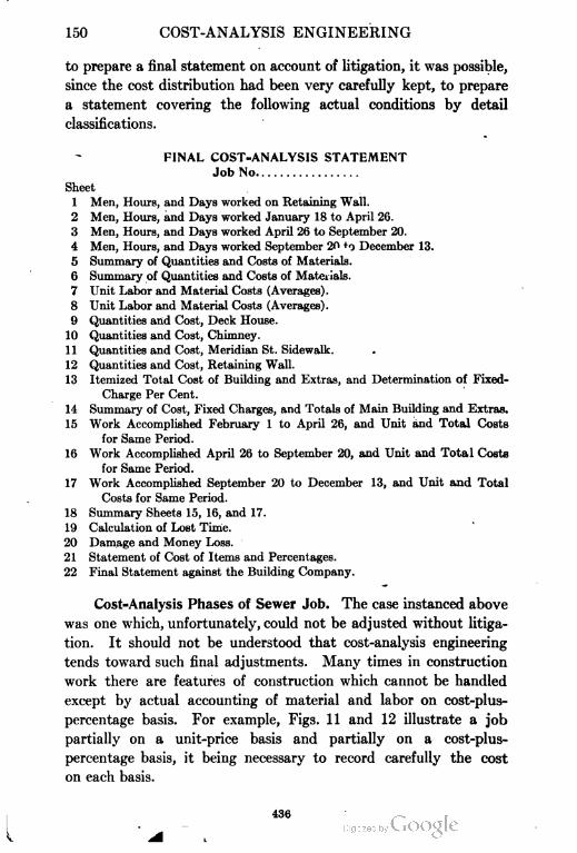
150 COST-ANALYSIS ENGINEERING
to prepare a final statement on account of litigation, it was possible,
since the cost distribution had been very carefully kept, to prepare
a statement covering the following actual conditions by detail
classifications.
FINAL COST-ANALYSIS STATEMENT
Job No
Sheet
1 Men, Hours, and Days worked on Retaining Wall.
2 Men, Hours, and Days worked January 18 to April 26.
3 Men, Hours, and Days worked April 26 to September 20.
4 Men, Hours, and Days worked September 20 *o December 13.
5 Summary of Quantities and Costs of Materials.
6 Summary of Quantities and Costs of Materials.
7 Unit Labor and Material Costs (Averages).
8 Unit Labor and Material Costs (Averages).
9 Quantities and Cost, Deck House.
10 Quantities and Cost, Chimney.
11 Quantities and Cost, Meridian St. Sidewalk. .
12 Quantities and Cost, Retaining Wall.
13 Itemized Total Cost of Building and Extras, and Determination of Fixed-
Charge Per Cent.
14 Summary of Cost, Fixed Charges, and Totals of Main Building and Extras.
15 Work Accomplished February 1 to April 26, and Unit and Total Costs
for Same Period.
16 Work Accomplished April 26 to September 20, and Unit and Total Costs
for Same Period.
17 Work Accomplished September 20 to December 13, and Unit and Total
Costs for Same Period.
18 Summary Sheets 15, 16, and 17.
19 Calculation of Lost Time.
20 Damage and Money Loss.
21 Statement of Cost of Items and Percentages.
22 Final Statement against the Building Company.
Cost=Analysis Phases of Sewer Job. The case instanced above
was one which, unfortunately, could not be adjusted without litiga
tion. It should not be understood that cost-analysis engineering
tends toward such final adjustments. Many times in construction
work there are features of construction which cannot be handled
except by actual accounting of material and labor on cost-plus-
percentage basis. For example, Figs. 11 and 12 illustrate a job
partially on a unit-price basis and partially on a cost-plus-
percentage basis, it being necessary to record carefully the cost
on each basis.
436
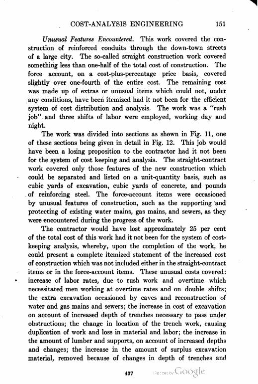
COST-ANALYSIS ENGINEERING 151
Unusual Features Encountered. This work covered the con
struction of reinforced conduits through the down-town streets
of a large city. The so-called straight construction work covered
something less than one-half of the total cost of construction. The
force account, on a cost-plus-percentage price basis, covered
slightly over one-fourth of the entire cost. The remaining cost
was made up of extras or unusual items which could not, under
any conditions, have been itemized had it not been for the efficient
system of cost distribution and analysis. The work was a "rush
job", and three shifts of labor were employed, working day and
night.
The work was divided into sections as shown in Fig. 11, one
of these sections being given in detail in Fig. 12. This job would
have been a losing proposition to the contractor had it not been
for the system of cost keeping and analysis. The straight-contract
work covered only those features of the new construction which
could be separated and listed on a unit-quantity basis, such as
cubic yards of excavation, cubic yards of concrete, and pounds
of reinforcing steel. The force-account items were occasioned
by unusual features of construction, such as the supporting and
protecting of existing water mains, gas mains, and sewers, as they
were encountered during the progress of the work.
The contractor would have lost approximately 25 per cent
of the total cost of this work had it not been for the system of cost-
keeping analysis, whereby, upon the completion of the work, he
could present a complete itemized statement of the increased cost
of construction which was not included either in the straight-contract
items or in the force-account items. These unusual costs covered:
increase of labor rates, due to rush work and overtime which
necessitated men working at overtime rates and on double shifts;
the extra excavation occasioned by caves and reconstruction of
\vater and gas mains and sewers; the increase in cost of excavation
on account of increased depth of trenches necessary to pass under
obstructions; the change in location of the trench work, causing
duplication of work and loss in material and labor; the increase in
the amount of lumber and supports, on account of increased depths
and changes; the increase in the amount of surplus excavation
material, removed because of changes in depth of trenches and
437
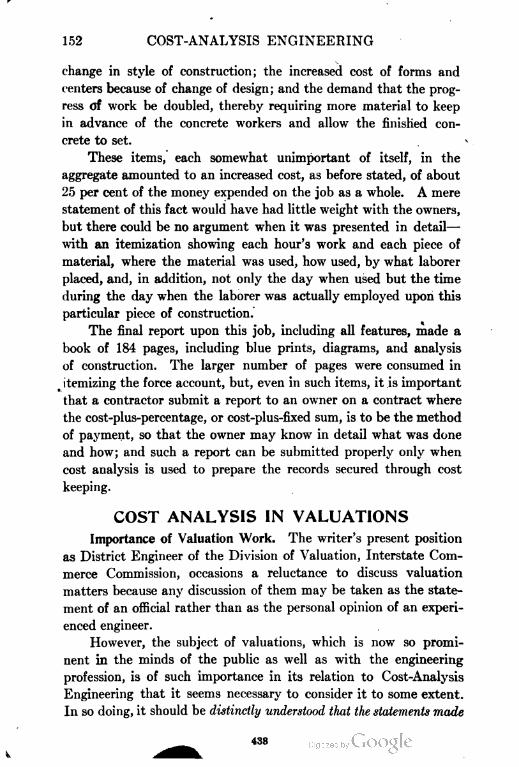
152 COST-ANALYSIS ENGINEERING
change in style of construction; the increased cost of forms and
centers because of change of design; and the demand that the prog
ress of work he doubled, thereby requiring more material to keep
in advance of the concrete workers and allow the finished con
crete to set.
These items, each somewhat unimportant of itself, in the
aggregate amounted to an increased cost, as before stated, of about
25 per cent of the money expended on the job as a whole. A mere
statement of this fact would have had little weight with the owners,
but there could be no argument when it was presented in detail—
with an itemization showing each hour's work and each piece of
material, where the material was used, how used, by what laborer
placed, and, in addition, not only the day when used but the time
during the day when the laborer was actually employed upon this
particular piece of construction.
The final report upon this job, including all features, made a
book of 184 pages, including blue prints, diagrams, and analysis
of construction. The larger number of pages were consumed in
itemizing the force account, but, even in such items, it is important
that a contractor submit a report to an owner on a contract where
the cost-plus-percentage, or cost-plus-fixed sum, is to be the method
of payment, so that the owner may know in detail what was done
and how; and such a report can be submitted properly only when
cost analysis is used to prepare the records secured through cost
keeping.
COST ANALYSIS IN VALUATIONS
Importance of Valuation Work. The writer's present position
as District Engineer of the Division of Valuation, Interstate Com
merce Commission, occasions a reluctance to discuss valuation
matters because any discussion of them may be taken as the state
ment of an official rather than as the personal opinion of an experi
enced engineer.
However, the subject of valuations, which is now so promi
nent in the minds of the public as well as with the engineering
profession, is of such importance in its relation to Cost-Analysis
Engineering that it seems necessary to consider it to some extent.
In so doing, it should be distinctly understood that the statements made
438
COST-ANALYSIS ENGINEERING 153
are not to be connected in any way with the writer's official work with
the government.
Scope of Work by Interstate Commerce Commission. For some
time past there has been increasing activity in the valuation and
"control of public utilities by state commissions. By an act of
March, 1913, the United States government undertook the physical
valuations of the property of all common carriers. The government
inquiry to date has covered principally the physical valuation of
railroad and telegraph properties. In order to carry out to the
fullest extent the work called for by the act of Congress, it may be
necessary ultimately to include electric-railway properties, express
companies, pipe-line companies, steamship lines, long-distance tele
phones, and in fact, any and all carriers serving the public in an
interstate capacity.
Conditions Governing Valuations. The study of Cost-Analysis
Engineering in connection with valuation work presents entirely
different conditions than those in connection with the estimating,
construction, and analysis of ordinary construction work.
Valuation of New Work or Work in Process. In the case of
construction work we proceed to make an estimate based upon the
plans and specifications, in which the materials and the labor neces
sary to install them are described in full detail; from it we may have
a fairly definite idea of what is necessary in the way of equipment
and costs to assemble the structure as designed. It is true that we
must depend upon our imagination to furnish a picture of the fin
ished structure, and of the multitude of details necessary to com
plete it which are supplementary to the plans and specifications.
It is also true that the estimator must fall back on his past experi
ence and again upon his imagination to list and describe the accessory
matt-rials and labor required in connection with the construction
and work of the various trades. These latter features will not be
covered by the plans and specifications, since they are incidental to
the work of the several trades, and an accurate estimate can be made
only by the man who from experience with the different lines of
work knows how much in the way of runways, mortar boxes, scaf
folds, temporary lumber, steel, rope, bolts, etc., will be necessary
to do that work which finally may be measured as a permanent
part of the structure.
439
154 COST-ANALYSIS ENGINEERING
To summarize—in any ordinary construction work, we examine
the plans and specifications and then form a mental picture of the
structure as it will be when completed, but in so doing we have an
accurate and full description of all of the materials and the manner
of their assembling as they are to enter into the completed structure.
Valuation of 0ld Work. In the case of the valuation of construc
tion work which is already completed or has been in use for some
time, the process is not so simple. For example, we may have a
building, which, to the observer, after completion, is a brick-wall
structure. The interior is divided into rooms with plastered par
titions. Now, as a matter of fact, the brick walls may be, as they
appear, a part of the actual load-carrying parts of the building, but
on the other hand, the brick may be only a masking or covering
material for the steel framework which is the real structure of the
building and which in reality carries the brick work as an additional
dead load. The partitions in this building may be of tile or they
may be of wood studding with wood lath or metal lath; or they may
be entirely metal, that is, metal studding and metal lath. In any
case, the partitions may be covered with old-style hair plaster or
with patent "quick-setting" plaster. The floors may be covered
with wood or tile. We may have a reasonable idea of how the floors
are constructed, but so far as the observer can see, there is no way
of determining just how the floor is secured in position.
Sometimes the plans and specifications for particular structures
are available, but in a great many cases they are not. We are there
fore dealing with the physical valuation of tangible property for
the purpose of considering the cost of reproduction—usually the cost
of reproduction of the property as existing at a certain date. Grant
ing that the cost-analysis engineer has had an actual experience in
construction work, and that he is dealing with structures where
plans and specifications are not available, and where, therefore, the
basis upon which the work was done, cannot be known, he is of
necessity compelled to draw upon his imagination and experience to
furnish a basis upon which the structure might be reconstructed so as
to secure practically the same results as he finds, and to reduce to
dollars the cost of duplicating the work. This means that, above
all, the valuation engineer must use good judgment, and this judg
ment must be based upon experience.
440
COST-ANALYSIS ENGINEERING 155
Depreciation. The subject of depreciation in connection with
valuation of property is of extreme importance. It must be given
consideration in the making of any valuation, whether the resulting
report controls the final valuation or not. Depreciation, when
considered in the fullest extent, covers wear and tear, deterioration,
inadequacy, obsolescence, and, where the structure is exposed
to exceptional hazards, must take casualties into consideration.
A sharp distinction should be made between the wear and tear
and deterioration of property, which may prompt the cost-analysis
engineer to determine that the structure has a probable remaining
life, and the other elements mentioned, which may radically affect
the remaining life as so determined. As an illustration: A build
ing may occupy an important business corner in a large city. So
far as actual deterioration is concerned the building in question
may be good for many years, but obsolescence, when considered
in connection with the value of the ground occupied and the business
demands of the community, might occasion the removal of the
building within a few months.
It is not suggested nor recommended that these elements be
given too much importance in field valuation work, but they must
be given some consideration and be noted in the final report. The
engineer is called upon to report facts to the fullest extent ; he should
report all facts as he sees them without attempting to make things
appear favorable, if in his own mind they are not. There is nothing
to be gained by deceiving with optimistic reports, or—to go to the
other extreme—with pessimistic reports. The owner or employer
is entitled to the truth, and to full information as to how the report
is prepared.
What Constitute Valuation Values. Valuation cost engineering,
therefore, must pass beyond a mere recognition of the physical
elements which enter into a property and which would be reported
under cost of reproduction. It must include a consideration of
the location, the earning capacity, the investment possibilities,
and the going value of the concern under inventory. It probably
will not come within the province of the young engineer to decide
these larger questions, his work dealing entirely with the physical
examination of the construction materials entering into the structure;
however, it is very much to be desired that he have the proper
441
156 COST-ANALYSIS ENGINEERING
conception of these larger elements of value so that he may correctly
note field conditions and enable the more experienced man to place,
if necessary, a judgment valuation upon these features.
Forms to Be Used. The forms and blanks used for valuation
purposes, especially in the valuation of large properties, must
of necessity be so condensed that it is impossible to show in detail
all of the elements going to make up the quantity units or the unit
prices as adopted. Generally it will be found that the state com
missions, in connection with the valuation of public utilities, and
the United States government, in connection with the valuation of
common carriers, have prescribed standard forms which must be
followed in accordance with standard instructions and the standard
itemization of accounts. In the progress of valuation surveys,
care should be taken to record systematically all the facts and also
the quantity units and cost units as finally determined, so that
in case it is necessary these calculations may be -referred to; this
feature should be carefully observed even if these preliminary
figures are only in the shape of notations or pencil calculations
on scratch-pad paper. The form of the calculation, while it is
essential and should be uniform throughout in any valuation work,
is, however, not so important as to be sure that, by indexing and
cross-indexing, the calculations for any portion of the work as
shown on the final assembly sheets may be quickly found, in case
they are required.
Valuation Problems. Valuation cost engineering has to deal
with large and important questions; -a few of them are mentioned
in order that individual study may be given, although in valuation
work the young engineer will in most cases receive specific instruc
tions as to how these matters are to be handled.
Cost of Production. The cost of production may be handled
(1) simply as a matter of present materials and present costs; (2)
on a basis of the average cost and general methods of construction
prevailing over a series of years; or (3) by a thorough considera
tion of methods, materials, equipment, and costs as they existed
at the time of the actual construction of the work. This latter
method, in its fullest development, leans toward the appraisal
upon a basis of the actual cost to date, which is necessarily an
accounting proposition, the data to be secured from the books and
442
COST-ANALYSIS ENGINEERING 157
records of the company for verification by inspection of the actual
work.
Accounting Problem. This naturally brings to our minds the
fact that valuation cost engineering is not alone an engineering
proposition but instead is very largely an accounting problem.
The ideal combination for this class of work would be an engineer-
accountant working in connection with the accountant-engineer.
Inasmuch as such -combinations do not exist except to a limited
extent, the practical basis is the working together of the expert
engineer with the expert accountant, so combining their work as
to secure a proper report.
Effect of Changes in Neighborhood. Many times, in the appraisal
of property, conditions will be found which are not at all the same
as when the structures were built. Many times the building-up
of the community as a whole has been occasioned by the construc
tion of the property under appraisal. In cases of this kind it must
be determined whether the property should be appraised as under
the conditions existing at the time of construction or as of the daj;
when the appraisal was made. This line of thought prompts us
to consider whether at the time the actual construction was started
it was necessary to wreck other and older structures or to move
natural formations, which at that time interfered with the con
struction but which are not now in existence or to be observed.
Effect of Transportation Facilities. If property of some con
siderable age is under appraisal, consideration must be given present
transportation facilities and the transportation facilities at the
time of the building's construction. Improvements and availability
of materials and supplies must also be studied with reference to
both the present time and the time of construction.
Secondhand Values and Quality of Material. The appraiser must
take into account the possible use of so-called secondhand material,
and also, perhaps, the fact that materials and supplies in the older
days were, in general, more carefully prepared and of a higher quality
than those now commercially available. As an illustration—consider
the much better quality, in dimensions and material, of wood
framing-materials entering into structures built, say, 50 years ago.
Overhead Charges. The valuation cost engineer must also
consider overhead charges, such as engineering contingencies,
443
158 COST-ANALYSIS ENGINEERING
interest, taxes, etc., having also due regard to the time necessary
for construction. In doing this, he must pay attention to the
conditions existing when the structure was built, and, so far as
they may be estimated, those prevailing on the date of inventory.
Appreciation. If it is true that the cost-analysis engineer
must give full consideration to depreciation- and its relations to
the various portions of the structure, then he must also give full
consideration to appreciation in those portions of the property
where that may occur. This appreciation may occur because of
location or it may result from the peculiar adaptability of the property
to the purposes for which it is used. It certainly is true that con
ditions affecting appreciation must be noted, if depreciation is
to be considered.
In the determination of depreciation or appreciation, it is
necessary that the individual portions of a property or of any one
structure be separated and a weighted average secured. Generally,
definite instructions will be given—in the way of a mortality table—
as to the life of various classes of material, with reference to their
use in the different parts of the structures. These tables can be
used as the basis for a judgment report when actual inspection is
made to determine whether the particular item should be given
a greater or less life than that shown by reported statistics. Many
engineers take the position that there is no such thing as depreciation,
so long as a property is well maintained. We are not taking issue
with this view, but inasmuch as we are here dealing with a question
which has not as yet been finally defined or accepted for the purpose
of universal practice, it is suggested that the young engineer give
careful consideration to the various points mentioned; making his
notes accordingly, and having in mind that by so doing the informa
tion is made available.
The items mentioned in Tables II to X, inclusive, pages 96
to 102, must be considered in connection with valuation work, and
reference should be had thereto. These items are, in general,
of such a character that they do not enter into the permanent
construction of a structure and cannot be observed, but must be,
as before mentioned, estimated on the basis of contributory expense.
Valuation Units. In valuations one of the most important
features is the selection of the quantity units and the cost-price
444
COST-ANALYSIS ENGINEERING 159
units, and attention is again called to the fact that it is necessary,
in order to determine such units, to divide the work under investi
gation into cost-analysis sections.
If the work has been carefully studied and so divided into
valuation sections, we may then proceed to select those quantity
units and cost units which are applicable to the particular section
under investigation. We may recognize two distinct types of
units, both for quantity and for cost, namely, simple units and
composite or combined units.
Simple Units. A unit for the purpose of a valuation may be
considered as that proper quantity unit to which may be applied
an ordinary cost unit, at the point of destination or use.
The selection of the quantity unit is more important than the
price unit. The first should be a standard, while the latter may be
considered a variable, probably determined as the average over
a term of years.
Ordinarily, the quantity unit which is adopted will be the
natural, customary, or ordinary commercial measure established
by United States standard, or by law, custom, trade rules, or local
conditions. Sometimes, however, the unit is an arbitrary or selected
one, formed by the conversion of a natural unit into another form,
possibly for the purpose of pricing all elements on the basis of a
common measure.
Illustrations of simple units are lineal feet, pounds, cubic yards
of material, rules for brick measurement, or per load or per day
for delivery of materials. An illustration of an arbitrary unit
might be the case of filling material, foundation concrete, top coat,
finishing, and curb construction in sidewalk work, changed to
square-foot price; or the material and the carpentry work, and the
work of the various trades on a .building, reduced to a price per
cubic foot enclosed.
In nearly all cases the natural quantity units in valuation
work will correspond with those understood in building, market,
and trade circles. Sometimes a natural unit becomes a composite
unit through custom, such as a cubic yard of masonry. Arbitrary
units are generally the result of a selection based upon experience,
and in most cases are used for special purposes such as quick esti
mates or short cuts.
445
160 COST-ANALYSIS ENGINEERING
X
It should be noted that simple or elementary units exist in
unit prices as well as in unit quantities. Depreciation on a natural
or simple unit may be taken direct.
Composite Units. A composite unit is a combination of a
number of natural units to form a certain standard form of con
struction—or at least a certain type of construction recurring
many -times—where the composite unit is recognized by the public
or by the trade interested as being sufficiently well defined to be
self-explanatory and sufficient in detail to serve the purpose
of a unit for valuation.
As illustrations there might be mentioned a standard building,
a concrete mixer, a car, a plumbing fixture installed, a standard
door or window opening complete, a standard sewer catch basin,
or a complete unit of any kind recurring frequently in ordinary
construction.
It should be noted that composite units exist in unit prices
as well as in unit quantities. Depreciation on a composite unit
must be a weighted average.
Comparison of Units. Advantages of Simple Unit. (1) The
closer analysis of the construction.
(2) The opportunity for a direct, close pricing. '
(3) The opportunity for closer comparisons with work of
similar character, but with varying quantities or
proportions.
(4) The tendency to produce more careful attention to details
by field men and computers.
(5) The obtaining of better reference cost data.
(6) The sureness of completeness in final result.
Advantages of Composite Unit.
(1) The. opportunity for speeding the work.
(2) The opportunity for criticism on minor points.
(3) Reduction in the volume of work to be done.
(4) Decrease in first cost of labor and dollars.
(5) Establishment of a means for quick, approximate com
parisons.
(6) The measuring to the full extent of the experience and
judgment of the engineer.
Analysis of Units. In the consideration of units a selection
446
COST-ANALYSIS ENGINEERING 161'
in many cases will be governed by the elements entering into the
construction, and the following features should be considered:
(1) In the selection of unit quantities at point of destination
or point of use, analysis should be made of the make-up
of the unit, with account taken of the material in its
raw condition, the cost of acquisition, labor, and produce,
cost of marketing, etc., and of the labor to manufacture,
and cost to market the product at each stage of devel
opment.
(2) In the determination of the unit cost to install, there
should be included the direct labor, indirect or non
productive labor, supervision, injuries, damages, expense
items, repairs, rentals or depreciation of equipment,
transportation cost, waste, insurance, interest, com
missions, discounts, overhead expense, and profit if
done by contract.
(3) It should be noted that we may have natural or composite
unit prices as well as natural and composite unit quan
tities. We may have (a) natural simple quantity units
at composite unit prices, or (b) composite unit quantities
at simple natural prices, or (c) composite unit quantities
at composite unit prices.
As illustrations of each of these points, consider the following :*
(a) A barrel of cement, at mill price, plus transportation,
plus unloading, plus hauling, plus storage, plus sack loss, plus
insurance and interest; (b) standard mill work, at a per annum con
tract price, f.o.b. location; and (c) a cubic yard of reinforced-concrete
culvert, at unit price for concrete, plus unit price for reinforcement,
plus unit price for form work.
Other combinations will naturally suggest themselves.
Recommendations. (1) Simple units should be used until the
young engineer has proceeded sufficiently, so that composite units
may be ascertained with a degree of certainty.
(2) Simple units should be used throughout the early stages
of any work, in order to secure working cost-reference
data.
*The three unit prices mentioned are variables changing in each case of change of design,
regardless of tlie fact that each unit price is of itself a composite unit.
447
162 COST-ANALYSIS ENGINEERING ,
(3) In general, simple units should be used in all detail reports.
(4) Composite units may be used to facilitate the inventory
and to reduce time, labor, and cost in work of extended
character, where sufficient duplications occur to make
the method worth while, and where specific instructions
have been given.
(5) In general, the conditions on any particular job should
receive individual study before any decision as to the
proper cost units is reached.
It should be added that a quantity unit at a unit price is not
necessarily a unit of value. The quantity unit may be readily
checked and established. The price unit may include many ele
ments not representing true value or even true cost. A contract
price or a quoted cost price should be analyzed with reference to
the thing furnished, with due regard to the various processes through
which the article has passed before delivery, to determine whether
the stated cost, at the cost unit used, is a reasonable cost under the
conditions surrounding the transfer of the construction unit . Many
times quantity units must be purchased with 80-cent dollars. In
some cases this is a natural condition, and represents value received;
in many others this is not so.
418
REVIEW QUESTIONS
449

V
REVIEW QUESTIONS
ON THE SUBJECT OF
DAMS AND WEIRS
PART I
1. What do you understand by reverse pressure? Does
this pressure favor the stability or not?
2. Discuss the determination of crest width.
3. Of what does the security of dams against sliding depend?
4. What do you understand by theoretical profile?
5. Discuss briefly the two methods of determining stresses
in a dam.
6. Make a complete design of a dam 65 feet high on rock
foundation. Use both analytical and' graphical methods.
7. Discuss Haessler's method of drawing lines of pressure.
8. What might be the effect of a mass of filling against
the toe of a dam?
9. Discuss briefly the precautions necessary to take in a
dam on pervious material.
10. Discuss briefly the correct design of crests for weirs.
451
REVIEW QUESTIONS
ON THE SUBJECT OF
DAMS AND WEIRS
PART II
1. Discuss the value of an impervious rear apron.
2. When a dam has a porous fore apron, what is done to
assist the stability of the dam?
3. What is the essential difference between arch dams
and plain gravity dams?
4. What is an "open" or "barrage" dam and what is the
purpose?
5. Discuss the "criterion for safety" of a weir.
6. Discuss the principle of the differential arch.
7. Discuss the principles of design of a submerged weir
on sand.
8. What is meant by the term "piping"?
9. Discuss American versus Indian treatment as regards
location of draw gates.
10, What are the advantages of open dams as compared
with solid weirs?
452
REVIEW QUESTIONS
ON THE SUBJECT OF
IRRIGATION ENGINEERING
1. Define the term gravity works as applied to irrigation, and
enumerate the sources of water supply.
2. Explain fully the effect of slope and of area of cross-
section upon the location of a canal. What should determine the
minimum and maximum velocity of flow?
3. Describe fully the nature of irrigation, and compare the
design and control of an irrigation system with the design and con
trol of a domestic-water supply system.
4. Describe fully the principles governing the design and
location of masonry weirs and dams.
5. Describe the different types of current meters, and explain
their use in determining mean velocity of flow.
6. Describe fully the principles governing the location of an
impounding dam, and describe the method of conducting surveys
to determine the capacity of the reservoir.
7. Explain the effect of evaporation upon storage-water
supplies, and the allowance to be made therefor.
8. Define the term duty of water as applied to irrigation.
Explain fully how and why the duty of water may determine the
financial success or failure of an irrigation project.
9. Define the term precipitation, and explain the relation
between available precipitation and the necessity for irrigation.
10. Explain the Chezy formula as modified by Kutter.
11. Define the term lift irrigation, and enumerate the sources
of water supply.
12. Define the terms wetted perimeter, hydraulic radius, and
coefficient of friction.
13. Define the term weir dam, and fully explain the principles
governing its location and construction.
453
IRRIGATION ENGINEERING
14. Describe the effect of evaporation upon run-off; and
explain how evaporation is affected by topography, soil, humidity,
and temperature.
15. Explain the effect of absorption and percolation upon
storage supplies, and the allowance to be made therefor.
16. Explain how the variations in run-off will affect the design
of the spillway of a reservoir.
17. Explain the method of measuring flow of streams by
weirs, and state the Francis formula for the flow of water over
weirs.
18. Describe fully the units of measure for water duty and
flow.
19. Describe the effect of altitude upon precipitation.
20. Enumerate the parts forming the headworks of a canal,
and describe fully the functions and construction of each part.
21. Explain fully the methods of measuring rainfall.
22. Describe the rating of the current meter.
23. Explain fully why the duty of water is rising in some por
tions of the West.
24. Explain how the topography of the country will affect
the location of a canal.
25. Explain the necessity for drainage upon hillside location,
and describe the various ways in which it may be accomplished.
26. Define the term run-off, and explain how it will be affected
by topography, soil, and temperature.
27. Explain the principles governing the flow of water in open
channels. Explain the relation between velocity of flow and cross-
sectional area of a channel.
28. Describe the field operations in determining the mean
velocity of flow in a stream.
29. Define the term storage works; explain their functions, and
fully explain the principles governing" their capacity, location, and
construction.
30. What depth of water upon the surface is necessary to
water the average soil thoroughly, and how many waterings should
be given in a season?
31. Enumerate the parts entering into a perennial canal
system, and fully describe the functions of each part.
32. Explain the relation between run-off from a given area and
the capacity of storage works.
— 454

GENERAL INDEX
455

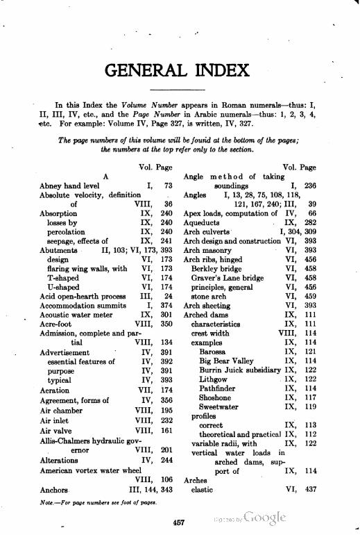
GENERAL INDEX
In this Index the Volume Number appears in Roman numerals—thus: I,
II, III, IV, etc., and the Page Number in Arabic numerals—thus: 1, 2, 3, 4,
«tc. For example: Volume IV, Page 327, is written, IV, 327.
The page numbers of this volume mil be found at the bottom of the pages;
the numbers at the top refer only to the section.
Vol. Page
Angle method of taking
soundings I, 236
Angles I, 13, 28, 75, 108, 118,
121, 167, 240; III, 39
Apex loads, computation of IV, 66
Aqueducts IX, 282
Arch culverts I, 304, 309
Arch design and construction VI, 393
Arch masonry
Arch ribs, hinged
Berkley bridge
Graver's Lane bridge
principles, general
stone arch
Arch sheeting
Arched dams
characteristics
crest width
examples
Barossa
Big Bear Valley
Burrin Juick subsidiary IX,
Lithgow
Pathfinder
Shoshone
Sweetwater
profiles
correct
theoretical and practical IX,
variable radii, with
vertical water loads in
arched dams, sup
port of IX,
Arches
elastic VI,
A
Vol. Page
Abney hand level I, 73
Absolute velocity, definition
of VIII, 36
Absorption IX, 240
losses by IX, 240
percolation IX, 240
seepage, effects of IX, 241
Abutments II, 103; VI, 173, 393
design VI, 173
flaring wing walls, with VI, 173
T-shaped VI, 174
U-shaped VI, 174
Acid open-hearth process III, 24
Accommodation summits I, 374
Acoustic water meter IX, 301
Acre-foot VIII, 350
Admission, complete and par-
tial VIII, 134
Advertisement IV, 391
essential features of IV, 392
purpose IV, 391
typical IV, 393
Aeration VII, 174
Agreement, forms of IV, 356
Air chamber VIII, 195
Air inlet VIII, 232
Air valve VIII, 161
Allis-Chalmers hydraulic gov
ernor VIII, 201
Alterations IV, 244
American vortex water wheel
VIII, 106
VI, 393
VI, 456
VI, 458
VI, 458
VI, 456
VI, 459
VI, 393
IX, 111
IX, 111
VIII, 114
IX, 114
IX, 121
IX, 114
y ix, 122
IX, 122
IX, 114
IX, 117
IX, 119
IX, 113
il IX, 112
IX, 122
114
437Anchors III, 144, 343
Note.—For page numbers see foot of pages.
457
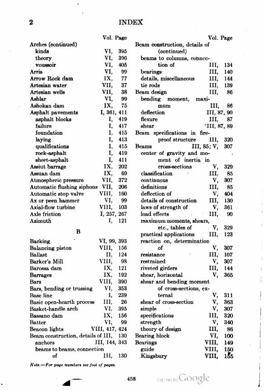
INDEX
Arches (continued)
kinds
theory
voussoir
Arris
Arrow Rock dam
Artesian water
Artesian wells
Ashlar
Ashokan dam
Asphalt pavements
asphalt blocks
failure
foundation
laying
qualifications
rock-asphalt
sheet-asphalt
Assiut barrage
Assuan dam
Atmospheric pressure
Automatic flushing siphons
Automatic stop valve
Ax or peen hammer
Axial-flow turbine
Axle friction
Azimuth
B
Vol. Page Vol. Page
Beam construction, details of
VI, 395 (continued)
VI, 396 beams to columns, connec
VI, 405 tion of III, 134
VI, 99 bearings III, 140
IX, 77 details, miscellaneous III, 144
VII, 37 tie rods III, 139
VII, 38 Beam design III, 86
VI, 99 bending moment, maxi
IX, 75 mum III, 86
I, 361, 411 deflection III, 87, 90
I, 419 flexure III, 87
I, 417 shear III, 87 , 89
I, 415 Beam specifications in fire
I, 413 proof structure III, 320
I, 415 Beams III, 85; V, 307
I, 419 center of gravity and mo
I, 411 ment of inertia in
IX, 202 cross-sections V, 329
IX, 69classification • III,
85
VII, 372 continuous V, 307
VII, 206 definitions III, 85
VIII, 160 deflection of V, 404
VI, 99 details of construction III, 130
VIII, 103 laws of strength of V, 361
I, 257, 267 load effects III, 90
I, 121 maximum moments, shears,
VI, 99, 393Backing
Balancing piston
Ballast
Barker's Mill
Barossa dam
Barrages
Bars
Bars, bending or trussing
Base line
Basic open-hearth process
Basket-handle arch
Bassano dam
Batter
Beacon lights VIII, 417, 424
Beam construction, details of III, 130
anchors III, 144, 343
VIII,
ii,
VIII,
IX,
IX,
VIII,
VI,
I,
III,VI,
IX,
VI,
156
124
98
121
192
390
353
239
26
395
156
99
beams to beams, connection
of III, 130
Note.—For page numbers see foot of pages.
etc., tables of V, 329
practical applications III, 123
reaction on, determination
of V, 307
resistance III, 107
restrained V, 307
riveted girders III, 144
shear, horizontal V, 365
shear and bending moment
of cross-sections, ex
ternal V, 311
shear of cross-section V, 363
simple V, 307
specifications III, 320
strength V, 340
theory of design III, 86
Bearing block VI, 100
Bearings VIII, 149
guide VIII, 150
Kingsbury VIII, 15*5
458
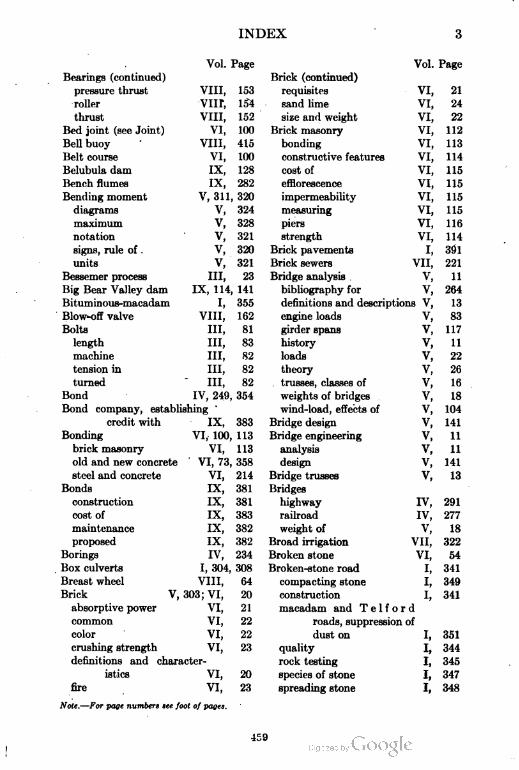
INDEX
Vol. Page Vol. Page
Bearings (continued) Brick (continued)
pressure thrust VIII, 153 requisites VI, 21
roller VIII, 154 sand lime VI, 24
thrust VIII, 152 size and weight VI, 22
Bed joint (see Joint) VI, 100 Brick masonry VI, 112
Bell buoy VIII, 415 bonding VI, 113
Belt course VI, 100 constructive features VI, 114
Belubula dam IX, 128 cost of VI, 115
Bench flumes IX, 282 efflorescence VI, 115
Bending moment V, 311, 320 impermeability VI, 115
diagrams V, 324 measuring VI, 115
maximum v, 328 piers VI, 116
notation v, 321 strength VI, 114
signs, rule of v, 320 Brick pavements I, 301
units v, 321 Brick sewers VII, 221
Bessemer process III, 23 Bridge analysis v, 11
Big Bear Valley dam IX, 114, 141 bibliography for v, 264
Bituminous-macadam I, 355 definitions and descriptions v, 13
Blow-off valve VIII, 162 engine loads v, 83
Bolts III, 81 girder spans v, 117
length III, 83 history v, 11
machine III, 82 loads v, 22
tension in III, 82 theory v, 26
turned III, 82 trusses, classes of v, 16
Bond IV, 249, 354 weights of bridges v, 18
Bond company, establishing '
credit with IX, 383
Bonding VI, 100, 113
brick masonry VI, 113
old and new concrete VI, 73, 358
steel and concrete VI, 214
Bonds IX, 381
construction IX, 381
cost of IX, 383
maintenance IX, 382
proposed IX, 382
Borings IV, 234
Box culverts I, 304, 308
Breast wheel VIII, 64
Brick V, 303; VI, 20
absorptive power VI, 21
common VI, 22
color VI, 22
crushing strength VI, 23
definitions and character
istics VI, 20
fire VI, 23
Note.—For page numbers see foot of pages.
wind-load, effects of V, 104
Bridge design V, 141
Bridge engineering V, 11
analysis V, 11
design V, 141
Bridge trusses V, 13
Bridges
highway IV, 291
railroad IV, 277
weight of V, 18
Broad irrigation VII, 322
Broken stone VI, 54
Broken-stone road I, 341
compacting stone I, 349
construction I, 341
macadam and T e 1 f o r d
roads, suppression of
dust on I, 351
quality I, 344
rock testing I, 345
species of stone I, 347
spreading stone I, 348
459
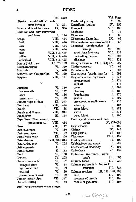
INDEX
Vol. Page
"Broken straight-line" col
umn formula V, 391
Brush and bowlder dams IX, 265
Building and city surveying
problems I, 194
Buoys VIII, 414
bell VIII, 415
can VIII, 414
cone VIII, 414
nun VIII, 414, 415
pillar VIII, 414, 415
spherical VIII, 414, 415
Burrin Juick dam IX, 75, 122
Bushhammering VI, 100
Butt joint V, 408
Buttress (see Counterfort) VI, 100
By-pass VIII, 191
Caissons VI, 156
hollow-crib VI, 157
open VI, 156
pneumatic VI, 159
Camer6 type of dam IX, 213
Can buoy VIII, 414
Canals VII, 88
Canals and flumes VIII, 244
Cantilevers III, 128
Cape Fear River mouth , im-
provement at VIII, 444
Case VIII, 147
Cast-iron piles VI, 136
Cast-iron pipes VII, 82
Castlewood weir IX, 106
Catch-basins VII, 209, 314
Catenarian arch VI, 395
Cattle guards II, 121
Cattle passes II, 112
Cavil VI, 100
Cement IV, 263
Cement materials VI, 27
comjnon lime VI, 28
hydraulic lime VI, 29
natural VI, 30
pozzuolana or slag VI, 29
Cement sewer-pipe VII, 217
Cement testing VI, 32
Note.—For page numbers see foot of pages.
Vol. Page
Center of gravity V, 329
Centrifugal pumps IV, 255
Cesspool VII, 188
Chaining I, 15
Channels III, 38
Cheeseman Lake dam IX, 63
Chemical composition of steel III, 55
Chemical precipitation of
sewage VII, 323
conditions favoring VII, 323
controlling factors VII, 323
efficiency VII, 323
Chezy's formula VIII, 354; IX, 297
Cinder concrete VI, 63
Circular arch VI, 395
City streets, foundations for I, 399
City streets and highways I, 371
arrangement I, 371
asphalt I, 411
brick I, 391
cleaning I, 430
foundations I, 379
grades I, 392
pavement, miscellaneous I, 422
selecting I, 434
stone-block I, 381
width I, 371
wood-block I, 405
Civil specifications and con
tracts IV, 221-398
City surveys I, 189
Claims IV, 243
Clay puddle VI, 120
Clearance VIII, 134
Coaling stations II, 120
Cobblestone pavement I, 383
Coefficient of elasticity V, 401
Cofferdams VI, 154
Collective insurance, work
men's IX, 385
Column bases III, 230
Column pedestals in fireproof
structure III, 333
Column sections III, 193, 195, 238
area III, 193
moment of inertia III, 194
radius of gyration III, 194
460
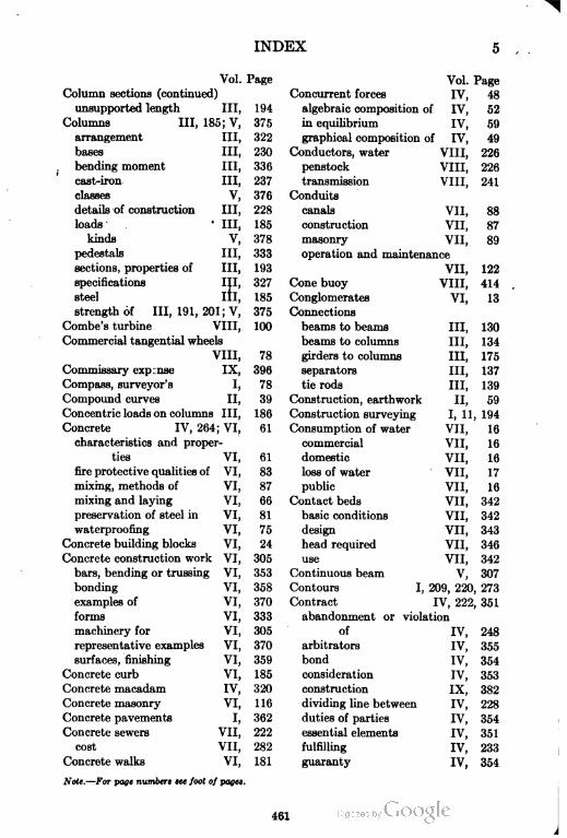
INDEX
Vol. Page
Column sections (continued)
unsupported length III, 194
Columns III, 185; V, 375
arrangement III, 322
bases III, 230
bending moment III, 336
cast-iron III, 237
classes V, 376
details of construction III, 228
loads' • III, 185
kinds V, 378
pedestals III, 333
sections, properties of III, 193
specifications III, 327
steel III, 185
strength of III, 191, 201; V, 375
Combe's turbine VIII, 100
Commercial tangential wheels
VIII, 78
Commissary exprnse IX, 396
Compass, surveyor's I, 78
Compound curves II, 39
Concentric loads on columns III, 186
Concrete IV, 264; VI, 61
characteristics and proper
ties VI, 61
fire protective qualities of VI, 83
mixing, methods of VI, 87
mixing and laying VI, 66
preservation of steel in VI, 81
waterproofing VI, 75
Concrete building blocks VI, 24
Concrete construction work VI, 305
bars, bending or trussing VI, 353
bonding VI, 358
examples of VI, 370
forms VI, 333
machinery for VI, 305
representative examples VI, 370
surfaces, finishing VI, 359
Concrete curb VI, 185
Concrete macadam IV, 320
Concrete masonry VI, 116
Concrete pavements I, 362
Concrete sewers VII, 222
cost VII, 282
Concrete walks VI, 181
Note.—For page numbers see foot of pages.
Vol. Page
Concurrent forces IV, 48
algebraic composition of IV, 52
in equilibrium IV, 59
graphical composition of IV, 49
Conductors, water VIII, 226
penstock VIII, 226
transmission VIII, 241
Conduits
canals VII, 88
construction VII, 87
masonry VII, 89
operation and maintenance
VII, 122
Cone buoy VIII, 414
Conglomerates VI, 13
Connections
beams to beams III, 130
beams to columns III, 134
girders to columns III, 175
separators III, 137
tie rods III, 139
Construction, earthwork II, 59
Construction surveying I, 11, 194
Consumption of water VII, 16
commercial VII, 16
domestic VII, 16
loss of water VII, 17
public VII, 16
Contact beds VII, 342
basic conditions VII, 342
design VII, 343
head required VII, 346
use VII, 342
Continuous beam V, 307
Contours I, 209, 220, 273
Contract IV, 222, 351
abandonment or violation
of IV, 248
arbitrators IV, 355
bond IV, 354
consideration IV, 353
construction IX, 382
dividing line between IV, 228
duties of parties IV, 354
essential elements IV, 351
fulfilling IV, 233
guaranty IV, 354
461
6 INDEX
'
Vol. Page Vol. Page
Contract (continued) Cost analysis (continued)
mutual consent IV, 353 labor costs, cost analysis as
nature and purpose IV, 351 applied to
number of parties IV, 351 methods of, comparison
payment clauses IV, 355 of IX, 324
subject matter IV, 353 number of distributions,
supply IX, 382 limiting IX, 324
Contractor IV, 258 labor, material, and ex
duties of IV, 233 pense, distribution
obligations of IV, 238 of IX, 327
Control of water VIII, 221 actual cost, what consti
gate house VIII, 225 tutes IX, 333
head gate VIII, 222 expense items, distribu
headrace and tailrace VIII, 221 tion of IX, 328
water racks VIII, 221 labor, distribution of IX, 327
Control works of canal IX, 273 material, distribution of IX, 328
drops IX, 279printed itemized estimate
escapes IX, 276forms, value of IX, 334
arrangement IX, 278 problems, illustrative IX, 337
functions IX, 276 cost distribution in con
location IX, 276 nection with power
regulators IX, 273 house contract IX, 337
arrangement IX, 275 Cost analysis as applied to
location, relative IX, 273 labor costs IX, 323
types ^ IX, 274 cost records vs. individual
turnouts IX, 280 impressions IX, 323
Coping VI, 101 methods IX, 324
Corbel II, 104; VII, ior cost-analysis IX, 324
Core walls VII, 65 cost-collection IX, 324
Cost analysis IX, 315mental conclusion IX, 324
cost keeping to cost analy
sis, relation of IX, 318
number of distributions,
limiting IX, 324
cost keeping, general con-Cost-analysis engineering IX, 315
" ditions affecting IX, 320 cost-analysis system IX, 339
methods, simple IX, 319 what is cost analysis? IX, 315
overlapping of the two Cost-analysis system, IX, 339
subjects IX, 318 fittings and repairs IX, 395
policy of cost analysis IX, 322 forms and materials, de
standardizing methods, tailed study of IX, 347
necessity of IX, 318 cost estimate, itemized IX, 368
definition IX, 315 outline of work IX, 347
good judgment in IX, 315 quantity estimates, item
labor costs, cost analysis as ized IX, 360
applied to IX, 323 management, science of IX, 340
cost records vs. individual need of IX, 339
impressions IX, 323 contracting work IX, 340
Note.—For page numbers see foot of pages
INDEX
Vol. Page
Cost-analysis system, a (con
tinued)
outline for study, detail IX, 341
estimates, value of IX, 344
job, analysiaof IX, 343
job, construction of IX, 342
job, estimating the IX, 341
Cost estimate for sub-bidders IX, 372
Cost estimates to previous
forms, relation of IX, 373
Counterfort (see Buttress) VI, 101
Country roads and boule
vards I, 257
location I, 268
maintenance and improve-
- ment I, 365
natural-soil roads I, 330
Couples IV, 96
Course VI, 101
Coursed masonry (see Ran
dom) VI, 101
Coursed rubble (see Rubble) VI, 101
Coursing joint VI, 393
Covered reservoirs VII, 101
Coverings, roads with I, 335
Cramp VI, 101
Crandall VI, 101
Crandalling VI, 101
Creosote, treatment of timber
with IV, 301
Cribs " VI, 156
Cross River IX, 75
Crossings II, 170, 171
Cross levels I, 271
Cross-sectioning I, 199
Culverts I, 302; II, 110; IV, 273;
VI, 174, 284
arch I, 304, 309; VI, 180, 292
box I, 308
cattle passes II, 112
classification by loadings VI, 284
double box VI, 177
end walls VI, 180
functions I, 302
iron pipe I, 307
old-rail II, 112
pipe II, 110
Note.—For page numbers see foot of pages.
Culverts (continued)
plain concrete
stone box
Curbing
Currents
Curvature
Cut-offs
Cylinder gate
Damietta and Rosetta
Dams
earthen
loose rock
masonry
timber
Dams and weirs
arched dams
barrages
buttress dams
gravit y dams
Vol. Page
VI, 178
VI, 175
IV, 327
VIII, 403
II, 235
VIII, 364
VIII, 146
IX, 189
VII, 63
VII, 63
VII, 77
VII, 72
VII, 76
IX, 11
IX, 111
IX, 192
IX, 146
IX, 12
gravity overfall dams, or
weirs IX, 85
hollow slab buttress dams IX, 146
introduction IX, 11
multiple arch or hollow arch
buttress dams IX, 123
open dams or barrages IX, 192
submerged weirs IX, 161
Dead load stress IV, 111
Deck bridges V, 14
Deep-well plunger pumps --IX, 255
Deep wells VII, 55
Deflecting nozzle, use of VIII, 87
Deformation V, 292
Dehri weir IX, 188
Delays IV, 238
Dhukwa weir IX, 100
Diffuser VIII, 137
Dikes VIII, 385
longitudinal VIII, 387
spur VIII, 385
submerged spur VIII, 387
Dimension stone VI, 102
Dipper dredge II, 377
Direct-recording water meter
VIII, 300
463
8 INDEX
Vol. Page
Discharge in flow of rivers,
definition of VIII, 349
Disk piles VI, 136
Distributaries IX, 255, 284
construction, details of IX, 286
designing, consideration in IX, 285
location IX, 284
Distribution of labor, material,
and expense IX, 327
actual cost IX, 333
expense items, distribution
of IX, 328
construction equipment,
method of charging IX, 332
division of expense, items
showing IX, 329
expense items, methods
of charging IX, 330
job expense items, kinds
of IX, 328
labor, distribution of IX, 327
direct labor IX, 327
indirect labor IX, 327
labor, material, and ex
pense, divisions of IX, 327
material, distribution of IX, 328
printed estimate forms,
value of IX, 334
Distribution reservoirs VII, 96
Ditches II, 61
Diversion lines of a canal
system IX, 256
Division of land I, 180
Docks VIII, 424
dry VIII, 424
slips VIII, 430
wet VIII, 430
Dolomite VI, 12
Dowel VI, 102
Downward-flow impulse
wheels VIII, 92
Draft VI, 102
Draft tube VIII, 137
Drain VII, 181
Drain outlets I, 299
Vol. Page
Drainage systems
I, 294, 377; VII, 151
Drainage works IX, 281
inlet dams IX, 281
flumes and aqueducts IX, 282
level crossings IX, 281
superpassages IX, 283
Drawing instruments I, 241
pantograph I, 252
pens and pencils I, 241
planimeter, polar I, 253
protractor I, 244
scales I, 243
Dredges II, 344; VIII, 433
bucket-ladder VIII, 433
clamshell VIII, 434
dipper VIII, 436
rock-breaking VIII, 438
suction VIII, 436
Driven wells VII, 52
Drop-hammer pile driver VI, 147
Drops IX, 279
Dry-land excavators II, 344
Dry-stone masonry VI, 102
Dumpy-level I, 59, 62
Dust, suppression of I, 351
Duty of water IX, 242
Dynamic pressure VIII, 27-30, 37
Dynamometer VIII, 114
Dynograph I, 257
E
Drainage ditches VII, 203
Note.—For page numbers see foot of pages.
Earth roads I, 330
Earthen dams IX, 265
Earthen reservoirs VII, 98
Earthwork I, 311; II, 301
classification I, 313
construction II, 59
cuts and fills, balancing I, 311
embankments, methods of
forming I, 314; II, 86
excavations, methods of II, 301
principle -II, 301
prosecution of I, 314
scope II, 301
shrinkage in I, 313
slopes, side I, 311
tools I, 316
464
INDEX 9
Vol. Page
Eccentric loads on columns III, 186
Edison Electric Company VIII, 312
power units VIII, 312
water supply VIII, 312
Efficiency, definition of VIII, 16, 17
Efficiency of turbines VIII, 206
Elastic arches VI, 437
Elasticity V, 292
Electric railway, specifica
tions for overhead
construction IV, 313
Electric shovels II, 339
Electric water meter IX, 300
Elevated tanks VII, 109
Elliptical arch VI, 395
Embankments - VII, 65
construction VII, 67
dimensions VII, 65
gate chambers VII, 69
outlet pipes VII, 68
waste weirs VII, 71
Energy ' VIII, 12, 15
Engineer IV, 222
Engineer's transit I, 36, 114
Engine houses II, 120
Engine loads V, 83
Engine yards II, 178
Equilibrium IV, 62
Erosion and transportation VIII, 387
Escapes IX, 276
Estimating IV, 11-43
costs IV, 34
structural steel for buildings
IV, 11
weights IV, 15
Evaporation of water IX, 234
amount IX, 236
cvaporometers IX, 235
factors influencing IX, 234
measurement IX, 235
water storage, value of IX, 239
Evaporometers IX, 235
floating pan IX, 235
Piche, results with IX, 235
Excavations I, 198; II, 301
Expansion joint VIII, 232
Expense items
Note.—For page numbers see foot of pages.
Vol. Page
Expense items (continued)
actual cost , IX, 333
charging, methods of IX, 330
division of expense IX, 329
job expense items, kinds
of IX, 328
printed itemized forms,
value of IX, 334
Expense items, general-
charge or IX, 377
application IX, 377
bonds IX, 381
commissary IX, 396
divisions, discussion of IX, 380
fittings and repairs IX, 395
fuel and oil IX, 329, 330, 394
general office and super
vision IX, 399
importance IX, 377
interest IX, 397
jobs, operation on partic
ular IX, 391
liability insurance IX, 384
machinery and equipment IX, 397
miscellaneous IX, 399
petty tools IX, 393
External shear V, 311
Extrados (see Intrados) VI, 102, 393
Factor of safety
Farm surveying
Fascines
Fiber stress
Filter beds
V, 296
I, 172, 248
VIII, 379
V, 343, 345
VII, 148
Filter operation, control of VII, 158
Filter sand . VII, 150
Filters VII, 143
Filtration
beds, filter VII, 148
coagulating system VII, 172
control VII, 158, 171
efficiency VII, 144
preliminary VII, 159
rapid sand VII, 160
rate VII, 146
sand, filter VII, 150
465
10 INDEX
Vol. Page
Filtration (continued)
sand washing VII, 156
slow sand VII, 143
systems, drainage VII, 151
Fink truss, complete analysis
of IV, 110
Fire III, 355
effects on steel III, 355
intensity of heat in III, 356
protective methods III, 356
Fireproof materials III, 358
brick III, 362
cinder concrete III, 358
hollow tile III, 359
Portland cement concrete III, 358
selection of III, 362
Fireproofing specifications
III, 308, 357
concrete, choice of III, 308
exterior columns, effect on
position of III, 308
thickness required III, 308
Fire hose VII, 413
Fire streams, number and
size of VII, 114
Fittings and repairs IX, 395
analysis of IX, 395
Flat-slab construction VI, 245
Flexural stress of beam V, 369
Flexure of concrete beam de
sign VI, 189
Floating excavators II, 377
Floating lights VIII, 417
Floods VIII, 360
conditions affecting VIII, 360
control of VIII, 364
Floor construction, fireproof III, 315
Flow of rivers VIII, 349
Flow in sewers, formulas for
computing VII, 223
Flow of water in open chan
nels VII, 417
Flow of water through orifices
VII, 391
Flow of water through pipes VII, 402
Flumes IX, 282
bench IX, 282
Note.—For page numbers see foot of pages.
Flush-tanks
Flywheel
Folsam weir
Footing
Foundations
Vol. Page
VII, 203
VIII, 195
IX, 95
VI, 102
IV, 256; VI, 121
bridge piers and abut
ments VI, 170
cofferdams, cribs, and cais
sons VI, 154
concrete curb VI, 185
concrete walks VI, 181
culverts VI, 174
piles VI, 135
preliminary work VI, 121
retaining walls VI, 162
Fourneyron turbine VIII, 105
Francis formula IX, 307
Francis formula for weirs VII, 400
Francis turbine VIII, 105
Freight yards II, 174
Fresno grader II, 305
Frogs II, 149
Fuel and oil item IX, 329, 330, 394
G
Gages
Garbage
collection
composition
disposal
incinerators, by
reduction plants, by
quantity
Gate chambers
Gate house
VIII, 162
VII, 365
VII, 366
VII, 365
VII, 366
VII, 366
VII, 367
VII, 366
VII, 69
VIII, 225
Gate opening—part gate and
full gate VIII, 134
General expense claims IX, 390
General office and super
vision IX, 399
General office expense IX, 399
Goedetic surveying I, 11
Girard impulse wheel VIII, 93
Girder III, 85, 223
Girder bridges V, 13
Girder spans V, 117
466
INDEX 11
Vol. Page
Governors VIII, 196
Allis-Chalmers hydraulic VIII, 201
control, mechanical and
hydraulic VIII, 196
Glocker-White ' VIII, 200
kinds of VIII, 89
Pelton governing devices VIII, 202
Replogle centrifugal gover
nor and return VIII, 198
Woodward VIII, 200
Grade II, 241
accelerated motion, laws of II, 242
minor and ruling, distinc
tion between II, 241
profile, virtual II, 245
Grade problems • I, 289
Graders II, 310
elevating II, 314
four-wheel blade II, 310
reclamation II, 311
two-wheel blade II, 310
Gradients I, 263, 287
Granite VI, 13
Granite reef weir IX, 102
Graphical composition of non-
concurrent forces IV, 91
Graphical condition of equilib
rium IV, 59
Graphical representation of a
force IV, 46
Graphical resolution of force
into two concurrent
components IV, 56
Gravel roads I, 339
Giavity dams IX, 12
design IX, 14
broken line profiles treat
ment for IX, 51
calculation IX, 21
crest, high and wide IX, 23
crest width IX, 19
failure by sliding on shear,
security against IX, 41
height, limiting IX, 39
height, variation of IX, 23
method, analytical IX, 22, 28, 44
method, graphical IX, 22, 26
Note.—For page numbers see foot of pages.
Vol. Page
Gravity dams (continued) t
design
method, Haessler's IX, 46, 52
polygon, stepped IX, 47
pressure diagram, modi
fied IX, 47
pressure distribution IX, 33, 35
pressure limit, maxi
mum IX, 37
pressure lines IX, 41
pressures in figures,
actual IX, 44
profile, practical IX, 18
profile, theoretical IX, 14
rear widening, IX, 20
shear and tension, inter
nal IX, 40
stepped polygon IX, 47
stresses, internal IX, 37
vertical component,
equivalent IX, 32
examples
Arrow Rock IX, 77
Assuan IX, 69
Burrin Juick IX, 75
Cheeseman Lake IX, 63
Cross River and Ashokan
IX, 75
New Croton IX, 68
Roosevelt IX, 66
foundations, special IX, 79
aprons affect uplift IX, 80
ice pressure, reinforced
against IX, 83
rear aprons decrease up
lift IX, 81
rock below gravel IX, 82
graphical calculations,
method of IX, 12
"high" dams IX, 53
base of, silt against IX, 60
partial weir dams IX, 62
pentagonal profile to be
widened IX, 57
pressure, ice IX, 61
toe of, filling against IX, 60
467
12 INDEX
Vol.
Gravity dams (continued)
"middle third" and limiting
stress, condition of IX,
pressure of water on wall IX,
stress limit, compressive IX,
Gravity-head VIII,
Gravity irrigation works IX,
intermittent or periodic
Page
13
12
14
14
251
252
252
251
252
canals IX,
inundation IX,
perennial canals IX,
storage works IX,
IX, 107
IX, 87
IX, 106
IX, 85
IX, 87
1
IX, 92
IX, 100
IX, 108
IX, 95
IX, 102
IX, 103
IX, 102
IX, 105
IX, 95
IX, 91
r
IX, 89
IX, 88
of IX, 109
types of IX, 85
Castlewood IX, 106
Dhukwa IX, 100
Folsam IX, 95
Granite Reef IX, 102
Mariquina IX, 102
Nira IX, 105
"Ogee" falls IX, 95
St. Maurice River IX, 109
Great Lakes resources
Greenville tanks
Grit chambers
Ground water supplies
artesian
flow
occurrence
porosity of soils
quality
springs
works for collection of
Grout
Guayabal dam
Guide bearing
Guides
Gunter's chain
Gurley binocular
Vol. Page
VIII, 253
339
328
31
VII,
VII,
VII,
VII,
VII,
VII,
VII,
VII,
VII,
VII,
VI,
IX,
VIII,
VIII,
37
33
31
32
39
35
45
102
151
150
103
I, 13, 15
I, 60
Gurley monocular hand level I, 61
Gutters I, 299, 301, 377, 428
H
Gravity overfall dams, or
weirs IX, 85
American dams on pervious
foundations
base width, approximate
Castlewood weir
characteristics
crest width, approximate
depth of overfall, method
of calculating
Dhukwa weir
fore apron, level of
Folsam weir
Granite Reef weir
hydraulic conditions
Mariquina weir
Nira weir
"O g e e" overfalls, objec
tions
pressure, moments of
pressures affected by water
level
process, graphical
spillway of St. Maurice
River dam, section
Hachures I, 211
Haessler's method of drawing
line of pressures IX, 46, 52
Harbor improvement, prob
lems of VIII, 392
currents VIII, 403
harbors, types of VIII, 394
investigation, preliminary
VIII, 393
natural forces, effects of VIII, 396
tides VIII, 401
waves VIII, 400
winds VIII, 398
Harbors VIII, 392
Atlantic coast, harbor im
provements on VIII, 439
breakwaters VIII, 404
docks VIII, 424
dredging VIII, 432
improvement, problems
of VIII, 392
signals VIII, 412
Haskell electric water meter IX, 301
Haunch VI, 393
Header VI, 102
Head gate VIII, 222
Note.—For page numbers see foot of pages.
468
INDEX 13
Vol. Page
VI, 393
VIII,
IX,
221
255
265
265
265
Heading joint
Headrace and tailrace
Headworks of canal
construction, types of IX,
brush and bowlder dams IX,
earthen dams IX,
iron or steel dams IX, 265, 271
loose rock-fill dams IX, 265, 270
masonry dams IX, 265, 267
open and closed weirs IX, 271
wooden dams and weirs
IX, 265, 270
diversion IX, 265
scouring sluices IX, 272
Highway construction I, 257-445
city streets and highways I,
country roads and boule
vards I,
Hindia barrage IX,
Hollow arch buttress dams
(see Multiple arch
dams) IX,
Hollow slab buttress dams IX,
arch dam deck, slab deck
compared with IX,
Bassano dam IX,
description IX,
fore slope, steel in III,
foundation foredeck, pres
sure on IX,
Guayabal dam IX,
reinforced concrete, form
IX,
VIII,
V,
V,
VII,
ulas for
Holyoke testing flume
Hooke's law
Horizontal shear
Horizontal wells
House plumbing
371
257
204
123
146
150
156
146
149
159
151
147
117
293
365
58
principles
regulations, test, licenses
soil pipe
trap
ventilation
House sewage
Hovland tile ditcher
Hydrants
Hydraulic dredge
Note.—For page numbers see foot of pages.
Vol. Page
Hydraulic grade line VII, 41 f
Hydraulic lime VI, 29
Hydraulic mean radius VII, 419
Hydraulic motor VIII, 50
Hydraulic Power Company VIII, 256
Hydraulic ' power installa
tions VIII, 253
Mill Creek, Utah, at VIII, 320
Mississippi River, along
the VIII, 313
Niagara Falls, at VIII, 253
Pacific slope, on the VIII, 288
Pike's Peak, Hydroelec
tric Company, at VIII, 324
Schaffhausen, Switzerland,
at VIII, 327
Vauvry, Switzerland, at VIII, 324
Hydraulic rams IX, 255
Hydraulics
definition VII, 371
flow of streams, measure
ment of VII, 422
flow of water in open chan
nels VII, 417
flow of water through ori
fices VII, 391
flow of water through
pipes VII, 402
units of measure VII, 371
water at rest, pressure of VII, 373
weight of water VII, 371
Hydrography VIII, 346
Hydrostatic arch VI, 395
Imhoff tank VII, 336
Impounding reservoirs VII, 60
Impulse and reaction of water
VII, 275 in motion VIII, 26, 29
VII, 312 Impulse turbine VIII, 104, 133
VII, 273 Impulse wheels VIII, 76
VII, 273 Inlet dams IX, 281
VII, 276 Inspection of work IV, 235
VII, 273 cost of IV, 236
II, 435 during construction IV, 235
VII, 120 final inspection IV, 236
n, 402 labor furnished to inspector IV, 236
439
14 INDEX
Vol. Page
Instruments, surveying
care of I, 64
compass I, 78
Gunter's chain I, 13, 15
level I, 51
level bubble I, 38
plane-table I, 226
rod, leveling I, 42
setting up the instrument I, 63
Insurance, builders' IV, 237
Intercepting sewers VII, 194
Interest IX, 397
Interest charges, handling IX, 397
Interlocking II, 195
Intersection method of taking
soundings I, 236
Intrados (see Extrados) VI, 103, 394
Inverted siphons VII, 210
Iron pipe culverts I, 307
Iron or steel dams IX, 271
Iron work for timber trestles IV, 304
Irrigation engineering IX, 219
crude methods IX, 219
measure, units of IX, 220
open channels, flow of water
in IX, 296
IX, 219
Vol. Page
Irrigation systems (continued)
reservoirs, storage
relation to irrigable lands IX, 295
topography IX, 291
works, classification of IX, 250
gravity LX, 251
pumping or lift irriga
tion IX, 252
Isogonic lines I, 77
Itemized cost estimate IX, 368
bidding, unit-price IX, 370
centers, cost affected by IX, 372
character of labor and
character of work,
cost affected by IX, 371
forms, cost affected by IX, 371
general charge item, cost
affected by IX, 372
locality, cost affected by IX, 371
materials, cost of IX, 371
reinforcement, cost
affected by IX, 372
equipment IX, 373
cost IX, 373
maintenance IX, 373
rental or depreciation IX, 374
estimate, summary of
points in making IX, 374
forms, analysis of IX, 368
previous forms, comparison
with EX, 368
Itemized quantity estimates IX, 360
problem of
systems, irrigation IX, 249
water supply, factors of IX, 220
Irrigation systems IX, 249
canal system, parts of IX, 255
control works IX, 273
distributaries IX, 284
divisions IX, 255
drainage works IX, 281
headworks IX, 263
main canal IX, 256
considerations, preliminary IX, . 249
land to be irrigated IX, 249
source of supply deter
mining
reservoirs, storage
classification
geological formation
locating factors in
natural and artificial
locations
Note.—For page numbers see foot of pages.
checking quantities IX, 360
machines, calculating IX, 367
slide rule IX, 368
plans, identification of IX, 361
quantity—estimate forms,
analysis of IX, 363
dimension column IX, 363
IX,
IX,
IX,
IX,
IX,
250——J
288
288
292
291
J
Jamb
Jet types of wheel
Joints
Jonval turbine
VI,
VIII,
VII,
VIII,
103
92
83
105
1
, special
IX, 295
470
INDEX 15
K
Vol. Page
Keystone VI, 394
Khanki weir . IX, 181
Kutter's formula VIII, 354; IX, 297
Labor cost distribution sys
tem IX, 404
Ladder dredge II, 388
Laguna weir IX, 189
Lake intakes VII, 44
Land-drainage systems VII, 263
Land surveying I, 11, 172
Lap joint V, 408
Lateral bracing V, 15
Lateral sewers VII, 194
Latitude, means of determin
ing I, 149
Latitude difference I, 90
Leaching cesspool VII, 188
Level crossings IX, 281
Leveling rod I, 42
Levels
dumpy I, 59, 62
hand level and clinometer,
Abney I, 73
Locke's hand I, 72
precise I, 61
wye I, 51
Levers VIII, 372
factors, construction VIII, 372
height VIII, 374
materials VIII, 375
size and section VIII, 373
Liability insurance IX, 384
collective, workmen's IX, 385
cost, how borne IX, 386
features IX, 384
fire IX, 389
premiums IX, 385
public IX, 385
rates IX, 386
Liability of contractor IV, 241
Liability premiums IX, 385
Liens " IV, 247
Lighthouses VIII, 418
Lightships VIII, 417
Note.'-—For page numbers see foot of pages
Limestone
Lintel III, 85, 126,
Liquidated damages
Lithgow dam
Load effects, calculation
combined
concentrated
typical loads
uniformly distributed
Load factor
Loads
classes
highway bridges, for
in fireproof building
railway bridges, for
wind
Lobnitz rock cutter
Locke's hand level
Longitudinal dike
Loose rock dams
Loose rock-fill dams
M
Vol. Page
VI, 11
342j VI, 103
IV, 243
IX, 122
of III, 90
III, 99
III, 95
III, 103
III, 90
VIII, 331, 333
V, 22
V, 22
V, 22
III, 309
V, 23
V, 24
II, 408
I, 72
• VIII, 387
VII, 77
IX, 270
Machinery and equipment
Magnetic declination
Main canal
alignment
cross-section, design of
embankment
slope and cross-section
velocities, limiting
Main sewers
Maintenance bonds
Manholes
Manufacture of steel
Manufacturing sewage
Mapping
Mariquina weir
Masonry and reinforced con
crete VI,
arch design and construc
tion VI,
beam design, reinforced-
concrete VI,
columns and walls, rein
forced concrete VI,
ten.t IX, 397
I, 75
IX, 255
IX, 256
of IX, 260
IX, 262
•a IX,' 258
IX, 258
VII, 194
IX, 382
VII, 201
III, 10
VII, 182
I, 207, 241, 276
IX, 102
11
393
189
253
471
10 INDEX
Vol. Page
Multiple arch or hollow arch
buttress dams (con
tinued)
arches, differential IX, 136
Belubula IX, 128
Big Bear Valley IX, 141
design IX, 132
foundations, pressure on IX. 135
inclination to the vertical IX, 129
Mir Alam IX, 124
Ogden IX, 130
pressure, flood IX, 139
pressure, reverse water IX, 134
stress analysis IX, 145
N
Narora weir IX, 177
Natural cement VI, 30
Natural-soil roads I, 330
New Croton dam IX, 68
Nira weir IX, 105
Non-concurrent forces IV, 49
algebraic composition of IV, 94
equilibrium of IV, 96
graphical composition of IV, 91
North Mon canal IX, 210
Nozzles, multiple VIII, 25
Nun buoy VIII, 414, 415
O
Vol. Page
Masonry and reinforced con
crete '(continued)
construction work, con
crete VI, 305
foundations VI, 121
masonry materials VI, 11
masonry, types of VI, 99
Masonry conduits VII, 89
Masonry dams VII, 72; IX, 267
classification IX, 267
conditions VII, 72
construction VII, 74
foundations IX, 267
height above water line VII, 74
materials IX, 267
structural considerations IX, 268
weirs, waste VII, 75
Masonry materials ' VI, 11
Masonry, types of VI, 99
Masonry waste weirs VII, 75
Merala weir IX, 181
Meridian, determination of I, 147
Mill building IV, 186-218
columns IV, 193
cornice details IV, 216
floors IV, 218
framing IV, 190
gable details IV, 216
general requirements IV, 189
knee-braces IV, 198
layout IV, 189
runway girders IV, 199
types of buildings IV, 188
ventilators IV, 216
Miller siphon VII, 207
Millet wheel VIII, 73
Mir Alam dam IX, 124
Mixed-flow turbine VIII, 103
Mixers, concrete VI, 306
Modulus of elasticity III, 90
Modulus of rupture V, 362
Moment of inertia III, 46, 194; V, 334
Moments, principle of V, 305
Mortar VI, 57
Multiple arch or hollow arch
buttress dams IX, 123
arch, crest width of IX, 135
Note.—For page numbers see foot of pages.
Ogden dam IX, 130
"Ogee" overfalls IX, 95
Okhla and Madaya weirs IX, 187
Open and closed weirs IX, 271
Open dams or barrages IX, 192
across rivers IX, 202
advantages IX, 210
American vs. Indian treat
ment IX, 206
Assiut barrage IX, 202
automatic dam or regulator
IX, 215
Corbett dam, weir sluices
of IX, 198
Hindia barrage IX, 204
North Mon canal IX, 210
piers, thickness of IX, 210
472
INDEX 17
Vol. Page
Open dams or barrages (con
tinued)
river regulators » IX, 203
St. Andrew's Rapids IX, 211
spans, length of IX, 207
weir scouring sluice IX, 195
weir sluices on sand IX, 200
Outlet pipes VII, 68
Outlet sewer VII, 194
Overshot wheel VIII, 53
Pacific slope development VIII, 288
Edison Electric Company VIII, 312
Pacific Coast Power Com
pany VIII, 305
Puget Sound Power Com
pany VIII, 303
Snoqualmie Falls Power
Company VIII, 288
Pantograph I, 252
Parabola-Euler column form
ulas V, 388
Parapet VI, 394
Partial weir dams IX, 62
Pathfinder dam IX, 114
Pavements IV, 322
asphalt IV, 329
granite block paving on
concrete base IV, 325
granite block paving on
sand base IV, 328
Telford IV, 327
vitrified-clay brick or block
IV, 324
wood block IV, 340
Payrolls IX, 402
Pelton governing devices VIII, 202
Penstock VIII, 226
Petty tools IX, 393
charges for, method of ap
plying IX, 393
Pick VI, 103
Piers VI, 170
Pile driving II, 98; VI, 146
Pile shoes IV, 256
Pile trestles II, 98; IV, 296
.Vote.—For page numbers see foot of pages.
Vol. Page
Piles IV, 256; VI, 135
Piling VIII, 379
specifications for, standard IV, 300
Pillar buoy . VIII, 414, 415
Pipe culverts II, 110
Pipe lines VII, 91
Pipe-trench excavators II, 414
Pitch of joints V, 408
Pitching chisel VI, 104
Plane surveying I, 11-255
chaining and leveling I, 15
compass and transit meas
urements I, 75
introduction I, 11
land and construction sur
veying I, 147
topographic surveying
and mapping I, 205
Plane table, topography by I, 226
Plans and specifications, com-
* parative importance
of IV, 231
Plate-girder railway-span, de
sign of V, 156
Plinth (see Water-table) VI, 104
Plotting I, 247
Plug VI, 104
Point VI, 104
Pointed arch VI, 395
Pointing VI, 104
Polar planimeter I, 253
Polaris, observation on I, 149, 158
Polk tanks VII, 332
Poncelet wheel VIII, 69
Pony-truss bridges V, 14
Porosity of soils VII, 32
Portals V, 15
Portland cement VI, 30
Power shovels II, 317
Pozzuolana or slag cement VI, 29
Precipitation IX, 220
Pressure-relief valve VIII, 190
Price acoustic water meter IX, 301
Prismatic compass I, 81
Progress charts IX, 414
Projection, plotting of maps
by I, 251
473
18 INDEX
Vol. Page
Proposals IV, 380
Protractor I, 244
Public-land surveys I, 184
Public liability insurance IX, 385
Puddling VI, 121
Pulsometers IX, 255
Pumping engines IX, 255
Pumping or lift irrigation IX, 252
Pumping, sewage VII, 358
design VII, 359
ejectors VII, 361
method VII, 358
station at Connellsville,
Pennsylvania • VII, 359
Pumps, types of IX, 255
centrifugal IX, 255
deep-well plunger IX, 255
hydraulic rams IX, 255
pulsometers IX, 255
pumping engines IX, J55
turbine IX, 255
water elevators IX, 255
Purification, miscellaneous
methods of VII, 173
aeration VII, 174
iron, removal of VII, 176
softening water VII, 175
sterilization and distilla
tion VII, 177
Purification of sewage, meth
ods of VII, 320
broad irrigation VII, 322
chemical precipitation VII, 323
contact beds VII, 342
disinfection VII, 355
electrolytic treatment VII, 364
filters, sand VII, 352
filters, sprinkling VII, 346
screens VII, 324
sedimentation tanks VII, 327
Purification of water VII, 131
efficiency, tests of VII, 132
filtration, rapid sand VII, 160
filtration, slow sand VII, 143
miscellaneous methods VII, 173
object and methods VII, 131
Note.—For page numbers see foot of pages.
IV, 232
VI, 105
VI, 105
Vol. Page
Purification of water (contin
ued)
sedimentation and coagula
tion VII, 133
Purlins IV, 65
Pusher grades II, 289
Q
Quantity estimates
Quarry-faced stone
Quoin
R
Radial-flow tanks VII, 341
Radial-flow turbine VIII, 103
Radius of gyration III, 48; V, -376
Rafters IV, 65
Rail braces II, 136
Rail joints II, 133
insulated II; 135
Railroad engineering II, 1 1
construction and mainte
nance, work of II, 11
economics II, 213
Railroad finances II, 213
capitalization II, 213
changes, fixed II, 222
equipment, maintenance of II, 228
expenses II, 223, 228
monopoly II, 219
revenue II, 216, 222
stocks and bonds II, 214
ways and structures, main
tenance of II, 225
Railroad grading IV, 249
Railroad surveys II, 11
Rails II, 130
Rainfall VII, 21; VIII, 347; IX, 221
influences IX, 221
measurement IX, 225
meteorological districts,
comparison by IX, 223
precipitation IX, 220
run-off IX, 227
Runkine's column formula V, 378
Rates of insurance IX, 386
Raymond concrete pile VI, 141
Reaction VIII, 26, 29
474
INDEX 19
Vol. Page
Reaction turbine VIII, 104, 128
entrance and discharge VIII, 136
flow, downward or paral
lel VIII, 132
flow, inward and out
ward VIII, 128
kinetic energy VIII, 135
partial operation VIII, 134
speed VIII, 135
Reaction water wheels VIII, 95
Barker's mill VIII, 98
closed vessel VIII, 96
design, improvements in VIII, 100
friction, effect of VIII, 99
modern turbine develop
ment VIII, 101
revolving tubes VIII, 96
rotating vessels . VIII, 95
Reconnoissance surveys
I, 206, 269; II, 12
Register gate VIII, 147
Regulating gates VIII, 145
cylinder VIII, 146
register VIII, 147
wicket or pivot VIII, 147
Reinforced - concrete beam
design VI, 189
Reinforced-concrete columns
and walls VI, 253
Reinforced - concrete work,
representative exam
ples of VI, 370
Relation of cost keeping to
cost analysis IX, 318
cost keeping, general con
ditions affecting IX, 320
construction labor IX, 321
expense items IX, 322
material IX, 321
shop labor IX, 320
methods, simple IX, 319
policy, cost-analysis IX, 322
two subjects, overlapping
of IX, 318
Relieving arch VI, 395
Reservoirs VII, 60; VIII, 365, 367
artificial storage VIII, 367
Note.—For page ntlmbers see foot of pages.
Reservoirs (continued)
cost
covered
distribution
earthen
impounding
location
maintenance
masonry
natural storage
Vol. Page
VII, 102
VII, 101
VII, 96
VII, 63, 98
VII, 60
VII, 61
VII, 62
VII, 72, 98
VIII, 365
Resistance, calculation of III, 107
Resistances I, 257; II, 252
grades for unequal traffic,
balance of II, 296
grades, pusher II, 289
train II, 252
Resisting moment 111,107; V, 345
Resisting shear V, 363
Restrained beam III, 85; V, 307
Resultant and composition IV, 49
Resurveys I, 177
Retaining walls VI, 162, 271
causes of failure VI, 162
design VI, 164
foundations VI, 163
types VI, 169
Right of way, delay in pro
curing IV, 233
Riprap VI, 105
River and harbor improve
ment VIII, 345
construction, forms of VIII, 376
dikes VIII, 385
fascines VIII, 379
piling VIII, 379
stone VIII, 377
River bank protection VIII, 376
River intakes VII, 42
River survey VIII, 345
Rivers VIII, 345
erosion and transportation
VIII, 387
floods VIII, 360
flow VIII, 349
survey, items of VIII, 345
Riveted girder III, 144
beam box III, 169
475
20 INDEX
Vol. Page
Riveted girder (continued)
construction, details of III, 174
practical applications III, 170
theory of design III, 145
Riveted girder construction,
details of III, 174
Riveted joints V, 408
Riveted roof truss, design of IV, -169
Riveting in girders III, 159
Rivets III, 62
Roads, location of I, 268
reconnoissance I, 269
selection, final I, 278
survey, preliminary I, 271
Roads, maintenance and im
provement of I, 365
Roads with special coverings I, 335
Roller bearing VIII, 154
Rolling ingots III, 28
Roof coverings IV, 65, 128
Roof trusses IV, 123-218
Roosevelt dam IX, 66
Rough-pointing VI, 105
Rubble VI, 105
Rubble concrete VI, 63, 117
Runner VIII, 103
Run-off VIII, 347, 350
8
Safe load of beam
Safe strength of beam
Safety head
Sand
Sand filters
at Alliance, Ohio
design
use
Sand filtration, rapid
V, 361
V, 361
VIII, 231
VI, 51
VII, 352
VII, 353
VII, 353
VII, 352
VII, 160
Sand washing in filtration VII, 156
Sandstone VI, 12
Sanitary engineering VII, 181
Sanitary regulations IV, 240
Sanitary sewage VII, 181
amount, general estima
tion of VII, 240
definition VII, 181
Note.—For page numbers see foot of pages.
Vol. Page
Sanitary sewage (continued)
per capita flow, use of sewer
gaugings on deter
mining . VII, 244
per capita flow, use of sta
tistics of water con
sumption in deter
mining VII, 242
Scales I, 243
Scoop wheel VIII, 74
Scouring sluices IX, 272
Scrapers, drag and wheel II, 304
Screens in sewage disposal
coarse VII, 324
fine VII, 324
purpose VII, 324
Section modulus III, 49, 108; V, 349
Secular variation I, 76
Sedimentation VII, 133
basins, settling VII, 139
with coagulation VII, 133
plain VII, 134
value and importance VII, 133
Sedimentation tanks VII, 327
Segmental arch % VI, 395
Selecting pavement I, 434
Semicircular arch VI, 395
Septic tanks VII, 330
Service pipes, materials for VII, 87
Settling basins VII, 139
Settling tanks VII, 328
Sewage VII, 316
analyses VII, 316
character VII, 316
definition VII, 181
dilution of VII, 320
disinfection of VII, 355
Sewage disposal VII, 213, 314
basic principle VII, 314
future conditions VII, 365
history VII, 315
pumping VII, 358
requirements for VII, 320
systems VII, 320
Sewer air VII, 182
Sewer construction VII, 305
Sewer maintenance VII, 312
476
INDEX 21
Vol. Page Vol. Page
Sewer materials VII, 213 Sewers (continued)
Sewerage and drainage plans VII, 287
condition VII, 312 siphons, inverted VII, 210
cost VII, 276 specifications for VII, 291
early history VII, 182 sub-drains VII, 199
house VII, '273 ventilation VII, 209
importance VII, 185 Sewers and drains VII, 181
maintenance VII, 312 Sheet piling VI, 138
plans and specifications Shoals VIII, 390
. for VII, 285 Shoshone dam IX, 117
systems VII, 187 Signaling II, 179
terms VII, 181 Siphons IX, 284
Sewerage, systems of VII, 187 automatic flushing VII, 206
cesspool VII, 188 inverted VII, 210
combined VII, 190 pipe line, in a VII, 411
crematory VII, 189 Skew arch VI, 396
dry closet VII, 189 Skewback VI, 394
engineering and contingen Slip switches II, 168
cies VII, 283 Slope-wall masonry VI, 105
house VII, 273 Slow sand filters vn, 147
outlets for VII, 212 Slow sand filtration VII, 143
pail VII, 189 Snow loads IV, 66
pneumatic VII, 189 Soffit VI, 394
preparation of plans and Softening water VII, 175
specifications for VII, 285 Soil pipe VII, 273, 275
privy vault VII, 187 Solar Ephemeris I, 155
separate VII, 190 Space diagram IV, 47
water-carriage VII, 190 Spalls VI, 106
Sewers Span III, 85; VI, 394
automatic flushing siphons Spandrel VI, 394
VII, 206 Spandrel beam III, 85
connections, house VII, 200 Spandrel girders III, 324
construction VII, 305 Specification and contract
cost VII, 276 writing, practice in IV, 395
depth VII, 198 Specifications
flow in, computing VII, 223 I, 443; III, 365; IV, 224, 249
flush tanks VII, 203 concrete macadam IV, 320
hand flushing VII, 208 culverts, cast-iron pipes for
house VII, 274 IV, 274
joints in pipe VII, 216 culverts, terra cotta drain
junction-chambers for VII, 220 pipes for IV, 273
kinds VII, 193 elevated tanks and stand-
location VII, 196 pipes IV, 345
maintenance VII, 312 example III, 369
manholes VII, 201 foundations IV, 256
materials and cross-sec general characteristics III, 366
tions VII, 213 highway bridges IV, 291
Note.—For page numbers see foot of pages.
477
22 INDEX
Vol. Page
Specifications (continued)
lumber IV, 271
masonry IV, 256
outline III, 366
overhead construction of
an electric railway IV, 313
pavements and curbing IV, 322
pile trestle for electric rail
road across an ocean
inlet IV, 296
purpose III, 365
railroad bridges IV, 277
railroad grading IV, 249
stone road IV, 315
structural steel for build
ings IV, 275
subaqueous tunnel, borings
for IV, 295
track laying IV, 305
tunnels IV, 292
Spherical buoy VIII, 414, 415
Spillways IX, 276
Spirit level I, 38
Splices III, 228
Springer VI, 395
Springing line VI, 395
Springs VII, 35
formation VII, 35
yield VII, 37
Sprinkling filters VII, 346
Spur dike VIII, 385
Squared-stone masonry VI, 106
Stadia I, 127, 136
Stadia rods I, 134
Stadia shots I, 249
Standpipes VII, 103;VIII, 192, 232
Static pressure VIII, 28
Statics ' IV, 45-120
Stavepipe VIII, 235
Steam cut-off, use of VIII, 88
Steel V, 300, 302, 304
compression, in V, 302
shear, in V, 304
tension, in V, 300
Steel, physical properties of III, 56
area, reduction of III, 58
breaking load III, 57
Note.—For page numbers see fool of pages.
Vol. Page
Steel, physical properties of
(continued)
elastic limit III, 57
railway bridge grade III, 56
yield point III, 57, 58
Steel bars VI, 90
Steel construction
beams III, 85
books, reference III, 15
columns III, 185
furnishing III, 18
practical design III, 283
presentation, method of III, 14
protection III, 349
safety, factor of III, 17
scope III, 11
structural steel III, 19
tables III, 16
tension members III, 245
Steel-core columns VI, 382
Steel for reinforcing con
crete VI, 89
Steel overshot water wheel,
test of VIII, 58
Steel sections
adaptability and use III, 33
properties III, 45
Steel-shelled concrete piles VI, 142
Sterilization and distillation VII, 177
Stone-block pavements I, 381
Stone masonry VI, 107
cost of VI, 112
features, constructive VI, 110
Stone tests VI, ~17
absorption VI, 18
chemical VI, 19
physical . VI, 19
Stop valve VIII, 158
Storm sewage VII, 182
Straight-line and Euler col
umn formulas V, 384
Streams, flow of VII, 24
Street cleaning I, 430
Streets, drainage of I, 377
Strength of beams V, 340
Strength of columns
III, 191, 201; V, 375
478
INDEX 23
Vol. Page Vol. Page
Strength of materials V, 289 Sun, observation on I, 154, 159
beams V, 340 Sun's altitude, measuring I, 160, 162
columns V, 375 Supervision IX, 399
external shear and bend Supports, reaction oP V, 304
ing moment V, 311 Surface drainage 299, 377
joints, riveted V, 408 Surface water supplies VII, 21
moment of inertia, center Surge tank VIII, 195
of gravity and V, 329, 334 Surveying, plane I, 11
reactions of supports V, 304 Surveys
rods, beams, and shafts, location II, 24
stiffness of V, 400 preliminary II, 19
shafts V, 395 railroad II, 1 1
stress V, 289 reconnoissance II, 12
Strength of shaft V, 395 Swain turbine II, 105
formula for V, 397 Switches II, 146
power, formula for trans construction II, 146
mission of V, 399 crossings II, 170, 171, 172
resisting moment V, 397 crossovers II, 162, 163
torsional stress V, 396 curve connections II, 159, 160
twisting moment V, 395 laying, rules for II, 167
Stress V, 289 slip II, 168
compressive V, 290 turnouts II, 155, 157
deformation V, 292
elasticity V, 292 T
factor of safety V, 296 Tables
Hooke's law, and elastic acreage cropped and value
limit V, 293 of crops, 1913, U. S.
shearing V, 290 Reclamation Service
strength, ultimate V, 294 projects IX, 247
stress-deformation diagram V, 294 allowable unit-stresses, me
tensile V, 290 dium steel IV, 167
unit-deformation V, 292 analysis of cost of roof
unit-stress V, 291 trusses and mill
working strength V, 296 buildings IV, 186
working stress V, 296 angles, standard gages for V, 175
Stress-deformation diagram V, 294 atmospheric pressure at dif
Stress diagrams IV, 76 ferent elevations VII, 373
Stringers II, 103 Austin trench excavators,
Structural steel III, 19 sizes and capacities
Structural steel for buildings IV, 275 of II, 421
Struts V, 375 average composition" of
Subaqueous rock breakers II, 408 shales for paving-
Subdivision surveys and com brick manufacture I, 392
putations I, 191 average consumption, ratios
Sub-drains VII, 199 of VII, 18
Submerged spur dike VIII, 387 average cost of operating a
Subsoil drainage I, 294 train 1 mile II, 225
Note.—For page numbers see foot of pages.
479
24 INDEX
Vol. Page
Tables (continued)
azimuth of Polaris at elon
gation I, 152
bacteria in water VII, 146
beam, required width of VI, 233
beams, strength of III, 110-117
bond adhesion of plain and
deformed bars per
inch of length VI, 216
bottom flange, rivet spacing
in V, 177
brick and mortar, quan
tities of VI, 114
bridge construction, unit
costs of V, 287
bridges, pins for country
highway V, 245
circular vertical orifices,
coefficients for VII, 394
city sewage, typical analysis
of VII, 317
commissary cost IX, 396
commissary expense items IX, 396
concrete, compressive tests
of VI, 64
concrete, tensile tests of VI, 89
construction equipment IX, 398
consumption of water in
American cities VII, 15, 243
contracted weirs, coeffi
cients for VII, 399
convergence of meridian
lines I, 126
conversion of discharge in
second-feet into run
off in acre-feet VIII, 351
conversion of discharge in
second-feet per
square mile into run
off in depth of inches
over the area VIII, 350
conversion equivalents VIII, 352
corrugated steel data IV, 133
cubic yards per lineal foot
of brick masonry in
egg-shaped and cir
cular sewers VII, 281
Note.—For page numbers see foot of pages.
Vol. Page
Tables (continued)
culminations of Polaris I, 150
cut-off and pounds of steam
per I. H. P.-hour for
various multiples of
M II, 269
deck-plate girder
design of V, 275-286
maximum moments in V, 126
maximum shears in V, 133
reactions for V, 126
diagrams, shear and mo
ment, data of V, 341
discharge, friction head,
and velocity of flow
through smooth
pipes VII, 407-410
discharge and run-off from
catchment areas of
important streams in
arid region of the
United States IX, 232
discharge of pipes in cubic
feet per second VII, 403
distilled water, weight of VII, 371
double-track bridges, pins
for V, 244
effects of grades upon load
a horse can draw on
different pavements I, 265
elasticity of coefficients V, 401
elongations of Polaris I, 151
evaporation in locomotive
> boilers, average of II, 266
evaporation from water sur
faces in various parts
of the United States IX, 237
fire streams from pipes of
various sizes, num
ber of VII, 118
fittings and repairs IX, 395
fittings and repairs cost IX, 395
fixed-platform shovel,work
ing limits of II, 325
floor-beam reactions V, 119
flow of sanitary sewage,
gagings of VII, 245
480
INDEX 25
Vol. Page
Tables (continued)
frictional head in drains per
100 feet of drain VII, 155
fuel and oil IX, 394
fuel and oil items IX, 394
gages for angles ' III, 64
gate- valves, coefficients
for VII, 416
general expense items IX, 390
general expense items on
twenty-one actual
jobs IX, 391
grades, methods of desig
nating I, 288
gross load on rectangular
beam one inch wide VI, 212
gross loads for horse on dif
ferent pavements on
different grades I, 266
Gunter's, or land, measure I, 13
head velocity of trains II, 244
hoist stresses in Fink truss IV, 147
hose and fire-stream data VII, 414
impact coefficient, values
of V, 102
impervious area in cities,
approximate per
centages in VII, 258
ingredients in one cubic
yard of concrete VI, 70
items contributing to unit
cost IX, 39!)
lacing bars, thickness of V, 229
Lambert hoisting engines,
sizes of VI, 316
latitude coefficients I, 169
life of various pavements I, 438
loaded vehicles over in
clined roads, data
for I, 267
loads, equivalent uniform V, 24
locomotive, resistances II, 270
masonry bearings, length of V, 158
maximum crane reaction IV, 208
maximum moments, deter- '
mination of position
of wheel loads for V, 93
Note.—For page numbers see foot of pages.
Vol. Page
Tables (continued)
maximum shear, determina
tion of position of
wheel loads for V, 90
mean refraction at various
altitudes I, 154
medium steel railroad
bridge loading E 60,
weights of V, 21
mild-steel columns, data
for V, 385, 389
minimum and maximum
flow of streams VII, 26
modulus of elasticity of
some grades of con
crete VI, 200
moments data IX, 59
moments of inertia, section
moduli, and radii of
gyration V, 340
mortar per cubic yard of
masonry VI, 111
motors for shovel capaci
ties, sizes of II, 340
operating expenses II, 224
pavements, comparative
rank of I, 442
percentage of water for
standard mortars VI, 38
petty-tool cost IX, 393
petty-tool items IX, 392
physical properties of some
building stones VI, 16
pier thickness—suitable for
open partial regula
tors and weir sluices IX, 210
plate-girder
plate variations IV, 13
Portland cement, data of VI, 69, 70
Portland cement mortars
containing two parts
river sand to one
part cement, colors
given to VI, 366
Pratt trusses V, 103, 113
481
26 \INDEX
Vol. Page
Tables (continued)
proportionate rise of center
to width of carriage-
way for. different
road materials I, 293
proportions of cement,
sand, and stone in
actual structures VI, 67
radii of gyration of angles
placed back to back IV, 175
railroads in U. S., expenses
of operating II, 226-227
rainfall and flow of i
streams VII, 25
rainfall statistics for U.S. VII, 23
Ransome steam engines, di
mensions for VI, 313
rectangular orifices 1 foot
wide, coefficients for
VII, 395
refraction corrections for
declination I, 168
reinforcing bars, chemical
and physical proper
ties of VI, 95
resistance due to gravity on
different inclinations I, 261
resistance to traction on dif
ferent pavements I, 436
resistance to traction on dif
ferent road surfaces I, 258
rise of pavement center
above gutter for dif
ferent paving ma
terials I, 377
riveted joints for standpipes,
proportions for VII, 105
rivets, bearing and shear
ing IV, 169
roof trusses, formulas giv
ing weights of IV, 128
rupture, moduli of V, 362
safe loads III, 208-221, 222-227, 241
sample page from solar
Ephemeris I, 156
segmental arch, 60-foot
span, data of VI, 441
Note.—For page numbers see foot of pages.
Vol. Page
Tables (continued)
segmental arch problem,
load data for VI, 448, 449
sanitary pipe sewers, sizes
of VII, 248
sewage, composition of VII, 316
sewer pipe, dimensions
for ' VII, 215
single-track bridges, pins
for V, 244
solid wood columns of dif
ferent kinds of tim
ber, strength of VI, 349
square vertical orifices, co
efficients for VII, 394
stadia readings, horizontal
distances and eleva
tions from I, 137
standard bell and spigot,
Metropolitan Water
Works, Boston, di
mensions of VII, 84
standard I-beams, proper
ties of V, 360
standard liability insurance
rates IX, 387-389
standard sizes of expanded
metal VI, 93
standard steam shovel,
sizes II, 320
steam shovel service II, 328
stones, specific gravity,
weight, resistance to A
crushing, absorption
power of I, 382
storm intensity, terms of
•VIII, 400
storm and combined sewers,
minimum grades for
VII, 252
street cleaning, rate and
cost of I, 431
stress record IV, 89, 114
surface covered per gallon
of paint IV, 185
tension members V, 217
tile drains, cost VII, 272
482
INDEX 27
Vol. Page
Tables (continued)
top flange, rivet spacing
in V, 170
traction power of horses at
different velocities I, 263
traffic census I, 368
transporting power of water
for various materials
VIII, 389
trusses V, 16
typhoid fever death rate VII, 147
typical electric cranes IV, 209
typical loadings, reactions
and bending mo
ments for III, 104, 105
unit-stress in compression III, 206
unit weights of steel and of
cast iron IV, 12
units of measure IX, 220
values of c, for earth chan
nels computed by
use of Kutter's form
ula IX, 298
values of c in Kutter's for
mula for various
values of n VII, 418
values of the coefficient c VII, 401
values of coefficient of
roughness n in vari
ous connections IX, 297
value of j for various values
of n and p (straight-
line formulas) VI, 198
value of k for various
values of n and p
I (straight-line form
ula) VI, 197
values of Li, or Talus width,
"actual and calcu
lated IX, 173
values for n for submerged
weirs VII, 401
value of p for various values
of (*-i-c) andn VI, 202
values of quantities used in
equations (62), (63),
etc. VI, 445
Note.—For page numbers see foot of pages.
Vol. Page
Tables (continued)
variation of tractive power
with time I, 264
various grades, values of c
+ (R+K) II, 258
various multiples of M,
cylinder tractive
power of II, 272
velocity heads VII, 405
velocity and discharge for
brick and concrete
sewers VII, 421
velocity and discharge for
pipe sewers VII, 420
velocities of flow of ground
water VII, 34
voussoir arches, first, sec
ond, and third con
dition of loading for VI, 414
water distribution, 1913,
U. S. Reclamation
Service IX, 244, 245
water pipe, thickness and
weight of VII, 83
weights of bridges, formu
las for V, 19
weights and areas of square
and round bars VI, 94
weights of roof coverings IV, 129
weirs without contractions,
coefficients for VII, 399
wheel excavators, dimen
sions of II, 364
wind, resistance to VIII, 399
wind pressure at various
velocities IV, 126; VIII, 399
wind pressure for various
vehicles I, 268
working loads on floor slabs,
M=Wl+ W VI, 207-209
yearly flow of streams VII, 28
yield of a 6-inch well, etc. VII, . 48
T-beam construction VI, 227
Tachymeter I, 118
Tank support III, 128
Tanks VI, 299
•183
28 INDEX
Vol. Page
Tanks and standpipes IV, 345
Tape I, 16, 18, 23, 189
Tees III, 41
Template VI, 106
Templet excavator II, 358
Tension members III, 245
Theodolite I, 118
Theoretic efficiency VIII, 17
Theory of water power VIII, 11
Three-point problem I, 231, 236
Through bridges V, 14
Thrust bearing VIII, 152
Thrust chamber VIII, 158
Tide wheels VIII, 75
Tides
currents affected by VIII, 403
half tide VIII, 402
range VIII, 402
spring VIII, 402
theory VIII, 401
Tie rods III, 139
Ties II, 127
cost II, 129
cutting II, 129
dimensions II, 128
laying and renewing II, 129
spacing II, 128
wood II, 127
Tile drains VII, 264
Tile-trench excavators II, 434
Timber V, 299, 302, 303
compression, in V, 302
shear, in V, 303
tension, in V, 299
Timber dams VII, 76
Time, extension of IV, 235
Time sheet
analysis of IX, 400
use, instructions for IX, 401
Title survey I, 192
Tools I, 316, 328, 420
Topographic surveying I, 11, 205, 219
Topography I, 271; VIII, 346
Track and track work ma
terials II, 124
ballast II, 124
bolts, track II, 138
Note.—For page numbers ice foot of pages.
Vol. Page
Track and track work ma
terials (continued)
braces, rail II, 136
joints, rail II, 133
nut locks II, 138
rails II, 130
spikes II, 136
tie plates II, 135
ties II, 127
Track laying II, 140; IV, 305
Track maintenance II, 197
Traffic census I, 367
Transit I, 102
Transit-theodolite I, 118
Trap VII, 273
Traversing I, 1 18, 230
Trench excavators II, 412
Trestles II, 97
Triangulation I, 236
Trusses IV, 65; V, 16
apex loads IV, 66
Fink IV, 110
forces at a joint IV, 69
graphical analysis IV, 75
loads IV, 65
method of sections IV, 104
polygon for a joint IV, 75
roof covering IV, 65
snow loads IV, 66
stress diagrams IV, 76
stress in a member IV, 69
stress records IV, 80
weight of roof trusses IV, 65
wind pressure IV, 66
Tunnel, subaqueous borings
for IV, 295
Tunnel construction II, 95
Tunnel design II, 92
Tunnels IV, 292
surveying II, 88
Turbine development, mod
em VIII, 101
Turbine pumps IX, 255
Turbine valves VIII, 160
Turbines VIII, 103
classification VIII, 103
elements VIII, 103
484
INDEX 29
Vol. Page
Turbines (continued)
testing VIII, 117
usage VIII, 106
Turbines, speed control of VIII, 215
Turbines and water wheels VIII, 103
design and construction,
present VIII, 206
reaction and impulse
types VIII, 128
testing VIII, 117
types, general VIII, 103
' uniform speed, mainte
nance of VIII, 189
water power, estimates
for VIII, 106
Turnouts II, 155, 157
Turntables II, 118
Tympanium VIII, 74
U
Vol. Page
Volume of earthwork, com
puting (continued)
irregular ground, volume in II, 75
methods, common II, 66
prismoid, volume of II, 68
products, computation of II, 72
sections
equivalent II, 67
irregular II, 73
level II, 66
three-level II, 69
side-hill section, eccentric
ity of center of grav
ity of II, 82
side-hill work II, 77
Voussoir VI, 106
Voussoir arches VI, 405
w
Underground structures, loca
tion of ' IV, 239
Undershot wheels VIII, 67
Unit stresses III, 59
Units of measure for duty of
water IX, 242
Vehicles, resistance to move
ment of I, 257
Velocities, absolute and rela
tive VIII, 36
Velocity-head, definition of VIII, 14
Verbal agreements IV, 232
Verbal information to con
tractor IV, 228
Vernier I, 35
Vertical breakwaters VIII, 406
Vertical wheel types VIII, 78
Vitrified clay pipes VII, 87
Volume of earthwork, com
puting II, 66
borrow pits II, 77
center of gravity, eccen
tricity of II, 79
correction, prismoidal II, 75
curvature, connection for II, 78
Note.—For page numbers see foot of pages.
Waste weirs VII, 71
Wasteways IX, 276
Water
conduction of VIII, 221
consumption of VII, 14
Water elevators IX, 255
Water flow in open channels IX, 296
canal water, measurement
of IX, 309
measuring or gaging stream
Velocities IX, 299
velocity calculation IX, 296
Water meters IX, 300-303
Water power
cost VIII, 328
estimates VIII, 106
forms of application VIII, 50
hydraulic motor VIII, 50
impulse wheels VIII, 76
reaction wheels VIII, 95
special forms of wheels VIII, 71
water wheels, standard VIII, 53
Water-power development VIII, 11
application VIII, 50
cost VIII, 328
installations VIII, 253
theory VIII, 11
Water racks VIII, 221
485
30 INDEX
Vol. Page
Water rates VII, 127
Water supply
II, 115; VII, 11; IX, 220
conduits and pipe lines VII, 81
earliest method of obtain
ing VII, 11
pumping II, 116
purification of VII, 131
run-off IX, 227
sources IX, 220
tanks II, 117
water, losses of IX, 234
water required, quantity of IX, 242
Water wheels, special forms
of
Water wheels, standard
breast
overshot
Poncelet
undershot
Water-carriage system
sewerage
Water-jet pile-driving
Water-pressure engine
Watershed
Waterworks system
Waves
71
53
VIII,
VIII,
VIII,
VIII,
VIII,
VIII,
of
VII,
VI,
VIII,
53
69
67
190
147
75
I, 338
IV, 15
IV, 30
IV, 26
IV, 15
IV, 15
IV, 21
am IX, 263
IX, 198
IV, 193, 272
IX, 200
IX, 200
IX, 195
IX, 273
IX, 273
III, 251, 336
IV, 66
IV, 85
V, 104
IV, 113
I, 405
IX, 270
VIII, 200
v, 296
VIII, 346, 362
VII, 39
VIII, 400
Vol. Page
Wearing surfaces
Weights, estimating
approximate estimates
checking
classification
forms
standard material
Weir distinguished from dam IX,
Weir sluices
Corbett dam, of
function of
heavy construction
sand, on
weir scouring
open
undersluice
Wind bracing
Wind pressure
Wind-load
analysis for
effects of
stress
Wood-block pavements
Wooden dams and weire
Woodward governor
Working stress
Wye level I, 51, 54, 62
Note.—For page numbers see foot of pages.
486


-o
RETURN TO the circulation desk of any
University of California Library
or to the
NORTHERN REGIONAL LIBRARY FACILITY
Bldg. 400, Richmond Field Station
University of California
Richmond, CA 94804-4698
ALL BOOKS MAY BE RECALLED AFTER 7 DAYS
• 2-month loans may be renewed by calling
(510)642-6753
• 1-year loans may be recharged by bringing
books to NRLF
• Renewals and recharges may be made
4 days prior to due date
DUE AS STAMPED BELOW
FEB 1 9 2005

PHYSICAt
SCIENCES
LIBRARY
o /
LIBRARY
DJflVEKSITY OF CALIFORNIA
DAVIS
LIBEABT, OOLLBOK OF AGRICCLTUBB, DAVIS
UNIVERSITY OF CAUPOBNIA