Cyclic Response and Design Recommendations of Weak-Axis Reduced Beam Section Moment Connections
10
287 Cyclic Response and Design Recommendations of RBS Moment Connections with Deep Column Chia-Ming Uang, University of California, San Diego Brandon Chi, Forell/Elsesser Engineers, Inc., San Francisco ABSTRACT Design engineers frequently use deep columns in a steel special moment resisting frame to control drift. As the Reduced Beam Section (RBS) moment connection is becoming popular after the Northridge earthquake, recent tests showed that the deep column is prone to twisting, causing premature strength degradation. The twisting was caused by the eccentric beam flange force due to significant lateral- torsional buckling of the beam. In this paper, cycle tests results of three full-scale RBS moment connections with deep columns are presented. An analytical study shows that the warping stress is highly dependent on the 3 / cf t h ratio. A design procedure is proposed that can be used to evaluate if column twisting is a concern. INTRODUCTION A significant amount of research on Reduced Beam Section (RBS) steel moment connections has been conducted in the United States since the 1994 Northridge earthquake. This type of connection is gaining wide acceptance by the design engineers in high seismic regions due to its robust performance of delivering large plastic rotations. In the seismic design of steel moment- resisting frames, design engineers often use deep columns to control drift. Nevertheless, the majority of the testing was conducted using shallow wide flange sections (e.g., W14 shapes). OBJECTIVES The first objective of the study was to investigate experimentally the cyclic behavior of RBS moment connections with deep wide-flange sections. The second objective was to develop design procedures for this type of connection. TEST SPECIMENS A total of three full-scale specimens were tested. Overall dimensions of the specimens and test setup are shown in Figure 1. Member sizes of the specimens are shown in Table 1. A992 steel was specified for all beams and columns. The design of the RBS moment connections was based on the procedure recommended by Engelhardt (4 ) and the AISC Seismic Provisions (2 ). Table 2 provides a brief summary of the design data. The test specimens were constructed by a commercial fabricator. All filler metals were specified
Transcript of Cyclic Response and Design Recommendations of Weak-Axis Reduced Beam Section Moment Connections

287
Cyclic Response and Design Recommendations of RBS Moment Connections with Deep Column
Chia-Ming Uang, University of California, San Diego Brandon Chi, Forell/Elsesser Engineers, Inc., San Francisco
ABSTRACT Design engineers frequently use deep columns in a steel special moment resisting frame to control drift. As the Reduced Beam Section (RBS) moment connection is becoming popular after the Northridge earthquake, recent tests showed that the deep column is prone to twisting, causing premature strength degradation. The twisting was caused by the eccentric beam flange force due to significant lateral-torsional buckling of the beam. In this paper, cycle tests results of three full-scale RBS moment connections with deep columns are presented. An analytical study shows that the warping stress is highly dependent on the 3/ cfth ratio. A design procedure is proposed that can be used to evaluate if column twisting is a concern.
INTRODUCTIONA significant amount of research on Reduced Beam Section (RBS) steel moment connections has been conducted in the United States since the 1994 Northridge earthquake. This type of connection is gaining wide acceptance by the design engineers in high seismic regions due to its robust performance of delivering large plastic rotations. In the seismic design of steel moment-resisting frames, design engineers often use deep columns to control drift. Nevertheless, the majority of the testing was conducted using shallow wide flange sections (e.g., W14 shapes).
OBJECTIVESThe first objective of the study was to investigate experimentally the cyclic behavior of RBS moment connections with deep wide-flange sections. The second objective was to develop design procedures for this type of connection.
TEST SPECIMENS A total of three full-scale specimens were tested. Overall dimensions of the specimens and test setup are shown in Figure 1. Member sizes of the specimens are shown in Table 1. A992 steel was specified for all beams and columns. The design of the RBS moment connections was based on the procedure recommended by Engelhardt (4) and the AISC Seismic Provisions (2). Table 2provides a brief summary of the design data.
The test specimens were constructed by a commercial fabricator. All filler metals were specified

288
to have a minimum Charpy V-Notch impact value of 27 N-m at -29 C. To simulate field conditions, the beam was installed and the moment connection of each specimen welded with the column in an upright position. Self-shielded flux-cored arc welding (FCAW) was used for all specimens. The E70T-6 filler metal was used for making beam flange groove welds, while the E71T-8 filler metal was used for other field welding.
TEST RESULTSThe standard SAC loading protocol (Clark et al. 3) was used for testing. Figure 2 summarizes the global response and failure mode of each specimen. Yielding was observed in the panel zone first. Web local buckling in the RBS region then occurred, which was followed by lateral-torsional buckling (LTB) and flange local buckling. Response that was not commonly observed in shallow-column RBS moment connections includes the following. Columns of all three specimens experienced twisting and out-of-plane bending (see Figure 2). Specimen DC-3 experienced fracture along the k line in the column web.
ANALYSIS OF COLUMN TWISTING PHENOMENON The twisting of a deep column is caused by two factors. First, RBS beams tend to buckle more laterally, creating higher torsion in the column. Second, the torsional characteristics of the deep section tend to produce high warping stress. Figure 3(a) shows the deformed beam of Specimen DC-2. Figure 3(b) shows that the inclined beam flange force due to LTB imposed not only weak-axis bending but also torsion to the column. The beam flange force, F, can be estimated by multiplying the reduced beam flange area by the expected yield strength at section A A. The force has a transverse component Fsin . This transverse component produces a torsion eyFsinin the column. The longitudinal component of the force (Fcos ) is also offset from the column centerline by a distance ex. Therefore, Figure 3(c) shows that the total torsion imposed to the column is F(excos +eysin ). Assuming that the column is simply supported for flexure and torsion at the mid-height of the story (i.e., the assumed inflection point), components of flexural stresses due to strong-axis bending, weak-axis bending, and torsion can be computed using elastic theory.
Based on the measurements of LTB amplitude of six RBS moment connection specimens, the LTB amplitude ( xe ) at 4% drift was estimated to be 0.2 fb , where fb is the unreduced beam flange width (Gilton et al. 5).
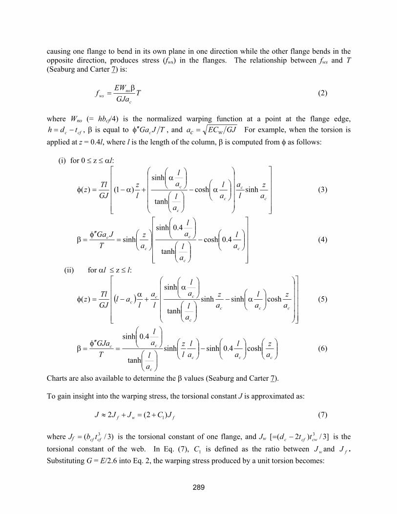
The torsional resistance provided by a wide flange member is the sum of the components due to pure torsion and warping:
wwp ECGJTTT (1)
where G, J, E, and Cw are the shear modulus of elasticity, torsional constant, modulus of elasticity, and warping constant, respectively. and are the first and third derivatives of the angle of twist with respect to the longitudinal (z) axis of the member. The warping torsion,
289
causing one flange to bend in its own plane in one direction while the other flange bends in the opposite direction, produces stress (fws) in the flanges. The relationship between fws and T(Seaburg and Carter 7) is:
TGJaEW
fc
nows (2)
where Wno (= hbcf/4) is the normalized warping function at a point at the flange edge,
cfc tdh , is equal to TJGac , and GJECa wc For example, when the torsion is applied at z = 0.4l, where l is the length of the column, is computed from as follows:
(i) for 0 z l:
c
c
c
c
c
az
la
al
al
al
lz
GJTl
z sinhcoshtanh
sinh)1()( (3)
c
c
c
c
c
al
al
al
az
TJGa
4.0coshtanh
4.0sinhsinh (4)
(ii) for l z l:
ccc
c
ccc a
zal
az
al
al
la
lal
GJTl
z coshsinhsinhtanh
sinh)( (5)
ccc
c
cc
az
al
al
lz
al
al
TGJa
cosh4.0sinhsinhtanh
4.0sinh (6)
Charts are also available to determine the values (Seaburg and Carter 7).
To gain insight into the warping stress, the torsional constant J is approximated as:
fwf JCJJJ )2(2 1 (7)
where Jf )3/( 3cfcf tb is the torsional constant of one flange, and Jw ]3/)2([ 3
cwcfc ttd is the torsional constant of the web. In Eq. (7), 1C is defined as the ratio between wJ and fJ .Substituting G = E/2.6 into Eq. 2, the warping stress produced by a unit torsion becomes:
290
c
nows
aJW
Tf
6.2 (8)
where
31
31 )2(4
33)2(
4
cfcfcf
cfno
t
hCtbC
hb
JW
(9)
Therefore, Eq. 8 can be re-written as:
ccf
ws
at
hCT
f3
1295.1 (10)
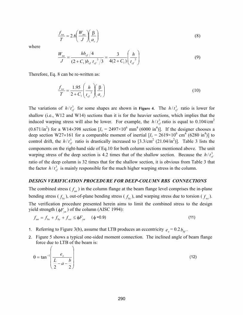
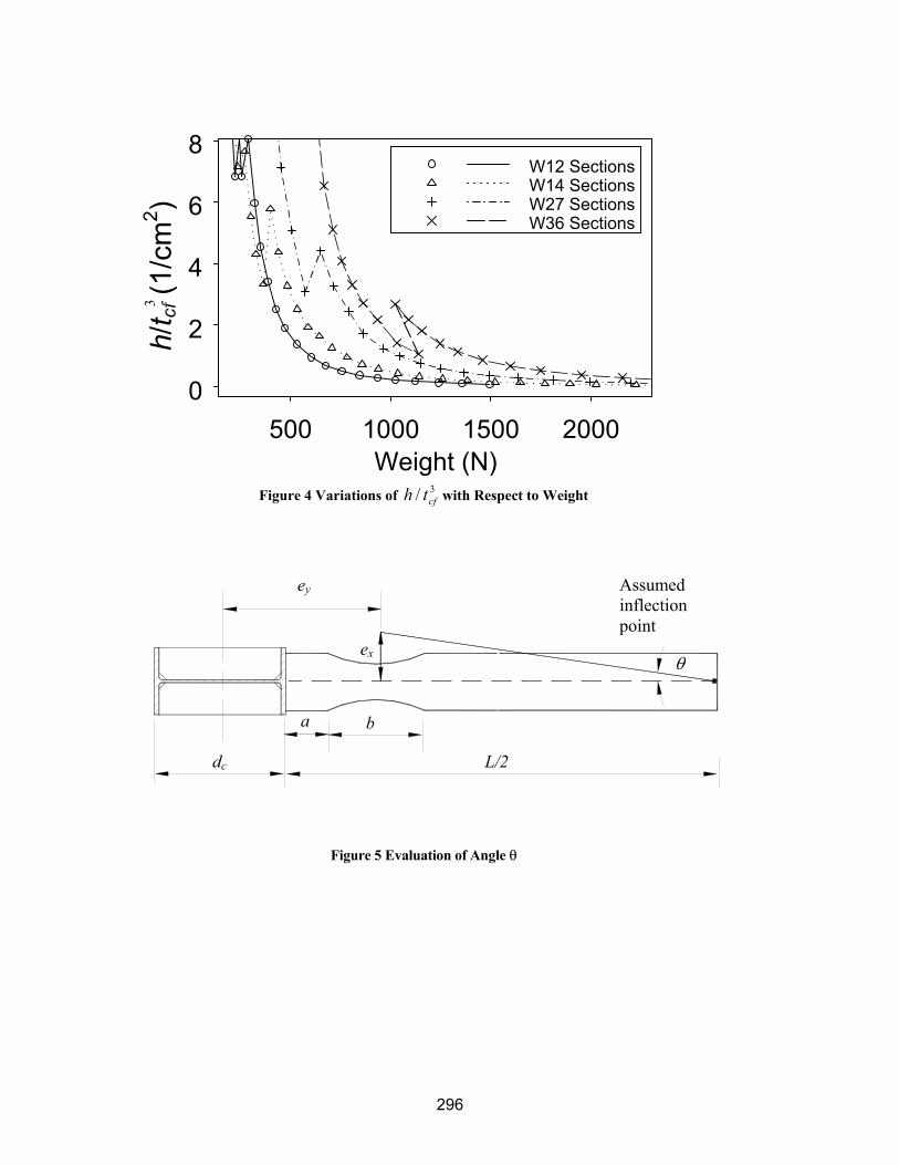
The variations of 3/ cfth for some shapes are shown in Figure 4. The 3/ cfth ratio is lower for shallow (i.e., W12 and W14) sections than it is for the heavier sections, which implies that the induced warping stress will also be lower. For example, the 3/ cfth ratio is equal to 0.104/cm2
(0.671/in2) for a W14 398 section [Ix = 2497×106 mm4 (6000 in4)]. If the designer chooses a deep section W27 161 for a comparable moment of inertial [Ix = 2619×106 cm4 (6280 in4)] to control drift, the 3/ cfth ratio is drastically increased to [3.3/cm2 (21.04/in2)]. Table 3 lists the components on the right-hand side of Eq.10 for both column sections mentioned above. The unit warping stress of the deep section is 4.2 times that of the shallow section. Because the 3/ cfth
ratio of the deep column is 32 times that for the shallow section, it is obvious from Table 3 that the factor 3/ cfth is mainly responsible for the much higher warping stress in the column.
DESIGN VERIFICATION PROCEDURE FOR DEEP-COLUMN RBS CONNECTIONS The combined stress (
unf ) in the column flange at the beam flange level comprises the in-plane bending stress (
bxf ), out-of-plane bending stress (byf ), and warping stress due to torsion (
wsf ). The verification procedure presented herein aims to limit the combined stress to the design yield strength (
ynF ) of the column (AISC 1994):
ynwsbybxun Fffff ( =0.9) (11)
1. Referring to Figure 3(b), assume that LTB produces an eccentricity xe = 0.2
bfb .2. Figure 5 shows a typical one-sided moment connection. The inclined angle of beam flange
force due to LTB of the beam is:
22
tan 1
ba
Lex (12)

291
3. The beam flange force can be estimated as: yebfbf FtbF (13)
wherebfb is the reduced beam flange width at the narrowest location, and Fye (= RyFyn) is the
expected yield strength. Strength degradation usually occurs at 4% story drift. Therefore, no strain hardening factor is included in Eq. 13.
4. The torsion produced by F in the column of a one-sided moment connection is [Figure 3(c)]:
)sincos( yx eeFT (14)
where22b
ad
e cy
. For a two-sided moment connection without a concrete slab, the
torsion in Eq. 14 is contributed by both beams; that is, T computed from Eq. 14 for each beam is assumed additive. Nevertheless, when a concrete slab is present and can be counted on to provide lateral bracing for the beam in positive bending, the torsion in Eq. 14 does not have to be doubled because it is only contributed by the beam under negative bending.
5. The warping stress, fws, is computed from Eq. 2. For a one-sided moment connection, the torsion is applied at the bottom flange level, and the warping stress is computed at the same location. This is also applicable to a two-sided moment connection with a concrete slab. For a two-sided moment connection without the benefit of concrete slab for lateral bracing, the column torsion contributed by both beams is applied at the mid-depth of the beams, but the warping stress is still computed at the bottom flange level, where the fbx value is the highest, in order to combine with fbx and fby in Eq. 11.
6. The in-plane bending moment produces the maximum column moment (Mc) at the beam flange level. This moment can be computed as the product of the column shear and the distance from the column inflection point to the beam flange level. (The Mc value is higher for two-sided moment connections). The strong-axis bending stress, fbx, due to this moment is:
xc
cbx S
Mf (15)
where Sxc is the elastic section modulus of the column.
7. The out-of-plane bending moment in the column is caused by the transverse component of the beam flange force (i.e., sinF ). Applying sinF at the compression flange level of the beam, and treating the column as simply supported at two inflection points, the out-of-plane bending stress, fby, can be computed by beam theory. This stress can be ignored for two-sided moment connections without slab because the force components tend to cancel each other out.
8. Check Eq. 11 to see if the combined stress is less than the design stress per Formula (H2-1) in the LRFD Specifications (AISC 1). If the combined stress is too high, the designer may consider changing the column size to obtain improved torsional properties. It was shown in Eq. 10 that 3/ cfth plays the most important role for the value

292
of warping stress. The selection should be guided to lower the 3/ cfth value. The most effective way to minimize the torsional problem is to add extra lateral bracing a short distance outside the RBS region to minimize the amplitude of LTB (
xe ). Experimental results showed that the maximum bracing force could reach 7% of the compressive force in the beam flange (Yu et al. 8). For design purposes, it is suggested that extra bracing be designed for 6% of the expected nominal strength of the beam flange. The third option to prevent column twisting is to brace the column flange instead of the beam flange.
SUMMARY AND CONCLUSIONS Based on both experimental results and analytical studies, the following conclusions can be made regarding the deep-column RBS moment connections: 1. Specimens DC-1 and DC-2 achieved 0.03 radian of plastic rotation. For both specimens, the
column flange connected to the beam experienced severe out-of-plane bending or column twisting. Specimen DC-3 experienced brittle fracture along the k-line of the column just before reaching 0.03 radian of plastic rotation.
2. Twisting in the deep column is caused by two factors: 1) RBS beams tend to buckle more laterally, introducing torsion in the column, and 2) the torsional property of deep sections tends to produce higher warping stress in the column. It was found that the high 3/ cfth ratio of the deep section was mainly responsible for the higher warping stress.
3. A verification procedure is developed for deep column RBS moment connections. In case twisting of the column is significant, providing extra lateral bracing near the RBS region is effective to minimize the torsional problem.
ACKNOWLEDGEMENTS Funding for this research was provided by the Federal Emergency Management Agency through the SAC Joint Venture. SAC is a partnership of the Structural Engineers Association of California, the Applied Technology Council, and California Universities for Research in Earthquake Engineering. This research was conducted as part of Task 7.11 in Phase II of the SAC Joint Venture. Mr. J.O. Malley was the Project Director of Topical Investigation. Mr. D. Long of PDM/Strocal donated the fabrication service.
REFERENCES [1] AISC (1993), Load and Resistance Factor Design Specification for Structural Steel Buildings, Second
Edition, Chicago, IL. [2] AISC (1997), Seismic Provisions for Structural Steel Buildings, Second Edition, Chicago, IL, with
Supplement No. 1 (1999). [3] Clark, P., Frank, K., Krawinkler, H., and Shaw, R., (1997) “Protocol for Fabrication, Inspection,
Testing, and Documentation of Beam-Column Connection Tests and Other Experimental Specimens,” Report No. SAC/BD-97/02, SAC Joint Venture, Sacramento, CA.
[4] Englehardt, M.D., (1998) “Design of Reduced Beam Section Moment Connections,” Proceedings, 1999 North American steel Construction Conference, AISC, pp.1-3 to 1-29.
[5] Gilton, C., Chi, B., and Uang, C.-M. (2000), “Cyclic Response of RBS Moment Connections: Weak-Axis and Deep Column Effects,” Report No. SSRP-2000/03, Department of Structural Engineering, University of California, San Diego, CA.
[6] SAC (1997), Interim Guidelines Advisory No. 1., FEMA-267A, SAC Joint Venture, Sacramento, Ca.
293
[7] Seaburg, P.A. and Carter, C.J. (1997), “Torsional Analysis of Structural Steel Members,” SteelDesign Guide Series 9, AISC, Chicago, IL.
[8] Yu, Q.S., Gilton, C., and Uang, C.-M. (2000), “Cyclic Response of RBS Moment Connections: Loading Sequence and Lateral Bracing Effects,” Report No. SSRP-99/13, Department of Structural Engineering, University of California, San Diego, CA.
Table 1 Specimen Member Sizes
Specimen Beam Size Column Size Doubler Plate DC-1 W36 150 W27 146 9.53 mm (3/8 in.) DC-2 W36 150 W27 194 N/ADC-3 W27 194 W27 194 15.9 mm (5/8 in.)
Table 2 Summary of Design Data
Specimen Flange Reduction
(%)
pdM(kN-m)
pdV(kN) )( yeb
f
FZ
M V
(kN)pzV
(kN) *
*
pb
pc
M
M
DC-1 50 2626 1001 0.90 2359 2780 1.45 DC-2 50 2626 1006 0.90 3097 2804 1.97 DC-3 43 2945 1113 0.92 3173 4236 1.78
Table 3 Comparison of Warping Stress Components
Section Type 12
95.1C 3
cfth
2
1cm ac (cm)
Tf ws
3
410cm
W14 398 0.893 0.104 89.2 0.48 5.00 W27 146 0.808 3.3 315 0.25 21.2

294
(a) Test Setup
(b) Typical Connection Details
Figure 1 Test Setup and Moment Connection Details
Plastic Rotation (% rad)
Mom
ent (
MN
-m)
-4 -2 0 2 4-4
-2
0
2
4
(a) Specimen DC-1
Plastic Rotation (% rad)
Mom
ent (
MN
-m)
-4 -2 0 2 4-4
-2
0
2
4
(b) Specimen DC-2
W14X370 (Typ)
FloorStrong
StrongWall
ActuatorHydraulic
1905
mm
1905
mm
Lateral RestraintColumn for
3581 mm (141 in)
(117 in) (24 in)2973 mm 610 mm
(75
in)
(75
in)
E70T-73/8Remove steel backing;Remove weld tabs
After root is cleaned and inspected
30
5/16E70T-7
5/8" Plate (A36)
1-1/16" Dia. Holes(For 1" Dia. A325 H.S.B.)
Typ. (A36)1" Stiffener Plate
3/165/16
E71T-8
451/4
E70T-7
Remove weld tabsSteel backing to remain;
303/8
E70T-7Weld steel backingto column
5/16

295
Plastic Rotation (% rad)
Mom
ent (
MN
-m)
-4 -2 0 2 4-4
-2
0
2
4
(c) Specimen DC-3 Figure 2 Global Response and Failure Mode
Figure 3 Eccentric Beam Flange Force to Column
ey
ex
y
x
F
A A
F sin F (ex cos ey sin )
F cos
(a) Deformed Beam at 4% Drift
(b) Inclined Beam Flange Force
(c) Forces Acting on Column
296
Weight (N)500 1000 1500 2000
0
2
4
6
8W12 SectionsW14 SectionsW27 SectionsW36 Sections
Figure 4 Variations of 3/ cfth with Respect to Weight
Figure 5 Evaluation of Angle
ey
ex
ba
dc L/2
h/t cf
(1/c
m2 )
3
Assumed inflectionpoint