Anti-hyperglyceamic Effects of Psidium guajava LINN Crude ...
Upload
khangminh22Category
view
3download
0
Advanced Closed Loop Controls of Refinery Off-site Operations
Dr. Suresh S. Agrawal Project Manager
ABB Industrial Systems, Inc. 1880 Dairy Ashford Road, #300
Houston, Texas 77077 (713) 497-3333
ABSTRACT
A typical refinery or any chemical processing plant has many activities which can be categorized into a number of areas such as feed and products preparations, material movement, stabilization and optimization of unit operations and information management. All refinery activities are further classified as either on-site or off-site operations. Most of the automation projects are focused towards on-site operations and neglect off-site operation such as oil movement and product blending. However, lately The viability of a plant depends on how strongly the plant management is committed to automate these areas to stay in today’s very competitive business. This paper discusses three of the major integrated automation systems, namely, Crude blending, products blending and oil movement and storage, for typical refinery activities and represent most of the benefits realized form automation. A refinery can save 10-14 M$/year in realized benefits by implementing these integrated systems. These systems are discussed in this paper only from concept points of view and their details are discussed elsewhere by the author.

- 2 -
1. Introduction
The activities of a typical refinery or any processing plant can be categorized into a number of major broad areas. The viability of a plant depends upon how these areas are managed and structured to meet operational requirements, market demand, fluctuating source and quality of raw materials and many other factors which are sometimes unpredictable and may be uncontrollable. Figure -1 shows the major activities in a typical refinery along with various sources of feed stocks and destinations of its products.
Plant resort to many methods to handle these uncertainties; one of them being the implementation of integrated computer systems to automate one or many of the important areas of concern. Table -1 below gives the refinery activity and related integrated computer control and / or optimization system for the activity.
Table - 1 Refinery Activity and Automation System
Refinery Activity Integrated System
• Feed Preparation Crude Blending Control & Optimization System
• Products Preparation Products Blending Control and Optimization
• Refinery Material Movement & Storage
1. Inter-process Units Oil Movement & Storage System
2. Terminal Operations (Dispatch & Receiving)
This paper discusses the scope and benefits of following three integrated computer control and optimization systems for the activities given in the above table.
1. Crude Blending Control and Optimization 2. Product Blending Control and Optimization 3. Oil Movement & Storage system.
Since details of each of the above systems is discussed separately elsewhere, this paper presents only overview of these systems to indicate their complexity and importance for an automated refinery.

CRUDE FEED PREPARATION
PRODUCTSPREPARATION
MATERIAL
MOVEMENT
OPERATION
STABILIZATIONOPERATION
OPTIMIZATION
INFORMATION
MANAGEMENT
Figure 1 Major Activities in a Typical Refinery

2. Crude Blending A typical refinery gets its crude supply from various sources that vary greatly in properties such as density, sulfur content and volatility, and consequently varies the feed quality to the crude unit. Ideally, the crude distillation unit in the refinery needs to be optimized on-line for yield and cut quality for product blending and other product slates for every crude feed, but may cause variation in the tower operational parameters and may not be desirable. Alternatively, crude oil from various sources may be blended upstream to produce an uniform feed to the crude unit.
The implementation of crude blending control and its integration with other sub-systems can achieve the following objectives.
• To minimize the dependency on the source for the crude feed properties and thus stabilize and optimize the operation of crude unit.
• To maximize the side-stream yields and optimize targeted side stream qualities for product blending.
• To improve crude oil inventory for just in-time manufacturing.
• To reduce demurrage cost by better planning and scheduling of crude unloading operations.
2.1 Integrated Crude Blending System
The benefits of crude blending by itself can not be realized unless it is integrated with other sub-systems for optimization, operational stability and just in-time manufacturing. These sub-systems can be categorized into two areas, namely, modules for crude quality control integration and modules for product quality control integration.

- 5 -
2.1.1 Crude Quality Control Sub-systems
The crude quality control sub-systems and their roles in integration are as follows:
No. Crude Quality Control Modules Purpose
I
Marine Planning and Scheduling
To interface with ships' arrival schedules and plan a strategy for unloading of crude into crude tanks based on the refinery operational targets.
II
Movement Task Monitor and Control
To automate the crude unloading operation into crude tanks based on the strategy planned by Module-I. This module is mainly responsible for Oil Movement and Control (OM&S) functions.
III
Crude Tank Composition Monitoring, Control and Optimize
To compute the composition and properties of each crude tank for current tank contents. This module also computes optimum crude mix recipe for each tank based on planned crude unloading and short-term refinery run plans for the crude units.
Above sub-systems are integrated only for the quality control of feed to the crude distillation unit and do not account for optimum operation of the crude distillation unit and product blending optimization. Implementation of only crude quality control modules would require the targeted properties of the feed to crude unit as manual input to module-III described above. Thus they would achieve only part of the benefits of over-all integration of both crude quality control and product quality control modules.
For example, target crude feed composition would depend upon the product blend optimization and target qualities of the side-streams of the crude unit. Feedback from the product quality control modules not only would compute the targeted crude feed composition but also set the targets for optimum operation of the crude unit.

- 6 -
2.1.2 Product Quality Control Sub-systems
The product quality control sub-systems and their roles in the over-all integration and feedback to the crude quality control sub-systems are as follows:
No. Product Quality Control Sub-
System Purpose
IV Crude Unit Model
To feedback the target crude feed properties to the crude quality control module-III to optimize the crude mix recipe for the crude unit. This module also set the target for the operations of the crude unit distillation unit for the module-II described below. This module closes the loop and integrates both product quality control and crude quality control modules.
V Crude Unit LP Optimizer
To optimize the operation of crude unit based on the target side-stream qualities and draw-off rate. This module uses model based control using LP algorithm.
VI Product Blending LP Optimizer
To optimize the recipe for product blending based on product specs, component qualities and availability and other constraints. This module uses the feedback from on-line blend header analyzer to adjust the setpoints of component flow rates. Tank quality integration adjusts on-line the target specs for the product tank during blending.
Figure -2 shows a graphical representation of crude quality control and product quality control sub-systems for an integrated crude blending, scheduling and optimizing system.
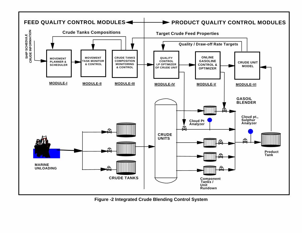
Figure -2 Integrated Crude Blending Control System
CRUDE TANKS
MARINEUNLOADING
MOVEMENTPLANNER &SCHEDULER
SHIP
SC
HED
ULE
CR
UD
E IN
FOR
MA
TIO
N
MODULE-I MODULE-II MODULE-III MODULE-IV
Crude Tanks Compositions
CRUDE UNITS
GASOILBLENDER
Cloud PtAnalyzer
Cloud pt.,SulphurAnalyzer
ComponentTanks /UnitRundown
ProducTank
ED QUALITY CONTROL MODULES PRODUCT QUALITY CONTROL MODUL
t
FE ES
MODULE-V
CRUDE UNITMODEL
MODULE-VI
Quality / Draw-off Rate Targets
Target Crude Feed Properties
ONLINEGASOLINE
CONTROL &OPTIMIZER
MOVEMENTTASK MONITOR
& CONTROL
CRUDE TANKSCOMPOSITIONMONITORING& CONTROL
QUALITYCONTROL
LP OPTIMIZEROF CRUDE UNIT

- 8 -
2.2 Feasibility of Crude Blending in a Refinery
The cost / benefits analysis to determine the feasibility of crude blending is complex and different from the product (gasoline, middle distillates) blending because of operational and physical constraints. It is very important to analyze these constraints in details to determine the feasibility of crude blending. A scoping study should examine at least 4 months' data of oil movement & storage activities in the crude oil area.
2.2.1 Operational Data Analysis
Oil movement & storage (OM&S) activities in the crude oil area should be analyzed for the following information.
• Types of OM&S activities and their relative distributions
• Crude oil types and their receipt volumes
• Schedules of marine unloading
• Schedules of crude types and their feeding to crude units
• Relative percentages of transferring slop ( volumes and occurrence frequencies ) from other process units.
A typically refinery handles 40-50% of all products by weight with only 5-8% OM&S activities in the crude oil area. Major transfer activities in the crude oil area are: "tank to tank," "tank to unit" and "unit to tank" and constitute about 85-90% of all crude oil area activities.
2.2.2 Operational and Physical Constraints
The result of the crude oil area transfer activities will determine the basis for the feasibility of crude blending as it will show the operational and physical constraints for its feasibility. Some of these constraints are discussed below for a typical refinery.
• Insufficient number of crude tanks for blending -- This may be due to types of crude processed, downstream processing demands, ships' schedules, etc.
• Lack of free space to install new crude tanks and / or pipelines - This may be physical limitation despite the economic feasibility of crude blending.

- 9 -
• Segregation of crude types and allocation of specific crude tanks for them -- Low sulfurs crude and high sulfur crude will be kept in separate tanks to avoid contamination.
• Recirculations and "tank to tank" transfer activities -- Recirculations of feed tank may limit its use for blending.
• Configurations of "tank to unit" activities in crude oil -- This is operational constraint as it determines the feasibility of blending of crude before feeding to unit. For a typical refinery with two crude units, there are four types of "tank to crude unit" transfer activities and are as follows:
1. One tank feeds to one crude unit only.
2. One tank feeds to both crude units.
3. One tank feeds to both crude units simultaneously and another tank also feeds to one of the crude units.
4. Both tanks feed to both units simultaneously.
Figure - 3 shows the configurations of "tank to unit" transfer activities.
Figure -3 Configuration of tank to Units Transfer Activities
Task Type - I
Task Type - I I
Task Type - I I I
CrudeUnit - I
CrudeUnit - I I
CrudeUnit - I
CrudeUnit - I I
1
2
1
CrudeUnit - I
CrudeUnit - I I
1
2
CrudeUnit - I
CrudeUnit - I I
1
2
Task Type - IV

- 10 -
2.2.3 Configurations of Blending Schemes
It is clear from the previous section that the configuration of blending scheme for crude depends greatly on the operational and physical constraints and may defeat the economic advantages. There are three following scenarios for the blending of crude.
1. "Ships to tanks" blending
2. 'Tank to tank" blending for crude feed
3. Inline blending from tanks to units
Figure - 4 shows various schemes for unloading and blending of crude from ships to tanks. Transfer types I and III unload crude oil into tanks directly and later may be blended from tank to tanks to prepare the final crude feed. However, integration of scheduling and tank inventory and composition modules, as discussed earlier in paper, will be necessary to implement any blending schemes. Such integration of application modules would alleviate some of the physical and operational constraints.
Ship -1 Crude - A
Ship -1 Crude - A
Ship -1 Crude - A
Ship -1 Crude - B
Task Type - I
Task Type - I I
Task Type - I I I
Figure -4 Configuration of "Ship to Tank" Transfer Activities

- 11 -
At any given time both physical and operational constraints govern the feasibility of one blending scheme over another. For example, physical constraints such as availability of crude tanks will determine the feasibility of for crude unloading and its blending into tanks at the same time or later for tank to tank blending configuration. On the other hand, operational constraints will determine the need for inline blending to crude unit.
It is important to realize that although the integration of all modules discussed earlier in this paper would stabilize the quality of feed to distillation unit to achieve the product quality targets and improve the operational stability of distillation unit, there may be situation where individual module is implemented for one reason or other. For example, if physical constraints do not permit for "ship to tank" or "tank to tank" blending of crude oil, inline crude blending to crude unit can accomplish the same objective to certain extent. It is worth to note here that tank to tank bending has more degrees of freedom (depending upon number of available crude storage tanks) than inline blending to crude unit. In inline blending scheme, crude oil are blended usually for density control purpose only since the API density determines the crude distillation curve.
3. Products Blending Blending of products such as gasoline, diesel and fuel oils has become increasingly complex process and demanding because of competition and new EPA regulations for the new formulated gasoline. Refineries suffer big economic losses due to quality giveaways of Octane and RVP, time lost in reblending, not meeting markets demands because of inadequate product inventory due to shortage of tanks, etc. The refining industry around the world is placing emphasis on automation of their refining and blending operations using latest technology to meet the market demands of tomorrow and stay in today’s’ cut throat business.
This paper discusses the essential elements of an integrated blend control system for the planning, control and optimization of their blending operations. This paper also presents the system architecture of an integrated blend control system using the state-of-the-art equation solver and optimization tools, blend models, software and hardware sets. The paper also discusses tangible and intangible economic benefits of an integrated blend control system.

- 12 -
3.1 Automation Levels of Blending Control
In the earlier years, before the advent of computers and digital instrumentation, refiners and others plants used to perform blending totally in a manual manner or “bucket mixing” approach according to predetermined proportions of ingredients. Severe competitions, decline in profits, scarcity of raw materials forced refiners to consider other methods to stay in business. A three levels of blending control strategy have evolved over last 15 years in the refining business and they are discussed briefly in the following paragraphs.
1. Regulatory Blend Control (RBC)
First level of blend control strategy resides in a DCS such as ABB MOD-300, Honeywell TDC-3000, Fisher ProVox, etc. and controls the amount of each component in the final product tank automatically by computer. Although this level of computer does not give any guarantees to blend the product to specifications as it does not use any analyzers feedback, it does relieve the operator from monitoring the process continuously.
2. Advanced Blend Control (ABC)
Second level of blend control strategy is a scheme which is implemented in another computer such as VAX, HP Work-station, IBM, etc. and is linked to DCS executing the first level of control. This control uses the analyzers feedback, corrects the recipe frequently and guarantees the final product on specifications. This is very complex technology and saves the refinery lots of money because of continuous optimization and feedback.
3. Off-line Optimization and Planning System (OOPS)
Third level of blend control strategy is off-line optimization of a blend recipe taking into account the refining process as expected in advance. This is done on a Personal Computer (PC) by a refinery planner and then he downloads the optimized recipe to on-line blend control (ABC) system for further on-line control and optimization and is finally executed in DCS by RBC. The planner typically may plan many recipes at one time depending upon refinery operational characteristics.
Figure -5 shows all levels of blend control, optimization and planning system modules in an integrated environment.

- 13 -
REGULATORYRATIO CONTROL
OFF-LINEOPTIMIZATION& PLANNING
ON-LINEADVANCEDCONTROL &
OPTIMIZATIONMAINTAINS A RECIPE
BLEND BATCH CONTROL
NO ON-LINE OPTIMIZATION
NO ANALYZER FEEDBACK
NON-LINEAR BLENDING MODELS
PROPERTY PREDICTIONS
NON-LINEAR OPTMIZATION
ANALYZERS FEEDBACK
ECONOMICS
MULTI BLENDS REQUIREMENTS
MARKETING DEMANDS
OPTIMIZATION-ECONOMICS &
INVENTORY
BLEND SEQUENCE
NON-LINEAR MODELS
INFO
RMAT
ION
BREA
K-DO
WN INFO
RMATIO
N COM
PLEXITY
DCSOPERATOR
ENGINEER
PLANNER
W ORK-STATION
X- TERMINAL
FC
FCFC
FC
FC
ANALYZERS
Figure -5 Control Levels of A Blending System

- 14 -
3.2 Integrated Products Blending System
Integrated blend control, optimization and planning systems are implemented separately for the blending of middle-distillate and motor gasoline products in a refinery. Such an integrated system usually consists of the following minimum numbers of modules and are integrated through a Relation Database Manager System (RDBMS) such as Oracle, Interbase, Informix, Sybase, etc..
• Regulatory Blend Control System (RBC)
• On-line Blend Control and Optimization System (ABC)
• Off-line Optimization, Planning and Scheduling System (OOPS)
• Tanks Inventory Information System (TIMS)
• Tank Quality Information and Management System TQIMS).
• On-line Blend History and Diagnostic Analysis.
• Blend Performance Analysis and Model Regression.
• Blends Information and Management System.
Figure -6 gives a typical architecture of an integrated blend control, optimization and planning system. The modules in the Figure -6 represent the minimum requirement for an integrated system. Although there are some other modules desirable in a more flexible and robust system, they will not be discussed in this paper.

Figure 6 Architecture of An Integrated Blend Control, Optimization and Planning System
- 15 -
REFINERY INFORMATION MANAGEMENT SYSTEM DATABASE
REGULATORYRATIO CONTROL
BLEND TANKSQUALITIES
MANAGEMENT
LABORATORYINFORMATIONMANGEMENT
SYSTEM (LIMS)
BLEND RECIPESMANAGEMENT
FLOW RATEESTD TIM E
GROSSCORRECTEDNETVOID
317.2314.6298.2335.8
273.1
256.7
VOLUM E, M 3 WEIGHT, TONS
49.3 M3/Hr5.46 Hrs
0
40
20
60
80
100 639
317
0
(% ) Volume (M3)
0
9700
(m m) Level (limit)
4850 250.8679
Maximum
Minimum
LevelTemperatureDensity
TANKSINFORMATIONMANAGEMENTSYSTEM (TIMS)
TANK FARM BLENDERS
OFF-LINEOPTIMIZATION &
PLANNING SYSTEM
ANALYZERS
RONMON RVP DIST
PTS
ON-LINE CONTROL& OPTIMIZATION
SYSTEM
BlendlineQuality Control& Optimization
Tank QualityIntegration
BlendingTargets
Non-linearOptimizer
SAM
PLES
TAN
K G
AU
GIN
G
TANK GAUGING
REC
IPE
SETP
OIN
TS
ANALYZER FEEDBACK
RATIOSETPT
BLEND DATA
BLENDSINFORMATIONMANAGEMENT
SYSTEM
BLENDS DIAGNOSTIC

.
4. Oil Movement & Storage
The functional capabilities of an Oil Movement and Storage (OM&S) system is primarily concerned with the transfers of bulk liquids within and across the refineries boundaries. Unlike the long-term, continuous, steady-state and complex operating characteristics of the processing units, these bulk movements tends to be batch operations of comparatively short duration, imposing relatively simple control requirements. However, what makes the transfer activities tedious, performed manually, in a refinery is not the nature of their control functionality but factors like their numerous types, large number of repetitions subject to inefficiencies, operating problems and economic loss, etc.
This paper gives an overview of the typical refinery oil movement activities, problems connected with them and concepts of automation of an Oil Movement and Storage (OM&S) system.
4.1 Refinery OM&S Activities and their Interactions
Typical an oil movement and storage operation in an refinery involve efficient management of
100-300 Tanks 100+ Pumps 100-200 Remote Operated Valves (ROV's) 50+ Mixers 100+ Flow, Temperatures and Pressure inputs 2000+ Manual valves
These equipment and tanks may be involved in one or more of the following activities:
• Receipts of Raw Material and / or shipment of Products using marine / truck / Rail cars/ Barges / Pipeline
• Tank-to-Tank Transfer
• Process unit feeds and rundowns
• Custody Transfer / Meter Proving
• Product Batch / Inline Blending
- 17 -
• Recirculations
• Seasonal Storage of Materials
• Water Drainage
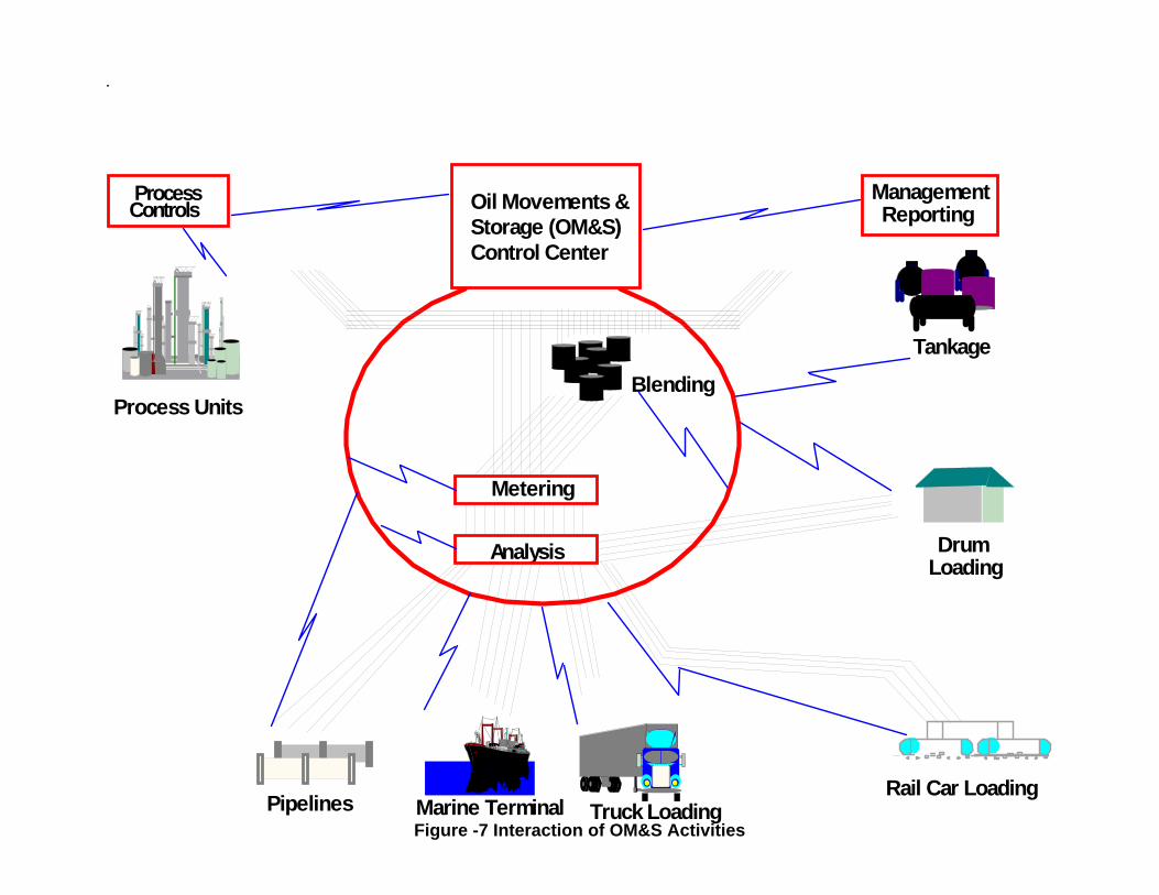
There may be as many as 80-90 different types of jobs or tasks involving these activities per day and theses activities not only require constant attention of the OM&S operator for the management of these tasks but they are highly interactive in nature, making them subjected to possible product contamination and accidents.
Figure - 7 shows a graphical representation of the interaction of various OM&S activities.
4.2 Problem Areas of OM&S Activities
It is quite natural that the management of such a large and complex network of equipment and transfer activities in a refinery and has some problems associated with it. Problems typically associated with OM&S activities can be classified into the following four areas:
1. Decrease in Plant Profitability
2. Operating Losses
3. Product Losses
4. Operating Costs
Following sections will discuss each of the above problem areas in detail.
4.2.1 Decrease in Plant Profitability
The plant profitability may be decreased due to the following factors. • Product quality and / or quantity giveaway - encountered in activities like
blending and custody transfer due to lack of inline blending and accurate measurements.
Oil Movements & Storage (OM&S) Control Center
ManagementReporting
ProcessControls
Analysis
Metering
Tankage
DrumLoading
Process Units
Pipelines Marine Terminal Truck LoadingRail Car Loading
Blending
Figure -7 Interaction of OM&S Activities
.

- 19 -
• Product degradation due to displacement of previous line material - This happens if same pipeline segment is used to transfer products of different qualities in activities such as tank to tank transfer, tank to ship transfer, etc. The product degradation usually requires either selling the product at lower price or quality correction by reblending or addition of corrective components.
4.2.2 Operating Problems
Operating problem vary from the areas related to man/machine interfaces to errors by the filed operators and may result into economic losses. Some of most common operating problems are: • Multiple Operator Interfaces - It is one of the major concerns of the
OM&S operations in a refinery as the operator has to work with as many as 7-8 different types of displays and systems such as tank gauging system, DCS workstations, blend control, MIS computer, Laboratory Information system and at times reduces his /her effectiveness and results into operational errors which may be at times very expensive for the refinery's profitability.
• Lineup Errors - The refinery has a very complex network of pipelines and field equipment. To lineup various valves, pumps, etc. for a transfer activity requires careful execution and may result into product contamination if any errors are made in the lineup. Lineup activity by itself is also time consuming and requires the availability of field operators in timely fashion.
• Product Contamination - This may be result of either lineup errors or due to unplanned or unauthorized movements.
• Pump cavitation - This situation could occur if the valve before the pump is stuck or does not open fully. Failure of valve downstream of the pump could also damage the pump.
• Floating Roof Sinking - This problem may occur if the liquid in the tank may fall below a certain level due to lack of timely action by the operator due to failure of low level alarm.

- 20 -
4.2.3 Product Losses
The direct effect of product losses is the decrease in the plant profitability and the followings factors contribute to this problem area. • Inadequate and /or Erroneous Measurements - OM&S activities
involving movement of products across the refinery boundaries such as custody transfer, marine loading / unloading may incur product losses just due to inadequate or erroneous measurements.
• Unplanned and unauthorized movements - This is related to human error either by the operator and /or field operators. The product loss may occur either in terms of need to reprocess the contaminated products or sell at lower price due to its downgraded quality.
• Leaks - Products leaks from valves and tanks result not only in products losses but also present environmental hazards.
• Spills - Unattended tank during its filling or failure of high level alarm may cause spills and thereby product losses and environmental hazards and clean-up cost associated with it.
4.2.4 Operating Costs
In addition to economic loss to the plant by problems areas discussed in earlier sections, plant may also incur increase in operating cost due to the following factors: • Large Plant Inventory - In the absence of any on-line and timely
information and availability of raw material and finished products, plant resorts to having a large plant inventory. Storage cost, unnecessary movement of products, not being able to respond to all market demands and fluctuation are some of the factors attributing to increased operating cost.
• Under-utilized tank Capacities - OM&S operators at times tend to fill tanks at levels lower their maximum due to fear of tank spills and failure of alarm. This results into under utilization of tank capacities and increase in operating cost as enough raw material and / or product may not be available for manufacturing or shipment.
• Wasted Energy - Electric utilities cost increase as the transfers are either repeated due to human error or execution of avoidable transfer activities.
• Demurrage Charges - This is quite substantial loss to the refinery in terms of demurrage charges payable to shipping companies due to

- 21 -
delays in marine loading and unloading and ships have to wait at port longer than necessary.
• Large Man-power - Manual operations of opening and closing of valves, pump start / stop sequences require a large number of field operators for the transfer activities. In addition to that, more maintenance personnel are also needed to maintain the field equipment to repair them in time.
• Improper and untimely Reports - Lack of any automation and / or implementation of information system may not provide inventory reports in timely and accurate fashion for day to day planning cycle of the refinery operation.
Most of the problems in areas discussed in the above sections can be either eliminated or reduced by implementing computer automation of oil movement and storage. Next sections will discuss some of the concepts and features of the automation of OM&S available today in the market.
4.3 Computer Automation of OM&S
The automation of oil movement and storage operation requires that the computer system to respond to the needs of the operator to perform the major functions discussed below.
4.3.1 Functionality
1. Utilize remote readings from tank gauges to:
• Calculate inventories, conditional events, total volumes shipped.
• Monitor tanks for improper movements, alarm on high, low levels.
2. Respond to field element status:
• Monitor remotely operated valves (ROV's), pumps and mixers for alarm conditions and proper response operator requests.
• Keep a list of out-of-service equipment.
• Provide status information to operator.
3. Monitor and control movements for receipts, rundowns, transfers and shipments.
4. Select equipment (tanks, valves, pumps, etc.) for moves required in the schedule.

- 22 -
5. Automatically sequence equipment to implement and terminate moves.
6. Terminate movements, swing tanks, start other movements, etc. when specified conditions are met.
7. Provide interfaces between DCS and supervisory level controls of in-line blenders and equipment sequencing, movement monitoring and customer's blend control strategy programs.
8. Provide summary reports, movement logs and profiles which are defined by the customer.
9. Utilize shared disks to support computer to receive operating data and to transmit historical data.
Above characteristics of a well designed and developed OM&S computer system provides interfaces and interaction among all activities of OM&S operations in a refinery. Figure - 8 shows the flow of information among OM&S activities and OM&S computer system.
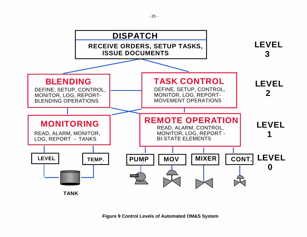
4.3.2 Levels of OM&S Control Functions
The functionality of automated OM&S system can be translated into various control levels, as shown in Figure - 9., are discussed below:
• Level - 0 - This is the lowest level at which all field equipment such as pump, ROV, mixer and control valve are controlled by the electronic system. Tank levels and temperature are also monitored at this level.
• Level - 1 - This level is called the supervisor control where a computer system either monitors the status of process variables, field equipment status and send the command for the remote control operation. For example, instead of starting or stopping a pump from the field or remote panel, the operator could issue a command from the computer to operate an valve or pump. Tank gauging systems such as Wessoe and Varec provide computer interfaces to monitor the tank levels and temperatures.
• Level - 2 - This level involves extensive application programming and offers the maximum of benefits of automation. Various steps of executing an OM&S activity are automated at this levels and categorized into separate modules such as task definition, sequence generator and control, task monitor, etc. Blending is also implemented at this level.
• Level - 3 - This is the top most level and is usually termed as information
system level. Information about various refinery activities such as

- 23 -
planning, scheduling, shipping and dispatching is collected at this level and interfaced with OM&S control modules for over-all integration of the system.
4.3.3 System Integration
The components of an integrated OM&S computer system would depend upon the status of automation and refinery information system in a particular refinery and the computing platforms of the OM&S system. For example, commercially available OM&S system either from IBM or Honeywell include blending as one of the modules. OM&S algorithm as such does not include any linear programming (LP) algorithm whereas the inline blending uses either LP and non-linear equation solver and optimization using non-linear blend models depending upon the type of product blend. In addition to this, a truly integrated OM&S system must interface with the refinery's information management system for history, databases, reports, reconciliation, etc. This results into customized integration of OM&S system for each refinery and may involve developing many interfaces for various modules and computers.
Figure - 10 shows a typical automation architecture of an OM&S system.

- 24 -
Receiving Dispatching
MovementAutomation
TankageMonitoring
BlendingOptimization
Plansand actual
Plans andlab results
Plansinventoriesqualities
Blenders
Receipts
Tankage
QuantityQuality
LevelsAlarmsTemps
QualitiesFlows
Plants
QuantityQuality
Exports
PumpsValves
ShipInformationMovement
Plans
OrdersPlansOIL MOVEMENT &
CONTROL CENTER
Figure -8 Computer Automated OM&S System
- 25 -
MONITORINGREAD, ALARM, MONITOR,LOG, REPORT - TANKS
LEVEL 3
LEVEL 2
LEVEL 1
LEVEL 0
LEVEL TEMP.
TANK
MOV
DISPATCHRECEIVE ORDERS, SETUP TASKS, ISSUE DOCUMENTS
BLENDINGDEFINE, SETUP, CONTROL,MONITOR, LOG, REPORT-BLENDING OPERATIONS
TASK CONTROLDEFINE, SETUP, CONTROL,MONITOR, LOG, REPORT-MOVEMENT OPERATIONS
REMOTE OPERATIONREAD, ALARM, CONTROL,MONITOR, LOG, REPORT -BI-STATE ELEMENTS
PUMP MIXER CONT.
Figure 9 Control Levels of Automated OM&S System

- 26 -
TASKCONTROL
REFINERY W IDE DATA BASE
TASK M ONITORING
TANKM ONITORING
REGULATORYBLENDING
ADVANCEDBLENDING
ECONOMICDATA
TANKQUALITY
BLENDREPORT
BLENDRECIPE
UNITDATA
TASKDEFINITION
TANKDATA
TASKHISTORY
PLANT MANAGER LAB SYSTEM TICKET/DISPATCH ENGINEERPRODUTIONSCHEDULER
OFFSITESSUPERVISOR
TASK STATE
ELEM
ENTS
STA
TES
REC
IPE
PRO
PER
TY
TASK
DEF
N
O IL M OVEM ENT & STORAGE SYSTEMPROCES UNITS BLENDING CONTROL
Figure -10 Architecture of a Typical Integrated OM&S System

- 27 -
5. Benefits
An integrated blend control and optimization system offers great economic benefits for a typical refinery and various modules discussed in this paper offer both tangible and intangible benefits. Table - 2 shown below summarizes typical range of average benefits for a 100,000 Bls/day refinery. Typical payback period for the implementation of an integrated blending system is usually 1-2 years.
Table 2 Tangible Benefits of Integrated Advanced Control Systems
Integrated SystemPotential Benefits
($M/Year)
• Crude Blending Control and Optimization System 2-3
• Products Blending, Control & planning System 5-7
• Oil Movement & Storage System 3-4
Total 10-14
6. Summary
This paper has discussed the concepts of three major integrated control systems which can save a refinery between 10-14 M$/Year in benefits. However, these systems can be implemented in phases to realize the for each one of them individually. Since oil movement and storage system is used for both of blending system, it must be implemented first keeping in mind the over-all integration of all three and other computer systems in the plant.

- 28 -
References 1. Agrawal, S. S., “Implementation Of Advanced on-line Blend Control,
Optimization And Planning Systems In Mexican Refineries”, presented at NPRA’96 Computer Conference, Atlanta, Georgia, U.S.A., November 9-12, 1996
2. Agrawal, S. S., "Economic Justification of an Oil Movement and Storage Control System", presented at ISA’96 Conference and Exhibit, Chicago, Illinois, U.S.A., October 9-12, 1996
3. Agrawal, S. S., "Scope of an Integrated Oil Movement & Storage (OM&S) Control System", presented at ISA’95 Conference and Exhibit, New Orleans, Louisiana, U.S.A., October 1-6, 1995
4. Agrawal, S. S., "Integrate Blending Control, Optimization and Planning ", Hydrocarbon Processing, Vol-78, No. 8, August, 1995, pp.129-139.
5. Agrawal, S. S., "Scope and Feasibility of Integrated Crude Blending Control and Optimization System", presented at ISA’94 Conference and Exhibit, Philadelphia, U.S.A., May 9-12, 1994.
6. Advanced Process Control handbook IV, Hydrocarbon Processing, March 1989.
7. Agrawal, S.S., "Computer Integrated Manufacturing (CIM) for Process Industries - A Perspective", presented at BIG' 90 conference, Pune, India, May 23-25, 1990.
8. Agrawal, S.S., "Functional Requirements for Integrating MIS with Advanced Controls", Presented at the Sixth Annual Control Engineering Conference, Chicago, Illinois, U.S.A., May 19-21, 1987.
9. Agrawal, S.S., "Modular Requirements to Integrate MIS with Computer Control Systems", Presented at ISA International Conference and Exhibit, Anaheim, California, U.S.A., October 4-8, 1987.
10. Agrawal, S.S., "PC Based Distributed Supervisory Control for Process Industries", presented at ISA Bombay Chapter conference, Bombay, India, May 5-6, 1991.
11. Bain, M.L., Mansfield, K.W., Maphet, J.G. et. al, “Gasoline Blending with an Integrated On-line Optimization, Scheduling and Control System”, Paper no. CC-93-131, NPRA Computer Conference, New Orleans, Nov. 17-17, 1993

- 29 -
12. Brooks, Robin, “Experiences with Oil Movements and Storage (OM&S) systems within Integrated Refinery Management Systems”, CC-93-128, Proceedings of NPRA Computer Conference, New Orleans, November 1993.
13. Czech, Robert S., “The Application of Computer Systems in Refinery Oil Movement Operations”, Proceedings of ISA Conference, Philadelphia, May 1983.
14. Dunmyer, J.L. and Bailey, H.O., “Gasoline Blending - Getting the Job Done Correctly”, Paper no. AM-89-11, NPRA Annual Meeting, San Francisco, March 19-21, 1989
15. Espinosa, A., Sanchez, M. et. al., “On-line NIR Analysis and Advanced Control Improve Gasoline Blending”, Oil & Gas Journal, pp 49-56, Oct 17, 1994.
16. Kuo, C.J., “Computer Simulates Refinery Oil Transfer”, Oil & Gas Journal, Jan 21, 1980, pp. 59-62.
17. McDonald, J.M., Grupa L.M., McKibben and M.P., Donald, E.R., “Gasoline Blending Using NIR Spectroscopy and LP Optimization”, Paper no. CC-92-137, NPRA Computer Conference, Washington D.C., Nov. 16-18, 1992
18. Oil Movement & Storage , Sales Brochure, Honeywell, Inc.
19. Oil Movement Control System Application Summary, Control Data Corporation, Publication no. 96767740
20. OM&S General Information Manual, IBM Process Plant Computing Center, Greenford, Middlesex, UK 1993
21. Osvaldo, S., Critchley, J., et. al, ”Blend Planning and Scheduling at Engen’s Durban Refinery”, Paper no. CC-93-133, NPRA Computer Conference, New Orleans, Nov. 17-17, 1993
22. Paul, T. L., “On-line RVP Analysis Improves Gas Blending”, pp 31-33, INTECH, September, 1994.
23. Serpemen, Y. , Baumeister, K.H., at. al, “Practical Experience and Results with an Advanced On-line Gasoline Blend Optimization System”, Paper no. AM-89-09, NPRA Annual Meeting, San Francisco, March 19-21, 1989
24. Tennessen, R.H. and Di Nello, R.P, “Closing the Loop Between Blending Operations and Planning and Scheduling”, Paper no. CC-93-135, NPRA Computer Conference, New Orleans, Nov. 17-17, 1993
Copyright © 2022 FDOKUMEN