Crankshaft assembly 03
80
Crankshaft assembly 03
-
Upload
khangminh22 -
Category
Documents
-
view
0 -
download
0
Transcript of Crankshaft assembly 03

Crankshaft assembly 03

Crankshaft assembly 03
Job No.
Checking, replacing and torquing conrod bolts .................................Reconditioning and checking angles on bearing bores ...........................Removal and installation of pistons .........................................Checking and reconditioning crankshaft ......................................Installation of crankshaft bearings ........... _ ..............................Replacing front crankshaft radial seal .......................................Replacing rear crankshaft radial seal ........................................Removal and installation of grooved bail bearing in crankshaft ......................Removal and installation of vibration damper ..................................Checking and correcting setting of TDC pulse generator ..........................Removal and installation of crankshaft gear ...................................Removal and installation of flywheel or flex plate ...............................Remachining flywheel ..................................................Replacing ring gear on flywheel ...........................................
03 - 3100 3 - 3 1 3
. -316
. -318
. - 320
. - 324
. - 327. - 330. - 342. - 345. - 350* -410. - 420. - 430
03il
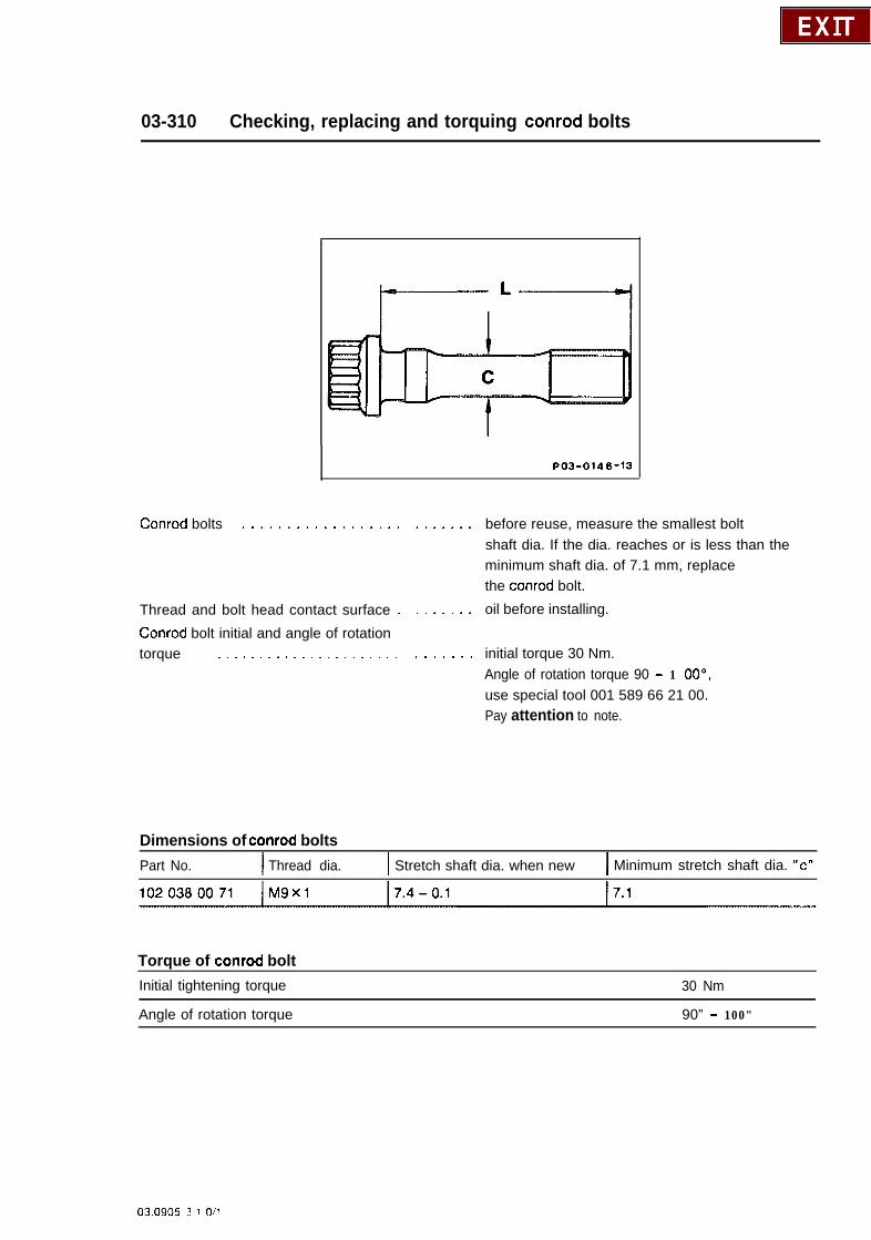
03-310 Checking, replacing and torquing conrod bolts
PO3-0146-13
Conrod bolts . . . . . . . . . . . . . . . . . .
Thread and bolt head contact surface .
Conrod bolt initial and angle of rotationtorque . . . . . . . . . . . . . . . . . . . . . .
Dimensions of conrod bolts
. , . . . . * before reuse, measure the smallest boltshaft dia. If the dia. reaches or is less than theminimum shaft dia. of 7.1 mm, replacethe conrod bolt.
. . . . . . . oil before installing.
. . . . . . . initial torque 30 Nm.Angle of rotation torque 90 - 1 OO",use special tool 001 589 66 21 00.Pay attention to note.
Part No. I Thread dia. I Stretch shaft dia. when new I Minimum stretch shaft dia. “c”
Torque of conrod boltInitial tightening torque
Angle of rotation torque
30 Nm
90” - 100"
03.0905 3 1 O/l
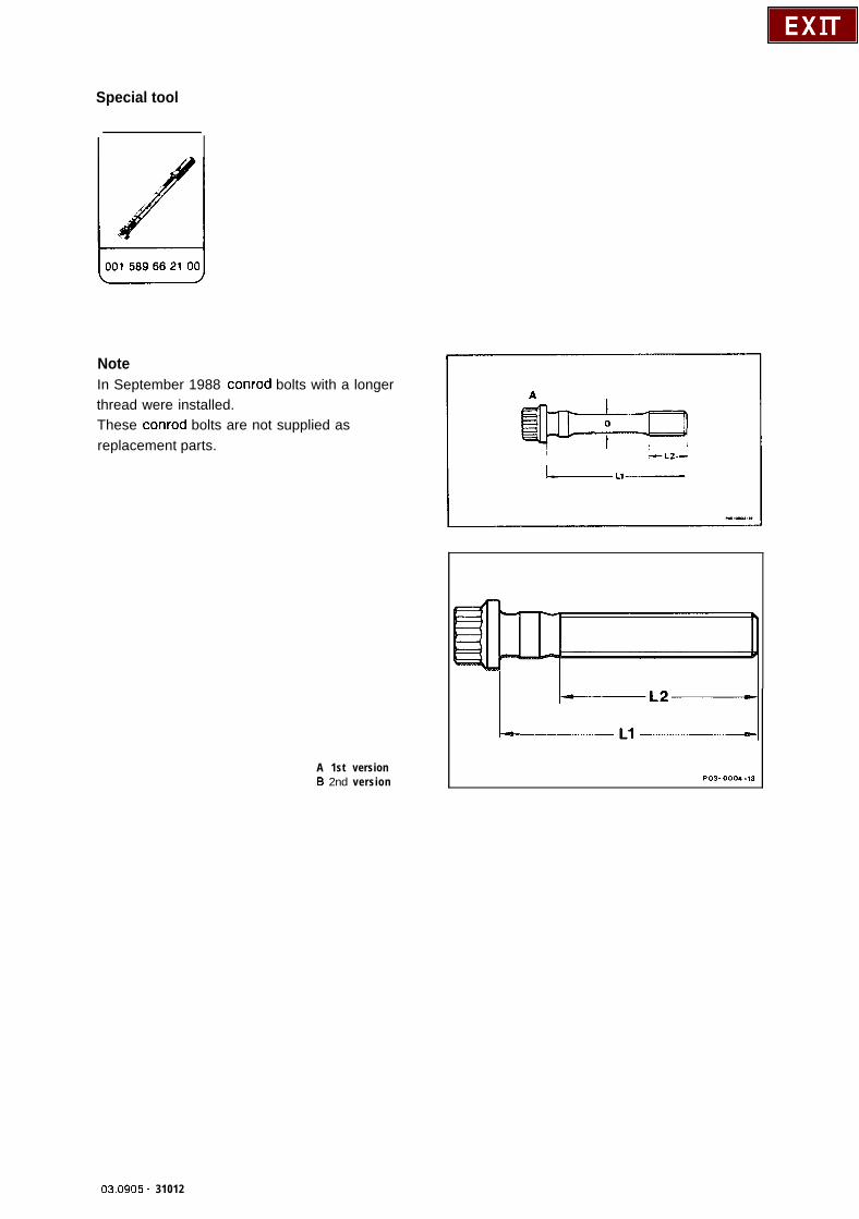
Special tool
NoteIn September 1988 conrod bolts with a longerthread were installed.These conrod bolts are not supplied asreplacement parts.
A 1st version6 2nd version
L---e-----
03.0905 - 31012
Standard imolementation: 09/86
Model
201.028
Engine
102.985
Engine End No.
Manualtransmission
Automatictransmission
027063 - 028449 I 076715 - 077418
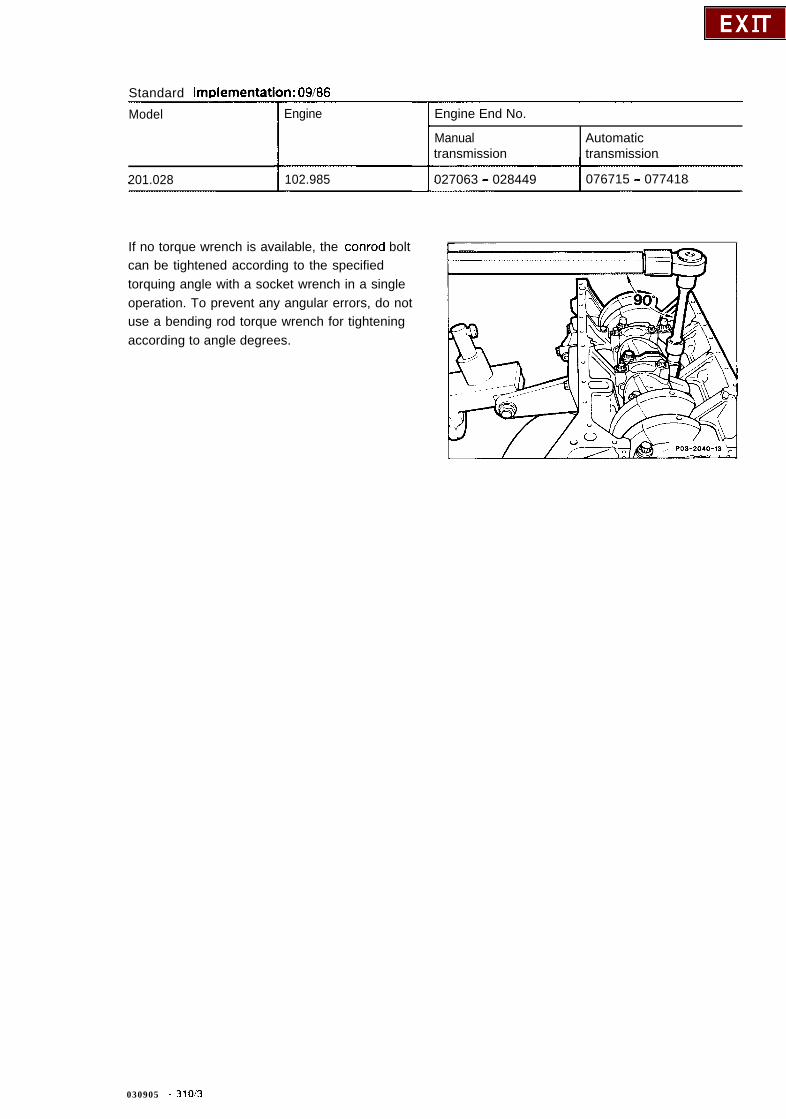
If no torque wrench is available, the conrod boltcan be tightened according to the specifiedtorquing angle with a socket wrench in a singleoperation. To prevent any angular errors, do notuse a bending rod torque wrench for tighteningaccording to angle degrees.
030905 - 31013
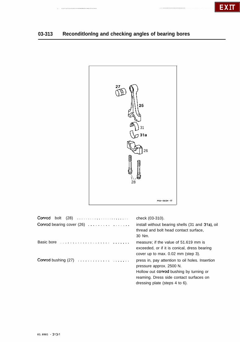
03-313 Reconditlonlng and checking angles of bearing bores
$I 31
GJ 31a
QB26
Bg\28
Conrod bolt (28) . . . . . . . . . . . . . . . . . . , . . . . . check (03-310).
Conrod bearing cover (26) .........
Basic bore ....................
Conrod bushing (27) .............
. . . . . . . install without bearing shells (31 and 31a), oilthread and bolt head contact surface,30 Nm.
. . . . . . . measure; if the value of 51.619 mm isexceeded, or if it is conical, dress bearingcover up to max. 0.02 mm (step 3).
. . . . . . . press in, pay attention to oil holes. Insertionpressure approx. 2500 N.Hollow out conrod bushing by turning orreaming. Dress side contact surfaces ondressing plate (steps 4 to 6).
03.0905 - 313/l
Conrod (25) . . . . . . . . . . . . . . . . . . . . . . . . . . . check angles of bearing bores with conrodtester. Align conrod bearing bore to small endbushing bore (steps 7 and 8).
Axial twist . . . . . . . . . . . . . . . . . . . . . . . . . . to small end bushing bore, check (step 9).
Special tool
Commercial toolConrod aligning tool 8. g. Hahn & Kolb
D-7000 StuttgartModel BC 503
03.0905 - 313!2
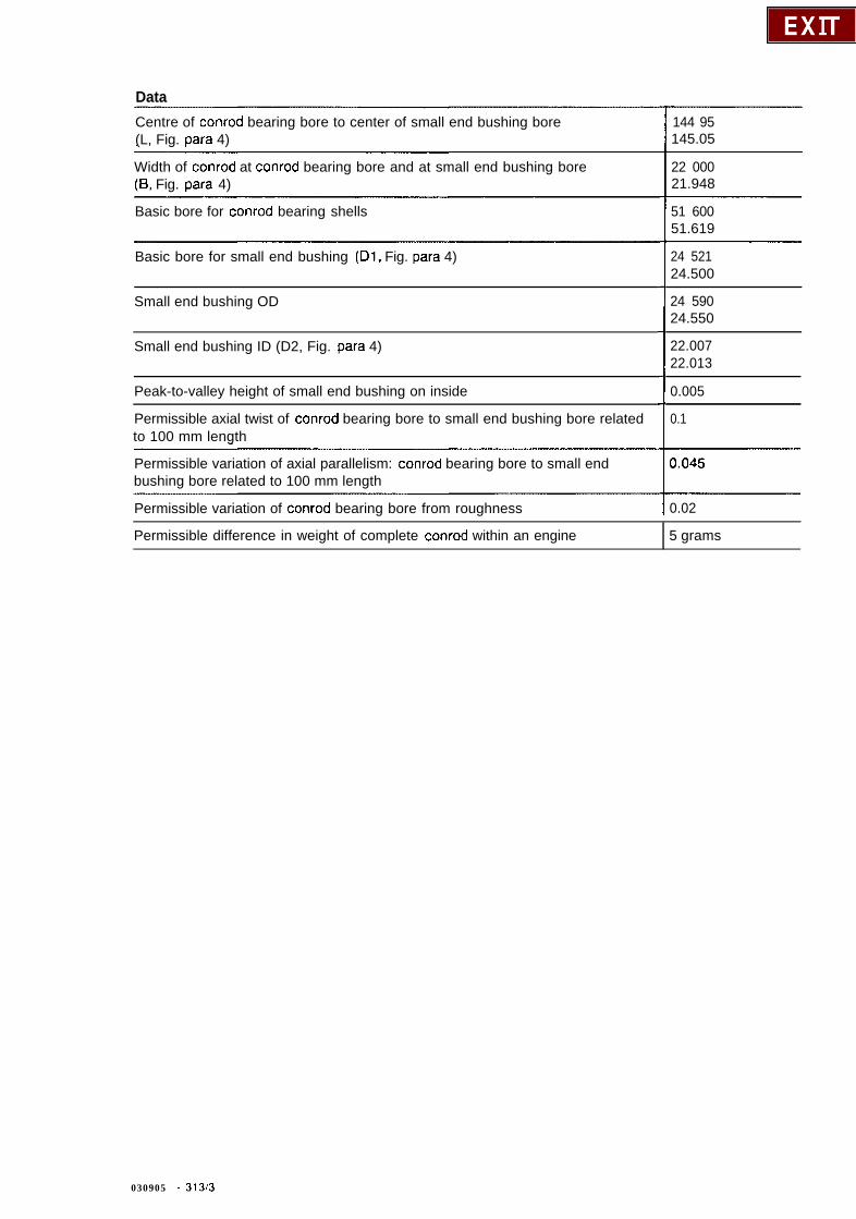
DataCentre of conrod bearing bore to center of small end bushing bore(L, Fig. para 4)
144 95145.05
Width of conrod at conrod bearing bore and at small end bushing bore(8, Fig. para 4)
22 00021.948
Basic bore for conrod bearing shells 51 60051.619
Basic bore for small end bushing (Dl, Fig. para 4)
Small end bushing OD
Small end bushing ID (D2, Fig. para 4)
Peak-to-valley height of small end bushing on inside
Permissible axial twist of conrod bearing bore to small end bushing bore relatedto 100 mm length
Permissible variation of axial parallelism: conrod bearing bore to small endbushing bore related to 100 mm length
24 52124.500
24 59024.550
22.00722.013
0.005
0.1
Permissible variation of conrod bearing bore from roughness I 0.02
Permissible difference in weight of complete conrod within an engine 5 grams
030905 - 3130

NoteThe end play of the conrod is limited not at thecrankshaft journals but at the piston pin bosses(piston-guided conrod, arrows).
Conrods which have been overheated as a resultof a bearing damage (blue discolouration), mustnot be reused.Conrod and conrod bearing cover are markedtogether. The conrod shaft must not show anycross scoring and notches.
Conrods are supplied as replacement parts witha machined small end bushing.
w-AA
PO3-2015-13
To reduce the distortion tendency, conrods witha modified material were installed from Junethrough September 1985 and are installedeffective February 1987.
030905 - 313,4

Standard im
Model
201.024
201.024 @
* not covered
lementation: June throuah Seotember 1985
Engine
102.961
102.985
Engine End No.
transmission
Effective 09/89 all conrods are subject toadditonal heat treatment to prevent conroddistortion resulting in noises when the engineis operating at normal temperature.
Reconditioning
1 Check conrod bolts, replace if necessary(03-310).
2 Install conrod bearing cover. To perform thestep, oil thread and bolt head contact surfaceand tighten to 30 + 5 Nm.
3 Measure conrod bearing basic bore. If thebasic bore exceeds the value of 51.619 mm or isconical, dress contact face of bearing cover on asurface plate to max. 0.02 mm.
Vehicle ldent End No.
030905-3135
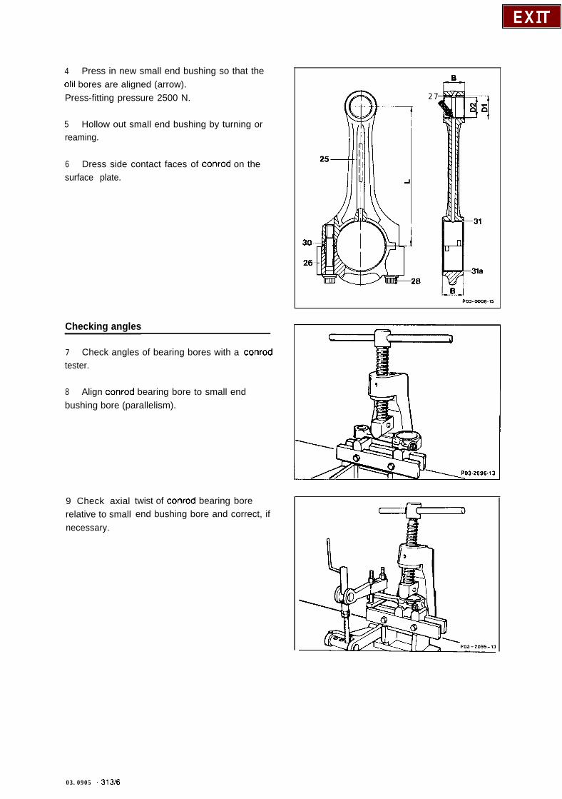
4 Press in new small end bushing so that theolil bores are aligned (arrow).Press-fitting pressure 2500 N.
5 Hollow out small end bushing by turning orreaming.
6 Dress side contact faces of conrod on thesurface plate.
Checking angles
7 Check angles of bearing bores with a conrodtester.
8 Align conrod bearing bore to small endbushing bore (parallelism).
9 Check axialrelative to smallnecessary.
twist of conrod bearing boreend bushing bore and correct, if
2 7
03.0905 - 3136

03-316 Removal and installation of pistons
Preceding work:Removal of engine (01-030).Removal of cylinder head (01-415).Removal of oil pan (01-310).
32
3334 373
35
- 26Q%
28II
Conrod bearing cover (26) . . . . . . . . . . . . . . . . . unbolt, bolt on, 30 Nm and 90” angle of rotationtorque. Do not mix up top and bottom bearingshells. Pay attention to matching of conrod andbearing cap (step 12).
Conrod bolt (28) . . . . . . . . . . . . . . . . . . . . . . . . check (03-310).
Piston (32) and conrod (25) . . . . . . . . . . . . . . . . push out of crankcase upwards.
Locking ring (37) . . . . . . . . . . . . . . . . . . . . . . . remove (step 3) and insert (step 9).
Piston pin (36) . . . . . . . . . . . . . . . . . . . . . . . . . press out and press in by hand (step 8).Installation lnstructlonInsert conrod into piston so that the chamferedsplash bore in the small end bearing with thearrow in the piston crown are pointing indirection of travel; do not heat piston.
03.0905 - 316.‘1

Piston (32) . . . . . . . . . . . . . .
Piston rings (33, 34 and 35) . .
Piston (32) with conrod (25) . . .
Piston projection . . . . . . . . . . .
. . .
. .
. . *
. . . . check condition, pay attention to installationposition.
. . . . check condition, pay attention to installationposition, “Top” must face upwards. Position ringgaps evenly around circumference of piston.
. . . . install with tensioning strap 000 589 04 14 00,oil piston beforehand and clean cylinder bores(steps 10 and 11).
. . . . check in TDC position (step 14).
Special tools
IO0 589 51 3700 I ~0005890414001 I001 589 72 21 001
Matching pistons and cylinders
102.922!924102.962963 I*Standard(normal size)
Repair size 1 0( + 0.5)
L - -
89 468L89.482
89 47889.492
89 488L89.502
89 49889.50889 50989.51889 51989.528
A 89.47389.479
89 50089.506
89 507L89.512
89 513ZzG
03.0905 - 31612

Group No.Engine
Repair size 2(+ 1.0)
89 96889.982 89 9989o.00889 97889.992 90 009
90.01889 9889o.002
90 01990.028
102.982i985Standard(normal size)
Repair size 1(+ 0.5)
95 96995.981 95 99896.008A 95 97995.991
96 96.018 009
95 98996.001
96 01996.028
Repair size 2( + 1 .O)
96 46996.481
96 49896.50896 47996.491
96 50996.518
03.0905 - 31613
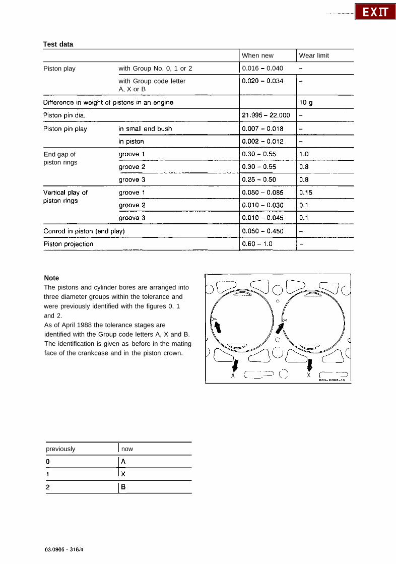
Test dataWhen new Wear limit
Piston play with Group No. 0, 1 or 2 I 0.016 - 0.040 -
with Group code letterA, X or B
End gap ofpiston rings
NoteThe pistons and cylinder bores are arranged intothree diameter groups within the tolerance andwere previously identified with the figures 0, 1and 2.
The identification is given asface of the crankcase and in
As of April 1988 the tolerance stages areidentified with the Group code letters A, X and B.
before in the matingthe piston crown.
previously I now
03.0905 - 31614
Only pistons with the Group code letter “X” aresupplied for repair purposes. These pistonsshould also be installed in the cylinder bores withthe Group code letters “A” or “B”.Only pistons with Group code letters are alsosupplied for the previous engines with Groupnumbers 0, 1 and 2, namely piston “x” forGroup No. 0 and 1. Piston “B” for Group No. 2.When performing repairs, the cylinder boresshould be honed according to the dimensionsof the existing pistons plus piston play.
The piston crown is designed differently in theindividual engines. The piston crown of normalcompression engines is either smooth or pro-vided with a recess. In addition, there are twovalve niches each in the piston crown.
030905 - 316/5
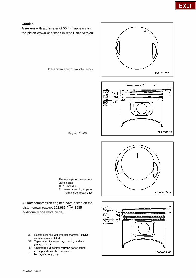
Caution!A recess with a diameter of 50 mm appears onthe piston crown of pistons in repair size version.
Piston crown smooth, two valve niches
Engine 102.985
Recess in piston crown, twovalve nichesD 70 mm dia.T vanes according to piston
(normal size, repair srzes)
All low compression engines have a step on thepiston crown (except 102.985 @, 1985additionally one valve niche).
33 Rectangular ring wrth Internal chamfer, runnrngsurface chrome-plated
34 Taper face 011 scraper ring, running surfaceprecksion-turned
35 Chamferred 011 control nng wrth garter spring,runnrng surfaces chrome-plated
T Herght of size 2.0 mm
PO3-0010-13
Ij7
T
:3
L
PO3-0011-13
PO3-0012-13
PO3.0013.13
03 0905 - 31616

PO3-0014-U
Engme 102.985 @
As the design of the piston crown (flat, recess orstep) has an influence on the compression, thepistons are not interchangeable.Two repair sizes (each step + 0.5 mm dia.) areapproved for the pistons of all engines.
The shape of the piston and the roughness ofthe grinding pattern of the pistons has beenmodified from 0.8 mm to 1.2 mm on Engine102.982 as a noise-reducing measure.
03.0905 -316/7

On engine 102.985 @ the rectangular ringmanufactured by Gotze is installed in groove Iof the piston manufactured by Mahle and KS.The running surface of this piston ring ischrome-plated, asymmetrically crowned andsharp-edged at the bottom to reduce oilconsumption.
Standard lmplementatlon: 0318 8
T
201.028 @ 1102.985
(Mahle)
Engine End No.
Manualtransmission
023341
Vehicle ldent End No.
ransmrssron
Standard Implementation: 03188 (KS)
201.028 @ 102.985 023788 070989 492527
The Group code numbers on the pistons and onthe mating face of the crankcase have beenreplaced by Group code letters.As a result, the cylinder diameters and matchingof pistons and cylinders have also been modified(refer to data).
Crankcase with Groupnumbers
Crankcase with Groupcode letters
03.0905 - 31616

Removal and installation
1 Unbolt conrod bearing cover and removeconrod together with piston upwards.
2 Check conrod bolts (03310).
3 Remove piston pin locking element withscrewdriver and press out piston pin.
4 Recondition conrod and check angles ofbearing bores, if necessary (03-313).
5 If the pistons are worn, check the gapclearance and end play of the piston rings (referto table). Check that the piston rings moveeasily. Pay attention to installation position:“Top” must be facing upwards. Distribute thering gaps evenly around the circumference ofthe piston.
6 Oil piston pin and small end bushes.
7 Install piston so that the chamfered splashbore in the small end bearing (arrow) and thearrow in the piston crown are facing in directionof travel.
PO3-2014.13A
Caution!Do not heat piston.
03.0905 _ 31619

8 Press in piston pin by hand.
9 Insert piston pin locking element into thegroove.
10 Oil cleaned cylinder bores, conrod bearingjournals, conrod bearing shells and pistons.
I I Install tensioning strap for piston rings andinstall piston into cylinder bore with arrow facingin direction of travel.
12 Mount conrod bearing cover onto the conrodwith the code marks (arrows) aligned with eachother and torque conrod bolts to an initial torqueof 30 Nm and angle of rotation torque of 90”.
13 Turn crankshaft and check clearancebetween piston pin boss and conrod.
03.0905 - 316ilO
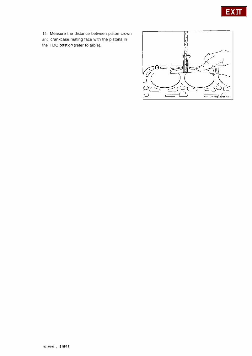
14 Measure the distance between piston crownand crankcase mating face with the pistons inthe TDC postion (refer to table).
03.0905 . 316111
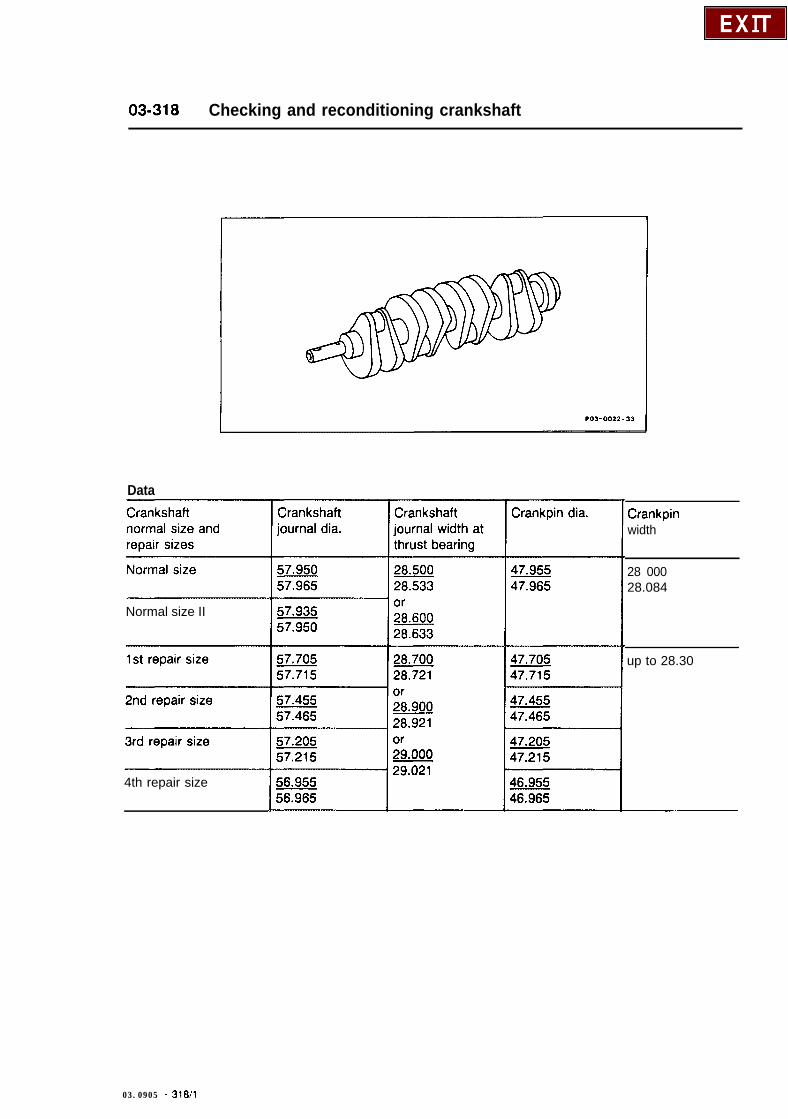
03-318 Checking and reconditioning crankshaft
Data
Normal size II
4th repair size
Crankpinwidth
28 00028.084
up to 28.30
03.0905 - 31811
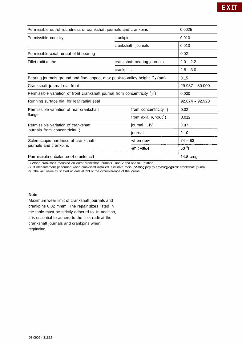
Permissible out-of-roundness of crankshaft journals and crankpins 0.0025
Permissible conicity crankpins 0.010
Permissible axial runout of fit bearing
crankshaft journals 0.010
0.02
Fillet radii at the crankshaft bearing journals 2.0 - 2.2
crankpins 2.8 - 3.0
Bearing journals ground and fine-lapped, max peak-to-valley height R, (pm) 0.15
Crankshaft journal1 dia. front I 29.987 - 30.000
Permissible variation of front crankshaft journal from concentricity ‘) ‘) 0.030
Running surface dia. for rear radial seal 92.874 - 92.928
Permissible variation of rear crankshaft from concentricity ‘) 0.02flange
from axial runout ‘) 0.012
Permissible variation of crankshaftjournals from concentricity ‘)
journal II, IV
journal Ill
Scleroscopic hardness of crankshaftjournals and crankpins
1) When crankshaft mounted on outer crankshaft journals I and V and one full rotation.2) If measurement performed when crankshaft installed, eliminate radial beanng play by pressmg against crankshaft journal.3) The llmlt value must exist at least at 2/3 of the circumference of the journal.
NoteMaximum wear limit of crankshaft journals andcrankpins 0.02 mmm. The repair sizes listed inthe table must be strictly adhered to. In addition,it is essential to adhere to the fillet radii at thecrankshaft journals and crankpins whenregrinding.
03.0905 - 31812
Special tool
jooo5892**1 OOJ
NoteAdhere to the sequence of operations of thediagram below when checking and reconditioningcrankshafts.
Dianram
‘) Refer to Section “Explanatory notes regardingdiagram”.
03.0905 . 31 a/3
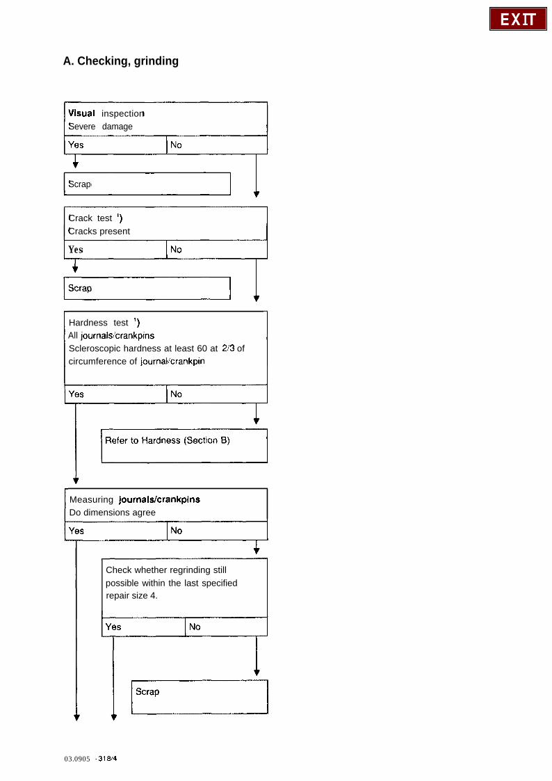
A. Checking, grinding
Visual inspectionSevere damage
f
Scrap
Crack test ‘)Cracks present
I Yes
Hardness test ‘)All journals/crankpinsScleroscopic hardness at least 60 at 213 ofcircumference of journallcrankpin
Measuring journals/crankpinsDo dimensions agree
Check whether regrinding stillpossible within the last specifiedrepair size 4.
I No
03.0905 - 31814
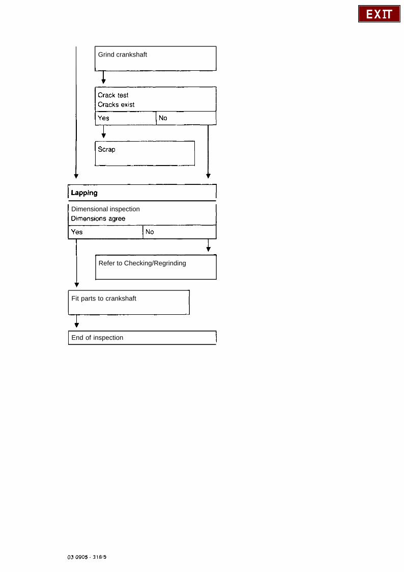
Grind crankshaft
Dimensional inspection
Refer to Checking/Regrinding
Fit parts to crankshaft
End of inspection I
03 0905 - 31815
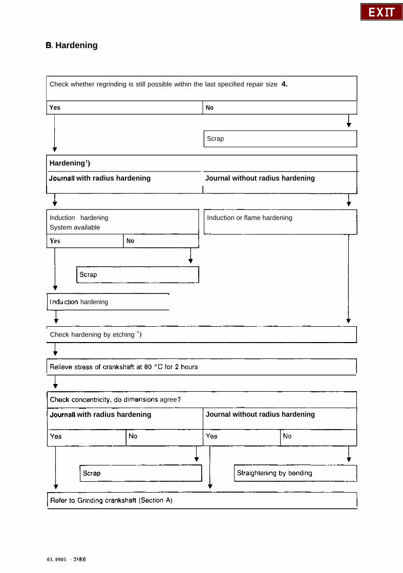
B. Hardening
Check whether regrinding is still possible within the last specified repair size 4.
Yes No
I I I
1 Scrap
Hardening ‘)
Journal1 with radius hardening Journal without radius hardening
Induction hardeningSystem available
Yes No
1 I y ction hardening1
Induction or flame hardening
Check hardening by etching ‘)
lmenslons agree
Journal1 with radius hardeningIJournal without radius hardening
03.0905 - 318/6
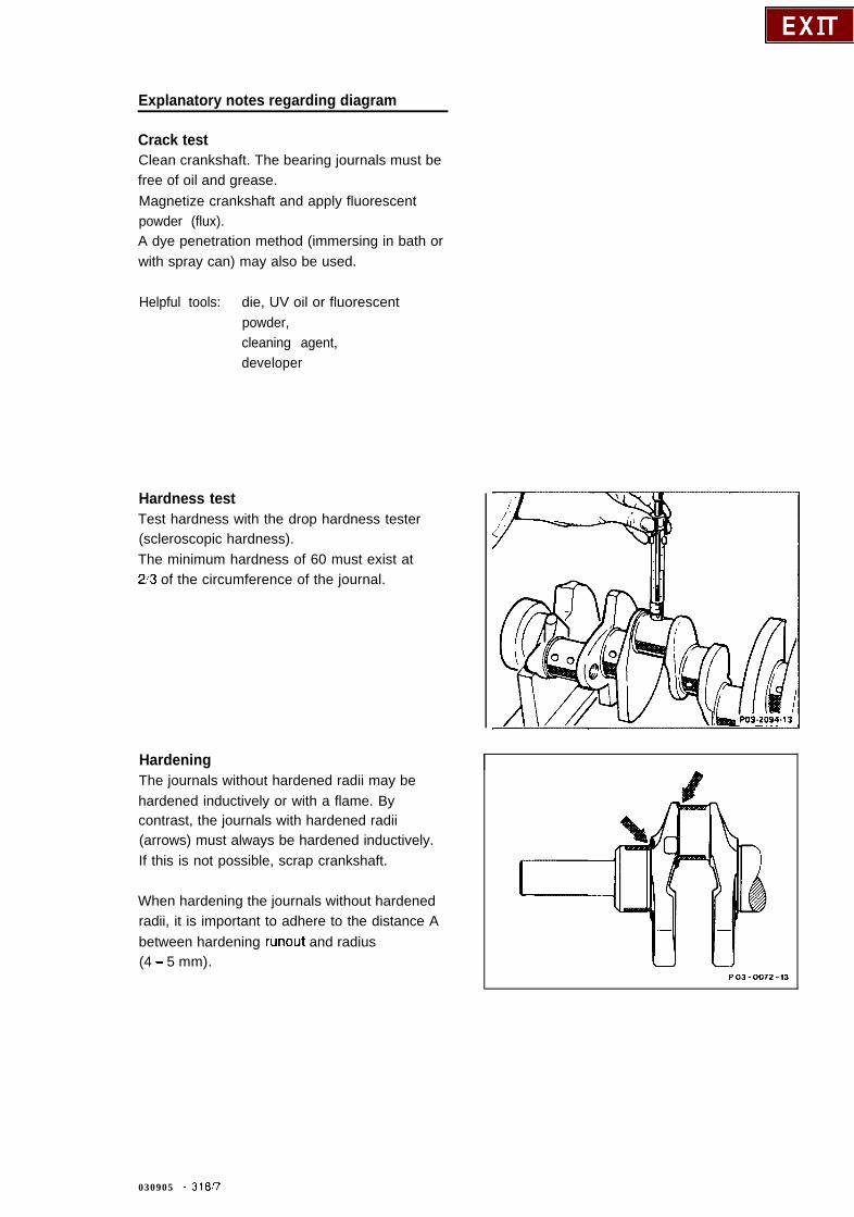
Explanatory notes regarding diagram
Crack testClean crankshaft. The bearing journals must befree of oil and grease.Magnetize crankshaft and apply fluorescentpowder (flux).A dye penetration method (immersing in bath orwith spray can) may also be used.
Helpful tools: die, UV oil or fluorescentpowder,cleaning agent,developer
Hardness testTest hardness with the drop hardness tester(scleroscopic hardness).The minimum hardness of 60 must exist at2’3 of the circumference of the journal.
HardeningThe journals without hardened radii may behardened inductively or with a flame. Bycontrast, the journals with hardened radii(arrows) must always be hardened inductively.If this is not possible, scrap crankshaft.
When hardening the journals without hardenedradii, it is important to adhere to the distance Abetween hardening runout and radius(4 - 5 mm).
PO3-0072-13
030905 - 31w
Inspection of hardening Corrosion protectionTo achieve proper hardening, check the setting Crankshafts which are not immediately re-of the hardening system by metallographic installed, must be oiled with initial operationground surfaces. engine oil (SAE 30).
These can be removed from test hardeningoperations on scrapped crankshafts.
Check hardening by etching the surface of thejournal with a 2 % alcoholic nitric acid (HNOs).
No dark spots should appear on the surface ofthe journal.
Non-hardened radii change to a dark colour.
By contrast, the hardened radii must be just asbright as the surface of the journal.
As a comparison, it is recommended to performetching on a metallographically tested journal.
Following this, carefully wash off the nitric acidwith alcohol.
03.0905 - 31&8
_.
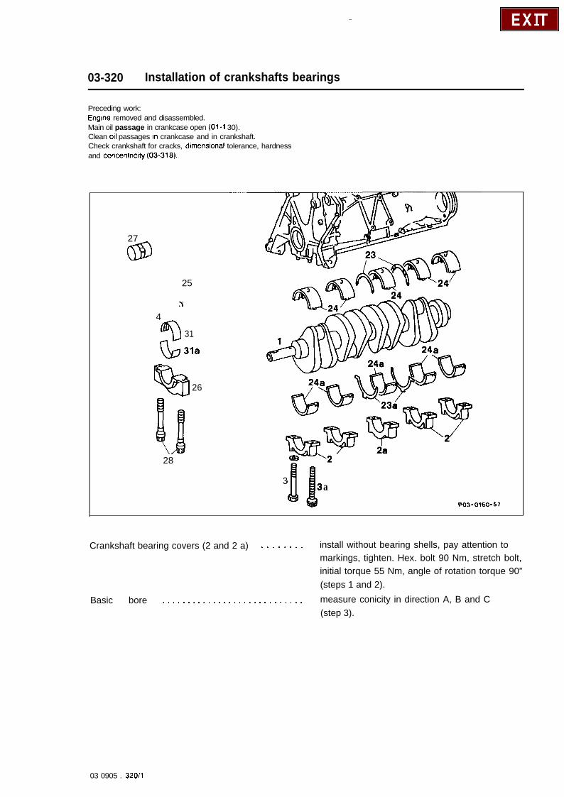
03-320 Installation of crankshafts bearings
Preceding work:Engine removed and disassembled.Main oil passage in crankcase open (01-l 30).Clean 011 passages In crankcase and in crankshaft.Check crankshaft for cracks, dimenslonal tolerance, hardnessand concentricity (03-318).
27
4
25
‘\
$I 31
QJ 31a
QTI26
28
3 aPQ3-0160-57
Crankshaft bearing covers (2 and 2 a) . . . . . . . . install without bearing shells, pay attention tomarkings, tighten. Hex. bolt 90 Nm, stretch bolt,initial torque 55 Nm, angle of rotation torque 90”(steps 1 and 2).
Basic bore . . . . . . . . . . . . , . . . . . . . . . . . . . . . measure conicity in direction A, B and C(step 3).
03 0905 . 32011
Crankshaft bearing shells (24 and 24 a) . , . . . . .
Bearing diameters .......................
Crankshaft (1) .........................
Thrust bearing journals . . . . . . . . . . . . . . . .
Bearing shells (24) . . . . . . . . . . . . . . . . . . . , . .
Thrust washers (23) . . . . . . . . . . . . . . . . . . . .
Thrust bearing cover (2a) . . . . . . . . . . . . . . . . .
Crankshaft bearing cover (2) . . . . . . . . . . . . . .
Crankshaft bearing end play . . . . . . . . . . . . . .
Conrod . . . . . . . . . . . . . . . . . . . . . . . . . . . . . .
Conrod bearing shells (31 and 31 a) ..........
Bearing diameter .......................
Wrist pins ............................
Piston ...............................
Conrod bearing cover (26) . . . . . . . . . . . . . .
insert, adhere to tightening torques(step 4).
measure and note values (step 5).
measure crankshaft bearing journals, determinebearing play (step 6).
measure width and match appropriate thrustwashers (step 7).
oil with engine oil and insert crankshaft(step 8).
oil and fit into grooves of thrust bearings, payattention to oil grooves (step 9).
oil together with thrust washers (23 a) andinstall (step 10).install, hexagon bolt, 90 Nm, stretch bolt (3 a),initial torque 55 Nm, angle of rotation torque 90”(steps 11 and 12).
measure. Check ease of movement ofcrankshaft (steps 13 and 14).
recondition and check angles (03-313).
insert, initial torque 30 Nm, angle of rotationtorque 90” (step 16).
measure and note value (step 17).
measure, determine bearing play (step 18).install on conrod (pay attention to installationposition and install (03-316).
install, initial torque 30 Nm, angle of rotationtorque 90” (step 20).Caution!Note step 20.
03.0905 - 32012
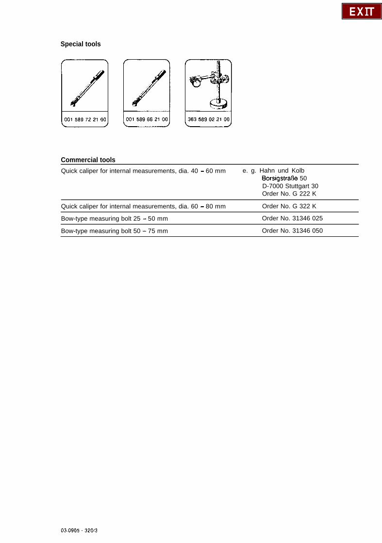
Special tools
Commercial toolsQuick caliper for internal measurements, dia. 40 - 60 mm e. g. Hahn und Kolb
BorsigstraOe 50D-7000 Stuttgart 30Order No. G 222 K
Quick caliper for internal measurements, dia. 60 - 80 mm Order No. G 322 K
Bow-type measuring bolt 25 - 50 mm Order No. 31346 025
Bow-type measuring bolt 50 - 75 mm Order No. 31346 050
03.0905 - 320/3
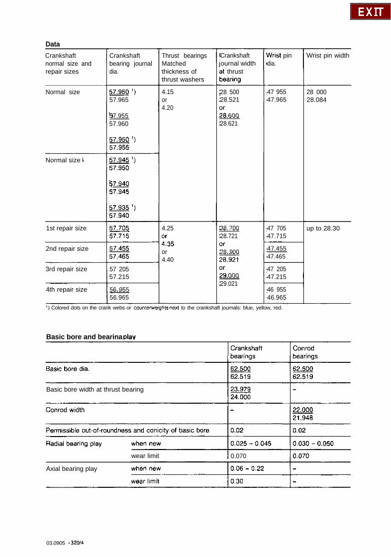
DataCrankshaftnormal size andrepair sizes
Normal size
Normal size I
1st repair size
2nd repair size
3rd repair size
4th repair size
Crankshaftbearing journaldia.
57.96Q ‘)57.965
‘)57.95557.960
1)57.94057.945
57 20557.215
56 955L56.965
Thrust bearingsMatchedthickness ofthrust washers
4.15or4.20
4.25
1735or4.40
Crankshaftournal widthat thrustoearing
28 50028.5213r78 600L28.621
38 700L28.7213r28 900zzi=3r29 000-29.021
vVrist pindia.
47 95547.965
47 70547.715
47.45547.465
47 20547.215
46 95546.965
1) Colored dots on the crank webs or counterwelghts next to the crankshaft journals: blue, yellow, red.
Basic bore and bearina dav
Wrist pin width
28 00028.084
up to 28.30
Basic bore width at thrust bearing
wear limit I 0.070
Axial bearing play
03.0905 - 32014

NotesEngine removed and disassembled.Main oil passage in crankcase open (01-130).Oil passages in crankcase and in crankshaftcarefully cleaned.Crankshaft checked for cracks, hardness,dimensional tolerance and concentricity (03-318).Normal bearing shells and thrust washers areinstalled on the 3rd crankshaft bearing (thrustbearing).The thrust washers absorb the axial forces of thecrankshaft.
The thrust washers (23 and 23a) inserted in thecrankcase and in the bearing cover on bothsides are each identical.The thrust washers each have two retaining lugsin the bearing cover as an anti-twist lock and toavoid assembly errors, the bottom lugs beingfitted off-center. In addition, all the thrustwashers are chamfered at one end.When repairing crankshafts, the thrust bearingjournals must be reground in the width to one ofthe dimensions stated in the table (Section“Data”).
1 Crankshaft2 Bearing cover3 M 12 x 60 bolts (1 St versm)3a Ml 1 x 62 collar bolts (2nd version)4b Washer23 Thrust washer in crankcase23a Thrust washer in bearing cover24 Bearing shell in crankcase24a Bearing shell in beating cover
Q 23
?I23
Q24 1
cb 24a
b23a
03.0905 - 32Oi5
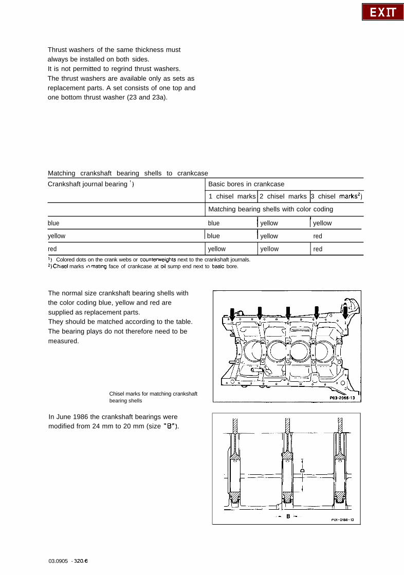
Thrust washers of the same thickness mustalways be installed on both sides.It is not permitted to regrind thrust washers.The thrust washers are available only as sets asreplacement parts. A set consists of one top andone bottom thrust washer (23 and 23a).
Matching crankshaft bearing shells to crankcase
Crankshaft journal bearing ‘) Basic bores in crankcase
1 chisel marks 2 chisel marks 3 chisel marks2)
Matching bearing shells with color coding
blue blue I yellow I yellow
yellow 1 blue I yellow red
red yellow yellow red1) Colored dots on the crank webs or counterwelghts next to the crankshaft journals.2, Chisel marks In mating face of crankcase at 011 sump end next to baste bore.
The normal size crankshaft bearing shells withthe color coding blue, yellow and red aresupplied as replacement parts.They should be matched according to the table.The bearing plays do not therefore need to bemeasured.
Chisel marks for matching crankshaftbearing shells
In June 1986 the crankshaft bearings weremodified from 24 mm to 20 mm (size “B”).
PO3-2066.13
03.0905 - 320~6
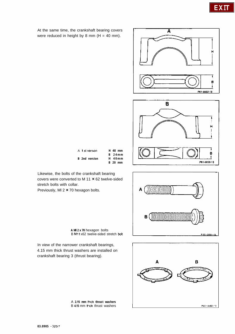
At the same time, the crankshaft bearing coverswere reduced in height by 8 mm (H = 40 mm).
A 1 st version
B 2nd version
H 48 mmB 2 4 m mH 4 0 m mB 20 mm
Likewise, the bolts of the crankshaft bearingcovers were converted to M 11 X 62 twelve-sidedstretch bolts with collar.Previously, Ml 2 x 70 hexagon bolts.
A Ml 2 x 70 hexagon boltsB Ml 1 x62 twelve-sided stretch bolt
In view of the narrower crankshaft bearings,4.15 mm thick thrust washers are installed oncrankshaft bearing 3 (thrust bearing).
A 2.15 mm thick thrust washersB 4.15 mm thick thrust washers
IH
-I I
PO1.0053-13
03.0905 - 32017
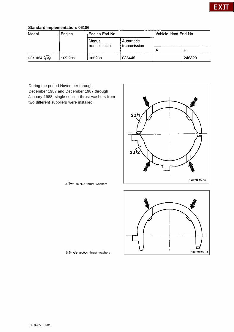
Standard implementation: 06186
During the period November throughDecember 1987 and December 1987 throughJanuary 1988, single-section thrust washers fromtwo different suppliers were installed.
A Two-section thrust washers
B Single-sectlon thrust washers
PO3-0045-15
PO3-0046-13
03.0905 . 32018

. . . . . . . . . . . . . . . . . . . . . . . . . . . . .
Matching crankshaft bearings, installingcrankshaft
NoteThese operations should be performed if thedimensions of the crankshaft journals or of thebasic bearing bores in the crankcase and at theconrod are not known, e.g. if the crankshaftshave been remachined.
All the bearing covers fit into the side of thecrankcase (arrows) and are attached each with2 bolts.The fit (arrows) is offset from the center so thatthe bearing covers can only be installed in oneposition.
In addition, they are marked from front to rearwith the code numbers 1, 2, 4 and 5 (arrows),with the exception of the thrust bearing covers,,and must not be interchanged or replaced.
1 Install crankshaft bearing covers withoutbearing shells.
2 Oil fastening bolts for crankshaft bearingcovers and tighten to 90 Nm (hexagon bolts) or55 Nm initial torque and 90” angle of rotationtorque (stretch bolts), respectively.
3 Measure basic bore in two planes in thedirection A, B and C (conicity).If a basic bore exceeds the specified value or isconical, dress the mating face of the bearingcover on a surface plate to max. 0.02 mm.
I
I I
pe--d4 ------Jo3 0 0 0
00 n n I
03.0905 - 32019
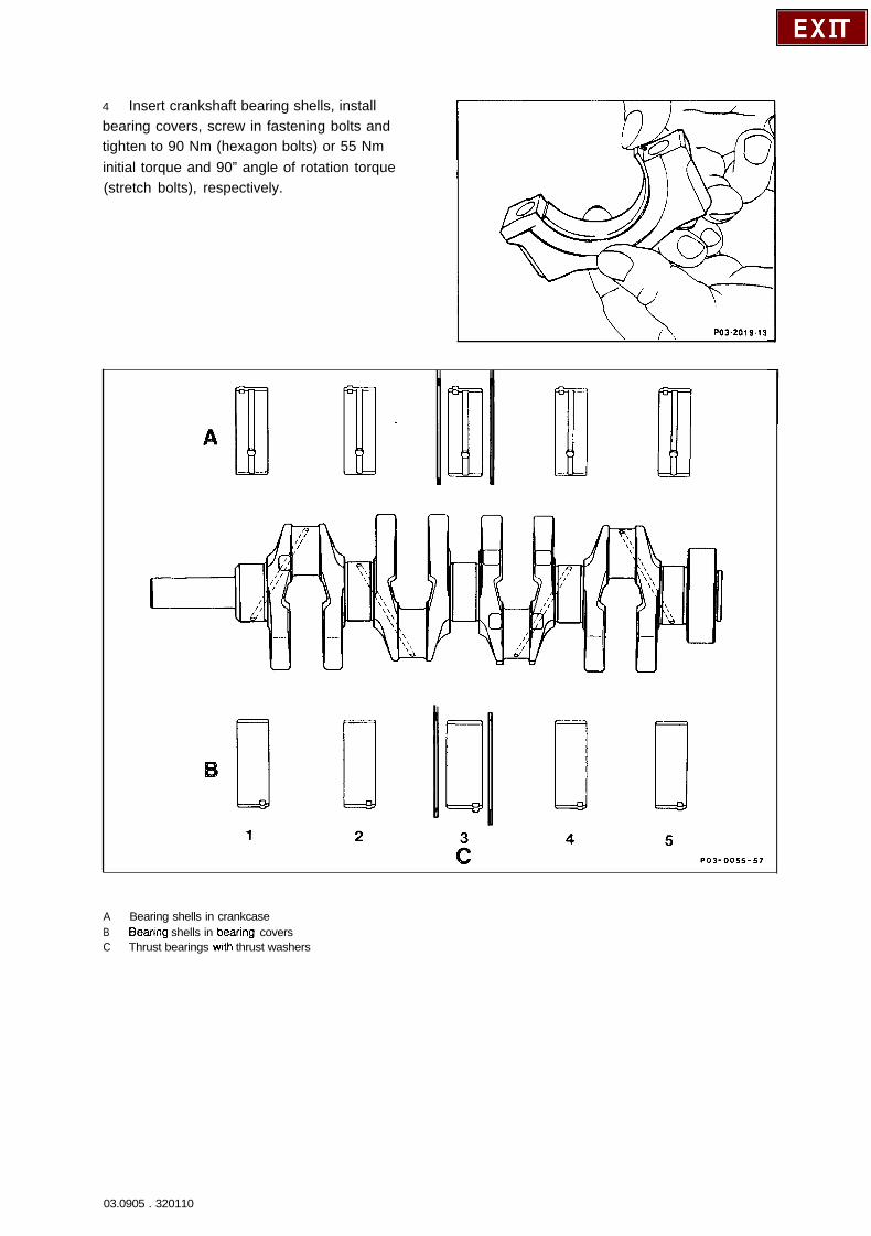
4 Insert crankshaft bearing shells, installbearing covers, screw in fastening bolts andtighten to 90 Nm (hexagon bolts) or 55 Nminitial torque and 90” angle of rotation torque(stretch bolts), respectively.
\ )\ PO32019.13
A Bearing shells in crankcaseB Bearing shells in bearmg coversC Thrust bearings with thrust washers
03.0905 . 320110
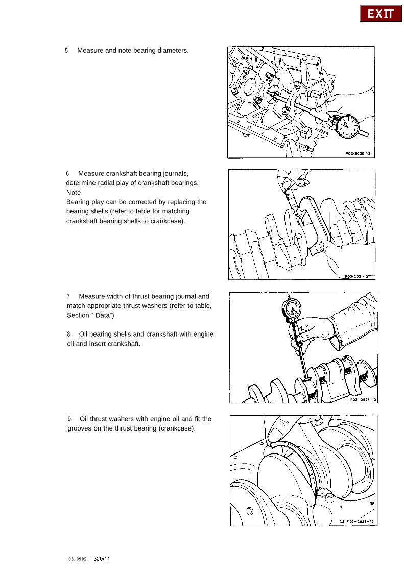
5 Measure and note bearing diameters.
I \ ‘I PO32020-13
6 Measure crankshaft bearing journals,determine radial play of crankshaft bearings.NoteBearing play can be corrected by replacing thebearing shells (refer to table for matchingcrankshaft bearing shells to crankcase).
7 Measure width of thrust bearing journal andmatch appropriate thrust washers (refer to table,Section 11 Data”).
8 Oil bearing shells and crankshaft with engineoil and insert crankshaft.
9 Oil thrust washers with engine oil and fit thegrooves on the thrust bearing (crankcase).
03.0905 _ z-320/11
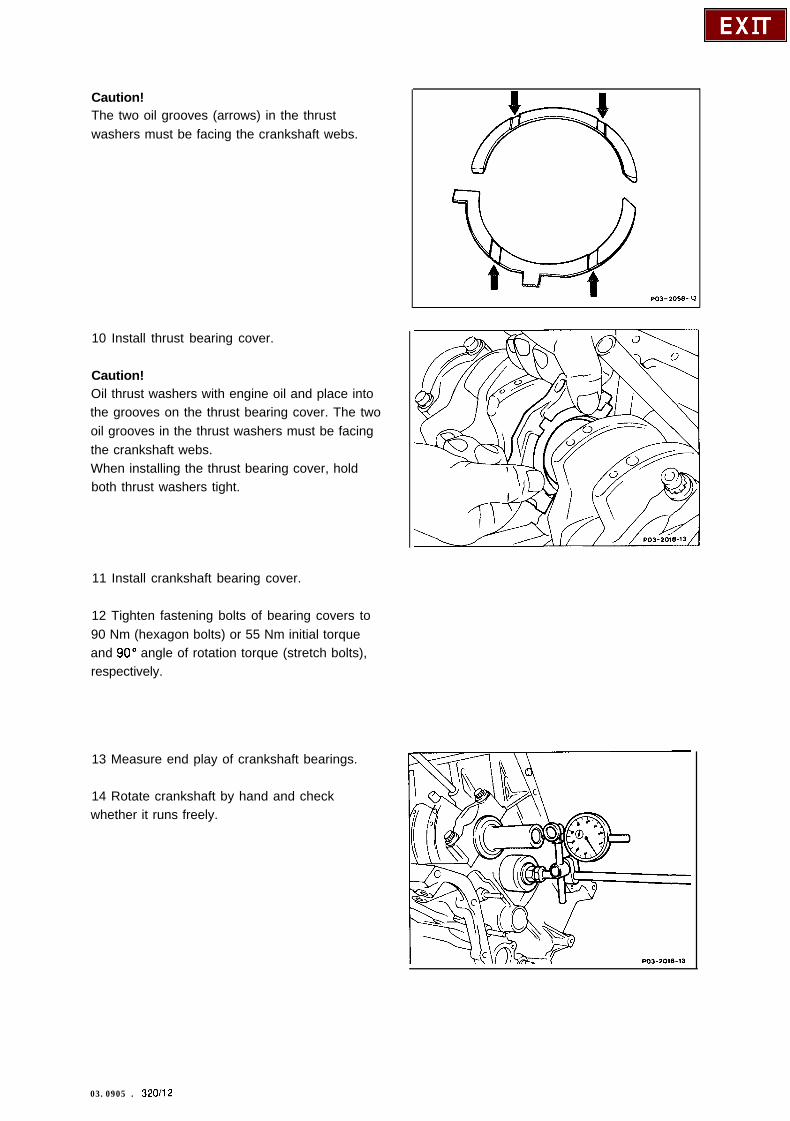
Caution!The two oil grooves (arrows) in the thrustwashers must be facing the crankshaft webs.
10 Install thrust bearing cover.
Caution!Oil thrust washers with engine oil and place intothe grooves on the thrust bearing cover. The twooil grooves in the thrust washers must be facingthe crankshaft webs.When installing the thrust bearing cover, holdboth thrust washers tight.
11 Install crankshaft bearing cover.
12 Tighten fastening bolts of bearing covers to90 Nm (hexagon bolts) or 55 Nm initial torqueand 90” angle of rotation torque (stretch bolts),respectively.
13 Measure end play of crankshaft bearings.
14 Rotate crankshaft by hand and checkwhether it runs freely.
03.0905 . 320/12
Matching conrod bearings and installingconrod
15 Recondition conrod and check angles ofbearing bores relative to each other(03313).
16 Insert conrod bearing shells. Install conrodbearing cover with bearing shell and tightenconrod bolts to an initial torque of 30 Nm andangle of rotation torque of 90”.NoteConrod bearing shells are supplied only in theyellow version.
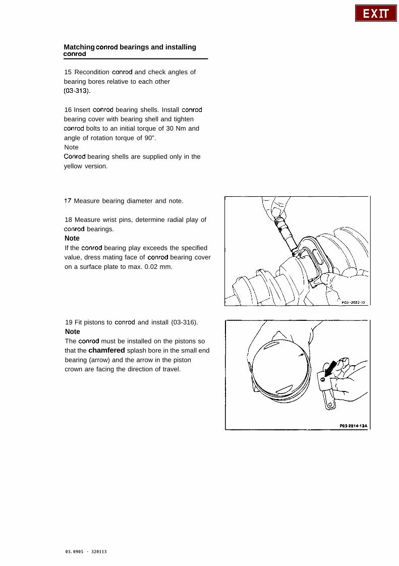
17 Measure bearing diameter and note.
18 Measure wrist pins, determine radial play ofconrod bearings.NoteIf the conrod bearing play exceeds the specifiedvalue, dress mating face of conrod bearing coveron a surface plate to max. 0.02 mm.
19 Fit pistons to conrod and install (03-316).NoteThe conrod must be installed on the pistons sothat the chamfered splash bore in the small endbearing (arrow) and the arrow in the pistoncrown are facing the direction of travel.
03.0905 - 320113
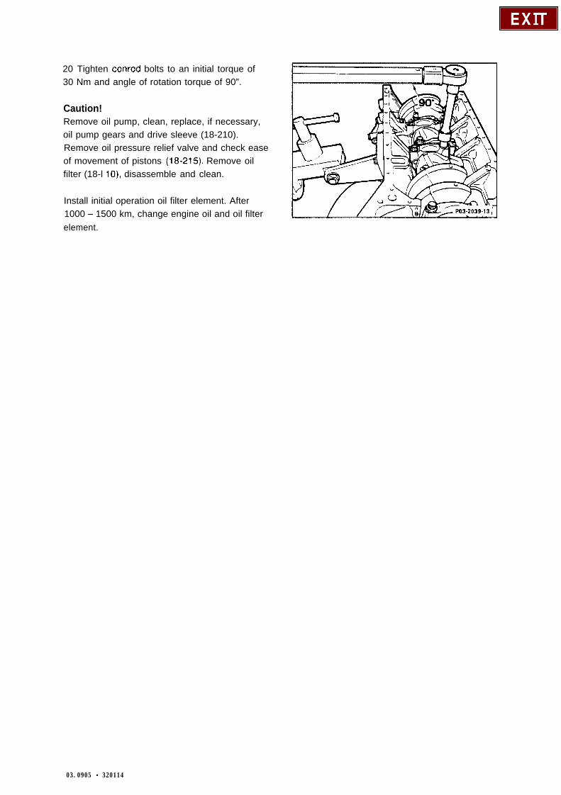
20 Tighten conrod bolts to an initial torque of30 Nm and angle of rotation torque of 90”.
Caution!Remove oil pump, clean, replace, if necessary,oil pump gears and drive sleeve (18-210).Remove oil pressure relief valve and check easeof movement of pistons (18-215). Remove oilfilter (18-l lo), disassemble and clean.
Install initial operation oil filter element. After1000 - 1500 km, change engine oil and oil filterelement.
03.0905 - 320114
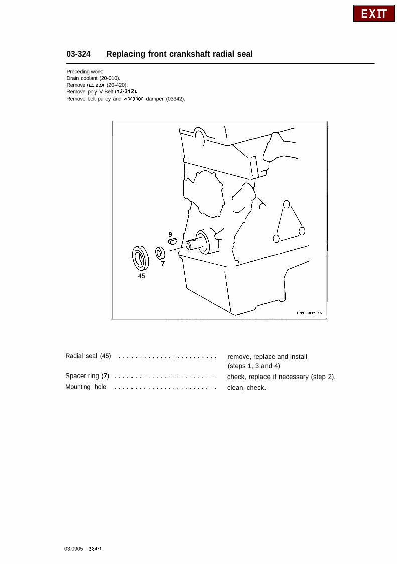
03-324 Replacing front crankshaft radial seal
Preceding work:Drain coolant (20-010).Remove radiator (20-420).Remove poly V-Belt (13-342).Remove belt pulley and vlbratlon damper (03342).
45
Radial seal (45) ........................ remove, replace and install(steps 1, 3 and 4)
Spacer ring (7) ......................... check, replace if necessary (step 2).Mounting hole ......................... clean, check.
03.0905 - 324/l

Special tools
102589001400 102 58901 14 00 102 58900 33 00
NotesSince August 1986 (implementation of use ofdouble roller chain) a 4 mm narrower radial sealhas been installed.Size “C” 8 mm (previously 12 mm).For the same reason, the mounting in the timingcase cover (D) was made 3.4 mm flatter.Size I’D” 9.8 mm (previously 13.2 mm).
POl-0194-13
Standard implementation: 08/86 radial seal
03.0905 - 32412
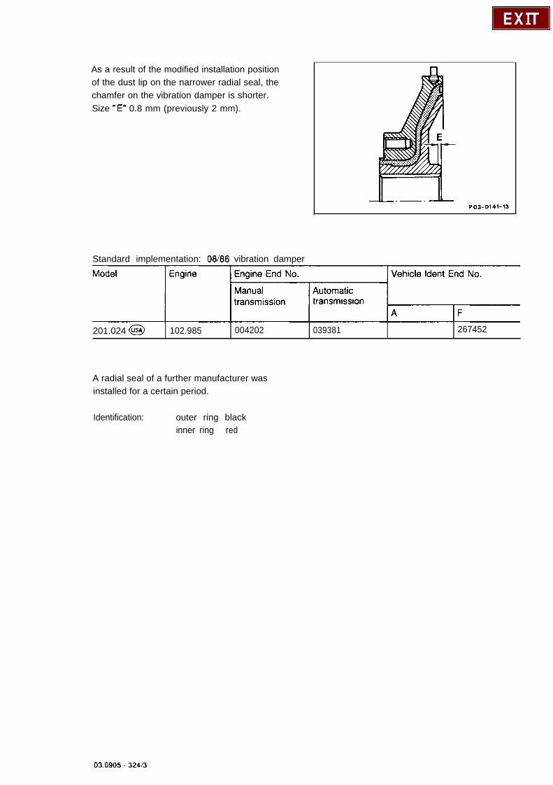
As a result of the modified installation positionof the dust lip on the narrower radial seal, thechamfer on the vibration damper is shorter.Size “E” 0.8 mm (previously 2 mm).
PO3-0141-13
Standard implementation: 08/86 vibration damper
transmwon
201.024 @ 102.985 004202 039381 267452
A radial seal of a further manufacturer wasinstalled for a certain period.
Identification: outer ring blackinner ring red
03.0905 - 32413

Removal and installation
NoteBefore replacing the front crankshaft radial seal,it is necessary to determine whether the leak isoccurring at the timing case cover itself (shrinkholes, cracks).This is done by cleaning the bottom area of thetiming case cover free of oil, drying and sprayingit with “MB contrast spray white”,Part No. 009 989 03 59. Run engine and pin-point oil leak after 2 - 5 minutes.
1 Pry radial seal (45) out of the timing casecover with a screwdriver.When performing the step, ensure that thecrankshaft journal and the mounting hole in thetiming case are not damaged. Cover over crank-shaft journal with a rag.Deburr mounting hole, if necessary.
03.0905 . 32414
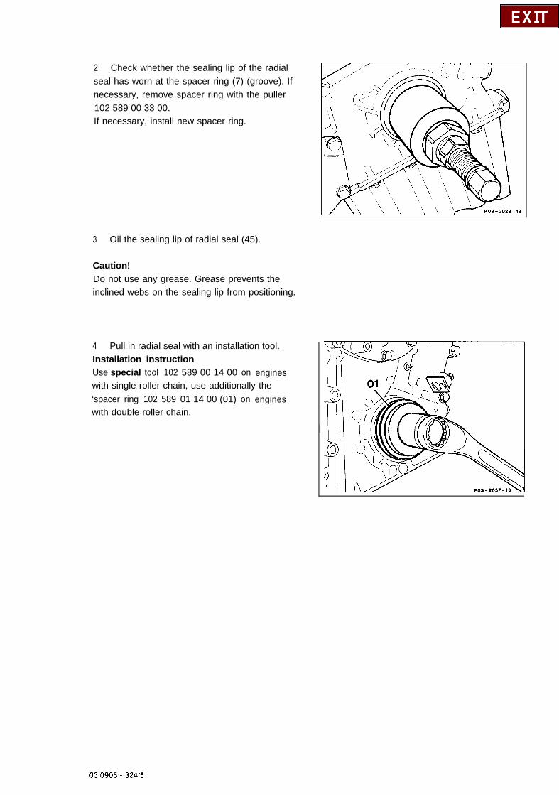
2 Check whether the sealing lip of the radialseal has worn at the spacer ring (7) (groove). Ifnecessary, remove spacer ring with the puller102 589 00 33 00.If necessary, install new spacer ring.
3 Oil the sealing lip of radial seal (45).
Caution!Do not use any grease. Grease prevents theinclined webs on the sealing lip from positioning.
4 Pull in radial seal with an installation tool.Installation instructionUse special tool 102 589 00 14 00 on engineswith single roller chain, use additionally the‘spacer ring 102 589 01 14 00 (01) on engineswith double roller chain.
03.0905 - 324el
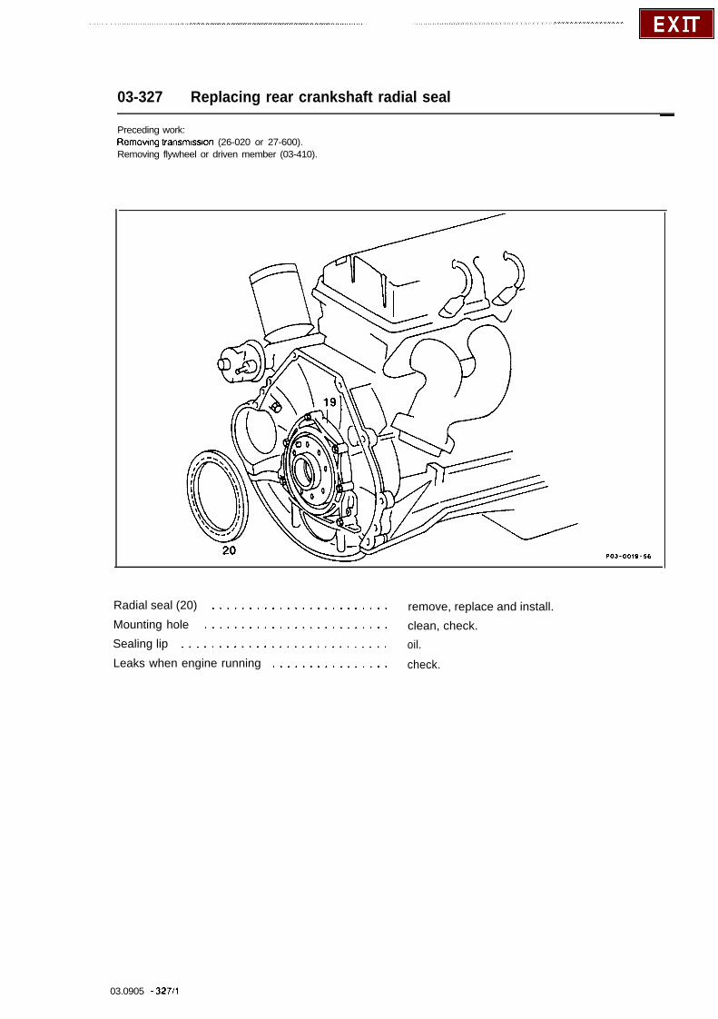
03-327 Replacing rear crankshaft radial seal-
Preceding work:Removing VansmIssIon (26-020 or 27-600).Removing flywheel or driven member (03-410).
Radial seal (20) ........................ remove, replace and install.Mounting hole ......................... clean, check.Sealing lip ............................ oil.Leaks when engine running ................ check.
03.0905 - 327/l

Special tool
NotesThe sealing lip of the replacement radial seal isoffset to the inside by 3 mm so that it does notrun in a groove which may have been producedon the running surface on the crankshaft by thestandard radial seal.
A Standard radial seal6 Repalr radial seal
1
PO3-0078-15_I
The radial seal1 is installed into the end coverflush without any sealant.Oil leaks can be determined after spraying thecleaned and dried surrounding area withMercedes-Benz contrast spray white, Part No.000 989 03 59.
03.0905 - 32712
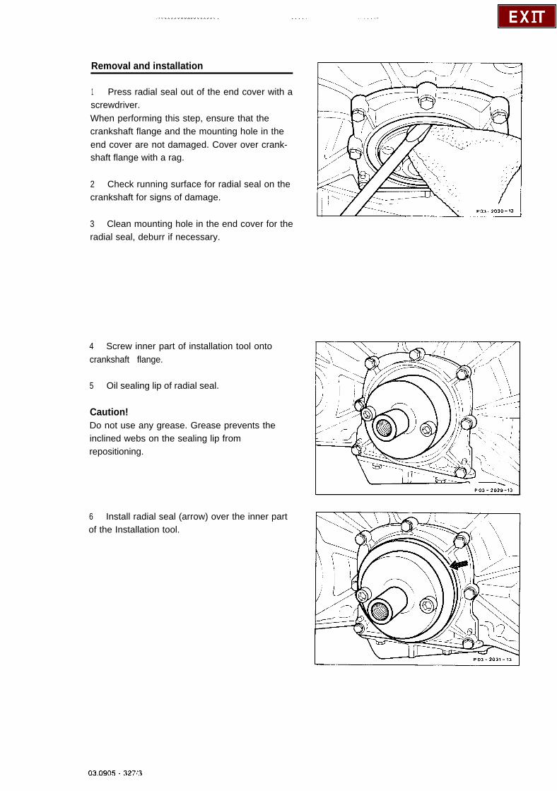
Removal and installation
1 Press radial seal out of the end cover with ascrewdriver.When performing this step, ensure that thecrankshaft flange and the mounting hole in theend cover are not damaged. Cover over crank-shaft flange with a rag.
2 Check running surface for radial seal on thecrankshaft for signs of damage.
3 Clean mounting hole in the end cover for theradial seal, deburr if necessary.
4 Screw inner part of installation tool ontocrankshaft flange.
5 Oil sealing lip of radial seal.
Caution!Do not use any grease. Grease prevents theinclined webs on the sealing lip fromrepositioning.
6 Install radial seal (arrow) over the inner partof the Installation tool.
03.0905 - 32713

7 Press the radial seal (arrow) into the endcover as far as the stop with the outer part of theinstallation tool.
Caution!The radial seal must be positioned exactly atright angles to the crankshaft flange or inner partof the installation tool to ensure that it provides aproper seal.
8 Check for leaks with engine running.
03.0905 - 32714

03-330 Removal and installation of grooved ball bearlng in crankshaft
Preceding work:Removing transmission (26-020 or 27-600).Removing clutch (25050).
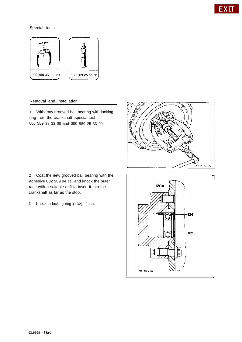
Grooved ball bearing (19) and locking ring (21) . . withdraw, special tool 000 589 33 33 00 and000 589 25 33 00.Before installation, coat outer race of groovedball bearing with adhesive 002 989 94 71.Knock in grooved ball bearing as far as the stop,outer race flush.
03.0905 - 330/l
Special tools
Removal and installation
1 Withdraw grooved ball bearing with lockingring from the crankshaft, special tool000 589 33 33 00 and 000 589 25 33 00.
2 Coat the new grooved ball bearing with theadhesive 002 989 94 71 and knock the outerrace with a suitable drift to insert it into thecrankshaft as far as the stop.
3 Knock in locking ring (132) flush.
03.0905 - 330:2
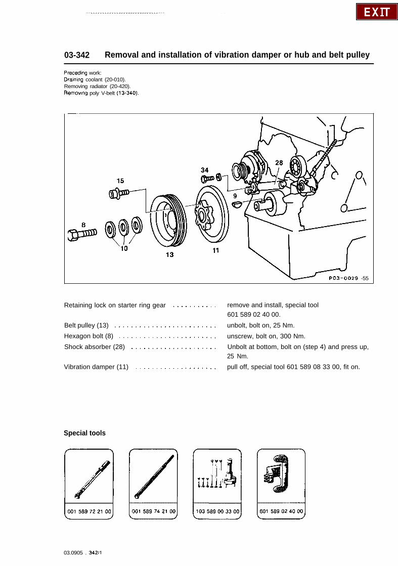
03-342 Removal and installation of vibration damper or hub and belt pulley
Preceding work:Dranng coolant (20-010).Removing radiator (20-420).Removing poly V-belt (13-340).
-.
PO3-0029 -55
Retaining lock on starter ring gear ........... remove and install, special tool601 589 02 40 00.
Belt pulley (13) ......................... unbolt, bolt on, 25 Nm.
Hexagon bolt (8) ........................ unscrew, bolt on, 300 Nm.
Shock absorber (28) ..................... Unbolt at bottom, bolt on (step 4) and press up,25 Nm.
Vibration damper (11) .................... pull off, special tool 601 589 08 33 00, fit on.
Special tools
03.0905 . 342/l

Commercial tool
314” square socket to 112” square driver coupler e. g. HazetD-5630 RemscheidOrder No. 1058 R-l
On vehicles with air conditioning/automaticclimate control, the belt pulley (13) was installedwith a hub with rubber part (38, damping part)with ball bearing (40) up to December 1984.
The uneven running of the crankshaft,particularly at low engine speeds and duringcutin surges of the AC compressor, are dampedby the coupling so that the V-belt runs practicallyslip-free on the belt pulley.
1 KW Crankshaft1ZK25678a9
101OP111315b222638
CrankcaseOil pump outer gearCrankshaft gearStrarght pm 3 x 5 mmSpacer ringM 18 x 1.5 x 75 stretch boltWoodruff keyBellevrlle spnng washerOil pump Inner gearVibratron damperBelt pulleyM6 x 13 bolts011 pump dnve sleeveOil sumpHub wrth rubber part andsteel ringFlangeBall bearingLockrng nngEnd coverTimrng case coverRadial seal
394041424445
‘8 ‘P 7 ,4,5 4,4 2,2 1KW
03.0905 - 34212

In order to provide greater clearance for the topshock absorber of the poly V-belt tensioningdevice, the shape of the vibration damper hasbeen modified.
Size “a”= 133.1 mm dia., previously 145 mmdia.
A 1st versionB 2nd version
Standard implementation: 1 O/87
201.028 I 102.985
The spacer ring on the crankshaft was made3.65 mm narrower with implementation of thedouble roller chain.
Removal and installation
1 Attach retaining lock 601 589 02 40 00 withtwo bolts to the oil pan (arrows).
03.0905 - 3421’3
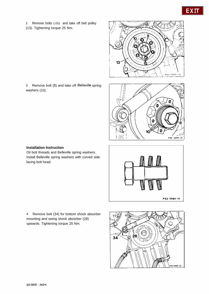
2 Remove bolts (15) and take off belt pulley(13). Tightening torque 25 Nm.
3 Remove bolt (8) and take off Eelleville springwashers (10).
Installation InstructionOil bolt threads and Belleville spring washers.Install Belleville spring washers with curved sidefacing bolt head.
4 Remove bolt (34) for bottom shock absorbermounting and swing shock abosrber (28)upwards. Tightening torque 25 Nm.
PO3-0064-13
03.0905 _ 342J4

5 Pull off vibration damper (11) with the puller103 589 00 33 00.Installation instructionWhen installing the vibration damper, checkwhether the groove in the hub is aligned with theBelleville spring washer in the crankshaft.
03.0905 - 34215
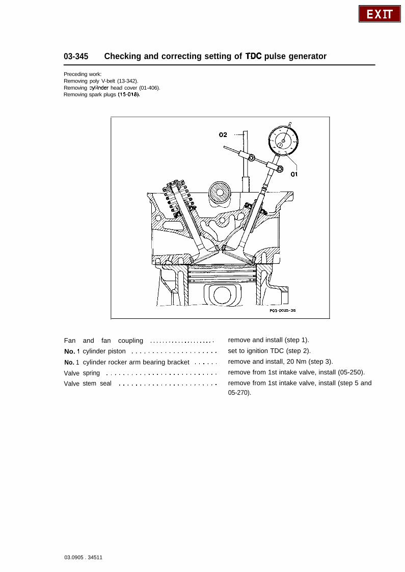
03-345 Checking and correcting setting of TDC pulse generator
Preceding work:Removing poly V-belt (13-342).Removing cylilnder head cover (01-406).Removing spark plugs (15-016).
PO3-0025-36
Fan and fan coupling . . . . . . . . . . . . . . . . . . . . . remove and install (step 1).
No. 1
No. 1ValveValve
cylinder piston ..................... set to ignition TDC (step 2).
cylinder rocker arm bearing bracket ...... remove and install, 20 Nm (step 3).
spring ........................... remove from 1st intake valve, install (05-250).
stem seal ........................ remove from 1st intake valve, install (step 5 and05-270).
03.0905 . 34511
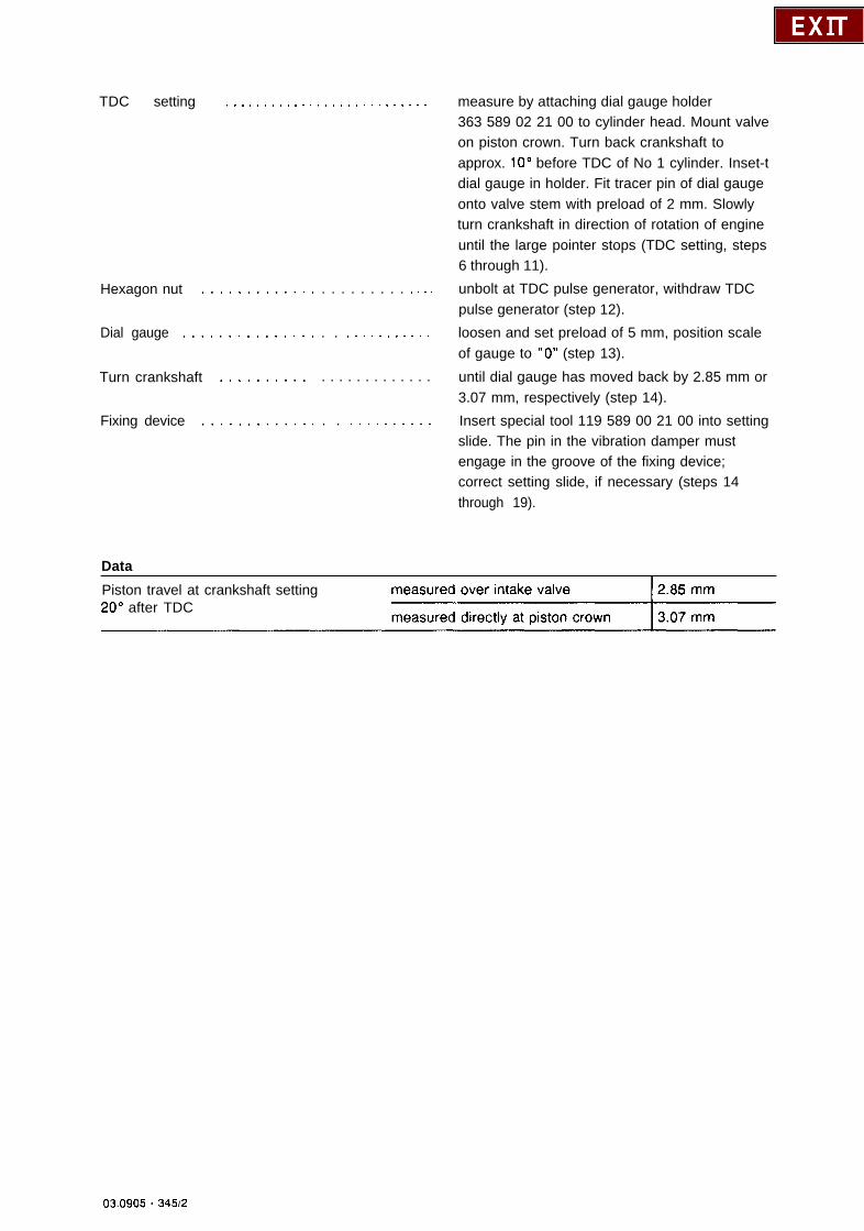
TDC setting . . . . . , . . . . . . . . . . . . . . . . . . . . . measure by attaching dial gauge holder
Hexagon nut ........... . .
Dial gauge ............. . .
Turn crankshaft ......... .
Fixing device ........... . .
Data
363 589 02 21 00 to cylinder head. Mount valveon piston crown. Turn back crankshaft toapprox. 10” before TDC of No 1 cylinder. Inset-tdial gauge in holder. Fit tracer pin of dial gaugeonto valve stem with preload of 2 mm. Slowlyturn crankshaft in direction of rotation of engineuntil the large pointer stops (TDC setting, steps6 through 11).
. . . . . . . . . , . . . unbolt at TDC pulse generator, withdraw TDCpulse generator (step 12).
. . * . . . . . . . . . . loosen and set preload of 5 mm, position scaleof gauge to “0” (step 13).
. . . . . . . . . . . . . until dial gauge has moved back by 2.85 mm or3.07 mm, respectively (step 14).
. . . . . . . . . . . . Insert special tool 119 589 00 21 00 into settingslide. The pin in the vibration damper mustengage in the groove of the fixing device;correct setting slide, if necessary (steps 14through 19).
Piston travel at crankshaft setting20” after TDC
03.0905 - 34512

Speclal tools
363 589 02 21 00
1102589 01 61 001
Commercial tool
1116589066300) I 104 58900 3700
001 589 51 21 001 I102 589 00 61 OC
Dial gauge A 1 DIN 878 8. g. MahrD-7300 EsslingenOrder No. 311000
NotesThe TDS pulse generator with holder (1) isattached to the timing case cover.The pin in the vibration damper or on the beltpulley must be positioned exactly below the TDCpulse generator at a crankshaft setting of 20”after TDC.
The adjustment of the TDC pulse generator mustbe checked or corrected:l When replacing the crankshaft or the
vibration damper.l When replacing the timing case cover.l When installing parts to reconditionedengines.
03.0905 - 34513
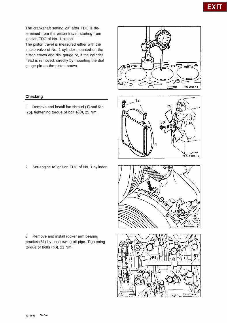
The crankshaft setting 20” after TDC is de-termined from the piston travel, starting fromignition TDC of No. 1 piston.The piston travel is measured either with theintake valve of No. 1 cylinder mounted on thepiston crown and dial gauge or, if the cylinderhead is removed, directly by mounting the dialgauge pin on the piston crown.
Checking
1 Remove and install fan shroud (1) and fan(75) tightening torque of bolt (SO), 25 Nm.
2 Set engine to ignition TDC of No. 1 cylinder.
3 Remove and install rocker arm bearingbracket (61) by unscrewing oil pipe. Tighteningtorque of bolts (63), 21 Nm.
PO3.2026.13
03.0905 - 34514
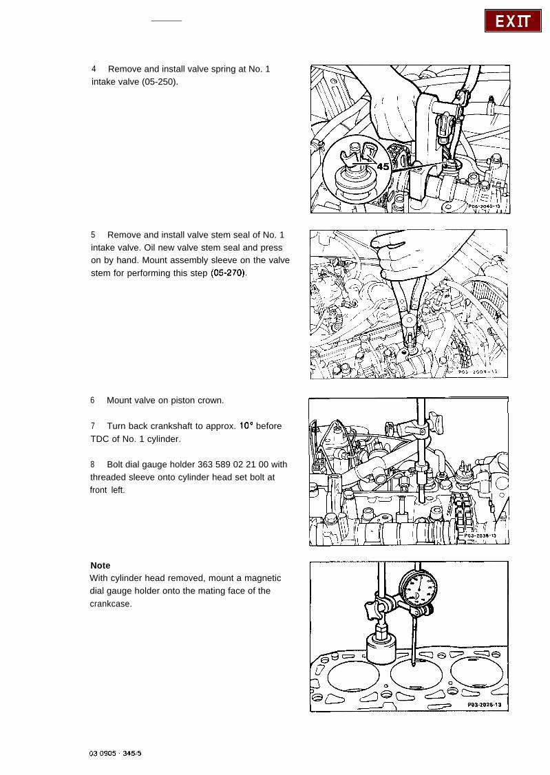
4 Remove and install valve spring at No. 1intake valve (05-250).
5 Remove and install valve stem seal of No. 1intake valve. Oil new valve stem seal and presson by hand. Mount assembly sleeve on the valvestem for performing this step (05-270).
6 Mount valve on piston crown.
7 Turn back crankshaft to approx. 10” beforeTDC of No. 1 cylinder.
8 Bolt dial gauge holder 363 589 02 21 00 withthreaded sleeve onto cylinder head set bolt atfront left.
NoteWith cylinder head removed, mount a magneticdial gauge holder onto the mating face of thecrankcase.
03 0905 - 34515
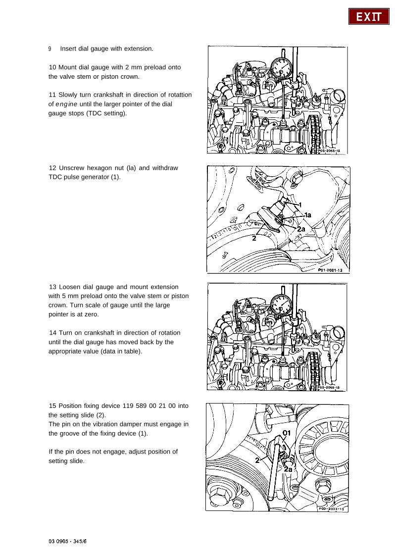
9 Insert dial gauge with extension.
10 Mount dial gauge with 2 mm preload ontothe valve stem or piston crown.
11 Slowly turn crankshaft in direction of rotattionof engine until the larger pointer of the dialgauge stops (TDC setting).
12 Unscrew hexagon nut (la) and withdrawTDC pulse generator (1).
13 Loosen dial gauge and mount extensionwith 5 mm preload onto the valve stem or pistoncrown. Turn scale of gauge until the largepointer is at zero.
14 Turn on crankshaft in direction of rotationuntil the dial gauge has moved back by theappropriate value (data in table).
15 Position fixing device 119 589 00 21 00 intothe setting slide (2).The pin on the vibration damper must engage inthe groove of the fixing device (1).
If the pin does not engage, adjust position ofsetting slide.
03 0905 - 34516
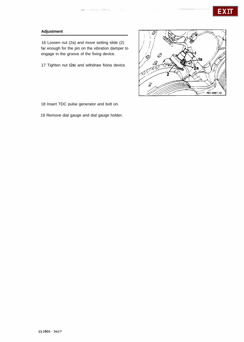
Adjustment
16 Loosen nut (2a) and move setting slide (2)far enough for the pin on the vibration damper toengage in the groove of the fixing device.
17 Tighten nut (2aj and withdraw fixina device.
18 Insert TDC pulse generator and bolt on.
19 Remove dial gauge and dial gauge holder.
03.0905 - 3497
03-350 Removal and installation of crankshaft gear
Preceding work:Removing liming case cover (01-210).Removing chain tensioner (05-310).
w PO3-0031-3s
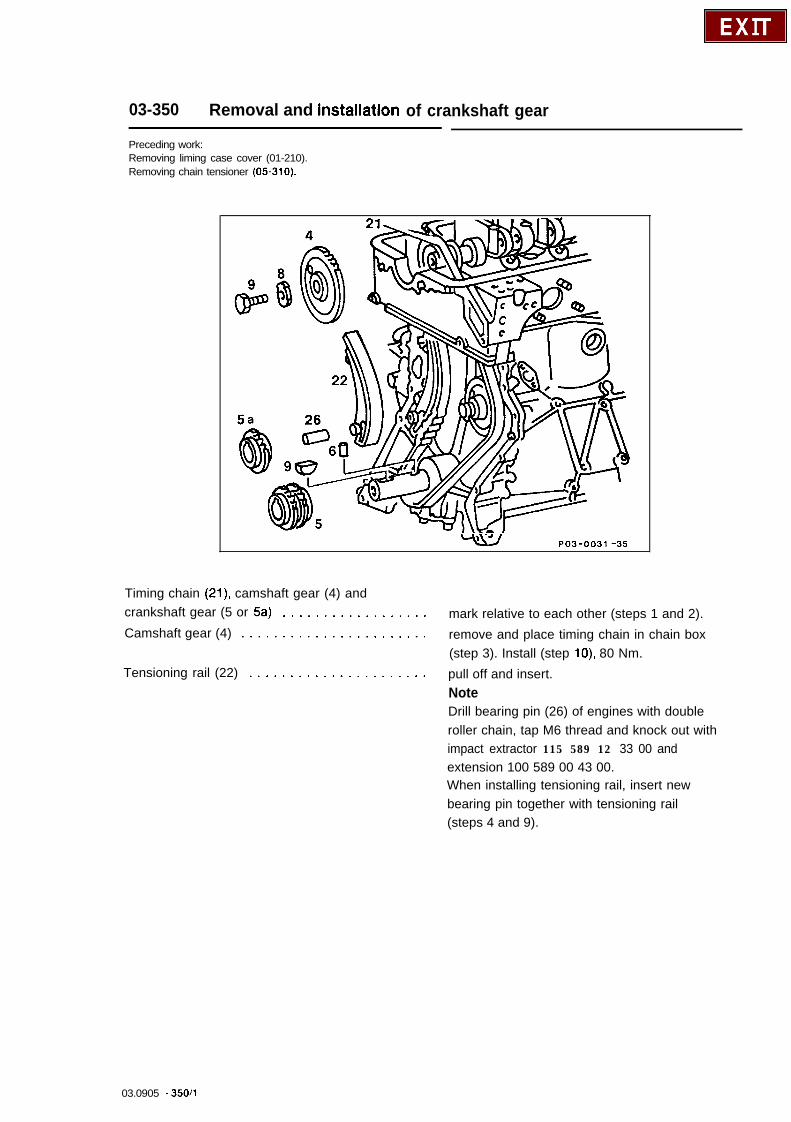
Timing chain (21) camshaft gear (4) andcrankshaft gear (5 or 5a) ..................Camshaft gear (4) .......................
Tensioning rail (22) ......................
mark relative to each other (steps 1 and 2).
remove and place timing chain in chain box(step 3). Install (step lo), 80 Nm.
pull off and insert.NoteDrill bearing pin (26) of engines with doubleroller chain, tap M6 thread and knock out withimpact extractor 115 589 12 33 00 andextension 100 589 00 43 00.When installing tensioning rail, insert newbearing pin together with tensioning rail(steps 4 and 9).
03.0905 - 35011
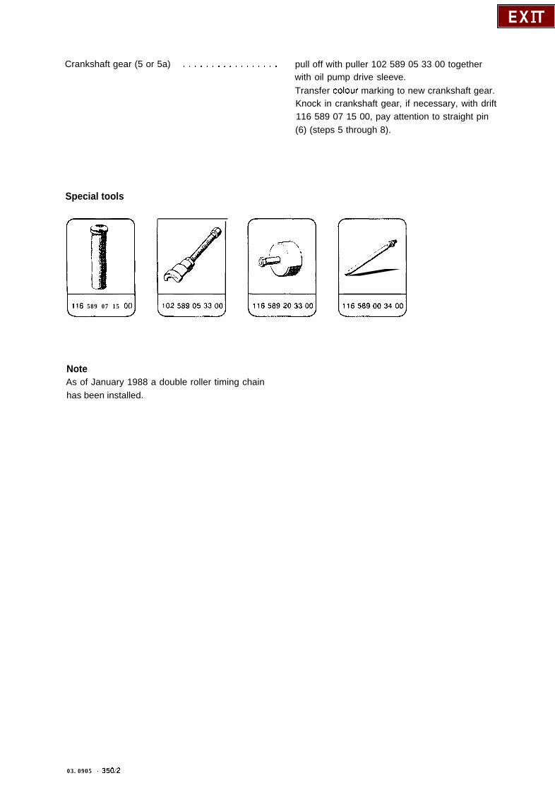
Crankshaft gear (5 or 5a) . . . . . . . . . . , . . . . . . pull off with puller 102 589 05 33 00 togetherwith oil pump drive sleeve.Transfer colour marking to new crankshaft gear.Knock in crankshaft gear, if necessary, with drift116 589 07 15 00, pay attention to straight pin(6) (steps 5 through 8).
Special tools
116 589 07 15 O(
I’I
/’
1165890034Ot
NoteAs of January 1988 a double roller timing chainhas been installed.
03.0905 - 35012

Removal and installation
1 Mark timing chain and camshaft gearrerlative to each other.
2 Mark timing chain and crankshaft gearrelative to each other.
3 Unbolt camshaft gear and place timing chainin chain box.
4 Pull tensioning rail (22) off bearing pin (26) .
NoteOn engines with double roller chain, knock outbearing pin of tensioning rail with the impactextractor 115 589 12 33 00 and the extension100 589 00 43 00.To perform the step, tap an M6 thread approx.10 mm deep into the bearing pin.
I /\ ? \/ PO3.2056.13
PO3-2054.13A
03 0905 - 350/3

5 Pull off crankshaft gear and oil pump drivesleeve with the puller 102 589 05 33 00.
6 If the crankshaft gear is replaced, transfercolor marking from the old to the new crankshaftgear.
7 Install crankshaft gear onto crankshaft. If thisproves difficult, knock in with the impact drift116 589 07 15 00.Pay attention to the straight pin for locating,when performing this step.
8 Insert drive sleeve.
9 Insert tensioning rail.On engines with double roller chain, inserttensioning rail and knock in new bearing pin asfar as the stop.
10 Install camshaft gear (pay attention to colormarking), tightening torque 80 Nm.
11 Check for leaks with engine running.
PO3.2035-13 I
03.0905 - 35014

03-410 Removal and Installation of flywheel or flex plate
Precedmg work:Removing transmssion (26-020 or 27-600).Removtng clutch (25-050).
PO3-0020-35
Retaining lock on starter ring gear . . . . . . . . . . . remove and install, special tool601 589 02 40 00 (step 2).
Stretch bolt (18) . . . . . . . . . . . , . . . , . . . . . . . . unbolt, bolt in, check length/stretch shaft dia.,initial torque 30 Nm, angle of rotation torque90”, with two-mass flywheel 50 Nm, angle ofrotation torque 90” (steps 6 and 7).
Flywheel (16) or flex plate (43) withspacer disc (44) . . . . . . . . . . . . . . . . . . . . . . . . detach, attach (step 5).
Special tools
001 569 66 21001 [ 601 569 02 40 00 1
03.0905 - 41011
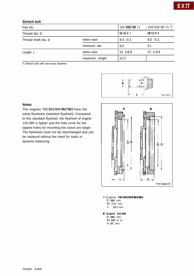
Stretch boltPart No. I 102 032 00 71 I 103 032 00 71 ‘)
Thread dia. D I MlOxl MlOxl
Thread shaft dia. d when new I 8.5 -0.2 8.5 -0.2
minimum dia. I 8.0 8.1
Length L when new I 22 20.2 57 kO.2
1) Stretch bolt with two-mass flywheel
maximum length 22.5
NotesThe engines 102.9221924i962/963 have thesame flywheels (standard flywheel). Comparedto this standard flywheel, the flywheel of engine102.985 is lighter and the hole circle for thetapped holes for mounting the clutch are larger.The flywheels must not be interchanged and can
’be replaced without the need for static ordynamic balancing.
I i--- H 4 I--H
--
1 f
60
.-
PO3-0026.15
A Engines 102.922/924/962/963D 253 mmDl 223 mmH 58.6 mm
8 Engine 102.985D 265 mmDl 237 m mH 57 mm
03.0905 . 410/2
._...__ . . ..-. _
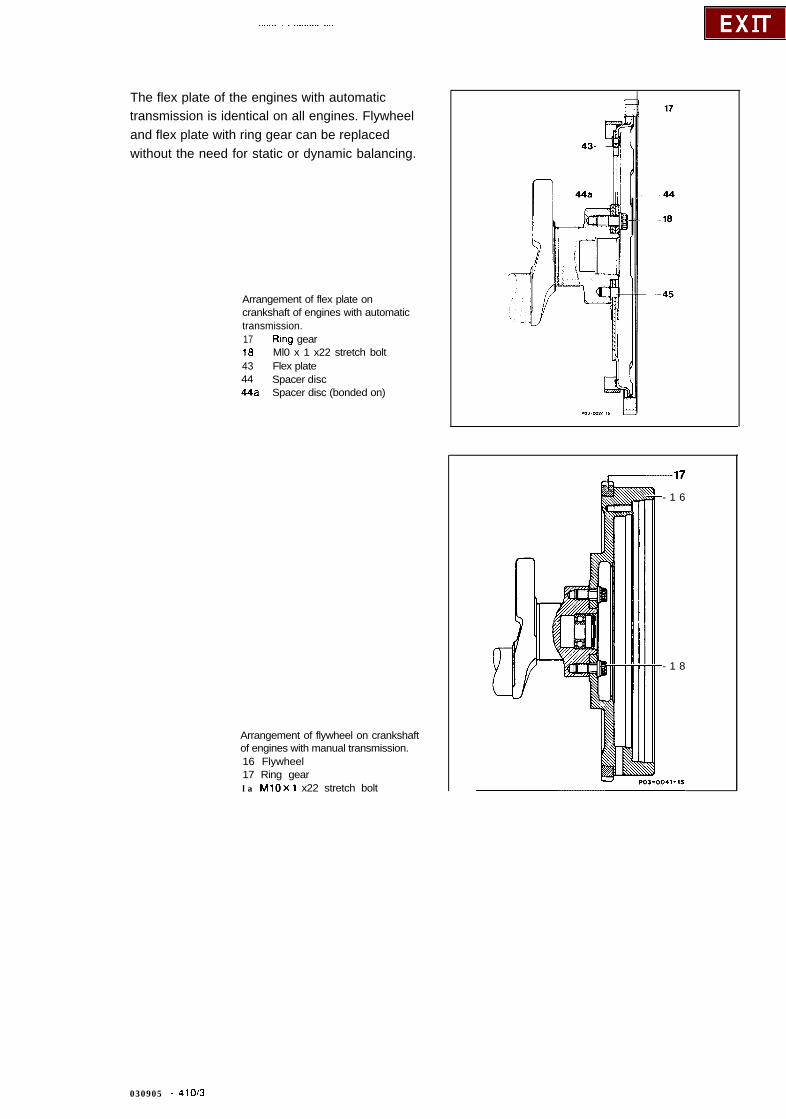
The flex plate of the engines with automatictransmission is identical on all engines. Flywheeland flex plate with ring gear can be replacedwithout the need for static or dynamic balancing.
Arrangement of flex plate oncrankshaft of engines with automatictransmission.17 Ring gearia Ml0 x 1 x22 stretch bolt43 Flex plate44 Spacer disc44a Spacer disc (bonded on)
Arrangement of flywheel on crankshaftof engines with manual transmission.16 Flywheel17 Ring gearla MlOxl x22 stretch bolt
- 1 6
- 1 8
030905 - 4100
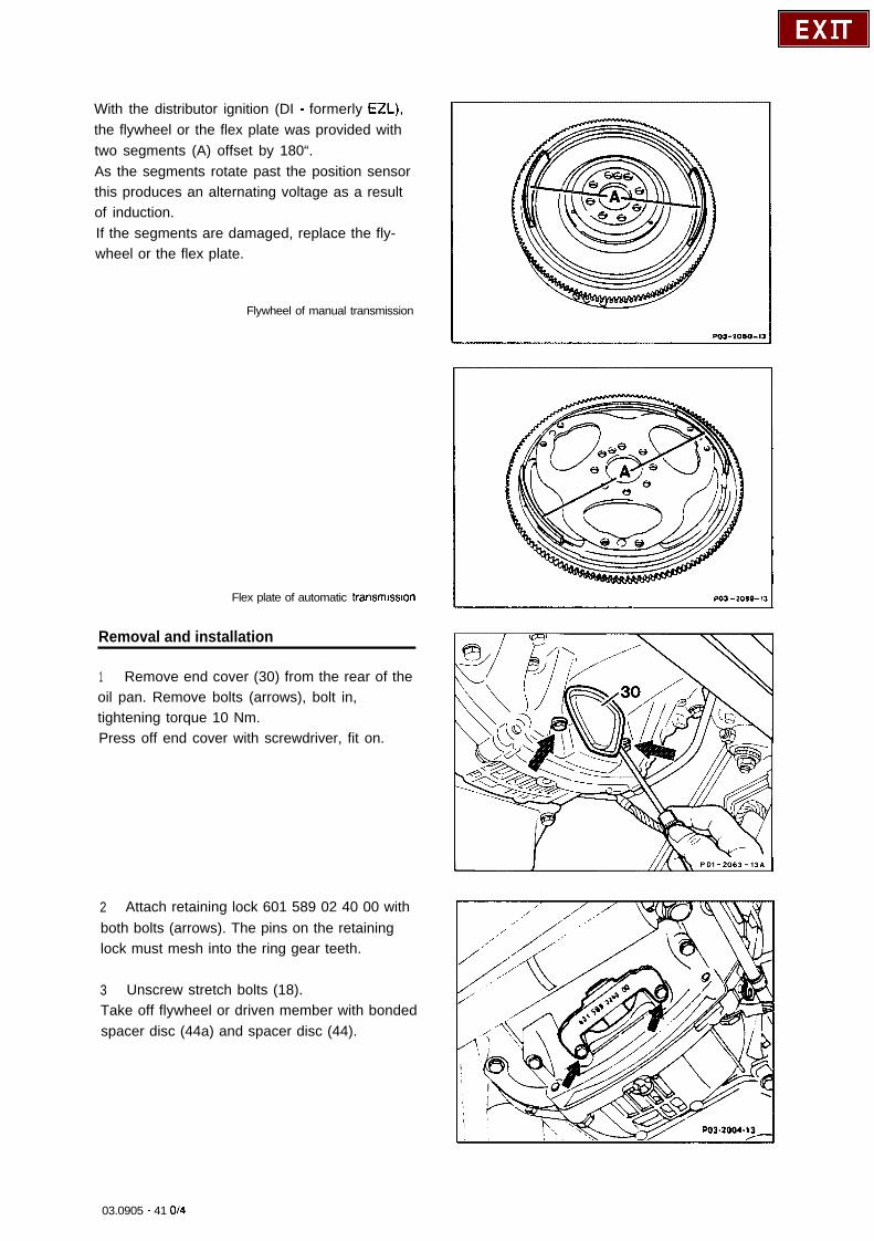
With the distributor ignition (DI - formerly EZL),the flywheel or the flex plate was provided withtwo segments (A) offset by 180“.As the segments rotate past the position sensorthis produces an alternating voltage as a resultof induction.If the segments are damaged, replace the fly-wheel or the flex plate.
Flywheel of manual transmission
Flex plate of automatic transmission
Removal and installation
1 Remove end cover (30) from the rear of theoil pan. Remove bolts (arrows), bolt in,tightening torque 10 Nm.Press off end cover with screwdriver, fit on.
2 Attach retaining lock 601 589 02 40 00 withboth bolts (arrows). The pins on the retaininglock must mesh into the ring gear teeth.
3 Unscrew stretch bolts (18).Take off flywheel or driven member with bondedspacer disc (44a) and spacer disc (44).
03.0905 - 41 o/4
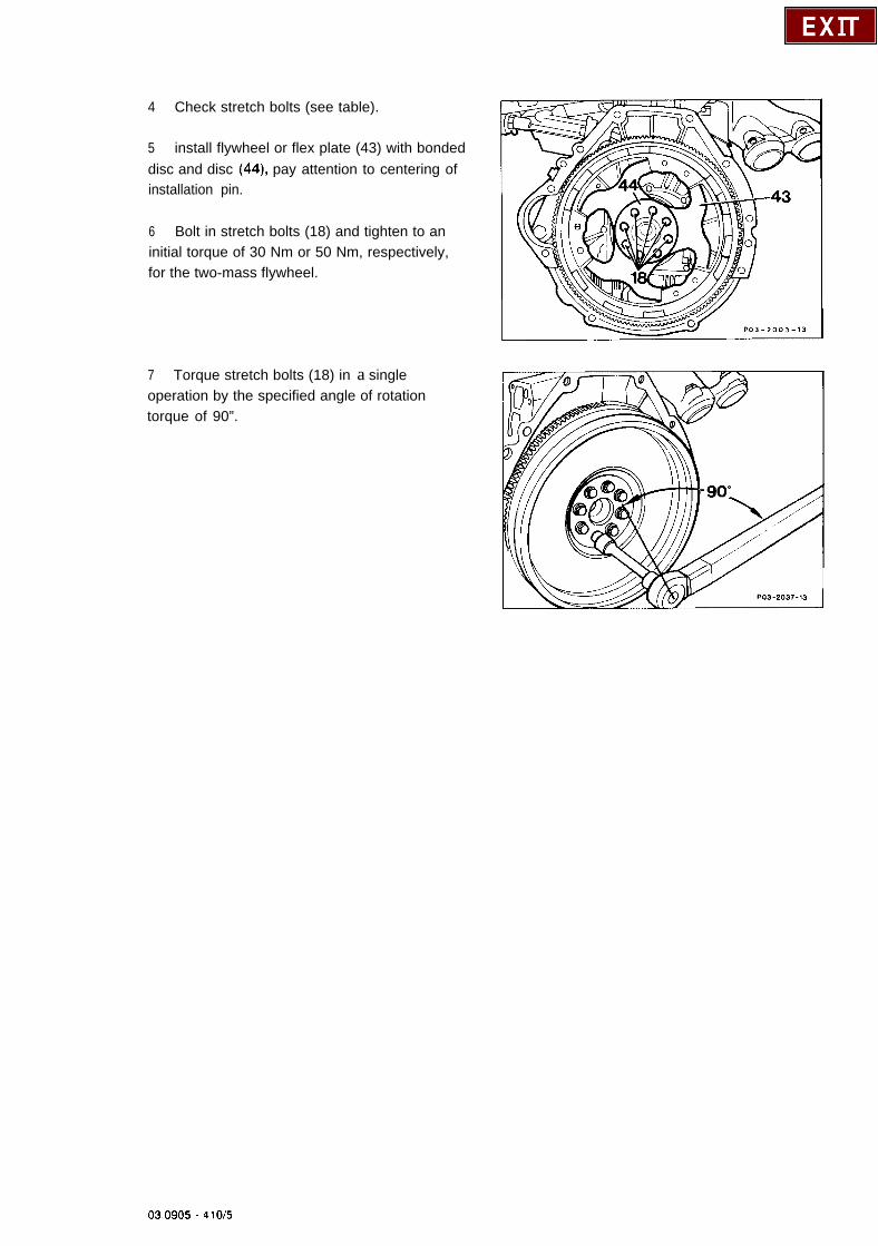
4 Check stretch bolts (see table).
5 install flywheel or flex plate (43) with bondeddisc and disc (44), pay attention to centering ofinstallation pin.
6 Bolt in stretch bolts (18) and tighten to aninitial torque of 30 Nm or 50 Nm, respectively,for the two-mass flywheel.
7 Torque stretch bolts (18) in a singleoperation by the specified angle of rotationtorque of 90”.
03.0905 . 410/5
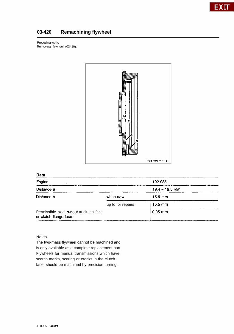
03-420 Remachining flywheel
Preceding work:Removing flywheel (03410).
PO3-0074-15
up to for repairs
Permissible axial runout at clutch face
NotesThe two-mass flywheel cannot be machined andis only available as a complete replacement part.Flywheels for manual transmissions which havescorch marks, scoring or cracks in the clutchface, should be machined by precision turning.
03.0905 - 42011
If grooves or cracks are deeper than themaximum permissible material removal, theflywheel must be replaced.If the clutch face A is machined, the mountingface B must be machined by the same amountin order to maintain the distance a.The size b must be maintained as a minimumwhen performing repairs.The flywheel must be properly clamped formachining to ensure that the permissible axialrunout of 0.05 mm is not exceeded.After machining, the clutch face must not showany shrink holes or chatter marks.
03.0905 - 42012
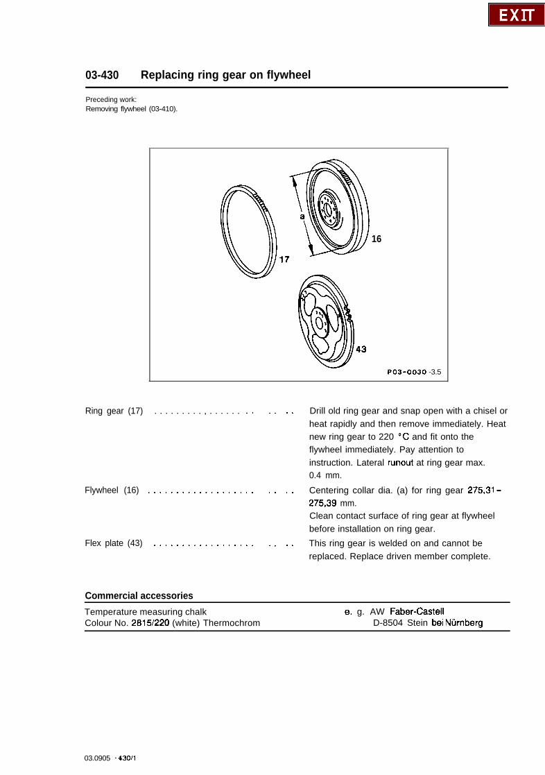
03-430 Replacing ring gear on flywheel
Preceding work:Removing flywheel (03-410).
16
PO3-0030 -3.5
Ring gear (17) . . . . . . . . . , . . . . . .
Flywheel (16) .................
Flex plate (43) ................
* .
. .
. .
. .
. .
. .
. . Drill old ring gear and snap open with a chisel orheat rapidly and then remove immediately. Heatnew ring gear to 220 “C and fit onto theflywheel immediately. Pay attention toinstruction. Lateral runout at ring gear max.0.4 mm.
. . Centering collar dia. (a) for ring gear 275,31 -27539 mm.Clean contact surface of ring gear at flywheelbefore installation on ring gear.
. . This ring gear is welded on and cannot bereplaced. Replace driven member complete.
Commercial accessories
Temperature measuring chalkColour No. 2815/220 (white) Thermochrom
e. g. AW Faber-Caste11D-8504 Stein bei Nurnberg
03.0905 - 430/l
NotesThe ring gear is hardened. For this reason, donot exceed a temperature of 220 “C (yellowannealing colour) at any point when heating. Thisis only reliably possible by using a heating plateor heating oven.Use a temperature measuring chalkcorresponding to the instructions if possible.Only use a flame in exceptional cases.Coat only the inside of the ring gear for thispurpose.After replacing a ring gear, the flywheel does notneed to be balanced.
To avoid damage to the ring gear, a ring gearwith axially chamferred teeth was installed for abrief period to vehicles with automatictransmission.
Standard implementation: April - July 1986 standard
Model Engine Engine End No.
Manualtransmission
Automatictransmission
201.028 102.985 033406 - 038268
03.0905 - 43Oi2