Cranes-and-Lifting-1.pdf - Vedanta Aluminium
37
Document: VED/CORP/SUST/GN17 Version V.1 Vedanta Resources Plc Sustainability Governance System Guidance Note GN17 Cranes and Lifting
-
Upload
khangminh22 -
Category
Documents
-
view
1 -
download
0
Transcript of Cranes-and-Lifting-1.pdf - Vedanta Aluminium

Document: VED/CORP/SUST/GN17 Version V.1
Vedanta Resources Plc
Sustainability Governance System
Guidance Note GN17
Cranes and Lifting

Document: VED/CORP/SUST/GN17 Version V.0 Page 2 | 37
Guidance Document Title: Cranes and Lifting Date of Revision 28/08/2019
Document VED/CORP/SUST/GN17 Revision: V.1.
Document Issue and Revision History
DATE REVISION NUMBER CHANGE SUMMARY
26/9/2019 V.2. Clarifications, additions and a section on maintenance practices
Prepared by: Roger Belair Authorised by: Phillip Turner
Signature
Signature
Position: Group Safety Head Position: Group Head – HSE &
Sustainability
Confidentiality
This document and its contents are the copyright property of Vedanta Resources Plc. The release of this document to
any third party outside of Vedanta is strictly prohibited without prior consent.

Document: VED/CORP/SUST/GN17 Version V.0 Page 3 | 37
Contents
1. INTRODUCTION 4
1.1. Who is this Guidance Note aimed at? 4
1.2. What is the aim of this Guidance Note? 4
1.3. What issues does this Guidance Note address? 4
1.4. How should this Guidance Note be used? 4
2. DEFINITIONS 4
3. LIFT PLANNING 8
3.1. Precautions for all lifts 10
3.2. Tailing lift planning 11
3.3. Selection of Cranes 12
3.4. Weight of Load 12
3.5. Data for lifting plan- (Operator must know) 12
3.6. Routine Lift Planning 12
3.7. Critical Lifts 13
3.8. Sample Lift Plan 15
4. PEOPLE 18
4.1. Lifting Coordinator 18
4.2. Crane Operator 19
4.3. Riggers 21
4.4. Banksman: 22
5. MAINTENANCE AND INSPECTIONS 24
5.1. Rigging Loft & Its Management 24
5.2. Safety Audits of all lifting equipment’s, Tools & Tackles and Operators, Riggers including that of Business Partners 24
5.3. Tests & Examinations 24
5.4. Periodic Checks 25
6. Maintenance Safety Requirements: 28
7. SPECIFIC CRANE CONFIGURATIONS AND INFORMATION 29
7.1. Crane Radius 29
7.2. Pick & Carry Cranes 31
7.3. Mobile Crane Procedures and Practices 31
7.4. Levelling of Cranes 37
Document: VED/CORP/SUST/GN17 Version V.0 Page 4 | 37
1. INTRODUCTION
1.1. Who is this Guidance Note aimed at?
This Guidance Note (GN) is aimed at all Vedanta subsidiaries, operations and managed sites, including new
acquisitions, corporate offices and research facilities and to all new and existing employees and Business
Partner employees. This GN is applicable to the entire operation lifecycle (including exploration and planning, evaluation, operation and closure). This GN is applicable to all Incidents.
1.2. What is the aim of this Guidance Note?
Guidance Note should identify the underlying causes: the safety management system weaknesses. This aim
of this Guidance Note is to outline the company and manufacture’s requirements which Vedanta implements in order to provide a consistent approach to reduce risk with respect to cranes and lifting safety.
1.3. What issues does this Guidance Note address?
This Guidance Note presents the framework on effective implementation of Best Practices within Vedanta
operations. The focus of the Guidance Note is on the provision of preferred method and outcomes rather than prescriptions whilst at the same time representing a practical “how to” guide for all Vedanta operators.
1.4. How should this Guidance Note be used?
This Guidance Note is mandatory (as per instructions in Section 1.3 above) and is intended to provide a standard baseline and reflect good practice whilst providing the basis for continual improvement of
sustainability issues across the Vedanta business. The need for flexibility at a site depending upon specific
circumstances or regulatory specific requirements is also recognized. This Guidance Note is not designed to be definitive text, nor is it designed to provide prescriptive methods and procedures for undertaking tasks,
the manufacturer’s instructions must be consulted, reviewed, understood and implemented.
In certain cases, there will be national and/or local regulatory requirements which address Incident
investigation process sites shall ensure that these requirements are identified and complied with. The
successful implementation of this Guidance Note is expected to require dedicated commitment from all of
the Vedanta sites.
2. DEFINITIONS
Anti-Two Blocking
Device
A device which prevents main block/auxiliary block from touching the boom tip sheaves.
Appointed Assigned specific responsibilities by representative.
Auxiliary Hoist A supplemental hoisting unit of lighter capacity and usually higher speed than provided for
the main hoist.
Banksman A crane driver's helper, who signals instructions to the driver for the movement of the
crane and its jib.
Below the hook
Lifting Devices
Devices that are not normally reeved onto the hoist rope or chain, such as hook-on
buckets, magnets, grabs, and other supplemental devices used for ease of handling certain
types of loads. The weight of these devices is to be considered part of the load to be lifted.

Document: VED/CORP/SUST/GN17 Version V.0 Page 5 | 37
Boom The horizontal beam (track) upon which is on a jib crane.
Capacity The maximum weight in tons the crane will be required to lift safely without tipping,
falling or loss of load.
Chain Guide A means to guide the hoist load chain at the load sprocket.
Clearance The distance from any part of the crane to a point of nearest obstruction, including swing
load of counter weight.
Competent “competent person” means a person who,
(a) is qualified because of knowledge, training and experience to conduct the work and its
performance safely;
(b) is familiar with this legal safety requirements and the Vedanta Safety Standards that
apply to the work, and
(c) has knowledge of any potential or actual danger to health or safety of workers and
known what controls are required to prevent an injury / illness.
Counter Torque A method of control by which the power to the motor is reversed to develop torque in the
opposite direction.
Counter Weight A counterweight is a weight that, by exerting an opposite force, provides balance and
stability of a mechanical system. Its purpose is to make lifting the load more efficient,
which saves energy and is less taxing on the lifting machine.
Crane A machine for lifting and lowering a load and moving it horizontally and vertically with the
hoisting integral part of the machine. Cranes whether fixed or mobile are driven manually
or by power.
Deflection The difference in elevation at the tip of the boom between an unloaded jib crane and a
fully loaded jib crane; usually measured in inches. Our Jib Crane designs tend to have
stricter deflection criteria than others in the industry.
Designated Person A person selected or assigned by the employer or the employer's representative as being
competent to perform specific duties.
Drum The cylindrical member around whom the ropes are wound for raising or lowering the
load.
Dual or Tandem Lift Tandem lift involving the simultaneous use of two or more cranes or hoists to lift a large
load. A lift in which the centre of gravity of the load can changes during the lift.
Dynamic A method of controlling crane motor speeds when in the overhauling condition to provide
a retarding force.
Emergency Stop Switch A manually or automatically operated electric switch to cut off electric power
independently of the regular operating controls.
Enclosures The enclosures house all of the electrical components on the crane.
Equalizer Beam Equalizer beams are used to equalize the load.
Fail safe A provision designed to automatically stop or safely control any motion in
which a malfunction occurs.
Fleet
Angle
The fleet angle is defined as the largest angle of the rope between the first
sheave and the drum flange, relative to the centre line of the drum. With all
types of drum, the rope is subject to a fleet angle, which directly influences its
behaviour and impacts on its service life.
Hand
Signals
A crane operator should always move loads according to the established code
of signals, and use a signaler. Hand signals are preferred and commonly used. A

Document: VED/CORP/SUST/GN17 Version V.0 Page 6 | 37
signaler may be required by law if the operator’s view of the intended path of
travel is obstructed.
Height Under Boom
(HUB)
The distance from the floor to the underside of a jib crane’s boom. The minimum height
under boom equals the height of the load, plus the maximum distance the load is to be
lifted, plus the headroom required for the hoist, trolley, and attachments.
Hoist A mechanical unit that is used for lifting and lowering a load via a hook or lifting
attachment.
Hoist Chain The load bearing chain in a hoist.
Hoist Motion The motion of a crane which raises and lowers a load.
Holding Brake A brake that automatically prevents movement when there is no power.
Hook Height See Lift Height.
Lift Height The maximum safe vertical distance that the hook can travel from the floor
Crane Jib Crane jib –an extension at the top of a crane tower that gives the crane additional lifting
or moving capabilities. There are different types of jibs. A saddle jib is a horizontal
extension, at a right angle to the tower, with a hook attached to a trolley.
Lifting Devices See Below
Crane Hook hook Lifting Devices
Limit Switch A device designed to disconnect the power automatically at or near the limit of travel for
the crane motion.
Load The total superimposed weight on the hoist load block or hook.
Load Block The assembly of hook or shackle, swivel, bearing, sheaves, sprockets, pins, becket and
frame suspended by the hoisting rope or load chain. This shall include any appurtenances
reeved in the hoisting rope or load chain.
Load Chain The load-bearing chain in a hoist.
Load Moment Indicator
/ Safe Load Indicator
A device in a mobile or portable cranes that indicates boom length, radius and load
weight. And also alerts the operator when lift exceeds the safe operating range of
machinery.
Load Sprocket A hoist component that transmits motion to the load chain. This hoist component is
sometimes called load wheel, load sheave, pocket wheel, or chain wheel.
Main Hoist The hoist mechanism provided for lifting the maximum rated load.
Main Boom Is the main boom of the mobile crane which takes the complete load
Mast The vertical steel component of a jib crane which supports the crane. Free
Standing jib cranes (including Work Station Jibs) have a circular pipe for a mast, Wall
Cantilever cranes have standard I-beams, and Mast Type cranes have wide flange beams.
Wall Bracket cranes do not have a mast.
Non running Sheave A hoist sheave used to equalize tension in opposite parts of the rope or chain. Because of
its slight movement, it is not termed a running sheave.
Out Riggers The foot of the crane which take complete weight of the machine and the load.
Out Rigger Pads Is a mat that is fabricated to distribute the load of the outriggers. These mats are
strong enough to support the crane and the hoisting material’s weight. As a general

Document: VED/CORP/SUST/GN17 Version V.0 Page 7 | 37
guideline, outrigger pad size should be at least three times the size of
the outrigger foot itself for proper weight distribution.
Overhead Power lines
lifting clearances
Cranes lifting near overhead line wire or electrical lines must maintain a minimum
standard clearance distances of:
750 or more volts, but no more than 150,000 volts. Minimum distance: 3
metres
Over 150,000 volts, but no more than 250,000 volts. Minimum distance: 4.5
metres.
More than 250,000 volts. Minimum distance: 6 metres
a. A person shall be designated to observe clearance of the equipment & give
timely warning for all operations, where it is difficult for the operator to maintain the
desired clearance by visual means
b. Any overhead wire shall be considered to be an energized line unless & until
the person owning such line or the electrical utility authorities indicate that it is not an
energized line and it has been visibly grounded. The crane operator must also apply his
isolation lock and sign on to the work permit.
Overload Any hoist load greater than the rated load.
Parts (Lines) Number of lines of rope or chain supporting the load block or hook.
Pendant The pendant gives the operator precise control over the motions of the crane.
Power Supply The electrical service available in the building for which the crane is being designed.
Power
Transmission Parts
Hoist machinery components including the gears, shafts, clutches, couplings,
bearings, motors, and brakes.
Qualified Person A person who, by possession of a recognized degree in an applicable field or a certificate
of professional standing, or who by extensive knowledge, training, and experience, has
successfully demonstrated the ability to solve or resolve problems relating to the subject
matter and work.
Radio Remote Control The radio control performs exactly like the pendant but operates using a radio frequency.
Rated load The maximum load a crane is designed to handle.
Reeving A system in which a rope or chain travels around drums, sheaves or sprockets.
Rigger A rigger works with the carne and affixes the rigging to the load and the hook on the
crane. They give instructions to the crane to safely lift a load. Riggers must be aware of
elements that can affect hoisting safety, factors that reduce capacity, and safe practices in
rigging, lifting, and landing loads. Riggers must also be familiar with the proper inspection
and use of slings and other rigging hardware.
Roller Chain A series of alternately assembled roller links and pin links in which the pins articulate inside the bushings and the rollers are free to turn on the bushings. Pins and bushings are press fit in their respective link plates.
Rope A wire rope, unless otherwise specified.
Running Sheave A hoist sheave that rotates as the load block is lifted or lowered.

Document: VED/CORP/SUST/GN17 Version V.0 Page 8 | 37
Safety Latch / Hook
Latch
A latch provided to bridge the throat opening on hook to prevent the release of load.
Side Pull The component of the hoist pull acting horizontally when the hoist lines are not operated
vertically.
Spreader Beam Any beam where the load being lifted mainly puts a compressive stress in the beam.
Standby Crane A crane which is not in regular service, but is used occasionally or intermittently as
required.
Stop A device to limit travel of a trolley or crane bridge. This device is normally attached to a
fixed structure and does not have energy absorbing ability.
SWL (Safe working
load)
The manufacturer's recommended maximum weight load for a line, rope, crane or any
other lifting device or component of a lifting device.
Tagline Is a piece of rope that is attached to the load to help directed while it being hoisted? They
must be non-conductive.
“Walkie Talkie” A walkie-talkie is a small portable radio, which you can talk into and hear messages
through so that you can communicate with someone far away.
3. LIFT PLANNING
There are many elements to be considered when developing a lift plan. In particular, whether it is a Routine or
Critical Lift; who will approve the lifting plan; the equipment to be used; and the skill, knowledge and competence of those conducting and supervising the lift. The process below is always required:
• Inspection of selected crane by a 3rd party/Vedanta rep at Business Partner’s location before mobilization
through an inspection checklist and checklist to be preserved for records;
• The selected crane must have valid visual inspection, NDT inspection & Load test certificates signed by a
competent authority of the respective state govt. where the lifting equipment’s will be deployed.
• The selected crane must have valid visual inspection, NDT inspection & Load test certificates signed by a
competent authority of the respective state govt. where the lifting equipment’s will be deployed;
• All the rigging hardware which will be used must have valid certificates from a competent person certified by
state Govt.
• Each lift is to be categorized into Routine or Critical Lift before commencing.
• Upon categorization, method statement needs to be prepared for every lift and the statements to be
preserved for records;
• There must be a documented process that ensures all critical components are inspected and in place prior to
a crane being commissioned and put into service and for recertification if the crane configuration is changed, for example, the attachment or removal of a boom section.
• Operators must undertake a pre-operational safety check for each shift the crane or lifting equipment is used
and this should be kept with the equipment. The detail required in the pre-operational safety check must be based on a risk assessment for the equipment.
• Lifting equipment must not be operated with an inoperable or defective safety device or work place
conditions. No inbuilt interlock should be bypassed.
• Checks that the load being lifted is within the rated capacity of the crane and lifting attachments and is also
within the limits set out in the lift plan;
• All lifting hooks (except for grab and chain shortening hooks) will be fitted with a safety latch to prevent the
load from accidentally detaching, unless otherwise specified in a risk assessment.

Document: VED/CORP/SUST/GN17 Version V.0 Page 9 | 37
• Loads must not swing over people or occupied buildings and no person shall be under a suspended load or in
a position where they could be struck by a falling load. Where there is a risk of a load falling and striking a
person, hard barricading or similar controls to prevent access must be in place at all times. Line of fire should be well defined & hard barricaded against any trespasser. Line of fire fall envelope also to have considerations
on crane toppling, boom failure etc.
• Tag lines/guide rope must be attached on both the side of the loads which require steadying or guidance while suspended. The load must be well secured and properly balanced in the sling or lifting device. No person shall
touch a suspended load – the load may only be positioned by the use of tag lines. Persons holding
taglines/guide ropes should not be in line of fire or be positioned under the load.
• Ground bearing strength is to be checked and level.
• The weight of the load must be known prior to hoist or lifting the load.
Sample pre-use checklist
OWNER: MACHINE MODEL: INSPECTED BY:
MACHINE MAKE: RATED CAPACITY: DATE OF INSPECTION:
SL NAME OF PARTS OK NOT OK REMARKS
1 Crankcase Oil
2 Coolant level
3 Hydrolytic oil
4 Electrical system
5 House lock
6 Service /Parking Breaks
7 Swing Break
8 Gauges/ meters
9 Housekeeping
10 Fire Extinguisher
11 Load Chart
12 Windows/ Mirrors
13 Travel/Marching
14 Seat Belts
15 Spill Kits
16 Check all mirrors, including the one
for the hoisting drum
17 Check all windows
18 Leveling device
19 Steering
20 Outriggers
21 Boom Up/Boom Down
22 Hoists Up/Down
23 Swing
24 Anti-Two-Blocking Device
Document: VED/CORP/SUST/GN17 Version V.0 Page 10 | 37
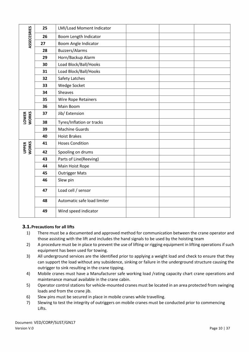
25 LMI/Load Moment Indicator
26 Boom Length Indicator
27 Boom Angle Indicator
28 Buzzers/Alarms
29 Horn/Backup Alarm
30 Load Block/Ball/Hooks
31 Load Block/Ball/Hooks
32 Safety Latches
33 Wedge Socket
34 Sheaves
35 Wire Rope Retainers
36 Main Boom
37 Jib/ Extension
38 Tyres/Inflation or tracks
39 Machine Guards
40 Hoist Brakes
41 Hoses Condition
42 Spooling on drums
43 Parts of Line(Reeving)
44 Main Hoist Rope
45 Outrigger Mats
46 Slew pin
47 Load cell / sensor
48 Automatic safe load limiter
49 Wind speed indicator
3.1. Precautions for all lifts
1) There must be a documented and approved method for communication between the crane operator and
those assisting with the lift and includes the hand signals to be used by the hoisting team
2) A procedure must be in place to prevent the use of lifting or rigging equipment in lifting operations if such
equipment has been used for towing. 3) All underground services are the identified prior to applying a weight load and check to ensure that they
can support the load without any subsidence, sinking or failure in the underground structure causing the
outrigger to sink resulting in the crane tipping.
4) Mobile cranes must have a Manufacturer safe working load /rating capacity chart crane operations and
maintenance manual available in the crane cabin. 5) Operator control stations for vehicle-mounted cranes must be located in an area protected from swinging
loads and from the crane jib.
6) Slew pins must be secured in place in mobile cranes while travelling. 7) Slewing to test the integrity of outriggers on mobile cranes must be conducted prior to commencing
Lifts.
Document: VED/CORP/SUST/GN17 Version V.0 Page 11 | 37
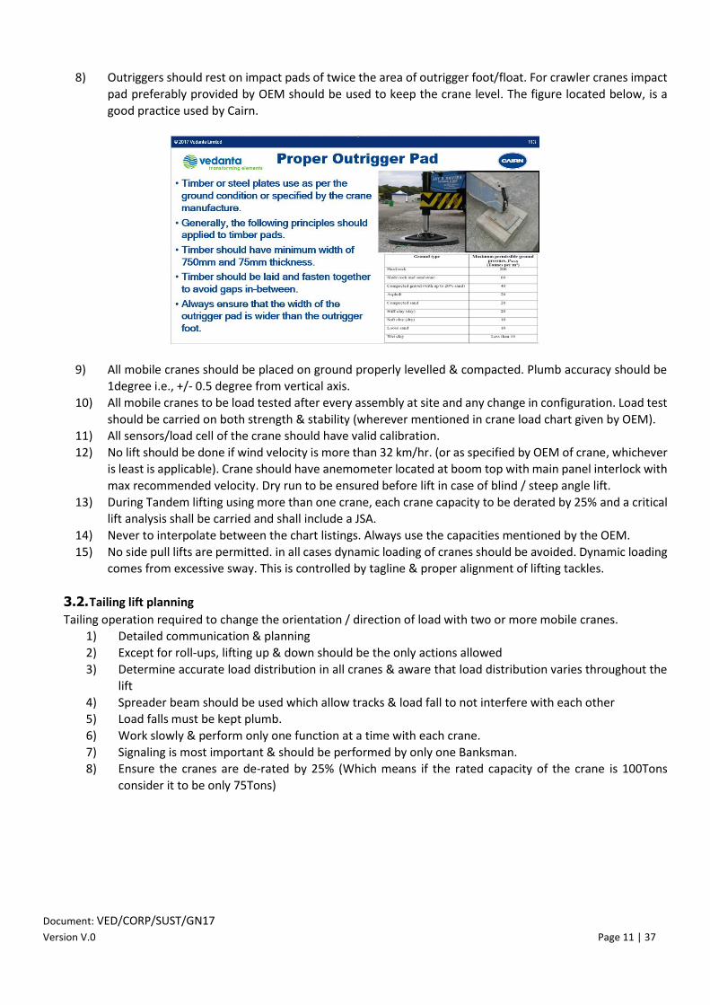
8) Outriggers should rest on impact pads of twice the area of outrigger foot/float. For crawler cranes impact
pad preferably provided by OEM should be used to keep the crane level. The figure located below, is a
good practice used by Cairn.
9) All mobile cranes should be placed on ground properly levelled & compacted. Plumb accuracy should be 1degree i.e., +/- 0.5 degree from vertical axis.
10) All mobile cranes to be load tested after every assembly at site and any change in configuration. Load test
should be carried on both strength & stability (wherever mentioned in crane load chart given by OEM).
11) All sensors/load cell of the crane should have valid calibration.
12) No lift should be done if wind velocity is more than 32 km/hr. (or as specified by OEM of crane, whichever is least is applicable). Crane should have anemometer located at boom top with main panel interlock with
max recommended velocity. Dry run to be ensured before lift in case of blind / steep angle lift.
13) During Tandem lifting using more than one crane, each crane capacity to be derated by 25% and a critical lift analysis shall be carried and shall include a JSA.
14) Never to interpolate between the chart listings. Always use the capacities mentioned by the OEM.
15) No side pull lifts are permitted. in all cases dynamic loading of cranes should be avoided. Dynamic loading
comes from excessive sway. This is controlled by tagline & proper alignment of lifting tackles.
3.2. Tailing lift planning
Tailing operation required to change the orientation / direction of load with two or more mobile cranes. 1) Detailed communication & planning
2) Except for roll-ups, lifting up & down should be the only actions allowed
3) Determine accurate load distribution in all cranes & aware that load distribution varies throughout the
lift
4) Spreader beam should be used which allow tracks & load fall to not interfere with each other 5) Load falls must be kept plumb.
6) Work slowly & perform only one function at a time with each crane.
7) Signaling is most important & should be performed by only one Banksman.
8) Ensure the cranes are de-rated by 25% (Which means if the rated capacity of the crane is 100Tons
consider it to be only 75Tons)

Document: VED/CORP/SUST/GN17 Version V.0 Page 12 | 37
3.3. Selection of Cranes
Ensure that the cranes taken from Business Partners on hire are not more than 10 years’ old. If the crane is
older than 10 years old, the business unit shall ensure the crane is in a safe operation condition. The crane
may only be used for a specific, one-time activity and must be safety inspected and certified by a third party for safe operation before use.
3.4. Weight of Load
• The weight, the packaging materials, rigging hardware and center of gravity of the load to be
lifted must be known. In the absence of this information from the supplier, the weight of the load
shall be determined either by weighbridge, load cell or accurate calculation.
• The weight of the block and of any lifting gear to be used shall be included in the total weight to
be lifted.
3.5. Data for lifting plan- (Operator must know)
a) Lift data: Equipment weight, rigging weight, total weight, height and radius of the lift, equipment surface
area, ground condition, canter of gravity;
b) Equipment data: Manufacturer, model, size, boom length, jib length, load block, material size; safety devices;
c) Rigging data: SWL, Sling diameter, length, sling configuration, capacity, hook type, shackle size and
capacity;
d) Lift calculations: Boom length, radius of lift, equipment capacity, size of outrigger footplates, outrigger
mats and wind speed;
e) Proximity to power lines and process areas: Mobile cranes working in proximity to energized power lines
must operate under a proximity permit, which must define exclusion zones and spotter duties;
f) Proximity to buildings, structures and process areas: Cranes operating in proximity to these must
document and plan for exclusion zones; to avoid structures; and to be able to complete the lift successfully;
g) Local hazards and their controls: Including the route for the crane, ground stability, proximity of people or
equipment and agreed communication method and known buried underground services.
3.6. Routine Lift Planning
Simple operations do not require elaborate planning. A note of the weight to be lifted and the maximum
radius that must be used from the centre of rotation of the crane shall be sufficient. Information on the height
to or from which the load is to be handled and an explanation of the slinging arrangements shall also be
included in the planning of simple operations and all of which shall be listed on JSA and Work Permit.
For each lift the following must be completed:
• Establishing the weight. • Selection of the crane.

Document: VED/CORP/SUST/GN17 Version V.0 Page 13 | 37
• Consideration of the operation location. • Ensuring that the crane has been thoroughly examined and inspected • Ensuring that a system for reporting defects is in place to stop work if a danger is identified. • Selecting appropriate lifting gear. • Ensuring that lifting gear are thoroughly examined, inspected and checked, before use. • Designating a person to check the lifting gear. • Briefing all persons involved in the lifting operation to ensure that the safe system of work described in
the method statement is understood. • Checking, if numerous loads are to be lifted over a long period, to ensure that no changes are required in
the safe system of work. • Ensure that the operation is carried out in accordance with the method statement. • Lifting gear checklist to be filled after selecting lifting gear
3.7. Critical Lifts
Critical lifts include all multiple crane lifts; lifts over operating facilities where this may endanger personnel;
lifts over power lines which must be de-energized and LOTOV applied; lifts involving personnel cages; blind
lift, lift below power lines, and lifts greater than 75% of the maximum rated load in each specific lifting
configuration. (No lifting to be done beyond 90%) Crane drivers and rigging crews involved in critical lifts must
have input into the lifting plan and be consulted prior to finalization of the plan. No
interpolation/extrapolation is allowed to arrive at intermediate loads not specified in load chart.
CAD drawings should be used wherever possible for Critical Lifts and are mandatory when planning a tandem
lift. The CAD drawings should have following details, if any changes then a proper Management of Change is
required:
• Complete configuration of all cranes.
• Crane make and type. • Rated capacity of all cranes.
• Gross weight of the load.
• Any change in the radius during the lift must be depicted in the drawings (it must be tried not to change the radius during the lift).
• Consideration of dynamic factor if lifting from water or bad weather anticipated. • Weight/SWL of the rigging hardware must be mentioned.
• All dimensions of the load to be lifted, including position of CG of the load.
• The size of mats and ground companion requirements.
The fundamental steps to planning a Critical Lift are:
• Make a workable lift plan; • The weight of the load is known through the manufacture of the equipment or weighed on a scale.
• Any lifting points provided on the load are adequate for the loads applied and tested and certified;
• The proportion of the weight taken by each crane throughout the lifting operation is known accurately to be within +/- 2%;
• The cranes are compatible in lifting characteristics; • The lifting operation is planned so that there is no possibility of contact between the jibs of the cranes or
jibs and load.
• The method statement includes access, ground conditions, erection etc., as well as the sequence of operations when lifting the load.
• A proper Risk assessment
• The suitability of the ground is investigated to withstand the force applied during the lifting.( As per Annexure 1)
• During the load lifting phase of the operation, the hoist rope loads and inclinations are monitored, and the information is displayed suitably and clearly to the lifting operations supervisor directing the crane
operators.

Document: VED/CORP/SUST/GN17 Version V.0 Page 14 | 37
• To be approved by internal competent person
• Work permit shall be issued for critical lifts • Conduct a dry run for complete operation without load, also conduct practice for signaling before
conducting the actual lift. • Designated banksman with reflective jacket to be provided for signals, which must be known by all
involved in the crane operations, please see appendix B for
Tandem/Multiple Lift Planning
Multiple or tandem lifting operations, involving the use of more than one crane, require the following: • Detailed & careful planning
• Make a workable lift plan • Proper JSA Risk Assessment.
• Accurate Assessment of the load on each crane, all rigging hardware which will be used must have valid
certificates from a competent person certified by state Govt. • Similar crane capacities are preferable
• Use one Banksman to signal both crane operators
• Use suitable lifting accessories must have valid certificates from a competent person certified by state Govt.
• Ensure the cranes are de-rated by 25% (Which means if the rated capacity of the crane is 100Tons consider it to be only 75Tons)
• Conduct a dry run before conducting actual lift
Access
Access for both the lifting equipment and the load to be lifted is considered at the planning stage. The following matters shall be included:
• The suitability of public roads and site condition for the movement of large cranes and large
loads;
• The widths of entrances to allow the passage of large loads without interrupting the movement
of other traffic and emergency egress;
• Enough space shall be available in which to erect mobile cranes for the work and space to
accommodate the maximum length of jib to be erected, together with sufficient space for
movement of the auxiliary crane; • Arrangements for closing the area during the erection of the crane, the lifting operation and the
subsequent dismantling of the crane, so as to completely exclude all personnel, other than those
immediately connected with the operations. The road closure permit shall be provided to the
on-site fore department.
Ground Conditions
Ensure that the ground conditions both in relation to access and the load, which will be imposed during the
erection and operation of the crane, are capable and can withstand the pressure.
Permissible Wind Speed during Crane Operations
Any Crane working on site should have Wind Speed Indicator (Anemometer) in order to warn the operator and/or cut-off crane operation if the wind exceeds the pre-determined speed of 32 km/h (20mph), or the
crane limitation due to manufacturer specifications.
Overhead Power Lines and Other Obstructions
At all stages during the progress of a lifting operation, from planning through to completion, the lift
coordinator shall ensure that precautions are in place to avoid overhead power lines and other overhead
obstructions. The overhead protection shall be placed at least 1½-jib lengths on either side of the power line.
Power line shall be de-energized and LOTOV applied.
Document: VED/CORP/SUST/GN17 Version V.0 Page 15 | 37
Rigging
• Rigging is a very vital link between a crane and the load.
• The crane may be brand new but if the wire ropes used are out dated the crane will
• Not be able to lift the load.
Therefore, every part of the rigging must be selected, inspected, applied and Maintained with utmost care
THE RIGGING PLAN
1. Who is responsible for rigging? 2. Has communication been established?
3. Is the rigging in acceptable condition?
4. Is the rigging appropriate for lifting?
5. Does the rigging have proper identification?
6. Does all gear have known SWL, check for certificates? 7. What is the weight of the load?
8. Any chances of slings fouling as the load leaves ground?
9. Will the load lift level and stable?
10. Where is the center of gravity?
11. What is the sling angle?
12. Will there be any side or angular loading? 13. Is adequate padding available to protect the sling against sharp edges?
14. Is the hitch appropriate for the load?
15. Is a tag line needed to control the load?
16. Is the load rigged keeping in mind the Center of Gravity?
17. Any unusual weather approaching? like strong winds, rain and lighting.
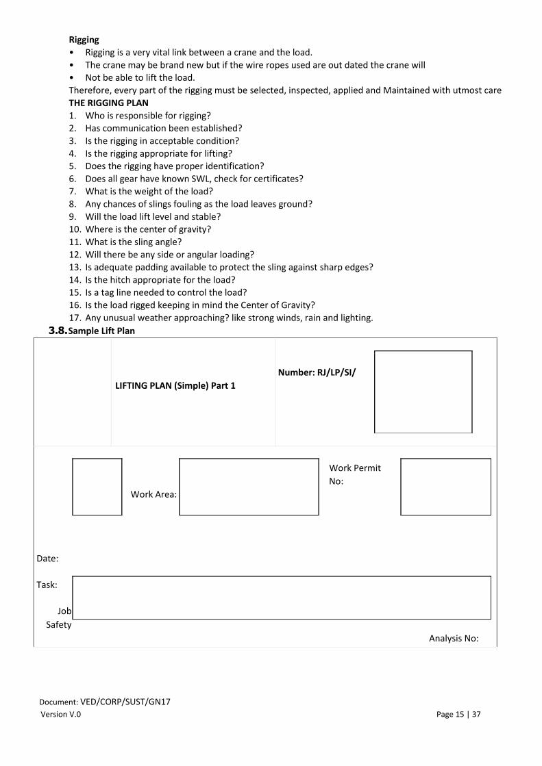
3.8. Sample Lift Plan
LIFTING PLAN (Simple) Part 1
Number: RJ/LP/SI/
Date:
Task:
Job
Safety
Analysis No:
Work Area:
Work Permit
No:

Document: VED/CORP/SUST/GN17 Version V.0 Page 16 | 37
Maximum Weight of Load:
Actual / Calculated:
Diagram, CAD Drawing Attached:
Yes
Description of Lifting Operation:
1.
Check List: Possible considerations (not exhaustive)
Hazards to personnel in the area Weigh of load verified Trial lift required
No lifting points directly above the
Load
Load on pallets requires securing
Risk of overturning
Awkward size/Shape /Sharp edges Transport fastenings removed Working under load
Dedicated lifting points on the load Stability of the load an issue Cross Hauling required
Certified suspension points available High Canter of gravity Tandem lifts
involved
Restricted headroom or confined
area Lifting chemicals Tag lines Required
Correctly installed lifting equipment Conflicting tasks in the area Barriers Required
Correctly installed lifting accessories Dynamic factors involved Certification Checked
Engineering Support required Method of communication agreed Safe Access available
Number of people involved identified Adequate lighting and visibility Lifting over live plant
Route to Be Travelled and Laydown Area Yes No
1 Are the route and laydown area clear of obstructions?
2. Is the laydown/landing area adequate

Document: VED/CORP/SUST/GN17 Version V.0 Page 17 | 37
3. Is the laydown /landing area adequate in term of load
bearing
4. Is suitable packing available for protecting the load, lifting equipment, slings etc. must be
calculated in the total load weight to be hoisted.
5. Have barriers been positioned to prevent access by unauthorised personnel
6. Have you confirmed that the laydown area is within the operating limits / radius of the equipment.
7. Have environmental conditions been considered with regards to the safety of the lifting operation
8. Will the Lifting Equipment operator be able to see the banksman throughout the operation
9. Are there hazardous process plan or materials in the areas?
Step by Step of the Lifting Operation
Person Responsible
1. Identify the locations for lifting of ( ). Ensure area is clear from any obstruction. Supervisor
2. Alert other group about the lifting activity. Supervisor
3. Position the crane for lifting within in detailed working radius Crane Opt
Document: VED/CORP/SUST/GN17 Version V.0 Page 18 | 37
4. Deploy the competent riggers and identify the banksman.
Rigging
Supervisor
5. Ensure proper communication established between Supervisor
6. Ensure certified lifting tools & tackles for lifting operations Riggers
7. Secure the load properly, ensure correct angle achieved for the lift Supervisor
8. Use tag lines to the load to prevent the sudden swing. Riggers
9. Lift the load slowly, check the load is secured properly Signalman
10.Ensure no movement in loading area, no one working under the load Supervisor
11. Place the load in designated area. Signalman to guide crane operator Signalman
12. Unsecure the load from pad eye Riggers
13. Hard barricading of operational area
14. Obtain and affix taglines
15. Check wind velocity
Riggers
Riggers
Crane Operator
4. PEOPLE
Personnel must be trained, competent and authorized to:
a) operate cranes and lifting equipment;
b) set-up or rig loads;
c) provide signals for controlling lifts; and d) Inspect, maintain or test cranes and lifting equipment
e) The training of all such personnel should be minimum once every three year.
Any person designing or approving a lifting plan must be trained and certified as competent. This will normally be through a Vedanta-certified approach but can be through a National certification system where this exists – either
method will be documented and approved in the site/business/project management system and in relevant
contracts.
There must be a system for establishing minimum operating time, workplace conditions, frequency of operation and testing to ensure competency for each class of crane.
All crane operators & riggers should have sufficient knowledge about dynamic loading of cranes & its impact. They
must be trained by the OEM of crane for better suitability.
4.1. Lifting Coordinator
The Lift Coordinator will be nominated & shall furnish a method statement for lifting operations, which
shall include following details:
• Risk assessment plan;
• Details of the equipment to be used (Complete configuration);
• Details of rigging hardware to be used;
• Ground condition;
• Weather condition;
• Category of lift;
• Preparation of lift plan as per attached format;
• Nominate Operator, Riggers, Hand signaler and read out them;
• Responsibilities;
• General precautions to be taken;
• Availability of charged microphones;
• Availability of first aid equipment;
• Availability of correct load chart of the machine;
• Ensure test certificates for lifting equipment’s & lifting gears are available;
Document: VED/CORP/SUST/GN17 Version V.0 Page 19 | 37
• Be present at all time during the list to ensure the safe execution of the load.
Lifting Coordinator must be:
• Authorized to direct and supervise the lifting operation, ensuring that these are carried out in accordance with the method statement; be competent and suitably trained and should have
sufficient experience and authority;
• Fully conversant with the duties of all persons involved in the lifting operation;
• Able to give clear, unambiguous instructions to all other members of the team;
• Able to assess danger to the lifting operation and to refer to the appointed person for further
instructions.
Lifting Coordinator must ensure:
• Accurate weights, radii, heights, type of crane required etc. are established;
• Suitable lifting machines and lifting gear are provided on worksite;
• The ground is made suitable for taking the loads to be imposed;
• Suitable access is provided to the site and any area required for erection and dismantling;
• All hazards such as services (gas, water, electricity, etc.) above or below ground are identified and
suitable precautions are taken.
• All personnel involved in lifting operation are competent and properly trained;
• Lifting Operations to be undertaken safely;
• Safety and Loss Prevention Section to be notified in case of blocking roads.
Lifting Coordinator is responsible for:
• Inspecting the crane and any associated equipment before each lift; ensuring that records of checks,
Certificates are valid;
• Maintaining records of checks, thorough examinations and repairs as appropriate;
• Ensuring that signaler/ Banksman is readily identifiable to the crane operator (e.g. by wearing high
visibility clothing);
• Ensuring that the work place is provided with adequate lighting;
• Ensuring that the crane operator and slinger is clearly aware of the weight and hazardous/ awkward
loads;
• Ensuring cranes are safe for use.
4.2. Crane Operator
• The crane operator should perform routine crane lubrication, daily and periodic maintenance and
checks of the crane. He should assist with the change out of ropes and hook blocks and procedures
recommended by the crane manufacturer and operating company. • All crane operators should be assessed every one year through practical and theoretical examinations
by suitably trained/ certified and qualified assessor (third party approved by Vedanta).
• Businesses are necessarily required to comply with local crane and lifting-related laws and regulations.
• Minimum age of operator to be 22 yrs.
• Crane operator/rigger shall be competent and medically fit as per local laws and regulations, including
a heat stress test.
• Crane operator must check his vision test every six month or as per statutory requirement as applicable (whichever is less)
The crane operator must be:
• Trained to the specific model of crane used;
Document: VED/CORP/SUST/GN17 Version V.0 Page 20 | 37
• Able to assimilate and apply information contained in reports and duty charts relating to the range of
duties and safe use of crane;
• Familiar with the manufacturer’s instructions for the rigging operation and for maintenance of the
crane;
• Aware that the crane should be used on level and compacted ground without any sinking or else set level on outriggers before any load is applied;
• Fully conversant with the correct use of outriggers and where outriggers should be fitted, and aware
of how to properly support the outrigger feet;
• Able to set and check the functioning of the rated capacity limiter and rated capacity indicator;
• Aware of the effects of wind and other climatic effects on the crane and load;
• Able to resist pressures from other persons to carry out unsafe operations and know his rights to refuse
unsafe work;
• Able to take the action to avoid dangerous situations, including stopping operations;
• Able to operate fire extinguishers and fire suppressant equipment (if fitted).
• Able to use spill kits to contain a spill form hydraulic or oil lines.
Crane Operator Duties The
crane driver should:
• Be responsible for correct operation of the crane in accordance with the manufacturer instructions and
within the safe system of work.
• Only respond to a signal from the slinger to carry out initial lifting of the load, and then only to signals from one slinger/signaler, who should be easy identified, during the remainder of the lifting operation.
Competency requirements for the crane operator
1. A workplace operations plan is developed in consultation with the relevant site supervisor.
The plan takes into account job requirements, priorities, workplace rules and procedures,
identified hazards and hazards control measures;
2. Site hazards, such as those listed below, are identified and correct hazard controls developed in accordance with the appropriate standard procedures:
• Overhead power lines;
• Trees;
• Overhead service lines such as steam, gas, water, oil, telephone, pipe racks;
• Underground services;
• Uneven and/ or unstable ground;
• Allowable floor loading as appropriate;
• Presence of other workers and persons;
• Surrounding buildings/vessels/structures/equipment;
• Hazardous materials;
• Corrosive substances;
• Barricades;
• Inadequate lighting;
• Radio interference;
• Inclement weather;
• Excavation and trenches;
• Other equipment.
3. Emergency procedures are planned to take into account the location of first aid and fire-fighting equipment, access/exit points in the workplace for emergency vehicles and
emergency personnel. This includes, where necessary, deciding to abort crane operations
where levels of illumination are inadequate;

Document: VED/CORP/SUST/GN17 Version V.0 Page 21 | 37
4. Precautions are taken to accommodate the effects of weather conditions in accordance
with the appropriate standard. This includes, deciding to abort crane operations where weather conditions exceed acceptable limits (e.g. wind velocity above 32km/h);
5. The operations plan ensures that the work area is correctly illuminated and restricted to
authorized personnel only;
6. The crane load chart is visibly located and information on permissible loads, radii, weights,
boom and jib configurations noted and taken into account in operational plans;
7. The signals and signaling systems to be used are confirmed with associated personnel, in accordance with appropriate standards;
8. The use of safety tags on electrical switches/isolators (where relevant) is noted and correct
hazard control procedures developed in consultation with authorized personnel.
4.3. Riggers
All riggers will be able to
Minimum age of rigger to be 22 yrs.
• Understand types of rigging hardware, its correct applications and inspection procedures.
• Understand the importance of hand signals and procedure for it.
• Identify, speak and use correct terminology for hardware and hand signals.
• Ascertain the conditions that reduce capacity of rigging hardware and visually inspect all rigging.
• Physically perform the inspections prior to the lift.
• Rig the crane and load as per prescribed safety norms / list plan.
• Calculate load on the slings, weight of the load, Location of center of gravity of the load etc.
• Select, Inspect and apply correct rigging hardware.
• Supervise the rigging operations for safety.
• Supervise the lifting operations for correct hand signaling.
Classification of riggers as “Competent” workers
Considering the importance of the job, the riggers will be skilled workers in all verticals of Vedanta, therefore
following needs to be maintained about their selection and utilization criteria’s:
A. Selection of the riggers will happen only through a written & oral assessment;
B. Post selection they will be put through a two days’ theory and practical training course conducted by nominated
Rigger Duties
• Be responsible for attaching and detaching the load to/from the crane lifting attachment, and for using the correct lifting accessories and equipment in accordance with the operation plan.
• Direct initial movement of the crane (if there is more than one slinger, only one slinger should direct
initial movement).
• Clearly indicate to the crane operator, to the second signaler that this responsibility is transferred,
and to whom.
• He must wear reflective jacket to have clear identification of slinger (Rigger)
• Fully conversant with the duties of the crane operator;
• Trained to use man-baskets and conversant with the relevant lifting procedures;
• Physically, he must be capable of handling lifting gear and equipment;
• The slinger should be assessed through practical and theoretical examination by suitably trained/
certified and qualified assessor (Third Party Approved by Vedanta)
• Ensure at all times that the load is under complete control by the use of tag lines, or whatever
assistance that is deemed necessary;
• If the slinger cannot see the load or maintain contact with the crane operator at all times, a signaler/
Banksman may be used to relay instructions from the slinger to the crane operator.

Document: VED/CORP/SUST/GN17 Version V.0 Page 22 | 37
• Able to establish weights and the effect of the center of gravity, and to balance loads and judge
distances, heights and clearances,
• Able to select the appropriate lifting accessories and check that they are in a suitable condition;
• Able to initiate safe movement of the crane and load using the designated signaling method.
Competency requirements for the slinger:
a. Potential hazards associated with the use of cranes and other moving equipment are identified and
measures to eliminate or control these hazards are planned;
b. Site information is obtained as necessary;
c. Potential hazards are identified, such as:
• Overhead power lines;
• Trees;
• Overhead service lines such as steam, gas, water, oil, telephone;
• Underground services;
• Uneven and/ or unstable ground;
• Allowable floor loading as appropriate;
• Presence of other workers and persons;
• Surrounding buildings/vessels/structures/equipment;
• Hazardous materials;
• Corrosive substances;
• Barricades;
• Inadequate lighting;
• Radio interference;
• Inclement weather;
• Other equipment.
d. Adequate site access and exit is identified;
e. Appropriate mass, Centre of gravity and dimensions of load are determined or confirmed, so that the
method of slinging can be established;
f. Appropriate lifting gear equipment is identified including:
• Slings;
• Rope;
• Shackles;
• Eye bolts; and others
4.4. Banksman:
The Banksman may be responsible for directing movement of the crane and load instead of the
Rigger, provided that only one person is responsible at any time (it is common practice to train
personnel to enable them to carry out duties of both Rigger and Banksman. The Banksman: • Must be more than 18 yrs. of age;
• Have sufficient experience and training in slinging and signaling; • Must be appointed on duties of a Banksman;
• Must have good eyesight & hearing attributes;
• Signals shall be given to crane drivers only by authorized persons i.e. the Banksman or a swinger; • Hand signals shall be given strictly in accordance with a known and established code;
• The Banksman shall wear a high visibility waistcoat to enable the driver to see the signals clearly;
• If radios are to be used the person using them shall speak clearly, distinctly and in common agreed upon language;
• Profane language shall be strictly avoided when using radios;
• Once a Banksman has been appointed, strict discipline shall be imposed to ensure that no other person
gives signals to the driver for any move other than the emergency stop.

Document: VED/CORP/SUST/GN17 Version V.0 Page 23 | 37
Banksman Duties
The signaler should be able to:
• Relay signals from the slinger to the crane operator;
• Direct safe movement of the crane and load
If radio signals are chosen, then the following method of use must be followed:
• All instructions must be repeated continuously, for. example “LOWER, LOWER, LOWER……” until the
movement is complete;
• If instructions stop HALT, the load;
• If there is more than one crane on site and more than one slinger / signaler / crane operator team using
radios, then the appointed person must devise a safe system of work to ensure that there are no problems such as one crane operator following the instructions being given to another.
• All personnel involved, must be competent and qualified to perform their duties.
• All personnel must be instructed and briefed for all operations
• Ground preparations are required to be done considering wt. of all cranes and the load.
• The outrigger mats or adequate blocking needs to be done beneath crawlers/outriggers for better
stability and must be 3 times the area of the Outrigger.
• All cranes must be levelled with level indicator and plumb bob method.
• The load weight must be accurately determined.
• Each cranes net capacity must be determined correctly.
• The lift must be made slow and without jerks.
• The rated capacity of all cranes to be reduced by 25% and cranes of same capacity must use.
• Pre-operational inspections to be completed for all cranes.
• All operators and signal person must be able to see each other.
Competency requirements for Banksman
1. Site hazards, such as those listed below, are identified and control measures implemented in
accordance with the standards;
• Overhead power lines;
• Trees;
• Overhead service lines, such as for steam, gas, oil, water, telephone, pipe racks;
• Underground services;
• Bridges;
• Surrounding buildings;
• Obstructions;
• Structures,
• Facilities;
• Other equipment;
• A recently filled trenches;
• Dangerous materials;
2. Plans for emergency procedures take into account the location of first aid and firefighting equipment, and access/ egress points in the workplace for emergency vehicles and rescue teams;
3. Precautions are taken to accommodate the effects of weather conditions. This includes, where
necessary, deciding to abort crane operations where weather conditions exceed acceptable limits (e.g.
when wind speed exceeds 20mph or 32 km/h);or as mentioned in the OEM catalog for all the lifts
4. The operation plan ensures that the work area is correctly illuminated;
5. The signals and signaling systems to be used are confirmed with crane operator, in accordance with
standards.
6. No crane lifting operation (erection activities) to be done after sunset, drizzling or inclement weather
conditions.

Document: VED/CORP/SUST/GN17 Version V.0 Page 24 | 37
7. Banksman shall not be in the influence of alcohol or addictive drugs
5. MAINTENANCE AND INSPECTIONS
If you receive lifting equipment in your area, you need to know for maintenance and inspection:
• A register of cranes and lifting equipment must be established which records all maintenance & lifting history;
• Any crane or lifting equipment brought to site must have a current test certificate and a pre-use safety
inspection to ensure the equipment is fit for purpose. As a minimum, this inspection must satisfy regulatory and manufacturer requirements for frequency of inspection and physical condition of the machine.
• There must be a system for the inspection, maintenance and approval of cranes and lifting equipment,
including a process that verifies the equipment is able to function to its design specifications and the integrity of:
a) mechanical and electrical components;
b) controls for each piece of lifting or rigging equipment;
c) crane cables and all lifting attachments;
d) structural components for example: boom, hoist, brakes, wheels, hooks, baskets, out-riggers, hook-
blocks and rails; and
e) Integrity of load limiting devices, safety devices, limit switches and control systems required for
individual equipment e.g. independent fail-safe braking systems, a device to stop the crane such as a
“dead-persons” switch, and emergency shut-off switch.
• Inspections and repairs to cranes, cables and lifting equipment must comply with the manufacturer’s
specifications and regulatory requirements as a minimum.
• Records of maintenance inspections and cable tests must be kept.
• All crane rope to be used only as per OEM specification (generally non-rotating ropes are used). They are to
be periodically inspected.
• All slings/D shackles of rated capacity are to be used.
• No crane to be used if any system is malfunctioning and any part like ropes, boom, a frame, Guy rope etc.
have any damage
• Bypass/Override key to be with the engineer/supervisor and not in cabin while lifting.
5.1. Rigging Loft & Its Management
Rigging loft is a place where all rigging hardware is secured in correct manner in order to prevent rigging hardware from “Abuse” further preventing capacity reduction, this culture will
be established in all verticals of Vedanta and will be maintained.
5.2. Safety Audits of all lifting equipment’s, Tools & Tackles and Operators, Riggers including that of Business Partners The Audits with regards lifting equipment’s, tools & tackles and personnel will be conducted
by the nominated third party lifting Specialist Company every six months and a written report will be submitted.
5.3. Tests & Examinations
The nature of suitable evidence of examination
The information to be contained in a thorough examination report is: a) The name and address of the duty holder for whom the report was made;
b) The address of the premises at which the thorough examination was carried out; c) Information which identified the equipment;
d) The date of the last thorough examination;
e) The SWL of the equipment or its safe working load for the last configuration in which it was thoroughly examined;
f) A statement that the equipment is safe to operate.
• No crane shall be allowed to work unless there are current, valid records of tests and examinations. To be current, records must show that the crane has been tested and
thoroughly examined satisfactorily within the previous 12 months (or since the last
substantial alteration or repair that could affect its stability).
Document: VED/CORP/SUST/GN17 Version V.0 Page 25 | 37
• No crane shall be allowed to work unless it is thoroughly examined after installation of
lifting equipment and before putting into service for the first time and after assembly and before being put into service at a new site or in a new location “to ensure it has been
installed correctly and is safe to operate”. • No crane shall be allowed to work unless the Automatic Safe Load Indicator (SLI) and other
safety devices has been tested and examined before the crane is taken into use after
erection, or alteration, which might affect the operation of the indicator. • In relation to a thorough examination of lifting equipment other than specifically
mentioned otherwise all lifting equipment for lifting persons or an accessory for lifting shall
be:
o Thoroughly examined at least every 6 months and at least every 12 months in
case of other lifting equipment or in accordance with an examination scheme. o A thorough examination of lifting equipment shall be necessary each time that
exceptional circumstances which are liable to jeopardize the safety of lifting
equipment have occurred to ensure that health and safety conditions are
maintained and that any deterioration can be detected and remedied in good time.
In relation to every thorough examination of lifting equipment, the following is necessary:
a) Identification of any part found to have a defect which is or could become a danger to persons, and a
description of the defect; b) Particulars of any repair, renewal or alteration required to remedy a defect found to be a danger to
persons;
c) In the case of a defect which is not yet but could become a danger to persons: (i) The time by which it could become such danger;
(ii) Particulars of any repair, renewal or alteration required to remedy it; d) The latest date by which the next thorough examination must be carried out;
e) Where the thorough examination included testing, particulars of any test;
f) Load test certificate, provided by a third part certification agency, is required for all lifting slings brought and used on Vedanta sites. A copy of the load test certificate is to be provided to Vedanta’s authorized
person.
g) The date of the thorough examination;
h) The name, address and qualifications of the person making the report, that he is self-employed or, if
employed, the name and address of his employer;
i) The name and address of a person signing or authenticating the report on behalf of its author;
j) A dated report.
5.4. Periodic Checks
All the rigging hardware which will be used must have valid certificates from a competent
person certified by state govt.
The lifting Operation Supervisor and Crane Operator should ensure that the following crane
checks have been carried out as deemed so: Pre-use Checks: As furnished in these procedures Wire Rope Slings
Prior to using any sling, the following checks should be made:
a) The SWL is adequate for the load;
b) The color coding (where applicable) is current and the sling has a plant serial number/ ID mark and SWL clearly visible on the sling;
c) Examine each individual leg along its entire length and check for wear, corrosion, abrasion, mechanical
damage and broken wires; d) Examine each ferrule and ensure the correct size of ferrule has been fitted;
e) The ferrule should be free from cracks or other deformities;
f) Examine each thimble and check for correct fitting, snagging damage and elongation. (Stretched thimbles/ eyes could indicate possible overload);
g) Examine wire rope around thimbles as it is often abraded due to sling being dragged over rough surfaces;

Document: VED/CORP/SUST/GN17 Version V.0 Page 26 | 37
h) If fitted with hooks, check for wear, corrosion and cracking and ensure safety latch functions.
i) Damaged slings shall be destroyed if one of the following cases was evidenced:
o 10 random broken wires in one lay; o 5 broken wires in one strand of a rope lay; o One broken wire at the fitting; o Sever localized abrasion or scraping;
o Kinking, crushing, bird-caging or any other damage causing
distortion; o Evidence of heat damage;
o End attachments are cracked, deformed or excessively worn; o
Bent or opened hooks;
Synthetic Web Slings
Prior to using web synthetic slings they should be visually examined along their entire length and checked for:
a) The SWL is adequate for the load;
b) The colour coding (where applicable) is current and the sling has a plant number/ ID mark;
c) The Web Sling is suitable (by material type) for the intended purpose.
d) Cuts, tears or chaffing;
e) Burst stitching (specially around the eyes);
f) Chemical damage;
g) Heat damage;
h) Ingress of foreign bodies into the fibres;
i) Distortion/ wear in the metal eyes (where fitted).
j) Damaged slings shall be destroyed.
Chain Slings
Prior to using a chain sling, the following checks should be carried out:
a. The SWL is adequate for the load;
b. The color coding (where applicable) is current and the sling has a plant serial number/ ID mark and
SWL clearly visible on the sling;
c. The Chain Sling is suitable (by material type) for the intended purpose.
d. All attached fittings (hooks, shackles, rings, etc.) shall be as prescribed by the manufacturer. Hooks, shackles and eyebolts shall be equal to or exceed the safe working load of the chain.
e. Lay out the chain slings on the floor or suspend from the crane hook and remove all twists from the
legs;
f. Damaged slings shall be destroyed.
Shackles
Prior to using a shackle, the following checks should be made:
a. The SWL is adequate for the load;
b. The color coding (where applicable) is current and the shackle has a plant number/ ID mark;
c. The Shackle is suitable (by Pin / Jaw type) for the intended purpose;
d. Ensure it is the correct pin for the shackle. (e.g. not a higher tensile pin in alloy shackle);
e. Check pin threads for wear / deformation;
f. Examine shackle body for deformation and cracking and check for wear in the crown and pin holes;
g. Check alignment of pinholes and ensure the pin fits correctly.
h. Damaged shackles shall be destroyed.
Eye Bolts
Prior to using the eyebolts, carry out the following checks:
a. The SWL is adequate for the load;
b. The color coding (where applicable) is current and the eyebolt has a plant number / ID mark;
c. The Eyebolt is suitable (by type) for the intended purpose.

Document: VED/CORP/SUST/GN17 Version V.0 Page 27 | 37
d. Examine threads and check for wear, stretch or impact damage. The threads must be complete (no broken
threads) and full (i.e. no flats on top); e. Damaged eyebolts shall be destroyed.
Note: It may be necessary to wire brush the threads to facilitate a proper visual examination. Should the eyebolts be new/ unused, the protective tape will have to be removed? f. The threads should be concentric and fit neatly in a standard nut. If stretch is suspected, a thread gauge
should be used to confirm condition;
g. Examine the eye of the bolt, check for wear / stretch / distortion, and look for hairline cracks at the crown of the rings. (this also applies to the link if fitted);
h. Check sureness of shank against shoulder;
i. Examine tapped hole and check thread condition (i.e. depth/ corrosion etc.) Hooks Prior to using the hooks, carry out the following checks:
h. Hooks should be fitted with a safety catch on the hook opening;
i. Loads should be applied on the hook only in the part designed to take them (i.e. the bend [bow] of the
hook. Point loading shall not be permitted;
j. Hooks should be regularly inspected for signs of damage;
k. The hook shall be removed from service for one or more of the following reasons:
• if there are visible cracks,
• if it is twisted 10° out of the place,
• if there is a 15% throat opening beyond the manufacturer’s specifications
i. Damaged hooks shall be destroyed.
j. No hook shall be painted, this may hide hairline fractures.

Document: VED/CORP/SUST/GN17 Version V.0 Page 28 | 37
Maintenance Safety Requirements:
The following safety Requirements for maintenance staff conducting maintenance activities on Cranes and Lifting
Devices must be strictly adhered to:
Work permit to be obtained before doing job on Cranes / lifting devices & energy isolation to be done
No maintenance person is permitted to stand, walk or work on equipment when exposed to a fall hazard of
1.6 meters of greater unless using fall protection and is tied off to a certified anchor point that is located
above the above his head.
No maintenance person is permitted to work on equipment that has its guards removed and the equipment,
gear, drum, pulley, rotating wheel, fans etc. is in motion. Wheel choke to be placed while doing maintenance
activities.
When a maintenance person touches, opens, climbs, accesses equipment for maintenance activities, he
shall apply his isolation lock and de-energize all electrical, pneumatic, mechanical, hydraulic and
gravitational parts so that no unintentional boom, leaver, arm, hood, cantilever can fall onto the worker.
All maintenance personnel must not enter into a drum, tank, or other similar confined space without a
confined space permit.
Oils, coolants, glycols, batteries and greases shall be kept and stored in supplier approved containers and in
areas where they will be protected from a fire hazard and secondary containers used so spills will not
contaminate the ground.
Oily rags shall be kept in steel containers with lids to prevent spontaneous combustion.
Personnel must complete all Vedanta required training specific to the task prior to conducting any task on
site.
Maintenance personnel shall wear all required PPE: Goggles, Helmut, High Visibility Clothing, safety shoes
and gloves.
Welding shall only be done by certified welders and only conducted on a hot work permit has been obtained
(battery should be disconnected before doing any welding activity).
Flame cutting requires a hot work permit. Oxygen and acetylene bottles are to kept away from hot work by
5 meters and covered with fire proof blanket, all valves and houses must be leak tested.
Sharp or hot surfaces objects must be shielded to protect maintenance person form cuts and burns.
Maintenance person are not permitted to wear rings, watches, long necklaces and keep sleeves rolled down
when doing work activities.
Mainatince personnel shall not clean parts with degreasers unless a JSA is completed.
Mainatince person shall keep clothes free of oil so that they do not become a fire hazard.
Maintenance person are to check boots frequently for oil and use three points of contact when mounting
and dismounting mobile equipment.
All hand tools used by the maintenance shall be in good condition and removed if altered, damage or has
lose parts. Only manufactured fabricated tools are allowed site.
No cheater bar is to used by maintenance person to tighten or losses bolts.
Tyres must have a tire cage or certified chains if being worked on, inflated or changed. Maintenance person
must have training competency to do this work.
No smoking is permitted when maintenance activities is occurring.
Maintenance personnel must barricading off equipment work zone.
Safety devices / interlock/ sensors / pressure relief valve/ cylinder / seal are to be categorized as critical
activity & to be serviced/replaced only by trained Service engineers & clear JSA to be made before doing
such activity. JSA must be reviewed and approved by Authorized Person.
Regular Predictive activities such as rope lubrication / oil checking can be done with standard maintenance
procedure & with work permit.

Document: VED/CORP/SUST/GN17 Version V.0 Page 29 | 37
6. SPECIFIC CRANE CONFIGURATIONS AND INFORMATION
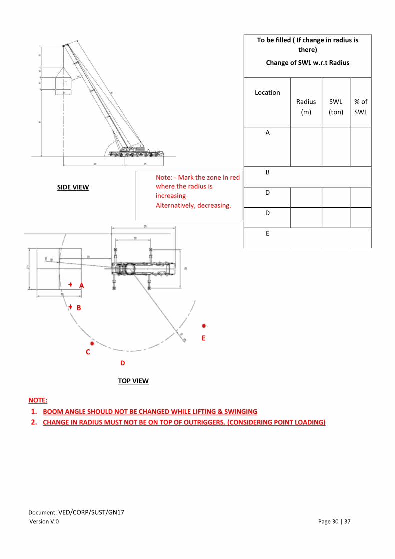
6.1. Crane Radius
Crane Make
Model
Max. Crane Capacity
Ton
Registration No.
Max. No. of falls
No. of falls
Crane capacity at
current falls
Ton
Load and
SWL
Weight of load
Ton
Working radius
m
SWL (at that radius)
Ton
Web Sli
ng
SWL Capacity
Ton
Length
m
Wire rope
sling
SWL Capacity
Ton
Length
m
Shackle
Shackle Type (Bow/D’)
SWL Capacity
Ton
Document: VED/CORP/SUST/GN17 Version V.0 Page 30 | 37
TOP VIEW
NOTE:
1. BOOM ANGLE SHOULD NOT BE CHANGED WHILE LIFTING & SWINGING
2. CHANGE IN RADIUS MUST NOT BE ON TOP OF OUTRIGGERS. (CONSIDERING POINT LOADING)
To be filled ( If change in radius is
there)
Change of SWL w.r.t Radius
Location
Radius
(m)
SWL
(ton)
% of
SWL
A
B
D
D
E
Note: - Mark the zone in red where the radius is
increasing
Alternatively, decreasing.
A
B
C
D
E
SIDE VIEW

Document: VED/CORP/SUST/GN17 Version V.1 Page 31 | 37
6.2. Pick & Carry Cranes
A Pick & Carry crane is the most dangerous machine among all mobile cranes as
in the case of pick & carry cranes it is the forward tipping point which shifts,
when the tyres are turned left or right which increases the load leverage on the machine during the lift, these criteria does not happen in case of other mobile
cranes which are setup on outriggers. Considering above fact it is mandatory to
follow, following points whenever operating with pick & carry machines. Follow common checkpoints for mobile crane operational safety & then
follow below points as well: -
1. Ensure the machine always travels on a firm & levelled surface
2. Ensure tyres size is as per manufacturers recommendation
3. Ensure tyre pressure is as per manufacturers guidelines
4. Always use 75% capacity rating load chart
5. Ensure tag line is used in order to control the dynamic loading of crane
6. Load to be tied to the mass
7. No person shall walk along side of load
In fig:1 when stabilizers are not extended the tipping point is on tyres, distance A1 becomes less and crane leverage becomes lesser, distance B1 increases which leads to increase in load leverage on crane which means the crane capacity reduces. (Point to ponder): - When the outriggers/stabilizers are not extended/partially extended, not only the crane capacity is reduced but also the load weight is increased. In fig: 2 if front outrigger is not extended and tipping point is on tyres, distance B1 increases and load leverage increases and A1 reduces reducing the crane leverage
6.3. Mobile Crane Procedures and Practices
PICTORIAL REPRESENTATION OF CORRECT PROCEDURES
Therefore, for ensuring safe operation always ensure that outriggers/stabilisers are extended completely:

Document: VED/CORP/SUST/GN17 Version V.1 Page 32 | 37
The Mobile crane load charts are furbished as per these criteria’
Carrier mounted cranes on Rubber/Tyres
Carrier mounted cranes on outriggers
Crawler Cranes
Boom Trucks on Stabilisers

Document: VED/CORP/SUST/GN17 Version V.1 Page 33 | 37
Every load chart is divided into two portions (strength & stability) by three different means as shown below
MEANING OF BLACK BOLD LINE
The capacities above the line are based on strength of the machine and the capacities blow the line are based on stability factor of the machine
MEANING OF SHADED AREA’S
The capacities in the shaded areas are based on strength of the machine and the capacities without shaded areas are based on stability factor of the machine
MEANING OF ASTERISKS
With asterisks are based on strength capacities without asterisks are based on stability factor of the machine
Always ensure that outriggers are extended completely and tyres are off the ground
Never block the outrigger rams as the machine leverage decreases

Document: VED/CORP/SUST/GN17 Version V.1 Page 34 | 37
Never extend outriggers partially
Ensure crawlers are always extended during the operations
Barricade the operational area
Always maintain a minimum of 1-meter gap between crane counter weights and the obstruction behind the crane
Always ensure the crane is levelled within 1 degree

Document: VED/CORP/SUST/GN17 Version V.1 Page 35 | 37
While placing the crane on backfill areas always ensure that the outriggers/crawlers are placed after keeping a gap of approx. 1-meter from the edge of backfill area
Investigate about the compaction where the
outrigger/crawlers will be placed
Always maintain a gap of 2 min metre’s between the newly constructed building and the outriggers/crawlers
Ensure the crane operations are smooth and jerk free and no dynamic loading is created
While lifting below the ground level, the weight of the total length of wire -rope below ground level must be added in the load

Document: VED/CORP/SUST/GN17 Version V.1 Page 36 | 37
Always reeve the pulleys from centre
PERMISIBLE WIND SPEED FOR SAFE
OPERATIONS -
9 metres /sec = 32Km/hr. = 20 miles/hr.
OPERATIONS MUST BE CEASED AT 30MPH
WIND SPEED
Ensure outriggers are properly placed squarely
Always block the crawlers with wooden mats or metallic plates in order to reduce ground pressure
Wedge socket must be secured as shown in the figure

Document: VED/CORP/SUST/GN17 Version V.1 Page 37 | 37
6.4. Levelling of Cranes
OFF LEVELING OF CRANES AND ITS ADVERSE AFFECTS:-
The adverse effect of side loading is self-explanatory, in the above figure, a long boom crane with just 3o out of level
creating so much side loading on the boom that the crane capacity is reduced by 50%, therefore generally any longer boom crane with loaded boom subjected to side loading will go for a structural failure (boom collapse) before a tipping failure. Appendix B: International Hoisting Hand Signals