CRACK INITIATION AND GROWTH IN CIRCULAR SAW MADE OF TOOL STEEL
13
JOURNAL OF THEORETICAL AND APPLIED MECHANICS 46, 2, pp. 291-303, Warsaw 2008 CRACK INITIATION AND GROWTH IN CIRCULAR SAW MADE OF TOOL STEEL Ismail Ucun Mehmet Colakoglu Suleyman Tasgetiren Department of Mechanics, Afyon Kocatepe University, Afyonkarahisar, Turkey e-mail: [email protected]; [email protected]; [email protected] Fatigue of a circular saw made of tool steel and used in metal industry to cut, in particular, metal bars and pipes is investigated in this study. Due to having a small tooth root radius, the circular saw is much more likely to get crack damage at the tooth root region. Radial and tangen- tial forces are also effective at this region for fatigue crack initiation. In high cutting speeds and feed rates of the circular saw, higher stress concentration occurs particularly at that region. To examine the fatigue and failure in the circular saw, specimens used in an experiment are pre- pared from a damaged circular saw are subjected to different mechanical tests. In the theoretical study, stress and fracture behaviour of the saw is determined by the finite element method. Results and causes of the failure are assessed and compared. Key words: circular saw, failure analysis, crack, tool steel, finite element analysis 1. Introduction A circular saw manufactured from tool steel is mostly used to cut profile cross- sectioned materials in metal industry. Feed rate and revolution speed (rpm) of a disk, type of a material being cut, etc., are important parameters for failure of the disk. Variable forces occur during the cutting process in the circular saw. When the disk starts to get dull, these forces get bigger (Andersson, 2001). As a result, undesired damage occurs at the tooth root region. The saw material is as important as the feed rate and cutting speed for wearing and damaging. Therefore, recent studies are especially focused on the development of better
-
Upload
independent -
Category
Documents
-
view
1 -
download
0
Transcript of CRACK INITIATION AND GROWTH IN CIRCULAR SAW MADE OF TOOL STEEL
JOURNAL OF THEORETICAL
AND APPLIED MECHANICS
46, 2, pp. 291-303, Warsaw 2008
CRACK INITIATION AND GROWTH IN CIRCULAR SAWMADE OF TOOL STEEL
Ismail Ucun
Mehmet Colakoglu
Suleyman Tasgetiren
Department of Mechanics, Afyon Kocatepe University, Afyonkarahisar, Turkey
e-mail: [email protected]; [email protected]; [email protected]
Fatigue of a circular saw made of tool steel and used in metal industryto cut, in particular, metal bars and pipes is investigated in this study.Due to having a small tooth root radius, the circular saw is much morelikely to get crack damage at the tooth root region. Radial and tangen-tial forces are also effective at this region for fatigue crack initiation.In high cutting speeds and feed rates of the circular saw, higher stressconcentration occurs particularly at that region. To examine the fatigueand failure in the circular saw, specimens used in an experiment are pre-pared from a damaged circular saw are subjected to different mechanicaltests. In the theoretical study, stress and fracture behaviour of the sawis determined by the finite element method. Results and causes of thefailure are assessed and compared.
Key words: circular saw, failure analysis, crack, tool steel, finite elementanalysis
1. Introduction
A circular saw manufactured from tool steel is mostly used to cut profile cross-sectioned materials in metal industry. Feed rate and revolution speed (rpm) ofa disk, type of a material being cut, etc., are important parameters for failureof the disk. Variable forces occur during the cutting process in the circular saw.When the disk starts to get dull, these forces get bigger (Andersson, 2001). Asa result, undesired damage occurs at the tooth root region. The saw materialis as important as the feed rate and cutting speed for wearing and damaging.Therefore, recent studies are especially focused on the development of better
292 I. Ucun et al.
materials and on manufacturing to protect saw, from damage (Nordstrom andBergstrom, 2001).
Fukaura et al. (2004) investigated fatigue properties of two types of cold-work steels tempered at various temperatures. The S-N curves of steels weresimilar to those of most structural steels. The results showed that the sub-surface fatigue cracks initiation was dominant at lower alternating stresses.Yesildal et al. (2003) determined fatigue characteristics of the hot work to-ol steel X40CrMoV 51 at high temperatures. In the experiment, cylindricalspecimens were used at the temperature range between 50-600◦C. As a re-sult, the fatigue limit of the material at room temperature was determinedas 432MPa, but it decreased to 383MPa at 400◦C and also stayed constantbetween 400-600◦C.
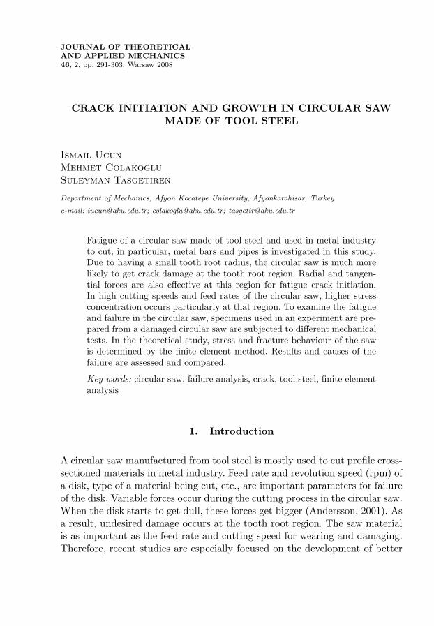
Fig. 1. A conventional cutting machine and a cracked circular saw
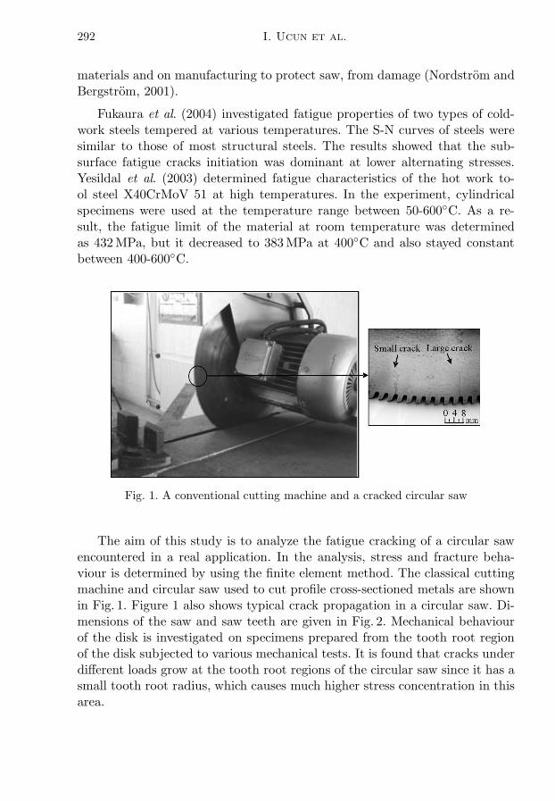
The aim of this study is to analyze the fatigue cracking of a circular sawencountered in a real application. In the analysis, stress and fracture beha-viour is determined by using the finite element method. The classical cuttingmachine and circular saw used to cut profile cross-sectioned metals are shownin Fig. 1. Figure 1 also shows typical crack propagation in a circular saw. Di-mensions of the saw and saw teeth are given in Fig. 2. Mechanical behaviourof the disk is investigated on specimens prepared from the tooth root regionof the disk subjected to various mechanical tests. It is found that cracks underdifferent loads grow at the tooth root regions of the circular saw since it has asmall tooth root radius, which causes much higher stress concentration in thisarea.
Crack initiation and growth in circular saw... 293
Fig. 2. Geometrical model of the circular saw with a work piece and geometry of thesaw teeth
2. Experimental investigation
The specimens used in experiments consisting of mechanical tests, and che-mical and metallographic analyses are prepared from a damaged circular saw.Three different mechanical tests, namely tensile, hardness and impact energytests are carried out. The Instron and Psd 300/150-1 test machines are used forthe tensile and impact energy tests, respectively. In addition, hardness measu-rements are carried out by a MetTest-HT type computer integrated hardnesstester.
2.1. Chemical analysis
A sample extracted from the circular saw is applied to spectrometric che-mical analysis, and the result of it is shown in Table 1.
Table 1. Chemical acomposition of the circular saw material [%wt]
C Si Mo Mn Ni Cu S Al V Cr
0.586 0.202 0.066 0.420 0.032 0.060 0.028 0.011 0.183 0.585
Depending on the material composition in Table 1, it is estimated as thetool steel DIN 17210, which has 60 WCrV 7 (Heat Treaters Guide, 1995;Topbas, 1998). According to this Standard, Si and Cr must be kept between0.55-0.7% and 0.9-1.2%, respectively, but it is found that Si is 0.202% and Cr is
294 I. Ucun et al.
0.585% in weight. As a result, lower Si element causes oxidation on the circularsaw. In addition, lower Cr element in it decreases not only the transformationtemperature and hardness but also significant amount of wear resistance.
2.2. Microstructure of the circular saw
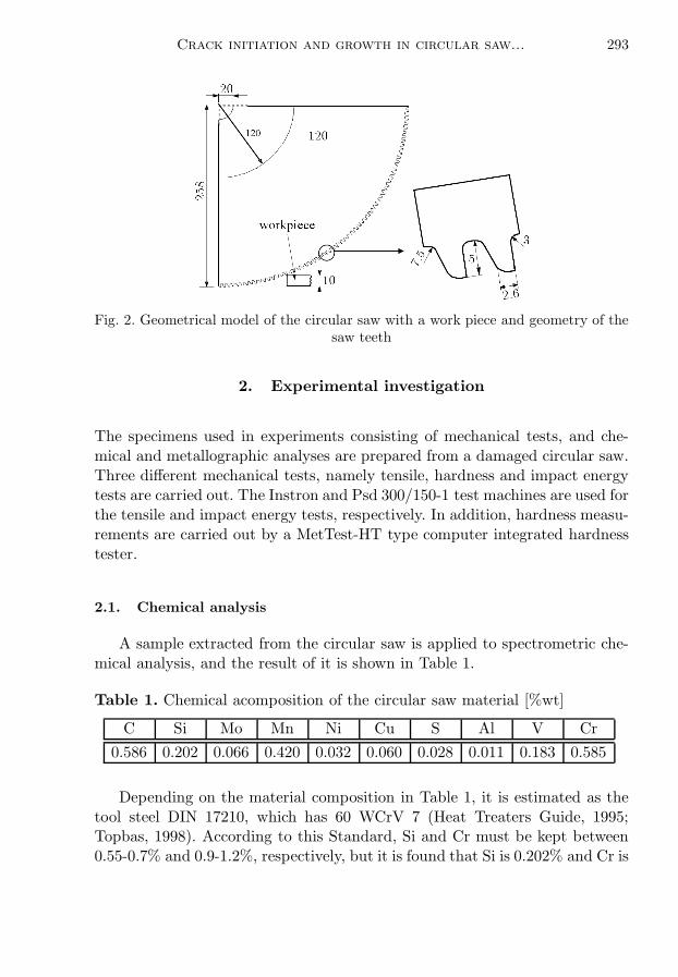
When the microstructure of the circular saw material is analyzed, it is seenthat the material is a tempered martensite. The microstructure of the circu-lar saw is given in Fig. 3. Usually, a martensitic steel is tempered to increaseductility and toughness. The material of the circular saw is thought to be sub-jected to quenching at approximately 850◦C which is followed by tempering atapproximately 470◦C (Heat Treaters Guide, 1995; ASM Speciality Handbook,1996). Grain boundaries are not exactly seen in the microstructure analysis ofthe circular saw due to the tempering process.
Fig. 3. Microstructure of the circular saw
2.3. Mechanical properties
The results of the mechanical tests are given in Table 2. Using the resultsof chemical analysis and mechanical tests, the material of the circular sawis estimated as a medium carbon alloy steel, DIN 17210, with a high tensilestrength because of quenching and tempering. The hardness is measured as43 HRC in the mid-part of the circular saw where no deformation occurs.On the other hand, severe heating that occurred during the cutting processdecreases the hardness in tooth root regions, where it is measured as 39 HRC.
Crack initiation and growth in circular saw... 295
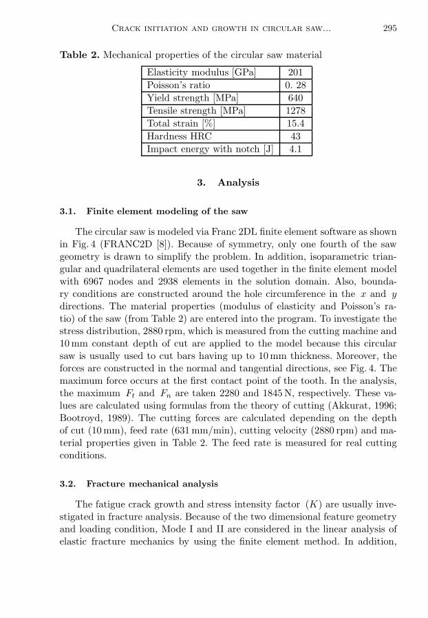
Table 2. Mechanical properties of the circular saw material
Elasticity modulus [GPa] 201
Poisson’s ratio 0. 28
Yield strength [MPa] 640
Tensile strength [MPa] 1278
Total strain [%] 15.4
Hardness HRC 43
Impact energy with notch [J] 4.1
3. Analysis
3.1. Finite element modeling of the saw
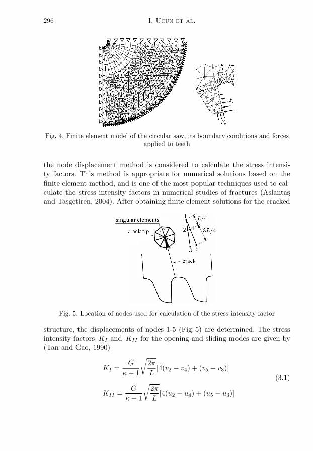
The circular saw is modeled via Franc 2DL finite element software as shownin Fig. 4 (FRANC2D [8]). Because of symmetry, only one fourth of the sawgeometry is drawn to simplify the problem. In addition, isoparametric trian-gular and quadrilateral elements are used together in the finite element modelwith 6967 nodes and 2938 elements in the solution domain. Also, bounda-ry conditions are constructed around the hole circumference in the x and ydirections. The material properties (modulus of elasticity and Poisson’s ra-tio) of the saw (from Table 2) are entered into the program. To investigate thestress distribution, 2880 rpm, which is measured from the cutting machine and10mm constant depth of cut are applied to the model because this circularsaw is usually used to cut bars having up to 10mm thickness. Moreover, theforces are constructed in the normal and tangential directions, see Fig. 4. Themaximum force occurs at the first contact point of the tooth. In the analysis,the maximum Ft and Fn are taken 2280 and 1845N, respectively. These va-lues are calculated using formulas from the theory of cutting (Akkurat, 1996;Bootroyd, 1989). The cutting forces are calculated depending on the depthof cut (10mm), feed rate (631mm/min), cutting velocity (2880 rpm) and ma-terial properties given in Table 2. The feed rate is measured for real cuttingconditions.
3.2. Fracture mechanical analysis
The fatigue crack growth and stress intensity factor (K) are usually inve-stigated in fracture analysis. Because of the two dimensional feature geometryand loading condition, Mode I and II are considered in the linear analysis ofelastic fracture mechanics by using the finite element method. In addition,
296 I. Ucun et al.
Fig. 4. Finite element model of the circular saw, its boundary conditions and forcesapplied to teeth
the node displacement method is considered to calculate the stress intensi-ty factors. This method is appropriate for numerical solutions based on thefinite element method, and is one of the most popular techniques used to cal-culate the stress intensity factors in numerical studies of fractures (Aslantasand Tasgetiren, 2004). After obtaining finite element solutions for the cracked
Fig. 5. Location of nodes used for calculation of the stress intensity factor
structure, the displacements of nodes 1-5 (Fig. 5) are determined. The stressintensity factors KI and KII for the opening and sliding modes are given by(Tan and Gao, 1990)
KI =G
κ+ 1
√
2π
L[4(v2 − v4) + (v5 − v3)]
(3.1)
KII =G
κ+ 1
√
2π
L[4(u2 − u4) + (u5 − u3)]
Crack initiation and growth in circular saw... 297
where G is the shear modulus and κ is defined for the plane stress conditionas
κ =3− ν1 + ν
(3.2)
and L is the element length, ν is Poisson’s ratio and ui and νi (i = 2, 3, 4, 5)are nodal displacements of the nodes in the x and y directions, respectively. Infracture mechanics, the critical stress intensity factor at the crack tip is used asthe failure criterion under static loading. The critical value is called the frac-ture toughness and designeted by KIC . The stress intensity factor increaseswith the increasing crack length. When the crack reaches a certain length, thestress intensity factor tends to fracture toughness and failure occurs. The fati-gue crack propagation behaviour is expressed by the Erdogan-Paris equation(Ergun et al., 2006)
da
dN= c(∆K)m (3.3)
where da is the increase of the crack length for dN cycles, ∆K is the range ofthe stress intensity factor, c and m are constants which depend on materialproperties. The material parameters having the microstructure given in Fig. 3and mechanical properties given in Table 2 are given as in the literature, i.e.c = 3.31 · 10−17, m = 4.16 and KIC = 85MPa
√m (Glodez et al., 2002). The
crack propagation of the opening mode is obtained from equation (3.3). Forthe mixed mode loading, the stress intensity factor range must be changedwith an effective value. It is (Aslantas and Tasgetiren, 2004)
∆Keff =4
√
∆K4I+∆K4
II(3.4)
The fatigue crack growth is assumed to occur either in the plane of themaximum shear stress intensity factor range or that of the maximum tensilestress intensity range (Aslantas and Tasgetiren, 2004). The most widely ac-cepted method for the prediction of propagation direction is the maximumprincipal stress theory. Depending on this theory, the crack propagates in thedirection perpendicular to the maximum principal stress. The crack propaga-tion direction is found from
θ = 2 tan−1[
1
4
(
KI
KII±
√
( KI
KII
)2
+ 8
)]
(3.5)
298 I. Ucun et al.
4. Results and discussions
4.1. Stress analysis
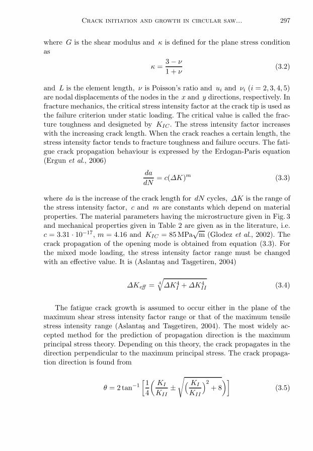
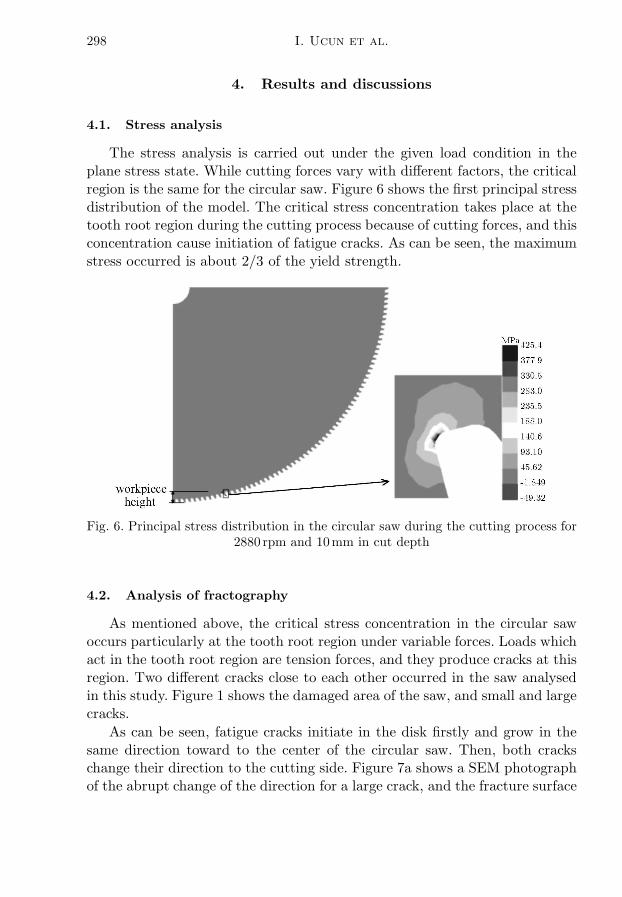
The stress analysis is carried out under the given load condition in theplane stress state. While cutting forces vary with different factors, the criticalregion is the same for the circular saw. Figure 6 shows the first principal stressdistribution of the model. The critical stress concentration takes place at thetooth root region during the cutting process because of cutting forces, and thisconcentration cause initiation of fatigue cracks. As can be seen, the maximumstress occurred is about 2/3 of the yield strength.
Fig. 6. Principal stress distribution in the circular saw during the cutting process for2880 rpm and 10mm in cut depth
4.2. Analysis of fractography
As mentioned above, the critical stress concentration in the circular sawoccurs particularly at the tooth root region under variable forces. Loads whichact in the tooth root region are tension forces, and they produce cracks at thisregion. Two different cracks close to each other occurred in the saw analysedin this study. Figure 1 shows the damaged area of the saw, and small and largecracks.
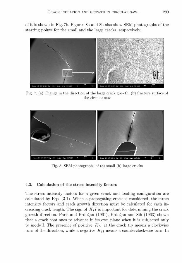
As can be seen, fatigue cracks initiate in the disk firstly and grow in thesame direction toward to the center of the circular saw. Then, both crackschange their direction to the cutting side. Figure 7a shows a SEM photographof the abrupt change of the direction for a large crack, and the fracture surface
Crack initiation and growth in circular saw... 299
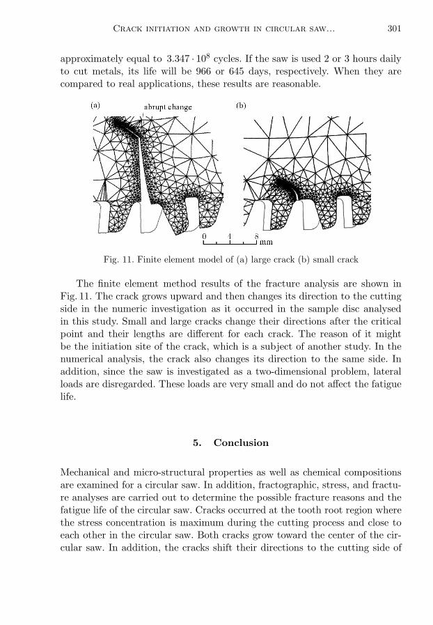
of it is shown in Fig. 7b. Figures 8a and 8b also show SEM photographs of thestarting points for the small and the large cracks, respectively.
Fig. 7. (a) Change in the direction of the large crack growth, (b) fracture surface ofthe circular saw
Fig. 8. SEM photographs of (a) small (b) large cracks
4.3. Calculation of the stress intensity factors
The stress intensity factors for a given crack and loading configuration arecalculated by Eqs. (3.1). When a propagating crack is considered, the stressintensity factors and crack growth direction must be calculated for each in-creasing crack length. The sign of KII is important for determining the crackgrowth direction. Paris and Erdogan (1961), Erdogan and Sih (1963) shownthat a crack continues to advance in its own plane when it is subjected onlyto mode I. The presence of positive KII at the crack tip means a clockwiseturn of the direction, while a negative KII means a counterclockwise turn. In

300 I. Ucun et al.
order to calculate the time elapsed for a certain crack length, the followingprocedures are practiced for each loading cycle:
• firstly, KI and KII are calculated for the initial crack length, and then∆K is calculated using Eq. (3.4) for the crack configuration,
• secondly, da is determined by consideration of parameters c and m.
This is added to the original crack length to obtain the new crack conditionby taking the effect of the crack front growing direction. The number of cyclesis recorded and the procedure is repeated until the desired crack length isachieved. In the analysis, variations of KI and KII are shown in Figs. 9 and 10.
Fig. 9. Variation of KI with length of the large crack
Fig. 10. Variation of KII with length of the large crack
In the numerical analysis, the fatigue life of the circular saw is found fromEq. (3.3) as 1.02 · 108 cycles after the crack initiation. In addition, the fatiguelife of the saw is found as 2.327·108 cycles before the crack initiation (Glodez etal., 2002). If this life is compared to the life of the circular saw under workingconditions, they are in good agreement. Finally, the total life of the saw is
Crack initiation and growth in circular saw... 301
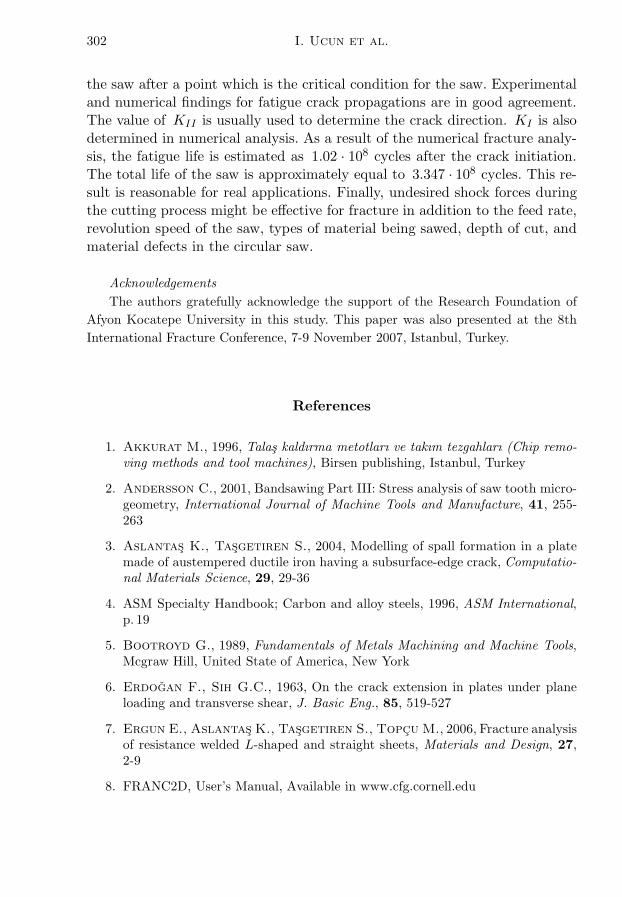
approximately equal to 3.347 · 108 cycles. If the saw is used 2 or 3 hours dailyto cut metals, its life will be 966 or 645 days, respectively. When they arecompared to real applications, these results are reasonable.
Fig. 11. Finite element model of (a) large crack (b) small crack
The finite element method results of the fracture analysis are shown inFig. 11. The crack grows upward and then changes its direction to the cuttingside in the numeric investigation as it occurred in the sample disc analysedin this study. Small and large cracks change their directions after the criticalpoint and their lengths are different for each crack. The reason of it mightbe the initiation site of the crack, which is a subject of another study. In thenumerical analysis, the crack also changes its direction to the same side. Inaddition, since the saw is investigated as a two-dimensional problem, lateralloads are disregarded. These loads are very small and do not affect the fatiguelife.
5. Conclusion
Mechanical and micro-structural properties as well as chemical compositionsare examined for a circular saw. In addition, fractographic, stress, and fractu-re analyses are carried out to determine the possible fracture reasons and thefatigue life of the circular saw. Cracks occurred at the tooth root region wherethe stress concentration is maximum during the cutting process and close toeach other in the circular saw. Both cracks grow toward the center of the cir-cular saw. In addition, the cracks shift their directions to the cutting side of
302 I. Ucun et al.
the saw after a point which is the critical condition for the saw. Experimentaland numerical findings for fatigue crack propagations are in good agreement.The value of KII is usually used to determine the crack direction. KI is alsodetermined in numerical analysis. As a result of the numerical fracture analy-sis, the fatigue life is estimated as 1.02 · 108 cycles after the crack initiation.The total life of the saw is approximately equal to 3.347 · 108 cycles. This re-sult is reasonable for real applications. Finally, undesired shock forces duringthe cutting process might be effective for fracture in addition to the feed rate,revolution speed of the saw, types of material being sawed, depth of cut, andmaterial defects in the circular saw.
Acknowledgements
The authors gratefully acknowledge the support of the Research Foundation of
Afyon Kocatepe University in this study. This paper was also presented at the 8th
International Fracture Conference, 7-9 November 2007, Istanbul, Turkey.
References
1. Akkurat M., 1996, Talas kaldırma metotları ve takım tezgahları (Chip remo-ving methods and tool machines), Birsen publishing, Istanbul, Turkey
2. Andersson C., 2001, Bandsawing Part III: Stress analysis of saw tooth micro-geometry, International Journal of Machine Tools and Manufacture, 41, 255-263
3. Aslantas K., Tasgetiren S., 2004, Modelling of spall formation in a platemade of austempered ductile iron having a subsurface-edge crack, Computatio-nal Materials Science, 29, 29-36
4. ASM Specialty Handbook; Carbon and alloy steels, 1996, ASM International,p. 19
5. Bootroyd G., 1989, Fundamentals of Metals Machining and Machine Tools,Mcgraw Hill, United State of America, New York
6. Erdogan F., Sih G.C., 1963, On the crack extension in plates under planeloading and transverse shear, J. Basic Eng., 85, 519-527
7. Ergun E., Aslantas K., Tasgetiren S., Topcu M., 2006, Fracture analysisof resistance welded L-shaped and straight sheets, Materials and Design, 27,2-9
8. FRANC2D, User’s Manual, Available in www.cfg.cornell.edu
Crack initiation and growth in circular saw... 303
9. Fukaura K., Yokoyama Y., Yokoi D., Tsujii N., Ono K., 2004, Fatigueof cold-work tool steels: effect of heat treatment and carbide morphology onfatigue crack formation, life, and fracture surface observation, Metallurgicaland Materials Transactions A, 35(04A), 1289
10. Glodez S., Sraml M., Kramberger J., 2002, A computational model fordetermination of service life of gears, International Journal of Fatigue, 24,1013-1020
11. Heat Treaters Guide: Practices and procedures for irons and steels, 1995, ASMInternational, 313-340 and 889
12. Nordstrom J., Bergstrom J., 2001, Wear testing of saw teeth in timbercutting, Wear, 250, 19-27
13. Paris P.C., Erdogan F., 1961, A critical analysis of crack propagation laws,J. Basic Eng., 85, 528-534
14. Tan C.L., Gao Y.L., 1990, Treatment of bimaterial interface crack problemsusing the boundary element method, Eng. Fract. Mechanics, 36, 6, 919-932
15. Topbas M.A., 1998, Celik el kitabı ve ısıl Islem (Steel handbook and heattreatment), October Press, Istanbul [in Turkish]
16. Yesildal R., Sen S., Kaymaz I., 2003, Fatigue behaviour of X40CrMoV 51at high temperatures, Journal of Materials Engineering and Performance, 12,2, p. 215
Inicjacja i wzrost pęknięcia w pile tarczowej wykonanej ze stalinarzędziowej
Streszczenie
Przedmiotem badań jest wytrzymałość zmęczeniowa piły tarczowej wykonanej zestali narzędziowej i przeznaczonej do pracy w przemyśle metalurgicznym, w szczegól-ności do cięcia prętów i rur. Z powodu niewielkiego promienia zaokrąglenia podstawyzęba tarczy, piły narażone są na pęknięcia właśnie w tym obszarze. Na rozwój procesupękania mają wpływ obciążenia promieniowe i styczne zęba. Tu występuje najwięk-sza koncentracja naprężeń przy znacznych prędkościach obrotowych tarczy i dużegotempa posuwu. Do przeanalizowania procesu zmęczenia piły użyto próbek wypre-parowanych ze zniszczonego narzędzia i poddano je licznym testom mechanicznym.Równolegle przeprowadzono symulacje teoretyczne za pomocą Metody ElementówSkończonych. Przyczyny i wyniki ilościowe dotyczące zniszczenia zmęczeniowego wy-znaczono na podstawie obydwu metod badawczych i następnie je porównano.
Manuscript received November 8, 2007; accepted for print February 15, 2008