CP6940 - User Guide - Kontron
82
www.kontron.com CP6940 Document Revision 1.01 Date: February 2021 User Guide
-
Upload
khangminh22 -
Category
Documents
-
view
1 -
download
0
Transcript of CP6940 - User Guide - Kontron

www.kontron.com
CP6940Document Revision 1.01
Date: February 2021
User Guide

// 2
CP6940 User Guide
www.kontron.com
CP6940 - USER GUIDE
Disclaimer
Kontron would like to point out that the information contained in this manual may be subject to alteration, particularly asa result of the constant upgrading of Kontron products. This document does not entail any guarantee on the part of Kon-tron with respect to technical processes described in the manual or any product characteristics set out in the manual.Kontron assumes no responsibility or liability for the use of the described product(s), conveys no license or title underany patent, copyright or mask work rights to these products and makes no representations or warranties that these pro-ducts are free from patent, copyright or mask work right infringement unless otherwise specified. Applications that aredescribed in this manual are for illustration purposes only. Kontron makes no representation or warranty that suchapplication will be suitable for the specified use without further testing or modification. Kontron expressly informs theuser that this manual only contains a general description of processes and instructions which may not be applicable inevery individual case. In cases of doubt, please contact Kontron.
This manual is protected by copyright. All rights are reserved by Kontron. No part of this document may be reproduced,transmitted, transcribed, stored in a retrieval system, or translated into any language or computer language, in any formor by any means (electronic, mechanical, photocopying, recording, or otherwise), without the express written permissionof Kontron. Kontron points out that the information contained in this manual is constantly being updated in line with thetechnical alterations and improvements made by Kontron to the products and thus this manual only reflects the techni-cal status of the products by Kontron at the time of publishing.
Brand and product names are trademarks or registered trademarks of their respective owners.
© 2019 by Kontron S&T AG
Kontron S&T AG
Lise-Meitner-Straße 3-586156 AugsburgGermanywww.kontron.com

// 3
CP6940 User Guide
www.kontron.com
Revision History
Intended Use
THIS DEVICE AND ASSOCIATED SOFTWARE ARE NOT DESIGNED, MANUFACTURED OR INTENDED FOR USE OR RESALE FOR THE OPERATION OF NUCLEAR FACILITIES, THE NAVIGATION, CONTROL OR COMMUNICATION SYSTEMS FOR AIRCRAFT OR OTHER TRANSPORTATION, AIR TRAFFIC CONTROL, LIFE SUPPORT OR LIFE SUSTAINING APPLICATIONS, WEAPONS SYSTEMS, OR ANY OTHER APPLICATION IN A HAZARDOUS ENVIRONMENT, OR REQUIRING FAIL-SAFE PERFORMANCE, OR IN WHICH THE FAILURE OF PRODUCTS COULD LEAD DIRECTLY TO DEATH, PERSONAL INJURY, OR SEVERE PHYSICAL OR ENV-IRONMENTAL DAMAGE (COLLECTIVELY, "HIGH RISK APPLICATIONS").
You understand and agree that your use of Kontron devices as a component in High Risk Applications is entirely at your risk. To minimize the risks associated with your products and applications, you should provide adequate design and ope-rating safeguards. You are solely responsible for compliance with all legal, regulatory, safety, and security related requi-rements concerning your products. You are responsible to ensure that your systems (and any Kontron hardware or software components incorporated in your systems) meet all applicable requirements. Unless otherwise stated in the product documentation, the Kontron device is not provided with error-tolerance capabilities and cannot therefore be deemed as being engineered, manufactured or setup to be compliant for implementation or for resale as device in High Risk Applications. All application and safety related information in this document (including application descriptions, suggested safety measures, suggested Kontron products, and other materials) is provided for reference only.
Customer Support
Find Kontron contacts by visiting: http://www.kontron.com/support.
Customer Service
As a trusted technology innovator and global solutions provider, Kontron extends its embedded market strengths into a services portfolio allowing companies to break the barriers of traditional product lifecycles. Proven product expertise coupled with collaborative and highly-experienced support enables Kontron to provide exceptional peace of mind to build and maintain successful products.
www.kontron.comFor more details on Kontron’s service offerings such as: enhanced repair services, extended warranty, Kontron training academy, and more visit http://www.kontron.com/support-and-services/services.
Rev. Index Brief Description of Changes Date of Issue
1.00 First official version 2020-07-29
1.01 Added own block diagram and Port mapping for each variant Added WeightsSome typos correctedAdded information about I/O bandwidthSome minor extensions and additions
2021-02-01

// 4
CP6940 User Guide
www.kontron.com
Customer Comments
If you have any difficulties using this guide, discover an error, or just want to provide some feedback, please send a mes-sage to Kontron. Detail any errors you find. We will correct the errors or problems as soon as possible and post the revi-sed user guide on our website.
Terms and Conditions
Kontron warrants products in accordance with defined regional warranty periods. For more information about warranty compliance and conformity, and the warranty period in your region, visit http://www.kontron.com/terms-and-conditi-ons.
Kontron sells products worldwide and declares regional General Terms & Conditions of Sale, and Purchase Order Terms & Conditions. Visit http://www.kontron.com/terms-and-conditions.
For contact information, refer to the corporate offices contact information on the last page of this user guide or visit our website CONTACT US.

www.kontron.com
CP6940 User Guide
// 5
Symbols
The following symbols may be used in this manual.
DANGER indicates a hazardous situation which, if not avoided, will result in death or serious injury.
WARNING indicates a hazardous situation which, if not avoided, could result in death or serious injury.
CAUTION indicates a hazardous situation which, if not avoided, may result in minor or moderate injury.
NOTICE indicates a property damage message.
Electric Shock!
This symbol and title warn of hazards due to electrical shocks (> 60 V) when touching products or parts of them. Failure to observe the precautions indicated and/or prescribed by the law may endanger your life/health and/or result in damage to your material.
Please refer also to the „High.Voltage Safety Instructions“ portion below in this section.
ESD Sensitive Device!
This symbol and title inform that the electronic boards and their components are sensitive to static electricity. Care must therefore be taken during all handling operations and inspections of this product in order to ensure product integrity at all times.
HOT Surface!
Do NOT touch! Allow to cool before servicing.
This symbol indicates general information about the product and the user manual.
This symbol also indicates detail information about the specific product configuration.
This symbol precedes helpful hints and tips for daily use.

www.kontron.com
CP6940 User Guide
// 6
For Your Safety
Your new Kontron product was developed and tested carefully to provide all features necessary to ensure its com-pliance with electrical safety requirements. It was also designed for a long fault-free life. However, the life expectancy of your product can be drastically reduced by improper treatment during unpacking and installation. Therefore, in the inte-rest of your own safety and of the correct operation of your new Kontron product, you are requested to conform with the following guidelines.
High Voltage Safety InstructionsAs a precaution and in case of danger, the power connector must be easily accessible. The power connector is the pro-duct’s main disconnect device.
Special Handling and Unpacking Instruction
Do not handle this product out of its protective enclosure while it is not used for operational purposes unless it is other-wise protected.Whenever possible, unpack or pack this product only at EOS/ESD safe work stations. Where a safe work station is not guaranteed, it is important for the user to be electrically discharged before touching the product with his/her hands or tools. This is most easily done by touching a metal part of your system housing.It is particularly important to observe standard anti-static precautions when changing piggybacks, ROM devices, jumper settings etc. If the product contains batteries for RTC or memory backup, ensure that the product is not placed on con-ductive surfaces, including anti-static plastics or sponges. They can cause short circuits and damage the batteries or conductive circuits on the product.
Warning
All operations on this product must be carried out by sufficiently skilled personnel only.
Electric Shock!
Before installing a non hot-swappable Kontron product into a system always ensure that your mains power is switched off. This also applies to the installation of piggybacks. Serious electrical shock hazards can exist during all installation, repair, and maintenance operations on this product. Therefore, always unplug the power cable and any other cables which provide external voltages before performing any work on this product.Earth ground connection to vehicle’s chassis or a central grounding point shall remain connected. The earth ground cable shall be the last cable to be disconnected or the first cable to be connected when performing installation or removal procedures on this product.
ESD
ESD Sensitive Device!
Electronic boards and their components are sensitive to static electricity. Therefore, care must be taken during all handling operations and inspections of this product, in order to ensure product integrity at all times.

www.kontron.com
CP6940 User Guide
// 7
General Instructions on Usage
In order to maintain Kontron’s product warranty, this product must not be altered or modified in any way. Changes or modifications to the product, that are not explicitly approved by Kontron and described in this User Guide or received from Kontron’s Technical Support as a special handling instruction, will void your warranty.This product should only be installed in or connected to systems that fulfill all necessary technical and specific environ-mental requirements. This also applies to the operational temperature range of the specific board version, that must not be exceeded. If batteries are present, their temperature restrictions must be taken into account.In performing all necessary installation and application operations, only follow the instructions supplied by the present User Guide.Keep all the original packaging material for future storage or warranty shipments. If it is necessary to store or ship the product then re-pack it in the same manner as it was delivered.Special care is necessary when handling or unpacking the product. See Special Handling and Unpacking Instruction.
Environmental Protection Statement
This product has been manufactured to satisfy environmental protection requirements where possible. Many of the components used (structural parts, printed circuit boards, connectors, batteries, etc.) are capable of being recycled. Final disposal of this product after its service life must be accomplished in accordance with applicable country, state, or local laws or regulations.
The Waste Electrical and Electronic Equipment (WEEE) Directive aims to:Reduce waste arising from electrical and electronic equipment (EEE)Make producers of EEE responsible for the environmental impact of their products, especially when the product become wasteEncourage separate collection and subsequent treatment, reuse, recovery, recycling and sound environmental disposal of EEEImprove the environmental performance of all those involved during the lifecycle of EEE.
Environmental protection is a high priority with Kontron. Kontron follows the DEEE/WEEE directiveYou are encouraged to return our products for proper disposal.

www.kontron.com
CP6940 User Guide
// 8
Table of Contents
Disclaimer .......................................................................................................................................................... 2Revision History ............................................................................................................................................... 3Intended Use ..................................................................................................................................................... 3Customer Support ........................................................................................................................................... 3Customer Service............................................................................................................................................. 3Customer Comments ..................................................................................................................................... 4Terms and Conditions .................................................................................................................................... 4Symbols .............................................................................................................................................................. 5For Your Safety................................................................................................................................................. 6General Instructions on Usage .................................................................................................................... 7Environmental Protection Statement ....................................................................................................... 7
1/ Introduction .............................................................................................................................................. 12
1.1 Product Overview ..........................................................................................................................................................121.1.1 CP6940 Features .............................................................................................................................................................. 121.1.2 General compliances ...................................................................................................................................................... 13
1.2 Technical Specification ...............................................................................................................................................141.2.1 Power Requirements ...................................................................................................................................................... 141.2.2 Mechanics ........................................................................................................................................................................... 141.2.3 Temperature ...................................................................................................................................................................... 141.2.4 Humidity ............................................................................................................................................................................... 141.2.5 Altitude ................................................................................................................................................................................. 141.2.6 Vibration .............................................................................................................................................................................. 141.2.7 Shock ..................................................................................................................................................................................... 151.2.8 Bump ..................................................................................................................................................................................... 151.2.9 Safety .................................................................................................................................................................................... 151.2.10 Electromagnetic Compatibility .................................................................................................................................... 151.2.11 Reliability ............................................................................................................................................................................. 151.2.12 WEEE ..................................................................................................................................................................................... 151.2.13 RoHS Compliance ............................................................................................................................................................. 151.2.14 Lead-free ............................................................................................................................................................................. 16
1.3 Software Support ..........................................................................................................................................................16
2/ CP6940 Installation ................................................................................................................................ 18
2.1 Safety Requirements ...................................................................................................................................................182.2 CP6940 Initial Installation Procedures .................................................................................................................192.3 Standard Removal Procedures ...............................................................................................................................202.4 Software Installation ...................................................................................................................................................212.5 Quick Start ........................................................................................................................................................................21
2.5.1 Out-of-Band CLI Access ................................................................................................................................................. 212.5.2 In-Band CLI Access ...........................................................................................................................................................222.5.3 Configuring user Accounts ............................................................................................................................................23

www.kontron.com
CP6940 User Guide
// 9
3/ Functional Description ..........................................................................................................................25
3.1 Ethernet Infrastructure ..............................................................................................................................................283.2 Unit Computer and Memory ..................................................................................................................................... 323.3 IPMI .................................................................................................................................................................................... 32
3.3.1 Voltage Sensors ................................................................................................................................................................333.3.2 Current sensors ................................................................................................................................................................33
3.4 Board Interfaces ...........................................................................................................................................................343.4.1 Front Panel Elements .................................................................................................................................................... 343.4.2 Front Panel Switches ......................................................................................................................................................363.4.3 Front Panel Ports ..............................................................................................................................................................373.4.4 Front Panel Management Port RJ45 ........................................................................................................................ 383.4.5 CompactPCI Connectors ................................................................................................................................................39
4/ Software Description .............................................................................................................................45
4.1 Supported RFCs ............................................................................................................................................................454.1.1 Management ..................................................................................................................................................................... 454.1.2 Switching .............................................................................................................................................................................474.1.3 Routing ................................................................................................................................................................................504.1.4 IPv6 Routing ....................................................................................................................................................................... 514.1.5 Quality of Service .............................................................................................................................................................524.1.6 Multicast ..............................................................................................................................................................................53
4.2 Supported MIBs ............................................................................................................................................................ 534.2.1 Enterprise MIB ...................................................................................................................................................................534.2.2 Switching MIBs ..................................................................................................................................................................534.2.3 Routing MIBs ..................................................................................................................................................................... 544.2.4 Multicast MIBs .................................................................................................................................................................. 544.2.5 IPv6 Routing MIBs ........................................................................................................................................................... 544.2.6 Quality of Service MIBs ................................................................................................................................................. 544.2.7 Kontron Private MIBs ..................................................................................................................................................... 54
4.3 Bootloader ...................................................................................................................................................................... 564.3.1 Power On Self Test ..........................................................................................................................................................564.3.2 Bootloader Shell Options ..............................................................................................................................................57
4.4 Accessing the Linux shell ..........................................................................................................................................584.5 IPMI Firmware ............................................................................................................................................................... 59
4.5.1 Supported IPMI Commands ..........................................................................................................................................594.5.2 Board Sensors .................................................................................................................................................................. 644.5.3 Board FRU Information ..................................................................................................................................................73
4.6 Software Administration ........................................................................................................................................... 754.6.1 Failsave update .................................................................................................................................................................754.6.2 Updating System Software ..........................................................................................................................................754.6.3 Updating IPMI Firmware ................................................................................................................................................ 77
5/ Thermal Considerations ....................................................................................................................... 79
6/ Power Considerations ........................................................................................................................... 81
6.1 Backplanes ......................................................................................................................................................................81

www.kontron.com
CP6940 User Guide
// 10
List of Tables
Table 1: CP6940 Software Specification.........................................................................................................................16
Table 2: Ethernet Port Mapping CP6940-RA-OC-P.................................................................................................... 29
Table 3: Ethernet Port Mapping CP6940-RA-OC ........................................................................................................30
Table 4: Ethernet Port Mapping CP6940-SA-OC-V.....................................................................................................31
Table 5: CP6940 Voltages and Operational ranges ................................................................................................... 33
Table 6: SFP Uplink Port Pinout ......................................................................................................................................... 37
Table 7: Front RJ45 Ethernet Connector.........................................................................................................................38
Table 8: Front RS232..............................................................................................................................................................38
Table 9: Serial console terminal cable interface: RJ45 Female to DB9 Female .............................................. 39
Table 10: Connector J1 Pinout ...............................................................................................................................................40
Table 11: Connector J2 Pinout...............................................................................................................................................41
Table 12: Connector J3 Pinout...............................................................................................................................................42
Table 13: Connector J4 Pinout ..............................................................................................................................................43
Table 14: Connector J5 Pinout...............................................................................................................................................44
Table 15: POST tests................................................................................................................................................................. 56
Table 16: Bootloader Environment Variables................................................................................................................. 57
Table 17: Standard Commands ............................................................................................................................................ 59
Table 18: HPM.1 Commands ...................................................................................................................................................61
Table 19: Kontron OEM Commands.....................................................................................................................................61
Table 20: Sensor List................................................................................................................................................................ 65
Table 21: IPMB Link (Type C3h) Reading.......................................................................................................................... 67
Table 22: IPMB Link (Type C3h) Event Message...........................................................................................................68
Table 23: MMC Reboot (Type 24h) Reading....................................................................................................................68
Table 24: MMC Reboot (Type 24h) Event Message .....................................................................................................69
Table 25: MMC FwUp (Type C7h) Reading ....................................................................................................................... 69
Table 26: MMC FwUp (Type C7h) Event Message......................................................................................................... 70
Table 27: POST Fail (Type 0Fh) Reading ........................................................................................................................... 70
Table 28: POST Fail (Type 0Fh) Event Message ............................................................................................................. 71
Table 29: Boot Fail (Sensor Type 1Eh) Reading............................................................................................................... 71
Table 30: Boot Fail (Sensor Type 1Eh) Event Message ............................................................................................... 72
Table 31: Temperature Sensor Thresholds [°C]............................................................................................................. 72
Table 32: Voltage Sensor Thresholds [V]......................................................................................................................... 72
Table 33: Current Sensor Thresholds [I]........................................................................................................................... 73
Table 34: On-board SPI NOR FLASH Partition Scheme................................................................................................ 75
Table 35: On-board eMMC- FLASH Partition Scheme ................................................................................................. 75
Table 36: Thermal Requirements........................................................................................................................................80
Table 37: Maximum Input Power Voltage Limits............................................................................................................81

www.kontron.com
CP6940 User Guide
// 11
List of Figures
Figure 1: CP6940-RA-OC- P Functional Block Diagram ............................................................................................26
Figure 2: CP6940-RA-OC Functional Block Diagram .................................................................................................27
Figure 3: CP6940-SA-OC-V Functional Block Diagram ............................................................................................ 28
Figure 4: Front Panel of the CP6940-RA-OC-P.............................................................................................................35
Figure 5: Front Panel of the CP6940-RA-OC .................................................................................................................35
Figure 6: Font Panel of the CP6940-SA-OC-V...............................................................................................................35
Figure 7: LED description CP6940-RA-OC-P .................................................................................................................36
Figure 8: LED description CP6940-RA-OC/CP6940-SA-OC-V ................................................................................36
Figure 9: Position of Temperature Sensors, Top Side View.................................................................................... 80

www.kontron.com
CP6940 User Guide
// 12
1/ IntroductionThis manual describes the features of the CP6940 board. The use of this User Guide implies a basic knowledge of PChard- and software. This manual is focused on describing the special features and is not intended to be a standard PCtextbook.
New users are recommended to study the short installation procedure stated in the following chapter before switchingon the power.
Latest revision of this manual, datasheet, Bootloader, drivers and BSP’s (Board Support Packages) can be downloadedfrom Kontron Web Page.
1.1 Product OverviewThe CP6940 is a Standard Fabric 6U CompactPCI Gigabit Ethernet Switch with 24 channels compliant to PICMG 2.16.
The board is available in three variants:
• CP6940-RA-OCRugged optical/copper managed layer 2/3 Switch with 24 rear GbE, Front uplinks (4x 1GBase-T RJ45, 4x 10G SFP+)Layer 2/3 managementReady for extended Temperature Range -40 to +70°C
• CP6940-RA-OC-P200Gbps performance rugged optical/copper managed layer 2/3 Switch with 24x rear GbE,Front uplinks (2x QSFP+ for 40G or 4 times 10G, 4x 10G SFP+, 2x 1G SFP)Layer 2/3 managementReady for extended Temperature Range -40 to +70°C
• CP6940-SA-OC-VValue line optical/copper managed layer 2 Switch with 24 rear GbE,Front uplinks (4x 1GBase-T RJ45, 2x 10G SFP+, 2x 1G SFP)Layer 2 managementStandard Temperature Range 0 to +60°C
1.1.1 CP6940 FeaturesThe board includes the following building blocks:
• Ethernet Infrastructure
• Unit Computer and Memory
• IPMI
• Power Supply
1.1.1.1 Ethernet Infrastructure• Broadcom high port count integrated switch with 100-FX/1G/2.5G/5G/10G-Capable SerDes lanes
• BCM56174 with 28x 1GbE Ports (SGMII) and 12x 10GbE
• 4 MBytes packet buffer size
• Unit Computer manages Switch via PCIe Gen2 x1 (5Gbps)
• Up to 7x Broadcom BCM54140 10/100/1000Base-T Transceiver with SGMII Ports
• Up to 24x 10/100/1000Base-T via MII interface to backplane connector J5, J4 and J3
• Up to four 10/100/1000Base-T RJ45 connectors at the front panel
• BCM56174 Switch manages transceiver via MIIM Interface
• SFP+ and SFP transceiver are direct connected to the switch
• SFIs connect to SFP+ interfaces at the front panel
• BSC Master I2C for SFP support
• SPI FLASH programming interface
• LED BUS controls the faceplate status LEDs
• I/O Bandwidth

www.kontron.com
CP6940 User Guide
// 13
Each of the switch interfaces is able to run at full wire speed regardless of the status of other interfaces.The switching fabric does not limit the throughput of the interfaces. The CP6940 is a non-blocking switch fabric with linerate switching.The number of interfaces and the corresponding speed defines the maximum I/O bandwidth of each board variant:
• CP6940-RA-OC-P: 147Gb/s 2 x 40G + 4 x 10G + 2 x 1G + 24x 1G Backplane + 1 x 1G Unit computer
• CP6940-RA-OC: 69Gb/s 4 x 10G + 4 x 1Gb + 24x 1G Backplane + 1 x 1G Unit computer
• CP6940-SA-OC-V: 51Gb/s 4 x 1G + 2 x 10G + 2 x 1G + 24x 1G Backplane + 1 x 1G Unit computer
1.1.1.2 Unit Computer and System Memory• NXP Layerscape LS1020 CPU running at 1200 MHz
• Used for switch provisioning and diagnostics
• 2 GBytes DDR3 RAM
• 4 GBytes eMMC (pSLC)
• 4 MBytes SPI FLASH Memory
• PCIe Management interface to BCM56174
• 10/100/1000Base-T Management Port via Copper PHY AR8031 connected to FP RJ45
• UART connects to CPLD
• I2C Interface and IFC Interface to CPLD
• NVRAM write protection
• NXP LS1020 supports JTAG Boundary Scan
1.1.1.3 IPMI• NXP LPC2368 32-Bit Microcontroller
• PICMG 2.9 / IPMI 1.5 compliant
• Dual Image Support
• 2 MByte Flash (Boot Image)
• 64 kByte EEPROM (FRU)
• Board Voltage and current monitoring
• Board Temperature monitoring via I²C enabled sensors
1.1.1.4 Power Supply• 5V and 3.3V only board, no 12V or -12V required
• IPMB_PWR used for 3.3V PM (generated by LDO)
• Hot Swap support
• 3V3 V stabilization
• Point of Load Converters for chip core voltages
1.1.1.5 Miscellaneous• JTAG Boundary Scan support
• All parts are extended temperature range parts: -40°C to +70°C or better
1.1.2 General compliancesThe Board is compatible to the following standards:
• PICMG® 2.0 R3.0 CompactPCI® Specification, as amended by ERN 2.0-3.0-002
• PICMG® 2.1 R2.0 CompactPCI® Hot Swap Specification
• PICMG® 2.9 R1.0 CompactPCI® System Management Specification
• PICMG® 2.16 R1.0 Sep. 5, 2005 Packet Switching Backplane Specification
• Intelligent Platform Management Interface Specification V1.5
• IEEE 802.3, 2008 section 3

www.kontron.com
CP6940 User Guide
// 14
1.2 Technical Specification
1.2.1 Power RequirementsOperating voltages are 5.0 Volt and 3.3 Volt.
The maximum power consumption is not more than 60W.
1.2.2 MechanicsCompliant to PICMG® 2.0 6U/4HP (233.35 mm x 160 mm).
• Weight:
• CP6940-1-RA-OC-P: 780 grams
• CP6940-1-RA-OC: 771 grams
• CP6940-1-SA-OC-V: 600 grams
1.2.3 TemperatureCompliant to IEC 60068-2-1 and IEC 60068-2-2.
• CP6940-RA-OC-P
• Operation from -40° C to +70° C inlet air temperature
• CP6940-RA-OC
• Operation from -40° C to +70° C inlet air temperature
• CP6940-SA-OC-V
• Operation from 0° C to +60° C inlet air temperature
Required average inlet airflow should be around 400LFM (2 m/s) for the maximum cooling. Other thermal limitationsmay apply and are the responsibility of the system integrator.
Storage temperature range is -50°C to +105°C for all variants.
1.2.4 HumidityThe board is designed to meet the standard IEC 60068-2-78 operating 93% at 40°C (non-condensing).
1.2.5 AltitudeThe boards are designed to meet the following requirements:
• Operating: 4000m (13123 ft)
• Non-Operating: 15000 m (49212 ft)
1.2.6 Vibration
The CP6940-SA-OC-V board is designed to meet the requirements according IEC60068-2-6:
• 10 Hz to 300 Hz, 2g acceleration
• 1 octave/min
• 10 cycles/axis, 3 directions [x, y, z]
• 5 Hz to 100 Hz PSD increasing at 3 dB/octave
• 100 Hz to 1000 Hz PSD = 0.04 g2/Hz
• 1000 Hz to 2000 Hz PSD decreasing at 6 dB/octave
If the CP6940 board is used in heavy shock and vibration environment, the hole system must withstand these requirements. This means the chassis, backplane and guiderails should be designed for harsh environment. Guide rails with wedge locks are recommend. The backplane has to be stiffened to avoid connector micro movement. It is also recommended to use connec-tors which are designed for a rugged environment.

www.kontron.com
CP6940 User Guide
// 15
The CP6940-RA-OC and CP6940-RA-OC-P boards are designed to meet the requirements according ANSI VITA47 V2:
• withstand vibration for 1 hour per axis:
• 5 Hz to 100 Hz PSD increasing at 3 dB/octave
• 100 Hz to 1000 Hz PSD = 0.04 g2/Hz
• 1000 Hz to 2000 Hz PSD decreasing at 6 dB/octave
1.2.7 ShockThe CP6940-RA-OC-P and the CP6940-RA-OC board is designed to meet the VITA 47 standard:
• 20g / 11ms half-sine, or 20g / 11ms terminal sawtooth shock pulses in all three axes
The CP6940-SA-OC-V board is designed to meet the requirements of the following standards:
• DIN/IEC 60068-2-27
• Peak Acceleration: 30 g, Shock Duration: 9 ms half sine, Recovery Time: 5 s, Shock Count: 3/direction, 6 direc-tions, total 18
1.2.8 BumpAll tree CP6940 Boards are designed to meet the IEC 60068-2-29:
• Peak Acceleration: 15 g
• Shock Dur.: 11 ms half sine
• Shock Count: 500
• Recovery time: 1 s
1.2.9 SafetyThe boards are designed to meet or meets the following requirements:
• UL 61010-1
The boards are designed to meet the following flammability requirement (as specified in Telcordia GR-63-CORE):
• UL 94V-0/1 with Oxygen index of 28% or greater material
1.2.10 Electromagnetic Compatibilityhe boards are designed to meet or exceed class B limit of the following specifications/requirements (assuming an ade-quate system/chassis):
• FCC 47 CFR Part 15, Subpart B (USA)
• EN55032 (Europe)
• EN61000
• VCCI (Voluntary Japan Electromagnetic Compatibility requirement)
1.2.11 ReliabilityTargeted MTBF
• CP6940-RA-OC and CP6940-SA-OC-V: 138,146h 30 °C
• CP6940-RA-OC-P: 140,823 h 30 °C
based on MIL-HDBK-217 FN2, Ground Benign, Controlled
1.2.12 WEEECompliant to:
• Directive 2002/96/EC: Waste electrical and electronic equipment
1.2.13 RoHS Compliance Components and materials of the product must not contain lead, mercury, cadmium, hexavalent chromium, polybromi-nated biphenyls (PBB) or polybrominated diphenyl ethers (PBDE) according Directive 2011/65/EU.

www.kontron.com
CP6940 User Guide
// 16
1.2.14 Lead-freeThe boards have to be completely lead-free concerning the production process and the components used.
1.3 Software SupportThe following table contains information related to software supported by the CP6940
Table 1: CP6940 Software Specification
CP6940 SPECIFICATIONS
General • Reliable field upgrades for all software components
• Dual boot images with roll-back capability
• Management via SNMP and Command Line Interface
• System access via TELNET, SSH and serial line
• Hot-Swap support (IPMI)
Ethernet/Bridging • Static link aggregation (IEEE 802.3ad)
• Classic and rapid spanning tree algorithms(IEEE 802.1D, IEEE 802.1w)
• Multiple Spanning Tree (IEEE 802.S)
• Quality Of Service on all ports (IEEE 802.1p)
• Full Duplex operation and flow control on all ports (IEEE 802.3x)
• Static MAC filtering
• Port Authentication (IEEE 802.1X)
• Auto negotiation of speeds and operational mode on all external copper GEinterfaces as well as on all base fabric interfaces
• Layer 2 multicast services using GARP/GMRP (IEEE 802.1p)
• VLAN support including VLAN tagging (IEEE 802.3ac), dynamic VLAN regis-tration with GARP/GVRP (IEEE 802.1Q) and Protocol based VLANs (IEEE802.1v)
• Double VLAN tagging
• Port Mirroring
IP Routing • Redundancy of routing functionality using a second switch hub board
• IPv4 Forwarding on all base channels and connected uplink ports
• Quality of service according to the DiffServ standards
• ARP for all routable interfaces
• ICMP for all routable interfaces
• OSPF routing protocol version 2
• RIP routing protocol version 2
• VRRP (virtual router redundancy protocol) for transparent fail over of de-fault routers
• IGMP snooping
QoS • CoS (Class of Service )
• DifffServ (Differentiated Services)
• ACL (Access Control List)
IP Multicast • DVMRP
• PIM-DM
• PIM-SM
• IGMP (Internet Group Message Protocol) v2 and v3
• IGMP Proxy

www.kontron.com
CP6940 User Guide
// 17
Applications • SNTP client for retrieving accurate time and date information
• DHCP server
• Onboard event management
• Test and trace facilities
• POST (power on self tests) diagnostics
• Standards based SNMP implementation supporting SNMP v1, v2 and v3 for monitoring and management purposes
• Persistent storage of configuration across restarts
• Support for retrieving and installing multiple configurations
• Support for startup configurations based on the cPCI SGA/GA (Shelf Geo-graphical Address/Geographical Address), see CP6940 CLI Reference Man-ual, chapter „AutoInstall Commands“
Supported MIBS • For a list of supported MIBs, see chapter “Supported MIBs” on page 41
Bootloader • u-boot Version 2019-07
• POST
• multi image support
• reliable field upgradable
• H/W protected
• KCS interface to PM
• serial console support
Operating System • Buildroot Linux, with vanilla LTS kernel 5.x
Table 1: CP6940 Software Specification (Continued)
CP6940 SPECIFICATIONS

www.kontron.com
CP6940 User Guide
// 18
2/ CP6940 InstallationThe CP6940 has been designed for easy installation. However, the following standard precautions, installation proce-dures, and general information must be observed to ensure proper installation and to preclude damage to the board,other system components, or injury to personnel.
2.1 Safety RequirementsThe following safety precautions must be observed when installing or operating the CP6940. Kontron assumes noresponsibility for any damage resulting from failure to comply with these requirements.
Due care should be exercised when handling the board due to the fact that the heat sink can get very hot. Do not touch the heat sink when installing or removing the board.
In addition, the board should not be placed on any surface or in any form of storage container until such time as the board and heat sink have cooled down to room temperature.
Be careful when inserting or removing the CP6940. The SFP cages have sharp edges which might lead to injuries.
ESD Sensitive Device
The CP6940 board contains electrostatically sensitive devices. Please observe the necessary precautions to avoid damage to your board:
• Discharge your clothing before touching the assembly. Tools must be discharged beforeuse.
• When unpacking a static-sensitive component from its shipping carton, do not remove thecomponent's antistatic packing material until you are ready to install the component in acomputer. Just before unwrapping the antistatic packaging, be sure you are at an ESDworkstation or grounded. This will discharge any static electricity that may have built upin your body.
• When transporting a sensitive component, first place it in an antistatic container or pack-aging.
• Handle all sensitive components at an ESD workstation. If possible, use antistatic floorpads and workbench pads.
• Handle components and boards with care. Don't touch the components or contacts on aboard. Hold a board by its edges or by its metal mounting bracket.
• Do not handle or store system boards near strong electrostatic, electromagnetic, magnet-ic, or radioactive fields.

www.kontron.com
CP6940 User Guide
// 19
2.2 CP6940 Initial Installation ProceduresThe following procedures are applicable only for the initial installation of the CP6940 in a system. Procedures for stan-dard removal and hot swap operations are found in their respective chapters.
To perform an initial installation of the CP6940 in a system proceed as follows:
1. Ensure that the safety requirements indicated in chapter Safety Requirements are observed.
2. Ensure that the board is properly configured for operation in accordance with application requirements before in-stalling. For information regarding the configuration of the CP6940 refer to the CLI Reference Manual.
3. To install the CP6940 perform the following:
• Ensure that no power is applied to the system before proceeding.
• Carefully insert the board into the slot designated by the application requirements for the board until itmakes contact with the backplane connectors.
• Using both ejector handles, engage the board with the backplane. When the ejector handles are locked, theboard is engaged.
• Fasten the front panel retaining screws.
• Connect all external interfacing cables to the board as required.
• Ensure that the board and all required interfacing cables are properly secured.
4. The CP6940 is now ready for operation.
Failure to comply with the instruction below may cause damage to the board or result in improper system operation.
Care must be taken when applying the procedures below to ensure that neither the CP6940 nor other system boards are physically damaged by the application of these procedures.
DO NOT push the board into the backplane connectors. Use the ejector handles to seat the board into the backplane connectors.

www.kontron.com
CP6940 User Guide
// 20
2.3 Standard Removal ProceduresTo remove the board proceed as follows:
1. Ensure that the safety requirements indicated in chapter Safety Requirements are observed.
2. Ensure that no power is applied to the system before proceeding.
3. Disconnect any interfacing cables that may be connected to the board.
4. Unscrew the front panel retaining screws.
5. Disengage the board from the backplane by first unlocking the board ejection handles and then by pressing the han-dles as required until the board is disengaged.
6. After disengaging the board from the backplane, pull the board out of the slot.
7. Dispose of the board as required.
Care must be taken when applying the procedures below to ensure that neither the CP6940 nor other system boards are physically damaged by the application of these procedures.
Due care should be exercised when handling the board due to the fact that the heat sink can get very hot. Do not touch the heat sink when installing or removing the board.

www.kontron.com
CP6940 User Guide
// 21
2.4 Software InstallationThe CP6940 comes as a pre-installed system with all necessary OS, filesystem, drivers and applications factory-installed with default configurations.
Updating the Software with new operating system or applications or new versions is provided by a dedicated updatemechanism, which is described in Chapter 4.
2.5 Quick StartThis section gives instructions for (initially) accessing the CLI (Command Line Interface) of the CP6940 using either in-band access via the ethernet fabric or the out-of-band management interfaces (serial port or Gigabit Ethernet) accessi-ble from the front plate serial connector or via an appropriate RIO module. The CLI is required for configuring the GbEswitch.
2.5.1 Out-of-Band CLI AccessThe CLI can be accessed via serial port (using the front plate connector and provided adapter or an appropriate RIO mod-ule) or Gigabit Ethernet (via the front plate RJ45 connector).
2.5.1.1 Serial PortThe serial port is ready to use out-of-the-box without further configuration.
Port settings are:
• 115200 bps (serial speed might be different for customized board variants)
• 8 bit, no parity, 1 stop bit (8N1)
• no flow control
2.5.1.2 Gigabit Ethernet ServiceportThe Gigabit Ethernet serviceport on the CP6940 front plate has no IP address set by default, it is necessary to assign an IPaddress statically or enable dhcp on the serviceport. Because the required configuration steps are done in the CLI, an ini-tial access using the serial port is required.
The procedure for assigning an IP address to the serviceport is described in the following. User input is printed in boldletters.
1. Connect to serial port on the front plate (using the Kontron DB9 adapter cable) or RIO module (using a RJ45 straightcable).
2. Ensure that the board is powered up.
3. Log in as admin and enter privileged mode by typing ’enable’ (no passwords required by default).
User:adminPassword:(Ethernet Fabric) >enablePassword:
(Ethernet Fabric) #
4. Set IP address and netmask. (see below for an example IP address setting)
(Ethernet Fabric) #serviceport ip 192.168.50.107 255.255.255.0
The GbE management interface is available from now on.
Alternatively, DHCP can be set for the serviceport
(Ethernet Fabric) #serviceport protocol dhcp
An IP address will be assigned to the serviceport by a DHCP server.

www.kontron.com
CP6940 User Guide
// 22
5. Save configuration using the ‘write mem’ command and confirm with ’y’’
(Ethernet Fabric) #write mem
This operation may take a few minutes.Management interfaces will not be available during this time.
Are you sure you want to save? (y/n) y
Config file 'current/startup-config' created successfully.
Configuration Saved!
(Ethernet Fabric) #
To access the CLI via Gigabit Ethernet serviceport, open a telnet connection to the configured IP address, port 23.
2.5.2 In-Band CLI AccessThe GbE switch network port (in-band management access) on the CP6940 has no IP address set by default, it is neces-sary to assign an IP address either statically or by using DHCP to the network port. Because the required configurationsteps are done in the CLI, an initial access using the serial port is required.
The procedure for assigning an IP address to the network port is described in the following. User input is printed in boldletters.
1. Connect to serial port on the front plate (using the Kontron DB9 adapter cable) or RIO module (using a RJ45 straightcable).
2. Ensure that the board is powered up.
3. Log in as admin and enter privileged mode by typing ’enable’ (no passwords required by default).
User:adminPassword:(Ethernet Fabric) >enablePassword:
(Ethernet Fabric) #
4. Set IP address, netmask and default gateway. (see below for an example IP address setting)
(Ethernet Fabric) #network parms 192.168.50.107 255.255.255.0 192.168.50.254
The GbE management interface is available from now on.
Alternatively, DHCP can be set for the network port
(Ethernet Fabric) #network protocol dhcp
An IP address will be given to the network port by a DHCP server.
5. Save configuration by using the ‘write mem’ command and confirm ’y’
(Ethernet Fabric) #write mem
This operation may take a few minutes.Management interfaces will not be available during this time.
Are you sure you want to save? (y/n) y
Config file 'current/startup-config' created successfully.

www.kontron.com
CP6940 User Guide
// 23
Configuration Saved!
(Ethernet Fabric) #
It might make sense to separate the management network from the data path by setting appropriate VLANs
For additional information on the system configuration, refer to the CP6940 CLI Reference Manual.
2.5.2.1 Accessing the system using telnet or sshTo access the system via telnet, the Telnet daemon has to be started (default: not started).
To access the Fastpath CLI via a telnet connection, use the command
telnet <IP-of-CP6940>
To access Linux via telnet, use the command
telnet <IP-of-CP6940> 2323
To access the system via ssh, the ssh daemon has to be running
To access the Fastpath CLI using ssh, use the command
ssh admin@<IP-of-CP6940>
To access Linux using ssh, use the command
ssh root@<IP-of-CP6940> -p 222
2.5.3 Configuring user AccountsWith a new CP6940 product, the Passwords to access the board are set to default values.
• The default password for the Fastpath-user 'admin' is blank, no password
• The default password for the Linux-user 'root' is 'root'
To change the default passwords, follow the instructions below to gain more security in the system.
The passwords are dependent form the way of accessing the system. There are identical passwords with using serialconnection, using telnet or ssh, both using out-of-band access via serviceport as well as in-band using one of the net-work ports.
2.5.3.1 Password Administration• There are two possibilities to change the Fastpath User password
1. Change password in User EXEC mode
(Ethernet Fabric)>password Enter old password:********Enter new password:********Confirm new password:********
Password Changed!
(Ethernet Fabric)>
2. Change the password of any Fastpath user (if permission granted) in Global Config mode,
(Ethernet Fabric)(Config)#username admin password NewAdminPW
• There are two possibilities to change the Linux User password
1. In Fastpath Privilege Exec mode
(Ethernet Fabric)#set board root-password

www.kontron.com
CP6940 User Guide
// 24
Enter new password:********
Confirm new password:********
Password Changed!
(Ethernet Fabric)#
2. In Linux
# passwdChanging password for rootNew password: Retype password: passwd: password for root changed by root#
For extended requirements with respect to user accounts, Radius and TACACS+ are supported to cover important fea-tures like authentication, authorisation and accounting.
Authentication itself basically determines if a user or entity is allowed access. This is usually defined by a user name andpassword. Authorization is to determine what the user is allowed to access and defines the level of access they have.
When a user is authenticated, and the server determines who they are, they can then assign them the correct level ofaccess (authorization). However this is not mandatory to pass any authentication checks in order to progress to authori-zation. For example if a user is not authenticated, the server does not know who they are, but may still give them basicrights; for example guest access.
The third service is accounting, which is basically logging. It is able to log all actions for security reasons.
FASTPATH offers Radius and TACACS+ to be used for authentication purposes and make use of AAA. For additional infor-mation on secure login configuration, refer to chapter 2 the CP6940 CLI Reference Manual,

www.kontron.com
CP6940 User Guide
// 25
3/ Functional DescriptionThis chapter describes the board specific items of the CP6940. The base board is a standard Fabric 6U CompactPCI Giga-bit Ethernet Switch with 24 channels.
Figure 1: CP6940-RA-OC- P Functional Block Diagram
QUADRJ45
ETH+MAG
1.8 V
1.2 V
Quad10/100/
1000Base-TPHY
x4x4
BroadcomBCM56174
Hurricane3-MG
Option 10b32x 1G + 4x 25 GbE +
8x 10G / 8x 40G
PCIe
SGMII 4P5
TSC4E 6 0
SGMII 4P1
SFP+ 1/2.5/5/10G
SFP+ 1/2.5/5/10G
x4
x4
J5
J34x MDI
4x MDI
4x MDI
3x MDI
Single10/100/1000Base-T PHY
USBNXP
LS1020-1200MHz
UAR
T[0:1]
DDR3
SGMII
SGMIIRJ45
ETH+MAG
SPI2MB / 4MB
MemoryDDR3
2048 MB
BMC NXPLPC2368
RTCMicroCrystalRV8564C3
EEPROM
PLD
RJ45COM
J1
J2
I2C
UAR
T[0:1]
SPI
UART_FRS232
UART_R
I2C (S)
I2C (M)
PowerHotswap
5.0 V3.3 V
5.0 V IPMI
JTAG
IPMB 1
IPMB 0
HEALTHY#
BD_SEL#
GA[4:0]
SA[4:0]
1.0 V_SW
TEMPSENSORTMP423
FRUEEPROMAT24C512
SPI
I2C
KCS(SPI‐S)
KCS(SPI‐M)
ADC
IMON 5V/3.3V
CP6940 RA‐OC‐P
Sec BootFlash
25DF161
GPIO GA[4:0]
BRD_REV[2:0]
DebugConnector
eMMC4GB pSLC
SD
TSC4E 6 1
TSC4E 6 2
TSC4E 6 3
QSFP+ 4x 1/2.5/5/10G / 1x 40G
QSFP+ 4x 1/10G / 1x 40G
TSC4E 4x4
x4 TSC4F
SGMII
J4
1x MDI
SFP+ 1/2.5/5/10G
SFP+ 1/2.5/5/10G
SFP 1G
SFP1G SGMII
SGMII TSC4Q0
RS232_R
UART_R
Quad10/100/1000Base-T PHY
Quad10/100/1000Base-T PHY
Quad10/100/1000Base-T PHY
Quad10/100/1000Base-T PHY
Quad10/100/1000Base-T PHY
Quad10/100/1000Base-T PHY
SGMII 4P0 x4
SGMII 4P2 x4
SGMII 4P3 x4
SGMII 4P4 x4
4x MDI
3x MDI
1x MDI
iPROC QSPI
iSGMII NAND
iUART
iUAR
T
iUART
iUART
I2C I2C
DDR4
I2C
I2C (S)
I2C
PCIe
SGMII TSC4Q1
TSC461Opt0
UART(BMC)
IFCInterf.
AD
T7
411
AD
T7
411
1.0 V_Phy
1.0 V_CPU
1.35 V
2.5 V3.3 V
IMON 5V/3.3V
RS232 RS232_R
BRD_VAR[2:0]

www.kontron.com
CP6940 User Guide
// 26
Figure 2: CP6940-RA-OC Functional Block Diagram
1.8 V
1.2 V
Quad10/100/
1000Base-TPHY
x4x4
BroadcomBCM56174
Hurricane3-MG
Option 10b32x 1G + 4x 25 GbE +
8x 10G / 8x 40G
PCIe
SGMII 4P5
TSC4E 6 0
SGMII 4P1
SFP+ 1/2.5/5/10G
SFP+ 1/2.5/5/10G
x4
x4
J5
J34x MDI
4x MDI
4x MDI
3x MDI
Single10/100/1000Base-T PHY
USB NXPLS1020-1200MHz
UAR
T[0:1]
DDR3
SGMII
SGMIIRJ45
ETH+MAG
SPI2MB / 4MB
MemoryDDR3
2048 MB
BMC NXPLPC2368
RTCMicroCrystalRV8564C3
EEPROM
PLD
RJ45COM
J1
J2
I2C
UAR
T[0:1]
SPI
UART_FRS232
UART_R
I2C (S)
I2C (M)
PowerHotswap
5.0 V3.3 V
5.0 V IPMI
JTAG
IPMB 1
IPMB 0
HEALTHY#
BD_SEL#
GA[4:0]
SA[4:0]
1.0 V_SW
TEMPSENSORTMP423
FRUEEPROMAT24C512
SPI
I2C
KCS(SPI‐S)
KCS(SPI‐M)
ADC
IMON 5V/3.3V
CP6940 RA‐OC
Sec BootFlash
25DF161
GPIO GA[4:0]
BRD_REV[5:0]
DebugConnector
eMMC4GB pSLC
SD
TSC4E 6 1
TSC4E 6 2
TSC4E 6 3
QSFP+ 4x 1/2.5/5/10G / 1x 40G
QSFP+ 4x 1/10G / 1x 40G
TSC4E 4x4
x4 TSC4F
SGMII
J4
1x MDI
SFP+ 1/2.5/5/10G
SFP+ 1/2.5/5/10G
SFP 1G
SFP1G
SGMII
SGMII TSC4Q0
RS232_R
UART_R
Quad10/100/1000Base-T PHY
Quad10/100/1000Base-T PHY
Quad10/100/1000Base-T PHY
Quad10/100/1000Base-T PHY
Quad10/100/1000Base-T PHY
Quad10/100/1000Base-T PHY
SGMII 4P0 x4
SGMII 4P2 x4
SGMII 4P3 x4
SGMII 4P4 x4
4x MDI
3x MDI
1x MDI
iPROC QSPI
iSGMII NAND
iUART
iUAR
T
iUART
iUART
I2C I2C
DDR4
I2C
I2C (S)
I2C
PCIe
SGMII TSC4Q1
TSC461Opt0
UART(BMC)
IFCInterf.
AD
T7
411
AD
T7
411
1.0 V_Phy
1.0 V_CPU
1.35 V
2.5 V3.3 V
IMON 5V/3.3V
QUADRJ45
ETH+MAG

www.kontron.com
CP6940 User Guide
// 27
Figure 3: CP6940-SA-OC-V Functional Block Diagram
Quad10/100/
1000Base-TPHY
x4x4
BroadcomBCM56174
Hurricane3-MG
Option 10b32x 1G + 4x 25 GbE +
8x 10G / 8x 40G
PCIe
SGMII 4P5
TSC4E 6 0
SGMII 4P1
SFP+ 1/2.5/5/10G
SFP+ 1/2.5/5/10G
x4
x4
J5
J34x MDI
4x MDI
4x MDI
3x MDI
Single10/100/1000Base-T PHY
USBNXP
LS1020-1200MHz
UAR
T[0:1]
DDR4
SGMII
SGMIIRJ45
ETH+MAG
SPI2MB / 4MB
MemoryDDR3
2048 MB
PM NXPLPC2368
RTCMicroCrystalRV8564C3
EEPROM
PLD
RJ45COM
J1
J2
I2C
UAR
T[0:1]
SPI
UART_FRS232
UART_R
I2C (S)
I2C (M)
PowerHotswap
5.0 V3.3 V
5.0 V IPMI
JTAG
IPMB 1
IPMB 0
HEALTHY#
BD_SEL#
GA[4:0]
SA[4:0]
TEMPSENSORTMP423
FRUEEPROMAT24C512
SPI
I2C
KCS(SPI‐S)
KCS(SPI‐M)
ADC
CP6940 SA‐OC(‐V)
Sec BootFlash
25DF161
RESETTPS3808
GPIO GA[4:0]
BRD_REV[2:0]
DebugConnector
eMMC2GB pSLC
SD
TSC4E 6 1
TSC4E 6 2
TSC4E 6 3
QSFP+ 4x 1/2.5/5/10G / 1x 40G
QSFP+ 4x 1/10/25G/ 1x 40G
TSC4E 4x4
x4 TSC4F
SGMII
J4
1x MDI
SFP+ 1/2.5/5/10G
SFP+ 1/2.5/5/10G
SFP 1G
SFP1G
SGMII
SGMII TSC4Q0
UART_R
UART_R
Quad10/100/1000Base-T PHY
Quad10/100/1000Base-T PHY
Quad10/100/1000Base-T PHY
Quad10/100/1000Base-T PHY
Quad10/100/1000Base-T PHY
Quad10/100/1000Base-T PHY
SGMII 4P0 x4
SGMII 4P2 x4
SGMII 4P3 x4
SGMII 4P4 x4
4x MDI
3x MDI
1x MDI
iPROC QSPI
iSGMII NAND
iUART
iUAR
T
iUART
iUART
I2C I2C
DDR4
I2C
I2C (S)
I2C
PCIe
SGMII TSC4Q1
TSC461Opt0
QUADRJ45
ETH+MAG
1.8 V
1.2 V
1.0 V_SWIMON 5V
/3.3V
1.0 V_Phy
1.0 V_CPU
1.35 V
2.5 V3.3 V
UART(BMC)
IFCInterf.
IMON 5V/3.3V

www.kontron.com
CP6940 User Guide
// 28
The board includes the following building blocks:
• Ethernet Infrastructure
• Unit Computer and Memory
• IPMI
• Power Supply
3.1 Ethernet InfrastructureThe fabric switch infrastructure includes:
• Broadcom high port count integrated switch with 100-FX/1G/2.5G/5G/10G-Capable SerDes lanes
• BCM56174 with 28x 1GbE Ports (SGMII) and 12x 10GbE
• Unit Computer manages Switch via PCIe Gen2 x1 (5Gbps)
• Up to 7x Broadcom BCM54140 10/100/1000Base-T Transceiver with SGMII Ports
• Up to 24x 10/100/1000Base-T via MII interface to backplane connector J5, J4 and J3
• Up to four 10/100/1000Base-T RJ45 connectors at the front panel
• BCM56174 Switch manages transceiver via MIIM Interface
• SFP+ and SFP transceiver are direct connected to the switch
• SFIs connect to SFP+ interfaces at the front panel
• BSC Master I2C for SFP support
• SPI FLASH programming interface
• LED BUS controls the faceplate status LEDs
• Switch supports JTAG Boundary Scan
The ports of the switch are mapped as shown in the following tables.

www.kontron.com
CP6940 User Guide
// 29
*: Could also be used in single port mode (1x40G) as QSFP+ interface, with the three following interfaces set to detachedstate
Table 2: Ethernet Port Mapping CP6940-RA-OC-P
CLI Interface Speed Settings
0/1 FL 1 10/100/1000 Mbps
0/2 FL 2 10/100/1000 Mbps
0/3 FL 3 10/100/1000 Mbps
0/4 FL 4 10/100/1000 Mbps
0/5 FL 5 10/100/1000 Mbps
0/6 FL 6 10/100/1000 Mbps
0/7 FL 7 10/100/1000 Mbps
0/8 FL 8 10/100/1000 Mbps
0/9 FL 9 10/100/1000 Mbps
0/10 FL 10 10/100/1000 Mbps
0/11 FL 11 10/100/1000 Mbps
0/12 FL 12 10/100/1000 Mbps
0/13 FL 13 10/100/1000 Mbps
0/14 FL 14 10/100/1000 Mbps
0/15 FL 15 10/100/1000 Mbps
0/16 FL 16 10/100/1000 Mbps
0/17 FL 17 10/100/1000 Mbps
0/18 FL 18 10/100/1000 Mbps
0/19 FL 19 10/100/1000 Mbps
0/20 FL 20 10/100/1000 Mbps
0/21 FL 21 10/100/1000 Mbps
0/22 FL 22 10/100/1000 Mbps
0/23 FL 23 10/100/1000 Mbps
0/24 FL 24/Fx 10/100/1000 Mbps
0/25 UC 1000 Mbps
0/26 SFP 1 1000 Mbps
0/27 SFP 2 1000 Mbps
0/28 SFP+ 1 1 / 2.5 / 5 / 10Gbps, for SFP max. 1Gbps
0/29 SFP+ 2 1 / 2.5 / 5 / 10Gbps, for SFP max. 1Gbps
0/30 SFP+ 3 1 / 2.5 / 5 / 10Gbps, for RJ45 max. 1Gbps
0/31 SFP+ 4 1 / 2.5 / 5 / 10Gbps, for RJ45 max. 1Gbps
0/32 QSFP+1_0 10Gbps *
0/33 QSFP+1_1 10Gbps
0/34 QSFP+1_2 10Gbps
0/35 QSFP+1_3 10Gbps
0/36 QSFP+2_0 10Gbps *
0/37 QSFP+2_1 10Gbps
0/38 QSFP+2_2 10Gbps
0/39 QSFP+2_3 10Gbps

www.kontron.com
CP6940 User Guide
// 30
Table 3: Ethernet Port Mapping CP6940-RA-OC
CLI Interface Speed Settings
0/1 FL 1 10/100/1000 Mbps
0/2 FL 2 10/100/1000 Mbps
0/3 FL 3 10/100/1000 Mbps
0/4 FL 4 10/100/1000 Mbps
0/5 FL 5 10/100/1000 Mbps
0/6 FL 6 10/100/1000 Mbps
0/7 FL 7 10/100/1000 Mbps
0/8 FL 8 10/100/1000 Mbps
0/9 FL 9 10/100/1000 Mbps
0/10 FL 10 10/100/1000 Mbps
0/11 FL 11 10/100/1000 Mbps
0/12 FL 12 10/100/1000 Mbps
0/13 FL 13 10/100/1000 Mbps
0/14 FL 14 10/100/1000 Mbps
0/15 FL 15 10/100/1000 Mbps
0/16 FL 16 10/100/1000 Mbps
0/17 FL 17 10/100/1000 Mbps
0/18 FL 18 10/100/1000 Mbps
0/19 FL 19 10/100/1000 Mbps
0/20 FL 20 10/100/1000 Mbps
0/21 FL 21 10/100/1000 Mbps
0/22 FL 22 10/100/1000 Mbps
0/23 FL 23 10/100/1000 Mbps
0/24 FL 24/Fx 10/100/1000 Mbps
0/25 UC 1 000 Mbps
0/26 SFP+ 1 1 / 2.5 / 5 / 10Gbps, for SFP max. 1Gbps
0/27 SFP+ 2 1 / 2.5 / 5 / 10Gbps, for SFP max. 1Gbps
0/28 SFP+ 3 1 / 2.5 / 5 / 10Gbps, for SFP max. 1Gbps
0/29 SFP+ 4 1 / 2.5 / 5 / 10Gbps, for SFP max. 1Gbps
0/30 FP1 10/100/1000 Mbps
0/31 FP2 10/100/1000 Mbps
0/32 FP3 10/100/1000 Mbps
0/33 FP4 10/100/1000 Mbps

www.kontron.com
CP6940 User Guide
// 31
Table 4: Ethernet Port Mapping CP6940-SA-OC-V
CLI Interface Speed Settings
0/1 FL 1 10/100/1000 Mbps
0/2 FL 2 10/100/1000 Mbps
0/3 FL 3 10/100/1000 Mbps
0/4 FL 4 10/100/1000 Mbps
0/5 FL 5 10/100/1000 Mbps
0/6 FL 6 10/100/1000 Mbps
0/7 FL 7 10/100/1000 Mbps
0/8 FL 8 10/100/1000 Mbps
0/9 FL 9 10/100/1000 Mbps
0/10 FL 10 10/100/1000 Mbps
0/11 FL 11 10/100/1000 Mbps
0/12 FL 12 10/100/1000 Mbps
0/13 FL 13 10/100/1000 Mbps
0/14 FL 14 10/100/1000 Mbps
0/15 FL 15 10/100/1000 Mbps
0/16 FL 16 10/100/1000 Mbps
0/17 FL 17 10/100/1000 Mbps
0/18 FL 18 10/100/1000 Mbps
0/19 FL 19 10/100/1000 Mbps
0/20 FL 20 10/100/1000 Mbps
0/21 FL 21 10/100/1000 Mbps
0/22 FL 22 10/100/1000 Mbps
0/23 FL 23 10/100/1000 Mbps
0/24 FL 24/Fx 10/100/1000 Mbps
0/25 UC 1000 Mbps
0/26 SFP 1 1000 Mbps
0/27 SFP 2 1000 Mbps
0/28 SFP+ 1 1 / 2.5 / 5 / 10Gbps, for SFP max. 1Gbps
0/29 SFP+ 2 1 / 2.5 / 5 / 10Gbps, for SFP max. 1Gbps
0/30 FP1 10/100/1000 Mbps
0/31 FP2 10/100/1000 Mbps
0/32 FP3 10/100/1000 Mbps
0/33 FP4 10/100/1000 Mbps

www.kontron.com
CP6940 User Guide
// 32
3.2 Unit Computer and MemoryThe Unit Computer controls the Ethernet infrastructure and hosts the management application. It is a NXP LS1020 withfollowing features:
• 1200MHz core frequency
• PCIe management connection to Ethernet Switch
• GbE connections to front management port and Ethernet Switch
The Unit Computer is equipped with following peripherals:
• 2 GBytes DDR3 RAM
• 4 GBytes eMMC (pSLC)
• 4 MBytes SPI FLASH Memory
• RTC Clock
3.3 IPMIThe CP6940 board supports an intelligent hardware management system, based on the Intelligent Platform Manage-ment Interface Specification 1.5. The hardware management system provides the ability to manage the power, coolingand interconnect needs of intelligent devices, to monitor events and to log events to a central repository intelligent FRU(Field Replaceable Unit).
The Peripheral Manager is a 32-bit microcontroller with on chip memory of 2 Mbyte Flash and 64 Kbyte EEPROM. It pro-vides several I²C interfaces for access to sensors and IPMB busses. Board voltage, current and temperature monitoringare accomplished through internal and external sensors.
The following section provides a listing of all inputs to the IPMI subsystem for H/W supervision.
• Thermal, current and voltage Sensors
• Reset status of the Unit Computer
• Power Status, the PM reads all supply voltages and status signals for possible failure and value reporting
• SFP status and control signals
• CompactPCI Handle switch
The PM uses the following outputs to control the CP6940:
• Power and Reset control of the payload
• IPMB A and IPMB B support
• LED HEALTHY
• Unit Computer reset
The Peripheral Manager provides additional feature and is equipped with following peripherals:
• The FRU Data Flash device contains the CP6940 FRU information
• Internal watchdog monitoring PM operation
• The external watchdog is implemented in glue logic. The PM will be reset if its alive signal fails. The watchdog isdisabled in case of a local update.
• CompactPCI IPMB-O interface

www.kontron.com
CP6940 User Guide
// 33
3.3.1 Voltage SensorsThe Peripheral Manager measure all voltages on the CP6940. The following table shows the all voltages used on theCP6940 and their recommended operating range.
3.3.2 Current sensorsThe current of the backplane voltages can be measured by the Peripheral Manager internal A/D converters.
• V_5V_CPCI_CURRENT The measuring range is 5.6A.
• V_3V3_CPCI_CURRENT The measuring range is 10.2A
Table 5: CP6940 Voltages and Operational ranges
Nominal Voltage Maximim Operating Conditions Description
5.0V 4.450V to 5.250V 5.0V IPMB_PWR
5.0V 4.450V to 5.250V 5.0V CPCI
3.3V 3.201V to 3.399V 3.3V CPCI
3.3V 3.201V to 3.399V 3.3V supply voltage CPLD
3.3V 3.201V to 3.399V 3.3V supply voltage BMC
3.3V 3.201V to 3.399V 3.3V supply voltage
1.8V 1.746V to 1.854V 1.8V supply voltage
1.35V 1.417V to 1.283V 1.35V supply voltage
1.2V 1.14V to 1.26V 1.2V supply voltage
1.0 V 0.97V to1.03V 1.0V supply voltage LS1020
1.0 V 0.95 to 1.05V 1.0V Core supply voltage BCM54140X
1.0 V 0.95V to 1.05V 1.0V Analog supply voltage BCM54140
1.0 V 0.95V to 1.05V 1.0V Core supply voltage BCM56174
1.0 V 0.97V to 1.03V 1.0V Analog supply voltage BCM56174
0.675V 0.97V to 1.03V 0.675V VTT DDR3 RAM

www.kontron.com
CP6940 User Guide
// 34
3.4 Board Interfaces
3.4.1 Front Panel Elements
3.4.1.1 CP6940-RA-OC-PAt the CP6940-RA-OC-P faceplate are two QSFP+ cages, four SFP+ ports, two SFP cages, the front RS232 and the man-agement port accessible. Also are there the status LEDs for the front interfaces, the hot swap LED the LED1 and the LED2visible. To activate or deactivate the board there are the Handle switch and the Reset switch mounted.
Figure 4: Front Panel of the CP6940-RA-OC-P
3.4.1.2 CP6940-RA-OCAt the CP6940-RA-OC faceplate are four SFP+ ports, the four front RJ45 ports, the front RS232 and the management portaccessible. Also are there the status LEDs for the 24 GBE ports, the hot swap LED the LED1 and the LED2 visible. To acti-vate or deactivate the board there are the Handle switch and the Reset switch mounted.
Figure 5: Front Panel of the CP6940-RA-OC
3.4.1.3 CP6940-SA-OC-VAt the CP6940-SA-OC-V faceplate are the two SFP+ cages, two SFP cages, the four front RJ45 ports, the front RS232 andthe management port accessible. Also are there the status LEDs for the 28 GBE ports, the hot swap LED the LED1 and theLED2 visible. To activate or deactivate the board there are the Handle switch and the Reset switch mounted.
Figure 6: Font Panel of the CP6940-SA-OC-V

www.kontron.com
CP6940 User Guide
// 35
3.4.1.4 CP6940 Front Panel LEDs
Figure 7: LED description CP6940-RA-OC-P
Figure 8: LED description CP6940-RA-OC/CP6940-SA-OC-V
3.4.1.5 Hot Swap LED (Blue LED)• Off payload activated
• On ready for hot swap
• Blinking not specified yet
3.4.1.6 LED1 Alarm (red)• Off all sensor values are within their specified range
• On one or more sensor values are out of their specified range
• Blinking not specified yet
3.4.1.7 LED2 Status (green)• Off application deactivated
• On application ready
• Blinking not specified yet
3.4.1.8 SFP+ LEDs• Off link down
• On link up but no activity
• Blinking link up and activity
3.4.1.9 SFP LEDs• Off link down
• On link up but no activity
• Blinking link up and activity

www.kontron.com
CP6940 User Guide
// 36
3.4.1.10 QSFP LEDs• Off link down
• On link up but no activity
• Blinking link up and activity
3.4.1.11 Front RJ45 status LEDsLink/Activity: Green LED
• Off link down
• On link up but no activity
• Blinking link up and activity
Speed: Green/Amber LED
• Off 10Base-T
• On (amber) 100Base-Tx
• On (Green) 1000Base-T
3.4.1.12 CPU 10/100/1000Base-T Management port LEDsLink/Activity: Green LED
• Off link down
• On link up but no activity
• Blinking link up and activity
Speed: Green/Amber LED
• Off 10Base-T
• On (amber) 100Base-Tx
• On (Green) 1000Base-T
3.4.1.13 CPLD healthy LEDThe CPLD healthy LED indicates that all Voltages are in their specified range and the CPLD is out of reset.
• On CPLD is out of reset, but not all power rails are ready
• Off CPLD is in reset
• Blinking The CPLD is out of reset and all power rails are ready
3.4.2 Front Panel Switches
3.4.2.1 HANDLE SWITCHA switch, actuated with the lower ejector handle of the board, is used to signal the inserting or impending extraction ofthe board.
3.4.2.2 RESETA reset switch is provided being activated with an adequate tool (e.g. pencil). When the reset switch is pressed the boardperforms a power cycle to all devices including CPLD and BMC.

www.kontron.com
CP6940 User Guide
// 37
3.4.3 Front Panel Ports
3.4.3.1 SFP/SFP+ Uplink PortsThe SFPs uplink ports are according the Small Form-factor Pluggable (SFP) Transceiver MultiSource Agreement (MSA),Sept. 14th, 2000. The SFP connectors have the following pin assignment:
1) MODDEF2 is used as SFP+ SDA signal MODDEF1 is used as SFP+ SCL signal MODDEF0 is used as SFP+ PRESENT signal PIN9, GND is used as RATE2_SELECT
Table 6: SFP Uplink Port Pinout
PIN Signal
1 GND
2 TX_FAULT
3 TX_DIS
4 MODDEF21)
5 MODDEF11)
6 MODDEF01)
7 R_SEL
8 LOS
9 GND1)
10 GND
11 GND
12 RD-
13 RD+
14 GND
15 3.3V RX
16 3.3V TX
17 GND
18 TD+
19 TD-
20 GND

www.kontron.com
CP6940 User Guide
// 38
3.4.4 Front Panel Management Port RJ45The standard RJ45 has the following Pin Assignment.
3.4.4.1 Front Panel RS232The Front RS232 RJ45 has the following Pin Assignment
Table 7: Front RJ45 Ethernet Connector
Contact MDI Contact MDI Contact MDI Contact MDI
30.1 BI_DA+ 31.1 BI_DA+ 32.1 BI_DA+ 33.1 BI_DA+
30.2 BI_DA– 31.2 BI_DA– 32.2 BI_DA– 33.2 BI_DA–
30.3 BI_DB+ 31.3 BI_DB+ 32.3 BI_DB+ 33.3 BI_DB+
30.4 BI_DC+ 31.4 BI_DC+ 32.4 BI_DC+ 33.4 BI_DC+
30.5 BI_DC– 31.5 BI_DC– 32.5 BI_DC– 33.5 BI_DC–
30.6 BI_DB– 31.6 BI_DB– 32.6 BI_DB– 33.6 BI_DB–
30.7 BI_DD+ 31.7 BI_DD+ 32.7 BI_DD+ 33.7 BI_DD+
30.8 BI_DD– 31.8 BI_DD– 32.8 BI_DD– 33.8 BI_DD–
Table 8: Front RS232
Pin Direction Signal
1 OUT RTS
2 DTR
3 OUT TXD
4 GND
5 GND
6 IN RXD
7 DSR
8 IN CTS
81

www.kontron.com
CP6940 User Guide
// 39
Connection to the front RS232 port is established with a straight through Ethernet cable and a RJ45 (female) to SubD(female) adapter if required. The adapter is described below.
3.4.5 CompactPCI ConnectorsThe complete CompactPCI connector configuration comprises five connectors named J1 to J5. Their functions are as fol-lows:
• J1, J2: management, IPMB and power, PCI is not supported
• J3, J4 and J5 have rear I/O interface functionality, providing GbE to the backplane or RIO module and an RS232 inter-face to a RIO module
The board supports signaling voltages V(I/O) of either 3.3 V or 5 V. No keying is required on J1 which designates universalV(I/O).
The CP6940 is compatible with all standard 6U CompactPCI passive backplanes with rear I/O support on the system slot.For accessing the GbE interfaces signals on connectors J3, J4 and J5 with a rear I/O module, a backplane with I/O supportis necessary.
Table 9: Serial console terminal cable interface: RJ45 Female to DB9 Female
RJ45 FemaleRJ45 Pin Number
Signal Connected DescriptionDB9 Pin Number
DB9 Female
Front View
1 RTS Y Request To Send 8
Front View
2 DTR Y Data Terminal Ready 76
3 TXD Y Transmit 2
4 GND N Ground -
5 GND Y Ground 5
6 RXD Y Receive 3
7 DSR Y Data Set Ready 4
8 CTS N Clear To Send 7
- RI N Ring Indicator (Not Used)
9
- DCD N Carrier Detect (Not Used)
1

www.kontron.com
CP6940 User Guide
// 40
3.4.5.1 J1 Connector• Power +3.3V, +5.0V, V(I/O)
• IPMB Power (+5.0V)
• IPMB 0
• Hot Swap
Table 10: Connector J1 Pinout
Pin Row A Row B Row C Row D Row E Row F
25 V_5V_CPCI NC NC V_3V3_CPCI V_5V_CPCI GND
24 NC V_5V_CPCI V_IO_CPCI NC NC GND
23 V_3V3_CPCI NC NC V_5V_CPCI NC GND
22 NC GND V_3V3_CPCI NC NC GND
21 V_3V3_CPCI NC NC NC NC GND
20 NC GND V_IO_CPCI NC NC GND
19 V_3V3_CPCI NC NC GND NC GND
18 NC GND V_3V3_CPCI NC NC GND
17 V_3V3_CPCI IPMB0_SCL IPMB0_SDA GND NC GND
16 NC GND V_IO_CPCI NC NC GND
15 V_3V3_CPCI NC NC CPCI_BD_SEL# NC GND
14Key Area13
12
11 NC NC NC GND NC GND
10 NC GND V_3V3_CPCI NC NC GND
9 NC NC NC GND NC GND
8 NC GND V_IO_CPCI NC NC GND
7 NC NC NC GND NC GND
6 NC NC V_3V3_CPCI NC NC GND
5 NC NC CPCI_PCI_RST# GND NC GND
4 V_5V_IPMB_PWR CPCI_HEALTHY# V_IO_CPCI NC NC GND
3 NC NC NC V_5V_CPCI NC GND
2 NC V_5V_CPCI NC NC NC GND
1 V_5V_CPCI NC NC NC V_5V_CPCI GND

www.kontron.com
CP6940 User Guide
// 41
3.4.5.2 J2 Connector• Geographical Address
• IPMB 1
• ALERT#
Table 11: Connector J2 Pinout
Pin Row A Row B Row C Row D Row E Row F
22 CPCI_GA[4] CPCI_GA[3] CPCI_GA[2] CPCI_GA[1] CPCI_GA[0] GND
21 NC NC NC NC NC GND
20 NC NC NC NC NC GND
19 NC NC IPMB1_SDA IPMB1_SCL IPMB_ALERT# GND
18 NC NC NC NC NC GND
17 NC NC NC NC NC GND
16 NC NC NC NC NC GND
15 NC NC NC NC NC GND
14 NC NC NC NC NC GND
13 NC NC NC NC NC GND
12 NC NC NC NC NC GND
11 NC NC NC NC NC GND
10 NC NC NC NC NC GND
9 NC NC NC NC NC GND
8 NC NC NC NC NC GND
7 NC NC NC NC NC GND
6 NC NC NC NC NC GND
5 NC NC NC NC NC GND
4 NC NC NC NC NC GND
3 NC NC NC NC NC GND
2 NC NC NC NC NC GND
1 NC NC NC NC NC GND

www.kontron.com
CP6940 User Guide
// 42
3.4.5.3 J3 Connector• Link Port 1 to Link Port 8 (10/100/1000Base-T)
• Link Port f
• Shelf Geographical Address
Table 12: Connector J3 Pinout
Pin Row A Row B Row C Row D Row E Row F
19 CPCI_SA[4] CPCI_SA[3] CPCI_SA[2] CPCI_SA[1] CPCI_SA[0] GND
18 FL_DA24_f+ FL_DA24_f- GND FL_DC24_f+ FL_DC24_f- GND
17 FL_DB24_f+ FL_DB24_f- GND FL_DD24_f+ FL_DD24_f- GND
16 FL_DA8+ FL_DA8- GND FL_DC8+ FL_DC8- GND
15 FL_DB8+ FL_DB8- GND FL_DD8+ FL_DD8- GND
14 FL_DA7+ FL_DA7- GND FL_DC7+ FL_DC7- GND
13 FL_DB7+ FL_DB7- GND FL_DD7+ FL_DD7- GND
12 FL_DA6+ FL_DA6- GND FL_DC6+ FL_DC6- GND
11 FL_DB6+ FL_DB6- GND FL_DD6+ FL_DD6- GND
10 FL_DA5+ FL_DA5- GND FL_DC5+ FL_DC5- GND
9 FL_DB5+ FL_DB5- GND FL_DD5+ FL_DD5- GND
8 FL_DA4+ FL_DA4- GND FL_DC4+ FL_DC4- GND
7 FL_DB4+ FL_DB4- GND FL_DD4+ FL_DD4- GND
6 FL_DA3+ FL_DA3- GND FL_DC3+ FL_DC3- GND
5 FL_DB3+ FL_DB3- GND FL_DD3+ FL_DD3- GND
4 FL_DA2+ FL_DA2- GND FL_DC2+ FL_DC2- GND
3 FL_DB2+ FL_DB2- GND FL_DD2+ FL_DD2- GND
2 FL_DA1+ FL_DA1- GND FL_DC1+ FL_DC1- GND
1 FL_DB1+ FL_DB1- GND FL_DD1+ FL_DD1- GND

www.kontron.com
CP6940 User Guide
// 43
3.4.5.4 J4 Connector• RS232 Interface (RX/TX)
The J4 connector provides the rear RS232 interface. The CP6940 distributes a 5V power supply rail to the RTM via J4. A 4Afuse protects the board from overcurrent or short circuit.
Table 13: Connector J4 Pinout
Pin Row A Row B Row C Row D Row E Row F
25 FL20_DA+ FL20_DA- GND FL20_DC+ FL20_DC- GND
24 FL20_DB+ FL20_DB- GND FL20_DD+ FL20_DD- GND
23 FL21_DA+ FL21_DA- GND FL21_DC+ FL21_DC- GND
22 FL21_DB+ FL21_DB- GND FL21_DD+ FL21_DD- GND
21 FL22_DA+ FL22_DA- GND FL22_DC+ FL22_DC- GND
20 FL22_DB+ FL22_DB- GND FL22_DD+ FL22_DD- GND
19 FL23_DA+ FL23_DA- GND FL23_DC+ FL23_DC- GND
18 FL23_DB+ FL23_DB- GND FL23_DD+ FL23_DD- GND
17 NC NC NC NC GND
16 NC NC NC NC GND
15 NC NC NC NC GND
14Key Area / ocher-yellow peg (ID: 36215)13
12
11 NC NC NC NC NC GND
10 NC NC NC NC NC GND
9 NC NC GND RTM_TXD# RTM_RXD# GND
8 NC NC NC NC NC GND
7 NC NC NC NC NC GND
6 NC NC NC NC NC GND
5 NC NC NC NC NC GND
4 NC NC NC NC NC GND
3 NC NC NC NC NC GND
2 NC NC NC NC NC GND
1 V_5V_HS_RT-M_F
V_5V_HS_RT-M_F
NC V_5V_HS_RT-M_F
V_5V_HS_RT-M_F
GND

www.kontron.com
CP6940 User Guide
// 44
3.4.5.5 J5 Connector• PICMG 2.16 Link Port 9 to Link Port 19 (10/100/1000Base-T)
Table 14: Connector J5 Pinout
Pin Row A Row B Row C Row D Row E Row F
22 FL_DA19+ FL_DA19- GND FL_DC19+ FL_DC19- GND
21 FL_DB19+ FL_DB19- GND FL_DD19+ FL_DD19- GND
20 FL_DA18+ FL_DA18- GND FL_DC18+ FL_DC18- GND
19 FL_DB18+ FL_DB18- GND FL_DD18+ FL_DD18- GND
18 FL_DA17+ FL_DA17- GND FL_DC17+ FL_DC17- GND
17 FL_DB17+ FL_DB17- GND FL_DD17+ FL_DD17- GND
16 FL_DA16+ FL_DA16- GND FL_DC16+ FL_DC16- GND
15 FL_DB16+ FL_DB16- GND FL_DD16+ FL_DD16- GND
14 FL_DA15+ FL_DA15- GND FL_DC15+ FL_DC15- GND
13 FL_DB15+ FL_DB15- GND FL_DD15+ FL_DD15- GND
12 FL_DA14+ FL_DA14- GND FL_DC14+ FL_DC14- GND
11 FL_DB14+ FL_DB14- GND FL_DD14+ FL_DD14- GND
10 FL_DA13+ FL_DA13- GND FL_DC13+ FL_DC13- GND
9 FL_DB13+ FL_DB13- GND FL_DD13+ FL_DD13- GND
8 FL_DA12+ FL_DA12- GND FL_DC12+ FL_DC12- GND
7 FL_DB12+ FL_DB12- GND FL_DD12+ FL_DD12- GND
6 FL_DA11+ FL_DA11- GND FL_DC11+ FL_DC11- GND
5 FL_DB11+ FL_DB11- GND FL_DD11+ FL_DD11- GND
4 FL_DA10+ FL_DA10- GND FL_DC10+ FL_DC10- GND
3 FL_DB10+ FL_DB10- GND FL_DD10+ FL_DD10- GND
2 FL_DA9+ FL_DA9- GND FL_DC9+ FL_DC9- GND
1 FL_DB9+ FL_DB9- GND FL_DD9+ FL_DD9- GND

www.kontron.com
CP6940 User Guide
// 45
4/ Software DescriptionSoftware on the CP6940 includes the following parts:
• Bootloader
• initrd (including rootFS, kernel)
• Application software (FASTPATH switching SW)
• IPMI Firmware
The Software accomplishes operation of the switching hardware and is therefore also referenced as firmware. It is pre-installed on the system and can only be updated by a dedicated update procedure. This manual describes bootloader,Linux rootfs/kernel and IPMI firmware, last chapter introduces the update procedures.
For additional information of system configuration using CLI commands refer to documentation “CP6940 CLI ReferenceManual”.
4.1 Supported RFCsThe Software supports the following standards and RFCs. Depending on the supported feature set (e.g. for the L2 onlyvariant), some RFCs might not be supported.
4.1.1 Management
4.1.1.1 Core Features• RFC 854:Telnet
• RFC 855: Telnet option specifications
• RFC 1155: SMI v1
• RFC 1157:SNMP
• RFC 1212:Concise MIB definitions
• RFC 1867:HTML/2.0 forms with file upload extensions
• RFC 1901:Community-based SNMP v2
• RFC 1908:Coexistence between SNMP v1 and SNMP v2
• RFC 2068:HTTP/1.1 protocol as updated by draft-ietf-http-v11-spec-rev-03
• RFC 2271:SNMP framework MIB
• RFC 2295:Transparent content negotiation
• RFC 2296:Remote variant selection; RSVA/1.0 state management cookies—draft-ietf-http-state-mgmt-05
• RFC 2576:Coexistence between SNMP v1, v2, and v3
• RFC 2578:SMI v2
• RFC 2579:Textual conventions for SMI v2
• RFC 2580:Conformance statements for SMI v2
• RFC 2616:HTTP/1.1
• RFC 3410:Introduction and Applicability Statements for Internet Standard Management Framework
• RFC 3411:An Architecture for Describing SNMP Management Frameworks
• RFC 3412:Message Processing and Dispatching
• RFC 3413:SNMP v3 Applications
• RFC 3414:User-Based Security Model for SNMP v3
• RFC 3415:View-based Access Control Model for SNMP
• RFC 3416:Version 2 of SNMP Protocol Operations for SNMP
• RFC 3417:Transport Mappings for SNMP
• RFC 3418:Management Information Base (MIB) for the Simple Network Management Protocol (SNMP)
• RFC 6020:A Data Modeling Language for NETCONF
• RFC 6022: YANG Module for NETCONF Monitoring
• RFC 6241: Network Configuration Protocol (NETCONF)

www.kontron.com
CP6940 User Guide
// 46
• RFC 6242: Using the NETCONF Protocol over Secure Shell (SSH)
• RFC 6415:Web Host Metadata
• RFC 6536:NETCONF Access Control Model
• RFC 7223:YANG Data Model for Interface Management
• RFC 7277:YANG Data Model for IP Management
• RFC 7317:YANG Data Model for System Management
• Configurable management VLAN
• SSL 3.0, TLS 1.0, TLS 1.1, and TLS 1.2:
• RFC 2246:The TLS protocol, version 1.0
• RFC 2818:HTTP over TLS
• RFC 3268:AES cipher suites for Transport layer security
• RFC 4346: The Transport Layer Security (TLS) Protocol Version 1.1
• RFC 5246: The Transport Layer Security (TLS) Protocol Version 1.2
• SSH 2.0
• RFC 4251:SSH protocol architecture
• RFC 4252:SSH authentication protocol
• RFC 4253:SSH transport layer protocol
• RFC 4254:SSH connection protocol
• RFC 4716:SECSH public key file format
• RFC 4419:Diffie-Hellman group exchange for the SSH transport layer protocol
• RFC 6668: SHA-2 Data Integrity Verification for the Secure Shell (SSH) Transport Layer Protocol
• HTML 4.0 specification, December 1997
• Java Plug-in 1.6.0_01 and Java Script 1.3
• RESTCONF:https://tools.ietf.org/html/draft-ietf-netconf-restconf-04
• draft-ietf-netmod-syslog-model-03
• draft-ietf-netconf-yang-library-00
• draft-ietf-httpauth-basicauth-update-03
• draft-ietf-netmod-yang-json-05
• broadcom-synce
• draft-jxl-tictoc-1588v2-yang-03
• Bonjour service
• Dual software images
• Management port access control
• Password management (history)
• Strong passwords
• RESTful APIs
• Management vis NetSNMP
4.1.1.2 Advanced Management Features• Industry-standard CLI with the following features:
• Scripting capability
• Command completion
• Context-sensitive help
• Optional user password encryption
• Multisession Telnet server
• Secure copy server
• Command authorization

www.kontron.com
CP6940 User Guide
// 47
• Port locator
• Dynamic/prescriptive topology map
• Management Access Control and Administration List
4.1.2 Switching
4.1.2.1 Core Features• IEEE 801.1Qbb: Priority-based Flow Control
• IEEE 802.1AB: Link Layer Discovery Protocol (LLDP)
• IEEE 802.1ak: Virtual Bridged Local Area Networks - Amendment 07: Multiple Registration Protocol
• IEEE 802.1as: Timing and Synchronization for Time-Sensitive Applications in Bridged Local Area Networks
• IEEE 802.1D: Spanning tree compatibility
• IEEE 802.1p: Ethernet priority with user provisioning and mapping
• IEEE 802.1s: Multiple spanning tree compatibility
• IEEE 802.1Q: Virtual LANs with port-based VLANs
• IEEE 802.1Qat: Multiple Stream Reservation Protocol (MSRP)
• IEEE 802.1Qav: Forwarding and Queuing Enhancements for Time-Sensitive Streams
• IEEE 802.1v: Protocol-based VLANs
• IEEE 802.1X-2010: Port-based authentication and supplicant support
• IEEE 802.1w: Rapid spanning tree compatibility
• IEEE 802.3:10Base-T
• IEEE 802.3u:100Base-T
• IEEE 802.3ab:1000Base-T
• IEEE 802.3ac: VLAN tagging
• IEEE 802.3ad: Link aggregation
• IEEE 802.3ae:10GbE
• IEEE 802.3bj-CL91:Forward Error Correction (FEC)
• IEEE 802.3x:Flow control
• ANSI/TIA-1057:LLDP-Media Endpoint Discovery (MED)
• GARP:Generic Attribute Registration Protocol
• GMRP:Dynamic L2 multicast registration
• GVRP:Dynamic VLAN registration
• PVSTP: Per VLAN Spanning Tree Protocol
• PVRSTP: Per VLAN Rapid Spanning Tree Protocol
• VPC: Virtual Port Channel (MLAG)
• RFC 4541:Considerations for Internet Group Management Protocol (IGMP) and Multicast Listener Discovery (MLD)Snooping Switches
• RFC 5171:UniDirectional Link Detection (UDLD) Protocol
4.1.2.2 Additional Layer 2 Functionality• ARP Guard
• Authentication, Authorization, and Accounting (AAA)
• Broadcast/Multicast/Unicast storm recovery
• Cut-through switching support
• DHCP Snooping (IPv4 and IPv6)
• Double VLAN/VMAN tagging
• Flow-based port mirroring
• IGMP and MLD Snooping Querier

www.kontron.com
CP6940 User Guide
// 48
• Independent VLAN Learning (IVL) support
• IPv6 classification APIs
• ISDP (CDP-interoperability)
• Jumbo Ethernet frames
• Multicast VLAN Registration (MVR)
• Port MAC locking
• VLAN MAC locking
• Port mirroring
• Protected ports
• RSPAN
• ERSPAN
• IP subnet-based VLANs
• MAC-based VLANs
• Static MAC filtering
• Voice VLANs
• Selectable LAG hashing algorithm
• IP source guard (IPv4 and IPv6)
• Dynamic ARP inspection
• MAC Authentication Bypass
• MGMD snooping SSM
• Switchport mode configuration
• Link Dependency
• IPv6 RA Guard (Stateless)
• STP features:
• Root guard
• BPDU guard
• TCN guard
• Loop guard
• BPDU filter
• BPDU flood
• MLAG — RPVST+
• L2 Loop Protection
• Link Debounce Feature
• Private VLANs
• Isolated private VLAN trunk port
• Promiscuous private VLAN trunk port
4.1.2.3 System Facilities• Autoinstall
• Cable test
• CPU rate limiting
• Dynamic link detection
• DNS client
• Event and error logging facility
• Runtime and configuration download capability
• Events-based interface shutdown and recovery
• Friendly port naming

www.kontron.com
CP6940 User Guide
// 49
• Network and host DOS protection
• IP address conflict notification
• Email alerts
• PING utility
• XMODEM
• Traceroute utility
• Authentication Tiering
• FTP transfers using IPv4/IPv6
• Malicious code detection
• RFC 768:UDP
• RFC 783:TFTP
• RFC 791:IP
• RFC 792:ICMP
• RFC 793:TCP
• RFC 826:Ethernet ARP
• RFC 894:Transmission of IP Datagrams over Ethernet Networks
• RFC 896:Congestion Control in IP/TCP Networks
• RFC 951:BootP
• RFC 1034:Domain names (concepts and facilities)
• RFC 1035:Domain names (implementation and specification)
• RFC 1321:Message digest algorithm
• RFC 1534:Interoperability between BootP and DHCP
• RFC 2021: Remote Network Monitoring Management Information base v2
• RFC 2030:Simple Network Time Protocol (SNTP) v4 for IPv4, IPv6, and OSI
• RFC 2131:DHCP Client/Server
• RFC 2132:DHCP options and BootP vendor extensions
• RFC 2347:TFTP Option Extension
• RFC 2348:TFTP Blocksize Option
• RFC 2819: Remote Network Monitoring Management Information Base
• RFC 2830:TLS support for LDAP
• RFC 2865:RADIUS client
• RFC 2866:RADIUS accounting
• RFC 2868:RADIUS attributes for tunnel protocol support
• RFC 2869:RADIUS Extensions—Support for Extensible Authentication Protocol (EAP)
• RFC 3162: RADIUS and IPv6
• RFC 3164:BSD syslog protocol
• RFC 3580:802.1X RADIUS usage guidelines
• RFC 4511:LDAP protocol
• RFC 4515: Lightweight Directory Access Protocol (LDAP): String Representation of Search Filters
• RFC 5176:Dynamic Authorization Server (Disconnect-Request processing only)
• RFC 5424:Syslog protocol
• TACACS+: Client with support for IPv4 and IPv6 functionality
• sFlow Version 5 : Industry standard for sFlow implementation
• sFlow LAG Counters Structure : Standard to export LACP counters in the sFlow counter sample for a port that is amember of a LAG
• Dying Gasp notifications
• Tracking of LAG flaps

www.kontron.com
CP6940 User Guide
// 50
4.1.3 Routing• ECMP
• ICMP Throttling
• Loopback interfaces
• Multinetting
• OSPF
• ARP and Proxy ARP
• RIP
• Route redistribution across RIPand OSPF
• Static routing
• VLAN and port-based routing
• VRRP
• UDP Relay/IP Helper
• Policy-Based Routing
• VRF-lite
• Bidirectional Forwarding Detection
• Algorithmic longest prefix match (ALPM)
• Configurable routing limits
• OSPF interface flap dampening/31 subnets
• Static routes on management interface
• OSPF LSA flooding reduction
• IP unnumbered interface
• Microsoft Network Load Balance (MS NLB)
• IP SLA
• RFC 1027:Using ARP to implement transparent subnet gateways (Proxy ARP)
• RFC 1256:ICMP router discovery messages
• RFC 1519:CIDR
• RFC 1765:OSPF database overflow
• RFC 1812:Requirements for IPv4 routers
• RFC 2082:RIP-2 MD5 authentication
• RFC 2131:DHCP relay
• RFC 2328:OSPFv2
• RFC 2370: The OSPF Opaque LSA Option
• RFC 2453:RIP v2
• RFC 3021:Using 31-Bit Prefixes on Point-to-Point Links
• RFC 3046:DHCP/BootP relay
• RFC 3101:The OSPF “Not So Stubby Area” (NSSA) option
• RFC 3137:OSPF Stub Router Advertisement
• RFC 3623:Graceful OSPF Restart
• RFC 3704:Ingress Filtering for Multihomed Networks
• RFC 3768:Virtual Router Redundancy Protocol (VRRP)
• RFC 5798:Virtual Router Redundancy Protocol (VRRP) Version 3 for IPv4 and IPv6
• RFC 5880: Bidirectional Forwarding Detection (BFD)
• RFC 5881: Bidirectional Forwarding Detection (BFD) for IPv4 and IPv6 (Single Hop)
• RFC 6860: Hiding Transit-Only networks in OSPF

www.kontron.com
CP6940 User Guide
// 51
4.1.4 IPv6 Routing
4.1.4.1 Core Features• RFC 1981:Path MTU for IPv6
• RFC 2460:IPv6 protocol specification
• RFC 2464:IPv6 over Ethernet
• RFC 2711:IPv6 router alert
• RFC 3056:Connection of IPv6 Domains through IPv4 Clouds
• RFC 3306: Unicast prefix-based IPv6 multicast addresses
• RFC 3315:Dynamic Host Configuration Protocol for IPv6 (DHCPv6)
• RFC 3484:Default address selection for IPv6
• RFC 3493:Basic socket interface for IPv6
• RFC 3513:Addressing architecture for IPv6
• RFC 3542:Advanced sockets API for IPv6
• RFC 3587: IPv6 Global Unicast Address Format
• RFC 3633: IPv6 Prefix Options for Dynamic Host Configuration Protocol (DHCP) version 6
• RFC 3736: Stateless DHCPv6
• RFC 4213: Basic Transition Mechanisms for IPv6
• RFC 4291: Addressing Architecture for IPv6
• RFC 4443: ICMPv6
• RFC 4861: Neighbor discovery for IPv6
• RFC 4862: IPv6 stateless address autoconfiguration
• RFC 5187:OSPFv3 Graceful Restart
• RFC 5340:OSPF for IPv6
• RFC 5549: Advertising IPv4 Network Layer Reachability Information with an IPv6 Next Hop
• RFC 5798: Virtual Router Redundancy Protocol (VRRP) version 3
• RFC 5881: BFD for IPv4 and IPv6 (Single Hop)
• RFC 6164: Using 127-Bit IPv6 Prefixes on Inter-Router Links
• RFC 6583: Operational Neighbor Discovery Problems
• Dual IPv4/IPv6 TCP/IP Stack Operation
• ICMPv6 Throttling
• 6to4 automatic tunnels
• DNSv6
• IPv6 negative ARPs
• IPv6/127 support
• Stateful DHCPv6 server
• IPv6 server lists
• OSPFv3 stub router
• OSPFv3 LSA group pacing
• OSPFv3 timers throttle
• OSPFv3 bundle direct ACKs

www.kontron.com
CP6940 User Guide
// 52
4.1.5 Quality of Service
4.1.5.1 Differentiated Services (DiffServ)• RFC 1858: Security Considerations for IP Fragment Filtering
• RFC 2474:Definition of the differentiated services field (DS Field) in the IPv4 and IPv6 headers
• RFC 2475:An architecture for differentiated services
• RFC 2597:Assured forwarding PHB group
• RFC 2697: Single-rate policing
• RFC 2698: A Two Rate Three Color Marker
• RFC 3246:An expedited forwarding PHB (Per-Hop Behavior)
• RFC 3260:New terminology and clarifications for DiffServ
4.1.5.2 Access Control Lists (ACL)• Permit/deny actions for inbound or outbound IP (IPv4 and IPv6) traffic classification based on:
• Type of service (ToS) or differentiated services (DS) DSCP field
• Source IP address
• Destination IP address
• TCP/UDP source port
• TCP/UDP destination port
• IP protocol number
• IPv6 flow label
• Permit/deny actions for inbound or outbound Layer-2 traffic classification based on:
• Source MAC address
• Destination MAC address
• EtherType
• VLAN identifier value or range (outer and/or inner VLAN tag)
• IEEE 802.1p user priority (outer and/or inner VLAN tag)
• DiffServ and ACL actions:
• Assign matching traffic flow to a specific queue
• Specific port redirect or mirror (flow-based mirroring) matching traffic flow
• Generate trap log entries containing rule hit counts
4.1.5.3 Class of Service• Auto VoIP: Automatic VoIP Class of Service (CoS) settings
• Direct user configuration of the following:
• IP DSCP to traffic class mapping
• IP precedence to traffic class mapping
• Interface trust mode: IEEE 802.1p, IP Precedence, IP DSCP, or untrusted
• Interface traffic shaping rate
• Minimum and maximum bandwidth per queue
• Strict priority versus weighted (WRR/WFQ) scheduling per queue
• Tail drop versus Weighted Random Early Detection (WRED) queue depth management

www.kontron.com
CP6940 User Guide
// 53
4.1.6 Multicast
4.1.6.1 Core Features• RFC 1112:Host extensions for IP multicasting
• RFC 2236:Internet Group Management Protocol (IGMP) version 2
• RFC 2365:Administratively scoped IP multicast
• RFC 2710:Multicast Listener Discovery (MLD) for IPv6
• RFC 3376:Internet Group Management Protocol (IGMP), version 3
• RFC 3810:Multicast Listener Discovery Version 2 (MLDv2) for IPv6
• RFC 3973:Protocol Independent Multicast - Dense Mode (PIM-DM)
• RFC 4601:Protocol Independent Multicast - Sparse Mode (PIM-SM)
• Draft-ietf-idmr-dvmrp-v3-10:Distance Vector Multicast Routing Protocol (DVMRP)
• Draft-ietf-magma-igmp-proxy-06:IGMP/MLD-based multicast forwarding (IGMP/MLD proxying)
• Draft-ietf-magma-igmpv3-and-routing-05:IGMPv3/MLDv2 and multicast routing protocol interaction
• draft-ietf-pim-sm-bsr-05:Bootstrap Router (BSR) Mechanism for PIM
• draft-ietf-ssm-arch-05.txt - Source-Specific Multicast (SSM) for IP
• Static RP configuration
• MLD proxy
• IGMPv3 proxy
• IP multicast Traceroute
• Multihop RP
4.2 Supported MIBsThe Software supports the following MIBs.
4.2.1 Enterprise MIB• Support for all managed objects not contained in standards based MIBs.
4.2.2 Switching MIBs• RFC 1213: MIB-II
• RFC 1493: Bridge MIB
• RFC 1612: DNS Resolver MIB Extensions
• RFC 1643: Ethernet-like MIB
• RFC 2011: IP-MIB
• RFC 2233: Interfaces Group MIB using SMI v2
• RFC 2613: SMON MIB
• RFC 2618: RADIUS Authentication Client MIB
• RFC 2620: RADIUS Accounting MIB
• RFC 2674: Q-BRIDGE-MIB
• RFC 2737: Entity MIB version 2
• RFC 2819: RMON Groups 1,2,3, and 9
• RFC 2863: IF-MIB
• RFC 2925: Definitions of Managed Objects for Remote Ping, Traceroute, and Lookup Operations
• RFC 3273: RMON Groups 1,2 and 3
• RFC 3291: INET-ADDRESS-MIB
• RFC 3434: RMON Groups 1,2, and 3
• RFC 4022: TCP-MIB

www.kontron.com
CP6940 User Guide
// 54
• RFC 4113: UDP-MIB
• IEEE 802.1X MIB (IEEE 802.1-PAE-MIB 2004 Revision)
• IEEE 802.1AB: LLDP MIB
• ANSI/TIA-1057: LLDP-MED MIB
• FASTPATH Enterprise MIBs supporting Switching features
4.2.3 Routing MIBs• RFC 1724: RIP v2 MIB Extension
• RFC 1850: OSPF MIB
• RFC 2096: IP Forwarding Table MIB
• RFC 2787: VRRP MIB
• RFC 3636: MAU MIB
• RFC 6527: Definitions of Managed Objects for the Virtual Router Redundancy Protocol Version 3 (VRRPv3)
• FASTPATH Enterprise MIB supporting Routing features
4.2.4 Multicast MIBs• RFC 2932: IPv4 Multicast Routing MIB
• RFC 2933: Internet Group Management Protocol MIB
• RFC 5060: Protocol Independent Multicast MIB
• RFC 5519: Multicast Group Membership Discovery MIB
• draft-ietf-idmr-dvmrp-mib-11: Distance-Vector Multicast Routing Protocol (DVMRP) standard MIB
• draft-ietf-magma-mgmd-mib-05: Multicast Group Membership Discovery MIB
• draft-ietf-pim-bsr-mib-06: PIM Bootstrap Router MIB
• FASTPATH Enterprise MIB supporting Multicast features
4.2.5 IPv6 Routing MIBs• RFC 2465: IPv6 MIB
• RFC 2466: ICMPv6 MIB
• RFC 3419: Transport Address MIB
• RFC 5643: OSPFv3 MIB
4.2.6 Quality of Service MIBs• RFC 3289: Management Information Base for the Differentiated Services Architecture (read-only)
• Private MIBs supporting DiffServ, ACL, and CoS functionality
4.2.7 Kontron Private MIBsFor the CP6940, Kontron provides several MIBs in addition to the Standard MIBs (see “Supported MIBs” on page 53) thatallows to use SNMP for configuration of :
• IPMI features
• extended Ethernet features
• Geographical Address
• extended management features
Kontron specific MIBs start with a “kex_”. Here‘s a list of MIBs provided, including its content:
• kex_config
• Set BSP startup services
• Handle arbitrary config. files
• DHCP Server packet manipulation
• ACL Trap Sleep Time

www.kontron.com
CP6940 User Guide
// 55
• DHCP Client Identifier
• Delete File and extra-profile
• user-timer settings
• Selectable port map
• Error counters• Expandable port configuration• Watchdog configuration• Logging messages decode
• kex-debug
• Debug information
• kex_ipmi
• Basic IPMI features: • Sensor list• SEL entries• FRU entries• FRU-Device information
• kex_mgmt
• Egress COS drop counter
• Protection Port Groups
• Advertise Speed
• LAG multicast hashing
• VLAN multicast flooding
• Port multicast flooding
• LAG unicast enhanced hashing
• Send IGMP reports (proxy)
• CPU load
• Suppress MAC learning
• Fast Reload
• Memory Usage
• L2 port bridge
• Port blocking mode
• BPDU forwarding
• Egress COS drop counters
• Set IP IGMP static entry
• kex_oem
• Customer specific information• OEM serial number• OEM hardware part number• OEM software part number• OEM software configuration
• kex_phy
• SFP/SFP+/QSFP information
• Status (present), auto/isolate/auto-configuration mode, Ethernet protocol, LOS/Transmit-Fault
• EEPROM content
• Present trap

www.kontron.com
CP6940 User Guide
// 56
• kex_ref
• basic Kontron Information
• kex_sensor
• common sensor list (IPMI sensors, chip sensors, PHY sensors)
• kex_version
• FASTPATH version
• Chip information
• Address information (GA/SGA address)
• Board information (name, part-number, serial-number, manufacturer, MAC address)
• Firmware versio0n (e.g. PLD) and write protect status
• System and IPMI release
• kex_file_integrity
• file integrity configuration
• kex_ntp
• NTP configuration
To use the MIBs, you must import the MIBs into the MIB browser. The MIBs are provided on demand for current releases.
SNMP can also be used for updating System Software, IPMI FW and PLD.
4.3 BootloaderOn the CP6940 Ethernet Switch, the bootloader 'u-boot' (universal bootloader) is used. The bootloader initializes themain components of the system like Unit Computer, DDR3 RAM, serial lines etc. for operation and performs a power onself test (POST). After these steps have been finished, the bootloader loads and starts the linux OS stored on eMMCdevice.
Two instances of the bootloader stored on the system. One resides on eMMC and is the one used for normal operation. Incase of failure or corruption of the normal operation bootloader, the failsafe bootloader that is stored on write protectedSPI flash will start instead. This redundancy concept allows for recovery actions in case of failure.
4.3.1 Power On Self Test
4.3.1.1 Test RoutinesUpon power on or system reset, the bootloader performs the following power on self tests (POST):
The POST result is stored in bootloader environment. It is passed to linux OS for further error handling purposes.
Table 15: POST tests
Test Description
Serial Onboard Unit Computer serial controller loopback test
I2C Check for presence of onboard I2C devices
PCI Express Check for PCI Express switch device presence
Serviceport Onboard NXP LS1020 ethernet internal loopback test
Bootloader environment Check for valid bootloader environment (CRC correct or both CRCs are 0xFFFFFFFF == not initialized)
VPD area Check for valid VPD area (CRC is valid)
DDR RAM memory cells Checkerboard standard test algorithm
KCS KCS Interface communication

www.kontron.com
CP6940 User Guide
// 57
4.3.2 Bootloader Shell OptionsThe boot process can be interrupted by entering the bootstopkey phrase “stop”. This will open a bootloader shell session.
Entering "?" provides a list of possible built-in commands, "printenv" provides a list of current environment settings. Thebootloader shell allows to customize boot options and system startup by changing some of its environment variables. Alist of available environment variables and its description can be seen in the table below..
There are three different types of bootloader environment variables:
• Script: The variable is a set of consecutive (more simple) bootloader commands to perform a specific task. A boot-loader environment script is executed using the ‘run <script>’ syntax.
• Var: The variable controls a specific behaviour of the bootloader startup sequence. E.g. the ‘bootdelay’ variable con-trols the time u-boot waits before execution of the bootcmd which normally loads and starts the linux kernel.
• Auto: The variable is automatically set during bootloader startup sequence.
It is possible to modify environment variables and start the pre-defined scripts form the bootloader shell. It is stronglydiscouraged to modify the pre-defined script variables. However, definition and execution of user-defined script vari-ables can be done.
Table 16: Bootloader Environment Variables
Name Type Description
baudrate Var Serial line baudratedefault: 115200
bootargs Var Default kernel arguments. (quiet postresult=0x${postresult} ${vram_kinfo})
bootcmd Script This variable defines a command string that is automatically executed when the initial countdown is not interrupted. This command is only executed when the variable bootdelay is also defined!
bootdelay Var After reset, U-Boot will wait this number of seconds before it executes the contents of the bootcmd variable. During this time a countdown is printed, which can be interrupted by pressing any key. Set this variable to 0 boots without delay. Be careful: depend-ing on the contents of your bootcmd variable, this can prevent you from entering interactive commands again forever! Set this variable to -1 to disable autoboot.default: 3 for boot monitor, 10 for boot write-protected boot firmware.
bootstopkey Var Defines the key phrase that the user needs to type to drop into the bootloader command line interface during startup.not set – use string “stop” as bootstop key phrase (default)<any> - use string <any> as bootstop key phrase
ethaddr Auto contains the default base MAC address of the board which is read from VPD area. If ethaddr environment variable is changed and stored using 'saveenv', this value will override VPD setting after board restart.
loadaddr Var Default load address for network transfers. This is used as a temporary storage for netbooting and firmware updates.default: 0x20000000
setbootargs Script This command is used before execution of the boot command to setup kernel command line properly with current post-result and vram_kinfo values

www.kontron.com
CP6940 User Guide
// 58
Bootloader environment variables can be modified and stored using the 'set'env and 'saveenv' bootloader CLI commands.Bootloader environment changes are stored in SPI flash sector.
The bootstopkey (key Phrase and delay) can be modified using the bootloader CLI, the bootstopkey phrase can also bemodified by using the FASTPATH CLI, using the command „set bootstopkey [keyname <name>]“
Default delay is set to „3“. to change the delay e.g. to „8“, use the commands
setenv bootdelay 8saveenv
Do not set the boodelay to „0“ to avoid the system to be stuck, see the table above for more information.
To disable the bootstopkey, use the command „setenv bootdelay -1; saveenv“ from the uboot CLI, or the command “no setbootstopkey“ from the FASTPATH CLI.
4.4 Accessing the Linux shell
There are two possibilities to access the Linux Shell:
1. With entering Ctrl-V in the Fastpath shell, the selection menu opens:
(Ethernet Fabric)#Disconnected from FASTPATH console.
b - connect FASTPATH console! - shell escaper - reset system
select>
Use the exclamation mark to access the Linux Shell.
You will be asked for the root password, which is set by default to „root“
select> !Password: #
To leave the Linux shell, the command „exit“ has to be used.
# exit
b - connect FASTPATH console! - shell escaper - reset system
select>
Meddling with the bootloader environment variables can affect significantly the startup sequence of the system and may cause the system to be un-bootable.
Changing the Linux filesystem and configurations can significantly affect system behavior and may cause the system to be un-usable.

www.kontron.com
CP6940 User Guide
// 59
2. Using the command "linuxsh" in the Fastpath-Prompt you will enter the linux Shell using a telnet session:
(Ethernet Fabric)#linuxsh Trying 127.0.0.1...
Connected to 127.0.0.1
/ #
To leave the Linux shell, the command „exit“ has to be used.
/ # exit
Connection closed by foreign host.(Ethernet Fabric)#
4.5 IPMI FirmwareThe Switch Management Controller communicates with the onboard Module Management Controller (MMC) using theKeyboard Controller Style (KCS) interface. The bootloader is able to communicate with the MMC, e.g. for POST error log-ging purposes and fault resilient purposes.
The memory subsystem of the MMC consists of an integrated flash memory to hold the MMC operation code and inte-grated RAM for data. The field replaceable unit (FRU) inventory information is stored in the nonvolatile memory on anEEPROM connected via a local I2C interface to the MMC microcontroller. It is possible to store up to 4 Kbytes within theFRU inventory information. Communication over IPMB bus to the BMC ensures that ‘post-mortem’ logging information isavailable even if the main processor becomes disabled.
The onboard DC voltage, current, and temperature sensors are monitored by the MMC continuously. The MMC will log anevent into the BMC’s System Event Log (SEL) if any of the thresholds are exceeded.
To increase the reliability of the Board management subsystem, an external watchdog supervisor for the MMC is imple-mented. The MMC strobes the external watchdog within 800 millisecond intervals to ensure continuity of operation ofthe board’s management subsystem. The MMC watchdog supervisor does not reset the payload power and the restart ofthe MMC will not affect the payload. The external watchdog supervisor is not configurable and must not be confusedwith the IPMI v1.5 watchdog timer commands.
This external watchdog of the MMC is implemented inside the PLD and is used to supervise the operational state of theMMC.
4.5.1 Supported IPMI Commands
4.5.1.1 Standard CommandsPart of the command list in IPMI specification 2.0
M = mandatory, O = optional
Table 17: Standard Commands
CommandIPMI 2.0 Spec. section
NetFn CMD Support on CP6940
IPM Device “Global” Commands M
Get Device ID 20.1 App 01h M / Yes [1]
Cold Reset 20.2 App 02h O / Yes
Get Self Test Results 20.4 App 04h O / Yes
Manufacturing Test On 20.5 App 05h O / Yes
Broadcast “Get Device ID” 20.9 App 01h M / Yes
BMC Watchdog Timer Commands O
Reset Watchdog Timer 27.5 App 22h O / Yes
Set Watchdog Timer 27.6 App 24h O / Yes
Get Watchdog Timer 27.7 App 25h O / Yes

www.kontron.com
CP6940 User Guide
// 60
BMC Device and Messaging Commands O
Set BMC Global Enables 22.1 App 2Eh O / Yes
Get BMC Global Enables 22.2 App 2Fh O / Yes
Clear Message Flags 22.3 App 30h O / Yes
Get Message Flags 22.4 App 31h O / Yes
Enable Message Channel Receive 22.5 App 32h O / Yes
Get Message 22.6 App 33h O / Yes
Send Message 22.7 App 34h O / Yes
Read Event Message Buffer 22.8 App 35h O / Yes
Get Channel Info 22.24 App 42h O / Yes
Chassis Commands M
Chassis Control 28.3 Chassis 02h O / Yes
Event Commands M
Set Event Receiver 29.1 S/E 01h M / Yes
Get Event Receiver 29.2 S/E 02h M / Yes
Platform Event (a.k.a. “Event Message”) 29.3 S/E 03h M / Yes
Sensor Device Commands M/O
Get Device SDR Info 35.2 S/E 20h M / Yes
Get Device SDR 35.3 S/E 21h M / Yes
Reserve Device SDR Repository 35.4 S/E 22h M / Yes
Set Sensor Hysteresis 35.6 S/E 24h O / Yes
Get Sensor Hysteresis 35.7 S/E 25h O / Yes
Set Sensor Threshold 35.8 S/E 26h O / Yes
Get Sensor Threshold 35.9 S/E 27h O / Yes
Set Sensor Event Enable 35.10 S/E 28h O / Yes
Get Sensor Event Enable 35.11 S/E 29h O / Yes
Get Sensor Reading 35.14 S/E 2Dh M / Yes
FRU Device Commands M
Get FRU Inventory Area Info 34.1 Storage 10h M / Yes
Read FRU Data 34.2 Storage 11h M / Yes
Write FRU Data 34.3 Storage 12h M / Yes
SEL Device Commands M
Get SEL Info 31.2 Storage 40h O / Yes
Get SEL Allocation Info 31.3 Storage 41h O / Yes
Reserve SEL 31.4 Storage 42h O / Yes
Get SEL Entry 31.5 Storage 43h O / Yes
Add SEL Entry 31.6 Storage 44h O / Yes
Delete SEL Entry 31.8 Storage 46h O / Yes
Clear SEL 31.9 Storage 47h O / Yes
Get SEL Time 31.10 Storage 48h O / Yes
Set SEL Time 31.11 Storage 49h O / Yes
Table 17: Standard Commands (Continued)
CommandIPMI 2.0 Spec. section
NetFn CMD Support on CP6940

www.kontron.com
CP6940 User Guide
// 61
[1] Has oem extensions
4.5.1.2 Kontron OEM Commands and Extensions
Table 18: HPM.1 Commands
Command name Standard CodeSupport on CP6940
Get Target Upgrade Capabilities HPM.1 2Eh YES
Get Component Properties HPM.1 2Fh YES
Abort Firmware Upgrade HPM.1 30h YES
Initiate Upgrade Action HPM.1 31h YES
Upload Firmware Block HPM.1 32h YES
Finish Firmware Upload HPM.1 33h YES
Get Upgrade Status HPM.1 34h YES
Activate Firmware HPM.1 35h YES
Query Self-Test Results HPM.1 36h YES
Query Rollback Status HPM.1 37h YES
Initiate Manual Rollback HPM.1 38h YES
Table 19: Kontron OEM Commands
Command NetFn LUN Code
OemApSetControlState 3Eh 0 20h
OemApGetControlState 3Eh 0 21h
OemApGetFirmwareSysUpTime 3Eh 3 03h
OemApFormatStorage 3Eh 3 09h
OemApSetSdrLocatorString 3Eh 3 0Ah
OemApSetSerialNumber 3Eh 3 0Bh
OemApGetSerialNumber 3Eh 3 0Ch
OemApSetManufacturingDate 3Eh 3 0Dh
OemApGetManufacturingDate 3Eh 3 0Eh
OemApSetNvData 3Eh 3 0Fh
OemApGetNvData 3Eh 3 10h
OemApSetNvSensConfig 3Eh 3 12h
OemApGetNvSensConfig 3Eh 3 13h
OemApLoadNvDefaults 3Eh 3 14h
OemApFpgaWriteRead 3Eh 3 62h
OemApGetReleaseInfo 30h 3 01h
OemApSetResetReason 3Eh 3 07h
OemApReadVariableValue 3Eh 3 69h
OemApRefreshExternUpdatedSensor 3Eh 3 01h

www.kontron.com
CP6940 User Guide
// 62
Get Device ID Command with OEM Extensions
Example:
# ipmitool bmc infoDevice ID : 16Device Revision : 0Firmware Revision : 0.90
LUN NetFn CMD
GetDeviceID 3 App = 06h 01h
Byte Data Field
Request Data - -
Response Data 1 Completion Code
2 Device ID10h = Kontron IPMC based on NXP Microcontroller
3 Device Revision[7] - 1b = device provides Device SDRs[6-0] – 0000000b = Reserved
4 Firmware Revision[7] – 0b = normal operation[6:0] – Major Firmware Revision (depends on OEM software major release number)
5 Firmware Revision 2Minor Firmware Revision, BCD encoded (depends on OEM soft-ware minor release number)
6 IPMI Version51h – IPMI version 1.5
7 Additional Device Support[7] - 1b = device does implement chassis device support[6] - 0b = device does not implement bridge device support[5] - 1b = device generates event messages onto the IPMB[4] – 1b = device does not accepts event messages from the IPMB[3] - 1b = device implements a FRU device repository[2] - 1b = device does implement a SEL[1] - 1b = device does implement a SDRR[0] - 1b = device implements sensors
8 – 10 Manufacturer ID 15000983A00h = Kontron
11 – 12 Product ID 17046A8h = S1704
13 Auxiliary Firmware Revision Information 1(variable) – Sensor version information
14 Auxiliary Firmware Revision Information 2(variable) – add-in card site number
15 Auxiliary Firmware Revision Information 3(variable) – maintenance revision
16 Auxiliary Firmware Revision Information 400h - reserved

www.kontron.com
CP6940 User Guide
// 63
IPMI Version : 1.5Manufacturer ID : 15000Manufacturer Name : KontronProduct ID : 1704 (0x06a8)Product Name : Unknown (0x6A8)Device Available : yesProvides Device SDRs : yesAdditional Device Support : Sensor Device SEL Device FRU Inventory Device IPMB Event Receiver IPMB Event Generator Chassis DeviceAux Firmware Rev Info : 0x00 0x02 0x03 0x00
OemApFormatStorage CommandThis command re-formats the I2C EEPROM attached to the IPMC. This clears the FRU data storage, the SEL storage andresets the NV parameter database to the default values. This command also causes the MMC to reset.
OemApSetNvData / OemApGetNvData CommandThese commands provide raw access to the internally held parameter database that is stored inside the I2C EEPROMattached to the IPMI controller.
LUN NetFn CMD
OemApFormatStorage 3 OEM = 3Eh 09h
Byte Data Field
Request data 1 Pass Code 0: ~’K’
2 Pass Code 1: ~’o’
3 Pass Code 2: ~’n’
4 Pass Code 3: ~’t’
Response data 1 Completion Code
LUN NetFn CMD
oemApSetNvData 3 OEM = 3Eh 0Fh
Byte Data Field
Request data 1 Pass Code 0: ~’K’
2 Pass Code 1: ~’o’
3 Pass Code 2: ~’n’
4 Pass Code 3: ~’t’
5 NV Data Param ID
6..N Raw data
Response data 1 Completion code

www.kontron.com
CP6940 User Guide
// 64
OemApFpgaWriteRead CommandThis command can be used to read multiple data bytes from or write one data to the register interface provided by theglue logic attached to the MMC.
OemApLoadNvDefaults CommandThis command is used to re-initialize the parameter database to its default values.
4.5.2 Board SensorsThe Management Controller includes many sensors for voltage or temperature monitoring and various others for pass/fail type signal monitoring.
Every sensor is associated with a Sensor Data Record (SDR). Sensor Data Records contain information about the sensorsidentification such as sensor type, sensor name, sensor unit. SDRs also contain the configuration of a specific sensorsuch as thresholds, hysteresis, event generation capabilities, etc. that specify the sensor’s behavior. Some fields of thesensor SDR are configurable through IPMI v1.5 command and are set to a built-in initial value.
Module sensors that have been implemented are listed in the sensor list in Table 4-7.
LUN NetFn CMD
oemApFpgaWriteRead 3 OEM = 3Eh 14h
Byte Data Field
Request data 1 Pass Code 0: ~’K’
2 Pass Code 1: ~’o’
3 Pass Code 2: ~’n’
4 Pass Code 3: ~’t’
5 Register offset
6 Read data count N
7 Write data
8 Write data mask
Response data 1 Completion Code
2..N Read data
LUN NetFn CMD
oemApLoadNvDefaults 3 OEM = 3Eh 62h
Byte Data Field
Request data 1 Pass Code 0: ~’K’
2 Pass Code 1: ~’o’
3 Pass Code 2: ~’n’
4 Pass Code 3: ~’t’
Response data 1 Completion Code

www.kontron.com
CP6940 User Guide
// 65
4.5.2.1 Sensor ListPlease note that the IPMI tool ‘ipmitool’ displays for command ‘ipmitool sdr list’ the contents of the sensor data recordrepository (SDRR) of the whole rack if the SDRR is generated. The generation of the SDRR has always to be done newafter adding or subtracting any board to or from the rack.
For OEM (Kontron) specific sensor types and reading types in the following table please refer to the next chapter.
Table 20: Sensor List
SDR Record ID
Sensor Nr
Sensor ID Sensor Type Code Description
0 NA CP6940 FRU Device Locator Record
1 0 Sxx:T_ PCB 01h (Temperature) Board thermal sensor
2 1 Sxx:T_ PHY1 01h (Temperature) PHY1 thermal sensor
3 2 Sxx:T_ PHY2 01h (Temperature) PHY2 thermal sensor
4 3 Sxx:T_ PHY3 01h (Temperature) PHY3 thermal sensor
5 4 Sxx:V_0V9_ VTT 01h (Voltage) Payload Voltage
6 5 Sxx:V_ 1V0 01h (Voltage) Payload Voltage
7 6 Sxx:V_ 1V2 01h (Voltage) Payload Voltage
8 7 Sxx:V_ 1V25 01h (Voltage) Payload Voltage
9 8 Sxx:V_ 1V8 01h (Voltage) Payload Voltage
10 9 Sxx:V_ 2V5 01h (Voltage) Payload Voltage
11 10 Sxx:V_3V3 01h (Voltage) Payload Voltage
12 11 Sxx:V_3V3_SUS 01h (Voltage) Suspend Voltage
13 12 Sxx:V_3V3_CPLD 01h (Voltage) Suspend CPLD Voltage
14 13 Sxx:V_3V3_CPCI 01h (Voltage) CPCI Voltage
15 14 Sxx:V_5V0_CPCI 01h (Voltage) CPCI Voltage
16 15 Sxx:V_5V0_IPMB 01h (Voltage) IPMB Voltage
17 16 Sxx:I_3V3_CPCI 03h (Current) CPCI Current
18 17 Sxx:I_5V0_CPCI 03h (Current) CPCI Current
19 18 Sxx:IPMBL State C3h (OEM IPMB link state)
20 19 Sxx:MMC Reboot 24h (Platform Alert) IPMI Firmware changed indication
21 20 Sxx:MMC FwUp C7h (OEMIPMC Firmware Upgrade)
22 21 Sxx:Ver change 2Bh (Version Change) Firmware Version Change
23 22 Sxx:IniAgent Err C2h (OEM Init Agent Error)
24 23 Sxx:IPMI Watch-dog
23h (Watchdog 2)
25 24 Sxx:POST Fail OFh (System Firmware System Firmware POST Error
26 25 Sxx:Boot Fail 1Eh (Boot Error) Primary CPU boot failure
27 26 Sxx:System Restart
1Dh (System Boot)
28 27 Sxx:IPMI Info-1 COh (OEM Firmware Info)
29 28 Sxx:IPMI Info-1 COh (OEM Firmware Info)

www.kontron.com
CP6940 User Guide
// 66
Example
# ipmitool sdr list S02:T_PCB | 32 degrees C | ok S02:T_PHY1 | 53 degrees C | ok S02:T_PHY2 | 64 degrees C | ok S02:T_PHY3 | 44 degrees C | ok S02:V_0V9_VTT | 0.90 Volts | ok S02:V_1V0 | 1.03 Volts | ok S02:V_1V2 | 1.19 Volts | ok S02:V_1V25 | 1.28 Volts | ok S02:V_1V8 | 1.88 Volts | ok S02:V_2V5 | 2.60 Volts | ok S02:V_3V3 | 3.41 Volts | ok S02:V_3V3_SUS | 3.41 Volts | ok S02:V_3V3_PLD | 3.41 Volts | ok S02:V_3V3_CPCI | 3.36 Volts | ok S02:V_5V0_CPCI | 5.20 Volts | ok S02:V_5V0_IPMB | 0 Volts | ok S02:I_5V0_CPCI | 0 Amps | ok S02:I_3V3_CPCI | 0 Amps | ok S02:IPMBL State | 0 unspecified | nc S02:MMC Reboot | 0 unspecified | ok S02:MMC FwUp | 0 unspecified | ok S02:Ver change | 0x00 | ok S02:Boot Fail | 0 unspecified | ok S02:POST Fail | 0 unspecified | ok S02:IPMI Watchdog | 0 unspecified | ok S02:System Restart| 0 unspecified | ok S02:IPMI Info-1 | 0x00 | ok S02:IPMI Info-2 | 0x00 | ok
# ipmitool sensor0 | S02:CP6940 | Dynamic MC @ B2h | ok1 | S02:T_PCB | 32.000 | degrees C | ok na | na | na | na | na | na2 | S02:T_PHY1 | 52.000 | degrees C | ok | na | na | na | na | na | na3 | S02:T_PHY2 | 64.000 | degrees C | ok | na | na | na | 91.000 | 101.000 | 4 | S02:T_PHY3 | 43.000 | degrees C | ok | na | na | na | 75.000 | 85.000 | 95.0005 | S02:V_0V9_VTT | 0.903 | Volts | ok | na | na | na | 75.000 | 85.000 | 95.0006 | S02:V_1V0 | 1.028 | Volts | ok | na | na | na | 75.000 | 85.000 | 95.0007 | S02:V_1V2 | 1.198 | Volts | ok | na | na | 75.000 | 85.000 | 95.0008 | S02:V_1V25 | 1.277 | Volts | ok | na | na | na | na | na | na9 | S02:V_1V8 | 1.880 | Volts | ok | na | na | na | na | na | na
10 | S02:V_2V5 | 2.583 | Volts | ok | na | na | na | na | na | na 11 | S02:V_3V3 | 3.407 | Volts | ok | na | na | na | na | na | na 12 | S02:V_3V3_SUS | 3.407 | Volts | ok | na | na | na | na | na | na 13 | S02:V_3V3_CPL D | 3.407 | Volts | ok | na | na | na | na | na | na 14 | S02:V_3V3_CPCI | 3.358 | Volts | ok | na | na | na | na | na | na 15 | S02:V_5V0_CPCI | 5.200 | Volts | ok | na | na | na | na | na | na 16 | S02:V_5V0_IPMB | 0.000 | Volts | cr | na | na | na | na | na | na 17 | S02:I_5V0_CPCI | 0.000 | Amps | ok | na | na | na | na | na | na 18 | S02:I_3V3_CPCI | 0.000 | Amps | ok | na | na | na | na | na | na 19 | S02:IPMBL State | 0x11 | discrete | 0x0880| na | na | na | na | na | na 20 | S02:MMC Reboot | 0x0 | discrete | 0x0080 | na | na | na | na | na | na 21 | S02:MMC FwUp | 0x0 | discrete | 0x0080| na | na | na | na | na | na 22 | S02:Ver change | 0x0 | discrete | 0x0080| na | na | na | na | na | na 25 | S02:Boot Fail | 0x0 | discrete | 0x0080 | na | na | na | na | na | na 24 | S02:POST Fail | 0x0 | discrete | 0x0080 | na | na | na | na | na | na 26 | S02:IPMI Watchdo | 0x0 | discrete | 0x0080 | na | na | na | na | na | na 27 | S02:System RestartResta| 0x0| discrete | 0x0080 | na | na | na | na | | na 28 | S02:IPMI Info-1 | 0x0 | discrete | 0x0080| na | na | na | na | na | na 29 | S02:IPMI Info-2 | 0x0 | discrete | 0x0080| na | na | na | na | na | na
Please note, Numbering at the beginning of each line of the ipmitool sensors command output shows SDR Record IDs.

www.kontron.com
CP6940 User Guide
// 67
4.5.2.2 OEM Sensors
OEM IPMB Link (Type C3h)
Table 21: IPMB Link (Type C3h) Reading
Offset
Request data 1 Sensor Number
Response data 1 Completion Code
2 Sensor Reading[7:4] – Reserved, ignore on read[3] – IPMB-L Override State0b = override state, bus isolated1b = local control state, MMC determines state of the bus[2:0] – IPMB-L Local State0h = no failure, bus enabled1h = unable to drive clock high2h = unable to drive data high3h = unable to drive clock low4h = unable to drive data low5h = clock low timeout6h = under test (MMC is attempting to determine if it is causing a bus hang)7h = undiagnosed communication failure
3 Standard IPMI Byte. (See “Get Sensor Reading in the IPMI Specification)
4 [7:2] – Reserved, read as zero[1] – 1b = IPMB-L enabled[0] – 1b = IPMB-L disabled
5 80h – Ignore on read

www.kontron.com
CP6940 User Guide
// 68
MMC Reboot (Type 24h)
Table 22: IPMB Link (Type C3h) Event Message
Offset
Request data 1 Event Message Rev04h
2 Sensor TypeF2h – Module Hot Swap
3 Sensor Number
4 [7] – Event Direction1b = Deassertion0b = Assertion[6-0] – Event Type6Fh = Generic Availability
5 Event Data 1[7:4] – Ah = OEM code in Event Data 2 and 3[3:0] – Offset00h = IPMB-L disabled01h = IPMB-L enabledAll other values are reserved.
6 Event Data 2[7:0] Reserved, read as zero
7 Event Data 3[7:4] – Reserved, read as zero[3] – IPMB-L Override State0b = override state, bus isolated1b = local control state, MMC determines state of the bus[2:0] – IPMB-L Local Status0h = no failure, bus enabled1h = unable to drive clock high2h = unable to drive data high3h = unable to drive clock low4h = unable to drive data low
Response data 1 Completion Code
Table 23: MMC Reboot (Type 24h) Reading
Offset
Request data 1 Sensor Number
Response data 1 Completion Code
2 Sensor Reading00h – ignore on read
3 Standard IPMI Byte. (See “Get Sensor Reading in the IPMI Specification)
4 [7:2] – Reserved, read as zero[1] – 1b = MMC in Reset[0] – 1b = MMC out of Reset
5 80h – Ignore on read

www.kontron.com
CP6940 User Guide
// 69
MMC FwUp (Type C7h)
Table 24: MMC Reboot (Type 24h) Event Message
Offset
Request data 1 Event Message Rev04h
2 Sensor Type24h – Platform Alert
3 Sensor Number
4 [7] – Event Direction1b = Deassertion0b = Assertion[6-0] – Event Type03h = digital discrete
5 Event Data 1[7:4] – 0h = no data in Event Data 2 and 3[3:0] – Offset00h = MMC out of Reset01h = MMC in ResetAll other values are reserved.
6 Event Data 2FFh = not specified
7 Event Data 3FFh = not specified
Response data 1 Completion Code
SDR Configuration Value Description
Assertion Event Mask 02h Offset 1 can generate an assertion event
Deassertion Event Mask 00h Sensor cannot generate deassertion events
Table 25: MMC FwUp (Type C7h) Reading
Offset
Request data 1 Sensor Number
Response data 1 Completion Code
2 Sensor Reading00h = first boot after upgrade01h = first boot after rollbackAll other values are reserved.
3 Standard IPMI Byte. (See “Get Sensor Reading in the IPMI Specification)
4 00h - ignore on read
5 80h – ignore on read

www.kontron.com
CP6940 User Guide
// 70
POST Fail (Type 0Fh)
Table 26: MMC FwUp (Type C7h) Event Message
Offset
Request data 1 Event Message Rev04h
2 Sensor TypeC7h – OEM Firmware Upgrade
3 Sensor Number
4 [7] – Event Direction1b = Deassertion0b = Assertion[6-0] – Event Type6Fh = sensor specific
5 Event Data 1[7:4] – 0h = no data in Event Data 2 and 3[3:0] – Offset00h = first boot after upgrade01h = first boot after rollbackAll other values are reserved.
6 Event Data 2FFh = not specified
7 Event Data 3FFh = not specified
Response data 1 Completion Code
SDR Configuration Value Description
Assertion Event Mask 01h Offset 0 can generate an assertion event
Deassertion Event Mask 00h Sensor cannot generate deassertion events
Table 27: POST Fail (Type 0Fh) Reading
Offset
Request data 1 Sensor Number
Response data 1 Completion Code
2 Sensor Reading00h – ignore on read
3 Standard IPMI Byte. (See “Get Sensor Reading in the IPMI Specification)
4 [7:1] – reserved, ignore on read[0] – 1b = System Firmware Error (POST Error)
5 80h – ignore on read

www.kontron.com
CP6940 User Guide
// 71
Boot Fail *(Sensor Type 1Eh)
Table 28: POST Fail (Type 0Fh) Event Message
Offset
Request data 1 Event Message Rev04h
2 Sensor Type0Fh – System Firmware Progress (POST Error)
3 Sensor Number
4 [7] – Event Direction1b = Deassertion0b = Assertion[6-0] – Event Type6Fh = sensor specific
5 Event Data 1[7:4] – 6h = OEM data in Event Data 2 and no data in Event Data 3[3:0] – Offset00h = System Firmware Error (POST Error)All other values are reserved.
6 Event Data 2Post Code (see )
7 Event Data 3unspecified
Response data 1 Completion Code
Table 29: Boot Fail (Sensor Type 1Eh) Reading
Offset
Request data 1 Sensor Number
Response data 1 Completion Code
2 Sensor Reading00h – ignore on read
3 Standard IPMI Byte. (See “Get Sensor Reading in the IPMI Specification)
4 [7:4] – reserved, ignore on read[3] – 1b = permanent boot failure, no more images to try[2] – 1b = activation of backup image, boot failure detected[1] – 1b = network boot error[0] – 1b = local boot error while executing from flash
5 80h – ignore on read

www.kontron.com
CP6940 User Guide
// 72
* Standard sensor type from IPMI2.0 defined for x86 systems.
4.5.2.3 Sensor ThresholdsFollowing tables show sensor thresholds for temperature, voltage and current sensors.
Table 30: Boot Fail (Sensor Type 1Eh) Event Message
Offset
Request data 1 Event Message Rev04h
2 Sensor Type 1Eh – Boot Error *
3 Sensor Number
4 [7] – Event Direction1b = Deassertion0b = Assertion[6-0] – Event Type6Fh = sensor specific
5 Event Data 1[7:4] – 80h = OEM data in Event Data 2 and no data in Event Data 3[3:0] – Offset00h = local boot error while executing from flash01h = network boot error02h = activation of backup image, boot failure detected03h = permanent boot failure, no more images to tryAll other values are reserved.
6 Event Data 201h = failed image is image 100h = failed image is image 0
7 Event Data 3FFh = not specified
Response data 1 Completion Code
Table 31: Temperature Sensor Thresholds [°C]
SENSOR Number/ ID string
Lower criti-cal
Lower non critical
NominalUpper non critical
Upper criti-cal
Upper Non Recoverable
CP6940
Sxx:T_PCB 95°C 100°C 110°C
Sxx:T_CPU 100°C 110°C 111°C
Sxx:T_OUTLET 95°C 100°C 110°C
Table 32: Voltage Sensor Thresholds [V]
SENSOR Number / ID string
Lower criti-cal
Lower non critical
NominalUpper non critical
Upper critical
Sxx:V_0V9_VTT 0.86V 0.882V 0,9V 0,918V 0.94V
Sxx:V_1V0 0.95V 0.98V 1.0V 1.02V 1.05V
Sxx:V_1V2 1.16V 1.176V 1.2V 1.224V 1.24V
Sxx:V_1V25 1.2V 1.225V 1.25V 1.275V 1.3V

www.kontron.com
CP6940 User Guide
// 73
4.5.3 Board FRU InformationThis FRU information contains the IPMI defined Board and Product Information areas that hold the part number andserial number of the board.
4.5.3.1 Structure And FunctionalityThe Management Controller provides 4 kB non-volatile storage space for FRU information.
Full low level access to read or write a module’s FRU Information is provided by regular IPMI FRU Device commands.Please be careful when writing FRU information directly using standard IPMI commands because there is no write pro-tection. Damaging the FRU Information e.g. may confuse a shelf management software which uses the FRU data.
4.5.3.2 Board Specific FRU DataSupported are the following FRU data areas and data fields (shown values are examples, which may differ, depending onthe used board typ):
Sxx:V_1V8 1.7V 1.764V 1.8V 1.872V 1.9V
Sxx:V_2V5 2.4V 2.45V 2.5V 2.55V 2.6V
Sxx:V_3V3 3.15V 3.175V 3.3V 3.43V 3.46V
Sxx:V_3V3_SUS 3.125V 3.175V 3.3V 3.432V 3.465V
Sxx:V_3V3_CPLD 3.0V 3.1V 3.3V 3.5V 3.6V
Sxx:V_3V3_CPCI 3.201V 3.234V 3.3V 3.432V 3.465V
Sxx:V_5V0_CPCI 4.85V 4.9V 5.0V 5.2V 5.25V
Sxx:V_5V0_IPMB 4.85V 4.9V 5.0V 5.2V 5.25V
LNR (Lower Non Recoverable), LNC (Lower Non Critical), UCR (Upper Non Critical) and UNR (Upper Non Recoverable) values and values marked n.a. are not defined.
Table 33: Current Sensor Thresholds [I]
SENSOR Number / ID string
Lower criti-cal
Lower non critical
NominalUpper non critical
Upper critical
Sxx:I_3V3_CPCI NA NA NA 5.25A 6.25A
Sxx:I_5V0_CPCI NA NA NA 3.45A 4.00A
Table 32: Voltage Sensor Thresholds [V] (Continued)
SENSOR Number / ID string
Lower criti-cal
Lower non critical
NominalUpper non critical
Upper critical

www.kontron.com
CP6940 User Guide
// 74
FRU Board Info Area• Manufacturing date / time
• Board manufacturer: “KONTRON”
• Board Product Name: “ S1705”
• Board Serial Number : “0123456789” *)
• Board Part Number: “xxxx-yyyy
• FRU File ID: “FRU-S1705-00”
FRU Product Info Area• Product manufacturer: “Kontron”
• Product Name: “CP6940”
• Product Version: “xxxx-yyyy”
• Product Serial Number: “0123456789” *)
• Asset Tag: “0000000000”
• FRU File ID : “FRU-S1705-00”
*) Shown values are examples.
Example
# ipmitool fruFRU Device Description : Builtin FRU Device (ID 0)Board Manufacturing date : Thu Sep 26 13:37:00 2013Board Manufacturer : KontronBoard Product : S1705Board Serial : 0400223034Board Part Number : 1055-1103Product Manufacturer : Kontron
Product Name : CP6940-RA-OCProduct Part Number : 1055-2670Product Version : 01Product Serial : 0400223034Product Asset Tag : 0000000000

www.kontron.com
CP6940 User Guide
// 75
4.6 Software AdministrationA running CP6940 system requires – after the bootloader has passed control to the kernel – the kernel itself, the root filesystem (initrd), the FASTPATH switching application and the IPMI firmware.
All parts of the Software running on the CP6940 (OS, applications, IPMI Firmware and CPLD Code) can be updated usingdedicated functionality. The update of OS, applications and IPMI Firmware is field save to be able to recover to a stablesystem, in any case.
The system supports an on-board integrated 4GB SPI NOR flash (pSLC) and a 4GB eMMC Flash.
The SPI flash is used for failsave, write protected bootloader (for emergency board recovery), VPD data and environmentdata.
The eMMC flash contains the system images, including the bootloader used for normal board operation as well as theoperating system and the FASTPATH switching application.
A complete software release for the CP6940 consists of the two files (example package-names):
• "system-bridge.pkg" or "system-router.pkg" (depending on the board type)
• "ipmi-fw.pkg" (firmware package for the IPMI firmware)
In the following, the CLI commands to setup and copy System SW images and the CLI commands necessary to performupgrades are described. As the commands are the very same for both system packages mentioned above, only the com-mands for the L3 (Router) version are described.
4.6.1 Failsave updateThe system provides two image locations in the eMMC flash for two independent instances of the firmware. This allowsrecovery from the redundant system in case the update fails due to power loss or other reasons.
Firmware files are protected with checksums to allow detection of corrupted images. In case checksum failures aredetected while booting e.g. image1, the system will reset and boot image2. In case image2 is corrupted too, the systemwill load the failsave bootloader from NOR flash.
4.6.2 Updating System SoftwareThe CLI commands described below are executed in the privileged mode of the CLI hierarchy, which is entered by execut-ing the ‘enable’ command. Please refer to the “CP6940 CLI Reference Manual“ for more information regarding the CLIcommands and how to use them.
Firmware update is only possible for the currently not used image, leaving the currently used image untouched duringfirmware update. This always keeps one known working image available.
A system update package (e.g, system-router.pkg) contains bootloader images, kernel and root file system includingswitch management application and an additional MD5 checksums for consistency check.
When performing a firmware update, the firmware package will be loaded from a remote TFTP server.
Table 34: On-board SPI NOR FLASH Partition Scheme
Linux Partition Name Offset in Flash Size [kB] Name Write Protection Description
mtd0 0 1C0000 bootloader yes failsave bootloader
mtd1 1C0000 30000 reserved0 yes Reserved for future use.
mtd2 1F0000 10000 vpd yes
mtd3 200000 1F0000 reserved1 Reserved for future use.
mtd4 3F0000 10000 environment
Table 35: On-board eMMC- FLASH Partition Scheme
Linux Partition Name Size [kB] Description
mmcblk0p1 1.369.559.040 system images
mmcblk0p2 510.496.768 volatile

www.kontron.com
CP6940 User Guide
// 76
In the following description, instructions use a TFTP server with IP address 192.168.70.2.
3. Log in to the privileged exec mode of the CLI of the system
4. Prepare network access of the system, the update package “system-router.pkg” has to be available on the corre-sponding TFTP directory. CLI copy command supports a URL length of 160 chars, with a filename length of 64 chars.
5. Check, which image is currently used
(Ethernet Fabric) #show bootvar
image1 : System Firmware (routing) image2 : none
-------------------------- -------------------------- -------------- ----------- image1 image2 current-active next-active -------------------------- -------------------------- -------------- ----------- ALPHA-1.01-20200210080617 <none> image1 image1
6. Copy system package into the currently not used image location, in this example image2
(Ethernet Fabric) #copy tftp://192.168.170.2/CP6940_Alpha1.02/system-router.pkg im-age2 Mode...........................................TFTP Set Server IP..................................192.168.170.2 Path...........................................CP6940_Alpha1.02/Filename.......................................system-router.pkg Data Type......................................Code Destination Filename...........................image2 Management access will be blocked for the duration of the transfer Are you sure you want to start? (y/n) y File transfer in progress. Management access will be blocked for the duration of the transfer. Please wait…TFTP Code transfer starting... Write image to flash starting...
File transfer operation completed successfully. (Ethernet Fabric) #
7. Select image2 as new boot image
(Ethernet Fabric) #boot system image2 Activating image image2 ..
8. Check correct boot image for next time boot using the command ‘show bootvar’
(Ethernet Fabric) #show bootvar
image1 : System Firmware (routing) image2 : System Firmware (routing)
-------------------------- -------------------------- -------------- ----------- image1 image2 current-active next-active -------------------------- -------------------------- -------------- ----------- ALPHA-1.01-20200210080617 ALPHA-1.02-20200221145132 image1 image2
9. Restart the system, to get new firmware running
(Ethernet Fabric) #reload Are you sure you would like to reset the system? (y/n)y
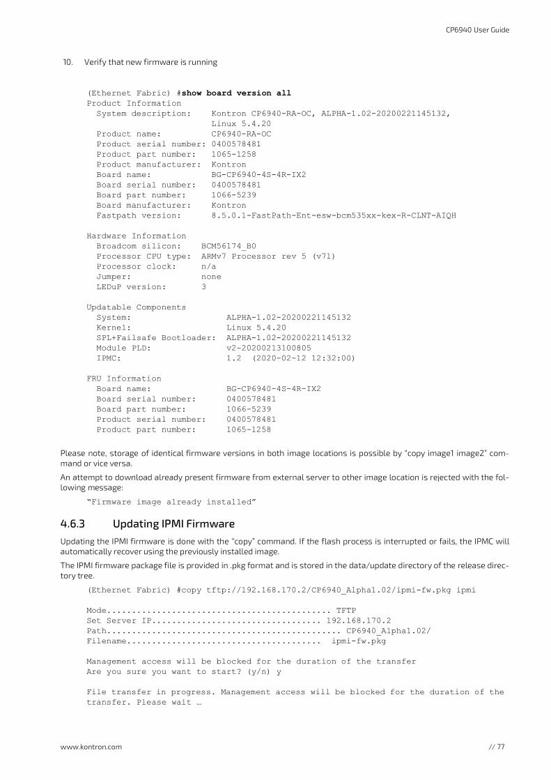
www.kontron.com
CP6940 User Guide
// 77
10. Verify that new firmware is running
(Ethernet Fabric) #show board version all Product Information System description: Kontron CP6940-RA-OC, ALPHA-1.02-20200221145132, Linux 5.4.20 Product name: CP6940-RA-OC Product serial number: 0400578481 Product part number: 1065-1258 Product manufacturer: Kontron Board name: BG-CP6940-4S-4R-IX2 Board serial number: 0400578481 Board part number: 1066-5239 Board manufacturer: Kontron Fastpath version: 8.5.0.1-FastPath-Ent-esw-bcm535xx-kex-R-CLNT-AIQH
Hardware Information Broadcom silicon: BCM56174_B0 Processor CPU type: ARMv7 Processor rev 5 (v7l) Processor clock: n/a Jumper: none LEDuP version: 3
Updatable Components System: ALPHA-1.02-20200221145132 Kernel: Linux 5.4.20 SPL+Failsafe Bootloader: ALPHA-1.02-20200221145132 Module PLD: v2-20200213100805 IPMC: 1.2 (2020-02-12 12:32:00)
FRU Information Board name: BG-CP6940-4S-4R-IX2 Board serial number: 0400578481 Board part number: 1066-5239 Product serial number: 0400578481 Product part number: 1065-1258
Please note, storage of identical firmware versions in both image locations is possible by “copy image1 image2” com-mand or vice versa.
An attempt to download already present firmware from external server to other image location is rejected with the fol-lowing message:
“Firmware image already installed”
4.6.3 Updating IPMI FirmwareUpdating the IPMI firmware is done with the “copy” command. If the flash process is interrupted or fails, the IPMC willautomatically recover using the previously installed image.
The IPMI firmware package file is provided in .pkg format and is stored in the data/update directory of the release direc-tory tree.
(Ethernet Fabric) #copy tftp://192.168.170.2/CP6940_Alpha1.02/ipmi-fw.pkg ipmi
Mode............................................. TFTP Set Server IP.................................. 192.168.170.2 Path............................................... CP6940_Alpha1.02/Filename....................................... ipmi-fw.pkg Management access will be blocked for the duration of the transfer Are you sure you want to start? (y/n) y File transfer in progress. Management access will be blocked for the duration of the transfer. Please wait …

www.kontron.com
CP6940 User Guide
// 78
Write image to flash starting... File transfer operation completed successfully. (Ethernet Fabric) #
Verify that new IPMI code is running
(Ethernet Fabric) #show board version allProduct Information System description: Kontron CP6940-SA-P, ALPHA-1.02-2020022114513, Linux 5.4.20 Product name: CP6940-RA-OC Product serial number: 0400578481 Product part number: 1065-1258 Product manufacturer: Kontron Board name: BG-CP6940-4S-4R-IX2 Board serial number: 0400578481 Board part number: 1066-5239 Board manufacturer: Kontron Fastpath version: 8.5.0.1-FastPath-Ent-esw-bcm535xx-kex-R-CLNT-AIQH
Hardware Information Broadcom silicon: BCM56174_B0 Processor CPU type: ARMv7 Processor rev 5 (v7l) Processor clock: n/a Jumper: none LEDuP version: 3
Updatable Components System: ALPHA-1.02-20200221145132 Kernel: Linux 5.4.20 SPL+Failsafe Bootloader: ALPHA-1.02-20200221145132 Module PLD: v2-20200213100805 IPMC : 1.4 (2020-03-27 11:53:02)
FRU Information Board name: BG-CP6940-4S-4R-IX2 Board serial number: 0400578481 Board part number: 1066-5239 Product serial number: 0400578481 Product part number: 1065-1258

www.kontron.com
CP6940 User Guide
// 79
5/ Thermal ConsiderationsThe CP6940 has some temperature sensors which ensure operation within the specified temperature limits. Sensor datais accessible via the Peripheral Manager. Although temperature sensing information is made available to the PM, theCP6940 itself does not provide any active means of temperature regulation.
The Switch device and all PHYs have internal temperature diodes. Their temperature values are stored in internal regis-ters. Additional, there are two temperature sensors for the inlet/outlet air temperature available.
As long as the temperature values stay below their upper critical threshold, all components on the CP6940 are consid-ered to be operated within their specified temperature range.
Figure 9: Position of Temperature Sensors, Top Side View

www.kontron.com
CP6940 User Guide
// 80
When developing applications using the CP6940, the system integrator must be aware of the overall system thermalrequirements. A system chassis must be provided which satisfy these requirements.
Measurements proofed that following conditions (maximum ambient temperature under maximum load) are possiblewhile all temperatures of on-board components stay below their critical thresholds..
Table 36: Thermal Requirements
Device Operation mode CoolingMaximum Tem-perature
CP6940-SA-OC-V 24x 1Gbps traffic rearFront: 4x 1GbBase-T RJ45, 2x 10 Gbe SFP+, 2x 1G SFP
Forced Air > 2m/s 0 to +60°C
CP6940-RA-OC 24x 1Gbps traffic rearFront: 4x 1GBase-T RJ45, 4x 10G SFP+
Forced Air > 2m/s -40 to +70°C
CP6940-RA-OC-P 24x 1Gbps traffic rearFront: 2x QSFP+ for 40G or 4 times 10G, 4x 10G SFP+, 2x 1G SFP
Forced Air > 2m/s -40 to +70°C
As Kontron assumes no responsibility for any damage to the CP6940 or other equipment resulting from overheating any of the components, it is highly recommended that system integrators as well as end users confirm that the operational environment of the CP6940 complies with the thermal considerations set forth in this document.

www.kontron.com
CP6940 User Guide
// 81
6/ Power ConsiderationsThe power considerations presented in this chapter must be taken into account by system integrators when specifyingthe CP6940 system environment.
The CP6940 has been designed for optimal power input and distribution. Still it is necessary to observe certain criteriaessential for application stability and reliability. The board is supplied by 3.3V and 5.0V from the backplane. All supplyvoltages from the backplane are enabled with a predefined ramp-up time. The inrush current is limited by Hot-Swapcontrollers.
The table below indicates the absolute maximum input voltage ratings that must not be exceeded. Power supplies to beused with the CP6940 should be carefully tested to ensure compliance with these ratings.
Power consumption: below 55 W.
5.0 V VIN +5%/-3%, designed for maximum load 5.50A (27.50W)
3.3 V VIN +5%/-3%, designed for maximum load 10.00A (33W)
6.1 BackplanesBackplanes to be used with the CP6940 must be adequately specified. The backplane must provide optimal power distri-bution for the +3.3 V and +5 V power inputs. Input power connections to the backplane itself should be carefully specifiedto ensure a minimum of power loss and to guarantee operational stability. Long input lines, under-dimensioned cablingor bridges, high resistance connections, etc. must be avoided. It is recommended to use POSITRONIC or M-type connectorbackplanes and power supplies where possible.
Backplanes does not need any 12V supply.
Table 37: Maximum Input Power Voltage Limits
Voltage Rail Operation Mode Maximum Current
V_3V3_CPCI 24x 1Gbps traffic rear2x QSFP+ for 40G, 4x 10G SFP+, 2x 1G SFP ports
8.00A
V_5V0_CPCI 24x 1Gbps traffic rear2x QSFP+ for 40G, 4x 10G SFP+, 2x 1G SFPports
4.50A

www.kontron.com // 82
CP6940 User Guide
About Kontron
Kontron, a global leader in embedded computing technology and trusted advisor in IoT, works closely with its customers,allowing them to focus on their core competencies by offering a complete and integrated portfolio of hardware, soft-ware and services designed to help them make the most of their applications.
With a significant percentage of employees in research and development, Kontron creates many of the standards thatdrive the world's embedded computing platforms; bringing to life numerous technologies and applications that touchmillions of lives. The result is an accelerated time-to-market, reduced total-cost-of-ownership, product longevity andthe best possible overall application with leading-edge, highest reliability embedded technology.
Kontron is a listed company. Its shares are traded in the Prime Standard segment of the Frankfurt Stock Exchange and onother exchanges under the symbol "KBC". For more information, please visit: http://www.kontron.com/
CORPORATE OFFICES
EUROPE, MIDDLE EAST & AFRICA NORTH AMERICA ASIA PACIFIC
Lise-Meitner-Str. 3-586156 AugsburgGermanyTel.: + 49 821 4086-0Fax: + 49 821 [email protected]
14118 Stowe DrivePoway, CA 92064-7147USATel.: + 1 888 294 4558Fax: + 1 858 677 [email protected]
1-2F, 10 Building, No. 8 Liangshuihe 2nd StreetEconomical & Technological Development ZoneBeijing 100070, P.R.ChinaTel.: + 86 10 63751188Fax: + 86 10 [email protected]