Corrosion behaviour of silica hybrid coatings produced from basic catalysed particulate sols by...
8
Corrosion behaviour of silica hybrid coatings produced from basic catalysed particulate sols by dipping and EPD Y. Castro, B. Ferrari * , R. Moreno, A. Dura ´n Instituto de Cera ´mica y Vidrio (CSIC), Campus de Cantoblanco, c/ Kelsen, 28049 Madrid, Spain Received 23 October 2003; accepted in revised form 3 March 2004 Available online 30 April 2004 Abstract This paper compares the corrosion behaviour of silica hybrid coatings produced from basic catalysed sols by dipping and electrophoretic deposition (EPD) onto stainless steel AISI 304. Particulate silica sols were prepared by basic catalysis with ethyltriethoxysilane (TEOS), methyltriethoxysilane (MTES) and sodium hydroxide. To improve the stability, the starting sol was diluted with ethanol. The maximum defect-free sintered thickness obtained by dipping was 3.5 Am while EPD allowed us to obtain coatings as thick as 12 Am. The protective behaviour against corrosion and the corrosion kinetics of the produced films were studied through potentiodynamic and polarisation resistance (PR) measurements in aggressive media (sea water and HCl). The corrosion resistance of coatings produced by dipping increases if concentrated solutions are used and the coating are thicker than 2 Am. However, the EPD process allows producing protective coatings using also diluted solutions, stable with time. The corrosion resistance of the steel is increased by two orders of magnitude for dip-coatings and by four orders of magnitude for coatings produced by EPD. Moreover, silica hybrid coatings present an excellent resistance not only in sea water but in HCl 1N media. AFM observations suggest that coatings produced by EPD are homogeneous and defect-free. D 2004 Elsevier B.V. All rights reserved. Keywords: Immersion test; Electrophoretic deposition; Sol – gel/coatings; Silicon oxide 1. Introduction Coatings manufacturing is a major feature of the sol–gel method. Thin films may be easily prepared by dip-coating but thicker coats are necessary for some applications as increasing the corrosion resistance of metals. In these cases, other deposition processes as the electrophoretic deposition technique (EPD) can be used. A few studies concerning the use of EPD for sol–gel systems have been published, and most of them report the deposition from aqueous suspensions of nanoparticles prepared by sol–gel [1,2], or commercially available colloidal suspensions [3]. However, only little information is available dealing with the deposition of precursor sols prepared by sol–gel synthesis. In basic con- ditions, the use of alkaline pHs leads to the clustering of alkoxide chains which behave as dense particles dispersed in the alcohol generated during synthesis or further dilution [4]. Much effort has been devoted to study the corrosion protection of metals (stainless steel, aluminium and alumin- ium alloys, copper, carbon steel, galvanized steel, etc.) by sol – gel coatings, but published results are often contradic- tory. Some papers have evaluated the protective behaviour of the coating considering the variation of corrosion poten- tial, a parameter not relevant for measuring the corrosion behaviour [5]. Inorganic coatings are adequate barriers against oxidation but show a poor behaviour in electrolytic media due to the presence of micro-cracks or defects [6,7]. On the other hand, hybrid organic–inorganic coatings have demonstrated to give an adequate protection to metals. The incorporation of organic groups makes it possible to in- crease ductility and thickness (f2 Am) and to reduce the defects and micro-cracking, thus enhancing the electrolytic corrosion behaviour [8]. The use of thicker coatings should allow increasing the corrosion resistance provided the coat- ings are dense and defect-free. Previous works described the use of EPD process to obtain thick silica coatings onto stainless steel using either acid-catalysed sols containing colloidal particles, or basic- catalysed particulate sols [9–11]. 0257-8972/$ - see front matter D 2004 Elsevier B.V. All rights reserved. doi:10.1016/j.surfcoat.2004.03.001 * Corresponding author. Tel.: +34-917-355-870; fax: +34-917-355- 843. E-mail address: [email protected] (B. Ferrari). www.elsevier.com/locate/surfcoat Surface & Coatings Technology 191 (2005) 228– 235
Transcript of Corrosion behaviour of silica hybrid coatings produced from basic catalysed particulate sols by...

www.elsevier.com/locate/surfcoat
Surface & Coatings Technology 191 (2005) 228–235
Corrosion behaviour of silica hybrid coatings produced from basic
catalysed particulate sols by dipping and EPD
Y. Castro, B. Ferrari*, R. Moreno, A. Duran
Instituto de Ceramica y Vidrio (CSIC), Campus de Cantoblanco, c/ Kelsen, 28049 Madrid, Spain
Received 23 October 2003; accepted in revised form 3 March 2004
Available online 30 April 2004
Abstract
This paper compares the corrosion behaviour of silica hybrid coatings produced from basic catalysed sols by dipping and electrophoretic
deposition (EPD) onto stainless steel AISI 304. Particulate silica sols were prepared by basic catalysis with ethyltriethoxysilane (TEOS),
methyltriethoxysilane (MTES) and sodium hydroxide. To improve the stability, the starting sol was diluted with ethanol. The maximum
defect-free sintered thickness obtained by dipping was 3.5 Am while EPD allowed us to obtain coatings as thick as 12 Am. The protective
behaviour against corrosion and the corrosion kinetics of the produced films were studied through potentiodynamic and polarisation
resistance (PR) measurements in aggressive media (sea water and HCl). The corrosion resistance of coatings produced by dipping increases if
concentrated solutions are used and the coating are thicker than 2 Am. However, the EPD process allows producing protective coatings using
also diluted solutions, stable with time. The corrosion resistance of the steel is increased by two orders of magnitude for dip-coatings and by
four orders of magnitude for coatings produced by EPD. Moreover, silica hybrid coatings present an excellent resistance not only in sea water
but in HCl 1N media. AFM observations suggest that coatings produced by EPD are homogeneous and defect-free.
D 2004 Elsevier B.V. All rights reserved.
Keywords: Immersion test; Electrophoretic deposition; Sol–gel/coatings; Silicon oxide
1. Introduction
Coatings manufacturing is a major feature of the sol–gel
method. Thin films may be easily prepared by dip-coating
but thicker coats are necessary for some applications as
increasing the corrosion resistance of metals. In these cases,
other deposition processes as the electrophoretic deposition
technique (EPD) can be used. A few studies concerning the
use of EPD for sol–gel systems have been published, and
most of them report the deposition from aqueous suspensions
of nanoparticles prepared by sol–gel [1,2], or commercially
available colloidal suspensions [3]. However, only little
information is available dealing with the deposition of
precursor sols prepared by sol–gel synthesis. In basic con-
ditions, the use of alkaline pHs leads to the clustering of
alkoxide chains which behave as dense particles dispersed in
the alcohol generated during synthesis or further dilution [4].
0257-8972/$ - see front matter D 2004 Elsevier B.V. All rights reserved.
doi:10.1016/j.surfcoat.2004.03.001
* Corresponding author. Tel.: +34-917-355-870; fax: +34-917-355-
843.
E-mail address: [email protected] (B. Ferrari).
Much effort has been devoted to study the corrosion
protection of metals (stainless steel, aluminium and alumin-
ium alloys, copper, carbon steel, galvanized steel, etc.) by
sol–gel coatings, but published results are often contradic-
tory. Some papers have evaluated the protective behaviour
of the coating considering the variation of corrosion poten-
tial, a parameter not relevant for measuring the corrosion
behaviour [5]. Inorganic coatings are adequate barriers
against oxidation but show a poor behaviour in electrolytic
media due to the presence of micro-cracks or defects [6,7].
On the other hand, hybrid organic–inorganic coatings have
demonstrated to give an adequate protection to metals. The
incorporation of organic groups makes it possible to in-
crease ductility and thickness (f2 Am) and to reduce the
defects and micro-cracking, thus enhancing the electrolytic
corrosion behaviour [8]. The use of thicker coatings should
allow increasing the corrosion resistance provided the coat-
ings are dense and defect-free.
Previous works described the use of EPD process to
obtain thick silica coatings onto stainless steel using either
acid-catalysed sols containing colloidal particles, or basic-
catalysed particulate sols [9–11].

Y. Castro et al. / Surface & Coatings Technology 191 (2005) 228–235 229
The aim of this work has been to prepare thick silica
hybrid coatings using basic-catalysed particulate sols de-
posited by dipping and EPD in order to increase the
corrosion resistance of stainless steel substrates. The stabil-
ity of the sols and the processing parameters of dipping and
EPD were studied. The corrosion resistance of the coatings
has been evaluated through electrochemical methods (linear
voltametry and polarisation resistance) as a function of
different processing parameters: viscosity and concentration
of the sol, final thickness of the coating, applied current
density, and deposition time.
2. Experimental
The starting sol was prepared under basic catalytic con-
ditions following the procedure described by Jonschker et al.
[12], where ethyltriethoxysilane (TEOS) and methyltriethox-
ysilane (MTES) were mixed with NaOH. The molar ratio
TEOS/MTES/NaOH and H2O/MTES+TEOS were 0.3/1.2/
0.2 and 1.18, respectively, and the final concentration of
silica was 267 g/l. The temperature of the synthesis was
maintained below 25 jC in order to avoid gelation. The
synthesis was performed under stirring, reflux and with N2
flow, to maintain the sol refrigerated and to preserve it from
the contact with open atmosphere. The concentrated sol,
called NaSi, was diluted by adding ethanol up to SiO2
concentrations of 210, 200, 188, 150 and 85 g/l. The size
of the particles produced during the hydrolysis and conden-
sation of alkoxides is below 20 nm.
The stability of 267 and 188 g/l NaSi sols was evaluated
by rheological measurements in closed conditions at 5 jC,using a rotational rheometer (Haake, RS50, Germany) under
controlled rate conditions. The shear rate was increased
from 0 to 1000 s�1 in 5 min, with 1 min at the maximum
rate and decreasing again to 0 in 5 min.
Coatings were deposited by dipping from 267, 210 and
188 g/l sols onto glass slides and polished stainless steel
(AISI 304) substrates, varying the withdrawal rate from 9 to
53 cm/min. The glass substrates were cleaned in an ultra-
sonic bath with absolute ethanol for 15 min. The stainless
steel was unsoiled using an alkaline commercial solution
(P3Emalan5668: P3Emalan0469, Miele, Germany) for 5 min
and subsequently washed with deionised water at 60 and
25 jC.A double coating was prepared in a two-step process
using NaSi 188 g/l with intermediate heat treatment at 500
jC for 30 min, the same applied after the second coating
deposition.
EPD coatings were deposited in galvanostatic conditions
using a potentiostate–galvanostate (AMEL 551, Italy).
Stainless steel AISI 304 substrate was used as working
electrode and graphite as counter-electrode. An electropho-
retic cell was designed consisting on a methacrylate contain-
er with a trap of the same material, which prevents contact
with atmosphere. All the system was maintained at 5 jC.
EPD parameters were studied in the light of Hamaker
equation (Eq. 1), according to which the deposited mass (m)
depends linearly on particle concentration (C), electrode
area (S), electric field (E), deposition time (t), and electro-
phoretic mobility (lE) [13].
m ¼ CSE tlE ð1Þ
EPD kinetics was studied for a constant current density
of 0.6 mA/cm2 and deposition times up to 60 min. Coatings
with a sintered thickness of 7 Am were produced by varying
the current density from 0.6 to 3.3 mA/cm2 and the
deposition time up to 35 min.
Coatings produced by either dipping and EPD were dried
at room conditions and sintered at 500 jC for 30 min in air,
with cooling and heating rates of 8 jC/min.
The thickness of coatings was measured on glass sub-
strates with a profilometer (Talystep, Taylor Hobson, UK),
while that of coatings onto stainless steel were calculated by
gravimetry and confirmed by scanning electron microscopy
(Zeiss DSM 950). Atomic force microscopy (AFM) (Nano-
tech, Spain) was used to characterise the surface texture of
the coatings.
The protective behaviour against corrosion was studied
by potentiodynamic polarisation in 0.6 N NaCl, with a
testing area of 1 cm2, without stirring. The tests were
controlled by a potentiostatic–galvanostatic equipment
(AMEL 256, Italy), using a potential sweep rate of 166
AV/s and a potential range of �500 to 1500 mV. Before
starting the measurement, the potential of open circuit was
measured until no changes were registered (approximately
30 min). The corrosion kinetics was studied through
polarisation resistance [14,15] in sea water and 1 N HCl.
The potential was varied from �20 to +10 mV with
respect to the corrosion potential and the potential sweep
rate was fixed to 200 AV/min. The evolution of the
polarisation resistance of coatings produced by dipping
was measured for immersion times varying from 0 to 1300
h of dipping. Saturated calomel (SCE) was used as a
reference electrode and platinum as a counter-electrode in
both experiments.
3. Results and discussion
3.1. Characterisation of particulate sols and coatings
The rheological characterisation of particulate NaSi
sols 188 and 267 g/l shows that they behave as New-
tonian fluids, with initial viscosities of 4 and 8.5 mPa s,
respectively [16]. Table 1 shows the rheological parame-
ters of fresh 267, 210 and 188 g/l sols, and of 267 g/l sol
after 1 and 2 h ageing, as well as the thickness of the
coatings obtained at different withdrawal rates: 53 (max-
imum rate of the lab lift used), 40, and 10 cm/min. The
viscosity of NaSi 267 g/l increases from 8.5 to 20 mPa s

Fig. 1. EPD kinetics at current density of 0.6 mA/cm2 for NaSi 267, 200,
150 and 188 g/l.
Table 1
Rheological properties of NaSi sols and characteristics of the coatings
NaSi sol Ageing Viscosity Stability Withdrawal rate (cm/min)
concentration (h) 5 jC (mPa s) (h) 5 jC10 40 53
(g/l)Thickness (Am)
267 Fresh 8.5 3 2.8 3.5 4.3
1 h 13 3.0 –
2 h 20 3.2 – –
210 Fresh – 1.6 2.1 2.6
188 Fresh 4 96 0.9 1.9 2.2
Fig. 2. Polarisation curves in 0.6 N NaCl of uncoated AISI 304 and
coatings with thickness 1.3, 2.3 and 3.3 Am obtained by dipping using the
NaSi 267 g/l.
Y. Castro et al. / Surface & Coatings Technology 191 (2005) 228–235230
in 2 h, indicating that the structure of the as-prepared sol
(267 g/l) develops quickly towards gelation, even when
maintained at temperatures below 5 jC in tight condi-
tions. Dilution retards the gelling process and the 188 g/
l sol maintains a constant viscosity of f4 mPa s for
around 96 h.
Dip-coatings were prepared on glass slides from NaSi
267, 210 and 188 g/l at different withdrawal rates (Table
1), but the critical thickness was not reached at any
concentration. The maximum thickness obtained after
sintering for the 267 g/l sol was 4.3 Am, but the coatings
present defects, as drips and edge effects, associated to
the high withdrawal rate (53 cm/min). When this velocity
is limited to 35–40 cm/min the maximum defect-free
thickness attainable by dipping is 3.5 Am. The defects
associated to high withdrawal rates are also evident for
coatings obtained from the 210 and 188 g/l sols, which
present a maximum defect-free thickness of 2.1 and 1.9
Am, respectively.
To obtain homogeneous coatings thicker than 2 Am with
diluted NaSi 188 g/l, a two-step dipping process was used,
obtaining a two-layer coating of 2.5 Am.
EPD tests were performed on AISI 304 stainless steel
substrates using a current density of 0.6 mA/cm2 for
deposition times up to 60 min, using the concentrated
and diluted sols. Since anodic deposition takes place, no
H2 bubbling is observed. A critical thickness, defined as
the maximum crack-free sintered thickness attainable, of
12 Am was reached after deposition times of 5, 25, 30 and
60 min for sol concentrations of 267, 200, 188 and 150 g/
l, respectively. Fig. 1 plots the variation of weight per unit
area with deposition time, for sols with different concen-
tration. As expected, the coating grows faster with in-
creasing concentration. However, deposition kinetics
shows a change of slope for all the SiO2 concentrations;
the higher the concentration, the shorter is the time at
which this change takes place. The concentration of solids
is one of the most critical parameters of the EPD process,
since there is a local increase of particles concentration in
the vicinity of the working electrode which allows the
coating formation, according to the Nicholson–Sarkar
model [11]. On the other hand, the sol concentration is
critical for the gelation process, as concluded from the
rheological study.
3.2. Electrochemical characterisation of coatings produced
by dipping
The protective character of the hybrid silica coatings was
determined by electrochemical measurements. Fig. 2 shows
the polarisation curves of coatings of different thickness,
(1.3, 2.3 and 2.8 Am) prepared by dipping from NaSi 267 g/
l, compared with the uncoated steel. Table 2 summarises the
parameters extracted from polarisation curves: breakdown
potential (Ep), passive region (DE) and passive current
density (ipass). These characteristic parameters are indicated
for the uncoated steel in Fig. 2.
The thinnest coating (1.3 Am) shows a cathodic current
density lower than that of the uncoated steel; but the passive
region, DE, is not well defined and the values of the
corrosion and the breakdown potentials are �0.082 and
0.108 V, respectively. This behaviour is associated to the
presence of defects such as micro-pores, which promote a
fast increase of the current density.

Fig. 4. Polarisation curves for dipping coatings obtained from 267, 210 and
188 g/l sols prepared with a similar thickness and compared with the
uncoated steel.
Table 2
Electrochemical parameters of dip-coatings prepared from NaSi 267 g/l
Coating thickness (Am) Ep (V) DE (V) ipass (A/cm2)
NaSi 1.3 Am 0.108 0.19 8.3�10�9
NaSi 2.3 Am 0.836 1.01 9.3�10�10
NaSi 2.8 Am 1.4 1.45 5.0�10�10
Uncoated steel 0.63 0.69 1.8�10�7
Y. Castro et al. / Surface & Coatings Technology 191 (2005) 228–235 231
The decrease of the passive current density from 10�7 to
10�10 A/cm2 for coatings thicker than 2 Am indicates an
important enhancement of the corrosion resistance, confirm-
ing that the breakdown potentials are much higher than
those of the uncoated steel. The passive range increases with
the coating thickness, achieving 1 and 1.4 V for coatings
with 2.3 and 2.8 Am, this also indicating better corrosion
behaviour. Although breakdown potentials >1 V can be
associated to the gas evolution (mainly O2), promoted by
the water decomposition that takes place at pH 7 for
potentials around 1 V, according to the Pourbaix diagram
of the thermodynamic stability of H2O. These results show
that coatings thicker than 2 Am behave as physical barriers,
preventing the electrochemical degradation of the substrates.
The effect of sol ageing on the protective behaviour of
the dip-coatings was also evaluated. Fig. 3 shows the
polarisation curves for coatings of similar thickness (f3
Am) prepared from different aged sols, compared with the
uncoated steel. The passive region decreases from 1.4 to 0.3
V after 1 h ageing, and tends to zero after 2 h, while the
viscosity of the sol evolves from 8.5 mPa s to 13 and 20
mPa s. The poorer protecting behaviour with ageing is
directly related to the viscosity increase. Indeed, it has been
reported that ageing promotes growth and agglomeration of
particles in the sol leading to porous films [17].
The effect of sol dilution on the corrosion resistance was
evaluated on dip-coatings thicker than 2 Am. Fig. 4 shows
the electrochemical behaviour of dip-coatings obtained from
NaSi 267 g/l and diluted sols (monolayer from 210 g/l and
two-layer coating with 188 g/l) compared with the uncoated
Fig. 3. Polarisation curves of uncoated steel and coatings obtained by
dipping using the 267 g/l as a function of viscosities.
steel. The dilution induces remarkable changes in the
potentiostatic polarisation curves. Although all the coatings
have roughly the same thickness, the passive range clearly
decreases as dilution increases, thus indicating a faster
degradation of the film. This suggests that coating porosity
likely increases with dilution.
The origin of defects with ageing or dilution of NaSi sols
could be related to the structure of these particulate sols.
During ageing, the growth of nanoparticles leads to inter-
stitial pores in the gel structure. If the final thickness is low,
the electrolyte can cross the coating through the pores
reaching the substrate. When dilution increases, the longer
drying time and the lower volume fraction of particles
produce thinner and more porous coatings.
3.3. Electrochemical characterisation of coatings produced
by EPD
Fig. 5 shows the polarisation curves of 7 Am coatings
obtained by EPD from the 188 g/l sol, compared with the
Fig. 5. Polarisation curves for EPD coatings of 7 Am obtained at different
current densities from 188 g/l sol compared with the uncoated steel.
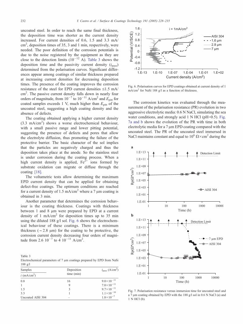
Fig. 6. Polarisation curves for EPD coatings obtained at current density of 1
mA/cm2 for NaSi 188 g/l as a function of thickness.
Y. Castro et al. / Surface & Coatings Technology 191 (2005) 228–235232
uncoated steel. In order to reach the same final thickness,
the deposition time was shorter as the current density
increased. For current densities of 0.6, 1.5 and 3.3 mA/
cm2, deposition times of 35, 3 and 1 min, respectively, were
needed. The poor definition of the corrosion potentials is
due to the noise registered by the equipment as they are
close to the detection limits (10�12 A). Table 3 shows the
deposition time and the passivity current density (ipass)
determined from the polarisation curves. Significant differ-
ences appear among coatings of similar thickness prepared
at increasing current densities for decreasing deposition
times. The presence of the coating improves the corrosion
resistance of the steel for EPD current densities V1.5 mA/
cm2. The passive current density falls down in nearly four
orders of magnitude, from 10�7 to 10�11 A/cm2 and Epitt for
coated samples exceeds 1 V, much higher than Epitt of the
uncoated steel, suggesting a high coating density and the
absence of defects.
The coating obtained applying a higher current density
(3.3 mA/cm2) shows a worse electrochemical behaviour,
with a small passive range and lower pitting potential,
suggesting the presence of defects and pores that allow
the electrolyte diffusion, thus promoting the failure of the
protective barrier. The basic character of the sol implies
that the particles are negatively charged and thus the
deposition takes place at the anode. So the stainless steel
is under corrosion during the coating process. When a
high current density is applied, Fe2+ ions formed by
substrate oxidation can migrate or diffuse through the
coating [18].
The voltametric tests allow determining the maximum
EPD current density that can be applied for obtaining
defect-free coatings. The optimum conditions are reached
for a current density of 1.5 mA/cm2 where a 7 Am coating is
obtained in 3 min.
Another parameter that determines the corrosion behav-
iour is the coating thickness. Coatings with thickness
between 1 and 8 Am were prepared by EPD at a current
density of 1 mA/cm2 for deposition times up to 35 min
using the diluted 188 g/l sol. Fig. 6 shows the electrochem-
ical behaviour of these coatings. There is a minimum
thickness (f2.8 Am) for the coating to be protective, the
corrosion current density decreasing four orders of magni-
tude from 2.6 10�7 to 4 10�11 A/cm2.
Table 3
Electrochemical parameters of 7 Am coatings prepared by EPD from NaSi
188 g/l
Samples Deposition ipass (A/cm2)
i (mA/cm2)time (min)
0.8 16 9.0�10�11
1 9 7.0�10�11
1.5 3 9.7�10�11
3.3 1 1.1�10�10
Uncoated AISI 304 – 1.8�10�7
The corrosion kinetics was evaluated through the mea-
surement of the polarisation resistance (PR) evolution in two
aggressive electrolytic media: 0.6 N NaCl, simulating the sea
water conditions, and strongly acid 1 N HCl (pH=0.5). Fig.
7a and b shows the evolution of the PR with time in both
electrolytic media for a 7 Am EPD coating compared with the
uncoated steel. The PR of the uncoated steel immersed in
NaCl maintains constant and equal to 106 V�cm2 during the
Fig. 7. Polarisation resistance versus immersion time for uncoated steel and
a 7 Am coating obtained by EPD with the 188 g/l sol in 0.6 N NaCl (a) and
1 N HCl (b).

Y. Castro et al. / Surface & Coatings Technology 191 (2005) 228–235 233
entire test (5000 h) due to the uniform dissolution of the
metal. The dashed line indicates that the PR of the coated
steel maintains over 1012 V�cm2, the detection limit of the
equipment, for more than 2 months of immersion, confirm-
ing that no defects appeared in the coating during this time,
and verifying that the coating acts as a stable protective
barrier, against the corrosion of the metal substrate.
The corrosion behaviour of EPD coatings was also
studied in a much more aggressive corrosion medium (1
N HCl), Fig. 7b. In this case, the PR of the uncoated steel
falls down to 103 V�cm2 in less than 1 h, indicating the
rapid degradation of the substrate in this medium. Contrari-
ly, PR of the EPD-coated steel maintains over the detection
limit of the equipment for at least 200 h of immersion, then
decreasing slowly up to reach the PR of the uncoated steel
after 1000 h.
The stability of these coatings in acid media without
appearance of defects in strong aggressive conditions shows
the excellent behaviour of the hybrid EPD silica coatings.
3.4. Comparison of dipping and EPD coatings
In order to compare the efficiency of the two processes
for producing protective coatings, Fig. 8 shows the polar-
isation curves of 2.8 Am-thick coatings obtained by dipping
from NaSi 267 g/l and by EPD using the 188 g/l sol. The
electrochemical behaviour improves for both coating pro-
cedures. The passivation current density decreases by three
orders of magnitude for the dip-coating and by four orders
of magnitude for the EPD coating, compared to the uncoat-
ed steel, confirming that EPD coatings present an increased
protective character against corrosion. This better behaviour
could be associated with the improved packing behaviour of
the particles moving in an electric field, this likely leading
to a higher density of the EPD coatings.
Atomic force microscopy was used to characterise the
surface texture of the coatings, since it was not possible to
detect neither defects nor pores in the transparent glass-like
coatings by scanning electron microscopy. Fig. 9 shows the
Fig. 8. Polarisation curves of uncoated steel and coatings with a thickness
of 2.8 Am obtained by dipping and EPD using the 267 and 188 g/l sols,
respectively.
Fig. 9. AFM images of coatings obtained by dipping from 267 g/l sol (a),
188 g/l sol (b), and 188 g/l with double dipping (c).

Fig. 10. AFM images of coating obtained by EPD applying a current
density of 1.5 mA/cm2 for 3 min using the NaSi 188 g/l.
Y. Castro et al. / Surface & Coatings Technology 191 (2005) 228–235234
AFM images of the topography of the dip-coatings obtained
from NaSi 267 g/l sol (a), and 188 g/l (b) and the two-layer
coating (c) with thicknesses of 2.3, 1.9 and 2.5 Am, respec-
tively. AFM indicates that the dip-coating from fresh con-
centrated sol presents a homogeneous, pore-free and dense
surface (Fig. 9a), while the coatings prepared from the
diluted sol present a less smooth surface with apparent
porosity regions (Fig. 9b). This effect is highlighted in the
two-step dipping process (Fig. 9c). As explained above, a
higher content of solvent could lead to porous structures
because the solidification process occurs faster than conden-
sation reactions, likely originating a lower packing density
[19]. AFM observations suggest that dip-coatings deposited
from diluted particulate sols are not dense enough to prevent
the contact between the substrate and the electrolyte.
On the other hand, the topographic analysis of the coat-
ings obtained by EPD applying 1.5 mA/cm2 for 3 min from
a diluted 188 g/l sol illustrate a dense and homogeneous
texture (Fig. 10). Electrochemical measurements and AFM
analysis show that dense coatings are obtained by EPD even
using the diluted sol. This represents a clear advantage
respecting to dip-coating method, since EPD allows the
dilution of the sol, which largely increases the sol stability
and simplifies processing.
4. Conclusions
Homogenous and cracks-free hybrid silica coatings have
been obtained by dipping and by electrophoretic deposition
(EPD) from a base catalysed sol (NaSi) with initial SiO2
concentration of 267, and 210 and 188 g/l after dilution with
ethanol.
Homogeneous defect-free coatings with a maximum
thickness of 3.5 Am were prepared by dipping. Thicker
coatings have been obtained by EPD, where a critical
thickness around 12 Am was reached after sintering at
500 jC.Coatings produced by dipping improve the corrosion
resistance of the steel when surpass 2 Am. For achieving
this thickness, it is necessary to use the concentrated sol,
which is highly unstable and ages in a few hours, thus
leading to non-homogeneous or defective coating.
EPD allows producing thicker coatings with enhanced
corrosion resistance, even when the sol is previously dilut-
ed. This facilitates processing and extends the stability of
the sol over much longer times.
The protective character of EPD coatings depends on the
electrical conditions imposed during forming. Current den-
sities higher than 1.5 mA/cm2 lead to corrosion of the metal
substrate used as electrode, which has a deleterious effect on
the coating properties. The measurement of corrosion ki-
netics from polarisation resistance tests demonstrates that a
7 Am-thick SiO2 coating obtained by EPD from 188g/l sol
acts as an effective barrier against corrosion in sea water and
1 N HCl.
AFM studies suggest a negative effect of dilution on
dipping, while the surface texture and the packing density of
EPD coatings appear uniform even after dilution.
Acknowledgements
This work has been supported by projects MAT2003-
05902-C02-01 (CICYT, Spain) and EC BRITE
Programme (BE97-5111) in collaboration with INM
(Germany), Miele (Germany), Corus (The Netherlands),
Ferro (France) and ABB (France). Dr. Mennig and Dr.
Niegisch (INM) are gratefully acknowledged for sol
processing.
Dr. Ferrari acknowledges CSIC and the European Social
Foundation for its financial support. Authors acknowledge
to the New Microscopies Laboratory (UAM) for their
collaborations to the performance of AFM studies.
References
[1] H. Nishimori, K. Hasegawa, M. Tatsumisago, T. Minami, J. Sol–Gel
Sci. Technol. 7 (1996) 211.
[2] K. Hasegawa, H. Nishimori, M. Tatsumisago, J. Mater. Sci. 33 (1998)
1095.
[3] A.R. Boccaccini, U. Schindler, H.G. Kruger, Mater. Lett. 51 (2001)
225.
[4] C.J. Brinker, G.W. Scherer, Sol–Gel Science: The Physics and
Chemistry of Sol–Gel Processing, Academic Press, San Diego,
USA, 1990.
[5] M. Atik, S.H. Messaddeq, F.P. Luna, M.A. Aegerter, J. Mater. Sci.
Lett. 15 (1996) 2051.
[6] M. Guglielmi, J. Sol–Gel Sci. Technol. 8 (1997) 443.
[7] J.J. Damborenea, N. Pellegri, A. Duran, J. Sol–Gel Sci. Technol. 4
(1995) 239.
[8] J. Gallardo, I. Garcıa, L. Celis, M.A. Arenas, A. Conde, A. Duran,
J. Sol–Gel Sci. Technol. 27 (2003) 175.

Y. Castro et al. / Surface & Coatings Technology 191 (2005) 228–235 235
[9] Y. Castro, A. Duran, R. Moreno, B. Ferrari, Adv. Mater. 14 (2002)
1505.
[10] Y. Castro, B. Ferrari, R. Moreno, A. Duran, J. Sol–Gel Sci. Technol.
26 (2003) 1.
[11] P. Sarkar, P.S. Nicholson, J. Am. Ceram. Soc. 79 (1996) 1987.
[12] J.G. Jonschker, M. Mennig, H. Schmidt, European Patent
EP0973958, 1998.
[13] P. Sarkar, P.S. Nicholson, J. Am. Ceram. Soc. 79 (1996) 1897.
[14] M. Prazk, Werkst. Korros. 2 (1974) 104.
[15] ASTM G59-91, p. 216.
[16] Y. Castro, B. Ferrari, A. Duran, R. Moreno, J. Mater. Sci. 39 (2003)
845.
[17] C. McDonagh, F. Sheridan, T. Butler, B.D. MacCraith, J. Non-Cryst.
Solids 194 (1996) 72.
[18] B. Ferrari, J.C. Farinas, R. Moreno, J. Am. Ceram. Soc. 84 (2001)
733.
[19] C.J. Brinker, A.J. Hurd, G.C. Frye, P.R. Schunk, C.S. Ashley, J. Ceram.
Soc. Jpn., Int. Ed. 99 (1991) 843.