Corrected Insp Repts 50-335/89-26 & 50-389/89-26 on 891011 ...
21
. ~gR RECy, (4 ~4 p Cy I p I cA p Cy o'**++ UNITED STATES NUCLEAR REGULATORY COMMISSION REGION II 101 MARIETTASTREET, N.W. ATLANTA, GEORGIA 30323 Report Nos.: 50-335/89-26 and 50-389/89-26 Licensee: Florida Power and Light Company 9250 West Flagler Street Miami, FL 33102 Docket Hos.: 50-335 and 50-389 License Nos.: DPR-67 and NPF-16 Facility Name: St. Lucie 1 and 2 Inspection Conducted: 'ctober 1 - November 13, 1989 Inspect'ors: '-. '. A. lr ,-Senior Resi nt Inspector ( r M. A. Scott esident pecto Approved by: R. V. Cr enjak, Chief Reactor Projects Section 2B Reactor Projects Branch 2 Division of Reactor Projects /< r~ PP ate Signed /z /g+ D te igned Da e S gn d SUMMARY Scope: Scope: This routine resident inspection was conducted onsite in the areas of plant operations review, maintenance observations, surveillance observations, safety system inspection, review of special reports, review of nonroutine events, and followup of previous inspection findings. Results: During this inspection period, both units experienced CEDMCS problems. As a result of these continuing CEDMCS failures the licensee performed an ih-depth review of the failures and problem causes. This in-depth review identified the root cause associated with the Unit 2, September 23, 1989, Dropped Rod Event (Paragraph 2). In addition, the licensee corrected the leakage associated with the Atmospheric Dump Valve Muffler (Paragraph 5). 00ii80372 900io PDR ADOCK 0 000335 9 PDC
-
Upload
khangminh22 -
Category
Documents
-
view
5 -
download
0
Transcript of Corrected Insp Repts 50-335/89-26 & 50-389/89-26 on 891011 ...
.~gR RECy,(4
~4 pCy
I pIcA
pCy
o'**++
UNITED STATESNUCLEAR REGULATORY COMMISSION
REGION II101 MARIETTASTREET, N.W.ATLANTA,GEORGIA 30323
Report Nos.: 50-335/89-26 and 50-389/89-26
Licensee: Florida Power and Light Company9250 West Flagler StreetMiami, FL 33102
Docket Hos.: 50-335 and 50-389 License Nos.: DPR-67 and NPF-16
Facility Name: St. Lucie 1 and 2
Inspection Conducted: 'ctober 1 - November 13, 1989
Inspect'ors: '-.'.
A. lr ,-Senior Resi nt Inspector(r M. A. Scott esident pecto
Approved by:R. V. Cr enjak, ChiefReactor Projects Section 2BReactor Projects Branch 2Division of Reactor Projects
/< r~ PPate Signed
/z /g+D te igned
Da e S gn d
SUMMARY
Scope:
Scope:
This routine resident inspection was conducted onsite in the areas of plantoperations review, maintenance observations, surveillance observations, safetysystem inspection, review of special reports, review of nonroutine events, andfollowup of previous inspection findings.
Results:
During this inspection period, both units experienced CEDMCS problems. As aresult of these continuing CEDMCS failures the licensee performed an ih-depthreview of the failures and problem causes. This in-depth review identified theroot cause associated with the Unit 2, September 23, 1989, Dropped Rod Event(Paragraph 2). In addition, the licensee corrected the leakage associated withthe Atmospheric Dump Valve Muffler (Paragraph 5).
00ii80372 900ioPDR ADOCK 0 0003359 PDC

REPORT DETAILS .
Persons Contacted
Licensee Employees
«0. Sager, St. Lucie Site Vice President*G. Boissy, Plant Manager*J. Barrow, Operations SuperintendentJ. Barrow, Fire Prevention CoordinatorS. Brain, Independent Safety Evaluation GroupH. Buchanan, Health Physics SupervisorC. Burton, Operations Supervisor
"C. Crider, Outage Supervisor0. Culpepper, Site Juno Engineering Manager
*R. Dawson, Maintenance SuperintendentR. Frechette, Chem1stry Supe~visorJ. Harper, equality Assurance Superintendent
«C. Leppla, I8C Supervisor"L. McLaughlin, Plant licensing Supervisor
L. Rogers,'lectrical Maintenance SupervisorN. Roos, guality Control. SupervisorR; Sipos, Services Manager0. West, Technical Staff SupervisorW. White, Security Supervisor
"C. Wilson, Mechanical Maintenance SupervisorG. Wood, Reliability and Support SupervisorE. Wunderlich, Reactor Eng1neering Supervisor
Other licensee employees contacted 1ncluded engineers, technicians,operators, mechan1cs, secur1ty force members and office personnel.
*Attended exit interview
Acronyms and 1n1tialisms used throughout this report are listed in thelast paragraph.
Review of Plant Operat1ons (71707)
Unit I began th >spection period at power. The un1t ended theinspection period .in day 59 of power operat1on.
Unit 2 began the inspection per1od at power. The unit ended theinspect1on period in day 46 of power operation.
a 0 Plant Tours
The inspectors periodically conducted plant tours'erify thatmonitoring equipment was recording as required,'qu$ 'paQt "
wasproperly tagged, operations personnel were aware of plant conditions,

and plant housekeep1ng-efforts were adequate. The 1nspectors alsodetermined that appropriate radiation controls were properlyestablished, critical clean areas were being controlled 1n accordancewith procedures, excess equipment or material was stored properly and
combustible materials and debris were d1sposed of expedit1ously.During tours, the inspectors looked for the existence of unusualfluid leaks, p1ping vibrations, pipe hanger arid seism1c restraintsett1ngs, various valve and breaker positions, equipment caution anddanger tags, component positions, adequacy of fire fightingequipment, and 1nstrument calibrat1on dates. Some tours wereconducted on backshifts. The frequency of plant tours and controlroom visits by site management was noted to be adequate.
The inspectors rout1nely conducted partial walkdown's of ESF, ECCS and
support systems. Valve, breaker, and sw1tch lineups and equ1pmentcond1tions were randomly veiified both locally and in the controlroom. The following accessible-area ESF/ECCS system walkdowns weremade to verify that system lineups were in accordance with 11censeerequirements for operab1lity and equipment material cond1tions weresatisfactory:
lA and 1B EDGsUnit 1 CCM
Unit 1 AFWUn1t 2 HPSI
No violations or deviations were identified in these areas.
Plant Operations Review
The inspectors periodically reviewed shi ft logs and operat1onsrecords, including data sheets, instrument traces, and records ofequipment malfunct1ons. This review included control room logs andauxil1ary logs, operating orders, stand1ng orders, jumper logs andequipment tagout records. The inspectors routinely observed operatoralertness and demeanor during plant tours. Dur1ng rout1neoperat1ons, control room staffing, control room access and operatorperformance and response actions were observed and evaluated. Theinspectors conducted random off-hours inspections to assure, thatoperations and security re.,',ined at an acceptable level. Shiftturnovers were observed to '.eri,fy that they were conducted inaccordance with approved licensee procedures. - Control roomannunc1ator status was verified.
The inspectors reviewed the following safety-related tagouts(clearances):
1-8-404, Tag 52 Fuel Pool Hatch Circu1t Breaker 1-42321
1-5-106, Tag 17 Boric Acid Concentrator Circuit Breaker1-40915
1-8-404, Tag 55 Fuel Building Bulkhead Monorail HoistCircuit Breaker 1-41515
The inspectors reviewed gA activities and findings concerning controlroom operations to determine if the objectives were being met. Thefollowing gA activities were included:
Electrical Power Availability Review.lA EOG Out of Service Review.Unit 2 MSIV quarterly Surveillance Review.Unit 1 Reactor Restart Review.
No violations or deviations were identified associated with thesafety-related tagouts or gA activities inspected.
Unit 1 CEA Problems
On the 26th of October, at approximately ll:05 a.m., during theperformance of OP 1-0110050, Control Element Assembly Periodic
. Exercise, a defective timer card was found in the circuit for CEA 33,Power to „the CEA 33 gripper circuit was paralleled from adjacent CEA31 to allow removal of normal CEA 33 circuitry power for timer cardreplacement (PWO 7483/61). This paralleling had previously beensuccessfully performed many times. A fuse in the paralleling circuithad failed and, when normal power was removed from CBk 33, the CEA
dropped.
The reactor operator had prestaged the dropped CEA off-normalprocedure, which was immediately utilized to stabilize power near 96percent. The CEA was retrieved by 11:40 a.m. A core flux map wasanalyzed by CE who found that no core physics limits were exceeded.
The remainder of the monthly surveillance was completed as powerascension was resumed; the unit was at 100 percent power by 1:30 p.m.
The licensee did not know the reason for the paralleling circuitfuses and intended to communicate with CE about their possible
~ removal. Since the fuse that blew was thought to have not been usedpreviously, the licensee believed that the fuse failed because of itsown aging or an original construction electrical fault.
On October 31, at 5:30 a.m., while Unit 1 w;.s at full power, CEA 33dropped into the core. Power was stabilized at 94 percent. The CEAwas relatched and withdrawn to the TS required group position by 6:31a.m.
The CEA dropped a second time at 6:48 a.m. PWO 7653 was utilized totrouble shoot and repair the CEA circuits. The CEA was verified tobe movable shortly there after as powe ~ )ng raiuced;~~~.percent to meet TS requirements. I8C 1'6d the'CEA, o servedits behavior, and, at approximately 8:09 a.m., determined that the

timer card that had been replaced the previous week had failed. Thelicensee took appropriate steps to stabilize the plant. CEA 33 was .
withdrawn from the core at 8:48 a.m., two hours after the CEA droppedfor the second time. At 9:38 a.m., additional CEAs were driven intocontrol the ASI. The RE, using the incore detectors, determined thecore flux profile and the CE performed an analysis of the flux profile,The analysis determined that there were no excessive peaking factorspresent; however, the quandrant tilt TS requirements were exceeded.The TS was satisfied by holding power at 70 percent until thequandrant tilt stabilized. guandrant tilt was acceptable by 1;00p.m., but power was held at 70 percent to allow further stabilizationof ASI. The unit returned to full'ower at 5:00 p.m. with severalminor power adjustments for ASI control.
The timer card that had been replaced was receipt inspected, Thisinspection included an electrical functional test. The card wasreplaced for a second time; subsequent investigation revealed thatthe timer board circuit had a manufacture defect which could have notbeen detected in the receipt inspection process. At present, noother such card was demonstrating the failure mode as seen on the CEA
33. Because of this, no further testing of remaining times cardswas planned.
No violations or deviations were identified.
Unit 2 CEA Problems
On the 20th of October with Unit 2 stable at full power, the DDPS
(pulse) CEA position information on computer printouts becameerroneous and the licensee entered the TS 3.1.3.2 (b) actionstatement. Since incore flux mapping had occurred that morning, thelicensee subsequently credited the maps as providing independent CEA
position indication and exited the TS action statement.
The DOPS continued to produce erroneous CEA position information.Since the CEAs were trippable and no other CEA problems wereapparent, the licensee attempted to move the CEAs to their upperelectrical limits to preclude entering other TS action statements.The CEOHCS would not allow CEA .outward motion. The fol>owing twoequipment problems were identified:
A disfunctional CEOMCS logic card prevented CEA withdrawal inthe manual individual mode; the CEAs could have been operated inthe manual group mode.
Electrical noise, which had been seen on several control roomsystems early on October 20, 1989, recurred during thissubsequent CEA trouble shooting and was traced to the/8„NG setwh1ch provided power to the CSNCS arid the'+S. lkee the HG

set was removed from service, the noise disappeared and CEA" motion was re-established.
Timer cards for CEAs l. and 70 were replaced. Card damage by thecircuit noise discussed above was suspected but could'ot besubstantiated. In reference to Unit I CEA problems also listedbelow, the timer cards associated with each unit are of differentdesigns.
Subsequent trouble shooting, performed under PWO 5751/62, of the 2BMG set, revealed several overheated relay circuit boards and a
degraded excitor voltage regulator transi stor. The licenseedetermined'hat the noise seen on the CEDMCS was caused by thedegraded transistor. Following repairs, the MG set was instrumentedand tested, without reconnecting .it to the CEDMCS, by powering a
resistive load for three days. During this period the performance ofthe MG set was monitored. On October 30, 1989, the 2B MG set wasparalleled without incident with the 2A MG set to provide CEDMCS
power. During the paralleling, the licensee ensured problem-freeequipment operation by technical overview of both the instrumented MG
set controls and instrumented CEDMCS.
The licensee is generating PM requirements for the MG set controls.to prevent future deterioration and is considering implementing a
.program to routinely replace and evaluate the degraded itemsdiscussed above and other MG set
components'he
licensee has determined that the excitor voltage regulator noiseproblem was directly related to the Unit 2 trip on September 23rd andthat the intermittent noise delayed the identification of- the rootcause of the intermittent, pretrip problems.
During the day shift on November 2, 1989, the Unit 2 control roomreceived annunication of a CEDMCS problem. Operations submitted an.urgent PWO, notified appropriate management, and suspended any workwork that might jeopardize plant stability. The CEA 35 controlcirc'uit had a driver card failure which had left the CEA supported byits lower gripper coil instead of its upper gripper coil. The cardwas replaced by PWO 7238. Card damage by the circuit noise discussedabove was identified as a potential cause of the problems,.associatedwith CEA 35.
The licensee took a conservative approach towards testing the CEA 35circuits. They tested these circuits for several days by inducingelectrical noise through the power inputs. As a result of therepairs, the testing performed by the licensee was unable toduplicate conditions, which contributed to the problems associatedwith the CEA 35 circuits.
c. Technical Specification Compliance
Licensee compliance with selected TS LCOs was verified. This includedthe = review of selected surveillance test results. Theseverifications were accomplished by direct observation of monitoringinstrumentation, valve positions, and switch positions, and by reviewof completed logs and records. The licensee's compliance with LCO
action statements was . reviewed on selected occurrences as theyhappened. The inspectors verified that plant procedures involvedwere adequate, complete, and the correct revision. Instrumentationand recorder traces were observed for abnormalities.
No violations or deviations were'identified in this area.
d. Physical Protection
The inspectors verified by observation during routine activities thatsecurity program plans were being implemented as evidencedby: proper display of picture badges; searching of packages andpersonnel at the plant entrance; and vital area portals being lockedand alarmed.
No violations or deviations were identified in this area.
3. Preparation for Refueling (60705)
During this period, the receipt, inspection, and storage of new Unit 1
fuel was observed. This fuel was procured for the February 1990, Unit Irefueling. Significant elements observed included: secur'ity, fuel vendorinterface, management involvement, quality organization involvement,procedural controls, and fuel handling activities.
The inspection focus was on fuel handling activities in accordance withOP 1610020, Rev 3, Receipt and Handling of New Fuel and CEAs. ReactorEngineering coordinated the overall effort and provided almost continuousmanagement presence. Shipping casks, both loaded and unloaded, werehandled and moved by the maintenance department. Shipping cask unloadingand fuel bundle movement were performed .by operators under the directionof a licensed SRO. Security activities were appropriate for the circum-stances. The fuel vendor provided an inspector who was on the scene andinvolved with all fuel handling activities. The vendor's inspector alsoperformed a detailed receipt inspection, in conjunction with thelicensee's, during the initial unloading of each fuel bundle. Activitiesobserved were well controlled. The licensee's QA organization discussedtheir pursuit of the root cause of an instance where a fuel bundle was
dropped about one half inch in an inspection stand when the lifting hoistwas powered up prior to the grapple being completely disengaged from thefuel bundle. Though the fuel bundle received no obvious damage, the fuelvendor was preparing a formal evaluation.
No violations or deviations were identified in this area.
4. Surveillance Observations
Various plant operations were verified to comply with selected TS
requirements. Typical of these were conf1rmation of TS compliance for.reactor coolant chemistry, RWT conditions, conta1nment pressure, controlroom ventilation and AC and OC electrical sources. The inspectorsverified that testing was performed in accordance with adequateprocedures, test instrumentation was calibrated, LCOs were met, removaland restoration of the affected components were accomplished properly,test results met requirements and were rev1ewed by personnel other thanthe individual directing the test, and that any def1ciencies identif1edduring the testing were properly reviewed and resolved by appropriatemanagement personnel. The following surveillance tests were observed:
Unit 1 surveillance OP 3200051, Rev 6, At Power Determination ofModerator Temperature Coefficient and Power Coefficient, wasperformed without incident on October 31. Data analysis indicatedthat moderator temperature coefficient was within both TS 11mits andCE fuel acceptance limits for core mid-life. Operators adequatelymaneuvered plant conditions during the test.
Unit 1 surveillance OP 1-2200050, Rev 46, Emergency Diesel GeneratorPeriodic Test and General Operating Instructions, was performedwithout incident on 1A EOG on November 1. The inspector noted some
minor physical EDG problems. These deficiencies did not 1nvalidatethe test and were subsequently scheduled for repair in the site'sNPWO system.
Unit 2 surveillance OP 2-1400059, Rev 12, Reactor Protection System-Periodic Logic Matrix Test, was observed 1n the control room andelectrical equipment room. Th1s test was performed by inexperiencedoperators supervised by the ANPS. Operator performance wasprofessional and the test results were satisfactory. A typographicalerror was promptly processed by the shift operators.
Un1t 1 surveillance 1-0110050, Rev 18, Control Element AssemblyPeriodic Exercise, is discussed in Section 2.b. above.
No violat1ons or deviations were identif1ed in these areas .
5. Maintenance Observation (62703)
Station maintenance activ1t1es involving selected safety-related systemsand components were observed/reviewed to ascertain that they wereconducted in accordance with requirements. The following items werecons1dered during this rev1ew: LCOs were met; activities were accomplishedusing approved procedures; functional tests and/or cal1brat1ons wereperformed pr1or to returning components or systems to serv)ce; qualitycontrol records were maintained; activities were accompl1s y qualifiedpersonnel; pal ts and'"mater)als used were properly cert). ,';,„.andradiological controls were implemented as required. Work requests werereviewed to determine the status of outstanding jobs and to assure that

I
priority was assigned to safety-related equipment. Portions of thefollowing maintenance activities were observed:
PWO 7617/61 was utilized to troubleshoot a Unit 1 air header pressureswitch alarm.
PWO 5280/61 investigated 10 instrument air compressor motor thermaloverload problems. The electrical overloads on at least two of thefour new'nstrument air compressor motors had been cycling, whichcaused some operational concern. The site 'taff has beeninvestigating the cause. When the 10 overload was tested inaccordance with vendor test curve characteristics, normal overloadfunction was indicated. At the time of this work observation, thesite staff planned to instrument the cabinet containing theoverloads, reset some pressure staging switches, and continue theevaluation.
.PWO 5280/61 above, which tested an instrument air compressor thermaloverload, was the beginning of a project to discover why theinstrument air systems were not performing as expected. The sitetechnical support group recently found that 'the. systems wereproviding minimal air header pressure in addition to experiencingperiodic motor overload trips. The instrument air systems for bothunits were modified during the last unit outages to add new
large'ompressors.andother significant system improvements. To date, thesite staff has found that higher header pressure was needed.Corporate engineering has been tasked to evaluate the system andprovide the required modifications. The site has also issuedoperational night orders to maintain in service a supplemental aircompressor, temporarily added to the Unit 1 MSIV accumulator branchline, to preclude inadvertant MSIV closure from low air pressure.The temporary compressor, which had been previously used, was addedunder an engineering evaluation.
PWO 0548/61 and three other PWOs were generated to clean out andevaluate mufflers on the Unit 2 atmospheric steam dump valves. OnUnit 2, the B train atmospheric steam dump valve, MV 08-18B, mufflerbegan to leak water on the steam trestle space beneath the valve.Increased dump valve seat leakage had increased water vapor in themuffler or flue; some of the vapor in the flue condensed and tendedto overflow the drip pans under. the flue. The drain collectionsystem, drip pans or the associated drain lines from the pans, wereblocked or could not handle the increased valve leak by/condensate.
The water was continuously wetting the equipment beneath the mufflerin the South side of the. trestle. This included safety-relatedequipment such as the 2B AFW pump. The wetting has been occurringsince the end of. July when the valve seat leak by began to increase.Though the steam trestle area was enclosed by grating and prone to be
X ~
cyclically wet and dry from the normal weather pattern, the advent ofthe additional valve leakage and attendant continuous wetting hadcaused visible deterioration of the equipment in the space. In mid-September, the A train steam dump valve began to similarly wet thearea around the 2C AFW pump. Toward the end of September, the NRC
inspectors brought the trestle space wetting to the attention of thelicensee. At that time, the focal point of the licensee was the 28AFW pump which was painted to prevent rusting. About the 20th ofOctober, the combined leakage of both atmospheric dumps and theassociated wetting was again raised as a concern. In late October,the licensee evaluated of the situation and began to implementremedial action. Tenting was temporarily installed over the affectedportions of the steam trestle. Drain hoses were installed to reliefline low points to remove water prior to it reaching the muffler s.These actions were effective. The site investigated the causitiveagent in the muffler leakage and found that the muffler/flue drainlines were clogged. The drain lines have been cleared and thetemporary tenting has been removed. The complete root cause couldnot be addressed until a major outage when the fives or mufflers canbe visually examined.
PWOs 5304, 5307, and 0802 worked AFW valve MV 09-11 during the weekof November 6. The valve, which is a 1C pump discharge
valve,'emonstratedsome indication of problems on the 4th of November.During subsequent testing, the valve became harder to stroke andrequired disassembly. The valve was found to have a bent stem in thevalve body, The stem and the globe plug were replaced. SubsequentMOVATS testing proved that the valve was satisfactory prior toexceeding TS time limits. The valve had been previously MOVATstested during the last Unit 1 outage. At the end of the inspectionperiod, the licensee was still performing failure root causeanalysis.
No violations or deviations were observed in these areas.
6. Followup (Units 1 and 2) (92701)
a. Followup of Inspection Identified Items
lpen) IFI 335,389/88-07-02, Establish a Program to Trend Valve.;roke Items.
This IFI concerned the ASME Code Section ll valve stroke time testprogram controlled by procedure AP 0010132, ASME Code Testing ofPumps and Valves. Several program weaknesses and corrective commit-ments were identified. The activities committe'd to were beinginformally implemented but all had not been incorporated intocurrently effective AP 0010132, Rev 11. At the time of the currentinspectioh')i, AP 0010132 was also being changed to accommodate GLQ:;„„:, .89-04, DeQAoping Acceptable Inservice Testing Programs, with issueplanned for early January 1990.
10
This item remain's open pending licensee completion of correctiveaction.
Followup of Unresolved Items
(Closed) URI 335,389/88-25-01, Ultimate Heat Sink SurveillanceInterpretation.
This URI involved review of TS surveillance 4.7.5. 1.2 which r equiredsemiannual operability verification of the UHS valves. The perceivedproblem was that the valves, which serve both units, were not openedindependently from each control room for each test. They wereinstead opened from Unit 1 for one semi-annual test and from Unit 2for the next semi-annual test. This did not seem to meet the TS
definition of operability, which required that all necessary attend-ant equipment be capable of performing it's function.
Review of the TS, FSAR, and equipment installation showed that therewas neither a valid safety concern nor a TS concern.
Regarding plant safety, review of the FSAR showed that, with twounits operating and canal blockage by an earthquake, sufficient waterwould be present to provide shutdown cooling for 24 hours prior toneeding water via the UHS valves. The UHS valves were self-openingand held closed by compressed air controlled by normally-energizedsolenoid valves. Review of the installed UHS valve control system,showed that there were no separate Unit 1 and Unit 2 control systems.One common control system provides the safety function ofinterrupting power to the solenoid valves. The solenoid valve poweroriginated in Unit 1, passed through the Unit 2 normally-closedcontrol switch, through the Unit 1 normally-closed control switch,and to the solenoids at the UHS valves as one series circuit. Anyinterruption .of power, including opening the circuit breaker, wouldcause the UHS valves to open. Even if a switch were postulated tofail closed, multiple means existed to perform that same precisesafety function of interrupting control power. The control switchesare of a rugged reliable type, used in many places, with no knownfailures. There is no need to test the switches semi-annually.
I
The operators,.auld have a full day to interrupt, at any of severallocations, pow~ 'o the solenoid .valves or, if necessary, isolateinstrument air from the UHS valves.
Review of the TS showed that they focused exclusively on the UHS
valves and not the controls. The action 'statement required forcingopen a balky valve, placing stop-logs across the opening, andstationing a crane to remove the stop-logs if necessary. Remotecontrols did not appear to be 'necessary attendant equipment'. TheTS basis focused on cooling water temperatu~ and haying a sufficientquantity of uater trapped in the canal to.Ta'st unt$ ) t'e.UHS 'valvescould be opened.
*


11
During discussions, the licensee stated that environmental require-ments limit the amount of water allowed to be flushed from the IndianRiver through the UHS valves for non-emergency purposes.
The inspector concluded that the remote controls under discuss1onwere not necessary to the vital part of the safety function, and thatsemi-annual test1ng of both switches would provide an 1ncrease inreliability. No violations or dev1ations were observed. This itemis closed.
followup of Headquarters and Regional Requests
(Closed -,Units I and 2) P2189-11, Design Defect in Tandem EDG
Starting Controls.
Licensee actions were reviewed regarding a Morrison-Knudsen Co.'10 CFR 21 report dated September 18, 1989. The report addressed ades1gn defect in tandem EDG start1ng controls, specif1cally thepinion recycle feature. The report did not apply to the Unit I EDG
sets because they were designed by a different vendor.
The EDG starting system was designed to detect starter pinion engage-ment for all air driven starter motor pairs and if a number adequateto start the EDG were not engaged, would recycle the start sequencein about I/2 second cycles until successful pinion engagementoccurred. The usual reason for pinion engagement failure would befor a pinion tooth to hit an engine turning (starting) gear tooth.Since starter motors rotate slightly during pinionengagement/d1sengagement, repetition of the event would be unlikely.
The reported problem involved air-start tandem engine EDGs with startsystem redundance provided by an individual starting system for eachengine. It was found that disabling one starting system formaintenance would prevent the other system from starting the EDGs ifneeded. The recycle relay was common to both start systems and thepinion engagement logic would cause 1/2 second cycling of both startsystems when at least one of the inoperable pin1on sets did notengage. The corrective act1on proposed by the vender was to changethe p1nion engagement [electrical] logic.
At St. Lucie Unit 2, the s",art, system mechanical components werearranged so that each mechanically-redundant start system wouldoperate- on both engines. Because of that, the pinion engagementdetector relay logic would not disable both start systems uponfailure of. one air system. This inherently complied with thecorrective action suggested in the Morrison-Knudsen report.
The Morrison"Knudsen report states that redundant start systems wereemployed. Since the recycle relay was coaeon to both start systems,the stiit systems were not actually 'redundant. NRC Yeadquarthr s
12
review found that redundancy and independence were not required forthe components of a specific EDG set. Redundancy and independencewere provided by having redundant EDG sets. No violations or devia-tions were observed. This 1tem 1s closed.
(Closed - Units 1 8 2) RAI 89-34, Reactor Operator LicenseVerification (71707)
The inspectors reviewed available documentation and interviewed sitepersonnel regarding positive control of licensed operator assignmentsto control room duties. Administrative procedures reviewedaddress1ng licensed operator qualif1cations were:
AP 0005719, Senior Reactor Operator License Training andQualification, Rev 9.
AP 0005720, L1censed Operator Requalifications Program,Rev 22.
AP 0005721; Reactor Control Operator Training and Qualifi-cation, Rev 9.
AP 0010120, Duties and Responsibilities of Operators onShift, Rev 43.
The above procedures did contain 10 CFR 55 requirements regarding thequalification and requalification of licensed operators. Addit1on-ally, the procedures required that the unit and shift superv1sors befamiliar with the performance of operators on their shift. Further,each licensed operator is required to ensure that his license was inan active status prior to performing any licensed duties.
AP 0005720 requires that the OS be notified immediately (prior to thesubject person standing a duty shift) when an operator has a felonyconviction, or physical or mental condition wh1ch does not meetmedical requirements. The FPL fitness for duty program will identifyconditions such as drug dependence. The requirement that the unit
~ and shift supervisors be familiar with the operators on their shiftwill identify certa1n other problems such as aberrant behavior.
Disqualification Status Control
Aspects of disqualification status control were not procedurally'stablished. The licensees'rocedures currently do not detail theactions taken as a result of an operator fa1ling a qua11fying testunder the requalification program: The inspector could notsubstantiate that this has created any problems. In the past, basedon operator training records, control of the process had been byinformal not1fication with written followup. Recently the OS,th'rough n1ght orders that were reviewed ahd In)tierce'd by the entire

13
operations staff, established a disqualification status board forboth licensed and nonlicensed operators. The locked board was
located, in the office. of the watch engineer, who scheduled the shiftmanning. The only keys were held by the shift clerk and OS. The
board would be used as follows:
When informed of a change in qualification status by thetraining staff, plant manager, etc., the OS would write a memo
to the operations clerk in the control room identifying theindividual or shift crew that had been disqualified orrequalified for duty. The clerk, utilizing his key, wouldchange the affected names on the locked status board. Theinformal notification by training is documented in writing. The
inspector examined the clerk's records for the past severalmonths and found no problems. No site licensed operators havebeen disqualified since the last requalification period in 1988.For example, within the inspection period; but just prior to the.inspectors reviewing the operator qualification area, several ofthe operators on one shift failed a preliminary test batterygiven by the training staff. This information was known
throughout the operations staff within one shift. The shiftthat had not passed the test battery did not stand licensed dutyfrom that time forward; they had been placed in interim trainingclasses. = The OS utilized his status board as described above.
Although no administrative procedure prescribes licensed operatorsstatus after failing a test, the site handles the mechanics of there-establishment of qualification procedurally.
The shift supervisors are aware of the status of crews. Thesupervisors were very knowledgeable about the staff on both units.The unit supervisors were aware of the disqualification status board.With the closeness and small size of this staff, qual)fication orother pertinent information about the staff flows freely within thegroup.
The training department staff did maintain several licenses. The
majority of the licenses were inactive and only two were likely foractive 'consideration. Currently, the training staff with activelicenses stand shift with two other licensed operas""- and twosupervisors. All of the training staff names are in thedisqualification box in the nuclear watch engineers office (ie, notqualified).
12. Exit interview (30703)
The inspection scope and findings were summarized on November 20, 1989,with those persons . indicated in paragraph 1, above. The inspectordescribed the areas inspected and discussed in detail the inspection~


14
findings listed below. Proprietary material is not contained in thisreport. Dissenting comments were not received from the licensees
Item Number Status Descri tion and Reference
335,389/88-07-02 open
335,389/88-25-01 closed
IFI - Establish a Program toTrend Valve Stroke Items
URI - Ultimate Heat Sink,Surveillance Interpretation
389/P 2189-11 closed P21 - Part 21; Design Defect inTandem EOG Starting Controls
Abbreviations, Acronyms, and Initialisms
ABBABACAFASAFWALARAANPOANSIAPASIASMEATWS
BQAPCARCCW
CEACEDMCS
CFRCISCSTCVCSOR
DDPSOEVECCS
EOG
EPRIESFFFCVFISFPLFSARFT
ASEA Brown Boveri (company)Auxiliary BuildingAlternating CurrentAuxiliary Feedwater Actuation SystemAuxiliary Feedwater (system)As Low as Reasonably Achievable (radiation exposure)Auxiliary Nuclear Plant [unlicensed] OperatorAmerican National Standards InstituteAdministrative ProcedureAxial Shape IndexAmerican Society of Mechanical EngineersAnticipated Transient Without ScramBackfit Quality Assurance Procedure (EBASCO Services Inc.)Corrective Action RequestComponent Cooling WaterControl Element AssemblyControl Element Drive Mechanism Control SystemCode of Federal RegulationsContainment Isolation SystemCondensate Storage TankChemical & Volume Control SystemDirect CurrentDigital Data Processing SystemDeviation (from Codes, Standards, Commitments, etc.)Emergency Core Cooling SystemEmergency Diesel GeneratorElectric Power Research InstituteEngineered Safety FeatureFahrenheitFlow Control ValveFlow Indicator/SwitchThe Florida. Power & Light Company
intel Safety Analysis Report" '6@ Transmitter p

15
GDC
GE
GLGMP
HCVHFAHP
HPSIHVEHX
IBCICWIFIILRTININPOIRISIIXJPEJPNLIV
LTOPLCO
LERLPSIMFIVMFP
MOVATS
MSIVMV
MW
NCV
NPO
NPSNPWO
NRCNSSSOIOS
ONOP
OP
PCM
PCVP8(IDPISPM
PORY
psigppm
Health PhysicsHigh Pressure Safety Injection ( system)Heating and Ventilating Exhaust (fan, system,Heat ExchangerInstrumentation and ControlIntake Cooling WaterNRC Inspector Follow-up ItemIntegrated Leak Rate TestingNRC Information NoticeInstitute for Nuclear Power OperationsNRC Inspection ReportInService Inspection (program)Ion Exchanger(Juno Beach) Power Plant Engineering(Juno Beach) Nuclear EngineeringLicensee Identified ViolationLow Temperature Overpressure Protection (systTS Limiting Condition for OperationLicensee Event ReportLow Pressure Safety Injection (system)Main Feed Isolation ValveMain Feed PumpMotor Operated Valve Actuator testing SystemMain Steam Isolation ValveMotorized ValveMegawatt(s)Non-Cited Violation (of NRC requirements)Nuclear Plant OperatorNuclear Plant SupervisorNuclear Plant Work OrderNuclear Regulatory CommissionNuclear Steam Supply SystemOperating InstructionOperations SupervisorOff Normal Operating ProcedureOperating ProcedurePlant Change/ModificationPressure Control ValvePiping & Instrumentation DiagramPressure Indicator/SwitchPreventive MaintenancePower Operated Relief ValvePounds per square inch (gage)Part(.s) pet„.'Nil.lion
etc.)
em)
General Design'Criteria (from 10 CFR 50, Appendix A)General Electric CompanyNRC Generic LetterGeneral Maintenance ProcedureHydraul ic 'Control ValveA GE relay designation
16
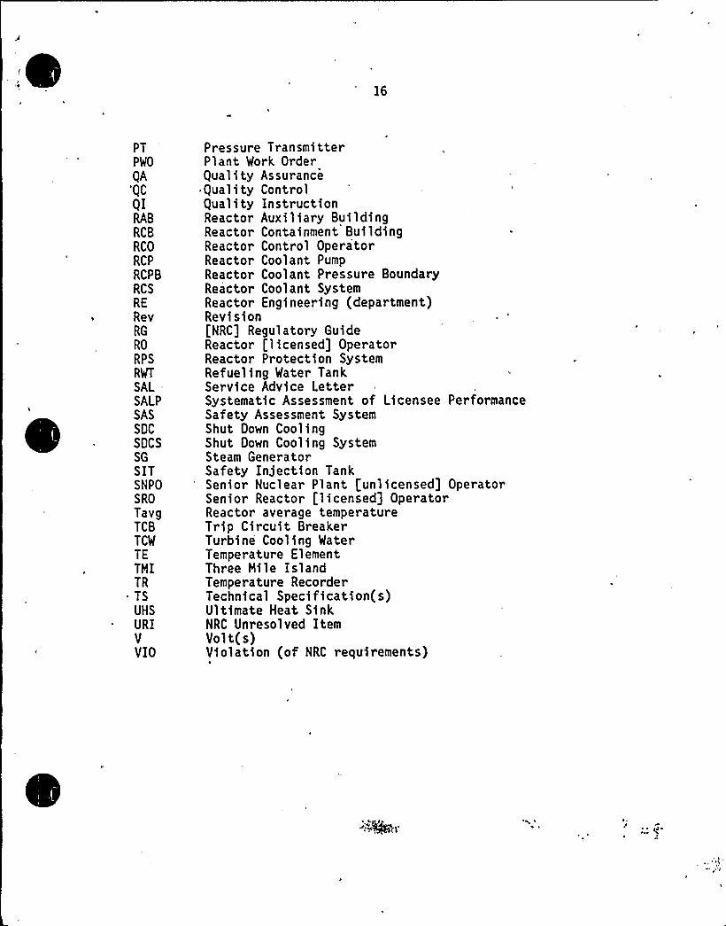
PTPWO
QA'QC
QIRAB
RCB
RCO
RCP
RCPB
RCS
RE
RevRG
RO
RPS
RWT
SAL =
SALPSASSDC
SDCSSG
SITSNPOSRO
TavgTCBTCW
TETMITRTSUHS
URIVVIO
Pressure TransmitterPlant Work OrderQuality AssuranceQuality ControlQuality InstructionReactor Auxiliary BuildingReactor Containment BuildingReactor Control OperatorReactor Coolant PumpReactor Coolant Pressure BoundaryReactor Coolant SystemReactor Engineering (department)Revision[NRC] Regulatory GuideReactor [licensed] OperatorReactor Protection SystemRefueling Water TankService Advice LetterSystematic Assessment of Licensee PerformanceSafety Assessment SystemShut Down CoolingShut Down Cooling SystemSteam GeneratorSafety Injection TankSenior Nuclear Plant [unlicensed] OperatorSenior Reactor [licensed] OperatorReactor average temperatureTrip Circuit BreakerTurbine Cooling WaterTemperature ElementThree Mile IslandTemperature RecorderTechnical Specification(s)Ultimate Heat SinkNRC Unresolved ItemVolt(s)Violation (of NRC requirements)