
Bam Earthquake of 05:26:26 of 26 December 2003, Ms6.5
234
JSEE: Special Issue on Bam Earthquake / 1 Editorial Summary: Bam Earthquake of 05:26:26 of 26 December 2003, Ms6.5 1. Introduction The Magnitude Ms = 6.5 earthquake of 26 th December 2003 occurred at early morning (05:26:26 local time) along Bam fault with no recorded of any major earthquake, at least, approximately in past 2500 years; and while many residents of the Bam historical city were still sleeping. The traditional mud-brick and clay homes put up little resistance to the violent shaking, and as walls and roofs crumbled and collapsed; more than 100,000 of victims were trapped beneath the rubble and from them around 26,500 lost their lives. Close to 11,000 of the city's students perished, along with one to five of Bam’s 5,400 teachers. Tens of thousands were left homeless and up to 6,000 children were orphaned. Arg-e-Bam (Bam Citadel), the largest mud-brick complex in the world and other historical buildings were almost totally destroyed. Bam earthquake not only shook the heart and mind of the Iranian, but the world and created on the biggest human solidarity. This earthquake have created a new initiative in Iran's risk reduction program and consequently provides a unique window of opportunity to raise international awareness of the importance of the effective implementation of a comprehensive earthquake risk reduction program in hazard-prone countries. 2. The Seismotectonic, Seismicity and Strong Ground Motion of Bam The Bam region in south east of Iran is located in an active seismic zone, however the Bam city itself had no reported major historical earthquake before the event of 26/12/2003. The earthquake was associated with two fresh surface rupture 5km apart trending north-south and 2km wide zone of hairline fractures developed be- tween the two main ruptures in the north of Bam. The Bam fault with a near north-south direction passes from the vicinity of the city of Bam (less that 1km distance to the east of Bam, and between the cities of Bam and Baravat. The other segment 5km to the west of the Bam fault passes through the city. The whole system of fresh ruptures associated with the main event is not direct manifestation of the earthquake faults but are secondary structures. No direct surface faulting were associated with the earthquake; however, the surface fissures cre- ated after the Bam earthquake are observed around the Bam fault between the cities on Bam and Baravat. Considering that the Bam earthquake was multiple event; the focal depth of the main event is estimated to be 8km, while the second event was 10km. Mw6.5 was calculated for this event based on the seismic moment of the main shock. Using the data from a dense network in the Bam, the focal depth distribution of the aftershocks show a nearly vertical alignment of aftershocks located between 6 to 20km depth. The focal mechanism of the main events and aftershocks indicate right lateral strike slip faulting on N-S trending faults which is compatible with the fault traces that were observed by the IIEES tectonic group. The strong motion record obtained by BHRC in the Bam station shows the Horizontal PGA of 0.8g and 0.7g, and 1.02g for the vertical component. The effective duration of the earthquake were estimated between 7 to 10 seconds. Two strong phases of the energy have been seen in the accelerograms; the first is interpreted to represent a starting sub-event with right-lateral strike slip mechanism and located south of Bam. The preliminary observations on the strong motion record obtained in the Bam station, as well as the observed damages in the region shows a vertical directivity effects which caused the amplification of the low frequency motions in the fault-normal direction as well as the greater amplitude of the motion in the vertical direction. The demolished walls and building of Bam are representative for such effects in the up-down (vertical) and east-west directions (fault-normal). The attenuation of strong motion was rapid which was even faster in the fault-normal direction. This fact has been observed from the damage distribution as well. The dominant period of this earthquake (1sec. for the vertical component) is around the period of the adobe buildings, which can be one the main cause of their failure.
-
Upload
khangminh22 -
Category
Documents
-
view
7 -
download
0
Transcript of Bam Earthquake of 05:26:26 of 26 December 2003, Ms6.5
JSEE: Special Issue on Bam Earthquake / 1
Editorial Summary:
Bam Earthquake of 05:26:26 of 26 December 2003, Ms6.5
1. Introduction
The Magnitude Ms = 6.5 earthquake of 26th December 2003 occurred at early morning (05:26:26 local time)along Bam fault with no recorded of any major earthquake, at least, approximately in past 2500 years; and whilemany residents of the Bam historical city were still sleeping. The traditional mud-brick and clay homes put uplittle resistance to the violent shaking, and as walls and roofs crumbled and collapsed; more than 100,000 ofvictims were trapped beneath the rubble and from them around 26,500 lost their lives. Close to 11,000 of thecity's students perished, along with one to five of Bam’s 5,400 teachers. Tens of thousands were left homelessand up to 6,000 children were orphaned. Arg-e-Bam (Bam Citadel), the largest mud-brick complex in the worldand other historical buildings were almost totally destroyed. Bam earthquake not only shook the heart and mindof the Iranian, but the world and created on the biggest human solidarity. This earthquake have created a newinitiative in Iran's risk reduction program and consequently provides a unique window of opportunity to raiseinternational awareness of the importance of the effective implementation of a comprehensive earthquake riskreduction program in hazard-prone countries.
2. The Seismotectonic, Seismicity and Strong Ground Motion of Bam
The Bam region in south east of Iran is located in an active seismic zone, however the Bam city itself had noreported major historical earthquake before the event of 26/12/2003. The earthquake was associated with twofresh surface rupture 5km apart trending north-south and 2km wide zone of hairline fractures developed be-tween the two main ruptures in the north of Bam. The Bam fault with a near north-south direction passes fromthe vicinity of the city of Bam (less that 1km distance to the east of Bam, and between the cities of Bam andBaravat. The other segment 5km to the west of the Bam fault passes through the city. The whole system of freshruptures associated with the main event is not direct manifestation of the earthquake faults but are secondarystructures. No direct surface faulting were associated with the earthquake; however, the surface fissures cre-ated after the Bam earthquake are observed around the Bam fault between the cities on Bam and Baravat.Considering that the Bam earthquake was multiple event; the focal depth of the main event is estimated to be8km, while the second event was 10km. Mw6.5 was calculated for this event based on the seismic moment ofthe main shock. Using the data from a dense network in the Bam, the focal depth distribution of the aftershocksshow a nearly vertical alignment of aftershocks located between 6 to 20km depth. The focal mechanism of themain events and aftershocks indicate right lateral strike slip faulting on N-S trending faults which is compatiblewith the fault traces that were observed by the IIEES tectonic group.
The strong motion record obtained by BHRC in the Bam station shows the Horizontal PGA of 0.8g and0.7g, and 1.02g for the vertical component. The effective duration of the earthquake were estimated between 7to 10 seconds. Two strong phases of the energy have been seen in the accelerograms; the first is interpreted torepresent a starting sub-event with right-lateral strike slip mechanism and located south of Bam. The preliminaryobservations on the strong motion record obtained in the Bam station, as well as the observed damages in theregion shows a vertical directivity effects which caused the amplification of the low frequency motions in thefault-normal direction as well as the greater amplitude of the motion in the vertical direction. The demolishedwalls and building of Bam are representative for such effects in the up-down (vertical) and east-west directions(fault-normal). The attenuation of strong motion was rapid which was even faster in the fault-normal direction.This fact has been observed from the damage distribution as well. The dominant period of this earthquake (1sec.for the vertical component) is around the period of the adobe buildings, which can be one the main cause of theirfailure.
2 / JSEE: Special Issue on Bam Earthquake
3. The Macroseismic Intensity and the Isoseismal Map
The macroseismic intensity of the earthquake is estimated to be I0=IX (in the EMS98 scale), where the strongmotions and damaging effects seems to be attenuated very fast especially in the fault-normal direction. Theintensity levels are estimated to be VIII in Baravat, VII in New-Arg (Arg-e Jadid) and the airport area. Theintensity level was estimated to be around IV-V in Kerman and Mahan.
4. Geotechnical Aspects
There were not any major geotechnical failures observed in the Bam; However, many land subsidence due tocollapse of Qanats (underground irrigation tunnels), local toppling and block slides along riverbanks or man-made channels were observed. For the purpose of geotechnical microzonation of Bam, seismic hazard analysis,geological studies accompanied by geophysical surveys and aftershock and microtremor measurements werecarried out to provide preliminary site classification and PGA distribution maps for two return periods of 475and 2475 years. Reasonable agreements exist between the site classification and 2475 years PGA distributionmaps of the city and the damage distribution map of the recent earthquake. Almost all damages of the low risebuildings occurred in sites with stiff shallow and medium depth soils, which possess a considerable amplifica-tion potential in the high frequency range. The maximum value of the peak ground acceleration was evaluated inthe south-east part of the city, where the highest value of damage percent (80-100) was experienced. Theminimum value of the peak ground acceleration was evaluated in the north-west part of the city, where the leastvalue of damage percent (20-50) was experienced. In addition, the 475 years PGA microzonation map could beused as a preliminary useful hint in reconstruction and urban planning of the city.
5. Structural Engineering Aspects
Existed buildings in Bam composed of Adobe and Masonry housing units (90%); Steel (8%) and ReinforcedConcrete (2%). Based on the statistical evaluation of 550 buildings (74% :1-story, 22% :2-story and 4% :3 storyor more) of the partially damaged, it was concluded that 62% could not be used for occupation, 34.8% could beretrofitted and 3.2% were safe.
The main reason for the failure of the adobe and masonry buildings were the heavy roofs and walls as wellas the lack of structural integrity, specially in the newly build ones. The good performance of the arch roof of theold adobe buildings was good example of the importance of structural integrity. Most of the steel building weredamaged due to lack of code implementation, poor workmanship, poor connections (specially Khorjinie orsatchel connection), weld rupture, buckling (overall, out of plane and lateral-torsional) of the weak columnsspecially in the batten columns, rupture and plastic shear of the battens, local buckling and rupture of X bracingand lack of frame in one direction of the buildings. The buildings that had followed the minimum code require-ments were not damaged. Performance of the concrete buildings were poor for the residential cases and goodfor the essential ones.
Up to 95% of the buildings and walls within the 2500-years-old-ancient-Arg-e-Bam (Bam Citadel), thelargest adobe construction in the world, were collapsed. The failure were mainly due to improper and lack ofseismic safety consideration in the restoration program.
6. Lifeline and Special Structures
The Lifeline systems of Bam were shut down due to various type of equipment failure; However most of thelifeline systems were restored within the first week after the earthquake. The performance of the bridges,roads, railways were good and slight damages did not cause interruption of their services. The failure of the Bamairport tower caused delay in using the airport facilities. However its rapid restoration of the airport played veryimportant role in the rescue and relief operation. Without the airport the human casualty were become muchmore. Water distribution systems for both drinking water and agricultural water which were done through thetraditional irrigation system (Qanats) were seriously damage. Water tower and underground water storage tank
JSEE: Special Issue on Bam Earthquake / 3
and deep well sustained some damage and in general had acceptable performance. Nonstructural damage in thePTT buildings caused the communication interruption. The cell phones started to work within a few hours.There were little damage to high voltage transmission lines and towers and moderate damage to electrical equip-ment in the Bam substation. Most factories and other industrial facilities were either not damaged or stayedintact. However, they remain dysfunctional due to loss of workers.
7. Conclusion
The Bam earthquake disaster, despite its high casualties and losses, provides a unique window of opportunityto raise international awareness of the importance of the effective implementation of a comprehensiveearthquake risk reduction program in Iran as well as in hazard-prone developing countries. It gives a challenge tothe governments to make the highest use of the existing know-how on earthquakes and its integration intodevelopment programs. It also compels the scientific and engineering community to provide moresocio-economic-cultural compatible solutions to national needs. Moreover, the public at large should becomemore concerned about the hazard and increase its own preparedness level. The UN Strategy document,Bam Declaration and Recommendation for Bam citadel, Bam reconstruction paper and formation of theUNESCO-UNDP-UN/ISDR-IIEES Alliance for earthquake risk reduction in developing countries are sample ofthe initiatives for the better future.
Acknowledgment
JSEE Editors would like to thank all of the authors of this special issue of the JSEE on Bam earthquake fortheir valuable efforts, cooperation and contributions since the occurrence of the earthquake. Moreover, wewould like to thank all of the reviewers and the editorial board for the timely and sincere efforts in reviewing thepapers in the shortest time possible, which were extremely useful toward the improvement of the papers. Finallyour thank to Ms. Khaledi for her hard works in putting the papers together in this nice format and make themready on the occasion of “Special Session on Bam Earthquake” in the 13th world conference on EarthquakeEngineering and Seismology (13 WCEE) in August 2004.
Mohsen Ghafory-AshtianyJSEE Editor in Chief
JSEE: Special Issue on Bam Earthquake / 5
Khaled Hessami1, Hadi Tabassi 1, Mohammad R. Abbassi 1, Takashi Azuma2,Koji Okumura3, Tomoo Echigo4, and Hisao Kondo3
1. International Institute of Earthquake Engineering and Seismology (IIEES), Tehran,
Iran, email: [email protected]
2. Active Fault Research Center, Geological Survey of Japan/AIST, Japan3. Department of Geography, Hiroshima University, Higashi-Hiroshima, Japan
4. Department of Earth Planet Science, Graduate School of Science, University of
Tokyo, Tokyo, Japan
ABSTRACT: The Bam fault zone is a major active fault zone insoutheastern Iran. Geomorphic evidence indicates that it has beenresponsible for repeated faulting events since late Pleistocene. TheDecember 26, 2003 Bam earthquake was associated with two freshsurface ruptures 5 km apart trending north-south and a 2 km widezone of hairline fractures developed between the two main ruptures innorth Bam. The amount of slip along the surface ruptures rangesbetween 0.5-5.5 cm across the zone. The whole system of fresh rupturesassociated with the Bam earthquake is not direct manifestations of theearthquake fault but are secondary structures such as synthetic shears(Reidel shears), mole tracks and oblique grabens which are stronglyindicative of right-lateral motion along principal displacement zone inthe earthquake source. This is compatible with the focal mechanismsolutions of the Bam earthquake and fault displacements during thelate Pleistocene.
Keywords: Bam; Active fault; Strike-slip fault; Geomorphology; BamFault
Surface Expression of the Bam Fault Zone in Southeastern Iran:
Causative Fault of the 26 December 2003 Bam Earthquake
1. Introduction
On the early morning of Friday, December 26, 2003the southeastern part of Iran was shaken by one of theworst earthquakes in Iranian history. The earthquakewhich was located south of Bam caused catastrophicdamage in the Bam city. Preliminary estimatesplaced the death toll at 26,500 and 85 percent ofbuildings damaged or destroyed in the Bam area.International Institute of Earthquake Engineeringand Seismology (IIEES ) placed the epicenter at29.02°N, 58.30°E with a focal depth of 8 kilometers,and assigned a surface wave magnitude (Ms) of 6.5to the earthquake.
The fault segment responsible for the December26 earthquake is difficult to locate as there is nodirect surface faulting associated with this earthquake.The only fault which can be related to the earthquake,the Bam fault zone, is not clearly expressed at the
surface along its large extent as a result of rapidsedimentation. However, aerial photographs and fieldobservations along some of its sections showgeomorphic evidence for repeated surface faultingevents. The objective of this paper is to describe themain geomorphic features of the Bam fault zone andfresh ground fractures associated with the earthquake.Based on surface ruptures and fault displacementsduring the late Pleistocene, the fault zone responsiblefor the Bam earthquake is recognized.
2. Geological Setting
The Bam earthquake of December 26, 2003 occurredin the low plateau region of southeastern Iran, (seeinset in Figure (1)). This region of Lut blockconstitutes a continental basin environment and is
6 / JSEE: Special Issue on Bam Earthquake
K. Hessami, et al.
tectonically very active compared to the central partsof the block. Cretaceous to Recent continentaldeposits are found throughout this region.
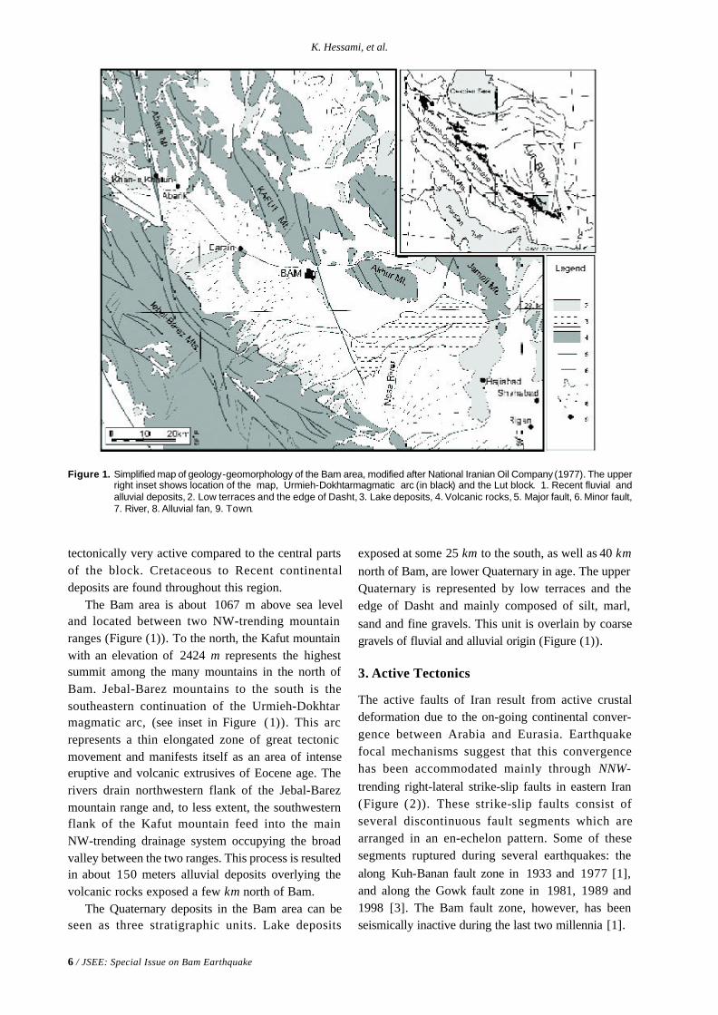
The Bam area is about 1067 m above sea leveland located between two NW-trending mountainranges (Figure (1)). To the north, the Kafut mountainwith an elevation of 2424 m represents the highestsummit among the many mountains in the north ofBam. Jebal-Barez mountains to the south is thesoutheastern continuation of the Urmieh-Dokhtarmagmatic arc, (see inset in Figure (1)). This arcrepresents a thin elongated zone of great tectonicmovement and manifests itself as an area of intenseeruptive and volcanic extrusives of Eocene age. Therivers drain northwestern flank of the Jebal-Barezmountain range and, to less extent, the southwesternflank of the Kafut mountain feed into the mainNW-trending drainage system occupying the broadvalley between the two ranges. This process is resultedin about 150 meters alluvial deposits overlying thevolcanic rocks exposed a few km north of Bam.
The Quaternary deposits in the Bam area can beseen as three stratigraphic units. Lake deposits
Figure 1. Simplified map of geology-geomorphology of the Bam area, modified after National Iranian Oil Company (1977). The upperright inset shows location of the map, Urmieh-Dokhtarmagmatic arc (in black) and the Lut block. 1. Recent fluvial andalluvial deposits, 2. Low terraces and the edge of Dasht, 3. Lake deposits, 4. Volcanic rocks, 5. Major fault, 6. Minor fault,7. River, 8. Alluvial fan, 9. Town.
exposed at some 25 km to the south, as well as 40 kmnorth of Bam, are lower Quaternary in age. The upperQuaternary is represented by low terraces and theedge of Dasht and mainly composed of silt, marl,sand and fine gravels. This unit is overlain by coarsegravels of fluvial and alluvial origin (Figure (1)).
3. Active Tectonics
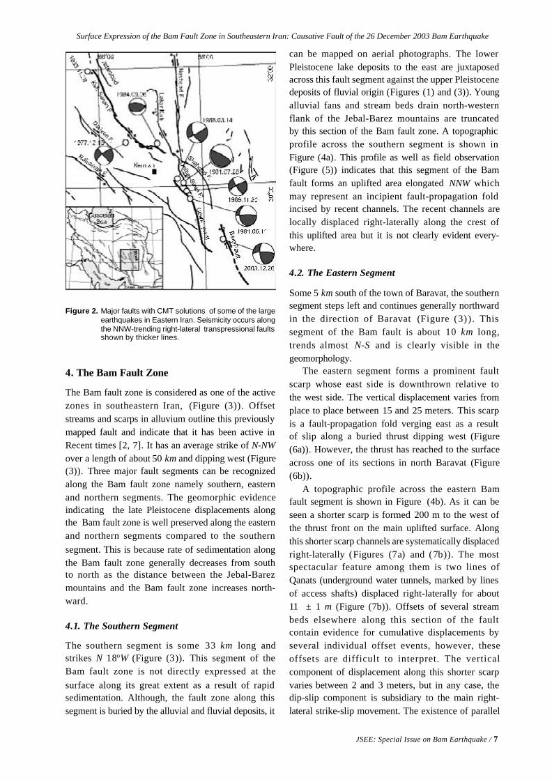
The active faults of Iran result from active crustaldeformation due to the on-going continental conver-gence between Arabia and Eurasia. Earthquakefocal mechanisms suggest that this convergencehas been accommodated mainly through NNW-trending right-lateral strike-slip faults in eastern Iran(Figure (2)). These strike-slip faults consist ofseveral discontinuous fault segments which arearranged in an en-echelon pattern. Some of thesesegments ruptured during several earthquakes: thealong Kuh-Banan fault zone in 1933 and 1977 [1],and along the Gowk fault zone in 1981, 1989 and1998 [3]. The Bam fault zone, however, has beenseismically inactive during the last two millennia [1].
Surface Expression of the Bam Fault Zone in Southeastern Iran: Causative Fault of the 26 December 2003 Bam Earthquake
JSEE: Special Issue on Bam Earthquake / 7
4. The Bam Fault Zone
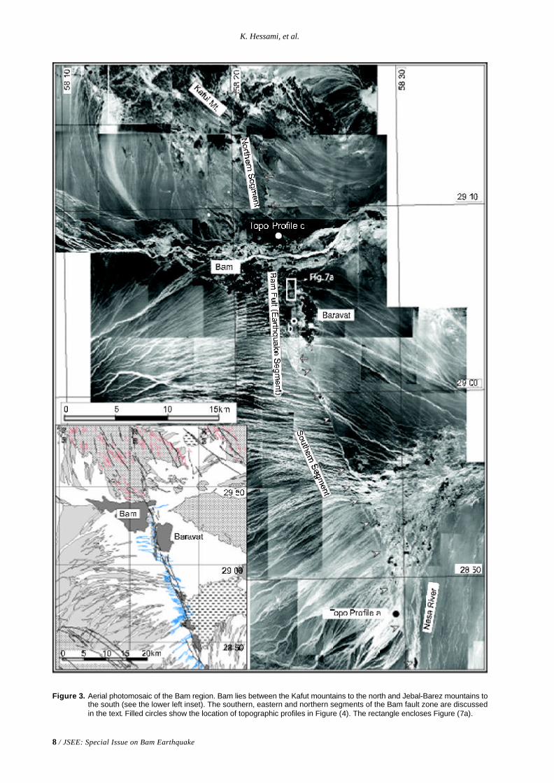
The Bam fault zone is considered as one of the activezones in southeastern Iran, (Figure (3)). Offsetstreams and scarps in alluvium outline this previouslymapped fault and indicate that it has been active inRecent times [2, 7]. It has an average strike of N-NWover a length of about 50 km and dipping west (Figure(3)). Three major fault segments can be recognizedalong the Bam fault zone namely southern, easternand northern segments. The geomorphic evidenceindicating the late Pleistocene displacements alongthe Bam fault zone is well preserved along the easternand northern segments compared to the southernsegment. This is because rate of sedimentation alongthe Bam fault zone generally decreases from southto north as the distance between the Jebal-Barezmountains and the Bam fault zone increases north-ward.
4.1. The Southern Segment
The southern segment is some 33 km long andstrikes N 18oW (Figure (3)). This segment of theBam fault zone is not directly expressed at thesurface along its great extent as a result of rapidsedimentation. Although, the fault zone along thissegment is buried by the alluvial and fluvial deposits, it
Figure 2. Major faults with CMT solutions of some of the largeearthquakes in Eastern Iran. Seismicity occurs alongthe NNW-trending right-lateral transpressional faultsshown by thicker lines.
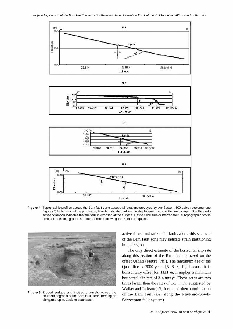
can be mapped on aerial photographs. The lowerPleistocene lake deposits to the east are juxtaposedacross this fault segment against the upper Pleistocenedeposits of fluvial origin (Figures (1) and (3)). Youngalluvial fans and stream beds drain north-westernflank of the Jebal-Barez mountains are truncatedby this section of the Bam fault zone. A topographicprofile across the southern segment is shown inFigure (4a). This profile as well as field observation(Figure (5)) indicates that this segment of the Bamfault forms an uplifted area elongated NNW whichmay represent an incipient fault-propagation foldincised by recent channels. The recent channels arelocally displaced right-laterally along the crest ofthis uplifted area but it is not clearly evident every-where.
4.2. The Eastern Segment
Some 5 km south of the town of Baravat, the southernsegment steps left and continues generally northwardin the direction of Baravat (Figure (3)) . Thissegment of the Bam fault is about 10 km long,trends almost N-S and is clearly visible in thegeomorphology.
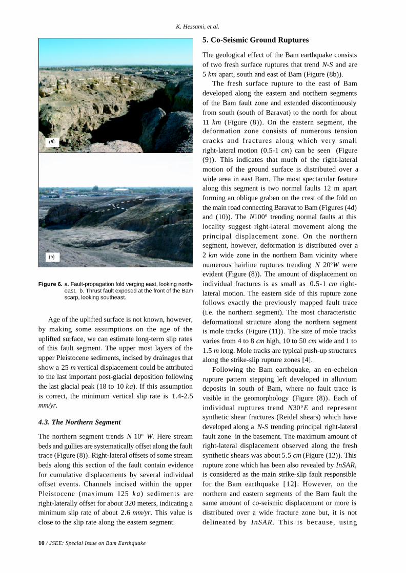
The eastern segment forms a prominent faultscarp whose east side is downthrown relative tothe west side. The vertical displacement varies fromplace to place between 15 and 25 meters. This scarpis a fault-propagation fold verging east as a resultof slip along a buried thrust dipping west (Figure(6a)). However, the thrust has reached to the surfaceacross one of its sections in north Baravat (Figure(6b)).
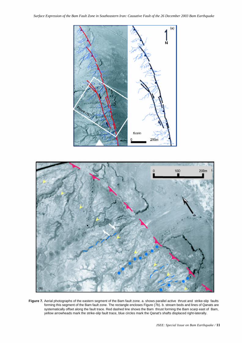
A topographic profile across the eastern Bamfault segment is shown in Figure (4b). As it can beseen a shorter scarp is formed 200 m to the west ofthe thrust front on the main uplifted surface. Alongthis shorter scarp channels are systematically displacedright-laterally (Figures (7a) and (7b)). The mostspectacular feature among them is two lines ofQanats (underground water tunnels, marked by linesof access shafts) displaced right-laterally for about11 ± 1 m (Figure (7b)). Offsets of several streambeds elsewhere along this section of the faultcontain evidence for cumulative displacements byseveral individual offset events, however, theseoffsets are difficult to interpret. The verticalcomponent of displacement along this shorter scarpvaries between 2 and 3 meters, but in any case, thedip-slip component is subsidiary to the main right-lateral strike-slip movement. The existence of parallel
8 / JSEE: Special Issue on Bam Earthquake
K. Hessami, et al.
Figure 3. Aerial photomosaic of the Bam region. Bam lies between the Kafut mountains to the north and Jebal-Barez mountains tothe south (see the lower left inset). The southern, eastern and northern segments of the Bam fault zone are discussedin the text. Filled circles show the location of topographic profiles in Figure (4). The rectangle encloses Figure (7a).
Surface Expression of the Bam Fault Zone in Southeastern Iran: Causative Fault of the 26 December 2003 Bam Earthquake
JSEE: Special Issue on Bam Earthquake / 9
Figure 4. Topographic profiles across the Bam fault zone at several locations surveyed by two System 500 Leica receivers, seeFigure (3) for location of the profiles. a, b and c indicate total vertical displacement across the fault scarps. Solid line withsense of motion indicates that the fault is exposed at the surface. Dashed line shows inferred fault. d, topographic profileacross co-seismic graben structure formed following the Bam earthquake.
active thrust and strike-slip faults along this segmentof the Bam fault zone may indicate strain partitioningin this region.
The only direct estimate of the horizontal slip ratealong this section of the Bam fault is based on theoffset Qanats (Figure (7b)). The maximum age of theQanat line is 3000 years [5, 6, 8, 11]; because it ishorizontally offset for 11±1 m, it implies a minimumhorizontal slip rate of 3-4 mm/yr. These rates are twotimes larger than the rates of 1-2 mm/yr suggested byWalker and Jackson [13] for the northern continuationof the Bam fault (i.e. along the Nayband-Gowk-Sabzevaran fault system).
Figure 5. Eroded surface and incised channels across thesouthern segment of the Bam fault zone forming anelongated uplift. Looking southeast.
10 / JSEE: Special Issue on Bam Earthquake
K. Hessami, et al.
Figure 6. a. Fault-propagation fold verging east, looking north-east. b. Thrust fault exposed at the front of the Bamscarp, looking southeast.
Age of the uplifted surface is not known, however,by making some assumptions on the age of theuplifted surface, we can estimate long-term slip ratesof this fault segment. The upper most layers of theupper Pleistocene sediments, incised by drainages thatshow a 25 m vertical displacement could be attributedto the last important post-glacial deposition followingthe last glacial peak (18 to 10 ka). If this assumptionis correct, the minimum vertical slip rate is 1.4-2.5mm/yr.
4.3. The Northern Segment
The northern segment trends N 10o W. Here streambeds and gullies are systematically offset along the faulttrace (Figure (8)). Right-lateral offsets of some streambeds along this section of the fault contain evidencefor cumulative displacements by several individualoffset events. Channels incised within the upperPleistocene (maximum 125 k a) sediments areright-laterally offset for about 320 meters, indicating aminimum slip rate of about 2.6 mm/yr. This value isclose to the slip rate along the eastern segment.
5. Co-Seismic Ground Ruptures
The geological effect of the Bam earthquake consistsof two fresh surface ruptures that trend N-S and are5 km apart, south and east of Bam (Figure (8b)).
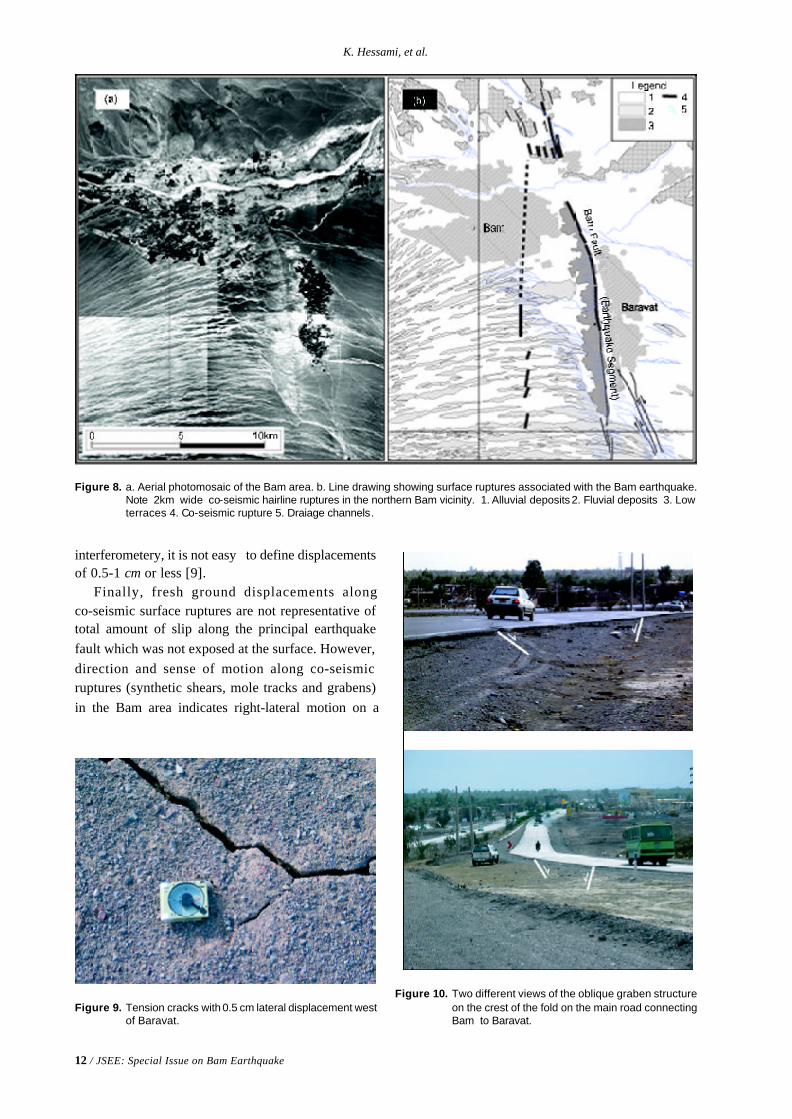
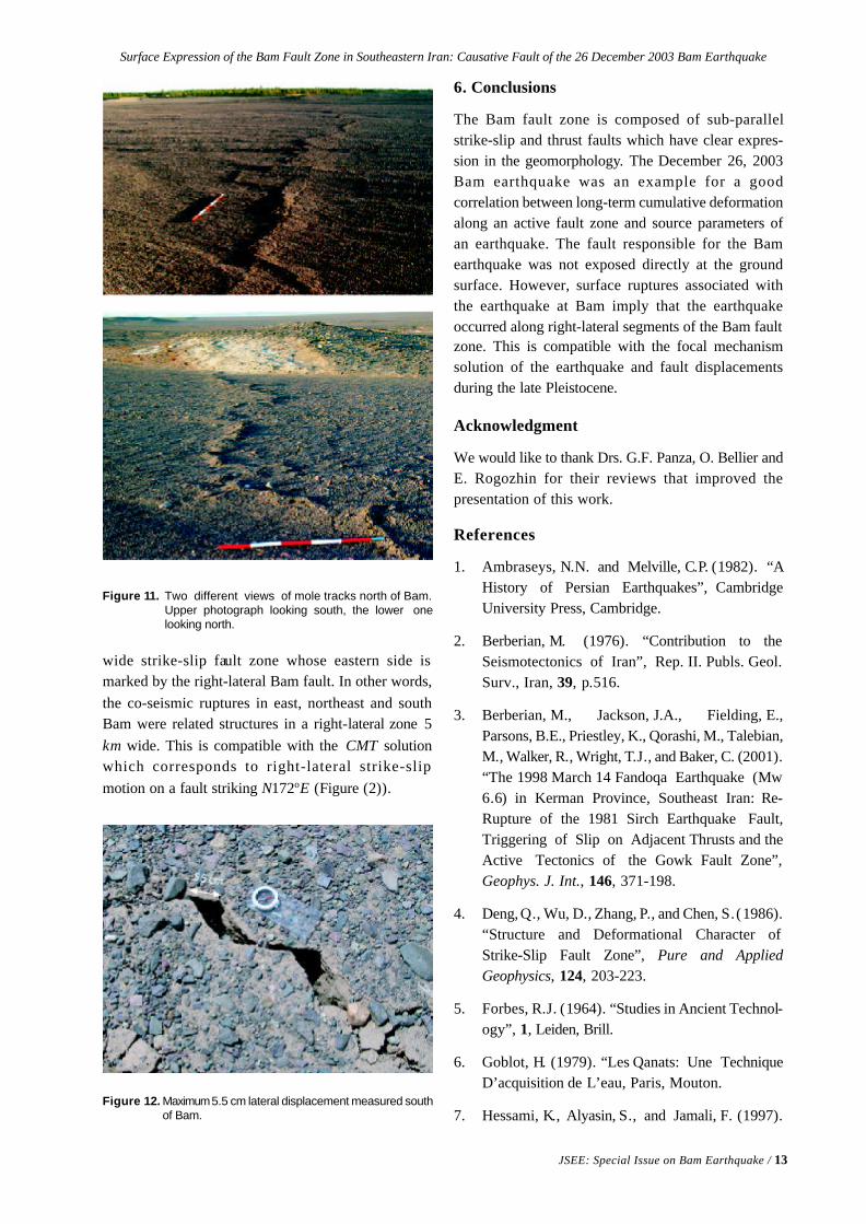
The fresh surface rupture to the east of Bamdeveloped along the eastern and northern segmentsof the Bam fault zone and extended discontinuouslyfrom south (south of Baravat) to the north for about11 km (Figure (8)). On the eastern segment, thedeformation zone consists of numerous tensioncracks and fractures along which very smallright-lateral motion (0.5-1 cm) can be seen (Figure(9)). This indicates that much of the right-lateralmotion of the ground surface is distributed over awide area in east Bam. The most spectacular featurealong this segment is two normal faults 12 m apartforming an oblique graben on the crest of the fold onthe main road connecting Baravat to Bam (Figures (4d)and (10)). The N100o trending normal faults at thislocality suggest right-lateral movement along theprincipal displacement zone. On the northernsegment, however, deformation is distributed over a2 km wide zone in the northern Bam vicinity wherenumerous hairline ruptures trending N 20oW wereevident (Figure (8)). The amount of displacement onindividual fractures is as small as 0.5-1 cm right-lateral motion. The eastern side of this rupture zonefollows exactly the previously mapped fault trace(i.e. the northern segment). The most characteristicdeformational structure along the northern segmentis mole tracks (Figure (11)). The size of mole tracksvaries from 4 to 8 cm high, 10 to 50 cm wide and 1 to1.5 m long. Mole tracks are typical push-up structuresalong the strike-slip rupture zones [4].
Following the Bam earthquake, an en-echelonrupture pattern stepping left developed in alluviumdeposits in south of Bam, where no fault trace isvisible in the geomorphology (Figure (8)). Each ofindividual ruptures trend N30o E and representsynthetic shear fractures (Reidel shears) which havedeveloped along a N-S trending principal right-lateralfault zone in the basement. The maximum amount ofright-lateral displacement observed along the freshsynthetic shears was about 5.5 cm (Figure (12)). Thisrupture zone which has been also revealed by InSAR,is considered as the main strike-slip fault responsiblefor the Bam earthquake [12] . However, on thenorthern and eastern segments of the Bam fault thesame amount of co-seismic displacement or more isdistributed over a wide fracture zone but, it is notdelineated by InSAR . This is because, using
Surface Expression of the Bam Fault Zone in Southeastern Iran: Causative Fault of the 26 December 2003 Bam Earthquake
JSEE: Special Issue on Bam Earthquake / 11
Figure 7. Aerial photographs of the eastern segment of the Bam fault zone. a. shows parallel active thrust and strike-slip faultsforming this segment of the Bam fault zone. The rectangle encloses Figure (7b). b. stream beds and lines of Qanats aresystematically offset along the fault trace. Red dashed line shows the Bam thrust forming the Bam scarp east of Bam,yellow arrowheads mark the strike-slip fault trace, blue circles mark the Qanat's shafts displaced right-laterally.
12 / JSEE: Special Issue on Bam Earthquake
K. Hessami, et al.
Figure 10. Two different views of the oblique graben structureon the crest of the fold on the main road connectingBam to Baravat.
interferometery, it is not easy to define displacementsof 0.5-1 cm or less [9].
Finally, fresh ground displacements alongco-seismic surface ruptures are not representative oftotal amount of slip along the principal earthquakefault which was not exposed at the surface. However,direction and sense of motion along co-seismicruptures (synthetic shears, mole tracks and grabens)in the Bam area indicates right-lateral motion on a
Figure 8. a. Aerial photomosaic of the Bam area. b. Line drawing showing surface ruptures associated with the Bam earthquake.Note 2km wide co-seismic hairline ruptures in the northern Bam vicinity. 1. Alluvial deposits 2. Fluvial deposits 3. Lowterraces 4. Co-seismic rupture 5. Draiage channels.
Figure 9. Tension cracks with 0.5 cm lateral displacement westof Baravat.
Surface Expression of the Bam Fault Zone in Southeastern Iran: Causative Fault of the 26 December 2003 Bam Earthquake
JSEE: Special Issue on Bam Earthquake / 13
Figure 11. Two different views of mole tracks north of Bam.Upper photograph looking south, the lower onelooking north.
Figure 12. Maximum 5.5 cm lateral displacement measured southof Bam.
wide strike-slip fault zone whose eastern side ismarked by the right-lateral Bam fault. In other words,the co-seismic ruptures in east, northeast and southBam were related structures in a right-lateral zone 5km wide. This is compatible with the CMT solutionwhich corresponds to right-lateral strike-slipmotion on a fault striking N172oE (Figure (2)).
6. Conclusions
The Bam fault zone is composed of sub-parallelstrike-slip and thrust faults which have clear expres-sion in the geomorphology. The December 26, 2003Bam earthquake was an example for a goodcorrelation between long-term cumulative deformationalong an active fault zone and source parameters ofan earthquake. The fault responsible for the Bamearthquake was not exposed directly at the groundsurface. However, surface ruptures associated withthe earthquake at Bam imply that the earthquakeoccurred along right-lateral segments of the Bam faultzone. This is compatible with the focal mechanismsolution of the earthquake and fault displacementsduring the late Pleistocene.
Acknowledgment
We would like to thank Drs. G.F. Panza, O. Bellier andE. Rogozhin for their reviews that improved thepresentation of this work.
References
1. Ambraseys, N.N. and Melville, C.P. (1982). “AHistory of Persian Earthquakes”, CambridgeUniversity Press, Cambridge.
2. Berberian, M. (1976). “Contribution to theSeismotectonics of Iran”, Rep. II. Publs. Geol.Surv., Iran, 39, p.516.
3. Berberian, M., Jackson, J.A., Fielding, E.,Parsons, B.E., Priestley, K., Qorashi, M., Talebian,M., Walker, R., Wright, T.J., and Baker, C. (2001).“The 1998 March 14 Fandoqa Earthquake (Mw6.6) in Kerman Province, Southeast Iran: Re-Rupture of the 1981 Sirch Earthquake Fault,Triggering of Slip on Adjacent Thrusts and theActive Tectonics of the Gowk Fault Zone”,Geophys. J. Int., 146, 371-198.
4. Deng, Q., Wu, D., Zhang, P., and Chen, S. (1986).“Structure and Deformational Character ofStrike-Slip Fault Zone”, Pure and AppliedGeophysics, 124, 203-223.
5. Forbes, R.J. (1964). “Studies in Ancient Technol-ogy”, 1, Leiden, Brill.
6. Goblot, H. (1979). “Les Qanats: Une TechniqueD’acquisition de L’eau, Paris, Mouton.
7. Hessami, K., Alyasin, S., and Jamali, F. (1997).
14 / JSEE: Special Issue on Bam Earthquake
K. Hessami, et al.
“An Investigation of Some Historical Earthquakesand Paleoseismic Sources in Iran, Historical andPrehistorical Earthquakes in the Caucasus”, In: D.Giardini and S. Balasanian (eds.), NATO AsiSeries, 2. Environment, Vol. 28, Kluwer AcademicPublishers, The Netherlands, 189-199.
8. Kamiar, M. (1983). “The Qanat System in Iran”,Ekistics, 50, 467-472.
9. Massonnet, D., Feigl, K., Rossi, M., and Adragna,F. (1994). “Radar Interferometric Mapping ofDeformation in the Year After the Landers Earth-quake”, Nature, 369, 227-230.
10. National Iranian Oil Company (1977). GeologicalMap of Iran, Sheet No. 6, South-east Iran, Scale1: 1000,000, Natl. Iran. Oil. Co., Explor. and
Prod., Tehran, Iran.
11. Potts, D.T. (1990). “The Arabian Gulf inAntiquity”, 1, from Prehistory to the Fall of theAchaemenid Empire, Oxford, Clarendon Press.
12. Talebian, M., Fielding, E.J., Funning, G.J.,Ghorashi, M., Jackson, J., Nazari, H., Parsons,B., Priestley, K., Rosen, P.A., Walker, R., andWright, T.J. (2004). “The 2003 Bam (Iran) Earth-quake: Rupture of a Blind Strike-Slip Fault”,Geophysical Research Letter, 31(11), L11611,10.1029.
13. Walker, R. and Jackson, J.A. (2002). “Offset andEvolution of the Gowk Fault, SE Iran: A MajorIntra-Continental Strike-Slip System”, Journal ofstructural Geology, 24, 1677-1698.
JSEE: Special Issue on Bam Earthquake / 15
Mehrdad Mostafazadeh , Amir Mansour Farahbod , Mohammad Mokhtari , andMostafa Allamehzadeh
Seismology Research Center, International Institute of Earthquake Engineering and
Seismology (IIEES), Tehran, Iran, email: [email protected]
ABSTRACT: A waveform inversion algorithm, based on least squaremethod, has been applied to the P and S waves of the 26 December2003 Bam earthquake. The aftershocks of this event distributed alonga narrow zone (approximately 20km) in N-S direction. In this research,estimates of centroid depth, seismic moment, and source mechanismhave been obtained. The source mechanism derived from the inversionof long period body waves revealed that two events occurred on N-Strending strike-slip fault with a thrust component. According to thesource model estimated in this study, the Bam earthquake was amultiple event. The rupture following the first event started at a depthof about 8km. However depth of the second event is about 10km. Thetotal seismic moment estimated from inversion processes is 8.34×10¹⁸Nm.The seismic moment of the second event is less than the first one (theseismic moment of second event is calculated as 2.34×10¹⁷Nm). Thepulse duration of main shock and the second event was determinedfrom source time function and it is 1.7s and 0.8s respectively. Cornerfrequency and source radius have been calculated for main shock andthe second event by using pulse duration. The range of cornerfrequency and source radius are from 0.187Hz -0.397Hz and 5.47km-2.57km for main shock and second event, respectively.
Keywords: Bam; Seismicity; Error ellipse; Waveform modeling;Mainshock
Seismological Aspect of 26 December 2003 Bam Earthquake
1. Introduction
The 26 December 2003 Bam earthquake, Mw = 6.5,occurred at 01:56:56 GMT, in southeast of Iran,see Figure (1) near the city of Bam which had apopulation of about 100,000. The earthquake killedaround 26500 people, destroyed and damaged morethan 70 percent of buildings completely, and damagedthe surrounding area. The strong motion recordof the main shock indicates a peak horizontal andvertical acceleration of about 0.79g and 1.01grespectively [1] where the maximum intensity wasassigned as IX (EMS 98 scale). This is generallyaccepted that the first aftershocks which occurringduring the first 24 or 48 hours after the mainshock defines the relevant rupture surface [2] .Based on this fact, from the first hours after themain shock, International Institute of EarthquakeEngineering and Seismology (IIEES) started to locatethe aftershocks using local and regional permanent
seismic stations. The largest aftershock was locatedby IIEES during the first 2 days after the main shockhad a magnitude of Ms = 5.1.
Using first motion analysis of P-wave or S-wavepolarization provides a powerful tool in order todetermine the most consistent orientation of a doublecouple mechanism which fits a number of observa-tions. However such studies rarely constrain the focalmechanism tightly, since in many cases there areinsufficient readings in many azimuths around theepicenter. Furthermore, the first arrivals describe onlythe early part of the source mechanism, which is notnecessarily representative of the whole earthquakesource process, and they give no information onthe scalar moment. In the recent years, technicalimprovement for calculating synthetic seismogramsand modeling the observed waveforms has become animportant tool in the study of source mechanisms. The
16 / JSEE: Special Issue on Bam Earthquake
M. Mostafazadeh, et al
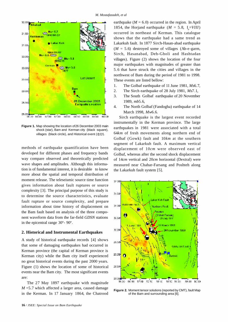
Figure 1. Map showing the location of 26 December 2003 mainshock (star), Bam and Kerman city (black square),villages (black circle), and Historical event ( ).
Figure 2. Moment tensor solutions (reported by CMT), fault Mapof the Bam and surrounding area [6].
methods of earthquake quantification have beendeveloped for different phases and frequency bandsway compare observed and theoretically predictedwave shapes and amplitudes. Although this informa-tion is of fundamental interest, it is desirable to knowmore about the spatial and temporal distribution ofmoment release. The teleseismic source time functiongives information about fault ruptures or sourcecomplexity [3]. The principal purpose of this study isto determine the source characteristics, evaluatefault rupture or source complexity, and prepareinformation about time history of displacement onthe Bam fault based on analysis of the three compo-nent waveform data from the far-field GDSN stationsin the epicentral range 30o- 90o.
2. Historical and Instrumental Earthquakes
A study of historical earthquake records [4] showsthat some of damaging earthquakes had occurred inKerman province (the capital of Kerman province isKerman city) while the Bam city itself experiencedno great historical events during the past 2000 years.Figure (1) shows the location of some of historicalevents near the Bam city. The most significant eventsare:
The 27 May 1897 earthquake with magnitudeM =5.7 which affected a larger area, caused damagein the Kerman. In 17 January 1864, the Chatrood
earthquake (M = 6.0) occurred in the region. In April1854, the Horjand earthquake (M = 5.8, Io=VIII )occurred in northeast of Kerman. This catalogueshows that the earthquake had a same trend asLakarkuh fault. In 1877 Sirch-Hasan-abad earthquake(M = 5.6) destroyed some of villages (Ab-e-garm,Sirch, Hasanabad, Deh-Gholi and Hashtadanvillages). Figure (2) shows the location of the fourmajor earthquakes with magnitudes of greater than5.6 that have struck the cities and villages in thenorthwest of Bam during the period of 1981 to 1998.These events are listed bellow:1. The Golbaf earthquake of 11 June 1981, Ms6.7,2. The Sirch earthquake of 28 July 1981, Ms7.1,3. The South Golbaf earthquake of 20 November
1989, mb5.6,4. The North Golbaf (Fandogha) earthquake of 14
March 1998, Mw6.6.Sirch earthquake is the largest event recorded
instrumentally in the Kerman province. The largeearthquakes in 1981 were associated with a total64km of fresh movements along northern end ofGolbaf (Gowk) fault and 10km at the southernsegment of Lakarkuh fault. A maximum verticaldisplacement of 10cm were observed east ofGolbaf, whereas after the second shock displacementof 14cm vertical and 20cm horizontal (Dextral) weremeasured near Chahar-Farsang and Poshteh alongthe Lakarkuh fault system [5].
Seismological Aspect of 26 December 2003 Bam Earthquake
JSEE: Special Issue on Bam Earthquake / 17
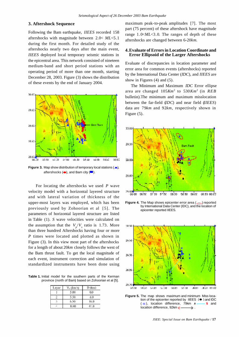
Figure 3. Map show distribution of temporary local stations ( ),aftershocks ( ), and Bam city ( ).
Table 1. Initial model for the southern parts of the Kermanprovince (north of Bam) based on Zohoorian et al [5].
Figure 4. The Map shows epicenter error area ( ) reportedby International Data Center (IDC), and the location ofepicenter reported IIEES.
Figure 5. The map shows maximum and minimum Miss loca-tion of the epicenter reported by IIEES ( ) and IDC( ), location difference, 79km andlocation difference, 92km .
3. Aftershock Sequence
Following the Bam earthquake, IIEES recorded 158aftershocks with magnitude between 2.0< ML<5.1during the first month. For detailed study of theaftershocks nearly two days after the main event,IIEES deployed local temporary seismic stations inthe epicentral area. This network consisted of nineteenmedium-band and short period stations with anoperating period of more than one month, startingDecember 28, 2003. Figure (3) shows the distributionof these events by the end of January 2004.
For locating the aftershocks we used P wavevelocity model with a horizontal layered structureand with lateral variation of thickness of theupper-most layers was employed, which has beenpreviously used by Zohoorian et al [5] . Theparameters of horizontal layered structure are listedin Table (1). S wave velocities were calculated onthe assumption that the Vp/Vs ratio is 1.73. Morethan three hundred Aftershocks having four or moreP times were located and plotted as shown inFigure (3). In this view most part of the aftershocksfor a length of about 20km closely follows the west ofthe Bam thrust fault. To get the local magnitude ofeach event, instrument correction and simulation ofstandardized instruments have been done using
maximum peak-to-peak amplitudes [7]. The mostpart (75 percent) of these aftershock have magnituderange 1.0<ML<3.0. The ranges of depth of theseaftershocks are changed between 6-20km.
4.Evaluate of Errors in Location Coordinate andError Ellipsoid of the Larger Aftershocks
Evaluate of discrepancies in location parameter anderror area for common events (aftershocks) reportedby the International Data Center (IDC), and IIEES areshow in Figures (4) and (5).
The Minimum and Maximum IDC Error ellipsearea are changed 105Km2 to 530Km2 (in REBbulletin).The minimum and maximum misslocationbetween the far-field (IDC) and near field (IIEES)data are 79km and 92km, respectively shown inFigure (5).
18 / JSEE: Special Issue on Bam Earthquake
M. Mostafazadeh, et al
5. Waveform Inversion of Body Waves andSource Parameters
Body wave modeling has become one of the mostimportant tools available to seismologist for refiningearth structure models and understanding fault-rupturing process. Both P- and SH- were used toconstrain earthquake source parameters. We comparedthe shapes and amplitudes of long-period P- andSH- wave recorded by GDSN stations. IASPEI SYN4algorithm [8], which is a recent version of Nabelek’s[9] inversion procedure based on a weighted leastsquares method, was used for waveform inversion.The source time function (described by a series ofoverlapping isosceles triangles) [8], centroid depth,and the fault orientation parameters (strike, dip, andthe rake) are used in order to compute syntheticseismograms and the seismic moment.
The inversion procedure adjusts the relativeamplitudes of the source time function element, thecentroid depth, the seismic moment and sourceorientation. This solution has been referred as theminimum misfit solution. The Green’s function for Pand SH waves can be express in the form [10]:
g ( t) = CR ( t)* M ( t)* gS ( t) (1)
Where gS ( t) is the displacement of the P or SH
waves emerging at the base of the crust in the sourceregion in response to a impulse, M ( t) and CR ( t) arethe responses to these waves by the mantle and crustat the receiver respectively.
Amplitudes which are corrected for geometricalspreading and attenuation is introduced with a t*=1sfor P wave and t*= 4s for SH wave [9]. As explainedby Fredrich [12], uncertainties in t* effect the sourceduration and seismic moment, rather than the sourceorientation or centroid depth.
The seismic moment clearly depends on theduration of the source time function, and to someextends on centroid depth and velocity structure [12].As the main interest was on source orientation anddepth, we did not concern much with uncertainties inseismic moment, which in most cases are probablyabout 30 per cent. The lengths of a time function wasestimated by increasing the number of isoscelestriangles until the amplitudes of the later ones becameinsignificant.
6. Uncertainties in Source Parameters
Having found a set of acceptable source parameters,the procedure described by MaCaffrey and Nabelek[11], Fredrick et al [12 ], and Taymaz [10] was
followed, in which the inversion routine is used tocarry out experiments to test how well individualsource parameters are resolved. One parameter at atime was investigated by fixing it at a series ofvalues either side of its value yielded by the minimummisfit solution, and allowing the other parameters tobe found by the inversion routine. The quality of fitbetween observed and synthetic seismograms wasthen visually examined to see whether it haddeteriorated from the minimum misfit solution. Inthis way we were able to estimate the uncertainty instrike, dip, rake and depth for each event. In commonwith the authors cited above, we believe thisprocedure gives a more realistic quantification oflikely errors than the formal errors derived from thecovariance matrix of the solution (strike test is showin Figure (6)).
Uncertainties in seismic moment and centroid deptharise from errors in the source velocity model. Thecrustal structure at the source and receiver is modeledas a single layer over a half space. The materialconstants assumed for region are VP = 6.5km s-1 ,Vs = 3.7km s-1 and ρ = 2.9gr.cm-3.
A number of automatic preliminary CMTsolutions for Bam earthquake have been reported byUSGS-PDE and the others. Among them the bestdouble-couple fault plane solutions determined byHarvard. While all solutions show dominant strikeslip faulting. Long-Period body wave seismogramswere inverted to obtain a detailed fault mechanismsolution and source parameters of the 26 December2003 Bam earthquake. In the distance range of about30o-90o M(t) includes only the effects of an-elasticattenuation, geometrical spreading and travel time.Body waves propagate steeply (15o-35o from thedownward vertical) through the crust and uppermostmantle and are therefore influenced mostly by thevertical structure below the source and receiver [10].
In this reason good quality GDSN long period P-waves and S-waves recorded in the distance rangeof 30o-90o were selected. All waveforms were low-pass filtered (Butterworth) at a cut of frequency of0.2Hz in order to remove the high frequencycomponent which may cause instability during theinversion. When the P waveforms were examinedprior to the inversion procedure, it was recognizedthat the occurrence of a second source with aconsiderable delay time is quite probable. The sourceparameters of inversion process are given in Table (2).The minimum misfit solution for the main shock isshown in Figure (7). According to direction of local
Seismological Aspect of 26 December 2003 Bam Earthquake
JSEE: Special Issue on Bam Earthquake / 19
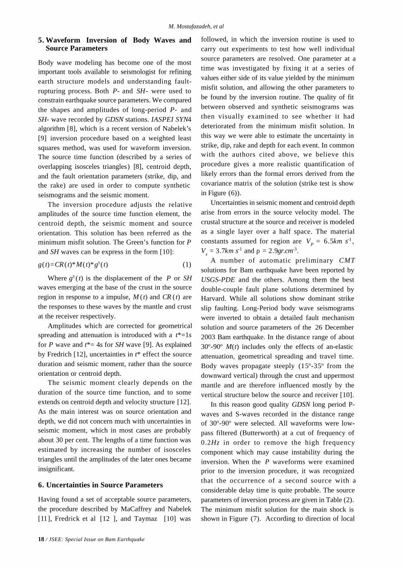
Figure 6. In this each row shows a selection of waveforms from a run of the inversion program. At the start of each row is the Pfocal sphere for the focal parameters represented by the five numbers (strike, dip, rake, depth and moment. The stationcode is identified to the left of each waveform. Observed waveform (solid lines) and synthetic data (dotted lines) shownin this figure.
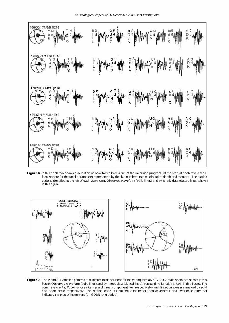
Figure 7. The P and SH radiation patterns of minimum misfit solutions for the earthquake of 26.12. 2003 main shock are shown in thisfigure. Observed waveform (solid lines) and synthetic data (dotted lines), source time function shown in this figure. Thecompression (Ps, Pt points for strike slip and thrust component fault respectively) and dilatation axes are marked by solidand open circle respectively. The station code is identified to the left of each waveforms, and lower case letter thatindicates the type of instrument (d= GDSN long period).
20 / JSEE: Special Issue on Bam Earthquake
M. Mostafazadeh, et al
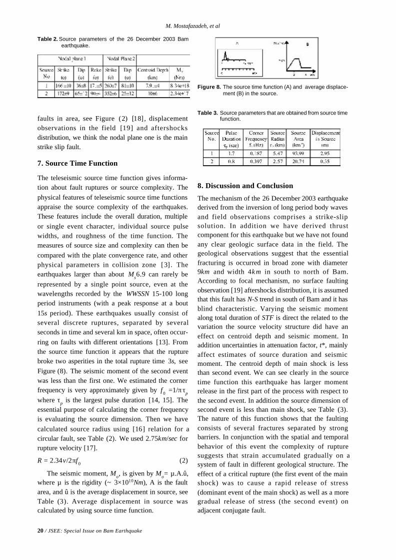
Table 2. Source parameters of the 26 December 2003 Bamearthquake.
Table 3. Source parameters that are obtained from source timefunction.
Figure 8. The source time function (A) and average displace-ment (B) in the source.
faults in area, see Figure (2) [18], displacementobservations in the field [19] and aftershocksdistribution, we think the nodal plane one is the mainstrike slip fault.
7. Source Time Function
The teleseismic source time function gives informa-tion about fault ruptures or source complexity. Thephysical features of teleseismic source time functionsappraise the source complexity of the earthquakes.These features include the overall duration, multipleor single event character, individual source pulsewidths, and roughness of the time function. Themeasures of source size and complexity can then becompared with the plate convergence rate, and otherphysical parameters in collision zone [3] . Theearthquakes larger than about Ms6.9 can rarely berepresented by a single point source, even at thewavelengths recorded by the WWSSN 15-100 longperiod instruments (with a peak response at a bout15s period). These earthquakes usually consist ofseveral discrete ruptures, separated by severalseconds in time and several km in space, often occur-ring on faults with different orientations [13]. Fromthe source time function it appears that the rupturebroke two asperities in the total rupture time 3s, seeFigure (8). The seismic moment of the second eventwas less than the first one. We estimated the cornerfrequency is very approximately given by f0 =1/π τp
where τp is the largest pulse duration [14, 15]. Theessential purpose of calculating the corner frequencyis evaluating the source dimension. Then we havecalculated source radius using [16] relation for acircular fault, see Table (2). We used 2.75km/sec forrupture velocity [17].
R = 2.34 v/2 π f0 (2)
The seismic moment, Mo, is given by Mo= µ.A.û,where µ is the rigidity (~ 3×10¹⁰Nm), A is the faultarea, and û is the average displacement in source, seeTable (3). Average displacement in source wascalculated by using source time function.
8. Discussion and Conclusion
The mechanism of the 26 December 2003 earthquakederived from the inversion of long period body wavesand field observations comprises a strike-slipsolution. In addition we have derived thrustcomponent for this earthquake but we have not foundany clear geologic surface data in the field. Thegeological observations suggest that the essentialfracturing is occurred in broad zone with diameter9km and width 4k m in south to north of Bam.According to focal mechanism, no surface faultingobservation [19] aftershocks distribution, it is assumedthat this fault has N-S trend in south of Bam and it hasblind characteristic. Varying the seismic momentalong total duration of STF is direct the related to thevariation the source velocity structure did have aneffect on centroid depth and seismic moment. Inaddition uncertainties in attenuation factor, t*, mainlyaffect estimates of source duration and seismicmoment. The centroid depth of main shock is lessthan second event. We can see clearly in the sourcetime function this earthquake has larger momentrelease in the first part of the process with respect tothe second event. In addition the source dimension ofsecond event is less than main shock, see Table (3).The nature of this function shows that the faultingconsists of several fractures separated by strongbarriers. In conjunction with the spatial and temporalbehavior of this event the complexity of rupturesuggests that strain accumulated gradually on asystem of fault in different geological structure. Theeffect of a critical rupture (the first event of the mainshock) was to cause a rapid release of stress(dominant event of the main shock) as well as a moregradual release of stress (the second event) onadjacent conjugate fault.
Seismological Aspect of 26 December 2003 Bam Earthquake
JSEE: Special Issue on Bam Earthquake / 21
Acknowledgment
We are grateful to Prof. Mohsen Ghafory Ashtianyfor his supports, all anonymous reviewers forreview and discussion and other colleagues at IIEESfor their efforts concerning the installation of localtemporary seismic network in the Bam area.
References
1. Zare, M. and Hamzeloo, H. (2004). “Study ofStrong Ground Motion Data for the 2003 BamEarthquake”, SE Iran, Published in This Issue.
2. Kisslinger, C. (1997). “Aftershocks and Fault Zoneproperties”, Advances in Geophysics, 38, 1-35.
3. Hartzell, S. and Heaton, T. (1985). “TeleseismicTime Functions for Large, Shallow SubductionZone Earthquakes”, Bull. Seism. Soc. Am. , 75(4),965-1004.
4. Berberian, M. (1994). “Natural Hazards and FirstEarthquake Catalogue of Iran, V.1. HistoricalHazards in Iran Prior to 1900”, InternationalInstitute of Earthquake Engineering and Seismol-ogy (IIEES), P.603
5. Zohoorian, A.A., Mohajer-Ashjai, A., Kabiri, A.,and Hosseinian-Ghamsari, M. (1984). “DamageDistribution and Aftershock Sequence of TwoDestructive Earthquakes in 1981 in EasternKerman”, J. Earth and space phys., 10(1, 2).
6. Cornel University, Building Digital Earth Project,Institute for the Study of Continent (INSTOC)Cornell University.
7. Hutton, L.K. and D. Boore (1987). “The ML Scalein Southern California”, Bull. Seism. Soc. Am.,77, 2074-2094.
8. McCaffery, R., Abers, G., and Zwick P. (1991).“Inversion of Teleseismic Body Waves”, In: DigitalSeismogram Analysis and Waveform Inversion(ed. By W. H. K. Lee), IASPEI software Library,3, 81-166.
9. Nabelek, J.L. (1984). “Determination of a Earth-quake Source Parameters from Inversion of BodyWaves”, Ph.D. Thesis, MIT, Cambridge Massa-chusetts.
10. Taymaz, T. (1990). “Earthquake Source Param-eters in the Eastern Mediterranean Region”, Ph.D.Thesis., Drawing college Cambridge.
11. McCaffrey, R. and Nabelek, J. (1987). “Earth-quakes Gravity, and the Origin of the Bali Basin:an Example of a Nascent Continental Fold-and-Thrust Belt, J.Geophys. Res., 92, 441-460.
12. Fredrick, J., McCaffrey, R., and Denham, D.(1988). “Source Parameters of Seven LargeAustralian Earthquakes Determined by BodyWaveform Inversion”, Geophys. J., 95, 1-13.
13. Butler, R., Stewart, G.S., and Kanamori, H. (1979).“The July 27 1976 Tangshan China Earthquake -aComplex Sequence of Intraplate Events, Bull.Seism. Soc. Am., 69, 207-220.
14. Helmberger, D.V. and Malone, S.D. (1975).“Modeling Local Earthquakes as Shear Disloca-tions in a Layered Half-Space, J. Geophys. Res.,80, 4881-4888.
15. Husebye, E.S. and Mykkeltveit, S. (1980).“Identification of Seismic Sources Earthquake orUnderground Explosion. Proceeding of the NATOAdvanced Study Institute Held at Voksenasen”,Oslo, Norway, 72-97.
16. Brune, J.N. (1970). “Tectonic Stress and theSpectra of Seismic Shear Waves from Earth-quakes, J. Geophys. Res., 75, 4997-5009.
17. Hartzel, S., Langer, C., and Mendoza, C. (1994).“Rupture Histories of Eastern North AmericanEarthquakes”, Bull. Seism. Soc. Am., 84(6), 1703-1772.
18. Berberian, M., Jackson, J.A., Fielding, E.,Parsons, B, E., Priestley, K., Qorashi, M., Talebian,M., Walker, R., Wright, T.J., and Baker, C. (2001).“The 1998 March 14 Fandooqa Earthquake(Mw6.6) in Kerman Province, Southeast Iran:Re-Rupture of the 1981 Sirch Earthquake Fault,Triggering of Slip on Adjacent Thrust and ActiveTectonics of the Gowk Fault Zone, Geophys. J.Int., 146, 371-398.
19. Hessami, K., Tabassi, H., Okumura, K., Azuma,T., Echigo, T., Kondo, H., and Abbassi, M.R.(2004). “Surface Expression of Bam Fault Zonein Southeastern Iran: Causative Fault of theDecember 26, 2003 Earthquake”, Press in thisVolume.
JSEE: Special Issue on Bam Earthquake / 23
M. Tatar 1, D. Hatzfeld 2, A.S. Moradi 1, A. Paul 2, A.M. Farahbod 1, and M. Mokhtari 1
1. Seismology Research Centre, International Institute of Earthquake Engineering
and Seismology (IIEES), Tehran, Iran, email: [email protected]
2. Laboratoire de Géophysique Interne et Tectonophysique, Grenoble, France
ABSTRACT: From 29 December to 30 January, a dense seismologicalnetwork of 20 stations surrounding the epicentral area of the 26December 2003 Bam earthquake was installed to study the seismicactivity that took place after the main shock. The aftershock distribu-tion is consistent with a 30 km north-south striking fault. The focaldepths distribution shows a nearly vertical alignment of aftershockslocated between 6 to 20 km depth. The focal mechanism solutions indi-cate right lateral strike slip faulting on N-S trending fault, parallel tothe Bam fault trace. However, there is a small offset of about 5kmwestward between the Bam fault trace and the aftershocks distribution.
Keywords: Bam; Aftershocks; Strike slip fault; Focal mechanism;Local seismological network
Aftershocks Study of the 26 December 2003 Bam Earthquake
1. Introduction
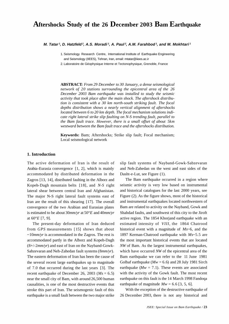
The active deformation of Iran is the result ofArabia-Eurasia convergence [1, 2], which is mainlyaccommodated by distributed deformation in theZagros [13, 14], distributed faulting in the Alborz andKopeh-Dagh mountain belts [18], and N-S rightlateral shear between central Iran and Afghanistan.The major N-S right lateral fault systems east ofIran are the result of this shearing [17]. The overallconvergence of the two Arabian and Eurasian platesis estimated to be about 30mm/yr at 50°E and 40mm/yrat 60°E [7, 9].
The present-day deformation of Iran deducedfrom GPS measurements [15] shows that about~10mm/yr is accommodated in the Zagros. The rest isaccommodated partly in the Alborz and Kopeh-Dagh(8+/-2mm/yr) and east of Iran on the Nayband-Gowk-Sabzevaran and Neh-Zahedan fault systems (8mm/yr).The eastern deformation of Iran has been the cause ofthe several recent large earthquakes up to magnitudeof 7.0 that occurred during the last years [3]. Therecent earthquake of December 26, 2003 (Ms = 6.5)near the small city of Bam, with around 26,500 humancausalities, is one of the most destructive events thatstroke this part of Iran. The seismogenic fault of thisearthquake is a small fault between the two major strike
slip fault systems of Nayband-Gowk-Sabzevaranand Neh-Zahedan on the west and east sides of theDasht-e-Lut, see Figure (1).
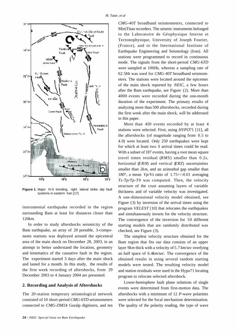
The Bam earthquake occurred in a region whereseismic activity is very low based on instrumentaland historical catalogues for the last 2000 years, seeFigure (2). As the figure shows, most of the historicaland instrumental earthquakes located northwestern ofBam are related to activity on the Nayband, Gowk andShahdad faults, and southwest of this city to the Jiroftactive region. The 1854 Khorjand earthquake with anestimated intensity of VIII , the 1864 Chatroodhistorical event with a magnitude of Ms~6, and the1897 Kerman-Chatrood earthquake with Ms~5.5 arethe most important historical events that are locatedNW of Bam. As the largest instrumental earthquakes,which have occurred NW of the epicentral area of theBam earthquake we can refer to the 11 June 1981Golbaf earthquake (Mw = 6.6) and 28 July 1981 Sirchearthquake (Mw = 7.1). These events are associatedwith the activity of the Gowk fault. The most recentearthquake on this fault is the 14 March 1998 Fandoqaearthquake of magnitude Mw = 6.6 [3, 5, 6].
With the exception of the destructive earthquake of26 December 2003, there is not any historical and
24 / JSEE: Special Issue on Bam Earthquake
M. Tatar, et al
instrumental earthquake recorded in the regionsurrounding Bam at least for distances closer than120km.
In order to study aftershocks seismicity of theBam earthquake, an array of 20 portable, 3-compo-nents stations was deployed around the epicentralarea of the main shock on December 28, 2003, in anattempt to better understand the location, geometryand kinematics of the causative fault in the region.The experiment started 3 days after the main shockand lasted for a month. In this study, the results ofthe first week recording of aftershocks, from 29December 2003 to 4 January 2004 are presented.
2. Recording and Analysis of Aftershocks
The 20-station temporary seismological networkconsisted of 10 short-period CMG-6TD seismometersconnected to CMG-DM24 Guralp digitizers, and ten
Figure 1. Major N-S trending, right lateral strike slip faultsystems in eastern Iran [17].
CMG-40T broadband seismometers, connected toMiniTitan recorders. The seismic instruments belongedto the Laboratoire de Géophysique Interne etTectonophysique, University of Joseph Fourier,(France), and to the International Institute ofEarthquake Engineering and Seismology (Iran). Allstations were programmed to record in continuousmode. The signals from the short-period CMG-6TDwere sampled at 100Hz, whereas a sampling rate of62.5Hz was used for CMG-40T broadband seismom-eters. The stations were located around the epicenterof the main shock reported by NEIC, a few hoursafter the Bam earthquake, see Figure (2). More than4000 events were recorded during the one-monthduration of the experiment. The primary results ofanalyzing more than 500 aftershocks, recorded duringthe first week after the main shock, will be addressedin this paper.
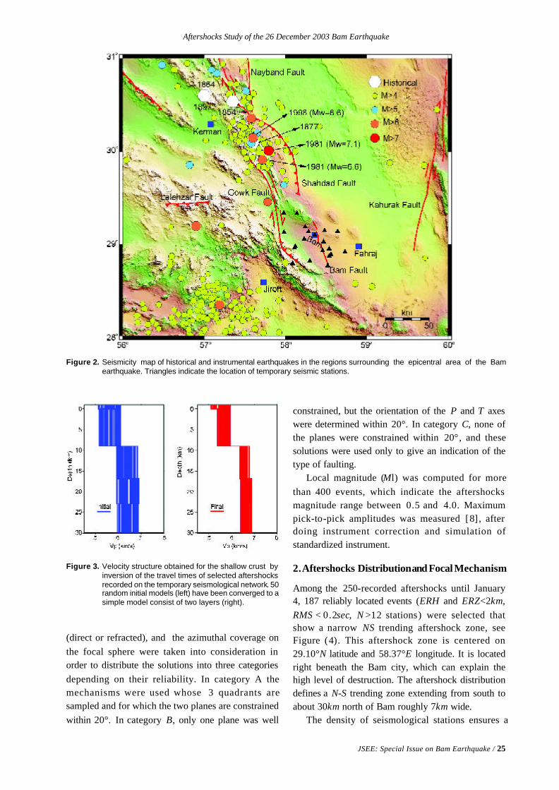
More than 450 events recorded by at least 4stations were selected. First, using HYPO71 [11], allthe aftershocks (of magnitude ranging from 0.5 to4.0) were located. Only 250 earthquakes were keptfor which at least two S arrival times could be read.With a subset of 187 events, having a root mean squaretravel times residual (RMS) smaller than 0.2s,horizontal (ERH) and vertical (ERZ) uncertaintiessmaller than 2km, and an azimuthal gap smaller than180°, a mean Vp/Vs ratio of 1.75+/-0.01 averagingTs-Tp/Tp-T0 was computed . Then, the velocitystructure of the crust assuming layers of variablethickness and of variable velocity was investigated.A one-dimensional velocity model obtained, seeFigure (3) by inversion of the arrival times using theprogram VELEST [10] that relocates the earthquakesand simultaneously inverts for the velocity structure.The convergence of the inversion for 50 differentstarting models that are randomly distributed waschecked, see Figure (3).
The simplest velocity structure obtained for theBam region that fits our data consists of an upperlayer 9km thick with a velocity of 5.7 km/sec overlyingan half space of 6.4km/sec. The convergence of theobtained results in using several random startingmodels were tested. The resulting velocity modeland station residuals were used in the Hypo71 locatingprogram to relocate selected aftershock.
Lower-hemisphere fault plane solutions of singleevents were determined from first-motion data. Theaftershocks with a minimum of 12 P-wave polaritieswere selected for the focal mechanism determination.The quality of the polarity reading, the type of wave
Aftershocks Study of the 26 December 2003 Bam Earthquake
JSEE: Special Issue on Bam Earthquake / 25
Figure 2. Seismicity map of historical and instrumental earthquakes in the regions surrounding the epicentral area of the Bamearthquake. Triangles indicate the location of temporary seismic stations.
Figure 3. Velocity structure obtained for the shallow crust byinversion of the travel times of selected aftershocksrecorded on the temporary seismological network. 50random initial models (left) have been converged to asimple model consist of two layers (right).
(direct or refracted), and the azimuthal coverage onthe focal sphere were taken into consideration inorder to distribute the solutions into three categoriesdepending on their reliability. In category A themechanisms were used whose 3 quadrants aresampled and for which the two planes are constrainedwithin 20°. In category B, only one plane was well
constrained, but the orientation of the P and T axeswere determined within 20°. In category C, none ofthe planes were constrained within 20°, and thesesolutions were used only to give an indication of thetype of faulting.
Local magnitude (Ml) was computed for morethan 400 events, which indicate the aftershocksmagnitude range between 0.5 and 4.0. Maximumpick-to-pick amplitudes was measured [8] , afterdoing instrument correction and simulation ofstandardized instrument.
2. Aftershocks Distribution and Focal Mechanism
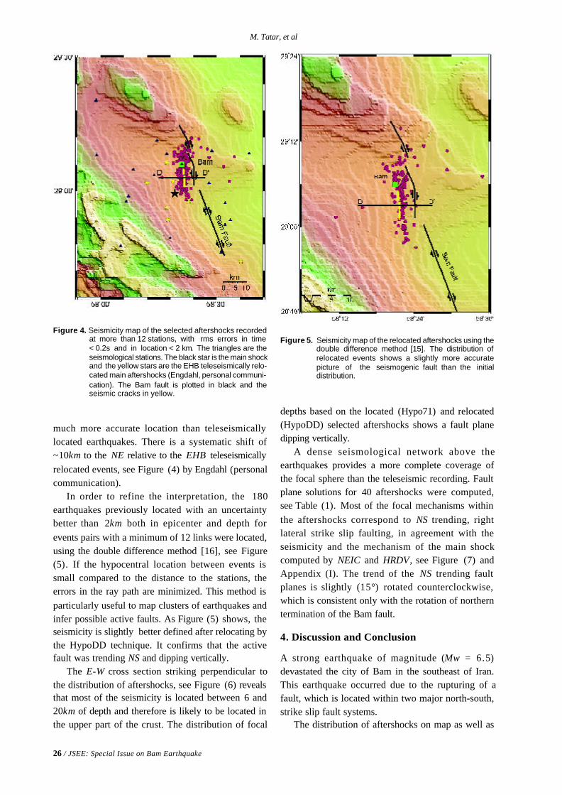
Among the 250-recorded aftershocks until January4, 187 reliably located events (ERH and ERZ<2km,RMS < 0.2sec, N >12 stations) were selected thatshow a narrow NS trending aftershock zone, seeFigure (4). This aftershock zone is centered on29.10°N latitude and 58.37°E longitude. It is locatedright beneath the Bam city, which can explain thehigh level of destruction. The aftershock distributiondefines a N-S trending zone extending from south toabout 30km north of Bam roughly 7km wide.
The density of seismological stations ensures a
26 / JSEE: Special Issue on Bam Earthquake
M. Tatar, et al
much more accurate location than teleseismicallylocated earthquakes. There is a systematic shift of~10km to the NE relative to the EHB teleseismicallyrelocated events, see Figure (4) by Engdahl (personalcommunication).
In order to refine the interpretation, the 180earthquakes previously located with an uncertaintybetter than 2km both in epicenter and depth forevents pairs with a minimum of 12 links were located,using the double difference method [16], see Figure(5). If the hypocentral location between events issmall compared to the distance to the stations, theerrors in the ray path are minimized. This method isparticularly useful to map clusters of earthquakes andinfer possible active faults. As Figure (5) shows, theseismicity is slightly better defined after relocating bythe HypoDD technique. It confirms that the activefault was trending NS and dipping vertically.
The E-W cross section striking perpendicular tothe distribution of aftershocks, see Figure (6) revealsthat most of the seismicity is located between 6 and20km of depth and therefore is likely to be located inthe upper part of the crust. The distribution of focal
Figure 4. Seismicity map of the selected aftershocks recordedat more than 12 stations, with rms errors in time< 0.2s and in location < 2 km. The triangles are theseismological stations. The black star is the main shockand the yellow stars are the EHB teleseismically relo-cated main aftershocks (Engdahl, personal communi-cation). The Bam fault is plotted in black and theseismic cracks in yellow.
Figure 5. Seismicity map of the relocated aftershocks using thedouble difference method [15]. The distribution ofrelocated events shows a slightly more accuratepicture of the seismogenic fault than the initialdistribution.
depths based on the located (Hypo71) and relocated(HypoDD) selected aftershocks shows a fault planedipping vertically.
A dense seismological network above theearthquakes provides a more complete coverage ofthe focal sphere than the teleseismic recording. Faultplane solutions for 40 aftershocks were computed,see Table (1). Most of the focal mechanisms withinthe aftershocks correspond to NS trending, rightlateral strike slip faulting, in agreement with theseismicity and the mechanism of the main shockcomputed by NEIC and HRDV, see Figure (7) andAppendix (I). The trend of the NS trending faultplanes is slightly (15°) rotated counterclockwise,which is consistent only with the rotation of northerntermination of the Bam fault.
4. Discussion and Conclusion
A strong earthquake of magnitude (Mw = 6.5)devastated the city of Bam in the southeast of Iran.This earthquake occurred due to the rupturing of afault, which is located within two major north-south,strike slip fault systems.
The distribution of aftershocks on map as well as

Aftershocks Study of the 26 December 2003 Bam Earthquake
JSEE: Special Issue on Bam Earthquake / 27
Table 1. Parameters of determined focal mechanisms.
Lat, Lon, Depth are the coordinates of the aftershocks, Mag is the local magnitude, Az1, Pl1, de1, AZ2, Pl2, de2 are Azimuth, dip andslip of plane 1 and 2 respectively. Azp, dep, Azt, det are azimuth and dip of P- and T-axis respectively. Im is 1 for reverse and -1 fornormal faulting respectively. A, B and C are a factor of quality of the fault plane solutions.
28 / JSEE: Special Issue on Bam Earthquake
M. Tatar, et al
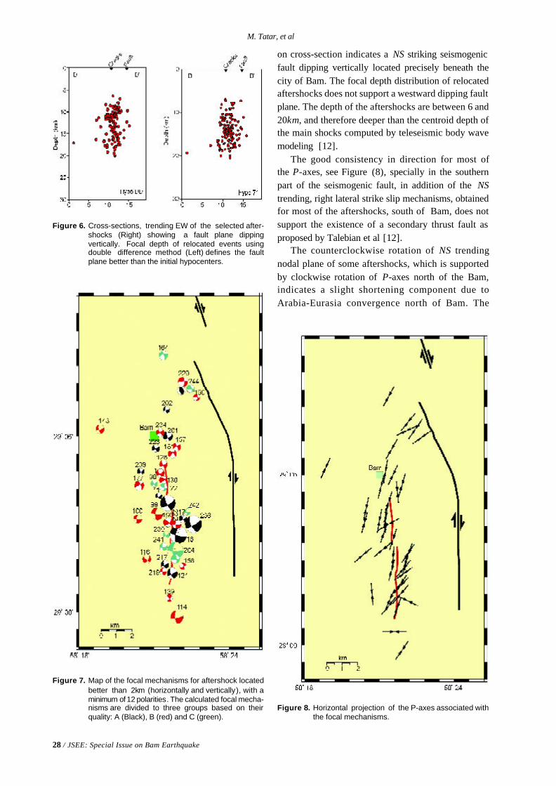
on cross-section indicates a NS striking seismogenicfault dipping vertically located precisely beneath thecity of Bam. The focal depth distribution of relocatedaftershocks does not support a westward dipping faultplane. The depth of the aftershocks are between 6 and20km, and therefore deeper than the centroid depth ofthe main shocks computed by teleseismic body wavemodeling [12].
The good consistency in direction for most ofthe P-axes, see Figure (8), specially in the southernpart of the seismogenic fault, in addition of the NStrending, right lateral strike slip mechanisms, obtainedfor most of the aftershocks, south of Bam, does notsupport the existence of a secondary thrust fault asproposed by Talebian et al [12].
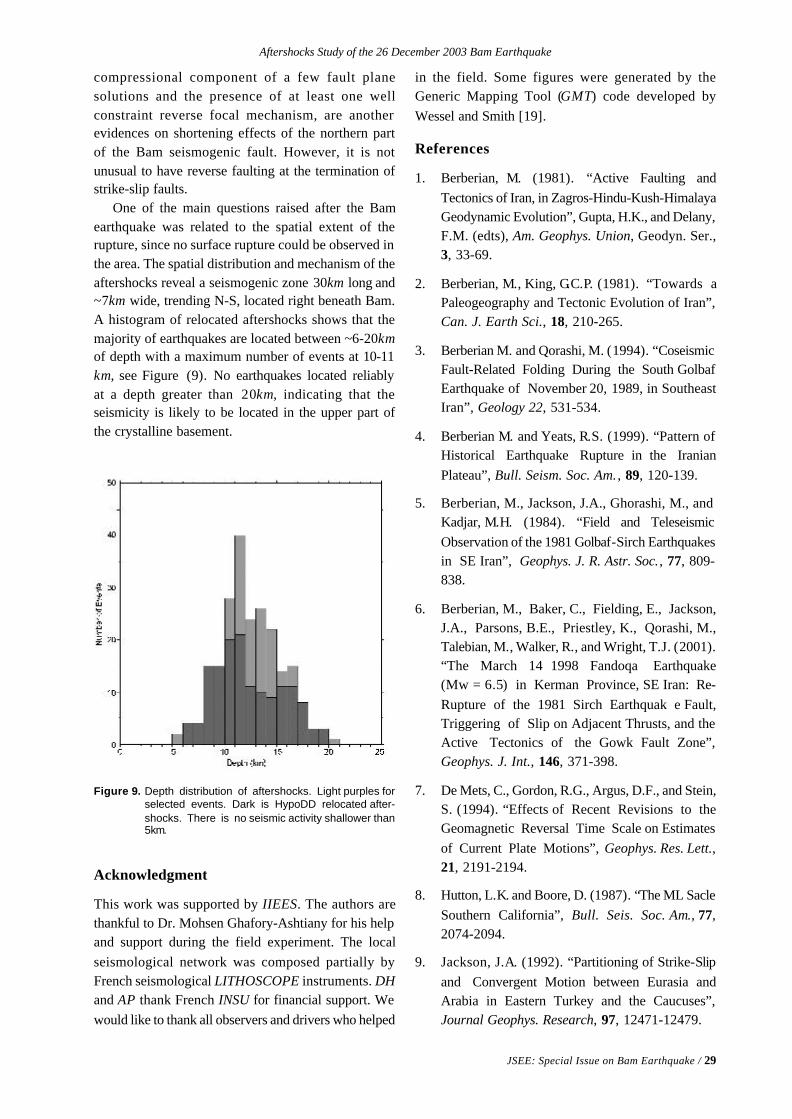
The counterclockwise rotation of NS trendingnodal plane of some aftershocks, which is supportedby clockwise rotation of P-axes north of the Bam,indicates a slight shortening component due toArabia-Eurasia convergence north of Bam. The
Figure 6. Cross-sections, trending EW of the selected after-shocks (Right) showing a fault plane dippingvertically. Focal depth of relocated events usingdouble difference method (Left) defines the faultplane better than the initial hypocenters.
Figure 7. Map of the focal mechanisms for aftershock locatedbetter than 2km (horizontally and vertically), with aminimum of 12 polarities. The calculated focal mecha-nisms are divided to three groups based on theirquality: A (Black), B (red) and C (green).
Figure 8. Horizontal projection of the P-axes associated withthe focal mechanisms.
Aftershocks Study of the 26 December 2003 Bam Earthquake
JSEE: Special Issue on Bam Earthquake / 29
compressional component of a few fault planesolutions and the presence of at least one wellconstraint reverse focal mechanism, are anotherevidences on shortening effects of the northern partof the Bam seismogenic fault. However, it is notunusual to have reverse faulting at the termination ofstrike-slip faults.
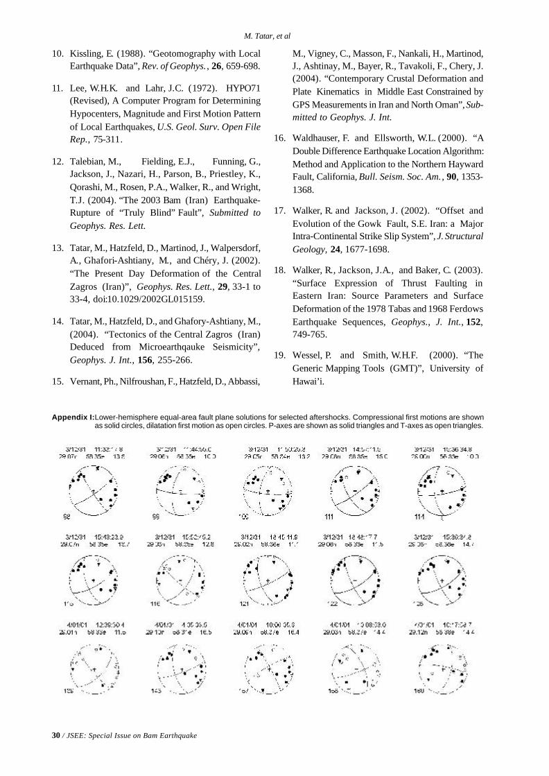
One of the main questions raised after the Bamearthquake was related to the spatial extent of therupture, since no surface rupture could be observed inthe area. The spatial distribution and mechanism of theaftershocks reveal a seismogenic zone 30km long and~7km wide, trending N-S, located right beneath Bam.A histogram of relocated aftershocks shows that themajority of earthquakes are located between ~6-20kmof depth with a maximum number of events at 10-11km, see Figure (9). No earthquakes located reliablyat a depth greater than 20km, indicating that theseismicity is likely to be located in the upper part ofthe crystalline basement.
in the field. Some figures were generated by theGeneric Mapping Tool (GMT) code developed byWessel and Smith [19].
References
1. Berberian, M. (1981). “Active Faulting andTectonics of Iran, in Zagros-Hindu-Kush-HimalayaGeodynamic Evolution”, Gupta, H.K., and Delany,F.M. (edts), Am. Geophys. Union, Geodyn. Ser.,3, 33-69.
2. Berberian, M., King, G.C.P. (1981). “Towards aPaleogeography and Tectonic Evolution of Iran”,Can. J. Earth Sci., 18, 210-265.
3. Berberian M. and Qorashi, M. (1994). “CoseismicFault-Related Folding During the South GolbafEarthquake of November 20, 1989, in SoutheastIran”, Geology 22, 531-534.
4. Berberian M. and Yeats, R.S. (1999). “Pattern ofHistorical Earthquake Rupture in the IranianPlateau”, Bull. Seism. Soc. Am. , 89, 120-139.
5. Berberian, M., Jackson, J.A., Ghorashi, M., andKadjar, M.H. (1984). “Field and TeleseismicObservation of the 1981 Golbaf-Sirch Earthquakesin SE Iran”, Geophys. J. R. Astr. Soc., 77, 809-838.
6. Berberian, M., Baker, C., Fielding, E., Jackson,J.A., Parsons, B.E., Priestley, K., Qorashi, M.,Talebian, M., Walker, R., and Wright, T.J. (2001).“The March 14 1998 Fandoqa Earthquake(Mw = 6.5) in Kerman Province, SE Iran: Re-Rupture of the 1981 Sirch Earthquak e Fault,Triggering of Slip on Adjacent Thrusts, and theActive Tectonics of the Gowk Fault Zone”,Geophys. J. Int., 146, 371-398.
7. De Mets, C., Gordon, R.G., Argus, D.F., and Stein,S. (1994). “Effects of Recent Revisions to theGeomagnetic Reversal Time Scale on Estimatesof Current Plate Motions”, Geophys. Res. Lett.,21, 2191-2194.
8. Hutton, L.K. and Boore, D. (1987). “The ML SacleSouthern California”, Bull. Seis. Soc. Am., 77,2074-2094.
9. Jackson, J.A. (1992). “Partitioning of Strike-Slipand Convergent Motion between Eurasia andArabia in Eastern Turkey and the Caucuses”,Journal Geophys. Research, 97, 12471-12479.
Figure 9. Depth distribution of aftershocks. Light purples forselected events. Dark is HypoDD relocated after-shocks. There is no seismic activity shallower than5km.
Acknowledgment
This work was supported by IIEES. The authors arethankful to Dr. Mohsen Ghafory-Ashtiany for his helpand support during the field experiment. The localseismological network was composed partially byFrench seismological LITHOSCOPE instruments. DHand AP thank French INSU for financial support. Wewould like to thank all observers and drivers who helped
30 / JSEE: Special Issue on Bam Earthquake
M. Tatar, et al
10. Kissling, E. (1988). “Geotomography with LocalEarthquake Data”, Rev. of Geophys., 26, 659-698.
11. Lee, W.H.K. and Lahr, J.C. (1972). HYPO71(Revised), A Computer Program for DeterminingHypocenters, Magnitude and First Motion Patternof Local Earthquakes, U.S. Geol. Surv. Open FileRep., 75-311.
12. Talebian, M., Fielding, E.J., Funning, G.,Jackson, J., Nazari, H., Parson, B., Priestley, K.,Qorashi, M., Rosen, P.A., Walker, R., and Wright,T.J. (2004). “The 2003 Bam (Iran) Earthquake-Rupture of “Truly Blind” Fault”, Submitted toGeophys. Res. Lett.
13. Tatar, M., Hatzfeld, D., Martinod, J., Walpersdorf,A., Ghafori-Ashtiany, M., and Chéry, J. (2002).“The Present Day Deformation of the CentralZagros (Iran)”, Geophys. Res. Lett., 29, 33-1 to33-4, doi:10.1029/2002GL015159.
14. Tatar, M., Hatzfeld, D., and Ghafory-Ashtiany, M.,(2004). “Tectonics of the Central Zagros (Iran)Deduced from Microearthqauke Seismicity”,Geophys. J. Int., 156, 255-266.
15. Vernant, Ph., Nilfroushan, F., Hatzfeld, D., Abbassi,
M., Vigney, C., Masson, F., Nankali, H., Martinod,J., Ashtinay, M., Bayer, R., Tavakoli, F., Chery, J.(2004). “Contemporary Crustal Deformation andPlate Kinematics in Middle East Constrained byGPS Measurements in Iran and North Oman”, Sub-mitted to Geophys. J. Int.
16. Waldhauser, F. and Ellsworth, W.L. (2000). “ADouble Difference Earthquake Location Algorithm:Method and Application to the Northern HaywardFault, California, Bull. Seism. Soc. Am. , 90, 1353-1368.
17. Walker, R. and Jackson, J. (2002). “Offset andEvolution of the Gowk Fault, S.E. Iran: a MajorIntra-Continental Strike Slip System”, J. StructuralGeology, 24, 1677-1698.
18. Walker, R., Jackson, J.A., and Baker, C. (2003).“Surface Expression of Thrust Faulting inEastern Iran: Source Parameters and SurfaceDeformation of the 1978 Tabas and 1968 FerdowsEarthquake Sequences, Geophys., J. Int., 152,749-765.
19. Wessel, P. and Smith, W.H.F. (2000). “TheGeneric Mapping Tools (GMT)”, University ofHawai’i.
Appendix I:Lower-hemisphere equal-area fault plane solutions for selected aftershocks. Compressional first motions are shownas solid circles, dilatation first motion as open circles. P-axes are shown as solid triangles and T-axes as open triangles.
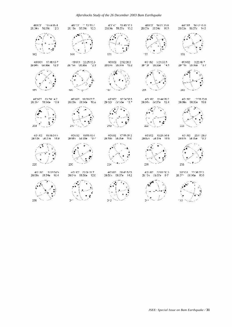
Aftershocks Study of the 26 December 2003 Bam Earthquake
JSEE: Special Issue on Bam Earthquake / 31
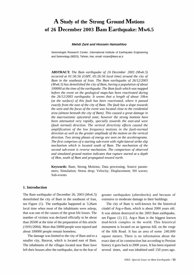
JSEE: Special Issue on Bam Earthquake / 33
Mehdi Zaré and Hossein Hamzehloo
Seismologist Research Center, International Institute of Earthquake Engineering
and Seismology (IIEES), Tehran, Iran, email: [email protected]
ABSTRACT: The Bam earthquake of 26 December 2003 (Mw6.5)occurred at 01:56:56 (GMT, 05:26:56 local time) around the city ofBam in the southeast of Iran. The Bam earthquake of 26/12/2003(Mw6.5) has demolished the city of Bam, having a population of about100000 at the time of the earthquake. The Bam fault-which was mappedbefore the event on the geological maps-has been reactivated duringthe 26/12/2003 earthquake. It seems that a length of about 10km(at the surface) of this fault has been reactivated, where it passedexactly from the east of the city of Bam. The fault has a slope towardsthe west and the focus of the event was located close to the residentialarea (almost beneath the city of Bam). This caused a great damage inthe macroseismic epicentral zone; however the strong motions havebeen attenuated very rapidly, specially towards the east-and west(fault normal) direction. The vertical directivity effects caused theamplification of the low frequency motions in the fault-normaldirection as well as the greater amplitude of the motion on the verticaldirection. Two strong phases of energy are seen on the accelerograms.The first comprises of a starting sub-event with right-lateral strike slipmechanism which is located south of Bam. The mechanism of thesecond sub-event is reverse mechanism. The comparison of observedand simulated ground motion indicates that rupture started at a depthof 8km, south of Bam and propagated toward north.
Keywords: Bam; Strong Motions; Data processing; Source param-eters; Simulation; Stress drop; Velocity; Displacement; SH waves;Sub-events
A Study of the Strong Ground Motions
of 26 December 2003 Bam Earthquake: Mw6.5
1. Introduction
The Bam earthquake of December 26, 2003 (Mw6.5)demolished the city of Bam in the southeast of Iran,see Figure (1). The earthquake happened at 5:26amlocal time when most of the inhabitants were asleep,that was one of the causes of the great life losses. Thenumber of victims was declared officially to be aboutthan 26500 at the time of the preparation of this article(19/01/2004). More that 50000 people were injured andabout 100000 people remain homeless.
The damage was limited to the city of Bam and to asmaller city, Baravat, which is located east of Bam.The inhabitants of the villages located near Bam haveleft their houses after the earthquake, due to the fear of
greater earthquakes (aftershocks) and because ofextensive to moderate damage to their buildings.
The city of Bam is well-known for the historicalcitadel of Arg-e-Bam, which is about 2000 years old.It was almost destroyed in the 2003 Bam earthquake,see Figure (1) [1]. Arg-e Bam is the biggest knownmud-brick complex in the world. This historicalmonument is located on an igneous hill, on the vergeof the Silk Road. It has an area of some 240,000square meters. There is no information about theexact date of its construction but according to Persianhistory it goes back to 2000 years. It has been repairedseveral times, and was inhabited until 150 years ago.
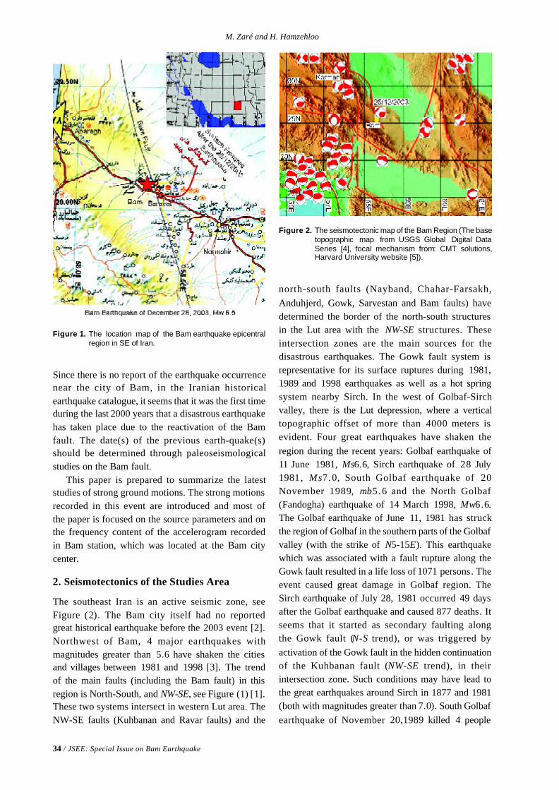
34 / JSEE: Special Issue on Bam Earthquake
M. Zaré and H. Hamzehloo
Figure 1. The location map of the Bam earthquake epicentralregion in SE of Iran.
Figure 2. The seismotectonic map of the Bam Region (The basetopographic map from USGS Global Digital DataSeries [4], focal mechanism from: CMT solutions,Harvard University website [5]).
Since there is no report of the earthquake occurrencenear the city of Bam, in the Iranian historicalearthquake catalogue, it seems that it was the first timeduring the last 2000 years that a disastrous earthquakehas taken place due to the reactivation of the Bamfault. The date(s) of the previous earth-quake(s)should be determined through paleoseismologicalstudies on the Bam fault.
This paper is prepared to summarize the lateststudies of strong ground motions. The strong motionsrecorded in this event are introduced and most ofthe paper is focused on the source parameters and onthe frequency content of the accelerogram recordedin Bam station, which was located at the Bam citycenter.
2. Seismotectonics of the Studies Area
The southeast Iran is an active seismic zone, seeFigure (2). The Bam city itself had no reportedgreat historical earthquake before the 2003 event [2].Northwest of Bam, 4 major earthquakes withmagnitudes greater than 5.6 have shaken the citiesand villages between 1981 and 1998 [3]. The trendof the main faults (including the Bam fault) in thisregion is North-South, and NW-SE, see Figure (1) [1].These two systems intersect in western Lut area. TheNW-SE faults (Kuhbanan and Ravar faults) and the
north-south faults (Nayband, Chahar-Farsakh,Anduhjerd, Gowk, Sarvestan and Bam faults) havedetermined the border of the north-south structuresin the Lut area with the NW-SE structures. Theseintersection zones are the main sources for thedisastrous earthquakes. The Gowk fault system isrepresentative for its surface ruptures during 1981,1989 and 1998 earthquakes as well as a hot springsystem nearby Sirch. In the west of Golbaf-Sirchvalley, there is the Lut depression, where a verticaltopographic offset of more than 4000 meters isevident. Four great earthquakes have shaken theregion during the recent years: Golbaf earthquake of11 June 1981, Ms6.6, Sirch earthquake of 28 July1981, Ms7.0, South Golbaf earthquake of 20November 1989, mb5.6 and the North Golbaf(Fandogha) earthquake of 14 March 1998, Mw6.6.The Golbaf earthquake of June 11, 1981 has struckthe region of Golbaf in the southern parts of the Golbafvalley (with the strike of N5-15E). This earthquakewhich was associated with a fault rupture along theGowk fault resulted in a life loss of 1071 persons. Theevent caused great damage in Golbaf region. TheSirch earthquake of July 28, 1981 occurred 49 daysafter the Golbaf earthquake and caused 877 deaths. Itseems that it started as secondary faulting alongthe Gowk fault (N-S trend), or was triggered byactivation of the Gowk fault in the hidden continuationof the Kuhbanan fault (NW-SE trend), in theirintersection zone. Such conditions may have lead tothe great earthquakes around Sirch in 1877 and 1981(both with magnitudes greater than 7.0). South Golbafearthquake of November 20,1989 killed 4 people
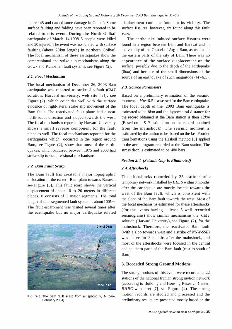
A Study of the Strong Ground Motions of 26 December 2003 Bam Earthquake: Mw6.5
JSEE: Special Issue on Bam Earthquake / 35
Figure 3. The Bam fault scarp from air (photo by M. Zare,February 2004).
injured 45 and caused some damage in Golbaf. Somesurface faulting and folding have been reported to berelated to this event. During the North Golbafearthquake of March 14,1998 5 people were killedand 50 injured. The event was associated with surfacefaulting (about 20km length) in northern Golbaf.The focal mechanism of these earthquakes show thecompressional and strike slip mechanisms along theGowk and Kuhbanan fault systems, see Figure (2).
2.1. Focal Mechanism
The focal mechanism of December 26, 2003 Bamearthquake was reported as strike slip fault (CMTsolution, Harvard university, web site [5]) , seeFigure (2) , which coincides well with the surfaceevidence of right-lateral strike slip movement of theBam fault. The reactivated fault plane had a nearnorth-south direction and sloped towards the west.The focal mechanism reported by Harvard Universityshows a small reverse component for the faultplane as well. The focal mechanisms reported for theearthquakes which occurred in the region aroundBam, see Figure (2), show that most of the earth-quakes, which occurred between 1975 and 2003 hadstrike-slip to compressional mechanisms.
2.2. Bam Fault Scarp
The Bam fault has created a major topographicdislocation in the eastern Bam plain towards Baravat,see Figure (3). This fault scarp shows the verticaldisplacement of about 10 to 20 meters in differentplaces. It consists of 3 major segments. The totallength of such segmented fault system is about 100km.The fault escarpment was visited several times afterthe earthquake but no major earthquake related
displacement could be found in its vicinity. Thesurface fissures, however, are found along this faultzone.
The earthquake induced surface fissures werefound in a region between Bam and Baravat and inthe vicinity of the Citadel of Arg-e Bam, as well as inthe eastern parts of the city of Bam. There was noappearance of the surface displacement on thesurface, possibly due to the depth of the earthquake(8km) and because of the small dimensions of thesource of an earthquake of such magnitude (Mw6.5).
2.3. Source Parameters
Based on a preliminary estimation of the seismicmoment, a Mw=6.5 is assessed for the Bam earthquake.The focal depth of the 2003 Bam earthquake isestimated to be 8km and the hypocentral distance forthe record obtained at the Bam station is then 12km(Based on a S-P estimation on the record obtainedfrom the mainshock). The seismic moment isestimated by the author to be based on the fast Fouriertransformations using the Haskell method [6] appliedto the accelerogram recorded at the Bam station. Thestress drop is estimated to be 480 bars.
Section 2.4. (Seismic Gap Is Eliminated)
2.4. Aftershocks
The aftershocks recorded by 25 stations of atemporary network installed by IIEES within 3 monthsafter the earthquake are mostly located towards thewest of the Bam fault, which is consistent withthe slope of the Bam fault towards the west. Most ofthe focal mechanisms estimated for these aftershocks(for the events having at least 5 well recordedseismograms) show similar mechanisms the CMTsolution (Harvard University), see Figure (2), for themainshock. Therefore, the reactivated Bam fault(with a slop towards west and a strike of NNW-SSE)was active for 3 months after the mainshock, andmost of the aftershocks were focused in the centraland southern parts of the Bam fault (east to south ofBam).
3. Recorded Strong Ground Motions
The strong motions of this event were recorded at 22stations of the national Iranian strong motion network(according to Building and Housing Research Center,BHRC web site) [7] , see Figure (4). The strongmotion records are studied and processed and thepreliminary results are presented mostly based on the
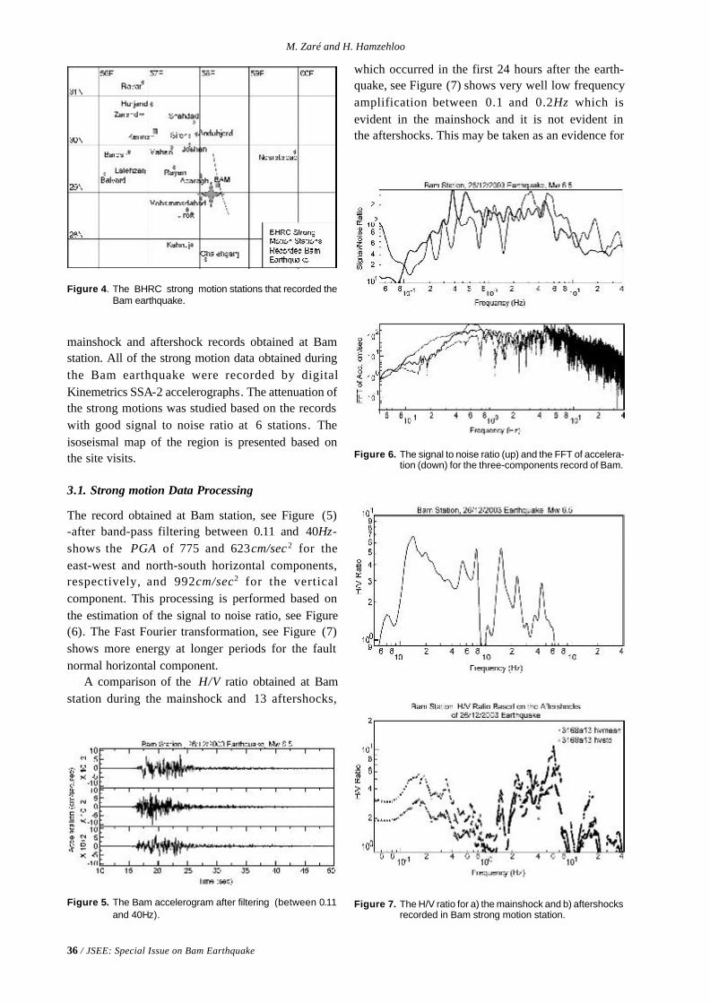
36 / JSEE: Special Issue on Bam Earthquake
M. Zaré and H. Hamzehloo
Figure 4. The BHRC strong motion stations that recorded theBam earthquake.
mainshock and aftershock records obtained at Bamstation. All of the strong motion data obtained duringthe Bam earthquake were recorded by digitalKinemetrics SSA-2 accelerographs. The attenuation ofthe strong motions was studied based on the recordswith good signal to noise ratio at 6 stations. Theisoseismal map of the region is presented based onthe site visits.
3.1. Strong motion Data Processing
The record obtained at Bam station, see Figure (5)-after band-pass filtering between 0.11 and 40Hz-shows the PGA of 775 and 623cm/sec2 for theeast-west and north-south horizontal components,respectively, and 992cm/sec2 for the verticalcomponent. This processing is performed based onthe estimation of the signal to noise ratio, see Figure(6). The Fast Fourier transformation, see Figure (7)shows more energy at longer periods for the faultnormal horizontal component.
A comparison of the H/V ratio obtained at Bamstation during the mainshock and 13 aftershocks,
Figure 5. The Bam accelerogram after filtering (between 0.11and 40Hz).
Figure 6. The signal to noise ratio (up) and the FFT of accelera-tion (down) for the three-components record of Bam.
Figure 7. The H/V ratio for a) the mainshock and b) aftershocksrecorded in Bam strong motion station.
which occurred in the first 24 hours after the earth-quake, see Figure (7) shows very well low frequencyamplification between 0.1 and 0.2Hz which isevident in the mainshock and it is not evident inthe aftershocks. This may be taken as an evidence for
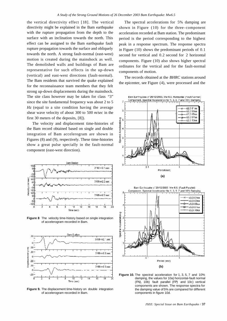
A Study of the Strong Ground Motions of 26 December 2003 Bam Earthquake: Mw6.5
JSEE: Special Issue on Bam Earthquake / 37
Figure 8 The velocity time-history based on single integrationof accelerogram recorded in Bam.
Figure 9. The displacement time-history on double integrationof accelerogram recorded in Bam.
the vertical directivity effect [18]. The verticaldirectivity might be explained in the Bam earthquakewith the rupture propagation from the depth to thesurface with an inclination towards the north. Thiseffect can be assigned to the Bam earthquake faultrupture propagation towards the surface and obliquelytowards the north. A strong fault-normal (east-west)motion is created during the mainshock as well.The demolished walls and buildings of Bam arerepresentative for such effects in the up-down(vertical) and east-west directions (fault-normal).The Bam residents that survived the quake explainedfor the reconnaissance team members that they feltstrong up-down displacements during the mainshock.The site class however may be taken for class “3”since the site fundamental frequency was about 2 to 5Hz (equal to a site condition having the averageshear wave velocity of about 300 to 500 m/sec in thefirst 30 meters of the deposits, [8]).
The velocity and displacement time-histories ofthe Bam record obtained based on single and doubleintegration of Bam accelerogram are shown inFigures (8) and (9), respectively. These time-historiesshow a great pulse specially in the fault-normalcomponent (east-west direction).
The spectral accelerations for 5% damping areshown in Figure (10) for the three -componentacceleration recorded at Bam station. The predominantperiod is the period corresponding to the highestpeak in a response spectrum. The response spectrain Figure (10) shows the predominant periods of 0.1second for vertical and 0.2 second for 2 horizontalcomponents. Figure (10) also shows higher spectralordinates for the vertical and for the fault-normalcomponents of motion.
The records obtained at the BHRC stations aroundthe epicenter, see Figure (4), were processed and the
Figure 10. The spectral acceleration for 1, 3, 5, 7 and 10%damping, the values for 10a) horizontal-fault normal(FN), 10b) fault parallel (FP) and 10c) verticalcomponents are shown. The response spectra forthe damping value of 5% are compared for differentcomponents in figure 10d.
(b)
(a)
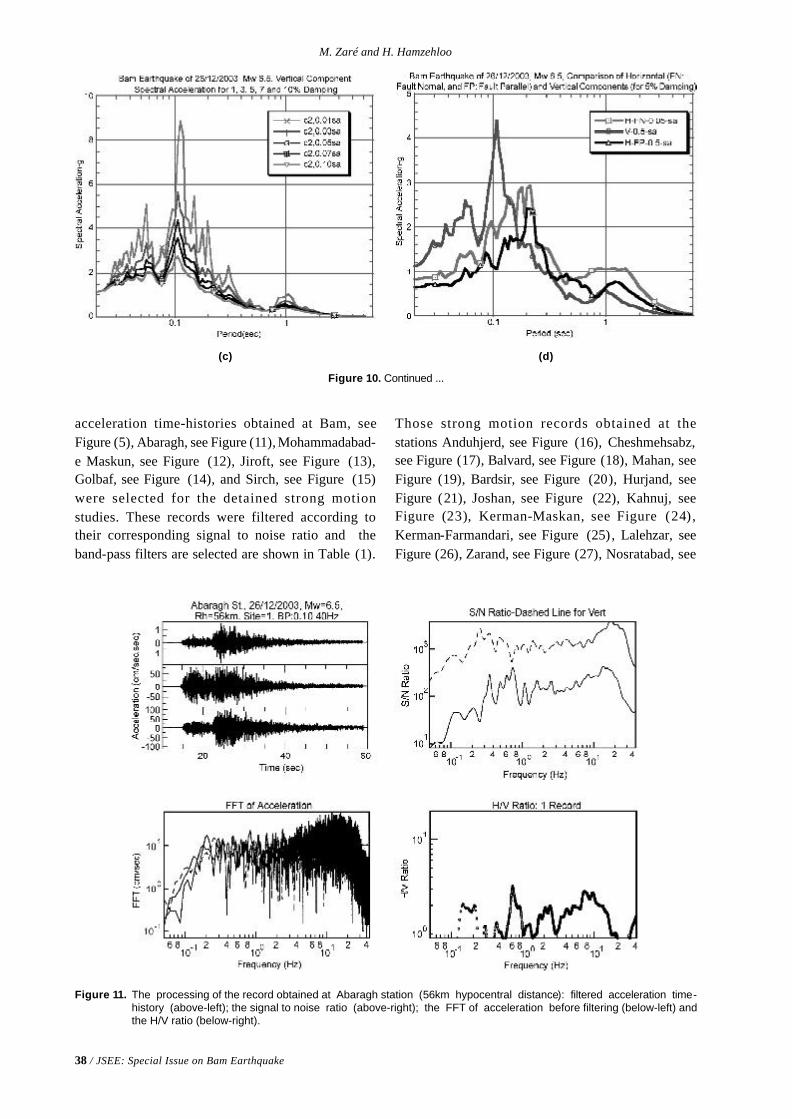
38 / JSEE: Special Issue on Bam Earthquake
M. Zaré and H. Hamzehloo
acceleration time-histories obtained at Bam, seeFigure (5), Abaragh, see Figure (11), Mohammadabad-e Maskun, see Figure (12), Jiroft, see Figure (13),Golbaf, see Figure (14), and Sirch, see Figure (15)were selected for the detained strong motionstudies. These records were filtered according totheir corresponding signal to noise ratio and theband-pass filters are selected are shown in Table (1).
(c) (d)
Figure 10. Continued ...
Figure 11. The processing of the record obtained at Abaragh station (56km hypocentral distance): filtered acceleration time-history (above-left); the signal to noise ratio (above-right); the FFT of acceleration before filtering (below-left) andthe H/V ratio (below-right).
Those strong motion records obtained at thestations Anduhjerd, see Figure (16), Cheshmehsabz,see Figure (17), Balvard, see Figure (18), Mahan, seeFigure (19), Bardsir, see Figure (20), Hurjand, seeFigure (21), Joshan, see Figure (22), Kahnuj, seeFigure (23), Kerman-Maskan, see Figure (24),Kerman-Farmandari, see Figure (25), Lalehzar, seeFigure (26), Zarand, see Figure (27), Nosratabad, see
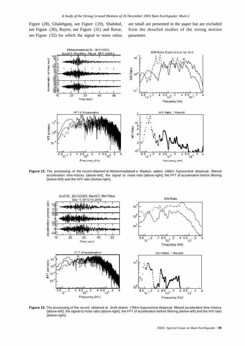
A Study of the Strong Ground Motions of 26 December 2003 Bam Earthquake: Mw6.5
JSEE: Special Issue on Bam Earthquake / 39
Figure 12. The processing of the record obtained at Mohammadabad-e Maskun station (48km hypocentral distance): filteredacceleration time-history (above-left); the signal to noise ratio (above-right); the FFT of acceleration before filtering(below-left) and the H/V ratio (below-right).
Figure 13. The processing of the record obtained at Jiroft station (76km hypocentral distance): filtered acceleration time-history(above-left); the signal to noise ratio (above-right); the FFT of acceleration before filtering (below-left) and the H/V ratio(below-right).
Figure (28), Ghalehganj, see Figure (29), Shahdad,see Figure (30), Rayen, see Figure (31) and Ravar,see Figure (32) for which the signal to noise ratios
are small are presented in the paper but are excludedfrom the detailed studies of the strong motionparameter.
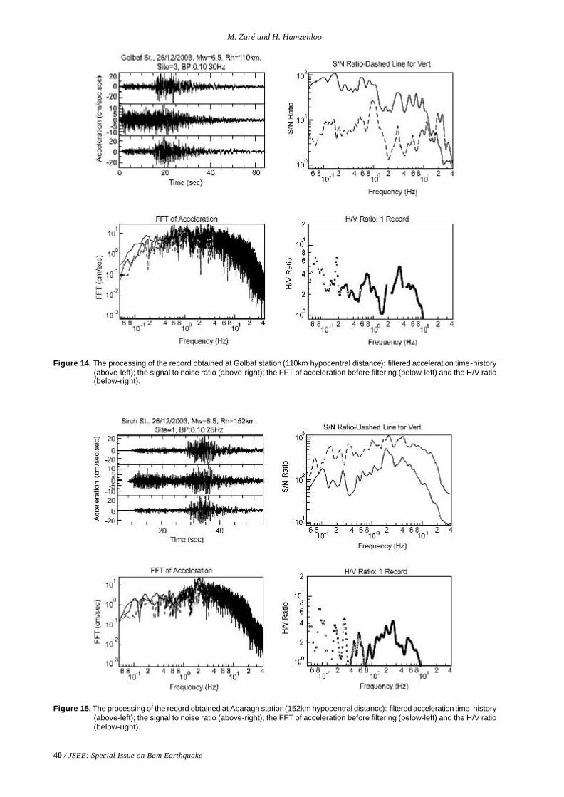
40 / JSEE: Special Issue on Bam Earthquake
M. Zaré and H. Hamzehloo
Figure 14. The processing of the record obtained at Golbaf station (110km hypocentral distance): filtered acceleration time-history(above-left); the signal to noise ratio (above-right); the FFT of acceleration before filtering (below-left) and the H/V ratio(below-right).
Figure 15. The processing of the record obtained at Abaragh station (152km hypocentral distance): filtered acceleration time-history(above-left); the signal to noise ratio (above-right); the FFT of acceleration before filtering (below-left) and the H/V ratio(below-right).
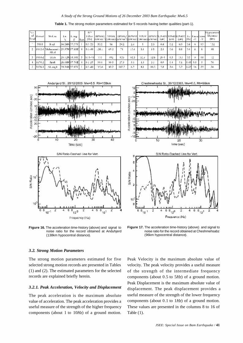
A Study of the Strong Ground Motions of 26 December 2003 Bam Earthquake: Mw6.5
JSEE: Special Issue on Bam Earthquake / 41
3.2. Strong Motion Parameters
The strong motion parameters estimated for fiveselected strong motion records are presented in Tables(1) and (2). The estimated parameters for the selectedrecords are explained briefly herein.
3.2.1. Peak Acceleration, Velocity and Displacement
The peak acceleration is the maximum absolutevalue of acceleration. The peak acceleration provides auseful measure of the strength of the higher frequencycomponents (about 1 to 10Hz) of a ground motion.
Table 1. The strong motion parameters estimated for 5 records having better qualities (part-1).
Figure 16. The acceleration time-history (above) and signal tonoise ratio for the record obtained at Anduhjerd(138km hypocentral distance).
Figure 17. The acceleration time-history (above) and signal tonoise ratio for the record obtained at Cheshmehsabz(96km hypocentral distance).
Peak Velocity is the maximum absolute value ofvelocity. The peak velocity provides a useful measureof the strength of the intermediate frequencycomponents (about 0.5 to 5Hz) of a ground motion.Peak Displacement is the maximum absolute value ofdisplacement. The peak displacement provides auseful measure of the strength of the lower frequencycomponents (about 0.1 to 1Hz) of a ground motion.These values are presented in the columns 8 to 16 ofTable (1).
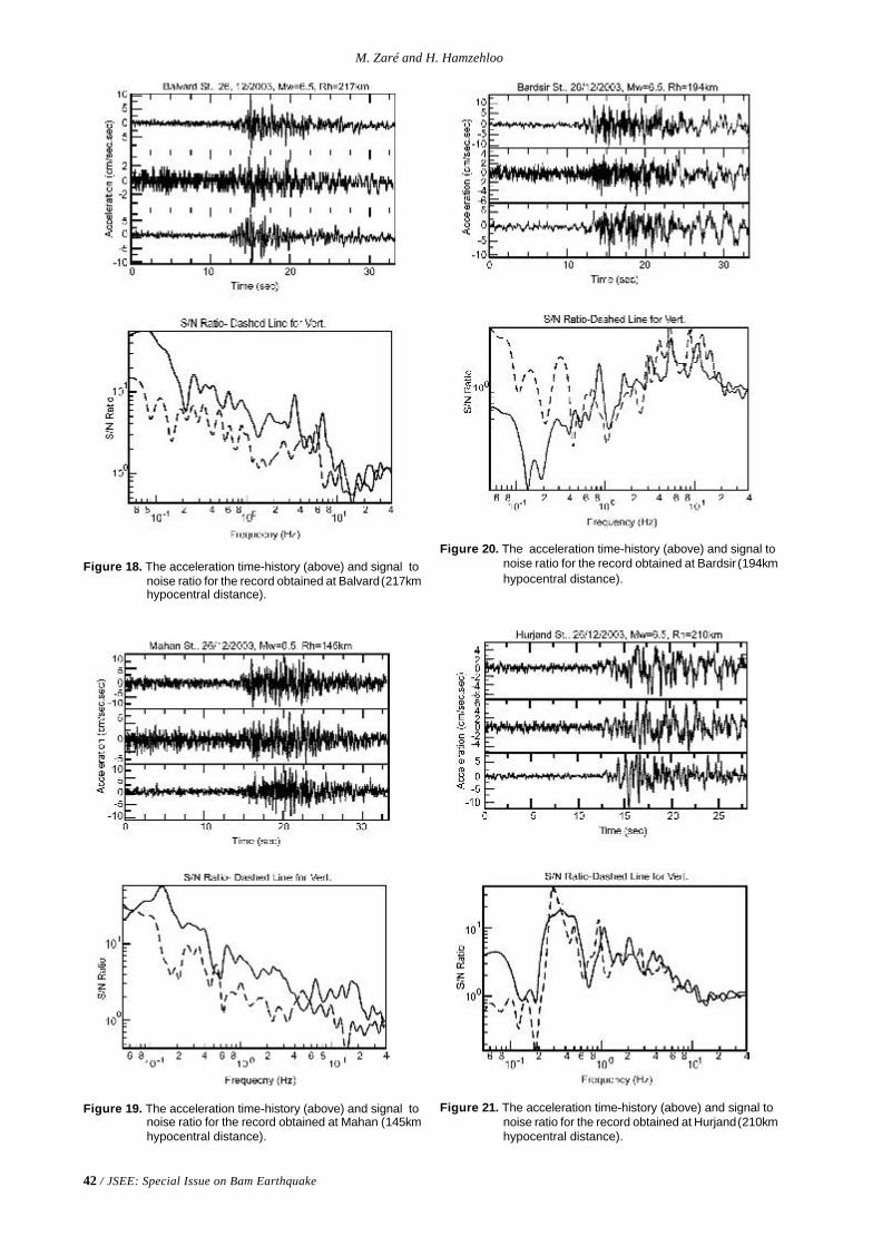
42 / JSEE: Special Issue on Bam Earthquake
M. Zaré and H. Hamzehloo
Figure 18. The acceleration time-history (above) and signal tonoise ratio for the record obtained at Balvard (217kmhypocentral distance).
Figure 19. The acceleration time-history (above) and signal tonoise ratio for the record obtained at Mahan (145kmhypocentral distance).
Figure 20. The acceleration time-history (above) and signal tonoise ratio for the record obtained at Bardsir (194kmhypocentral distance).
Figure 21. The acceleration time-history (above) and signal tonoise ratio for the record obtained at Hurjand (210kmhypocentral distance).
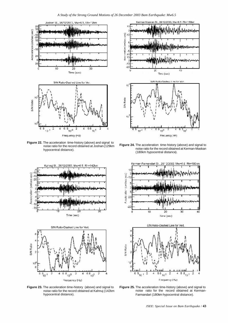
A Study of the Strong Ground Motions of 26 December 2003 Bam Earthquake: Mw6.5
JSEE: Special Issue on Bam Earthquake / 43
Figure 22. The acceleration time-history (above) and signal tonoise ratio for the record obtained at Joshan (129kmhypocentral distance).
Figure 23. The acceleration time-history (above) and signal tonoise ratio for the record obtained at Kahnuj (142kmhypocentral distance).
Figure 24. The acceleration time-history (above) and signal tonoise ratio for the record obtained at Kerman-Maskan(180km hypocentral distance).
Figure 25. The acceleration time-history (above) and signal tonoise ratio for the record obtained at Kerman-Farmandari (180km hypocentral distance).
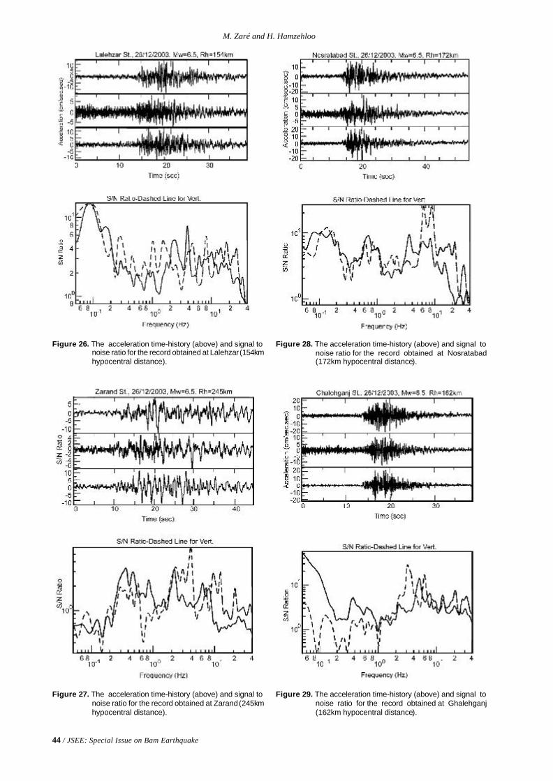
44 / JSEE: Special Issue on Bam Earthquake
M. Zaré and H. Hamzehloo
Figure 26. The acceleration time-history (above) and signal tonoise ratio for the record obtained at Lalehzar (154kmhypocentral distance).
Figure 27. The acceleration time-history (above) and signal tonoise ratio for the record obtained at Zarand (245kmhypocentral distance).
Figure 28. The acceleration time-history (above) and signal tonoise ratio for the record obtained at Nosratabad(172km hypocentral distance).
Figure 29. The acceleration time-history (above) and signal tonoise ratio for the record obtained at Ghalehganj(162km hypocentral distance).
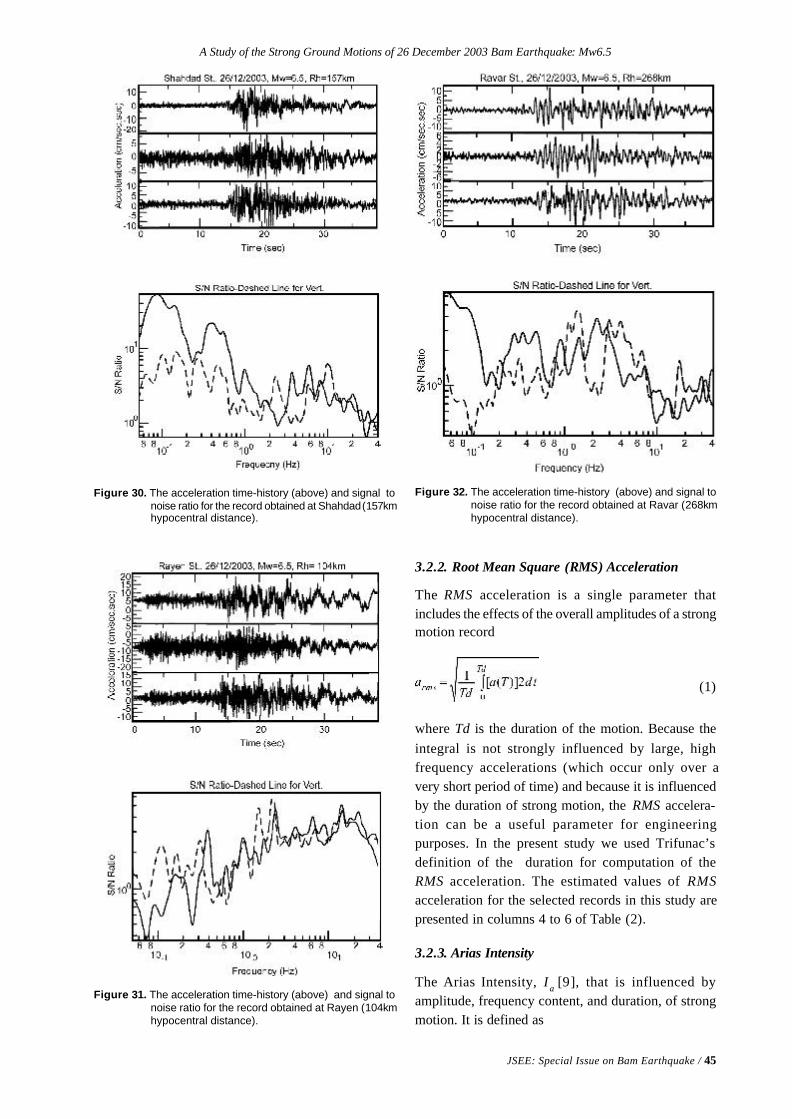
A Study of the Strong Ground Motions of 26 December 2003 Bam Earthquake: Mw6.5
JSEE: Special Issue on Bam Earthquake / 45
Figure 30. The acceleration time-history (above) and signal tonoise ratio for the record obtained at Shahdad (157kmhypocentral distance).
Figure 31. The acceleration time-history (above) and signal tonoise ratio for the record obtained at Rayen (104kmhypocentral distance).
Figure 32. The acceleration time-history (above) and signal tonoise ratio for the record obtained at Ravar (268kmhypocentral distance).
3.2.2. Root Mean Square (RMS) Acceleration
The RMS acceleration is a single parameter thatincludes the effects of the overall amplitudes of a strongmotion record
(1)
where Td is the duration of the motion. Because theintegral is not strongly influenced by large, highfrequency accelerations (which occur only over avery short period of time) and because it is influencedby the duration of strong motion, the RMS accelera-tion can be a useful parameter for engineeringpurposes. In the present study we used Trifunac’sdefinition of the duration for computation of theRMS acceleration. The estimated values of RMSacceleration for the selected records in this study arepresented in columns 4 to 6 of Table (2).
3.2.3. Arias Intensity
The Arias Intensity, Ia [9], that is influenced byamplitude, frequency content, and duration, of strongmotion. It is defined as
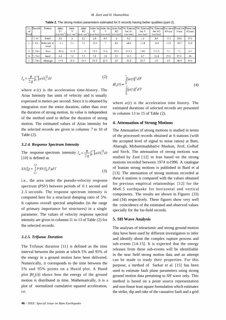
46 / JSEE: Special Issue on Bam Earthquake
M. Zaré and H. Hamzehloo
(2)
where a (t) is the acceleration time-history. TheArias Intensity has units of velocity and is usuallyexpressed in meters per second. Since it is obtained byintegration over the entire duration, rather than overthe duration of strong motion, its value is independentof the method used to define the duration of strongmotion. The estimated values of Arias intensity forthe selected records are given in columns 7 to 10 ofTable (2).
3.2.4. Response Spectrum Intensity
The response spectrum intensity[10] is defined as
(3)
i.e., the area under the pseudo-velocity responsespectrum (PSV) between periods of 0.1 second and2.5 seconds. The response spectrum intensity iscomputed here for a structural damping ratio of 5%.It captures overall spectral amplitudes (in the rangeof primary importance for structures) in a singleparameter. The values of velocity response spectralintensity are given in columns 11 to 13 of Table (2) forthe selected records.
3.2.5. Trifunac Duration
The Trifunac duration [11] is defined as the timeinterval between the points at which 5% and 95% ofthe energy in a ground motion have been delivered.Numerically, it corresponds to the time between the5% and 95% points on a Husid plot. A Husidplot [Hn(t)] shows how the energy of the groundmotion is distributed in time. Mathematically, it is aplot of normalized cumulative squared acceleration,i.e.
Table 2. The strong motion parameters estimated for 5 records having better qualities (part-2).
(4)
where a (t) is the acceleration time history. Theestimated durations of selected records are presentedin columns 13 to 15 of Table (2).
4. Attenuation of Strong Motions
The Attenuation of strong motions is studied in termsof the processed records obtained at 6 stations (withthe accepted level of signal to noise ratios) at Bam,Abaragh, Mohammadabad-e Maskun, Jirof, Golbafand Sirch. The attenuation of strong motions wasstudied by Zaré [12] in Iran based on the strongmotions recorded between 1974 to1996. A catalogueof Iranian strong motions is published in Bard et al[13]. The attenuation of strong motions recorded atthese 6 stations is compared with the values obtainedfor previous empirical relationships [12] for theMw6.5 earthquake for horizontal and verticalcomponents. The results are shown in Figures (33)and (34) respectively. These figures show very wellthe coincidence of the estimated and observed valuesspecially for the far-field records.
5. SH Wave Analysis
The analyses of teleseismic and strong ground motiondata have been used by different investigators to inferand identify about the complex rupture process andsub-events [14-15]. It is expected that the energyreleases from these sub-events will be identifiablein the near field strong motion data and an attemptcan be made to study their properties. For thispurpose, a method of Sarkar et al [15] has beenused to estimate fault plane parameters using strongground motion data pertaining to SH wave only. Thismethod is based on a point source representationand non-linear least square formulation which estimatesthe strike, dip and rake of the causative fault and a grid
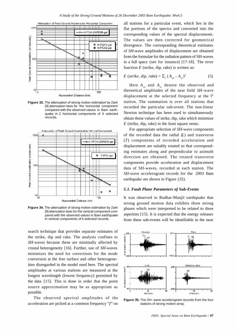
A Study of the Strong Ground Motions of 26 December 2003 Bam Earthquake: Mw6.5
JSEE: Special Issue on Bam Earthquake / 47
search technique that provides separate estimates ofthe strike, dip and rake. The analysis confines toSH-waves because these are minimally affected bycrustal heterogeneity [16]. Further, use of SH-wavesminimizes the need for corrections for the modeconversion at the free surface and other heterogene-ities disregarded in the model used here. The spectralamplitudes at various stations are measured at thelongest wavelength (lowest frequency) permitted bythe data [15]. This is done in order that the pointsource approximation may be as appropriate aspossible.
The observed spectral amplitudes of theacceleration are picked at a common frequency “f” on
Figure 33. The attenuation of strong motion estimation by Zaré[9] attenuation laws for the horizontal componentcompared with the observed values in Bam earth-quake in 2 horizontal components of 6 selectedrecords.
Figure 34. The attenuation of strong motion estimation by Zaré[9] attenuation laws for the vertical component com-pared with the observed values in Bam earthquakein vertical components of 6 selected records.
Figure 35. The SH- wave accelerogram records from the fourstations of strong motion array.
all stations for a particular event, which lies in theflat portions of the spectra and converted into thecorresponding values of the spectral displacements.The values are then corrected for geometricaldivergence. The corresponding theoretical estimatesof SH-wave amplitudes of displacement are obtainedfrom the formulae for the radiation pattern of SH-wavesin a full space (see for instance) [17-18]. The errorfunction E (strike, dip, rake) is written as:
E (strike, dip, rake) = Σi ( Aoi - Ati )2 (5)
Here A oi and A ti denote the observed andtheoretical amplitudes of the near field SH-wavedisplacement at the selected frequency at the it h
station. The summation is over all stations thatrecorded the particular sub-event. The non-linearNewton technique has been used to simultaneouslyobtain those values of strike, dip, rake which minimizeE (strike, dip, rake) in the least square sense.
For appropriate selection of SH-wave componentsof the recorded data the radial (L) and transverse(T) components of recorded acceleration anddisplacement are suitably rotated so that correspond-ing estimates along and perpendicular to azimuthdirection are obtained. The rotated transversecomponents provide acceleration and displacementdata of SH-waves, recorded at each station. TheSH-wave accelerogram records for the 2003 Bamearthquake are shown in Figure (35).
5.1. Fault Plane Parameters of Sub-Events
It was observed in Rudbar-Manjil earthquake thatstrong ground motion data exhibits three strongphases which were interpreted to be related to threeasperities [15]. It is expected that the energy releasesfrom these sub-events will be identifiable in the near
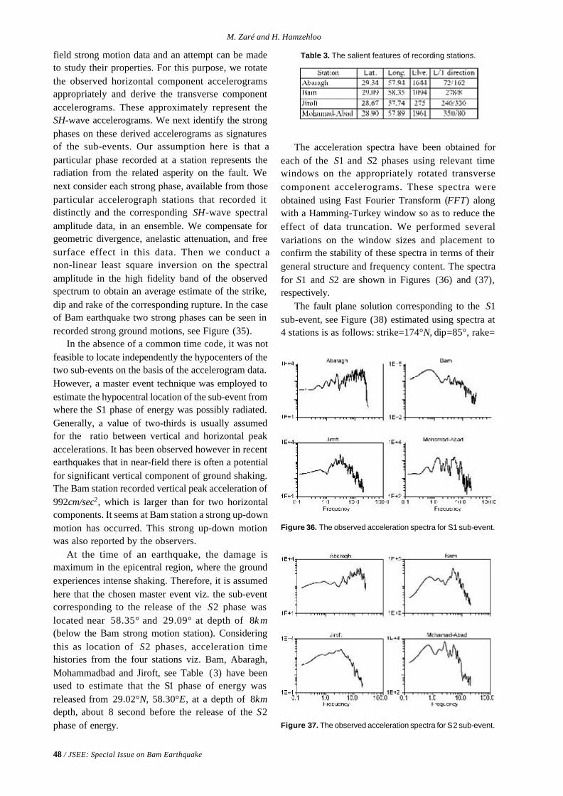
48 / JSEE: Special Issue on Bam Earthquake
M. Zaré and H. Hamzehloo
field strong motion data and an attempt can be madeto study their properties. For this purpose, we rotatethe observed horizontal component accelerogramsappropriately and derive the transverse componentaccelerograms. These approximately represent theSH-wave accelerograms. We next identify the strongphases on these derived accelerograms as signaturesof the sub-events. Our assumption here is that aparticular phase recorded at a station represents theradiation from the related asperity on the fault. Wenext consider each strong phase, available from thoseparticular accelerograph stations that recorded itdistinctly and the corresponding SH-wave spectralamplitude data, in an ensemble. We compensate forgeometric divergence, anelastic attenuation, and freesurface effect in this data. Then we conduct anon-linear least square inversion on the spectralamplitude in the high fidelity band of the observedspectrum to obtain an average estimate of the strike,dip and rake of the corresponding rupture. In the caseof Bam earthquake two strong phases can be seen inrecorded strong ground motions, see Figure (35).
In the absence of a common time code, it was notfeasible to locate independently the hypocenters of thetwo sub-events on the basis of the accelerogram data.However, a master event technique was employed toestimate the hypocentral location of the sub-event fromwhere the S1 phase of energy was possibly radiated.Generally, a value of two-thirds is usually assumedfor the ratio between vertical and horizontal peakaccelerations. It has been observed however in recentearthquakes that in near-field there is often a potentialfor significant vertical component of ground shaking.The Bam station recorded vertical peak acceleration of992cm/sec2, which is larger than for two horizontalcomponents. It seems at Bam station a strong up-downmotion has occurred. This strong up-down motionwas also reported by the observers.
At the time of an earthquake, the damage ismaximum in the epicentral region, where the groundexperiences intense shaking. Therefore, it is assumedhere that the chosen master event viz. the sub-eventcorresponding to the release of the S2 phase waslocated near 58.35° and 29.09° at depth of 8k m(below the Bam strong motion station). Consideringthis as location of S2 phases, acceleration timehistories from the four stations viz. Bam, Abaragh,Mohammadbad and Jiroft, see Table (3) have beenused to estimate that the S1 phase of energy wasreleased from 29.02°N, 58.30°E, at a depth of 8kmdepth, about 8 second before the release of the S2phase of energy.
The acceleration spectra have been obtained foreach of the S1 and S2 phases using relevant timewindows on the appropriately rotated transversecomponent accelerograms. These spectra wereobtained using Fast Fourier Transform (FFT) alongwith a Hamming-Turkey window so as to reduce theeffect of data truncation. We performed severalvariations on the window sizes and placement toconfirm the stability of these spectra in terms of theirgeneral structure and frequency content. The spectrafor S1 and S2 are shown in Figures (36) and (37),respectively.
The fault plane solution corresponding to the S1sub-event, see Figure (38) estimated using spectra at4 stations is as follows: strike=174°N, dip=85°, rake=
Table 3. The salient features of recording stations.
Figure 37. The observed acceleration spectra for S2 sub-event.
Figure 36. The observed acceleration spectra for S1 sub-event.
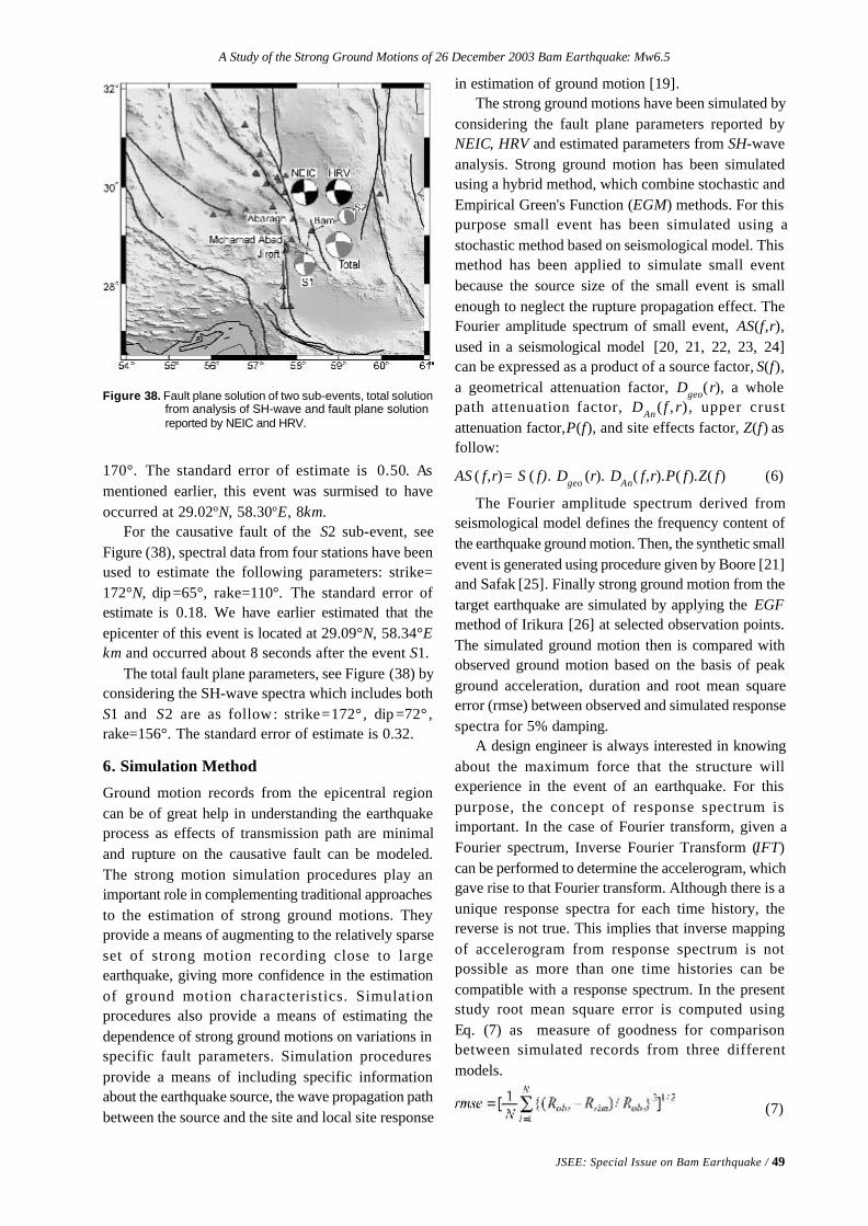
A Study of the Strong Ground Motions of 26 December 2003 Bam Earthquake: Mw6.5
JSEE: Special Issue on Bam Earthquake / 49
Figure 38. Fault plane solution of two sub-events, total solutionfrom analysis of SH-wave and fault plane solutionreported by NEIC and HRV.
170°. The standard error of estimate is 0.50. Asmentioned earlier, this event was surmised to haveoccurred at 29.02oN, 58.30oE, 8km.
For the causative fault of the S2 sub-event, seeFigure (38), spectral data from four stations have beenused to estimate the following parameters: strike=172°N, dip=65°, rake=110°. The standard error ofestimate is 0.18. We have earlier estimated that theepicenter of this event is located at 29.09°N, 58.34°Ekm and occurred about 8 seconds after the event S1.
The total fault plane parameters, see Figure (38) byconsidering the SH-wave spectra which includes bothS1 and S2 are as follow: strike=172°, dip =72°,rake=156°. The standard error of estimate is 0.32.
6. Simulation Method
Ground motion records from the epicentral regioncan be of great help in understanding the earthquakeprocess as effects of transmission path are minimaland rupture on the causative fault can be modeled.The strong motion simulation procedures play animportant role in complementing traditional approachesto the estimation of strong ground motions. Theyprovide a means of augmenting to the relatively sparseset of strong motion recording close to largeearthquake, giving more confidence in the estimationof ground motion characteristics. Simulationprocedures also provide a means of estimating thedependence of strong ground motions on variations inspecific fault parameters. Simulation proceduresprovide a means of including specific informationabout the earthquake source, the wave propagation pathbetween the source and the site and local site response
in estimation of ground motion [19].The strong ground motions have been simulated by
considering the fault plane parameters reported byNEIC, HRV and estimated parameters from SH-waveanalysis. Strong ground motion has been simulatedusing a hybrid method, which combine stochastic andEmpirical Green's Function (EGM) methods. For thispurpose small event has been simulated using astochastic method based on seismological model. Thismethod has been applied to simulate small eventbecause the source size of the small event is smallenough to neglect the rupture propagation effect. TheFourier amplitude spectrum of small event, AS(f,r),used in a seismological model [20, 21, 22, 23, 24]can be expressed as a product of a source factor, S(f),a geometrical attenuation factor, Dgeo(r), a wholepath attenuation factor, DAn ( f , r), upper crustattenuation factor,P(f), and site effects factor, Z(f) asfollow:
AS ( f,r)= S ( f). Dgeo (r). DAn( f,r).P( f).Z( f) (6)
The Fourier amplitude spectrum derived fromseismological model defines the frequency content ofthe earthquake ground motion. Then, the synthetic smallevent is generated using procedure given by Boore [21]and Safak [25]. Finally strong ground motion from thetarget earthquake are simulated by applying the EGFmethod of Irikura [26] at selected observation points.The simulated ground motion then is compared withobserved ground motion based on the basis of peakground acceleration, duration and root mean squareerror (rmse) between observed and simulated responsespectra for 5% damping.
A design engineer is always interested in knowingabout the maximum force that the structure willexperience in the event of an earthquake. For thispurpose, the concept of response spectrum isimportant. In the case of Fourier transform, given aFourier spectrum, Inverse Fourier Transform (IFT)can be performed to determine the accelerogram, whichgave rise to that Fourier transform. Although there is aunique response spectra for each time history, thereverse is not true. This implies that inverse mappingof accelerogram from response spectrum is notpossible as more than one time histories can becompatible with a response spectrum. In the presentstudy root mean square error is computed usingEq. (7) as measure of goodness for comparisonbetween simulated records from three differentmodels.
(7)
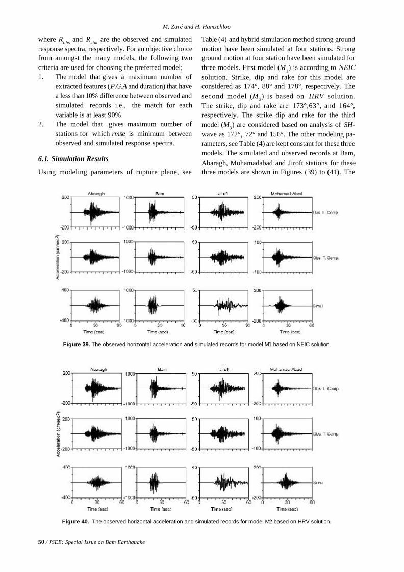
50 / JSEE: Special Issue on Bam Earthquake
M. Zaré and H. Hamzehloo
where Robs and Rsim are the observed and simulatedresponse spectra, respectively. For an objective choicefrom amongst the many models, the following twocriteria are used for choosing the preferred model;1. The model that gives a maximum number of
extracted features (P.G.A and duration) that havea less than 10% difference between observed andsimulated records i.e., the match for eachvariable is at least 90%.
2. The model that gives maximum number ofstations for which rmse is minimum betweenobserved and simulated response spectra.
6.1. Simulation Results
Using modeling parameters of rupture plane, see
Figure 39. The observed horizontal acceleration and simulated records for model M1 based on NEIC solution.
Figure 40. The observed horizontal acceleration and simulated records for model M2 based on HRV solution.
Table (4) and hybrid simulation method strong groundmotion have been simulated at four stations. Strongground motion at four station have been simulated forthree models. First model (M1) is according to NEICsolution. Strike, dip and rake for this model areconsidered as 174°, 88° and 178°, respectively. Thesecond model (M2) is based on HRV solution.The strike, dip and rake are 173°,63°, and 164°,respectively. The strike dip and rake for the thirdmodel (M3) are considered based on analysis of SH-wave as 172°, 72° and 156°. The other modeling pa-rameters, see Table (4) are kept constant for these threemodels. The simulated and observed records at Bam,Abaragh, Mohamadabad and Jiroft stations for thesethree models are shown in Figures (39) to (41). The
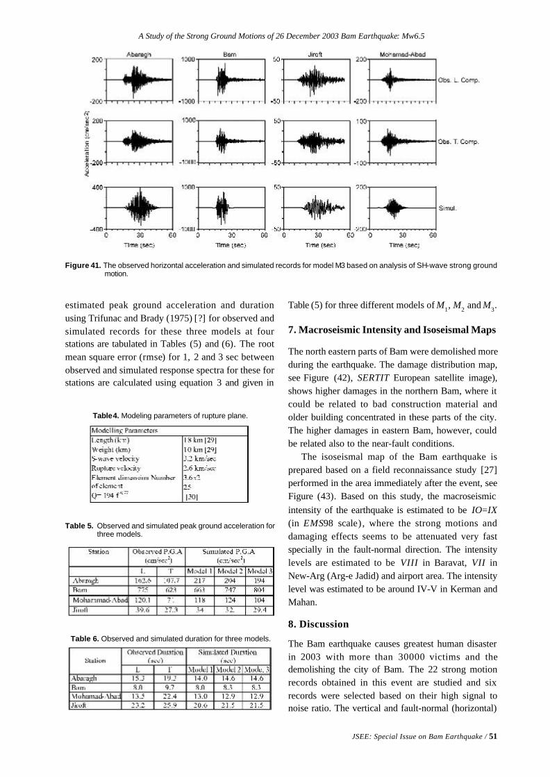
A Study of the Strong Ground Motions of 26 December 2003 Bam Earthquake: Mw6.5
JSEE: Special Issue on Bam Earthquake / 51
Figure 41. The observed horizontal acceleration and simulated records for model M3 based on analysis of SH-wave strong groundmotion.
Table4. Modeling parameters of rupture plane.
Table 5. Observed and simulated peak ground acceleration forthree models.
Table 6. Observed and simulated duration for three models.
estimated peak ground acceleration and durationusing Trifunac and Brady (1975) [?] for observed andsimulated records for these three models at fourstations are tabulated in Tables (5) and (6). The rootmean square error (rmse) for 1, 2 and 3 sec betweenobserved and simulated response spectra for these forstations are calculated using equation 3 and given in
Table (5) for three different models of M1, M2 and M3.
7. Macroseismic Intensity and Isoseismal Maps
The north eastern parts of Bam were demolished moreduring the earthquake. The damage distribution map,see Figure (42), SERTIT European satellite image),shows higher damages in the northern Bam, where itcould be related to bad construction material andolder building concentrated in these parts of the city.The higher damages in eastern Bam, however, couldbe related also to the near-fault conditions.
The isoseismal map of the Bam earthquake isprepared based on a field reconnaissance study [27]performed in the area immediately after the event, seeFigure (43). Based on this study, the macroseismicintensity of the earthquake is estimated to be IO=IX(in EMS98 scale) , where the strong motions anddamaging effects seems to be attenuated very fastspecially in the fault-normal direction. The intensitylevels are estimated to be VIII in Baravat, VII inNew-Arg (Arg-e Jadid) and airport area. The intensitylevel was estimated to be around IV-V in Kerman andMahan.
8. Discussion
The Bam earthquake causes greatest human disasterin 2003 with more than 30000 victims and thedemolishing the city of Bam. The 22 strong motionrecords obtained in this event are studied and sixrecords were selected based on their high signal tonoise ratio. The vertical and fault-normal (horizontal)
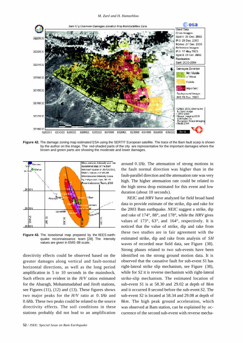
52 / JSEE: Special Issue on Bam Earthquake
M. Zaré and H. Hamzehloo
around 0.1Hz. The attenuation of strong motions inthe fault normal direction was higher than in thefault-parallel direction and the attenuation rate was veryhigh. The higher attenuation rate could be related tothe high stress drop estimated for this event and lowduration (about 10 seconds).
NEIC and HRV have analyzed far field broad banddata to provide estimate of the strike, dip and rake forthe 2003 Bam earthquake. NEIC suggest a strike, dipand rake of 174°, 88°, and 178°, while the HRV givesvalues of 173°, 63°, and 164°, respectively. It isnoticed that the value of strike, dip and rake fromthese two studies are in fair agreement with theestimated strike, dip and rake from analysis of SHwaves of recorded near field data, see Figure (38).Strong phases related to two sub-events have beenidentified on the strong ground motion data. It isobserved that the causative fault for sub-event S1 hasright-lateral strike slip mechanism, see Figure (38),while for S2 it is reverse mechanism with right-lateralstrike-slip mechanism. The estimated location ofsub-event S1 is at 58.30 and 29.02 at depth of 8kmand it occurred 8 second before the sub-event S2. Thesub-event S2 is located at 58.34 and 29.08 at depth of8km. The high peak ground acceleration, whichwas observed at Bam station, can be explained by oc-currence of the second sub-event with reverse mecha-
directivity effects could be observed based on thegreater damages along vertical and fault-normalhorizontal directions, as well as the long periodamplification in 5 to 10 seconds in the mainshock.Such effects are evident in the H/V ratios estimatedfor the Abaragh, Mohammadabad and Jiroft stations,see Figures (11), (12) and (13). These figures showstwo major peaks for the H/V ratio at 0.1Hz and0.6Hz. These two peaks could be related to the sourcedirectivity effects. The soil conditions in thesestations probably did not lead to an amplification
Figure 42. The damage zoning map estimated ESA using the SERTIT European satellite. The trace of the Bam fault scarp is shownby the author on the image. The red-shaded parts of the city are representative for the important damages where thebrown and green parts are showing the moderate and lower damages.
Figure 43. The isoseismal map prepared by the IIEES earth-quake reconnaissance team [28]. The intensityvalues are given in EMS-98 scale.
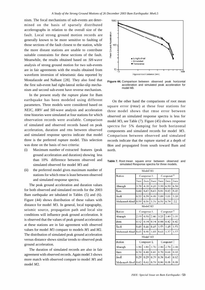
A Study of the Strong Ground Motions of 26 December 2003 Bam Earthquake: Mw6.5
JSEE: Special Issue on Bam Earthquake / 53
nism. The focal mechanisms of sub-events are deter-mined on the basis of sparsely distributedaccelerographs in relation to the overall size of thefault. Local strong ground motion records aregenerally known to be more sensitive to faulting ofthose sections of the fault closest to the station, whilethe more distant stations are unable to contributesuitable constraints for these sections of the fault.Meanwhile, the results obtained based on SH-waveanalysis of strong ground motion for two sub-eventsare in fair agreements with the results obtained fromwaveform inversion of teleseismic data reported byMostafazzde and Nalbant [28]. They also fond thatthe first sub-event had right-lateral strike-slip mecha-nism and second sub-event have reverse mechanism.
In the present study the rupture plane for Bamearthquake has been modeled using differentparameters. Three models were considered based onNEIC, HRV and SH-wave analysis and accelerationtime histories were simulated at four stations for whichobservation records were available. Comparisonof simulated and observed records based on peakacceleration, duration and rms between observedand simulated response spectra indicate that modelthree is the preferred rupture model. This selectionwas done on the basis of two criteria:(i) Maximum number of extracted features (peak
ground acceleration and duration) showing lessthan 10% difference between observed andsimulated observed for model M3 and
(ii) the preferred model gives maximum number ofstations for which rmse is least between observedand simulated response spectra.
The peak ground acceleration and duration valuesfor both observed and simulated records for the 2003Bam earthquake are tabulated in Tables (5) and (6).Figure (44) shows distribution of these values withdistance for model M3. In general, local topography,seismic source, propagation path and local siteconditions will influence peak ground acceleration. Itis observed that the values of peak ground accelerationat these stations are in fair agreement with observedvalues for model M3 compare to models M1 and M2.The distribution of simulated peak ground accelerationversus distance shows similar trends to observed peakground acceleration.
The duration of simulated records are also in fairagreement with observed records. Again model 3 showsmore match with observed compare to model M1 andmodel M2.
Figure 44. Comparison between observed peak horizontalacceleration and simulated peak acceleration formodel M3.
Table 7. Root mean square error between observed andsimulated Response spectra for three models.
On the other hand the comparisons of root meansquare error (rmse) at these four stations forthree model shows that rmse error betweenobserved an simulated response spectra is less formodel M3, see Table (7). Figure (45) shows responsespectra for 5% damping for both horizontalcomponents and simulated records for model M3.Comparison between observed and simulatedrecords indicate that the rupture started at a depth of8km and propagated from south toward Bam andnorth.
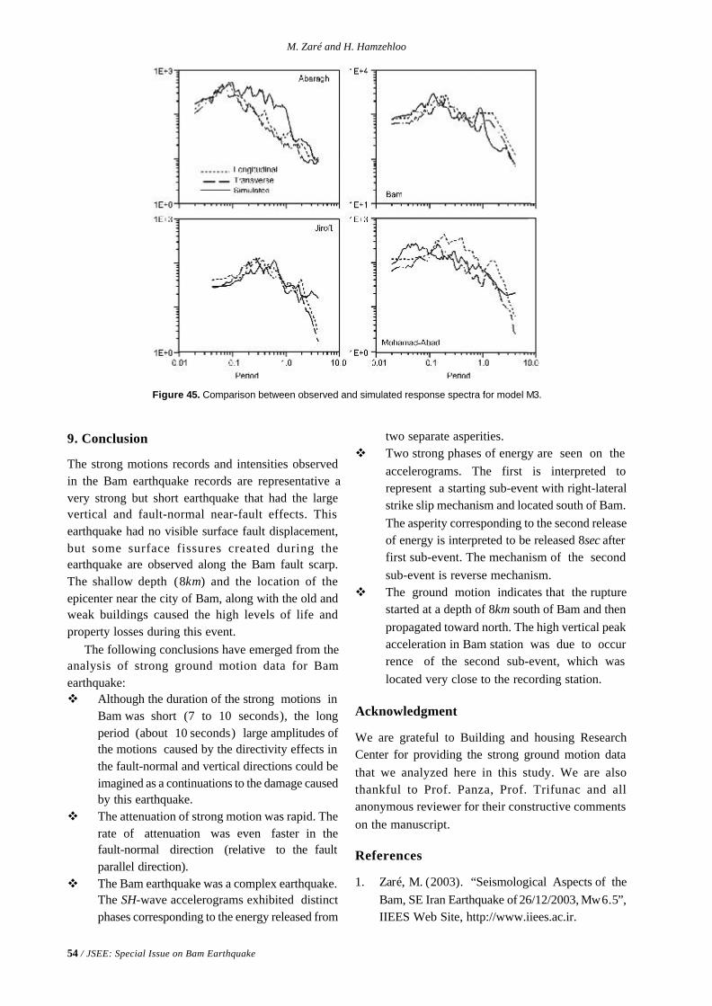
54 / JSEE: Special Issue on Bam Earthquake
M. Zaré and H. Hamzehloo
9. Conclusion
The strong motions records and intensities observedin the Bam earthquake records are representative avery strong but short earthquake that had the largevertical and fault-normal near-fault effects. Thisearthquake had no visible surface fault displacement,but some surface fissures created during theearthquake are observed along the Bam fault scarp.The shallow depth (8km) and the location of theepicenter near the city of Bam, along with the old andweak buildings caused the high levels of life andproperty losses during this event.
The following conclusions have emerged from theanalysis of strong ground motion data for Bamearthquake:v Although the duration of the strong motions in
Bam was short (7 to 10 seconds), the longperiod (about 10 seconds) large amplitudes ofthe motions caused by the directivity effects inthe fault-normal and vertical directions could beimagined as a continuations to the damage causedby this earthquake.
v The attenuation of strong motion was rapid. Therate of attenuation was even faster in thefault-normal direction (relative to the faultparallel direction).
v The Bam earthquake was a complex earthquake.The SH-wave accelerograms exhibited distinctphases corresponding to the energy released from
two separate asperities.v Two strong phases of energy are seen on the
accelerograms. The first is interpreted torepresent a starting sub-event with right-lateralstrike slip mechanism and located south of Bam.The asperity corresponding to the second releaseof energy is interpreted to be released 8sec afterfirst sub-event. The mechanism of the secondsub-event is reverse mechanism.
v The ground motion indicates that the rupturestarted at a depth of 8km south of Bam and thenpropagated toward north. The high vertical peakacceleration in Bam station was due to occurrence of the second sub-event, which waslocated very close to the recording station.
Acknowledgment
We are grateful to Building and housing ResearchCenter for providing the strong ground motion datathat we analyzed here in this study. We are alsothankful to Prof. Panza, Prof. Trifunac and allanonymous reviewer for their constructive commentson the manuscript.
References
1. Zaré, M. (2003). “Seismological Aspects of theBam, SE Iran Earthquake of 26/12/2003, Mw6.5”,IIEES Web Site, http://www.iiees.ac.ir.
Figure 45. Comparison between observed and simulated response spectra for model M3.
A Study of the Strong Ground Motions of 26 December 2003 Bam Earthquake: Mw6.5
JSEE: Special Issue on Bam Earthquake / 55
2. Ambraseys, N.N. and Melville, C.P. (1982). “AHistory of Persian Earthquakes”, Cambridge EarthSci. Ser.
3. National Earthquake Information Center (USGS),Web Site (2004). http:/neicr.usgs.gov.
4. United States Geological Survey, USGS, DigitalData Series DDS-62-C, 2001.
5. Harvard University, Seismology Department, WebSite (2004). http://www.seismology.harvard.edu,http://www.seismology.harvard.edu/
6. Haskell, N.A. (1964). “Total Energy and EnergySpectral Density of Elastic Wave Radiation fromPropagating Faults”, Bull. Seism. Soc. of America,54, 1811-1841.
7. Building and Housing Research Center (BHRC)(2004). http://www.bhrc.gov.ir/
8. Zaré, M., Bard,P-Y., Ghafory-Ashtiany, M. (1999).“Site Characterizations for the Iranian StrongMotion Network”, Journal of Soil Dynamics andEarthquake Engineering, 18(2), 101-121.
9. Arias, A. (1970). “A Measure of EarthquakeIntensity”, In Seismic Design of Nuclear PowerPlants, R.J. Hansen Editor, M.I.T. press.
10. Housner, G.W. (1959). “Behavior of StructuresDuring Earthquakes”, Journal of the EngineeringMechanics Division, ASCE, 85(EM14), 109-129.
11. Trifunac M.D. and Brady, A.G. (1975). “A Studyon the Duration of the Strong Earthquake GroundMotions”, Bull. Seismol. Soc. of America, 65(3),581-626.
12. Zaré, M. (1999). “Contribution à L'étude desMovements Forts en Iran: Du Catalogue Aux LoisD'atténuation”, Université Joseph Fourier, Thésede Doctorat (Ph.D. Thesis), 237p.
13. Bard, P.-Y., Zare, M. and Ghafory-Ashtiany, M.(1998). “The Iranian Accelerometric Data Bank,A Revision and Data Correction”, Journal ofSeismology and Earthquake Engineering, 1(1),1-22.
14. Campos, J., Madariaga, R., Nabelek, J., Bukchin,B.G., Deschamps, A. (1994). “Faulting Processof the 1990 June 20 Iran Earthquake from Broad-Band Records”, Geophys. J. Int., 118, 31-46.
15. Sarkar, I., Hamzehloo, H., and Khattri, K.N. (2003).
Estimation of Causative Fault Parameters of theRudbar Earthquake of June 20, 1990 from NearField SH-Wave Data”, Tectonophysics, 364,55-70.
16. Haskell, N.A. (1960). “Crustal Reflection of PlaneSH Waves”, J. Geophys. Res., 65, 4147-4150.
17. Aki, K. and Richards, P.G. (1980). “QuantitativeSeismology”, Theory and Methods, 1, Freemn,San Francisco, 558p.
18. Lay, T. and Wallace, C. (1995). “Modern GlobalSeismology”.
19. Somerville, P.G., Sen, M., and Cohee, B. (1991).“Simulation of Strong Ground Motion RecordedDuring the 1985 Michoacan, Mexico an Valparaiso,Chile Earthquakes”, Bull. Seismol. Soc. Am. , 81,1-27.
20. Brune, J.N. (1970). “Tectonic Stree and Spectraof Seismic Shear Waves from Earthquakes”, J.Geophys. Res., 75, 4997-5009.
21. Boore, D.M. (1983). “Stochastic Simulation ofHigh-Frequency Ground Motions Based onSeismological Models of the Radiated Spectra,Bull. Seismol. Soc. Am. , 73, 1865-1894.
22. Atkinson, G. and Boore, D.M. (1995). “Ground-Motion Relations for Eastern North America”, Bull.Seism. Soc. Am., 85, 17-30.
23. Atkinson, G. and Boore, D.M. (1998). “Evaluationof Models for Earthquake Source in Eastern NorthAmerica”, Bull. Seismol. Soc. Am. , 88, 917-934.
24. Atkinson, G., Silva, (1997). An Empirical Studyof Earthquake Source Spectra for CalifornianEarthquakes, Bull. Seismol. Soc. Am., 87, 97-113.
25. Safak, E. (1988). “Analytical Approach to Calulationof Response Spectra from Seismological Modelsof Ground Motion”, Earthquake EngineeringStruct. Dyn., 16, 121-134.
26. Irikura, K. (1986). “Prediction of Strong GroundAcceleration Motions Using Empirical Green’sFunction”, Proc. 7th Japan Earthquake Engineer-ing Symp., 151-157.
27. Eshghi, S., Zare, M., Naser-Asadi, K., Seyed-Razzaghi, M., Noorali-Ahari, M., and Motamedi,M. (2004). Reconnaissance Report on 26 Dec.2003 Bam Earthquake, International Institute of

56 / JSEE: Special Issue on Bam Earthquake
M. Zaré and H. Hamzehloo
Earthquake Engineering and Seismology (IIEES),Report in Persian.
28. Mostafazadeh, M. and Nalbant, S. (2004).“Waveform Inversion of 26 December 2003, BamEarthquake”, J. Seismol. Earthquake Engineering(Submitted).
29. Wells, D.L. and Coppersmith, K.J. (1994). “NewEmpirical Relationships Among Magnitude,
Rupture length, Rupture Width, Rupture Area, and
Surface Displacement, Bull. Seismol. Soc. Am. ,
84, 974-1002.
30. Farahbod, M. and Alahyarkhani, M. (2003).
“Attenuation and Propagation Characteristics of
Seismic Waves in Iran”, Proc. 4th Int. Conf. Earthq.
Engg., Tehran, I.R. Iran.
JSEE: Special Issue on Bam Earthquake / 57
Kambod Amini Hosseini, Mohammad Reza Mahdavifar, and Mohammad Keshavarz Bakhshaiesh
Geotechnical Engineering Research Center, International Institute of EarthquakeEngineering and Seismology (IIEES), Tehran, Iran, email: [email protected]
ABSTRACT: This paper describes the geotechnical instabilities suchas landslide, liquefaction, and ground subsidence caused by the Bamearthquake. Based on the results of geotechnical investigations, afterthe Bam earthquake, land subsidence due to collapse of Qanats(underground irrigation tunnels), local toppling, and block slidesalong riverbanks or man-made channels were the most dominantgeotechnical instabilities of the event. These effects will be introducedand discussed in this paper and the distribution of them will bepresented based on the study of aerial photos and site investigations.In addition, the geological setting of the area based on field investiga-tions and evaluation of some geophysical data will be discussed.
Keywords: Bam; Geological settings; Qanats; Landslide; Liquefaction;Sinkhole
Geotechnical Instabilities Occurred During the
Bam Earthquake of 26 December 2003
1. Introduction
Bam Earthquake, which occurred at 01:56:56 (GMT)on 26th December 2003, destroyed the city of Bam,Baravat, and some small villages at the area(southeast of Iran) and caused around 26,500 deathsand thousands of disappeared and injured. The Ms ofthis destructive event was equal to 6.5 (IIEES) andfocal depth evaluated to be about 8km. The correctedPGA values of this earthquake recorded at Bamstation are equal to 992, 775 and 623cm/sec2 forvertical, lateral and tangential components [3].
Besides the structural damages, Bam earthquakehas been accompanied with some geotechnicalinstabilities such as landslide, land subsidence andground fissures, however based on the surfaceevidences, no effects of liquefaction observed at thearea that can be related to the level of ground waterand type of the soil and its characteristics.
In the first part of this paper, a summary aboutthe geological and topographical conditions of theBam area will be presented and in the second part theinstabilities and geotechnical aspects of this event willbe discussed.
2. Geographical Situation
The city of Bam is located in the southeast of Iran at
175thkm of the main road of Kerman to Zahedan. Thearea of the city is about 5400 Hectares having a nearlyflat topography and smooth morphology. The altitudeof the city is approximately 1050 meters above sealevel in average. The main topographical features ofthe city are the volcanic hills located at the north andsouth west of Bam.
Climatologically, the area is located at an aridregion having dry weather. The total amount of annualrainfall is not considerable especially during the recentyears. There is one seasonal river passing through theBam city called Posht-e-Rood that is nearly dry mostof the year but water from some Qanats flow in thisriver. Due to small amount of rainfall and surfacewater, the main resource to supply water for drinkingand irrigation purposes is the underground water thatare extracted mainly by using deep wells and Qanats.In the recent years, due to heavy use of deep wells, theground water table is lower than 30 meters in mostparts of Bam and its vicinity.
3. Geological Setting
Figure (1) shows a schematic view of the 1:100,000geological map of the area prepared by Geological
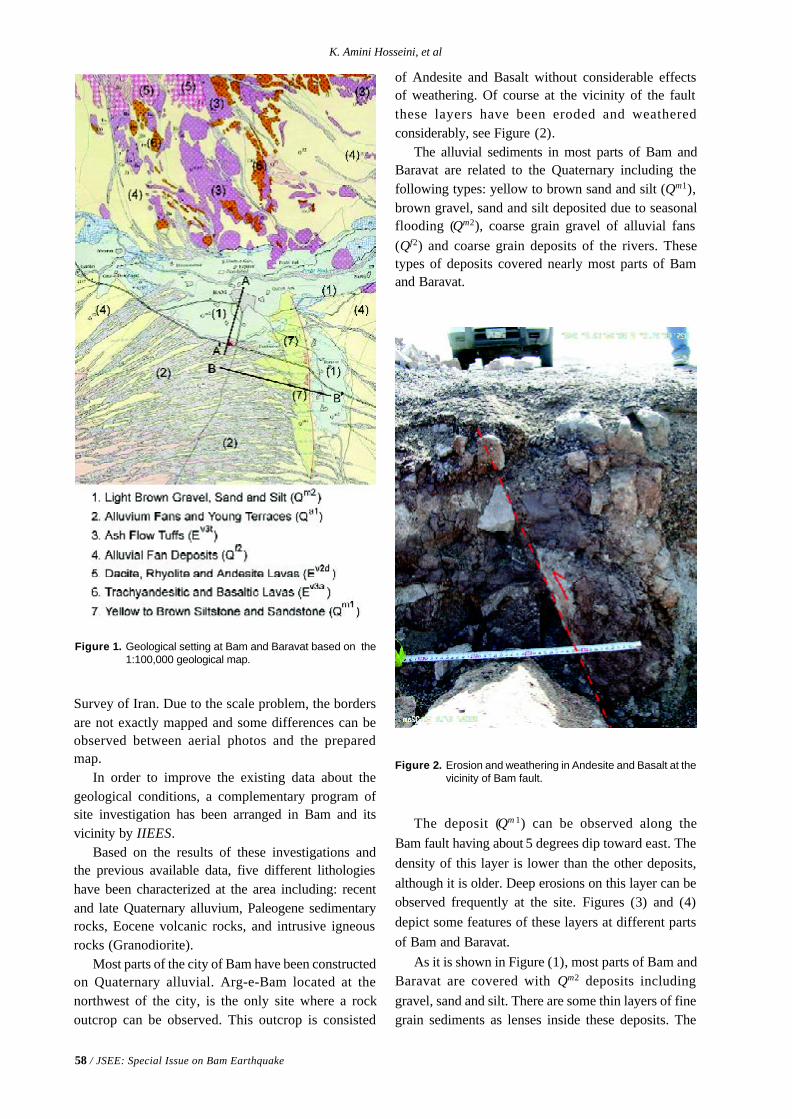
58 / JSEE: Special Issue on Bam Earthquake
K. Amini Hosseini, et al
Figure 1. Geological setting at Bam and Baravat based on the1:100,000 geological map.
Survey of Iran. Due to the scale problem, the bordersare not exactly mapped and some differences can beobserved between aerial photos and the preparedmap.
In order to improve the existing data about thegeological conditions, a complementary program ofsite investigation has been arranged in Bam and itsvicinity by IIEES.
Based on the results of these investigations andthe previous available data, five different lithologieshave been characterized at the area including: recentand late Quaternary alluvium, Paleogene sedimentaryrocks, Eocene volcanic rocks, and intrusive igneousrocks (Granodiorite).
Most parts of the city of Bam have been constructedon Quaternary alluvial. Arg-e-Bam located at thenorthwest of the city, is the only site where a rockoutcrop can be observed. This outcrop is consisted
Figure 2. Erosion and weathering in Andesite and Basalt at thevicinity of Bam fault.
of Andesite and Basalt without considerable effectsof weathering. Of course at the vicinity of the faultthese layers have been eroded and weatheredconsiderably, see Figure (2).
The alluvial sediments in most parts of Bam andBaravat are related to the Quaternary including thefollowing types: yellow to brown sand and silt (Qm1),brown gravel, sand and silt deposited due to seasonalflooding (Qm2), coarse grain gravel of alluvial fans(Qf2) and coarse grain deposits of the rivers. Thesetypes of deposits covered nearly most parts of Bamand Baravat.
The deposit (Qm 1) can be observed along theBam fault having about 5 degrees dip toward east. Thedensity of this layer is lower than the other deposits,although it is older. Deep erosions on this layer can beobserved frequently at the site. Figures (3) and (4)depict some features of these layers at different partsof Bam and Baravat.
As it is shown in Figure (1), most parts of Bam andBaravat are covered with Qm2 deposits includinggravel, sand and silt. There are some thin layers of finegrain sediments as lenses inside these deposits. The
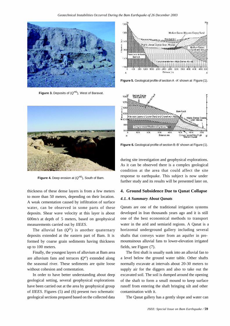
Geotechnical Instabilities Occurred During the Bam Earthquake of 26 December 2003
JSEE: Special Issue on Bam Earthquake / 59
Figure 3. Deposits of (Qm1), West of Baravat.
Figure 4. Deep erosion at (Qm1), South of Bam.
Figure 6. Geological profile of section B-B' shown at Figure (1).
Figure 5. Geological profile of section A -A' shown at Figure (1).
thickness of these dense layers is from a few metersto more than 50 meters, depending on their location.A weak cementation caused by infiltration of surfacewater, can be observed in some parts of thesedeposits. Shear wave velocity at this layer is about600m/s at depth of 5 meters, based on geophysicalmeasurements carried out by IIEES.
The alluvial fan (Q f2) is another quaternarydeposits extended at the eastern part of Bam. It isformed by coarse grain sediments having thicknessup to 100 meters.
Finally, the youngest layers of alluvium at Bam areaare alluvium fans and terraces (Qal) extended alongthe seasonal river. These sediments are quite loosewithout cohesion and cementation.
In order to have better understanding about deepgeological setting, several geophysical explorationshave been carried out at the area by geophysical groupof IIEES. Figures (5) and (6) present two schematicgeological sections prepared based on the collected data
during site investigation and geophysical explorations.As it can be observed there is a complex geologicalcondition at the area that could affect the siteresponse to earthquake. This subject is now underfurther study and its results will be presented later on.
4. Ground Subsidence Due to Qanat Collapse
4.1. A Summary About Qanats
Qanats are one of the traditional irrigation systemsdeveloped in Iran thousands years ago and it is stillone of the best economical methods to transportwater in the arid and semiarid regions. A Qanat is ahorizontal underground gallery including severalshafts that conveys water from an aquifer in pre-mountainous alluvial fans to lower-elevation irrigatedfields, see Figure (7).
The first shaft is usually sunk into an alluvial fan toa level below the ground water table. Other shaftsnormally excavate at intervals about 20-30 meters tosupply air for the diggers and also to take out theexcavated soil. The soil is dumped around the openingof the shaft to form a small mound to keep surfacerunoff from entering the shaft bringing silt and othercontamination with it.
The Qanat gallery has a gently slope and water can
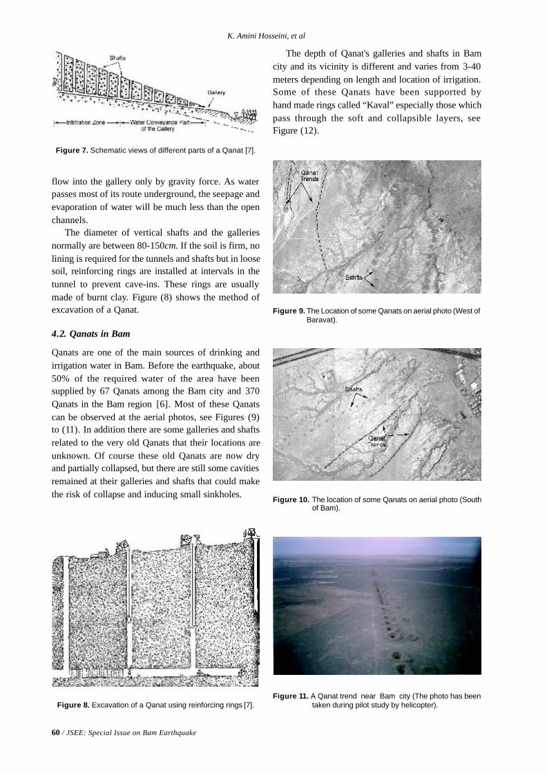
60 / JSEE: Special Issue on Bam Earthquake
K. Amini Hosseini, et al
Figure 7. Schematic views of different parts of a Qanat [7].
Figure 8. Excavation of a Qanat using reinforcing rings [7].
Figure 10. The location of some Qanats on aerial photo (Southof Bam).
Figure 11. A Qanat trend near Bam city (The photo has beentaken during pilot study by helicopter).
Figure 9. The Location of some Qanats on aerial photo (West ofBaravat).
flow into the gallery only by gravity force. As waterpasses most of its route underground, the seepage andevaporation of water will be much less than the openchannels.
The diameter of vertical shafts and the galleriesnormally are between 80-150cm. If the soil is firm, nolining is required for the tunnels and shafts but in loosesoil, reinforcing rings are installed at intervals in thetunnel to prevent cave-ins. These rings are usuallymade of burnt clay. Figure (8) shows the method ofexcavation of a Qanat.
4.2. Qanats in Bam
Qanats are one of the main sources of drinking andirrigation water in Bam. Before the earthquake, about50% of the required water of the area have beensupplied by 67 Qanats among the Bam city and 370Qanats in the Bam region [6]. Most of these Qanatscan be observed at the aerial photos, see Figures (9)to (11). In addition there are some galleries and shaftsrelated to the very old Qanats that their locations areunknown. Of course these old Qanats are now dryand partially collapsed, but there are still some cavitiesremained at their galleries and shafts that could makethe risk of collapse and inducing small sinkholes.
The depth of Qanat's galleries and shafts in Bamcity and its vicinity is different and varies from 3-40meters depending on length and location of irrigation.Some of these Qanats have been supported byhand made rings called “Kaval” especially those whichpass through the soft and collapsible layers, seeFigure (12).
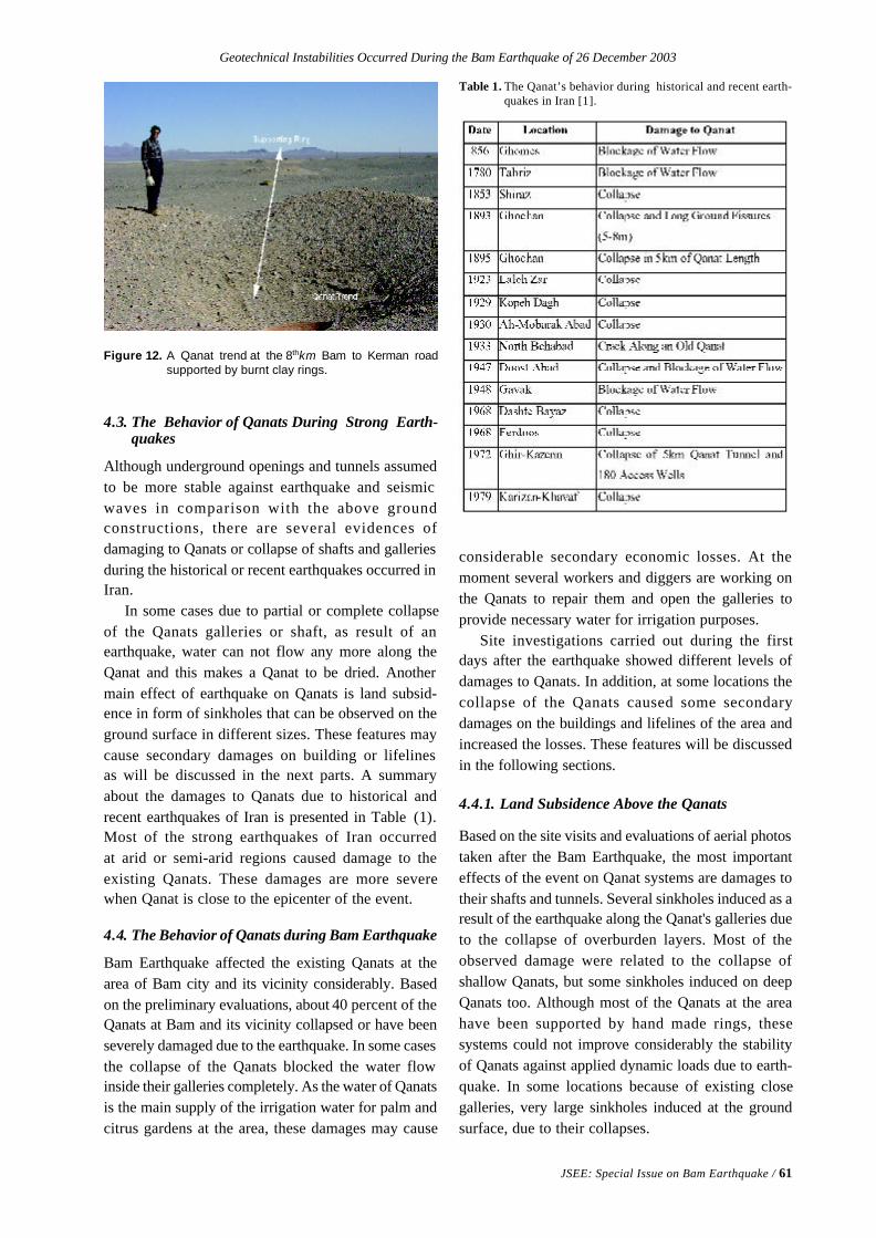
Geotechnical Instabilities Occurred During the Bam Earthquake of 26 December 2003
JSEE: Special Issue on Bam Earthquake / 61
Figure 12. A Qanat trend at the 8thkm Bam to Kerman roadsupported by burnt clay rings.
Table 1. The Qanat’s behavior during historical and recent earth-quakes in Iran [1].
considerable secondary economic losses. At themoment several workers and diggers are working onthe Qanats to repair them and open the galleries toprovide necessary water for irrigation purposes.
Site investigations carried out during the firstdays after the earthquake showed different levels ofdamages to Qanats. In addition, at some locations thecollapse of the Qanats caused some secondarydamages on the buildings and lifelines of the area andincreased the losses. These features will be discussedin the following sections.
4.4.1. Land Subsidence Above the Qanats
Based on the site visits and evaluations of aerial photostaken after the Bam Earthquake, the most importanteffects of the event on Qanat systems are damages totheir shafts and tunnels. Several sinkholes induced as aresult of the earthquake along the Qanat's galleries dueto the collapse of overburden layers. Most of theobserved damage were related to the collapse ofshallow Qanats, but some sinkholes induced on deepQanats too. Although most of the Qanats at the areahave been supported by hand made rings, thesesystems could not improve considerably the stabilityof Qanats against applied dynamic loads due to earth-quake. In some locations because of existing closegalleries, very large sinkholes induced at the groundsurface, due to their collapses.
4.3. The Behavior of Qanats During Strong Earth-quakes
Although underground openings and tunnels assumedto be more stable against earthquake and seismicwaves in comparison with the above groundconstructions, there are several evidences ofdamaging to Qanats or collapse of shafts and galleriesduring the historical or recent earthquakes occurred inIran.
In some cases due to partial or complete collapseof the Qanats galleries or shaft, as result of anearthquake, water can not flow any more along theQanat and this makes a Qanat to be dried. Anothermain effect of earthquake on Qanats is land subsid-ence in form of sinkholes that can be observed on theground surface in different sizes. These features maycause secondary damages on building or lifelinesas will be discussed in the next parts. A summaryabout the damages to Qanats due to historical andrecent earthquakes of Iran is presented in Table (1).Most of the strong earthquakes of Iran occurredat arid or semi-arid regions caused damage to theexisting Qanats. These damages are more severewhen Qanat is close to the epicenter of the event.
4.4. The Behavior of Qanats during Bam Earthquake
Bam Earthquake affected the existing Qanats at thearea of Bam city and its vicinity considerably. Basedon the preliminary evaluations, about 40 percent of theQanats at Bam and its vicinity collapsed or have beenseverely damaged due to the earthquake. In some casesthe collapse of the Qanats blocked the water flowinside their galleries completely. As the water of Qanatsis the main supply of the irrigation water for palm andcitrus gardens at the area, these damages may cause
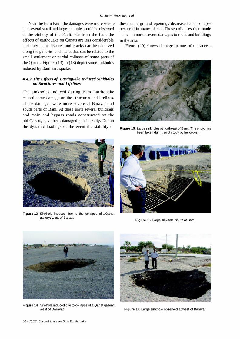
62 / JSEE: Special Issue on Bam Earthquake
K. Amini Hosseini, et al
Figure 14. Sinkhole induced due to collapse of a Qanat gallery;west of Baravat
Figure 15. Large sinkholes at northeast of Bam; (The photo hasbeen taken during pilot study by helicopter).
Figure 13. Sinkhole induced due to the collapse of a Qanatgallery; west of Baravat
Figure 16. Large sinkhole; south of Bam.
Figure 17. Large sinkhole observed at west of Baravat.
Near the Bam Fault the damages were more severeand several small and large sinkholes could be observedat the vicinity of the Fault. Far from the fault theeffects of earthquake on Qanats are less considerableand only some fissures and cracks can be observedalong the galleries and shafts that can be related to thesmall settlement or partial collapse of some parts ofthe Qanats. Figures (13) to (18) depict some sinkholesinduced by Bam earthquake.
4.4.2.The Effects of Earthquake Induced Sinkholeson Structures and Lifelines
The sinkholes induced during Bam Earthquakecaused some damage on the structures and lifelines.These damages were more severe at Baravat andsouth parts of Bam. At these parts several buildingsand main and bypass roads constructed on theold Qanats, have been damaged considerably. Due tothe dynamic loadings of the event the stability of
these underground openings decreased and collapseoccurred in many places. These collapses then madesome minor to severe damages to roads and buildingsin the area.
Figure (19) shows damage to one of the access
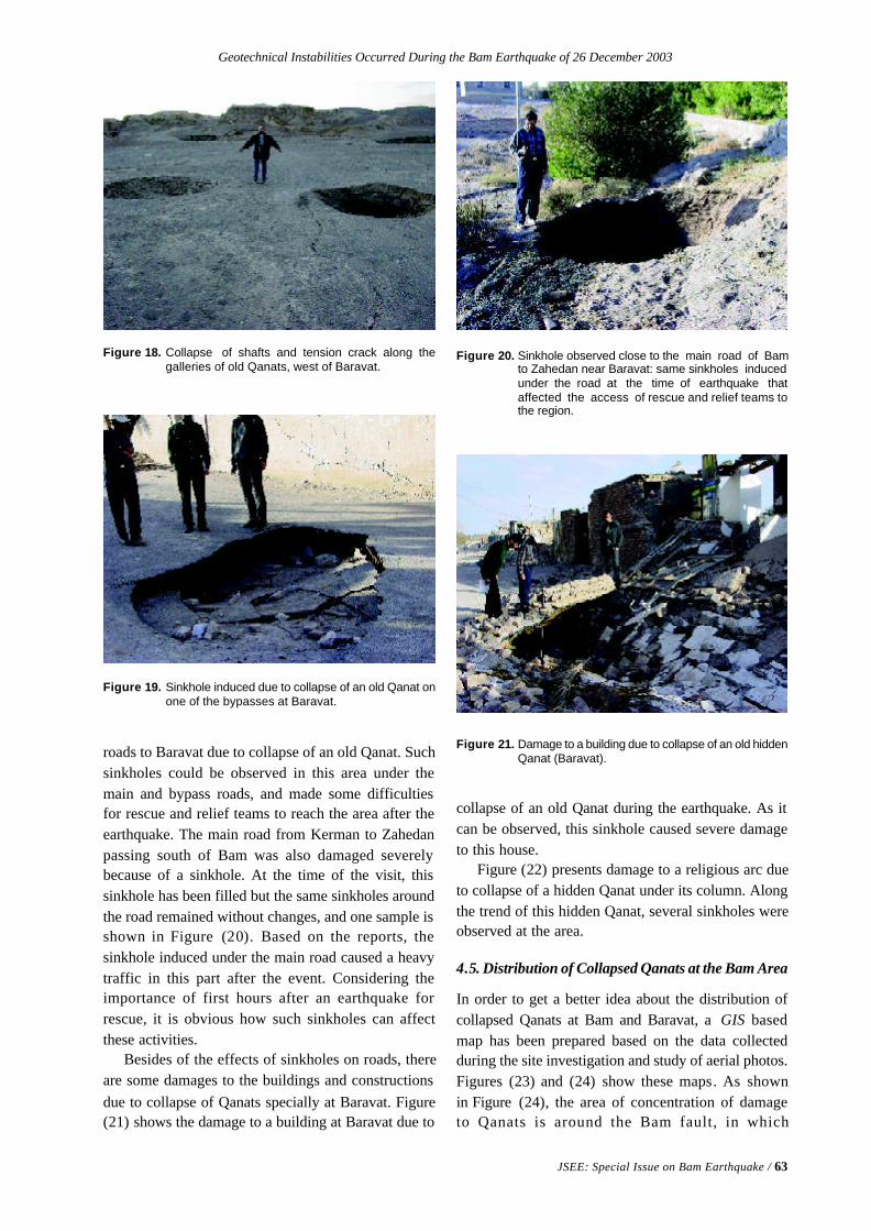
Geotechnical Instabilities Occurred During the Bam Earthquake of 26 December 2003
JSEE: Special Issue on Bam Earthquake / 63
Figure 18. Collapse of shafts and tension crack along thegalleries of old Qanats, west of Baravat.
roads to Baravat due to collapse of an old Qanat. Suchsinkholes could be observed in this area under themain and bypass roads, and made some difficultiesfor rescue and relief teams to reach the area after theearthquake. The main road from Kerman to Zahedanpassing south of Bam was also damaged severelybecause of a sinkhole. At the time of the visit, thissinkhole has been filled but the same sinkholes aroundthe road remained without changes, and one sample isshown in Figure (20). Based on the reports, thesinkhole induced under the main road caused a heavytraffic in this part after the event. Considering theimportance of first hours after an earthquake forrescue, it is obvious how such sinkholes can affectthese activities.
Besides of the effects of sinkholes on roads, thereare some damages to the buildings and constructionsdue to collapse of Qanats specially at Baravat. Figure(21) shows the damage to a building at Baravat due to
Figure 19. Sinkhole induced due to collapse of an old Qanat onone of the bypasses at Baravat.
Figure 20. Sinkhole observed close to the main road of Bamto Zahedan near Baravat: same sinkholes inducedunder the road at the time of earthquake thataffected the access of rescue and relief teams tothe region.
Figure 21. Damage to a building due to collapse of an old hiddenQanat (Baravat).
collapse of an old Qanat during the earthquake. As itcan be observed, this sinkhole caused severe damageto this house.
Figure (22) presents damage to a religious arc dueto collapse of a hidden Qanat under its column. Alongthe trend of this hidden Qanat, several sinkholes wereobserved at the area.
4.5. Distribution of Collapsed Qanats at the Bam Area
In order to get a better idea about the distribution ofcollapsed Qanats at Bam and Baravat, a GIS basedmap has been prepared based on the data collectedduring the site investigation and study of aerial photos.Figures (23) and (24) show these maps. As shownin Figure (24), the area of concentration of damageto Qanats is around the Bam fault, in which
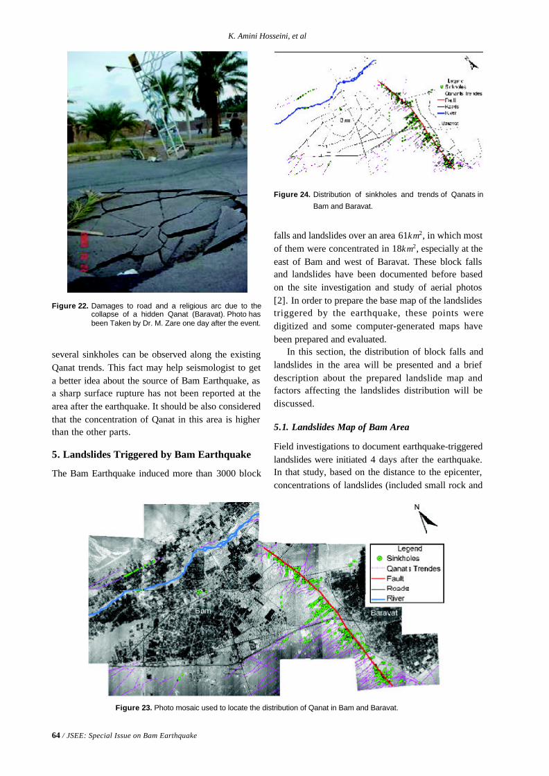
64 / JSEE: Special Issue on Bam Earthquake
K. Amini Hosseini, et al
Figure 22. Damages to road and a religious arc due to thecollapse of a hidden Qanat (Baravat). Photo hasbeen Taken by Dr. M. Zare one day after the event.
Figure 23. Photo mosaic used to locate the distribution of Qanat in Bam and Baravat.
Figure 24. Distribution of sinkholes and trends of Qanats in
Bam and Baravat.
several sinkholes can be observed along the existingQanat trends. This fact may help seismologist to geta better idea about the source of Bam Earthquake, asa sharp surface rupture has not been reported at thearea after the earthquake. It should be also consideredthat the concentration of Qanat in this area is higherthan the other parts.
5. Landslides Triggered by Bam Earthquake
The Bam Earthquake induced more than 3000 block
falls and landslides over an area 61km2, in which mostof them were concentrated in 18km2, especially at theeast of Bam and west of Baravat. These block fallsand landslides have been documented before basedon the site investigation and study of aerial photos[2]. In order to prepare the base map of the landslidestriggered by the earthquake, these points weredigitized and some computer-generated maps havebeen prepared and evaluated.
In this section, the distribution of block falls andlandslides in the area will be presented and a briefdescription about the prepared landslide map andfactors affecting the landslides distribution will bediscussed.
5.1. Landslides Map of Bam Area
Field investigations to document earthquake-triggeredlandslides were initiated 4 days after the earthquake.In that study, based on the distance to the epicenter,concentrations of landslides (included small rock and
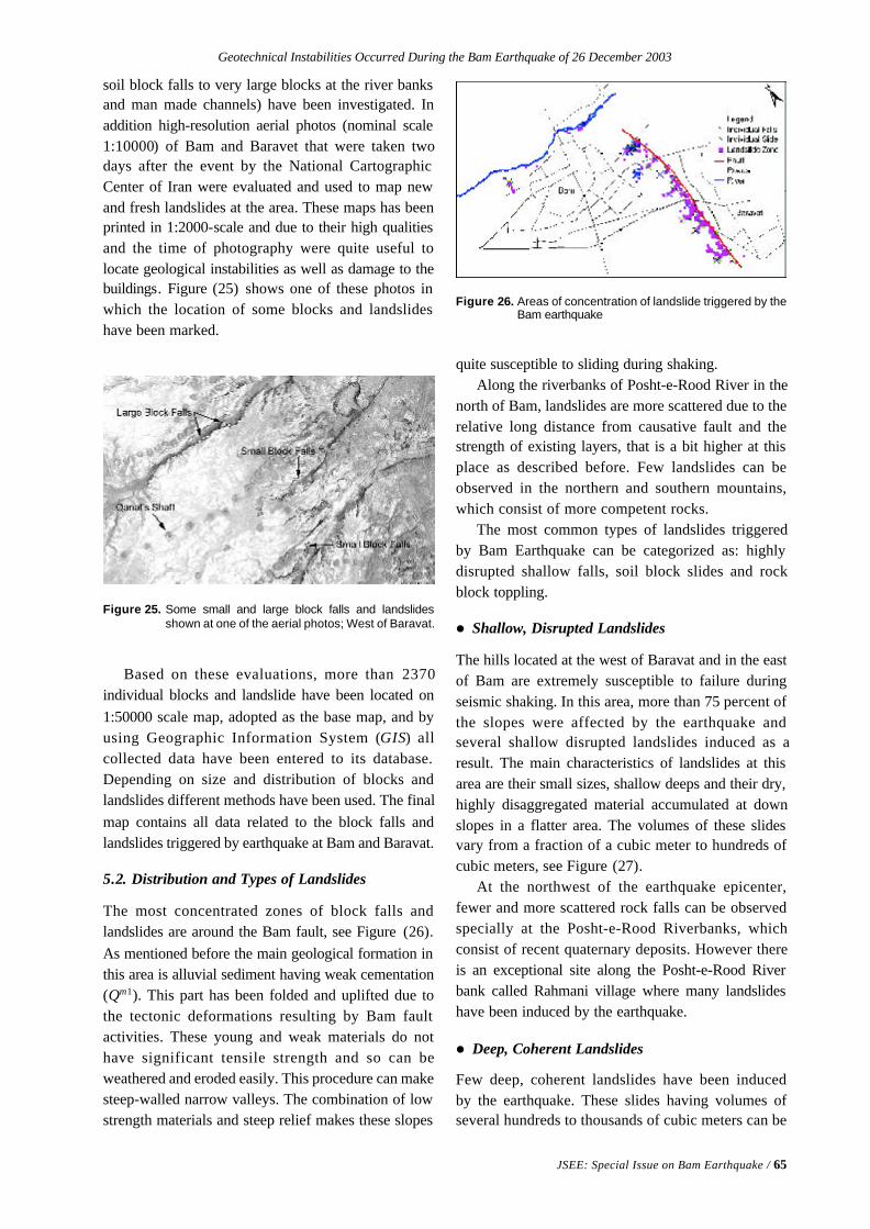
Geotechnical Instabilities Occurred During the Bam Earthquake of 26 December 2003
JSEE: Special Issue on Bam Earthquake / 65
Figure 25. Some small and large block falls and landslidesshown at one of the aerial photos; West of Baravat.
Figure 26. Areas of concentration of landslide triggered by theBam earthquake
soil block falls to very large blocks at the river banksand man made channels) have been investigated. Inaddition high-resolution aerial photos (nominal scale1:10000) of Bam and Baravet that were taken twodays after the event by the National CartographicCenter of Iran were evaluated and used to map newand fresh landslides at the area. These maps has beenprinted in 1:2000-scale and due to their high qualitiesand the time of photography were quite useful tolocate geological instabilities as well as damage to thebuildings. Figure (25) shows one of these photos inwhich the location of some blocks and landslideshave been marked.
Based on these evaluations, more than 2370individual blocks and landslide have been located on1:50000 scale map, adopted as the base map, and byusing Geographic Information System (GIS) allcollected data have been entered to its database.Depending on size and distribution of blocks andlandslides different methods have been used. The finalmap contains all data related to the block falls andlandslides triggered by earthquake at Bam and Baravat.
5.2. Distribution and Types of Landslides
The most concentrated zones of block falls andlandslides are around the Bam fault, see Figure (26).As mentioned before the main geological formation inthis area is alluvial sediment having weak cementation(Qm1). This part has been folded and uplifted due tothe tectonic deformations resulting by Bam faultactivities. These young and weak materials do nothave significant tensile strength and so can beweathered and eroded easily. This procedure can makesteep-walled narrow valleys. The combination of lowstrength materials and steep relief makes these slopes
quite susceptible to sliding during shaking.Along the riverbanks of Posht-e-Rood River in the
north of Bam, landslides are more scattered due to therelative long distance from causative fault and thestrength of existing layers, that is a bit higher at thisplace as described before. Few landslides can beobserved in the northern and southern mountains,which consist of more competent rocks.
The most common types of landslides triggeredby Bam Earthquake can be categorized as: highlydisrupted shallow falls, soil block slides and rockblock toppling.
l Shallow, Disrupted Landslides
The hills located at the west of Baravat and in the eastof Bam are extremely susceptible to failure duringseismic shaking. In this area, more than 75 percent ofthe slopes were affected by the earthquake andseveral shallow disrupted landslides induced as aresult. The main characteristics of landslides at thisarea are their small sizes, shallow deeps and their dry,highly disaggregated material accumulated at downslopes in a flatter area. The volumes of these slidesvary from a fraction of a cubic meter to hundreds ofcubic meters, see Figure (27).
At the northwest of the earthquake epicenter,fewer and more scattered rock falls can be observedspecially at the Posht-e-Rood Riverbanks, whichconsist of recent quaternary deposits. However thereis an exceptional site along the Posht-e-Rood Riverbank called Rahmani village where many landslideshave been induced by the earthquake.
l Deep, Coherent Landslides
Few deep, coherent landslides have been inducedby the earthquake. These slides having volumes ofseveral hundreds to thousands of cubic meters can be
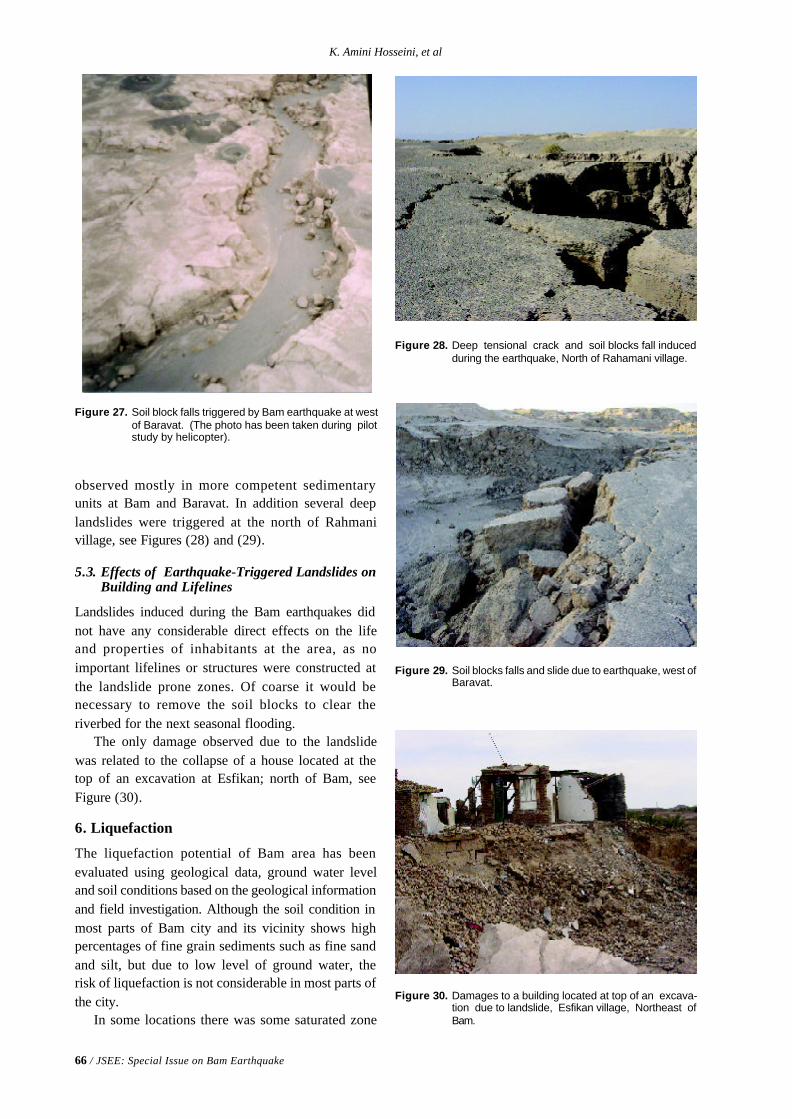
66 / JSEE: Special Issue on Bam Earthquake
K. Amini Hosseini, et al
Figure 27. Soil block falls triggered by Bam earthquake at westof Baravat. (The photo has been taken during pilotstudy by helicopter).
Figure 29. Soil blocks falls and slide due to earthquake, west ofBaravat.
Figure 28. Deep tensional crack and soil blocks fall inducedduring the earthquake, North of Rahamani village.
Figure 30. Damages to a building located at top of an excava-tion due to landslide, Esfikan village, Northeast ofBam.
observed mostly in more competent sedimentaryunits at Bam and Baravat. In addition several deeplandslides were triggered at the north of Rahmanivillage, see Figures (28) and (29).
5.3. Effects of Earthquake-Triggered Landslides onBuilding and Lifelines
Landslides induced during the Bam earthquakes didnot have any considerable direct effects on the lifeand properties of inhabitants at the area, as noimportant lifelines or structures were constructed atthe landslide prone zones. Of coarse it would benecessary to remove the soil blocks to clear theriverbed for the next seasonal flooding.
The only damage observed due to the landslidewas related to the collapse of a house located at thetop of an excavation at Esfikan; north of Bam, seeFigure (30).
6. Liquefaction
The liquefaction potential of Bam area has beenevaluated using geological data, ground water leveland soil conditions based on the geological informationand field investigation. Although the soil condition inmost parts of Bam city and its vicinity shows highpercentages of fine grain sediments such as fine sandand silt, but due to low level of ground water, therisk of liquefaction is not considerable in most parts ofthe city.
In some locations there was some saturated zone
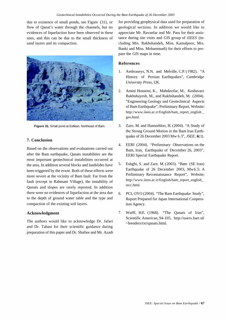
Geotechnical Instabilities Occurred During the Bam Earthquake of 26 December 2003
JSEE: Special Issue on Bam Earthquake / 67
Figure 31. Small pond at Esfikan, Northeast of Bam.
due to existence of small ponds, see Figure (31), orflow of Qanat’s water through the channels, but noevidences of liquefaction have been observed in thesesites, and this can be due to the small thickness ofsand layers and its compaction.
7. Conclusion
Based on the observations and evaluations carried outafter the Bam earthquake, Qanats instabilities are themost important geotechnical instabilities occurred atthe area. In addition several blocks and landslides havebeen triggered by the event. Both of these effects weremore severe at the vicinity of Bam fault. Far from thefault (except in Rahmani Village), the instability ofQanats and slopes are rarely reported. In additionthere were no evidences of liquefaction at the area dueto the depth of ground water table and the type andcompaction of the existing soil layers.
Acknowledgment
The authors would like to acknowledge Dr. Jafariand Dr. Tabasi for their scientific guidance duringpreparation of this paper and Dr. Shafiee and Mr. Azadi
for providing geophysical data used for preparation ofgeological sections. In addition we would like toappreciate Mr. Ravanfar and Mr. Pass for their assis-tance during site visits and GIS group of IIEES (in-cluding Mrs. Rakhshandeh, Miss. Kamalpoor, Mrs.Banki and Miss. Mohammadi) for their efforts to pre-pare the GIS maps in time.
References
1. Ambraseys, N.N. and Melville, C.P. (1982). “AHistory of Persian Earthquakes”, CambridgeUniversity Press, UK.
2. Amini Hosseini, K., Mahdavifar, M., KeshavarzBakhshayesh, M., and Rakhshandeh, M. (2004).“Engineering Geology and Geotechnical Aspectsof Bam Earthquake”, Preliminary Report, Website:http://www.iiees.ac.ir/English/bam_report_english _geo.html.
3. Zare, M. and Hamzehloo, H. (2004). “A Study ofthe Strong Ground Motion in the Bam Iran Earth-quake of 26 December 2003 Mw 6.5”, JSEE, 6(1).
4. EERI (2004). “Preliminary Observations on theBam, Iran, Earthquake of December 26, 2003”,EERI Special Earthquake Report.
5. Eshghi, S. and Zare, M. (2003). “Bam (SE Iran)Earthquake of 26 December 2003, Mw6.5: APreliminary Reconnaissance Report”, Website:http://www.iiees.ac.ir/English/bam_report_english_recc.html.
6. PCI, OYO (2004). “The Bam Earthquake Study”,Report Prepared for Japan International Coopera-tion Agency.
7. Wulff, H.E. (1968). “The Qanats of Iran”,Scientific American, 94-105, http://users.bart.nl/~leenders/txt/qanats.html.
JSEE: Special Issue on Bam Earthquake / 69
1. Geotechnical Engineering Research Center, International Institute of Earthquake
Engineering and Seismology (IIEES), Tehran, Iran, [email protected]. Seismology Research Center, International Institute of Earthquake Engineering
and Seismology (IIEES), Tehran, Iran
ABSTRACT: After the devastating earthquake of 26 December 2003in Bam, a discipline was followed to prepare a preliminary site effectmicrozonation map for the city. Seismic hazard studies for two returnperiods, geological studies accompanied by geophysical surveys andaftershock and microtremor measurements were carried out to providesite classification and PGA distribution maps. The results of this studyshow that reasonable agreements exist between the 2475 years PGAdistribution map and the damage distribution map for the recentearthquake. The 475 years PGA microzonation maps could also beused as a preliminary useful hint in reconstruction and urban planningof the totally destroyed city.
Keywords: Bam; Seismic microzonation; Site effect; Microtremor;Shear wave velocity; Peak ground acceleration; Urban planning
Preliminary Seismic Microzonation of Bam
F. Askari 1, A. Azadi 1, M. Davoodi 1, M.R. Ghayamghamian 1, E. Haghshenas 1,H. Hamzehloo 2, M.K. Jafari 1, M. Kamalian 1, M. Keshavarz 1, O. Ravanfar 1,
A. Shafiee 1, and A. Sohrabi-Bidar 1
1. Introduction
Nowadays it is well established that ground motionsare strongly influenced by source, path and local siteeffects. The city of Bam in the south-eastern part ofIran was hit by an earthquake of Ms 6.5 at a localtime of 5:26 am on 26 December 2003. Among manyresearch groups of different disciplines, the authorscarried out their investigation on evaluation of siteeffects on ground motion in Bam city. The main aim ofthis investigation was to prepare preliminary seismicmicrozonation maps for the Bam city.
It is well known that the capability of localgeologic deposits to amplify strong ground shakingdepends on the physical properties of the materialsas well as their three-dimensional geometricaldistribution. Due to the dominant construction ofadobe and low rise buildings in Bam, valuable dataon geotechnical properties and three-dimensionaldistribution of materials were not available throughoutthe city in sufficient detail. Consequently themicrozonation maps were developed using thedistribution of geologic materials as mapped at theground surface, geophysical surveying, microtremor
and aftershock measurements. The methodology ofthe site effect assessment throughout the studyarea adopted in this study, consisted of the followingsteps:1. Preparing the seismic hazard maps of the study
area for two return periods of 475 and 2475 years;2. Revising the existent geological map, utilizing
field observations and aerial photo studies;3. Defining the representative geophysical groups,
based on the geological map and the geophysicalinvestigations. Non-linear amplification capabil-ity of the representative sites were estimatedusing the latest empirical correlations betweenthe site type and the relative amplification factor;
4. Estimation of the natural frequencies throughoutthe study area based on the microtremor andaftershocks measurements;
5. Preparing the site classification map, based onthe geological map, the representative geophysi-cal groups and the estimated natural frequencies;
6. Preparing the peak ground acceleration (PGA)distribution maps of the study area, by
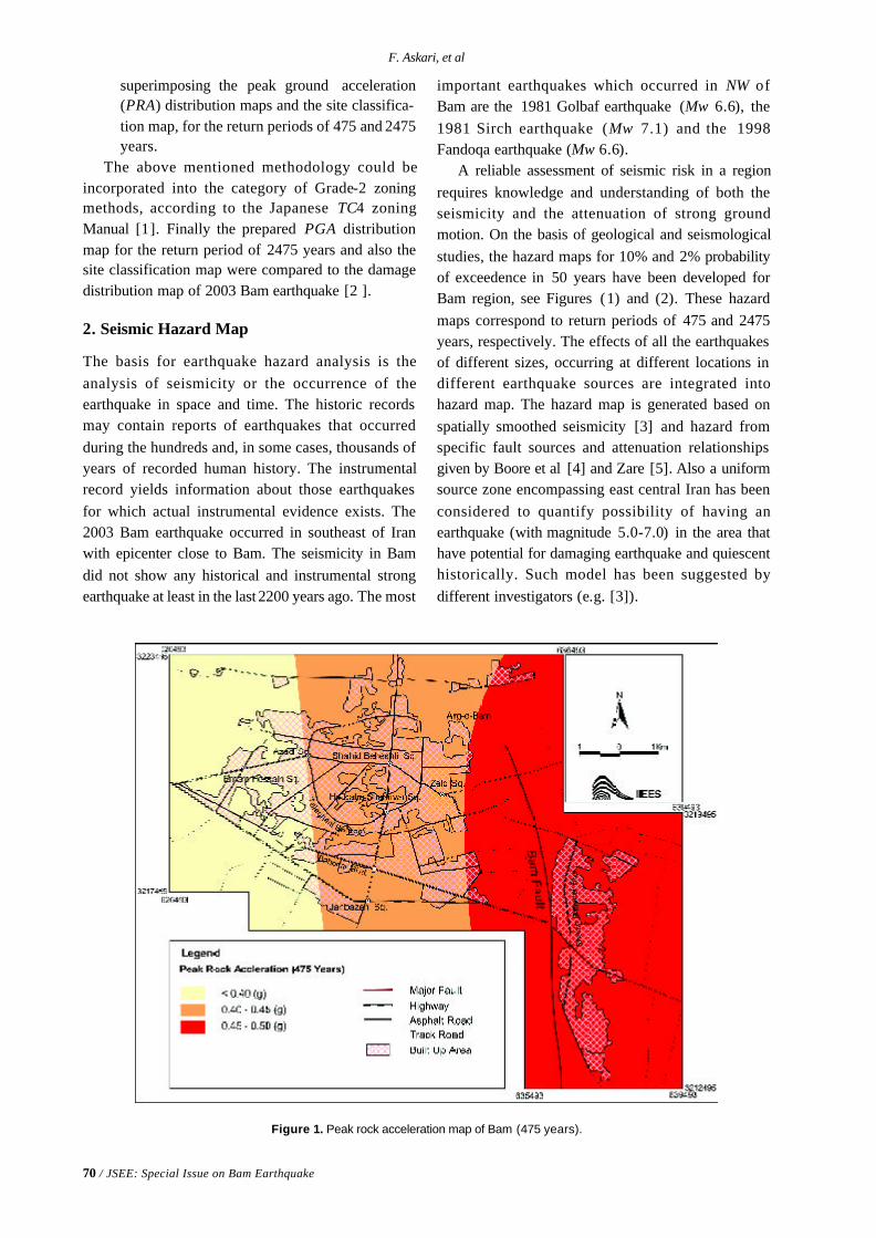
70 / JSEE: Special Issue on Bam Earthquake
F. Askari, et al
superimposing the peak ground acceleration(PRA) distribution maps and the site classifica-tion map, for the return periods of 475 and 2475years.
The above mentioned methodology could beincorporated into the category of Grade-2 zoningmethods, according to the Japanese TC4 zoningManual [1]. Finally the prepared PGA distributionmap for the return period of 2475 years and also thesite classification map were compared to the damagedistribution map of 2003 Bam earthquake [2 ].
2. Seismic Hazard Map
The basis for earthquake hazard analysis is theanalysis of seismicity or the occurrence of theearthquake in space and time. The historic recordsmay contain reports of earthquakes that occurredduring the hundreds and, in some cases, thousands ofyears of recorded human history. The instrumentalrecord yields information about those earthquakesfor which actual instrumental evidence exists. The2003 Bam earthquake occurred in southeast of Iranwith epicenter close to Bam. The seismicity in Bamdid not show any historical and instrumental strongearthquake at least in the last 2200 years ago. The most
important earthquakes which occurred in NW ofBam are the 1981 Golbaf earthquake (Mw 6.6), the1981 Sirch earthquake (Mw 7.1) and the 1998Fandoqa earthquake (Mw 6.6).
A reliable assessment of seismic risk in a regionrequires knowledge and understanding of both theseismicity and the attenuation of strong groundmotion. On the basis of geological and seismologicalstudies, the hazard maps for 10% and 2% probabilityof exceedence in 50 years have been developed forBam region, see Figures (1) and (2). These hazardmaps correspond to return periods of 475 and 2475years, respectively. The effects of all the earthquakesof different sizes, occurring at different locations indifferent earthquake sources are integrated intohazard map. The hazard map is generated based onspatially smoothed seismicity [3] and hazard fromspecific fault sources and attenuation relationshipsgiven by Boore et al [4] and Zare [5]. Also a uniformsource zone encompassing east central Iran has beenconsidered to quantify possibility of having anearthquake (with magnitude 5.0-7.0) in the area thathave potential for damaging earthquake and quiescenthistorically. Such model has been suggested bydifferent investigators (e.g. [3]).
Figure 1. Peak rock acceleration map of Bam (475 years).
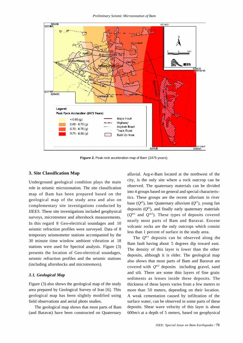
Preliminary Seismic Microzonation of Bam
JSEE: Special Issue on Bam Earthquake / 71
Figure 2. Peak rock acceleration map of Bam (2475 years).
3. Site Classification Map
Underground geological condition plays the mainrole in seismic microzonation. The site classificationmap of Bam has been prepared based on thegeological map of the study area and also oncomplementary site investigations conducted byIIEES. These site investigations included geophysicalsurveys, microtremor and aftershock measurements.In this regard 8 Geo-electrical soundages and 10seismic refraction profiles were surveyed. Data of 8temporary seismometer stations accompanied by the30 minute time window ambient vibration at 18stations were used for Spectral analysis. Figure (3)presents the location of Geo-electrical soundages,seismic refraction profiles and the seismic stations(including aftershocks and microtremors).
3.1. Geological Map
Figure (3) also shows the geological map of the studyarea prepared by Geological Survey of Iran [6]. Thisgeological map has been slightly modified usingfield observations and aerial photo studies.
The geological map shows that most parts of Bam(and Baravat) have been constructed on Quaternary
alluvial. Arg-e-Bam located at the northwest of thecity, is the only site where a rock outcrop can beobserved. The quaternary materials can be dividedinto 4 groups based on general and special characteris-tics. These groups are the recent alluvium in riverbase (Qal), late Quaternary alluvium (Qt2), young fandeposits (Qf2), and finally early quaternary materials(Qm1 and Qm2). These types of deposits coverednearly most parts of Bam and Baravat. Eocenevolcanic rocks are the only outcrops which consistless than 1 percent of surface in the study area.
The Qm1 deposits can be observed along theBam fault having about 5 degrees dip toward east.The density of this layer is lower than the otherdeposits, although it is older. The geological mapalso shows that most parts of Bam and Baravat arecovered with Qm2 deposits including gravel, sandand silt. There are some thin layers of fine grainsediments as lenses inside these deposits. Thethickness of these layers varies from a few meters tomore than 50 meters, depending on their location.A weak cementation caused by infiltration of thesurface water, can be observed in some parts of thesedeposits. Shear wave velocity of this layer is about600m/s at a depth of 5 meters, based on geophysical
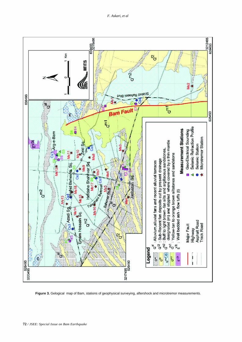
72 / JSEE: Special Issue on Bam Earthquake
F. Askari, et al
Figure 3. Gelogical map of Bam, stations of geophysical surveying, aftershock and microtremor measurements.
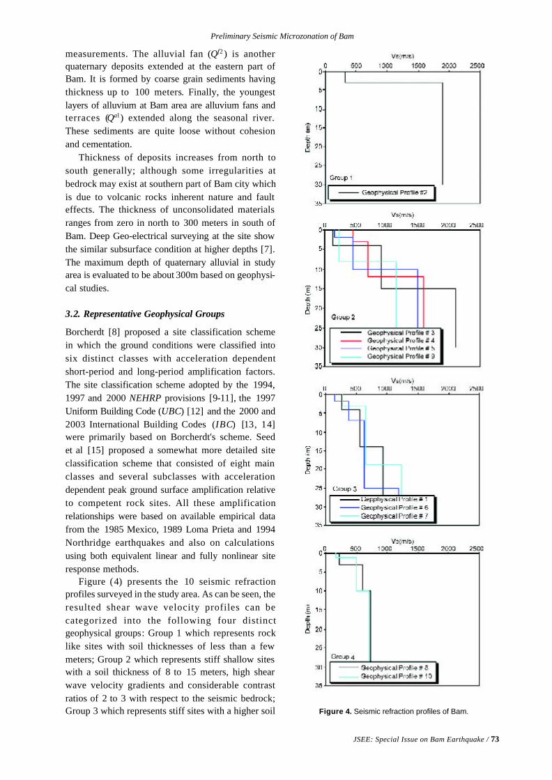
Preliminary Seismic Microzonation of Bam
JSEE: Special Issue on Bam Earthquake / 73
measurements. The alluvial fan (Qf2 ) is anotherquaternary deposits extended at the eastern part ofBam. It is formed by coarse grain sediments havingthickness up to 100 meters. Finally, the youngestlayers of alluvium at Bam area are alluvium fans andterraces (Qal ) extended along the seasonal river.These sediments are quite loose without cohesionand cementation.
Thickness of deposits increases from north tosouth generally; although some irregularities atbedrock may exist at southern part of Bam city whichis due to volcanic rocks inherent nature and faulteffects. The thickness of unconsolidated materialsranges from zero in north to 300 meters in south ofBam. Deep Geo-electrical surveying at the site showthe similar subsurface condition at higher depths [7].The maximum depth of quaternary alluvial in studyarea is evaluated to be about 300m based on geophysi-cal studies.
3.2. Representative Geophysical Groups
Borcherdt [8] proposed a site classification schemein which the ground conditions were classified intosix distinct classes with acceleration dependentshort-period and long-period amplification factors.The site classification scheme adopted by the 1994,1997 and 2000 NEHRP provisions [9-11], the 1997Uniform Building Code (UBC) [12] and the 2000 and2003 International Building Codes (IBC) [13, 14]were primarily based on Borcherdt's scheme. Seedet al [15] proposed a somewhat more detailed siteclassification scheme that consisted of eight mainclasses and several subclasses with accelerationdependent peak ground surface amplification relativeto competent rock sites. All these amplificationrelationships were based on available empirical datafrom the 1985 Mexico, 1989 Loma Prieta and 1994Northridge earthquakes and also on calculationsusing both equivalent linear and fully nonlinear siteresponse methods.
Figure (4) presents the 10 seismic refractionprofiles surveyed in the study area. As can be seen, theresulted shear wave velocity profiles can becategorized into the following four distinctgeophysical groups: Group 1 which represents rocklike sites with soil thicknesses of less than a fewmeters; Group 2 which represents stiff shallow siteswith a soil thickness of 8 to 15 meters, high shearwave velocity gradients and considerable contrastratios of 2 to 3 with respect to the seismic bedrock;Group 3 which represents stiff sites with a higher soil Figure 4. Seismic refraction profiles of Bam.
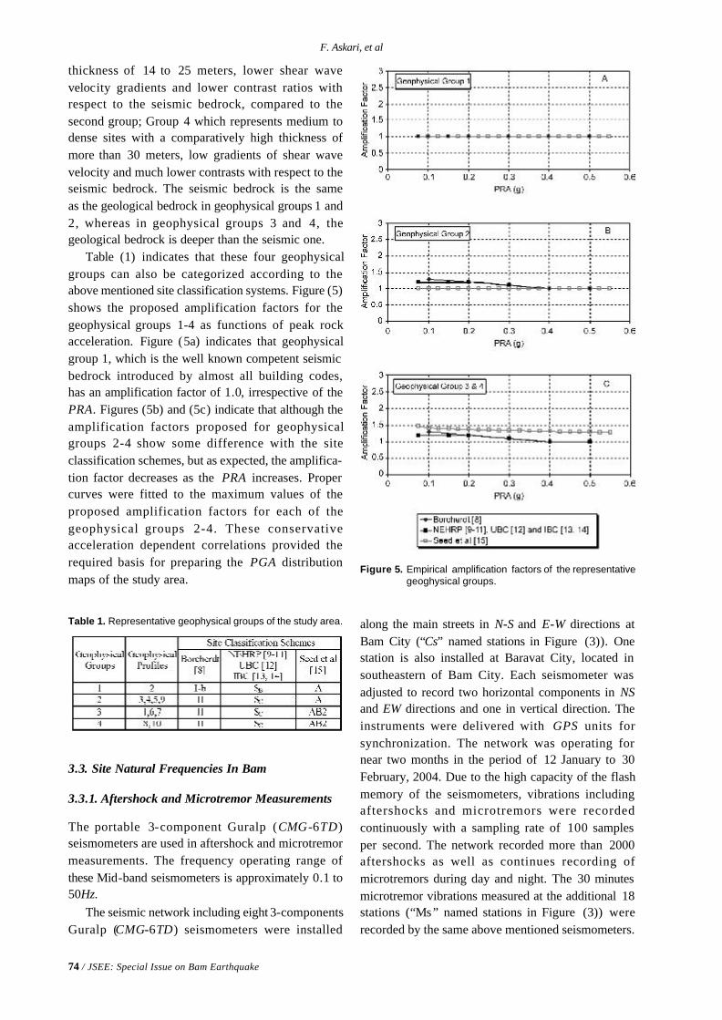
74 / JSEE: Special Issue on Bam Earthquake
F. Askari, et al
thickness of 14 to 25 meters, lower shear wavevelocity gradients and lower contrast ratios withrespect to the seismic bedrock, compared to thesecond group; Group 4 which represents medium todense sites with a comparatively high thickness ofmore than 30 meters, low gradients of shear wavevelocity and much lower contrasts with respect to theseismic bedrock. The seismic bedrock is the sameas the geological bedrock in geophysical groups 1 and2, whereas in geophysical groups 3 and 4, thegeological bedrock is deeper than the seismic one.
Table (1) indicates that these four geophysicalgroups can also be categorized according to theabove mentioned site classification systems. Figure (5)shows the proposed amplification factors for thegeophysical groups 1-4 as functions of peak rockacceleration. Figure (5a) indicates that geophysicalgroup 1, which is the well known competent seismicbedrock introduced by almost all building codes,has an amplification factor of 1.0, irrespective of thePRA. Figures (5b) and (5c) indicate that although theamplification factors proposed for geophysicalgroups 2-4 show some difference with the siteclassification schemes, but as expected, the amplifica-tion factor decreases as the PRA increases. Propercurves were fitted to the maximum values of theproposed amplification factors for each of thegeophysical groups 2-4. These conservativeacceleration dependent correlations provided therequired basis for preparing the PGA distributionmaps of the study area.
Table 1. Representative geophysical groups of the study area.
Figure 5. Empirical amplification factors of the representativegeoghysical groups.
along the main streets in N-S and E-W directions atBam City (“Cs” named stations in Figure (3)). Onestation is also installed at Baravat City, located insoutheastern of Bam City. Each seismometer wasadjusted to record two horizontal components in NSand EW directions and one in vertical direction. Theinstruments were delivered with GPS units forsynchronization. The network was operating fornear two months in the period of 12 January to 30February, 2004. Due to the high capacity of the flashmemory of the seismometers, vibrations includingaftershocks and microtremors were recordedcontinuously with a sampling rate of 100 samplesper second. The network recorded more than 2000aftershocks as well as continues recording ofmicrotremors during day and night. The 30 minutesmicrotremor vibrations measured at the additional 18stations (“Ms” named stations in Figure (3)) wererecorded by the same above mentioned seismometers.
3.3. Site Natural Frequencies In Bam
3.3.1. Aftershock and Microtremor Measurements
The portable 3-component Guralp (CMG-6TD)seismometers are used in aftershock and microtremormeasurements. The frequency operating range ofthese Mid-band seismometers is approximately 0.1 to50Hz.
The seismic network including eight 3-componentsGuralp (CMG-6TD) seismometers were installed
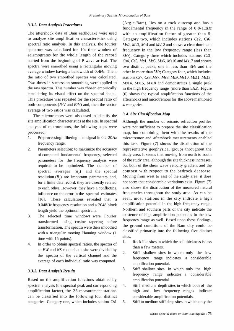
Preliminary Seismic Microzonation of Bam
JSEE: Special Issue on Bam Earthquake / 75
3.3.2. Data Analysis Procedures
The aftershock data of Bam earthquake were usedto analyze site amplification characteristics usingspectral ratio analysis. In this analysis, the fourierspectrum was calculated for 10s time window ofseismograms for the whole length of the recordstarted from the beginning of P-wave arrival. Thespectra were smoothed using a rectangular movingaverage window having a bandwidth of 0.4Hz. Then,the ratio of two smoothed spectra was calculated.Two times in succession smoothing were applied tothe raw spectra. This number was chosen empiricallyconsidering its visual effect on the spectral shape.This procedure was repeated for the spectral ratio ofboth components (N/V and E/V) and, then the vectoraverage of two ratios was calculated.
The microtremors were also used to identify thesite amplification characteristics at the site. In spectralanalysis of microtremors, the following steps wereprocessed:1. Preprocessing: filtering the signal in 0.2-20Hz
frequency range.2. Parameters selection: to maximize the accuracy
of computed fundamental frequency, selectedparameters for the frequency analysis wererequired to be optimized. The number ofspectral averages (nd) and the spectralresolution (Be) are important parameters and,for a finite data record, they are directly relatedto each other. However, they have a conflictinginfluence on the error in the spectral estimates[16]. These calculations revealed that a0.048Hz frequency resolution and a 2048 blocklength yield the optimum spectrum.
3. The selected time windows were Fouriertransformed using cosine tapering beforetransformation. The spectra were then smoothedwith a triangular moving Hanning window (1time with 15 points).
4. In order to obtain spectral ratios, the spectra ofan EW and NS channel at a site were divided bythe spectra of the vertical channel and theaverage of each individual ratio was computed.
3.3.3. Data Analysis Results
Based on the amplification functions obtained byspectral analysis (the spectral peak and correspondingamplification factor), the 26 measurement stationscan be classified into the following four distinctcategories: Category one, which includes station Cs1
(Arg-e-Bam), lies on a rock outcrop and has afundamental frequency in the range of 0.8-1.2Hzwith an amplification factor of greater than 5;Category two, which includes stations Cs2, Cs6,Ms2, Ms3, Ms4 and Ms12 and shows a clear dominantfrequency in the low frequency range (less than3Hz); Category three which includes stations Cs3,Cs4, Cs5, Ms1, Ms5, Ms6, Ms16 and Ms17 and showstwo distinct peaks, one in less than 3Hz and theother in more than 5Hz; Category four, which includesstations Cs7, Cs8, Ms7, Ms8, Ms9, Ms10, Ms11, Ms13,Ms14, Ms15, Ms18 and demonstrates a single peakin the high frequency range (more than 5Hz). Figure(6) shows the typical amplification functions of theaftershocks and microtremors for the above mentioned4 categories.
3.4. Site Classification Map
Although the number of seismic refraction profileswere not sufficient to prepare the site classificationmap, but combining them with the results of themicrotremor and aftershock measurements enabledthis task. Figure (7) shows the distribution of therepresentative geophysical groups throughout thestudy area. It seems that moving from north to southof the study area, although the site thickness increases,but both of the shear wave velocity gradient and thecontrast with respect to the bedrock decrease.Moving from west to east of the study area, it doesnot seem that considerable variations exist. Figure (7)also shows the distribution of the measured naturalfrequencies throughout the study area. As can beseen, most stations in the city indicate a highamplification potential in the high frequency range.Northern and southern parts of the city indicate theexistence of high amplification potentials in the lowfrequency range as well. Based upon these findings,the ground conditions of the Bam city could beclassified primarily into the following five distinctsites:1. Rock like sites in which the soil thickness is less
than a few meters.2. Stiff shallow sites in which only the low
frequency range indicates a considerableamplification potential.
3. Stiff shallow sites in which only the highfrequency range indicates a considerableamplification potential.
4. Stiff medium depth sites in which both of thehigh and low frequency ranges indicateconsiderable amplification potentials.
5. Stiff to medium stiff deep sites in which only the
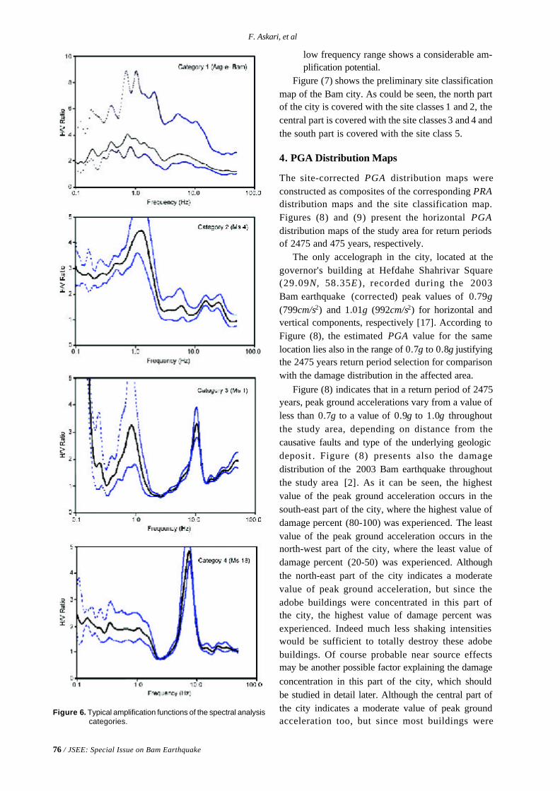
76 / JSEE: Special Issue on Bam Earthquake
F. Askari, et al
low frequency range shows a considerable am-plification potential.
Figure (7) shows the preliminary site classificationmap of the Bam city. As could be seen, the north partof the city is covered with the site classes 1 and 2, thecentral part is covered with the site classes 3 and 4 andthe south part is covered with the site class 5.
4. PGA Distribution Maps
The site-corrected PGA distribution maps wereconstructed as composites of the corresponding PRAdistribution maps and the site classification map.Figures (8) and (9) present the horizontal PGAdistribution maps of the study area for return periodsof 2475 and 475 years, respectively.
The only accelograph in the city, located at thegovernor's building at Hefdahe Shahrivar Square(29.09N, 58.35E ) , recorded during the 2003Bam earthquake (corrected) peak values of 0.79g(799cm/s2) and 1.01g (992cm/s2) for horizontal andvertical components, respectively [17]. According toFigure (8), the estimated PGA value for the samelocation lies also in the range of 0.7g to 0.8g justifyingthe 2475 years return period selection for comparisonwith the damage distribution in the affected area.
Figure (8) indicates that in a return period of 2475years, peak ground accelerations vary from a value ofless than 0.7g to a value of 0.9g to 1.0g throughoutthe study area, depending on distance from thecausative faults and type of the underlying geologicdeposit . Figure (8) presents also the damagedistribution of the 2003 Bam earthquake throughoutthe study area [2]. As it can be seen, the highestvalue of the peak ground acceleration occurs in thesouth-east part of the city, where the highest value ofdamage percent (80-100) was experienced. The leastvalue of the peak ground acceleration occurs in thenorth-west part of the city, where the least value ofdamage percent (20-50) was experienced. Althoughthe north-east part of the city indicates a moderatevalue of peak ground acceleration, but since theadobe buildings were concentrated in this part ofthe city, the highest value of damage percent wasexperienced. Indeed much less shaking intensitieswould be sufficient to totally destroy these adobebuildings. Of course probable near source effectsmay be another possible factor explaining the damageconcentration in this part of the city, which shouldbe studied in detail later. Although the central part ofthe city indicates a moderate value of peak groundacceleration too, but since most buildings were
Figure 6. Typical amplification functions of the spectral analysiscategories.
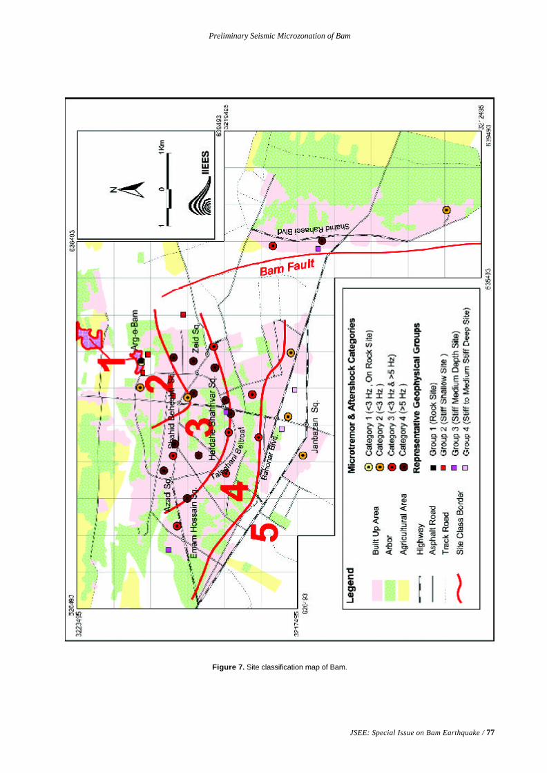
Preliminary Seismic Microzonation of Bam
JSEE: Special Issue on Bam Earthquake / 77
Figure 7. Site classification map of Bam.
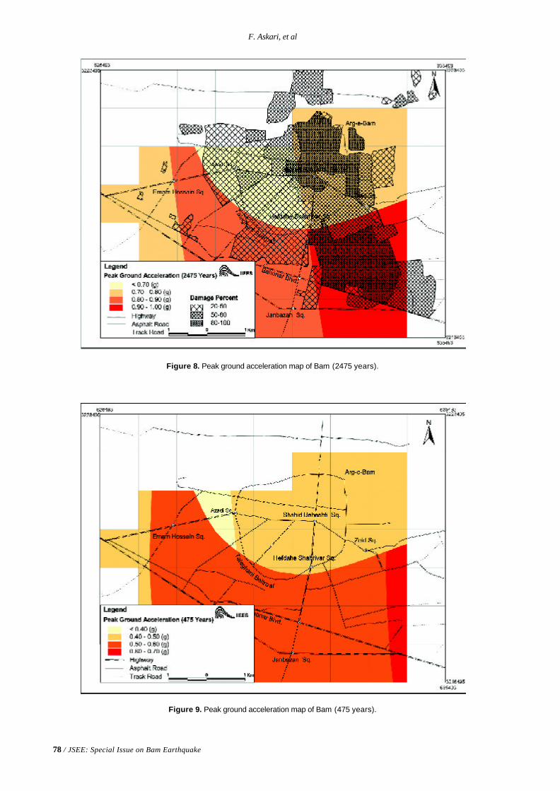
78 / JSEE: Special Issue on Bam Earthquake
F. Askari, et al
Figure 9. Peak ground acceleration map of Bam (475 years).
Figure 8. Peak ground acceleration map of Bam (2475 years).
Preliminary Seismic Microzonation of Bam
JSEE: Special Issue on Bam Earthquake / 79
designed and constructed on engineering basis, theexperienced value of damage percent was the least.The damage distribution of Figure (8) could also becompared with the site classification map of Figure(7). As can be seen, almost all damages of low risebuildings occurred in site classes, which possess aconsiderable amplification potential in the highfrequency range.
Figure (9) indicates that in a return period of 475years, peak ground accelerations vary from a valueof less than 0.4g to a value of 0.6g to 0.7g throughoutthe study area. Comparison of Figures (8) and (9)shows that irrespective of the return period, thepeak ground acceleration increases by moving fromnorth to south and from west to east of the city.
5. Conclusions
After the devastating earthquake disaster in the Bamcity of Iran, a discipline was followed to preparepreliminary seismic microzonation maps for this city.This paper presented the preliminary results of seismicmicrozonation studies of the Bam city. The site effectevaluations were based on geophysical, microtremorand aftershock measurements conducted by IIEESin the study area. Good agreements existed betweenthe 2475 years PGA distribution map and the damagedistribution map of the recent earthquake. Highestvalues of damage percents concentrated in siteswith stiff shallow and medium depth soils, whichpossessed considerable amplification potentials inhigh frequency ranges. The obtained microzonationmaps could be used as a preliminary useful hint inreconstruction and urban planning of the totallydestroyed city. It is obvious that more accurateevaluations of ground motion characteristics requiremore geotechnical and geophysical data, considerationof multi-dimensional sub-surface topographic effectsas well as all possible near source effects.
References
1. The Technical Committee for EarthquakeGeotechnical Engineering (TC4) (1993). “Manualfor Zonation on seismic Geotechnical hazard”, TheJapanese Society of Soil Mechanics and Founda-tion Engineering.
2. National Cartographic Center (2003). “DamageDistribution Map of Bam Earthquake”.
3. Frankel, A. (1995). “Mapping Seismic Hazard inthe Central and Eastern United States”, Seismo-logical Research Letters, 66(4), 8-21.
4. Boore, D.M., Joyner, W.B., and Fumal, T.E.(1997). “Equations for Estimating HorizontalResponse Spectra and Peak Acceleration fromWestern North American Earthquakes: A summaryof Recent Work”, Seismological Research Letters,68(1), 128-153.
5. Zare, M. (1999). “Contribution a L'etude DesMovements Forts en Iran: Du Catalogue Aux LoisD'attenuation”, These De L'universite JosephFourier, Grenoble, France.
6. Geological Survey of Iran (1993). Geological Mapof Iran, 1:100000 Series, Sheet 7648-Bam.
7. Abkav Consulting Engineers (1973). “Geo-Elec-trical Studies of Bam and Narmachir Region”,Ministry of Water and Electric.
8. Borcherdt, R.D. (1994). “Estimates of Site-Dependent Response Spectra for Design(Methodology and Justification)”, EarthquakeSpectra, 10, 617-653.
9. The NEHRP Recommended Provisions forSeismic Regulations for New Buildings (1994)Edition.
10. The NEHRP Recommended Provisions forSeismic Regulations for New Buildings (1997)Edition.
11. The NEHRP Recommended Provisions forSeismic Regulations for New Buildings and OtherStructures (2000) Edition.
12. Uniform Building Code (UBC) (1997). Chap. 16.
13. International Building Code (IBC) (2000). Chap.16.
14. International Building Code (IBC) (2003). Chap.16.
15. Seed, R.B., Cetin, K.O., Moss, R.E.S., Kammerer,A.M., Wu, J., Pestana, J.M., and Riemer, M.F.(2001). “Recent Advances in Soil LiquefactionEngineering and Seismic Site Response Evalua-tion”, Proceedings Fourth InternationalConference on Recent Advances in GeotechnicalEarthquake Engineering and Soil Dynamics andSymposium in Honor of Professor W.D. Liam Finn,San Diego, California, (SPL-2).

80 / JSEE: Special Issue on Bam Earthquake
F. Askari, et al
16. Bendat, J.S. and Piersol, A.J. (1993). “Engineer-ing Application of Correlation and SpectralAnalysis”, John Willey & Sons Inc., SecondEdition.
17. Zare, M. and Hamzehloo, H. (2004). “A Study ofthe Strong Ground Motion in the Bam Iran Earth-quake of 26 December 2003 Mw 6.5”, JSEE,5(4) and 6(1).
JSEE: Special Issue on Bam Earthquake / 81
A.S. Moghadam and A. Eskandari
Structural Engineering Reaserch Center, International Institute of EarthquakeEngineering and Seismology (IIEES), Tehran, Iran, e-mail: [email protected]
ABSTRACT: A procedure developed for quick inspection of buildingsin earthquake damaged areas of Bam by a group of volunteer engineersis introduced. The procedure is applied to 550 masonry, steel andreinforced concrete buildings. Distribution and statistics of thebuildings characteristics such as their use, number of stories, penthouseand stairs damages, type of material and structural systems and type ofdiaphragms are determined. The information has provided importantdata about the design, detailing and construction deficiencies ofcommon types of buildings in Bam.
Keywords: Bam; Post-earthquake inspection; Damaged building
Post-Earthquake Quick Inspection of Damaged Buildings inBam Earthquake of 26 December 2003
1. Introduction
Following any major damaging earthquake thatdisrupts and threatens life and normal activities,there is likely to be shock, confusion and chaos in theperiod following that usually lasts some appreciabletime. Although, there might be a scene of apparentdisruption and emotion, actions are required torespond to the emergency and to start the process ofrecovery. An important action is to address the safetyof buildings, to establish those that cannot be used, tomake those damaged so that they can be used, and toidentify those that can continue to be fully used. Therewill be a mix of extent of damage to buildings withinan area and between different areas. Many buildingsat first may appear to be undamaged, but on closerinspection these may be found to be perhaps severelydamaged. Very often the full extent of damagecontinues to emerge over time.
With Iran's history of earthquakes and otherdisasters, one of the most important post-disasteractivities is to determine the safety and functionalityof buildings and especially the key facilities. Thesefacilities include emergency operation centers,hospitals, sewage plants, water treatment systems,and airports. However, the most challenging task is toaddress the safety of large stack of private homes.
In some countries, a group of professionalsimmediately after earthquake begin to evaluate the
damaged buildings. The evaluation consists of somephases. At the beginning, the first phase of evaluationthat is called “rapid screening” or “quick inspection” isdone. The aim of this step is to find out whether abuilding is safe for occupying or it need somestructural and non-structural retrofitting or it is notrecommended for occupying. Because inspection isdone very quickly, providing retrofitting details in thisphase is not possible. Although, there are somecountries that have developed postearthquakeevaluation procedures, only Japanese and Americanquick inspection development histories are brieflyreviewed here.
When the Southern Italy Earthquake struck in1980, the then Ministry of Construction of Japan(at present, the Ministry of Land, Infrastructure andTransportation) started the “project for advancedrepairing technology for earthquake damagedbuildings” in 1981. It created a series of methods;from risk evaluation of damaged buildings to repairingtechnology of wooden, steel and reinforced concretestructure buildings. When the Mexico Earthquakeoccurred in 1985, the temporary risk evaluationmethod for damaged reinforced concrete buildingswas applied. After the project of comprehensivetechnology was undertaken, the Building DisasterPrevention Association of Japan published, “The
82 / JSEE: Special Issue on Bam Earthquake
A.S. Moghadam and A. Eskandari
standard of damage evaluation and the guidance ofrepairing technology for the buildings hit byearthquakes”. Then a technological standard wasestablished, Shizuoka government established atemporary risk evaluation system of damagedbuildings in 1991, followed by the Kanagawagovernment in 1992. When the Great Hanshin-AwajiEarthquake occurred in 1995, the temporary riskevaluation of damaged buildings was applied for thefirst time in Japan. Then many other local governmentsestablished their own system.
In July 1987 the California Governor’s Office ofEmergency Services (OES), California Office ofStatewide Health Planning and Development(OSHPD), and Federal Emergency ManagementAgency (FEMA), jointly awarded ATC a contract todevelop procedures for postearthquake safetyevaluation of buildings. This led to the developmentof the ATC-20 [1] report “Procedures for Postearthquake Safety Evaluation of Buildings”. ATC-20documents procedures and guidelines for the safetyevaluation of damaged buildings. These are writtenspecifically for volunteer structural engineers, andbuilding inspectors and structural engineers from citybuilding departments and other regulatory agencies,who would be required to make on-the-spotevaluations and decisions regarding continued useand occupancy of damaged buildings [2]. To providethe ATC-20 methodology in a concise, easy to usefield reference document, a Field Manual wasdeveloped as part of the ATC-20-1 [3] project. TheField Manual is intended to be taken into damagedareas and used by those trained in the ATC-20methodology.
A three-tier posting classification system isrecommended by ATC-20 and is described in thepublication series Procedures for PostearthquakeSafety Evaluation of Buildings. The modified formsand placards are described in the Addendum to ATC-20 (ATC-20-2) [4]. The colored placards (tags) aretools posted on inspected structures to easily identifyfacility damage assessment results from a distance.They are normally posted at all building entrances.The following describes the circumstances by whichinspectors should post each type of placard.t Inspected: (Green Tags) Buildings can be
damaged, yet remain safe. If the safety of abuilding was not significantly changed by thedisaster, it should be posted with a green placardreading INSPECTED.
t Unsafe: (Red Tags) Buildings damaged by a
disaster that pose an imminent threat to life orsafety under expected loads or other unsafeconditions should be posted with a red placardreading UNSAFE. These are not demolitionorders.
t Restricted Use: (Yellow Tags) When there issome risk from damage in all or part of thebuilding that does not warrant red-tagging, ayellow tag should be used. The placard shouldindicate the specific restriction (i.e., entry,duration of occupancy, use, etc.). When theextent of damage is uncertain or cannot beascertained within the time and resourcesavailable to a Rapid Evaluation team, the buildingshould be posted with a yellow placard readingRestricted Use indicating additional inspectionrequirements, and any restrictions on use oroccupancy should be clearly noted on theplacard. Although a building may be placardedRestricted Use, specific areas in and around thebuilding could be further identified as unsafe.This specific area should be identified andposted with a red placard reading Area Unsafe.An Area Unsafe placard helps identify dangeroussituations that may exist around or within anotherwise structurally sound building. A buildingposted Restricted Use may have a specific areathat is posted Area Unsafe. In this situation, theRestricted Use placard should indicate thespecifics of the restrictions and identify thelocation of the Area Unsafe [1].
In this paper, a procedure for quick inspection ofbuildings that has been developed by a group ofvolunteer engineers is introduced. The procedurethen applied to 550 buildings in Bam. For eachbuilding, a set of forms has been filled. Then thedata is collected in a database. A study on the dataprovides some statistics about buildings and commonconstruction practices in Bam area.
2. Procedure Used
In order to quickly inspect damaged buildings ofBam city, a form has been prepared that contains somestructural and non-structural related items. The itemsare selected based on the available quick inspectionforms, considering special features of commonbuildings in Iran. In the conclusion part of this formthree cases have been mentioned:1. Building is relatively safe and can be occupied
with probably some non-structural retrofitting;
Post-Earthquake Quick Inspection of Damaged Buildings in Bam Earthquake of 26 December 2003
JSEE: Special Issue on Bam Earthquake / 83
2. Building can be occupied with structural retro-fitting;
3. The building is not recommended for occupa-tion. A translation of forms to English is includedin Appendix [A].
The questions in the forms are intended tosummarize the type and extent of damages in abuilding. They are also designed to compare thebuilding characteristics with the minimum require-ments of “Iranian Code of Practice for SeismicResistant Design of Buildings” [5].
3. Quick Inspection Form Items
Rapid evaluation form has been shown in Appendix[A]. This form has nine parts. The form items shouldbe completed according to the available data in thelocation of building. A brief explanation of each part ofthe form follows.Part A) Building general information: In this part, the
general information of the building, such asaddress, area, building use and its owner arementioned.
Part B) Building general characteristics: In this part,general characteristics of the building such asnumber of stories, height of stories, existenceor lack of basement, penthouse and cantileverand their damage level are marked.
Part C) Material: In this part, the material of structuralelements (frame, wall, and foundation) andnon-structural elements (partitions, finishingand ceiling) are entered.
Part D) Stairs: In this part, the stairs and stairs sidewall damages are mentioned.
Part E) Structural system characteristics: This part isone of the most important parts in the quickinspection report and contains structural dataof the building such as structural system typein each direction, type of bracing, slabsystem, foundations system and structuralelements such as columns, beams, bracings,connections, base plates and infills.
Part F) Visible plastic deformations: The large storydrifts and inappropriate deformations shall bementioned in this part.
Part G) Non-structural elements damage: In this partthe damage level of non-structural elementssuch as ceilings, pipes, partitions, facets,parapets and electrical and mechanicalequipments are mentioned.
Part H) Conclusion: By evaluating the items in eachsection of the form, the buildings can be
classified into three categories:1. Building is relatively safe and can be
occupied with probably some non-structural retrofitting;
2. Building can be occupied with structuralretrofitting;
3. The building is not recommended foroccupation.
Due to rapid nature of inspection, the conclusion issomehow dependent to the level of skill of inspector.To avoid inconsistent results, some training session washeld for the volunteer engineers for familiarizing themto interpretation of form items.Part I) Recommendations: In order to prevent later
damages and dangers and guarantee the safetyof the residents, any special point that mayhave been observed during the evaluation,shall be recommended to the residents.These recommendations are mentioned in thelast part of the form. At the end of the form,a schematic drawing of the structure shouldbe drawn.
The forms have been filled for 550 buildings inBam. The collected data of buildings has beentransferred to a database program that has beendeveloped for gathering and processing the data.Figure (1) shows the forms in database format.
4. Damage Statistics
Having compiled all the form items for 550 buildingsin the database, one may extract different statisticsout of the information. The statistics are aboutdifferent buildings characteristics such as their use,number of stories, penthouse and stairs damages,type of material and structural systems and type ofdiaphragms. The information helps identifying manydesign, detailing and construction deficiencies ofcommon types of buildings in Bam. Some of thisinformation is presented in this section.
Shown on Figure (2) is the percentage ofbuildings function and use. It is noteworthy that thebuildings are mainly private homes that are registeredfor surveying by their owners in municipality.Therefore, it is not surprising that the number ofresidential buildings is much more than other types ofbuildings.
Shown on Figure (3) is the number of storiesfor the surveyed buildings. Almost 75% of surveyedbuildings are single story buildings. It can be concludedthat most of these building are short period structures.
The widespread damage to penthouses was a
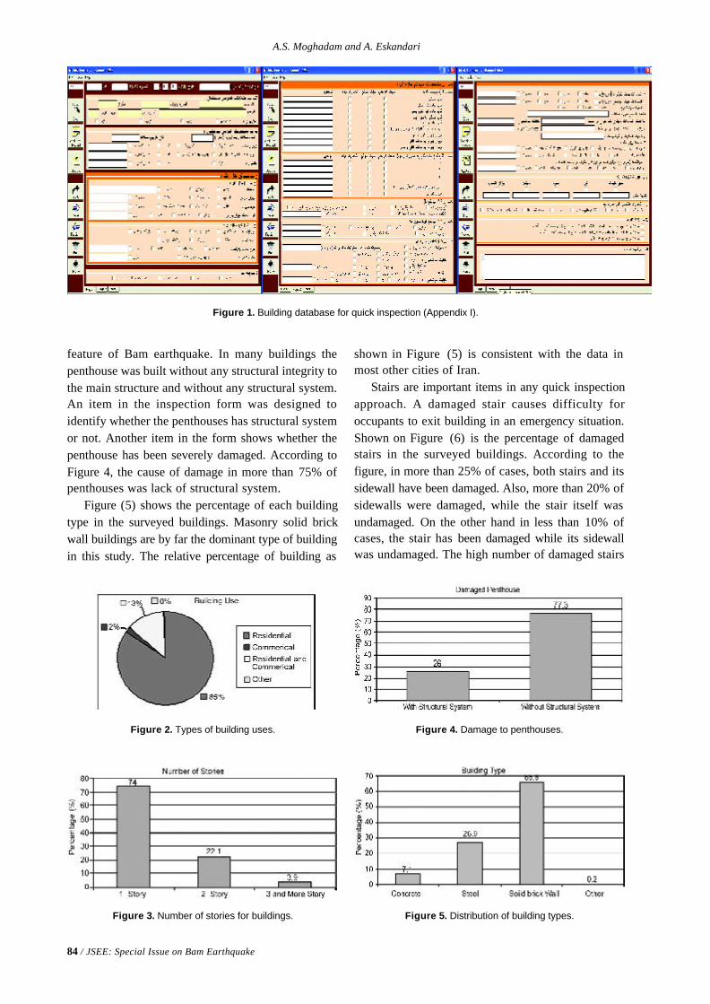
84 / JSEE: Special Issue on Bam Earthquake
A.S. Moghadam and A. Eskandari
Figure 1. Building database for quick inspection (Appendix I).
Figure 2. Types of building uses.
feature of Bam earthquake. In many buildings thepenthouse was built without any structural integrity tothe main structure and without any structural system.An item in the inspection form was designed toidentify whether the penthouses has structural systemor not. Another item in the form shows whether thepenthouse has been severely damaged. According toFigure 4, the cause of damage in more than 75% ofpenthouses was lack of structural system.
Figure (5) shows the percentage of each buildingtype in the surveyed buildings. Masonry solid brickwall buildings are by far the dominant type of buildingin this study. The relative percentage of building as
Figure 3. Number of stories for buildings.
Figure 4. Damage to penthouses.
Figure 5. Distribution of building types.
shown in Figure (5) is consistent with the data inmost other cities of Iran.
Stairs are important items in any quick inspectionapproach. A damaged stair causes difficulty foroccupants to exit building in an emergency situation.Shown on Figure (6) is the percentage of damagedstairs in the surveyed buildings. According to thefigure, in more than 25% of cases, both stairs and itssidewall have been damaged. Also, more than 20% ofsidewalls were damaged, while the stair itself wasundamaged. On the other hand in less than 10% ofcases, the stair has been damaged while its sidewallwas undamaged. The high number of damaged stairs
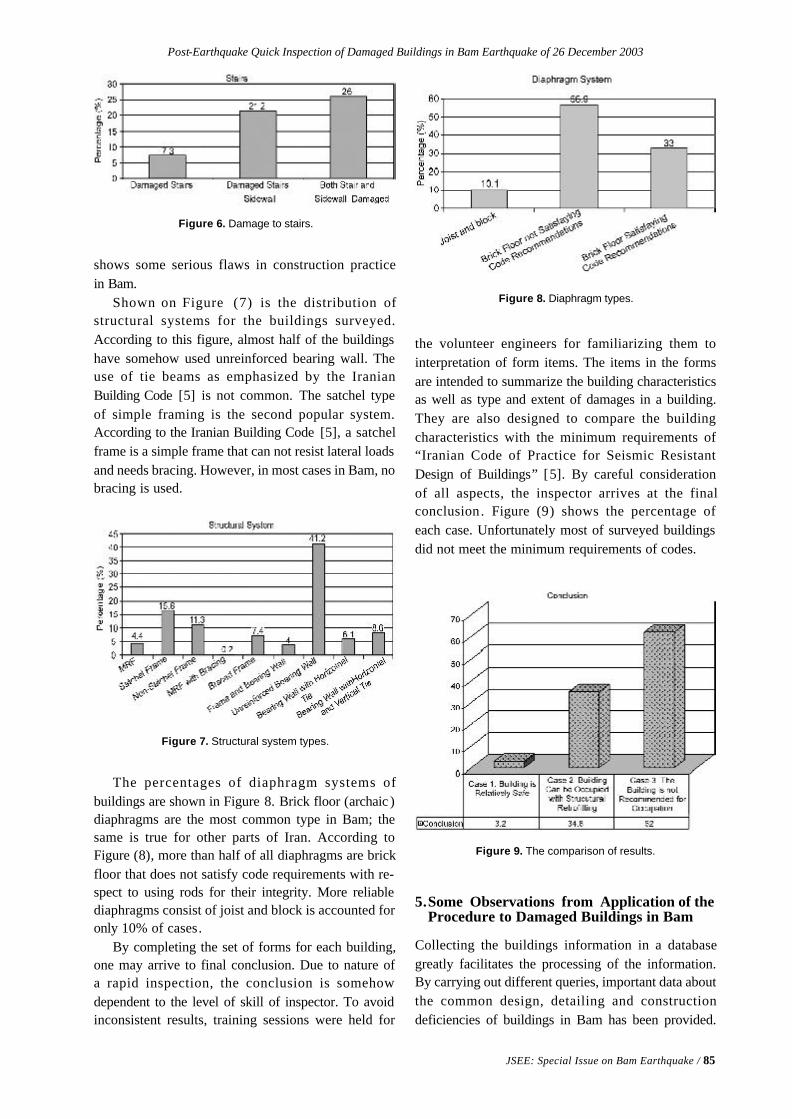
Post-Earthquake Quick Inspection of Damaged Buildings in Bam Earthquake of 26 December 2003
JSEE: Special Issue on Bam Earthquake / 85
shows some serious flaws in construction practicein Bam.
Shown on Figure (7) is the distribution ofstructural systems for the buildings surveyed.According to this figure, almost half of the buildingshave somehow used unreinforced bearing wall. Theuse of tie beams as emphasized by the IranianBuilding Code [5] is not common. The satchel typeof simple framing is the second popular system.According to the Iranian Building Code [5], a satchelframe is a simple frame that can not resist lateral loadsand needs bracing. However, in most cases in Bam, nobracing is used.
Figure 6. Damage to stairs.
the volunteer engineers for familiarizing them tointerpretation of form items. The items in the formsare intended to summarize the building characteristicsas well as type and extent of damages in a building.They are also designed to compare the buildingcharacteristics with the minimum requirements of“Iranian Code of Practice for Seismic ResistantDesign of Buildings” [5]. By careful considerationof all aspects, the inspector arrives at the finalconclusion. Figure (9) shows the percentage ofeach case. Unfortunately most of surveyed buildingsdid not meet the minimum requirements of codes.
Figure 7. Structural system types.
Figure 8. Diaphragm types.
Figure 9. The comparison of results.
5.Some Observations from Application of theProcedure to Damaged Buildings in Bam
Collecting the buildings information in a databasegreatly facilitates the processing of the information.By carrying out different queries, important data aboutthe common design, detailing and constructiondeficiencies of buildings in Bam has been provided.
The percentages of diaphragm systems ofbuildings are shown in Figure 8. Brick floor (archaic )diaphragms are the most common type in Bam; thesame is true for other parts of Iran. According toFigure (8), more than half of all diaphragms are brickfloor that does not satisfy code requirements with re-spect to using rods for their integrity. More reliablediaphragms consist of joist and block is accounted foronly 10% of cases.
By completing the set of forms for each building,one may arrive to final conclusion. Due to nature ofa rapid inspection, the conclusion is somehowdependent to the level of skill of inspector. To avoidinconsistent results, training sessions were held for
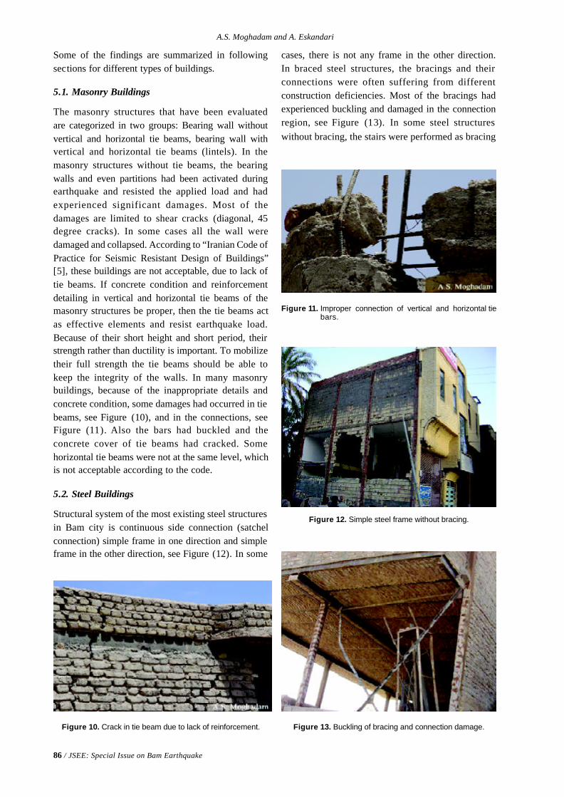
86 / JSEE: Special Issue on Bam Earthquake
A.S. Moghadam and A. Eskandari
Some of the findings are summarized in followingsections for different types of buildings.
5.1. Masonry Buildings
The masonry structures that have been evaluatedare categorized in two groups: Bearing wall withoutvertical and horizontal tie beams, bearing wall withvertical and horizontal tie beams (lintels). In themasonry structures without tie beams, the bearingwalls and even partitions had been activated duringearthquake and resisted the applied load and hadexperienced significant damages. Most of thedamages are limited to shear cracks (diagonal, 45degree cracks). In some cases all the wall weredamaged and collapsed. According to “Iranian Code ofPractice for Seismic Resistant Design of Buildings”[5], these buildings are not acceptable, due to lack oftie beams. If concrete condition and reinforcementdetailing in vertical and horizontal tie beams of themasonry structures be proper, then the tie beams actas effective elements and resist earthquake load.Because of their short height and short period, theirstrength rather than ductility is important. To mobilizetheir full strength the tie beams should be able tokeep the integrity of the walls. In many masonrybuildings, because of the inappropriate details andconcrete condition, some damages had occurred in tiebeams, see Figure (10), and in the connections, seeFigure (11). Also the bars had buckled and theconcrete cover of tie beams had cracked. Somehorizontal tie beams were not at the same level, whichis not acceptable according to the code.
5.2. Steel Buildings
Structural system of the most existing steel structuresin Bam city is continuous side connection (satchelconnection) simple frame in one direction and simpleframe in the other direction, see Figure (12). In some
Figure 10. Crack in tie beam due to lack of reinforcement.
Figure 11. Improper connection of vertical and horizontal tiebars.
Figure 12. Simple steel frame without bracing.
Figure 13. Buckling of bracing and connection damage.
cases, there is not any frame in the other direction.In braced steel structures, the bracings and theirconnections were often suffering from differentconstruction deficiencies. Most of the bracings hadexperienced buckling and damaged in the connectionregion, see Figure (13). In some steel structureswithout bracing, the stairs were performed as bracing
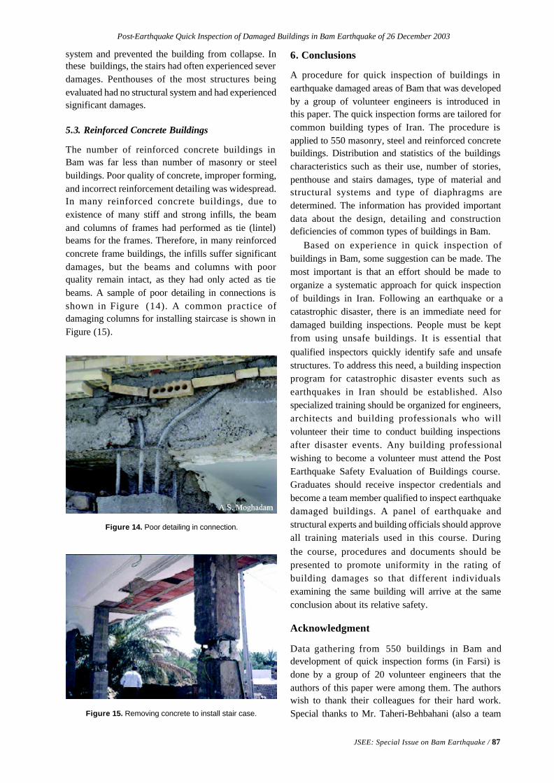
Post-Earthquake Quick Inspection of Damaged Buildings in Bam Earthquake of 26 December 2003
JSEE: Special Issue on Bam Earthquake / 87
system and prevented the building from collapse. Inthese buildings, the stairs had often experienced severdamages. Penthouses of the most structures beingevaluated had no structural system and had experiencedsignificant damages.
5.3. Reinforced Concrete Buildings
The number of reinforced concrete buildings inBam was far less than number of masonry or steelbuildings. Poor quality of concrete, improper forming,and incorrect reinforcement detailing was widespread.In many reinforced concrete buildings, due toexistence of many stiff and strong infills, the beamand columns of frames had performed as tie (lintel)beams for the frames. Therefore, in many reinforcedconcrete frame buildings, the infills suffer significantdamages, but the beams and columns with poorquality remain intact, as they had only acted as tiebeams. A sample of poor detailing in connections isshown in Figure (14). A common practice ofdamaging columns for installing staircase is shown inFigure (15).
Figure 14. Poor detailing in connection.
6. Conclusions
A procedure for quick inspection of buildings inearthquake damaged areas of Bam that was developedby a group of volunteer engineers is introduced inthis paper. The quick inspection forms are tailored forcommon building types of Iran. The procedure isapplied to 550 masonry, steel and reinforced concretebuildings. Distribution and statistics of the buildingscharacteristics such as their use, number of stories,penthouse and stairs damages, type of material andstructural systems and type of diaphragms aredetermined. The information has provided importantdata about the design, detailing and constructiondeficiencies of common types of buildings in Bam.
Based on experience in quick inspection ofbuildings in Bam, some suggestion can be made. Themost important is that an effort should be made toorganize a systematic approach for quick inspectionof buildings in Iran. Following an earthquake or acatastrophic disaster, there is an immediate need fordamaged building inspections. People must be keptfrom using unsafe buildings. It is essential thatqualified inspectors quickly identify safe and unsafestructures. To address this need, a building inspectionprogram for catastrophic disaster events such asearthquakes in Iran should be established. Alsospecialized training should be organized for engineers,architects and building professionals who willvolunteer their time to conduct building inspectionsafter disaster events. Any building professionalwishing to become a volunteer must attend the PostEarthquake Safety Evaluation of Buildings course.Graduates should receive inspector credentials andbecome a team member qualified to inspect earthquakedamaged buildings. A panel of earthquake andstructural experts and building officials should approveall training materials used in this course. Duringthe course, procedures and documents should bepresented to promote uniformity in the rating ofbuilding damages so that different individualsexamining the same building will arrive at the sameconclusion about its relative safety.
Acknowledgment
Data gathering from 550 buildings in Bam anddevelopment of quick inspection forms (in Farsi) isdone by a group of 20 volunteer engineers that theauthors of this paper were among them. The authorswish to thank their colleagues for their hard work.Special thanks to Mr. Taheri-Behbahani (also a teamFigure 15. Removing concrete to install stair case.
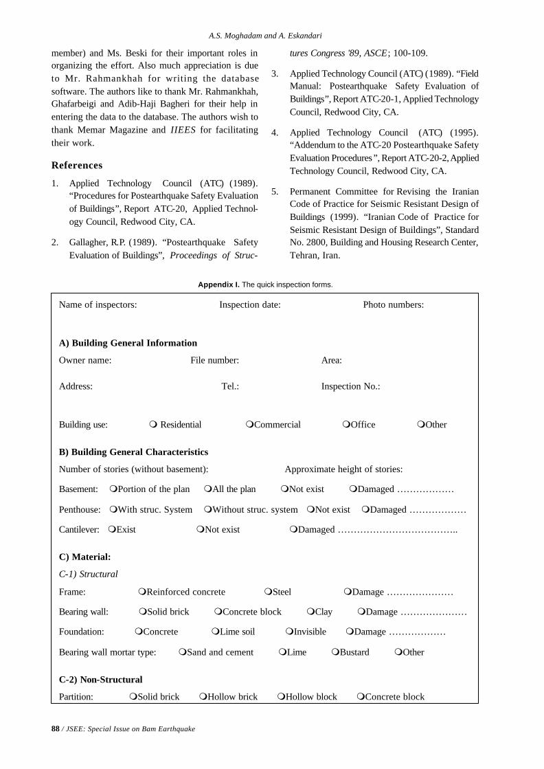
88 / JSEE: Special Issue on Bam Earthquake
A.S. Moghadam and A. Eskandari
member) and Ms. Beski for their important roles inorganizing the effort. Also much appreciation is dueto Mr. Rahmankhah for writing the databasesoftware. The authors like to thank Mr. Rahmankhah,Ghafarbeigi and Adib-Haji Bagheri for their help inentering the data to the database. The authors wish tothank Memar Magazine and IIEES for facilitatingtheir work.
References
1. Applied Technology Council (ATC) (1989).“Procedures for Postearthquake Safety Evaluationof Buildings”, Report ATC-20, Applied Technol-ogy Council, Redwood City, CA.
2. Gallagher, R.P. (1989). “Postearthquake SafetyEvaluation of Buildings”, Proceedings of Struc-
Appendix I. The quick inspection forms.
tures Congress '89, ASCE; 100-109.
3. Applied Technology Council (ATC) (1989). “FieldManual: Postearthquake Safety Evaluation ofBuildings”, Report ATC-20-1, Applied TechnologyCouncil, Redwood City, CA.
4. Applied Technology Council (ATC) (1995).“Addendum to the ATC-20 Postearthquake SafetyEvaluation Procedures”, Report ATC-20-2, AppliedTechnology Council, Redwood City, CA.
5. Permanent Committee for Revising the IranianCode of Practice for Seismic Resistant Design ofBuildings (1999). “Iranian Code of Practice forSeismic Resistant Design of Buildings”, StandardNo. 2800, Building and Housing Research Center,Tehran, Iran.
Name of inspectors: Inspection date: Photo numbers:
A) Building General Information
Owner name: File number: Area:
Address: Tel.: Inspection No.:
Building use: m Residential mCommercial mOffice mOther
B) Building General Characteristics
Number of stories (without basement): Approximate height of stories:
Basement: mPortion of the plan mAll the plan mNot exist mDamaged ………………
Penthouse: mWith struc. System mWithout struc. system mNot exist mDamaged ………………
Cantilever: mExist mNot exist mDamaged ………………………………..
C) Material:
C-1) Structural
Frame: mReinforced concrete mSteel mDamage …………………
Bearing wall: mSolid brick mConcrete block mClay mDamage …………………
Foundation: mConcrete mLime soil mInvisible mDamage ………………
Bearing wall mortar type: mSand and cement mLime mBustard mOther
C-2) Non-Structural
Partition: mSolid brick mHollow brick mHollow block mConcrete block
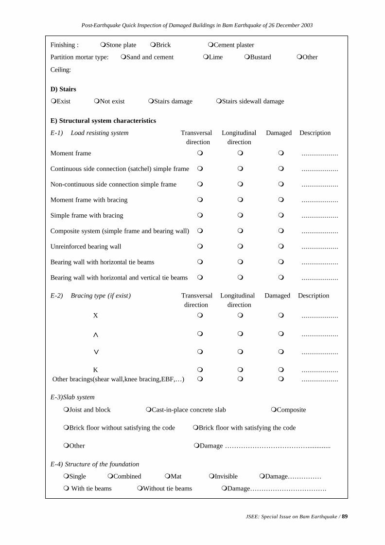
Post-Earthquake Quick Inspection of Damaged Buildings in Bam Earthquake of 26 December 2003
JSEE: Special Issue on Bam Earthquake / 89
Finishing : mStone plate mBrick mCement plaster
Partition mortar type: mSand and cement mLime mBustard mOther
Ceiling:
D) Stairs
mExist mNot exist mStairs damage mStairs sidewall damage
E) Structural system characteristics
E-1) Load resisting system Transversal Longitudinal Damaged Description direction direction
Moment frame m m m ...................
Continuous side connection (satchel) simple frame m m m ...................
Non-continuous side connection simple frame m m m ...................
Moment frame with bracing m m m ...................
Simple frame with bracing m m m ...................
Composite system (simple frame and bearing wall) m m m ...................
Unreinforced bearing wall m m m ...................
Bearing wall with horizontal tie beams m m m ...................
Bearing wall with horizontal and vertical tie beams m m m ...................
E-2) Bracing type (if exist) Transversal Longitudinal Damaged Description direction direction
X m m m ...................
m m m ...................
m m m ...................
K m m m ................... Other bracings(shear wall,knee bracing,EBF,…) m m m ...................
E-3)Slab system
mJoist and block mCast-in-place concrete slab mComposite
mBrick floor without satisfying the code mBrick floor with satisfying the code
mOther mDamage ……………………………….............
E-4) Structure of the foundation
mSingle mCombined mMat mInvisible mDamage……………
m With tie beams mWithout tie beams mDamage…………………………….
>
>

90 / JSEE: Special Issue on Bam Earthquake
A.S. Moghadam and A. Eskandari
E-5) Structural Elements
-Columns: mOpen double profile column flat-bars condition (dimensions,…)
mClosed double profile mSteel box mOther (steel)
Welding quality: mGood mModerate mPoor
mConcrete rectangles mConcrete circle mOther (concrete) mDamage…………
-Beams: mRolled mCast beams mPlate girder mComposite cross-section
Welding quality: mGood mModerate mPoor
mConcrete beam mOther mDamage ……………………...
-Longitudinal direction connections: mContinuous side connection mPin mRigid
mOther mDamage…………………………………
-Transversal direction connections: mContinuous side connection mPin mRigid
mOther mDamage…………………………………
-Connections welding quality: mGood mModerate mPoor
-Bracings:
Bracing cross-section: …………………………………………………………………..
X bracing middle connections details: ………………………………………………….
X bracing connections details at end joints: ……………………………………………
Damage and description: ………………………………………………………………
-Base plate:
Column to base plate connection method: mWith angle mwith plate
minvisible mDamage …………………………..
-Bolts: mNon-deformed bar mDeformed bar mWelded connection
mBolted connection mDamage ……………………………………………………….
-Infill:
mExist mNot exist mActivated mNon-activated mDamage ……………………
F) Plastic Deformations
mStory drift mBeam mColumn mBracing mConnection elements estimation ……………. ..………… ………….. ………….. ……………………….
G) Non-Structural Elements Damage
mCeiling mPipes mInterior partitions mFaces mParapets
mElectrical and mechanical equipments
H) Conclusions:
mBuilding is relatively safe and may be occupied with probably some non-structural retrofitting
mBuilding may be occupied with structural retrofitting
mNot recommended for occupation
J) Schematic drawing of the structure.
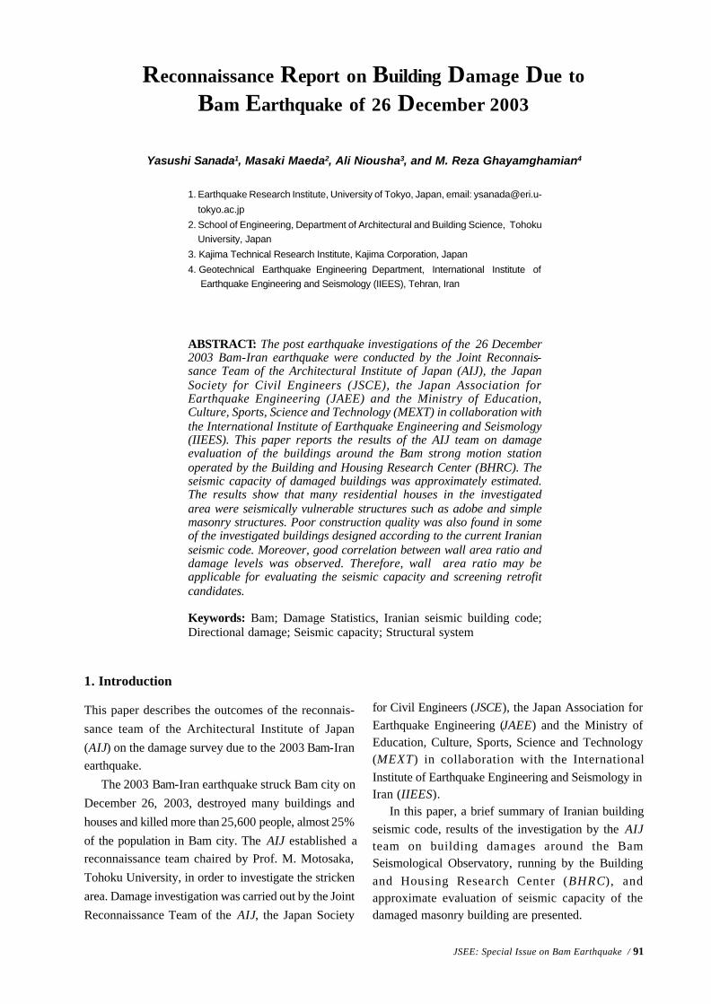
JSEE: Special Issue on Bam Earthquake / 91
1. Earthquake Research Institute, University of Tokyo, Japan, email: [email protected]
tokyo.ac.jp
2. School of Engineering, Department of Architectural and Building Science, TohokuUniversity, Japan
3. Kajima Technical Research Institute, Kajima Corporation, Japan
4. Geotechnical Earthquake Engineering Department, International Institute of Earthquake Engineering and Seismology (IIEES), Tehran, Iran
ABSTRACT: The post earthquake investigations of the 26 December2003 Bam-Iran earthquake were conducted by the Joint Reconnais-sance Team of the Architectural Institute of Japan (AIJ), the JapanSociety for Civil Engineers (JSCE), the Japan Association forEarthquake Engineering (JAEE) and the Ministry of Education,Culture, Sports, Science and Technology (MEXT) in collaboration withthe International Institute of Earthquake Engineering and Seismology(IIEES). This paper reports the results of the AIJ team on damageevaluation of the buildings around the Bam strong motion stationoperated by the Building and Housing Research Center (BHRC). Theseismic capacity of damaged buildings was approximately estimated.The results show that many residential houses in the investigatedarea were seismically vulnerable structures such as adobe and simplemasonry structures. Poor construction quality was also found in someof the investigated buildings designed according to the current Iranianseismic code. Moreover, good correlation between wall area ratio anddamage levels was observed. Therefore, wall area ratio may beapplicable for evaluating the seismic capacity and screening retrofitcandidates.
Keywords: Bam; Damage Statistics, Iranian seismic building code;Directional damage; Seismic capacity; Structural system
Reconnaissance Report on Building Damage Due toBam Earthquake of 26 December 2003
Yasushi Sanada1, Masaki Maeda2, Ali Niousha3, and M. Reza Ghayamghamian4
1. Introduction
This paper describes the outcomes of the reconnais-sance team of the Architectural Institute of Japan(AIJ) on the damage survey due to the 2003 Bam-Iranearthquake.
The 2003 Bam-Iran earthquake struck Bam city onDecember 26, 2003, destroyed many buildings andhouses and killed more than 25,600 people, almost 25%of the population in Bam city. The AIJ established areconnaissance team chaired by Prof. M. Motosaka,Tohoku University, in order to investigate the strickenarea. Damage investigation was carried out by the JointReconnaissance Team of the AIJ, the Japan Society
for Civil Engineers (JSCE), the Japan Association forEarthquake Engineering (JAEE) and the Ministry ofEducation, Culture, Sports, Science and Technology(MEXT) in collaboration with the InternationalInstitute of Earthquake Engineering and Seismology inIran (IIEES).
In this paper, a brief summary of Iranian buildingseismic code, results of the investigation by the AIJteam on building damages around the BamSeismological Observatory, running by the Buildingand Housing Research Center (BHRC), andapproximate evaluation of seismic capacity of thedamaged masonry building are presented.
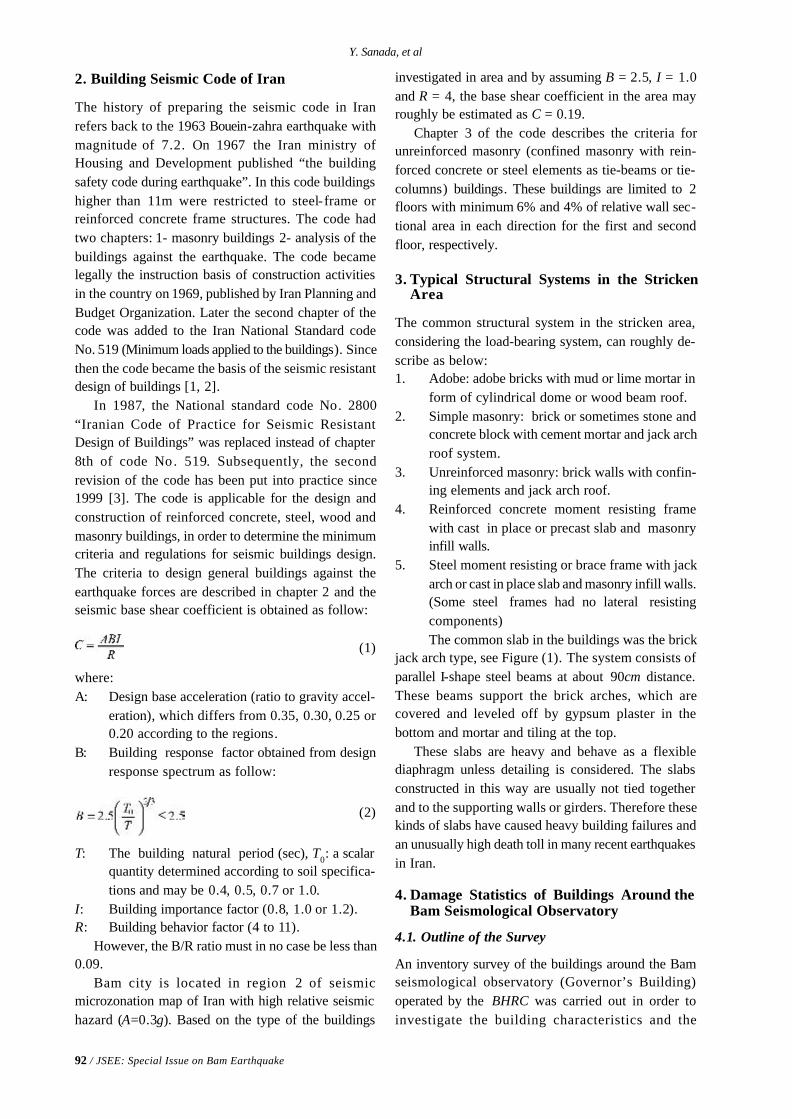
92 / JSEE: Special Issue on Bam Earthquake
Y. Sanada, et al
2. Building Seismic Code of Iran
The history of preparing the seismic code in Iranrefers back to the 1963 Bouein-zahra earthquake withmagnitude of 7.2. On 1967 the Iran ministry ofHousing and Development published “the buildingsafety code during earthquake”. In this code buildingshigher than 11m were restricted to steel-frame orreinforced concrete frame structures. The code hadtwo chapters: 1- masonry buildings 2- analysis of thebuildings against the earthquake. The code becamelegally the instruction basis of construction activitiesin the country on 1969, published by Iran Planning andBudget Organization. Later the second chapter of thecode was added to the Iran National Standard codeNo. 519 (Minimum loads applied to the buildings). Sincethen the code became the basis of the seismic resistantdesign of buildings [1, 2].
In 1987, the National standard code No. 2800“Iranian Code of Practice for Seismic ResistantDesign of Buildings” was replaced instead of chapter8th of code No. 519. Subsequently, the secondrevision of the code has been put into practice since1999 [3]. The code is applicable for the design andconstruction of reinforced concrete, steel, wood andmasonry buildings, in order to determine the minimumcriteria and regulations for seismic buildings design.The criteria to design general buildings against theearthquake forces are described in chapter 2 and theseismic base shear coefficient is obtained as follow:
(1)
where:A: Design base acceleration (ratio to gravity accel-
eration), which differs from 0.35, 0.30, 0.25 or0.20 according to the regions.
B: Building response factor obtained from designresponse spectrum as follow:
(2)
T: The building natural period (sec), T0: a scalarquantity determined according to soil specifica-tions and may be 0.4, 0.5, 0.7 or 1.0.
I: Building importance factor (0.8, 1.0 or 1.2).R: Building behavior factor (4 to 11).
However, the B/R ratio must in no case be less than0.09.
Bam city is located in region 2 of seismicmicrozonation map of Iran with high relative seismichazard (A=0.3g). Based on the type of the buildings
investigated in area and by assuming B = 2.5, I = 1.0and R = 4, the base shear coefficient in the area mayroughly be estimated as C = 0.19.
Chapter 3 of the code describes the criteria forunreinforced masonry (confined masonry with rein-forced concrete or steel elements as tie-beams or tie-columns) buildings. These buildings are limited to 2floors with minimum 6% and 4% of relative wall sec-tional area in each direction for the first and secondfloor, respectively.
3. Typical Structural Systems in the StrickenArea
The common structural system in the stricken area,considering the load-bearing system, can roughly de-scribe as below:1. Adobe: adobe bricks with mud or lime mortar in
form of cylindrical dome or wood beam roof.2. Simple masonry: brick or sometimes stone and
concrete block with cement mortar and jack archroof system.
3. Unreinforced masonry: brick walls with confin-ing elements and jack arch roof.
4. Reinforced concrete moment resisting framewith cast in place or precast slab and masonryinfill walls.
5. Steel moment resisting or brace frame with jackarch or cast in place slab and masonry infill walls.(Some steel frames had no lateral resistingcomponents)The common slab in the buildings was the brick
jack arch type, see Figure (1). The system consists ofparallel I-shape steel beams at about 90cm distance.These beams support the brick arches, which arecovered and leveled off by gypsum plaster in thebottom and mortar and tiling at the top.
These slabs are heavy and behave as a flexiblediaphragm unless detailing is considered. The slabsconstructed in this way are usually not tied togetherand to the supporting walls or girders. Therefore thesekinds of slabs have caused heavy building failures andan unusually high death toll in many recent earthquakesin Iran.
4. Damage Statistics of Buildings Around theBam Seismological Observatory
4.1. Outline of the Survey
An inventory survey of the buildings around the Bamseismological observatory (Governor’s Building)operated by the BHRC was carried out in order toinvestigate the building characteristics and the
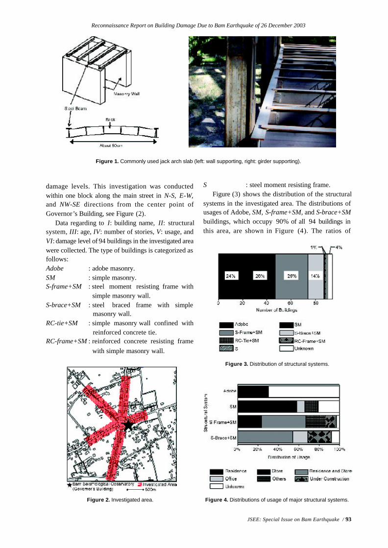
Reconnaissance Report on Building Damage Due to Bam Earthquake of 26 December 2003
JSEE: Special Issue on Bam Earthquake / 93
damage levels. This investigation was conductedwithin one block along the main street in N-S, E-W,and NW-SE directions from the center point ofGovernor’s Building, see Figure (2).
Data regarding to I: building name, II: structuralsystem, III: age, IV: number of stories, V: usage, andVI: damage level of 94 buildings in the investigated areawere collected. The type of buildings is categorized asfollows:Adobe : adobe masonry.SM : simple masonry.S-frame+SM : steel moment resisting frame with
simple masonry wall.S-brace+SM : steel braced frame with simple
masonry wall.RC-tie+SM : simple masonry wall confined with
reinforced concrete tie.RC-frame+SM : reinforced concrete resisting frame
with simple masonry wall.
Figure 1. Commonly used jack arch slab (left: wall supporting, right: girder supporting).
Figure 2. Investigated area.
Figure 3. Distribution of structural systems.
Figure 4. Distributions of usage of major structural systems.
S : steel moment resisting frame.Figure (3) shows the distribution of the structural
systems in the investigated area. The distributions ofusages of Adobe, SM, S-frame+SM, and S-brace+SMbuildings, which occupy 90% of all 94 buildings inthis area, are shown in Figure (4). The ratios of
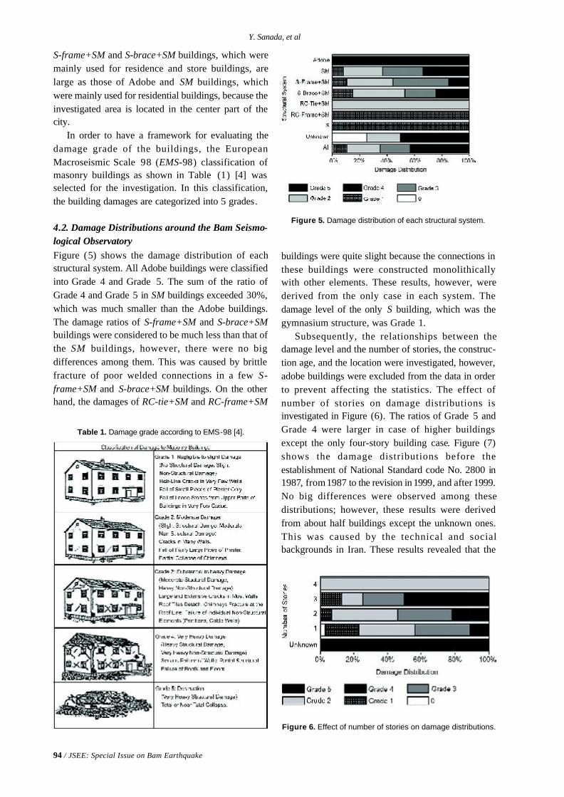
94 / JSEE: Special Issue on Bam Earthquake
Y. Sanada, et al
S-frame+SM and S-brace+SM buildings, which weremainly used for residence and store buildings, arelarge as those of Adobe and SM buildings, whichwere mainly used for residential buildings, because theinvestigated area is located in the center part of thecity.
In order to have a framework for evaluating thedamage grade of the buildings, the EuropeanMacroseismic Scale 98 (EMS-98) classification ofmasonry buildings as shown in Table (1) [4] wasselected for the investigation. In this classification,the building damages are categorized into 5 grades.
4.2. Damage Distributions around the Bam Seismo-logical ObservatoryFigure (5) shows the damage distribution of eachstructural system. All Adobe buildings were classifiedinto Grade 4 and Grade 5. The sum of the ratio ofGrade 4 and Grade 5 in SM buildings exceeded 30%,which was much smaller than the Adobe buildings.The damage ratios of S-frame+SM and S-brace+SMbuildings were considered to be much less than that ofthe SM buildings, however, there were no bigdifferences among them. This was caused by brittlefracture of poor welded connections in a few S-frame+SM and S-brace+SM buildings. On the otherhand, the damages of RC-tie+SM and RC-frame+SM
buildings were quite slight because the connections inthese buildings were constructed monolithicallywith other elements. These results, however, werederived from the only case in each system. Thedamage level of the only S building, which was thegymnasium structure, was Grade 1.
Subsequently, the relationships between thedamage level and the number of stories, the construc-tion age, and the location were investigated, however,adobe buildings were excluded from the data in orderto prevent affecting the statistics. The effect ofnumber of stories on damage distributions isinvestigated in Figure (6). The ratios of Grade 5 andGrade 4 were larger in case of higher buildingsexcept the only four-story building case. Figure (7)shows the damage distributions before theestablishment of National Standard code No. 2800 in1987, from 1987 to the revision in 1999, and after 1999.No big differences were observed among thesedistributions; however, these results were derivedfrom about half buildings except the unknown ones.This was caused by the technical and socialbackgrounds in Iran. These results revealed that the
Table 1. Damage grade according to EMS-98 [4].
Figure 5. Damage distribution of each structural system.
Figure 6. Effect of number of stories on damage distributions.
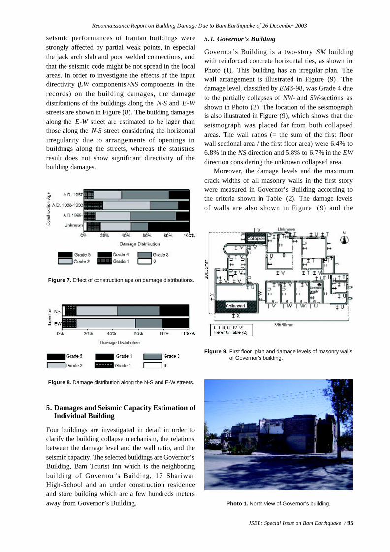
Reconnaissance Report on Building Damage Due to Bam Earthquake of 26 December 2003
JSEE: Special Issue on Bam Earthquake / 95
5.1. Governor’s Building
Governor’s Building is a two-story SM buildingwith reinforced concrete horizontal ties, as shown inPhoto (1). This building has an irregular plan. Thewall arrangement is illustrated in Figure (9). Thedamage level, classified by EMS-98, was Grade 4 dueto the partially collapses of NW- and SW-sections asshown in Photo (2). The location of the seismographis also illustrated in Figure (9), which shows that theseismograph was placed far from both collapsedareas. The wall ratios (= the sum of the first floorwall sectional area / the first floor area) were 6.4% to6.8% in the NS direction and 5.8% to 6.7% in the EWdirection considering the unknown collapsed area.
Moreover, the damage levels and the maximumcrack widths of all masonry walls in the first storywere measured in Governor’s Building according tothe criteria shown in Table (2). The damage levelsof walls are also shown in Figure (9) and the
Figure 7. Effect of construction age on damage distributions.
Figure 8. Damage distribution along the N-S and E-W streets.
5. Damages and Seismic Capacity Estimation ofIndividual Building
Four buildings are investigated in detail in order toclarify the building collapse mechanism, the relationsbetween the damage level and the wall ratio, and theseismic capacity. The selected buildings are Governor’sBuilding, Bam Tourist Inn which is the neighboringbuilding of Governor ’s Building, 17 ShariwarHigh-School and an under construction residenceand store building which are a few hundreds metersaway from Governor’s Building. Photo 1. North view of Governor’s building.
Figure 9. First floor plan and damage levels of masonry wallsof Governor's building.
seismic performances of Iranian buildings werestrongly affected by partial weak points, in especialthe jack arch slab and poor welded connections, andthat the seismic code might be not spread in the localareas. In order to investigate the effects of the inputdirectivity (EW components>NS components in therecords) on the building damages, the damagedistributions of the buildings along the N-S and E-Wstreets are shown in Figure (8). The building damagesalong the E-W street are estimated to be lager thanthose along the N-S street considering the horizontalirregularity due to arrangements of openings inbuildings along the streets, whereas the statisticsresult does not show significant directivity of thebuilding damages.
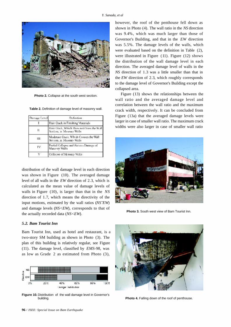
96 / JSEE: Special Issue on Bam Earthquake
Y. Sanada, et al
distribution of the wall damage level in each directionwas shown in Figure (10). The averaged damagelevel of all walls in the EW direction of 2.3, which iscalculated as the mean value of damage levels ofwalls in Figure (10), is larger than that in the NSdirection of 1.7, which means the directivity of theinput motions, estimated by the wall ratios (NS˜EW)and damage levels (NS<EW), corresponds to that ofthe actually recorded data (NS<EW).
5.2. Bam Tourist Inn
Bam Tourist Inn, used as hotel and restaurant, is atwo-story SM building as shown in Photo (3). Theplan of this building is relatively regular, see Figure(11). The damage level, classified by EMS-98, wasas low as Grade 2 as estimated from Photo (3),
Photo 2. Collapse at the south west section.
Table 2. Definition of damage level of masonry wall.
Figure 10. Distribution of the wall damage level in Governor’sbuilding.
Photo 3. South west view of Bam Tourist Inn.
Photo 4. Falling down of the roof of penthouse.
however, the roof of the penthouse fell down asshown in Photo (4). The wall ratio in the NS directionwas 9.4%, which was much larger than those ofGovernor's Building, and that in the EW directionwas 5.5%. The damage levels of the walls, whichwere evaluated based on the definition in Table (2),were illustrated in Figure (11). Figure (12) showsthe distribution of the wall damage level in eachdirection. The averaged damage level of walls in theNS direction of 1.3 was a little smaller than that inthe EW direction of 2.3, which roughly correspondsto the damage level of Governor's Building except thecollapsed area.
Figure (13) shows the relationships between thewall ratio and the averaged damage level andcorrelation between the wall ratio and the maximumcrack width, respectively. It can be concluded fromFigure (13a) that the averaged damage levels werelarger in case of smaller wall ratio. The maximum crackwidths were also larger in case of smaller wall ratio
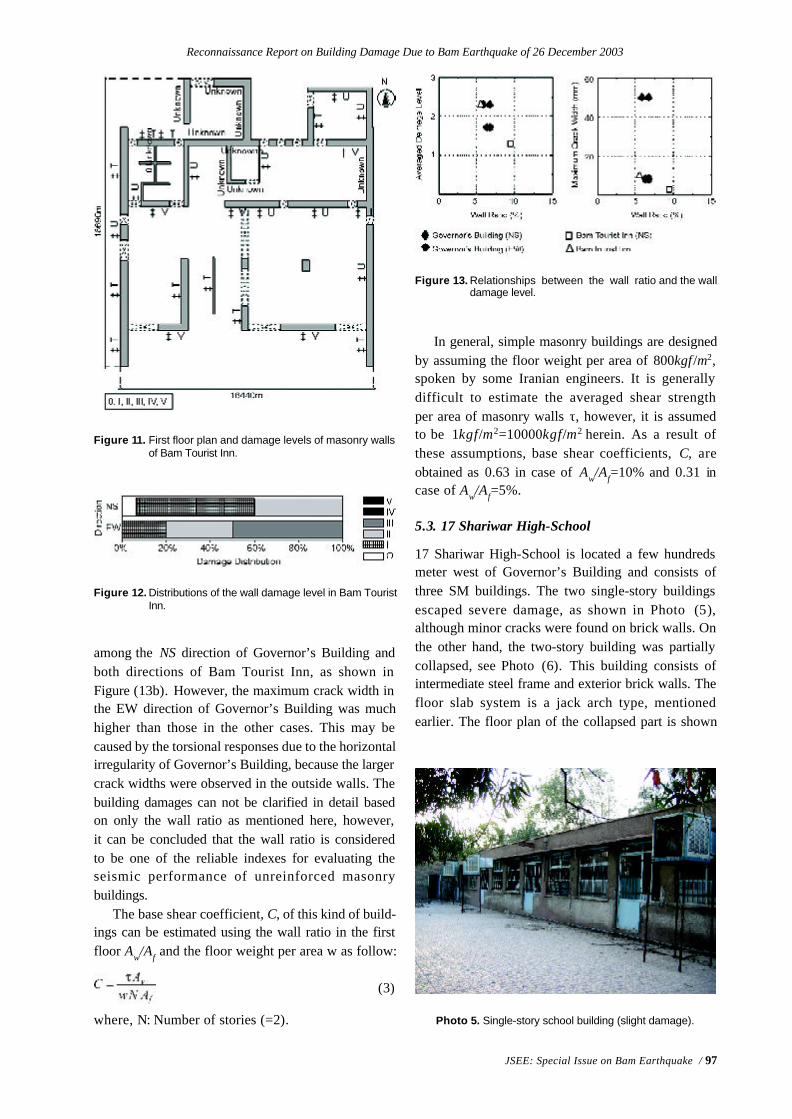
Reconnaissance Report on Building Damage Due to Bam Earthquake of 26 December 2003
JSEE: Special Issue on Bam Earthquake / 97
Figure 12. Distributions of the wall damage level in Bam TouristInn.
Figure 11. First floor plan and damage levels of masonry wallsof Bam Tourist Inn.
among the NS direction of Governor’s Building andboth directions of Bam Tourist Inn, as shown inFigure (13b). However, the maximum crack width inthe EW direction of Governor’s Building was muchhigher than those in the other cases. This may becaused by the torsional responses due to the horizontalirregularity of Governor’s Building, because the largercrack widths were observed in the outside walls. Thebuilding damages can not be clarified in detail basedon only the wall ratio as mentioned here, however,it can be concluded that the wall ratio is consideredto be one of the reliable indexes for evaluating theseismic performance of unreinforced masonrybuildings.
The base shear coefficient, C, of this kind of build-ings can be estimated using the wall ratio in the firstfloor Aw/Af and the floor weight per area w as follow:
(3)
where, N: Number of stories (=2).
In general, simple masonry buildings are designedby assuming the floor weight per area of 800kgf /m2,spoken by some Iranian engineers. It is generallydifficult to estimate the averaged shear strengthper area of masonry walls τ, however, it is assumedto be 1kgf/m2=10000kgf/m2 herein. As a result ofthese assumptions, base shear coefficients, C, areobtained as 0.63 in case of Aw/Af=10% and 0.31 incase of Aw/Af=5%.
5.3. 17 Shariwar High-School
17 Shariwar High-School is located a few hundredsmeter west of Governor’s Building and consists ofthree SM buildings. The two single-story buildingsescaped severe damage, as shown in Photo (5),although minor cracks were found on brick walls. Onthe other hand, the two-story building was partiallycollapsed, see Photo (6). This building consists ofintermediate steel frame and exterior brick walls. Thefloor slab system is a jack arch type, mentionedearlier. The floor plan of the collapsed part is shown
Figure 13. Relationships between the wall ratio and the walldamage level.
Photo 5. Single-story school building (slight damage).
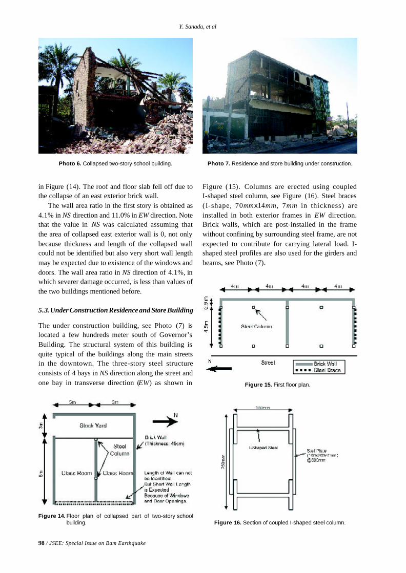
98 / JSEE: Special Issue on Bam Earthquake
Y. Sanada, et al
in Figure (14). The roof and floor slab fell off due tothe collapse of an east exterior brick wall.
The wall area ratio in the first story is obtained as4.1% in NS direction and 11.0% in EW direction. Notethat the value in NS was calculated assuming thatthe area of collapsed east exterior wall is 0, not onlybecause thickness and length of the collapsed wallcould not be identified but also very short wall lengthmay be expected due to existence of the windows anddoors. The wall area ratio in NS direction of 4.1%, inwhich severer damage occurred, is less than values ofthe two buildings mentioned before.
5.3.Under Construction Residence and Store Building
The under construction building, see Photo (7) islocated a few hundreds meter south of Governor’sBuilding. The structural system of this building isquite typical of the buildings along the main streetsin the downtown. The three-story steel structureconsists of 4 bays in NS direction along the street andone bay in transverse direction (EW) as shown in
Photo 6. Collapsed two-story school building.
Figure 14. Floor plan of collapsed part of two-story schoolbuilding.
Photo 7. Residence and store building under construction.
Figure (15). Columns are erected using coupledI-shaped steel column, see Figure (16). Steel braces(I-shape, 70mmx14mm, 7mm in thickness) areinstalled in both exterior frames in EW direction.Brick walls, which are post-installed in the framewithout confining by surrounding steel frame, are notexpected to contribute for carrying lateral load. I-shaped steel profiles are also used for the girders andbeams, see Photo (7).
Figure 15. First floor plan.
Figure 16. Section of coupled I-shaped steel column.
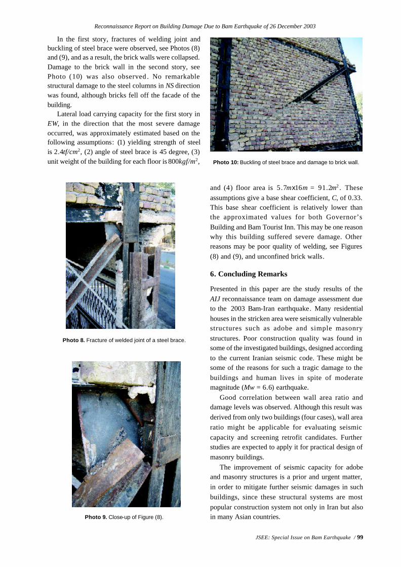
Reconnaissance Report on Building Damage Due to Bam Earthquake of 26 December 2003
JSEE: Special Issue on Bam Earthquake / 99
In the first story, fractures of welding joint andbuckling of steel brace were observed, see Photos (8)and (9), and as a result, the brick walls were collapsed.Damage to the brick wall in the second story, seePhoto (10) was also observed . No remarkablestructural damage to the steel columns in NS directionwas found, although bricks fell off the facade of thebuilding.
Lateral load carrying capacity for the first story inEW, in the direction that the most severe damageoccurred, was approximately estimated based on thefollowing assumptions: (1) yielding strength of steelis 2.4tf/cm2, (2) angle of steel brace is 45 degree, (3)unit weight of the building for each floor is 800kgf/m2,
Photo 8. Fracture of welded joint of a steel brace.
Photo 9. Close-up of Figure (8).
Photo 10: Buckling of steel brace and damage to brick wall.
and (4) floor area is 5.7mx16m = 91.2m2 . Theseassumptions give a base shear coefficient, C, of 0.33.This base shear coefficient is relatively lower thanthe approximated values for both Governor’sBuilding and Bam Tourist Inn. This may be one reasonwhy this building suffered severe damage. Otherreasons may be poor quality of welding, see Figures(8) and (9), and unconfined brick walls.
6. Concluding Remarks
Presented in this paper are the study results of theAIJ reconnaissance team on damage assessment dueto the 2003 Bam-Iran earthquake. Many residentialhouses in the stricken area were seismically vulnerablestructures such as adobe and simple masonrystructures. Poor construction quality was found insome of the investigated buildings, designed accordingto the current Iranian seismic code. These might besome of the reasons for such a tragic damage to thebuildings and human lives in spite of moderatemagnitude (Mw = 6.6) earthquake.
Good correlation between wall area ratio anddamage levels was observed. Although this result wasderived from only two buildings (four cases), wall arearatio might be applicable for evaluating seismiccapacity and screening retrofit candidates. Furtherstudies are expected to apply it for practical design ofmasonry buildings.
The improvement of seismic capacity for adobeand masonry structures is a prior and urgent matter,in order to mitigate further seismic damages in suchbuildings, since these structural systems are mostpopular construction system not only in Iran but alsoin many Asian countries.

100 / JSEE: Special Issue on Bam Earthquake
Y. Sanada, et al
Acknowledgment
This investigation owes much to helpful assistanceof IIEES and BHRC of Iran for collecting materialssuch as damage statistics and seismic recordsetc. This investigation was partially funded by agrant-in-aid for scientific research from MEXT .Special thanks are due to thoughtful commentsfrom the members of the Joint ReconnaissanceTeam. The authors gratefully acknowledge theirassistance.
References
1. BHRC Website, http://www.bhrc.gov.ir.
2. Institute of Standards and Industrial Research ofIran, “ISIRI No. 519”.
3. BHRC (1999). “Iranian Code of Practice forSeismic Resistant Design of Buildings StandardNo. 2800 2nd edition”.
4. Grünthal, G. (1998). “European MacroseismicScale 1998”, http://www.gfz-potsdam.de/pb5/pb53/projects/en/ems/menue_ems_e.html.
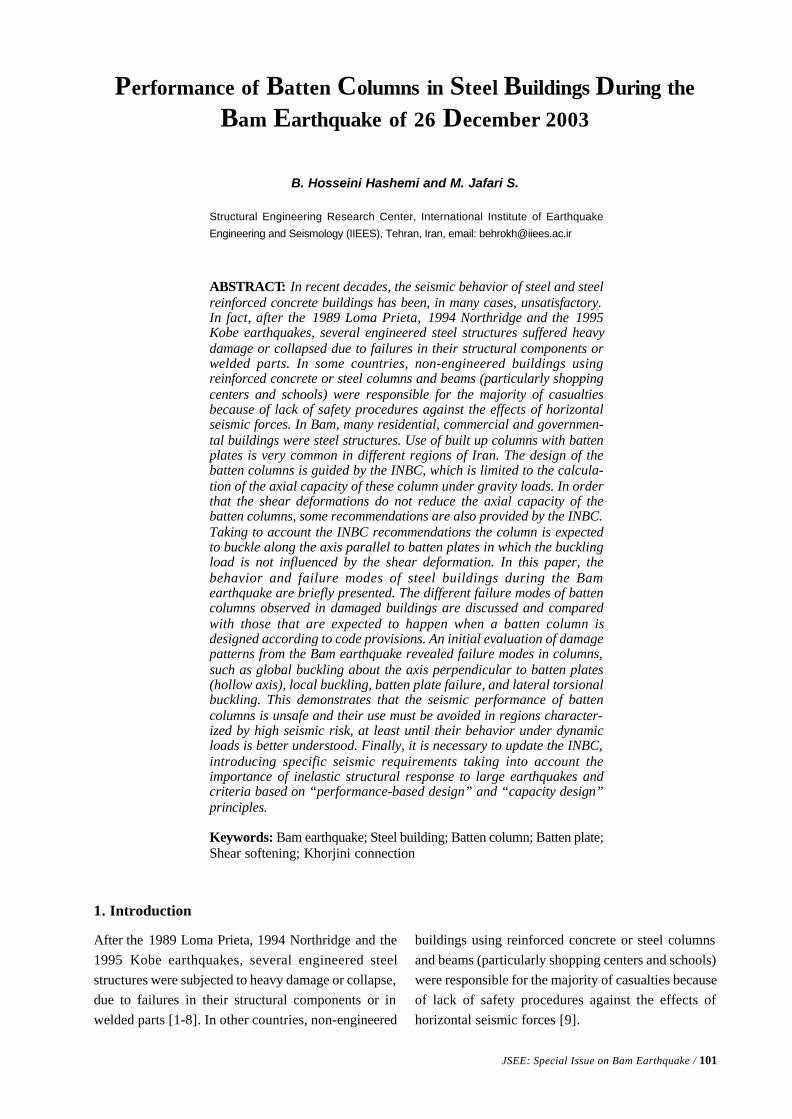
JSEE: Special Issue on Bam Earthquake / 101
Structural Engineering Research Center, International Institute of Earthquake
Engineering and Seismology (IIEES), Tehran, Iran, email: [email protected]
ABSTRACT: In recent decades, the seismic behavior of steel and steelreinforced concrete buildings has been, in many cases, unsatisfactory.In fact, after the 1989 Loma Prieta, 1994 Northridge and the 1995Kobe earthquakes, several engineered steel structures suffered heavydamage or collapsed due to failures in their structural components orwelded parts. In some countries, non-engineered buildings usingreinforced concrete or steel columns and beams (particularly shoppingcenters and schools) were responsible for the majority of casualtiesbecause of lack of safety procedures against the effects of horizontalseismic forces. In Bam, many residential, commercial and governmen-tal buildings were steel structures. Use of built up columns with battenplates is very common in different regions of Iran. The design of thebatten columns is guided by the INBC, which is limited to the calcula-tion of the axial capacity of these column under gravity loads. In orderthat the shear deformations do not reduce the axial capacity of thebatten columns, some recommendations are also provided by the INBC.Taking to account the INBC recommendations the column is expectedto buckle along the axis parallel to batten plates in which the bucklingload is not influenced by the shear deformation. In this paper, thebehavior and failure modes of steel buildings during the Bamearthquake are briefly presented. The different failure modes of battencolumns observed in damaged buildings are discussed and comparedwith those that are expected to happen when a batten column isdesigned according to code provisions. An initial evaluation of damagepatterns from the Bam earthquake revealed failure modes in columns,such as global buckling about the axis perpendicular to batten plates(hollow axis), local buckling, batten plate failure, and lateral torsionalbuckling. This demonstrates that the seismic performance of battencolumns is unsafe and their use must be avoided in regions character-ized by high seismic risk, at least until their behavior under dynamicloads is better understood. Finally, it is necessary to update the INBC,introducing specific seismic requirements taking into account theimportance of inelastic structural response to large earthquakes andcriteria based on “performance-based design” and “capacity design”principles.
Keywords: Bam earthquake; Steel building; Batten column; Batten plate;Shear softening; Khorjini connection
Performance of Batten Columns in Steel Buildings During the
Bam Earthquake of 26 December 2003
B. Hosseini Hashemi and M. Jafari S.
1. Introduction
After the 1989 Loma Prieta, 1994 Northridge and the1995 Kobe earthquakes, several engineered steelstructures were subjected to heavy damage or collapse,due to failures in their structural components or inwelded parts [1-8]. In other countries, non-engineered
buildings using reinforced concrete or steel columnsand beams (particularly shopping centers and schools)were responsible for the majority of casualties becauseof lack of safety procedures against the effects ofhorizontal seismic forces [9].
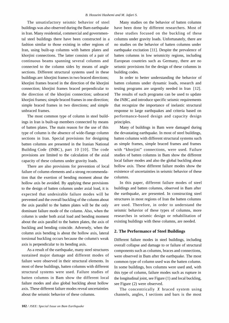
102 / JSEE: Special Issue on Bam Earthquake
B. Hosseini Hashemi and M. Jafari S.
The unsatisfactory seismic behavior of steelbuildings was also observed during the Bam earthquakein Iran. Many residential, commercial and governmen-tal steel buildings there have been constructed in afashion similar to those existing in other regions ofIran, using built-up columns with batten plates andkhorjini connections. The latter consists of a pair ofcontinuous beams spanning several columns andconnected to the column sides by means of anglesections. Different structural systems used in thesebuildings are: khorjini frames in two braced directions;khorjini frames braced in the direction of the khorjiniconnection; khorjini frames braced perpendicular tothe direction of the khorjini connection; unbracedkhorjini frames; simple braced frames in one direction;simple braced frames in two directions; and simpleunbraced frames.
The most common type of column in steel build-ings in Iran is built-up members connected by meansof batten plates. The main reason for the use of thistype of column is the absence of wide-flange columnsections in Iran. Special provisions for designingbatten columns are presented in the Iranian NationalBuilding Code (INBC ), part 10 [10]. The codeprovisions are limited to the calculation of the axialcapacity of these columns under gravity loads.
There are also provisions for prevention of localfailure of column elements and a strong recommenda-tion that the exertion of bending moment about thehollow axis be avoided. By applying these provisionsto the design of batten columns under axial load, it isexpected that undesirable failure modes will beprevented and the overall buckling of the column aboutthe axis parallel to the batten plates will be the onlydominant failure mode of the column. Also, when thecolumn is under both axial load and bending momentabout the axis parallel to the batten plates, the axis ofbuckling and bending coincide. Adversely, when thecolumn axis bending is about the hollow axis, lateraltorsional buckling occurs because the column's weakaxis is perpendicular to its bending axis.
As a result of the earthquake, many steel structuressustained major damage and different modes offailure were observed in their structural elements. Inmost of these buildings, batten columns with differentstructural systems were used. Failure studies ofbatten columns in Bam show the different localfailure modes and also global buckling about hollowaxis. These different failure modes reveal uncertaintiesabout the seismic behavior of these columns.
Many studies on the behavior of batten columnshave been done by different researchers. Most ofthese studies focused on the buckling of thesecolumns under gravity loads. Unfortunately, there areno studies on the behavior of batten columns underearthquake excitation [11]. Despite the prevalence ofbatten columns in low seismicity regions, includingEuropean countries such as Germany, there are noseismic provisions for the design of these columns inbuilding codes.
In order to better understanding the behavior ofbatten columns under dynamic loads, research andtesting programs are urgently needed in Iran [12].The results of such programs can be used to updatethe INBC, and introduce specific seismic requirementsthat recognize the importance of inelastic structuralresponse to large earthquakes and criteria based onperformance-based design and capacity designprinciples.
Many of buildings in Bam were damaged duringthe devastating earthquake. In most of steel buildings,batten columns with different structural systems suchas simple frames, simple braced frames and frameswith “khorjini” connections, were used. Failurestudies of batten columns in Bam show the differentlocal failure modes and also the global buckling abouthollow axis. These different failure modes show theexistence of uncertainties in seismic behavior of thesecolumns.
In this paper, different failure modes of steelbuildings and batten columns, observed in Bam afterthe earthquake, are presented. In constructing steelstructures in most regions of Iran the batten columnsare used. Therefore, in order to understand theseismic behavior of these types of columns, moreresearches in seismic design or rehabilitation ofexisting buildings with these columns, are needed.
2. The Performance of Steel Buildings
Different failure modes in steel buildings, includingoverall collapse and damage to or failure of structuralcomponents such as columns, braces and connections,were observed in Bam after the earthquake. The mostcommon type of column used was the batten column.In some buildings, box columns were used and, withthis type of column, failure modes such as rupture inthe longitudinal joint, see Figure (1) and local buckling,see Figure (2) were observed.
The concentrically X braced system usingchannels, angles, I sections and bars is the most
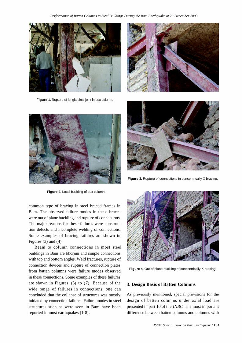
Performance of Batten Columns in Steel Buildings During the Bam Earthquake of 26 December 2003
JSEE: Special Issue on Bam Earthquake / 103
common type of bracing in steel braced frames inBam. The observed failure modes in these braceswere out of plane buckling and rupture of connections.The major reasons for these failures were construc-tion defects and incomplete welding of connections.Some examples of bracing failures are shown inFigures (3) and (4).
Beam to column connections in most steelbuildings in Bam are khorjini and simple connectionswith top and bottom angles. Weld fractures, rupture ofconnection devices and rupture of connection platesfrom batten columns were failure modes observedin these connections. Some examples of these failuresare shown in Figures (5) to (7). Because of thewide range of failures in connections, one canconcluded that the collapse of structures was mostlyinitiated by connection failures. Failure modes in steelstructures such as were seen in Bam have beenreported in most earthquakes [1-8].
Figure 1. Rupture of longitudinal joint in box column.
Figure 2. Local buckling of box column.
Figure 3. Rupture of connections in concentrically X bracing.
Figure 4. Out of plane buckling of concentrically X bracing.
3. Design Basis of Batten Columns
As previously mentioned, special provisions for thedesign of batten columns under axial load arepresented in part 10 of the INBC. The most importantdifference between batten columns and columns with
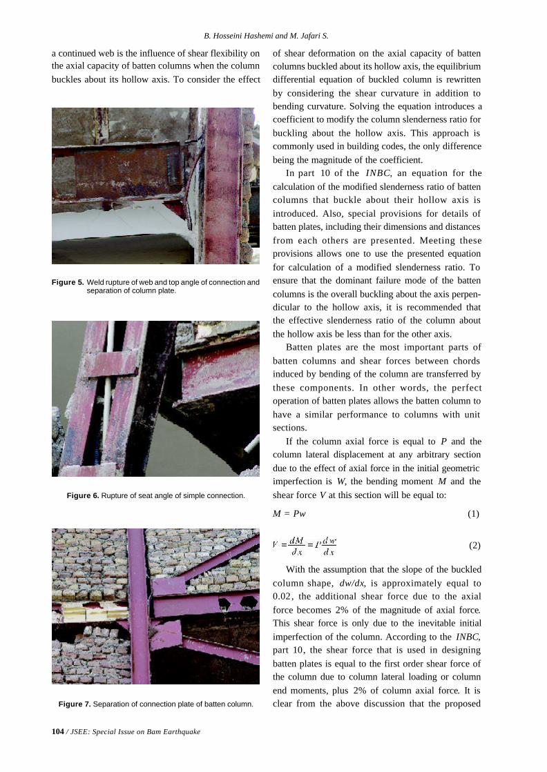
104 / JSEE: Special Issue on Bam Earthquake
B. Hosseini Hashemi and M. Jafari S.
a continued web is the influence of shear flexibility onthe axial capacity of batten columns when the columnbuckles about its hollow axis. To consider the effect
Figure 7. Separation of connection plate of batten column.
Figure 5. Weld rupture of web and top angle of connection andseparation of column plate.
Figure 6. Rupture of seat angle of simple connection.
of shear deformation on the axial capacity of battencolumns buckled about its hollow axis, the equilibriumdifferential equation of buckled column is rewrittenby considering the shear curvature in addition tobending curvature. Solving the equation introduces acoefficient to modify the column slenderness ratio forbuckling about the hollow axis. This approach iscommonly used in building codes, the only differencebeing the magnitude of the coefficient.
In part 10 of the INBC, an equation for thecalculation of the modified slenderness ratio of battencolumns that buckle about their hollow axis isintroduced. Also, special provisions for details ofbatten plates, including their dimensions and distancesfrom each others are presented. Meeting theseprovisions allows one to use the presented equationfor calculation of a modified slenderness ratio. Toensure that the dominant failure mode of the battencolumns is the overall buckling about the axis perpen-dicular to the hollow axis, it is recommended thatthe effective slenderness ratio of the column aboutthe hollow axis be less than for the other axis.
Batten plates are the most important parts ofbatten columns and shear forces between chordsinduced by bending of the column are transferred bythese components. In other words, the perfectoperation of batten plates allows the batten column tohave a similar performance to columns with unitsections.
If the column axial force is equal to P and thecolumn lateral displacement at any arbitrary sectiondue to the effect of axial force in the initial geometricimperfection is W, the bending moment M and theshear force V at this section will be equal to:
M = Pw (1)
(2)
With the assumption that the slope of the buckledcolumn shape, dw/dx, is approximately equal to0.02, the additional shear force due to the axialforce becomes 2% of the magnitude of axial force.This shear force is only due to the inevitable initialimperfection of the column. According to the INBC,part 10, the shear force that is used in designingbatten plates is equal to the first order shear force ofthe column due to column lateral loading or columnend moments, plus 2% of column axial force. It isclear from the above discussion that the proposed
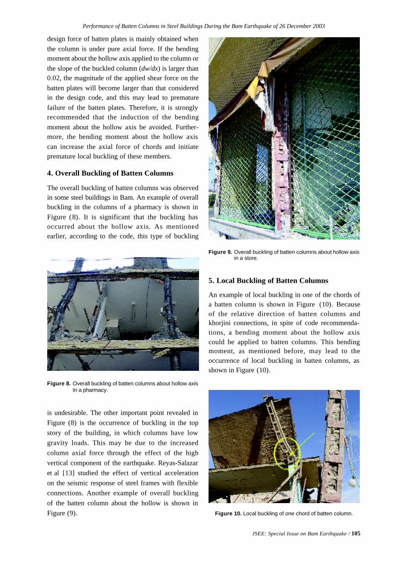
Performance of Batten Columns in Steel Buildings During the Bam Earthquake of 26 December 2003
JSEE: Special Issue on Bam Earthquake / 105
design force of batten plates is mainly obtained whenthe column is under pure axial force. If the bendingmoment about the hollow axis applied to the column orthe slope of the buckled column (dw/dx) is larger than0.02, the magnitude of the applied shear force on thebatten plates will become larger than that consideredin the design code, and this may lead to prematurefailure of the batten plates. Therefore, it is stronglyrecommended that the induction of the bendingmoment about the hollow axis be avoided. Further-more, the bending moment about the hollow axiscan increase the axial force of chords and initiatepremature local buckling of these members.
4. Overall Buckling of Batten Columns
The overall buckling of batten columns was observedin some steel buildings in Bam. An example of overallbuckling in the columns of a pharmacy is shown inFigure (8). It is significant that the buckling hasoccurred about the hollow axis. As mentionedearlier, according to the code, this type of buckling
Figure 10. Local buckling of one chord of batten column.
Figure 8. Overall buckling of batten columns about hollow axisIn a pharmacy.
is undesirable. The other important point revealed inFigure (8) is the occurrence of buckling in the topstory of the building, in which columns have lowgravity loads. This may be due to the increasedcolumn axial force through the effect of the highvertical component of the earthquake. Reyas-Salazaret al [13] studied the effect of vertical accelerationon the seismic response of steel frames with flexibleconnections. Another example of overall bucklingof the batten column about the hollow is shown inFigure (9).
Figure 9. Overall buckling of batten columns about hollow axisin a store.
5. Local Buckling of Batten Columns
An example of local buckling in one of the chords ofa batten column is shown in Figure (10). Becauseof the relative direction of batten columns andkhorjini connections, in spite of code recommenda-tions, a bending moment about the hollow axiscould be applied to batten columns. This bendingmoment, as mentioned before, may lead to theoccurrence of local buckling in batten columns, asshown in Figure (10).
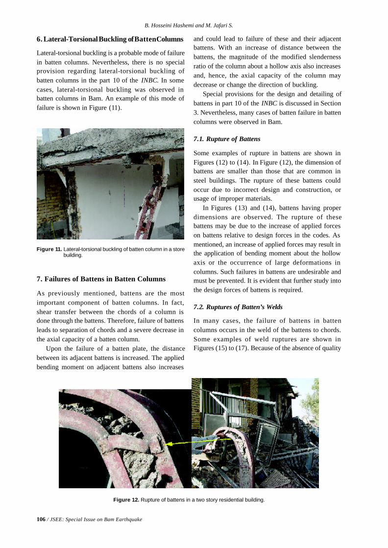
106 / JSEE: Special Issue on Bam Earthquake
B. Hosseini Hashemi and M. Jafari S.
6. Lateral-Torsional Buckling of Batten Columns
Lateral-torsional buckling is a probable mode of failurein batten columns. Nevertheless, there is no specialprovision regarding lateral-torsional buckling ofbatten columns in the part 10 of the INBC. In somecases, lateral-torsional buckling was observed inbatten columns in Bam. An example of this mode offailure is shown in Figure (11).
Figure 11. Lateral-torsional buckling of batten column in a storebuilding.
7. Failures of Battens in Batten Columns
As previously mentioned, battens are the mostimportant component of batten columns. In fact,shear transfer between the chords of a column isdone through the battens. Therefore, failure of battensleads to separation of chords and a severe decrease inthe axial capacity of a batten column.
Upon the failure of a batten plate, the distancebetween its adjacent battens is increased. The appliedbending moment on adjacent battens also increases
Figure 12. Rupture of battens in a two story residential building.
and could lead to failure of these and their adjacentbattens. With an increase of distance between thebattens, the magnitude of the modified slendernessratio of the column about a hollow axis also increasesand, hence, the axial capacity of the column maydecrease or change the direction of buckling.
Special provisions for the design and detailing ofbattens in part 10 of the INBC is discussed in Section3. Nevertheless, many cases of batten failure in battencolumns were observed in Bam.
7.1. Rupture of Battens
Some examples of rupture in battens are shown inFigures (12) to (14). In Figure (12), the dimension ofbattens are smaller than those that are common insteel buildings. The rupture of these battens couldoccur due to incorrect design and construction, orusage of improper materials.
In Figures (13) and (14), battens having properdimensions are observed. The rupture of thesebattens may be due to the increase of applied forceson battens relative to design forces in the codes. Asmentioned, an increase of applied forces may result inthe application of bending moment about the hollowaxis or the occurrence of large deformations incolumns. Such failures in battens are undesirable andmust be prevented. It is evident that further study intothe design forces of battens is required.
7.2. Ruptures of Batten’s Welds
In many cases, the failure of battens in battencolumns occurs in the weld of the battens to chords.Some examples of weld ruptures are shown inFigures (15) to (17). Because of the absence of quality
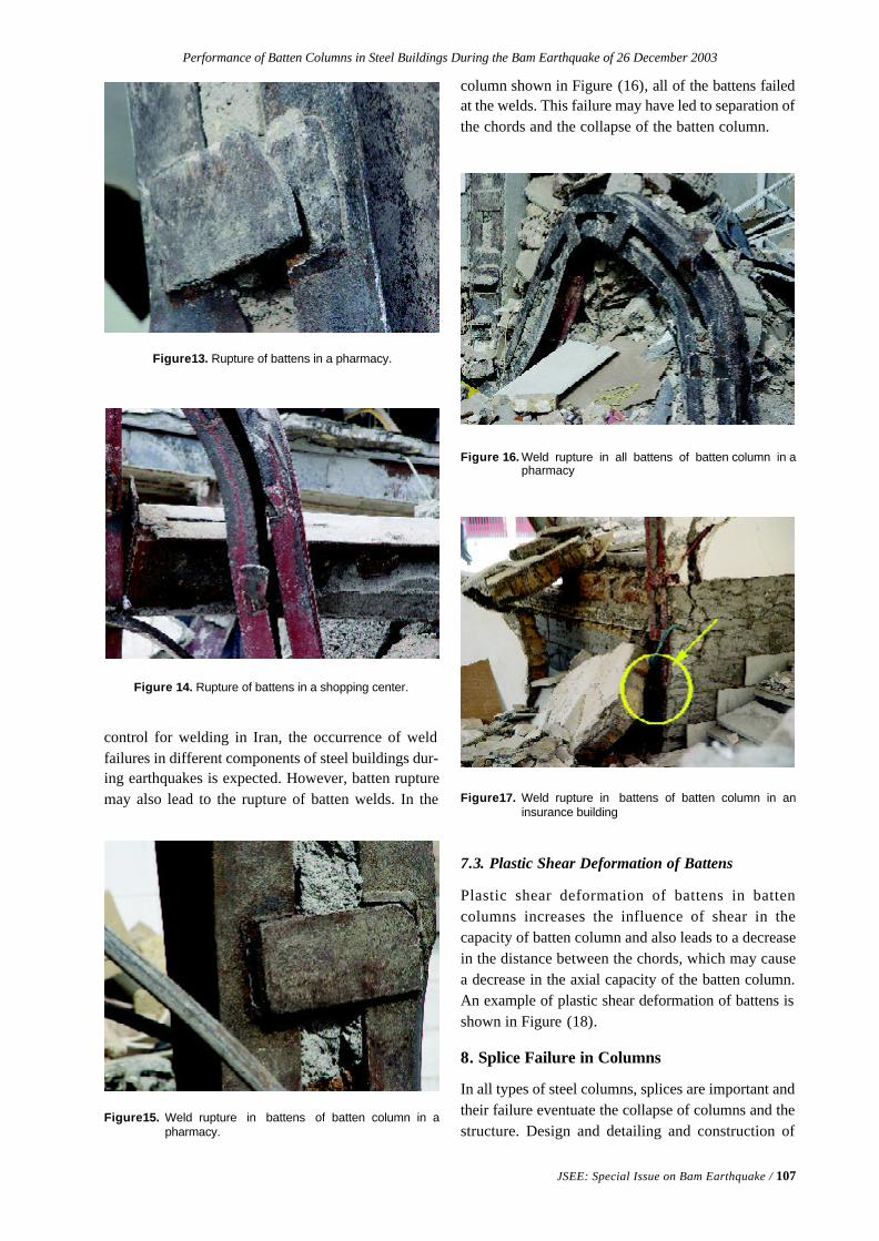
Performance of Batten Columns in Steel Buildings During the Bam Earthquake of 26 December 2003
JSEE: Special Issue on Bam Earthquake / 107
Figure 14. Rupture of battens in a shopping center.
Figure13. Rupture of battens in a pharmacy.
control for welding in Iran, the occurrence of weldfailures in different components of steel buildings dur-ing earthquakes is expected. However, batten rupturemay also lead to the rupture of batten welds. In the
column shown in Figure (16), all of the battens failedat the welds. This failure may have led to separation ofthe chords and the collapse of the batten column.
Figure15. Weld rupture in battens of batten column in apharmacy.
Figure17. Weld rupture in battens of batten column in aninsurance building
Figure 16. Weld rupture in all battens of batten column in apharmacy
7.3. Plastic Shear Deformation of Battens
Plastic shear deformation of battens in battencolumns increases the influence of shear in thecapacity of batten column and also leads to a decreasein the distance between the chords, which may causea decrease in the axial capacity of the batten column.An example of plastic shear deformation of battens isshown in Figure (18).
8. Splice Failure in Columns
In all types of steel columns, splices are important andtheir failure eventuate the collapse of columns and thestructure. Design and detailing and construction of
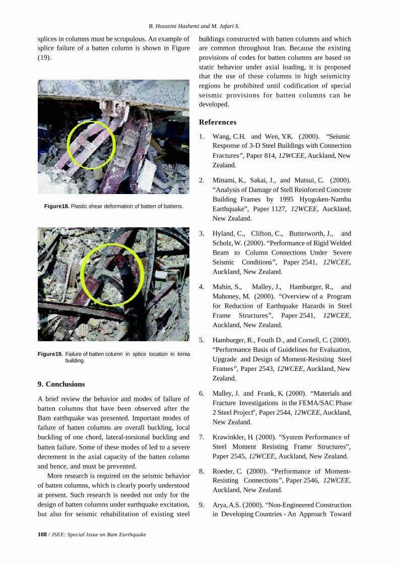
108 / JSEE: Special Issue on Bam Earthquake
B. Hosseini Hashemi and M. Jafari S.
Figure18. Plastic shear deformation of batten of battens.
splices in columns must be scrupulous. An example ofsplice failure of a batten column is shown in Figure(19).
Figure19. Failure of batten column in splice location in kimiabuilding.
9. Conclusions
A brief review the behavior and modes of failure ofbatten columns that have been observed after theBam earthquake was presented. Important modes offailure of batten columns are overall buckling, localbuckling of one chord, lateral-torsional buckling andbatten failure. Some of these modes of led to a severedecrement in the axial capacity of the batten columnand hence, and must be prevented.
More research is required on the seismic behaviorof batten columns, which is clearly poorly understoodat present. Such research is needed not only for thedesign of batten columns under earthquake excitation,but also for seismic rehabilitation of existing steel
buildings constructed with batten columns and whichare common throughout Iran. Because the existingprovisions of codes for batten columns are based onstatic behavior under axial loading, it is proposedthat the use of these columns in high seismicityregions be prohibited until codification of specialseismic provisions for batten columns can bedeveloped.
References
1. Wang, C.H. and Wen, Y.K. (2000). “SeismicResponse of 3-D Steel Buildings with ConnectionFractures”, Paper 814, 12WCEE, Auckland, NewZealand.
2. Minami, K., Sakai, J., and Matsui, C. (2000).“Analysis of Damage of Stell Reinforced ConcreteBuilding Frames by 1995 Hyogoken-NambuEarthquake”, Paper 1127, 12WCEE, Auckland,New Zealand.
3. Hyland, C., Clifton, C., Butterworth, J., andScholz, W. (2000). “Performance of Rigid WeldedBeam to Column Connections Under SevereSeismic Conditions”, Paper 2541, 12WCEE,Auckland, New Zealand.
4. Mahin, S., Malley, J., Hamburger, R., andMahoney, M. (2000). “Overview of a Programfor Reduction of Earthquake Hazards in SteelFrame Structures”, Paper 2541, 12WCEE,Auckland, New Zealand.
5. Hamburger, R., Fouth D., and Cornell, C. (2000).“Performance Basis of Guidelines for Evaluation,Upgrade and Design of Moment-Resisting SteelFrames”, Paper 2543, 12WCEE, Auckland, NewZealand.
6. Malley, J. and Frank, K. (2000). “Materials andFracture Investigations in the FEMA/SAC Phase2 Steel Project”, Paper 2544, 12WCEE, Auckland,New Zealand.
7. Krawinkler, H. (2000). “System Performance ofSteel Moment Resisting Frame Structures”,Paper 2545, 12WCEE, Auckland, New Zealand.
8. Roeder, C. (2000). “Performance of Moment-Resisting Connections”, Paper 2546, 12WCEE,Auckland, New Zealand.
9. Arya, A.S. (2000). “Non-Engineered Constructionin Developing Countries - An Approach Toward
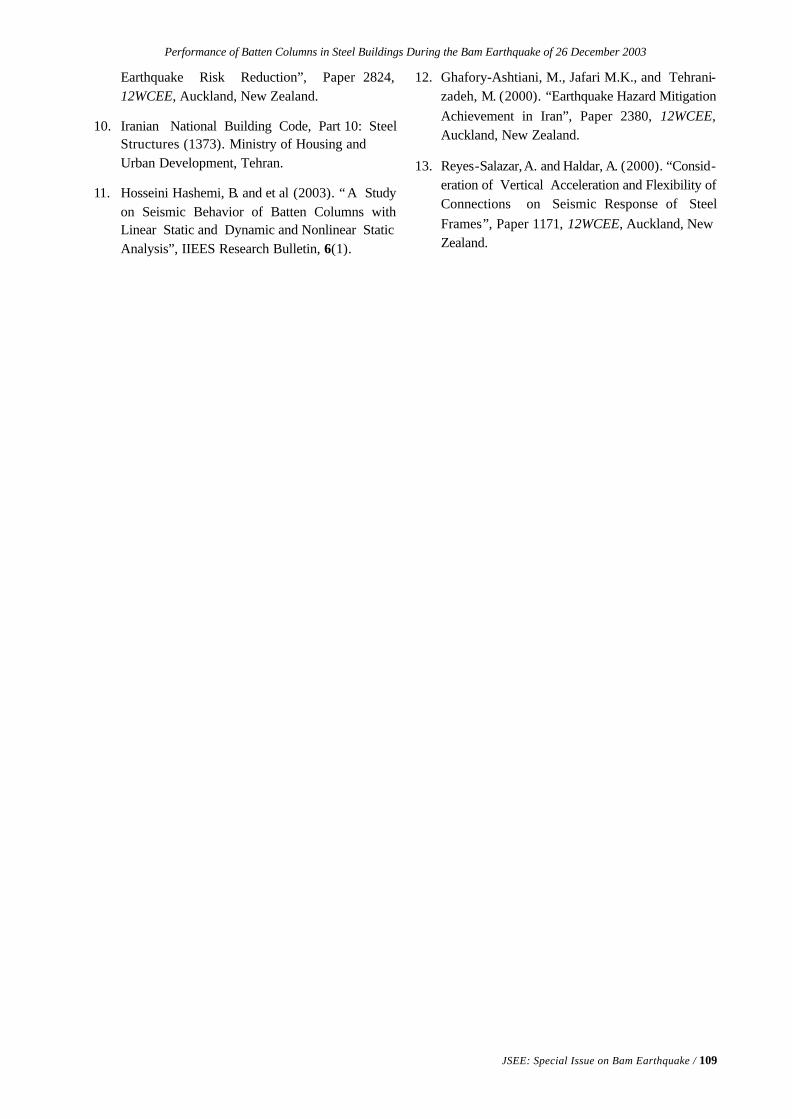
Performance of Batten Columns in Steel Buildings During the Bam Earthquake of 26 December 2003
JSEE: Special Issue on Bam Earthquake / 109
Earthquake Risk Reduction”, Paper 2824,12WCEE, Auckland, New Zealand.
10. Iranian National Building Code, Part 10: SteelStructures (1373). Ministry of Housing andUrban Development, Tehran.
11. Hosseini Hashemi, B. and et al (2003). “ A Studyon Seismic Behavior of Batten Columns withLinear Static and Dynamic and Nonlinear StaticAnalysis”, IIEES Research Bulletin, 6(1).
12. Ghafory-Ashtiani, M., Jafari M.K., and Tehrani-zadeh, M. (2000). “Earthquake Hazard MitigationAchievement in Iran”, Paper 2380, 12WCEE,Auckland, New Zealand.
13. Reyes-Salazar, A. and Haldar, A. (2000). “Consid-eration of Vertical Acceleration and Flexibility ofConnections on Seismic Response of SteelFrames”, Paper 1171, 12WCEE, Auckland, NewZealand.
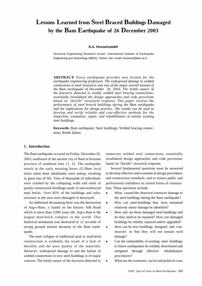
JSEE: Special Issue on Bam Earthquake / 111
Structural Engineering Research Center, International Institute of Earthquake
Engineering and Seismology (IIEES), Tehran, Iran, email: [email protected]
ABSTRACT: Every earthquake provides new lessons for theearthquake engineering profession. The widespread damage to weldedconnections in steel structures was one of the major overall lessons ofthe Bam earthquake of December 26, 2003. The brittle nature ofthe fractures detected in weakly welded steel bracing connections,essentially invalidated the design approaches and code provisionsbased on "ductile" structural response. This paper reviews theperformance of steel braced buildings during the Bam earthquakeand the implications for design practice. The results can be used todevelop and verify reliable and cost-effective methods for theinspection, evaluation, repair, and rehabilitation of similar existingsteel buildings.
Keywords: Bam earthquake; Steel buildings; Welded bracing connec-tions; Brittle failure
Lessons Learned from Steel Braced Buildings Damaged
by the Bam Earthquake of 26 December 2003
N.A. Hosseinzadeh
1. Introduction
The Bam earthquake occured on Friday, December 26,2003, southwest of the ancient city of Bam in Kermanprovince of southeast Iran [1, 2]. The earthquakestruck in the early morning hours (5:26am localtime) when most inhabitants were asleep, resultingin great loss of life. Tens of thousands of individualswere crushed by the collapsing walls and roofs ofpoorly-constructed dwellings made of non-reinforcedmud bricks. Over 85% of the buildings and infra-structure in the area were damaged or destroyed.
An additional devastating blow was the destructionof Arg-e-Bam, a citadel on the historic Silk Roadwhich is more than 2,000 years old. Arg-e Bam is thelargest mud-brick complex in the world. Thishistorical monument was destroyed in 12 seconds ofstrong ground motion duration of the Bam earth-quake.
The total collapse of traditional mud or mud-brickconstruction is evidently the result of a lack ofductility and the poor quality of the materials.However, widespread damage to and the failure ofwelded connections in new steel buildings is of majorconcern. The brittle nature of the fractures detected in
numerous welded steel connections, essentiallyinvalidated design approaches and code provisionsbased on “ductile” structural response.
Several fundamental questions must be answeredto develop effective and economical design proceduresand construction standards, and to restore public andprofessional confidence in current forms of construc-tion. These questions include:l What caused the observed extensive damage to
the steel buildings during the Bam earthquake?l How can steel buildings that have sustained
relatively minor damage be identified?l How safe are these damaged steel buildings and
do they need to be repaired? How can damagedbuildings be reliably repaired and/or upgraded?
l How can be new buildings designed and con-structed so that they will not sustain suchdamage?
l Can the vulnerability of existing steel buildingsto future earthquakes be reliably determined andmitigated through effective rehabilitationprocedures?
l What are the economic, social and political costs
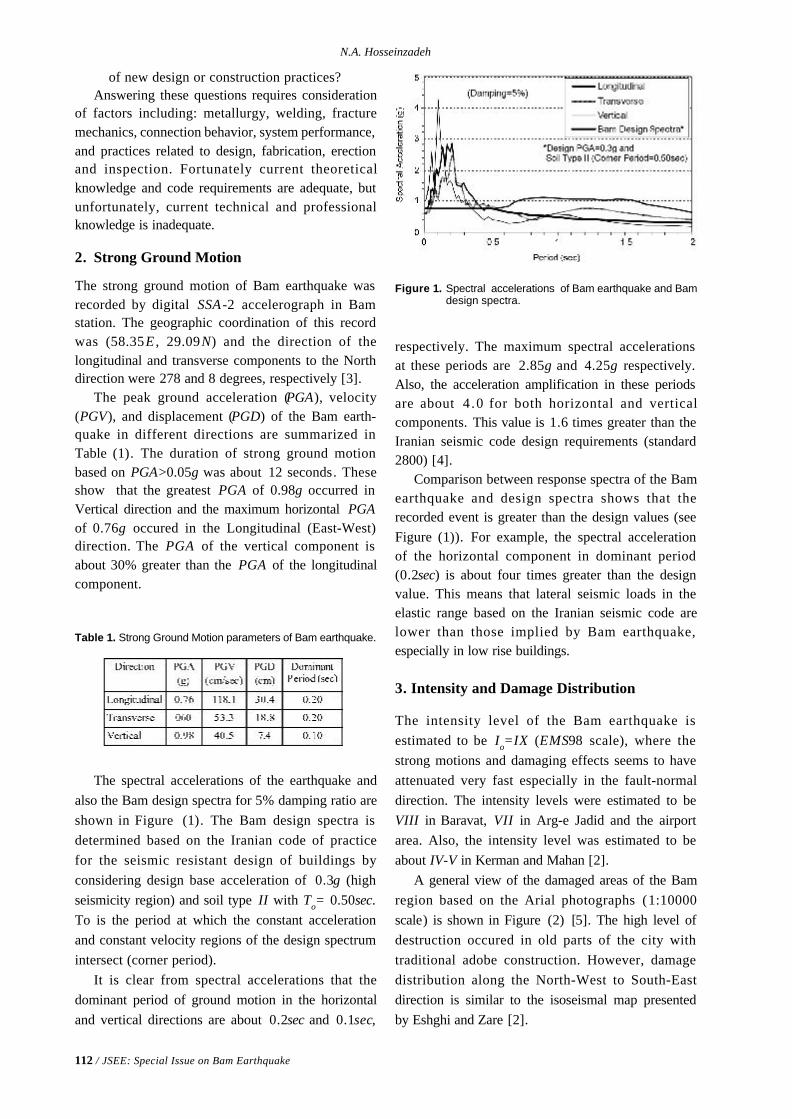
112 / JSEE: Special Issue on Bam Earthquake
N.A. Hosseinzadeh
of new design or construction practices?Answering these questions requires consideration
of factors including: metallurgy, welding, fracturemechanics, connection behavior, system performance,and practices related to design, fabrication, erectionand inspection. Fortunately current theoreticalknowledge and code requirements are adequate, butunfortunately, current technical and professionalknowledge is inadequate.
2. Strong Ground Motion
The strong ground motion of Bam earthquake wasrecorded by digital SSA -2 accelerograph in Bamstation. The geographic coordination of this recordwas (58.35E , 29.09N) and the direction of thelongitudinal and transverse components to the Northdirection were 278 and 8 degrees, respectively [3].
The peak ground acceleration (PGA), velocity(PGV), and displacement (PGD) of the Bam earth-quake in different directions are summarized inTable (1). The duration of strong ground motionbased on PGA>0.05g was about 12 seconds. Theseshow that the greatest PGA of 0.98g occurred inVertical direction and the maximum horizontal PGAof 0.76g occured in the Longitudinal (East-West)direction. The PGA of the vertical component isabout 30% greater than the PGA of the longitudinalcomponent.
respectively. The maximum spectral accelerationsat these periods are 2.85g and 4.25g respectively.Also, the acceleration amplification in these periodsare about 4 .0 for both horizontal and verticalcomponents. This value is 1.6 times greater than theIranian seismic code design requirements (standard2800) [4].
Comparison between response spectra of the Bamearthquake and design spectra shows that therecorded event is greater than the design values (seeFigure (1)). For example, the spectral accelerationof the horizontal component in dominant period(0.2sec) is about four times greater than the designvalue. This means that lateral seismic loads in theelastic range based on the Iranian seismic code arelower than those implied by Bam earthquake,especially in low rise buildings.
3. Intensity and Damage Distribution
The intensity level of the Bam earthquake isestimated to be Io=IX (EMS98 scale), where thestrong motions and damaging effects seems to haveattenuated very fast especially in the fault-normaldirection. The intensity levels were estimated to beVIII in Baravat, VII in Arg-e Jadid and the airportarea. Also, the intensity level was estimated to beabout IV-V in Kerman and Mahan [2].
A general view of the damaged areas of the Bamregion based on the Arial photographs (1:10000scale) is shown in Figure (2) [5]. The high level ofdestruction occured in old parts of the city withtraditional adobe construction. However, damagedistribution along the North-West to South-Eastdirection is similar to the isoseismal map presentedby Eshghi and Zare [2].
Table 1. Strong Ground Motion parameters of Bam earthquake.
Figure 1. Spectral accelerations of Bam earthquake and Bamdesign spectra.
The spectral accelerations of the earthquake andalso the Bam design spectra for 5% damping ratio areshown in Figure (1). The Bam design spectra isdetermined based on the Iranian code of practicefor the seismic resistant design of buildings byconsidering design base acceleration of 0.3g (highseismicity region) and soil type II with To= 0.50sec.To is the period at which the constant accelerationand constant velocity regions of the design spectrumintersect (corner period).
It is clear from spectral accelerations that thedominant period of ground motion in the horizontaland vertical directions are about 0.2sec and 0.1sec,
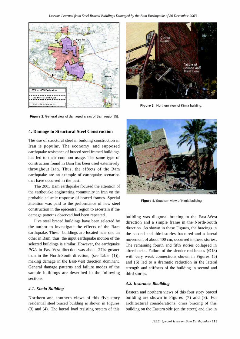
Lessons Learned from Steel Braced Buildings Damaged by the Bam Earthquake of 26 December 2003
JSEE: Special Issue on Bam Earthquake / 113
Figure 2. General view of damaged areas of Bam region [5].
4. Damage to Structural Steel Construction
The use of structural steel in building construction inIran is popular. The economy, and supposedearthquake resistance of braced steel framed buildingshas led to their common usage. The same type ofconstruction found in Bam has been used extensivelythroughout Iran. Thus, the effects of the Bamearthquake are an example of earthquake scenariosthat have occurred in the past.
The 2003 Bam earthquake focused the attention ofthe earthquake engineering community in Iran on theprobable seismic response of braced frames. Specialattention was paid to the performance of new steelconstruction in the epicentral region to ascertain if thedamage patterns observed had been repeated.
Five steel braced buildings have been selected bythe author to investigate the effects of the Bamearthquake. These buildings are located near one another in Bam, thus, the input earthquake motion of theselected buildings is similar. However, the earthquakePGA in East-Vest direction was about 27% greaterthan in the North-South direction, (see Table (1)),making damage in the East-Vest direction dominant.General damage patterns and failure modes of thesample buildings are described in the followingsections.
4.1. Kimia Building
Northern and southern views of this five storyresidential steel braced building is shown in Figures(3) and (4). The lateral load resisting system of this
building was diagonal bracing in the East-Westdirection and a simple frame in the North-Southdirection. As shown in these Figures, the bracings inthe second and third stories fractured and a lateralmovement of about 400 cm, occurred in these stories.The remaining fourth and fifth stories collapsed inaftershocks. Failure of the slender rod braces (Ø18)with very weak connections shown in Figures (5)and (6) led to a dramatic reduction in the lateralstrength and stiffness of the building in second andthird stories.
4.2. Insurance Bbuilding
Eastern and northern views of this four story bracedbuilding are shown in Figures (7) and (8). Forarchitectural considerations, cross bracing of thisbuilding on the Eastern side (on the street) and also in
Figure 3. Northern view of Kimia building.
Figure 4. Southern view of Kimia building
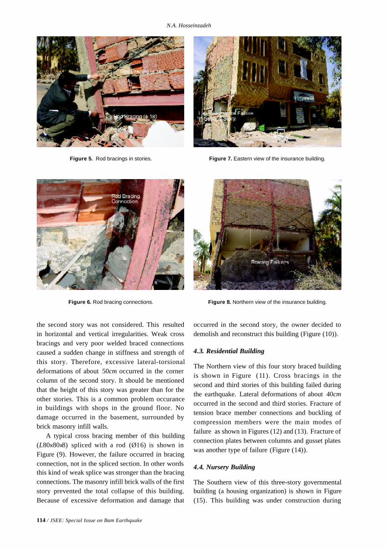
114 / JSEE: Special Issue on Bam Earthquake
N.A. Hosseinzadeh
the second story was not considered. This resultedin horizontal and vertical irregularities. Weak crossbracings and very poor welded braced connectionscaused a sudden change in stiffness and strength ofthis story. Therefore, excessive lateral-torsionaldeformations of about 50cm occurred in the cornercolumn of the second story. It should be mentionedthat the height of this story was greater than for theother stories. This is a common problem occurancein buildings with shops in the ground floor. Nodamage occurred in the basement, surrounded bybrick masonry infill walls.
A typical cross bracing member of this building(L80x80x8) spliced with a rod (Ø16) is shown inFigure (9). However, the failure occurred in bracingconnection, not in the spliced section. In other wordsthis kind of weak splice was stronger than the bracingconnections. The masonry infill brick walls of the firststory prevented the total collapse of this building.Because of excessive deformation and damage that
occurred in the second story, the owner decided todemolish and reconstruct this building (Figure (10)).
4.3. Residential Building
The Northern view of this four story braced buildingis shown in Figure (11). Cross bracings in thesecond and third stories of this building failed duringthe earthquake. Lateral deformations of about 40cmoccurred in the second and third stories. Fracture oftension brace member connections and buckling ofcompression members were the main modes offailure as shown in Figures (12) and (13). Fracture ofconnection plates between columns and gusset plateswas another type of failure (Figure (14)).
4.4. Nursery Building
The Southern view of this three-story governmentalbuilding (a housing organization) is shown in Figure(15). This building was under construction during
Figure 5. Rod bracings in stories.
Figure 6. Rod bracing connections.
Figure 7. Eastern view of the insurance building.
Figure 8. Northern view of the insurance building.
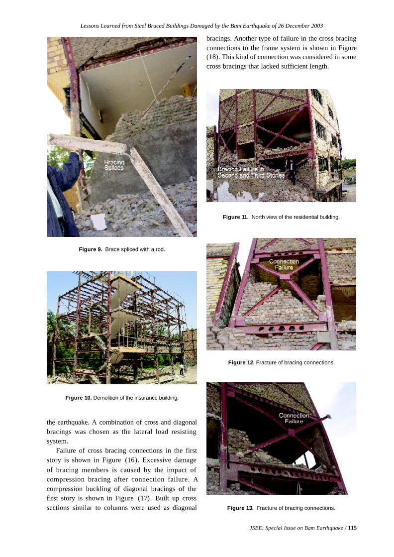
Lessons Learned from Steel Braced Buildings Damaged by the Bam Earthquake of 26 December 2003
JSEE: Special Issue on Bam Earthquake / 115
Figure 9. Brace spliced with a rod.
Figure 10. Demolition of the insurance building.
the earthquake. A combination of cross and diagonalbracings was chosen as the lateral load resistingsystem.
Failure of cross bracing connections in the firststory is shown in Figure (16). Excessive damageof bracing members is caused by the impact ofcompression bracing after connection failure. Acompression buckling of diagonal bracings of thefirst story is shown in Figure (17). Built up crosssections similar to columns were used as diagonal
Figure 11. North view of the residential building.
Figure 12. Fracture of bracing connections.
Figure 13. Fracture of bracing connections.
bracings. Another type of failure in the cross bracingconnections to the frame system is shown in Figure(18). This kind of connection was considered in somecross bracings that lacked sufficient length.
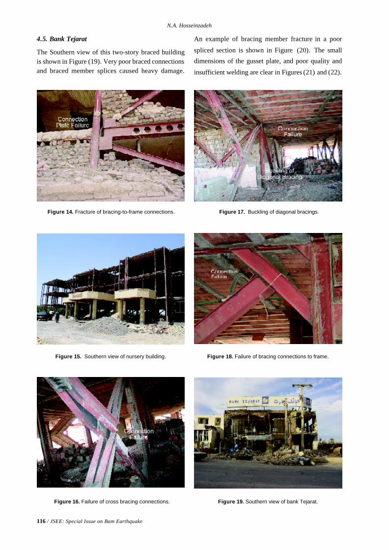
116 / JSEE: Special Issue on Bam Earthquake
N.A. Hosseinzadeh
4.5. Bank Tejarat
The Southern view of this two-story braced buildingis shown in Figure (19). Very poor braced connectionsand braced member splices caused heavy damage.
Figure 14. Fracture of bracing-to-frame connections.
Figure 15. Southern view of nursery building.
Figure 16. Failure of cross bracing connections.
Figure 17. Buckling of diagonal bracings.
Figure 18. Failure of bracing connections to frame.
Figure 19. Southern view of bank Tejarat.
An example of bracing member fracture in a poor
spliced section is shown in Figure (20). The small
dimensions of the gusset plate, and poor quality and
insufficient welding are clear in Figures (21) and (22).
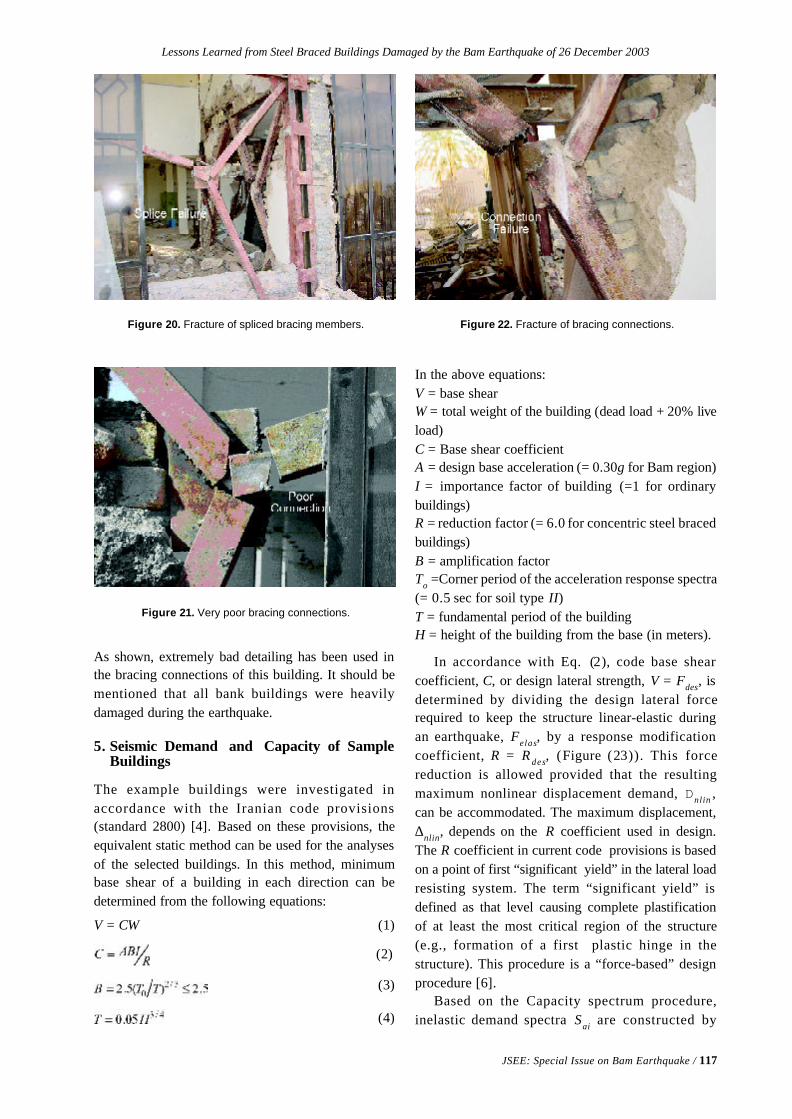
Lessons Learned from Steel Braced Buildings Damaged by the Bam Earthquake of 26 December 2003
JSEE: Special Issue on Bam Earthquake / 117
Figure 20. Fracture of spliced bracing members. Figure 22. Fracture of bracing connections.
Figure 21. Very poor bracing connections.
As shown, extremely bad detailing has been used inthe bracing connections of this building. It should bementioned that all bank buildings were heavilydamaged during the earthquake.
5. Seismic Demand and Capacity of SampleBuildings
The example buildings were investigated inaccordance with the Iranian code provisions(standard 2800) [4]. Based on these provisions, theequivalent static method can be used for the analysesof the selected buildings. In this method, minimumbase shear of a building in each direction can bedetermined from the following equations:
V = CW (1)
(2)
(3)
(4)
In the above equations:V = base shearW = total weight of the building (dead load + 20% liveload)C = Base shear coefficientA = design base acceleration (= 0.30g for Bam region)I = importance factor of building (=1 for ordinarybuildings)R = reduction factor (= 6.0 for concentric steel bracedbuildings)B = amplification factorTo =Corner period of the acceleration response spectra(= 0.5 sec for soil type II)T = fundamental period of the buildingH = height of the building from the base (in meters).
In accordance with Eq. (2), code base shearcoefficient, C, or design lateral strength, V = Fdes, isdetermined by dividing the design lateral forcerequired to keep the structure linear-elastic duringan earthquake, Felas, by a response modificationcoefficient, R = R des, (Figure (23)). This forcereduction is allowed provided that the resultingmaximum nonlinear displacement demand, Dnlin ,can be accommodated. The maximum displacement,∆nlin, depends on the R coefficient used in design.The R coefficient in current code provisions is basedon a point of first “significant yield” in the lateral loadresisting system. The term “significant yield” isdefined as that level causing complete plastificationof at least the most critical region of the structure(e.g., formation of a first plastic hinge in thestructure). This procedure is a “force-based” designprocedure [6].
Based on the Capacity spectrum procedure,inelastic demand spectra Sai are constructed by
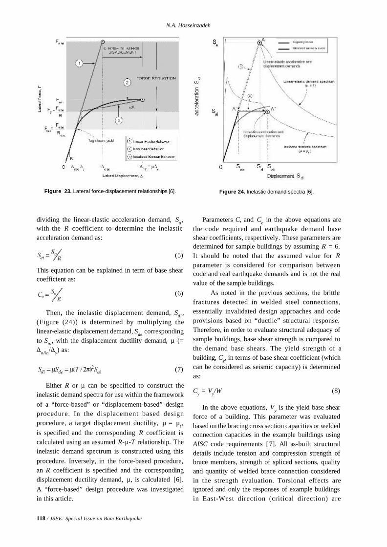
118 / JSEE: Special Issue on Bam Earthquake
N.A. Hosseinzadeh
dividing the linear-elastic acceleration demand, Sa ,with the R coefficient to determine the inelasticacceleration demand as:
(5)
This equation can be explained in term of base shearcoefficient as:
(6)
Then, the inelastic displacement demand, Sdi ,(Figure (24)) is determined by multiplying thelinear-elastic displacement demand, Sde correspondingto Sai, with the displacement ductility demand, µ (=∆nlin/∆y) as:
(7)
Either R or µ can be specified to construct theinelastic demand spectra for use within the frameworkof a “force-based” or “displacement-based” designprocedure. In the displacement based designprocedure, a target displacement ductility, µ = µt ,is specified and the corresponding R coefficient iscalculated using an assumed R-µ-T relationship. Theinelastic demand spectrum is constructed using thisprocedure. Inversely, in the force-based procedure,an R coefficient is specified and the correspondingdisplacement ductility demand, µ, is calculated [6].A “force-based” design procedure was investigatedin this article.
Figure 23. Lateral force-displacement relationships [6].
Parameters C, and Ce in the above equations arethe code required and earthquake demand baseshear coefficients, respectively. These parameters aredetermined for sample buildings by assuming R = 6.It should be noted that the assumed value for Rparameter is considered for comparison betweencode and real earthquake demands and is not the realvalue of the sample buildings. As noted in the previous sections, the brittlefractures detected in welded steel connections,essentially invalidated design approaches and codeprovisions based on “ductile” structural response.Therefore, in order to evaluate structural adequacy ofsample buildings, base shear strength is compared tothe demand base shears. The yield strength of abuilding, Cy, in terms of base shear coefficient (whichcan be considered as seismic capacity) is determinedas:
Cy = Vy/W (8)
In the above equations, Vy is the yield base shearforce of a building. This parameter was evaluatedbased on the bracing cross section capacities or weldedconnection capacities in the example buildings usingAISC code requirements [7]. All as-built structuraldetails include tension and compression strength ofbrace members, strength of spliced sections, qualityand quantity of welded brace connection consideredin the strength evaluation. Torsional effects areignored and only the responses of example buildingsin East-West direction (critical direction) are
Figure 24. Inelastic demand spectra [6].
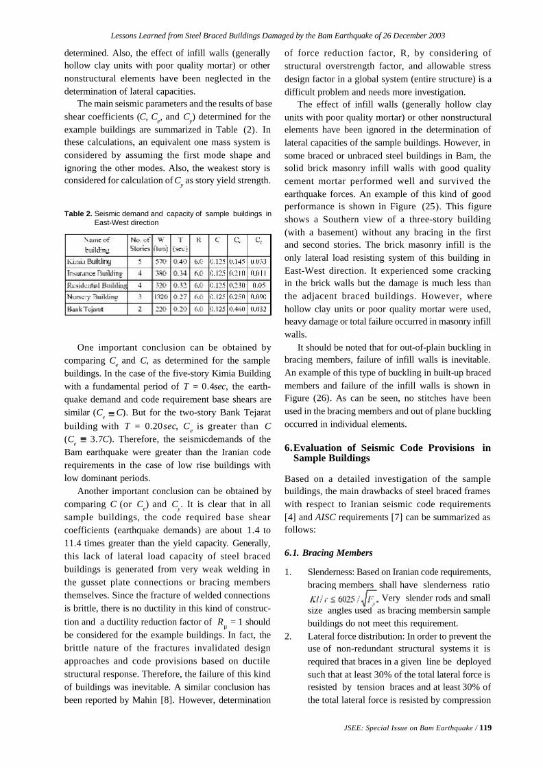
Lessons Learned from Steel Braced Buildings Damaged by the Bam Earthquake of 26 December 2003
JSEE: Special Issue on Bam Earthquake / 119
Table 2. Seismic demand and capacity of sample buildings inEast-West direction
determined. Also, the effect of infill walls (generallyhollow clay units with poor quality mortar) or othernonstructural elements have been neglected in thedetermination of lateral capacities.
The main seismic parameters and the results of baseshear coefficients (C, Ce, and Cy) determined for theexample buildings are summarized in Table (2). Inthese calculations, an equivalent one mass system isconsidered by assuming the first mode shape andignoring the other modes. Also, the weakest story isconsidered for calculation of Cy as story yield strength.
One important conclusion can be obtained bycomparing Ce and C, as determined for the samplebuildings. In the case of the five-story Kimia Buildingwith a fundamental period of T = 0.4sec, the earth-quake demand and code requirement base shears aresimilar (C
e C). But for the two-story Bank Tejarat
building with T = 0.20sec, Ce is greater than C(C
e 3.7C). Therefore, the seismicdemands of the
Bam earthquake were greater than the Iranian coderequirements in the case of low rise buildings withlow dominant periods.
Another important conclusion can be obtained bycomparing C (or Ce) and C
y. It is clear that in all
sample buildings, the code required base shearcoefficients (earthquake demands) are about 1.4 to11.4 times greater than the yield capacity. Generally,this lack of lateral load capacity of steel bracedbuildings is generated from very weak welding inthe gusset plate connections or bracing membersthemselves. Since the fracture of welded connectionsis brittle, there is no ductility in this kind of construc-tion and a ductility reduction factor of Rµ = 1 shouldbe considered for the example buildings. In fact, thebrittle nature of the fractures invalidated designapproaches and code provisions based on ductilestructural response. Therefore, the failure of this kindof buildings was inevitable. A similar conclusion hasbeen reported by Mahin [8]. However, determination
of force reduction factor, R, by considering ofstructural overstrength factor, and allowable stressdesign factor in a global system (entire structure) is adifficult problem and needs more investigation.
The effect of infill walls (generally hollow clayunits with poor quality mortar) or other nonstructuralelements have been ignored in the determination oflateral capacities of the sample buildings. However, insome braced or unbraced steel buildings in Bam, thesolid brick masonry infill walls with good qualitycement mortar performed well and survived theearthquake forces. An example of this kind of goodperformance is shown in Figure (25). This figureshows a Southern view of a three-story building(with a basement) without any bracing in the firstand second stories. The brick masonry infill is theonly lateral load resisting system of this building inEast-West direction. It experienced some crackingin the brick walls but the damage is much less thanthe adjacent braced buildings. However, wherehollow clay units or poor quality mortar were used,heavy damage or total failure occurred in masonry infillwalls.
It should be noted that for out-of-plain buckling inbracing members, failure of infill walls is inevitable.An example of this type of buckling in built-up bracedmembers and failure of the infill walls is shown inFigure (26). As can be seen, no stitches have beenused in the bracing members and out of plane bucklingoccurred in individual elements.
6.Evaluation of Seismic Code Provisions inSample Buildings
Based on a detailed investigation of the samplebuildings, the main drawbacks of steel braced frameswith respect to Iranian seismic code requirements[4] and AISC requirements [7] can be summarized asfollows:
6.1. Bracing Members
1. Slenderness: Based on Iranian code requirements,bracing members shall have slenderness ratio Very slender rods and smallsize angles used as bracing membersin samplebuildings do not meet this requirement.
2. Lateral force distribution: In order to prevent theuse of non-redundant structural systems it isrequired that braces in a given line be deployedsuch that at least 30% of the total lateral force isresisted by tension braces and at least 30% ofthe total lateral force is resisted by compression
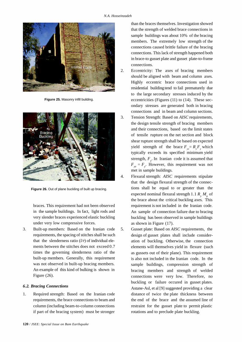
120 / JSEE: Special Issue on Bam Earthquake
N.A. Hosseinzadeh
Figure 26. Out of plane buckling of built up bracing.
braces. This requirement had not been observedin the sample buildings. In fact, light rods andvery slender braces experienced elastic bucklingunder very low compressive forces.
3. Built-up members: Based on the Iranian coderequirements, the spacing of stitches shall be suchthat the slenderness ratio (l/r) of individual ele-ments between the stitches does not exceed 0.7times the governing slenderness ratio of thebuilt-up members. Generally, this requirementwas not observed in built-up bracing members.An example of this kind of bulking is shown inFigure (26).
6.2. Bracing Connections
1. Required strength: Based on the Iranian coderequirements, the brace connections to beam andcolumn (including beam-to-column connectionsif part of the bracing system) must be stronger
than the braces themselves. Investigation showedthat the strength of welded brace connections insample buildings was about 10% of the bracingmembers. The extremely low strength of theconnections caused brittle failure of the bracingconnections. This lack of strength happened bothin brace-to gusset plate and gusset plate-to-frameconnections.
2. Eccentricity: The axes of bracing membersshould be aligned with beam and column axes.Highly eccentric brace connections used inresidential building tend to fail prematurely dueto the large secondary stresses induced by theeccentricities (Figures (11) to (14). These sec-ondary stresses are generated both in bracingconnections and in beam and column sections.
3. Tension Strength: Based on AISC requirements,the design tensile strength of bracing membersand their connections, based on the limit statesof tensile rupture on the net section and blockshear rupture strength shall be based on expectedyield strength of the brace F
ye= R
y Fy which
typically exceeds its specified minimum yieldstrength, Fy. In Iranian code it is assumed thatFye = Fy. However, this requirement was notmet in sample buildings.
4. Flexural strength: AISC requirements stipulatethat the design flexural strength of the connec-tions shall be equal to or greater than theexpected nominal flexural strength 1.1 Ry Mρ ofthe brace about the critical buckling axes. Thisrequirement is not included in the Iranian code.An sample of connection failure due to bracingbuckling has been observed in sample buildingsas shown in Figure (17).
5. Gusset plate: Based on AISC requirements, thedesign of gusset plates shall include consider-ation of buckling. Otherwise, the connectionelements will themselves yield in flexure (suchas gussets out of their plane). This requirementis also not included in the Iranian code. In thesample buildings, compression strength ofbracing members and strength of weldedconnections were very low. Therefore, nobuckling or failure occured in gusset plates.Astane-Asl, et al [9] suggested providing a cleardistance of twice the plate thickness betweenthe end of the brace and the assumed line ofrestraint for the gusset plate to permit plasticrotations and to preclude plate buckling.
Figure 25. Masonry infill building.
Lessons Learned from Steel Braced Buildings Damaged by the Bam Earthquake of 26 December 2003
JSEE: Special Issue on Bam Earthquake / 121
7. Concluding Remarks
Hundreds of damaged and collapsed steel buildings inBam have been identified, including hospitals andhealth care facilities, government, civic and privateoffices, cultural and educational facilities, residentialstructures, and commercial buildings. Damageoccurred in new as well as old low rise (generallylower than 5 stories ) buildings. While inadequateworkmanship was believed to play the major role inthe damage observed, very few damaged buildingsare believed to have been constructed according tonew codes and standards of practice. The effect ofthese observations has been a loss of confidence in theprocedures used in the past to design and constructwelded connections in steel braced frames and aconcern that existing structures incorporating theseconnections may not be sufficiently safe. Based on thefield investigations and detailed evaluations of samplesteel braced buildings presented in this paper thefollowing conclusions can be drawn:v Current professional judgment is that the old or
traditional practices used for the design andconstruction of bracing connections do notprovide adequate reliability and safety and shouldbe revised in the construction of new buildingsintended to resist earthquake ground shakingthrough inelastic behavior.
v Common failure modes of bracing membersinclude buckling of slender members, lack ofcompression strength, and weak spliced sections.Also, common failure modes of bracingconnections include lack of strength in weldedconnections, brittle failure of nonductileconnections, failure of brace-to-beam-columnconnections, failure of gusset plate connectiondue to out of plane buckling.
v Lack of strength in slender and weak bracingmembers and lack of strength in bracing weldedconnections limited the lateral strength of bracedbuildings to 0.10 to 0.5 times that of the coderequirements and earthquake demands. Since thefracture of welded connections is brittle, there isno ductility in this kind of construction and thea ductility reduction factor Rµ = 1 should beconsidered for these buildings.
v Sudden failure of brittle and weak weldedconnections of gusset plates introduced additionalimpact to earthquake forces in steel bracedbuildings. In accordance with second order
effects (P-∆ effects), this caused large drifts insoft and weak stories. Damage was so severe insome buildings that all of bracing connectionson one or more stories failed or significantpermanent lateral displacement (between 40-400cm) occurred. From these observations inBam, it can be concluded that no bracing isbetter than poor bracing.
v Damage to solid brick masonry infill walledbuildings with good quality cement mortar wasmuch less than to similar braced buildings. Forout of plane buckling in brace members, failureoccurred in infill walls.
References
1. Eshghi, S., et al (2003). “A Preliminary Recon-naissance Report on 26 December 2003 BamEarthquake”, IIEES Research Bulletin, 6(3 and 4),Tehran, Iran.
2. Eshghi, S. and Zaré, M. (2003). “Bam (SE Iran)Earthquake of 26 December 2003, Mw6.5: APreliminary Reconnaissance Report”, IIEES,http://www.iiees.ac.ir.
3. BHRC (2003). “The History of Bam AccelerographStation”, http://www.bhrc.ac.ir.
4. BHRC (1999). “Iranian Code of Practice forSeismic Resistant Design of Buildings (Standard2800)”,2nd ed.
5. Geological Survey of Iran (GSI) (2003), http://www.gsi.org.ir.
6. Farrow, K.T. and Kurama, Y.C. (2001). “Capac-ity-Demand Index Relationships for Performance-Based Seismic Design”, Report # NDSE-01-02,University of Notre Dame, Notre Dame, Indiana.
7. AISC (2002). “Seismic Provisions for StructuralSteel Buildings”, ANSI/AISC 341-02.
8. Mahin, S.A. (1997). “Lessons from SteelBuildings in Northridge Earthquake”, NISEE,University of California, Berkeley.
9. Astaneh-Asl, A., Goel, S.C., and Hanson, R.D.(1986). “Earthquake-Resistant Design of DoubleAngle Bracing”, Engineering Jouranl, 23 (4), (4th
Qtr.), AISC, Chicago, IL.
JSEE: Special Issue on Bam Earthquake / 123
Mahmoud R. Maheri
Civil Engineering Department, Shiraz University, Shiraz, Iran, email: [email protected]
ABSTRACT: Collapse of non-engineered roofs and floor slabsduring the Bam earthquake of December 2003 was the single majorcontributor to the large fatalities during that earthquake. Different floorsystems of buildings in the city of Bam can be categorised into threetypes namely; the traditional masonry dome or vault, the steel I-beamjack arch system and the concrete beam-hollow block system. In thispaper the seismic performance of each type of flooring as observedafter the Bam earthquake is discussed and their points of weaknessand strength are highlighted. Also the poor seismic performance of thetraditional dome and vault roofs and the unanchored jack arch slabsare noted and the seismic merits of the anchored jack arch slabs andconcrete beam-hollow block slabs are discussed.
Keywords: Bam earthquake; Seismic response; Domes and vaults;Jack arch slabs; Concrete beam-block slab
Performance of Roofs and Floor Slabs During Bam,
Earthquake of 26 December 2003
1. Introduction
The Bam earthquake of 2003 caused widespreaddevastation in the city of Bam. Despite the relativelylow magnitude of the earthquake, the shallow depth ofthe event resulted in very high and localised groundaccelerations both in horizontal and vertical directions.The recorded accelerations of 0.8g in the horizontaldirection and 1.0g in the vertical direction wereamongst the highest accelerations ever recorded foran earthquake. As a result of the high global groundaccelerations, various modes of failure could beobserved in structural systems and elements. The mostimportant of the structural elements, so far as theireffect on the level of earthquake fatalities is concerned,are floor and roofs.
Majority of buildings in the city of Bam at the timeof the earthquake were unreinforced masonrybuildings with load bearing walls or low rise steel-framed buildings. The former buildings were roofedby either the traditional masonry domes or vaults ornon-engineered, unanchored, jack arch flooringsystem, whereas the latter buildings were mainlyfloored by anchored jack arch slabs. In some of themore recently constructed buildings, the floorsconsisted of concrete beam-hollow block slabs.
A large number of the buildings in the older
quarters of Bam were traditional masonry typeshaving masonry dome or vault roofs. These buildingsare generally characterised by weak, brittle materials,weak element connections and excessive weight.The construction materials and techniques used forthis type of construction have remained unchangedthroughout the history for thousands of years. Fromaround the middle of 20th century a new type of floorconstruction in the form of steel beam jack arch slabwas introduced into Iran from Europe. The newflooring system, considered as a non-engineeredconstruction, became very popular in Iran such thatthe majority of existing buildings in provincial townsand villages and a vast number of buildings inTehran are floored with this type of construction. Inthis flooring method a number of parallel steelI-beams are placed directly on the load bearing wallsat between 80cm to 1.0m spacing and spanning fromone wall to the other. The space between the twoadjacent I-beams is then filled with a series of shallowbrick arches, see Figure (1). The process is repeateduntil the whole slab area is covered. A layer oflime-clay mortar or concrete is then placed on thebrick arches to create a flat surface. The slab issubsequently plastered underneath to create a flat
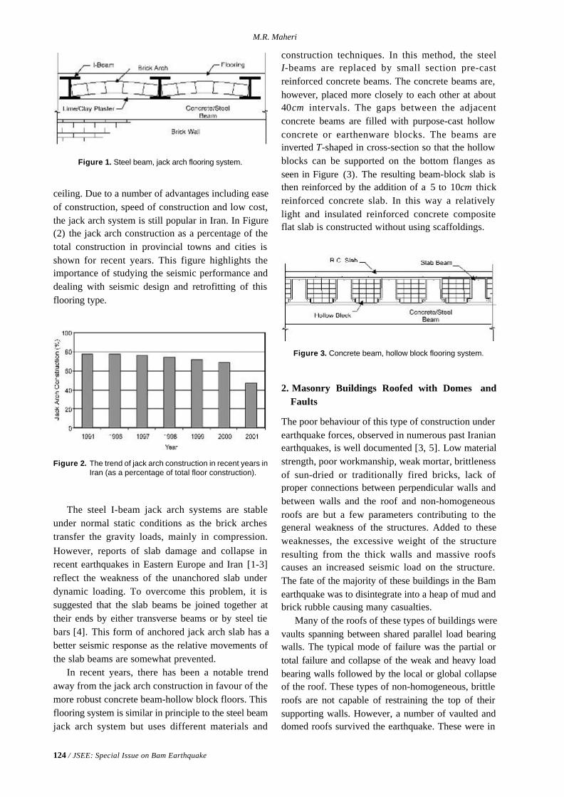
124 / JSEE: Special Issue on Bam Earthquake
M.R. Maheri
Figure 1. Steel beam, jack arch flooring system.
Figure 2. The trend of jack arch construction in recent years inIran (as a percentage of total floor construction).
Figure 3. Concrete beam, hollow block flooring system.
ceiling. Due to a number of advantages including easeof construction, speed of construction and low cost,the jack arch system is still popular in Iran. In Figure(2) the jack arch construction as a percentage of thetotal construction in provincial towns and cities isshown for recent years. This figure highlights theimportance of studying the seismic performance anddealing with seismic design and retrofitting of thisflooring type.
The steel I-beam jack arch systems are stableunder normal static conditions as the brick archestransfer the gravity loads, mainly in compression.However, reports of slab damage and collapse inrecent earthquakes in Eastern Europe and Iran [1-3]reflect the weakness of the unanchored slab underdynamic loading. To overcome this problem, it issuggested that the slab beams be joined together attheir ends by either transverse beams or by steel tiebars [4]. This form of anchored jack arch slab has abetter seismic response as the relative movements ofthe slab beams are somewhat prevented.
In recent years, there has been a notable trendaway from the jack arch construction in favour of themore robust concrete beam-hollow block floors. Thisflooring system is similar in principle to the steel beamjack arch system but uses different materials and
construction techniques. In this method, the steelI-beams are replaced by small section pre-castreinforced concrete beams. The concrete beams are,however, placed more closely to each other at about40cm intervals. The gaps between the adjacentconcrete beams are filled with purpose-cast hollowconcrete or earthenware blocks. The beams areinverted T-shaped in cross-section so that the hollowblocks can be supported on the bottom flanges asseen in Figure (3). The resulting beam-block slab isthen reinforced by the addition of a 5 to 10cm thickreinforced concrete slab. In this way a relativelylight and insulated reinforced concrete compositeflat slab is constructed without using scaffoldings.
2. Masonry Buildings Roofed with Domes andFaults
The poor behaviour of this type of construction underearthquake forces, observed in numerous past Iranianearthquakes, is well documented [3, 5]. Low materialstrength, poor workmanship, weak mortar, brittlenessof sun-dried or traditionally fired bricks, lack ofproper connections between perpendicular walls andbetween walls and the roof and non-homogeneousroofs are but a few parameters contributing to thegeneral weakness of the structures. Added to theseweaknesses, the excessive weight of the structureresulting from the thick walls and massive roofscauses an increased seismic load on the structure.The fate of the majority of these buildings in the Bamearthquake was to disintegrate into a heap of mud andbrick rubble causing many casualties.
Many of the roofs of these types of buildings werevaults spanning between shared parallel load bearingwalls. The typical mode of failure was the partial ortotal failure and collapse of the weak and heavy loadbearing walls followed by the local or global collapseof the roof. These types of non-homogeneous, brittleroofs are not capable of restraining the top of theirsupporting walls. However, a number of vaulted anddomed roofs survived the earthquake. These were in
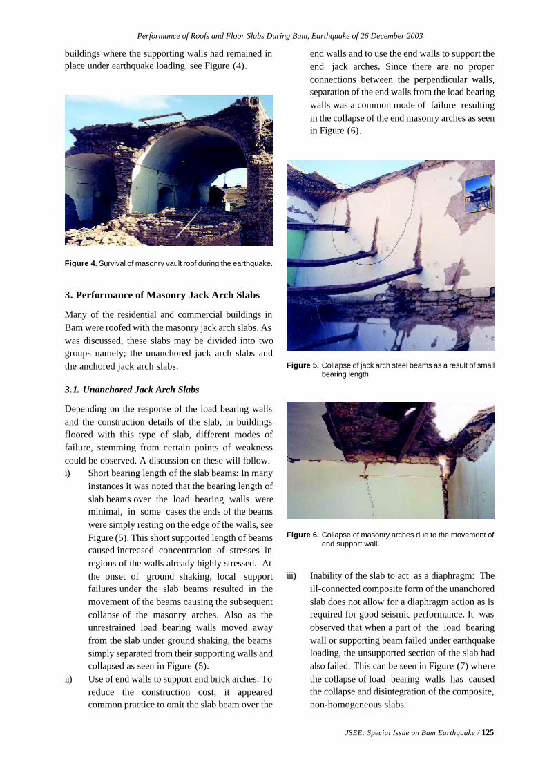
Performance of Roofs and Floor Slabs During Bam, Earthquake of 26 December 2003
JSEE: Special Issue on Bam Earthquake / 125
Figure 4. Survival of masonry vault roof during the earthquake.
Figure 5. Collapse of jack arch steel beams as a result of smallbearing length.
Figure 6. Collapse of masonry arches due to the movement ofend support wall.
buildings where the supporting walls had remained inplace under earthquake loading, see Figure (4).
3. Performance of Masonry Jack Arch Slabs
Many of the residential and commercial buildings inBam were roofed with the masonry jack arch slabs. Aswas discussed, these slabs may be divided into twogroups namely; the unanchored jack arch slabs andthe anchored jack arch slabs.
3.1. Unanchored Jack Arch Slabs
Depending on the response of the load bearing wallsand the construction details of the slab, in buildingsfloored with this type of slab, different modes offailure, stemming from certain points of weaknesscould be observed. A discussion on these will follow.i) Short bearing length of the slab beams: In many
instances it was noted that the bearing length ofslab beams over the load bearing walls wereminimal, in some cases the ends of the beamswere simply resting on the edge of the walls, seeFigure (5). This short supported length of beamscaused increased concentration of stresses inregions of the walls already highly stressed. Atthe onset of ground shaking, local supportfailures under the slab beams resulted in themovement of the beams causing the subsequentcollapse of the masonry arches. Also as theunrestrained load bearing walls moved awayfrom the slab under ground shaking, the beamssimply separated from their supporting walls andcollapsed as seen in Figure (5).
ii) Use of end walls to support end brick arches: Toreduce the construction cost, it appearedcommon practice to omit the slab beam over the
end walls and to use the end walls to support theend jack arches. Since there are no properconnections between the perpendicular walls,separation of the end walls from the load bearingwalls was a common mode of failure resultingin the collapse of the end masonry arches as seenin Figure (6).
iii) Inability of the slab to act as a diaphragm: Theill-connected composite form of the unanchoredslab does not allow for a diaphragm action as isrequired for good seismic performance. It wasobserved that when a part of the load bearingwall or supporting beam failed under earthquakeloading, the unsupported section of the slab hadalso failed. This can be seen in Figure (7) wherethe collapse of load bearing walls has causedthe collapse and disintegration of the composite,non-homogeneous slabs.
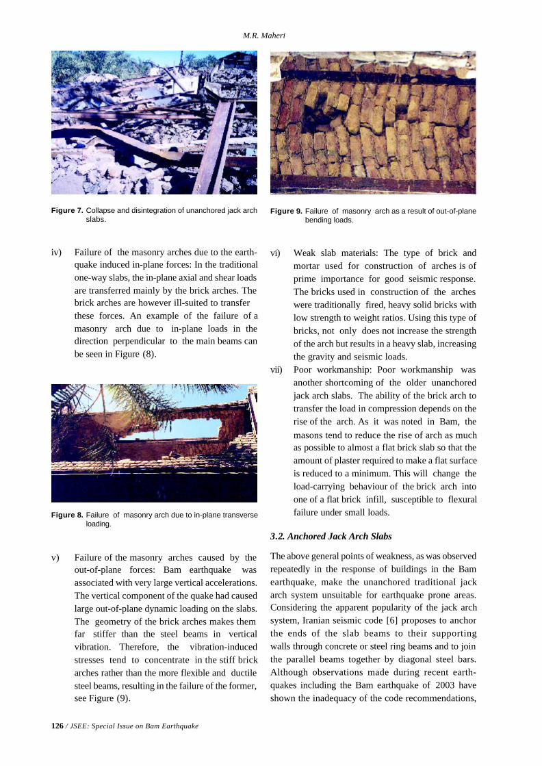
126 / JSEE: Special Issue on Bam Earthquake
M.R. Maheri
Figure 7. Collapse and disintegration of unanchored jack archslabs.
Figure 8. Failure of masonry arch due to in-plane transverseloading.
Figure 9. Failure of masonry arch as a result of out-of-planebending loads.
iv) Failure of the masonry arches due to the earth-quake induced in-plane forces: In the traditionalone-way slabs, the in-plane axial and shear loadsare transferred mainly by the brick arches. Thebrick arches are however ill-suited to transferthese forces. An example of the failure of amasonry arch due to in-plane loads in thedirection perpendicular to the main beams canbe seen in Figure (8).
v) Failure of the masonry arches caused by theout-of-plane forces: Bam earthquake wasassociated with very large vertical accelerations.The vertical component of the quake had causedlarge out-of-plane dynamic loading on the slabs.The geometry of the brick arches makes themfar stiffer than the steel beams in verticalvibration. Therefore, the vibration-inducedstresses tend to concentrate in the stiff brickarches rather than the more flexible and ductilesteel beams, resulting in the failure of the former,see Figure (9).
vi) Weak slab materials: The type of brick andmortar used for construction of arches is ofprime importance for good seismic response.The bricks used in construction of the archeswere traditionally fired, heavy solid bricks withlow strength to weight ratios. Using this type ofbricks, not only does not increase the strengthof the arch but results in a heavy slab, increasingthe gravity and seismic loads.
vii) Poor workmanship: Poor workmanship wasanother shortcoming of the older unanchoredjack arch slabs. The ability of the brick arch totransfer the load in compression depends on therise of the arch. As it was noted in Bam, themasons tend to reduce the rise of arch as muchas possible to almost a flat brick slab so that theamount of plaster required to make a flat surfaceis reduced to a minimum. This will change theload-carrying behaviour of the brick arch intoone of a flat brick infill, susceptible to flexuralfailure under small loads.
3.2. Anchored Jack Arch Slabs
The above general points of weakness, as was observedrepeatedly in the response of buildings in the Bamearthquake, make the unanchored traditional jackarch system unsuitable for earthquake prone areas.Considering the apparent popularity of the jack archsystem, Iranian seismic code [6] proposes to anchorthe ends of the slab beams to their supportingwalls through concrete or steel ring beams and to jointhe parallel beams together by diagonal steel bars.Although observations made during recent earth-quakes including the Bam earthquake of 2003 haveshown the inadequacy of the code recommendations,
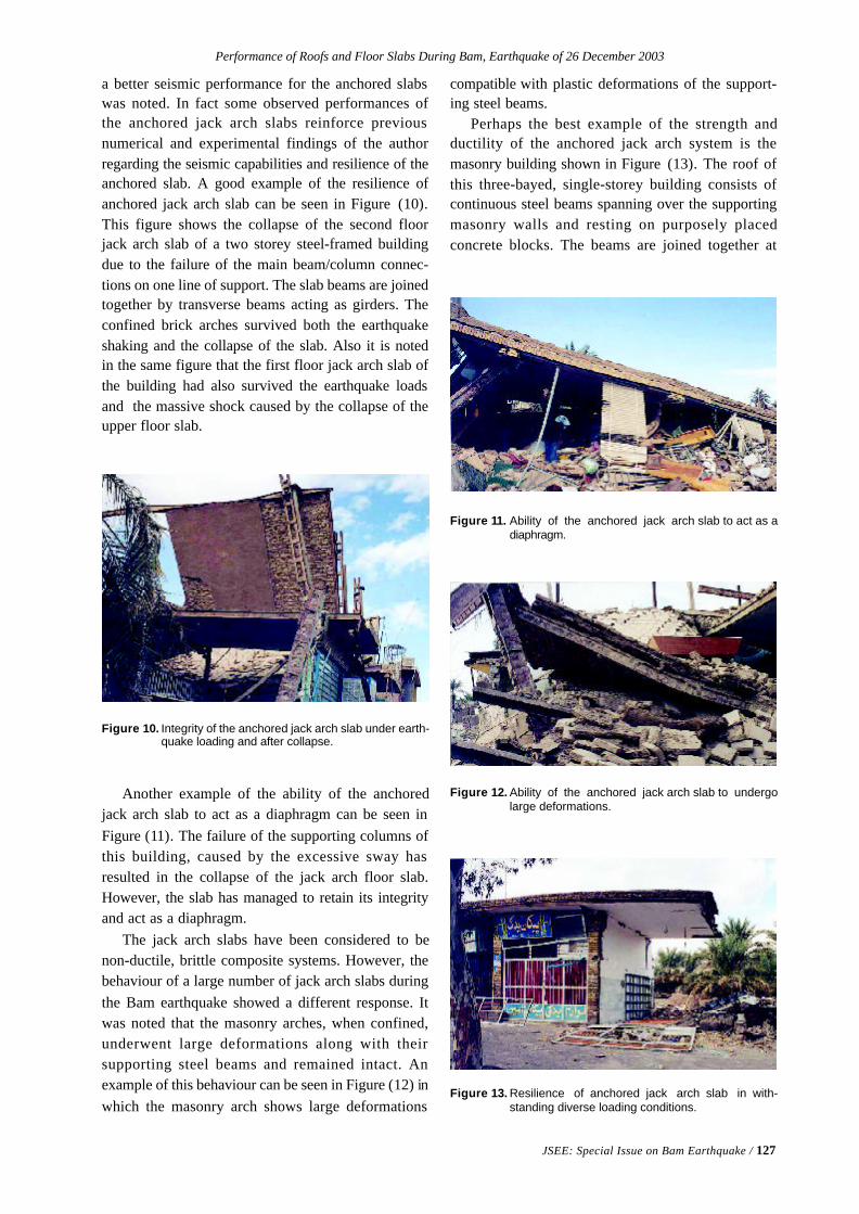
Performance of Roofs and Floor Slabs During Bam, Earthquake of 26 December 2003
JSEE: Special Issue on Bam Earthquake / 127
Figure 10. Integrity of the anchored jack arch slab under earth-quake loading and after collapse.
Figure 11. Ability of the anchored jack arch slab to act as adiaphragm.
Figure 13. Resilience of anchored jack arch slab in with-standing diverse loading conditions.
Figure 12. Ability of the anchored jack arch slab to undergolarge deformations.
a better seismic performance for the anchored slabswas noted. In fact some observed performances ofthe anchored jack arch slabs reinforce previousnumerical and experimental findings of the authorregarding the seismic capabilities and resilience of theanchored slab. A good example of the resilience ofanchored jack arch slab can be seen in Figure (10).This figure shows the collapse of the second floorjack arch slab of a two storey steel-framed buildingdue to the failure of the main beam/column connec-tions on one line of support. The slab beams are joinedtogether by transverse beams acting as girders. Theconfined brick arches survived both the earthquakeshaking and the collapse of the slab. Also it is notedin the same figure that the first floor jack arch slab ofthe building had also survived the earthquake loadsand the massive shock caused by the collapse of theupper floor slab.
Another example of the ability of the anchoredjack arch slab to act as a diaphragm can be seen inFigure (11). The failure of the supporting columns ofthis building, caused by the excessive sway hasresulted in the collapse of the jack arch floor slab.However, the slab has managed to retain its integrityand act as a diaphragm.
The jack arch slabs have been considered to benon-ductile, brittle composite systems. However, thebehaviour of a large number of jack arch slabs duringthe Bam earthquake showed a different response. Itwas noted that the masonry arches, when confined,underwent large deformations along with theirsupporting steel beams and remained intact. Anexample of this behaviour can be seen in Figure (12) inwhich the masonry arch shows large deformations
compatible with plastic deformations of the support-ing steel beams.
Perhaps the best example of the strength andductility of the anchored jack arch system is themasonry building shown in Figure (13). The roof ofthis three-bayed, single-storey building consists ofcontinuous steel beams spanning over the supportingmasonry walls and resting on purposely placedconcrete blocks. The beams are joined together at
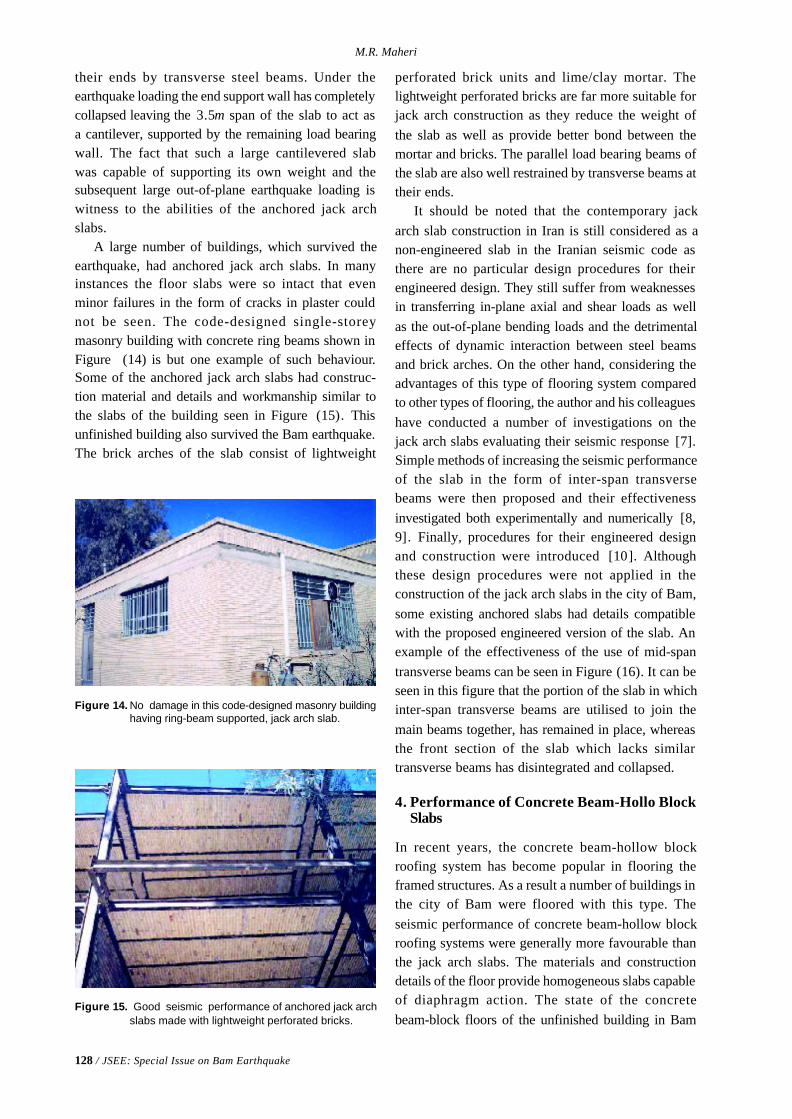
128 / JSEE: Special Issue on Bam Earthquake
M.R. Maheri
Figure 14. No damage in this code-designed masonry buildinghaving ring-beam supported, jack arch slab.
Figure 15. Good seismic performance of anchored jack archslabs made with lightweight perforated bricks.
their ends by transverse steel beams. Under theearthquake loading the end support wall has completelycollapsed leaving the 3.5m span of the slab to act asa cantilever, supported by the remaining load bearingwall. The fact that such a large cantilevered slabwas capable of supporting its own weight and thesubsequent large out-of-plane earthquake loading iswitness to the abilities of the anchored jack archslabs.
A large number of buildings, which survived theearthquake, had anchored jack arch slabs. In manyinstances the floor slabs were so intact that evenminor failures in the form of cracks in plaster couldnot be seen. The code-designed single-storeymasonry building with concrete ring beams shown inFigure (14) is but one example of such behaviour.Some of the anchored jack arch slabs had construc-tion material and details and workmanship similar tothe slabs of the building seen in Figure (15). Thisunfinished building also survived the Bam earthquake.The brick arches of the slab consist of lightweight
perforated brick units and lime/clay mortar. Thelightweight perforated bricks are far more suitable forjack arch construction as they reduce the weight ofthe slab as well as provide better bond between themortar and bricks. The parallel load bearing beams ofthe slab are also well restrained by transverse beams attheir ends.
It should be noted that the contemporary jackarch slab construction in Iran is still considered as anon-engineered slab in the Iranian seismic code asthere are no particular design procedures for theirengineered design. They still suffer from weaknessesin transferring in-plane axial and shear loads as wellas the out-of-plane bending loads and the detrimentaleffects of dynamic interaction between steel beamsand brick arches. On the other hand, considering theadvantages of this type of flooring system comparedto other types of flooring, the author and his colleagueshave conducted a number of investigations on thejack arch slabs evaluating their seismic response [7].Simple methods of increasing the seismic performanceof the slab in the form of inter-span transversebeams were then proposed and their effectivenessinvestigated both experimentally and numerically [8,9]. Finally, procedures for their engineered designand construction were introduced [10]. Althoughthese design procedures were not applied in theconstruction of the jack arch slabs in the city of Bam,some existing anchored slabs had details compatiblewith the proposed engineered version of the slab. Anexample of the effectiveness of the use of mid-spantransverse beams can be seen in Figure (16). It can beseen in this figure that the portion of the slab in whichinter-span transverse beams are utilised to join themain beams together, has remained in place, whereasthe front section of the slab which lacks similartransverse beams has disintegrated and collapsed.
4. Performance of Concrete Beam-Hollo BlockSlabs
In recent years, the concrete beam-hollow blockroofing system has become popular in flooring theframed structures. As a result a number of buildings inthe city of Bam were floored with this type. Theseismic performance of concrete beam-hollow blockroofing systems were generally more favourable thanthe jack arch slabs. The materials and constructiondetails of the floor provide homogeneous slabs capableof diaphragm action. The state of the concretebeam-block floors of the unfinished building in Bam
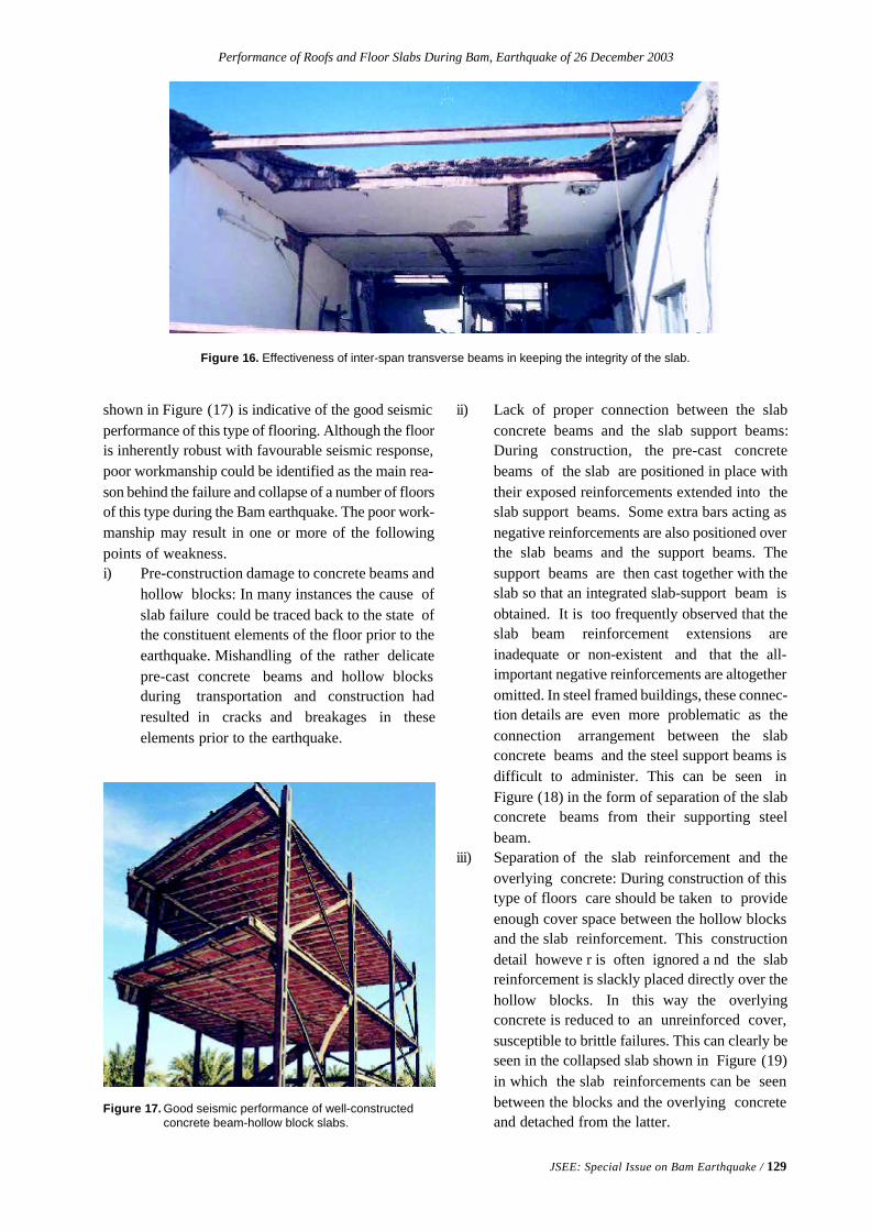
Performance of Roofs and Floor Slabs During Bam, Earthquake of 26 December 2003
JSEE: Special Issue on Bam Earthquake / 129
Figure 16. Effectiveness of inter-span transverse beams in keeping the integrity of the slab.
Figure 17. Good seismic performance of well-constructedconcrete beam-hollow block slabs.
shown in Figure (17) is indicative of the good seismicperformance of this type of flooring. Although the flooris inherently robust with favourable seismic response,poor workmanship could be identified as the main rea-son behind the failure and collapse of a number of floorsof this type during the Bam earthquake. The poor work-manship may result in one or more of the followingpoints of weakness.i) Pre-construction damage to concrete beams and
hollow blocks: In many instances the cause ofslab failure could be traced back to the state ofthe constituent elements of the floor prior to theearthquake. Mishandling of the rather delicatepre-cast concrete beams and hollow blocksduring transportation and construction hadresulted in cracks and breakages in theseelements prior to the earthquake.
ii) Lack of proper connection between the slabconcrete beams and the slab support beams:During construction, the pre-cast concretebeams of the slab are positioned in place withtheir exposed reinforcements extended into theslab support beams. Some extra bars acting asnegative reinforcements are also positioned overthe slab beams and the support beams. Thesupport beams are then cast together with theslab so that an integrated slab-support beam isobtained. It is too frequently observed that theslab beam reinforcement extensions areinadequate or non-existent and that the all-important negative reinforcements are altogetheromitted. In steel framed buildings, these connec-tion details are even more problematic as theconnection arrangement between the slabconcrete beams and the steel support beams isdifficult to administer. This can be seen inFigure (18) in the form of separation of the slabconcrete beams from their supporting steelbeam.
iii) Separation of the slab reinforcement and theoverlying concrete: During construction of thistype of floors care should be taken to provideenough cover space between the hollow blocksand the slab reinforcement. This constructiondetail howeve r is often ignored a nd the slabreinforcement is slackly placed directly over thehollow blocks. In this way the overlyingconcrete is reduced to an unreinforced cover,susceptible to brittle failures. This can clearly beseen in the collapsed slab shown in Figure (19)in which the slab reinforcements can be seenbetween the blocks and the overlying concreteand detached from the latter.
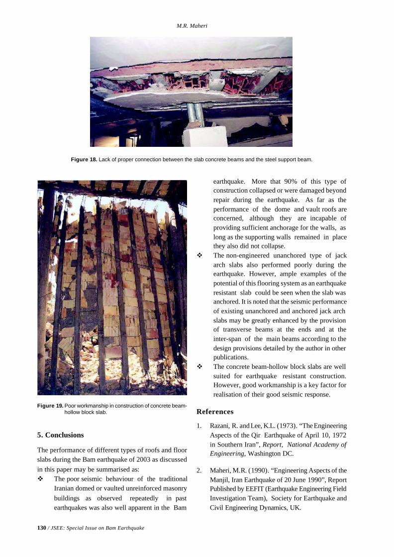
130 / JSEE: Special Issue on Bam Earthquake
M.R. Maheri
Figure 18. Lack of proper connection between the slab concrete beams and the steel support beam.
Figure 19. Poor workmanship in construction of concrete beam-hollow block slab.
5. Conclusions
The performance of different types of roofs and floorslabs during the Bam earthquake of 2003 as discussedin this paper may be summarised as:v The poor seismic behaviour of the traditional
Iranian domed or vaulted unreinforced masonrybuildings as observed repeatedly in pastearthquakes was also well apparent in the Bam
earthquake. More that 90% of this type ofconstruction collapsed or were damaged beyondrepair during the earthquake. As far as theperformance of the dome and vault roofs areconcerned, although they are incapable ofproviding sufficient anchorage for the walls, aslong as the supporting walls remained in placethey also did not collapse.
v The non-engineered unanchored type of jackarch slabs also performed poorly during theearthquake. However, ample examples of thepotential of this flooring system as an earthquakeresistant slab could be seen when the slab wasanchored. It is noted that the seismic performanceof existing unanchored and anchored jack archslabs may be greatly enhanced by the provisionof transverse beams at the ends and at theinter-span of the main beams according to thedesign provisions detailed by the author in otherpublications.
v The concrete beam-hollow block slabs are wellsuited for earthquake resistant construction.However, good workmanship is a key factor forrealisation of their good seismic response.
References
1. Razani, R. and Lee, K.L. (1973). “The EngineeringAspects of the Qir Earthquake of April 10, 1972in Southern Iran”, Report, National Academy ofEngineering, Washington DC.
2. Maheri, M.R. (1990). “Engineering Aspects of theManjil, Iran Earthquake of 20 June 1990”, ReportPublished by EEFIT (Earthquake Engineering FieldInvestigation Team), Society for Earthquake andCivil Engineering Dynamics, UK.
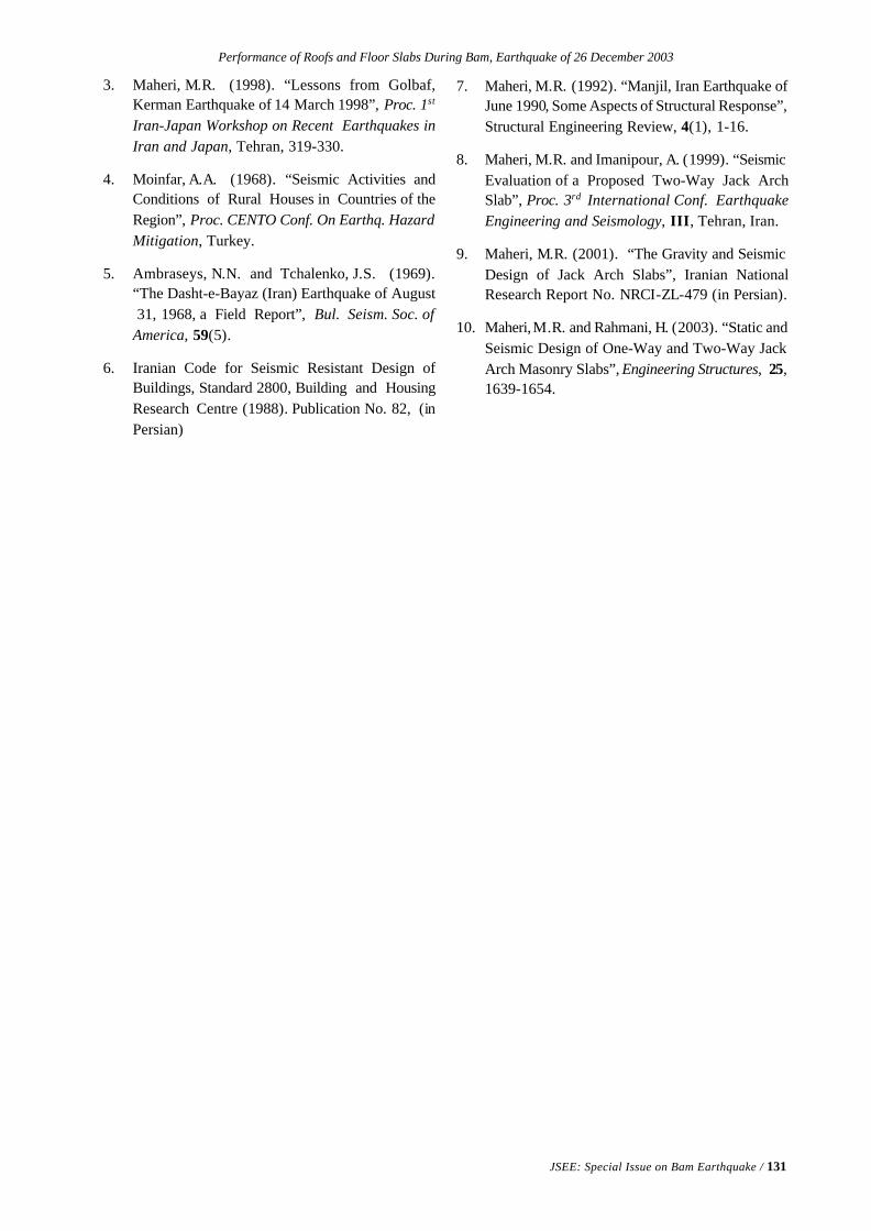
Performance of Roofs and Floor Slabs During Bam, Earthquake of 26 December 2003
JSEE: Special Issue on Bam Earthquake / 131
3. Maheri, M.R. (1998). “Lessons from Golbaf,Kerman Earthquake of 14 March 1998”, Proc. 1st
Iran-Japan Workshop on Recent Earthquakes inIran and Japan, Tehran, 319-330.
4. Moinfar, A.A. (1968). “Seismic Activities andConditions of Rural Houses in Countries of theRegion”, Proc. CENTO Conf. On Earthq. HazardMitigation, Turkey.
5. Ambraseys, N.N. and Tchalenko, J.S. (1969).“The Dasht-e-Bayaz (Iran) Earthquake of August 31, 1968, a Field Report”, Bul. Seism. Soc. ofAmerica, 59(5).
6. Iranian Code for Seismic Resistant Design ofBuildings, Standard 2800, Building and HousingResearch Centre (1988). Publication No. 82, (inPersian)
7. Maheri, M.R. (1992). “Manjil, Iran Earthquake ofJune 1990, Some Aspects of Structural Response”,Structural Engineering Review, 4(1), 1-16.
8. Maheri, M.R. and Imanipour, A. (1999). “SeismicEvaluation of a Proposed Two-Way Jack ArchSlab”, Proc. 3rd International Conf. EarthquakeEngineering and Seismology, III, Tehran, Iran.
9. Maheri, M.R. (2001). “The Gravity and SeismicDesign of Jack Arch Slabs”, Iranian NationalResearch Report No. NRCI-ZL-479 (in Persian).
10. Maheri, M.R. and Rahmani, H. (2003). “Static andSeismic Design of One-Way and Two-Way JackArch Masonry Slabs”, Engineering Structures, 25,1639-1654.
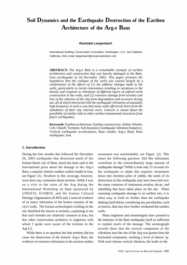
JSEE: Special Issue on Bam Earthquake / 133
Randolph Langenbach
International Building Conservation Consultant, Washington, D.C. and Oakland,
California, USA, email: [email protected]
ABSTRACT: The Arg-e Bam is a remarkable example of earthenarchitecture and construction that was heavily damaged in the Bam,Iran earthquake of 26 December 2003. This paper presents thehypothesis that the collapse of the walls was caused largely by acombination of the effects of (1) the additive changes made to thewalls, particularly in recent restorations resulting in variations in thedensity and response to vibrations of different layers of unfired earthconstruction in the walls, and (2) extensive damage from termites andloss of the cohesion of the clay from degradation and excessive dryingout, all of which interacted with the earthquake vibrations of unusuallyhigh frequency in such a way that many walls effectively burst from thesubsidence of their clay internal cores. Concern is raised about thepossibility of similar risks to other earthen monumental structures fromfuture earthquakes.
Keywords: Earthen architecture; Earthen construction; Adobe, Khesht;Cob; Chineh; Termites; Soil dynamics; Earthquake vibration frequency;Vertical earthquake accelerations; Bam citadel; Arg-e Bam; Bamearthquake; Iran
Soil Dynamics and the Earthquake Destruction of the Earthen
Architecture of the Arg-e Bam
1. Introduction
During the four months that followed the December26, 2003 earthquake that destroyed much of theIranian desert city of Bam, much has been said in theinternational press about the damage to the Arg-eBam, a majestic historic earthen walled citadel in Iran,see Figure (1). Nowhere in this coverage, however,were there any comments about termites. While I wason a visit to the ruins of the Arg during theInternational Workshop on Bam sponsored byUNESCO, ICOMOS, and the Iranian CulturalHeritage Organization (ICHO) and, I noticed evidenceof an insect infestation in the broken remains of thecity's walls. The Iranian archeologists working on thesite identified the insects as termites, explaining to methat such termites are relatively common in Iran, butfew other conservation architects or engineers withwhom I spoke were aware of the termites in theArg [1].
While there is no question but that termites did notcause the destruction of the historic Arg-e Bam, theevidence of extensive infestation in the ancient earthen
monument was unmistakable, see Figure (2). Thisraises the following question: Did this infestationcontribute to the extraordinarily large amount ofearthquake damage? While it took only 12 seconds forthe earthquake to shake this majestic monumentdown into formless piles of rubble, the seeds of itsdestruction in this earthquake may have been laid overthe many centuries of continuous erosion, decay, andrebuilding that have taken place on the site. Whenassessing earthquake damage to an earthen site, it isoften easy to look no further than the earthquakeshaking itself before considering any peculiarities, suchas insects, that may have further weakened the earthenwalls.
Many engineers and seismologists have pointed tothe intensity of the Bam earthquake itself as sufficientto explain much of the damage. The seismographrecords show that the vertical component of thevibrations near the site of the Arg was greater than thehorizontal component, reaching a level of almost 1g.With such intense vertical vibration, the loads on the
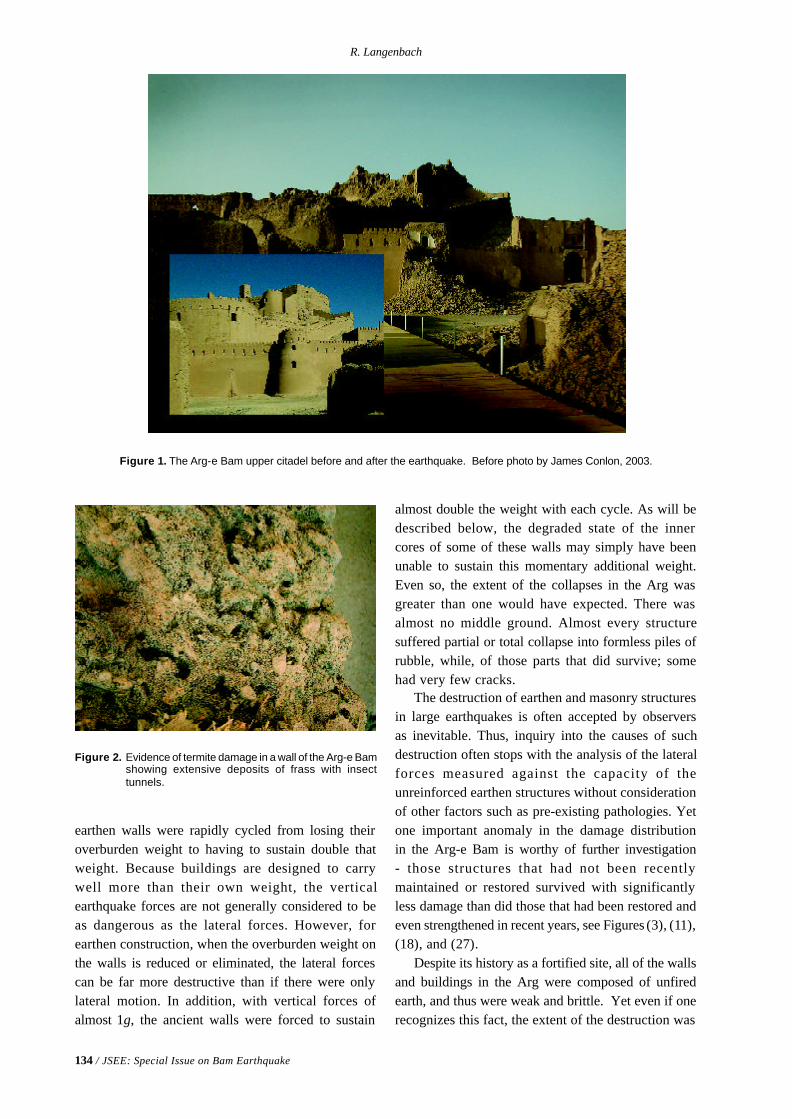
134 / JSEE: Special Issue on Bam Earthquake
R. Langenbach
Figure 1. The Arg-e Bam upper citadel before and after the earthquake. Before photo by James Conlon, 2003.
Figure 2. Evidence of termite damage in a wall of the Arg-e Bamshowing extensive deposits of frass with insecttunnels.
earthen walls were rapidly cycled from losing theiroverburden weight to having to sustain double thatweight. Because buildings are designed to carrywell more than their own weight, the verticalearthquake forces are not generally considered to beas dangerous as the lateral forces. However, forearthen construction, when the overburden weight onthe walls is reduced or eliminated, the lateral forcescan be far more destructive than if there were onlylateral motion. In addition, with vertical forces ofalmost 1g, the ancient walls were forced to sustain
almost double the weight with each cycle. As will bedescribed below, the degraded state of the innercores of some of these walls may simply have beenunable to sustain this momentary additional weight.Even so, the extent of the collapses in the Arg wasgreater than one would have expected. There wasalmost no middle ground. Almost every structuresuffered partial or total collapse into formless piles ofrubble, while, of those parts that did survive; somehad very few cracks.
The destruction of earthen and masonry structuresin large earthquakes is often accepted by observersas inevitable. Thus, inquiry into the causes of suchdestruction often stops with the analysis of the lateralforces measured against the capacity of theunreinforced earthen structures without considerationof other factors such as pre-existing pathologies. Yetone important anomaly in the damage distributionin the Arg-e Bam is worthy of further investigation- those structures that had not been recentlymaintained or restored survived with significantlyless damage than did those that had been restored andeven strengthened in recent years, see Figures (3), (11),(18), and (27).
Despite its history as a fortified site, all of the wallsand buildings in the Arg were composed of unfiredearth, and thus were weak and brittle. Yet even if onerecognizes this fact, the extent of the destruction was
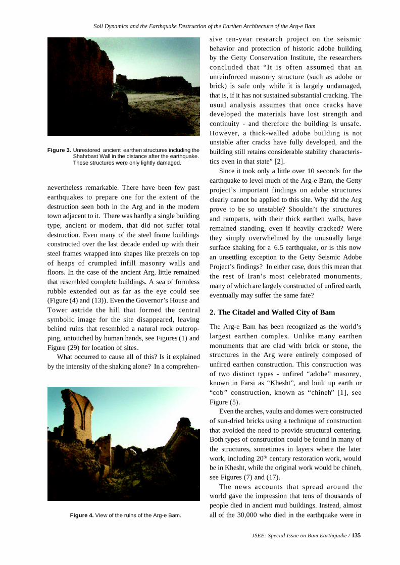
Soil Dynamics and the Earthquake Destruction of the Earthen Architecture of the Arg-e Bam
JSEE: Special Issue on Bam Earthquake / 135
Figure 3. Unrestored ancient earthen structures including theShahrbast Wall in the distance after the earthquake.These structures were only lightly damaged.
nevertheless remarkable. There have been few pastearthquakes to prepare one for the extent of thedestruction seen both in the Arg and in the moderntown adjacent to it. There was hardly a single buildingtype, ancient or modern, that did not suffer totaldestruction. Even many of the steel frame buildingsconstructed over the last decade ended up with theirsteel frames wrapped into shapes like pretzels on topof heaps of crumpled infill masonry walls andfloors. In the case of the ancient Arg, little remainedthat resembled complete buildings. A sea of formlessrubble extended out as far as the eye could see(Figure (4) and (13)). Even the Governor’s House andTower astride the hill that formed the centralsymbolic image for the site disappeared, leavingbehind ruins that resembled a natural rock outcrop-ping, untouched by human hands, see Figures (1) andFigure (29) for location of sites.
What occurred to cause all of this? Is it explainedby the intensity of the shaking alone? In a comprehen-
sive ten-year research project on the seismicbehavior and protection of historic adobe buildingby the Getty Conservation Institute, the researchersconcluded that “It is often assumed that anunreinforced masonry structure (such as adobe orbrick) is safe only while it is largely undamaged,that is, if it has not sustained substantial cracking. Theusual analysis assumes that once cracks havedeveloped the materials have lost strength andcontinuity - and therefore the building is unsafe.However, a thick-walled adobe building is notunstable after cracks have fully developed, and thebuilding still retains considerable stability characteris-tics even in that state” [2].
Since it took only a little over 10 seconds for theearthquake to level much of the Arg-e Bam, the Gettyproject’s important findings on adobe structuresclearly cannot be applied to this site. Why did the Argprove to be so unstable? Shouldn’t the structuresand ramparts, with their thick earthen walls, haveremained standing, even if heavily cracked? Werethey simply overwhelmed by the unusually largesurface shaking for a 6.5 earthquake, or is this nowan unsettling exception to the Getty Seismic AdobeProject’s findings? In either case, does this mean thatthe rest of Iran’s most celebrated monuments,many of which are largely constructed of unfired earth,eventually may suffer the same fate?
2. The Citadel and Walled City of Bam
The Arg-e Bam has been recognized as the world’slargest earthen complex. Unlike many earthenmonuments that are clad with brick or stone, thestructures in the Arg were entirely composed ofunfired earthen construction. This construction wasof two distinct types - unfired “adobe” masonry,known in Farsi as “Khesht”, and built up earth or“cob” construction, known as “chineh” [1], seeFigure (5).
Even the arches, vaults and domes were constructedof sun-dried bricks using a technique of constructionthat avoided the need to provide structural centering.Both types of construction could be found in many ofthe structures, sometimes in layers where the laterwork, including 20th century restoration work, wouldbe in Khesht, while the original work would be chineh,see Figures (7) and (17).
The news accounts that spread around theworld gave the impression that tens of thousands ofpeople died in ancient mud buildings. Instead, almostall of the 30,000 who died in the earthquake were inFigure 4. View of the ruins of the Arg-e Bam.
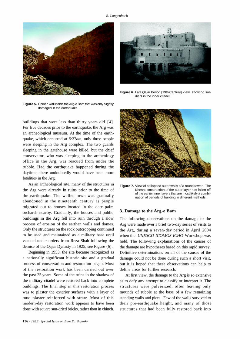
136 / JSEE: Special Issue on Bam Earthquake
R. Langenbach
Figure 5. Chineh wall inside the Arg-e Bam that was only slightlydamaged in the earthquake.
buildings that were less than thirty years old [4].For five decades prior to the earthquake, the Arg wasan archeological museum. At the time of the earth-quake, which occurred at 5:27am, only three peoplewere sleeping in the Arg complex. The two guardssleeping in the gatehouse were killed, but the chiefconservator, who was sleeping in the archeologyoffice in the Arg, was rescued from under therubble. Had the earthquake happened during thedaytime, there undoubtedly would have been morefatalities in the Arg.
As an archeological site, many of the structures inthe Arg were already in ruins prior to the time ofthe earthquake. The walled town was graduallyabandoned in the nineteenth century as peoplemigrated out to houses located in the date palmorchards nearby. Gradually, the houses and publicbuildings in the Arg fell into ruin through a slowprocess of erosion of the earthen walls and domes.Only the structures on the rock outcropping continuedto be used and maintained as a military base untilvacated under orders from Reza Shah following thedemise of the Qajar Dynasty in 1925, see Figure (6).
Beginning in 1953, the site became recognized asa nationally significant historic site and a gradualprocess of conservation and restoration began. Mostof the restoration work has been carried out overthe past 25 years. Some of the ruins in the shadow ofthe military citadel were restored back into completebuildings. The final step in this restoration processwas to plaster the exterior surfaces with a layer ofmud plaster reinforced with straw. Most of thismodern-day restoration work appears to have beendone with square sun-dried bricks, rather than in chineh.
Figure 6. Late Qajar Period (19th Century) view showing sol-diers in the inner citadel.
3. Damage to the Arg-e Bam
The following observations on the damage to theArg were made over a brief two-day series of visits tothe Arg, during a seven-day period in April 2004when the UNESCO-ICOMOS-ICHO Workshop washeld. The following explanations of the causes ofthe damage are hypotheses based on this rapid survey.Definitive determinations on all of the causes of thedamage could not be done during such a short visit,but it is hoped that these observations can help todefine areas for further research.
At first view, the damage to the Arg is so extensiveas to defy any attempt to classify or interpret it. Thestructures were pulverized, often leaving onlymounds of rubble at the base of a few remainingstanding walls and piers. Few of the walls survived totheir pre-earthquake height, and many of thosestructures that had been fully restored back into
Figure 7. View of collapsed outer walls of a round tower. TheKhesht construction of the outer layer has fallen offof the earlier inner layers that are most likely a combi-nation of periods of building in different methods.
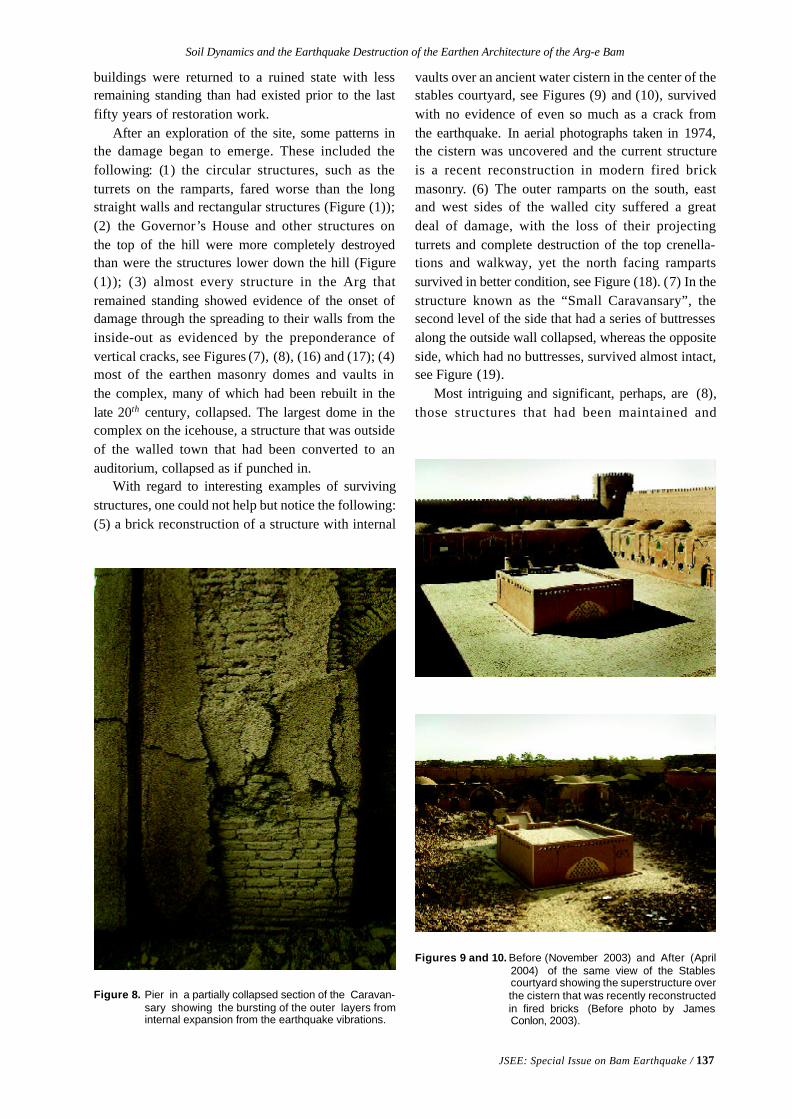
Soil Dynamics and the Earthquake Destruction of the Earthen Architecture of the Arg-e Bam
JSEE: Special Issue on Bam Earthquake / 137
buildings were returned to a ruined state with lessremaining standing than had existed prior to the lastfifty years of restoration work.
After an exploration of the site, some patterns inthe damage began to emerge. These included thefollowing: (1) the circular structures, such as theturrets on the ramparts, fared worse than the longstraight walls and rectangular structures (Figure (1));(2) the Governor’s House and other structures onthe top of the hill were more completely destroyedthan were the structures lower down the hill (Figure(1)); (3) almost every structure in the Arg thatremained standing showed evidence of the onset ofdamage through the spreading to their walls from theinside-out as evidenced by the preponderance ofvertical cracks, see Figures (7), (8), (16) and (17); (4)most of the earthen masonry domes and vaults inthe complex, many of which had been rebuilt in thelate 20th century, collapsed. The largest dome in thecomplex on the icehouse, a structure that was outsideof the walled town that had been converted to anauditorium, collapsed as if punched in.
With regard to interesting examples of survivingstructures, one could not help but notice the following:(5) a brick reconstruction of a structure with internal
Figure 8. Pier in a partially collapsed section of the Caravan-sary showing the bursting of the outer layers frominternal expansion from the earthquake vibrations.
vaults over an ancient water cistern in the center of thestables courtyard, see Figures (9) and (10), survivedwith no evidence of even so much as a crack fromthe earthquake. In aerial photographs taken in 1974,the cistern was uncovered and the current structureis a recent reconstruction in modern fired brickmasonry. (6) The outer ramparts on the south, eastand west sides of the walled city suffered a greatdeal of damage, with the loss of their projectingturrets and complete destruction of the top crenella-tions and walkway, yet the north facing rampartssurvived in better condition, see Figure (18). (7) In thestructure known as the “Small Caravansary”, thesecond level of the side that had a series of buttressesalong the outside wall collapsed, whereas the oppositeside, which had no buttresses, survived almost intact,see Figure (19).
Most intriguing and significant, perhaps, are (8),those structures that had been maintained and
Figures 9 and 10. Before (November 2003) and After (April2004) of the same view of the Stablescourtyard showing the superstructure overthe cistern that was recently reconstructedin fired bricks (Before photo by JamesConlon, 2003).
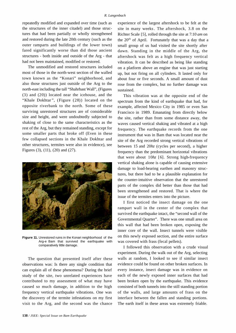
138 / JSEE: Special Issue on Bam Earthquake
R. Langenbach
repeatedly modified and expanded over time (such asthe structures of the inner citadel) and those struc-tures that had been partially or wholly strengthenedand restored during the late 20th century (such as theouter ramparts and buildings of the lower town)fared significantly worse than did those ancientstructures - both inside and outside of the Arg - thathad not been maintained, modified or restored.
The unmodified and restored structures includedmost of those in the north-west section of the walledtown known as the “Konari” neighborhood, andalso those structures just outside of the Arg to thenorth-east including the tall “Shahrbast Wall”, (Figures(3) and (20)) located near the icehouse, and the“Khale Dokhtar ”, (Figure (28)) located on theopposite riverbank to the north. Some of thesesurviving unrestored structures are of considerablesize and height, and were undoubtedly subjected toshaking of close to the same characteristics as therest of the Arg, but they remained standing, except forsome smaller parts that broke off (Even in thesefew collapsed sections in the Khale Dokhtar andother structures, termites were also in evidence), seeFigures (3), (11), (20) and (27).
Figure 11. Unrestored ruins in the Konari neighborhood of theArg-e Bam that survived the earthquake withcomparatively little damage.
The question that presented itself after theseobservations was: Is there any single condition thatcan explain all of these phenomena? During the briefstudy of the site, two unrelated experiences havecontributed to my assessment of what may havecaused so much damage, in addition to the highfrequency vertical earthquake vibrations. One wasthe discovery of the termite infestations on my firstvisit to the Arg, and the second was the chance
experience of the largest aftershock to be felt at thesite in many weeks . The aftershock, 3.8 on theRichter Scale [5], rolled through the site at 7:10 am onthe 20th of April. Fortunately that was a day that asmall group of us had visited the site shortly afterdawn. Standing in the middle of the Arg, theaftershock was felt as a high frequency verticalvibration. It can be described as being like standingon a platform above an engine that was just startingup, but not firing on all cylinders. It lasted only forabout four or five seconds. A small amount of dustrose from the complex, but no further damage wassustained.
This vibration was at the opposite end of thespectrum from the kind of earthquake that had, forexample, affected Mexico City in 1985 or even SanFrancisco in 1989. Emanating from directly belowthe site, rather than from some distance away, thewaves caused vertical shaking and vibrated at a highfrequency. The earthquake records from the oneinstrument that was in Bam that was located near thesite of the Arg recorded strong vertical vibrations ofbetween 15 and 20hz (cycles per second), a higherfrequency than the predominant horizontal vibrationsthat were about 10hz [6]. Strong high-frequencyvertical shaking alone is capable of causing extensivedamage to load-bearing earthen and masonry struc-tures, but there had to be a plausible explanation forthe counter-intuitive observation that the unrestoredparts of the complex did better than those that hadbeen strengthened and restored. That is where theissue of the termites enters into the picture.
I first noticed the insect damage on the onerampart wall in the center of the complex thatsurvived the earthquake intact, the “second wall of theGovernmental Quarter”. There was one small area onthis wall that had been broken open, exposing theinner core of the wall. Insect tunnels were visibleon this newly exposed section, and the entire surfacewas covered with frass (fecal pellets).
I followed this observation with a crude visualexperiment. During the walk out of the Arg, selectingwalls at random, I looked to see if similar insectevidence could be found on other broken surfaces. Inevery instance, insect damage was in evidence oneach of the newly exposed inner surfaces that hadbeen broken open by the earthquake. This evidenceconsisted of both tunnels into the still standing portionof the walls, and large amounts of frass on theinterface between the fallen and standing portions.The earth itself in these areas was extremely friable.
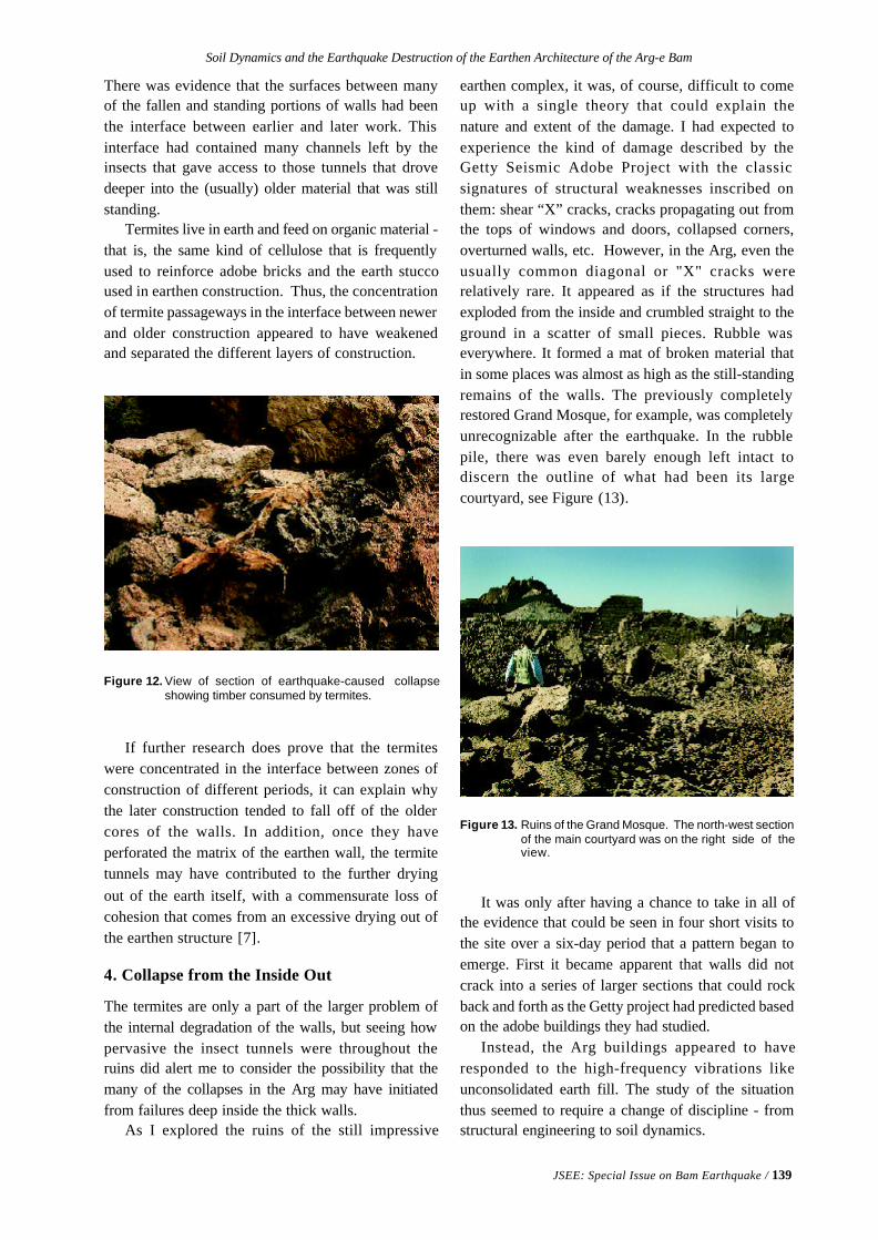
Soil Dynamics and the Earthquake Destruction of the Earthen Architecture of the Arg-e Bam
JSEE: Special Issue on Bam Earthquake / 139
There was evidence that the surfaces between manyof the fallen and standing portions of walls had beenthe interface between earlier and later work. Thisinterface had contained many channels left by theinsects that gave access to those tunnels that drovedeeper into the (usually) older material that was stillstanding.
Termites live in earth and feed on organic material -that is, the same kind of cellulose that is frequentlyused to reinforce adobe bricks and the earth stuccoused in earthen construction. Thus, the concentrationof termite passageways in the interface between newerand older construction appeared to have weakenedand separated the different layers of construction.
Figure 12. View of section of earthquake-caused collapseshowing timber consumed by termites.
If further research does prove that the termiteswere concentrated in the interface between zones ofconstruction of different periods, it can explain whythe later construction tended to fall off of the oldercores of the walls. In addition, once they haveperforated the matrix of the earthen wall, the termitetunnels may have contributed to the further dryingout of the earth itself, with a commensurate loss ofcohesion that comes from an excessive drying out ofthe earthen structure [7].
4. Collapse from the Inside Out
The termites are only a part of the larger problem ofthe internal degradation of the walls, but seeing howpervasive the insect tunnels were throughout theruins did alert me to consider the possibility that themany of the collapses in the Arg may have initiatedfrom failures deep inside the thick walls.
As I explored the ruins of the still impressive
earthen complex, it was, of course, difficult to comeup with a single theory that could explain thenature and extent of the damage. I had expected toexperience the kind of damage described by theGetty Seismic Adobe Project with the classicsignatures of structural weaknesses inscribed onthem: shear “X” cracks, cracks propagating out fromthe tops of windows and doors, collapsed corners,overturned walls, etc. However, in the Arg, even theusually common diagonal or "X" cracks wererelatively rare. It appeared as if the structures hadexploded from the inside and crumbled straight to theground in a scatter of small pieces. Rubble waseverywhere. It formed a mat of broken material thatin some places was almost as high as the still-standingremains of the walls. The previously completelyrestored Grand Mosque, for example, was completelyunrecognizable after the earthquake. In the rubblepile, there was even barely enough left intact todiscern the outline of what had been its largecourtyard, see Figure (13).
Figure 13. Ruins of the Grand Mosque. The north-west sectionof the main courtyard was on the right side of theview.
It was only after having a chance to take in all ofthe evidence that could be seen in four short visits tothe site over a six-day period that a pattern began toemerge. First it became apparent that walls did notcrack into a series of larger sections that could rockback and forth as the Getty project had predicted basedon the adobe buildings they had studied.
Instead, the Arg buildings appeared to haveresponded to the high-frequency vibrations likeunconsolidated earth fill. The study of the situationthus seemed to require a change of discipline - fromstructural engineering to soil dynamics.
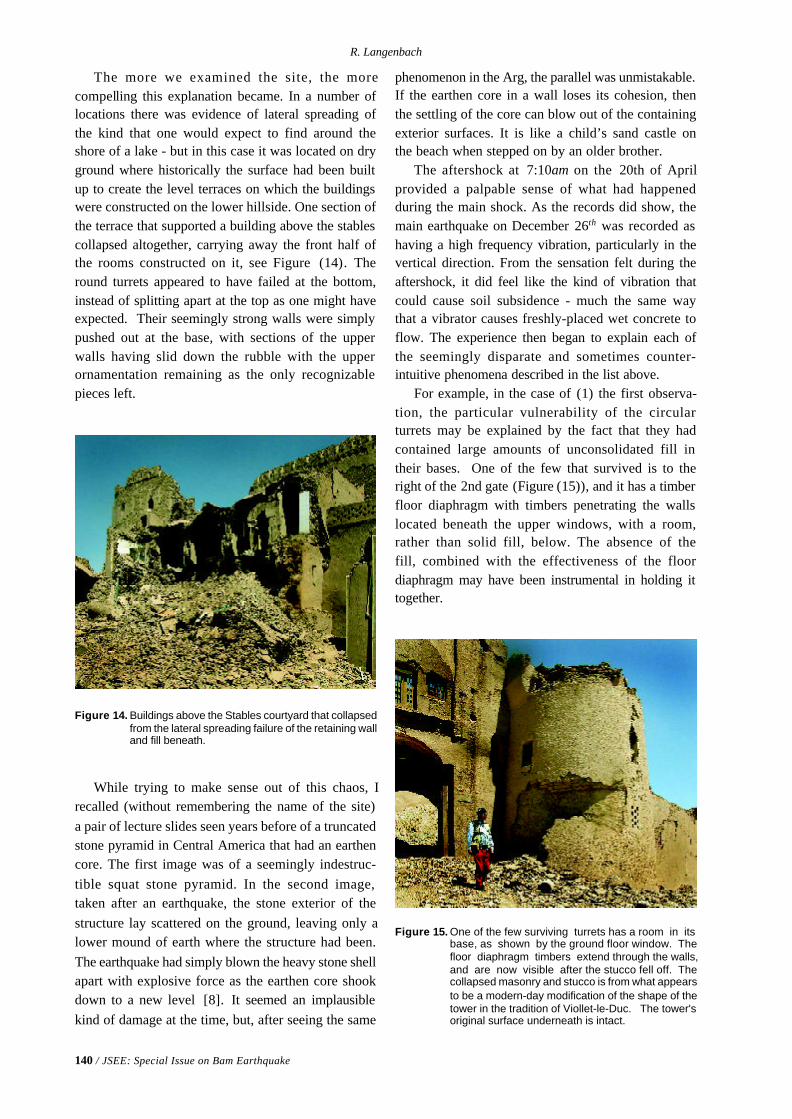
140 / JSEE: Special Issue on Bam Earthquake
R. Langenbach
The more we examined the site, the morecompelling this explanation became. In a number oflocations there was evidence of lateral spreading ofthe kind that one would expect to find around theshore of a lake - but in this case it was located on dryground where historically the surface had been builtup to create the level terraces on which the buildingswere constructed on the lower hillside. One section ofthe terrace that supported a building above the stablescollapsed altogether, carrying away the front half ofthe rooms constructed on it, see Figure (14). Theround turrets appeared to have failed at the bottom,instead of splitting apart at the top as one might haveexpected. Their seemingly strong walls were simplypushed out at the base, with sections of the upperwalls having slid down the rubble with the upperornamentation remaining as the only recognizablepieces left.
phenomenon in the Arg, the parallel was unmistakable.If the earthen core in a wall loses its cohesion, thenthe settling of the core can blow out of the containingexterior surfaces. It is like a child’s sand castle onthe beach when stepped on by an older brother.
The aftershock at 7:10am on the 20th of Aprilprovided a palpable sense of what had happenedduring the main shock. As the records did show, themain earthquake on December 26th was recorded ashaving a high frequency vibration, particularly in thevertical direction. From the sensation felt during theaftershock, it did feel like the kind of vibration thatcould cause soil subsidence - much the same waythat a vibrator causes freshly-placed wet concrete toflow. The experience then began to explain each ofthe seemingly disparate and sometimes counter-intuitive phenomena described in the list above.
For example, in the case of (1) the first observa-tion, the particular vulnerability of the circularturrets may be explained by the fact that they hadcontained large amounts of unconsolidated fill intheir bases. One of the few that survived is to theright of the 2nd gate (Figure (15)), and it has a timberfloor diaphragm with timbers penetrating the wallslocated beneath the upper windows, with a room,rather than solid fill, below. The absence of thefill, combined with the effectiveness of the floordiaphragm may have been instrumental in holding ittogether.
Figure 14. Buildings above the Stables courtyard that collapsedfrom the lateral spreading failure of the retaining walland fill beneath.
While trying to make sense out of this chaos, Irecalled (without remembering the name of the site)a pair of lecture slides seen years before of a truncatedstone pyramid in Central America that had an earthencore. The first image was of a seemingly indestruc-tible squat stone pyramid. In the second image,taken after an earthquake, the stone exterior of thestructure lay scattered on the ground, leaving only alower mound of earth where the structure had been.The earthquake had simply blown the heavy stone shellapart with explosive force as the earthen core shookdown to a new level [8]. It seemed an implausiblekind of damage at the time, but, after seeing the same
Figure 15. One of the few surviving turrets has a room in itsbase, as shown by the ground floor window. Thefloor diaphragm timbers extend through the walls,and are now visible after the stucco fell off. Thecollapsed masonry and stucco is from what appearsto be a modern-day modification of the shape of thetower in the tradition of Viollet-le-Duc. The tower'soriginal surface underneath is intact.
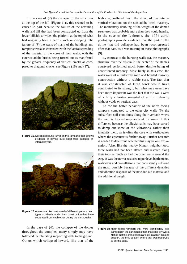
Soil Dynamics and the Earthquake Destruction of the Earthen Architecture of the Arg-e Bam
JSEE: Special Issue on Bam Earthquake / 141
In the case of (2) the collapse of the structuresat the top of the hill (Figure (1)), this seemed to becaused in part because the failure of the retainingwalls and fill that had been constructed up from thelower hillside to widen the platform at the top of whathad originally been a narrow rock outcropping. Thefailure of (3) the walls of many of the buildings andramparts was also consistent with the lateral spreadingof the material in the cores of their walls, with theexterior adobe bricks being forced out as manifestedby the greater frequency of vertical cracks as com-pared to diagonal cracks, see Figure (16) and (17).
Icehouse, suffered from the effect of the intensevertical vibrations on the soft adobe brick masonry.The momentary doubling of the weight of the domedstructures was probably more than they could handle.In the case of the Icehouse, the 1974 aerialphotographs provide evidence that the part of thedome that did collapse had been reconstructedafter that date, as it was missing in those photographs[9].
By contrast to the bursting walls (5), the masonrystructure over the cistern in the center of the stablescourtyard performed much better despite being ofunreinforced masonry. Most likely in this case, thewalls were of a uniformly solid and bonded masonryconstruction without a rubble core. The fact thatit was constructed of fired brick would havecontributed to its strength, but what may even havebeen more important was the fact that the walls wereof a fully cohesive material of uniform densitywithout voids or vertical gaps.
As for the better behavior of the north-facingramparts compared to the other city walls (6), thesubsurface soil conditions along the riverbank wherethe wall is located may account for some of thisdifference because the alluvial soils may have servedto damp out some of the vibrations, rather thanintensify them, as is often the case with earthquakeswhere the epicenter is farther away. Further researchis needed to determine whether this may be one expla-nation. Also, like the nearby Konari neighborhood,these walls had not been altered and restored alongtheir tops as much as had the other walls around theArg. It was the newer restored upper level battlements,walkways and crenellations that consistently sufferedthe most, possibly because of the different densitiesand vibration response of the new and old material andthe additional weight.
Figure 16. Collapsed round turret on the ramparts that showsevidence of having burst apart from collapse ofinternal layers.
Figure 17. A massive pier composed of different periods andtypes of Khesht and chineh construction that haveseparated from each other during the earthquake.
In the case of (4), the collapse of the domesthroughout the complex, many simply may havefollowed their bursting supporting walls to the ground.Others which collapsed inward, like that of the
Figure 18. North-facing ramparts that were significantly lessdamaged in the earthquake than the other city walls.Notice that the crenellations are still intact on this onesection, the only section where that was observedto be the case.
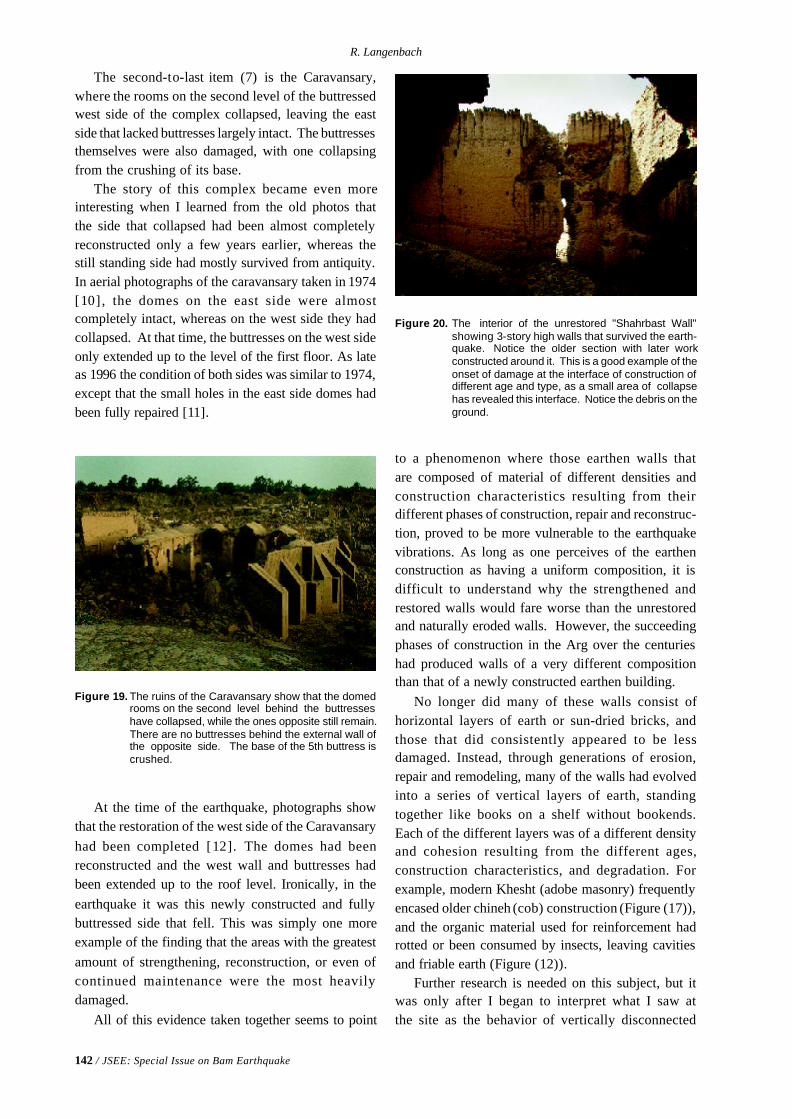
142 / JSEE: Special Issue on Bam Earthquake
R. Langenbach
The second-to-last item (7) is the Caravansary,where the rooms on the second level of the buttressedwest side of the complex collapsed, leaving the eastside that lacked buttresses largely intact. The buttressesthemselves were also damaged, with one collapsingfrom the crushing of its base.
The story of this complex became even moreinteresting when I learned from the old photos thatthe side that collapsed had been almost completelyreconstructed only a few years earlier, whereas thestill standing side had mostly survived from antiquity.In aerial photographs of the caravansary taken in 1974[10], the domes on the east side were almostcompletely intact, whereas on the west side they hadcollapsed. At that time, the buttresses on the west sideonly extended up to the level of the first floor. As lateas 1996 the condition of both sides was similar to 1974,except that the small holes in the east side domes hadbeen fully repaired [11].
to a phenomenon where those earthen walls thatare composed of material of different densities andconstruction characteristics resulting from theirdifferent phases of construction, repair and reconstruc-tion, proved to be more vulnerable to the earthquakevibrations. As long as one perceives of the earthenconstruction as having a uniform composition, it isdifficult to understand why the strengthened andrestored walls would fare worse than the unrestoredand naturally eroded walls. However, the succeedingphases of construction in the Arg over the centurieshad produced walls of a very different compositionthan that of a newly constructed earthen building.
No longer did many of these walls consist ofhorizontal layers of earth or sun-dried bricks, andthose that did consistently appeared to be lessdamaged. Instead, through generations of erosion,repair and remodeling, many of the walls had evolvedinto a series of vertical layers of earth, standingtogether like books on a shelf without bookends.Each of the different layers was of a different densityand cohesion resulting from the different ages,construction characteristics, and degradation. Forexample, modern Khesht (adobe masonry) frequentlyencased older chineh (cob) construction (Figure (17)),and the organic material used for reinforcement hadrotted or been consumed by insects, leaving cavitiesand friable earth (Figure (12)).
Further research is needed on this subject, but itwas only after I began to interpret what I saw atthe site as the behavior of vertically disconnected
Figure 19. The ruins of the Caravansary show that the domedrooms on the second level behind the buttresseshave collapsed, while the ones opposite still remain.There are no buttresses behind the external wall ofthe opposite side. The base of the 5th buttress iscrushed.
Figure 20. The interior of the unrestored "Shahrbast Wall"showing 3-story high walls that survived the earth-quake. Notice the older section with later workconstructed around it. This is a good example of theonset of damage at the interface of construction ofdifferent age and type, as a small area of collapsehas revealed this interface. Notice the debris on theground.
At the time of the earthquake, photographs showthat the restoration of the west side of the Caravansaryhad been completed [12]. The domes had beenreconstructed and the west wall and buttresses hadbeen extended up to the roof level. Ironically, in theearthquake it was this newly constructed and fullybuttressed side that fell. This was simply one moreexample of the finding that the areas with the greatestamount of strengthening, reconstruction, or even ofcontinued maintenance were the most heavilydamaged.
All of this evidence taken together seems to point
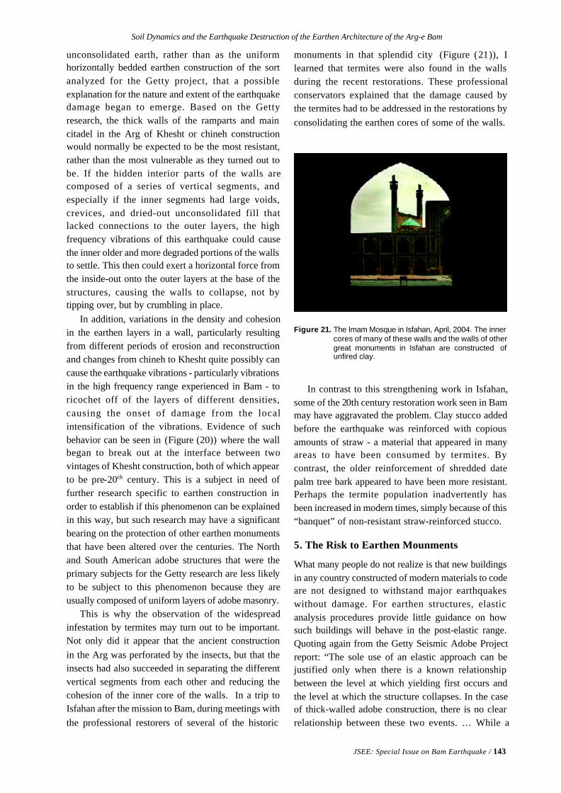
Soil Dynamics and the Earthquake Destruction of the Earthen Architecture of the Arg-e Bam
JSEE: Special Issue on Bam Earthquake / 143
unconsolidated earth, rather than as the uniformhorizontally bedded earthen construction of the sortanalyzed for the Getty project, that a possibleexplanation for the nature and extent of the earthquakedamage began to emerge. Based on the Gettyresearch, the thick walls of the ramparts and maincitadel in the Arg of Khesht or chineh constructionwould normally be expected to be the most resistant,rather than the most vulnerable as they turned out tobe. If the hidden interior parts of the walls arecomposed of a series of vertical segments, andespecially if the inner segments had large voids,crevices, and dried-out unconsolidated fill thatlacked connections to the outer layers, the highfrequency vibrations of this earthquake could causethe inner older and more degraded portions of the wallsto settle. This then could exert a horizontal force fromthe inside-out onto the outer layers at the base of thestructures, causing the walls to collapse, not bytipping over, but by crumbling in place.
In addition, variations in the density and cohesionin the earthen layers in a wall, particularly resultingfrom different periods of erosion and reconstructionand changes from chineh to Khesht quite possibly cancause the earthquake vibrations - particularly vibrationsin the high frequency range experienced in Bam - toricochet off of the layers of different densities,causing the onset of damage from the localintensification of the vibrations. Evidence of suchbehavior can be seen in (Figure (20)) where the wallbegan to break out at the interface between twovintages of Khesht construction, both of which appearto be pre-20th century. This is a subject in need offurther research specific to earthen construction inorder to establish if this phenomenon can be explainedin this way, but such research may have a significantbearing on the protection of other earthen monumentsthat have been altered over the centuries. The Northand South American adobe structures that were theprimary subjects for the Getty research are less likelyto be subject to this phenomenon because they areusually composed of uniform layers of adobe masonry.
This is why the observation of the widespreadinfestation by termites may turn out to be important.Not only did it appear that the ancient constructionin the Arg was perforated by the insects, but that theinsects had also succeeded in separating the differentvertical segments from each other and reducing thecohesion of the inner core of the walls. In a trip toIsfahan after the mission to Bam, during meetings withthe professional restorers of several of the historic
monuments in that splendid city (Figure (21)), Ilearned that termites were also found in the wallsduring the recent restorations. These professionalconservators explained that the damage caused bythe termites had to be addressed in the restorations byconsolidating the earthen cores of some of the walls.
In contrast to this strengthening work in Isfahan,some of the 20th century restoration work seen in Bammay have aggravated the problem. Clay stucco addedbefore the earthquake was reinforced with copiousamounts of straw - a material that appeared in manyareas to have been consumed by termites. Bycontrast, the older reinforcement of shredded datepalm tree bark appeared to have been more resistant.Perhaps the termite population inadvertently hasbeen increased in modern times, simply because of this“banquet” of non-resistant straw-reinforced stucco.
5. The Risk to Earthen Mounments
What many people do not realize is that new buildingsin any country constructed of modern materials to codeare not designed to withstand major earthquakeswithout damage. For earthen structures, elasticanalysis procedures provide little guidance on howsuch buildings will behave in the post-elastic range.Quoting again from the Getty Seismic Adobe Projectreport: “The sole use of an elastic approach can bejustified only when there is a known relationshipbetween the level at which yielding first occurs andthe level at which the structure collapses. In the caseof thick-walled adobe construction, there is no clearrelationship between these two events. … While a
Figure 21. The Imam Mosque in Isfahan, April, 2004. The innercores of many of these walls and the walls of othergreat monuments in Isfahan are constructed ofunfired clay.
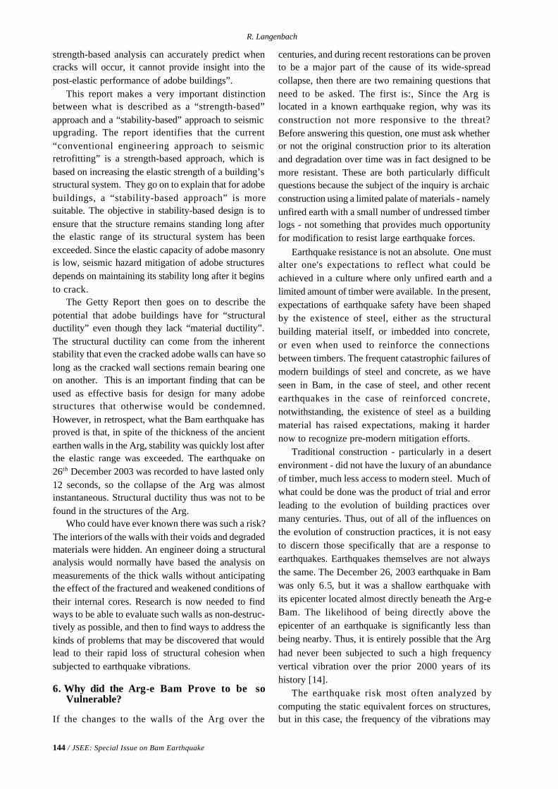
144 / JSEE: Special Issue on Bam Earthquake
R. Langenbach
strength-based analysis can accurately predict whencracks will occur, it cannot provide insight into thepost-elastic performance of adobe buildings”.
This report makes a very important distinctionbetween what is described as a “strength-based”approach and a “stability-based” approach to seismicupgrading. The report identifies that the current“conventional engineering approach to seismicretrofitting” is a strength-based approach, which isbased on increasing the elastic strength of a building’sstructural system. They go on to explain that for adobebuildings, a “stability-based approach” is moresuitable. The objective in stability-based design is toensure that the structure remains standing long afterthe elastic range of its structural system has beenexceeded. Since the elastic capacity of adobe masonryis low, seismic hazard mitigation of adobe structuresdepends on maintaining its stability long after it beginsto crack.
The Getty Report then goes on to describe thepotential that adobe buildings have for “structuralductility” even though they lack “material ductility”.The structural ductility can come from the inherentstability that even the cracked adobe walls can have solong as the cracked wall sections remain bearing oneon another. This is an important finding that can beused as effective basis for design for many adobestructures that otherwise would be condemned.However, in retrospect, what the Bam earthquake hasproved is that, in spite of the thickness of the ancientearthen walls in the Arg, stability was quickly lost afterthe elastic range was exceeded. The earthquake on26th December 2003 was recorded to have lasted only12 seconds, so the collapse of the Arg was almostinstantaneous. Structural ductility thus was not to befound in the structures of the Arg.
Who could have ever known there was such a risk?The interiors of the walls with their voids and degradedmaterials were hidden. An engineer doing a structuralanalysis would normally have based the analysis onmeasurements of the thick walls without anticipatingthe effect of the fractured and weakened conditions oftheir internal cores. Research is now needed to findways to be able to evaluate such walls as non-destruc-tively as possible, and then to find ways to address thekinds of problems that may be discovered that wouldlead to their rapid loss of structural cohesion whensubjected to earthquake vibrations.
6. Why did the Arg-e Bam Prove to be soVulnerable?
If the changes to the walls of the Arg over the
centuries, and during recent restorations can be provento be a major part of the cause of its wide-spreadcollapse, then there are two remaining questions thatneed to be asked. The first is:, Since the Arg islocated in a known earthquake region, why was itsconstruction not more responsive to the threat?Before answering this question, one must ask whetheror not the original construction prior to its alterationand degradation over time was in fact designed to bemore resistant. These are both particularly difficultquestions because the subject of the inquiry is archaicconstruction using a limited palate of materials - namelyunfired earth with a small number of undressed timberlogs - not something that provides much opportunityfor modification to resist large earthquake forces.
Earthquake resistance is not an absolute. One mustalter one's expectations to reflect what could beachieved in a culture where only unfired earth and alimited amount of timber were available. In the present,expectations of earthquake safety have been shapedby the existence of steel, either as the structuralbuilding material itself, or imbedded into concrete,or even when used to reinforce the connectionsbetween timbers. The frequent catastrophic failures ofmodern buildings of steel and concrete, as we haveseen in Bam, in the case of steel, and other recentearthquakes in the case of reinforced concrete,notwithstanding, the existence of steel as a buildingmaterial has raised expectations, making it hardernow to recognize pre-modern mitigation efforts.
Traditional construction - particularly in a desertenvironment - did not have the luxury of an abundanceof timber, much less access to modern steel. Much ofwhat could be done was the product of trial and errorleading to the evolution of building practices overmany centuries. Thus, out of all of the influences onthe evolution of construction practices, it is not easyto discern those specifically that are a response toearthquakes. Earthquakes themselves are not alwaysthe same. The December 26, 2003 earthquake in Bamwas only 6.5, but it was a shallow earthquake withits epicenter located almost directly beneath the Arg-eBam. The likelihood of being directly above theepicenter of an earthquake is significantly less thanbeing nearby. Thus, it is entirely possible that the Arghad never been subjected to such a high frequencyvertical vibration over the prior 2000 years of itshistory [14].
The earthquake risk most often analyzed bycomputing the static equivalent forces on structures,but in this case, the frequency of the vibrations may
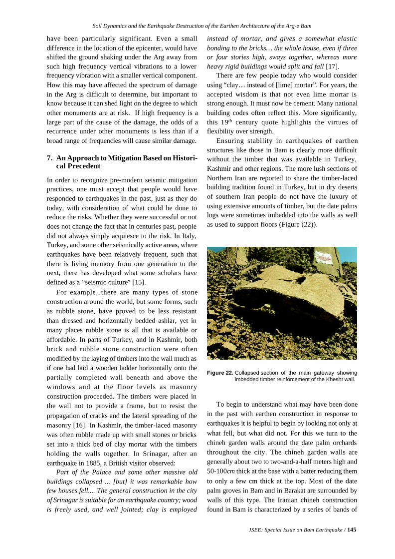
Soil Dynamics and the Earthquake Destruction of the Earthen Architecture of the Arg-e Bam
JSEE: Special Issue on Bam Earthquake / 145
have been particularly significant. Even a smalldifference in the location of the epicenter, would haveshifted the ground shaking under the Arg away fromsuch high frequency vertical vibrations to a lowerfrequency vibration with a smaller vertical component.How this may have affected the spectrum of damagein the Arg is difficult to determine, but important toknow because it can shed light on the degree to whichother monuments are at risk. If high frequency is alarge part of the cause of the damage, the odds of arecurrence under other monuments is less than if abroad range of frequencies will cause similar damage.
7. An Approach to Mitigation Based on Histori-cal Precedent
In order to recognize pre-modern seismic mitigationpractices, one must accept that people would haveresponded to earthquakes in the past, just as they dotoday, with consideration of what could be done toreduce the risks. Whether they were successful or notdoes not change the fact that in centuries past, peopledid not always simply acquiesce to the risk. In Italy,Turkey, and some other seismically active areas, whereearthquakes have been relatively frequent, such thatthere is living memory from one generation to thenext, there has developed what some scholars havedefined as a “seismic culture” [15].
For example, there are many types of stoneconstruction around the world, but some forms, suchas rubble stone, have proved to be less resistantthan dressed and horizontally bedded ashlar, yet inmany places rubble stone is all that is available oraffordable. In parts of Turkey, and in Kashmir, bothbrick and rubble stone construction were oftenmodified by the laying of timbers into the wall much asif one had laid a wooden ladder horizontally onto thepartially completed wall beneath and above thewindows and at the floor levels as masonryconstruction proceeded. The timbers were placed inthe wall not to provide a frame, but to resist thepropagation of cracks and the lateral spreading of themasonry [16]. In Kashmir, the timber-laced masonrywas often rubble made up with small stones or bricksset into a thick bed of clay mortar with the timbersholding the walls together. In Srinagar, after anearthquake in 1885, a British visitor observed:
Part of the Palace and some other massive oldbuildings collapsed ... [but] it was remarkable howfew houses fell.... The general construction in the cityof Srinagar is suitable for an earthquake country; woodis freely used, and well jointed; clay is employed
instead of mortar, and gives a somewhat elasticbonding to the bricks… the whole house, even if threeor four stories high, sways together, whereas moreheavy rigid buildings would split and fall [17].
There are few people today who would considerusing “clay… instead of [lime] mortar”. For years, theaccepted wisdom is that not even lime mortar isstrong enough. It must now be cement. Many nationalbuilding codes often reflect this. More significantly,this 19th century quote highlights the virtues offlexibility over strength.
Ensuring stability in earthquakes of earthenstructures like those in Bam is clearly more difficultwithout the timber that was available in Turkey,Kashmir and other regions. The more lush sections ofNorthern Iran are reported to share the timber-lacedbuilding tradition found in Turkey, but in dry desertsof southern Iran people do not have the luxury ofusing extensive amounts of timber, but the date palmslogs were sometimes imbedded into the walls as wellas used to support floors (Figure (22)).
Figure 22. Collapsed section of the main gateway showingimbedded timber reinforcement of the Khesht wall.
To begin to understand what may have been donein the past with earthen construction in response toearthquakes it is helpful to begin by looking not only atwhat fell, but what did not. For this we turn to thechineh garden walls around the date palm orchardsthroughout the city. The chineh garden walls aregenerally about two to two-and-a-half meters high and50-100cm thick at the base with a batter reducing themto only a few cm thick at the top. Most of the datepalm groves in Bam and in Barakat are surrounded bywalls of this type. The Iranian chineh constructionfound in Bam is characterized by a series of bands of
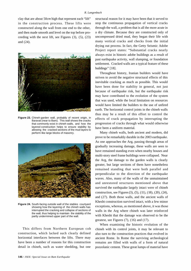
146 / JSEE: Special Issue on Bam Earthquake
R. Langenbach
clay that are about 50cm high that represent each “lift”in the construction process. These lifts wereconstructed along the wall from one end to the other,and then made smooth and level on the top before pro-ceeding with the next lift, see Figures (3), (5), (23)and (24).
structural reason for it may have been that it served tostop the continuous propagation of vertical cracksthrough the wall, a problem that is all the more acute ina dry climate. Because they are constructed only ofuncompressed dried mud, they began their life withmany vertical cracks and checks from the initialdrying out process. In fact, the Getty Seismic AdobeProject report states: “Substantial cracks nearlyalways exist in historic adobe buildings as a result ofpast earthquake activity, wall slumping, or foundationsettlement. Cracked walls are a typical feature of thesebuildings” [18].
Throughout history, Iranian builders would havestriven to avoid the negative structural effects of thisinevitable cracking as much as possible. This wouldhave been done for stability in general, not justbecause of earthquake risk, but the earthquake riskmay have contributed to the evolution of the systemthat was used, while the local limitation on resourceswould have limited the builders to the use of unfiredearth. The horizontal control joints in the chineh wallsthus may be a result of this effort to control theeffects of crack propagation by interrupting theprogression of cracks through what would otherwisehave been a uniform material.
Many chineh walls, both ancient and modern, didprove to be remarkably durable in the 2003 earthquake.As one approaches the Arg, passing through areas ofgradually increasing damage, these walls are seen tohave remained standing even when nearby houses andmulti-story steel frame buildings were collapsed. Nearthe Arg, the damage to the garden walls is clearlygreater, but large sections of them have nonethelessremained standing that were both parallel andperpendicular to the direction of the earthquakewaves. Also, many of the walls of the unmaintainedand unrestored structures mentioned above thatsurvived the earthquake largely intact were of chinehconstruction, see Figures (3), (5), (11), (18), (20), (24),and (27). Both those walls, and the ancient walls ofKhesht construction survived intact, with a few minorexceptions, whereas, as mentioned above, it was thosewalls in the Arg where chineh was later reinforcedwith Khesht that the damage was observed to be thegreatest, see Figures (7), (16) and (17).
When examining the historic evolution of thechineh with its control joints, it may be relevant toalso turn to the construction practices that evolved inancient Rome. In Rome the surviving archeologicalremains are filled with walls of a form of naturalpozzolanic cement. These great lumps of material have
Figure 24. South-facing outside wall of the stables courtyardshowing how the layering of the chineh walls hasinterrupted the cracking and collapse of sections ofthe wall, thus helping to maintain the stability of thepartly undermined upper part of the wall.
Figure 23. Chineh garden wall, probably of recent origin, inBaravat (near to Bam). This wall shows the cracksthat commonly exist in chineh walls, and how thelayered construction helps to ensure stability byallowing the cracked sections of the mud layers toperform like large blocks of masonry.
This differs from Northern European cobconstruction, which lacked such clearly definedhorizontal interfaces between the lifts. There mayhave been a number of reasons for this constructiondetail in chineh, such as water shedding, but one
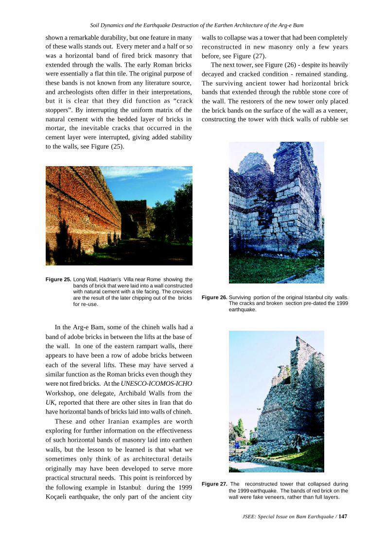
Soil Dynamics and the Earthquake Destruction of the Earthen Architecture of the Arg-e Bam
JSEE: Special Issue on Bam Earthquake / 147
shown a remarkable durability, but one feature in manyof these walls stands out. Every meter and a half or sowas a horizontal band of fired brick masonry thatextended through the walls. The early Roman brickswere essentially a flat thin tile. The original purpose ofthese bands is not known from any literature source,and archeologists often differ in their interpretations,but it is clear that they did function as “crackstoppers”. By interrupting the uniform matrix of thenatural cement with the bedded layer of bricks inmortar, the inevitable cracks that occurred in thecement layer were interrupted, giving added stabilityto the walls, see Figure (25).
Figure 25. Long Wall, Hadrian's Villa near Rome showing thebands of brick that were laid into a wall constructedwith natural cement with a tile facing. The crevicesare the result of the later chipping out of the bricksfor re-use.
In the Arg-e Bam, some of the chineh walls had aband of adobe bricks in between the lifts at the base ofthe wall. In one of the eastern rampart walls, thereappears to have been a row of adobe bricks betweeneach of the several lifts. These may have served asimilar function as the Roman bricks even though theywere not fired bricks. At the UNESCO-ICOMOS-ICHOWorkshop, one delegate, Archibald Walls from theUK, reported that there are other sites in Iran that dohave horizontal bands of bricks laid into walls of chineh.
These and other Iranian examples are worthexploring for further information on the effectivenessof such horizontal bands of masonry laid into earthenwalls, but the lesson to be learned is that what wesometimes only think of as architectural detailsoriginally may have been developed to serve morepractical structural needs. This point is reinforced bythe following example in Istanbul: during the 1999Koçaeli earthquake, the only part of the ancient city
walls to collapse was a tower that had been completelyreconstructed in new masonry only a few yearsbefore, see Figure (27).
The next tower, see Figure (26) - despite its heavilydecayed and cracked condition - remained standing.The surviving ancient tower had horizontal brickbands that extended through the rubble stone core ofthe wall. The restorers of the new tower only placedthe brick bands on the surface of the wall as a veneer,constructing the tower with thick walls of rubble set
Figure 27. The reconstructed tower that collapsed duringthe 1999 earthquake. The bands of red brick on thewall were fake veneers, rather than full layers.
Figure 26. Surviving portion of the original Istanbul city walls.The cracks and broken section pre-dated the 1999earthquake.
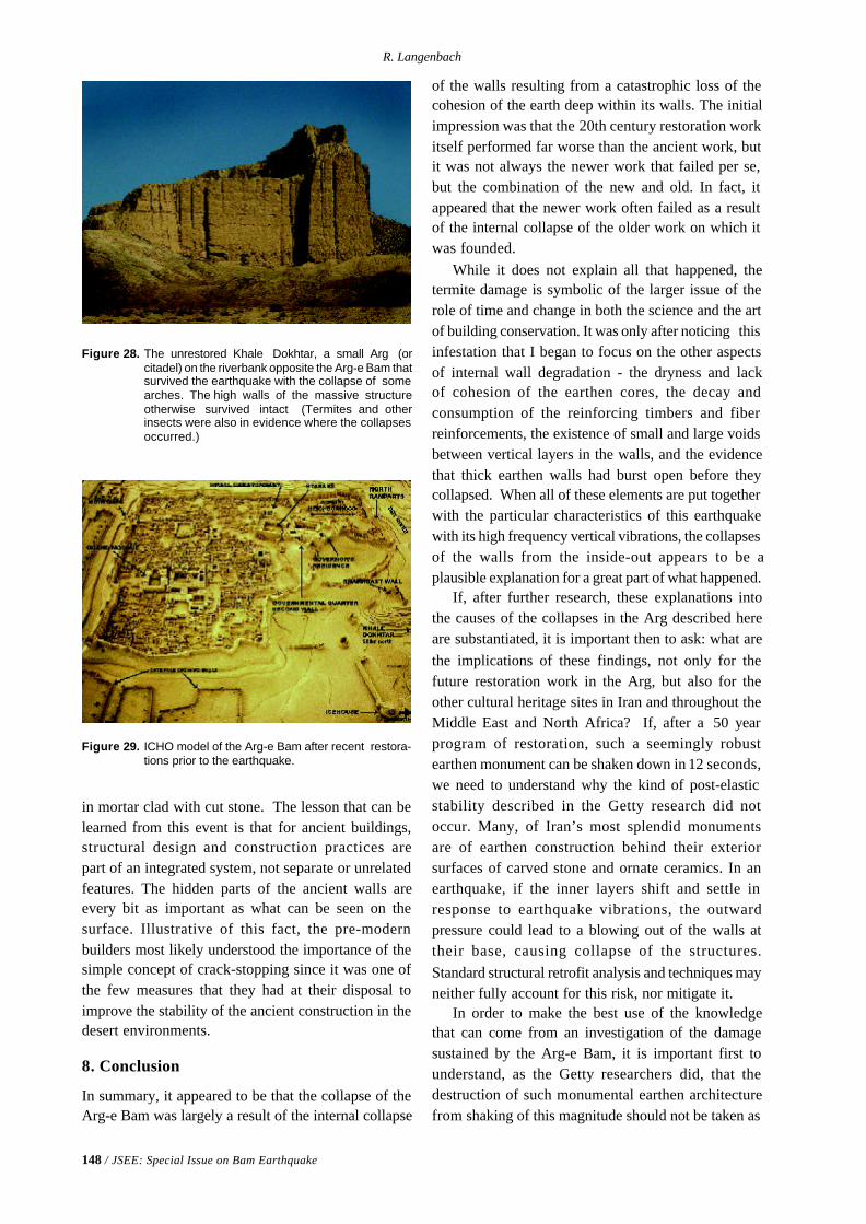
148 / JSEE: Special Issue on Bam Earthquake
R. Langenbach
in mortar clad with cut stone. The lesson that can belearned from this event is that for ancient buildings,structural design and construction practices arepart of an integrated system, not separate or unrelatedfeatures. The hidden parts of the ancient walls areevery bit as important as what can be seen on thesurface. Illustrative of this fact, the pre-modernbuilders most likely understood the importance of thesimple concept of crack-stopping since it was one ofthe few measures that they had at their disposal toimprove the stability of the ancient construction in thedesert environments.
8. Conclusion
In summary, it appeared to be that the collapse of theArg-e Bam was largely a result of the internal collapse
Figure 28. The unrestored Khale Dokhtar, a small Arg (orcitadel) on the riverbank opposite the Arg-e Bam thatsurvived the earthquake with the collapse of somearches. The high walls of the massive structureotherwise survived intact (Termites and otherinsects were also in evidence where the collapsesoccurred.)
Figure 29. ICHO model of the Arg-e Bam after recent restora-tions prior to the earthquake.
of the walls resulting from a catastrophic loss of thecohesion of the earth deep within its walls. The initialimpression was that the 20th century restoration workitself performed far worse than the ancient work, butit was not always the newer work that failed per se,but the combination of the new and old. In fact, itappeared that the newer work often failed as a resultof the internal collapse of the older work on which itwas founded.
While it does not explain all that happened, thetermite damage is symbolic of the larger issue of therole of time and change in both the science and the artof building conservation. It was only after noticing thisinfestation that I began to focus on the other aspectsof internal wall degradation - the dryness and lackof cohesion of the earthen cores, the decay andconsumption of the reinforcing timbers and fiberreinforcements, the existence of small and large voidsbetween vertical layers in the walls, and the evidencethat thick earthen walls had burst open before theycollapsed. When all of these elements are put togetherwith the particular characteristics of this earthquakewith its high frequency vertical vibrations, the collapsesof the walls from the inside-out appears to be aplausible explanation for a great part of what happened.
If, after further research, these explanations intothe causes of the collapses in the Arg described hereare substantiated, it is important then to ask: what arethe implications of these findings, not only for thefuture restoration work in the Arg, but also for theother cultural heritage sites in Iran and throughout theMiddle East and North Africa? If, after a 50 yearprogram of restoration, such a seemingly robustearthen monument can be shaken down in 12 seconds,we need to understand why the kind of post-elasticstability described in the Getty research did notoccur. Many, of Iran’s most splendid monumentsare of earthen construction behind their exteriorsurfaces of carved stone and ornate ceramics. In anearthquake, if the inner layers shift and settle inresponse to earthquake vibrations, the outwardpressure could lead to a blowing out of the walls attheir base, causing collapse of the structures.Standard structural retrofit analysis and techniques mayneither fully account for this risk, nor mitigate it.
In order to make the best use of the knowledgethat can come from an investigation of the damagesustained by the Arg-e Bam, it is important first tounderstand, as the Getty researchers did, that thedestruction of such monumental earthen architecturefrom shaking of this magnitude should not be taken as
Soil Dynamics and the Earthquake Destruction of the Earthen Architecture of the Arg-e Bam
JSEE: Special Issue on Bam Earthquake / 149
a forgone conclusion or as a condemnation of the useof unfired earth as a building material. What thedestruction of the Arg does provide, however, is thecautionary message: Buildings are not always as theyseem to be when looked at from the outside. Thismessage is particularly profound when it comes toearthen architecture. The transition of the walls ofthe Arg from horizontally bedded layers to separatingvertical segments resulted from centuries of erosionand renewal, but the external look of the walls hadchanged little over that time. It took an earthquake toopen the walls up and reveal that the internal composi-tion of the wall was no longer the same as it had beenwhen originally constructed.
More than any other building material, unfired claycan change over time from cumulative effects of theshort repeating cycle of erosion and renewal, and alsofrom a gradual deterioration of the hidden core of thewalls, not only from termites, but also from risingdamp, water intrusion from the top and sides,differential settlement, gradual compaction, andgradual chemical or mineralogical changes to thematrix of the material. Although of particularimportance when dealing with unfired earth, thesecauses of deterioration can affect many differentbuilding materials.
The visual symbol of this earthquake to the worldhas become the dramatic juxtaposition of the “before”and “after” images of the Arg-e Bam (Figure (1)).However, for the future of both construction withadobe and the conservation of earthen architecture, thesymbol should also be the ancient earthen structuresaround the Arg that did not collapse, see Figure (3),(11), (20) and (28). Without having had modern-daymaintenance or restoration, at the time of theearthquake, these structures were closer to thestructural form of their original construction datingfrom centuries past. Having survived the earthquakeintact, they stand today as examples of earthenconstruction that proved to be capable of resisting amajor earthquake better even than some of the newsteel frame buildings that did collapse. The age of anhistoric structure thus may be less of a factor thanmodern-day changes to its fabric, including, ironically,modern efforts to strengthen and restore that ancientfabric.
If this is true, we may need to look no furtherthan some of these modern-day construction andconservation practices to begin to find a solution to theproblem. It is at this level that the fate of the Argbecomes intertwined with the fate of the modern
town that stood along side. The houses in which peopledied were modern houses. Their walls may have beenof Khesht, but many also had roof beams of steel, andfloors or roofs of fired brick. If both the twentiethcentury restorations in the Arg and the new houses inthe town suffered more than the untouched ancientabandoned earthen ruins in the desert nearby, then theproblem had less to do with earthen constructionper-se than it had to do with the particular form ofearthen construction that was practiced in modernBam. Therefore, both restoration practices and newbuilding construction practices need to change, andsome of the guidance for how they should bechanged may be found in the heritage of the nationitself, rather than only between the covers ofengineering textbooks.
With so many deaths having occurred in buildingswith earthen walls, occurring together with thecollapse of such a symbolically important monument,these two phenomena have been fused in the eyesof many around the world. Life safety concernswith adobe construction are now tragicallyhighlighted, creating a problem for the conservationof other earthen sites in seismic areas, all of whichare now at greater known risk than before the Bamearthquake. By coming to understand the collapsemechanisms in the Arg, one can go beyond the levelof blaming a construction material for the poorperformance of construction systems. If one stopsat the material in the determination of the causes offailures, all discussion stops, and the fundamentalneed to determine all of the necessary ingredientsthat constitute earthquake safety will not beachieved.
Although it would seem that it should be easier todesign and construct safe structures out of steel andconcrete, in practice, this earthquake, as well as otherrecent earthquakes in Mexico, Turkey, India, Moroccoand many other countries, have tragically provedthat safety can be elusive, even with modern materials.In many parts of the world, unfired earth is the mostavailable and economical building material. It is alsodeeply imbedded as part of the history and culture ofIran and the region. While it may be more challengingto construct safe structures using unfired earth, thatdoes not mean that it cannot or should not continue tobe done.
The research for this paper was supported by a grantfrom the World Monuments Fund and US/ICOMOS.
150 / JSEE: Special Issue on Bam Earthquake
R. Langenbach
References
1. In Farsi, “Arg” Means “Citadel”.
2. Leroy, T., Kimbro, E., and Ginel, W. (2002).“Planning and Engineering Guidelines for theSeismic Retrofitting of Historic Adobe Structures”,The Getty Conservation Institute, Los Angeles.
3. Hubert, G. (2004). “Technical Mission to Bam andIts Citadel”, In UNESCO-ICHO Joint Mission toBam and Its Citadel, ICHO, 37p.
4. The Official Death Toll is About 26,000, andUnofficial Counts Have Risen as High as 43,000.
5. Data from IIEES, Iran (http://www.iiees.ac.ir/English/bank/eng_recent.html)
6. Iran Strong Motion Network (ISMN) (2004).http://www.bhrc.gov.ir, and Ashtiany, M., et al,Preliminary Observations on the Bam, Iran, Earth-quake of Dec. 26, 2003, EERI.
7. The Inter-Atomic Forces that Give Clay itsCohesiveness of Clay, that Allows it to be Such aUseful Building Material, are Dependent on the
Presence of moisture.
8. An Example of this, Similar to the one Remem-bered, can be Found in: Marcelino Gonzáles Cano,Restauración Arquitectónica De EstructurasArqueológicas En Áreas Sísmicas: El Caso DeMixco Viejo, Guatemala, (1976), Figures (7) and(8).
9. Photographs by James Blair for t he NationalGeographic Magazine (1974). Courtesy of theNational Geographic Society.
10. IBID.
11. Aerial Photograph in The Bam Citadel, a Com-prehensive Report, ICHO, (2004). Page 26, Dated1996 (the same image as used on the WorkshopPoster).
12. As Shown in a Photograph in the UNESCO-ICHOJoint Mission to Bam and Its Citadel, ICHO (2004),p80.
13. Ed Crocker of the USA Recommends “That theFibrous Material be Soaked with Borates. This inFact could have been done Historically SinceBorax is Common in Desert Deposits. BoratesDestroy the Digestive Enzyme of Termites andother Invasive Critters. It is also Inexpensive and
14. For a Further Discussion of the Historical Vari-ability of Earthquakes at a Given Site, See: PieroPierotti, ed, A Manual of Historical Seismography,(Published in English and Italian), University ofPisa, Edizioni Plus (2003).
15. Ferruccio, F. (1997). “Local Seismic Culture”,Ancient Buildings and Earthquakes, EuropeanUniversity Centre and Council of Europe, AlsoSee Piero Pierotti, Op Cit.
16. For more information, see R. Langenbach, Bricks,Mortar and Earthquakes, APT Bulletin, 31:3-4,(1989), available on the web at www.conservationtech. com.
17. Arthur Neve, Thirty Years in Kashmir (London)(1913), p38, Quoted in Ibid. It is Interesting toNote That This Historical Kashmiri ConstructionHas Subsequently Provided an Influential Modelfor the Modern Development of a Similar Rein-Forcement System for Rural Earthen Construc-tion in the Rest of India and then later in Nepal,which is Now Embodied in the Indian and NepaliNational Building Codes. (L., Randolph, op cit,and interviews with Anand Arya of University ofRoorkee, India, and Richard Sharpe of NewZealand.)
18. Getty Report op cit, p80.
Bibliography
- Ashtiany, M., et al (2004). “Preliminary Observationson the Bam, Iran, Earthquake of Dec. 26, 2003”, EERI.
- Ferruccio, F. (1997). “Local Seismic Culture”,Ancient Buildings and Earthquakes, European Univer-sity Centre and Council of Europe.
- Hubert, G. (2004). “Technical Mission to Bam and itsCitadel, in UNESCO-ICHO Joint Mission to Bam andIts Citadel, ICHO.
- ICHO (2004). The Bam Citadel, a ComprehensiveReport.
- ICHO (2004). UNESCO-ICHO Joint Mission to Bamand Its Citadel, ICHO.
- IIEES, Iran (www.iiees.ac.ir/English/bank/eng_recent.html).
- Iran Strong Motion Network (ISMN) http://www.bhrc.gov.ir,
- Langenbach, R. (1989). “Bricks, Mortar and Earth-quakes”, APT Bulletin, 31:3-4, This and other papers
Soil Dynamics and the Earthquake Destruction of the Earthen Architecture of the Arg-e Bam
JSEE: Special Issue on Bam Earthquake / 151
are available on the web at www.conservationtech.com.
- Pierotti, Piero, ed (2003). “A Manual of HistoricalSeismography”, (published in English and Italian),University of Pisa, Edizioni Plus.
- Leroy, T., Kimbro, E., and Ginell, W. (2002).“Planning and Engineering Guidelines for the SeismicRetrofitting of Historic Adobe Structures, The GettyConservation Institute, Los Angeles.
- Tolles, Leroy, Kimbro, E., Webster, F., Ginell, W.(2000) Seismic Stabilization of Historic AdobeStructures, The Final Report of the Getty SeismicAdobe Project, The Getty Conservation Institute,Los Angeles.
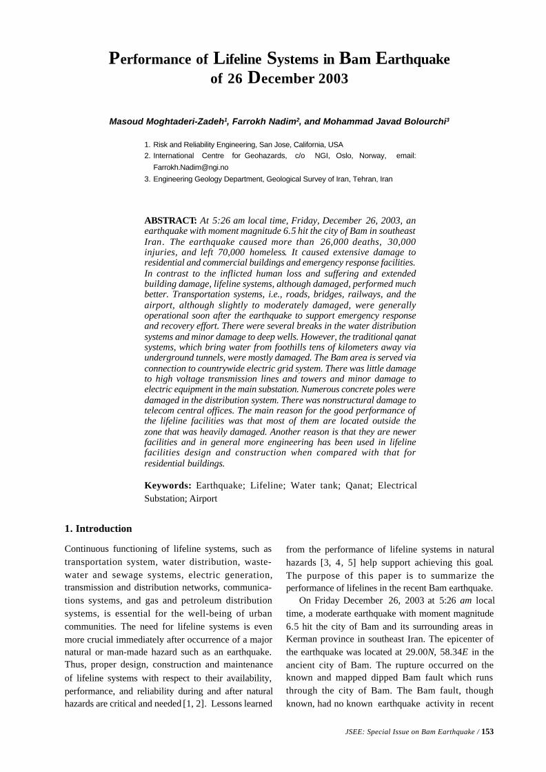
JSEE: Special Issue on Bam Earthquake / 153
1. Risk and Reliability Engineering, San Jose, California, USA2. International Centre for Geohazards, c/o NGI, Oslo, Norway, email:
3. Engineering Geology Department, Geological Survey of Iran, Tehran, Iran
ABSTRACT: At 5:26 am local time, Friday, December 26, 2003, anearthquake with moment magnitude 6.5 hit the city of Bam in southeastIran. The earthquake caused more than 26,000 deaths, 30,000injuries, and left 70,000 homeless. It caused extensive damage toresidential and commercial buildings and emergency response facilities.In contrast to the inflicted human loss and suffering and extendedbuilding damage, lifeline systems, although damaged, performed muchbetter. Transportation systems, i.e., roads, bridges, railways, and theairport, although slightly to moderately damaged, were generallyoperational soon after the earthquake to support emergency responseand recovery effort. There were several breaks in the water distributionsystems and minor damage to deep wells. However, the traditional qanatsystems, which bring water from foothills tens of kilometers away viaunderground tunnels, were mostly damaged. The Bam area is served viaconnection to countrywide electric grid system. There was little damageto high voltage transmission lines and towers and minor damage toelectric equipment in the main substation. Numerous concrete poles weredamaged in the distribution system. There was nonstructural damage totelecom central offices. The main reason for the good performance ofthe lifeline facilities was that most of them are located outside thezone that was heavily damaged. Another reason is that they are newerfacilities and in general more engineering has been used in lifelinefacilities design and construction when compared with that forresidential buildings.
Keywords: Earthquake; Lifeline; Water tank; Qanat; ElectricalSubstation; Airport
Performance of Lifeline Systems in Bam Earthquakeof 26 December 2003
Masoud Moghtaderi-Zadeh1, Farrokh Nadim2, and Mohammad Javad Bolourchi3
1. Introduction
Continuous functioning of lifeline systems, such astransportation system, water distribution, waste-water and sewage systems, electric generation,transmission and distribution networks, communica-tions systems, and gas and petroleum distributionsystems, is essential for the well-being of urbancommunities. The need for lifeline systems is evenmore crucial immediately after occurrence of a majornatural or man-made hazard such as an earthquake.Thus, proper design, construction and maintenanceof lifeline systems with respect to their availability,performance, and reliability during and after naturalhazards are critical and needed [1, 2]. Lessons learned
from the performance of lifeline systems in naturalhazards [3, 4, 5] help support achieving this goal.The purpose of this paper is to summarize theperformance of lifelines in the recent Bam earthquake.
On Friday December 26, 2003 at 5:26 am localtime, a moderate earthquake with moment magnitude6.5 hit the city of Bam and its surrounding areas inKerman province in southeast Iran. The epicenter ofthe earthquake was located at 29.00N, 58.34E in theancient city of Bam. The rupture occurred on theknown and mapped dipped Bam fault which runsthrough the city of Bam. The Bam fault, thoughknown, had no known earthquake activity in recent
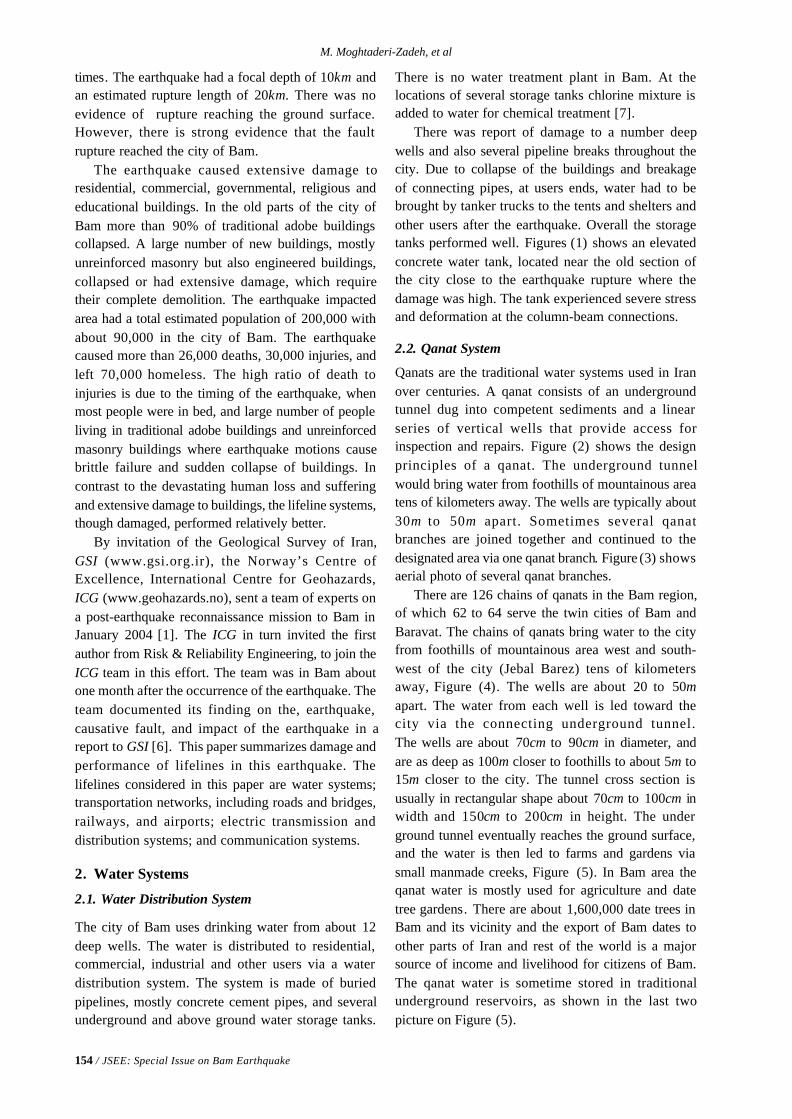
154 / JSEE: Special Issue on Bam Earthquake
M. Moghtaderi-Zadeh, et al
times. The earthquake had a focal depth of 10km andan estimated rupture length of 20km. There was noevidence of rupture reaching the ground surface.However, there is strong evidence that the faultrupture reached the city of Bam.
The earthquake caused extensive damage toresidential, commercial, governmental, religious andeducational buildings. In the old parts of the city ofBam more than 90% of traditional adobe buildingscollapsed. A large number of new buildings, mostlyunreinforced masonry but also engineered buildings,collapsed or had extensive damage, which requiretheir complete demolition. The earthquake impactedarea had a total estimated population of 200,000 withabout 90,000 in the city of Bam. The earthquakecaused more than 26,000 deaths, 30,000 injuries, andleft 70,000 homeless. The high ratio of death toinjuries is due to the timing of the earthquake, whenmost people were in bed, and large number of peopleliving in traditional adobe buildings and unreinforcedmasonry buildings where earthquake motions causebrittle failure and sudden collapse of buildings. Incontrast to the devastating human loss and sufferingand extensive damage to buildings, the lifeline systems,though damaged, performed relatively better.
By invitation of the Geological Survey of Iran,GSI (www.gsi.org.ir), the Norway’s Centre ofExcellence, International Centre for Geohazards,ICG (www.geohazards.no), sent a team of experts ona post-earthquake reconnaissance mission to Bam inJanuary 2004 [1]. The ICG in turn invited the firstauthor from Risk & Reliability Engineering, to join theICG team in this effort. The team was in Bam aboutone month after the occurrence of the earthquake. Theteam documented its finding on the, earthquake,causative fault, and impact of the earthquake in areport to GSI [6]. This paper summarizes damage andperformance of lifelines in this earthquake. Thelifelines considered in this paper are water systems;transportation networks, including roads and bridges,railways, and airports; electric transmission anddistribution systems; and communication systems.
2. Water Systems
2.1. Water Distribution System
The city of Bam uses drinking water from about 12deep wells. The water is distributed to residential,commercial, industrial and other users via a waterdistribution system. The system is made of buriedpipelines, mostly concrete cement pipes, and severalunderground and above ground water storage tanks.
There is no water treatment plant in Bam. At thelocations of several storage tanks chlorine mixture isadded to water for chemical treatment [7].
There was report of damage to a number deepwells and also several pipeline breaks throughout thecity. Due to collapse of the buildings and breakageof connecting pipes, at users ends, water had to bebrought by tanker trucks to the tents and shelters andother users after the earthquake. Overall the storagetanks performed well. Figures (1) shows an elevatedconcrete water tank, located near the old section ofthe city close to the earthquake rupture where thedamage was high. The tank experienced severe stressand deformation at the column-beam connections.
2.2. Qanat System
Qanats are the traditional water systems used in Iranover centuries. A qanat consists of an undergroundtunnel dug into competent sediments and a linearseries of vertical wells that provide access forinspection and repairs. Figure (2) shows the designprinciples of a qanat. The underground tunnelwould bring water from foothills of mountainous areatens of kilometers away. The wells are typically about30m to 50m apart. Sometimes several qanatbranches are joined together and continued to thedesignated area via one qanat branch. Figure (3) showsaerial photo of several qanat branches.
There are 126 chains of qanats in the Bam region,of which 62 to 64 serve the twin cities of Bam andBaravat. The chains of qanats bring water to the cityfrom foothills of mountainous area west and south-west of the city (Jebal Barez) tens of kilometersaway, Figure (4). The wells are about 20 to 50mapart. The water from each well is led toward thecity via the connecting underground tunnel.The wells are about 70cm to 90cm in diameter, andare as deep as 100m closer to foothills to about 5m to15m closer to the city. The tunnel cross section isusually in rectangular shape about 70cm to 100cm inwidth and 150cm to 200cm in height. The underground tunnel eventually reaches the ground surface,and the water is then led to farms and gardens viasmall manmade creeks, Figure (5). In Bam area theqanat water is mostly used for agriculture and datetree gardens. There are about 1,600,000 date trees inBam and its vicinity and the export of Bam dates toother parts of Iran and rest of the world is a majorsource of income and livelihood for citizens of Bam.The qanat water is sometime stored in traditionalunderground reservoirs, as shown in the last twopicture on Figure (5).
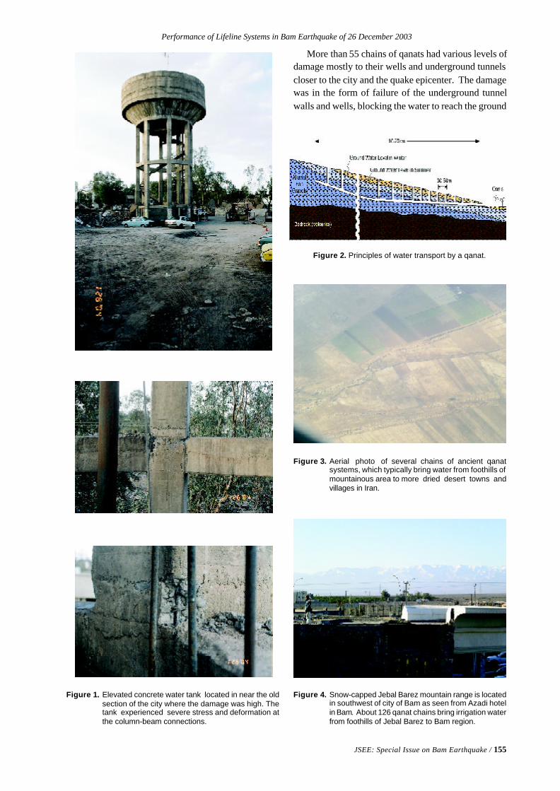
Performance of Lifeline Systems in Bam Earthquake of 26 December 2003
JSEE: Special Issue on Bam Earthquake / 155
Figure 1. Elevated concrete water tank located in near the oldsection of the city where the damage was high. Thetank experienced severe stress and deformation atthe column-beam connections.
Figure 2. Principles of water transport by a qanat.
Figure 3. Aerial photo of several chains of ancient qanatsystems, which typically bring water from foothills ofmountainous area to more dried desert towns andvillages in Iran.
Figure 4. Snow-capped Jebal Barez mountain range is locatedin southwest of city of Bam as seen from Azadi hotelin Bam. About 126 qanat chains bring irrigation waterfrom foothills of Jebal Barez to Bam region.
More than 55 chains of qanats had various levels ofdamage mostly to their wells and underground tunnelscloser to the city and the quake epicenter. The damagewas in the form of failure of the underground tunnelwalls and wells, blocking the water to reach the ground
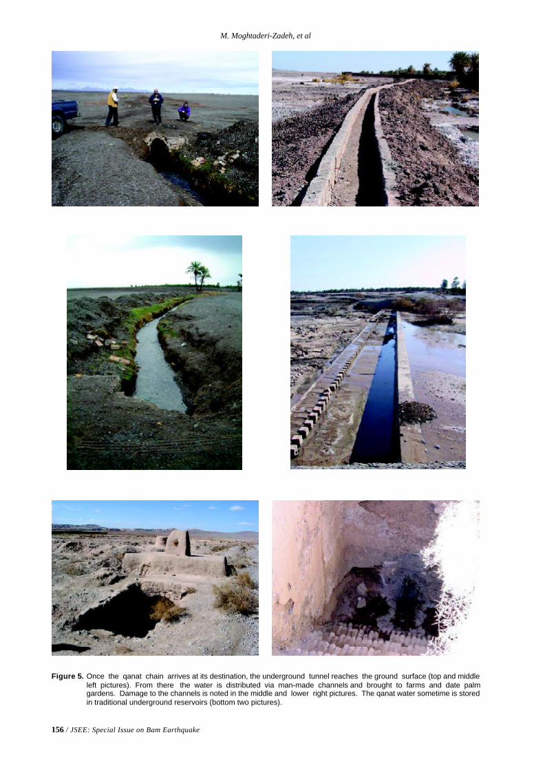
156 / JSEE: Special Issue on Bam Earthquake
M. Moghtaderi-Zadeh, et al
Figure 5. Once the qanat chain arrives at its destination, the underground tunnel reaches the ground surface (top and middleleft pictures). From there the water is distributed via man-made channels and brought to farms and date palmgardens. Damage to the channels is noted in the middle and lower right pictures. The qanat water sometime is storedin traditional underground reservoirs (bottom two pictures).
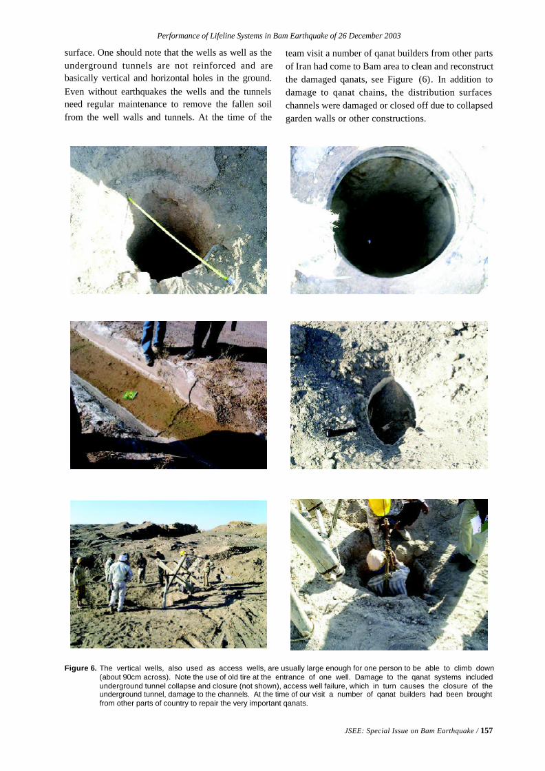
Performance of Lifeline Systems in Bam Earthquake of 26 December 2003
JSEE: Special Issue on Bam Earthquake / 157
Figure 6. The vertical wells, also used as access wells, are usually large enough for one person to be able to climb down(about 90cm across). Note the use of old tire at the entrance of one well. Damage to the qanat systems includedunderground tunnel collapse and closure (not shown), access well failure, which in turn causes the closure of theunderground tunnel, damage to the channels. At the time of our visit a number of qanat builders had been broughtfrom other parts of country to repair the very important qanats.
surface. One should note that the wells as well as theunderground tunnels are not reinforced and arebasically vertical and horizontal holes in the ground.Even without earthquakes the wells and the tunnelsneed regular maintenance to remove the fallen soilfrom the well walls and tunnels. At the time of the
team visit a number of qanat builders from other partsof Iran had come to Bam area to clean and reconstructthe damaged qanats, see Figure (6). In addition todamage to qanat chains, the distribution surfaceschannels were damaged or closed off due to collapsedgarden walls or other constructions.

158 / JSEE: Special Issue on Bam Earthquake
M. Moghtaderi-Zadeh, et al
3. Electricity
There are no electric generating plants in Bam or theaffected area. Bam and its vicinity are connected tothe countrywide electric grid system. Main transmis-sion lines, bring electricity from this grid to Bam area.There are four substations in the area: two in Bam, onein Baravat, and one in New Arg. The two in Bam are230kV and 115kV. Transformers are used to reducethe voltage to 220V for residential and commercial use.
There was no damage to main 230kV transmissionlines. There was however damage to concrete polesin the distribution system and streetlights. Part of thedamage to the concrete poles was due to collapse ofadjacent walls and buildings. We observed series ofpoles to be out of plumb. Damage to transformers ondistribution poles was reported [8], see Figure (8).
The 230kV substation in Bam experienced somedamage. There was some damage to porcelaininsulators and bushings at this substation. The wallaround the substation collapsed. The office/controlbuilding in the substation structurally performedwell, see Figures (8) and (9). This substation wasabout 5km distance from epicenter. At the time ofour visit (one month after the earthquake), electricityhad been restored throughout the city, even in thearea where there was severe to complete buildingdestruction.
4. Transportation Systems
4.1. Roads
There is a main two-way highway-connecting city ofBam to Kerman on the northwest and Zahedan andIranshahr on east and southeast of Bam. This roadcrosses the Bam fault scarp. Very minor damage toroad embankments and surface cracks in the mainhighway close to Bam fault scarp were observed.For the most part, roads and streets were usableimmediately after the earthquake, see Figure (10).
Cross-country bus lines are the main mode oftransportation for masses in Iran especially outsidethe major cities. The last picture of Figure (10) showsthe roof of a bus terminal building collapsed ontoseveral busses.
The bridges over a Bam river, called Posht-e-rud,performed relatively well. Figure (11) shows one ofthe main bridges over the river. There are signs ofvertical movement in the base of the support walls/columns. Damage to the pipeline on the side of thebridge is observed. All of the three main bridges were
operational for service after the quake.
4.2. Airport
The main terminal building at the Bam airport hadmoderate damage, but the runway was operationalimmediately after the earthquake, see Figures (12).The steel frame terminal building was moderatelydamaged, but it withstood the quake. The masonryinfill walls were damaged. The false ceilings wereseverely damaged. There was moderate damage tostairway to the second floor. There was nonstructuraldamage to airport control tower (broken windows).The airport runway had little damage and came to beextremely useful for emergency response andrecovery effort. Hundreds of flights from inside ofIran and around the world landed in this airportimmediately after the earthquake to bring search andrescue teams and equipment as well as much neededmedical, food, blankets, tents and other supplies.
4.3. Railway
The construction of railroad to Bam had just beencompleted but the railroad had not been used prior tothe quake. The passenger terminal located some25km south of the city was under construction andhad some damage. There was no damage to therail tracks. There was light damage to embankment.The railroad was extremely useful for bringingsupplies and help to Bam immediately after theearthquake, see Figure (13).
5. Gas and Petroleum
There is no petroleum pipelines installed in theaffected area. Even though a large number of smalland large cities in Iran have natural gas distributionsystem, Bam and the affected area did not have a gastransmission and distribution system at the time of thequake. One should note that, fires followingearthquakes are very common and existence ofunderground gas pipelines and their ruptures due toearthquakes could lead to major conflagration. Eventhough there were reports of at least seven fires afterthe earthquake, lack of a natural gas system andwood constructions did prevent a conflagration in thecity.
The gas stations and heating gas suppliers bringtheir material via tankers to the city. Fortunately, therewas no gas station in the old section of the city, whichexperienced severe shaking. The gas stations in thecity, Figure (14), were in operation at the time of ourvisit (one month after the earthquake).
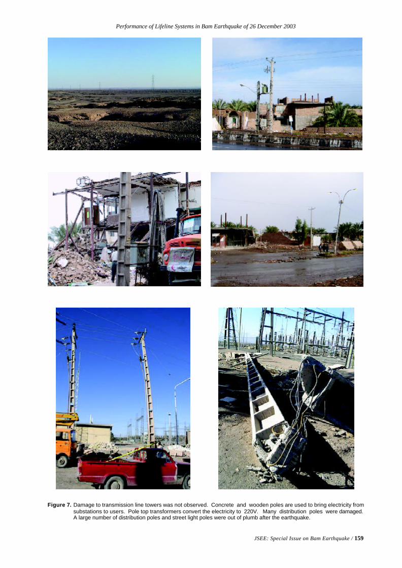
Performance of Lifeline Systems in Bam Earthquake of 26 December 2003
JSEE: Special Issue on Bam Earthquake / 159
Figure 7. Damage to transmission line towers was not observed. Concrete and wooden poles are used to bring electricity fromsubstations to users. Pole top transformers convert the electricity to 220V. Many distribution poles were damaged.A large number of distribution poles and street light poles were out of plumb after the earthquake.
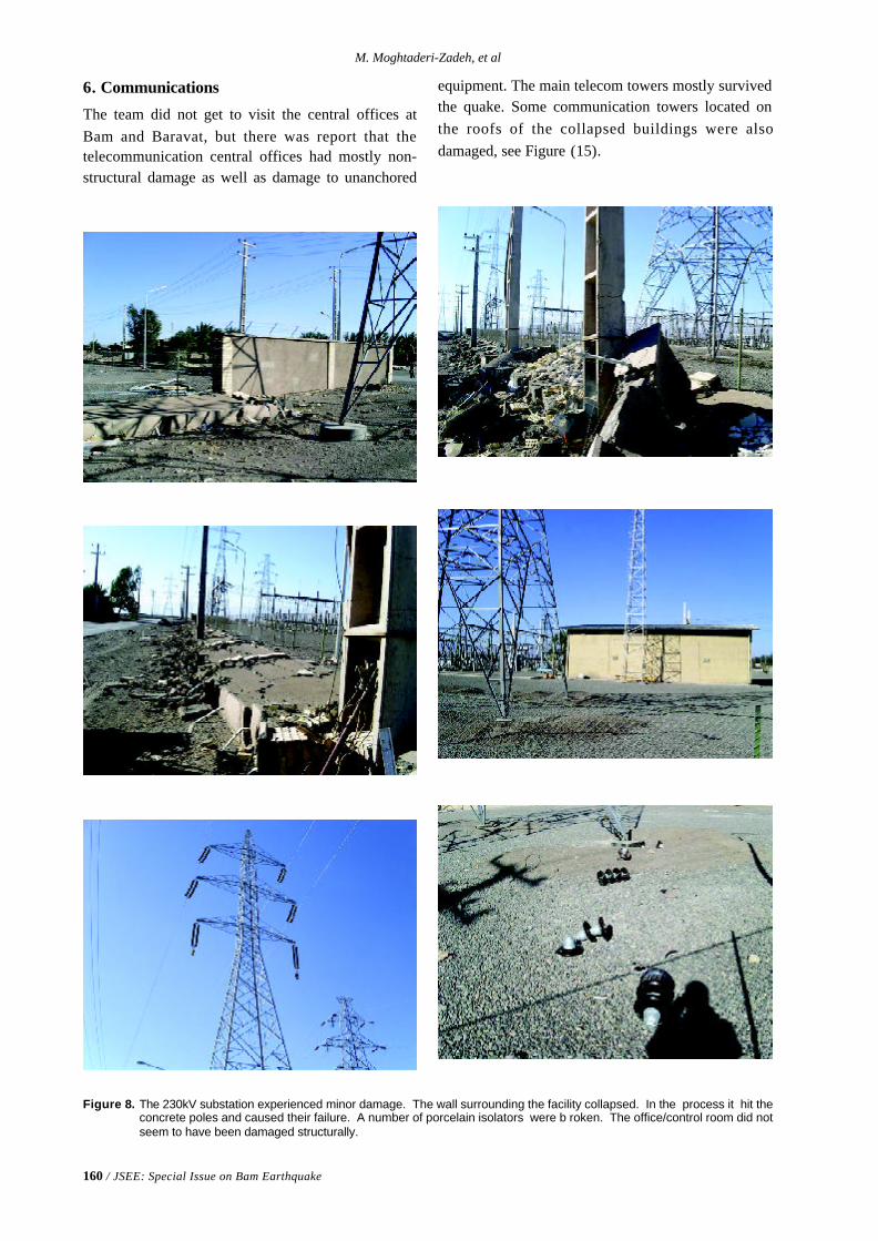
160 / JSEE: Special Issue on Bam Earthquake
M. Moghtaderi-Zadeh, et al
Figure 8. The 230kV substation experienced minor damage. The wall surrounding the facility collapsed. In the process it hit theconcrete poles and caused their failure. A number of porcelain isolators were b roken. The office/control room did notseem to have been damaged structurally.
6. Communications
The team did not get to visit the central offices atBam and Baravat, but there was report that thetelecommunication central offices had mostly non-structural damage as well as damage to unanchored
equipment. The main telecom towers mostly survivedthe quake. Some communication towers located onthe roofs of the collapsed buildings were alsodamaged, see Figure (15).
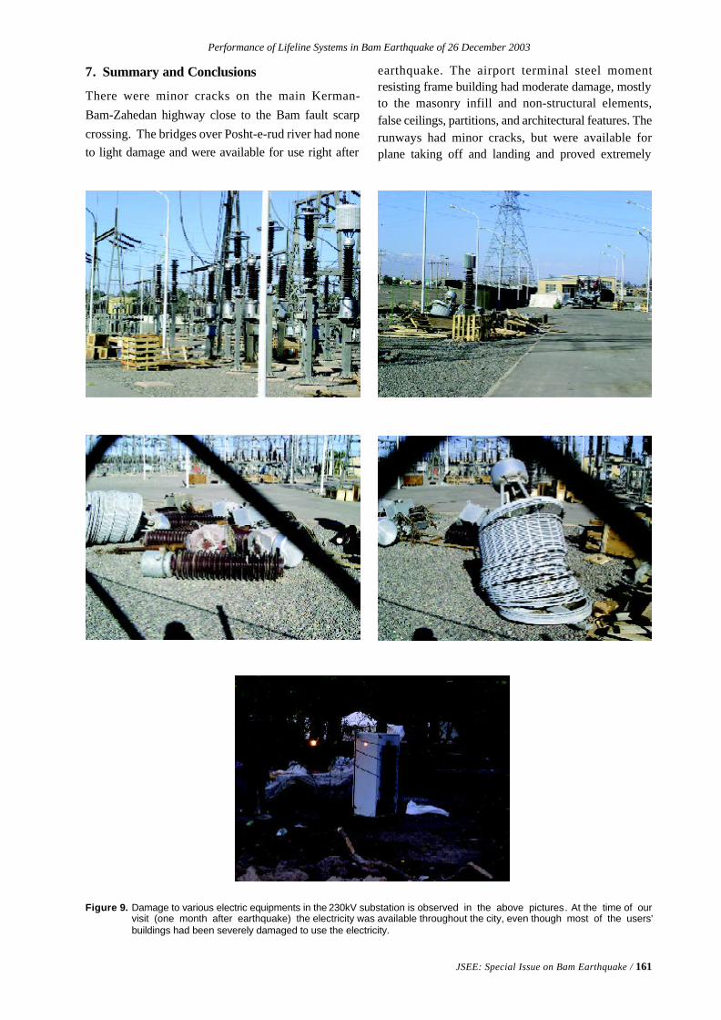
Performance of Lifeline Systems in Bam Earthquake of 26 December 2003
JSEE: Special Issue on Bam Earthquake / 161
Figure 9. Damage to various electric equipments in the 230kV substation is observed in the above pictures. At the time of ourvisit (one month after earthquake) the electricity was available throughout the city, even though most of the users'buildings had been severely damaged to use the electricity.
7. Summary and Conclusions
There were minor cracks on the main Kerman-Bam-Zahedan highway close to the Bam fault scarpcrossing. The bridges over Posht-e-rud river had noneto light damage and were available for use right after
earthquake. The airport terminal steel momentresisting frame building had moderate damage, mostlyto the masonry infill and non-structural elements,false ceilings, partitions, and architectural features. Therunways had minor cracks, but were available forplane taking off and landing and proved extremely
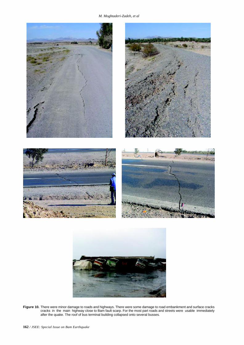
162 / JSEE: Special Issue on Bam Earthquake
M. Moghtaderi-Zadeh, et al
Figure 10. There were minor damage to roads and highways. There were some damage to road embankment and surface crackscracks in the main highway close to Bam fault scarp. For the most part roads and streets were usable immediatelyafter the quake. The roof of bus terminal building collapsed onto several busses.
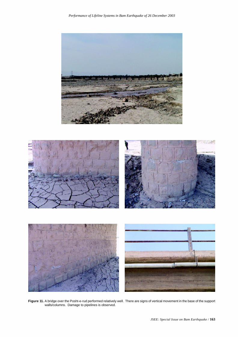
Performance of Lifeline Systems in Bam Earthquake of 26 December 2003
JSEE: Special Issue on Bam Earthquake / 163
Figure 11. A bridge over the Posht-e-rud performed relatively well. There are signs of vertical movement in the base of the supportwalls/columns. Damage to pipelines is observed.
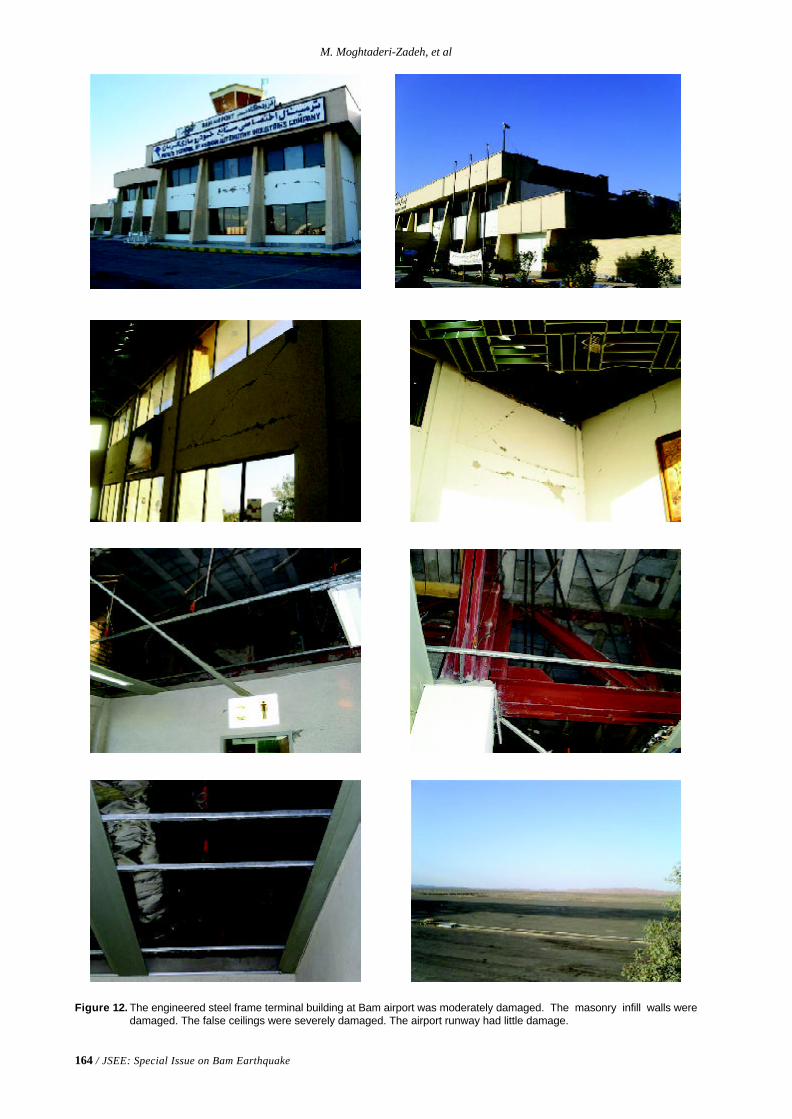
164 / JSEE: Special Issue on Bam Earthquake
M. Moghtaderi-Zadeh, et al
Figure 12. The engineered steel frame terminal building at Bam airport was moderately damaged. The masonry infill walls weredamaged. The false ceilings were severely damaged. The airport runway had little damage.
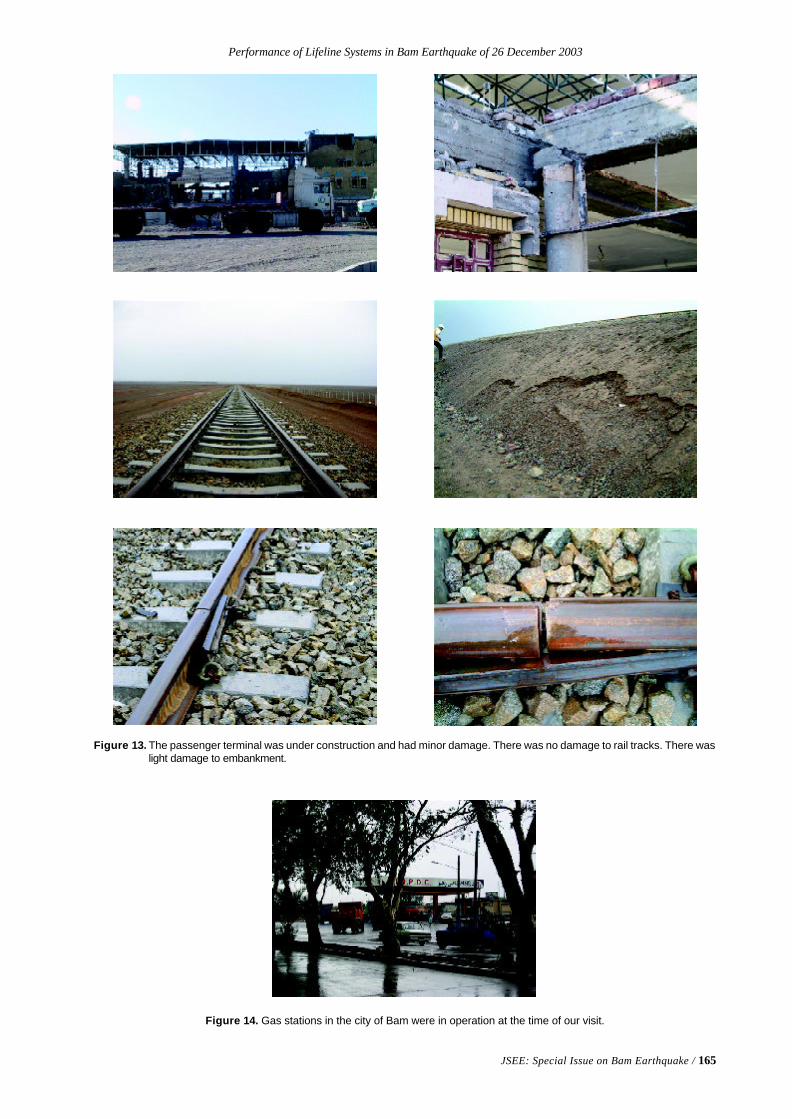
Performance of Lifeline Systems in Bam Earthquake of 26 December 2003
JSEE: Special Issue on Bam Earthquake / 165
Figure 13. The passenger terminal was under construction and had minor damage. There was no damage to rail tracks. There waslight damage to embankment.
Figure 14. Gas stations in the city of Bam were in operation at the time of our visit.
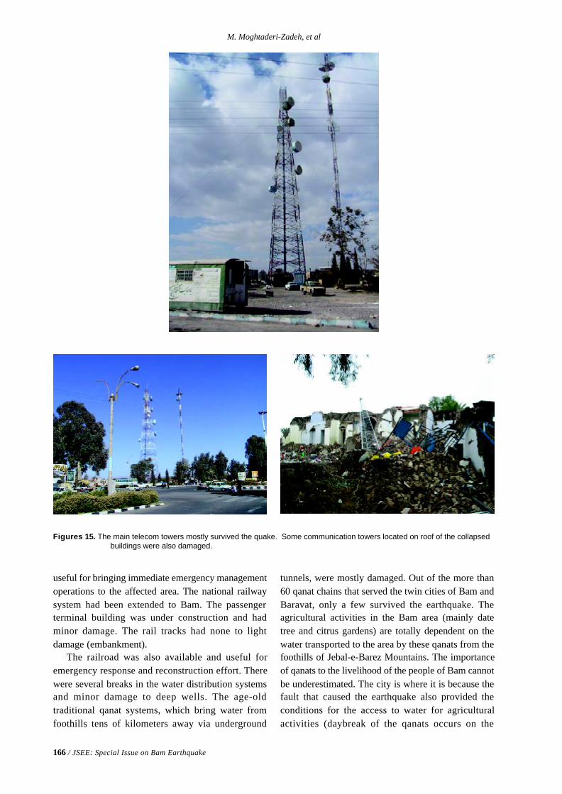
166 / JSEE: Special Issue on Bam Earthquake
M. Moghtaderi-Zadeh, et al
Figures 15. The main telecom towers mostly survived the quake. Some communication towers located on roof of the collapsedbuildings were also damaged.
useful for bringing immediate emergency managementoperations to the affected area. The national railwaysystem had been extended to Bam. The passengerterminal building was under construction and hadminor damage. The rail tracks had none to lightdamage (embankment).
The railroad was also available and useful foremergency response and reconstruction effort. Therewere several breaks in the water distribution systemsand minor damage to deep wells. The age-oldtraditional qanat systems, which bring water fromfoothills tens of kilometers away via underground
tunnels, were mostly damaged. Out of the more than60 qanat chains that served the twin cities of Bam andBaravat, only a few survived the earthquake. Theagricultural activities in the Bam area (mainly datetree and citrus gardens) are totally dependent on thewater transported to the area by these qanats from thefoothills of Jebal-e-Barez Mountains. The importanceof qanats to the livelihood of the people of Bam cannotbe underestimated. The city is where it is because thefault that caused the earthquake also provided theconditions for the access to water for agriculturalactivities (daybreak of the qanats occurs on the
Performance of Lifeline Systems in Bam Earthquake of 26 December 2003
JSEE: Special Issue on Bam Earthquake / 167
surface expression of the Bam lineament).The area is served via connection to countrywide
electric grid system. There was little damage to highvoltage transmission lines and towers. There wasminor damage to electric equipment in the mainsubstation. Numerous concrete poles were damagedin the distribution system. There was nonstructuraldamage to telecom central offices.
The damage pattern of the earthquake was nearlysymmetric about a line 3 km to the west of the surfaceexpression of the Bam fault, and the damageattenuated rapidly with distance from this line. Therewas very little or no damage at distances greater than5 km from the reference line [6]. The main reasonfor the relatively good performance of the lifelinefacilities was that most of them are located morethan 5km from this reference line (e.g. airport,railway, train station, electrical substations). Theqanats were damaged in the area between thereference line and surface expression of the Bamfault. Qanats typically have daybreak at locationswhere there is a sudden change in the ground elevationlevel (and the water table). These sudden changes insurface topography usually occur because of theexistence of faults underneath. The correlationbetween access to water and proximity toearthquake-generating faults is a problem that needs tobe studied further.
Another reason might be that for the most partsthey are newer facilities. In general more engineeringhas been used in lifeline facilities design andconstruction when compared with that for buildings(e.g. concrete water tank, airport, railway station,telecommunication facilities). The observationsconfirmed that well-designed and constructedstructures would have survived with only minordamage the severe earthquake shaking levelsexperienced during the Bam earthquake.
In summary, with the exception of qanats, lifelinesystems by far had less damage than buildings.Having said that, there was still significant damage tolifeline facilities. More attention must be paid tonon-structural elements and equipment installations inlifeline facilities.
Acknowledgment
The authors would like to express their deep gratitudeto GSI for inviting the ICG team to Iran, and their
hospitality and professional arrangement of the visitto Bam. In particular, the tireless effort of the GSIteam in Bam is gratefully acknowledged.
This paper is the International Centre forGeohazards (ICG) contribution No. 56.
References
1. Moghtaderi-Zadeh, M., Wood, R.K., Der Kiureghian,A., and Barlow, R.E. (1982). “Seismic Reliabilityof Lifeline Networks”, Journal of the TechnicalCouncils, ASCE, 108(TC1).
2. Taylor, C. editor (1991). “Seismic Loss Estimatesfor a Hypothetical Water System, A Demonstra-tion Project”, ASCE Technical Council on LifelineEarthquake Engineering Monograph No. 2.
3. Zadeh, M., Larsen, T., Scawthorn, C., Van Anne,C., and Chan, T.K. (1993). “Effects of HurricanesAndrew and Iniki on Lifelines”, Proceedings ofthe ASCE Conference on Hurricanes of 1992,Miami, Florida.
4. Goltz, J.D. editor ( 1994). “The Northridge,California Earthquake of January 17, 1994:General Reconnaissance Report”, National Centerfor Earthquake Engineering Research, TechnicalReport NCEER-94-0005, Buffalo, New York.
5. Beavers, J. editor (2003). “Advancing MitigationTechnologies and Disaster Response for LifelineSystems”, Proceedings of the Sixth U.S. Conf.and Workshop on Lifeline Earthquake Engineering,ASCE Technical Council on Lifeline EarthquakeEngineering Monograph No. 25.
6. Nadim, F., Lindholm, C. Remseth, S., Andresen,A., and Moghtaderi-Zadeh, M. (2004). “BamEarthquake of 26 December 2003: ICG Recon-naissance Mission”, ICG Report 2004-99-1, AlsoPosted at www.geohazards.no.
7. Eshghi, S., Zare, M., Assadi, K., Razzaghi, M.,Ahari, M., and Motamedi, M. (2004).“Reconnaisance Report on 26 December 2003Bam Earthquake”, (in Persian), International In-stitute of Earthquake Engineering and Seismology,Tehran, Iran.
JSEE: Special Issue on Bam Earthquake / 169
Structural Engineering Research Center, International Institute of Earthquake
Engineering and Seismology (IIEES), Tehran, Iran, email: [email protected]
ABSTRACT: Regarding the importance of the nonstructural elementsin the vulnerability of buildings, and the extensive damages of some ofthese elements in recent earthquakes, particularly the Bam event, inthis paper at first the characteristics of nonstructural elements are brieflyreviewed, with emphasis on the Iranian buildings; then the seismicdesign, vulnerability, and upgrading of these elements are explainedand discussed as a state-of-the-art review; and finally, the results of athorough survey performed on the behavior of and the damagessustained by these elements, particularly the architectural ones, in thecity of Bam because of the December26, 2003 earthquake arepresented. Finally, based on the results of this survey some recommen-dations are made which can be useful for modification of the"Guidelines for the Seismic Retrofit of the Existing Buildings", whichis used presently in the country as the only official reference in thisregard.
Keywords: Bam; Nonstructural; Seismic safety level; Designprovisions; Vulnerability; Upgrading techniques; Seismic retrofit; Riskmitigation
On the Nonstructural Elements and Their Behavior in the
Bam Earthquake of 26 December 2003
Mahmood Hosseini
1. Introduction
Nonstructural elements are those elements in abuilding which are supposed not to participate incarrying the applied loads to the structural system,including the seismic forces. These elements can bedivided into four main categories:1. Architectural elements2. Mechanical facilities3. Electrical and communicational facilities4. Interior equipments
The characteristics of elements in each of theabovementioned categories are not only different fromthose of other categories, but also are quite numerousand distinct within each category, particularly in thecase of architectural elements. This great variety ofcharacteristics has made the study of their seismicbehavior much more difficult than the buildingstructural elements. This can be claimed to be onereason behind the fact that the seismic study of theseelements has started much later than the studies ofstructural elements. Another reason is the discardingof structural engineers with regard to the design of
nonstructural elements as they are usually believedto be designed by architects or by the designers ofmechanical and/or electrical facilities. The mainreason has been obviously the fact that the totalcollapse of or severe damage to the building structuresin past earthquakes has diverted the attention ofbuilding engineers from the vulnerability of thenonstructural elements. However, these elementshave shown their high vulnerability, even in recentearthquakes, in which the level of structural damageshas been comparatively low.
Past earthquakes have proven that the nonstructuralelements are highly vulnerable, if not designed forearthquake excitations. The consequences of thenonstructural elements vulnerability can be summarizedas follows:l Direct damagesl Premature collapse of the buildingl Creating post earthquake firesl Spreading hazardous materialsl Interrupting the rescue activities
170 / JSEE: Special Issue on Bam Earthquake
M. Hosseini
A brief explanation on each of the above mentionedconsequences is given here. Since the costs ofconstruction and/or installation of the nonstructuralelements versus their relative volume of the wholeconstruction work are usually much more than thoseof the building structures, the financial loss due to thedirect damage to the nonstructural elements can berelatively high, even when there is no structuraldamage. This is particularly true in the case ofindustrial buildings in which the building cost itselfis very little in comparison with the costs of interiorequipments.
The premature collapse of a building by thenonstructural elements may be accelerated by theuncounted for contribution of these elements tocarrying of the lateral seismic load. Damage to eithermechanical or electrical systems can easily result infires. Some samples of these fires have been observedin the Bam earthquake as discussed in section 4 of thisarticle.
Spreading the hazardous material is anotherconsequence of damage to mechanical facilities. Thisis particularly true in industrial buildings, in whichvarious chemicals are used.
Interrupting the rescue activities because ofdamage to the nonstructural elements is a case whichhas occurred in some hospitals in the past earthquakes.A similar case occurred in Bam airport, in whichdamage to the nonstructural elements interrupted theoperation of the Control Tower as discussed in section4.2 of the paper.
As mentioned before, the study of seismicbehavior of the nonstructural elements has startedmuch later than the structural elements of buildings.One of the first attempts in this regard was aworkshop held by Earthquake Engineering ResearchInstitute (EERI) in 1983 with the objective ofreviewing and evaluating the status of nonstructuralelements [6]. The studies continued since then invarious forms from mathematical modeling toretrofitting techniques to their effect on the emergencyfunction of an essential building. For example,Henry and Stein (1987) conducted a comparativestudy of the effects of cladding panel modeling[14]. They studied the macroscopic effects on thebehavior of a two story, one bay frame with a singlecladding panel at mid-height when cladding panelsare structurally incorporated into the analysis. Theresults indicate that incorporation of cladding panelsresults in a dramatic reduction in a structure’s naturalperiods of vibration.
In early 90s the Applied Technology Council (ATC)held a seminar and workshop on Seismic Designand Performance of Equipment and NonstructuralElements in Buildings and Industrial Structures, inwhich several issues with regard to the nonstructuralelements were addressed. As an example, the seismicperformance database based on the study of morethan 100 major facilities and many smaller facilitiesand hundreds of buildings located in the strong-motionareas of 42 earthquakes that have occurred inCalifornia, Latin America, Europe, Asia, and thePacific region since 1971 can be mentioned [52].More examples of the studies reported in that work-shop, which were published later as the ATC-29, arementioned in section 3 of this paper. In a state of-the-art report by Soong [43] theseismic behavior of nonstructural elements theimportance of nonstructural issues in seismic designand performance evaluation was emphasized [43].In a study on the nonstructural damage fromthe Northridge earthquake by McKevitt, et al [25]potentially hazardous nonstructural damage waspointed out with more emphasis [25]. As a goodexample of detailed analytical studies on the seismicbehavior of the nonstructural elements the study byPantelides, et al [33] can be mentioned. They workedon the development of a loading history for seismictesting of architectural glass in a shop-front wallsystem. In their work a systematic analytical studyof the effect of the S00E component of the 1940 ElCentro earthquake on the response of a one-storeyglass and aluminum shop-front wall system waspresented. The seismic response of a one-storeycommercial building comprised of three reinforcedmasonry walls, a glass and aluminum shop-front wallsystem, and a steel bar joist metal deck roof systemwas determined using the ABAQUS and SAP 90 finiteelement packages [33]. One of the first experimental works on thenonstructural elements was conducted by Negroand Colombo [32]. They made some full-scalepseudodynamic tests on a four-storey framedstructure designed according to Eurocode 8, withdifferent infill configurations. Their results showedthat an irregular distribution of the panels yieldsunacceptably large damage in the frame. In addition,it was shown that even a regular distribution ofinfills can lead to irregular behavior of the frame [32].Another experimental study was conducted on theseismic horizontal force of nonstructural systemsmounted on the buildings using a shaking table [27].
On the Nonstructural Elements and Their Behavior in the Bam Earthquake of 26 December 2003
JSEE: Special Issue on Bam Earthquake / 171
In that study the nonstructural systems mounted ontwo conditions of main structures, fixed base andisolated structures, were examined using severalearthquake motions. The acceleration responses ofthe nonstructural systems, the amplification factorrelative to the input ground accelerations, and thehorizontal force coefficients were observed, andcomparison between the experimental results and the1997 UBC and the 1997 BCJ design codes were alsoconducted [27]. In the second seminar of ATC on the nonstructuralelements, held in 1998, Seismic Design, Retrofit, andPerformance of nonstructural components werediscussed. As a sample of studies presented in thatseminar, whose contents were published as the ATC29-1, the work reported by Porter and Scawthorn [34]can be mentioned, in which the seismic reliability ofcritical equipment systems such as fire protectionsystems in high-rise buildings was studied [34]. Inthat study attaining seismic reliability was reportedto involve several steps, including: 1) modeling theequipment and the system they constitute with regardto seismic performance, 2) assessing the risk posedby failure of the equipment due to a major earthquake,3) determining an appropriate criterion, or level ofreliability, and 4) cost effectively assuring thereliability.
The seismic response of nonstructural systemsmounted on the suspended pendulum isolation (SPI)devices was also studied by shaking table test [26]. Ascompared to the results of the reference fixedstructures, it was found that the utilization of theSPI system produced the significantly low accelera-tion amplification factors of supported nonstructuralsystems. The SPI system also gave relatively constantamplification factors along the natural period ofnonstructural systems and over the various input groundexcitations. Comparison between the experimentalresults and two nonstructural design stipulations of the1997 Uniform Building Code and the 1997 BuildingCenter of Japan was also conducted to show that thehorizontal force coefficients of nonstructural systemsmounted on isolated structures are sufficiently lowerthan the maximum provided design values [26]. Following the work of Yanev, [52], Kao, et al [16]developed a nonstructural damage database. Thatdatabase provides information on earthquake-causeddamage to nonstructural elements in buildings andother facilities from the 1964 Alaska earthquake to thepresent. It contains nearly 3,000 entries encompassingmore than 50 earthquakes [16].
Recently the nonlinear analysis of nonstructuralcomponents was studied by Villaverde [50]. Heproposed a design-oriented simplified method for theseismic design of nonlinear nonstructural componentsattached to nonlinear building structures. His methodis based on a previously developed simplifiedprocedure for linear systems that is analogous to thereduction of response spectrum ordinates by a ductil-ity factor and involves the use of reduced naturalfrequencies and augmented damping ratios to linearizethe nonlinear systems [50].
More recently the nonstructural seismic prepared-ness of Southern California hospitals was taken intoconsideration [51]. They tried to assess the level ofadoption of nonstructural seismic hazard adjustmentsby hospitals in Southern California, and to identifythe factors that led to adoption of these adjustments.Results provide evidence that hospitals in SouthernCalifornia have partially implemented a variety ofearthquake preparedness and mitigation activities.However, many adjustments specific only to earth-quake hazard were not commonly implemented, andthis is cause for concern [51]. Finally, very recentlythe effect of damage to nonstructural elements in ahospital evacuation was studied [38]. Based on astudy on the 1995 Kobe earthquake they havereported that the immediate nonstructural damage,after even a moderate earthquake, can put a hospital atserious risk [35].
It is seen that the nonstructural elements havebeen looked at by researchers from many differentviewpoints. However, the ongoing research showsthat there are still some problems with regard to theseelements which need more investigations. Amongthese, the studies done on the three following subjectsare of more importance, since they are more related tothe “seismic risk mitigation” as the main goal: 1) theseismic design provisions and recommendations, 2) theseismic vulnerability evaluation, and 3) the seismicupgrading techniques. The works done with regard tothese subjects are reviewed in detail in section 3 of thisarticle to help making better decisions on the futureworks in this field. However, before the review, it ishelpful to have a brief explanation of the characteris-tics of the nonstructural elements, which make themdifferent from the structural elements, particularly inthe case of Iranian buildings. These are discussed insection 2 of the paper. After the review in section 3,the behavior of nonstructural elements in the Bamearthquake is studied in section 4, and finally basedon the Bam observations some discussions and
172 / JSEE: Special Issue on Bam Earthquake
M. Hosseini
recommendations are presented in section 5 of thepaper, which are useful for revising the correspondingchapter in the “Guidelines for the Seismic Retrofit ofthe Existing Buildings”, which is used presently in thecountry as the only official reference in this regard.
2. Characteristics of the Nonstructural Elements
In spite of different specifications for various kinds ofthe nonstructural elements, these elements have somegeneral physical characteristics which make themdifferent from the structural elements from theseismic behavior point of view. Furthermore, in thecase of Iranian construction styles, and also becauseof some cultural fact in Iranian lifestyle theseelements have some particular features which cannot be found in conventional types of buildingconstruction and use in other countries.
2.1. General Characteristics
Most of the nonstructural elements have thefollowing general mechanical specifications whichmakes them different from the structural elements,such as steel or reinforced concrete members, whichare generally utilized for seismic resistant design ofbuildings:l High initial stiffnessl Low ultimate strengthl Brittle behavior subjected to dynamic loads
Masonry nonbearing walls and partitions, façadesand claddings, mechanical pipings, and some ofinterior facilities, which are attached to the buildingsuch as cupboards and shelves, are all samples of thenonstructural elements having the abovementionedcharacteristics. The first specification makes thewhole building structure stiffer than the buildingskeleton alone. This means a lower natural periodwhich usually results in higher seismic forces receivedby the building. Obviously, these high seismic forceswill act on all elements showing resistance against theloads, regardless of being structural or nonstructural.The high imposed forces to the nonstructuralelements on the one hand, and their second andthird specifications, namely the low ultimate strengthand brittleness, on the other, will make these elementsto get damaged or even fail just in the very firstmoments of earthquake excitations. It is notable thatif the nonstructural elements are not permitted to actas parts of lateral resisting system to participate incarrying the lateral seismic loads, the value of theseismic forces received by the whole building system
would be much less, as the stiffness of the buildingskeleton alone is lower than the combined structuraland nonstructural system.
Another adverse effect of the participation of thenonstructural elements in carrying the lateral loadsraises from the non-uniform distribution of theseelements in the plan of the buildings, which is almostinevitable. This non-uniformity on the one hand, andthe high stiffness of these elements, on the other, cancauses the building center of stiffness to be muchfarther of the building center of mass than what hasbeen considered in the design based on the buildingskeleton alone. This uncounted eccentricity canmake the even a building with regular and symmetricstructural system behave torsional, and this additionaltorsion in turn can result if excessive damage or evencollapse of the building.
The two abovementioned facts have encouragedmany researchers and designers to work on the ideaof isolating the nonstructural elements from lateralload bearing system of the building. This isolationidea can be easily applied if the nonstructuralelements are lightweight, but if these elements areheavy, which is the case for most of architecturalnonstructural elements in Iranian buildings, theisolation idea can not work well. This problem isdiscussed in the following subsection with moredetails.
2.2. Particular Features of the NonstructuralElements in Iranian Buildings
In the case of Iranian buildings there are some particu-lar features which make the nonstructural elements ofthese buildings different from those of other countries,especially US and Japan as the two developed seismiccountries. Some of these differences are due to thedifferent building construction styles in Iran and theUS, and some others relate to the lifestyles in the twocountries, which is basically a cultural problem.Regardless of their roots, these differences are of greatimportance as the Iranian codes have been developedand are still being developed mostly based on theUS corresponding documents. These features aredifferent depending on the category of the nonstructuralelements as follow.
2.2.1. Architectural Elements
This group has the most different features from thecorresponding group in developed seismic countries,and is the most problematic group among thenonstructural elements in Iran. The particular features
On the Nonstructural Elements and Their Behavior in the Bam Earthquake of 26 December 2003
JSEE: Special Issue on Bam Earthquake / 173
of this group are:l Heavy weightl Low inherent integrityl Weak connection to supporting structure
The external walls and internal separating walls andpartitions, made of massive brick masonry, as well asthe stone facade or cladding, particularly the 3cmbrick finishing of the external walls, are samples ofarchitectural components having all of theabovementioned characteristics. Internal veneer, suchas ceramic tiles, and internal walls and ceiling finishingare samples of components having the second and thethird characteristics. The top wall and the parapetcornices are the sample components having the firstand the third characteristics. Finally, window framesare the sample components which have the thirdcharacteristics in Iranian buildings.
2.2.2. Mechanical and Electrical Elements
This group of the nonstructural elements can beconsidered as the second problematic group becauseof the following features:l Having various manufacturing standardsl Mostly installed without any specific standard
In fact, most of the major mechanical and electri-cal equipments, such as HVAC, are imported fromabroad, and in many cases from the northernEuropean countries, which are not earthquake prone,and accordingly do not have any specific seismicprovisions. Furthermore, although these countriesusually have high installation standards, the installationin Iran is done mostly by non-expert people who donot follow the installation instructions properly, andtherefore, even if the equipment is from a seismic pronecounties, and has the required anti-seismic installationinstructions those measures usually are not actuallyimplemented.
2.2.3. Interior Equipments
This group has also some differences with those inother seismic countries, particularly the US. Thesedifferences are as follow:l They either are, or are occupied by fragile
objects, particularly in the case of house internalornaments
l They are mostly heavy and are installed ashanging objects from the ceilings in many partsof the building
These two features have basically cultural roots,for example having several old glass or ceramic jarsor other similar objects, and also big and heavy
chandeliers in almost all rooms, particularly in moreluxury houses is an Iranian tradition.
The special features discussed in this section makethe use of design guidelines and also evaluation criteriaand retrofitting measures, developed by othercountries and discussed in the following section of thepaper, inadequate in many cases, and therefore, somemore appropriate methods and techniques are requiredto be developed.
3. Studies on Seismic Design, Evaluation, andUpgrading of the Nonstructural Elements
As mentioned in section 1 of the paper several studieshave been performed on the nonstructural elementssince late 70s. However, among these studies thoserelated to the seismic design, vulnerability evaluation,and retrofitting techniques are more important for the“seismic risk mitigation” purposes. Therefore, in thissection of the article a state-of-the-art review on theseismic design, evaluation, and upgrading of thenonstructural elements is presented.
3.1. Seismic Design Provisions and Recommendations
The first seismic design provisions for nonstructuralcomponents in buildings can be found in the 1978ATC 03 report. These provisions were discussed tosome extent in the EERI [6] publication based on theworkshop held in April 1983 with the objective ofreviewing and evaluating the status of nonstructuralelements as considered factors in seismic design andconstruction, with emphasis on the status of and needto improve implementation of research [6]. In thatworkshop four issues were discussed, which includelife hazards, structural relationships, institutional roles,and economic losses. Sakamoto, et al [37] proposed some methods foraseismic design of nonstructural elements based onexperiments and field surveys [37]. Their workbasically was focused on exterior walls and partitions,particularly falling of broken glass, and to some extenton the environmental design. Hirosawa, et al [15]presented a state-of-the-art report on seismic designof building equipment and nonstructural componentsin Japan [15]. They reported various kinds of damageto the nonstructural elements, including brokenwindows and water storage tanks, loss of exterior andinterior finishing, and battered furniture. They alsomentioned that in reinforced concrete buildings, thenonstructural walls have often caused a brittle failureof structural columns, with displaced doorway sashespreventing people from entering or exiting.
174 / JSEE: Special Issue on Bam Earthquake
M. Hosseini
In an overview of the building code seismicrequirements for nonstructural elements Porush [35]suggested some replacements for some the UniformBuilding Code provisions [35]. Also Lai and Soong[19] proposed some seismic design recom-mendationsfor the secondary structural systems [19]. Theyshowed that by selecting an optimum damping of thesupport, the maximum acceleration of the secondarysystem can be minimized and that this damping ratio isrelatively insensitive to the earthquake input. On theother hand, the relative displacement between thesecondary system and the structure can always bedecreased by increasing the support damping.Compromises thus need to be made when there is aconflict in achieving the best global secondary systemperformance. Haupt [13] discussed the barriers and challenges indeveloping seismic code rules for equipment andnon-building structures. He has mentioned thatdeveloping requires the identification of the disparategroups involved, defining and making concrete theappropriate interface parameters between thedefinition of seismic effects and acceptance criteria,developing tiered acceptance criteria consistent withdefined hazard, and developing long-term relationshipsamong organizations preparing rules. Some simplifiedprocedures for seismic design of nonstructuralcomponents were also proposed by National Centerfor Earthquake Engineering Research (NCEER) [40],in which an assessment of the current code provisionsof that time was also done. In their assessment the1978 ATC 03 report provisions, adopted with someminor changes by the 1991 NEHRP RecommendedProvisions that were used as the basis for the firstgeneration seismic force provisions for the design ofnonstructural components in codes and manuals ofthat period were critically evaluated, and improvedprocedures were proposed for incorporating of thedynamic characteristics of the supporting structure aswell as the nonstructural components. In another NCEER report the research accomplish-ments on the code development for nonstructuralcomponents have been discussed [42]. Focusing onthe 1991 NEHRP (National Earthquake HazardReduction Program) provisions, he tried to identifytheir shortcomings, and to recommend revisionswhich would bring them more in line with the state-of-the-art knowledge of the time in this area. Hisrevisions were recommended within the frameworkof the equivalent lateral force format for practicalapplicability. Villaverde [48, 49] also proposed a
replacement for the seismic code provisions fornonstructural components in buildings [48, 49]. Hetried to develop a procedure to determine in a rationalbut simple way the lateral forces for the seismicdesign of nonstructural components attached tobuildings based on the results of studies on seismicresponse of secondary systems. It takes into accountthe dynamic interaction between the structure and thenonstructural component, the level above the base ofthe structure of the point or points where thenonstructural component is attached to the structure,and the number of such attachment points. It uses, inaddition, the design spectra specified by building codesfor the design of the structure as the earthquake inputto the nonstructural component. Sucuo lu and Vallabhan [46] worked on thebehavior of window glass panels during earthquakes[46]. Based on the review of glass damage observed inpast earthquakes and previous research on the seismicperformance of glass components they evaluatedthe seismic design code procedures proposed formitigating the damage sustained by glass components.They developed some analytical procedures forcalculating the in-plane deformation capacity andout-of-plane resistance of window glass panelssubjected to seismic excitation, and proposed somesimple practical procedures for the design of glasspanels against earthquake effects. Their proceduresaccount for the inter-storey drift displacements andfloor responses of multi-storey buildings as well as themechanical properties of the window glass. Freeman and Kehoe [11] performed a review onthe NEHRP-94 Recommended Provisions, in whichtwo alternate methods for determining the horizontalseismic force for architectural, mechanical, andelectrical components is suggested: one methodspecifies a constant acceleration over the height of thebuilding, and the other assumes a linear distribution ofacceleration over the height. Comparing with the 1994Uniform Building Code (UBC-94) seismic designprovisions, in which the lateral forces on nonstructuralcomponents and equipment are calculated by aformula based on the assumption that the horizontalacceleration of the component is constant over theheight of the building, Freeman and Kehoe tried to judgethe NEHRP recommended provisions by the recordeddata from the instrumented buildings subjectedto earthquakes [11]. Freeman [10] also tried tosummarize the provisions of the Tri-Servicesguidelines to be used as a basis for performance-basedengineering of nonstructural components [10]. (The
On the Nonstructural Elements and Their Behavior in the Bam Earthquake of 26 December 2003
JSEE: Special Issue on Bam Earthquake / 175
1982 edition of “Seismic Design for Buildings” manualby the Departments of the Army, Navy, and the AirForce is generally referred to as the Tri-Servicesmanual, and it its supplements, “Seismic DesignGuidelines for Essential Buildings” (1986) and“Seismic Design Analysis for Buildings” (1996),dynamic analysis procedures for nonstructuralcomponents are presented that account for bothelastic and inelastic response of the building toearthquake ground motion. Those design manualsprovide criteria for two levels of earthquake motion,methods for approximating floor response spectra,performance requirements of nonstructuralcomponents, and design examples.) Gurbuz, Wu, and Wittchen [12] reviewed theevolution of the requirements for design ofnonstructural components and their anchorage,including UBC-94, UBC-97, and the draft InternationalBuilding Code (to be IBC-2000 later) and showedthat classical design and anchorage practice forsome heavy equipment may not meet the UBC-97 orIBC-2000 provisions [12]. A similar study on thedevelopment, evolution, and application of theearthquake design force for nonstructural elementswas also done by Bachman, and Drake [3] based onthe UBC and the NEHRP provisions. Bachman [2]also presented a comparison of design forces fortypical applications for the UBC-94, UBC-97, andIBC-2000, and mentioned that one primary differenceis that the UBC-94 forces are to be used withworking stress design and the UBC-97 and IBC-2000forces are to be used with strength design. Thereforethe UBC-97 and IBC-2000 design forces aretypically 1.4 times greater than those found in theUBC-94. Kehoe and Freeman [17] also criticized theprocedures for calculating seismic design forces fornonstructural elements by comparing UBC-94 andUBC-97. They studied the effects of the significantchanges in UBC-97, including the introduction ofan R factor for nonstructural elements, the use of soilfactors in determining the design force, and thevariation of the design force over the height of thebuilding, by comparison of design forces betweenthe UBC-94 and the UBC-97 for rigid and flexibleelements, and by comparison with dynamic analysisand building response data. They claimed that thecomparisons results do not provide justification forthe radical changes in the UBC-97. On this basis theyproposed restoring the provisions of the UBC-94 withsome minor modifications, including inclusion of an
amplification factor on the design acceleration forroof-mounted elements and improved procedures forcalculations of amplification of flexible or flexiblymounted equipment based on the proceduresdeveloped in the Tri-Services manual. They alsomade some recommendations for further research toimprove the design procedures.
An interesting case of seismic design of intricateexterior cladding systems was reported by Krakower,et al [18]. In their report it is mentioned that success-ful seismic design of intricate exterior claddingsystems requires awareness of many factors. Whensome or all of the factors are not considered, thedesign and construction of the cladding may affectthe construction schedule and may result inincompatibility between the cladding and structuralsystems that lead to unsatisfactory seismicperformance. Working on the reconstructed historicHouse of Hospitality in San Diego's Balboa Park,which has a complex decorative cladding system ofabout 3000 highly ornamental pieces of glass fiberreinforced concrete (GFRC) cast from molds of thesalvaged original staff plaster ornamentation, theymentioned that a refinement of the cladding supportoccurred after the start of construction to improvethe constructability and compatibility of the design.Based on their report the seismic design of theGFRC cladding structural system faced conflictingparameters, some of which forced the design andconstruction team to develop a few typical framingand anchorage details that could be used in a variety ofpotential support conditions. Once these details wereestablished, the testing program was defined andanchor capacities were obtained. They also mentionedthat all of the building systems in the vicinity of thecladding had to be accounted for in order to developthe strategy to simplify the structural system [18].
Another interesting issue with regard to thedesign of the nonstructural elements is the designresponsibility as discussed by McGavin and Gates[22]. Referring to California hospital design theirrecommendation is a systems approach rather thana component by component approach as is currentlythe case. They also gave some suggestions how theresponsible professionals might be brought intothe building design industry [22]. A very interestingcase, which was related to the 1994 Northridgeearthquake, was reported by McGavin, et al [23]. Basedon their report following the 1994 Northridgeearthquake the City of Los Angeles establishedworking groups in numerous areas to study the need
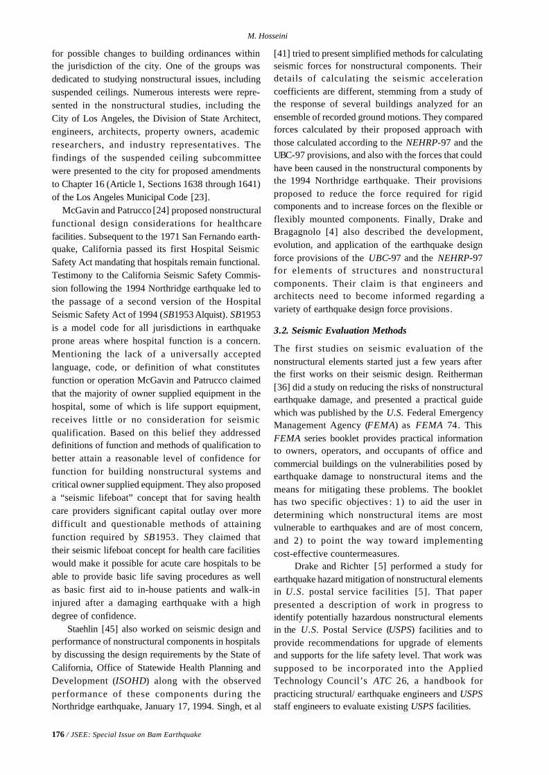
176 / JSEE: Special Issue on Bam Earthquake
M. Hosseini
for possible changes to building ordinances withinthe jurisdiction of the city. One of the groups wasdedicated to studying nonstructural issues, includingsuspended ceilings. Numerous interests were repre-sented in the nonstructural studies, including theCity of Los Angeles, the Division of State Architect,engineers, architects, property owners, academicresearchers, and industry representatives. Thefindings of the suspended ceiling subcommitteewere presented to the city for proposed amendmentsto Chapter 16 (Article 1, Sections 1638 through 1641)of the Los Angeles Municipal Code [23]. McGavin and Patrucco [24] proposed nonstructuralfunctional design considerations for healthcarefacilities. Subsequent to the 1971 San Fernando earth-quake, California passed its first Hospital SeismicSafety Act mandating that hospitals remain functional.Testimony to the California Seismic Safety Commis-sion following the 1994 Northridge earthquake led tothe passage of a second version of the HospitalSeismic Safety Act of 1994 (SB1953 Alquist). SB1953is a model code for all jurisdictions in earthquakeprone areas where hospital function is a concern.Mentioning the lack of a universally acceptedlanguage, code, or definition of what constitutesfunction or operation McGavin and Patrucco claimedthat the majority of owner supplied equipment in thehospital, some of which is life support equipment,receives little or no consideration for seismicqualification. Based on this belief they addresseddefinitions of function and methods of qualification tobetter attain a reasonable level of confidence forfunction for building nonstructural systems andcritical owner supplied equipment. They also proposeda “seismic lifeboat” concept that for saving healthcare providers significant capital outlay over moredifficult and questionable methods of attainingfunction required by SB1953. They claimed thattheir seismic lifeboat concept for health care facilitieswould make it possible for acute care hospitals to beable to provide basic life saving procedures as wellas basic first aid to in-house patients and walk-ininjured after a damaging earthquake with a highdegree of confidence. Staehlin [45] also worked on seismic design andperformance of nonstructural components in hospitalsby discussing the design requirements by the State ofCalifornia, Office of Statewide Health Planning andDevelopment (ISOHD) along with the observedperformance of these components during theNorthridge earthquake, January 17, 1994. Singh, et al
[41] tried to present simplified methods for calculatingseismic forces for nonstructural components. Theirdetails of calculating the seismic accelerationcoefficients are different, stemming from a study ofthe response of several buildings analyzed for anensemble of recorded ground motions. They comparedforces calculated by their proposed approach withthose calculated according to the NEHRP-97 and theUBC-97 provisions, and also with the forces that couldhave been caused in the nonstructural components bythe 1994 Northridge earthquake. Their provisionsproposed to reduce the force required for rigidcomponents and to increase forces on the flexible orflexibly mounted components. Finally, Drake andBragagnolo [4] also described the development,evolution, and application of the earthquake designforce provisions of the UBC-97 and the NEHRP-97for elements of structures and nonstructuralcomponents. Their claim is that engineers andarchitects need to become informed regarding avariety of earthquake design force provisions.
3.2. Seismic Evaluation Methods
The first studies on seismic evaluation of thenonstructural elements started just a few years afterthe first works on their seismic design. Reitherman[36] did a study on reducing the risks of nonstructuralearthquake damage, and presented a practical guidewhich was published by the U.S. Federal EmergencyManagement Agency (FEMA) as FEMA 74. ThisFEMA series booklet provides practical informationto owners, operators, and occupants of office andcommercial buildings on the vulnerabilities posed byearthquake damage to nonstructural items and themeans for mitigating these problems. The booklethas two specific objectives : 1) to aid the user indetermining which nonstructural items are mostvulnerable to earthquakes and are of most concern,and 2) to point the way toward implementingcost-effective countermeasures. Drake and Richter [5] performed a study forearthquake hazard mitigation of nonstructural elementsin U.S. postal service facilities [5]. That paperpresented a description of work in progress toidentify potentially hazardous nonstructural elementsin the U.S. Postal Service (USPS) facilities and toprovide recommendations for upgrade of elementsand supports for the life safety level. That work wassupposed to be incorporated into the AppliedTechnology Council’s ATC 26, a handbook forpracticing structural/ earthquake engineers and USPSstaff engineers to evaluate existing USPS facilities.
On the Nonstructural Elements and Their Behavior in the Bam Earthquake of 26 December 2003
JSEE: Special Issue on Bam Earthquake / 177
Arnold (1998) worked on the requirements fornonstructural components for the NEHRP guidelinesfor the seismic rehabilitation of buildings [1]. He actedas the team leader for the development of therequirements for Architectural, Mechanical andElectrical Components for the NEHRP Guidelines forthe Seismic Rehabilitation of Buildings (FEMA273). In that paper the methods by which a range ofperformance levels and objectives was accommodatedis discussed. Other issues outlined are the scope of thenonstructural components to be considered, thecategorization of nonstructural components asacceleration-sensitive or deformation-sensitive, issuesrelating to means of egress, the nonstructural damagestates, and the definition of the operational andcollapse prevention levels of performance. Somecomments about the difficulties of developing aperformance-based set of provisions for nonstructuralcomponents are also provided.
3.3. Seismic Upgrading Techniques
The work on seismic upgrading of the nonstructuralelements started almost a decade later than the firstworks on their seismic design. Lagorio [20] publisheda book entitled “Earthquakes -- an architect’s guide tononstructural seismic hazards for members of thearchitectural profession. The book covers some ofthe latest developments in earthquake hazardsreduction prior to the time of its publication. It isdivided into the following sections: 1) EarthquakeCauses and Effects, 2) General Aspects of BuildingPerformance, 3) Site Investigation, 4) Site Planning,5) Building Design, 6) Nonstructural Building Elements,7) Existing Buildings, 8) Urban Planning and Design,9) Recovery and Reconstruction, 10) Earthquake Haz-ards Mitigation Process, 11) Recommendations andSummary, and 12) 1989 Loma Prieta Earthquake inthe Santa Cruz Mountains of the San Francisco BayArea Region. An index is also included. Merz and Cumming [29] presented somerecommendations for installation of suspendedacoustical ceiling in moderate- and low-risk seismicareas. Following the installation guidance for seismicrestraint of suspended ceilings in UBC Standard47-18, which has its origins in a 1972 Ceilings andInterior Systems Construction Association (CISCA)Recommended Standard for Seismic Restraint ofDirect-Hung Suspended Ceiling Assemblies, and itsdevelopment for the splay wire restraint requirementsin UBC 47-18 and their modification during theintervening years for the lateral force design levels
specified for Seismic Zone 4 (California), Merz andCumming discussed the background of the thoseceiling restraint provisions and provided separaterecommendations for ceiling installation in SeismicZones 0-2. Masek and Reitherman [28] performed a studyon problems in the implementation of nonstructuralearthquake hazard reduction efforts. In that study theauthors express their general agreement with thefrequently made statement that reducing nonstructuralvulnerabilities is cost effective and necessary toreduce significant risks. However, they claim thattheir experience over the past decade indicates thatthe barriers to actual implementation are oftenoverlooked. So, the purpose of that paper is to presenta summary of solutions to problems that can inhibitimplementation of earthquake damage mitigationprograms for equipment. Their observations are basedupon studies conducted involving in excess of 30million square feet of processing, manufacturing,computer equipment, mechanical/electrical equipment,and office space. Projects have included design ofequipment for new facilities, design of retrofit seismicrestraints, and third-party review of restraint designsby others. At the end of that paper some suggestionsare drawn from the experience of the authors inworking with contractors, facility and risk managers,equipment vendors, and maintenance personnel.
Selvaduray [39] worked on nonstructuralhazard mitigation for schools, which was publishedas NCEER-93-0015 report. That report tries to define“nonstructural” and provide the motivation fornonstructural hazard mitigation. It is also tried thattypical examples of nonstructural damage duringearthquakes are described, with a special emphasis ondamaged incurred by schools. Also hazard reductiontechniques that are applicable to schools are described,with specific recommendations on what can be donein the office and classroom environment, how thepotential of hazardous materials incidents occurringcan be reduced, and how mechanical equipment canbe anchored.
Fierro, et al [9] presented a practical guide forreducing the risks of nonstructural earthquakedamage, which was published as the third edition ofFEMA 74. That guide was developed to fulfill severaldifferent objectives and address a wide audience withvarying needs. The primary intent was to explain thesources of nonstructural earthquake damage in simpleterms and to provide information on effective methodsof reducing the potential risks. However, the
178 / JSEE: Special Issue on Bam Earthquake
M. Hosseini
recommendations contained in that guide are intendedto reduce the potential hazards but cannot completelyeliminate them. A few years later Fierro and Perry [8]made a further discussion on FEMA 74. Mentioningthat FEMA 74, Reducing the Risks of NonstructuralEarthquake Damage -- A Practical Guide, was writtento help both the layperson and the engineer to under-stand, evaluate, and mitigate the risks associated withnonstructural earthquake damage, that paper presentsa history of the development of the original documentand subsequent revisions, including the third editionby Wiss, Janney, Elstner Assocs., Inc., published inSeptember 1994. Mentioning that the documentincludes 39 upgrade details that are all categorizedas either “Do-It-Yourself” or “Engineering Required”and that the document also includes a NonstructuralInventory Form, a Checklist of NonstructuralEarthquake Hazards, and a table of NonstructuralRisk Ratings; their paper provides some suggestionsfor their use in surveying nonstructural earthquakehazards. The authors tried to cover a sample facilityinventory using the methodology of FEMA 74, andinclude a summary of suggested improvements andmodifications in light of recent developments.
Eidinger and Goettel [7] performed a study on thebenefits and costs of seismic retrofits of nonstructuralcomponents for hospitals, essential facilities andschools. The cost effectiveness of seismic upgradesof nonstructural components at hospitals, emergencyoperation centers, city halls, and schools wereexamined in that paper. They provide examples forbracing of fire sprinkler pipes, upgrades of suspendedceilings, installation of flexible utility connectionsbetween buildings, anchoring of equipment, steampipe upgrades and window retrofits. Also Lama [21]presented some practical guidelines for seismicretrofitting of HVAC systems. In that paper Lamadeals with the methods developed that allow thecontractor to retrofit on HVAC equipment, pipingand ductwork a seismic system that is practical,economically feasible, proven, and trouble free. Healso mentions in his paper that proper snubbing andcable sway brace systems for floor mount andsuspended systems, which have no moving parts, aredesigned not to interfere with the acoustical andvibration systems that are mandated by theMechanical Engineers and Acoustical Consultants forthe HVAC systems. These systems also shouldmeet the requirements of the structural engineeringcommunity for the foreseeable future.
Meyer, et al [30] worked on retrofit seismic
mitigation of mainframe computers and associatedequipment as a case study. Their work is a casehistory of a completed seismic restraint program at araised floor data center. Their restraint systememploys splayed tension cables from the equipmentto the concrete floor slab, and anchored equipmentincludes mainframe computers and related equipment.That paper outlines the three major steps in an actualnonstructural mitigation project including analysis,design, and installation. The analyses included timehistory dynamic analysis to study the effects ofvarious design parameters on the acceleration of theanchored equipment, and the loads on the anchoringsystem. The design included consideration of anchorbolts, cable stretch implications, and pre-tensioning.The installation issues included constraints due toobstacles, difficulties in attaching to the equipment,working in a fully operational facility, and costcontrols. They also discussed the quality controlthrough testing, submittals, and inspection.
Thiel, et al [47] worked on the seismic retrofit ofnonstructural components in acute care hospitals. Inthat work they mention that the Office of StatewideHospital Planning and Development (OSHPD) hasdeveloped technical provisions for the seismic retrofitof acute care hospitals, and that under SB 1953 acutecare hospitals must be either certified as, or retrofittedto be, life-safe by 2008 and must be capable of main-taining operations following an earthquake by 2030.They also mention that the provisions for nonstructuralsystems and components are an integral part of therequirements adopted by the Building StandardsCommission to meet these performance objectives.These requirements have two distinct aspects: 1) thedelineation of the specific systems included in thevarious performance levels, ranging from the lowest,Nonstructural Performance Category NPC-1, to thehighest, NPC-5, and 2) the technical standards usedto achieve the performance. The OSHPD modifiedDivision III-R -- Earthquake Evaluation and Designfor Retrofit of Existing State-Owned Buildings andExisting Hospital Buildings -- of Part 2, Chapter 16,Title 24 is to serve as the standard to be consistentwith those standards to be used for other statebuildings. That paper presents the technical details ofthe standard and discusses its application, particularlyto typical equipment.
Recently the near-fault issue was taken intoconsideration. Soong, et al [44] studied the near-faultseismic vulnerability of nonstructural components andretrofit strategies. In their paper they mention that the
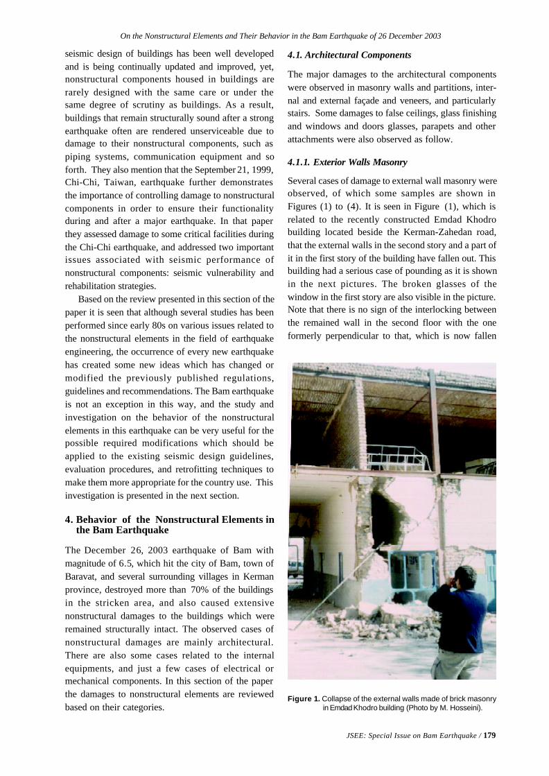
On the Nonstructural Elements and Their Behavior in the Bam Earthquake of 26 December 2003
JSEE: Special Issue on Bam Earthquake / 179
seismic design of buildings has been well developedand is being continually updated and improved, yet,nonstructural components housed in buildings arerarely designed with the same care or under thesame degree of scrutiny as buildings. As a result,buildings that remain structurally sound after a strongearthquake often are rendered unserviceable due todamage to their nonstructural components, such aspiping systems, communication equipment and soforth. They also mention that the September 21, 1999,Chi-Chi, Taiwan, earthquake further demonstratesthe importance of controlling damage to nonstructuralcomponents in order to ensure their functionalityduring and after a major earthquake. In that paperthey assessed damage to some critical facilities duringthe Chi-Chi earthquake, and addressed two importantissues associated with seismic performance ofnonstructural components: seismic vulnerability andrehabilitation strategies.
Based on the review presented in this section of thepaper it is seen that although several studies has beenperformed since early 80s on various issues related tothe nonstructural elements in the field of earthquakeengineering, the occurrence of every new earthquakehas created some new ideas which has changed ormodified the previously published regulations,guidelines and recommendations. The Bam earthquakeis not an exception in this way, and the study andinvestigation on the behavior of the nonstructuralelements in this earthquake can be very useful for thepossible required modifications which should beapplied to the existing seismic design guidelines,evaluation procedures, and retrofitting techniques tomake them more appropriate for the country use. Thisinvestigation is presented in the next section.
4. Behavior of the Nonstructural Elements inthe Bam Earthquake
The December 26, 2003 earthquake of Bam withmagnitude of 6.5, which hit the city of Bam, town ofBaravat, and several surrounding villages in Kermanprovince, destroyed more than 70% of the buildingsin the stricken area, and also caused extensivenonstructural damages to the buildings which wereremained structurally intact. The observed cases ofnonstructural damages are mainly architectural.There are also some cases related to the internalequipments, and just a few cases of electrical ormechanical components. In this section of the paperthe damages to nonstructural elements are reviewedbased on their categories.
4.1. Architectural Components
The major damages to the architectural componentswere observed in masonry walls and partitions, inter-nal and external façade and veneers, and particularlystairs. Some damages to false ceilings, glass finishingand windows and doors glasses, parapets and otherattachments were also observed as follow.
4.1.1. Exterior Walls Masonry
Several cases of damage to external wall masonry wereobserved, of which some samples are shown inFigures (1) to (4). It is seen in Figure (1), which isrelated to the recently constructed Emdad Khodrobuilding located beside the Kerman-Zahedan road,that the external walls in the second story and a part ofit in the first story of the building have fallen out. Thisbuilding had a serious case of pounding as it is shownin the next pictures. The broken glasses of thewindow in the first story are also visible in the picture.Note that there is no sign of the interlocking betweenthe remained wall in the second floor with the oneformerly perpendicular to that, which is now fallen
Figure 1. Collapse of the external walls made of brick masonryin Emdad Khodro building (Photo by M. Hosseini).
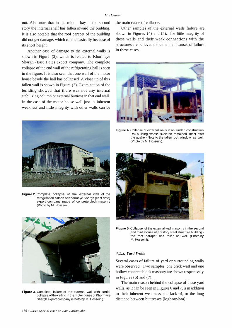
180 / JSEE: Special Issue on Bam Earthquake
M. Hosseini
Figure 2. Complete collapse of the external wall of therefrigeration saloon of Khormaye Shargh (east date)export company made of concrete block masonry(Photo by M. Hosseini).
Figure 3. Complete failure of the external wall with partialcollapse of the ceiling in the motor house of KhormayeShargh export company (Photo by M. Hosseini).
out. Also note that in the middle bay at the secondstory the internal shelf has fallen inward the building.It is also notable that the roof parapet of the buildingdid not get damage, which can be basically because ofits short height.
Another case of damage to the external walls isshown in Figure (2), which is related to KhormayeShargh (East Date) export company. The completecollapse of the end wall of the refrigerating hall is seenin the figure. It is also seen that one wall of the motorhouse beside the hall has collapsed. A close up of thisfallen wall is shown in Figure (3). Examination of thebuilding showed that there was not any internalstabilizing column or external buttress in that end wall.In the case of the motor house wall just its inherentweakness and little integrity with other walls can be
Figure 4. Collapse of external walls in an under constructionR/C building, whose skeleton remained i ntact afterthe quake - Note to the fallen out window as well(Photo by M. Hosseini).
the main cause of collapse.Other samples of the external walls failure are
shown in Figures (4) and (5). The little integrity ofthese walls and their weak connections with thestructures are believed to be the main causes of failurein these cases.
Figure 5. Collapse of the external wall masonry in the secondand third stories of a 3 story steel structure building -the roof parapet has fallen as well (Photo byM. Hosseini).
4.1.2. Yard Walls
Several cases of failure of yard or surrounding wallswere observed. Two samples, one brick wall and onehollow concrete block masonry are shown respectivelyin Figures (6) and (7).
The main reason behind the collapse of these yardwalls, as it can be seen in Figures 6 and 7, is in additionto their inherent weakness, the lack of, or the longdistance between buttresses [loghaaz-haa].
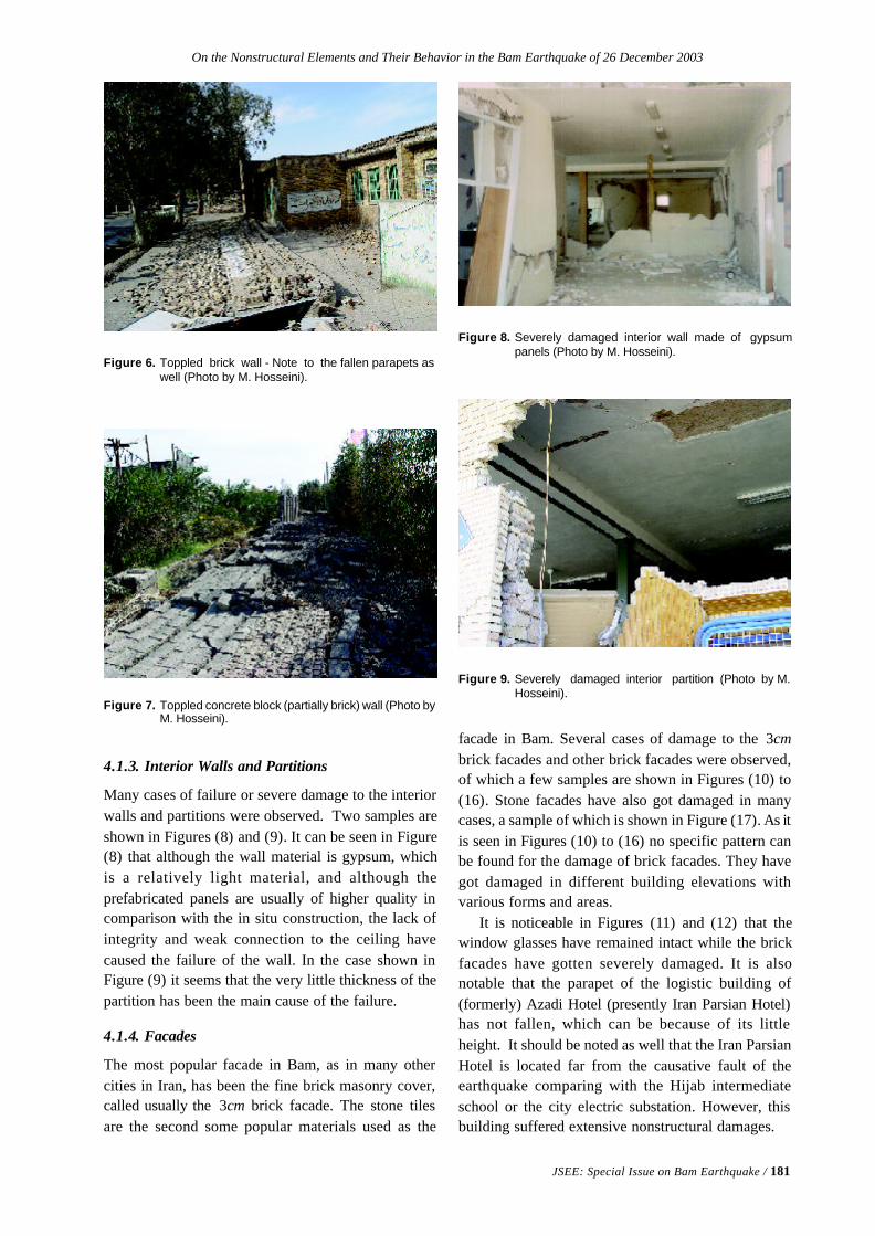
On the Nonstructural Elements and Their Behavior in the Bam Earthquake of 26 December 2003
JSEE: Special Issue on Bam Earthquake / 181
Figure 6. Toppled brick wall - Note to the fallen parapets aswell (Photo by M. Hosseini).
Figure 7. Toppled concrete block (partially brick) wall (Photo byM. Hosseini).
4.1.3. Interior Walls and Partitions
Many cases of failure or severe damage to the interiorwalls and partitions were observed. Two samples areshown in Figures (8) and (9). It can be seen in Figure(8) that although the wall material is gypsum, whichis a relatively light material, and although theprefabricated panels are usually of higher quality incomparison with the in situ construction, the lack ofintegrity and weak connection to the ceiling havecaused the failure of the wall. In the case shown inFigure (9) it seems that the very little thickness of thepartition has been the main cause of the failure.
4.1.4. Facades
The most popular facade in Bam, as in many othercities in Iran, has been the fine brick masonry cover,called usually the 3cm brick facade. The stone tilesare the second some popular materials used as the
Figure 8. Severely damaged interior wall made of gypsumpanels (Photo by M. Hosseini).
Figure 9. Severely damaged interior partition (Photo by M.Hosseini).
facade in Bam. Several cases of damage to the 3cmbrick facades and other brick facades were observed,of which a few samples are shown in Figures (10) to(16). Stone facades have also got damaged in manycases, a sample of which is shown in Figure (17). As itis seen in Figures (10) to (16) no specific pattern canbe found for the damage of brick facades. They havegot damaged in different building elevations withvarious forms and areas.
It is noticeable in Figures (11) and (12) that thewindow glasses have remained intact while the brickfacades have gotten severely damaged. It is alsonotable that the parapet of the logistic building of(formerly) Azadi Hotel (presently Iran Parsian Hotel)has not fallen, which can be because of its littleheight. It should be noted as well that the Iran ParsianHotel is located far from the causative fault of theearthquake comparing with the Hijab intermediateschool or the city electric substation. However, thisbuilding suffered extensive nonstructural damages.
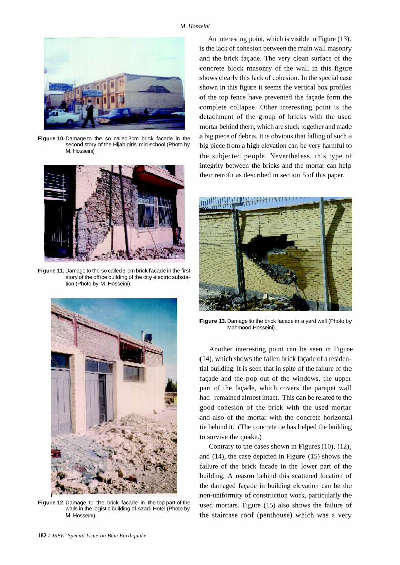
182 / JSEE: Special Issue on Bam Earthquake
M. Hosseini
Figure 13. Damage to the brick facade in a yard wall (Photo byMahmood Hosseini).
Figure 10. Damage to the so called 3cm brick facade in thesecond story of the Hijab girls' mid school (Photo byM. Hosseini)
Figure 11. Damage to the so called 3-cm brick facade in the firststory of the office building of the city electric substa-tion (Photo by M. Hosseini).
Figure 12. Damage to the brick facade in the top part of thewalls in the logistic building of Azadi Hotel (Photo byM. Hosseini).
An interesting point, which is visible in Figure (13),is the lack of cohesion between the main wall masonryand the brick façade. The very clean surface of theconcrete block masonry of the wall in this figureshows clearly this lack of cohesion. In the special caseshown in this figure it seems the vertical box profilesof the top fence have prevented the façade form thecomplete collapse. Other interesting point is thedetachment of the group of bricks with the usedmortar behind them, which are stuck together and madea big piece of debris. It is obvious that falling of such abig piece from a high elevation can be very harmful tothe subjected people. Nevertheless, this type ofintegrity between the bricks and the mortar can helptheir retrofit as described in section 5 of this paper.
Another interesting point can be seen in Figure(14), which shows the fallen brick façade of a residen-tial building. It is seen that in spite of the failure of thefaçade and the pop out of the windows, the upperpart of the façade, which covers the parapet wallhad remained almost intact. This can be related to thegood cohesion of the brick with the used mortarand also of the mortar with the concrete horizontaltie behind it. (The concrete tie has helped the buildingto survive the quake.) Contrary to the cases shown in Figures (10), (12),and (14), the case depicted in Figure (15) shows thefailure of the brick facade in the lower part of thebuilding. A reason behind this scattered location ofthe damaged façade in building elevation can be thenon-uniformity of construction work, particularly theused mortars. Figure (15) also shows the failure ofthe staircase roof (penthouse) which was a very
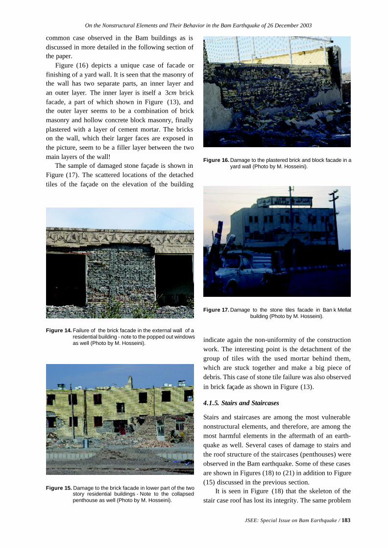
On the Nonstructural Elements and Their Behavior in the Bam Earthquake of 26 December 2003
JSEE: Special Issue on Bam Earthquake / 183
common case observed in the Bam buildings as isdiscussed in more detailed in the following section ofthe paper.
Figure (16) depicts a unique case of facade orfinishing of a yard wall. It is seen that the masonry ofthe wall has two separate parts, an inner layer andan outer layer. The inner layer is itself a 3cm brickfacade, a part of which shown in Figure (13), andthe outer layer seems to be a combination of brickmasonry and hollow concrete block masonry, finallyplastered with a layer of cement mortar. The brickson the wall, which their larger faces are exposed inthe picture, seem to be a filler layer between the twomain layers of the wall! The sample of damaged stone façade is shown inFigure (17). The scattered locations of the detachedtiles of the façade on the elevation of the building
Figure 17. Damage to the stone tiles facade in Ban k Mellatbuilding (Photo by M. Hosseini).
Figure 16. Damage to the plastered brick and block facade in ayard wall (Photo by M. Hosseini).
Figure 14. Failure of the brick facade in the external wall of aresidential building - note to the popped out windowsas well (Photo by M. Hosseini).
Figure 15. Damage to the brick facade in lower part of the twostory residential buildings - Note to the collapsedpenthouse as well (Photo by M. Hosseini).
indicate again the non-uniformity of the constructionwork. The interesting point is the detachment of thegroup of tiles with the used mortar behind them,which are stuck together and make a big piece ofdebris. This case of stone tile failure was also observedin brick façade as shown in Figure (13).
4.1.5. Stairs and Staircases
Stairs and staircases are among the most vulnerablenonstructural elements, and therefore, are among themost harmful elements in the aftermath of an earth-quake as well. Several cases of damage to stairs andthe roof structure of the staircases (penthouses) wereobserved in the Bam earthquake. Some of these casesare shown in Figures (18) to (21) in addition to Figure(15) discussed in the previous section. It is seen in Figure (18) that the skeleton of thestair case roof has lost its integrity. The same problem
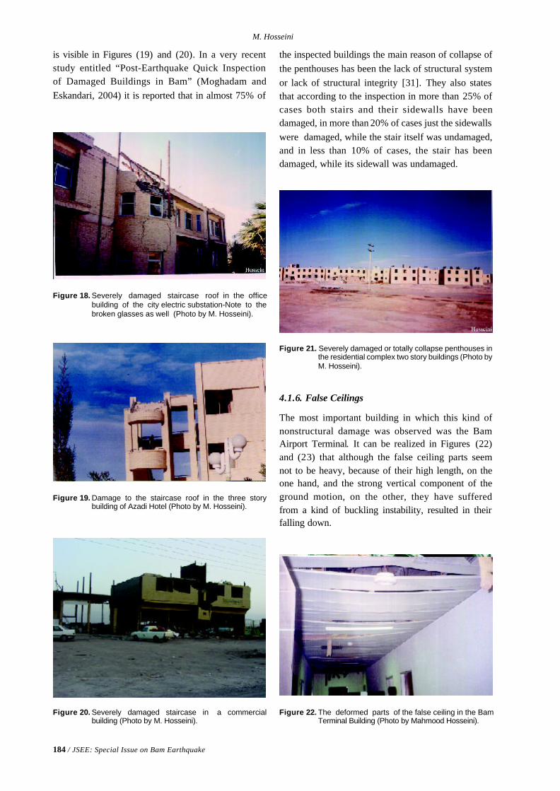
184 / JSEE: Special Issue on Bam Earthquake
M. Hosseini
Figure 18. Severely damaged staircase roof in the officebuilding of the city electric substation-Note to thebroken glasses as well (Photo by M. Hosseini).
Figure 21. Severely damaged or totally collapse penthouses inthe residential complex two story buildings (Photo byM. Hosseini).
Figure 19. Damage to the staircase roof in the three storybuilding of Azadi Hotel (Photo by M. Hosseini).
Figure 20. Severely damaged staircase in a commercialbuilding (Photo by M. Hosseini).
is visible in Figures (19) and (20). In a very recentstudy entitled “Post-Earthquake Quick Inspectionof Damaged Buildings in Bam” (Moghadam andEskandari, 2004) it is reported that in almost 75% of
the inspected buildings the main reason of collapse ofthe penthouses has been the lack of structural systemor lack of structural integrity [31]. They also statesthat according to the inspection in more than 25% ofcases both stairs and their sidewalls have beendamaged, in more than 20% of cases just the sidewallswere damaged, while the stair itself was undamaged,and in less than 10% of cases, the stair has beendamaged, while its sidewall was undamaged.
4.1.6. False Ceilings
The most important building in which this kind ofnonstructural damage was observed was the BamAirport Terminal. It can be realized in Figures (22)and (23) that although the false ceiling parts seemnot to be heavy, because of their high length, on theone hand, and the strong vertical component of theground motion, on the other, they have sufferedfrom a kind of buckling instability, resulted in theirfalling down.
Figure 22. The deformed parts of the false ceiling in the BamTerminal Building (Photo by Mahmood Hosseini).
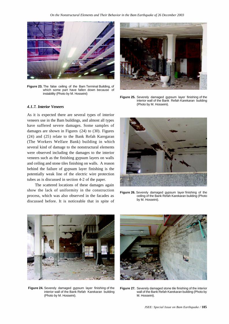
On the Nonstructural Elements and Their Behavior in the Bam Earthquake of 26 December 2003
JSEE: Special Issue on Bam Earthquake / 185
Figure 23. The false ceiling of the Bam Terminal Building, ofwhich some part have fallen down because ofinstability (Photo by M. Hosseini)
4.1.7. Interior Veneers
As it is expected there are several types of interiorveneers use in the Bam buildings, and almost all typeshave suffered severe damages. Some samples ofdamages are shown in Figures (24) to (30). Figures(24) and (25) relate to the Bank Refah Karegaran(The Workers Welfare Bank) building in whichseveral kind of damage to the nonstructural elementswere observed including the damages to the interiorveneers such as the finishing gypsum layers on wallsand ceiling and stone tiles finishing on walls. A reasonbehind the failure of gypsum layer finishing is thepotentially weak line of the electric wire protectiontubes as is discussed in section 4-2 of the paper. The scattered locations of these damages againshow the lack of uniformity in the constructionprocess, which was also observed in the facades asdiscussed before. It is noticeable that in spite of
Figure 24. Severely damaged gypsum layer finishing of theinterior wall of the Bank Refah Karekaran building(Photo by M. Hosseini).
Figure 27. Severely damaged stone tile finishing of the interiorwall of the Bank Refah Karekaran building (Photo byM. Hosseini).
Figure 26. Severely damaged gypsum layer finishing of theceiling of the Bank Refah Karekaran building (Photoby M. Hosseini).
Figure 25. Severely damaged gypsum layer finishing of theinterior wall of the Bank Refah Karekaran building(Photo by M. Hosseini).
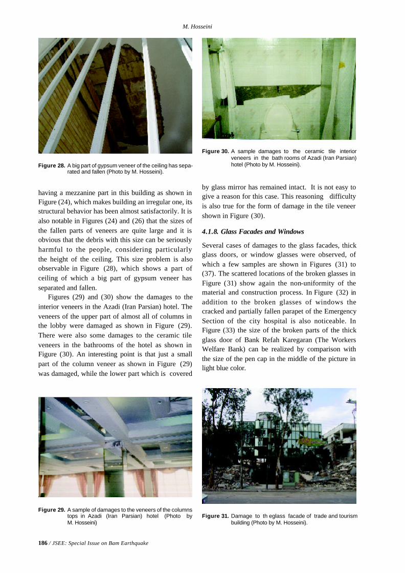
186 / JSEE: Special Issue on Bam Earthquake
M. Hosseini
having a mezzanine part in this building as shown inFigure (24), which makes building an irregular one, itsstructural behavior has been almost satisfactorily. It isalso notable in Figures (24) and (26) that the sizes ofthe fallen parts of veneers are quite large and it isobvious that the debris with this size can be seriouslyharmful to the people, considering particularlythe height of the ceiling. This size problem is alsoobservable in Figure (28), which shows a part ofceiling of which a big part of gypsum veneer hasseparated and fallen.
Figures (29) and (30) show the damages to theinterior veneers in the Azadi (Iran Parsian) hotel. Theveneers of the upper part of almost all of columns inthe lobby were damaged as shown in Figure (29).There were also some damages to the ceramic tileveneers in the bathrooms of the hotel as shown inFigure (30). An interesting point is that just a smallpart of the column veneer as shown in Figure (29)was damaged, while the lower part which is covered
Figure 28. A big part of gypsum veneer of the ceiling has sepa-rated and fallen (Photo by M. Hosseini).
Figure 29. A sample of damages to the veneers of the columnstops in Azadi (Iran Parsian) hotel (Photo byM. Hosseini)
Figure 30. A sample damages to the ceramic tile interiorveneers in the bath rooms of Azadi (Iran Parsian)hotel (Photo by M. Hosseini).
by glass mirror has remained intact. It is not easy togive a reason for this case. This reasoning difficultyis also true for the form of damage in the tile veneershown in Figure (30).
4.1.8. Glass Facades and Windows
Several cases of damages to the glass facades, thickglass doors, or window glasses were observed, ofwhich a few samples are shown in Figures (31) to(37). The scattered locations of the broken glasses inFigure (31) show again the non-uniformity of thematerial and construction process. In Figure (32) inaddition to the broken glasses of windows thecracked and partially fallen parapet of the EmergencySection of the city hospital is also noticeable. InFigure (33) the size of the broken parts of the thickglass door of Bank Refah Karegaran (The WorkersWelfare Bank) can be realized by comparison withthe size of the pen cap in the middle of the picture inlight blue color.
Figure 31. Damage to th eglass facade of trade and tourismbuilding (Photo by M. Hosseini).
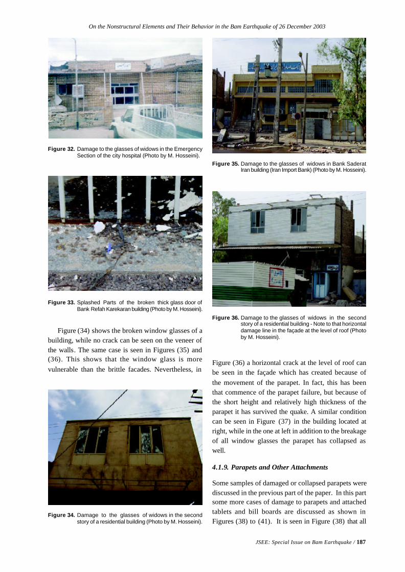
On the Nonstructural Elements and Their Behavior in the Bam Earthquake of 26 December 2003
JSEE: Special Issue on Bam Earthquake / 187
Figure 34. Damage to the glasses of widows in the secondstory of a residential building (Photo by M. Hosseini).
Figure 32. Damage to the glasses of widows in the EmergencySection of the city hospital (Photo by M. Hosseini).
Figure 33. Splashed Parts of the broken thick glass door ofBank Refah Karekaran building (Photo by M. Hosseini).
Figure (34) shows the broken window glasses of abuilding, while no crack can be seen on the veneer ofthe walls. The same case is seen in Figures (35) and(36). This shows that the window glass is morevulnerable than the brittle facades. Nevertheless, in
Figure 35. Damage to the glasses of widows in Bank SaderatIran building (Iran Import Bank) (Photo by M. Hosseini).
Figure 36. Damage to the glasses of widows in the secondstory of a residential building - Note to that horizontaldamage line in the façade at the level of roof (Photoby M. Hosseini).
Figure (36) a horizontal crack at the level of roof canbe seen in the façade which has created because ofthe movement of the parapet. In fact, this has beenthat commence of the parapet failure, but because ofthe short height and relatively high thickness of theparapet it has survived the quake. A similar conditioncan be seen in Figure (37) in the building located atright, while in the one at left in addition to the breakageof all window glasses the parapet has collapsed aswell.
4.1.9. Parapets and Other Attachments
Some samples of damaged or collapsed parapets werediscussed in the previous part of the paper. In this partsome more cases of damage to parapets and attachedtablets and bill boards are discussed as shown inFigures (38) to (41). It is seen in Figure (38) that all
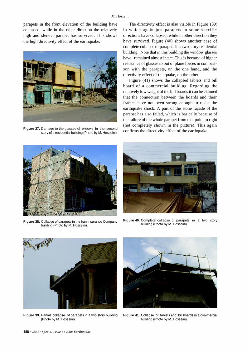
188 / JSEE: Special Issue on Bam Earthquake
M. Hosseini
parapets in the front elevation of the building havecollapsed, while in the other direction the relativelyhigh and slender parapet has survived. This showsthe high directivity effect of the earthquake.
Figure 37. Damage to the glasses of widows in the secondstory of a residential building (Photo by M. Hosseini).
Figure 38. Collapse of parapets in the Iran Insurance Companybuilding (Photo by M. Hosseini).
Figure 39. Partial collapse of parapets in a two story building(Photo by M. Hosseini).
The directivity effect is also visible in Figure (39)in which again just parapets in some specificdirections have collapsed, while in other direction theyhave survived. Figure (40) shows another case ofcomplete collapse of parapets in a two story residentialbuilding. Note that in this building the window glasseshave remained almost intact. This is because of higherresistance of glasses to out of plane forces in compari-son with the parapets, on the one hand, and thedirectivity effect of the quake, on the other.
Figure (41) shows the collapsed tablets and billboard of a commercial building. Regarding therelatively low weight of the bill boards it can be claimedthat the connection between the boards and theirframes have not been strong enough to resist theearthquake shock. A part of the stone façade of theparapet has also failed, which is basically because ofthe failure of the whole parapet from that point to right(not completely shown in the picture). This againconfirms the directivity effect of the earthquake.
Figure 41. Collapse of tablets and bill boards in a commercialbuilding (Photo by M. Hosseini).
Figure 40. Complete collapse of parapets in a two storybuilding (Photo by M. Hosseini).
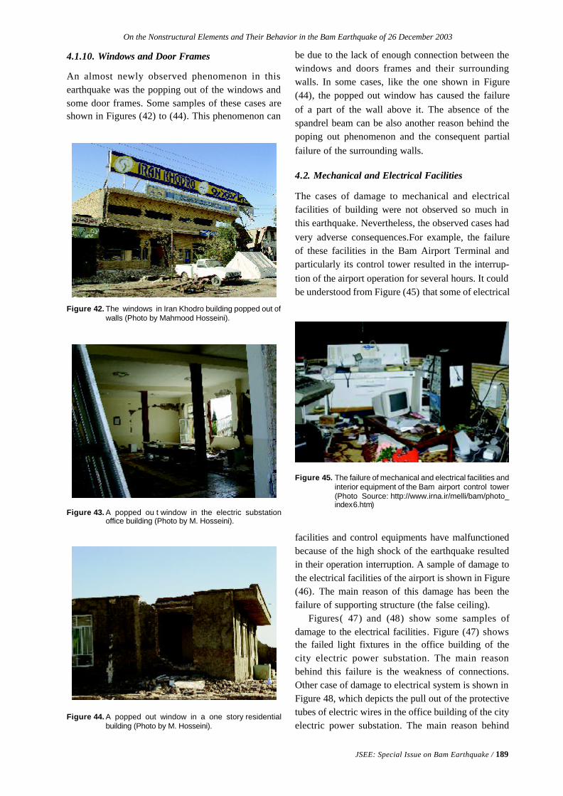
On the Nonstructural Elements and Their Behavior in the Bam Earthquake of 26 December 2003
JSEE: Special Issue on Bam Earthquake / 189
4.1.10. Windows and Door Frames
An almost newly observed phenomenon in thisearthquake was the popping out of the windows andsome door frames. Some samples of these cases areshown in Figures (42) to (44). This phenomenon can
Figure 44. A popped out window in a one story residentialbuilding (Photo by M. Hosseini).
Figure 43. A popped ou t window in the electric substationoffice building (Photo by M. Hosseini).
Figure 42. The windows in Iran Khodro building popped out ofwalls (Photo by Mahmood Hosseini).
be due to the lack of enough connection between thewindows and doors frames and their surroundingwalls. In some cases, like the one shown in Figure(44), the popped out window has caused the failureof a part of the wall above it. The absence of thespandrel beam can be also another reason behind thepoping out phenomenon and the consequent partialfailure of the surrounding walls.
4.2. Mechanical and Electrical Facilities
The cases of damage to mechanical and electricalfacilities of building were not observed so much inthis earthquake. Nevertheless, the observed cases hadvery adverse consequences.For example, the failureof these facilities in the Bam Airport Terminal andparticularly its control tower resulted in the interrup-tion of the airport operation for several hours. It couldbe understood from Figure (45) that some of electrical
Figure 45. The failure of mechanical and electrical facilities andinterior equipment of the Bam airport control tower(Photo Source: http://www.irna.ir/melli/bam/photo_index6.htm)
facilities and control equipments have malfunctionedbecause of the high shock of the earthquake resultedin their operation interruption. A sample of damage tothe electrical facilities of the airport is shown in Figure(46). The main reason of this damage has been thefailure of supporting structure (the false ceiling).
Figures( 47) and (48) show some samples ofdamage to the electrical facilities. Figure (47) showsthe failed light fixtures in the office building of thecity electric power substation. The main reasonbehind this failure is the weakness of connections.Other case of damage to electrical system is shown inFigure 48, which depicts the pull out of the protectivetubes of electric wires in the office building of the cityelectric power substation. The main reason behind
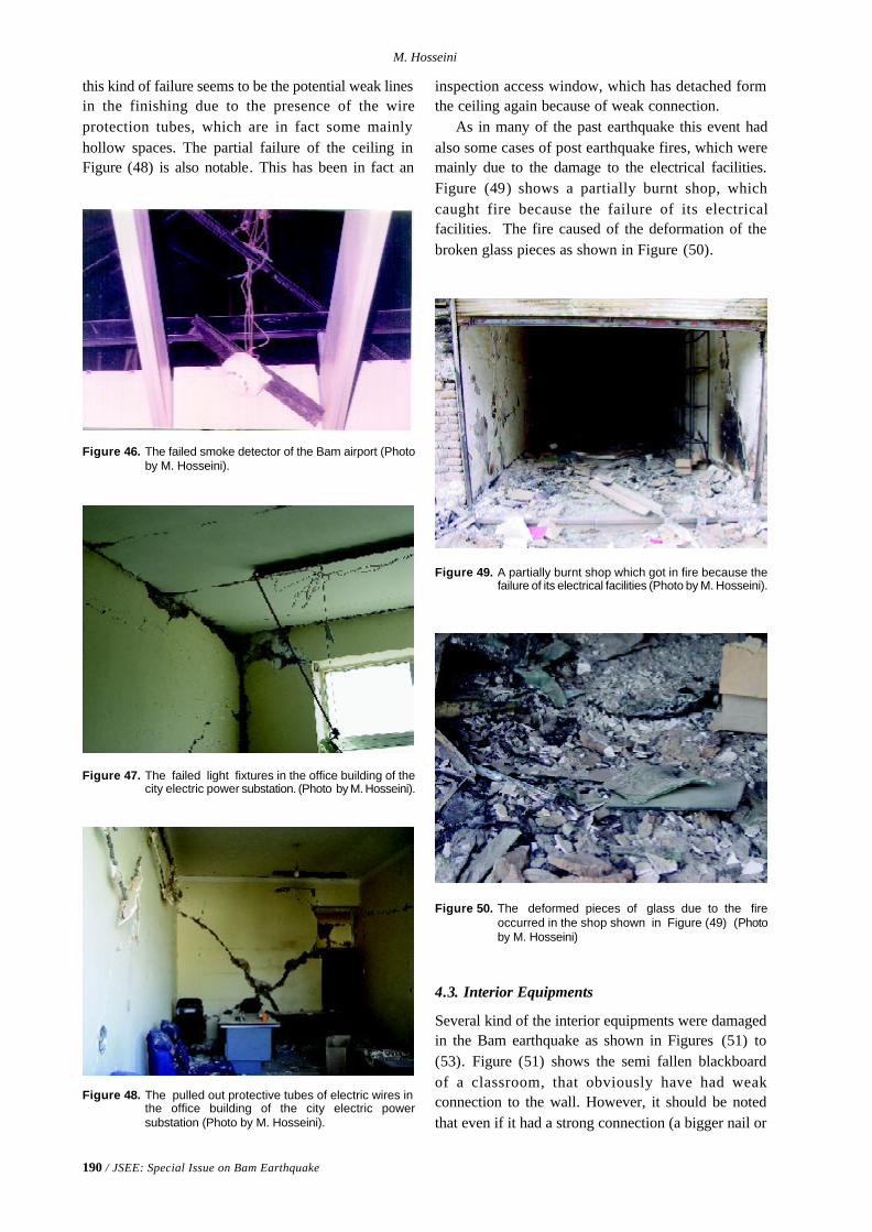
190 / JSEE: Special Issue on Bam Earthquake
M. Hosseini
this kind of failure seems to be the potential weak linesin the finishing due to the presence of the wireprotection tubes, which are in fact some mainlyhollow spaces. The partial failure of the ceiling inFigure (48) is also notable. This has been in fact an
Figure 50. The deformed pieces of glass due to the fireoccurred in the shop shown in Figure (49) (Photoby M. Hosseini)
Figure 46. The failed smoke detector of the Bam airport (Photoby M. Hosseini).
Figure 47. The failed light fixtures in the office building of thecity electric power substation. (Photo by M. Hosseini).
Figure 48. The pulled out protective tubes of electric wires inthe office building of the city electric powersubstation (Photo by M. Hosseini).
inspection access window, which has detached formthe ceiling again because of weak connection.
As in many of the past earthquake this event hadalso some cases of post earthquake fires, which weremainly due to the damage to the electrical facilities.Figure (49) shows a partially burnt shop, whichcaught fire because the failure of its electricalfacilities. The fire caused of the deformation of thebroken glass pieces as shown in Figure (50).
Figure 49. A partially burnt shop which got in fire because thefailure of its electrical facilities (Photo by M. Hosseini).
4.3. Interior Equipments
Several kind of the interior equipments were damagedin the Bam earthquake as shown in Figures (51) to(53). Figure (51) shows the semi fallen blackboardof a classroom, that obviously have had weakconnection to the wall. However, it should be notedthat even if it had a strong connection (a bigger nail or
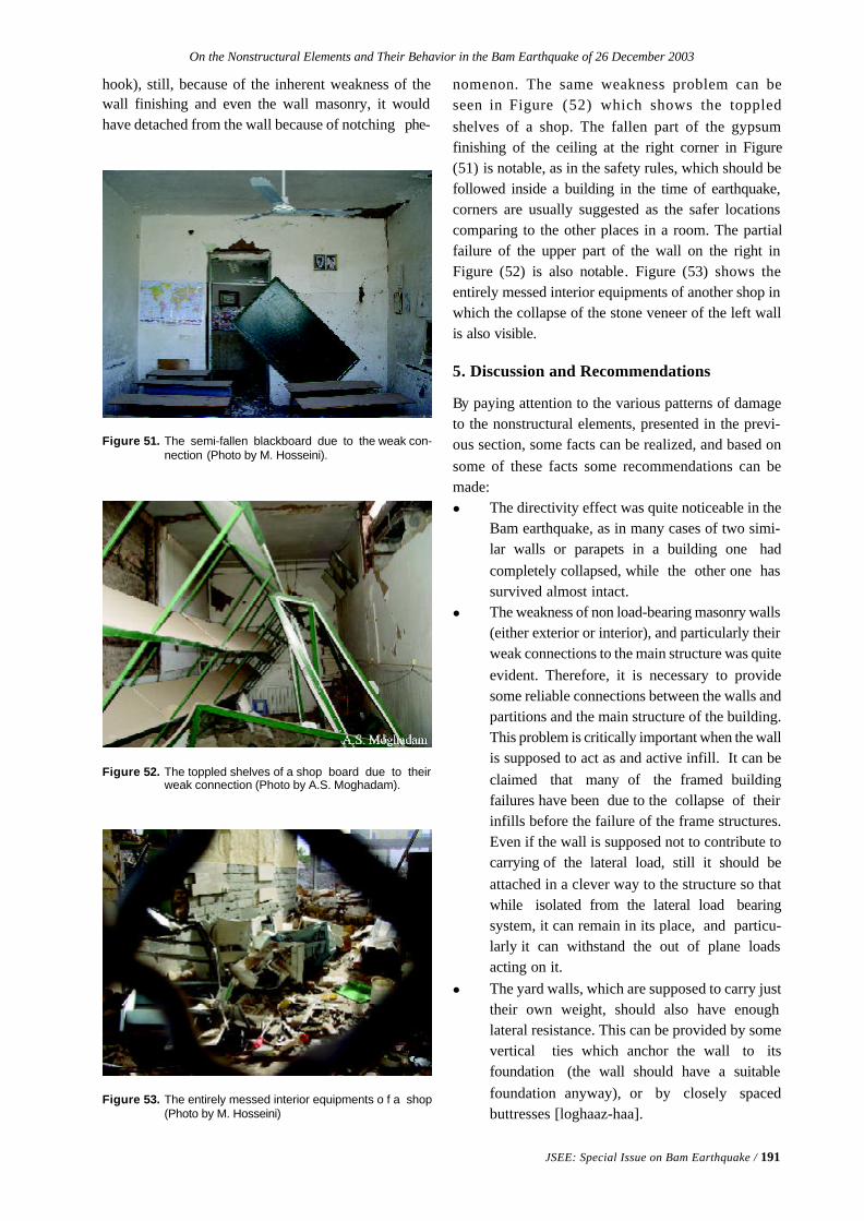
On the Nonstructural Elements and Their Behavior in the Bam Earthquake of 26 December 2003
JSEE: Special Issue on Bam Earthquake / 191
hook), still, because of the inherent weakness of thewall finishing and even the wall masonry, it wouldhave detached from the wall because of notching phe-
Figure 51. The semi-fallen blackboard due to the weak con-nection (Photo by M. Hosseini).
Figure 53. The entirely messed interior equipments o f a shop(Photo by M. Hosseini)
Figure 52. The toppled shelves of a shop board due to theirweak connection (Photo by A.S. Moghadam).
nomenon. The same weakness problem can beseen in Figure (52) which shows the toppledshelves of a shop. The fallen part of the gypsumfinishing of the ceiling at the right corner in Figure(51) is notable, as in the safety rules, which should befollowed inside a building in the time of earthquake,corners are usually suggested as the safer locationscomparing to the other places in a room. The partialfailure of the upper part of the wall on the right inFigure (52) is also notable. Figure (53) shows theentirely messed interior equipments of another shop inwhich the collapse of the stone veneer of the left wallis also visible.
5. Discussion and Recommendations
By paying attention to the various patterns of damageto the nonstructural elements, presented in the previ-ous section, some facts can be realized, and based onsome of these facts some recommendations can bemade:l The directivity effect was quite noticeable in the
Bam earthquake, as in many cases of two simi-lar walls or parapets in a building one hadcompletely collapsed, while the other one hassurvived almost intact.
l The weakness of non load-bearing masonry walls(either exterior or interior), and particularly theirweak connections to the main structure was quiteevident. Therefore, it is necessary to providesome reliable connections between the walls andpartitions and the main structure of the building.This problem is critically important when the wallis supposed to act as and active infill. It can beclaimed that many of the framed buildingfailures have been due to the collapse of theirinfills before the failure of the frame structures.Even if the wall is supposed not to contribute tocarrying of the lateral load, still it should beattached in a clever way to the structure so thatwhile isolated from the lateral load bearingsystem, it can remain in its place, and particu-larly it can withstand the out of plane loadsacting on it.
l The yard walls, which are supposed to carry justtheir own weight, should also have enoughlateral resistance. This can be provided by somevertical ties which anchor the wall to itsfoundation (the wall should have a suitablefoundation anyway), or by closely spacedbuttresses [loghaaz-haa].
192 / JSEE: Special Issue on Bam Earthquake
M. Hosseini
l Facade, particularly the large stone plates andthe 3cm bricks, should be securely attached tothe corresponding walls. A notable point in thisregard is that a group of small tiles or bricks,stuck to the mortar behind them, make itpossible to retrofit these kinds of facade with areasonable amount of supporting ties system, byan external structure.
l Glass façade should be also made safe againstearthquake. This can be done in three differentways: 1) using the shatterproof glasses, 2) usingsome kind of very soft materials around the glassplates in their frames to accommodate theirmovement without breakage, and 3) using anoverall framed structure for the whole glassfacade and putting it on a rocker-roller support-ing system.
l The parapets and tablets or bill board should havereliable supporting structure securely attached tothe main building structure. If the use of lightweight materials is encouraged in the countryvulnerability of these kind of attachments will begreatly reduced.
l The interior veneers and finishing should be alsosecurely attached to their corresponding walls.It is suggested that the use of integrated sheetveneers is encouraged. This will decrease thevulnerability of the interior veneers to a greatextent.
l The connecting methods of the interiorequipments to the main structural elements orother parts of the building, recommended orsuggested by other countries, including the US,are not appropriate for the Iranian buildings,particularly in the cases of concerning themasonry walls. This returns back to theinherent weakness of walls masonry mentionedin section 4 of the paper. It is suggested thatthese equipments are attached to the walls bysome kind of ties which can pass through thewall and can be secured in the other side of thewall.
l Staircases and penthouses are among the mostvulnerable nonstructural elements in Iranianbuildings. It is suggested that the supportingstructure of stairs is prevented from contribution to carrying of the lateral loads. This willhelp not only the structural system to have amore reliable seismic behavior, but also thestaircase itself to sustain less damage.
6. Conclusions
Based on the matters discussed in the previoussections of this paper it can be concluded that:v Almost all of the nonstructural elements in the
existing building of the country are moderatelyto highly vulnerable to the probable futurearthquakes. Therefore, the retrofit of theseelements is a necessity parallel with the retrofitof the structural systems of the existingbuildings.
v Infill walls and staircases are the most vulner-able architectural elements. It is stronglysuggested that these elements are separatedfrom the lateral load bearing system of thebuilding.
v The connecting methods of the interior equipments to the structural systems, recommendedby other countries, including the US, are notappropriate for the Iranian buildings, particularlyin the cases concerning the masonry walls. Someappropriate methods, like the one mentioned insection 5 can be developed.
v The proposed recommendations are useful aidsfor completion and modification of the thirdvolume of the present “Guideline for SeismicRetrofit of the Existing Building” which is nowunder revision by the IIEES.
v The use of lightweight materials and integratedsheet veneers should be encouraged in thecountry. This will be a very effective way forreducing the seismic vulnerability of thesenonstructural elements.
v Some of the suggestions and recommendations,discussed in the paper for retrofit of thenonstructural elements need new researchprojects, particularly the experimental ones, toachieve the reasonable solutions.
References
1. Arnold, C. (1998). “The Requirements for Non-structural Components for the NEHRP Guidelinesfor the Seismic Rehabilitation of Buildings, ATC29-1”, Proceedings of Seminar on Seismic Design,Retrofit, and Performance of NonstructuralComponents, Applied Technology Council,
Redwood City, California, 433-444.
2. Bachman, R. (1998). “Building Code SeismicDesign Provisions for Non-Structural Compo-nents”, ATC 29-1, Proceedings of Seminar onSeismic Design, Retrofit, and Performance of
On the Nonstructural Elements and Their Behavior in the Bam Earthquake of 26 December 2003
JSEE: Special Issue on Bam Earthquake / 193
Nonstructural Components, Applied TechnologyCouncil, Redwood City, California, 7-14.
3. Bachman, R.E. and Drake, R.M. (1998). “DesignForce Provisions for Nonstructural Elements andModel Codes”, Proceedings of the Sixth U.S.National Conference on Earthquake Engineering[Computer File], Earthquake EngineeringResearch Inst., Oakland, California, p.12
4. Drake, R., Bragagnolo, M., and Leo J. (2000).“Model Code Design Force Provisions forElements of Structures and NonstructuralComponents, Earthquake Spectra, 16(1), 115-125.
5. Drake, R.M. and Richter, P.J. (1990). “EarthquakeHazard Mitigation of Nonstructural Elements inU.S. Postal Service Facilities”, Proceedings of theFourth U.S. National Conference on EarthquakeEngineering, Earthquake Engineering ResearchInst., El Cerrito, California, 3, 21-29.
6. EERI (1984). “Nonstructural Issues of SeismicDesign and Construction”, Earthquake Engineer-ing Research I nstitute (EERI), 84-04, Berkeley,California, p. 122.
7. Eidinger, J. and Goettel, K. (1998). “The Benefitsand Costs of Seismic Retrofits of NonstructuralComponents for Hospitals, Essential Facilities andSchools, ATC 29-1”, Proceedings of Seminar onSeismic Design, Retrofit, and Performance ofNonstructural Components, Applied TechnologyCouncil, Redwood City, California, 491-504.
8. Fierro, E.A. and Perry, C.L. (1998). “Develop-ment and Usage of FEMA 74, Reducing the Risksof Nonstructural Earthquake Damage: A PracticalGuide, ATC 29-1”, Proceedings of Seminar onSeismic Design, Retrofit, and Performance ofNonstructural Components, Applied TechnologyCouncil, Redwood City, California, 421-431.
9. Fierro, E.A., Perry, C.L., and Freeman, S.A.(1994). “Reducing the Risks of NonstructuralEarthquake Damage: A Practical Guide”, FEMA74, Federal Emergency Management Agency,Washington, D.C., 1, 3rd ed. (Superseded the 1985edition).
10. Freeman, S.A. (1998). “Design Criteria for Non-Structural Components Based on Tri-ServicesManuals, ATC 29-1”, Proceedings of Seminar onSeismic Design, Retrofit, and Performance ofNonstructural Components, Applied Technology
Council, Redwood City, California, 15-29.
11. Freeman, S.A. and Kehoe, B.E. (1997). “Reviewof Proposed Design Accelerations for Nonstruc-tural Elements”, Proceedings Fourth Conferenceon Tall Buildings in Seismic Regions: Tall Build-ings for the 21st Century, Los Angeles TallBuildings Structural Design Council and Councilon Tall Buildings and Urban Habitat, Los Angeles,California, and Bethlehem, Pennsylvania, 291-302.
12. Gurbuz, Orhan; Wu, Sheng; Wittchen, Scott, Re-view of Requirements for Design of Nonstructuralcomponents and their anchorage, ATC 29-1, Pro-ceedings of Seminar on Seismic Design, Retrofit,and Performance of Nonstructural Components,Applied Technology Council, Redwood City, Cali-fornia, pages 71-77, 1998.
13. Haupt, R.W. (1992). “Problems, Barriers, andChallenges in Developing Seismic Code Rules forEquipment and Non-Building Structures, ATC-29”,Proceedings of ATC-29 Seminar and Workshop onSeismic Design and Performance of Equipmentand Nonstructural Elements in Buildings andIndustrial Structures, Applied TechnologyCouncil, Redwood City, California, 99-105.
14. Henry, R.M. and Stein, C. (1987). “A Compara-tive Study of the Effects of Cladding PanelModeling”, Mathematical Modelling, 8, 560-565.
15. Hirosawa, M., Mizuno, H., and Midorikawa, M.(1991). “State-of-the-Art Report on SeismicDesign of Building Equipment and NonstructuralComponents in Japan, NIST SP 820, Wind andSeismic Effects”, Proceedings of the 23rd JointMeeting of the U.S.-Japan Cooperative Programin Natural Resources, Panel on Wind and SeismicEffects, National Institute of Standards andTechnology, Gaithersburg, Maryland, 397-412.
16. Kao, A.S., Soong, T.T., and Vender, A. (1999).“Nonstructural Damage Database, MCEER-99-0014”, Multidisciplinary Center for EarthquakeEngineering Research, Buffalo, N.Y., p. 59.
17. Kehoe, B.E. and Freeman, S.A. (1998). “ACritique of Procedures for Calculating SeismicDesign Forces for Nonstructural Elements, ATC29-1”, Proceedings of Seminar on Seismic Design,Retrofit, and Performance of NonstructuralComponents, Applied Technology Council,Redwood City, California, 57-70.
194 / JSEE: Special Issue on Bam Earthquake
M. Hosseini
18. Krakower, M., Donaldson, M.W., and Court, A.B.(1998). “Simplifying Complex GFRC CladdingStructural Systems in Seismic Hazard Zones: ACase Study, ATC 29-1”, Proceedings of Seminaron Seismic Design, Retrofit, and Performance ofNonstructural Components, Applied TechnologyCouncil, Redwood City, California,215-228.
19. Lai, M.L. and Soong, T.T. (1992). “OptimumSeismic Design of Secondary Structural Systems,ATC-29”, Proceedings of ATC-29 Seminar andWorkshop on Seismic Design and Performance ofEquipment and Nonstructural Elements inBuildings and Industrial Structures, AppliedTechnology Council, Redwood City, California,229-239.
20 Lagorio, H J., (1990). “Earthquakes--an Architect'sGuide to Nonstructural Seismic Hazards”, JohnWiley & Sons, Inc., New York, p. 312.
21. Lama, P.J. (1998). “Practical Guidelines forSeismic Retrofitting of HVAC Systems, ATC 29-1”, Proceedings of Seminar on Seismic Design,Retrofit, and Performance of NonstructuralComponents, Applied Technology Council, Red-wood City, California, 445-454.
22. McGavin, G.L. and Gates, B. (1998). “EarthquakeDesign Consideration for Nonstructural Compo-nents ... Who is Responsible?”, Proceedings ofthe Sixth U.S. National Conference on EarthquakeEngineering [computer file], EarthquakeEngineering Research Inst., Oakland, California,p. 5.
23. McGavin, G.L., Lai, J., and Ikkanda, S. (1998).“City of Los Angeles Proposed Ordinance Changesfor Suspended Ceiling Systems Prompted by the1994 Northridge earthquake, ATC 29-1”, Proceed-ings of Seminar on Seismic Design, Retrofit, andPerformance of Nonstructural Components,Applied Technology Council, Redwood City,California, 277-282.
24. McGavin, G.L., Patrucco, H. (1998). “Nonstruc-tural Functional Design Considerations forHealthcare Facilities”, Proceedings of the Sixth U.S.National Conference on Earthquake Engineering[Computer File], Earthquake EngineeringResearch Inst., Oakland, California, p. 11.
25. McKevitt, W.E., Timler, P.A.M., and Lo, K.K.(1996). “Nonstructural Damage from the
Northridge Earthquake”, International Journal ofRock Mechanics and Mining Sciences andGeomechanics Abstracts.
26. Marsantyo, R. et al (1999). “Shaking Table Teston the Seismic Response of NonstructuralSystems Mounted on Base Isolated Buildings”,Proceedings of the Second World Conference onStructural Control, John Wiley & Sons, Chichester,England, New York, 2, 1101-1110.
27. Marsantyo, R., Shimazu, T., and Araki, H. (2000).“Experimental Work on the Seismic HorizontalForce of Nonstructural Systems Mounted on theBuildings”, Proceedings of the 10th EarthquakeEngineering Symposium, Architectural Institute ofJapan, Tokyo, Paper No. G3-22, 2, 2635-2640.This study has been also published as (2000)“Dynamic Tesponse of Nonstructural DystemsMounted on Floors of Buildings” in the Proceed-ings of the 12th World Conference on EarthquakeEngineering [computer file], New Zealand Soci-ety for Earthquake Engineering, Upper Hutt, NewZealand, Paper No. 1872.
28. Masek, J.P. and Reitherman, R.K. (1992).“Current Problems in the Implementation ofNonstructural Earthquake Hazard ReductionEfforts, ATC-29”, Proceedings of ATC-29Seminar and Workshop on Seismic Design andPerformance of Equipment and NonstructuralElements in Building s and Industrial Structures,Applied Technology Council, Redwood City,California, 53-59.
29. Merz, K.L. and Cumming, L. (1992). “CISCARecommendations for Installation of Suspendedacoustical Ceiling in Moderate- and Low-EiskSeismic Areas, ATC-29”, Proceedings of ATC-29Seminar and Workshop on Seismic Design andPerformance of Equipment and NonstructuralElements in Buildings and Industrial Structures,Applied Technology Council, R edwood City,California, 87-97.
30. Meyer, J.D., Soong, T.T., and Hill, R.H. (1998).“Retrofit Seismic Mitigation of MainframeComputers and Associated Equipment: A CaseStudy, ATC 29-1”, Proceedings of Seminar onSeismic Design, Retrofit, and Performance ofNonstructural Components, Applied TechnologyCouncil, Redwood City, California, 149-163.
31. Moghadam, A.S. and Eskandari, A. (2004). “Post-
On the Nonstructural Elements and Their Behavior in the Bam Earthquake of 26 December 2003
JSEE: Special Issue on Bam Earthquake / 195
Earthquake Quick Inspection of Damaged Build-ings in Bam”, to be published in the InternationalJournal of Seismology and Earthquake Engineer-ing, Special Issue on the Bam Earthquake.
32. Negro, P. and Colombo, A. (1997). “IrregularitiesInduced by Nonstructural Masonry Panels inFramed Buildings”, Engineering Structures, 19(7),576-585.
33. Pantelides, C.P., Truman, K.Z., Behr, R.A., andBelarbi, A. (1996). “Development of a LoadingHistory for Seismic Testing of Architectural Glassin a Shop-front Wall System”, Engineering Struc-tures, Volume 18(12), 917-935.
34. Porter, K.A. and Scawthorn, C. (1998). “Appro-priate Seismic Reliability for Critical EquipmentSystems --an Approach Based on RegionalAnalysis of Financial and Life Loss, ATC 29-1”,Proceedings of Seminar on Seismic Design,Retrofit, and Performance of NonstructuralComponents, Applied Technology Council,Redwood City, California, 393-420.
35. Porush, A.R. (1992). “An Overview of theCurrent Building Code Seismic Requirements forNonstructural Elements, ATC-29”, Proceedings ofATC-29 Seminar and Workshop on SeismicDesign and Performance of Equipment andNonstructural Elements in Buildings andIndustrial Structures, Applied TechnologyCouncil, Redwood City, California, 17-31.
36. Reitherman, R. (1985). “Reducing the Risks ofNonstructural Earthquake Damage: A PracticalGuide”, Earthquake Hazards Reduction Series 1,FEMA 74, Federal Emergency ManagementAgency, Washington, D.C., p.87.
37. Sakamoto, I., Itoh, H., and Ohashi, Y. (1984).“Proposals for Aseismic Design Method onNonstructural Elements”, Proceedings of theEighth World Conference on EarthquakeEngineering, Prentice-Hall, Inc., EnglewoodCliffs, New Jersey, V, 1093-1100.
38. Schultz, C.H., Koenig, K.L., and Lewis, R.J.(2003). “Implications of Hospital EvacuationAfter the Northridge”, California, Earthquake,Annals of Emergency Medicine, 42(4), 604-605.
39. Selvaduray, G.S. (1993). “Nonstructural HazardMitigation for Schools, NCEER-93-0015”,
Proceedings from School Sites: BecomingPrepared for Earthquakes, Commemorating theThird Anniversary of the Loma Prieta Earthquake,National Center for Earthquake EngineeringResearch, Buffalo, N.Y., 2-29--2-34.
40. Singh, M.P. et al (1993). “Simplified Proceduresfor Seismic Design of Nonstructural Componentsand Assessment of Current Code Provisions,NCEER-93-0013”, National Center for EarthquakeEngineering Research, Buffalo, N.Y., 1.
41. Singh, M.P., Moreschi, L.M., and Suarez, L.E.,(1998). “Simplified Methods for CalculatingSeismic Forces for Nonstructural Components,ATC 29-1”, Proceedings of Seminar on SeismicDesign, Retrofit, and Performance of Nonstruc-tural Components, Applied Technology Council,Redwood City, California, 43-56.
42. Soong, T.T. (1994). “Code Development forNonstructural Components”, Research Accom-plishments, 1986-1994, The National Center forEarthquake Engineering Research, NationalCenter for Earthquake Engineering Research, StateUniv. of New York at Buffalo, 137-143.
43. Soong, T.T. (1995). “Seismic Behavior ofNonstructural Elements--State-of-the-Art Report”,Proceedings of the 10th European Conference onEarthquake Engineering, A.A. Balkema, Rotter-dam, 3, 1599-1606.
44. Soong, T.T., Yao, G.C., and Lin, C.C. (2000).“Near-Fault Seismic Vulnerability of NonstructuralComponents and Retrofit Strategies”, Proceedingsof International Workshop on Annual Commemo-ration of Chi-Chi Earthquake, National Center forResearch on Earthquake Engineering, Taipei,Taiwan, 100-111, II, Technology Aspect.
45. Staehlin, W. (1998). “Seismic Design and Performance of Nonstructural Components in Hospitals,ATC 29-1”, Proceedings of Seminar on SeismicDesign, Retrofit, and Performance of Nonstruc-tural Components, Applied Technology Council,Redwood City, California, 469-473.
46. Sucuoglu, H. and Vallabhan C.V.G. (1997).Behaviour of Window Glass Panels During Earthquakes, Engineering Structures, 19(8), 685-694.
47. Thiel, C.C.Jr., Zsutty, T.C., and Tokas, C. (1998).“Seismic Retrofit of Nonstructural Components
196 / JSEE: Special Issue on Bam Earthquake
M. Hosseini
in Acute Care Hospitals: Title 24, Part 2, Chapter16, Division III-R Requirements, ATC 29-1”,Proceedings of Seminar on Seismic Design,Retrofit, and Performance of NonstructuralComponents, Applied Technology Council,Redwood City, California, 475-489.
48. Villaverde, R. (1996). “A Proposed Replacementfor the Seismic Code Provisions for NonstructuralComponents in Buildings”, Proceedings of theEleventh World Conference on Earthquake Engi-neering, Pergamon, Elsevier Science Ltd., Oxford,England, Disc 2, Paper No. 643.
49. Villaverde, R. (1997). “Method to ImproveSeismic Provisions for Nonstructural Componentsin Buildings”, Journal of Structural Engineering,123(4), 432-439.
50. Villaverde, R. (2000). “Design-Oriented Approach
for Seismic Nonlinear Analysis of NonstructuralComponents”, Proceedings of the 12th WorldConference on Earthquake Engineering [Computerfile] , New Zealand Society for EarthquakeEngineering, Upper Hutt, New Zealand, Paper No.1979.
51. Whitney, D.J., Dickerson, A., and Lindell, M.K.(2001). “Nonstructural Seismic Preparedness ofSouthern California Hospitals”, EarthquakeSpectra, 17(1), 153-171.
52. Yanev, P.I. (1992). “The EQE Earthquake DataBase and the Performance of Equipment and Non-Structural Components, ATC-29”, Proceedings ofATC-29 Seminar and Workshop on SeismicDesign and Performance of Equipment andNonstructural Elements in Buildings andIndustrial Structures, Applied Technology Coun-cil (ATC), Redwood City, California, 107-118.
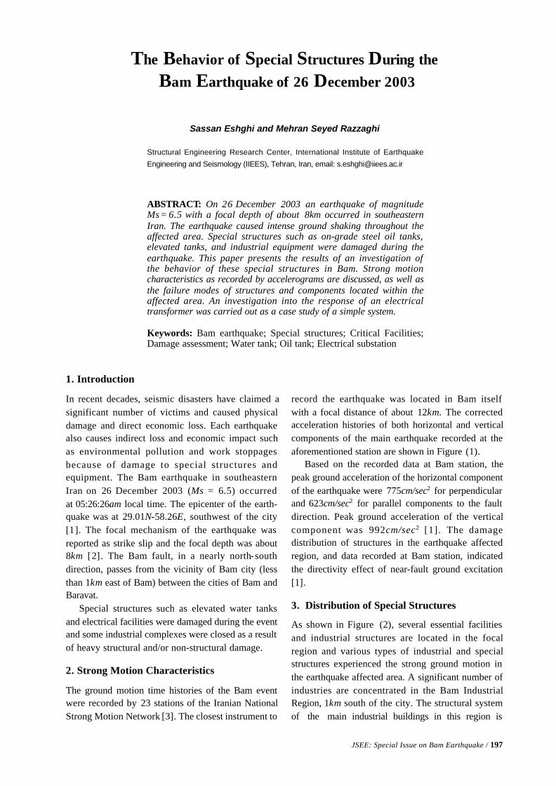
JSEE: Special Issue on Bam Earthquake / 197
Structural Engineering Research Center, International Institute of Earthquake
Engineering and Seismology (IIEES), Tehran, Iran, email: [email protected]
ABSTRACT: On 26 December 2003 an earthquake of magnitudeMs = 6.5 with a focal depth of about 8km occurred in southeasternIran. The earthquake caused intense ground shaking throughout theaffected area. Special structures such as on-grade steel oil tanks,elevated tanks, and industrial equipment were damaged during theearthquake. This paper presents the results of an investigation ofthe behavior of these special structures in Bam. Strong motioncharacteristics as recorded by accelerograms are discussed, as well asthe failure modes of structures and components located within theaffected area. An investigation into the response of an electricaltransformer was carried out as a case study of a simple system.
Keywords: Bam earthquake; Special structures; Critical Facilities;Damage assessment; Water tank; Oil tank; Electrical substation
The Behavior of Special Structures During the
Bam Earthquake of 26 December 2003
Sassan Eshghi and Mehran Seyed Razzaghi
1. Introduction
In recent decades, seismic disasters have claimed asignificant number of victims and caused physicaldamage and direct economic loss. Each earthquakealso causes indirect loss and economic impact suchas environmental pollution and work stoppagesbecause of damage to special structures andequipment. The Bam earthquake in southeasternIran on 26 December 2003 (Ms = 6.5) occurredat 05:26:26am local time. The epicenter of the earth-quake was at 29.01N-58.26E, southwest of the city[1]. The focal mechanism of the earthquake wasreported as strike slip and the focal depth was about8km [2]. The Bam fault, in a nearly north-southdirection, passes from the vicinity of Bam city (lessthan 1km east of Bam) between the cities of Bam andBaravat.
Special structures such as elevated water tanksand electrical facilities were damaged during the eventand some industrial complexes were closed as a resultof heavy structural and/or non-structural damage.
2. Strong Motion Characteristics
The ground motion time histories of the Bam eventwere recorded by 23 stations of the Iranian NationalStrong Motion Network [3]. The closest instrument to
record the earthquake was located in Bam itselfwith a focal distance of about 12km. The correctedacceleration histories of both horizontal and verticalcomponents of the main earthquake recorded at theaforementioned station are shown in Figure (1).
Based on the recorded data at Bam station, thepeak ground acceleration of the horizontal componentof the earthquake were 775cm/sec2 for perpendicularand 623cm/sec2 for parallel components to the faultdirection. Peak ground acceleration of the verticalcomponent was 992cm/sec2 [1] . The damagedistribution of structures in the earthquake affectedregion, and data recorded at Bam station, indicatedthe directivity effect of near-fault ground excitation[1].
3. Distribution of Special Structures
As shown in Figure (2), several essential facilitiesand industrial structures are located in the focalregion and various types of industrial and specialstructures experienced the strong ground motion inthe earthquake affected area. A significant number ofindustries are concentrated in the Bam IndustrialRegion, 1km south of the city. The structural systemof the main industrial buildings in this region is
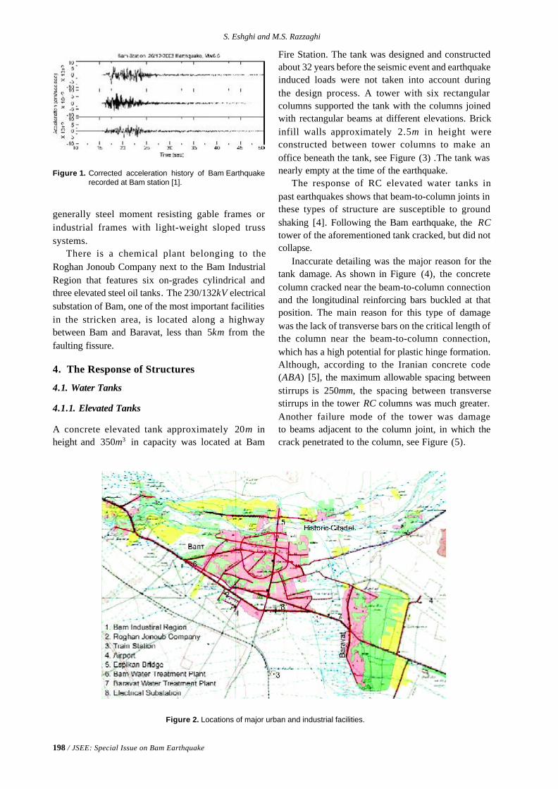
198 / JSEE: Special Issue on Bam Earthquake
S. Eshghi and M.S. Razzaghi
Figure 1. Corrected acceleration history of Bam Earthquakerecorded at Bam station [1].
generally steel moment resisting gable frames orindustrial frames with light-weight sloped trusssystems.
There is a chemical plant belonging to theRoghan Jonoub Company next to the Bam IndustrialRegion that features six on-grades cylindrical andthree elevated steel oil tanks. The 230/132kV electricalsubstation of Bam, one of the most important facilitiesin the stricken area, is located along a highwaybetween Bam and Baravat, less than 5km from thefaulting fissure.
4. The Response of Structures
4.1. Water Tanks
4.1.1. Elevated Tanks
A concrete elevated tank approximately 20m inheight and 350m3 in capacity was located at Bam
Figure 2. Locations of major urban and industrial facilities.
Fire Station. The tank was designed and constructedabout 32 years before the seismic event and earthquakeinduced loads were not taken into account duringthe design process. A tower with six rectangularcolumns supported the tank with the columns joinedwith rectangular beams at different elevations. Brickinfill walls approximately 2.5m in height wereconstructed between tower columns to make anoffice beneath the tank, see Figure (3) .The tank wasnearly empty at the time of the earthquake.
The response of RC elevated water tanks inpast earthquakes shows that beam-to-column joints inthese types of structure are susceptible to groundshaking [4]. Following the Bam earthquake, the RCtower of the aforementioned tank cracked, but did notcollapse.
Inaccurate detailing was the major reason for thetank damage. As shown in Figure (4), the concretecolumn cracked near the beam-to-column connectionand the longitudinal reinforcing bars buckled at thatposition. The main reason for this type of damagewas the lack of transverse bars on the critical length ofthe column near the beam-to-column connection,which has a high potential for plastic hinge formation.Although, according to the Iranian concrete code(ABA) [5], the maximum allowable spacing betweenstirrups is 250mm, the spacing between transversestirrups in the tower RC columns was much greater.Another failure mode of the tower was damageto beams adjacent to the column joint, in which thecrack penetrated to the column, see Figure (5).
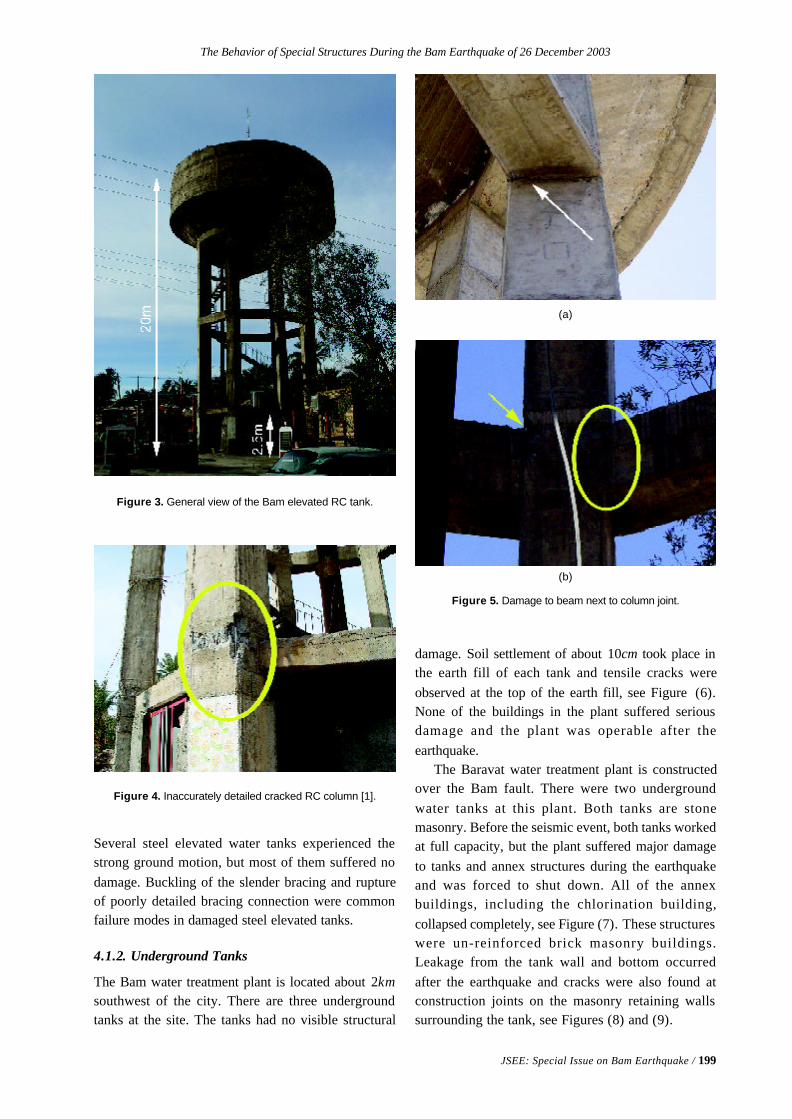
The Behavior of Special Structures During the Bam Earthquake of 26 December 2003
JSEE: Special Issue on Bam Earthquake / 199
Several steel elevated water tanks experienced thestrong ground motion, but most of them suffered nodamage. Buckling of the slender bracing and ruptureof poorly detailed bracing connection were commonfailure modes in damaged steel elevated tanks.
4.1.2. Underground Tanks
The Bam water treatment plant is located about 2kmsouthwest of the city. There are three undergroundtanks at the site. The tanks had no visible structural
Figure 3. General view of the Bam elevated RC tank.
Figure 4. Inaccurately detailed cracked RC column [1].
Figure 5. Damage to beam next to column joint.
damage. Soil settlement of about 10cm took place inthe earth fill of each tank and tensile cracks wereobserved at the top of the earth fill, see Figure (6).None of the buildings in the plant suffered seriousdamage and the plant was operable after theearthquake.
The Baravat water treatment plant is constructedover the Bam fault. There were two undergroundwater tanks at this plant. Both tanks are stonemasonry. Before the seismic event, both tanks workedat full capacity, but the plant suffered major damageto tanks and annex structures during the earthquakeand was forced to shut down. All of the annexbuildings, including the chlorination building,collapsed completely, see Figure (7). These structureswere un-reinforced brick masonry buildings.Leakage from the tank wall and bottom occurredafter the earthquake and cracks were also found atconstruction joints on the masonry retaining wallssurrounding the tank, see Figures (8) and (9).
(a)
(b)
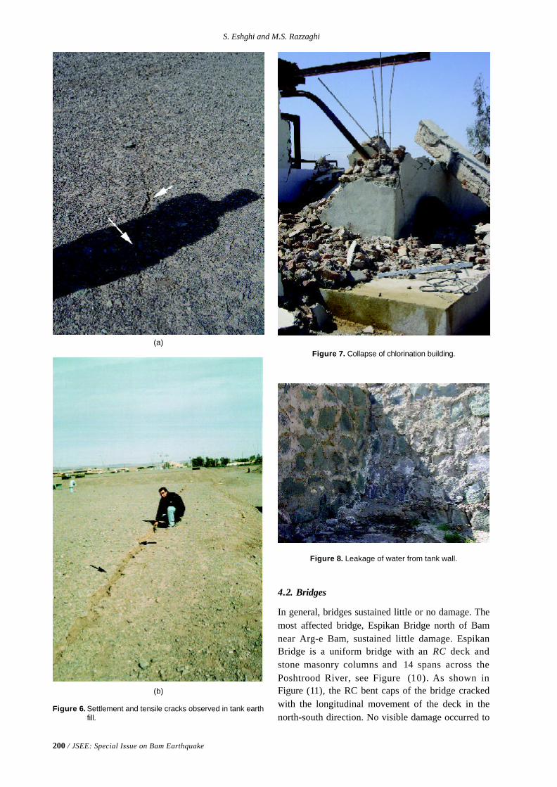
200 / JSEE: Special Issue on Bam Earthquake
S. Eshghi and M.S. Razzaghi
4.2. Bridges
In general, bridges sustained little or no damage. Themost affected bridge, Espikan Bridge north of Bamnear Arg-e Bam, sustained little damage. EspikanBridge is a uniform bridge with an RC deck andstone masonry columns and 14 spans across thePoshtrood River, see Figure (10). As shown inFigure (11), the RC bent caps of the bridge crackedwith the longitudinal movement of the deck in thenorth-south direction. No visible damage occurred to
Figure 6. Settlement and tensile cracks observed in tank earthfill.
Figure 7. Collapse of chlorination building.
Figure 8. Leakage of water from tank wall.
(a)
(b)
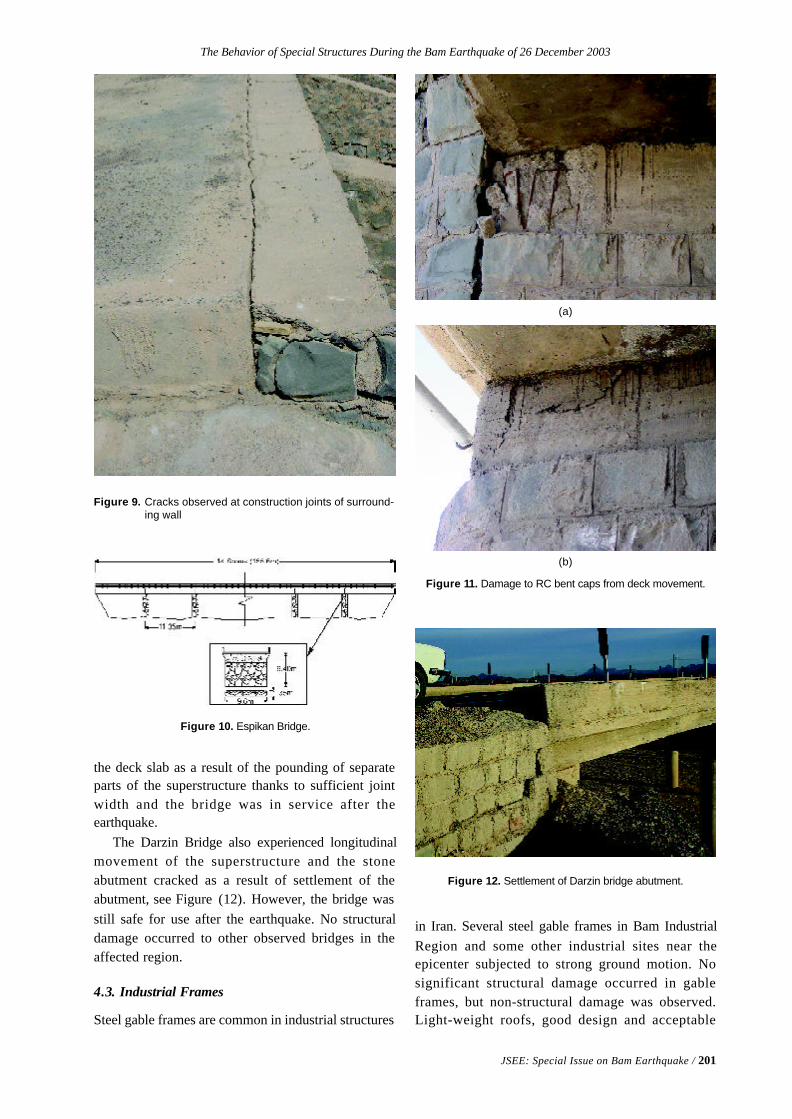
The Behavior of Special Structures During the Bam Earthquake of 26 December 2003
JSEE: Special Issue on Bam Earthquake / 201
Figure 9. Cracks observed at construction joints of surround-ing wall
Figure 11. Damage to RC bent caps from deck movement.
Figure 10. Espikan Bridge.
the deck slab as a result of the pounding of separateparts of the superstructure thanks to sufficient jointwidth and the bridge was in service after theearthquake.
The Darzin Bridge also experienced longitudinalmovement of the superstructure and the stoneabutment cracked as a result of settlement of theabutment, see Figure (12). However, the bridge wasstill safe for use after the earthquake. No structuraldamage occurred to other observed bridges in theaffected region.
4.3. Industrial Frames
Steel gable frames are common in industrial structures
Figure 12. Settlement of Darzin bridge abutment.
in Iran. Several steel gable frames in Bam IndustrialRegion and some other industrial sites near theepicenter subjected to strong ground motion. Nosignificant structural damage occurred in gableframes, but non-structural damage was observed.Light-weight roofs, good design and acceptable
(a)
(b)
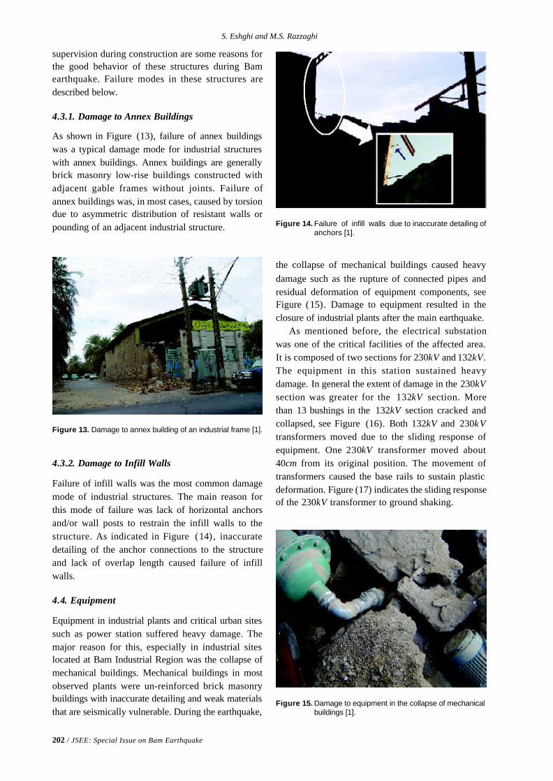
202 / JSEE: Special Issue on Bam Earthquake
S. Eshghi and M.S. Razzaghi
supervision during construction are some reasons forthe good behavior of these structures during Bamearthquake. Failure modes in these structures aredescribed below.
4.3.1. Damage to Annex Buildings
As shown in Figure (13), failure of annex buildingswas a typical damage mode for industrial structureswith annex buildings. Annex buildings are generallybrick masonry low-rise buildings constructed withadjacent gable frames without joints. Failure ofannex buildings was, in most cases, caused by torsiondue to asymmetric distribution of resistant walls orpounding of an adjacent industrial structure. Figure 14. Failure of infill walls due to inaccurate detailing of
anchors [1].
Figure 13. Damage to annex building of an industrial frame [1].
4.3.2. Damage to Infill Walls
Failure of infill walls was the most common damagemode of industrial structures. The main reason forthis mode of failure was lack of horizontal anchorsand/or wall posts to restrain the infill walls to thestructure. As indicated in Figure (14), inaccuratedetailing of the anchor connections to the structureand lack of overlap length caused failure of infillwalls.
4.4. Equipment
Equipment in industrial plants and critical urban sitessuch as power station suffered heavy damage. Themajor reason for this, especially in industrial siteslocated at Bam Industrial Region was the collapse ofmechanical buildings. Mechanical buildings in mostobserved plants were un-reinforced brick masonrybuildings with inaccurate detailing and weak materialsthat are seismically vulnerable. During the earthquake,
the collapse of mechanical buildings caused heavydamage such as the rupture of connected pipes andresidual deformation of equipment components, seeFigure (15). Damage to equipment resulted in theclosure of industrial plants after the main earthquake.
As mentioned before, the electrical substationwas one of the critical facilities of the affected area.It is composed of two sections for 230kV and 132kV.The equipment in this station sustained heavydamage. In general the extent of damage in the 230kVsection was greater for the 132kV section. Morethan 13 bushings in the 132kV section cracked andcollapsed, see Figure (16). Both 132kV and 230kVtransformers moved due to the sliding response ofequipment. One 230kV transformer moved about40cm from its original position. The movement oftransformers caused the base rails to sustain plasticdeformation. Figure (17) indicates the sliding responseof the 230kV transformer to ground shaking.
Figure 15. Damage to equipment in the collapse of mechanicalbuildings [1].
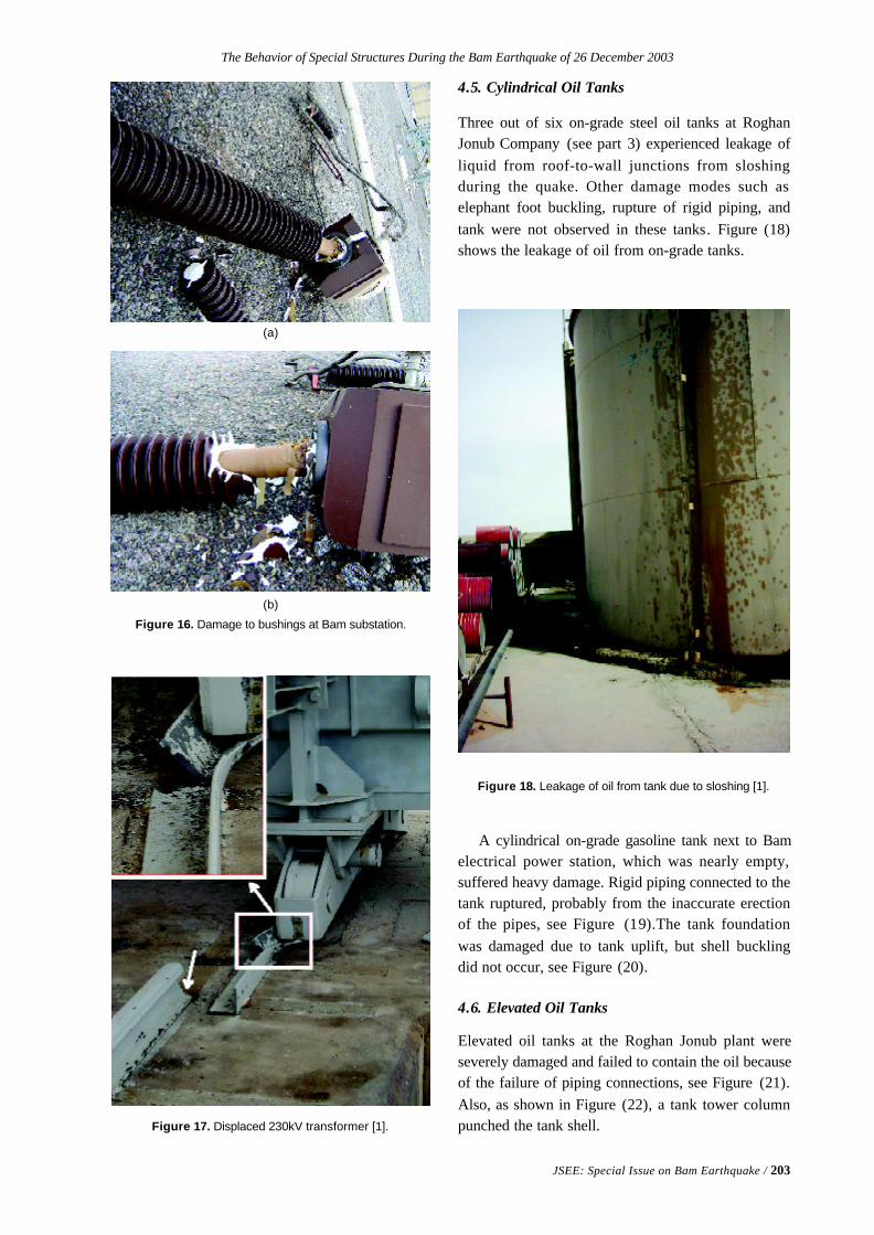
The Behavior of Special Structures During the Bam Earthquake of 26 December 2003
JSEE: Special Issue on Bam Earthquake / 203
Figure 17. Displaced 230kV transformer [1].
Figure 16. Damage to bushings at Bam substation.
4.5. Cylindrical Oil Tanks
Three out of six on-grade steel oil tanks at RoghanJonub Company (see part 3) experienced leakage ofliquid from roof-to-wall junctions from sloshingduring the quake. Other damage modes such aselephant foot buckling, rupture of rigid piping, andtank were not observed in these tanks. Figure (18)shows the leakage of oil from on-grade tanks.
Figure 18. Leakage of oil from tank due to sloshing [1].
A cylindrical on-grade gasoline tank next to Bamelectrical power station, which was nearly empty,suffered heavy damage. Rigid piping connected to thetank ruptured, probably from the inaccurate erectionof the pipes, see Figure (19).The tank foundationwas damaged due to tank uplift, but shell bucklingdid not occur, see Figure (20).
4.6. Elevated Oil Tanks
Elevated oil tanks at the Roghan Jonub plant wereseverely damaged and failed to contain the oil becauseof the failure of piping connections, see Figure (21).Also, as shown in Figure (22), a tank tower columnpunched the tank shell.
(a)
(b)
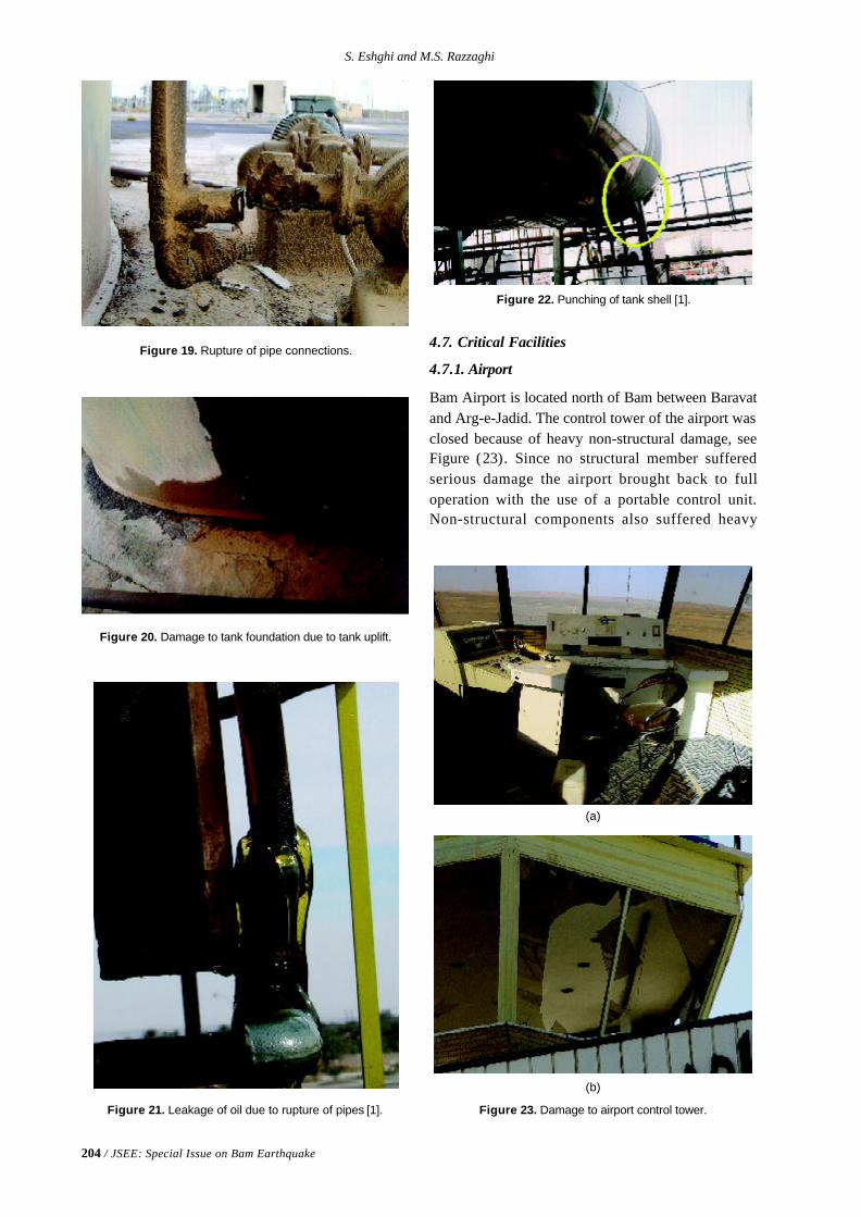
204 / JSEE: Special Issue on Bam Earthquake
S. Eshghi and M.S. Razzaghi
4.7. Critical Facilities
4.7.1. Airport
Bam Airport is located north of Bam between Baravatand Arg-e-Jadid. The control tower of the airport wasclosed because of heavy non-structural damage, seeFigure (23). Since no structural member sufferedserious damage the airport brought back to fulloperation with the use of a portable control unit.Non-structural components also suffered heavy
Figure 20. Damage to tank foundation due to tank uplift.
Figure 22. Punching of tank shell [1].
Figure 19. Rupture of pipe connections.
Figure 21. Leakage of oil due to rupture of pipes [1]. Figure 23. Damage to airport control tower.
(b)
(a)
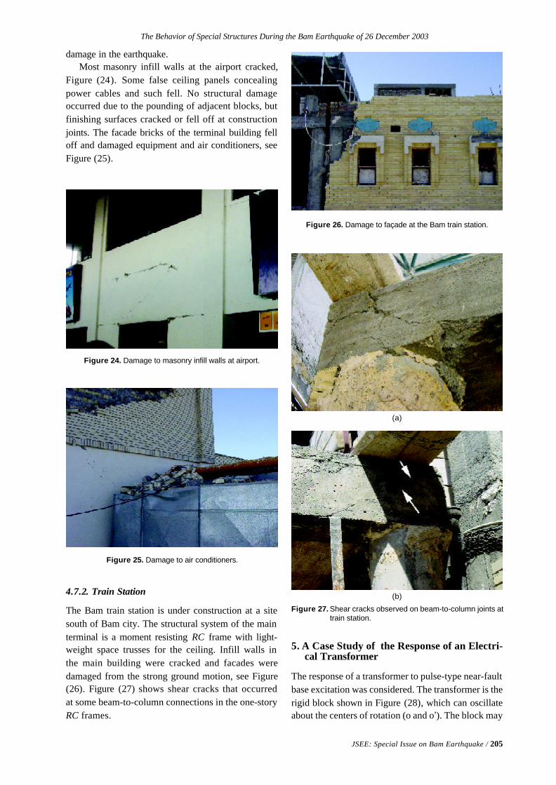
The Behavior of Special Structures During the Bam Earthquake of 26 December 2003
JSEE: Special Issue on Bam Earthquake / 205
damage in the earthquake.Most masonry infill walls at the airport cracked,
Figure (24). Some false ceiling panels concealingpower cables and such fell. No structural damageoccurred due to the pounding of adjacent blocks, butfinishing surfaces cracked or fell off at constructionjoints. The facade bricks of the terminal building felloff and damaged equipment and air conditioners, seeFigure (25).
Figure 24. Damage to masonry infill walls at airport.
Figure 25. Damage to air conditioners.
4.7.2. Train Station
The Bam train station is under construction at a sitesouth of Bam city. The structural system of the mainterminal is a moment resisting RC frame with light-weight space trusses for the ceiling. Infill walls inthe main building were cracked and facades weredamaged from the strong ground motion, see Figure(26). Figure (27) shows shear cracks that occurredat some beam-to-column connections in the one-storyRC frames.
5. A Case Study of the Response of an Electri-cal Transformer
The response of a transformer to pulse-type near-faultbase excitation was considered. The transformer is therigid block shown in Figure (28), which can oscillateabout the centers of rotation (o and o’). The block may
Figure 27. Shear cracks observed on beam-to-column joints attrain station.
Figure 26. Damage to façade at the Bam train station.
(a)
(b)
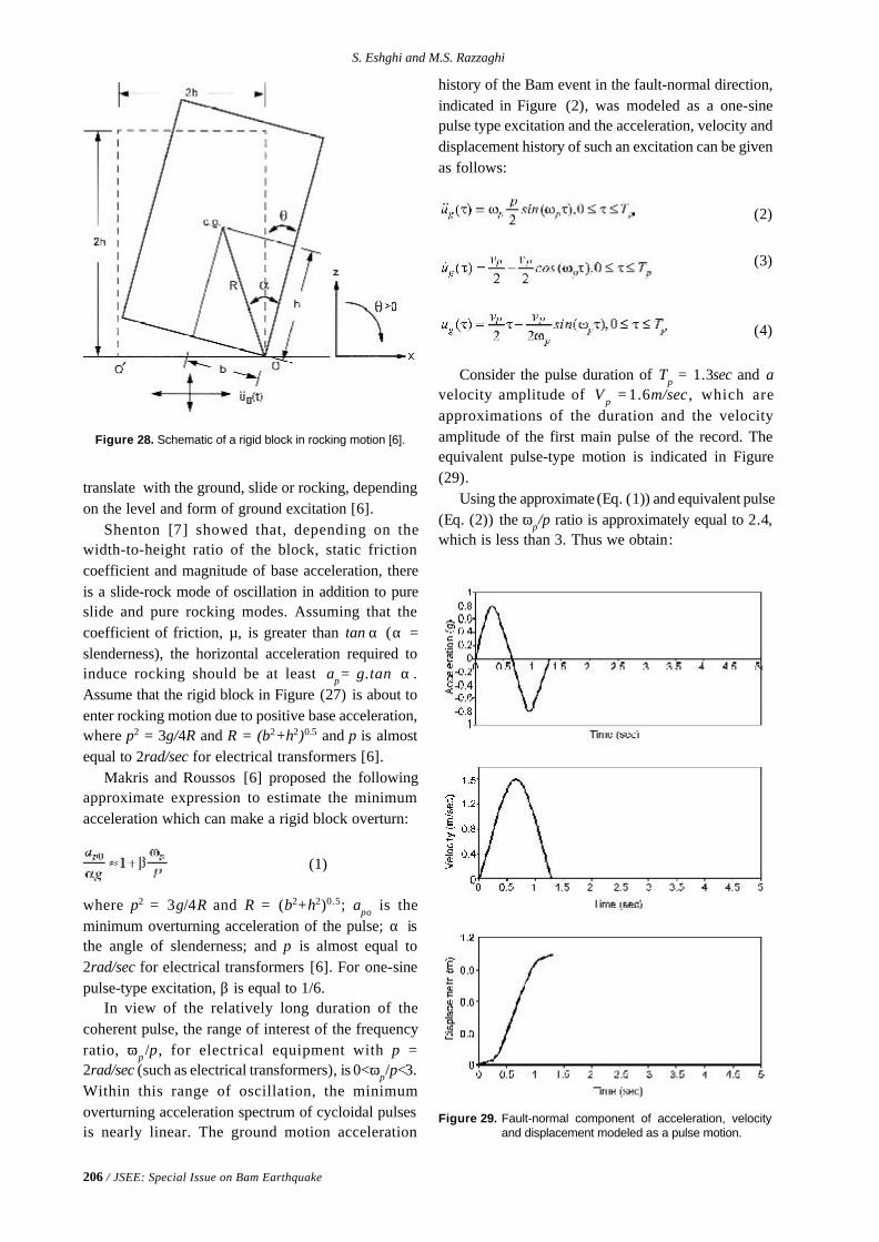
206 / JSEE: Special Issue on Bam Earthquake
S. Eshghi and M.S. Razzaghi
translate with the ground, slide or rocking, dependingon the level and form of ground excitation [6].
Shenton [7] showed that, depending on thewidth-to-height ratio of the block, static frictioncoefficient and magnitude of base acceleration, thereis a slide-rock mode of oscillation in addition to pureslide and pure rocking modes. Assuming that thecoefficient of friction, µ, is greater than tan α (α =slenderness), the horizontal acceleration required toinduce rocking should be at least ap= g.tan α .Assume that the rigid block in Figure (27) is about toenter rocking motion due to positive base acceleration,where p2 = 3g/4R and R = (b2+h2)0.5 and p is almostequal to 2rad/sec for electrical transformers [6].
Makris and Roussos [6] proposed the followingapproximate expression to estimate the minimumacceleration which can make a rigid block overturn:
(1)
where p2 = 3g/4R and R = (b2+h2)0.5; apo is theminimum overturning acceleration of the pulse; α isthe angle of slenderness; and p is almost equal to2rad/sec for electrical transformers [6]. For one-sinepulse-type excitation, β is equal to 1/6.
In view of the relatively long duration of thecoherent pulse, the range of interest of the frequencyratio, ωp /p, for electrical equipment with p =2rad/sec (such as electrical transformers), is 0<ωp/p<3.Within this range of oscillation, the minimumoverturning acceleration spectrum of cycloidal pulsesis nearly linear. The ground motion acceleration
Figure 28. Schematic of a rigid block in rocking motion [6].
history of the Bam event in the fault-normal direction,indicated in Figure (2), was modeled as a one-sinepulse type excitation and the acceleration, velocity anddisplacement history of such an excitation can be givenas follows:
(2)
(3)
(4)
Consider the pulse duration of Tp = 1.3sec and avelocity amplitude of V p = 1.6m/sec , which areapproximations of the duration and the velocityamplitude of the first main pulse of the record. Theequivalent pulse-type motion is indicated in Figure(29).
Using the approximate (Eq. (1)) and equivalent pulse(Eq. (2)) the ωp/p ratio is approximately equal to 2.4,which is less than 3. Thus we obtain:
Figure 29. Fault-normal component of acceleration, velocityand displacement modeled as a pulse motion.
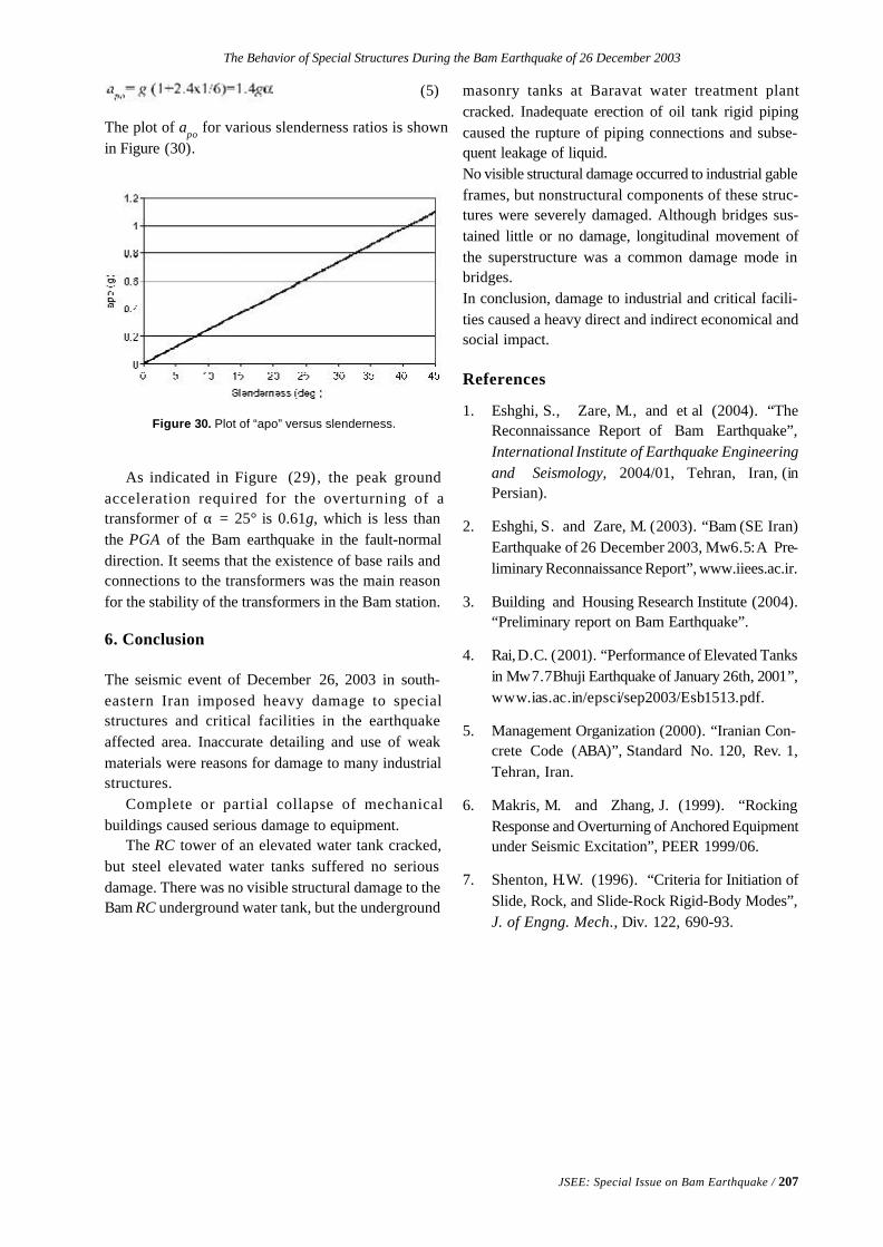
The Behavior of Special Structures During the Bam Earthquake of 26 December 2003
JSEE: Special Issue on Bam Earthquake / 207
(5)
The plot of apo for various slenderness ratios is shownin Figure (30).
Figure 30. Plot of “apo” versus slenderness.
As indicated in Figure (29), the peak groundacceleration required for the overturning of atransformer of α = 25° is 0.61g, which is less thanthe PGA of the Bam earthquake in the fault-normaldirection. It seems that the existence of base rails andconnections to the transformers was the main reasonfor the stability of the transformers in the Bam station.
6. Conclusion
The seismic event of December 26, 2003 in south-eastern Iran imposed heavy damage to specialstructures and critical facilities in the earthquakeaffected area. Inaccurate detailing and use of weakmaterials were reasons for damage to many industrialstructures.
Complete or partial collapse of mechanicalbuildings caused serious damage to equipment.
The RC tower of an elevated water tank cracked,but steel elevated water tanks suffered no seriousdamage. There was no visible structural damage to theBam RC underground water tank, but the underground
masonry tanks at Baravat water treatment plantcracked. Inadequate erection of oil tank rigid pipingcaused the rupture of piping connections and subse-quent leakage of liquid.No visible structural damage occurred to industrial gableframes, but nonstructural components of these struc-tures were severely damaged. Although bridges sus-tained little or no damage, longitudinal movement ofthe superstructure was a common damage mode inbridges.In conclusion, damage to industrial and critical facili-ties caused a heavy direct and indirect economical andsocial impact.
References
1. Eshghi, S., Zare, M., and et al (2004). “TheReconnaissance Report of Bam Earthquake”,International Institute of Earthquake Engineeringand Seismology, 2004/01, Tehran, Iran, (inPersian).
2. Eshghi, S. and Zare, M. (2003). “Bam (SE Iran)Earthquake of 26 December 2003, Mw6.5: A Pre-liminary Reconnaissance Report”, www.iiees.ac.ir.
3. Building and Housing Research Institute (2004).“Preliminary report on Bam Earthquake”.
4. Rai, D.C. (2001). “Performance of Elevated Tanksin Mw7.7 Bhuji Earthquake of January 26th, 2001”,www.ias.ac.in/epsci/sep2003/Esb1513.pdf.
5. Management Organization (2000). “Iranian Con-crete Code (ABA)”, Standard No. 120, Rev. 1,Tehran, Iran.
6. Makris, M. and Zhang, J. (1999). “RockingResponse and Overturning of Anchored Equipmentunder Seismic Excitation”, PEER 1999/06.
7. Shenton, H.W. (1996). “Criteria for Initiation ofSlide, Rock, and Slide-Rock Rigid-Body Modes”,J. of Engng. Mech., Div. 122, 690-93.
JSEE: Special Issue on Bam Earthquake / 209
1. Natural Hazards Research and Applications Information Center, University ofColorado and EERI, Colorado, USA, email: [email protected]
2. GeoHazards International and EERI, California, USA3. Earth Institute, Columbia University and EERI, USA4. Center for Disaster Risk Management, Virginia Polytechnic Institute and State
University and EERI, Virginia, USA5. Public Education Department, International Institute of Earthquake Engineering and
Seismology (IIEES), Tehran, Iran
ABSTRACT: May, 2004 the "Learning from Earthquakes" program ofthe Earthquake Engineering Research Institute sent a team ofresearchers on a reconnaissance mission to Iran and the site of the Bamearthquake (December 26,2003). The purpose of this team was to studysocial science and policy aspects of the earthquake impact, relief andrecovery phases. Interviews were conducted with a wide range ofstakeholder groups including victims and those responsible for publicand private recovery activities. Observations were collected related totransitional housing, mental health, economic and social recovery andthe planning process for permanent reconstruction. Particular attentionwas paid to innovative programs and policies developed in response tothis earthquake disaster.
Keywords: Earthquake; Iran; Social Impact; Disaster Recovery; Post-earthquake reconstruction; Economic recovery; Transition housing
Reconnaissance Report on Bam Earthquake
Social and Public Policy Issues
Kathleen Tierney 1, Thomas Tobin 2, Bijan Khazai 3, Frederick Krimgold 4, and Farokh Parsizadeh 5
1. Introduction
The Earthquake Engineering Research Institute(EERI) through the “Learning from Earthquakes”program sponsors technical reconnaissance missionsto study the effects of damaging earthquakesthroughout the world. A team of engineers andseismologists was sent to the site of the Bamearthquake shortly after the event to study evidence ofthe event and subsequent physical damage. Thisarticle summarizes initial findings from a secondreconnaissance trip to Iran and the earthquake-strickenarea, carried out from May 8-16, which focused onsocietal impacts five months after the Bam event,early recovery activities, longer-term recoveryplanning, and public policy aspects of earthquakeloss-reduction in Iran. For this report, fact-findingmeetings were conducted with many organizations,including the International Institute of EarthquakeEngineering and Seismology, which hosted the EERIteam; UN-affiliated organizations; national-levelentities concerned with loss reduction and disasterresponse and recovery; international non-governmen-
tal organizations (NGOs); local NGOs in Bam, city andprovincial government officials and agencies; andhealth care and mental health professionals.
2. The Social and Policy Context
Response and recovery activities following theBam earthquake were influenced in important ways byfour broader societal factors: the 1979 revolution; theIran-Iraq war, which lasted from 1980 to 1988; theexperience of other recent earthquake events in Iran,especially the M 7.2 1990 Manjil-Rudbar earthquake,which killed 37,000; and the distinctive characteristicsof Iran’s governmental system.
The 1979 revolution, which established theIslamic Republic of Iran, resulted in significantpolicy shifts and in the creation of new governmentalinstitutions. One cornerstone of the Islamic revolutionwas a focus on rural development and the provisionof services to residents of small towns and villages,which had been seriously neglected under the previousregime. Such services included the distribution of
210 / JSEE: Special Issue on Bam Earthquake
K. Tierney, et al
grants, low-interest loans and building materials, as wellas land and technical assistance for the improvementof rural housing. The Housing Foundation, a quasi-governmental organization established following therevolution, was given major responsibilities in thearea of rural redevelopment. The responsibilities ofthe Housing Foundation also extended to bothpost-war and post-disaster reconstruction-forexample, through financing homes destroyed in warand disasters and providing temporary shelter forwar refugees and disaster victims. Consistent withthis mission, the Foundation is now directing post-earthquake residential reconstruction in Bam.
The Iran-Iraq war, which resulted in the deaths ofan estimated 600,000 Iranians, required Iraniansociety to develop capacity in such areas as theprovision of emergency medical care and reconstruc-tion and recovery-related services. Skills andcapabilities developed during eight years of war,like those employed in rural development initiatives,were readily transferable to earthquake response andrecovery.
Both before and after the revolution, Iran hadexperienced a number of damaging earthquakes,which also fostered the development of response andrecovery capacity within Iranian society. The 1990sdecade was a particularly active seismic period; threemajor damaging earthquakes occurred in rural areasof the country in 1997 alone. While the Bam eventdiffered from earlier earthquakes in that it affected arelatively urbanized population, lessons learned inresponding to and recovering from recent seismicevents were in many respects applicable to the Bamdisaster. The 1990 Manjil earthquake proved to be awatershed event in terms of policies it helped set inmotion, including a 1991 law that established theNatural Disaster Headquarter (NDH) under Iran’sMinistry of Interior. That law gave the Department ofInterior full authority for the management of seismichazards, including the coordination of disasterresponse, reconstruction, and recovery.
Finally, response- and recovery-related policiesand practices following the Bam earthquake must beunderstood within the context of Iran’s centralizedgovernmental system. While local governmentelections were introduced in the late 1990’s ,theoretically increasing local-level participation inpolitical decision-making, authority for governmentalprograms and policies remains overwhelmingly at thenational level, with implementation carried outthrough provincial offices of national ministries suchas Health and Housing. Consistent with Iran’s overall
governmental structure, the major responsibility forpost-disaster reconstruction and recovery resides withthe central government, although, as discussed below,efforts are being made to involve the population of thedisaster-stricken region in the recovery process.
3. Societal and Economic Impacts
3.1. Earthquake Casualties
As tends to be the case in major disasters, earlyreports on the earthquake's death toll appear to haveoverestimated the number killed. While the numbersare still not finalized, revised figures now indicate that26,271 people died in the quake-although somecontinue to dispute that death count. Over 20,000people were injured and an estimated 120,000 weremade homeless. The dead included Bam's foremostsinger, many writers and scientists, farmers andbazaaris, and an estimated 560 teachers and 200 healthprofessionals, accounting for almost one-fifth of thecity's teachers and one-third of its health workers. Thesurvivors include an estimated 2,000 widows, 1,600widowers, 1,200 orphans and 3,000 children with oneparent. About 400 people were permanently disabled.Efforts to obtain more detailed data on patterns ofmortality and morbidly, such as gender and agebreakdowns and injury severity, so far have beenunsuccessful. Follow-up work is needed to collectand analyze epidemiological data.
The high death and injury toll can be attributed tothe time of day the earthquake occurred and to theextreme vulnerability of the built environment in thegreater Bam region. The earthquake, which took placebefore dawn when most residents were still asleep,caused the immediate collapse of residential structures,the vast majority of which were of adobe construc-tion. Asphyxiation due to dust inhalation and the coldDecember temperatures undoubtedly also contributedto the deaths of survivors who were trapped under therubble.
It also appears that most residents were unawareof the magnitude of the earthquake threat in theregion and thus were unprepared when the earthquakestruck. There were significant foreshocks in thehours leading up to the earthquake, and some residentswarned others or left their houses during the night toseek shelter outdoors, but most people remained intheir homes. Residents now question whether somesort of warning should have been issued to the publicwhen those smaller earthquakes occurred.
Residential Damage. Damage to residentialstructures was very severe, leaving approximately
Reconnaissance Report on Bam Earthquake Social and Public Policy Issues
JSEE: Special Issue on Bam Earthquake / 211
95% of the homes within the city of Bam and a largeproportion of dwellings in the surrounding villagesuninhabitable. Nearly all of the housing in Bam andin eight to ten villages within about 10km of Bammust be replaced. The high vulnerability of residentialstructures to the earthquake was largely due to theexistence of adobe and non-engineered buildings,which accounted for 80% of the building stock.Additionally, rapid and uncontrolled development inrecent years resulted in the construction of manyunsafe buildings.
3.2. Educational Institutions
Iran’s very young population includes manyschool-age children. Forty eight percent of thepopulation of Bam was under the age of 20 before theearthquake. Schools in Bam and the surroundingregion were destroyed or very severely damaged.Before the earthquake, there were about 32,000students, 3,200 teachers, and nearly 300 schools inBam. Hundreds of teachers and 8-10,000 studentswere killed in Bam and surrounding areas.
3.3. Impacts on the Economy and Population of the Region
Business impacts were comparable in scale andseverity to impacts on households; at the time of theMay reconnaissance trip, very few businessestablishments were operating in Bam's commercialdistricts. Some businesses had been reestablished incontainers and makeshift sheds outside the city;however, many of these businesses gravitated to Bamfrom outlying areas. Many more prosperous andestablished businesses relocated to other cities, suchas Kerman, the provincial capital. Bam is a regionalagricultural center that is known for its high-qualitydates, citrus crops, henna and dairy products. Manyof the 400 surrounding villages have close economicties with Bam. The economies of these communitieswere already severely stressed before the earthquakedue to a six-year drought. Because of the extensivedamage that had been done to the qanats, an irrigationsystem distinctive to the region, there was greatconcern that these high-value crops would be lost.However, repairs to the irrigation system progressedwell, and this year's crops will likely not suffer as aconsequence of the earthquake.
The “New Arg” industrial complex east of the cityis another engine for the local economy. Prior to theearthquake, 1000 workers at an automobile plant inthis complex were laid off, creating ripples throughout
the community. Even before the earthquake, unemploy-ment was about 20 percent.
Arg-e-Bam, the 2,000-year-old Bam Citadel, is amajor resource and important tourist destinationthat attracted numerous tourists to Bam every year.The Citadel, which was of adobe construction, wasvery extensively damaged. UNESCO and otherinternational organizations are currently consideringways of rehabilitating and restoring the Citadel, bothbecause of its enormous cultural significance andbecause of its economic value for the region. Howthat restoration will be planned and financed has yetto be determined. In its current degraded state, theArg is highly vulnerable to water damage, andadditional deterioration is virtually certain unless stepsare taken immediately to protect the Citadel complex.The Arg has long been a living symbol of Bam, andmany among the population feel an intense sense ofattachment to the site. Plans for recovery must thusconsider the cultural, economic, and social value ofthis unique complex.
Bam is located along a major drug-smugglingroute, serving as a conduit point for drugs smuggledout of Afghanistan and bound for Europe. Althoughthere are of course no exact figures, drug transportclearly contributes to the informal economy of theregion. The trade is responsible for significant safetyand health problems among the already demoralizedpopulation. It is also a major contributor to highincarceration rates for males in the region.
The earthquake dealt a severe blow to publicfinances in Bam and surrounding communities. Thecity of Bam is currently experiencing a severe budgetdeficit-a shortfall that reportedly will be made up at alater time by the central government.
Major population shifts have occurred as aconsequence of the earthquake. At the time of theearthquake, the greater Bam area consisted of the cityitself, with a population of approximately 86,000, aswell as numerous surrounding villages with a totalpopulation of 100,000 residents . City and villageeconomies were tightly integrated, with villagersbringing goods to sell and working in Bam, and thecity providing services, such as warehouse servicesfor dates, health care, and other services, for thesurrounding region. The earthquake disrupted theregional economy, causing many survivors to leavethe area on at least a temporary basis, while stimulat-ing migration into the city from surrounding regions,as villagers came to the city in search of temporaryhousing and other disaster-related services. Thus,
212 / JSEE: Special Issue on Bam Earthquake
K. Tierney, et al
despite the high death toll, the population of Bam islarger now than it was before the earthquake.
4. Status of Early Recovery Activities
While much has been accomplished since theearthquake, conditions remain desperate in Bam, and ahost of problems persist. The earthquake had adevastating impact on community institutions. Inaddition to causing widespread residential andcommercial damage, the earthquake destroyed orseverely damaged all schools, hospitals, and healthcare facilities in the impact area. Virtually everyhousehold was touched in some way by the earthquake.Recovery activities thus must address all aspects ofcommunity life, including homes, businesses andeconomic activity, education, and health and socialservices.
The Red Crescent Society and the Iranian militaryplayed key roles in the initial response and theprovision of emergency aid to affected populations.Additionally, there was an enormous outpouring ofcharitable giving from the general population, overseasIranians, Islamic charitable organizations, and otherdonors. In an unprecedented move, after the earth-quake, the government of Iran invited internationalaid organizations into the country and lifted visa andpassport restrictions following the earthquake. Thisresulted in a large-scale convergence of aid-givingorganizations into the impact region and ensured anabundance of relief assistance for victims while alsocreating major coordination problems. In an effort tobetter co-ordinate relief activities, the impact regionwas divided into fourteen geographic sectors, anddifferent Iranian provinces and aid organizationsassumed responsibility for service provision toindividual sectors. This system provided amanagement framework and ensured a steady flowof resources and volunteers during the post-impactperiod. This arrangement was to be replaced bymanagement by the province of Kerman at the end ofMay.
In contrast, intermediate-term and especiallylonger-term recovery planning has not been as wellcoordinated. International NGOs are gradually leavingthe earthquake-stricken area, and while somerecovery-related needs are being addressed, othersare being neglected. Many of those contacted duringthe reconnaissance visit cited problems with variousaspects of “transition planning”, such as how toensure continuity of services when agencies leave thearea and how to manage the transition from temporary
shelter to intermediate-term temporary housing.Relief, reconstruction and recovery activities arebeing managed through a Ministry of Interior Councilconsisting of 24 organizations, including governmen-tal ministries, the Red Crescent Society, andinternational organizations, with representation fromthe Bam City Council. The task force compositionfollows guidelines established in the new disastermanagement system, which had been developed inMay 2003. The new system was designed to integrateagency activities across the hazards cycle, encompass-ing mitigation, preparedness, response, and recoveryactivities. Reconstruction is being financed through arange of sources, including the national government;the Islamic Development Bank; UN agencies such asUNESCO (for the Arg-e-Bam project) and UNDP; a$300-400 million loan from the World Bank, andprivate charitable donations.
4.1. Temporary Housing and Residential Reconstruc- tion
At the time of the second reconnaissance trip, thevast majority of displaced households were stillliving in tents, most of which had been provided bythe Red Crescent Society. At the insistence ofresidents, the majority of these tents had beenplaced on private property near homes that had beendestroyed. Other tents were erected in congregatecamps, while still others were located on streetsadjacent to former dwellings. Tent camps are beingused mainly to house former renters and migrantsfrom the nearby villages. The tents are very small, andthe vast majority have no capacity for cooling, withtemperatures currently rising to over 100 degrees.There are no bathroom facilities; instead, displacedresidents must use collective toilets and showers.
Under the general direction of the Department ofInterior and the supervision of the Housing Founda-tion, approximately 18,000 temporary housing unitshave been constructed, and plans were underway tomove residents into these units beginning in late May.Like the tents, temporary housing units are very small(3 x 6 meters); the units are being constructed bothon private property and in large complexes. Bathroomand sanitary facilities are either single-stall temporarytoilets located near tents and temporary structures, orin some instances consist of groups of stall joinedtogether. The shower is usually in the stall, using thetoilet for a drain. The sewerage and wastewater arenot treated. Concerns have been expressed regardingthe congregate toilet/shower facilities, both because
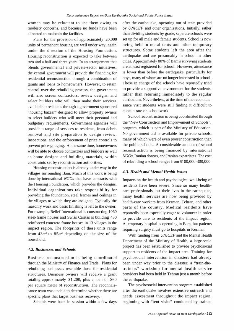
Reconnaissance Report on Bam Earthquake Social and Public Policy Issues
JSEE: Special Issue on Bam Earthquake / 213
women may be reluctant to use them owing tomodesty concerns, and because no funds have beenallocated to maintain the facilities.
Plans for the provision of approximately 20,000units of permanent housing are well under way, againunder the direction of the Housing Foundation.Housing reconstruction is expected to take betweentwo and a half and three years. In an arrangement thatblends governmental and private-sector initiatives,the central government will provide the financing forresidential reconstruction through a combination ofgrants and loans to homeowners. However, to retaincontrol over the rebuilding process, the governmentwill also screen contractors, review designs, andselect builders who will then make their servicesavailable to residents through a government sponsored“housing bazaar” designed to allow property ownersto select builders who will meet their personal andbudgetary requirements. Government agencies willprovide a range of services to residents, from debrisremoval and site preparation to design review,inspections, and the enforcement of price controls toprevent price-gouging. At the same time, homeownerswill be able to choose contractors and builders as wellas home designs and building materials, withinconstraints set by reconstruction authorities.
Housing reconstruction is already under way in thevillages surrounding Bam. Much of this work is beingdone by international NGOs that have contracts withthe Housing Foundation, which provides the designs.Individual organizations take responsibility forproviding the foundation, steel frames and ceilings inthe villages to which they are assigned. Typically themasonry work and basic finishing is left to the owner.For example, Relief International is constructing 1060steel-frame houses and Swiss Caritas is building 430reinforced concrete frame houses in 13 villages in theimpact region. The footprints of these units rangefrom 43m2 to 85m2 depending on the size of thehousehold.
4.2. Businesses and Schools
Business reconstruction is being coordinatedthrough the Ministry of Finance and Trade. Plans forrebuilding businesses resemble those for residentialstructures. Business owners will receive a granttotaling approximately $1,200, plus a loan of $60per square meter of reconstruction. The reconnais-sance team was unable to determine whether there arespecific plans that target business recovery.
Schools were back in session within a few days
after the earthquake, operating out of tents providedby UNICEF and other organizations. Initially, ratherthan dividing students by grade, separate schools wereset up for all male and female students. School is nowbeing held in metal tents and other temporarystructures. Some students left the area after theearthquake and are presumably in school in othercities. Approximately 80% of Bam's surviving studentsare at least registered for school. However, attendanceis lower than before the earthquake, particularly forboys, many of whom are no longer interested in school.Those in charge of the schools have reportedly triedto provide a supportive environment for the students,rather than returning immediately to the regularcurriculum. Nevertheless, at the time of the reconnais-sance visit students were still finding it difficult toconcentrate on schoolwork.
School reconstruction is being coordinated throughthe “New Construction and Improvement of Schools”,program, which is part of the Ministry of Education.No government aid is available for private schools,many of which were of even poorer construction thanthe public schools. A considerable amount of schoolreconstruction is being financed by internationalNGOs, Iranian donors, and Iranian expatriates. The costof rebuilding a school ranges from $100,000-300,000.
4.3. Health and Mental Health Issues
Impacts on the health and psychological well-being ofresidents have been severe. Since so many health-care professionals lost their lives in the earthquake,many health services are now being provided byhealth-care workers from Kerman, Tehran, and otherparts of the country. Medical residents havereportedly been especially eager to volunteer in orderto provide care to residents of the impact region.A temporary hospital is operating in Bam, but patientsrequiring surgery must go to hospitals in Kerman.
With funding from UNICEF and the Mental HealthDepartment of the Ministry of Health, a large-scaleproject has been established to provide psychosocialsupport to residents of the impact area. Training forpsychosocial intervention in disasters had alreadybeen under way prior to the disaster; a “train-the-trainers” workshop for mental health serviceproviders had been held in Tehran just a month beforethe earthquake.
The psychosocial intervention program establishedafter the earthquake involves extensive outreach andneeds assessment throughout the impact region,beginning with “tent visits” conducted by trained
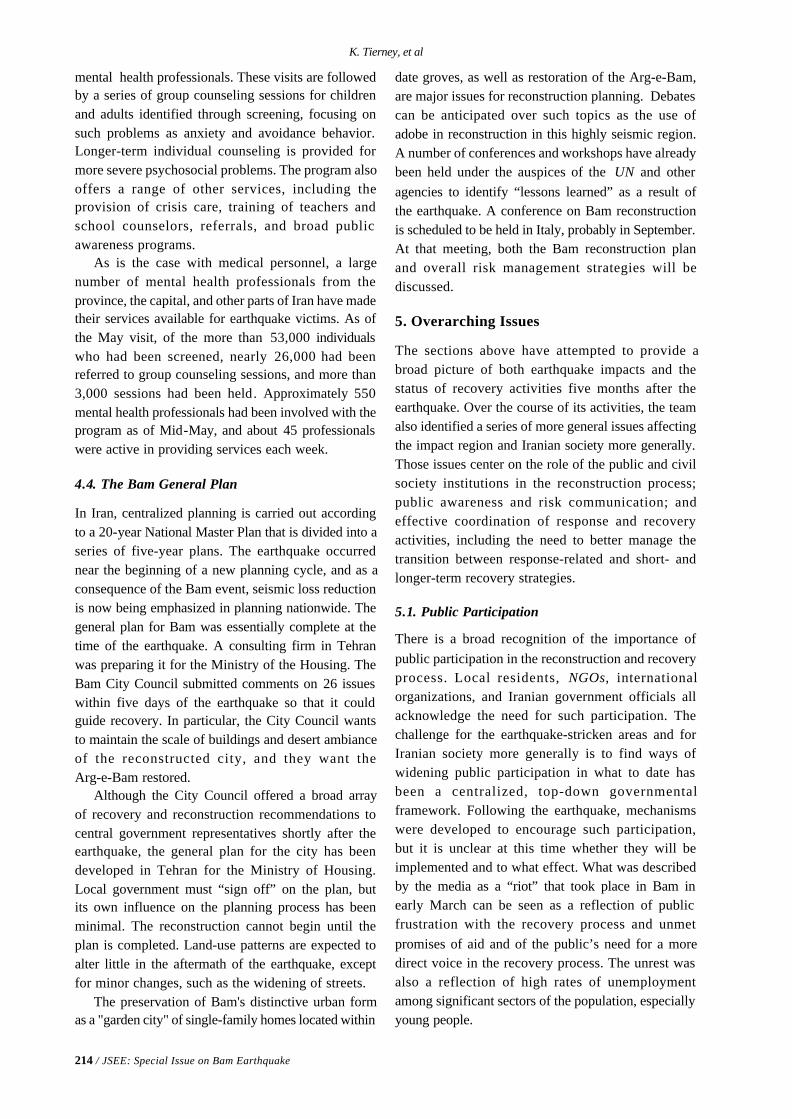
214 / JSEE: Special Issue on Bam Earthquake
K. Tierney, et al
mental health professionals. These visits are followedby a series of group counseling sessions for childrenand adults identified through screening, focusing onsuch problems as anxiety and avoidance behavior.Longer-term individual counseling is provided formore severe psychosocial problems. The program alsooffers a range of other services, including theprovision of crisis care, training of teachers andschool counselors, referrals, and broad publicawareness programs.
As is the case with medical personnel, a largenumber of mental health professionals from theprovince, the capital, and other parts of Iran have madetheir services available for earthquake victims. As ofthe May visit, of the more than 53,000 individualswho had been screened, nearly 26,000 had beenreferred to group counseling sessions, and more than3,000 sessions had been held. Approximately 550mental health professionals had been involved with theprogram as of Mid-May, and about 45 professionalswere active in providing services each week.
4.4. The Bam General Plan
In Iran, centralized planning is carried out accordingto a 20-year National Master Plan that is divided into aseries of five-year plans. The earthquake occurrednear the beginning of a new planning cycle, and as aconsequence of the Bam event, seismic loss reductionis now being emphasized in planning nationwide. Thegeneral plan for Bam was essentially complete at thetime of the earthquake. A consulting firm in Tehranwas preparing it for the Ministry of the Housing. TheBam City Council submitted comments on 26 issueswithin five days of the earthquake so that it couldguide recovery. In particular, the City Council wantsto maintain the scale of buildings and desert ambianceof the reconstructed city, and they want theArg-e-Bam restored.
Although the City Council offered a broad arrayof recovery and reconstruction recommendations tocentral government representatives shortly after theearthquake, the general plan for the city has beendeveloped in Tehran for the Ministry of Housing.Local government must “sign off” on the plan, butits own influence on the planning process has beenminimal. The reconstruction cannot begin until theplan is completed. Land-use patterns are expected toalter little in the aftermath of the earthquake, exceptfor minor changes, such as the widening of streets.
The preservation of Bam's distinctive urban formas a "garden city" of single-family homes located within
date groves, as well as restoration of the Arg-e-Bam,are major issues for reconstruction planning. Debatescan be anticipated over such topics as the use ofadobe in reconstruction in this highly seismic region.A number of conferences and workshops have alreadybeen held under the auspices of the UN and otheragencies to identify “lessons learned” as a result ofthe earthquake. A conference on Bam reconstructionis scheduled to be held in Italy, probably in September.At that meeting, both the Bam reconstruction planand overall risk management strategies will bediscussed.
5. Overarching Issues
The sections above have attempted to provide abroad picture of both earthquake impacts and thestatus of recovery activities five months after theearthquake. Over the course of its activities, the teamalso identified a series of more general issues affectingthe impact region and Iranian society more generally.Those issues center on the role of the public and civilsociety institutions in the reconstruction process;public awareness and risk communication; andeffective coordination of response and recoveryactivities, including the need to better manage thetransition between response-related and short- andlonger-term recovery strategies.
5.1. Public Participation
There is a broad recognition of the importance ofpublic participation in the reconstruction and recoveryprocess. Local residents, NGOs, internationalorganizations, and Iranian government officials allacknowledge the need for such participation. Thechallenge for the earthquake-stricken areas and forIranian society more generally is to find ways ofwidening public participation in what to date hasbeen a centralized, top-down governmentalframework. Following the earthquake, mechanismswere developed to encourage such participation,but it is unclear at this time whether they will beimplemented and to what effect. What was describedby the media as a “riot” that took place in Bam inearly March can be seen as a reflection of publicfrustration with the recovery process and unmetpromises of aid and of the public’s need for a moredirect voice in the recovery process. The unrest wasalso a reflection of high rates of unemploymentamong significant sectors of the population, especiallyyoung people.
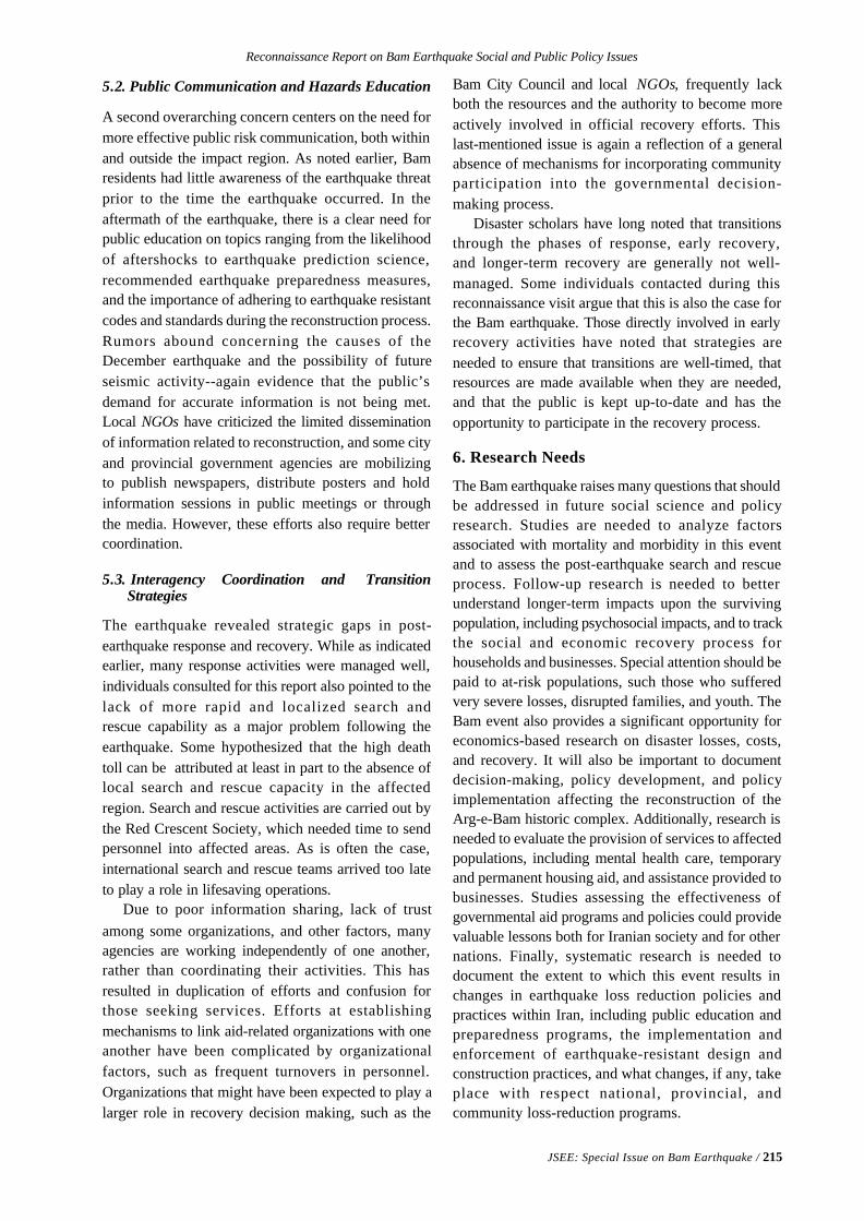
Reconnaissance Report on Bam Earthquake Social and Public Policy Issues
JSEE: Special Issue on Bam Earthquake / 215
5.2. Public Communication and Hazards Education
A second overarching concern centers on the need formore effective public risk communication, both withinand outside the impact region. As noted earlier, Bamresidents had little awareness of the earthquake threatprior to the time the earthquake occurred. In theaftermath of the earthquake, there is a clear need forpublic education on topics ranging from the likelihoodof aftershocks to earthquake prediction science,recommended earthquake preparedness measures,and the importance of adhering to earthquake resistantcodes and standards during the reconstruction process.Rumors abound concerning the causes of theDecember earthquake and the possibility of futureseismic activity--again evidence that the public’sdemand for accurate information is not being met.Local NGOs have criticized the limited disseminationof information related to reconstruction, and some cityand provincial government agencies are mobilizingto publish newspapers, distribute posters and holdinformation sessions in public meetings or throughthe media. However, these efforts also require bettercoordination.
5.3. Interagency Coordination and Transition Strategies
The earthquake revealed strategic gaps in post-earthquake response and recovery. While as indicatedearlier, many response activities were managed well,individuals consulted for this report also pointed to thelack of more rapid and localized search andrescue capability as a major problem following theearthquake. Some hypothesized that the high deathtoll can be attributed at least in part to the absence oflocal search and rescue capacity in the affectedregion. Search and rescue activities are carried out bythe Red Crescent Society, which needed time to sendpersonnel into affected areas. As is often the case,international search and rescue teams arrived too lateto play a role in lifesaving operations.
Due to poor information sharing, lack of trustamong some organizations, and other factors, manyagencies are working independently of one another,rather than coordinating their activities. This hasresulted in duplication of efforts and confusion forthose seeking services. Efforts at establishingmechanisms to link aid-related organizations with oneanother have been complicated by organizationalfactors, such as frequent turnovers in personnel.Organizations that might have been expected to play alarger role in recovery decision making, such as the
Bam City Council and local NGOs, frequently lackboth the resources and the authority to become moreactively involved in official recovery efforts. Thislast-mentioned issue is again a reflection of a generalabsence of mechanisms for incorporating communityparticipation into the governmental decision-making process.
Disaster scholars have long noted that transitionsthrough the phases of response, early recovery,and longer-term recovery are generally not well-managed. Some individuals contacted during thisreconnaissance visit argue that this is also the case forthe Bam earthquake. Those directly involved in earlyrecovery activities have noted that strategies areneeded to ensure that transitions are well-timed, thatresources are made available when they are needed,and that the public is kept up-to-date and has theopportunity to participate in the recovery process.
6. Research Needs
The Bam earthquake raises many questions that shouldbe addressed in future social science and policyresearch. Studies are needed to analyze factorsassociated with mortality and morbidity in this eventand to assess the post-earthquake search and rescueprocess. Follow-up research is needed to betterunderstand longer-term impacts upon the survivingpopulation, including psychosocial impacts, and to trackthe social and economic recovery process forhouseholds and businesses. Special attention should bepaid to at-risk populations, such those who sufferedvery severe losses, disrupted families, and youth. TheBam event also provides a significant opportunity foreconomics-based research on disaster losses, costs,and recovery. It will also be important to documentdecision-making, policy development, and policyimplementation affecting the reconstruction of theArg-e-Bam historic complex. Additionally, research isneeded to evaluate the provision of services to affectedpopulations, including mental health care, temporaryand permanent housing aid, and assistance provided tobusinesses. Studies assessing the effectiveness ofgovernmental aid programs and policies could providevaluable lessons both for Iranian society and for othernations. Finally, systematic research is needed todocument the extent to which this event results inchanges in earthquake loss reduction policies andpractices within Iran, including public education andpreparedness programs, the implementation andenforcement of earthquake-resistant design andconstruction practices, and what changes, if any, takeplace with respect national, provincial, andcommunity loss-reduction programs.
JSEE: Special Issue on Bam Earthquake / 217
1. South and Southwest Asia, Bureau for Crisis Prevention and Recovery, UnitedNations Development Programme (UNDP), India
2. UNDP, India Country Office, India
3. United Nations Development Programme (UNDP), Tehran, I.R. Iran, email:[email protected]
4. Int. Institute of Earthquake Engineering and Seismology (IIEES), Tehran, Iran
ABSTRACT: After the earthquake on 26 December 2003 withmagnitude 6.3 which struck the historic city of Bam and its surround-ing villages and took the lives of nearly 26,500 people, left over 25,000injured and about 75,000 homeless; the United Nations agencies inthe Islamic Republic of Iran have worked closely with the Governmentto respond to the immediate needs of the affected people, byundertaking a rapid needs assessment and launching a Flash Appeal toaddress the urgent and immediate needs of the affected population, andto facilitate a smooth transition from the immediate rescue and reliefphase to a medium and long-term reconstruction and recovery phase.The UN has committed itself to supporting the Government not only inthe provision of short-term relief, but also in long-term reconstruction,recovery and risk reduction. UN Secretary-General Kofi Annan offeredsupport for an international conference on the reconstruction of Bamas well as organizing an international workshop on earthquakedisaster risk management. Recognizing the value of a concerted UNapproach that complements the Government's reconstruction anddisaster risk reduction efforts, the UN System in consultation with itsnational and international partners has prepared a strategy document,using methods of social research such as participant observation, casestudies, the use of key informants, group discussions and individualin-depth interviews. The strategy builds on past efforts of the UNSystem in the Iran and on the UN Flash Appeal of 8 January 2004. Itoutlines UN support to the Government of Iran for reconstruction,rehabilitation and risk reduction over the next five years, and detailsspecific activities in the short, medium and long term.
Keywords: Bam earthquake; Rescue, Relief; Recovery; Reconstruc-tion; Disaster; Risk management; United nations; UNDP; Iran
A United Nations Strategy for Support to the Government
of the Islamic Republic of Iran Following the
Bam Earthquake of 26 December 2003
Kamal Kishore 1, Saroj Komar Jha
2, Zenab Bagha 3, Frederick Lyons
3,Mohsen Ghafory Ashtiany
4, and Victoria Kianpour Atabaki 3
1. Introduction
On 26 December 2003, a powerful earthquake withMs = 6.3 struck the historic city of Bam and itssurrounding villages. It took the lives of nearly 26,500people, left over 25,000 injured and about 75,000homeless. Approximately 85 percent of the houses,commercial units, health and educational facilities and
administrative buildings in the city and surroundingvillages were either severely damaged or completelydestroyed. The 2,500 year -old historic citadel ofBam (Arg-e-Bam), an internationally famous heritagesite, was almost completely destroyed, dealing asevere blow to the economic prospects of the Bam
218 / JSEE: Special Issue on Bam Earthquake
K. Kishore, et al
region and the livelihoods of its people.In the aftermath of the earthquake in Bam on 26
December 2003, the United Nations agencies in theIslamic Republic of Iran have worked closely withthe Government to respond to the immediate needs ofthe affected people. At the request of the Government,UN agencies undertook a rapid needs assessmentand launched a Flash Appeal to address the urgent andimmediate needs of the affected population, and tofacilitate a smooth transition from the immediaterescue and relief phase to a medium and long-termreconstruction and recovery phase. The Flash Appealwas launched by the UN Under-Secretary-General JanEgeland in Bam, Geneva and New York on 8, 9 and 12January respectively.
The UN has committed itself to supporting theGovernment not only in the provision of short-termrelief, but also in long-term reconstruction, recoveryand risk reduction. In his letter of 5 January 2004 tothe President of Iran, UN Secretary-General KofiAnnan offered support for an international conferenceon the reconstruction of Bam. The Secretary-Generalalso proposed an international workshop on earthquakedisaster risk management.
International experience has shown that whenappropriate technical support is provided early on inthe recovery effort, risk management and reductionconsiderations can be factored into all recoveryand reconstruction initiatives from the beginning;discouraging the reconstruction of risk, and layingthe foundation for more sustainable recovery andlonger-term development. In a highly disaster-pronecountry such as the Iran, the successful reconstruc-tion of Bam would provide a good opportunity notonly to reduce vulnerability to future earthquakes inBam but also in other areas equally or more vulnerableto earthquakes and other natural disasters.
While it is unlikely that the financial supportfrom the UN will match the resources that will beallocated by the Government, regional and interna-tional financial institutions and other internationalagencies, the UN System with its experience,technical expertise and long history of involvementin natural disaster risk reduction issues is uniquelypositioned to provide both technical and coordinationassistance to the reconstruction programme on asustained basis.
Recognizing the value of a concerted UNapproach that complements the Government’sreconstruction and disaster risk reduction efforts,
the UN System in consultation with its nationaland international partners has prepared a strategydocument. The strategy builds on past efforts of theUN System in the Iran and on the UN Flash Appealof 8 January 2004. It outlines UN support to theGovernment of Iran for reconstruction, rehabilitationand risk reduction over the next five years, anddetails specific activities in the short, medium andlong term.
1.1. The Challenge of Rebuilding Bam
The long-term reconstruction and recovery for Bamprogramme will be a major challenge for the people ofIran. The reconstruction effort will be a massive exer-cise requiring a multi-sectoral approach ranging fromrehabilitation of livelihoods and the local economy, torestoration of water, health and sanitation systems, tothe rebuilding of critical infrastructure, to housing andsocial sector reconstruction etc. It will require signifi-cant financial resources, skilled human resources andinnovative institutional arrangements, and will involvea wide range of actors at the local, provincial, nationaland international levels. Initial estimates indicate thatthe long-term recovery will take a number of years,and that it could cost anywhere between US$700 to$1,000 million. Although most of these resources willhave to be gathered by the Government of Iran, theinternational community can provide critical supportto some of the more strategic areas.
1.2.Challenges to Disaster Risk Management in Iran
The devastating effect of the Bam earthquake hasbrought back into focus the fact that Iran is highlyvulnerable to natural disasters. On the Global SeismicHazard Map, Iran, which is crossed by two major faultlines, stands out as one of the most earthquake pronecountries in the world. The country however, is notonly exposed to earthquakes but also to frequent flashfloods and recurrent drought. Annually, Iran suffersan average of 2,393 deaths, or about 3.4 percent of theglobal annual total of about 70,000 deaths. Yet with apopulation of 73 million, Iran represents only about1.25 percent of the global population.
The country has significant technical expertise inalmost all aspects of disaster risk management. It ishost to internationally renowned institutions such asthe International Institute of Earthquake Engineeringand Seismology (IIEES). Iran also has some of thebest-developed building codes. Seismicity acrossalmost the entire country has been well studiedand mapped. In addition, much work has been done
A United Nations Strategy for Support to the Government of the Islamic Republic of Iran ...
JSEE: Special Issue on Bam Earthquake / 219
on seismic zonation of the country as a whole, and onmicro-zonation of urban areas, such as Tehran. Yetthis wide range of technical expertise and know-howhas not translated into adequate action for disasterrisk reduction. A preliminarily analysis indicates thatsome of the challenges that the practice of disasterrisk management faces in Iran are:v Inadequate emphasis on comprehensive disaster
risk management vis-à-vis disaster reliefv Lack of awareness among decisions makers in
key development sectors of disaster riskmanagement issues
v Absence of multi-disciplinary approaches toassessing and managing disaster risk
v Inadequate compliance with building regulationsand inadequate training for constructionworkers and labourers
v Lack of appropriate techno-legal and techno-financial regimes for disaster risk management
v Insufficient application and use of existingscientific and technical knowledge in Iran towards enhanced city planning, seismically safeconstruction and disaster risk reduction actions.
2. Towards a Consolidated UN Strategy
2.1. Past UN Initiatives on Disaster Risk Managementin Iran
Over the last decade, UN agencies in Iran have workedon a wide range of disaster risk managementinitiatives. While these initiatives have made importantcontributions, they leave much to be desired. Thefollowing are some of the key activities undertaken inthe past:v Preparation of guidelines for earthquake disaster
management: after the Manjil earthquake of 1990,UN-HABITAT and UNDP collaborated with theHousing Foundation of the Islamic Revolution toprepare detailed guidelines for earthquakedisaster management. The guidelines includeregional and urban planning and design; produc-tion of building materials; quality control; designand construction of engineered and non-engineered earthquake resistant buildings; andupgrading of existing and earthquake damagedbuildings.
v UNDP-UNESCO joint project to assist in theestablishment of the International Institute ofEarthquake Engineering and Seismology (IIEES):Based on the decision taken by the 24th Sessionof the UNESCO General Conference represent-
ing the will of the international community tobuild capacities in Iran and the region, UNDPand UNESCO launched a project (UNDP/IRA/90/009) to support the establishment of IIEES.The project included training of IIEES technicalstaff as well as provision of equipment forseismic monitoring and forced vibration testingof existing structures for research purposes.
v Development of an Integrated National DisasterManagement Plan (INDMP): The objective ofthis project was to develop a plan that wouldprovide a strong basis, at the national level, forthe sustained protection of population, propertyand d evelopment achievements in Iran. TheUNDP project emphasised need for improvedorganizational coordination mechanisms;disaster implication checklists for majordevelopment projects; establishment of effectivecommunication and information systems; andthe enhancement of earthquake awareness inurban areas. The project also introduced acoherent structure for emergency managementat the national, provincial and local levels inpreparedness, mitigation and recovery phases.The decree introducing the Plan was approvedby the Council of Ministers on 6 April 2003.
v Capacity development for national disasterresponse and coordination: The aim of this jointUNDP-Iranian Red Crescent Society project wasto reduce the loss of lives from natural disastersby improving national disaster responsecapability and coordination.
2.2. The UNDAF Process
The United Nations Development AssistanceFramework (UNDAF) is an essential component ofthe UN programme for reform introduced by theSecretary-General in 1997. As a strategic five-yearplanning framework for UN development operationsand assistance at the country level, the UNDAFprovides a collective, coherent and integrated UNSystem response to key national priorities andneeds as outlined in the Common Country Assessment,and within the context of the Millennium DevelopmentGoals (MDGs) and the Millennium Declaration.
Iran’s first UNDAF (2005-2009), which isscheduled for finalisation in mid-2004, identifies“sustainable development, energy efficiency anddisaster risk management” as one of the five priorityareas, and envisages “reduced disaster risk fromhydro-meteorological and geophysical hazards in
220 / JSEE: Special Issue on Bam Earthquake
K. Kishore, et al
Iran” as one of the key outcomes of UN collaboration.Some of the strategies adopted by the various UNagencies in the wake of the Bam earthquake are beingwritten into the UNDAF document to ensure that theagency country programmes address some of thedisaster risk reduction challenges highlighted by theBam earthquake.
3. Key Elements of a Consolidated UN Strategy,Methodology
While it is unlikely that the financial support from theUN will match the resources that will be allocated bythe Government, regional and international financialinstitutions and other international agencies, the UNSystem with its experience, technical expertise andlong history of involvement in natural disaster riskreduction issues is uniquely positioned to provideboth technical and coordination assistance to thereconstruction programme on a sustained basis. Thefollowing are three distinct but inter-related elementsof the proposed UN Strategy:v In the short term, very specific and targeted
technical support to the start-up phase of thereconstruction and recovery programme(February-May 2004).
v Sustained technical and coordination support tothe Government for the duration of thereconstruction programme to help ensureefficient and sustainable recovery and long-termdisaster risk reduction (May 2004-December2005).
v Capacity building for mainstreaming disaster riskreduction into development processes at local,provincial and national levels (2004-2009).
3.1. Methodology of Development
In development of UN strategy Paper a number ofsocial research methods for identifying communityneeds such as participant observation, case studies,the use of key informants, group discussions, andindividual in depth interviews were used.
3.2. Technical Support to the Start-Up Phase of theReconstruction and Recovery Programme(February-May 2004)
In the first five months following the earthquake, theUN System has worked closely with the Governmentof Iran, local and provincial authorities, the affectedcommunities, private sector and subject matterspecialists to provide technical inputs for thereconstruction programme for Bam through: focused
workshops, and technical consultations on sectoralthemes such as health, water and sanitation,education, livelihoods, shelter, protection of vulner-able groups, urban redevelopment and planning,conservation of cultural heritage, etc; provision oflocal and international expertise and experience;demonstration projects; advocacy initiatives, andcapacity building and training programmes on avariety of subjects for both reconstruction managersand members of the affected communities. Key UN-supported activities in this phase have included:v Technical workshop on the management of
reconstruction programmes (25-26 February)-The workshop brought together members of theSteering Committee for the Reconstruction ofBam, senior Government and UN officials andpost-earthquake reconstruction experts from Iran,Japan, India and Turkey. Participants sharedexperiences, lessons learnt and advice on thetechnological, financial and institutionalarrangements for reconstruction; site selectionand land tenure; s helter sector reconstruction;rebuilding critical infrastructure; and urbanredevelopment and planning. Recommendationsfrom the workshop were submitted to theSteering Committee for the Reconstruction ofBam for inclusion in the Government’sreconstruction programme for Bam.
v Technical consultation on emergency measuresto safeguard Bam’s cultural heritage (10-17March)-The UNESCO-Iranian Cultural HeritageOrganization (ICHO) consultation reviewedplans for the conservation of heritage structuresin need of immediate stabilization, and developedpreliminary guidelines for the zonation of the
Bam’s historical quarters.v Training workshops to support education
managers and teachers/educators (April-May2004)-Workshops in the series focussed on:capacity building for education management inpost-crisis situations; communication skills;basics of school health; formal and informaltechnical and vocational education; etc.
v Workshop on lessons learned from the healthresponse (11-13 April 2004): The workshop,organised by WHO, allowed for an analysis ofthe lessons learnt and best practices from healthresponse to the Bam earthquake. Topics ofdiscussion included: immediate emergencymedical care, delayed medical care, managementof dead bodies, communication disease
A United Nations Strategy for Support to the Government of the Islamic Republic of Iran ...
JSEE: Special Issue on Bam Earthquake / 221
urveillance and control, water and sanitation,national and provincial responses etc.Recommendations from the workshop werepresented at the OCHA workshop on lessonslearned from the response operations in Bam(14-15 April).
v Workshop on lessons learned from the responseoperations in Bam (14-15 April)-Given themagnitude of the disaster, the immediateresponse to the Bam earthquake was impressive.The workshop, organised by UN-OCHA and theInternational Search and Rescue Group(INSARAG), provided and opportunity for asystematic analysis of those aspects of theimmediate response that worked and those thatdid not. Recommendations from the workshopwere presented at the INSARAG conference inTunisia in April.
v Technical consultation on urban redevelopmentand planning for the “new” city of Bam (15 April)-The workshop provided an opportunity formembers of the Steering Committee for theReconstruction of Bam, the Bam city planners,representatives from key Governmentdepartments, technical and scientificorganisations, UN agencies and civil society todiscuss issues such as long-term disaster riskmanagement, creative recovery and thepreservation of cultural heritage, in the contextof urban redevelopment and planning. Conceptssuch as a “child-friendly city’ and a “healthy city”were also explored. As a result of the workshop,a decision has been taken at the national level tomake microzonation studies mandatory beforethe start of all future redevelopment andplanning exercises.
v Preparation of technical guidelines for theconservation, restoration and management of
Arg-e-Bam and other historic monuments in Bam(18-20 April)-The consultation resulted in thepreparation and adoption of detailed guidelinesfor the mid-to-long-term conservation,restoration, and management (including riskpreparedness, presentation, tourism development,and capacity building) of the Arg-e-Bam and otherhistoric monuments.
v Workshop on livelihoods recovery andreconstruction (1-2 May)- The workshopexplored livelihoods rehabilitation strategies forvarious sectors including shelter, agriculture,health, education, industry and tourism.
Economic reactivation of micro-enterprises andself-help groups, and community integration inthe reconstruction process as an interimeconomic recovery tool also featured heavily inthe discussions. In follow-up to the workshop,ILO and UNDP, in collaboration with the KermanChamber of Commerce and the Bam CityCouncil will conduct rapid surveys to assess thelabor market and business opportunities in Bam.
v Consultation on social sector and basic servicesrecovery (3-4 May)- The UNICEF-supportedworkshop was held as the first in a series ofparticipatory consultations involving theauthorities, NGOs and the people of Bam onrecovery strategies for water and sanitationprovision, health and nutrition, education, childand family protection and psychosocial support.“Child-friendly city” and “healthy city” conceptswere also discussed in detail.
v Meeting on professional partnerships (4 May):Reconstruction is likely to involve thousands ofarchitects, engineers, planners and builders fromacross the country. Most of these specialistsbelong to professional associations such asengineers and architects associations. Thehalf-day meeting provided a networking opportunity for members of various professionalassociations involved in the physicalreconstruction of Bam. Partnerships andnetworks between the various associations atthe regional and national levels would allow fortransference of cutting-edge knowledge thatcould be cross-linked to the practical initiativesbeing undertaken. It could also help improveefficiency and cost-effectiveness, result in aunified strategic framework for decision makingon issues of common concern, reduceduplication of efforts, and ensure better divisionof responsibilities.
v Meeting on public-private partnerships forreconstruction (5 May): The meeting broughttogether public and private sector representatives.Topics of discussion included enhanced marketaccess for the products from the affected areas;training and capacity building of skilledworkers; and financing for reconstruction.
v Technical workshop on lessons learned from reconstruction programmes in Iran (6 May) - Theworkshop was an opportunity for disastermanagement specialists and reconstructionmanagers in the country to share experiences
222 / JSEE: Special Issue on Bam Earthquake
K. Kishore, et al
from past reconstruction programmes, identifylessons learnt and best practices, and brainstormon strategies for disaster risk assessment andrisk reduction in Iran.
v Technical workshop on appropriate buildingtechnology designs, construction and deliverymechanisms for shelter and public lifelineinfrastructure (8-9 May)- International experi-ence has shown that a wide variety of buildingconstruction technologies are often introducedinto post-disaster reconstruction activities. Whilesome of these technologies may meet therequirement of rapid delivery and high earthquakeresistance, many will not lend themselves to easyreplication and integration into the localconstruction industry because they do notcorrespond to the needs and lifestyles of theaffected people. The workshop showcased arange of building technology options that areearthquake resistant, cost-effective and locallyappropriate for the Bam region. It provided anopportunity for policy-makers, reconstructionmanagers, engineers, architects and contractorsto consider the pros and cons of differentbuilding technologies for Bam reconstruction. Infollow-up to the workshop, resource materialsfor seismically safe design and construction arebeing developed and will be disseminated througha number of smaller, hands-on trainingworkshops for the various categories ofbuilding workers.
3.3.The Key Recommendations from TechnicalWorkshops and Consultations
3.3.1.General
v The local authorities (municipal governments)should play a central role in planning andimplementation of the reconstruction program.Reconstruction effort can be used as anopportunity for the empowerment and capacitybuilding of the local government.
v Continuity of leadership of the reconstructionprogram at all levels-policy, programme designas well as implementation levels-should beensured.
v The institutional arrangements for the recon-struction program should reflect strongownership of the program at the provincial andlocal levels. The reconstruction program shouldcontinue to derive strength from high-levelpolitical support.
v While ensuring smooth and rapid recovery in theaffected area, the institutional arrangements forthe reconstruction program should also pave theway for longer-term disaster risk reduction.
v Special attention should be paid to the mostvulnerable groups (such as orphans, womenheaded households, lone survivors in the family,severely injured and permanently disable),affected by the earthquake. The institutionalarrangement should provide for a review of thesituation of these vulnerable groups after everysix months for the next several years.
v “Participation” of the affected communities indecision-making and implementation is a keysuccess factor in making any reconstruction andrecovery program sustainable. The institutionalarrangements should make use of existingstructures at the local level (such as villageIslamic councils) to ensure participation at alllevels and at all stages of decision making.Appropriate methodologies, tools and techniquesneed to be devised and applied to ensureeffective participation.
v The civil society organizations should have animportant role in the institutional arrangementsfor t he reconstruction program. As required,their capacities also need to be developed to playan appropriate role in the reconstruction program.
v Recognizing that a reconstruction programrequires a different (quicker and flexible) way ofoperating, appropriate operational guidelines/manuals should be developed for the implemen-tation of the program.
3.3.2.Urban Redevelopment Planning, Site Selectionand Land Tenure
v Given the proximity of Bam to seismically activefault lines, the location of some of the criticalfacilities will have to be revaluated and if required,changed to safer location. Overall, it is likely thatthe reconstruction will follow a combination ofreconstruction on the same site and relocationof some of the critical buildings to a newlocation.
v The main cause of extensive damage to Bam citywas due to bad quality of construction. There-fore the main emphasis will have to be onimproving the quality of construction to ensureadequate level of earthquake resistance.
v In the newly reconstructed Bam, the issues ofsecurity of tenure for the inhabitants will haveto be addressed. The security of tenure of not
A United Nations Strategy for Support to the Government of the Islamic Republic of Iran ...
JSEE: Special Issue on Bam Earthquake / 223
only the permanent inhabitants of Bam but alsothose living on rented land and property needs tobe ensured.
v Land and property ownership records (throughexisting official registration documents, aerialmaps, mutual confirmation by local people etc.)should be systematized in order to avoidcompeting claims at later stages of thereconstruction process. It may be useful to setup an Area Development Authority to deal withday-to-day problems and disputes that mightemerge as the reconstruction progresses. Thegovernment has already taken steps by briningin a legislation to stop the buying and selling of land in Bam area (during the reconstruction phase)to avoid any ownership disputes.
v Appropriate arrangements need to be put in placeto ensure enforcement of safety standards andbuilding codes. The architects and engineers needto be made responsible for the safety of newbuildings. Approved drawings of the newlyconstructed buildings in Bam city should bedigitized and kept for posterity in governmentrecords.
v The process of urban redevelopment andplanning after an earthquake is a complex one.It will be beneficial for a team of relevantofficials to visit Gujarat and to learn from theexperience of reconstruction of urban centersafter the Gujarat earthquake.
v The process of debris removal should be seen asan opportunity to improve the habitat of affectedcommunities. Several potential uses of thedebris can be explored such as salvaging ofreusable house building components andconstruction of flood protection dykes.
v The reconstruction program also offersopportunities to promote improved environmentmanagement practices and to reduce vulnerabil-ity to other natural hazards. In the case of Bam,there is an opportunity to introduce watermanagement practices that help re-charge groundwater resources. Like wise, application of roofwater harvesting and wastewater-recyclingprocesses can also be explored.
v Urban redevelopment planning should be closelylinked to economic recovery processes in theaffected area. There should be adequateemphasis on making the exiting livelihoodoptions more resilient as well as exploring newlivelihood options.
3.3.3. Shelter Sector-Appropriate Delivery Mecha- nisms
v The linkage between temporary or intermediateshelter and permanent needs to be carefullyexamined.The experience of past reconstructionprograms in some countries indicates thattemporary shelter should be used to buy someextra time for building permanent shelters. It isnot always advisable to easily upgrade orintegrate a temporary shelter into a permanentone.
v Shelter sector reconstruction is likely to be thelargest component of the reconstructionprogram. It should be closely linked to localeconomic recovery and enhancement oflivelihood options.
v Systems for producing locally appropriate, lowcost building materials (such as stabilized earthblocks) need to be put in place. A lot of techno-logical innovation has taken place in othercountries. Possibilities of technology transferfrom other countries can be explored.
v Buildings codes, in their existing format, are noteasily understandable to local builders andcontractors. Easily understandable and locallyusable guidelines and manuals need to bedeveloped for earthquake resistant construction.
v Training programmes for a large number ofsupervising engineers need to be instituted tofacilitate the delivery of safe housing at such alarge scale.
v Financial mechanisms to support delivery inshelter sector should be linked to application ofearthquake safety standards. An appropriatesystem of incentives and disincentives needs tobe put in place.
v There should be a provision for retrofitting ownerbuilt new houses that are not built to earthquakesafety standards.
v While owner-driven housing reconstruction hasits merits, it may not always be possible to applythis approach. The house-owners may bepre-occupied with their other livelihoodactivities and may not be able to participate inthe reconstruction activity. Therefore, acombination of owner-driven and contractor-driven approach should be adopted. There maybe other innovative approaches such as estab-lishment of family cooperatives for owner-drivenconstruction that can be explored.
v The assistance package to the affected house-
224 / JSEE: Special Issue on Bam Earthquake
K. Kishore, et al
holds can be structured in such a way that it ismore targeted towards the less affluent, lessprivileged and the most vulnerable groups.
v While promoting low-cost and locally appropri-ate technologies, aspirations of the affectedpopulation should be taken into account.
3.3.4.Rebuilding Critical Infrastructure and Enhanc-ing Standards of Safety
v For all critical infrastructure performance basedcodes need to be established.
3.3.5. Response
v A comprehensive planning process for disasterrisk management, taking into account nationaland international capacities should be put in place.
v A permanent, full-time structure for disastermanagement should exist.
v In particular, managers should be given a chanceto participate in simulation exercises of large-scaleemergencies with the participation of internationalactors.
v More “discipline” on the part of internationalssuch as contacting with local authorities chosingone contact point should be taken.
v Proactive information sharing should be followedup.
v The Government needs to establish strongerinstitutional mechanisms to deal with internationalassistance.
v More effective mechanisms should be availableto decline offers for assistance and/or preventunwanted assistance from reaching the country.
v More commitment should be put by agencies anddonor Governments towards respecting a) thewill of the Government, b) the indicationsprovided by the United Nations and c) existingtechnical standards.
v The involvement and participation of beneficia-ries is indeed fundamental.
v A number of practical and easy-to-implementprocedures for a greater participation of benefi-ciaries should become standard for internationalagencies.
v During emergencies, information management isas important as the provision of actual relief assistance.
v Informing the affected population in theimmediate aftermath of the disaster (and evenbefore) is extremely important.
The detail recommendation and proceedings ofthe workshops can be obtained from the UNDP office
in Tehran.
3.4. Sustained Technical and Coordination Supportfor Sustainable Recovery and Long-TermDisaster Risk Reduction (March 2004-December2005)
The main focus in this phase is on supporting theGovernment of Iran in the implementation of the Bamreconstruction programme. Efforts will be targeted togathering additional financial and technical resourcesfor the institutional arrangements, strategies andplans that the Government has put in place, and onmanaging, tracking and coordinating the use of theseresources. The UN will also use the opportunity todraw attention to the importance of all aspects ofearthquake disaster risk management, with particularemphasis on identifying best practices and lessonslearned from the Bam earthquake. Key activitiesduring this phase include:
l Establishment of a Public Information System
The aim of the initiative is to empower the affectedcommunities through enhanced access to informationresources on disaster recovery and reconstructionprogrammes and projects. The UNDP -supportedproject will entail mapping of potential communitylearning and information sharing points; collectionand collation of data for an electronic Central ResourceDatabase Centre; design and development of anInformation Bank and query-based portal for thegeneration of various information products for theprint and electronic media; and the establishment ofICT kiosks in various locations throughout theaffected areas to provide families with informationon Government policies and activities, updateddamage reports, entitlements, land status, rehabilita-tion schemes etc.
l Educational Materials for Earthquake RiskPreparedness (May-December 2004):
The loss of around 12,000 student and teachers anddestruction of several schools in Bam earthquakehas highlighted the high vulnerability of schoolsand children. It has also highlighted the need forearthquake-preparedness training in schools.UNESCO and IIEES are supporting the developmentof a school-text that will contain: success stories fromthe Bam earthquake survivors on the efficacy of theearthquake preparedness training; information on seis-micity and seismic hazards in the region; and basicearthquake-preparedness training information.
A United Nations Strategy for Support to the Government of the Islamic Republic of Iran ...
JSEE: Special Issue on Bam Earthquake / 225
l Training Sessions and Workshops in the Educa-tion Sector (May-December 2004)
These UNESCO-supported workshops will cover:communication skills; access to psychosocial supportfor school-aged children, including treatment and care;basic health education; life skills training, inclusive edu-cation for orphans; etc
l International Conference for the Reconstructionof Bam (September 2004)
As proposed by the UN Secretary-General, once theGovernment of Iran has formulated its strategy for thelong-term reconstruction programme in Bam, and hasput in place institutional arrangements to manage thereconstruction, the UN will assist in organising aforum for the Government to present its strategy tothe international community. The forum will providean opportunity for the Government of Iran and itspartners to discuss the different proposals outlined inthe strategy, from technical, financial, institutional andsocial perspectives.
l International Seminar on Earthquake Disaster RiskManagement (October 2004)
The Bam earthquake has underscored the need forgreater emphasis on earthquake disaster riskmanagement not only in Iran but also in otherearthquake prone countries of the developing world.As proposed by the UN Secretary-General, aninternational seminar on earthquake disaster riskmanagement, held in the wake of the Bam earthquakecould help stimulate more serious discussion on theneed for careful and coherent planning to mitigate theimpact of future disasters. The seminar could bringtogether experts and decisions makers from twelve tofifteen of the most earthquake prone countries toaddress real issues of concern, such as whatfinancially and politically-viable mechanisms orprogramme approaches exist to reduce earthquakerisk in mega-cities such as Tehran. The seminarwould also be an opportunity for the Iran launch ofUNDP’s global report on “Reducing Disaster Risk: Achallenge for Development”.
4.4. Capacity Building to Mainstream Disaster RiskReduction into Development Processes at Local,Provincial and National Levels (2004-2009)
Iran’s development objectives clearly emphasisesustainable and equitable development. However,progress in this regard will only be possible when
development policies and plans succeed in reducingvulnerability to natural disasters. A greater awarenessof this, generated by the Bam earthquake, can bechannelled towards the mainstreaming of disaster riskreduction approaches in national development policiesand processes. Under the UNDAF, the UN system isdeveloping a comprehensive programme in support ofnational disaster management efforts that will focuson: the mainstreaming of disaster risk management atthe local, provincial and national levels; increased publicparticipation in disaster risk management; and enhancedcoping mechanisms of local communities to deal withnatural disasters. The following are a few areas wherethe UN could work with the Government:
l Urban Earthquake Disaster Risk ReductionProgramme for Iran
Given the level of seismic activity in the country, andgiven the concentration of population and economicactivities in urban areas, the level of earthquakerisk faced by Iranian cities is very high. The Bamearthquake should act as a wake up call and mobiliseconcerted efforts for urban earthquake disaster riskreduction. Such efforts are already being made inTehran. However, most of the ongoing work focuseson purely technical aspects. These efforts need to bemainstreamed into urban development policy makingand greater emphasis needs to be put on publicawareness raising. Ultimately, urban earthquake riskreduction issues will also have to be linked to issuesof good governance. Over the next year, UNDP ,capitalizing on its experience of governance issues inIran, could help initiate an urban earthquake disasterrisk reduction programme in Iran.
l Promoting an Appropriate Techno-FinancialRegime for Disaster Reduction
While there is easy access to engineering and technicalsolutions for earthquake-resistant buildings, fewfinancial mechanisms exist in Iran to put thesesolutions into practice. Now would be a good time toexplore possible kinds of financial support mechanismsor systems of incentives and disincentives that couldbe established to foster greater compliance withearthquake safety standards in all sectors.
l Promoting an Appropriate Techno-legal Regimefor Disaster Reduction
Iran has one of the best developed building codes forearthquake resistant construction? However, the rateof compliance, even in urban areas, is very low. Even
226 / JSEE: Special Issue on Bam Earthquake
K. Kishore, et al
where the building designs follow building codes, theexecution of those designs on construction sites isusually poor. Laying down interim standards andsimple quality control methods for building materials,a construction method etc. is essential. It may be timeto undertake a thorough review of the legislativeand institutional arrangements for the enforcement ofbuilding codes in Iran.
l Enhancing Cooperation with the Government ofIran on Natural Disaster Response and Strength-ening Disaster Response Capacities at Local,Provincial and National Levels
The UN will contribute to strengthen capacity fornatural disaster response at all levels in Iran. OCHAhas developed a module for this training and is able tostart at 6 to 8 weeks notice. The UN is interested incontinuing the training of Iranian experts for the UnitedNations Disaster Assessment and Coordination(UNDAC) teams. Capacities of various Iranianagencies and departments to deal with the internationalcommunity (search and rescue and health responseteams etc.) in times of disasters will also be enhanced.
l Development of a Sub Regional Programme onUrban Earthquake Risk reduction:
The UNDP Country Office is managing a ten-countrypreparatory assistance on disaster risk management inCentral and Southwest Asia. As a part of the prepara-tory assistance, a multi-country urban earthquake riskreduction programme could be designed that wouldlink selected mega-cities from the region that are earth-quake prone, and foster an exchange of experiences,expertise and strategies on earthquake risk reduction.The Government of Iran has been very supportiveof this preparatory assistance and has shown aninclination to play a leadership role.
l An Open Alliance for Earthquake Risk Reduction:
The Bam earthquake has provided a challenge togovernments to make the best use of existingknow-how on earthquakes, and to integrate it intotheir development programmes. It has also providedan opportunity to the scientific and engineeringcommunity to provide more socio-economic andculturally compatible solutions to national needs. Tofacilitate discussion in this regard, UNESCO, UNDP,ISDR and IIEES (as the host institute in Iran) haveagreed to form an alliance which will be open to awider partnership among both Iranian and internationalinstitutions and organizations. The objective is to
initiate a series of activities to protect people,building stock, lifelines and critical infrastructurefrom the impacts of future earthquakes. The alliancewill advocate a shift in emphasis from post-disasterreaction to pre-disaster prevention and risk reductionactions. It will stress the importance of preventiveapproaches through the enhancement of research andknowledge capacities, the design and disseminationof risk mitigation measures as well as increasedinformation, education and public awareness. Thealliance’s vision is: expanded scientific and appliedresearch, technical infrastructures and capacitiesfor implementation of an effective risk mitigationaction; reduction of risk in all types of built structures;initiatives for earthquake risk mitigation in rural areaswith emphasis on the provision of realistic, doable,affordable, simple methods and methodologies; andenhanced disaster preparedness through publicawareness. In the short term, the alliance willensure that post-Bam earthquake scientific andtechnical studies and investigations are conducive tothe production of comprehensive and authoritativecompendium on lessons learnt from the earthquakeand guidelines for reducing future losses in similarcases. The long-term objective will be to enhance themonitoring of seismic activity; assessment of seismichazards; investigation of geotechnical issues; improve-ment of building design, resilience of importantpublic buildings, lifelines, critical infrastructure andhistorical monuments; and the promotion of earthquakepreparedness and disaster management. The detail isgiven in a separate document in this issue of JSEE.
4. The Way Forward
Effective reconstruction and recovery of Bam willrequire concerted efforts by the local, provincialand national authorities, national and internationalNGOs, the UN and other international agencies. Anumber of regional and international organizationshave shown an interest in contributing to differentaspects of the reconstruction programme. Makingthe most of these inputs, however, will require closecoordination. Within the UN system, efforts are beingmade to develop a collective, coherent and coordinatedresponse through the UNDAF. Under the UNDAF,disaster management has been identified as a toppriority by the UN and the Government. Sustainablereconstruction of Bam and disaster risk managementin Iran will therefore guide the future programmes ofthe UN system.
On a more general level, the UN is committed toproviding coordination support to the Government

A United Nations Strategy for Support to the Government of the Islamic Republic of Iran ...
JSEE: Special Issue on Bam Earthquake / 227
and the international community throughout thereconstruction process. In the initial rescue andrelief phase, the UN assisted the Government incoordinating the donor and NGO support byorganizing sectoral meetings both in Bam and inTehran. Through the UN Coordination Office in Bamand the Resident Coordinator's Office in Tehran, theUN System has continued to provide coordinationassistance during the transition from the immediaterescue and relief phases to medium term recovery.Recognising that the recovery and reconstruction
offer an opportunity for wider participatoryplanning processes at all levels, the UN System, incollaboration with the local authorities, has attemptedto engage and bring together the earthquake-affectedcommunities, local NGOs and the private sector in aseries of consultative meetings, entitled “The Bam ThatWe All Want”. An Inter-Sectoral Recovery Managerhas also been recruited to facilitate coordinationbetween the various UN, national and internationalactors for the sustainable recovery and reconstructionof Bam.
Annex 1. Abbreviations and Acronyms.
FAO Food and Agricultural OrganizationICHO Iranian Cultural Heritage OrganisationICRC Iranian Red Crescent SocietyIIEES International Institute of Earthquake Engineering and SeismologyINDMP Integrated National Disaster Management PlanINSARAG International Search and Rescue GroupISDR International Strategy for Disaster Reduction.ILO International Labour OrganizationMDGs Millennium Development GoalsMOI Ministry of InteriorNDTF National Disaster Task ForceNGOs Non-Governmental OrganizationsUNDAC United Nations Disaster Assessment and Coordination TeamUNDAF UN Development Assistance FrameworkUNDP United Nations Development ProgrammeUNDMT United Nations Disaster Management TeamUNESCO United Nations Educational, Scientific and Cultural OrganisationUNFPA United Nations Population FundUN-HABITAT United Nations Human Settlements ProgrammeUNHCR United Nations High Commissioner for RefugeesUNICEF United Nations Children's FundUNIDO United Nations Industrial Development OrganisationWHO World Health OrganizationYICLD Yazd International Centre for Living with the Desert
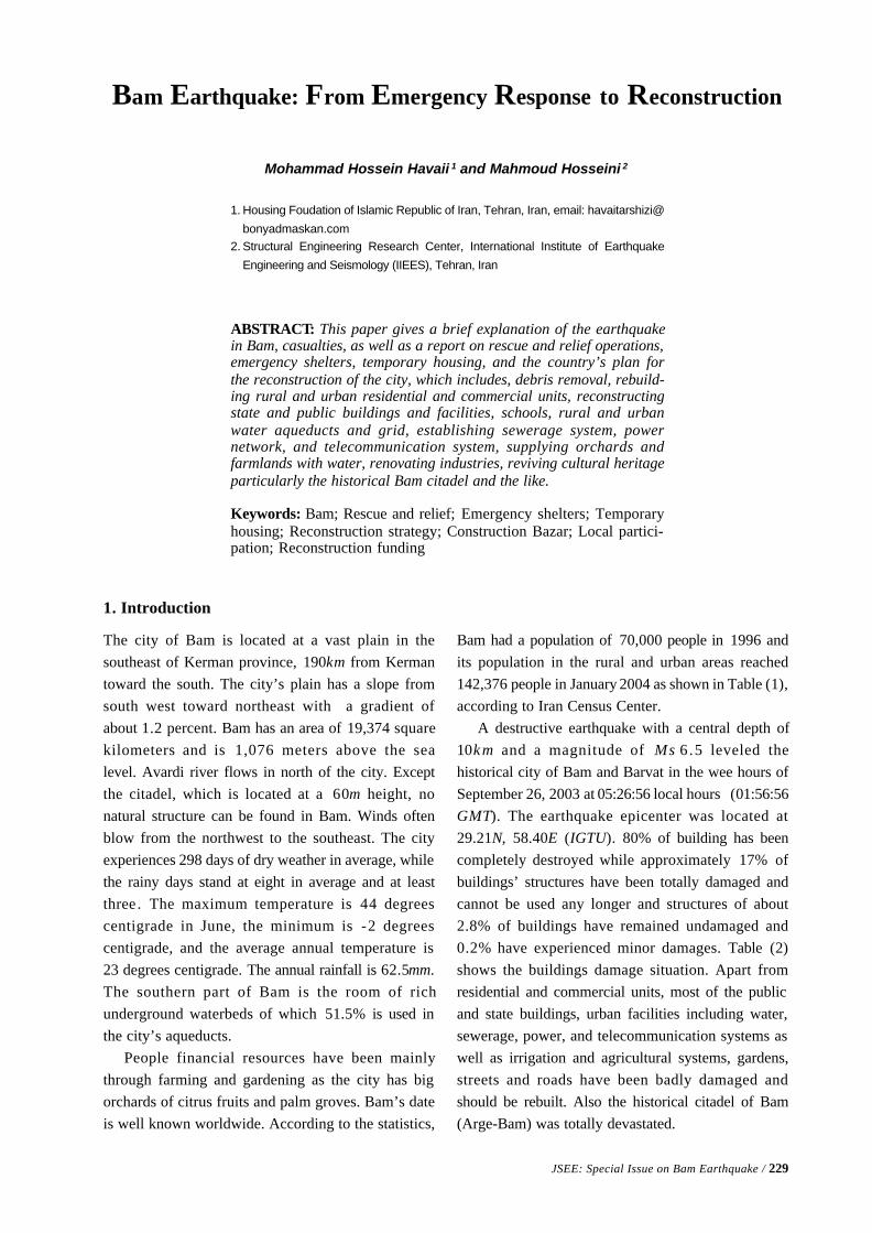
JSEE: Special Issue on Bam Earthquake / 229
1. Housing Foudation of Islamic Republic of Iran, Tehran, Iran, email: havaitarshizi@
bonyadmaskan.com2. Structural Engineering Research Center, International Institute of Earthquake
Engineering and Seismology (IIEES), Tehran, Iran
ABSTRACT: This paper gives a brief explanation of the earthquakein Bam, casualties, as well as a report on rescue and relief operations,emergency shelters, temporary housing, and the country’s plan forthe reconstruction of the city, which includes, debris removal, rebuild-ing rural and urban residential and commercial units, reconstructingstate and public buildings and facilities, schools, rural and urbanwater aqueducts and grid, establishing sewerage system, powernetwork, and telecommunication system, supplying orchards andfarmlands with water, renovating industries, reviving cultural heritageparticularly the historical Bam citadel and the like.
Keywords: Bam; Rescue and relief; Emergency shelters; Temporaryhousing; Reconstruction strategy; Construction Bazar; Local partici-pation; Reconstruction funding
Bam Earthquake: From Emergency Response to Reconstruction
Mohammad Hossein Havaii 1 and Mahmoud Hosseini 2
1. Introduction
The city of Bam is located at a vast plain in thesoutheast of Kerman province, 190km from Kermantoward the south. The city’s plain has a slope fromsouth west toward northeast with a gradient ofabout 1.2 percent. Bam has an area of 19,374 squarekilometers and is 1,076 meters above the sealevel. Avardi river flows in north of the city. Exceptthe citadel, which is located at a 60m height, nonatural structure can be found in Bam. Winds oftenblow from the northwest to the southeast. The cityexperiences 298 days of dry weather in average, whilethe rainy days stand at eight in average and at leastthree. The maximum temperature is 44 degreescentigrade in June, the minimum is -2 degreescentigrade, and the average annual temperature is23 degrees centigrade. The annual rainfall is 62.5mm.The southern part of Bam is the room of richunderground waterbeds of which 51.5% is used inthe city’s aqueducts.
People financial resources have been mainlythrough farming and gardening as the city has bigorchards of citrus fruits and palm groves. Bam’s dateis well known worldwide. According to the statistics,
Bam had a population of 70,000 people in 1996 andits population in the rural and urban areas reached142,376 people in January 2004 as shown in Table (1),according to Iran Census Center.
A destructive earthquake with a central depth of10k m and a magnitude of Ms 6.5 leveled thehistorical city of Bam and Barvat in the wee hours ofSeptember 26, 2003 at 05:26:56 local hours (01:56:56GMT). The earthquake epicenter was located at29.21N, 58.40E (IGTU). 80% of building has beencompletely destroyed while approximately 17% ofbuildings’ structures have been totally damaged andcannot be used any longer and structures of about2.8% of buildings have remained undamaged and0.2% have experienced minor damages. Table (2)shows the buildings damage situation. Apart fromresidential and commercial units, most of the publicand state buildings, urban facilities including water,sewerage, power, and telecommunication systems aswell as irrigation and agricultural systems, gardens,streets and roads have been badly damaged andshould be rebuilt. Also the historical citadel of Bam(Arge-Bam) was totally devastated.
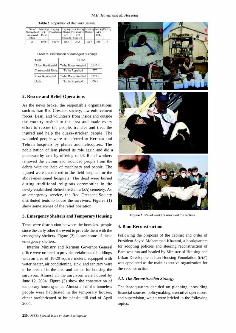
230 / JSEE: Special Issue on Bam Earthquake
M.H. Havaii and M. Hosseini
Table 1. Population of Bam and Baravat.
Table 2. Distribution of damaged buildings.
2. Rescue and Relief Operations
As the news broke, the responsible organizationssuch as Iran Red Crescent society, law enforcementforces, Basij, and volunteers from inside and outsidethe country rushed to the area and made everyeffort to rescue the people, transfer and treat theinjured and help the quake-stricken people. Thewounded people were transferred to Kerman andTehran hospitals by planes and helicopters. Thenoble nation of Iran played its role again and did apraiseworthy task by offering relief. Relief workersremoved the victims and wounded people from thedebris with the help of machinery and people. Theinjured were transferred to the field hospitals or theabove-mentioned hospitals. The dead were buriedduring traditional religious ceremonies in thenewly-established Behesht-e-Zahra (SA) cemetery. Asan emergency service, the Red Crescent Societydistributed tents to house the survivors. Figures (1)show some scenes of the relief operation.
3. Emergency Shelters and Temporary Housing
Tents were distribution between the homeless peoplesince the early other the event to provide them with theemergency shelters. Figure (2) shows some of theseemergency shelters.
Interior Ministry and Kerman Governor Generaloffice were ordered to provide prefabricated buildingswith an area of 18-20 square meters, equipped withwater heater, air conditioning, sink, and sanitary wareto be erected in the area and camps for housing thesurvivors. Almost all the survivors were housed byJune 12, 2004. Figure (3) show the construction oftemporary housing units. Almost all of the homelesspeople were habituated in the temporary houses,either prefabricated or built-insitu till end of April2004.
Figure 1. Relief workers removed the victims.
4. Bam Reconstruction
Following the proposal of the cabinet and order ofPresident Seyed Mohammad Khatami, a headquartersfor adopting policies and steering reconstruction ofBam was run and headed by Minister of Housing andUrban Development. Iran Housing Foundation (IHF)was appointed as the main executive organization forthe reconstruction.
4.1. The Reconstruction Strategy
The headquarters decided on planning, providingfinancial sources, policymaking, executive operations,and supervision, which were briefed in the followingtopics:
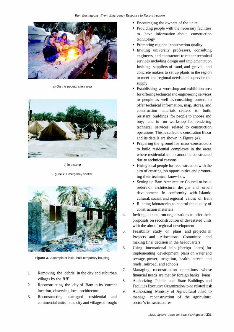
Bam Earthquake: From Emergency Response to Reconstruction
JSEE: Special Issue on Bam Earthquake / 231
Figure 3. A sample of insitu-built temporary housing.
Figure 2. Emergency shelter.
a) On the pedestration area
b) In a camp
1. Removing the debris in the city and suburbanvillages by the IHF
2. Reconstructing the city of Bam in its currentlocation, observing local architecture
3. Reconstructing damaged residential andcommercial units in the city and villages through:
s Encouraging the owners of the unitss Providing people with the necessary facilities
to have information about constructiontechnologys Promoting regional construction qualitys Inviting university professors, consulting
engineers, and contractors to render technicalservices including design and implementationInviting suppliers of sand, and gravel, andconcrete makers to set up plants in the regionto meet the regional needs and supervise thesupplys Establishing a workshop and exhibition area
for offering technical and engineering servicesto people as well as consulting centers tooffer technical information, map, stores, andconstruction materials centers to buildresistant buildings for people to choose andbuy, and to run workshop for renderingtechnical services related to constructionoperations. This is called the constration Bazarand its details are shown in Figure (4).s Preparing the ground for mass-constructors
to build residential complexes in the areaswhere residential units cannot be constructeddue to technical reasonss Hiring local people for reconstruction with the
aim of creating job opportunities and promot-ing their technical know-hows Setting up Bam Architecture Council to issue
orders on architectural designs and urbandevelopment in conformity with Islamiccultural, social, and regional values of Bams Running laboratories to control the quality of
construction materials4. Inviting all state-run organizations to offer their
proposals on reconstruction of devastated unitswith the aim of regional development
5. Feasibility study on plans and projects inProjects and Allocations Committee andmaking final decision in the headquarters
6. Using international help (foreign loans) forimplementing development plans on water andsewage, power, irrigation, health, streets androads, railroad, and schools
7. Managing reconstruction operations whosefinancial needs are met by foreign banks’ loans
8. Authorizing Public and State Buildings andFacilities Executive Organization to do related task
9. Authorizing Ministry of Agricultural Jihad tomanage reconstruction of the agriculturesector’s infrastructures
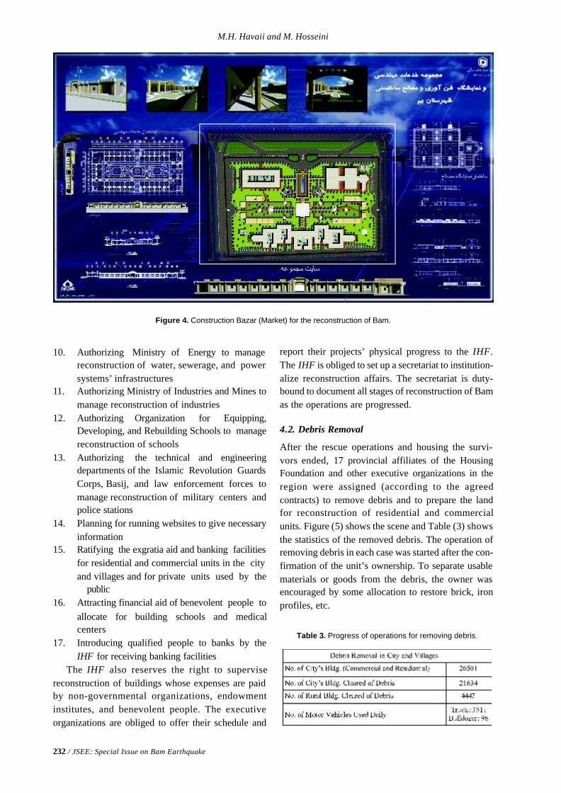
232 / JSEE: Special Issue on Bam Earthquake
M.H. Havaii and M. Hosseini
10. Authorizing Ministry of Energy to managereconstruction of water, sewerage, and powersystems’ infrastructures
11. Authorizing Ministry of Industries and Mines tomanage reconstruction of industries
12. Authorizing Organization for Equipping,Developing, and Rebuilding Schools to managereconstruction of schools
13. Authorizing the technical and engineeringdepartments of the Islamic Revolution GuardsCorps, Basij, and law enforcement forces tomanage reconstruction of military centers andpolice stations
14. Planning for running websites to give necessaryinformation
15. Ratifying the exgratia aid and banking facilitiesfor residential and commercial units in the cityand villages and for private units used by the
public16. Attracting financial aid of benevolent people to
allocate for building schools and medicalcenters
17. Introducing qualified people to banks by theIHF for receiving banking facilities
The IHF also reserves the right to supervisereconstruction of buildings whose expenses are paidby non-governmental organizations, endowmentinstitutes, and benevolent people. The executiveorganizations are obliged to offer their schedule and
report their projects’ physical progress to the IHF.The IHF is obliged to set up a secretariat to institution-alize reconstruction affairs. The secretariat is duty-bound to document all stages of reconstruction of Bamas the operations are progressed.
4.2. Debris Removal
After the rescue operations and housing the survi-vors ended, 17 provincial affiliates of the HousingFoundation and other executive organizations in theregion were assigned (according to the agreedcontracts) to remove debris and to prepare the landfor reconstruction of residential and commercialunits. Figure (5) shows the scene and Table (3) showsthe statistics of the removed debris. The operation ofremoving debris in each case was started after the con-firmation of the unit’s ownership. To separate usablematerials or goods from the debris, the owner wasencouraged by some allocation to restore brick, ironprofiles, etc.
Table 3. Progress of operations for removing debris.
Figure 4. Construction Bazar (Market) for the reconstruction of Bam.
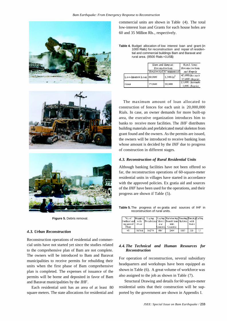
Bam Earthquake: From Emergency Response to Reconstruction
JSEE: Special Issue on Bam Earthquake / 233
Figure 5. Debris removal.
Table 4. Budget allocation of low interest loan and grant (in1000 Rials) for reconstruction and repair of residen-tial and commercial buildings Bam and Baravat andrural area. (8500 Rials =1US$)
Table 5. The progress of ex gratia and sources of IHF inreconstruction of rural units.
4.3. Urban Reconstruction
Reconstruction operations of residential and commer-cial units have not started yet since the studies relatedto the comprehensive plan of Bam are not complete.The owners will be introduced to Bam and Baravatmunicipalities to receive permits for rebuilding theirunits when the first phase of Bam comprehensiveplan is completed. The expenses of issuance of thepermits will be borne and deposited in favor of Bamand Baravat municipalities by the IHF.
Each residential unit has an area of at least 80square meters. The state allocations for residential and
commercial units are shown in Table (4). The totallow-interest loan and Grants for each house holes are60 and 35 Million Rls., respectively.
The maximum amount of loan allocated toconstruction of fences for each unit is 20,000,000Rials. In case, an owner demands for more built-uparea, the executive organization introduces him tobanks to receive more facilities. The IHF distributesbuilding materials and prefabricated metal skeleton fromgrant found and the owners. As the permits are issued,the owners will be introduced to receive banking loanwhose amount is decided by the IHF due to progressof construction in different stages.
4.3. Reconstruction of Rural Residential Units
Although banking facilities have not been offered sofar, the reconstruction operations of 60-square-meterresidential units in villages have started in accordancewith the approved policies. Ex gratia aid and sourcesof the IHF have been used for the operations, and theirprogress are shown if Table (5).
4.4. The Technical and Human Resources forReconstruction
For operation of reconstruction, several subsidiaryheadquarters and workshops have been equipped asshown in Table (6). A great volume of workforce wasalso assigned to the job as shown in Table (7).
Structural Drawing and details for 60 square-meterresidential units that their construction will be sup-ported by the government are shown in Appendix I.
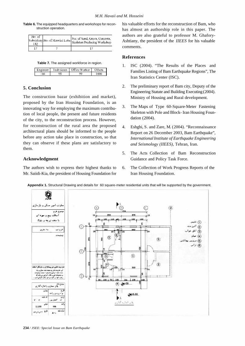
234 / JSEE: Special Issue on Bam Earthquake
M.H. Havaii and M. Hosseini
Appendix 1. Structural Drawing and details for 60 square-meter residential units that will be supported by the government.
Table 6. The equipped headquarters and workshops for recon-struction operation.
Table 7. The assigned workforce in region.
5. Conclusion
The construction bazar (exhibition and market),proposed by the Iran Housing Foundation, is aninnovating way for employing the maximum contribu-tion of local people, the present and future residentsof the city, to the reconstruction process. However,for reconstruction of the rural area the proposedarchitectural plans should be informed to the peoplebefore any action take place in construction, so thatthey can observe if these plans are satisfactory tothem.
Acknowledgment
The authors wish to express their highest thanks toMr. Saiidi-Kia, the president of Housing Foundation for
his valuable efforts for the reconstruction of Bam, whohas almost an authorship role in this paper. Theauthors are also grateful to professor M. Ghafory-Ashtiany, the president of the IIEES for his valuablecomments.
References
1. ISC (2004). “The Results of the Places andFamilies Listing of Bam Earthquake Regions”, TheIran Statistics Center (ISC).
2. The preliminary report of Bam city, Deputy of theEngineering Statute and Building Executing (2004).Ministry of Housing and Rural development.
3. The Maps of Type 60-Square-Meter FasteningSkeleton with Pole and Block- Iran Housing Foun-dation (2004).
4. Eshghi, S. and Zare, M. (2004). “ReconnaissanceReport on 26 December 2003, Bam Earthquake”,International Institute of Earthquake Engineeringand Seismology (IIEES), Tehran, Iran.
5. The Acts Collection of Bam ReconstructionGuidance and Policy Task Force.
6. The Collection of Work Progress Reports of theIran Housing Foundation.
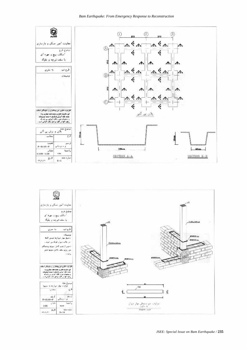
Bam Earthquake: From Emergency Response to Reconstruction
JSEE: Special Issue on Bam Earthquake / 235
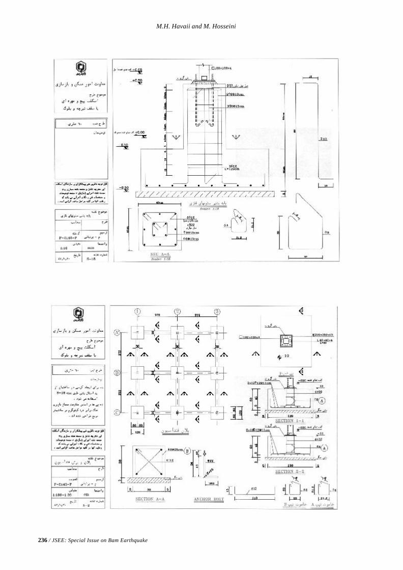
236 / JSEE: Special Issue on Bam Earthquake
M.H. Havaii and M. Hosseini
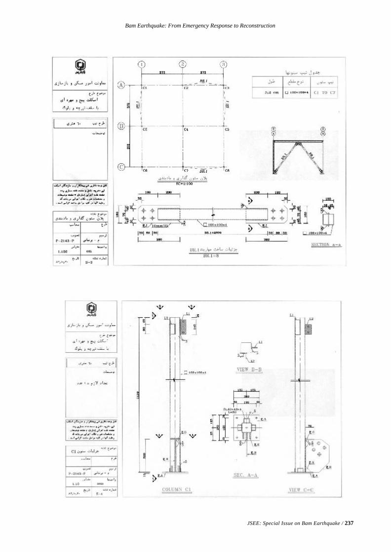
Bam Earthquake: From Emergency Response to Reconstruction
JSEE: Special Issue on Bam Earthquake / 237
JSEE: Special Issue on Bam Earthquake / 239
An Open Alliance of
The United Nations Educational, Scientific and Cultural Organization (UNESCO)
The United Nations Development Programme (UNDP)
The United Nations International Strategy for Disaster Reduction (UN/ISDR) and
The International Institute of Earthquake Engineering and Seismology (IIEES)
A Framework for Cooperation on Earhquake Risk Reduction
In the Islamic Republic of IRAN and Developing Countries
1. Overriding Considerations
The Bam earthquake disaster provides a unique window of opportunity to raise international awareness ofthe importance of the effective implementation of a comprehensive earthquake risk reduction program inIran as well as in hazard-prone developing countries. It gives a challenge to the governments to makethe highest use of the existing know-how on earthquakes and its integration into development programs.It also compels the scientific and engineering community to provide more socio-economic-culturalcompatible solutions to national needs. Moreover, the public at large should become more concernedabout the hazard and increase its own preparedness level. To initiate such an approach the United NationsEducational, Scientific and Cultural Organization (UNESCO), the United Nations Development Programme(UNDP) and the Secretariat of the International Strategy for Disaster Reduction (UN/ISDR) and theInternational Institute of Earthquake Engineering and Seismology (IIEES) as the host institute in Iran,decided to work in partnership with other organisations and professionals throughout the world toprovide leadership for a series of activities that will protect people, building stock, lifelines and criticalinfrastructure from the impacts of the inevitable future earthquakes in Iran.
In the wake of the Bam earthquake, and based on the document “UN Strategy for Support to theGovernment of Islamic Republic of Iran following the Bam Earthquake of 26 December 2003”. UNESCO,UNDP, UN/ISDR Secretariat and the IIEES, agreed to form an Alliance which will be open to a widerpartnership among both Iranian and international institutions and organizations. They recognize that toimprove human security and life safety in Iran as well as in developing countries by reducing thevulnerability to hazards and risks, including earthquake risk, is the overarching primary objective of theAlliance. This Alliance is expected to provide advise in the reconstruction process of Bam and in theprevention of future risks in similar cases.
Iran is recognized among the highly exposed countries to natural hazards, namely earthquakes. The riskof earthquake and other natural disasters is increasing in Iran as a result of population growth, urbanisation,alteration of the natural environment, climate change, vulnerable dwellings, public buildings and lifelineinfrastructure. With further population growth, expanding public and private infrastructures, environ-mental changes and continuing trends towards urbanisation and industrialisation, the risks of greatertragedies stemming from natural hazards are expected to increase in the next years and over the currentnew century.
IIEES, UNESCO, UNDP and the UN/ISDR Secretariat underline that making disaster prevention andmitigation integral parts of development in Iran as well as in other hazard-prone countries requires agenuine shift in emphasis from post-disaster reaction to pre-disaster prevention and risk reduction

240 / JSEE: Special Issue on Bam Earthquake
UNESCO-UNDP-UN/ISDR-IIEES Alliance on Earthquake Risk Reduction
actions. Hence, the new emerging approach, to be spearheaded by the Alliance will stress the merit ofpreventive approaches through enhancement of research and knowledge capacities, the design anddissemination of risk mitigation measures as well as increased information, education and publicawareness.
The Alliance affirms the importance of science and technology in laying the foundations for disaster riskmanagement. As regards Iran, it notes that steady development in earthquake-related knowledge, researchand technical applications has occurred since the 1990 Manjil earthquake. This trend ought to be furtherfostered. Above all the implications of this trend across the whole elements of the disaster reductionsectors and stakeholders should be ensured if significant risk mitigation is to be achieved in the finalanalysis.
Based on the above-mentioned considerations, the Alliance recalls that the establishment of theInternational Institute of Earthquake Engineering and Seismology in Tehran was founded on a decisiontaken by the 24th session of the UNESCO General Conference, representing the will of the internationalcommunity to build capacities in Iran and in the seismically active regions to excel in earthquake riskmitigation. It recognizes that, since its establishment in 1990, the IIEES has gradually succeeded inmeeting the challenge of developing into a Centre of Excellence in earthquake-related studies and theproduction of knowledge and know-how. Other Iranian competent agencies, including academicand public institutes, have a recognized role in furthering earthquake fundamental and applied research.Through IIEES and other competent Iranian institutions, there is more scientific knowledge andtechnological know-how than ever before to promote science-based disaster preparedness andprevention and to assist in designing and implementing risk mitigation strategies.
The Alliance emphasizes the importance of international cooperation in support of disaster reductionand in sharing knowledge and experience in disaster reduction practices. It is committed to facilitatethe further expansion of the regional and international vocation of IIEES and other specialized Iranianinstitutions.
The Alliance notes with much regret the inertia and lack of effective action in enforcing building codesin Iran as well as in other countries. Furthermore, it considers the violation of earthquake-resistantconstruction norms in cities and rural areas worldwide which are at risk, as a major source of concernand risk and therefore calls for a zero tolerance of such a violation.
The Alliance is committed to encourage that part of post-Bam national and international aid for the recon-struction be used for long-term risk mitigation projects and activities. The Alliance stands prepared toprovide technical advise to the Government and the Steering Council for the reconstruction of Bam.
The Alliance affirms the need for incorporation of components from ethic, science and education toculminate in a preventive culture as an integral part of disaster risk reduction strategy. This techno-ethicin its turn relies on techno-legal concepts.
The Alliance emphasizes that a coordinated approach should be systematically pursued in the designand implementation of the UN international initiatives related to risk reduction, as well as those involvingspecialized non-governmental entities, capitalizing and building on national capacities. The Alliancebelieves that a partnership of this kind could provide opportunities to UN Agencies and Bilaterals tomake use of state-of-the art knowledge and experience gained from the post-Bam earthquake recoveryand reconstruction into the developing country programme facing similar situations.
Vision
The Alliance affirms the following principles for action:§ Expanding scientific and applied research, technical infrastructures and capacities for implementa-
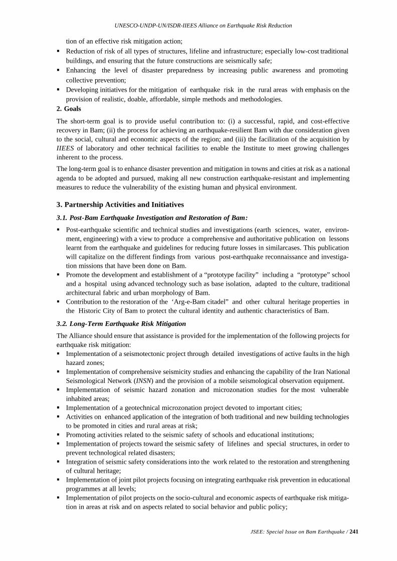
JSEE: Special Issue on Bam Earthquake / 241
UNESCO-UNDP-UN/ISDR-IIEES Alliance on Earthquake Risk Reduction
tion of an effective risk mitigation action;§ Reduction of risk of all types of structures, lifeline and infrastructure; especially low-cost traditional
buildings, and ensuring that the future constructions are seismically safe;§ Enhancing the level of disaster preparedness by increasing public awareness and promoting
collective prevention;§ Developing initiatives for the mitigation of earthquake risk in the rural areas with emphasis on the
provision of realistic, doable, affordable, simple methods and methodologies.2. Goals
The short-term goal is to provide useful contribution to: (i) a successful, rapid, and cost-effectiverecovery in Bam; (ii) the process for achieving an earthquake-resilient Bam with due consideration givento the social, cultural and economic aspects of the region; and (iii) the facilitation of the acquisition byIIEES of laboratory and other technical facilities to enable the Institute to meet growing challengesinherent to the process.
The long-term goal is to enhance disaster prevention and mitigation in towns and cities at risk as a nationalagenda to be adopted and pursued, making all new construction earthquake-resistant and implementingmeasures to reduce the vulnerability of the existing human and physical environment.
3. Partnership Activities and Initiatives
3.1. Post-Bam Earthquake Investigation and Restoration of Bam:
§ Post-earthquake scientific and technical studies and investigations (earth sciences, water, environ-ment, engineering) with a view to produce a comprehensive and authoritative publication on lessonslearnt from the earthquake and guidelines for reducing future losses in similarcases. This publicationwill capitalize on the different findings from various post-earthquake reconnaissance and investiga-tion missions that have been done on Bam.
§ Promote the development and establishment of a “prototype facility” including a “prototype” schooland a hospital using advanced technology such as base isolation, adapted to the culture, traditionalarchitectural fabric and urban morphology of Bam.
§ Contribution to the restoration of the ‘Arg-e-Bam citadel” and other cultural heritage properties inthe Historic City of Bam to protect the cultural identity and authentic characteristics of Bam.
3.2. Long-Term Earthquake Risk Mitigation
The Alliance should ensure that assistance is provided for the implementation of the following projects forearthquake risk mitigation:§ Implementation of a seismotectonic project through detailed investigations of active faults in the high
hazard zones;§ Implementation of comprehensive seismicity studies and enhancing the capability of the Iran National
Seismological Network (INSN) and the provision of a mobile seismological observation equipment.§ Implementation of seismic hazard zonation and microzonation studies for the most vulnerable
inhabited areas;§ Implementation of a geotechnical microzonation project devoted to important cities;§ Activities on enhanced application of the integration of both traditional and new building technologies
to be promoted in cities and rural areas at risk;§ Promoting activities related to the seismic safety of schools and educational institutions;§ Implementation of projects toward the seismic safety of lifelines and special structures, in order to
prevent technological related disasters;§ Integration of seismic safety considerations into the work related to the restoration and strengthening
of cultural heritage;§ Implementation of joint pilot projects focusing on integrating earthquake risk prevention in educational
programmes at all levels;§ Implementation of pilot projects on the socio-cultural and economic aspects of earthquake risk mitiga-
tion in areas at risk and on aspects related to social behavior and public policy;

242 / JSEE: Special Issue on Bam Earthquake
UNESCO-UNDP-UN/ISDR-IIEES Alliance on Earthquake Risk Reduction
§ Implementation of an appropriate techno-ethical and techno-legal regime for the enforcementof building codes and standards toward the effective implementation of risk reduction.
§ Establishment in IIEES of a UNESCO Chair UNITWIN Programme on research and applicationsrelated to the assessment and mitigation of earthquake risk;
§ Implementation of annual courses on “Aseismic Design and Construction of Structures” in IIEESfor the benefit of the countries in the region;
§ Preparation of a Report on above efforts to be presented during the UN World Conference on DisasterReduction in Kobe, Japan, January 2005.
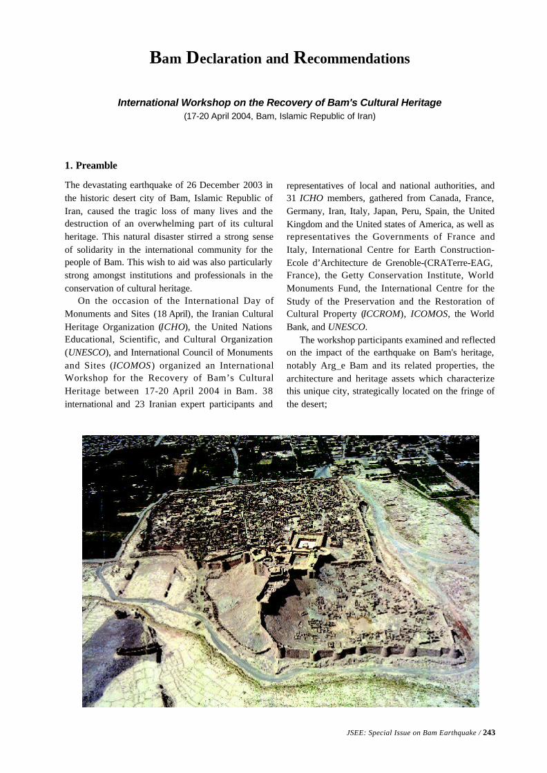
JSEE: Special Issue on Bam Earthquake / 243
Bam Declaration and Recommendations
International Workshop on the Recovery of Bam's Cultural Heritage(17-20 April 2004, Bam, Islamic Republic of Iran)
1. Preamble
The devastating earthquake of 26 December 2003 inthe historic desert city of Bam, Islamic Republic ofIran, caused the tragic loss of many lives and thedestruction of an overwhelming part of its culturalheritage. This natural disaster stirred a strong senseof solidarity in the international community for thepeople of Bam. This wish to aid was also particularlystrong amongst institutions and professionals in theconservation of cultural heritage.
On the occasion of the International Day ofMonuments and Sites (18 April), the Iranian CulturalHeritage Organization (ICHO), the United NationsEducational, Scientific, and Cultural Organization(UNESCO), and International Council of Monumentsand Sites (ICOMOS) organized an InternationalWorkshop for the Recovery of Bam’s CulturalHeritage between 17-20 April 2004 in Bam. 38international and 23 Iranian expert participants and
representatives of local and national authorities, and31 ICHO members, gathered from Canada, France,Germany, Iran, Italy, Japan, Peru, Spain, the UnitedKingdom and the United states of America, as well asrepresentatives the Governments of France andItaly, International Centre for Earth Construction-Ecole d’Architecture de Grenoble-(CRATerre-EAG,France), the Getty Conservation Institute, WorldMonuments Fund, the International Centre for theStudy of the Preservation and the Restoration ofCultural Property (ICCROM), ICOMOS, the WorldBank, and UNESCO.
The workshop participants examined and reflectedon the impact of the earthquake on Bam's heritage,notably Arg_e Bam and its related properties, thearchitecture and heritage assets which characterizethis unique city, strategically located on the fringe ofthe desert;
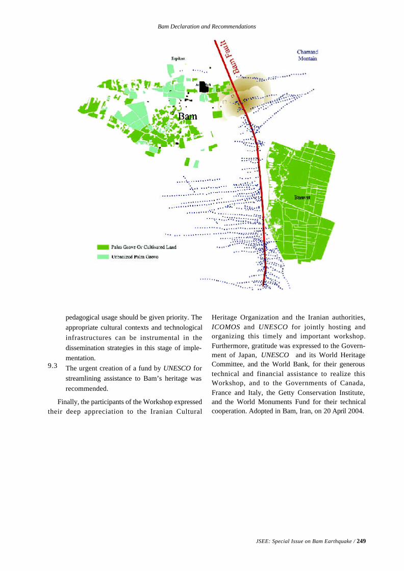
Bam Declaration and Recommendations
JSEE: Special Issue on Bam Earthquake / 249
9.3
pedagogical usage should be given priority. Theappropriate cultural contexts and technologicalinfrastructures can be instrumental in thedissemination strategies in this stage of imple-mentation.The urgent creation of a fund by UNESCO forstreamlining assistance to Bam’s heritage wasrecommended.
Finally, the participants of the Workshop expressedtheir deep appreciation to the Iranian Cultural
Heritage Organization and the Iranian authorities,ICOMOS and UNESCO for jointly hosting andorganizing this timely and important workshop.Furthermore, gratitude was expressed to the Govern-ment of Japan, UNESCO and its World HeritageCommittee, and the World Bank, for their generoustechnical and financial assistance to realize thisWorkshop, and to the Governments of Canada,France and Italy, the Getty Conservation Institute,and the World Monuments Fund for their technicalcooperation. Adopted in Bam, Iran, on 20 April 2004.
Distinguished reviewer of the papers in the JSEE special issue on Bam Earthquake.
Prof. G. Ahmadi, Clarkson University, USADr. M.T. Ahmadi, Tarbiat Moddarres University, IranProf. O. Bellier, Universite Aix-Marseille III, FranceProf. P. Bormann, GeoForschungsZentrum Potsdam, GermanyProf. M. Erdik, Bogazici University, TurkeyDr. S. Eshghi, IIEES, IranDr. P. Garnier, University of Oxford, UKProf. A. Ghobarah, McMaster University, CanadaProf. P. Gulkan, Middle East University, TurkeyDr. H. Hamzehloo, IIEES, IranProf. D. Hatzfeld, Laboratoire De Geophysique Interne Et Tectonophysique, FranceDr. M. Hosseini, IIEES, IranDr. B. Hosseini Hashemi, IIEES, IranProf. J. Havskov, University of Bergen, NorwayProf. M.K. Jafari, IIEES, IranDr. M. Kamalian, IIEES, IranProf. M.R. Maheri, Shiraz University, IranDr. M. Mehrain, Dames & Moore, USADr. S. Moghadam, IIEES, IranDr. M. Mokhtari, IIEES, IranProf. M. Motosaka, University of Tohoku, JapanDr. F. Naeim, John A. Martin & Associates, Inc., USADr. F. Nadim, International Centre for Geohazards, c/o NGI, NorwayProf. K. Nakanishi, University of California,USAProf. G.F. Panza, University of Trieste and ICTP, ItalyProf. K. Priestley, University of Cambridge, UKProf. F. Scherbaum, Potsdam University, GermanyProf. M.D. Trifunac, University of Southern California, USADr. A. Vaseghi, IIEES, IranProf. Alice Walker, Earthquake Seismology, British Geological Survey, UKProf. KunioWatanabe, Geosphere Research Institute, Saitama University, JapanDr. M. Ziyaeifar, IIEES, IranProf. J. Zschau, Zschau GeoForschungsZentrum Potsdam, Germany
Editors would express their deep appreciation for their kind and Valuable cooperation inreviewing the papers within the time constraint in order to make this special issue to beprinted on time, 7 month after the Bam earthquake.
GENERAL INFORMATION
SCOPE
Journal of Seismology and Earthquake Engineering is a quarterly journal that provides a forum for the publication oforiginal papers in four general areas of Structural Earthquake Engineering, Seismology, Geotechnical EarthquakeEngineering, and Seismotectonics. The editor’s policy is to include at least one paper on each of the aforementionedtopics as well as providing a balance between theoretic and design oriented contributions in each journal issue.
CONTRIBUTION GUIDELINES
All contributions to be considered for publication should be sent to the Editor-in-Chief. Authors should make everyeffort to conform to the guidelines given below for the preparation of their manuscripts.
1. Types of contributions are research papers, technical notes and discussions.2. Three copies should be provided in double spaced typing on pages of uniform size, with a wide margin on the left .3. Generally, the size of the manuscript should not exceed 7500 words for papers, 3500 words for technical notes and
1500 words for discussions.4. Each paper should be provided with an abstract of about 100-150 words, reporting concisely on the purpose and
results of the paper.5. The SI system should be used for all scientific and laboratory data; if in certain instances, it is necessary to quote
other units, these should be added in parentheses.6. Tables, references and legends to illustrations should be typed on separate sheets and placed at the end of the
paper.7. Mathematical expressions and equations should be clearly printed. Particular care should be used in identifying
unusual symbols or notations and to upper or lower case letters. Awkward mathematical notations and nonstand-ard symbols should be avoided.
8. References to published work should be numbered sequentially in order of citation and given in the text by anumeral within brackets, with a reference list, in numerical order at the end of the paper. Some examples are givenbelow:
Books
5. Berberian, M. (1995). “Natural Hazard and the First Earthquake Catalogue of Iran. Vol. 1: Historical Hazards inIran Prior to 1990”. IIEES, Tehran, Iran
Reports
10. Kaynia, A .M. (1993). “Stochastic Response of Pile Foundations”, IIEES Report No. 72-93-2. International Institute ofEarthquake Engineering and Seismology, Tehran, Iran.
Journal Articles
12. Miller, R.K., Masri, S.F., Dehghanyar, T.J., and Caughey, T.K. (1988). “Active Control of Large Civil Structures”, J.Engr. Mech., ASCE, 114(3), 1542-1570.
DISK SUBMISSION OF MANUSCRIPTS
For papers produced using a well-known word processor, preferably Word 97 or please submit a disk with the finalrevised version of the manuscript. The file on disk should correspond exactly to the hard copy. If the disk and the papercopy differ, the paper copy will be treated as the accepted version. The preferred medium for disk submittal is in PC-Windows environment. Illustrations may be submitted in disk form, provided that the file format and the program usedto produce them is clearly indicated and a hard copy is also supplied.
ILLUSTRATIONS
The original and two copies of each illustration, which may be of reduced size should be provided. Line drawings maybe submitted in any medium provided that the image is black and very sharp. They should preferably require the samedegree of reduction; large diagrams, more than four times the final size, are discouraged due to handling difficulties.Lettering should be large enough to be legible after reduction of the illustration to fit (ideally 7p t. lettering afterreduction). Photographs should be submitted as contrasting black and white prints on glossy paper. The illustration canalso be given in a diskette. Each illustration must be clearly numbered and the name(s) of the author(s) of the paperwritten on the reverse side.
PROOFS
The author (or the selected author where several are included) will receive a set of proofs for checking. No new materialmay be inserted in the text at the time of proof-reading unless accepted by the editors. All joint communications mustindicate the name and full postal address of the author to whom proofs should be sent.
PAGE CHARGES AND OFFPRINTS
There are no page charges. Twenty-five offprints of paper will be supplied free of charge. Additional copies can beordered at current printing prices.

JSEE Order Form
Please complete and return the order form below to:Journal of Seismology and Earthquake Engineering (JSEE),International Institute of Earthquake Engineering and Seismology, (IIEES)P.O. Box 19395/3913,Tehran, I.R. IranTelephone: 0098 21 2831116-19Fax: 0098 21 2299479E-mail: [email protected] No.: Code: 1551, Account number: 40056 Bank Melli, Kashef Branch,
Tehran, I.R. Iran
I would like to order: Volume ............... No. ..........I would like to order a free sample copy of: Volume .............. No. ...........
Method of payment:1) Please invoice my company (proforma) r2) I enclose the receipt of or money order to JSEE r
Name ............................................................Company .................................................................................Address ............................................................................................................................................................................... ......................................................................................................................................................................................Country .............................
Tel.: ................................................... Fax: ................................................... E-mail: .................................................
Date ........................................
Subscription FeeInternational subscription rates: Annually $250
Single $70
For subscription and address changes, please contact:[email protected]
Accesss JSEE Online - http://www.iiees.ac.ir/jsee.html