Fast multicolor 3D imaging using aberration-corrected multifocus microscopy
Upload
independentCategory
view
1download
0
A. Guirao and P. Artal Vol. 17, No. 6 /June 2000/J. Opt. Soc. Am. A 955
Corneal wave aberration from videokeratography:accuracy and limitations of the procedure
Antonio Guirao and Pablo Artal
Laboratorio de Optica, Departamento de Fısica, Universidad de Murcia, Campus de Espinardo (Edificio C),30071 Murcia, Spain
Received August 30, 1999; revised manuscript received January 23, 2000; accepted February 1, 2000
A procedure to calculate the wave aberration of the human cornea from its surface shape measured by video-keratography is presented. The wave aberration was calculated as the difference in optical path between themarginal rays and the chief ray refracted at the surface, for both on- and off-axis objects. The corneal shapeelevation map was obtained from videokeratography and fitted to a Zernike polynomial expansion through aGram–Schmidt orthogonalization. The wave aberration was obtained also as a Zernike polynomial represen-tation. The accuracy of the procedure was analyzed. For calibrated reference surface elevations, a root-mean-square error (RMSE) of 1 to 2 mm for an aperture 4–6 mm in diameter was obtained, and the RMSEassociated with the experimental errors and with the fitting method was 0.2 mm. The procedure permits es-timation of the corneal wave aberration from videokeratoscopic data with an accuracy of 0.05–0.2 mm for apupil 4–6 mm in diameter, rendering the method adequate for many applications. © 2000 Optical Society ofAmerica [S0740-3232(00)01205-9]
OCIS codes: 330.4460, 330.5370, 330.7310, 080.1010.
1. INTRODUCTIONAn accurate procedure to obtain the corneal aberrationsfrom the corneal shape is required in different applica-tions. In basic studies the corneal aberrations used inconjunction with those measured in the complete eyeserve to estimate the relative sources of aberrations in thehuman eye1 or can be incorporated into more elaboratedschematic eye models.2 In cases of relevant clinical in-terest, i.e., keratoconus3,4 and corneal refractive sur-gery,5,6 the corneal aberrations also provide important in-formation.
The wave aberration of the cornea is modified by the in-ternal ocular surfaces1,7,8 to produce the final retinal im-age, and therefore measuring only the anterior cornealaberrations is not the most adequate procedure to evalu-ate the overall image quality in the eye. However, thecornea is the main refracting element and probably also amajor contributor to the ocular aberrations.9 Moreover,this will certainly be the case in abnormally aberratedcorneas, such as those reported after refractive surgery.
The spherical aberration has been usually consideredas the main aberration of the cornea,9,10 in addition to theastigmatism, but since new corneal topography deviceshave permitted more detailed studies of the corneal sur-face, the importance of coma11 and higher-orderaberrations12 has been revealed.
The first step in estimating the aberrations producedby the anterior surface of the cornea is to measure thecornea’s shape accurately. In the early 1960’s Jenkinsalready noted10 the importance of having an instrumentcapable of measuring with precision the corneal curvatureat each point. Various techniques have been proposed tomeasure the corneal topography: interferometry, ultra-sonography, profile photography, and holography; butmany of the devices in practical use today (e.g., videokera-
0740-3232/2000/060955-11$15.00 ©
toscopes) are based on the Placido disk principle. In thissystem, a series of concentric rings reflected on the corneaare imaged by a video camera and the corneal geometry isobtained in each meridian from the ring spacing. Sev-eral studies13–15 that used calibrated surfaces showedthat, owing to the approximations in the surface recon-struction computations, Placido-based devices do not ac-curately measure the corneal shape, in particular in theperiphery and when the surface differs greatly from asphere. In addition to the errors due to the reconstruc-tion algorithms, other sources of inaccuracy arise fromthe measuring process, for instance, tilt between the op-tical axis of the cornea and the axis of the instrument, de-focus in the ring image, and misalignments of the eye.
A second problem related to the determination of cor-neal aberrations is how to calculate them once the cornealsurface is known. A direct approach is to obtaina remainder lens by subtracting the best conic surface fit-ted to the measured cornea and simply to calculate theaberrations by multiplying by the refractive-indexdifference.16 However, this method neglects some aber-ration terms that can be important. Anotheralternative11 uses an approximate (neglecting nonlinearterms) analytical expression that depends on the cornealsurface.
We present here a further procedure to estimate theaberrations of the cornea from the corneal elevationsmeasured with a videokeratoscope, and we analyze its ac-curacy in detail.
2. METHODSA. Wave Aberration Associated with a RefractingSurfaceThis section presents a procedure to obtain the wave ab-erration associated with a given surface for point objects
2000 Optical Society of America

956 J. Opt. Soc. Am. A/Vol. 17, No. 6 /June 2000 A. Guirao and P. Artal
located both on axis and off axis. Figure 1 shows a sche-matic representation of the image formation by a refract-ing surface separating two media of refractive indices nand n8. An object point at an arbitrary position (x, y)5 ( p sin b, p cos b) on the plane XY has its image cen-tered at the point (x8, y8) 5 (2p8 sin b, 2p8 cos b)5 (x/m, y/m) of the paraxial plane X8Y8, where m is themagnification. A marginal ray intersects the system atsome point (r, u) of the exit pupil. Corresponding to thispoint, the surface has an elevation z(r, u). The wave ab-erration (W) along a certain marginal ray is defined as thedifference in optical path length between the ray underconsideration, d 2 d8, and the chief ray, l 2 l8, passingthrough the center of the exit pupil17:
W 5 nd 1 n8d8 2 nl 2 n8l8. (1)
These four distances may be written as
l 5 s~1 1 Y2!1/2, (2a)
l8 5 s8~1 1 Y82!1/2, (2b)
d 5 s~1 1 X2 1 Y2 1 Z2 1 2Z 2 2AXY !1/2, (3a)
d8 5 s8~1 1 X82 1 Y82 1 Z82 2 2Z8 1 2AX8Y8!1/2,
(3b)
with X 5 r/s (X8 5 r/s8), Y 5 p/s (Y8 5 p8/s8), Z5 z/s (Z8 5 z/s8), and A 5 sin(u 1 b).
An analytical expression for the wave aberration as afunction of the surface elevation, up to the fourth order inpupil and object coordinates, is obtained from Eqs. (2a)and (2b), rewritten as l ' s@1 1 (p2/2s2)2( p4/8s4)#,when p, r, z ! s, and from Eqs. (3a) and (3b) expressedas a Taylor expansion of three variables.18 If we take thederivatives of the functions d and d8 with respect to X, Y,and Z and rearrange terms, Eq. (1) for the wave aberra-tion can be expressed as
W~r, u; z !
5 Fn
s1
n8
s82 n2S 1
ns1
1
n8s8D sin2 vG r2
2
2 S n
s3 1n8
s83D r4
81
n~n82 2 n2!
2n82
3 r~cos b sin u 1 sin b cos u!sin3 v
1n2
4 S 1
n8s81
1
ns D r2~cos 2b cos 2u
2 sin 2b sin 2u!sin2 v 1n
2 S 1
s2 21
s82D r3~cos b sin u
1 sin b cos u!sin v 1 ~n 2 n8!S 1 1n
2n8sin2 v D z
1 nS 1
s1
1
s8D rz~cos b sin u 1 sin b cos u!sin v
1n2
2 S 1
n8s81
1
ns D z2 sin2 v 1 nS 1
s82 21
s2D3 rz2~cos b sin u 1 sin b cos u!sin v
1 S n
s3 1n8
s83D r2z2
21 S n8
s82 2n
s2D r2z
2. (4)
Since we are interested in surfaces with a general el-lipsoidal shape, similar to that of the cornea, we expressthe shape as a conic plus an asymmetric term:
z~r, u! 5r2
2R1
r4
8R3 K2 1r6
16R5 K4 1 ¯ 1 Dz~r, u!,
(5)
where R is the base radius of curvature of the conic sur-face and K is a constant of asphericity, with K . 0 corre-sponding to an ellipsoid, K , 0 to a hyperboloid, K 5 0 toa paraboloid, and K 5 1 to a sphere. K is related withthe eccentricity of the ellipsoid as K2 5 1 2 e2. With ex-pression (5), the wave aberration can be described as thatof a conic surface plus asymmetric terms:
Fig. 1. Imaging of an off-axis point object by a refracting surface separating media of refractive indices n and n8. The exit pupil islocated at the vertex of the surface.
A. Guirao and P. Artal Vol. 17, No. 6 /June 2000/J. Opt. Soc. Am. A 957
W~r,u! 5 Wsphere~r,u! 2e2~n 2 n8!
8R3 r4 1 @~n 2 n8!
1 L sin2 v 1 Mr2 1 N~cos b sin u
1 sin b cos u!r sin v#Dz 1 @T sin2 v 1 Ur2
1 V~cos b sin u 1 sin b cos u!r sin v#Dz2,
(6)
with
L 5 ~n 2 n8!n
2n8, M 5
1
2 S n8
s82 2n
s2D ,
N 5 nS 1
s1
1
s8D , T 5
n2
2 S 1
n8s81
1
ns D ,
U 51
2 S n
s3 1n8
s83D , V 5 nS 1
s82 21
s2D .
The first term in expression (6) represents the wave aber-ration for a spherical refracting surface and can be ex-pressed by
Wsphere~r,u! 5 adr2 1 asr4
1 at~cos b r sin u 1 sin b r cos u!
1 aa~cos 2br2 cos 2u 2 sin 2br2 sin 2u!
1 ac~cos br3 sin u 1 sin br3 cos u!, (7)
where
as 5n 2 n8
8R3 1M
2R2
U
4,
ad 5 S L
2R2 T D sin2 v 2
n8Ds8
2s82 ,
at 5n~n82 2 n2!
2n82 sin3 v,
ac 512 S N
R2 V D sin v, aa 5
T2
sin2 v
represent the coefficients of defocus, spherical aberration,distortion, astigmatism and coma, respectively. Defocusis introduced if the image is observed at a plane separateda distance Ds8 from the paraxial plane.
For objects on-axis (sin v 5 0), expression (6) is re-duced to
W~r,u! 52n8Ds8
2s82 r2 1 FasP 1K2~n 2 n8!
8R3 Gr4
1 ~n 2 n8!Dz 1 Mr2Dz 1 U r2Dz2, (8)
asP 5 (M/2R) 2 (U/4) being the spherical aberration fora paraboloid. Only a spherical aberration appears in thiscase for a refracting sphere.
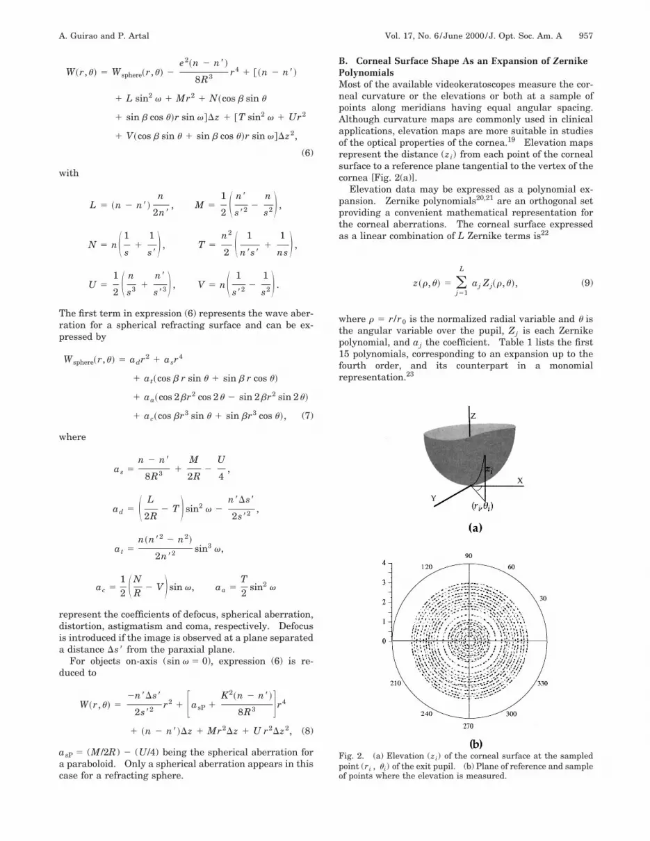
B. Corneal Surface Shape As an Expansion of ZernikePolynomialsMost of the available videokeratoscopes measure the cor-neal curvature or the elevations or both at a sample ofpoints along meridians having equal angular spacing.Although curvature maps are commonly used in clinicalapplications, elevation maps are more suitable in studiesof the optical properties of the cornea.19 Elevation mapsrepresent the distance (zi) from each point of the cornealsurface to a reference plane tangential to the vertex of thecornea [Fig. 2(a)].
Elevation data may be expressed as a polynomial ex-pansion. Zernike polynomials20,21 are an orthogonal setproviding a convenient mathematical representation forthe corneal aberrations. The corneal surface expressedas a linear combination of L Zernike terms is22
z~r,u! 5 (j51
L
aj Zj~r,u!, (9)
where r 5 r/r0 is the normalized radial variable and u isthe angular variable over the pupil, Zj is each Zernikepolynomial, and aj the coefficient. Table 1 lists the first15 polynomials, corresponding to an expansion up to thefourth order, and its counterpart in a monomialrepresentation.23
Fig. 2. (a) Elevation (zi) of the corneal surface at the sampledpoint (ri , u i) of the exit pupil. (b) Plane of reference and sampleof points where the elevation is measured.

958 J. Opt. Soc. Am. A/Vol. 17, No. 6 /June 2000 A. Guirao and P. Artal
Table 1. First 15 Zernike Polynomials and Their Monomial Representation
Order Zernike Polynomial Monomial Representation
0 Z1 5 1 1
First Z2 5 2r cos u xZ3 5 2r sin u y
Second Z4 5 )(2r2 2 1) 21 1 2(x2 1 y2)Z5 5 A6r2 cos 2u x2 2 y2
Z6 5 A6r2 sin 2u 2xy
Third Z7 5 A8(3r2 2 2)r cos u 22x 1 3x(x2 1 y2)Z8 5 A8(3r2 2 2)r sin u 22y 1 3y(x2 1 y2)
Z10 5 A8r3 cos 3u x(x2 2 3y2)Z11 5 A8r3 sin 3u y(3x2 2 y2)
Fourth Z9 5 A5(6r4 2 6r2 1 1) 1 1 6(x4 1 y4 2 x2 2 y2 1 2x2y2)Z12 5 A10(4r2 2 3)r2 cos 2u 23(x2 2 y2) 1 4(x4 2 y4)Z13 5 A10(4r2 2 3)r2 sin 2u 2xy@23 1 4(x2 1 y2)#
Z14 5 A10r4 cos 4u x4 2 6x2y2 1 y4
Z15 5 A10r4 sin 4u 4xy(x2 2 y2)
Videokeratoscopy provides a finite number of values zifor the corneal elevation [Fig. 2(b) shows an example],whereas Zernike polynomials are orthogonal only on thecontinuous unit circle domain, not over a discrete and fi-nite sample of points (r i ,u i). Therefore it is not possibleto calculate the expansion coefficients by using the advan-tages of orthogonality directly. There are several meth-ods to deduce the coefficients when the function issampled. The classical procedure has been the least-squares method, consisting in minimizing the expression( i@( jaj Zj (r i ,u i) 2 zi#
2 to obtain the coefficients aj . Al-though, the least-squares method has been regarded asnumerically unstable owing to matricial inversion pro-cess, it has been found stable with adequate sampling.20
Another alternative that obtains each coefficient bystraightforward numerical integration and by use of theorthogonal properties of the polynomials is not adequatebecause of the uniformly distributed sample and the ex-cessive two-dimensional integration required.
A third procedure that generates a set of polynomialsthat are orthogonal on the finite and discrete sample al-lows us to keep the advantages of an orthogonalexpansion.20,22,24 This technique first requires the con-struction of the new set of polynomials, Vj(r,u), from theZernike ones. To find this intermediate set, we perform aGram–Schmidt orthogonalization to generate the newpolynomials through the iterative expression
Vj 5 Zj 1 (s51
j21
DjsVs, (10)
with Djs 5 2( iZjVs /( iVs2, j 5 2, 3,..., L, and s
5 1, 2,..., j 2 1. In a second step, corneal elevationsare decomposed into a linear combination of the new poly-nomials:
z~r,u! 5 (j51
L
bjVj~r,u!. (11)
The values of the coefficients bj are computed simply asorthogonal projections: bj 5 ( iziVj /( iVj
2. Finally, bycomparison with the Zernike expansion, the following re-lationship between coefficients bj and Zernike coefficients(aj) is obtained:
aj 5 bj 1 (k5j11
L
akDkj , aL 5 bL . (12)
C. Zernike Representation of the Wave AberrationFrom the elevation values z(r i ,u i), the exact wave aber-ration W(r i ,u i) is obtained at each point of the sampledsurface by means of Eqs. (1)–(3). This set of values forthe wave aberration may be fitted to Zernike polynomialsby use of the same method as for fitting the corneal sur-face, producing the next expansion:
W~r,u! 5 (j51
L
Aj Zj~r,u!. (13)
When the refracting surface is expressed as a Zernikepolynomial expansion, an alternative way to obtain thewave aberration in Zernike polynomials, which providesthe functional dependencies, consists of introducing theright-hand side of Eq. (9) into Eq. (4). Coefficients for theaberrations are obtained as linear combinations of theZernike coefficients for the surface when only the termsup to the fourth order are kept:
A9 5 ~n 2 n8!a9 1r0
4
6A5asP ,
A4 56A5
2)A9 1
1
2)adr0
2 1Nr0
2)@~a2 2 A8a7!sin b
1 ~a3 2 A8a8!cos b#sin v,

A. Guirao and P. Artal Vol. 17, No. 6 /June 2000/J. Opt. Soc. Am. A 959
A2~3 ! 5 ~n 2 n8!a2~3 ! 1 S at
21
acr02
3 D r0 sin b~cos b!
1 ~n 2 n8!S n
2n8sin2 v 1
2
3g D [a2~3 !
2 A8a7~8 !]
1Nr0
A6 F2~a5 2 A15a12!sin b~cos b!
1 ~a6 2 A15a13!cos b~sin b!
Gsin v,
A5~6 ! 5 ~n 2 n8!a5~6 ! 2aar0
2
A6cos 2b~sin 2b!
1 ~n 2 n8!
3 S n
2n8sin2 v 1
3
4g D @a5~6 ! 2 A15a12~13!#
1Nr0
2A6 F2~a2 2 A8a7!sin b~cos b!
2 2~a3
2 A15a8!cos b~sin b!
Gsin v,
A7~8 ! 5 ~n 2 n8!a7~8 ! 1acr0
3
3A8sin
~cos b!
b
1 ~n 2 n8!2
3A8g@a2~3 ! 2 A8a7~8 !#
1Nr0
A48 F ~a5 2 A15a12!sin b~cos b!
1 ~a6 2 A15a13!cos b~sin b!
Gsin v,
A10~11! 5 ~n 2 n8!a10~11!
1)
2A4Nr0F ~a5 2 A15a12!sin b
~cos b!
2 ~a6 2 A15a13!cos b~sin b!
Gsin v,
A12~13! 5 ~n 2 n8!a12~13! 1 ~n 2 n8!
3)
4A5g@a5~6 ! 2 A15a12~13!#,
A14~15! 5 ~n 2 n8!a14~15! , (14)
where g 5 (r02M)/(n 2 n8) and r0 is the radius of the
pupil.These expressions show how each coefficient expressing
the surface affects the fourth-order aberration coeffi-cients. Coefficient A9 in Eq. (14) represents the sphericalaberration and has two terms: The first appears if thesurface is an ellipsoid, and the second corresponds to thespherical aberration of the paraboloid (a9 5 0). Theideal conic surface for fourth-order aberrations (A9 5 0)has an asphericity given by
K02 5
8R3
~n8 2 n !asP . (15)
This value reduces to K02 5 1 2 (n2/n82) (e0 5 n/n8)
when the object is at infinity. On the other hand, everyterm characterizing the surface passes directly to the ab-erration with the factor (n 2 n8). However, it is inter-esting to note the apparition of the off-axis and crossedterms. For instance, a tilted surface @a2(3) Þ 0# gener-ates coma [coefficients A7(8)].
Coefficients Aj for the aberration depend on the param-eter g, i.e., of the distance s8 to the image plane. Aber-rations may be evaluated on a plane close to the paraxialone, in particular, on the plane of the best image that canbe calculated by finding the value Ds8 that minimizes theStrehl ratio.25 For not-very-large aberrations, the Strehlratio is given approximately17 by P j52
L exp(2Aj2). The
best-image plane is determined by solvingS j52
L Aj(dAj /ds8) 5 0. Since the Zernike terms representbalanced aberrations, a valid approximation to this equa-tion consists of calculating the value Ds8 that yields A45 0 [defocus coefficient in Eq. (14)].
Often it is useful to refer to the primary or Seidel aber-rations, represented as expansions of the first Zernikepolynomials. Z2 and Z3 are tilt terms in the X and Y di-rections, respectively. The term Z4 represents defocus.Z5 and Z6 contain defocus plus astigmatism along 0° and45°. Z7 and Z8 represent coma and tilt, respectively. Z9represents spherical aberration plus defocus. Since in ageneral surface the coordinates of the aberrations maynot be aligned in any specific direction with respect to the
Table 2. Aberration Seidel Coefficients in the Function of the Fourth-Order Zernike Coefficients
Name Magnitude Angle
Tilt At 5 2@(A2 2 A8A7)2 1 (A3 2 A8A8)2#1/2ut 5 arctan
A3 2 A8A8
A2 2 A8A7
Astigmatism Aa 5 2A6@(A5 2 A15A12)2 1 (A6 2 A15A13)
2#1/2ua 5
12
arctanA6 2 A15A13
A5 2 A15A12Defocus Ad 5 2)A4 2 6A5A9 2 Aa/2
Coma Ac 5 3A8AA72 1 A8
2uc 5 arctan
A7
A8Spherical As 5 6A5A9

960 J. Opt. Soc. Am. A/Vol. 17, No. 6 /June 2000 A. Guirao and P. Artal
symmetry of the system, the Seidel terms of the wave ab-erration can be expressed as
WSeidel 5 Adr2 1 Asr4 1 Atr cos~u 2 u t!
1 Aar2 cos~u 2 ua! 1 Acr3 cos~u 2 uc!. (16)
By rearranging and grouping the Zernike polynomials, weobtain the magnitude and the angle of the Seidelterms.26,27 Table 2 lists the Seidel coefficients as a func-tion of the Zernike coefficients.
3. ACCURACY AND LIMITATIONS OF THEPROCEDUREThe precision of the wave aberration of the cornea ob-tained with the procedure described above is limited bydifferent factors: accuracy of videokeratoscope devices tomeasure the surface elevation, numerical accuracy of thefitting method to Zernike polynomials, fourth-order ap-proximations in the wave-aberration expansion, and ex-perimental errors. In this section we study the impact ofeach of these factors, determining the accuracy and limi-tations of the complete procedure and establishing arange in which one may expect accurate results for thecorneal aberrations.
To obtain the corneal shape, we used a MasterVue cor-neal topography system, manufactured by Humphrey In-struments. It is based on projection on the cornea of 20Placido rings and posterior recording of the reflected lightby a video camera. An algorithm reconstructs the cor-neal shape from the image of the rings by means of adouble iterative method that forces the convergence ofboth the radial and the axial positions,28 providing thevalues of corneal elevation (zi) and curvature (Ri) in eachof the points (ri ,u i) distributed in 20 rings and 180 me-ridians [see Fig. 2(b)].
A. Accuracy of the VideokeratoscopeTo test the videokeratoscope, we measured conic surfaceswith the following characteristics: four spheres with ra-dius of 7.02, 7.94, 8.00, and 9.37 mm and three ellipsoidswith radius and asphericities of R 5 7.03 mm, K 5 0.6;R 5 7.99, K 5 0.8278; and R 5 9.37, K 5 0.6. Test sur-faces were calibrated by profilometry and interferometrywith a root-mean-square error (RMSE) , 0.09 mm (seeRef. 13 for details). Surfaces were positioned with athree-dimensional micrometric stage in front of thevideokeratoscope. The reference elevation of each cali-brated conic surface was first obtained from its radius andasphericity,
z~ri! 5R 2 ~R2 2 K2ri
2!1/2
K2 , (17)
at each point of the sample, where ri is the radial posi-tion. With the N values of corneal elevations, zi , ob-tained from the videokeratoscope and the values obtainedwith Eq. (17), the RMSE was calculated as
RMSE 5 H 1
N (i51
N
@zi 2 z~ri!#2J 1/2
. (18)
Since the topographer used provides two independent setsof data, elevation, and curvature, we also evaluated theRMSE by using the new elevations obtained from the val-ues of curvature.13
Figure 3 shows the calculated RMSE’s, both from directelevations and from curvatures, for six of the calibratedsurfaces (three spheres and three ellipsoids) as a functionof the distance to the axis. The two sets of values for theRMSE are similar, which is in agreement with the exigen-cies of convergence in the double iterative algorithm inthe MasterVue system.28 The error is highest for thesurfaces with the largest radius, which indicates thatprobably the algorithm is optimized for the typical radiusof the cornea (7–8 mm). As a general conclusion, theRMSE increases as the radial distance increases. How-ever, the RMSE is never higher than 3 mm for an apertureof 8 mm in diameter; for a central area of 4 mm in diam-eter, the RMSE is lower than 1 mm. In a similar analysisfor a TMS-1 corneal topographer, Applegate et al.13 foundRMSE’s within 5–10 mm for a 6-mm-diameter apertureand RMSE’s ;2 mm for 4 mm in diameter.
To test the topographer with nonrotationally symmet-ric surfaces, the calibrated surfaces were also measuredplaced at different angles with respect to the topographer.
Fig. 3. RMSE between the actual values of surface elevationand the measured values for each ring of the MasterVue system,for six calibrated surfaces. The horizontal axis represents theradial average distance from each ring to the vertex of the sur-face. Solid circles, RMSE from the MasterVue elevation file;open circles, from elevations calculated from the MasterVue cur-vature file.

A. Guirao and P. Artal Vol. 17, No. 6 /June 2000/J. Opt. Soc. Am. A 961
Elevations obtained were in agreement with the expectedresults for each angle, with RMSE values similar to thoseshown in Figure 3.
B. Numerical Accuracy of the Fitting MethodWe fitted the calibrated surfaces to Zernike polynomialsand calculated the curvature radius and asphericity fromthe Zernike coefficients.29 Table 3 presents these resultsin comparison with the actual data. Values were calcu-lated within the area covered both by the 20 Placido ringsand by only the first 15 rings. The largest discrepanciesin the estimation of radius and asphericity appear whenall the information is used. Taking the N values zi pro-vided by the videokeratoscope and the elevations calcu-lated with Eq. (9), the RMSE of the fitting is
RMSE 5 H 1
N (i51
N F zi 2 (j51
L
ajZj~r i , u i!G 2J 1/2
. (19)
Within an area of 5 mm in diameter, the RMSE’s of thefitting with 15 terms (fourth order) were lower than 0.2mm. That value is of the same order as the fabricationerror of the surfaces.
We also calculated the RMSE’s for the fitting of a cor-nea when a central area of 5 mm in diameter was mod-eled with different orders in the Zernike expansion (seeFig. 4). The values of the RMSE obtained (lower than0.35 mm for third order and higher) indicate that the ac-
Fig. 4. RMSE between the measured corneal elevations and theelevations given by Eq. (9), for the fitting of the central area (5mm in diameter) of a cornea as a function of the order of theZernike expansion. Open circles represent an expansion withfour terms (first-order plus second-order focus term) and an ex-pansion with nine terms (second-order plus third-order cylindri-cal terms plus fourth-order spherical term).
Table 3. Radius of Curvature and Asphericity ofSix Calibrated Surfaces Estimated from
Videokeratoscopic Data, in Comparison with theActual Values, by Use of 15 and 20 Rings of the
MasterVue System
Calculated
Actual 15 Rings 20 Rings
R (mm) K R (mm) K R (mm) K
7.02 1 7.011 1.007 7.013 1.0097.94 1 7.941 1.015 7.939 1.0209.37 1 9.372 1.031 9.376 1.0927.03 0.6 7.031 0.593 7.031 0.5847.99 0.828 7.977 0.814 7.956 0.8089.37 0.6 9.366 0.602 9.365 0.602
curacy with which the corneal surface is estimated is lim-ited by the videokeratoscope and not by the fitting rou-tine, since the error of the measurement device is 1 mmfor the same area. On the other hand, Fig. 4 shows thatthe value of the RMSE decreases slowly beyond the fourthorder (15 terms), and the reduction is low from 9 terms(second order, plus the third-order cylindrical terms, plusthe fourth-order spherical term) to 15 terms. These re-sults indicate that, for normal corneas, the lower-orderZernike polynomials carry most of the information, inparticular, the terms corresponding to the Seidel aberra-tions.
When the number of sampled points is large, polynomi-als Vj tend to the Zernike polynomials. Therefore the co-efficients calculated for the Zernike expansion are practi-cally independent of the number of terms employed.That occurs for the number of points we used. Table 4shows the coefficients for the fitting of a cornea by use ofthe first 4, 6, 9, or 15 Zernike polynomials. When includ-ing new terms, the first coefficients (except piston, whichis not relevant) remained practically constants.
C. Accuracy in the Estimation of the Wave AberrationAn error arises in the wave aberration owing to theRMSE associated with the corneal shape measurements.To evaluate the impact of this error on the estimation ofthe corneal aberrations, we now consider, for simplicity,the case of an object on axis at infinity. The surface baseof the cornea is
z 5 F r2
2R1
K02r4
8R3 G 1~K2 2 K0
2!r4
8R3
5 F r2
2R1
K02r4
8R3 G 1As
~n 2 n8!
r4
r04 , (20)
where K0 is the ideal asphericity [Eq. (15)]. The termwithin brackets determines the position of the imageplane, and the second term corresponds to the spherical
Table 4. Zernike Coefficient Values When aCorneal Surface Is Modeled with the 4, 6, 9,
or 15 First Terms Listed in Table 1
ZernikeCoefficient
Zernike Coefficient Values (mm)
First 4 First 6 First 9 First 15
a1 0.010820 0.000532 0.000757 0.000821a2 0.000851 0.000817 0.000954 0.000954a3 0.000368 0.000352 0.000381 0.000381a4 0.157641 0.158260 0.158791 0.157987a5 20.007624 20.007841 20.007772a6 0.003078 0.003146 0.003241a7 0.000471 0.000498a8 0.000166 0.000152a9 0.001218 0.001208a10 20.000780a11 20.000005a12 0.000057a13 20.000025a14 0.000018a15 20.000006

962 J. Opt. Soc. Am. A/Vol. 17, No. 6 /June 2000 A. Guirao and P. Artal
aberration. Therefore, if the estimate of the elevation (z)is not correct, a fraction of the RMSE is transferred to thewave aberration as defocus. Figure 5(a) represents theerror in the spherical aberration that is due to the RMSEin the elevation of two calibrated surfaces. Although theerror in the elevation increases approximately linearly(see Fig. 3), the error in the spherical aberration is low forsmall apertures. For instance, the RMSE is 1.5 mm forthe calibrated sphere (R 5 7.94 mm) at r0 5 3.5 mm,and the corresponding error in the spherical aberrationresult is 0.5 mm, approximately (n 2 n8) 3 RMSE. Butfor r0 5 2 mm the RMSE is 0.4 mm and the error in theaberration is only 0.05 mm, almost three times lower than(n 2 n8) 3 RMSE. This indicates that themultiplication13 of the RMSE by the factor (n 2 n8) over-estimates the error in the aberration for small apertures,since part of the RMSE implies an image-plane displace-
Fig. 5. (a) Error in the spherical aberration when calculatedfrom the surface elevation measured with the MasterVue sys-tem, as a function of the distance to the axis, for two calibratedsurfaces. Solid circles, sphere (R 5 7.94 mm); open circles, el-lipsoid (R 5 7.99 mm and K 5 0.828). The value n8 5 1.3375was used to calculate the aberration. (b) Modulation transferfunction for the spherical surface mentioned in (a), calculatedwith the actual wave aberration (solid curve) and the estimatedwave aberration (dotted curve). Pupil diameter, 4 mm.
Fig. 6. Zernike coefficient values corresponding to the wave ab-erration of a cornea, calculated up to fourth-order (white bars),fifth-order (gray bars), and sixth-order (black bars).
ment that is not relevant to the image quality. Figure5(b) shows the modulation transfer function calculated30
for the sphere for a 4-mm-diameter pupil, from the actualand measured values of spherical aberration. Differ-ences between the two curves were small.
To determine the error that arose when the Taylor ex-pansion of the square roots in Eqs. (2) and (3) was takenup to fourth order, we calculated the wave aberration inZernike polynomials of a cornea by using both methodsmentioned—elevation data fitting with posterior calculusof the aberration with Eq. (14) and fitting of the exact ab-erration values from Eq. (1). For a pupil of 4 mm in di-ameter, the resulting error was lower than 0.003 mm (dif-ferences between each pair of Zernike coefficients werelower than 0.001 mm), and for 8 mm in diameter, the errorwas ;0.2 mm. This indicates that both Eqs. (4) and (14)are accurate enough if the previous limitations are con-sidered.
Figure 6 shows the Zernike coefficients of the wave ab-erration of a cornea when fourth-, fifth-, and sixth-orderexpansions are used. Higher-order coefficients are verysmall, and the first coefficients are similar if more termsare added.
D. Experimental ErrorsWe compared the results obtained from four sets of datameasured in a calibrated sphere and in an astigmatic cor-nea. Figures 7(a) and 7(b) show the mean value and thestandard deviation of the first 15 Zernike coefficients rep-resenting the surfaces, for a pupil of 4 mm in diameter.As one should expect, in the case of the calibrated sphereevery coefficient is approximately zero except a4 and a9(curvature and asphericity). From those coefficients weobtained R 5 7.9902 6 0.0358 mm and K 5 1.00166 0.0182, in good agreement with the reference data.
Fig. 7. (a) Mean value and error bars (two standard deviations),from four videokeratographs, of the first 15 Zernike coefficientsrepresenting a calibrated spherical surface (R 5 8 mm), for a4-mm-diameter pupil. (b) Same as (a), except for a cornea. (c)Mean value and error bars (two standard deviations) of theZernike coefficients corresponding to the wave aberration calcu-lated from the data of (a). (d) Same as (c), except for the waveaberration of the cornea of (b).

A. Guirao and P. Artal Vol. 17, No. 6 /June 2000/J. Opt. Soc. Am. A 963
The error intervals were lower than 0.1 mm for thesphere. The interval of variability for the cornea wasalso small, with standard deviations lower than 0.1 mm,except for the tilt coefficient, a2 , with a standard devia-tion of 0.15 mm. This larger error is reasonable becauseof the right–left motion of the head, and it is not relevantfor the wave-aberration estimation.
An error interval of ;0.2 mm appears in the estimationof the surface elevation as a result of that variability.This value is five times lower than the RMSE that re-sulted from the videokeratoscope for the same aperture.That means that the limitation of the procedure is im-posed by the instrument, as previously mentioned. Fig-ures 7(c) and 7(d) show the mean values of the Zernikecoefficients corresponding to the wave aberration (for4-mm diameter) calculated from the previous elevations.Figures 8(a) and 8(b) represent modulation transfer func-
Fig. 8. (a) MTF from the wave aberration of the sphere of Fig.7(c), calculated with the mean values of the Zernike coefficients(solid curve), and with the mean values plus two standard devia-tions (dotted curve). (b) Same as (a), except for the cornea ofFig. 7(d).
Fig. 9. First 15 Zernike coefficients for the corneal wave aber-ration calculated in a subject when the subject was instructed toblink before recording the videokeratography (white bars) andnot to blink during the preceding 5 s (gray bars).
tions calculated for the cornea and the calibrated surface,with the mean values of the aberration Zernike coeffi-cients and with the mean values plus the experimentalerror. Differences between each pair of curves werenearly negligible.
E. Effect of the Posterior Surface of the CorneaThe posterior surface of the cornea has not been consid-ered in this study. This surface separates two mediawith similar refractive indices and contributes to a smallfraction of the eye power. We used the geometry of theanterior surface, using the separation of air (n 5 1) andaqueous humor with an effective refractive index (n85 1.3375) to calculate the aberrations of the completecornea. To consider somehow the effect of both surfaces,a group of authors has proposed for the humor an effec-tive refractive index that depends on the radialcoordinate.31 However, since we do not have access to ac-curate geometrical data from the second surface, we pre-fer to neglect it (assuming a certain interval of error)rather than assuming an incorrect posterior cornealshape. To estimate the error associated with this ap-proximation, we considered a typical cornea with the fol-lowing parameters:
• First surface9: R 5 7.8 mm and K 5 0.9, separat-ing refractive indices 1 and 1.3771.
• Second surface: R 5 6.5 mm and KP @0.632, 0.894#, separating 1.3771 and 1.3374.
With this interval for the values of asphericity of the pos-terior corneal surface, the prediction of the schematic eyeof Liou and Brennan2 lies within the range of empiricalresults for the spherical aberration. Considering thetwo-surface model, the Zernike coefficient for the cornealspherical aberration is then within the interval A95 @20.037,20.046# mm, whereas with the one-surfacesimple model the coefficient is 20.039 mm. This indi-cates that the error from the model that we assumed issimilar to the indeterminacy that arises when both sur-faces are considered, since the exact asphericity for eachsubject is unknown.
F. Influence of the Tear FilmThe first interface that refracts the light coming into theeye is the tear film covering the cornea. Probably thesurface measured by the videokeratoscope is the tear filminstead of the anterior surface of the cornea. On theother hand, a problem could arise if tear instabilitychanges the measurements, in particular, if the tearsbreak up during the recording of the videokeratography.Figure 9 shows the values of the Zernike coefficients ob-tained in a subject from measurements under two differ-ent conditions: normal, when the subject just blinked be-fore the recording (producing a normal tear film), andkeeping the eye opened during several seconds withoutblinking (producing a more deteriorated tear film). Dif-ferences between the two sets of results are relativelysmall, which indicates that the method is robust against apossible break in the tear film. However, if the time forthe nonblinking is sufficient to allow the tear film tobreak up, it is not possible to record the videokeratogra-

964 J. Opt. Soc. Am. A/Vol. 17, No. 6 /June 2000 A. Guirao and P. Artal
phy, owing to the low contrast in the images of the Placidorings. This ensures that all measurements were madewith normal tear film.
4. SUMMARY AND CONCLUSIONSWe have described a complete procedure to calculate thewave aberration of a refracting surface from the elevationdata. The wave aberration was calculated as the differ-ence in optical path between the marginal rays and thechief ray refracted at the surface. We have obtained ageneral analytical expression truncating up to fourth or-der the square roots of the distances. The procedure isgeneral and permits calculation of the aberrations of agiven surface for objects both on axis and off axis. Foraspheric surfaces we reobtained the known Seidel aberra-tions for objects off axis generalized for objects at any lo-cation on the plane (using a description with sine and co-sine). For nonrotationally symmetric surfaces, weobtained the aberrations as the addition of radial symme-try terms and some asymmetric terms. In the wave-aberration expression, some nonlinear and crossed termsappear that could be important. The term Mr2Dz in ex-pression (8) indicates that, for example, a tilt in the sur-face produces coma, or an astigmatic surface generatesfourth-order aberrations with angular dependency. Inpractice, the calculation of the wave aberration by multi-plying by (n 2 n8) the residual elevations after subtract-ing a reference conic from the measured elevations maybe used as an approximation, which neglects some aber-ration terms. However, the complete expression [seeEqs. (6) and (8)] must be applied if a higher accuracy isrequired. The equations derived here are useful for dif-ferent cases such as objects on axis, objects at infinity,spherical refracting surfaces, aspheric surfaces, andplane-parallel plate. etc.; the equations may be reiteratedif more than one surface is present in the optical system.
The shape elevation map of the corneal surface was ob-tained from videokeratoscopy and fitted to a Zernike poly-nomial expansion. To calculate the expansion coeffi-cients, a Gram–Schmidt orthogonalization, constructingintermediate orthogonal polynomials over a discrete andfinite sample, was carried out. The wave aberration wasobtained also as a Zernike polynomial representation.Several potential sources of inaccuracy are present in thismethodology: experimental errors due to defocus error,misalignments, or movements; inaccuracy of the Zernikefitting method; approximations in the square roots to cal-culate the wave aberration; and assumptions intrinsic tothe videokeratoscopic devices. The last one is the great-est limitation of the procedure. We tested the accuracyof the videokeratoscope by measuring calibrated surfaceswith a MasterVue system, and we found an RMSE of 1–2mm for an aperture of 4–6 mm in diameter, whereas theRMSE associated with the experimental errors and withthe fitting method was 0.2 mm. Experimental variabilitywas small, indicating that this device is not very sensitiveto alignment or defocus errors, although other devicescould present larger errors.14
A fourth-order Zernike expansion (15 terms) is a goodapproximation to the normal human cornea for pupils of4–6 mm in diameter. For abnormal corneas (after radial
keratotomy, for instance32), higher-order terms should beincluded. If an exact method to determine the corneal el-evations is available, the inclusion of additional terms issuggested to improve the accuracy (for instance, with 45terms, up to eighth order, the RMSE of the fitting de-creased to 0.02 mm22). Approximations up to fourth or-der in the Taylor expansion of the square roots in thewave aberration are accurate for typical corneal dimen-sions.
Several researchers have studied the accuracy of differ-ent systems to measure the corneal shape. In general,they found that the error in the estimation of the cornealelevation increased with increased radial position andwhen the surface differed from a sphere. Greivenkampet al.14 compared the capabilities of three videokerato-scopes (EyeSys, TMS-1, EH-270) to measure toric sur-faces with curvature radius of 7.8 mm, finding that thethree instruments present a systematic error in detectingthe amount of astigmatism. For instance, for a five-dimensional astigmatic surface the RMSE is 1.5–1.7 mmwith the TMS-1 and EH-270 and 7.5 mm with the EyeSys,for apertures of 8 mm in diameter. For nonastigmaticsurfaces (sphere) they found a RMSE ;0.6–0.8 mm (lowerthan the 2 mm we found in the sphere of 7.94-mm radiusfor a similar area). Applegate et al.13 discussed whetherthe surface elevation measured with videokeratoscopesmay be used to estimate the corneal wave aberration ac-curately. For a TMS-1 system they found a RMSE eleva-tion measurement of ;5 mm for a pupil of 8 mm in diam-eter and fixated an error for the aberration of 0.3375times this RMSE, i.e., approximately 2 mm, which is ahigh value when compared with the typical aberration ofthe normal eye. With the MasterVue system the RMSEis 3 mm or smaller for the 8-mm-diameter pupil, andtherefore the error in the aberration is ;1 mm. On theother hand, we have demonstrated that a fraction of theRMSE in determining the surface shape affects defocus,especially for small pupils. For a 4-mm-diameter pupil,the error in the spherical aberration is 0.05 mm, whereasthe spherical aberration is ;0.5 mm for the eye33 or 0.4mm for the cornea9 for the same pupil.
In conclusion, the complete method presented here isapplicable with sufficient precision to calculate the waveaberration of the cornea from videokeratoscopic data overan area of 4–6 mm in diameter. The accuracy of the pro-cedure is limited by the error of the videokeratoscopes toobtain the corneal elevation. This error depends on thecorneal topography system used and should be tested ineach case to determine the range of precision. Since theerror is a systematic one, increasing from center to pe-riphery, comparative studies of the corneal aberrationsmay be extended to larger pupils. In the future the ac-curacy of determining with this procedure the actualwave aberration of an individual cornea will be better ifvideokeratoscopes with improved capabilities or new cor-neal topography devices providing more accurate mea-surements are available.
ACKNOWLEDGMENTSThis research was partially supported by grants to P. Ar-tal from Pharmacia and Upjohn Groningen (The Nether-

A. Guirao and P. Artal Vol. 17, No. 6 /June 2000/J. Opt. Soc. Am. A 965
lands) and Direccion General de Ensenanza Superior(Spain) (grant PB97-1056). The authors thank RaymondApplegate (University of Texas, San Antonio) for lendingus reference-calibrated surfaces and Charlie Campbell(Humphrey Instruments) for providing us with the soft-ware for access to the corneal elevation data.
REFERENCES AND NOTES1. P. Artal and A. Guirao, ‘‘Contributions of the cornea and
the lens to the aberrations of the human eye,’’ Opt. Lett. 23,1713–1715 (1998).
2. H. L. Liou and N. Brennan, ‘‘Anatomically accurate, finitemodel eye for optical modeling,’’ J. Opt. Soc. Am. A 14,1684–1695 (1997).
3. J. Schwiegerling and J. E. Greivenkamp, ‘‘Keratoconus de-tection based on videokeratoscopic height data,’’ Optom. Vi-sion Sci. 73, 721–728 (1996).
4. J. Schwiegerling, ‘‘Cone dimensions in keratoconus usingZernike polynomials,’’ Optom. Vision Sci. 74, 963–969(1997).
5. R. D. Applegate, G. Hilmantel, and H. C. Howland, ‘‘Cor-neal aberrations increase with the magnitude of radialkeratotomy refractive correction,’’ Optom. Vision Sci. 73,585–589 (1996).
6. K. M. Oliver, G. P. Hemenger, M. C. Corbett, D. P. S.Obrant, S. Verna, J. Marshall, and A. Tomlinson, ‘‘Cornealoptical aberrations induced by photorefractive keratoc-tomy,’’ J. Refrac. Surg. 13, 246–254 (1997).
7. S. G. El Hage and F. Berny, ‘‘Contribution of the crystallinelens to the spherical aberration of the eye,’’ J. Opt. Soc. Am.63, 205–211 (1973).
8. A. Tomlinson, R. P. Hemenger, and R. Garriott, ‘‘Method forestimating the spherical aberration of the human crystal-line lens in vivo,’’ Invest. Ophthalmol. Visual Sci. 34, 621–629 (1993).
9. P. M. Kiely, G. Smith, and L. G. Carney, ‘‘The mean shapeof the human cornea,’’ Opt. Acta 29, 1027–1040 (1982).
10. T. C. A. Jenkins, ‘‘Aberrations of the eye and their effects onvision: part 1,’’ Br. J. Physiol. Opt. 20, 59–91 (1963).
11. R. P. Hemenger, A. Tomlinson, and K. Oliver, ‘‘Optical con-sequences of asymmetries in normal corneas,’’ OphthalmicPhysiol. Opt. 16, 124–129 (1996).
12. T. W. Raasch, ‘‘Corneal topography and irregular astigma-tism,’’ Optom. Vision Sci. 72, 809–815 (1995).
13. R. A. Applegate, R. Nunez, J. Buettner, and H. C. Howland,‘‘How accurately can videokeratographic systems measuresurface elevation?’’ Optom. Vision Sci. 72, 785–792 (1995).
14. J. E. Greivenkamp, M. D. Mellinger, R. W. Snyder, J. T.Schwiegerling, A. E. Lowman, and J. M. Miller, ‘‘Compari-son of three videokeratoscopes in measurements of torictests surfaces,’’ J. Refract. Surg. 12, 229–239 (1996).
15. R. L. Schultze, ‘‘Accuracy of corneal elevation with four cor-neal topography systems,’’ J. Refract. Surg. 14, 100–104(1998).
16. J. Schwiegerling and J. E. Greivenkamp, ‘‘Using cornealheight maps and polynomial decomposition to determinecorneal aberrations,’’ Optom. Vision Sci. 74, 906–916(1997).
17. V. N. Mahajan, Aberration Theory Made Simple (SPIE Op-tical Engineering Press, Bellingham, Wash., 1991).
18. The Taylor expansion of a function with three variables isgiven by f(x) 5 Sk50
` (1/k!)f (k)(x0), with x 5 (X, Y, Z), x0
5 (0, 0, 0), and f (k)(x) 5 (x¹)kf(x).19. T. O. Salmon and D. G. Horner, ‘‘Comparison of elevation,
curvature, and power descriptors for corneal topographicmapping,’’ Optom. Vision Sci. 72, 800–808 (1995).
20. J. Y. Wang and D. E. Silva, ‘‘Wave-front interpretation withZernike polynomials,’’ Appl. Opt. 19, 1510–1518 (1980).
21. M. Born and E. Wolf, Principles of Optics (Pergamon, NewYork, 1985).
22. J. Schwiegerling, J. E. Greivenkamp, and J. M. Miller,‘‘Representation of videokeratoscopic height data withZernike polynomials,’’ J. Opt. Soc. Am. A 12, 2105–2113(1995).
23. C-J. Kim and R. R. Shannon, ‘‘Catalog of Zernike polynomi-als,’’ in Applied Optics and Optical Engineering, R. R.Shannon and J. C. Wyant, eds. (Academic, San Diego, Ca-lif., 1987), Vol. X, Chap. 4. (Note that the ordering of thepolynomials in the list is not universally accepted; here weused a different ordering.)
24. D. Malacara, J. M. Carpio-Valadez, and J. J. Sanchez-Mondragon, ‘‘Wavefront fitting with discrete orthogonalpolynomials in a unit radius circle,’’ Opt. Eng. 29, 672–675(1990).
25. S. N. Bezdid’ko, ‘‘Calculation of the Strehl coefficient anddetermination of the best-focus plane in the case of poly-chromatic light,’’ Sov. J. Opt. Technol. 42, 514–516 (1975).
26. G. Conforti, ‘‘Zernike aberration coefficients from Seideland higher-order power-series coefficients,’’ Opt. Lett. 8,407–408 (1983).
27. R. K. Tyson, ‘‘Conversion of Zernike aberration coefficientsto Seidel and higher-order power-series aberration coeffi-cients,’’ Opt. Lett. 7, 262–264 (1982).
28. C. Campbell, ‘‘Reconstruction of the corneal shape with theMasterVue corneal topography system,’’ Optom. Vision Sci.74, 899–905 (1997).
29. By comparing Eqs. (9) and (5), we can calculate the curva-ture and asphericity from the Zernike coefficients as
R 5r0
2
2~2)a4 2 6A5a9 2 30A7a22 1 ¯ !,
K2 58R3
r04 ~6A5a9 2 30A7a22 1 ¯ !,
where r0 is the maximum radial extent of the surface.30. J. W. Goodman, Introduction to Fourier Optics, 2nd ed.
(McGraw-Hill, New York, 1996).31. R. P. Hemenger, A. Tomlinson, and K. Oliver, ‘‘Corneal op-
tics from videokeratographs,’’ Ophthalmic Physiol. Opt. 15,63–68 (1995).
32. R. A. Applegate, H. C. Howland, J. Buettner, A. J. Cotting-ham, Jr., R. P. Sharp, and R. W. Yee, ‘‘Radial keratotomy(RK), corneal aberrations and visual performance,’’ Invest.Ophthalmol. Visual Sci. 36, S309 (1995).
33. I. Iglesias, E. Berrio, and P. Artal, ‘‘Estimates of the ocularwave aberration from pairs of double-pass retinal images,’’J. Opt. Soc. Am. A 15, 2466–2476 (1998).
Copyright © 2022 FDOKUMEN