CORA KELLY - b2E Consulting Engineers
384
ALEXANDRIA CITY PUBLIC SCHOOLS CORA KELLY ELEMENTARY SCHOOL RTU REPLACEMENT Project No.: 21666 FOR BID DATE: JANUARY 20 TH , 2022 PREPARED FOR: ALEXANDRIA CITY PUBLIC SCHOOLS MR. ALEX ALEXANDER, PE EDUCATIONAL FACILITIES: DESIGNA DN CONSTRUCTION OFFICE 1340 BRADDOCK PLACE ALEXANDRIA, VA 22314 PREPARED BY: B2E CONSULTING ENGINEERS, P.C. 116-N EDWARDS FERRY ROAD, NE LEESBURG, VIRGINIA 20176 TEL: (703) 737-0400 E-mail: [email protected]
-
Upload
khangminh22 -
Category
Documents
-
view
0 -
download
0
Transcript of CORA KELLY - b2E Consulting Engineers

ALEXANDRIA CITY PUBLIC SCHOOLS
CORA KELLY ELEMENTARY SCHOOL
RTU REPLACEMENT
Project No.: 21666
FOR BID
DATE: JANUARY 20TH, 2022
PREPARED FOR: ALEXANDRIA CITY PUBLIC SCHOOLS MR. ALEX ALEXANDER, PE EDUCATIONAL FACILITIES: DESIGNA DN CONSTRUCTION OFFICE 1340 BRADDOCK PLACE ALEXANDRIA, VA 22314 PREPARED BY: B2E CONSULTING ENGINEERS, P.C. 116-N EDWARDS FERRY ROAD, NE LEESBURG, VIRGINIA 20176 TEL: (703) 737-0400 E-mail: [email protected]

FOR BID – 01.20.2022 Page 1
CC OO RR AA KK EE LL LL YY EE LL EE MM EE NN TT AA RR YY SS CC HH OO OO LL ,, AA LL EE XX AA NN DD RR II AA CC II TT YY PP UU BB LL II CC SS CC HH OO OO LL SS
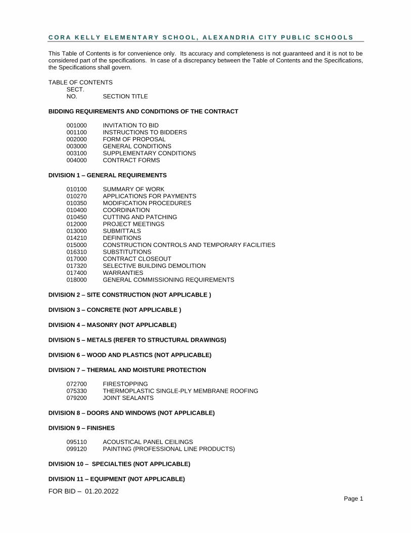
This Table of Contents is for convenience only. Its accuracy and completeness is not guaranteed and it is not to be considered part of the specifications. In case of a discrepancy between the Table of Contents and the Specifications, the Specifications shall govern.
TABLE OF CONTENTS SECT. NO. SECTION TITLE
BIDDING REQUIREMENTS AND CONDITIONS OF THE CONTRACT 001000 INVITATION TO BID 001100 INSTRUCTIONS TO BIDDERS 002000 FORM OF PROPOSAL 003000 GENERAL CONDITIONS 003100 SUPPLEMENTARY CONDITIONS 004000 CONTRACT FORMS
DIVISION 1 – GENERAL REQUIREMENTS 010100 SUMMARY OF WORK 010270 APPLICATIONS FOR PAYMENTS 010350 MODIFICATION PROCEDURES 010400 COORDINATION 010450 CUTTING AND PATCHING 012000 PROJECT MEETINGS 013000 SUBMITTALS 014210 DEFINITIONS 015000 CONSTRUCTION CONTROLS AND TEMPORARY FACILITIES 016310 SUBSTITUTIONS 017000 CONTRACT CLOSEOUT 017320 SELECTIVE BUILDING DEMOLITION 017400 WARRANTIES 018000 GENERAL COMMISSIONING REQUIREMENTS
DIVISION 2 – SITE CONSTRUCTION (NOT APPLICABLE )
DIVISION 3 – CONCRETE (NOT APPLICABLE )
DIVISION 4 – MASONRY (NOT APPLICABLE)
DIVISION 5 – METALS (REFER TO STRUCTURAL DRAWINGS)
DIVISION 6 – WOOD AND PLASTICS (NOT APPLICABLE)
DIVISION 7 – THERMAL AND MOISTURE PROTECTION 072700 FIRESTOPPING 075330 THERMOPLASTIC SINGLE-PLY MEMBRANE ROOFING 079200 JOINT SEALANTS
DIVISION 8 – DOORS AND WINDOWS (NOT APPLICABLE)
DIVISION 9 – FINISHES 095110 ACOUSTICAL PANEL CEILINGS 099120 PAINTING (PROFESSIONAL LINE PRODUCTS)
DIVISION 10 – SPECIALTIES (NOT APPLICABLE)
DIVISION 11 – EQUIPMENT (NOT APPLICABLE)

FOR BID – 01.20.2022 Page 2
DIVISION 12 – FURNISHINGS (NOT APPLICABLE)
DIVISION 13 – SPECIAL CONSTRUCTION (NOT APPLICABLE)
DIVISION 14 – CONVEYING SYSTEMS (NOT APPLICABLE)
DIVISION 15 - MECHANICAL
230100 BASIC MECHANICAL MATERIALS AND METHODS 230513 COMMON MOTOR REQUIREMENTS FOR HVAC EQUIPMENT 230529 HANGERS AND SUPPORTS 230553 MECHANICAL IDENTIFICATION 230593 TESTING, ADJUSTING, AND BALANCING 230716 DUCT INSULATION 230800 HVAC COMMISSIONING REQUIREMENTS 230923 DIRECT DIGITAL CONTROL (DDC) FOR HVAC 231123 FUEL GAS PIPING 233113 METAL DUCTS 233300 DUCT ACCESSORIES 233713 DIFFUSERS, REGISTERS AND GRILLES 234100 AIR FILTERS 237416 PACKAGED ROOFTOP HVAC UNITS
DIVISION 26 - ELECTRICAL
260100 BASIC ELECTRICAL MATERIALS AND METHODS 260519 LOW VOLTAGE CONDUCTORS AND CABLES 260523 CONTROL VOLTAGE CONTROLS AND CABLES 260526 GROUNDING AND BONDING 260533 RACEWAYS AND BOXES 260823 ELECTRIAL TESTING 262726 WIRING DEVICES 262816 ENCLOSED SWITCHES, ENCLOSED CIRCUIT BREAKERS AND FUSES
DIVISION 28 – FIRE ALARM 284621 FIRE ALARM
END TABLE OF CONTENTS

CORA KELLY ELEMENTARY SCHOOL, ALEXANDRIA, VA
INVITATION TO BID 001000 - 1 FOR BID – 01.20.2022
INVITATION TO BID 1. The Alexandria City School Board invites sealed bids from qualified bidders for the Cora Kelly
Elementary School, Packaged Rooftop HVAC Unit Replacement located at 3600 Commonwealth Ave, Alexandria, VA 22305 in accordance with the construction documents prepared by B2E Consulting Engineers, P.C., located at 116-N Edwards Ferry Road, N.E., Leesburg, Virginia, 20176, Tel: (703) 737-0400. Bid documents (drawings and specifications) can be downloaded from the b2E website, b2epc.com under ITB Documents Downloads tab.
2. Bids will be received at Alexandria City Public Schools, 1340 Braddock Place, Alexandria, VA
22314, Attn: Ms. Sharon T. Lewis, M.P.B. VCO, CPPB, Procurement Officer, Tel: (703) 619-8343, until 2:00 p.m. local time << Date >>, 2022.
3. Bids will be opened publicly and read aloud. 4. Bids shall be based upon the AIA Document A101, “Standard Form of Agreement Between
Owner and Contractor” and AIA Document A201, “General Conditions of the Contract for Construction”.
5. Contractors may obtain copies of the Contract Documents for bidding from B2E Consulting
Engineers, 116-N, Edwards Ferry Road, N.E., Leesburg, Virginia, 20176. Contractors may secure up to one (1) set of contract documents. Partial sets of contract documents will not be issued.
6. A pre-bid conference will be held on << Date >>, 2022 at 10:00 a.m. at the project site to
provide an opportunity to tour the site and discuss project issues with the Owner, Engineer and Architect. Attendance is encouraged but is not required.
7. A bid security is required in the form of a certified check, cashiers check or bid bond on AIA
Document A310 from a surety legally authorized to do business in the state of Virginia, acceptable to and executed in favor of the Owner for the amount of not less than 5% (percent) of the base bid. No forfeiture under a bid bond shall exceed the lesser of the difference between the bid and the next lowest bid of the face amount of the bid bond.
8. No bidder shall modify, withdraw or cancel his bid or any part thereof for 45 calendar days after
bid opening, except as noted in “Withdrawal of Bids” section of “Instructions to Bidders”. 9. The Owner reserves the right to reject any or all bids, waive bidding formalities or irregularities
and without explanation, accept bids which the Owner believes are in his best interest. Bids will be evaluated on experience and best value.
10. All dates will be provided in the ACPS Invitation to Bid (ITB) document for schedules and critical
milestones. BY: Ms. Sharon T. Lewis, M.P.B., VCO, CPPB Procurement Officer Alexandria City Public Schools END OF SECTION 001000

CORA KELLY ELEMENTARY SCHOOL, ALEXANDRIA, VA
INVITATION TO BID 001000 - 2 FOR BID – 01.20.2022

CORA KELLY ELEMENTARY SCHOOL, ALEXANDRIA, VA
INSTRUCTIONS TO BIDDERS 001100 - 1 FOR BID – 01.20.2022
SECTION 001100 - INSTRUCTIONS TO BIDDERS
ARTICLE 1- DEFINITIONS A. All definitions set forth in the General Conditions of the Contract for Construction, AIA Document
A201, are applicable to these Instructions to Bidders. B. Bidding documents include the “Invitation to Bid”, “Instructions to Bidders”, “Form of Proposal” and
the proposed Contract Documents including Addenda issued prior to receipt of bids. C. Addenda are written or graphic instruments issued prior to the execution of the Contract which modify
or interpret the bidding documents, including drawings and specifications, by additions, deletions, clarifications or corrections. Addenda will become part of the Contract Documents when the Construction Contract is issued.
ARTICLE 2- BIDDERS REPRESENTATION A. Each bidder by submitting his bid represents that he has read and understands the bidding
documents. B. Each bidder by submitting his bid represents that he and his subcontractors have visited the
project site and have familiarized themselves with the local conditions under which the work is to be performed. Failure to visit the site will not relieve the successful bidder of his obligation to furnish all material and labor necessary to work under the conditions of the existing facility in order to carry out the provisions of the Contract Documents and to complete the work for the consideration set forth in his bid.
ARTICLE 3- BIDDING PROCEDURES A. A copy of the “Form of Proposal” is included in the Project Manual for the information and
convenience of the bidders; this copy is to be removed from the Project Manual and be filled out and executed. Make duplicate copies of the “Form of Proposal” as required for submission of a bid.
B. Submit bids in duplicate with all spaces filled in by typewriter or clearly by hand in ink by the bidder.
Where both written words and numerical figures are to be filled in on the “Form for Proposal”, the written words will apply in event of a conflict between the written words and the numerical figures. Bidders shall acknowledge receipt of Addendum in the spaces provided on the “Form of Proposal” as part of his bid.
C. Bids will be received at the time and place set forth in the “Invitation to Bid”. No bidder shall modify,
withdraw or cancel his bid or any part thereof for a period of 45 days after the time designated for the receipt of bids specified in the “Invitation to Bid”, or prior to any extension thereof issued to the bids.
D. Bids received after the designated time and date will be returned unopened. E. Prior to the receipt of bids, addenda will be mailed, or delivered to each person or firm recorded by
the Engineer as having received the bidding documents and will be available for inspection at the locations listed in the “Invitation to Bid”. Addenda issued after the receipt of bids will be mailed only to the apparent successful bidder.

CORA KELLY ELEMENTARY SCHOOL, ALEXANDRIA, VA
INSTRUCTIONS TO BIDDERS 001100 - 2 FOR BID – 01.20.2022
F. Each bidder shall examine the bidding documents carefully and not later than seven (7) days prior to the date of receipt of bids, make written requests to the Engineer for interpretation or correction of any ambiguity, inconsistency, or apparent error therein which he may discover. Any interpretation or correction will be issued as an addendum by the Engineer. Only a written interpretation or correction issued as an addendum will be binding. No bidder shall rely upon interpretation of correction given by any other method.
G. Submit bids in sealed opaque envelopes with the following written clearly on the outside of the
envelope: TO: Alexandria City Public Schools Attn: Ms. Sharon T. Lewis, M.P.B., VCO, CPPB Procurement Office 1340 Braddock Place Alexandria, VA 22314 Re: Project Name: ___________________________ From: Bidder’s Name: __________________________ Registered Virginia Class “A” Contractor No.: ________________ Date: ________________________________ H. Bid Security in the type and amount stated in the “Invitation to Bid” shall accompany each bid. The
bid security will be retained by the Owner if the apparent successful bidder fails to execute the Contract or fails to provide satisfactory Performance and Payment Bonds as required, within ten (10) days after Notice of Award is mailed to the successful bidder.
ARTICLE 4- SUSTITUTIONS A. Each bidder represents that his bid is based upon the materials and equipment described in the
contract documents. B. Substitutions of material and equipment described in the bidding documents shall be in accordance
with the requirements specified in Section 01631 “Substitutions”. C. No substitution will be considered unless submitted to the Engineer and Owner in writing at least ten
(10) days prior to the date of the bid opening. ARTICLE 5- QUALIFICATION OF BIDDERS A. Attach to the bid, bidders must provide evidence of Class A registration, each bidder shall be a
General Contractor and also meet all City of Alexandria licensing and registration requirements. B. Attached to the bid, the bidder shall submit to the Owner a list of at least 3 previously completed
school projects of similar scope where the bidder acted as the General Contractor. The projects listed must have been completed within the last 5 years and the list shall include the following information: (1) Project Name and Address, (2) Owner’s Name, (3) Contact Person for Owner with Title and Phone Number, (4) Construction Cost and (5) Construction Start and Completion Dates.

CORA KELLY ELEMENTARY SCHOOL, ALEXANDRIA, VA
INSTRUCTIONS TO BIDDERS 001100 - 3 FOR BID – 01.20.2022
ARTICLE 6- REJECTION OF BIDS A. The bidder acknowledges the right of the Owner to reject any or all bids and to waive any informality
or irregularity in any bid received. In addition, the bidder recognizes the right of the Owner to reject a bid if the bidder failed to comply with the requirements of the bidding documents, or if the bid is in any way incomplete or irregular.
B. The Owner reserves the right to reject bids, before or after opening, upon evidence of collusion with
intent to defraud or other illegal practices on the part of the bidder or bidders. ARTICLE 7- WITHDRAWAL OF BIDS A. A bidder may withdraw his bid if the price was substantially lower than the other bids submitted due
solely to a mistake therein, provided the bid was submitted in good faith, and the mistake was a clerical mistake, as opposed to a judgment mistake and was actually due to an unintentional arithmetic error or an unintentional omission of a quantity of work, labor or material made directly in the compilation of the bid, which unintentional arithmetic error or unintentional omission can be clearly shown by objective evidence drawn from inspection of original work papers, documents and materials used in the preparation of the bid sought to be withdrawn. The bidder shall give written notice of this claim of right to withdraw his bid to the Owner within two (2) business days after the conclusion of the bid opening procedures.
B. No bid may be withdrawn under this provision when the result would be awarding of the contract on
another bid of the same bidder or of another bidder in which the ownership of the withdrawing bidder is more than 5 percent.
C. If a bid is withdrawn under the authority of this provision, the lowest remaining bid shall be deemed to
be the low bid, including alternates accepted. D. No bidder who is permitted to withdraw a bid shall, for compensation, supply any material or labor to
perform any subcontract or any other work agreement for the person or firm to whom the contract is awarded or otherwise benefit, directly or indirectly, from the performance of the project for which the withdrawn bid was submitted.
E. If the Owner denies withdrawal of a bid, it shall notify the bidder in writing stating the reasons for its
decision and award the contract to such bidder at the bid price, provided such bidder is a responsible and responsive bidder.
ARTICLE 8- PRE-BID CONFERENCE A. A prebid conference will be held on << Date >>, 2022 at 10:00 am at the project site, Cora Kelly
Elementary School, 3600 Commonwealth Avenue, Alexandria, VA 22305. B. This will be an opportunity for each contractor to tour the site and discuss project issues with the
Owner and Engineer. C. Attendance to the pre-bid conference is encouraged but not required. ARTICLE 9- CONTRACTOR'S PROPOSED CONSTRUCTION SCHEDULE SUBMITTAL
A. Bar-Chart Schedule: Prepare a horizontal bar-chart-type, contractor's construction schedule. Submit with bid attached to FORM OF PROPOSAL.
1. Provide a separate time bar for each significant construction activity. Use the same breakdown of units of the Work as required for the "Schedule of Values."
CORA KELLY ELEMENTARY SCHOOL, ALEXANDRIA, VA
INSTRUCTIONS TO BIDDERS 001100 - 4 FOR BID – 01.20.2022
2. Prepare the schedule to show data for the entire construction period from contract award to substantial completion
3. Coordinate each element on the schedule with other construction activities. Show each activity in proper sequence. Indicate graphically the sequences necessary for completion of related portions of the Work.
4. Indicate completion in advance of the date established for Substantial Completion.
Work Stages: Indicate important stages of construction for each major portion of the Work, including submittal review, ordering and delivery of long lead equipment such as RTU’s, steel, electrical gear and controls, number of crane lifts, if the RTU’s lead time extends beyond the start of the school year August 15th, 2022, then indicate that on the schedule. After the school year begins all crane lifts must be performed after normal business hours or on the weekends. ARTICLE 10- AWARD OF CONTRACT A. The Contract award will be made to a qualified bidder as defined in article 5, submitting a bid within
the availability of funds. B. Any protest of award or decision to award must be made in writing within ten (10) days of the bid
opening or contract award and include specific reasons and basis for protest. Owner will render a decision on the protest within ten (10) days in accordance with requirements of the Virginia Procurement Act.
C. The contract is determined by the aggregate amount of the base bid plus any alternates, and
previous experience with similar projects and proposed means and methods as accepted by the Owner.
D. The Owner anticipates making the award of the contract on or about << Date >>, 2022, pending
approval of the Capital Improvement Budget for the project by the Alexandria City Council on or about << Date >>, 2022. The Owner anticipates that Notice-to-Proceed will be given on or about << Date >>, 2022.
ARTICLE 11- SUBMISSION OF POST BID INFORMATION A. Upon request by the Engineer and Owner, and before contract award, the selected bidder shall within
seven (7) days submit the following:
A statement of costs for each major item of work included in the bid. A designation of the work to be performed by the bidder with his own forces. A list of names of the subcontractors or other persons of organizations (including those who will
furnish materials or equipment fabricated for a special design) proposed for such portions of the work as may be designated.
The names of subcontractors proposed for the principal portions of the work. A list of any hazardous materials that will be used during the execution of this contract or that
will be furnished as part of the work, including Material Safety Data Sheets for all such materials, in compliance with the Virginia Occupational Safety and Health Program, Hazardous Materials Communications Standard.
Submittals for permitting and for long lead equipment in accordance with the submittal schedule outlined in specification section 013000, “SUBMITTALS”.
B. The bidder will be required to establish to the satisfaction of the Engineer and the Owner the reliability
and responsibility of the proposed subcontractors to furnish and perform the portions of the work assigned to them.

CORA KELLY ELEMENTARY SCHOOL, ALEXANDRIA, VA
INSTRUCTIONS TO BIDDERS 001100 - 5 FOR BID – 01.20.2022
C. Prior to the award of the contract, the Engineer will notify the bidder, in writing, if either the Owner or
the Engineer, after due investigation, has reasonable and substantial objection to any person or organization listed, and refuses in writing to accept a person or organization listed, the bidder may, at his option, withdraw his bid, not withstanding anything to the contrary contained in the “Bidding Procedures” section of this specification.
If the bidder submits an acceptable substitute subcontractor with an increase in his bid price to cover the difference in cost occasioned by the substitution, the Owner may, at his discretion, accept the increased bid price or disqualify the bidder.
D. Subcontractors, other persons, and organizations proposed by the bidder and accepted by the Owner and the Engineer shall be used on the portion of the work for which they have been proposed and accepted and shall not be changed except with the written approval of the Owner and Engineer.
ARTICLE 12- PERFORMANCE BOND AND LABOR AND MATERIAL PAYMENT BOND A. Prior to execution of the contract, the successful bidder shall deliver to the Owner two (2) copies of
each of the following:
Performance Bond and Labor and Material Bond payable to the Owner in the amount of 100 percent of the entire contract sum as security for the payment of all persons performing labor and/or furnishing materials or equipment for the work.
A certified and current copy of Power of Attorney from the attorney-in-fact who executed the required bonds on behalf of the surety. Indicate the monetary limit of the power of attorney.
B. Prepare bonds on AIA Form A311 or similar form acceptable to Owner and Engineer. C. Bonds shall be issued by a surety company acceptable to the Owner and authorized to do business
in the Commonwealth of Virginia. Include the cost of bonds in the bid. D. Nothing in this section shall preclude the bidder from requiring each subcontractor to furnish a
payment bond with surety thereon in the sum of the full amount of the contract with each subcontractor for performing labor and furnishing materials in the completion of the work provided for in the contract.
E. No action against the surety on a Performance Bond shall be brought, unless within one year (1) after
completion of the contract, including the expiration of all warranties and guarantees or (2) after discovery of the defect or breach of warranty if the action be for such.
ARTICLE 13- RETURN OF BIDDING DOCUMENTS A. To qualify for deposit refund, sets of bidding documents shall be in accordance with the following
terms:
Return to the Engineer complete and in a condition suitable for reissue. Sets with binding removed, pencil marks, torn sheets or pages and missing sheets or pages will be considered unsuitable for reissue.
Return to the Engineer no later than 30 days after the opening of bids.
B. Deposit refunds will be made after the Engineer has ascertained the condition of the bidding
documents.

CORA KELLY ELEMENTARY SCHOOL, ALEXANDRIA, VA
INSTRUCTIONS TO BIDDERS 001100 - 6 FOR BID – 01.20.2022
C. Deposit refunds will be forfeited if bidding documents are not returned within the time limit or are found to be unsuitable for reissue.
ARTICLE 14- PUBLIC PROCUREMENT ACT In the event any term of the contract document is ambiguous, inconsistent with any other term, or invalid, the appropriate provision(s) of Virginia’s Procurement Act shall be controlling. ARTICLE 15- TAX EXEMPT STATUS The Alexandria City School Board is tax exempt for purchases made directly by the School Board. All purchases made by any contractor on behalf of the school board are not tax exempt. ARTICLE 16- EXAMINATION AND INTENT OF CONTRACT DOCUMENTS A. Include in the bid a sum to cover all items necessary to perform the work within the work sequence
phasing specified as set forth in the contract documents for this project. No allowance will be made to any bidder because of the lack of examination or knowledge. The submission of a bid shall be evidence that the bidder has made this examination.
B. The contract documents are complimentary and what is required by one shall be as binding as
required by all. The intention of the contract documents is to include all labor, materials, equipment and other items necessary for the proper execution of the work.
C. Within the contract documents, there shall be the following precedence: 1. Addenda or modifications of any nature to the drawings or specifications take precedence over
the original. 2. Specifications take precedence over the drawings. 3. Within the drawings, the larger scale takes precedence over smaller scale drawings; figures
dimensions over scaled; and noted materials over graphic indications. D. If there is doubt to the true meaning of any part of the contract documents or suspected
discrepancies or omissions, submit a written request for interpretation or correction to the engineer no later than 7 days before bids are to be opened. Any interpretation will be made only by addendum and will be mailed or transmitted by FAX. The Owner and Engineer will not be responsible for any other explanation or interpretation of the contract documents.
E. The Engineer has endeavored to separate all work into various categories as set forth in the
specifications. This separation is done forth the convenience of the Contractor and the Engineer assumes no responsibility for the inclusion of all or any specific items under any particular section or trade.
F. Mechanical and electrical drawings are diagrammatic, intending to show general locations and
arrangements of piping, wiring, equipment, and specialties and not necessarily to show all required offsets, conditions and appurtenances required for maximum practical accessibility for operation, maintenance and headroom.
G. No drawings are intended to be rigid in specific details where any details may be in conflict with the
recommendations of the equipment manufacturer. Make any modifications in designs indicated or specified as may be required to assure that all work conforms to manufacturers’ recommendations.
H. Furnish all specified equipment and materials with features normally provided with items, although all
features of design and construction may not be specified in complete details. Include all standard

CORA KELLY ELEMENTARY SCHOOL, ALEXANDRIA, VA
INSTRUCTIONS TO BIDDERS 001100 - 7 FOR BID – 01.20.2022
features and appurtenances normally provided or required for safe operation, subject to the engineer’s approval.
END OF SECTION 001100

CORA KELLY ELEMENTARY SCHOOL, ALEXANDRIA, VA
INSTRUCTIONS TO BIDDERS 001100 - 8 FOR BID – 01.20.2022

CORA KELLY ELEMENTARY SCHOOL, ALEXANDRIA, VA
FORM OF PROPOSAL 002000 - 1 FOR BID – 01.20.2022
SECTION 002000 - FORM OF PROPOSAL TO: Alexandria City Public Schools FROM: (Bidder’s Name and Address)
Ms. Sharon T. Lewis, M.P.B., VCO, CPPB __________________________________ Procurement Officer __________________________________ 1340 Braddock Place __________________________________ Alexandria, Virginia 22314 __________________________________
RE: Cora Kelly Elementary School, Packaged Rooftop HVAC System Replacement Pursuant to and in compliance with the “Invitation to Bid”, “Instructions to Bidders”, contract documents and addenda for this project, the undersigned hereby proposes and agrees to fully perform and complete the work within the time stated and in strict accordance with the contract documents for the following sums: BASE BIDS: Base Bid: ____________________________________________________________________________Dollars ($ ) COMPLETION TIME: The undersigned agrees, if awarded the contract, to substantially complete the work no later than August 15th, 2022, in accordance with the Work Sequence outlined in the SUMMARY OF WORK. LIQUIDATED DAMAGES: See Article 9, AIA Document A201 and Supplementary Conditions. I understand the owner reserves the right to reject this bid and bid shall not be withdrawn for 45 calendar days after bid opening. The undersigned will execute and deliver to the Owner the contract Performance Bond, Labor and Material Payment Bond, proof of insurance and Power of Attorney within 15 calendar days after notice of bid acceptance is mailed or delivered to undersigned. All items will be delivered to the Owner prior to execution of the contract. ADDENDA Receipt of the following addenda is acknowledged: No.______dated:____________________ No.______dated:____________________ No.______dated:____________________ No.______dated:____________________ No.______dated:____________________ No.______dated:____________________ No.______dated:____________________ No.______dated:____________________
Notice of acceptance or request for additional information may be forwarded to the undersigned at the address set forth below. The names of all persons interested in the forgoing bid as principals are: _______________________________________________________________ _______________________________________________________________ _______________________________________________________________

CORA KELLY ELEMENTARY SCHOOL, ALEXANDRIA, VA
FORM OF PROPOSAL 002000 - 2 FOR BID – 01.20.2022
Note: If bidder or other interested person is a corporation, fill in legal corporation president and secretary; if a partnership, fill in partnership names and names of all partners composing the partnership; if an individual, fill in first and last names. All signatures below shall be of officers or partners authorized to sign contracts. Sign Here: ________________________________________________ Date: ______________________
Title: ________________________________________________
Telephone Number: ___________________________________________ State of Incorporation: ________________________ Registered Virginia Contractor Number: _______________
END OF SECTION 002000

CORA KELLY ELEMENTARY SCHOOL, ALEXANDRIA, VA
GENERAL CONDITIONS 003000 - 1 FOR BID – 01.20.2022
SECTION 003000 - GENERAL CONDITIONS ARTICLE 1- DESCRIPTION
A. The Form of Agreement is AIA Document A101, Standard Form of Agreement Between Owner and Contractor Where Basis of Payment is a Stipulated Sum, 2017 Edition, and AIA Document A201, General Conditions of the Contract for Construction, 2017 Edition, as modified by the Supplementary Conditions.
B. The General Conditions and Modifications to the General Conditions as noted in
“Supplementary Conditions” as set forth hereinafter shall apply with equal force to General Contractor, all subcontractors, suppliers, and tradesmen for performance of the work, extra work and/or services under this contract, and apply to each Section in the Specifications.
END OF SECTION 003000

CORA KELLY ELEMENTARY SCHOOL, ALEXANDRIA, VA
GENERAL CONDITIONS 003000 - 2 FOR BID – 01.20.2022

CORA KELLY ELEMENTARY SCHOOL, ALEXANDRIA, VA
SUPPLEMENTARY CONDITIONS 003100 - 1 FOR BID – 01.20.2022
SECTION 003100 - SUPPLEMENTARY CONDITIONS The following supplements modify the “General Conditions of the Contract for Construction” AIA Document A201, 2017 edition. Where a portion of the General Condition is modified or deleted by Supplementary Conditions, the unaltered portions of the General Conditions shall remain in effect. ARTICLE 1- BASIC DEFINITIONS See specification section 014210. ARTICLE 2- OWNER DELETE subparagraph 2.2.5 and SUBSTITUTE the following: 2.2.5 The Contractor will be furnished in portable document format (pdf) files free of charge for
Drawings and the Technical Specifications Project Manual. ARTICLE 3- CONTRACTOR 3.4 Labor and Materials Delete subparagraph 3.4.3 and substitute the following: 3.4.3 After the contract has been executed, the Owner and Engineer will consider a formal request for
the substitution of products in place of those specified only under the conditions set forth in the Substitutions Section 016310.
DELETE subparagraph 3.71. and SUBSTITUTE the following: 3.7.1 The Owner will apply for the building permit; the Contractor shall secure the building permit. The
Contractor shall secure and pay for all other permits and government fees, licenses, and inspections including Alexandria Health Department inspections, necessary for proper execution of and completing the contract, which are legally required when bids are received, or negotiations concluded. The Contractor shall apply for and secure the Certificate of Occupancy Permit, and/or other permits required by the city for approval of all City final inspections. The Owner will complete the appropriate forms. The City of Alexandria will waive the fees for the permits, but not overtime inspections if driven by the contractor.
Comply with all procedures and submission requirements of the Alexandria Complex Structure Manual.
3.8.2.3 ADD the following to the end of clause 3.8.2.3:
“Except when installation is specified as part of the allowance in the General Requirements (Division 1 of the Specifications).
ARTICLE 4- ADMINISTRATION OF THE CONTRACT 4.5 Mediation: Delete paragraph 4.5 in its entirety. 4.6 DELETE paragraph 4.6 “ARBITRATION” in its entirety and substitute the following:

CORA KELLY ELEMENTARY SCHOOL, ALEXANDRIA, VA
SUPPLEMENTARY CONDITIONS 003100 - 2 FOR BID – 01.20.2022
4.6.1 Subject to the Owner’s election, claims, disputes, or other matters in question between Owner and Contractor shall be subject to Arbitration only upon written demand of either party upon the provisions and limitations set forth herein.
4.6.2 Claims and disputes between Owner and Contractor subject to Arbitration will be decided in
accordance with the Construction Industry Arbitration Rules of the American Arbitration Association currently in effect unless the parties agree otherwise. Notice of demand for Arbitration shall be filed with the other party of the Contract, with the American Arbitration Association, and with the Engineer.
4.6.3 No arbitration arising out of or relating to the Contract Documents shall include by consolidation
or joiner or in any other manner, the Engineer, the Engineer’s employees, or consultants, except by the Owner’s sole discretion, and written consent containing specific references to the Agreement and signed by the person or entity sought to be joined.
4.6.4 Before the Contractor may pursue a claim or other dispute against Owner arising out of or relating
to the Work of the Project, Contractor must send to Owner at least 30 days advance written notice, which shall state Contractor’s intent to pursue a claim or dispute, the nature of the claim or dispute including the compensation and/or other relief being sought. Failure to provide advance written notice shall render premature any arbitration or other legal proceedings sought by Contractor.
4.6.5 Owner shall exercise its option to elect arbitration by written notice within 30 days of receipt of
Contractor’s written notice of a claim. Failure of the Owner to respond within 30 days constitutes a waiver of Owner’s rights to elect arbitration.
4.6.6 In the event Owner has a claim or dispute with Contractor, Owner shall exercise its option by
commencement of arbitration proceedings against Contractor. 4.6.7 Venue for arbitration shall be the same locale as the Project site in Alexandria, Virginia, and the
laws of the Commonwealth of Virginia shall control any such dispute proceedings, including the interpretation and enforcement of the Contract Documents.
ARTICLE 7- CHANGES IN THE WORK 7.3 Construction Change Directives 7.3.6 First sentence, DELETE the words “a reasonable allowance for overhead and profit” and
SUBSTITUTE the words “an allowance for overhead and profit in accordance with clauses 7.3.10.1 through 7.3.10.6 below”.
ADD the following subparagraph 7.3.10 to paragraph 7.3: 7.3.10 In subparagraph 7.3.6 the allowance for the combined overhead and profit included in the total
cost to the Owner shall be based on the following schedule: .1 For the Contractor, for work performed by the Contractor’s own forces, 15 percent of the
cost. .2 For the Contractor, for Work performed by Contractors subcontractors, 5 percent of amount
due the subcontractor .3 For each subcontractor or sub-subcontractor involved, for Work performed by that
Subcontractor’s or sub-subcontractor’s own forces, 15 percent of the cost. .4 For each Subcontractor, for Work performed by the Subcontractor’s sub-subcontractor, 5
percent of the amount due of the subcontractor.

CORA KELLY ELEMENTARY SCHOOL, ALEXANDRIA, VA
SUPPLEMENTARY CONDITIONS 003100 - 3 FOR BID – 01.20.2022
.5 Cost to which overhead and profit is to be applied shall be determined in accordance with subparagraph 7.3.6.
.6 In order to facilitate checking of quotations for extras or credits, all proposals, except those so minor that their propriety can be seen by inspection, shall be accompanied by a complete itemization of costs including labor, materials, and subcontracts. Labor and materials shall be itemized in the manner prescribed above. Where major cost items are subcontracts, they shall be itemized also. In no case will a change over $ 500.00 be approved without such itemization.
.7 RS Means Cost Data Book (latest edition) shall be used to check subcontractor material and labor costs for any proposed changed orders.
ARTICLE 9- PAYMENT AND COMPLETION 9.3 Applications for Payment 9.3.1 ADD the following sentence to subparagraph 9.3.1:
The form of Application for Payment shall be a notarized AIA Document G702, Application and Certification for Payment, supported by AIA Document G703, Continuation Sheet.
ADD the following clause 9.3.1.3 to 9.3.1: 9.3.1.3 Until Substantial Completion, the Owner shall pay 95 percent of the amount due the contractor on
account of progress payments. The Contractor shall pay 95 percent of the amount due to all subcontractors on account of progress payments. Substantial completion is defined in paragraph 9.8.1 of the General Conditions.
9.11 Liquidated Damages 9.11.1 The Owner requires that the work be performed under this agreement by the Contractor be
substantially complete by the date specified in the Form of Proposal. The parties agree that the amount of damages which would be suffered by the Owner in the event of the Contractor’s failure to meet such completion dates is not capable of precise determination. Therefore, the Contractor and his surety agree to pay the Owner the sum of five hundred dollars ($ 500) for each calendar day beyond the substantial completion date of August 15th, 2022, as liquidated damages for delay. Substantial completion is defined as completing work required in the contract documents and for approval of final inspection by the City of Alexandria code enforcement office.
ARTICLE 10- PROTECTION OF PERSONS AND PROPERTY 10.2 Safety of Persons and Property 10.2.4.1 When use or storage of explosives or other hazardous materials or equipment or unusual
methods are necessary, the Contractor shall give the Owner reasonable advance notice. 10.3.1 An asbestos survey has been conducted for the existing building. The Contractor may review the
asbestos report at the Owner’s office.

CORA KELLY ELEMENTARY SCHOOL, ALEXANDRIA, VA
SUPPLEMENTARY CONDITIONS 003100 - 4 FOR BID – 01.20.2022
ARTICLE 11- INSURANCES AND BONDS 11.1 DELETE the semicolon at the end of clause 11.1.1.1 and ADD:
“, including private entities performing Work at the site and exempt from the coverage on account of number of employees or occupation, which entities shall maintain voluntary compensation coverage at the same limits specified for mandatory coverage for the duration of the project;”
11.1.1.2 DELETE the semicolon at the end of clause 11.1.2 and ADD:
“or persons or entities excluded by statute from the requirements of clause 11.1.1.1 but required by the Contract Documents to provide insurance required by that clause;”
11.1.1.9 Liability insurance shall include all major divisions of coverage and be on a comprehensive basis
including:
1. Premises Operations (including X, C and U coverage as applicable). 2. Independent Contractors’ Protective. 3. Products and Completed Operations. 4. Personal Injury Liability with Employment Exclusion deleted. 5. Contractual, including specified provision for Contractor’s obligation under paragraph 3.18. 6. Owned, non-owned and hired motor vehicles. 7. Broad Form Property Damage including Completed Operations
11.1.1.10 If the General Liability coverage is provided by a commercial General Liability Policy on a
claims-made basis, the policy date or Retroactive Date shall predate the Contract; the termination date of the policy or applicable extended reporting period shall be no earlier than the termination date of coverage’s required after final payment, certified in accordance with subparagraph 9.10.2.
ADD the following clause 11.1.2.1 or 11.1.2: 11.2.1 The Insurance required by subparagraph 11.1.1 shall be written for not less than the following
limits, or greater if required by law:
1. Workers’ Compensation: (a) State Statutory (b) Applicable Federal (e.g. Longshoremens’) Statutory (c) Employer’s Liability $100,000 per Accident; $500,000 Disease, Policy Limit
2. Comprehensive or Commercial General Liability and Contractual Liability, (including Premises-Operations; Independent Contractor’s Protective; Products and Completed Operations; Broad Form Property Damage):
(a) Bodily Injury: $ 1,000,000 Each Occurrence $ 1,000,000 Aggregate (b) Property Damage: $ 1,000,000 Each Occurrence $ 1,000,000 Aggregate (c) Personal Injury: $ 1,000,000 Aggregate (d) Products and Completed Operations to be maintained for two (2) years after final payment. (e) Property Damage Liability Insurance shall provide X, C, and U coverage. (f) Broad Form Property Damage Coverage shall include Completed Operations.

CORA KELLY ELEMENTARY SCHOOL, ALEXANDRIA, VA
SUPPLEMENTARY CONDITIONS 003100 - 5 FOR BID – 01.20.2022
3. Business Auto Liability (including owned, non-owned and hired vehicles):
(a) Bodily Injury $ 1,000,000 Each Person $ 1,000,000 Each Occurrence (b) Property Damage $ 1,000,000 Each Occurrence
4. If the General Liability coverage is provided by a Commercial Liability policy, the:
(a) General Aggregate shall be not less than $ 1,000,000 and it shall apply, in total, to this project only.
(b) Fire Damage Limit shall be not less than $ 1,000,000 on any one (1) fire.
(c) Medical Expense Limit shall be not less than $ 1,000,000 on any one person
5. Umbrella Excesses Liability $ 1,000,000 over primary insurance. 11.1.3 ADD the following sentence to subparagraph 11.1.3:
If this insurance is written on the Comprehensive Liability policy form, the Certificate shall be AIA Document G705, Certificate of Insurance. If this insurance is written on a Commercial General Liability policy form, ACORD form 25S will be acceptable as a certificate of insurance.
11.5 Performance and Payment Bond DELETE subparagraph 11.5.1 and SUBSTITUTE the following: 11.5.1 The Contractor shall furnish bonds covering faithful performance of the Contract and payment of
obligations arising thereunder. Bonds may be obtained through the Contractor’s usual source and the cost thereof shall be included in the Contract Sum. The amount of each bond shall be equal to 100 percent of the Contract Sum.
11.5.1.1 The Contractor shall deliver the required bonds to the Owner not less than three (3) days
following the date of the Agreement is entered into, or if the Work is to be commenced prior to thereto in response to a letter of intent, the Contractor shall, prior to the commencement of the Work, submit evidence satisfactory to the Owner that such bonds will be furnished.
11.5.1.2 The Contractor shall require the attorney-in-fact who executes the required bonds on behalf of
the surety to affix thereto a certified and current copy of the power of attorney. END OF SECTION 003100
CORA KELLY ELEMENTARY SCHOOL, ALEXANDRIA, VA
SUPPLEMENTARY CONDITIONS 003100 - 6 FOR BID – 01.20.2022

CORA KELLY ELEMENTARY SCHOOL, ALEXANDRIA, VA
CONTRACT FORMS 004000 - 1 FOR BID – 01.20.2022
SECTION 004000 - CONTRACT FORMS ARTICLE 1- GENERAL A. The following forms, as listed or set forth in this section and as described elsewhere in these
documents, shall be used as a basis for all required documents, completed in detail as they apply, for and during the life of the Contract, shall be prepared by the Contractor in accordance in accordance with the particular requirements of this Contract, shall be submitted to and approved by the Engineer except as otherwise specifically noted in these documents.
B. Forms may be examined at the offices of the Engineer. ARTICLE 2- STANDARD AIA FORMS
The latest edition, unless otherwise noted, of each of the following forms, as printed and distributed by the American Institute of Architects (AIA) will be used by the Contractor when required in the execution of this Contract:
DESCRIPTION AIA DOCUMENT NUMBER Change Order G-701 Application for Payment G-702 Certificate for Payment G-703 Certificate for Substantial Completion G-704 Certificate of Insurance G-705 Contractor’s Affidavit of Payment G-706 Contractor’s Release of Liens G-706A Consent of Surety to Final Payment G-707 List of Subcontractors G-805
ARTICLE 3- OTHER FORMS The following forms shall be prepared by the Contractor in accordance with the requirements of this
contract and shall be submitted to and approved by the Engineer. 1. Initial List of Subcontractors 2. Project Progress Schedule 3. Schedule of Values END OF SECTION 004000

CORA KELLY ELEMENTARY SCHOOL, ALEXANDRIA, VA
CONTRACT FORMS 004000 - 2 FOR BID – 01.20.2022

CORA KELLY ELEMENTARY SCHOOL, ALEXANDRIA, VA
SUMMARY OR WORK 010100 - 1 FOR BID – 01.20.2022
SECTION 010100 - SUMMARY OF WORK
PART 1 - GENERAL
1.1 RELATED DOCUMENTS A. Drawings and general provisions of the Contract, including General and Supplementary
Conditions and other Division 1 Specification Sections, apply to this Section.
1.2 WORK COVERED BY CONTRACT DOCUMENTS A. The Project consists of Packaged Rooftop HVAC Unit Replacement, Cora Kelly Elementary
School, Alexandria City Public Schools, Alexandria, Virginia. 1. Project Location: 3600 Commonwealth Avenue, Alexandria, Virginia 22305 2. Owner: Alexandria City Public Schools
1340 Braddock Place Alexandria, Virginia 22314
B. Contract Documents, dated, January 20, 2022, were prepared for the Project by:
B2E Consulting Engineers, P.C. 116-N Edwards Ferry Road, N.E. Leesburg, Virginia 20176
C. The Work consists of:
1. MECHANICAL The mechanical work required for the HVAC system upgrade generally consists of the following:
a. Removal of existing selected packaged rooftop HVAC units and adaptor curbs for RTU-1 thru 4.
b. Removal of existing ductwork as indicated, c. Installation of adapter curbs for RTU-1 thru 4 and RTU-15 thru 17. d. Installation of new packaged rooftop HVAC units with Niagra Open Protocol controls by
unit manufacturer. e. Installation of new ductwork inside the building as indicated. f. Installation of new diffusers, registers, and grilles as indicated. g. Re-configuration of existing gas piping on roof and installation of new gas piping to
rooftop HVAC units as indicated. h. Full coordination with the BMS contractor, for a complete operating system as described
in Div. 23 of the specifications. i. Testing, adjusting, and balancing the new rooftop HVAC units, including areas where
existing ductwork and air outlets are being reused. j. Commissioning and systems demonstrations.

CORA KELLY ELEMENTARY SCHOOL, ALEXANDRIA, VA
SUMMARY OR WORK 010100 - 2 FOR BID – 01.20.2022
2. ELECTRICAL The electrical work required for the HVAC and electrical system upgrade generally consists of the following: a. Disconnection of existing fire alarm devices (i.e., duct smoke detectors) in existing
rooftop HVAC unit ductwork. Coordinate with Division 230000 on exact quantities and locations.
b. Install electric feeders serving packaged rooftop HVAC unit as indicated. c. Interlock of existing fire alarm devices (i.e., duct smoke detectors) to new rooftop HVAC
units. d. Verification of existing fire alarm annunciator panel to include testing of duct smoke
detectors zoning. e. Installation of convenience receptacles on the roof and for the BMS panels. f. Installation of new NEMA 3R fused disconnect switches for new mechanical equipment
as indicated. g. Electrical Insulation, Resistance Testing of existing feeders serving RTU’s in accordance
with the International Electrical Testing Association, Inc., (NETA) Acceptance Testing Specifications.
3. STRUCTURAL AND ARCHITECTURAL The structural work required for the HVAC replacement consists of the following:
a. Framing for RTUs on existing steel support systems on roof. b. Steel platform walkways and railways c. miscellaneous structural work as required. Architectural work is limited to work required in connection with the installation of the mechanical HVAC and electrical systems upgrade. The work includes but is not limited to:
a. Removal and reinstallation of existing suspended acoustical tile ceilings as required, b. Installation of new suspended acoustical tile ceilings, for any areas where ceilings are
damaged due to construction. c. A limited amount of patching and or refinishing of existing interior room finishes, d. Roof flashing at penetrations for conduit and HVAC roof curbs, as required to maintain
existing 20-year roof warranty. e. Roofing to weatherproof ductwork above the roof as required to maintain existing 20-year
roof warranty, f. installation and patching of miscellaneous floor, wall, and ceiling finishes in areas of
renovation work. g. Addition of 200 walkway pads. h. Roofing inspection and recertification of the existing 20-year roof warranty.
D. The Work will be constructed under a single prime contract. E. The contractor shall plan in advance the number of crane days needed considering the long
lead times for equipment. Crane work involving lifting equipment onto or off of the roof must be coordinated with the Alexandria City Public Schools Representatives. Cranes shall not be used while the students and teachers occupy the building.
1.3 WORK UNDER OTHER CONTRACTS

CORA KELLY ELEMENTARY SCHOOL, ALEXANDRIA, VA
SUMMARY OR WORK 010100 - 3 FOR BID – 01.20.2022
A. Cooperate fully with separate contractors so that work under those contracts may be carried out smoothly, without interfering with or delaying work under this Contract. No claim for delay will be considered as a result of the Contractor’s efforts required to coordinate the Owner’s various separate contracts.
1.4 WORK SEQUENCE A. The Work to be completed in accordance with the following schedule: These dates may
change. Refer to the ACPS Invitation to Bid (ITB). 1. Carryout the work in accordance with the approved Contractor’s Construction Schedule. 2. Award of Contract on or about << Date >>, 2022. 3. Pre-construction Conference << Date >>, 2022. 4. Notice-To-Proceed shall be on or about << Date >>, 2022. Construction work which
does not interface with the educational program can commence at time of Notice-To-Proceed.
5. The building will remain fully operational as a school and be occupied by students and staff until June 20, 2008.
6. The existing air conditioning systems (cooling) must remain operational until June 20, 2022.
7. All HVAC systems shall be completed for their intended use by August 15, 2022. 8. Systems Demonstrations shall be conducted and completed between August 15 and
September 1, 2022. 9. All other work included in the contract to carry the project through SUBSTANTIAL
COMPLETION must be fully complete by September 1, 2022, as defined by a final inspection certificate.
B. See Section 001300 for Submittal Schedule of shop drawings.
1.5 CONTRACTOR USE OF PREMISES A. Use of the Site: Limit use of the premises to work in areas indicated. Confine operations to
areas within contract limits indicated. Do not disturb portions of the site beyond the areas in which the Work is indicated.
1. General: The Contractor shall limit his use of the premises to the work areas indicated so
as to allow for Owner occupancy and use by the public during the period of construction. The Contractor shall coordinate with the Owner to establish an identification badge system to be utilized and worn by all workers while on the site or in the building.
2. Storage of Materials: Do not unreasonably encumber the site with materials or equipment. Confine stockpiling of materials and location of storage sheds to areas indicated. If additional storage is necessary, obtain and pay for such storage off site.
3 Driveways and Entrances: Keep driveways, fire lanes and entrances serving the premises clear and available to the Owner, the Owner's employees, and emergency vehicles at all times. Do not use these areas for parking or storage of materials. Schedule deliveries to minimize space and time requirements for storage of materials and equipment on-site.
4. Contractor’s or Worker Vehicles: Lock automotive vehicles, such as passenger cars and trucks and other mechanized or motorized equipment, when parked or unattended, so as to prevent unauthorized use. Do not leave any vehicles or equipment unattended with the motor running or the ignition key in place. Park all vehicles in paved parking lots, streets and alleys. No parking will be allowed on lawns, sidewalks or playing fields unless required by construction operations, specifically indicated in the Contract

CORA KELLY ELEMENTARY SCHOOL, ALEXANDRIA, VA
SUMMARY OR WORK 010100 - 4 FOR BID – 01.20.2022
Documents, or approved by the Owner’s Representative. Repair any damage caused to lawns, sidewalks or playing fields caused as a result of construction operations.
B. Use of the Existing Building: Maintain the existing building in a weathertight condition
throughout the construction period. Repair damage caused by construction operations. Take all precautions necessary to protect the building and its occupants during the construction period. Repair any damage caused by construction operations to match existing conditions and finishes. Take all precautions necessary to protect the building and its occupants during the construction period. 1. Keep public areas such as hallways, stairs, elevator lobbies and toilet rooms free from
accumulation of waste material, rubbish, or construction debris. 2. Smoking or open fires will not be permitted within the building enclosure or on the
premises at any time. 3. Contractor’s use of existing toilets within the building will be limited until the end of the
school year, coordinate with the Owner’s Representative. 4. The Owner will designate a staging and storage area for the Contractor’s use on site.
The Contractor shall assume full responsibility for protection of products, equipment and materials stored on site, in vehicles or in trailers.
C. See Specifications Section 01040, “Coordination”.
1.6 OCCUPANCY REQUIREMENTS A. Owner Occupancy: The Owner reserves the right to occupy the building in accordance with the
work sequence outlined previously and to place and install equipment in completed areas of the building prior to Substantial Completion, provided such occupancy does not interfere with completion of the Work. Such placing of equipment and partial occupancy shall not constitute acceptance of the total Work. During the summer vacation period, school staff will continue to occupy the building and site. Contractor is responsible for final construction cleaning as part of substantial completion.
1.7 CONTRACTOR’S MANPOWER TO CONDUCT THE WORK
A. Commencement of each phase of work in existing classrooms shall not occur until sufficient materials and equipment are available for the particular phase and sufficient numbers of workmen are available to execute the work in the time period indicated.
B. Multiple Work Shifts: In order to ensure completion of work phases during the time periods
indicated, the contractor may operate two (2) separate, full time, eight hour shifts per day, six days per week, employing trades, skills, and specialties including, but not limited to, the following:
1. General Labor 2. Cleaning Staff 3. Special Systems Technicians 4. Electrical 5. Plumbing 6. HVAC 7 The Contractor may modify this list to include other trade, skill and specialties required to
comply with the phasing requirements. 8. Qualified supervision for all trades for all work shifts.

CORA KELLY ELEMENTARY SCHOOL, ALEXANDRIA, VA
SUMMARY OR WORK 010100 - 5 FOR BID – 01.20.2022
1.8 OWNER’S REPRESENTATIVE The Owner’s representative during the course of this work will be:
Mr. Alex Alexander Supervisor Design and Construction City of Alexandria Public Schools 1340 Braddock Place Alexandria, Virginia 22314 Office: 703.619.8300 Mobile: 703.403.3211
1.9 HAZARDOUS MATERIALS
The Owner’s representative will notify the Contractor of any asbestos or other hazardous materials that may be encountered in this building during the course of the contract, in compliance with AHERA regulations and the Virginia Occupational Safety and Health Program Hazard Communication standard. Copies of the Alexandria City Schools Hazard Communication Program and Material Safety Data Sheets for each facility are available on site and from the Owner’s Representative. Copies of the AHERA Asbestos Management Plan for each facility are available on site and from the Owner’s Representative.
1.10 BUILDING PERMITS The Owner will provide signed and sealed drawings to the contractor to make application for the Alexandria City Building Trade Permits. The Contractor shall obtain, prior to beginning work, all building permits necessary for the completion of this contract. Permits shall be clearly displayed at the project site and a copy delivered to the Owner’s Representative prior to commencing work. All inspections required by the City of Alexandria Code Enforcement Office shall be completed and certificates delivered to the Owner’s Representative prior to Request for Final Payment. All fees for building permits are waived by the City of Alexandria Code Enforcement Office.
1.11 HEALTH AND SAFETY PROGRAM Contractor shall comply with and meet all OSHA standards and the ACPS Safety manual
during construction. Contractor shall provide Owner with a copy of a company wide Safety Program relating to this construction project. Periodic safety meetings will be held, and all safety reports maintained at the construction site. Contractor shall provide Owner with a copy of HAZMAT Communications Program which includes labeling, MSDS, employee training and other right-to-know materials.
END OF SECTION 010100

CORA KELLY ELEMENTARY SCHOOL, ALEXANDRIA, VA
SUMMARY OR WORK 010100 - 6 FOR BID – 01.20.2022

CORA KELLY ELEMENTARY SCHOOL, ALEXANDRIA, VA
APPLICATIONS FOR PAYMENT 010270 - 1 FOR BID – 01.20.2022
SECTION 010270 - APPLICATIONS FOR PAYMENT PART 1 - GENERAL
1.1 RELATED DOCUMENTS A. Drawings and general provisions of the Contract, including General and Supplementary
Conditions and other Division 1 Specification Sections, apply to this Section.
1.2 SUMMARY A. This Section specifies administrative and procedural requirements governing the Contractor's
Applications for Payment. B. Related Sections: The following Sections contain requirements that relate to this Section.
1. Schedules: The Contractor's Construction Schedule and Submittal Schedule are
specified in Division 1 Section "Submittals."
1.3 SCHEDULE OF VALUES A. Coordination: Coordinate preparation of the Schedule of Values with preparation of the
Contractor's Construction Schedule. 1. Correlate line items in the Schedule of Values with other required administrative
schedules and forms, including: a. Contractor's Construction Schedule. b. Application for Payment forms, including Continuation Sheets. c. List of subcontractors. d. Schedule of allowances. e. Schedule of alternates. f. List of products. g. List of principal suppliers and fabricators. h. Schedule of submittals.
2. Submit the Schedule of Values to the Engineer at the earliest possible date but no later
than 7 days before the date scheduled for submittal of the initial Applications for Payment.
3. Subschedules: Where Work is separated into phases requiring separately phased payments, provide subschedules showing values correlated with each phase of payment.
C. Format and Content: Use the Project Manual table of contents as a guide to establish the
format for the Schedule of Values. Provide at least one line item for each Specification Section; provide additional line items as may be requested by the Engineer. 1. Identification: Include the following Project identification on the Schedule of Values:
a. Project name and location. b. Name of the Engineer.

CORA KELLY ELEMENTARY SCHOOL, ALEXANDRIA, VA
APPLICATIONS FOR PAYMENT 010270 - 2 FOR BID – 01.20.2022
c. Project number. d. Contractor's name and address. e. Date of submittal.
2. Arrange the Schedule of Values in tabular form with separate columns to indicate the
following for each item listed: a. Related Specification Section or Division. b. Description of Work. c. Name of subcontractor. d. Name of manufacturer or fabricator. e. Name of supplier. f. Change Orders (numbers) that affect value. g. Dollar value.
1) Percentage of Contract Sum to nearest one-hundredth percent, adjusted to
total 100 percent. 3. Provide a breakdown of the Contract Sum in sufficient detail to facilitate continued
evaluation of Applications for Payment and progress reports. Coordinate with the Project Manual table of contents. Break principal subcontract amounts down into several line items.
4. Round amounts to nearest whole dollar; the total shall equal the Contract Sum. 5. Provide a separate line item in the Schedule of Values for each part of the Work where
Applications for Payment may include materials or equipment, purchased or fabricated and stored, but not yet installed. a. Differentiate between items stored on-site and items stored off-site. No Payment
will be made for equipment or materials stored off-site, unless delivery tickets and insurance certificates are provided.
6. Provide separate line items on the Schedule of Values for initial cost of the materials, for
each subsequent stage of completion, and for total installed value of that part of the Work.
7. Unit-Cost Allowances: Show the line-item value of unit-cost allowances, as a product of the unit cost, multiplied by the measured quantity. Estimate quantities from the best indication in the Contract Documents.
8. Schedule Updating: Update and resubmit the Schedule of Values prior to the next
Applications for Payment when Change Orders or Construction Change Directives result in a change in the Contract Sum.
1.4 APPLICATIONS FOR PAYMENT A. Each Application for Payment shall be consistent with previous applications and payments as
certified by the Engineer and paid for by the Owner. B. Payment-Application Times: The date for each progress payment is the 10th day of each
month; unless mutually agreed otherwise by the Contractor and Owner. The period covered by each Application for Payment starts on the day following the end of the preceding period and ends 15 days prior to the date for each progress payment.
C. Payment-Application Forms: Use AIA Document G702 and Continuation Sheets G703 as the
form for Applications for Payment.

CORA KELLY ELEMENTARY SCHOOL, ALEXANDRIA, VA
APPLICATIONS FOR PAYMENT 010270 - 3 FOR BID – 01.20.2022
D. Application Preparation: Complete every entry on the form. Include notarization and execution
by a person authorized to sign legal documents on behalf of the Contractor. The Engineer will return incomplete applications without action. 1. Entries shall match data on the Schedule of Values and the Contractor's Construction
Schedule. Use updated schedules if revisions were made. 2. Include amounts of Change Orders and Construction Change Directives issued prior to
the last day of the construction period covered by the application. E. Transmittal: Submit 3 signed and notarized original copies of each Application for Payment to
the Engineer by a method ensuring receipt within 24 hours. One copy shall be complete, including waivers of lien and similar attachments, when required. 1. Transmit each copy with a transmittal form listing attachments and recording appropriate
information related to the application, in a manner acceptable to the Engineer. F. Waivers of Mechanics Lien: With each Application for Payment, submit waivers of mechanics
liens from subcontractors, sub-subcontractors and suppliers for the construction period covered by the previous application. 1. Submit partial waivers on each item for the amount requested, prior to deduction for
retainage, on each item. 2. When an application shows completion of an item, submit final or full waivers. 3. The Owner reserves the right to designate which entities involved in the Work must
submit waivers. 4. Waiver Delays: Submit each Application for Payment with the Contractor's waiver of
mechanics lien for the period of construction covered by the application. a. Submit final Applications for Payment with or proceeded by final waivers from
every entity involved with performance of the Work covered by the application that is lawfully entitled to a lien.
5. Waiver Forms: Submit waivers of lien on forms, and executed in a manner, acceptable to
the Owner. G. Initial Application for Payment: Administrative actions and submittals, that must precede or
coincide with submittal of the first Application for Payment, include the following: 1. List of subcontractors. 2. List of principal suppliers and fabricators. 3. Schedule of Values. 4. Contractor's Construction Schedule. 5. Schedule of principal products. 6. Schedule of unit prices. 7. Submittal Schedule. 8. List of Contractor's staff assignments. 9. List of Contractor's principal consultants. 10. Copies of building permits. 11. Copies of authorizations and licenses from governing authorities for performance of the
Work. 12. Initial progress report. 13. Report of preconstruction meeting. 14. Certificates of insurance and insurance policies.

CORA KELLY ELEMENTARY SCHOOL, ALEXANDRIA, VA
APPLICATIONS FOR PAYMENT 010270 - 4 FOR BID – 01.20.2022
K. Application for Payment at Substantial Completion: Following issuance of the Certificate of Substantial Completion, submit an Application for Payment. 1. This application shall reflect Certificates of Partial Substantial Completion issued
previously for Owner occupancy of designated portions of the Work. 2. Administrative actions and submittals that shall precede or coincide with this application
include: a. Occupancy permits and final inspection certificates from city. b. Warranties (guarantees) and maintenance agreements. c. Test/adjust/balance records. d. Maintenance instructions. e. Meter readings. f. Startup performance reports. g. Changeover information related to Owner's occupancy, use, operation, and
maintenance. h. Final cleaning. i. Application for reduction of retainage. j. Advice on shifting insurance coverages. k. Final progress photographs. l. List of incomplete Work, recognized as exceptions to Engineer’s Certificate of
Substantial Completion. L. Final Payment Application: Administrative actions and submittals that must precede or coincide
with submittal of the final Application for Payment include the following: 1. Completion of Project closeout requirements. 2. Completion of items specified for completion after Substantial Completion. 3. Release of liens and consent of surety to final payment on appropriate AIA forms. 4. Affidavit of payment of all claims against the work on appropriate AIA forms. 5. Transmittal of required Project construction records to the Owner. 6. Proof that taxes, fees, and similar obligations were paid. 7. Removal of temporary facilities and services. 8. Removal of surplus materials, rubbish, and similar elements. 9. Completion of Systems Demonstration to the satisfaction of ACPS and the Engineer. 10. Completion of all punchlist items.
END OF SECTION 010270

CORA KELLY ELEMENTARY SCHOOL, ALEXANDRIA, VA
MODIFICATION PROCEDURES 010350 - 1 FOR BID – 01.20.2022
SECTION 010350 – MODIFICATION PROCEDURES
PART 1 - GENERAL
1.1 RELATED DOCUMENTS A. Drawings and general provisions of the Contract, including General and Supplementary
Conditions and other Division 1 Specification Sections, apply to this Section.
1.2 SUMMARY A. This Section specifies administrative and procedural requirements for handling and processing
contract modifications. B. Related Sections: The following Sections contain requirements that relate to this Section:
1. Division 1 Section "Unit Prices" for administrative requirements governing use of unit
prices. 2. Division 1 Section "Submittals" for requirements for the Contractor's Construction
Schedule. 3. Division 1 Section "Applications for Payment" for administrative procedures governing
Applications for Payment. 4. Division 1 Section "Product Substitutions" for administrative procedures for handling
requests for substitutions made after award of the Contract. 5. Division 1 Section “Supplementary Conditions” for determining costs for changes in the
work.
1.3 REQUESTS FOR INFORMATION (RFI’s)
A. When a RFI is submitted to ACPS and the Engineer of Record, the RFI must include a proposed solution in the form a a narrative description and must include sketches or drawings explain the proposed solution.
B. All dimensions shall be the responsibility of the contractor. Field dimensions take precedence over scaling plan documents.
1.4 CHANGE ORDER PROPOSAL REQUESTS A. Owner-Initiated Proposal Requests: The Engineer will issue a detailed description of proposed
changes in the Work that will require adjustment to the Contract Sum or Contract Time. If necessary, the description will include supplemental or revised Drawings and Specifications. 1. Proposal requests issued by the Engineer are for information only. Do not consider them
as an instruction either to stop work in progress or to execute the proposed change. 2. Within 7 days of receipt of a proposal request, submit an estimate of cost necessary to
execute the change to the Engineer for the Owner's review.

CORA KELLY ELEMENTARY SCHOOL, ALEXANDRIA, VA
MODIFICATION PROCEDURES 010350 - 2 FOR BID – 01.20.2022
a. Include a list of quantities of products required and unit costs, with the total amount of purchases to be made. Where requested, furnish survey data to substantiate quantities.
b. Indicate applicable taxes, delivery charges, equipment rental, and amounts of trade discounts.
c. Include a statement indicating the effect the proposed change in the Work will have on the Contract Time.
B. Contractor-Initiated Proposals: When latent or unforeseen conditions require modifications to
the Contract, the Contractor may propose changes by submitting a request for a change to the Engineer. 1. Include a statement outlining the reasons for the change and the effect of the change on
the Work. Provide a complete description of the proposed change. Indicate the effect of the proposed change on the Contract Sum and Contract Time.
2. Include a list of quantities of products required and unit costs, with the total amount of purchases to be made. Where requested, furnish survey data to substantiate quantities.
3. Indicate applicable taxes, delivery charges, equipment rental, and amounts of trade discounts.
4. Comply with requirements in Section "Product Substitutions" if the proposed change requires substitution of one product or system for a product or system specified.
C. Proposal Request Form: Use AIA Document G709 for Change Order Proposal Requests.
1.5 CONSTRUCTION CHANGE DIRECTIVE A. Construction Change Directive: When the Owner and the Contractor disagree on the terms of a
Proposal Request, the Engineer may issue a Construction Change Directive on AIA Form G714. The Construction Change Directive instructs the Contractor to proceed with a change in the Work, for subsequent inclusion in a Change Order. 1. The Construction Change Directive contains a complete description of the change in the
Work. It also designates the method to be followed to determine change in the Contract Sum or Contract Time.
B. Documentation: Maintain detailed records on a time and material basis of work required by the
Construction Change Directive. 1. After completion of the change, submit an itemized account and supporting data
necessary to substantiate cost and time adjustments to the Contract.
1.6 CHANGE ORDER PROCEDURES A. Upon the Owner's approval of a Proposal Request, the Architect will issue a Change Order for
signatures of the Owner and the Contractor on AIA Form G701.
END OF SECTION 010350

CORA KELLY ELEMENTARY SCHOOL, ALEXANDRIA, VA
COORDINATION 010400 - 1 FOR BID – 01.20.2022
SECTION 010400 - COORDINATION
PART 1 - GENERAL
1.1 RELATED DOCUMENTS A. Drawings and general provisions of the Contract, including General and Supplementary
Conditions and other Division 1 Specification Sections, apply to this Section.
1.2 SUMMARY A. This Section includes administrative and supervisory requirements necessary for coordinating
construction operations including, but not necessarily limited to, the following: 1. General project coordination procedures, especially as relating to the continued
occupancy of the facility during part of the contract time. 2. Conservation. 3. Coordination Drawings. 4. Administrative and supervisory personnel. 5. Cleaning and protection. 6. Temporary power for the Owner to keep the Library and accessory rooms in continuous
operation. B. Related Sections: The following Sections contain requirements that relate to this Section:
1. Division 1 Section "Project Meetings" for progress meetings, coordination meetings, and pre-installation conferences.
2. Division 1 Section "Submittals" for preparing and submitting the Contractor's Construction Schedule.
3. Division 1 Section "Materials and Equipment" for coordinating general installation. 4. Division 1 Section "Contract Closeout" for coordinating contract closeout. 5. Division 1 Section "Summary of Work" for Owner Occupancy, Owner’s Representative
and Hazardous Materials.
1.3 COORDINATION A. Coordinate construction operations included in various Sections of these Specifications to
assure efficient and orderly installation of each part of the Work. Coordinate construction operations included under different Sections that depend on each other for proper installation, connection, and operation. 1. SEE SECTION 010100, SUMMARY OF WORK for project WORK SEQUENCE
requirements. The building will remain in operation as a school facility during part of the contract time. The Contractor will schedule his work so as to not interfere with the educational program. Schedule construction operations in the sequence required to obtain the best results where installation of one part of the Work depends on installation of other components, before or after its own installation.
2. Coordinate installation of different components to assure maximum accessibility for required maintenance, service, and repair.
3. Make provisions to accommodate items scheduled for later installation.

CORA KELLY ELEMENTARY SCHOOL, ALEXANDRIA, VA
COORDINATION 010400 - 2 FOR BID – 01.20.2022
B. Where necessary, prepare memoranda for distribution to each party involved, outlining special
procedures required for coordination. Include such items as required notices, reports, and attendance at meetings. 1. Prepare similar memoranda for the Owner and separate contractors where coordination
of their work is required. C. Administrative Procedures: Coordinate scheduling and timing of required administrative
procedures with other construction activities to avoid conflicts and assure orderly progress of the Work. Such administrative activities include, but are not limited to, the following: 1. Preparation of schedules. 2. Installation and removal of temporary facilities. 3. Delivery and processing of submittals. 4. Progress meetings. 5. Project closeout activities. 6. Identification badges for al works on site; coordinate procedure with Owner.
D. Conservation: Coordinate construction operations to assure that operations are carried out with
consideration given to conservation of energy, water, and materials.
1.4 SUBMITTALS A. Coordination Drawings: Prepare coordination drawings where careful coordination is needed
for installation of products and materials and to coordinate with the Owner the scheduling of the execution of the work within the existing occupied building.
B. Staff Names: Within 15 days of commencement of construction operations, submit a list of the
Contractor's principal staff assignments, including the superintendent and other personnel in attendance at the Project Site. Identify individuals and their duties and responsibilities. List their addresses, telephone numbers, including pagers and 24-hour emergency telephone numbers. 1. Post copies of the list in the Project meeting room, the temporary field office, and each
temporary telephone.
PART 2 - PRODUCTS (Not Applicable)
PART 3 - EXECUTION
3.1 GENERAL COORDINATION PROVISIONS A. Inspection of Conditions: Require the Installer of each major component to inspect both the
substrate and conditions under which Work is to be performed. Do not proceed until unsatisfactory conditions have been corrected in an acceptable manner.
B. Coordinate temporary enclosures with required inspections and tests to minimize the necessity
of uncovering completed construction for that purpose.

CORA KELLY ELEMENTARY SCHOOL, ALEXANDRIA, VA
COORDINATION 010400 - 3 FOR BID – 01.20.2022
3.2 CLEANING AND PROTECTION A. Clean the work area the end of each work day. Protect construction in progress and adjoining
materials in place, during handling and installation. Apply protective covering to walls, floors, ceilings, furnishings and equipment to remain in place where required to assure protection from damage or deterioration at throughout the construction period until substantial completion.
B. Clean and provide maintenance on completed construction as frequently as necessary through
the remainder of the construction period. Adjust and lubricate operable components to assure operability without damaging effects.
C. Limiting Exposures: Supervise construction operations to assure that no part of the
construction, completed or in progress, is subject to harmful, dangerous, damaging, or otherwise deleterious exposure during the construction period. Where applicable, such exposures include, but are not limited to, the following: 1. Dangerous exposure to building occupants. 2. Excessively high or low humidity. 3. Air contamination or pollution. 4. Water or ice. 5. Solvents. 6. Chemicals. 7. Soiling, staining, and corrosion. 8. Bacteria. 9. Rodent and insect infestation. 10. Combustion. 11. Electrical current. 12. Contact between incompatible materials. 13. Misalignment. 14. Excessive weathering. 15. Unprotected storage. 16. Improper shipping or handling. 17. Theft. 18. Vandalism.
3.3 Provide temporary power as required during any electrical service outage to back-feed electrical panels in the Library and ancillary rooms to provide uninterrupted power, lighting, and heating, ventilating and air conditioning throughout the construction period.
3.4 The Contractor shall be responsible for all coordination with Virginia Power for the electrical
service switchover.
END OF SECTION 010400

CORA KELLY ELEMENTARY SCHOOL, ALEXANDRIA, VA
COORDINATION 010400 - 4 FOR BID – 01.20.2022

CORA KELLY ELEMENTARY SCHOOL, ALEXANDRIA, VA
CUTTING AND PATCHING 010450 - 1 FOR BID – 01.20.2022
SECTION 010450 - CUTTING AND PATCHING
PART 1 - GENERAL
1.1 RELATED DOCUMENTS A. Drawings and general provisions of the Contract, including General and Supplementary
Conditions and other Division 1 Specification Sections, apply to this Section.
1.2 SUMMARY A. This Section includes administrative and procedural requirements for cutting and patching. B. Related Sections: The following Sections contain requirements that relate to this Section:
1. Division 1 Section "Coordination" for procedures for coordinating cutting and patching
with other construction activities. 2. Division 1 Section "Selective Demolition" for demolition of selected portions of the
building for alterations. 3. Refer to other Sections for specific requirements and limitations applicable to cutting and
patching individual parts of the Work. a. Requirements of this Section apply to mechanical and electrical installations.
Refer to Division 23 and 26 Sections for other requirements and limitations applicable to cutting and patching mechanical and electrical installations.
1.3 SUBMITTALS A. Cutting and Patching Proposal: Submit a proposal describing procedures well in advance of the
time cutting and patching will be performed. Include product data for patching materials. Request approval to proceed.
1.4 QUALITY ASSURANCE A. Requirements for Structural Work: Do not cut and patch structural elements in a manner that
would change their load-carrying capacity or load-deflection ratio. 1. Obtain approval of the cutting and patching proposal before cutting and patching the
following structural elements: a. Foundation and pier construction. b. Load bearing and basement walls. c. Structural concrete. b. Structural steel c. Lintels and lintel bearing. d. Bar joists e. Roof deck

CORA KELLY ELEMENTARY SCHOOL, ALEXANDRIA, VA
CUTTING AND PATCHING 010450 - 2 FOR BID – 01.20.2022
B. Visual Requirements: Do not cut and patch construction exposed on the exterior or in occupied spaces in a manner that would, in the Engineer's opinion, reduce the building's aesthetic qualities. Do not cut and patch construction in a manner that would result in visual evidence of cutting and patching. Remove and replace construction cut and patched in a visually unsatisfactory manner, at no additional cost to the Owner.
1.5 WARRANTY A. Existing Warranties: Replace, patch, and repair material and surfaces cut or damaged by
methods and with materials in such a manner as not to void any warranties required or existing.
PART 2 - PRODUCTS
2.1 MATERIALS, GENERAL A. Use materials identical to existing materials. For exposed surfaces, use materials that visually
match existing adjacent surfaces to the fullest extent possible if identical materials are unavailable or cannot be used. Use materials whose installed performance will equal or surpass that of existing materials.
PART 3 - EXECUTION
3.1 INSPECTION A. Examine surfaces to be cut and patched and conditions under which cutting and patching is to
be performed before cutting. If unsafe or unsatisfactory conditions are encountered, take corrective action before proceeding. 1. Before proceeding, meet at the Project Site with parties involved in cutting and patching,
including mechanical and electrical trades. Review areas of potential interference and conflict with structural elements and utilities. Coordinate procedures and resolve potential conflicts before proceeding. Locate under-slab or in-slab utilities prior to proceeding with cutting and demolition of concrete slab areas or concrete equipment pads.
3.2 PREPARATION A. Temporary Support: Provide temporary support of work to be cut. B. Protection: Protect existing construction during cutting and patching to prevent damage.
Provide protection from adverse weather conditions for portions of the Project that might be exposed during cutting and patching operations.
C. Avoid interference with use of adjoining areas or interruption of free passage to adjoining areas. D. Avoid cutting existing pipe, conduit, or ductwork serving the building but scheduled to be
removed or relocated until provisions have been made to bypass them.

CORA KELLY ELEMENTARY SCHOOL, ALEXANDRIA, VA
CUTTING AND PATCHING 010450 - 3 FOR BID – 01.20.2022
3.3 PERFORMANCE A. General: Employ skilled workmen to perform cutting and patching. Proceed with cutting and
patching at the earliest feasible time and complete without delay. 1. Cut existing construction to provide for installation of other components or performance of
other construction activities and the subsequent fitting and patching required to restore surfaces to their original condition.
B. Cutting: Cut existing construction using methods least likely to damage elements retained or
adjoining construction. Where possible, review proposed procedures with the original Installer; comply with the original Installer's recommendations. 1. In general, where cutting, use hand or small power tools designed for sawing or
grinding, not hammering, and chopping. Cut holes and slots as small as possible, neatly to size required, and with minimum disturbance of adjacent surfaces. Temporarily cover openings when not in use.
2. To avoid marring existing finished surfaces cut or drill from the exposed or finished side into concealed surfaces.
3. Cut through concrete and masonry using a cutting machine, such as a Carborundum saw or a diamond-core drill.
4. Where services are required to be removed, relocated, or abandoned, by-pass utility services, such as pipe or conduit, before cutting. Cut-off pipe or conduit in walls or partitions to be removed. Cap, valve, or plug and seal the remaining portion of pipe or conduit to prevent entrance of moisture or other foreign matter after by-passing and cutting.
C. Patching: Patch with durable seams that are as invisible as possible. Comply with specified
tolerances. 1. Inspect and test patched areas to demonstrate integrity of the installation. 2. Restore exposed-to-view finishes of patched areas and extend finish restoration into
retained adjoining construction in a manner that will eliminate evidence of patching and refinishing.
3. Patch and repair floor surfaces to provide an even surface; provide troweled finish to match existing adjacent concrete.
4. Patch, repair, or rehang existing ceilings as necessary to provide an even-plane surface of uniform appearance.
3.4 CLEANING A. Clean areas and spaces where cutting and patching are performed. Completely remove paint,
mortar, oils, putty, and similar items. Thoroughly clean piping, conduit, and similar features before applying paint or other finishing materials. Restore damaged pipe covering to its original condition.
END OF SECTION 010450

CORA KELLY ELEMENTARY SCHOOL, ALEXANDRIA, VA
CUTTING AND PATCHING 010450 - 4 FOR BID – 01.20.2022

CORA KELLY ELEMENTARY SCHOOL, ALEXANDRIA, VA
PROJECT MEETINGS 012000 - 1 FOR BID – 01.20.2022
SECTION 012000 - PROJECT MEETINGS
PART 1 - GENERAL
1.1 RELATED DOCUMENTS A. Drawings and general provisions of the Contract, including General and Supplementary
Conditions and other Division 1 Specification Sections, apply to this Section.
1.2 SUMMARY A. This Section specifies administrative and procedural requirements for project meetings,
including, but not limited to, the following: 1. Preconstruction conferences. 2. Preinstallation conferences. 3. Progress meetings.
B. Related Sections: The following Sections contain requirements that relate to this Section:
1. Division 1 Section "Coordination" for procedures for coordinating project meetings with
other construction activities. 2. Division 1 Section "Submittals" for submitting the Contractor's Construction Schedule. 3. Division 7 Section "Thermoplastic Single-Ply Roofing" for preliminary roofing
conferences.
1.3 PRECONSTRUCTION CONFERENCE A. Schedule a preconstruction conference before starting construction, at a time convenient to the
Owner and the Engineer, but no later than 15 days after execution of the Agreement. Hold the conference at the Project Site or another convenient location. Conduct the meeting to review responsibilities, project scheduling and personnel assignments.
B. Attendees: Authorized representatives of the Owner, Engineer, and their consultants; the
Contractor and its superintendent; major subcontractors; manufacturers; suppliers; and other concerned parties shall attend the conference. All participants at the conference shall be familiar with the Project and authorized to conclude matters relating to the Work.
C. Agenda: Discuss items of significance that could affect progress, including the following:
1. Tentative construction schedule. 2. Critical work sequencing. 3. Designation of responsible personnel. 4. Procedures for processing field decisions and Change Orders. 5. Procedures for processing Applications for Payment. 6. Distribution of Contract Documents. 7. Submittal of Shop Drawings, Product Data, and Samples. 8. Preparation of record documents. 9. Use of the premises. 10. Parking availability.

CORA KELLY ELEMENTARY SCHOOL, ALEXANDRIA, VA
PROJECT MEETINGS 012000 - 2 FOR BID – 01.20.2022
11. Office, work, and storage areas. 12. Equipment deliveries and priorities. 13. Safety procedures. 14. First aid. 15. Security. 16. Housekeeping. 17. Working hours.
1.4 PREINSTALLATION CONFERENCES A. Conduct a preinstallation conference as required by other sections of these specifications in
conjunction with regularly scheduled progress meetings.
1.5 PROGRESS MEETINGS A. Conduct progress meetings at the Project Site at regular intervals, a minimum of every 2 weeks
during the time of the contract. Notify the Owner and the Engineer of scheduled meeting dates. Coordinate dates of meetings with preparation of the payment request.
B. Attendees: In addition to representatives of the Owner and the Engineer, each subcontractor,
supplier, or other entity concerned with current progress or involved in planning, coordination, or performance of future activities shall be represented at these meetings. All participants at the conference shall be familiar with the Project and authorized to conclude matters relating to the Work.
C. Agenda: Review and correct or approve minutes of the previous progress meeting. Review
other items of significance that could affect progress. Include topics for discussion as appropriate to the status of the Project. 1. Contractor's Construction Schedule: Review progress since the last meeting. Determine
where each activity is in relation to the Contractor's Construction Schedule, whether on time or ahead or behind schedule. Determine how construction behind schedule will be expedited; secure commitments from parties involved to do so. Discuss whether schedule revisions are required to insure that current and subsequent activities will be completed within the Contract Time.
2. Review the present and future needs of each entity present, including the following: a. Interface requirements. b. Time. c. Sequences. d. Status of submittals. e. Deliveries. f. Off-site fabrication problems. g. Access. h. Site utilization. i. Temporary facilities and services. j. Hours of work. k. Hazards and risks. l. Housekeeping. m. Quality and work standards. n. Change Orders. o. Documentation of information for payment requests.

CORA KELLY ELEMENTARY SCHOOL, ALEXANDRIA, VA
PROJECT MEETINGS 012000 - 3 FOR BID – 01.20.2022
D. Reporting: No later than 3 days after each meeting, distribute minutes of the meeting to each party present and to parties who should have been present. Include a brief summary, in narrative form, of progress since the previous meeting and report. 1. Schedule Updating: Revise the Contractor's Construction Schedule after each progress
meeting where revisions to the schedule have been made or recognized. Issue the revised schedule concurrently with the report of each meeting.
PART 2 - PRODUCTS (Not Applicable)
PART 3 - EXECUTION (Not Applicable)
END OF SECTION 012000

CORA KELLY ELEMENTARY SCHOOL, ALEXANDRIA, VA
PROJECT MEETINGS 012000 - 4 FOR BID – 01.20.2022

CORA KELLY ELEMENTARY SCHOOL, ALEXANDRIA, VA
SUBMITTALS 013000 - 1 FOR BID – 01.20.2022
SECTION 013000 - SUBMITTALS
PART 1 - GENERAL
1.1 RELATED DOCUMENTS A. Drawings and general provisions of the Contract, including General and Supplementary
Conditions and other Division 1 Specification Sections, apply to this Section.
1.2 SUMMARY A. This Section includes administrative and procedural requirements for submittals required for
performance of the Work, including the following: 1. Contractor's construction schedule. 2. Submittal schedule. 3. Daily construction reports. 4. Shop Drawings. 5. Product Data. 6. Samples. 7. Quality assurance submittals.
B. Administrative Submittals: Refer to other Division 1 Sections and other Contract Documents for
requirements for administrative submittals. Such submittals include, but are not limited to, the following: 1. Permits. 2. Applications for Payment. 3. Performance and payment bonds. 4. Insurance certificates. 5. List of subcontractors.
C. Related Sections: The following Sections contain requirements that relate to this Section:
1. Division 1 Section "Applications for Payment" specifies requirements for submittal of the
Schedule of Values. 2. Division 1 Section "Coordination" specifies requirements governing preparation and
submittal of required Coordination Drawings. 3. Division 1 Section "Project Meetings" specifies requirements for submittal and distribution
of meeting and conference minutes. 4. Division 1 Section "Quality Control" specifies requirements for submittal of inspection and
test reports. 5. Division 1 Section "Contract Closeout" specifies requirements for submittal of Project
Record Documents and warranties at project closeout.
CORA KELLY ELEMENTARY SCHOOL, ALEXANDRIA, VA
SUBMITTALS 013000 - 2 FOR BID – 01.20.2022
1.3 DEFINITIONS A. Coordination Drawings show the relationship and integration of different construction elements
that require careful coordination during fabrication or installation to fit in the space provided or to function as intended. 1. Preparation of Coordination Drawings is specified in Division 1 Section "Coordination"
and may include components previously shown in detail on Shop Drawings or Product Data.
1.4 SUBMITTAL SCHEDULE
A. Submittals of shop drawings and product data for MECHANICAL ROOFTOP HVAC UNITS and CUSTOM/ADAPTER CURBS work to be submitted to the engineer for review on << Date >>, 2022 at the Pre-construction Conference. Submit CONSTRUCTION SCHEDULE for review on << Date >>, 2022 at the Pre-Construction Conference.
B. Submittals for STRUCTURAL STEEL work to be submitted to the Engineer for review not
later than 3 weeks after Contract Award (on or about << Date >>, 2022). D. Submittals for other ARCHITECTURAL ROOFING work to be submitted to the Engineer
not later than 4 weeks after Contract Award (on or about << Date >>, 2022).
1.5 SUBMITTAL PROCEDURES A. Coordination: Coordinate preparation and processing of submittals with performance of
construction activities. Transmit each submittal sufficiently in advance of performance of related construction activities to avoid delay. 1. Coordinate each submittal with fabrication, purchasing, testing, delivery, other submittals,
and related activities that require sequential activity. 2. Coordinate transmittal of different types of submittals for related elements of the Work so
processing will not be delayed by the need to review submittals concurrently for coordination. a. The Engineer reserves the right to withhold action on a submittal requiring
coordination with other submittals until all related submittals are received. 3. Processing: To avoid the need to delay installation as a result of the time required to
process submittals, allow sufficient time for submittal review, including time for re-submittals. a. Allow 2 weeks for initial review. Allow additional time if the Engineer must delay
processing to permit coordination with subsequent submittals. b. If an intermediate submittal is necessary, process the same as the initial submittal. c. Allow 2 weeks for reprocessing each submittal. d. No extension of Contract Time will be authorized because of failure to transmit
submittals to the Engineer sufficiently in advance of the Work to permit processing. B. Submittal Preparation: Place a permanent label or title block on each submittal for
identification. Indicate the name of the entity that prepared each submittal on the label or title block.

CORA KELLY ELEMENTARY SCHOOL, ALEXANDRIA, VA
SUBMITTALS 013000 - 3 FOR BID – 01.20.2022
1. Provide a space approximately 4 by 5 inches (100 by 125 mm) on the label or beside the title block on Shop Drawings to record the Contractor's review and approval markings and the action taken.
2. Include the following information on the label for processing and recording action taken. a. Project name. b. Date. c. Name and address of the Engineer. d. Name and address of the Contractor. e. Name and address of the Subcontractor. f. Name and address of the Supplier. g. Name of the Manufacturer. h. Number and title of appropriate Specification Section. i. Drawing number and detail references, as appropriate.
C. Submittal Transmittal: Package each submittal appropriately for transmittal and handling.
Transmit each submittal from the Contractor to the Engineer using a transmittal form. The Engineer will not accept submittals received from sources other than the Contractor. 1. On the transmittal, record relevant information and requests for data. On the form, or
separate sheet, record deviations from Contract Document requirements, including variations and limitations. Include Contractor's certification that information complies with Contract Document requirements.
1.6 BASIS OF DESIGN
A. Equipment specifically designated with the term “Basis of Design” or one of the Acceptable
Manufacturers” listed in the specifications or as scheduled on the drawings.
1. The Contractor shall provide the “Basis of Design” or one of the “Acceptable Manufacturers” listed in the specification. If an “Acceptable Manufacturer” but not the “Basis of Design” is provided then coordinate and provide design changes to structural steel, electrical power to match nameplate data, controls, ductwork connections, piping connections, unit efficiency, compatibility with controls, for a complete operating system in accordance with the plans and specifications.
2. Any structural design shall be provided by a Professional Engineer licensed in the Commonwealth of Virginia. The professional engineer shall be provided by the contractor and shall stamp and seal the contractor’s shop/submittal fabrication drawings for support of the actual equipment being installed. The sealed design shall be reviewed and approved by the Engineer for general compliance with the Construction Documents prior to the Contractor ordering any equipment or starting any work.
3. Include the cost of this design work and incorporate it into the coordination drawings as necessary to meet the milestone deadlines and construction completion schedules.
1.7 CONTRACTOR'S CONSTRUCTION SCHEDULE A. Bar-Chart Schedule: Prepare a fully developed, horizontal bar-chart-type, contractor's
construction schedule. 1. Provide a separate time bar for each significant construction activity. Provide a
continuous vertical line to identify the first working day of each week. Use the same breakdown of units of the Work as indicated in the "Schedule of Values."

CORA KELLY ELEMENTARY SCHOOL, ALEXANDRIA, VA
SUBMITTALS 013000 - 4 FOR BID – 01.20.2022
2. Within each time bar, indicate estimated completion percentage in 10 percent increments. As Work progresses, place a contrasting mark in each bar to indicate Actual Completion.
3. Prepare the schedule on a sheet, or series of sheets, of stable transparency, or other reproducible media, of sufficient width to show data for the entire construction period.
Identify long lead equipment delivery, crane lifts, outages, equipment start-up, controls completion, commissioning, substantial completion and project closeout.
4. Secure time commitments for performing critical elements of the Work from parties involved. Coordinate each element on the schedule with other construction activities; include minor elements involved in the sequence of the Work. Show each activity in proper sequence. Indicate graphically the sequences necessary for completion of related portions of the Work.
5. Coordinate the Contractor's Construction Schedule with the Schedule of Values, list of subcontracts, Submittal Schedule, progress reports, payment requests, and other schedules.
6. Indicate completion in advance of the date established for Substantial Completion. Indicate Substantial Completion on the schedule to allow time for the Engineer's procedures necessary for certification of Substantial Completion.
C. Work Stages: Indicate important stages of construction for each major portion of the Work,
including submittal review, testing, and installation. D. Area Separations: Provide a separate time bar to identify each major construction area for each
major portion of the Work. Indicate where each element in an area must be sequenced or integrated with other activities.
E. Cost Correlation: At the head of the schedule, provide a cost correlation line, indicating planned
and actual costs. On the line, show dollar volume of Work performed as of the dates used for preparation of payment requests.
F. Distribution: Following response to the initial submittal, print and distribute copies to the
Engineer, Owner, subcontractors, and other parties required to comply with scheduled dates. Post copies in the Project meeting room and temporary field office. 1. When revisions are made, distribute to the same parties and post in the same locations.
Delete parties from distribution when they have completed their assigned portion of the Work and are no longer involved in construction activities.
G. Schedule Updating: Revise the schedule after each meeting, event, or activity where revisions
have been recognized or made. Issue the updated schedule concurrently with the report of each meeting.
1.8 SHOP DRAWINGS A. Submit newly prepared information drawn accurately to scale. Highlight, encircle, or otherwise
indicate deviations from the Contract Documents. Do not reproduce Contract Documents or copy standard information as the basis of Shop Drawings. Standard information prepared without specific reference to the Project is not a Shop Drawing.
B. Shop Drawings include fabrication and installation Drawings, setting diagrams, schedules,
patterns, templates, and similar Drawings. Include the following information: 1. Dimensions. 2. Identification of products and materials included by sheet and detail number.

CORA KELLY ELEMENTARY SCHOOL, ALEXANDRIA, VA
SUBMITTALS 013000 - 5 FOR BID – 01.20.2022
3. Compliance with specified standards. 4. Notation of coordination requirements. 5. Notation of dimensions established by field measurement. 6. Sheet Size: Except for templates, patterns and similar full-size Drawings, submit Shop
Drawings on sheets at least 8-1/2 by 11 inches (215 by 280 mm) but no larger than 36 by 48 inches (890 by 1220 mm).
9. Final Submittal: Submit 3 blue- or black-line prints; submit 5 prints where required for maintenance manuals. The Engineer will retain 2 prints and return the remainder.
10. Final Submittal: Submit 3 blue- or black-line prints and 2 additional prints where required for maintenance manuals, plus the number of prints needed by the Engineer for distribution. The Engineer will retain 2 prints and return the remainder. a. One of the prints returned shall be marked up and maintained as a "Record
Document." 11. Do not use Shop Drawings without an appropriate final stamp indicating action taken.
1.9 PRODUCT DATA A. Collect Product Data into a single submittal for each element of construction or system. Product
Data includes printed information, such as manufacturer's installation instructions, catalog cuts, standard color charts, roughing-in diagrams and templates, standard wiring diagrams, and performance curves. 1. Mark each copy to show applicable choices and options. Where printed Product Data
includes information on several products that are not required, mark copies to indicate the applicable information. Include the following information: a. Manufacturer's printed recommendations. b. Compliance with trade association standards. c. Compliance with recognized testing agency standards. d. Application of testing agency labels and seals. e. Notation of dimensions verified by field measurement. f. Notation of coordination requirements.
2. Do not submit Product Data until compliance with requirements of the Contract
Documents has been confirmed. 3. Preliminary Submittal: Submit a preliminary single copy of Product Data where selection
of options is required. 4. Submittals: Submit 2 copies of each required submittal; submit 4 copies where required
for maintenance manuals. The Engineer will retain one and will return the other marked with action taken and corrections or modifications required. a. Unless noncompliance with Contract Document provisions is observed, the
submittal may serve as the final submittal. 5. Distribution: Furnish copies of final submittal to installers, subcontractors, suppliers,
manufacturers, fabricators, and others required for performance of construction activities. Show distribution on transmittal forms. a. Do not proceed with installation until a copy of Product Data is in the Installer's
possession. b. Do not permit use of unmarked copies of Product Data in connection with
construction.
CORA KELLY ELEMENTARY SCHOOL, ALEXANDRIA, VA
SUBMITTALS 013000 - 6 FOR BID – 01.20.2022
1.10 SAMPLES A. Submit full-size, fully fabricated Samples cured and finished as specified and physically identical
with the material or product proposed. Samples include partial sections of manufactured or fabricated components, cuts or containers of materials, color range sets, and swatches showing color, texture, and pattern. 1. Mount or display Samples in the manner to facilitate review of qualities indicated.
Prepare Samples to match the Engineer's sample. Include the following: a. Specification Section number and reference. b. Generic description of the Sample. c. Sample source. d. Product name or name of the manufacturer. e. Compliance with recognized standards. f. Availability and delivery time.
2. Submit Samples for review of size, kind, color, pattern, and texture. Submit Samples for
a final check of these characteristics with other elements and a comparison of these characteristics between the final submittal and the actual component as delivered and installed. a. Where variation in color, pattern, texture, or other characteristic is inherent in the
material or product represented, submit at least 3 multiple units that show approximate limits of the variations.
b. Refer to other Specification Sections for requirements for Samples that illustrate workmanship, fabrication techniques, and details of assembly, connections, operation, and similar construction characteristics.
c. Refer to other Sections for Samples to be returned to the Contractor for incorporation in the Work. Such Samples must be undamaged at time of use. On the transmittal, indicate special requests regarding disposition of Sample submittals.
d. Samples not incorporated into the Work, or otherwise designated as the Owner's property, are the property of the Contractor and shall be removed from the site prior to Substantial Completion.
3. Preliminary Submittals: Submit a full set of choices where Samples are submitted for
selection of color, pattern, texture, or similar characteristics from a range of standard choices. a. The Engineer will review and return preliminary submittals with the Engineer's
notation, indicating selection and other action. 4. Submittals: Except for Samples illustrating assembly details, workmanship, fabrication
techniques, connections, operation, and similar characteristics, submit 3 sets. The Engineer will return one set marked with the action taken.
5. Maintain sets of Samples, as returned, at the Project Site, for quality comparisons throughout the course of construction. a. Unless noncompliance with Contract Document provisions is observed, the
submittal may serve as the final submittal. b. Sample sets may be used to obtain final acceptance of the construction associated
with each set.

CORA KELLY ELEMENTARY SCHOOL, ALEXANDRIA, VA
SUBMITTALS 013000 - 7 FOR BID – 01.20.2022
B. Distribution of Samples: Prepare and distribute additional sets to subcontractors, manufacturers, fabricators, suppliers, installers, and others as required for performance of the Work. Show distribution on transmittal forms. 1. Field samples are full-size examples erected on-site to illustrate finishes, coatings, or
finish materials and to establish the Project standard. a. Comply with submittal requirements to the fullest extent possible. Process
transmittal forms to provide a record of activity.
1.11 QUALITY ASSURANCE SUBMITTALS A. Submit quality-control submittals, including design data, certifications, manufacturer's
instructions, manufacturer's field reports, and other quality-control submittals as required under other Sections of the Specifications.
B. Certifications: Where other Sections of the Specifications require certification that a product,
material, or installation complies with specified requirements, submit a notarized certification from the manufacturer certifying compliance with specified requirements. 1. Signature: Certification shall be signed by an officer of the manufacturer or other
individual authorized to sign documents on behalf of the company. C. Inspection and Test Reports: Requirements for submittal of inspection and test reports from
independent testing agencies are specified in Division 1 Section "Quality Control."
1.12 ENGINEER'S ACTION A. Except for submittals for the record or information, where action and return is required, the
Engineer will review each submittal, mark to indicate action taken, and return promptly. 1. Compliance with the characteristics specified in the Contract Documents is the
Contractor's responsibility. B. Action Stamp: The Engineer will stamp each submittal with a uniform, action stamp. The
Engineer will mark the stamp appropriately to indicate the action taken, as follows: 1. Final Unrestricted Release: When the Engineer marks a submittal "No Exception Taken,"
the Work covered by the submittal may proceed provided it complies with requirements of the Contract Documents. Final payment depends on that compliance.
2. Final-But-Restricted Release: When the Engineer marks a submittal "Make Corrections Noted," the Work covered by the submittal may proceed provided it complies with notations or corrections on the submittal and requirements of the Contract Documents. Final payment depends on that compliance.
3. Returned for Resubmittal: When the Engineer marks a submittal "Revise and Resubmit or Rejected," do not proceed with Work covered by the submittal, including purchasing, fabrication, delivery, or other activity. Revise or prepare a new submittal according to the notations; resubmit without delay. Repeat if necessary to obtain different action mark. “Rejected “does not meet the requirements of the Contract Documents. Resubmit another product or material that is in compliance with the Contract Documents. a. Do not use, or allow others to use, submittals marked "Revise and Resubmit or
Rejected" at the Project Site or elsewhere where Work is in progress.

CORA KELLY ELEMENTARY SCHOOL, ALEXANDRIA, VA
SUBMITTALS 013000 - 8 FOR BID – 01.20.2022
4. Other Action: Where a submittal is for information or record purposes or special processing or other activity, the Engineer will return the submittal marked "Action Not Required."
C. Unsolicited Submittals: The Engineer will return unsolicited submittals to the sender without
action.
PART 2 - PRODUCTS (Not Applicable)
PART 3 - EXECUTION (Not Applicable)
END OF SECTION 013000

CORA KELLY ELEMENTARY SCHOOL, ALEXANDRIA, VA
DEFINITIONS 014210 - 1 FOR BID – 01.20.2022
SECTION 014210 - DEFINITIONS
PART 1 - GENERAL
1.1 RELATED DOCUMENTS A. Drawings and general provisions of the Contract, including General and Supplementary
Conditions and other Division 1 Specification Sections, apply to this Section.
1.2 DEFINITIONS A. General: Basic contract definitions are included in the Conditions of the Contract. B. "Indicated": The term "indicated" refers to graphic representations, notes, or schedules on the
Drawings; or to other paragraphs or schedules in the Specifications and similar requirements in the Contract Documents. Terms such as "shown," "noted," "scheduled," and "specified" are used to help the user locate the reference. Location is not limited.
C. "Directed": Terms such as "directed," "requested," "authorized," "selected," "approved,"
"required," and "permitted" mean directed by the Engineer, requested by the Engineer, and similar phrases.
D. "Approved": The term "approved," when used in conjunction with the Engineer's action on the
Contractor's submittals, applications, and requests, is limited to the Engineer's duties and responsibilities as stated in the Conditions of the Contract.
E. "Regulations": The term "regulations" includes laws, ordinances, statutes, and lawful orders
issued by authorities having jurisdiction, as well as rules, conventions, and agreements within the construction industry that control performance of the Work.
F. "Furnish": The term "furnish" means to supply and deliver to the Project site, ready for
unloading, unpacking, assembly, installation, and similar operations. G. "Install": The term "install" describes operations at the Project site including the actual
unloading, temporary storage, unpacking, assembling, erecting, placing, anchoring, applying, working to dimension, finishing, curing, protecting, cleaning, and similar operations.
H. "Provide": The term "provide" means to furnish and install, complete and ready for the intended
use. I. "Installer": An installer is the Contractor, or another entity engaged by the Contractor, either as
an employee, subcontractor, or contractor of lower tier, to perform a particular construction activity, including installation, erection, application, or similar operations. Installers are required to be experienced in the operations they are engaged to perform. 1. The term "experienced," when used with the term "installer," means having successfully
completed a minimum of five previous projects similar in size and scope to this Project; being familiar with the special requirements indicated; and having complied with requirements of authorities having jurisdiction.
2. Trades: Using a term such as "carpentry" does not imply that certain construction activities must be performed by accredited or unionized individuals of a corresponding
CORA KELLY ELEMENTARY SCHOOL, ALEXANDRIA, VA
DEFINITIONS 014210 - 2 FOR BID – 01.20.2022
generic name, such as "carpenter." It also does not imply that requirements specified apply exclusively to tradespersons of the corresponding generic name.
3. Assigning Specialists: Certain Sections of the Specifications require that specific construction activities shall be performed by specialists who are recognized experts in those operations. The specialists must be engaged for those activities, and their assignments are requirements over which the Contractor has no option. However, the ultimate responsibility for fulfilling contract requirements remains with the Contractor. a. This requirement shall not be interpreted to conflict with enforcing building codes
and similar regulations governing the Work. It is also not intended to interfere with local trade-union jurisdictional settlements and similar conventions.
J. "Project site" is the space available to the Contractor for performing construction activities,
either exclusively or in conjunction with others performing other work as part of the Project. The extent of the Project site is shown on the Drawings and may or may not be identical with the description of the land on which the Project is to be built.
K. "Testing Agencies": A testing agency is an independent entity engaged to perform specific
inspections or tests, either at the Project site or elsewhere, and to report on and, if required, to interpret results of those inspections or tests.
L. The term “product” includes materials, systems, and equipment.
M. The term “match existing” means provide all materials and labor required to make new work
have the same appearance as the existing work. END OF SECTION 014210

CORA KELLY ELEMENTARY SCHOOL, ALEXANDRIA, VA
CONSTRUCTION CONTROLS AND TEMPORARY FACILITIES 015000 - 1 FOR BID – 01.20.2022
SECTION 015000 - CONSTRUCTION CONTROLS AND TEMPORARY FACILITIES PART 1 - GENERAL
1.1 RELATED DOCUMENTS A. Drawings and general provisions of the Contract, including General and Supplementary
Conditions and other Division 1 Specification Sections, apply to this Section.
1.2 SUMMARY A. This Section includes requirements for construction facilities and temporary controls, including
temporary utilities, support facilities, and security and protection. B. Temporary utilities include, but are not limited to, the following: potable water and electrical
power. C. Support facilities include, but are not limited to, the following:
1. Field offices and storage sheds. 2. Temporary enclosures. 3. Temporary project identification signs and bulletin boards. 4. Waste disposal services. 5. Construction aids and miscellaneous services and facilities. 6. Temporary office and toilet facilities until June 20, 2003.
D. Security and protection facilities include, but are not limited to, the following:
1. Temporary fire protection. 2. Barricades, warning signs, and lights. 3. Environmental protection.
1.3 QUALITY ASSURANCE A. Regulations: Comply with industry standards and applicable laws and regulations of authorities
having jurisdiction including, but not limited to, the following: 1. Building code requirements. 2. Health and safety regulations. 3. Utility company regulations. 4. Police, fire department, and rescue squad rules. 5. Environmental protection regulations.
B. Standards: Comply with NFPA 241 "Standard for Safeguarding Construction, Alterations, and
Demolition Operations," ANSI A10 Series standards for "Safety Requirements for Construction and Demolition," and NECA Electrical Design Library "Temporary Electrical Facilities."
C. Inspections: Arrange for authorities having jurisdiction to inspect and test each temporary
facility, if required, before use. Obtain required certifications and permits.

CORA KELLY ELEMENTARY SCHOOL, ALEXANDRIA, VA
CONSTRUCTION CONTROLS AND TEMPORARY FACILITIES 015000 - 2 FOR BID – 01.20.2022
1.4 PROJECT CONDITIONS A. Temporary Utilities: The Owner will furnish reasonable quantities of potable water and electric
power for the project at no cost to the Contractor. B. Conditions of Use: Keep temporary services and facilities clean and neat in appearance.
Operate in a safe and efficient manner. Relocate temporary services and facilities as the Work progresses. Do not overload facilities or permit them to interfere with progress. Take necessary fire-prevention measures. Do not allow hazardous, dangerous, or unsanitary conditions, or public nuisances to develop or persist on-site.
PART 2 - PRODUCTS
2.1 MATERIALS A. General: Provide new materials. If acceptable to the Engineer, the Contractor may use
undamaged, previously used materials in serviceable condition. Provide materials suitable for use intended.
2.2 EQUIPMENT
A. Fire Extinguishers: Hand carried, portable, UL rated. Provide class and extinguishing agent as indicated or a combination of extinguishers of NFPA-recommended classes for exposures.
1. Comply with NFPA 10 and NFPA 241 for classification, extinguishing agent, and size required by location and class of fire exposure.
B. Self-Contained Toilet Units: Single-occupant units of chemical, aerated recirculation or combustion type; vented; fully enclosed with a glass-fiber-reinforced polyester shell or similar nonabsorbent material.
C. General: Provide new equipment. If acceptable to the Engineer, the Contractor may use undamaged, previously used equipment in serviceable condition. Provide equipment suitable for use intended.
PART 3 - EXECUTION
3.1 INSTALLATION A. Use qualified personnel for installation of temporary facilities. Locate facilities where they will
serve the Project adequately and result in minimum interference with performance of the Work. Relocate and modify facilities as required.
B. Provide each facility ready for use when needed to avoid delay. Maintain and modify as
required. Do not remove until facilities are no longer needed or are replaced by authorized use of completed permanent facilities.
3.2 SUPPORT FACILITIES INSTALLATION

CORA KELLY ELEMENTARY SCHOOL, ALEXANDRIA, VA
CONSTRUCTION CONTROLS AND TEMPORARY FACILITIES 015000 - 3 FOR BID – 01.20.2022
A. Locate field offices, storage sheds, and other temporary construction and support facilities for
easy access in area approved by Owner. B. Provide incombustible construction for offices, shops, and sheds located within the construction
area or within 30 feet (9 m) of building lines. Comply with requirements of NFPA 241. C. Field Offices: Provide insulated, weathertight temporary offices of sufficient size to
accommodate required office personnel at the Project Site. Keep the office clean and orderly for use for small progress meetings. Maintain one complete up-to-date set of contract documents and approved submittals in the field office at all times. Maintain field office in clean and orderly condition at all times.
D. Storage and Fabrication Sheds: Install storage and fabrication sheds sized, furnished, and
equipped to accommodate materials and equipment involved, including temporary utility service. Sheds may be open shelters or fully enclosed spaces within the building or elsewhere on-site.
E. Temporary Enclosures: Provide temporary enclosures for protection of construction, in
progress and completed, from exposure, foul weather, other construction operations, and similar activities. 1. Close openings through floor or roof decks and horizontal surfaces with load-bearing,
wood-framed construction.
F. Temporary Lifts and Hoists: Provide facilities for hoisting materials and employees. Truck cranes and similar devices for hoisting materials are considered "tools and equipment" and not temporary facilities.
G. Collection and Disposal of Waste: Collect waste from construction areas and elsewhere daily.
Comply with requirements of NFPA 241 for removal of combustible waste material and debris. Enforce requirements strictly. Do not hold materials more than 7 days during normal weather or 3 days when the temperature is expected to rise above 80 deg F. Handle hazardous, dangerous, or unsanitary waste materials separately from other waste by containerizing properly. Dispose of material lawfully. Use of Owners dumpsters and waste disposal facilities is NOT permitted.
3.3 SECURITY AND PROTECTION FACILITIES INSTALLATION A. The building will remain occupied during construction. Provide barriers as required to prevent
entry into isolated construction areas and to protect adjacent rooms or spaces from damage during construction operations. See section 01040, “Coordination”.
B. Barricades, Warning Signs, and Lights: Comply with standards and code requirements for
erection of structurally adequate barricades. Paint with appropriate colors, graphics, and warning signs to inform personnel and the public of the hazard being protected against. On exterior of building, where appropriate and needed, provide lighting, including flashing red or amber lights, is required.
C. Environmental Protection: Provide protection, operate temporary facilities, and conduct
construction in ways and by methods that comply with environmental regulations, and minimize the possibility that air, waterways, and subsoil might be contaminated or polluted or that other undesirable effects might result. Avoid use of tools and equipment that produce harmful noise.

CORA KELLY ELEMENTARY SCHOOL, ALEXANDRIA, VA
CONSTRUCTION CONTROLS AND TEMPORARY FACILITIES 015000 - 4 FOR BID – 01.20.2022
Restrict use of noise-making tools and equipment to hours that will minimize complaints from persons or firms near the site.
3.4 OPERATION, TERMINATION, AND REMOVAL
A. Supervision: Enforce strict discipline in use of temporary facilities. Limit availability of temporary facilities to essential and intended uses to minimize waste and abuse.
B. Maintenance: Maintain facilities in good operating condition until removal. Protect from
damage by freezing temperatures and similar elements. C. Termination and Removal: Unless the Engineer requests that it be maintained longer, remove
each temporary facility when the need has ended, when replaced by authorized use of a permanent facility, or no later than Substantial Completion. Complete or, if necessary, restore permanent construction that may have been delayed because of interference with the temporary facility. Repair damaged Work, clean exposed surfaces, and replace construction that cannot be satisfactorily repaired.
END OF SECTION 015000

CORA KELLY ELEMENTARY SCHOOL, ALEXANDRIA, VA
SUBSTITUTIONS 016310 - 1 FOR BID – 01.20.2022
SECTION 016310 - SUBSTITUTIONS
PART 1 - GENERAL
1.1 RELATED DOCUMENTS A. Drawings and general provisions of the Contract, including General and Supplementary
Conditions and other Division 1 Specification Sections, apply to this Section.
1.2 SUMMARY A. This Section includes administrative and procedural requirements for handling requests for
substitutions made after award of the Contract. B. Related Sections: The following Sections contain requirements that relate to this Section:
1. Division 1 Section "Reference Standards and Definitions" specifies the applicability of
industry standards to products specified. 2. Division 1 Section "Submittals" specifies requirements for submitting the Contractor's
Construction Schedule and the Submittal Schedule. 3. Applicable sections of Division 23 and Division 26.
1.3 DEFINITIONS A. Substitutions: Changes in products, materials, equipment, and methods of construction
required by the Contract Documents proposed by the Contractor during bidding are considered to be requests for substitutions.
1.4 CONTRACTOR’S OPTIONS A. For products specified only by referenced standards, select any product meeting standards, by
any manufacturer.
B. For products specified by naming several products or manufacturers, select any product and manufacturer named.
C. Products specified by naming one product or manufacturer shall be interpreted as establishing a
standard of quality and shall not be construed as limited competition. The Contractor may propose substitution s to specified item.
D. For products specified by naming one product or manufacturer followed by the phrase “No
Substitute” there is no option, and no substitution will be allowed.

CORA KELLY ELEMENTARY SCHOOL, ALEXANDRIA, VA
SUBSTITUTIONS 016310 - 2 FOR BID – 01.20.2022
1.5 SUBMITTALS FOR SUBSTITUTION A. Substitution Request Submittal: The Engineer will consider requests for substitution if
received within 10 calendar days before the bid opening. Requests received after that time will not be considered. 1. Submit 3 copies of each request for substitution for consideration. Submit requests in the
form and according to procedures required for change-order proposals. 2. Identify the product or the fabrication or installation method to be replaced in each
request. Include related Specification Section and Drawing numbers. 3. Provide complete documentation showing compliance with the requirements for
substitutions, and the following information, as appropriate: a. Coordination information, including a list of changes or modifications needed to
other parts of the Work and to construction performed by the Owner and separate contractors that will be necessary to accommodate the proposed substitution.
b. A detailed comparison of significant qualities of the proposed substitution with those of the Work specified. Significant qualities may include elements, such as performance, weight, size, durability, and visual effect.
c. Product Data, including Drawings and descriptions of products and fabrication and installation procedures.
d. Samples, where applicable or requested. e. A statement indicating the substitution's effect on the Contractor's Construction
Schedule compared to the schedule without approval of the substitution. Indicate the effect of the proposed substitution on overall Contract Time.
f. Cost information, including a proposal of the net change, if any in the Contract Sum.
g. The Contractor's certification that the proposed substitution conforms to requirements in the Contract Documents in every respect and is appropriate for the applications indicated.
h. The Contractor's waiver of rights to additional payment or time that may subsequently become necessary because of the failure of the substitution to perform adequately.
I. Name and addresses of similar projects on which the product was used and date of installation.
4. The Contractor’s request for substitution represents that:
a. The Contractor has personally investigated proposed product or method and determined that it is equal or superior in all respects to that specified.
b. The Contractor will provide the same guarantee for substitution as for the product or method specified.
c. The Contractor will coordinate installation of accepted substitution into work, making such changes as may be required for work to be complete, at no additional cost to the Owner or any extension in time for the completion date stated in the Contract.
d. The Contractor waives all claims for additional costs related to substitution which consequent become apparent as a result of making the substitution.
5. Substitutions will not be considered if:
a. They are indicated or implied on shop drawings or product data submittals without
formal request submitted as specified. b. Acceptance will require substantial revision of Contract Documents. c. They are submitted after the deadline noted above.
6. Substitutions will be considered after the deadline only under the following conditions

CORA KELLY ELEMENTARY SCHOOL, ALEXANDRIA, VA
SUBSTITUTIONS 016310 - 3 FOR BID – 01.20.2022
a. The specified is no longer manufactured. b. The specified product is not available due to a strike.
END OF SECTION 016310

CORA KELLY ELEMENTARY SCHOOL, ALEXANDRIA, VA
SUBSTITUTIONS 016310 - 4 FOR BID – 01.20.2022

CORA KELLY ELEMENTARY SCHOOL, ALEXANDRIA, VA
CONTRACT CLOSEOUT 017000 - 1 FOR BID – 01.20.2022
SECTION 017000 - CONTRACT CLOSEOUT
PART 1 - GENERAL
1.1 RELATED DOCUMENTS A. Drawings and general provisions of the Contract, including General and Supplementary
Conditions and other Division 1 Specification Sections, apply to this Section.
1.2 SUMMARY A. This Section includes administrative and procedural requirements for contract closeout
including, but not limited to, the following: 1. Inspection procedures. 2. Project record document submittal. 3. Operation and maintenance manual submittal. 4. Submittal of warranties. 5. Final cleaning.
B. Closeout requirements for specific construction activities are included in the appropriate
Sections in Divisions 2 through 26.
1.3 SUBSTANTIAL COMPLETION A. Preliminary Procedures: Before requesting inspection for certification of Substantial
Completion, complete the following. List exceptions in the request. 1. In the Application for Payment that coincides with, or first follows, the date Substantial
Completion is claimed. 2. Obtain and submit releases enabling the Owner unrestricted use of the Work. Include
occupancy permits, operating certificates, and similar releases. B. Inspection Procedures: On receipt of a request for inspection, the Engineer will either proceed
with inspection or advise the Contractor of unfilled requirements. The Engineer will prepare the Certificate of Substantial Completion following inspection or advise the Contractor of construction that must be completed or corrected before the certificate will be issued.
1.4 FINAL ACCEPTANCE A. Preliminary Procedures: Before requesting final inspection for certification of final acceptance
and final payment, complete the following. List exceptions in the request. 1. Submit the final payment request with releases and supporting documentation not
previously submitted and accepted. Include insurance certificates for products and completed operations where required.
2. Submit an updated final statement, accounting for final additional changes to the Contract Sum.
CORA KELLY ELEMENTARY SCHOOL, ALEXANDRIA, VA
CONTRACT CLOSEOUT 017000 - 2 FOR BID – 01.20.2022
3. Submit a certified copy of the Engineer's final inspection list of items to be completed or corrected, endorsed, and dated by the Engineer. The certified copy of the list shall state that each item has been completed or otherwise resolved for acceptance and shall be endorsed and dated by the Engineer.
4. Submit consent of surety to final payment. 5. Submit a final liquidated damages settlement statement. 6. Submit evidence of final, continuing insurance coverage complying with insurance
requirements. 7. Completion of Systems Demonstration to satisfaction of ACPS and the Engineer.
B. Reinspection Procedure: The Engineer will reinspect the Work upon receipt of notice that the
Work, including inspection list items from earlier inspections, has been completed, except for items whose completion is delayed under circumstances acceptable to the Engineer. 1. Upon completion of reinspection, the Engineer will prepare a certificate of final
acceptance. If the Work is incomplete, the Engineer will advise the Contractor of Work that is incomplete or of obligations that have not been fulfilled but are required for final acceptance.
2. If necessary, reinspection will be repeated.
1.5 RECORD DOCUMENT SUBMITTALS A. General: Do not use record documents for construction purposes. Protect record documents
from deterioration and loss in a secure, fire-resistant location. Provide access to record documents for the Engineer's reference during normal working hours.
B. Record Drawings: Maintain a clean, undamaged set of blue or black line white-prints of
Contract Drawings and Shop Drawings. Mark the set to show the actual installation where the installation varies substantially from the Work as originally shown. Mark which drawing is most capable of showing conditions fully and accurately. Where Shop Drawings are used, record a cross-reference at the corresponding location on the Contract Drawings. Give particular attention to concealed elements that would be difficult to measure and record at a later date. 1. Mark record sets with red erasable pencil. Use other colors to distinguish between
variations in separate categories of the Work. 2. Mark new information that is important to the Owner but was not shown on Contract
Drawings or Shop Drawings. 3. Note related change-order numbers where applicable. 4. Organize record drawing sheets into manageable sets. Bind sets with durable-paper
cover sheets; print suitable titles, dates, and other identification on the cover of each set. C. Record Specifications: Maintain one complete copy of the Project Manual, including addenda.
Include with the Project Manual one copy of other written construction documents, such as Change Orders and modifications issued in printed form during construction. 1. Mark these documents to show substantial variations in actual Work performed in
comparison with the text of the Specifications and modifications. 2. Give particular attention to substitutions and selection of options and information on
concealed construction that cannot otherwise be readily discerned later by direct observation.
3. Note related record drawing information and Product Data. 4. Upon completion of the Work, submit record Specifications to the Architect for the
Owner's records.

CORA KELLY ELEMENTARY SCHOOL, ALEXANDRIA, VA
CONTRACT CLOSEOUT 017000 - 3 FOR BID – 01.20.2022
D. Record Product Data: Maintain one copy of each Product Data submittal. Note related Change Orders and markup of record drawings and Specifications. 1. Mark these documents to show significant variations in actual Work performed in
comparison with information submitted. Include variations in products delivered to the site and from the manufacturer's installation instructions and recommendations.
2. Give particular attention to concealed products and portions of the Work that cannot otherwise be readily discerned later by direct observation.
3. Upon completion of markup, submit complete set of record Product Data to the Engineer for the Owner's records.
E. Record Sample Submitted: Immediately prior to Substantial Completion, the Contractor shall
meet with the Engineer and the Owner's personnel at the Project Site to determine which Samples are to be transmitted to the Owner for record purposes. Comply with the Owner's instructions regarding delivery to the Owner's Sample storage area.
F. Miscellaneous Record Submittals: Refer to other Specification Sections for requirements of
miscellaneous record keeping and submittals in connection with actual performance of the Work. Immediately prior to the date or dates of Substantial Completion, complete miscellaneous records and place in good order. Identify miscellaneous records properly and bind or file, ready for continued use and reference. Submit to the Engineer for the Owner's records.
G. Maintenance Manuals: Organize operation and maintenance data into suitable sets of
manageable size. Bind properly indexed data in individual, heavy-duty, 2-inch (51-mm), 3-ring, vinyl-covered binders, with pocket folders for folded sheet information. Mark appropriate identification on front and spine of each binder. Include the following types of information: 1. Emergency operations procedures and instructions. 2. Spare parts list with manufacturer and/or distributor’s telephone numbers. 3. Copies of warranties. 4. Wiring diagrams. 5. Recommended "turn-around" cycles. 6. Inspection procedures. 7. Shop Drawings and Product Data. 8. Fixture lamping schedule. 9. Start-up and operations procedures. 10. Detailed sequence of operation for all automatic equipment.
PART 2 - PRODUCTS (Not Applicable)
PART 3 - EXECUTION
3.1 CLOSEOUT PROCEDURES A. Operation and Maintenance Instructions: Arrange for each Installer of equipment that requires
regular maintenance to meet with the Owner's personnel to provide instruction in proper operation and maintenance. Provide instruction by manufacturer's representatives if installers are not experienced in operation and maintenance procedures. Include a detailed review of the following items: 1. Maintenance manuals. 2. Record documents.

CORA KELLY ELEMENTARY SCHOOL, ALEXANDRIA, VA
CONTRACT CLOSEOUT 017000 - 4 FOR BID – 01.20.2022
3. Spare parts and materials. 4. Tools. 5. Lubricants. 6. Fuels. 7. Identification systems. 8. Control sequences. 9. Hazards. 10. Cleaning. 11. Warranties and bonds. 12. Maintenance agreements and similar continuing commitments.
B. As part of instruction for operating equipment, demonstrate the following procedures:
1. Startup. 2. Shutdown. 3. Emergency operations. 4. Noise and vibration adjustments. 5. Safety procedures. 6. Economy and efficiency adjustments. 7. Effective energy utilization.
3.2 FINAL CLEANING A. General: The General Conditions require general cleaning during construction. Regular site
cleaning is included in Division 1 Section "Construction Facilities and Temporary Controls." B. Cleaning: Employ experienced workers or professional cleaners for final cleaning. Clean each
surface or unit to the condition expected in a normal, commercial building cleaning and maintenance program. Comply with manufacturer's instructions. 1. Complete the following cleaning operations before requesting inspection for certification
of Substantial Completion. a. Remove labels that are not permanent labels. b. Replace chipped or broken glass and other damaged transparent materials. c. Leave tile and concrete floors broom clean. Vacuum carpeted surfaces. d. Wipe surfaces of mechanical and electrical equipment. Remove excess lubrication
and other substances. Clean light fixtures and lamps. e. Clean the site, including landscape development areas, of rubbish, litter, and other
foreign substances. Sweep paved areas broom clean; remove stains, spills, and other foreign deposits. Rake grounds that are neither paved nor planted to a smooth, even-textured surface. Remove mud and dirt from pavement.
C. Removal of Protection: Remove temporary protection and facilities installed for protection of the
Work during construction. D. Compliance: Comply with regulations of authorities having jurisdiction and safety standards for
cleaning. Do not burn waste materials. Do not bury debris or excess materials on the Owner's property. Do not discharge volatile, harmful, or dangerous materials into drainage systems. Remove waste materials from the site and dispose of lawfully.
END OF SECTION 017000
CORA KELLY ELEMENTARY SCHOOL, ALEXANDRIA, VA
SELECTIVE BUILDING DEMOLITION 017320 - 1 FOR BID – 01.20.2022
SECTION 017320 - SELECTIVE BUILDING DEMOLITION
PART 1 - GENERAL
1.1 RELATED DOCUMENTS A. Drawings and general provisions of the Contract, including General and Supplementary
Conditions and Division 1 Specification Sections, apply to this Section.
1.2 SUMMARY A. This Section includes the following:
1. Demolition and removal of selected portions of a building. 2. Patching and repairs.
B. Related Sections: The following Sections contain requirements that relate to this Section:
1. Division 1 Section "Summary of Work" for use of the building and phasing requirements. 2. Division 1 Section "Cutting and Patching" for cutting and patching procedures for
selective demolition operations. 3. Division 1 Section "Schedules and Reports" for selective demolition schedule
requirements. 4. Division 1 Section "Construction Facilities and Temporary Controls" for temporary
utilities, temporary construction and support facilities, temporary security and protection facilities, and environmental protection measures for selective demolition operations.
5. Division 23 Sections for cutting, patching, or relocating mechanical items. 6. Division 26 Sections for cutting, patching, or relocating electrical items.
1.3 DEFINITIONS A. Remove: Remove and legally dispose of items except those indicated to be reinstalled,
salvaged, or to remain the Owner's property. B. Existing to Remain: Protect construction indicated to remain against damage and soiling during
selective demolition. C. Existing to be Removed and Reinstalled: Items to be removed to a suitable, protected storage
location during selective demolition and then cleaned and reinstalled in their original locations.
1.4 MATERIALS OWNERSHIP
A. Except for items or materials indicated to be reused, salvaged, reinstalled, or otherwise indicated to remain the Owner's property, demolished materials shall become the Contractor's property and shall be removed from the site with further disposition at the Contractor's option.

CORA KELLY ELEMENTARY SCHOOL, ALEXANDRIA, VA
SELECTIVE BUILDING DEMOLITION 017320 - 2 FOR BID – 01.20.2022
1.5 SUBMITTALS A. General: Submit each item in this Article according to the Conditions of the Contract and
Division 1 Specification Sections, for information only, unless otherwise indicated. B. Proposed dust-control measures. C. Proposed noise-control measures. D. Schedule of selective demolition activities indicating the following:
1. Detailed sequence of selective demolition and removal work, with starting and ending
dates for each activity. 2. Interruption of utility services. 3. Coordination for shutoff, capping, and continuation of utility services. 4. Use of elevator and stairs. 5. Coordination of Owner's continuing occupancy of portions of existing building and of
Owner's partial occupancy of completed Work. 6. Locations of temporary partitions and means of egress.
E. Photographs or videotape, sufficiently detailed, of existing conditions of adjoining construction
and site improvements that might be misconstrued as damage caused by selective demolition operations.
F. Record drawings at Project closeout according to Division 1 Section "Contract Closeout."
1. Identify and accurately locate capped utilities and other subsurface structural, electrical,
or mechanical conditions.
1.6 QUALITY ASSURANCE A. Regulatory Requirements: Comply with governing EPA notification regulations before starting
selective demolition. Comply with hauling and disposal regulations of authorities having jurisdiction.
B. Predemolition Conference: Conduct conference at Project site to comply with preinstallation
conference requirements of Division 1 Section "Project Meetings."
1.7 PROJECT CONDITIONS A. Owner will occupy portions of the building immediately adjacent to selective demolition area.
Conduct selective demolition so that Owner's operations will not be disrupted. Provide not less than 72 hours' notice to Owner of activities that will affect Owner's operations.
B. Do not overload building floors or roof structures with demolition construction debris or
removed items. C. Asbestos: It is not expected that asbestos will be encountered in the Work. If any materials
suspected of containing asbestos are encountered, do not disturb the materials. Immediately notify the Owner. 1. Asbestos encountered will be removed by Owner under a separate contract.

CORA KELLY ELEMENTARY SCHOOL, ALEXANDRIA, VA
SELECTIVE BUILDING DEMOLITION 017320 - 3 FOR BID – 01.20.2022
D. Storage or sale of removed items or materials on-site will not be permitted.
1.8 SCHEDULING A. Arrange selective demolition schedule so as not to interfere with Owner's on-site operations.
1.9 WARRANTY A. Existing Special Warranty: Remove, replace, patch, and repair materials and surfaces cut or
damaged during selective demolition, by methods and with materials so as not to void existing warranties. See Section 07533, Thermoplastic Single-Ply Membrane Roofing.
PART 2 - PRODUCTS
2.1 REPAIR MATERIALS A. Use repair materials identical to existing materials.
1. Where identical materials are unavailable or cannot be used for exposed surfaces, use
materials that visually match existing adjacent surfaces to the fullest extent possible. 2. Use materials whose installed performance equals or surpasses that of existing
materials.
PART 3 - EXECUTION
3.1 EXAMINATION A. Verify that utilities have been disconnected and capped. B. Survey existing conditions and correlate with requirements indicated to determine extent of
selective demolition required. Existing conditions shown on drawings are documented to best of the knowledge of the Engineer and Architect, however, documentation of existing conditions is not guaranteed. The Contractor must make his own investigation of existing conditions. Special attention is to be given to locating existing utilities in or under concrete floor slabs in areas where existing floor slabs or concrete equipment pads are to be removed or in concrete masonry walls where new openings are to be made. Also give special attention to electrical conduits located above or below ceilings being demolished or in other areas where new work is being done to the existing structure.
C. Inventory and record the condition of items to be removed and reinstalled and items to be
removed and salvaged. D. When unanticipated mechanical, electrical, or structural elements that conflict with the intended
function or design are encountered, investigate and measure the nature and extent of the conflict. Promptly submit a written report to the Engineer within 24 hours of discovery.

CORA KELLY ELEMENTARY SCHOOL, ALEXANDRIA, VA
SELECTIVE BUILDING DEMOLITION 017320 - 4 FOR BID – 01.20.2022
E. Survey the condition of the building to determine whether removing any element might result in structural deficiency or unplanned collapse of any portion of the structure or adjacent structures during selective demolition.
F. Perform surveys as the Work progresses to detect hazards resulting from selective demolition
activities.
3.2 UTILITY SERVICES A. Maintain existing utilities indicated to remain in service and protect them against damage during
selective demolition operations. 1. Do not interrupt existing utilities serving occupied or operating facilities, except when
authorized in writing by Owner and authorities having jurisdiction. Provide temporary services during interruptions to existing utilities, as acceptable to Owner and to governing authorities. a. Provide not less than 72 hours' notice to Owner if shutdown of service is required
during changeover. B. Utility Requirements: Locate, identify, disconnect, and seal or cap off indicated utility services
serving building to be selectively demolished. 1. Owner will arrange to shut off indicated utilities when requested by Contractor. 2. Arrange to shut off indicated utilities with utility companies. 3. Where utility services are required to be removed, relocated, or abandoned, provide
bypass connections to maintain continuity of service to other parts of the building before proceeding with selective demolition.
4. Cut off pipe or conduit in walls or partitions to be removed. Cap, valve, or plug and seal the remaining portion of pipe or conduit after bypassing.
C. Utility Requirements: Refer to Division 23 and 26 Sections for shutting off, disconnecting,
removing, and sealing or capping utility services. Do not start selective demolition work until utility disconnecting and sealing have been completed and verified in writing.
3.3 PREPARATION A. Drain, purge, or otherwise remove, collect, and dispose of chemicals, gases, explosives, acids,
flammables, or other dangerous materials before proceeding with selective demolition operations.
B. Conduct demolition operations and remove debris to ensure minimum interference with roads,
streets, walks, and other adjacent occupied and used facilities. 1. Do not close or obstruct streets, walks, or other adjacent occupied or used facilities
without permission from Owner and authorities having jurisdiction. Provide alternate routes around closed or obstructed traffic ways if required by governing regulations.
C. Conduct demolition operations to prevent injury to people and damage to adjacent buildings and
facilities to remain. Ensure safe passage of people around selective demolition area. 1. Protect existing site improvements, appurtenances, and landscaping to remain.

CORA KELLY ELEMENTARY SCHOOL, ALEXANDRIA, VA
SELECTIVE BUILDING DEMOLITION 017320 - 5 FOR BID – 01.20.2022
2. Provide temporary weather protection, during interval between demolition and removal of existing construction, on exterior surfaces and new construction to ensure that no water leakage or damage occurs to structure or interior areas.
3. Protect walls, ceilings, floors, and other existing finish work that are to remain and are exposed during selective demolition operations.
4. Cover and protect furniture, furnishings, and equipment that have not been removed. D. Erect and maintain dustproof partitions and temporary enclosures to limit dust and dirt migration
and to separate areas from fumes and noise. 1. Construct dustproof partitions of not less than nominal 4-inch (100-mm) studs, 5/8-inch
(16-mm) gypsum wallboard with joints taped on occupied side, and 1/2-inch (13-mm) fire-retardant plywood on the demolition side.
2. Insulate partition to provide noise protection to occupied areas. 3. Seal joints and perimeter. Equip partitions with dustproof doors and security locks;
coordinate installation of locks with Owner. 4. Protect air-handling equipment. 5. Weatherstrip openings.
E. Provide and maintain interior and exterior shoring, bracing, or structural support to preserve
stability and prevent movement, settlement, or collapse of building to be selectively demolished. 1. Strengthen or add new supports when required during progress of selective demolition.
3.4 POLLUTION CONTROLS A. Use water mist, temporary enclosures, and other suitable methods to limit the spread of dust
and dirt. Comply with governing environmental protection regulations. 1. Do not use water when it may damage existing construction or create hazardous or
objectionable conditions, such as ice, flooding, and pollution. 2. Shoring design and installation is solely the responsibility of the contractor.
B. Remove and transport debris in a manner that will prevent spillage on adjacent surfaces and
areas. 1. Remove debris from elevated portions of building by chute, hoist, or other device that will
convey debris to grade level. C. Clean adjacent structures and improvements of dust, dirt, and debris caused by selective
demolition operations. Return adjacent areas to condition existing before start of selective demolition.
3.5 SELECTIVE DEMOLITION A. Demolish and remove existing construction only to the extent required by new construction and
as indicated. Use methods required to complete Work within limitations of governing regulations and as follows: 1. Proceed with selective demolition systematically, from higher to lower level. Complete
selective demolition work above each floor or tier before disturbing supporting members on lower levels.

CORA KELLY ELEMENTARY SCHOOL, ALEXANDRIA, VA
SELECTIVE BUILDING DEMOLITION 017320 - 6 FOR BID – 01.20.2022
2. Neatly cut openings and holes plumb, square, and true to dimensions required. Use cutting methods least likely to damage construction to remain or adjoining construction. To minimize disturbance of adjacent surfaces, use hand or small power tools designed for sawing or grinding, not hammering and chopping. Temporarily cover openings to remain.
3. Cut or drill from the exposed or finished side into concealed surfaces to avoid marring existing finished surfaces.
4. Do not use cutting torches. At concealed spaces, such as duct and pipe interiors, verify condition and contents of hidden space before starting flame-cutting operations. Maintain portable fire-suppression devices during demolition operations.
5. Maintain adequate ventilation. 6. Remove decayed, vermin-infested, or otherwise dangerous or unsuitable materials and
promptly dispose of off-site. 7. Remove structural framing members and lower to ground by method suitable to avoid
free fall and to prevent ground impact or dust generation. 8. Locate selective demolition equipment throughout the structure and remove debris and
materials so as not to impose excessive loads on supporting walls, floors, or framing. 9. Dispose of demolished items and materials promptly. On-site storage or sale of removed
items is prohibited. 10. Return elements of construction and surfaces to remain to condition existing before start
of selective demolition operations. B. Demolish concrete and masonry in small sections. Cut concrete and masonry at junctures with
construction to remain, using power-driven masonry saw or hand tools; do not use power-driven impact tools.
C. Break up and remove concrete slabs on grade, unless otherwise shown to remain. D. Remove no more existing roofing than can be covered in one day by new roofing. See
applicable Division 7 Section for new roofing requirements. E. Remove air-conditioning equipment without releasing refrigerants.
3.6 PATCHING AND REPAIRS A. Promptly patch and repair holes and damaged surfaces caused to adjacent construction by
selective demolition operations. B. Patching is specified in Division 1 Section "Cutting and Patching." C. Where repairs to existing surfaces are required, patch to produce surfaces suitable for new
materials. 1. Completely fill holes and depressions in existing masonry walls to remain with an
approved masonry patching material, applied according to manufacturer's printed recommendations.
D. Restore exposed finishes of patched areas and extend finish restoration into adjoining
construction to remain in a manner that eliminates evidence of patching and refinishing. E. Patch and repair floor and wall surfaces in the new space where demolished walls or partitions
extend one finished area into another. Provide a flush and even surface of uniform color and appearance.

CORA KELLY ELEMENTARY SCHOOL, ALEXANDRIA, VA
SELECTIVE BUILDING DEMOLITION 017320 - 7 FOR BID – 01.20.2022
1. Closely match texture and finish of existing adjacent surface; concrete floor patches are to be troweled smooth to match existing adjacent concrete floor areas to remain.
2. Patch with durable seams that are as invisible as possible. Comply with specified tolerances.
3. Inspect and test patched areas to demonstrate integrity of the installation, where feasible. F. Patch, repair, or rehang existing ceilings as necessary to provide an even-plane surface of
uniform appearance.
3.7 DISPOSAL OF DEMOLISHED MATERIALS A. General: Promptly dispose of demolished materials. Do not allow demolished materials to
accumulate on-site. B. Burning: Do not burn demolished materials. C. Disposal: Transport demolished materials off Owner's property and legally dispose of them.
3.8 CLEANING
A. Sweep the building broom clean on completion of selective demolition operation. B. Change filters on air-handling equipment on completion of selective demolition operations.
END OF SECTION 017320
CORA KELLY ELEMENTARY SCHOOL, ALEXANDRIA, VA
SELECTIVE BUILDING DEMOLITION 017320 - 8 FOR BID – 01.20.2022
CORA KELLY ELEMENTARY SCHOOL, ALEXANDRIA, VA
WARRANTIES 017400 - 1 FOR BID – 01.20.2022
SECTION 017400 - WARRANTIES
PART 1 - GENERAL
1.1 RELATED DOCUMENTS A. Drawings and general provisions of the Contract, including General and Supplementary
Conditions and other Division 1 Specification Sections, apply to this Section.
1.2 SUMMARY A. This Section includes administrative and procedural requirements for warranties required by the
Contract Documents, including manufacturer’s standard warranties on products and special warranties. 1. Refer to the General Conditions for terms of the Contractor's period for correction of the
Work. B. Related Sections: The following Sections contain requirements that relate to this Section:
1. Division 1 Section "Submittals" specifies procedures for submitting warranties. 2. Division 1 Section "Contract Closeout" specifies contract closeout procedures. 3. Divisions 2 through 26 Sections for specific requirements for warranties on products and
installations specified to be warranted. 4. Certifications and other commitments and agreements for continuing services to Owner
are specified elsewhere in the Contract Documents. C. Disclaimers and Limitations: Manufacturer's disclaimers and limitations on product warranties
do not relieve the Contractor of the warranty on the Work that incorporates the products. Manufacturer's disclaimers and limitations on product warranties do not relieve suppliers, manufacturers, and subcontractors required to countersign special warranties with the Contractor.
1.3 DEFINITIONS A. Standard product warranties are preprinted written warranties published by individual
manufacturers for particular products and are specifically endorsed by the manufacturer to the Owner.
B. Special warranties are written warranties required by or incorporated in the Contract
Documents, either to extend time limits provided by standard warranties or to provide greater rights for the Owner.
1.4 WARRANTY REQUIREMENTS A. Related Damages and Losses: When correcting failed or damaged warranted construction,
remove and replace construction that has been damaged as a result of such failure or must be removed and replaced to provide access for correction of warranted construction.

CORA KELLY ELEMENTARY SCHOOL, ALEXANDRIA, VA
WARRANTIES 017400 - 2 FOR BID – 01.20.2022
B. Reinstatement of Warranty: When Work covered by a warranty has failed and been corrected by replacement or rebuilding, reinstate the warranty by written endorsement. The reinstated warranty shall be equal to the original warranty with an equitable adjustment for depreciation.
C. Replacement Cost: Upon determination that Work covered by a warranty has failed, replace or
rebuild the Work to an acceptable condition complying with requirements of the Contract Documents. The Contractor is responsible for the cost of replacing or rebuilding defective Work regardless of whether the Owner has benefited from use of the Work through a portion of its anticipated useful service life.
D. Owner's Recourse: Expressed warranties made to the Owner are in addition to implied
warranties and shall not limit the duties, obligations, rights, and remedies otherwise available under the law. Expressed warranty periods shall not be interpreted as limitations on the time in which the Owner can enforce such other duties, obligations, rights, or remedies.
E. Where the Contract Documents require a special warranty, or similar commitment on the Work
or part of the Work, the Owner reserves the right to refuse to accept the Work, until the Contractor presents evidence that entities required to countersign such commitments are willing to do so.
1.5 SUBMITTALS FOR WARRANTIES A. Submit written warranties to the Engineer prior to the date certified for Substantial Completion.
If the Engineer's Certificate of Substantial Completion designates a commencement date for warranties other than the date of Substantial Completion for the Work, or a designated portion of the Work, submit written warranties upon request of the Engineer. 1. When a designated portion of the Work is completed and occupied or used by the Owner,
by separate agreement with the Contractor during the construction period, submit properly executed warranties to the Engineer within 15 days of completion of that designated portion of the Work.
B. When the Contract Documents require the Contractor, or the Contractor and a subcontractor,
supplier or manufacturer to execute a special warranty, prepare a written document that contains appropriate terms and identification, ready for execution by the required parties. Submit a draft to the Owner, through the Engineer, for approval prior to final execution. 1. Refer to Divisions 2 through 26 Sections for specific content requirements and particular
requirements for submitting special warranties. C. Form of Submittal: At Final Completion compile 2 copies of each required warranty properly
executed by the Contractor, or by the Contractor, subcontractor, supplier, or manufacturer. Organize the warranty documents into an orderly sequence on the table of contents of the Project Manual.
D. Bind warranties and bonds in heavy-duty, commercial-quality, durable 3-ring, vinyl-covered
loose-leaf binders, thickness as necessary to accommodate contents, and sized to receive 8-1/2-by-11-inch (115-by-280-mm) paper. 1. Provide heavy paper dividers with celluloid covered tabs for each separate warranty.
Mark the tab to identify the product or installation. Provide a typed description of the product or installation, including the name of the product, and the name, address, and telephone number of the Installer.

CORA KELLY ELEMENTARY SCHOOL, ALEXANDRIA, VA
WARRANTIES 017400 - 3 FOR BID – 01.20.2022
2. Identify each binder on the front and spine with the typed or printed title "WARRANTIES," Project title or name, and name of the Contractor.
END OF SECTION 017400

CORA KELLY ELEMENTARY SCHOOL, ALEXANDRIA, VA
WARRANTIES 017400 - 4 FOR BID – 01.20.2022
CORA KELLY SCHOOL, ALEXANDRIA, VA
GENERAL COMMISSIONING REQUIREMENTS 018000-1 FOR BID – 01.20.2022
SECTION 018000 - GENERAL COMMISSIONING REQUIREMENTS
PART 1 - GENERAL
1.1 DESCRIPTION
A. Commissioning is a quality-oriented process for achieving, verifying, and documenting that the performance of facilities, systems, and assemblies meet defined objectives and criteria. The commissioning process includes specific tasks to be conducted during construction to verify that construction is performed in accordance with contract requirements, equipment installations provide adequate service access, systems perform in accordance with design intent, and training meets the owner's requirements.
B. The commissioning process does not take away from or reduce the responsibility of the system designers or installing contractors to provide a finished and fully functioning product.
1.2 RELATED DOCUMENTS
A. Drawings and general provisions of the contract, including General and Supplementary Conditions and other Division 1 specification sections, apply to this section.
B. Commissioning is further defined throughout Division 23.
1.3 COMMISSIONING TEAM
A. Commissioning Team: The members of the commissioning team consist of:
1. The owner’s representative (OR) 2. The commissioning authority (CA) 3. The architect and design engineers (AE) 4. The general contractor (GC) 5. The mechanical contractor (MC) 6. The electrical contractor (EC) 7. The testing and balancing contractor (TAB) 8. The controls contractor (CC) 9. The facility operating and maintenance staff
10. Other installing subcontractors 11. Equipment suppliers and manufacturers representatives
B. The CA directs and coordinates the project commissioning activities and reports to the owner. All team members work together to fulfill their contracted responsibilities and meet the objectives of the contract documents.
1.4 SCOPE
A. This section provides the general requirements that apply to the implementation of the commissioning process. Specific components, assemblies, and systems commissioning requirements are per Division 23.
CORA KELLY SCHOOL, ALEXANDRIA, VA
GENERAL COMMISSIONING REQUIREMENTS 018000-2 FOR BID – 01.20.2022
B. In general, the following components, assemblies, and systems will be commissioned:
1. HVAC 2. Building automation controls
1.5 COORDINATION
A. Project Commissioning Team: The members of the project commissioning team will consist of the commissioning authority and any support personnel, the construction manager, the owner’s facility staff or designee, the general contractor, subcontractors and/or vendors as required, and the architect/ engineer.
B. Management: The CA coordinates the commissioning activities through the construction manager. All members shall work together to fulfill their contracted responsibilities and meet the objectives of the contract documents.
C. Scheduling: The CA will provide sufficient information to the contractor for required commissioning activities. The contractor will integrate all commissioning activities into the overall project schedule. All parties will address scheduling problems and make necessary notifications in a timely manner in order to expedite the commissioning process.
1.6 PROCESS
A. The following is a brief overview of the typical commissioning tasks during and after construction and the general order in which they occur.
1. Commissioning during construction begins with an initial commissioning meeting conducted by the CA where the commissioning process is reviewed with the project commissioning team members.
2. Additional meetings will be required throughout construction, scheduled by the CA, through the owner or CM, with necessary parties attending to plan, scope, coordinate, schedule future activities and resolve problems.
3. Equipment documentation is submitted to the CA, through the owner or CM, during normal submittals, including detailed startup procedures.
4. The pre-functional checklists are to be completed by the contractors throughout the construction installation and during the startup process.
5. Pre-functional checklists and equipment startup must be completed before systems performance verification. Additionally, testing and balancing and automation system trending must be completed before HVAC systems performance verification can occur.
6. The contractor ensures that the subcontractors’ construction checklists are executed and documented, and that startup and initial checkout are performed. The CA verifies that the TAB, construction checklists and startup were completed according to contract requirements.
7. The CA develops and implements equipment and system performance verification procedures. The performance verification tests are executed by the contractor under the direction of the CA with participation of the facility staff.
8. Deficiencies discerned during construction, start-up, or performance verification will be documented by the CA. Rectification of deficiencies resides with the contractor or AE.
9. The CA reviews the O&M documentation for completeness and pertinence
B. Other than deferred seasonal performance verification of HVAC systems, all equipment/systems commissioning shall be completed before substantial completion.

CORA KELLY SCHOOL, ALEXANDRIA, VA
GENERAL COMMISSIONING REQUIREMENTS 018000-3 FOR BID – 01.20.2022
1.7 RESPONSIBILITIES
A. The general responsibilities of various parties in the commissioning process are provided herein; amplification of specific responsibilities are in Division 23.
B. All Parties
1. Follow the commissioning plan. 2. Attend initial commissioning meeting and additional meetings as necessary.
C. Owner’s Representative (OR)
1. Facilitate the coordination of the commissioning work by the CA, and, with the GC and CA, ensure that commissioning activities are being scheduled into the master schedule.
2. Review and approve the final Commissioning Plan. 3. Attend a commissioning scoping meeting and other commissioning team meetings. 4. Furnish a copy of all construction documents, addenda, change orders and approved
submittals and shop drawings related to commissioned equipment to the CA. OR may delegate this duty to the AE.
5. Review and approve the performance test procedures submitted by the CA. 6. Observe and witness startup and performance testing of selected equipment. 7. Review commissioning progress and deficiency reports. Coordinate and enforce the
resolution of cited non-compliance issues and deficiencies. 8. Sign-off (final approval) on individual commissioning tests as completed and passing. 9. Assign operation and maintenance personnel and schedule them to participate in
commissioning team activities and contractor’s instructions and training. 10. Assist the CA as necessary in the seasonal or deferred performance verification and
deficiency corrections required by the specifications. 11. Acknowledge completion of commissioning process and accept substantial completion.
D. Architect/Engineer (AE)
1. Architect: In addition to performing the normal construction contract administration functions, architect shall:
a. Attend initial commissioning meeting and selected commissioning team meetings. b. Provide any design narrative documentation requested by the CA. c. Coordinate with OR to assure that the CA is:
1) Provided copies of approved shop drawings as they are returned to the Contractor 2) Notified of time, date, and place of all regularly scheduled progress meetings, and of
any special meetings that may be called regarding commissioned systems. 3) Copied on all correspondence pertinent to the commissioned systems including but
not limited to minutes of progress meetings, responses to contractor requests for information, change order documentation.
d. Coordinate resolution of cited deficiencies.
2. Engineers: In addition to performing the normal construction contract administration functions of submittals review, site visits, O&M manuals and As-Built documents review, engineers shall:
a. Attend initial commissioning meeting and other selected commissioning team meetings.

CORA KELLY SCHOOL, ALEXANDRIA, VA
GENERAL COMMISSIONING REQUIREMENTS 018000-4 FOR BID – 01.20.2022
b. Provide any design narrative and sequences documentation requested by the CA. Assist in clarifying the operation and control of commissioned equipment in areas where the specifications, control drawings, or equipment documentation is not sufficient for writing performance verification procedures.
c. Participate in the resolution of cited deficiencies. d. Participate in training of owner’s operating and maintenance personnel, including
providing systems design intent. e. Witness performance verification of selected equipment and systems
E. Contractors: General contractor, subcontractors, and vendors shall assign representatives with expertise and authority to act on their behalf and schedule them to participate in and perform commissioning activities including, but not limited to, the following:
1. Facilitate the coordination of commissioning and incorporate commissioning activities into the project schedule.
2. Provide detailed startup procedures for all commissioned equipment/systems. 3. Include the cost of commissioning in the total contract price. 4. Attend initial commissioning meeting and other selected commissioning team meetings. 5. GC shall execute the commissioning responsibilities according to the contract documents and
ensure that all subcontractors and vendors do likewise. Among the requirements:
a. The CA is to be notified to witness construction milestones. b. Pre-functional checklists are completed by contractors as work progresses. c. Written responses are to be provided to deficiencies/issues resolution logs issued by the
CA; responses are to be returned to the CA within 2-weeks of date of issue. d. O&M manuals are to be submitted for review no later than 60 days after the last shop
drawing/submittal has been approved.
6. Provide the training of owner personnel. Training plan shall be submitted for approval at least four weeks prior to first training session. Approved O&M manuals shall be employed in training.
7. Provide equipment/systems performance verification under CA direction, including for seasonal or deferred verification. The contractors shall provide all tools or the use of tools to start, check-out and test equipment and systems. Evaluate performance deficiencies and, in collaboration with entity responsible for system and equipment installation, recommend corrective action.
F. Commissioning Authority (CA)
1. Coordinates and directs the commissioning activities in a logical, sequential and efficient manner using consistent protocols and forms, centralized documentation, clear and regular communications and consultations with all necessary parties, frequently updated timelines and schedules and technical expertise.
2. Coordinate the commissioning work and, with the GC and owner/CM, help integrate commissioning activities into the master schedule.
3. Revise the Construction Phase Commissioning Plan as necessary. 4. Plan and conduct an initial commissioning meeting and other commissioning meetings as
required. 5. Request and review additional information required to perform commissioning tasks, including
O&M materials, contractor startup and checkout procedures. 6. Review AE approved contractor submittals applicable to systems being commissioned for
compliance with commissioning needs. 7. Write and distribute construction pre-functional checklists. Monitor execution of checklists

CORA KELLY SCHOOL, ALEXANDRIA, VA
GENERAL COMMISSIONING REQUIREMENTS 018000-5 FOR BID – 01.20.2022
during construction and provide approval when warranted. 8. Perform site visits, as necessary, to observe component and system installations. Attend
selected planning and job-site meetings to obtain information on construction progress. Review construction meeting minutes for revisions/substitutions relating to the commissioning process. Assist in resolving discrepancies.
9. Witness and document milestone events as identified in Division 23. 10. Recommend approval of systems startup by reviewing startup reports and by selected site
observation. 11. With necessary assistance and review from A/E, installing contractors, and vendors; write the
performance verification procedures for equipment and systems. Analyze any performance trend logs and monitoring data to verify performance. Direct, coordinate, and/or witness equipment/systems performance verification and recommend approval. Coordinate retesting as necessary until satisfactory performance is achieved
12. Maintain a master Issues Log. Provide the owner with written progress reports and test results with recommended actions.
13. Witness performance testing of select systems over which the CA may not have direct control such as smoke control systems tested by Fire Marshall, tests by manufacturer’s personnel, and other owner contracted tests. Assure that tests documentation is in O&M manuals.
14. Review equipment warranties to ensure that the owner’s responsibilities are clearly defined. 15. Review the O&M manuals. 16. Provide a final commissioning report (as described in this section).
PART 2 – PRODUCTS (Not Used)
PART 3 - EXECUTION
3.1 SEQUENCING AND SCHEDULING: Systems commissioning may be construed to be in three parts: installation verification, training and demonstrations, and performance verification.
A. Installation verification utilizes Pre-Functional Check Lists, documenting that equipment/systems are installed with contract documents, are serviceable, and started in accordance contract requirements and/or manufacturers’ recommendations.
B. Contractor’s training of and demonstrations for Owner’s operating and maintenance personnel occurs after Pre-Functional Checks are complete and all test and inspection reports and operation and maintenance manuals have been submitted and approved. Training and demonstrations usually precede Performance Verification; some training, such as use and operations of the automation system, occurs during and after performance verifications.
C. Performance verification employs Functional Performance Verification forms and occurs only after all work required in related Sections has been successfully completed. HVAC systems require functional performance verification in distinct heating and cooling seasons; i.e. a minimum of two sessions of performance verification.
3.2 MEETINGS:
A. Initial Meeting. Within 60 days of the Notice to Proceed, CA shall schedule an initial commissioning meeting. All commissioning parties are required to attend. CA will issue an

CORA KELLY SCHOOL, ALEXANDRIA, VA
GENERAL COMMISSIONING REQUIREMENTS 018000-6 FOR BID – 01.20.2022
agenda and chair the meeting. General content of the meeting will be for the CA to provide an overview of the commissioning process for the project, to establish lines of communications.
B. Post-Submittal Meeting: Within 30 days of the final submittal approval by trade (mechanical, electrical, security, etc.), the CA will schedule a coordination meeting for the concerned parties. CA will issue an agenda and chair the meeting. General content of the meeting will be for the CA to provide and discuss pre-functional checklists and performance verification forms.
C. Miscellaneous Meetings. Other meetings may be planned and conducted by the CA as construction progresses to address coordination, deficiency resolution, and planning issues.
3.3 SUBMITTALS
A. The CA will review the approved submittals related to the commissioned equipment for conformance to the contract documents as it relates to the commissioning process, to the performance of the equipment and adequacy for developing test procedures. This review is intended primarily to aid in the development of performance verification procedures and only secondarily to verify compliance with equipment specifications. The CA will notify the owner, PM and/or A/E as requested, of items missing or areas that are not in conformance with contract documents.
B. The CA may request additional submittal documentation to facilitate the commissioning work. These requests may entail manufacturer’s printed installation and detailed startup procedures, full sequences of operation, O&M data, performance test procedures, control drawings and details of owner contracted tests. All documentation requested by the CA shall be included by the subcontractors in the O&M manuals.
3.4 CONSTRUCTION CHECKLISTS AND START-UP
A. Pre-Functional checklists are employed to verify that the equipment and systems are fully connected and operational. Installation elements of the checklists for a given system must be successfully completed and approved prior to startup. Contractors assert completion of installations; CA verifies contractors’ assertions.
B. Equipment startups are performed by responsible contractors and/or factory authorized technicians as required by pertinent specification sections. The primary role of the CA in the start-up process is to ensure that there is written documentation that each of the specified start-up requirements or the manufacturer-recommended procedures has been completed. Successful start-ups shall be documented on the Pre-Functional Checklists.
C. Execution of Pre-Functional Checklists and Startup
1. The pre-functional checklists will be provided by the CA at the Post Submittal Commissioning Meeting. Sample checklists are provided by the EMS/ATC Contractor and shall be indicative of required procedures to be executed as part of startup and initial checkout of the systems and the parties responsible for their execution. The sample pre-functional checklists will be honed responsive to approved submittals.
2. The execution and approval of the pre-functional checklist and startup shall be directed and performed by the contractor, subcontractor or vendor. Signatures are required of the applicable subcontractors for verification of completion of their work.
3. The contractor/subcontractor responsible for the purchase of the equipment shall develop the full startup plan by combining the manufacturer’s detailed startup and checkout procedures

CORA KELLY SCHOOL, ALEXANDRIA, VA
GENERAL COMMISSIONING REQUIREMENTS 018000-7 FOR BID – 01.20.2022
and the construction checklists and document the successful start-up. CA shall witness startups and verify successful startup documentation.
4. The contractor shall coordinate startup and checkout with the owner, A/E, and CA. Startups requiring witnessing by the CA and the ERU system, and the hot water boilers. In general, startup of all major pieces of equipment shall be witnessed; a sampling strategy will be used for witnessing startup of multiple similar pieces of equipment.
D. Deficiencies, Non-Conformance, and Approval in Checklists and Startup (Issues Log).
1. During the commissioning process, the Commissioning Agent may identify issues that require corrective action. The Commissioning Agent has no authority to dictate ways and means of issues resolution other than enforcing the dictates of Contract Drawings and Specifications. Resolution of issues that require interpretations or modifications to the contract documents shall be the responsibility of the Architect and Engineers. Project completion date shall not be delayed due to lack of timely issues resolution unless authorized contract extensions have been executed.
2. Written responses shall be made to issues reported by the Commissioning Agent. The
Commissioning Agent shall provide status reports and issues logs as deemed appropriate during the commissioning process with original provided to Owner and copies to the General Contractor, and Architect. The General Contractor and/or Architect shall provide the Owner with a written response to each issue cited by the Commissioning Agent as to corrective actions implemented. The written response shall be provided to the Owner within two (2) weeks of the date of the Commissioning Agent's issues citing correspondence; copies shall be provided to the Commissioning Agent, General Contractor, and Architect. Issues that have not been fully resolved within the two week period shall be noted as such with explanation of intended resolution; and subsequent status reports of the continued issue resolution shall be made in writing at two week intervals until such time as the issue has been fully rectified. The Owner reserves the right to withhold partial payment for construction contract or professional services until satisfactory resolution of mechanical issues have been documented and verified.
3.5 OPERATIONS AND MAINTENANCE MANUALS
A. The commissioning process requires detailed O&M documentation as identified in this section, Division 1, and technical specifications.
B. Operating and Maintenance Manuals shall be provided to the Architect/Engineer for review no later than sixty (60) days after the last submittal/shop drawing has been approved. A/E shall provide the Operating and Maintenance Manuals to the Commissioning Agent after the A/E’s review. The Manuals with A/E and Commissioning Agent’s review comments will be returned to the Contractor for preparation for use in training of Owner’s operating and maintenance personnel. Return of the reviewed Manuals shall be approximately six weeks after Contractor submission.
C. Manuals format and content shall be as specified in Division 1.
3.6 DEMONSTRATIONS AND TRAINING
A. The contractor shall provide demonstrations and training in accordance with Division 1, technical specification sections.

CORA KELLY SCHOOL, ALEXANDRIA, VA
GENERAL COMMISSIONING REQUIREMENTS 018000-8 FOR BID – 01.20.2022
B. Demonstration and training plan shall be submitted to the Commissioning Agent at the time of submission of the Operation and Maintenance Manuals. Plan shall fully detail all demonstrations and training that are to be provided by the Contractor to the Owner’s operating and maintenance personnel and include a time allocation schedule. Actual dates and times, if used, shall be understood as tentative and subject to change based upon actual construction progress. However, at a minimum, the Demonstration and Training schedule shall include time allocations (i.e. hours) for each piece of equipment or system for which demonstration and training are specified. Commissioning agent review comments will be provided to when Operating and Maintenance Manuals are returned to the Contractor. The plan shall cover the following elements:
1. Equipment/system. 2. Intended audience. 3. Location of training. 4. Subjects covered (description, duration of discussion, special methods, etc.). 5. Methods (classroom lecture, manufacturer’s quality video, site walk-through, actual
operational demonstrations, written handouts, etc.).
C. The O&M manuals shall be incorporated into all training sessions.
1. Use the printed installation, operation and maintenance instruction material included in the O&M manuals.
2. Review the written O&M instructions emphasizing safe and proper operating requirements, preventative maintenance, special tools needed and spare parts inventory suggestions. The training shall include startup, operation in all modes possible, shutdown, seasonal changeover and any emergency procedures.
3. Discussion of relevant health and safety issues and concerns. 4. Discussion of warranties and guarantees. 5. Common troubleshooting problems and solutions. 6. Discussion of any peculiarities of equipment installation or operation.
D. Most of the training and demonstrations shall precede Performance Verification; some training, such as use and operations of the automation system, occurs during and after performance verifications.
3.7 PERFORMANCE VERIFICATION
A. Requirements: Performance verification shall demonstrate that each system is operating according to the design intent and contract documents. Performance verification facilitates bringing the systems from a state of individual substantial completion to full dynamic operation. All major systems, such as large air handling units, shall have performances verified by the CA. Systems involving multiple, repeated equipment, such as VAV terminals, shall be verified by sampling.
B. Coordination and Scheduling: The contractor shall provide sufficient notice, regarding their completion schedule for the pre-functional checklists and startup of all equipment and systems to allow the performance verification to be scheduled. The commissioning team shall oversee, witness, and document the performance all equipment and systems. The CA in association with the contractor/subcontractors and facility staff shall execute the verifications.
1. Performance verification shall be conducted after the pre-functional checklists and startup has been satisfactorily completed.
2. For HVAC systems, air balancing and water balancing shall be completed and all systems shall be operating under automation system control programming (automatic control) prior to

CORA KELLY SCHOOL, ALEXANDRIA, VA
GENERAL COMMISSIONING REQUIREMENTS 018000-9 FOR BID – 01.20.2022
performance verification. 3. Performance verification proceeds from components to sub-systems to systems. When the
proper performance of all interacting, individual systems has been achieved, the interface or coordinated responses between systems shall be verified.
C. Procedures. CA will provide detailed performance verification procedures and forms after all submittals, including controls, have been approved. Equipment performance shall be tested or verified per the parameters and requirements of the pertinent technical specifications and/or manufacturers’ recommendations. Systems performances shall be verified per procedures of pertinent technical specifications, including Testing and Balancing of Division 23, and as further amplified by the CA.
1. Performance testing and verification may be achieved by manual testing or by monitoring the performance and analyzing the results using the control system’s trend log capabilities or by stand-alone data loggers. The CA may substitute specified methods or require an additional method to be executed other than what was specified, with the approval of the A/E and owner. The CA will determine which method is most appropriate for tests that do not have a specified method.
2. Performance verification and testing shall be performed under design conditions as closely as is practically possible. Simulation of design conditions may be employed to verify performance. When simulation is used, the actual results may also require re-verification under design load conditions.
3. The Installing Contractor shall operate all equipment and systems in support of the commissioning work effort and shall provide all labor, equipment, and materials necessary to allow operational and performance verification of all commissioned equipment and systems.
D. Non-Conformance.
1. Corrections of minor deficiencies identified may be made during performance verification at the discretion of the CA. In such cases the deficiency and resolution will be documented on the procedure form or on an attached sheet.
2. As tests progress and a deficiency is identified that cannot be immediately rectified, the CA shall discuss the issue with the commissioning team:
a. When there is no dispute on the deficiency and the contractor accepts responsibility to correct it, the CA will document the deficiency in the Issues Log. After the contractor acknowledges correction of the deficiency in writing in the Issues Log, the contractor shall reschedule the test; and the test shall be repeated.
b. If there is a dispute about a deficiency, regarding whether it is a contractor issue or a design issue:
1) The apparent deficiency shall be documented in the Issues Log. 2) The deciding responsible party shall indicate the resolution on the Issues Log and the
performance verification shall be repeated responsive to the resolution.
3. The contractor shall acknowledge in writing the status of each outstanding discrepancy identified in the Issues Log. A two-week time interval shall be allowed between the date of issuance of the Issues Log and the contractor’s response. Where deficiencies have not been rectified within the allotted two weeks, contractor’s response shall provide explanations.
4. Failure Due to Manufacturer Defect: If 10% (or three, whichever is greater) of identical pieces of equipment fail to perform to the contract documents (mechanically or substantively) due to a manufacturing defect, not allowing it to meet its submitted performance specification, all identical units may be considered unacceptable by the A/E or CA. In such case, the contractor shall provide the owner with the following:

CORA KELLY SCHOOL, ALEXANDRIA, VA
GENERAL COMMISSIONING REQUIREMENTS 018000-10 FOR BID – 01.20.2022
a. The contractor or manufacturer’s representative shall examine all other identical units making a record of the findings. The findings shall be signed and dated, written explanation of the problem, cause of failures, etc., and all proposed solutions.
b. The A/E will determine whether a replacement of all identical units or a repair is acceptable.
c. Performance verification shall be repeated after all repairs/replacements have been completed.
E. Deferred Performance Verification
1. Unforeseen Deferred Tests. If any check or test cannot be completed due to the project completion level or required occupancy condition, execution of checklists and performance verification may be delayed upon approval of the CA and Owner. These tests will be conducted in the same manner as originally required as soon as possible.
2. Seasonal Testing: During the warranty period, seasonal testing (tests delayed until weather conditions are closer to the system’s design) shall be completed as part of this contract. The CA shall coordinate this activity through the owner. Tests will be executed, documented by the CA and deficiencies should be corrected by the appropriate contractor/ subcontractors with the CA witnessing. Any final adjustments to the O&M manuals and as-builts due to the testing shall be made by the contractor.
F. Costs for Re-Testing: Contractor is responsible for costs of performance verification. The cost of the work of the CA is covered by the Owner. However, where re-testing of a system is required due to a deficiency having been cited and the re-test again fails due to un-rectified deficiencies, the costs of the CA associated with all subsequent re-testing may be withheld from Owner’s payment to the contractor. Retesting shall not be considered a justified reason for a claim of delay or for a time extension by the contractor.
3.8 RECOMMENDED ACCEPTANCE: The CA notes each satisfactorily demonstrated function on the performance verification forms. CA provides all forms in the final commissioning manual delivered to the Owner with an executive summary recommending acceptance of the installation as complete and operating in accordance with contract requirements. Recommendation of acceptance may be conditional where:
A. The vast majority of the work was found to be installed and operating per contract requirements, but some minor deficiencies remain. Final acceptance would be predicated upon the condition that all know deficiencies have been corrected and accepted by the Owner.
B. The HVAC system may be conditionally accepted in the initial season of operation, with the condition that the operations in the opposite season must meet performance verification. Final acceptance of the HVAC system requires two seasons (i.e., heating season and cooling season) performance verification.
END OF SECTION 018000

CORA KELLY ELEMENTARY SCHOOL, ALEXANDRIA, VA
FIRESTOPPING 072700 - 1 FOR BID – 01.20.2022
SECTION 072700 - FIRESTOPPING PART 1 - GENERAL 1.1 RELATED DOCUMENTS
A. Drawings and general provisions of the Contract, including General and Supplementary
Conditions and Division 1 Specification Sections, apply to this Section. See Mechanical and Electrical Drawings for locations where firestopping is required. See Architectural Drawings for typical firestopping details for penetrations of various structural elements.
1.2 SUMMARY A. This Section includes firestopping for the following:
1. Penetrations through fire-resistance-rated floor and roof construction including both
empty openings and openings containing cables, pipes, ducts, conduits, and other penetrating items.
2. Penetrations through fire-resistance-rated walls and partitions including both empty openings and openings containing cables, pipes, ducts, conduits, and other penetrating items.
3. Sealant joints in fire-resistance-rated construction. B. Related Sections: The following Sections contain requirements that relate to this Section:
1. Division 23 Sections specifying ducts and piping penetrations. 2. Division 26 Sections specifying cable and conduit penetrations.
1.3 SYSTEM PERFORMANCE REQUIREMENTS A. General: Provide firestopping systems that are produced and installed to resist the spread of
fire, according to requirements indicated, and the passage of smoke and other gases. B. F-Rated Through-Penetration Firestop Systems: Provide through-penetration firestop systems
with F ratings indicated, as determined per ASTM E 814, but not less than that equaling or exceeding the fire-resistance rating of the constructions penetrated.
C. T-Rated Through-Penetration Firestop Systems: Provide through-penetration firestop systems
with T ratings, in addition to F ratings, as determined per ASTM E 814, where indicated and where systems protect penetrating items exposed to contact with adjacent materials in occupiable floor areas. T-rated assemblies are required where the following conditions exist: 1. Where firestop systems protect penetrations located outside of wall cavities. 2. Where firestop systems protect penetrations located outside fire-resistive shaft
enclosures. 3. Where firestop systems protect penetrating items larger than a 4 inch (100 mm) diameter
nominal pipe or 26 sq. in. (100 sq. cm) in overall cross-sectional area.
CORA KELLY ELEMENTARY SCHOOL, ALEXANDRIA, VA
FIRESTOPPING 072700 - 2 FOR BID – 01.20.2022
D. Fire-Resistive Joint Sealants: Provide joint sealants with fire-resistance ratings indicated, as determined per ASTM E 119, but not less than that equaling or exceeding the fire-resistance rating of the construction in which the joint occurs.
E. For firestopping exposed to view, traffic, moisture, and physical damage, provide products that
do not deteriorate when exposed to these conditions. 1. For piping penetrations for plumbing systems, provide moisture-resistant through-
penetration firestop systems. 2. For floor penetrations with annular spaces exceeding 4 inches (100 mm) or more in width
and exposed to possible loading and traffic, provide firestop systems capable of supporting the floor loads involved either by installing floor plates or by other means.
3. For penetrations involving insulated piping, provide through-penetration firestop systems not requiring removal of insulation.
F. For firestopping exposed to view, provide products with flame-spread values of less than 25 and
smoke-developed values of less than 450, as determined per ASTM E 84.
1.4 SUBMITTALS A. General: Submit the following according to Conditions of Contract and Division 1 Specification
Sections. B. Product data for each type of product specified.
1. Certification by firestopping manufacturer that products supplied comply with local
regulations controlling use of volatile organic compounds (VOCs) and are nontoxic to building occupants.
C. Shop drawings detailing materials, installation methods, and relationships to adjoining
construction for each through-penetration firestop system, and each kind of construction condition penetrated and kind of penetrating item. Include firestop design designation of qualified testing and inspecting agency evidencing compliance with requirements for each condition indicated. 1. Submit documentation, including illustrations, from a qualified testing and inspecting
agency that is applicable to each through-penetration firestop configuration for construction and penetrating items.
2. Where Project conditions require modification of qualified testing and inspecting agency's illustration to suit a particular through-penetration firestop condition, submit illustration approved by firestopping manufacturer's fire protection engineer with modifications marked.
D. Product certificates signed by manufacturers of firestopping products certifying that their
products comply with specified requirements. E. Product test reports from, and based on tests performed by, a qualified testing and inspecting
agency evidencing compliance of firestopping with requirements based on comprehensive testing of current products.
1.5 QUALITY ASSURANCE

CORA KELLY ELEMENTARY SCHOOL, ALEXANDRIA, VA
FIRESTOPPING 072700 - 3 FOR BID – 01.20.2022
A. Fire-Test-Response Characteristics: Provide firestopping that complies with the following requirements and those specified under the "System Performance Requirements" article: 1. Firestopping tests are performed by a qualified testing and inspecting agency. A qualified
testing and inspecting agency is UL, Warnock Hersey, or another agency performing testing and follow-up inspection services for firestop systems that is acceptable to authorities having jurisdiction.
B. Information on drawings referring to specific design designations of through-penetration firestop
systems is intended to establish requirements for performance based on conditions that are expected to exist during installation. Any changes in conditions and designated systems require the Engineer's prior approval. Submit documentation showing that the performance of proposed substitutions equals or exceeds that of the systems they would replace and are acceptable to authorities having jurisdiction.
C. Installer Qualifications: Engage an experienced Installer who is certified, licensed, or otherwise
qualified by the firestopping manufacturer as having the necessary experience, staff, and training to install manufacturer's products per specified requirements. A manufacturer's willingness to sell its firestopping products to the Contractor or to an Installer engaged by the Contractor does not in itself confer qualification on the buyer.
D. Single-Source Responsibility: Obtain through-penetration firestop systems for each kind of
penetration and construction condition indicated from a single manufacturer. E. Provide firestopping products containing no detectable asbestos as determined by the method
specified in 40 CFR Part 763, Subpart F, Appendix A, Section 1, "Polarized Light Microscopy." F. Coordinating Work: Coordinate construction of openings and penetrating items to ensure that
designated through-penetration firestop systems are installed per specified requirements.
1.6 DELIVERY, STORAGE, AND HANDLING A. Deliver firestopping products to Project site in original, unopened containers or packages with
intact and legible manufacturers' labels identifying product and manufacturer; date of manufacture; lot number; shelf life, if applicable; qualified testing and inspecting agency's classification marking applicable to Project; curing time; and mixing instructions for multicomponent materials.
B. Store and handle firestopping materials to prevent their deterioration or damage due to
moisture, temperature changes, contaminants, or other causes.
1.7 PROJECT CONDITIONS A. Environmental Conditions: Do not install firestopping when ambient or substrate temperatures
are outside limits permitted by firestopping manufacturers or when substrates are wet due to rain, frost, condensation, or other causes.
B. Ventilation: Ventilate firestopping per firestopping manufacturers' instructions by natural means
or, where this is inadequate, forced air circulation.
1.8 SEQUENCING AND SCHEDULING

CORA KELLY ELEMENTARY SCHOOL, ALEXANDRIA, VA
FIRESTOPPING 072700 - 4 FOR BID – 01.20.2022
A. Do not cover up those firestopping installations that will become concealed behind other construction until authorities having jurisdiction, if required, have examined each installation.
PART 2 - PRODUCTS
2.1 FIRESTOPPING, GENERAL A. Compatibility: Provide firestopping composed of components that are compatible with each
other, the substrates forming openings, and the items, if any, penetrating the firestopping under conditions of service and application, as demonstrated by firestopping manufacturer based on testing and field experience.
B. Accessories: Provide components for each firestopping system that are needed to install fill
materials and to comply with "System Performance Requirements" article in Part 1. Use only components specified by the firestopping manufacturer and approved by the qualified testing and inspecting agency for the designated fire-resistance-rated systems.
C. Applications: Provide firestopping systems composed of materials specified in this Section that
comply with system performance and other requirements.
2.2 MIXING A. For those products requiring mixing prior to application, comply with firestopping manufacturer's
directions for accurate proportioning of materials, water (if required), type of mixing equipment, selection of mixer speeds, mixing containers, mixing time, and other procedures needed to produce firestopping products of uniform quality with optimum performance characteristics for application indicated.
PART 3 - EXECUTION
3.1 EXAMINATION
A. Examine substrates and conditions, with Installer present, for compliance with requirements for opening configurations, penetrating items, substrates, and other conditions affecting performance of firestopping. Do not proceed with installation until unsatisfactory conditions have been corrected.
3.2 PREPARATION A. Surface Cleaning: Clean out openings and joints immediately prior to installing firestopping to
comply with recommendations of firestopping manufacturer and the following requirements: 1. Remove all foreign materials from surfaces of opening and joint substrates and from
penetrating items that could interfere with adhesion of firestopping. 2. Clean opening and joint substrates and penetrating items to produce clean, sound
surfaces capable of developing optimum bond with firestopping. Remove loose particles remaining from cleaning operation.
3. Remove laitance and form release agents from concrete.

CORA KELLY ELEMENTARY SCHOOL, ALEXANDRIA, VA
FIRESTOPPING 072700 - 5 FOR BID – 01.20.2022
B. Priming: Prime substrates where recommended by firestopping manufacturer using that
manufacturer's recommended products and methods. Confine primers to areas of bond; do not allow spillage and migration onto exposed surfaces.
C. Masking Tape: Use masking tape to prevent firestopping from contacting adjoining surfaces
that will remain exposed upon completion of Work and that would otherwise be permanently stained or damaged by such contact or by cleaning methods used to remove smears from firestopping materials. Remove tape as soon as it is possible to do so without disturbing firestopping's seal with substrates.
3.3 INSTALLING THROUGH-PENETRATION FIRESTOPS A. General: Comply with the "System Performance Requirements" article in Part 1 and the
through-penetration firestop manufacturer's installation instructions and drawings pertaining to products and applications indicated.
B. Install forming/damming materials and other accessories of types required to support fill
materials during their application and in the position needed to produce the cross-sectional shapes and depths required to achieve fire ratings of designated through-penetration firestop systems. After installing fill materials, remove combustible forming materials and other accessories not indicated as permanent components of firestop systems.
C. Install fill materials for through-penetration firestop systems by proven techniques to produce
the following results: 1. Completely fill voids and cavities formed by openings, forming materials, accessories,
and penetrating items. 2. Apply materials so they contact and adhere to substrates formed by openings and
penetrating items. 3. For fill materials that will remain exposed after completing Work, finish to produce
smooth, uniform surfaces that are flush with adjoining finishes.
3.4 INSTALLING FIRE-RESISTIVE JOINT SEALANTS A. General: Comply with the sealant manufacturer's installation instructions and drawings
pertaining to products and applications indicated. B. Install joint fillers to provide support of sealants during application and at position required to
produce the cross-sectional shapes and depths of installed sealants relative to joint widths that allow optimum sealant movement capability and develop fire-resistance rating required.
C. Install sealants by proven techniques that result in sealants directly contacting and fully wetting
joint substrates, completely filling recesses provided for each joint configuration, and providing uniform, cross-sectional shapes and depths relative to joint width that optimum sealant movement capability. Install sealants at the same time joint fillers are installed.
D. Tool nonsag sealants immediately after sealant application and prior to the time skinning or
curing begins. Form smooth, uniform beads of configuration indicated or required to produce fire-resistance rating, as well as to eliminate air pockets, and to ensure contact and adhesion of sealants with sides of joint. Remove excess sealant from surfaces adjacent to joint. Do not use tooling agents that discolor sealants or adjacent surfaces or are not approved by sealant manufacturer.

CORA KELLY ELEMENTARY SCHOOL, ALEXANDRIA, VA
FIRESTOPPING 072700 - 6 FOR BID – 01.20.2022
3.5 PROTECTION OF INSTALLED FIRESTOPPING A. Protect firestopping during and after curing period from contact with contaminating substances
or from damage resulting from construction operations or other causes so that they are without deterioration or damage at time of Substantial Completion. If, despite such protection, damage or deterioration occurs, cut out and remove damaged or deteriorated firestopping immediately and install new materials to produce firestopping complying with specified requirements.
END OF SECTION 072700

CORA KELLY ELEMENTARY SCHOOL, ALEXANDRIA, VA
THERMOPLASTIC SINGLE-PLY MEMBRANE ROOFING 075330 - 1 FOR BID – 01.20.2022
SECTION 075330 - THERMOPLASTIC SINGLE-PLY MEMBRANE ROOFING PART 1 - GENERAL 1.1 RELATED DOCUMENTS
A. Drawings and general provisions of the Contract, including General and Supplementary
Conditions and Division 1 Specification Sections, apply to this Section. B. This section covers modifications to the existing roofing system. The existing roofing system is
an adhered thermoplastic single ply membrane roofing system manufactured, Seaman Corporation Fiber Tite, Keytone Ethylene Ester (KEE), as installed by Nastus Construction Inc., 4640 Forbes Blvd, Lanham, MD 20706, (301)-306-4411, [email protected]. (Attn: Ray Amirian). This roofing system is currently under warranty. All work conducted to or on the roof area must be conducted in such a way as to maintain all provisions of the current warranty. Coordinate with Owner to obtain a copy of the current 20 year roof warranty.
1.2 SUMMARY
A. This Section includes the following:
1. Patching of existing mechanically fastened sheet roofing. 2. Walkway pads. 3. Installation of flashing.
B. Related Sections include the following:
1. Division 5 for structural steel for equipment supports. 2. Division 23 Section for mechanical curbs and pipe and duct supports.
1.3 DEFINITIONS
A. Roofing Terminology: Refer to ASTM D 1079 for definition of terms related to roofing work not
otherwise defined in this Section. 1.4 PERFORMANCE REQUIREMENTS
A. General: Install sheet membrane roofing and base flashing that are watertight; will not permit
the passage of liquid water; and will withstand wind loads, thermally induced movement, and exposure to weather without failure.
B. Material Compatibility: Provide roofing materials that are compatible with one another under
conditions of service and application required, as demonstrated by roofing system manufacturer based on testing and field experience.
1.5 SUBMITTALS
A. Installer Certificates: Signed by roofing system manufacturer certifying that Installer is
approved, authorized, or licensed by manufacturer to install specified roofing system. B. Manufacturer Certificates: Signed by roofing manufacturer certifying that the roofing system
complies with requirements specified. Upon request, submit evidence of meeting requirements.

CORA KELLY ELEMENTARY SCHOOL, ALEXANDRIA, VA
THERMOPLASTIC SINGLE-PLY MEMBRANE ROOFING 075330 - 2 FOR BID – 01.20.2022
C. Qualification Data: For firms and persons specified in the "Quality Assurance" Article to
demonstrate their capabilities and experience. Include lists of completed projects with project names and addresses, names and addresses of architects and owners, and other information specified.
D. Warranty: Written verification that all work conducted under this contract has been completed in
order to maintain manufacturer's original, current warranty stating obligations, remedies, limitations, and exclusions of warranty.
E. Inspection Report: Copy of roofing system manufacturer's inspection report of completed
roofing modifications.
1. Report of inspection prior to commencing any work in the roof area. 2. Report of inspection after completion of all work on the roof area.
1.6 QUALITY ASSURANCE
A. Installer Qualifications: Engage an experienced installer to perform work of this Section who
has specialized in installing roofing similar to that required for this Project and who is approved, authorized, or licensed by the roofing system manufacturer to install manufacturer's product.
B. Preinstallation Conference: Before doing roof modifications, patching and associated flashing
work, conduct conference at Project site. 1. Meet with roofing installer; roofing system manufacturer's representative; and installers of
any other trades whose work interfaces with or affects roofing, including installers of roof accessories and roof-mounted equipment.
2. Review methods and procedures related to roofing installation, including manufacturer's written instructions.
3. Review flashings, special roofing details, roof drainage, roof penetrations, equipment curbs, and condition of other construction that will affect roofing.
4. Review governing regulations and requirements for insurance, certificates, and inspection and testing, if applicable.
5. Review temporary protection requirements for roofing system during and after roofing modifications and during installation of HVAC roof-top equipment and structural modifications for roof-top equipment.
6. Review roof observation and repair procedures after roofing installation. 7. Document proceedings, including corrective measures or actions required, and furnish
copy of record to each participant as well as the Owner and Engineer. 1.7 DELIVERY, STORAGE, AND HANDLING
A. Deliver roofing materials to Project site in original containers with seals unbroken and labeled
with manufacturer's name, product brand name and type, date of manufacture, and directions for storing and mixing with other components.
B. Store liquid materials in their original undamaged containers in a clean, dry, protected location
and within the temperature range required by roofing system manufacturer. Protect stored liquid materials from direct sunlight. Discard and legally dispose of liquid material that cannot be applied within its stated shelf life.
C. Handle and store roofing materials and place equipment in a manner to avoid permanent
deflection of deck or puncturing of the existing roof membrane. NO ROOFING, HVAC

CORA KELLY ELEMENTARY SCHOOL, ALEXANDRIA, VA
THERMOPLASTIC SINGLE-PLY MEMBRANE ROOFING 075330 - 3 FOR BID – 01.20.2022
EQUIPMENT OR STRUCTURAL MATERIALS ARE TO BE STORED ON THE EXISTING ROOF.
1.8 PROJECT CONDITIONS
A. Weather Limitations: Proceed with roofing work only when existing and forecasted weather
conditions permit roofing to be installed according to manufacturers' written instructions and warranty requirements.
1.9 WARRANTY
A. General Warranty: The warranties specified in this Article shall not deprive the Owner of other
rights the Owner may have under other provisions of the Contract Documents and shall be in addition to, and run concurrent with, other warranties made by the Contractor under requirements of the Contract Documents.
B. Standard Roofing Manufacturer's Warranty: Submit a written warranty, without monetary
limitation, signed by roofing system manufacturer agreeing to promptly repair leaks resulting from defects in materials or workmanship. Warranty shall note roof modifications made to the existing roof membrane under this contract. Verify in writing from the roof membrane manufacturer as an amendment to the existing warranty, that the existing warranty has not been voided in any respect as a result of work under this contract and that the existing original warranty remains in full effect.
PART 2 - PRODUCTS
2.1 MANUFACTURERS A. Manufacturers for Thermoplastic Keytone Ethylene Ester (KEE): Seaman Corporation Inc.
Fibertite Roofing System.
2.3 THERMOPLASTIC POLYOLEFIN SHEET A. Reinforced Thermoplastic Polyolefin Sheet: Uniform, flexible elastomer sheet formed from a
thermoplastic Keytone Ethylene Ester (KEE), reinforced, of the following thickness, exposed face color, and physical properties: 1. Thickness: 0.81 mm (0.032 in). 2. Exposed Face Color: White.
2.5 AUXILIARY MATERIALS A. General: Furnish auxiliary materials recommended by roofing system manufacturer for
intended use and compatible with membrane roofing material. B. Sheet Flashing: Manufacturer's standard sheet flashing of same material, type, thickness, and
color as sheet membrane. C. Bonding Adhesive: Manufacturer's standard bonding adhesive. D. Slip Sheet: Manufacturer's recommended slip sheet, of type required for application.

CORA KELLY ELEMENTARY SCHOOL, ALEXANDRIA, VA
THERMOPLASTIC SINGLE-PLY MEMBRANE ROOFING 075330 - 4 FOR BID – 01.20.2022
E. Metal Termination Bars: Manufacturer's standard aluminum bars, approximately 1 inch (25
mm) wide, roll formed and prepunched. F. Metal Battens: Manufacturer's standard aluminum-zinc-alloy-coated or zinc-coated steel sheet,
approximately 1 inch (25 mm) wide by 0.05 inch (1.3 mm) thick, prepunched. G. Fasteners: Factory-coated steel fasteners and metal or plastic plates meeting corrosion-
resistance provisions of FM 4470, designed for fastening sheet to substrate, and acceptable to roofing system manufacturer.
H. Miscellaneous Accessories: Provide preformed cone and vent sheet flashings, preformed
inside and outside corner sheet flashings, clamps, seam caulk, termination reglets, and other accessories recommended by roofing system manufacturer for intended use.
2.8 INSULATION MATERIALS A. General: Provide additional preformed roof insulation boards as required to match existing
insulation and that comply with requirements, selected from manufacturer's standard sizes and of thicknesses.
2.9 INSULATION ACCESSORIES A. General: Furnish roof insulation accessories recommended by insulation manufacturer for
intended use and compatible with sheet roofing material. B. Fasteners: Factory-coated steel fasteners and metal or plastic plates meeting corrosion-
resistance provisions of FM 4470, designed for fastening roof insulation to substrate, and acceptable to roofing system manufacturer.
2.10 WALKWAYS
A. Walkway Pads: Factory-formed, nonporous, heavy-duty, slip-resisting, surface-textured
walkway pads, approximately 3/16 inch (5 mm) thick, of materials acceptable to roofing system manufacturer. Each pad to be approximately 24” x 36”. Provide 200 walkway pads to be installed in locations on the existing roof as directed by the Engineer and Owner.
PART 3 - EXECUTION
3.1 EXAMINATION A. Examine substrates, areas, and conditions under which roofing will be applied, with Installer
present, for compliance with requirements. B. Verify that roof openings and penetrations are in place and set and braced. C. Maintain waterproofing integrity of existing roof. Do not make more new penetration openings
in existing roof than can be flashed and made waterproof in the same day, D. Do not proceed with installation until unsatisfactory conditions have been corrected.

CORA KELLY ELEMENTARY SCHOOL, ALEXANDRIA, VA
THERMOPLASTIC SINGLE-PLY MEMBRANE ROOFING 075330 - 5 FOR BID – 01.20.2022
3.2 PREPARATION A. Clean substrate of dust, debris, and other substances detrimental to roofing installation
according to roofing system manufacturer's written instructions. Remove sharp projections. B. Prevent materials from entering and clogging roof drains and conductors and from spilling or
migrating onto surfaces of other construction. Remove roof-drain plugs when no work is taking place or when rain is forecast.
C. Complete terminations and base flashings and provide temporary seals to prevent water from
entering completed sections of the roofing system at the end of the workday or when rain is forecast. Remove and discard temporary seals before beginning work on adjoining roofing.
3.5 INSULATION INSTALLATION A. Coordinate installing roofing system flashing components so insulation is not exposed to
precipitation or left exposed at the end of the workday. Provide additional insulation to match existing, as required, where equipment supports, curbs or other roof penetrations are to be installed.
3.9 FLASHING INSTALLATION A. WHERE NEW PENETRATIONS ARE MADE IN THE EXISTING ROOFING MEMBRANE,
EDGES OF MEMBRANE TO REMAIN ARE TO BE MECHANICALLY FASTENED TO THE ROOF DECK AROUND ALL EDGES OF THE NEW PENETRATION PRIOR TO DOING FLASHING WORK. Install sheet flashings and preformed flashing accessories and adhere to substrate according to roofing system manufacturer's written instructions. Extend flashings a minimum of 5 inches onto and over existing membrane.
B. Apply bonding adhesive to substrate and underside of flashing sheet at required rate and allow
to partially dry. Do not apply bonding adhesive to seam area of flashing. C. Flash penetrations and field-formed inside and outside corners with sheet flashing as
recommended by manufacturer. D. Clean seam areas, overlap sheets, and firmly roll flashings into the adhesive. Weld side and
end laps to ensure a watertight seam installation. E. Test lap edges with probe to verify seam weld continuity. Apply lap sealant and seal exposed
edges of sheet flashing terminations. F. Terminate and seal top of sheet flashings and mechanically anchor to substrate through
termination bars or clamps as recommended by roofing manufacturer.
3.10 WALKWAY INSTALLATION A. Walkways: Heat weld or adhere walkway pads to substrate with compatible adhesive according
to roofing system manufacturer's written instructions. In areas indicated, install a second layer of membrane over existing membrane; adhere by heat welding.
B. Provide walkway pads from roof hatch to all rooftop HVAC units for service worker access on walkways.

CORA KELLY ELEMENTARY SCHOOL, ALEXANDRIA, VA
THERMOPLASTIC SINGLE-PLY MEMBRANE ROOFING 075330 - 6 FOR BID – 01.20.2022
3.11 FIELD QUALITY CONTROL A. Verify field strength of seams a minimum of twice daily, according to manufacturer's written
instructions, and repair seam sample areas. B. Final Roof Inspection: Arrange for roofing system manufacturer's technical personnel to
inspect roofing installation on completion and submit report to Engineer. Notify Owner 48 hours in advance of the date and time of inspection.
3.12 PROTECTING AND CLEANING A. Protect sheet membrane roofing from damage and wear during remainder of construction
period. When remaining construction will not affect or endanger roofing, inspect roofing for deterioration and damage, describing its nature and extent in a written report, with copies to Architect and Owner.
B. Correct deficiencies in or remove roofing that does not comply with requirements, repair
substrates, reinstall roofing, and repair sheet flashings to a condition free of damage and deterioration at the time of Substantial Completion and according to warranty requirements.
3.13 ROOFING INSTALLER'S WARRANTY
A. Provide written addendum to Owner’s existing warranty prepared by roofing membrane
manufacturer outlining work conducted under this contract and verifying that original warranty conditions remain in effect for the term of the original warranty.
END OF SECTION 075330

CORA KELLY ELEMENTARY SCHOOL, ALEXANDRIA, VA
JOINT SEALANTS 079200 - 1 FOR BID – 01.20.2022
SECTION 079200 - JOINT SEALANTS PART 1 - GENERAL 1.1 RELATED DOCUMENTS
A. Drawings and general provisions of the Contract, including General and Supplementary
Conditions and Division 1 Specification Sections, apply to this Section. 1.2 SUMMARY
A. This Section includes sealants for the following applications, including those specified by
reference to this Section: B. This Section includes sealants for the following applications:
1. Interior joints in the following vertical surfaces and horizontal nontraffic surfaces:
a. Joints between interior wall surfaces and frames of interior doors, windows, and
louvers. b. Joints between adjoining walls, floors, and counters. c. Other joints as indicated.
C. Related Sections include the following:
1. Division 7 Section "Firestopping" for fire-resistant building joint-sealant systems.
1.3 PERFORMANCE REQUIREMENTS
A. Provide elastomeric joint sealants that establish and maintain watertight and airtight continuous
joint seals without staining or deteriorating joint substrates. B. Provide joint sealants for interior applications that establish and maintain airtight and water-
resistant continuous joint seals without staining or deteriorating joint substrates. 1.4 SUBMITTALS
A. Product Data: For each joint-sealant product indicated. B. Samples for Initial Selection: Manufacturer's color charts consisting of strips of cured sealants
showing the full range of colors available for each product exposed to view. 1.5 QUALITY ASSURANCE
A. Installer Qualifications: An experienced installer who has specialized in installing joint sealants
similar in material, design, and extent to those indicated for this Project and whose work has resulted in joint-sealant installations with a record of successful in-service performance.

CORA KELLY ELEMENTARY SCHOOL, ALEXANDRIA, VA
JOINT SEALANTS 079200 - 2 FOR BID – 01.20.2022
1.6 DELIVERY, STORAGE, AND HANDLING A. Deliver materials to Project site in original unopened containers or bundles with labels indicating
manufacturer, product name and designation, color, expiration date, pot life, curing time, and mixing instructions for multicomponent materials.
B. Store and handle materials in compliance with manufacturer's written instructions to prevent
their deterioration or damage due to moisture, high or low temperatures, contaminants, or other causes.
1.7 PROJECT CONDITIONS
A. Environmental Limitations: Do not proceed with installation of joint sealants under the following
conditions: 1. When ambient and substrate temperature conditions are outside limits permitted by joint
sealant manufacturer. 2. When ambient and substrate temperature conditions are outside limits permitted by joint
sealant manufacturer or are below 40 deg F (4.4 deg C). 3. When joint substrates are wet.
B. Joint-Width Conditions: Do not proceed with installation of joint sealants where joint widths are
less than those allowed by joint sealant manufacturer for applications indicated. C. Joint-Substrate Conditions: Do not proceed with installation of joint sealants until contaminants
capable of interfering with adhesion are removed from joint substrates. 1.8 WARRANTY
A. General Warranty: Special warranties specified in this Article shall not deprive Owner of other
rights Owner may have under other provisions of the Contract Documents and shall be in addition to, and run concurrent with, other warranties made by Contractor under requirements of the Contract Documents.
PART 2 - PRODUCTS 2.1 PRODUCTS AND MANUFACTURERS
A. Available Products: Subject to compliance with requirements, products that may be
incorporated into the Work include, but are not limited to, the products specified in the sealant schedules at the end of Part 3.
2.2 MATERIALS, GENERAL
A. Compatibility: Provide joint sealants, backings, and other related materials that are compatible
with one another and with joint substrates under conditions of service and application, as demonstrated by sealant manufacturer based on testing and field experience.
B. Colors of Exposed Joint Sealants: Match color of adjcent materials from manufacturer’s
standard available color selections. 2.3 LATEX JOINT SEALANTS
A. Latex Sealant Standard: Comply with ASTM C 834 for each product of this description
indicated in the Latex Joint-Sealant Schedule at the end of Part 3.

CORA KELLY ELEMENTARY SCHOOL, ALEXANDRIA, VA
JOINT SEALANTS 079200 - 3 FOR BID – 01.20.2022
2.4 JOINT-SEALANT BACKING
A. General: Provide sealant backings of material and type that are nonstaining; are compatible
with joint substrates, sealants, primers, and other joint fillers; and are approved for applications indicated by sealant manufacturer based on field experience and laboratory testing.
B. Bond-Breaker Tape: Polyethylene tape or other plastic tape recommended by sealant
manufacturer for preventing sealant from adhering to rigid, inflexible joint-filler materials or joint surfaces at back of joint where such adhesion would result in sealant failure. Provide self-adhesive tape where applicable.
PART 3 - EXECUTION 3.1 EXAMINATION
A. Examine joints indicated to receive joint sealants, with Installer present, for compliance with
requirements for joint configuration, installation tolerances, and other conditions affecting joint-sealant performance.
B. Proceed with installation only after unsatisfactory conditions have been corrected.
3.2 PREPARATION
A. Surface Cleaning of Joints: Clean out joints immediately before installing joint sealants to
comply with joint sealant manufacturer's written instructions and the following requirements: 1. Remove all foreign material from joint substrates that could interfere with adhesion of
joint sealant, including dust, paints (except for permanent, protective coatings tested and approved for sealant adhesion and compatibility by sealant manufacturer), old joint sealants, oil, grease, waterproofing, water repellents, water, surface dirt, and frost.
2. Clean porous joint substrate surfaces by brushing, grinding, blast cleaning, mechanical abrading, or a combination of these methods to produce a clean, sound substrate capable of developing optimum bond with joint sealants. Remove loose particles remaining from above cleaning operations by vacuuming or blowing out joints with oil-free compressed air. Porous joint surfaces include the following: a. Concrete. b. Masonry.
3.3 INSTALLATION OF JOINT SEALANTS
A. General: Comply with joint sealant manufacturer's written installation instructions for products
and applications indicated, unless more stringent requirements apply. B. Sealant Installation Standard: Comply with recommendations of ASTM C 1193 for use of joint
sealants as applicable to materials, applications, and conditions indicated. C. Acoustical Sealant Application Standard: Comply with recommendations of ASTM C 919 for
use of joint sealants in acoustical applications as applicable to materials, applications, and conditions indicated.

CORA KELLY ELEMENTARY SCHOOL, ALEXANDRIA, VA
JOINT SEALANTS 079200 - 4 FOR BID – 01.20.2022
D. Install sealant backings of type indicated to support sealants during application and at position required to produce cross-sectional shapes and depths of installed sealants relative to joint widths that allow optimum sealant movement capability.
E. Install sealants by proven techniques to comply with the following and at the same time
backings are installed: 1. Place sealants so they directly contact and fully wet joint substrates. 2. Completely fill recesses provided for each joint configuration. 3. Produce uniform, cross-sectional shapes and depths relative to joint widths that allow
optimum sealant movement capability. F. Tooling of Nonsag Sealants: Immediately after sealant application and before skinning or
curing begins, tool sealants according to requirements specified below to form smooth, uniform beads of configuration indicated; to eliminate air pockets; and to ensure contact and adhesion of sealant with sides of joint. 1. Remove excess sealants from surfaces adjacent to joint. 2. Use tooling agents that are approved in writing by sealant manufacturer and that do not
discolor sealants or adjacent surfaces. 3. Provide concave joint configuration per Figure 5A in ASTM C 1193, unless otherwise
indicated. 3.4 CLEANING
A. Clean off excess sealants or sealant smears adjacent to joints as the Work progresses by
methods and with cleaning materials approved in writing by manufacturers of joint sealants and of products in which joints occur.
3.5 PROTECTION
A. Protect joint sealants during and after curing period from contact with contaminating substances
and from damage resulting from construction operations or other causes so sealants are without deterioration or damage at time of Substantial Completion. If, despite such protection, damage or deterioration occurs, cut out and remove damaged or deteriorated joint sealants immediately so installations with repaired areas are indistinguishable from the original work.
3.7 LATEX SEALANT
A. Latex Sealant: Where joint sealants are required, provide products complying with the
following: 1. Products:
a. Chem-Calk 600; Bostik Inc. b. NuFlex 330; NUCO Industries, Inc. c. LC 160 All Purpose Acrylic Caulk; Ohio Sealants, Inc. d. AC-20; Pecora Corporation. e. PSI-701; Polymeric Systems, Inc. f. Sonolac; Sonneborn Building Products Div., ChemRex, Inc. g. Tremflex 834; Tremco.
2. Applications: All interior applications requiring caulk joints as noted above.
END OF SECTION 07920

CORA KELLY ELEMENTARY SCHOOL, ALEXANDRIA, VA
ACOUSTAL PANEL CEILINGS 095110 - 1 FOR BID – 01.20.2022
SECTION 095110 - ACOUSTICAL PANEL CEILINGS PART 1 - GENERAL
1.1 RELATED DOCUMENTS A. Drawings and general provisions of the Contract, including General and Supplementary
Conditions and Division 1 Specification Sections, apply to this Section. B. Paint walls where surface mounted raceway and outlet boxes are removed for existing
thermostats, temperature sensors, humidity sensors and CO2 sensors.
1.2 SUMMARY A. This Section includes ceilings consisting of acoustical panels and exposed suspension systems.
B. Replace ceiling tiles and ceiling grids that are damaged as a result of the work.
1.3 SUBMITTALS A. Product Data: For each type of product specified. B. Samples for Verification: Full-size units of each type of ceiling assembly indicated; in sets for
each color, texture, and pattern specified, showing the full range of variations expected in these characteristics. 1. 6-inch- (150-mm-) square samples of each acoustical panel type, pattern, and color. 2. Set of 12-inch- (300-mm-) long samples of exposed suspension system members,
including moldings, for each color and system type required.
1.4 QUALITY ASSURANCE A. Installer Qualifications: Engage an experienced installer who has completed acoustical panel
ceilings similar in material, design, and extent to that indicated for this Project and with a record of successful in-service performance.
1.5 DELIVERY, STORAGE, AND HANDLING
A. Deliver acoustical panels and suspension system components to Project site in original, unopened packages and store them in a fully enclosed space where they will be protected against damage from moisture, direct sunlight, surface contamination, and other causes.
1.6 COORDINATION A. Coordinate layout and installation of acoustical panels and suspension system with other
construction that penetrates ceilings or is supported by them, including light fixtures, HVAC equipment, fire-suppression system, and partition assemblies.

CORA KELLY ELEMENTARY SCHOOL, ALEXANDRIA, VA
ACOUSTAL PANEL CEILINGS 095110 - 2 FOR BID – 01.20.2022

CORA KELLY ELEMENTARY SCHOOL, ALEXANDRIA, VA
ACOUSTAL PANEL CEILINGS 095110 - 3 FOR BID – 01.20.2022
PART 2 - PRODUCTS
2.1 MANUFACTURERS A. Products: Subject to compliance with requirements, provide one of the products indicated for
each designation in the Acoustical Panel Ceiling Schedule at the end of Part 3.
2.2 ACOUSTICAL PANELS, GENERAL
A. Acoustical Panel Standard: Provide manufacturer's standard panels of configuration indicated that comply with ASTM E 1264 classifications as designated by types, patterns, acoustical ratings, and light reflectance’s, unless otherwise indicated. 1. Mounting Method for Measuring Noise Reduction Coefficient: Type E-400; plenum
mounting in which face of test specimen is 15-3/4 inches (400 mm) away from test surface per ASTM E 795.
B. Acoustical Panel Colors and Patterns: Match appearance characteristics indicated for each
product type. 1. Where appearance characteristics of acoustical panels are indicated by referencing
ASTM E 1264 pattern designations and not manufacturers' proprietary product designations, provide products selected by Architect from each manufacturer's full range of products that comply with requirements indicated for type, pattern, color, light reflectance, acoustical performance, edge detail, and size.
C. Antimicrobial Treatment: Provide acoustical panels treated with manufacturer's standard
antimicrobial solution consisting of a synergistic blend of substituted ammonium salts of alkylated phosphoric acids admixed with free alkylated phosphoric acid that inhibits fungus, mold, mildew, and gram-positive and gram-negative bacteria.
D. Panel Characteristics: Comply with requirements indicated in the Acoustical Panel Ceiling
Schedule at the end of Part 3, including those referencing ASTM E 1264 classifications.
2.3 METAL SUSPENSION SYSTEMS, GENERAL A. Metal Suspension System Standard: Provide manufacturer's standard direct-hung metal
suspension systems of types, structural classifications, and finishes indicated that comply with applicable ASTM C 635 requirements.
B. Metal Suspension System Characteristics: Comply with requirements indicated in the
Acoustical Panel Ceiling Schedule at the end of Part 3. C. Finishes and Colors, General: Comply with NAAMM's "Metal Finishes Manual for Architectural
and Metal Products" for recommendations for applying and designating finishes. Provide manufacturer's standard factory-applied finish for type of system indicated.
D. Attachment Devices: Size for five times design load indicated in ASTM C 635, Table 1, Direct Hung, unless otherwise indicated. 1. Where hanger wires must be installed throught the existing plaster ceiling to the steel
structure above, any holes made in the plaster ceiling must be patched with plaster to

CORA KELLY ELEMENTARY SCHOOL, ALEXANDRIA, VA
ACOUSTAL PANEL CEILINGS 095110 - 4 FOR BID – 01.20.2022
match adjacent finishes, Small holes at hanger wires may be sealed with firestopping caulk. See specification Section 07270.
2. Postinstalled Powder-Actuated Fasteners in Concrete: Fastener system of type suitable for application indicated, fabricated from corrosion-resistant materials, with clips or other accessory devices for attaching hangers of type indicated, and with capability to sustain, without failure, a load equal to 10 times that imposed by ceiling construction, as determined by testing per ASTM E 1190, conducted by a qualified testing and inspecting agency.
E. Wire Hangers, Braces, and Ties: Provide wires complying with the following requirements:
1. Zinc-Coated Carbon-Steel Wire: ASTM A 641/A 641M, Class 1 zinc coating, soft temper. 2. Size: Select wire diameter so its stress at three times hanger design load (ASTM C 635,
Table 1, Direct Hung) will be less than yield stress of wire, but provide not less than 0.106-inch- (2.69-mm) diameter wire.
F. Sheet-Metal Edge Moldings and Trim: Type and profile indicated or, if not indicated,
manufacturer's standard moldings for edges and penetrations that fit acoustical panel edge details and suspension systems indicated; formed from sheet metal of same material and finish as that used for exposed flanges of suspension system runners.
2.4 ACOUSTICAL SEALANT A. Acoustical Sealant for Exposed and Concealed Joints: Manufacturer's standard nonsag,
paintable, nonstaining latex sealant complying with ASTM C 834.
PART 3 - EXECUTION
3.1 EXAMINATION A. Examine substrates and structural framing to which acoustical panel ceilings attach or abut, with
Installer present, for compliance with requirements specified in this and other Sections that affect ceiling installation and anchorage, and other conditions affecting performance of acoustical panel ceilings.
3.2 PREPARATION A. Measure each ceiling area and establish layout of acoustical panels to balance border widths at
opposite edges of each ceiling. Avoid using less-than-half-width panels at borders, and comply with layout shown on reflected ceiling plans.
3.3 INSTALLATION A. General: Install acoustical panel ceilings to comply with publications referenced below per
manufacturer's written instructions and CISCA's "Ceiling Systems Handbook." 1. Standard for Ceiling Suspension System Installations: Comply with ASTM C 636. 3. CISCA's Recommendations for Acoustical Ceilings: Comply with CISCA's
"Recommendations for Direct-Hung Acoustical Tile and Lay-in Panel Ceilings"
CORA KELLY ELEMENTARY SCHOOL, ALEXANDRIA, VA
ACOUSTAL PANEL CEILINGS 095110 - 5 FOR BID – 01.20.2022
B. Suspend ceiling hangers from building's structural members and as follows: 1. Install hangers plumb and free from contact with insulation or other objects within ceiling
plenum that are not part of supporting structure or of ceiling suspension system. 2. Splay hangers only where required to miss obstructions; offset resulting horizontal forces
by bracing, countersplaying, or other equally effective means. 3. Splay hangers only where required and, if permitted with fire-resistance-rated ceilings, to
miss obstructions; offset resulting horizontal forces by bracing, countersplaying, or other equally effective means.
4. Where width of ducts and other construction within ceiling plenum produces hanger spacings that interfere with location of hangers at spacings required to support standard suspension system members, install supplemental suspension members and hangers in form of trapezes or equivalent devices. Size supplemental suspension members and hangers to support ceiling loads within performance limits established by referenced standards and publications.
5. Secure wire hangers to ceiling suspension members and to supports above with a minimum of three tight turns. Connect hangers directly either to structures or to inserts, eye screws, or other devices that are secure; that are appropriate for substrate; and that will not deteriorate or otherwise fail due to age, corrosion, or elevated temperatures.
7. Do not support ceilings directly from permanent metal forms or floor deck. Fasten hangers to powder-actuated fasteners, or drilled-in anchors that extend through forms into concrete.
8. Do not attach hangers to steel deck tabs. 9. Space hangers not more than 48 inches (1200 mm) o.c. along each member supported
directly from hangers, unless otherwise indicated; and provide hangers not more than 8 inches (200 mm) from ends of each member.
C. Where hanger wires must be installed throught the existing plaster ceiling to the steel structure
above, any holes made in the plaster ceiling must be patched with plaster to match adjacent finishes, Small holes at hanger wires may be sealed with firestopping caulk. See specification Section 07270.
D. Secure bracing wires to ceiling suspension members and to supports with a minimum of four
tight turns. Suspend bracing from building's structural members as required for hangers, without attaching to permanent metal forms, steel deck, or steel deck tabs. Fasten bracing wires into concrete with cast-in-place or postinstalled anchors.
E. Install edge moldings and trim of type indicated at perimeter of acoustical ceiling area and
where necessary to conceal edges of acoustical panels. F. Install suspension system runners so they are square and securely interlocked with one
another. Remove and replace dented, bent, or kinked members. G. Install acoustical panels with undamaged edges and fitted accurately into suspension system
runners and edge moldings. Scribe and cut panels at borders and penetrations to provide a neat, precise fit. 1. Arrange directionally patterned acoustical panels as indicated on reflected ceiling plans. 2. For square-edged panels, install panels with edges fully hidden from view by flanges of
suspension system runners and moldings. 3. Paint cut panel edges remaining exposed after installation; match color of exposed panel
surfaces using coating recommended in writing for this purpose by acoustical panel manufacturer.

CORA KELLY ELEMENTARY SCHOOL, ALEXANDRIA, VA
ACOUSTAL PANEL CEILINGS 095110 - 6 FOR BID – 01.20.2022
4. Install hold-down clips in areas indicated, in areas required by authorities having jurisdiction, and for fire-resistance ratings; space as recommended by panel manufacturer's written instructions, unless otherwise indicated or required.
3.4 CLEANING A. Clean exposed surfaces of acoustical panel ceilings, including trim, edge moldings, and
suspension system members. Comply with manufacturer's written instructions for cleaning and touchup of minor finish damage. Remove and replace ceiling components that cannot be successfully cleaned and repaired to permanently eliminate evidence of damage.
3.5 ACOUSTICAL PANEL CEILING SCHEDULE A. “Type A”: Mineral-Base Acoustical Panels for Acoustical Panel Ceiling:
1. Products: Provide one of the following:
a. Armstrong “Cortega” Square Lay-in b. Celotex “Directional Fissured”
2. Classification: Panels fitting ASTM E 1264 for type and form as follows:
a. Type III, mineral base with painted finish; Form 2, nodular.
3. Pattern: Panels fitting ASTM E 1264 pattern designation (description): C (perforated, small holes). or D (fissured).
4. Color: White. 5. Light Reflectance Coefficient: Not less than LR 0.80. 6. Noise Reduction Coefficient: NRC 0.55. 7. Ceiling Attenuation Class: Not less than CAC 35. 8. Edge Detail: Square. 9. Thickness: 5/8 inch (13 mm). 10. Size: 24 by 24 inches (610 by 610 mm).
B. “Type B” (if required): High-Density Ceramic-Base or Vinyl Faced Acoustical Panels with
Scrubbable Finish for Acoustical Panel Ceiling to be installed (if required) in existing Cafeteria KITCHEN and KITCHEN Accossory Rooms: Where this designation is indicated, provide acoustical panels, treated with antimicrobial solution, and complying with the following: 1. Products: Provide one of the following:
a. Armstrong “Ceramaguard” Non-perforated b. Celotex “Envirogard” or “Vinylrock”
2. Classification: Panels fitting ASTM E 1264 for Type XX, other types; described as high-
density, ceramic-base panels with scrubbable finish, resistant to heat, moisture, and corrosive fumes.
3. Pattern: Panels fitting ASTM E 1264 pattern designation: Plain (smooth). 4. Color: White. 5. Light Reflectance Coefficient: Not less than LR 0.75. 6. Edge Detail: Square. 7. Thickness: 5/8 inch

CORA KELLY ELEMENTARY SCHOOL, ALEXANDRIA, VA
ACOUSTAL PANEL CEILINGS 095110 - 7 FOR BID – 01.20.2022
8. Size: 24 by 24 inches C. Suspension System for Acoustical Panel Ceilings: Where required, provide acoustical panel
ceiling suspension system complying with the following: 1. Products: Provide one of the following:
a. Armstrong “Prelude” 15/16” b. Chicago Metallic”Snap-Grid 200” 15/16” or equivalent
2. Wide-Face, Capped, Double-Web, Steel Suspension System: Main and cross runners
roll formed from cold-rolled steel sheet, prepainted, electrolytically zinc coated, or hot-dip galvanized according to ASTM A 653/A 653M, G01 (Z001) coating designation, with prefinished 15/16-inch- (24-mm-) wide metal caps on flanges; other characteristics as follows: a. Structural Classification: Heavy-duty system. b. End Condition of Cross Runners: Override (stepped) or butt-edge type, as
standard with manufacturer. c. Face Design: Flush face. d. Cap Material: Aluminum sheet as standard with manufacturer. e. Cap Finish: Painted white.
END OF SECTION 095110

CORA KELLY ELEMENTARY SCHOOL, ALEXANDRIA, VA
ACOUSTAL PANEL CEILINGS 095110 - 8 FOR BID – 01.20.2022

CORA KELLY ELEMENTARY SCHOOL, ALEXANDRIA, VA
PAINTING (PROFESSIONAL LINE PRODUCTS) 099120 - 1 FOR BID – 01.20.2022
SECTION 099120 - PAINTING (PROFESSIONAL LINE PRODUCTS)
PART 1 - GENERAL
1.1 SUMMARY
A. This Section includes surface preparation and field painting of exposed interior items and surfaces that are damaged or scratches as a result of the work under this contract (match adjacent finish, color).
B. Paint walls where surface mounted raceway and outlet boxes are removed for existing thermostats, temperature sensors, humidity sensors and CO2 sensors.
1.2 SUBMITTALS
A. Product Data: For each product indicated.
B. Samples: For each type of finish-coat material indicated.
1.3 PROJECT CONDITIONS
A. Store materials not in use in tightly covered containers in a well-ventilated area at a minimum ambient temperature of 45 deg F (7 deg C). Maintain storage containers in a clean condition, free of foreign materials and residue.
B. Apply waterborne paints only when temperatures of surfaces to be painted and surrounding air are between 50 and 90 deg F (10 and 32 deg C).
C. Apply solvent-thinned paints only when temperatures of surfaces to be painted and surrounding air are between 45 and 95 deg F (7 and 35 deg C).
D. Do not apply paint in snow, rain, fog, or mist; or when relative humidity exceeds 85 percent; or at temperatures less than 5 deg F (3 deg C) above the dew point; or to damp or wet surfaces.
PART 2 - PRODUCTS
2.1 MANUFACTURERS
A. Available Products: Subject to compliance with requirements, products that may be incorporated into the Work include, but are not limited to, products listed in other Part 2 articles.
B. Products: Subject to compliance with requirements, provide one of the products listed in other Part 2 articles.
C. Manufacturers' Names: Shortened versions (shown in parentheses) of the following manufacturers' names are used in other Part 2 articles:
CORA KELLY ELEMENTARY SCHOOL, ALEXANDRIA, VA
PAINTING (PROFESSIONAL LINE PRODUCTS) 099120 - 2 FOR BID – 01.20.2022
1. Benjamin Moore & Co. (Benjamin Moore). 2. Coronado Paint Company (Coronado). 3. ICI Dulux Paint Centers (ICI Dulux Paints). 4. Kelly-Moore Paint Co. (Kelly-Moore). 5. M. A. Bruder & Sons, Inc. (M. A. B. Paint). 6. PPG Industries, Inc. (Pittsburgh Paints). 7. Sherwin-Williams Co. (Sherwin-Williams).
2.2 PAINT MATERIALS, GENERAL
A. Material Compatibility: Provide block fillers, primers, and finish-coat materials that are compatible with one another and with the substrates indicated under conditions of service and application, as demonstrated by manufacturer based on testing and field experience.
B. Material Quality: Provide manufacturer's best-quality paint material of the various coating types specified that are factory formulated and recommended by manufacturer for application indicated. Paint-material containers not displaying manufacturer's product identification will not be acceptable.
C. Colors: As selected from manufacturer's full range.
2.3 PREPARATORY COATS
A. Interior Primer: Interior latex-based or alkyd primer of finish coat manufacturer and recommended in writing by manufacturer for use with finish coat and on substrate indicated.
B. Concrete Unit Masonry Block Filler: High-performance latex block filler of finish coat manufacturer and recommended in writing by manufacturer for use with finish coat and on substrate indicated.
2.4 INTERIOR FINISH COATS
A. Interior Low-Luster Acrylic Enamel:
1. Benjamin Moore; Moorcraft Super Spec Latex Eggshell Enamel No. 274. 2. Coronado; 30-Line Super Kote 5000 Latex Eggshell Enamel. 3. ICI Dulux Paints; 1402-XXXX Dulux Professional Acrylic Eggshell Interior Wall & Trim
Enamel. 4. Kelly-Moore; 1610 Sat-N-Sheen Interior Latex Low Sheen Wall and Trim Finish. 5. Kelly-Moore; 1686 Dura-Poxy Eggshell Acrylic Enamel. 6. M. A. B. Paint; Fresh Kote Latex Satin Eggshell Enamel 405 Line. 7. Pittsburgh Paints; 6-400 Series SpeedHide Eggshell Acrylic Latex Enamel. 8. Sherwin-Williams; ProMar 200 Interior Latex Egg-Shell Enamel B20W200 Series.
B. Interior Semigloss Alkyd Enamel:
1. Benjamin Moore; Moorcraft Super Spec Alkyd Semi-Gloss Enamel No. 271. 2. Coronado; 27-Line Super Kote 5000 Alkyd Semi-Gloss Enamel. 3. ICI Dulux Paints; 1516-XXXX Ultra-Hide Alkyd Semi-Gloss Interior Wall & Trim Enamel. 4. Kelly-Moore; 1630--Kel-Cote Interior Alkyd Semi-Gloss Enamel.

CORA KELLY ELEMENTARY SCHOOL, ALEXANDRIA, VA
PAINTING (PROFESSIONAL LINE PRODUCTS) 099120 - 3 FOR BID – 01.20.2022
5. M. A. B. Paint; Fresh Kote Semi-Gloss 403 Line. 6. Pittsburgh Paints; 6-1110 Series SpeedHide Interior Enamel Wall&Trim Semi-Gloss Oil. 7. Sherwin-Williams; ProMar 200 Interior Alkyd Semi-Gloss Enamel B34W200 Series.
PART 3 - EXECUTION
3.1 APPLICATION
A. Comply with procedures specified in PDCA P4 for inspection and acceptance of surfaces to be painted.
B. Coordination of Work: Review other Sections in which primers are provided to ensure compatibility of the total system for various substrates. On request, furnish information on characteristics of finish materials to ensure use of compatible primers.
C. Remove hardware and hardware accessories, plates, machined surfaces, lighting fixtures, and similar items already installed that are not to be painted. If removal is impractical or impossible because of size or weight of the item, provide surface-applied protection before surface preparation and painting.
1. After completing painting operations in each space or area, reinstall items removed using workers skilled in the trades involved.
D. Surface Preparation: Clean and prepare surfaces to be painted according to manufacturer's written instructions for each particular substrate condition and as specified.
1. Provide barrier coats over incompatible primers or remove and reprime. 2. Wood: Clean surfaces of dirt, oil, and other foreign substances with scrapers, mineral
spirits, and sandpaper, as required. Sand surfaces exposed to view smooth and dust off.
a. Scrape and clean small, dry, seasoned knots, and apply a thin coat of white shellac or other recommended knot sealer before applying primer. After priming, fill holes and imperfections in finish surfaces with putty or plastic wood filler. Sand smooth when dried.
b. Prime edges, ends, faces, undersides, and back sides of wood, including cabinets, counters, cases, and paneling.
3. Ferrous Metals: Clean ungalvanized ferrous-metal surfaces that have not been shop coated; remove oil, grease, dirt, loose mill scale, and other foreign substances. Use solvent or mechanical cleaning methods that comply with SSPC's recommendations. a. Touch up bare areas and shop-applied prime coats that have been damaged.
Wire-brush, clean with solvents recommended by paint manufacturer, and touch up with same primer as the shop coat.
4. Galvanized Surfaces: Clean galvanized surfaces with nonpetroleum-based solvents so surface is free of oil and surface contaminants. Remove pretreatment from galvanized sheet metal fabricated from coil stock by mechanical methods.
5. Cementitious (concrete and masonry) Materials: For both new and existing surfaces to be painted.

CORA KELLY ELEMENTARY SCHOOL, ALEXANDRIA, VA
PAINTING (PROFESSIONAL LINE PRODUCTS) 099120 - 4 FOR BID – 01.20.2022
6. a, remove efflorescence, chalk, dust, dirt, grease, oils, and release agents. Roughen as required to remove glaze. If hardeners or sealers have been used to improve curing, use mechanical methods of surface preparation.
E. Material Preparation:
1. Maintain containers used in mixing and applying paint in a clean condition, free of foreign materials and residue.
2. Stir material before application to produce a mixture of uniform density. Stir as required during application. Do not stir surface film into material. If necessary, remove surface film and strain material before using.
F. Exposed Surfaces: Include areas visible when permanent or built-in fixtures, grilles, convector covers, covers for finned-tube radiation, and similar components are in place. Extend coatings in these areas, as required, to maintain system integrity and provide desired protection.
G. Scheduling Painting: Apply first coat to surfaces that have been cleaned, pretreated, or otherwise prepared for painting as soon as practicable after preparation and before subsequent surface deterioration.
1. Omit primer over metal surfaces that have been shop primed and touchup painted. 2. If undercoats, stains, or other conditions show through final coat of paint, apply additional
coats until paint film is of uniform finish, color, and appearance.
H. Application Procedures: Apply paints and coatings by brush, roller, or other applicators according to manufacturer's written instructions. SPRAY PAINTING IS NOT ALLOWED UNLESS APPROVED IN WRITING BY THE OWNER.
I. Minimum Coating Thickness: Apply paint materials no thinner than manufacturer's recommended spreading rate. Provide total dry film thickness of the entire system as recommended by manufacturer.
J. Mechanical and Electrical Work: Painting of mechanical and electrical work is limited to items exposed in equipment rooms and occupied spaces.
K. Prime Coats: Before applying finish coats, apply a prime coat, as recommended by manufacturer, to material that is required to be painted or finished and that has not been prime coated by others. Recoat primed and sealed surfaces where evidence of suction spots or unsealed areas in first coat appears, to ensure a finish coat with no burn-through or other defects due to insufficient sealing.
L. Pigmented (Opaque) Finishes: Completely cover surfaces as necessary to provide a smooth, opaque surface of uniform finish, color, appearance, and coverage. Cloudiness, spotting, holidays, laps, brush marks, runs, sags, ropiness, or other surface imperfections will not be acceptable.
3.2 CLEANING AND PROTECTING
A. At the end of each workday, remove empty cans, rags, rubbish, and other discarded paint materials from Project site.
B. Protect work of other trades, whether being painted or not, against damage from painting. Correct damage by cleaning, repairing or replacing, and repainting, as approved by Architect.

CORA KELLY ELEMENTARY SCHOOL, ALEXANDRIA, VA
PAINTING (PROFESSIONAL LINE PRODUCTS) 099120 - 5 FOR BID – 01.20.2022
C. Provide "Wet Paint" signs to protect newly painted finishes. After completing painting operations, remove temporary protective wrappings provided by others to protect their work. 1. After work of other trades is complete, touch up and restore damaged or defaced painted
surfaces. Comply with procedures specified in PDCA P1.
3.3 INTERIOR PAINT SCHEDULE A. Gypsum Board and patched wall areas:
1. Acrylic Finish: Two finish coats over a primer. a. Primer: Interior gypsum board primer. b. Finish Coats: Interior low-luster acrylic enamel.
B. Plaster or Masonry: 1. Acrylic Finish: Two finish coats over a primer.
a. Primer: Interior plaster primer or masonry primer/block filler. b. Finish Coats: Interior low-luster acrylic enamel.
C. Wood and Hardboard: 1. Acrylic-Enamel Finish: Two finish coats over a primer.
a. Primer: Interior wood primer for acrylic-enamel and semigloss alkyd-enamel finishes.
b. Finish Coats: Interior low-luster acrylic enamel.
D. Ferrous Metal: 1. Alkyd-Enamel Finish: Two finish coats over a primer.
a. Primer: Interior ferrous-metal primer. b. Finish Coats: Interior semigloss alkyd enamel.
E. Zinc-Coated Metal: 1. Alkyd-Enamel Finish: Two finish coats over a primer.
a. Primer: Interior zinc-coated metal primer. b. Finish Coats: Interior semigloss alkyd enamel.
F. Concrete Floors: 1. Alkyd-Enamel Finish: Two finish coats over a primer.
a. Primer: Interior concrete and masonry primer. b. Finish Coats: Interior semigloss alkyd enamel formulated for use on concrete
floors.
END OF SECTION 099120

CORA KELLY ELEMENTARY SCHOOL, ALEXANDRIA, VA
PAINTING (PROFESSIONAL LINE PRODUCTS) 099120 - 6 FOR BID – 01.20.2022

CORA KELLY ELEMENTARY SCHOOL, ALEXANDRIA, VA
BASIC MECHANICAL MATERIALS AND METHODS 230100 - 1 FOR BID – 01.20.2022
SECTION 230100 - BASIC MECHANICAL MATERIALS AND METHODS
PART 1 - GENERAL
1.1 SPECIAL MECHANICAL REQUIREMENTS
A. Drawing use and interpretation:
1. Mechanical and electrical drawings are diagrammatic and indicate general arrangement of systems and equipment, except when specifically dimensioned or detailed.
2. Refer to architectural and structural drawings, for locations of building elements. 3. Mechanical plans are intended to indicate size, capacity, approximate location, direction,
and general relationship of the work, but not exact detail or arrangement. 4. Field verify locations and arrangement of actual structures, ceilings, systems and
equipment. 5. Include the design work and incorporate any changes into the coordination drawings as
necessary to meet the milestone deadlines and construction completion schedules.
B. Installation of systems and equipment:
1. Installation is subject to clarification as indicated in reviewed and approved Shop and Field Coordination Drawings. The Contractor shall submit complete coordination drawings for review and obtain approval prior to starting construction. Coordination drawings shall include all building systems and components, including all actual equipment provided and service/maintenance clearances as recommended by the manufacturer and as required by all applicable codes. Refer to submittal requirements, this section and other applicable sections.
a. Generally, lay out piping requiring gravity drainage first; then lay out large pipe mains, ductwork and electrical conduit.
b. This procedure is intended to promote orderly installation, but not to establish trade precedence.
c. Dimensions indicated are limiting dimensions. d. Do not use equipment that does not meet the manufacturers and applicable code
requirements for clear service access. The contractor shall remove and replace any equipment which does not meet the manufacturers and code required clearances as determined by the Engineer and/or the local authorities having jurisdiction.
e. Coordinate ductwork penetrations through walls, floors and roof with actual field conditions and dimensions. Contractors shall thoroughly familiarize themselves with the project requirements and the construction documents prior to submitting bid price and shall have measured and coordinated the installations between trades using manufacturer’s actual equipment dimension drawing prior to submitting coordinated shop drawings.
f. This building contains original plaster and tile ceilings above the lay-in acoustical tile ceilings. Under no circumstances shall any mechanical equipment be hung, supported, or suspended from the building ceilings. Ductwork, etc. shall only be hung directly from the building structure (i.e. steel beam, steel joist or concrete structures). Refer to structural requirements for building attachments.

CORA KELLY ELEMENTARY SCHOOL, ALEXANDRIA, VA
BASIC MECHANICAL MATERIALS AND METHODS 230100 - 2 FOR BID – 01.20.2022
C. Utility coordination with the Alexandria City Public School Representative (ACPS) and the Engineer: There shall be no unauthorized utility interruptions throughout the duration of the project.
1. Notify Engineer and obtain approval for any utility interruptions at least seventy-two (72) hours in advance of such interruption and obtain approval from ACPS Representative through the Engineer before proceeding.
2. Identify extent and duration of utility interruptions. 3. Any damage to ACPS Representative materials and equipment due to the Contractor’s
work or utility interruptions shall be entirely the Contractor’s responsibility. 4. Where ACPS Representative finds excessive utility (i.e., gas, water, and electricity)
usage during the course of the work the contractor shall share in the expenses as determined by ACPS Representative.
5. Coordinate with Washington Gas and ensure that the gas meter is replaced and is provided with a “Gas Meter Retrofit Kit” for connection to the Building Management System (BMS).
D. Description of Systems: Provide materials and equipment as indicated on the construction documents. Where items installed are determined by ACPS and the Engineer not in general conformance with the intent of the construction documents replace materials and equipment at no additional cost to ACPS.
E. Quality Control for the HVAC System: The contractor is responsible to provide complete start-up commissioning and systems demonstrations for this project. Refer to Sections 230900 and 230593 for applicable requirements. Completion of all project manual requirements to the satisfaction of the Engineer is a condition precedent to applying for payments withheld as indicated in paragraph 1.12 of this section.
F. Roof and Related Work: This project includes installation of roof mounted HVAC equipment. Each rooftop system requires outside air (ventilation) intake. The building code will not allow a vent be within 10-feet from the air intake unless it is at least 3-feet higher than the top of the intake. Include the relocation of all existing plumbing vents, which are within 10-linear feet of the roof mounted HVAC unit air intakes for a complete code compliant system.
G. Reflected Ceiling Coordination and Related Work: This project includes installation of materials and equipment above existing ceilings. Refer to the drawings for locations of existing ceilings and ceilings to be provided under this contract. Where ceilings are existing to remain, remove ceilings and grid to perform demolition and installation as required for a complete operating system. Reinstall the existing ceilings and grid system (including, diffusers, registers, grilles, lighting fixtures, speakers, fire alarm devices, technology devices, and all other existing equipment) back into the ceiling system. Replace any damaged equipment to match existing and to match adjacent construction immediately. Existing to remain materials and equipment shall be replaced in the exact location as it was prior to the start of construction.
1. The contract includes hanging each piece of existing equipment to remain as required to meet the local code requirements and the contract requirements.
2. Absolutely no materials or equipment shall be hung from existing ceilings (original plaster/tile system or suspended acoustical tile system). Provide hangers for each piece of ductwork, piping equipment, and other associated systems to structure prior to working in or removing existing ceiling(s).
H. Building Automation System Coordination and Related Work: This project includes upgrade of the existing digital electronic control system to WEB control and to control all existing equipment as well as equipment provided under this contract. “The BMS contractor shall be responsible to provide and install all control equipment. Refer to section 230900 for applicable requirements.”

CORA KELLY ELEMENTARY SCHOOL, ALEXANDRIA, VA
BASIC MECHANICAL MATERIALS AND METHODS 230100 - 3 FOR BID – 01.20.2022
1. All existing equipment to remain and equipment provided under this contract mechanical systems shall be connected to the new Building Management System (BMS) panels provided under this contract.
I. Responsibility to Survey Existing Conditions Prior to Bidding: This is Phase I of a phased renovation project in an occupied educational building. Survey the building completely prior to submitting bid price. Survey shall include, but not be limited to, the following:
1. All finished rooms. 2. All unfinished rooms and crawlspaces 3. Above lay-in tile ceilings. 4. Above other accessible ceilings. 5. In attic spaces. 6. In closets. 7. On roof. 8. In mechanical rooms (including mezzanines). 9. In electric rooms (including VA Power transformer vault). 10. In kitchen areas, and above built-in kitchen coolers and equipment. 11. In trenches (where accessible). 12. On exterior at building and on site. 13. In the courtyard.
J. Obtain Occupancy: Provide all labor and materials as necessary to substantially complete and obtain occupancy for the work. Provide after-hours and/or weekend and/or overtime labor for all work required to meet the contract milestone deadlines and construction completion schedules. Request for additional payment for after-hours and/or weekend and/or overtime work will not be considered.
1. Occupied spaces shall be totally secure and made safe from construction. There shall be no open ductwork, piping, conduit or other systems within the occupied spaces. Exposed equipment shall be out of reach of the building occupants. Respond to any complaints from the Owner/Engineer and take corrective action immediately.
K. Protection of Network Cabling and all other low voltage Owner Systems: Owner equipment is existing in the building. This includes, but is not limited to, fire alarm, intercom, time clock, telephone, data network, AV systems, etc. Do not damage any existing equipment or systems. The wiring for the systems is lying on the lay-in tile ceiling. Tie-up any loose cabling to the structure above.
1. Any damaged building systems shall be replaced with new immediately.
1.3 SUMMARY
A. This Section includes the following:
1. Piping materials and installation instructions common to most piping systems. 2. Transition fittings. 3. Dielectric fittings. 4. Mechanical sleeve seals. 5. Sleeves. 6. Escutcheons. 7. Grout. 8. Equipment installation requirements common to equipment sections. 9. Painting and finishing.

CORA KELLY ELEMENTARY SCHOOL, ALEXANDRIA, VA
BASIC MECHANICAL MATERIALS AND METHODS 230100 - 4 FOR BID – 01.20.2022
10. Concrete bases. 11. Supports and anchorages. 12. Electric Heat Trace. 13. Coordination Drawings.
1.4 DEFINITIONS
A. Finished Spaces: Spaces other than mechanical and electrical equipment rooms concealed furred spaces, pipe and duct shafts, unheated spaces immediately below roof, spaces above ceilings, unexcavated spaces, crawlspaces, and tunnels.
B. Exposed, Interior Installations: Exposed to view indoors. Examples include finished occupied spaces and mechanical equipment rooms.
C. Exposed, Exterior Installations: Exposed to view outdoors or subject to outdoor ambient temperatures and weather conditions. Examples include rooftop locations.
D. Concealed, Interior Installations: Concealed from view and protected from physical contact by building occupants. Examples include above ceilings and in duct shafts.
E. Concealed, Exterior Installations: Concealed from view and protected from weather conditions and physical contact by building occupants but subject to outdoor ambient temperatures. Examples include installations within unheated shelters.
F. Basis of Design: Equipment specifically designated with the term “Basis of Design” as indicated in the specifications or as scheduled on drawings.
1. The Contractor shall provide the “Basis of Design” or one of the “Acceptable Manufacturers” listed in the specification. If an “Acceptable Manufacture” but not the “Basis of Design” is provided coordinate and provide design changes to structural steel, electrical power to match nameplate data, controls, ductwork connections, piping connections, unit efficiency, compatibility with controls, for a complete operating system in accordance with the plans and specifications.
2. Any structural design shall be provided by a Professional Engineer licensed in the Commonwealth of Virginia. The professional engineer shall be provided by the contractor and shall stamp and seal the contractor’s shop/submittal fabrication drawings for support of the actual equipment being installed. The sealed design shall be reviewed and approved by the Engineer for general compliance with the Construction Documents prior to the Contractor ordering any equipment or starting any work.
3. Include the cost of this design work and incorporate it into the coordination drawings as necessary to meet the milestone deadlines and construction completion schedules.
G. Substantial Completion: Refer to the General Conditions and Division 1 and Section 01770 “Closeout Procedures” sections of the Project Manual for the Substantial Completion requirements.
H. Acceptance: Shall occur after Substantial Completion and at which time all contract requirements (including start-up commissioning, and systems demonstrations) are completed to the satisfaction of ACPS Representative and the Engineer.
1. Payment of retainage will not be considered unless the Engineer accepts the HVAC System (including start-up commissioning and systems demonstration) are completed in accordance with the Contract Documents.

CORA KELLY ELEMENTARY SCHOOL, ALEXANDRIA, VA
BASIC MECHANICAL MATERIALS AND METHODS 230100 - 5 FOR BID – 01.20.2022
I. ACPS: Alexandria City Public Schools, 1340 Braddock Place, Alexandria, VA 22314.
J. TAB: Testing, Adjusting and Balancing. Refer to Sections 230593 for specific requirements.
K. BMS: Building Management System (Division 23).
L. Acceptable Manufacturer: Equipment that meets the criteria specified and which is fabricated and assembled by one of the manufacturers listed in the “manufacturer’s” paragraph of the Specification Section.
M. After-hours: Unoccupied hours of operation for the facility as determined by ACPS Representative.
N. Occupied Area: Any area on the property during occupied hours as determined by ACPS Representative.
O. Scheduled: As scheduled on drawing equipment schedules or as called-out by manufacturer/model number/designation in the specification.
P. Cutting: Removal of existing construction necessary to permit installation or performance of other Work.
Q. Patching: Fitting and repair work required to restore surfaces to specified “new” or better conditions after installation or removal of other Work.
R. ACPS: Alexandria City Public Schools
S. AI: Analog Input to the BMS
T. AO: Analog Output from the BMS
U. ASC: Application Specific Controllers
V. ATC: Automatic Temperature Controls
W. BI: Digital or Binary Input to the BMS
X. BO: Digital or Binary Output from the BMS
Y. CEF: Cabinet Exhaust Fan
Z. CV: Constant Volume
AA. DCW: Domestic Cold Water
BB. DDC: Direct-digital Controls.
CC. D-X: Damper Tag
DD. EF: Exhaust Fan
EE. EF-X: Exhaust Fan Tag
FF. HOA: Hands-Off-Auto Switch (with switch position status)
CORA KELLY ELEMENTARY SCHOOL, ALEXANDRIA, VA
BASIC MECHANICAL MATERIALS AND METHODS 230100 - 6 FOR BID – 01.20.2022
GG. I/O: Input/Output
HH. IEF: In Line Exhaust Fan
II. LAN: Local Area Network.
JJ. MOD: Motor Operated Damper
KK. MS/TP: Master-slave/token-passing.
LL. PB: Pushbutton Override
MM. PICS: Protocol Implementation Conformance Statement.
NN. PID: Proportional Integral Derivative.
OO. RTU: Roof Top HVAC Unit
PP. TOD: Time of day.
QQ. TT-X: Temperature Transmitter (Tag)
RR. UV: Unit Ventilator
SS. UH: Unit Heater
TT. V-X: Valve Tag
1.5 SUBMITTALS
A. Product Data: For the following:
1. Transition fittings. 2. Dielectric fittings. 3. Mechanical sleeve seals. 4. Escutcheons. 5. Flexible Connectors 6. Identification Materials and Devices 7. Maximum size of equipment components to be installed in the basement, and assurance
that equipment can be installed/removed after concrete is poured in place.
B. Welding certificates.
C. Shop Drawings: Detail fabrication and installation for structural steel strengthening, metal supports and anchorage for mechanical materials and equipment. Provide Division 5 and 23 submittals at same time to allow engineering review of all the complete proposed systems.
D. Coordination Drawings: Detail major elements, components, and systems of mechanical equipment and materials in relationship with other systems, installations, and building components. Show space requirements for installation and access. Indicate if sequence and coordination of installations are important to efficient flow of the Work. Include the following:
1. Clearances for servicing and maintaining equipment, accessories, and specialties, including space for disassembly required for periodic maintenance, minimum or greater

CORA KELLY ELEMENTARY SCHOOL, ALEXANDRIA, VA
BASIC MECHANICAL MATERIALS AND METHODS 230100 - 7 FOR BID – 01.20.2022
code required clearance to electric panels, fan shaft pull, and compressor and motor service access shall be indicated.
2. Equipment and accessory service connections and support details. 3. Roof, wall, and floor penetrations. 4. Access clearance to rig equipment in the building. 5. Scheduling, sequencing, movement, and positioning of large equipment into/onto building
during construction.
a. The floor or roof structure may not support concentrated loads. Do not set heavy tools or equipment on the floors or roof. Obtain written permission from the Structural Engineer prior setting any equipment on the floors or roof.
6. Floor plans, elevations, and details to indicate penetrations in floors, walls, and ceilings and their relationship to other penetrations and installations.
a. Ductwork: Supply and return ductwork extends through the roof and in the ceiling space.
b. Air Outlets: Supply air outlets are in the ceiling. Coordinate exact locations with ductwork, piping, structural, lighting, and other ceiling mounted equipment.
c. Ductwork Risers: Insulated ductwork rises through walls and chases. d. Penetrations through exterior walls above and below grade. Indicate sleeve type
and material provided. e. Rooftop HVAC equipment serving the existing ducted air distribution systems. f. Exhaust fans above the ceilings. g. Exhaust fans on the roof. h. Gas piping on roof to mechanical HVAC equipment. i. Fire Dampers.
7. Access panel and door locations.
a. Inaccessible Ceilings: Coordinate exact location with Engineer during coordination drawing review and provide in location desired by Engineer.
b. Walls: Coordinate exact location with Engineer during coordination drawing review and provide in location desired by Engineer.
8. Roof plans, elevations, and details to indicate penetrations in roof for rooftop equipment, sloped curbs around roof system walk-ways, equipment service access, etc.
9. Operation and Maintenance Data: In accordance with Division 1 and provide multiple review submissions to modify or reorganize format and content as requested by the Engineer at no additional cost to ACPS.
a. Submit O&M manuals for initial review and comment no later than 90 days after
equipment submittals have been completed.
E. Penetration and Building Attachment Coordination Plans: Submit scaled coordination plans indicating all penetrations, sleeves, shafts, etc. Plans shall be min. ¼” scale and shall indicate penetrations required for all trades work, including mechanical and electrical. Include the following information:
1. Extent: Indicate all floor, wall, and roof penetrations. Indicate all building attachments. 2. Products: List products to be used and firms or entities that will perform the Work. 3. Structural Elements: Where building penetrations and attachments involve adding
reinforcement to structural elements, submit details and engineering calculations showing integration of reinforcement with structure for review and approval by the Engineer.

CORA KELLY ELEMENTARY SCHOOL, ALEXANDRIA, VA
BASIC MECHANICAL MATERIALS AND METHODS 230100 - 8 FOR BID – 01.20.2022
4. Powder-Driven Fasteners maybe Prohibited in some locations: Do not use powder driven fasteners in lightweight concrete or reinforced concrete (<4-inches thick) construction in this building unless previously approved by the Structural Engineer. Building damage due to the Contractor’s use of powder-driven fasteners in the building shall be entirely the responsibility of the Contractor.
5. Mechanical-Anchor Fasteners maybe Prohibited in some locations: Do not use mechanical-anchor fasteners in lightweight concrete or reinforced concrete (<4-inches thick) construction in this building unless previously approved by the Structural Engineer. Building damage due to the Contractor’s use of mechanical-anchor fasteners in the building shall be entirely the responsibility of the Contractor.
6. Steel Channels: The Contractor shall provide steel channels as necessary to hang all mechanical and electrical equipment. The steel channels position (spacing interval) and quantities and lengths shall be coordinated by the contractor. Refer to structural and Division 5 for other applicable requirements.
F. Samples: Of color, lettering style, and other graphic representation required for each identification material and device.
1.6 QUALITY ASSURANCE
A. Steel Support Welding: Qualify processes and operators according to AWS D1.1, "Structural Welding Code--Steel."
B. Steel Pipe Welding: Qualify processes and operators according to ASME Boiler and Pressure Vessel Code: Section IX, "Welding and Brazing Qualifications."
1. Comply with provisions in ASME B31 Series, "Code for Pressure Piping." 2. Certify that each welder has passed AWS qualification tests for welding processes
involved and that certification is current.
C. Comply with ASME A13.1 for lettering size, length of color field, colors, and viewing angles of identification devices.
D. Equipment Selection: Provide “Basis of Design” where listed in the drawings and specifications. “Acceptable Manufacturers” (listed in this specification) equipment of higher electrical characteristics, physical dimensions, weight, capacities, and ratings other than indicated as “Basis of Design”, may be furnished provided such proposed acceptable equipment is approved by the Engineer in writing and connecting mechanical and electrical services, circuit breakers, conduit, motors, bases, structural steel, hangers and supports, and equipment spaces are increased. Additional costs to ACPS shall not be considered for such modifications and shall remain the responsibility of the contractor. Equipment must meet design capacities, minimum energy ratings or efficiencies, controls, and systems demonstration requirements.
1. Provide “Basis of Design” where listed in the drawings and specifications. If, the contractor provided one of the listed “Acceptable Manufacturer’s” equipment other than the “Basis of Design”, the contractor shall provide the services of a professional Engineer licensed in the Commonwealth of Virginia and shall provide complete sealed and signed drawings for review and approval by the Engineer. This requirement shall not change the contract cost or extend the contract construction completion date.
E. Investigation: Thoroughly investigate concrete slabs, concrete planks, and concrete walls which have penetrations drilled or cut into the slab or wall before proceeding with such work. Immediately repair and or replace conduit, piping or structural members in or under the concrete slabs or walls which are damaged during the work at no additional cost to ACPS.
CORA KELLY ELEMENTARY SCHOOL, ALEXANDRIA, VA
BASIC MECHANICAL MATERIALS AND METHODS 230100 - 9 FOR BID – 01.20.2022
a. Investigate structures and locate any cables, electric conduit, piping, etc. prior to cutting or drilling.
b. Repair or replace any structural damage to the building immediately as determined by the Engineer.
F. Structural Elements: Do not cut and patch structural elements if allowed by the Structural Engineer, cut and patch in a manner that will not change their load-carrying capacity or load-deflection ratio.
G. Operational Elements: Do not cut and patch the following operating elements and related components in a manner that results in reducing their capacity to perform as intended or that results in increased maintenance or decreased operational life or safety.
1. Primary operational systems and equipment. 2. Air or smoke barriers. 3. Fire-protection systems. 4. Control systems. 5. Communication systems. 6. Conveying systems. 7. Electrical wiring systems. 8. Building structure, including concrete slabs, walls, floors, etc.
H. Miscellaneous Elements: Do not cut and patch the following elements or related components in a manner that could change their load-carrying capacity that results in reducing their capacity to perform as intended or that result in increased maintenance or decreased operational life or safety.
1. Water, moisture, or vapor barriers. 2. Membranes and flashings. 3. Exterior curtain-wall construction. 4. Equipment supports. 5. Piping, ductwork, vessels, and equipment. 6. Noise- and vibration-control elements and systems. 7. Building structure, including concrete slabs, walls, floors, etc.
I. Visual Requirements: Do not cut and patch construction in a manner that results in visual evidence of cutting and patching. Do not cut and patch construction exposed on the exterior or in occupied spaces in a manner that would, in Engineer’s opinion, reduce the building's aesthetic qualities. Remove and replace construction that has been cut and patched in a visually unsatisfactory manner.
J. Perform work in accordance with following codes:
1. International Mechanical Code 2015 (IMC) with VMC Supplement (Latest Addition). 2. National Fire Protection Association Applicable Codes listed below others applicable
latest editions unless otherwise specified.
a. National Fuel Gas Code (NFPA 54). b. National Electric Code (NFPA 70). c. Air Distribution (NFPA 90 A).
3. International Mechanical Code, 2015. 4. SMACNA Fire Smoke and Radiation Damper Installation Guide for HVAC Systems
(Latest Edition). 5. Underwriters Laboratories (UL) Firestopping Systems Guide. (Latest Edition).

CORA KELLY ELEMENTARY SCHOOL, ALEXANDRIA, VA
BASIC MECHANICAL MATERIALS AND METHODS 230100 - 10 FOR BID – 01.20.2022
6. In accordance with local codes, ordinances, amendments, etc. and as required by the authorities having jurisdiction.
1.8 DELIVERY, STORAGE, AND HANDLING
A. Deliver pipes and tubes with factory-applied end caps. Maintain end caps through shipping, storage, and handling to prevent pipe end damage and prevent entrance of dirt, debris, and moisture.
B. Protect stored pipes and tubes from moisture and dirt. Elevate above grade. Do not exceed structural capacity of floor or roof, when rigging materials or equipment.
1. Do not store heavy equipment or materials inside or on the roof.
C. Protect flanges, fittings, and piping specialties from moisture and dirt.
D. Provide covering and shielding for equipment to protect from damage.
E. Protect existing building and building components.
F. Repair, restore, and replace damaged existing and new building components and equipment.
G. Protect nameplates on motors, pumps, and other equipment.
1.9 COORDINATION, SEQUENCING AND SCHEDULING
A. Coordinate mechanical equipment installation with other building components.
B. The floors, walls and roofs may contain electric conduit and piping either under or in the floor/roof and walls. The contractor is responsible for locating equipment under or in the floor/roof or walls. The contractor is responsible for immediately repairing any equipment damaged due to cutting the floors, walls, and roof.
C. Arrange for pipe spaces, chases, slots, and openings in building structure during progress of construction to allow for mechanical installations.
1. Set sleeves in poured-in-place concrete and other structural components as they are constructed.
D. Coordinate installation of required supporting devices with actual field conditions to ensure that maximum support intervals do not exceed code requirements.
E. Sequence, coordinate, and integrate installations of mechanical materials and equipment for efficient flow of the Work.
F. Coordinate lifting and rigging, and connection of mechanical systems with exterior underground and overhead utilities and services. Comply with requirements of governing regulations, franchised service companies, and controlling agencies for setting or moving large equipment. Perform work in accordance with all applicable codes and local authorities having jurisdiction and obtain and pay for all permits and other costs.
1. Do not lift or crane any equipment above occupied areas of the site or the building.

CORA KELLY ELEMENTARY SCHOOL, ALEXANDRIA, VA
BASIC MECHANICAL MATERIALS AND METHODS 230100 - 11 FOR BID – 01.20.2022
G. Coordinate requirements for access panels and doors and provide where mechanical items requiring access are concealed behind finished surfaces.
H. Coordinate installation of identifying devices and provide after completing covering and painting, where devices are applied to surfaces. Install identifying devices before installing acoustical ceilings and similar concealment.
I. Coordinate lifting and rigging and connection of mechanical systems with interior space limitations and finishes. Remove and replace as necessary existing architectural, mechanical, electrical, plumbing, etc., building components as required to install large and/or heavy equipment.
J. Coordinate and provide installation of all work to meet the contract milestone deadlines, substantial completion, and final completion dates. Refer to the “Contract Requirements” and Division 1 and Section 017000 “Project Closeout” sections of the project manual for other applicable requirements.
1.10 JOB CONDITIONS
A. Once utilities and services are functional cause as little interference or interruption of utilities and services as possible.
B. Examine Contract Documents to determine how other work will affect execution of mechanical work.
C. Examine site and become familiar with actual conditions affecting work.
D. Record drawings: Shall be provided as required in the General Conditions and Division 1 sections of the Project Manual.
1. Keep a complete set of mechanical drawings in job site office for indicating actual installation of mechanical systems and equipment.
2. Use this set of drawings for no other purpose. 3. Where material, equipment, or systems components are installed differently from that
indicated, show such differences clearly and neatly. 4. At project completion, submit record set of drawings in accordance with Division 1.
1.11 HAZARDOUS MATERIALS
A. The Contractor shall refer to the Project Manual for procedures.
B. Hazardous materials are known to be present in the facility.
C. Contact Owner’s Representative immediately upon suspecting the presence of hazardous materials.
1.12 SUBSTANTIAL COMPLETION AND ACCEPTANCE
A. The Contractor shall refer to General Conditions,” Section 017000, “Project Closeout”, Division 1, and other applicable Project Manual Sections for Substantial Completion requirements.
CORA KELLY ELEMENTARY SCHOOL, ALEXANDRIA, VA
BASIC MECHANICAL MATERIALS AND METHODS 230100 - 12 FOR BID – 01.20.2022
B. Acceptance: Acceptance of the mechanical systems by the Engineer shall not be considered until all systems are installed, fully operational (including start-up commissioning and systems demonstrations) and all submittal and project closeout documentation are completed to the satisfaction of ACPS Representative and the Engineer.
PART 2 - PRODUCTS
2.1 MANUFACTURERS
A. In other Part 2 articles where subparagraph titles below introduce lists, the following requirements apply for product selection:
1. Acceptable Manufacturers: Subject to compliance with requirements, provide products by one of the manufacturers specified.
2.2 IDENTIFYING DEVICES AND LABELS
A. General: Manufacturer's standard products of categories and types required for each application as referenced in Division 23 Section 230553. If more than one type is specified for application, selection is Installer's option, but provides one selection for each product category.
2.3 ROOF CURBS
A. Custom roof mounted equipment adapter curbs to match existing ductwork connections or duct penetrations: A factory prefabricated heavy gauge galvanized steel curb shall be provided for field assembly on roof deck for support of the roof mounted HVAC equipment. The curb shall be provided with a wood nailer strip, and wide base to match roofing contractor’s requirements. Flashing, counter flashing and waterproofing shall be provided according to NRCA and roofing contractor’s standards and shall maintain roofing warranty. Contractor is responsible for all roof penetrations and curb coordination, quantities, sizes and locations for ductwork, piping and wiring.
1. Curb Height: Minimum 16 inches (400 mm) above finished roof or curb elevation as required to maintain the 20-year roof warranty.
2. Adapter Curb Acceptable Manufacturer: Curb Technologies or equal, contact: Mark Nelligan (301) 943-6604.
3. Provide curb with sloped bottom designed to match roof pitch and maintain level rails for setting unit.
4. Provide RTU adapter curbs for units to fit on top of existing curbs as indicated on the equipment schedules.
5. Provide custom/adapter curbs to set on roof and offset duct connections from bottom of HVAC unit to roof penetration locations through existing roof structure as indicated on the equipment schedules.
B. Roof mounted piping and conduit supports: A prefabricated heavy duty pipe support consisting of tough, UV resistant, flexible, recycled rubber. Pipe supports shall absorb vibrations and shock and shall accommodate expansion and contraction of piping and conduit. Pipe supports shall be provided with a section of channel (strut) bolted to rod in a block of recycled rubber (height adjustable, minimum 12-inch high), allowing the pipe support to be used with standard strut clamps and accessories.
CORA KELLY ELEMENTARY SCHOOL, ALEXANDRIA, VA
BASIC MECHANICAL MATERIALS AND METHODS 230100 - 13 FOR BID – 01.20.2022
1. Provide for natural gas piping and electrical and controls conduit on roof. Maximum Spacing shall be 8’-0”. Provide extra supports at changes in direction.
2. Provide riser for gas piping to rooftop HVAC equipment to ensure that natural gas piping sediment trap cap is minimum 12-inches above the finished roof level.
3. Acceptable Manufacturer: B-line, C-port, CE-series.
2.4 PENETRATIONS
A. Ductwork: Coordinate and provide the actual penetration and sleeve sizes in the walls and floors and roof with the actual duct final (outside) dimensions, including all space required for insulation hangers, supports, and all other associated equipment.
1. Fire Dampers: Coordinate exact clearance for UL 555, Type A dynamic fire dampers in floor, as indicated on plans.
2.5 STRUCTURAL STEEL FOR SUPPORTS
A. Mechanical Equipment: Maximum allowable operating weights are identified on the mechanical equipment schedules. The contractor shall ensure that the operating weight of the actual equipment installed does not exceed the scheduled value. Refer to the structural for other applicable requirements. The contractor shall provide a structural engineer licensed in the Commonwealth of Virginia to design the steel fabrication drawings for all mechanical and electrical equipment. Refer to Structural.
B. Refer to Structural drawings and Division 5 Sections for other applicable requirements.
PART 3 - EXECUTION
3.1 GENERAL
A. When changes in location of work are required, for coordination with the building structural or between trades work, obtain approval of Engineer before making change.
B. Provide all necessary offsets and crossovers in ductwork, whether indicated or not, as required to allow code required maintenance (service) access and architectural ceiling heights.
C. Do not change indicated sizes without approval of Engineer.
1. Duct sizes indicated shall be inside clear dimensions. Where ducts must be reduced in height to fit below structure above lighting fixtures etc., or other trades work, provide duct fittings and transitions in accordance with SMACNA and maintain original duct cross sectional area indicated by design.
D. Electrical equipment:
1. Install no ductwork in or above electrical equipment rooms and closets. 2. Install no ductwork above panelboards, switchboards, motor control centers, or motor
control panels. 3. Disconnect/Starters: All starters shall be provided with panel mounted hand-off-auto
(H.O.A.) switches with indicating lights.
CORA KELLY ELEMENTARY SCHOOL, ALEXANDRIA, VA
BASIC MECHANICAL MATERIALS AND METHODS 230100 - 14 FOR BID – 01.20.2022
3.2 LOCATING SERVICEABLE DEVICES
A. Install devices that may require adjustment, service, or maintenance in normally accessible locations, or provide flush-mounted doors.
1. Such devices include but are not limited to equipment, valves, filters, motors, drives, compressors, unions, traps, strainers, meters, switches, measurement devices, coils, detectors, dampers, sensors, monitors, test stations, signal devices, system drains, etc.
2. Arrange piping, conduit, ducts, and related work to facilitate maintenance. 3. Relocate items, which interfere with access. 4. All equipment in exposed spaces requiring adjustment, service or maintenance shall be
installed no higher than 8’-0” above finished floor and 48” above roof level. Where indicated on drawings, locate at elevation no higher than indicated.
5. Final location of equipment requiring adjustment, service or maintenance shall be identified on the coordination drawings.
6. The Contractor is responsible to provide adequate means for maintenance and inspection and removal of equipment for repairs. This includes, but is not limited to access doors in building construction and ductwork, removable walls/ceilings, removable structural, supports, etc. The Contractor shall demonstrate the method for maintenance and inspection and removal of the equipment with one (1) person to the Engineer and ACPS Representative.
3.3 CUTTING AND PATCHING
A. Refer to Division 1 Section 010450 “Cutting and Patching” for applicable requirements.
B. General: Employ skilled workers to perform cutting and patching.
3.4 PIPING SYSTEMS - COMMON REQUIREMENTS
A. Install piping according to the following requirements and Division 23 Sections specifying piping systems.
B. Drawing plans, schematics, and diagrams indicate general location and arrangement of piping systems. Indicated locations and arrangements were used to size pipe and calculate friction loss, and other design considerations. Install piping as generally indicated. Make necessary modifications where deviations to layout are approved on Coordination Drawings.
C. Install piping to permit valve servicing.
D. Install piping free of sags and bends.
E. Install fittings for changes in direction and branch connections.
F. Select and install system components with pressure rating equal to or greater than system operating pressure.
1. Minimum allowable pressure rating 125 psi.
G. Verify final equipment locations for roughing-in.
H. Refer to equipment specifications in other Sections of these Specifications for roughing-in requirements.

CORA KELLY ELEMENTARY SCHOOL, ALEXANDRIA, VA
BASIC MECHANICAL MATERIALS AND METHODS 230100 - 15 FOR BID – 01.20.2022
3.5 EQUIPMENT INSTALLATION - COMMON REQUIREMENTS
A. Install equipment in accordance with manufacturer’s recommendations, and as specified.
1. Where RTU’s or other equipment are supported from a steel support system, or concrete floor or pad support structure, the structure shall be designed by the contractor’s structural engineer not to exceed 1/8” maximum deflection over entire unit length.
2. The Equipment Support Structure shall be level. If the RTU or other equipment service doors cannot be opened (or bind) due to the contractors failure to provide a level support, than the contractor shall make adjustments to the support system, including removing the units and reworking the support system until level.
3. The contractor shall continue until the RTU equipment is level and the service doors are not binding.
B. Install equipment to provide maximum possible headroom if mounting heights are not indicated.
C. Install equipment according to approved submittal data. Portions of the Work are shown only in diagrammatic form. Report conflicts to Engineer.
D. Install equipment level and plumb, parallel, and perpendicular to other building systems and components in exposed interior spaces, unless otherwise indicated.
E. Install mechanical equipment to facilitate service, maintenance, and repair or replacement of components. Connect equipment for ease of disconnecting, with minimum interference to other installations. Extend grease fittings to accessible locations.
F. Provide necessary anchoring devices and supports.
1. Use structural supports suitable for equipment (See Structural). 2. Check loadings and dimensions of equipment with shop drawings. 3. Do not cut or weld to building structural members. 4. Provide equipment supports, for all equipment whether or not, indicated or detailed on
construction documents. 5. Where installed equipment exceeds the maximum weight indicated by the “Basis of
Design” manufacturer, it shall be the contractor’s responsibility to design, provide and install additional structural work required to support the acceptable manufacturer’s equipment at no additional cost to ACPS Representative.
G. Verify that equipment will fit exactly in the support layouts indicated.
1. Where substitute equipment is used, revise supports to fit. 2. See Structural.
H. Arrange for necessary openings in building or clear passage thru building corridors and to allow entry of equipment.
I. Install rain hoods and metal counter flashings and make penetrations of mechanical work through walls and roof both water and weathertight.
J. Install equipment to allow right of way for piping installed at required slope.
3.6 LABELING AND IDENTIFYING

CORA KELLY ELEMENTARY SCHOOL, ALEXANDRIA, VA
BASIC MECHANICAL MATERIALS AND METHODS 230100 - 16 FOR BID – 01.20.2022
A. Equipment: Install engraved plastic-laminate sign or equipment marker on or near each item of mechanical and electrical equipment, and BAS control and power circuit numbers.
1. Lettering Size: Minimum 1/4-inch- (6.4-mm-) high lettering for name of unit if viewing distance is less than 24 inches (610 mm), 1/2-inch- (12.7-mm-) high lettering for distances up to 72 inches (1800 mm), and proportionately larger lettering for greater distances. Provide secondary lettering two-thirds to three-fourths of size of principal lettering.
2. Text of Signs: Provide name of identified unit. Include text to distinguish between multiple units, inform user of operational requirements, indicate safety and emergency precautions, and warn of hazards and improper operations.
B. Duct Systems: Identify air supply, return, exhaust, intake, and relief ducts with duct markers; or provide stenciled signs and arrows showing duct system service and direction of flow, for concealed ductwork, color coded jacket for exposed inside ductwork, and aluminum jacket for exposed outdoor ductwork
1. Location: In each space, if ducts are exposed or concealed by removable ceiling system, locate signs near points where ducts enter into space and at maximum intervals of 20 feet (15 m).
2. Refer to Section 230553 for other applicable requirements.
C. Adjusting: Relocate identifying devices as necessary for unobstructed view in finished construction.
3.7 PAINTING AND FINISHING
A. Ferrous Metal: Provide the following yellow finish systems over ferrous metal gas piping.
1. Semigloss, Alkyd-Enamel Finish. One finish coat over an enamel undercoater and a primer.
a. Primer: Quick-drying, rust inhibitive, alkyd-based or epoxy-metal primer, as recommended by the manufacturer for this substrate, applied at spreading rate recommended by the manufacturer to achieve a total dry film thickness of not less than 1.5 mils (0.038 mm).
1. Devoe 13101 Mirrolac Rust Penetrating Metal Primer. 2. Fuller: 621-04 Blox-Rust Alkyd Metal Primer. 3. Glidden: 520 Ghd-Guard Tank & Structural Primer, White. 4. Moore: IronClad Retardo Rust-Inhibitive Pain #163. 5. PPG: 6-208 Speedhide Interior/Exterior Rust Inhibitive Steel Primer. 6. S-W: Kem Kromik Metal Primer B50N2/B50WI.
b. Undercoat Alkyd, interior enamel undercoat or semigloss, interior, alkyd-enamel finish coat, as recommended by the manufacturer for this substrate, applied at spreading rate recommended by the manufacturer to achieve a total dry film thickness of not less than 1.2 mils (0.031 mm).
1. Devoe 26XX Velour Interior Alkyd Semi-Gloss Enamel. 2. Fuller: 222-07 Interior Alkyd Enamel Undercoat. 3. Glidden: UH 8400 Ultra Traditional Alkyd Semi-Gloss Enamel. 4. Moore: Moore’s Alkyd Enamel Underbody #217. 5. PPG: 6-6 Speedhide Interior Quick-Drying Enamel Undercoat.

CORA KELLY ELEMENTARY SCHOOL, ALEXANDRIA, VA
BASIC MECHANICAL MATERIALS AND METHODS 230100 - 17 FOR BID – 01.20.2022
6. P & L: S/D 1011 Suprime “11” Interior Alkyd Wood Primer. 7. S-W: ProMar 200 Interior Alkyd Semi-Glass Enamel B34W200.
c. Finish Coat: Odorless, semigloss, alkyd, interior enamel applied at spreading rate recommended by the manufacturer to achieve a total dry film thickness of not less than 1.4 mils (0.036 mm).
1. Devoe 26XX Velour Interior Alkyd Semi-Gloss Enamel. 2. Fuller: 110-XX Fullerglo Alkyd Semi-Gloss Enamel. 3. Glidden: UH 8400 Ultra Traditional Alkyd Semi-Gloss Enamel. 4. Moore: Satin Impervo #235. 5. PPG: 27 Line Wallhide Low Odor Interior Enamel Wall and Trim Semi-Gloss Oil. 6. P & L: S/D 5700 Cellu-Tone Alkyd Satin Enamel. 7. S-W: Classic 99 Interior/Exterior Semi-Gloss Alkyd Enamel A-40 Series.
B. Apply paint to exposed piping according to the following, unless otherwise indicated:
1. Interior, Ferrous Piping: Use semigloss, acrylic-enamel finish. Include finish coat over enamel undercoat and primer.
2. Interior, Ferrous Supports (misc.): Use semigloss, acrylic-enamel finish. Include finish coat over enamel undercoat and primer.
3. Exterior, Ferrous Piping: Use semigloss, acrylic-enamel finish. Include two finish coats over rust-inhibitive metal primer.
4. Exterior, Ferrous Supports (misc.): Use semigloss, acrylic-enamel finish. Include two finish coats over rust-inhibitive metal primer.
C. Do not paint piping specialties with factory-applied finish.
D. Damage and Touchup: Repair marred and damaged factory-painted finishes with materials and procedures to match original factory finish.
1. Refer to Section 09960 for touchup of welded galvanized metal with zinc-rich coating and other high-performance coatings.
3.8 ERECTION OF METAL SUPPORTS AND ANCHORAGES
A. Refer to Division 5 Section 055000 "Miscellaneous Metals" for structural steel.
B. Cut, fit, and place miscellaneous metal supports accurately in location, alignment, and elevation to support and anchor mechanical materials and equipment.
C. Field Welding: Comply with AWS D1.1.
3.9 FIELD QUALITY CONTROL
A. Perform indicated tests to demonstrate workmanship, operation, and performance.
1. Conduct tests in presence of Engineer and ACPS Representative and, if required, inspectors of agencies having jurisdiction.
2. Arrange date of tests in advance with Engineer and ACPS Representative, manufacturer, and installer.
CORA KELLY ELEMENTARY SCHOOL, ALEXANDRIA, VA
BASIC MECHANICAL MATERIALS AND METHODS 230100 - 18 FOR BID – 01.20.2022
3. Give inspectors minimum of 24 hours notice, or as required by local inspection department.
4. Furnish or arrange for use of electrical energy, water or gas required for tests. 5. Furnish materials required for test.
B. Repair or replace equipment and systems found inoperative or defective and retest.
1. If equipment or system fails retest, replace it with products conforming to Contract Document.
2. Continue remedial measures and retest until satisfactory results are obtained.
C. Test all equipment and systems.
1. Tests specified in Section 230593, Testing and Balancing need not be duplicated under other sections.
2. Systems Demonstration tests must be performed in the presence of the Engineer and ACPS Representative. Systems demonstration shall be repeated by the Contractor(s) until all systems are Accepted to the Satisfaction of the Engineer.
3.10 ADJUST AND CLEAN
A. Inspect equipment and put in satisfactory working order.
B. Clean exposed and concealed items:
1. Clean air surfaces of coils, fans (including fan wheels and motors), air handler plenums and air filter frames.
2. Clean piping of tags, debris, and other construction materials before insulating or painting.
3. Clean debris out of ductwork.
3.11 PUTTING SYSTEMS IN OPERATION-START-UP
A. Prior to substantial completion, at time agreed to by Engineer, put systems into satisfactory operation. Do not start units unless all areas are completely clean of all dust and debris. Include in bid price provisions for temporary heating during construction, do not use the building heating system for temporary heating during construction.
1. At first cooling or heating season following Substantial Completion, put systems not yet operated under their seasonal loads into satisfactory operation.
2. At second cooling or heating season following Substantial Completion put systems not yet operated under their first seasonal loads into satisfactory operation.
B. Perform first Systems Demonstration and make all adjustments required. The first Systems Demonstration shall be completed by the Contractor and results approved by the Engineer prior to the Engineer accepting the work.
1. Perform first Systems Demonstration for all of the work prior to Substantial Completion, and the TAB balancing report is submitted and approved.

CORA KELLY ELEMENTARY SCHOOL, ALEXANDRIA, VA
BASIC MECHANICAL MATERIALS AND METHODS 230100 - 19 FOR BID – 01.20.2022
C. Provide a second Systems Demonstration, not sooner than six (6) months after substantial completion and make all adjustments/corrections required by the Engineer prior to expiration of two (2) year EMS warranty period.
END OF SECTION 230100

CORA KELLY ELEMENTARY SCHOOL, ALEXANDRIA, VA
BASIC MECHANICAL MATERIALS AND METHODS 230100 - 20 FOR BID – 01.20.2022
CORA KELLY ELEMENTARY SCHOOL, ALEXANDRIA, VA
COMMON MOTOR REQUIREMENTS FOR HVAC EQUIP 230513 - 1 FOR BID – 01.20.2022
SECTION 230513 - COMMON MOTOR REQUIREMENTS FOR HVAC EQUIPMENT
PART 1 - GENERAL
1.1 SUMMARY
A. Section includes general requirements for single-phase and polyphase, general-purpose, horizontal, small, and medium, squirrel-cage induction motors for use on ac power systems up to 600 V and installed at equipment manufacturer's factory or shipped separately by equipment manufacturer for field installation.
1.2 SUBMITTALS
A. Submit shop drawings for all motors, including manufacturer, motor rpm, full load efficiency, full load power factor, service factor, and frame type.
1.3 COORDINATION
A. Coordinate features of motors, installed units, and accessory devices to be compatible with the following:
1. Motor controllers. 2. Torque, speed, and horsepower requirements of the load. 3. Ratings and characteristics of supply circuit and required control sequence. 4. Ambient and environmental conditions of installation location.
B. Provide all motors, power transformers, control power transformers, and all electrically powered or electrically controlled equipment.
C. All starters, disconnects, VFDs, relays, pushbuttons, pilot lights, and other devices required for the control of motors or electrical equipment shall be furnished by Division 26, except as specifically noted elsewhere in the specifications. Coordinate minimum AIC ratings with Division 26 drawings for Division 22 supplied starters and variable frequency drives.
D. Drawings and/or specifications show number and horsepower ratings of all motors, together with the actuating devices. Should any change in size, horsepower rating or means of control be made to any motor or other electrical equipment after the contracts are awarded, Division 22 Contractor to immediately notify General Contractor of change. Any additional costs due to these changes shall be the responsibility of the Division 22 Contractor.
E. Division 26 Contractor will provide power wiring to starter, disconnect, and motor and connect all equipment complete and ready to operate. Division 22 Contractor shall provide all control wiring line and low voltage, including associated conduit for all control wiring.
F. Wire all equipment associated with this contract, including interlock wiring, except wiring which is scheduled to be done by others.
G. Provide wiring diagrams to Division 26 Contractor for all apparatus indicating external connection and internal controls.

CORA KELLY ELEMENTARY SCHOOL, ALEXANDRIA, VA
COMMON MOTOR REQUIREMENTS FOR HVAC EQUIP 230513 - 2 FOR BID – 01.20.2022
PART 2 - PRODUCTS
2.1 GENERAL MOTOR REQUIREMENTS
A. Comply with requirements in this Section except when stricter requirements are specified in HVAC equipment schedules or Sections.
B. Comply with NEMA MG 1 unless otherwise indicated.
C. Comply with IEEE 841 for severe-duty motors.
D. Select motors for conditions in which the will be required to perform; i.e., general purpose, splash proof, explosion proof, standard duty, high torque, or any other special type as required by the manufacturer’s recommendations. 1. Furnish ODP Motors for indoor non-hazardous environments. 2. Furnish Inverter Duty motors for all application connected to variable frequency drives as
specified in this section. 3. Furnish motors with splash proof or weatherproof housing where required or
recommended by the manufacturer. 4. Furnish TEFC or TENF motors for outdoor installation. 5. Furnish Severe Duty motors complying with IEEE-841 standards or severe duty and
hazardous locations.
E. Motor enclosures shall be of the type recommended by the equipment manufacturer for the specified application.
F. All motors shall be furnished for starting in accordance with utility requirements, and shall be compatible with starters, as specified hereinafter, or under Division 26 of the specifications.
2.2 MOTOR CHARACTERISTICS
A. Refer to the equipment schedules and specification sections for specific voltages required.
B. All motors shall be 1750 RPM, unless otherwise noted.
C. Motors 1-1/2 horsepower and larger shall be premium efficiency, unless otherwise noted.
D. Duty: Continuous duty at ambient temperature of 40 degrees Celsius and at altitude of 3300 feet above sea level.
E. Voltage Rating: NEMA standard voltage selected to operate on nominal circuit voltage to which motor is connected.
F. Duty: Continuous duty at ambient temperature of 40 deg C and at altitude of 3300 feet above sea level.
G. Capacity and Torque Characteristics: Sufficient to start, accelerate, and operate connected loads at designated speeds, at installed altitude and environment, with indicated operating sequence, and without exceeding nameplate ratings or considering service factor.
H. Enclosure: Open dripproof (ODP) for motors located in airstreams. Totally enclosed fan-cooled (TEFC) for motors used in unconditioned spaces (i.e. mechanical rooms) with adjustable frequency drives (AFD’s).

CORA KELLY ELEMENTARY SCHOOL, ALEXANDRIA, VA
COMMON MOTOR REQUIREMENTS FOR HVAC EQUIP 230513 - 3 FOR BID – 01.20.2022
2.3 PREMIUM EFFICIENCY POLYPHASE MOTORS
A. Basis-of-Design Product: Subject to compliance with requirements, provide comparable product by one of the following: 1. Baldor Super E 2. Marathon Blue Chip XRI 3. Reliance XEX 4. Siemens GP100A 5. Toshiba EQPIII
B. Description: NEMA MG 1, Design B, medium induction motor.
C. Efficiency: Meet or exceed the stringent of the applicable Energy Code, NEMA Premium efficiency standards, as defined in NEMA MG 1 or the efficiencies listed below when tested in accordance with IEEE Standard 112, Method B procedures as stated in NEMA MG 1-12.53a.
HP 6-pole 4-pole 2-pole 6-pole 4-pole 2-pole
1 82.5 85.5 77.0 82.5 85.5 77.0
1.5 86.5 86.5 84.0 87.5 86.5 84.0
2 87.5 86.5 85.5 88.5 86.5 85.5
3 88.5 89.5 85.5 89.5 89.5 86.5
5 89.5 89.5 86.5 89.5 89.5 88.5
7.5 90.2 91.0 88.5 91.0 91.7 89.5
10 91.7 91.7 89.5 91.0 91.7 90.2
15 91.7 93.0 90.2 91.7 92.4 91.0
20 92.4 93.0 91.0 91.7 93.0 91.0
25 93.0 93.6 91.7 93.0 93.6 91.7
30 93.6 94.1 91.7 93.0 93.6 91.7
40 94.1 94.1 92.4 94.1 94.1 92.4
50 94.1 94.5 93.0 94.1 94.5 93.0
60 94.5 95.0 93.6 94.5 95.0 93.6
75 94.5 95.0 93.6 94.5 95.4 93.6
100 95.0 95.4 93.6 95.0 95.4 94.1
125 95.0 95.4 94.1 95.0 95.4 95.0
150 95.4 95.8 94.1 95.8 95.8 95.0
200 95.4 95.8 95.0 95.8 96.2 95.4
250 95.4 95.8 95.0 95.8 96.2 95.8
300 95.4 95.8 95.4 95.8 96.2 95.8
350 95.4 95.8 95.4 95.8 96.2 95.8
400 95.8 95.8 95.8 95.8 96.2 95.8
450 96.2 96.2 95.8 95.8 96.2 95.8
500 96.2 96.2 95.8 95.8 96.2 95.8
Open Drip-Proof Totally Enclosed Fan-Cooled
D. Service Factor: 1.15.
E. Multispeed Motors: Variable torque. 1. For motors with 2:1 speed ratio, consequent pole, single winding. 2. For motors with other than 2:1 speed ratio, separate winding for each speed.
F. Multispeed Motors: Separate winding for each speed.

CORA KELLY ELEMENTARY SCHOOL, ALEXANDRIA, VA
COMMON MOTOR REQUIREMENTS FOR HVAC EQUIP 230513 - 4 FOR BID – 01.20.2022
G. Rotor: Random-wound, squirrel cage.
H. Bearings: Regreasable, shielded, antifriction ball bearings suitable for radial and thrust loading.
I. Temperature Rise: Class B.
J. Insulation: Class F.
K. Code Letter Designation: 1. Motors 15 HP and larger: NEMA starting Code F or Code G. 2. Motors smaller than 15 HP: Manufacturer’s standard starting characteristic.
L. Warranty: 12 months.
M. Enclosure Material: Cast iron for motor frame sizes 324T and larger; rolled steel for motor frame sizes smaller than 324T.
N. All motors 40 HP and greater shall be provided with motor mounted power factor correction capacitors to improve power factor to 0.90 minimum. Motors less than 40 HP shall be provided with 0.85 power factor. Where motors less than 40 HP are not available with minimum 0.85 power factor, provide motor mounted power factor correction capacitor to improve power factor to at least 0.90 under rated load condition.
2.4 POLYPHASE MOTORS WITH ADDITIONAL REQUIREMENTS
A. Motors Used with Reduced-Voltage and Multispeed Controllers: Match wiring connection requirements for controller with required motor leads. Provide terminals in motor terminal box, suited to control method.
B. Motors Used with Variable Frequency Controllers: Ratings, characteristics, and features coordinated with and approved by controller manufacturer.
1. Windings: Copper magnet wire with moisture-resistant insulation varnish, designed and tested to resist transient spikes, high frequencies, and short time rise pulses produced by pulse-width modulated inverters.
2. Energy- and Premium-Efficient Motors: Class B temperature rise; Class F insulation. 3. Inverter-Duty Motors: Class F temperature rise; Class H insulation. 4. Thermal Protection: Comply with NEMA MG 1 requirements for thermally protected
motors. 5. Motors connected to variable frequency controllers shall have shaft grounding devices
meeting the following requirements. a. Shaft grounding shall be a bearing isolator, or labyrinth seal, that includes a built-in
grounding ring and brush. The brush shall contain conductive microfibers that completely surround the shaft the discharge any current flowing through it.
b. Motors less than 100 HP size shall be provided with a single shaft grounding ring provided on the drive end of the motor.
c. Motors 100 HP in size and larger shall be provided with a shaft grounding ring on both ends of the motor shaft or shall have an insulated ceramic bearing installed on the non-drive end of the motor and a shaft grounding ring installed on the drive end of the motor.
d. Apply a fast drying silver paint on the shaft surface to prevent corrosion. e. Shaft grounding ring wear shall be less than 0.001” in 10,000 hours with a fiber
wear length designed for expected life 200,000+ hours based on testing. Shaft

CORA KELLY ELEMENTARY SCHOOL, ALEXANDRIA, VA
COMMON MOTOR REQUIREMENTS FOR HVAC EQUIP 230513 - 5 FOR BID – 01.20.2022
grounding rings shall be compatible with operating environments ranging from 40 degrees Fahrenheit to 300 degrees Fahrenheit.
f. AEGIS SGR Bearing Protection Rings manufactured by Electro Static Technology (EST).
C. Severe-Duty Motors: Comply with IEEE 841, with 1.15 minimum service factor.
2.5 SINGLE-PHASE MOTORS
A. Motors larger than 1/20 hp shall be one of the following, to suit starting torque and requirements of specific motor application:
1. Permanent-split capacitor. 2. Split phase. 3. Capacitor start, inductor run. 4. Capacitor start, capacitor run.
B. Multispeed Motors: Variable-torque, permanent-split-capacitor type.
C. Bearings: Pre-lubricated, antifriction ball bearings or sleeve bearings suitable for radial and thrust loading.
D. Motors 1/20 HP and Smaller: Shaded-pole type.
E. Thermal Protection: Internal protection to automatically open power supply circuit to motor when winding temperature exceeds a safe value calibrated to temperature rating of motor insulation. Thermal-protection device shall automatically reset when motor temperature returns to normal range.
2.6 STARTERS AND DISCONNECTS
A. Furnish starters in accordance with Division 26 Specifications.
B. Furnish adjustable frequency drives in accordance with of Division 26 Specifications.
C. Furnish disconnect switches in accordance with Division 26 Specifications.
D. Starters for NEMA rated 200 or 230 volt motors, 30 HP and above, shall be reduced voltage starting type.
E. Starters for NEMA rated 460 volt motors, 60 HP and above shall be reduced voltage starting type.
F. Unless otherwise indicated, reduced voltage starters to be autotransformer type.
G. Equipment control power transformers shall have the required primary and secondary voltage and be of adequate size for equipment served.
H. AIC Ratings:
1. All starters and adjustable frequency drives (AFD/VFD) furnished by Division 23 shall comply with minimum amps interrupting current (AIC) rating as identified on Division 26 drawings and specifications. Where furnished equipment does not meet these minimum ratings requirements by itself, then a U.L. series rating can be used by providing U.L.

CORA KELLY ELEMENTARY SCHOOL, ALEXANDRIA, VA
COMMON MOTOR REQUIREMENTS FOR HVAC EQUIP 230513 - 6 FOR BID – 01.20.2022
recognized fuse of circuit breaker located upstream of starter of VFD in accordance with U.L. distance limitations. Division 22 Contractor is responsible for providing any additional fusing or circuit breakers to meet the minimum AIC requirements.
PART 3 - EXECUTION
3.1 EXAMINATION
A. Examine areas to receive field-installed motors for compliance with requirements, installation tolerances, and other conditions affecting performance.
B. Examine roughing-in of conduit systems to verify actual locations of conduit connections before motor installation.
C. Proceed with installation only after unsatisfactory conditions have been corrected.
3.2 MOTOR INSTALLATION
A. Install materials in accordance with details, approved shop drawings, and manufacturer’s instructions.
B. Anchor each motor assembly to base, adjustable rails, or other support, arranged and sized according to manufacturer's written instructions. Attach by bolting. Level and align with load transfer link.
C. Install motors on equipment bases for pumps, and on other equipment in accordance with manufacturer’s written instructions.
D. Comply with mounting and anchoring requirements specified.
3.3 FIELD QUALITY CONTROL
A. Prepare for acceptance tests as follows:
1. Align motors, bases, shafts, pulleys, and belts. Tension belts according to manufacture’s written instructions.
2. Verify bearing lubrication. 3. Run each motor with its controller. Demonstrate correct rotation, alignment, and speed at
motor design load. 4. Test interlocks and control and safety features for proper operation. 5. Verify that current and voltage for each phase comply with nameplate rating and NEMA
MG 1 tolerances.
B. Testing: Engage a qualified testing agency to perform the following field quality-control testing:
1. Perform each electrical test and visual and mechanical inspection stated in NETA ATS, Section 7.15.1.
2. Certify compliance with test parameters. 3. Correct malfunctioning units on-site, where possible, and retest to demonstrate
compliance; otherwise, replace with new units and retest.
CORA KELLY ELEMENTARY SCHOOL, ALEXANDRIA, VA
COMMON MOTOR REQUIREMENTS FOR HVAC EQUIP 230513 - 7 FOR BID – 01.20.2022
C. Manufacturer's Field Service: Engage a factory-authorized service representative to perform the following:
1. Inspect components, equipment installation, and piping and electrical connections for compliance with requirements.
2. Test and adjust controls and safeties. Replace damaged and malfunctioning controls and equipment.
3. Verify bearing lubrication. 4. Verify proper motor rotation. 5. Test Reports: Prepare a written report to record the following:
a. Test procedures used. b. Test results that comply with requirements. c. Test results that do not comply with requirements and corrective action taken to
achieve compliance.
3.4 ADJUSTING
A. Align motors, bases, shafts, pulleys and belts. Tension belts according to manufacturer's written instructions.
3.5 CLEANING
A. After completing equipment installation, inspect unit components. Remove paint splatters and other spots, dirt, and debris. Repair damaged finish to match original finish.
B. Clean motors, on completion of installation, according to manufacturer's written instructions.
3.6 FIELD-INTALLED MOTOR DEMONSTATION
A. Engage a factory-authorized service representative to train Owner’s maintenance personnel to adjust, operate, and maintain field-installed motors.
END OF SECTION 230513

CORA KELLY ELEMENTARY SCHOOL, ALEXANDRIA, VA
COMMON MOTOR REQUIREMENTS FOR HVAC EQUIP 230513 - 8 FOR BID – 01.20.2022

CORA KELLY ELEMENTARY SCHOOL, ALEXANDRIA, VA
HANGERS AND SUPPORTS 230529 - 1 FOR BID – 01.20.2022
SECTION 230529 - HANGERS AND SUPPORTS
PART 1 - GENERAL
1.1 SUMMARY
A. This Section includes hangers and supports for mechanical system piping and equipment.
B. Related Sections include the following:
1. Division 5 Section “Miscellaneous Metals" for materials for attaching hangers and supports to building structure.
1.2 DEFINITIONS
A. MSS: Manufacturers Standardization Society for the Valve and Fittings Industry.
B. Terminology: As defined in MSS SP-90, "Guidelines on Terminology for Pipe Hangers and Supports."
1.3 PERFORMANCE REQUIREMENTS
A. Design channel support systems for piping to support multiple pipes capable of supporting combined weight of supported systems, system contents, and test water.
B. Design heavy-duty steel trapezes for piping to support multiple pipes capable of supporting combined weight of supported systems, system contents, and test water.
1.4 SUBMITTALS
A. Product Data: For each type of pipe hanger, channel support system component, and thermal-hanger shield insert indicated.
PART 2 - PRODUCTS
2.1 MANUFACTURERS
A. Acceptable Manufacturers: Subject to compliance with requirements, provide products by one of the following:
1. Channel Support Systems:
a. B-Line Systems, Inc. b. Grinnell Corp.; Power-Strut Unit. c. GS Metals Corp. d. Michigan Hanger Co., Inc.; O-Strut Div. e. National Pipe Hanger Corp.

CORA KELLY ELEMENTARY SCHOOL, ALEXANDRIA, VA
HANGERS AND SUPPORTS 230529 - 2 FOR BID – 01.20.2022
f. Thomas & Betts Corp. g. Unistrut Corp. h. Wesanco, Inc.
2. Powder-Actuated Fastener Systems:
a. Gunnebo Fastening Corp. b. Hilti, Inc. c. ITW Ramset/Red Head. d. Masterset Fastening Systems, Inc.
2.2 MANUFACTURED UNITS
A. Channel Support Systems: MFMA-2, factory-fabricated components for field assembly.
1. Coatings: Manufacturer's standard finish unless bare metal surfaces are indicated. 2. Nonmetallic Coatings: On attachments for electrolytic protection where attachments are
in direct contact with copper tubing.
2.3 MISCELLANEOUS MATERIALS
A. Powder-Actuated Drive-Pin Fasteners: Powder-actuated-type, drive-pin attachments with pull-out and shear capacities appropriate for supported loads and building materials where used.
1. Do not use powder-activated drive pipe fasteners without prior written approval by Structural Engineer. Any building damage due to the use of powder-activated drive pin fasteners shall be entirely the responsibility of the contractor.
B. Mechanical-Anchor Fasteners: Insert-type attachments with pull-out and shear capacities appropriate for supported loads and building materials where used.
1. Do not use mechanical-anchor fasteners without prior written approval by Structural Engineer. Any building damage due to the use of powder-activated drive pin fasteners shall be entirely the responsibility of the contractor.
PART 3 - EXECUTION
3.1 HANGER AND SUPPORT APPLICATIONS
A. Specific hanger requirements are specified in Sections specifying equipment and systems.
B. Comply with MSS SP-69 for pipe hanger selections and applications that are not specified in piping system Specification Sections.
3.2 HANGER AND SUPPORT INSTALLATION
A. Install powder-actuated drive-pin fasteners in concrete after concrete is placed and completely cured. Use operators that are licensed by powder-actuated tool manufacturer. Install fasteners according to powder-actuated tool manufacturer's operating manual.

CORA KELLY ELEMENTARY SCHOOL, ALEXANDRIA, VA
HANGERS AND SUPPORTS 230529 - 3 FOR BID – 01.20.2022
1. Do not use powder-activated drive pipe fasteners without prior written approval by Structural Engineer. Any building damage due to the use of powder-activated drive pin fasteners shall be entirely the responsibility of the contractor.
B. Install mechanical-anchor fasteners in concrete after concrete is placed and completely cured. Install fasteners according to manufacturer's written instructions.
1. Do not use mechanical-anchor fasteners without prior written approval by Structural Engineer. Any building damage due to the use of powder-activated drive pin fasteners shall be entirely the responsibility of the Contractor.
C. Install hangers and supports complete with necessary inserts, bolts, rods, nuts, washers, and other accessories.
D. Load Distribution: Install hangers and supports so that piping live and dead loads and stresses from movement will not be transmitted to connected equipment.
3.3 EQUIPMENT SUPPORTS
A. Fabricate structural-steel stands to suspend equipment from structure above or to support equipment above floor.
B. Grouting: Place grout under supports for equipment and make smooth bearing surface.
3.4 METAL FABRICATION
A. Cut, drill, and fit miscellaneous metal fabrications for heavy-duty steel trapezes and equipment supports.
B. Fit exposed connections together to form hairline joints. Field-weld connections that cannot be shop-welded because of shipping size limitations.
C. Field Welding: Comply with AWS D1.1 procedures for shielded metal arc welding, appearance and quality of welds, and methods used in correcting welding work, and with the following:
1. Use materials and methods that minimize distortion and develop strength and corrosion resistance of base metals.
2. Obtain fusion without undercut or overlap. 3. Remove welding flux immediately. 4. Finish welds at exposed connections so no roughness shows after finishing and contours
of welded surfaces match adjacent contours.
3.5 ADJUSTING
A. Hanger Adjustment: Adjust hangers to distribute loads equally on attachments and to achieve indicated slope of pipe.
3.6 PAINTING

CORA KELLY ELEMENTARY SCHOOL, ALEXANDRIA, VA
HANGERS AND SUPPORTS 230529 - 4 FOR BID – 01.20.2022
A. Touching Up: Clean field welds and abraded areas of shop paint. Paint exposed areas immediately after erecting hangers and supports. Use same materials as used for shop painting. Comply with SSPC-PA 1 requirements for touching up field-painted surfaces.
1. Apply paint by brush or spray to provide a minimum dry film thickness of 2.0 mils (0.05 mm).
B. Touching Up: Cleaning and touchup painting of field welds, bolted connections, and abraded areas of shop paint on miscellaneous metal are specified in Division 9 Section "Painting."
C. Galvanized Surfaces: Clean welds, bolted connections, and abraded areas and apply galvanizing-repair paint to comply with ASTM A 780.
END OF SECTION 230529
CORA KELLY ELEMENTARY SCHOOL, ALEXANDRIA, VA
MECHANICAL IDENTIFICATION 230553 - 1 FOR BID – 01.20.2022
SECTION 230553 - MECHANICAL IDENTIFICATION
PART 1 - GENERAL
1.1 SUMMARY
A. This Section includes the following mechanical identification materials and their installation:
1. Equipment nameplates. 2. Equipment markers. 3. Equipment signs. 4. Access panel and door markers. 5. Duct markers. 6. Stencils. 7. Valve tags. 8. Valve schedules. 9. Warning tags.
B. Ceiling Identification: Provide a tag on the ceiling for each adjustable and/or serviceable device concealed above the ceiling. Provide engraved tag with min. ¼-inch high lettering and dual color scheme. Color coordinate identification with engraved plates permanently fastened to the wall and/or ceiling for clear view.
1. Submit visual signage and tags to Owner for review.
1.2 SUBMITTALS
A. Product Data: For each type of product indicated.
B. Samples: For color, letter style, and graphic representation required for each identification material and device.
C. Valve numbering scheme.
D. Valve Schedules: For each piping system. Furnish extra copies (in addition to mounted copies) to include in maintenance manuals.
1.3 QUALITY ASSURANCE
A. ASME Compliance: Comply with ASME A13.1, "Scheme for the Identification of Piping Systems," for letter size, length of color field, colors, and viewing angles of identification devices for piping.

CORA KELLY ELEMENTARY SCHOOL, ALEXANDRIA, VA
MECHANICAL IDENTIFICATION 230553 - 2 FOR BID – 01.20.2022
1.4 COORDINATION
A. Coordinate installation of identifying devices with completion of covering and painting of surfaces where devices are to be applied.
B. Coordinate installation of identifying devices with location of access panels and doors.
C. Install identifying devices before installing acoustical ceilings and similar concealment.
PART 2 - PRODUCTS
2.1 EQUIPMENT IDENTIFICATION DEVICES
A. Equipment Nameplates: Metal, with data engraved or stamped, for permanent attachment on equipment.
1. Data:
a. Manufacturer, product name, model number, and serial number. b. Capacity, operating and power characteristics, and essential data. c. Labels of tested compliances.
2. Location: Accessible and visible. 3. Fasteners: As required to mount on equipment.
B. Equipment Markers: Engraved, color-coded laminated plastic. Include contact-type, permanent adhesive.
1. Terminology: Match schedules as closely as possible. 2. Data:
a. Name and plan number. b. Equipment service. c. Design capacity. d. Other design parameters such as pressure drop, entering and leaving conditions,
and speed.
3. Size: 2-1/2 by 4 inches (64 by 100 mm) for control devices, dampers, and valves; 4-1/2 by 6 inches (115 by 150 mm) for equipment.
4. Color Coding: Refer to paragraph 3.2.D.
C. Equipment Signs: ASTM D 709, Type I, cellulose, paper-base, phenolic-resin-laminate engraving stock; Grade ES-2, black surface, black phenolic core, with white melamine subcore, unless otherwise indicated. Fabricate in sizes required for message. Provide holes for mechanical fastening.
1. Data: Instructions for operation of equipment and for safety procedures. 2. Engraving: Manufacturer's standard letter style, of sizes and with terms to match
equipment identification. 3. Thickness: 1/16 inch (1.6 mm) for units up to 20 sq. in. (130 sq. cm) or 8 inches (200
mm) in length, and 1/8 inch (3.2 mm) for larger units.

CORA KELLY ELEMENTARY SCHOOL, ALEXANDRIA, VA
MECHANICAL IDENTIFICATION 230553 - 3 FOR BID – 01.20.2022
4. Fasteners: Self-tapping, stainless-steel screws or contact-type, permanent adhesive.
D. Access Panel and Door Markers: 1/16-inch- (1.6-mm-) thick, engraved laminated plastic, with abbreviated terms and numbers corresponding to identification. Provide 1/8-inch (3.2-mm) center hole for attachment.
1. Fasteners: Self-tapping, stainless-steel screws or contact-type, permanent adhesive.
2.2 DUCT IDENTIFICATION DEVICES
A. Duct Markers for Concealed Ductwork: Engraved, color-coded laminated plastic. Include direction and quantity of airflow and duct service (such as supply, return, exhaust and outside air). Include contact-type, permanent adhesive.
B. Duct Painting for Duct with Board Insulation and Glass Cloth Jacket: Prepare surface for painting and paint entire surface of glass cloth jacket ductwork (all sides) with color indicated in paragraph 3.3.A. Provide stencil marking after painting indicate duct type and air-flow direction.
C. PVC Jacket Color for Exposed Insulated Ductwork: Provide the colors indicated in paragraph 3.3.A. Provide stencil marking to indicate duct type and air-flow direction.
D. Duct Painting for Lined Ductwork: Prepare surface for painting and paint entire surface (all sides) with color indicated in paragraph 3.3.A. Provide stencil marking after painting to indicate duct type, pressure, and air-flow direction.
2.3 STENCILS
A. Stencils: Prepared with letter sizes according to ASME A13.1 for piping; minimum letter height of 1-1/4 inches (32 mm) for ducts; and minimum letter height of 3/4 inch (19 mm) for access panel and door markers, equipment markers, equipment signs, and similar operational instructions.
1. Stencil Material: Galvanized. 2. Stencil Paint: Exterior, gloss, alkyd enamel or acrylic enamel black, unless otherwise
indicated. Paint may be in pressurized spray-can form. 3. Identification Paint: Exterior, alkyd enamel or acrylic enamel in colors according to
ASME A13.1, unless otherwise indicated.
2.4 VALVE TAGS
A. Valve Tags: Stamped or engraved with 1/4-inch (6.4-mm) letters for piping system abbreviation and 1/2-inch (13-mm) numbers, with numbering scheme approved by Architect/Engineer. Provide 5/32-inch (4-mm) hole for fastener.
1. Material: 0.032-inch- (0.8-mm-) thick brass in equipment areas. 2. Valve-Tag Fasteners: Brass wire-link; or S-hook.
2.5 VALVE SCHEDULES
A. Valve Schedules: For each piping system, on standard-size bond paper. Tabulate valve number, piping system, system abbreviation (as shown on valve tag), location of valve (room or

CORA KELLY ELEMENTARY SCHOOL, ALEXANDRIA, VA
MECHANICAL IDENTIFICATION 230553 - 4 FOR BID – 01.20.2022
space), normal-operating position (open, closed, or modulating), and variations for identification. Mark valves for emergency shutoff and similar special uses.
1. Valve-Schedule Frames: Glazed display frame for removable mounting on masonry walls for each page of valve schedule. Include mounting screws.
2. Frame: Extruded Galvanized. 3. Glazing: ASTM C 1036, Type I, Class 1, Glazing Quality B, 2.5-mm, single-thickness
glass.
2.6 WARNING TAGS
A. Warning Tags: Preprinted or partially preprinted, accident-prevention tags; of plasticized card stock with matte finish suitable for writing.
1. Size: Approximately 4 by 7 inches (100 by 178 mm) 2. Fasteners: Brass grommet and wire. 3. Nomenclature: Large-size primary caption such as DANGER, CAUTION, or DO NOT
OPERATE. 4. Color: Yellow background with black lettering.
PART 3 - EXECUTION
3.1 APPLICATIONS, GENERAL
A. Products specified are for applications referenced in other Division 23 Sections. If more than single-type material, device, or label is specified for listed applications, selection is Installer's option.
3.2 EQUIPMENT IDENTIFICATION
A. Install PVC jackets for all equipment and permanently fasten equipment nameplates on each major item of mechanical equipment. Locate nameplates where accessible and visible. Include nameplates for the following general categories of equipment:
1. Fuel-burning units, including boilers and all associated pumps, domestic hot water storage tanks, etc.
2. Pumps, chillers, and similar motor-driven units. 3. Heat recovery air-handlers, coils, fans, filters, heat exchanger, and similar equipment
components. 4. Air-handling units, air distribution systems, primary balancing dampers, mixing boxes,
airflow monitoring systems and air terminal units (VAV boxes), etc. 5. BMS Control Panels, actuators, operators, valves, dampers, switches, etc.
a. BMS Control Panels, actuators, operators, valves, dampers, switches, etc. 6. Any electrical breakers, disconnects, AFD’s, etc. serving mechanical equipment.
B. Install equipment markers with minimum two (2) permanent self-tapping screws on or near each major item of mechanical equipment. Data required for markers may be included on signs, and markers may be omitted if both are indicated.

CORA KELLY ELEMENTARY SCHOOL, ALEXANDRIA, VA
MECHANICAL IDENTIFICATION 230553 - 5 FOR BID – 01.20.2022
1. Letter Size: Minimum 1/4 inch (6.4 mm) for name of units if viewing distance is less than 24 inches (600 mm), 1/2 inch (13 mm) for viewing distances up to 72 inches (1830 mm), and proportionately larger lettering for greater viewing distances. Include secondary lettering two-thirds to three-fourths the size of principal lettering.
2. Data: Distinguish among multiple units, indicate operational requirements, indicate safety and emergency precautions, warn of hazards and improper operations, and identify units.
3. Locate markers where accessible and visible. Include markers for the following general categories of equipment:
a. Main control and operating valves, including safety devices and hazardous units such as gas outlets.
b. Meters, gages, thermometers, and similar units. c. Rooftop HVAC units, air distribution systems, primary balancing dampers, and
mixing boxes. d. BMS Control Panels, actuators, operators, valves, dampers, switches, etc. e. Any electrical breakers, disconnects, AFD’s, MCC’s, etc. serving mechanical
equipment.
C. Stenciled Equipment Marker Option: Stenciled markers may be provided instead of laminated-plastic equipment markers, at Installer's option, if lettering larger than 1 inch (25 mm) high is needed for proper identification because of distance from normal location of required identification.
D. Install equipment signs with minimum two (2) self-tapping screws on or near each major item of mechanical equipment. Locate signs where accessible and visible.
1. Identify mechanical equipment with equipment markers in the following color codes:
a. Blue: For cooling equipment and components. b. Red: For heating equipment and components. c. Red/Blue: For combination cooling and heating equipment and components. d. Green: For energy-reclamation equipment and components.
2. Letter Size: Minimum 1/4 inch (6.4 mm) for name of units if viewing distance is less than 24 inches (600 mm), 1/2 inch (13 mm) for viewing distances up to 72 inches (1830 mm), and proportionately larger lettering for greater viewing distances. Include secondary lettering two-thirds to three-fourths the size of principal lettering.
3. Data: Distinguish among multiple units, indicate operational requirements, indicate safety and emergency precautions, warn of hazards and improper operations, and identify units.
4. Include signs for the following general categories of equipment:
a. Main control and operating valves, including safety devices and hazardous units such as gas outlets.
b. Packaged rooftop HVAC units, and associated exhaust fans. c. BMS Control Panels, actuators, operators, valves, dampers, switches, etc. d. Any electrical breakers, disconnects, AFD’s, MCC’s, etc. serving mechanical
equipment.
E. Stenciled Equipment Sign Option: Stenciled signs may be provided instead of laminated-plastic equipment signs, at Installer's option, if lettering larger than 1 inch (25 mm) high is needed for proper identification because of distance from normal location of required identification.
F. Install access panel markers with screws on equipment access panels.
3.3 DUCT IDENTIFICATION

CORA KELLY ELEMENTARY SCHOOL, ALEXANDRIA, VA
MECHANICAL IDENTIFICATION 230553 - 6 FOR BID – 01.20.2022
A. Install PVC jackets or painted glass cloth jackets for all exposed ductwork; lined exposed ductwork shall be painted to match. Install ducts in the following color codes; concealed ducts shall be provided with duct markers with permanent adhesive; exposed ducts shall be prepared and completely painted with stencils and identification.
1. Blue: For supply air ducts. 2. Red: For return air ducts. 3. Green: For outside air ducts. 4. Yellow: For exhaust air and relief air ducts. 5. ASME A13.1 Colors and Designs: For hazardous material exhaust. 6. Letter Size: Minimum 1 inch (25 mm) for name of units if viewing distance is less than 24
inches (600 mm), 1-1/2 inch (38 mm) for viewing distances up to 72 inches (1830 mm), and proportionately larger lettering for greater viewing distances. Include secondary lettering two-thirds to three-fourths the size of principal lettering.
7. Nomenclature: Include the following:
a. Direction of airflow. b. Duct service. c. Duct origin. d. Duct destination. e. Design cubic feet per minute (liters per second).
B. Stenciled Duct Marker Option: Stenciled markers, showing service and direction of flow, may be provided instead of laminated-plastic duct markers, at Installer's option, if lettering larger than 1-1/2 inch (38 mm) high is needed for proper identification because of distance from normal location of required identification.
C. Locate markers near points where ducts enter into concealed spaces and at maximum intervals of 50 feet (15 m) in each space where ducts are exposed or concealed by removable ceiling system.
3.4 VALVE-TAG INSTALLATION
A. Install tags on all valves and control devices in piping systems, except check valves; plumbing fixture supply stops; shutoff valves; faucets; convenience and lawn-watering hose connections; and similar roughing-in connections of end-use fixtures and units. List tagged valves in a valve schedule.
1. Contractor shall number valves to match control valves schedule for all HVAC equipment control valves.
2. Contractor shall number isolation valves in each HVAC system circuit as follows; where “X” denotes a numbering sequence for the actual numbering of valves installed.
a. Equipment Isolation Valves: EI - Equip # - X b. Plant Isolation Valves: PI-Room # - X c. Bypass Valves: BP - Device - X d. Drain Valves: D -Equip # - X e. Manual Air Vent Valves: MV – Equip # - X f. Calibrated Balancing Valves: BV – Equip # - X g. Temperature Control Valves: TC-Equip# - X.
B. Valve-Tag Application Schedule: Tag valves according to size, shape, and color scheme and with captions similar to those indicated in the following:
CORA KELLY ELEMENTARY SCHOOL, ALEXANDRIA, VA
MECHANICAL IDENTIFICATION 230553 - 7 FOR BID – 01.20.2022
1. Valve-Tag Size and Shape:
a. Cold Water: 2 inches (50 mm), round. b. Hot Water: 2 inches (50 mm), round. c. Gas: 2 inches (50 mm), round.
2. Valve-Tag Color:
a. Cold Water: Natural. b. Hot Water: Natural. c. Gas: Yellow.
3. Letter Color:
a. Cold Water: Black. b. Hot Water: Black. c. Gas: Black.
3.5 VALVE-SCHEDULE INSTALLATION
A. Mount valve schedule on wall in accessible location in each equipment room.
3.6 WARNING-TAG INSTALLATION
A. Write required message on, and attach warning tags to, equipment and other items where required.
B. Paint gas piping yellow.
C. Label gas piping with gas pressure either 2.0 psi or 0.5 psi.
3.7 ADJUSTING
A. Relocate mechanical identification materials and devices that have become visually blocked by other work.
3.8 CLEANING
A. Clean faces of mechanical identification devices and glass frames of valve schedules.
END OF SECTION 230553

CORA KELLY ELEMENTARY SCHOOL, ALEXANDRIA, VA
MECHANICAL IDENTIFICATION 230553 - 8 FOR BID – 01.20.2022

CORA KELLY ELEMENTARY SCHOOL, ALEXANDRIA, VA
TESTING, ADJUSTING, AND BALANCING 230593-1 FOR BID – 01.20.2022
SECTION 230593 - TESTING, ADJUSTING, AND BALANCING
PART 1 - GENERAL
1.1 SUMMARY
A. This Section includes TAB to produce design objectives for the following:
1. Air Systems: RTU-1 thru 17, including all existing ductwork air outlets in the building. a. Constant-volume RTU air systems. b. Constant volume exhaust fans.
2. HVAC equipment quantitative-performance settings. 3. Verifying that automatic control devices are functioning properly. 4. Reporting results of activities and procedures specified in this Section.
B. Thoroughly review the requirements of this section and all other applicable sections of the Project Manual prior to submitting bid price.
1.2 FIELD QUALITY CONTROL
A. Inspection: Engage a qualified inspection agency to perform the following field quality control inspections, after installing equipment and controls to determine compliance with requirements. 1. Inspect existing ductwork and make a deficiency report prior to testing, adjusting, and
balancing. 2. Some existing air outlets (diffusers) have been pushed up into the ceiling. Replace them
back into the ceiling grid prior to testing, adjusting, and balancing. a. Identify any missing volume dampers that will be necessary to properly test, adjust
and balance the existing air distribution system. b. Provide a scaled plan document showing where volume dampers need to be
added to properly test, adjust, and balance the existing air distribution system.
1.3 DEFINITIONS
A. Adjust: To regulate fluid flow rate and air patterns at the terminal equipment, such as to reduce fan speed or adjust a damper.
B. Balance: To proportion flows within the distribution system, including submains, branches, and terminals, according to indicated quantities.
C. Barrier or Boundary: Construction, either vertical or horizontal, such as walls, floors, and ceilings that are designed and constructed to restrict the movement of airflow, smoke, odors, and other pollutants.
D. Draft: A current of air, when referring to localized effect caused by one or more factors of high air velocity, low ambient temperature, or direction of airflow, whereby more heat is withdrawn from a person's skin than is normally dissipated.
E. NC: Noise criteria.
F. Procedure: An approach to and execution of a sequence of work operations to yield repeatable results.

CORA KELLY ELEMENTARY SCHOOL, ALEXANDRIA, VA
TESTING, ADJUSTING, AND BALANCING 230593-2 FOR BID – 01.20.2022
G. RC: Room criteria.
H. Report Forms: Test data sheets for recording test data in logical order.
I. Static Head: The pressure due to the weight of the fluid above the point of measurement. In a closed system, static head is equal on both sides of the pump.
J. Suction Head: The height of fluid surface above the centerline of the pump on the suction side.
K. System Effect: A phenomenon that can create undesired or unpredicted conditions that cause reduced capacities in all or part of a system.
L. System Effect Factors: Allowances used to calculate a reduction of the performance ratings of a fan when installed under conditions different from those presented when the fan was performance tested.
M. TAB: Testing, adjusting, and balancing.
N. Terminal: A point where the controlled medium, such as fluid or energy, enters or leaves the distribution system.
O. Test: A procedure to determine quantitative performance of systems or equipment.
P. Testing, Adjusting, and Balancing (TAB) Firm: The entity responsible for performing and reporting TAB procedures.
1.4 SUBMITTALS
A. Qualification Data: Within 30 days from Contractor's Notice to Proceed, submit 6 copies of evidence that TAB firm and this Project's TAB team members meet the qualifications specified in "Quality Assurance" Article.
B. Contract Documents Examination Report: Within 45 days from Contractor's Notice to Proceed, submit 6 copies of the Contract Documents review report as specified in Part 3.
C. Strategies and Procedures Plan: Within 90 days from Contractor's Notice to Proceed, submit 6 copies of TAB strategies and step-by-step procedures as specified in Part 3 "Preparation" Article. Include a complete set of report forms intended for use on this Project.
D. Certified TAB Reports: Submit two copies of reports prepared, as specified in this Section, on approved forms certified by TAB firm.
E. Sample Report Forms: Submit two sets of sample TAB report forms.
F. Warranties specified in this Section.
1.5 QUALITY ASSURANCE
A. TAB Firm Qualifications: Engage a TAB firm certified by either AABC or NEBB.
1. Suggested TAB Contractors
CORA KELLY ELEMENTARY SCHOOL, ALEXANDRIA, VA
TESTING, ADJUSTING, AND BALANCING 230593-3 FOR BID – 01.20.2022
a. Comfort Control. b. Baltimore Air Balance. c. Seneca Air Balance. d. Environmental Balancing Corporation. e. Annandale Air Balancing.
B. TAB Conference: Meet with Architect's and Architect's representatives on approval of TAB strategies and procedures plan to develop a mutual understanding of the details. Ensure the participation of TAB team members, equipment manufacturers' authorized service representatives, HVAC controls installers, and other support personnel. Provide seven days' advance notice of scheduled meeting time and location.
1. Agenda Items: Include at least the following:
a. Submittal distribution requirements. b. The Contract Documents examination report. c. TAB plan. d. Work schedule and Project-site access requirements. e. Coordination and cooperation of trades and subcontractors. f. Coordination of documentation and communication flow.
C. Certification of TAB Reports: Certify TAB field data reports. This certification includes the following:
1. Review field data reports to validate accuracy of data and to prepare certified TAB reports.
2. Certify that TAB team complied with approved TAB plan and the procedures specified and referenced in this Specification.
D. TAB Report Forms: Use standard forms from AABC's "National Standards for Testing and Balancing Heating, Ventilating, and Air Conditioning Systems” or NEBB's "Procedural Standards for Testing, Adjusting, and Balancing of Environmental Systems.” TAB firm's forms must be approved by Architect.
E. Instrumentation Type, Quantity, and Accuracy: As described in AABC's "National Standards for Testing and Balancing Heating, Ventilating, and Air Conditioning Systems or NEBB's "Procedural Standards for Testing, Adjusting, and Balancing of Environmental Systems," Section II, "Required Instrumentation for NEBB Certification."
F. Instrumentation Calibration: Calibrate instruments at least every six months or more frequently if required by instrument manufacturer.
1. Keep an updated record of instrument calibration that indicates date of calibration and the name of party performing instrument calibration.
1.6 PROJECT CONDITIONS
A. Architect Occupancy: Architect may occupy completed areas of building before Substantial Completion. Cooperate with Architect during TAB operations to minimize conflicts with Architect's operations.
1.7 COORDINATION

CORA KELLY ELEMENTARY SCHOOL, ALEXANDRIA, VA
TESTING, ADJUSTING, AND BALANCING 230593-4 FOR BID – 01.20.2022
A. Coordinate the efforts of factory-authorized service representatives for systems and equipment, HVAC controls installers, and other mechanics to operate HVAC systems and equipment to support and assist TAB activities.
B. Notice: Provide seven days' advance notice for each test. Include scheduled test dates and times.
C. Perform TAB after leakage and pressure tests on air and water distribution systems have been satisfactorily completed.
1.8 WARRANTY
A. National Project Performance Guarantee: Provide a guarantee on AABC's "National Standards for Testing and Balancing Heating, Ventilating, and Air Conditioning Systems" forms stating that AABC will assist in completing requirements of the Contract Documents if TAB firm fails to comply with the Contract Documents. Guarantee includes the following provisions:
B. Special Guarantee: Provide a guarantee on NEBB forms stating that NEBB will assist in completing requirements of the Contract Documents if TAB firm fails to comply with the Contract Documents. Guarantee shall include the following provisions:
1. The certified TAB firm has tested and balanced systems according to the Contract Documents.
2. Systems are balanced to optimum performance capabilities within design and installation limits.
PART 2 - PRODUCTS (Not Applicable)
PART 3 - EXECUTION
3.1 EXAMINATION
A. Examine the Contract Documents to become familiar with Project requirements and to discover conditions in systems' designs that may preclude proper TAB of systems and equipment.
1. Contract Documents are defined in the General and Supplementary Conditions of Contract.
2. Verify that balancing devices, such as test ports, gage cocks, thermometer wells, flow-control devices, balancing valves and fittings, and manual volume dampers, are required by the Contract Documents. Verify that quantities and locations of these balancing devices are accessible and appropriate for effective balancing and for efficient system and equipment operation.
B. Examine approved submittal data of HVAC systems and equipment.
C. Examine Project Record Documents described in Division 1 Section "Project Record Documents."

CORA KELLY ELEMENTARY SCHOOL, ALEXANDRIA, VA
TESTING, ADJUSTING, AND BALANCING 230593-5 FOR BID – 01.20.2022
D. Examine design data, including HVAC system descriptions, statements of design assumptions for environmental conditions and systems' output, and statements of philosophies and assumptions about HVAC system and equipment controls.
E. Examine equipment performance data including fan. Relate performance data to Project conditions and requirements, including system effects that can create undesired or unpredicted conditions that cause reduced capacities in all or part of a system. Calculate system effect factors to reduce performance ratings of HVAC equipment when installed under conditions different from those presented when the equipment was performance tested at the factory. To calculate system effects for air systems, use tables and charts found in AMCA 201, "Fans and Systems," Sections 7 through 10; or in SMACNA's "HVAC Systems--Duct Design," Sections 5 and 6. Compare this data with the design data and installed conditions.
F. Examine system and equipment installations to verify that they are complete and that testing, cleaning, adjusting, and commissioning specified in individual Sections have been performed.
G. Examine system and equipment test reports.
H. Examine HVAC system and equipment installations to verify that indicated balancing devices, such as test ports, gage cocks, thermometer wells, flow-control devices, balancing valves and fittings, and manual volume dampers, are properly installed, and that their locations are accessible and appropriate for effective balancing and for efficient system and equipment operation.
I. Examine systems for functional deficiencies that cannot be corrected by adjusting and balancing.
J. Examine HVAC equipment to ensure that clean filters have been installed, bearings are greased, belts are aligned and tight, and equipment with functioning controls is ready for operation.
K. Examine strainers for clean screens and proper perforations.
L. Examine heat-transfer coils for correct piping connections and for clean and straight fins.
M. Examine equipment for installation and for properly operating safety interlocks and controls.
N. Examine automatic temperature system components to verify the following:
1. Dampers and other controlled devices are operated by the intended controller. 2. Dampers are in the position indicated by the controller. 3. Integrity of dampers for free and full operation and for tightness of fully closed and fully
open positions. 4. Thermostats and humidistats are located to avoid adverse effects of sunlight, drafts, and
cold walls. 5. Sensors are located to sense only the intended conditions. 6. Sequence of operation for control modes is according to the Contract Documents. 7. Controller set points are set at indicated values. 8. Interlocked systems are operating. 9. Changeover from heating to cooling mode occurs according to indicated values.
O. Report deficiencies discovered before and during performance of TAB procedures. Observe and record system reactions to changes in conditions. Record default set points if different from indicated values.

CORA KELLY ELEMENTARY SCHOOL, ALEXANDRIA, VA
TESTING, ADJUSTING, AND BALANCING 230593-6 FOR BID – 01.20.2022
3.2 PREPARATION
A. Prepare a TAB plan that includes strategies and step-by-step procedures.
B. Complete system readiness checks and prepare system readiness reports. Verify the following:
1. Permanent electrical power wiring is complete. 2. Automatic temperature-control systems are operational. 3. Equipment and duct access doors are securely closed. 4. Balance and fire dampers are open. 5. Isolating and balancing valves are open and control valves are operational. 6. Ceilings are installed in critical areas where air-pattern adjustments are required and
access to balancing devices is provided. 7. Windows and doors can be closed so indicated conditions for system operations can be
met.
3.3 GENERAL PROCEDURES FOR TESTING AND BALANCING
A. Perform testing and balancing procedures on each system according to the procedures contained in AABC's "National Standards for Testing and Balancing Heating, Ventilating, and Air Conditioning Systems" or NEBB's "Procedural Standards for Testing, Adjusting, and Balancing of Environmental Systems” and this Section.
B. Cut insulation, ducts, pipes, and equipment cabinets for installation of test probes to the minimum extent necessary to allow adequate performance of procedures. After testing and balancing, close probe holes and patch insulation with new materials identical to those removed. Restore vapor barrier and finish according to insulation Specifications for this Project.
C. Mark equipment and balancing device settings with paint or other suitable, permanent identification material, including damper-control positions, valve position indicators, fan-speed-control levers, and similar controls and devices, to show final settings.
D. Take and report testing and balancing measurements in inch-pound (IP) and metric (SI)] units.
3.4 GENERAL PROCEDURES FOR BALANCING AIR SYSTEMS
A. Prepare test reports for both fans and outlets. Obtain manufacturer's outlet factors and recommended testing procedures. Crosscheck the summation of required outlet volumes with required fan volumes.
B. Prepare schematic diagrams of systems' "as-built" duct layouts.
C. Determine the best locations in main and branch ducts for accurate duct airflow measurements.
D. Check airflow patterns from the outside-air louvers and dampers and the return- and exhaust-air dampers, through the supply-fan discharge and mixing dampers.
E. Locate start-stop and disconnect switches, electrical interlocks, and motor starters.
F. Verify that motor starters are equipped with properly sized thermal protection.
G. Check dampers for proper position to achieve desired airflow path.
CORA KELLY ELEMENTARY SCHOOL, ALEXANDRIA, VA
TESTING, ADJUSTING, AND BALANCING 230593-7 FOR BID – 01.20.2022
H. Check for airflow blockages.
I. Check condensate drains for proper connections and functioning.
J. Check for proper sealing of air-handling unit components.
K. Check for proper sealing of air duct system.
3.5 PROCEDURES FOR CONSTANT-VOLUME AIR SYSTEMS
A. Adjust fans to deliver total indicated airflows within the maximum allowable fan speed listed by fan manufacturer.
1. Measure fan static pressures to determine actual static pressure as follows:
a. Measure outlet static pressure as far downstream from the fan as practicable and upstream from restrictions in ducts such as elbows and transitions.
b. Measure static pressure directly at the fan outlet or through the flexible connection. c. Measure inlet static pressure of single-inlet fans in the inlet duct as near the fan as
possible, upstream from flexible connection and downstream from duct restrictions. d. Measure inlet static pressure of double-inlet fans through the wall of the plenum
that houses the fan.
2. Measure static pressure across each component that makes up an air-handling unit, rooftop unit, and other air-handling and -treating equipment.
a. Simulate dirty filter operation and record the point at which maintenance personnel must change filters.
3. Measure static pressures entering and leaving other devices such as sound traps, heat recovery equipment, and air washers, under final balanced conditions.
4. Compare design data with installed conditions to determine variations in design static pressures versus actual static pressures. Compare actual system effect factors with calculated system effect factors to identify where variations occur. Recommend corrective action to align design and actual conditions.
5. Obtain approval from Architect for adjustment of fan speed higher or lower than indicated speed. Make required adjustments to pulley sizes, motor sizes, and electrical connections to accommodate fan-speed changes.
6. Do not make fan-speed adjustments that result in motor overload. Consult equipment manufacturers about fan-speed safety factors. Modulate dampers and measure fan-motor amperage to ensure that no overload will occur. Measure amperage in full cooling, full heating, economizer, and any other operating modes to determine the maximum required brake horsepower.
B. Adjust volume dampers for main duct, submain ducts, and major branch ducts to indicated airflows within specified tolerances.
1. Measure static pressure at a point downstream from the balancing damper and adjust volume dampers until the proper static pressure is achieved.
a. Where sufficient space in submain and branch ducts is unavailable for Pitot-tube traverse measurements, measure airflow at terminal outlets and inlets and calculate the total airflow for that zone.
CORA KELLY ELEMENTARY SCHOOL, ALEXANDRIA, VA
TESTING, ADJUSTING, AND BALANCING 230593-8 FOR BID – 01.20.2022
2. Remeasure each submain and branch duct after all have been adjusted. Continue to adjust submain and branch ducts to indicated airflows within specified tolerances.
C. Measure terminal outlets and inlets without making adjustments.
1. Measure terminal outlets using a direct-reading hood or outlet manufacturer's written instructions and calculating factors.
D. Adjust terminal outlets and inlets for each space to indicated airflows within specified tolerances of indicated values. Make adjustments using volume dampers rather than extractors and the dampers at air terminals.
1. Adjust each outlet in same room or space to within specified tolerances of indicated quantities without generating noise levels above the limitations prescribed by the Contract Documents.
2. Adjust patterns of adjustable outlets for proper distribution without drafts.
3.6 PROCEDURES FOR MOTORS
A. Motors, 1/2 HP and Larger: Test at final balanced conditions and record the following data:
1. Manufacturer, model, and serial numbers. 2. Motor horsepower rating. 3. Motor rpm. 4. Efficiency rating. 5. Nameplate and measured voltage, each phase. 6. Nameplate and measured amperage, each phase. 7. Starter thermal-protection-element rating.
B. Motors Driven by Variable-Frequency Controllers: Test for proper operation at speeds varying from minimum to maximum. Test the manual bypass for the controller to prove proper operation. Record observations, including controller manufacturer, model and serial numbers, and nameplate data.
3.7 PROCEDURES FOR TEMPERATURE MEASUREMENTS
A. During TAB, report the need for adjustment in temperature regulation within the automatic temperature-control system.
B. Measure indoor wet- and dry-bulb temperatures every other hour for a period of two successive eight-hour days, in each separately controlled zone, to prove correctness of final temperature settings. Measure when the building or zone is occupied.
C. Measure outside-air, wet- and dry-bulb temperatures.
3.8 TEMPERATURE-CONTROL VERIFICATION
A. Verify that controllers are calibrated and commissioned.
B. Check transmitter and controller locations and note conditions that would adversely affect control functions.

CORA KELLY ELEMENTARY SCHOOL, ALEXANDRIA, VA
TESTING, ADJUSTING, AND BALANCING 230593-9 FOR BID – 01.20.2022
C. Record controller settings and note variances between set points and actual measurements.
D. Check the operation of limiting controllers (i.e., high- and low-temperature controllers).
E. Check free travel and proper operation of control devices such as damper and valve operators.
F. Check the sequence of operation of control devices. Note air pressures and device positions and correlate with airflow and water flow measurements. Note the speed of response to input changes.
G. Check the interaction of electrically operated switch transducers.
H. Check the interaction of interlock and lockout systems.
I. Check main control supply-air pressure and observe compressor and dryer operations.
J. Record voltages of power supply and controller output. Determine whether the system operates on a grounded or non-grounded power supply.
K. Note operation of electric actuators using spring return for proper fail-safe operations.
3.9 TOLERANCES
A. Set HVAC system airflow and water flow rates within the following tolerances:
1. Supply, Return, and Exhaust Fans and Equipment with Fans: Plus 10 to minus 10 percent.
2. Air Outlets and Inlets: Plus 10 to minus 10 percent.
3.10 REPORTING
A. Initial Construction-Phase Report: Based on examination of the Contract Documents as specified in "Examination" Article, prepare a report on the adequacy of design for systems' balancing devices. Recommend changes and additions to systems' balancing devices to facilitate proper performance measuring and balancing. Recommend changes and additions to HVAC systems and general construction to allow access for performance measuring and balancing devices.
B. Status Reports: As Work progresses, prepare reports to describe completed procedures, procedures in progress, and scheduled procedures. Include a list of deficiencies and problems found in systems being tested and balanced. Prepare a separate report for each system and each building floor for systems serving multiple floors.
3.11 FINAL REPORT
A. General: Typewritten, or computer printout in letter-quality font, on standard bond paper, in three-ring binder, tabulated and divided into sections by tested and balanced systems.
B. Include a certification sheet in front of binder signed and sealed by the certified testing and balancing engineer.
1. Include a list of instruments used for procedures, along with proof of calibration.

CORA KELLY ELEMENTARY SCHOOL, ALEXANDRIA, VA
TESTING, ADJUSTING, AND BALANCING 230593-10 FOR BID – 01.20.2022
C. Final Report Contents: In addition to certified field report data, include the following: 1. Fan curves. 2. Manufacturers' test data. 3. Field test reports prepared by system and equipment installers. 4. Other information relative to equipment performance, but do not include Shop Drawings
and Product Data.
D. General Report Data: In addition to form titles and entries, include the following data in the final report, as applicable:
1. Title page. 2. Name and address of TAB firm. 3. Project name. 4. Project location. 5. Engineer's name and address. 6. Contractor's name and address. 7. Report date. 8. Signature of TAB firm who certifies the report. 9. Table of Contents with the total number of pages defined for each section of the report.
Number each page in the report. 10. Summary of contents including the following:
a. Indicated versus final performance. b. Notable characteristics of systems. c. Description of system operation sequence if it varies from the Contract
Documents.
11. Nomenclature sheets for each item of equipment. 12. Data for terminal units, including manufacturer, type size, and fittings. 13. Notes to explain why certain final data in the body of reports varies from indicated values. 14. Test conditions for fans and pump performance forms including the following:
a. Settings for outside-, return-, and exhaust-air dampers. b. Conditions of filters. c. Cooling coil, wet- and dry-bulb conditions. d. Fan drive settings including settings and percentage of maximum pitch diameter. e. Inlet vane settings for variable-air-volume systems. f. Settings for supply-air, static-pressure controller. g. Other system operating conditions that affect performance.
E. System Diagrams: Include schematic layouts of air and hydronic distribution systems. Present each system with single-line diagram and include the following:
1. Quantities of outside, supply, return, and exhaust airflows. 2. Water and steam flow rates. 3. Duct, outlet, and inlet sizes. 4. Pipe and valve sizes and locations. 5. Terminal units. 6. Balancing stations. 7. Position of balancing devices.
F. Air-Handling Unit Test Reports: For air-handling units with coils, include the following:
1. Unit Data: Include the following:
CORA KELLY ELEMENTARY SCHOOL, ALEXANDRIA, VA
TESTING, ADJUSTING, AND BALANCING 230593-11 FOR BID – 01.20.2022
a. Unit identification. b. Location. c. Make and type. d. Model number and unit size. e. Manufacturer's serial number. f. Unit arrangement and class. g. Discharge arrangement. h. Sheave make, size in inches (mm), and bore. i. Sheave dimensions, center-to-center, and amount of adjustments in inches (mm). j. Number of belts, make, and size. k. Number of filters, type, and size.
2. Motor Data:
a. Make and frame type and size. b. Horsepower and rpm. c. Volts, phase, and hertz. d. Full-load amperage and service factor. e. Sheave make, size in inches (mm), and bore. f. Sheave dimensions, center-to-center, and amount of adjustments in inches (mm).
3. Test Data (Indicated and Actual Values):
a. Total airflow rate in cfm (L/s). b. Total system static pressure in inches wg (Pa). c. Fan rpm. d. Discharge static pressure in inches wg (Pa). e. Filter static-pressure differential in inches wg (Pa). f. Cooling coil static-pressure differential in inches wg (Pa). g. Heating coil static-pressure differential in inches wg (Pa). h. Outside airflow in cfm (L/s). i. Return airflow in cfm (L/s). j. Outside-air damper position. k. Return-air damper position. l. Vortex damper position.
G. Apparatus-Coil Test Reports:
1. Coil Data:
a. System identification. b. Location. c. Coil type. d. Number of rows. e. Fin spacing in fins per inch (mm) o.c. f. Make and model number. g. Face area in sq. ft. (sq. m). h. Tube size in NPS (DN). i. Tube and fin materials. j. Circuiting arrangement.
2. Test Data (Indicated and Actual Values):
a. Airflow rate in cfm (L/s). b. Average face velocity in fpm (m/s).

CORA KELLY ELEMENTARY SCHOOL, ALEXANDRIA, VA
TESTING, ADJUSTING, AND BALANCING 230593-12 FOR BID – 01.20.2022
c. Air pressure drop in inches wg (Pa). d. Outside-air, wet- and dry-bulb temperatures in deg F (deg C). e. Return-air, wet- and dry-bulb temperatures in deg F (deg C). f. Entering-air, wet- and dry-bulb temperatures in deg F (deg C). g. Leaving-air, wet- and dry-bulb temperatures in deg F (deg C). h. Refrigerant expansion valve and refrigerant types. i. Refrigerant suction pressure in psig (kPa). j. Refrigerant suction temperature in deg F (deg C). k. Inlet steam pressure in psig (kPa).
H. Gas- Fired Heat Apparatus Test Reports: In addition to manufacturer's factory startup equipment reports, include the following:
1. Unit Data:
a. System identification. b. Location. c. Make and type. d. Model number and unit size. e. Manufacturer's serial number. f. Fuel type in input data. g. Output capacity in Btuh (kW). h. Ignition type. i. Burner-control types. j. Motor horsepower and rpm. k. Motor volts, phase, and hertz. l. Motor full-load amperage and service factor. m. Sheave make, size in inches (mm), and bore. n. Sheave dimensions, center-to-center, and amount of adjustments in inches (mm).
2. Test Data (Indicated and Actual Values):
a. Total airflow rate in cfm (L/s). b. Entering-air temperature in deg F (deg C). c. Leaving-air temperature in deg F (deg C). d. Air temperature differential in deg F (deg C). e. Entering-air static pressure in inches wg (Pa). f. Leaving-air static pressure in inches wg (Pa). g. Air static-pressure differential in inches wg (Pa). h. Low-fire fuel input in Btuh (kW). i. High-fire fuel input in Btuh (kW). j. Manifold pressure in psig (kPa). k. High-temperature-limit setting in deg F (deg C). l. Operating set point in Btuh (kW). m. Motor voltage at each connection. n. Motor amperage for each phase. o. Heating value of fuel in Btuh (kW).
I. Fan Test Reports: For supply, return, and exhaust fans, include the following:
1. Fan Data:
a. System identification. b. Location. c. Make and type.

CORA KELLY ELEMENTARY SCHOOL, ALEXANDRIA, VA
TESTING, ADJUSTING, AND BALANCING 230593-13 FOR BID – 01.20.2022
d. Model number and size. e. Manufacturer's serial number. f. Arrangement and class. g. Sheave make, size in inches (mm), and bore. h. Sheave dimensions, center-to-center, and amount of adjustments in inches (mm).
2. Motor Data:
a. Make and frame type and size. b. Horsepower and rpm. c. Volts, phase, and hertz. d. Full-load amperage and service factor. e. Sheave make, size in inches (mm), and bore. f. Sheave dimensions, center-to-center, and amount of adjustments in inches (mm). g. Number of belts, make, and size.
3. Test Data (Indicated and Actual Values):
a. Total airflow rate in cfm (L/s). b. Total system static pressure in inches wg (Pa). c. Fan rpm. d. Discharge static pressure in inches wg (Pa). e. Suction static pressure in inches wg (Pa).
J. Round and Rectangular Duct Traverse Reports: Include a diagram with a grid representing the duct cross-section and record the following:
1. Report Data:
a. System and air-handling unit number. b. Location and zone. c. Traverse air temperature in deg F (deg C). d. Duct static pressure in inches wg (Pa). e. Duct size in inches (mm). f. Duct area in sq. ft. (sq. m). g. Indicated airflow rate in cfm (L/s). h. Indicated velocity in fpm (m/s). i. Actual airflow rate in cfm (L/s). j. Actual average velocity in fpm (m/s). k. Barometric pressure in psig (Pa).
K. Instrument Calibration Reports:
1. Report Data:
a. Instrument type and make. b. Serial number. c. Application. d. Dates of use. e. Dates of calibration.
3.12 INSPECTIONS

CORA KELLY ELEMENTARY SCHOOL, ALEXANDRIA, VA
TESTING, ADJUSTING, AND BALANCING 230593-14 FOR BID – 01.20.2022
A. Initial Inspection:
1. After testing and balancing are complete, operate each system and randomly check measurements to verify that the system is operating according to the final test and balance readings documented in the Final Report.
2. Randomly check the following for each system: a. Measure airflow of at least 10 percent of air outlets. b. Measure room temperature at each thermostat/temperature sensor. Compare the
reading to the set point. c. Verify that balancing devices are marked with final balance position. d. Note deviations to the Contract Documents in the Final Report.
B. Final Inspection:
1. After initial inspection is complete and evidence by random checks verifies that testing and balancing are complete and accurately documented in the final report, request that a final inspection be made by Architect and Architect.
2. TAB firm test and balance engineer shall conduct the inspection in the presence of Architect and Architect.
3. Architect and Architect shall randomly select measurements documented in the final report to be rechecked. The rechecking shall be limited to either 10 percent of the total measurements recorded, or the extent of measurements that can be accomplished in a normal 8-hour business day.
4. If the rechecks yield measurements that differ from the measurements documented in the final report by more than the tolerances allowed, the measurements shall be noted as "FAILED."
5. If the number of "FAILED" measurements is greater than 10 percent of the total measurements checked during the final inspection, the testing and balancing shall be considered incomplete and shall be rejected.
6. TAB firm shall recheck all measurements and make adjustments. Revise the final report and balancing device settings to include all changes and resubmit the final report.
7. Request a second final inspection. If the second final inspection also fails, Architect shall contract the services of another TAB firm to complete the testing and balancing in accordance with the Contract Documents and deduct the cost of the services from the final payment.
3.13 ADDITIONAL TESTS
A. Within 90 days of completing TAB, perform additional testing and balancing to verify that balanced conditions are being maintained throughout and to correct unusual conditions.
B. Seasonal Periods: If initial TAB procedures were not performed during near-peak summer and winter conditions, perform additional testing, inspecting, and adjusting during near-peak summer and winter conditions.
END OF SECTION 230593

CORA KELLY ELEMENTARY SCHOOL, ALEXANDRIA, VA
DUCT INSULATION 230716 - 1 FOR BID – 01.20.2022
SECTION 230716 - DUCT INSULATION
PART 1 - GENERAL
1.1 SUMMARY
A. This Section includes semi-rigid and flexible duct, plenum, and breeching insulation; insulating cements; field-applied jackets; accessories and attachments; and sealing compounds.
1.2 SUBMITTALS
A. Product Data: Identify thermal conductivity, thickness, and jackets (both factory and field applied), for each type of product indicated.
B. Shop Drawings: Show fabrication and installation details for the following:
1. Removable insulation sections at access panels. 2. Application of field-applied jackets. 3. Applications at linkages for control devices.
C. Samples: For each type of insulation and field-applied jacket. Identify each Sample, describing product and intended use. Submit 12-inch- (300-mm-) square sections of each sample material.
1. Manufacturer's Color Charts: Show the full range of colors available for each type of field-applied finish material indicated.
D. Material Test Reports: From a qualified testing agency acceptable to authorities having jurisdiction indicating, interpreting, and certifying test results for compliance of insulation materials, sealers, attachments, cements, and jackets with requirements indicated. Include dates of tests.
E. Installer Certificates: Signed by the Contractor certifying that installers comply with requirements.
1.3 QUALITY ASSURANCE
A. Installer Qualifications: Skilled mechanics who have successfully completed an apprenticeship program or another craft training program certified by the U.S. Department of Labor, Bureau of Apprenticeship and Training.
B. Fire-Test-Response Characteristics: As determined by testing materials identical to those specified in this Section according to ASTM E 84, by a testing and inspecting agency acceptable to authorities having jurisdiction. Factory label insulation and jacket materials and sealer and cement material containers with appropriate markings of applicable testing and inspecting agency.
1. Insulation Installed Indoors: Flame-spread rating of 25 or less, and smoke-developed rating of 50 or less.
2. Insulation Installed Outdoors: Flame-spread rating of 75 or less, and smoke-developed rating of 150 or less.

CORA KELLY ELEMENTARY SCHOOL, ALEXANDRIA, VA
DUCT INSULATION 230716 - 2 FOR BID – 01.20.2022
1.4 DELIVERY, STORAGE, AND HANDLING
A. Packaging: Ship insulation materials in containers marked by manufacturer with appropriate ASTM specification designation, type and grade, and maximum use temperature.
1.5 COORDINATION
A. Coordinate clearance requirements with duct Installer for insulation application.
1.6 SCHEDULING
A. Schedule insulation application after testing duct systems. Insulation application may begin on segments of ducts that have satisfactory test results.
PART 2 - PRODUCTS
2.1 MANUFACTURERS
A. Acceptable Manufacturers: Subject to compliance with requirements, provide products by one of the following:
1. Mineral-Fiber Insulation:
a. CertainTeed Manson. b. Knauf FiberGlass GmbH. c. Owens-Corning Fiberglas Corp. d. Schuller International, Inc.
2.2 INSULATION MATERIALS
A. Mineral-Fiber Blanket Thermal Insulation: Glass fibers bonded with a thermosetting resin. Comply with ASTM C 553, Type II, without facing and with all-service jacket manufactured from kraft paper, reinforcing scrim, galvanized foil, and vinyl film.
2.3 FIELD-APPLIED JACKETS
A. General: ASTM C 921, Type 1, unless otherwise indicated.
B. Foil and Paper Jacket: Laminated, glass-fiber-reinforced, flame-retardant kraft paper and galvanized foil.
2.4 VAPOR RETARDERS
A. Mastics: Materials recommended by insulation material manufacturer that are compatible with insulation materials, jackets, and substrates.
PART 3 - EXECUTION

CORA KELLY ELEMENTARY SCHOOL, ALEXANDRIA, VA
DUCT INSULATION 230716 - 3 FOR BID – 01.20.2022
3.1 EXAMINATION
A. Examine substrates and conditions for compliance with requirements for installation and other conditions affecting performance of insulation application.
B. Proceed with installation only after unsatisfactory conditions have been corrected. If insulation is exposed to weather or becomes wet it is considered damaged. Contractor shall remove the damaged insulation from the site and replace it at their own expense.
3.2 PREPARATION
A. Surface Preparation: Clean and dry surfaces to receive insulation. Remove materials that will adversely affect insulation application.
3.3 GENERAL APPLICATION REQUIREMENTS
A. Apply insulation materials, accessories, and finishes according to the manufacturer's written instructions; with smooth, straight, and even surfaces; and free of voids throughout the length of ducts and fittings.
B. Refer to schedules at the end of this Section for materials, forms, jackets, and thicknesses required for each duct system.
C. Use accessories compatible with insulation materials and suitable for the service. Use accessories that do not corrode, soften, or otherwise attack insulation or jacket in either wet or dry state.
D. Apply multiple layers of insulation with longitudinal and end seams staggered.
E. Seal joints and seams with vapor-retarder mastic on insulation indicated to receive a vapor retarder.
F. Keep insulation materials dry during application and finishing. Remove and replace any insulation which was wet (even if it has dried out).
G. Apply insulation with tight longitudinal seams and end joints. Bond seams and joints with adhesive recommended by the insulation material manufacturer.
H. Apply insulation with the least number of joints practical.
I. Apply insulation over fittings and specialties, with continuous thermal and vapor-retarder integrity, unless otherwise indicated.
J. Hangers and Anchors: Where vapor retarder is indicated, seal penetrations in insulation at hangers, supports, anchors, and other projections with vapor-retarder mastic. Apply insulation continuously through hangers and around anchor attachments.
K. Insulation Terminations: For insulation application where vapor retarders are indicated, seal ends with a compound recommended by the insulation material manufacturer to maintain vapor retarder.
L. Apply insulation with integral jackets as follows:

CORA KELLY ELEMENTARY SCHOOL, ALEXANDRIA, VA
DUCT INSULATION 230716 - 4 FOR BID – 01.20.2022
1. Pull jacket tight and smooth. 2. Joints and Seams: Cover with tape and vapor retarder as recommended by insulation
material manufacturer to maintain vapor seal. 3. Vapor-Retarder Mastics: Where vapor retarders are indicated, apply mastic on seams
and joints and at ends adjacent to duct flanges and fittings.
M. Cut insulation according to manufacturer's written instructions to prevent compressing insulation to less than 75 percent of its nominal thickness.
N. Install vapor-retarder mastic on ducts and plenums scheduled to receive vapor retarders.
1. Ducts with Vapor Retarders: Overlap insulation facing at seams and seal with vapor-retarder mastic and pressure-sensitive tape having same facing as insulation. Repair punctures, tears, and penetrations with tape or mastic to maintain vapor-retarder seal.
2. Ducts without Vapor Retarders: Overlap insulation facing at seams and secure with outward clinching staples and pressure-sensitive tape having same facing as insulation.
O. Roof Penetrations: Apply insulation for interior applications to a point even with top of roof flashing.
1. Seal penetrations with vapor-retarder mastic. 2. Apply insulation for exterior applications tightly joined to interior insulation ends. 3. Seal insulation to roof flashing with vapor-retarder mastic.
P. Interior Wall and Partition Penetrations: Apply insulation continuously through walls and partitions, except fire-rated walls and partitions.
Q. Floor Penetrations: Terminate insulation at underside of floor assembly and at floor support at top of floor.
1. For insulation indicated to have vapor retarders, taper termination and seal insulation ends with vapor-retarder mastic.
R. Fire-Rated Floor Penetrations: Terminate insulation at fire damper sleeves for fire-rated floor penetrations.
3.4 MINERAL-FIBER INSULATION APPLICATION
A. Blanket Applications for Ducts and Plenums: Secure blanket insulation with adhesive and anchor pins and speed washers.
1. Apply adhesives according to manufacturer's recommended coverage rates per square foot, for 100 percent coverage of duct and plenum surfaces.
2. Apply adhesive to entire circumference of ducts and to all surfaces of fittings and transitions.
3. Install anchor pins and speed washers on sides and bottom of horizontal ducts and sides of vertical ducts as follows:
a. On duct sides with dimensions 18 inches (450 mm) and smaller, along longitudinal centerline of duct. Space 3 inches (75 mm) maximum from insulation end joints, and 16 inches (400 mm) o.c.
b. On duct sides with dimensions larger than 18 inches (450 mm). Space 16 inches (400 mm) o.c. each way, and 3 inches (75 mm) maximum from insulation joints.

CORA KELLY ELEMENTARY SCHOOL, ALEXANDRIA, VA
DUCT INSULATION 230716 - 5 FOR BID – 01.20.2022
Apply additional pins and clips to hold insulation tightly against surface at cross bracing.
c. Anchor pins may be omitted from top surface of horizontal, rectangular ducts and plenums.
d. Do not overcompress insulation during installation.
4. Impale insulation over anchors and attach speed washers. 5. Cut excess portion of pins extending beyond speed washers or bend parallel with
insulation surface. Cover exposed pins and washers with tape matching insulation facing.
6. Create a facing lap for longitudinal seams and end joints with insulation by removing 2 inches (50 mm) from one edge and one end of insulation segment. Secure laps to adjacent insulation segment with 1/2-inch (13-mm) staples, 1-inch (25 mm) o.c., and cover with pressure-sensitive tape having same facing as insulation.
7. Overlap unfaced blankets a minimum of 2 inches (50 mm) on longitudinal seams and end joints. Secure with steel band at end joints and spaced a maximum of 18 inches (450 mm) o.c.
8. Apply insulation on rectangular duct elbows and transitions with a full insulation segment for each surface. Apply insulation on round and flat-oval duct elbows with individually mitered gores cut to fit the elbow.
9. Insulate duct stiffeners, hangers, and flanges that protrude beyond the insulation surface with 6-inch- (150-mm-) wide strips of the same material used to insulate duct. Secure on alternating sides of stiffener, hanger, and flange with anchor pins spaced 6 inches (150 mm) o.c.
10. Apply vapor-retarder mastic to open joints, breaks, and punctures for insulation indicated to receive vapor retarder.
3.5 DUCT SYSTEM APPLICATIONS
A. Insulation materials and thicknesses are specified in schedules at the end of this Section.
B. Materials and thicknesses for systems listed below are specified in schedules at the end of this Section.
C. Insulate the following plenums and duct systems:
1. Indoor concealed supply-, return-, and outside-air ductwork. 2. Indoor exposed supply-, return-, and outside-air ductwork. 3. Provide insulation for all lined ductwork, where duct liner is less than 2-inches thick.
Insulate to material and thickness scheduled on the duct and plenum schedules.
D. Items Not Insulated: Unless otherwise indicated, do not apply insulation to the following systems, materials, and equipment:
1. Fibrous-glass ducts. 2. Factory-insulated flexible ducts. 3. Factory-insulated plenums, casings, terminal boxes, and filter boxes and sections as part
of manufactured equipment. 4. Flexible connectors. 5. Vibration-control devices. 6. Testing agency labels and stamps. 7. Nameplates and data plates. 8. Access panels and doors in air-distribution systems.

CORA KELLY ELEMENTARY SCHOOL, ALEXANDRIA, VA
DUCT INSULATION 230716 - 6 FOR BID – 01.20.2022
3.6 INDOOR DUCT AND PLENUM APPLICATION SCHEDULE
A. Service: Round, supply, return; outside, and exhaust air ducts, concealed.
1. Material: Mineral-fiber blanket. 2. Thickness: 2 inches. 3. Number of Layers: One. 4. Field-Applied Jacket: Foil and paper. 5. Vapor Retarder Required: Yes.
B. Service: Rectangular, supply, return; outside, and exhaust-air ducts, concealed.
1. Material: Mineral-fiber blanket. 2. Thickness: 2 inches. 3. Number of Layers: One. 4. Field-Applied Jacket: Foil and paper. 5. Vapor Retarder Required: Yes.
3.7 OUTDOOR DUCT AND PLENUM APPLICATION SCHEDULE
1. Material: External mineral fiber board or Internal 2-inch liner. 2. Thickness: 2-inches. 3. Number of Layers: One. 4. Field Applied Jacket: ¾” thick fire retardant plywood or 1” thick 50 psi roofing protection
board and Seaman Corp. Thermoplastic Single-Ply Roofing Membrane. 5. Roofing Material. Refer to section 075330. 6. Vapor Retarder Required: Yes.
END OF SECTION 230716

CORA KELLY SCHOOL, ALEXANDRIA, VA
HVAC COMMISSIONING REQUIREMENTS 230800-0 FOR BID – 01.20.2022
SECTION 230800 - HVAC COMMISSIONING REQUIREMENTS
PART 1 - GENERAL
1.1 SUMMARY
A. This Section includes requirements for commissioning the HVAC system and its subsystems and equipment. This Section supplements the general requirements specified in Division 01 Section "General Commissioning Requirements."
B. Related Sections include the following:
1. Division 01 Section "General Commissioning Requirements" for general requirements for commissioning processes that apply to this Section.
C. The following systems and/or equipment shall be commissioned: 1. Rooftop Units (RTU-1 – RTU-17) 2. Existing Interlocked Exhaust Fans 3. TAB Verification
1.2 CONTRACTOR'S RESPONSIBILITIES
A. The following responsibilities are in addition to those specified in Division 01 Section "General Commissioning Requirements."
B. Contractor:
1. Attend procedures meeting for TAB Work. 2. Certify that TAB Work is complete. 3. Assist performing functional performance tests.
C. Mechanical Contractor:
1. Attend TAB verification testing. 2. Provide representative who is has extensive knowledge of all equipment to assist with
functional performance testing. 3. Provide measuring instruments and logging devices to record test data, and data
acquisition equipment to record data for the complete range of testing for the required test period.
D. HVAC Instrumentation and Control Contractor: With the CxA, review control designs for compliance with the contract documents, controllability with respect to actual equipment to be installed, and recommend adjustments to control designs and sequence of operation descriptions. Provide representative who is has extensive knowledge of all equipment to assist with functional performance testing.
E. TAB Subcontractor:
CORA KELLY SCHOOL, ALEXANDRIA, VA
HVAC COMMISSIONING REQUIREMENTS 230800-1 FOR BID – 01.20.2022
1. Contract Documents Review: With the CxA, review the Contract Documents before developing TAB procedures.
a. Verify the following:
1) Accessibility of equipment and components required for TAB Work. 2) Adequate number and placement of duct balancing dampers to allow proper
balancing while minimizing sound levels in occupied spaces. 3) Adequate number and placement of balancing valves to allow proper
balancing and recording of water flow. 4) Adequate number and placement of test ports and test instrumentation to
allow reading and compilation of system and equipment performance data needed to conduct both TAB and commissioning testing.
5) Air and water flow rates have been specified and compared to central equipment output capacities.
b. Identify discontinuities and omissions in the contract documents. c. This review of the contract documents by the TAB Subcontractor satisfies
requirements for a design review report as specified in Division 23 Section "Testing, Adjusting, and Balancing."
d. Assist performing functional performance tests. e. Assist in testing and balancing verification of 10% of readings from the TAB report
with the commissioning agent.
2. Additional Responsibilities: Participate in tests specified in Division 23 Sections "HVAC Instrumentation and Controls" and "Sequence of Operation."
F. Electrical Contractor:
1. With the Mechanical Contractor, coordinate installations and connections between and among electrical and HVAC systems, subsystems, and equipment.
2. Assist with lighting controls functional testing.
1.3 COMMISSIONING DOCUMENTATION
A. The following are in addition to documentation specified in Division 01 Section "General Commissioning Requirements."
B. Test Checklists: CxA with assistance of Contractor shall develop test checklists for HVAC systems, subsystems, and equipment, including interfaces and interlocks with other systems. CxA shall prepare separate checklists for each mode of operation and provide space to indicate whether the mode under test responded as required. In addition to the requirements specified in Division 01 Section "General Commissioning Requirements," checklists shall include, but not be limited to, the following:
1. Calibration of sensors and sensor function. 2. Testing conditions under which test was conducted, including (as applicable) ambient
conditions, set points, override conditions, and status and operating conditions that impact the results of test.
3. Control sequences for HVAC systems. 4. Sequence of response(s) to control signals at specified conditions. 5. Electrical power input at specified conditions.

CORA KELLY SCHOOL, ALEXANDRIA, VA
HVAC COMMISSIONING REQUIREMENTS 230800-2 FOR BID – 01.20.2022
6. Expected performance of systems, subsystems, and equipment at each step of test. 7. Narrative description of observed performance of systems, subsystems, and equipment.
Notation to indicate whether the observed performance at each step meets the expected results.
8. Interaction of auxiliary equipment. 9. Deficiencies List.
1.4 SUBMITTALS
A. The following submittals are in addition to those specified in Division 01 Section "General Commissioning Requirements."
B. Testing Procedures: CxA shall submit detailed testing plan, procedures, and checklists for each series of tests. Submittals shall include samples of data reporting sheets that will be part of the reports.
C. Pre-functional checklists: Contractor shall compile pre-functional checklists from contractor certifying that systems, subsystems, equipment, and associated controls are ready for testing.
D. Pre-functional, point-to-point, startup: Contractor shall verify that installation, controls and startup activities have been completed. Certification shall include completed checklists provided by CxA.
E. Functional testing: CxA shall compile and submit functional performance testing reports, and shall include them in systems manual and commissioning report.
F. Deficiency list: CxA shall submit deficiency list.
G. Certified TAB Reports: CxA shall submit verified, certified TAB reports.
PART 2 - EXECUTION
2.1 TESTING PREPARATION
A. Prerequisites for Testing:
1. Certify that HVAC systems, subsystems, and equipment have been completed, calibrated, and started; are operating according to the Contract Documents; and that pre-functional checklists are signed and submitted.
2. Certify that HVAC instrumentation and control systems have been completed and calibrated; are operating according to the Contract Documents; and that pretest set points have been recorded.
3. Certify that TAB procedures have been completed, and that TAB reports have been submitted, discrepancies corrected, and corrective work approved.
4. Test systems and intersystem performance after approval of test checklists for systems, subsystems, and equipment.
5. Set systems, subsystems, and equipment into operating mode to be tested (e.g., normal shut down, normal auto position, normal manual position, unoccupied cycle, emergency power, and alarm conditions).

CORA KELLY SCHOOL, ALEXANDRIA, VA
HVAC COMMISSIONING REQUIREMENTS 230800-3 FOR BID – 01.20.2022
6. Verify each operating cycle after it has been running for a specified period and is operating in a steady-state condition.
7. Inspect and verify the position of each device and interlock identified on checklists. Sign off each item as acceptable, or failed. Repeat this test for each operating cycle that applies to system being tested.
8. Check safety cutouts, alarms, and interlocks with and life-safety systems during each mode of operation.
9. Annotate checklist or data sheet when a deficiency is observed. 10. Verify equipment interface with monitoring and control system and data points are trended
as per the design sequence.
11. Verify proper responses of monitoring and control system controllers and sensors to include the following:
a. For each controller or sensor, record the indicated monitoring and control system reading and the test instrument reading. If initial test indicates that the test reading is outside of the control range of the installed device, check calibration of the installed device and adjust as required. Retest malfunctioning devices and record results on checklist or data sheet.
b. Report deficiencies and prepare a deficiencies list.
12. Verify that HVAC equipment field quality-control testing has been completed and approved. CxA shall direct, witness, and document field quality-control tests, inspections, and startup specified in individual Division 23 Sections.
2.2 TAB VERIFICATION
A. TAB Subcontractor shall coordinate with CxA for work required in Division 23 Section "Testing, Adjusting, and Balancing." TAB Subcontractor shall copy CxA with required reports, sample forms, checklists, and certificates.
B. Contractor, HVAC Contractor, and CxA shall witness TAB Work.
C. TAB Preparation:
1. TAB Subcontractor shall provide CxA with data required for "Pre-Field TAB Engineering Reports" specified in Division 23 Section "Testing, Adjusting, and Balancing."
a. CxA shall use this data to certify that prestart and startup activities have been completed for systems, subsystems, and equipment installation.
D. Verification of Final TAB Report:
1. CxA shall select, at random, 10 percent of report for field verification. 2. CxA shall notify TAB Subcontractor 10 days in advance of the date of field verification;
however, notice shall not include data points to be verified. The TAB Subcontractor shall use the same instruments (by model and serial number) that were used when original data were collected.
3. Failure of an item is defined as follows:
a. For all readings a deviation of more than 10 percent.

CORA KELLY SCHOOL, ALEXANDRIA, VA
HVAC COMMISSIONING REQUIREMENTS 230800-4 FOR BID – 01.20.2022
4. Failure of more than 10 percent of selected items shall result in rejection of final TAB report.
E. If deficiencies are identified during verification testing, CxA shall notify the HVAC Contractor and Architect, and shall take action to remedy the deficiency. Architect shall review final tabulated checklists and data sheets to determine if verification is complete and that system is operating according to the Contract Documents.
F. CxA shall certify that TAB Work has been successfully completed.
2.3 TESTING
A. Test systems and intersystem performance after test checklists for systems, subsystems, and equipment have been approved.
B. Perform tests using design conditions whenever possible.
1. Simulate conditions by imposing an artificial load when it is not practical to test under design conditions and when written approval for simulated conditions is received from CxA. Before simulating conditions, calibrate testing instruments. Set and document simulated conditions and methods of simulation. After tests, return settings to normal operating conditions.
2. Alter set points when simulating conditions is not practical and when written approval is received from CxA.
3. Alter sensor values with a signal generator when design or simulating conditions and altering set points are not practical. Do not use sensor to act as signal generator to simulate conditions or override values.
C. Scope of HVAC Contractor Testing:
1. Testing scope shall include entire HVAC installation, from central equipment for heat generation and refrigeration through distribution systems to each conditioned space. It shall include measuring capacities and effectiveness of operational and control functions.
2. Test all operating modes, interlocks, control responses, responses to abnormal or emergency conditions, and verify proper response of building automation system controllers and sensors.
D. Detailed Testing Procedures: CxA, with HVAC Contractor, TAB Subcontractor, and HVAC Instrumentation and Control Contractor, shall prepare detailed testing plans, procedures, and checklists for HVAC systems, subsystems, and equipment.
E. HVAC Instrumentation and Control System Testing:
1. Field testing plans and testing requirements are specified in Division 23 Sections "HVAC Instrumentation and Controls" and "Sequence of Operation." The CxA, HVAC Contractor, and the HVAC Instrumentation and Control Contractor shall collaborate to prepare testing plans.
2. CxA shall convene a meeting of appropriate entities to review test report of HVAC instrumentation and control systems.
F. Deferred Testing:

CORA KELLY SCHOOL, ALEXANDRIA, VA
HVAC COMMISSIONING REQUIREMENTS 230800-5 FOR BID – 01.20.2022
1. If tests cannot be completed because of a deficiency outside the scope of the HVAC system, the deficiency shall be documented and reported to owner. Deficiencies shall be resolved and corrected by appropriate parties and test rescheduled.
2. If the testing plan indicates specific seasonal testing, appropriate initial performance tests shall be completed and documented and additional tests scheduled.
G. Testing Reports:
1. Reports shall include measured data, data sheets, and a comprehensive summary describing the operation of systems at the time of testing.
2. Include data sheets for each controller to verify proper operation of the control system, the system it serves, the service it provides, and its location. For each controller, provide space for recording its readout, the reading at the controller's sensor(s), plus comments. Provide space for testing personnel to sign off on each data sheet.
3. Prepare a preliminary test report. Deficiencies will be evaluated by Architect to determine corrective action. Deficiencies shall be corrected and test repeated.
END OF SECTION 230800

CORA KELLY ELEMENTARY SCHOOL, ALEXANDRIA, VA
DIRECT DIGITAL CONTROL (DDC) SYSTEM FOR HVAC FOR BID – 01.20.2022
230923 - 1
CORA KELLY MAGNET SCHOOL
ALEXANDRIA CITY PUBLIC SCHOOLS DIRECT DIGITAL CONTROL (DDC) FOR HVAC - SECTION 230923
TABLE OF CONTENTS
PART 1. GENERAL ............................................................................................................................. 3 1.1 RELATED DOCUMENTS ...................................................................................................... 3 1.2 SUMMARY ............................................................................................................................. 3 1.3 DESCRIPTION OF WORK .................................................................................................... 4 1.4 COODINATION WITH OTHERS ............................................................................................ 6 1.5 DEFINITIONS......................................................................................................................... 9 1.6 SUBMITTALS ....................................................................................................................... 11 1.7 OPERATION AND MAINTENANCE DOCUMENTATION ................................................... 15 1.8 MAINTENANCE MATERIAL SUBMITTALS ........................................................................ 15 1.9 WARRANTY ......................................................................................................................... 16 1.10 DELIVERY, STORAGE, AND HANDLING .......................................................................... 17 1.11 LICENSING .......................................................................................................................... 17
PART 2. PRODUCTS ......................................................................................................................... 15
2.0 QUALITY ASSURANCE ...................................................................................................... 15 2.1 PROCUREMENT/DDC SYSTEM MANUFACTURERS....................................................... 15 2.2 DDC SYSTEM DESCRIPTION ............................................................................................ 16 2.3 WEB ACCESS ..................................................................................................................... 16 2.4 PERFORMANCE REQUIREMENTS ................................................................................... 17 2.5 SYSTEM ARCHITECTURE ................................................................................................. 21 2.6 DDC SYSTEM OPERATOR INTERFACES ........................................................................ 21 2.7 NETWORK COMMUNICATION PROTOCOL ..................................................................... 23 2.8 DDC SYSTEM WIRELESS NETWORKS ............................................................................ 24 2.9 SYSTEM SOFTWARE ......................................................................................................... 25 2.10 ASHRAE 135 PROTOCOL ANALYZER .............................................................................. 28 2.11 CONTROLLER SOFTWARE ............................................................................................... 28 2.12 APPLICATION PROGRAMMING DESCRIPTION ............................................................... 30 2.13 APPLICATION CONTROL LOGIC....................................................................................... 30 2.14 APPLICATION BUILDER CAPABILITIES ........................................................................... 31 2.15 REPORT WRITER ............................................................................................................... 33 2.16 ENERGY MANAGEMENT APPLICATIONS ........................................................................ 34 2.17 GRAPHICAL USER INTERFACE SOFTWARE .................................................................. 39 2.18 DDC CONTROLLERS ......................................................................................................... 47 2.19 PROGRAMMABLE CONTROL UNITS (PCU) ..................................................................... 48 2.20 APPLICATION-SPECIFIC CONTROLLERS (ASC) ............................................................. 50 2.21 CONTROLLER SOFTWARE ............................................................................................... 51 2.22 APPLICATION PROGRAMMING SOFTWARE TOOL ........................................................ 51 2.23 END DEVICES ..................................................................................................................... 52 2.24 ENCLOSURES..................................................................................................................... 54 2.25 VALVES AND DAMPERS .................................................................................................... 55 2.26 UNINTERRUPTABLE POWER SUPPLY (UPS) UNITS FOR WORKSTATIONS .............. 57 2.27 PIPING AND TUBING .......................................................................................................... 57 2.28 CONTROL WIRE AND CABLE ............................................................................................ 58
CORA KELLY ELEMENTARY SCHOOL, ALEXANDRIA, VA
DIRECT DIGITAL CONTROL (DDC) SYSTEM FOR HVAC FOR BID – 01.20.2022
230923 - 2
2.29 RACEWAYS ......................................................................................................................... 59 2.30 IDENTIFICATION ................................................................................................................. 59 PART 3. EXECUTION ........................................................................................................................ 59 3.0 EXAMINATION..................................................................................................................... 59 3.1 PROTECTION ...................................................................................................................... 60 3.2 COORDINATION ................................................................................................................. 60 3.3 GENERAL WORKMANSHIP ............................................................................................... 61 3.4 FIELD QUALITY CONTROL ................................................................................................ 61 3.5 EXISTING EQUIPMENT ...................................................................................................... 62 3.6 WIRING ................................................................................................................................ 63 3.7 COMMUNICATION WIRING ................................................................................................ 63 3.8 INSTALLATION OF SENSORS ........................................................................................... 64 3.9 DIFFERENTIAL AIR STATIC PRESSURE .......................................................................... 64 3.10 ACTUATORS ....................................................................................................................... 64 3.11 CONTROLLERS .................................................................................................................. 65 3.12 PROGRAMMING ................................................................................................................. 65 3.13 BMS CHECKOUT AND TESTING ....................................................................................... 66 3.14 BMS SYSTEM DEMONSTRATION AND ACCEPTANCE .................................................. 66 3.15 CLEANING ........................................................................................................................... 67 3.16 TRAINING ............................................................................................................................ 68 PART 4. SEQUENCE OF OPERATIONS .......................................................................................... 69 4.1 SEQUENCE OF OPERATION ............................................................................................. 69

CORA KELLY ELEMENTARY SCHOOL, ALEXANDRIA, VA
DIRECT DIGITAL CONTROL (DDC) SYSTEM FOR HVAC FOR BID – 01.20.2022
230923 - 3
SECTION 230923 - DIRECT DIGITAL CONTROL (DDC) SYSTEM FOR HVAC
PART 1 - GENERAL
1.1 SUMMARY
A. Scope: Furnish all labor, materials, and equipment necessary for a complete and operating Building Management System (BMS), utilizing Direct Digital Controls as shown on the drawings and as described herein. Drawings are diagrammatic only. All controllers furnished in this section shall communicate on a peer-to-peer bus over a single open protocol bus. 1. The intent of this specification is to provide a system that is consistent with BMS systems
throughout the owner’s facilities running the Niagara N4™ Framework. 2. System architecture shall fully support a multi-vendor environment and be able to
integrate third party systems via existing vendor protocols including, as a minimum, BACnet, and Modbus.
3. System architecture shall provide secure Web access using MS Internet Explorer from any computer on the owner’s LAN.
4. All control devices furnished with this Section shall be programmable directly from the Niagara-N4™ Workbench upon completion of this project. The use of configurable or programmable controllers that require additional software tools for post-installation maintenance shall not be acceptable.
5. Any control vendor that must provide additional BMS server software shall be unacceptable. Only systems that utilize open Niagara N4™ Framework shall satisfy the requirements of this section.
6. The BMS server shall host all graphic files for the control system. All graphics and navigation schemes for this project shall match those that are on the existing campus Niagara-N4 framework server
7. Before the completion of the project, the contractor will provide the owner with all credentials for full access to the DDC system, including system workbench credentials, programming configuration tools, and any other items, programs, credentials, and user access rights that are required for the owner to make changes to the system, graphics, programming, SQL database, and any other aspects of the system. The contractor agrees to pay a penalty of $500 each day after substantial completion if the contractor fails to provide any item required for complete control of the DDC system, up to and in excess of their original contract value. At no point after substantial completion will the owner be dependent on the original DDC installation contractor for maintaining, updating, or expanding the DDC system
8. A laptop computer including engineering/programming software to modify Operating System Server BMS programs and graphics shall be included
1.2 DESCRIPTION OF WORK
A. Contractor shall furnish, install, and commission a complete direct digital control (DDC) and building automation system (BMS,) including Operator interface graphic software (GUI) and a web-based operator interface as specified herein and as indicated on the drawings. 1. This system shall reside on the owner’s existing building automation server where
available. 2. The web-based operator interface shall allow access from a standard web browser. 3. The new DDC/BMS shall utilize electronic sensing; microprocessor based digital control
and electronic actuation of dampers and valves to perform control sequences and functions specified.

CORA KELLY ELEMENTARY SCHOOL, ALEXANDRIA, VA
DIRECT DIGITAL CONTROL (DDC) SYSTEM FOR HVAC FOR BID – 01.20.2022
230923 - 4
4. The BMS for this project shall generally consist of monitoring and control of central heating and cooling plants/systems, air handling systems, terminal equipment, and other miscellaneous equipment.
B. The extent of Automatic Temperature Control Systems work is indicated on the drawings, schedules and by requirements of this section. 1. The DDC/BMS system shall provide complete automatic temperature control functions,
building management functions and energy management functions that will achieve all functions and results specified.
2. The execution of the work shall be in strict accordance with these specifications, except as any of the specified work conflicts with the local building codes and regulations. Such conflicts or discrepancies shall be immediately brought to the attention of the engineer.
C. Include all engineering, programming, controls and installation materials, installation labor, commissioning and start-up, training, final project documentation and warranty.
D. The direct-digital control system(s) shall be native BACnet. All new workstations, controllers, devices, and components shall be listed by BACnet Testing Laboratories. All new workstations, controller, devices, and components shall be accessible using a Web browser interface and shall communicate exclusively using the ASHRAE Standard 135 BACnet communications protocol without the use of gateways, unless otherwise allowed by this Section of the technical specifications, specifically shown on the design drawings and specifically requested otherwise by ACPS.
E. The work administered by this Section of the technical specifications shall include all labor, materials, special tools, equipment, enclosures, power supplies, software, software licenses, Project specific software configurations and database entries, interfaces, wiring, tubing, installation, labeling, engineering, calibration, documentation, submittals, testing, verification, training services, permits and licenses, transportation, shipping, handling, administration, supervision, management, insurance, Warranty, specified services and items required for complete and fully functional Controls Systems.
F. The control systems shall be designed such that each mechanical system shall operate under stand-alone mode. The contractor administered by this Section of the technical specifications shall provide controllers for each mechanical system. In the event of a network communication failure, or the loss of any other controller, the control system shall continue to operate independently.
G. Alexandria City Public Schools (ACPS) has an integrated Building Management System (BMS) at every existing school site. The existing BMS platform consists of Automated Logic Controls or Siemens based equipment which at minimum provides control and monitoring of the HVAC equipment. The intent of this specification is to move toward an open platform for new work and is to integrate separate brands of control systems in to one standard Cloud-Based Enterprise system.
H. Contact the ACPS Management Office designated service representatives for additional information concerning the BMS equipment interface and ATC requirements.
I. The Building Automation Contractor shall be responsible to provide an open Tridium system with standard Project Haystack point naming conventions. Full communications to the existing BMS network will be provided by the BMS contractor under the supervision of the BMS integration contractor.
CORA KELLY ELEMENTARY SCHOOL, ALEXANDRIA, VA
DIRECT DIGITAL CONTROL (DDC) SYSTEM FOR HVAC FOR BID – 01.20.2022
230923 - 5
J. For all new schools, existing schools, and new building additions to existing school facilities, the BMS system shall be a Direct Digital Control (DDC) The BMS will be based on the open Tridium Niagara platform. Systems using locked or proprietary software shall not be acceptable 1. OPEN NIC STATEMENTS - All Niagara software licenses shall have the following NiCS:
“accept.station.in=*”; “accept.station.out=*”and “accept.wb.in=*”and “accept.wb.out=*”. All open NIC statements shall follow Niagara Open NIC specifications
2. All JACE hardware products used on this project must be Made in the USA or come through the Tridium Richmond, VA shipping facility. JACE hardware products not meeting these requirements will not be allowed.
K. Full communications with the ACPS facility system will allow the ACPS operators will be able to utilize the BMS through Niagara network N4 station manager software from a new operator workstation, The facilities management system operator will be able to receive alarms, logs, and reports; monitor operating conditions; change control setpoints and operating schedules; and, operate equipment as desired at all new systems. The existing operator workstation locations. shall continue to operate with the existing workstation and will be phased in to communicate over the new Cloud-Based Enterprise System over time.
L. Single Source Responsibility - The control system shall be completely installed and placed in operating condition by a firm specializing in this type of work. The firm shall provide a single source responsibility for all system components, engineering services, maintenance, and warranty. Qualifying conditions are more fully described in a separate paragraph.
M. The BMS Contractor shall be qualified and thoroughly experienced in providing single source responsibility for the Automatic Temperature Control System. 1. The BMS Contractor shall be fully responsible for the complete design, installation, and
proper operation of the system, including but not limited to: Data and control signal transmission systems, DDC Controllers and interfacing of all system equipment, sensors and controls, memory units and peripheral devices. The BMS Contractor shall also coordinate the installation with the security system (i.e., if Master controller loses power a general alarm will be generated). This alarm signal shall be furnished by the security system.
2. After the installation, the Contractor shall be responsible for the debugging and calibration of the system, including all software, and maintenance of the system until the system functions in accordance with these specifications and successfully completes the final operational acceptance Test described in this Section. The Contractor's responsibilities shall also include all software and software maintenance during the warranty periods.
3. The BMS contractor shall coordinate with the mechanical equipment supplier to successfully create a communication interface with the factory supplied communication protocol. The BMS contractor shall be responsible for the mounting of the manufacturer supplied interface device(s), this includes power wiring, communication wiring, necessary switches, and enclosures.
4. The BMS contractor shall be responsible for the mounting of VRF/VRV centralized and BACnet controllers/devices, in panels constructed in compliance with this specification.
N. All documentation required shall be considered as much as part of this contract as the system installation itself. Its accuracy and applicability shall be considered for conformance to the specifications. Any system revisions and/or additions provided for or required under this contract shall be included in this documentation in the form of updated documents.
1.3 COORDINATION WITH OTHERS
A. Coordination Meeting

CORA KELLY ELEMENTARY SCHOOL, ALEXANDRIA, VA
DIRECT DIGITAL CONTROL (DDC) SYSTEM FOR HVAC FOR BID – 01.20.2022
230923 - 6
1. The purpose of this meeting shall be to ensure that there will be no unresolved issues regarding the integration of these products into the DDC network.
2. The installer furnishing the DDC network shall meet with the installer(s) furnishing each of the following products to coordinate details of the interface between these products and the DDC network. The Owner or his designated representative shall be present at this meeting.
3. Each installer shall provide the Owner and all other installers with details of the proposed interface including Protocol Implementation Conformance Statement (PICS) for BACnet equipment, hardware and software identifiers for the interface points, network identifiers, wiring requirements, communication speeds, and required network accessories
4. Submittals for these products shall not be approved prior to the completion of this meeting
B. Commissioning 1. BMS System contractor shall convene a pre-submittal meeting with the engineer,
commissioning agent and owner within one month of the notice to proceed. a. The purpose of this meeting is
1) To review the sequences of operation and points as submitted by the equipment manufacturers
2) To outline where the proposed system deviates from the specified sequence of operation.
3) To identify the available equipment points and identify modifications which may pose potential problems with the specified sequence.
2. The Owner, and Commissioning Agent, shall work with the Contractor and the Design Engineer to ensure that the systems, equipment, and interfaces are installed, tested, and operate per the design intent and contract documents, that the systems are adequately documented; and that the Owner is adequately trained on system intent, operation, and maintenance.
3. Once the sequences of operation are agreed to by all parties, the contractor shall proceed with the formal controls submittal process.
4. The Commissioning Agent will provide pre-functional and functional tests based on the final approved submittal
5. Commissioning Agent and owner shall perform the commissioning process to establish and document the criteria for systems function, performance, and maintainability and to verify/document compliance with these criteria throughout the construction, equipment start-up, space turnover, and the initial period of operation.
6. Completion - It is the intention of the specifications and drawings to call for furnished work, tested, and ready for operation. Wherever the word "provide" is used, it shall mean "provide and install complete and ready for use".
C. Products Not Furnished or Installed but Integrated with the Work of This Section: 1. Packaged Rooftop Air Handling Units (RTU):
a. Packaged air handling systems shall be furnished configured to accept control inputs from an external building automation system controller as listed in the input/output summaries. Factory mounted safeties and other controls shall not interfere with this controller.
b. Should an interface be specified, the RTU supplier shall furnish the air handling system with an interface to the control and monitoring points listed in the input/output summaries.
c. The air handling system manufacturer and installing contractor shall coordinate and collaborate with the BMS contractor for the following: 1) Programming and protocols of the mechanical equipment by the equipment
manufacturer to support the specified BMS interface. 2) Start-up coordination with the BMS contractor to verify correct operation. 3) Clearly defined termination points in the OEM control panel to allow BMS
interface as specified

CORA KELLY ELEMENTARY SCHOOL, ALEXANDRIA, VA
DIRECT DIGITAL CONTROL (DDC) SYSTEM FOR HVAC FOR BID – 01.20.2022
230923 - 7
4) Clearly defined points list for all RTU monitoring and control points provided through integration.
2. Additional Integrated equipment shall be provided with Network Communication Cards (NCC). The NCCs will utilize open standard protocols as defined herein and will be provided with all of the necessary interface hardware, and software, required to support the specified BMS interface. a. The Division 23 Contractor shall coordinate with the equipment manufacturer and
the BMS Contractor to provide 1) Programming and protocols of the mechanical equipment by the equipment
manufacturer to support the specified BMS interface. 2) Start-up coordination to verify correct equipment integration. 3) Clearly defined termination points in the equipment control panel to allow for
the BMS interface as specified and submitted 4) Clearly defined points list for all equipment points provided through
integration. b. This equipment includes:
1) Smoke Detectors (through alarm relay contacts).
D. Products Supplied but Not Installed Under This Section: 1. The Division 23 contractor shall provide a conduit sleeve for all roof top equipment (not
including PRV/EF). The required conduit size shall be coordinated with the division 230923 contractor.
E. Work Required Under Division 26 Related to This Section: 1. The Division 26 Contractor shall provide (2) two Telecommunications outlet and one Data
only outlet. at the location of the main BMS panels Should the BMS suppliers’ system require more than one outlet for their system this requirement will be the BMS supplier’s responsibility
2. Provide the following electrical work as work of this section, complying with requirements of Division- 23 sections: a. Power wiring from a dedicated circuit breaker at each 120 Volt panel to a junction
box shall be provided by the Division 16 Contractor. Electrical circuits for use by the BMS Contractor are shown on the electrical drawings. This Contractor is responsible for all power wiring from this junction box to control panels, devices, controllers and components for a complete and operating system. See plans for details.
b. Control wiring between field-installed controls, indicating devices, and unit control panels.
c. Interlock wiring between electrically interlocked devices, sensors, and between a hand or auto position of motor starters as indicated.
d. All other electrical wiring, conduit and additional electrical components required to complete the automatic temperature control system including, but not limited to, interlocking of motor controllers with all other control and building system components, power wiring between junction boxes and control transformers and power wiring of auxiliary power receptacles, shall be provided and installed under this section of the specifications. Wiring shall comply with all requirements of Division 26 of this specification and the National Electrical Code.
3. Smoke Detectors – Shall be furnished and wired to the fire alarm system by the Division 26 contractor. Smoke detectors are to be furnished with one set of normally closed contacts for interface to the equipment starters. They shall be installed under Division 23 and interlocked to their respective starters under this section. Fire alarm modules for unit shutdown shall be provided and installed by the division 26 contractor. It shall interlock with the respective starters under this section.

CORA KELLY ELEMENTARY SCHOOL, ALEXANDRIA, VA
DIRECT DIGITAL CONTROL (DDC) SYSTEM FOR HVAC FOR BID – 01.20.2022
230923 - 8
1.4 DEFINITIONS
A. Algorithm: A logical procedure for solving a recurrent mathematical problem. A prescribed set of well-defined rules or processes for solving a problem in a finite number of steps.
B. Analog: A continuously varying signal value, such as current, flow, pressure, or temperature. C. BACnet Specific Definitions:
1. BACnet: Building Automation Control Network Protocol, ASHRAE 135. A communications protocol allowing devices to communicate data over and services over a network.
2. BACnet Interoperability Building Blocks (BIBBs): BIBB defines a small portion of BACnet functionality that is needed to perform a particular task. BIBBs are combined to build the BACnet functional requirements for a device.
3. BACnet/IP: Defines and allows using a reserved UDP socket to transmit BACnet messages over IP networks. A BACnet/IP network is a collection of one or more IP subnetworks that share the same BACnet network number.
4. BACnet Testing Laboratories (BTL): Organization responsible for testing products for compliance with ASHRAE 135, operated under direction of BACnet International.
5. PICS (Protocol Implementation Conformance Statement): Written document that identifies the particular options specified by BACnet that are implemented in a device.
D. Binary: Two-state signal where a high signal level represents ON" or "OPEN" condition and a low signal level represents "OFF" or "CLOSED" condition. "Digital" is sometimes used interchangeably with "Binary" to indicate a two-state signal.
E. Controller: Generic term for any standalone, microprocessor-based, digital controller residing on a network, used for local or global control. Three types of controllers are indicated: Network Controller, Programmable Application Controller, and Application-Specific Controller.
F. Control System Integrator: An entity that assists in expansion of existing enterprise system and support of additional operator interfaces to I/O being added to existing enterprise system.
G. COV: Changes of value. H. DDC System Provider: Authorized representative of, and trained by, DDC system manufacturer
and responsible for execution of DDC system Work indicated. I. Distributed Control: Processing of system data is decentralized, and control decisions are made
at subsystem level. System operational programs and information are provided to remote subsystems and status is reported back. On loss of communication, subsystems shall be capable of operating in a standalone mode using the last best available data.
J. DOCSIS: Data-Over Cable Service Interface Specifications. K. E/P: Voltage to pneumatic. L. Gateway: Bidirectional protocol translator that connects control systems that use different
communication protocols. M. HLC: Heavy load conditions. N. I/A: Internet Appliance, a handheld communication device operating on the Apple or Android
OS. O. I/O: System through which information is received and transmitted. I/O refers to analog input
(AI), binary input (BI), analog output (AO) and binary output (BO). Analog signals are continuous and represent control influences such as flow, level, moisture, pressure, and temperature. Binary signals convert electronic signals to digital pulses (values) and generally represent two-position operating and alarm status. "Digital," (DI and (DO), is sometimes used interchangeably with "Binary," (BI) and (BO), respectively.
P. I/P: Current to pneumatic. Q. LAN: Local area network. R. Low Voltage: As defined in NFPA 70 for circuits and equipment operating at less than 50 V or
for remote-control, signaling power-limited circuits. S. Mobile Device: A data-enabled phone or tablet computer capable of connecting to a cellular
data network and running a native control application or accessing a web interface. T. Modbus TCP/IP: An open protocol for exchange of process data. U. MS/TP: Master-slave/token-passing, IEE 8802-3. Datalink protocol LAN option that uses
twisted-pair wire for low-speed communication.

CORA KELLY ELEMENTARY SCHOOL, ALEXANDRIA, VA
DIRECT DIGITAL CONTROL (DDC) SYSTEM FOR HVAC FOR BID – 01.20.2022
230923 - 9
V. MTBF: Mean time between failures. W. Network Controller: Digital controller, which supports a family of programmable application
controllers and application-specific controllers, that communicates on peer-to-peer network for transmission of global data.
X. Network Repeater: Device that receives data packet from one network and rebroadcasts it to another network. No routing information is added to protocol.
Y. Peer to Peer: Networking architecture that treats all network stations as equal partners. Z. RAM: Random access memory. AA. RF: Radio frequency. BB. Router: Device connecting two or more networks at network layer. CC. Server: Computer used to maintain system configuration, historical and programming database. DD. TCP/IP: Transport control protocol/Internet protocol. EE. UPS: Uninterruptible power supply. FF. USB: Universal Serial Bus. GG. User Datagram Protocol (UDP): This protocol assumes that the IP is used as the underlying
protocol. HH. VAV: Variable air volume. II. WLED: White light emitting diode.
1.5 SUBMITTALS
A. System Description: 1. Full description of DDC system architecture, network configuration, operator interfaces
and peripherals, servers, controller types and applications, gateways, routers and other network devices, and power supplies.
2. Complete listing and description of each report, log and trend for format and timing and events which initiate generation.
3. System and product operation under each potential failure condition including, but not limited to, the following: a. Loss of power with restart sequence. b. Loss of network communication signal. c. Loss of controller signals to inputs and outpoints. d. Operator workstation failure. e. Server failure. f. Network failure g. Controller failure. h. Instrument failure. i. Control damper and valve actuator failure. j. Complete bibliography of documentation and media to be delivered to Owner. k. Description of testing plans and procedures. l. Description of Owner training.
B. Qualification Data: 1. Systems Provider Qualification Data:
a. Resume of project manager assigned to Project. b. Resumes of application engineering staff assigned to Project. c. Resumes of installation and programming technicians assigned to Project. d. Resumes of service technicians assigned to Project.
C. Product Data: For each type of product include the following: 1. Construction details, material descriptions, dimensions of individual components and
profiles, and finishes. 2. Operating characteristics, electrical characteristics, and furnished accessories indicating
process operating range, accuracy over range, control signal over range, default control signal with loss of power, calibration data specific to each unique application, electrical

CORA KELLY ELEMENTARY SCHOOL, ALEXANDRIA, VA
DIRECT DIGITAL CONTROL (DDC) SYSTEM FOR HVAC FOR BID – 01.20.2022
230923 - 10
power requirements, and limitations of ambient operating environment, including temperature and humidity.
3. Product description with complete technical data, performance curves, and product specification sheets.
4. Installation, operation and maintenance instructions including factors effecting performance.
5. Bill of materials of indicating quantity, manufacturer, and extended model number for each unique product. a. Workstations. b. Printers. c. Routers. d. DDC controllers. e. Enclosures. f. Electrical power devices. g. UPS units. h. Accessories. i. Instruments. j. Control dampers and actuators. k. Control valves and actuators.
6. When manufacturer's product datasheets apply to a product series rather than a specific product model, clearly indicate and highlight only applicable information.
7. Each submitted piece of product literature shall clearly cross reference specification and drawings that submittal is to cover.
D. Shop Drawings:
1. General Requirements: a. Submit electronic (pdf) of shop drawings for each control system. Submit a
completed drawing for each piece of controlled equipment. with all point descriptors, addresses and point names indicated. Shop drawings shall be submitted both on paper and electronic media as an AutoCAD Version 2010 or newer version-drawing file.
b. Include cover drawing with Project name, location, Owner, Architect, Contractor, and issue date with each Shop Drawings submission.
c. Include a drawing index sheet listing each drawing number and title that matches information in each title block.
d. Drawings Size: 11” X 17”. 2. Shop Drawings shall
a. Commence with Color-coded small-scale building plans showing different colors for each HVAC zone.
b. Include 1) Scaled plans, elevations, sections, and mounting details where applicable. 2) Details of product assemblies. Indicate dimensions, weights, loads, required
clearances, method of field assembly, components, and location and size of each field connection.
3) Plan Drawings indicating the following: 4) Screened backgrounds of walls, structural grid lines, HVAC equipment,
ductwork, and piping. 5) Room names and numbers with coordinated placement to avoid
interference with control products indicated. 6) Exact placement of products in rooms, ducts, and piping to reflect proposed
installed condition. a) Diagrammatic sensor locations. The BMS contractor is responsible for
the proper location/placement of all sensors. Interior sensors are to be located using the following criteria:
b) Locations near the entrance door to the space are preferred.

CORA KELLY ELEMENTARY SCHOOL, ALEXANDRIA, VA
DIRECT DIGITAL CONTROL (DDC) SYSTEM FOR HVAC FOR BID – 01.20.2022
230923 - 11
c) Locations near return air grills are preferred. d) Temperature and Humidity sensors must be located away from:
supply air diffusers, mechanical or electrical equipment mounted in the room, shelving, lockers and anything that could adversely effect the sensor function.
e) Any sensor that must be relocated from the position identified on the contract drawings must be reviewed with the Owner and Engineer.
7) Each desktop workstation, server, router, DDC controller, control panel instrument connecting to DDC controller, and damper and valve connecting to DDC controller, if included in project.
8) Network communication cable and raceway routing. 9) System Architecture showing proposed routing of wiring, cabling, conduit,
and tubing, coordinated with building services for review before installation.
3. Schematic drawings for each controlled HVAC system indicating the following: a. I/O points labeled with point names shown. Indicate instrument range, normal
operating set points, and alarm set points. Indicate fail position of each damper and valve, if included in Project.
b. I/O listed in table format showing point name, type of device, manufacturer, model number, and cross-reference to product data sheet number.
c. A graphic showing location of control I/O in proper relationship to HVAC system. d. Wiring diagram with each I/O point having a unique identification and indicating
labels for all wiring terminals. e. Unique identification of each I/O that shall be consistently used between different
drawings showing same point. f. Elementary wiring diagrams of controls for HVAC equipment motor circuits
including interlocks, switches, relays and interface to DDC controllers. g. Narrative sequence of operation. h. Graphic sequence of operation, showing all inputs and output logical blocks.
4. Control panel drawings indicating the following: a. Panel dimensions, materials, size, and location of field cable, raceways, and
tubing connections. b. Interior subpanel layout, drawn to scale and showing all internal components,
cabling, and wiring raceways, nameplates and allocated spare space. c. Front, rear, and side elevations and nameplate legend. d. Unique drawing for each panel.
5. DDC system network riser diagram indicating the following: a. Each device connected to network with unique identification for each. b. Interconnection of each different network in DDC system. c. For each network, indicate communication protocol, speed and physical means
of interconnecting network devices, such as copper cable type, or optical fiber cable type. Indicate raceway type and size for each.
d. Each network port for connection of an operator workstation or other type of operator interface with unique identification for each.
6. Monitoring and control signal diagrams indicating the following: a. Control signal cable and wiring between controllers and I/O. b. Point-to-point schematic wiring diagrams for each product. c. Control signal tubing to sensors, switches and transmitters. d. Process signal tubing to sensors, switches and transmitters.
7. Color graphics indicating the following: a. Itemized list of color graphic displays to be provided. b. Intended operator access between related hierarchical display screens.

CORA KELLY ELEMENTARY SCHOOL, ALEXANDRIA, VA
DIRECT DIGITAL CONTROL (DDC) SYSTEM FOR HVAC FOR BID – 01.20.2022
230923 - 12
E. Multiple Submissions: 1. If multiple submissions are required to execute work within schedule, first submit a
coordinated schedule clearly defining intent of multiple submissions. Include a proposed date of each submission with a detailed description of submittal content to be included in each submission.
2. Clearly identify each submittal requirement indicated and in which submission the information will be provided.
3. Include an updated schedule in each subsequent submission with changes highlighted to easily track the changes made to previous submitted schedule.
1.6 OPERATION AND MAINTENANCE DOCUMENTATION
A. Operation and Maintenance Data: For DDC system to include in emergency, operation and maintenance manuals. 1. In addition to items specified in Section 017823 "Operation and Maintenance Data,"
include the following: a. Project Record Drawings of as-built versions of submittal Shop Drawings
provided in electronic PDF format. b. Testing and commissioning reports and checklists of completed final versions of
reports, checklists, and trend logs. c. As-built versions of submittal Product Data. d. Names, addresses, e-mail addresses and 24-hour telephone numbers of Installer
and service representatives for DDC system and products. e. Operator's manual with procedures for operating control systems including
logging on and off, handling alarms, producing point reports, trending data, overriding computer control and changing set points and variables.
f. Programming manuals with description of programming language and syntax, of statements for algorithms and calculations used, of point database creation and modification, of program creation and modification, and of editor use.
g. Engineering, installation, and maintenance manuals that explain how to: 1) Design and install new points, panels, and other hardware. 2) Perform preventive maintenance and calibration. 3) Debug hardware problems. 4) Repair or replace hardware.
h. Documentation of all programs created using custom programming language including set points, tuning parameters, and object database.
i. Backup copy of graphic files, programs, and database on electronic media such as DVDs.
j. List of recommended spare parts with part numbers and suppliers. k. Complete original-issue documentation, installation, and maintenance
information for furnished third-party hardware including computer equipment and sensors.
l. Complete original-issue copies of furnished software, including operating systems, custom programming language, operator workstation software, and graphics software.
m. Licenses, guarantees, and warranty documents. n. Recommended preventive maintenance procedures for system components,
including schedule of tasks such as inspection, cleaning, and calibration; time between tasks; and task descriptions.
o. Owner training materials.

CORA KELLY ELEMENTARY SCHOOL, ALEXANDRIA, VA
DIRECT DIGITAL CONTROL (DDC) SYSTEM FOR HVAC FOR BID – 01.20.2022
230923 - 13
1.7 MAINTENANCE MATERIAL SUBMITTALS
A. Furnish extra materials and parts that match products installed and that are packaged with protective covering for storage and identified with labels describing contents.
B. Include product manufacturers' recommended parts lists for proper product operation over 2-year period following warranty period. Parts list shall be indicated for each year.
C. Furnish parts, as indicated by manufacturer's recommended parts list, for product operation during (2) two-year period following warranty period.
D. Furnish quantity indicated of matching product(s) in Project inventory for each unique size and type of following: 1. Programmable Application Controller: (1) 2. Application-Specific Controller: (1) 3. Space Carbon Dioxide Sensor: (4) 4. Each Type of Temperature Sensor (1 ea. Space and Duct:) 5. DC Power Supply: (1)
E. Furnish quantity indicated of matching product(s) in Project inventory for each unique size and type of following: 1. Programmable Application Controller: (1) 2. Application-Specific Controller: (1) 3. Space Carbon Dioxide Sensor: (4) 4. Duct Pressure Sensor and Transmitter: (1) 5. Each Type of Temperature Sensor (1 ea. Space and Duct:) 6. General-Purpose Relay: (2) 7. Current-Sensing Relay: (2) 8. Transformer: (1 ea different VA rating) 9. DC Power Supply: (1)
1.8 WARRANTY
A. Contractor shall warrant all products and labor for a period of two (2) years after date of substantial completion.
B. The BMS system shall not be considered substantially complete until the successful completion of the final inspection and demonstration.
C. The warranty period shall begin only after the successful completion of the BMS final inspection and demonstration for new construction and renovation projects.
D. At no cost to the Owner, during the construction and warranty period, the Contractor shall provide maintenance services for software and hardware components as specified below: 1. Maintenance services shall be provided for all devices and hardware specified in this
Section. Service all equipment per the manufacturer’s recommendations. All devices shall be calibrated within the last month of the warranty period.
E. Owners Request for Service: 1. Contractor shall specify a maximum of three telephone numbers for Owner to call in the
event of a need for service. At least one of the lines shall be attended at any given time at all times.
2. Response by telephone to any request for service shall be provided within (2) hours of the Owner’s initial telephone request for service.

CORA KELLY ELEMENTARY SCHOOL, ALEXANDRIA, VA
DIRECT DIGITAL CONTROL (DDC) SYSTEM FOR HVAC FOR BID – 01.20.2022
230923 - 14
F. Normal Service: Any malfunction, failure, or defect in any hardware component or failure of any control programming that would not result in property damage or loss of comfort control shall be corrected and repaired following telephonic notification by the Owner to the Contractor. 1. Response by telephone to any request for “Normal Service” shall be provided within (4)
hours of the Owner’s initial telephone request for service during the contractor specified 40 hr per week normal working period. Outside of the contractors normal working period, the request will be responded to the next business day.
2. Attempts shall be made to rectify the issue over the internet. In the event that the malfunction, failure, or defect is not corrected via remote communications, at least one (1) hardware or software technician, trained in the system to be serviced, shall be dispatched to the Owner’s site within (1) Working day.
G. Emergency Service: Any malfunction, failure, or defect in any hardware component or failure of any control programming that would result in property damage or loss of comfort control shall be corrected and repaired following telephonic notification by the Owner to the Contractor. 1. Response by telephone to any request for “Emergency- Service” shall be provided within
one (1) hour of the Owner’s initial telephone request for service independent of contractors normal 40 hr per week normal working period
2. Attempts shall be made to rectify the issue over the internet In the event that the malfunction, failure, or defect is not corrected through remote communication, at least one (1) hardware or software technician, trained in the system to be serviced, shall be dispatched to the Owner’s site within (2) hours of the Owner’s initial telephone request for such services, as specified.
H. Failure to respond within the described time frames shall be cause to hold the Contractor liable for damages incurred due to the lack of response.
I. Technical Support: Contractor shall provide up to (2) hours per month technical support by telephone throughout the warranty period.
J. Preventive maintenance shall be provided throughout the warranty period in accordance with the hardware component manufacturer’s requirements.
1.9 DELIVERY, STORAGE, AND HANDLING
A. Provide factory-shipping cartons for each piece of equipment and control device. Maintain cartons during shipping, storage and handling as required to prevent equipment damage, and to eliminate dirt and moisture from equipment. Store equipment and materials inside and protect from weather.
1.10 LICENSING
A. Provide open licensing documentation, and credentials for the Tridium system
B. Upgrade all software packages to the release (version) in effect at the end of the Warranty Period and prior to the end of the Warranty Period.

CORA KELLY ELEMENTARY SCHOOL, ALEXANDRIA, VA
DIRECT DIGITAL CONTROL (DDC) SYSTEM FOR HVAC FOR BID – 01.20.2022
230923 - 15
PART 2 - PRODUCTS
2.0 QUALITY ASSURANCE
A. DDC System Provider Qualifications: 1. Authorized representative of, and trained by, DDC system manufacturer. 2. In-place facility located within (50) miles of Project. 3. Demonstrated past experience with installation of DDC system products being installed
for period within (5) consecutive years before time of bid. 4. Demonstrated past experience on (10) projects of similar complexity, scope and value. 5. Each person assigned to Project shall have demonstrated past experience. 6. Staffing resources of competent and experienced full-time employees that are assigned
to execute work according to schedule. 7. Service and maintenance staff assigned to support Project during warranty period. 8. Product parts inventory to support on-going DDC system operation for a period of not
less than (5) years after Substantial Completion.
2.1 PROCUREMENT / DDC SYSTEM MANUFACTURERS
A. The BMS and digital control and communications components installed, as work of this contract shall be an integrated distributed processing system of one of the following manufacturers.
B. The BMS shall be installed by competent mechanics regularly employed by a specialty firm that is in the full-time business of designing and installing environmental control systems and is an authorized representative of one of the prequalified control equipment manufacturers listed.
C. Prequalified Controls Manufacturers/Installers: 1. Open Niagara N4 based systems by one of the following:
a. Delta Controls - Engineered Services Incorporated (ESI) Sterling, Va b. Alerton - Facility Engineering Services (FES) Reisterstown, Md c. Alerton - Havtech Solutions Columbia, Md Branch
2. Substitutions: None
2.2 DDC SYSTEM DESCRIPTION
A. Microprocessor-based monitoring and control including analog/digital conversion and program logic. A control loop or subsystem in which digital and analog information is received and processed by a microprocessor, and digital control signals are generated based on control algorithms and transmitted to field devices to achieve a set of predefined conditions.
1. DDC system shall consist of a high-speed peer-to-peer network of distributed DDC controllers, operator interface devices, and software.
B. Electrical Components, Devices, and Accessories: Listed and labeled as defined in NFPA 70, by a qualified testing agency, and marked for intended location and application.
2.3 WEB ACCESS
A. DDC system shall be web based
1. Web-Based Access to DDC System:

CORA KELLY ELEMENTARY SCHOOL, ALEXANDRIA, VA
DIRECT DIGITAL CONTROL (DDC) SYSTEM FOR HVAC FOR BID – 01.20.2022
230923 - 16
a. DDC system software shall be based on server thin-client architecture, designed around open standards of Web technology. DDC system server shall be accessed using a Web browser over DDC system network, an independently installed using Owner’s LAN and remotely over Internet.
b. Intent of thin-client architecture is to provide operators complete access to DDC system via a Web browser. No special software other than a Web browser shall be required to access graphics, point displays, and trends; to configure trends, points, and controllers; and to edit programming.
c. The Web browser software shall run on any operating system and system configuration that is supported by the Web browser. Systems that require specific machine requirements in terms of processor speed, memory, etc., in order to allow the Web browser to function with the BMS, shall not be acceptable.
d. The Web browser shall provide the same view of the system, in terms of graphics, schedules, calendars, logs, etc., and provide the same interface methodology as is provided by the Graphical User Interface. Systems that require different views or that require different means of interacting with objects such as schedules, or logs, shall not be permitted.
e. The Web browser client shall support at a minimum, the following functions: 1) User log-on identification and password shall be required. If an unauthorized
user attempts access, the system shall note user name or password is not recognized and not allow logon. Security using Java authentication and encryption techniques to prevent unauthorized access shall be implemented.
2) Graphical screens developed for the GUI shall be the same screens used for the Web browser client. Any animated graphical objects supported by the GUI shall be supported by the Web browser interface.
3) HTML/HTML5 programming shall not be required to display system graphics or data on a Web page. HTML/HTML5 editing of the Web page shall be allowed if the user desires a specific look or format.
4) Storage of the graphical screens shall be in the network web server, without requiring any graphics to be stored on the client machine. Systems that require graphics storage on each client are not acceptable.
5) Real-time values displayed on a Web page shall update automatically without requiring a manual “refresh” of the Web page.
6) Users shall have administrator-defined access privileges. Depending on the access privileges assigned, the user shall be able to perform the following: a) Modify common application objects, such as schedules, calendars,
and set-points in a graphical manner. Schedule times will be adjusted using a graphical slider. Holidays shall be set by using a graphical calendar.
b) Commands to start and stop binary objects shall be done by right-clicking the selected object and selecting the appropriate command from the pop-up menu. No entry of text shall be required.
c) View logs and charts. d) View and acknowledge alarms. e) Set up and execute SQL queries on log and archive information.
7) The system shall provide the capability to specify a user’s (as determined by the log-on user identification) home page. Provide the ability to limit a specific user to just their defined home page. From the home page, links to other views, or pages in the system shall be possible, if allowed by the system administrator.
8) Graphic screens on the Web Browser client shall support hypertext links to other locations on the Internet or on Intranet sites, by specifying the Uniform Resource Locator (URL) for the desired link.
2. Web-Compatible Access to DDC System:

CORA KELLY ELEMENTARY SCHOOL, ALEXANDRIA, VA
DIRECT DIGITAL CONTROL (DDC) SYSTEM FOR HVAC FOR BID – 01.20.2022
230923 - 17
a. Workstation and or server shall perform overall system supervision and configuration, graphical user interface, management report generation, and alarm annunciation.
b. DDC system shall support Web browser access to building data. Operator using a standard Web browser shall be able to access control graphics and change adjustable set points.
c. Web access shall be password protected.
2. 4 PERFORMANCE REQUIREMENTS
A. A qualified professional shall design the BMS system to satisfy requirements indicated.
1. System Performance Objectives:
a. BMS system shall manage HVAC systems. b. BMS system control shall operate HVAC systems to achieve optimum operating
costs while using least possible energy and maintaining specified performance. c. BMS system shall respond to power failures, HVAC equipment failures, and
adverse and emergency conditions encountered through connected I/O points. d. BMS system shall operate while unattended by an operator and through operator
interaction. e. BMS system shall record trends and transaction of events and produce report
information such as performance, energy, occupancies, and equipment operation.
B. Surface-Burning Characteristics: Products installed in ducts, equipment, and return-air paths shall comply with ASTM E 84; testing by a qualified testing agency. Identify products with appropriate markings of applicable testing agency.
1. Flame-Spread Index: 25 or less. 2. Smoke-Developed Index: 50 or less.
C. System Speed:
1. Response Time of Connected I/O:
a. AI point values connected to BMS system shall be updated at least every (5) seconds for use by DDC controllers. Points used globally shall also comply with this requirement.
b. BI point values connected to BMS system shall be updated at least every [(5) seconds for use by DDC controllers. Points used globally shall also comply with this requirement.
c. AO points connected to BMS system shall begin to respond to controller output commands within (2) second(s). Global commands shall also comply with this requirement.
d. BO point values connected to BMS system shall respond to controller output commands within (2) second(s). Global commands shall also comply with this requirement.
2. Display of Connected I/O:
a. Analog point COV connected to DDC system shall be updated and displayed at least every 15 seconds for use by operator.
CORA KELLY ELEMENTARY SCHOOL, ALEXANDRIA, VA
DIRECT DIGITAL CONTROL (DDC) SYSTEM FOR HVAC FOR BID – 01.20.2022
230923 - 18
b. Binary point COV connected to DDC system shall be updated and displayed at least every 15 seconds for use by operator.
c. Alarms of analog and digital points connected to DDC system shall be displayed within 45 seconds of activation or change of state.
d. Graphic display refresh shall update within 4 seconds. e. Point change of values and alarms displayed from workstation to workstation when
multiple operators are viewing from multiple workstations shall not exceed graphic refresh rate indicated.
D. Network Bandwidth: Design each network of DDC system to include at least 20 percent available spare bandwidth with DDC system operating under normal and heavy load conditions indicated. Calculate bandwidth usage, and apply a safety factor to ensure that requirement is satisfied when subjected to testing under worst case conditions.
E. DDC System Data Storage: 1. Local Storage:
a. Include capability to archive not less than 12 consecutive months of historical data for all I/O points connected to system, including alarms, event histories, transaction logs, trends and other information indicated.
F. DDC Data Access:
1. When logged into the system, operator shall be able to also interact with any DDC controller connected to DDC system as required for functional operation of DDC system.
2. System(s) shall be used for application configuration; for archiving, reporting and trending of data; for operator transaction archiving and reporting; for network information management; for alarm annunciation; and for operator interface tasks and controls application management.
G. Future Expandability:
1. DDC system controllers shall be expandable to an ultimate capacity of at least 15% of the total I/O points indicated.
2. DDC System capacity shall be designed to accept an extra 20% of devices. 3. Initial network infrastructure shall be designed and installed to support ultimate capacity. 4. Enterprise expandability shall be unlimited through Integration without the need for
gateways and shall be provided by the owner outside of this scope of work. 5. Operator interfaces installed initially shall not require hardware and software additions
and revisions for ultimate capacity.
H. Environmental Conditions for Controllers, Instruments and Actuators and Routers:
1. Products shall operate without performance degradation under ambient environmental temperature, pressure and humidity conditions encountered for installed location. a. If product alone cannot comply with requirement, install product in a protective
enclosure that is isolated and protected from conditions impacting performance. Enclosure shall be internally insulated, electrically heated, cooled and ventilated as required by product and application.
2. Products shall be protected with enclosures satisfying the following minimum requirements unless more stringent requirements are indicated. Products not available with integral enclosures complying with requirements indicated shall be housed in protective secondary enclosures. Installed location shall dictate the following NEMA 250 enclosure requirements:

CORA KELLY ELEMENTARY SCHOOL, ALEXANDRIA, VA
DIRECT DIGITAL CONTROL (DDC) SYSTEM FOR HVAC FOR BID – 01.20.2022
230923 - 19
a. Outdoors, Protected: Type 12 b. Outdoors, Unprotected: Type 4 c. Indoors, Heated with Filtered Ventilation: Type1 d. Indoors, Heated with Non-Filtered Ventilation: Type 12 e. Indoors, Heated and Air Conditioned: Type 1 f. Mechanical Equipment Rooms:
1) Chiller and Boiler Rooms: Type 12 2) Air-Moving Equipment Rooms: Type 1
g. Localized Areas Exposed to Washdown: Type 4x h. Within Duct Systems and Air-Moving Equipment Not Exposed to Possible
Condensation: Type 12 i. Within Duct Systems and Air-Moving Equipment Exposed to Possible
Condensation: Type 4 j. Hazardous Locations: Explosion-proof rating for condition.
I. DDC System Reliability: 1. Design, install and configure DDC controllers, and routers to yield a MTBF of at least
20,000 hours, based on a confidence level of at least 90 percent. MTBF value shall include any failure for any reason to any part of products indicated.
2. If required to comply with MTBF indicated, include DDC system and product redundancy to maintain DCC system, and associated systems and equipment that are being controlled, operational and under automatic control.
3. Critical systems and equipment that require a higher degree of DDC system redundancy than MTBF indicated shall be indicated on Drawings.
J. Electric Power Quality:
1. Power-Line Surges:
a. Protect DDC system products connected to ac power circuits from power-line surges to comply with requirements of IEEE C62.41.
b. Do not use fuses for surge protection. c. Test protection in the normal mode and in the common mode, using the following
two waveforms:
1) 10-by-1000-mic.sec. waveform with a peak voltage of 1500 V and a peak current of 60 A.
2) 8-by-20-mic.sec. waveform with a peak voltage of 1000 V and a peak current of 500 A.
2. Power Conditioning:
a. Protect DDC system products connected to ac power circuits from irregularities and noise rejection. Characteristics of power-line conditioner shall be as follows:
1) At 85 percent load, output voltage shall not deviate by more than plus or minus 1 percent of nominal when input voltage fluctuates between minus 20 percent to plus 10 percent of nominal.
2) During load changes from zero to full load, output voltage shall not deviate by more than plus or minus 3 percent of nominal.
3) Accomplish full correction of load switching disturbances within five cycles, and 95 percent correction within two cycles of onset of disturbance.
4) Total harmonic distortion shall not exceed 3-1/2 percent at full load.

CORA KELLY ELEMENTARY SCHOOL, ALEXANDRIA, VA
DIRECT DIGITAL CONTROL (DDC) SYSTEM FOR HVAC FOR BID – 01.20.2022
230923 - 20
3. Ground Fault: Protect products from ground fault by providing suitable grounding. Products shall not fail due to ground fault condition.
K. Backup Power Source:
1. HVAC systems and equipment served by a backup power source shall have associated DDC system products that control such systems and equipment also served from a backup power source.
L. UPS:
1. DDC system products powered by UPS units shall include the following:
a. Desktop workstations. b. Printers. c. Servers. d. DDC controllers, except application-specific controllers
2. DDC system instruments and actuators powered by UPS units shall include the following:
a. Instruments, dampers valves and actuators associated with the systems controlled by DDC system under emergency power operation:
M. Continuity of Operation after Electric Power Interruption:
1. Equipment and associated factory-installed controls, field-installed controls, electrical equipment, and power supply connected to building normal and backup power systems shall automatically return equipment and associated controls to operating state occurring immediately before loss of normal power, without need for manual intervention by operator when power is restored either through backup power source or through normal power if restored before backup power is brought online.
2.5 SYSTEM ARCHITECTURE
A. System architecture shall consist of no more than 3 levels of LANs.
1. Level one LAN shall connect network controllers and operator workstations. 2. Level two LAN shall connect BACnet interoperable programmable application and
application specific controllers to one another and to network controllers. 3. Level three LAN shall connect tertiary open protocol controllers to network controllers.
B. Minimum Data Transfer and Communication Speed:
1. LAN Connecting Operator Workstations and Network Controllers: 100 Mbps. 2. LAN Connecting BACnet interoperable programmable application and application-specific
Controllers: 115,000 bps. 3. LAN Connecting tertiary open protocol controllers: Equipment compatible at their
maximum compatible speed but no less than 38,600 bps.
C. DDC system shall consist of separated LANs that are not shared with other building systems and tenant data and communication networks.
D. System architecture shall be modular and have inherent ability to expand to not less than two times system size indicated with no impact to performance indicated.

CORA KELLY ELEMENTARY SCHOOL, ALEXANDRIA, VA
DIRECT DIGITAL CONTROL (DDC) SYSTEM FOR HVAC FOR BID – 01.20.2022
230923 - 21
E. System architecture shall perform modifications without having to remove and replace existing network equipment.
F. Number of LANs and associated communication shall be transparent to operator. All I/O points residing on any LAN shall be capable of global sharing between all system LANs.
G. System design shall eliminate dependence on any single device for system alarm reporting and control execution. Each controller shall operate independently by performing its' own control, alarm management and historical data collection.
2.6 DDC SYSTEM OPERATOR INTERFACES
A. Operator Means of System Access: Operator shall be able to access entire DDC system through any of multiple means, including, but not limited to, the following:
1. Desktop and portable workstation with hardwired connection through LAN port. 2. Portable operator terminal with hardwired connection through LAN port. 3. Portable operator workstation with wireless connection through LAN router. 4. Mobile device and application with secured wireless connection through LAN router or
cellular data service. 5. Remote connection through web access.
B. Access to system, regardless of operator means used, shall be transparent to operator. Owner shall be required to provide and maintain internet access through their selected ISP.
C. Network Ports: For hardwired connection of desktop or portable workstation. Network port shall be easily accessible, properly protected, clearly labeled, and installed at each Programmable Control Unit panel location.
D. Workstations:
1. Performance Requirements: a. Performance requirements may dictate equipment exceeding minimum
requirements indicated. b. Energy Star compliant.
2. Provide (1) PC workstation with the following minimum requirements:
a. 9th Gen Intel® Core™ i5 9400 (6-Core, 9MB Cache, up to 4.1GHz with Intel® Turbo Boost Technology) Processor
b. Windows 10 Pro 64 Bit OS c. 8GB DDR4 RAM operating at 2666 MHz d. 256 GB M.2 PCIe Solid State Drive + 1TB 7200 RPM 3.5” SATA HDD e. Tray load DVD RW Optical Drive f. Intel UHD Graphics 630 with shared graphics memory g. Wireless 802.11bgn + Bluetooth 4.0, 1x1 h. 100/10 Base TM network Interface Card i. Onboard sound j. Wireless 101 Keyboard and Mouse Preloaded k. Preloaded MS Office Professional l. McAfee Small Business Security 24-month subscription, Digitally Delivered m. 2 year premium support with extended warranty n. I/O Cabling: Include applicable cabling to connect I/O devices
3. (1) 24” Flat Screen backlit LED monitor

CORA KELLY ELEMENTARY SCHOOL, ALEXANDRIA, VA
DIRECT DIGITAL CONTROL (DDC) SYSTEM FOR HVAC FOR BID – 01.20.2022
230923 - 22
a. 16:9 aspect Ratio b. 1920 x 1080 max resolution at 60 Hz c. 1 year warranty
4. (1) Color Laser Printer
a. A4/Legal paper size b. Up to 24 PPM letter size color, up to 13 ppm B/W duplex c. 600x600 dpi resolution d. USB 2.0, LAN or WIFI(n) e. 256 MB installed RAM f. 250 sheet input tray, 1 sheet manual tray g. Supply with (1) 500 sheet ream of standard 8.5”x11” office paper
5. Provide (1) Laptop computer with the following minimum requirements: a. 10th Generation Intel® Core™ i5-10210U Processor (6MB Cache, up to 4.2 GHz) b. Windows 10 Pro 64-bit OS c. 8GB, 8Gx1, DDR4, 2666MHz RAM d. 500GB 5400RPM 2.5" SATA Hard Drive e. Intel® UHD Graphics with shared graphics memory f. 15.6-inch FHD (1920 x 1080) Anti-Glare LED-Backlit Non-touch Display g. I/O Ports
1) 2 USB 3.1 Gen 1 Type-A 2) 1 SD Card Reader 3) 1 USB2.0 4) 1 Wedge Shaped Lock Slot 5) 1 Power Jack 6) 1 HDMI 7) 1 RJ45 - 10/100/1000Mbps GbE
h. 1 Headphone/Mic Wireless 802.11ac 1x1 WiFi and Bluetooth 4.1 i. Tray load DVD Drive (Reads and Writes to DVD/CD) j. Integrated 720P Camera k. 3-Cell, 42 WHr., Integrated battery with 45W AC Charger l. Preloaded MS Office Professional m. McAfee Small Business Security 24-month subscription, Digitally Delivered n. 2 year premium support with extended warranty o. I/O Cabling: Include applicable cabling to connect I/O devices
6. Accessories:
a. Nylon carrying case. b. Docking station. c. Wireless optical mouse. d. Category 6a patch cable. Minimum cable length shall be 6’ e. HDMI cable. Minimum cable length shall be 4’
E. Mobile Device:
1. Connect to system through a wireless router connected to LAN or cellular data service if applicable.
2. Able to communicate with any DDC controller connected to DDC system using secure web access.
3. Owner Provided.
F. Critical Alarm Reporting:
1. Operator-selected critical alarms shall be sent by DDC system to notify operator of critical alarms that require immediate attention.
CORA KELLY ELEMENTARY SCHOOL, ALEXANDRIA, VA
DIRECT DIGITAL CONTROL (DDC) SYSTEM FOR HVAC FOR BID – 01.20.2022
230923 - 23
2. DDC system shall send alarm notification to multiple recipients that are assigned for each alarm.
3. DDC system shall notify recipients by any or all means, including e-mail, text message and prerecorded phone message to mobile and landline phone numbers.
G. Simultaneous Operator Use: Capable of accommodating up to 25 simultaneous operators that are accessing DDC system through any one of operator interfaces indicated.
2.7 NETWORK COMMUNICATION PROTOCOL
A. Network communication protocol(s) used throughout entire DDC system shall be open to Owner and available to other companies for use in making future modifications to DDC system.
B. ASHRAE 135 Protocol:
1. ASHRAE 135 communication protocol shall be sole and native protocol used throughout entire DDC system.
2. DDC system shall not require use of gateways except to integrate HVAC equipment and other building systems and equipment, not required to use ASHRAE 135 communication protocol.
3. If used, gateways shall connect to DDC system using ASHRAE 135 communication protocol and Project object properties and read/write services indicated by interoperability schedule.
4. Operator workstations, controllers and other network devices shall be tested and listed by BACnet Testing Laboratories.
C. Industry Standard Protocols:
1. DDC system shall use any one or a combination of the following industry standard protocols for network communication while complying with other DDC system requirements indicated:
a. ASHRAE 135. b. Modbus Application Protocol Specification V1.1b. c. Mesh Networking 900 MHz Radio Frequency
2. Operator workstations controllers shall communicate through ASHRAE 135 protocol. 3. Portions of DDC system networks using ASHRAE 135 communication protocol shall be
an open implementation of network devices complying with ASHRAE 135. Network devices shall be tested and listed by BACnet Testing Laboratories.
4. Portions of DDC system networks using Modbus Application Protocol Specification V1.1b communication protocol shall be an open implementation of network devices and technology complying with Modbus Application Protocol Specification V1.1b.
5. Wireless coordinators may be used under certain conditions where it is not feasible to use a wired network or to connect to specialty devices.
6. Gateways used to connect network devices using different protocols will not be allowed for new construction.
7. Gateways may be used for communications to legacy technologies on a case by case basis at the discretion of the Engineer.

CORA KELLY ELEMENTARY SCHOOL, ALEXANDRIA, VA
DIRECT DIGITAL CONTROL (DDC) SYSTEM FOR HVAC FOR BID – 01.20.2022
230923 - 24
2.8 DDC SYSTEM WIRELESS NETWORKS
A. Use Zigbee or 900 MHz technology to create a wireless mesh network to provide wireless connectivity for network devices at multiple system levels including communications from programmable application controllers and application-specific controllers to temperature sensors and from network controllers to programmable application controllers and application-specific controllers.
B. Installer shall design wireless networks to comply with DDC system performance requirements indicated. Wireless network devices shall co-exist on same network with hardwired devices.
C. A wireless coordinator shall provide a wireless interface between programmable application controllers, application-specific controllers, and network controllers.
D. Wireless Coordinators:
1. Each wireless mesh network shall use wireless coordinator(s) for initiation and formation of network.
2. Use direct sequence spread spectrum RF technology. 3. Operate on the 900 MHz Band. 4. Comply with Part 15 of the FCC Rules. (FCC ID: ZTL-G2SC1) 5. Operate as a bidirectional transceiver with sensors and routers to confirm and
synchronize data transmission. 6. Capable of communication with sensors and routers up to a maximum distance of 1200
non-line of sight. 7. Include visual indicators to provide diagnostic information required for operator
verification of operation.
E. Wireless Sensors:
1. Wireless temperature sensors shall sense and transmit room temperatures, temperature set point, room occupancy notification and low battery condition to an associated router.
2. Battery life greater than 10 years in regular use 3. Use direct sequence spread spectrum RF technology. 4. Operate on the 900 MHz operating Frequency. 5. Comply with Part 15 of the FCC Rules. (FCC ID: ZTL-G2SC1) 6. Multiple sensors shall be able to report to a router connected to a DDC controller for
averaging or high and low selection.
2.9 SYSTEM SOFTWARE
A. Summary 1. This section describes the features and requirements of the hardware and software
necessary to manage the Building Management System (BMS) Control Networks. 2. Fully configure systems and furnish and install all software, programming and dynamic
color graphics for a complete and fully functioning system as specified. a. Provide network management of all BMS control devices. b. Provide custom set-up and development of the software to provide the functional
and performance requirements specified. c. Develop system graphics for all specified mechanical and electrical systems, using
animated objects to display all system variables and process valves. d. Provide supervisory control strategies for mechanical and electrical systems to
permit the global sequence of operations specified herein

CORA KELLY ELEMENTARY SCHOOL, ALEXANDRIA, VA
DIRECT DIGITAL CONTROL (DDC) SYSTEM FOR HVAC FOR BID – 01.20.2022
230923 - 25
3. The User Interface software shall provide concurrent support of multiple display nodes utilizing the latest version of Windows 10 Pro network operating system. The imbedded software shall permit client/server distributed processing of the local area network nodes. The following features as a minimum shall be provided: a. Scalable architecture to permit system expansion without configuration changes. b. Full RAS and WAN support. c. System Diagnostics. The system shall automatically monitor the operation of all
workstations, printers, modems, network connections, building management panels, and controllers. The failure of any device shall be annunciated to the operator.
B. Licensing
1. Provide or upgrade all licensing for all software packages at all required Network Controllers and Web Supervisors. BMS licensing shall allow unlimited simultaneous users for access to all aspects of the system including system access, workstations, points, programming, database management, network management, graphics etc. No restrictions shall be placed on the licensing. All operator interfaces, programming environment, networking, database management and any other software used by the Contractor to install the system or needed to operate the system to its full capabilities shall be licensed and provided to the Owner.
2. Hardware and software keys to provide all rights shall be provided. At least two (2) sets of flash drives shall be provided with backup software for all software provided, so that the Owner may reinstall any software as necessary. Include all licensing for workstation operating systems, and all required third-party software licenses.
3. In the last month of the Warranty Period, upgrade all software and firmware packages to the latest release (version) in effect at the end of the Warranty Period.
C. Network Management
1. The Contractor shall furnish network management hardware and software to logically manage, configure and program the BMS Control Devices locally. The Contractor shall provide network management of the BMS Control Devices. Network management shall include the following services: Device installation, device configuration, device diagnostics, programming, device maintenance, network variable binding, channel traffic analysis, message priority levels, alarm message routing and repeating and protocol conversion.
2. Network Management Software shall be an intuitive interface for network design and installation and act as a bridge to integrate DDC Controller devices. The Network Management tool shall include all software modules necessary to provide complete network management, configuration, programming and maintenance locally and via the GUI web browser.
3. Network Management clients shall be capable of performing the following network services by accessing the appropriate network node databases from the Network Services Server: a. Device / node installation. b. Device / node configuration. c. Device / node diagnostics. d. Device / node maintenance. e. Programming. f. Network variable binding. g. A network variable browser. h. A graphical user interface. i. System diagnostics.

CORA KELLY ELEMENTARY SCHOOL, ALEXANDRIA, VA
DIRECT DIGITAL CONTROL (DDC) SYSTEM FOR HVAC FOR BID – 01.20.2022
230923 - 26
4. The Network Management Server Application shall reside on the BMS Local Area Network server. This application shall support multiple thin clients on the Local Area Network via the GUI web browser.
D. Graphical User Interface
1. User Interface Software shall be N4 development software and shall be configured to provide the following level of functionality
2. The User Interface software shall include support for building automation supervisory control, data acquisition, alarming, historical data collection and trending, and management report generation. The User Interface software shall have an open architecture design that allows the system to run in a multi-tasking, multi-user environment with support for on-line, dynamic data exchange and the latest version of ODBC with other applications such as spreadsheets, and database programs. The system shall have the built-in flexibility to permit easy configuration of the system in accordance with the specific objectives of the end user, as well as quick and easy modification of the end application by the user in the field.
3. The GUI shall employ browser-like functionality for ease of navigation. It shall It shall be dynamic to allow multiple views and menus. It shall include menu pull-downs, and toolbars shall employ buttons, commands and navigation to permit the operator to perform tasks with a minimum knowledge of the HVAC Control System and basic computing skills. These shall include, but are not limited to, forward/backward buttons, home button, and a context sensitive locator line (similar to a URL line), that displays the location and the selected object identification.
4. Real-Time Graphic Displays. The GUI shall, at a minimum, support the following graphical features and functions: <Coordinate with Client Goals and Objectives> a. Graphic screens shall be developed using any drawing package capable of
generating a GIF, BMP, PDF, or JPG file format. Use of proprietary graphic file formats shall not be acceptable. In addition to, or in lieu of a graphic background, the GUI shall support the use of scanned pictures.
b. Graphic screens shall have the capability to contain objects for text, real-time values, animation, color spectrum objects, logs, graphs, HTML5 or XML document links, schedule objects, hyperlinks to other URL’s, and links to other graphic screens.
c. Modifying common application objects, such as schedules, calendars, and set points shall be accomplished in a graphical manner. Schedule times will be adjusted using a graphical slider, without requiring any keyboard entry from the operator. Holidays shall be set by using a graphical calendar, without requiring any keyboard entry from the operator.
d. Commands to start and stop binary objects shall be done by either right-clicking the selected object and selecting the appropriate command from the pop-up menu or buttons that allow program functionality. No entry of text shall be required.
e. Adjustments to analog objects, such as set points, shall be done by right-clicking the selected object and entering the desired value or buttons with program functionality.
5. System Configuration. At a minimum, the GUI shall permit the operator to perform the following tasks, with proper password access:
a. Create, delete or modify control strategies. b. Add/delete objects and network variables to the system. c. Tune control loops through the adjustment of control loop parameters. d. Enable, disable or create control strategies; configure and program controllers. e. Generate hard copy records or control strategies on a printer. f. Select points to be alarmable and define the alarm state.
CORA KELLY ELEMENTARY SCHOOL, ALEXANDRIA, VA
DIRECT DIGITAL CONTROL (DDC) SYSTEM FOR HVAC FOR BID – 01.20.2022
230923 - 27
g. Select points to be trended over a period of time and initiate the recording of values automatically.
6. Operators shall be able to perform commands including, but not limited to, the following:
a. Start or stop selected equipment. b. Adjust set points. c. Add, modify, and delete time programming. d. Enable and disable process execution. e. Lock and unlock alarm reporting for each point. f. Enable and disable totalization for each point. g. Enable and disable trending for each point. h. Override control loop set points. i. Enter temporary override schedules. j. Define holiday schedules. k. Change time and date. l. Enter and modify analog alarm limits. m. Enter and modify analog warning limits. n. Enable and disable demand limiting. o. Enable and disable duty cycle. p. Display logic programming for each control sequence.
7. Summaries: For specific points, for a logical point group, for an operator selected group(s), or for entire system without restriction due to hardware configuration.
2.10 ASHRAE 135 PROTOCOL ANALYZER
A. Analyzer and required cables and fittings for connection to ASHRAE 135 network.
B. Analyzer shall include the following minimum capabilities:
1. Capture and store to a file data traffic on all network levels. 2. Measure bandwidth usage. 3. Filtering options with ability to ignore select traffic.
2.11 CONTROLLER SOFTWARE
A. PCU Software Residency: Each PCU as defined below shall be capable of control and monitoring of all points physically connected to it. All software including the following shall reside and execute at the PCU: 1. Real-Time Operating System software 2. Real-Time Clock/Calendar and network time synchronization 3. PCU diagnostic software 4. PCU Communication software/firmware 5. Direct Digital Control software 6. Alarm Processing and Buffering software 7. Energy Management software 8. Data Trending, Reporting, and Buffering software 9. I/O (physical and virtual) database 10. Remote Communication software
B. ASC Software Residency: Each ASC as defined below shall be capable of control and monitoring of all points physically connected to it. As a minimum, software including the following shall reside and execute at the ASC.

CORA KELLY ELEMENTARY SCHOOL, ALEXANDRIA, VA
DIRECT DIGITAL CONTROL (DDC) SYSTEM FOR HVAC FOR BID – 01.20.2022
230923 - 28
1. Real-Time Operating System software. 2. ASC diagnostic software. 3. ASC Communication software. 4. Control software applicable to the unit it serves that will support a single mode of
operation. 5. I/O (physical and virtual) database to support one mode of operation.
C. Operating System: Controllers shall include a real-time operating system resident in ROM. This software shall execute independently from any other devices in the system. It shall support all specified functions. It shall provide a command prioritization scheme to allow functional override of control functions.
D. Network Communications: Each controller shall include software/firmware that supports the networking of controllers on a common communications trunk. Network support shall include the following: 1. Controller communication software shall include error detection, correction, and re-
transmission to ensure data integrity. 2. Operator/System communication software shall facilitate communications between other
NCs, all subordinate PCUs/ASCs, LAN Interface Devices or Operator Workstations. Software shall allow point interrogation, adjustment, addition/deletion, and programming while the controller is on line and functioning without disruption to unaffected points. The software architecture shall allow networked controllers to share selected physical and virtual point information throughout the entire system.
E. Point Database/Summary Table: 1. All points included in the typical equipment point list must be represented to Owner’s
WAN in a common, open protocol format. All points should be provided as BACnet objects.
2. Network Management: Point/system database creation and modification shall be via a user-friendly, menu-driven program. Network Management software shall support virtual or logic point (points not representing a physical I/O) creation.
F. Diagnostic Software: Controller software shall include diagnostic software that checks memory and communications and reports any malfunctions.
G. Alarm/Messaging Software: Controller software shall support alarm/message processing and buffering software as more fully specified below.
H. Application Programs: Controllers shall support and execute application programs as more fully specified below: 1. All Direct Digital Control software, Energy Management Control software, and functional
block application programming software templates shall be provided in a ‘ready-to-use’ state, and shall not require (but shall allow) Owner programming.
2. Accurately and reliably record and transmit critical electrical information from pulse output demand side applications to provide revenue grade data analysis.
3. Line programs shall supply preprogrammed functions to support energy management and functional block application algorithms. All functions shall be provided with printed narratives and/or flow diagrams to document algorithms and how to modify and use them.
I. Security: Controller software shall support multiple level password access restriction.
J. Direct Digital Control: Controller shall support application of Direct Digital Control Logic. All logic modules shall be provided pre-programmed with written documentation to support their application. Provide the following logic modules as a minimum: 1. Proportional-Integral-Derivative (PID) control with analog, PWM and floating output.

CORA KELLY ELEMENTARY SCHOOL, ALEXANDRIA, VA
DIRECT DIGITAL CONTROL (DDC) SYSTEM FOR HVAC FOR BID – 01.20.2022
230923 - 29
2. Two Position control (Hi or Low crossing with dead band). 3. Single-Pole Double-Throw relay. 4. Delay Timer (delay-on-make, delay-on-break, and interval). 5. Hi/Low Selection. 6. Reset or Scaling Module. 7. Logical Operators (And, Or, Not, Xor).
K. Psychometric Parameters: Controller software shall provide preprogrammed functions to calculated and present psychometric parameters (given temperature and relative humidity) including the following as a minimum: Enthalpy, Wet Bulb Temperature.
L. Updating/Storing Application Data: Site-specific programming residing in volatile memory shall be uploadable/downloadable from an OWS or CSS connected locally, to the FAC LAN, to the device level network and remotely via the Internet as applicable, but all must be available.
M. Restart: System software shall provide for orderly shutdown upon loss of power and automatic restart upon power restoration. Volatile memory shall be retained; outputs shall go to programmed fail (open, closed, or last) position. Equipment restart shall include a user definable time delay on each piece of equipment to stagger the restart. Loss of power shall be alarmed at operator interface indicating date and time.
N. Time Synchronization: Operators shall be able to set the time and date in any device on the network that supports time-of-day functionality. The operator shall be able to select to set the time and date for an individual device, devices on a single network, or all devices simultaneously. Automatic time synchronization shall be provided.
O. Miscellaneous Calculations: System software shall automate calculation of psychometric functions, calendar functions, kWh/kW, and flow determination and totalization from pulsed or analog inputs, curve-fitting, look-up table, input/output scaling, time averaging of inputs and A/D conversion coefficients.
2.12 APPLICATION PROGRAMMING DESCRIPTION
A. The application software shall be user programmable.
B. This Specification generally requires a programming convention that is logical, easy to learn, use, and diagnose. General approaches to application programming shall be provided by one, or a combination, of the following conventions: 1. Graphical Block Programming: Manipulation of graphic icon ‘blocks’, each of which
represents a subroutine, in a functional/logical manner forming a control logic diagram. Blocks shall allow entry of adjustable settings and parameters via pop-up windows. Provide a utility that shall allow the graphic logic diagrams to be directly compiled into application programs. Logic diagrams shall be viewable either off-line, or on-line with real-time block output values.
2. Functional Application Programming: Pre-programmed application specific programs that allow/require limited customization via ‘fill-in-the-blanks’ edit fields. Typical values would be setpoints gains, associated point names, alarm limits, etc.
3. Line Programming: Textual syntax-based programming in a language similar to BASIC designed specifically for HVAC control. Subroutines or functions for energy management applications, setpoints, and adjustable parameters shall be customizable, but shall be provided preprogrammed and documented.
C. Provide a means for testing and/or debugging the control programs both off-line and on-line.

CORA KELLY ELEMENTARY SCHOOL, ALEXANDRIA, VA
DIRECT DIGITAL CONTROL (DDC) SYSTEM FOR HVAC FOR BID – 01.20.2022
230923 - 30
2.13 APPLICATION CONTROL LOGIC
A. The following type of process variable types shall be supported: 1. Discrete: On/Off or 0/1 2. Integer: 32 bit signed integer value between -2,147,483,648 and +2,147,483,647 3. Real: + or - 3.4 E38 4. String: Text string up to 131 characters long
B. System shall have the ability to execute user defined logic scripts. Logic scripts shall be created in an object or statement-based programming environment. No compilers or linkers shall be required.
C. System logic shall be able to automatically perform functions such as increase set-points, perform totalization, and check the status of process set-points to take action.
D. System logic shall be able to control and start other application programs running in the multi-tasking environment.
E. System logic shall be able to monitor the status of each process variable in the system, and perform specific functions based on the following parameters: 1. Normal Status 2. Alarm Status 3. Lo Alarm Status 4. Hi Alarm Status 5. Logical Result of Boolean Expression 6. Individual Bit in Word Status (0-31) 7. Acknowledged Alarm Status 8. Unacknowledged Alarm Status
F. System shall have the capability to perform application control to turn on/off discrete points, show windows, download recipes, etc. This application logic shall also start and stop other application programs in the multitasking environment, including spreadsheet programs, database programs, and recipe storage programs. Condition Logic shall be able to support up to 32,767 bytes of memory and shall support the following command functions: 1. String Functions 2. Math Functions 3. System Functions 4. Add-On Functions 5. Miscellaneous Functions
G. System shall have the capability to perform application control based upon a user definable state of a process variable or the result of an expression involving multiple process variables.
H. It shall be possible to define Condition Logic scripts which execute once when the condition expression becomes true, once when the condition expression becomes false or while the condition is true or while the condition is false at a user definable rate down to 55 mSec.
I. System shall have the ability to execute System Logic when the value of a Process Variable changes.
J. Data Change Logic shall support up to 32,767 bytes of memory and shall support execution and control of logic

CORA KELLY ELEMENTARY SCHOOL, ALEXANDRIA, VA
DIRECT DIGITAL CONTROL (DDC) SYSTEM FOR HVAC FOR BID – 01.20.2022
230923 - 31
2.14 APPLICATION BUILDER CAPABILITIES
A. Graphics development tools shall allow the creation of filled rectangles, circles/ellipses, polygons, and arcs. All display elements such as real time and historical trends, alarm summary displays, bitmap images, and charts shall be configurable objects with the capability to be placed in any window in any configuration.
B. The graphic drawing system shall be object-oriented. The user shall have the capability to arrange graphic objects based on the following commands: 1. Align Top 2. Send to Front 3. Align Bottom 4. Send to Back 5. Align Left 6. Space Horizontal 7. Align Center Points 8. Rotate Clockwise and Counter-Clockwise 9. Space Vertical 10. Group Objects into a Cell
C. Graphics Editor shall allow layering of objects to activate specific objects based upon conditions in the process.
D. Graphics development tools shall allow object placement via a “snap-to-grid” feature with configurable grid spacing.
E. Graphics development tools shall support an “undo/redo” feature with a configurable number of levels and command display.
F. The system shall support a library of “self-configuring” objects that change properties based on dialog box entries made by the configurator. For example consider a standard setpoint loader object that has a graduated scale and a default range of 0 to 100.0. By simply making entries in a dialog box it shall be possible to change the range of the set-point loader to 32 - 212, change the number of major and minor divisions on the scale, and change the font used for the label text. The object should then redraw itself with new number of tick marks, new spacing, new labels, and new font.
G. The system shall support the import of .DXF files with the drawing elements imported as native objects. It shall be possible to animate these objects using the full set of object animation properties.
H. Graphics editor shall also allow the user to import drawings and images in .BMP file format.
I. In order to ensure the most productive graphics development environment, animated graphic objects or symbols shall be copyable in just two keystrokes, and immediate substitution of a tag name for the duplicated object shall be possible without leaving the graphics editor.
J. Animated graphic objects or process symbols shall be copyable from one window or display to another with all of their animation characteristics retained, thereby eliminating duplication of effort. In addition, it shall be possible to import windows from another application in this same fashion.
K. User shall have the capability to add tag name dictionary items while building a display without exiting the graphics editor.

CORA KELLY ELEMENTARY SCHOOL, ALEXANDRIA, VA
DIRECT DIGITAL CONTROL (DDC) SYSTEM FOR HVAC FOR BID – 01.20.2022
230923 - 32
L. User shall have the capability to search for process tag names while building a display and then get the exact detail of the item (alarm set-points, I/O address, and all other dictionary details) while building a display without exiting the graphics editor.
M. User shall have online context sensitive help on the display build routines to be able to obtain immediate help should he or she have a question about the details of linking objects to the tag name database dictionary.
N. The user shall be able to configure graphic screens while the system is monitoring the process.
O. User shall have the capability to edit tag name items and add new tag names while the system is running the process.
P. It shall be possible to export the entire database in .CSV format for import and subsequent editing to a spreadsheet such as Microsoft Excel.
Q. It shall be possible to import the entire database from a .CSV file created with Microsoft Excel.
R. A built-in editor shall be provided for the development of logic scripts. The editor shall be a full-featured text editor with single keystroke entry of Tag names, logic constructs and script functions. When a script function is placed in the editing window any arguments necessary for the script function to operate shall be automatically pasted into the window.
S. Online help shall be provided for all script functions.
T. The user shall be able to configure and edit logic scripts while the system is monitoring the process.
2.15 REPORT WRITER
A. Report Printing Capability 1. Printed reports shall contain process information including process data, status,
accumulated variables, etc. 2. Reports shall have the capability to include a snapshot of trends, histograms, and SPC
charts on the printed report. 3. Reports shall support use of graphic templates in a printed report.
B. Report Scheduling 1. Reports shall be able to be scheduled by time of day, day of week, hour of day, or at the
end of a shift. 2. Reports shall be able to be printed on demand by the operator. 3. Reports shall be able to be printed based on any state change in the system.
C. Standard Reports: Standard DDC system reports shall be provided and operator shall be able to customize reports later.
1. All I/O: With current status and values. 2. Alarm: All current alarms, except those in alarm lockout. 3. Disabled I/O: All I/O points that are disabled. 4. Alarm Lockout I/O: All I/O points in alarm lockout, whether manual or automatic. 5. Alarm Lockout I/O in Alarm: All I/O in alarm lockout that are currently in alarm. 6. Logs:
a. Alarm history.

CORA KELLY ELEMENTARY SCHOOL, ALEXANDRIA, VA
DIRECT DIGITAL CONTROL (DDC) SYSTEM FOR HVAC FOR BID – 01.20.2022
230923 - 33
b. System messages. c. System events. d. Trends.
D. Custom Reports: Operator shall be able to easily define any system data into a daily, weekly, monthly, or annual report. Reports shall be time and date stamped and shall contain a report title. Custom Reports may include: 1. Tenant Override Reports: Prepare Project-specific reports.
a. Weekly report showing daily total time in hours that each tenant has requested after-hours HVAC.
b. Monthly report showing daily total time in hours that each tenant has requested after-hours HVAC.
c. Annual summary report that shows after-hours HVAC usage on a monthly basis.
E. Standard Trends:
1. Trend all I/O point present values, set points, and other parameters indicated for trending at 60-minute intervals.
2. Trend intervals shall be operator selectable from 10 seconds up to 60 minutes. Minimum number of consecutive trend values stored at one time shall be 100 per variable.
3. Trends shall be associated into groups, and a trend report shall be set up for each group. 4. Trends shall be stored within DDC controller and uploaded to hard drives automatically
on reaching 75% of DDC controller buffer limit, or by operator request, or by archiving time schedule.
5. Preset trend intervals for each I/O point after review with Owner. 6. When drive storage memory is full, most recent data shall overwrite oldest data. 7. Archived and real-time trend data shall be available for viewing numerically and
graphically by operators.
F. Custom Trends: Operator shall be able to define a custom trend log for any I/O point in DDC system.
1. Each trend shall include interval, start time, and stop time. 2. Data shall be sampled and stored on DDC controller, within storage limits of DDC
controller, and then uploaded to archive on [workstation] [server] hard drives. 3. Data shall be retrievable for use in spreadsheets and standard database programs.
2.16 ENERGY MANAGEMENT APPLICATIONS
A. System shall have the ability to perform all of the following energy management routines via preprogrammed function blocks or template programs. As a minimum provide the following whether or not required in the software: 1. Meets ANSI C12.20 Accuracy Standard 2. Time-of-Day Scheduling 3. Calendar-Based Scheduling 4. Holiday Scheduling 5. Temporary Schedule Overrides 6. Optimal Start/Optimal Stop-based on space temperature offset, outdoor air temperature,
and building heating and cooling capacitance factors as a minimum 7. Night Setback and Morning Recovery Control, with ventilation only during occupancy 8. Economizer Control 9. Peak Demand Limiting / Load Shedding 10. Dead Band Control

CORA KELLY ELEMENTARY SCHOOL, ALEXANDRIA, VA
DIRECT DIGITAL CONTROL (DDC) SYSTEM FOR HVAC FOR BID – 01.20.2022
230923 - 34
B. The User Interface HVAC application package shall automatically perform predefined calculations based on operated input, real-time data and required constants. Calculations shall be defined for evaluation by both the User Interface and BMS LAN Clients. Calculations shall include, but not be limited to, the following: 1. Enthalpy: Calculate total heat of air by sensing dry bulb and either relative humidity, wet
bulb, or dew point 2. Relative Humidity: Calculate RH from dry bulb temperature and either wet bulb or dew
point. Acronym and type of sensor shall be operator input. 3. Wet Bulb: Calculate wet bulb temperature from enthalpy 4. Liquid Flow: Calculate flow rate from differential pressure across an orifice or venturi, or
from an annubar sensor. Sensor acronym and type shall be operator input. 5. Zone Heat Energy: Calculate total heat energy in a zone based on dry bulb and either
wet bulb, relative humidity, or dew point, and the volume of the space. All parameters shall be operator input.
6. Electrical Power: Calculate electrical power based on voltage and amperage, or on pulse meter input
7. Fluid Btu Rate: Based on flow and differential temperature 8. Addition/Subtraction/Multiplication/Division/ - Min/Max/Increment/ Decrement: Add,
subtract, multiply, divide, selection of min or max for a number of real values and/or constants, and increase or decrease value by a fixed amount to obtain a virtual value.
9. Steam Flow: Calculate steam flow from pressure and temperature values 10. Steam Energy: Btu of steam flow 11. General Degree Three Polynomial. 12. Degree Days
C. Calculated points for which all component data is available within the realm of a single Control Unit shall be downloaded to the Network Controller or BMS LAN Server for calculation. Changes of state shall be reported to the BMS LAN Server as described for analog points. The definition of such a point shall include the creation of a free form algorithm using a command language designed specifically for User Interface applications. In addition to the arithmetic operators listed above, the algorithm shall allow trigonometric, logarithmic, and exponential terms. The time increment of calculating such points shall be on a resolution of 10 seconds.
D. Calculations requiring data from more than one controller shall be defined for evaluation by the User Interface Workstation. The operator shall choose the output units for the calculations from a list. The operator shall be able to determine the time increment for performing calculations on a resolution of 1 minute. Each calculated point shall be assigned a calculation priority which dictates the order in which the calculations are performed. Acronyms of sensed values shall be input by the operator. The operator shall input the value of required constants.
E. Calculated points shall be defined through the operator’s terminal in the same manner as sensed points with additional information requested as required. The calculated point shall appear to the operator as any real point (with a sensor) and the operator shall be able to use the acronym of the calculated point in the same manner as a real point.
F. Run-time Totalizing: Provide the capability to totalize the number of hours that any binary point in the system is in the “on” condition. The point may be a motor, lights, unlocked doors, and so forth. Every binary point shall be able to be totalized on operator assignment. 1. The operator shall be able to set limits associated with run-time. Provide capability to
have a limit with every binary point. Limits shall be set through the operator’s keyboard. The system shall print an alarm on the event printer when the run-time of a point reaches the run-time limit. Run-time totals and limits shall be able to be reset from the operator’s terminal on command.
2. The operator shall be able to list a summary of run-time totals and each associated limit, if any. The summary shall be of all binary points or restricted to a particular location,

CORA KELLY ELEMENTARY SCHOOL, ALEXANDRIA, VA
DIRECT DIGITAL CONTROL (DDC) SYSTEM FOR HVAC FOR BID – 01.20.2022
230923 - 35
system or point. The summary shall also be able to be restricted to those points that have reached the run-time limit.
G. Analog Totalizing/Averaging: Any analog or calculated point in the system shall be able to be assigned to the totalized and/or averaging program. The points assigned shall be totalized for averaged as minimum of once a minute. The following totals and averages for each point assigned shall be kept in storage. 1. Last 12 Months, by Month 2. Last 30 Days, by Day 3. Last 24 Hours, by Hour 4. Last Hour, by 5 Minute Increments 5. Last 10 Minutes, by Minute
H. Time Based Control 1. Any commandable point in the system shall be able to be assigned a specific command
by time of day and day(s) of week through the operator’s terminal. The number of commands per point, per day, shall be limited only by the amount of memory available in the respective controller. The following commands shall be available: a. Start b. Stop c. Auto d. Low e. High f. Change set-point g. Change high limit h. Change low limit
2. Points shall be assigned time windows in which the assigned command is valid. Points shall be able to be assigned different time windows each day of the week plus a holiday schedule. Provide a means of deleting points from the time schedule by day(s) and time window.
3. Provide a time delay between starts, within an individual controller, that shall be adjustable on a per point basis.
4. Time schedules shall be downloaded to the respective controller for implementation. Loss of communication with the User Interface Workstation shall not affect the operation of downloaded time schedules. Any changes made by a time schedule shall be communicated to the User Interface Workstation and saved to the BMS LAN Server.
5. The operator shall be able to list summaries of time schedules on the operator’s terminal or data logger. The summary shall indicate the point and the various time windows assigned for that particular day. The summary shall be able to be restricted to a particular location, system, system type, point type, or point as well as to those days of the week desired.
6. Provide a means of scheduling holidays one year in advance. The system shall recognize scheduled holidays and run the holiday schedule for that day or days. The holidays shall be defined through the User Interface Workstation.
7. Provide a means to extend the time of equipment operation in a particular zone. The extended time shall be initiated from an operator’s keyboard or for a binary input request from the one itself. The extension shall be for a user defined period (minutes, days) and the system shall automatically use the normal schedule the next day. The zone, equipment within the zone (motors, lights, and so forth), and the length of the time extension shall be defined through the User Interface Workstation. Provide a summary of zone parameters and a summary of zones currently operating under extended time.
I. Time and Event Programs 1. Provide a method for automatically running programs based on occurrence of specified
changes in the status of any binary, analog, or calculated point. The following changes in status shall be able to generate an automatic sequence.

CORA KELLY ELEMENTARY SCHOOL, ALEXANDRIA, VA
DIRECT DIGITAL CONTROL (DDC) SYSTEM FOR HVAC FOR BID – 01.20.2022
230923 - 36
a. Change of binary status from 1 to 0, or 0 to 1 b. Reaching run-time limit c. High analog alarm (adjustable, prioritized) d. Low analog alarm (adjustable, prioritized) e. Analog return to normal
2. Each input point in the system shall be able to initiate a program and any number of points shall be able to initiate the same program
3. Points initiating programs shall pass a number of parameters to the program. These parameters shall be the following: a. Acronym of the point b. Pointer to the point in the data base c. Current status d. Last value
4. Programs shall be assigned to points through the User Interface Workstation. Assignments shall be able to be modified at any time. Time and Event Programs shall be generated at the User Interface Workstation and downloaded to local NC for execution.
5. The operator shall be able to request a summary of all automatic sequences with point assignments. The summary shall be displayed or printed on the data logger.
J. Duty Cycle 1. The operator shall be able to assign through the operator’s terminal online any controlled
load in the system on the duty cycle program and define associated parameters. Parameters shall be individually assigned per load. Parameters shall be at least as follows: a. Acronym of the load start/stop point b. Acronym of the point that will feed back, (space temperature, loop temperature,
differential pressure, other) c. The minimum on and off times for the load required for equipment protection from
damage d. A description of at least one complete cycle and the time windows in which each is
to be followed. At least five different cycles shall be allowed in any one day. The system shall support unique schedules for each day of the week (including holidays) and schedules do not violate the equipment’s minimum on and minimum off times. Cycles shall be defined with a resolution of at least five minutes.
2. The operator shall be able to modify any parameter on an individual basis at any time 3. Each load assigned to the duty cycler shall be cycled based on the individual parameters
assigned to it. The duty cycler shall not stop the load if the feedback (space temperature, loop temperature, differential pressure, other) is in alarm. In no case shall the load ever be on or off for less time that the minimum on or off times defined.
4. The operator shall be able to display or print all the parameters associated with a load assigned to the duty cycler on request. Summaries shall be able to be requested for all points or restricted to a particular location or load by operator choice.
5. Loads shall be able to be locked out from or restored to the duty cycler by the operator at any time
6. Duty cycling shall be performed by a controller using parameters downloaded from the BMS User Interface Workstation. A change of state shall be reported to the BMS User Interface Workstation Server by the controller each item the duty cycler starts or stops the load.
K. Power Demand Monitoring and Load Shedding 1. The operator shall be able to assign through the operator's terminal online any controlled
load in the system to the load shed program and define associated parameters. Parameters shall be individually assigned per load. Parameters shall be at least as follows: a. Acronym of the load start/stop point

CORA KELLY ELEMENTARY SCHOOL, ALEXANDRIA, VA
DIRECT DIGITAL CONTROL (DDC) SYSTEM FOR HVAC FOR BID – 01.20.2022
230923 - 37
b. Acronym of the point that will feed back space conditions or system status to the program (i.e., space temperature, differential pressure, light level (foot-candles), etc.). If no space temperature point exists, this parameter shall not have to be defined.
c. The minimum on and off times for the load required for equipment protection from damage.
d. The kilowatt rating of the load. e. The acronym of the electric meter that the load is associated with. f. The priority level of the load. Provided capability of 16 priority levels.
2. The operator shall be able to modify any load parameter on an individual basis at any time.
3. The operator shall be able to display or print all of the parameters associated with the load assigned to the load shedding program on request. Summaries shall be able to be requested for all points, or restricted to a particular location or load by operator choice.
4. Demand meters shall be defined by the operator through the operator's terminal. Parameters associated with demand meters are as follows: a. Acronym of the meter b. The demand limit to begin shedding loads c. The demand at which loads shall begin to be restored d. The number of priority level associated with the meter e. The demand interval strength
5. The operator shall be able to modify any meter parameters on an individual basis at any time
6. The operator shall be able to display or print all parameters associated with a particular demand meter on request
7. The power demand program shall operate on a sliding window basis. Each minute shall be in the middle of the cycle interval. The demand data shall be gathered each minute. The data from the last N minutes (where N equals one-half the interval length) shall then be used to create a best fit first-degree polynomial curve. The curve shall then be examined at what would be the end of the interval (N minutes ahead). If this value is greater than the shed limit, the power demand program shall calculate the excess load and initiate load shedding. The shedding shall begin with the lowest priority loads and shall be governed by the point's minimum on time, maximum off time, point disability, and status of the space temperature point (if one has been defined). If the point has not satisfied (continuously) its minimum on time, if the maximum off time has already been reached, if the point is disabled, or if the space temperature point is in alarm, the load initially shall not be shed. If the power demand program finds that it has examined all loads in all priorities and more shedding is still necessary, according to the predicted load, it shall go back to the lowest level and re-examine the points, this time overlooking the status of space temperature points. If it is still unable to adequately reduce the load level, the operator shall be informed of the number of kilowatts still needed to be shed. Under no circumstances shall the system shed a load if the point's minimum on time has not been satisfied or if the point is disabled.
8. If at any time after load shedding has been initiated, the system forecasts the end of cycle consumption to be below the restore limit, the power demand program shall begin starting up the loads to bring the system back into the state in which it was operating before the shedding began. Load restoration shall be performed in inverse order from that observed in the shedding process. The first group of points to be restored shall consist of those whose sample area is in alarm. The second group shall be the remainder of the power demand monitored points that are currently off and have met their minimum off time. Under no circumstances shall the power demand program restore a point that is either disabled or has not yet satisfied its minimum off time. The starts shall be performed in an efficient manner, each being delayed by the amount of time specified by the preceding point within the same controller. When enough load has been restored so that the forecasted consumption is above the restore limit, the power demand program shall discontinue the restoration process.

CORA KELLY ELEMENTARY SCHOOL, ALEXANDRIA, VA
DIRECT DIGITAL CONTROL (DDC) SYSTEM FOR HVAC FOR BID – 01.20.2022
230923 - 38
9. Points that are both duty cycled and power demand monitored may be shed by the power demand program, but shall only be started up by the duty cycler. If the duty cycler deems it necessary to start such a point, it shall determine whether the point is off due to load shedding or normal cycling. If the point was shed and an entire power demand program interval has not elapsed since the time of the shed, the duty cycler shall then locate and shed enough other load to allow the original point to be started, without affecting the total system power consumption.
10. A power demand profile shall be available to the operator upon request. The profile shall be displayed or printed by operator selection. The profile shall include the demand meter description, the time, date, demand limit, restore limit, interval length, current demand, highest demand today and time of occurrence, highest demand yesterday and time of occurrence, highest demand during current billing period with time and date of occurrence, and the highest demand for the last 11 billing periods by billing period with time and date of occurrence, and the highest demand for the last 11 billing periods by billing period with time and date of occurrence. Billing periods shall be able to be defined by the operator through the operator’s terminal.
L. Mixed Air Enthalpy Control 1. The system shall calculate the enthalpy of the outside air and the return air of each air
handling unit assigned to the program. The program shall use the logic required as defined in the sequence of operations.
M. Optimum Start Time 1. The optimum start program shall calculate the latest start time for air handling units in
each operator-defined zone. The calculations shall consider occupancy time, outdoor temperature, indoor temperature, desired indoor temperature at occupancy, the capacity of the air handler(s), and the zone's heat gain/loss rate.
2. The program shall run at a reschedule interval of no more than five minutes beginning at an hour that is certain to be before the start-up time for all of the optimum start zones. The program shall examine each zone at the frequency defined for that zone.
3. When the program determines that the optimum start time has been reached, it shall start all of the air handling units included in the zone definition.
4. At the zone occupancy time, the system shall record the actual zone temperature and any deviation from desired temperature. If any unit within the zone was found to have been off-line between the startup time and the occupancy time, the data shall be flagged as invalid.
5. Optimum start zones shall be defined by the operator through the operator's terminal. Parameters shall include as a minimum: a. Occupancy time for each day of the week b. Desired temperature at occupancy during heating season c. Desired temperature at occupancy during cooling season d. Whether the zone is on cooling, heating, or both e. Acronym of outdoor temperature sensor f. Acronym of indoor temperature sensor g. Acronym(s) of air handler(s) to be started h. Acronym of the zone
6. The operator shall be able to modify the parameters at any time. A summary of the zone parameters shall be available on command. The summary shall be displayed on the operator's terminal or printed on the data logger. This summary shall detail the conditions presented to the optimum start program as well as the results of the optimum start function for one week. The information, output by zone, shall include the difference between the target temperature and both the inside and outside air temperatures at the zone start time, the difference between the target temperature and the actual room temperature at occupancy time, and the start time measured in minutes before occupancy. Performance summaries shall be able to be requested for individual or multiple zones.
CORA KELLY ELEMENTARY SCHOOL, ALEXANDRIA, VA
DIRECT DIGITAL CONTROL (DDC) SYSTEM FOR HVAC FOR BID – 01.20.2022
230923 - 39
N. All programs shall be executed automatically without the need for operator intervention, and shall be flexible enough to allow operator customization
2.17 GRAPHICAL USER INTERFACE SOFTWARE
A. System Protection 1. A supervisory control system is used to control sensitive processes and costly
equipment. Therefore, system protection is essential to prevent unauthorized actions on the system or accidental damage to the system. The following describes minimum required system protection capabilities.
2. Foreground Program Switching a. It shall be possible to configure the run-time system to prevent the operator from
obtaining direct access to foreground program switching by disabling certain keys in the system. In this way, only the foreground program switching which is built into the end application shall be accessible to the process operator.
3. File Menu Access a. It shall be possible to configure the run-time system to prevent the operator from
obtaining direct access to the File Menu or any other direct ability to open and close files outside of the desired built-in capabilities of the final operator interface application.
4. System Level Interface a. It shall be possible to provide password protection on a moveable mask that can
cover the entire system level graphical user interface, including the operating system title bars, menu bars, etc. such that only authorized personnel would have access to this level of control. This protection is necessary to prevent lesser skilled personnel from causing damage to the operator interface application, from accidentally erasing files or records, or from accessing other software not directly connected with the desired plant monitoring and supervisory control application.
5. Operator Log-On a. It shall be possible to assign each operator a log-on password which defines a
unique access level, thereby limiting access to various command functions based on the operator's access level. Multiple-level password access protection shall be provided to allow the Owner’s authorized BMS Administrator to limit workstation control, display and database manipulation capabilities as BMS Administrator deems appropriate for each user, based upon an assigned user name with a unique password.
b. Based on the operator's unique password, it shall be possible to log each operator's actions for later review.
c. It shall be possible to define an inactivity time span between operator actions on the system, requiring the operator to log on again with his password. This capability is useful in preventing unauthorized access to the operator interface system while an operator is away from his station performing other duties.
d. All passwords for the system shall be provided to the Owner including administrator, dealer, or factory level passwords for the systems provided under this Project.
e. Passwords shall restrict access to all Controllers. f. A minimum of 250 user names shall be supported per Owner’s direction.
B. Alarm and Event Management Reporting 1. Alarm Display Capability:
a. System shall support displaying of alarms on any display as a user defined sizable object, which may be placed by itself or along with other objects in a window. It shall be possible to scroll forward or backward through the alarm displays by depressing command buttons. Current Alarms shall be available as an Alarm
CORA KELLY ELEMENTARY SCHOOL, ALEXANDRIA, VA
DIRECT DIGITAL CONTROL (DDC) SYSTEM FOR HVAC FOR BID – 01.20.2022
230923 - 40
Summary Object and a chronological summary of Alarms shall be available as an Alarm History object.
b. The operator shall be able to select the alarms displayed by an object alarms by group and/or priority by using command buttons. Up to 999 priority levels shall be supported.
c. The system shall support an unlimited number of alarm displays. d. Alarms shall be color coded according to the state of the alarm, including an
acknowledged alarm, unacknowledged alarm, and an alarm that has returned to normal, but is not yet acknowledged. The user shall be able to choose from 32 different colors for display of each of these alarm states. The alarm display object may also support event display with the color used for events also being one of the 32 different colors.
e. The alarm display shall support the display of the following alarm parameters, which are user selectable in the configuration mode:
Date Time Type of Alarm (HI, LO, etc.) Value of Variable in Alarm Operator Name Alarm Priority Alarm Group Name Comment f. It shall be possible to configure the system such that the operator is notified of an
alarm no matter what display he or she is currently viewing. Notification shall include the option of a pop-up alarm display window, a flashing process symbol, such as a process vessel, an alarm text message that is available on each display, or a dedicated alarm display window on the screen.
g. The user shall be able to display alarms on an individual or a group basis, with support for sixteen (16) groups, each having up to sixteen (16) subgroups. The alarm hierarchy shall be capable of being nested up to eight (8) levels deep.
h. It shall be possible to inform the operator of an alarm condition via an audible tone, a pop-up display, or any combination of animation types on the screen. Alarm acknowledgment may be performed on all alarms, alarms in a single group, alarms in a collection of groups as defined in an alarm group hierarchy or on a point-by-point basis.
2. Alarm File Capability: a. Alarms shall be logged to a file for future viewing or review of alarm history data.
The user shall have the capability to review the file for cause and event analysis. b. The alarms that are logged shall be configurable from a choice of the parameters.
3. Alarm Printing Capability: a. Alarms shall be printed to a printer using either a serial or parallel interface. The
format of the alarm printout shall be configurable and made up of any of the parameters listed in Section 2.3.A.4. All alarms shall be capable of being printed to either a local or a remote network printer.
4. Alarm Transmission Capability: a. Alarms shall be transmitted over the Owner’s secure internal wide area network. b. Each alarm shall be associated with a priority level and unique user-defined list of
operator devices including any combination of local or remote workstations, printers, workstation disk files, e-mail addresses, and pagers. All alarms associated with a given priority level shall be routed to all operator devices on the user-defined list associated with that priority level. For each priority level, alarms shall be automatically routed to a default operator device if alarms are unable to be routed to any operator device assigned to the priority level.
5. Events: a. Events shall be logged for review by the operator, engineering, or management
personnel. The system shall log each new operator log-on, and whenever an operator changes a set-point or turns any device on or off. Each time the event log records an event, it will record the operator logged in and the type of action taken (set-point change, state change, etc.), along with a date and time stamp.

CORA KELLY ELEMENTARY SCHOOL, ALEXANDRIA, VA
DIRECT DIGITAL CONTROL (DDC) SYSTEM FOR HVAC FOR BID – 01.20.2022
230923 - 41
C. Real-Time and Historical Trending 1. The software shall display real-time and historical data in both a tabular and graphical
format. The requirements of this trending shall include the following: a. Provide trends for all physical points, virtual points, and calculated variables. b. In the graphical format, the trend shall plot at least four (4) different values for a
given time period superimposed on the same graph. The four (4) values shall be distinguishable by using unique colors. In printed form the four (4) lines shall be distinguishable by different line symbology. Displayed trend graphs shall indicate the engineering units for each trended value.
c. The sample rate and data selection shall be selectable by the operator. d. The trended value range shall be selectable by the operator. e. Where trended values on one table/graph are COV, software shall automatically
fill the trend samples between COV entries. f. Real-time trend displays shall support the use of expressions of tag names
including add, multiply, divide, etc., to permit proper scaling of variables. g. Historical trend display should allow the user to zoom in and out in time from
1 minute up to 6 weeks in one display. It shall be possible to activate the zoom-in and zoom-out features using action scripted command buttons available to the operator.
h. The operator shall have the capability to pan backward and forward in time to view historically logged data.
i. Historically collected data shall be available to be exported to a spreadsheet format for analysis, additional reports, etc.
j. Control Loop Performance Trends: Controllers incorporating PID control loops shall also provide high resolution sampling in less than six second increments for verification of control loop performance.
k. Data Buffering and Archiving: Trend data shall be buffered at the NC and/or CSS and uploaded to hard disk storage when archival is desired. All archived trends shall be transmitted to the on-Site OWS or CSS as applicable. Uploads shall occur based upon a user-defined interval, manual command, or automatically when the trend buffers become full.
l. Time Synchronization: Provide a time master that is installed and configured to synchronize the clocks of all BMS devices supporting time synchronization. All trend sample times shall be able to be synchronized.
D. Data acquisition and Storage 1. All points included in the typical equipment point list must be represented in a common,
open or accessible format. All points must be provided as BACnet Objects with both read and write permissions available.
2. Data from the BMS shall be stored in relational database format. The format and the naming convention used for storing the database files shall remain consistent across the database and across time. The relational structure shall allow for storage of any additional data points, which are added to the BMS in future. The metadata/schema or formal descriptions of the tables, columns, domains, and constraints shall be provided for each database.
3. The database shall allow applications to access the data while the database is running. The database shall not require shutting down in order to provide read-write access to the data. Data shall be able to be read from the database without interrupting the continuous storage of trend data being carried by the BMS.
4. The database shall be ODBC or OLE database compliant. Provide a commercially available ODBC driver or OLE database data provider, which would allow applications to access the data via Microsoft Windows standard data access services.
E. Cloud Based Storage 1. Provide for scalable cloud-based storage capabilities for each network
CORA KELLY ELEMENTARY SCHOOL, ALEXANDRIA, VA
DIRECT DIGITAL CONTROL (DDC) SYSTEM FOR HVAC FOR BID – 01.20.2022
230923 - 42
F. Totalization 1. The software shall support totalizing analog, digital, and pulsed inputs and be capable of
accumulating, storing, and converting these totals to engineering units used in the documents. These values shall generally be accessible to the Operator Interfaces to support management-reporting functions.
2. Totalization of electricity use/demand shall allow application of totals to different rate periods, which shall be user definable.
3. When specified to provide electrical or utility Use/Demand, the Contractor shall obtain from the local utility all information required to obtain meter data, including k factors, conversion constants, and the like.
G. Equipment Scheduling 1. Provide a graphic utility for user-friendly operator interface to adjust equipment-operating
schedules. 2. All operators shall be able to view the entries for a schedule. Operators with sufficient
privilege shall be able to modify schedule entries from any workstation. 3. Scheduling feature shall include multiple seven-day schedules, plus holiday schedule,
each with start time and stop time. Schedules shall be individually editable for each day and holiday.
4. Scheduling feature shall allow for each individual equipment unit to be assigned to one of the schedules.
5. Timed override feature shall allow an operator to temporarily change the state of scheduled equipment. An override command shall be selectable to apply to an individual unit, all units assigned to a given schedule, or to all units in a building. Timed override shall terminate at the end of an operator selectable time. A password level that does not allow assignment of schedules shall allow a timed override feature.
6. A yearly calendar feature shall allow assignment of holidays, and automatic reset of system real time clocks for transitions between daylight savings time and standard time.
H. Point Structuring and Naming 1. General:
a. The intent of this Section is to require a consistent means of naming points across the Owner’s WAN. Contractor shall configure the systems from the perspective of the Owner’s WAN, not solely the local Project.
b. IN general, the naming conventions used shall follow Project Haystack point naming conventions. The following requirement establishes a standard for naming points and addressing Buildings, Networks, Devices, Instances, and the like.
c. The convention is tailored towards the Owner’s WAN and as such, the interface shall always use this naming convention.
d. BACnet systems shall use this naming convention. For non BACnet systems (e.g., MODBUS), the naming convention shall be implemented as much as practical, and any deviations from this naming convention shall be approved by the Owner.
e. Each Network Controller shall have English language descriptors for all system points, variables, parameters etc. located and accessible from the NC memory. All point naming shall match between all system files and record documents.
2. Point Summary Table: a. The term ‘Point’ is a generic description for the class of object represented by analog
and binary inputs, outputs, and values. b. With each schematic, Contractor shall provide a Point Summary Table listing:
1) Building code (3-digit building acronym) 2) Floor code 3) Room number 4) Sub room letter 5) Equipment type 6) Equipment number 7) Equipment code
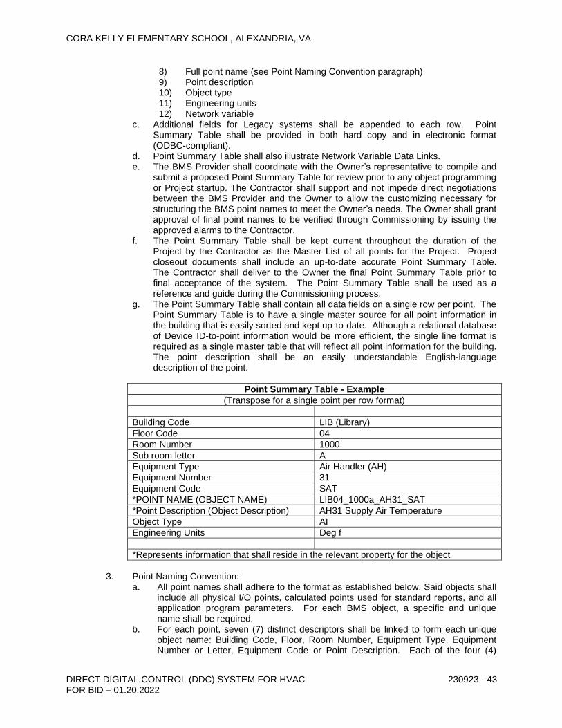
CORA KELLY ELEMENTARY SCHOOL, ALEXANDRIA, VA
DIRECT DIGITAL CONTROL (DDC) SYSTEM FOR HVAC FOR BID – 01.20.2022
230923 - 43
8) Full point name (see Point Naming Convention paragraph) 9) Point description 10) Object type 11) Engineering units 12) Network variable
c. Additional fields for Legacy systems shall be appended to each row. Point Summary Table shall be provided in both hard copy and in electronic format (ODBC-compliant).
d. Point Summary Table shall also illustrate Network Variable Data Links. e. The BMS Provider shall coordinate with the Owner’s representative to compile and
submit a proposed Point Summary Table for review prior to any object programming or Project startup. The Contractor shall support and not impede direct negotiations between the BMS Provider and the Owner to allow the customizing necessary for structuring the BMS point names to meet the Owner’s needs. The Owner shall grant approval of final point names to be verified through Commissioning by issuing the approved alarms to the Contractor.
f. The Point Summary Table shall be kept current throughout the duration of the Project by the Contractor as the Master List of all points for the Project. Project closeout documents shall include an up-to-date accurate Point Summary Table. The Contractor shall deliver to the Owner the final Point Summary Table prior to final acceptance of the system. The Point Summary Table shall be used as a reference and guide during the Commissioning process.
g. The Point Summary Table shall contain all data fields on a single row per point. The Point Summary Table is to have a single master source for all point information in the building that is easily sorted and kept up-to-date. Although a relational database of Device ID-to-point information would be more efficient, the single line format is required as a single master table that will reflect all point information for the building. The point description shall be an easily understandable English-language description of the point.
Point Summary Table - Example
(Transpose for a single point per row format)
Building Code LIB (Library)
Floor Code 04
Room Number 1000
Sub room letter A
Equipment Type Air Handler (AH)
Equipment Number 31
Equipment Code SAT
*POINT NAME (OBJECT NAME) LIB04_1000a_AH31_SAT
*Point Description (Object Description) AH31 Supply Air Temperature
Object Type AI
Engineering Units Deg f
*Represents information that shall reside in the relevant property for the object
3. Point Naming Convention:
a. All point names shall adhere to the format as established below. Said objects shall include all physical I/O points, calculated points used for standard reports, and all application program parameters. For each BMS object, a specific and unique name shall be required.
b. For each point, seven (7) distinct descriptors shall be linked to form each unique object name: Building Code, Floor, Room Number, Equipment Type, Equipment Number or Letter, Equipment Code or Point Description. Each of the four (4)

CORA KELLY ELEMENTARY SCHOOL, ALEXANDRIA, VA
DIRECT DIGITAL CONTROL (DDC) SYSTEM FOR HVAC FOR BID – 01.20.2022
230923 - 44
descriptors must be bound by an underscore to form the entire object name. Reference the paragraphs below for an example of these descriptors.
c. The Owner shall designate the ‘Building’ descriptor. The ‘Equipment Type’ descriptor shall define the equipment category, e.g., Chiller, Air Handling Unit, or other equipment. The ‘Equipment Code’ descriptor shall define the hardware or software type or function associated with the equipment; e.g., supply temperature, water pressure, alarm, mixed air temperature setpoint, etc. and shall contain any numbering conventions for multiples of equipment; e.g., CHLR1KW, CHLR2KW, BLR2AL (Boiler 2 Alarm), HWP1ST (Hot Water Pump 1 Status).
d. A consistent object (point) naming convention shall be utilized to facilitate familiarity and operational ease across Owner’s WAN. Inter-facility consistency shall be maintained to ensure transparent operability to the greatest degree possible. The table below details the object naming convention and general format of the descriptor string. A maximum of 30 characters shall be used.
Point / Object Name Requirements
Sample: LIB04_1000a_AH31_SAT
(LIB) - Building Code 2 or 3 alpha characters - Building Name
(04) - Floor Location 2 alpha or numeric characters - Must use two characters, such as, (02) for Second Floor
(_) 1 character – underscore; acts as a separator
(1000) - Room Number 3 - 4 numeric characters
(a) - Sub Room Letter (a-z) if no sub room DO NOT use space or a dash
(_) 1 character – underscore; acts as a separator
(AH) - Equipment Type 2 alpha characters
(31) - Equipment Number, Equipment Letter, or Combination
1-2 upper case alpha and/or numeric characters
(_) 1 character - period; acts as a separator
(SAT) - Equipment Code 1 - 4 alpha characters
4. Examples: Within each object name, the descriptors shall be bound by an underscore.
Within each descriptor, words shall not be separated by dashes, spaces, or other separators as follows: a. LIB04_1000a_AH31_SAT - Library, 4th Floor, Rm. 1000a, Air Handler #31,
Supply Air Temperature. b. OFC03_0407_BR01_S/S – Office Building, 3rd Floor, Rm. 407, Boiler #1,
Start/Stop. c. CH04_0102_VV19_ZSTP - Courthouse, 4th Floor, Rm. 102, VAV Terminal 19,
Zone Temperature Setpoint.
I. User Input/Control Functions 1. Graphic software shall facilitate user-friendly interface to all aspects of the System
Software specified above. The intent of this Specification is to require a graphic package that provides for intuitive operation of the systems without extensive training and experience. It shall facilitate logical and simple system interrogation, modification, configuration, and diagnosis.
2. The operator shall be able to access displays via a pointing device and/or soft key menus with a choice of function keys, cursor control keys, or any key on the keyboard. Supported pointing devices shall include a mouse, touch screen, light pen, or trackball.
3. The system shall support operator access to multiple displays at one time, including split screens where the operator may view more than one process area at a time. In addition, the system shall support unlimited use of pop-up displays for additional help or diagnostic information.

CORA KELLY ELEMENTARY SCHOOL, ALEXANDRIA, VA
DIRECT DIGITAL CONTROL (DDC) SYSTEM FOR HVAC FOR BID – 01.20.2022
230923 - 45
4. Access to all displays and to all command functions shall be based on the operator’s security level to protect against unauthorized use. The security level shall be established during the operator sign-on procedure.
5. Visibility and operation of command buttons, symbols, etc. shall be controllable based upon the operator’s security level.
6. The operator shall be able to have access to context sensitive help at any time during operation of the system.
7. Graphic software shall provide for multitasking such that third-party programs can be used while the OWS software is on line. Software shall provide the ability to alarm graphically even when operator is in another software package.
8. An operator shall be able to control a discrete point using an action command button. This control includes momentary on, momentary off, toggle on-off, set, and reset.
9. The operator shall be able to use command buttons to adjust set-points up and down on a percentage or absolute basis. Each request for increase or decrease shall be evaluated against valid operating limits before allowing the adjustment.
10. Control of individual set-points shall be enabled based upon a user’s security level and password.
J. Display Capability 1. The software shall allow for Owner creation of user-defined, color graphic displays of
geographic maps, building plans, floor plans, and mechanical and electrical system schematics. These graphics shall be capable of displaying all point information from the database including any attributes associated with each point (i.e., engineering units, etc.). In addition, operators shall be able to command equipment or change setpoints from a graphic through the use of the mouse.
2. The system shall allow the user to view animated graphics for process templates including tanks, pumps, etc. This includes: a. Percentage fill of the object including irregular shapes such as polygons, ellipses,
etc. b. Color change of the object. Up to 32 colors. c. Blinking of the object based upon any alarm in the system or upon a designated
group of alarms. d. Each object shall have a visibility attribute option allowing for visibility of the
object based upon a condition in the system. e. The system shall support animation of objects via resizing, moving, and/or
rotating objects based upon a change in a process variable. f. Objects shall be animated based upon any user-defined criteria made up of other
tag-names in the system. This includes the use of expressions containing all mathematical functions and the status of analog and discrete values in the system.
g. Objects shall be able to be animated according to any of eight (8) different alarm conditions for an analog variable, including:
Lo Alarm LoLo Alarm Hi Alarm HiHi Alarm Rate of Change Normal State h. Objects shall be able to blink or change color by evaluating any of the 32 bits in
an analog register. Up to 32 colors shall be possible. 3. The system shall support the capability for the operator to view scanned images from
desktop or hand-held scanners. It shall be possible to animate these images to show a color change based on the status of process operations, including alarm or normal state.
4. Screen Penetration: The operator interface shall allow users to access the various system graphic screens via a graphical penetration scheme by using the mouse to select from menus or ‘button’ icons. Each graphic screen shall be capable of having a unique list of other graphic screens that are directly linked through the selection of a menu item or button icon.

CORA KELLY ELEMENTARY SCHOOL, ALEXANDRIA, VA
DIRECT DIGITAL CONTROL (DDC) SYSTEM FOR HVAC FOR BID – 01.20.2022
230923 - 46
5. Dynamic Data Displays: Dynamic physical point values shall automatically updated at a minimum frequency of six (6) updates per minute without operator intervention. Point value fields shall be displayed with a color code depicting normal, abnormal, override and alarm conditions.
6. Point Override Feature: Each displayed point shall be individually enabled/disabled to allow mouse-driven override of digital points or changing of analog points. Such overrides or changes shall occur in the control unit, not just in the workstation software. The graphic point override feature shall be subject to password level protection. Points that are overridden shall be recorded as an event, and shall be displayed in a coded color. The event message shall include the operator’s user name.
7. System shall support use of true-type scalable fonts that may be scaled according to the desired size of the text. The fonts shall be loaded by the operating system. The user may choose from up to 32 different text colors.
8. System shall support change of text color based upon the process value going into eight (8) different alarm states.
9. Text shall be able to blink based upon any user definable condition occurring in the system, such as an alarm on a particular setpoint, alarm on any value in a process group, or based on the actual value of a process variable.
10. System shall display process values based upon the security level of the user. 11. Text shall be able to be made visible or invisible based upon an alarm condition in the
process or any other state change in the system.
K. Graphics Development Package: Graphic development and generation software shall be provided to allow the user to add, modify, or delete system graphic displays. 1. The Contractor shall provide libraries of pre-engineered screens and symbols depicting
standard air handling unit components (e.g. fans, cooling coils, filters, dampers, etc.), mechanical system components (e.g., pumps, chillers, cooling towers, boilers, etc.), complete mechanical systems (e.g. constant volume-terminal reheat, VAV, etc.) and electrical symbols.
2. The Graphic Development Package shall use a mouse or similar pointing device to allow the user to perform the following: a. Define symbols. b. Position items on graphic screens. c. Attach physical or virtual points to a graphic. d. Define background screens. e. Define connecting lines and curves. f. Locate, orient and size descriptive text. g. Define and display colors for all elements. h. Establish correlation between symbols or text and associated system points or
other displays. i. Create hot spots or link triggers to other graphic displays or other functions in the
software.
2.18 DDC CONTROLLERS
A. Section includes: 1. Network Controller (NC). 2. Programmable Control Unit (PCU). 3. Application Specific Controller (ASC).
B. DDC system shall consist of a combination of network controllers, programmable application controllers and application-specific controllers to satisfy performance requirements indicated.
C. DDC controllers shall perform monitoring, control, energy optimization and other requirements indicated.

CORA KELLY ELEMENTARY SCHOOL, ALEXANDRIA, VA
DIRECT DIGITAL CONTROL (DDC) SYSTEM FOR HVAC FOR BID – 01.20.2022
230923 - 47
D. DDC controllers shall use a multitasking, multiuser, real-time digital control microprocessor with a distributed network database and intelligence.
E. Each DDC controller shall be capable of full and complete operation as a completely independent unit and as a part of a DDC system wide distributed network.
F. Environment Requirements:
1. Controller hardware shall be suitable for the anticipated ambient conditions. 2. Controllers located in conditioned space shall be rated for operation at 32 to 120 deg F 3. Controllers located outdoors shall be rated for operation at 40 to 150 deg F
G. Power and Noise Immunity:
1. Controller shall operate at 90 to 110 percent of nominal voltage rating and shall perform an orderly shutdown below 80 percent of nominal voltage.
2. Operation shall be protected against electrical noise of 5 to 120 Hz and from keyed radios with up to 5 W of power located within 36 inches of enclosure.
H. General Network Controller Requirements:
1. Include adequate number of controllers to achieve performance indicated. 2. Network Controllers shall utilize The Niagara Tridium N4 Platform 3. System shall consist of one or more independent, standalone, microprocessor-based
network controllers to manage global strategies indicated. 4. Controller shall have enough memory to support its operating system, database, and
programming requirements. 5. Data shall be shared between networked controllers and other network devices. 6. Operating system of controller shall manage input and output communication signals to
allow distributed controllers to share real and virtual object information and allow for central monitoring and alarms.
7. Controllers shall have a real-time clock. 8. Controller shall continually check status of its processor and memory circuits. If an
abnormal operation is detected, controller shall assume a predetermined failure mode and generate an alarm notification.
9. Controllers shall be fully programmable.
I. Communication:
1. Network controllers shall communicate with other devices on DDC system Level one network.
2. Network controller also shall perform routing if connected to a network of programmable control unit and application-specific controllers.
J. Operator Interface:
1. Controller shall be equipped with a service communications port for connection to a portable operator's workstation or mobile device.
K. Serviceability:
1. Controller shall be equipped with diagnostic LEDs or other form of local visual indication of power, communication, and processor.
2. Wiring and cable connections shall be made to field-removable, modular terminal strips or to a termination card connected by a ribbon cable.

CORA KELLY ELEMENTARY SCHOOL, ALEXANDRIA, VA
DIRECT DIGITAL CONTROL (DDC) SYSTEM FOR HVAC FOR BID – 01.20.2022
230923 - 48
3. Controller shall maintain BIOS and programming information in event of a power loss for at least 72 hours.
2.19 PROGRAMMABLE CONTROL UNITS (PCU)
A. BACnet® based DDC Programmable Control Unit (PCU) shall be provided where required to perform the sequence of operation. The PCU shall be fully configurable and programmable via the GUI web browser. The controller shall store all specific control sequences and program settings in non-volatile memory.
B. All PCU processors shall be operating at 5 MHz or higher with 8K of RAM and 64K of Flash memory with a minimum 10-year memory retention between program downloads.
C. Each PCU shall perform all intended control functions in a ‘standalone’ mode should the unit incur a loss of communications.
D. The complete PCU including accessory devices such as relays, transducers, power supplies, etc., shall be factory-mounted, wired and housed in a NEMA 1 enclosure or as required by the location and local code requirements.
E. Each PCU shall allow <MS/TP, IP or Peer-to-Peer> communications. <Closely coordinate PCU requirements with the BMS Design Drawings>
F. All PCUs shall be provided as self sufficient units to maximize reliability and shall include internal ‘soft’ clock, operating systems, communication timing and interrupt controls, and shall be suitable for the specified applications.
G. In the event of a power outage or controller reset, each PCU shall enter a preprogrammed state on power re-application. Upon application of power to the PCU, all control conditions will start from an ‘off’ / ‘closed’ position or the default state. This state will be maintained for an automatically adjusted amount of time. Once this time delay has passed, the PCU control sequence shall resume according to current values
H. Network and controller-to-controller communications must conform to BACnet® standards.
I. All PCUs shall be provided with a communications port to allow connection of any industry standard laptop PC and custom configuration tools. Program access via this communications port allows direct field modification of the configuration parameters.
J. Digital Inputs 1. All digital inputs shall be over voltage protected. 2. Digital Input types supported by the PCU:
a. Normally open contacts (24V and 120V). b. Normally closed contacts (24V and 120V). c. Current/no current. d. Voltage/no voltage. e. Pulse/Totalizer contacts.
K. Digital Outputs 1. All digital outputs shall be 24-volt AC, current sinking, 0.5 amp opto-isolated triacs. 2. Digital outputs shall be capable of handling maintained as well as pulsed outputs for
momentary or magnetic latching circuits. It shall be possible to configure outputs for 3-mode control (fast-slow-off) and 2-mode control.

CORA KELLY ELEMENTARY SCHOOL, ALEXANDRIA, VA
DIRECT DIGITAL CONTROL (DDC) SYSTEM FOR HVAC FOR BID – 01.20.2022
230923 - 49
L. Analog Inputs 1. All analog inputs shall be over voltage protected. 2. The analog to digital resolutions shall be a minimum of 10 bit. 3. Analog inputs shall accept the following temperature types: 10K Ohm thermistor, 20K
Ohm thermistor, or 1K Ohm RTD. 4. Inputs shall be configurable to accept a wide range of inputs including: 4-20mA, 1-5Vdc,
2-10Vdc, etc.
M. Analog Outputs 1. The PCU shall accommodate true analog outputs. Voltage (0-10V) and current (4-20
mA) outputs shall be accommodated. 2. All analog outputs shall be proportional current or voltage type. 3. The digital to analog resolution shall be a minimum of 10 bit. 4. Outputs shall be configurable so that 0-100% output commands can represent any
portion of the output voltage/current range. 5. Outputs shall be reversible so that an increasing output command yields a decreasing
electrical signal.
N. In addition to local physical or internal I/O, each PCU shall support distributed or ‘bound’ I/O. This bound I/O can be used to allow the PCU to provide I/O data to another controller on the network or to allow another controller to provide data to the controlling PCU Operator Interface:
1. Controller shall be equipped with a service communications port for connection to a portable operator's workstation or mobile device
O. Serviceability:
1. Controller shall be equipped with diagnostic LEDs or other form of local visual indication of power, communication, and processor.
2. Wiring and cable connections shall be made to field-removable, modular terminal strips or to a termination card connected by a ribbon cable.
3. Controller shall maintain BIOS and programming information in event of a power loss for at least 72 hours.
P. A PCU as specified above is generally fully featured and customizable whereas the ASC refers to a more cost-effective unit designed for lower-end, high quantity applications. Specific requirements indicated below are required for the respective application. The Contractor may apply the most cost-effective unit that meets the requirement of that application.
Q. Each Controller shall be capable of performing the required sequence of operation for the associated equipment.
R. All physical point data and calculated values required to accomplish the sequence of operation shall originate within the associated Controller with only the exceptions enumerated below. Listed below are functional point data and calculated values that shall be allowed to be obtained from or stored by other Controllers via the LAN.
2.20 APPLICATION-SPECIFIC CONTROLLERS (ASC)
A. Description: Microprocessor-based controllers, which through hardware or firmware design are dedicated to control a specific piece of equipment. Controllers are not fully user-programmable but are configurable and customizable for operation of equipment they are designed to control. 1. Capable of standalone operation and shall continue to include control functions without
being connected to network.

CORA KELLY ELEMENTARY SCHOOL, ALEXANDRIA, VA
DIRECT DIGITAL CONTROL (DDC) SYSTEM FOR HVAC FOR BID – 01.20.2022
230923 - 50
2. Data shall be shared between networked controllers and other network devices.
B. Communication: Application-specific controllers shall communicate with other application-specific controller and devices on network, and to programmable application and network controllers.
C. Operator Interface: Controller shall be equipped with a service communications port for connection to a portable operator's workstation serviceability: 1. Controller shall be equipped with diagnostic LEDs or other form of local visual indication
of power, communication, and processor. 2. Wiring and cable connections shall be made to field-removable, modular terminal strips
or to a termination card connected by a ribbon cable. 3. Controller shall use nonvolatile memory and maintain all BIOS and programming
information in event of power loss.
2.21 CONTROLLER SOFTWARE
A. General Controller Software Requirements: 1. Software applications shall reside and operate in controllers. Editing of applications shall
occur at operator workstations. 2. Controller-to-controller communications must conform to BACnet standards. 3. All ASCs shall be provided with a communications port to allow connection of any
industry standard laptop PC and custom configuration tools. Program access via this communications port allows direct field modification of the configuration parameters.
4. Digital Inputs a. All digital inputs shall be over voltage protected. b. Digital Input types supported by the ASC:
1) Normally open contacts (24V and 120V). 2) Normally closed contacts (24V and 120V). 3) Current/no current. 4) Voltage/no voltage. 5) Pulse/Totalizer contacts.
5. Digital Outputs a. All digital outputs shall be 24-volt AC, current sinking, 0.5 amp opto-isolated triacs. b. Digital outputs shall be capable of handling maintained as well as pulsed outputs
for momentary or magnetic latching circuits. It shall be possible to configure outputs for 3-mode control (fast-slow-off) and 2-mode control.
6. Analog Inputs a. All analog inputs shall be over voltage protected. b. The analog to digital resolutions shall be a minimum of 10 bit. c. Analog inputs shall accept the following temperature types: 10K Ohm thermistor,
20K Ohm thermistor, or 1K Ohm RTD. d. Inputs shall be configurable to accept a wide range of inputs including: 4-20mA, 1-
5Vdc, 2-10Vdc, etc. 7. Analog Outputs
a. The ASC shall accommodate true analog outputs. Voltage (0-10V) and current (4-20 mA) outputs shall be accommodated.
b. All analog outputs shall be proportional current or voltage type. c. The digital to analog resolution shall be a minimum of 10 bit. d. Outputs shall be configurable so that 0-100% output commands can represent any
portion of the output voltage/current range. e. Outputs shall be reversible so that an increasing output command yields a
decreasing electrical signal.

CORA KELLY ELEMENTARY SCHOOL, ALEXANDRIA, VA
DIRECT DIGITAL CONTROL (DDC) SYSTEM FOR HVAC FOR BID – 01.20.2022
230923 - 51
8. In addition to local physical or internal I/O, each ASC shall support distributed or ‘bound’ I/O. This bound I/O can be used to allow the ASC to provide I/O data to another controller on the network or to allow another controller to provide data to the controlling ASC.
9. Control functions shall be executed within controllers using DDC algorithms. 10. Controllers shall be configured to use stored default values to ensure fail-safe operation.
Default values shall be used when there is a failure of a connected input instrument or loss of communication of a global point value.
2.22 APPLICATION PROGRAMMING SOFTWARE TOOL
A. The Contractor shall furnish one (1) copy of the manufacturer’s application programming software tool. This software package shall be the same engineering tool that installation technicians / program engineers used to program, configure, and commission each DDC controller used on this project. If more than one software tool is required to achieve this functionality then the Contactor shall provide the necessary packages to accomplish the programming, configuration, and commissioning of each controller used on this project. The Contractor shall include all software licensing fees and costs. If the manufacturer’s software license agreement requires this license to be renewed the Contractor shall include the first <two years> fees in this scope of work. If end user training is required as part of the license agreement the Contractor shall provide a letter stating so and the associated costs and requirements as part of their submittal package.
2.23 END DEVICES
A. Binary Temperature Devices. 1. Low-Voltage Space Thermostats. Low-voltage space thermostats shall be 24 V, bimetal-
operated, mercury-switch type, with adjustable or fixed anticipation heater, concealed setpoint adjustment, 55°F-85°F setpoint range, 2°F maximum differential, and vented ABS plastic cover.
2. Line-Voltage Space Thermostats. Line-voltage space thermostats shall be bimetal-actuated, open-contact type or bellows-actuated, enclosed, snap-switch type or equivalent solid-state type, with heat anticipator, UL listing for electrical rating, concealed setpoint adjustment, 55°F-85°F setpoint range, 2°F maximum differential, and vented ABS plastic cover.
3. Low-Limit Thermostats. Low-limit airstream thermostats shall be UL listed, vapor pressure type. Element shall be at least 20 ft long. Element shall sense temperature in each 1 ft section and shall respond to lowest sensed temperature. Low-limit thermostat shall be manual reset only.
B. Temperature Sensors. 1. Type. Temperature sensors shall be Resistance Temperature Device (RTD) or
thermistor. 2. Duct Sensors. Duct sensors shall be single point or averaging as required to meet
performance requirements. Averaging sensors shall be used where ducts are larger than 9 sq. ft. or where prone to stratification, length as required.
3. Immersion Sensors. Provide immersion sensors with a separable stainless steel well. Well pressure rating shall be consistent with system pressure it will be immersed in. Well shall withstand pipe design flow velocities.
4. Space Sensors. Space sensors shall have setpoint adjustment and timed override pushbutton.
5. Differential Sensors. Provide matched sensors for differential temperature measurement. 6. Outside Air Sensors: Watertight inlet fitting, shielded from direct sunlight where required
and unshielded from sun where required by the drawings.
C. Humidity Sensors.

CORA KELLY ELEMENTARY SCHOOL, ALEXANDRIA, VA
DIRECT DIGITAL CONTROL (DDC) SYSTEM FOR HVAC FOR BID – 01.20.2022
230923 - 52
1. Duct or plenum sensors shall have a sensing range of 20%-80%. 2. Duct or plenum sensors shall have a sampling chamber. 3. Outdoor air humidity sensors shall have a sensing range of 20%-95% RH and shall be
suitable for ambient conditions of 40°F-170°F. 4. Humidity sensors shall not drift more than 1% of full scale annually 5. Humidity sensor shall have an accuracy of +/- 3%.
D. Static-Pressure Transmitter: 1. Non-directional sensor with suitable range for expected input, temperature compensated. 2. Accuracy: 2 percent of full scale with repeatability of 0.5 percent. 3. Output: 4 to 20 mA. 4. Building or Plenum Static-Pressure Range: -0.25 to +0.25 inch wg. 5. Supply Air Duct Static-Pressure Range: 0 to 5 inches wg.
E. Combination Temperature and Humidity Sensor 1. Interior or exterior wall mounted sensor which provides both temperature and humidity
sensing capabilities in one unit. 2. Temperature sensor shall be thermistor or RTD. 3. Humidity sensor shall be impedence type. 4. Power shall be 15VDC – 24 VDC utilizing shielded wiring. 5. Unit shall have full range temperature compensation for humidity sensor. 6. Humidity sensor shall have an accuracy of +/- 3%. 7. Temperature sensor shall have an accuracy of +/- 1°F.
F. CO2 Sensors 1. Wall mounted or return air plenum mounted sensor utilizing non-dispersive infrared
(NDIR) analyzer technology and a self-calibrating technology. 2. Unit shall have a total range of 0-2000 ppm. 3. Unit shall have an accuracy of 40 ppm total range or 8.5 % of measured value. 4. Unit shall have a repeatability of 30 ppm total range or 4.5 % of measured value. 5. Unit shall provide a 5-year calibration interval. 6. Unit shall have dual analog output with 0-10 vdc and 4-20 mA. 7. Unit shall be provided with LED indicating light for both power and error detection.
G. Flow Switches. Flow-proving switches shall be paddle (water service only) or differential pressure type (air or water service) as shown. Switches shall be UL listed, SPDT snap-acting, and pilot duty rated (125 VA minimum). 1. Paddle switches shall have adjustable sensitivity and NEMA 1 enclosure unless
otherwise specified. 2. Differential pressure switches shall have scale range and differential suitable for intended
application and NEMA 1 enclosure unless otherwise specified.
H. Relays. 1. Control Relays. Control relays shall be plug-in type, UL listed, and shall have dust cover
and LED "energized" indicator. Contact rating, configuration, and coil voltage shall be suitable for application.
2. Time Delay Relays. Time delay relays shall be solid-state plug-in type, UL listed, and shall have adjustable time delay. Delay shall be adjustable ±100% from setpoint shown. Contact rating, configuration, and coil voltage shall be suitable for application. Provide NEMA 1 enclosure for relays not installed in local control panel.
I. Override Timers. 1. Unless implemented in control software, override timers shall be spring-wound line
voltage, UL Listed, with contact rating and configuration required by application. Provide 0-12 hour calibrated dial unless otherwise specified. Flush mount timer on local control panel face.

CORA KELLY ELEMENTARY SCHOOL, ALEXANDRIA, VA
DIRECT DIGITAL CONTROL (DDC) SYSTEM FOR HVAC FOR BID – 01.20.2022
230923 - 53
J. Current Transmitters. 1. AC current transmitters shall be self-powered, combination split-core current transformer
type with built-in rectifier and high-gain servo amplifier with 4-20 mA two-wire output. Full-scale unit ranges shall be 10 A, 20 A, 50 A, 100 A, 150 A, and 200 A, with internal zero and span adjustment. Unit accuracy shall be ±1% full-scale at 500 ohm maximum burden.
2. Transmitter shall meet or exceed ANSI/ISA S50.1 requirements and shall be UL/CSA recognized.
3. Unit shall be split-core type for clamp-on installation on existing wiring.
K. Current Transformers. 1. AC current transformers shall be UL/CSA recognized and shall be completely encased
(except for terminals) in approved plastic material. 2. Transformers shall be available in various current ratios and shall be selected for ±1%
accuracy at 5 A full-scale output. 3. Use fixed-core transformers for new wiring installation and split-core transformers for
existing wiring installation.
L. Voltage Transmitters. 1. AC voltage transmitters shall be self-powered single-loop (two-wire) type, 4-20 mA output
with zero and span adjustment. 2. Adjustable full-scale unit ranges shall be 100-130 Vac, 200-250 Vac, 250-330 Vac, and
400-600 Vac. Unit accuracy shall be ±1% full-scale at 500 ohm maximum burden. 3. Transmitters shall meet or exceed ANSI/ISA S50.1 requirements and shall be UL/CSA
recognized at 600 Vac rating.
M. Voltage Transformers. 1. AC voltage transformers shall be UL/CSA recognized, 600 Vac rated, and shall have
built-in fuse protection. 2. Transformers shall be suitable for ambient temperatures of 40°F-130°F and shall provide
±0.5% accuracy at 24 Vac and 5 VA load. 3. Windings (except for terminals) shall be completely enclosed with metal or plastic.
N. Current Switches. 1. Current-operated switches shall be self-powered, solid-state with adjustable trip current.
Select switches to match application current and DDC system output requirements.
O. Pressure Transducers. 1. Transducers shall have linear output signal and field-adjustable zero and span. 2. Continuous operating conditions of positive or negative pressure 50% greater than
calibrated span shall not damage transducer sensing elements. 3. Water pressure transducer diaphragm shall be stainless steel with minimum proof
pressure of 150 psi. Transducer shall have 4-20 mA output, suitable mounting provisions, and block and bleed valves.
4. Water differential pressure transducer diaphragm shall be stainless steel with minimum proof pressure of 150 psi. Over-range limit (differential pressure) and maximum static pressure shall be 300 psi. Transducer shall have 4-20 mA output, suitable mounting provisions, and 5-valve manifold.
5. Air differential pressure transducer shall be a direct reading device with a +/-1% accuracy of full scale. Unit shall provide a 4-20 mA output. Unit shall be Dwyer Series 616, with a range of 0-2 inches W.C.
P. Differential Pressure Switches. Differential pressure switches (air or water service) shall be UL listed, SPDT snap-acting, pilot duty rated (125 VA minimum) and shall have scale range and differential suitable for intended application and NEMA 1 enclosure unless otherwise specified.

CORA KELLY ELEMENTARY SCHOOL, ALEXANDRIA, VA
DIRECT DIGITAL CONTROL (DDC) SYSTEM FOR HVAC FOR BID – 01.20.2022
230923 - 54
2.24 ENCLOSURES
A. General Enclosure Requirements:
1. House each controller and associated control accessories in a single enclosure. Enclosure shall serve as central tie-in point for control devices such as switches, transmitters, transducers, power supplies and transformers.
2. Properly size enclosures to allow for access to internal devices and for ease of service. 3. Do not house more than one controller in a single enclosure. 4. Include enclosure door with key locking mechanism. Key locks alike for all enclosures
and include one pair of keys per enclosure. 5. Supply each enclosure with a complete set of as-built schematics, tubing, and wiring
diagrams and product literature located in a pocket on inside of door
B. Internal Arrangement:
1. Internal layout of enclosure shall group and protect pneumatic, electric, and electronic components associated with a controller, but not an integral part of controller.
2. Arrange layout to group similar products together. 3. Include a barrier between line-voltage and low-voltage electrical and electronic products. 4. Factory or shop install products, tubing, cabling and wiring complying with requirements
and standards indicated. 5. Terminate field cable and wire using heavy-duty terminal blocks. 6. Include spare terminals, equal to not less than 10% percent of used terminals. 7. Include spade lugs for stranded cable and wire. 8. Install a maximum of two wires on each side of a terminal. 9. Include enclosure field power supply with a toggle-type switch located at entrance inside
enclosure to disconnect power. 10. Include enclosure with a line-voltage nominal 20-A GFCI duplex receptacle for service
and testing tools. Wire receptacle on hot side of enclosure disconnect switch and include with a 5-A circuit breaker.
11. Mount products within enclosure on removable internal panel(s). 12. Include products mounted in enclosures with engraved, laminated phenolic nameplates
(black letters on a white background). The nameplates shall have at least 1/4-inch- high lettering.
13. Route tubing cable and wire located inside enclosure within a raceway with a continuous removable cover.
14. Label each end of cable, wire and tubing in enclosure following an approved identification system that extends from field I/O connection and all intermediate connections throughout length to controller connection.
15. Size enclosure internal panel to include at least 15 percent spare area on face of panel.
2.25 VALVES AND DAMPERS
A. Electric Damper and Valve Actuators. 1. Stall Protection. Mechanical or electronic stall protection shall prevent actuator damage
throughout the actuator's rotation. 2. Spring-return Mechanism. Actuators used for all mechanical equipment in the penthouse,
penthouse return air plenum, basement and sub-basement (dampers and valves) and safety applications (smoke control dampers) shall have an internal mechanical spring-return mechanism.
3. Signal and Range. Proportional actuators for modulating valve and damper service shall accept a 0-10 Vdc or a 0-20 mA input control signal and shall have a 2-10 Vdc or 4-20 mA operating range.
4. Wiring. 24 Vac and 24 Vdc actuators shall operate on Class 2 wiring.

CORA KELLY ELEMENTARY SCHOOL, ALEXANDRIA, VA
DIRECT DIGITAL CONTROL (DDC) SYSTEM FOR HVAC FOR BID – 01.20.2022
230923 - 55
5. Analog Output: Actuators shall have an analog output to correlate to actual valve or damper position.
6. Manual Override Positioning. Operators shall be able to manually position each actuator when the actuator is not powered. Non-spring-return actuators shall have an external manual gear release. Spring-return actuators with more than 60 in.-lb torque capacity shall have a manual crank.
7. Mechanical: Gear trains completely oil immersed and sealed. 8. Position Indicator: Actuators shall have a visible position indicator.
B. Damper Blade Limit Switches:
1. Sense positive open and/or closed position of the damper blades. 2. NEMA 250, Type 13, oil-tight construction. 3. Arrange for the mounting application. 4. Additional waterproof enclosure when required by its environment. 5. Arrange to prevent "over-center" operation.
C. Outdoor Air, Return Air, and Exhaust Air Control Motorized Dampers. 1. Type. Damper shall be UL listed and/or AMCA-rated for the intended service. Control
dampers shall have linear flow characteristics and shall be parallel- or opposed-blade type as specified below or as scheduled on drawings. a. Outdoor and return air mixing dampers (not provided as a component of factory
constructed air Handling Unit – see Section 15720 – Air Handling Units) shall be parallel-blade and shall direct airstreams toward each other.
b. Two-position shutoff dampers used for exhaust air control shall be parallel- or opposed-blade with blade and side seals.
2. Frame. Damper frames shall be 13-gauge galvanized steel channel or 1/8 in. extruded aluminum with reinforced corner bracing.
3. Blades. Damper blades shall not exceed 8 in. in width or 48 in. in length. Blades shall be suitable for medium velocity 2000 fpm performance. Blades shall be not less than 16 gauge.
4. Shaft Bearings. Damper shaft bearings shall be as recommended by manufacturer for application, oil impregnated sintered bronze, or better.
5. Seals. Blade edges and frame top and bottom shall have replaceable seals of butyl rubber or neoprene. Side seals shall be spring-loaded stainless steel. Blade seals shall leak no more than 10 cfm per ft2 at 4 in. w.g. differential pressure. Blades shall be airfoil type suitable for wide-open face velocity of 1500 fpm.
6. Sections. Damper sections shall not exceed 48 in. - 60 in. Each section shall have at least one damper actuator.
7. Linkages. Dampers shall have exposed linkages. 8. Damper Fail Position. Return air dampers shall fail normally open, Outdoor air dampers
shall fail normally closed, exhaust air dampers shall fail normally closed.
D. Round Space/Zone Control Dampers 1. Fabrication: Dampers shall be of the butterfly type consisting of circular blade mounted to
a shaft. Inside frame surface shall be clean and smooth with no blade stops or similar inward projections. Frame shall include rolled stiffener beads to allow easy sealing to spiral ductwork joints. Frames shall have no holes or openings to allow air through damper frame.
2. Size as scheduled or as indicated. 3. Type: Round. 4. Frame: 20 gage galvanized steel. 5. Blade: Two layers of galvanized steel; 14 gage equivalent thickness. 6. Axle: 1/2 inch diameter plated steel with stainless steel sleeve bearing pressed into
frame. 7. Finish:

CORA KELLY ELEMENTARY SCHOOL, ALEXANDRIA, VA
DIRECT DIGITAL CONTROL (DDC) SYSTEM FOR HVAC FOR BID – 01.20.2022
230923 - 56
a. Mill galvanized steel frame. b. Mill finished blades.
8. Blade Seals: Vinyl foam seals sandwiched between two blades.
E. Rectangular Space/Zone Control Dampers 1. Size as scheduled or as indicated. 2. Frame: 18 gauge galvanized, mechanically joined. 3. Blades: 18 gauge galvanized steel, 3 Inches nominal width. 4. Linkage: Plastic gears. 5. Blade Pin: 1/2 inch round steel, zinc plated. 6. Bearings: None. 7. Side Seals: None. 8. Blade Seals: None.
2.26 UNINTERRUPTABLE POWER SUPPLY (UPS) UNITS FOR WORKSTATIONS
A. 250 through 1000 VA: 1. UPS units shall provide continuous, regulated output power without using their batteries
during brown-out, surge, and spike conditions. 2. Load served shall not exceed 75 percent of UPS rated capacity, including power factor of
connected loads. a. Larger-capacity units shall be provided for systems with larger connected loads. b. UPS shall provide seven minutes of battery power.
3. Performance: a. Input Voltage: Single phase, 120- or 230-V ac, compatible with field power source. b. Load Power Factor Range (Crest Factor): 0.65 to 1.0. c. Output Voltage: 101- to 132-V ac, while input voltage varies between 89 and 152-
V ac. d. On Battery Output Voltage: Sine wave. e. Inverter overload capacity shall be minimum 150 percent for 30 seconds. f. Recharge time shall be a maximum of six hours to 90 percent capacity after full
discharge to cutoff. g. Transfer Time: 6 ms. h. Surge Voltage Withstand Capacity: IEEE C62.41, Categories A and B; 6 kV/200
and 500 A; 100-kHz ringwave. 4. UPS shall be automatic during fault or overload conditions. 5. Unit with integral line-interactive, power condition topology to eliminate all power
contaminants. 6. Include front panel with power switch and visual indication of power, battery, fault and
temperature. 7. Unit shall include an audible alarm of faults and front panel silence feature. 8. Unit with four NEMA WD 1, NEMA WD 6 Configuration 5-15R receptacles. 9. UPS shall include dry contacts (digital output points) for low battery condition and battery-
on (primary utility power failure) and connect the points to the DDC system. 10. Batteries shall be sealed lead-acid type and be maintenance free. Battery replacement
shall be front accessible by user without dropping load. 11. Include tower models installed in ventilated cabinets to the particular installation location.
2.27 PIPING AND TUBING
A. Pneumatic, and Pressure Instrument Signal Air, Tubing and Piping: 1. Products in this paragraph are intended for use with the following:
a. Main air and signal air to pneumatically controlled instruments, actuators and other control devices and accessories.

CORA KELLY ELEMENTARY SCHOOL, ALEXANDRIA, VA
DIRECT DIGITAL CONTROL (DDC) SYSTEM FOR HVAC FOR BID – 01.20.2022
230923 - 57
b. Signal air between pressure instruments, such as sensors, switches, transmitters, controllers, and accessories.
2. Copper Tubing: a. Seamless phosphor deoxidized copper, soft annealed or drawn tempered, with
chemical and physical properties according to ASTM B 75. b. Performance, dimensions, weight, and tolerance according to ASTM B 280. c. Diameter, as required by application, not less than nominal 0.25 inch d. Wall thickness, as required by the application, but not less than 0.030 inch
3. Polyethylene Tubing: a. Fire-resistant black virgin polyethylene according to ASTM D 1248, Type 1, Class C
and Grade 5. b. Tubing shall comply with stress crack test according to ASTM D 1693. c. Diameter, as required by application, of not less than nominal 0.25 inch
B. Connect instruments to tubing with connectors having compression connector on one end and IPS or NPT thread on other end.
2.28 CONTROL WIRE AND CABLE
A. Wire: Single conductor control wiring above 24 V.
1. Wire size shall be at least No. 18AWG. Final wiring s1ze shall be determined by system length of run and ampacity requirements
2. Conductor shall be 7/24 soft annealed copper strand with 2- to 2.5-inch lay. 3. Conductor insulation shall be 600 V, Type THWN or Type THHN, and 90 deg C
according to UL 83. 4. Conductor colors shall be black (hot), white (neutral), and green (ground). 5. Furnish wire on spools.
B. Single Twisted Shielded Instrumentation Cable above 24 V:
1. Wire size shall be a minimum No. 22 AWG. 2. Conductors shall be a twisted, 7/24 soft annealed copper strand with a 2- to 2.5-inch lay. 3. Conductor insulation shall have a Type THHN/THWN or Type TFN rating. 4. Shielding shall be 100 percent type, 0.35/0.5-mil aluminum/Mylar tape, helically applied
with 25 percent overlap, and aluminum side in with tinned copper drain wire. 5. Outer jacket insulation shall have a 600-V, 90-deg C rating and shall be Type TC cable. 6. For twisted pair, conductor colors shall be black and white. For twisted triad, conductor
colors shall be black, red and white. 7. Furnish wire on spools.
C. Single Twisted Shielded Instrumentation Cable 24 V and Less:
1. Wire size shall be a minimum No. 22 AWG. 2. Conductors shall be a twisted, 7/24 soft annealed copper stranding with a 2- to 2.5-inch
lay. 3. Conductor insulation shall have a nominal 15-mil thickness, constructed from flame-
retardant PVC. 4. Shielding shall be 100 percent type, 1.35-mil aluminum/polymer tape, helically applied
with 25 percent overlap, and aluminum side in with tinned copper drain wire. 5. Outer jacket insulation shall have a 300-V, 105-deg C rating and shall be Type PLTC
cable. 6. For twisted pair, conductor colors shall be black and white. For twisted triad, conductor
colors shall be black, red and white.

CORA KELLY ELEMENTARY SCHOOL, ALEXANDRIA, VA
DIRECT DIGITAL CONTROL (DDC) SYSTEM FOR HVAC FOR BID – 01.20.2022
230923 - 58
7. Furnish wire on spools.
D. LAN and Communication Cable: Comply with DDC system manufacturer requirements for network being installed.
1. Cable shall be balanced twisted pair. 2. Comply with the following requirements and for balanced twisted pair cable described in
Section 260523 "Control-Voltage Electrical Power Cables.” a. Cable shall be plenum rated. b. Cable shall have a unique color that is different from other cables used on Project.
2.29 RACEWAYS
A. Comply with requirements in Section 260533 "Raceways and Boxes for Electrical Systems" for electrical power raceways and boxes.
B. Comply with requirements in Section 270528 "Pathways for Communications Systems" for raceways for balanced twisted pair cables and optical fiber cables.
2.30 IDENTIFICATION
A. Control Equipment, Instruments, and Control Devices: 1. Self-adhesive label bearing unique identification.
a. Include instruments with unique identification identified by equipment being controlled or monitored, followed by point identification.
2. Letter size shall be Minimum of 0.5 inch high. 3. Legend shall consist of white lettering on black background. 4. Laminated acrylic or melamine plastic sign shall be engraved phenolic consisting of three
layers of rigid laminate. Top and bottom layers are color-coded black with contrasting white center exposed by engraving through outer layer and shall be fastened with drive pins.
5. Instruments, control devices and actuators with Project-specific identification tags having unique identification numbers following requirements indicated and provided by original manufacturer do not require additional identification.
B. Raceway and Boxes: 1. Comply with requirements for identification specified in Section 260553 "Identification for
Electrical Systems." 2. Paint cover plates on junction boxes and conduit same color as the tape banding for
conduits. After painting, label cover plate "HVAC Controls," using an engraved phenolic tag.
PART 3 - EXECUTION
3.0 EXAMINATION
A. Thoroughly examine project plans for control device and equipment locations. Report discrepancies, conflicts, or omissions to Architect or Engineer for resolution before starting rough-in work.

CORA KELLY ELEMENTARY SCHOOL, ALEXANDRIA, VA
DIRECT DIGITAL CONTROL (DDC) SYSTEM FOR HVAC FOR BID – 01.20.2022
230923 - 59
B. Inspect site to verify that equipment can be installed as shown. Report discrepancies, conflicts, or omissions to Engineer for resolution before starting rough-in work.
C. Examine drawings and specifications for work of others. Report inadequate headroom or space conditions or other discrepancies to Engineer and obtain written instructions for changes necessary to accommodate Section 23 09 23 work with work of others. Controls Contractor shall perform at his expense necessary changes in specified work caused by failure or neglect to report discrepancies.
3.1 PROTECTION
A. Controls Contractor shall protect against and be liable for damage to work and to material caused by Contractor's work or employees.
B. Controls Contractor shall be responsible for work and equipment until inspected, tested, and accepted. Protect material not immediately installed. Close open ends of work with temporary covers or plugs during storage and construction to prevent entry of foreign objects.
3.2 COORDINATION
A. Commissioning Authority 1. Assist in coordinating the work of the Commissioning Authority (engaged by the owner) in
verifying the performance of the BMS. Refer to Specification Section – HVAC Commissioning.
B. Site 1. Assist in coordinating space conditions to accommodate the work of each trade where
work will be installed near or will interfere with work of other trades. If installation without coordination causes interference with work of other trades, Contractor shall correct conditions without extra charge.
2. Coordinate and schedule work with other work in the same area and with work dependent upon other work to facilitate mutual progress.
C. Test and Balance Sub Contractor 1. Provide Test and Balance Contractor a single set of necessary tools to interface to
control system for testing and balancing. 2. Train Test and Balance Contractor to use control system interface tools. 3. Test and Balance Contractor shall return tools undamaged and in working condition at
completion of testing and balancing.
D. Life Safety 1. Duct smoke detectors required for air handler shutdown are provided under Division 26.
Interlock smoke detectors to air handlers for shutdown as required by the Sequences of Operation.
2. Smoke dampers and actuators required for duct smoke isolation are provided under Division 23. Interlock smoke dampers to air handlers as required by the Sequences of Operation.
E. Coordination with Other Controls. Integrate with and coordinate controls and control devices furnished or installed by others as follows. 1. Communication media and equipment shall be provided as specified in Section 23 09 23
Article 2.2 (Communication).
CORA KELLY ELEMENTARY SCHOOL, ALEXANDRIA, VA
DIRECT DIGITAL CONTROL (DDC) SYSTEM FOR HVAC FOR BID – 01.20.2022
230923 - 60
2. Each supplier of a controls product shall configure, program, start up, and test that product to meet the sequences of operation regardless of where within the contract documents those products are described.
3. Coordinate and resolve incompatibility issues that arise between control products provided under this section and those provided under other sections or divisions of this specification.
4. Controls Contractor shall be responsible for integration of control products provided by multiple suppliers regardless of where integration is described within the contract documents.
3.3 GENERAL WORKMANSHIP
A. Install equipment, piping, and wiring or raceway horizontally, vertically, and parallel to walls wherever possible.
B. Provide sufficient slack and flexible connections to allow for piping and equipment vibration isolation.
C. Install equipment in readily accessible locations as defined by National Electrical Code (NEC) Chapter 1 Article 100 Part A.
D. Verify wiring integrity to ensure continuity and freedom from shorts and ground faults.
E. Equipment, installation, and wiring shall comply with industry specifications and standards and local codes for performance, reliability, and compatibility.
3.4 FIELD QUALITY CONTROL
A. Work, materials, and equipment shall comply with rules and regulations of applicable local, state, and federal codes and ordinances as identified in Section 23 09 23 Article 1.6 (Codes and Standards).
B. Continually monitor field installation for code compliance and workmanship quality.
C. Contractor shall arrange for work inspection by local or state authorities having jurisdiction over the work.
3.5 EXISTING EQUIPMENT
A. Wiring. Interconnecting control wiring shall be removed and shall become Contractor's property unless specifically noted or shown to be reused. 1. Local Control Panels. Remove and deliver existing control panels to Owner.
B. Room Thermostats. Remove and deliver existing room thermostats to Owner unless otherwise noted. Patch and finish holes and marks left by removal to match existing walls.
C. Electronic Sensors and Transmitters. Remove and deliver existing sensors and transmitters to Owner.
D. Controllers and Auxiliary Electronic Devices. Remove and deliver existing controllers and auxiliary electronic devices to Owner.
CORA KELLY ELEMENTARY SCHOOL, ALEXANDRIA, VA
DIRECT DIGITAL CONTROL (DDC) SYSTEM FOR HVAC FOR BID – 01.20.2022
230923 - 61
E. Damper Actuators, Linkages, and Appurtenances: Remove and deliver existing damper actuators, linkages and appurtenances to Owner.
F. Control Valves. Replace existing control valves with new. Deliver removed control valves to Owner.
G. Existing System Operating Schedule. Existing mechanical system may be disabled during this work.
H. Maintain fan scheduling using existing or temporary time clocks or control systems throughout the control system installation.
I. Modify existing starter control circuits if necessary to provide hand-off-auto control of each controlled starter. Furnish new starters or starter control packages as required.
3.6 WIRING
A. Control and interlock wiring and installation shall comply with national and local electrical codes, Division 26, and manufacturer's recommendations. Where the requirements of Section 23 09 23 differ from Division 26, Section 23 09 23 shall take precedence.
B. NEC Class 1 (line voltage) wiring shall be UL listed in approved raceway as specified by NEC and Division 26.
C. Low-voltage wiring shall meet NEC Class 2 requirements. Subfuse low-voltage power circuits as required to meet Class 2 current limit.
D. NEC Class 2 (current-limited) wires not in raceway but in concealed and accessible locations such as return air plenums shall be UL listed for the intended application.
E. Install wiring in raceway where subject to mechanical damage and at levels below 3 m (10ft) in mechanical, electrical, or service rooms.
F. Install Class 1 and Class 2 wiring in separate raceways. Boxes and panels containing high-voltage wiring and equipment shall not be used for low-voltage wiring except for the purpose of interfacing the two through relays and transformers.
G. Do not install wiring in raceway containing tubing.
H. Run exposed Class 2 wiring parallel to a surface or perpendicular to it and tie neatly at 3 m (10 ft) intervals.
I. Use structural members to support or anchor plenum cables without raceway. Do not use ductwork, electrical raceways, piping, or ceiling suspension systems to support or anchor cables.
J. Secure raceways with raceway clamps fastened to structure and spaced according to code requirements. Raceways and pull boxes shall not be hung on or attached to ductwork, electrical raceways, piping, or ceiling suspension systems.
K. Size raceway and select wire size and type in accordance with manufacturer's recommendations and NEC requirements.
L. Include one pull string in each raceway 2.5 cm (1 in.) or larger.
CORA KELLY ELEMENTARY SCHOOL, ALEXANDRIA, VA
DIRECT DIGITAL CONTROL (DDC) SYSTEM FOR HVAC FOR BID – 01.20.2022
230923 - 62
M. Use color-coded conductors throughout.
N. Locate control and status relays in designated enclosures only. Do not install control and status relays in packaged equipment control panel enclosures containing Class 1 starters.
O. Conceal raceways except within mechanical, electrical, or service rooms. Maintain minimum clearance of 15 cm (6 in.) between raceway and high-temperature equipment such as steam pipes or flues.
P. Adhere to requirements in Division 26 where raceway crosses building expansion joints.
Q. Install insulated bushings on raceway ends and enclosure openings. Seal top ends of vertical raceways.
R. Terminate control and interlock wiring related to the work of this section. Maintain at the job site updated (as-built) wiring diagrams that identify terminations.
S. Flexible metal raceways and liquid-tight flexible metal raceways shall not exceed 1 m (3 ft) in length and shall be supported at each end. Do not use flexible metal raceway less than ½ in. electrical trade size. Use liquid-tight flexible metal raceways in areas exposed to moisture including chiller and boiler rooms.
T. Install raceway rigidly, support adequately, ream at both ends, and leave clean and free of obstructions. Join raceway sections with couplings and according to code. Make terminations in boxes with fittings. Make terminations not in boxes with bushings.
3.7 COMMUNICATION WIRING
A. Communication wiring shall be low-voltage Class 2 wiring and shall comply with Article 3.7 (Wiring).
B. Install communication wiring in separate raceways and enclosures from other Class 2 wiring. Plenum rated cabling may be installed in concealed, accessible locations
C. During installation do not exceed maximum cable pulling, tension, or bend radius specified by the cable manufacturer.
D. Verify entire network's integrity following cable installation using appropriate tests for each cable.
E. Install lightning arrestor according to manufacturer's recommendations between cable and ground where a cable enters or exits a building.
F. Each run of communication wiring shall be a continuous length without splices when that length is commercially available. Runs longer than commercially available lengths shall have as few splices as possible using commercially available lengths.
G. Label communication wiring to indicate origination and destination.
H. Ground coaxial cable according to NEC regulations article on "Communications Circuits, Cable, and Protector Grounding."

CORA KELLY ELEMENTARY SCHOOL, ALEXANDRIA, VA
DIRECT DIGITAL CONTROL (DDC) SYSTEM FOR HVAC FOR BID – 01.20.2022
230923 - 63
3.8 INSTALLATION OF SENSORS
A. Install sensors according to manufacturer's recommendations.
B. Mount sensors rigidly and adequately for operating environment.
C. Install room temperature sensors on concealed junction boxes properly supported by wall framing.
D. Air seal wires attached to sensors in their raceways or in the wall to prevent sensor readings from being affected by air transmitted from other areas.
E. Use averaging sensors in mixing plenums. Install averaging sensors in a serpentine manner vertically across duct. Support each bend with a capillary clip.
F. Install mixing plenum low-limit sensors in a serpentine manner horizontally across duct and/or air handling unit. Support each bend with a capillary clip. Provide 3 m (1 ft) of sensing element for each 1 m2 (1 ft2) of coil area.
G. Install pipe-mounted temperature sensors in wells. Install liquid temperature sensors with heat-conducting fluid in thermal wells. Sensors shall be installed to the mid-point of the pipe diameter.
3.9 DIFFERENTIAL AIR STATIC PRESSURE.
A. Supply Duct Static Pressure. Pipe high-pressure tap to duct using a pitot tube. Make pressure tap connections according to manufacturer's recommendations.
B. Return Duct Static Pressure. Pipe high-pressure tap to duct using a pitot tube. Make pressure tap connections according to manufacturer's recommendations.
C. Building Static Pressure. Pipe pressure sensor's low-pressure port to the static pressure port located on the outside of the building through a high-volume accumulator. Pipe high-pressure port to a location behind a thermostat cover.
D. Piping to pressure transducer pressure ports shall contain a capped test port adjacent to transducer.
E. Pressure transducers shall be located in control panels, not on monitored equipment or on ductwork. Mount transducers in a vibration-free location accessible for service without use of ladders or special equipment.
F. Mount gauge tees adjacent to air and water differential pressure taps. Install shut-off valves before tee for water gauges.
G. Smoke detectors, freezestats, high-pressure cut-offs, and other safety switches shall be hard-wired to de-energize equipment as described in the sequence of operation. Switches shall require manual reset. Provide contacts that allow BMCS software to monitor safety switch status.
3.10 ACTUATORS
A. General. Mount actuators and adapters according to manufacturer's recommendations.
CORA KELLY ELEMENTARY SCHOOL, ALEXANDRIA, VA
DIRECT DIGITAL CONTROL (DDC) SYSTEM FOR HVAC FOR BID – 01.20.2022
230923 - 64
B. Electric and Electronic Damper Actuators. Mount actuators directly on damper shaft or jackshaft unless shown as a linkage installation. Link actuators according to manufacturer's recommendations.
C. For low-leakage dampers with seals, mount actuator with a minimum 5° travel available for damper seal tightening.
D. To compress seals when spring-return actuators are used on normally closed dampers, power actuator to approximately 5° open position, manually close the damper, then tighten linkage.
E. Check operation of damper-actuator combination to confirm that actuator modulates damper smoothly throughout stroke to both open and closed positions.
F. Provide necessary mounting hardware and linkages for actuator installation.
G. Valve Actuators. Connect actuators to valves with adapters approved by actuator manufacturer for specific valve body type.
3.11 CONTROLLERS
A. Provide a separate controller for each HVAC system. A DDC controller may control more than one system provided that all points associated with the system are assigned to the same DDC controller. Points used for control loop reset, such as outside air or space temperature, are exempt from this requirement.
B. Future use of spare capacity as previously indicated shall only require providing the field device, field wiring, point database definition, and custom programming. No additional controller boards or point modules shall be required to implement use of these spare points.
3.12 PROGRAMMING
A. Point Naming. 1. System point names shall be modular in design, allowing easy operator interface without
the use of a written point index. Use the Project Haystack standard point naming convention: shall be followed for all equipment to aid in consistent tagging and for use in data analysis as outlined in section 2.17.
B. Software Programming 1. Provide programming for the system and adhere to the sequences of operation provided.
All other system programming necessary for the operation of the system, but not specified in this document, also shall be provided by the contractor. Imbed into the control program sufficient comment statements to clearly describe each section of the program. The comment statements shall reflect the language used in the sequences of operation. Use the appropriate technique based on the following programming types: a. Text-based
1) Must provide actions for all possible situations 2) Must be modular and structured 3) Must be commented
b. Graphic-based 1) Must provide actions for all possible situations 2) Must be documented
c. Parameter-based 1) Must provide actions for all possible situations

CORA KELLY ELEMENTARY SCHOOL, ALEXANDRIA, VA
DIRECT DIGITAL CONTROL (DDC) SYSTEM FOR HVAC FOR BID – 01.20.2022
230923 - 65
2) Must be documented
C. Operator Interface 1. Standard graphics—Provide graphics for all mechanical systems and floor plans of the
building. This includes each chilled water system, hot water system, chiller, boiler, air handler, and all terminal equipment. Point information on the graphic displays shall dynamically update. Show on each graphic all input and output points for the system. Also show relevant calculated points such as setpoints.
2. Show terminal equipment information on a graphic summary table. Provide dynamic information for each point shown.
3. The contractor shall provide all the labor necessary to install, initialize, start up, and troubleshoot all operator interface software and its functions as described in this section. This includes any operating system software, the operator interface database, and any third-party software installation and integration required for successful operation of the operator interface
3.13 BMS CHECKOUT AND TESTING
A. Start-up Testing. Complete startup testing to verify operational control system before notifying Owner of system demonstration. Provide Owner and Commissioning Authority with schedule for startup testing.
B. The contractor shall furnish all labor and test apparatus required to calibrate and prepare for service of all instruments, controls, and accessory equipment furnished under this specification.
C. Verify that control wiring is properly connected and free of shorts and ground faults. Verify that terminations are tight.
D. Enable control systems and verify each input device's calibration. Calibrate each device according to manufacturer's recommendations.
E. Verify that binary output devices such as relays, solenoid valves, two-position actuators, modulating actuators, control valves and dampers, and magnetic starters, operate properly and that normal positions are correct.
F. Verify that analog output devices such as actuators are functional, that start and span are correct, and that direction and normal positions are correct. Check control valves and automatic dampers to ensure proper action and closure. Make necessary adjustments to valve stem and damper blade travel.
G. Prepare and submit a log documenting startup testing of each input and output device, with technician's initials certifying each device has been tested and calibrated.
H. Verify that system operates according to sequences of operation. Simulate and observe each operational mode by overriding and varying inputs and schedules. Tune PID loops and each control routine that requires tuning.
I. Alarms and Interlocks. 1. Check each alarm with an appropriate signal at a value that will trip the alarm. 2. Trip interlocks using field contacts to check logic and to ensure that actuators fail in the
proper direction. 3. Test interlock actions by simulating alarm conditions to check initiating value of variable
and interlock action.
CORA KELLY ELEMENTARY SCHOOL, ALEXANDRIA, VA
DIRECT DIGITAL CONTROL (DDC) SYSTEM FOR HVAC FOR BID – 01.20.2022
230923 - 66
3.14 BMS SYSTEM DEMONSTRATION AND ACCEPTANCE
A. Demonstration. 1. Prior to acceptance, perform the following performance tests in the presence of the
Owner, the Engineer and the Commissioning Authority to demonstrate system operation and compliance with specification after and in addition to tests specified in Article 3.16 (BMS Checkout and Testing). Provide Engineer with log documenting completion of startup tests.
B. Owner, Engineer and Commissioning Authority will be present to observe and review system demonstration. Provide at least 10 days written notification before system demonstration begins.
C. Provide trend analysis performed under section 3.15 BMS Checkout and Testing at least 5 days prior to demonstration testing.
D. Demonstration shall follow process submitted and approved under Section 23 09 23 Article 1.8 (Submittals). Complete approved checklists and forms for each system as part of system demonstration.
E. Demonstrate actual field operation of each sequence of operation. Demonstrate calibration and response of any input and output points requested by the Engineer or Commissioning Authority. Provide and operate test equipment required to prove proper system operation.
F. Demonstrate compliance with Section 23 09 23 Part 1 (System Performance).
G. Demonstrate compliance with sequences of operation through each operational mode.
H. Demonstrate complete operation of operator interface.
I. Demonstrate each of the following. 1. DDC loop response. Supply graphical trend data output showing each DDC loop's
response to a setpoint change representing an actuator position change of at least 25% of full range. Trend sampling rate shall be from 10 seconds to 3 minutes, depending on loop speed. Each sample's trend data shall show setpoint, actuator position, and controlled variable values. Engineer will require further tuning of each loop that displays unreasonably under- or over-damped control.
2. Building fire alarm system interface. 3. Trend logs for each system. Trend data shall be developed for each log and shall cover
three 48-hour periods and shall have a sample frequency not less than 10 minutes or as specified on its points list. Logs shall be accessible through system's operator interface and shall be retrievable for use in other software programs as specified in Section 23 09 23 Article 2.3 Paragraph E.11 (Trend Configuration).
J. Tests that fail to demonstrate proper system operation shall be repeated after Contractor makes necessary repairs or revisions to hardware or software to successfully complete each test.
K. Acceptance.
L. After tests described in this specification are performed to the satisfaction of the Engineer and Commissioning Authority/Owner, the Commissioning Authority/Owner will accept control system as meeting completion requirements. Commissioning Authority/Owner may exempt tests from completion requirements that cannot be performed due to circumstances beyond Contractor's control. Commissioning Authority/Owner will provide written statement of each exempted test. Exempted tests shall be performed as part of warranty.

CORA KELLY ELEMENTARY SCHOOL, ALEXANDRIA, VA
DIRECT DIGITAL CONTROL (DDC) SYSTEM FOR HVAC FOR BID – 01.20.2022
230923 - 67
M. System shall not be accepted until completed demonstration forms and checklists are submitted and approved as required in Section 23 09 23 Article 1.10 (Submittals).
3.15 CLEANING
A. Clean debris resulting from work daily. Remove packaging material as soon as its contents have been removed. Collect waste, place in designated location.
B. On completion of work in each area, clean work debris and equipment. Keep areas free from dust, dirt, and debris.
C. On completion of work, check equipment furnished under this section for paint damage. Repair damaged factory-finished paint to match adjacent areas. Replace deformed cabinets and enclosures with new material and repaint to match adjacent areas.
3.16 TRAINING
A. Provide training for a designated staff of Owner's representatives in accordance with the requirements of this section and Specification Section – Demonstration and Training. Training shall be provided via a combination of self-paced training, web-based or computer-based training and classroom training.
B. Training Attendee List and Sign-in Sheet: 1. Request from Owner in advance of training a proposed attendee list with name, phone
number and e-mail address. 2. Provide a preprinted sign-in sheet for each training session with proposed attendees
listed and no fewer than six blank spaces to add additional attendees. 3. Preprinted sign-in sheet shall include training session number, date and time, instructor
name, phone number and e-mail address, and brief description of content to be covered during session. List attendees with columns for name, phone number, e-mail address and a column for attendee signature or initials.
4. Circulate sign-in sheet at beginning of each session and solicit attendees to sign or initial in applicable location.
5. At end of each training day, send Owner an e-mail with an attachment of scanned copy (PDF) of circulated sign-in sheet for each session.
C. Attendee Training Manuals: 1. Provide each attendee with a color hard copy of all training materials and visual
presentations. 2. Hard-copy materials shall be organized in a three-ring binder with table of contents and
individual divider tabs marked for each logical grouping of subject matter. Organize material to provide space for attendees to take handwritten notes within training manuals.
3. In addition to hard-copy materials included in training manual, provide each binder with a sleeve or pocket that includes a DVD or flash drive with PDF copy of all hard-copy materials.
D. Training Outline: 1. Submit training outline for Owner review at least 10 business day before scheduling
training.
E. Outline shall include a detailed agenda for each training day that is broken down into each of four training sessions that day, training objectives for each training session and synopses for each lesson planned

CORA KELLY ELEMENTARY SCHOOL, ALEXANDRIA, VA
DIRECT DIGITAL CONTROL (DDC) SYSTEM FOR HVAC FOR BID – 01.20.2022
230923 - 68
F. Minimum training requirements shall include: 1. Building Operations Staff: Training for three (3) individuals over a 1-day training class.
Training shall cover basic system operations, minor programming/setpoint changes, trending/reporting, and alarms.
2. Advanced Operators Building Management Staff: Training for three (3) individuals over a 2-day training class for elementary schools. Training shall include a comprehensive review all system operations, programming, software setpoint creation and changes, trending/reporting and alarms. Training shall enable students to accomplish the following objectives. a. Proficiently operate system b. Understand control system architecture and configuration c. Understand DDC system components d. Understand system operation, including DDC system control and optimizing
routines (algorithms) e. Operate workstation and peripherals f. Log on and off system g. Access graphics, point reports, and logs h. Adjust/change system setpoints, time schedules, holiday schedules i. Recognize common HVAC system malfunctions by observing system graphics,
trend graphs, and other system tools j. Understand system drawings and Operation and Maintenance manual k. Understand job layout and location of control components l. Access data from DDC controllers m. Operate portable operator's terminals n. Create and change system graphics o. Create, delete, and modify alarms, including configuring alarm reactions p. Create, delete, and modify point trend logs (graphs) and multi-point trend graphs q. Configure and run reports r. Add, remove, and modify system's physical points s. Create, modify, and delete application programming t. Add operator interface stations u. Add a new controller to system v. Download firmware and advanced applications programming to a controller w. Configure and calibrate I/O points x. Maintain software and prepare backups y. Interface with job-specific, third-party operator software z. Add new users and understand password security procedures
PART 4 – SEQUENCE OF OPERATION
4.1 SEQUENCE OF OPERATION
General:
A. The management and control system functionality specified in a sequence of operation, specified herein, in the schedule of point descriptions, or shown on the drawings shall be supplied in full without exception. The BAS contractor shall be responsible for providing all necessary equipment, hardware, software, programming, and tuning to achieve the specified sequences of operation. However, the provided control sequences and BAS functions including alarms, monitoring, reset functions, and operational sequences shall not necessarily be limited to the specified point schedules and written sequences of operation if additional functions are needed for the specified operation. It shall be the responsibility of the BAS Contractor to review the drawings and applicable Specifications to determine the complete Project requirements. Any deviations from these Contract Documents shall be submitted in written form for review by the Owner's Representative. Complete drawings and itemizations of deviations shall be included with the shop drawings and submittals.

CORA KELLY ELEMENTARY SCHOOL, ALEXANDRIA, VA
DIRECT DIGITAL CONTROL (DDC) SYSTEM FOR HVAC FOR BID – 01.20.2022
230923 - 69
1. Provide the operating sequence described in detail in the following paragraphs. The
sequence shall not be deviated from unless a proposed change is submitted with justifying reasons approved by ACPS and a Change Order is issued. Inability of the proposed control system logic to produce the desired sequence is not grounds for approval of a change. Furnish adequate programming capability for the sequence outlined below.
2. Equipment Response Time – Operating program shall be arranged so that system
components such as valve, damper and VAV box operators shall require no more than 12 minutes elapse time to complete a totally closed to totally open position cycle if space conditions are such that continued movement in one direction is necessary.
3. System operation printouts shall be accurate and sufficiently detailed to establish that the
specified sequence is being affected. 4. Control shall be direct digital Owner programmable microprocessor located in the field,
unless otherwise specified 5. Equipment listed in the following Input/Output Summaries shall have the necessary
electric and electronic equipment, material and supplies added to accomplish the indicated actions. Present time clock functions shall be done by the IFID.
6. Provide all equipment listed in the following input/output summaries with individual times
override switches located in the boiler room or adjacent equipment room. 7. All points indicated in the Input/Output summaries shall be displayed on the proper
computer graphic display screen. 8. Scheduling Terminology: When control zones are scheduled throughout the day, the
following defines the terminology used: a) Day or Occupied Period: period of time when the building is in use and occupied.
This period is defined as follows: Elementary Schools – 6:00 a.m. to 4:30 p.m. Monday – Friday Actual schedules shall be coordinated with ACPS. Exclude all County holidays. Systems shall be fully operational throughout this period and ventilation air shall be continuously introduced.
b) Night or Unoccupied period: period of time when the building or zone is not in use
and unoccupied. Ventilation air shall not be introduced. Systems shall be off except to maintain a night setting.
c) Occupancy During Construction: New equipment shall run during the period of time
when spaces are turned over. This period is defined as follows: Actual schedules shall be coordinated with ACPS. Systems shall be fully operational throughout this period and ventilation air shall be
continuously introduced.
9. Where any sequence or occupancy schedule calls for more than one motorized unit to start simultaneously, the BAS start commands shall be staggered by 5 second (adj.) intervals to minimize inrush current.
10. Alarm messages specified throughout the sequences are assigned to discrete priority levels. Priority levels dictate the handling and destination of alarm reports, and are defined in Section 3.07.E.

CORA KELLY ELEMENTARY SCHOOL, ALEXANDRIA, VA
DIRECT DIGITAL CONTROL (DDC) SYSTEM FOR HVAC FOR BID – 01.20.2022
230923 - 70
11. All setpoints, deadbands, PID gains, throttling ranges, requests etc. shall be adjustable and shall be easily modifiable, with the proper password level, from the operator interface or via a function block menu. For all setpoints, deadbands, throttling ranges, requests etc., it is unacceptable to have to modify programming statements to change the setpoint.
12. Each analog output shall include, as an integral function, a ramp control algorithm that
limits the rate of change of an output on an increase in value or a decrease in value. These values shall be adjustable from the graphic screen.
13. Where reset action is specified in a sequence of operation, but a reset schedule is not
indicated on the drawings, one of the following methods shall be employed:
14. Smoke Safety: Upon indication of smoke by a smoke detector, the mechanical unit shall be de-energized by a hardwired interlock. OA dampers cooling valve and heating valve shall spring to the failsafe position.
15. Abbreviations used in the input/output summaries and sequences:
1. CEF - CABINET OR CEILING EXHAUST FAN
2. CONF - CONFIRMATION
3. C.R. - CLASSROOM
4. CU - CONDENSING UNIT
5. CUH - CABINET UNIT HEATER
6. CZ - CONTROL ZONE
7. HGRH - HOT GAS REHEAT
8. IFID - INTELLIGENT FIELD INTERFACE DEVICE
9. MAU - MAKE-UP AIR UNIT
10. O.A. - OUTSIDE AIR
11. PBOR - PUSHBUTTON OVERRIDE
12. PRV - POWER ROOF VENTILATORS
13. RTU - ROOFTOP UNIT (CONSTANT VOLUME AND VARIABLE VOLUME)
14. TEMP - TEMPERATURE
15. TWU - THRU-WALL UNIT
16. UH - UNIT HEATER
17. UVS - UTILITY VENT SET
18. VFD - VARIABLE FREQUENCY DRIVE
19. SF - SUPPLY FAN

CORA KELLY ELEMENTARY SCHOOL, ALEXANDRIA, VA
DIRECT DIGITAL CONTROL (DDC) SYSTEM FOR HVAC FOR BID – 01.20.2022
230923 - 71
20. EF - EXHAUST FAN
21. ECON - ECONOMIZER
22. RAT - RETURN AIR TEMPERATURE
23. OAT - OUTSIDE AIR TEMPERATURE
24. DAT - DISCHARGE AIR TEMPERATURE
25. DPS - DIFFERENTIAL PRESSURE SENSOR
Notes: (1) Provide the required number of inputs and outputs in each classroom or space to comply with the sequence of operations specified in Part 3, Execution, Paragraph 3.5 whether or not they are shown in the summaries.
(2) When equipment is supplied and wired by the factory as a complete product, the
factory points shall be acceptable for monitoring and control provided that all aspects of this specification and sequences are met.
ACTION
ANALOG
INPUTS
SPACE/EQUIP LOCATION RESPONSE REMARKS
1. NORTH WALL O. A. TEMP/HUMIDITY NOTE #3
2. RTU ON WALL TEMPERATURE NOTE #1
3. RTU ON WALL HUMIDITY NOTE #1
4. RTU-11 (ONLY) ON WALL CO2 NOTE #1, 4
5. RTU SUPPLY AIR TEMPERATURE NOTE #2
6. RTU RETURN AIR TEMPERATURE NOTE #2
7. RTU MIXED AIR TEMPERATURE NOTE #2
8. RTU DX DISCHARGE TEMPERATURE NOTE #2
9. RTU HGRH DISCHARGE TEMPERATURE NOTE #2
12. COMM ROOM ON WALL TEMPERATURE NOTE #8
15. AT IFID SPARES (5% OF TOTAL
POINTS)
Notes:
1. one per control zone. 2. one per unit. 3. mount on shaded wall with shield. 4. readout in parts per million with 4-20 ma signal.
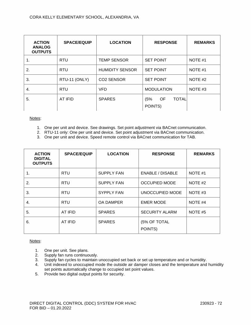
CORA KELLY ELEMENTARY SCHOOL, ALEXANDRIA, VA
DIRECT DIGITAL CONTROL (DDC) SYSTEM FOR HVAC FOR BID – 01.20.2022
230923 - 72
Notes:
1. One per unit and device. See drawings. Set point adjustment via BACnet communication. 2. RTU-11 only: One per unit and device. Set point adjustment via BACnet communication. 3. One per unit and device. Speed remote control via BACnet communication for TAB.
ACTION DIGITAL
OUTPUTS
SPACE/EQUIP LOCATION RESPONSE REMARKS
1. RTU SUPPLY FAN ENABLE / DISABLE NOTE #1
2. RTU SUPPLY FAN OCCUPIED MODE NOTE #2
3. RTU SYPPLY FAN UNOCCUPIED MODE NOTE #3
4. RTU OA DAMPER EMER MODE NOTE #4
5. AT IFID SPARES SECURITY ALARM NOTE #5
6. AT IFID SPARES (5% OF TOTAL
POINTS)
Notes:
1. One per unit. See plans. 2. Supply fan runs continuously. 3. Supply fan cycles to maintain unoccupied set back or set up temperature and or humidity. 4. Unit indexed to unoccupied mode the outside air damper closes and the temperature and humidity
set points automatically change to occupied set point values. 5. Provide two digital output points for security.
ACTION ANALOG OUTPUTS
SPACE/EQUIP
LOCATION
RESPONSE
REMARKS
1. RTU TEMP SENSOR SET POINT NOTE #1
2. RTU HUMIDITY SENSOR SET POINT NOTE #1
3. RTU-11 (ONLY) CO2 SENSOR SET POINT NOTE #2
4. RTU VFD MODULATION NOTE #3
5. AT IFID SPARES (5% OF TOTAL
POINTS)

CORA KELLY ELEMENTARY SCHOOL, ALEXANDRIA, VA
DIRECT DIGITAL CONTROL (DDC) SYSTEM FOR HVAC FOR BID – 01.20.2022
230923 - 73
Notes:
1. One per unit. 2. Any alarm 3. Provide a digital output point for each heating and cooling stage. Connect to factory built in
controls via BACnet communication.
B. Rooftop Units - Single Zone with Economizer Cycle
1. General - Rooftop unit shall be controlled through the IFID timing function by the IFID operating program reacting to space temperature signals from the room sensor located where shown. The IFID shall actuate control relays, which will start and stop the unit and open or close circuits for the fan, heating, or cooling operation. Compressors and heating section shall be hardwired interlocked internally so that they cannot operate unless the unit fan is running. When the unit is de-energized the outside air damper shall close.
2. Fan - When the IFID timing function energizes the system, the program shall cause the supply fan to run constantly using the factory built-in control circuitry. The modulating electrically operated low leakage outside air damper shall be internally interlocked with the fan to open to its preset minimum position with the return air damper closing a corresponding amount.
3. Heating a. Occupied Mode - The IFID shall cause modulation or cycling of the heating to
maintain the space programmed heating setting of 71F. Whenever the unit is energized, BAS shall enable the heater and use a DA PID loop to control its output via the unit mounted heater management system to maintain space temperature at setpoint, through a step control logic function utilizing dead bands with a 2°F (ADJ.) throttling range. Heating shall remain off if the outside air temperature is above 62°F (ADJ.).
b. Unoccupied Mode - The IFID shall close the outside air damper and stop the fan. When the space temperature falls below the programmed reduced night
ACTION DIGITAL INPUTS
SPACE/EQUIP LOCATION RESPONSE REMARKS
1. RTU ROOF STATUS NOTE #1
2. RTU ROOF ALARM NOTE #2
3. RTU HEAT PER STAGE NOTE #3
4 RTU COOL PER STAGE NOTE #3
5. RTU GAS VALVE STATUS NOTE #1
6. CEF ABOVE CEILING STATUS NOTE #1
7. PRV ROOF STATUS NOTE #1
8. AT IFID SPARES (5% OF TOTAL POINTS)

CORA KELLY ELEMENTARY SCHOOL, ALEXANDRIA, VA
DIRECT DIGITAL CONTROL (DDC) SYSTEM FOR HVAC FOR BID – 01.20.2022
230923 - 74
temperature of 55F, the IFID shall return the system to operation as described above until the programmed setting is reached. During night setback heating operation, the outside air damper shall remain closed.
c. Morning Warm-Up - When the IFID returns the equipment to the occupied mode it shall start in a morning warm-up configuration. The fan shall run, the heat shall cycle and the outside air damper shall remain closed until the space temperature
signal transmitted to the IFID reaches the programmed setting of 68F. If after a one-hour time period the space temperature has not reached 68 DEG F the outside air damper will be indexed to the occupied position.
4. Cooling
a. Occupied Mode
1. The IFID shall close the cooling control circuits to the rooftop unit in noted
stages causing the controls to operate the cooling cycle to maintain the IFID programmed cooling setting of 74o F.
2. Mechanical Cooling - When the unit panel operates the cooling controls
and the outside air enthalpy is above the built-in enthalpy sensor set point the economizer mode is locked out and the outside air dampers remain at their minimum position. Cooling is done mechanically by the compressors.
3. Economizer Cooling - When the unit panel operates the cooling controls
and the outside air enthalpy is below the setting of the built-in enthalpy sensor the economizer mode operates under built-in thermostatic control. The outside air dampers modulate toward their open position while the return air dampers modulate toward closed correspondingly. The economizer mode acts as the first stage of cooling using outside air. In this mode as the outside air damper modulates to the 50% open point and an end switch on the damper shall close the circuit to the relief air means described below. If the outside air alone cannot satisfy the cooling requirements of the conditioned space economizer cooling is integrated with mechanical cooling. Compressors working simultaneously with the economizer mode will be staged on to meet the cooling load. As the conditioned space temperature approaches the set point the mechanical stages cycle off, last stage first. After all stages of mechanical cooling are
off as the discharge air temperature drops below 62F the outside air damper will modulate toward its minimum setting. At a discharge air
temperature of 50F the outside air damper will be at its minimum position.
4. During the economizer cycle building air shall be relieved through the
rooftop unit using barometric dampers, powered exhaust or remote relief dampers sized at 100%.
b. Unoccupied Mode - The IFID shall de-energize the controls and
rooftop unit. The outside air dampers shall close. When the space temperature sensor rises above the programmed night
temperature of 85F, the IFID shall return the system to operation as described above until the programmed setting is reached. During the night setback cooling operation, the outside air damper shall remain closed.

CORA KELLY ELEMENTARY SCHOOL, ALEXANDRIA, VA
DIRECT DIGITAL CONTROL (DDC) SYSTEM FOR HVAC FOR BID – 01.20.2022
230923 - 75
5. Rooftop Unit No. 11 - In addition to the above sequence the following shall apply.
a. The rooftop units shall operate an equal amount of time each
week. During normal occupancy only one primary unit shall operate. A different unit shall be the primary unit each day. The lead unit shall be determined by the owner.
b. The change from normal occupancy to high occupancy shall be
through a carbon dioxide sensor located in the space adjacent to the room sensor. Normal occupancy shall be below 900 parts per million or less and high occupancy shall be above 900 parts per million.
c. Ventilation - When the changeover is made to high occupancy, additional units shall be staged on to provide ventilation as the CO2 level in the space rises from 900 ppm to 1100 ppm so that all rooftop units are energized at a CO2 level of 1100 ppm. Upon a fall in CO2 level, the reverse shall occur. Units shall run for a minimum of one hour when brought on by CO2.
d. Heating - The IFID shall cycle the heating stages in all rooftop
units consecutively to maintain a space temperature of 71F.
e. Cooling - The IFID shall cycle the cooling stages in all rooftop
units consecutively to maintain a space temperature of 74F.
6. Dehumidification mode – Daikin Maverick I units.
a. The Maverick I rooftop units equipped with dehumidification control require both a space temperature sensor and a space humidity sensor. The demand for cooling will always be satisfied first before the rooftop unit will go into dehumidification control.
The rooftop has 2 types of dehumidification control modes, low
dehumidification, and high dehumidification control. Unit sizes 3~5 tons only have the high dehumidification control mode since they have only 1 stage of cooling and 1 supply fan speed. Unit sizes 7~25 tons have both the low and high dehumidification control modes since they have 2 stages of cooling and a 2-speed supply fan operation controlled by a VFD. If the space relative humidity is 2~5% above the setpoint the dehumidification control mode will be the “low” dehumidification control. If the space relative humidity is greater than 5% above the set point the unit will operate in the “high” dehumidification control mode. In the low dehumidification control mode, the supply fan will run at the low speed and the 1st stage of compressors will operate. In the high dehumidification control mode, the supply fan will run at high or full speed and the 2nd stage of cooling will operate. When the dehumidification control is initiated the liquid line solenoid valve going to the txv valve closes and the valve from the reheat coil to the txv opens. The bypass solenoid valve (discharge valve) at the condenser coil also opens. During the dehumidification mode some of the hot gas leaving the compressor goes thru the bypass line and the some continues to the condenser coil. The bypass gas and the liquid from the

CORA KELLY ELEMENTARY SCHOOL, ALEXANDRIA, VA
DIRECT DIGITAL CONTROL (DDC) SYSTEM FOR HVAC FOR BID – 01.20.2022
230923 - 76
condenser come together in a 2-phase liquid/gas mixture and then goes to the reheat coil.
The amount of refrigerant going to the condenser coil and the
amount of heat rejected at the condenser coil is controlled by the Outdoor Fan Motor Control – OFMC. The OFMC controls the outdoor fans based on the liquid line temperature sensor installed at the liquid line of the condenser coil. The OFMC has a temperature adjustment setting and can be controlled to increase or decrease the leaving air temperature (LAT) from the unit. The default temperature for the OFMC is 90F. Increasing this temperature setting will increate the leaving air temperature (LAT) of the unit and decreasing the OFMC temperature setting will decrease the LAT of the unit. The refrigerant system is balanced to produce about the same dry bulb temperature leaving the unit as the dry bulb temperature entering the cooling coil. Thus, when the entering air temperature to the cooling coil is 70F the LAT of the unit will be above 70F also but with less moisture, lower dew point and drier/less humid air. The unit will operate in the dehumidification mode until the space humidity is satisfied.
C. Power Roof Ventilators
1. PRV-1 (North Classroom Wing Toilet Rooms) - Shall be operated through the
BMS time clock function constantly during occupied hours interlocked with respective zones and shall be de-energized during unoccupied hours.
2. PRV-2 (South Library Toilet Rooms) - Shall be operated through the BMS time clock function constantly during occupied hours interlocked with respective zones and shall be de-energized during unoccupied hours.
3. PRV-3 (South Library Clinic Toilet Bathrooms) - Shall be operated through the BMS time clock function constantly during occupied hours interlocked with respective zones and shall be de-energized during unoccupied hours.
4. PRV-4 (Main Electric Room) - Shall be operated through the BMS based on time clock function and temperature in the electric room. Run constantly during occupied hours interlocked with respective zones and shall cycle on/off during unoccupied hours to maintain 80 degF space temperature.
5. PRV-5 (Lounge Toilet Rooms) - Shall be operated through the BMS time clock function constantly during occupied hours interlocked with respective zones and shall be de-energized during unoccupied hours.
6. PRV-6 (Second Floor Toilet Rooms) - Shall be operated through the BMS time clock function constantly during occupied hours interlocked with respective zones and shall be de-energized during unoccupied hours.
7. Dry Food Storage Exhaust Fan PRV – Existing to remain, not in contract.
8. Kitchen Heat Removal Hood PRV – Existing to remain, not in contract.
D. Ceiling Exhaust Fans

CORA KELLY ELEMENTARY SCHOOL, ALEXANDRIA, VA
DIRECT DIGITAL CONTROL (DDC) SYSTEM FOR HVAC FOR BID – 01.20.2022
230923 - 77
1. CEF-1 (Library Data/Electric Room) - Shall be operated through the BMS based on time clock function and temperature in the electric room. Run constantly during occupied hours interlocked with respective zones and shall cycle on/off during unoccupied hours to maintain 80 degF space temperature.
2. CEF-2 (Classroom 32 & 35 Toilet Rooms) - Shall be operated through the BMS time clock function constantly during occupied hours interlocked with respective zones and shall be de-energized during unoccupied hours.
3. CEF-3 (Classroom 31 & 33 Toilet Rooms) - Shall be operated through the BMS time clock function constantly during occupied hours interlocked with respective zones and shall be de-energized during unoccupied hours.
4. CEF-4 (Classroom 28 & 30 Toilet Rooms) - Shall be operated through the BMS time clock function constantly during occupied hours interlocked with respective zones and shall be de-energized during unoccupied hours.
5. CEF-5 (Classroom 32 Toilet Room) - Shall be operated through the BMS time clock function constantly during occupied hours interlocked with respective zones and shall be de-energized during unoccupied hours.
3.5 SYSTEM COMMUNICATION DEVICES
A. Provide a minimum of one LANID or equivalent function to support OW’s.
B. Provide gateways as required to support manufacturers configuration.
3.6 SYSTEM SOFTWARE AND PROGRAMMING
A. System Configuration
1. Thoroughly configure ATC system software, network communications, remote operator workstations, portable operators’ terminals, printers, alarm printers.
B. Site Specific Application Programming
1. Provide all database creation and site-specific application control programming as required by these specifications for a fully functioning system. Contractor shall provide all initial site-specific application programming and thoroughly document programming. Meet the written sequences of operation. It is Contractor’s responsibility to request clarification on sequence issues that require such clarification.
2. All site-specific programming shall be fully documented and submitted for review and approval, both prior to downloading into the panel, at the completion of functional performance testing, and at the end of the warranty period.
C. Password Setup
1. Set up the following password levels to include the specified capabilities:
a) Level 1: (Owner’s BMS Administrator)
1) Level 2 capabilities
2) View, add, change, and delete usernames, passwords, password levels
b) Level 2: (Programmer)
1) Level 3 capabilities

CORA KELLY ELEMENTARY SCHOOL, ALEXANDRIA, VA
DIRECT DIGITAL CONTROL (DDC) SYSTEM FOR HVAC FOR BID – 01.20.2022
230923 - 78
2) Configure system software
3) Modify control unit programs
4) Modify graphic software
5) Essentially unrestricted except for viewing or modifying usernames, passwords, password levels
c) Level 3: (HVAC Technician)
1) Level 4 capabilities
2) Override output points
3) Change setpoints
4) Change equipment schedules
5) Exit BMS software to use third party programs
6) Acknowledge alarms
d) Level 4: (Non-Technician)
1) Temporarily override equipment schedules
2) Display all graphic data and alarms
3) Trend point data
2. Assist owner’s operators with assigning usernames, passwords and password levels.
D. Point Parameters
1. Provide the following minimum programming for each analog input:
a) Name
b) Address
c) Scanning frequency
d) Engineering units
e) Offset calibration and scaling factor for engineering units
f) High and low alarm values and alarm differentials for return to normal condition
g) High and low value-reporting limits (reasonableness values) which shall prevent control logic from using shorted or open circuit values.
h) Default value to be used when the actual measured value is not reporting. This is required only for points that are transferred across the primary and/or secondary networks and used in control programs residing in control units other than the one in which the point resides. Events causing the default value to be used shall include failure of the control unit in which the point resides, or failure of any network over which the point value is transferred.
i) Selectable averaging function that shall average the measured value over a user selected number of scans for reporting.
2. Provide the following minimum programming for each analog output:
a) Name
b) Address

CORA KELLY ELEMENTARY SCHOOL, ALEXANDRIA, VA
DIRECT DIGITAL CONTROL (DDC) SYSTEM FOR HVAC FOR BID – 01.20.2022
230923 - 79
c) Output updating frequency
d) Engineering units
e) Offset calibration and scaling factor for engineering units
f) Output Range
g) Default value to be used when the normal controlling value is not reporting.
3. Provide the following minimum programming for each digital input:
a) Name
b) Address
c) Scanning frequency
d) Engineering units (on/off, open/closed, freeze/normal, etc.)
e) Debounce time delay
f) Message and alarm reporting as specified.
g) Reporting of each change of state, and memory storage of the time of the last change of state.
h) Totalization of on time (for all motorized equipment status points), and accumulated number of off-to-on transitions.
4. Provide the following minimum programming for each digital output:
a) Name
b) Address
c) Output updating frequency
d) Engineering units (on/off, open/closed, freeze/normal, etc.)
e) Direct or Reverse action selection
f) Minimum on time
g) Minimum off time
h) Status association with a DI and failure alarming (as applicable)
i) Reporting of each change of state, and memory storage of the time of the last change of state.
j) Totalization of on time (for all motorized equipment status points), and accumulated number of off-to-on transitions.
k) Default value to be used when the normal controlling value is not reporting.
E. Alarms
1. Alarm Priority Levels: Alarm messages specified below and the section “Sequence of Operation” shall be assigned to one of the following priority levels. Level 1 is the most critical. Level 5 is the least critical. Unless otherwise specified, alarm messages shall be assigned to priority level 5. If the BMS does not have the capability of displaying the entire specified message, it shall condense the message as necessary; if the entire meaning of the message cannot be included, the message shall reference a code number that refers to an alarm code list. The alarm code list shall be provided by the contractor with a third party database, spreadsheet, or word processor software package in a format that

CORA KELLY ELEMENTARY SCHOOL, ALEXANDRIA, VA
DIRECT DIGITAL CONTROL (DDC) SYSTEM FOR HVAC FOR BID – 01.20.2022
230923 - 80
is searchable and easy to interface using the alarm code number. Return to normal conditions for all alarms shall be reported at the same priority level. For those alarm level, which include the POT as a reporting location, alarms shall be reported to the POT only during scheduled off-shift hours.
2. Alarm message reporting locations for each alarm priority level shall be as follows:
a) Level 1: All Workstations and Energy Management Alarm Logger Printer
b) Level 2: Energy Management and Applicable HVAC Maintenance Shop Workstation, POT’s, and Energy Management Alarm Logger Printers.
c) Level 3: Energy Management Engineer Workstation Screen and Applicable Zone Maintenance Shop Workstation Screen.
d) Level 4: Energy Management Engineer Workstation Screen.
e) Level 5: Maintenance Shop Workstation Alarm Logging Printer.
3. Override alarms: Any point that is overridden through the override feature of the graphic workstation software shall be reported as a Level 3 alarm.
4. Analog Input Alarms: For each analog input, program an alarm message for reporting whenever the analog value is outside of the programmed alarm limits. Report a return to normal message after the analog value returns to the normal range, using a programmed alarm differential. The alarm limits shall be individually selected by the contractor based on the following criteria:
a) Space temperature, except as otherwise stated in sequence of operation with a built in delay of 15 minutes (adjustable): Level 2
1) low alarm: 10F below setpoint
2) low return to normal: 8F below setpoint
3) high alarm: 10F above setpoint
4) high return to normal: 8F above setpoint
b) Controlled media temperature other than space temperature (e.g. AHU discharge air temperature) with a built in delay of 10 minutes (adjustable): Level 2
1) low alarm: 8F below setpoint
2) low return to normal: 5F below setpoint
3) high alarm: 8F above setpoint
4) high return to normal: 5F above setpoint.
c) AHU mixed air temperature: Level 2
1) low alarm: 45F
2) low return to normal: 47F
3) high alarm: 90F
4) high return to normal: 85F
d) Space humidity: Level 2
1) high alarm: 80%
2) high return to normal: 70%
5. RTU Tampering Alarms: The sequences of operation are based on the presumption that motor starter VFDs are in the auto position. If a motorized

CORA KELLY ELEMENTARY SCHOOL, ALEXANDRIA, VA
DIRECT DIGITAL CONTROL (DDC) SYSTEM FOR HVAC FOR BID – 01.20.2022
230923 - 81
equipment unit starts without a prior start command from the BMS, (as sensed by status sensing device), then BMS shall perform the remaining sequence as specified. BMS shall also enunciate the following Level 3 alarm message if status indicates a unit is operational when the run command is not present.
a) DEVICE XXXX FAILURE: Status is indicated on even though it has been commanded to stop. Check the VFD, control relay, status-sensing device, contactors, etc. involved in starting the unit. Acknowledge this alarm when the problem has been corrected.
6. Maintenance Alarms: Enunciate Level 5 alarms when runtime accumulation exceeds a value specified by the operator
a) DEVICE XXXX REQUIRES MAINTENANCE. Runtime has exceeded specified value since last reset.
7. To eliminate nuisance and invalid alarms, alarms shall not be reported if the software algorithm or point is inactive.
8. See requirements for additional equipment-specific alarms specified under “Sequence of Operation”.
9. During the construction and warranty period the following alarms and their
parameters are the only alarms which are to be considered Level 1. These alarms will not require acknowledgement and display return to normal when the alarm condition has cleared. a) RTU alarm. b) RTU fan failure alarm- fan shall alarm when command= on and status is
off, or command=off and status is on. c) Electric room high temperature alarm- alarm if room temperature is
greater than 90 Deg F. END OF SECTION 230923

CORA KELLY ELEMENTARY SCHOOL, ALEXANDRIA, VA
DIRECT DIGITAL CONTROL (DDC) SYSTEM FOR HVAC FOR BID – 01.20.2022
230923 - 82

CORA KELLY ELEMENTARY SCHOOL, ALEXANDRIA, VA
FUEL GAS PIPING 231123 - 1 FOR BID – 01.20.2022
SECTION 231123 - FUEL GAS PIPING
PART 1 - GENERAL
1.1 SUMMARY
A. This Section includes fuel gas piping, specialties, and accessories within the building.
B. Work includes demolition of existing piping and providing new distribution piping.
1. Refer to plans for other applicable requirements. 2. Provide pipe piers/supports for all new gas piping. Refer to this Section and Section
230100 for additional information on pipe piers.
C. This work will be performed over the summer construction period.
1. The Contractor shall provide repeated testing and inspection of the fuel gas piping as the work is completed. The contractor shall retest and reinspect the existing and new systems immediately and repeatedly until ACPS and the authorities having jurisdiction accept the system(s).
2. The existing gas meter regulator is set to 2 psig. Each RTU appliance on the roof shall be provided with a 2 psi to inches wc rated regulator.
3. Regulator Basis of Design: Maxitrol Series 325, or equal.
1.2 PROJECT CONDITIONS
A. Gas System Pressures: Two pressure ranges. The primary pressure from meter/primary regulator is more than 0.5 psig (3.45 kPa) but not more than 2.0 psig (13.8 kPa), and is reduced to appliance inlet pressure at appliance of 0.5 psig (3.45 kPa) or less.
B. Design values of natural fuel gas supplied for these systems are as follows:
1. Nominal Heating Value: 1000 Btu/cu. ft. (93.25 MJ/cu. m). 2. Nominal Specific Gravity: 0.6.
1.3 SUBMITTALS
A. Product Data: For the following:
1. Steel piping include associated components. 2. Specialty valves. Include pressure rating, capacity, settings, and electrical connection
data of selected models. 3. Pressure regulators. Include pressure rating, capacity, and settings to accommodate
selected models. 4. Roof pipe piers/supports.
B. Shop Drawings: For fuel gas piping. Include plans and attachments to other Work.

CORA KELLY ELEMENTARY SCHOOL, ALEXANDRIA, VA
FUEL GAS PIPING 231123 - 2 FOR BID – 01.20.2022
1. Wiring Diagrams: Power, signal, and control wiring. Differentiate between manufacturer-installed and field-installed wiring.
C. Field Test Reports: Indicate and interpret test results for compliance with performance requirements.
D. Maintenance Data: For natural gas specialties and accessories to include in maintenance manuals specified in Division 1.
1.4 QUALITY ASSURANCE
A. Electrical Components and Devices: Listed and labeled as defined in NFPA 70, Article 100, by testing agency acceptable to authorities having jurisdiction, and marked for intended use.
B. ANSI Standard: Comply with ANSI Z223.1, "National Fuel Gas Code."
C. IAS Standard: Provide components listed in IAS's "Directory of A. G. A. and C. G. A Certified Appliances and Accessories" if specified to be IAS listed.
D. UL Standard: Provide components listed in UL's "Gas and Oil Equipment Directory" if specified to be UL listed.
1.5 DELIVERY, STORAGE, AND HANDLING
A. Handling Flammable Liquids: Remove and legally dispose of liquids from drips in existing gas piping. Handle cautiously to avoid spillage and ignition. Notify fuel gas supplier. Handle flammable liquids used by Installer with proper precautions and do not leave on premises from end of one day to beginning of next day.
1.6 COORDINATION
A. Existing Utilities: Do not interrupt utilities serving facilities occupied by Owner or others unless permitted under the following conditions and then only after arranging to provide temporary utility services according to requirements indicated:
1. Notify Architect/Engineer not less than two days in advance of proposed utility interruptions.
2. Do not proceed with utility interruptions without Architect/Engineer’s written permission. 3. Scope of work includes, but not limited to provision and installation of piping, regulators
(Typ. of 17) and other accessories on the roof as required by the local authorities having jurisdiction. Equipment inside building is not indicated on plans as those appliances are existing to remain. Rooftop units 15, 16 & 17 will be fed using existing piping inside building to a roof penetration near units. Load will be decreased so there will be no change to pipe sizes at point of connection to new rooftop units.
PART 2 - PRODUCTS
2.1 MANUFACTURERS

CORA KELLY ELEMENTARY SCHOOL, ALEXANDRIA, VA
FUEL GAS PIPING 231123 - 3 FOR BID – 01.20.2022
A. Manufacturers: Subject to compliance with requirements, provide products by one of the following:
1. Appliance Connector Valves:
a. American Valve. b. B&K Industries, Inc. c. Brass Craft Manufacturing Co. d. Conbraco Industries, Inc.; Apollo Div. e. Mueller Co.; Mueller Gas Products Div. f. Watts Industries, Inc.; Water Products Div.
2. Gas Valves, NPS 2 (DN 50) and Smaller:
a. Crane Valves. b. Flow Control Equipment, Inc. c. Grinnell Corp. d. Honeywell, Inc. e. Milwaukee Valve Co., Inc. f. Mueller Co.; Mueller Gas Products Div. g. Watts Industries, Inc.; Water Products Div.
3. Plug Valves, NPS 2-1/2 (DN 65) and Larger:
a. Flow Control Equipment, Inc. b. Milliken Valve Co., Inc. c. Nordstrom Valves, Inc. d. Olson Technologies, Inc.; Homestead Valve Div. e. Walworth Co.
4. Automatic Gas Valves (Provided with rooftop units).
5. Line Pressure Regulators:
a. American Meter Co. b. Donkin: Bryan Donkin RMG Canada, Ltd. c. Eclipse Combustion, Inc. d. Invensys Energy Metering Co. e. Fisher Controls International, Inc. f. Maxitrol Co. g. National Meter. h. Richards Industries, Inc.; Jordan Valve Div. i. Schlumberger Industries; Gas Div.
6. Appliance Pressure Regulators:
a. Eaton Corp.; Controls Div. b. Harper Wyman Co. c. Invensys Energy Metering Co. d. Maxitrol Co. e. SCP, Inc.
2.2 PIPING MATERIALS

CORA KELLY ELEMENTARY SCHOOL, ALEXANDRIA, VA
FUEL GAS PIPING 231123 - 4 FOR BID – 01.20.2022
A. Refer to Part 3 "Piping Applications" Article for applications of pipe, tube, fitting, and joining materials.
2.3 PIPES, TUBES, FITTINGS, AND JOINING MATERIALS
A. Steel Pipe: ASTM A 53; Type E or S; Grade B; Schedule 40; black.
1. Malleable-Iron Threaded Fittings: ASME B16.3, Class 150, standard pattern, with threaded ends according to ASME B1.20.1.
2. Unions: ASME B16.39, Class 150, malleable iron with brass-to-iron seat, ground joint, and threaded ends according to ASME B1.20.1.
3. Cast-Iron Flanges and Flanged Fittings: ASME B16.1, Class 125. 4. Steel Welding Fittings: ASME B16.9, wrought steel or ASME B16.11, forged steel. 5. Steel Threaded Fittings: ASME B16.11, forged steel with threaded ends according to
ASME B1.20.1. 6. Joint Compound and Tape: Suitable for natural gas. 7. Steel Flanges and Flanged Fittings: ASME B16.5. 8. Gasket Material: Thickness, material, and type suitable for natural gas.
2.4 SPECIALTY VALVES
A. Valves, NPS 2 (DN 50) and Smaller: Threaded ends according to ASME B1.20.1 for pipe threads.
B. Valves, NPS 2-1/2 (DN 65) and Larger: Flanged ends according to ASME B16.5 for steel flanges and according to ASME B16.24 for copper and copper-alloy flanges.
C. Appliance Connector Valves: ANSI Z21.15 and IAS listed.
D. Gas Stops: Bronze body with AGA stamp, plug type with bronze plug and flat or square head, ball type with chrome-plated brass ball and lever handle, or butterfly valve with stainless-steel disc and fluorocarbon elastomer seal and lever handle; 2-psig (13.8-kPa) minimum pressure rating.
E. Gas Valves, NPS 2 (DN 50) and Smaller: ASME B16.33 and IAS-listed bronze body and 125-psig (860-kPa) pressure rating. Provide valve which cannot be locked in the open position.
F. Plug Valves, NPS 2-1/2 (DN 65) and Larger: ASME B16.38 and MSS SP-78 cast-iron, lubricated plug valves, with 125-psig (860-kPa) pressure rating. Provide valve with lubricated stop.
G. General-Duty Valves, NPS 2-1/2 (DN 65) and Larger: ASME B16.38, cast-iron body, suitable for fuel gas service, with "WOG" indicated on valve body, and 125-psig (860-kPa) pressure rating.
1. Gate Valves: MSS SP-70, OS&Y type with solid wedge. 2. Butterfly Valves: MSS SP-67, lug type with lever handle.
H. Automatic Gas Valves: ANSI Z21.21, with electrical operator for actuation by appliance automatic shutoff device.

CORA KELLY ELEMENTARY SCHOOL, ALEXANDRIA, VA
FUEL GAS PIPING 231123 - 5 FOR BID – 01.20.2022
I. Electrically Operated Gas Valves: UL 429, bronze, aluminum, or cast-iron body solenoid valve; 120-V ac, 60 Hz, Class B, continuous-duty molded coil. Include NEMA ISC 6, Type 4, coil enclosure and electrically opened and closed dual coils. Valve position shall normally be closed.
2.5 PRESSURE REGULATORS
A. Description: Single stage and suitable for fuel gas service. Include steel jacket and corrosion-resistant components, elevation compensator, and atmospheric vent.
1. NPS 2 (DN 50) and Smaller: Threaded ends according to ASME B1.20.1 for pipe threads.
2. NPS 2-1/2 (DN 65) and Larger: Flanged ends according to ASME B16.5 for steel flanges and according to ASME B16.24 for copper and copper-alloy flanges.
3. Service Pressure Regulators: ANSI Z21.80. Include 100-psig- (690-kPa-) minimum inlet pressure rating.
4. Line Pressure Regulators: ANSI Z21.80 with 2-psig- (13.8-kPa-) minimum inlet pressure rating.
5. Appliance Pressure Regulators: ANSI Z21.18. Regulator may include vent limiting device, instead of vent connection, if approved by authorities having jurisdiction.
B. Pressure Regulator Vents: Factory- or field-installed, corrosion-resistant screen in opening if not connected to vent piping.
2.6 ROOF PIPE SUPPORTS
A. Description: Roof support UV resistant, 100% recycled rubber system to support all gas piping a minimum of 6” above roof. B-Line CE-Series. Provide UV resistant “Cush-Clamps” as required for pipe being supported.
PART 3 - EXECUTION
3.1 PREPARATION
A. Close equipment shutoff valves before turning off fuel gas to premises or section of piping. Perform leakage test as specified in "Field Quality Control" Article to determine that all equipment is turned off in affected piping section.
B. Comply with ANSI Z223.1, "Prevention of Accidental Ignition" Paragraph.
3.2 ROOFTOP GAS PIPING
A. Remove existing natural gas piping serving existing equipment as required to accommodate new gas piping arrangement and new equipment layout. Provide new 2 psig gas piping as required for rooftop equipment (RTU’s). Coordinate with Washington Gas Co.; Contact: Jennifer Eugene (703) 750-4844. See plans for full extent of rooftop piping modifications.
1. Existing system has 2 psi (to RTU’s) and low-pressure service (to kitchen), service pressure regulator and service meter.

CORA KELLY ELEMENTARY SCHOOL, ALEXANDRIA, VA
FUEL GAS PIPING 231123 - 6 FOR BID – 01.20.2022
2. Existing service shall be reworked to accommodate 2 psi gas pressure and revised gas load.
3. Revise piping to accommodate new rooftop unit gas connection requirements. 4. Rooftop piping support shall be in accordance with Section 230100.2.3.B. 5. Paint all gas piping yellow with outdoor paint suitable for ferrous metal application. Paint
pipe prior to installation of cush-clamps. 6. Provide 2 psi to 0.5 psi regulators at each RTU (Typ. of 17).
a. Basis of Design: Maxitrol Series 325 or equal.
3.3 PIPING APPLICATIONS
A. Flanges, unions, transition, and special fittings with pressure ratings same as or higher than system pressure rating may be used in applications below, unless otherwise indicated.
B. Fuel Gas Piping, 0.5 psig (3.45 kPa) or Less: Use the following:
1. NPS 3/4 and NPS 1 (DN 20 and DN 25): Steel pipe, malleable-iron threaded fittings, and threaded joints.
2. NPS 1-1/4 to NPS 2 (DN 32 to DN 50): Steel pipe, malleable-iron threaded fittings, and threaded joints.
3. NPS 2-1/2 (DN 65) and Larger: Steel pipe, malleable-iron threaded fittings, and threaded joints.
C. Fuel Gas Piping, 0.5 to 2 psig (3.45 to 13.8 kPa): Use the following:
1. NPS 3/4 and NPS 1 (DN 20 and DN 25): Steel pipe, malleable-iron threaded fittings, and threaded joints.
2. NPS 1-1/4 to NPS 2 (DN 32 to DN 50): Steel pipe, malleable-iron threaded fittings, and threaded joints.
3. NPS 2-1/2 to NPS 4 (DN 65 to DN 100): Steel pipe, malleable-iron threaded fittings, and threaded joints.
4. NPS 2-1/2 (DN 65) and Larger: Steel pipe, steel welded fittings, and welded joints.
3.4 VALVE APPLICATIONS
A. Appliance Shutoff Valves for Pressure 0.5 psig (3.45 kPa) or Less: Appliance connector valve or gas stop.
B. Appliance Shutoff Valves for Pressure 0.5 to 2 psig (3.45 to 13.8 kPa): Gas stop or gas valve.
C. Piping Line Valves, NPS 2 (DN 50) and Smaller: Gas valve.
D. Piping Line Valves, NPS 2-1/2 (DN 65) and Larger: Plug valve or general-duty valve.
3.5 PIPING INSTALLATION
A. Refer to Division 23 Section "Basic Mechanical Materials and Methods" for basic piping installation requirements.
B. Drips and Sediment Traps: Install drips at points where condensate may collect. Include outlets of service meters. Locate where readily accessible for cleaning and emptying.
CORA KELLY ELEMENTARY SCHOOL, ALEXANDRIA, VA
FUEL GAS PIPING 231123 - 7 FOR BID – 01.20.2022
1. Construct drips and sediment traps using tee fitting with bottom outlet plugged or capped. Use minimum-length nipple of 3 pipe diameters, but not less than 3 inches (75 mm) long, and same size as connected pipe. Install with min 8-inch space between bottom of drip and finished roof elevation for removal of plug or cap.
C. Install fuel gas piping at uniform grade of 0.1 percent slope upward toward risers.
D. Use eccentric reducer fittings to make reductions in pipe sizes. Install fittings with level side down.
E. Connect branch piping from top or side of horizontal piping.
F. Install unions in pipes NPS 2 (DN 50) and smaller, adjacent to each valve, at final connection to each piece of equipment, and elsewhere as indicated. Unions are not required on flanged devices.
G. Install strainer on inlet of each line pressure regulator and automatic and electrically operated valve.
H. Install flanges on valves, specialties, and equipment having NPS 2-1/2 (DN 65) and larger connections.
I. Install vent piping for gas pressure regulators and gas trains, extend outside building, and vent to atmosphere. Terminate vents with turned-down, reducing-elbow fittings with corrosion-resistant insect screens in large end.
3.6 JOINT CONSTRUCTION
A. Refer to Division 23 Section "Basic Mechanical Materials and Methods" for basic piping joint construction.
B. Use materials suitable for fuel gas.
3.7 HANGER AND SUPPORT INSTALLATION
A. Refer to Division 23 Section "Hangers and Supports" for pipe hanger and support devices.
B. Install hangers for horizontal steel piping with the following maximum spacing and minimum rod sizes:
1. NPS 1 (DN 25) and Smaller: Maximum span, 96 inches (2438 mm); minimum rod size, 3/8 inch (10 mm).
2. NPS 1-1/4 (DN 32): Maximum span, 108 inches (2743 mm); minimum rod size, 3/8 inch (10 mm).
3. NPS 1-1/2 and NPS 2 (DN 40 and DN 50): Maximum span, 108 inches (2743 mm); minimum rod size, 3/8 inch (10 mm).
4. NPS 2-1/2 to NPS 3-1/2 (DN 65 to DN 90): Maximum span, 10 feet (3 m); minimum rod size, 1/2 inch (13 mm).
5. NPS 4 (DN 100) and Larger: Maximum span, 10 feet (3 m); minimum rod size, 5/8 inch (16 mm).
3.8 CONNECTIONS

CORA KELLY ELEMENTARY SCHOOL, ALEXANDRIA, VA
FUEL GAS PIPING 231123 - 8 FOR BID – 01.20.2022
A. Drawings indicate general arrangement of fuel gas piping, fittings, and specialties.
B. Install piping adjacent to appliances to allow service and maintenance.
C. Connect piping to appliances using gas with shutoff valves and unions. Install valve upstream from and within 72 inches (1800 mm) of each appliance. Install union downstream from valve.
D. Sediment Traps: Install tee fitting with capped nipple in bottom to form drip, as close as practical to inlet of each appliance using gas.
E. Ground equipment.
1. Tighten electrical connectors and terminals according to manufacturer's published torque-tightening values. If manufacturer's torque values are not indicated, use those specified in UL 486A and UL 486B.
2. Do not use gas pipe as grounding electrode.
3.9 LABELING AND IDENTIFYING
A. Equipment Nameplates and Signs: Install engraved plastic-laminate equipment nameplate or sign on or near each, pressure regulator, and specialty valve.
1. Text: In addition to name of identified unit, distinguish between multiple units, inform operator of operational requirements, indicate safety and emergency precautions, and warn of hazards and improper operations.
2. Refer to Division 23 Section "Basic Mechanical Materials and Methods" for nameplates and signs.
3.10 PAINTING
A. Use materials and procedures in Division 9 Section "Paints and Coatings," "Exterior Paint Schedule" Article, "Ferrous Metal" Paragraph, "Full-Gloss, Alkyd-Enamel Finish" Subparagraph.
B. Paint exterior gas piping, pressure regulators, and specialty valves.
1. Color: Yellow.
3.11 FIELD QUALITY CONTROL
A. Inspect, test, and purge piping according to ANSI Z223.1, Part 4 "Inspection, Testing, and Purging," and requirements of authorities having jurisdiction.
B. Repair leaks and defects with new materials and retest system until satisfactory results are obtained.
C. Report test results promptly and in writing to Architect and authorities having jurisdiction.
D. Report pressure readings, upstream and downstream of 2 psi to inches w.c. regulator at each boiler and RTU. Use boiler and RTU numbers to reference reading data.

CORA KELLY ELEMENTARY SCHOOL, ALEXANDRIA, VA
FUEL GAS PIPING 231123 - 9 FOR BID – 01.20.2022
E. Verify capacities and pressure ratings of service meters, pressure regulators, valves, and specialties.
F. Verify correct pressure settings for pressure regulators.
G. Verify that specified piping tests are complete.
3.12 ADJUSTING
A. Adjust controls and safety devices. Replace damaged and malfunctioning controls and safety devices.
END OF SECTION 231123

CORA KELLY ELEMENTARY SCHOOL, ALEXANDRIA, VA
FUEL GAS PIPING 231123 - 10 FOR BID – 01.20.2022
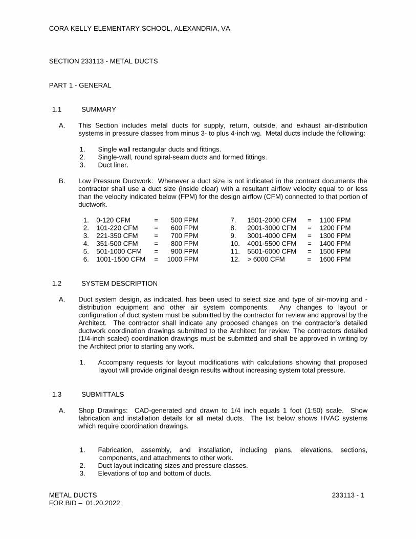
CORA KELLY ELEMENTARY SCHOOL, ALEXANDRIA, VA
METAL DUCTS 233113 - 1 FOR BID – 01.20.2022
SECTION 233113 - METAL DUCTS
PART 1 - GENERAL
1.1 SUMMARY
A. This Section includes metal ducts for supply, return, outside, and exhaust air-distribution systems in pressure classes from minus 3- to plus 4-inch wg. Metal ducts include the following:
1. Single wall rectangular ducts and fittings. 2. Single-wall, round spiral-seam ducts and formed fittings. 3. Duct liner.
B. Low Pressure Ductwork: Whenever a duct size is not indicated in the contract documents the contractor shall use a duct size (inside clear) with a resultant airflow velocity equal to or less than the velocity indicated below (FPM) for the design airflow (CFM) connected to that portion of ductwork.
1. 0-120 CFM = 500 FPM 7. 1501-2000 CFM = 1100 FPM 2. 101-220 CFM = 600 FPM 8. 2001-3000 CFM = 1200 FPM 3. 221-350 CFM = 700 FPM 9. 3001-4000 CFM = 1300 FPM 4. 351-500 CFM = 800 FPM 10. 4001-5500 CFM = 1400 FPM 5. 501-1000 CFM = 900 FPM 11. 5501-6000 CFM = 1500 FPM 6. 1001-1500 CFM = 1000 FPM 12. > 6000 CFM = 1600 FPM
1.2 SYSTEM DESCRIPTION
A. Duct system design, as indicated, has been used to select size and type of air-moving and -distribution equipment and other air system components. Any changes to layout or configuration of duct system must be submitted by the contractor for review and approval by the Architect. The contractor shall indicate any proposed changes on the contractor’s detailed ductwork coordination drawings submitted to the Architect for review. The contractors detailed (1/4-inch scaled) coordination drawings must be submitted and shall be approved in writing by the Architect prior to starting any work.
1. Accompany requests for layout modifications with calculations showing that proposed layout will provide original design results without increasing system total pressure.
1.3 SUBMITTALS
A. Shop Drawings: CAD-generated and drawn to 1/4 inch equals 1 foot (1:50) scale. Show fabrication and installation details for all metal ducts. The list below shows HVAC systems which require coordination drawings.
1. Fabrication, assembly, and installation, including plans, elevations, sections,
components, and attachments to other work. 2. Duct layout indicating sizes and pressure classes. 3. Elevations of top and bottom of ducts.

CORA KELLY ELEMENTARY SCHOOL, ALEXANDRIA, VA
METAL DUCTS 233113 - 2 FOR BID – 01.20.2022
4. Dimensions of main duct runs from building grid lines. 5. Fittings. 6. Reinforcement and spacing. 7. Seam and joint construction. 8. Penetrations through fire-rated and other partitions. 9. Equipment installation based on equipment being used on Project. 10. Duct accessories, including access doors and panels. 11. Hangers and supports, including methods for duct and building attachment, vibration
isolation. Refer to Section 230529 for structure and attachment requirements in structure.
B. Coordination Drawings: Coordination drawings shall also indicate. Reflected ceiling plans, drawn to scale, on which the following items are shown and coordinated with each other, based on input from installers of the items involved:
1. Ceiling suspension assembly members. 2. Other systems installed in same space as ducts. 3. Ceiling- and wall-mounting access doors and panels required to provide access to
dampers and other operating devices. 4. Ceiling-mounting items, including lighting fixtures, diffusers, grilles, speakers, sprinklers,
access panels, and special moldings.
C. Welding certificates.
D. Field quality-control test reports.
1. All ductwork shall be pressure tested to the design pressure rating of the ductwork. Pressure testing shall be performed in accordance with SMACNA procedures and recommendation. Submit test results for review and approval prior to close-in of ceilings.
1.4 QUALITY ASSURANCE
A. Welding: Qualify procedures and personnel according to
1. AWS D1.1, "Structural Welding Code--Steel," for hangers and supports 2. AWS D1.2, "Structural Welding Code--Aluminum," for aluminum supporting members 3. AWS D9.1, "Sheet Metal Welding Code," for duct joint and seam welding].
B. NFPA Compliance:
1. NFPA 90A, "Installation of Air Conditioning and Ventilating Systems." 2. NFPA 90B, "Installation of Warm Air Heating and Air Conditioning Systems."
C. Comply with NFPA 96, "Ventilation Control and Fire Protection of Commercial Cooking Operations," Ch. 3, "Duct System," for range hood ducts, unless otherwise indicated.
PART 2 - PRODUCTS
2.1 MANUFACTURERS
A. In other Part 2 articles where titles below introduce lists, the following requirements apply to product selection:

CORA KELLY ELEMENTARY SCHOOL, ALEXANDRIA, VA
METAL DUCTS 233113 - 3 FOR BID – 01.20.2022
1. Acceptable Manufacturers: Subject to compliance with requirements, provide products by one of the manufacturers specified.
2. Suggested Sheet Metal Contractors: Subject to compliance with requirements, sheet metal contractor shall be responsible for drawing ¼ - scale, 3-dimensional duct coordination drawings. Drawings shall be complete including details for all air-handling units, energy recovery units, air terminal units, kitchen hoods, air inlets, air outlets, exhaust fans, wall and floor penetrations, volume dampers, and all other sheet metal products.
a. Airways Sheet Metal b. Kogok. c. Stromberg Sheet Metal d. Custom Sheet Metal e. Starling Sheet Metal f. South East Sheet Metal g. Other equal sheet metal contractor.
2.2 SHEET METAL MATERIALS
A. Comply with SMACNA's "HVAC Duct Construction Standards--Metal and Flexible" for acceptable materials, material thicknesses, and duct construction methods, unless otherwise indicated. Sheet metal materials shall be free of pitting, seam marks, roller marks, stains, discolorations, and other imperfections.
B. Galvanized Sheet Steel: Lock-forming quality; complying with ASTM A 653/A 653M and having G90 (Z275) coating designation; ducts shall have mill-phosphatized finish for surfaces exposed to view.
C. Reinforcement Shapes and Plates: Galvanized-steel reinforcement where installed on galvanized sheet metal ducts.
D. Tie Rods: Galvanized steel, 1/4-inch (6-mm) minimum diameter for lengths 36 inches (900 mm) or less; 3/8-inch (10-mm) minimum diameter for lengths longer than 36 inches (900 mm).
2.3 DUCT LINER
A. Fibrous-Glass Liner: Comply with NFPA 90A or NFPA 90B and with NAIMA AH124. Use for all double-wall ductwork.
1. Acceptable Manufacturers:
a. Basis of Design: Knauf Fiber Glass GmbH (Green Guard). b. CertainTeed Corp.; Insulation Group. c. Johns Manville International, Inc. d. Owens Corning.
2. Materials: ASTM C 1071; surfaces exposed to airstream shall be coated to prevent erosion of glass fibers. All liner shall meet the Environmental Institute’s Certification “Greenguard”.
a. Thickness: 2 inch for RTU-1 thru 17; 1-inch (25 mm) for all exhaust ductwork.

CORA KELLY ELEMENTARY SCHOOL, ALEXANDRIA, VA
METAL DUCTS 233113 - 4 FOR BID – 01.20.2022
b. Thermal Conductivity (k-Value): 0.26 at 75 deg F (0.037 at 24 deg C) mean temperature.
c. Fire-Hazard Classification: Maximum flame-spread index of 25 and smoke-developed index of 50 when tested according to ASTM E 84.
d. Liner Adhesive: Comply with NFPA 90A or NFPA 90B and with ASTM C 916. e. Mechanical Fasteners: Galvanized steel suitable for adhesive attachment,
mechanical attachment, or welding attachment to duct without damaging liner when applied as recommended by manufacturer and without causing leakage in duct.
1) Tensile Strength: Indefinitely sustain a 50-lb- (23-kg-) tensile, dead-load test perpendicular to duct wall.
2) Fastener Pin Length: As required for thickness of insulation and without projecting more than 1/8 inch (3 mm) into airstream.
3) Adhesive for Attaching Mechanical Fasteners: Comply with fire-hazard classification of duct liner system.
2.4 SEALANT MATERIALS
A. Joint and Seam Sealants, General: The term "sealant" is not limited to materials of adhesive or mastic nature but includes tapes and combinations of open-weave fabric strips and mastics.
B. Joint and Seam Tape: 2 inches (50 mm) wide; glass-fiber-reinforced fabric.
C. Tape Sealing System: Woven-fiber tape impregnated with gypsum mineral compound and modified acrylic/silicone activator to react exothermically with tape to form hard, durable, airtight seal.
D. Water-Based Joint and Seam Sealant: Flexible, adhesive sealant, resistant to UV light when cured, UL 723 listed, and complying with NFPA requirements for Class 1 ducts.
E. Solvent-Based Joint and Seam Sealant: One-part, nonsag, solvent-release-curing, polymerized butyl sealant formulated with a minimum of 75 percent solids.
F. Flanged Joint Mastic: One-part, acid-curing, silicone, elastomeric joint sealant complying with ASTM C 920, Type S, Grade NS, Class 25, Use O.
G. Flange Gaskets: Butyl rubber or EPDM polymer with polyisobutylene plasticizer.
2.5 HANGERS AND SUPPORTS
A. Building Attachments: Concrete inserts, mechanical-expansion fasteners, or structural-steel fasteners appropriate for construction materials to which hangers are being attached.
1. Powder actuated fasteners must be approved in writing by the structural engineer prior to use in this building
2. Use mechanical-expansion anchors for standard-weight aggregate concretes or for slabs more than 4 inches (100 mm) thick.
3. Refer to Section 230529.1.2.C and Division 3 and 5 for specific requirements for superstructure and attachment in concrete structure.
B. Hanger Materials: Galvanized sheet steel or threaded steel rod.

CORA KELLY ELEMENTARY SCHOOL, ALEXANDRIA, VA
METAL DUCTS 233113 - 5 FOR BID – 01.20.2022
1. Hangers Installed in Corrosive Atmospheres: Electrogalvanized, all-thread rods or galvanized rods with threads painted with zinc-chromate primer after installation.
2. Strap and Rod Sizes: Comply with SMACNA's "HVAC Duct Construction Standards--Metal and Flexible" for steel sheet width and thickness and for steel rod diameters.
C. Duct Attachments: Sheet metal screws, blind rivets, or self-tapping metal screws; compatible with duct materials.
D. Trapeze and Riser Supports: Steel shapes complying with ASTM A 36/A 36M.
1. Supports for Galvanized-Steel Ducts: Galvanized-steel shapes and plates. 2. Supports for Stainless-Steel Ducts: Stainless-steel support materials.
2.6 RECTANGULAR DUCT FABRICATION
A. Fabricate ducts, elbows, transitions, offsets, branch connections, and other construction according to SMACNA's "HVAC Duct Construction Standards--Metal and Flexible" and complying with requirements for metal thickness, reinforcing types and intervals, tie-rod applications, and joint types and intervals.
1. Lengths: Fabricate rectangular ducts in lengths appropriate to reinforcement and rigidity class required for pressure class.
2. Deflection: Duct systems shall not exceed deflection limits according to SMACNA's "HVAC Duct Construction Standards--Metal and Flexible."
3. Provide flanged and gasketed ductwork for all ducts with design pressure rating 4-inch wg and higher.
B. All ductwork shall be 2-inch thick rectangular double wall ductwork with perforated metal inner duct (RTU’s) from the unit discharge and inlet connection for a minimum of 20-feet. Provide insulated single wall ductwork after double wall is stopped. (Refer to section 230716.)
1. Refer to paragraph 2.9 for Double-Wall Duct and Fitting Fabrication.
C. Transverse Joints: Prefabricated slide-on joints and components constructed using manufacturer's guidelines for material thickness, reinforcement size and spacing, and joint reinforcement.
1. Acceptable Manufacturers:
a. Ductmate Industries, Inc. b. Nexus Inc. c. Ward Industries, Inc.
D. Formed-On Flanges: Construct according to SMACNA's "HVAC Duct Construction Standards--Metal and Flexible," Figure 1-4, using corner, bolt, cleat, and gasket details.
1. Acceptable Manufacturers:
a. Ductmate Industries, Inc. b. Lockformer.
2. Duct Size: Maximum 30 inches (750 mm) wide and up to 2-inch wg (500-Pa) pressure class.
CORA KELLY ELEMENTARY SCHOOL, ALEXANDRIA, VA
METAL DUCTS 233113 - 6 FOR BID – 01.20.2022
3. Longitudinal Seams: Pittsburgh lock sealed with noncuring polymer sealant.
E. Cross Breaking or Cross Beading: Cross break or cross bead duct sides 19 inches (480 mm) and larger and 0.0359 inch (0.9 mm) thick or less, with more than 10 sq. ft. (0.93 sq. m) of nonbraced panel area unless ducts are lined.
2.7 APPLICATION OF LINER IN RECTANGULAR DUCTS
A. Adhere a single layer of indicated thickness of duct liner with at least 90 percent adhesive coverage at liner contact surface area. Attaining indicated thickness with multiple layers of duct liner is prohibited.
B. Apply adhesive to transverse edges of liner facing upstream that do not receive metal nosing.
C. Butt transverse joints without gaps and coat joint with adhesive.
D. Fold and compress liner in corners of rectangular ducts or cut and fit to ensure butted-edge overlapping.
E. Do not apply liner in rectangular ducts with longitudinal joints, except at corners of ducts, unless duct size and standard liner product dimensions make longitudinal joints necessary.
F. Apply adhesive coating on longitudinal seams in ducts with air velocity of 2500 fpm (12.7 m/s).
G. Secure liner with mechanical fasteners 4 inches (100 mm) from corners and at intervals not exceeding 12 inches (300 mm) transversely; at 3 inches (75 mm) from transverse joints and at intervals not exceeding 18 inches (450 mm) longitudinally.
H. Secure transversely oriented liner edges facing the airstream with metal nosings that have either channel or "Z" profiles or are integrally formed from duct wall. Fabricate edge facings at the following locations:
1. Fan discharges. 2. Intervals of lined duct preceding unlined duct. 3. Upstream edges of transverse joints in ducts where air velocities are greater than 2500
fpm (12.7 m/s) or where indicated.
I. Secure insulation between perforated or solid (continuous) sheet metal inner duct of thickness required to maintain SMACNA pressure class as specified. Provide outer shell at same thickness as inner duct or as indicated below, which ever is thicker. Use mechanical fasteners that maintain inner duct at uniform distance from outer shell without compressing insulation.
1. Inner Duct: G90 Galvanized Sheet Metal Inner Duct Perforations, 3/32-inch (2.4-mm) diameter, with an overall open area of 23 percent.
a. Galvanized Sheet: Min. 22 gauge solid (continuous) inner pressure duct.
J. Terminate inner ducts with buildouts attached to fire-damper sleeves, dampers, turning vane assemblies, or other devices. Fabricated buildouts (metal hat sections) or other buildout means are optional; when used; secure buildouts to duct walls with bolts, screws, rivets, or welds.
2.8 ROUND DUCT FITTING FABRICATION

CORA KELLY ELEMENTARY SCHOOL, ALEXANDRIA, VA
METAL DUCTS 233113 - 7 FOR BID – 01.20.2022
A. Round, Spiral Lock Seam Ducts: Fabricate supply ducts of galvanized steel according to SMACNA's "HVAC Duct Construction Standards--Metal and Flexible."
1. Acceptable Manufacturers:
a. Basis of Design: McGill AirFlow Corporation. b. SEMCO Incorporated. c. Lindab Inc.
B. Duct Joints:
1. Ducts up to 20 Inches (500 mm) in Diameter: Interior, center-beaded slip coupling, sealed before and after fastening, attached with sheet metal screws.
2. Ducts 21 to 72 Inches (535 to 1830 mm) in Diameter: Three-piece, gasketed, flanged joint consisting of two internal flanges with sealant and one external closure band with gasket.
3. Ducts Larger Than 72 Inches (1830 mm) in Diameter: Companion angle flanged joints per SMACNA "HVAC Duct Construction Standards--Metal and Flexible," Figure 3-2.
4. Round Ducts: Prefabricated connection system consisting of double-lipped, EPDM rubber gasket. Manufacture ducts according to connection system manufacturer's tolerances.
a. Acceptable Manufacturers:
1) Basis of Design: McGill Air Flow Corporation 2) Linab Inc. 3) Semco
C. 90-Degree Tees and Laterals and Conical Tees: Fabricate to comply with SMACNA's "HVAC Duct Construction Standards--Metal and Flexible," with metal thicknesses specified for longitudinal-seam straight ducts.
D. Diverging-Flow Fittings: Fabricate with reduced entrance to branch taps and with no excess material projecting from fitting onto branch tap entrance.
E. Fabricate elbows using die-formed, gored, pleated, or mitered construction. Bend radius of die-formed shall be 1-1/2 times duct diameter.] Unless elbow construction type is indicated, fabricate elbows as follows:
1. Mitered-Elbow Radius and Number of Pieces: Welded construction complying with SMACNA's "HVAC Duct Construction Standards--Metal and Flexible," unless otherwise indicated.
2. Round Mitered Elbows: Welded construction with the following metal thickness for pressure classes from minus 3- to 10-inch wg minus 750 to plus (2500 Pa): (Thickness indicated is for galvanized steel ductwork, provide aluminum thickness as required to meet duct pressure class requirements.)
a. Ducts 3 to 26 Inches (75 to 660 mm) in Diameter: 0.034 inch (0.85 mm). b. Ducts 27 to 50 Inches (685 to 1270 mm) in Diameter: 0.040 inch (1.0 mm). c. Ducts 52 to 60 Inches (1320 to 1525 mm) in Diameter: 0.052 inch (1.3 mm). d. Ducts 62 to 84 Inches (1575 to 2130 mm) in Diameter: 0.064 inch (1.6 mm).

CORA KELLY ELEMENTARY SCHOOL, ALEXANDRIA, VA
METAL DUCTS 233113 - 8 FOR BID – 01.20.2022
3. 90-Degree, 2-Piece, Mitered Elbows: Use only for supply systems or for material-handling Class A or B exhaust systems and only where space restrictions do not permit using radius elbows. Fabricate with single-thickness turning vanes.
4. Round Elbows 8 Inches (200 mm) and Less in Diameter: Fabricate die-formed elbows for 45- and 90-degree elbows and pleated elbows for 30, 45, 60, and 90 degrees only. Fabricate nonstandard bend-angle configurations or nonstandard diameter elbows with gored construction.
5. Round Elbows 9 through 14 Inches (225 through 355 mm) in Diameter: Fabricate gored or pleated elbows for 30, 45, 60, and 90 degrees unless space restrictions require mitered elbows. Fabricate nonstandard bend-angle configurations or nonstandard diameter elbows with gored construction.
6. Round Elbows Larger Than 14 Inches (355 mm) in Diameter: Fabricate gored elbows unless space restrictions require mitered elbows.
7. Die-Formed Elbows for Sizes through 8 Inches (200 mm) in Diameter and All Pressures 0.040 inch (1.0 mm) thick with 2-piece welded construction.
8. Round Gored-Elbow Metal Thickness: Same as non-elbow fittings specified above. 9. Pleated Elbows for Sizes through 14 Inches (355 mm) in Diameter and Pressures
through 10-Inch wg (2500 Pa): 0.022 inch (0.55 mm).
PART 3 - EXECUTION
3.1 DUCT APPLICATIONS
A. Static-Pressure Classes: Construct ducts according to the following. Detailed duct pressure and seal classes for each duct system as indicated. In the event of a conflict use whichever is greater (more stringent).
1. Supply Ducts: 4-inch wg; Seal Class A. 2. Return Ducts (Negative Pressure): 3-inch wg; Seal Class B. 3. Exhaust Ducts (negative pressure for exhaust fans): 2-inch; Seal Class B.
B. All ducts shall be galvanized steel.
C. All round duct runouts from mains shall be provided with factory fabricated manual balancing (volume) dampers with stand-offs and locking quadrants.
D. All low pressure round duct runout dimensions shall match inlet throat (diameter) for diffuser served, except duct dimensions shall be increased by 1-inch diameter if total length hard duct exceeds 6-feet.
1. Maximum length of low-pressure flexible ductwork shall be 4-feet.
E. Duct Liner:
1. RTU’s (Double Wall): 2-inch thick, 1-1/2 # density liner with perforated metal retainer for 20 linear feet from duct unit inlet and discharge connections.
2. All ductwork above the roof shall be lined with 2-inch thick duct liner and protected using either fire retardant ¾ inch thick plywood or 1-inch thick roofing protection board around duct and waterproofed with Seaman Corporation Thermoplastic Fiberlite membrane. Refer to Section 075330.
3. Lined ductwork dimensions are inside clear.
CORA KELLY ELEMENTARY SCHOOL, ALEXANDRIA, VA
METAL DUCTS 233113 - 9 FOR BID – 01.20.2022
3.2 DUCT INSTALLATION
A. Construct and install ducts according to SMACNA's "HVAC Duct Construction Standards--Metal and Flexible," unless otherwise indicated.
B. Install round and flat-oval ducts in lengths not less than 12 feet (3.7 m) unless interrupted by fittings.
C. Install ducts with fewest possible joints.
D. Install fabricated fittings for changes in directions, size, and shape and for connections.
E. Install couplings tight to duct wall surface with a minimum of projections into duct. Secure couplings with sheet metal screws. Install screws at intervals of 12 inches (300 mm), with a minimum of 3 screws in each coupling.
F. Install ducts, unless otherwise indicated, vertically and horizontally and parallel and perpendicular to building lines; avoid diagonal runs.
G. Install ducts close to walls, overhead construction, columns, and other structural and permanent enclosure elements of building.
H. Install ducts with a clearance of 1 inch (25 mm), plus allowance for insulation thickness.
I. Conceal ducts from view in finished spaces. Do not encase horizontal runs in solid partitions unless specifically indicated.
J. Coordinate layout with suspended ceiling, fire and smoke-control dampers, lighting layouts, and similar finished work.
K. Seal all joints and seams. Apply sealant to male end connectors before insertion, and afterward to cover entire joint and sheet metal screws.
L. Electrical Equipment Spaces: Route ducts to avoid passing through transformer vaults and electrical equipment spaces and enclosures.
M. Non-Fire-Rated Partition Penetrations: Where ducts pass through interior partitions and exterior walls and are exposed to view, conceal spaces between construction openings and ducts or duct insulation with sheet metal flanges of same metal thickness as ducts. Overlap openings on 4 sides by at least 1-1/2 inches (38 mm).
N. Fire-Rated Partition Penetrations: Where ducts pass through interior partitions and exterior walls, install appropriately rated fire dampers, sleeves, and firestopping sealant. Fire and smoke dampers are specified in Division 23 Section "Duct Accessories." Firestopping materials and installation methods are specified in Division 7 Section "Through-Penetration Firestop Systems."
O. Protect duct interiors from the elements and foreign materials until building is enclosed. Follow SMACNA's "Duct Cleanliness for New Construction."
P. Paint interiors of metal ducts that do not have duct liner, for 24 inches (600 mm) upstream of registers and grilles. Apply one coat of flat, black, latex finish coat over a compatible

CORA KELLY ELEMENTARY SCHOOL, ALEXANDRIA, VA
METAL DUCTS 233113 - 10 FOR BID – 01.20.2022
galvanized-steel primer. Paint materials and application requirements are specified in Division 9 Painting Sections.
Q. Keep ductwork protected from the weather and seal to keep out moisture, dust and debris.
3.3 SEAM AND JOINT SEALING
A. Seal duct seams and joints according to SMACNA's "HVAC Duct Construction Standards--Metal and Flexible" for duct pressure class indicated.
1. Refer to paragraph 233113.3.1.A for duct application schedule. 2. No ductwork shall be installed for less than 3-inch wg (750 Pa), Seal Class A.
B. Seal ducts before external insulation is applied.
C. All ducts longitudinal seams shall be sealed manually to ensure duct leaks will be minimized, and construction will meet duct pressure class specified.
3.4 HANGING AND SUPPORTING
A. Refer to Section 230529 “Hangers and Supports” for steel support superstructure requirements.
B. Support horizontal ducts within 24 inches (600 mm) of each elbow and within 48 inches (1200 mm) of each branch intersection.
C. Support vertical ducts at maximum intervals of 16 feet (5 m) and at each floor.
D. Install upper attachments to structures with an allowable load not exceeding one-fourth of failure (proof-test) load.
E. Install mechanical expansion anchors in concrete only where allowed by the structural Engineer conformance to the manufacturer’s instructions. 1. Any building damage due to the use of mechanical expansion fasteners is entirely the
responsibility of the contractor.
F. Install powder-actuated anchors in concrete only where allowed by the structural Engineer conformance to the manufacturer’s instructions. 1. Any building damage due to the use of powder-actuated fasteners is entirely the
responsibility of the contractor.
3.5 CONNECTIONS
A. Make connections to equipment with flexible connectors according to Division 23 Section "Duct Accessories."
B. Comply with SMACNA's "HVAC Duct Construction Standards--Metal and Flexible" for branch, outlet and inlet, and terminal unit connections.
END OF SECTION 233113

CORA KELLY ELEMENTARY SCHOOL, ALEXANDRIA, VA
DUCT ACCESSORIES 233300 - 1
FOR BID – 01.20.2022
SECTION 233300 - DUCT ACCESSORIES
PART 1 - GENERAL
1.1 SUMMARY
A. This Section includes the following:
1. Backdraft dampers. 2. Volume dampers. 3. Motorized control dampers. 4. Turning vanes. 5. Duct-mounting access doors. 6. Flexible connectors. 7. Flexible ducts. 8. Duct accessory hardware.
1.2 SUBMITTALS
A. Product Data: For the following:
1. Backdraft dampers. 2. Volume dampers. 3. Motorized control dampers. 4. Fire dampers. 5. Turning vanes. 6. Duct-mounting access doors. 7. Flexible connectors. 8. Flexible ducts.
B. Shop Drawings: Detail equipment assemblies and indicate dimensions, weights, loads, required clearances, method of field assembly, components, and location and size of each field connection.
1. Special fittings. 2. Manual-volume damper installations. 3. Motorized-control damper installations. 4. Fire-damper, installations, including sleeves and duct-mounting access doors. 5. Wiring Diagrams: Power, signal, and control wiring.
C. Coordination Drawings: Reflected ceiling plans, drawn to scale and coordinating penetrations and ceiling-mounting items. Show ceiling-mounting access panels and access doors required for access to duct accessories.
1. Provide submittal indicating the location for all fire dampers, including installation locations and sizes of fire dampers in existing ductwork penetrating corridor walls. This shall be on the ductwork coordination drawings.
1.3 QUALITY ASSURANCE
CORA KELLY ELEMENTARY SCHOOL, ALEXANDRIA, VA
DUCT ACCESSORIES 233300 - 2
FOR BID – 01.20.2022
A. Comply with NFPA 90A, "Installation of Air Conditioning and Ventilating Systems," and NFPA 90B, "Installation of Warm Air Heating and Air Conditioning Systems."
1.4 EXTRA MATERIALS
A. Furnish extra materials described below that match products installed and that are packaged with protective covering for storage and identified with labels describing contents.
1. Fusible Links: Furnish quantity equal to 20 extra.
B. Approval from local Authority having jurisdiction: The contractor is responsible to develop details indicating actual conditions for installation fire dampers. The contractor shall meet with the building officials and inspectors and obtain approval for the installation prior to installing the fire dampers. The contractor’s price shall include adjusting the detail as necessary and making changes required or requested by the authorities having jurisdiction for a complete code compliant UL listed fire stopping system.
PART 2 - PRODUCTS
2.1 MANUFACTURERS
A. In other Part 2 articles where titles below introduce lists, the following requirements apply to product selection:
1. Acceptable Manufacturers: Subject to compliance with requirements, provide products by one of the manufacturers specified.
2.2 SHEET METAL MATERIALS
A. Comply with SMACNA's "HVAC Duct Construction Standards--Metal and Flexible" for acceptable materials, material thicknesses, and duct construction methods, unless otherwise indicated.
B. Galvanized Sheet Steel: Lock-forming quality; complying with ASTM A 653/A 653M and G90 (Z275) coating designation; ducts shall have mill-phosphatized finish for surfaces exposed to view.
C. Aluminum Sheets: ASTM B 209 (ASTM B 209M), alloy 3003, temper H14; with mill finish for concealed ducts and standard, 1-side bright finish for exposed ducts.
D. Extruded Aluminum: ASTM B 221 (ASTM B 221M), alloy 6063, temper T6.
E. Reinforcement Shapes and Plates: Galvanized-steel reinforcement where installed on galvanized sheet metal ducts; compatible materials for aluminum and stainless-steel ducts.
F. Tie Rods: Galvanized steel, 1/4-inch (6-mm) minimum diameter for lengths 36 inches (900 mm) or less; 3/8-inch (10-mm) minimum diameter for lengths longer than 36 inches (900 mm).
2.3 BACKDRAFT DAMPERS

CORA KELLY ELEMENTARY SCHOOL, ALEXANDRIA, VA
DUCT ACCESSORIES 233300 - 3
FOR BID – 01.20.2022
A. Acceptable Manufacturers:
1. CESCO Products. 2. Greenheck. 3. Penn Ventilation Company, Inc. 4. Prefco Products, Inc. 5. Ruskin Company.
B. Description: Multiple-blade, parallel action gravity balanced, with center-pivoted blades of maximum 6-inch (150-mm) width, with sealed edges, assembled in rattle-free manner with 90-degree stop, steel ball bearings, and axles; adjustment device to permit setting for varying differential static pressure.
C. Frame: 0.063-inch- (1.6-mm-) thick extruded aluminum, with welded corners and mounting flange.
D. Blades: 0.050-inch- (1.2-mm-) thick aluminum sheet.
E. Blade Seals: Neoprene.
F. Blade Axles: Galvanized steel.
G. Tie Bars and Brackets: Aluminum or Galvanized steel.
H. Return Spring: Adjustable tension.
2.4 VOLUME DAMPERS
A. Acceptable Manufacturers:
1. McGill AirFlow Corporation. 2. METALAIRE, Inc. 3. Nailor Industries Inc. 4. Penn Ventilation Company, Inc. 5. Ruskin Company.
B. General Description: Factory fabricated, with required hardware and accessories. Stiffen damper blades for stability. Include locking device to hold single-blade dampers in a fixed position without vibration. Close duct penetrations for damper components to seal duct consistent with pressure class.
1. Pressure Classes of 3-Inch wg (750 Pa) or Higher: End bearings or other seals for ducts with axles full length of damper blades and bearings at both ends of operating shaft.
C. Low-Leakage Volume Dampers: Multiple- or single-blade, parallel- or opposed-blade design as indicated, low-leakage rating, with linkage outside airstream, and suitable for horizontal or vertical applications.
1. Steel Frames for steel ductwork: Hat or U-shaped, galvanized sheet steel channels, minimum of 0.064 inch (1.62 mm) thick, with mitered and welded corners; frames with flanges where indicated for attaching to walls and flangeless frames where indicated for installing in ducts.
2. Roll-Formed Steel Blades: 0.064-inch- (1.62-mm-) thick, galvanized sheet steel.

CORA KELLY ELEMENTARY SCHOOL, ALEXANDRIA, VA
DUCT ACCESSORIES 233300 - 4
FOR BID – 01.20.2022
3. Aluminum Frames for aluminum ductwork: Hat or U-shaped, 0.10-inch- (2.5-mm-) thick, aluminum sheet channels; frames with flanges where indicated for attaching to walls and flangeless frames where indicated for installing in ducts.
4. Extruded-Aluminum Blades: 0.050-inch- (1.2-mm-) thick extruded aluminum. 5. Blade Axles: Galvanized steel. 6. Bearings: Oil-impregnated bronze thrust or ball. 7. Blade Seals: Neoprene. 8. Jamb Seals: Cambered aluminum. 9. Tie Bars and Brackets: Galvanized steel or Aluminum.
D. Jackshaft: 1-inch- (25-mm-) diameter, galvanized-steel pipe rotating within pipe-bearing assembly mounted on supports at each mullion and at each end of multiple-damper assemblies.
1. Length and Number of Mountings: Appropriate to connect linkage of each damper in multiple-damper assembly.
E. Damper Hardware: Zinc-plated, die-cast core with dial and handle made of 3/32-inch- (2.4-mm) thick zinc-plated steel, and a 3/4-inch (19-mm) hexagon locking nut. Include center hole to suit damper operating-rod size. Include elevated platform for insulated duct mounting.
2.5 MOTORIZED CONTROL DAMPERS
A. Accept Manufacturers:
1. CESCO Products. 2. Greenheck. 3. McGill AirFlow Corporation. 4. METALAIRE, Inc. 5. Nailor Industries Inc. 6. Penn Ventilation Company, Inc. 7. Ruskin Company.
B. General Description: AMCA-rated, parallel or opposed (as indicated)-blade design; minimum of 0.1084-inch- (2.8-mm-) thick, galvanized-steel frames with holes for duct mounting; minimum of 0.0635-inch- (1.61-mm-) thick, galvanized-steel damper blades with maximum blade width of 8 inches (203 mm).
1. Secure blades to 1/2-inch- (13-mm-) diameter, zinc-plated axles using zinc-plated hardware, with nylon blade bearings, blade-linkage hardware of zinc-plated steel and brass, ends sealed against spring-stainless-steel blade bearings, and thrust bearings at each end of every blade.
2. Operating Temperature Range: From minus 40 to plus 200 deg F (minus 40 to plus 93 deg C).
3. Provide parallel- or opposed-blade design with inflatable seal blade edging, or replaceable rubber seals, rated for leakage at less than 10 cfm per sq. ft. (51 L/s per sq. m) of damper area, at differential pressure of 4-inch wg (995 Pa) when damper is being held by torque of 50 in. x lbf (5.6 N x m); when tested according to AMCA 500D.
2.6 TURNING VANES
A. Fabricate to comply with SMACNA's "HVAC Duct Construction Standards--Metal and Flexible" for vanes and vane runners. Vane runners shall automatically align vanes.

CORA KELLY ELEMENTARY SCHOOL, ALEXANDRIA, VA
DUCT ACCESSORIES 233300 - 5
FOR BID – 01.20.2022
B. Manufactured Turning Vanes: Fabricate 1-1/2-inch- (38-mm-) wide, double-vane, curved blades of galvanized sheet steel set 3/4 inch (19 mm) o.c.; support with bars perpendicular to blades set 2 inches (50 mm) o.c.; and set into vane runners suitable for duct mounting.
1. Acceptable Manufacturers:
a. Ductmate Industries, Inc. b. Duro Dyne Corp. c. METALAIRE, Inc. d. Ward Industries, Inc.
C. Acoustic Turning Vanes: Fabricate airfoil-shaped aluminum extrusions with perforated faces and fibrous-glass fill.
D. Provide turning vanes for duct airflow velocity greater or equal to 1000 fpm.
2.7 DUCT-MOUNTING ACCESS DOORS
A. General Description: Fabricate doors airtight and suitable for duct pressure class.
B. Door: Double wall, duct mounting, and rectangular; fabricated of galvanized sheet metal with insulation fill and thickness as indicated for duct pressure class. Include vision panel where indicated. Include 1-by-1-inch (25-by-25-mm) butt or piano hinge and cam latches.
1. Acceptable Manufacturers: a. CESCO Products. b. Ductmate Industries, Inc. c. Flexmaster U.S.A., Inc. d. Greenheck. e. McGill AirFlow Corporation. f. Nailor Industries Inc.
2. Frame: Galvanized sheet steel, with bend-over tabs and foam gaskets. 3. Provide number of hinges and locks as follows:
a. Less Than 12 Inches (300 mm) Square: Secure with two sash locks. b. Up to 18 Inches (450 mm) Square: Two hinges and two sash locks. c. Up to 24 by 48 Inches (600 by 1200 mm): Three hinges and two compression
latches with outside handles. d. Sizes 24 by 48 Inches (600 by 1200 mm) and Larger: One additional hinge.
C. Door: Double wall, duct mounting, and round; fabricated of galvanized sheet metal with insulation fill and 1-inch (25-mm) thickness. Include cam latches.
1. Acceptable Manufacturers:
a. Flexmaster U.S.A., Inc.
2. Frame: Galvanized sheet steel, with spin-in notched frame.
D. Pressure Relief Access Door: Double wall and duct mounting; fabricated of galvanized sheet metal with insulation fill and thickness as indicated for duct pressure class. Include vision panel where indicated, latches, and retaining chain.

CORA KELLY ELEMENTARY SCHOOL, ALEXANDRIA, VA
DUCT ACCESSORIES 233300 - 6
FOR BID – 01.20.2022
1. Acceptable Manufacturers:
a. CESCO Products. b. Ductmate Industries, Inc. c. Greenheck. d. McGill AirFlow Corporation.
2. Frame: Galvanized sheet steel, with bend-over tabs and foam gaskets.
E. Seal around frame attachment to duct and door to frame with neoprene or foam rubber.
F. Insulation: 1-inch- (25-mm-) thick, fibrous-glass or polystyrene-foam board.
2.8 FLEXIBLE CONNECTORS
A. Acceptable Manufacturers:
1. Duro Dyne Corp. 2. Ventfabrics, Inc. 3. Ward Industries, Inc.
B. General Description: Flame-retardant or noncombustible fabrics, coatings, and adhesives complying with UL 181, Class 1.
C. Metal-Edged Connectors: Factory fabricated with a fabric strip 5-3/4 inches (146 mm) wide attached to two strips of 2-3/4-inch- (70-mm-) wide, 0.028-inch- (0.7-mm-) thick, galvanized sheet steel or 0.032-inch- (0.8-mm-) thick aluminum sheets. Select metal compatible with ducts.
D. Indoor System, Flexible Connector Fabric: Glass fabric double coated with neoprene.
1. Minimum Weight: 26 oz./sq. yd. (880 g/sq. m). 2. Tensile Strength: 480 lbf/inch (84 N/mm) in the warp and 360 lbf/inch (63 N/mm) in the
filling. 3. Service Temperature: Minus 40 to plus 200 deg F (Minus 40 to plus 93 deg C).
2.9 FLEXIBLE DUCTS
A. Acceptable Manufacturers:
1. Ductmate Industries, Inc. 2. Flexmaster U.S.A., Inc. 3. Hart & Cooley, Inc. 4. McGill AirFlow Corporation.
B. Insulated-Duct Connectors for low pressure applications: UL 181, Class 1, 2-ply vinyl film supported by helically wound, spring-steel wire; fibrous-glass insulation; aluminized vapor barrier film.
1. Pressure Rating: 10-inch wg (2500 Pa) positive and 1.0-inch wg (250 Pa) negative. 2. Maximum Air Velocity: 4000 fpm (20.3 m/s). 3. Temperature Range: Minus 10 to plus 160 deg F (Minus 23 to plus 71 deg C).

CORA KELLY ELEMENTARY SCHOOL, ALEXANDRIA, VA
DUCT ACCESSORIES 233300 - 7
FOR BID – 01.20.2022
4. Insulation Thickness: 2-inch (50 mm).
C. Insulated-Duct Connectors for medium pressure applications: UL 181, Class 0, interlocking spiral of aluminum foil; fibrous-glass insulation; aluminized vapor barrier film.
1. Pressure Rating: 8-inch wg (2280 Pa) positive or negative. 2. Maximum Air Velocity: 5000 fpm (25.4 m/s). 3. Temperature Range: Minus 20 to plus 250 deg F (Minus 28 to plus 121 deg C). 4. Insulation Thickness: 2-inch (50 mm).
D. Flexible Duct Clamps: Stainless-steel band with cadmium-plated hex screw to tighten band with a worm-gear action, in sizes 3 through 18 inches (75 to 450 mm) to suit duct size.
2.10 DUCT ACCESSORY HARDWARE
A. Instrument Test Holes: Cast iron or cast aluminum to suit duct material, including screw cap and gasket. Size to allow insertion of pitot tube and other testing instruments and of length to suit duct insulation thickness.
B. Adhesives: High strength, quick setting, neoprene based, waterproof, and resistant to gasoline and grease.
PART 3 - EXECUTION
3.1 APPLICATION AND INSTALLATION
A. Install duct accessories according to applicable details in SMACNA's "HVAC Duct Construction Standards--Metal and Flexible" for metal ducts and in NAIMA AH116, "Fibrous Glass Duct Construction Standards," for fibrous-glass ducts.
1. Install in accordance with manufacturer’s recommendations and as required by the local authorities having jurisdiction.
B. Provide duct accessories of materials suited to duct materials; use galvanized-steel accessories in galvanized-steel and fibrous-glass ducts, stainless-steel accessories in stainless-steel ducts, and aluminum accessories in aluminum ducts.
C. Install backdraft dampers on exhaust fans or exhaust ducts nearest to outside and where indicated.
D. Install volume dampers at all duct runouts from the mains, including in ducts with liner; avoid damage to and erosion of duct liner.
1. Where size not indicated on plans, duct runouts to diffusers shall be sized to match inlet (throat) diameter of diffuser or register served.
E. Provide balancing dampers at points on supply, return, and exhaust systems where branches lead from larger ducts as required for air balancing. Install at a minimum of two duct widths from branch takeoff.

CORA KELLY ELEMENTARY SCHOOL, ALEXANDRIA, VA
DUCT ACCESSORIES 233300 - 8
FOR BID – 01.20.2022
F. Provide test holes at fan inlets and outlets and elsewhere as indicated.
G. Install duct silencers rigidly to ducts.
H. Install duct access doors to allow for inspecting, adjusting, and maintaining accessories and terminal units as follows:
1. On both sides of duct coils. 2. Downstream from volume dampers, turning vanes, and equipment. 3. Adjacent to fire, providing access to reset or reinstall fusible links. 4. To interior of ducts for cleaning; before and after each change in direction, at maximum
50-foot (15-m) spacing. 5. On sides of ducts where adequate clearance is available.
I. Install the following sizes for duct-mounting, rectangular access doors:
1. One-Hand or Inspection Access: 8 by 5 inches (200 by 125 mm). 2. Two-Hand Access: 12 by 6 inches (300 by 150 mm). 3. Head and Hand Access: 18 by 10 inches (460 by 250 mm). 4. Head and Shoulders Access: 21 by 14 inches (530 by 355 mm). 5. Body Access: 25 by 14 inches (635 by 355 mm). 6. Body Plus Ladder Access: 25 by 17 inches (635 by 430 mm).
J. Install the following sizes for duct-mounting, round access doors:
1. One-Hand or Inspection Access: 8 inches (200 mm) in diameter. 2. Two-Hand Access: 10 inches (250 mm) in diameter. 3. Head and Hand Access: 12 inches (300 mm) in diameter. 4. Head and Shoulders Access: 18 inches (460 mm) in diameter. 5. Body Access: 24 inches (600 mm) in diameter.
K. Install the following sizes for duct-mounting, pressure relief access doors:
1. One-Hand or Inspection Access: 7 inches (175 mm) in diameter. 2. Two-Hand Access: 10 inches (250 mm) in diameter. 3. Head and Hand Access: 13 inches (330 mm) in diameter. 4. Head and Shoulders Access: 19 inches (480 mm) in diameter.
L. Label access doors according to Division 23 Section "Mechanical Identification."
M. Install flexible connectors immediately adjacent to equipment in ducts associated with fans and motorized equipment supported by vibration isolators.
N. For fans developing static pressures of 5-inch wg (1250 Pa) and higher, cover flexible connectors with loaded vinyl sheet held in place with metal straps.
O. Connect diffusers to low pressure ducts with maximum 72-inch (1800-mm) lengths of flexible duct clamped and strapped in place.
P. Connect flexible ducts to metal ducts with adhesive and draw bands.
Q. Install duct test holes where indicated and required for testing and balancing purposes.
3.2 ADJUSTING

CORA KELLY ELEMENTARY SCHOOL, ALEXANDRIA, VA
DUCT ACCESSORIES 233300 - 9
FOR BID – 01.20.2022
A. Adjust duct accessories for proper settings.
B. Adjust fire dampers for proper action.
C. Final positioning of manual-volume dampers is specified in Division 23 Section "Testing, Adjusting, and Balancing."
3.3 FIELD QUALITY CONTROL
A. Inspection: Engage a qualified inspection agency to perform the following field quality control inspections, after installing equipment and controls to determine compliance with requirements.
3.4 FIELD QUALITY CONTROL
A. Inspection: Engage a qualified inspection agency to perform the following field quality control inspections, after installing equipment and controls to determine compliance with requirements. 1. Inspect existing ductwork and make a deficiency report prior to testing, adjusting and
balancing. 2. Some existing air outlets (diffusers) have been pushed up into the ceiling. Replace them
back into the ceiling grid prior to testing, adjusting, and balancing. a. Identify any missing volume dampers that will be necessary to properly test, adjust
and balance the existing air distribution system. b. Provide a scaled plan document showing where volume dampers need to be
added to properly test, adjust, and balance the existing air distribution system.
END OF SECTION 233300

CORA KELLY ELEMENTARY SCHOOL, ALEXANDRIA, VA
DUCT ACCESSORIES 233300 - 10
FOR BID – 01.20.2022

CORA KELLY ELEMENTARY SCHOOL, ALEXANDRIA, VA
DIFFUSERS, REGISTERS, AND GRILLES 233713 - 1
FOR BID – 01.20.2022
SECTION 233713 - DIFFUSERS, REGISTERS, AND GRILLES
PART 1 - GENERAL
1.1 SUMMARY
A. This Section includes ceiling- and wall-mounted diffusers, registers, and grilles.
1. Provide steel diffusers registers and grilles with baked enamel, white finish, unless indicated otherwise.
2. Toilet Rooms: Provide anodized aluminum diffusers, registers and grilles. 3. Classrooms, Offices, and Cafeteria: Provide architectural face, diffusers as indicated on
diffuser schedule.
a. Classroom, Offices, and Cafeteria Return: Provided perforated face 2’ x 2’ lay in return grilles.
b. Corridors: No return allowed.
4. All diffusers shall be provided with opposed blade damper (OBD) type balancing dampers unless noted otherwise. Each duct runout from the main serving a diffuser or register shall also have a factory fabricated manual balancing damper with a locking quadrant.
a. Balance system using volume dampers at duct run-outs with air outlet OBD in full open position. This shall allow return to original balance by simply opening all air outlet OBD’s to full open position adjustment(s) at air outlets after occupant adjustments have been made.
5. All diffusers, registers and grille accessories shall be coordinated and provided as necessary to match the ceiling type. Provide plaster frames for plaster/drywall ceilings and ceiling clips for corridor ceilings.
6. Existing air outlets above the existing lay in ceiling shall be reinstalled in the existing ceiling grid and rebalanced to the airflow rate indicated on the TAB plans.
B. Reflected Ceiling Coordination and Related Work: This project includes installation of materials and equipment above existing ceilings. Refer to the architectural drawings for locations of existing ceilings and ceilings to be provided under this contract. Where ceilings are existing to remain, remove ceilings and grid to perform demolition and installation as required for a complete operating system. Reinstall the existing ceilings and grid system (including, diffusers, registers, grilles, lighting fixtures, speakers, fire alarm devices, technology devices, and all other existing equipment) back into the ceiling system. Replace any damaged equipment to match existing and to match adjacent construction immediately. Existing to remain materials and equipment shall be replaced in the exact location as it was prior to the start of construction.
1. The contract includes hanging each piece of existing equipment to remain as required to meet the local code requirements and the contract requirements.
2. Absolutely no materials or equipment shall be hung from existing ceilings (original plaster/tile system or suspended acoustical tile system). Provide hangers for each piece of ductwork, piping equipment, and other associated systems to structure prior to working in or removing existing ceiling(s).

CORA KELLY ELEMENTARY SCHOOL, ALEXANDRIA, VA
DIFFUSERS, REGISTERS, AND GRILLES 233713 - 2
FOR BID – 01.20.2022
1.2 SUBMITTALS
A. Product Data: For each product indicated, include the following:
1. Data Sheet: Indicate materials of construction, finish, and mounting details; and performance data including throw and drop, static pressure drop, and noise ratings.
2. Diffuser, Register, and Grille Schedule: Indicate Drawing designation, room location, quantity, model number, size, and accessories furnished.
a. Shall also indicate ceiling/wall type and margin type to be provided. Contractor is responsible to match.
b. Contractor is responsible to coordinate all quantities and sizes indicated on plans.
B. Coordination Drawings: Reflected ceiling plans, drawn to scale, on which the following items are shown and coordinated with each other, based on input from installers of the items involved:
1. Ceiling suspension assembly members (i.e., Grid, drywall, etc.). 2. Method of attaching hangers to building structure. 3. Size and location of initial access modules for acoustical tile. 4. Ceiling-mounted items including lighting fixtures, diffusers, grilles, speakers, sprinklers,
access panels, and special moldings. 5. Duct access panels. 6. Margin type schedule to match ceiling/wall type for all diffusers, registers, and grilles.
Coordinate with Architectural.
C. Samples for Initial Selection: For diffusers, registers, and grilles with factory-applied color finishes.
D. Samples for Verification: For diffusers, registers, and grilles, in manufacturer's standard sizes to verify color selected.
PART 2 - PRODUCTS
2.1 MANUFACTURERS
A. In other Part 2 articles where titles below introduce lists, the following requirements apply to product selection:
1. Manufacturers: Subject to compliance with requirements, provide products by one of the manufacturers specified.
2.2 GRILLES AND REGISTERS
A. Adjustable Bar Grilles and Registers: Refer to Schedule on Drawings for Basis of Design.
1. Manufacturers:
a. Basis of Design: Titus. b. Carnes. c. Krueger. d. METALAIRE, Inc.; Metal Industries Inc.

CORA KELLY ELEMENTARY SCHOOL, ALEXANDRIA, VA
DIFFUSERS, REGISTERS, AND GRILLES 233713 - 3
FOR BID – 01.20.2022
e. Nailor Industries of Texas Inc. f. Price Industries.
2.3 CEILING DIFFUSER OUTLETS
A. Round Ceiling Diffuser: Refer to Schedule on Drawings for Basis of Design.
1. Manufacturers:
a. Basis of Design: Titus “Omni”. b. Carnes. c. Krueger d. METALAIRE, Inc.; Metal Industries Inc. e. Nailor Industries of Texas Inc. f. Price Industries.
B. Rectangular and Square Ceiling Diffusers: Refer to Schedule on Drawings for Basis of Design.
1. Manufacturers:
a. Basis of Design: Titus “Omni”. b. Carnes. c. Krueger d. METALAIRE, Inc.; Metal Industries Inc. e. Nailor Industries of Texas Inc. f. Price Industries.
C. Architectural Registers: Refer to Schedule on Drawings for Basis of Design.
1. Manufacturers:
a. Basis of Design: Air Concepts. b. Seiho.
2.4 SOURCE QUALITY CONTROL
A. Verification of Performance: Rate diffusers, registers, and grilles according to ASHRAE 70, "Method of Testing for Rating the Performance of Air Outlets and Inlets."
B. All devices shall be tested per Air Diffusion Council and labeled as such.
C. Conform to ARI 890-94 Rating of Air Diffusers and Air Assemblies.
PART 3 - EXECUTION
3.1 EXAMINATION
A. Examine areas where diffusers, registers, and grilles are to be installed for compliance with requirements for installation tolerances and other conditions affecting performance of equipment.

CORA KELLY ELEMENTARY SCHOOL, ALEXANDRIA, VA
DIFFUSERS, REGISTERS, AND GRILLES 233713 - 4
FOR BID – 01.20.2022
1. Verify that accessory items such as plaster rims are installed for areas with drywall ceilings. Coordinate exact location with architectural for symmetrical and even installation.
B. Proceed with installation only after unsatisfactory conditions have been corrected.
3.2 INSTALLATION
A. Install diffusers, registers, and grilles level, plumbing and evenly spaced.
B. Ceiling-Mounted Outlets and Inlets: Drawings indicate general arrangement of ducts, fittings, and accessories. Air outlet and inlet locations have been indicated to achieve design requirements for air volume, noise criteria, airflow pattern, throw, and pressure drop. Make final locations where indicated, as much as practicable. For units installed in lay-in ceiling panels, locate units in the center of panel. Where architectural features or other items conflict with installation, notify Architect/Engineer for a determination of final location.
C. Install diffusers, registers, and grilles with airtight connections to ducts and to allow service and maintenance of dampers, air extractors, and fire dampers.
3.3 ADJUSTING
A. After installation, adjust diffusers, registers, and grilles to air patterns indicated, or as directed, before starting air balancing.
B. Diffusers and Registers: Shall be provided with integral opposed blade manual volume damper. Manual volume dampers shall be provided at each duct runout from the main serving a diffuser or register.
1. Round throat outlets shall be provided with the Titus AG-75 O.B.D. or approved equal.
C. Air Balance: Shall be achieved using the manual volume damper at the duct runout with the O.B.D. in the air outlet in the full open position. The manual volume damper shall be provided with a stand-off locking quadrant. The quadrant shall be marked once the entire system air balance has been achieved. When the ductwork is insulated, neatly pull back the insulation and tape it such that the quadrant and locking mechanism is easily located and adjusted. Indicate the actual location for each diffuser and manual volume damper on the as-built drawings and in the sketches included with the balancing report. Refer to Section 230593 for other applicable requirements.
END OF SECTION 233713

CORA KELLY ELEMENTARY SCHOOL, ALEXANDRIA, VA
AIR FILTERS 234100 - 1 FOR BID – 01.20.2022
SECTION 234100 - AIR FILTERS
PART 1 - GENERAL
1.1 SUMMARY
A. This Section includes factory-fabricated air-filter devices and media used to remove particulate matter from air for HVAC applications.
1. Provide 2 sets of extra filters for the following units:
a. RTU-1 thru 17.
1.2 DEFINITIONS
A. ASHRAE: American Society of Heating Refrigeration and Air-Conditioning Engineers.
B. Efficiency: Particle removal efficiency rating based on ASHRAE Test Standard 52.2-99.
C. Arrestance: Filter quality rating based on ASHRAE Test Standard 52.1-92.
D. FPM: Airflow velocity across face of filter area (feet per minute).
E. UL: Underwriters Laboratories, independent testing agency.
1.3 SUBMITTALS
A. Product Data: Include dimensions; shipping, installed, and operating weights; required clearances and access; rated flow capacity, including initial and final pressure drop at rated airflow; efficiency and test method; fire classification; furnished specialties; and accessories for each model indicated.
B. Shop Drawings: Include plans, elevations, sections, and details to illustrate component assemblies and attachments.
1. Show filter rack assembly, for each unit. This includes arrangement and filter sizes for each unit.
C. Maintenance Data: For each type of filter and rack to include in maintenance manuals specified in Division 1.
1.4 QUALITY ASSURANCE
A. Product Options: Drawings indicate size, profiles, and dimensional requirements of air filters and are based on the specific system indicated. Other manufacturers systems with equal performance characteristics may be considered. Refer to Division 1 Section "Substitutions."
B. Comply with NFPA 90A and NFPA 90B.

CORA KELLY ELEMENTARY SCHOOL, ALEXANDRIA, VA
AIR FILTERS 234100 - 2 FOR BID – 01.20.2022
C. ASHRAE Compliance: Comply with provisions of ASHRAE 52.1 for method of testing and rating air-filter units.
D. Comply with ARI 850.
E. Comply with NFPA 70 for installing electrical components.
1.5 COORDINATION
A. Coordinate with Architect’s construction phasing plan. Ship filters to jobsite at appropriate time when needed to prevent filters from being damaged prior to use. Refer to “Extra Materials” for other applicable requirements.
1.6 EXTRA MATERIALS
A. Furnish extra materials described below that match products installed and that are packaged with protective covering for storage and identified with labels describing contents.
1. Filters: Two complete (2) sets of filters for each unit.
a. Do not run HVAC equipment without filters installed. b. Install one (1) set during construction. c. Install one (1) set at substantial completion.
PART 2 - PRODUCTS
2.1 MANUFACTURERS
A. Manufacturers: Subject to compliance with requirements, provide products by one of the following:
1. Air Filters:
a. Basis of Design: Farr Co. b. AAF International. c. Flanders Filters, Inc.
2.2 EXTENDED-SURFACE, DISPOSABLE PANEL FILTERS (PRE-FILTER)
A. Description: UL 600, Class 2, Factory-fabricated, dry, extended-surface filters with holding frames.
B. Media: Fibrous material formed into deep-V-shaped pleats and held by self-supporting wire grid.
C. Media and Media-Grid Frame: Nonflammable cardboard.
D. Duct-Mounting Frames: Welded, galvanized steel with gaskets and fasteners, and suitable for bolting together into built-up filter banks.

CORA KELLY ELEMENTARY SCHOOL, ALEXANDRIA, VA
AIR FILTERS 234100 - 3 FOR BID – 01.20.2022
E. Efficiency: 30-35% dust spot efficiency, MERV 8, 2-inches thick, rated on ASHRAE Test Standard 52.2-99.
1. Refer to: Filter Schedule at the end of this Section for filter thickness for each unit.
F. Arrestance: 90 – 92%, rated on ASHRAE Test Standard 52.1-92.
G. Maximum Pressure Loss: 0.15 in. wg. clean and 0.5 in. wg. dirty @ 400 FPM face velocity for 2-inch thick; 0.15 in. wg. clean and 0.5 in wg dirty.
H. Basis of Design: Farr 30/30.
PART 3 - EXECUTION
3.1 INSTALLATION
A. Install filter frames according to manufacturer's written instructions.
B. Position each filter unit with clearance for normal service and maintenance.
C. Install filters in position to prevent passage of unfiltered air.
D. Coordinate filter installations with duct and air-handling unit installations.
E. Electrical wiring and connections are specified in Division 26 Sections.
F. Ground equipment.
1. Tighten electrical connectors and terminals according to manufacturer's published torque-tightening values. If manufacturer's torque values are not indicated, use those specified in UL 486A and UL 486B.
3.2 FIELD QUALITY CONTROL
A. Manufacturer's Field Service: Engage a factory-authorized service representative to inspect field-assembled components, filter and filter-frame installation, and electrical wiring. Report results in writing.
3.3 CLEANING
A. After completing system installation and testing, adjusting, and balancing air-handling and air-distribution systems, clean filter housings and install new filter media.
3.4 FILTER SCHEDULE
A. RTU-X: 2-inch thick filter media (Typ. of 17 RTU’s).
END OF SECTION 234100

CORA KELLY ELEMENTARY SCHOOL, ALEXANDRIA, VA
AIR FILTERS 234100 - 4 FOR BID – 01.20.2022

CORA KELLY ELEMENTARY SCHOOL, ALEXANDRIA, VA
PACKAGED ROOFTOP HVAC UNITS 237416 - 1 FOR BID – 01.20.2022
SECTION 237416 - PACKAGED ROOFTOP HVAC UNITS
PART 1 - GENERAL
1.1 SUMMARY
A. This Section includes outdoor rooftop heating and cooling units.
B. Basis of Design: The support curb and structural steel support system is designed around the Basis of Design Packaged Rooftop HVAC Units. Provide detailed survey of existing conditions and dimensions. Provide dimensional information to steel fabricator. Ensure that complete and accurate dimensional survey and RTU information is incorporated into the steel fabricator’s shop drawings. Provide steel coordination and fabrication drawings and systems for each packaged rooftop HVAC Unit for review and approval by the structural engineer. If a manufacturer other than listed as the Basis of Design is provided by the contractor, the contractor shall perform the following: 1. Redesign the structural steel support system to accommodate the installation
requirements for actual units provided. 2. Adjust duct transitions accordingly and include all materials and labor to perform work.
The Basis of Design HVAC RTUs do not have the same duct configuration as the existing HVAC RTUs.
3. Refer to Section 230100.1.4.F and 013000.1.6 for “Submittal” requirements.
C. Adapter Curbs: The existing structure shall not be cut unless specifically allowed by the structural engineer in writing. Where the RTU duct connections would require cutting of joists and beams (not allowed by the structural engineer) install an adapter curb to adjust the duct size aspect ratio and distance between the duct penetrations as necessary not to cut the metal deck or the structure. 1. Adjust duct transitions accordingly and include all materials and labor to perform work.
The Basis of Design HVAC RTUs do not have the same duct configuration as the existing HVAC RTUs.
2. RTU-1 thru 4: Remove entire existing curb and replace with new adapter curb. 3. RTU-15 thru 17: Reuse existing curb and add an adapter curb to make the duct
transitions inside the adapter curb. 4. RTU-5 thru 14: Set on existing steel support system. Refer to Structural drawings for
other applicable requirements. 5. Protect the building from weather damage until the new RTU is installed and the roofing
is patched and repaired.
D. RTU-X: The rooftop HVAC units shall be controlled as single zone constant volume variable temperature system. The unit will operate as a constant volume air-handler during occupied hours and shall cycle “on-off” during unoccupied hours of operation. The outside damper position shall be set to the airflow rate indicated on the RTU schedule in occupied mode. RTU-11 shall have demand-controlled ventilation (DCV) and shall automatically modulate open to maintain CO2 concentration set point 1,000 ppm (adj.). 1. The unit supply air fan motor shall be provided with an adjustable speed drive for ease of
balancing to the supply airflow rate. The VFD shall be provided factory installed by the RTU unit manufacturer. The VFD data shall be read at the graphic interface via BACnet.
2. The supply air fans shall have built-in air flow monitoring stations to allow the supply airflow (CFM) to be read at the BMS graphic interface via BACnet.

CORA KELLY ELEMENTARY SCHOOL, ALEXANDRIA, VA
PACKAGED ROOFTOP HVAC UNITS 237416 - 2 FOR BID – 01.20.2022
3. Ventilation airflow rate (CFM) shall be balanced to the design value on the RTU schedule.
a. Unoccupied Mode: OA damper closed. b. Morning Warm up Mode: OA damper closed. c. Occupied Mode: OA damper open to design value (minimum set point). d. RTU-11 Only: Occupied Mode and CO2 sensor setpoint exceeded, then OA
dampers open to maintain 1,000 ppm (adj.).
4. The rooftop HVAC unit supply fan shall an electrotonically commutated motor (ECM). 5. The rooftop HVAC unit shall have direct expansion (DX) cooling and natural gas, indirect
fired furnace heating (reheat position). Units 6 ton and larger shall have 2-stage or greater compressor cooling control.
6. The rooftop HVAC unit shall have hot gas reheat. Units 6 tons and larger shall have 2-stage hot gas reheat control.
7. RTU-1 thru 17: The rooftop HVAC unit shall have a barometric relief economizer. 8. The unit casing shall be powder coated galvanized, double-wall construction with min. 2-
inch-thick internal rigid vapor barrier liner for outdoor use. Provide hail guards to protect the condenser coils.
9. The unit condensate drain shall be double wall ASTM A666 Type 304 stainless steel sloped in both directions to drain. a. If ASTM A123 hot dipped galvanized steel is used, top of pan shall be coated with
an elastomeric compound.
E. BMS Coordination: Refer to Section 230900 for other applicable factory controls installation requirements
1.2 RTU-1 THRU 17
A. RTU-1 thru 17: Provide supply motor adjustable frequency drive (AFD) for ease of balancing for constant volume airflow for all RTU’s. Provide premium efficiency ECM fan motors. 1. BMS shall have limited control of all the RTU’s, including enable disable, room
temperature set point, room humidity set point, room CO2 concentration set point (RTU-11 Only). Heating and cooling safeties shall be provided by the RTU unit manufacturer. Refer to the schematic flow control diagrams and the sequence of operation specified.
2. BMS components shall be factory provided and installed by the RTU manufacturer. The RTU manufacturer shall factory test each RTU before shipping. The manufacture shall provide all field installed components such as space temperature sensors, space humidity sensors and space CO2 sensors. The BMS contractor shall provide field wiring, programming, systems demonstration, and all other work required in Section 230923.
1.3 SUBMITTALS
A. Product Data: Include manufacturer's technical data for each model indicated, including rated capacities of selected model clearly indicated; dimensions; required clearances; shipping, installed, and operating weights; furnished specialties; accessories; and installation and startup instructions.
B. Shop Drawings: Detail equipment assemblies and indicate dimensions, weights, loadings, required clearances, method of field assembly, components, and location and size of each field connection. Detail mounting, securing, and flashing of roof curb to roof structure, service connections for mounting units, locations of duct support curbs and piping, conduit curbs and duct penetration curbs. Indicate coordinating requirements with roofing system.

CORA KELLY ELEMENTARY SCHOOL, ALEXANDRIA, VA
PACKAGED ROOFTOP HVAC UNITS 237416 - 3 FOR BID – 01.20.2022
1. Wiring Diagrams: Detail wiring for power, signal, and control systems and differentiate between manufacturer-installed and field-installed wiring.
C. Commissioning Reports: Indicate results of startup and testing commissioning requirements. Submit copies of checklists.
D. Maintenance Data: For equipment to include in the maintenance manuals specified in Division 1.
E. Warranties: Special warranties specified in this Section.
1.4 QUALITY ASSURANCE
A. Fabricate and label refrigeration system to comply with ASHRAE 15, "Safety Code for Mechanical Refrigeration."
B. Energy Efficiency Ratio: Equal to or greater than prescribed by ASHRAE 90.1, "Energy Efficient Design of New Buildings except Low-Rise Residential Buildings." 1. Individual and combined EER shall meet or exceed scheduled values.
C. Listing and Labeling: Provide electrically operated components specified in this Section that are listed and labeled. 1. The Terms "Listed" and "Labeled": As defined in the National Electrical Code,
Article 100. 2. Listing and Labeling Agency Qualifications: A "Nationally Recognized Testing
Laboratory" as defined in OSHA Regulation 1910.7.
D. Comply with AGA Z223.1 and ANSI Z27.47 for gas-fired furnace section.
E. Comply with NFPA 70.
F. Rated in accordance with AHRI Standards 210/240 or 340/360.
G. Insulation shall meet NFPA 90A for flame spread and smoke generation.
H. Unit casing shall be capable of withstanding 500-hour salt spray exposure per ASTM B117.
I. Roof curbs and adapter curbs shall be designed to conform to NRCA Standards.
J. Unit shall be designed to prevent water intrusion.
1.5 DELIVERY, STORAGE, AND HANDLING
A. Deliver rooftop units as factory-assembled units with protective crating and covering.
B. Coordinate delivery of units in sufficient time to allow movement into building.
C. Handle rooftop units to comply with manufacturer's written rigging and installation instructions for unloading and moving to final location.
1.6 COORDINATION
CORA KELLY ELEMENTARY SCHOOL, ALEXANDRIA, VA
PACKAGED ROOFTOP HVAC UNITS 237416 - 4 FOR BID – 01.20.2022
A. Coordinate installation of roof curbs, equipment supports, and roof penetrations with roof construction. Roof specialties are specified in Division 7 and 23 Sections.
B. Coordinate installation of RTU support requirements and RTU service connections with structural and concrete support (systems). See Structural.
1. Locate units on roof to ensure that duct penetrations through roof between joists are aligned with the unit duct connections. Where the packaged rooftop units require accessory adapter curbs to ensure duct penetrations miss the structure, and/or attach to existing ductwork include all materials and labor to perform the work in the bid price. Requests for additional payment or claims for delay for coordination with existing structure and/or inclusion of adapter curbs will not be considered.
1.7 WARRANTY
A. General Warranty: The special warranty specified in this Article shall not deprive the Owner of other rights the Owner may have under other provisions of the Contract Documents and shall be in addition to, and run concurrent with, other warranties made by the Contractor under requirements of the Contract Documents.
B. Special Warranty: A written warranty, executed by the manufacturer and signed by the Contractor, agreeing to replace components that fail in materials or workmanship, within the specified warranty period, provided manufacturer's written instructions for installation, operation, and maintenance have been followed.
1. Warranty Period, Compressors: Manufacturer’s standard, but not less than 5 years after date of Substantial Completion.
2. Warranty Period, Heat Exchangers: Manufacturer’s standard, but not less than 20 years after date of Substantial Completion.
1.8 EXTRA MATERIALS
A. Furnish extra materials described below that match products installed, are packaged with protective covering for storage, and are identified with labels describing contents. 1. Filters: Two (2) sets of filters for each unit.
a. Do not run RTU without filters installed. b. Install one (1) set during construction. c. Install one (1) set at substantial completion.
PART 2 - PRODUCTS
2.1 MANUFACTURERS
A. Basis of Design: If a manufacturer other than the “Basis of Design” is provided the contractor shall coordinate the location of all unit connections, including ductwork, piping, power, and controls. The contractor shall also coordinate and be responsible for steel support modifications, and adaptor curb modifications. 1. Refer to Section 230100.1.4.F and 013000.1.6 for “Submittal” requirements.
C. Acceptable Manufacturers: Subject to compliance with requirements; provide products by one of the following:

CORA KELLY ELEMENTARY SCHOOL, ALEXANDRIA, VA
PACKAGED ROOFTOP HVAC UNITS 237416 - 5 FOR BID – 01.20.2022
1. Rooftop Units, 5 tons and smaller: a. Basis of Design: Daikin with BACnet interface to Alerton Controls. b. Trane with BACnet Interface to Delta or Alerton Controls. c. Aaon with BACnet Interface to Delta or Alerton Controls. d. Dunham - Bush with BACnet Interface to Delta or Alerton Controls.
2. Rooftop Units, 6 tons and larger: a. Basis of Design: Daikin with BACnet Interface to Alterton Controls. b. Trane with BACnet Interface to Delta or Alerton Controls. c. Aaon with BACnet Interface to Delta or Alerton Controls. d. Dunham - Bush with BACnet Interface to Delta or Alerton Controls
2.2 ROOFTOP UNITS 5 TONS AND SMALLER
A. Description: Factory assembled and tested; designed for constant air volume (CV) application and roof installation on factory or custom provided curb with bottom (or horizontal as indicated) supply and return air connections, and consisting of compressors, condenser coils, evaporator coils, hot gas reheat coils, condenser and evaporator fans, refrigeration, indirect fired natural gas furnace heating, factory provided and installed safety controls (heating and cooling safeties), factory installed temperature controls provided by the manufacturer and fully tested at the factory prior to shipping, filters, dampers and accessories. 1. UL or ETL listed, AGA certified, ARI rated; heat exchangers shall be in compliance with
ANSI Standard Z21.47. 2. Cooling Operating range 60 deg F to 115 deg F outdoor ambient temperature.
B. Casing: Manufacturer's standard construction with 0.048” (18 gauge) corrosion-protection coating and exterior finish, service panels or 0.048” (18 gauge) access doors with neoprene gaskets for inspection and access to internal parts, minimum 1 inch (25 mm) thick thermal insulation, knockouts for electrical and piping connections, exterior condensate drain connection, and lifting lugs. Side rails shall be 0.075” (14 gauge) 3 ½” tall. 1. Provide condenser coil all weather and hail guards. 2. Bottom unit insulation kit. 3. Down discharge or horizontal discharge duct connections. Refer to plans and schedules. 4. Hinged access doors (factory installed) with locking handles. 5. Provide stainless steel evaporator coil drain pans. 6. Sloped condensate drain pan with both horizontal and vertical drain connection.
Connection shall be made per the manufacturer’s recommendations. 7. Provide baked powder coat finish with neutral beige color. Finished panels surfaces shall
withstand minimum 500-hour salt spray test in accordance with ASTM B117 standard for salt spray resistance.
C. Evaporator Fans: Forward curved, centrifugal, single, or double width single or double inlet, non-overloading fan wheel, ECM direct driven multi-speed with permanently lubricated motor bearings. 1. Provide integral motor adjustable frequency drive (AFD) for start/stop control from the
BMS. 2. Provide premium efficiency, motors. 3. Class II fan construction with aluminum fan and blade.
D. Condenser Fans: Propeller type, directly driven with permanently lubricated motor bearings with totally enclosed air over (TEAO) to protect the motors from damage by water.

CORA KELLY ELEMENTARY SCHOOL, ALEXANDRIA, VA
PACKAGED ROOFTOP HVAC UNITS 237416 - 6 FOR BID – 01.20.2022
E. Refrigerant Coils: Aluminum-plate fin and seamless copper tube in galvanized steel casing with equalizing-type vertical distributor.
F. Compressors: Hermetic ally sealed scroll-type with integral vibration isolators and crankcase heaters. Provide minimum of 1-stage of cooling per RTU. 1. Safety Controls: Automatic-reset type for low pressure; manual reset for high pressure,
and compressor motor overload protection. 2. Timed-Off Control: Automatic-reset control prevents compressor from starting within 5
minutes of previous “off” cycle. 3. Refrigerant Circuits: Interlaced coil refrigerant circuiting with circuit for each compressor. 4. Thermostatic Expansion Valve: Provide for all units.
G. Heat Exchangers: UL/ETL certified Manufacturer's 409 stainless steel (20 Ga.) construction for gas-fired heat exchangers and burners with the following controls: 1. Redundant dual gas valves (2-stage heating). 2. Electronic-spark ignition system. 3. High-limit cutout. 4. Induced-draft fan with airflow proving switch. 5. High temperature limit switches. 6. Flame out runout switch. 7. Flame powering controls.
H. Economizer Control (Provide for all units): Return- and outside-air dampers, outside-air filter, fully modulating electronic-control system with adjustable mixed-air thermostat and automatic changeover through adjustable enthalpy-control device. 1. Refer to schedule on plans for other applicable information. 2. Provide 0-100% economizer package. 3. OA dampers shall have maximum 2% leakage at 1 in wg.
I. Smoke Detectors: Photoelectric detector located in supply-and return air duct to de-energize unit upon sensing products of combustion. 1. Provided powered and interlocked to fire alarm system by Division 26. 2. Installed in ductwork by Division 23. 3. Interlocked to de-energize unit by Division 23. 4. Auxiliary contacts to de-energize unit factory installed by manufacturer.
J. Electrical Convenience Outlet: 115V, non-powered, located in unit cabinet. 1. Provide for all RTU’s. 2. Electrical power for convenience outlet shall be through the base by Division 26. Provide
factory installed through the base electrical access for convenience outlet. This applies for vertical and horizontal discharge connection units.
K. Electronic Motor Protectors: Provide field installed devices to protect equipment from electric utility power undervoltage, overvoltage, loss of phase, phase imbalance and phase reversal. 1. Provide ICM 450 motor protector for each RTU.
L. Operating Controls: Provide automatic temperature controls by the unit manufacturer with BACnet communications interface. Provide factory installed refrigeration and heating safety controls by the RTU manufacturer. Heating and cooling safety controls shall be factory provided and installed to protect compressors and prevent overheating. BACnet integration of all available BACnet points shall be provided by the BMS contractor to the head end BMS controller for graphical interface to all the rooftop HVAC units. 1. Unit enabled/disabled by BMS. 2. Space temperature sensor set point adjust.

CORA KELLY ELEMENTARY SCHOOL, ALEXANDRIA, VA
PACKAGED ROOFTOP HVAC UNITS 237416 - 7 FOR BID – 01.20.2022
3. Space humidity setpoint adjust. 4. Unit indexed to unoccupied, night setback, occupied and economizer modes via factory
installed standalone microprocessor. 5. Unit operating schedules shall be programmable at operator workstation located at ACPS
facilities office offsite. a. Temperature sensors in space shall be surface mounted with Wiremold V2000 (or
equal); Color shall be Ivory. 6. Refer to Section, 230923 for other applicable requirements. 7. Refer to schematic flow control diagrams on drawings Sheets M-801 and M-802 for other
applicable requirements.
M. Condensate Drain Piping: Provide PVC condensate drain min. 1½” diameter, coupling adapter to unit connection size. Route to nearest roof drain. Provide pipe support or straight curb sections to support piping (max. 6-feet spacing for PVC piping). 1. Refer to Section 230100.2.3.
N. Supply Motor AFDs: Mount inside weatherproof control NEMA 3R panel inside control section of unit. 1. Do not locate where AFD will cause interference or obstruction to operation or
maintenance. 2. Install AFD in ventilated compartment inside the RTU.
2.3 ROOFTOP UNITS, 6 TO 20 TONS
A. Description: Factory assembled and tested; designed for constant air volume (CV) application and roof installation on factory or custom provided curb with bottom (or horizontal as indicated) supply and return air connections and consisting of compressors, condensers, evaporator coils, hot gas reheat coils, condenser and evaporator fans, refrigeration, indirect fired natural gas furnace heating, factory provided and installed safety controls (heating and cooling safeties), factory installed temperature controls provided by the manufacturer and fully tested at the factory prior to shipping, filters, dampers and accessories. 1. UL or ETL listed; AGA certified, ARI rated; heat exchangers shall be in compliance with
ANSI standard Z21.47. 2. Cooling operating range 35°F to 115°F outdoor ambient temperature.
B. Casing: Manufacturer's standard construction with 0.048” (18 gauge) corrosion-protection coating and exterior finish, removable panels or 0.048” (18 gauge) access doors with neoprene gaskets for inspection and access to internal parts, minimum 1 inch (25 mm) thick thermal insulation, knockouts for electrical and piping connections, exterior condensate drain connection, and lifting lugs. Side rails shall be 0.075” (14 gauge) 3½” tall. 1. Provide condenser coil all weather guards. 2. Bottom unit insulation kit. 3. Down discharge or horizontal discharge duct connections. Refer to plans and schedules. 4. Hinged access doors (factory installed) with locking handles. 5. Provide stainless steel evaporator coil drain pans. 6. Provide baked powder coat finish with neutral beige color. Finished panels surfaces shall
withstand minimum 500-hour salt spray test in accordance with ASTM B117 standard for salt spray resistance.
C. Evaporator Fans: Forward curved, centrifugal, double width double inlet, non-overloading fan wheel, ECM direct driven multi-speed with adjustable sheaves; and with permanently lubricated motor bearings.
CORA KELLY ELEMENTARY SCHOOL, ALEXANDRIA, VA
PACKAGED ROOFTOP HVAC UNITS 237416 - 8 FOR BID – 01.20.2022
1. Provide integral motor adjustable frequency drive (AFD) for start/stop control from the BMS.
2. Provide premium efficiency motors. 3. Class II fan construction with aluminum fan and blades.
D. Condenser Fans: Propeller type, directly driven with permanently lubricated motor bearings with totally enclosed air area (TEAO) to protect the motors from water damage.
E. Refrigerant Coils: Aluminum-plate fin and seamless copper tube in galvanized steel casing with equalizing-type vertical distributor.
RTU-11 (only): Demand Controlled Ventilation (DCV): 1. Provide CO2 controller to maintain CO2 set point 1,000 ppm (adj.).
F. Compressors: Serviceable, semi hermetic, or fully hermetic scroll-type compressors with oil pump, integral vibration isolators and crankcase heaters. Provide minimum 2-stages of cooling for each RTU (Provide min. 4-stages for 20 ton and larger units as scheduled). 1. Safety Controls: Automatic-reset type for low pressure; manual high pressure, and
compressor motor overload protection. 2. Timed-Off Control: Automatic-reset control prevents compressor from starting within 5
minutes. 3. Refrigerant Circuits: Interlaced coil refrigerant circuiting with circuit for each compressor. 4. Thermostatic Expansion Valve: Provide for all units.
G. Heat Exchangers: UL/ETL certified manufacturer's 409 stainless steel (20 Ga.) construction for gas-fired heat exchangers and burners with the following controls: 1. Redundant, dual gas valves (2-stage heating). 2. Electronic-spark ignition system. 3. High-limit cutout. 4. Induced-draft air-flow proving switch. 5. High Temperature limit switch. 6. Flame out rollout switch. 7. Flaming proving controls.
H. Economizer Control (Provide for all units): Return- and outside-air dampers, outside-air filter, fully modulating electronic-control system with adjustable mixed-air thermostat and automatic changeover through adjustable enthalpy-control device. 1. Refer to schedule on plans for other applicable information. 2. Provide 0-100% economizer package. 3. OA dampers shall have maximum 2% leakage at 1 in wc.
I. Hot Gas Reheat Coil: Provide modulating hot gas reheat for temperature humidity control.
N. Smoke Detectors: Photoelectric detector located in supply-and return-air duct, to de-energize unit. 1. Provided, powered, and interlocked to fire alarm system by Division 26. 2. Installed in ductwork by Division 23. 3. Interlocked to de-energize unit by Division 23. 4. Auxiliary contacts to de-energize unit factory installed by manufacturer.
O. Electrical Convenience Outlet: 115V, non-powered, located in unit cabinet.
1. Option: Provide for all RTU’s or field install weatherproof GFCI receptacle.
CORA KELLY ELEMENTARY SCHOOL, ALEXANDRIA, VA
PACKAGED ROOFTOP HVAC UNITS 237416 - 9 FOR BID – 01.20.2022
2. Electrical power for convenience outlet shall be through the base by Division 26. Provide factory installed through the base electrical access for convenience outlet. This applies for vertical and horizontal discharge connection units.
P. Electronic Motor Protectors: Provide field installed devices to protect equipment from Electric Utility undervoltage, overvoltage, loss of phase, phase imbalance and phase reversal. 1. Provide ICM 450 Motor protector for each RTU.
Q. Operating Controls: Provide DDC automatic temperature controls by the unit manufacturer with BACnet communications interface and have them factory installed. Provide factory installed refrigeration and heating safety controls by the RTU manufacturer. Heating and cooling safety controls shall be factory provided and installed to protect compressors and prevent overheating. BACnet integration of all available BACnet points shall be provided by the BMS contractor to the head end BMS controller for graphical interface to all the rooftop HVAC units. 1. Unit enabled/disabled by BMS. 2. Space temperature sensor set point adjust. 3. Space humidity setpoint adjust. 4. Unit indexed to unoccupied, night setback, occupied and economizer modes via factory
installed standalone microprocessor. 5. Unit operating schedules shall be programmable at operator workstation located at ACPS
facilities office offsite. a. Temperature sensors in space shall be surface mounted with Wiremold V2000 (or
equal); Color shall be Ivory.
6. Refer to Section, 230923 for other applicable requirements. 7. Refer to schematic flow control diagrams on drawings Sheets M-801 and M-802 for other
applicable requirements.
R. Condensate Drain Piping: Provide PVC condensate drain min. 1½” diameter, coupling adapter to unit connection size. Route to nearest roof drain. Provide pipe support or straight curb sections to support piping (max. 6-feet spacing for PVC piping). 1. Refer to Section 230100.2.3.
P. RTU-11 Only: CO2 indoor air quality sensor to interface with BMS for monitoring and control of the OA damper position by the BMS. 1. CO2 sensors provided by RTU manufacturer and installed by BMS in the return air
ductwork or in the space near the unit return.
S. Motor Adjustable Frequency Drives (AFDs): Mount inside weatherproof control NEMA 3R panel inside control section of unit. 1. Do not locate where AFD will cause interference or obstruction to operation or
maintenance. 2. Install AFD in ventilated compartment inside the RTU.
2.4 ROOF CURBS
A. See Division 7 Sections and 230100. “Basic Mechanical Means and Methods” for other applicable requirements.
B. Adapter Curbs: Provide insulated factory or custom fabricated roof curbs suitable for field insulation by roofing contractor. Contractor shall coordinate roof curb with concrete and structural steel/roof slope to match roof pitch and ensure level RTU installation.

CORA KELLY ELEMENTARY SCHOOL, ALEXANDRIA, VA
PACKAGED ROOFTOP HVAC UNITS 237416 - 10 FOR BID – 01.20.2022
1. RTU-1,2,3,4: Adapter curbs shall be provided by RTU vendor. Provide adapter curbs mounted to the existing roof. The footprint of the new adapter curb shall match the existing curb being removed. Provide detailed field survey to verify final dimensions prior to ordering curbs.
2. RTU-15, 16, & 17: Adapter curbs shall be used to fit on existing curb and reuse existing duct roof penetrations and make the new transition from the new supply and return connections to the old RTU supply and return connections at the roof level, but above the roof deck.
2.5 STRUCTURAL STEEL SUPPORT
A. The manufacturer shall provide detailed, correctly dimensioned drawings of the RTU’s which indicate exact service connection locations and sizes, operating weights, and rail support location requirements to the contractor with the submittals. 1. RTU-5 thru 14 shall be set on Existing Steel Dunnage: Refer to Structural Drawings for
modifications to existing steel dunnage and access platforms, ladders and railings.
2.6 MOTORS
A. Refer to Division 23 Section "Motors" for general requirements for factory-installed motors.
B. Motor Construction: NEMA MG 1, general purpose, continuous duty, Design B.
C. Enclosure Type: Open, drip proof.
D. Efficiency: Provide premium efficiency ECM motors. Refer to Section 230513 for minimum allowable efficiency ratings.
2.7 SOURCE QUALITY CONTROL
A. Verification of Performance: Rate capacity according to ARI 360, “Commercial and Industrial Unitary Air-Conditioning Equipment”. 1. Sound Power Level Ratings: Comply with ARI 270, "Standard for Sound Rating of
Outdoor Unitary Equipment."
PART 3 - EXECUTION
3.1 EXAMINATION
A. Examine roof for compliance with requirements for conditions affecting installation and performance of rooftop units. Do not proceed with installation until unsatisfactory conditions have been corrected.
3.2 INSTALLATION
A. Install units according to manufacturer's written instructions.
B. Install units level and plumb, maintaining manufacturer's recommended clearances.

CORA KELLY ELEMENTARY SCHOOL, ALEXANDRIA, VA
PACKAGED ROOFTOP HVAC UNITS 237416 - 11 FOR BID – 01.20.2022
C. Curb Support: Install roof curb on roof structure, level, according to NRCA's guidelines and manufacturer’s written installation instructions. Install and secure rooftop units on curbs and coordinate roof penetrations and flashing with roof construction.
D. Unit Support Steel: Strengthen existing steel structure, according to contractor’s approved coordination drawings. Coordinate ductwork and service elevations with steel support system to miss existing steel joists, etc.
3.3 CONNECTIONS
A. Piping installation requirements are specified in other Division 23 Sections. Drawings indicate the general arrangement of piping, fittings, and specialties. The following are specific connection requirements:
1. Install piping to allow service and maintenance. 2. Gas Piping: Conform to applicable requirements of Division 23 Section "Natural Gas
Piping." Connect gas piping to burner, full size of gas train inlet, and provide union with sufficient clearance for burner removal and service.
B. Duct installation requirements are specified in other Division 23 Sections. Drawings indicate the general arrangement of ducts. The following are specific connection requirements:
1. Install ducts to termination at bottom of unit between roof structural support framing. 2. Support ductwork above roof by straight curb sections. 3. New Penetrations: Rotate unit and modify ductwork as necessary to clear structural steel
and/or concrete joists. 4. Adaptor Curbs: Provide adapter curbs as necessary to miss existing joists with duct
penetration and/or connect to existing ductwork.
C. Electrical: Conform to applicable requirements in Division 26 Sections.
D. Ground equipment.
1. Tighten electrical connectors and terminals according to manufacturer's published torque-tightening values. Where manufacturer's torque values are not indicated, use those specified in UL 486A and UL 486B.
3.4 COMMISSIONING
A. Verify that installation is as indicated and specified.
B. Complete manufacturer's installation and startup checks and perform the following:
1. Level unit on structural steel support dunnage. 2. Inspect for visible damage to unit casing. 3. Inspect for visible damage to furnace combustion chamber. 4. Inspect for visible damage to compressor, air-cooled condenser coil, and fans. 5. Verify that clearances have been provided for servicing. 6. Check that labels are clearly visible. 7. Clean furnace flue and condenser and inspect for construction debris. 8. Verify that controls are connected and operable. 9. Remove shipping bolts, blocks, and tie-down straps.

CORA KELLY ELEMENTARY SCHOOL, ALEXANDRIA, VA
PACKAGED ROOFTOP HVAC UNITS 237416 - 12 FOR BID – 01.20.2022
10. Verify that filters are installed. 11. Adjust vibration isolators. 12. Connect and purge gas line. 13. Verify curb has been installed in accordance with manufacturer’s recommendations. 14. Check that burner and controls are suitable to operate at temperatures as low as minus
40 deg F (minus 40 deg C). 15. Check acoustic insulation. 16. Check operation of barometric dampers. 17. Check to see that ductwork above roof is supported min. 4 linear feet on center.
C. Lubricate bearings on fan.
D. Check fan-wheel rotation for correct direction without vibration and binding.
E. Adjust fan belts to proper alignment and tension.
F. Start unit according to manufacturer's written instructions.
1. Perform starting of refrigeration in summer only. 2. Complete startup sheets and attach copy with Contractor's startup report.
G. Check and record performance of interlocks and protection devices; verify sequences.
H. Operate unit for an initial period as recommended or required by manufacturer.
I. Perform the following operations for both minimum and maximum firing, and adjust burner for peak efficiency. Adjust pilot to stable flame.
1. Measure gas pressure on manifold. 2. Measure combustion-air temperature at inlet to combustion chamber. 3. Measure flue-gas temperature at furnace discharge. 4. Perform flue-gas analysis. Measure and record flue-gas carbon dioxide and oxygen
concentration. 5. Measure supply-air temperature and volume when burner is at maximum firing rate and
when burner is off. Calculate useful heat to supply air. 6. Check for backdraft under full operation.
J. Calibrate temperature sensors, humidity sensors and CO2 sensors.
K. Adjust and check high-temperature limits.
L. Check internal isolators.
M. Check outside-air damper for proper stroke and interlock with return-air dampers.
N. Check controls for correct sequencing of heating, mixing dampers, refrigeration, and normal and emergency shutdown.
O. Start refrigeration and measure and record the following:
1. Coil leaving-air, dry- and wet-bulb temperatures. 2. Coil entering-air, dry- and wet-bulb temperatures. 3. Outside-air, dry-bulb temperature. 4. Air-cooled-condenser, discharge-air, dry-bulb temperature.
CORA KELLY ELEMENTARY SCHOOL, ALEXANDRIA, VA
PACKAGED ROOFTOP HVAC UNITS 237416 - 13 FOR BID – 01.20.2022
P. Measure and record the following minimum and maximum airflows. Plot fan volumes on fan curve.
1. Supply-air volume. 2. Return-air volume. 3. Relief-air volume. 4. Outside-air intake volume.
Q. Simulate maximum cooling demand and check the following:
1. Compressor refrigerant suction and hot-gas pressures. 2. Short circuiting air through condenser or from condenser to outside-air intake.
R. Verify operation of remote panel, including pilot-light operation and failure modes. Check the following:
1. High-limit heat exchanger. 2. Warm-up for morning cycle. 3. Freezestat operation. 4. Free-cooling mode, outside-air changeover. 5. Alarms.
S. After starting and performance testing, change filters, vacuum heat exchanger and cooling and condenser coils, lubricate bearings, adjust belt tension, and check operation of power vents.
T. Owner’s Commissioning Authority: Refer to Sections 018000 “General Commissioning Requirements” and 230800 “HVAC Commissioning Requirements” for other additional requirements.
3.5 DEMONSTRATION
A. Engage a factory-authorized service representative to train Owner's maintenance personnel as specified below:
1. Train Owner's maintenance personnel on procedures and schedules related to startup and shutdown, troubleshooting, servicing, and preventive maintenance.
2. Review data in the maintenance manuals. Refer to Division 1 Section "Closeout Procedures."
3. Review data in the maintenance manuals. Refer to "Operation and Maintenance Data." requirements in Division 1 Sections.
4. Schedule training with Owner, through Architect, with at least 7 days' advance notice. 5. Provide man-hours as required to work with the Building Management System (BMS)
contractor to ensure that all monitoring points are available at the operator workstation. 6. Provide the BMS contractor with technical information and onsite assistance until the
BMS contractor has successfully demonstrated the system to the Owner and until final punch list work is completed to the satisfaction of the Owner and Architect/Engineer.
END OF SECTION 237416

CORA KELLY ELEMENTARY SCHOOL, ALEXANDRIA, VA
PACKAGED ROOFTOP HVAC UNITS 237416 - 14 FOR BID – 01.20.2022

CORA KELLY ELEMENTARY SCHOOL, ALEXANDRIA, VA
BASIC ELECTRICAL MATERIALS AND METHODS 260100 - 1 FOR BID – 01.20.2022
SECTION 260100 - BASIC ELECTRICAL MATERIALS AND METHODS
PART 1 - GENERAL
1.1 SUMMARY
A. Drawings and general provisions of the Contract, including General and Supplementary Conditions and Division 1 Specification Sections and other applicable Division 26 Sections, apply to this Section.
1. This Section compliments and applies to all other Division 26 Sections. 2. NETA Standards: In all Sections where reference is made to NETA, the Contractor shall
utilize the “Acceptance Testing” Specifications for Electrical Power Distribution Equipment and Systems” as published by the International Electrical Testing Association, Latest Edition (NETA).
1.2 SPECIAL ELECTRICAL REQUIREMENTS
A. Drawing use and interpretation:
1. Drawings are diagrammatic and indicate general arrangement of systems and equipment, except when specifically dimensioned or detailed.
2. Refer to architectural, structural, mechanical, and electrical drawings for locations of building elements.
3. Field measurements take precedence over drawings. 4. Electrical plans are intended to indicate size, capacity, approximate location, direction
and general relationship of the work, but not exact detail or arrangement. The contractor is solely responsible for indicating detailed arrangements for procured equipment and layouts on all shop drawings required in all Div. 26 Specifications.
5. Field verify locations and arrangement of existing systems and equipment. 6. Where conflict occurs within the specifications, within drawings or between specifications
and drawings the more stringent requirement is considered as part of the bid price.
B. Installation of systems and equipment:
1. Installation is subject to clarification as indicated in reviewed Shop and Field Coordination Drawings.
a. Generally, lay out piping requiring gravity drainage first; then lay out large pipe mains, ductwork, and electrical conduit.
b. This procedure is intended to promote orderly installation, but not to establish trade precedence.
c. Dimensions indicated are limiting dimensions. d. Do not use equipment exceeding dimensions required by manufacturer for service
access, and applicable codes reduce required clearances. e. In electrical equipment room corridors and aisle ways, maintain clear head room
between floor and underside of conduit, switches, controllers, panelboards, transformers, and equipment to allow for future replacing of equipment and major components.

CORA KELLY ELEMENTARY SCHOOL, ALEXANDRIA, VA
BASIC ELECTRICAL MATERIALS AND METHODS 260100 - 2 FOR BID – 01.20.2022
f. Coordinate connections to existing and new equipment, and penetrations of conduit through floors, walls and roof with actual field conditions and dimensions. Contractors shall thoroughly familiarize themselves with the project requirement building prior to submitting bid price and shall have field measured and coordinated the installations between trades prior to submitting shop drawings.
g. Under no circumstances shall any electrical equipment be hung, supported, or suspended from the building suspended ceilings. Ductwork, piping, etc., shall be hung directly from the existing or new building structure (i.e., steel bar joist or truss system).
h. Provide submittals on all fastening methods. Submittals shall also be reviewed by the structural engineer.
i. This work includes complete familiarization with the project requirements and the construction documents prior to submitting bid price. The contractor shall have measured and coordinated the installations between trades using manufacturer’s actual equipment dimension drawing prior to submitting coordinated shop drawings.
j. This building contains original plaster and tile ceilings above the lay-in acoustical tile ceilings. Under no circumstances shall any Division 26 equipment be hung, supported or suspended from the building ceilings. Conduits, channels, disconnects, or other hardware, etc. shall only be hung directly from the building structure (i.e., steel beam, steel joist or concrete structures). Refer to structural requirements for building attachments. Refer to Architectural for removal of existing ceilings.
k. Any and all cable, for any system routed outside of EMT, rigid steel or other metal raceways shall without exception be plenum rated.
C. Utility coordination with the Owner (ACPS).
1. There shall be no utility interruptions at any time during scheduled school operation of this facility.
2. Notify ACPS of any utility interruptions at least fourteen (14) days in advance and obtain approval from ACPS before proceeding.
3. Identify extent and duration of utility interruptions. 4. Provide full coordination of service routing below grade for primary routings on school
property and all secondary routings on school property. 5. Include replacement of any landscape, plantings, pavement, or structure where same is
damaged by installation or routing of electrical. Such replacement shall be with original matching materials to preclude any evidence of damage.
6. Provide all service associated trenching and backfilling.
D. Coordination Drawings: Detail major elements, components, and systems of electrical equipment, electrical equipment rooms, and layout of all feeder conduits. The drawings shall show placement of all materials, conduit, and equipment in relationship with all other systems, installations, and building components. Show space requirements for installation and access. Indicate if sequence and coordination of installations are important to efficient flow of the Work. All shop drawings shall be prepared in scale using AutoCAD software (version 2020 or higher). Prepare coordination drawings and obtain comments before roughing in any installations. Include the following:
1. Clearances for servicing and maintaining equipment, accessories, and specialties, including space for disassembly required for periodic maintenance, minimum or greater code required clearance to electric panels, switchboard, ATS’s, disconnects, starters, AFD’s, etc. show all pull-boxes and indicate method of access to box covers.
2. Equipment and accessory service connections and support details. 3. Roof penetrations.

CORA KELLY ELEMENTARY SCHOOL, ALEXANDRIA, VA
BASIC ELECTRICAL MATERIALS AND METHODS 260100 - 3 FOR BID – 01.20.2022
4. Fire-rated wall and floor penetrations including methods used and U.L. listed sealants. 5. Scheduling, sequencing, movement, and positioning of distribution and switchboard
equipment into/onto building during construction.
a. Structure and columns may not support concentrated loads. Do not set heavy tools, transformers, etc. on roof, slabs, or columns without permission from the structural engineer. Obtain such permission prior to setting any equipment.
6. Floor plans, elevations, and details are to indicate penetrations in floors, walls, and ceilings and their relationship to other penetrations and installations.
7. Floor plans are to coordinate and integrate installation of all building attachments for ductwork, piping equipment, light fixtures, sprinkler, structural steel framing, pipe hangers/supports, electric equipment, conduit, etc.
8. Roof plans, elevations, and details are to indicate penetrations in roof for piping and conduit, locations of rooftop equipment, structural steel, walk-ways, equipment service access, natural gas piping, piping hangers and supports, etc.
9. Operation and Maintenance Data: In accordance with Division 1 and provide multiple review submissions to modify or reorganize format and content as requested by the Architect at no additional cost to Stafford County Public Schools.
a. Submit O&M manuals for initial review and comment no later than 90 days after
equipment submittals have been completed.
10. Submit technical data on materials and methods proposed for securing existing-to-remain lights, speakers, data, cabinets, or other existing-to-remain electrical devices that are mounted on grid ceiling designated for removal.
11. Submit floor plan drawings indicating routing of all feeders for each panelboard and all HVAC equipment fed from the existing switchboard.
E. Description of systems: Furnish and install materials resulting, upon completion, in functioning systems in compliance with performance requirements specified, and modifications resulting from reviewed Shop and Field Coordination Drawings.
F. Responsibility to Survey Existing Conditions Prior to Bidding: Survey the building completely prior to submitting bid price. Survey shall include, but not be limited to the following:
1. Above lay-in tile ceilings. 2. In mechanical rooms (including mezzanines). 3. In electric rooms. 4. On exterior at building and on site. 5. All building roof areas.
G. Miscellaneous provisions:
1. This project requires electrical connections to multiple miscellaneous devices. The Division 26 shall coordinate with all other trades and ensure adequate power connections are made to facilitate a complete, functioning system.
2. Whether in part, in whole, or not shown on the documents, provide connections to all such devices including but not limited to:
a. Relays b. Miscellaneous signal transformers. c. HVAC Unit interior lighting d. Miscellaneous condenser water pumps e. BMS Control points
CORA KELLY ELEMENTARY SCHOOL, ALEXANDRIA, VA
BASIC ELECTRICAL MATERIALS AND METHODS 260100 - 4 FOR BID – 01.20.2022
3. Where such devices are circuited by the contractor but may not be shown on the drawings, the contractor’s bid includes using available spare circuit breakers and includes all cable, wire, labor, hardware, and disconnect devices necessary to complete connection of the equipment.
1.3 SUMMARY
A. This Section includes the following:
1. Raceways. 2. Building wire and connectors. 3. Supporting devices for electrical components. 4. Electrical identification. 5. Electrical demolition. 6. Cutting and patching for electrical construction. 7. Touchup painting.
1.4 DEFINITIONS
A. RMC: Rigid Metal (Galvanized).
B. EMT: Electrical metallic tubing.
C. FMC: Flexible metal conduit.
D. IMC: Intermediate metal conduit.
E. LFMC: Liquid tight flexible metal conduit.
F. ACPS: Alexandria City Public Schools
G. DVP: Dominion Virginia Power.
H. CM: Construction Manager.
I. Scheduled: As scheduled on drawing equipment schedules or as called out by model number/designation in the specification.
J. Acceptance: With respect to initiation of warranty, the date when the Architect signs the Contractor’s Application for Final Payment for release of retainage.
K. BMS: Building Management System.
J. Notice-to-Proceed: The date, which the building owner or authorized agent authorizes Notice–to-Proceed by Letter.
K. Scheduled: As scheduled on drawing equipment schedules or as called-out by manufacturer/model number/designation in the specification.
L. Concealed: Means installation within structural cavity framing members such as between studs, beams, joists, etc; hidden behind finish materials; or below slab-on grade structure. Conceal

CORA KELLY ELEMENTARY SCHOOL, ALEXANDRIA, VA
BASIC ELECTRICAL MATERIALS AND METHODS 260100 - 5 FOR BID – 01.20.2022
(concealed, etc.) does not allow embedding or routing conduits in poured concrete slabs, floors, or other structure. Embedding PVC in utility company ductbank is allowed.
1.5 SUBMITTALS
A. Shop Drawings: Dimensioned plans and sections or elevation layouts of electricity-metering equipment.
B. Field Test Reports: Indicate and interpret test results for compliance with performance requirements.
C. As required and described in all other Sections and as required in each part of this Section.
D. Special Coordination: Certain shop submittals require coordination with other trade disciplines and/or other submittals. Where required herein or in other Sections of contract specifications or drawings, review of submittals will embrace checking for such coordination. Where required coordination’s have not occurred, the submittals are subject to rejection and accordingly shall be resubmitted until such coordination is evident in submittal.
E. Provide submittals for each Div. 26 Sections as a complete submittal with all applicable materials for that particular section. Piece-meal, incomplete, or otherwise deficient submittals will be returned, not reviewed.
1.6 QUALITY ASSURANCE
A. Electrical Components, Devices, and Accessories: Listed and labeled as defined in NFPA 70, Article 100, by a testing agency acceptable to authorities having jurisdiction, and marked for intended use.
B. Equipment Selection: Mechanical equipment by “Acceptable Manufacturer” of higher electrical characteristics other than as indicated as “Basis of Design” on drawings may be furnished provided electrical services, circuit breakers, conduit, starters, adjustable frequency drives, panelboards, motor control cabinets are increased. The contractor is responsible to coordinate between trades prior to submitting bid price. Additional costs to the Owner shall not be considered for such modifications.
C. Perform work in accordance with the following codes:
1. State and local building electrical and fire alarm codes. 2. National Electric Code (NFPA 70). 3. National Fire Alarm Code (NFAP 72). 4. National Fire Protection Association (Applicable Codes). 5. Underwriter Laboratories (Comply with or exceed all provisions of specific equipment
listings or classifications). 6. National Electrical Manufacturers Association (NEMA). 7. Virginia Uniform Statewide Building Code (latest amendments). 8. Fire alarm testing criteria as may published or otherwise required by the Chief Fire Code
Inspector for the city of Alexandria, Virginia. 9. ASHRAE Energy Code – 1989.

CORA KELLY ELEMENTARY SCHOOL, ALEXANDRIA, VA
BASIC ELECTRICAL MATERIALS AND METHODS 260100 - 6 FOR BID – 01.20.2022
D. Conductors: All wire, bus, lugs terminations, connectors, etc. shall be copper. Use of any aluminum in the conductor path is not allowed. This includes but is not limited to all panels, disconnects, enclosed breakers, lugs, splices, terminals, etc.
E. Investigation: Include all in investigation of concrete slabs, structure, and columns which have penetrations drilled or cut into the slab or wall before proceeding with such work. The Contractor is responsible to immediately repair and or replace conduit, piping or structural members in or under the concrete slabs or walls which are damaged during the course of the work at no additional cost to SCPS. This includes existing and/or new systems.
a. Investigate structures and locate any cables, electric conduit, piping, etc. prior to cutting or drilling.
b. Include full repair or replacement of structural elements damaged in the course of this work.
F. Structural Elements: Do not cut and patch structural elements in a manner that could change their load-carrying capacity or load-deflection ratio.
G. Operational Elements: Do not cut and patch the following operating elements and related components in a manner that results in reducing their capacity to perform as intended or that results in increased maintenance or decreased operational life or safety.
1. Primary operational systems and equipment. 2. Air or smoke barriers. 3. Fire-protection systems. 4. Control systems. 5. Communication systems. 6. Conveying systems. 7. Electrical wiring systems. 8. Building structure. 9. Telecommunications or data systems.
H. Miscellaneous Elements: Do not cut and patch the following elements or related components in a manner that could change their load-carrying capacity that results in reducing their capacity to perform as intended or that result in increased maintenance or decreased operational life or safety.
1. Water, moisture, or vapor barriers. 2. Membranes and flashings. 3. Exterior curtain-wall construction. 4. Equipment supports. 5. Piping, ductwork, vessels, and equipment. 6. Noise- and vibration-control elements and systems. 7. Building structure including but not limited to beams, joists, truss members, columns,
rafters, etc.
I. Visual Requirements: Do not cut and patch construction in a manner that results in visual evidence of cutting and patching. Do not cut and patch construction exposed on the exterior or in occupied spaces in a manner that would, in Architect’s or Owner’s opinion, reduce the building's aesthetic qualities. Remove and replace construction that has been cut and patched in a visually unsatisfactory manner.
1.7 DELIVERY, STORAGE AND HANDLING

CORA KELLY ELEMENTARY SCHOOL, ALEXANDRIA, VA
BASIC ELECTRICAL MATERIALS AND METHODS 260100 - 7 FOR BID – 01.20.2022
A. Deliver conduit with factory-applied end caps. Maintain end caps through shipping, storage, and handling to prevent conduit end damage and prevent entrance of dirt, debris, and moisture.
B. Protect stored conduit from moisture and dirt. Elevate above grade. Do not exceed structural capacity of floor or roof, if stored inside or on the roof.
1. Do not store heavy equipment or materials inside or on the roof.
C. Protect couplings, fittings and specialties from moisture and dirt.
D. Provide covering and shielding for equipment to protect from damage.
E. Protect existing building and building components.
F. Repair, restore, and replace damaged existing and new building components and equipment.
G. Protect nameplates on electrical panelboards, motor controllers, control centers, transformers, circuit breakers and other equipment.
1.8 SEQUENCING AND SCHEDULING
A. Coordinate electrical equipment installation with other building components. B. Arrange for conduit spaces, chases, slots, and openings in existing building structure and shaft
during progress of construction to allow for electrical installations.
C. Coordinate installation of required supporting devices and set sleeves in poured-in-place concrete and other structural components, as they are constructed.
D. Sequence, coordinate, and integrate installations of electrical materials and equipment for efficient flow of the Work. Coordinate installation of large equipment requiring positioning, re-assembly before closing in all mechanical rooms, electric rooms, shaft, etc.
E. Coordinate lifting and rigging and connection of electrical systems with exterior underground and overhead utilities and services. Comply with requirements of governing regulations, franchised service companies, and controlling agencies for setting or moving large equipment. Perform work in accordance with all applicable codes and local authorities having jurisdiction and obtain and pay for all permits and other costs.
F. Coordinate requirements for access panels and doors if electrical items requiring access are concealed behind finished surfaces.
G. Coordinate lifting and rigging and connection of electrical systems with interior space limitations and finishes. Remove and replace as necessary existing architectural, mechanical, electrical, plumbing, etc., building components as required to install large and/or heavy equipment.
1.9 JOB CONDITIONS
A. Cause as little interference or interruption of existing utilities and services as possible.
1. Schedule work which will cause interference or interruption in advance with Owner Authorities having jurisdiction and affected contractors.

CORA KELLY ELEMENTARY SCHOOL, ALEXANDRIA, VA
BASIC ELECTRICAL MATERIALS AND METHODS 260100 - 8 FOR BID – 01.20.2022
B. Keep roads clear of materials and debris.
C. Examine Contract Documents to determine how other work will affect execution of electrical work.
D. Examine site and become familiar with existing local conditions affecting work.
E. Determine and verify locations of existing conduit and equipment in building where work is being performed.
F. Make arrangements and pay for necessary permits, licenses, and inspections.
G. Record drawings:
1. Keep a complete set of electrical drawings in job site office for indicating actual installation of electrical systems and equipment.
2. Use this set of drawings for no other purpose. 3. Where material, equipment, or systems components are installed differently from that
indicated, show such differences clearly and neatly. 4. At project completion, submit record set of drawings in accordance with Division 1.
1.10 HAZARDOUS MATERIALS
A. The Contractor shall refer to the “Contract Requirements” Sections, Division 1 and other applicable Divisions and Sections for hazardous materials abatement requirements prior to submitting bid price.
PART 2 - PRODUCTS
2.1 SUPPORTING DEVICES
A. Material: Cold-formed steel, with corrosion-resistant coating acceptable to authorities having jurisdiction.
B. Metal Items for Use Outdoors or in Damp Locations: Hot-dip galvanized steel.
C. Slotted-Steel Channel Supports: Flange edges turned toward web, and 9/16-inch- (14-mm-) diameter slotted holes at a maximum of 2 inches o.c., in webs.
D. Slotted-Steel Channel Supports: Comply with Division 5 Section "Metal Fabrications" for slotted channel framing.
1. Channel Thickness: Selected to suit structural loading. 2. Fittings and Accessories: Products of the same manufacturer as channel supports.
E. Raceway and Cable Supports: Manufactured clevis hangers, “J” hooks, riser clamps, straps, threaded C-clamps with retainers, ceiling trapeze hangers, wall brackets, and spring-steel clamps or click-type hangers.
F. Pipe Sleeves: ASTM A 53, Type E, Grade A, Schedule 40, galvanized steel, plain ends.
CORA KELLY ELEMENTARY SCHOOL, ALEXANDRIA, VA
BASIC ELECTRICAL MATERIALS AND METHODS 260100 - 9 FOR BID – 01.20.2022
G. Cable Supports for Vertical Conduit: Factory-fabricated assembly consisting of threaded body and insulating wedging plug for nonarmored electrical cables in riser conduits. Plugs have number and size of conductor gripping holes as required to suit individual risers. Body constructed of malleable-iron casting with hot-dip galvanized finish.
H. Expansion Anchors: Carbon-steel wedge or sleeve type.
I. Toggle Bolts: All-steel springhead type.
J. Powder-Driven Threaded Studs: Heat-treated steel (obtain approval from Structural Engineer).
2.2 TOUCHUP PAINT
A. For Equipment: Equipment manufacturer's paint selected to match installed equipment finish.
B. Galvanized Surfaces: Zinc-rich paint recommended by item manufacturer.
2.3 PENETRATIONS
A. Maintain fire ratings and provide U.L. Listed firestopping system where electrical items penetrate fire rated building elements. Include in written warranty of work, a guarantee of the weatherproof integrity of penetrations.
PART 3 - EXECUTION
3.1 ELECTRICAL EQUIPMENT INSTALLATION
A. Headroom Maintenance: If mounting heights or other location criteria are not indicated, arrange and install components and equipment to provide the maximum possible headroom.
B. Materials and Components: Install level, plumb, and parallel and perpendicular to other building systems and components, unless otherwise indicated.
C. Equipment: Install to facilitate service, maintenance, and repair or replacement of components. Connect for ease of disconnecting, with minimum interference with other installations.
D. Conduit Raceway Right of Way: Give to raceways and piping systems installed at a required slope.
E. The contractor shall not install any raceway in a manner that creates moisture traps.
3.2 RACEWAY APPLICATION
A. Use the following raceways for outdoor installations:
1. Exposed: RMC. 2. Concealed: RMC. 3. Connection to Vibrating Equipment: LFMC. 4. Boxes and Enclosures: NEMA 250, Type 3R or Type 4.

CORA KELLY ELEMENTARY SCHOOL, ALEXANDRIA, VA
BASIC ELECTRICAL MATERIALS AND METHODS 260100 - 10 FOR BID – 01.20.2022
B. Use the following raceways for indoor installations:
1. Exposed: Subject to Damage: RMC. 2. Concealed: EMT. 3. Connection to Vibrating Equipment: FMC; except in wet or damp locations, use LFMC. 4. Damp or Wet Locations: RMC. 5. Boxes and Enclosures: NEMA 250, Type 1, unless otherwise indicated.
3.3 RACEWAY AND CABLE INSTALLATION
A. Conceal raceways and cables, unless otherwise indicated, within finished walls and ceilings.
B. Install raceways and cables at least 6 inches away from parallel runs of flues and steam or hot-water pipes. Locate horizontal raceway runs above water and steam piping.
C. Use temporary raceway caps to prevent foreign matter from entering.
D. Make conduit bends and offsets so ID is not reduced. Keep legs of bends in the same plane and straight legs of offsets parallel, unless otherwise indicated.
E. Use raceway and cable fittings compatible with raceways and cables and suitable for use and location.
F. Raceways may not be installed within slab. Route below slab on grade and in ceilings cavities.
1. Where installed below slab, transition from nonmetallic tubing to, rigid steel conduit, or IMC before rising above floor. Coating for metal conduit below slab and penetrating slab shall be suitable for contact with concrete. Exposed PVC is not allowed and will be rejected.
2. Make bends in exposed parallel or banked runs from same centerline to make bends parallel. Use factory elbows only where elbows can be installed parallel; otherwise, provide field bends for exposed parallel raceways.
G. Without exception, install pull wires in empty raceways. Use No. 14 AWG zinc-coated steel or monofilament plastic line with not less than 200-lb tensile strength. Leave at least 12 inches of slack at each end of the pull wire.
H. Connect motors and equipment subject to vibration, noise transmission, or movement with a maximum of 72-inch flexible conduit. Install LFMC in wet or damp locations. Install separate ground conductor across flexible connections.
I. All conduits and cabling for all systems shall be routed perfectly parallel and perpendicular to structure and structural members. Follow structural contours. Diagonal routes and non-uniformly installed systems will be rejected and require to be reinstalled at no additional cost to the Owner. Where ceilings are exposed, fully coordinate routing and groupings with the architect before rough-in of any system.
3.4 WIRING METHODS FOR POWER, LIGHTING, AND CONTROL CIRCUITS
A. Feeders: Type THHN/THWN insulated conductors in raceway.

CORA KELLY ELEMENTARY SCHOOL, ALEXANDRIA, VA
BASIC ELECTRICAL MATERIALS AND METHODS 260100 - 11 FOR BID – 01.20.2022
B. Branch Circuits: Type THHN/THWN insulated conductors in EMT or rigid steel raceway. Flexible metallic raceway for #8 and smaller conductors may only be used to route conductors in existing, concealed cavities. FMC use inside new wall, ceiling, or other new structural cavity is not allowed.
C. Remote-Control Signaling and Power-Limited Circuits: Type THHN/THWN insulated conductors in raceway for Classes 1, 2, and 3, unless otherwise indicated.
D. THWN shall be installed in all exterior and damp or wet interior locations.
3.5 WIRING INSTALLATION
A. Install splices and taps that are compatible with conductor material and that possess equivalent or better mechanical strength and insulation ratings than unspliced conductors.
B. Connect outlet and component connections to wiring systems and to ground. Tighten electrical connectors and terminals, according to manufacturer's published torque-tightening values. If manufacturer's torque values are not indicated, use those specified in UL 486A.
3.6 ELECTRICAL SUPPORTING DEVICE APPLICATION
A. Damp Locations and Outdoors: Hot-dip galvanized materials or nonmetallic, U-channel system components.
B. Dry Locations: Steel materials.
C. Selection of Supports: Comply with manufacturer's written instructions, (See Structural).
D. Strength of Supports: Adequate to carry present and future loads, times a safety factor of at least four; minimum of 200-lb design load.
3.7 SUPPORT INSTALLATION
A. Install support devices to securely and permanently fasten and support electrical components.
B. Install individual and multiple raceway hangers and riser clamps to support raceways. Provide U-bolts, clamps, attachments, and other hardware necessary for hanger assemblies and for securing hanger rods and conduits.
C. Support parallel runs of horizontal raceways together on trapeze- or bracket-type hangers.
D. Size supports for multiple raceway installations so capacity can be increased by a 25 percent minimum in the future.
E. Support individual horizontal raceways with separate, malleable-iron pipe hangers or clamps.
F. Install 1/4-inch- diameter or larger threaded steel hanger rods, unless otherwise indicated.
G. Spring-steel fasteners specifically designed for supporting single conduits or tubing may be used instead of malleable-iron hangers for 1-1/2-inch and smaller raceways serving lighting and

CORA KELLY ELEMENTARY SCHOOL, ALEXANDRIA, VA
BASIC ELECTRICAL MATERIALS AND METHODS 260100 - 12 FOR BID – 01.20.2022
receptacle branch circuits above suspended ceilings and for fastening raceways to slotted channel and angle supports.
H. Arrange supports in vertical runs so the weight of raceways and enclosed conductors is carried entirely by raceway supports, with no weight load on raceway terminals.
I. Simultaneously install vertical conductor supports with conductors.
J. Install metal channel racks for mounting cabinets, panelboards, disconnect switches, control enclosures, pull and junction boxes, transformers, and other devices unless components are mounted directly to structural elements of adequate strength.
K. Install sleeves for cable and raceway penetrations of concrete slabs and walls unless core-drilled holes are used. Install sleeves for cable and raceway penetrations of masonry and fire-rated gypsum walls and of all other fire-rated floor and wall assemblies. Install sleeves during erection of concrete and masonry walls.
L. Securely fasten electrical items and their supports to the building structure. Perform fastening according to the following unless other fastening methods are indicated or required by structural engineer.
1. Wood: Fasten with wood screws or screw-type nails. 2. Masonry: Toggle bolts on hollow masonry units and expansion bolts on solid masonry
units. 3. New Concrete: Concrete inserts with machine screws and bolts. 4. Existing Concrete: Expansion bolts. 5. Instead of expansion bolts, threaded studs driven by a powder charge and provided with
lock washers may be used in existing concrete. 6. Steel: Welded threaded studs or spring-tension clamps on steel.
a. Field Welding: Comply with AWS D1.1. 7. Welding to steel structure may be used only for threaded studs, not for conduits, pipe
straps, or other items. 8. Light Steel: Sheet-metal screws. 9. Fasteners: Select so the load applied to each fastener does not exceed 25 percent of its
proof-test load.
3.8 FIRESTOPPING
A. Apply firestopping to cable and raceway penetrations of fire-rated floor and wall assemblies to achieve fire-resistance rating of the assembly. Firestopping materials and installation requirements are specified in Division 7 Section "Firestopping." Include firestopping materials, listings, and ratings in contractor’s submittal package. Without exception, all fire stopping shall match or exceed U.L. listing for fire rating of penetrated structure.
3.9 CUTTING AND PATCHING
A. The installed floors, walls and roofs contain electric conduit and piping either under or in the floor/roof and walls. The contractor is responsible for locating previously installed equipment under or in the floor/roof or walls. The contractor is responsible for repairing previously installed equipment damaged due to cutting the floors, walls and roof.

CORA KELLY ELEMENTARY SCHOOL, ALEXANDRIA, VA
BASIC ELECTRICAL MATERIALS AND METHODS 260100 - 13 FOR BID – 01.20.2022
B. Perform or pay for cutting, fitting, repairing, patching and finishing of work of other sections where it is necessary to disturb such work to permit installation of mechanical work.
C. Avoid cutting, where possible, by setting sleeves or frames, and by requesting openings in advance. Coordinate locations with work of other sections.
D. Before cutting of structural elements, obtain written approval of Structural Engineer. Use only approved methods. Neatly cut holes as small as possible to necessary to perform work. Do not weaken walls or floors; locate holes in concrete to miss structural.
E. Locate openings and sleeves to permit neat installation of piping, ductwork and equipment.
F. Do not remove or damage fireproofing materials. Install hangers, inserts, supports, and anchors prior to installation of fireproofing. Repair or replace fireproofing removed or damaged, at no extra cost.
G. Cut channel, chase and drill floors, walls, partitions, ceilings and other surfaces necessary for mechanical installations. Perform cutting by skilled mechanics of trades involved.
H. Repair cut surfaces to match adjacent surfaces.
I. Cut, channel, chase, and drill floors, walls, partitions, ceilings, and other surfaces required to permit electrical installations. Perform cutting by skilled mechanics of trades involved.
J. Repair and refinish disturbed finish materials and other surfaces to match adjacent undisturbed surfaces. Install new fireproofing where existing firestopping has been disturbed. Repair and refinish materials and other surfaces by skilled mechanics of trades involved.
3.10 INSTALLATION OF EQUIPMENT TO BE REMOVED AND REPLACED
A. Remove without damaging; protect existing wiring and conduit, note installation connections, motor sizes, conduit sizes, wire sizes, circuit breaker sizes, etc.
B. Provide rough-in and final connections to electrical equipment requiring electrical services.
1. For existing equipment: Obtain rough-in data from inspection of same.
C. Re-install to perform existing function, complete with all conduit fittings, wire, boxes, controls, etc.
D. Demonstrate operation to owner until functioning properly.
3.11 FIELD QUALITY CONTROL
A. Inspect installed components for damage and faulty work, including the following:
1. Raceways. 2. Building wire and connectors. 3. Supporting devices for electrical components. 4. Electrical identification. 5. Electrical demolition. 6. Cutting and patching for electrical construction.

CORA KELLY ELEMENTARY SCHOOL, ALEXANDRIA, VA
BASIC ELECTRICAL MATERIALS AND METHODS 260100 - 14 FOR BID – 01.20.2022
7. Touchup painting.
3.12 REFINISHING AND TOUCHUP PAINTING
A. Refinish and touch up paint. Paint materials and application requirements are specified in Division 9 Section "Painting."
1. Clean damaged and disturbed areas and apply primer, intermediate, and finish coats to suit the degree of damage at each location.
2. Follow paint manufacturer's written instructions for surface preparation and for timing and application of successive coats.
3. Repair damage to galvanized finishes with zinc-rich paint recommended by manufacturer.
4. Repair damage to PVC or paint finishes with matching touchup coating recommended by manufacturer.
3.13 CLEANING AND PROTECTION
A. On completion of installation, including outlets, fittings, and devices, inspect exposed finish. Remove burrs, dirt, paint spots, and construction debris.
B. Protect equipment and installations and maintain conditions to ensure that coatings, finishes, and cabinets are without damage or deterioration at time of Substantial Completion.
C. Thoroughly clean work area no less than weekly.
3.14 DIV. 26 CONTRACTOR SUPPORT FOR SYSTEMS IN OPERATION-START-UP
Provide all electrical associated labor and electrical materials to fully support Div. 23 HVAC systems start up field quality control, pre-commissioning and commissioning. Perform and provide all required electrical portions of the Div. 23 commissioning. As part of this requirement, indicate by signature when check list items are complete where so indicated in the Div. 23 checklists. Assist in performing the following:
A. Prior to substantial completion, at time agreed to by Owner, put systems into satisfactory operation.
1. At first cooling or heating season following Substantial Completion, put systems not yet operated under their seasonal loads into satisfactory operation.
2. At second cooling or heating season following Substantial Completion put systems not yet operated under their first seasonal loads into satisfactory operation.
B. Perform first quality control for the HVAC system (i.e. Systems Demonstration) specified in Section 018000 and 230800 and make all adjustments required. The first Systems Demonstration shall be completed by the Contractor and results approved by the Owner and Engineer prior to the Owner accepting the work.
1. Perform first Systems Demonstration in accordance with Sections 018000 and 230800 for all of the work prior to Substantial Completion and after the Contractor has obtained a certificate of occupancy, and the TAB balancing report is submitted and approved.

CORA KELLY ELEMENTARY SCHOOL, ALEXANDRIA, VA
BASIC ELECTRICAL MATERIALS AND METHODS 260100 - 15 FOR BID – 01.20.2022
C. Include provision of a second Systems Demonstration, not sooner than twelve (12) months after substantial completion and make all adjustments/corrections required by the Owner and Architect prior to expiration of two (2) year BMS warranty period.
END OF SECTION 260100

CORA KELLY ELEMENTARY SCHOOL, ALEXANDRIA, VA
BASIC ELECTRICAL MATERIALS AND METHODS 260100 - 16 FOR BID – 01.20.2022

CORA KELLY ELEMENTARY SCHOOL, ALEXANDRIA, VA
LOW VOLTAGE CONDUCTORS AND CABLES 260519 - 1 FOR BID – 01.20.2022
SECTION 260519 – LOW VOLTAGE CONDUCTORS AND CABLES
PART 1 - GENERAL
1.1 SUMMARY
A. This Section includes building wires and cables and associated connectors, splices, and terminations for wiring systems rated 600 V and less.
B. Provide all conductors rated for up to 600 volt.
C. RTU-1 thru 17: Provide Electrical Insulation Resistance Testing in accordance with the International Electrical Testing Association, Inc. (NETA) Acceptance Testing Specification for each existing RTU feeder and submit results for review by ACPS and the Engineer of Record.
1.2 SUBMITTALS
A. Product Data: For each type of product indicated.
B. Qualification Data: For testing agency.
1.3 QUALITY ASSURANCE
A. Electrical Components, Devices, and Accessories: Listed and labeled as defined in NFPA 70, Article 100, by a testing agency acceptable to the County of Stafford, Virginia and marked for intended use.
B. Comply with NFPA 70.
PART 2 - PRODUCTS
2.1 MANUFACTURERS
A. In other Part 2 articles where subparagraph titles below introduce lists, the following requirements apply for product selection:
1. Manufacturers: Subject to compliance with requirements, provide products by the manufacturers specified.

CORA KELLY ELEMENTARY SCHOOL, ALEXANDRIA, VA
LOW VOLTAGE CONDUCTORS AND CABLES 260519 - 2 FOR BID – 01.20.2022
2.2 CONDUCTORS AND CABLES
A. Manufacturers:
1. A.F.C. 2. American Insulated Wire Corp.; a Leviton Company. 3. General Cable Corporation. 4. Senator Wire & Cable Company. 5. Southwire Company. 6. Pyrotenax (M.I. Cable).
B. Refer to Part 3 "Conductor and Insulation Applications" Article for insulation type, cable construction, and ratings.
C. Conductor Material: Copper solid conductor for No. 10 AWG and smaller, stranded for No. 8 AWG and larger. Use of aluminum conductors is prohibited and shall not be used on this project.
D. Conductor Insulation Types: Type THHN, THWN complying with NEMA WC.
2.3 CONNECTORS AND SPLICES
A. Manufacturers:
1. AFC Cable Systems, Inc. 2. AMP Incorporated/Tyco International. 3. Hubbell/Anderson. 4. O-Z/Gedney; EGS Electrical Group LLC. 5. 3M Company; Electrical Products Division.
B. Description: Factory-fabricated connectors and splices of size, ampacity rating, material, type, and class for application and service indicated.
PART 3 - EXECUTION
3.1 CONDUCTOR AND INSULATION APPLICATIONS
A. Exposed Feeders: Type THHN-THWN, single conductors in raceway.
B. Feeders Concealed in Ceilings, Walls, and Partitions: Type THHN-THWN, single conductors in EMT or rigid steel raceway
C. Feeders Concealed in Concrete, below Slabs-on-Grade, and Below Grade: Type -THWN, single conductors in raceway.
D. Exposed Branch Circuits: Type THHN-THWN, single conductors in raceway.
E. Branch Circuits or Feeders Concealed in existing Ceilings, Walls, and Partitions: Type THHN-THWN, single conductors in rigid steel or EMT raceway.

CORA KELLY ELEMENTARY SCHOOL, ALEXANDRIA, VA
LOW VOLTAGE CONDUCTORS AND CABLES 260519 - 3 FOR BID – 01.20.2022
1. Armor- Cable, Type AC: Not allowed. 2. Metal-clad cable, Type MC: Not allowed.
F. Branch Circuits or Feeders concealed or embedded in concrete structure are not allowed.
G. Class 1 Control Circuits: Type THHN-THWN, in raceway or U.L. Listed for use, plenum rated ceilings.
H. Class 2 Control Circuits: Power-limited cable, concealed in building finishes.
3.2 INSTALLATION
A. Conceal cables in finished walls, ceilings, and floors, unless otherwise indicated.
B. Use manufacturer-approved pulling compound or lubricant where necessary; compound used must not deteriorate conductor or insulation. Do not exceed manufacturer's recommended maximum pulling tensions and sidewall pressure values.
C. Use pulling means; including fish tape, cable, rope, and basket-weave wire/cable grips that will not damage cables or raceway.
D. Install all cables (exposed and concealed) parallel and perpendicular to surfaces of exposed structural members and follow surface contours where possible.
E. Support cables according to Division 26 Section "Basic Electrical Materials and Methods."
F. Seal around cables penetrating fire-rated elements according to Division 7 Section "Through-Penetration Firestop Systems."
G. Identify and color-code conductors and cables according to Division 26 Section Electrical Identification."
3.3 CONNECTIONS
A. Tighten electrical connectors and terminals according to manufacturer's published torque-tightening values. If manufacturer's torque values are not indicated, use those specified in UL 486A and UL 486B.
B. Make splices and taps that are compatible with conductor material and that possess equivalent or better mechanical strength and insulation ratings than unspliced conductors.
1. Use oxide inhibitor in each splice and tap conductor for aluminum conductors.
C. Wiring at Outlets: Install conductor at each outlet, with at least 6 inches of slack.
3.4 FIELD QUALITY CONTROL
A. Testing: Perform the following field quality-control testing:
1. After installing conductors and cables and before electrical circuitry has been energized, test for compliance with requirements.

CORA KELLY ELEMENTARY SCHOOL, ALEXANDRIA, VA
LOW VOLTAGE CONDUCTORS AND CABLES 260519 - 4 FOR BID – 01.20.2022
2. Perform each electrical test and visual and mechanical inspection stated in NETA ATS, Section 7.3.1. Certify compliance with test parameters.
B. Test Reports: Prepare a written report to record the following:
1. Test procedures used. 2. Test results that comply with requirements. 3. Test results that do not comply with requirements and corrective action taken to achieve
compliance with requirements.
END OF SECTION 260519

CORA KELLY ELEMENTARY SCHOOL, ALEXANDRIA, VA
CONTROL VOLTAGE ELECTRICAL POWER CABLES 260523 - 1 FOR BID – 01.20.2022
SECTION 260523 - CONTROL-VOLTAGE ELECTRICAL POWER CABLES
PART 1 - GENERAL
1.1 SUMMARY
A. Section Includes:
1. UTP cabling. 2. Low-voltage control cabling. 3. Control-circuit conductors. 4. Identification products.
B. All low voltage wiring shall be plenum rated.
1.2 DEFINITIONS
A. EMI: Electromagnetic interference.
B. Low Voltage: As defined in NFPA 70 for circuits and equipment operating at less than 50 V or for remote-control and signaling power-limited circuits.
C. NICET Level III or BMS Technician: Registered Fire Alarm (Section 284621) and Building Management System Designer (Section 230923) .
D. Raceway: An enclosed channel of metal or non-metallic materials designed expressly for holding wires or cables. Raceways include, but are not limited to, rigid metal conduit, rigid non-metallic conduit, intermediate metal conduit, liquid tight flexible conduit, flexible metal tubing, flexible metal conduit, electrical non-metallic tubing, electrical metallic tubing, and surface raceways (such as Wiremold©). 1. Cables such as MC, AC, or Greenfield are not raceways.
E. UTP: Unshielded twisted pair.
1.3 SUBMITTALS
A. Product Data: For each type of product indicated.
B. Shop Drawings: For cable layout, showing cable route to scale, with relationship between the existing ceiling and adjacent structural, electrical, and mechanical elements. Include the following:
1. Vertical and horizontal offsets and transitions. 2. Clearances for access above ceilings and to side of walls.

CORA KELLY ELEMENTARY SCHOOL, ALEXANDRIA, VA
CONTROL VOLTAGE ELECTRICAL POWER CABLES 260523 - 2 FOR BID – 01.20.2022
C. Qualification Data: For qualified NICET Level III Fire Alarm layout technician, and Building Management System (BMS) Designer, including supervisors and , and field inspectors for each system.
D. Source quality-control reports.
E. Field quality-control reports by contractor.
F. Maintenance Data: For wire and cable to include in maintenance manuals.
1.4 QUALITY ASSURANCE
A. Testing Agency Qualifications: Member company of an NRTL.
1. Testing Agency's Field Supervisor: Currently certified by BICSI as an RCDD to supervise on-site testing. Provide copy of certification with submittals.
B. Surface-Burning Characteristics: As determined by testing identical products according to ASTM E 84 by a qualified testing agency. Identify products with appropriate markings of applicable testing agency.
1. Flame-Spread Index: 25 or less. 2. Smoke-Developed Index: 50 or less.
C. Electrical Components, Devices, and Accessories: Listed and labeled as defined in NFPA 70, by a qualified testing agency, and marked for intended location and application
1.5 DELIVERY, STORAGE, AND HANDLING
A. Test cables upon receipt at Project site.
PART 2 - PRODUCTS
2.1 PATHWAYS
A. Support of Open Cabling: NRTL labeled for support of Building Management System (BMS) cabling, designed to prevent degradation of cable performance and pinch points that could damage cable.
1. Support brackets with cable tie slots for fastening cable ties to brackets. 2. Lacing bars, spools, J-hooks, and D-rings. 3. Straps and other devices.
B. Conduit and Boxes: Comply with requirements in Division 26 Section "Raceway and Boxes for Electrical Systems."
1. Outlet boxes shall be no smaller than 2 inches wide, 3 inches high, and 2-1/2 inches deep.

CORA KELLY ELEMENTARY SCHOOL, ALEXANDRIA, VA
CONTROL VOLTAGE ELECTRICAL POWER CABLES 260523 - 3 FOR BID – 01.20.2022
2. Fire Alarm cabling shall be installed in metal Raceway and Boxes.
2.2 UTP CABLE
A. Acceptable Manufacturers: Subject to compliance with requirements, provide products by one of the following:
1. Belden CDT Inc.; Electronics Division. 2. Berk-Tek; a Nexans company. 3. CommScope, Inc. 4. Superior Essex Inc. 5. SYSTIMAX Solutions; a CommScope, Inc. brand.
B. Description: 100-ohm, four-pair UTP, formed into 25-pair binder groups covered with a blue thermoplastic jacket.
1. Comply with ICEA S-90-661 for mechanical properties. 2. Comply with TIA/EIA-568-B.1 for performance specifications. 3. Comply with TIA/EIA-568-B.2, Category 6. 4. Listed and labeled by an NRTL acceptable to authorities having jurisdiction as complying
with UL 444 and NFPA 70 for the following types:
a. Communications, Plenum Rated: Type CMP, complying with NFPA 262. b. Communications, Riser Rated: Type CMR; complying with UL 1666. c. Multipurpose, Plenum Rated: Type MPP, complying with NFPA 262. d. Multipurpose, Riser Rated: Type MPR, complying with UL 1666.
2.3 UTP CABLE HARDWARE
A. Acceptable Manufacturers: Subject to compliance with requirements, provide products by one of the following:
1. Hubbell Premise Wiring. 2. Panduit Corp. 3. Siemens Company
B. UTP Cable Connecting Hardware: Comply with TIA/EIA-568-C.2, IDC type, using modules designed for punch-down caps or tools. Cables shall be terminated with connecting hardware of the same category or higher.
C. Connecting Blocks: 110 style for Category 6. Provide blocks for the number of cables terminated on the block, plus 25 percent spare; integral with connector bodies, including plugs and jacks where indicated.
2.4 LOW VOLTAGE CONTROL CABLE
A. Plenum-Rated, Paired Cable: NFPA 70, Type CMP.
1. Two pair, twisted, No. 16 AWG, stranded (19x29) tinned-copper conductors. 2. PVC insulation.

CORA KELLY ELEMENTARY SCHOOL, ALEXANDRIA, VA
CONTROL VOLTAGE ELECTRICAL POWER CABLES 260523 - 4 FOR BID – 01.20.2022
3. Unshielded. 4. PVC jacket. 5. Flame Resistance: Comply with NFPA 262.
B. Plenum-Rated, Paired Cable: NFPA 70, Type CMP.
1. Two pair, twisted, No. 18 AWG, stranded (19x30) tinned-copper conductors. 2. Fluorinated ethylene propylene insulation. 3. Unshielded. 4. Plastic jacket. 5. Flame Resistance: NFPA 262, Flame Test.
2.5 CONTROL-CIRCUIT CONDUCTORS
A. Acceptable Manufacturers: Subject to compliance with requirements, manufacturers offering products that may be incorporated into the work include one of the following: 1. Encore Wire Corporation. 2. General Cable Technologies Corporation. 3. Southwire Company.
B. Class 2 Control Circuits: Stranded copper, Type THHN-THWN, in raceway, complying with UL 83.
C. Class 3 Remote-Control and Signal Circuits: Stranded copper, Type TW or Type TF, complying with UL 83.
2.6 IDENTIFICATION PRODUCTS
A. Manufacturers: Subject to compliance with requirements. Provide products by one of the following:
1. Brady Corporation. 2. HellermannTyton. 3. Kroy LLC. 4. Panduit Corp.
B. Comply with UL 969 for a system of labeling materials, including label stocks, laminating adhesives, and inks used by label printers.
C. Comply with requirements in Division 26 Section "Identification for Electrical Systems."
2.7 SOURCE QUALITY CONTROL
A. Testing Agency: Engage a qualified testing agency to evaluate cables.
B. Factory test UTP cables according to TIA/EIA-568-C.2.
C. Cable will be considered defective if it does not pass tests and inspections.
D. Prepare test and inspection reports. Provide to engineer for review.

CORA KELLY ELEMENTARY SCHOOL, ALEXANDRIA, VA
CONTROL VOLTAGE ELECTRICAL POWER CABLES 260523 - 5 FOR BID – 01.20.2022
PART 3 - EXECUTION
3.1 INSTALLATION OF PATHWAYS
A. Comply with requirements in Division 26 Section 26 05 33 “Raceways and Boxes for Electrical Systems” for raceway selection and installation requirements for boxes, conduits, and wireways as supplemented or modified in this section.
1. Flexible metal conduit shall not be used.
B. Cable Trays: Comply with NEMA VE 2 and TIA/EIA-569-A-7.
C. Comply with TIA/EIA-569-B for pull-box sizing and length of conduit and number of bends between pull points.
D. Comply with requirements in Division 26 Section 26 05 33 "Raceway and Boxes for Electrical Systems" for installation of conduits and wireways.
E. Install manufactured conduit sweeps and long-radius elbows if possible.
3.2 INSTALLATION OF CONDUCTORS AND CABLES
A. Comply with NECA 1 and NFPA 70.
B. General Requirements for Cabling:
1. Comply with TIA/EIA-568-B1. 2. Comply with BICSI ITSIM, Ch. 6, “Cable Termination Practices.” 3. Terminate all conductors; no cable shall contain un-terminated elements. Make
terminations only at indicated outlets, terminals, and cross-connect and patch panels. 4. Cables may not be spliced. 5. Secure and support cables at intervals not exceeding 30 inches and not more than 6
inches from cabinets, boxes, fittings, outlets, racks, frames, and terminals. 6. Bundle, lace, and train conductors to terminal points without exceeding manufacturer's
limitations on bending radii, but not less than radii specified in BICSI ITSIM, Ch. 6, “Cable Termination Practices” install lacing bars and distribution spools.
7. Do not install bruised, kinked, scored, deformed, or abraded cable. Do not splice cable between termination, tap, or junction points. Remove and discard cable if damaged during installation and replace it with new cable.
8. Cold-Weather Installation: Bring cable to room temperature before de-reeling. Do not use heat lamps for heating.
9. Pulling Cable: Comply with BICSI ITSIM, Ch. 4, “Pulling Cable". Monitor cable pull tensions.
10. Support: Do not allow cables to lay on removable ceiling tiles. 11. Secure: Fasten, securely in place with hardware designed and installed so as to not
damage cables.
C. UTP Cable Installation:
1. Comply with TIA/EIA-568-B.2.

CORA KELLY ELEMENTARY SCHOOL, ALEXANDRIA, VA
CONTROL VOLTAGE ELECTRICAL POWER CABLES 260523 - 6 FOR BID – 01.20.2022
2. Install 110-style termination hardware as specified in Section 27 15 00 “Communications Horizontal Cabling”, unless otherwise indicated.
3. Do not untwist UTP cables more than 1/2 inch from the point of termination to maintain cable geometry.
D. Installation of Fire Alarm Control-Circuit Conductors:
1. Install wiring in metal Raceways and Boxes. Comply with requirements specified in Division 26 Section 26 05 33, "Raceway and Boxes for Electrical Systems."
E. Open-Cable Installation: Building Management System (BMS)
1. Install cabling with horizontal and vertical cable supports above the ceiling spaces. 2. Suspend copper cable not in a wireway or pathway a minimum of 8 inches above ceilings
by cable supports not more than 60 inches apart. 3. Cable shall not be run through or on structural members or in contact with pipes, ducts,
or other potentially damaging items. Do not run cables between structural members and corrugated panels.
F. Separation from EMI Sources:
1. Comply with BICSI TDMM and TIA/EIA-569-A recommendations for separating unshielded copper data communication cable from potential EMI sources, including electrical power lines and equipment.
2. Separation between open communications cables or cables in nonmetallic raceways and unshielded power conductors and electrical equipment shall be as follows:
a. Electrical Equipment Rating Less Than 2 kVA: A minimum of 5 inches. b. Electrical Equipment Rating between 2 and 5 kVA: A minimum of 12 inches. c. Electrical Equipment Rating More Than 5 kVA: A minimum of 24 inches.
3. Separation between communications cables in grounded metallic raceways and unshielded power lines or electrical equipment shall be as follows:
a. Electrical Equipment Rating Less Than 2 kVA: A minimum of 2-1/2 inches. b. Electrical Equipment Rating between 2 and 5 kVA: A minimum of 6 inches. c. Electrical Equipment Rating More Than 5 kVA: A minimum of 12 inches.
4. Separation between communications cables in grounded metallic raceways and power lines and electrical equipment located in grounded metallic conduits or enclosures shall be as follows:
a. Electrical Equipment Rating Less Than 2 kVA: No requirement. b. Electrical Equipment Rating between 2 and 5 kVA: A minimum of 3 inches. c. Electrical Equipment Rating More Than 5 kVA: A minimum of 6 inches.
5. Separation between Cables and Electrical Motors and Transformers, 5 kVA or HP and Larger: A minimum of 48 inches.
6. Separation between Cables and Fluorescent Fixtures: A minimum of 5 inches.
G. Fire Alarm Wiring: Provide all fire alarm wiring in red EMT raceway for concealed and exposed conduit.

CORA KELLY ELEMENTARY SCHOOL, ALEXANDRIA, VA
CONTROL VOLTAGE ELECTRICAL POWER CABLES 260523 - 7 FOR BID – 01.20.2022
3.3 CONTROL-CIRCUIT CONDUCTORS
A. Minimum Conductor Sizes:
1. Class 1 remote-control and signal circuits, No. 14 AWG. 2. Class 2 low-energy, remote-control, and signal circuits, No. 16 AWG. 3. Class 3 low-energy, remote-control, alarm, and signal circuits, No. 12 AWG.
3.4 FIRESTOPPING
A. Apply firestopping to electrical penetrations of fire-rated floor and wall assemblies to restore original fire-resistance rating of assembly. Comply with requirements in Division 07 Section "Penetration Firestopping."
B. Comply with TIA/EIA-569-A, Annex A, "Firestopping."
C. Comply with BICSI TDMM, "Firestopping Systems" Chapter.
3.5 GROUNDING
A. For data communication wiring, comply with ANSI-J-STD-607-A and with BICSI TDMM, "Grounding, Bonding, and Electrical Protection" Chapter.
B. For low-voltage wiring and cabling, comply with requirements in Division 26 Section 26 05 26, "Grounding and Bonding."
3.6 IDENTIFICATION
A. Identify system components, wiring, and cabling according to TIA/EIA-606-A. Comply with requirements for identification specified in Division 26 Section 26 05 53, "Identification for Electrical Systems."
B. Identify data and communications system components, wiring, and cabling according to TIA-606A; label printers shall use label stocks laminating adhesives, and inks complying with UL 969.
3.7 FIELD QUALITY CONTROL
A. Testing Agency: Engage a qualified testing agency to perform tests and inspections.
B. Perform the following tests and inspections.
1. Visually inspect UTP cable jacket materials for UL or third-party certification markings. Inspect cabling terminations to confirm color-coding for pin assignments, and inspect cabling connections to confirm compliance with TIA/EIA-568-B.1.
2. Visually inspect cable placement, cable termination, grounding and bonding, equipment and patch cords, and labeling of all components.
3. Test UTP cabling for DC loop resistance, shorts, opens, intermittent faults, and polarity between conductors. Test operation of shorting bars in connection blocks. Test cables after termination but not after cross connection.

CORA KELLY ELEMENTARY SCHOOL, ALEXANDRIA, VA
CONTROL VOLTAGE ELECTRICAL POWER CABLES 260523 - 8 FOR BID – 01.20.2022
a. Test instruments shall meet or exceed applicable requirements in TIA/EIA-568-B.2. Perform tests with a tester that complies with performance requirements in "Test Instruments (Normative)" Annex, complying with measurement accuracy specified in "Measurement Accuracy (Informative)" Annex. Use only test cords and adapters that are qualified by test equipment manufacturer for channel or link test configuration.
C. Document data for each measurement. Print data for submittals in a summary report that is formatted using Table 10.1 in BICSI TDMM as a guide or transfer the data from the instrument to the computer, save as text files, print, and submit for review by the Engineer.
D. End-to-end cabling will be considered defective if it does not pass tests and inspections.
E. Remove and replace malfunctioning units and retest if it does not pass tests and inspections.
F. Prepare test and inspection reports for review by the Engineer.
END OF SECTION

CORA KELLY ELEMENTARY SCHOOL, ALEXANDRIA, VA
GROUNDING AND BONDING 260526 - 1 FOR BID – 01.20.2022
SECTION 260526 - GROUNDING AND BONDING
PART 1 - GENERAL
1.1 SUMMARY
A. This Section includes grounding of electrical systems and equipment. Grounding requirements specified in this Section may be supplemented by special requirements of systems described in other Sections.
1.2 SUBMITTALS
A. Product Data: For each type of product indicated.
B. Product Data: For the following:
1. Ground rods. 2. Exothermic weld materials
C. Qualification Data: For firms and persons specified in "Quality Assurance" Article.
D. Field Test Reports: Submit written test reports to include the following:
1. Test procedures used. 2. Test results that comply with requirements. 3. Results of failed tests and corrective action taken to achieve test results that comply with
requirements.
1.3 QUALITY ASSURANCE
A. Testing Agency Qualifications: Testing agency as defined by OSHA in 29 CFR 1910.7 or a member company of the InterNational Electrical Testing Association and that is acceptable to authorities having jurisdiction.
1. Testing Agency's Field Supervisor: Person currently certified by the InterNational Electrical Testing Association to supervise on-site testing specified in Part 3.
B. Electrical Components, Devices, and Accessories: Listed and labeled as defined in NFPA 70, Article 100, by a testing agency acceptable to authorities having jurisdiction, and marked for intended use.
1. Comply with UL 467.
C. Comply with NFPA 70; for overhead-line construction and medium-voltage underground construction, comply with IEEE C2.
D. Comply with NFPA 780 and UL 96 when interconnecting with lightning protection system.

CORA KELLY ELEMENTARY SCHOOL, ALEXANDRIA, VA
GROUNDING AND BONDING 260526 - 2 FOR BID – 01.20.2022
PART 2 - PRODUCTS
2.1 MANUFACTURERS
A. Manufacturers: Subject to compliance with requirements, provide products by one of the following:
1. Grounding Conductors, Cables, Connectors, and Rods:
a. Chance/Hubbell. b. Copperweld Corp. c. Erico Inc.; Electrical Products Group. d. Framatome Connectors/Burndy Electrical. e. Harger Lightning Protection, Inc. f. Heary Brothers Lightning Protection Co. g. Ideal Industries, Inc. h. ILSCO. i. Kearney/Cooper Power Systems. j. Korns: C. C. Korns Co.; Division of Robroy Industries. k. O-Z/Gedney Co.; a business of the EGS Electrical Group. l. Raco, Inc.; Division of Hubbell. m. Robbins Lightning, Inc. n. Superior Grounding Systems, Inc. o. Thomas & Betts, Electrical.
2.2 GROUNDING CONDUCTORS
A. For insulated conductors, comply with Division 26 Section "Conductors and Cables."
B. Material: Copper.
C. Equipment Grounding Conductors: Insulated with green-colored insulation.
D. Grounding Electrode Conductors: Stranded cable.
E. Underground Conductors: Bare, tinned, stranded, unless otherwise indicated.
F. Bare Copper Conductors: Comply with the following:
1. Solid Conductors: ASTM B 3. 2. Assembly of Stranded Conductors: ASTM B 8. 3. Tinned Conductors: ASTM B 33.
G. Copper Bonding Conductors: As follows:
1. Bonding Cable: 28 kcmil, 14 strands of No. 17 AWG copper conductor, in diameter. 2. Bonding Conductor: No. 4 or No. 6 AWG, stranded copper conductor. 3. Bonding Jumper: Bare copper tape, braided bare copper conductors, terminated with
copper ferrules; 1-5/8 inches wide and 1/16 inch thick. 4. Tinned Bonding Jumper: Tinned-copper tape, braided copper conductors, terminated
with copper ferrules; 1-5/8 inches wide and 1/16 inch thick.

CORA KELLY ELEMENTARY SCHOOL, ALEXANDRIA, VA
GROUNDING AND BONDING 260526 - 3 FOR BID – 01.20.2022
2.3 CONNECTOR PRODUCTS
A. Comply with IEEE 837 and UL 467; listed for use for specific types, sizes, and combinations of conductors and connected items.
B. Bolted Connectors: Bolted-pressure-type connectors, or compression type.
C. Welded Connectors: Exothermic-welded type, in kit form, and selected per manufacturer's written instructions.
PART 3 - EXECUTION
3.1 APPLICATION
A. Use only copper conductors for both insulated and bare grounding conductors in direct contact with earth, concrete, masonry, crushed stone and similar materials.
B. In raceways, use insulated equipment grounding conductors.
C. Exothermic-Welded Connections: Use for connections to structural steel and for underground connections, except those at test wells.
D. Equipment Grounding Conductor Terminations: Use bolted pressure clamps.
E. Underground Grounding Conductors: Use tinned copper conductor, No. 2/0 AWG minimum. Bury at least 24 inches below grade or bury 12 inches above duct bank when installed as part of the duct bank.
F. Provide grounding of utility company transformer equipment as required by Dominion Virginia Power published guidelines.
3.2 EQUIPMENT GROUNDING CONDUCTORS
A. Comply with NFPA 70, Article 250, for types, sizes, and quantities of equipment grounding conductors, unless specific types, larger sizes, or more conductors than required by NFPA 70 are indicated.
B. Install equipment grounding conductors in all feeders and circuits.
C. Install insulated equipment grounding conductor with circuit conductors for the following items, in addition to those required by NEC:
1. Feeders and branch circuits. 2. Receptacle circuits. 3. Single-phase motor and appliance branch circuits. 4. Three-phase motor and appliance branch circuits. 5. Flexible raceway runs.
D. Isolated Equipment Enclosure Circuits: For designated equipment supplied by a branch circuit or feeder, isolate equipment enclosure from supply raceway with a nonmetallic raceway fitting listed for the purpose. Install fitting where raceway enters enclosure and install a separate

CORA KELLY ELEMENTARY SCHOOL, ALEXANDRIA, VA
GROUNDING AND BONDING 260526 - 4 FOR BID – 01.20.2022
equipment grounding conductor. Isolate equipment grounding conductor from raceway and from panelboard grounding terminals. Terminate at equipment grounding conductor terminal of the applicable derived system or service, unless otherwise indicated.
E. Nonmetallic Raceways: Install an equipment grounding conductor in nonmetallic raceways unless they are designated for telephone or data cables.
F. Air-Duct Equipment Circuits: Install an equipment grounding conductor to duct-mounted electrical devices operating at 120 V and more, including air cleaners and heaters. Bond conductor to each unit and to air duct.
3.3 INSTALLATION
A. Grounding Conductors: Route along shortest and straightest paths possible, unless otherwise indicated. Avoid obstructing access or placing conductors where they may be subjected to strain, impact, or damage.
B. Bonding Straps and Jumpers: Install so vibration by equipment mounted on vibration isolation hangers and supports is not transmitted to rigidly mounted equipment. Use exothermic-welded connectors for outdoor locations, unless a disconnect-type connection is required; then, use a bolted clamp. Bond straps directly to the basic structure taking care not to penetrate any adjacent parts. Install straps only in locations accessible for maintenance.
3.4 CONNECTIONS
A. General: Make connections so galvanic action or electrolysis possibility is minimized. Select connectors, connection hardware, conductors, and connection methods so metals in direct contact will be galvanically compatible.
1. Use electroplated or hot-tin-coated materials to ensure high conductivity and to make contact points closer to order of galvanic series.
2. Make connections with clean, bare metal at points of contact. 3. Make aluminum-to-steel connections with stainless-steel separators and mechanical
clamps. 4. Make aluminum-to-galvanized steel connections with tin-plated copper jumpers and
mechanical clamps. 5. Coat and seal connections having dissimilar metals with inert material to prevent future
penetration of moisture to contact surfaces.
B. Exothermic-Welded Connections: Comply with manufacturer's written instructions. Welds that are puffed up or that show convex surfaces indicating improper cleaning are not acceptable.
C. Equipment Grounding Conductor Terminations: For No. 8 AWG and larger, use pressure-type grounding lugs. No. 10 AWG and smaller grounding conductors may be terminated with winged pressure-type connectors.
D. Noncontact Metal Raceway Terminations: If metallic raceways terminate at metal housings without mechanical and electrical connection to housing, terminate each conduit with a grounding bushing. Connect grounding bushings with a bare grounding conductor to grounding bus or terminal in housing. Bond electrically noncontinuous conduits at entrances and exits with grounding bushings and bare grounding conductors, unless otherwise indicated.

CORA KELLY ELEMENTARY SCHOOL, ALEXANDRIA, VA
GROUNDING AND BONDING 260526 - 5 FOR BID – 01.20.2022
E. Tighten screws and bolts for grounding and bonding connectors and terminals according to manufacturer's published torque-tightening values. If manufacturer's torque values are not indicated, use those specified in UL 486A and UL 486B.
F. Compression-Type Connections: Use hydraulic compression tools to provide correct circumferential pressure for compression connectors. Use tools and dies recommended by connector manufacturer. Provide embossing die code or other standard method to make a visible indication that a connector has been adequately compressed on grounding conductor.
G. Moisture Protection: If insulated grounding conductors are connected to ground rods or grounding buses, insulate entire area of connection and seal against moisture penetration of insulation and cable.
3.5 FIELD QUALITY CONTROL
A. Testing: Engage a qualified testing agency acceptable to the Alexandria City Public Schools, Virginia to perform the following field quality-control testing:
1. Electric Insulation Resistance Testing of all power feeders and grounding conductors serving RTU-1 thru RTU-17.
END OF SECTION 260526

CORA KELLY ELEMENTARY SCHOOL, ALEXANDRIA, VA
GROUNDING AND BONDING 260526 - 6 FOR BID – 01.20.2022

CORA KELLY ELEMENTARY SCHOOL, ALEXANDRIA, VA
RACEWAYS AND BOXES 260533 - 1 FOR BID – 01.20.2022
SECTION 260533 - RACEWAYS AND BOXES
PART 1 - GENERAL
1.1 SUMMARY
A. This Section includes raceways, fittings, boxes, enclosures, and cabinets for electrical wiring.
1.2 DEFINITIONS
A. EMT: Electrical metallic tubing.
B. ENT: Electrical nonmetallic tubing.
C. FMC: Flexible metal conduit.
D. IMC: Intermediate metal conduit.
E. LFMC: Liquidtight flexible metal conduit.
F. LFNC: Liquidtight flexible nonmetallic conduit.
G. RMC: Rigid Metal Conduit (Galvanized).
H. RNC: Rigid nonmetallic conduit.
1.3 SUBMITTALS
A. Product Data: For surface raceways, wireways and fittings, floor boxes, hinged-cover enclosures, cabinets, and duct bank rack/spacers.
B. Shop Drawings: Show fabrication and installation details of components for raceways, fittings, boxes, enclosures, and cabinets.
1.4 QUALITY ASSURANCE
A. Electrical Components, Devices, and Accessories: Listed and labeled as defined in NFPA 70, Article 100, by a testing agency acceptable to authorities having jurisdiction, and marked for intended use.
B. Comply with NFPA 70.
1.5 COORDINATION
A. Coordinate layout and installation of raceways, boxes, enclosures, cabinets, and suspension system with other construction that penetrates ceilings or is supported by them, including light fixtures, HVAC equipment, fire-suppression system, and partition assemblies.

CORA KELLY ELEMENTARY SCHOOL, ALEXANDRIA, VA
RACEWAYS AND BOXES 260533 - 2 FOR BID – 01.20.2022
PART 2 - PRODUCTS
2.1 MANUFACTURERS
A. In other Part 2 articles where subparagraph titles below introduce lists, the following requirements apply for product selection:
1. Manufacturers: Subject to compliance with requirements, provide products by the manufacturers specified. “No Substitutions Allowed.”
2.2 CONDUIT AND TUBING
A. Manufacturers:
1. AFC Cable Systems, Inc. 2. Alflex Inc. 3. Thomas & Betts, Steel City. 4. Grinnell Co./Tyco International; Allied Tube and Conduit Div. 5. LTV Steel Tubular Products Company. 6. Manhattan/CDT/Cole-Flex. 7. O-Z Gedney; Unit of General Signal. 8. Wheatland Tube Co.
B. Rigid Metal Conduit (Galvanized): ANSI C80.1.
C. Aluminum Rigid Conduit: ANSI C80.5.
D. IMC: ANSI C80.6.
E. Plastic-Coated Steel Conduit and Fittings: NEMA RN 1.
F. Plastic-Coated IMC and Fittings: NEMA RN 1.
G. EMT and Fittings: ANSI C80.3.
1. All Steel Fittings: Use compression fittings. Use of alloy fittings and screws, “pot metal”, or “white metal” is not allowed.
H. FMC: Zinc-coated steel.
I. LFMC: Flexible steel conduit with PVC jacket.
J. Fittings: NEMA FB 1; compatible with conduit and tubing materials.
K. RNM Conduit: PVC schedule 40.
2.3 METAL WIREWAYS
A. Manufacturers:
1. Hoffman.

CORA KELLY ELEMENTARY SCHOOL, ALEXANDRIA, VA
RACEWAYS AND BOXES 260533 - 3 FOR BID – 01.20.2022
2. Square D. 3. Thomas & Betts, Steel City.
B. Material and Construction: Sheet metal sized and shaped as indicated.
1. Indoor Standard Area: NEMA 1. 2. Outdoors: NEMA 4.
C. Fittings and Accessories: Include couplings, offsets, elbows, expansion joints, adapters, hold-down straps, end caps, and other fittings to match and mate with wireways as required for complete system.
D. Select features, unless otherwise indicated, as required to complete wiring system and to comply with NFPA 70.
E. Wireway Covers: Hinged type or Screw-cover type.
F. Finish: Manufacturer's standard enamel finish.
G. Outdoor Pull Box; NEMA 250, Type 3R or 4.
2.4 BOXES, ENCLOSURES, AND CABINETS
A. Manufacturers:
1. Cooper Crouse-Hinds; Div. of Cooper Industries, Inc. 2. Emerson/General Signal; Appleton Electric Company. 3. Erickson Electrical Equipment Co. 4. Hoffman. 5. Hubbell, Inc.; Killark Electric Manufacturing Co. 6. O-Z/Gedney; Unit of General Signal. 7. RACO; Division of Hubbell, Inc. 8. Scott Fetzer Co.; Adalet-PLM Division. 9. Spring City Electrical Manufacturing Co. 10. Thomas & Betts Corporation, Steel City. 11. Walker Systems, Inc.; Wiremold Company (The).
B. Sheet Metal Outlet and Device Boxes: NEMA OS 1.
C. Cast-Metal Outlet and Device Boxes: NEMA FB 1, Type FD, with gasketed cover.
D. Small Sheet Metal Pull and Junction Boxes: NEMA OS 1.
E. Cast-Metal Pull and Junction Boxes: NEMA FB 1, cast aluminum with gasketed cover.
F. Hinged-Cover Enclosures: NEMA 250, Type 1, with continuous hinge cover and flush latch.
1. Metal Enclosures: Steel, finished inside and out with manufacturer's standard enamel.
G. Cabinets: NEMA 250, Type 1, galvanized steel box with removable interior panel and removable front, finished inside and out with manufacturer's standard enamel. Hinged door in front cover with flush latch and concealed hinge. Key latch to match panelboards. Include

CORA KELLY ELEMENTARY SCHOOL, ALEXANDRIA, VA
RACEWAYS AND BOXES 260533 - 4 FOR BID – 01.20.2022
metal barriers to separate wiring of different systems and voltage and include accessory feet where required for freestanding equipment.
2.5 FACTORY FINISHES
A. Finish: For raceway, enclosure, or cabinet components, provide manufacturer's standard Gray paint applied to factory-assembled surface raceways, enclosures, and cabinets before shipping.
PART 3 - EXECUTION
3.1 RACEWAY APPLICATION
A. Outdoors:
1. Exposed: Rigid metal conduit (galvanized). 2. Concealed: Rigid metal conduit (galvanized). 3. Underground, Single Run: RNC, with waterproof fittings. 4. Underground, Grouped: RNC, with waterproof fittings. 5. Connection to Vibrating Equipment (Including Hydraulic, Pneumatic, Electric Solenoid, or
Motor-Driven Equipment): LFMC. 6. Boxes and Enclosures: NEMA 250, Type 4.
B. Indoors:
1. Exposed: (where can be damaged) RMC. 2. Concealed: EMT. 3. Connection to Vibrating Equipment (Including Transformers and Hydraulic, Pneumatic,
Electric Solenoid, or Motor-Driven Equipment): FMC; except use LFMC in damp or wet locations.
4. Damp or Wet Locations: RMC (galvanized). 5. Boxes and Enclosures: NEMA 250, Type 1. 6. Exposed in Occupied Spaces: Wiremold Series V2000 (Ivory) or equal.
C. Minimum Raceway Size: 3/4-inch trade size.
D. Raceway Fittings: Compatible with raceways and suitable for use and location.
1. Intermediate Steel Conduit: Use threaded rigid steel conduit fittings, unless otherwise indicated.
E. Install nonferrous conduit or tubing for circuits operating above 60 Hz. Where aluminum raceways are installed for such circuits and pass-through concrete, install in nonmetallic sleeve.
F. Do not install aluminum conduits embedded in or in contact with concrete.
3.2 INSTALLATION
A. Keep raceways at least 6 inches away from parallel runs of flues and steam or hot-water pipes. Install horizontal raceway runs above water and steam piping.

CORA KELLY ELEMENTARY SCHOOL, ALEXANDRIA, VA
RACEWAYS AND BOXES 260533 - 5 FOR BID – 01.20.2022
B. Complete raceway installation before starting conductor installation.
C. Support raceways as specified in Division 26 Section "Basic Electrical Materials and Methods."
D. Install temporary closures to prevent foreign matter from entering raceways.
E. Protect stub-ups from damage where conduits rise through floor slabs. Arrange so curved portions of bends are not visible above the finished slab.
F. Make bends and offsets so ID is not reduced. Keep legs of bends in the same plane and keep straight legs of offsets parallel, unless otherwise indicated.
G. Conceal conduit and EMT within finished walls, ceilings, and floors, unless otherwise indicated.
1. Install concealed raceways with a minimum of bends in the shortest practical distance, considering type of building construction and obstructions, unless otherwise indicated.
H. Install all raceways parallel or at right angles to nearby surfaces or structural members and follow surface contours as much as possible. The Owner reserves the right to have conduits reinstalled at no additional cost where installation is judged by the Owner to be disorganized, non-uniform, or not parallel/perpendicular to structure.
1. Run parallel or banked raceways together on common supports. 2. Make parallel bends in parallel or banked runs. Use factory elbows only where elbows
can be installed parallel; otherwise, provide field bends for parallel raceways.
I. Join raceways with fittings designed and approved for that purpose and make joints tight.
1. Use insulating bushings to protect conductors.
J. Tighten compression fittings with suitable tools.
K. Terminations:
1. Where raceways are terminated with locknuts and bushings, align raceways to enter squarely and install locknuts with dished part against box. Use two locknuts, one inside and one outside box.
2. Where raceways are terminated with threaded hubs, screw raceways or fittings tightly into hub so end bears against wire protection shoulder. Where chase nipples are used, align raceways so coupling is square to box; tighten chase nipple so no threads are exposed.
L. Without exception, install pull wires in empty raceways. Use polypropylene or monofilament plastic line with not less than 200-lb tensile strength. Leave at least 12 inches of slack at each end of pull wire.
M. Install raceway sealing fittings at suitable, approved, and accessible locations and fill them with UL-listed sealing compound. For concealed raceways, install each fitting in a flush steel box with a blank cover plate having a finish similar to that of adjacent plates or surfaces. Install raceway sealing fittings at the following points: 1. Where conduits pass from warm to cold locations, such as building exterior. 2. Where otherwise required by NFPA 70.

CORA KELLY ELEMENTARY SCHOOL, ALEXANDRIA, VA
RACEWAYS AND BOXES 260533 - 6 FOR BID – 01.20.2022
N. Flexible Connections: Use maximum of 72 inches of flexible conduit for equipment subject to vibration, noise transmission, or movement; and for all motors. Use LFMC in damp or wet locations. Install separate ground conductor across flexible connections.
O. Surface Raceways: Install a separate, green, ground conductor in raceways from junction box supplying raceways to receptacle or fixture ground terminals. 1. Indoor in Occupied Spaces: Wiremold, Series V2000 (Ivory) or equal. 2. Indoor in Unoccupied Spaces: EMT or RMC per the NEC.
P. Install hinged-cover enclosures and cabinets plumb. Support at each corner.
Q. Use of any PVC (NM conduit) above slab on grade is not allowed.
3.3 PROTECTION
A. Provide final protection and maintain conditions that ensure coatings, finishes, and cabinets are without damage or deterioration at time of Substantial Completion. 1. Repair damage to galvanized finishes with zinc-rich paint recommended by
manufacturer. 2. Repair damage to PVC or paint finishes with matching touchup coating recommended by
manufacturer.
3.4 CLEANING
A. After completing installation of exposed, factory-finished raceways and boxes, inspect exposed finishes and repair damaged finishes.
END OF SECTION 260533

CORA KELLY ELEMENTARY SCHOOL, ALEXANDRIA, VA
ELECTRICAL TESTING 260823 - 1 FOR BID – 01.20.2022
SECTION 260823 - ELECTRICAL TESTING
PART 1 - GENERAL
1.1 SUMMARY
A. This Section includes general requirements for electrical field testing and inspecting. Without exception, the Contractor is responsible and bid price includes all testing referenced within this section and all other Div. 26 sections. General requirements include the following:
1. Qualifications of testing agencies and their personnel. 2. Suitability of test equipment. 3. Calibration of test instruments. 4. Coordination requirements for testing and inspecting. 5. Reporting requirements for testing and inspecting.
B. Feeders:
1. Include in testing, grounding, insulation resistance, conducting, and torque testing on all existing power feeders serving RTU-1 thru RTU-17 (Typ. of 17). This applies to all feeders to panelboards and individual pieces of HVAC equipment.
2. Test shall be from and including lugs of originating source to terminal lugs @ equipment listed above.
a. Test ground continuity throughout circuit per NETA Standards. b. Test resistivity of insulation for each feeder conductor per tables and text in NETA
Standards. c. Test and verify conductance per NETA Standards, wire manufacturers
recommendations, and applicable U.L. Standards. Check torque at all lugs. Retorque where appropriate ft. pound valve at termination does not meet cable manufacturer specifications, U.L. standards for tested cable, and NETA Test Standards.
e. Contractor shall also adhere to my requirements of the County of Stafford Officials with respect to feeder requirements.
4. The Contractor shall record in writing the results for each test parameter at each feeder
and submit to both ACPS and the Engineer prior to beginning any work in subject panelboard.
5. The Contractor includes in bid price, the full services of a certified, independent electrical testing organization approved by ACPS. The independent testing organization must be certified and have ten (10) or more years in demonstrated experience in testing and analyzing conditions and performance of existing aluminum cables.
1.2 QUALITY ASSURANCE
A. Testing Agency Qualifications: As specified in each Section containing electrical testing requirements and in subparagraph and associated subparagraph below. 1. Independent Testing Agencies: Independent of manufacturers, suppliers, and installers
of components to be tested or inspected.

CORA KELLY ELEMENTARY SCHOOL, ALEXANDRIA, VA
ELECTRICAL TESTING 260823 - 2 FOR BID – 01.20.2022
a. Testing Agency's Field Supervisor for Power Component Testing: Person currently certified by the InterNational Electrical Testing Association or the National Institute for Certification in Engineering Technologies to supervise on-site testing specified in Division 26 power component Sections.
B. Test Equipment Suitability: Comply with NETA ATS, Section 5.2.
C. Test Equipment Calibration: Comply with NETA ATS, Section 5.3.
PART 2 - NOT USED
PART 3 - EXECUTION
3.1 GENERAL TESTS AND INSPECTIONS
A. If a group of tests are specified to be performed by an independent testing agency, prepare systems, equipment, and components for tests and inspections, and perform preliminary tests to ensure that systems, equipment, and components are ready for independent agency testing. Include the following minimum preparations as appropriate: 1. Perform insulation-resistance tests. 2. Perform continuity tests. 3. Perform rotation test (for motors to be tested). 4. Provide a stable source of single-phase, 208/120-V electrical power for test
instrumentation at each test location.
B. Test and Inspection Reports: In addition to requirements specified elsewhere, report the following: 1. Manufacturer's written testing and inspecting instructions. 2. Calibration and adjustment settings of adjustable and interchangeable devices involved in
tests. 3. Tabulation of expected measurement results made before measurements. 4. Tabulation of "as-found" and "as-left" measurement and observation results.
END OF SECTION 260823

CORA KELLY ELEMENTARY SCHOOL, ALEXANDRIA, VA
WIRING DEVICES 262726-1 FOR BID – 01.20.2022
SECTION 262726 - WIRING DEVICES
PART 1 - GENERAL
1.1 SUMMARY
A. This Section includes the following:
1. Single and duplex receptacles, ground-fault circuit interrupters, integral surge suppression units, and isolated-ground receptacles.
2. Single- and double-pole snap switches and dimmer switches. 3. Device wall plates. 4. Pin and sleeve connectors and receptacles.
1.2 DEFINITIONS
A. EMI: Electromagnetic interference.
B. GFCI: Ground-fault circuit interrupter.
C. PVC: Polyvinyl chloride.
D. RFI: Radio-frequency interference.
E. TVSS: Transient voltage surge suppressor.
1.3 SUBMITTALS
A. Product Data: For each type of product indicated.
B. Shop Drawings: List of legends and description of materials and process used for premarking wall plates.
C. Samples: One for each type of device and wall plate specified, in each color specified.
D. Field quality-control test reports.
1.4 QUALITY ASSURANCE
A. Source Limitations: Obtain each type of wiring device through one source from a single manufacturer.
B. Electrical Components, Devices, and Accessories: Listed and labeled as defined in NFPA 70, Article 100, by a testing agency acceptable to authorities having jurisdiction, and marked for intended use.
C. Comply with NFPA 70.

CORA KELLY ELEMENTARY SCHOOL, ALEXANDRIA, VA
WIRING DEVICES 262726-2 FOR BID – 01.20.2022
1.5 COORDINATION
A. Receptacles for Owner-Furnished Equipment: Match plug configurations.
1. Cord and Plug Sets: Match equipment requirements.
PART 2 - PRODUCTS
2.1 MANUFACTURERS
A. Manufacturers: Subject to compliance with requirements, provide products by one of the following, “No Substitutions Allowed”:
1. Wiring Devices:
a. Bryant Electric, Inc./Hubbell Subsidiary. b. Eagle Electric Manufacturing Co., Inc. c. Hubbell Incorporated; Wiring Device-Kellems. d. Leviton Mfg. Company Inc. e. Pass & Seymour/Legrand; Wiring Devices Div.
2.2 RECEPTACLES
A. Straight-Blade-Type Receptacles: Comply with NEMA WD 1, NEMA WD 6, DSCC W-C-596G, and UL 498.
B. Straight-Blade and Locking Receptacles: Heavy-Duty grade.
C. Straight-Blade Receptacles: Heavy-Duty grade.
D. GFCI Receptacles: Straight blade, through type, Heavy-Duty grade, with integral NEMA WD 6, Configuration 5-20R duplex receptacle; complying with UL 498 and current UL 943. Design units for installation in a 2-3/4-inch-deep outlet box without an adapter.
E. Industrial Heavy-Duty Pin and Sleeve Devices: Comply with IEC 309-1.
2.3 WALL PLATES
A. Single and combination types to match corresponding wiring devices.
1. Plate-Securing Screws: Metal with head color to match plate finish. 2. Material for Finished Spaces: 0.04-inch-thick #4 brushed satin-finished stainless steel. 3. Material for Unfinished Spaces: Steel. 4. Material for Wet Locations: Cast aluminum with spring-loaded lift cover, and listed and
labeled for use in "wet locations."
2.4 FINISHES
A. Color:

CORA KELLY ELEMENTARY SCHOOL, ALEXANDRIA, VA
WIRING DEVICES 262726-3 FOR BID – 01.20.2022
1. Wiring Devices Connected to Normal Power System: White, unless otherwise indicated or required by NFPA 70.
2. Wiring Devices Connected to Emergency Power System: Red. 3. GFCI Duplex Outlets: Grey.
PART 3 - EXECUTION
3.1 INSTALLATION
A. Install devices and assemblies level, plumb, and square with building lines.
B. Remove wall plates and protect devices and assemblies during painting.
C. Wrap 277v. toggle switch terminals with (HM) two (2) layers of U.L. Listed electrical tape. Wrap after making connections and before securing device into metal wall or surface box.
D. Do not loop GFCI outlet devices fully in line with other circuit devices. “Pig-Tail” connect outlet in box such that operation of ground fault opens the circuit at the device for user protection but other circuit devices remain on-line.
3.2 IDENTIFICATION
A. Comply with Division 26 Section "Electrical Identification".
3.3 CONNECTIONS
A. Ground equipment according to Division 26 Section "Grounding and Bonding."
B. Connect wiring according to Division 26 Section "Conductors and Cables."
C. Tighten electrical connectors and terminals according to manufacturer's published torque-tightening values. If manufacturer's torque values are not indicated, use those specified in UL 486A and UL 486B.
3.4 FIELD QUALITY CONTROL
A. Perform the following field tests and inspections and prepare test reports:
1. After installing wiring devices and after electrical circuitry has been energized, test for proper polarity, ground continuity, and compliance with requirements.
2. Test GFCI operation with both local and remote fault simulations according to manufacturer's written instructions.
B. Remove malfunctioning units, replace with new units, and retest as specified above.
END OF SECTION 262726

CORA KELLY ELEMENTARY SCHOOL, ALEXANDRIA, VA
WIRING DEVICES 262726-4 FOR BID – 01.20.2022

CORA KELLY ELEMENTARY SCHOOL, ALEXANDRIA, VA
ENCLOSED SWITCHES, ENCLOSED CIRCUIT BREAKERS, AND FUSES 262816 - 1 FOR BID – 01.20.2022
SECTION 262816 - ENCLOSED SWITCHES, ENCLOSED CIRCUIT BREAKERS, AND FUSES
PART 1 - GENERAL
1.1 SUMMARY
A. This Section includes individually mounted switches and circuit breakers used for the following:
1. Feeder and equipment disconnect switches. 2. Feeder branch-circuit protection. 3. Motor disconnect switches.
1.2 SUBMITTALS
A. Product Data for disconnect switches, circuit breakers, and accessories specified in this Section.
B. Product Data for switches, circuit breakers, and accessories specified in this Section. Include the following:
1. Descriptive data and time-current curves. 2. Let-through current curves for circuit breakers with current-limiting characteristics. 3. Coordination charts and tables and related data.
C. Wiring diagrams detailing wiring for power and control systems and differentiating between manufacturer-installed and field-installed wiring.
D. Qualification data for firms and persons specified in the "Quality Assurance" Article to demonstrate their capabilities and experience. Include lists of completed projects with project names and addresses, names and addresses of architects and owners, and other information specified.
E. Field test reports indicating and interpreting test results.
F. Maintenance data for tripping devices to include in the operation and maintenance manual specified in Division 1.
1.3 QUALITY ASSURANCE
A. Testing Agency Qualifications: In addition to the requirements specified in Division 1 Section "Quality Control," an independent testing agency shall meet OSHA criteria for accreditation of testing laboratories, Title 29, Part 1907, or shall be a full member company of the InterNational Electrical Testing Association (NETA).
1. Testing Agency's Field Supervisor: Person currently certified by NETA or the National Institute for Certification in Engineering Technologies, to supervise on-site testing specified in Part 3.
B. Source Limitations: Obtain disconnect switches and circuit breakers from one source and by a single manufacturer.

CORA KELLY ELEMENTARY SCHOOL, ALEXANDRIA, VA
ENCLOSED SWITCHES, ENCLOSED CIRCUIT BREAKERS, AND FUSES 262816 - 2 FOR BID – 01.20.2022
C. Comply with NFPA 70 for components and installation.
D. Listing and Labeling: Provide disconnect switches and circuit breakers specified in this Section that are listed and labeled.
1. The Terms "Listed" and "Labeled": As defined in the National Electrical Code, Article 100.
2. Listing and Labeling Agency Qualifications: A "Nationally Recognized Testing Laboratory" (NRTL) as defined in OSHA Regulation 1910.7.
E. Provide all enclosed breakers, disconnects, switches, with copper lugs. Use of aluminum is not
allowed.
PART 2 - PRODUCTS
2.1 MANUFACTURERS
A. Manufacturers: Subject to compliance with requirements, provide disconnect switches and circuit breakers by one of the following:
1. Fusible Switches:
a. Eaton Corp.; Cutler-Hammer Products. b. Square D Electric. c. Siemens.
2. Molded-Case Circuit Breakers:
a. Eaton Corp.; Cutler-Hammer Products. b. Square D Electric. c. Siemens.
3. Combination Circuit Breaker and Ground Fault Trip:
a. Eaton Corp; Cutler Hammer Products. b. Square D. c. Siemens.
4. Molded-Case, Current-Limiting Circuit Breakers:
a. Eaton Corp; Cutler Hammer Products. b. Square. c. Siemens.
2.2 DISCONNECT SWITCHES
A. Enclosed, Nonfusible Switch: NEMA KS 1, Type HD, with lockable handle in open position. Heavy duty rated.
B. Enclosed, Fusible Switch, 800 A and Smaller: NEMA KS 1, Type HD, clips to accommodate specified fuses, enclosure consistent with environment where located, handle lockable with 2 padlocks, and interlocked with cover in CLOSED position. Heavy duty rated.

CORA KELLY ELEMENTARY SCHOOL, ALEXANDRIA, VA
ENCLOSED SWITCHES, ENCLOSED CIRCUIT BREAKERS, AND FUSES 262816 - 3 FOR BID – 01.20.2022
C. Enclosure: NEMA KS 1, Type 1, unless otherwise specified or required to meet environmental conditions of installed location.
1. Outdoor Locations: Type 3R or Type 4. 2. Other Wet or Damp Indoor Locations: Type 4. Type 3R.
D. Lugs shall be copper, CU, and sized to accept wire size indicated on plan.
2.3 ENCLOSED CIRCUIT BREAKERS
A. Enclosed, Molded-Case Circuit Breaker: NEMA AB 1, with lockable handle.
B. 1. Where used in circuits for HVAC equipment, HVAC combination equipment, motor circuits, provide U.L. Listed, HACR circuit breakers.
C. Characteristics: Frame size, trip rating, number of poles, and auxiliary devices as indicated and interrupting rating to meet available fault current.
D. Application Listing: Appropriate for application, including switching fluorescent lighting loads or heating, air-conditioning, and refrigerating equipment.
E. Circuit Breakers, 200 A and Larger: Trip units interchangeable within frame size.
F. Circuit Breakers, 400 A and Larger: Field-adjustable, short-time and continuous-current settings.
G. Current-Limiting Trips: Where indicated, let-through ratings less than NEMA FU 1, Class RK-5.
H. Current Limiters: Where indicated, integral fuse listed for circuit breaker.
I. Molded-Case Switch: Where indicated, molded-case circuit breaker without trip units.
J. Lugs: Mechanical lugs and power-distribution connectors for number, size, and material of conductors indicated.
K. Shunt Trip: Where indicated.
L. Accessories: As indicated.
M. Enclosure: NEMA AB 1, Type 1, unless otherwise specified or required to meet environmental conditions of installed location.
1. Outdoor Locations: Type 3R or Type 4. 2. Other Wet or Damp Indoor Locations: Type 4.
N. Lugs shall be copper, CU, and sized to accept wire size indicated on plan.
PART 3 - EXECUTION
3.1 INSTALLATION

CORA KELLY ELEMENTARY SCHOOL, ALEXANDRIA, VA
ENCLOSED SWITCHES, ENCLOSED CIRCUIT BREAKERS, AND FUSES 262816 - 4 FOR BID – 01.20.2022
A. Install disconnect switches and circuit breakers in locations as indicated, according to manufacturer's written instructions.
B. Install disconnect switches and circuit breakers level and plumb.
C. Install wiring between disconnect switches, circuit breakers, control, and indication devices.
D. Connect disconnect switches and circuit breakers and components to wiring system and to ground as indicated and instructed by manufacturer.
1. Tighten electrical connectors and terminals according to manufacturer's published torque-tightening values. Where manufacturer's torque values are not indicated, use those specified in UL 486A and UL 486B.
E. Identify each disconnect switch and circuit breaker according to requirements specified in Division 26 Section "Basic Electrical Materials and Methods."
F. Identify each disconnect switch and circuit breaker according to requirements specified in Division 26 Section "Electrical Identification."
3.2 FIELD QUALITY CONTROL
A. Testing: After installing disconnect switches and circuit breakers and after electrical circuitry has been energized, demonstrate product capability and compliance with requirements.
1. Procedures: Perform each visual and mechanical inspection and electrical test stated in NETA ATS, Section 7.5 for disconnect switches and Section 7.6 for molded-case circuit breakers. Certify compliance with test parameters.
B. Correct malfunctioning units on-site, where possible, and retest to demonstrate compliance; otherwise, remove and replace with new units and retest.
3.3 ADJUSTING
A. Set field-adjustable disconnect switches and circuit-breaker trip ranges as indicated.
3.4 CLEANING
A. After completing system installation, including outlet fittings and devices, inspect exposed finish. Remove burrs, dirt, and construction debris and repair damaged finish including chips, scratches, and abrasions.
PART 4 - FUSES
4.1 SUBMITTALS
A. General: Submit each item in this Article according to the Conditions of the Contract and Division 1 Specification Sections.
B. Product Data for each fuse type specified.

CORA KELLY ELEMENTARY SCHOOL, ALEXANDRIA, VA
ENCLOSED SWITCHES, ENCLOSED CIRCUIT BREAKERS, AND FUSES 262816 - 5 FOR BID – 01.20.2022
C. Product Data for each fuse type specified. Include the following:
1. Descriptive data and time-current curves. 2. Let-through current curves for fuses with current-limiting characteristics. 3. Coordination charts and tables and related data.
D. Field test reports indicating and interpreting test results.
E. Maintenance data for tripping devices to include in the operation and maintenance manual specified in Division 1.
4.2 QUALITY ASSURANCE
A. Source Limitations: Obtain fuses from one source and by a single manufacturer.
B. Comply with NFPA 70 for components and installation.
C. Listing and Labeling: Provide fuses specified in this Section that are listed and labeled.
1. The Terms "Listed" and "Labeled": As defined in the National Electrical Code, Article 100. 2. Listing and Labeling Agency Qualifications: A "Nationally Recognized Testing Laboratory"
(NRTL) as defined in OSHA Regulation 1910.7.
4.3 EXTRA MATERIALS
A. Furnish extra materials described below that match products installed, are packaged with protective covering for storage, and are identified with labels describing contents.
1. Spare Fuses: Furnish quantity equal to 20 percent of each fuse type and size installed, but not less than 1 set of 3 of each type and size.
4.4 MANUFACTURERS
A. Manufacturers: Subject to compliance with requirements, provide fuses by one of the following:
1. Cooper Industries, Inc.; Bussmann Div. 2. Eagle Electric Mfg. Co., Inc. 3. Gould Shawmut. 4. Tracor, Inc.; Littelfuse, Inc. Subsidiary.
4.5 EXAMINATION
A. Examine utilization equipment nameplates and installation instructions to verify proper fuse locations, sizes, and characteristics.
B. Do not proceed with installation until unsatisfactory conditions have been corrected.
4.6 FUSE APPLICATIONS
CORA KELLY ELEMENTARY SCHOOL, ALEXANDRIA, VA
ENCLOSED SWITCHES, ENCLOSED CIRCUIT BREAKERS, AND FUSES 262816 - 6 FOR BID – 01.20.2022
A. Main Feeders: Class J, time delay.
B. Motor Branch Circuits: Class RK1, time delay.
C. Other Branch Circuits: Class RK5, non-time delay.
4.7 INSTALLATION
A. Install fuses in fusible devices as indicated. Arrange fuses so fuse ratings are readable without removing fuse.
B. Provide and install steel spare fuse cabinet mount in main electric room unless otherwise directed by the owner. Install spare fuse cabinet with hinged doors.
4.8 IDENTIFICATION
A. Install typewritten labels on inside door of each fused switch to indicate fuse replacement information.
END OF SECTION 262816

CORA KELLY ELEMENTARY SCHOOL, ALEXANDRIA, VA
FIRE ALARM 284621 - 1 FOR BID – 01.20.2022
SECTION 284621 - FIRE ALARM
PART 1 - GENERAL
1.1 SUMMARY
A. Existing Fire Alarm System: The existing Tyco Simplex fire alarm system shall remain and includes manual pull stations, smoke detectors, duct smoke detectors, heat detectors, signal equipment, controls and devices. The facility is equipped with an operating fire alarm annunciating, detection, and notification system. The contractors work includes disconnecting seventeen (17) existing duct smoke detectors (return duct) from seventeen rooftop HVAC units and reconnection of the existing duct smoke detectors to the new rooftop HVAC units. 1. Existing duct smoke detectors shall be temporarily disconnected from the existing
packaged rooftop HVAC unit, then reconnected and tested after the new RTU is set in place and started-up.
B. New Duct Smoke Detectors: Provide seventeen (17) new duct smoke detectors which are compatible with the existing Tyco Simplex fire alarm system. The new duct mounted smoke detectors shall be provided and installed in the existing supply ductwork. Interlock the duct smoke detectors to the existing fire alarm system to initiate an alarm signal upon detecting products of combustion at the fire alarm control panel (FACP) and initiate a duct smoke detector LED in the existing fire alarm annunciator pane (FAAP). 1. Duct smoke detectors shall be installed inside the building envelope in the ductwork
above the ceiling by Div 23 and interlocked to shut-down the RTU by Div 23. 2. Provide extender panel(s), battery calculations, batteries, conduit, wiring and
programming. For a complete operating system in accordance with NFPA 72 and the Local Authorities Having Jurisdiction.
C. Fire Alarm Testing: This contract includes testing of the existing fire alarm system after connecting existing duct smoke detectors to the new packaged rooftop HVAC units and powering and testing the new duct smoke detectors after they are connected to the new RTUs. The work also includes any necessary reworking of existing fire alarm wiring and replacement of existing fire alarm devices as required to pass the fire alarm inspection by the local authorities having jurisdiction.
D. The contractor shall test and certify system upon completion of work. Bid price includes all material, labor, cable, boxes, extensions, necessary to facilitate a finished, functioning system upon completion of work.
E. Coordinate and provide roof penetrations in accordance with Section 075330. All penetrations shall be performed in accordance with the National Roofing Contractors Association (NRCA) and as required by the roof manufacturer to maintain the existing 20 year roof warranty.
1.2 DEFINITIONS
A. FACP: Fire Alarm Control Panel.
B. FAAP: Fire Alarm Annunciator Panel.
C. LED: Light-Emitting Diode.

CORA KELLY ELEMENTARY SCHOOL, ALEXANDRIA, VA
FIRE ALARM 284621 - 2 FOR BID – 01.20.2022
D. Definitions in NFPA 72 apply to fire alarm terms used in this Section. SD: Duct mounted smoke detector (Refer to mechanical plans for locations of existing and
new (to be provided under this contract) duct mounted smoke detectors.
1.3 SYSTEM DESCRIPTION
A. General: The existing to remain system is a Tyco Simplex, addressable, system with manual and automatic alarm initiation; automatic sensitivity control of certain smoke detectors; and multiplexed signal transmission dedicated to fire alarm service only.
1.4 SUBMITTALS
A. Product Data: For each duct mounted SD of that needs to be added to the system of has failed and needs to be replaced.
B. Product Certificates: Signed by manufacturers of system components certifying that products furnished comply with requirements.
C. Field Test Reports: Indicate and interpret test results for compliance with performance requirements. Comply with NFPA 72.
D. Maintenance Data: For new duct smoke detectors. Comply with NFPA 72.
E. Submissions to Authorities Having Jurisdiction: In addition to distribution requirements for Submittals specified in Division 1 Section "Submittals," make an identical submission to authorities having jurisdiction. Include copies of annotated Contract Drawings as needed to depict component locations to facilitate review. Resubmit if required to make clarifications or revisions to obtain approval. On receipt of comments from authorities having jurisdiction, submit them to Architect for review.
F. Certificate of Completion: Comply with NFPA 72.
1.5 QUALITY ASSURANCE
A. Manufacturer Qualifications: A firm experienced in manufacturing systems similar to those indicated for this Project and with a record of successful in-service performance.
B. Source Limitations: Obtain fire alarm system components through one source from a single manufacturer.
C. Compliance with Local Requirements: Comply with applicable building code, local ordinances and regulations, and requirements of authorities having jurisdiction.
D. Comply with NFPA 72.
E. The existing fire alarm system for this building is currently maintained and serviced by Tyco Simplex; Contact: Megan McCandless at Johnson Controls; Tel: (571) 306-6773; email: [email protected].
1. The contractor shall coordinate all modifications to the existing system with Tyco Simplex.

CORA KELLY ELEMENTARY SCHOOL, ALEXANDRIA, VA
FIRE ALARM 284621 - 3 FOR BID – 01.20.2022
2. The contractor shall program, adjust, modify and test the fire alarm system until completely operational, and approved by the Local Authorities having jurisdiction. Present approved certificate of inspection to ACPS.
3. The system shall be re-tested by Tyco Simplex prior to August 15th 2022, and the certificate of inspection is presented from Simplex Grinnell including a detailed report of all system functions. The contractor shall make any corrections to the system as noted by Tyco Simplex prior to substantial completion.
4. The contractor’s work includes, but is not limited to, provision and connections of new detectors, connection of detectors to appropriate zones, provision of new zone modules (as necessary), and full testing of entire system upon completion of the work, including correct annunciation of existing and new duct smoke detectors.
5. The contractor shall provide a fire watch for the entire building at all times that the fire alarm system or any portion thereof is rendered inoperative. Do not remove the system from service without prior approval from ACPS and the Local Authorities having jurisdiction.
6. Battery Calculations: Provide battery calculations which take into consideration all existing and new devices, including the extra materials in paragraph 1.7.
1.6 SEQUENCING AND SCHEDULING
A. Existing Fire Alarm Equipment: Maintain fully operational until new equipment has been tested and accepted. As new equipment is installed, label it "NOT IN SERVICE" until it is accepted. Remove labels from new equipment when put into service and label existing fire alarm equipment "NOT IN SERVICE" until removed from the building. For all periods of time where it is necessary to expose building to no active fire alarm, provide full 24 manned fire watch over 100% of building area.
1.7 EXTRA MATERIALS
A. Furnish extra materials described below that match products installed and that are packaged with protective covering for storage and identified with labels describing contents.
1. Duct smoke detectors: (2 each). 2. Smoke detectors: (2 each). 3. Heat detectors: (1 each). 4. Strobe/horn devices (2 each).
PART 2 - PRODUCTS
2.1 MANUFACTURERS
A. Manufacturers: Subject to compliance with requirements, provide products to match existing system components:
2.2 EXISTING FIRE ALARM SYSTEM
A. Compatibility with Existing Equipment: New Fire alarm devices and components shall operate as an extension of an existing system.

CORA KELLY ELEMENTARY SCHOOL, ALEXANDRIA, VA
FIRE ALARM 284621 - 4 FOR BID – 01.20.2022
B. The contractors work and price includes full responsibility for ensuring new devices will fully function with existing system as a comprehensive fire alarm system.
C. Include compatibility of new devices with existing system as part of fire alarm system warranty.
D. Existing system shall remain operational. For relocation of FACP, or any time any portion of the system does not operate, the contractors bid price includes providing a 24 hour, manned fire watch. Fire watch program shall be presented to City of Alexandria Fire Officials for approval and the Contractor shall staff and conduct fire watch as directed by the Fire Marshal.
E. At any time an existing device is disconnected for demolition or otherwise rendered inoperable, the contractor shall label device “Not in Service”. The “Not in Service” label may be removed only when device is again connected and tested proper operation and zone assignment.
2.3 SYSTEM SMOKE DETECTORS
A. General Description:
1. UL 268 listed, operating at 24-V dc, nominal. 2. Integral Addressable Module: Arranged to communicate detector status (normal, alarm,
or trouble) to the FACP. 3. Multipurpose type, containing the following:
a. Integral Addressable Module: Arranged to communicate detector status (normal, alarm, or trouble) to the FACP.
b. Piezoelectric sounder rated at 88 dBA at 10 feet (3 m) according to UL 464. c. Heat sensor, combination rate-of-rise and fixed temperature.
4. Plug-in Arrangement: Detector and associated electronic components shall be mounted in a plug-in module that connects to a fixed base. Provide terminals in the fixed base for connection of building wiring.
5. Self-Restoring: Detectors do not require resetting or readjustment after actuation to restore them to normal operation.
6. Integral Visual-Indicating Light: LED type. Indicating detector has operated and power-on status.
B. Duct Smoke Detectors:
1. Photoelectric Smoke Detectors:
a. Sensor: LED or infrared light source with matching silicon-cell receiver. b. Detector Sensitivity: Between 2.5 and 3.5 percent/foot (0.008 and 0.011
percent/mm) smoke obscuration when tested according to UL 268A.
2. UL 268A listed, operating at 24-V dc, nominal. 3. Integral Addressable Module: Arranged to communicate detector status (normal, alarm,
or trouble) to the FACP. 4. Plug-in Arrangement: Detector and associated electronic components shall be mounted
in a plug-in module that connects to a fixed base. The fixed base shall be designed for mounting directly to the air duct. Provide terminals in the fixed base for connection to building wiring.
5. Self-Restoring: Detectors shall not require resetting or readjustment after actuation to restore them to normal operation.

CORA KELLY ELEMENTARY SCHOOL, ALEXANDRIA, VA
FIRE ALARM 284621 - 5 FOR BID – 01.20.2022
6. Integral Visual-Indicating Light: LED type. Indicating detector has operated and power-on status. Provide remote status and alarm indicator and test station where indicated.
7. Sampling Tubes: Design and dimensions as recommended by manufacturer for the specific duct size, air velocity, and installation conditions where applied.
8. Relay Fan Shutdown: Rated to interrupt fan motor-control circuit. 9. Provided by Div. 26, installed and interlock to HVAC controls by Div. 23, and connected
to FACP power and device zones and the FAAP by Div. 26. 10. The contractors work (installation) provision, and price includes twenty (20) duct smoke
detector units installed in existing ductwork above the existing ceiling, where indicated on the mechanical drawings MD103, M-101, M-102, M-103, M-301, M-302 & M-303. Fully coordinate exact locations with Div. 23 drawings and site conditions.
PART 3 - EXECUTION
3.1 EQUIPMENT INSTALLATION
A. Connecting to Existing Equipment: Verify that existing fire alarm system is operational before making changes or connections.
1. Connect new equipment to the existing control panel in the main office area. 2. Expand, modify, and supplement the existing control and monitoring equipment as
necessary to extend the existing control and monitoring functions to the new points. New components shall be capable of merging with the existing configuration without degrading the performance of either system.
B. Duct Smoke Detectors: Comply with NFPA 72 and NFPA 90A. Install sampling tubes so they extend the full width of the duct.
C. Device Location-Indicating Lights: Remote L.E.D.; locate in public space near the device they monitor.
3.2 WIRING INSTALLATION
A. Install wiring according to the following: All wiring shall be installed in color coded (red) EMT conduit (indoors) and RMC with LFMC connection to RTU above the roof outdoors.
1. NECA 1. 2. TIA/EIA 568-A.
B. Wiring Method: Install wiring in metal raceway according to Division 26 Section "Raceways and Boxes."
1. Fire alarm circuits and equipment control wiring associated with the fire alarm system shall be installed in a dedicated raceway system. This system shall not be used for any other wire or cable.
C. Wiring Method:
1. Cables and raceways used for fire alarm circuits, and equipment control wiring associated with the fire alarm system, may not contain any other wire or cable.

CORA KELLY ELEMENTARY SCHOOL, ALEXANDRIA, VA
FIRE ALARM 284621 - 6 FOR BID – 01.20.2022
2. Signaling Line Circuits: Power-limited fire alarm cables shall not be installed in the same cable or raceway as signaling line circuits.
D. Wiring within Enclosures: Separate power-limited and non-power-limited conductors as recommended by manufacturer. Install conductors parallel with or at right angles to sides and back of the enclosure. Bundle, lace, and train conductors to terminal points with no excess. Connect conductors that are terminated, spliced, or interrupted in any enclosure associated with the fire alarm system to terminal blocks. Mark each terminal according to the system's wiring diagrams. Make all connections with approved crimp-on terminal spade lugs, pressure-type terminal blocks, or plug connectors.
E. Cable Taps: Use numbered terminal strips in junction, pull, and outlet boxes, cabinets, or equipment enclosures where circuit connections are made.
F. Color-Coding: Color-code fire alarm conductors differently from the normal building power wiring. Use one color-code for alarm circuit wiring and a different color-code for supervisory circuits. Color-code audible alarm-indicating circuits differently from alarm-initiating circuits. Use different colors for visible alarm-indicating devices. Paint fire alarm system junction boxes and covers red.
3.3 IDENTIFICATION
A. Identify all new system components, wiring, cabling, and terminals according to Division 26 Section "Basic Electrical Materials and Methods."
B. Install instructions frame in a location visible from the FACP.
C. Paint power-supply disconnect switch red and label "FIRE ALARM."
3.4 GROUNDING
A. Ground the FACP and associated circuits; comply with IEEE 1100.
B. Ground all shields and cable loops in strict accordance with manufacturer’s written instructions.
3.5 FIELD QUALITY CONTROL
A. Manufacturer's Field Service: Engage a factory-authorized service representative to inspect existing, relocated, and new components and connections and to supervise pretesting, testing, and adjustment of the system. Report results in writing.
B. Pretesting: After installation, align, adjust, and balance the system and perform complete pretesting. Determine, through pretesting, the compliance of the system with requirements of Drawings and Specifications. Correct deficiencies observed in pretesting. Replace malfunctioning or damaged items with new ones, and retest until satisfactory performance and conditions are achieved. Prepare forms for systematic recording of acceptance test results.
C. Report of Pretesting: After pretesting is complete, provide a letter certifying the installation is complete and fully operable, including the names and titles of witnesses to preliminary tests.

CORA KELLY ELEMENTARY SCHOOL, ALEXANDRIA, VA
FIRE ALARM 284621 - 7 FOR BID – 01.20.2022
D. Final Test Notice: Provide a minimum of 10 days' notice in writing when the system is ready for final acceptance testing.
E. Minimum System Tests: Test the system according to procedures outlined in NFPA 72. Minimum required tests are as follows:
1. Verify the absence of unwanted voltages between circuit conductors and ground. 2. Test all conductors for short circuits using an insulation-testing device. 3. With each circuit pair, short circuit at the far end of the circuit and measure the circuit
resistance with an ohmmeter. Record the circuit resistance of each circuit on record drawings.
4. Verify that the control unit is in the normal condition as detailed in the manufacturer's operation and maintenance manual.
5. Test initiating and indicating circuits for proper signal transmission under open circuit conditions. One connection each should be opened at not less than 10 percent of initiating and indicating devices. Observe proper signal transmission according to class of wiring used.
6. Test each initiating and indicating device for alarm operation and proper response at the control unit. Test duct smoke detectors with actual products of combustion.
7. Test the system for all specified functions according to the approved operation and maintenance manual. Systematically initiate specified functional performance items at each station, including making all possible alarm and monitoring initiations and using all communications options. For each item, observe related performance at all devices required to be affected by the item under all system sequences. Observe indicating lights, displays, signal tones, and annunciator indications. Observe all voice audio for routing, clarity, quality, freedom from noise and distortion, and proper volume level.
8. Test Both Primary and Secondary Power: Verify by test that the secondary power system is capable of operating the system for the period and in the manner specified.
F. Retesting: Correct deficiencies indicated by tests and completely retest work affected by such deficiencies. Verify by the system test that the total system meets Specifications and complies with applicable standards.
G. Report of Tests and Inspections: Provide a written record of inspections, tests, and detailed test results in the form of a test log. Submit log on the satisfactory completion of tests.
3.6 CLEANING AND ADJUSTING
A. Cleaning: Remove paint splatters and other spots, dirt, and debris. Touch up scratches and marred finish to match original finish. Clean unit internally using methods and materials recommended by manufacturer.
3.7 ON-SITE ASSISTANCE
A. Occupancy Adjustments: When requested within one year of date of Substantial Completion, provide on-site assistance in adjusting sound levels, controls, and sensitivities to suit actual occupied conditions. Provide up to three requested visits to Project site for this purpose.
END OF SECTION 284621

CORA KELLY ELEMENTARY SCHOOL, ALEXANDRIA, VA
FIRE ALARM 284621 - 8 FOR BID – 01.20.2022