COOL-FIT® PE Plus - GF Piping Systems
138
GF Piping Systems COOL-FIT ® PE Plus Catalog and Technical Information 2019
-
Upload
khangminh22 -
Category
Documents
-
view
5 -
download
0
Transcript of COOL-FIT® PE Plus - GF Piping Systems

GF Piping Systems
COOL-FIT® PE Plus Catalog and TechnicalInformation 2019
16 mm = 3/8”
20 mm = ½”
25 mm = ¾”
32 mm = 1”
40 mm = 1¼”
50 mm = 1½”
63 mm = 2”
75 mm = 2½”
90 mm = 3”
110 mm = 4”
160 mm = 6”
225 mm = 8”
280 mm = 10”
315 mm = 12”
355 mm = 14”
400 mm = 16”
450 mm = 18”
500 mm = 20”
630 mm = 24"
GF Piping Systems
COOL-FIT® PE PlusPre-insulated system for refrigeration and chilled water
www.gfps.com
Pipe Fittings Valves Instrumentation
Metric-To-Inch Conversion Chart

Table of Contents
General Information 4System Specification 5Technical Details 6
COOL-FIT PE Plus Pipes and Fittings 6
COOL-FIT Tools 12
Dimensioning and Design 13General Information About the Dimensioning and Installation of Plastic Piping 13
COOL-FIT PE Plus Pressure-Temperature Diagram 14
Polyethylene (PE) 16
Hydraulic Design 18
Nomogram For Easy Calculation of Diameter and Pressure Loss 20
Pressure Loss 21
Dimension Comparison Cool-Fit PE Plus Metal 24
Z-Dimension Method 25
Length Changes and Flexible Sections 28
Installation 32
Pipe Bracket Spacing and Support of Pipelines 34
Hoses 37
Underground Installation 39
Cooling Tool-Box 40
Jointing and Installation 41Joining of COOL-FIT PE Plus 41
Pressure Test 51
Internal Pressure and Leak Testing 51
Start-Up With Secondary Refrigerants 54
Transport, Handling and Storage 55Transport 55
Storage 55
Environment 55
COOL FIT® PE Plus Catalog 57
COOL-FIT® PE Plus
3
COOL-FIT® PE Plus
Key Industries
• Breweries and wineries• Food processing• Cold stores• Supermarkets and dairies• Hospitals
• Multi-use buildings• Retail• Universities• Apartment complexes• Hotels
Key Applications
• HVAC• Refrigerated liquid
• Process cooling• Cooling towers
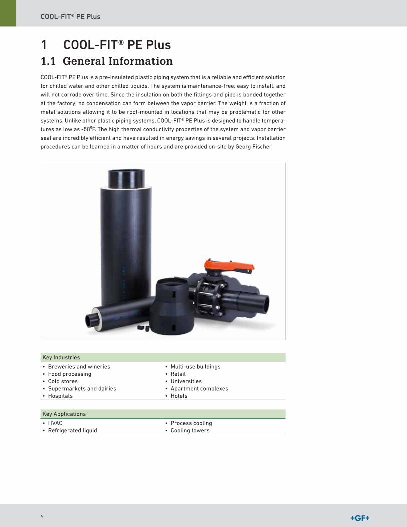
1 COOL-FIT® PE Plus1.1 General InformationCOOL-FIT® PE Plus is a pre-insulated plastic piping system that is a reliable and efficient solution
for chilled water and other chilled liquids The system is maintenance-free, easy to install, and
will not corrode over time Since the insulation on both the fittings and pipe is bonded together
at the factory, no condensation can form between the vapor barrier The weight is a fraction of
metal solutions allowing it to be roof-mounted in locations that may be problematic for other
systems Unlike other plastic piping systems, COOL-FIT® PE Plus is designed to handle tempera-
tures as low as -58⁰F The high thermal conductivity properties of the system and vapor barrier
seal are incredibly efficient and have resulted in energy savings in several projects Installation
procedures can be learned in a matter of hours and are provided on-site by Georg Fischer
4

COOL-FIT® PE Plus Design and Installation
2 System SpecificationSpecification COOL-FIT PE Plus
Materials(All three materials are firmly bonded together )
Pipe PE100 Insulation GF PUR (Polyurethane) foam, halogen free,
closed-cellOuter jacket Pipe: PE
Fitting: PESize d32 (1") – d450 (18")Joining technology ElectrofusionNominal pressure(at 68ºF [20ºC] Media Water)
16 bar (232 psi), SDR 1110 bar (150 psi), SDR 17
d32 (1") – d450 (18")
Temperature Media -58ºF to +140ºF (-50 °C to +60 °C)Environment -22ºF to +140ºF (-30 °C to +60 °C)
Thermal conductivity λ20°C
GF HE/PUR FoamPE jacket & inner pipe
0 015 BTU/hr ft oF; 0 026 W/mK (d160-d450)0 220 BTU/hr ft oF ; 0 38 W/mK
Density ≥ 4 37 lb/ft3; 70 kg/m3
Foam cell size max Ø 0 5 mmMechanical strength (from insulation)
Axial shear strength 2) ≥ 0 12 N/mm2 (17 4 psi)Compressive strength ≥ 0 3 N/mm2 (43 5 psi)
Color Outer jacket BlackWeight(without )
Pipe d32 (1") 0 95 lb/ft (1 41 kg/m)Pipe d110 (4") 4 17 lb/ft (6 20 kg/m)Pipe d225 (8") 11 15 lb/ft (16 6 kg/m)
Oxygen diffusion at < 58 1ºF (14 5° C)
ISO 17455 ≤ 0 32 mg/(m2 d)
Environment Moisture and vapor-tightWeather resistant UV resistant
Global warming potential GWP
≤ 0 01
Ozone Depletion Potential ODP
Zero
Standards and Guidelines
EN ISO 15494 Plastic piping systems for industrial applications
ISO 7 Threaded JointsEN ISO 16135 Industrial valves – Ball valves made of
thermoplasticsEN ISO 16136 Industrial valves – Butterfly valves made
of thermoplasticsEN ISO 16137 Industrial valves – Backflow protection
made of thermoplasticsEN ISO 16871 Plastic piping and ducting systems –
Plastic pipe and fittings – Method for exposure to direct (natural) weathering
Product declarations Greenbuildings According to:DGNB 2015DGNB 2012BREEAM 2016LEED 2009LEED v4
5
COOL-FIT® PE Plus
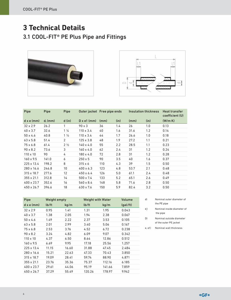
3 Technical Details3.1 COOL-FIT® PE Plus Pipe and Fittings
Pipe Pipe Pipe Outer jacket Free pipe ends Insulation thickness Heat transfer coefficient (U)
d x e (mm) di (mm) d (in) D x e1 (mm) (mm) (in) (mm) (in) (W/m K)
32 x 2 9 26 2 1 90 x 3 36 1 4 26 1 0 0 1340 x 3 7 32 6 1 1/4 110 x 3 4 40 1 6 31 6 1 2 0 14
50 x 4 6 40 8 1 1/2 110 x 3 4 44 1 7 26 6 1 0 0 1863 x 5 8 51 4 2 125 x 3 8 48 1 9 27 2 1 1 0 2175 x 6 8 61 4 2 1/2 140 x 4 0 55 2 2 28 5 1 1 0 2390 x 8 2 73 6 3 160 x 4 0 62 2 4 31 1 2 0 24110 x 10 90 4 180 x 4 0 72 2 8 31 1 2 0 28160 x 9 5 141 0 6 250 x 5 90 3 5 40 1 6 0 37225 x 13 4 198 2 8 315 x 6 110 4 3 39 1 5 0 50280 x 16 6 246 8 10 400 x 6 3 123 4 8 53 7 2 1 0 48315 x 18 7 277 6 12 450 x 6 4 126 5 0 61 1 2 4 0 48355 x 21 1 312 8 14 500 x 7 4 133 5 2 65 1 2 6 0 49400 x 23 7 352 6 16 560 x 8 4 148 5 8 71 6 2 8 0 50 450 x 26 7 396 6 18 630 x 7 6 150 5 9 82 4 3 2 0 50
Pipe Weight empty Weight with Water Volume
d x e (mm) lb/ft kg/m lb/ft kg/m (gal/ft)
32 x 2 9 0 95 1 41 1 31 1 95 0 04340 x 3 7 1 38 2 05 1 94 2 38 0 067
50 x 4 6 1 49 2 22 2 37 3 53 0 10563 x 5 8 2 01 2 99 3 40 5 06 0 16775 x 6 8 2 53 3 76 4 52 6 72 0 23890 x 8 2 3 24 4 82 6 09 9 07 0 342110 x 10 4 37 6 50 8 64 12 86 0 512160 x 9 5 6 69 9 95 17 18 25 56 1 257225 x 13 4 11 15 16 60 31 88 47 45 2 484280 x 16 6 15 21 22 63 47 33 70 43 3 850315 x 18 7 19 09 28 41 59 74 88 90 4 871355 x 21 1 23 76 35 36 75 37 112 16 6 185400 x 23 7 29 61 44 06 95 19 141 66 7 859450 x 26 7 37 29 55 49 120 26 178 97 9 942
d) Nominal outer diameter of
the PE pipe
di) Nominal inside diameter of
the pipe
D) Nominal outside diameter
of the outer PE jacket
e, e1) Nominal wall thickness
6
COOL-FIT® PE Plus Design and Installation
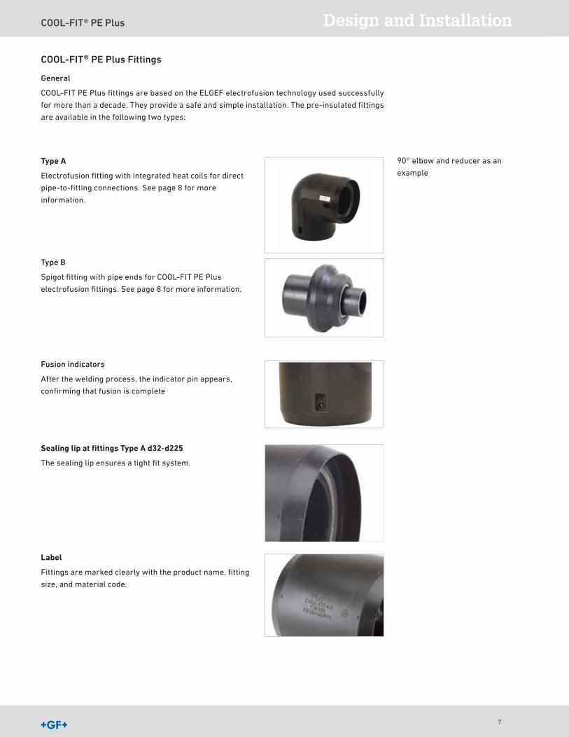
COOL-FIT® PE Plus Fittings
General
COOL-FIT PE Plus fittings are based on the ELGEF electrofusion technology used successfully
for more than a decade They provide a safe and simple installation The pre-insulated fittings
are available in the following two types:
Type A
Electrofusion fitting with integrated heat coils for direct
pipe-to-fitting connections See page 8 for more
information
Type B
Spigot fitting with pipe ends for COOL-FIT PE Plus
electrofusion fittings See page 8 for more information
Fusion indicators
After the welding process, the indicator pin appears,
confirming that fusion is complete
90° elbow and reducer as an
example
Label
Fittings are marked clearly with the product name, fitting
size, and material code
Sealing lip at fittings Type A d32-d225
The sealing lip ensures a tight fit system
7
COOL-FIT® PE Plus
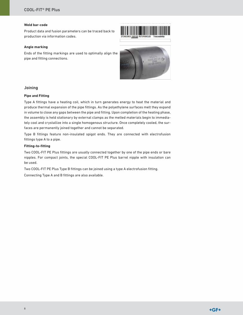
Weld bar-code
Product data and fusion parameters can be traced back to
production via information codes
Angle marking
Ends of the fitting markings are used to optimally align the
pipe and fitting connections
Joining
Pipe and Fitting
Type A fittings have a heating coil, which in turn generates energy to heat the material and
produce thermal expansion of the pipe fittings As the polyethylene surfaces melt they expand
in volume to close any gaps between the pipe and fitting Upon completion of the heating phase,
the assembly is held stationary by external clamps as the melted materials begin to immedia-
tely cool and crystallize into a single homogenous structure Once completely cooled, the sur-
faces are permanently joined together and cannot be separated
Type B fittings feature non-insulated spigot ends They are connected with electrofusion
fittings type A to a pipe
Fitting-to-fitting
Two COOL-FIT PE Plus fittings are usually connected together by one of the pipe ends or bare
nipples For compact joints, the special COOL-FIT PE Plus barrel nipple with insulation can
be used
Two COOL-FIT PE Plus Type B fittings can be joined using a type A electrofusion fitting
Connecting Type A and B fittings are also available
8

COOL-FIT® PE Plus Design and Installation
COOL-FIT PE Plus T90 equal and COOL-FIT T90° reduced
Type A sizes 32mm-225mm (1" - 8"): Run
Type B sizes 280mm - 450mm (10" - 18"): Branch
COOL-FIT PE Plus reducer
The COOL-FIT PE Plus reducer can be used to decrease the
diameter of the piping system to accommodate process spe-
cifications The COOL-FIT PE Plus reducer can be used to
decrease the flow rate
• Type A sizes 32mm - 50mm (1" - 11/2")
• Type B sizes 63mm - 160mm (2" - 6")
COOL-FIT PE Plus barrel nipple
COOL-FIT PE Plus barrel nipple serves as a compact direct
connector for type A fittings
COOL-FIT PE Plus T90 and Reducer Combination Chart
RunBranch
40 50 63 75 90 110 160 225
32 X X X O O O O O40 X X O O O O O
50 X O O O O O
63 Δ Δ Δ Δ Δ75 Δ Δ 90 Δ Δ Δ110 Δ Δ
Δ) T90° reducedX) T90° equal + reducer type AO) T90° reduced to d63 +
reducer type A) T90° reduced to d90 +
coupler d90 + reducer type B
COOL-FIT PE Plus Elbows 45° and 90°
ComponentsCOOL-FIT PE Plus Electrofusion coupler
COOL-FIT PE Plus electrofusion couplers are used to connect
pipe and components with pipe ends like type B fittings,
valves and transition fittings
B
B
A
A
9

COOL-FIT® PE Plus
Accessories for dimensions d32 - d225 Insulation for fusion contacts
Supplied with each fitting Prevent formation of a cold bridge
at the fusion contacts Insulation parts can also serve as an
indicator that a connection has been welded Install
insulation after welding to show that the welding has been
completed
Sealing tape
The sealing tape with width 25mm ensures proper vapor
sealing
COOL-FIT® PE Plus ValvesThe plastic valves designed for COOL-FIT PE Plus are
supplied including PUR insulation shells with a protective PE
jacket The sealing faces between the shells are vapor tight
by design No additional tape or sealant is required
Releasable plastic bands for sizes d32 (1")– d63 (2") with tension locks for sizes d75 (21/2") –
d225 (8") permit the pre-insulated shells to be fitted to and removed from the valves easily,
allowing for quick maintenance
The insulated ball valve in ABS is available in sizes d32 (1") – d90 (3") For sizes d110 (4") – d225
(8"), butterfly valve kits which consist of a butterfly valve, flange adaptor, backing flange PP-St,
screw-kits and insulation half shells Both valve types are available either as manually opera-
ted or electrically actuated version
The electric actuators used feature the following benefits:
• Position feedback via relays (open/close/middle)
• Heating element to prevent condensation
• Optical position indicator with LED status monitoring
• Third position between “open” and “closed” optional
• Relay output for “ready to operate” and 7-segment error display
• Integrated manual override with magnetic lock
• Long service life due to robust design and superior electronics
• Flexible configuration thanks to modular concept
• Numerous monitoring and control options
• Simple handling
10

COOL-FIT® PE Plus Design and Installation
COOL-FIT® PE Plus flange jointsTransition fittings and flange connectors enable connections
to either metal or plastic systems The components supplied
includes insulation half shells with a protective PE jacket
The sealing faces between the shells are vapor tight
by design
Size Material Thread type/ connector/bolt circle
Adaptor fitting d32 – d631“ – 2“
PE – stainless steel male thread ( NPT),female thread (NPT)
Unions d32 – d63d32 – d110
PE – PE,PE – ABS
Welding spigotscementing sockets
Flange Adaptor (flange joints) d32 – d225 PE
COOL-FIT® PE Plus Flex HosesThe EPDM rubber flexible hoses permit access to the
chillers, fan coils, and allow expansion and contraction
within the system The tear-resistant protective jacket and
its insulation stabilize the cooling fluid temperature inside
the system
COOL-FIT® PE Plus Instrument FittingsThe COOL-FIT PE Plus fittings are used to install various
types of sensors to the system Pressure or temperature
sensors can be connected using the NPT female thread
11

COOL-FIT® PE Plus
3.2 COOL-FIT® PE Plus Tools
Electrofusion machines are required to join COOL-FIT PE
Plus components The range includes dedicated and
multipurpose electrofusion machines which are reliable
and easy to use
Long Fusion adaptors
Long Fusion adaptors serve as an extension of the fusion
plugs of electrofusion machines Compared to standard
adaptors, the longer adaptor length matches the insulation
of the COOL-FIT PE Plus electrofusion fittings The long
fusion adaptors are needed for electrofusion of fittings
d ≥ d160/D250
Y-cable kit for COOL-FIT fixed point
Saves half of the normal welding time of the COOL-FIT
fixed points
Assembly aids
The COOL-FIT PE Plus assembly aids are used for an easy
mounting of the COOL-FIT PE Plus fitting on pipe
Foam removal tool and peeling tool – manually operated
The foam removal tool is used to prepare shortened COOL-
FIT PE Plus pipe for electrofusion The tool removes the
foam, cuts the outer jacket, and peels the surface of the core
pipe The tool is available in three versions based on the
following sizes:
1 for sizes d32 (1") – d90 (3")
2 for sizes d110 (4") – d225 (8")
3 for sizes d250 (10") – d450 (18")
Powered foam removal and peeling tool
The powered foam removal tool is also used to prepare a
shortened COOL-FIT PE Plus pipe for electro fusion Utilizing
commonly used power drills, it serves as a supplement to
the manually operated tool The tool is available as a kit for
d32 (1")-d63 (2") sizes
12
COOL-FIT® PE Plus Design and Installation
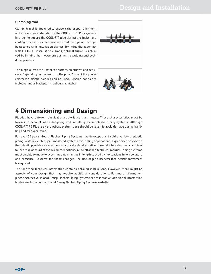
Clamping tool
Clamping tool is designed to support the proper alignment
and stress-free installation of the COOL-FIT PE Plus system
In order to secure the COOL-FIT pipe during the fusion and
cooling process, it is recommended that the pipe and fittings
be secured with installation clamps By fitting the assembly
with COOL-FIT installation clamps, optimal fusion is achie-
ved by limiting the movement during the welding and cool-
down process
The hinge allows the use of the clamps on elbows and redu-
cers Depending on the length of the pipe, 2 or 4 of the glass-
reinforced plastic holders can be used Tension bands are
included and a T-adaptor is optional available
4 Dimensioning and DesignPlastics have different physical characteristics than metals These characteristics must be
taken into account when designing and installing thermoplastic piping systems Although
COOL-FIT PE Plus is a very robust system, care should be taken to avoid damage during hand-
ling and transportation
For over 50 years, Georg Fischer Piping Systems has developed and sold a variety of plastic
piping systems such as pre-insulated systems for cooling applications Experience has shown
that plastic provides an economical and reliable alternative to metal when designers and ins-
tallers take account of the recommendations in the attached technical manual Piping systems
must be able to move to accommodate changes in length caused by fluctuations in temperature
and pressure To allow for these changes, the use of pipe holders that permit movement
is required
The following technical information contains detailed instructions However, there might be
aspects of your design that may require additional considerations For more information,
please contact your local Georg Fischer Piping Systems representative Additional information
is also available on the official Georg Fischer Piping Systems website
13
COOL-FIT® PE Plus
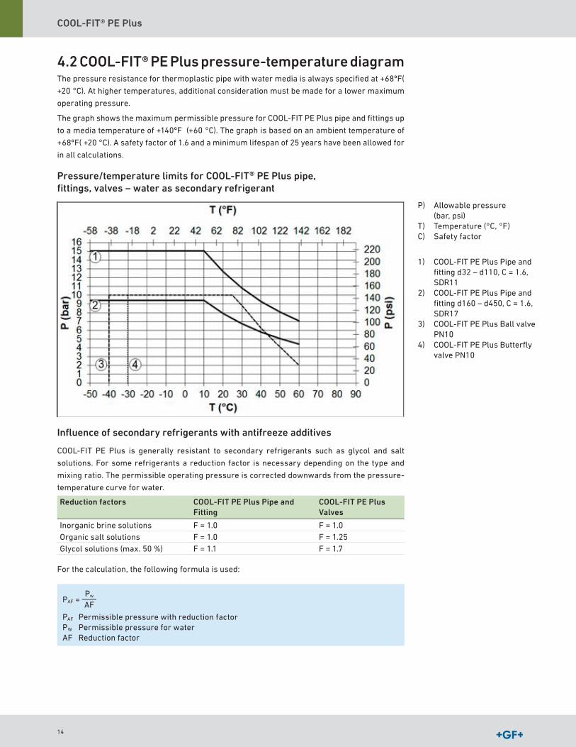
4.2 COOL-FIT® PE Plus pressure-temperature diagramThe pressure resistance for thermoplastic pipe with water media is always specified at +68ºF(
+20 °C) At higher temperatures, additional consideration must be made for a lower maximum
operating pressure
The graph shows the maximum permissible pressure for COOL-FIT PE Plus pipe and fittings up
to a media temperature of +140ºF (+60 °C) The graph is based on an ambient temperature of
+68ºF( +20 °C) A safety factor of 1 6 and a minimum lifespan of 25 years have been allowed for
in all calculations
Pressure/temperature limits for COOL-FIT® PE Plus pipe, fittings, valves – water as secondary refrigerant
Influence of secondary refrigerants with antifreeze additives
COOL-FIT PE Plus is generally resistant to secondary refrigerants such as glycol and salt
solutions For some refrigerants a reduction factor is necessary depending on the type and
mixing ratio The permissible operating pressure is corrected downwards from the pressure-
temperature curve for water
Reduction factors COOL-FIT PE Plus Pipe and Fitting
COOL-FIT PE Plus Valves
Inorganic brine solutions F = 1 0 F = 1 0Organic salt solutions F = 1 0 F = 1 25Glycol solutions (max 50 %) F = 1 1 F = 1 7
For the calculation, the following formula is used:
PAF =Pw
AF
PAF Permissible pressure with reduction factorPW Permissible pressure for waterAF Reduction factor
P) Allowable pressure (bar, psi)
T) Temperature (°C, °F)C) Safety factor
1) COOL-FIT PE Plus Pipe and fitting d32 – d110, C = 1 6, SDR11
2) COOL-FIT PE Plus Pipe and fitting d160 – d450, C = 1 6, SDR17
3) COOL-FIT PE Plus Ball valve PN10
4) COOL-FIT PE Plus Butterfly valve PN10
14
COOL-FIT® PE Plus Design and Installation
Glycol solutions
COOL-FIT PE Plus can be used with glycol solutions with concentrations up to 50% The
chemical resistance of COOL-FIT PE Plus systems is suitable for the following glycol types:
Brand name Manufacturer Type
Antifrogen N Clariant Ethylene glycolAntifrogen L Clariant Propylene glycol
Showbrine Blue Showa standard EC brine
Showa Brine Ethylene glycol
Tyfocor L Tyfo Propylene glycolTyfocor Tyfo Ethylene glycolDOWFROST DOW Propylene glycolZytrec FC Frigol Propylene glycolZytrec LC Frigol Propylene glycolZytrec MC Frigol Ethylene glycolNeutrogel Neo Climalife Dehon Ethylene glycolFriogel Neo Climalife Dehon Propylene glycolDOWTHERM SR-1 DOW Ethylene glycol
Example – glycol dissolved in water
For water-glycol mixture ≤ 50%, the reduction factor for the pressure-temperature
diagram is 1 7 (for COOL-FIT PE Plus valves) Thus, at +10 °C, with a minimum life of
25 years, the maximum allowable working pressure is reduced as follows:
PAF = = 5.88 bar10 bar
1.7
Organic salt solutions
These media are usually potassium formates or potassium acetates: aqueous solutions with
low viscosity at low temperatures COOL-FIT PE Plus can be used with the media below The
manufacturer's instructions must be followed
Brand name Manufacturer Type
Kilfrost ALV Clariant BrineZytrec S-55 Frigol Brine
Temper1) Temper BrineHycool Addcon Brine
For detailed information on resistance and reduction factors, see Planning Funda-mentals "Material selection – Chemical resistance".
When using other secondary refriegerants, compatibility with COOL-FIT PE Plus should be clarified with Georg Fischer Piping Systems
1) Please contact Georg Fischer Piping Systems
15
COOL-FIT® PE Plus
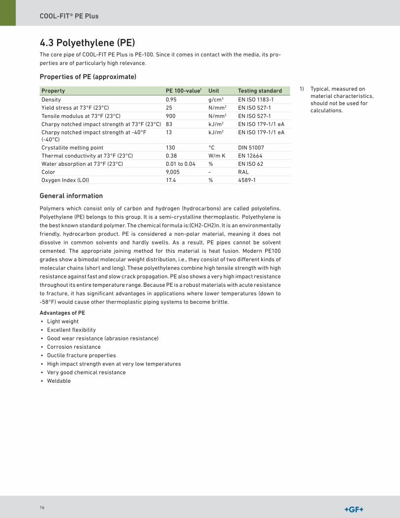
4.3 Polyethylene (PE)The core pipe of COOL-FIT PE Plus is PE-100 Since it comes in contact with the media, its pro-
perties are of particularly high relevance
Properties of PE (approximate)
Property PE 100-value1 Unit Testing standard
Density 0 95 g/cm3 EN ISO 1183-1Yield stress at 73°F (23°C) 25 N/mm2 EN ISO 527-1
Tensile modulus at 73°F (23°C) 900 N/mm2 EN ISO 527-1Charpy notched impact strength at 73°F (23°C) 83 kJ/m2 EN ISO 179-1/1 eACharpy notched impact strength at -40°F (-40°C)
13 kJ/m2 EN ISO 179-1/1 eA
Crystallite melting point 130 °C DIN 51007Thermal conductivity at 73°F (23°C) 0 38 W/m K EN 12664Water absorption at 73°F (23°C) 0 01 to 0 04 % EN ISO 62Color 9,005 - RALOxygen Index (LOI) 17 4 % 4589-1
General information
Polymers which consist only of carbon and hydrogen (hydrocarbons) are called polyolefins
Polyethylene (PE) belongs to this group It is a semi-crystalline thermoplastic Polyethylene is
the best known standard polymer The chemical formula is:(CH2-CH2)n It is an environmentally
friendly, hydrocarbon product PE is considered a non-polar material, meaning it does not
dissolve in common solvents and hardly swells As a result, PE pipes cannot be solvent
cemented The appropriate joining method for this material is heat fusion Modern PE100
grades show a bimodal molecular weight distribution, i e , they consist of two different kinds of
molecular chains (short and long) These polyethylenes combine high tensile strength with high
resistance against fast and slow crack propagation PE also shows a very high impact resistance
throughout its entire temperature range Because PE is a robust materials with acute resistance
to fracture, it has significant advantages in applications where lower temperatures (down to
-58°F) would cause other thermoplastic piping systems to become brittle
Advantages of PE
• Light weight
• Excellent flexibility
• Good wear resistance (abrasion resistance)
• Corrosion resistance
• Ductile fracture properties
• High impact strength even at very low temperatures
• Very good chemical resistance
• Weldable
1) Typical, measured on material characteristics, should not be used for calculations
16

COOL-FIT® PE Plus Design and Installation
Mechanical properties, chemicals, weathering and abrasion resistance
UV and weather resistance
PE is a weather resistant material due to the carbon black additives used in the GF resin This
stabilizes the material against UV exposure, so it can be used in wind and rain without
restrictions
Chemical resistance
PE exhibits good resistance to a wide range of media For detailed information, please see the
detailed chemical resistance list from Georg Fischer Piping Systems
Abrasion resistance
PE has excellent resistance to abrasive wear You can therefore find PE piping systems in use
in numerous applications for transporting solids and media containing solids
Thermal and electrical properties
Operating limits
At higher temperatures, the tensile strength and stiffness of the material are reduced
Electrical properties
PE, like most thermoplastics, is non-conductive This means that systems in PE do not suffer
from electrolytic corrosion However, the non-conductive properties must be taken into consi-
deration, as electrostatic charges can build up in the pipe Polyethylene has good electrical
insulation properties The volume resistance is 3 5 x 10¹⁶ Ωcm, the surface resistance 1013 Ω
This must be taken into account in applications where there is danger of fire or
explosion
17
COOL-FIT® PE Plus
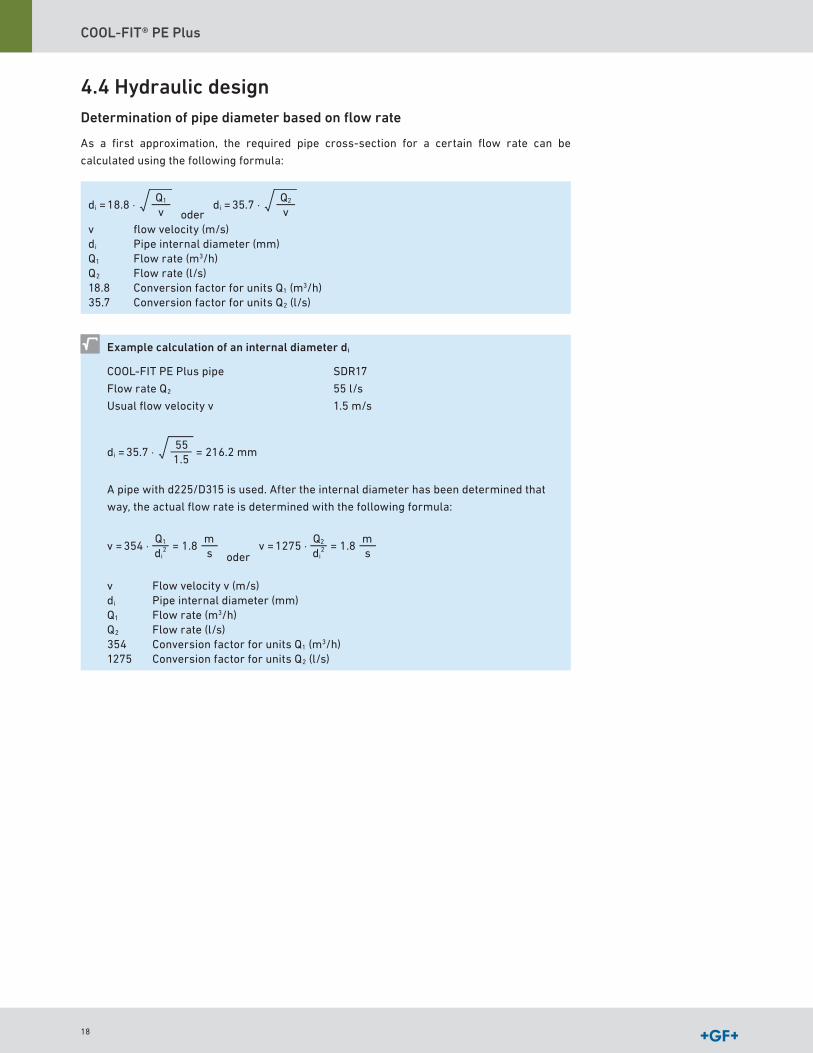
4.4 Hydraulic designDetermination of pipe diameter based on flow rate
As a first approximation, the required pipe cross-section for a certain flow rate can be
calculated using the following formula:
18.8 ⋅di =Q1
v oder 35.7 ⋅di =
Q2
v
v flow velocity (m/s)di Pipe internal diameter (mm)Q1 Flow rate (m3/h)Q2 Flow rate (l/s)18 8 Conversion factor for units Q1 (m3/h)35 7 Conversion factor for units Q2 (l/s)
Example calculation of an internal diameter di
COOL-FIT PE Plus pipe
Flow rate Q2
Usual flow velocity v
SDR17
55 l/s
1 5 m/s
35.7 ⋅di = = 216.2 mm551.5
A pipe with d225/D315 is used After the internal diameter has been determined that
way, the actual flow rate is determined with the following formula:
354 ⋅v = = 1.8Q1
di2
ms oder
1275 ⋅v = = 1.8Q2
di2
ms
v Flow velocity v (m/s)di Pipe internal diameter (mm)Q1 Flow rate (m3/h)Q2 Flow rate (l/s)354 Conversion factor for units Q1 (m3/h)1275 Conversion factor for units Q2 (l/s)
18
COOL-FIT® PE Plus Design and Installation
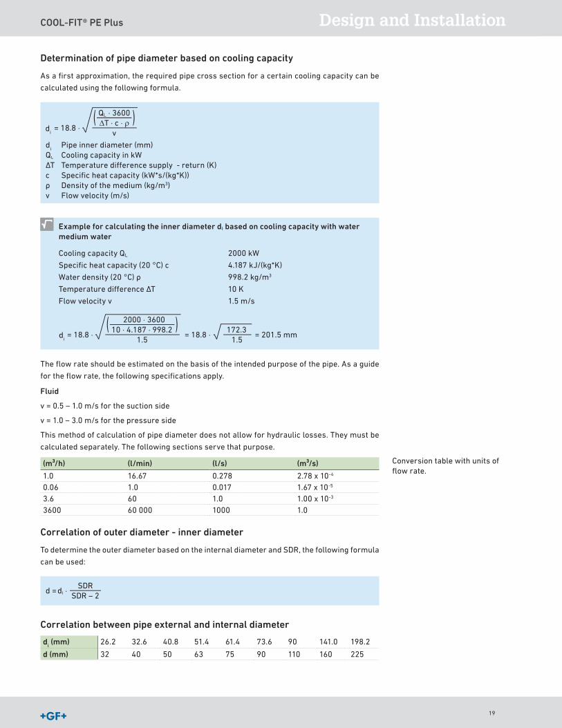
Determination of pipe diameter based on cooling capacity
As a first approximation, the required pipe cross section for a certain cooling capacity can be
calculated using the following formula
di = 18.8 ⋅
QL ⋅ 3600∆T ⋅ c ⋅ ρ
v
di Pipe inner diameter (mm)
QL Cooling capacity in kWΔT Temperature difference supply - return (K)c Specific heat capacity (kW*s/(kg*K))ρ Density of the medium (kg/m3)v Flow velocity (m/s)
Example for calculating the inner diameter di based on cooling capacity with water medium water
Cooling capacity QL
Specific heat capacity (20 °C) c
Water density (20 °C) ρ
Temperature difference ΔT
Flow velocity v
2000 kW
4 187 kJ/(kg*K)
998 2 kg/m3
10 K
1 5 m/s
di = 18.8 ⋅
2000 ⋅ 360010 ⋅ 4.187 ⋅ 998.2
1.5= 18.8 ⋅ = 201.5 mm
172.31.5
The flow rate should be estimated on the basis of the intended purpose of the pipe As a guide
for the flow rate, the following specifications apply
Fluid
v = 0 5 – 1 0 m/s for the suction side
v = 1 0 – 3 0 m/s for the pressure side
This method of calculation of pipe diameter does not allow for hydraulic losses They must be
calculated separately The following sections serve that purpose
(m³/h) (l/min) (l/s) (m³/s)
1 0 16 67 0 278 2 78 x 10-4
0 06 1 0 0 017 1 67 x 10-5
3 6 60 1 0 1 00 x 10-3
3600 60 000 1000 1 0
Correlation of outer diameter - inner diameter
To determine the outer diameter based on the internal diameter and SDR, the following formula
can be used:
di ⋅d =SDR
SDR – 2
Correlation between pipe external and internal diameter
di (mm) 26 2 32 6 40 8 51 4 61 4 73 6 90 141 0 198 2
d (mm) 32 40 50 63 75 90 110 160 225
Conversion table with units of flow rate
di
di
19
COOL-FIT® PE Plus
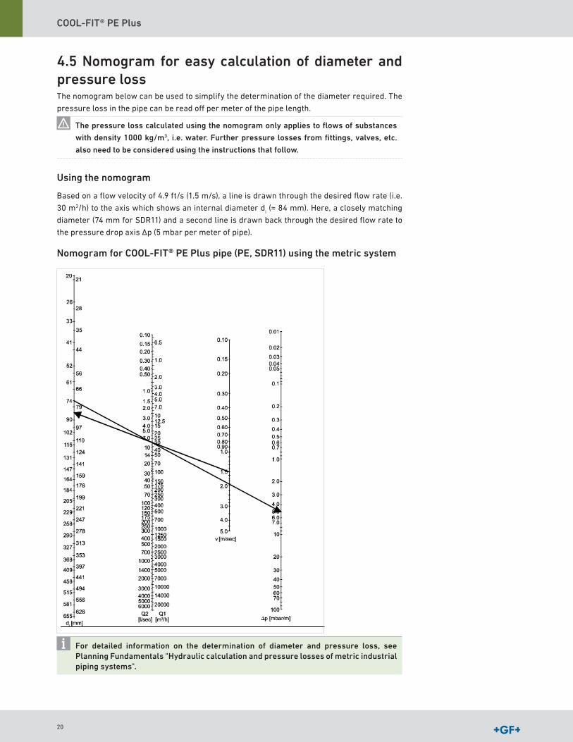
4.5 Nomogram for easy calculation of diameter and pressure lossThe nomogram below can be used to simplify the determination of the diameter required The
pressure loss in the pipe can be read off per meter of the pipe length
The pressure loss calculated using the nomogram only applies to flows of substances
with density 1000 kg/m3, i.e. water. Further pressure losses from fittings, valves, etc.
also need to be considered using the instructions that follow.
Using the nomogram
Based on a flow velocity of 4 9 ft/s (1 5 m/s), a line is drawn through the desired flow rate (i e
30 m3/h) to the axis which shows an internal diameter di (≈ 84 mm) Here, a closely matching
diameter (74 mm for SDR11) and a second line is drawn back through the desired flow rate to
the pressure drop axis Δp (5 mbar per meter of pipe)
Nomogram for COOL-FIT® PE Plus pipe (PE, SDR11) using the metric system
For detailed information on the determination of diameter and pressure loss, see Planning Fundamentals "Hydraulic calculation and pressure losses of metric industrial piping systems".
20
COOL-FIT® PE Plus Design and Installation
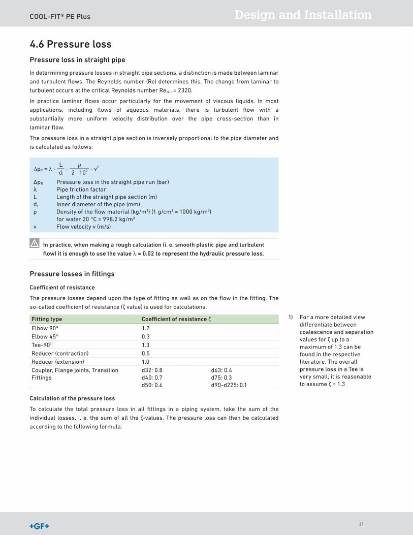
4.6 Pressure lossPressure loss in straight pipe
In determining pressure losses in straight pipe sections, a distinction is made between laminar
and turbulent flows The Reynolds number (Re) determines this The change from laminar to
turbulent occurs at the critical Reynolds number Recrit = 2320
In practice laminar flows occur particularly for the movement of viscous liquids In most
applications, including flows of aqueous materials, there is turbulent flow with a
substantially more uniform velocity distribution over the pipe cross- section than in
laminar flow
The pressure loss in a straight pipe section is inversely proportional to the pipe diameter and
is calculated as follows:
Ldi
∆pR = λ ⋅ρ
2 ⋅ 102⋅ ⋅ v2
ΔpR Pressure loss in the straight pipe run (bar) λ Pipe friction factorL Length of the straight pipe section (m)di Inner diameter of the pipe (mm) ρ Density of the flow material (kg/m3) (1 g/cm3 = 1000 kg/m3)
for water 20 °C = 998 2 kg/m3
v Flow velocity v (m/s)
In practice, when making a rough calculation (i. e. smooth plastic pipe and turbulent
flow) it is enough to use the value λ = 0.02 to represent the hydraulic pressure loss.
Pressure losses in fittings
Coefficient of resistance
The pressure losses depend upon the type of fitting as well as on the flow in the fitting The
so-called coefficient of resistance (ζ value) is used for calculations
Fitting type Coefficient of resistance ζ
Elbow 90° 1 2Elbow 45° 0 3Tee-901) 1 3Reducer (contraction) 0 5Reducer (extension) 1 0Coupler, Flange joints, Transition Fittings
d32: 0 8d40: 0 7d50: 0 6
d63: 0 4d75: 0 3d90-d225: 0 1
Calculation of the pressure loss
To calculate the total pressure loss in all fittings in a piping system, take the sum of the
individual losses, i e the sum of all the ζ-values The pressure loss can then be calculated
according to the following formula:
1) For a more detailed view differentiate between coalescence and separation values for ζ up to a maximum of 1 3 can be found in the respective literature The overall pressure loss in a Tee is very small, it is reasonable to assume ζ = 1 3
21
COOL-FIT® PE Plus
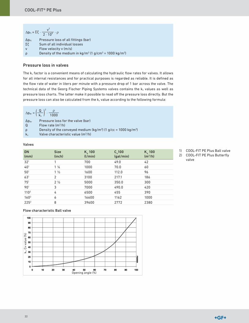
∆pFi = Σζ ⋅v2
2 ⋅ 105 ⋅ ρ
ΔpFi Pressure loss of all fittings (bar)Σζ Sum of all individual lossesv Flow velocity v (m/s)ρ Density of the medium in kg/m3 (1 g/cm3 = 1000 kg/m3)
Pressure loss in valves
The kv factor is a convenient means of calculating the hydraulic flow rates for valves It allows
for all internal resistances and for practical purposes is regarded as reliable It is defined as
the flow rate of water in liters per minute with a pressure drop of 1 bar across the valve The
technical data of the Georg Fischer Piping Systems valves contains the kv values as well as
pressure loss charts The latter make it possible to read off the pressure loss directly But the
pressure loss can also be calculated from the kv value according to the following formula:
∆pAr =ρ
1000⋅Q
kv
2
ΔpAr Pressure loss for the valve (bar)Q Flow rate (m3/h)ρ Density of the conveyed medium (kg/m3) (1 g/cc = 1000 kg/m3)kv Valve characteristic value (m3/h)
Valves
DN(mm)
Size(inch)
KV 100(l/min)
CV100(gal/min)
KV 100(m3/h)
321 1 700 49 0 42401 1 1/4 1000 70 0 60501 1 1/2 1600 112 0 96631 2 3100 217 1 186751 2 1/2 5000 350 0 300901 3 7000 490 0 4201102 4 6500 455 3901602 6 16600 1162 10002252 8 39600 2772 2380
Flow characteristic Ball valve
1) COOL-FIT PE Plus Ball valve2) COOL-FIT PE Plus Butterfly
valve
Opening angle (%)
k v, C
v va
lue
(%)
Σζ
22

COOL-FIT® PE Plus Design and Installation
Flow characteristic butterfly valve
Pressure difference between the static pressure
If the piping system is installed vertically, then a geodetic pressure difference must be calcula-
ted for it This pressure difference is calculated as follows:
∆pgeod = ∆Hgeod ⋅ ρ ⋅ 10–4
Δpgeod Geodetic pressure difference (bar)ΔHgeod Difference in elevation of the piping system (m)ρ Density of the medium (kg/m3) (1 g/cm3 = 1000 kg/m3)
At closed systems, the geodetic pressure difference does not need to be considered
Sum of pressure losses
The sum of all pressure drops for a piping system is calculated as follows:
Σ∆p = ∆pR + ∆pFi + ∆pAr + ∆pgeo
Example for pressure drop calculations
The following example illustrates the calculation process for determining the pressure
loss of a piping system
COOL-FIT PE Plus pipe
SDR11 - flow rate
Medium
Density of the medium
Length straight pipe
Height difference
d40 mm
1 5 l/s
Water
1 0 g/cm³
15 m
2 0 m
Number of Fittings
12 x 90° angle
4 x 45° angle
3 x T-piece
3 x screws
2 x flange connections
1 x ball valve, 80 %
opened
The wall thickness of the piping system can be calculated as follows with the SDR:
e = = = 3.6 mmd
SDR40 mm
11
The inner diameter of the piping system is as follows:
di = d – 2 ⋅ e = d – = 32.8 mm2 ⋅ dSDR
With the desired flow rate of 1 5 l/s, the flow velocity is as follows:
v = 1275 ⋅ = 1275 ⋅ = 1.78 Q2
di2
msec
msec
1.532.82
Opening angle (%)
k v, C
v va
lue
(%)
23
COOL-FIT® PE Plus
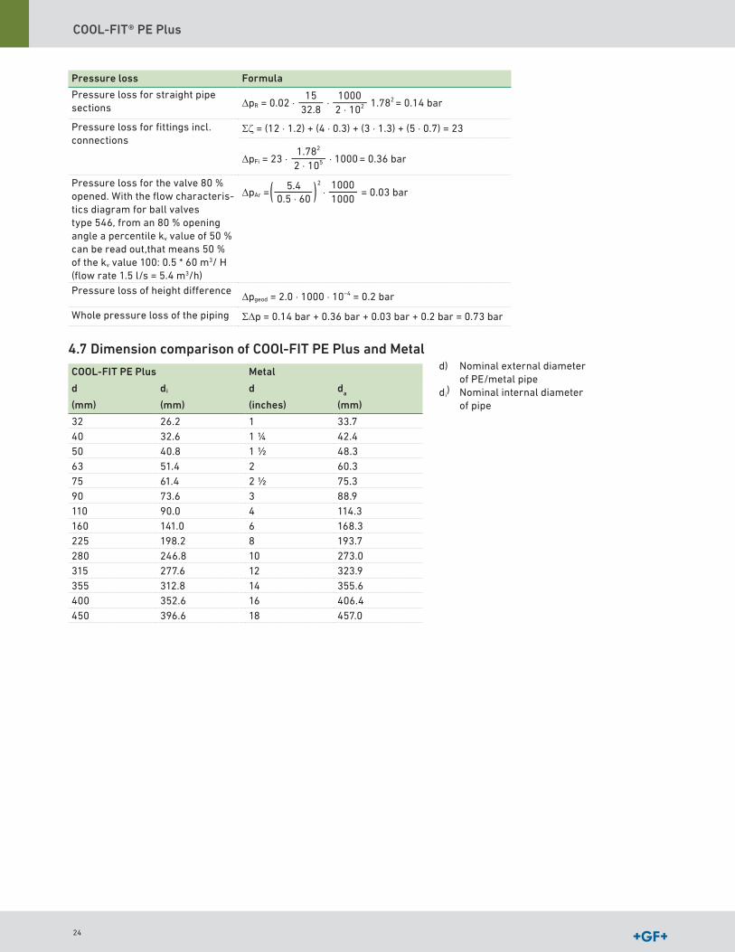
Pressure loss Formula
Pressure loss for straight pipe sections ∆pR = 0.02 ⋅ ⋅ 1.782 = 0.14 bar
1532.8
10002 ⋅ 102
Pressure loss for fittings incl connections
Σζ = (12 ⋅ 1.2) + (4 ⋅ 0.3) + (3 ⋅ 1.3) + (5 ⋅ 0.7) = 23
∆pFi = 23 ⋅ ⋅ 1000 = 0.36 bar1.782
2 ⋅ 105
Pressure loss for the valve 80 % opened With the flow characteris-tics diagram for ball valves type 546, from an 80 % opening angle a percentile kv value of 50 % can be read out,that means 50 % of the kv value 100: 0 5 * 60 m3/ H (flow rate 1 5 l/s = 5 4 m3/h)
∆pAr = = 0.03 bar10001000
5.40.5 ⋅ 60
2
⋅
Pressure loss of height difference ∆pgeod = 2.0 ⋅ 1000 ⋅ 10–4 = 0.2 bar
Whole pressure loss of the piping Σ∆p = 0.14 bar + 0.36 bar + 0.03 bar + 0.2 bar = 0.73 bar
4.7 Dimension comparison of COOl-FIT PE Plus and Metal
COOL-FIT PE Plus Metal
d di d da
(mm) (mm) (inches) (mm)
32 26 2 1 33 740 32 6 1 1/4 42 450 40 8 1 1/2 48 363 51 4 2 60 375 61 4 2 1/2 75 390 73 6 3 88 9110 90 0 4 114 3160 141 0 6 168 3225 198 2 8 193 7280 246 8 10 273 0315 277 6 12 323 9355 312 8 14 355 6400 352 6 16 406 4450 396 6 18 457 0
d) Nominal external diameter of PE/metal pipe
di) Nominal internal diameter
of pipe
24
COOL-FIT® PE Plus Design and Installation
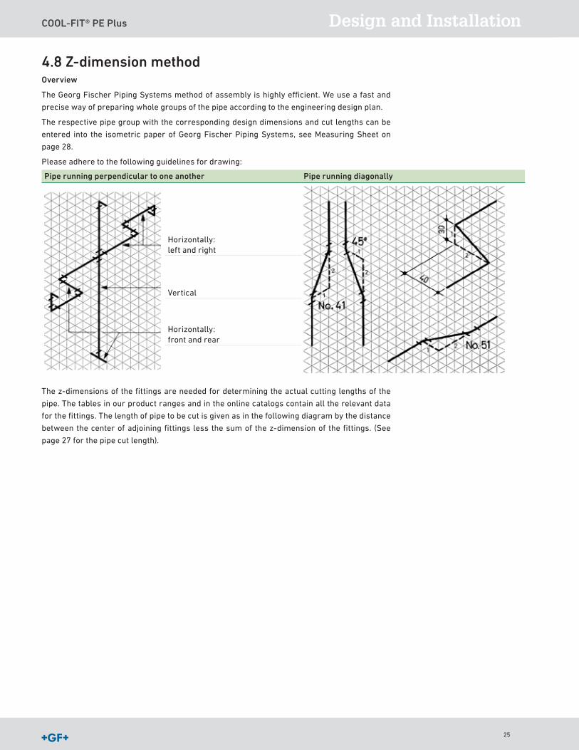
4.8 Z-dimension methodOverview
The Georg Fischer Piping Systems method of assembly is highly efficient We use a fast and
precise way of preparing whole groups of the pipe according to the engineering design plan
The respective pipe group with the corresponding design dimensions and cut lengths can be
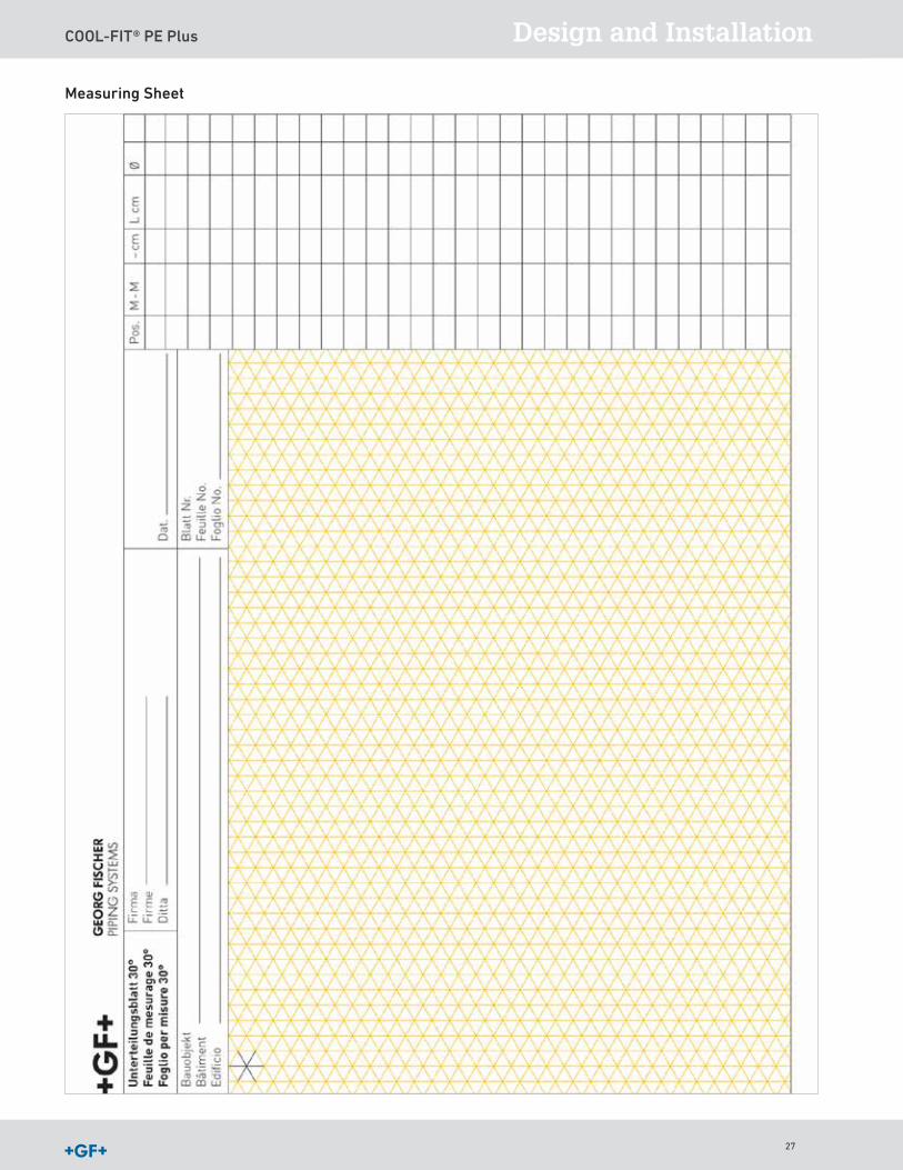
entered into the isometric paper of Georg Fischer Piping Systems, see Measuring Sheet on
page 28
Please adhere to the following guidelines for drawing:
Pipe running perpendicular to one another Pipe running diagonally
Horizontally: left and right
Vertical
Horizontally: front and rear
The z-dimensions of the fittings are needed for determining the actual cutting lengths of the
pipe The tables in our product ranges and in the online catalogs contain all the relevant data
for the fittings The length of pipe to be cut is given as in the following diagram by the distance
between the center of adjoining fittings less the sum of the z-dimension of the fittings (See
page 27 for the pipe cut length)
25
COOL-FIT® PE Plus
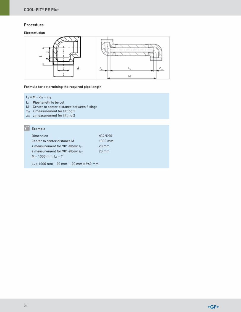
Procedure
Electrofusion
Formula for determining the required pipe length
L0 = M – ZF1 – ZF2
L0 Pipe length to be cutM Center to center distance between fittingszF1 z measurement for fitting 1zF2 z measurement for fitting 2
Example
Dimension
Center to center distance M
z measurement for 90° elbow zF1
z measurement for 90° elbow zF2
M = 1000 mm; L0 = ?
d32/D90
1000 mm
20 mm
20 mm
L0 = 1000 mm – 20 mm – 20 mm = 960 mm
26
COOL-FIT® PE Plus Design and Installation
Measuring Sheet
27
COOL-FIT® PE Plus
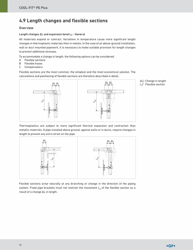
4.9 Length changes and flexible sectionsOverview
Length changes ΔL and expansion bend LB – General
All materials expand or contract Variations in temperature cause more significant length
changes in thermoplastic materials than in metals In the case of an above-ground installation,
wall or duct mounted pipework, it is necessary to make suitable provision for length changes
to prevent additional stresses
To accommodate a change in length, the following options can be considered:A Flexible sectionsB Flexible hosesC Compensators
Flexible sections are the most common, the simplest and the most economical solution The
calculations and positioning of flexible sections are therefore described in detail
∆L∆L
L B
∆L∆L
L B
Thermoplastics are subject to more significant thermal expansion and contraction than
metallic materials A pipe installed above ground, against walls or in ducts, require changes in
length to prevent any extra strain on the pipe
∆L
L B
∆L∆L
L B
Flexible sections arise naturally at any branching or change in the direction of the piping
system Fixed pipe brackets must not restrain the movement LB of the flexible section as a
result of a change ΔL in length
ΔL) Change in lengthLB
) Flexible section
28
COOL-FIT® PE Plus Design and Installation
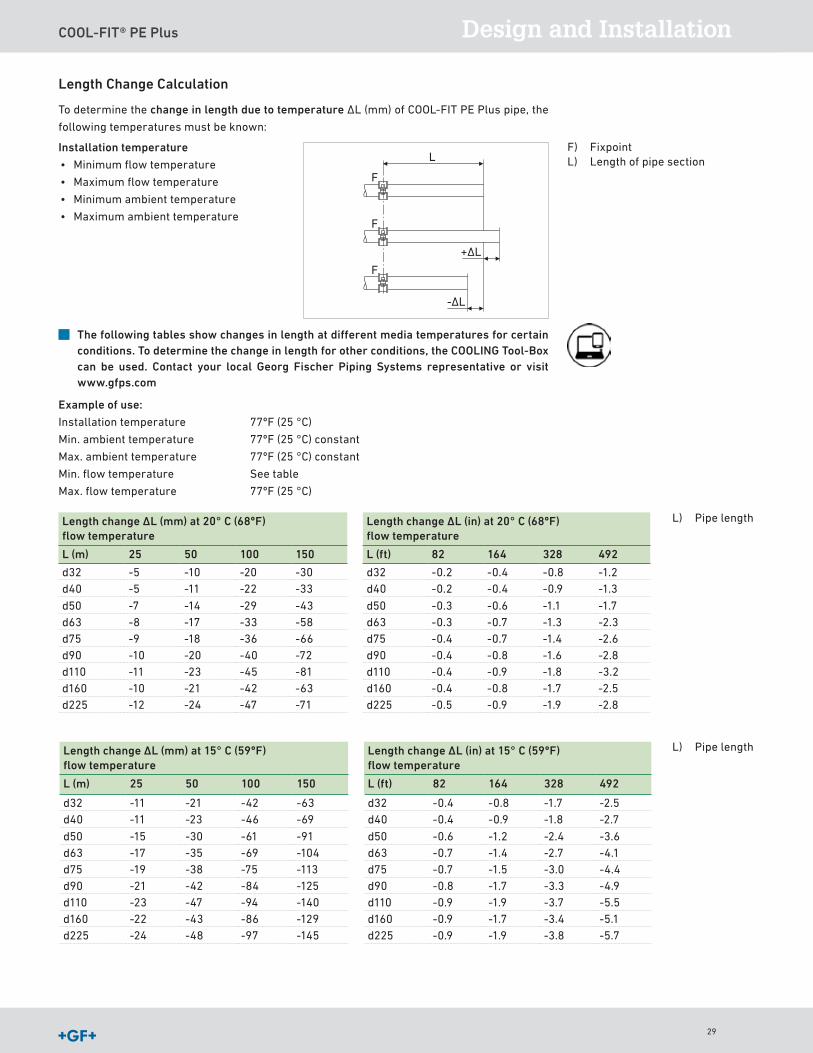
Length Change Calculation
To determine the change in length due to temperature ΔL (mm) of COOL-FIT PE Plus pipe, the
following temperatures must be known:
Installation temperature
• Minimum flow temperature
• Maximum flow temperature
• Minimum ambient temperature
• Maximum ambient temperature
F
F
F
L
-∆L
+∆L
The following tables show changes in length at different media temperatures for certain conditions. To determine the change in length for other conditions, the COOLING Tool-Box can be used. Contact your local Georg Fischer Piping Systems representative or visit www.gfps.com
Example of use:
Installation temperature 77ºF (25 °C)
Min ambient temperature 77ºF (25 °C) constant
Max ambient temperature 77ºF (25 °C) constant
Min flow temperature See table
Max flow temperature 77ºF (25 °C)
Length change ∆L (mm) at 20° C (68ºF) flow temperature
Length change ∆L (in) at 20° C (68ºF) flow temperature
L (m) 25 50 100 150 L (ft) 82 164 328 492
d32 -5 -10 -20 -30 d32 -0 2 -0 4 -0 8 -1 2d40 -5 -11 -22 -33 d40 -0 2 -0 4 -0 9 -1 3
d50 -7 -14 -29 -43 d50 -0 3 -0 6 -1 1 -1 7d63 -8 -17 -33 -58 d63 -0 3 -0 7 -1 3 -2 3d75 -9 -18 -36 -66 d75 -0 4 -0 7 -1 4 -2 6d90 -10 -20 -40 -72 d90 -0 4 -0 8 -1 6 -2 8d110 -11 -23 -45 -81 d110 -0 4 -0 9 -1 8 -3 2d160 -10 -21 -42 -63 d160 -0 4 -0 8 -1 7 -2 5d225 -12 -24 -47 -71 d225 -0 5 -0 9 -1 9 -2 8
F) FixpointL) Length of pipe section
L) Pipe length
L) Pipe length
Length change ∆L (mm) at 15° C (59ºF) flow temperature
Length change ∆L (in) at 15° C (59ºF) flow temperature
L (m) 25 50 100 150 L (ft) 82 164 328 492
d32 -11 -21 -42 -63 d32 -0 4 -0 8 -1 7 -2 5d40 -11 -23 -46 -69 d40 -0 4 -0 9 -1 8 -2 7
d50 -15 -30 -61 -91 d50 -0 6 -1 2 -2 4 -3 6d63 -17 -35 -69 -104 d63 -0 7 -1 4 -2 7 -4 1d75 -19 -38 -75 -113 d75 -0 7 -1 5 -3 0 -4 4d90 -21 -42 -84 -125 d90 -0 8 -1 7 -3 3 -4 9d110 -23 -47 -94 -140 d110 -0 9 -1 9 -3 7 -5 5d160 -22 -43 -86 -129 d160 -0 9 -1 7 -3 4 -5 1d225 -24 -48 -97 -145 d225 -0 9 -1 9 -3 8 -5 7
29
COOL-FIT® PE Plus
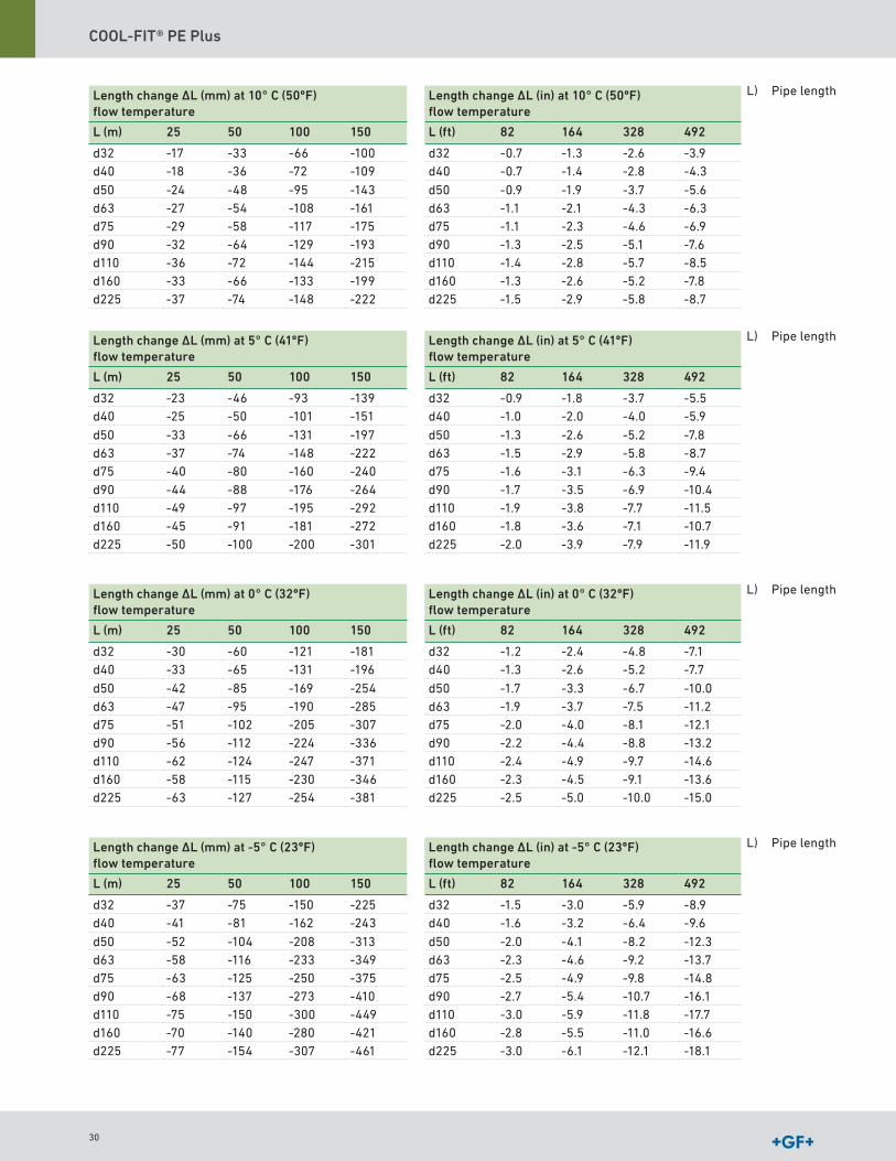
L) Pipe lengthLength change ∆L (mm) at 10° C (50ºF) flow temperature
Length change ∆L (in) at 10° C (50ºF) flow temperature
L (m) 25 50 100 150 L (ft) 82 164 328 492
d32 -17 -33 -66 -100 d32 -0 7 -1 3 -2 6 -3 9d40 -18 -36 -72 -109 d40 -0 7 -1 4 -2 8 -4 3
d50 -24 -48 -95 -143 d50 -0 9 -1 9 -3 7 -5 6d63 -27 -54 -108 -161 d63 -1 1 -2 1 -4 3 -6 3d75 -29 -58 -117 -175 d75 -1 1 -2 3 -4 6 -6 9d90 -32 -64 -129 -193 d90 -1 3 -2 5 -5 1 -7 6d110 -36 -72 -144 -215 d110 -1 4 -2 8 -5 7 -8 5d160 -33 -66 -133 -199 d160 -1 3 -2 6 -5 2 -7 8d225 -37 -74 -148 -222 d225 -1 5 -2 9 -5 8 -8 7
L) Pipe lengthLength change ∆L (mm) at 5° C (41ºF) flow temperature
Length change ∆L (in) at 5° C (41ºF) flow temperature
L (m) 25 50 100 150 L (ft) 82 164 328 492
d32 -23 -46 -93 -139 d32 -0 9 -1 8 -3 7 -5 5d40 -25 -50 -101 -151 d40 -1 0 -2 0 -4 0 -5 9
d50 -33 -66 -131 -197 d50 -1 3 -2 6 -5 2 -7 8d63 -37 -74 -148 -222 d63 -1 5 -2 9 -5 8 -8 7d75 -40 -80 -160 -240 d75 -1 6 -3 1 -6 3 -9 4d90 -44 -88 -176 -264 d90 -1 7 -3 5 -6 9 -10 4d110 -49 -97 -195 -292 d110 -1 9 -3 8 -7 7 -11 5d160 -45 -91 -181 -272 d160 -1 8 -3 6 -7 1 -10 7d225 -50 -100 -200 -301 d225 -2 0 -3 9 -7 9 -11 9
L) Pipe lengthLength change ∆L (mm) at 0° C (32ºF) flow temperature
Length change ∆L (in) at 0° C (32ºF) flow temperature
L (m) 25 50 100 150 L (ft) 82 164 328 492
d32 -30 -60 -121 -181 d32 -1 2 -2 4 -4 8 -7 1d40 -33 -65 -131 -196 d40 -1 3 -2 6 -5 2 -7 7
d50 -42 -85 -169 -254 d50 -1 7 -3 3 -6 7 -10 0d63 -47 -95 -190 -285 d63 -1 9 -3 7 -7 5 -11 2d75 -51 -102 -205 -307 d75 -2 0 -4 0 -8 1 -12 1d90 -56 -112 -224 -336 d90 -2 2 -4 4 -8 8 -13 2d110 -62 -124 -247 -371 d110 -2 4 -4 9 -9 7 -14 6d160 -58 -115 -230 -346 d160 -2 3 -4 5 -9 1 -13 6d225 -63 -127 -254 -381 d225 -2 5 -5 0 -10 0 -15 0
L) Pipe lengthLength change ∆L (mm) at -5° C (23ºF) flow temperature
Length change ∆L (in) at -5° C (23ºF) flow temperature
L (m) 25 50 100 150 L (ft) 82 164 328 492
d32 -37 -75 -150 -225 d32 -1 5 -3 0 -5 9 -8 9d40 -41 -81 -162 -243 d40 -1 6 -3 2 -6 4 -9 6
d50 -52 -104 -208 -313 d50 -2 0 -4 1 -8 2 -12 3d63 -58 -116 -233 -349 d63 -2 3 -4 6 -9 2 -13 7d75 -63 -125 -250 -375 d75 -2 5 -4 9 -9 8 -14 8d90 -68 -137 -273 -410 d90 -2 7 -5 4 -10 7 -16 1d110 -75 -150 -300 -449 d110 -3 0 -5 9 -11 8 -17 7d160 -70 -140 -280 -421 d160 -2 8 -5 5 -11 0 -16 6d225 -77 -154 -307 -461 d225 -3 0 -6 1 -12 1 -18 1
30
COOL-FIT® PE Plus Design and Installation
L) Pipe length
L) Pipe length
L) Pipe length
L) Pipe length
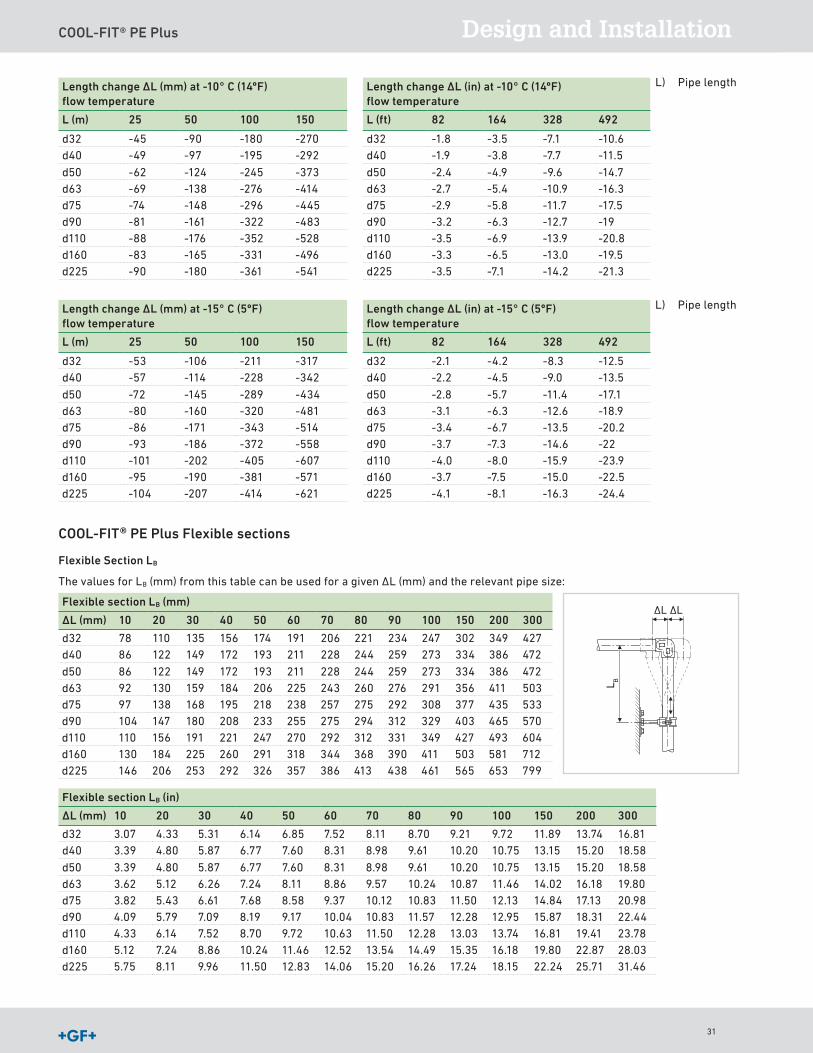
L) Pipe lengthLength change ∆L (mm) at -10° C (14ºF) flow temperature
Length change ∆L (in) at -10° C (14ºF) flow temperature
L (m) 25 50 100 150 L (ft) 82 164 328 492
d32 -45 -90 -180 -270 d32 -1 8 -3 5 -7 1 -10 6d40 -49 -97 -195 -292 d40 -1 9 -3 8 -7 7 -11 5
d50 -62 -124 -245 -373 d50 -2 4 -4 9 -9 6 -14 7d63 -69 -138 -276 -414 d63 -2 7 -5 4 -10 9 -16 3d75 -74 -148 -296 -445 d75 -2 9 -5 8 -11 7 -17 5d90 -81 -161 -322 -483 d90 -3 2 -6 3 -12 7 -19d110 -88 -176 -352 -528 d110 -3 5 -6 9 -13 9 -20 8d160 -83 -165 -331 -496 d160 -3 3 -6 5 -13 0 -19 5d225 -90 -180 -361 -541 d225 -3 5 -7 1 -14 2 -21 3
L) Pipe lengthLength change ∆L (mm) at -15° C (5ºF) flow temperature
Length change ∆L (in) at -15° C (5ºF) flow temperature
L (m) 25 50 100 150 L (ft) 82 164 328 492
d32 -53 -106 -211 -317 d32 -2 1 -4 2 -8 3 -12 5d40 -57 -114 -228 -342 d40 -2 2 -4 5 -9 0 -13 5
d50 -72 -145 -289 -434 d50 -2 8 -5 7 -11 4 -17 1d63 -80 -160 -320 -481 d63 -3 1 -6 3 -12 6 -18 9d75 -86 -171 -343 -514 d75 -3 4 -6 7 -13 5 -20 2d90 -93 -186 -372 -558 d90 -3 7 -7 3 -14 6 -22d110 -101 -202 -405 -607 d110 -4 0 -8 0 -15 9 -23 9d160 -95 -190 -381 -571 d160 -3 7 -7 5 -15 0 -22 5d225 -104 -207 -414 -621 d225 -4 1 -8 1 -16 3 -24 4
COOL-FIT® PE Plus Flexible sections
Flexible Section LB
The values for LB (mm) from this table can be used for a given ΔL (mm) and the relevant pipe size:
Flexible section LB (mm)
∆L (mm) 10 20 30 40 50 60 70 80 90 100 150 200 300
d32 78 110 135 156 174 191 206 221 234 247 302 349 427d40 86 122 149 172 193 211 228 244 259 273 334 386 472
d50 86 122 149 172 193 211 228 244 259 273 334 386 472d63 92 130 159 184 206 225 243 260 276 291 356 411 503d75 97 138 168 195 218 238 257 275 292 308 377 435 533d90 104 147 180 208 233 255 275 294 312 329 403 465 570d110 110 156 191 221 247 270 292 312 331 349 427 493 604d160 130 184 225 260 291 318 344 368 390 411 503 581 712d225 146 206 253 292 326 357 386 413 438 461 565 653 799
Flexible section LB (in)
∆L (mm) 10 20 30 40 50 60 70 80 90 100 150 200 300
d32 3 07 4 33 5 31 6 14 6 85 7 52 8 11 8 70 9 21 9 72 11 89 13 74 16 81d40 3 39 4 80 5 87 6 77 7 60 8 31 8 98 9 61 10 20 10 75 13 15 15 20 18 58
d50 3 39 4 80 5 87 6 77 7 60 8 31 8 98 9 61 10 20 10 75 13 15 15 20 18 58d63 3 62 5 12 6 26 7 24 8 11 8 86 9 57 10 24 10 87 11 46 14 02 16 18 19 80d75 3 82 5 43 6 61 7 68 8 58 9 37 10 12 10 83 11 50 12 13 14 84 17 13 20 98d90 4 09 5 79 7 09 8 19 9 17 10 04 10 83 11 57 12 28 12 95 15 87 18 31 22 44d110 4 33 6 14 7 52 8 70 9 72 10 63 11 50 12 28 13 03 13 74 16 81 19 41 23 78d160 5 12 7 24 8 86 10 24 11 46 12 52 13 54 14 49 15 35 16 18 19 80 22 87 28 03d225 5 75 8 11 9 96 11 50 12 83 14 06 15 20 16 26 17 24 18 15 22 24 25 71 31 46
∆L∆LL B
31
COOL-FIT® PE Plus
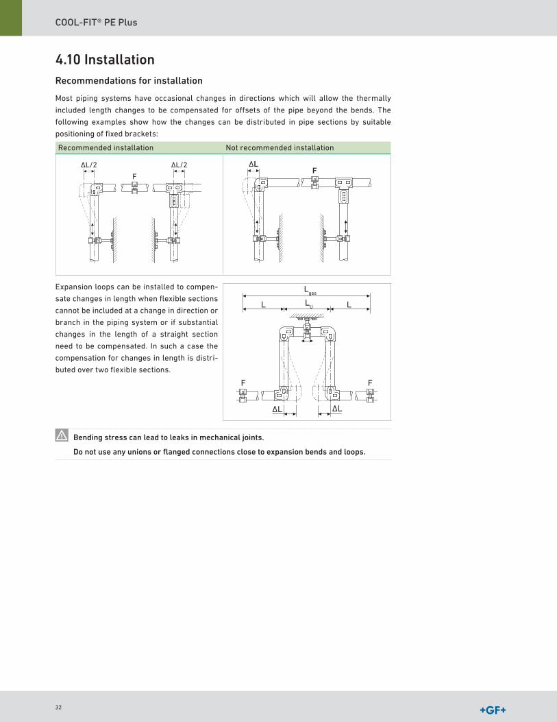
4.10 InstallationRecommendations for installation
Most piping systems have occasional changes in directions which will allow the thermally
included length changes to be compensated for offsets of the pipe beyond the bends The
following examples show how the changes can be distributed in pipe sections by suitable
positioning of fixed brackets:
Recommended installation Not recommended installation
F
∆L/2 ∆L/2 ∆LF
Expansion loops can be installed to compen-
sate changes in length when flexible sections
cannot be included at a change in direction or
branch in the piping system or if substantial
changes in the length of a straight section
need to be compensated In such a case the
compensation for changes in length is distri-
buted over two flexible sections
∆L
F F
∆L
L L
Lges
LU
Bending stress can lead to leaks in mechanical joints.
Do not use any unions or flanged connections close to expansion bends and loops.
32

COOL-FIT® PE Plus Design and Installation
Pre-Stressing
In particularly difficult situations with large changes in one direction only, it is possible to
pre-stress the flexible section during installation in order to reduce the length of LB, as illust-
rated in the next example:
Example
Pipe length L 25 m
Diameter d225/D315 mm
Installation temperature 77ºF (25 °C)
Min ambient temperature 77ºF (25 °C) constant
Max ambient temperature 77ºF (25 °C) constant
Min flow temperature 50ºF (10 °C)
Max flow temperature 77ºF (25 °C)
Change in length from the table or COOLING Tool-Box:
-ΔL = 39 mm
A flexible section to take up a change in length of +/- ΔL = 40 mm needs to be
LB (mm) = 2920 mm long according to the table
If the flexible section is pre-stressed to ΔL/2, the flexible section required is reduced to ~2060
mm (2 06 m) The change in length starting from the 0 position is then +/- ΔL/2 = 39/2 = 19 5 mm
(0 77")
By pre-stressing the flexible section makes it possible to reduce its required length in
installations where space is restricted Pre-stressing also reduces the bending of the flexible
section in service, improving the appearance of the piping system
∆L/2
F
L B=~
0.9m
L=25m- ∆L/2
33

COOL-FIT® PE Plus
4.11 Pipe bracket spacing and support of piping systemsOverview
COOL-FIT PE Plus pipe should be installed using supports designed for use with plastics and
should be installed taking care not to damage or overstress the pipe
Thanks to the excellent insulating properties of the
COOL-FIT PE Plus pipe and its hard, impact resistant outer
jacket, standard pipe clamps with hard plastic inlay may be
used
Pipe Bracket Requirements
A loose bracket is a pipe bracket which allows axial movement of the pipe This allows stress-
free compensation of temperature changes and compensation of any other operating condition
changes
Axial displacement of the pipe through the clamp
The pipe is fixed by the clamp with free axial displacement
The pipe is fixed by the clamp with free biaxial displace-ment
The inner diameter of the bracket must be larger than the outer diameter of the pipe to allow
free movement of the pipe The inner edges of the brackets should be free from any sharp
contours to avoid damaging the pipe surface
It is recommended to use brackets with spacers in the bolts
which also avoids clamping the bracket on the pipe
The axial movement of the piping may not be hindered by
fittings arranged next to the pipe bracket or other diameter
changes Sliding brackets and hanging brackets permit the
pipe to move in different directions Attaching a sliding block
to the base of the pipe bracket allows free movement of the
pipe along a flat supporting surface Sliding and hanging
brackets are needed in situations where the piping system
changes direction and free movement of the pipe must be
allowed
Spacers prevent pinching the
pipe
34
COOL-FIT® PE Plus Design and Installation
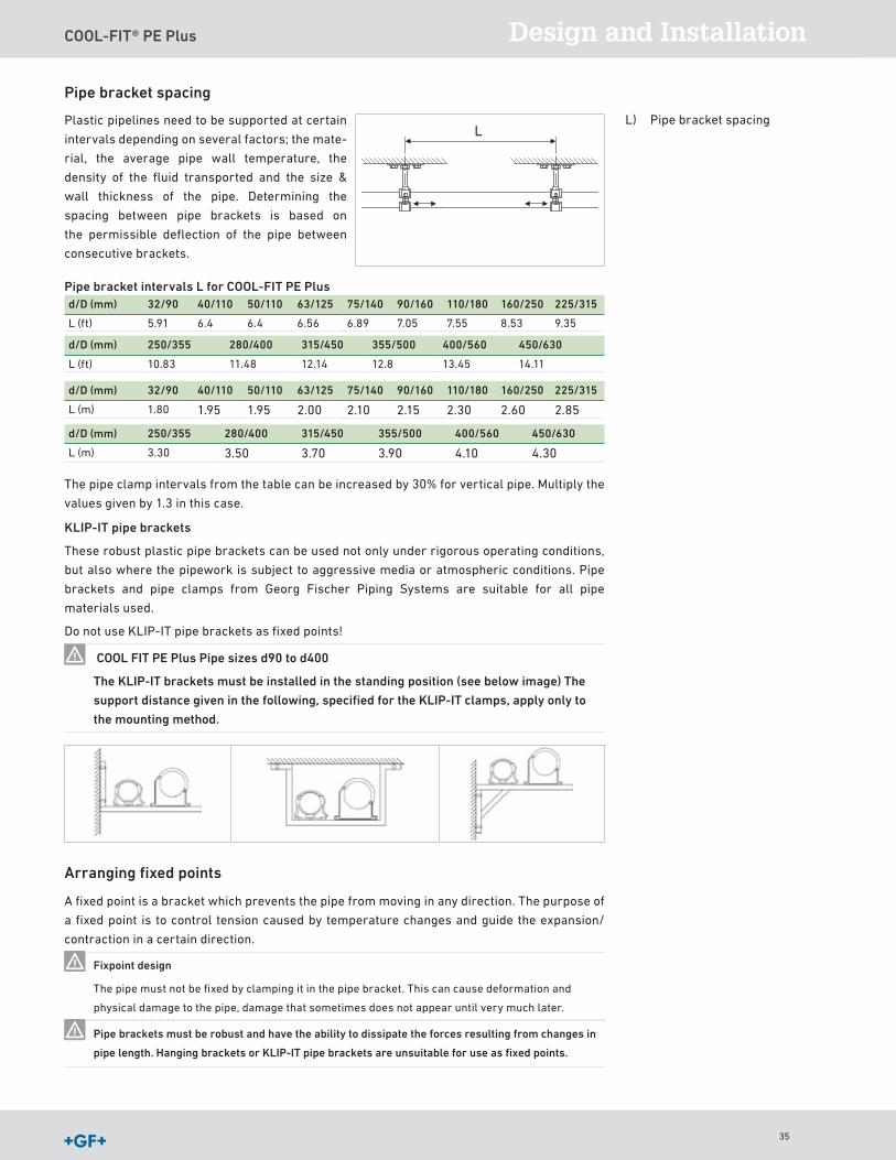
Pipe bracket spacing
Plastic pipelines need to be supported at certain
intervals depending on several factors; the mate-
rial, the average pipe wall temperature, the
density of the fluid transported and the size &
wall thickness of the pipe Determining the
spacing between pipe brackets is based on
the permissible deflection of the pipe between
consecutive brackets
L
Pipe bracket intervals L for COOL-FIT PE Plusd/D (mm) 32/90 40/110 50/110 63/125 75/140 90/160 110/180 160/250 225/315
L (ft) 5 91 6 4 6 4 6 56 6 89 7 05 7 55 8 53 9 35
d/D (mm) 250/355 280/400 315/450 355/500 400/560 450/630
L (ft) 10 83 11 48 12 14 12 8 13 45 14 11
The pipe clamp intervals from the table can be increased by 30% for vertical pipe Multiply the
values given by 1 3 in this case
KLIP-IT pipe brackets
These robust plastic pipe brackets can be used not only under rigorous operating conditions,
but also where the pipework is subject to aggressive media or atmospheric conditions Pipe
brackets and pipe clamps from Georg Fischer Piping Systems are suitable for all pipe
materials used
Do not use KLIP-IT pipe brackets as fixed points!
COOL FIT PE Plus Pipe sizes d90 to d400
The KLIP-IT brackets must be installed in the standing position (see below image) The
support distance given in the following, specified for the KLIP-IT clamps, apply only to
the mounting method.
Arranging fixed points
A fixed point is a bracket which prevents the pipe from moving in any direction The purpose of
a fixed point is to control tension caused by temperature changes and guide the expansion/
contraction in a certain direction
Fixpoint design
The pipe must not be fixed by clamping it in the pipe bracket This can cause deformation and
physical damage to the pipe, damage that sometimes does not appear until very much later
Pipe brackets must be robust and have the ability to dissipate the forces resulting from changes in
pipe length. Hanging brackets or KLIP-IT pipe brackets are unsuitable for use as fixed points.
L) Pipe bracket spacing
d/D (mm) 32/90 40/110 50/110 63/125 75/140 90/160 110/180 160/250 225/315
L (m) 1 80 1 95 1 95 2 00 2 10 2 15 2 30 2 60 2 85
d/D (mm) 250/355 280/400 315/450 355/500 400/560 450/630
L (m) 3 30 3 50 3 70 3 90 4 10 4 30
35
COOL-FIT® PE Plus
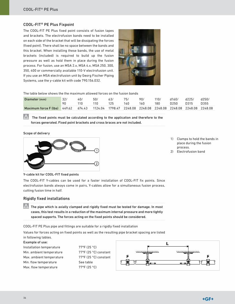
COOL-FIT® PE Plus FixpointThe COOL-FIT PE Plus fixed point consists of fusion tapes
and brackets The electrofusion bands need to be installed
on each side of the bracket that will be dissipating the forces
(fixed point) There shall be no space between the bands and
this bracket When installing these bands, the use of metal
brackets (included) is required to build up the fusion
pressure as well as hold them in place during the fusion
process For fusion, use an MSA 2 x, MSA 4 x, MSA 250, 300,
350, 400 or commercially available 110-V electrofusion unit
If you use an MSA electrofusion unit by Georg Fischer Piping
Systems, use the y-cable kit with code 790 156 032
The table below shows the the maximum allowed forces on the fusion bands
Diameter (mm) 32/ 90
40/ 110
50/ 110
63/ 125
75/ 140
90/ 160
110/ 180
d160/D250
d225/D315
d250/D355
Maximum force F (lbs) 449 62 674 43 1124 04 1798 47 2248 08 2248 08 2248 08 2248 08 2248 08 2248 08
The fixed points must be calculated according to the application and therefore to the
forces generated. Fixed point brackets and cross braces are not included.
Scope of delivery
Y-cable kit for COOL-FIT fixed points
The COOL-FIT Y-cables can be used for a faster installation of COOL-FIT fix points Since
electrofusion bands always come in pairs, Y-cables allow for a simultaneous fusion process,
cutting fusion time in half
Rigidly fixed installations
The pipe which is axially clamped and rigidly fixed must be tested for damage. In most
cases, this test results in a reduction of the maximum internal pressure and more tightly
spaced supports. The forces acting on the fixed points should be considered.
COOL-FIT PE Plus pipe and fittings are suitable for a rigidly fixed installation
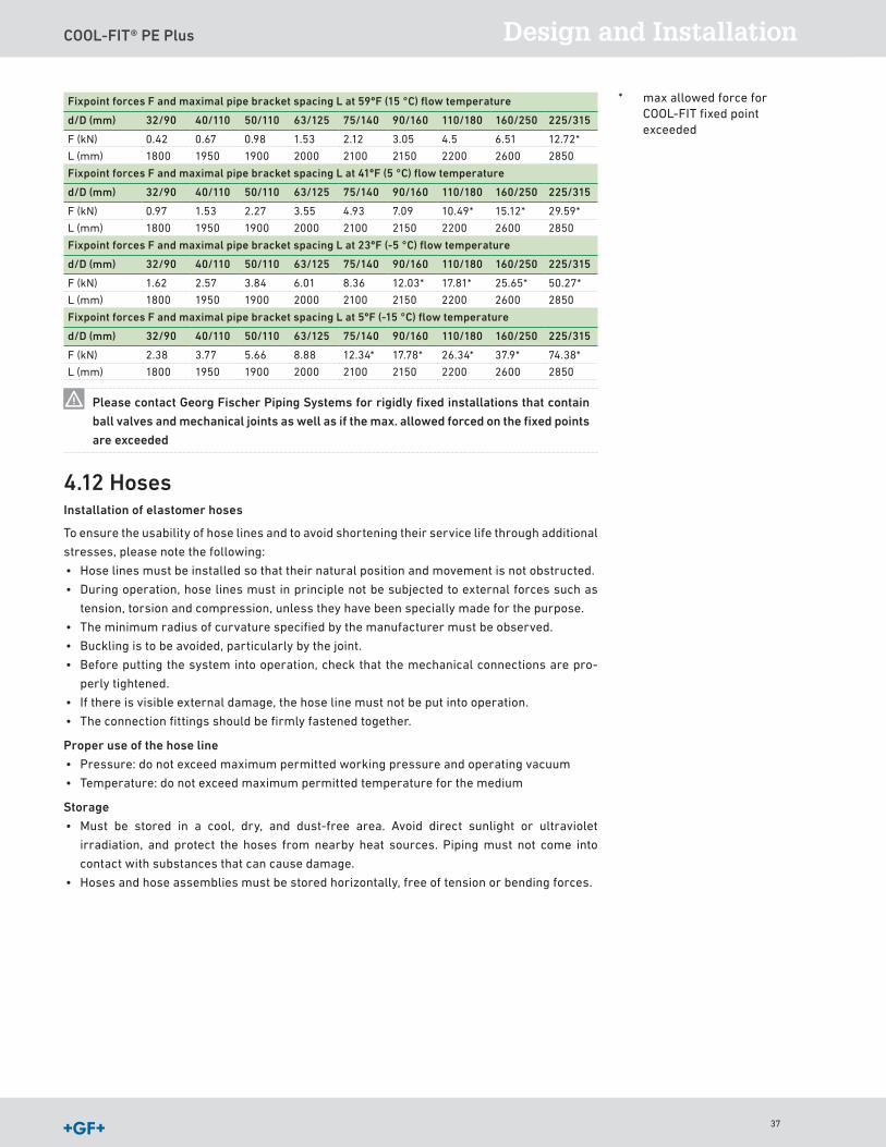
Values for forces acting on fixed points as well as the resulting pipe bracket spacing are listed
in following tables Example of use:
Installation temperature 77ºF (25 °C)
Min ambient temperature 77ºF (25 °C) constant
Max ambient temperature 77ºF (25 °C) constant
Min flow temperature See table
Max flow temperature 77ºF (25 °C)
1) Clamps to hold the bands in place during the fusion process
2) Electrofusion band
36
COOL-FIT® PE Plus Design and Installation
Fixpoint forces F and maximal pipe bracket spacing L at 59ºF (15 °C) flow temperature
d/D (mm) 32/90 40/110 50/110 63/125 75/140 90/160 110/180 160/250 225/315
F (kN) 0 42 0 67 0 98 1 53 2 12 3 05 4 5 6 51 12 72*
L (mm) 1800 1950 1900 2000 2100 2150 2200 2600 2850
Fixpoint forces F and maximal pipe bracket spacing L at 41ºF (5 °C) flow temperature
d/D (mm) 32/90 40/110 50/110 63/125 75/140 90/160 110/180 160/250 225/315
F (kN) 0 97 1 53 2 27 3 55 4 93 7 09 10 49* 15 12* 29 59*
L (mm) 1800 1950 1900 2000 2100 2150 2200 2600 2850
Fixpoint forces F and maximal pipe bracket spacing L at 23ºF (-5 °C) flow temperature
d/D (mm) 32/90 40/110 50/110 63/125 75/140 90/160 110/180 160/250 225/315
F (kN) 1 62 2 57 3 84 6 01 8 36 12 03* 17 81* 25 65* 50 27*
L (mm) 1800 1950 1900 2000 2100 2150 2200 2600 2850
Fixpoint forces F and maximal pipe bracket spacing L at 5ºF (-15 °C) flow temperature
d/D (mm) 32/90 40/110 50/110 63/125 75/140 90/160 110/180 160/250 225/315
F (kN) 2 38 3 77 5 66 8 88 12 34* 17 78* 26 34* 37 9* 74 38*
L (mm) 1800 1950 1900 2000 2100 2150 2200 2600 2850
Please contact Georg Fischer Piping Systems for rigidly fixed installations that contain
ball valves and mechanical joints as well as if the max. allowed forced on the fixed points
are exceeded
4.12 HosesInstallation of elastomer hoses
To ensure the usability of hose lines and to avoid shortening their service life through additional
stresses, please note the following:
• Hose lines must be installed so that their natural position and movement is not obstructed
• During operation, hose lines must in principle not be subjected to external forces such as
tension, torsion and compression, unless they have been specially made for the purpose
• The minimum radius of curvature specified by the manufacturer must be observed
• Buckling is to be avoided, particularly by the joint
• Before putting the system into operation, check that the mechanical connections are pro-
perly tightened
• If there is visible external damage, the hose line must not be put into operation
• The connection fittings should be firmly fastened together
Proper use of the hose line
• Pressure: do not exceed maximum permitted working pressure and operating vacuum
• Temperature: do not exceed maximum permitted temperature for the medium
Storage
• Must be stored in a cool, dry, and dust-free area Avoid direct sunlight or ultraviolet
irradiation, and protect the hoses from nearby heat sources Piping must not come into
contact with substances that can cause damage
• Hoses and hose assemblies must be stored horizontally, free of tension or bending forces
* max allowed force for COOL-FIT fixed point exceeded
37
COOL-FIT® PE Plus
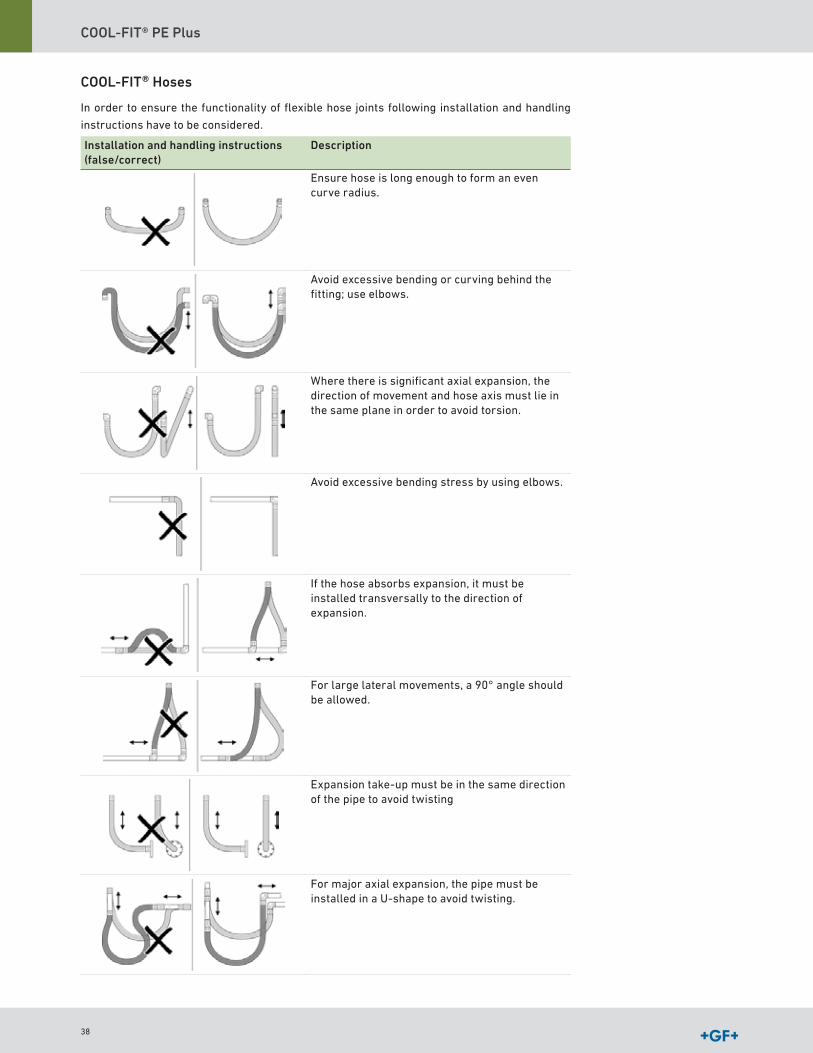
COOL-FIT® Hoses
In order to ensure the functionality of flexible hose joints following installation and handling
instructions have to be considered
Installation and handling instructions (false/correct)
Description
Ensure hose is long enough to form an even curve radius
Avoid excessive bending or curving behind the fitting; use elbows
Where there is significant axial expansion, the direction of movement and hose axis must lie in the same plane in order to avoid torsion
Avoid excessive bending stress by using elbows
If the hose absorbs expansion, it must be installed transversally to the direction of expansion
For large lateral movements, a 90° angle should be allowed
Expansion take-up must be in the same direction of the pipe to avoid twisting
For major axial expansion, the pipe must be installed in a U-shape to avoid twisting
38

COOL-FIT® PE Plus Design and Installation
4.13 Underground installationCOOL-FIT PE Plus can be used underground The corresponding national installation guidelines
apply to building the pipe trenches and installing the pipe In general, trenches should not be
less than 1 meter deep; deeper depth recommended if frost is present The sand bed must be
built in such a way that the pipe is evenly supported The pipe must be laid in a sand bed and
protected against sharp stones and debris The sand must be well compacted
The pipe zone has to be designed according to planning requirements and static calculations
The area between trench sole and side fill is referred to as bedding A load-carrying bedding
must be created by using soil replacement For regular soil conditions, EN 1610 specifies a
minimum thickness of a = 5 9 (150 mm) in for the lower bedding In addition to the minimum
thickness, corresponding requirements are also imposed on the building materials that must
be used for the bedding
No building materials with components exceeding the following ranges may be used:
• 22 mm for (0 87")
The upper bedding layer b is derived from static calculations It is also important to ensure that
no cavities are created below the pipe The bedding dissipates all loads from the pipe securely
and evenly into the ground For this reason, the COOL-FIT PE Plus pipe has to rest solidly on the
bedding across its entire length The upper end of the pipe zone is defined according to EN 1610
as 5 9 (150 mm) in above the pipe apex or 3 9 (100 mm) in above the pipe connection Ensure that
the pipe is not damaged when the cover and main backfill are filled and compacted
The COOL-FIT PE Plus system has a higher degree of stiffness and a higher weight than the
non-insulated pipe For this reason, the pipe should always be connected in the trench Unne-
cessary stress on the COOL-FIT PE Plus joining elements thus avoided Under normal circum-
stances, it is not necessary to install expansion loops in the system
A movement of the pipe before filling the pipe trench should be avoided. Please contact
Georg Fischer Piping Systems concerning recommendations for underground installa-
tions.
Ground level
Trench walls
b
a
Height of cover
Trench depth
Pipe zone
Bedding
OD
Lower bedding layer
Upper bedding layer
Side fill
Cover depthMain backfill
c (min 15 cm)
Trench sole
39
COOL-FIT® PE Plus
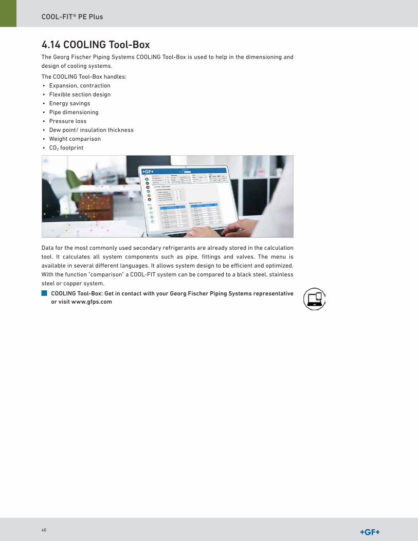
4.14 COOLING Tool-BoxThe Georg Fischer Piping Systems COOLING Tool-Box is used to help in the dimensioning and
design of cooling systems
The COOLING Tool-Box handles:
• Expansion, contraction
• Flexible section design
• Energy savings
• Pipe dimensioning
• Pressure loss
• Dew point/ insulation thickness
• Weight comparison
• CO2 footprint
Data for the most commonly used secondary refrigerants are already stored in the calculation
tool It calculates all system components such as pipe, fittings and valves The menu is
available in several different languages It allows system design to be efficient and optimized
With the function "comparison" a COOL-FIT system can be compared to a black steel, stainless
steel or copper system
COOLING Tool-Box: Get in contact with your Georg Fischer Piping Systems representative or visit www.gfps.com
40
COOL-FIT® PE Plus Design and Installation
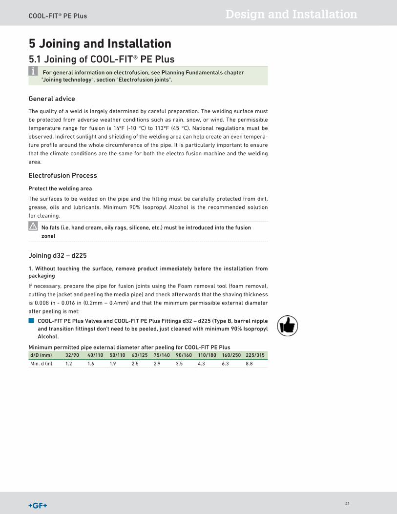
5 Joining and Installation5.1 Joining of COOL-FIT® PE Plus
For general information on electrofusion, see Planning Fundamentals chapter "Joining technology", section "Electrofusion joints".
General advice
The quality of a weld is largely determined by careful preparation The welding surface must
be protected from adverse weather conditions such as rain, snow, or wind The permissible
temperature range for fusion is 14ºF (-10 °C) to 113ºF (45 °C) National regulations must be
observed Indirect sunlight and shielding of the welding area can help create an even tempera-
ture profile around the whole circumference of the pipe It is particularly important to ensure
that the climate conditions are the same for both the electro fusion machine and the welding
area
Electrofusion Process
Protect the welding area
The surfaces to be welded on the pipe and the fitting must be carefully protected from dirt,
grease, oils and lubricants Minimum 90% Isopropyl Alcohol is the recommended solution
for cleaning
No fats (i.e. hand cream, oily rags, silicone, etc.) must be introduced into the fusion
zone!
Joining d32 – d225
1. Without touching the surface, remove product immediately before the installation from packaging
If necessary, prepare the pipe for fusion joints using the Foam removal tool (foam removal,
cutting the jacket and peeling the media pipe) and check afterwards that the shaving thickness
is 0 008 in - 0 016 in (0 2mm – 0 4mm) and that the minimum permissible external diameter
after peeling is met:
COOL-FIT PE Plus Valves and COOL-FIT PE Plus Fittings d32 – d225 (Type B, barrel nipple and transition fittings) don’t need to be peeled, just cleaned with minimum 90% Isopropyl Alcohol.
Minimum permitted pipe external diameter after peeling for COOL-FIT PE Plusd/D (mm) 32/90 40/110 50/110 63/125 75/140 90/160 110/180 160/250 225/315
Min d (in) 1 2 1 6 1 9 2 5 2 9 3 5 4 3 6 3 8 8
41
COOL-FIT® PE Plus
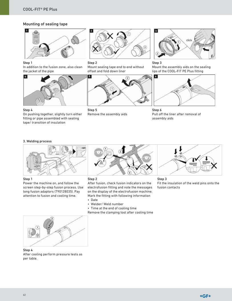
3. Welding process
Step 1Power the machine on, and follow the screen step-by-step fusion process Use long fusion adaptors (790128035) Pay attention to fusion and cooling time
Step 2After fusion, check fusion indicators on the electrofusion fitting and note the messages on the display of the electro fusion machine Mark the fitting with following information• Date• Welder/ Weld number• Time at the end of cooling timeRemove the clamping tool after cooling time
Step 3Fit the insulation of the weld pins onto the fusion contacts
Step 4After cooling perform pressure tests as per table
Mounting of sealing tape
Step 1In addition to the fusion zone, also clean the jacket of the pipe
Step 2Mount sealing tape end to end without offset and fold down liner
Step 3Mount the assembly aids on the sealing lips of the COOL-FIT PE Plus fitting
Step 4On pushing together, slightly turn either fitting or pipe assembled with sealing tape/ transition of insulation
Step 5Remove the assembly aids
Step 6Pull off the liner after removal of assembly aids
42

COOL-FIT® PE Plus Design and Installation
Cooling Time Table
d (mm) Cooling time before Remove clamping tool [min.]
Cooling time before internal pressure test at 6 bar≤ 87 psi [min.]
Cooling time before internal pressure test at 18 bar≤ 261 psi [hours]
32 10 15 3 040 10 20 5 050 10 20 5 063 10 20 5 075 15 25 6 090 20 35 8 0110 30 50 8 0160 45 90 8 0225 45 90 9 5
The values are valid for pressure tests using water or a liquid compatible with PE (check
chemical resistance table or contact GF technical support) at ≤ 68ºF (20 ° C) For testing with
nitrogen (do not use comptressed air) a cooling time of 12 hours is recommended
Joining d250 – d450
Preparing for fusion
Step 1 Step 2 Step 3
Clean the welding surfaces of the COOL-FIT PE Plus fittings and pipes
Check the pipe outer diameter before and after peeling with a circumferential measuring tape
Check the free spigot length
Overview of pipe outer diameter and insulation free spigot length
Dimension
(mm)
Minimum permissible pipe outer diameter after peeling(mm)
Factory-set spigot length
(mm)
Minimum permissible pipe outer diameter after peeling(in)
Factory-set spigot length
(in)
d250 249 3 113 – 123 9 8 4 4 - 4 8d280 279 3 116 – 126 11 0 4 6 - 5 0
d315 314 3 123 – 133 12 4 4 8 - 5 2d355 354 3 135 – 145 13 9 5 3 - 5 7d400 399 3 137 – 147 15 7 5 4 - 5 8d450 449 3 153 – 163 17 7 6 0 - 6 4
Cleaning
Step 1 Step 2 Step 3
Peel the outer jacket and foam with the peeling tool
Clean peeled pipe section with PE cleaner and lint-free cloth and allow to air out
Clean fusion area of the electrofusion coupler with PE cleaner and lint-free cloth and allow to air out
43

COOL-FIT® PE Plus
Fusion process
Step 1 Step 2 Step 3
Slide on the electrofusion socket up to the insulation without touching the fusion area Slide on the shrink socket and fix the components stress-free1)
Power the machine on, and follow the screen step-by-step fusion process Use long fusion adaptors (790128035) Pay attention to fusion and cooling time
After fusion, check fusion indicators on the electrofusion fitting and note the messages on the display of the electrofusion machine Mark the fitting with following information• Date• Welder/ Weld number• Time at the end of cooling timeRemove the clamping tool after cooling time
Sealing
Step 1 Step 2 Step 3
Place the sealing tape centered over the gap and overlap it at the end Press it on well and smooth out folds
Position the shrink socket centered
Using a roofers torch (yellow flame), strike the shrink socket as vertically as possible keep the flame moving over the shrink socket to maintain an uniform heating process Avoid applying unnecessary heat to the fittings
Valves and flange joints
1. Preparation of fitting – cut the sealing lip flush on one side, clean the sealing surfaces
For joining the valve or flange adaptor, the sealing lip of the fitting has to be removed on the side
that will be joining with the valve or flange adaptor The sealing and fusion areas need to be
cleaned
2. Standard fusion
Fuse both valve ends without valve mounted
Following insertion depths A are valid for COOL-FIT PE Plus components:
d/D (mm) 32/90 40/110 50/110 63/125 75/140 90/160 110/180 160/250 225/315
L1 (in) 1 4 1 6 1 7 1 9 2 2 2 4 2 8 3 5 4 3
L1 (mm) 35 6 40 6 43 2 48 3 55 9 61 0 71 1 88 9 109 2
1) The use of suitable fixing devices is recommended
44
COOL-FIT® PE Plus Design and Installation
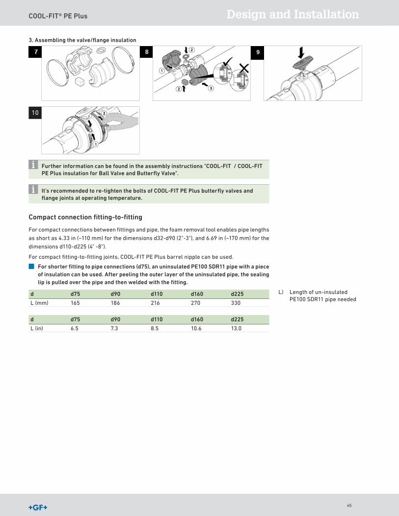
3. Assembling the valve/flange insulation
Further information can be found in the assembly instructions "COOL-FIT / COOL-FIT PE Plus insulation for Ball Valve and Butterfly Valve".
It’s recommended to re-tighten the bolts of COOL-FIT PE Plus butterfly valves and flange joints at operating temperature.
Compact connection fitting-to-fitting
For compact connections between fittings and pipe, the foam removal tool enables pipe lengths
as short as 4 33 in (~110 mm) for the dimensions d32-d90 (2"-3"), and 6 69 in (~170 mm) for the
dimensions d110-d225 (4" -8")
For compact fitting-to-fitting joints, COOL-FIT PE Plus barrel nipple can be used
For shorter fitting to pipe connections (d75), an uninsulated PE100 SDR11 pipe with a piece of insulation can be used. After peeling the outer layer of the uninsulated pipe, the sealing lip is pulled over the pipe and then welded with the fitting.
d d75 d90 d110 d160 d225
L (mm) 165 186 216 270 330
L) Length of un-insulated PE100 SDR11 pipe needed
d d75 d90 d110 d160 d225
L (in) 6 5 7 3 8 5 10 6 13 0
10
45
COOL-FIT® PE Plus
Transition Fittings
The Georg Fischer Piping Systems range of fittings provides a variety of transitions and
threaded fittings to connect plastic piping components to pipe, fittings or valves in metal (or
vice versa) The metal threads Rp, R or NPT can be sealed with a PTFE tape as long as the coun-
terpart is not made of plastic Male and female G threads must be sealed with flat gaskets The
advantage of a threaded G connection is radial and torsion-free possibility for installing and
uninstalling
To prevent electrochemical corrosion, stainless steel connecting elements should
preferably be used for steel transitions.
Combining G and R threads
The connection of an external parallel pipe thread G in accordance with EN ISO 228-1, with
an internal parallel pipe thread Rp in accordance with ISO 7-1 is not intended according to
standards A tight connection is possible under favorable conditions, but cannot be established
reliably
46
COOL-FIT® PE Plus Design and Installation
Mounting the insulation half shells of Transition Fittings
Following the joining of the COOL-FIT PE Plus Transition Fittings with the COOL-FIT PE Plus
Fitting Type A, and the mechanical joining of the threaded components, the insulation half
shells can be mounted Assembling of the shells can be done in the same way like for the COOL-
FIT PE Plus valves With the exception of COOL-FIT unions, the sealing lip of the type A fitting
must not be cut off on mounting the insulation half shells of transition fittings
Further information can be found in the assembly instructions "COOL-FIT PE Plus insulation for transition fittings".
Connecting the flexible hose insulation to the Transition Fittings
The radial joining of the joining face of the NBR insulation of flexible hoses to the insulation of
transition fittings can be applied either by adhesive cement or by adhesive tape
Joining Instructions for the adhesive cement
The adhesive should be thoroughly stirred before use A thin film is applied using the brush to
both surfaces to be bonded The open joint time is about 3 to 15 minutes depending on
temperature and humidity of surrounding air
Before the coated surfaces are bonded together, the adhesive must still be wet but should not
transfer to the skin when touched The surfaces should be brought together quickly and firmly
and should be held together for a few seconds
The recommended temperature for storage and processing is in the range between 59ºF
(+15 °C) and 77ºF (25 °C) The adhesive should not be used below 50ºF (+10 °C)
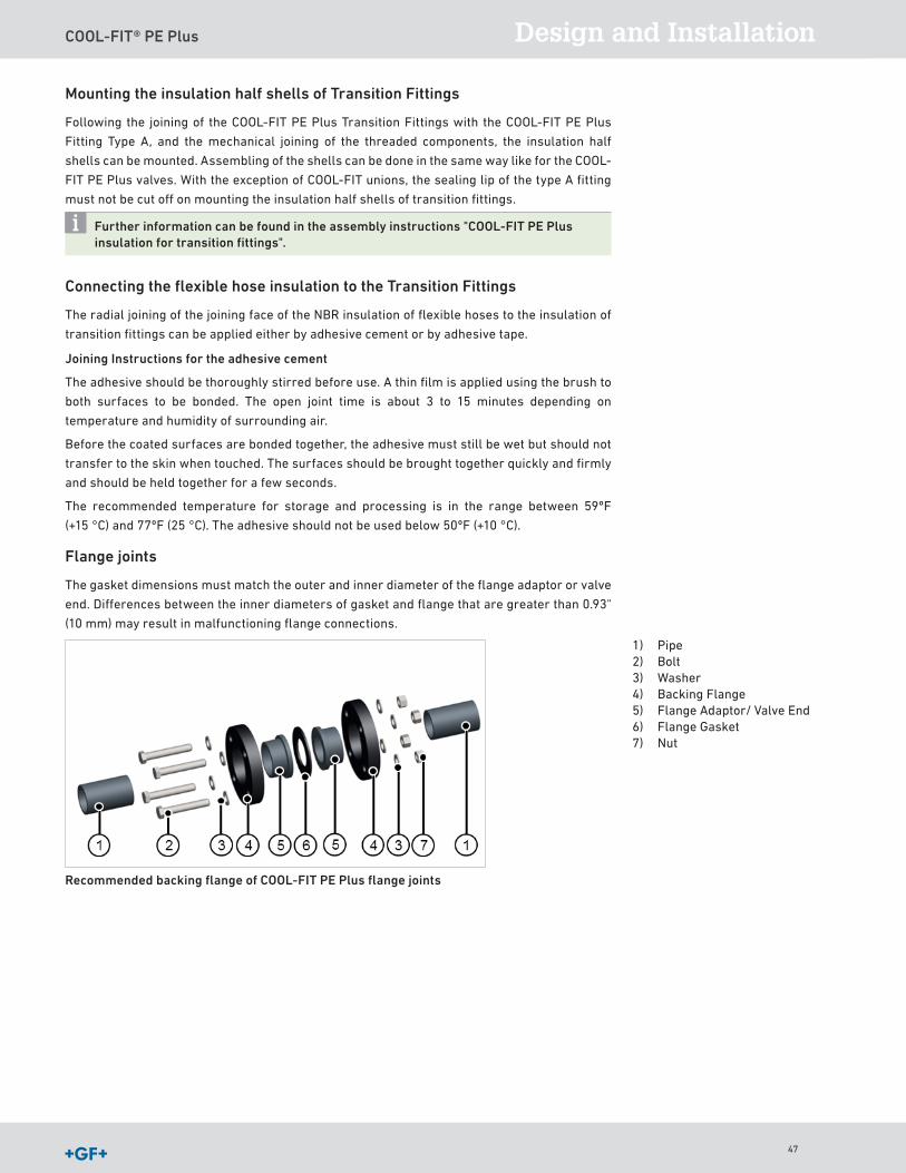
Flange joints
The gasket dimensions must match the outer and inner diameter of the flange adaptor or valve
end Differences between the inner diameters of gasket and flange that are greater than 0 93"
(10 mm) may result in malfunctioning flange connections
Recommended backing flange of COOL-FIT PE Plus flange joints
1) Pipe2) Bolt3) Washer4) Backing Flange5) Flange Adaptor/ Valve End6) Flange Gasket7) Nut
47
COOL-FIT® PE Plus
12 - Bolt Pattern
8 - Bolt Pattern
4 - Bolt Pattern
11 1
7 6
3 10
9 4
5
2 12
8
3
5 1
8
4
6
7
2
3 1
2 4
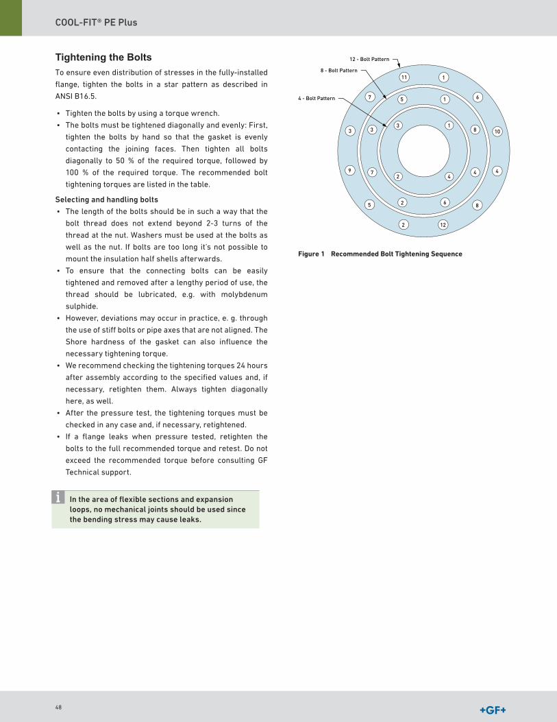
Tightening the Bolts To ensure even distribution of stresses in the fully-installed
flange, tighten the bolts in a star pattern as described in
ANSI B16 5
• Tighten the bolts by using a torque wrench
• The bolts must be tightened diagonally and evenly: First,
tighten the bolts by hand so that the gasket is evenly
contacting the joining faces Then tighten all bolts
diagonally to 50 % of the required torque, followed by
100 % of the required torque The recommended bolt
tightening torques are listed in the table
Selecting and handling bolts
• The length of the bolts should be in such a way that the
bolt thread does not extend beyond 2-3 turns of the
thread at the nut Washers must be used at the bolts as
well as the nut If bolts are too long it’s not possible to
mount the insulation half shells afterwards
• To ensure that the connecting bolts can be easily
tightened and removed after a lengthy period of use, the
thread should be lubricated, e g with molybdenum
sulphide
• However, deviations may occur in practice, e g through
the use of stiff bolts or pipe axes that are not aligned The
Shore hardness of the gasket can also influence the
necessary tightening torque
• We recommend checking the tightening torques 24 hours
after assembly according to the specified values and, if
necessary, retighten them Always tighten diagonally
here, as well
• After the pressure test, the tightening torques must be
checked in any case and, if necessary, retightened
• If a flange leaks when pressure tested, retighten the
bolts to the full recommended torque and retest Do not
exceed the recommended torque before consulting GF
Technical support
In the area of flexible sections and expansion loops, no mechanical joints should be used since the bending stress may cause leaks.
Figure 1 Recommended Bolt Tightening Sequence
48
COOL-FIT® PE Plus Design and Installation
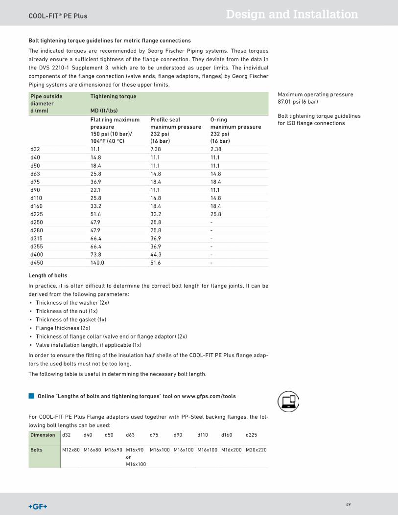
Bolt tightening torque guidelines for metric flange connections
The indicated torques are recommended by Georg Fischer Piping systems These torques
already ensure a sufficient tightness of the flange connection They deviate from the data in
the DVS 2210-1 Supplement 3, which are to be understood as upper limits The individual
components of the flange connection (valve ends, flange adaptors, flanges) by Georg Fischer
Piping systems are dimensioned for these upper limits
Pipe outside diameter d (mm)
Tightening torque
MD (ft/lbs)
Flat ring maximum pressure 150 psi (10 bar)/ 104°F (40 °C)
Profile seal maximum pressure 232 psi(16 bar)
O-ring maximum pressure 232 psi(16 bar)
d32 11 1 7 38 2 38
d40 14 8 11 1 11 1
d50 18 4 11 1 11 1d63 25 8 14 8 14 8d75 36 9 18 4 18 4d90 22 1 11 1 11 1d110 25 8 14 8 14 8d160 33 2 18 4 18 4d225 51 6 33 2 25 8d250 47 9 25 8 -d280 47 9 25 8 -d315 66 4 36 9 -d355 66 4 36 9 -d400 73 8 44 3 -d450 140 0 51 6 -
Length of bolts
In practice, it is often difficult to determine the correct bolt length for flange joints It can be
derived from the following parameters:
• Thickness of the washer (2x)
• Thickness of the nut (1x)
• Thickness of the gasket (1x)
• Flange thickness (2x)
• Thickness of flange collar (valve end or flange adaptor) (2x)
• Valve installation length, if applicable (1x)
In order to ensure the fitting of the insulation half shells of the COOL-FIT PE Plus flange adap-
tors the used bolts must not be too long
The following table is useful in determining the necessary bolt length
Online "Lengths of bolts and tightening torques" tool on www.gfps.com/tools
For COOL-FIT PE Plus Flange adaptors used together with PP-Steel backing flanges, the fol-
lowing bolt lengths can be used:
Dimension d32 d40 d50 d63 d75 d90 d110 d160 d225
Bolts M12x80 M16x80 M16x90 M16x90 or M16x100
M16x100 M16x100 M16x100 M16x200 M20x220
Maximum operating pressure 87 01 psi (6 bar)
Bolt tightening torque guidelines for ISO flange connections
49
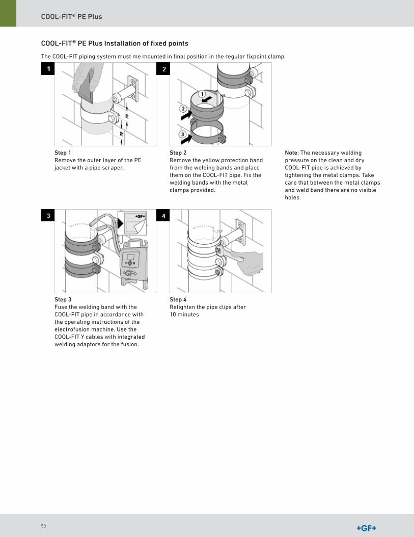
COOL-FIT® PE Plus
COOL-FIT® PE Plus Installation of fixed points
The COOL-FIT piping system must me mounted in final position in the regular fixpoint clamp
Step 1Remove the outer layer of the PE jacket with a pipe scraper
Step 2Remove the yellow protection band from the welding bands and place them on the COOL-FIT pipe Fix the welding bands with the metal clamps provided
Note: The necessary welding pressure on the clean and dry COOL-FIT pipe is achieved by tightening the metal clamps Take care that between the metal clamps and weld band there are no visible holes
Step 3Fuse the welding band with the COOL-FIT pipe in accordance with the operating instructions of the electrofusion machine Use the COOL-FIT Y cables with integrated welding adaptors for the fusion
Step 4Retighten the pipe clips after 10 minutes
50
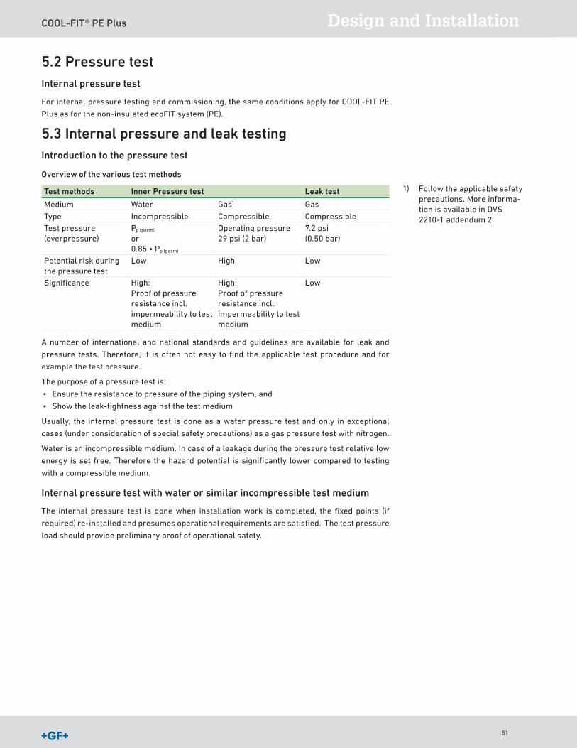
COOL-FIT® PE Plus Design and Installation
5.2 Pressure testInternal pressure test
For internal pressure testing and commissioning, the same conditions apply for COOL-FIT PE
Plus as for the non-insulated ecoFIT system (PE)
5.3 Internal pressure and leak testingIntroduction to the pressure test
Overview of the various test methods
Test methods Inner Pressure test Leak test
Medium Water Gas1 Gas
Type Incompressible Compressible CompressibleTest pressure (overpressure)
Pp (perm)
or0 85 • Pp (perm)
Operating pressure29 psi (2 bar)
7 2 psi(0 50 bar)
Potential risk during the pressure test
Low High Low
Significance High: Proof of pressure resistance incl impermeability to test medium
High: Proof of pressure resistance incl impermeability to test medium
Low
A number of international and national standards and guidelines are available for leak and
pressure tests Therefore, it is often not easy to find the applicable test procedure and for
example the test pressure
The purpose of a pressure test is:
• Ensure the resistance to pressure of the piping system, and
• Show the leak-tightness against the test medium
Usually, the internal pressure test is done as a water pressure test and only in exceptional
cases (under consideration of special safety precautions) as a gas pressure test with nitrogen
Water is an incompressible medium In case of a leakage during the pressure test relative low
energy is set free Therefore the hazard potential is significantly lower compared to testing
with a compressible medium
Internal pressure test with water or similar incompressible test medium
The internal pressure test is done when installation work is completed, the fixed points (if
required) re-installed and presumes operational requirements are satisfied The test pressure
load should provide preliminary proof of operational safety
1) Follow the applicable safety precautions More informa-tion is available in DVS 2210-1 addendum 2
51
COOL-FIT® PE Plus
Test parameters
The following table provides recommendations on the performance of the internal pressure
test
Purpose Preliminary Review Main examination
Test pressure pp (depends on the pipe wall temperature and the permitted test pressure of the installed components, see "determi-nation of the test pressure")
≤ Pp (perm) ≤ 0 85 Pp (perm)
Test duration (depends on the length of the pipe sections)
L ≤ 328ft (100 m): 3 h328ft (100 m) < L ≤ 1640ft (500 m): 6 h
328ft (L ≤ 100 m): 3 h328ft (100 m) <L ≤ 1640ft (500 m): 6 h
Checks during the test (test pressure and temperature curves must be recorded)
At least 3 checks distributed across the test period with test pres-sure restored
At least 3 checks distributed across the test period without restoring the test pressure
Pre-test
The pre-test serves to prepare the piping system for the actual test (main test) In the course of
pre-testing, a tension-expansion equilibrium in relation to an increase in volume will develop in
the piping system A material related drop in pressure will occur which will require repeated
pumping to restore the test pressure and also frequently a re-tightening of the flange connec-
tion bolts
The guidelines for an expansion-related pressure decrease in pipe are:
Material Pressure drop(bar/h)
Pressure drop(psi/h)
COOL-FIT PE Plus 1 2 17 4
Main test
In the context of the main test, a much smaller drop in pressure can be expected at constant
pipe wall temperatures so that it is not necessary to pump again The checks can focus
primarily on leak detection at the flange joints and any position changes of the pipe
Observe if using compensators
If the piping system to be tested contains compensators, it has an influence on the expected
axial forces on the fixed points of the piping system Because the test pressure is higher than
the operating pressure, the axial forces on the fixed points increase proportionately This has
to be taken into account when designing the fixed points
Observe if using valves
When using a valve at the end of a piping system (end or final valve), the valve and the pipe
end should be closed by a cap This prevents an accidental opening of the valve and release of
the medium
Filling the pipe
Before starting the pressure test, the following points should be checked:
1 The installation has been carried out in accordance with its plans
2 All pressure relief and check valves are fitted in the direction of flow
3 All end valves have been closed
4 All valves for devices have been closed to secure against pressure
5 A visual inspection has been made of all connections, pumps, measurement devices
and tanks
6 The waiting time after the last weld
52
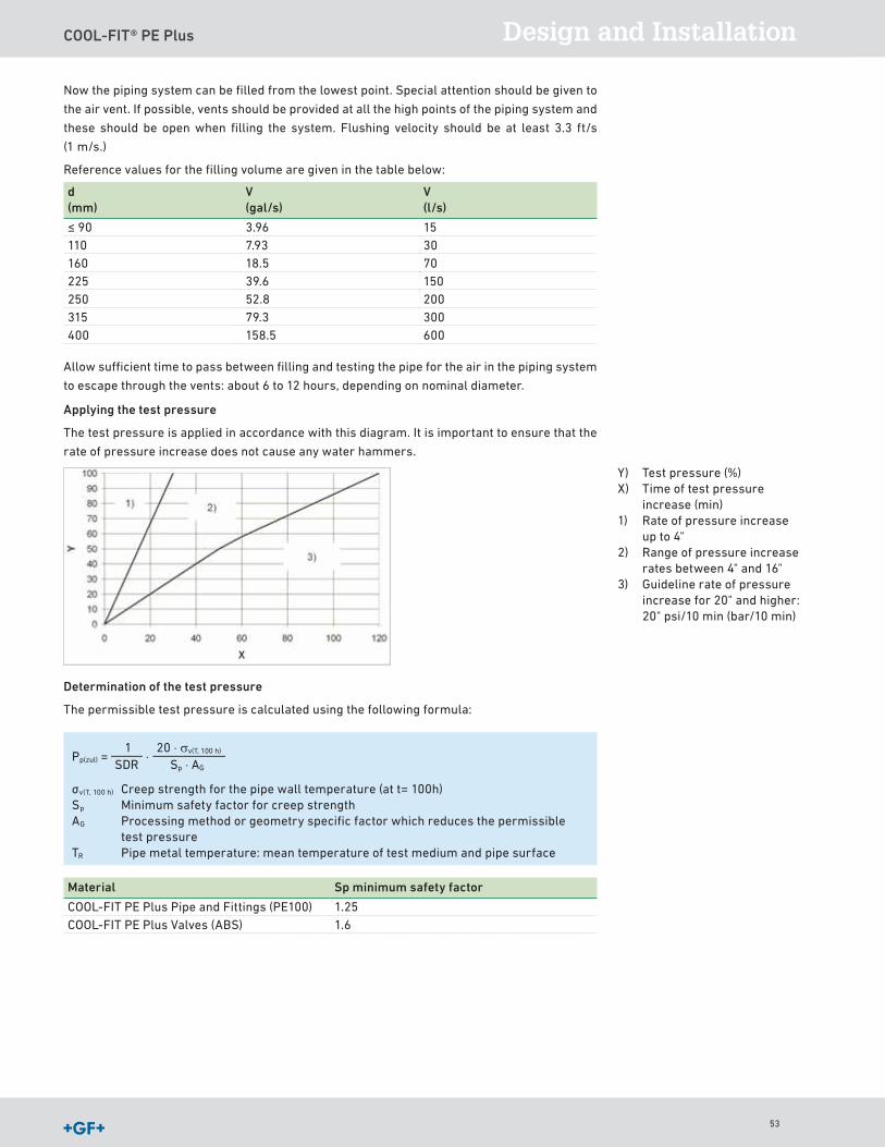
COOL-FIT® PE Plus Design and Installation
Now the piping system can be filled from the lowest point Special attention should be given to
the air vent If possible, vents should be provided at all the high points of the piping system and
these should be open when filling the system Flushing velocity should be at least 3 3 ft/s
(1 m/s )
Reference values for the filling volume are given in the table below:
d (mm)
V (gal/s)
V (l/s)
≤ 90 3 96 15110 7 93 30160 18 5 70225 39 6 150250 52 8 200315 79 3 300400 158 5 600
Allow sufficient time to pass between filling and testing the pipe for the air in the piping system
to escape through the vents: about 6 to 12 hours, depending on nominal diameter
Applying the test pressure
The test pressure is applied in accordance with this diagram It is important to ensure that the
rate of pressure increase does not cause any water hammers
Determination of the test pressure
The permissible test pressure is calculated using the following formula:
Pp(zul) = ⋅20 ⋅ σv(T, 100 h)
Sp ⋅ AG 1
SDR
σv(T, 100 h) Creep strength for the pipe wall temperature (at t= 100h)Sp Minimum safety factor for creep strengthAG Processing method or geometry specific factor which reduces the permissible
test pressureTR Pipe metal temperature: mean temperature of test medium and pipe surface
Material Sp minimum safety factor
COOL-FIT PE Plus Pipe and Fittings (PE100) 1 25COOL-FIT PE Plus Valves (ABS) 1 6
Y) Test pressure (%)X) Time of test pressure
increase (min)1) Rate of pressure increase
up to 4"2) Range of pressure increase
rates between 4" and 16"3) Guideline rate of pressure
increase for 20" and higher: 20" psi/10 min (bar/10 min)
53

COOL-FIT® PE Plus
Checks during testing
The following measurement values must be recorded consistently during testing:
1 Internal pressure at the absolute lowest point of the piping system
2 Medium and ambient temperature
3 Water volume input
4 Water volume output
5 Pressure drop rates
5.4 Start-up with secondary refrigerantsSecondary refrigerants in pre-mixed solutions should be introduced into COOL-FIT PE Plus
piping systems Filling should be performed slowly from the lowest point of the system to allow
the piping system to vent at its highest point
Filling and de-aeration
It is important to vent air from all piping systems This is particularly important with saline
solutions, because of their corrosive properties Venting process:
• The system must be filled slowly
• Manual or automatic venting devices must be fitted at the highest point of the system
• Long horizontal lines should be installed at a slight gradient
• The piping layout should be chosen in such a way as to prevent the formation of air pockets
• Installation of an air vent with a medium column as a reserve
• Follow the specific manufacturer instructions for the liquids as regards filling
54

COOL-FIT® PE Plus Design and Installation
6 Transport, Handling and Storage6.1 TransportOn trucks/in crates, manual transport
6.2 StorageAll plastic pipe including pre-insulated plastic pipe such as COOL-FIT PE Plus must be stacked
on a flat surface with no sharp edges During handling, care must be taken to avoid damage to
the external surface of the pipe (i e by dragging along the ground) Pipe should not cross over
each other in storage as this is likely to cause bending
6.3 EnvironmentThe materials used for COOL-FIT PE Plus are suitable for recycling Georg Fischer Piping
Systems aims to satisfy its customer’s wishes concerning environmental aspects TEWI, ODP
and GWP values and test reports are available for COOL-FIT PE Plus
For more information at www.gfps.com
55

56

GF Piping Systems
COOL-FIT® PE Plus Catalog
57

COOL-FIT® PE Plus
58
COOL-FIT® PE Plus Catalog
Table of contents
COOL-FIT PE Plus 60
COOL-FIT PE Uninsulated 72
Valves 94
59
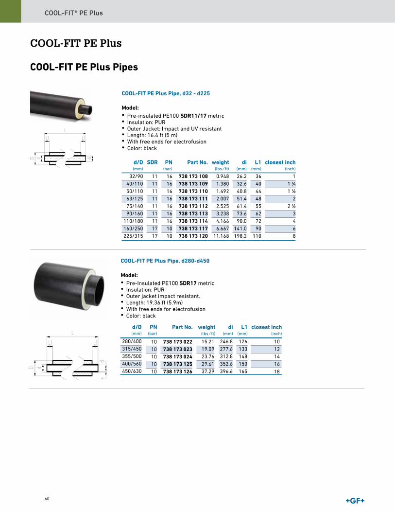
COOL-FIT® PE Plus
60
COOL-FIT PE Plus
COOL-FIT PE Plus Pipes
COOL-FIT PE Plus Pipe, d32 - d225
Model:• Pre-insulated PE100 SDR11/17 metric• Insulation: PUR• Outer Jacket: Impact and UV resistant • Length: 16.4 ft (5 m) • With free ends for electrofusion
d/D(mm)
SDR PN(bar)
Part No. weight(lbs ⁄ ft)
di(mm)
L1(mm)
closest inch(inch)
32/90 11 16 738 173 108 0.948 26.2 36 140/110 11 16 738 173 109 1.380 32.6 40 1 1∕450/110 11 16 738 173 110 1.492 40.8 44 1 1∕263/125 11 16 738 173 111 2.007 51.4 48 275/140 11 16 738 173 112 2.525 61.4 55 2 1∕290/160 11 16 738 173 113 3.238 73.6 62 3
110/180 11 16 738 173 114 4.166 90.0 72 4160/250 17 10 738 173 117 6.667 141.0 90 6225/315 17 10 738 173 120 11.168 198.2 110 8
280/400 10 738 173 022 246.8 126 10315/450 10 738 173 023 277.6 133 12355/500 10 738 173 024 312.8 148 14400/560 10 738 173 125 352.6 150 16450/630 10 738 173 126 396.6 165
COOL-FIT PE Plus Pipe, d280-d450
Model:• Pre-Insulated PE100 SDR17 metric• Insulation: PUR• Outer jacket impact resistant.• Length: 19.36 ft (5.9m)• With free ends for electrofusion
• Color: black
15.2119.0923.7629.6137.29
• Color: black
d/D(mm)
PN(bar)
Part No. weight(lbs ⁄ ft)
di(mm)
L1(mm)
closest inch(inch)
18
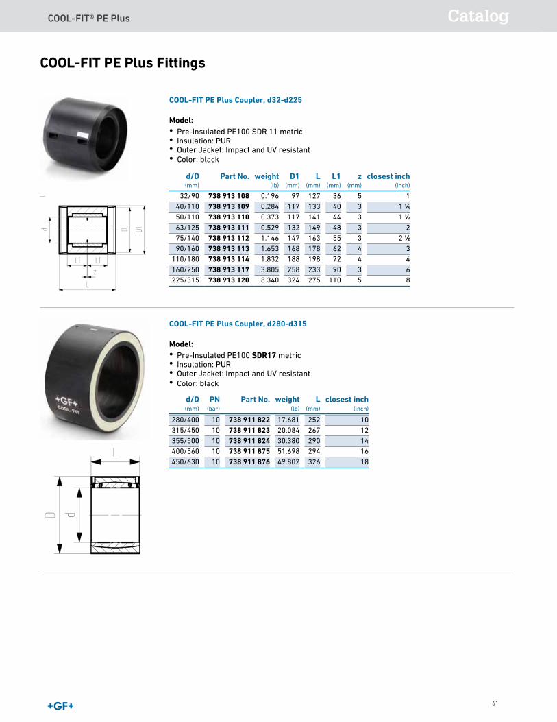
COOL-FIT® PE Plus Catalog
61
COOL-FIT PE Plus Fittings
COOL-FIT PE Plus Coupler, d32-d225
Model:• Pre-insulated PE100 SDR 11 metric• Insulation: PUR• Outer Jacket: Impact and UV resistant
d/D(mm)
Part No. weight(lb)
D1(mm)
L(mm)
L1(mm)
z(mm)
closest inch(inch)
32/90 738 913 108 0.196 97 127 36 5 140/110 738 913 109 0.284 117 133 40 3 1 1∕450/110 738 913 110 0.373 117 141 44 3 1 1∕263/125 738 913 111 0.529 132 149 48 3 275/140 738 913 112 1.146 147 163 55 3 2 1∕290/160 738 913 113 1.653 168 178 62 4 3
110/180 738 913 114 1.832 188 198 72 4 4160/250 738 913 117 3.805 258 233 90 3 6225/315 738 913 120 8.340 324 275 110 5 8
COOL-FIT PE Plus Coupler, d280-d315
Model:• Pre-Insulated PE100 SDR17 metric• Insulation: PUR• Outer Jacket: Impact and UV resistant • Color: black
• Color: black
d/D(mm)
PN(bar)
Part No. weight(lb)
L(mm)
closest inch(inch)
280/400 10 738 911 822 17.681 252 10315/450 10 738 911 823 20.084 267 12355/500 10 738 911 824 30.380 290 14400/560 10 738 911 875 51.698 294 16450/630 10 738 911 876 49.802 326 18
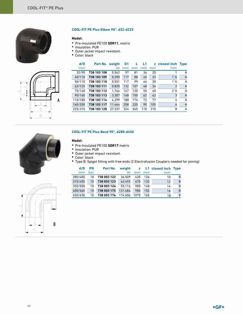
COOL-FIT® PE Plus
62
COOL-FIT PE Plus Elbow 90°, d32-d225
Model:• Pre-insulated PE100 SDR11, metric• Insulation: PUR• Outer jacket impact resistant.
d/D(mm)
Part No. weight(lb)
D1(mm)
L(mm)
L1(mm)
z(mm)
Typeclosest inch(inch)
32/90 738 103 108 0.562 97 81 36 20 A1
40/110 738 103 109 0.390 117 88 40 23 A1 1∕4
50/110 738 103 110 0.551 117 99 44 30 A1 1∕2
63/125 738 103 111 0.820 132 107 48 34 A2
75/140 738 103 112 1.764 147 120 55 40 A2 1∕2
90/160 738 103 113 3.307 168 150 62 63 A3
110/180 738 103 114 4.299 188 174 72 77 A4
160/250 738 103 117 11.464 258 220 90 105 A6
225/315 738 103 120 27.337 324 345 110 210 A8
COOL-FIT PE Plus Bend 90°, d280-d450
Model:• Pre-Insulated PE100 SDR17 metric• Insulation: PUR• Outer jacket impact resistant. •
d/D(mm)
PN(bar)
Part No. weight(lb)
z(mm)
L1(mm)
Typeclosest inch(inch)
280/400 10 738 003 122 36.509 430 126 B10315/450 10 738 003 123 63.493 470 133 B12355/500 10 738 003 124 55.116 900 148 B14400/560 10 738 003 175 131.484 980 150 B16450/630 10 738 003 176 174.606 1070 165 B
• Type B: Spigot fitting with free ends (2 Electrofusion Couplers needed for joining)
• Color: black
• Color: black
18
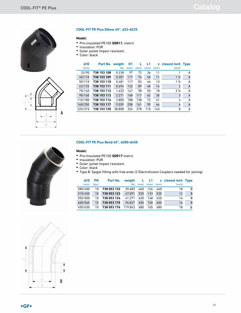
COOL-FIT® PE Plus Catalog
63
COOL-FIT PE Plus Elbow 45°, d32-d225
Model:• Pre-insulated PE100 SDR11, metric• Insulation: PUR• Outer jacket impact resistant.
d/D(mm)
Part No. weight(lb)
D1(mm)
L(mm)
L1(mm)
z(mm)
closest inch(inch)
Type
32/90 738 153 108 0.238 97 72 36 11 1 A40/110 738 153 109 0.357 117 76 40 11 1 1∕4 A50/110 738 153 110 0.481 117 82 44 13 1 1∕2 A63/125 738 153 111 0.694 132 89 48 16 2 A75/140 738 153 112 1.433 147 98 55 18 2 1∕2 A90/160 738 153 113 2.271 168 117 62 30 3 A
110/180 738 153 114 2.800 188 138 72 41 4 A160/250 738 153 117 9.039 258 161 90 46 6 A225/315 738 153 120 38.808 324 278 110 143 8 A
COOL-FIT PE Plus Bend 45°, d280-d450
Model:• Pre-Insulated PE100 SDR17 metric• Insulation: PUR• Outer jacket impact resistant.•
d/D(mm)
PN(bar)
Part No. weight(lb)
L(mm)
L1(mm)
z(mm)
closest inch(inch)
Type
280/400 10 738 053 122 39.683 460 126 460 10 B315/450 10 738 053 123 47.091 535 133 535 12 B355/500 10 738 053 124 41.271 620 148 620 14 B400/560 10 738 053 175 96.827 650 150 650 16 B450/630 10 738 053 176 119.843 680 165 680 18 B
• Type B: Spigot fitting with free ends (2 Electrofusion Couplers needed for joining)
• Color: black
• Color: black
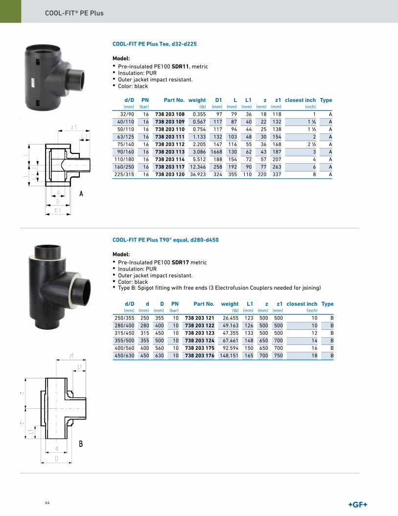
COOL-FIT® PE Plus
64
COOL-FIT PE Plus Tee, d32-d225
Model:• Pre-insulated PE100 SDR11, metric• Insulation: PUR• Outer jacket impact resistant.
d/D(mm)
PN(bar)
Part No. weight(lb)
D1(mm)
L(mm)
L1(mm)
z(mm)
z1(mm)
closest inch(inch)
Type
32/90 16 738 203 108 0.355 97 79 36 18 118 1 A40/110 16 738 203 109 0.567 117 87 40 22 132 1 1∕4 A50/110 16 738 203 110 0.754 117 94 44 25 138 1 1∕2 A63/125 16 738 203 111 1.133 132 103 48 30 154 2 A75/140 16 738 203 112 2.205 147 116 55 36 168 2 1∕2 A90/160 16 738 203 113 3.086 1668 130 62 43 187 3 A
110/180 16 738 203 114 5.512 188 154 72 57 207 4 A160/250 16 738 203 117 12.346 258 192 90 77 263 6 A225/315 16 738 203 120 36.923 324 355 110 220 337 8 A
COOL-FIT PE Plus T90° equal, d280-d450
Model:• Pre-Insulated PE100 SDR17 metric• Insulation: PUR• Outer jacket impact resistant. • • Type B: Spigot fitting with free ends (3 Electrofusion Couplers needed for joining)
• Color: black
• Color: black
d/D(mm)
d(mm)
D(mm)
PN(bar)
Part No. weight(lb)
L1(mm)
z(mm)
z1(mm)
closest inch(inch)
Type
250/355 250 355 10 738 203 121 26.455 123 500 500 10 B280/400 280 400 10 738 203 122 49.163 126 500 500 10 B315/450 315 450 10 738 203 123 47.355 133 500 500 12 B355/500 355 500 10 738 203 124 67.461 148 650 700 14 B400/560 400 560 10 738 203 175 92.594 150 650 700 16 B450/630 450 630 10 738 203 176 148.151 165 700 750 18 B

COOL-FIT® PE Plus Catalog
65
COOL-FIT PE Plus T90° reduced, d32-d225
Model:• Pre-insulated PE100 SDR11, metric• Insulation: PUR• Outer jacket impact resistant.
d/D(mm)
d1/D1(mm)
PN(bar)
Part No. weight(lb)
75/140 63/125 16 738 203 218 1.90390/160 63/125 16 738 203 222 2.71690/160 75/140 16 738 203 223 2.851
110/180 63/125 16 738 203 227 4.348110/180 75/140 16 738 203 228 4.297110/180 90/160 16 738 203 229 4.491160/250 63/125 16 738 203 247 11.354160/250 90/160 16 738 203 249 11.347160/250 110/180 16 738 203 250 11.508225/315 63/125 16 738 203 264 37.108225/315 90/160 16 738 203 266 37.234225/315 110/180 16 738 203 267 37.049225/315 160/250 16 738 203 269 40.786
d/D(mm)
d1/D1(mm)
D2(mm)
L(mm)
L1(mm)
L2(mm)
z(mm)
z1(mm)
closest inch(inch)
Type
75/140 63/125 147 116 55 48 36 228 2 1∕2 A90/160 63/125 168 130 62 48 43 253 3 - 2 A90/160 75/140 168 130 62 55 43 252 3 - 2 1∕2 A
110/180 63/125 188 154 72 48 57 267 4 - 2 A110/180 75/140 188 154 72 55 57 268 4 - 2 1∕2 A110/180 90/160 188 154 72 62 57 268 4 - 3 A160/250 63/125 258 192 90 48 77 327 6 - 2 A160/250 90/160 258 192 90 62 77 327 6 - 3 A160/250 110/180 258 192 90 72 77 325 6 - 5 A225/315 63/125 324 355 110 48 220 412 8 - 2 A225/315 90/160 324 355 110 62 220 412 8 - 3 A225/315 110/180 324 355 110 72 220 412 8 - 4 A225/315 160/250 324 355 110 90 220 396 8 - 6 A
B•
• Color: black
- 2

COOL-FIT® PE Plus
66
COOL-FIT PE Plus Reducer, d32-d225
Model:• Pre-insulated PE100 SDR11, metric• Insulation: PUR• Outer jacket impact resistant. •
d/D(mm)
d1/D1(mm)
PN(bar)
Part No. weight(lb)
D2(mm)
L(mm)
L1(mm)
L2(mm)
z(mm)
closest inch(inch)
Type
40/110 32/90 16 738 903 206 0.551 117 143 40 36 17 1 1∕4 - 1 A50/110 32/90 16 738 903 209 0.617 117 151 44 36 21 1 1∕2 - 1 A50/110 40/110 16 738 903 210 0.705 117 149 44 40 15 1 1∕2 - 1 1∕4 A63/125 32/90 16 738 903 212 0.478 132 160 48 36 26 2 - 1 A63/125 40/110 16 738 903 213 0.511 132 159 48 40 21 2 - 1 1∕4 A63/125 50/110 16 738 903 214 0.536 132 159 48 44 17 2 - 1 1∕2 A75/140 63/125 16 738 903 318 0.582 55 48 170 2 1∕2 - 2 B90/160 63/125 16 738 903 322 0.853 62 48 190 3 - 2 B90/160 75/140 16 738 903 323 0.917 62 55 189 3 - 2 1∕2 B
110/180 63/125 16 738 903 327 1.248 72 48 204 4 - 2 B110/180 75/140 16 738 903 328 1.272 72 55 205 4 - 2 1∕2 B110/180 90/160 16 738 903 329 1.420 72 62 205 4 - 3 B160/250 63/125 16 738 903 347 2.862 90 48 244 6 - 2 B160/250 90/160 16 738 903 349 2.917 90 62 244 6 - 3 B160/250 110/180 16 738 903 350 3.003 90 72 242 6 - 4 B225/315 63/125 16 738 903 364 6.526 110 48 295 8 - 2 B225/315 90/160 16 738 903 366 6.654 110 62 295 8 - 3 B225/315 110/180 16 738 903 367 6.788 110 72 295 8 - 4 B225/315 160/250 16 738 903 369 7.826 110 90 279 8 - 6 B
COOL-FIT PE Plus Reducer, d280-d450
Model:• Pre-Insulated PE100 SDR17 metric• Insulation: PUR• Outer jacket impact resistant. •
d(mm)
D(mm)
PN Part No. weight(lb)
d1(mm)
L(mm)
L1(mm)
z(mm)
Type
280 400 PN 10 738 903 899 10.362 225 126 110 335 B315 450 PN 10 738 903 807 15.653 225 133 110 365 B315 450 PN 10 738 903 806 14.991 280 133 126 365 B355 500 PN 10 738 903 809 16.976 280 145 126 390 B355 500 PN 10 738 903 810 18.298 315 145 133 390 B400 560 PN 10 738 903 871 20.062 280 147 126 415 B400 560 PN 10 738 903 872 25.133 315 147 133 415 B400 560 PN 10 738 903 873 24.251 355 147 145 420 B450 630 PN 10 738 903 874 29.101 280 163 126 389 B450 630 PN 10 738 903 875 29.983 315 163 133 390 B450 630 PN 10 738 903 876 30.203 355 163 145 393 B450 630 PN 10 738 903 877 32.628 400 163 147 395 B
• Type B: Spigot Fitting with free ends
• Color: black
• Type B: Spigot fitting with free ends (2 Electrofusion Couplers needed for joining)
• Color: black
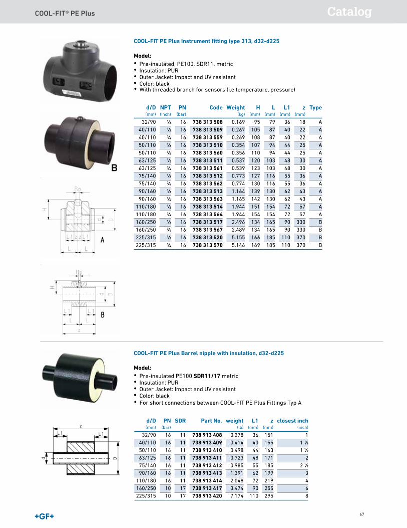
COOL-FIT® PE Plus Catalog
67
COOL-FIT PE Plus Reducer, d32-d225
Model:• Pre-insulated PE100 SDR11, metric• Insulation: PUR• Outer jacket impact resistant. •
d/D(mm)
d1/D1(mm)
PN(bar)
Part No. weight(lb)
D2(mm)
L(mm)
L1(mm)
L2(mm)
z(mm)
closest inch(inch)
Type
40/110 32/90 16 738 903 206 0.551 117 143 40 36 17 1 1∕4 - 1 A50/110 32/90 16 738 903 209 0.617 117 151 44 36 21 1 1∕2 - 1 A50/110 40/110 16 738 903 210 0.705 117 149 44 40 15 1 1∕2 - 1 1∕4 A63/125 32/90 16 738 903 212 0.478 132 160 48 36 26 2 - 1 A63/125 40/110 16 738 903 213 0.511 132 159 48 40 21 2 - 1 1∕4 A63/125 50/110 16 738 903 214 0.536 132 159 48 44 17 2 - 1 1∕2 A75/140 63/125 16 738 903 318 0.582 55 48 170 2 1∕2 - 2 B90/160 63/125 16 738 903 322 0.853 62 48 190 3 - 2 B90/160 75/140 16 738 903 323 0.917 62 55 189 3 - 2 1∕2 B
110/180 63/125 16 738 903 327 1.248 72 48 204 4 - 2 B110/180 75/140 16 738 903 328 1.272 72 55 205 4 - 2 1∕2 B110/180 90/160 16 738 903 329 1.420 72 62 205 4 - 3 B160/250 63/125 16 738 903 347 2.862 90 48 244 6 - 2 B160/250 90/160 16 738 903 349 2.917 90 62 244 6 - 3 B160/250 110/180 16 738 903 350 3.003 90 72 242 6 - 4 B225/315 63/125 16 738 903 364 6.526 110 48 295 8 - 2 B225/315 90/160 16 738 903 366 6.654 110 62 295 8 - 3 B225/315 110/180 16 738 903 367 6.788 110 72 295 8 - 4 B225/315 160/250 16 738 903 369 7.826 110 90 279 8 - 6 B
COOL-FIT PE Plus Reducer, d280-d450
Model:• Pre-Insulated PE100 SDR17 metric• Insulation: PUR• Outer jacket impact resistant. •
d(mm)
D(mm)
PN Part No. weight(lb)
d1(mm)
L(mm)
L1(mm)
z(mm)
Type
280 400 PN 10 738 903 899 10.362 225 126 110 335 B315 450 PN 10 738 903 807 15.653 225 133 110 365 B315 450 PN 10 738 903 806 14.991 280 133 126 365 B355 500 PN 10 738 903 809 16.976 280 145 126 390 B355 500 PN 10 738 903 810 18.298 315 145 133 390 B400 560 PN 10 738 903 871 20.062 280 147 126 415 B400 560 PN 10 738 903 872 25.133 315 147 133 415 B400 560 PN 10 738 903 873 24.251 355 147 145 420 B450 630 PN 10 738 903 874 29.101 280 163 126 389 B450 630 PN 10 738 903 875 29.983 315 163 133 390 B450 630 PN 10 738 903 876 30.203 355 163 145 393 B450 630 PN 10 738 903 877 32.628 400 163 147 395 B
• Type B: Spigot Fitting with free ends
• Color: black
• Type B: Spigot fitting with free ends (2 Electrofusion Couplers needed for joining)
• Color: black
COOL-FIT PE Plus Instrument fitting type 313, d32-d225
Model:• Pre-insulated, PE100, SDR11, metric• Insulation: PUR• Outer Jacket: Impact and UV resistant •
d/D(mm)
Rp(inch)
PN(bar)
Part No. weight(lb)
H(mm)
L(mm)
L1(mm)
z(mm)
Type
32/90 1∕2 16 738 313 608 0.373 95 79 36 18 A40/110 1∕2 16 738 313 609 0.589 105 87 40 22 A40/110 3∕4 16 738 313 659 0.593 108 87 40 22 A50/110 1∕2 16 738 313 610 0.780 107 94 44 25 A50/110 3∕4 16 738 313 660 0.785 110 94 44 25 A63/125 1∕2 16 738 313 611 1.184 120 103 48 30 A63/125 3∕4 16 738 313 661 1.188 123 103 48 30 A75/140 1∕2 16 738 313 612 1.704 127 116 55 36 A75/140 3∕4 16 738 313 662 1.706 130 116 55 36 A90/160 1∕2 16 738 313 613 2.566 139 130 62 43 A90/160 3∕4 16 738 313 663 2.568 142 130 62 43 A
110/180 1∕2 16 738 313 614 4.286 151 154 72 57 A110/180 3∕4 16 738 313 664 4.286 154 154 72 57 A160/250 1∕2 16 738 313 617 5.503 134 165 90 330 B160/250 3∕4 16 738 313 667 5.487 134 165 90 330 B225/315 1∕2 16 738 313 620 11.365 166 185 110 370 B225/315 3∕4 16 738 313 670 11.345 169 185 110 370 B
COOL-FIT PE Plus Barrel nipple with insulation, d32-d225
Model:• Pre-insulated PE100 SDR11/17 metric• Insulation: PUR• Outer Jacket: Impact and UV resistant•
d/D(mm)
PN(bar)
SDR Part No. weight(lb)
L1(mm)
z(mm)
closest inch(inch)
32/90 16 11 738 913 408 0.278 36 151 140/110 16 11 738 913 409 0.414 40 155 1 1∕450/110 16 11 738 913 410 0.498 44 163 1 1∕263/125 16 11 738 913 411 0.723 48 171 275/140 16 11 738 913 412 0.985 55 185 2 1∕290/160 16 11 738 913 413 1.391 62 199 3
110/180 16 11 738 913 414 2.048 72 219 4160/250 10 17 738 913 417 3.474 90 255 6225/315 10 17 738 913 420 7.174 110 295 8
• With threaded branch for sensors (i.e temperature, pressure)
• Color: black
• For short connections between COOL-FIT PE Plus Fittings Typ A
• Color: black
Data sheetvalid from: 10/22/19
Page 1 of 1
COOL-FIT 4.0 Installation fitting type 313, d32-d225 ANSI
Model:• Pre-insulated PE100 SDR11 ANSI• Insulation made from GF HE foam• Impact resistant. Color: black• With threaded branch for sensors (i.e temperature, pressure)• A: Electrofusion Fitting with integrated sealing lip, for a water and vapour tight sealing• B: Spigot Fitting with free end
d/D(mm)
NPT(inch)
PN(bar)
Code Weight(kg)
H(mm)
L(mm)
L1(mm)
z(mm)
Type
32/90 1∕2 16 738 313 508 0.169 95 79 36 18 A40/110 1∕2 16 738 313 509 0.267 105 87 40 22 A40/110 3∕4 16 738 313 559 0.269 108 87 40 22 A50/110 1∕2 16 738 313 510 0.354 107 94 44 25 A50/110 3∕4 16 738 313 560 0.356 110 94 44 25 A63/125 1∕2 16 738 313 511 0.537 120 103 48 30 A63/125 3∕4 16 738 313 561 0.539 123 103 48 30 A75/140 1∕2 16 738 313 512 0.773 127 116 55 36 A75/140 3∕4 16 738 313 562 0.774 130 116 55 36 A90/160 1∕2 16 738 313 513 1.164 139 130 62 43 A90/160 3∕4 16 738 313 563 1.165 142 130 62 43 A
110/180 1∕2 16 738 313 514 1.944 151 154 72 57 A110/180 3∕4 16 738 313 564 1.944 154 154 72 57 A160/250 1∕2 16 738 313 517 2.496 134 165 90 330 B160/250 3∕4 16 738 313 567 2.489 134 165 90 330 B225/315 1∕2 16 738 313 520 5.155 166 185 110 370 B225/315 3∕4 16 738 313 570 5.146 169 185 110 370 B
The technical data are not binding. They neither constitute expressly warranted characteristics nor guaranteed properties nor a guar-
anteed durability. They are subject to modification. Our General Terms of Sale apply.
Georg Fischer Piping Systems Ltd, Postfach, CH-8201 Schaffhausen/Switzerland
Phone +41 -(0)52-631 1111
e-mail: [email protected]
Internet: http://www.gfps.com
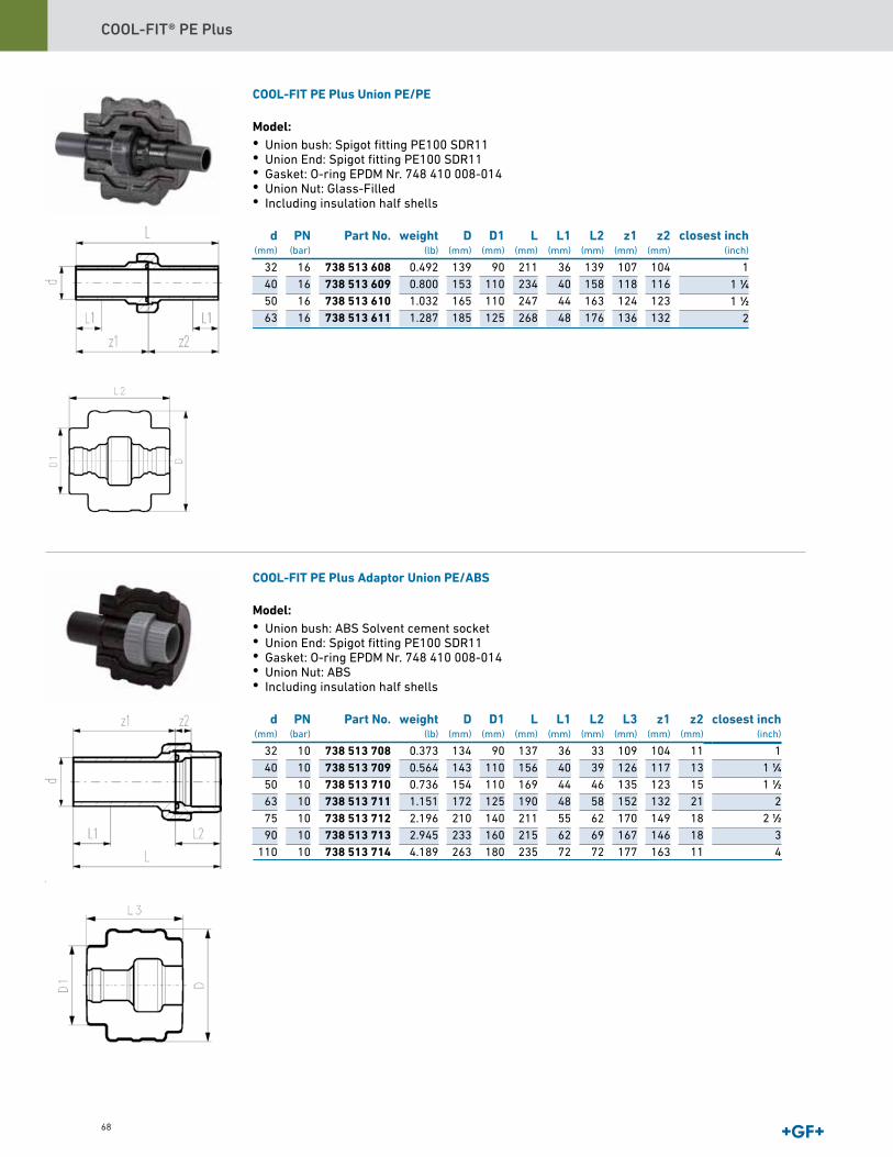
COOL-FIT® PE Plus
68
COOL-FIT PE Plus Union PE/PE
Model:• Union bush: Spigot fitting PE100 SDR11• Union End: Spigot fitting PE100 SDR11• Gasket: O-ring EPDM Nr. 748 410 008-014• Union Nut: Glass-Filled• Including insulation half shells
d(mm)
PN(bar)
Part No. weight(lb)
D(mm)
D1(mm)
L(mm)
L1(mm)
L2(mm)
z1(mm)
z2(mm)
32 16 738 513 608 0.492 139 90 211 36 139 107 10440 16 738 513 609 0.800 153 110 234 40 158 118 11650 16 738 513 610 1.032 165 110 247 44 163 124 12363 16 738 513 611 1.287 185 125 268 48 176 136 132
COOL-FIT PE Plus Adaptor Union PE/ABS
Model:• Union bush: ABS Solvent cement socket• Union End: Spigot fitting PE100 SDR11• Gasket: O-ring EPDM Nr. 748 410 008-014• Union Nut: ABS• Including insulation half shells
d(mm)
PN(bar)
Part No. weight(lb)
D(mm)
D1(mm)
L(mm)
L1(mm)
L2(mm)
L3(mm)
z1(mm)
z2(mm)
32 10 738 513 708 0.373 134 90 137 36 33 109 104 1140 10 738 513 709 0.564 143 110 156 40 39 126 117 1350 10 738 513 710 0.736 154 110 169 44 46 135 123 1563 10 738 513 711 1.151 172 125 190 48 58 152 132 2175 10 738 513 712 2.196 210 140 211 55 62 170 149 1890 10 738 513 713 2.945 233 160 215 62 69 167 146 18
110 10 738 513 714 4.189 263 180 235 72 72 177 163 11
closest inch(inch)
11 1∕41 1∕2
2
closest inch(inch)
11 1∕41 1∕2
22 1∕2
34
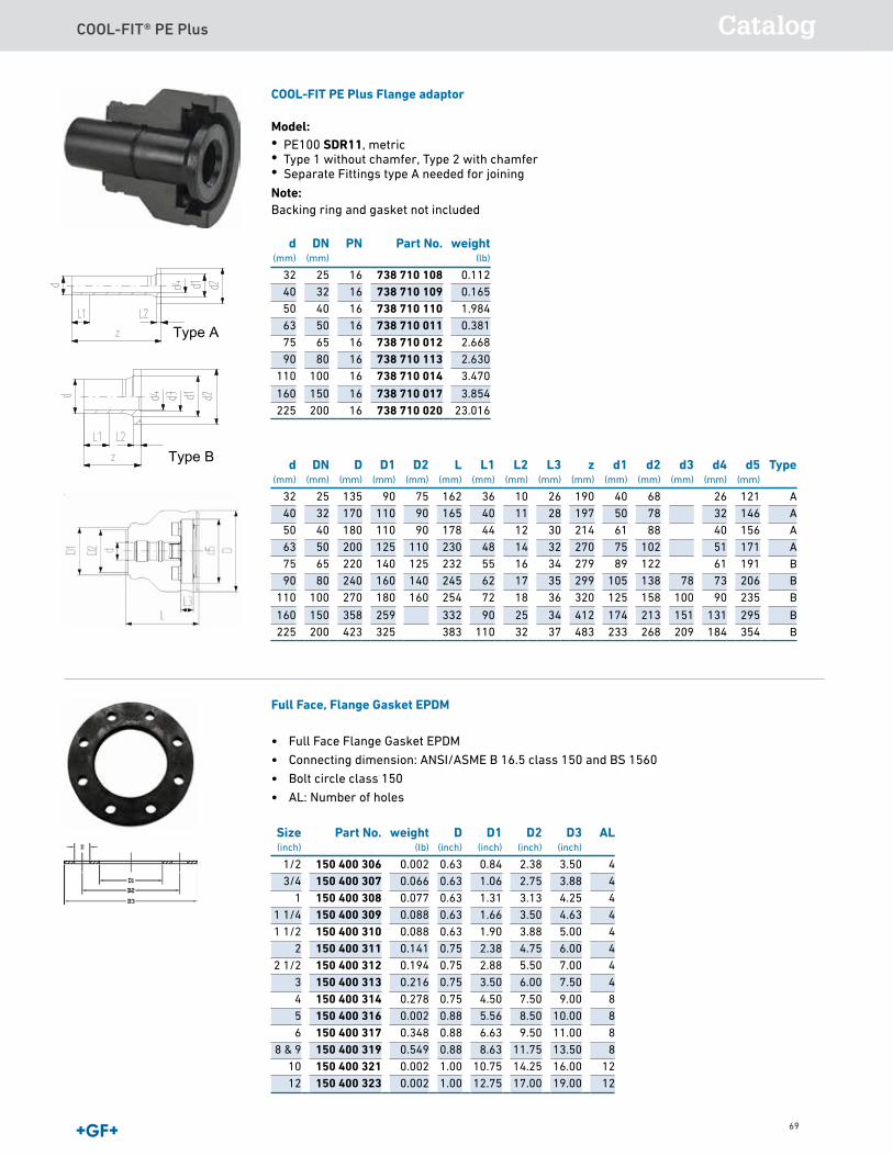
COOL-FIT® PE Plus Catalog
69
COOL-FIT PE Plus Flange adaptor
Model:• PE100 SDR11, metric• Type 1 without chamfer, Type 2 with chamfer• Separate Fittings type A needed for joining Note:Backing ring and gasket not included
d(mm)
DN(mm)
PN Part No. weight(lb)
32 25 16 738 710 108 0.11240 32 16 738 710 109 0.16550 40 16 738 710 110 1.98463 50 16 738 710 011 0.38175 65 16 738 710 012 2.66890 80 16 738 710 113 2.630
110 100 16 738 710 014 3.470
160 150 16 738 710 017 3.854225 200 16 738 710 020 23.016
d(mm)
DN(mm)
D(mm)
D1(mm)
D2(mm)
L(mm)
L1(mm)
L2(mm)
L3(mm)
z(mm)
d1(mm)
d2(mm)
d3(mm)
d4(mm)
d5(mm)
Type
32 25 135 90 75 162 36 10 26 190 40 68 26 12140 32 170 110 90 165 40 11 28 197 50 78 32 14650 40 180 110 90 178 44 12 30 214 61 88 40 15663 50 200 125 110 230 48 14 32 270 75 102 51 17175 65 220 140 125 232 55 16 34 279 89 122 61 19190 80 240 160 140 245 62 17 35 299 105 138 78 73 206
110 100 270 180 160 254 72 18 36 320 125 158 100 90 235
160 150 358 259 332 90 25 34 412 174 213 151 131 295225 200 423 325 383 110 32 37 483 233 268 209 184 354
Full Face, Flange Gasket EPDM
• Full Face Flange Gasket EPDM
• Connecting dimension: ANSI/ASME B 16.5 class 150 and BS 1560
• Bolt circle class 150
• AL: Number of holes
Size(inch)
Part No. weight(lb)
D(inch)
D1(inch)
D2(inch)
D3(inch)
AL
1/2 150 400 306 0.002 0.63 0.84 2.38 3.50 43/4 150 400 307 0.066 0.63 1.06 2.75 3.88 4
1 150 400 308 0.077 0.63 1.31 3.13 4.25 41 1/4 150 400 309 0.088 0.63 1.66 3.50 4.63 41 1/2 150 400 310 0.088 0.63 1.90 3.88 5.00 4
2 150 400 311 0.141 0.75 2.38 4.75 6.00 42 1/2 150 400 312 0.194 0.75 2.88 5.50 7.00 4
3 150 400 313 0.216 0.75 3.50 6.00 7.50 44 150 400 314 0.278 0.75 4.50 7.50 9.00 85 150 400 316 0.002 0.88 5.56 8.50 10.00 86 150 400 317 0.348 0.88 6.63 9.50 11.00 8
8 & 9 150 400 319 0.549 0.88 8.63 11.75 13.50 810 150 400 321 0.002 1.00 10.75 14.25 16.00 1212 150 400 323 0.002 1.00 12.75 17.00 19.00 12
Type A
Type B
AAAABBB
BB
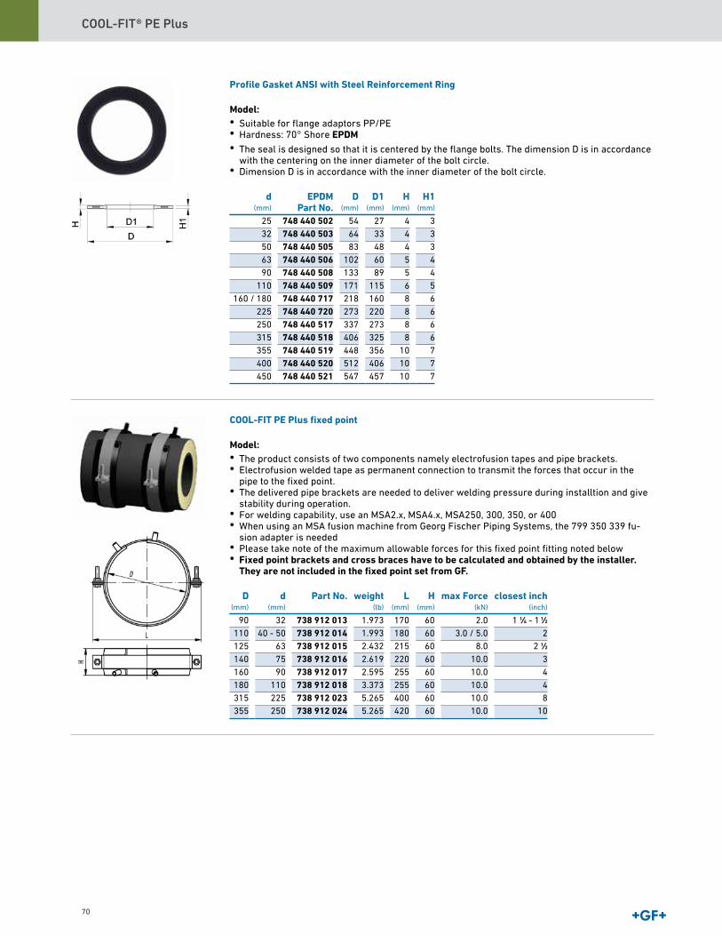
COOL-FIT® PE Plus
70
Profile Gasket ANSI with Steel Reinforcement Ring
Model:• Suitable for flange adaptors PP/PE• Hardness: 70° Shore EPDM • The seal is designed so that it is centered by the flange bolts. The dimension D is in accordance
with the centering on the inner diameter of the bolt circle.• Dimension D is in accordance with the inner diameter of the bolt circle.
d(mm)
EPDMPart No.
D(mm)
D1(mm)
H(mm)
H1(mm)
25 748 440 502 54 27 4 332 748 440 503 64 33 4 350 748 440 505 83 48 4 363 748 440 506 102 60 5 490 748 440 508 133 89 5 4
110 748 440 509 171 115 6 5160 / 180 748 440 717 218 160 8 6
225 748 440 720 273 220 8 6250 748 440 517 337 273 8 6315 748 440 518 406 325 8 6355 748 440 519 448 356 10 7400 748 440 520 512 406 10 7450 748 440 521 547 457 10 7
COOL-FIT PE Plus fixed point
Model:• The product consists of two components namely electrofusion tapes and pipe brackets.• Electrofusion welded tape as permanent connection to transmit the forces that occur in the
pipe to the fixed point.• The delivered pipe brackets are needed to deliver welding pressure during installtion and give
stability during operation.• For welding capability, use an MSA2.x, MSA4.x, MSA250, 300, 350, or 400• When using an MSA fusion machine from Georg Fischer Piping Systems, the 799 350 339 fu-
sion adapter is needed• Please take note of the maximum allowable forces for this fixed point fitting noted below• Fixed point brackets and cross braces have to be calculated and obtained by the installer.
They are not included in the fixed point set from GF. D
(mm)d
(mm)Part No. weight
(lb)L
(mm)H
(mm)max Force
(kN)closest inch
(inch)
90 32 738 912 013 1.973 170 60 2.0 1 1∕4 - 1 1∕2110 40 - 50 738 912 014 1.993 180 60 3.0 / 5.0 2125 63 738 912 015 2.432 215 60 8.0 2 1∕2140 75 738 912 016 2.619 220 60 10.0 3160 90 738 912 017 2.595 255 60 10.0 4180 110 738 912 018 3.373 255 60 10.0 4315 225 738 912 023 5.265 400 60 10.0 8355 250 738 912 024 5.265 420 60 10.0 10
COOL-FIT PE Plus Accessories
COOL-FIT PE Plus Assembly Aid-Kit
Model:• For mounting of COOL-FIT PE Plus Fitting on COOL-FIT PE Plus Pipe
d(mm)
D(mm)
Part No. weight(lb)
pieces/kit
32 - 225 90 - 315 799 738 501 12.346 2 / Dimension32 90 799 738 511 0.847 6
40 - 50 110 799 738 512 1.005 663 125 799 738 513 1.111 675 140 799 738 514 1.243 690 160 799 738 515 1.402 6
110 180 799 738 516 1.561 6160 250 799 738 519 1.367 4225 315 799 738 522 1.676 4
COOL-FIT PE Plus Insulation for welding indicator-kit
Model:• Type A suitable for COOL-FIT PE Plus Fittings d32-d110• Type B suitable for COOL-FIT PE Plus Fittings d160 and coupler d225• Type C suitable for COOL-FIT PE Plus Fittings d225 except coupler
d(mm)
Part No. weight(lb)
Type pieces/kit
32 - 110 738 010 052 0.198 A 20160 - 225 738 010 053 0.441 B 10
225 738 010 054 0.073 C 10
COOL-FIT PE Plus adhesive ring
Model:• Double sided, for sealing compact connections between fittings, where sealing lip has been re-
moved d
(mm)D
(mm)Part No. weight
(lb)
32 90 738 010 013 0.00440, 50 110 738 010 014 0.007
63 125 738 010 015 0.00775 140 738 010 016 0.00790 160 738 010 017 0.011
110 180 738 010 018 0.011160 250 738 010 021 0.020225 315 738 010 023 0.060
• Optional: Each fitting comes with the necessary insulation plugs
• Optional: Each fitting comes with the necessary insulation plugs
COOL-FIT PE Plus Sealing tape
Model:• 30m on a roll, 25mm width, buthylene rubber-based
d(mm)
D(mm)
Part No. weight(lb)
32 - 225 90 - 315 738 013 031 3.086
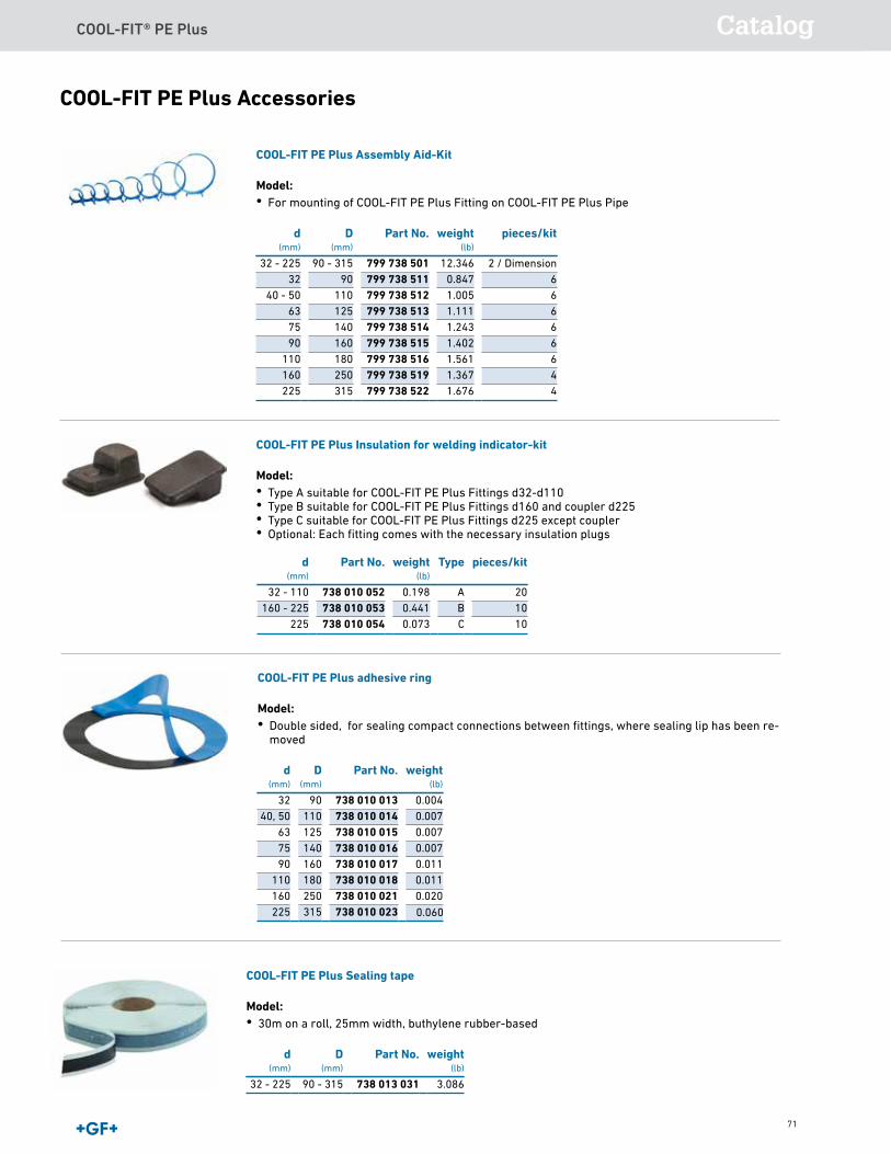
COOL-FIT® PE Plus Catalog
71
COOL-FIT PE Plus Accessories
COOL-FIT PE Plus Assembly Aid-Kit
Model:• For mounting of COOL-FIT PE Plus Fitting on COOL-FIT PE Plus Pipe
d(mm)
D(mm)
Part No. weight(lb)
pieces/kit
32 - 225 90 - 315 799 738 501 12.346 2 / Dimension32 90 799 738 511 0.847 6
40 - 50 110 799 738 512 1.005 663 125 799 738 513 1.111 675 140 799 738 514 1.243 690 160 799 738 515 1.402 6
110 180 799 738 516 1.561 6160 250 799 738 519 1.367 4225 315 799 738 522 1.676 4
COOL-FIT PE Plus Insulation for welding indicator-kit
Model:• Type A suitable for COOL-FIT PE Plus Fittings d32-d110• Type B suitable for COOL-FIT PE Plus Fittings d160 and coupler d225• Type C suitable for COOL-FIT PE Plus Fittings d225 except coupler
d(mm)
Part No. weight(lb)
Type pieces/kit
32 - 110 738 010 052 0.198 A 20160 - 225 738 010 053 0.441 B 10
225 738 010 054 0.073 C 10
COOL-FIT PE Plus adhesive ring
Model:• Double sided, for sealing compact connections between fittings, where sealing lip has been re-
moved d
(mm)D
(mm)Part No. weight
(lb)
32 90 738 010 013 0.00440, 50 110 738 010 014 0.007
63 125 738 010 015 0.00775 140 738 010 016 0.00790 160 738 010 017 0.011
110 180 738 010 018 0.011160 250 738 010 021 0.020225 315 738 010 023 0.060
• Optional: Each fitting comes with the necessary insulation plugs
• Optional: Each fitting comes with the necessary insulation plugs
COOL-FIT PE Plus Sealing tape
Model:• 30m on a roll, 25mm width, buthylene rubber-based
d(mm)
D(mm)
Part No. weight(lb)
32 - 225 90 - 315 738 013 031 3.086
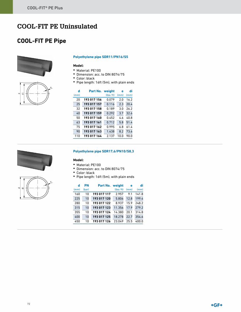
COOL-FIT® PE Plus
72
COOL-FIT PE Uninsulated
COOL-FIT PE Pipe
Polyethylene pipe SDR11/PN16/S5
Model:• Material: PE100• Dimension: acc. to DIN 8074/75• Color: black• Pipe length: 16ft (5m), with plain ends
d(mm)
Part No. weight(lbs ⁄ ft)
e(mm)
di(mm)
20 193 017 156 0.079 2.0 16.225 193 017 157 0.116 2.3 20.432 193 017 158 0.189 3.0 26.240 193 017 159 0.292 3.7 32.650 193 017 160 0.452 4.6 40.863 193 017 161 0.712 5.8 51.475 193 017 162 0.995 6.8 61.490 193 017 163 1.438 8.2 73.6
110 193 017 164 2.137 10.0 90.0
Polyethylene pipe SDR17,6/PN10/S8,3
Model:• Material: PE100• Dimension: acc. to DIN 8074/75• Color: black• Pipe length: 16ft (5m), with plain ends
d(mm)
PN(bar)
Part No. weight(lbs ⁄ ft)
e(mm)
di(mm)
160 10 193 017 117 2.957 9.1 141.8225 10 193 017 120 5.806 12.8 199.4280 10 193 017 122 8.937 15.9 248.2315 10 193 017 123 11.356 17.9 279.2355 10 193 017 124 14.380 20.1 314.8400 10 193 017 125 18.278 22.7 354.6450 10 193 017 126 23.049 25.5 400.0

COOL-FIT® PE Plus Catalog
73
COOL-FIT PE Electrofusion Fittings
CouplerWith integral pipe fixation
• PE 100 SDR 11 (ISO S5)• 4mm pin connectors• Limited path fusion indicators• Removable center stop
d(mm)
Part No. d1(mm)
L(mm)
SDR pipe
32 753 911 608 44 72 9-1140 753 911 609 54 80 9-1150 753 911 610 66 88 9-1163 753 911 611 81 96 9-17.6
Coupler
• PE 100 SDR 11 (ISO S5)• 4mm pin connectors• Limited path fusion indicators• Removable centre stop up to d160
d(mm)
Part No. weight(lb)
d1(mm)
L(mm)
SDR pipe
75 753 911 612 0.622 96 110 9-17.690 753 911 613 0.895 113 125 9-17.6
110 753 911 614 1.526 138 145 9-17.6160 753 911 617 3.003 196 180 9-17.6225 753 911 620 7.339 273 225 9-17.6280 753 911 622 16.535 340 252 9-17.6315 753 911 623 17.950 382 267 9-17.6
Elbow 90°With integral pipe fixation
• PE 100 SDR 11 (ISO S5)• 4mm pin connectors• Limited path fusion indicators
d(mm)
Part No. weight(lb)
d1(mm)
L(mm)
L1(mm)
z(mm)
SDR pipe
32 753 101 608 0.207 44 53 36 17 9-1140 753 101 609 0.282 54 62 39 23 9-1150 753 101 610 0.432 66 71 43 28 9-1163 753 101 611 0.688 81 81 48 32 9-17.6
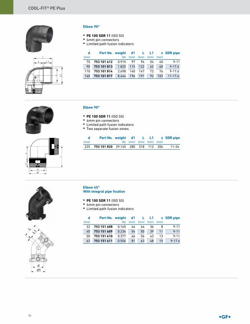
COOL-FIT® PE Plus
74
Elbow 90°
• PE 100 SDR 11 (ISO S5)• 4mm pin connectors• Limited path fusion indicators
d(mm)
Part No. weight(lb)
d1(mm)
L(mm)
L1(mm)
z(mm)
SDR pipe
75 753 101 612 0.915 97 94 54 40 9-1190 753 101 813 1.825 115 122 62 60 9-17.6
110 753 101 814 2.698 140 147 72 76 9-17.6160 753 101 817 8.444 196 191 92 103 11-17.6
Elbow 90°
• PE 100 SDR 11 (ISO S5)• 4mm pin connectors• Limited path fusion indicators• Two separate fusion zones
d(mm)
Part No. weight(lb)
d1(mm)
L(mm)
L1(mm)
z(mm)
SDR pipe
225 753 101 820 29.145 280 318 112 206 11-26
Elbow 45°With integral pipe fixation
• PE 100 SDR 11 (ISO S5)• 4mm pin connectors• Limited path fusion indicators
d(mm)
Part No. weight(lb)
d1(mm)
L(mm)
L1(mm)
z(mm)
SDR pipe
32 753 151 608 0.165 44 44 36 8 9-1140 753 151 609 0.234 54 50 39 11 9-1150 753 151 610 0.377 66 56 43 13 9-1163 753 151 611 0.556 81 63 48 15 9-17.6
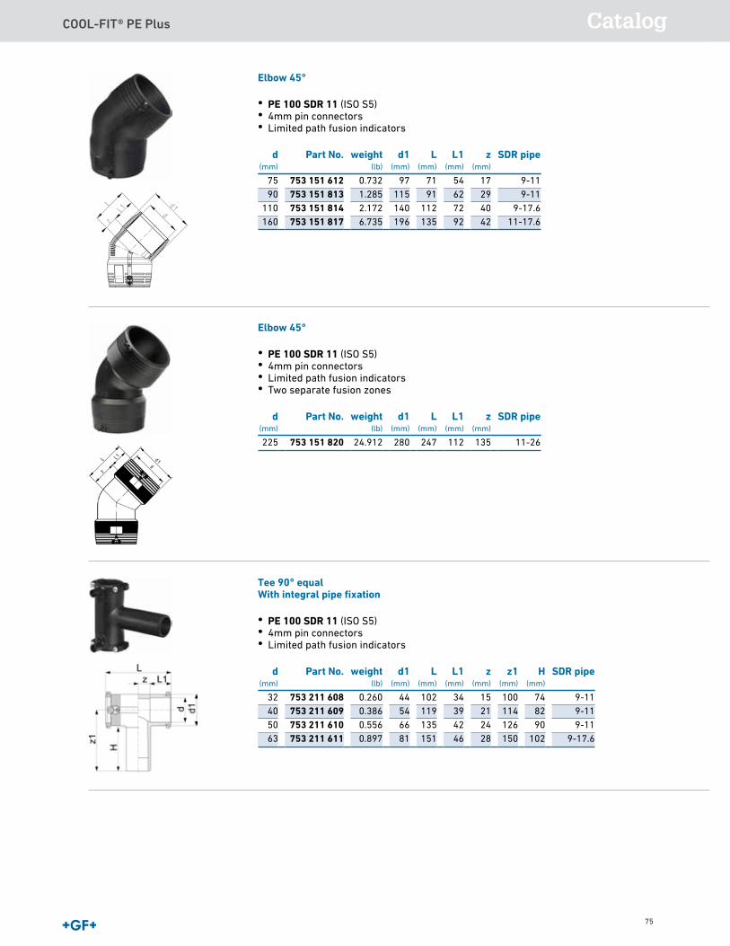
COOL-FIT® PE Plus Catalog
75
Elbow 90°
• PE 100 SDR 11 (ISO S5)• 4mm pin connectors• Limited path fusion indicators
d(mm)
Part No. weight(lb)
d1(mm)
L(mm)
L1(mm)
z(mm)
SDR pipe
75 753 101 612 0.915 97 94 54 40 9-1190 753 101 813 1.825 115 122 62 60 9-17.6
110 753 101 814 2.698 140 147 72 76 9-17.6160 753 101 817 8.444 196 191 92 103 11-17.6
Elbow 90°
• PE 100 SDR 11 (ISO S5)• 4mm pin connectors• Limited path fusion indicators• Two separate fusion zones
d(mm)
Part No. weight(lb)
d1(mm)
L(mm)
L1(mm)
z(mm)
SDR pipe
225 753 101 820 29.145 280 318 112 206 11-26
Elbow 45°With integral pipe fixation
• PE 100 SDR 11 (ISO S5)• 4mm pin connectors• Limited path fusion indicators
d(mm)
Part No. weight(lb)
d1(mm)
L(mm)
L1(mm)
z(mm)
SDR pipe
32 753 151 608 0.165 44 44 36 8 9-1140 753 151 609 0.234 54 50 39 11 9-1150 753 151 610 0.377 66 56 43 13 9-1163 753 151 611 0.556 81 63 48 15 9-17.6
Elbow 45°
• PE 100 SDR 11 (ISO S5)• 4mm pin connectors• Limited path fusion indicators
d(mm)
Part No. weight(lb)
d1(mm)
L(mm)
L1(mm)
z(mm)
SDR pipe
75 753 151 612 0.732 97 71 54 17 9-1190 753 151 813 1.285 115 91 62 29 9-11
110 753 151 814 2.172 140 112 72 40 9-17.6160 753 151 817 6.735 196 135 92 42 11-17.6
Elbow 45°
• PE 100 SDR 11 (ISO S5)• 4mm pin connectors• Limited path fusion indicators• Two separate fusion zones
d(mm)
Part No. weight(lb)
d1(mm)
L(mm)
L1(mm)
z(mm)
SDR pipe
225 753 151 820 24.912 280 247 112 135 11-26
Tee 90° equalWith integral pipe fixation
• PE 100 SDR 11 (ISO S5)• 4mm pin connectors• Limited path fusion indicators
d(mm)
Part No. weight(lb)
d1(mm)
L(mm)
L1(mm)
z(mm)
z1(mm)
H(mm)
SDR pipe
32 753 211 608 0.260 44 102 34 15 100 74 9-1140 753 211 609 0.386 54 119 39 21 114 82 9-1150 753 211 610 0.556 66 135 42 24 126 90 9-1163 753 211 611 0.897 81 151 46 28 150 102 9-17.6
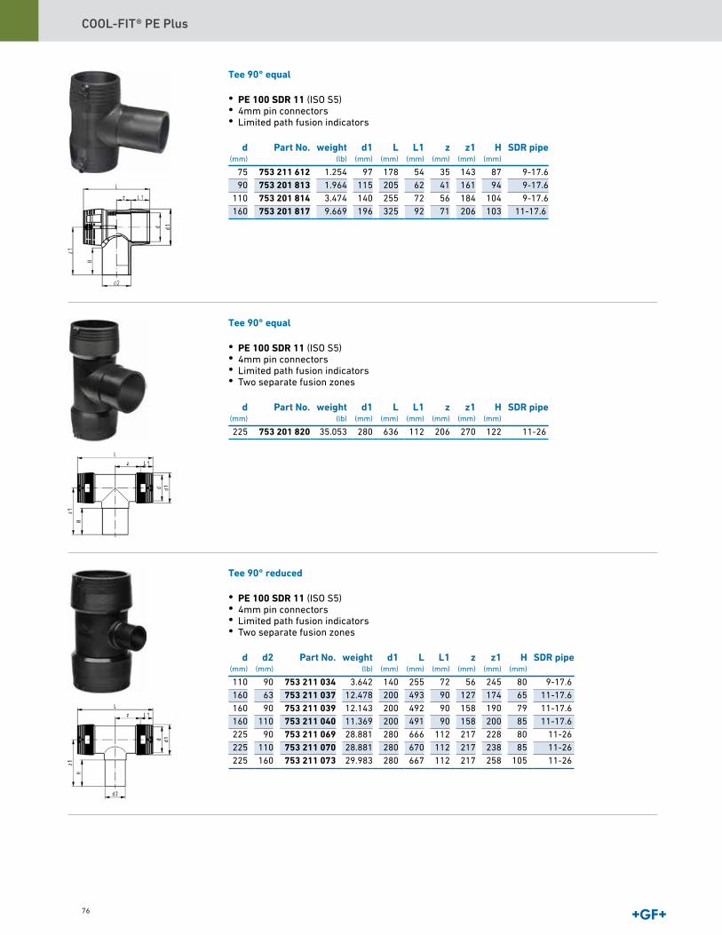
COOL-FIT® PE Plus
76
Tee 90° equal
• PE 100 SDR 11 (ISO S5)• 4mm pin connectors• Limited path fusion indicators
d(mm)
Part No. weight(lb)
d1(mm)
L(mm)
L1(mm)
z(mm)
z1(mm)
H(mm)
SDR pipe
75 753 211 612 1.254 97 178 54 35 143 87 9-17.690 753 201 813 1.964 115 205 62 41 161 94 9-17.6
110 753 201 814 3.474 140 255 72 56 184 104 9-17.6160 753 201 817 9.669 196 325 92 71 206 103 11-17.6
Tee 90° equal
• PE 100 SDR 11 (ISO S5)• 4mm pin connectors• Limited path fusion indicators• Two separate fusion zones
d(mm)
Part No. weight(lb)
d1(mm)
L(mm)
L1(mm)
z(mm)
z1(mm)
H(mm)
SDR pipe
225 753 201 820 35.053 280 636 112 206 270 122 11-26
Tee 90° reduced
• PE 100 SDR 11 (ISO S5)• 4mm pin connectors• Limited path fusion indicators• Two separate fusion zones
d(mm)
d2(mm)
Part No. weight(lb)
d1(mm)
L(mm)
L1(mm)
z(mm)
z1(mm)
H(mm)
SDR pipe
110 90 753 211 034 3.642 140 255 72 56 245 80 9-17.6160 63 753 211 037 12.478 200 493 90 127 174 65 11-17.6160 90 753 211 039 12.143 200 492 90 158 190 79 11-17.6160 110 753 211 040 11.369 200 491 90 158 200 85 11-17.6225 90 753 211 069 28.881 280 666 112 217 228 80 11-26225 110 753 211 070 28.881 280 670 112 217 238 85 11-26225 160 753 211 073 29.983 280 667 112 217 258 105 11-26
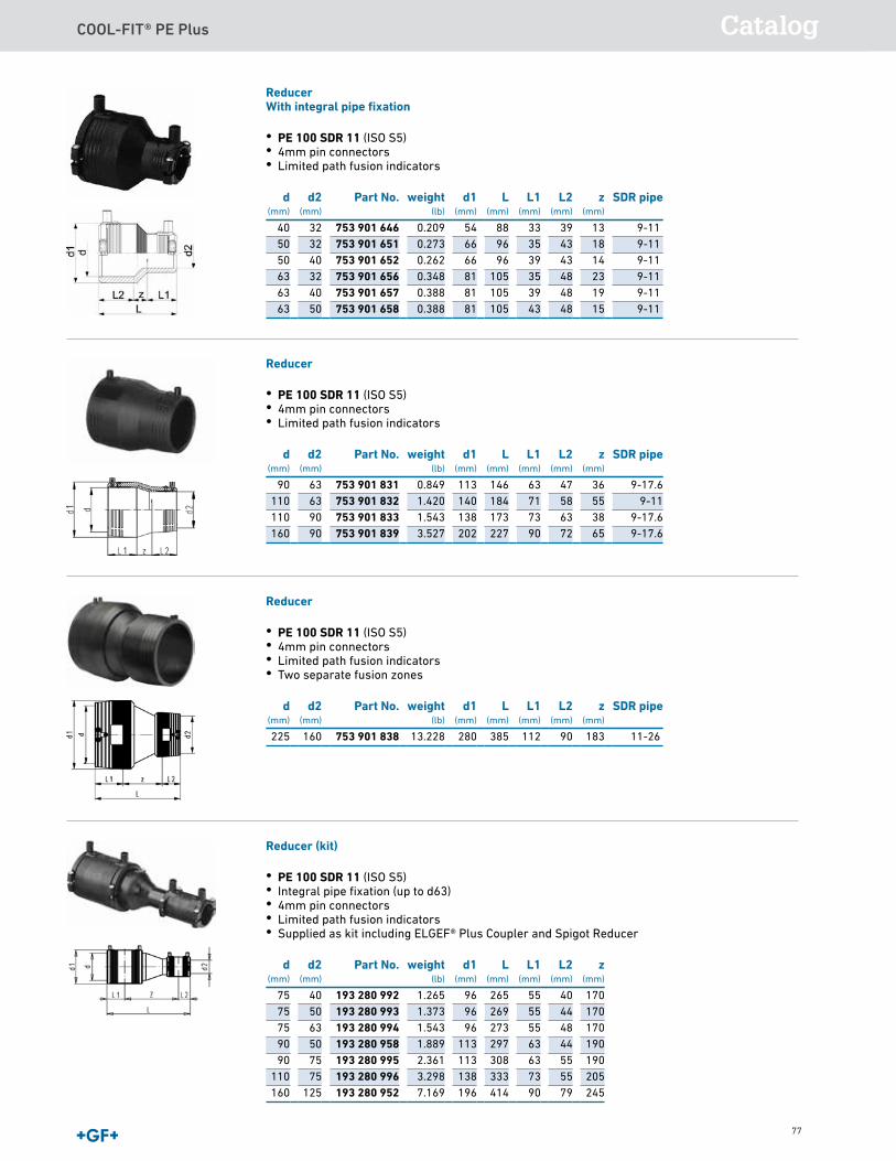
COOL-FIT® PE Plus Catalog
77
ReducerWith integral pipe fixation
• PE 100 SDR 11 (ISO S5)• 4mm pin connectors• Limited path fusion indicators
d(mm)
d2(mm)
Part No. weight(lb)
d1(mm)
L(mm)
L1(mm)
L2(mm)
z(mm)
SDR pipe
40 32 753 901 646 0.209 54 88 33 39 13 9-1150 32 753 901 651 0.273 66 96 35 43 18 9-1150 40 753 901 652 0.262 66 96 39 43 14 9-1163 32 753 901 656 0.348 81 105 35 48 23 9-1163 40 753 901 657 0.388 81 105 39 48 19 9-1163 50 753 901 658 0.388 81 105 43 48 15 9-11
Reducer
• PE 100 SDR 11 (ISO S5)• 4mm pin connectors• Limited path fusion indicators
d(mm)
d2(mm)
Part No. weight(lb)
d1(mm)
L(mm)
L1(mm)
L2(mm)
z(mm)
SDR pipe
90 63 753 901 831 0.849 113 146 63 47 36 9-17.6110 63 753 901 832 1.420 140 184 71 58 55 9-11110 90 753 901 833 1.543 138 173 73 63 38 9-17.6160 90 753 901 839 3.527 202 227 90 72 65 9-17.6
Reducer
• PE 100 SDR 11 (ISO S5)• 4mm pin connectors• Limited path fusion indicators• Two separate fusion zones
d(mm)
d2(mm)
Part No. weight(lb)
d1(mm)
L(mm)
L1(mm)
L2(mm)
z(mm)
SDR pipe
225 160 753 901 838 13.228 280 385 112 90 183 11-26
Reducer (kit)
• PE 100 SDR 11 (ISO S5)• Integral pipe fixation (up to d63)• 4mm pin connectors• Limited path fusion indicators• Supplied as kit including ELGEF® Plus Coupler and Spigot Reducer
d(mm)
d2(mm)
Part No. weight(lb)
d1(mm)
L(mm)
L1(mm)
L2(mm)
z(mm)
75 40 193 280 992 1.265 96 265 55 40 17075 50 193 280 993 1.373 96 269 55 44 17075 63 193 280 994 1.543 96 273 55 48 17090 50 193 280 958 1.889 113 297 63 44 19090 75 193 280 995 2.361 113 308 63 55 190
110 75 193 280 996 3.298 138 333 73 55 205160 125 193 280 952 7.169 196 414 90 79 245
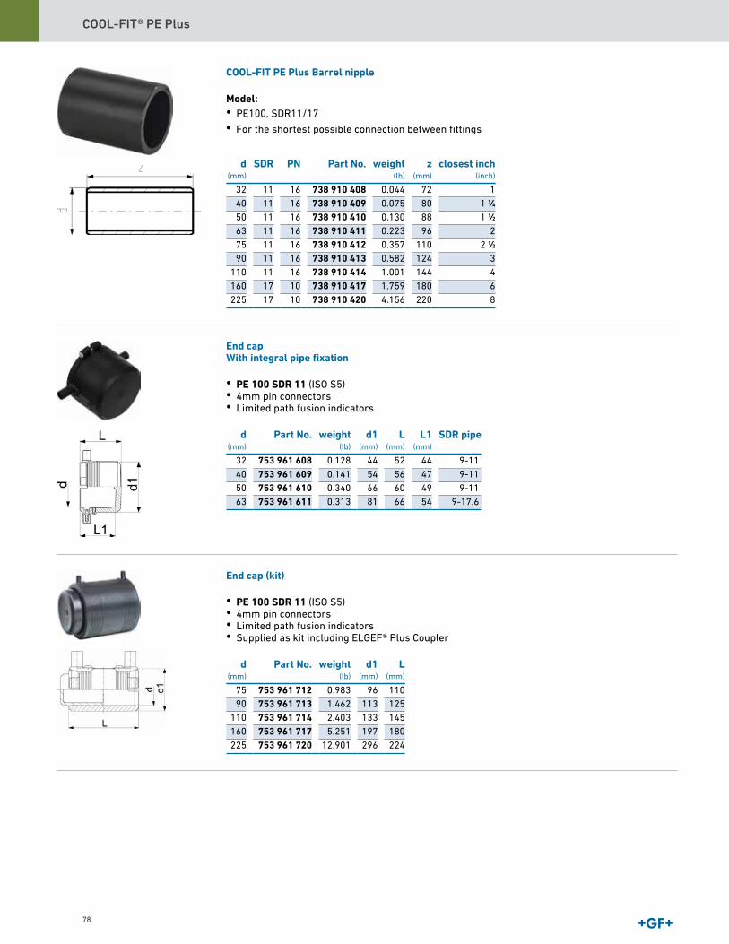
COOL-FIT® PE Plus
78
d(mm)
SDR PN Part No. weight(lb)
z(mm)
closest inch(inch)
32 11 16 738 910 408 0.044 72 140 11 16 738 910 409 0.075 80 1 1∕450 11 16 738 910 410 0.130 88 1 1∕263 11 16 738 910 411 0.223 96 275 11 16 738 910 412 0.357 110 2 1∕290 11 16 738 910 413 0.582 124 3
110 11 16 738 910 414 1.001 144 4160 17 10 738 910 417 1.759 180 6225 17 10 738 910 420 4.156 220 8
End capWith integral pipe fixation
• PE 100 SDR 11 (ISO S5)• 4mm pin connectors• Limited path fusion indicators
d(mm)
Part No. weight(lb)
d1(mm)
L(mm)
L1(mm)
SDR pipe
32 753 961 608 0.128 44 52 44 9-1140 753 961 609 0.141 54 56 47 9-1150 753 961 610 0.340 66 60 49 9-1163 753 961 611 0.313 81 66 54 9-17.6
End cap (kit)
• PE 100 SDR 11 (ISO S5)• 4mm pin connectors• Limited path fusion indicators• Supplied as kit including ELGEF® Plus Coupler
d(mm)
Part No. weight(lb)
d1(mm)
L(mm)
75 753 961 712 0.983 96 11090 753 961 713 1.462 113 125
110 753 961 714 2.403 133 145160 753 961 717 5.251 197 180225 753 961 720 12.901 296 224
COOL-FIT PE Plus Barrel nipple
Model:• PE100, SDR11/17
• For the shortest possible connection between fittings
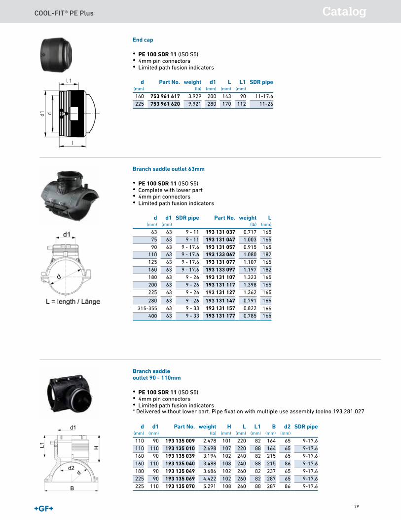
COOL-FIT® PE Plus Catalog
79
End cap
• PE 100 SDR 11 (ISO S5)• 4mm pin connectors• Limited path fusion indicators
d(mm)
Part No. weight(lb)
d1(mm)
L(mm)
L1(mm)
SDR pipe
160 753 961 617 3.929 200 143 90 11-17.6225 753 961 620 9.921 280 170 112 11-26
Branch saddle outlet 63mm
• PE 100 SDR 11 (ISO S5)• Complete with lower part• 4mm pin connectors• Limited path fusion indicators
d(mm)
d1(mm)
SDR pipe Part No. weight(lb)
L(mm)
63 63 9 - 11 193 131 037 0.717 16575 63 9 - 11 193 131 047 1.003 16590 63 9 - 17.6 193 131 057 0.915 165
110 63 9 - 17.6 193 133 067 1.080 182125 63 9 - 17.6 193 131 077 1.107 165160 63 9 - 17.6 193 133 097 1.197 182180 63 9 - 26 193 131 107 1.323 165200 63 9 - 26 193 131 117 1.398 165225 63 9 - 26 131 127 1.362 165
280 63 9 - 26 131 147 0.791 16563 9 - 33 193 131 157 0.82263 9 - 33 193 131 177 0.785
Branch saddleoutlet 90 - 110mm
• PE 100 SDR 11 (ISO S5)• 4mm pin connectors• Limited path fusion indicators* Delivered without lower part. Pipe fixation with multiple use assembly toolno.193.281.027
d(mm)
d1(mm)
Part No. weight(lb)
H(mm)
L(mm)
L1(mm)
B(mm)
d2(mm)
SDR pipe
110 90 193 135 009 2.478 101 220 82 164 65 9-17.6110 110 193 135 010 2.698 107 220 88 164 65 9-17.6160 90 193 135 039 3.194 102 240 82 215 65 9-17.6160 110 193 135 040 3.488 108 240 88 215 86 9-17.6180 90 193 135 049 3.686 102 260 82 237 65 9-17.6225 90 193 135 069 4.422 102 260 82 287 65 9-17.6225 110 193 135 070 5.291 108 260 88 287 86 9-17.6
315-355400
165165
193
193
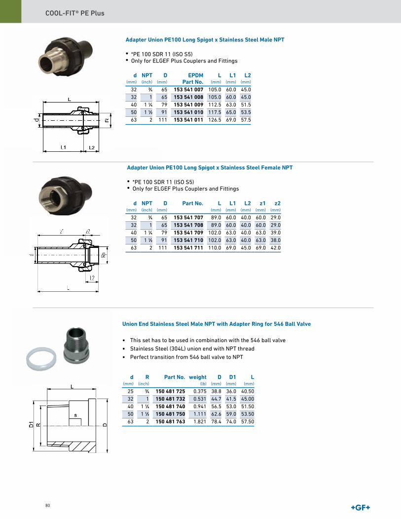
COOL-FIT® PE Plus
80
Union End Stainless Steel Male NPT with Adapter Ring for 546 Ball Valve
• This set has to be used in combination with the 546 ball valve
• Stainless Steel (304L) union end with NPT thread
• Perfect transition from 546 ball valve to NPT
d(mm)
R(inch)
Part No. weight(lb)
D(mm)
D1(mm)
L(mm)
25 3∕4 150 481 725 0.375 38.8 36.0 40.5032 1 150 481 732 0.531 44.7 41.5 45.0040 1 1∕4 150 481 740 0.941 56.5 53.0 51.5050 1 1∕2 150 481 750 1.111 62.6 59.0 53.5063 2 150 481 763 1.821 78.4 74.0 57.50
Adapter Union PE100 Long Spigot x Stainless Steel Male NPT
• *PE 100 SDR 11 (ISO S5)• Only for ELGEF Plus Couplers and Fittings
d(mm)
NPT(inch)
D(mm)
EPDMPart No.
L(mm)
L1(mm)
L2(mm)
32 3∕4 65 153 541 007 105.0 60.0 45.032 1 65 153 541 008 105.0 60.0 45.040 1 1∕4 79 153 541 009 112.5 63.0 51.550 1 1∕2 91 153 541 010 117.5 65.0 53.563 2 111 153 541 011 126.5 69.0 57.5
Adapter Union PE100 Long Spigot x Stainless Steel Female NPT
• *PE 100 SDR 11 (ISO S5)• Only for ELGEF Plus Couplers and Fittings
d(mm)
NPT(inch)
D(mm)
Part No. L(mm)
L1(mm)
L2(mm)
z1(mm)
z2(mm)
32 3∕4 65 153 541 707 89.0 60.0 40.0 60.0 29.032 1 65 153 541 708 89.0 60.0 40.0 60.0 29.040 1 1∕4 79 153 541 709 102.0 63.0 40.0 63.0 39.050 1 1∕2 91 153 541 710 102.0 63.0 40.0 63.0 38.063 2 111 153 541 711 110.0 69.0 45.0 69.0 42.0

COOL-FIT® PE Plus Catalog
81
Union End Stainless Steel Female NPT with Adapter Ring for 546 Ball Valve
• This set has to be used in combination with the 546 ball valve
• Stainless Steel (304L) union end with NPT thread
• Perfect transition from 546 ball valve to NPT
NPT(inch)
d(mm)
Part No. weight(lb)
d2(mm)
d3(mm)
d4(mm)
L(mm)
L1(mm)
L3(mm)
Refrigerationsize(inch)
3∕4 25 150 481 025 0.243 36.07 21.08 43.94 25.91 6.09 5.08 7∕81 32 150 481 032 0.320 40.89 25.91 53.09 28.97 7.87 6.09 1 1∕8
1 1∕4 40 150 481 040 0.595 52.80 32.70 56.40 30.50 6.50 5.50 1 3∕81 1∕5 50 150 481 050 0.728 58.00 40.10 62.20 34.20 7.10 5.90 1 1∕2
2 63 150 481 063 1.124 73.30 53.80 78.30 33.50 8.20 7.20 2
Transition Adaptor PE/SSMale thread NPT
• PE 100 SDR 11 (ISO S5)• Only for ELGEF Plus Couplers and Fittings
d(mm)
NPT(inch)
Part No. weight(lb)
L(mm)
z(mm)
25 3∕4 153 924 707 0.320 76 3332 1 153 924 708 0.485 80 3540 1 1∕4 153 924 709 0.849 86 3950 1 1∕2 153 924 710 1.146 90 4363 2 153 924 711 1.543 98 47
Transition Adaptor PE/SSFemale thread NPT
• PE 100 SDR 11 (ISO S5)• Only for ELGEF Plus Couplers and Fittings
d(mm)
NPT(inch)
Part No. weight(lb)
L(mm)
z(mm)
32 1 153 924 208 0.408 71 3540 1 1∕4 153 924 209 0.606 77 3950 1 1∕2 153 924 210 0.805 81 4363 2 153 924 211 1.213 89 47
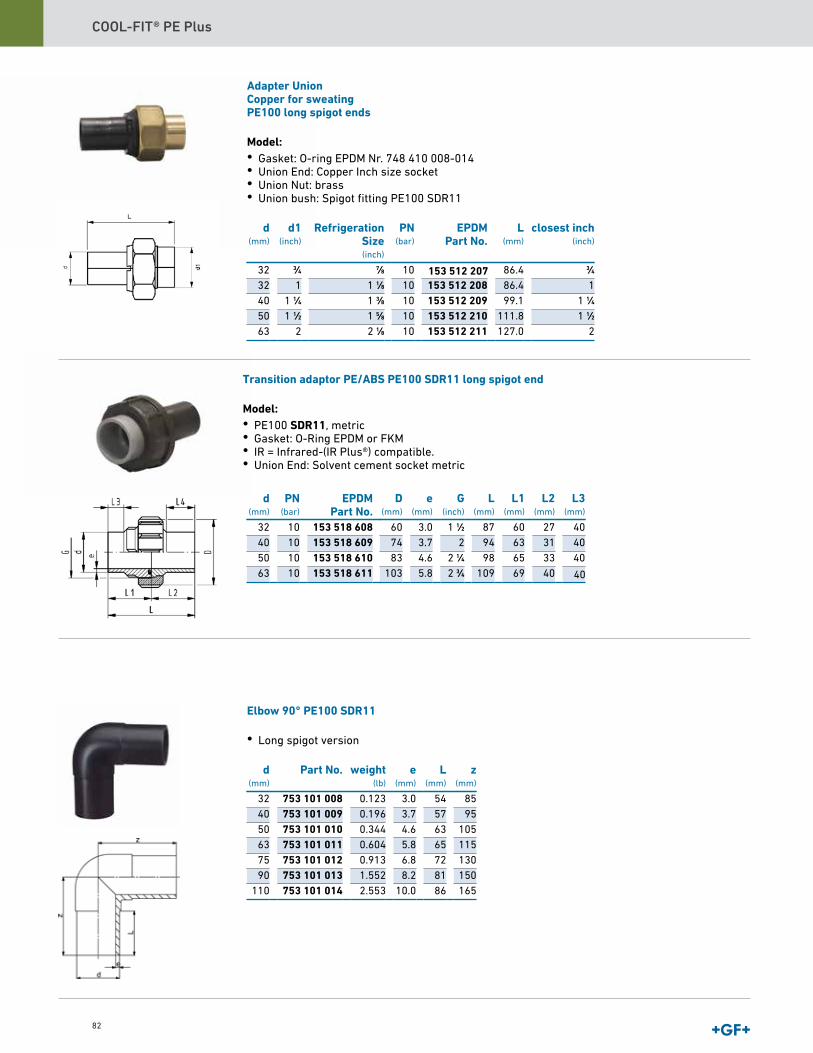
COOL-FIT® PE Plus
82
Adapter UnionCopper for sweatingPE100 long spigot ends
Model:• Gasket: O-ring EPDM Nr. 748 410 008-014• Union End: Copper Inch size socket• Union Nut: brass• Union bush: Spigot fitting PE100 SDR11
d(mm)
d1(inch)
RefrigerationSize(inch)
PN(bar)
EPDMPart No.
L(mm)
closest inch(inch)
32 3∕4 7∕8 10 86.4 3∕432 1 1 1∕8 10 153 512 208 86.4 140 1 1∕4 1 3∕8 10 153 512 209 99.1 1 1∕450 1 1∕2 1 5∕8 10 153 512 210 111.8 1 1∕263 2 2 1∕8 10 153 512 211 127.0 2
Elbow 90° PE100 SDR11
• Long spigot version d
(mm)Part No. weight
(lb)e
(mm)L
(mm)z
(mm)
32 753 101 008 0.123 3.0 54 8540 753 101 009 0.196 3.7 57 9550 753 101 010 0.344 4.6 63 10563 753 101 011 0.604 5.8 65 11575 753 101 012 0.913 6.8 72 13090 753 101 013 1.552 8.2 81 150
110 753 101 014 2.553 10.0 86 165
153 512 207
d(mm)
PN(bar)
EPDMPart No.
D(mm)
e(mm)
G(inch)
L(mm)
L1(mm)
L2(mm)
L3(mm)
32 10 153 518 608 60 3.0 1 1∕2 87 60 27 4040 10 153 518 609 74 3.7 2 94 63 31 4050 10 153 518 610 83 4.6 2 1∕4 98 65 33 4063 10 153 518 611 103 5.8 2 3∕4 109 69 40
Transition adaptor PE/ABS PE100 SDR11 long spigot end
Model:• PE100 SDR11, metric• Gasket: O-Ring EPDM or FKM• IR = Infrared-(IR Plus®) compatible.• Union End: Solvent cement socket metric
40
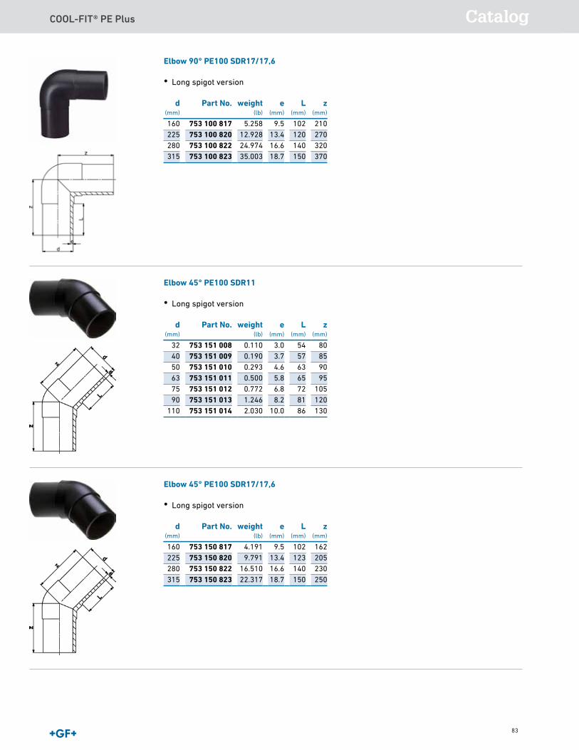
COOL-FIT® PE Plus Catalog
83
Elbow 90° PE100 SDR17/17,6
• Long spigot version d
(mm)Part No. weight
(lb)e
(mm)L
(mm)z
(mm)
160 753 100 817 5.258 9.5 102 210225 753 100 820 12.928 13.4 120 270280 753 100 822 24.974 16.6 140 320315 753 100 823 35.003 18.7 150 370
Elbow 45° PE100 SDR11
• Long spigot version d
(mm)Part No. weight
(lb)e
(mm)L
(mm)z
(mm)
32 753 151 008 0.110 3.0 54 8040 753 151 009 0.190 3.7 57 8550 753 151 010 0.293 4.6 63 9063 753 151 011 0.500 5.8 65 9575 753 151 012 0.772 6.8 72 10590 753 151 013 1.246 8.2 81 120
110 753 151 014 2.030 10.0 86 130
Elbow 45° PE100 SDR17/17,6
• Long spigot version d
(mm)Part No. weight
(lb)e
(mm)L
(mm)z
(mm)
160 753 150 817 4.191 9.5 102 162225 753 150 820 9.791 13.4 123 205280 753 150 822 16.510 16.6 140 230315 753 150 823 22.317 18.7 150 250
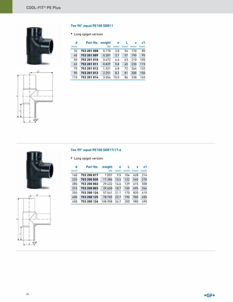
COOL-FIT® PE Plus
84
Tee 90° equal PE100 SDR11
• Long spigot version d
(mm)Part No. weight
(lb)e
(mm)L
(mm)z
(mm)z1
(mm)
32 753 201 008 0.170 3.0 54 170 8540 753 201 009 0.287 3.7 57 190 9550 753 201 010 0.472 4.6 63 210 10563 753 201 011 0.829 5.8 65 230 11575 753 201 012 1.321 6.8 72 264 13290 753 201 013 2.251 8.2 81 300 150
110 753 201 014 3.554 10.0 86 330 165
Tee 90° equal PE100 SDR17/17,6
• Long spigot version d
(mm)Part No. weight
(lb)e
(mm)L
(mm)z
(mm)z1
(mm)
160 753 200 817 7.057 9.5 104 428 214225 753 200 820 17.386 13.4 122 540 270280 753 200 802 29.432 16.6 139 615 308315 753 200 803 39.650 18.7 150 695 346355 753 200 124 57.541 21.1 170 820 410400 753 200 125 78.705 23.7 190 900 450450 753 200 126 108.908 26.7 200 980 490
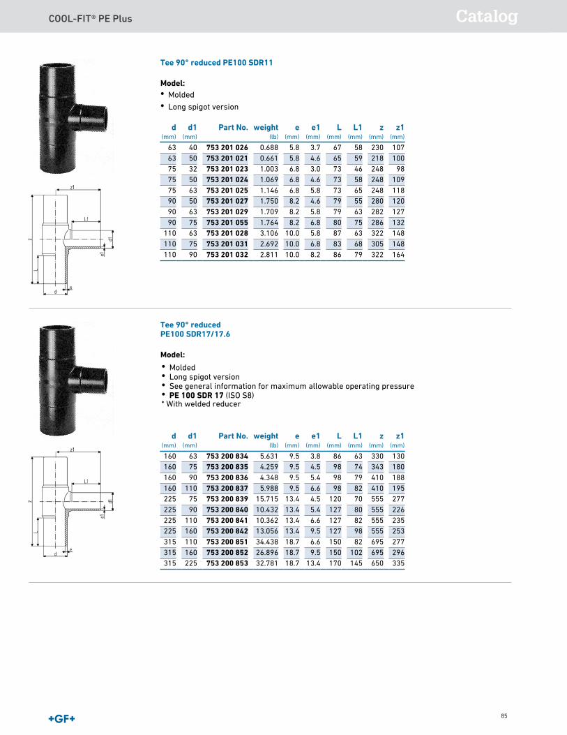
COOL-FIT® PE Plus Catalog
85
Tee 90° reduced PE100 SDR11
Model:• Molded • Long spigot version
d(mm)
d1(mm)
Part No. weight(lb)
e(mm)
e1(mm)
L(mm)
L1(mm)
z(mm)
z1(mm)
63 40 753 201 026 0.688 5.8 3.7 67 58 230 10763 50 753 201 021 0.661 5.8 4.6 65 59 218 10075 32 753 201 023 1.003 6.8 3.0 73 46 248 9875 50 753 201 024 1.069 6.8 4.6 73 58 248 10975 63 753 201 025 1.146 6.8 5.8 73 65 248 11890 50 753 201 027 1.750 8.2 4.6 79 55 280 12090 63 753 201 029 1.709 8.2 5.8 79 63 282 12790 75 753 201 055 1.764 8.2 6.8 80 75 286 132
110 63 753 201 028 3.106 10.0 5.8 87 63 322 148110 75 753 201 031 2.692 10.0 6.8 83 68 305 148110 90 753 201 032 2.811 10.0 8.2 86 79 322 164
Tee 90° reducedPE100 SDR17/17.6
Model:
d(mm)
d1(mm)
Part No. weight(lb)
e(mm)
e1(mm)
L(mm)
L1(mm)
z(mm)
z1(mm)
160 63 753 200 834 5.631 9.5 3.8 86 63 330 130160 75 753 200 835 4.259 9.5 4.5 98 74 343 180160 90 753 200 836 4.348 9.5 5.4 98 79 410 188160 110 753 200 837 5.988 9.5 6.6 98 82 410 195225 75 753 200 839 15.715 13.4 4.5 120 70 555 277225 90 753 200 840 10.432 13.4 5.4 127 80 555 226225 110 753 200 841 10.362 13.4 6.6 127 82 555 235225 160 753 200 842 13.056 13.4 9.5 127 98 555 253315 110 753 200 851 34.438 18.7 6.6 150 82 695 277315 160 753 200 852 26.896 18.7 9.5 150 102 695 296315 225 753 200 853 32.781 18.7 13.4 170 145 650 335
• Molded• Long spigot version• See general information for maximum allowable operating pressure• PE 100 SDR 17 (ISO S8)* With welded reducer

COOL-FIT® PE Plus
86
63 32 753 901 060 0.249 5.8 3,0 65 53 15063 40 753 901 059 0.269 5.8 3,7 65 57 15063 50 753 901 058 0.282 5.8 4,6 65 62 15075 40 753 901 063 0.408 6.8 3,7 72 51 17075 50 753 901 064 0.414 6.8 4,6 72 65 17075 63 753 901 065 0.461 6.8 5,8 72 65 17090 50 753 901 072 0.637 8.2 4,6 81 61 19090 63 753 901 071 0.697 8.2 5,8 81 65 19090 75 753 901 070 0.728 8.2 6,8 81 72 190
110 63 753 901 078 1.074 10.0 5,8 85 65 205110 75 753 901 077 1.105 10.0 6,8 84 72 205110 90 753 901 076 1.210 10.0 8,2 85 81 205
Reducer PE100 SDR17/17,6
• Long spigot version d
(mm)d1
(mm)Part No. weight
(lb)e
(mm)e1
(mm)L
(mm)L1
(mm)z
(mm)
160 90 753 900 888 1.658 9.5 5,4 120 85 248160 110 753 900 890 2.050 9.5 6,6 100 85 245225 160 753 900 896 4.453 13.4 9,5 120 100 280280 225 753 900 899 8.955 16.6 13,4 140 120 335315 225 753 900 807 13.669 18.7 13,4 150 120 365315 280 753 900 806 13.095 18.7 16,6 150 140 365355 280 753 900 809 14.833 21.1 16,6 165 140 390355 315 753 900 810 15.961 21.1 18,7 165 150 390400 280 753 900 811 17.483 23.7 16,6 180 140 415400 315 753 900 812 21.934 23.7 18,7 180 150 415400 355 753 900 813 21.208 23.7 21,1 180 165 420450 280 753 900 814 25.353 26.7 16,6 195 140 389450 315 753 900 815 26.026 26.7 18,7 195 150 390450 355 753 900 816 26.235 26.7 21,1 195 164 393450 400 753 900 817 28.581 26.7 23,7 195 179 395
Cap PE100 SDR11
• Long spigot version d
(mm)Part No. weight
(lb)e
(mm)L
(mm)z
(mm)
32 753 961 008 0.044 3.0 54 5440 753 961 009 0.073 3.7 57 5750 753 961 010 0.119 4.6 63 6363 753 961 011 0.190 5.8 65 6575 753 961 012 0.322 6.8 72 8090 753 961 013 0.529 8.2 81 90
110 753 961 014 0.822 10.0 86 98
Reducer PE100 SDR11
• Long spigot version
d(mm)
d1(mm)
Part No. weight(lb)
e(mm)
e1(mm)
L(mm)
L1(mm)
z(mm)
32 20 753 901 042 0.060 3.0 3,0 55 53 12232 25 753 901 041 0.073 3.0 3,0 55 53 12240 20 753 901 048 0.095 3.7 3,0 56 50 12740 25 753 901 047 0.099 3.7 3,0 55 50 12840 32 753 901 046 0.104 3.7 3,0 55 52 12850 20 753 901 055 0.141 4.6 3,0 62 50 14750 25 753 901 054 0.152 4.6 3,0 62 50 13950 32 753 901 053 0.148 4.6 3,0 62 54 14050 40 753 901 052 0.174 4.6 3,7 62 55 138
Reducer PE100 SDR11
• Long spigot version Cap PE100 SDR17/17,6
• Long spigot version d
(mm)Part No. weight
(lb)e
(mm)L
(mm)z
(mm)
160 753 960 817 2.028 9.5 102 120225 753 960 820 4.993 13.4 122 148280 753 960 822 7.767 16.6 139 235315 753 960 823 10.490 18.7 150 255355 753 960 824 14.352 21.1 165 280400 753 960 825 20.607 23.7 180 310450 753 960 826 39.238 26.7 195 265
Flange adaptor SDR11 ANSICombined jointing face: flat and serrated
Model:• Material: PE100• Long spigot for Butt fusion or Electrofusion• Suitable for flange connections to ANSI/ASME B 16.5• Gasket d20-d630: Profile flange gasket NBR No. 45 44 07, EPDM No. 48 44 07• Type A without chamfer, Type B with chamfer
d(mm)
FM Part No. weight(lb)
d1(mm)
d2(mm)
d3(mm)
d4(mm)
e(mm)
L(mm)
L1(mm)
L2(mm)
Type
32 IR 753 800 058 0.101 40 63 26 3.0 91.5 61.0 10 A40 IR 753 800 059 0.154 50 73 32 3.7 94.5 61.5 11 A50 IR 753 800 060 0.216 61 82 40 4.6 105.0 55.0 12 A63 IR 753 800 011 0.412 75 102 51 5.8 98.0 69.0 14 A75 IR 753 800 012 0.692 89 122 66 61 6.8 125.0 89.0 16 B90 IR 753 800 063 0.933 105 133 73 8.2 140.0 85.0 17 B
110 IR 753 800 014 1.583 125 158 100 90 10.0 160.0 114.0 18 B
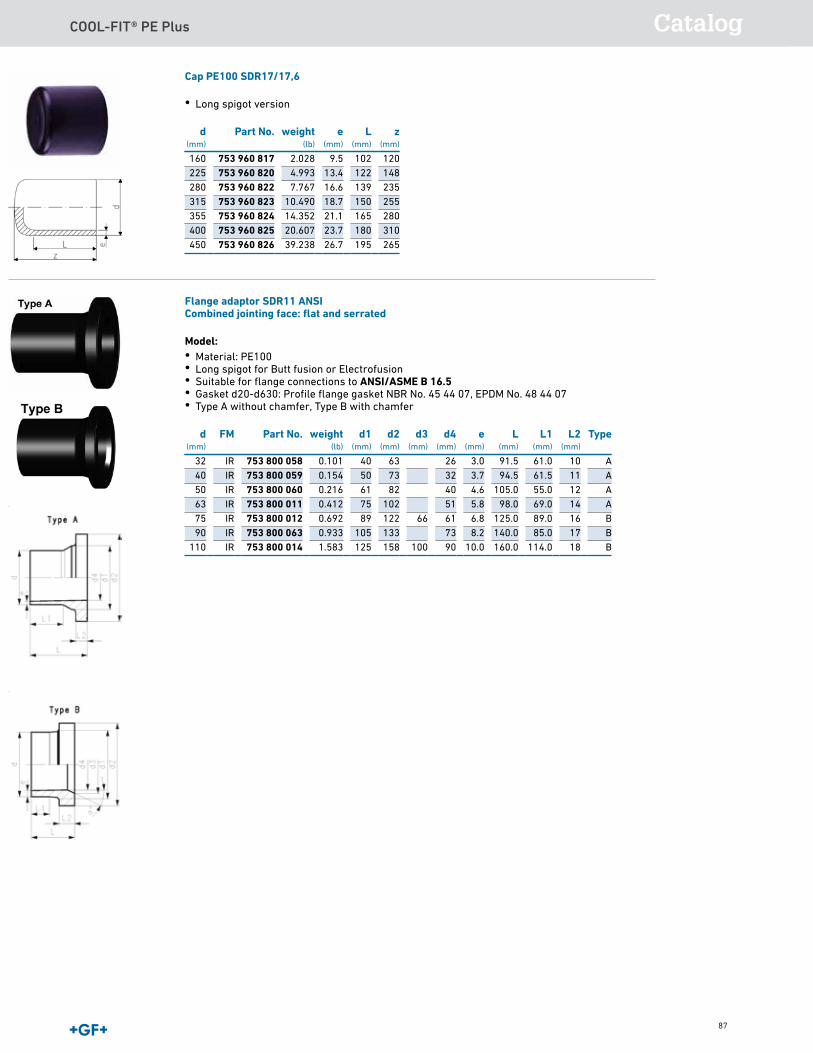
COOL-FIT® PE Plus Catalog
87
Cap PE100 SDR17/17,6
• Long spigot version d
(mm)Part No. weight
(lb)e
(mm)L
(mm)z
(mm)
160 753 960 817 2.028 9.5 102 120225 753 960 820 4.993 13.4 122 148280 753 960 822 7.767 16.6 139 235315 753 960 823 10.490 18.7 150 255355 753 960 824 14.352 21.1 165 280400 753 960 825 20.607 23.7 180 310450 753 960 826 39.238 26.7 195 265
Flange adaptor SDR11 ANSICombined jointing face: flat and serrated
Model:• Material: PE100• Long spigot for Butt fusion or Electrofusion• Suitable for flange connections to ANSI/ASME B 16.5• Gasket d20-d630: Profile flange gasket NBR No. 45 44 07, EPDM No. 48 44 07• Type A without chamfer, Type B with chamfer
d(mm)
FM Part No. weight(lb)
d1(mm)
d2(mm)
d3(mm)
d4(mm)
e(mm)
L(mm)
L1(mm)
L2(mm)
Type
32 IR 753 800 058 0.101 40 63 26 3.0 91.5 61.0 10 A40 IR 753 800 059 0.154 50 73 32 3.7 94.5 61.5 11 A50 IR 753 800 060 0.216 61 82 40 4.6 105.0 55.0 12 A63 IR 753 800 011 0.412 75 102 51 5.8 98.0 69.0 14 A75 IR 753 800 012 0.692 89 122 66 61 6.8 125.0 89.0 16 B90 IR 753 800 063 0.933 105 133 73 8.2 140.0 85.0 17 B
110 IR 753 800 014 1.583 125 158 100 90 10.0 160.0 114.0 18 B
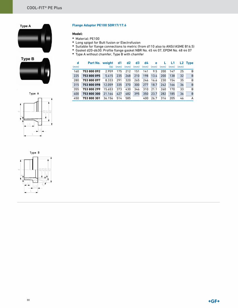
COOL-FIT® PE Plus
88
Flange Adaptor PE100 SDR17/17.6
Model:• Material: PE100• Long spigot for Butt fusion or Electrofusion• Suitable for flange connections to metric (from d110 also to ANSI/ASME B16.5)• Gasket d20-d630: Profile flange gasket NBR No. 45 44 07, EPDM No. 48 44 07• Type A without chamfer, Type B with chamfer
d(mm)
Part No. weight(lb)
d1(mm)
d2(mm)
d3(mm)
d4(mm)
e(mm)
L(mm)
L1(mm)
L2(mm)
Type
160 753 800 092 2.959 175 212 151 141 9.5 200 147 25 B225 753 800 095 5.415 235 268 210 198 13.4 200 138 32 B280 753 800 097 8.333 291 320 265 246 16.6 230 154 35 B315 753 800 098 12.059 335 370 300 277 18.7 242 166 36 B355 753 800 299 15.653 373 430 346 310 21.1 260 170 33 B400 753 800 300 21.164 427 482 395 350 23.7 282 185 36 B450 753 800 301 36.156 514 585 400 26.7 316 205 46 A

COOL-FIT® PE Plus Catalog
89
Data sheetvalid from: 8/14/19
Page 1 of 1
V-Flange RingFor Butt Fusion Systems
Model:• Full-plastic flange PP-GF (30% glass-fiber reinforced), with V-groove which applies force even-
ly on collar• Connecting dimension: ANSI/ASME B 16.5 class 150, ASTM D 4024, BS 1560, BS EN 1759• Bolt circle class 150• UV-resistant AL: number of holesAll sizes suitable for butt fusion. Sizes 20-75mm also for socket fusion.Combined version, metric-ANSI Size(inch)
d(mm)
Part No. D(mm)
D1(mm)
D2(mm)
D3(mm)
H(mm)
AL SC
1∕2 20 727 701 406 95 60 28 16 16 4 M123∕4 25 727 701 407 105 70 34 16 17 4 M121 32 727 701 408 115 79 42 16 18 4 M12
1 1∕4 40 727 701 409 140 89 51 16 20 4 M161 1∕2 50 727 701 410 150 98 62 16 22 4 M16
2 63 727 701 411 165 121 78 19 24 4 M162 1∕2 75 727 701 412 185 140 92 19 26 4 M16
3 90 727 701 513 200 152 108 19 27 4 M164 110 727 701 514 229 190 128 19 28 8 M166 160 727 700 517 285 240 178 22 32 8 M208 200 727 700 519 340 295 235 22 34 8 M208 225 727 700 520 340 295 238 22 34 8 M20
10 250 727 701 521 406 362 288 26 38 12 M2010 280 727 701 522 406 362 294 26 38 12 M2012 315 727 701 523 483 432 338 26 42 12 M20
The technical data are not binding. They neither constitute expressly warranted characteristics nor guaranteed properties nor a guar-
anteed durability. They are subject to modification. Our General Terms of Sale apply.
Georg Fischer Piping Systems Ltd, Postfach, CH-8201 Schaffhausen/Switzerland
Phone +41 -(0)52-631 1111
e-mail: [email protected]
Internet: http://www.gfps.com
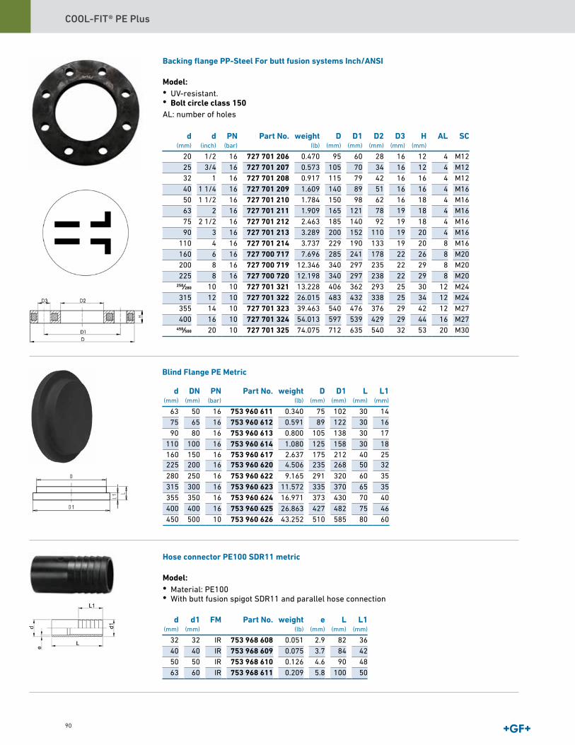
COOL-FIT® PE Plus
90
Backing flange PP-Steel For butt fusion systems Inch/ANSI
Model:• UV-resistant.• Bolt circle class 150 AL: number of holes
d(mm)
d(inch)
PN(bar)
Part No. weight(lb)
D(mm)
D1(mm)
D2(mm)
D3(mm)
H(mm)
AL SC
20 1/2 16 727 701 206 0.470 95 60 28 16 12 4 M1225 3/4 16 727 701 207 0.573 105 70 34 16 12 4 M1232 1 16 727 701 208 0.917 115 79 42 16 16 4 M1240 1 1/4 16 727 701 209 1.609 140 89 51 16 16 4 M1650 1 1/2 16 727 701 210 1.784 150 98 62 16 18 4 M1663 2 16 727 701 211 1.909 165 121 78 19 18 4 M1675 2 1/2 16 727 701 212 2.463 185 140 92 19 18 4 M1690 3 16 727 701 213 3.289 200 152 110 19 20 4 M16
110 4 16 727 701 214 3.737 229 190 133 19 20 8 M16160 6 16 727 700 717 7.696 285 241 178 22 26 8 M20200 8 16 727 700 719 12.346 340 297 235 22 29 8 M20225 8 16 727 700 720 12.198 340 297 238 22 29 8 M20
250∕280 10 10 727 701 321 13.228 406 362 293 25 30 12 M24315 12 10 727 701 322 26.015 483 432 338 25 34 12 M24355 14 10 727 701 323 39.463 540 476 376 29 42 12 M27400 16 10 727 701 324 54.013 597 539 429 29 44 16 M27
450∕500 20 10 727 701 325 74.075 712 635 540 32 53 20 M30
Hose connector PE100 SDR11 metric
Model:• Material: PE100• With butt fusion spigot SDR11 and parallel hose connection
d(mm)
d1(mm)
FM Part No. weight(lb)
e(mm)
L(mm)
L1(mm)
32 32 IR 753 968 608 0.051 2.9 82 3640 40 IR 753 968 609 0.075 3.7 84 4250 50 IR 753 968 610 0.126 4.6 90 4863 60 IR 753 968 611 0.209 5.8 100 50
d(mm)
DN(mm)
PN(bar)
Part No. weight(lb)
D(mm)
D1(mm)
L(mm)
L1(mm)
63 50 16 753 960 611 0.340 75 102 30 1475 65 16 753 960 612 0.591 89 122 30 1690 80 16 753 960 613 0.800 105 138 30 17
110 100 16 753 960 614 1.080 125 158 30 18160 150 16 753 960 617 2.637 175 212 40 25225 200 16 753 960 620 4.506 235 268 50 32
280 250 16 753 960 622 9.165 291 320 60 35315 300 16 753 960 623 11.572 335 370 65 35355 350 16 753 960 624 16.971 373 430 70 40400 400 16 753 960 625 26.863 427 482 75 46450 500 10 753 960 626 43.252 510 585 80 60
Blind Flange PE Metric

COOL-FIT® PE Plus Catalog
91
Machines for PEMSA Electrofusion
MSA 2.0 Automatic Electrofusion Unit (230V)
The MSA 2.0 automatic electro fusion unit combines light weight and high efficiency, thanks to itsinverter technology. The unit is extremely fast and simple, with three basic operations required tooperator: connect, scan, start the fusion.The MSA 2.0 has 350 protocols permanently stored in the internal memory.It is robust, safe and ergonomic.All is meant to simplify the job: the barcode scanner, for long distance reading, the cooling sys-tem to joint in series, the icon system, to keep the interaction between user and machine intuitive.The entire welding process is controlled and regulated with energy output compensation depend-ing on ambient temperature and the indication of cooling time.Scope of delivery includes: transport box, 1 pair of angle adapter clips 4.0 mm and operating in-structions.Technical Data:• Operating temperature: -20°C to +50°C• Mains frequency: 50-60 Hz• Mains voltage: 230V (190V - 265V)• Fusion current: 90 A (max)• Suggested power generators: 3.5 kVA• Welding technique: Voltage controlled• Fusion voltage: 8-42 V (48 V)• Fittings range: d16-1200 mm• Fusion data input mode: bar code, manual• Internal memory capacity: 350 protocols• USB Port: Type A• Protection factor: Class 1 / IP 65• Mains cable: 13.1 ft (4 m)• Fusion cable: 3 m• Dimensions: 280 x 420 x 280 mm• Weight: ca. 26.2 lbs (11.9 kg)• Display: Graphical LCD, adjustable contrast• Languages support: all
Type Part No. SP weightlb
Barcode scanner, transport case 790 156 001 1 44.093

COOL-FIT® PE Plus
92
MSA 2.0 Automatic Electrofusion Unit (115V)
The MSA 2.0 automatic electro fusion unit combines light weight and high efficiency, thanks to itsinverter technology. The unit is extremely fast and simple, with three basic operations required tooperator: connect, scan, start the fusion.The MSA 2.0 has 350 protocols permanently stored in the internal memory.It is robust, safe and ergonomic.All is meant to simplify the job: the barcode scanner, for long distance reading, the cooling sys-tem to joint in series, the icon system, to keep the interaction between user and machine intuitive.The entire welding process is controlled and regulated with energy output compensation depend-ing on ambient temperature and the indication of cooling time.Scope of delivery includes: transport box, 1 pair of angle adapter clips 4.0 mm and operating in-structions.Technical Data:• Operating temperature: -20°C to +50°C• Mains frequency: 50-60 Hz• Mains voltage: 230V (190V - 265V)• Fusion current: 90 A (max)• Suggested power generators: 3.5 kVA• Welding technique: Voltage controlled• Fusion voltage: 8-42 V (48 V)• Fittings range: d16-1200 mm• Fusion data input mode: bar code, manual• Internal memory capacity: 350 protocols• USB Port: Type A• Protection factor: Class 1 / IP 65• Mains cable: 13.1 ft (4 m)• Fusion cable: 3 m• Dimensions: 280 x 420 x 280 mm• Weight: ca. 26.2 lbs (11.9 kg)• Display: Graphical LCD, adjustable contrast• Languages support: all
Type Part No. SP weight(kg)
Barcode scanner, transport case 790 156 001 1 20.000Barcode scanner, transport case, Swiss plug 790 156 004 1 20.000
COOL-FIT Y cables kit
• The COOL-FIT Y cables are used to speed up the installation of the fixed points electrofusiontapes. The Y cables allow the welding in parallel of 2 E-Tapes, halving the total duration of thefusion process.• Compatible with MSA 210-230, MSA 330-340, MSA 250 – 400, MSA 250 – 400 PLUS
Type Part No. weight(lb)
4 leads cable with 2mm plugs in output 790 156 032 0.849
Long adapters
• Required adapters for Electrofusion units with 4 mm connectors.• Longer version, suitable for all COOL-FIT PE Plus dimensions.
Type Part No. weight(lb)
Description
4,0 mm 790 128 035 0.128 Angle adapter, black
MSA 2 CF @ 115V - Automatic Electrofusion Unit with protocols retrieval
The MSA 2 CF electro fusion unit combines light weight and high efficiency, thanks to its pow-er switching technology and furthermore provides fusion documentation in PDF. The unit is ex-tremely fast and simple, like COOL-FIT installations, with three basic operations required to theoperator: connect, scan, start the fusion.It is robust, safe and ergonomic.All is meant to simplify the job: the barcode scanner, for long distance reading, the cooling sys-tem to joint in series, the icon system, to keep the interaction between user and machine intuitive.The entire welding process is controlled and regulated with energy output compensation depend-ing on ambient temperature and the indication of cooling time.The unit has 1000 protocols permanently stored in the internal memory. The user can copy thefusion reports in an USB stick to print them out in PDF format.Scope of delivery includes: transport box, standard and long angle adapters (4.0 mm), operatinginstructions, START/STOP badge and USB memory stick with PC applications.Technical Data:• Operating temperature: -20°C to +50°C• Mains voltage: 90V - 135V AC• Mains frequency: 50-60 Hz• Fusion voltage: 8-42 V• Fusion data input mode: bar code, manual• Fusion current: 90 A (max)• Suggested power generators: 3.5 kVA• Fittings range: d20-d450 (inner diameter) COOL-FIT 2.0/4.0• Protocols format: PDF and binary (compatible with mini Welding Book)• USB Port: Type A• Protection factor: Class 1 / IP 65• Mains cable: 13.1 ft (4 m)• Fusion cable: 13.1 ft (4 m)• Weight: ca 12.5 kg• Display: Graphical LCD, adjustable contrast• Languages support: all
Type Part No. weightlb
Barcode scanner, transport case, mini Welding Book 790 156 023 39.652
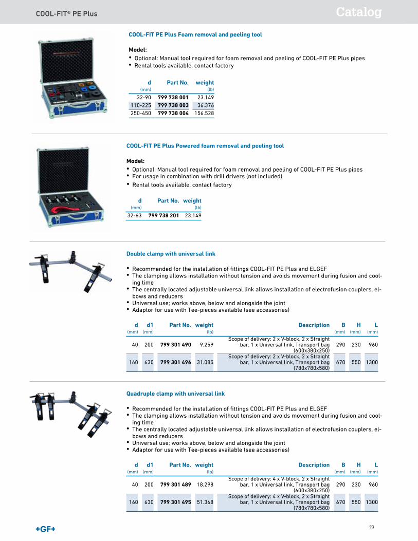
COOL-FIT® PE Plus Catalog
93
COOL-FIT PE Plus Powered foam removal and peeling tool
Model:• Optional: Manual tool required for foam removal and peeling of COOL-FIT PE Plus pipes• For usage in combination with drill drivers (not included)
d(mm)
Part No. weight(lb)
32-63 799 738 201 23.149
Double clamp with universal link
• Recommended for the installation of fittings COOL-FIT PE Plus and ELGEF• The clamping allows installation without tension and avoids movement during fusion and cool-
ing time• The centrally located adjustable universal link allows installation of electrofusion couplers, el-
bows and reducers• Universal use; works above, below and alongside the joint• Adaptor for use with Tee-pieces available (see accessories)
d(mm)
d1(mm)
Part No. weight(lb)
Description B(mm)
H(mm)
L(mm)
40 200 799 301 490 9.259Scope of delivery: 2 x V-block, 2 x Straight
bar, 1 x Universal link, Transport bag(600x380x250)
290 230 960
160 630 799 301 496 31.085Scope of delivery: 2 x V-block, 2 x Straight
bar, 1 x Universal link, Transport bag(780x780x580)
670 550 1300
Quadruple clamp with universal link
• Recommended for the installation of fittings COOL-FIT PE Plus and ELGEF• The clamping allows installation without tension and avoids movement during fusion and cool-
ing time• The centrally located adjustable universal link allows installation of electrofusion couplers, el-
bows and reducers• Universal use; works above, below and alongside the joint• Adaptor for use with Tee-pieces available (see accessories)
d(mm)
d1(mm)
Part No. weight(lb)
Description B(mm)
H(mm)
L(mm)
40 200 799 301 489 18.298Scope of delivery: 4 x V-block, 2 x Straight
bar, 1 x Universal link, Transport bag(600x380x250)
290 230 960
160 630 799 301 495 51.368Scope of delivery: 4 x V-block, 2 x Straight
bar, 1 x Universal link, Transport bag(780x780x580)
670 550 1300
COOL-FIT PE Plus Foam removal and peeling tool
Model:• Optional: Manual tool required for foam removal and peeling of COOL-FIT PE Plus pipes
d(mm)
Part No. weight(lb)
32-90 799 738 001 23.149110-225 799 738 003 36.376250-450 799 738 004 156.528
• Rental tools available, contact factory
• Rental tools available, contact factory
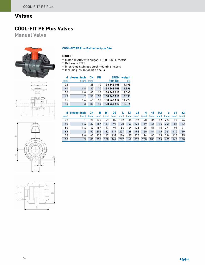
COOL-FIT® PE Plus
94
Valves
COOL-FIT PE Plus ValvesManual Valve
COOL-FIT PE Plus Ball valve type 546
Model:• Material: ABS with spigot PE100 SDR11, metric• Ball seals PTFE• Integrated stainless steel mounting inserts• Including insulation half shells
d(mm)
closest inch(inch)
DN(mm)
PN EPDMPart No.
weight(lb)
32 1 25 10 138 546 108 1.19540 1 1∕4 32 10 138 546 109 1.95650 1 1∕2 40 10 138 546 110 2.56863 2 50 10 138 546 111 4.63075 2 1∕2 65 10 138 546 112 11.29990 3 80 10 138 546 113 15.814
d(mm)
closest inch(inch)
DN(mm)
D(mm)
D1(mm)
D2(mm)
L(mm)
L1(mm)
L3(mm)
H(mm)
H1(mm)
H2(mm)
z(mm)
z1(mm)
z2(mm)
32 1 25 135 97 82 152 36 97 98 36 12 223 76 7640 1 1∕4 32 157 117 97 170 40 128 119 44 15 249 82 8250 1 1∕2 40 169 117 97 184 44 128 125 51 15 271 91 9163 2 50 204 132 117 227 48 152 150 64 15 321 110 11075 2 1∕2 65 235 147 132 276 55 270 194 85 15 386 125 12590 3 80 255 168 147 297 62 270 200 105 15 421 140 140
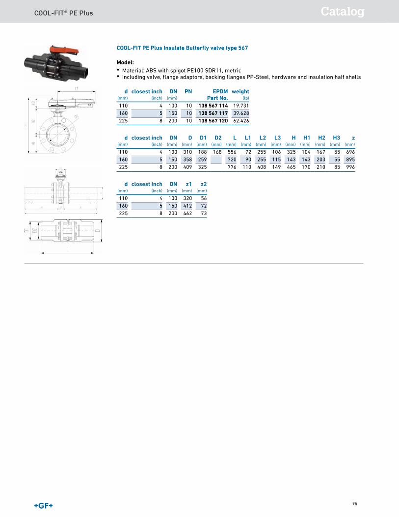
COOL-FIT® PE Plus Catalog
95
COOL-FIT PE Plus Insulate Butterfly valve type 567
Model:• Material: ABS with spigot PE100 SDR11, metric• Including valve, flange adaptors, backing flanges PP-Steel, hardware and insulation half shells
d(mm)
closest inch(inch)
DN(mm)
PN EPDMPart No.
weight(lb)
110 4 100 10 138 567 114 19.731160 5 150 10 138 567 117 39.628225 8 200 10 138 567 120 62.426
d(mm)
closest inch(inch)
DN(mm)
D(mm)
D1(mm)
D2(mm)
L(mm)
L1(mm)
L2(mm)
L3(mm)
H(mm)
H1(mm)
H2(mm)
H3(mm)
z(mm)
110 4 100 310 188 168 556 72 255 106 325 104 167 55 696160 5 150 358 259 720 90 255 115 143 143 203 55 895225 8 200 409 325 776 110 408 149 465 170 210 85 996
d(mm)
closest inch(inch)
DN(mm)
z1(mm)
z2(mm)
110 4 100 320 56160 5 150 412 72225 8 200 462 73

COOL-FIT® PE Plus
96
Actuated Valve
COOL-FIT PE Plus Electric Actuated Insulated Ball valve type 179
Model:• Material: ABS with spigot PE100 SDR11, metric• Ball seals PTFE• Integrated stainless steel mounting inserts• Voltage 100-230V, 50-60Hz• Factory set control range 90°• Including insulation half shells
d(mm)
closest inch(inch)
DN(mm)
PN(bar)
Part No. weight(lb)
32 1 25 10 138 546 208 6.25740 1 1∕4 32 10 138 546 209 6.99750 1 1∕2 40 10 138 546 210 7.61063 2 50 10 138 546 211 9.86675 2 1∕2 65 10 138 546 212 15.77690 3 80 10 138 546 213 28.660
d(mm)
closest inch(inch)
DN(mm)
D(mm)
D1(mm)
D2(mm)
L(mm)
L1(mm)
L3(mm)
L4(mm)
H(mm)
H1(mm)
H2(mm)
z(mm)
z1(mm)
32 1 25 135 97 82 152 36 190 25 228 36 12 223 7640 1 1∕4 32 157 117 97 170 40 190 45 240 44 15 249 8250 1 1∕2 40 169 117 97 184 44 190 45 246 51 15 271 9163 2 50 204 132 117 227 48 190 45 263 64 15 321 11075 2 1∕2 65 235 147 132 276 55 190 70 322 85 15 386 12590 3 80 255 168 147 297 62 190 70 357 105 15 421 140
d(mm)
closest inch(inch)
DN(mm)
z2(mm)
M
32 1 25 71 M640 1 1∕4 32 85 M850 1 1∕2 40 89 M863 2 50 101 M875 2 1∕2 65 136 M890 3 80 141 M8
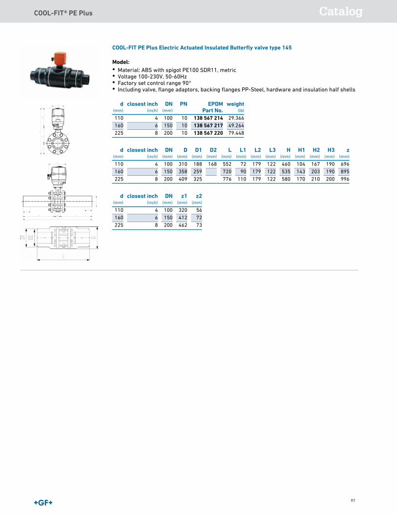
COOL-FIT® PE Plus Catalog
97
COOL-FIT PE Plus Electric Actuated Insulated Butterfly valve type 145
Model:• Material: ABS with spigot PE100 SDR11, metric• Voltage 100-230V, 50-60Hz• Factory set control range 90°• Including valve, flange adaptors, backing flanges PP-Steel, hardware and insulation half shells
d(mm)
closest inch(inch)
DN(mm)
PN EPDMPart No.
weight(lb)
110 4 100 10 138 567 214 29.366160 6 150 10 138 567 217 49.264225 8 200 10 138 567 220 79.448
d(mm)
closest inch(inch)
DN(mm)
D(mm)
D1(mm)
D2(mm)
L(mm)
L1(mm)
L2(mm)
L3(mm)
H(mm)
H1(mm)
H2(mm)
H3(mm)
z(mm)
110 4 100 310 188 168 552 72 179 122 460 104 167 190 696160 6 150 358 259 720 90 179 122 535 143 203 190 895225 8 200 409 325 776 110 179 122 580 170 210 200 996
d(mm)
closest inch(inch)
DN(mm)
z1(mm)
z2(mm)
110 4 100 320 56160 6 150 412 72225 8 200 462 73
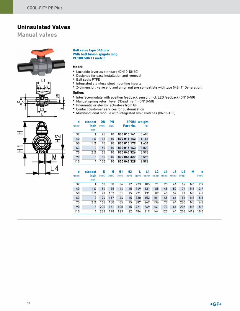
COOL-FIT® PE Plus
98
Uninsulated ValvesManual valves
Ball valve type 546 proWith butt fusion spigots longPE100 SDR11 metric
Model:• Lockable lever as standard (DN10-DN50)• Designed for easy installation and removal• Ball seals PTFE• Integrated stainless steel mounting inserts• Z-dimension, valve end and union nut are compatible with type 546 (1st
Generation) Option:• Interface-module with position feedback sensor, incl. LED feedback (DN10-50)• Manual spring return lever ("Dead man") (DN10-50)• Pneumatic or electric actuators from GF• Contact customer services for customization• Multifunctional module with integrated limit switches (DN65-100)
d(mm)
closestinch(inch)
DN(mm)
PN(bar)
EPDMPart No.
weight(lb)
32 1 25 10 800 015 141 0.68340 1 1∕4 32 10 800 015 142 1.16850 1 1∕2 40 10 800 015 179 1.63163 2 50 10 800 015 143 3.02075 2 1∕2 65 10 800 045 326 8.59890 3 80 10 800 045 327 8.598
110 4 100 10 800 045 328 8.598
d(mm)
closestinch(inch)
D(mm)
H(mm)
H1(mm)
H2(mm)
L(mm)
L1(mm)
L2(mm)
L4(mm)
L5(mm)
L6(mm)
M e(mm)
32 1 68 80 36 12 223 105 71 25 44 62 M6 2.940 1 1∕4 84 95 44 15 249 131 85 45 57 74 M8 3.750 1 1∕2 97 102 51 15 271 131 89 45 57 74 M8 4.663 2 124 117 64 15 320 152 101 45 66 86 M8 5.875 2 1∕2 166 150 85 15 387 269 136 70 64 206 M8 6.890 3 200 161 105 15 421 269 141 70 64 206 M8 8.2
110 4 238 178 123 22 484 319 164 120 64 256 M12 10.0

COOL-FIT® PE Plus Catalog
99
ecoFIT3-Way Ball Valve Type 543 ABSHorizontal/L-portWith butt fusion spigots longPE100 SDR11 metric
Model:• Ball seals PTFE• Pneumatic or electric actuator available separately• Angle of operation 360° without turn limiter• Turn limiter 90° enclosed, in different positions usable as a clip-on ring• Integrated stainless steel mounting inserts• Delivery status A-C opened, see flow scheme
d(mm)
closestinch(inch)
DN(mm)
PN(bar)
EPDMPart No.
weight(lb)
32 1 25 10 169 543 304 0.99240 1 1∕4 32 10 169 543 305 1.68050 1 1∕2 40 10 169 543 306 2.56063 2 50 10 169 543 307 5.531
d(mm)
closestinch(inch)
D(mm)
L(mm)
L1(mm)
L2(mm)
L3(mm)
L4(mm)
L5(mm)
L6(mm)
H(mm)
H1(mm)
H2(mm)
M e(mm)
32 1 68 251 97 99 50 25 39 58 73 36 8 6 2.940 1 1∕4 84 283 128 120 60 45 54 74 90 45 9 8 3.750 1 1∕2 97 319 128 137 69 45 54 74 97 51 9 8 4.663 2 124 399 152 179 89 45 66 87 116 65 9 8 5.8
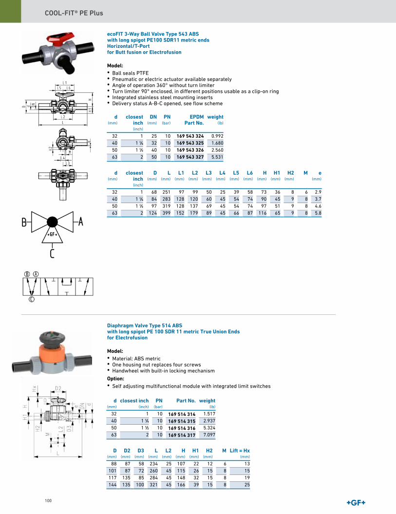
COOL-FIT® PE Plus
100
ecoFIT 3-Way Ball Valve Type 543 ABSwith long spigot PE100 SDR11 metric endsHorizontal/T-Portfor Butt fusion or Electrofusion
Model:• Ball seals PTFE• Pneumatic or electric actuator available separately• Angle of operation 360° without turn limiter• Turn limiter 90° enclosed, in different positions usable as a clip-on ring• Integrated stainless steel mounting inserts• Delivery status A-B-C opened, see flow scheme
d(mm)
closestinch(inch)
DN(mm)
PN(bar)
EPDMPart No.
weight(lb)
32 1 25 10 169 543 324 0.99240 1 1∕4 32 10 169 543 325 1.68050 1 1∕2 40 10 169 543 326 2.56063 2 50 10 169 543 327 5.531
d(mm)
closestinch(inch)
D(mm)
L(mm)
L1(mm)
L2(mm)
L3(mm)
L4(mm)
L5(mm)
L6(mm)
H(mm)
H1(mm)
H2(mm)
M e(mm)
32 1 68 251 97 99 50 25 39 58 73 36 8 6 2.940 1 1∕4 84 283 128 120 60 45 54 74 90 45 9 8 3.750 1 1∕2 97 319 128 137 69 45 54 74 97 51 9 8 4.663 2 124 399 152 179 89 45 66 87 116 65 9 8 5.8
Diaphragm Valve Type 514 ABSwith long spigot PE 100 SDR 11 metric True Union Endsfor Electrofusion
Model:• Material: ABS metric• One housing nut replaces four screws• Handwheel with built-in locking mechanism Option:• Self adjusting multifunctional module with integrated limit switches
d(mm)
closest inch(inch)
PN(bar)
Part No. weight(lb)
32 1 10 1.51740 1 1∕4 10 2.93750 1 1∕2 10 5.32463 2 10 7.097
D(mm)
D2(mm)
D3(mm)
L(mm)
L2(mm)
H(mm)
H1(mm)
H2(mm)
M Lift = Hx(mm)
88 87 58 234 25 107 22 12 6 13101 87 72 260 45 115 26 15 8 15117 135 85 284 45 148 32 15 8 19144 135 100 321 45 166 39 15 8 25
169 514 314169 514 315169 514 316169 514 317
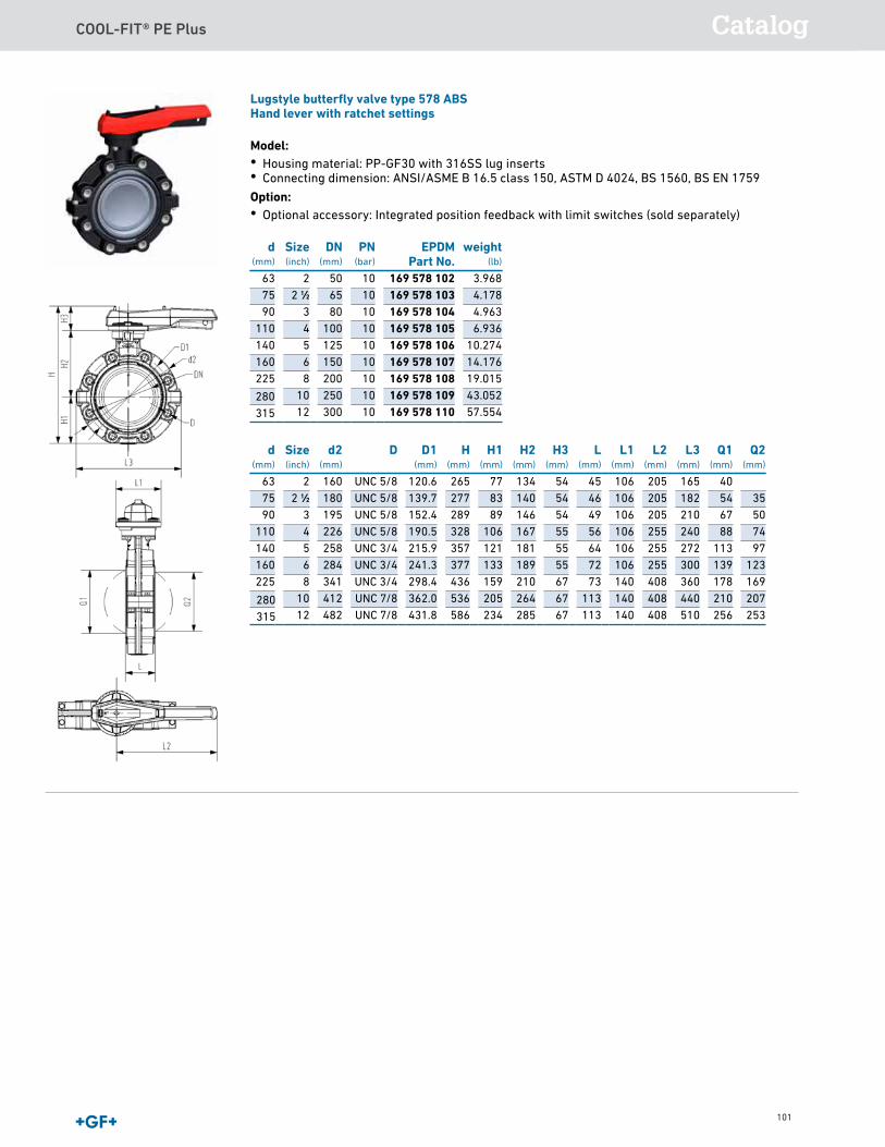
COOL-FIT® PE Plus Catalog
101
Lugstyle butterfly valve type 578 ABSHand lever with ratchet settings
Model:• Housing material: PP-GF30 with 316SS lug inserts• Connecting dimension: ANSI/ASME B 16.5 class 150, ASTM D 4024, BS 1560, BS EN 1759 Option:• Optional accessory: Integrated position feedback with limit switches (sold separately)
d(mm)
Size(inch)
DN(mm)
PN(bar)
EPDMPart No.
weight(lb)
63 2 50 10 169 578 102 3.96875 2 1∕2 65 10 169 578 103 4.17890 3 80 10 169 578 104 4.963
110 4 100 10 169 578 105 6.936140 5 125 10 169 578 106 10.274160 6 150 10 169 578 107 14.176225 8 200 10 169 578 108 19.015
10 250 10 169 578 109 43.05212 300 10 169 578 110 57.554
d(mm)
Size(inch)
d2(mm)
D D1(mm)
H(mm)
H1(mm)
H2(mm)
H3(mm)
L(mm)
L1(mm)
L2(mm)
L3(mm)
Q1(mm)
Q2(mm)
63 2 160 UNC 5/8 120.6 265 77 134 54 45 106 205 165 4075 2 1∕2 180 UNC 5/8 139.7 277 83 140 54 46 106 205 182 54 3590 3 195 UNC 5/8 152.4 289 89 146 54 49 106 205 210 67 50
110 4 226 UNC 5/8 190.5 328 106 167 55 56 106 255 240 88 74140 5 258 UNC 3/4 215.9 357 121 181 55 64 106 255 272 113 97160 6 284 UNC 3/4 241.3 377 133 189 55 72 106 255 300 139 123225 8 341 UNC 3/4 298.4 436 159 210 67 73 140 408 360 178 169
10 412 UNC 7/8 362.0 536 205 264 67 113 140 408 440 210 20712 482 UNC 7/8 431.8 586 234 285 67 113 140 408 510 256 253
280315
280315

COOL-FIT® PE Plus
102
Lugstyle butterfly valve type 578 ABSReduction gear with handwheel
Model:• Housing material: PP-GF30 with 316SS lug inserts• Connecting dimension: ANSI/ASME B 16.5 class 150, ASTM D 4024, BS 1560, BS EN 1759 Option:• Optional accessory: Integrated position feedback with limit switches (sold separately)
d(mm)
Size(inch)
DN(mm)
PN(bar)
EPDMPart No.
weight(lb)
2 50 10 169 578 122 7.6432 1∕2 65 10 169 578 123 7.959
3 80 10 169 578 124 8.6624 100 10 169 578 125 10.6575 125 10 169 578 126 13.9956 150 10 169 578 127 17.8778 200 10 169 578 128 20.620
10 250 10 169 578 129 43.05212 300 10 169 578 130 57.554
d(mm)
Size(inch)
d2(mm)
D D1(mm)
D3(mm)
H(mm)
H1(mm)
H2(mm)
H3(mm)
H4(mm)
L(mm)
L1(mm)
L2(mm)
L3(mm)
63 2 160 UNC 5/8 120.6 150 273 77 134 62 23 45 78 112 17975 2 1∕2 180 UNC 5/8 139.7 150 285 83 140 62 23 46 78 112 17990 3 195 UNC 5/8 152.4 150 297 89 146 62 23 49 78 112 179
110 4 226 UNC 5/8 190.5 150 335 106 167 62 23 56 78 112 179140 5 258 UNC 3/4 215.9 150 364 121 181 62 23 64 78 112 179160 6 284 UNC 3/4 241.3 160 384 133 189 62 23 72 78 112 179225 8 341 UNC 3/4 298.4 160 431 159 210 62 23 73 78 112 179
10 412 UNC 7/8 362.0 200 524 205 264 55 23 113 130 140 44012 482 UNC 7/8 431.8 200 574 234 285 55 23 113 130 140 510
d(mm)
Size(inch)
L4(mm)
Q1(mm)
Q2(mm)
63 2 165 4075 2 1∕2 182 54 3590 3 210 67 50
110 4 240 88 74140 5 272 113 97160 6 300 139 123225 8 360 178 169
10 200 210 20712 200 256 253
637590
110140160225280315
280315
280315
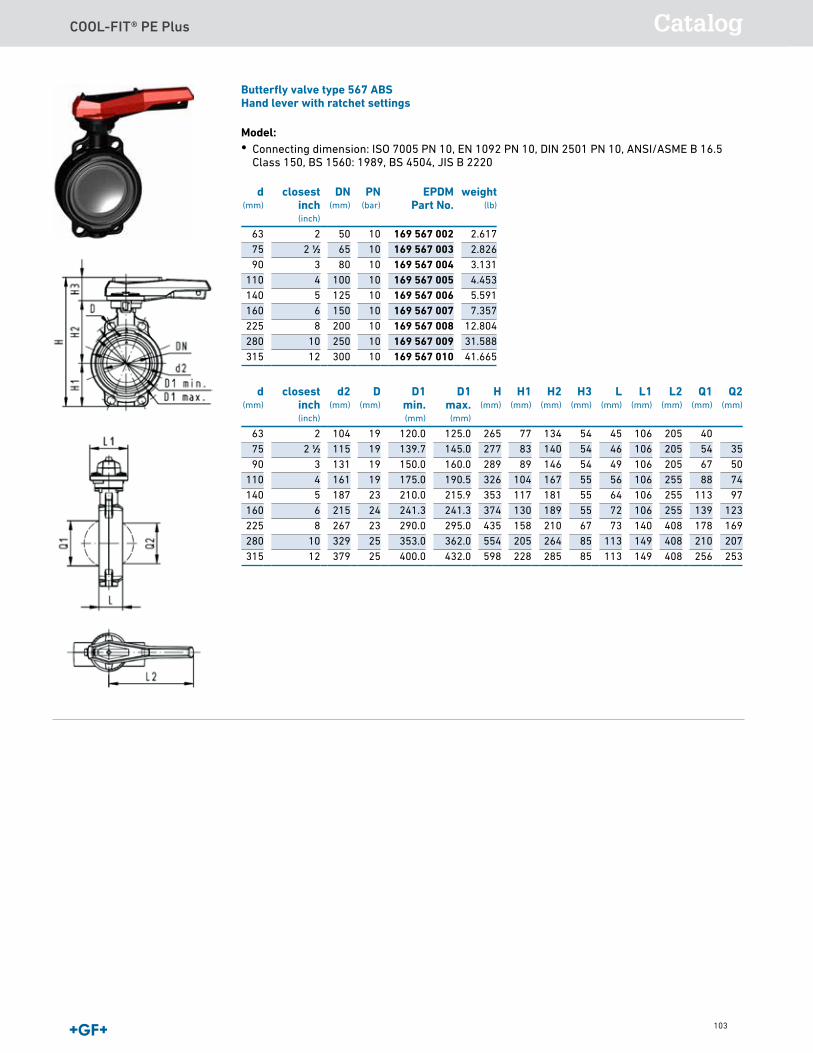
COOL-FIT® PE Plus Catalog
103
Butterfly valve type 567 ABSHand lever with ratchet settings
Model:• Connecting dimension: ISO 7005 PN 10, EN 1092 PN 10, DIN 2501 PN 10, ANSI/ASME B 16.5
Class 150, BS 1560: 1989, BS 4504, JIS B 2220
d(mm)
closestinch(inch)
DN(mm)
PN(bar)
EPDMPart No.
63 2 50 10 169 567 00275 2 1∕2 65 10 169 567 00390 3 80 10 169 567 004
110 4 100 10 169 567 005140 5 125 10 169 567 006160 6 150 10 169 567 007225 8 200 10 169 567 008280 10 250 10 169 567 009315 12 300 10 169 567 010
d(mm)
closestinch(inch)
d2(mm)
D(mm)
D1min.(mm)
D1max.
(mm)
H(mm)
H1(mm)
H2(mm)
H3(mm)
L(mm)
L1(mm)
L2(mm)
Q1(mm)
Q2(mm)
63 2 104 19 120.0 125.0 265 77 134 54 45 106 205 4075 2 1∕2 115 19 139.7 145.0 277 83 140 54 46 106 205 54 3590 3 131 19 150.0 160.0 289 89 146 54 49 106 205 67 50
110 4 161 19 175.0 190.5 326 104 167 55 56 106 255 88 74140 5 187 23 210.0 215.9 353 117 181 55 64 106 255 113 97160 6 215 24 241.3 241.3 374 130 189 55 72 106 255 139 123225 8 267 23 290.0 295.0 435 158 210 67 73 140 408 178 169280 10 329 25 353.0 362.0 554 205 264 85 113 149 408 210 207315 12 379 25 400.0 432.0 598 228 285 85 113 149 408 256 253
2.6172.8263.1314.4535.5917.357
12.80431.58841.665
weight(lb)
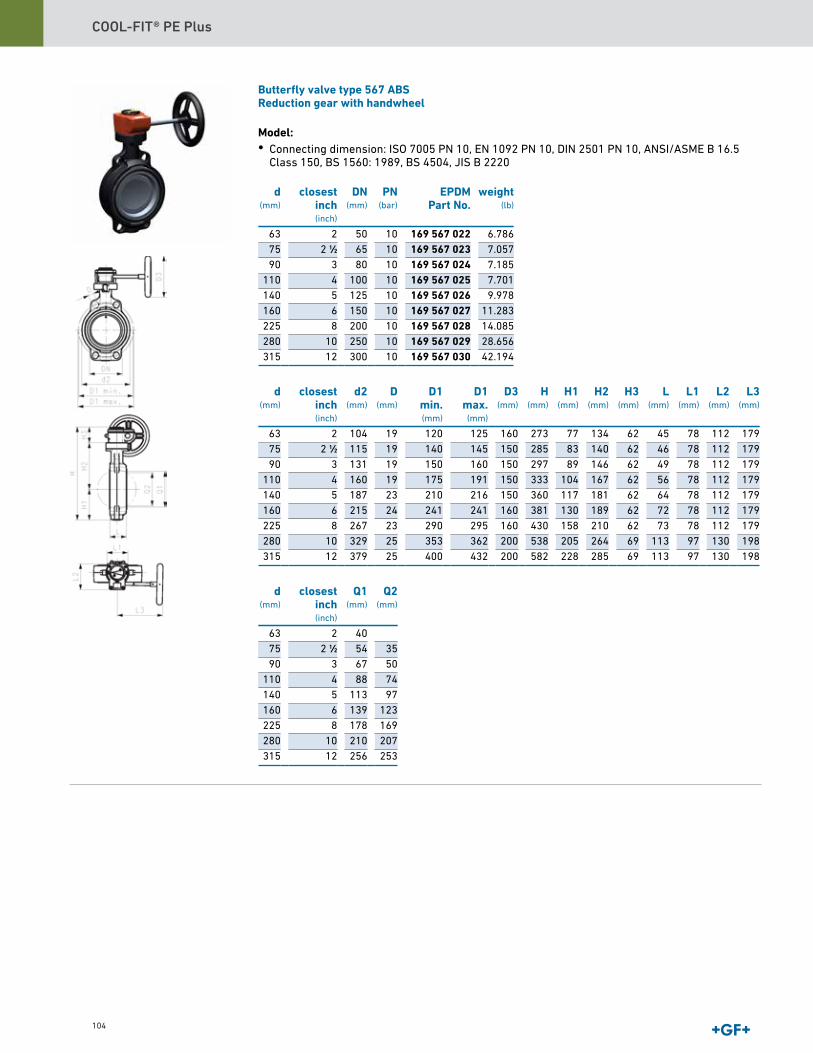
COOL-FIT® PE Plus
104
Butterfly valve type 567 ABSReduction gear with handwheel
Model:• Connecting dimension: ISO 7005 PN 10, EN 1092 PN 10, DIN 2501 PN 10, ANSI/ASME B 16.5
Class 150, BS 1560: 1989, BS 4504, JIS B 2220
d(mm)
closestinch(inch)
DN(mm)
PN(bar)
EPDMPart No.
63 2 50 10 169 567 02275 2 1∕2 65 10 169 567 02390 3 80 10 169 567 024
110 4 100 10 169 567 025140 5 125 10 169 567 026160 6 150 10 169 567 027225 8 200 10 169 567 028280 10 250 10 169 567 029315 12 300 10 169 567 030
d(mm)
closestinch(inch)
d2(mm)
D(mm)
D1min.(mm)
D1max.
(mm)
D3(mm)
H(mm)
H1(mm)
H2(mm)
H3(mm)
L(mm)
L1(mm)
L2(mm)
L3(mm)
63 2 104 19 120 125 160 273 77 134 62 45 78 112 17975 2 1∕2 115 19 140 145 150 285 83 140 62 46 78 112 17990 3 131 19 150 160 150 297 89 146 62 49 78 112 179
110 4 160 19 175 191 150 333 104 167 62 56 78 112 179140 5 187 23 210 216 150 360 117 181 62 64 78 112 179160 6 215 24 241 241 160 381 130 189 62 72 78 112 179225 8 267 23 290 295 160 430 158 210 62 73 78 112 179280 10 329 25 353 362 200 538 205 264 69 113 97 130 198315 12 379 25 400 432 200 582 228 285 69 113 97 130 198
d(mm)
closestinch(inch)
Q1(mm)
Q2(mm)
63 2 4075 2 1∕2 54 3590 3 67 50
110 4 88 74140 5 113 97160 6 139 123225 8 178 169280 10 210 207315 12 256 253
6.7867.0577.1857.7019.978
11.28314.08528.65642.194
weight(lb)
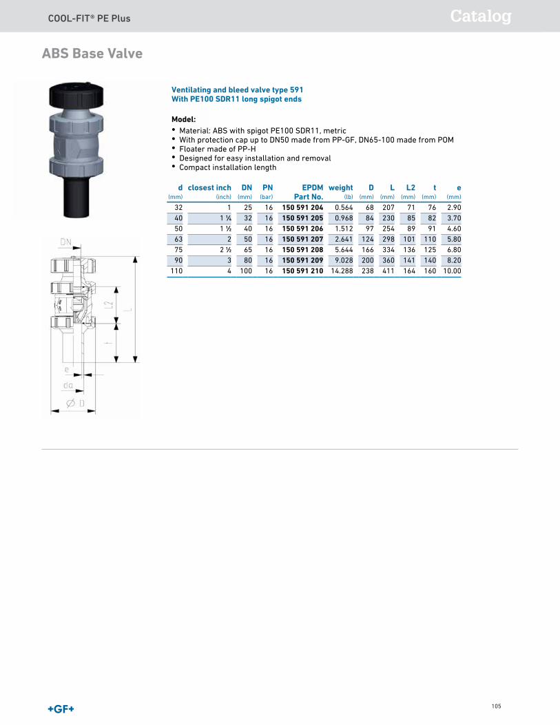
COOL-FIT® PE Plus Catalog
105
ABS Base Valve
Ventilating and bleed valve type 591With PE100 SDR11 long spigot ends
Model:• Material: ABS with spigot PE100 SDR11, metric• With protection cap up to DN50 made from PP-GF, DN65-100 made from POM• Floater made of PP-H• Designed for easy installation and removal• Compact installation length
d(mm)
closest inch(inch)
DN(mm)
PN(bar)
EPDMPart No.
weight(lb)
D(mm)
L(mm)
L2(mm)
t(mm)
e(mm)
32 1 25 16 150 591 204 0.564 68 207 71 76 2.9040 1 1∕4 32 16 150 591 205 0.968 84 230 85 82 3.7050 1 1∕2 40 16 150 591 206 1.512 97 254 89 91 4.6063 2 50 16 150 591 207 2.641 124 298 101 110 5.8075 2 1∕2 65 16 150 591 208 5.644 166 334 136 125 6.8090 3 80 16 150 591 209 9.028 200 360 141 140 8.20
110 4 100 16 150 591 210 14.288 238 411 164 160 10.00

COOL-FIT® PE Plus
106
Ventilating valve type 595 With PE100 SDR11 long spigot ends
Model:• Material: ABS with spigot PE100 SDR11, metric• With protection cap up to DN50 made from PP-GF, DN65-100 made from POM• Floater made of PP-H• Designed for easy installation and removal• Compact installation length
d(mm)
closest inch(inch)
DN(mm)
PN(bar)
EPDMPart No.
weight(lb)
D(mm)
L(mm)
L2(mm)
t(mm)
e(mm)
32 1 25 16 150 595 204 0.564 68 207 71 76 2.9040 1 1∕4 32 16 150 595 205 0.968 84 230 85 82 3.7050 1 1∕2 40 16 150 595 206 1.512 97 254 89 91 4.6063 2 50 16 150 595 207 2.641 124 298 101 110 5.8075 2 1∕2 65 16 150 595 208 5.644 166 334 136 125 6.8090 3 80 16 150 595 209 9.028 200 360 141 140 8.20
110 4 100 16 150 595 210 14.288 238 411 164 160 10.00
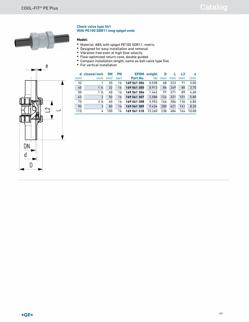
COOL-FIT® PE Plus Catalog
107
Check valve type 561With PE100 SDR11 long spigot ends
Model:• Material: ABS with spigot PE100 SDR11, metric• Designed for easy installation and removal• Vibration free even at high flow velocity• Flow-optimized return cone, double guided• Compact installation length, same as ball valve type 546• For vertical installation
d(mm)
closest inch(inch)
DN(mm)
PN(bar)
EPDMPart No.
weight(lb)
D(mm)
L(mm)
L2(mm)
e(mm)
32 1 25 16 0.538 68 223 71 3.0040 1 1∕4 32 16 0.913 84 249 85 3.7050 1 1∕2 40 16 1.442 97 271 89 4.6063 2 50 16 2.588 124 321 101 5.8075 2 1∕2 65 16 5.952 166 386 136 6.8090 3 80 16 9.436 200 421 141 8.20
110 4 100 16 15.260 238 484 164 10.00
169 561 304169 561 305169 561 306169 561 307169 561 308169 561 309169 561 310
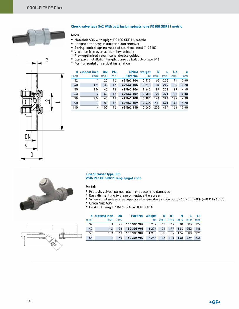
COOL-FIT® PE Plus
108
Line Strainer type 305With PE100 SDR11 long spigot ends
Model:• Protects valves, pumps, etc. from becoming damaged• Easy dismantling to clean or replace the screen• Screen in stainless steel operable temperature range up to -40oF to 140oF (-40oC to 60oC )• Union Nut: ABS• Gasket: O-ring EPDM Nr. 748 410 008-014
d(mm)
closest inch(inch)
DN(mm)
Part No. weight(lb)
D(mm)
D1(mm)
H(mm)
L(mm)
L1(mm)
32 1 25 150 305 904 0.732 62 65 90 306 17440 1 1∕4 32 150 305 905 1.274 71 77 104 352 18850 1 1∕2 40 150 305 906 1.953 88 84 124 380 22263 2 50 150 305 907 3.263 103 105 148 429 264
Check valve type 562 With butt fusion spigots long PE100 SDR11 metric
Model:• Material: ABS with spigot PE100 SDR11, metric• Designed for easy installation and removal• Spring loaded, spring made of stainless steel (1.4310)• Vibration free even at high flow velocity• Flow-optimized return cone, double guided• Compact installation length, same as ball valve type 546• For horizontal or vertical installation
d(mm)
closest inch(inch)
DN(mm)
PN(bar)
EPDMPart No.
weight(lb)
D(mm)
L(mm)
L2(mm)
e(mm)
32 1 25 16 169 562 304 0.538 68 223 71 3.0040 1 1∕4 32 16 169 562 305 0.913 84 249 85 3.7050 1 1∕2 40 16 169 562 306 1.442 97 271 89 4.6063 2 50 16 169 562 307 2.588 124 321 101 5.8075 2 1∕2 65 16 169 562 308 5.952 166 386 136 6.8090 3 80 16 169 562 309 9.436 200 421 141 8.20
110 4 100 16 169 562 310 15.260 238 484 164 10.00
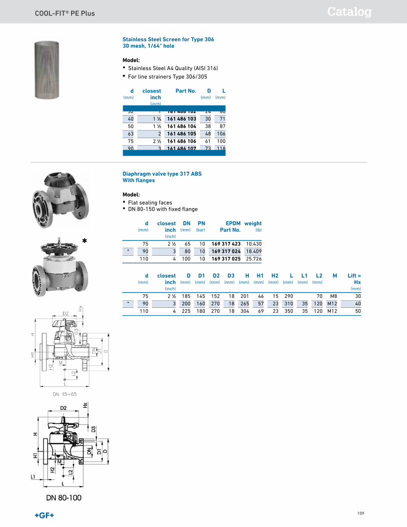
COOL-FIT® PE Plus Catalog
109
Stainless Steel Screen for Type 30630 mesh, 1/64" hole
Model:• Stainless Steel A4 Quality (AISI 316) •
d(mm)
Part No. D(mm)
L(mm)
closestinch(inch)
32 161 486 102 24 60140 161 486 103 30 711 1∕450 161 486 104 38 871 1∕263 161 486 105 48 106275 161 486 106 61 1002 1∕290 161 486 107 73 1183
Diaphragm valve type 317 ABSWith flanges
Model:• Flat sealing faces• DN 80-150 with fixed flange
d(mm)
closestinch(inch)
DN(mm)
PN(bar)
EPDMPart No.
weight(lb)
75 2 1∕2 65 10 169 317 423 10.430* 90 3 80 10 169 317 024 18.409
110 4 100 10 169 317 025 25.726
d(mm)
closestinch(inch)
D(mm)
D1(mm)
D2(mm)
D3(mm)
H(mm)
H1(mm)
H2(mm)
L(mm)
L1(mm)
L2(mm)
M Lift =Hx
(mm)
75 2 1∕2 185 145 152 18 201 46 15 290 70 M8 30* 90 3 200 160 270 18 265 57 23 310 35 120 M12 40
110 4 225 180 270 18 304 69 23 350 35 120 M12 50
• For line strainers Type 306/305
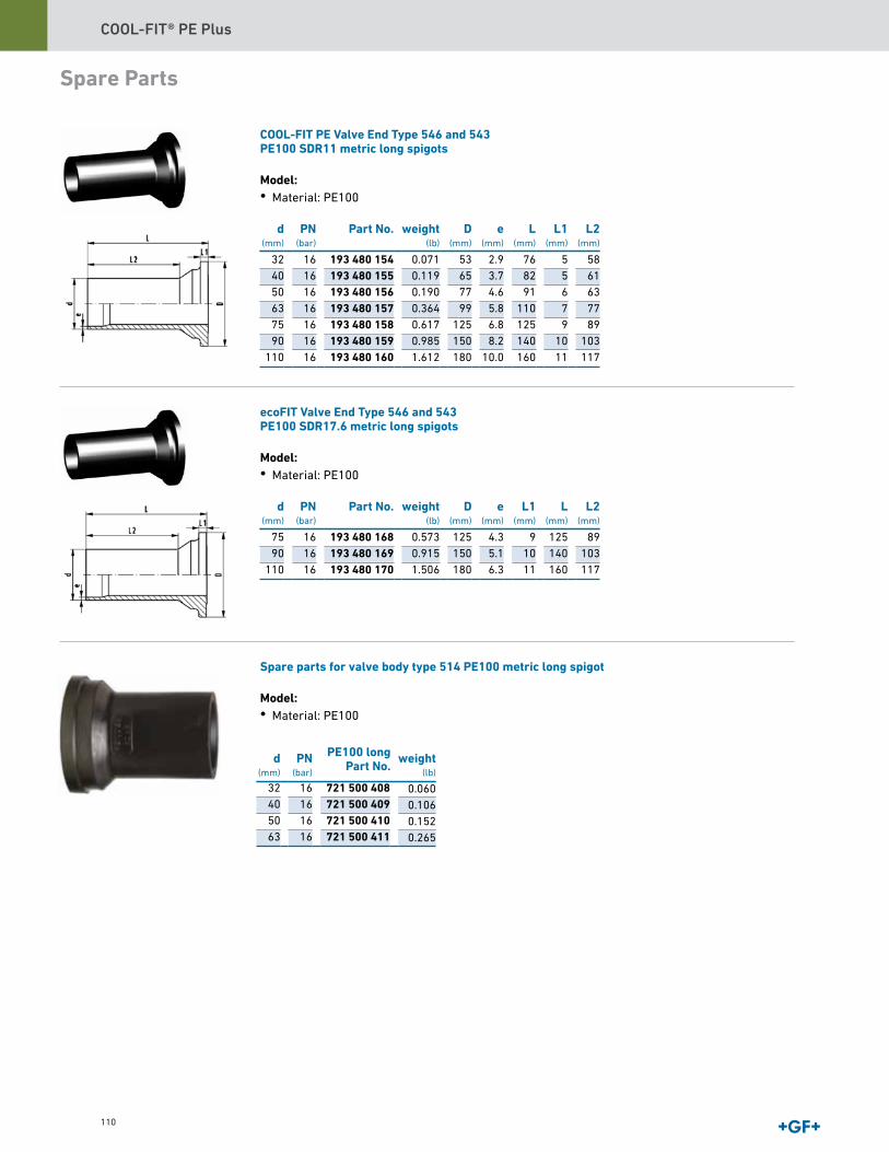
COOL-FIT® PE Plus
110
Spare Parts
COOL-FIT PE Valve End Type 546 and 543PE100 SDR11 metric long spigots
Model:• Material: PE100
d(mm)
PN(bar)
Part No. D(mm)
e(mm)
L(mm)
L1(mm)
L2(mm)
32 16 193 480 154 53 2.9 76 5 5840 16 193 480 155 65 3.7 82 5 6150 16 193 480 156 77 4.6 91 6 6363 16 193 480 157 99 5.8 110 7 7775 16 193 480 158 125 6.8 125 9 8990 16 193 480 159 150 8.2 140 10 103
110 16 193 480 160 180 10.0 160 11 117
ecoFIT Valve End Type 546 and 543PE100 SDR17.6 metric long spigots
Model:• Material: PE100
d(mm)
PN(bar)
Part No. weight(lb)
D(mm)
e(mm)
L1(mm)
L(mm)
L2(mm)
75 16 193 480 168 0.573 125 4.3 9 125 8990 16 193 480 169 0.915 150 5.1 10 140 103
110 16 193 480 170 1.506 180 6.3 11 160 117
Spare parts for valve body type 514 PE100 metric long spigot
Model:• Material: PE100
0.0710.1190.1900.3640.6170.9851.612
weight(lb)
32 16 721 500 40840 16 721 500 40950 16 721 500 41063 16 721 500 411
0.0600.1060.1520.265
d(mm)
PN(bar)
weight(lb)
PE100 longPart No.

COOL-FIT® PE Plus Catalog
111
Union nut 546 and 543 ABS
d(mm)
DN(mm)
Part No. weight(lb)
D(mm)
D1(mm)
L(mm)
S(mm)
32 25 169 480 715 0.066 68 47 24 5840 32 169 480 716 0.104 84 57 27 7150 40 169 480 717 0.148 97 65 30 8463 50 169 480 718 0.306 124 79 36 10675 65 169 480 719 0.959 166 94 48 13590 80 169 480 720 1.506 200 113 54 135
110 100 169 480 721 2.310 238 137 60 198
Handle extension for Ball valve type 546, 75-110mm
Model:• Height Variable• Multiple use in succession possible.
d-d(mm)
Part No. SP weight(lb)
H(mm)
D(mm)
H1(mm)
75 ‐ 90 161 490 920 1 0.712 143 58 100- ‐ 110 161 490 921 1 0.911 143 64 100
COOL-FIT PE Plus Insulation for Ball valve type 546
Model:• Set consisting of half shells and clamps
d(mm)
Part No. weight(lb)
32 738 990 308 0.35340 738 990 309 0.50350 738 990 310 0.62263 738 990 311 1.09875 738 990 312 2.06190 738 990 313 2.277

COOL-FIT® PE Plus
112
COOL-FIT PE Plus Insulation for Butterfly valve type 567
Model:• Set consisting of half shells and clamps
d(mm)
Part No. weight(lb)
546 Ball Valve Insulation Kit
Model:• Insulation made from PE• Outer jacket UV resistant• For Ball Valve Type 546 * handle extension for ball valve recommended, d75/90 161.490.920, d110 161.490.921
d(mm)
Part No. SP weight(lb)
L(mm)
D(mm)
closestinch(inch)
D1(mm)
32 738 990 139 1 0.220 121 96 1 9440 738 990 140 1 0.220 143 110 1 1∕4 11050 738 990 141 1 0.220 156 122 1 1∕2 12063 738 990 142 1 0.220 181 150 2 147
* 75 738 990 143 1 0.220 235 190 2 1∕2 185* 90 738 990 144 1 0.220 255 226 3 221* 110 738 990 145 1 2.425 300 268 4 262
110
160
225
738 990 327
738 990 324
738 990 330
4.528
8.101
10.606

COOL-FIT® PE Plus Catalog
113
Actuated Valves
Ball valve type 127 ABS 100-230VWith manual emergency overrideWith PE100 SDR11 long spigot ends
Model:• Built with electric actuator EA15• Voltage 100-230V, 50-60Hz• Factory set control range 90°<)• Heating element, position feedback (Open/Close)• Integrated stainless steel mounting inserts Option:• Fail-safe return unit
d(mm)
closest inch(inch)
D(mm)
H(mm)
H1(mm)
H2(mm)
H3(mm)
H5(mm)
L(mm)
L1(mm)
L2(mm)
L3(mm)
L4(mm)
L5(mm)
L6(mm)
32 1 68 209 36 73 64 137 223 161 71 160 25 77 8340 1 1∕4 84 220 44 84 64 137 249 161 85 180 45 77 8350 1 1∕2 97 220 51 84 64 137 271 161 89 200 45 77 8363 2 124 243 64 106 64 137 320 161 101 230 45 77 83
d(mm)
closest inch(inch)
L7(mm)
L8(mm)
z(mm)
32 1 122 33 7940 1 1∕4 122 33 9450 1 1∕2 122 33 9563 2 122 33 107
d(mm)
closest inch(inch)
DN(mm)
PN(bar)
EPDMPart No.
weight(lb)
32 1 25 10 5.02040 1 1∕4 32 10 5.78950 1 1∕2 40 10 6.63263 2 50 10 7.480
199 127 385199 127 386199 127 387199 127 388
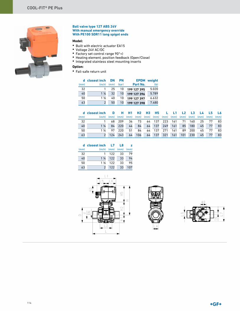
COOL-FIT® PE Plus
114
d(mm)
closest inch(inch)
D(mm)
H(mm)
H1(mm)
H2(mm)
H3(mm)
H5(mm)
L(mm)
L1(mm)
L2(mm)
L3(mm)
L4(mm)
L5(mm)
L6(mm)
32 1 68 209 36 73 64 137 223 161 71 160 25 77 8340 1 1∕4 84 220 44 84 64 137 249 161 85 180 45 77 8350 1 1∕2 97 220 51 84 64 137 271 161 89 200 45 77 8363 2 124 243 64 106 64 137 321 161 101 230 45 77 83
d(mm)
closest inch(inch)
L7(mm)
L8(mm)
z(mm)
32 1 122 33 7940 1 1∕4 122 33 9450 1 1∕2 122 33 9563 2 122 33 107
d(mm)
closest inch(inch)
DN(mm)
PN(bar)
EPDMPart No.
weight(lb)
32 1 25 10 5.02040 1 1∕4 32 10 5.78950 1 1∕2 40 10 6.63263 2 50 10 7.480
199 127 395199 127 396199 127 397199 127 398
Ball valve type 127 ABS 24VWith manual emergency overrideWith PE100 SDR11 long spigot ends
Model:• Built with electric actuator EA15• Voltage 24V AC/DC• Factory set control range 90°<)• Heating element, position feedback (Open/Close)• Integrated stainless steel mounting inserts Option:• Fail-safe return unit
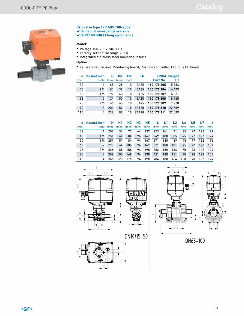
COOL-FIT® PE Plus Catalog
115
Ball valve type 179 ABS 100-230VWith manual emergency overrideWith PE100 SDR11 long spigot ends
Model:• Voltage 100-230V, 50-60Hz• Factory set control range 90°<)• Integrated stainless steel mounting inserts Option:• Fail-safe return unit, Monitoring board, Position controller, Profibus DP board
d(mm)
closest inch(inch)
H(mm)
H1(mm)
H2(mm)
H3(mm)
H5(mm)
L(mm)
L1(mm)
L2(mm)
L4(mm)
L5(mm)
L7(mm)
z(mm)
32 1 209 36 73 64 137 223 161 71 25 77 122 7940 1 1∕4 251 44 84 94 167 249 180 85 45 97 122 9450 1 1∕2 251 51 84 94 167 271 180 89 45 97 122 9563 2 273 64 106 94 167 321 180 101 45 97 122 10775 2 1∕2 346 85 156 94 190 386 180 136 70 98 122 14490 3 358 105 168 94 190 421 180 141 70 98 122 151
110 4 365 123 175 94 190 484 180 164 120 98 122 174
d(mm)
closest inch(inch)
D(mm)
DN(mm)
PN(bar)
EA EPDMPart No.
weight(lb)
32 1 68 25 10 EA25 150 179 205 5.88440 1 1∕4 84 32 10 EA25 150 179 206 6.47950 1 1∕2 97 40 10 EA25 150 179 207 6.82163 2 124 50 10 EA25 150 179 208 8.96075 2 1∕2 166 65 10 EA45 150 179 209 17.22090 3 200 80 10 EA120 150 179 210 22.509
110 4 238 100 10 EA120 150 179 211 32.589
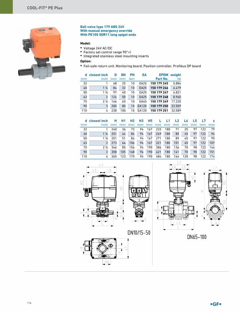
COOL-FIT® PE Plus
116
Ball valve type 179 ABS 24VWith manual emergency overrideWith PE100 SDR11 long spigot ends
Model:• Voltage 24V AC/DC• Factory set control range 90°<)• Integrated stainless steel mounting inserts Option:• Fail-safe return unit, Monitoring board, Position controller, Profibus DP board
d(mm)
closest inch(inch)
H(mm)
H1(mm)
H2(mm)
H3(mm)
H5(mm)
L(mm)
L1(mm)
L2(mm)
L4(mm)
L5(mm)
L7(mm)
z(mm)
32 1 240 36 73 94 167 233 180 71 25 97 122 7940 1 1∕4 251 44 84 94 167 249 180 85 45 97 122 9450 1 1∕2 251 51 84 94 167 271 180 89 45 97 122 9563 2 273 64 106 94 167 321 180 101 45 97 122 10775 2 1∕2 346 85 156 94 190 386 180 136 70 98 122 14490 3 358 105 168 94 190 421 180 141 70 98 122 151
110 4 365 123 175 94 190 484 180 164 120 98 122 174
d(mm)
closest inch(inch)
D(mm)
DN(mm)
PN(bar)
EA EPDMPart No.
weight(lb)
32 1 68 25 10 EA25 150 179 245 5.88440 1 1∕4 84 32 10 EA25 150 179 246 6.47950 1 1∕2 97 40 10 EA25 150 179 247 6.82163 2 124 50 10 EA25 150 179 248 8.96075 2 1∕2 166 65 10 EA45 150 179 249 17.22090 3 200 80 10 EA120 150 179 250 22.509
110 4 238 100 10 EA120 150 179 251 32.589
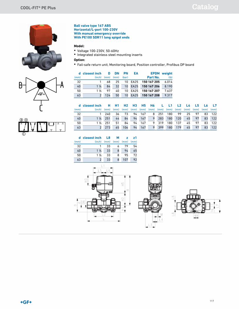
COOL-FIT® PE Plus Catalog
117
Ball valve type 179 ABS 24VWith manual emergency overrideWith PE100 SDR11 long spigot ends
Model:• Voltage 24V AC/DC• Factory set control range 90°<)• Integrated stainless steel mounting inserts Option:• Fail-safe return unit, Monitoring board, Position controller, Profibus DP board
d(mm)
closest inch(inch)
H(mm)
H1(mm)
H2(mm)
H3(mm)
H5(mm)
L(mm)
L1(mm)
L2(mm)
L4(mm)
L5(mm)
L7(mm)
z(mm)
32 1 240 36 73 94 167 233 180 71 25 97 122 7940 1 1∕4 251 44 84 94 167 249 180 85 45 97 122 9450 1 1∕2 251 51 84 94 167 271 180 89 45 97 122 9563 2 273 64 106 94 167 321 180 101 45 97 122 10775 2 1∕2 346 85 156 94 190 386 180 136 70 98 122 14490 3 358 105 168 94 190 421 180 141 70 98 122 151
110 4 365 123 175 94 190 484 180 164 120 98 122 174
d(mm)
closest inch(inch)
D(mm)
DN(mm)
PN(bar)
EA EPDMPart No.
weight(lb)
32 1 68 25 10 EA25 150 179 245 5.88440 1 1∕4 84 32 10 EA25 150 179 246 6.47950 1 1∕2 97 40 10 EA25 150 179 247 6.82163 2 124 50 10 EA25 150 179 248 8.96075 2 1∕2 166 65 10 EA45 150 179 249 17.22090 3 200 80 10 EA120 150 179 250 22.509
110 4 238 100 10 EA120 150 179 251 32.589
Ball valve type 167 ABSHorizontal/L-port 100-230VWith manual emergency overrideWith PE100 SDR11 long spigot ends
Model:• Voltage 100-230V, 50-60Hz• Integrated stainless steel mounting inserts Option:• Fail-safe return unit, Monitoring board, Position controller, Profibus DP board
d(mm)
closest inch(inch)
H(mm)
H1(mm)
H2(mm)
H3(mm)
H5(mm)
H6(mm)
L(mm)
L1(mm)
L2(mm)
L4(mm)
L5(mm)
L6(mm)
L7(mm)
32 1 240 36 73 94 167 8 251 180 99 25 97 83 12240 1 1∕4 251 44 84 94 167 9 283 180 120 45 97 83 12250 1 1∕2 251 51 84 94 167 9 319 180 137 45 97 83 12263 2 273 65 106 94 167 9 399 180 179 45 97 83 122
d(mm)
closest inch(inch)
L8(mm)
M(mm)
z(mm)
z1(mm)
32 1 33 6 79 5440 1 1∕4 33 8 94 6550 1 1∕2 33 8 95 7263 2 33 8 107 92
d(mm)
closest inch(inch)
D(mm)
DN(mm)
PN(bar)
EA EPDMPart No.
weight(lb)
32 1 68 25 10 EA25 150 167 205 6.01440 1 1∕4 84 32 10 EA25 150 167 206 8.19050 1 1∕2 97 40 10 EA25 150 167 207 7.63763 2 124 50 10 EA25 150 167 208 9.317

COOL-FIT® PE Plus
118
Ball valve type 167 ABSHorizontal/L-port 24VWith manual emergency overrideWith PE100 SDR11 long spigot ends
Model:• Voltage 24V AC/DC• Integrated stainless steel mounting inserts Option:• Fail-safe return unit, Monitoring board, Position controller, Profibus DP board
d(mm)
closest inch(inch)
H(mm)
H1(mm)
H2(mm)
H3(mm)
H5(mm)
H6(mm)
L(mm)
L1(mm)
L2(mm)
L4(mm)
L5(mm)
L6(mm)
L7(mm)
32 1 240 36 73 94 167 8 251 180 99 25 97 83 12240 1 1∕4 251 44 84 94 167 9 283 180 120 45 97 83 12250 1 1∕2 251 51 84 94 167 9 319 180 137 45 97 83 12263 2 273 65 106 94 167 9 399 180 179 45 97 83 122
d(mm)
closest inch(inch)
L8(mm)
M(mm)
z(mm)
z1(mm)
32 1 33 6 79 5440 1 1∕4 33 8 94 6550 1 1∕2 33 8 95 7263 2 33 8 107 92
d(mm)
closest inch(inch)
D(mm)
DN(mm)
PN(bar)
EA EPDMPart No.
weight(lb)
32 1 68 25 10 EA25 150 167 245 6.01440 1 1∕4 84 32 10 EA25 150 167 246 8.19050 1 1∕2 97 40 10 EA25 150 167 247 7.63763 2 124 50 10 EA25 150 167 248 9.317
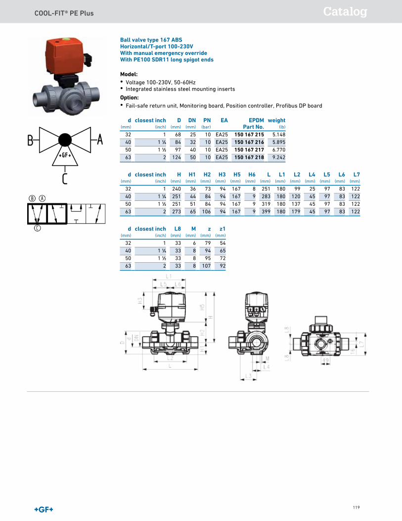
COOL-FIT® PE Plus Catalog
119
Ball valve type 167 ABSHorizontal/T-port 100-230VWith manual emergency overrideWith PE100 SDR11 long spigot ends
Model:• Voltage 100-230V, 50-60Hz• Integrated stainless steel mounting inserts Option:• Fail-safe return unit, Monitoring board, Position controller, Profibus DP board
d(mm)
closest inch(inch)
H(mm)
H1(mm)
H2(mm)
H3(mm)
H5(mm)
H6(mm)
L(mm)
L1(mm)
L2(mm)
L4(mm)
L5(mm)
L6(mm)
L7(mm)
32 1 240 36 73 94 167 8 251 180 99 25 97 83 12240 1 1∕4 251 44 84 94 167 9 283 180 120 45 97 83 12250 1 1∕2 251 51 84 94 167 9 319 180 137 45 97 83 12263 2 273 65 106 94 167 9 399 180 179 45 97 83 122
d(mm)
closest inch(inch)
L8(mm)
M(mm)
z(mm)
z1(mm)
32 1 33 6 79 5440 1 1∕4 33 8 94 6550 1 1∕2 33 8 95 7263 2 33 8 107 92
d(mm)
closest inch(inch)
D(mm)
DN(mm)
PN(bar)
EA EPDMPart No.
weight(lb)
32 1 68 25 10 EA25 150 167 215 5.14840 1 1∕4 84 32 10 EA25 150 167 216 5.89550 1 1∕2 97 40 10 EA25 150 167 217 6.77063 2 124 50 10 EA25 150 167 218 9.242

COOL-FIT® PE Plus
120
Ball valve type 167 ABSHorizontal/T-port 24VWith manual emergency overrideWith PE100 SDR11 long spigot ends
Model:• Voltage 24V AC/DC• Integrated stainless steel mounting inserts Option:• Fail-safe return unit, Monitoring board, Position controller, Profibus DP board
d(mm)
closest inch(inch)
H(mm)
H1(mm)
H2(mm)
H3(mm)
H5(mm)
H6(mm)
L(mm)
L1(mm)
L2(mm)
L4(mm)
L5(mm)
L6(mm)
L7(mm)
32 1 240 36 73 94 167 8 251 180 99 25 97 83 12240 1 1∕4 251 44 84 94 167 9 283 180 120 45 97 83 12250 1 1∕2 251 51 84 94 167 9 319 180 137 45 97 83 12263 2 273 65 106 94 167 9 399 180 179 45 97 83 122
d(mm)
closest inch(inch)
L8(mm)
M(mm)
z(mm)
z1(mm)
32 1 33 6 79 5440 1 1∕4 33 8 94 6550 1 1∕2 33 8 95 7263 2 33 8 107 92
d(mm)
closest inch(inch)
D(mm)
DN(mm)
PN(bar)
EA EPDMPart No.
weight(lb)
32 1 68 25 10 EA25 150 167 255 5.14840 1 1∕4 84 32 10 EA25 150 167 256 5.89550 1 1∕2 97 40 10 EA25 150 167 257 6.77063 2 124 50 10 EA25 150 167 258 9.242
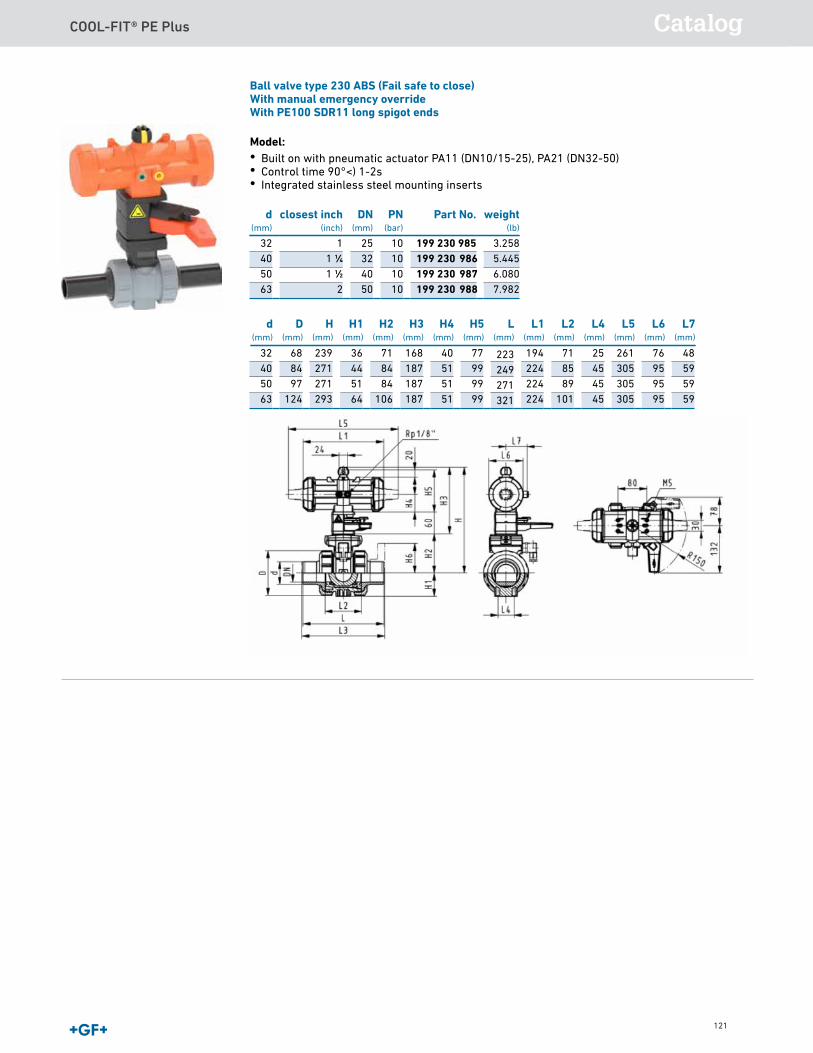
COOL-FIT® PE Plus Catalog
121
Ball valve type 230 ABS (Fail safe to close)With manual emergency overrideWith PE100 SDR11 long spigot ends
Model:• Built on with pneumatic actuator PA11 (DN10/15-25), PA21 (DN32-50)• Control time 90°<) 1-2s• Integrated stainless steel mounting inserts
223249271321
d(mm)
D(mm)
H(mm)
H1(mm)
H2(mm)
H3(mm)
H4(mm)
H5(mm)
L(mm)
L1(mm)
L2(mm)
L4(mm)
L5(mm)
L6(mm)
L7(mm)
32 68 239 36 71 168 40 77 194 71 25 261 76 4840 84 271 44 84 187 51 99 224 85 45 305 95 5950 97 271 51 84 187 51 99 224 89 45 305 95 5963 124 293 64 106 187 51 99 224 101 45 305 95 59
d(mm)
closest inch(inch)
DN(mm)
PN(bar)
Part No. weight(lb)
32 1 25 10 199 230 985 3.25840 1 1∕4 32 10 199 230 986 5.44550 1 1∕2 40 10 199 230 987 6.08063 2 50 10 199 230 988 7.982
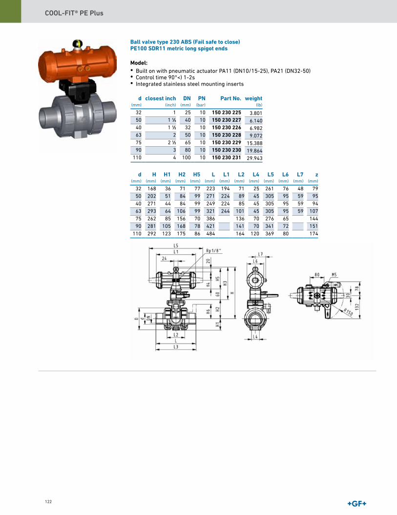
COOL-FIT® PE Plus
122
Ball valve type 230 ABS (Fail safe to close)PE100 SDR11 metric long spigot ends
Model:• Built on with pneumatic actuator PA11 (DN10/15-25), PA21 (DN32-50)• Control time 90°<) 1-2s• Integrated stainless steel mounting inserts
d(mm)
H(mm)
H1(mm)
H2(mm)
H5(mm)
L(mm)
L1(mm)
L2(mm)
L4(mm)
L5(mm)
L6(mm)
L7(mm)
z(mm)
32 168 36 71 77 223 194 71 25 261 76 48 7950 202 51 84 99 271 224 89 45 305 95 59 9540 271 44 84 99 249 224 85 45 305 95 59 9463 293 64 106 99 321 244 101 45 305 95 59 10775 262 85 156 70 386 136 70 276 65 14490 281 105 168 78 421 141 70 341 72 151
110 292 123 175 86 484 164 120 369 80 174
d(mm)
closest inch(inch)
DN(mm)
PN(bar)
Part No.
32 1 25 10 150 230 22550 1 1∕4 40 10 150 230 22740 1 1∕2 32 10 150 230 22663 2 50 10 150 230 22875 2 1∕2 65 10 150 230 22990 3 80 10 150 230 230
110 4 100 10 150 230 231
weight(lb)
3.8016.1406.9829.072
15.38819.86429.943
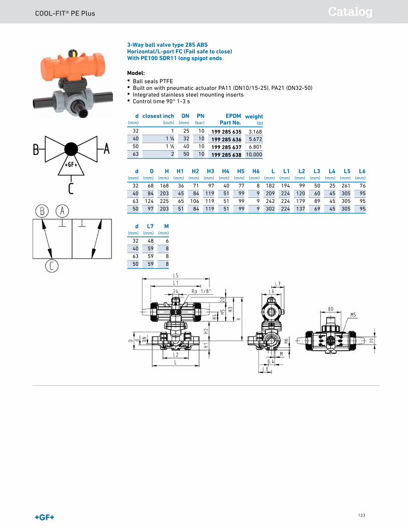
COOL-FIT® PE Plus Catalog
123
3-Way ball valve type 285 ABSHorizontal/L-port FC (Fail safe to close)With PE100 SDR11 long spigot ends
Model:• Ball seals PTFE• Built on with pneumatic actuator PA11 (DN10/15-25), PA21 (DN32-50)• Integrated stainless steel mounting inserts• Control time 90° 1-3 s
d(mm)
D(mm)
H(mm)
H1(mm)
H2(mm)
H3(mm)
H4(mm)
H5(mm)
H6(mm)
L(mm)
L1(mm)
L2(mm)
L3(mm)
L4(mm)
L5(mm)
L6(mm)
32 68 168 36 71 97 40 77 8 182 194 99 50 25 261 7640 84 203 45 84 119 51 99 9 209 224 120 60 45 305 9563 124 225 65 106 119 51 99 9 242 224 179 89 45 305 9550 97 203 51 84 119 51 99 9 302 224 137 69 45 305 95
d(mm)
L7(mm)
M(mm)
32 48 640 59 863 59 850 59 8
d(mm)
closest inch(inch)
DN(mm)
PN(bar)
EPDMPart No.
32 1 25 1040 1 1∕4 32 1050 1 1∕2 40 1063 2 50 10
weight(lb)
3.1685.6726.801
10.000
199 285 635199 285 636199 285 637199 285 638
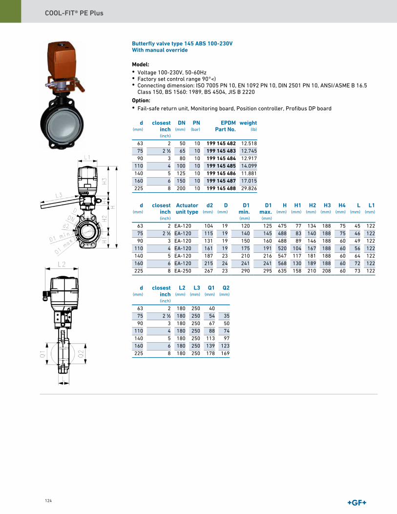
COOL-FIT® PE Plus
124
Butterfly valve type 145 ABS 100-230VWith manual override
Model:• Voltage 100-230V, 50-60Hz• Factory set control range 90°<)• Connecting dimension: ISO 7005 PN 10, EN 1092 PN 10, DIN 2501 PN 10, ANSI/ASME B 16.5
Class 150, BS 1560: 1989, BS 4504, JIS B 2220
Option:• Fail-safe return unit, Monitoring board, Position controller, Profibus DP board
d(mm)
closestinch(inch)
DN(mm)
PN(bar)
EPDMPart No.
weight(lb)
63 2 50 10 199 145 482 12.51875 2 1∕2 65 10 199 145 483 12.74590 3 80 10 199 145 484 12.917
110 4 100 10 199 145 485 14.099140 5 125 10 199 145 486 11.881160 6 150 10 199 145 487 17.015225 8 200 10 199 145 488 29.826
d(mm)
closestinch(inch)
Actuatorunit type
d2(mm)
D(mm)
D1min.(mm)
D1max.
(mm)
H(mm)
H1(mm)
H2(mm)
H3(mm)
H4(mm)
L(mm)
L1(mm)
63 2 EA-120 104 19 120 125 475 77 134 188 75 45 12275 2 1∕2 EA-120 115 19 140 145 488 83 140 188 75 46 12290 3 EA-120 131 19 150 160 488 89 146 188 60 49 122
110 4 EA-120 161 19 175 191 520 104 167 188 60 56 122140 5 EA-120 187 23 210 216 547 117 181 188 60 64 122160 6 EA-120 215 24 241 241 568 130 189 188 60 72 122225 8 EA-250 267 23 290 295 635 158 210 208 60 73 122
d(mm)
closestinch(inch)
L2(mm)
L3(mm)
Q1(mm)
Q2(mm)
63 2 180 250 4075 2 1∕2 180 250 54 3590 3 180 250 67 50
110 4 180 250 88 74140 5 180 250 113 97160 6 180 250 139 123225 8 180 250 178 169
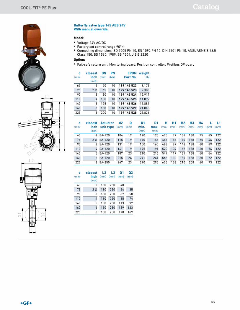
COOL-FIT® PE Plus Catalog
125
Butterfly valve type 145 ABS 100-230VWith manual override
Model:• Voltage 100-230V, 50-60Hz• Factory set control range 90°<)• Connecting dimension: ISO 7005 PN 10, EN 1092 PN 10, DIN 2501 PN 10, ANSI/ASME B 16.5
Class 150, BS 1560: 1989, BS 4504, JIS B 2220
Option:• Fail-safe return unit, Monitoring board, Position controller, Profibus DP board
d(mm)
closestinch(inch)
DN(mm)
PN(bar)
EPDMPart No.
weight(lb)
63 2 50 10 199 145 482 12.51875 2 1∕2 65 10 199 145 483 12.74590 3 80 10 199 145 484 12.917
110 4 100 10 199 145 485 14.099140 5 125 10 199 145 486 11.881160 6 150 10 199 145 487 17.015225 8 200 10 199 145 488 29.826
d(mm)
closestinch(inch)
Actuatorunit type
d2(mm)
D(mm)
D1min.(mm)
D1max.
(mm)
H(mm)
H1(mm)
H2(mm)
H3(mm)
H4(mm)
L(mm)
L1(mm)
63 2 EA-120 104 19 120 125 475 77 134 188 75 45 12275 2 1∕2 EA-120 115 19 140 145 488 83 140 188 75 46 12290 3 EA-120 131 19 150 160 488 89 146 188 60 49 122
110 4 EA-120 161 19 175 191 520 104 167 188 60 56 122140 5 EA-120 187 23 210 216 547 117 181 188 60 64 122160 6 EA-120 215 24 241 241 568 130 189 188 60 72 122225 8 EA-250 267 23 290 295 635 158 210 208 60 73 122
d(mm)
closestinch(inch)
L2(mm)
L3(mm)
Q1(mm)
Q2(mm)
63 2 180 250 4075 2 1∕2 180 250 54 3590 3 180 250 67 50
110 4 180 250 88 74140 5 180 250 113 97160 6 180 250 139 123225 8 180 250 178 169
Butterfly valve type 145 ABS 24VWith manual override
Model:• Voltage 24V AC/DC• Factory set control range 90°<)• Connecting dimension: ISO 7005 PN 10, EN 1092 PN 10, DIN 2501 PN 10, ANSI/ASME B 16.5
Class 150, BS 1560: 1989, BS 4504, JIS B 2220
Option:• Fail-safe return unit, Monitoring board, Position controller, Profibus DP board
d(mm)
closestinch(inch)
DN(mm)
PN(bar)
EPDMPart No.
weight(lb)
63 2 50 10 199 145 522 9.17375 2 1∕2 65 10 199 145 523 9.38590 3 80 10 199 145 524 12.917
110 4 100 10 199 145 525 14.099140 5 125 10 199 145 526 11.881160 6 150 10 199 145 527 21.848225 8 200 10 199 145 528 29.826
d(mm)
closestinch(inch)
Actuatorunit type
d2(mm)
D(mm)
D1min.(mm)
D1max.
(mm)
H(mm)
H1(mm)
H2(mm)
H3(mm)
H4(mm)
L(mm)
L1(mm)
63 2 EA-120 104 19 120 125 475 77 134 188 75 45 12275 2 1∕2 EA-120 115 19 140 145 488 83 140 188 75 46 12290 3 EA-120 131 19 150 160 488 89 146 188 60 49 122
110 4 EA-120 161 19 175 191 520 104 167 188 60 56 122140 5 EA-120 187 23 210 216 547 117 181 188 60 64 122160 6 EA-120 215 24 241 241 568 130 189 188 60 72 122225 8 EA-250 267 23 290 295 635 158 210 208 60 73 122
d(mm)
closestinch(inch)
L2(mm)
L3(mm)
Q1(mm)
Q2(mm)
63 2 180 250 4075 2 1∕2 180 250 54 3590 3 180 250 67 50
110 4 180 250 88 74140 5 180 250 113 97160 6 180 250 139 123225 8 180 250 178 169
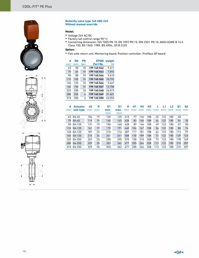
COOL-FIT® PE Plus
126
Butterfly valve type 145 ABS 24VWithout manual override
Model:• Voltage 24V AC/DC• Factory set control range 90°<)• Connecting dimension: ISO 7005 PN 10, EN 1092 PN 10, DIN 2501 PN 10, ANSI/ASME B 16.5
Class 150, BS 1560: 1989, BS 4504, JIS B 2220
Option:• Fail-safe return unit, Monitoring board, Position controller, Profibus DP board
d(mm)
DN(mm)
PN(bar)
EPDMPart No.
weight(lb)
63 50 10 199 145 542 9.21175 65 10 199 145 543 7.09290 80 10 199 145 544 9.610
110 100 10 199 145 545 10.792140 125 10 199 145 546 9.647160 150 10 199 145 547 13.708225 200 10 199 145 548 26.519280 250 6 199 145 549 31.601315 300 6 199 145 550 43.092
d(mm)
Actuatorunit type
d2(mm)
D(mm)
D1min.(mm)
D1max.
(mm)
H(mm)
H1(mm)
H2(mm)
H3(mm)
L(mm)
L1(mm)
L2(mm)
Q1(mm)
Q2(mm)
63 EA-45 104 19 120 125 415 77 134 188 45 122 180 4075 EA-45 115 19 140 145 428 83 140 188 46 122 180 54 3590 EA-120 131 19 150 160 428 89 146 188 49 122 180 67 50
110 EA-120 161 19 175 191 460 104 167 188 56 122 180 88 74140 EA-120 187 23 210 216 487 117 181 188 64 122 180 113 97160 EA-120 215 24 241 241 508 130 189 188 72 122 180 139 123225 EA-250 267 23 290 295 575 158 210 208 73 122 180 178 169280 EA-250 329 25 353 362 677 205 264 208 113 122 180 210 207315 EA-250 329 25 353 362 677 205 264 208 113 122 180 210 207
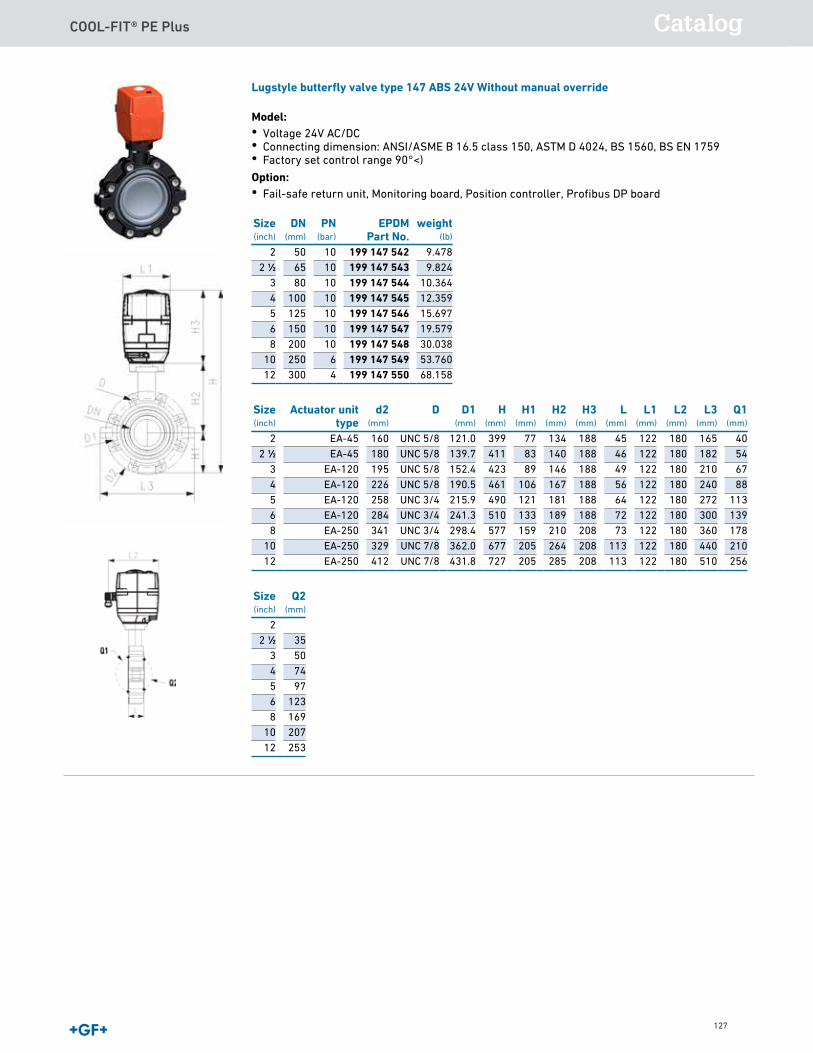
COOL-FIT® PE Plus Catalog
127
Lugstyle butterfly valve type 147 ABS 24V Without manual override
Model:• Voltage 24V AC/DC• Connecting dimension: ANSI/ASME B 16.5 class 150, ASTM D 4024, BS 1560, BS EN 1759• Factory set control range 90°<) Option:• Fail-safe return unit, Monitoring board, Position controller, Profibus DP board Size(inch)
DN(mm)
PN(bar)
EPDMPart No.
2 50 10 199 147 5422 1∕2 65 10 199 147 543
3 80 10 199 147 5444 100 10 199 147 5455 125 10 199 147 5466 150 10 199 147 5478 200 10 199 147 548
10 250 6 199 147 54912 300 4 199 147 550
Size(inch)
Actuator unittype
d2(mm)
D D1(mm)
H(mm)
H1(mm)
H2(mm)
H3(mm)
L(mm)
L1(mm)
L2(mm)
L3(mm)
Q1(mm)
2 EA-45 160 UNC 5/8 121.0 399 77 134 188 45 122 180 165 402 1∕2 EA-45 180 UNC 5/8 139.7 411 83 140 188 46 122 180 182 54
3 EA-120 195 UNC 5/8 152.4 423 89 146 188 49 122 180 210 674 EA-120 226 UNC 5/8 190.5 461 106 167 188 56 122 180 240 885 EA-120 258 UNC 3/4 215.9 490 121 181 188 64 122 180 272 1136 EA-120 284 UNC 3/4 241.3 510 133 189 188 72 122 180 300 1398 EA-250 341 UNC 3/4 298.4 577 159 210 208 73 122 180 360 178
10 EA-250 329 UNC 7/8 362.0 677 205 264 208 113 122 180 440 21012 EA-250 412 UNC 7/8 431.8 727 205 285 208 113 122 180 510 256
Size(inch)
Q2(mm)
22 1∕2 35
3 504 745 976 1238 169
10 20712 253
9.4789.824
10.36412.35915.69719.57930.03853.76068.158
weight(lb)
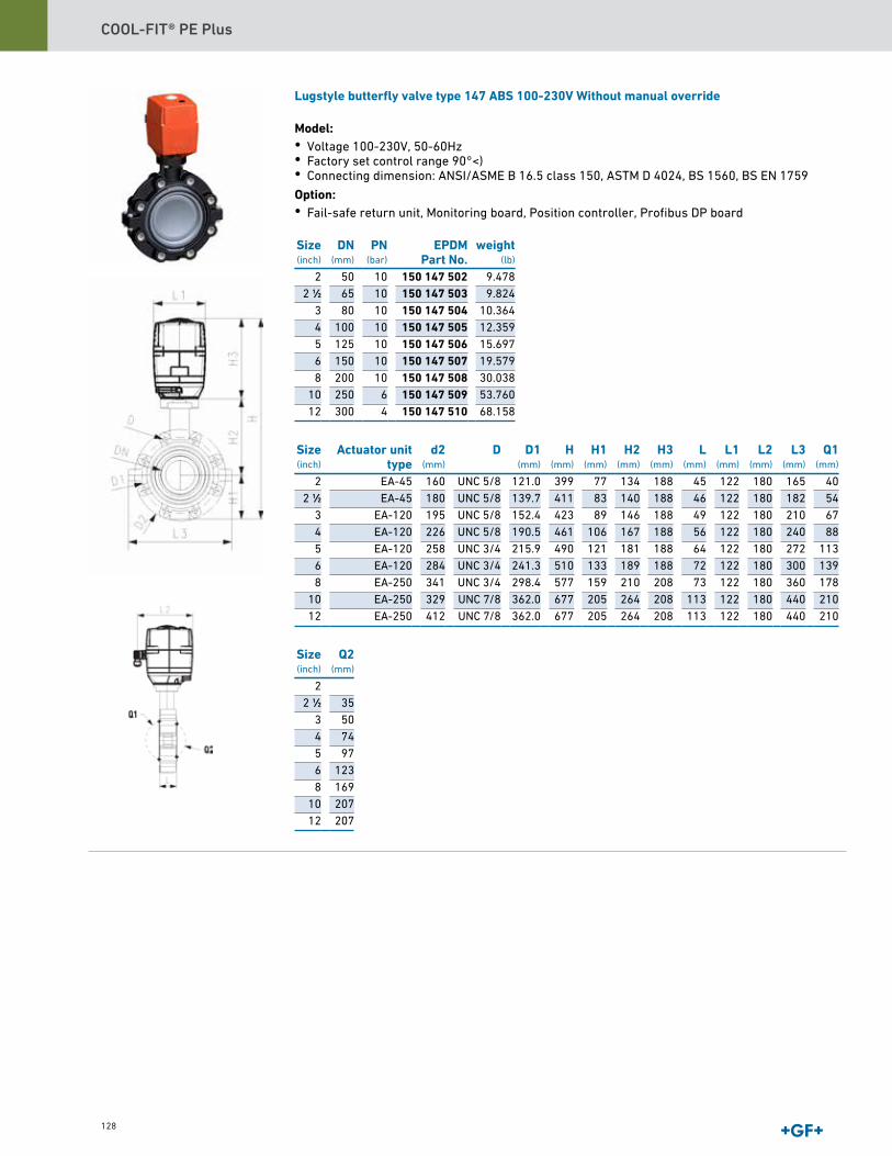
COOL-FIT® PE Plus
128
Lugstyle butterfly valve type 147 ABS 100-230V Without manual override
Model:• Voltage 100-230V, 50-60Hz• Factory set control range 90°<)• Connecting dimension: ANSI/ASME B 16.5 class 150, ASTM D 4024, BS 1560, BS EN 1759 Option:• Fail-safe return unit, Monitoring board, Position controller, Profibus DP board Size(inch)
DN(mm)
PN(bar)
EPDMPart No.
2 50 10 150 147 5022 1∕2 65 10 150 147 503
3 80 10 150 147 5044 100 10 150 147 5055 125 10 150 147 5066 150 10 150 147 5078 200 10 150 147 508
10 250 6 150 147 50912 300 4 150 147 510
Size(inch)
Actuator unittype
d2(mm)
D D1(mm)
H(mm)
H1(mm)
H2(mm)
H3(mm)
L(mm)
L1(mm)
L2(mm)
L3(mm)
Q1(mm)
2 EA-45 160 UNC 5/8 121.0 399 77 134 188 45 122 180 165 402 1∕2 EA-45 180 UNC 5/8 139.7 411 83 140 188 46 122 180 182 54
3 EA-120 195 UNC 5/8 152.4 423 89 146 188 49 122 180 210 674 EA-120 226 UNC 5/8 190.5 461 106 167 188 56 122 180 240 885 EA-120 258 UNC 3/4 215.9 490 121 181 188 64 122 180 272 1136 EA-120 284 UNC 3/4 241.3 510 133 189 188 72 122 180 300 1398 EA-250 341 UNC 3/4 298.4 577 159 210 208 73 122 180 360 178
10 EA-250 329 UNC 7/8 362.0 677 205 264 208 113 122 180 440 21012 EA-250 412 UNC 7/8 362.0 677 205 264 208 113 122 180 440 210
Size(inch)
Q2(mm)
22 1∕2 35
3 504 745 976 1238 169
10 20712 207
weight(lb)
9.4789.824
10.36412.35915.69719.57930.03853.76068.158
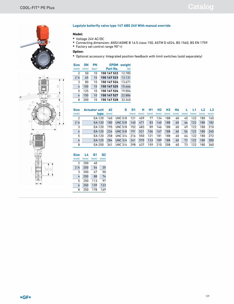
COOL-FIT® PE Plus Catalog
129
Lugstyle butterfly valve type 147 ABS 24V With manual override
Model:• Voltage 24V AC/DC• Connecting dimension: ANSI/ASME B 16.5 class 150, ASTM D 4024, BS 1560, BS EN 1759• Factory set control range 90°<) Option:• Optional accessory: Integrated position feedback with limit switches (sold separately) Size(inch)
DN(mm)
PN(bar)
EPDMPart No.
2 50 10 150 147 5222 1∕2 65 10 150 147 523
3 80 10 150 147 5244 100 10 150 147 5255 125 10 150 147 5266 150 10 150 147 5278 200 10 150 147 528
Size(inch)
Actuator unittype
d2(mm)
D D1(mm)
H(mm)
H1(mm)
H2(mm)
H3(mm)
H4(mm)
L(mm)
L1(mm)
L2(mm)
L3(mm)
2 EA-120 160 UNC 5/8 121 459 77 134 188 60 45 122 180 1652 1∕2 EA-120 180 UNC 5/8 140 471 83 140 188 60 46 122 180 182
3 EA-120 195 UNC 5/8 152 483 89 146 188 60 49 122 180 2104 EA-120 226 UNC 5/8 191 521 106 167 188 60 56 122 180 2405 EA-120 258 UNC 3/4 216 550 121 181 188 60 64 122 180 2726 EA-120 284 UNC 3/4 241 570 133 189 188 60 72 122 180 3008 EA-250 341 UNC 3/4 298 637 159 210 208 60 73 122 180 360
Size(inch)
L4(mm)
Q1(mm)
Q2(mm)
2 200 402 1∕2 200 54 35
3 200 67 504 250 88 745 250 113 976 250 139 1238 250 178 169
12.78513.13113.67115.66619.00422.88633.345
weight(lb)
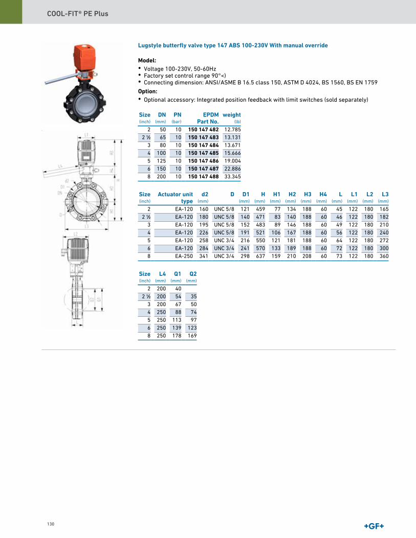
COOL-FIT® PE Plus
130
Lugstyle butterfly valve type 147 ABS 100-230V With manual override
Model:• Voltage 100-230V, 50-60Hz• Factory set control range 90°<)• Connecting dimension: ANSI/ASME B 16.5 class 150, ASTM D 4024, BS 1560, BS EN 1759 Option:• Optional accessory: Integrated position feedback with limit switches (sold separately) Size(inch)
DN(mm)
PN(bar)
EPDMPart No.
2 50 10 150 147 4822 1∕2 65 10 150 147 483
3 80 10 150 147 4844 100 10 150 147 4855 125 10 150 147 4866 150 10 150 147 4878 200 10 150 147 488
Size(inch)
Actuator unittype
d2(mm)
D D1(mm)
H(mm)
H1(mm)
H2(mm)
H3(mm)
H4(mm)
L(mm)
L1(mm)
L2(mm)
L3(mm)
2 EA-120 160 UNC 5/8 121 459 77 134 188 60 45 122 180 1652 1∕2 EA-120 180 UNC 5/8 140 471 83 140 188 60 46 122 180 182
3 EA-120 195 UNC 5/8 152 483 89 146 188 60 49 122 180 2104 EA-120 226 UNC 5/8 191 521 106 167 188 60 56 122 180 2405 EA-120 258 UNC 3/4 216 550 121 181 188 60 64 122 180 2726 EA-120 284 UNC 3/4 241 570 133 189 188 60 72 122 180 3008 EA-250 341 UNC 3/4 298 637 159 210 208 60 73 122 180 360
Size(inch)
L4(mm)
Q1(mm)
Q2(mm)
2 200 402 1∕2 200 54 35
3 200 67 504 250 88 745 250 113 976 250 139 1238 250 178 169
12.78513.13113.67115.66619.00422.88633.345
weight(lb)
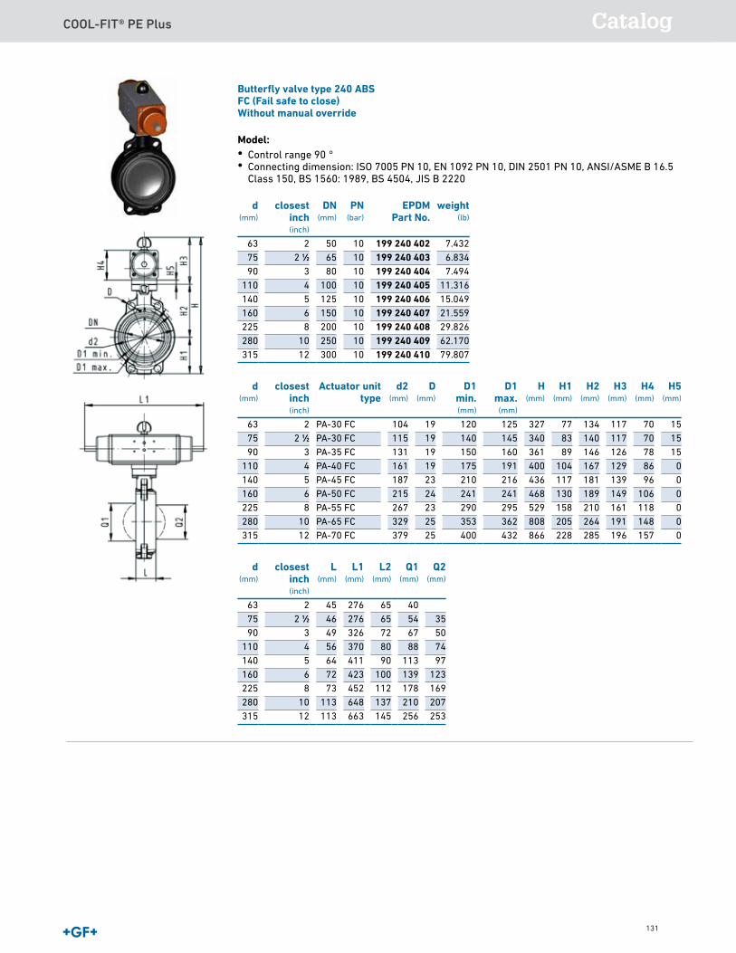
COOL-FIT® PE Plus Catalog
131
Lugstyle butterfly valve type 147 ABS 100-230V With manual override
Model:• Voltage 100-230V, 50-60Hz• Factory set control range 90°<)• Connecting dimension: ANSI/ASME B 16.5 class 150, ASTM D 4024, BS 1560, BS EN 1759 Option:• Optional accessory: Integrated position feedback with limit switches (sold separately) Size(inch)
DN(mm)
PN(bar)
EPDMPart No.
2 50 10 150 147 4822 1∕2 65 10 150 147 483
3 80 10 150 147 4844 100 10 150 147 4855 125 10 150 147 4866 150 10 150 147 4878 200 10 150 147 488
Size(inch)
Actuator unittype
d2(mm)
D D1(mm)
H(mm)
H1(mm)
H2(mm)
H3(mm)
H4(mm)
L(mm)
L1(mm)
L2(mm)
L3(mm)
2 EA-120 160 UNC 5/8 121 459 77 134 188 60 45 122 180 1652 1∕2 EA-120 180 UNC 5/8 140 471 83 140 188 60 46 122 180 182
3 EA-120 195 UNC 5/8 152 483 89 146 188 60 49 122 180 2104 EA-120 226 UNC 5/8 191 521 106 167 188 60 56 122 180 2405 EA-120 258 UNC 3/4 216 550 121 181 188 60 64 122 180 2726 EA-120 284 UNC 3/4 241 570 133 189 188 60 72 122 180 3008 EA-250 341 UNC 3/4 298 637 159 210 208 60 73 122 180 360
Size(inch)
L4(mm)
Q1(mm)
Q2(mm)
2 200 402 1∕2 200 54 35
3 200 67 504 250 88 745 250 113 976 250 139 1238 250 178 169
12.78513.13113.67115.66619.00422.88633.345
weight(lb)
Butterfly valve type 240 ABSFC (Fail safe to close)Without manual override
Model:• Control range 90 °• Connecting dimension: ISO 7005 PN 10, EN 1092 PN 10, DIN 2501 PN 10, ANSI/ASME B 16.5
Class 150, BS 1560: 1989, BS 4504, JIS B 2220
d(mm)
closestinch(inch)
DN(mm)
PN(bar)
EPDMPart No.
63 2 50 10 199 240 40275 2 1∕2 65 10 199 240 40390 3 80 10 199 240 404
110 4 100 10 199 240 405140 5 125 10 199 240 406160 6 150 10 199 240 407225 8 200 10 199 240 408280 10 250 10 199 240 409315 12 300 10 199 240 410
d(mm)
closestinch(inch)
Actuator unittype
d2(mm)
D(mm)
D1min.(mm)
D1max.
(mm)
H(mm)
H1(mm)
H2(mm)
H3(mm)
H4(mm)
H5(mm)
63 2 PA-30 FC 104 19 120 125 327 77 134 117 70 1575 2 1∕2 PA-30 FC 115 19 140 145 340 83 140 117 70 1590 3 PA-35 FC 131 19 150 160 361 89 146 126 78 15
110 4 PA-40 FC 161 19 175 191 400 104 167 129 86 0140 5 PA-45 FC 187 23 210 216 436 117 181 139 96 0160 6 PA-50 FC 215 24 241 241 468 130 189 149 106 0225 8 PA-55 FC 267 23 290 295 529 158 210 161 118 0280 10 PA-65 FC 329 25 353 362 808 205 264 191 148 0315 12 PA-70 FC 379 25 400 432 866 228 285 196 157 0
d(mm)
closestinch(inch)
L(mm)
L1(mm)
L2(mm)
Q1(mm)
Q2(mm)
63 2 45 276 65 4075 2 1∕2 46 276 65 54 3590 3 49 326 72 67 50
110 4 56 370 80 88 74140 5 64 411 90 113 97160 6 72 423 100 139 123225 8 73 452 112 178 169280 10 113 648 137 210 207315 12 113 663 145 256 253
7.4326.8347.494
11.31615.04921.55929.82662.17079.807
weight(lb)
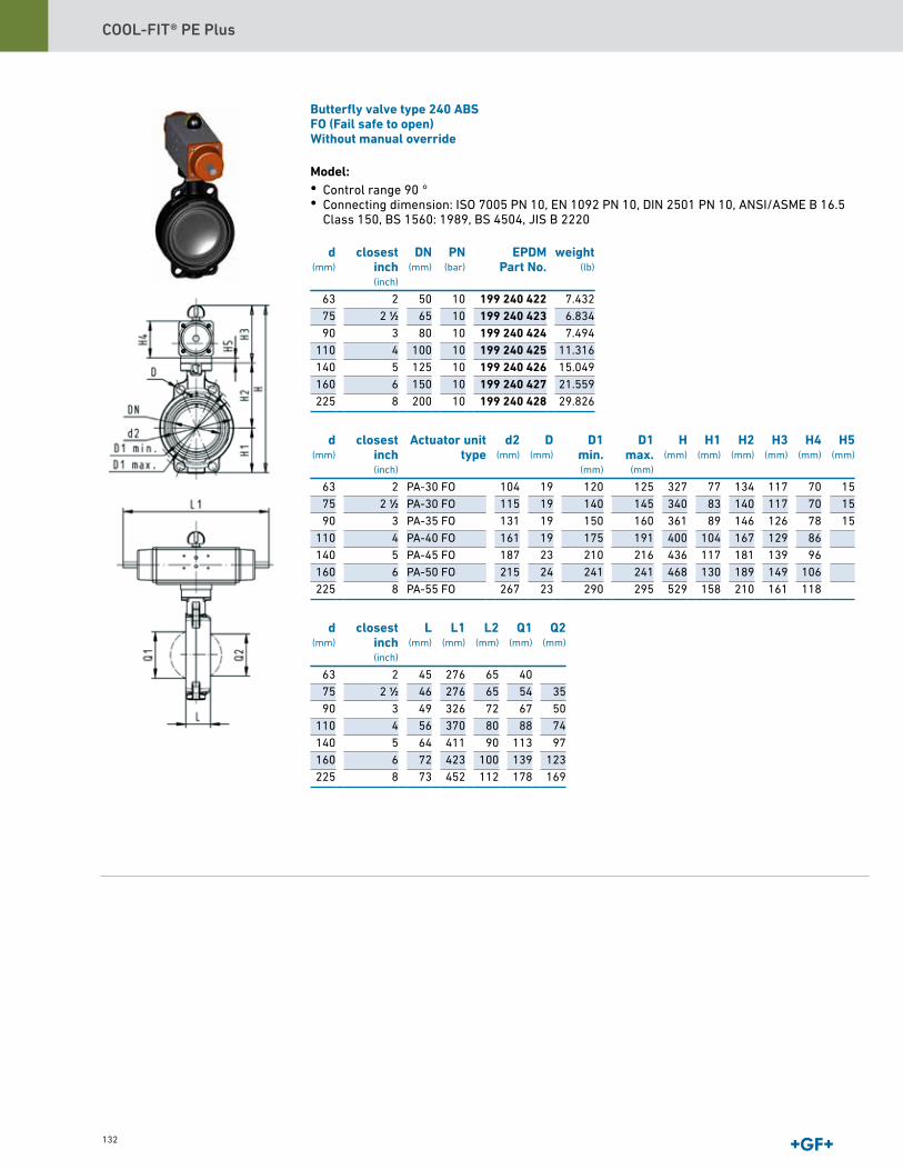
COOL-FIT® PE Plus
132
Butterfly valve type 240 ABSFO (Fail safe to open)Without manual override
Model:• Control range 90 °• Connecting dimension: ISO 7005 PN 10, EN 1092 PN 10, DIN 2501 PN 10, ANSI/ASME B 16.5
Class 150, BS 1560: 1989, BS 4504, JIS B 2220
d(mm)
closestinch(inch)
DN(mm)
PN(bar)
EPDMPart No.
63 2 50 10 199 240 42275 2 1∕2 65 10 199 240 42390 3 80 10 199 240 424
110 4 100 10 199 240 425140 5 125 10 199 240 426160 6 150 10 199 240 427225 8 200 10 199 240 428
d(mm)
closestinch(inch)
Actuator unittype
d2(mm)
D(mm)
D1min.(mm)
D1max.
(mm)
H(mm)
H1(mm)
H2(mm)
H3(mm)
H4(mm)
H5(mm)
63 2 PA-30 FO 104 19 120 125 327 77 134 117 70 1575 2 1∕2 PA-30 FO 115 19 140 145 340 83 140 117 70 1590 3 PA-35 FO 131 19 150 160 361 89 146 126 78 15
110 4 PA-40 FO 161 19 175 191 400 104 167 129 86140 5 PA-45 FO 187 23 210 216 436 117 181 139 96160 6 PA-50 FO 215 24 241 241 468 130 189 149 106225 8 PA-55 FO 267 23 290 295 529 158 210 161 118
d(mm)
closestinch(inch)
L(mm)
L1(mm)
L2(mm)
Q1(mm)
Q2(mm)
63 2 45 276 65 4075 2 1∕2 46 276 65 54 3590 3 49 326 72 67 50
110 4 56 370 80 88 74140 5 64 411 90 113 97160 6 72 423 100 139 123225 8 73 452 112 178 169
weight(lb)
7.4326.8347.494
11.31615.04921.55929.826
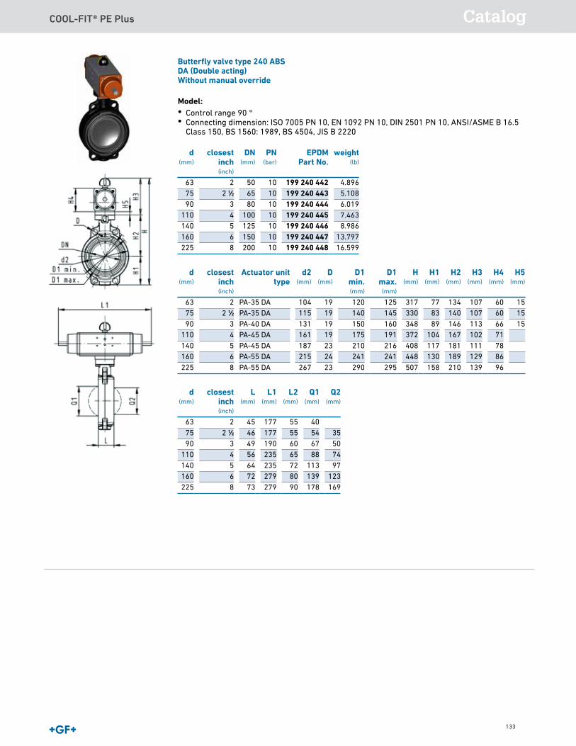
COOL-FIT® PE Plus Catalog
133
Butterfly valve type 240 ABSFO (Fail safe to open)Without manual override
Model:• Control range 90 °• Connecting dimension: ISO 7005 PN 10, EN 1092 PN 10, DIN 2501 PN 10, ANSI/ASME B 16.5
Class 150, BS 1560: 1989, BS 4504, JIS B 2220
d(mm)
closestinch(inch)
DN(mm)
PN(bar)
EPDMPart No.
63 2 50 10 199 240 42275 2 1∕2 65 10 199 240 42390 3 80 10 199 240 424
110 4 100 10 199 240 425140 5 125 10 199 240 426160 6 150 10 199 240 427225 8 200 10 199 240 428
d(mm)
closestinch(inch)
Actuator unittype
d2(mm)
D(mm)
D1min.(mm)
D1max.
(mm)
H(mm)
H1(mm)
H2(mm)
H3(mm)
H4(mm)
H5(mm)
63 2 PA-30 FO 104 19 120 125 327 77 134 117 70 1575 2 1∕2 PA-30 FO 115 19 140 145 340 83 140 117 70 1590 3 PA-35 FO 131 19 150 160 361 89 146 126 78 15
110 4 PA-40 FO 161 19 175 191 400 104 167 129 86140 5 PA-45 FO 187 23 210 216 436 117 181 139 96160 6 PA-50 FO 215 24 241 241 468 130 189 149 106225 8 PA-55 FO 267 23 290 295 529 158 210 161 118
d(mm)
closestinch(inch)
L(mm)
L1(mm)
L2(mm)
Q1(mm)
Q2(mm)
63 2 45 276 65 4075 2 1∕2 46 276 65 54 3590 3 49 326 72 67 50
110 4 56 370 80 88 74140 5 64 411 90 113 97160 6 72 423 100 139 123225 8 73 452 112 178 169
weight(lb)
7.4326.8347.494
11.31615.04921.55929.826
Butterfly valve type 240 ABSDA (Double acting)Without manual override
Model:• Control range 90 °• Connecting dimension: ISO 7005 PN 10, EN 1092 PN 10, DIN 2501 PN 10, ANSI/ASME B 16.5
Class 150, BS 1560: 1989, BS 4504, JIS B 2220
d(mm)
closestinch(inch)
DN(mm)
PN(bar)
EPDMPart No.
63 2 50 10 199 240 44275 2 1∕2 65 10 199 240 44390 3 80 10 199 240 444
110 4 100 10 199 240 445140 5 125 10 199 240 446160 6 150 10 199 240 447225 8 200 10 199 240 448
d(mm)
closestinch(inch)
Actuator unittype
d2(mm)
D(mm)
D1min.(mm)
D1max.
(mm)
H(mm)
H1(mm)
H2(mm)
H3(mm)
H4(mm)
H5(mm)
63 2 PA-35 DA 104 19 120 125 317 77 134 107 60 1575 2 1∕2 PA-35 DA 115 19 140 145 330 83 140 107 60 1590 3 PA-40 DA 131 19 150 160 348 89 146 113 66 15
110 4 PA-45 DA 161 19 175 191 372 104 167 102 71140 5 PA-45 DA 187 23 210 216 408 117 181 111 78160 6 PA-55 DA 215 24 241 241 448 130 189 129 86225 8 PA-55 DA 267 23 290 295 507 158 210 139 96
d(mm)
closestinch(inch)
L(mm)
L1(mm)
L2(mm)
Q1(mm)
Q2(mm)
63 2 45 177 55 4075 2 1∕2 46 177 55 54 3590 3 49 190 60 67 50
110 4 56 235 65 88 74140 5 64 235 72 113 97160 6 72 279 80 139 123225 8 73 279 90 178 169
4.8965.1086.0197.4638.986
13.79716.599
weight(lb)
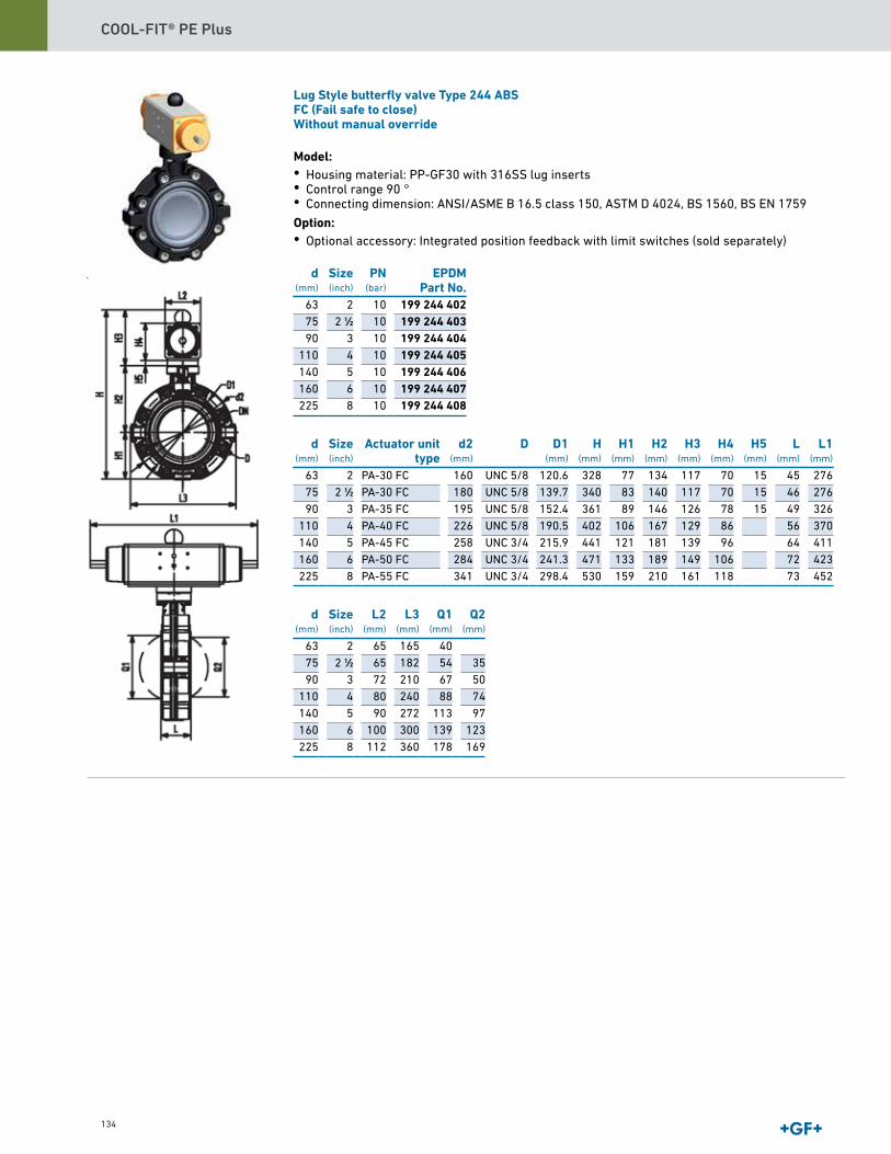
COOL-FIT® PE Plus
134
Lug Style butterfly valve Type 244 ABSFC (Fail safe to close)Without manual override
Model:• Housing material: PP-GF30 with 316SS lug inserts• Control range 90 °• Connecting dimension: ANSI/ASME B 16.5 class 150, ASTM D 4024, BS 1560, BS EN 1759 Option:• Optional accessory: Integrated position feedback with limit switches (sold separately)
d(mm)
Size(inch)
PN(bar)
EPDMPart No.
63 2 10 199 244 40275 2 1∕2 10 199 244 40390 3 10 199 244 404
110 4 10 199 244 405140 5 10 199 244 406160 6 10 199 244 407225 8 10 199 244 408
d(mm)
Size(inch)
Actuator unittype
d2(mm)
D D1(mm)
H(mm)
H1(mm)
H2(mm)
H3(mm)
H4(mm)
H5(mm)
L(mm)
L1(mm)
63 2 PA-30 FC 160 UNC 5/8 120.6 328 77 134 117 70 15 45 27675 2 1∕2 PA-30 FC 180 UNC 5/8 139.7 340 83 140 117 70 15 46 27690 3 PA-35 FC 195 UNC 5/8 152.4 361 89 146 126 78 15 49 326
110 4 PA-40 FC 226 UNC 5/8 190.5 402 106 167 129 86 56 370140 5 PA-45 FC 258 UNC 3/4 215.9 441 121 181 139 96 64 411160 6 PA-50 FC 284 UNC 3/4 241.3 471 133 189 149 106 72 423225 8 PA-55 FC 341 UNC 3/4 298.4 530 159 210 161 118 73 452
d(mm)
Size(inch)
L2(mm)
L3(mm)
Q1(mm)
Q2(mm)
63 2 65 165 4075 2 1∕2 65 182 54 3590 3 72 210 67 50
110 4 80 240 88 74140 5 90 272 113 97160 6 100 300 139 123225 8 112 360 178 169
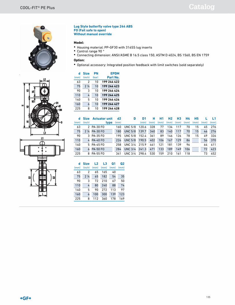
COOL-FIT® PE Plus Catalog
135
Lug Style butterfly valve type 244 ABSFO (Fail safe to open)Without manual override
Model:• Housing material: PP-GF30 with 316SS lug inserts• Control range 90 °• Connecting dimension: ANSI/ASME B 16.5 class 150, ASTM D 4024, BS 1560, BS EN 1759 Option:• Optional accessory: Integrated position feedback with limit switches (sold separately)
d(mm)
Size(inch)
PN(bar)
EPDMPart No.
63 2 10 199 244 42275 2 1∕2 10 199 244 42390 3 10 199 244 424
110 4 10 199 244 425140 5 10 199 244 426160 6 10 199 244 427225 8 10 199 244 428
d(mm)
Size(inch)
Actuator unittype
d2(mm)
D D1(mm)
H(mm)
H1(mm)
H2(mm)
H3(mm)
H4(mm)
H5(mm)
L(mm)
L1(mm)
63 2 PA-30 FO 160 UNC 5/8 120.6 328 77 134 117 70 15 45 27675 2 1∕2 PA-30 FO 180 UNC 5/8 139.7 340 83 140 117 70 15 46 27690 3 PA-35 FO 195 UNC 5/8 152.4 361 89 146 126 78 15 49 326
110 4 PA-40 FO 226 UNC 5/8 190.5 402 106 167 129 86 56 370140 5 PA-45 FO 258 UNC 3/4 215.9 441 121 181 139 96 64 411160 6 PA-50 FO 284 UNC 3/4 241.3 471 133 189 149 106 72 423225 8 PA-55 FO 341 UNC 3/4 298.4 530 159 210 161 118 73 452
d(mm)
Size(inch)
L2(mm)
L3(mm)
Q1(mm)
Q2(mm)
63 2 65 165 4075 2 1∕2 65 182 54 3590 3 72 210 67 50
110 4 80 240 88 74140 5 90 272 113 97160 6 100 300 139 123225 8 112 360 178 169
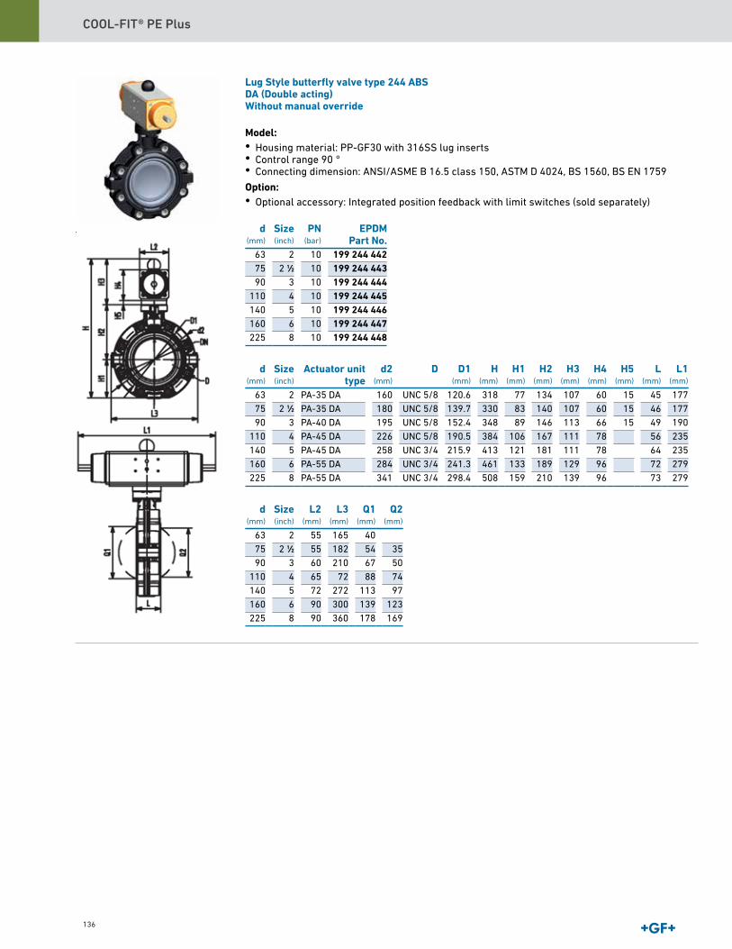
COOL-FIT® PE Plus
136
Lug Style butterfly valve type 244 ABSDA (Double acting)Without manual override
Model:• Housing material: PP-GF30 with 316SS lug inserts• Control range 90 °• Connecting dimension: ANSI/ASME B 16.5 class 150, ASTM D 4024, BS 1560, BS EN 1759 Option:• Optional accessory: Integrated position feedback with limit switches (sold separately)
d(mm)
Size(inch)
PN(bar)
EPDMPart No.
63 2 10 199 244 44275 2 1∕2 10 199 244 44390 3 10 199 244 444
110 4 10 199 244 445140 5 10 199 244 446160 6 10 199 244 447225 8 10 199 244 448
d(mm)
Size(inch)
Actuator unittype
d2(mm)
D D1(mm)
H(mm)
H1(mm)
H2(mm)
H3(mm)
H4(mm)
H5(mm)
L(mm)
L1(mm)
63 2 PA-35 DA 160 UNC 5/8 120.6 318 77 134 107 60 15 45 17775 2 1∕2 PA-35 DA 180 UNC 5/8 139.7 330 83 140 107 60 15 46 17790 3 PA-40 DA 195 UNC 5/8 152.4 348 89 146 113 66 15 49 190
110 4 PA-45 DA 226 UNC 5/8 190.5 384 106 167 111 78 56 235140 5 PA-45 DA 258 UNC 3/4 215.9 413 121 181 111 78 64 235160 6 PA-55 DA 284 UNC 3/4 241.3 461 133 189 129 96 72 279225 8 PA-55 DA 341 UNC 3/4 298.4 508 159 210 139 96 73 279
d(mm)
Size(inch)
L2(mm)
L3(mm)
Q1(mm)
Q2(mm)
63 2 55 165 4075 2 1∕2 55 182 54 3590 3 60 210 67 50
110 4 65 72 88 74140 5 72 272 113 97160 6 90 300 139 123225 8 90 360 178 169

COOL-FIT® PE Plus Design and Installation
Lug Style butterfly valve type 244 ABSDA (Double acting)Without manual override
Model:• Housing material: PP-GF30 with 316SS lug inserts• Control range 90 °• Connecting dimension: ANSI/ASME B 16.5 class 150, ASTM D 4024, BS 1560, BS EN 1759 Option:• Optional accessory: Integrated position feedback with limit switches (sold separately)
d(mm)
Size(inch)
PN(bar)
EPDMPart No.
63 2 10 199 244 44275 2 1∕2 10 199 244 44390 3 10 199 244 444
110 4 10 199 244 445140 5 10 199 244 446160 6 10 199 244 447225 8 10 199 244 448
d(mm)
Size(inch)
Actuator unittype
d2(mm)
D D1(mm)
H(mm)
H1(mm)
H2(mm)
H3(mm)
H4(mm)
H5(mm)
L(mm)
L1(mm)
63 2 PA-35 DA 160 UNC 5/8 120.6 318 77 134 107 60 15 45 17775 2 1∕2 PA-35 DA 180 UNC 5/8 139.7 330 83 140 107 60 15 46 17790 3 PA-40 DA 195 UNC 5/8 152.4 348 89 146 113 66 15 49 190
110 4 PA-45 DA 226 UNC 5/8 190.5 384 106 167 111 78 56 235140 5 PA-45 DA 258 UNC 3/4 215.9 413 121 181 111 78 64 235160 6 PA-55 DA 284 UNC 3/4 241.3 461 133 189 129 96 72 279225 8 PA-55 DA 341 UNC 3/4 298.4 508 159 210 139 96 73 279
d(mm)
Size(inch)
L2(mm)
L3(mm)
Q1(mm)
Q2(mm)
63 2 55 165 4075 2 1∕2 55 182 54 3590 3 60 210 67 50
110 4 65 72 88 74140 5 72 272 113 97160 6 90 300 139 123225 8 90 360 178 169
General Terms and Conditions of SaleThese GF Piping Systems USA Terms and Conditions (Rev 11/2018) supersede all previous Terms and Conditions for Georg Fischer LLC and Georg Fischer Harvel LLC
It is the responsibility of the Distributor, Dealer, or Agent to provide a current copy of these Terms and Conditions to the Consumers of Georg Fischer Piping products
Always check for the most current General Terms and Conditions and Warranty Statement at www gfpiping com under "Price Lists," which supersede and replace these General Terms and Condi-tions and Warranty Statement If unable to access this website please request a copy at (714) 731-8800
Acceptance of Terms and ConditionsAcceptance by Customer of GF Piping Systems USA, (hereinafter “Seller”) offer of Products for sale is hereby expressly conditioned upon Customer’s acceptance of these General Terms and Conditions of Sale and these General Terms and Conditions of Sale will be deemed accepted, as written, despite any language in Customer’s purchase order and/or other documentation which is either conflicting or supplemental, unless promptly after this offer, Customer specifically advises Seller of each term and condition not so accepted and Seller accepts Customer’s conflicting and/or supplemental term(s) in writing
Order AcceptanceSeller reserves the right to accept or reject any order Possession of a price list by Customer does not constitute an offer to sell
Credit Approval and Minimum Order Charge
Customer credit approval is required prior to any shipment
The minimum order is $100 net
List Price, Discount or Freight ChargesList prices, discount, and freight terms are subject to change without notice All prices are F O B Seller’s factory or authorized warehouse at Seller’s discretion
QuotesAll prices provided by the Seller are in US currency and cover only the goods expressly specified Quotations are valid for a period of 30 days unless otherwise specified HDPE Pipe pricing is valid for seven (7) days after quote issuance unless otherwise stated or unless there has been funda-mental change to our cost exposure within the seven (7) day period
Payment TermsNet 30, from date the invoice is issued unless otherwise stated in a specific quotation No unau-thorized deductions allowed, such as deductions for pending Return Material Transactions that are subject to review Seller reserves the right to apply a finance charge to the balance of any past-due invoice (over 30 days from date of invoice) at a rate of 1 5% per month, 18% per annum Payment terms on fusion machine rentals net 30; see rental agreement for more details
TaxesSeller charges Customer for all sales, excise and other taxes and governmental charges Seller is required to collect from Customer Customers claiming exemption must furnish documentation required by law, which is satisfactory to Seller to permit Seller to refrain from collecting such charges
Order Changes or CancellationsCancellation or modifications of orders may be possible only with prior written consent from Seller Since all orders are individually entered for processing immediately upon receipt, Seller reserves the right to charge back to the Customer costs incurred from either order cancellation or order modification Seller also reserves the right to consider all order additions as new orders and subject to all terms and conditions Seller will not cancel orders for custom or non-cancelable products if Seller has already produced the product or incurred expenses toward producing the product at the time the Customer seeks to cancel
DeliverySeller disclaims liability for consequential damages from late deliveries unless seller assumes liability for such damages in writing when the order is placed Further, Seller disclaims liability where delivery delays caused by strike, differences with workmen, or causes beyond Seller’s control, including but not limited to fires, floods, accidents, government actions, shortages of labor, raw materials, production facilities, or transportation Where delivery delays are caused by labor problems, Seller is not obligated to seek or obtain any settlement, which, in Seller’s judgment, is not in Seller’s best interest
Standard PackagingSeller will accept orders from Customer exclusively in multiples of the standard packaging quan-tity or boxed quantity Seller reserves the right to reject any order that is not a standard packaging or boxed quantity of a Product
Freight Continental US – Full freight will be paid on the following orders:
1 Pipe $8,000 net or greater in one of the following categories:
Combination of products to meet freight allowance is at the sole discretion of the Seller 2 Fittings, Valves, & Actuation $2,200 net or greater
Freight allowed orders will be sent by a designated carrier of Seller’s choice Additional charges will be invoiced to Customer for special handling and airfreight when requested Standard Pipe lengths require long truck beds for shipping and may be shipped separately from valves and/or fit-tings purchased on the same order Valves and/or fittings will be shipped using practical shipping methods
Freight will not be paid on the following orders:
Unless otherwise specified, shipments are surface, prepaid and added to invoice
Mode of Shipment and Packaging
Seller reserves the right to ship orders in the most economical manner, as long as the product is shipped on or before the promised ship date If product ships after the prom-ised ship date, Seller may automatically adjust the shipping method to help improve de-livery of the delayed shipment, at no additional cost If Seller pays freight, Seller may hold shipment until all items become available Customer bears extra cost of non-standard packaging or handling requested by Customer
Transfer of Ownership
All products are FOB Seller’s facility and title of merchandise transfers when product is loaded onto carrier Claims for damaged merchandise should be made to carrier by Customer
Non-Conforming Shipments
Customer must notify Seller in writing within 7 days after receipt of shipments not con-forming with Customer’s order, stating specifically Customer’s claim of non-conformity, or Customer is deemed to accept the shipment as is If Seller is satisfied the shipment is non-conforming, Seller will (i) credit Customer for the price of defective goods or goods shipped but not ordered (including allocated outbound and return freight) upon return of goods; (ii) promptly ship omitted items waiving Seller’s new order charges Customer is required to make timely payment to Seller of any amount, which is undisputed, or not subject to such claims
Return of Goods for Credit
Seller accepts returns of certain Engineered Piping Products, Valve and Actuation Products, Signet Instrumentation Products, Waste and Containment Products, PVC/CPVC/HDPE Fittings and Accessories for a standard restock charge of 25% Pipe and Custom Products are not returnable Products denoted with a caret (^) symbol in front of the part number in the current Master Distributor Price List have a 40% restock and products denoted with an asterisk (*) symbol are non-cancelable/non-returnable Only products purchased within the past six (6) months, in original “like new” packaging (full carton quantities), of current design, and listed in the current Master Distributor Price List shall be considered for returns All products qualifying for return are subject to review for marketability (quantities in question in relationship to historical stock movement) before issuance of a Return Material Authorization (RMA) number Returns due to Seller’s product warranty or order entry/shipping error will not be charged a restock fee Product for credit consideration should be returned to location designated by Seller All returns are subject to inspection upon receipt No credit will be issued until the returned material has been inspected, accepted, and processed Customers will be contacted if quantity dif-ferences and/or non-acceptable material are found during inspection Any credit issued will reflect only quantities actually received and accepted by Seller Disposition (return to Customer or scrap) of returned product not accepted back by Seller must be provided by Customer within 10 business days, otherwise it will be subject to disposal All material returns must be accompanied by a valid Return Material Authorization (RMA) number RMA numbers may be obtained from the Inside Sales Department When requesting a RMA, the original purchase order number and date of purchase must be provided All material returns must be received within thirty (30) days of the RMA issuance All mate-rial returns must be shipped freight prepaid and arrive to Seller's location in saleable condition No collect shipments will be accepted by Seller Restock charges and prepaid freight do not apply to warranty defective merchandise or returns due to Seller order entry or shipping errors
Rev 11/2018
Always check for the most current General Terms and Conditions and Warranty Statement at www gfpiping com under "Catalogs and Pricing"
137

COOL-FIT® PE Plus
Return of Goods for Warranty EvaluationWhen requesting a RMA for material evaluation, Customer must first complete and submit a Material Safety Disclosure sheet and Request For Evaluation form obtained from Customer Service Material arriving to Seller without a valid RMA number will be returned to the customer/distributor, freight collect RMA numbers must be clearly referenced on all shipping documents and shipping containers
Technical Documentation and Intellectual Property
Unless specified otherwise, technical documents such as drawings, descriptions, illustrations and the like constitute only an approximate guide Seller reserves the right to make any changes considered necessary Seller expressly reserves any and all intellectual property rights therein
Warranty and LimitationsSeller's Products are carefully inspected for manufacturing defects; however, it is not always possible to detect hidden defects
Seller warrants that its products and/or services shall conform to the description of such products or services as provided to Customer by Seller through Seller's catalog, analytical data or other literature THIS WARRANTY IS EXCLUSIVE, AND SELLER MAKES NO OTHER WARRANTY, EXPRESS OR IMPLIED, INCLUDING ANY IMPLIED WARRANTY OF MERCHANTABILITY OR FITNESS FOR ANY PARTICULAR PURPOSE OR COURSE OF DEALING OR USAGE OF TRADE – WHICH ARE HEREBY DISCLAIMED
Seller's warranties made in connection with the sale of Products shall not be effective if Seller has determined, in its sole discretion, that Customer has misused the products in any manner, has failed to use the products in accordance with industry standards and practices, or has failed to use the products in accordance with instructions, if any, furnished by Seller Seller does not warrant any Products or Services obtained through an unauthorized Distributor, Dealer, or Agent
Limitations of RemedySeller's sole and exclusive liability and Customer’s exclusive remedy with respect to products proved to Seller's satisfaction to be defective or nonconforming shall be repair or replacement of such products without charge or refund of the purchase price, in Seller's sole discretion, upon the return of such products in accordance with Seller's instructions SELLER SHALL NOT IN ANY EVENT BE LIABLE FOR INDIRECT, DIRECT, INCIDENTAL, CONSEQUENTIAL OR SPECIAL DAMAGES OF ANY KIND RESULTING FROM ANY USE OR FAILURE OF THE PRODUCTS, OR IN CONNECTION WITH ANY SERVICES, EVEN IF SELLER HAS BEEN ADVISED OF THE POSSIBILITY OF SUCH DAMAGE INCLUDING, WITHOUT LIMITA-TION, LIABILITY FOR LOSS OF USE, LOSS OF WORK IN PROGRESS, DOWN TIME, LOSS OF REVENUE OR PROFITS, FAILURE TO REALIZE SAVINGS, LOSS OF PRODUCTS OF CUSTOMER OR OTHER USE, ANY LIABILITY OF CUSTOMER TO A THIRD PARTY ON ACCOUNT OF SUCH LOSS, OR FOR ANY OTHER EXPENSE, DAMAGE OR LOSS OCCASIONED BY SUCH PRODUCT OR SERVICE, INCLUDING PERSONAL INJURY OR PROPERTY DAMAGE
Any and all claims of Customer against Seller must be brought within one (1) year of Seller’s tender of delivery, regardless of their nature
ServicesIn the event Seller provides any technical or other information, advice, suggestions, assistance, work, training, or services of any kind to Buyer (“Services”), whether or not for a fee, SELLER MAKES NO WARRANTIES, EXPRESS OR IMPLIED, ORAL OR WRITTEN, WITH RESPECT TO SUCH SERVICES, EXCEPT AS STATED IN THESE TERMS AND CONDITIONS The willingness of Seller to provide the Services is based upon Buyer’s acceptance of and agreement to the terms, conditions, and obligations set forth herein and in any related Service Agreement signed by Buyer
Welder CertificationsTraining and certifications, for example, LeveL I, II, III (Welder Certifications) are provided based on the agreement of Buyer to follow and conform to all instructions, recommendations, and requirements of such certifications and related training Buyer shall indemnify, defend and forever hold Seller and its directors, officers, employees, agents, suppliers, parents, affiliates, subsidiaries, successors and assigns harmless from any and all fines, penalties, suits, actions, claims, liabilities, judgments, costs, and expenses (including reasonable attorneys' fees) resulting or arising from the acts or omissions of Buyer, its directors, officers, employees, agents, suppliers, customers, parents, affiliates, subsidiaries, successors and assigns (all collectively referred to herein as “Buyer”) related to or arising from Welder Certifications, or the performance of any related work by Buyer The foregoing shall apply, but shall not be limited to, injury to person (including death) or damage or harm to property or the environment Buyer shall not be obligated to indemnify Seller for any fine, penalty, suit, action, claim, liability, judg-ment, cost, or expense to the extent attributable to Seller's negligence or willful misconduct
Export Law Compliance Buyer represents that Products will not be diverted, transshipped, exported or re exported to any coun-try whatsoever, except in accordance with all applicable United States laws and regulations, including, but not limited to the Export Administration Act of 1979, and the regulations issued thereunder
EU GDPR ComplianceSeller affiliates are subject to the European Union’s General Data Privacy Regulation [Regulation (EU) 2016/679] (the “GDPR”) when acting as a controller or processor of personal data of an individual data subject located in the European Union, as those terms are defined in the GDPR Buyer acknowledges and agrees that it may be acting as a processor of personal data for Seller or its affiliates under these Terms and Conditions and that all applicable requirements of the GDPR are incorporated by refer-ence herein Buyer represents and warrants that (1) it is aware of and understands its compliance obligations under GDPR; (2) it will process personal data received from Seller or its affiliates only in accordance with Seller instructions and only in compliance with GDPR; and (3) with regard to its obliga-tions under these Terms and Conditions it shall comply with all applicable requirements of the GDPR to the same extent as required for Seller
Assignment Customer may not assign its rights under or interest in any purchase order without the prior written consent of Seller These terms and conditions of sale shall be binding upon and inure to the benefit of Customer and Seller, their successors and permitted assigns
Applicable LawThe sale and purchase of Products and/or Services shall be governed by, and these terms and condi-tions shall be interpreted in accordance with the laws of the State where the Products purchased hereunder are manufactured or Services purchased hereunder are performed All disputes hereunder shall be resolved in courts of competent jurisdiction located within the State where the Products sold or Services performed hereunder are manufactured or performed The parties hereby waive the right to trial by jury
Relationship of the PartiesThe relationship between the parties shall be that of Seller and independent contractor Neither Party shall be the agent of the other or have authority to act on behalf of the other party, except in a manner and to the extent provided herein or otherwise agreed to in writing There is no special relationship be-tween the parties or between Seller and any customer of Buyer This Agreement creates a contractual relationship among the parties hereto, and creates no other relationship, including but not limited to a franchise, partnership, joint venture, agency, or any form of fiduciary or special relationship Buyer agrees that it will never represent itself to third parties as having any relationship with Seller other than that of independent contractor
Entire AgreementThese terms and conditions constitute the entire and complete agreement between Seller and Buyer concerning the sale and purchase of Products or Services Neither party shall claim any modification, amendment or release from any of these terms and conditions unless the parties have entered into a mutual agreement to that effect, signed by Buyer and Seller
Rev 11/2018138