
Controlled Strategies Using DC Voltage for Asymmetric Twin Converter for a High Power STATCOM
12
IOSR Journal of Electrical and Electronics Engineering (IOSR-JEEE) e-ISSN: 2278-1676,p-ISSN: 2320-3331, Volume 9, Issue 6 Ver. I (Nov – Dec. 2014), PP 22-33 www.iosrjournals.org www.iosrjournals.org 22 | Page Controlled Strategies Using DC Voltage for Asymmetric Twin Converter for a High Power STATCOM D.Sadakar 1 , Mrs.G.Indirarani 2 1 (Dept of EEE, VBIT College, JNTUH, Hyderabad, India,email:[email protected]) 2 (Asst.Professor, Dept of EEE, VBIT College ,JNTUH, Hyderabad, India,email:[email protected]) Abstract: The proposed controller can balance individual dc capacitor voltages when H-bridges run with different switching patterns and have parameter variations. It has two advantages: 1) the controller can work well in all operation modes (the capacitive mode, the inductive mode, and the standby mode) and 2) the impact of the individual dc voltage controller on the voltage quality is small. This topology suggests further improvement Here we have to using fuzzy logic controllers in the control scheme to reduce total harmonic distortion. A three phase cascaded H-bridge inverter this control method uses a discrete-time model of the system to predict the future value of the current for all voltage vectors, and selects the vector which minimizes a cost function. Analytical solutions of pulse width-modulation (PWM) strategies for multilevel inverters are used to identify that alternative phase opposition disposition PWM for diode clamped inverters produces the same harmonic performance as phase-shifted carrier PWM for cascaded inverters, and hybrid PWM for hybrid inverters, when the carrier frequencies are set to achieve the same number of inverter switch transitions over each fundamental cycle. In order to improve the performance, a phase-shifted carrier based pulse width modulation technique is used. A mathematical model of the system is derived, based on which a controller for the scheme is designed. The effectiveness of the scheme is verified through detailed simulation study. Index Terms: DC voltage regulation, fuzzy logic controllers, voltage source converter (VSC), Pulse width modulation (PWM), static compensator (STATCOM) I. Introduction The static synchronous compensator (STATCOM) is a flexible ac transmission system device, which is connected as a shunt to the power system, for generating or absorbing reactive power [5]. A STATCOM works in the capacitive mode if it injects reactive power to the power system and in the inductive mode it absorbs reactive power from the power system. A multi pulse converter uses more than one voltage source converter (VSC), with common dc link, operating with nearly fundamental switching frequency, and the output of each module is connected in series through the multi pulse transformer. By adjusting the triggering pulses of different VSCs, specified total harmonic distortion (THD) of the injected current is achieved with reduced switching losses as compared to that of single-VSC-based solution. The major drawback of this scheme is the high cost and complex structure of the bulky multi pulse transformer. Multilevel converter technology is a very efficient alternative for medium voltage and high-power applications and also for other applications where high-quality voltages and currents are required [1], [2]. The other commonly used multilevel topology, i.e., cascaded converter topology comprises several single-phase H-bridge/full-bridge converters, with separate dc links. The following are the two associated problems of this topology: 1) The size of the dc-link capacitor required is high because the instantaneous power involved with each module varies at twice the fundamental frequency. 2) Regulating voltage across a large number of self supported dc-link capacitors makes the controller design complex. To address some of the aforementioned limitations in multilevel converters, a four-level open ended transformer-based multilevel converter, shown in Fig. 1, is proposed in [3]. When the multilevel converter is applied to STATCOM, each of the cascaded H-bridge converters should be equipped [9] with a galvanically isolated and floating dc capacitor without any power source or circuit. This topology uses a reduced number of components (12 controlled switches with [3] anti parallel diodes) as compared to the diode clamped topology (18 controlled switches with anti parallel diodes plus 18 diodes) [5]. Moreover, in this case, semiconductor switches are arranged as VSC, which enables easier structural layout and reduced driver circuit complexity. Therefore, standard VSC power modules [include six insulated-gate bipolar transistors (IGBTs) and their driver circuits in one package] can be used instead of discrete components. Moreover, this topology utilizes cascade connection of three-phase VSCs, and hence, the size of the dc-link capacitor is less as compared to that
-
Upload
independent -
Category
Documents
-
view
6 -
download
0
Transcript of Controlled Strategies Using DC Voltage for Asymmetric Twin Converter for a High Power STATCOM
IOSR Journal of Electrical and Electronics Engineering (IOSR-JEEE)
e-ISSN: 2278-1676,p-ISSN: 2320-3331, Volume 9, Issue 6 Ver. I (Nov – Dec. 2014), PP 22-33 www.iosrjournals.org
www.iosrjournals.org 22 | Page
Controlled Strategies Using DC Voltage for
Asymmetric Twin Converter for a High Power STATCOM
D.Sadakar1, Mrs.G.Indirarani
2
1(Dept of EEE, VBIT College, JNTUH, Hyderabad, India,email:[email protected]) 2(Asst.Professor, Dept of EEE, VBIT College ,JNTUH, Hyderabad, India,email:[email protected])
Abstract: The proposed controller can balance individual dc capacitor voltages when H-bridges run with
different switching patterns and have parameter variations. It has two advantages: 1) the controller can work
well in all operation modes (the capacitive mode, the inductive mode, and the standby mode) and 2) the impact
of the individual dc voltage controller on the voltage quality is small. This topology suggests further
improvement Here we have to using fuzzy logic controllers in the control scheme to reduce total harmonic
distortion. A three phase cascaded H-bridge inverter this control method uses a discrete-time model of the
system to predict the future value of the current for all voltage vectors, and selects the vector which minimizes a
cost function. Analytical solutions of pulse width-modulation (PWM) strategies for multilevel inverters are used
to identify that alternative phase opposition disposition PWM for diode clamped inverters produces the same
harmonic performance as phase-shifted carrier PWM for cascaded inverters, and hybrid PWM for hybrid
inverters, when the carrier frequencies are set to achieve the same number of inverter switch transitions over each fundamental cycle. In order to improve the performance, a phase-shifted carrier based pulse width
modulation technique is used. A mathematical model of the system is derived, based on which a controller for
the scheme is designed. The effectiveness of the scheme is verified through detailed simulation study.
Index Terms: DC voltage regulation, fuzzy logic controllers, voltage source converter (VSC), Pulse width
modulation (PWM), static compensator (STATCOM)
I. Introduction The static synchronous compensator (STATCOM) is a flexible ac transmission system device, which is
connected as a shunt to the power system, for generating or absorbing reactive power [5]. A STATCOM works
in the capacitive mode if it injects reactive power to the power system and in the inductive mode it absorbs reactive power from the power system. A multi pulse converter uses more than one voltage source converter
(VSC), with common dc link, operating with nearly fundamental switching frequency, and the output of each
module is connected in series through the multi pulse transformer. By adjusting the triggering pulses of different
VSCs, specified total harmonic distortion (THD) of the injected current is achieved with reduced switching
losses as compared to that of single-VSC-based solution. The major drawback of this scheme is the high cost
and complex structure of the bulky multi pulse transformer. Multilevel converter technology is a very efficient
alternative for medium voltage and high-power applications and also for other applications where high-quality
voltages and currents are required [1], [2]. The other commonly used multilevel topology, i.e., cascaded
converter topology comprises several single-phase H-bridge/full-bridge converters, with separate dc links. The
following are the two associated problems of this topology:
1) The size of the dc-link capacitor required is high because the instantaneous power involved with each module
varies at twice the fundamental frequency.
2) Regulating voltage across a large number of self supported dc-link capacitors makes the controller design
complex.
To address some of the aforementioned limitations in multilevel converters, a four-level open ended
transformer-based multilevel converter, shown in Fig. 1, is proposed in [3]. When the multilevel converter is
applied to STATCOM, each of the cascaded H-bridge converters should be equipped [9] with a galvanically
isolated and floating dc capacitor without any power source or circuit. This topology uses a reduced number of
components (12 controlled switches with [3] anti parallel diodes) as compared to the diode clamped topology
(18 controlled switches with anti parallel diodes plus 18 diodes) [5]. Moreover, in this case, semiconductor
switches are arranged as VSC, which enables easier structural layout and reduced driver circuit complexity. Therefore, standard VSC power modules [include six insulated-gate bipolar transistors (IGBTs) and
their driver circuits in one package] can be used instead of discrete components. Moreover, this topology utilizes
cascade connection of three-phase VSCs, and hence, the size of the dc-link capacitor is less as compared to that
Controlled Strategies Using DC Voltage for Asymmetric Twin Converter for a High ….
www.iosrjournals.org 23 | Page
in cascaded H-bridge multilevel converter. Most power electronics technologies, including control skills, are
required to convert the dc into ac power.
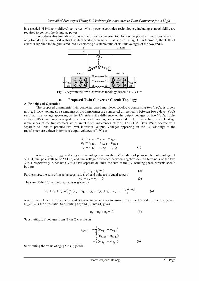
To address this limitation, an asymmetric twin converter topology is proposed in this paper where in only two dc links are used without split-capacitor arrangement, as shown in Fig. 1. Furthermore, the THD of
currents supplied to the grid is reduced by selecting a suitable ratio of dc-link voltages of the two VSCs.
Fig. 1. Asymmetric-twin-converter-topology-based STATCOM
II. Proposed Twin Converter Circuit Topology
A. Principle of Operation
The proposed asymmetric-twin-converter-based multilevel topology, comprising two VSCs, is shown
in Fig. 1. Low voltage (LV) windings of the transformer are connected differentially between two 2-level VSCs
such that the voltage appearing on the LV side is the difference of the output voltages of two VSCs. High-
voltage (HV) windings, arranged in a star configuration, are connected to the three-phase grid. Leakage
inductances of the transformers act as input filter inductances of the STATCOM. Both VSCs operate with
separate dc links to produce two-level individual output. Voltages appearing on the LV windings of the
transformer are written in terms of output voltages of VSCs as
ea = ea1g1 − ea2g2 + eg1g2
eb = eb1g1 − eb2g2 + eg1g2
ec = ec1g1 − ec2g2 + eg1g2 (1)
where ea, ea1g1, ea2g2, and eg1g2 are the voltages across the LV winding of phase-a, the pole voltage of
VSC-1, the pole voltage of VSC-2, and the voltage difference between negative dc-link terminals of the two
VSCs, respectively. Since both VSCs have separate dc links, the sum of the LV winding phase currents should
be zero
ia + ib + ic = 0 (2)
Furthermore, the sum of instantaneous values of grid voltages is equal to zero
vA + v𝐁 + vC = 0 (3)
The sum of the LV winding voltages is given by
ea + eb + ec =NLV
NHV vA + v𝐁 + vC − r ia + ib + ic −
Ld ia +ib +ic
dt (4)
where r and L are the resistance and leakage inductance as measured from the LV side, respectively, and
NLV/NHV is the turns ratio. Substituting (2) and (3) into (4) gives
ea + eb + ec = 0 (5)
Substituting LV voltages from (1) in (5) results in
eg1g2 = −1
3(ea1g1 − ea2g2)
−1
3(eb1g1 − eb2g2)
−1
3(ec1g1 − ec2g2) (6)
Substituting the value of eg1g2 in (1) yields
Controlled Strategies Using DC Voltage for Asymmetric Twin Converter for a High ….
www.iosrjournals.org 24 | Page
ea
eb
ec
=1
3
2 −1 −1−1 2 −1−1 −1 2
ea1g1 − ea2g2
eb1g1 − eb2g2
ec1g1 − ec2g2
(7)
The relation between LV winding voltages and pole voltages is expressed in (7). Pole voltages depend
on the conduction state of the switches in VSC-1 and VSC-2. A total of 26 = 64 different combinations of states
of the switches is possible, the ratio of dc-link voltages of VSCs Vdc1:Vdc2 should be equal to 1:0.366 for better
performance. Using this, the voltage space vector plot corresponding to unique switching states is shown in Fig.
3.3. Out of 64 switching states, 49 states produce unique phase voltages, and 25 voltage steps are viable in the
LV-side voltage. The line voltages of the LV side eab, ebc, and eca are expressed as pole voltages using (1)
eab = ea − eb = ea1g1 − ea2g2 − eb1g1 + eb2g2
ebc = eb − ec = eb1g1 − eb2g2 − ec1g1 + ec2g2
eca = ec − ea = ec1g1 − ec2g2 − ea1g1 + ea2g2 (8)
For vdc2 = 0.5vdc1, depending on the state of switches, voltage waveforms of eab, ebc, and eca has seven
different steps. This is same as the number of steps obtained in the line voltage of four-level diode clamped
multilevel converter. For vdc2 = 0.366vdc1, nine different steps are observed in the line voltage waveforms, which is the same as that in four-level diode clamped converter with the capacitor voltage ratio vdc1 : vdc2 : vdc3 equal to
0.33:0.66:0.33. This makes the proposed scheme equivalent to a four-level converter.
B. PWM Strategy
LV voltage ea takes one of the 25 values given by (7), depending on the state of the switches. The
switching state is decided by the modulating waveform and the PWM strategy used. Selective harmonic
elimination method (SHEM), space vector modulation (SVM), or carrier-based PWM (CB-PWM)
’
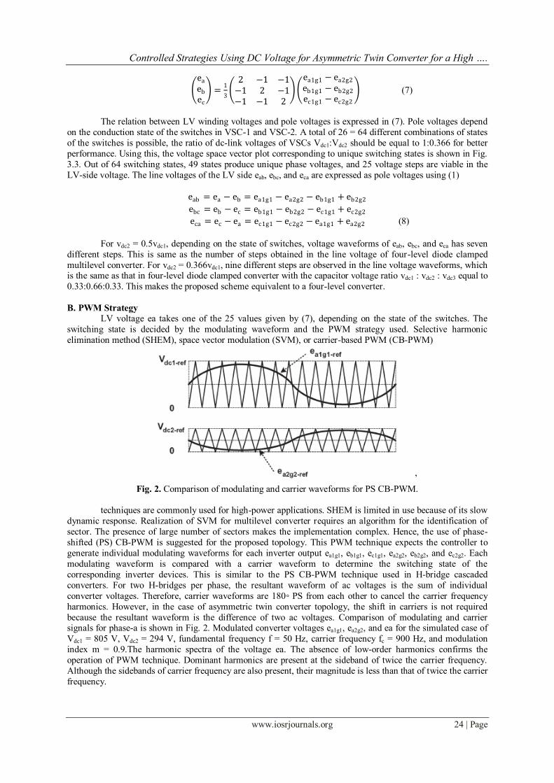
Fig. 2. Comparison of modulating and carrier waveforms for PS CB-PWM.
techniques are commonly used for high-power applications. SHEM is limited in use because of its slow
dynamic response. Realization of SVM for multilevel converter requires an algorithm for the identification of
sector. The presence of large number of sectors makes the implementation complex. Hence, the use of phase-
shifted (PS) CB-PWM is suggested for the proposed topology. This PWM technique expects the controller to
generate individual modulating waveforms for each inverter output ea1g1, eb1g1, ec1g1, ea2g2, eb2g2, and ec2g2. Each
modulating waveform is compared with a carrier waveform to determine the switching state of the
corresponding inverter devices. This is similar to the PS CB-PWM technique used in H-bridge cascaded
converters. For two H-bridges per phase, the resultant waveform of ac voltages is the sum of individual
converter voltages. Therefore, carrier waveforms are 180◦ PS from each other to cancel the carrier frequency
harmonics. However, in the case of asymmetric twin converter topology, the shift in carriers is not required
because the resultant waveform is the difference of two ac voltages. Comparison of modulating and carrier signals for phase-a is shown in Fig. 2. Modulated converter voltages ea1g1, ea2g2, and ea for the simulated case of
Vdc1 = 805 V, Vdc2 = 294 V, fundamental frequency f = 50 Hz, carrier frequency fc = 900 Hz, and modulation
index m = 0.9.The harmonic spectra of the voltage ea. The absence of low-order harmonics confirms the
operation of PWM technique. Dominant harmonics are present at the sideband of twice the carrier frequency.
Although the sidebands of carrier frequency are also present, their magnitude is less than that of twice the carrier
frequency.

Controlled Strategies Using DC Voltage for Asymmetric Twin Converter for a High ….
www.iosrjournals.org 25 | Page
III. Development Of The Equivalent Circuit Of The System For the purpose of analysis, an equivalent circuit of the proposed STATCOM is derived. Transformer
is represented by equivalent series combination of inductances, resistances, and voltage sources. To model the
losses in two VSCs, two resistances r1 and r2 are placed in parallel to the two dc links. The governing equations
of the proposed system can be derived as
s ia
ib
ic
=
−rwb
L0 0
0 −rwb
L0
0 0 −rwb
L
ia
ib
ic
+wb
L −ea + Va
−eb + Vb
−ec + Vc
(9)
where L is defined as ωbl/zbase. l, ωb, and zbase are the leakage inductance, base frequency, and base
impedance of STATCOM. All the parameters and variables are expressed in per-unit (p.u.) system. Equation (9)
is transformed into dq0 reference frame, which has been defined in the Appendix. The system variables in the
dq0 frame are expressed as follows:
s id
iq =
−rwb
Lw
−w −rwb
L
id
iq +
wb
L −ed1 + ed2 + V
−eq1 + eq2 (10)
where id and iq are the d- and q-axis components of LV-side currents. ed1 and eq1 are the voltage
components of VSC-1, and ed2 and eq2 are the voltage components of VSC-2. Equation (10) interrelates the ac
parameters of the STATCOM with those of the grid. The dependence between dc and ac parameters of
STATCOM is derived using instantaneous power balance equations. The following equation gives the power
balance condition between the ac and dc links of VSC-1:
vdc 1idc 1 =3
2(ed1 id + eq1iq ) (11)
The current flowing through the dc-link capacitor c1 is related to the dc-link voltage vdc1 as follows:
svdc 1 = wb C1 idc 1 −vdc 1
r1 (12)
where C1 is defined as 1/(ωbc1zbase). Substituting idc1 from (11)
svdc 1 = wb C1 3
2vdc 1 ed1id + eq1iq −
vdc 1
r1 (13)
Similarly, the governing equation for VSC-2 is expressed as
svdc 2 = wb C2 −3
2vdc 2 ed2id + eq2iq −
vdc 2
r2 (14)
Equations (10), (13), and (14) represent the behavior of the system. These equations are used in the following
section.
IV. Development Of The Controller The proposed asymmetric-twin-converter-based STATCOM has two dc-link voltages vdc1 and vdc2. The
controller should regulate these two dc-link voltages and govern the total reactive power flowing to/from the
STATCOM. The total active power required to overcome losses and regulate dc-link voltages is drawn by STATCOM from the grid. This active power needs to be redistributed among the two dc links. The distribution
should ensure that the two dc-link voltages vdc1 and vdc2 are maintained equal to their corresponding reference
values. The suitable controller to achieve these objectives is discussed in this section.
1. Current Control
The overall system is represented by two coupled differential equations. To decouple them, two
variables x1 and x2 are defined such that
−ed1 + ed2 =L
wb x1 − wiq − V (15)

Controlled Strategies Using DC Voltage for Asymmetric Twin Converter for a High ….
www.iosrjournals.org 26 | Page
−eq1 + eq2 =L
wb x2 − wid (16)
By combining (10) with (15) and (16), the decoupled system equations are obtained as follows:
s id
iq =
−rwb
L0
0 −rwb
L
id
iq +
wb
L
x1
x2 (17)
Applying small-signal analysis on the decoupled system of (17), the small-signal plant transfer function is
derived as
G s =∆id
∆x1=
∆iq
∆x2=
1
s+rw b
L
(18)
Fig. 3 .Equivalent circuit diagram of the proposed STATCOM.
Fig. 4. Controller for STATCOM.
Control variables x1 and x2 govern the system currents id and iq, respectively, as per the differential
equation (17). Therefore, current control is achieved by controlling variables x1 and x2 using the errors between
reference values and actual currents, as given by
x1 = kp1 id_ref− id + ki1 id_ref
− id dt (19)
x2 = kp2 iq_ref− iq + ki2 iq_ref
− iq dt (20)
Required LV voltages ed1 − ed2 and eq1 − eq2 are derived by using these values of x1 and x2 in (15) and (16). To
generate these voltages, modulation signals for the VSCs are derived as follows:
md1 =ed 1
vdc 1; mq1 =
eq 1
vdc 1; md2 =
ed 2
vdc 2; mq2 =
eq 2
vdc 2 (21)
An inner current controller is implemented using (15), (16) and (19)–(21). As shown in Fig.4.
The inner current controller generates the modulating waveforms of LV voltages (md1vdc1 − md2vdc2)
and (mq1vdc1 − mq2vdc2). However, modulating waveforms for individual VSCs md1, md2, mq1, and mq2 have to be
derived from these LV voltages. This distribution is used to regulate real power exchange between the two VSCs, as given in Section IV-C. Furthermore, the current controller requires the reference current signals id_ref
and iq_ref as inputs. The phase-locked loop is synchronized with the grid voltage such that q component of the
grid voltage is kept equal to zero. Therefore, the total active and reactive powers absorbed or supplied by the
STATCOM are proportional to id_ref and iq_ref , respectively. The outer cascaded controller generates the
reference current signals id_ref and iq_ref such that the system variables (total reactive power and two dc-link
voltages) are maintained at their respective reference values

Controlled Strategies Using DC Voltage for Asymmetric Twin Converter for a High ….
www.iosrjournals.org 27 | Page
2. Reactive Power Control
STATCOMs are commonly used either for transmission line voltage support or for reactive power
compensation of load. For voltage support of the transmission line, the reactive current reference iq_ref is controlled by the deviation of the transmission-line voltage from its nominal value. On the other hand, for load
compensation operation, the reactive current reference iq_ref is controlled by the deviation of source power factor
from its required value. In both the aforementioned cases, iq_ref will be supplied to the current controller by a
higher level controller. The issues pertaining to the higher level controller are kept outside the purview of this
paper.
3. DC Voltage Control
A dc voltage controller should ensure that the two dc-link voltages vdc1 and vdc2 are regulated at their
reference values. This problem is divided into two separate control objectives: first, to maintain the sum of two
dc-link voltages (vdc1 + vdc2) that is equal to the sum of their reference values (vdc1−ref + vdc2−ref ) and, second, to
maintain the difference of the two dc link voltages (vdc1 − vdc2) that is equal to the difference of their reference values (vdc1−ref − vdc2−ref ).
1) Sum of DC Voltages: The sum of the dc voltages (vdc1 + vdc2) increases with the net real power flow from
grid to STATCOM and vice versa. In other words, the error in the sum of dc-link voltages (vdc1 + vdc2 − vdc1−ref −
vdc2−ref) indicates the amount of real power to be absorbed from the grid. Hence, the d-axis reference current id_ref
is controlled by the error existing between reference and actual dc-link voltages of VSCs.
2) Difference of DC Voltages: System equations (13) and (14) are coupled equations describing the behavior of
the dc link voltages. Considering C1 = C2 = C and subtracting (14) from (13) give
s(vdc 1 − vdc 2) = x3 − wb C vdc 1
r1−
vdc 2
r2 (22)
Where
x3 =3wb C
2 id
ed 1
vdc 1+
ed 2
vdc 2 + iq
eq 1
vdc 1+
eq 2
vdc 2 (23)
Substituting modulation signals from (21) into (23) gives
x3 =3wb C
2 id md1 + md2 + iq mq1 + mq2 (24)
x3 =3wb C
2(m ∗ i ) (25)
where the modulation vector −→m = md1 + md2 + j(mq1 + mq2) and the current vector −→i = id + jiq. Considering
r1 = r2 = r and applying small-signal analysis on (22) give the transfer function
H s =∆vdc 1−∆vdc 2
∆x3=
1
s+w b C
r
(26)
Equation (22) gives the relation between the control variable x3 and the difference of dc-link voltages vdc1 − vdc2. Therefore, it is inferred that error (vdc1_ref − vdc2_ref ) − (vdc1 − vdc2) is to be processed through a
proportional–integral controller to obtain the control variable x3. Hence, the difference in power requirement
between VSC-1 and VSC-2 is reflected in x3. Using it, (−→m • −→i ) is determined from (25). To achieve the
required power flow between VSCs with low dc-link voltages, the modulation vector −→m is maintained in
phase with −→i . Hence
m =2
3wb C i x3 . ∠∆m = ∠i (27)
The controller which ensures that the difference of dc voltages vdc1 − vdc2 is maintained equal to the reference
vdc1_ref − vdc2_ref is shown in Fig. 4
4. Generation of Modulation Signals
The current controller, generates the signals for primary voltages ed1 − ed2 and eq1 − eq2. These are
transformed to modulation signals as follows:
md1vdc 1 − md2vdc 2 = ed1 − ed2
mq1vdc 1 − mq2vdc 2 = eq1 − eq2 (28)

Controlled Strategies Using DC Voltage for Asymmetric Twin Converter for a High ….
www.iosrjournals.org 28 | Page
V. Fuzzy Logic Controller L.A.Zadeh presented the first paper on fuzzy set theory in 1965. Since then, a new language was
developed to describe the fuzzy properties of reality, which are very difficult and sometime even impossible to
be described using conventional methods. Fuzzy set theory has been widely used in the control area with some
application to dc-to-dc converter system. A simple fuzzy logic control is built up by a group of rules based on
the human knowledge of system behavior. Matlab /Simulink simulation model is built to study the dynamic
behavior of converter.
Furthermore, design of fuzzy logic controller can provide desirable both small signal and large signal
dynamic performance at same time, which is not possible with linear control technique. Thus, fuzzy logic
controller has been potential ability to improve the robustness of converters. The basic scheme of a fuzzy logic
controller is shown in Fig 6 and consists of four principal components such as: a fuzzyfication interface, which
converts input data into suitable linguistic values; a knowledge base, which consists of a data base with the necessary linguistic definitions and the control rule set; a decision-making logic which, simulating a human
decision process, infer the fuzzy control action from the knowledge of the control rules and linguistic variable
definitions; a de-fuzzyfication interface which yields non fuzzy control action from an inferred fuzzy control
action.
Fig.5. General structure of the fuzzy logic controller
The fuzzy control systems are based on expert knowledge that converts the human linguistic concepts
into an automatic control strategy without any complicated mathematical model .
Fig.6. Block diagram of the Fuzzy Logic Controller (FLC) for proposed Converter.
A. Fuzzy Logic Membership Functions: Fuzzy controllers do not require an exact mathematical model. Instead, they are designed based on
general knowledge of the plant. Fuzzy controllers are designed to adapt to varying operating points. Fuzzy
Logic Controllers designed to control the change in voltage of the converter using Mamdani style fuzzy
inference system. Two input variables, error (e) and change of error (de) are used in this fuzzy logic system. The
single output variable(u) is steady state signal of the converter, nothing but error free response is directly fed to
the system.

Controlled Strategies Using DC Voltage for Asymmetric Twin Converter for a High ….
www.iosrjournals.org 29 | Page
Fig.7. Membership functions for Input, Change in input, Output
Fig.8. Shows the membership functions for input (error(e)), Change in input (change of error (de)), Output
variable (u).
B. Fuzzy Logic Rules
The objective of this dissertation is to control the output voltage of the boost converter. The error and
change of error of the output voltage will be the inputs of fuzzylogic controller. These 2 inputs are divided into
seven groups; NL: Negative Large, NM: Negative Medium, NS: Negative Small, ZO: Zero Area, PS: Positive small, PM: Positive Medium and PL: Positive Large and its parameter [10]. These fuzzy control rules for error
and change of error can be referred that is shown as below.
Fig.8. Rules for fuzzy logic controller
VI. Matlab Modeling And Simulation Results Here Simulation is carried out in two different Conditions,
1). Conventional (PI) Controller Based High Power STATCOM.
2). Intelligence (FUZZY) Controller Based High Power STATCOM.
Case 1: Conventional Controller Based High Power STATCOM
Fig. 9 Matlab / Simulink Model of Conventional Controller Based High Power STATCOM.

Controlled Strategies Using DC Voltage for Asymmetric Twin Converter for a High ….
www.iosrjournals.org 30 | Page
Fig.10. HV-side (grid) phase-a voltage & LV-side phase-a transformer Current
As above fig 10 shows the Matlab/Simulink Model of Conventional Controller Asymmetric Twin
Conversion Based High Power STATCOM, Fig.11 shows the HV Side Phase A voltage and LV Side Phase A
TransformerCurrent, with conventional controller
Fig.11. Converter Side Input Voltage
Fig.11shows the Converter side input voltages, nothing but primary side voltages to support the converter
operations with conventional controller.
Fig.12. FFT Analysis of LV Side Phase A Current
Fig.12. shows the FFT Analysis of LV Side Phase A Current, we get 4.29%, with conventional controller.

Controlled Strategies Using DC Voltage for Asymmetric Twin Converter for a High ….
www.iosrjournals.org 31 | Page
Fig.13. FFT Analysis of LV Side Voltage
Fig.13. shows the FFT Analysis of LV Side Voltage, we get 39.23%, with conventional controller.
Case 2: Fuzzy logic Controller Based High Power STATCOM
Fig.14 Converter Side Input Voltage
Fig.14 shows the Converter side input voltages, nothing but primary side voltages to support the converter
operations with intelligence controller.
Fig.15 HV-side (grid) phase-a voltage & LV-side phase-a transformer current
Fig.15 shows the HV Side Phase A voltage and LV Side Phase A Transformer Current with Intelligence
Controller.

Controlled Strategies Using DC Voltage for Asymmetric Twin Converter for a High ….
www.iosrjournals.org 32 | Page
Fig.16 FFT Analysis of LV Side Phase A Current
Fig.16 shows the FFT Analysis of LV Side Phase A Current, we get 3.13%, with Intelligence Controller.
VII. Conclusion A high-power STATCOM based on two 2-level VSCs is proposed with two different controlling
techniques such as conventional (PI) controller & intelligence (FUZZY) controller .Reduced component count,
simpler layout of switches, and reduced capacitance requirement are the attractive features of the scheme over
the diode clamped and cascaded multilevel converters. In the proposed topology, only two dc voltages have to
be controlled. Furthermore, the ratio of the dc-link voltages of the two VSCs is selected such that low distortion
in current is achieved. A dc-link voltage controller has been proposed to regulate the dc-link voltages of the two converters by drawing requisite amount of real power from the utility and by differentially distributing them
between the two converters.
A Matlab/Simulink model of the system is developed to facilitate the design of the conventional
&Intelligence controllers, by using Intelligence controllers we get better response and fast response and better
THD values, THD values well within IEEE Standards. Fuzzy control system is developed to derived, the
effectiveness of the scheme is verified through detailed simulation study. By implementing Fuzzy system we
have reduced the THD from 4.65% to 3.17%.
References [1]. S. Anand, B. G. Fernandes, and K. Chatterjee, ―A new 4-level open-ended transformer based STATCOM for high power
applications,‖ in Proc. 36th Annu. IEEE IECON, Nov. 7–10, 2010, pp. 1957–1962.
[2]. C. Schauder and H. Mehta, ―Vector analysis and control of advanced static VAR compensators,‖ Proc. Inst. Elect. Eng. C—Gener.,
Transm. Distrib., vol. 140, no. 4, pp. 299–306, Jul. 1993.
[3]. E. M. John, A. Oskoui, and A. Petersson, ―Using a STATCOM to retire urban generation,‖ in Proc. IEEE Power Syst. Conf. Expo.,
Oct. 2004, vol. 2, pp. 693–698.
[4]. D. Soto and T. C. Green, ―A comparison of high-power converter topologies for the implementation of FACTS controllers,‖ IEEE
Trans. Ind. Electron., vol. 49, no. 5, pp. 1072–1080, Oct. 2002.
[5]. J. Rodriguez, J.-S. Lai, and F. Z. Peng, ―Multilevel inverters: A survey of topologies, controls, and applications,‖ IEEE Trans. Ind.
Electron., vol. 49, no. 4, pp. 724–738, Aug. 2002.
[6]. Y. Cheng, C. Qian, M. L. Crow, S. Pekarek, and S. Atcitty, ―A comparison of diode-clamped and cascaded multilevel converters for
a STATCOM with energy storage,‖ IEEE Trans. Ind. Electron., vol. 53, no. 5, pp. 1512– 1521, Oct. 2006.
[7]. H. Abu-Rub, J. Holtz, J. Rodriguez, and G. Baoming, ―Medium-voltage multilevel converters—State of the art, challenges, and
requirements in industrial applications,‖ IEEE Trans. Ind. Electron., vol. 57, no. 8, pp. 2581–2596, Aug. 2010.
[8]. S. Kouro, M. Malinowski, K. Gopakumar, J. Pou, L. G. Franquelo, B.Wu, J. Rodriguez, M. A. Pérez, and J. I. Leon, ―Recent
advances and industrial applications of multilevel converters,‖ IEEE Trans. Ind. Electron., vol. 57, no. 8, pp. 2553–2580, Aug.
2010.
[9]. F. Z. Peng, J. W. McKeever, and D. J. Adams, ―A power line conditioner using cascade multilevel inverters for distribution
systems,‖ IEEE Trans. Ind. Appl., vol. 34, no. 6, pp. 1293–1298, Nov./Dec. 1998.
[10]. K. V. Patil, R. M. Mathur, J. Jiang, and S. H. Hosseini, ―Distribution system compensation using a new binary multilevel voltage
source inverter,‖ IEEE Trans. Power Del., vol. 14, no. 2, pp. 459–464, Apr. 1999.
[11]. C. K. Lee, S. Y. Ron Hui, and H. S. Chung, ―A 31-level cascade inverter for power applications,‖ IEEE Trans. Ind. Electron., vol.
49, no. 3, pp. 613–617, Jun. 2002.
[12]. H. Akagi, S. Inoue, and T. Yoshii, ―Control and performance of a transformerless cascade PWM STATCOM with star
configuration,‖ IEEE Trans. Ind. Appl., vol. 43, no. 4, pp. 1041–1049, Jul./Aug. 2007.

Controlled Strategies Using DC Voltage for Asymmetric Twin Converter for a High ….
www.iosrjournals.org 33 | Page
[13]. M. Malinowski, K. Gopakumar, J. Rodriguez, and M. A. Perez, ―A survey on cascaded multilevel inverters,‖ IEEE Trans. Ind.
Electron., vol. 57, no. 7, pp. 2197–2206, Jul. 2010.
[14]. Y. Fukuta and G. Venkataramanan, ―DC bus ripple minimization in cascaded H-bridge multilevel converters under staircase
modulation,‖ in Proc. 37th IEEE IAS Annu. Meeting, 2002, vol. 3, pp. 1988–1993.
[15]. S. Vazquez, J. I. Leon, J. M. Carrasco, L. G. Franquelo, E. Galvan, M. Reyes, J. A. Sanchez, and E. Dominguez, ―Analysis of the
power balance in the cells of a multilevel cascaded H-bridge converter,‖ IEEE Trans. Ind. Electron., vol. 57, no. 7, pp. 2287–2296,
Jul. 2010.
[16]. S. Lu, S.Mariethoz, and K. A. Corzine, ―Asymmetrical cascade multilevel converters with noninteger or dynamically changing DC
voltage ratios: Concepts andmodulation techniques,‖ IEEE Trans. Ind. Electron., vol. 57, no. 7, pp. 2411–2418, Jul. 2010.
Sadakar.D received the B.Tech degree in electrical & electronics engineering from the Jawaharlal Nehru Technological University Hyderabad, Hyderabad, India, in 2011.He is
currently pursuing M.Tech ( Electrial Power Systems) in VBIT Engineering College,
Aushapur(v), Ghatkesar, Hyderabad, India. His areas of interest are Power Systems,
Electrical Machines and Power Electronics
Mrs.G.Indira rani (M.Tech), Assistant Professor, Department of Electrical & Electronics
Engineering in Vignana Bharathi Institute of Technology Engineering College, Jawaharlal
Nehru Technological University Hyderabad,Aushapu(v), Ghatkesar,Hyderabad,India. She has
a teaching experience of 7 years.