control units local extractors - Movex, Inc.
12
Adaptable to all types of facilies, Movex control units support a highly efficient working environment. Choosing the right control unit reduces energy costs and lowers noise levels. Movex also offers a wide range of local extractors, fans, accessories and filters. LOCAL EXTRACTORS CONTROL UNITS LOCAL EXTRACTORS Control automaon incorporates specially adapted and proven components and will even influence recommendaons for appropriate system selecons. In the installaon examples on pages 2 through 5, there are suggesons for various soluons to help find systems to sasfy most needs. Local extracon arms are presented in various system soluons within the examples. Automaon can even be used in other applicaons, such as when connecng extractors directly to machinery. For control of automove exhaust installaons, see the control automaon for exhaust extracon. Most types of sensors (such as for gas, heat, light and vibraons) can be combined with the S 200 and S 400 control units. For help in opmising extractor installaons or calculang energy savings, please contact Movex. Pure advantage
-
Upload
khangminh22 -
Category
Documents
-
view
2 -
download
0
Transcript of control units local extractors - Movex, Inc.

Adaptable to all types of facilities, Movex control units support a highly
efficient working environment. Choosing the right control unit reduces energy costs and lowers noise levels.
Movex also offers a wide range of local extractors, fans, accessories and filters.
L O C A L E X T R A C T O R S
CONTROL UNITSLOCAL EXTRACTORS
Control automation incorporates specially adapted and proven components and will even influence recommendations for appropriate system selections. In the installation examples on pages 2 through 5, there are suggestions for various solutions to help find systems to satisfy most needs. Local extraction arms are presented in various system solutions within the examples. Automation can even be used in other applications, such as when connecting extractors directly to machinery. For control of automotive exhaust installations, see the control automation for exhaust extraction. Most types of sensors (such as for gas, heat, light and vibrations) can be combined with the S 200 and S 400 control units. For help in optimising extractor installations or calculating energy savings, please contact Movex.
Pure advantage

1x230 VAC/ 3x460 VAC
1x230 VAC/ 3x460 VAC
1x230 VAC/ 3x460 VAC
3x208 / 3x460 VAC
1x230/ 3x208 / 3X460 VACSignal cable
System 1:1Manual start and stop of fan
The fan is manually started and stopped with a protective motor switch SMB.
The protective motor switch has a thermal-magnetic release and phase failure protection.
System 1:2Manual speed control of fan is started and stopped with external signal 3-phase motor only
The signal for starting and stopping the fan is produced with an external signal from, for example, a central monitoring system.
The fan’s speed is regulated manually as necessary with the SFC POT potentiometer.
System 1:3Manual start and stop of fan with two speeds 3-phase motor only
The fan is manually started and stopped with the SFC VSS rotary switch.
With the rotary switch, the fan speed can be regulated between two preset speeds that are programmed on the frequency converter display.
Start and stop of fans, with or without speed control
SFCFrequency converter
SFC POTPotentiometer
SFCFrequency converter
SFC VSSRotary switch
SMBProtective motor switch
System 1:4Manual start and stop of fan and need-adapted control of fan speed 3-phase motor only
The fan is manually started and stopped with the SFC SB switch.
The frequency converter maintains a constant negative pressure in the main duct via the pressure sensor.
SFCFrequency converter
SFC SBSwitch
ST 300Pressure sensor
Hose

3x208 VAC/ 3x460 VAC
1x115 VAC
3x208 VAC/ 3x460 VAC
1x115 VAC
Start and stop fans with contactor
System 2:2Manual start and stop of fan.
Start and stop is made manually with a push-button mounted on the extractor.
The S 400 control unit has a built-in adjustable time delay of 0 - 15 minutes.
Manual control from work station with time delay
PRT / KHTPush-button
PRT / KHTPush-button
S 600Trans-former
S 400Control unit
S 400Control unit
SKOContactor
3x208 / 3x460 VAC24 VACSignal cable
System 2:3Automatic starting and stopping of fan.
Starting and stopping are conducted automatically with the STG 400 pliers sensor, which is clipped onto the earth cable of the welding transformer.
The S 400 control unit has a built-in adjustable time delay of 0–15 minutes.
Automatic control from work station with time delay.
S 600Trans-former
S 400Controlunit
S 400Controlunit
STG 400Pliers sensor
SKOContactor
STG 400Pliers sensor

3x208 VAC/ 3x460 VAC
1x115 VAC
3x208 VAC/ 3x460 VAC
1x115 VAC
3x208/ 3x460 VAC24 VACSignal cable
System 3:2Manual control of damper and start and stop of fan
Opening and closing of the damper is made manually via a push-button mounted on the extractor.
A control signal from the control unit starts and stops the fan.
The S 400 control unit has a built-in adjustable time delay of 0–15 minutes.
Individual damper control and start and stopping of fan via contactor
System 3:3Automatic control of damper and start and stop of fan
The damper opened and closed automatically with the STG 400 pliers sensor, which is clipped onto the earth cable of the welding transformer.
A control signal from the control unit starts and stops the fan.
The S 400 control unit has a built-in adjustable time delay of 0–15 minutes.
Damper and contactor manually controlled from the work station with time delay
Damper and contactor automatically controlled from the work station with time delay
S 600Trans-former
S 400Controlunit
S 400Controlunit
STG 400Pliers sensor
SKOContactor
SAS-xxx/24Automatic damper
SAS-xxx/24Automatic damper
STG 400Pliers sensor
PRT / KHTPush-button
S 600Trans-former
S 400Controlunit
S 400Control unit
SKOContactor
PRT / KHTPush-button
SAS-xxx/24Automatic damper
SAS-xxx/24Automatic damper

1x230 VAC/ 3x460 VAC
1x115 VAC
1x230 VAC/ 3x460 VAC
1x115 VAC
1x230/ 3x460 VAC24 VACSignal cable
System 4:2Manual control of damper and need-adapted control and start and stop of fan 3-phase motor only
The damper is opened and closed manually with a push-button mounted on the extractor, which also starts and stops the fan.
The frequency converter maintains a constant negative pressure in the main duct via the pressure sensor.
The S 400 control unit has a built-in adjustable time delay of 0–15 minutes.
System 4:3Automatic control of damper and need-adapted control and start and stop of fan 3-phase motor only
The damper is opened and closed automatically with the STG 400 pliers sensor, which is clipped onto the earth cable of the welding transformer.
A control signal from the control unit starts and stops the fan.
The frequency converter maintains a constant negative pressure in the main duct via the pressure sensor.
The S 400 control unit has a built-in adjustable time delay of 0–15 minutes.
Individual damper control and need-adapted control of fan via a pressure sensor and frequency converter
Hose
Damper and frequency converter manually controlled from the work station with time delay
Damper and frequency converter automatically controlled from the work station with time delay
S 600Trans-former
S 400Controlunit
S 400Controlunit
STG 400Pliers sensor
SFCFrequencyconverter
ST 300Pressure sensor
SAS-xxx/24Automatic damper
SAS-xxx/24Automatic damper
STG 400Pliers sensor
PRT / KHTPush-button
PRT / KHTPush-button
S 600Trans-former
S 400Controlunit
S 400Controlunit
SFCFrequencyconverter
ST 300Pressure sensor
SAS-xxx/24Automatic damper
SAS-xxx/24Automatic damper
1x115 VAC

SFCFREQUENCY CONVERTER
Designed for process ventilation
The SFC frequency converter is designed for variable speed control of e.g. fans. This provides optimal operating economy and the lowest possible noise level. Depending on the number of work stations in operation, the SFC (along with the ST 300 pressure sensor) varies the fan speed and thus evacuates the correct amount of air. Alternatively, manual variable control can be used with the SFC POT potentiometer. The SFC VSS is used if a 2-step control is preferred.
Interference filters are included. The enclosure class is IP 21 for built-in applications, alternatively IP 55 for dust- and water protection.
Movex can supply SFC PROG pre-programmed frequency converters to make it easier to put systems in operation.
For alternative voltages, etc., please contact Movex.
Designa on Rated powerkW / HP
Rated currentA
Input VoltageV
1 phase 3 phase
Output VoltageV
3 phase
Weightlb
Widthinch
Heightinch
Depthinch
SFC 037/21-1SFC 037/21-3
0.37 / 0.50.37 / 0.5
3.31.5
230460
230460
3.33.9
2 13/16
5 1/85 11/16
5 5/85 1/8
5 7/8
SFC 055/21-1SFC 055/21-3
0.55 / 0.750.55 / 0.75
3.71.9
230460
230460
3.33.9
2 13/16
5 1/85 11/16
5 5/85 1/2
5 7/8
SFC 075/21-1SFC 075/21-3
0.75 / 10.75 / 1
4.82.3
230460
230460
3.33.9
2 13/16
5 1/85 11/16
5 5/85 1/2
5 7/8
SFC 110/21-1SFC 110/21-3
1.1 / 1.51.1 / 1.5
6.93
230460
230460
3.93.9
5 1/8
5 1/85 5/8
5 5/85 7/8
5 7/8
SFC 150/21-1SFC 150/21-3
1.5 / 21.5 / 2
84.1
230460
230460
3.93.9
5 1/8
5 1/85 5/8
5 5/85 7/8
5 7/8
SFC 220/21-1SFC 220/21-3
2.2 / 32.2 / 3
115.5
230460
230460
6.86.8
5 1/2
5 1/27 1/4
7 1/45 7/8
5 7/8
SFC 400/21-3 4 / 5.5 9.5 460 460 6.8 5 1/2 7 1/4 5 7/8
SFC 750/21-3 7.5 / 10 17 460 460 14.3 7 1/16 9 1/8 6 11/16
Designa on Rated powerkW / HP
Rated currentA
Input VoltageV
1 phase 3 phase
Output VoltageV
3 phase
Weightlb
Widthinch
Heightinch
Depthinch
SFC 037/55-1SFC 037/55-3
0.37 / 0.50.37 / 0.5
3.31.5
230460
230460
13.819.4
8 1/4
8 7/169 7/6
11 11/166 7/16
7 9/16
SFC 055/55-1SFC 055/55-3
0.55 / 0.750.55 / 0.75
3.71.9
230460
230460
13.819.4
8 1/4
8 7/169 7/6
11 11/166 7/16
7 9/16
SFC 075/55-1SFC 075/55-3
0.75 / 10.75 / 1
4.82.3
230460
230460
13.819.4
8 1/4
8 7/169 7/6
11 11/166 7/16
7 9/16
SFC 110/55-1SFC 110/55-3
1.1 / 1.51.1 / 1.5
6.93
230460
230460
19.419.4
8 7/16
8 7/1611 11/16
11 11/167 9/16
7 9/16
SFC 150/55-1SFC 150/55-3
1.5 / 21.5 / 2
84.1
230460
230460
19.419.4
8 7/16
8 7/1611 11/16
11 11/167 9/16
7 9/16
SFC 220/55-1SFC 220/55-3
2.2 / 32.2 / 3
115.5
230460
230460
23.523.5
9 1/16
9 1/1613 3/8
13 3/88 3/16
8 3/16
SFC 400/55-3 4 / 5.5 9.5 460 460 23.5 9 1/16 13 3/8 8 3/16
SFC 750/55-3 7.5 / 10 17 460 460 52 12 5/8 16 3/4 11 7/16
ENCLOSURE CLASS IP 55
ENCLOSURE CLASS IP 21

SFC POT/VSS/SBSFC POT POTENTIOMETER
The SFC POT is a potentiometer for a variable regulation of fan speed via frequency converters.
Dimensions 315/16x 315/16x 25/8 inchesResistance 10 kΩ
SFC VSS ROTARY SWITCH
The SFC POT is a rotary switch for 2-step regulation of fan speeds via frequency converters.
Dimensions 315/16x 315/16x 25/8 inchesIncrements 0-1-2
SFC SB SWITCH
The SFC SB is a switch for start/stop of fans via frequency converters.
Dimensions 23/8x 31/8x 23/16 inchesEnclosure class IP 54Power supply Max 250 V, 16 A
ST 300
ST 300 PRESSURE SENSOR
The ST 300 maintains constant negative pressure in the discharge duct via a frequency converter that controls fan speeds. The ST 300 always provides the correct flow, regardless of the number of open and closed dampers.
Dimensions 39/16x 33/4x 17/16 inchesEnclosure class IP 54Operating range 2, 4, 8, 12 IN/WGPower supply 24 VDCOutput signal 0-10 V (alt. 4-20 mA)Included accessories Measurement output and 7 feet hose
SFC VSS
SFC SB
SFC POT

SAS
STG 400
KHT / MEMT-XXX
1 2 3 4 5 6 7 8 9 10 11 12 1314
S 400S 400 CONTROL UNIT
The S 400 is used for automatic control of damper motor SAS 24 at terminals 1–4. Fans are normally controlled via the S 600 transformer units. The after-run time for evacuation of remaining gases is built into the control unit. The time is set between 0–15 min. The S 400 is supplied with 24 VAC from the S 600 transformer unit.
Dimensions 51/8x 31/8x 31/16 mmEnclosure class IP 54Primary side 24 VACSecondary side 24 VAC
SMT 60 TIMER SWITCH
The SMT mechanical timer switch is a manual timer, adjustable from 0 to 60 minutes. It can replace a KHT push-button unit. The SMT 60 is wall-mounted close to the extractor.
Dimensions 315/16x 315/16x 25/8
Timeset 0 - 60 min.
ACCESSORIES
SSB SwitchSTG 400 Clip-on sensorKHT / MEMT Push-button unitPRT Push-button
S 400Terminals
1-4 24 V~ For damper SAS-xxx/24. 5-7 Potential-free VX-switch. 8-9 24 V~ supply from S 600.10-14 Connection sensor (15 V).
SSB
MEMT-XXX
STG 400
SMT 60
PRT
PRT

SKO
SFC
S 400L PE N 1 2 3 4 5 6 7 81
S 600S 600 TRANSFORMER UNIT
The S 600 is used to supply 24 VAC to the S 400 control unit. Control of fan is made via external contactor 230 VAC, via signal from terminals 1 & 2. Frequency converter is controlled via the potential-free outputs, terminals 3 and 4.
Dimensions 51/8x 71/6x 41/16 inches.Enclosure class IP 54Primary side 115 VACSecondary side 24 VAC (60 VA)
Terminals
L1-N 115 V~ Main connection. 1-2 115 V~ Connection SKO. 3-4 Potential-free VX-switch. 5-6 24 V~ Votage (S400). 7-8 Switch connection (S400).
S 600
S 600
1 2 3 4 5 6 7 8 9 1011 121314
SASSTG 200
1 2 3 4 5 6 7 8 9 1011 121314
SAS
SKO
STG 200
KHT / MEMT-XXX
S 200/115 S 200/115-24S 200/115 CONTROL UNIT
The S 200/115 is used for start/stop of a fan. The after-run time for evacuation of remaining gases is built into the pliers sensor (~30 sec.). For longer run-times, there are adjustable timer cards available (0-15 min. and 0-240 min.) as accessories. Single-phase fans (max. 1 hp) can be directly controlled via an integrated relay. Other fans are controlled with an external contactor via the same integrated relay, terminals 1–5. Frequency converters are controlled via the potential-free output, terminals 6–8.
Dimensions 71/16x 51/8x 31/16 inchesEnclosure class IP 54 Primary side 115 VACSecondary side 115 VAC (Max 10A)
ACCESSORIES
STK 15 Timer card 0-15 minSTK 240 Timer card 0-240 minSSB SwitchSTG 200 Pliers sensor (~30s delay)KHT Push-button unit
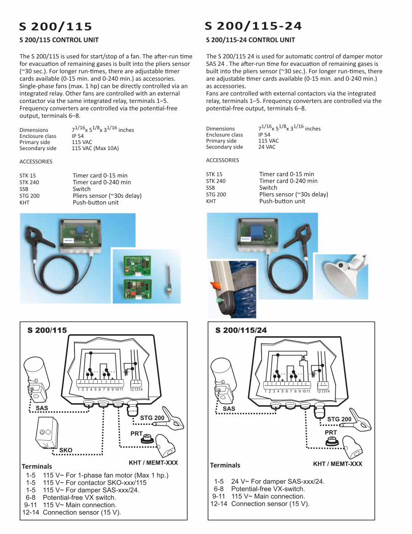
S 200/115-24 CONTROL UNIT
The S 200/115 24 is used for automatic control of damper motor SAS 24 . The after-run time for evacuation of remaining gases is built into the pliers sensor (~30 sec.). For longer run-times, there are adjustable timer cards available (0-15 min. and 0-240 min.) as accessories.Fans are controlled with external contactors via the integrated relay, terminals 1–5. Frequency converters are controlled via the potential-free output, terminals 6–8.
Dimensions 71/16x 51/8x 31/16 inchesEnclosure class IP 54Primary side 115 VACSecondary side 24 VAC
ACCESSORIES
STK 15 Timer card 0-15 minSTK 240 Timer card 0-240 minSSB SwitchSTG 200 Pliers sensor (~30s delay)KHT Push-button unit
Terminals1-5 115 V~ For 1-phase fan motor (Max 1 hp.)
1-5 115 V~ For contactor SKO-xxx/115 1-5 115 V~ For damper SAS-xxx/24.
6-8 Potential-free VX switch. 9-11 115 V~ Main connection. 12-14 Connection sensor (15 V).
Terminals
1-5 24 V~ For damper SAS-xxx/24. 6-8 Potential-free VX-switch. 9-11 115 V~ Main connection. 12-14 Connection sensor (15 V).
S 200/115 S 200/115/24
PRT
KHT / MEMT-XXX
PRT

SMB
SKO
SMB PROTECTIVE MOTOR SWITCH
The SMB is a 3-pole protective motor switch with thermal-magnetic release and equipped with phase failure protection. The SMB is designed for control and protection of fan motors.
Dimensions 311/16x 513/16x 35/16 inches.Enclosure class IP 55
Product Current 3-phase range ~460 V (A) (HP)
SMB 10* 0,63-1,0 0,37SMB 16* 1,0-1,6 0,5/0,75SMB 25* 1,6-2,5 1SMB 40* 2,5-4,0 1,5/2,0SMB 63* 4,0-6,3 3,0SMB 100* 6,0-10,0 5,5SMB 140** 9,0-14,0 7,5SMB 180** 13,0-18,0 10
* Self-protecting, pre-fusing not required** Max. pre-fusing when Ik>Icu is 63 A.
SKO CONTACTOR
The SKO is a 3-pole contactor with an overcurrent relay for manual resetting. The overcurrent relay has phase failure protection. It is used with external switches or control.
Dimensions 41/16x 77/8x 6 inchesEnclosure class IP 55
Product Current 3-phase range ~460 V (A) (HP)
SKO 10/115* 0,63-1,0 0,37SKO 17/115* 1,0-1,7 0,5/0,75SKO 25/115* 1,6-2,5 1SKO 40/115* 2,5-4,0 1,5/2,0SKO 60/115* 4,0-6,0 3,0SKO 80/115* 5,5-8,0 5,5SKO 130/115** 9,0-13,0 7,5SKO 180/115** 12,0-18,0 10
* Maximum power is 4 hp.**Maximum power is 13 hp.

SASSAS AUTOMATIC DAMPER
The SAS is an automatic single-leaf damper for applications where short operating times are necessary.The high speed motor opens the damper blade in 7.5 seconds creating a 95% extraction capacity after only 3 seconds.The damper is supplied for air tightness class 1.For other air tightness classes, please contact Movex.
Dimensions (motor) 51/2x 315/16x 33/8 inchesMaterial (cowling) PAMaterial (damper housing) Galvanised sheet metalOpening time, 90º 7,5 sTorque 3 NmPower consumption (24 V) 2 VA in operation / 0 VA in end position
Product Diameter Voltage (mm) (V)
SAS-100/24 Ø3 15/16 24SAS-125/24 Ø4 15/16 24SAS-160/24 Ø6 5/16 24SAS-200/24 Ø7 7/8 24SAS-250/24 Ø9 13/16 24SAS-315/24 Ø12 3/8 24
~24 V
Movex Inc.104 Commerce DriveNorthampton, PA 18067, USAPhone: 610 440-0478 Fax: 610 440-0480www.movexinc.com