Control of a channel-flow behind a backward-facing step by suction/blowing
8
Control of a channel-flow behind a backward-facing step by suction/blowing Va ´clav Uruba * , Pavel Jona ´s ˇ, Oton Mazur Department of Fluid Dynamics, Institute of Thermomechanics, v.v.i., Academy of Sciences of the Czech Republic, Dolejs ˇkova 5, 182 00 Praha 8, Czech Republic Received 2 November 2006; received in revised form 16 February 2007; accepted 1 April 2007 Available online 21 May 2007 Abstract Results of the experimental investigation on control of narrow channel flow behind a backward-facing step by blowing/suction near the step foot are presented. The slots differ in both the orifice shape (rectangle or serrated) and area (50–375 10 6 m 2 ) of its cross-sec- tion. The intensity of flow control is characterized by the suction/blowing flow coefficient (mass flow through the slot over mass flow above the step, suction: negative values) that varies from 0.035 up to 0.035 at Reynolds number 5 10 4 (defined on the basis of the hydraulic diameter and volume velocity). Preliminary results indicate that both blowing and suction are able to reduce the length of the separation zone down to one third of its value without control. Control effectiveness is given by absolute value of the flow coefficient. The other parameters (slot area and shape) are important only for blowing, in this case small cross-section with serrated edge is the most effective. The existing three-dimensional vortex structures near the step (resulting from interaction of boundary layers near the step edge) are influenced by suction more then by blowing. The experiments are still in progress. Ó 2007 Elsevier Inc. All rights reserved. Keywords: Channel flow; Backward-facing step; Reattachment control; Blowing; Suction 1. Introduction Active flow control concepts have become an increas- ingly attractive topic in fluid mechanics in the last few years. Flow separation results in negative effects such as drag increase, lift reduction and noise generation. The most common objective in the control of separated flows is the control of the size of the separation region. Thus the reat- tachment length x r can be defined as a control variable, the control goal is in reducing this parameter. Prandtl already in 1904 showed the modern way of flow control. In his famous paper he described several experi- ments in which the boundary layer was controlled. Prandtl used suction to delay boundary-layer separation from the surface of a cylinder. The backward-facing step flow has been established as a benchmark configuration for separated flow studies in fluid mechanics first. The presented paper deals with possibilities of three-dimensional backward-facing step flow control at high Reynolds numbers (Re order of 5 10 4 based on hydraulic diameter d h of the inlet channel and the bulk velocity U e just upstream the step edge). A backward- facing step configuration of a channel occurs in many engineering applications ranging from various fluidic ele- ments, cooling of turbine blades, air-conditioning pipelines to many other devices. Flow separation on the step edge is a source of pressure loss, vibrations, and noise and affects heat transfer (reat- tachment region corresponds to maximum heat transfer however low-heat transfer appears in separation region). Turbulent shear flow in channels with sudden expansion of the cross-section could be met very often in many tech- nical applications in mechanical and civil engineering. This flow belongs to the complex-flow family defined in the 0142-727X/$ - see front matter Ó 2007 Elsevier Inc. All rights reserved. doi:10.1016/j.ijheatfluidflow.2007.04.002 * Corresponding author. Tel.: +420 286 588 547; fax: +420 286 584 695. E-mail address: [email protected] (V. Uruba). www.elsevier.com/locate/ijhff International Journal of Heat and Fluid Flow 28 (2007) 665–672
Transcript of Control of a channel-flow behind a backward-facing step by suction/blowing

www.elsevier.com/locate/ijhff
International Journal of Heat and Fluid Flow 28 (2007) 665–672
Control of a channel-flow behind a backward-facingstep by suction/blowing
Vaclav Uruba *, Pavel Jonas, Oton Mazur
Department of Fluid Dynamics, Institute of Thermomechanics, v.v.i., Academy of Sciences of the Czech Republic,
Dolejskova 5, 182 00 Praha 8, Czech Republic
Received 2 November 2006; received in revised form 16 February 2007; accepted 1 April 2007Available online 21 May 2007
Abstract
Results of the experimental investigation on control of narrow channel flow behind a backward-facing step by blowing/suction nearthe step foot are presented. The slots differ in both the orifice shape (rectangle or serrated) and area (50–375 Æ 10�6 m2) of its cross-sec-tion. The intensity of flow control is characterized by the suction/blowing flow coefficient (mass flow through the slot over mass flowabove the step, suction: negative values) that varies from �0.035 up to 0.035 at Reynolds number 5 Æ 104 (defined on the basis of thehydraulic diameter and volume velocity). Preliminary results indicate that both blowing and suction are able to reduce the length ofthe separation zone down to one third of its value without control. Control effectiveness is given by absolute value of the flow coefficient.The other parameters (slot area and shape) are important only for blowing, in this case small cross-section with serrated edge is the mosteffective. The existing three-dimensional vortex structures near the step (resulting from interaction of boundary layers near the step edge)are influenced by suction more then by blowing. The experiments are still in progress.� 2007 Elsevier Inc. All rights reserved.
Keywords: Channel flow; Backward-facing step; Reattachment control; Blowing; Suction
1. Introduction
Active flow control concepts have become an increas-ingly attractive topic in fluid mechanics in the last fewyears. Flow separation results in negative effects such asdrag increase, lift reduction and noise generation. The mostcommon objective in the control of separated flows is thecontrol of the size of the separation region. Thus the reat-tachment length xr can be defined as a control variable, thecontrol goal is in reducing this parameter.
Prandtl already in 1904 showed the modern way of flowcontrol. In his famous paper he described several experi-ments in which the boundary layer was controlled. Prandtlused suction to delay boundary-layer separation from thesurface of a cylinder.
0142-727X/$ - see front matter � 2007 Elsevier Inc. All rights reserved.
doi:10.1016/j.ijheatfluidflow.2007.04.002
* Corresponding author. Tel.: +420 286 588 547; fax: +420 286 584 695.E-mail address: [email protected] (V. Uruba).
The backward-facing step flow has been established as abenchmark configuration for separated flow studies in fluidmechanics first. The presented paper deals with possibilitiesof three-dimensional backward-facing step flow controlat high Reynolds numbers (Re order of 5 Æ 104 based onhydraulic diameter dh of the inlet channel and the bulkvelocity Ue just upstream the step edge). A backward-facing step configuration of a channel occurs in manyengineering applications ranging from various fluidic ele-ments, cooling of turbine blades, air-conditioning pipelinesto many other devices.
Flow separation on the step edge is a source of pressureloss, vibrations, and noise and affects heat transfer (reat-tachment region corresponds to maximum heat transferhowever low-heat transfer appears in separation region).Turbulent shear flow in channels with sudden expansionof the cross-section could be met very often in many tech-nical applications in mechanical and civil engineering. Thisflow belongs to the complex-flow family defined in the

Nomenclature
a effective slot gap (m)dh hydraulic diameter (m)ei voltage difference (V)f frequency (Hz)h step height (m)p wall pressure (Pa)w channel width (m)xd position of maximum pressure derivative (m)xe position of maximum pressure (m)xr reattachment position (m)Cp static pressure coefficient (–)CQ suction/blowing flow coefficient (–)CU suction/blowing velocity ratio coefficient (–)F cross-section area (m2)
H channel height (m)Pc contact perimeter (m)Re Reynolds number (–)T total observation period (s)Tf additive time of forward-flow (s)Ue mean velocity in the inlet (m/s)cp forward-flow-fraction coefficient (–)q fluid (air) density (kg/m3)
Subscriptse at the inlet of the test sections at the suction/blowing slot
666 V. Uruba et al. / Int. J. Heat and Fluid Flow 28 (2007) 665–672
pioneering paper by Bradshaw (1971), specifically to theperturbed shear layer according to Bradshaw and Wong(1972). The flow over a backward-facing step is a very sim-ple as to its geometry but the flow structure is extremelycomplex. A lot of experimental data sets have been col-lected using hot-wire and/or laser anemometry and flowvisualisation from the simple case of the two-dimensionalbackward-facing step at low-values of Reynolds number,e.g., Biswas et al. (2004), and 3D case at high Reynoldsnumber, e.g., Lee et al. (2004). Last two mentioned papersand paper by Ota (2000) and Nie and Armaly (2004)present literature surveys on channel flow over a backward-facing step. Some results on control the flow in the recircu-lation region were presented and quoted by Sakuraba et al.(2004).
The presented paper summarizes a recent stage of thework on the above mentioned subject in the Institute ofThermomechanics AS CR, some older achievements onthis subject could be found in, e.g., Jonas et al. (2005)and Jonas et al. (2006).
The channel arrangement could be characterized bydimensions of the channel with rectangular cross-section,width w and height H upstream the step and step height h.
It has been shown, that the flow-field is well symmetricalwith the plane of symmetry (identical with the geometricone). However, a three-dimensional vortex system couldbe observed in the flow behind the step. The mechanismof the vortices formation has not been fully explainedyet, nonetheless their existence was confirmed also bymathematical modelling, e.g., Reinders et al. (2001) andPrıhoda and Sedlar (2006). Initially, a couple of nearly sta-ble contra-rotating corner vortices in the channel inputnear sidewalls are passing towards the plane of symmetry,they are pushed downwards in the same time. Then, theyform a kidney-shaped common footprint on the bottomwall behind the step (see wall visualisation Fig. 3). Finally,the vortices rebound from the wall pointing up and turningdownstream being pressed to the centre of the channel.
Some experimental evidence of this scenario could befound, e.g., in Janour and Jonas (1994) and Jonas et al.(2004). For higher step (h/w > 0.5) only single oval foot-print is observed on the bottom wall indicating stronginteraction of the vortices. In all cases, the vortex structuresare far from stable state showing apparent dynamicalbehaviour. Types of the footprints behind the backward-facing step in narrow channel are analysed in detail inthe paper by Jonas et al. (2005).
The aim of the presented investigation is to prove con-clusions of the preliminary study by Janour and Jonas(2004) on control strategy using more sophisticated experi-ments and examining the blowing/suction slot shape effecton the flow control effectiveness.
2. Experimental apparatus
The existing blow-down test rig was modified for exper-iments with the separated flow in a channel with a back-ward-facing step. The tunnel has rectangular cross-section with filled corners (to suppress corner vortices),honeycomb and a system of damping screens followed bycontraction with contraction ratio 16. The area of the testsection input is 0.25 m in height and 0.1 m in width. Thetime mean velocity departures from homogeneity in planesperpendicular to the tunnel axis are of order tenth of per-cent with the exception of corners, where corner vortexstarters could be detected. Reynolds number based on thehydraulic diameter of the inlet channel and volume velocitywas about 5 Æ 104, while that based on step height h wasapproximately 3.5 Æ 104. Conventional thickness of bound-ary layer at the step tip was approximately 0.003 m. Thenatural turbulence level was about 0.1% in the working sec-tion input. The channel downstream the backward-facingstep was 1.4 m in length, and the ratio of the step heighth to the input channel height H was 0.1 (H = 0.25 m,h = 0.025 m). A detailed description of the experimentalarrangement could be found in Jonas et al. (2004). The

V. Uruba et al. / Int. J. Heat and Fluid Flow 28 (2007) 665–672 667
interchangeable step face allows varying slot for suction/blowing in the step foot. This allows modelling differentarea and/or shape of the slot cross-section. The layout isschematically shown in Fig. 1.
Various slots with rectangular and serrated cross-sectionshape were tested. The sketches of slots with fundamentaldimensions and definitions are shown in Fig. 2, a is theeffective width of the slot.
The reason for various shapes of the slot is to studyinfluence of the slot perimeter, which forms the jet-like flowfrom the slot with different contact area with the controlledflow behind the step, if blowing from the slot is applied.
List of examined slots is given in Table 1 including someimportant characteristics: Fs is the area of the slot cross-
H Ue
Usw
ah
Fig. 1. Experimental setup (blowing, rectangular slot).
h
2a
h
4a
step face
slot
step face
slot
w
a
Fig. 2. Slots: rectangular (top), serrated (bottom).
Table 1Slots parameters
Nos. Type a (10�3 m) Fs (10�6 m2) ds (10�3 m) Pc (10�3 m)
1 Rect. 0.95 95 1.88 100.02 Rect. 2.25 225 4.40 100.03 Rect. 3.75 375 7.23 100.04 Serr. 1.00 50 0.83 141.45 Serr. 2.00 100 1.66 141.46 Serr. 4.00 200 3.31 141.4
section, ds is slot hydraulic diameter and Pc is contactperimeter.
The special exhauster/air pump serves for suction/blow-ing through the slot. It is connected with a metering nozzleand via a tube (inner diameter = 24.5 mm) with the slotchamber.
3. Experimental methods
The investigated flow-field is of very complex three-dimensional and non-stationary nature. Unfortunately,the study was limited by the methods available.
Short description of measurement techniques used in thepresented study is to be given. Description covers usedinstrumentation, measuring and evaluation methods.
3.1. Reference quantities
The main flow parameters were measured by means of aPitot-static tube (Prandtl type, dia 4 mm) and a RTD ther-mometer Pt100 inserted upstream the step. The bulk velo-city Ue upstream the step was calculated from measureddata. The mass flow through the slot was calculated frompressure differences measured on the metering nozzle (out-put section: dia = 13.7 mm, the contraction ratio is about20) and temperature measured upstream from the inlet ofmetering nozzle. The velocity in the slot output was calcu-lated with the respect to the static pressure value in thechamber upstream the slot.
The following differential pressure transducers wereused at the mentioned measurements: two OMEGAPX653-05D5V 5, range 1.25 kPa, error < ±0.2% FS(OMEGA Technologies Ltd., England) and BHV 5355,range 10 kPa, error < ±0.1% FS and range 100 kPa,error < ±0.1% FS (BHV Sensors, Czech Republic). Thepressure transducers were calibrated using the Betztype micromanometer (AVA Gottingen, Germany, range4 kPa, direct reading 0.1 mm H2O).
3.2. Wall pressure
Static pressure distribution on the bottom wall down-stream from the step was measured with 0.4 mm diameterorifices (near the bottom wall centreline, spacing 0.01 m)successively connected to the sixteen-channel pressuretransducer (Intelligent Pressure Scanner model 9010, Pres-sure Systems Int., range 2.5 kPa, accuracy ±0.1% FS).
The pressure distribution was originally analysedaccording to Chandrasuda and Bradshaw (1981). Thelength of the separated region xr is evaluated from the posi-tion xe of the maximum value of the pressure coefficient
CpðxÞ ¼pðxÞ � pð0Þ
0:5qU 2e
; max Cp ¼ CpðxeÞ: ð1Þ
Later on Prıhoda (1991) found out (from the wall fric-tion measurement) that the maximum Cp appears farther

step edge
vortices’ footprint
back-flow region
forward-flow region
reattachment region
Fig. 3. Wall visualisation.
Fig. 4. The probe sensors.
668 V. Uruba et al. / Int. J. Heat and Fluid Flow 28 (2007) 665–672
downstream from the reattachment xr and proposed theempirical formula derived from measurements of numer-ous authors:
xr
hffi xe
h� 0:238 exp 0:25
xe
h
� �: ð2Þ
Janour and Jonas (2004) and Jonas et al. (2005) noticedthat the time mean position of reattachment lies betweenthe locations xe and xd indicating positions of maxCp
and maxdCp/dx. In the paper Jonas et al. (2006) a differentempirical formula for the evaluation was derived:
xr
hffi 0:49
xd
hþ xe
h
� �ð1� 0:04Þ;
max Cp ¼ CpðxeÞ; maxdCp
dx¼ dCp
dx
� �x¼xd
: ð3Þ
The accuracy of presented formulae is comparable andquite satisfactory. More details see the paper Jonas et al.(2006).
3.3. Wall visualisations
The surface-streamline flow-visualisation technique is anold one (see, e.g., Rosenhead, 1963; Janour, 1972), but thismethod still gives a lot of information about the organisa-tion of a complex flow near the wall. For this work a coat-ing of magnesia (MgO) particles in a suspension inkerosene (70 g/l) is chosen. The coating is spread on thewall before starting the blower. When the fluid impingesthe wall, the coating spreads over the surface showing thedirections of the wall friction. After the coating has driedthe wall is photographed and analysed.
The method works well for the suction control, for theblowing case there is a wall-jet along the wall behind thestep with no back-flow near the wall. So the method failsto indicate the reattachment region is this case.
An example of the wall visualisation result is shown inFig. 3 for the case without control, flow is coming from theright-hand side to the left. The forward- and back-flowregions as well as the reattachment could be easily identified.
The reattachment positions evaluated from the wallpressure distribution have been checked by visualisations.
3.4. Back-flow indication
The third approach to detection of the flow reattach-ment is based on measurement of the flow direction bymeans of a thermo-anemometer using a split-film probe.In a preliminary study of recirculation flow in separationregion Uruba et al. (2005) applied a two-sensor split-filmprobe, which could detect direction of the velocity vectorin plane perpendicular to the sensors’ axis. The probe(DANTEC t. 55R58; both sensors heated to 200 �C, DAN-TEC StreamLine anemometer) was moving downstreamfrom the step in the x direction with the sensor’s axis per-pendicular to the channel axis and parallel to the surface inthe distance approximately 1 mm – see Fig. 4.
The probe calibration has been performed in a channeljust on the exit of the contraction, air-flow velocity hasbeen varied from �33 to 33 m/s, the sensor was locatedoutside the boundary layer. To suppress influence of differ-ent voltage output levels the still air values were subtracted.The voltage differences with respect to still-air case wereused for following analysis.
In Fig. 5 the voltage differences ei (i = 1,2) acquiredfrom the split-film probe respective sensors are shown.From the graph it is clear that the windward sensor givesalways higher output voltage difference then the downwindone.
The dynamical process of intermittent nature could becharacterized by distribution of the local forward-flow-fraction coefficient cp, which is defined as follows:
cp ¼ T f=T ; ð4Þ
where Tf is an additive time of forward-flow and T is totaltime of observation.
0
0.5
1
1.5
2
2.5
3
-40 -30 -20 -10 0 10 20 30 40U [m/s]
e [V
]
e1e2
Fig. 5. Output voltage differences of the sensors.
-1.5
-1
-0.5
0
0.5
1
-5 0 5 10 15x/h
C p
0.0000-0.0060-0.0125-0.0159-0.0232-0.0289-0.0316
CQ =
Slot No.2
Fig. 6. Pressure distribution for suction.
-1.5
-1
-0.5
0
0.5
1
-5 0 5 10 15
C p0.00000.00610.01250.02280.02810.0369
C Q =
Slot No.2
V. Uruba et al. / Int. J. Heat and Fluid Flow 28 (2007) 665–672 669
The forward-flow-fraction coefficient distribution cp(x)was calculated from the anemometer output voltages(cp = 0 corresponds to the backward-flow – direction ori-ented to the step root; while cp = 1 corresponds to the samelocal flow direction as the outer stream). The ‘‘reattach-ment point’’ position xr is defined as the point where theprobabilities of the occurrence of the backward- and for-ward-flows are equal, that is, cp(xr) = 0.5. In the reattach-ment region, the cp lays in open interval (0, 1).
The 20 s records of voltage signals were acquired in7.5 kHz acquisition frequency has been analyzed point-by-point.
x/h
Fig. 7. Pressure distribution for blowing.
0
1
2
3
4
5
6
7
-0.04 -0.03 -0.02 -0.01 0 0.01 0.02 0.03 0.04C Q
x r/h
No.1No.2No.3No.4No.5No.6
Slot
Fig. 8. Reattachment length from pressure distribution as function of flowrate.
4. Results
The intensity of blowing/suction is characterized bynon-dimensional coefficients. The flow coefficient CQ
defined as the ratio of mass-flux through the slot over theamount of the incoming air-flow through the area of thestep-head
CQ ¼qsU sF s
qeU eF e
; F s ¼ w � a; F e ¼ w � H : ð5Þ
The velocity ratio coefficient CU is used alternatively:
CU ¼U s
U e
: ð6Þ
The coefficients are positive for blowing from the slot andnegative for suction.
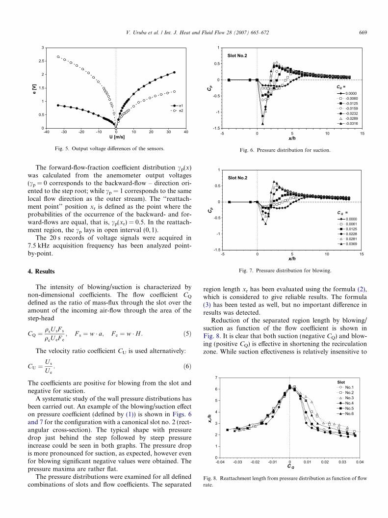
A systematic study of the wall pressure distributions hasbeen carried out. An example of the blowing/suction effecton pressure coefficient (defined by (1)) is shown in Figs. 6and 7 for the configuration with a canonical slot no. 2 (rect-angular cross-section). The typical shape with pressuredrop just behind the step followed by steep pressureincrease could be seen in both graphs. The pressure dropis more pronounced for suction, as expected, however evenfor blowing significant negative values were obtained. Thepressure maxima are rather flat.
The pressure distributions were examined for all definedcombinations of slots and flow coefficients. The separated
region length xr has been evaluated using the formula (2),which is considered to give reliable results. The formula(3) has been tested as well, but no important difference inresults was detected.
Reduction of the separated region length by blowing/suction as function of the flow coefficient is shown inFig. 8. It is clear that both suction (negative CQ) and blow-ing (positive CQ) is effective in shortening the recirculationzone. While suction effectiveness is relatively insensitive to

0
0.1
0.2
0.3
0.4
0.5
0.6
0.7
0.8
0.9
1
0 3 4 8 10x/h
γ p
C Q = 0
C Q = -0.35
γ p = 1%
γ p = 99%
γ p = 50%
1 2 5 6 7 9
Fig. 10. Back-flow-fraction coefficient for suction control.
670 V. Uruba et al. / Int. J. Heat and Fluid Flow 28 (2007) 665–672
the slot profile, that of blowing strongly depends on theslot geometrical parameters. Reduction of the recirculationzone length is more effective for smaller slot cross-sectionkeeping the same CQ value. Shape of the slot orifice isnot very important, serrated shape gives slightly shorterrecirculation zone than rectangular one for the same blow-ing rate and orifice cross-section. The most effective is theslot no. 4 producing the fastest jet flow for a given flowrate, while the longest recirculation zone produces slotno. 3 with the biggest cross-section.
The suction control mechanism is based on removing oflow-velocity fluid from the recirculation zone. The slotworks as a sink, only its capacity is important and notthe orifice geometrical parameters, nor the suction velocity.
Blowing control, unlike suction, is influenced by the slotgeometry. Higher velocity (that is smaller slot area) givesmore intensive static pressure drop, which promotes thecontrol mechanism. Thus entrainment mechanism in thewall-jet boundary plays an important role in the controlprocess. This hypothesis is supported by effect of interfacearea on control effectiveness. (Compare results in blow-control for rectangular and serrated slot orifice). However,the role of the control flow velocity is not very clear – seeFig. 9 showing effect of blowing in reducing the separatedzone length as function of the velocity ratio coefficient CU.
Apparently, the secondary vortical structures mentionedin Section 1 play an important role in control process, espe-cially in the dynamical behaviour of the flow in the recircu-lation zone. They should be definitely taken into account inmathematical modelling of the case.
As the reattachment is highly non-stationary dynamicalprocess, we could rather speak about ‘‘zone of reattach-ment’’ instead of ‘‘line’’ or ‘‘point of reattachment’’.Detailed study of dynamical behaviour of the reattachmentprocess has been carried out for suction control case. Theback-flow indication method described in Section 3.4 hasbeen applied. In Fig. 10 distributions of forward-flow-frac-tion coefficient for the slot no. 1 and various suctioncoefficients are shown. A typical S-shape of the curves isapparent.
0
1
2
3
4
5
6
7
0 4 8 10 12 14 16 18C U
x r/h
No.1No.2No.3No.4No.5No.6
Slot
2 6
Fig. 9. Reattachment length from pressure distribution as function ofvelocity rate.
Position of the conventional reattachment point xr
could be defined by the cp value equal to 50% (0.5), thereattachment zone could be delimited by cp values 1%(0.01) and 99% (0.99). For low-absolute values of blowingcoefficient the cp distributions are nearly symmetrical withconventional reattachment point nearly in the middle ofthe reattachment region. For greater negative CQ valuesthe cp distributions are steeper with more pronouncedupper curved part resulting in non-symmetrical configura-tion – see Fig. 10. The positions of crossing points indicat-ing the reattachment region and conventional reattachmentpoint are shown in Fig. 11.
The process dynamics should be examined in time and/or frequency domain. Frequency characteristics of the reat-tachment process were studied from measurements ofchanging flow direction in a given x position. Mean timeinterval lengths of forward-/backward-flow are evaluatedfrom 20 s records as well as the period of flow directionchanges. Typical distribution of the mean length of timeintervals and period of direction change within the reat-tachment region in semi-logarithmic coordinate systemfor CQ = 0 is shown in Fig. 12. Detailed settings are givenin Section 3.4. In Fig. 12 also cp values are indicated. Min-imum of the period length, corresponding to equal for-ward-flow and backward-flow mean intervals, coincideswith cp = 0.5 defining the conventional reattachment point.
0
1
2
3
4
5
6
7
8
-0.035 -0.03 -0.025 -0.02 -0.015 -0.01 -0.005 0
CQ
x/h
γ p = 99%
γ p = 50% γ p = 1%
Fig. 11. Reattachment region and point for suction control.

0.0001
0.001
0.01
0.1
3.7 4.2 4.7 5.2 5.7 6.2 6.7 7.2x/h
time
inte
rval
[s]
periodforward intervalbackward interval
γ p = 50%γ p = 1% γ p = 99%
minimalperiod
Fig. 12. Mean time intervals and period of flow direction changes withoutcontrol.
0
1
2
3
4
5
6
7
-0.04 -0.03 -0.02 -0.01 0C Q
x r/h
No.1 pNo.1 HFNo.5 pNo.5 HF
Slot
Fig. 14. Comparison of pressure (p) and hot-film (HF) measurements.
V. Uruba et al. / Int. J. Heat and Fluid Flow 28 (2007) 665–672 671
The mean length of forward and backward time inter-vals could characterize the mean period of changes of flowdirection, which is given by sum of the two intervals. Theminimal period corresponds to cp equal to 0.5 and indicatestypical frequency of reattachment point fluctuation f.In Fig. 13 this frequency is shown against the suctioncoefficient.
The reattachment point fluctuation is nearly constantfor low-suction rates up to CQ = �0.012, when the corre-sponding frequency is about 350 Hz. For more intensivesuction the frequency f falls linearly with CQ absolutevalue, for CQ = �0.035 its value reaches 200 Hz.
The reattachment point fluctuations seem to be dampedby suction. This conclusion is supported by steeper back-flow-fraction coefficient characteristics (see Fig. 10) show-ing smaller amplitude of typical fluctuations.
Of course, the mean recirculation zone length could beevaluated on the basis of reattachment point dynamicalmeasurements as well. The results for rectangular no. 1and serrated no. 5 slots evaluated from pressure distribu-tion measurements and dynamical moving hot-film probedata are compared in Fig. 14.
Very good agreement of both methods is evident. How-ever the hot-film probe method gives more precise results,
0
50
100
150
200
250
300
350
400
-0.04 -0.035 -0.03 -0.025 -0.02 -0.015 -0.01 -0.005 0
C Q
f [H
z]
Fig. 13. Mean frequency of reattachment point fluctuations.
this is indicated by nicely smooth curves. Further, this isa direct method of the flow direction indication, no addi-tional assumptions are needed, unlike the method basedon pressure distribution.
Unfortunately, for the blowing control the methodcould not be applied, so only indirect pressure distributionevaluation method of the recirculation region length isavailable.
5. Conclusions
The suggested control method based on suction or blow-ing in the step foot seems to be effective in shortening therecirculation zone length. Shortening of the separationzone was evaluated using direct measurement only for suc-tion, blowing relies on indirect evaluation method usingwall pressure distribution.
The suction control mechanism is based on simpleremoving of low-velocity fluid from the recirculation zone,resulting in its reduction. This process is not influenced bythe slot orifice geometry. However, the blowing controlmechanism is completely different relaying on entrainmentof fluid in recirculation zone into the wall jet. Then the slotgeometry is of great importance as it implies the jet velocityand contact perimeter.
Energy considerations of the flow-control process are tobe done to estimate its energy effectiveness. The continuoussuction/blowing is rather demanding from energetic pointof view, pulsating flow seems to be good alternative forfuture experiments. Hot-candidate is synthetic jet actuator,review of this type of actuators used for flow control couldbe found, e.g., in Uruba (2005) study.
In the future we intend using the time resolved PIVmethod for studying the non-stationary structures withinthe recirculation region. This seems to be necessary forchecking the blowing control case results.
Acknowledgement
This work has been supported by the Grant Agency ASCR, project no. A2076403.

672 V. Uruba et al. / Int. J. Heat and Fluid Flow 28 (2007) 665–672
References
Biswas, G., Breuer, M., Durst, F., 2004. Backward-facing Step flows forvarious expansion rations at low and moderate Reynolds numbersTransactions of the ASME. J. Fluids Eng. 126, 362–374.
Bradshaw, P., 1971. Variation on the Theme of Prandtl. I. C. Aero Rep.,71–73.
Bradshaw, P., Wong, F.Y.F., 1972. The reattachment and relaxation of aturbulent shear layer. J. Fluid Mech. 52, 113–135.
Chandrasuda, C., Bradshaw, P., 1981. Turbulence structure of areattaching mixing layer. J. Fluid Mech. 110, 171–194.
Janour, Z., 1972. Boundary layer on a wing in highly turbulent flow. (inCzech). Aeronautical Research and Test Institute, Praha – Letnany,Report No. V-1151/72.
Janour, Z., Jonas, P., 1994. On the flow in a channel with a backward-facing step on one wall. Eng. Mech. 1 (5/6), 313–320.
Janour, Z., Jonas, P., 2004. Some methods of the control of the separationregion behind a backward-facing step. PAMM 4 (1), 438–439.
Jonas, P., Mazur, O., Uruba, V., 2004. Experimental apparatus for flowseparation modelling at a step expansion of a channel. (in Czech). In:Vodohospodarska konference 2004, Prace a studie Ustavu vodnıchstaveb FAST VUT v Brne, Akademicke nakladatelstvı CERM, s.r.o.,205–212.
Jonas, P., Mazur, O., Uruba, V., 2005. The effect of the backward facingstep height on flow in a channel with rectangular cross-section. PAMM5 (1), 549–550.
Jonas, P., Mazur, O., Uruba, V., 2006. Pressure distributions in a channelwith a backward facing step. PAMM 6 (1), 567–568.
Lee, I., Ahn, S.K., Sung, H.J., 2004. Three-dimensional coherent structurein a separated and reattaching flow over a backward-facing step.Experiments in Fluids. Springer-Verlag, pp. 15.
Nie, J.H., Armaly, B.F., 2004. Three-dimensional convective flow adjacentto backward-facing step – Effects of step height. Int. J. Heat MassTransfer 45, 2431–2438.
Ota, T., 2000. A survey of heat transfer in separated and reattached flows.Appl. Mech. Rev. 53, 219–235.
Prıhoda, J., 1991. Effect of the outer stream turbulence on twodimensional backward facing flow (in Czech). Strojnicky casopis 42(4), 289–304.
Prıhoda, J., Sedlar, M., 2006. Flow separation and relaxation of the shearlayer behind a backward facing step. In: Proc. of conf. Aplikaciaexperimentalnych a numerickych metod v mechanike tekutın, April2006, Zilina – Strecno, Slovakia, 19–24.
Reinders, F., Post, F.H., Spoelder, H.J.W., 2001. Visualization of time-dependent data with feature tracking and event detection. Vis.Comput. 17 (1), 55–71.
Rosenhead, L., 1963. Laminar boundary layers. Clarendon Press, Oxford.Sakuraba, K., Fukazawa, K., Sano, M., 2004. Control of turbulent
channel flow over a backward-facing step by suction or injection.Heat Transfer – Asian Res. 33 (8), 490–504.
Uruba, V., 2005. Flow control using synthetic jet actuators. Eng. Mech.12 (1), 41–62.
Uruba, V., Mazur, O., Jonas, P., 2005. Study on reversing flow inreattachment region. In: Jonas, P., Uruba, V. (Eds.), Proc. ofConference of Colloquium Fluid Dynamics 2005. AS CR, Prague,IT, pp. 171–174.