Control Design of Autonomous Drone Using Deep Learning ...
12
This work has been submitted to the IEEE for possible publication. Copyright may be transferred without notice, after which this version may no longer be accessible. Control Design of Autonomous Drone Using Deep Learning Based Image Understanding Techniques Seid Miad Zandavi, Vera Chung, Ali Anaissi Abstract—This paper presents a new framework to use images as the inputs for the controller to have autonomous flight, considering the noisy indoor environment and uncertainties. A new Proportional-Integral-Derivative-Accelerated (PIDA) control with a derivative filter is proposed to improves drone/quadcopter flight stability within a noisy environment and enables au- tonomous flight using object and depth detection techniques. The mathematical model is derived from an accurate model with a high level of fidelity by addressing the problems of non-linearity, uncertainties, and coupling. The proposed PIDA controller is tuned by Stochastic Dual Simplex Algorithm (SDSA) to support autonomous flight. The simulation results show that adapting the deep learning-based image understanding techniques (RetinaNet ant colony detection and PSMNet) to the proposed controller can enable the generation and tracking of the desired point in the presence of environmental disturbances. Index Terms—Control, Autonomous Drone, Face Detection, Depth Detection, Stochastic Dual Simplex Algorithm I. I NTRODUCTION R ECENTLY, unmanned aerial vehicle (UAV) garners the attention of many researchers working in different ap- plication domains such as search and rescue, delivering, and crowdsourcing [1], [2]. UAVs or drones have been developed in many areas, including robotic research, control, path plan- ning, communication, etc. [3], [4], [5]. Attention to increasing the usability of drones in many commercial/civil applications inspires researchers to make this dynamic system better con- trollable. In particular, quadcopters are popular drones due to their performance in terms of vertical take-off and landing, simple and stable structure. However, their instability, unstable dynamics, non-linearity, and cross-coupling make this system an interesting under-actuated system. Generally, a quadcopter has six degrees of freedom, although four rotors should control all directions. This causes the cross-coupling between rotation and translational motions. Therefore, the nonlinear dynamics need to be managed by the controller. Over recent years, various control algorithms have been developed to deal with the non-linearity of the quadrotor. For example, command-filtered Proportional-Derivative (PD)/ Proportional-Integral-Derivative (PID) control [6], integral predictive control [7] and optimal control [8], [9] have been applied. The Sliding Mode Control (SMC) is another common control algorithm that is used to achieve greater performance in terms of stability due to the influence of modeling errors and external disturbances [5], [10], [11]. Note that the chattering Seid Miad Zandavi, Vera Chung and Ali Anaissi are with the School of Computer Science, The University of Sydney, Camperdown NSW 2006, Australia e-mail: {miad.zandavi, vera.chung, ali.anaissi}@sydney.edu.au. effect in the SMC arises in the steady state, where it simulates unmodeled frequencies of the system dynamics. Of these controllers, PID is preferred due to its simplicity, although it leads to wide overshoot and large settling time [12]. Thus, adding a new derivative term (i.e., zero) can decrease the size of the overshoot [13]. This can support better controlla- bility. In addition, this derivative term improves the response in terms of speed and smoothness where limiting overshoot and settling time in an acceptable bound are considered. Adapting deep learning-based image understanding tech- niques and the controller opens advancements in drone ap- plications because it improves the capability for autonomous flight without global positioning. Object and depth detection can provide fast, reliable, and integrated information, which is required to reach a target. In this study, the target is a human face, where object detection techniques such as hybrid RentinaNet ant colony detection [14], [15] are utilized to recognize the target. To reach the target, depth detention techniques, like PSMNet [16] are applied to estimate the relative distance to the target. In this paper, the proposed accelerated PID controller with a derivative filter aims to make an unstable drone/quadcopter track the desired reference with the proper stability. Deep learning and optimization-based image understanding tech- niques, like object and depth detection, are utilized to make an autonomous drone fly inside buildings and consider uncertain- ties. The image understanding techniques provide information about a target, such as measuring the relative distance to the recognized target and following a particular threshold. This information is processed to prepare it for the guidance module, which is followed by the control discipline. Thus, the control tracks the desired input, which is generated by the guidance law. Consequently, the mathematical model of the dynamic sys- tem is provided and considers non-linearity, instability, cross- coupling among different modes (i.e., pitch, roll, and yaw), and the uncertain environment. The controller parameters are tuned using the Stochastic Dual Simplex Algorithm (SDSA) optimization algorithm [17], which improves the trade-off between exploration and exploitation to achieve better optimal parameters for the proposed controller. This paper is organized as follows. Section II describes the mathematical model of the dynamic system.The proposed controller is explained and introduced in Section III. Stability analysis is presented in Section IV and SDSA is briefly explained in Section V. Guidance law is then introduced in Section VI and deep learning-based image understanding techniques are introduced in Section VII. The numerical results 1 arXiv:2004.12886v3 [cs.RO] 16 Sep 2020
-
Upload
khangminh22 -
Category
Documents
-
view
4 -
download
0
Transcript of Control Design of Autonomous Drone Using Deep Learning ...

This work has been submitted to the IEEE for possible publication. Copyright may be transferred without notice, after whichthis version may no longer be accessible.
Control Design of Autonomous Drone Using DeepLearning Based Image Understanding Techniques
Seid Miad Zandavi, Vera Chung, Ali Anaissi
Abstract—This paper presents a new framework to use imagesas the inputs for the controller to have autonomous flight,considering the noisy indoor environment and uncertainties. Anew Proportional-Integral-Derivative-Accelerated (PIDA) controlwith a derivative filter is proposed to improves drone/quadcopterflight stability within a noisy environment and enables au-tonomous flight using object and depth detection techniques. Themathematical model is derived from an accurate model with ahigh level of fidelity by addressing the problems of non-linearity,uncertainties, and coupling. The proposed PIDA controller istuned by Stochastic Dual Simplex Algorithm (SDSA) to supportautonomous flight. The simulation results show that adapting thedeep learning-based image understanding techniques (RetinaNetant colony detection and PSMNet) to the proposed controller canenable the generation and tracking of the desired point in thepresence of environmental disturbances.
Index Terms—Control, Autonomous Drone, Face Detection,Depth Detection, Stochastic Dual Simplex Algorithm
I. INTRODUCTION
RECENTLY, unmanned aerial vehicle (UAV) garners theattention of many researchers working in different ap-
plication domains such as search and rescue, delivering, andcrowdsourcing [1], [2]. UAVs or drones have been developedin many areas, including robotic research, control, path plan-ning, communication, etc. [3], [4], [5]. Attention to increasingthe usability of drones in many commercial/civil applicationsinspires researchers to make this dynamic system better con-trollable. In particular, quadcopters are popular drones due totheir performance in terms of vertical take-off and landing,simple and stable structure. However, their instability, unstabledynamics, non-linearity, and cross-coupling make this systeman interesting under-actuated system. Generally, a quadcopterhas six degrees of freedom, although four rotors should controlall directions. This causes the cross-coupling between rotationand translational motions. Therefore, the nonlinear dynamicsneed to be managed by the controller.
Over recent years, various control algorithms have beendeveloped to deal with the non-linearity of the quadrotor.For example, command-filtered Proportional-Derivative (PD)/Proportional-Integral-Derivative (PID) control [6], integralpredictive control [7] and optimal control [8], [9] have beenapplied. The Sliding Mode Control (SMC) is another commoncontrol algorithm that is used to achieve greater performancein terms of stability due to the influence of modeling errors andexternal disturbances [5], [10], [11]. Note that the chattering
Seid Miad Zandavi, Vera Chung and Ali Anaissi are with the Schoolof Computer Science, The University of Sydney, Camperdown NSW 2006,Australia e-mail: miad.zandavi, vera.chung, [email protected].
effect in the SMC arises in the steady state, where it simulatesunmodeled frequencies of the system dynamics.
Of these controllers, PID is preferred due to its simplicity,although it leads to wide overshoot and large settling time [12].Thus, adding a new derivative term (i.e., zero) can decrease thesize of the overshoot [13]. This can support better controlla-bility. In addition, this derivative term improves the responsein terms of speed and smoothness where limiting overshootand settling time in an acceptable bound are considered.
Adapting deep learning-based image understanding tech-niques and the controller opens advancements in drone ap-plications because it improves the capability for autonomousflight without global positioning. Object and depth detectioncan provide fast, reliable, and integrated information, whichis required to reach a target. In this study, the target is ahuman face, where object detection techniques such as hybridRentinaNet ant colony detection [14], [15] are utilized torecognize the target. To reach the target, depth detentiontechniques, like PSMNet [16] are applied to estimate therelative distance to the target.
In this paper, the proposed accelerated PID controller witha derivative filter aims to make an unstable drone/quadcoptertrack the desired reference with the proper stability. Deeplearning and optimization-based image understanding tech-niques, like object and depth detection, are utilized to make anautonomous drone fly inside buildings and consider uncertain-ties. The image understanding techniques provide informationabout a target, such as measuring the relative distance to therecognized target and following a particular threshold. Thisinformation is processed to prepare it for the guidance module,which is followed by the control discipline. Thus, the controltracks the desired input, which is generated by the guidancelaw.
Consequently, the mathematical model of the dynamic sys-tem is provided and considers non-linearity, instability, cross-coupling among different modes (i.e., pitch, roll, and yaw),and the uncertain environment. The controller parameters aretuned using the Stochastic Dual Simplex Algorithm (SDSA)optimization algorithm [17], which improves the trade-offbetween exploration and exploitation to achieve better optimalparameters for the proposed controller.
This paper is organized as follows. Section II describesthe mathematical model of the dynamic system.The proposedcontroller is explained and introduced in Section III. Stabilityanalysis is presented in Section IV and SDSA is brieflyexplained in Section V. Guidance law is then introducedin Section VI and deep learning-based image understandingtechniques are introduced in Section VII. The numerical results
1
arX
iv:2
004.
1288
6v3
[cs
.RO
] 1
6 Se
p 20
20

2
and discussion are presented in Section VIII. Finally, this paperends with a conclusion.
II. DYNAMIC MODEL
The mathematical model of a system can be used asthe first step to study its performance. In this regard, thequadcopter studied in this research is modeled in Fig. 1,considering earth-centered inertia (ECI) and body frame. Thus,XE = [xE , yE , zE ]T and XB = [xB , yB , zB ]T are defined astransformational motions from inertia frame to body frame dueto having an accurate dynamic model.
Ex
Ey
Ez
Bz
4F
2F2F
3FBy
Bx
4
1
2
3CG
l
Fig. 1. Earth Fixed and Body Fixed coordinate systems
The attitude of the quadcopter is formulated based on theEular angles roll, pitch, and yaw, which are rotated from thex-axis, y-axis and z-axis, respectively. Thus, the Eular anglesare Θ = [φ, θ, ψ]T , and the angular velocity in the body frameis Θ = [φ, θ, ψ]T . In this sense, the angular velocity in inertia(ω = [p, q, r]T ) is formulated as follows:
ω =
1 0 − sin(θ)0 cos(φ) cos(θ) sin(φ)0 − sin(φ) cos(θ) cos(φ)
· Θ (1)
Total torques are caused by three segments: thrust forces(τ ), body gyroscopic torque (τb) and aerodynamic friction(τa). In addition, each component of the torque vector (τ =[τφ, τθ, τψ]T ), corresponding to a rotation in the roll, pitch,and yaw axis, can be determined by Eqs (2)−(4):
τφ = l(F2 − F4) (2)
τθ = l(F3 − F1) (3)
τψ = c(F2 − F1 + F4 − F3) (4)
where l is the distance between the center of motor and thecenter of mass, and c is the force to torque coefficient. Asassumed, the quadcopter is a rigid body and symmetricaldynamics apply, from which the torque can be calculated byfollowing equation:
τ = Iω + Ω(Iω) (5)
where l is the distance between the center of motor to centerof mass, and c is the force to torque coefficient. As assumed,the quadcopter is a rigid body and symmetrical dynamics, fromwhich the following equation can calculate the torque:
Ω =
0 −r qr 0 −p−q p 0
(6)
In this system, the main control inputs are correlated tothe torque (τ = [τφ, τθ, τψ]T ) caused by thrust forces, bodygyroscopic effects, propeller gyroscopic effects and aerody-namic friction. Gyroscopic effects and aerodynamic frictionare considered external disturbances for the control. Thus,control inputs are determined as Eq (7).
uφuθuψuT
=
τφτθτψτT
=
0 l 0 −l−l 0 l 0−c c −c c1 1 1 1
F1
F2
F3
F4
(7)
where τT is the lift force and uT corresponds to the totalthrust acting on the four propellers, where uφ, uθ and uψrepresent the roll, pitch, and yaw, respectively. The dronesaltitude can be controlled by lift force (uT ), which is equal toquadcopter weight. The dynamic equations of the quadcopterare formulated based on the Newton-Euler method [18]. Thesix degree of freedom (6-DOF) motion equations are statedby Eqs (8)−(13).
u = rv − qw − g sin(θ) (8)
v = pw − ru+ g sin(φ) cos(θ) (9)
w = qu− pv + g cos(θ) cos(φ)− 1
muT (10)
p =1
Ixx[(Iyy − Izz)qr + uφ + dφ] (11)
q =1
Iyy[(Izz − Ixx)pr + uθ + dθ] (12)
r =1
Izz[(Ixx − Iyy)pq + uψ + dψ] (13)
where d = [dφ, dθ, dψ]T is the angular acceleration distur-bance corresponded to propeller angular speed, and theseacceleration disturbances are modeled by Eq (14).
d =
+qImΩr−pImΩr
0
(14)
where Ωr =∑4i=1(−1)iΩi is the overall residual propeller
angular speed, and Ωi is the angular velocity of each rotor.Im is the rotor moment of inertia around the axis of rotation.Hence, the dynamics equations of the system can be summa-rized as follows:

3
x(t) = A(x) +B(x)u(t) + dy(t) = C(x) +D(x)u(t)
(15)
where x = [φ, θ, ψ, p, q, r, w]T and y = [y1, y2, y3, y4]T
are the states and measurable outputs, respectively. u =[u1, u2, u3, u4]T is the control and d is the disturbance. A,B, C, and D are the nonlinear functions regarding dynamicequations of the system.
The control design is considered to minimize the error fortracking the desired command (see Eq (16)).
limt→∞
|e(t)| = ε (16)
where e(t) = r(t) − y(t) is the difference between referenceinputs and the systems measurable outputs and ε is the smallpositive value.
III. PROPOSED PIDA CONTROLLER
The PID control is used in many engineering applicationsbecause of its simplicity. Note that PID cannot function wellwhen wide overshoot and large settling time occur in thesystem. This issue can be addressed by a modifying the PIDcontroller by adding an additional zero known as PIDA. Itis employed to achieve a faster and smoother response forhigher-order systems and retains both overshoot and settlingtime within an acceptable limit. Additionally, the proposedlinear control is able to control the nonlinear system. Inthis approach, the dynamic airframe is linearized about theequilibrium point. The linearization of the model is given byEq (17).
∆X = JX∆X + JU∆U (17)
where JX and JU are the Jacobian transformation ofthe nonlinear model about the equilibrium point (Xeq =[φ0, θ0, ψ0, p0, q0, r0, w0]T ). Note that the equilibrium pointcan be calculated by solving X = AX = 0. Any solution canbe the equilibrium point because of null space if det(A) isequal to zero.
In this regard, a Multi-Input Multi-Output (MIMO) controlsystem design follows the desire command in altitude andattitude channels. A MIMO tracking controller can not onlystabilize the system, but also make it follow a reference input.Thus, the linear system is given as follows:
X = AX +BU +Dd
Y = CX(18)
where Y is the outputs that follow the reference inputs andDd = [0, 0, 0, dT , 0]T is the angular disturbance. In thisapproach, the integral state is defined as follows:
XN = R− Y = R− CX (19)
According to Eq (19), the new state space of the systemis formulated in Eq (20). It is obvious that the system canfollow the reference inputs if the designed controller provesthe stability of the system.
[X
XN
]=
[A 0−C 0
] [XXN
]+
[BΦ
]U+[
ΦI
]R+
[IΦ
]Dd
Y =[C 0
] [ XXN
] (20)
where Φ is a zero matrix.Regarding the acceleration disturbance in the system, the
general form of the proposed controller in the time series isgiven in Eq (21).
u(t) = kpe(t) + ki
∫e(t)dt+ kde(t) + kae(t) (21)
where kp, ki, kd, and ka are the gain of the proposedcontroller. Then, the MIMO controller is generated by:
U(s) =
[kp +
kis
+ kds+ kas2
]E(s) (22)
As seen in Eq (22), the derivative term is not efficient in ahigh-frequency domain. This term can affect the performanceof the whole system in a noisy environment. Adding derivativefilter is proposed to address this issue and thus, the proposedcontrol is modeled as follows:
U(s) =
[kp +
kis
+ kd × sL(s) + ka × sL(s)× sL(s)
]E(s)
(23)where L(s) is the optimal derivative filter which is formulatedas follows:
L(s) =N/T
(N/T ) 1s + 1
(24)
where N and T are the order of the filter and time constant,respectively. Based on Eq (24), the transfer function of optimalderivative filter can be simplified as follows:
L(s) =1
1 + Tfs(25)
where Tf = T/N is the time constant of the optimal derivativefilter. Hence, the controller and filters parameters can be foundby SDSA to minimize the objective function given by Eq (26).
fobj = (Mos −Ms)2 − (ts − ts)2 (26)
where Mos is the desired maximum overshoot, which is set to5 percent; ts, the desired settling time for the system, is 2 sec.Ms and ts are the overshoot and settling time for each set ofdesigned controllers. Before the simulation result is presented,the stability analysis of the system is introduced in Section IV.

4
IV. STABILITY ANALYSIS OF THE PROPOSED PIDA
In this section, the stability of a system considering theproposed controller is investigated. The following definitionsare needed.
Definition 1. Asymptotically stable is a system around itsequilibrium point if it meets the following conditions:
1) Given any ε > 0, ∃ δ1 > 0 such that if ‖x(t0)‖ < δ1,then ‖x(t)‖ < ε, ∀ t ¿ t0
2) ∃ δ2 > 0 such that if ‖x(t0)‖ < δ2, then x(t) → 0 ast→∞
Theorem 1. [V (x) = xTPx, x ∈ Rn] is a positive definitefunction if and only if all the eigenvalues of P are positive.
Since P is symmetric, it can be diagonalized by an orthog-onal matrix so P = UTDU with UTU = I and D diagonal.Then, if y = Ux,
V (x) = xTPX
= xTUTDUx
= yTDy
=∑
λi|yi|2
(27)
Thus,
V (x) > 0 ∀x 6= 0 ⇐⇒ λi > 0, ∀i (28)
Definition 2. A matrix P is a positive definite if it satisfiesxTPx > 0 ∀x 6= 0.
Therefore, any positive definite matrix follows the inequalityin Eq (29).
λminP‖x‖2 ≤ V (x) ≤ λmaxP‖x‖2 (29)
Definition 3. (V ) is a positive definite function as a candidateLyapunov function if (V ) has derivative, and it is negativesemi-definite function.
Theorem 2. If the candidate Lyapunov function (i.e., V (x) =xTPx, P > 0) exists for the dynamic system, there is astable equilibrium point.
According to Theorem 2 and the dynamic system model,the system in the form of Lyapunov function is as follows:
V (x) = xTPx+ xTPx
= xTATPx+ xTPAx
= xT (ATP + PA)x
= −xTQx
(30)
where the new notation (see Eq (31)) is introduced to simplifythe calculation. It is noted that Q is a symmetric matrix.According to Definition 3, V is a Lyapunov function if Qis positive definite (i.e., Q > 0). Thus, there is a stableequilibrium point which shows the stability of the systemaround the equilibrium (see Theorem 2).
ATP + PA = −Q (31)
The relationship between Q and P shows that the solutionof Eq (31), called a Lyapunov equation, proves the stabilityof the system for picking Q > 0 if P is a positive definitesolution. Thus, there is a unique positive definite solutionif all the eigenvalues of A are in the left half-plane. Anoisy environment causes the movement of eigenvalues to theright half-plane. Therefore, the system dynamics can intensifyinstability. This issue raises the cross-coupling among differentmodes such as roll, pitch, and yaw rate, which are causedby the four rotors. Thus, the derivative term of the proposedcontroller plays an essential role in maintaining stability. Thenumerical results show that all eigenvalues of the quadcopterwith considering the proposed controller with uncertainties inthe environment are in the left half-plane, which proves thatthe dynamic system is stable with uncertainties.
V. STOCHASTIC DUAL SIMPLEX ALGORITHM
The heuristic optimization algorithm (i.e., SDSA) is usedto find the best tuned parameters for the proposed controller.SDSA is a new version of the Nelder-Mead simplex algorithm[19], executing three different operators, such as reflection,expansion, and contraction. These operators reshape the dualsimplex and move it toward the maximum-likelihood regionsof the promising area. Each simplex follows the standard rulesof simplex, from which the transformed vertices of the generalsimplex approach are formulated, as in Eqs (32)-(34).
xr = (1 + α)x0 − αxh, α > 0 (32)
xe = γxr + (1− γ)x0, γ > 1 (33)
xc = βxh + (1− β)x0, 0 ≤ β ≤ 1 (34)
where α, γ, and β are reflection, expansion, and contractioncoefficients, respectively. During these transformations, thecentroid of all vertices excluding the worst point (xh) is x0.
In addition to the movement of dual simplex, a new defi-nition of reflection points is applied to improve the diversityand decrease the probability of a local minimum. Therefore,during the i-th iteration, the worst vertices of simplexes in thesearch space are replaced by normal distribution directions,which are modeled in Eq (35).
∗x
(i)
hs= x(i)
hs+ g(i)x(i)
0 (35)
where∗x
(i)
hsis the new reflected point computed by the worst
point of each simplex (x(i)hs
), and g(i) is the normal distributionof the sampled solution in i-th iteration and s-th simplex. Thecentroid of all simplexes and the probability density functionof the normally distributed simplexes are then expressed in Eq(36) and Eq (37).
x(i)0 =
ns∑s=1
x(i)0s
(36)
g(xh|Σ) =1√
2π|Σ|.exp(− (xh − x0)TΣ−1(xh − x0)
2) (37)

5
where ns and Σ are the number of simplexes and covariancematrix of simplexes, respectively.
Reflection makes an action regarding reflect the worst point,called high, over the centroid x0. In this approach, simplexoperators utilize the expansion operation to expand the simplexin the reflection direction if the reflected point is better thanother spots. Nevertheless, the reflection output is at least betterthan the worst; the algorithm repeats the reflection operationwith the new worst point [17], [19]. The contraction is anotheroperation that contracts the simplex, while the worst pointhas the same value as the reflected point. The SDSA pseudo-code is presented in Algorithm 1, and the tuned parameters ofSDSA, chosen based on [17], are listed in Table I.
Algorithm 1 Stochastic Dual Simplex Algorithm (SDSA)Initialization
set ←[amax,αmax, γmax, βmax, imax
]x0 ← randomGenerate initial simplexes
RepeatCompute Objective Function (F )xh ← xworst
while (∃ xi):reflectionexpansioncontraction
endxh ←
∗xh
Update simplexesUntil Stop condition satisfied.
TABLE ITUNED PARAMETERS OF SDSA
Parameters Valueamax 10.5907αmax 9.7323γmax 9.9185βmax 0.4679imax 979
VI. GUIDANCE LAW
Guidance law is a process to generate commands for apursuer to track its target. An interesting guidance law isproportional navigation (PN) which considers the rotation rateof line of sight (LOS) [20]. The general concept of PN isto vary the lateral acceleration of the pursuer in proportionwith the rotation rate of LOS. In this study, pure proportionalnavigation (PPN) guidance law is applied to the quadcopterfor tracking and reaching the target. In PPN, the desiredacceleration command (proportional to LOS turning rate) isapplied normal to the velocity vector of the pursuer. Therefore,PPN is modeled as follows:
ac = NΩLOS × (VM − VT ) (38)
where N is the constant number, named navigation constant(N = 1). ΩLOS , VM , and VT are the angular velocity of
LOS, pursuer velocity (drone velocity), and the target velocity,respectively. The angular velocity of LOS is formulated in Eq(39).
ΩLOS =(VM − VT )×R
|R|2(39)
where R is the relative distance between the pursuer and thetarget. R is estimated by image depth detection. In this study,the drone is simulated to fly inside the indoor environment ofa building, where positioning systems such GPS are unableto operate. In this regard, object tracking and depth detectionare employed to estimate the relative distance between thedrone and target. The target is set as a building mockett,considering the safe distance from the target. The followingsection explains the object and depth detection approaches.
VII. DEEP LEARNING BASED IMAGE UNDERSTANDINGTECHNIQUES
This section proposes a framework to adapt deep learning-based image understanding techniques using object and depthdetection for generating and translating the target to thedrone. Object and depth detection play an important role inautonomous drones without positioning systems. Note thatthe indoor environment is furnished with many objects anda particular object (a building mockett) is considered a targetfor the drone to reach.
Object detection is an indispensable aspect of positioningin autonomous drone flight inside a building because it isthe target point to obtain the relative distance estimation(R). While the relative distance is estimated through depthdetection, the guidance law (PPN) is used to issue such acommand to the controller to track the target. In this study,RetinaNet ant colony detection [15] is applied in the detectionmodule of the proposed autonomous system.
Ant Colony Detection (ACD) [14] utilizes a novel multi-region feature selection method that defines histogram valuesof basic areas and random areas (MRH), and is combinedwith Continuous Ant Colony Filter (CACF) as a heuristicfilter [21], [22] detection to represent the original target. Inthis paper, the ant colony detection is combined with thepopular one-stage RetinaNet [15] using five modification steps.First, classification and regression are applied for detection.Second, the intersection over union (IoU) loss function is usedfor regression. Third, reconsideration is augmented regardingdata-anchor-sampling for training. Forth, there is a robust clas-sification utilizing the max-out operation and fifth, the multi-scale testing strategy is applied for inference. Consequently,the proposed method achieved efficient performance in therecognition of the target. The RetinaNet ant colony detectionsarchitecture is presented in Fig. 2.
The proposed method uses a RentinaNet [15] object detec-tor baseline considering the particular focal loss function toaddress extreme class imbalance encountered during training.The focal loss function is formulated in Eq (40 and 41).
FL(pt) = −νt(1− pt)τ log(pt) (40)
and

6
Class + box Subnets
Class + box Subnets
Class + box Subnets
×4 W × H
×256
W × H
×256
W × H
×4A
×4 W × H
×256
W × H
×256
W × H
×A
ResNet Feature Net
Class Subnet
Box Subnet
Ant
Detection
Fig. 2. The architectuer of RetinaNet Ant Colony Detection
pt =
p if y = 11− p otherwise (41)
where y ∈ ±1 defines the ground-truth class, p ∈ [0, 1] isthe models estimated probability for the class labeled y =1, and νt and τ are the balanced and focusing parameters,respectively.
The object detection component includes the classificationand regression sub-tasks. For the regression task, the Unit-Box [23] is applied to minimize the differences between thepredictions and ground-truth through IoU, rather than usingthe smooth L1 [24] as the common loss function for theregression. Thus, the IoU regression loss function is modeledin Eq (42).
LIoU = − lnIntersection(Bp, Bgt)
Union(Bp, Bgt)(42)
where Bp = (x1, y1, x2, y2) and Bgt = (x∗1, y∗1 , x∗2, y∗2) are
the predicted and the ground-truth bounding boxes, respec-tively. Consequently, IoU calculates the similarity between thetruth and predicted bounding boxes. The minimization of thissimilarity improves algorithm performance in the regressionsub-task.
In addition to the regression loss function, two-step clas-sification (STC) and selective two-step regression (STR) are
employed in the selective refinement network [25]. In this re-gard, STC and STR conduct a two-step classification on threelow-level detection layers and two-step regression on threehigh-level detection layers, respectively. These loss functionsare formulated in Eq (43)−(44).
LSTC(pi, qi) =1
Ns1
∑i∈Υ
LFL(pi, l∗i)
+1
Ns2
∑i∈Γ
LFL(qi, l∗i)
(43)
and
LSTR(ri, ti) =1
Ns1
∑i∈Ψ
[l∗i = 1]LIoU (ri, g∗i)
+1
Ns2
∑i∈Γ
[l∗i = 1]LIoU (ti, g∗i)
(44)
where i, pi/qi, and ri/ti are the anchor index, first/secondstep of predicted classification and regression, respectively,and l∗i /g∗i are the class/location ground-truth. The number ofpositive anchors is Ns1 /Ns2 for first/second step, and Υ/Ψand Γ are the collection of classification/regression samplesfor the first and second steps. LFR is also the sigmoid focalloss function, which is formulated in Eq (40).

7
Left Image
Right Image CNN
CNN
Weight Sharing
SPP Module
SPP Module
Weight Sharing
Spatial Pyramid Pooling Module
Input
Conv
Weight Sharing
Conv
Cost Volume
3D CNN
Up
sam
plin
g
Reg
ression
Pred
iction
Fig. 3. The architecture of Pyramid Stereo Matching Network (PSMNet)
To perform the depth detection, information on the objectis needed. RetinaNet ant colony detection conducts targetrecognition. For depth detection, the stereo images are used todetermine the distance from the camera, which can be installedin the drones center of gravity. In this regard, PSMNet isutilized to provide depth estimation from a stereo pair ofimages [16]. PSMNet utilizes global information in stereomatching using spatial pyramid pooling [26], [27] and dilatedconvolution [28]. The architecture of PSMNet is illustrated inFig. 3.
Several left-right images are utilized by a stereo disparityestimation algorithm, from which they are captured by twocameras with a horizontal offset (i.e., baseline (b)). The outputof disparity estimation (Y ) is the same as either the left or rightimages. Generally, the depth estimation algorithm uses the leftimage as a reference and records in Y; thereby, the horizontaldisparity is applied to the right image for each pixel. Togetherwith the horizontal focal length fu of the left camera, the depthmap D is derived as follows:
D(u, v) =fu × bY (u, v)
(45)
Thus, the 3D location (x, y, z) of each pixel (u, v) of thetarget, which can be used to calculate the relative distancebetween drone and target, is formulated as below:
z = D(u, v) (46)
x =(u− cu)× z
fu(47)
y =(v − cv)× z
fv(48)
where (cu, cv) is the pixel location corresponding to thecamera center and fv is the vertical focal length. Thus, theextrinsic parameters of simulated cameras with 150 mm offsetcan be visualized in Fig. 4.
The guidance module is needed to utilize object and depthdetection. The proposed independent drone uses the image asan input for autonomous flying. In this regard, the image asinput passes through the object detection to provide the objectinformation for the depth detection modules. Depth detectionestimates the relative distance from the target. Further, the
Fig. 4. Visualization of Extrinsic parameters
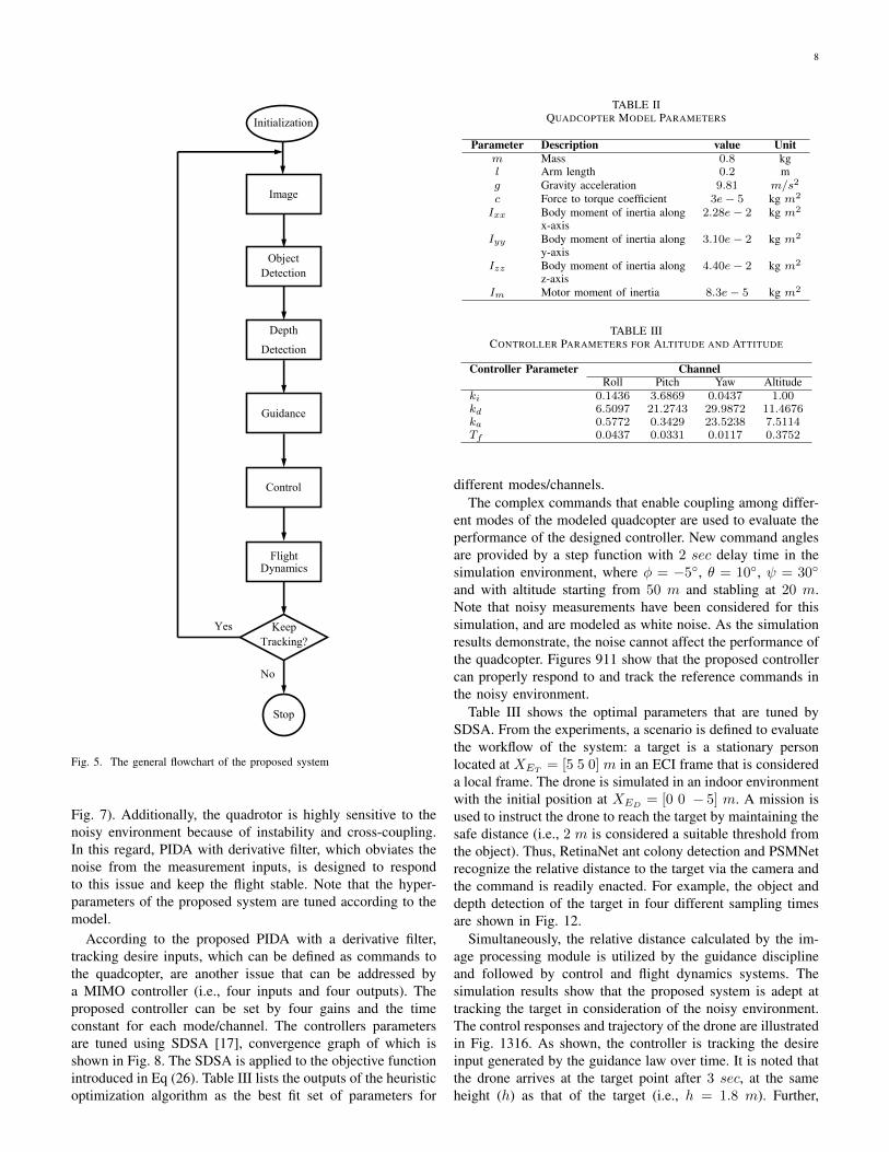
guidance law (PPN) generates the commands for the droneto reach the target by applying the proposed PIDA controller.Finally, the controller takes action on flight dynamics. Thegeneral flowchart of the proposed system is presented in Fig.5.
VIII. NUMERICAL RESULTS
The numerical simulation is implemented to evaluate theperformance of the proposed architecture in autonomous flight,considering image processing techniques and the controller.The model quadcopter was simulated in MATLAB R2018bin a Simulink environment on Windows 10 with an Intel(R)Core(TM)i7-6700 CPU @ 3.4 Hz. The quadcopter parametersare listed in Table II.
To begin the simulation and tune the hyper-parameters,the initial state is introduced to identify the best optimalparameters. In this study, it is assumed that the initial altitudeand velocity are XE = [0 0 -50]T m and V = [u v w]T =[1 1 0]T m/s, respectively. A disturbance is applied to thequadcopter and is modeled as white noise (mean value (µ) iszero and standard deviation (σ) is one) at time 1 sec in the rollchannel. This disturbance destabilizes the system and locatesthe eigenvalues of A in the right half-plane (see Fig. 6 and
8
Image
Object
Detection
Initialization
Flight Dynamics
Depth
Detection
Guidance
Control
Keep
Tracking?
Stop
Yes
No
Fig. 5. The general flowchart of the proposed system
Fig. 7). Additionally, the quadrotor is highly sensitive to thenoisy environment because of instability and cross-coupling.In this regard, PIDA with derivative filter, which obviates thenoise from the measurement inputs, is designed to respondto this issue and keep the flight stable. Note that the hyper-parameters of the proposed system are tuned according to themodel.
According to the proposed PIDA with a derivative filter,tracking desire inputs, which can be defined as commands tothe quadcopter, are another issue that can be addressed bya MIMO controller (i.e., four inputs and four outputs). Theproposed controller can be set by four gains and the timeconstant for each mode/channel. The controllers parametersare tuned using SDSA [17], convergence graph of which isshown in Fig. 8. The SDSA is applied to the objective functionintroduced in Eq (26). Table III lists the outputs of the heuristicoptimization algorithm as the best fit set of parameters for
TABLE IIQUADCOPTER MODEL PARAMETERS
Parameter Description value Unitm Mass 0.8 kgl Arm length 0.2 mg Gravity acceleration 9.81 m/s2
c Force to torque coefficient 3e− 5 kg m2
Ixx Body moment of inertia alongx-axis
2.28e− 2 kg m2
Iyy Body moment of inertia alongy-axis
3.10e− 2 kg m2
Izz Body moment of inertia alongz-axis
4.40e− 2 kg m2
Im Motor moment of inertia 8.3e− 5 kg m2
TABLE IIICONTROLLER PARAMETERS FOR ALTITUDE AND ATTITUDE
Controller Parameter ChannelRoll Pitch Yaw Altitude
ki 0.1436 3.6869 0.0437 1.00kd 6.5097 21.2743 29.9872 11.4676ka 0.5772 0.3429 23.5238 7.5114Tf 0.0437 0.0331 0.0117 0.3752
different modes/channels.The complex commands that enable coupling among differ-
ent modes of the modeled quadcopter are used to evaluate theperformance of the designed controller. New command anglesare provided by a step function with 2 sec delay time in thesimulation environment, where φ = −5, θ = 10, ψ = 30
and with altitude starting from 50 m and stabling at 20 m.Note that noisy measurements have been considered for thissimulation, and are modeled as white noise. As the simulationresults demonstrate, the noise cannot affect the performance ofthe quadcopter. Figures 911 show that the proposed controllercan properly respond to and track the reference commands inthe noisy environment.
Table III shows the optimal parameters that are tuned bySDSA. From the experiments, a scenario is defined to evaluatethe workflow of the system: a target is a stationary personlocated at XET
= [5 5 0] m in an ECI frame that is considereda local frame. The drone is simulated in an indoor environmentwith the initial position at XED
= [0 0 − 5] m. A mission isused to instruct the drone to reach the target by maintaining thesafe distance (i.e., 2 m is considered a suitable threshold fromthe object). Thus, RetinaNet ant colony detection and PSMNetrecognize the relative distance to the target via the camera andthe command is readily enacted. For example, the object anddepth detection of the target in four different sampling timesare shown in Fig. 12.
Simultaneously, the relative distance calculated by the im-age processing module is utilized by the guidance disciplineand followed by control and flight dynamics systems. Thesimulation results show that the proposed system is adept attracking the target in consideration of the noisy environment.The control responses and trajectory of the drone are illustratedin Fig. 1316. As shown, the controller is tracking the desireinput generated by the guidance law over time. It is noted thatthe drone arrives at the target point after 3 sec, at the sameheight (h) as that of the target (i.e., h = 1.8 m). Further,

9
0 0.5 1 1.5 2 2.5 3 3.5-10
0
10
(de
g)
0 0.5 1 1.5 2 2.5 3 3.5-2
0
2
(de
g)
0 0.5 1 1.5 2 2.5 3 3.5time (sec)
-0.2
-0.1
0
(de
g)
Fig. 6. Roll, Pitch and Yaw angle in noisy environment without controller
0 0.5 1 1.5 2 2.5 3 3.5-20
0
20
p (d
eg/s
ec)
0 0.5 1 1.5 2 2.5 3 3.5-5
0
5
q (d
eg/s
ec)
0 0.5 1 1.5 2 2.5 3 3.5time (sec)
0
0.05
r (d
eg/s
ec)
Fig. 7. Angular velocity of the modeled drone in noisy environment withoutcontroller
the drone stays in its position to meet the safe thresholdrequirement (i.e., safe distance = 2 m ). Fig. 13 and Fig. 14demonstrate that the quadcopter moves smoothly to touch thetarget because angular velocity fluctuates minimally aroundzero, and the Euler angles converge on zero to maintain boththe height and safe distance to stabilize and approach around2 m (see Fig. 15).
IX. CONCLUSION
This paper has proposed a new workflow to use im-ages as inputs for the controller to achieve autonomousflight while considering the noisy indoor environment anduncertainties. The proposed Proportional-Integral-Derivative-Accelerated (PIDA) controller with the derivative filter is used
0 2 4 6 8 10 12 14 16 18Iteration
0
2
4
6
8
10
12
Obj
ectiv
e Fu
nctio
n
Min Objective Function: 1.05859e-06
Fig. 8. Performance of SDSA versus iteration
0 0.5 1 1.5 2 2.5 3 3.5 4 4.5 5-10
0
10
(de
g)
0 0.5 1 1.5 2 2.5 3 3.5 4 4.5 5-20
0
20
(de
g)
0 0.5 1 1.5 2 2.5 3 3.5 4 4.5 5time (sec)
-50
0
50
(de
g)
Fig. 9. Controller response to the change of Roll, Pitch and Yaw angle
to improve flight stability for a drone, which has consideredthe noisy environment. The paper has also proposed a plat-form to adapt deep learning-based object and depth detec-tion techniques to fly the drone autonomously in the indoorenvironment surrounded by uncertainties. The mathematicalmodel considering non-linearity, uncertainties, and couplingwas derived from an accurate model with a high level offidelity.The simulation results show that image processingtechniques (RetinaNet ant colony detection and PSMNet) andthe proposed PIDA controller tuned by tochastic Dual SimplexAlgorithm (SDSA) are able to track the desired point in thepresence of disturbances.

10
0 0.5 1 1.5 2 2.5 3 3.5 4 4.5 5-10
0
10
p (d
eg/s
ec)
0 0.5 1 1.5 2 2.5 3 3.5 4 4.5 5-10
0
10
q (d
eg/s
ec)
0 0.5 1 1.5 2 2.5 3 3.5 4 4.5 5time (sec)
-200
0
200
r (d
eg/s
ec)
Fig. 10. Controller response to the change of Angular velocity
0 1 2 3 4 5 6 7 8time (sec)
0
5
10
15
20
25
30
35
40
45
50
h (m
)
Fig. 11. Controller response to the change of Altitude
REFERENCES
[1] S.-K. Kim and C. K. Ahn, “Adaptive nonlinear tracking control algo-rithm for quadcopter applications,” IEEE Transactions on Aerospace andElectronic Systems, 2019.
[2] L. P. Koh and S. A. Wich, “Dawn of drone ecology: low-cost au-tonomous aerial vehicles for conservation,” Tropical Conservation Sci-ence, vol. 5, no. 2, pp. 121–132, 2012.
[3] M. D. Phung, C. H. Quach, T. H. Dinh, and Q. Ha, “Enhanced discreteparticle swarm optimization path planning for uav vision-based surfaceinspection,” Automation in Construction, vol. 81, pp. 25–33, 2017.
[4] S. Rajappa, C. Masone, H. H. Bulthoff, and P. Stegagno, “Adaptive supertwisting controller for a quadrotor uav,” in 2016 IEEE InternationalConference on Robotics and Automation (ICRA). IEEE, 2016, pp.2971–2977.
[5] L. Derafa, A. Benallegue, and L. Fridman, “Super twisting controlalgorithm for the attitude tracking of a four rotors uav,” Journal of theFranklin Institute, vol. 349, no. 2, pp. 685–699, 2012.
Fig. 12. Object and Depth Detection of the target
[6] Z. Zuo, “Trajectory tracking control design with command-filteredcompensation for a quadrotor,” IET control theory & applications, vol. 4,no. 11, pp. 2343–2355, 2010.
[7] G. V. Raffo, M. G. Ortega, and F. R. Rubio, “An integral predic-tive/nonlinear h control structure for a quadrotor helicopter,” Automatica,vol. 46, no. 1, pp. 29–39, 2010.
[8] R. Ritz, M. Hehn, S. Lupashin, and R. D’Andrea, “Quadrocopterperformance benchmarking using optimal control,” in 2011 IEEE/RSJInternational Conference on Intelligent Robots and Systems. IEEE,2011, pp. 5179–5186.
[9] S. M. Zandavi and S. H. Pourtakdoust, “Multidisciplinary design ofa guided flying vehicle using simplex nondominated sorting geneticalgorithm ii,” Structural and Multidisciplinary Optimization, vol. 57,no. 2, pp. 705–720, 2018.
[10] R. Xu and U. Ozguner, “Sliding mode control of a quadrotor helicopter,”in Proceedings of the 45th IEEE Conference on Decision and Control.IEEE, 2006, pp. 4957–4962.

11
0 1 2 3 4 5 6 7 8 9 10-0.2
-0.15
-0.1
-0.05
0
0.05
(de
g)
DroneCommand
0 1 2 3 4 5 6 7 8 9 100
1
2
3
(de
g)
DroneCommand
0 1 2 3 4 5 6 7 8 9 10time (sec)
-0.3
-0.2
-0.1
0
0.1
(de
g)
DroneCommand
Fig. 13. Controller response to the commands in different channels
0 1 2 3 4 5 6 7 8 9 10-5
0
5
p (d
eg/s
ec)
10-3
0 1 2 3 4 5 6 7 8 9 10-0.05
0
0.05
q (d
eg/s
ec)
0 1 2 3 4 5 6 7 8 9 10time (sec)
-2
0
2
r (d
eg/s
ec)
10-3
Fig. 14. Controller response to the commands in different channels
[11] L. Besnard, Y. B. Shtessel, and B. Landrum, “Control of a quadrotorvehicle using sliding mode disturbance observer,” in 2007 AmericanControl Conference. IEEE, 2007, pp. 5230–5235.
[12] K. H. Ang, G. Chong, and Y. Li, “Pid control system analysis, design,and technology,” IEEE transactions on control systems technology,vol. 13, no. 4, pp. 559–576, 2005.
[13] S. Jung and R. C. Dorf, “Analytic pida controller design techniquefor a third order system,” in Proceedings of 35th IEEE Conference onDecision and Control, vol. 3. IEEE, 1996, pp. 2513–2518.
[14] S. M. Zandavi, F. Sha, V. Chung, Z. Lu, and W. Zhi, “A novel antcolony detection using multi-region histogram for object tracking,” inInternational Conference on Neural Information Processing. Springer,2017, pp. 25–33.
[15] T.-Y. Lin, P. Goyal, R. Girshick, K. He, and P. Dollar, “Focal lossfor dense object detection,” in Proceedings of the IEEE internationalconference on computer vision, 2017, pp. 2980–2988.
[16] J.-R. Chang and Y.-S. Chen, “Pyramid stereo matching network,” inProceedings of the IEEE Conference on Computer Vision and Pattern
0 1 2 3 4 5 6 7 8 9 101
2
3
4
5
h (m
)
0 1 2 3 4 5 6 7 8 9 10time (sec)
0
2
4
6
8
Safe
Dis
tanc
e (m
)
Fig. 15. Height and safe distance of the drone over time
Fig. 16. Drone Trajectory
Recognition, 2018, pp. 5410–5418.[17] S. M. Zandavi, V. Y. Y. Chung, and A. Anaissi, “Stochastic dual simplex
algorithm: A novel heuristic optimization algorithm,” IEEE Transactionson Cybernetics, pp. 1–10, 2019.
[18] P. H. Zipfel, Modeling and simulation of aerospace vehicle dynamics.American Institute of Aeronautics and Astronautics, 2007.
[19] S. S. Rao and S. S. Rao, Engineering optimization: theory and practice.John Wiley & Sons, 2009.
[20] G. M. Siouris, Missile guidance and control systems. Springer Science& Business Media, 2004.
[21] H. Nobahari, S. M. Zandavi, and H. Mohammadkarimi, “Simplex filter:a novel heuristic filter for nonlinear systems state estimation,” AppliedSoft Computing, vol. 49, pp. 474–484, 2016.
[22] S. M. Zandavi and V. Chung, “State estimation of nonlinear dynamicsystem using novel heuristic filter based on genetic algorithm,” SoftComputing, vol. 23, no. 14, pp. 5559–5570, 2019.
[23] J. Yu, Y. Jiang, Z. Wang, Z. Cao, and T. Huang, “Unitbox: An advancedobject detection network,” in Proceedings of the 24th ACM internationalconference on Multimedia. ACM, 2016, pp. 516–520.
[24] R. Girshick, “Fast r-cnn,” in Proceedings of the IEEE international

12
conference on computer vision, 2015, pp. 1440–1448.[25] C. Chi, S. Zhang, J. Xing, Z. Lei, S. Z. Li, and X. Zou, “Selective
refinement network for high performance face detection,” in Proceedingsof the AAAI Conference on Artificial Intelligence, vol. 33, 2019, pp.8231–8238.
[26] K. He, X. Zhang, S. Ren, and J. Sun, “Spatial pyramid pooling in deepconvolutional networks for visual recognition,” IEEE transactions onpattern analysis and machine intelligence, vol. 37, no. 9, pp. 1904–1916, 2015.
[27] H. Zhao, J. Shi, X. Qi, X. Wang, and J. Jia, “Pyramid scene parsingnetwork,” in Proceedings of the IEEE conference on computer visionand pattern recognition, 2017, pp. 2881–2890.
[28] L.-C. Chen, G. Papandreou, I. Kokkinos, K. Murphy, and A. L. Yuille,“Deeplab: Semantic image segmentation with deep convolutional nets,atrous convolution, and fully connected crfs,” IEEE transactions onpattern analysis and machine intelligence, vol. 40, no. 4, pp. 834–848,2017.