Control - Cebu Champion Hardware, Inc.
64
Enabling Innovation Product Solutions for Panel Building Switching Control Power Display Distributed by: CEBU CHAMPION HARDWARE, INC. #11 Pres. Quirino, Villa Aurora Subd., Kasambagan, Cebu City Tel. No. (032) 231-7139 www.cebuchampionhardware.com
-
Upload
khangminh22 -
Category
Documents
-
view
1 -
download
0
Transcript of Control - Cebu Champion Hardware, Inc.

11
Enabling Innovation
Product Solutions for Panel Building
Switching
ControlPower
Display
Distributed by:CEBU CHAMPION HARDWARE, INC.#11 Pres. Quirino, Villa Aurora Subd., Kasambagan, Cebu City Tel. No. (032) 231-7139www.cebuchampionhardware.com

Genset / Industrial Equipment Electrical / Building Automation
Machinery / Packaging Equipment Water / Motor Pump
Omron’s core business continues to be equipping electrical control components for panels around the world. The growth of industrial automation has demanded the supply of mechanical and electronic components that can be integrated to provide a control system. Omron has risen to this challenge by becoming one of the first global suppliers of panel products.
While control automation has become an established field, the challenge of more recent times has been to develop products for panel designers and builder that offer superior performance and user friendliness. Omron has taken the lead in these competitive times by listening to customers and delivering technologically advanced products that meet the demands of their markets.
PANEL PRODUCT TECHNOLOGY
Preface
3
4
5
6
7
7
8
Applications
Omron Industrial Solution Provider
Omron Innovation in Switching
Omron Innovation in Control
Omron Innovation in Power
Omron Innovation in Display
Product Lineup
APPLICATIONSAPPLICATIONS
15Ordering Information
APPLICATIONS
Genset / Industrial Equipment Electrical / Building Automation
Machinery / Packaging Equipment Water / Motor Pump

Genset / Industrial Equipment Electrical / Building Automation
Machinery / Packaging Equipment Water / Motor Pump
Omron’s core business continues to be equipping electrical control components for panels around the world. The growth of industrial automation has demanded the supply of mechanical and electronic components that can be integrated to provide a control system. Omron has risen to this challenge by becoming one of the first global suppliers of panel products.
While control automation has become an established field, the challenge of more recent times has been to develop products for panel designers and builder that offer superior performance and user friendliness. Omron has taken the lead in these competitive times by listening to customers and delivering technologically advanced products that meet the demands of their markets.
PANEL PRODUCT TECHNOLOGY
Preface
3
4
5
6
7
7
8
Applications
Omron Industrial Solution Provider
Omron Innovation in Switching
Omron Innovation in Control
Omron Innovation in Power
Omron Innovation in Display
Product Lineup
APPLICATIONSAPPLICATIONS
15Ordering Information
APPLICATIONS
Genset / Industrial Equipment Electrical / Building Automation
Machinery / Packaging Equipment Water / Motor Pump

Omron Industrial Solution Provider Omron Innovation in SWITCHINGOmron Innovation in SWITCHING
Relays Switches
Omron is committed to supplying a range of industries with reliable, high quality relays. Available in DIN-rail, surface, quick connect and PCB mounting, as well as mechanical, solid state and MOSFET switching types.
Omron’s relays cover a very wide range of applications while meeting all the relevant international standards for global use. An Omron relay is available to suit every application.
Omron designs and manufactures a diverse range of high quality switches for use in applications across the industry including lifts, production lines, safety doors, tools, automotive, security, domestic goods, vending machines, office automation equipment and others.
Omron’s range of switches is comprehensive, and includeseverything from safety switches, limit switches, micro switches and tactile switches to dip switches, pushbuttons and optical switches.
Omron’s level controllers (61F) are plug-in types for 8-pin or 11-pin sockets. The range includes models for long distance, high and low sensitivity, two-wired control and general purpose use. A 24 VDC voltage type is available.
These controllers are suitable for water purification, drainage, food and beverage production lines and wastewater treatment.
Level Controllers
Display Panel Indicators
Level / MonitoringControllers
Human Machine Interface
Switches
Relays
Timers
Counters
Programmable Controllers
Inverters
SwitchingPower Supplies

Omron Innovation in CONTROLOmron Innovation in CONTROL Omron Innovation in POWEROmron Innovation in POWER
Programmable Controllers (PLC)
Programmable Relays Human Machine Interface (HMI)Timers/Counters
Omron’s ZEN is a modular, expandable programmable relay whose compact size enables it to be installed in almost any location. ZEN offers an integrated interface for programming, parameter setting, monitoring and communication via PC and modem, as well as calendar and weekly switch clock function.
Special emphasis has been placed on ZEN’s user-friendlyoperation. Optionally, pushbuttons can be used for menu navigation and programming. ZEN’s software can be used for programming all parameter settings and printing. Programming cable allows programs to be easily downloaded from a PC via a front panel socket.
Omron is a leading global manufacturer in timers and counters and so can offer most complete series of products on the market today. Based on extensive customer research, our timers have been designed with added value features that users both need and appreciate. Our counters cater to a wide range of application from "simple" models for counting production numbers, total counts to application specific such as counting rpm or hours.
For demanding industries applications, there are programmable counter and timer that meet protection classes IP54 to IP66 which can be mounted in panel door. These guarantees top performance under adverse conditions, and extensive functionality in its class.
Omron’s PLCs provide the flexibility and efficiency for panel builders. Products range from the
smart remote I/O, the new compact CP1 with built-in advanced functions to the high performance modular CJ1 and
the highly advanced backplane-based CS1 series with redundant capabilities.
Omron's PLCs assist panel builders to replace conventional relay systems due to more demanding controls to upkeep with customer's requirements. Besides reducing space constraints, saving wiring, easy troubleshooting and simple programming, there are wide model range available to suit different applications.
Omron’s PLC are designed to meet the demands for speed anddata transfer, with supporting software to help you unlash the power and flexibility of these control systems. Simply choose the software tools you need now, and add other software components later or get our all-in-one CX-One package.
Omron's HMI series, NS and NP series, are well placed to replace mimic panels and conventional lamps and switches. For easy monitor-ing, there are programmable lamps, digital displays, level meters and alarm tables to monitor real-time status, alarms and values. For triggering, there are programmable switches, digital input, keypads to activate and adjust values and status. A firm favourite feature is a built-in library with wide range of graphics to provide the flexibility to draw the actual application layout.
Omron’s NS series of HMI provides controllable and manageable industrial IT solutions. They offer the shallowest depth in their class, which means that they can be installed and integrated more easily into environment. In addition, the programming of even complex functions is a quick and easy operation, thanks to Omron’s use of proven touch-screen technology and Windows-style user interfaces.
Omron's NP series of HMI offers a cost-effective solution for panel builders who require monitoring and triggering of real time operations. With multi-vendor drivers, it allows users to interface with multiple brands of PLCs.
Switching Power Supplies
Omron’s industrial power supplies must meet the same standards of robustness and reliability as the machines in which they operate. Failure, resulting in interrupted processes and lost production, are expensive and must be corrected as fast as possible to minimize machine downtime.
To support industrial manufacturers serving international markets, the series complies with all relevant international safety standards.
Inverters
Omron’s frequency inverter that includes the latest 3G3JX, 3G3MX and 3G3RX series inverter was designed to meet today’s increased application demands. Vector Control Mode is set in 3G3MX and 3G3RX as a factory default to provide higher starting torque than V/F control. Parameters can also be set for a high starting torque of 200% at 1 Hz.
With 3G3RX, simple positioning control can be handled by the Inverter. The 3G3RX’s functions include position command, speed commands and acceleration and deceleration times which can be set in parameters to perform up to 8 steps positioning. The Teaching Function can also be used to store positioning points in memory by actually moving the machines.
Display Panel Indicators
Omron’s new generation of digital panel indicators brings quality, reliability and a professional look and feel to your application. Each model features a high tech backlit LCD display that gives excellent read-out of values, The display is dual color, and so provides intuitive feedback of value status.
A simple-to-use menu structure gives programming continuity across all applications. These indicators are housed in dust and waterproof casing (IP66) that guarantees top performance under adverse conditions. The models in this range gives precise, reliable information on processes, temperature and rate/frequency applications.
Omron Innovation in DISPLAYOmron Innovation in DISPLAY
Monitoring Relays
Omron’s monitoring products (K8AB) provides you with first-class quality products, all in compact 22.5 mm wide DIN-rail housing! This new monitoring range can be split into models for single-phase current and voltage control, 3-phase voltage control and conductive level control. Designed for use worldwide, they are based on a line of monitoring products has given Omron an established and leading market share, especially in Japan.
Just 8 models make up the range which together with all of Omron’s other products, offer you a flexible and complete one-stop-shopping solution!

S8JX Series
S8M Series Multi-Functional Circuit Protector
S8VS Series Compact Power Supply withDiagnostics & Output Monitor Function
S8VM SeriesSlim-size, Wide Wattage Range
Power Supply
S8TS Series
S8VT Series
Output voltages - 5 V, 12 V and 24 VAvailable for 35 to 150 W capacity (100 W, 150 W: 24-V models only)Supports DIN rail mountingUL 50/60950-1, EN 60950-1, CSA C22.2 No. 60950-1
Widest range in DC-output voltage (5, 12, 15 and
24 V) and wattage (15 up to 1,500 W)Transistor output and LED indication under-voltagealarmDIN-rail mounting (except 1,500 kW), universal height of 84.5 mmRoHS compliant including lead-free construction
Replacement indication (Maintenance Forecast Monitor)Operation time measurement (Total Run-time Monitor)Display output values: voltage, current or peak currentNon-display models from 15 to 480 W at 5, 12 and24 VDCUL Class 2 (15 to 60 W) and UL Class 1 div.2 (15, 30 W)
3-phase input (340-576 VAC) or 1-phase (810 VDC)5, 10, 20 and 40 A; 24 VDC outputCompact design with best footprint on the marketUL-60950 (CSA 22.2-60950), UL508 listing(CSA 22.2-14), CEParallel and serial operation (for two units) possible
4-circuit protection up to 4 A per channel Outputs conform to UL Class 2 (at 24 VDC, S8M-CP04-RS only)Emergency stop by external signalOptimize use of available power through start-upsequenceMaintenance control
Improves system reliability by building up N+1redundancyDeliver total power up to 240 W at 24 VDCOptional battery backup unit protects against power outageBuffer unit protects against power glitches and outage
New!
PRODUCT LINEUPPRODUCT LINEUP
Switching Power Supplies
Economical Power SupplyCompliant with Global Standards
Supply for Multiple Configuration
3-phase Power Supply
Slim and Compact
Industrial Use, Modular Power
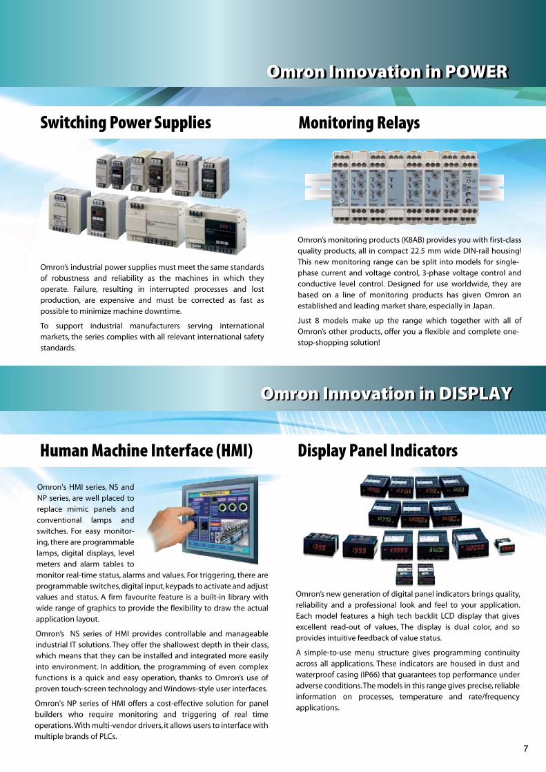
A16 Series
WL Series General-purpose Limit Switch
A165E Series Emergency Stop Switch
A165K Series Key-type Selector Switch
HL-5000 Series
Z Series
Mounting aperture of 16 mmModular construction (Pushbutton + Case + Lamp +Switch)Increase visibility illumination with low currentconsumption
Mounting aperture of 16 mm
Available in automatic and manual modelsOil-resistant IP65 models with UL and CSA approval
Mounting aperture of 16 mmIncludes safety lock to prevent misuseIdentifiable, clearly visible and will stop a dangerousprocess, without creating additional hazards
Provides large switching capacity of 15 A with highrepeat accuracyHigh-precision switchingWide range of variations in contactDrip-proof IP00/IP62
Wide selection of models including overtravel modelswith greater OT, lamp-equipped models for checkingoperation, low-temperature and heat-resistant modelsand micro-load modelsMetal housingDirect and pre-wired
Highly rigid construction with dust and drip-proofSmooth operation with greater OTEasy-to-wire conduit opening designJet-proof IP65
Switches
Pushbutton Switch
General-purpose Basic Switch
General-purpose Limit Switch
New white color!
S8JX Series
S8M Series Multi-Functional Circuit Protector
S8VS Series Compact Power Supply withDiagnostics & Output Monitor Function
S8VM SeriesSlim-size, Wide Wattage Range
Power Supply
S8TS Series
S8VT Series
Output voltages - 5 V, 12 V and 24 VAvailable for 35 to 150 W capacity (100 W, 150 W: 24-V models only)Supports DIN rail mountingUL 50/60950-1, EN 60950-1, CSA C22.2 No. 60950-1
Widest range in DC-output voltage (5, 12, 15 and
24 V) and wattage (15 up to 1,500 W)Transistor output and LED indication under-voltagealarmDIN-rail mounting (except 1,500 kW), universal height of 84.5 mmRoHS compliant including lead-free construction
Replacement indication (Maintenance Forecast Monitor)Operation time measurement (Total Run-time Monitor)Display output values: voltage, current or peak currentNon-display models from 15 to 480 W at 5, 12 and24 VDCUL Class 2 (15 to 60 W) and UL Class 1 div.2 (15, 30 W)
3-phase input (340-576 VAC) or 1-phase (810 VDC)5, 10, 20 and 40 A; 24 VDC outputCompact design with best footprint on the marketUL-60950 (CSA 22.2-60950), UL508 listing(CSA 22.2-14), CEParallel and serial operation (for two units) possible
4-circuit protection up to 4 A per channel Outputs conform to UL Class 2 (at 24 VDC, S8M-CP04-RS only)Emergency stop by external signalOptimize use of available power through start-upsequenceMaintenance control
Improves system reliability by building up N+1redundancyDeliver total power up to 240 W at 24 VDCOptional battery backup unit protects against power outageBuffer unit protects against power glitches and outage
New!
PRODUCT LINEUPPRODUCT LINEUP
Switching Power Supplies
Economical Power SupplyCompliant with Global Standards
Supply for Multiple Configuration
3-phase Power Supply
Slim and Compact
Industrial Use, Modular Power
A16 Series
WL Series General-purpose Limit Switch
A165E Series Emergency Stop Switch
A165K Series Key-type Selector Switch
HL-5000 Series
Z Series
Mounting aperture of 16 mmModular construction (Pushbutton + Case + Lamp +Switch)Increase visibility illumination with low currentconsumption
Mounting aperture of 16 mm
Available in automatic and manual modelsOil-resistant IP65 models with UL and CSA approval
Mounting aperture of 16 mmIncludes safety lock to prevent misuseIdentifiable, clearly visible and will stop a dangerousprocess, without creating additional hazards
Provides large switching capacity of 15 A with highrepeat accuracyHigh-precision switchingWide range of variations in contactDrip-proof IP00/IP62
Wide selection of models including overtravel modelswith greater OT, lamp-equipped models for checkingoperation, low-temperature and heat-resistant modelsand micro-load modelsMetal housingDirect and pre-wired
Highly rigid construction with dust and drip-proofSmooth operation with greater OTEasy-to-wire conduit opening designJet-proof IP65
Switches
Pushbutton Switch
General-purpose Basic Switch
General-purpose Limit Switch
New white color!

PRODUCT LINEUPPRODUCT LINEUP
H7CX Series
H8GN Series
H7BX Series Multifunctional Counter
K3MA Series
H7E Series
48 × 48 × 64~100 mm (H × W × D)Two-color display value, red or greenFront-mounting / plug-in6-digit model -99999 to 999999, set value -99999 to999999 or 0 to 999999Input contact, NPN or PNP
Highly visible display with backlit transmissive LCD
Selectable display color (red/green)Configurable as Total and Preset Counter, BatchCounter, Dual Counter and TachometerWide range of inputs accepted for NPN/PNP inputs(multi-inputs) and 2-wire Sensors
24 × 48 × 83 mm (H × W × D)8-digit display, 4 values and 4 set valuesFront mounting-999 to 999924 VDC
8 digits, counting range 0 to 99999999Dual input speed: 30 Hz < > 1 kHz (except for AC/DCmulti-voltage input models)AC/DC voltage, DC voltage and no-voltage input typesTime Counter (H7ET), Tachometer (H7ER) and TotalCounter (H7EC) available
Position meter indication for easy monitoringOptional DeviceNet, RS-232C, RS-485Double display, with 5 digits, in 2 colorsDimensions: 48 × 96 × 100 mm (H × W × D)7 models to choose from
DIN-size of 48 × 96 mm (H × W)Highly visible, negative transmissive back-lit LCD display3 models: K3MA-J (Process), K3MA-L (Temperature)and K3MA-F (Frequency)14.2-mm-high characters; 5 digits (-19999 to 99999)Front-panel IP66
Counters / Display Panel Indicators
Feature Rich Preset Counter
Self-powered LCD Totalizer
with Communications
DIN 1/8 StandardDigital Panel Indicator
DIN 1/32 Timer and Counter
K3HB Series DIN 1/8 AdvancedDigital Panel Indicator
New!
Timers
H3CR Series
H5CX Series
H3JA Series Subminiature Solid State Timer
H3Y Series Subminiature Analog Timer
ZEN Series
H3DE Series
48 × 48 mm front panel / plug-inHigh-/low-voltage models (except -H and -G)0.05 s to 300 h (except -H and -G)DPDT, 5 A at 250 VACTransistor 100 mA at 30 VDC
Exclusive C-MOS IC permits miniaturization resulting
in high performanceHigh repeat accuracy: ±2%; Short reset time: 0.1 s max.Large transparent time setting knob facilities time settingEquipped with an LED power-ON indicator
High accuracy at 7% max.Dual color LED indicates status of power supply andtiming operationTime limit operation with automatic resettingWide supply voltages: 24 VDC, 100 to 120 VAC or200 to 240 VAC
79 × 22.5 × 100 mm (H × W × D)DIN-rail mounting24 to 230 VAC/VDC (except -H)Wide time setting range: 0.10 s to 120 h (except -H and -G)8 selectable time ranges; DIN-rail mounted
48 × 48 × 64~100 mm (H × W × D)Two-color display value, red or greenFront-mounting / plug-in0.001 s to 9999 h, 10 rangesInput NPN, PNP and contact
Easy programming using onboard LCD and soft buttonsSingle unit contains relay, timer, counter and switchfunctionsExpansion I/O communication units up to 44 I/O pointsHigh timing accuracy with a monthly deviation of ±15 s max.
Multi-functional Digital Timer
22.5-mm-widthSolid State Timer
DIN 36 × 36 mm
Programmable Relay
Multi-Functional Analog TimerDIN 48 × 48 mm
10

PRODUCT LINEUPPRODUCT LINEUP
H7CX Series
H8GN Series
H7BX Series Multifunctional Counter
K3MA Series
H7E Series
48 × 48 × 64~100 mm (H × W × D)Two-color display value, red or greenFront-mounting / plug-in6-digit model -99999 to 999999, set value -99999 to999999 or 0 to 999999Input contact, NPN or PNP
Highly visible display with backlit transmissive LCD
Selectable display color (red/green)Configurable as Total and Preset Counter, BatchCounter, Dual Counter and TachometerWide range of inputs accepted for NPN/PNP inputs(multi-inputs) and 2-wire Sensors
24 × 48 × 83 mm (H × W × D)8-digit display, 4 values and 4 set valuesFront mounting-999 to 999924 VDC
8 digits, counting range 0 to 99999999Dual input speed: 30 Hz < > 1 kHz (except for AC/DCmulti-voltage input models)AC/DC voltage, DC voltage and no-voltage input typesTime Counter (H7ET), Tachometer (H7ER) and TotalCounter (H7EC) available
Position meter indication for easy monitoringOptional DeviceNet, RS-232C, RS-485Double display, with 5 digits, in 2 colorsDimensions: 48 × 96 × 100 mm (H × W × D)7 models to choose from
DIN-size of 48 × 96 mm (H × W)Highly visible, negative transmissive back-lit LCD display3 models: K3MA-J (Process), K3MA-L (Temperature)and K3MA-F (Frequency)14.2-mm-high characters; 5 digits (-19999 to 99999)Front-panel IP66
Counters / Display Panel Indicators
Feature Rich Preset Counter
Self-powered LCD Totalizer
with Communications
DIN 1/8 StandardDigital Panel Indicator
DIN 1/32 Timer and Counter
K3HB Series DIN 1/8 AdvancedDigital Panel Indicator
New!
Timers
H3CR Series
H5CX Series
H3JA Series Subminiature Solid State Timer
H3Y Series Subminiature Analog Timer
ZEN Series
H3DE Series
48 × 48 mm front panel / plug-inHigh-/low-voltage models (except -H and -G)0.05 s to 300 h (except -H and -G)DPDT, 5 A at 250 VACTransistor 100 mA at 30 VDC
Exclusive C-MOS IC permits miniaturization resulting
in high performanceHigh repeat accuracy: ±2%; Short reset time: 0.1 s max.Large transparent time setting knob facilities time settingEquipped with an LED power-ON indicator
High accuracy at 7% max.Dual color LED indicates status of power supply andtiming operationTime limit operation with automatic resettingWide supply voltages: 24 VDC, 100 to 120 VAC or200 to 240 VAC
79 × 22.5 × 100 mm (H × W × D)DIN-rail mounting24 to 230 VAC/VDC (except -H)Wide time setting range: 0.10 s to 120 h (except -H and -G)8 selectable time ranges; DIN-rail mounted
48 × 48 × 64~100 mm (H × W × D)Two-color display value, red or greenFront-mounting / plug-in0.001 s to 9999 h, 10 rangesInput NPN, PNP and contact
Easy programming using onboard LCD and soft buttonsSingle unit contains relay, timer, counter and switchfunctionsExpansion I/O communication units up to 44 I/O pointsHigh timing accuracy with a monthly deviation of ±15 s max.
Multi-functional Digital Timer
22.5-mm-widthSolid State Timer
DIN 36 × 36 mm
Programmable Relay
Multi-Functional Analog TimerDIN 48 × 48 mm
11
PRODUCT LINEUPPRODUCT LINEUP
Programmable Controllers (PLC) / Human Machine Interface (HMI)
CJ1 Series
NP Series
Max I/O of 640/1280/2560 points depending on modelsModular expansions for space savingHigh processing speed and wide range of expandable options catered for different applicationsSeamless communications for component, controller and information networks
CP1L with 10/14/20/30/40/60 I/O models, expandable to maximum of 50/54/60/150/160/180 pointsCP1H with 20/40 I/O models, expandable to max of 300/320 points, and with built-in analog I/OsFunction block capabilities, optional RS-232/422/485 boards and USB interface cablePositioning functions available
Advanced STN/TFT models for 5.7", 8.4", 10.4" & 12.1"Smart Active Parts eliminate programming and screen design when interfacing with Omron productsMulti Language supportEthernet connection capabilities
Cost-effective STN monochrome black or ivory models for 3.8" and 5.7"3 or 6 function keys at the side of HMI for easy accessMulti-language supportMulti-vendor drivers availableRS-232 and RS-422/485 ports for flexibility in interfacing
Programmable Terminal
High-performance PLC
CP1 Series Compact Smart Cube
Coming Soon!
Relays
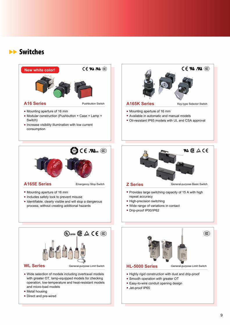
MY Series
MK-S Series General-purpose Relays Featuring
G2RS Series with Enhanced Features
LY Series Miniature Power Relay
G4Q Series
G2RV Series
10 A (DPDT), 5 A (4PDT) contact, gold-clad contacts(MY4)Mechanical and LED indicationPush-to-test button - momentary and lockableHermetically sealed (MYH), latching (MY2K) and PCBtypes
Equipped with arc barrier and built-in diodeSingle-, double-, three- and four-pole modelsSPDT, DPDT, 3PDT and 4PDT contact typesDIN-rail by socket, PCB and flange mounting typesavailable10 A rated load
Lockable test button models now available Built-in mechanical operation indicator with nameplateAC type is equipped with a coil-disconnection self-diagnostic function (LED type)Environment-friendly (CD, Pb free); wide range ofsockets
Large plug-in terminals for easy connectionLED indicator and mechanical flag to check operationTransparent housing enables checking relay conditionSlim outline to save spacePush-in terminals and accessories for easy wiring
Built-in operation indicator (mechanical and LED)New models with lockable test buttonNameplate provided on models with lockable test buttonRoHS compliantUL approval for most models (UL approval pending formodels with built-in LED indicators)
Positive operation is assured due to unique ratchetmechanismSatisfies dielectric strength of 2,000 VACLow power consumption (AC: approx. 6.4 VA; DC:approx. 3.9 W)DPDT contact configuration
New!
Versatile Miniature Plug-in Relay
Unique Ratchet Relay
6-mm-wide Relay withStrong Mechanical Pins
Indicator and Lockable Test Button
New!
LR
Plug-in Relay
G7Z Series Compact 160 A Relay MM Series
Max. switching current 160 A (40 A rating/4 pole/IEC-AC1)Switching voltage 440 VACSafety function with mirror contacts in variousconfigurationsPower consumption less than 4 WLow switching noise (70 dB)All materials used are compliant with RoHS directive
Easy to mount, wire, and use
Large selection of models including various contact formDC-switching models and open modelsModels also available with built-in diodes and for use as auxiliary Power Relays
Stable Contact Reliabilityand Long Life
New!
LR LR
LR
NS Series Advanced Programmable Terminal
1

PRODUCT LINEUPPRODUCT LINEUP
Programmable Controllers (PLC) / Human Machine Interface (HMI)
CJ1 Series
NP Series
Max I/O of 640/1280/2560 points depending on modelsModular expansions for space savingHigh processing speed and wide range of expandable options catered for different applicationsSeamless communications for component, controller and information networks
CP1L with 10/14/20/30/40/60 I/O models, expandable to maximum of 50/54/60/150/160/180 pointsCP1H with 20/40 I/O models, expandable to max of 300/320 points, and with built-in analog I/OsFunction block capabilities, optional RS-232/422/485 boards and USB interface cablePositioning functions available
Advanced STN/TFT models for 5.7", 8.4", 10.4" & 12.1"Smart Active Parts eliminate programming and screen design when interfacing with Omron productsMulti Language supportEthernet connection capabilities
Cost-effective STN monochrome black or ivory models for 3.8" and 5.7"3 or 6 function keys at the side of HMI for easy accessMulti-language supportMulti-vendor drivers availableRS-232 and RS-422/485 ports for flexibility in interfacing
Programmable Terminal
High-performance PLC
CP1 Series Compact Smart Cube
Coming Soon!
Relays
MY Series
MK-S Series General-purpose Relays Featuring
G2RS Series with Enhanced Features
LY Series Miniature Power Relay
G4Q Series
G2RV Series
10 A (DPDT), 5 A (4PDT) contact, gold-clad contacts(MY4)Mechanical and LED indicationPush-to-test button - momentary and lockableHermetically sealed (MYH), latching (MY2K) and PCBtypes
Equipped with arc barrier and built-in diodeSingle-, double-, three- and four-pole modelsSPDT, DPDT, 3PDT and 4PDT contact typesDIN-rail by socket, PCB and flange mounting typesavailable10 A rated load
Lockable test button models now available Built-in mechanical operation indicator with nameplateAC type is equipped with a coil-disconnection self-diagnostic function (LED type)Environment-friendly (CD, Pb free); wide range ofsockets
Large plug-in terminals for easy connectionLED indicator and mechanical flag to check operationTransparent housing enables checking relay conditionSlim outline to save spacePush-in terminals and accessories for easy wiring
Built-in operation indicator (mechanical and LED)New models with lockable test buttonNameplate provided on models with lockable test buttonRoHS compliantUL approval for most models (UL approval pending formodels with built-in LED indicators)
Positive operation is assured due to unique ratchetmechanismSatisfies dielectric strength of 2,000 VACLow power consumption (AC: approx. 6.4 VA; DC:approx. 3.9 W)DPDT contact configuration
New!
Versatile Miniature Plug-in Relay
Unique Ratchet Relay
6-mm-wide Relay withStrong Mechanical Pins
Indicator and Lockable Test Button
New!
LR
Plug-in Relay
G7Z Series Compact 160 A Relay MM Series
Max. switching current 160 A (40 A rating/4 pole/IEC-AC1)Switching voltage 440 VACSafety function with mirror contacts in variousconfigurationsPower consumption less than 4 WLow switching noise (70 dB)All materials used are compliant with RoHS directive
Easy to mount, wire, and use
Large selection of models including various contact formDC-switching models and open modelsModels also available with built-in diodes and for use as auxiliary Power Relays
Stable Contact Reliabilityand Long Life
New!
LR LR
LR
NS Series Advanced Programmable Terminal
1
PRODUCT LINEUPPRODUCT LINEUP
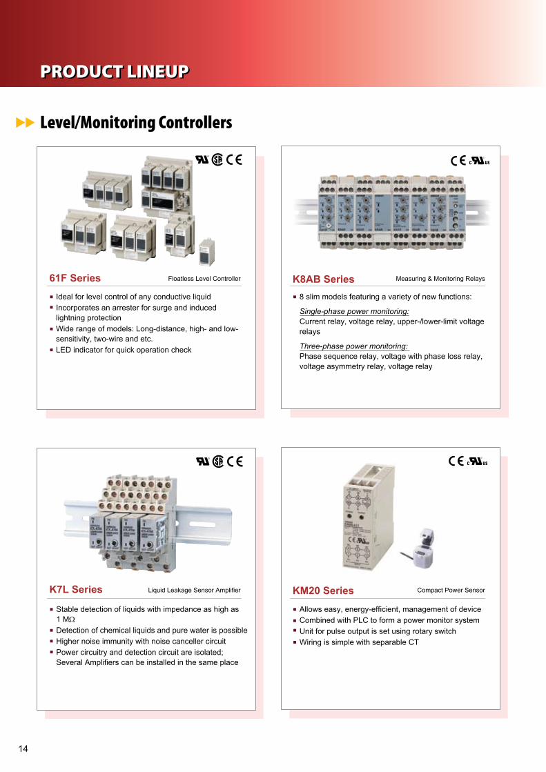
Level/Monitoring Controllers
ORDERING INFORMATION
61F Series
K7L Series Liquid Leakage Sensor Amplifier KM20 Series
Ideal for level control of any conductive liquidIncorporates an arrester for surge and inducedlightning protectionWide range of models: Long-distance, high- and low-sensitivity, two-wire and etc.LED indicator for quick operation check
8 slim models featuring a variety of new functions:
Single-phase power monitoring:Current relay, voltage relay, upper-/lower-limit voltagerelays
Three-phase power monitoring: Phase sequence relay, voltage with phase loss relay, voltage asymmetry relay, voltage relay
Stable detection of liquids with impedance as high as1 MΩDetection of chemical liquids and pure water is possibleHigher noise immunity with noise canceller circuitPower circuitry and detection circuit are isolated;Several Amplifiers can be installed in the same place
Allows easy, energy-efficient, management of deviceCombined with PLC to form a power monitor systemUnit for pulse output is set using rotary switchWiring is simple with separable CT
Compact Power Sensor
Floatless Level Controller
K8AB Series Measuring & Monitoring Relays
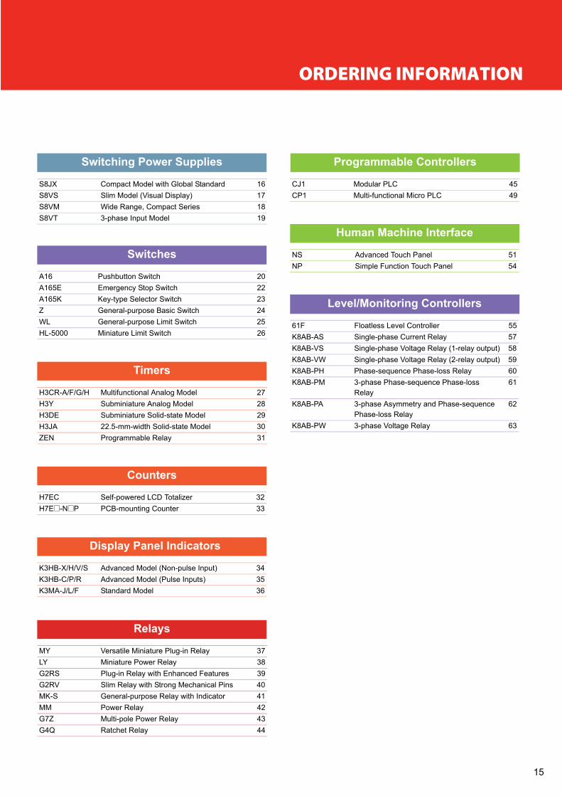
Switching Power Supplies
S8JX Compact Model with Global Standard 16S8VS Slim Model (Visual Display) 17S8VM Wide Range, Compact Series 18
91ledoMtupnIesahp-3TV8S
Relays
MY Versatile Miniature Plug-in Relay 3738yaleRrewoPerutainiMYL
G2RS Plug-in Relay with Enhanced Features 39G2RV Slim Relay with Strong Mechanical Pins 40MK-S General-purpose Relay with Indicator 41
42yaleRrewoPMM43yaleRrewoPelop-itluMZ7G44yaleRtehctaRQ4G
Switches
02hctiwSnottubhsuP61A22hctiwSpotSycnegremEE561A
A165K Key-type Selector Switch 23Z General-purpose Basic Switch 24WL General-purpose Limit Switch 25
26hctiwStimiLerutainiM0005-LH
Timers
H3CR-A/F/G/H Multifunctional Analog Model 27H3Y Subminiature Analog Model 28H3DE Subminiature Solid-state Model 29H3JA 22.5-mm-width Solid-state Model 30
31yaleRelbammargorPNEZ
Counters
H7EC Self-powered LCD Totalizer 32H7E@-N@ 33retnuoCgnitnuom-BCPP
Display Panel Indicators
43l (Non-pulse Input)edoMdecnavdAS/V/H/X-BH3K53l (Pulse Inputs)edoMdecnavdAR/P/C-BH3K63ledoMdradnatSF/L/J-AM3K
Programmable Controllers
54CLPraludoM1JCCP1 Multi-functional Micro PLC 49
Human Machine Interface
51lenaPhcuoTdecnavdASNNP Simple Function Touch Panel 54
Level/Monitoring Controllers
61F Floatless Level Controller 55K8AB-AS Single-phase Current Relay 57K8AB-VS Single-phase Voltage Relay (1-relay output) 58K8AB-VW Single-phase Voltage Relay (2-relay output) 59K8AB-PH Phase-sequence Phase-loss Relay 60K8AB-PM 3-phase Phase-sequence Phase-loss
Relay61
K8AB-PA 3-phase Asymmetry and Phase-sequencePhase-loss Relay
62
63yaleRegatloVesahp-3WP-BA8K
1
PRODUCT LINEUPPRODUCT LINEUP
Level/Monitoring Controllers
ORDERING INFORMATION
61F Series
K7L Series Liquid Leakage Sensor Amplifier KM20 Series
Ideal for level control of any conductive liquidIncorporates an arrester for surge and inducedlightning protectionWide range of models: Long-distance, high- and low-sensitivity, two-wire and etc.LED indicator for quick operation check
8 slim models featuring a variety of new functions:
Single-phase power monitoring:Current relay, voltage relay, upper-/lower-limit voltagerelays
Three-phase power monitoring: Phase sequence relay, voltage with phase loss relay, voltage asymmetry relay, voltage relay
Stable detection of liquids with impedance as high as1 MΩDetection of chemical liquids and pure water is possibleHigher noise immunity with noise canceller circuitPower circuitry and detection circuit are isolated;Several Amplifiers can be installed in the same place
Allows easy, energy-efficient, management of deviceCombined with PLC to form a power monitor systemUnit for pulse output is set using rotary switchWiring is simple with separable CT
Compact Power Sensor
Floatless Level Controller
K8AB Series Measuring & Monitoring Relays
Switching Power Supplies
S8JX Compact Model with Global Standard 16S8VS Slim Model (Visual Display) 17S8VM Wide Range, Compact Series 18
91ledoMtupnIesahp-3TV8S
Relays
MY Versatile Miniature Plug-in Relay 3738yaleRrewoPerutainiMYL
G2RS Plug-in Relay with Enhanced Features 39G2RV Slim Relay with Strong Mechanical Pins 40MK-S General-purpose Relay with Indicator 41
42yaleRrewoPMM43yaleRrewoPelop-itluMZ7G44yaleRtehctaRQ4G
Switches
02hctiwSnottubhsuP61A22hctiwSpotSycnegremEE561A
A165K Key-type Selector Switch 23Z General-purpose Basic Switch 24WL General-purpose Limit Switch 25
26hctiwStimiLerutainiM0005-LH
Timers
H3CR-A/F/G/H Multifunctional Analog Model 27H3Y Subminiature Analog Model 28H3DE Subminiature Solid-state Model 29H3JA 22.5-mm-width Solid-state Model 30
31yaleRelbammargorPNEZ
Counters
H7EC Self-powered LCD Totalizer 32H7E@-N@ 33retnuoCgnitnuom-BCPP
Display Panel Indicators
43l (Non-pulse Input)edoMdecnavdAS/V/H/X-BH3K53l (Pulse Inputs)edoMdecnavdAR/P/C-BH3K63ledoMdradnatSF/L/J-AM3K
Programmable Controllers
54CLPraludoM1JCCP1 Multi-functional Micro PLC 49
Human Machine Interface
51lenaPhcuoTdecnavdASNNP Simple Function Touch Panel 54
Level/Monitoring Controllers
61F Floatless Level Controller 55K8AB-AS Single-phase Current Relay 57K8AB-VS Single-phase Voltage Relay (1-relay output) 58K8AB-VW Single-phase Voltage Relay (2-relay output) 59K8AB-PH Phase-sequence Phase-loss Relay 60K8AB-PM 3-phase Phase-sequence Phase-loss
Relay61
K8AB-PA 3-phase Asymmetry and Phase-sequencePhase-loss Relay
62
63yaleRegatloVesahp-3WP-BA8K
1

Switch Mode Power Supply
S8JX (35/50/100/150-W Models)
Ordering InformationNote: For details on normal stock models, contact your nearest OMRON representative.
SpecificationsRatings/Characteristics
Note: 1. Do not use an Inverter output for the Power Supply. Inverters with an output frequency of 50/60 Hz are available, but the rise in the internal temperature of the Power Supply may result inignition or burning.
2. If the output voltage adjuster (V. ADJ) is turned, the voltage will increase by more than +15% of the voltage adjustment range.When adjusting the output voltage, confirm the actual output voltage from the Power Supply and be sure that load is not damaged.
Configuration Power ratings Input voltage Output voltage Output current Front-mounting type DIN Rail mounting brackettype
Open-frame type 35 W 200 to 240 VAC 5V 7 A S8JX-03505 S8JX-03505D12V 2.9 A S8JX-03512 S8JX-03512D24V 1.5 A S8JX-03524 S8JX-03524D
D50050-XJ8S50050-XJ8SA01V5W0512V 4.2 A S8JX-05012 S8JX-05012D24V 2.1 A S8JX-05024 S8JX-05024D
D42001-XJ8S42001-XJ8SA2.4V42W001D42051-XJ8S42051-XJ8SA5.6V42W051
Covered type 35 W 200 to 240 VAC 5V 7 A S8JX-03505C S8JX-03505CD12V 2.9 A S8JX-03512C S8JX-03512CD24V 1.5 A S8JX-03524C S8JX-03524CD
DC50050-XJ8SC50050-XJ8SA01V5W0512V 4.2 A S8JX-05012C S8JX-05012CD24V 2.1 A S8JX-05024C S8JX-05024CD
DC42001-XJ8SC42001-XJ8SA2.4V42W001DC42051-XJ8SC42051-XJ8SA5.6V42W051
Power ratings 35 W 50 W 100 W 150 WItemEfficiency (typical) 5-V models ------.nim%37.nim%76
12-V models ------.nim%87.nim%6724-V models 76% min. 78% min. 78% min. 81% min.
Input Voltage (See note 1.) 200 to 240 VAC (170 to 264 VAC)Frequency (See note 1.) 50/60 Hz (47 to 450 Hz)Current 200 V input 0.6 A max. 0.8 A max. 1.6 A max. 2.5 A max.Power factor ---Harmonic current emissions ---Leakage current 200 V input 1.0 mA max.Inrush current(See note 1.)
200 V input 50 A max. (for a cold start at 25°C)
Output Voltage adjustment range (See note 2.) −10% to 15% (with V. ADJ) (guaranteed)Ripple 250 mV (p-p) max. (5 V), 240 mV (p-p) max. (12 V),
480 mV (p-p) max. (24 V) (at rated input/output voltage)Input variation influence 0.5% max.Load variation influence (rated input voltage) 1.5% max.Temperature variation influence 0.05%/°C max.Start up time 1500 ms max. (at rated input/output voltage)Hold time 20 ms min. (at rated input/output voltage)
Weight 420 g max. 440 g max. 600 g max. 720 g max.
1

Switch Mode Power Supply
S8VS (15/30/60/90/120/180/240/480-W Models)
Ordering information
Specifications
Power Output voltage Output current Diagnosticsfunction
Diagnostic alarm output Size in mm(H × W × D)
Model
15 W 5 VDC 2 A (10 W) Undervoltage alarmindicator
no 85 × 22.5 × 96.4 S8VS-0150512 VDC 1.2 A no S8VS-0151224 VDC 0.65 A no S8VS-01524
30 W 5 VDC 4 A (20 W) Undervoltage alarmindicator
no 85 × 22.5 × 96.4 S8VS-0300512 VDC 2.5 A no S8VS-0301224 VDC 1.3 A no S8VS-03024
60 W 24 VDC 2.5 A no no 95 × 40 × 108.3 S8VS-0602490 W 24 VDC 3.75 A no no 115 × 50 × 121.3 S8VS-09024120 W 24 VDC 5 A no no S8VS-12024180 W 24 VDC 7.5 A no no 115× 75 × 125.3 S8VS-18024240 W 24 VDC 10 A no no 115 × 100 × 125.3 S8VS-2402460 W 24 VDC 2.5 A Maintenance *1
*1 Maintenance indicates main tenance forecast monitor
no 95 × 40 × 108.3 S8VS-06024ATotal run-time no S8VS-06024B
Alarm output sinking(NPN)
Alarm output sourcing(PNP)
90 W 24 VDC 3.75 A Maintenance *1 yes 115 × 50 × 121.3 S8VS-09024A S8VS-09024APTotal run-time S8VS-09024B S8VS-09024BP
120 W 24 VDC 5 A Maintenance *1 yes S8VS-12024A S8VS-12024APTotal run-time S8VS-12024B S8VS-12024BP
180 W 24 VDC 7.5 A Maintenance *1 yes 115 × 75 × 125.3 S8VS-18024A S8VS-18024APTotal run-time S8VS-18024B S8VS-18024BP
240 W 24 VDC 10 A Maintenance *1 yes 115 × 100 × 125.3 S8VS-24024A S8VS-24024APTotal run-time S8VS-24024B S8VS-24024BP
Specification 15 W 30 W 60 W 90 W 120 W 180 W 240 WEfficiency 77% min. (24 V) 80% min. (24 V) 78% min. 80% min. 80% min. 80% min. 80% min.Power factor – – – – 0.95 min. 0.95 min. 0.95 min.Input voltage 100 to 240 VAC (85 to 264 VAC), single-phaseOutputvoltage
Voltage adjustment ±10 to ±15% (with V. ADJ) min.Ripple 2% p-p max. (at rated input/output voltage)Input variation 0.5% max. (at 85 to 264 VAC input, 100% load)Temperatureinfluence
0.05%/°C max.
Overload protection 105 to 160% of rated load current, voltage drop, automatic resetOvervoltage protection yes yes yes yes yes yes yesInputcurrent
100 V 0.45 A m Ax. 0.9 A m Ax. 1.7 A m Ax. 2.3 A m Ax. 1.9 A m Ax. 2.7 A m Ax. 3.8 A m Ax.200 V 0.25 A m Ax. 0.6 A m Ax. 1.0 A m Ax. 1.4 A m Ax. 1.1 A m Ax 1.6 A m Ax. 2.0 A m Ax.230 V 0.19 A
(5 V: 0.14 A)0.37 A(5 V: 0.27 A)
0.7 A typ. 0.9 A typ. 0.6 A typ. 0.9 A typ. 1.2 A typ.
Output indicator yes (green) yes (green) yes (green) yes (green) yes (green) yes (green) yes (green)Weight 160 g 180 g 330 g 490 g 550 g 850 g 1,150 gOperating temperature -10 to 60°C -10 to 60°C *1
*1 For 30 W model 24 V: No derating, 12 & 5 V: Derating beyond 50°C.
-10 to 60°C, derating beyond 40°C, no icing or condensationSeries operation yes (24 V only) yes yes yes yes yes yes
480 W 24 VDC 20 A, Peak current: 30 A (200 VAC)
Maintenance *1 yes 115 × 150 × 127.2Total run-time
S8VS-48024A (sinking/sourcing)S8VS-48024B (sinking/sourcing)
480 W83% min.0.95 min.
yes7.4 A m Ax.3.9 A m Ax.---
yes (green)1,700 g max.
yes
-10 to 15% (with V. ADJ guaranteed)
Switch Mode Power Supply
S8JX (35/50/100/150-W Models)
Ordering InformationNote: For details on normal stock models, contact your nearest OMRON representative.
SpecificationsRatings/Characteristics
Note: 1. Do not use an Inverter output for the Power Supply. Inverters with an output frequency of 50/60 Hz are available, but the rise in the internal temperature of the Power Supply may result inignition or burning.
2. If the output voltage adjuster (V. ADJ) is turned, the voltage will increase by more than +15% of the voltage adjustment range.When adjusting the output voltage, confirm the actual output voltage from the Power Supply and be sure that load is not damaged.
Configuration Power ratings Input voltage Output voltage Output current Front-mounting type DIN Rail mounting brackettype
Open-frame type 35 W 200 to 240 VAC 5V 7 A S8JX-03505 S8JX-03505D12V 2.9 A S8JX-03512 S8JX-03512D24V 1.5 A S8JX-03524 S8JX-03524D
D50050-XJ8S50050-XJ8SA01V5W0512V 4.2 A S8JX-05012 S8JX-05012D24V 2.1 A S8JX-05024 S8JX-05024D
D42001-XJ8S42001-XJ8SA2.4V42W001D42051-XJ8S42051-XJ8SA5.6V42W051
Covered type 35 W 200 to 240 VAC 5V 7 A S8JX-03505C S8JX-03505CD12V 2.9 A S8JX-03512C S8JX-03512CD24V 1.5 A S8JX-03524C S8JX-03524CD
DC50050-XJ8SC50050-XJ8SA01V5W0512V 4.2 A S8JX-05012C S8JX-05012CD24V 2.1 A S8JX-05024C S8JX-05024CD
DC42001-XJ8SC42001-XJ8SA2.4V42W001DC42051-XJ8SC42051-XJ8SA5.6V42W051
Power ratings 35 W 50 W 100 W 150 WItemEfficiency (typical) 5-V models ------.nim%37.nim%76
12-V models ------.nim%87.nim%6724-V models 76% min. 78% min. 78% min. 81% min.
Input Voltage (See note 1.) 200 to 240 VAC (170 to 264 VAC)Frequency (See note 1.) 50/60 Hz (47 to 450 Hz)Current 200 V input 0.6 A max. 0.8 A max. 1.6 A max. 2.5 A max.Power factor ---Harmonic current emissions ---Leakage current 200 V input 1.0 mA max.Inrush current(See note 1.)
200 V input 50 A max. (for a cold start at 25°C)
Output Voltage adjustment range (See note 2.) −10% to 15% (with V. ADJ) (guaranteed)Ripple 250 mV (p-p) max. (5 V), 240 mV (p-p) max. (12 V),
480 mV (p-p) max. (24 V) (at rated input/output voltage)Input variation influence 0.5% max.Load variation influence (rated input voltage) 1.5% max.Temperature variation influence 0.05%/°C max.Start up time 1500 ms max. (at rated input/output voltage)Hold time 20 ms min. (at rated input/output voltage)
Weight 420 g max. 440 g max. 600 g max. 720 g max.
1

Switch Mode Power Supply
S8VM (15/30/50/100/150/300/600/1,500-W Models)
Ordering information
Specifications
Power ratings Output voltage Output current Size in mm (H × W × D) ModelDIN-rail mounting Undervoltage alarm type
Sinking (NPN) Sourcing (PNP)15 W 12 V 1.3 A 84.5 × 35.1 × 94.4 S8VM-01512CD – –
24 V 0.65 A S8VM-01524CD S8VM-01524AD *1
*1 No output built-in.
30 W 12 V 2.5 A 84.5 × 35.1 × 109.4 S8VM-03012CD – –24 V 1.3 A S8VM-03024CD S8VM-03024AD *1
50 W 12 V 4.3 A 84.5 × 35.1 × 124.5 S8VM-05012CD – –24 V 2.2 A S8VM-05024CD S8VM-05024AD S8VM-05024PD
100 W 12 V 8.5 A 84.5 × 36.6 × 164.5 S8VM-10012CD – –24 V 4.5 A S8VM-10024CD S8VM-10024AD S8VM-10024PD
150 W 12 V 12.5 A 84.5 × 45.6 × 164.5 S8VM-15012CD – –24 V 6.5 A S8VM-15024CD S8VM-15024AD S8VM-15024PD
Power ratings Output voltage Output current Size in mm (H × W × D) Bottom mounting DIN-rail adaptor Other features300 W 12 V 27 A 84.5 × 62.5 × 188 S8VM-30012C S82Y-VM30D overload, overvoltage and
24 V 14 A S8VM-30024C600 W 12 V 53 A 84.5 × 101.8 × 192 S8VM-60012C S82Y-VM60D
overheat
24 V 27 A S8VM-60024C1,500 W 24 V 70 A 84.5 × 126.5 × 327 S8VM-15224C –
Item 15 W 30 W 50 W 100 W 150 W 300 W 600 W 1,500 WEfficiency 12 V models 78% min. 79% min. 79% min. 81% min. 81% min. 78% min. 79% min. –
24 V models 80% min. 81% min. 80% min. 82% min. 83% min. 81% min. 81% min. 82% min.Input voltage 100 to 240 VAC, (85 to 264 VAC), single phaseOutput Voltage adjustment -20% to 20% with V. ADJ min. (S8VM-_ _ _ 24A_ /P_ : -10% to 20%)
Ripple 12 V models 1.5% (p-p) max. 1.5% (p-p) max. 2.0% (p-p) max. –24 V models 1.0% (p-p) max. 0.75% (p-p) max. 1.25% (p-p) max. 1.25% (p-p) max.
Input variation 0.4% max.Temperature influence 0.02%/°C max.
Overload protection 105% to 160% of rated load current, voltage drop, automatic resetOvervoltage protection yesOutput indicator yes (green)Weight 180 g max. 220 g max. 290 g max. 460 g max. 530 g max. 1,100 g max. 1,700 g max. 3,800 g max.Series operation yesRemote sensing function no no no yes
1
Switch Mode Power Supply
S8VM (15/30/50/100/150/300/600/1,500-W Models)
Ordering information
Specifications
Power ratings Output voltage Output current Size in mm (H × W × D) ModelDIN-rail mounting Undervoltage alarm type
Sinking (NPN) Sourcing (PNP)15 W 12 V 1.3 A 84.5 × 35.1 × 94.4 S8VM-01512CD – –
24 V 0.65 A S8VM-01524CD S8VM-01524AD *1
*1 No output built-in.
30 W 12 V 2.5 A 84.5 × 35.1 × 109.4 S8VM-03012CD – –24 V 1.3 A S8VM-03024CD S8VM-03024AD *1
50 W 12 V 4.3 A 84.5 × 35.1 × 124.5 S8VM-05012CD – –24 V 2.2 A S8VM-05024CD S8VM-05024AD S8VM-05024PD
100 W 12 V 8.5 A 84.5 × 36.6 × 164.5 S8VM-10012CD – –24 V 4.5 A S8VM-10024CD S8VM-10024AD S8VM-10024PD
150 W 12 V 12.5 A 84.5 × 45.6 × 164.5 S8VM-15012CD – –24 V 6.5 A S8VM-15024CD S8VM-15024AD S8VM-15024PD
Power ratings Output voltage Output current Size in mm (H × W × D) Bottom mounting DIN-rail adaptor Other features300 W 12 V 27 A 84.5 × 62.5 × 188 S8VM-30012C S82Y-VM30D overload, overvoltage and
24 V 14 A S8VM-30024C600 W 12 V 53 A 84.5 × 101.8 × 192 S8VM-60012C S82Y-VM60D
overheat
24 V 27 A S8VM-60024C1,500 W 24 V 70 A 84.5 × 126.5 × 327 S8VM-15224C –
Item 15 W 30 W 50 W 100 W 150 W 300 W 600 W 1,500 WEfficiency 12 V models 78% min. 79% min. 79% min. 81% min. 81% min. 78% min. 79% min. –
24 V models 80% min. 81% min. 80% min. 82% min. 83% min. 81% min. 81% min. 82% min.Input voltage 100 to 240 VAC, (85 to 264 VAC), single phaseOutput Voltage adjustment -20% to 20% with V. ADJ min. (S8VM-_ _ _ 24A_ /P_ : -10% to 20%)
Ripple 12 V models 1.5% (p-p) max. 1.5% (p-p) max. 2.0% (p-p) max. –24 V models 1.0% (p-p) max. 0.75% (p-p) max. 1.25% (p-p) max. 1.25% (p-p) max.
Input variation 0.4% max.Temperature influence 0.02%/°C max.
Overload protection 105% to 160% of rated load current, voltage drop, automatic resetOvervoltage protection yesOutput indicator yes (green)Weight 180 g max. 220 g max. 290 g max. 460 g max. 530 g max. 1,100 g max. 1,700 g max. 3,800 g max.Series operation yesRemote sensing function no no no yes
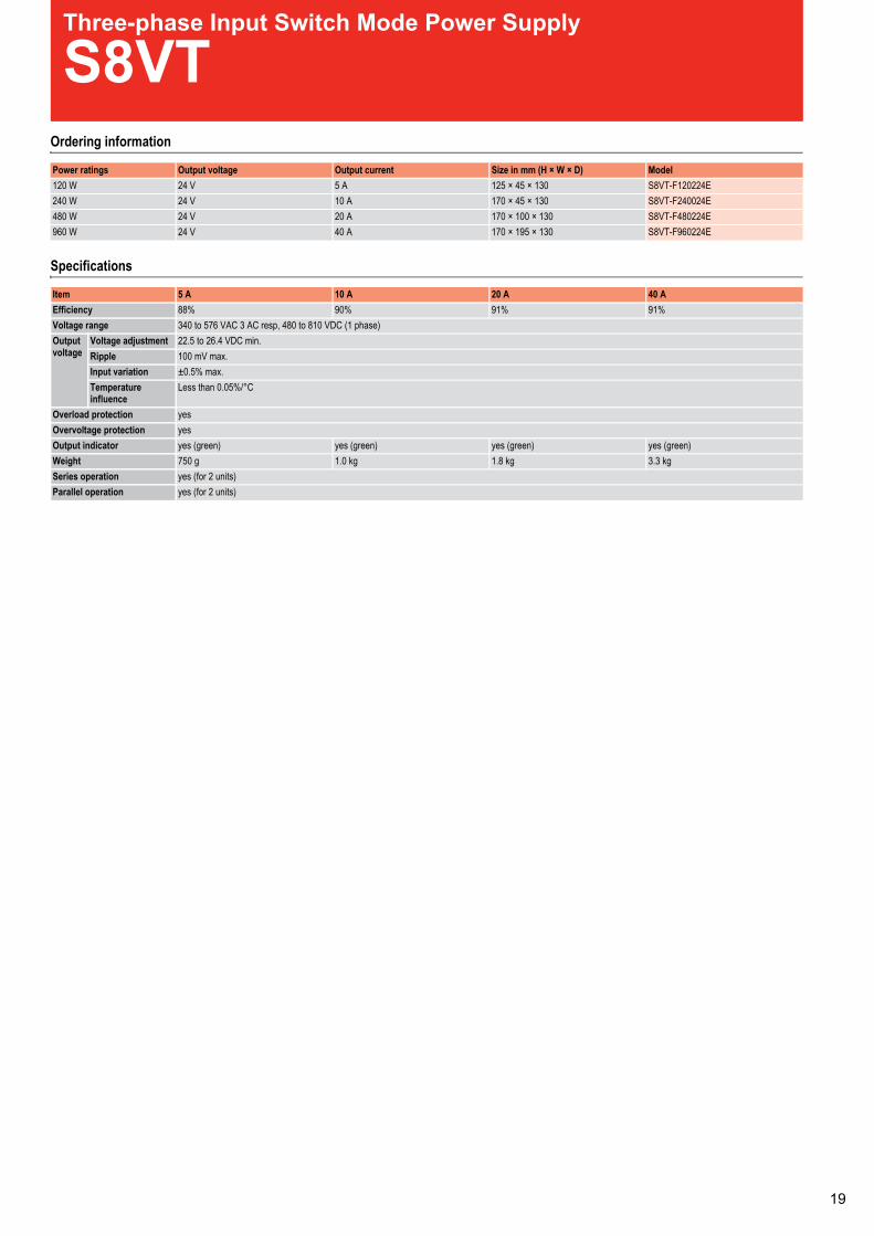
Three-phase Input Switch Mode Power Supply
S8VTOrdering information
Specifications
Power ratings Output voltage Output current Size in mm (H × W × D) Model120 W 24 V 5 A 125 × 45 × 130 S8VT-F120224E240 W 24 V 10 A 170 × 45 × 130 S8VT-F240024E480 W 24 V 20 A 170 × 100 × 130 S8VT-F480224E960 W 24 V 40 A 170 × 195 × 130 S8VT-F960224E
Item 5 A 10 A 20 A 40 AEfficiency 88% 90% 91% 91%Voltage range 340 to 576 VAC 3 AC resp, 480 to 810 VDC (1 phase)Outputvoltage
Voltage adjustment 22.5 to 26.4 VDC min.Ripple 100 mV max.Input variation ±0.5% max.Temperatureinfluence
Less than 0.05%/°C
Overload protection yesOvervoltage protection yesOutput indicator yes (green) yes (green) yes (green) yes (green)Weight 750 g 1.0 kg 1.8 kg 3.3 kgSeries operation yes (for 2 units)Parallel operation yes (for 2 units)
1
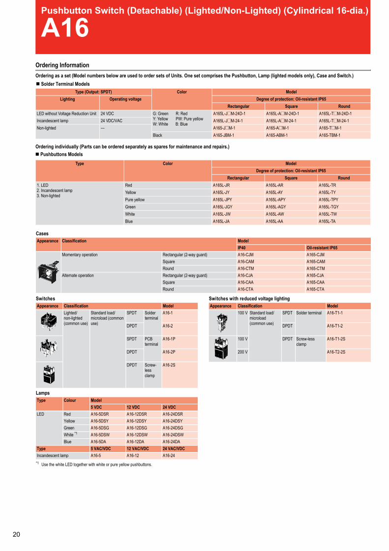
Pushbutton Switch (Detachable) (Lighted/Non-Lighted) (Cylindrical 16-dia.)
A16Ordering InformationOrdering as a set (Model numbers below are used to order sets of Units. One set comprises the Pushbutton, Lamp (lighted models only), Case and Switch.)
Ordering individually (Parts can be ordered separately as spares for maintenance and repairs.)
Type (Output: SPDT) Color ModelLighting Operating voltage Degree of protection: Oil-resistant IP65
Rectangular Square RoundLED without Voltage Reduction Unit 24 VDC G: Green R: Red
Y: Yellow PW: Pure yellowW: White B: Blue
A165L-J@M-24D-1 A165L-A@M-24D-1 A165L-T@M-24D-1Incandescent lamp A165L-J@M-24-1 A165L-A@M-24-1 A165L-T@M-24-1Non-lighted --- A165-J@M-1 A165-A@M-1 A165-T@M-1
Black A165-JBM-1 A165-ABM-1 A165-TBM-1
Type Color ModelDegree of protection: Oil-resistant IP65
Rectangular Square Round1. LED2. Incandescent lamp3. Non-lighted
Red A165L-JR A165L-AR A165L-TRYellow A165L-JY A165L-AY A165L-TYPure yellow A165L-JPY A165L-APY A165L-TPYGreen A165L-JGY A165L-AGY A165L-TGYWhite A165L-JW A165L-AW A165L-TWBlue A165L-JA A165L-AA A165L-TA
Cases
erhtiwsehctiwSsehctiwS duced voltage lighting
Lamps
Appearance Classification ModelOil-resistant IP65
Momentary operation Rectangular (2-way guard) A165-CJMSquare A165-CAMRound A165-CTM
Alternate operation Rectangular (2-way guard) A165-CJASquare A165-CAARound A165-CTA
Appearance Classification ModelLighted/non-lighted(common use)
Standard load/microload (commonuse)
SPDT Solderterminal
A16-1
DPDT A16-2
SPDT PCBterminal
A16-1P
DPDT A16-2P
DPDT Screw-lessclamp
A16-2S
Appearance Classification Model100 V Standard load/
microload(common use)
SPDT Solder terminal A16-T1-1
DPDT A16-T1-2
100 V DPDT Screw-lessclamp
A16-T1-2S
200 V A16-T2-2S
Type Colour Model5 VDC 12 VDC 24 VDC
LED Red A16-5DSR A16-12DSR A16-24DSRYellow A16-5DSY A16-12DSY A16-24DSYGreen A16-5DSG A16-12DSG A16-24DSGWhite *1
*1 Use the white LED together with white or pure yellow pushbuttons.
A16-5DSW A16-12DSW A16-24DSWBlue A16-5DA A16-12DA A16-24DA
Type 5 VAC/VDC 12 VAC/VDC 24 VAC/VDCIncandescent lamp A16-5 A16-12 A16-24
IP40A16-CJMA16-CAMA16-CTMA16-CJAA16-CAAA16-CTA
Solder Terminal Models
Pushbuttons Models
24 VDC/VAC
0

Pushbutton Switch (Detachable) (Lighted/Non-Lighted) (Cylindrical 16-dia.)
A16Ordering InformationOrdering as a set (Model numbers below are used to order sets of Units. One set comprises the Pushbutton, Lamp (lighted models only), Case and Switch.)
Ordering individually (Parts can be ordered separately as spares for maintenance and repairs.)
Type (Output: SPDT) Color ModelLighting Operating voltage Degree of protection: Oil-resistant IP65
Rectangular Square RoundLED without Voltage Reduction Unit 24 VDC G: Green R: Red
Y: Yellow PW: Pure yellowW: White B: Blue
A165L-J@M-24D-1 A165L-A@M-24D-1 A165L-T@M-24D-1Incandescent lamp A165L-J@M-24-1 A165L-A@M-24-1 A165L-T@M-24-1Non-lighted --- A165-J@M-1 A165-A@M-1 A165-T@M-1
Black A165-JBM-1 A165-ABM-1 A165-TBM-1
Type Color ModelDegree of protection: Oil-resistant IP65
Rectangular Square Round1. LED2. Incandescent lamp3. Non-lighted
Red A165L-JR A165L-AR A165L-TRYellow A165L-JY A165L-AY A165L-TYPure yellow A165L-JPY A165L-APY A165L-TPYGreen A165L-JGY A165L-AGY A165L-TGYWhite A165L-JW A165L-AW A165L-TWBlue A165L-JA A165L-AA A165L-TA
Cases
erhtiwsehctiwSsehctiwS duced voltage lighting
Lamps
Appearance Classification ModelOil-resistant IP65
Momentary operation Rectangular (2-way guard) A165-CJMSquare A165-CAMRound A165-CTM
Alternate operation Rectangular (2-way guard) A165-CJASquare A165-CAARound A165-CTA
Appearance Classification ModelLighted/non-lighted(common use)
Standard load/microload (commonuse)
SPDT Solderterminal
A16-1
DPDT A16-2
SPDT PCBterminal
A16-1P
DPDT A16-2P
DPDT Screw-lessclamp
A16-2S
Appearance Classification Model100 V Standard load/
microload(common use)
SPDT Solder terminal A16-T1-1
DPDT A16-T1-2
100 V DPDT Screw-lessclamp
A16-T1-2S
200 V A16-T2-2S
Type Colour Model5 VDC 12 VDC 24 VDC
LED Red A16-5DSR A16-12DSR A16-24DSRYellow A16-5DSY A16-12DSY A16-24DSYGreen A16-5DSG A16-12DSG A16-24DSGWhite *1
*1 Use the white LED together with white or pure yellow pushbuttons.
A16-5DSW A16-12DSW A16-24DSWBlue A16-5DA A16-12DA A16-24DA
Type 5 VAC/VDC 12 VAC/VDC 24 VAC/VDCIncandescent lamp A16-5 A16-12 A16-24
IP40A16-CJMA16-CAMA16-CTMA16-CJAA16-CAAA16-CTA
Solder Terminal Models
Pushbuttons Models
24 VDC/VAC
Accessories
Specifications
Name Appearance Classification Remarks ModelSwitch guards For rectangular models Cannot be used with the dust cover A16ZJ-5050
For square and round models A16ZA-5050
Dust covers For rectangular models Cannot be used with the switch guard A16ZJ-5060
For square models A16ZA-5060
For round models A16ZT-5060
Panel plugs For rectangular models Used for covering the panel cutouts for future panel expansion A16ZJ-3003
For square models A16ZA-3003
For round models A16ZT-3003
Allowable operatingfrequency
Mechanical Momentary operation: 120 operations/minute max.Alternate operation: 60 operations/minute max.
Electrical 20 operations/minute max.Durability Mechanical Momentary operation: 2,000,000 operations min.
Alternate operation: 200,000 operations min.Electrical 100,000 operations min.
Ambient temperature Operating: -10 to 55°C (with no icing or condensation)Storage: -25 to 65°C (with no icing or condensation)
Weight Approx. 10 g (in the case of a lighted DPDT switch with solder terminals)Size in mm (H × W × D) Round/square: 18 × 18 × 28.5
rectangular: 18 × 24 × 28.5
Operatingcharacteristics
Pushbutton switchOil-resistant IP65SPDT DPDT2.94 N 4.91 N0.29 NApprox. 3 mm2.5 mm0.5 mm
Item Screw-less clampRecommended wire size 0.5 mm² twisted wire or 0.8 mm dia. solid wireUsable wires andtensile strength
Twisted wire 0.3 mm² 0.5 mm² 0.75 mm² 1.25 mm²Solid wire 0.5 mm dia. 0.8 mm dia. 1.0 mm dia.Tensile strength 10 N 20 N 30 N 40 N
Length of exposed wire 10 ±1 mm
Operating force (OF) max.Releasing force (RF) min.Total travel (TT)Pretravel (PT) max.Lock stroke (LTA) min.
Item Specifications
*1 Lock stroke is only for alternate operation.
*1
1
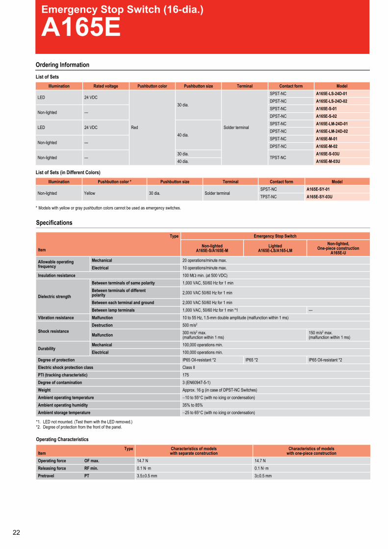
Emergency Stop Switch (16-dia.)
A165EOrdering Information
List of Sets
List of Sets (in Different Colors)
* Models with yellow or gray pushbutton colors cannot be used as emergency switches.
Illumination Rated voltage Pushbutton color Pushbutton size Terminal Contact form Model
LED 24 VDC
Red
30 dia.
Solder terminal
SPST-NC A165E-LS-24D-01DPST-NC A165E-LS-24D-02
Non-lighted ---SPST-NC A165E-S-01DPST-NC A165E-S-02
LED 24 VDC40 dia.
SPST-NC A165E-LM-24D-01DPST-NC A165E-LM-24D-02
Non-lighted ---SPST-NC A165E-M-01DPST-NC A165E-M-02
Non-lighted ---30 dia.
TPST-NCA165E-S-03U
40 dia. A165E-M-03U
Illumination Pushbutton color * Pushbutton size Terminal Contact form Model
Non-lighted Yellow 30 dia. Solder terminalSPST-NC A165E-SY-01
A165E-SY-03UTPST-NC
Specifications
*1. LED not mounted. (Test them with the LED removed.)*2. Degree of protection from the front of the panel.
Operating Characteristics
Type
Item
Emergency Stop Switch
Non-lightedA165E-S/A165E-M
LightedA165E-LS/A165-LM
Non-lighted,One-piece construction
A165E-U
Allowable operatingfrequency
Mechanical 20 operations/minute max.Electrical 10 operations/minute max.
Insulation resistance 100 MΩ min. (at 500 VDC)
Dielectric strength
Between terminals of same polarity 1,000 VAC, 50/60 Hz for 1 minBetween terminals of differentpolarity 2,000 VAC 50/60 Hz for 1 min
Between each terminal and ground 2,000 VAC 50/60 Hz for 1 minBetween lamp terminals ---1*nim1rofzH06/05,CAV000,1
Vibration resistance Malfunction 10 to 55 Hz, 1.5-mm double amplitude (malfunction within 1 ms)
Shock resistanceDestruction 500 m/s2
Malfunction 300 m/s2 max.(malfunction within 1 ms)
150 m/s2 max.(malfunction within 1 ms)
DurabilityMechanical 100,000 operations min.Electrical 100,000 operations min.
Degree of protection 2*tnatsiser-liO56PI2*56PI2*tnatsiser-liO56PIElectric shock protection class Class IIPTI (tracking characteristic) 175Degree of contamination 3 (EN60947-5-1)Weight Approx. 16 g (in case of DPST-NC Switches)Ambient operating temperature −10 to 55°C (with no icing or condensation)Ambient operating humidity 35% to 85%Ambient storage temperature −25 to 65°C (with no icing or condensation)
TypeItem
Characteristics of modelswith separate construction
Characteristics of modelswith one-piece construction
Operating force OF max. N7.41N7.41Releasing force RF min. m·N1.0m·N1.0Pretravel PT 3.5± 3mm5.0 ±0.5 mm
Key-type Selector Switch (Detachable) (Cylindrical 16-dia.)
A165KOrdering Information
Ordering as a set (Model numbers below are used to order sets of Units. One set comprises the Selector, Switch and 2 Keys.)
Ordering individually (Selectors and Switches can be ordered separately as spares for maintenance and repairs.)
Number of notches Output Reset method Key release position ModelRectangular Square Round
2 notches SPDT Manual Left A165K-J2ML-1 A165K-A2ML-1 A165K-T2ML-1Right A165K-J2MR-1 A165K-A2MR-1 A165K-T2MR-1Left and right A165K-J2M-1 A165K-A2M-1 A165K-T2M-1
Automatic Left A165K-J2AL-1 A165K-A2AL-1 A165K-T2AL-1DPDT Manual Left A165K-J2ML-2 A165K-A2ML-2 A165K-T2ML-2
Right A165K-J2MR-2 A165K-A2MR-2 A165K-T2MR-2Left and right A165K-J2M-2 A165K-A2M-2 A165K-T2M-2
Automatic Left A165K-J2AL-2 A165K-A2AL-2 A165K-T2AL-23 notches DPDT Manual Left, right and center A165K-J3M-2 A165K-A3M-2 A165K-T3M-2
Number of notches Reset method Key release position ModelRectangular Square Round
2 notches Manual Left A165K-J2ML A165K-A2ML A165K-T2MLRight A165K-J2MR A165K-A2MR A165K-T2MRLeft and right A165K-J2M A165K-A2M A165K-T2M
Automatic Left A165K-J2AL A165K-A2AL A165K-T2AL
3 notches Manual Center A165K-J3MC A165K-A3MC A165K-T3MCRight A165K-J3MR A165K-A3MR A165K-T3MRLeft A165K-J3ML A165K-A3ML A165K-T3MLLeft and right A165K-J3M A165K-A3M A165K-T3M
Automatic Center A165K-J3AC A165K-A3AC A165K-T3AC
Switches
Switches with Screw-less Clamp
Accessories
Key
Note: Two Keys are provided.
Appearance Classification Model
Switch
2 notchesSPDT
Solder terminal
A16S-2N-1
DPDTA16S-2N-2
3 notches DPDTA16S-3N-2
2 notchesSPDT
PCB terminal
A16S-2N-1P
DPDTA16S-2N-2P
Appearance Classification Model Remarks
Common tostandardload andmicroload.
DPDT
2notches
Non-lighted
A16-2S Common toones forpushbuttonswitches.
3notches
A16S-3N-2LS---
Name Appearance Classification Model Remarks
Panel Plugs
Rectangular A16ZJ-3003 Used for coveringthe panel cutoutsfor future panelexpansion.Degree ofprotection: IP40
Square A16ZA-3003
Round A16ZT-3003
Appearance ModelA165K-KEY
Specifications
Allowable operatingfrequency
Mechanical Momentary operation: 20 operations/minute max.Electrical 10 operations/minute max.
Durability Mechanical 250,000 operations min. (lift of key: 10,000 operations min.)Electrical 100,000 operations min.
Operating: -10 to 55°C (with no icing or condensation)Storage: -25 to 65°C (with no icing or condensation)Approx. 26.5 g (in the case of a DPDT switch key)Round/square: 18 × 18 × 28.5Rectangular: 24 × 18 × 28.5
Ambient temperature
WeightSize in mm (H × W × D)
Operatingcharacteristics
Key-type selector switch2 notches 3 notches
Operating force (OF) max. 9.8 NmSet position (SP) 90 ± 5° 45° + 10/0
Item Specifications
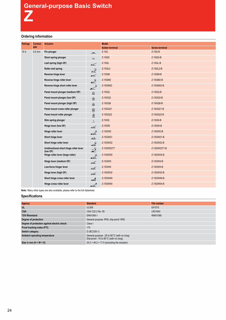
General-purpose Basic Switch
ZOrdering information
Note: Many other types are also available, please refer to the full datasheet.
Specifications
Ratings Contactgap
Actuator ModelSolder terminal Screw terminal
15 A 0.5 mm Pin plunger Z-15G Z-15G-B
Short spring plunger Z-15GD Z-15GD-B
Leaf spring (high OF) Z-15GL Z-15GL-B
Roller leaf spring Z-15GL2 Z-15GL2-B
Reverse hinge lever Z-15GM Z-15GM-B
Reverse hinge roller lever Z-15GM2 Z-15GM2-B
Reverse hinge short roller lever Z-15GM22 Z-15GM22-B
Panel mount plunger (medium OP) Z-15GQ Z-15GQ-B
Panel mount plunger (low OP) Z-15GQ3 Z-15GQ3-B
Panel mount plunger (high OP) Z-15GQ8 Z-15GQ8-B
Panel mount cross roller plunger Z-15GQ21 Z-15GQ21-B
Panel mount roller plunger Z-15GQ22 Z-15GQ22-B
Slim spring plunger Z-15GS Z-15GS-B
Hinge lever (low OF) Z-15GW Z-15GW-B
Hinge roller lever Z-15GW2 Z-15GW2-B
Short hinge lever Z-15GW21 Z-15GW21-B
Short hinge roller lever Z-15GW22 Z-15GW22-B
Unidirectional short hinge roller lever(low OF)
Z-15GW2277 Z-15GW2277-B
Hinge roller lever (large roller) Z-15GW25 Z-15GW25-B
Hinge lever (medium OF) Z-15GW3 Z-15GW3-B
Low-force hinger lever Z-15GW4 Z-15GW4-B
Hinge lever (high OF) Z-15GW32 Z-15GW32-B
Short hinge cross roller lever Z-15GW49 Z-15GW49-B
Hinge cross roller lever Z-15GW54 Z-15GW54-B
Agency Standard File numberUL UL508 E41515CSA CSA C22.2 No. 55 LR21642TÜV Rheinland EN61058-1 R9451585Degree of protection General purpose: IP00, drip-proof: IP62Degree of protection against electric shock Class IProof tracking index (PTI) 175Switch category D (IEC335-1)Ambient operating temperature General purpose: -25 to 80°C (with no icing)
Drip-proof: -15 to 80°C (with no icing)Size in mm (H × W × D) 24.2 × 49.2 × 17.5 (excluding the actuator)
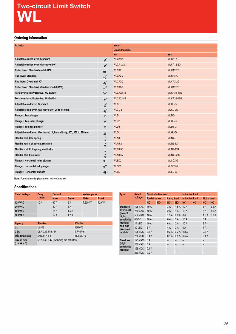
Two-circuit Limit Switch
WLOrdering information
Note: For other model please refer to the datasheet
Specifications
Actuator ModelGround terminalNo Yes
Adjustable roller lever: Standard WLCA12 WLCA12-G
Adjustable roller lever: Overtravel 90° WLCA12-2 WLCA12-2G
Roller lever: Standard model (R38) WLCA2 WLCA2-2G
Rod lever: Standard WLCA2-2 WLCA2-G
Rod lever: Overtravel 90° WLCA2-2 WLCA2-2G
Roller lever: Standard, standard model (R50) WLCA2-7 WLCA2-7G
Fork lever lock: Protective, WL-5A100 WLCA32-41 WLCA32-41G
Fork lever lock: Protective, WL-5A104 WLCA32-43 WLCA32-43G
Adjustable rod lever: Standard WLCL WLCL-G
Adjustable rod lever: Overtravel 90°, 25 to 140 mm WLCL-2 WLCL-2G
Plunger: Top plunger WLD WLDG
Plunger: Top roller plunger WLD2 WLD2-G
Plunger: Top ball plunger WLD3 WLD3-G
Adjustable rod lever: Overtravel, high sensitivity, 80°, 350 to 380 mm WLGL WLGL-G
Flexible rod: Coil spring WLNJ WLNJ-G
Flexible rod: Coil spring, resin rod WLNJ-2 WLNJ-2G
Flexible rod: Coil spring, multi-wire WLNJ-30 WLNJ-30G
Flexible rod: Steel wire WLNJ-S2 WLNJ-S2-G
Plunger: Horizontal roller plunger WLSD2 WLSD2-G
Plunger: Horizontal ball plunger WLSD3 WLSD3-G
Plunger: Horizontal plunger WLSD WLSD-G
Rated voltage Carrycurrent
Current Volt-amperesMake Break Make Break
120 VAC 10 A 60 A 6 A 7,200 VA 720 VA240 VAC 30 A 3 A480 VAC 15 A 1.5 A600 VAC 12 A 1.2 A
Agency Standard File No.UL UL508 E76675CSA CSA C22.2 No. 14 LR45746TÜV Rheinland EN60947-5-1 R9551016Size in mm(H × W × D)
68.7 × 40 × 42 (excluding the actuator)
Type Ratedvoltage
Non-inductive load Inductive loadResistive load Lamp load Inductive load Motor loadNC NO NC NO NC NO NC NO
Standard,overtravel(excepthigh-sensitivitymodels),and high-precisionmodels.
125 VAC 10 A 3 A 1.5 A 10 A 5 A 2.5 A250 VAC 10 A 2 A 1 A 10 A 3 A 1.5 A500 VAC 10 A 1.5 A 0.8 A 3 A 1.5 A 0.8 A8 VDC 10 A 6 A 3 A 10 A 6 A14 VDC 10 A 6 A 3 A 10 A 6 A30 VDC 6 A 4 A 3 A 6 A 4 A125 VDC 0.8 A 0.2 A 0.2 A 0.8 A 0.2 A250 VDC 0.4 A 0.1 A 0.1 A 0.4 A 0.1 A
Overtravel(high-sensitivitymodels)
125 VAC 5 A – – – –250 VAC 5 A – – – –125 VDC 0.4 A – – – –250 VDC 0.2 A – – – –

General-purpose Limit Switch
HL-5000Ordering information
Specifications
Application Operating forcemax. (OF)
Release forcemax. (RF)
Pre travel (PT) Over travel (OT) Movementdifferential (MD)
Operatingposition (OP)
Size in mm(H × W × D)excl. actuator
Model
Roller lever 7.35 N 0.98 N 20° 50° 12° – 82.4 × 33 × 34 HL-5000
Adjustable roller lever 7.35 N 0.98 N 20° 50° 12° – – HL-5030
Adjustable rod lever 7.35 N 0.98 N 20° 50° 12° – – HL-5050
Sealed plunger 8.83 N 1.47 N 1.5 mm 4 mm 1 mm 30 ±0.8 mm 60.6 × 33 × 34 HL-5100
Sealed roller plunger 8.83 N 1.47 N 1.5 mm 4 mm 1 mm 40 ±0.8 mm – HL-5200
Coil spring 1.47 N – 30 mm – – – – HL-5300
Ratings Non-inductive load Inductive loadRated voltage Resistive load Lamp load Inductive load Motor load
NC NO NC NO NC NO NC NO125 VAC 5 A 1.5 A 0.7 A 3 A 2 A 1 A250 VAC 5 A 1 A 0.5 A 3 A 1.5 A 0.8 A12 VDC 5 A 3 A 4 A 3 A24 VDC 5 A 3 A 4 A 3 AInrush current NC 24 A max.
NO 12 A max.Degree of protection IP65Life expectancy Mechanical: 10,000,000 operations min. (under rated conditions)Operating speed 5 mm/s to 0.5 m/s (HL-5000)Operating frequency Mechanical: 120 operations/min, electrical: 30 operations/minRated frequency 50/60 HzAmbient temperature Operating: -5 to 65°C (with no icing)Ambient humidity Operating: 95% max.Weight Approx. 130 to 190 g
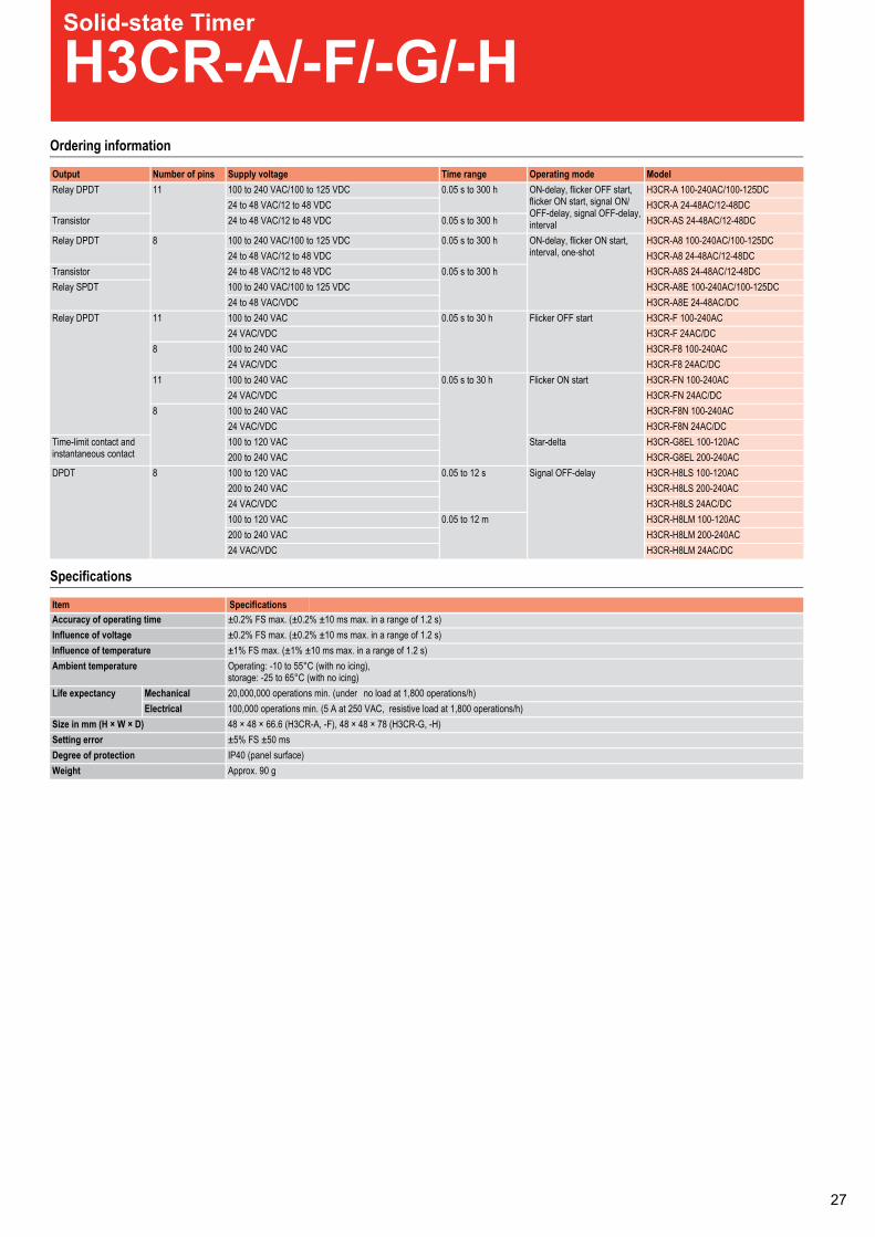
Solid-state Timer
H3CR-A/-F/-G/-HOrdering information
Specifications
Output Number of pins Supply voltage Time range Operating mode ModelRelay DPDT 11 100 to 240 VAC/100 to 125 VDC 0.05 s to 300 h ON-delay, flicker OFF start,
flicker ON start, signal ON/OFF-delay, signal OFF-delay,interval
H3CR-A 100-240AC/100-125DC24 to 48 VAC/12 to 48 VDC H3CR-A 24-48AC/12-48DC
Transistor 24 to 48 VAC/12 to 48 VDC 0.05 s to 300 h H3CR-AS 24-48AC/12-48DC
Relay DPDT 8 100 to 240 VAC/100 to 125 VDC 0.05 s to 300 h ON-delay, flicker ON start,interval, one-shot
H3CR-A8 100-240AC/100-125DC24 to 48 VAC/12 to 48 VDC H3CR-A8 24-48AC/12-48DC
Transistor 24 to 48 VAC/12 to 48 VDC 0.05 s to 300 h H3CR-A8S 24-48AC/12-48DCRelay SPDT 100 to 240 VAC/100 to 125 VDC H3CR-A8E 100-240AC/100-125DC
24 to 48 VAC/VDC H3CR-A8E 24-48AC/DCRelay DPDT 11 100 to 240 VAC 0.05 s to 30 h Flicker OFF start H3CR-F 100-240AC
24 VAC/VDC H3CR-F 24AC/DC8 100 to 240 VAC H3CR-F8 100-240AC
24 VAC/VDC H3CR-F8 24AC/DC11 100 to 240 VAC 0.05 s to 30 h Flicker ON start H3CR-FN 100-240AC
24 VAC/VDC H3CR-FN 24AC/DC8 100 to 240 VAC H3CR-F8N 100-240AC
24 VAC/VDC H3CR-F8N 24AC/DCTime-limit contact andinstantaneous contact
100 to 120 VAC Star-delta H3CR-G8EL 100-120AC200 to 240 VAC H3CR-G8EL 200-240AC
DPDT 8 100 to 120 VAC 0.05 to 12 s Signal OFF-delay H3CR-H8LS 100-120AC200 to 240 VAC H3CR-H8LS 200-240AC24 VAC/VDC H3CR-H8LS 24AC/DC100 to 120 VAC 0.05 to 12 m H3CR-H8LM 100-120AC200 to 240 VAC H3CR-H8LM 200-240AC24 VAC/VDC H3CR-H8LM 24AC/DC
Accuracy of operating time ±0.2% FS max. (±0.2% ±10 ms max. in a range of 1.2 s)Influence of voltage ±0.2% FS max. (±0.2% ±10 ms max. in a range of 1.2 s)Influence of temperature ±1% FS max. (±1% ±10 ms max. in a range of 1.2 s)Ambient temperature Operating: -10 to 55°C (with no icing),
storage: -25 to 65°C (with no icing)Life expectancy Mechanical 20,000,000 operations min. (under no load at 1,800 operations/h)
Electrical 100,000 operations min. (5 A at 250 VAC, resistive load at 1,800 operations/h)Size in mm (H × W × D) 48 × 48 × 66.6 (H3CR-A, -F), 48 × 48 × 78 (H3CR-G, -H)Setting error ±5% FS ±50 msDegree of protection IP40 (panel surface)Weight Approx. 90 g
Item Specifications
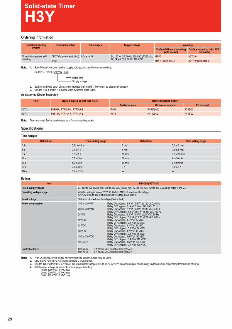
Solid-state Timer
H3YOrdering Information
Note: 1. Specify both the model number, supply voltage, and rated time when ordering.
2. Sockets and Hold-down Clips are not included with the H3Y. They must be ordered separately.3. Use the H3Y-4 or H3Y-4-0 Series when switching micro loads.
Accessories (Order Separately)
Note: Track-mounted Socket can be used as a front-connecting socket.
Specifications
Time Ranges
Ratings
Note: 1.2.
With DC ratings, single-phase full-wave rectified power sources may be used.
3.Only the H3Y-2 and H3Y-2-0 Series include 2-VDC models.
4.Use the Timer within 90% to 110% of the rated supply voltage (95% to 110% for 12 VDC) when using it continuously under an ambient operating temperature of 50°C.Set the reset voltage as follows to ensure proper resetting.
100 to 120 VAC:10 VAC max.200 to 230 VAC:20 VAC max.100 to 110 VDC:10 VDC max.
Operation/resettingsystem
Time-limit contact Time ranges Supply voltage MountingSurface/DIN-track mounting
(with socket)Surface mounting (with PCB
terminals)Time-limit operation/ self-resetting
DPDT (for power switching) 0.04 s to 3 h 24, 100 to 120, 200 to 230 VAC (50/60 Hz);12, 24, 48, 125, 100 to 110 VDC
H3Y-2 H3Y-2-04PDT H3Y-4 (See note 3.) H3Y-4-0 (See note 3.)
Ex. H3Y-2 100 to 120 VAC 0.5 s
Rated timeSupply voltage
Timer Track-mounted Socket (See note.) Back-connecting SocketSolder terminal Wire-wrap terminal PC terminal
20-80YP)2(NQ80YP80YPE-A80FYP,N-A80FYP,A80FYP2-Y3H20-41YP)2(NQ41YP41YPE-A41FYP,N-A41FYP,A41FYP4-Y3H
Rated time Time setting range Rated time Time setting rangenim3ot1.0nim3s5.0ot40.0s5.0nim5ot2.0nim5s1ot1.0s1nim01ot5.0nim01s5ot2.0s5
nim03ot1nim03s01ot5.0s01nim06ot2nim06s03ot0.1s03
h3ot1.0h3s06ot0.2s06------s021ot0.5s021
Item H3Y-2(-0)/H3Y-4(-0)Rated supply voltage 24, 100 to 120 (50/60 Hz), 200 to 230 VAC (50/60 Hz), 12, 24, 48, 125, 100 to 110 VDC (See notes 1 and 2.)Operating voltage range All rated voltages except 12 VDC: 85% to 110% of rated supply voltage
12 VDC: 90% to 110% of rated supply voltage (See note 3.)Reset voltage 10% min. of rated supply voltage (See note 4.)Power consumption 100 to 120 VAC: Relay ON: Approx. 1.8 VA (1.6 W) at 120 VAC, 60 Hz
Relay OFF:approx. 1 VA (0.6 W) at 120 VAC, 60 Hz200 to 230 VAC: Relay ON: Approx. 2.2 VA (1.8 W) at 230 VAC, 60 Hz
Relay OFF: Approx. 1.5 VA (1.1 W) at 230 VAC, 60 Hz24 VAC: Relay ON: Approx. 1.8 VA (1.4 W) at 24 VAC, 60 Hz
Relay OFF: Approx. 0.3 VA (0.2 W) at 24 VAC, 60 Hz12 VDC: Relay ON: Approx. 1.1 W at 12 VDC
Relay OFF: Approx. 0.1 W at 12 VDC24 VDC: Relay ON: Approx. 1.1 W at 24 VDC
Relay OFF: Approx. 0.1 W at 24 VDC48 VDC: Relay ON: Approx. 1.2 W at 48 VDC
Relay OFF: Approx. 0.3 W at 48 VDC100 to 110 VDC: Relay ON: Approx. 1.6 W at 110 VDC
Relay OFF: Approx. 0.4 W at 110 VDC125 VDC: Relay ON: Approx. 1.6 W at 125 VDC
Relay OFF: Approx. 0.4 W at 125 VDCControl outputs H3Y-2(-0): 5 A at 250 VAC, resistive load (cosφ = 1)
H3Y-4(-0): 3 A at 250 VAC, resistive load (cosφ = 1)
Solid-state Timer
H3DEOrdering information
Specifications
Type Supply voltage Control output Time setting range Operating modes ModelMulti-functionalstandard timers
12 VDC DPDT 0.1 s to 120 h ON-delay, flicker OFF start, flicker ON start, signal ON/OFF-de-lay, signal OFF-delay, interval, one-shot
H3DE-M2 DC12 *1
*1 One output can be set to instantaneous.
24 to 230 VAC/VDC SPDT H3DE-M1 AC/DC24-230DPDT H3DE-M2 AC/DC24-230 *1
SPDT ON-delay, flicker ON start, interval,one-shot
H3DE-S1 AC/DC24-230DPDT H3DE-S2 AC/DC24-230 *1
Twin timer SPDT 0.1 s to 12 h Flicker OFF start, flicker ON start H3DE-F AC/DC24-230Star-delta timer 2x SPDT 1 to 120 s Star-delta H3DE-G AC/DC24-230Power OFF-delay timer 24 VAC/VDC SPDT 1 to 120 s Signal OFF-delay H3DE-H AC/DC24 L
0.1 to 12 s H3DE-H AC/DC24 S48 VAC/VDC 1 to 120 s H3DE-H AC/DC48 L
0.1 to 12 s H3DE-H AC/DC48 S100 to 120 VAC 1 to 120 s H3DE-H AC100-120 L
0.1 to 12 s H3DE-H AC100-120 S200 to 230 VAC 1 to 120 s H3DE-H AC200-230 L
0.1 to 12 s H3DE-H AC200-230 S
Terminal block Clamps two 2.5 mm² max. bar terminals without sleevesMounting method DIN-rail mountingOperating voltage range 85 to 110% of rated supply voltagePower reset Minimum power-off time: H3DE-M/S, H3DE-F: 0.1 s, H3DE-G: 0.5 sReset voltage 2.4 VAC/VDC max. (not for H3DE-H)Voltage input (H3DE-M/-S) Max. permissible capacitance between input lines (terminals B1 and A2): 2,000 pF
Load connectable in parallel with inputs (terminals B1 and A2)H-level: 20.4 to 253 VAC/VDC, L-level: 0 to 2.4 VAC/VDC
Control output Contact output: 5 A at 250 VAC with resistive load (cos φ = 1), 5 A at 30 VDC with resistive load (cos φ = 1)Ambient temperature Operating: -10 to 55°C (with no icing), storage: -25 to 65°C (with no icing)Accuracy of operating time ±1% max. of FS (±1% ±10 ms max. at 1.2 s range)Setting error ±10% ±0.05 s max. of FSSignal input time 50 ms min.Influence of voltage ±0.5% max. of FSInfluence of temperature ±2% max. of FSContact material AGNi+gold platingLife expectancy Mechanical: 10 million operations min. (under no load at 1,800 operations/h)
Electrical: 100,000 operations min. (5 A at 250 VAC, resistive load at 360 operations/h)Degree of protection IP30 (terminal block: IP20)Size in mm (H × W × D) 79 × 22.5 × 100
Item Specifications

Solid-state Timer
H3JAOrdering Information
Note: Specify the model number, supply voltage, and rated time when ordering.
Specifications
Time Ranges
Ratings
Operation/resetting system Time-limit contact Mounting method Rated time Model
Time-limit operation/self-resetting
,gnitnuomecafruSTDPS flush mounting,and DIN track mounting
1 s, 3 s, 5 s, 10 s, 30 s, 60 s, 3 min, 5min, 10 min, 30 min, 60 min, 3 hrs
H3JA-8A
DPDT H3JA-8C
Ex. H3JA-8A 100 to 120 VAC 1 s
Rated time
Supply voltage
Rated time Time range Rated time Time range
nim3ot3.0nim3s1ot1.0s1
nim5ot5.0nim5s3ot3.0s3
nim01ot1nim01s5ot5.0s5
nim03ot3nim03s01ot1s01
nim06ot6nim06s03ot3s03
srh3ot3.0srh3s06ot6s06
Rated supply voltage 24, 100 to 120 or 200 to 240 VAC (50/60 Hz);12, 24 VDC
Operating voltage range 85% to 110% of rated supply voltage
Power consumption H3JA-8A100 to 120 VAC: Approx. 2.6 VA (1.1 W) at 120 VAC200 to 240 VAC: Approx. 5.0 VA (1.5 W) at 240 VAC24 VAC: Approx. 1.0 VA (0.9 W) at 24 VAC24 VDC: Approx. 0.8 W at 24 VDC12 VDC: Approx. 0.5 W at 12 VDCH3JA-8C100 to 120 VAC: Approx. 2.4 VA (0.9 W) at 120 VAC200 to 240 VAC: Approx. 4.1 VA (1.1 W) at 240 VAC24 VAC: Approx. 1.2 VA (1.0 W) at 24 VAC24 VDC: Approx. 0.8 W at 24 VDC
Control outputs H3JA-8A: 7 A at 250 VAC, resistive loadH3JA-8C: 5 A at 250 VAC, resistive load
Item Specifications
0
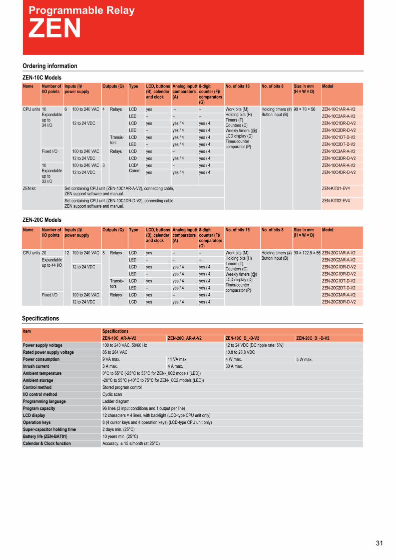
Solid-state Timer
H3JAOrdering Information
Note: Specify the model number, supply voltage, and rated time when ordering.
Specifications
Time Ranges
Ratings
Operation/resetting system Time-limit contact Mounting method Rated time Model
Time-limit operation/self-resetting
,gnitnuomecafruSTDPS flush mounting,and DIN track mounting
1 s, 3 s, 5 s, 10 s, 30 s, 60 s, 3 min, 5min, 10 min, 30 min, 60 min, 3 hrs
H3JA-8A
DPDT H3JA-8C
Ex. H3JA-8A 100 to 120 VAC 1 s
Rated time
Supply voltage
Rated time Time range Rated time Time range
nim3ot3.0nim3s1ot1.0s1
nim5ot5.0nim5s3ot3.0s3
nim01ot1nim01s5ot5.0s5
nim03ot3nim03s01ot1s01
nim06ot6nim06s03ot3s03
srh3ot3.0srh3s06ot6s06
Rated supply voltage 24, 100 to 120 or 200 to 240 VAC (50/60 Hz);12, 24 VDC
Operating voltage range 85% to 110% of rated supply voltage
Power consumption H3JA-8A100 to 120 VAC: Approx. 2.6 VA (1.1 W) at 120 VAC200 to 240 VAC: Approx. 5.0 VA (1.5 W) at 240 VAC24 VAC: Approx. 1.0 VA (0.9 W) at 24 VAC24 VDC: Approx. 0.8 W at 24 VDC12 VDC: Approx. 0.5 W at 12 VDCH3JA-8C100 to 120 VAC: Approx. 2.4 VA (0.9 W) at 120 VAC200 to 240 VAC: Approx. 4.1 VA (1.1 W) at 240 VAC24 VAC: Approx. 1.2 VA (1.0 W) at 24 VAC24 VDC: Approx. 0.8 W at 24 VDC
Control outputs H3JA-8A: 7 A at 250 VAC, resistive loadH3JA-8C: 5 A at 250 VAC, resistive load
Item Specifications
Programmable Relay
ZENOrdering informationZEN-10C Models
Specifications
Name Number ofI/O points
Inputs (I)/power supply
Outputs (Q) Type LCD, buttons(B), calendarand clock
Analog input/comparators(A)
8-digitcounter (F)/comparators(G)
No. of bits 16 No. of bits 8 Size in mm(H × W × D)
Model
CPU units 10Expandableup to34 I/O
6 100 to 240 VAC 4 Relays LCD yes – – Work bits (M)Holding bits (H)Timers (T)Counters (C)Weekly timers (@)LCD display (D)Timer/countercomparator (P)
Holding timers (#)Button input (B)
90 × 70 × 56 ZEN-10C1AR-A-V2LED – – – ZEN-10C2AR-A-V2
12 to 24 VDC LCD yes yes / 4 yes / 4 ZEN-10C1DR-D-V2LED – yes / 4 yes / 4 ZEN-10C2DR-D-V2
Transis-tors
LCD yes yes / 4 yes / 4 ZEN-10C1DT-D-V2LED – yes / 4 yes / 4 ZEN-10C2DT-D-V2
Fixed I/O 100 to 240 VAC Relays LCD yes – yes / 4 ZEN-10C3AR-A-V212 to 24 VDC LCD yes yes / 4 yes / 4 ZEN-10C3DR-D-V2
10Expandableup to33 I/O
100 to 240 VAC 3 LCD/Comm.
yes – yes / 4 ZEN-10C4AR-A-V212 to 24 VDC yes yes / 4 yes / 4 ZEN-10C4DR-D-V2
ZEN kit Set containing CPU unit (ZEN-10C1AR-A-V2), connecting cable,ZEN support software and manual.
ZEN-KIT01-EV4
Set containing CPU unit (ZEN-10C1DR-D-V2), connecting cable,ZEN support software and manual.
ZEN-KIT02-EV4
Item SpecificationsZEN-10C_AR-A-V2 ZEN-10C_D_-D-V2
Power supply voltage 100 to 240 VAC, 50/60 Hz 12 to 24 VDC (DC ripple rate: 5%)Rated power supply voltage 85 to 264 VAC 10.8 to 28.8 VDCPower consumption 9 VA max. 4 W max.Inrush current 3 A max. 30 A max.Ambient temperature 0°C to 55°C (-25°C to 55°C for ZEN-_0C2 models (LED))Ambient storage -20°C to 55°C (-40°C to 75°C for ZEN-_0C2 models (LED))Control method Stored program controlI/O control method Cyclic scanProgramming language Ladder diagramProgram capacity 96 lines (3 input conditions and 1 output per line)LCD display 12 characters × 4 lines, with backlight (LCD-type CPU unit only)Operation keys 8 (4 cursor keys and 4 operation keys) (LCD-type CPU unit only)Super-capacitor holding time 2 days min. (25°C)Battery life (ZEN-BAT01) 10 years min. (25°C)Calendar & Clock function Accuracy: ± 15 s/month (at 25°C)
Name Number ofI/O points
Inputs (I)/power supply
Outputs (Q) Type LCD, buttons(B), calendarand clock
Analog input/comparators(A)
8-digitcounter (F)/comparators(G)
No. of bits 16 No. of bits 8 Size in mm(H × W × D)
Model
CPU units 20 12 100 to 240 VAC 8 Relays LCD yes – – Work bits (M)Holding bits (H)Timers (T)Counters (C)Weekly timers (@)LCD display (D)Timer/countercomparator (P)
Holding timers (#)Button input (B)
90 × 122.5 × 56 ZEN-20C1AR-A-V2Expandableup to 44 I/O
LED – – – ZEN-20C2AR-A-V212 to 24 VDC LCD yes yes / 4 yes / 4 ZEN-20C1DR-D-V2
LED – yes / 4 yes / 4 ZEN-20C1DR-D-V2Transis-tors
LCD yes yes / 4 yes / 4 ZEN-20C1DT-D-V2LED – yes / 4 yes / 4 ZEN-20C2DT-D-V2
Fixed I/O 100 to 240 VAC Relays LCD yes – yes / 4 ZEN-20C3AR-A-V212 to 24 VDC LCD yes yes / 4 yes / 4 ZEN-20C3DR-D-V2
ZEN-20C Models
ZEN-20C_AR-A-V2 ZEN-20C_D_-D-V2
11 VA max.4 A max.
5 W max.
1
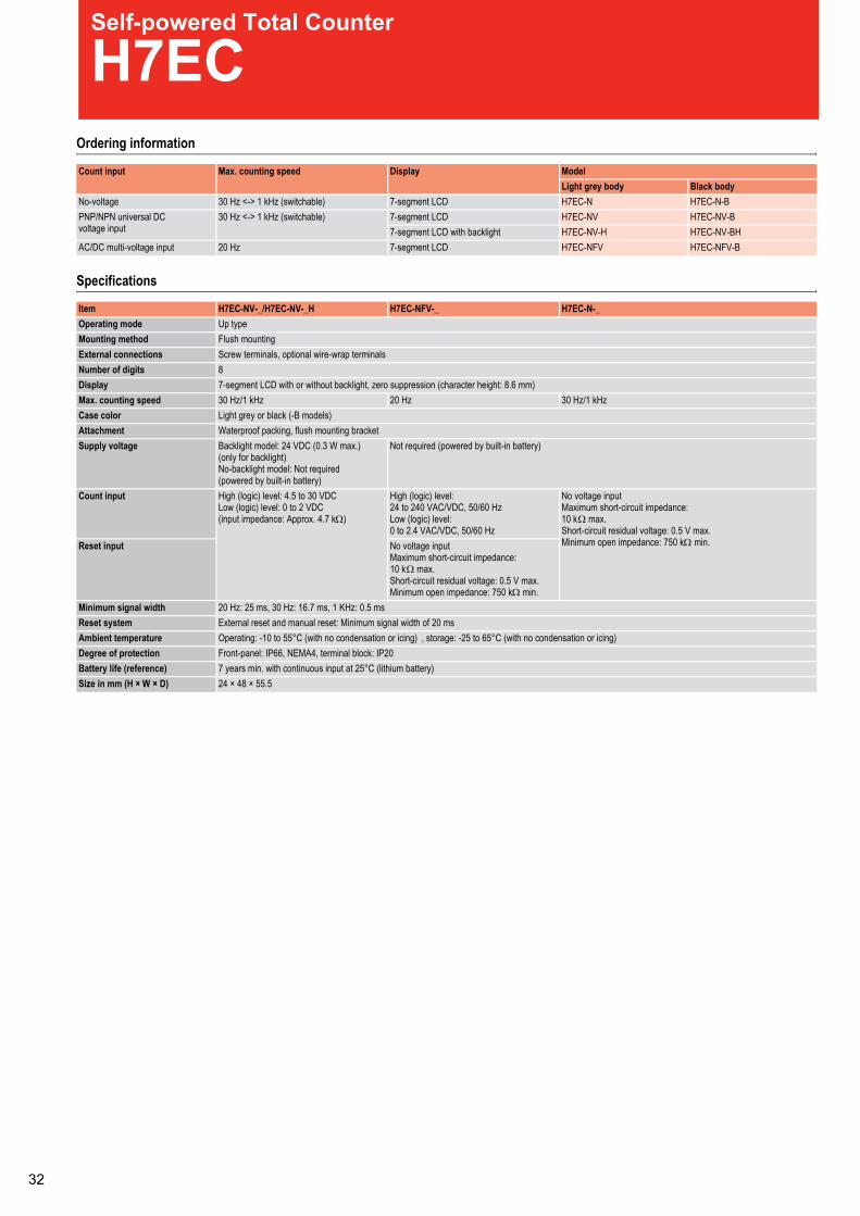
Self-powered Total Counter
H7ECOrdering information
Specifications
Count input Max. counting speed Display ModelLight grey body Black body
No-voltage 30 Hz <-> 1 kHz (switchable) 7-segment LCD H7EC-N H7EC-N-BPNP/NPN universal DCvoltage input
30 Hz <-> 1 kHz (switchable) 7-segment LCD H7EC-NV H7EC-NV-B7-segment LCD with backlight H7EC-NV-H H7EC-NV-BH
AC/DC multi-voltage input 20 Hz 7-segment LCD H7EC-NFV H7EC-NFV-B
Item H7EC-NV-_/H7EC-NV-_H H7EC-NFV-_ H7EC-N-_Operating mode Up typeMounting method Flush mountingExternal connections Screw terminals, optional wire-wrap terminalsNumber of digits 8Display 7-segment LCD with or without backlight, zero suppression (character height: 8.6 mm)Max. counting speed 30 Hz/1 kHz 20 Hz 30 Hz/1 kHzCase color Light grey or black (-B models)Attachment Waterproof packing, flush mounting bracketSupply voltage Backlight model: 24 VDC (0.3 W max.)
(only for backlight)No-backlight model: Not required(powered by built-in battery)
Not required (powered by built-in battery)
Count input High (logic) level: 4.5 to 30 VDCLow (logic) level: 0 to 2 VDC(input impedance: Approx. 4.7 kΩ)
High (logic) level:24 to 240 VAC/VDC, 50/60 HzLow (logic) level:0 to 2.4 VAC/VDC, 50/60 Hz
No voltage inputMaximum short-circuit impedance:10 kΩ max.Short-circuit residual voltage: 0.5 V max.Minimum open impedance: 750 kΩ min.Reset input No voltage input
Maximum short-circuit impedance:10 kΩ max.Short-circuit residual voltage: 0.5 V max.Minimum open impedance: 750 kΩ min.
Minimum signal width 20 Hz: 25 ms, 30 Hz: 16.7 ms, 1 KHz: 0.5 msReset system External reset and manual reset: Minimum signal width of 20 msAmbient temperature Operating: -10 to 55°C (with no condensation or icing) , storage: -25 to 65°C (with no condensation or icing)Degree of protection Front-panel: IP66, NEMA4, terminal block: IP20Battery life (reference) 7 years min. with continuous input at 25°C (lithium battery)Size in mm (H × W × D) 24 × 48 × 55.5
PCB-mounting Counter
H7E@-N@POrdering Information
PC Board-use Counters
Specifications
General
Ratings
Note: ON/OFF ratio 1:1
Count input Display Total counter Time counterMax. counting speed
1 kHz 30 HzPN-TE7HPLN-CE7HPN-CE7HDCLtnemges-7tupniegatlov-oN
Item Total Counter Time CounterH7EC-NP H7EC-NLP H7ET-NP
Operating mode Up typeMounting method Direct mounting on PC Board or mounting on 28-pin socketReset External reset, Power-OFF resetNumber of digits 8 7Time range --- 0.0h to 999999.9hMax. counting speed ---zH03zHk1Count/Timer input No-voltage inputDisplay 7-segment LCD (character height: 8.6 mm)Case color TransparentApproved standard UL863, CSA C22.2 No.14
Item H7EC-NPH7EC-NLP
H7ET-NP
Supply voltage 3 VDC (2.7 to 3.3 VDC)Count/Timer input No voltage input
Maximum short-circuit impedance: 10 kΩ max.Short-circuit residual voltage: 0.5 V max.Minimum open impedance: 750 kΩ min.
Reset input
Max. counting speed (see note) 1 kHz: Minimum signal width of 0.5 ms30 Hz: Minimum signal width of 16.7 ms
---
Minimum signal input width s1---Reset system External reset: Minimum signal width of 20 ms
Power-OFF reset: Minimum power OFF time of 500 msAmbient temperature Operating: –10°C to 55°C (with no condensation or icing)
Storage: –25°C to 65°C (with no condensation or icing)Ambient humidity Operating: 25% to 85%
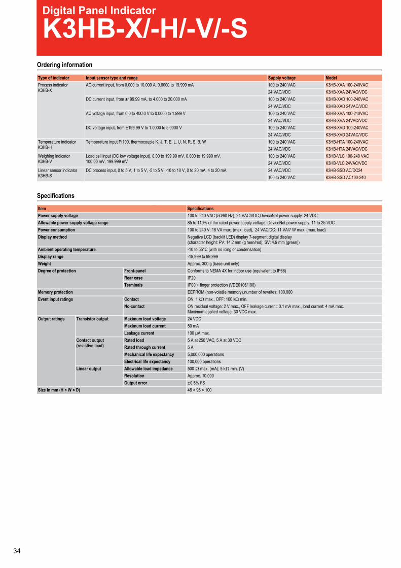
Ordering information
Type of indicator Input sensor type and range Supply voltage ModelProcess indicatorK3HB-X
AC current input, from 0.000 to 10.000 A, 0.0000 to 19.999 mA 100 to 240 VAC K3HB-XAA 100-240VAC24 VAC/VDC K3HB-XAA 24VAC/VDC
DC current input, from ±199.99 mA, to 4.000 to 20.000 mA 100 to 240 VAC K3HB-XAD 100-240VAC24 VAC/VDC K3HB-XAD 24VAC/VDC
AC voltage input, from 0.0 to 400.0 V to 0.0000 to 1.999 V 100 to 240 VAC K3HB-XVA 100-240VAC24 VAC/VDC K3HB-XVA 24VAC/VDC
DC voltage input, from ±199.99 V to 1.0000 to 5.0000 V 100 to 240 VAC K3HB-XVD 100-240VAC24 VAC/VDC K3HB-XVD 24VAC/VDC
Temperature indicatorK3HB-H
Temperature input Pt100, thermocouple K, J, T, E, L, U, N, R, S, B, W 100 to 240 VAC K3HB-HTA 100-240VAC24 VAC/VDC K3HB-HTA 24VAC/VDC
Weighing indicatorK3HB-V
Load cell input (DC low voltage input), 0.00 to 199.99 mV, 0.000 to 19.999 mV,100.00 mV, 199.999 mV
100 to 240 VAC K3HB-VLC 100-240 VAC24 VAC/VDC K3HB-VLC 24VAC/VDC
Linear sensor indicatorK3HB-S
DC process input, 0 to 5 V, 1 to 5 V, -5 to 5 V, -10 to 10 V, 0 to 20 mA, 4 to 20 mA 24 VAC/VDC K3HB-SSD AC/DC24100 to 240 VAC K3HB-SSD AC100-240
Specifications
Power supply voltage 100 to 240 VAC (50/60 Hz), 24 VAC/VDC,DeviceNet power supply: 24 VDCAllowable power supply voltage range 85 to 110% of the rated power supply voltage, DeviceNet power supply: 11 to 25 VDCPower consumption 100 to 240 V: 18 VA max. (max. load), 24 VAC/DC: 11 VA/7 W max. (max. load)Display method Negative LCD (backlit LED) display 7-segment digital display
(character height: PV: 14.2 mm (g reen/red); SV: 4.9 mm (green))Ambient operating temperature -10 to 55°C (with no icing or condensation)Display range -19,999 to 99,999Weight Approx. 300 g (base unit only)Degree of protection Front-panel Conforms to NEMA 4X for indoor use (equivalent to IP66)
Rear case IP20Terminals IP00 + finger protection (VDE0106/100)
Memory protection EEPROM (non-volatile memory),number of rewrites: 100,000Event input ratings Contact ON: 1 kΩ max., OFF: 100 kΩ min.
No-contact ON residual voltage: 2 V max., OFF leakage current: 0.1 mA max., load current: 4 mA max.Maximum applied voltage: 30 VDC max.
Output ratings Transistor output Maximum load voltage 24 VDCMaximum load current 50 mALeakage current 100 µA max.
Contact output(resistive load)
Rated load 5 A at 250 VAC, 5 A at 30 VDCRated through current 5 AMechanical life expectancy 5,000,000 operationsElectrical life expectancy 100,000 operations
Linear output Allowable load impedance 500 Ω max. (mA); 5 kΩ min. (V)Resolution Approx. 10,000Output error ±0.5% FS
Size in mm (H × W × D) 48 × 96 × 100
Item Specifications
Digital Panel Indicator
K3HB-X/-H/-V/-S
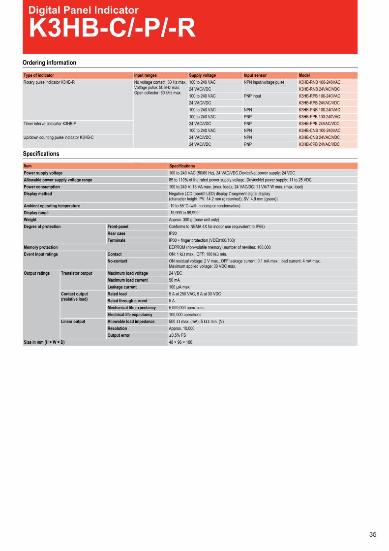
Ordering information
Type of indicator Input sensor type and range Supply voltage ModelProcess indicatorK3HB-X
AC current input, from 0.000 to 10.000 A, 0.0000 to 19.999 mA 100 to 240 VAC K3HB-XAA 100-240VAC24 VAC/VDC K3HB-XAA 24VAC/VDC
DC current input, from ±199.99 mA, to 4.000 to 20.000 mA 100 to 240 VAC K3HB-XAD 100-240VAC24 VAC/VDC K3HB-XAD 24VAC/VDC
AC voltage input, from 0.0 to 400.0 V to 0.0000 to 1.999 V 100 to 240 VAC K3HB-XVA 100-240VAC24 VAC/VDC K3HB-XVA 24VAC/VDC
DC voltage input, from ±199.99 V to 1.0000 to 5.0000 V 100 to 240 VAC K3HB-XVD 100-240VAC24 VAC/VDC K3HB-XVD 24VAC/VDC
Temperature indicatorK3HB-H
Temperature input Pt100, thermocouple K, J, T, E, L, U, N, R, S, B, W 100 to 240 VAC K3HB-HTA 100-240VAC24 VAC/VDC K3HB-HTA 24VAC/VDC
Weighing indicatorK3HB-V
Load cell input (DC low voltage input), 0.00 to 199.99 mV, 0.000 to 19.999 mV,100.00 mV, 199.999 mV
100 to 240 VAC K3HB-VLC 100-240 VAC24 VAC/VDC K3HB-VLC 24VAC/VDC
Linear sensor indicatorK3HB-S
DC process input, 0 to 5 V, 1 to 5 V, -5 to 5 V, -10 to 10 V, 0 to 20 mA, 4 to 20 mA 24 VAC/VDC K3HB-SSD AC/DC24100 to 240 VAC K3HB-SSD AC100-240
Specifications
Power supply voltage 100 to 240 VAC (50/60 Hz), 24 VAC/VDC,DeviceNet power supply: 24 VDCAllowable power supply voltage range 85 to 110% of the rated power supply voltage, DeviceNet power supply: 11 to 25 VDCPower consumption 100 to 240 V: 18 VA max. (max. load), 24 VAC/DC: 11 VA/7 W max. (max. load)Display method Negative LCD (backlit LED) display 7-segment digital display
(character height: PV: 14.2 mm (g reen/red); SV: 4.9 mm (green))Ambient operating temperature -10 to 55°C (with no icing or condensation)Display range -19,999 to 99,999Weight Approx. 300 g (base unit only)Degree of protection Front-panel Conforms to NEMA 4X for indoor use (equivalent to IP66)
Rear case IP20Terminals IP00 + finger protection (VDE0106/100)
Memory protection EEPROM (non-volatile memory),number of rewrites: 100,000Event input ratings Contact ON: 1 kΩ max., OFF: 100 kΩ min.
No-contact ON residual voltage: 2 V max., OFF leakage current: 0.1 mA max., load current: 4 mA max.Maximum applied voltage: 30 VDC max.
Output ratings Transistor output Maximum load voltage 24 VDCMaximum load current 50 mALeakage current 100 µA max.
Contact output(resistive load)
Rated load 5 A at 250 VAC, 5 A at 30 VDCRated through current 5 AMechanical life expectancy 5,000,000 operationsElectrical life expectancy 100,000 operations
Linear output Allowable load impedance 500 Ω max. (mA); 5 kΩ min. (V)Resolution Approx. 10,000Output error ±0.5% FS
Size in mm (H × W × D) 48 × 96 × 100
Item Specifications
Digital Panel Indicator
K3HB-X/-H/-V/-SOrdering information
Type of indicator Input ranges Supply voltage Input sensor ModelRotary pulse indicator K3HB-R No voltage contact: 30 Hz max.
Voltage pulse: 50 kHz max.Open collector: 50 kHz max.
100 to 240 VAC NPN input/voltage pulse K3HB-RNB 100-240VAC24 VAC/VDC K3HB-RNB 24VAC/VDC100 to 240 VAC PNP input K3HB-RPB 100-240VAC24 VAC/VDC K3HB-RPB 24VAC/VDC100 to 240 VAC NPN K3HB-PNB 100-240VAC100 to 240 VAC PNP K3HB-PPB 100-240VAC
Timer interval indicator K3HB-P 24 VAC/VDC PNP K3HB-PPB 24VAC/VDC100 to 240 VAC NPN K3HB-CNB 100-240VAC
Up/down counting pulse indicator K3HB-C 24 VAC/VDC NPN K3HB-CNB 24VAC/VDC24 VAC/VDC PNP K3HB-CPB 24VAC/VDC
Specifications
Power supply voltage 100 to 240 VAC (50/60 Hz), 24 VAC/VDC,DeviceNet power supply: 24 VDCAllowable power supply voltage range 85 to 110% of the rated power supply voltage, DeviceNet power supply: 11 to 25 VDCPower consumption 100 to 240 V: 18 VA max. (max. load), 24 VAC/DC: 11 VA/7 W max. (max. load)Display method Negative LCD (backlit LED) display 7-segment digital display
(character height: PV: 14.2 mm (g reen/red); SV: 4.9 mm (green))Ambient operating temperature -10 to 55°C (with no icing or condensation)Display range -19,999 to 99,999Weight Approx. 300 g (base unit only)Degree of protection Front-panel Conforms to NEMA 4X for indoor use (equivalent to IP66)
Rear case IP20Terminals IP00 + finger protection (VDE0106/100)
Memory protection EEPROM (non-volatile memory),number of rewrites: 100,000Event input ratings Contact ON: 1 kΩ max., OFF: 100 kΩ min.
No-contact ON residual voltage: 2 V max., OFF leakage current: 0.1 mA max., load current: 4 mA max.Maximum applied voltage: 30 VDC max.
Output ratings Transistor output Maximum load voltage 24 VDCMaximum load current 50 mALeakage current 100 µA max.
Contact output(resistive load)
Rated load 5 A at 250 VAC, 5 A at 30 VDCRated through current 5 AMechanical life expectancy 5,000,000 operationsElectrical life expectancy 100,000 operations
Linear output Allowable load impedance 500 Ω max. (mA); 5 kΩ min. (V)Resolution Approx. 10,000Output error ±0.5% FS
Size in mm (H × W × D) 48 × 96 × 100
Item Specifications
Digital Panel Indicator
K3HB-C/-P/-R
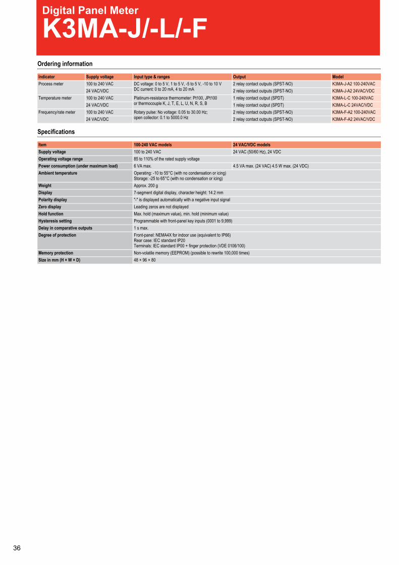
Ordering information
Specifications
Indicator Supply voltage Input type & ranges Output ModelProcess meter 100 to 240 VAC DC voltage: 0 to 5 V, 1 to 5 V, -5 to 5 V, -10 to 10 V
DC current: 0 to 20 mA, 4 to 20 mA2 relay contact outputs (SPST-NO) K3MA-J-A2 100-240VAC
24 VAC/VDC 2 relay contact outputs (SPST-NO) K3MA-J-A2 24VAC/VDCTemperature meter 100 to 240 VAC Platinum-resistance thermometer: Pt100, JPt100
or thermocouple K, J, T, E, L, U, N, R, S, B1 relay contact output (SPDT) K3MA-L-C 100-240VAC
24 VAC/VDC 1 relay contact output (SPDT) K3MA-L-C 24VAC/VDCFrequency/rate meter 100 to 240 VAC Rotary pulse: No voltage: 0.05 to 30.00 Hz;
open collector: 0.1 to 5000.0 Hz2 relay contact outputs (SPST-NO) K3MA-F-A2 100-240VAC
24 VAC/VDC 2 relay contact outputs (SPST-NO) K3MA-F-A2 24VAC/VDC
Item 100-240 VAC models 24 VAC/VDC modelsSupply voltage 100 to 240 VAC 24 VAC (50/60 Hz), 24 VDCOperating voltage range 85 to 110% of the rated supply voltagePower consumption (under maximum load) 6 VA max. 4.5 VA max. (24 VAC) 4.5 W max. (24 VDC)Ambient temperature Operating: -10 to 55°C (with no condensation or icing)
Storage: -25 to 65°C (with no condensation or icing)Weight Approx. 200 gDisplay 7-segment digital display, character height: 14.2 mmPolarity display "-" is displayed automatically with a negative input signalZero display Leading zeros are not displayedHold function Max. hold (maximum value), min. hold (minimum value)Hysteresis setting Programmable with front-panel key inputs (0001 to 9,999)Delay in comparative outputs 1 s max.Degree of protection Front-panel: NEMA4X for indoor use (equivalent to IP66)
Rear case: IEC standard IP20Terminals: IEC standard IP00 + finger protection (VDE 0106/100)
Memory protection Non-volatile memory (EEPROM) (possible to rewrite 100,000 times)Size in mm (H × W × D) 48 × 96 × 80
Digital Panel Meter
K3MA-J/-L/-F

Ordering information
Specifications
Indicator Supply voltage Input type & ranges Output ModelProcess meter 100 to 240 VAC DC voltage: 0 to 5 V, 1 to 5 V, -5 to 5 V, -10 to 10 V
DC current: 0 to 20 mA, 4 to 20 mA2 relay contact outputs (SPST-NO) K3MA-J-A2 100-240VAC
24 VAC/VDC 2 relay contact outputs (SPST-NO) K3MA-J-A2 24VAC/VDCTemperature meter 100 to 240 VAC Platinum-resistance thermometer: Pt100, JPt100
or thermocouple K, J, T, E, L, U, N, R, S, B1 relay contact output (SPDT) K3MA-L-C 100-240VAC
24 VAC/VDC 1 relay contact output (SPDT) K3MA-L-C 24VAC/VDCFrequency/rate meter 100 to 240 VAC Rotary pulse: No voltage: 0.05 to 30.00 Hz;
open collector: 0.1 to 5000.0 Hz2 relay contact outputs (SPST-NO) K3MA-F-A2 100-240VAC
24 VAC/VDC 2 relay contact outputs (SPST-NO) K3MA-F-A2 24VAC/VDC
Item 100-240 VAC models 24 VAC/VDC modelsSupply voltage 100 to 240 VAC 24 VAC (50/60 Hz), 24 VDCOperating voltage range 85 to 110% of the rated supply voltagePower consumption (under maximum load) 6 VA max. 4.5 VA max. (24 VAC) 4.5 W max. (24 VDC)Ambient temperature Operating: -10 to 55°C (with no condensation or icing)
Storage: -25 to 65°C (with no condensation or icing)Weight Approx. 200 gDisplay 7-segment digital display, character height: 14.2 mmPolarity display "-" is displayed automatically with a negative input signalZero display Leading zeros are not displayedHold function Max. hold (maximum value), min. hold (minimum value)Hysteresis setting Programmable with front-panel key inputs (0001 to 9,999)Delay in comparative outputs 1 s max.Degree of protection Front-panel: NEMA4X for indoor use (equivalent to IP66)
Rear case: IEC standard IP20Terminals: IEC standard IP00 + finger protection (VDE 0106/100)
Memory protection Non-volatile memory (EEPROM) (possible to rewrite 100,000 times)Size in mm (H × W × D) 48 × 96 × 80
Digital Panel Meter
K3MA-J/-L/-FGeneral-purpose Relay
MYOrdering Information
Accessories (Order Separately)
Sockets
Specifications
Contact Ratings
Note: Don’t exceed the carry current of a Socket in use.
Type Contact form Plug-in socket/Solder terminals Without LED indicatorStandard with LED indicator With LED indicator and test button
2YMNI2YMN2YMTDPDdradnatS4YMNI4YMN4YMTDP4Z4YMNIZ4YMNZ4YM)detacrufib(TDP4
With built-in diode(DC only)
---2D-NI2YM2D-N2YMTDPD---2D-NI4YM2D-N4YMTDP4---2D-NIZ4YM2D-NZ4YM)detacrufib(TDP4
With built-in CR(220/240 VAC, 110/120 VAC only)
---RC-NI2YMRC-N2YMTDPD---RC-NI4YMRC-N4YMTDP4---RC-NIZ4YMRC-NZ4YM)detacrufib(TDP4
Poles Front-mounting Socket(DIN-track/screw
mounting)
Back-mounting SocketSolder terminals Wire-wrap terminals PCB terminals
Without clip With clip Without clip With clip2 PYF08A-E
PYF08A-NPY08 PY08-Y1 PY08QN
PY08QN2PY08QN-Y1PY08QN2-Y1
PY08-02
4 PYF14A-EPYF14A-N
PY14 PY14-Y1 PY14QNPY14QN2
PY14QN-Y1PY14QN2-Y1
PY14-02
Item 2-pole 4-pole 4-pole (bifurcated)Resistive load
(cosφ = 1)Inductive load
(cosφ = 0.4, L/R = 7 ms)Resistive load
(cosφ = 1)Inductive load
(cosφ = 0.4, L/R = 7 ms)Resistive load
(cosφ = 1)Inductive load
(cosφ = 0.4, L/R = 7 ms)5A, 250 VAC5A, 30 VDC
2A, 250 VAC2 A, 30 VDC
3 A, 250 VAC3 A, 30 VDC
0.8 A, 250 VAC1.5 A, 30 VDC
3 A, 250 VAC3 A, 30 VDC
0.8 A, 250 VAC1.5 A, 30 VDC
)etonees(A5)etonees(A01250 VAC125 VDC
250 VAC125 VDC
A5A012,500 VA300 W
1,250 VA300 W
1,250 VA150 W
500 VA150 W
1,250 VA150 W
500 VA150 W
Failure rate(reference value)
001,CDV1Am1,CDV1Am1,CDV5 µA
Rated load
Max. switching power
Max. switchingvoltage
Carry current
Max. switching current

General-purpose Relay
LYOrdering Information
Note: 1. When ordering, add the rated coil voltage to the model number. Rated coil voltages are given in the coil ratings table.
2. Relays with #187 quick connect terminals are also available with SPDT and DPDT contact. Ask your OMRON representative for details.3. SEV models are standard Relays excluding DPDT (bifurcated) models.4. VDE- or LR- qualifying Relays must be specified when ordering.
Accessories (Order Separately)
Sockets
Note: 1. For PTF08-E and PTF14A-E, see “Track Mounted Socket.”2. PTF@A (-E) Sockets have met UL and CSA standards: UL 508/CSA C22.2.
Specifications
Contact Ratings
*Note: P level: λ60 = 0.1 x 10⁻⁶/operation, reference value
Type Contact form
F1YL0-1YLN1YL1YLTDPSdradnatSF2YL0-2YLN2YL2YLTDPD
FZ2YL0-Z2YLNZ2YLZ2YL)detacrufib(TDPDF3YL0-3YLN3YL3YLTDP3F4YL0-4YLN4YL4YLTDP4
With built-in diode(DC only)
------2D-N1YLD-1YLTDPS------2D-N2YLD-2YLTDPD------2D-NZ2YLD-Z2YL)detacrufib(TDPD---------D-3YLTDP3------2D-N4YLD-4YLTDP4
With built-in CR(AC only)
------------TDPS------RC-N2YLRC-2YLTDPD------RC-NZ2YLRC-Z2YL)detacrufib(TDPD
Plug-in/solder terminals Plug-in/solder terminals with LED indicator PCB terminals
Upper-mountingPlug-in/solder terminals
Rated coil voltage Example: LY2, 6 VAC
Poles Front-connecting Socket Back-connecting SocketDIN track/screw terminals Plug-in/solder terminals Wrapping terminals PCB terminals
1 or 2 0-80TPNQ80TP80TPA80FTP,E-A80FTP3 0-11TPNQ11TP11TPA11FTP4 0-41TPNQ41TP41TPA41FTP,E-A41FTP
Relay Single contact Bifurcated contacts1-pole 2-, 3- or 4-pole 2-pole
Load Resistive load(cosφ = 1)
Inductive load(cosφ=0.4,L/R=7 ms)
Resistive load(cosφ = 1)
Inductive load(cosφ=0.4,L/R=7 ms)
Resistive load(cosφ = 1)
Inductive load(cosφ=0.4,L/R=7 ms)
Rated load 110 VAC 15 A24 VDC 15 A
110 VAC 10 A24 VDC 7 A
110 VAC 10 A24 VDC 10 A
110 VAC 7.5 A24 VDC 5 A
110 VAC 5A24 VDC 5 A
110 VAC 4 A24 VDC 4A
Rated carry current A7A01A51Max. switchingvoltage
250 VAC125 VDC
250 VAC125 VDC
250 VAC125 VDC
Max. switchingcurrent
A7A01A51
Max. switchingpower
1,700 VA360 W
1,100 VA170 W
1,100 VA240 W
825 VA120 W
550 VA120 W
440 VA100 W
Failure rate(reference value)*
CDV5,Am01CDV5,Am001CDV5,Am001
General-purpose Relay
G2RSOrdering Information
Accessories (Order Separately)
Connecting Sockets
Specifications
Contact Ratings
Note: 1. P level: λ60 = 0.1 x 10⁻⁶/operation2. ( ): Bifurcated crossbar contact type.
Classification Enclosure rating Coil ratings Contact formSPDT DPDT
Plug-in terminal General-purpose Unsealed AC/DC G2R-1-S G2R-2-SNS-2-R2GNS-1-R2GrotacidniDEL
INS-2-R2GINS-1-R2GnottubtsethtiwrotacidniDELDS-2-R2GDS-1-R2GCDedoiD
DNS-2-R2GDNS-1-R2GedoiddnarotacidniDELLED indicator and diode with testbutton
G2R-1-SNDI G2R-2-SNDI
Rated coil voltage
Note: When ordering, add the rated coil voltage to the model number.Example: G2R-1-S 12 VDC
Number of poles Applicable Relay model Track/surface-mounting Socket Back-mounting SocketTerminals Model
1 pole G2R-1-S(N)(D)(ND)(NI)(NDI)G2R-13-S (G2R-1A3-S)
P2RF-05-EP2RF-05
PCB terminals P2R-05P, P2R-057P
Solder terminals P2R-05A
2 poles G2R-2-S(N)(D)(ND)(NI)(NDI) P2RF-08-EP2RF-08
PCB terminals P2R-08P, P2R-087PSolder terminals P2R-08A
Item SpecificationsNumber of poles selop2elop1Load Resistive load
(cosφ = 1)Inductive load(cosφ = 0.4; L/R = 7 ms)
Resistive load(cosφ = 1)
Inductive load(cosφ = 0.4; L/R = 7 ms)
Rated load 10 (1) A at 250 VAC;10 (1) A at 30 VDC
7.5 A at 250 VAC;5 A at 30 VDC
5 A at 250 VAC;5 A at 30 VDC
2 A at 250 VAC; 3 A at30 VDC
Rated carry current A5A)1(01Max. switching voltage CDV521,CAV083CDV521,CAV083Max. switching current A5A)1(01Max. switching power 2,500 (250) VA,
300 (30) W1,875 VA,150 W
1,250 VA,150 W
500 VA,90 W
Failure rate (reference value) CDV5taAm01)CDV5taAm1(CDV5taAm001

Slim Relay
G2RV
Specifications
Contact Ratings
Note: 1. P level: λ60 = 0.1 x 10⁻⁶/operation
Item SpecificationsNumber of poles elop1Load Resistive load
(cosφ = 1)Inductive load(cosφ = 0.4; L/R = 7 ms)
Rated load 6 A at 250 VAC;6 A at 30 VDC
2.5 A at 250 VAC;2 A at 30 VDC
Rated carry current 6 AMax. switching voltage CDV521,CAV004Max. switching current 6 AMax. switching power 1,500 VA,
180 W500 VA,60 W
Failure rate (reference value) C (P level)DV5taAm01
Ordering information
Input voltage ModelScrew terminals Push-in terminals
12 VDC G2RV-SL700-12 VDC G2RV-SL500-12 VDC24 VDC G2RV-SL700-24 VDC G2RV-SL500-24 VDC24 VAC/VDC G2RV-SL700-24 VAC/VDC G2RV-SL500-24 VAC/VDC48 VAC/VDC G2RV-SL700-48 VAC/VDC G2RV-SL500-48 VAC /VDC110 VAC G2RV-SL700-110 VAC G2RV-SL500-110 VAC230 VAC G2RV-SL700-230 VAC G2RV-SL500-230 VAC
Input RatingsRated voltage Rated current Operate voltage Release voltage Power consumption Input voltage
AC DC % of rated voltage AC (VA)Approx.
DC (mW)Approx.
% of rated voltage50 Hz 60 Hz
12 VDC --- --- 27.2 80% 10% --- 300 mW ±10%24 VDC --- --- 13.3 --- 300 mW24 VAC/DC 21.1 22.5 13.0 0.5 VA 300 mW48 VAC/DC 8.5 9.0 5.2 0.4 VA 250 mW110 VAC 7.1 7.5 --- 0.8 VA ---230 VAC 7.3 7.9 --- 1.7 VA ---
0
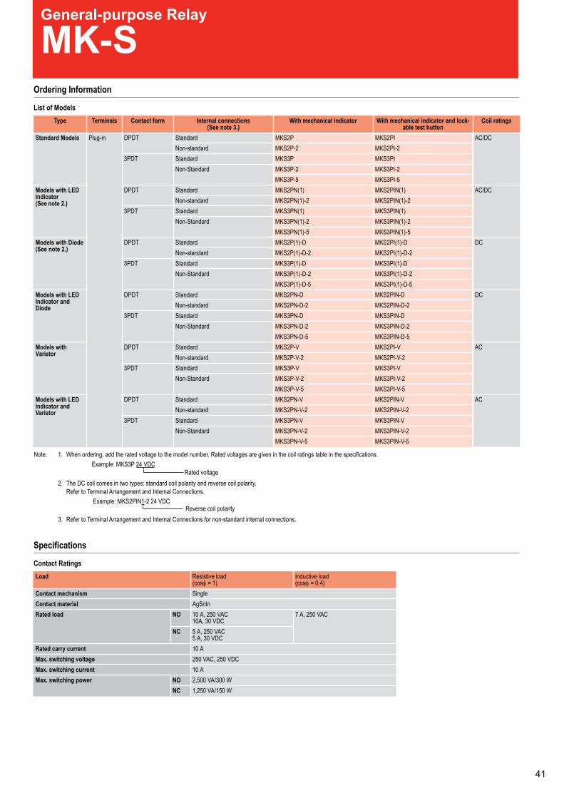
Slim Relay
G2RV
Specifications
Contact Ratings
Note: 1. P level: λ60 = 0.1 x 10⁻⁶/operation
Item SpecificationsNumber of poles elop1Load Resistive load
(cosφ = 1)Inductive load(cosφ = 0.4; L/R = 7 ms)
Rated load 6 A at 250 VAC;6 A at 30 VDC
2.5 A at 250 VAC;2 A at 30 VDC
Rated carry current 6 AMax. switching voltage CDV521,CAV004Max. switching current 6 AMax. switching power 1,500 VA,
180 W500 VA,60 W
Failure rate (reference value) C (P level)DV5taAm01
Ordering information
Input voltage ModelScrew terminals Push-in terminals
12 VDC G2RV-SL700-12 VDC G2RV-SL500-12 VDC24 VDC G2RV-SL700-24 VDC G2RV-SL500-24 VDC24 VAC/VDC G2RV-SL700-24 VAC/VDC G2RV-SL500-24 VAC/VDC48 VAC/VDC G2RV-SL700-48 VAC/VDC G2RV-SL500-48 VAC /VDC110 VAC G2RV-SL700-110 VAC G2RV-SL500-110 VAC230 VAC G2RV-SL700-230 VAC G2RV-SL500-230 VAC
Input RatingsRated voltage Rated current Operate voltage Release voltage Power consumption Input voltage
AC DC % of rated voltage AC (VA)Approx.
DC (mW)Approx.
% of rated voltage50 Hz 60 Hz
12 VDC --- --- 27.2 80% 10% --- 300 mW ±10%24 VDC --- --- 13.3 --- 300 mW24 VAC/DC 21.1 22.5 13.0 0.5 VA 300 mW48 VAC/DC 8.5 9.0 5.2 0.4 VA 250 mW110 VAC 7.1 7.5 --- 0.8 VA ---230 VAC 7.3 7.9 --- 1.7 VA ---
General-purpose Relay
MK-SOrdering Information
List of Models
Specifications
Contact Ratings
Type Terminals Contact form Internal connections(See note 3.)
With mechanical indicator With mechanical indicator and lock-able test button
Coil ratings
Standard Models CD/CAIP2SKMP2SKMdradnatSTDPDni-gulP2-IP2SKM2-P2SKMdradnats-noN
IP3SKMP3SKMdradnatSTDP32-IP3SKM2-P3SKMdradnatS-noN5-IP3SKM5-P3SKM
Models with LEDIndicator(See note 2.)
CD/CA)1(NIP2SKM)1(NP2SKMdradnatSTDPD2-)1(NIP2SKM2-)1(NP2SKMdradnats-noN
)1(NIP3SKM)1(NP3SKMdradnatSTDP3Non-Standard MKS3PN(1)-2 MKS3PIN(1)-2
MKS3PN(1)-5 MKS3PIN(1)-5Models with Diode(See note 2.)
1(P2SKMdradnatSTDPD CDD-)1(IP2SKMD-)2-D-)1(IP2SKM2-D-)1(P2SKMdradnats-noN
(P3SKMdradnatSTDP3 D-)1(IP3SKMD-)1Non-Standard MKS3P(1)-D-2 MKS3PI(1)-D-2
MKS3P(1)-D-5 MKS3PI(1)-D-5Models with LEDIndicator andDiode
CDD-NIP2SKMD-NP2SKMdradnatSTDPD2-D-NIP2SKM2-D-NP2SKMdradnats-noN
D-NIP3SKMD-NP3SKMdradnatSTDP32-D-NIP3SKM2-D-NP3SKMdradnatS-noN5-D-NIP3SKM5-D-NP3SKM
Models withVaristor
CAV-IP2SKMV-P2SKMdradnatSTDPD2-V-IP2SKM2-V-P2SKMdradnats-noN
V-IP3SKMV-P3SKMdradnatSTDP32-V-IP3SKM2-V-P3SKMdradnatS-noN5-V-IP3SKM5-V-P3SKM
Models with LEDIndicator andVaristor
CAV-NIP2SKMV-NP2SKMdradnatSTDPD2-V-NIP2SKM2-V-NP2SKMdradnats-noN
V-NIP3SKMV-NP3SKMdradnatSTDP32-V-NIP3SKM2-V-NP3SKMdradnatS-noN5-V-NIP3SKM5-V-NP3SKM
Rated voltage
Note: 1. When ordering, add the rated voltage to the model number. Rated voltages are given in the coil ratings table in the specifications. Example: MKS3P 24 VDC
2. The DC coil comes in two types: standard coil polarity and reverse coil polarity.Refer to Terminal Arrangement and Internal Connections.
Example: MKS2PIN1-2 24 VDC
3. Refer to Terminal Arrangement and Internal Connections for non-standard internal connections.Reverse coil polarity
Load Resistive load(cosφ = 1)
Inductive load(cosφ = 0.4)
Contact mechanism SingleContact material AgSnIn
ONdaoldetaR 10 A, 250 VAC10A, 30 VDC
7 A, 250 VAC
NC 5 A, 250 VAC5 A, 30 VDC
Rated carry current 10 AMax. switching voltage 250 VAC, 250 VDCMax. switching current 10 A
ONrewopgnihctiws.xaM 2,500 VA/300 WNC 1,250 VA/150 W
1
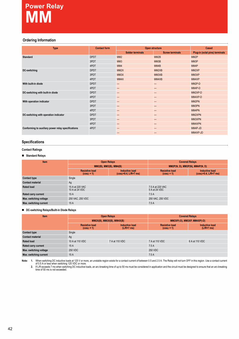
Power Relay
MM Ordering Information
Specifications
Contact Ratings
Standard Relays
DC-switching Relays/Built-in Diode Relays
Note: 1. When switching DC inductive loads at 125 V or more, an unstable region exists for a contact current of between 0.5 and 2.5 A. The Relay will not turn OFF in this region. Use a contact currentof 0.5 A or less when switching 125 VDC or more.
2. If L/R exceeds 7 ms when switching DC inductive loads, an arc-breaking time of up to 50 ms must be considered in application and the circuit must be designed to ensure that an arc-breakingtime of 50 ms is not exceeded.
Type Contact form Open structure CasedSolder terminals Screw terminals Plug-in (octal pins) terminals
Standard DPDT MM2 MM2B MM2P3PDT MM3 MM3B MM3P4PDT MM4 MM4B MM4P
DC-switching DPDT MM2X MM2XB MM2XP3PDT MM3X MM3XB MM3XP4PDT MM4X MM4XB MM4XP
With built-in diode DPDT --- --- MM2P-D4PDT --- --- MM4P-D
DC-switching with built-in diode DPDT --- --- MM2XP-D4PDT --- --- MM4XP-D
With operation indicator DPDT --- --- MM2PN3PDT --- --- MM3PN4PDT --- --- MM4PN
DC-switching with operation indicator DPDT --- --- MM2XPN3PDT --- --- MM3XPN4PDT --- --- MM4XPN
Conforming to auxiliary power relay specifications 4PDT --- --- MM4P-JD--- --- MM4XP-JD
Item Open Relays Covered RelaysMM2(B), MM3(B), MM4(B) MM2P(N, D), MM3P(N), MM4P(N, D)
Resistive load(cosφ = 1)
Inductive load(cosφ=0.4, L/R=7 ms)
Resistive load(cosφ = 1)
Inductive load(cosφ=0.4, L/R=7 ms)
Contact type SingleContact material AgRated load 15 A at 220 VAC
10 A at 24 VDC7.5 A at 220 VAC5 A at 24 VDC
Rated carry current 15 A 7.5 AMax. switching voltage 250 VAC, 250 VDC 250 VAC, 250 VDCMax. switching current 15 A 7.5 A
Item Open Relays Covered RelaysMM2X(B), MM3X(B), MM4X(B) MM2XP(-D), MM3XP, MM4XP(-D)
Resistive load(cosφ = 1)
Inductive load(L/R=7 ms)
Resistive load(cosφ = 1)
Inductive load(L/R=7 ms)
Contact type SingleContact material AgRated load 10 A at 110 VDC 7 A at 110 VDC 7 A at 110 VDC 6 A at 110 VDCRated carry current 15 A 7.5 AMax. switching voltage 250 VDC 250 VDCMax. switching current 15 A 7.5 A
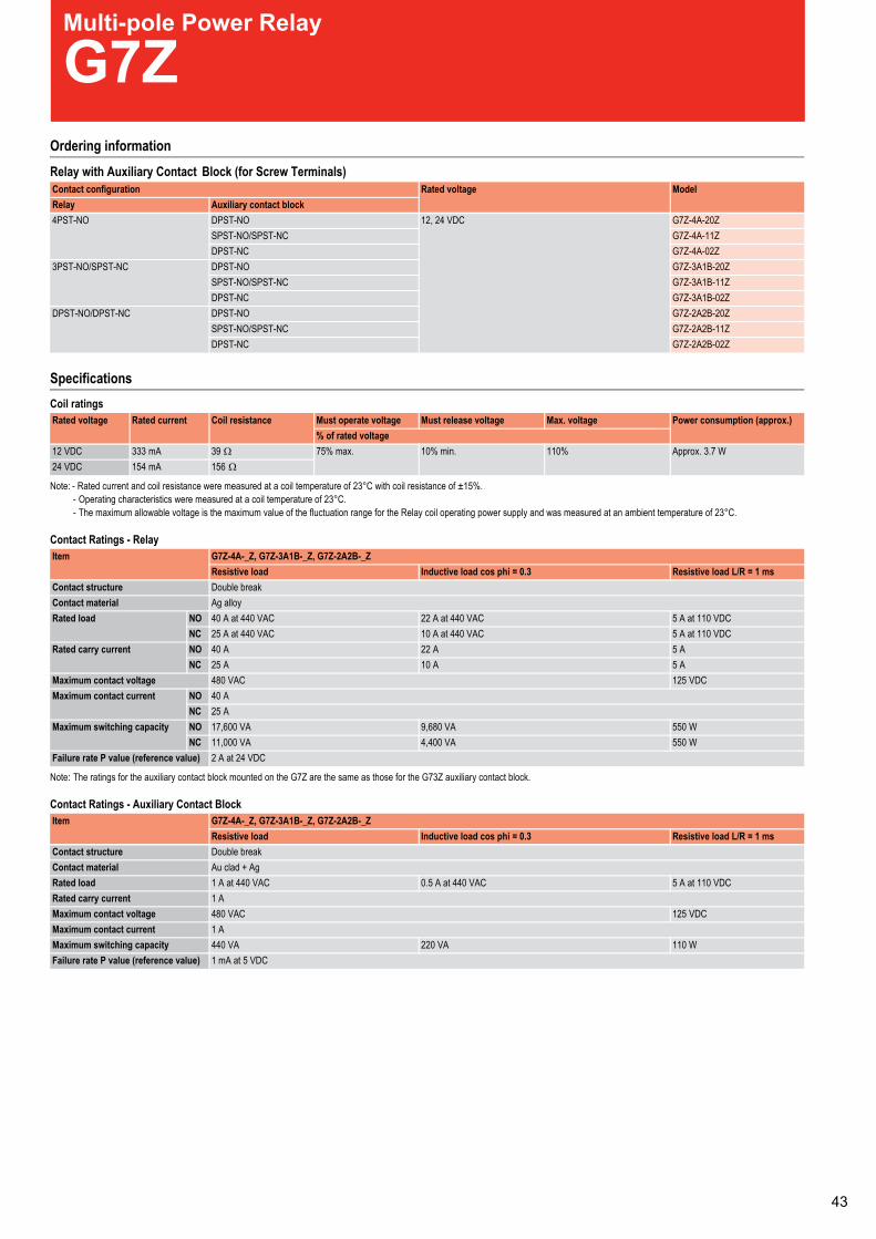
Multi-pole Power Relay
G7ZOrdering informationRelay with Auxiliary Contact Block (for Screw Terminals)
SpecificationsCoil ratings
Note: - Rated current and coil resistance were measured at a coil temperature of 23°C with coil resistance of ±15%.- Operating characteristics were measured at a coil temperature of 23°C.- The maximum allowable voltage is the maximum value of the fluctuation range for the Relay coil operating power supply and was measured at an ambient temperature of 23°C.
Contact Ratings - Relay
Note: The ratings for the auxiliary contact block mounted on the G7Z are the same as those for the G73Z auxiliary contact block.
Contact Ratings - Auxiliary Contact Block
Contact configuration Rated voltage ModelRelay Auxiliary contact block4PST-NO DPST-NO 12, 24 VDC G7Z-4A-20Z
SPST-NO/SPST-NC G7Z-4A-11ZDPST-NC G7Z-4A-02Z
3PST-NO/SPST-NC DPST-NO G7Z-3A1B-20ZSPST-NO/SPST-NC G7Z-3A1B-11ZDPST-NC G7Z-3A1B-02Z
DPST-NO/DPST-NC DPST-NO G7Z-2A2B-20ZSPST-NO/SPST-NC G7Z-2A2B-11ZDPST-NC G7Z-2A2B-02Z
Rated voltage Rated current Coil resistance Must operate voltage Must release voltage Max. voltage Power consumption (approx.)% of rated voltage
12 VDC 333 mA 39 Ω 75% max. 10% min. 110% Approx. 3.7 W24 VDC 154 mA 156 Ω
Item G7Z-4A-_Z, G7Z-3A1B-_Z, G7Z-2A2B-_ZResistive load Inductive load cos phi = 0.3 Resistive load L/R = 1 ms
Contact structure Double breakContact material Ag alloyRated load NO 40 A at 440 VAC 22 A at 440 VAC 5 A at 110 VDC
NC 25 A at 440 VAC 10 A at 440 VAC 5 A at 110 VDCRated carry current NO 40 A 22 A 5 A
NC 25 A 10 A 5 AMaximum contact voltage 480 VAC 125 VDCMaximum contact current NO 40 A
NC 25 AMaximum switching capacity NO 17,600 VA 9,680 VA 550 W
NC 11,000 VA 4,400 VA 550 WFailure rate P value (reference value) 2 A at 24 VDC
Item G7Z-4A-_Z, G7Z-3A1B-_Z, G7Z-2A2B-_ZResistive load Inductive load cos phi = 0.3 Resistive load L/R = 1 ms
Contact structure Double breakContact material Au clad + AgRated load 1 A at 440 VAC 0.5 A at 440 VAC 5 A at 110 VDCRated carry current 1 AMaximum contact voltage 480 VAC 125 VDCMaximum contact current 1 AMaximum switching capacity 440 VA 220 VA 110 WFailure rate P value (reference value) 1 mA at 5 VDC
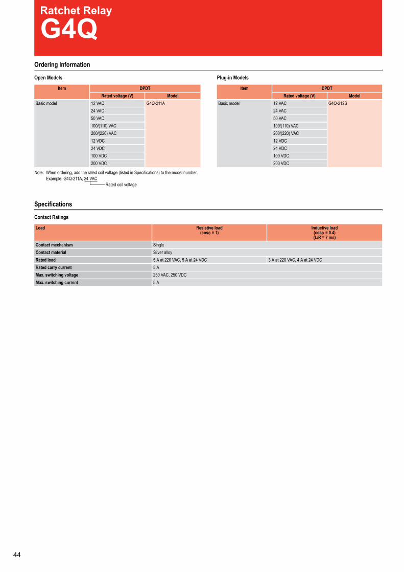
Ratchet Relay
G4QOrdering Information
sledoMni-gulPsledoMnepO
Specifications
Contact Ratings
Item DPDTRated voltage (V) Model
Basic model 12 VAC G4Q-211A24 VAC50 VAC100/(110) VAC200/(220) VAC12 VDC24 VDC100 VDC200 VDC
Item DPDTRated voltage (V) Model
Basic model 12 VAC G4Q-212S24 VAC50 VAC100/(110) VAC200/(220) VAC12 VDC24 VDC100 VDC200 VDC
Rated coil voltage
Note: When ordering, add the rated coil voltage (listed in Specifications) to the model number. Example: G4Q-211A, 24 VAC
Load Resistive load(cosφ = 1)
Inductive load(cosφ = 0.4)(L/R = 7 ms)
Contact mechanism SingleContact material Silver alloyRated load 5 A at 220 VAC, 5 A at 24 VDC 3 A at 220 VAC, 4 A at 24 VDCRated carry current 5 AMax. switching voltage 250 VAC, 250 VDCMax. switching current 5 A
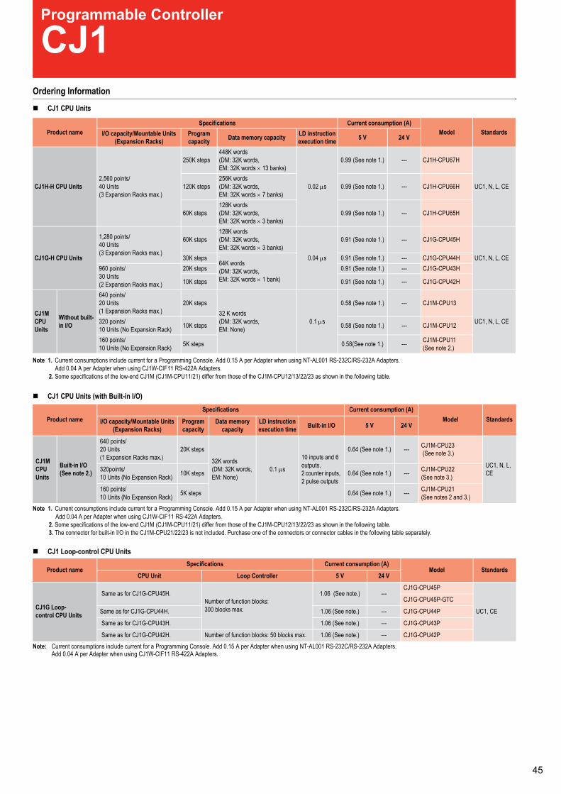
Programmable Controller
CJ1Ordering Information
CJ1 CPU Units
Note 1. Current consumptions include current for a Programming Console. Add 0.15 A per Adapter when using NT-AL001 RS-232C/RS-232A Adapters.Add 0.04 A per Adapter when using CJ1W-CIF11 RS-422A Adapters.
2. Some specifications of the low-end CJ1M (CJ1M-CPU11/21) differ from those of the CJ1M-CPU12/13/22/23 as shown in the following table.
CJ1 CPU Units (with Built-in I/O)
Note 1. Current consumptions include current for a Programming Console. Add 0.15 A per Adapter when using NT-AL001 RS-232C/RS-232A Adapters.Add 0.04 A per Adapter when using CJ1W-CIF11 RS-422A Adapters.
2. Some specifications of the low-end CJ1M (CJ1M-CPU11/21) differ from those of the CJ1M-CPU12/13/22/23 as shown in the following table.3. The connector for built-in I/O in the CJ1M-CPU21/22/23 is not included. Purchase one of the connectors or connector cables in the following table separately.
CJ1 Loop-control CPU Units
Note: Current consumptions include current for a Programming Console. Add 0.15 A per Adapter when using NT-AL001 RS-232C/RS-232A Adapters.Add 0.04 A per Adapter when using CJ1W-CIF11 RS-422A Adapters.
Product nameSpecifications Current consumption (A)
Model StandardsI/O capacity/Mountable Units(Expansion Racks)
Programcapacity Data memory capacity LD instruction
execution time 5 V 24 V
CJ1H-H CPU Units2,560 points/40 Units(3 Expansion Racks max.)
250K steps448K words(DM: 32K words,EM: 32K words × 13 banks)
0.02 µs
0.99 (See note 1.) --- CJ1H-CPU67H
UC1, N, L, CE120K steps256K words(DM: 32K words,EM: 32K words × 7 banks)
0.99 (See note 1.) --- CJ1H-CPU66H
60K steps128K words(DM: 32K words,EM: 32K words × 3 banks)
0.99 (See note 1.) --- CJ1H-CPU65H
CJ1G-H CPU Units
1,280 points/40 Units(3 Expansion Racks max.)
60K steps128K words(DM: 32K words,EM: 32K words × 3 banks)
0.04 µs
0.91 (See note 1.) --- CJ1G-CPU45H
UC1, N, L, CE30K steps64K words(DM: 32K words,EM: 32K words × 1 bank)
0.91 (See note 1.) --- CJ1G-CPU44H960 points/30 Units(2 Expansion Racks max.)
20K steps 0.91 (See note 1.) --- CJ1G-CPU43H
10K steps 0.91 (See note 1.) --- CJ1G-CPU42H
CJ1MCPUUnits
Without built-in I/O
640 points/20 Units(1 Expansion Racks max.)
20K steps32 K words(DM: 32K words,EM: None)
0.1 µs
0.58 (See note 1.) --- CJ1M-CPU13
UC1, N, L, CE320 points/10 Units (No Expansion Rack) 10K steps 0.58 (See note 1.) --- CJ1M-CPU12
160 points/10 Units (No Expansion Rack) 5K steps 0.58(See note 1.) --- CJ1M-CPU11
(See note 2.)
Product nameSpecifications Current consumption (A)
Model StandardsI/O capacity/Mountable Units(Expansion Racks)
Programcapacity
Data memorycapacity
LD instructionexecution time Built-in I/O 5 V 24 V
CJ1MCPUUnits
Built-in I/O(See note 2.)
640 points/20 Units(1 Expansion Racks max.)
20K steps
32K words(DM: 32K words,EM: None)
0.1 µs
10 inputs and 6outputs,2 counter inputs,2 pulse outputs
0.64 (See note 1.) --- CJ1M-CPU23(See note 3.)
UC1, N, L,CE320points/
10 Units (No Expansion Rack) 10K steps 0.64 (See note 1.) --- CJ1M-CPU22(See note 3.)
160 points/10 Units (No Expansion Rack) 5K steps 0.64 (See note 1.) --- CJ1M-CPU21
(See notes 2 and 3.)
Product nameSpecifications Current consumption (A)
Model StandardsCPU Unit Loop Controller 5 V 24 V
CJ1G Loop-control CPU Units
Same as for CJ1G-CPU45H.Number of function blocks:300 blocks max.
1.06 (See note.) ---CJ1G-CPU45P
UC1, CE
CJ1G-CPU45P-GTC
Same as for CJ1G-CPU44H. 1.06 (See note.) --- CJ1G-CPU44P
Same as for CJ1G-CPU43H. 1.06 (See note.) --- CJ1G-CPU43P
Same as for CJ1G-CPU42H. Number of function blocks: 50 blocks max. 1.06 (See note.) --- CJ1G-CPU42P
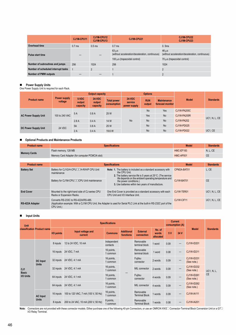
Power Supply UnitsOne Power Supply Unit is required for each Rack.
Optional Products and Maintenance Products
Input Units
Note: Connectors are not provided with these connector models. Either purchase one of the following 40-pin Connectors, or use an OMRON XW2@ Connector-Terminal Block Conversion Unit or a G7@I/O Relay Terminal.
CJ1M-CPU11 CJ1M-CPU12CJ1M-CPU13 CJ1M-CPU21 CJ1M-CPU22
CJ1M-CPU23
Overhead time 0.7 ms 0.5 ms 0.7 ms 0. 5ms
Pulse start time --- ---63 µs(without acceleration/deceleration, continuous)
46 µs(without acceleration/deceleration, continuous)
100 µs (trapezoidal control) 70 µs (trapezoidal control)
Number of subroutines and jumps 256 1024 256 1024Number of scheduled interrupt tasks 1 2 1 2Number of PMW outputs --- --- 1 2
Product name Power supplyvoltage
Output capacity Options
Model Standards5-VDCoutput
capacity
24-VDCoutput
capacity
Total powerconsumption
24-VDCservice
power supply
RUNoutput
Maintenanceforecast monitor
AC Power Supply Unit 100 to 240 VAC5 A 0.8 A 25 W
No
No Yes CJ1W-PA205C
UC1, N, L, CEYes No CJ1W-PA205R
2.8 A 0.4 A 14 W No No CJ1W-PA202
DC Power Supply Unit 24 VDC5A 0.8 A 25 W No No CJ1W-PD025
2 A 0.4 A 19.6 W No No CJ1W-PD022 UC1, CE
Product name Specifications Model Standards
Memory CardsFlash memory, 128 MB HMC-EF183 N, L, CE
Memory Card Adapter (for computer PCMCIA slot) HMC-AP001 CE
Product name Specifications Model Standards
Battery Set Battery for CJ1G/H-CPU@@H-R/H/P CPU Unitmaintenance
Note: 1. The battery is included as a standard accessory withthe CPU Unit.
2. The battery service life is 5 years at 25°C. (The servicelife depends on the ambient operating temperature andthe power conditions.)
3. Use batteries within two years of manufacture.
CPM2A-BAT01 L, CE
Battery for CJ1M-CPU@@CPU Unit maintenance CJ1W-BAT01 CE
End Cover Mounted to the right-hand side of CJ-series CPURacks or Expansion Racks.
One End Cover is provided as a standard accessory with eachCPU Unit and I/O Interface Unit.
CJ1W-TER01 UC1, N, L, CE
RS-422A AdapterConverts RS-233C to RS-422A/RS-485.(Application example: With a CJ1M CPU Unit, the Adapter is used for Serial PLC Link at the built-in RS-232C port of theCPU Unit.)
CJ1W-CIF11 UC1, N, L, CE
Unitclassification Product name
Specifications Currentconsumption (A)
Model StandardsI/O points Input voltage and
current Commons Additionalfunctions
Externalconnection
No. ofwords
allocated5 V 24 V
CJ1BasicI/O Units
DC InputUnits
8 inputs 12 to 24 VDC, 10 mA Independentcontacts
---
Removableterminal block 1 word 0.09 --- CJ1W-ID201
UC1, N, L,CE
16 inputs 24 VDC, 7 mA 16 points,1 common
Removableterminal block 1 word 0.08 --- CJ1W-ID211
32 inputs 24 VDC, 4.1 mA 16 points,1 common
Fujitsuconnector 2 words 0.09 --- CJ1W-ID231
(See note.)
32 inputs 24 VDC, 4.1 mA 16 points,1 common MIL connector 2 words 0.09 --- CJ1W-ID232
(See note.)
64 inputs 24 VDC, 4.1 mA 16 points,1 common
Fujitsuconnector 4 words 0.09 --- CJ1W-ID261
(See note.)
64 inputs 24 VDC, 4.1 mA 16 points,1 common MIL connector 4 words 0.09 --- CJ1W-ID262
(See note.)
AC InputUnits
16 inputs 100 to 120 VAC, 7 mA (100 V, 50 Hz) 16 points,1 common
RemovableTerminal Block 1 words 0.09 --- CJ1W-IA111
8 inputs 200 to 24 VAC, 10 mA (200 V, 50 Hz) 8 points,1 common
RemovableTerminal Block 1 words 0.08 --- CJ1W-IA201

Output Units
Note: Connectors are not provided with these connector models. Either purchase one of the following 40-pin Connectors, or use an OMRON XW2@ Connector-Terminal Block Conversion Unit or a G7@I/O Relay Terminal.
Unitclassification Product name
Specifications No. ofwords
allocated
Currentconsumption (A)
Model StandardsI/O points Maximum switching
capacity Commons Additionalfunctions
Externalconnection 5 V 24 V
CJ1BasicI/O Units
RelayContactOutputUnits
8outputs 250 VAC/24 VDC, 2 A Independent
contacts
---
Removableterminalblock
1 words 0.090.048max. CJ1W-OC201
UC1, N, L,CE
16outputs 250 VAC/24 VDC, 2 A 16 points,
1 common
Removableterminalblock
1 words 0.110.096max. CJ1W-OC211
TransistorOutputUnits
8outputs 12 to 24 VDC, 2 A, sinking 4 points,
1 common
Removableterminalblock
1 words 0.09 --- CJ1W-OD201
8outputs 24 VDC, 2 A, sourcing 4 points,
1 common
Short-circuitprotection,disconnectiondetection
Removableterminalblock
1 words 0.11 --- CJ1W-OD202
8outputs
12 to 24 VDC, 0.5 A,sinking
8 points,1 common ---
Removableterminalblock
1 words 0.10 --- CJ1W-OD203
8outputs
24 VDC, 0.5 A,sourcing
8 points,1 common
Short-circuitprotection
Removableterminalblock
1 words 0.10 --- CJ1W-OD204
16outputs
12 to 24 VDC, 0.5 A,sinking
16 points,1 common ---
Removableterminalblock
1 words 0.10 --- CJ1W-OD211
16outputs
24 VDC, 0.5 A, 16 points,1 common
Short-circuitprotection
Removableterminalblock
1 words 0.10 --- CJ1W-OD212
32outputs
12 to 24 VDC, 0.5 A,sinking
16 points,1 common --- Fujitsu
connector 2 words 0.14 --- CJ1W-OD231(See note.)
32outputs
24 VDC, 0.5 A,sourcing
16 points,1 common
Short-circuitprotection
MILconnector 2 words 0.15 --- CJ1W-OD232
(See note.)
32outputs
12 to 24 VDC, 0.5 A,sinking
16 points,1 common --- MIL
connector 2 words 0.14 --- CJ1W-OD233(See note.)
64outputs
12 to 24 VDC, 0.3 A,sinking
16 points,1 common --- Fujitsu
connector 4 words 0.17 --- CJ1W-OD261(See note.)
64outputs
12 to 24 VDC, 0.3 A,sourcing
16 points,1 common --- MIL
connector 4 words 0.17 --- CJ1W-OD262(See note.)
64outputs
12 to 24 VDC, 0.3 A,sinking
16 points,1 common --- MIL
connector 4 words 0.17 --- CJ1W-OD263(See note.)
TriacOutputUnit
8outputs 250 VAC, 0.6 A 8 points,
1 common ---Removableterminalblock
1 words 0.22 --- CJ1W-OA201
Power Supply UnitsOne Power Supply Unit is required for each Rack.
Optional Products and Maintenance Products
Input Units
Note: Connectors are not provided with these connector models. Either purchase one of the following 40-pin Connectors, or use an OMRON XW2@ Connector-Terminal Block Conversion Unit or a G7@I/O Relay Terminal.
CJ1M-CPU11 CJ1M-CPU12CJ1M-CPU13 CJ1M-CPU21 CJ1M-CPU22
CJ1M-CPU23
Overhead time 0.7 ms 0.5 ms 0.7 ms 0. 5ms
Pulse start time --- ---63 µs(without acceleration/deceleration, continuous)
46 µs(without acceleration/deceleration, continuous)
100 µs (trapezoidal control) 70 µs (trapezoidal control)
Number of subroutines and jumps 256 1024 256 1024Number of scheduled interrupt tasks 1 2 1 2Number of PMW outputs --- --- 1 2
Product name Power supplyvoltage
Output capacity Options
Model Standards5-VDCoutput
capacity
24-VDCoutput
capacity
Total powerconsumption
24-VDCservice
power supply
RUNoutput
Maintenanceforecast monitor
AC Power Supply Unit 100 to 240 VAC5 A 0.8 A 25 W
No
No Yes CJ1W-PA205C
UC1, N, L, CEYes No CJ1W-PA205R
2.8 A 0.4 A 14 W No No CJ1W-PA202
DC Power Supply Unit 24 VDC5A 0.8 A 25 W No No CJ1W-PD025
2 A 0.4 A 19.6 W No No CJ1W-PD022 UC1, CE
Product name Specifications Model Standards
Memory CardsFlash memory, 128 MB HMC-EF183 N, L, CE
Memory Card Adapter (for computer PCMCIA slot) HMC-AP001 CE
Product name Specifications Model Standards
Battery Set Battery for CJ1G/H-CPU@@H-R/H/P CPU Unitmaintenance
Note: 1. The battery is included as a standard accessory withthe CPU Unit.
2. The battery service life is 5 years at 25°C. (The servicelife depends on the ambient operating temperature andthe power conditions.)
3. Use batteries within two years of manufacture.
CPM2A-BAT01 L, CE
Battery for CJ1M-CPU@@CPU Unit maintenance CJ1W-BAT01 CE
End Cover Mounted to the right-hand side of CJ-series CPURacks or Expansion Racks.
One End Cover is provided as a standard accessory with eachCPU Unit and I/O Interface Unit.
CJ1W-TER01 UC1, N, L, CE
RS-422A AdapterConverts RS-233C to RS-422A/RS-485.(Application example: With a CJ1M CPU Unit, the Adapter is used for Serial PLC Link at the built-in RS-232C port of theCPU Unit.)
CJ1W-CIF11 UC1, N, L, CE
Unitclassification Product name
Specifications Currentconsumption (A)
Model StandardsI/O points Input voltage and
current Commons Additionalfunctions
Externalconnection
No. ofwords
allocated5 V 24 V
CJ1BasicI/O Units
DC InputUnits
8 inputs 12 to 24 VDC, 10 mA Independentcontacts
---
Removableterminal block 1 word 0.09 --- CJ1W-ID201
UC1, N, L,CE
16 inputs 24 VDC, 7 mA 16 points,1 common
Removableterminal block 1 word 0.08 --- CJ1W-ID211
32 inputs 24 VDC, 4.1 mA 16 points,1 common
Fujitsuconnector 2 words 0.09 --- CJ1W-ID231
(See note.)
32 inputs 24 VDC, 4.1 mA 16 points,1 common MIL connector 2 words 0.09 --- CJ1W-ID232
(See note.)
64 inputs 24 VDC, 4.1 mA 16 points,1 common
Fujitsuconnector 4 words 0.09 --- CJ1W-ID261
(See note.)
64 inputs 24 VDC, 4.1 mA 16 points,1 common MIL connector 4 words 0.09 --- CJ1W-ID262
(See note.)
AC InputUnits
16 inputs 100 to 120 VAC, 7 mA (100 V, 50 Hz) 16 points,1 common
RemovableTerminal Block 1 words 0.09 --- CJ1W-IA111
8 inputs 200 to 24 VAC, 10 mA (200 V, 50 Hz) 8 points,1 common
RemovableTerminal Block 1 words 0.08 --- CJ1W-IA201
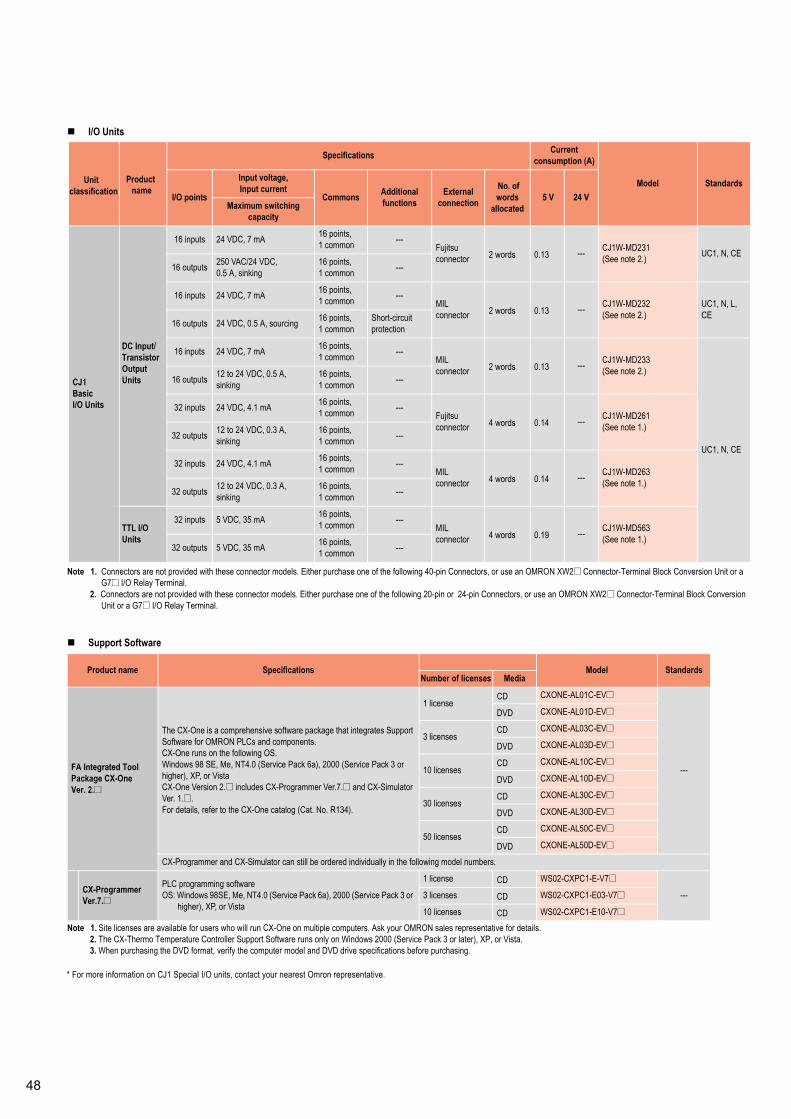
I/O Units
Note 1. Connectors are not provided with these connector models. Either purchase one of the following 40-pin Connectors, or use an OMRON XW2@ Connector-Terminal Block Conversion Unit or aG7@ I/O Relay Terminal.
2. Connectors are not provided with these connector models. Either purchase one of the following 20-pin or 24-pin Connectors, or use an OMRON XW2@ Connector-Terminal Block ConversionUnit or a G7@ I/O Relay Terminal.
Support Software
Note 1. Site licenses are available for users who will run CX-One on multiple computers. Ask your OMRON sales representative for details.2. The CX-Thermo Temperature Controller Support Software runs only on Windows 2000 (Service Pack 3 or later), XP, or Vista.3. When purchasing the DVD format, verify the computer model and DVD drive specifications before purchasing.
Unit Productname
Specifications Currentconsumption (A)
Model StandardsI/O points
Input voltage,Input current
Commons Additionalfunctions
Externalconnection
No. ofwords
allocated5 V 24 V
Maximum switchingcapacity
CJ1BasicI/O Units
DC Input/TransistorOutputUnits
16 inputs 24 VDC, 7 mA 16 points,1 common ---
Fujitsuconnector 2 words 0.13 --- CJ1W-MD231
(See note 2.) UC1, N, CE16 outputs 250 VAC/24 VDC,
0.5 A, sinking16 points,1 common ---
16 inputs 24 VDC, 7 mA 16 points,1 common ---
MILconnector 2 words 0.13 --- CJ1W-MD232
(See note 2.)UC1, N, L,CE
16 outputs 24 VDC, 0.5 A, sourcing 16 points,1 common
Short-circuitprotection
16 inputs 24 VDC, 7 mA 16 points,1 common ---
MILconnector 2 words 0.13 --- CJ1W-MD233
(See note 2.)
UC1, N, CE
16 outputs 12 to 24 VDC, 0.5 A,sinking
16 points,1 common ---
32 inputs 24 VDC, 4.1 mA 16 points,1 common ---
Fujitsuconnector 4 words 0.14 --- CJ1W-MD261
(See note 1.)32 outputs 12 to 24 VDC, 0.3 A,
sinking16 points,1 common ---
32 inputs 24 VDC, 4.1 mA 16 points,1 common ---
MILconnector 4 words 0.14 --- CJ1W-MD263
(See note 1.)32 outputs 12 to 24 VDC, 0.3 A,
sinking16 points,1 common ---
TTL I/OUnits
32 inputs 5 VDC, 35 mA 16 points,1 common ---
MILconnector 4 words 0.19 --- CJ1W-MD563
(See note 1.)32 outputs 5 VDC, 35 mA 16 points,
1 common ---
Product name Specifications Model StandardsNumber of licenses Media
FA Integrated ToolPackage CX-OneVer. 2.@
The CX-One is a comprehensive software package that integrates SupportSoftware for OMRON PLCs and components.CX-One runs on the following OS.Windows 98 SE, Me, NT4.0 (Service Pack 6a), 2000 (Service Pack 3 orhigher), XP, or VistaCX-One Version 2.@ includes CX-Programmer Ver.7.@ and CX-SimulatorVer. [email protected] details, refer to the CX-One catalog (Cat. No. R134).
1 licenseCD CXONE-AL01C-EV@
---
DVD CXONE-AL01D-EV@
3 licensesCD CXONE-AL03C-EV@
DVD CXONE-AL03D-EV@
10 licensesCD CXONE-AL10C-EV@
DVD CXONE-AL10D-EV@
30 licensesCD CXONE-AL30C-EV@
DVD CXONE-AL30D-EV@
50 licensesCD CXONE-AL50C-EV@
DVD CXONE-AL50D-EV@
CX-Programmer and CX-Simulator can still be ordered individually in the following model numbers.
CX-ProgrammerVer.7.@
PLC programming softwareOS: Windows 98SE, Me, NT4.0 (Service Pack 6a), 2000 (Service Pack 3 or
higher), XP, or Vista
1 license CD WS02-CXPC1-E-V7@
---3 licenses CD WS02-CXPC1-E03-V7@
10 licenses CD WS02-CXPC1-E10-V7@
classification
* For more information on CJ1 Special I/O units, contact your nearest Omron representative.
Programmable Controller
CP1Ordering Information
CP1H CPU Units
Note: CP1H PLCs are supported by CX-Programmer version 6.2 or higher.
CP1L CPU Units
Note: CP1L PLCs are supported by auto-updating CX-Programmer version 7.0 or 7.1 (to add new CP1L models) or by using CX-Programmer version 7.2 or higher.
Options for CPU Units
CPU UnitSpecifications
Model StandardsPower supply Output method Inputs Outputs
CP1H-X CPU UnitsMemory capacity: 20K stepsHigh-speed counters: 100 kHz, 4 axesPulse outputs: 100 kHz, 4 axes(Models with transistor outputs only)
AC powersupply Relay output (No pulse output)
24 16
CP1H-X40DR-A
UC1, N, L,CE
DC powersupply
Transistor output (sinking) CP1H-X40DT-D
Transistor output (sourcing) CP1H-X40DT1-D
CP1H-XA CPU UnitsMemory capacity: 20K stepsHigh-speed counters: 100 kHz, 4 axesPulse outputs: 100 kHz, 4 axes(Models with transistor outputs only)Analog inputs: 4; Analog outputs: 2
AC powersupply Relay output
24 16
CP1H-XA40DR-A
DC powersupply
Transistor output (sinking) CP1H-XA40DT-D
Transistor output (sourcing) CP1H-XA40DT1-D
CP1H-Y CPU UnitsMemory capacity: 20K stepsHigh-speed counters: 1 MHz, 2 axes; 100 kHz, 2 axesPulse outputs: 1 MHz, 2 axes; 100 kHz, 2 axes
DC powersupply Transistor output (sinking)
12+
line-driver input,2 axes
8+
line-driveroutput,2 axes
CP1H-Y20DT-D
CPU UnitSpecifications
Model StandardsPower supply Output method Inputs Outputs
CP1L-M CPU Units with 40 Points
AC power supplyRelay output
24 16
CP1L-M40DR-A
N, L, CE
DC power supplyCP1L-M40DR-D
Transistor output (sinking) CP1L-M40DT-DTransistor output (sourcing) CP1L-M40DT1-D
CP1L-M CPU Units with 30 Points
AC power supplyRelay output
18 12
CP1L-M30DR-A
DC power supplyCP1L-M30DR-D
Transistor output (sinking) CP1L-M30DT-DTransistor output (sourcing) CP1L-M30DT1-D
CP1L-L CPU Units with 20 Points
AC power supplyRelay output
12 8
CP1L-L20DR-A
DC power supplyCP1L-L20DR-D
Transistor output (sinking) CP1L-L20DT-DTransistor output (sourcing) CP1L-L20DT1-D
CP1L-L CPU Units with 14 Points
AC power supplyRelay output
8 6
CP1L-L14DR-A
DC power supplyCP1L-L14DR-D
Transistor output (sinking) CP1L-L14DT-DTransistor output (sourcing) CP1L-L14DT1-D
Name Specifications Model StandardsRS-232C Option Board For CPU Unit option port. CP1W-CIF01
UC1, N, L,CERS-422A/485 Option Board For CPU Unit option port. CP1W-CIF11
Memory Cassette Can be used for backing up programs or auto-booting. CP1W-ME05M

Expansion Units
Optional and Maintenance Products
CJ-series Special I/O Units and CPU Bus Units
Programming Devices
Note 1. CP1H PLCs are supported by CX-P rogrammer version 6.2 or higher; CP1L PLCs are supported by CX-Programmer version 7.2 or higher.Update The CX-Programmer version automatically from the websit e using CX-Programmer version 7.0 (included with CX-One version 2.0).
2. Cannot be used with a peripheral USB port. To connect to a personal computer via a peripheral USB port, use commercially-available USB cable (A or B type, male).
Name Output method Inputs Outputs Model Standards
Expansion I/O Units
Relay24 16
CP1W-40EDRN, L, CETransistor (sinking) CP1W-40EDT
Transistor output (sourcing) CP1W-40EDT1Relay
12 8CP1W-20EDR1 U, C, L, CE
Transistor (sinking) CP1W-20EDTU, C, N, L, CE
Transistor output (sourcing) CP1W-20EDT1Relay --- 16 CP1W-16ER CE
--- 8 --- CP1W-8ED
U, C, N, L, CERelay --- 8 CP1W-8ER
Transistor (sinking)--- 8
CP1W-8ETTransistor output (sourcing) CP1W-8ET1
Analog Input Unit Analog (resolution: 1/6000) 4 --- CP1W-AD041 UC1, CEAnalog Output Unit Analog (resolution: 1/6000) --- 4 CP1W-DA041 UC1, CEAnalog I/O Unit Analog (resolution: 1/6000) 2 1 CP1W-MAD11 U, C, N, CE
CompoBus/S I/O Link Unit --- 8(I/O link input bits)
8(I/O link input bits) CP1W-SRT21 U, C, N, L, CE
Temperature Sensor Unit
2 thermocouple inputs CP1W-TS001
U, C, N, L, CE4 thermocouple inputs CP1W-TS0022 platinum resistance thermometer inputs CP1W-TS1014 platinum resistance thermometer inputs CP1W-TS102
Name Specifications Model StandardsBattery Set For CP1H CPU Units (Use batteries within two years of manufacture.) CJ1W-BAT01 CEEnd Plate There are 2 stoppers provided with CPU Units and I/O Interface Units as standard accessories to secure the Units on the DIN Track. PFP-M ---
Name Specifications Model StandardsCJ Unit Adapter Adapter for connecting CJ-series Special I/O Units and CPU Bus Units (includes CJ-series End Cover) CP1W-EXT01 UC1, N, L, CE
Name Specifications Model Standards
CX-One FA Integrated ToolPackage Ver. 2.@
CX-One is a package that integrates the Support Software for OMRONPLCs and components. CX-One runs on the following OS.OS: Windows 98SE, Me, NT 4.0 (Service Pack 6a), 2000 (Service Pack 3
or higher), or XP* CX-Thermo runs only on Windows 2000 (Service Pack 3 or higher) or XP.
CX-One Ver. 2.0 includes CX-Programmer Ver. [email protected] details, refer to the CX-One catalog (Cat. No. R134).
* The software is provided on CDs for the CXONE-AL@@C-@EV2 and onDVD for the CXONE-AL@@D-@EV2.
* Site licenses are available for users who must run the CX-One on manycomputers. Ask your OMRON representative for details.
1 license CXONE-AL01C-EV@CXONE-AL01D-EV@
---
3 licenses CXONE-AL03C-EV@CXONE-AL03D-EV@
10 licenses CXONE-AL10C-EV@CXONE-AL10D-EV@
30 licenses CXONE-AL30C-EV@CXONE-AL30D-EV@
50 licenses CXONE-AL50C-EV@CXONE-AL50D-EV@
CX-Programmer can still be ordered individually in the following model number.
CX-ProgrammerVer. 7.@(See note 1.)
PLC Support SoftwareOS: Windows 98SE, Me, NT 4.0 (Service Pack 6a), 2000 (Service Pack 3
or higher), or XP
1 license WS02-CXPC1-E-V7@
---
3 licenses WS02-CXPC1-E03-V7@
10 licenses WS02-CXPC1-E10-V7@
Micro PLC EditionNote: One License Only,
Applicable models:CP1L, CP1H,CPM@@, SRM1
WS02-CXPC1-EJ-V7@
Programming Device Con-necting Cable for CP1W-CIF01 RS-232C Option Board(See note 2.)
Connects DOS computers, D-Sub 9-pin (Length: 2.0 m)For anti-static connectors
XW2Z-200S-CV
---Connects DOS computers, D-Sub 9-pin (Length: 5.0 m) XW2Z-500S-CVConnects DOS computers, D-Sub 9-pin (Length: 2.0 m) XW2Z-200S-VConnects DOS computers, D-Sub 9-pin (Length: 5.0 m) XW2Z-500S-V
USB-Serial ConversionCable(See note 2.)
USB-RS-232C Conversion Cable (Length: 0.5 m) and PC driver (on a CD-ROM disc) are included.Complies with USB Specification 1.1On personal computer side: USB (A plug connector, male)On PLC side: RS-232C (D-sub 9-pin, male)Driver: Supported by Windows 98, Me, 2000, and XP
CS1W-CIF31 N
0
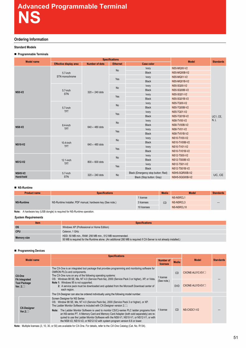
Expansion Units
Optional and Maintenance Products
CJ-series Special I/O Units and CPU Bus Units
Programming Devices
Note 1. CP1H PLCs are supported by CX-P rogrammer version 6.2 or higher; CP1L PLCs are supported by CX-Programmer version 7.2 or higher.Update The CX-Programmer version automatically from the websit e using CX-Programmer version 7.0 (included with CX-One version 2.0).
2. Cannot be used with a peripheral USB port. To connect to a personal computer via a peripheral USB port, use commercially-available USB cable (A or B type, male).
Name Output method Inputs Outputs Model Standards
Expansion I/O Units
Relay24 16
CP1W-40EDRN, L, CETransistor (sinking) CP1W-40EDT
Transistor output (sourcing) CP1W-40EDT1Relay
12 8CP1W-20EDR1 U, C, L, CE
Transistor (sinking) CP1W-20EDTU, C, N, L, CE
Transistor output (sourcing) CP1W-20EDT1Relay --- 16 CP1W-16ER CE
--- 8 --- CP1W-8ED
U, C, N, L, CERelay --- 8 CP1W-8ER
Transistor (sinking)--- 8
CP1W-8ETTransistor output (sourcing) CP1W-8ET1
Analog Input Unit Analog (resolution: 1/6000) 4 --- CP1W-AD041 UC1, CEAnalog Output Unit Analog (resolution: 1/6000) --- 4 CP1W-DA041 UC1, CEAnalog I/O Unit Analog (resolution: 1/6000) 2 1 CP1W-MAD11 U, C, N, CE
CompoBus/S I/O Link Unit --- 8(I/O link input bits)
8(I/O link input bits) CP1W-SRT21 U, C, N, L, CE
Temperature Sensor Unit
2 thermocouple inputs CP1W-TS001
U, C, N, L, CE4 thermocouple inputs CP1W-TS0022 platinum resistance thermometer inputs CP1W-TS1014 platinum resistance thermometer inputs CP1W-TS102
Name Specifications Model StandardsBattery Set For CP1H CPU Units (Use batteries within two years of manufacture.) CJ1W-BAT01 CEEnd Plate There are 2 stoppers provided with CPU Units and I/O Interface Units as standard accessories to secure the Units on the DIN Track. PFP-M ---
Name Specifications Model StandardsCJ Unit Adapter Adapter for connecting CJ-series Special I/O Units and CPU Bus Units (includes CJ-series End Cover) CP1W-EXT01 UC1, N, L, CE
Name Specifications Model Standards
CX-One FA Integrated ToolPackage Ver. 2.@
CX-One is a package that integrates the Support Software for OMRONPLCs and components. CX-One runs on the following OS.OS: Windows 98SE, Me, NT 4.0 (Service Pack 6a), 2000 (Service Pack 3
or higher), or XP* CX-Thermo runs only on Windows 2000 (Service Pack 3 or higher) or XP.
CX-One Ver. 2.0 includes CX-Programmer Ver. [email protected] details, refer to the CX-One catalog (Cat. No. R134).
* The software is provided on CDs for the CXONE-AL@@C-@EV2 and onDVD for the CXONE-AL@@D-@EV2.
* Site licenses are available for users who must run the CX-One on manycomputers. Ask your OMRON representative for details.
1 license CXONE-AL01C-EV@CXONE-AL01D-EV@
---
3 licenses CXONE-AL03C-EV@CXONE-AL03D-EV@
10 licenses CXONE-AL10C-EV@CXONE-AL10D-EV@
30 licenses CXONE-AL30C-EV@CXONE-AL30D-EV@
50 licenses CXONE-AL50C-EV@CXONE-AL50D-EV@
CX-Programmer can still be ordered individually in the following model number.
CX-ProgrammerVer. 7.@(See note 1.)
PLC Support SoftwareOS: Windows 98SE, Me, NT 4.0 (Service Pack 6a), 2000 (Service Pack 3
or higher), or XP
1 license WS02-CXPC1-E-V7@
---
3 licenses WS02-CXPC1-E03-V7@
10 licenses WS02-CXPC1-E10-V7@
Micro PLC EditionNote: One License Only,
Applicable models:CP1L, CP1H,CPM@@, SRM1
WS02-CXPC1-EJ-V7@
Programming Device Con-necting Cable for CP1W-CIF01 RS-232C Option Board(See note 2.)
Connects DOS computers, D-Sub 9-pin (Length: 2.0 m)For anti-static connectors
XW2Z-200S-CV
---Connects DOS computers, D-Sub 9-pin (Length: 5.0 m) XW2Z-500S-CVConnects DOS computers, D-Sub 9-pin (Length: 2.0 m) XW2Z-200S-VConnects DOS computers, D-Sub 9-pin (Length: 5.0 m) XW2Z-500S-V
USB-Serial ConversionCable(See note 2.)
USB-RS-232C Conversion Cable (Length: 0.5 m) and PC driver (on a CD-ROM disc) are included.Complies with USB Specification 1.1On personal computer side: USB (A plug connector, male)On PLC side: RS-232C (D-sub 9-pin, male)Driver: Supported by Windows 98, Me, 2000, and XP
CS1W-CIF31 N
Advanced Programmable Terminal
NSOrdering Information
Standard Models
Programmable Terminals
NS-Runtime
Note: A hardware key (USB dongle) is required for NS-Runtime operation.
System Requirements
Programming Devices
Note: Multiple licenses (3, 10, 30, or 50) are available for CX-One. For details, refer to the CX-One Catalog (Cat. No. R134).
Model nameSpecifications
Model StandardsEffective display area Number of dots Ethernet Case color
NS5-V2
5.7-inchSTN monochrome
320 × 240 dots
NoIvory NS5-MQ00-V2
UC1, CE,N, L
Black NS5-MQ00B-V2
YesIvory NS5-MQ01-V2Black NS5-MQ01B-V2
5.7-inchSTN
NoIvory NS5-SQ00-V2Black NS5-SQ00B-V2
YesIvory NS5-SQ01-V2Black NS5-SQ01B-V2
5.7-inchTFT
NoIvory NS5-TQ00-V2Black NS5-TQ00B-V2
YesIvory NS5-TQ01-V2Black NS5-TQ01B-V2
NS8-V2 8.4-inchTFT 640 × 480 dots
NoIvory NS8-TV00-V2Black NS8-TV00B-V2
YesIvory NS8-TV01-V2Black NS8-TV01B-V2
NS10-V2 10.4-inchTFT 640 × 480 dots
NoIvory NS10-TV00-V2Black NS10-TV00B-V2
YesIvory NS10-TV01-V2Black NS10-TV01B-V2
NS12-V2 12.1-inchTFT 800 × 600 dots
NoIvory NS12-TS00-V2Black NS12-TS00B-V2
YesIvory NS12-TS01-V2Black NS12-TS01B-V2
NSH5-V2Hand-held
5.7-inchSTN 320 × 240 dots No
Black (Emergency stop button: Red) NSH5-SQR00B-V2UC, CE
Black (Stop button: Gray) NSH5-SQG00B-V2
Product name Specifications Media Model Standards
NS-Runtime NS-Runtime Installer, PDF manual, hardware key (See note.)1 license
CD
NS-NSRCL1---3 licenses NS-NSRCL3
10 licenses NS-NSRCL10
Item SpecificationsOS Windows XP (Professional or Home Edition)CPU Celeron, 1 GHz
Memory size HDD: 50 MB min., RAM: 256 MB min., 512 MB recommended.50 MB is required for the Runtime alone. (An additional 280 MB is required if CX-Server is not already installed.)
Model nameSpecifications
Model StandardsNumber oflicenses Media
CX-OneFA IntegratedTool PackageVer. 2.@
The CX-One is an integrated tool package that provides programming and monitoring software forOMRON PLCs and components.The CX-One runs on any of the following operating systems:OS: Windows 98 SE, Me, NT 4.0 (Service Pack 6a), 2000 (Service Pack 3 or higher), XP, or Vista.Note 1: Windows 95 is not supported.
2: A service pack must be downloaded and updated from the Microsoft Download center ofeach region.
1 license(See note.)
CD CXONE-AL01C-EV@
---
DVD CXONE-AL01D-EV@
The CX-Designer can also be ordered individually using the following model number.
CX-DesignerVer.2.@
Screen Designer for NS SeriesOS: Window 98 SE, Me, NT 4.0 (Service Pack 6a), 2000 (Service Pack 3 or higher), or XP.The Ladder Monitor Software is included with CX-Designer version [email protected]: The Ladder Monitor Software is used to monitor CS/CJ-series PLC ladder programs from
an NS-series PT. A Memory Card and Memory Card Adapter (both sold separately) are re-quired to use the Ladder Monitor Software with the NS8-V1, NS10-V1, or NS12-V1, or withthe NS8-V2, NS10-V2, or NS12-V2 with system program version 6.6 or lower.
1 license CD NS-CXDC1-V2 ---
1
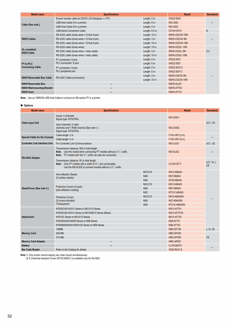
Note: Use an OMRON USB Host Cable to connect an NS-series PT to a printer.
Options
Note 1. One screen cannot display two video inputs simultaneously.2. A Chemical-resistant Cover (NT30-KBA01) is available only for the NS5.
Model name Specifications Model Standards
Cable (See note.)
Screen transfer cable for DOS/V (CX-Designer ↔ 200S-Z2WXm2:htgneL)TP---USB Host Cable (For a pr 25SU-SNm5:htgneL)retni
USB Host Cable (For a pr 22SU-SNm2:htgneL)retniN13FIC-W1SCm5.0:htgneLelbaCnoisrevnoClaireS-BSU
NSH5 CablesM01-WC224-5HSNm01:htgneL)nip-9buS-D+seriwesool(elbacA224-SR
---RS-232C cable (loose wires + D-S M3-WC232-5HSNm3:htgneL)nip-9buRS-232C cable (loose wires + D-Sub M01-WC232-5HSNm01:htgneL)nip-9
UL-compliantNSH5 Cable
M01-LU224-5HSNm01:htgneL)seriwesool(elbacA224-SRCURS-232C cable (loose wires + rela M3-LU232-5HSNm3:htgneL)elbacy
M01-LU232-5HSNm01:htgneL)elbacyaler+seriwesool(elbacC232-SR
PT-to-PLCConnecting Cable
PT connection: 9 pinsPLC connection: 9 pins
Length: 2 m XW2Z-200T
---
Length: 5 m XW2Z-500TPT connection: 9 pinsPLC peripheral port
Length: 2 m XW2Z-200T-2Length: 5 m XW2Z-500T-2
NSH5 Removable Box Cable RS-232C Cable (connectors)Length: 3 m NSH5-232CN-3MLength: 10 m NSH5-232CN-10M
NSH5 Removable Box 100LA-5HSN---NSH5 Wall-mounting Bracket 20TTA-5HSN---NSH5 Visor 10TTA-5HSN---
Model name Specifications Model Standards
Video Input Unit
Inputs: 4 channelsSignal type: NTSC/PAL NS-CA001
UC1, CEInput channels: 2 videochannels and 1 RGB channel (See note 1.)Signal type: NTSC/PAL
NS-CA002
Special Cable for the ConsoleCable length: 2 m F150-VKP (2 m)
---Cable length: 5 m F150-VKP (5 m)
Controller Link Interface Unit EC,1CU12KLC-SNsnoitacinummoCkniLrellortnoCroF
RS-422A Adapter
Transmission distance: 500 m total lengthNote: Use this model when connecting PT models without a V@ suffix.Note: PT models with the V@ suffix can also be connected.
---200LA-SN
Transmission distance: 50 m total lengthNote: Only PT models with a suffix of V@ are connectable.
Use the NS-AL002 to connect models without a V@ suffix.CJ1W-CIF11 UC1, N, L,
CE
Sheet/Cover (See note 2.)
Anti-reflection Sheets(5 surface sheets)
NS12/10 NS12-KBA04
---
NS8 NS7-KBA04NS5 NT30-KBA04
Protective Covers (5 pack)(anti-reflection coating)
NS12/10 NS12-KBA05NS8 NS7-KBA05NS5 NT31C-KBA05
Protective Covers(5 covers included)(Transparent)
NS12/10 NS12-KBA05NNS8 NS7-KBA05NNS5 NT31C-KBA05N
Attachment
NT625C/631/631C Series to 10TTA-21SNseireS01/21SNNT625C/631/631C Series to NS12/NS B10TTA-21SN)kcalB(seireS01
20TTA-21SNseireS01/21SNotseireSC016TN10TTA-8SNseireS8SNotseireSS006/C026/S026TN20TTA-8SNseireS8SNotseireSG216/G016/G006/M006TN
Memory Card128MB HMC-EF183 L, N, CE256 MB HMC-EF283
CE512 MB HMC-EF583Memory Card Adapter 100PA-CMH---Battery 10TAB-W1JC---
---Bar Code Reader 6-12HR-025V.sliatedrofgolataCehtotrefeR

Specifications
12”/10”/8” ModelsItem NS12 NS10 NS8Display type TFT 12 inch colour TFT 10 inch colour TFT 8 inch colourSize in mm (HxWxD) 241 × 315 × 48.5 241 × 315 × 48.5 177 × 232 × 48.5Effective display area 246 × 184.5 mm (800 × 600 pixels) 215.2 × 162.4 mm (640 × 480 pixels) 170.9 × 128.2 (640 × 480 pixels)Display colour 256 colours Image data: 32,768 coloursPower supply 24 V DC ±15%Touch panel 38 vertical × 50 horizontal 30 vertical × 40 horizontal 24 vertical × 32 horizontalObtained standards UL 1604 C1D2, cUL, EC Directives, NEMA equivalentDisplay graphics Rectangle, circle, oval, straight line, polyline, polygon, arcNo. of display characters (standard characters) 100 characters × 37 lines 80 characters × 30 lines 80 characters × 30 linesNo. of registered screens 3,999 screens max.
(depending on screen contents)Screen data capacity (standard) 60 MBMemory card interface ATA compact flash card interface, 1 slotInternal memory Bit memory: 32,767 bits, Word memory: 32,767 words, Retentative memory: 8,192 bits and 8,192 words.Printer connection SupportedBacklight life 50,000 hours minimum 50,000 hours minimum 40,000 hours minimumMulti-Vendor support Supported for several non-Omron PLCs. Please contact Omron for more information.Video board (composite/RGB) SupportedPower consumption 25 W max. 15 W max.Ambient operating temperature 0 to 50°CStorage temperature -20 to 60°CAmbient operating humidity 35% to 85% (0 to 40°C) with no condensation
35% to 60% (40 to 50°C) with no condensationOperating environment No corrosive gasesNoise immunity Conforms to IEC61000-4-4, 2 KV (power lines)Vibration resistance (during operation) 10 to 57 Hz with 0.075 mm amplitude and 57 to 150 Hz with 9.8 m/s2 acceleration for 30 min in each of X,Y, and Z directionsShock resistance (during operation) 147 m/s2 3 times in each of X, Y, and Z directionsWeight 2.5 kg max. 2.0 kg max.Enclosure rating Front panel: Equivalent to IP65F (NEMA4)
Item NS5-TQ NS5-SQ NS5-MQDisplay type TFT 5.7 inch colour display STN 5.7 inch colour display STN 5.7 inch monochrome displaySize in mm (H × W × D) 142 × 195 × 54Effective display area 117.2 × 88.4 mm (320 × 240 pixels)Display colour 256 colours, Image data: 32,768 colours 256 colours, Image data: 4,096 colours 16 grey scalesPower supply 24 V DC ±15%Touch panel 15 vertical × 20 horizontalObtained standards UL 1604 C1D2, cUL, EC Directives, NEMA equivalentDisplay graphics Rectangle, circle, oval, straight line, polyline, polygon, arcNo. of display characters (standard characters) 80 characters × 30 linesNo. of registered screens 3,999 screens max. (depending on screen contents)Screen data capacity (standard) 20 MBMemory card interface ATA compact flash card interface, 1 slotInternal memory Bit memory: 32,767 bits, Word memory: 32,767 words, Retentative memory: 8,192 bits and 8,192 words.Printer connection –Backlight life 75,000 hours minimum 50,000 hours minimumMulti-Vendor support Supported for several non-Omron PLCs. Please contact Omron for more information.Video board (composite/RGB) –Power consumption 15 W max.Ambient operating temperature 0 to 50°C*1 *2 *3
*1 The operating temperature is subject to the following restrictions, depending on the mounting angle and whether an Expansion Unit is installed or not.Without any Expansion Unit Installed: Mounting angle of 0° to 90° less to the horizontal: Operating temperature range of 0 to 50°C
Storage temperature -20 to 60°CAmbient operating humidity 35% to 85% (0 to 40°C) with no condensation
35% to 60% (40 to 50°C) with no condensationOperating environment No corrosive gasesNoise immunity Conforms to IEC61000-4-4, 2 KV (power lines)Vibration resistance (during operation) 10 to 57 Hz with 0.075 mm amplitude and 57 to 150 Hz with 9.8 m/s² acceleration for 30 min in each of X, Y, and Z directionsShock resistance (during operation) 147 m/s² 3 times in each of X, Y, and Z directionsWeight 1.0 kg max.Enclosure rating Front panel: Equivalent to IP65F (NEMA4)*4
5” Models
*2 Operate the PT within the temperature and humidity ranges shown in the following diagram.
*3 When a STN LCD display device is used (NS5-SQ-V1/-V2 or NS5-MQ-V2), the display quality will decline (e.g., the contrast ratio will be reduced) if the temperature exceeds 40°C.Also, when the temperature drops, the response speed is lowered due to characteristics of liquid crystals.
*4 May not be applicable in locations with long-term exposure to oil.
30˚
Horizontal 0˚
90˚
Display surface Humidity (RH)
Note: Use an OMRON USB Host Cable to connect an NS-series PT to a printer.
Options
Note 1. One screen cannot display two video inputs simultaneously.2. A Chemical-resistant Cover (NT30-KBA01) is available only for the NS5.
Model name Specifications Model Standards
Cable (See note.)
Screen transfer cable for DOS/V (CX-Designer ↔ 200S-Z2WXm2:htgneL)TP---USB Host Cable (For a pr 25SU-SNm5:htgneL)retni
USB Host Cable (For a pr 22SU-SNm2:htgneL)retniN13FIC-W1SCm5.0:htgneLelbaCnoisrevnoClaireS-BSU
NSH5 CablesM01-WC224-5HSNm01:htgneL)nip-9buS-D+seriwesool(elbacA224-SR
---RS-232C cable (loose wires + D-S M3-WC232-5HSNm3:htgneL)nip-9buRS-232C cable (loose wires + D-Sub M01-WC232-5HSNm01:htgneL)nip-9
UL-compliantNSH5 Cable
M01-LU224-5HSNm01:htgneL)seriwesool(elbacA224-SRCURS-232C cable (loose wires + rela M3-LU232-5HSNm3:htgneL)elbacy
M01-LU232-5HSNm01:htgneL)elbacyaler+seriwesool(elbacC232-SR
PT-to-PLCConnecting Cable
PT connection: 9 pinsPLC connection: 9 pins
Length: 2 m XW2Z-200T
---
Length: 5 m XW2Z-500TPT connection: 9 pinsPLC peripheral port
Length: 2 m XW2Z-200T-2Length: 5 m XW2Z-500T-2
NSH5 Removable Box Cable RS-232C Cable (connectors)Length: 3 m NSH5-232CN-3MLength: 10 m NSH5-232CN-10M
NSH5 Removable Box 100LA-5HSN---NSH5 Wall-mounting Bracket 20TTA-5HSN---NSH5 Visor 10TTA-5HSN---
Model name Specifications Model Standards
Video Input Unit
Inputs: 4 channelsSignal type: NTSC/PAL NS-CA001
UC1, CEInput channels: 2 videochannels and 1 RGB channel (See note 1.)Signal type: NTSC/PAL
NS-CA002
Special Cable for the ConsoleCable length: 2 m F150-VKP (2 m)
---Cable length: 5 m F150-VKP (5 m)
Controller Link Interface Unit EC,1CU12KLC-SNsnoitacinummoCkniLrellortnoCroF
RS-422A Adapter
Transmission distance: 500 m total lengthNote: Use this model when connecting PT models without a V@ suffix.Note: PT models with the V@ suffix can also be connected.
---200LA-SN
Transmission distance: 50 m total lengthNote: Only PT models with a suffix of V@ are connectable.
Use the NS-AL002 to connect models without a V@ suffix.CJ1W-CIF11 UC1, N, L,
CE
Sheet/Cover (See note 2.)
Anti-reflection Sheets(5 surface sheets)
NS12/10 NS12-KBA04
---
NS8 NS7-KBA04NS5 NT30-KBA04
Protective Covers (5 pack)(anti-reflection coating)
NS12/10 NS12-KBA05NS8 NS7-KBA05NS5 NT31C-KBA05
Protective Covers(5 covers included)(Transparent)
NS12/10 NS12-KBA05NNS8 NS7-KBA05NNS5 NT31C-KBA05N
Attachment
NT625C/631/631C Series to 10TTA-21SNseireS01/21SNNT625C/631/631C Series to NS12/NS B10TTA-21SN)kcalB(seireS01
20TTA-21SNseireS01/21SNotseireSC016TN10TTA-8SNseireS8SNotseireSS006/C026/S026TN20TTA-8SNseireS8SNotseireSG216/G016/G006/M006TN
Memory Card128MB HMC-EF183 L, N, CE256 MB HMC-EF283
CE512 MB HMC-EF583Memory Card Adapter 100PA-CMH---Battery 10TAB-W1JC---
---Bar Code Reader 6-12HR-025V.sliatedrofgolataCehtotrefeR
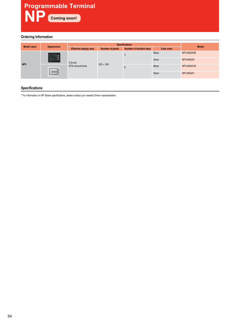
Programmable Terminal
NPOrdering Information
Model nameSpecifications
ModelEffective display area Number of pixels Number of function keys Case color
NP3 3.8-inchSTN monochrome 320 × 240
3Black NP3-MQ000B
Silver NP3-MQ000
6 Black NP3-MQ001B
Silver NP3-MQ001
Specifications
Coming soon!
* For information on NP Series specifications, please contact your nearest Omron representative.
Appearance
Floatless Level Controller (Basic Type)
61FModel Number Structure
1 261F- @@
1. Control ApplicationG: Automatic water supply and drainageG1: Automatic water supply with idling prevention or water
shortage alarmG2: Automatic water supply and drainage with abnormal
water increase alarmG3: Automatic water supply and drainage with full tank and
water shortage alarmG4: Automatic water supply with water level indicator for
water supply tank and water receiving tank andprevention of idling due to water shortage
I: Liquid level indication and alarm (no two-wire models)
2. TypeBlank: General-purposeL 2KM: Long-distance (for 2 km)L 4KM: Long-distance (for 4 km)H: High-sensitivityD: Low-sensitivityR: Two-wireT: High-temperature
Position of LED indicator
Ordering Information
Note: Ask your OMRON representative about power supply voltages.
Type General-purpose Long-distance, 2 km Long-distance, 4 km High-sensitivityModel Model Model Model
Application G 61F-G 61F-GL 2KM 61F-GL 4KM 61F-GHApplication G1 61F-G1 61F-G1L 2KM 61F-G1L 4KM 61F-G1HApplication G2 61F-G2 61F-G2L 2KM 61F-G2L 4KM 61F-G2HApplication G3 61F-G3 61F-G3L 2KM 61F-G3L 4KM 61F-G3HApplication G4 61F-G4 61F-G4L 2KM 61F-G4L 4KM 61F-G4HApplication I 61F-I 61F-IL 2KM 61F-IL 4KM 61F-IHRelay Unit 61F-11 61F-11L 2KM 61F-11L 4KM 61F-11H
Type Low-sensitivity 2-wire Tropical environments High-temperatureModel Model Model Model
Application G 61F-GD 61F-GR 61F-G-TDL 61F-GT
Application G1 61F-G1D 61F-G1R 61F-G1-TDL 61F-G1T
Application G2 61F-G2D 61F-G2R 61F-G2-TDL 61F-G2T
Application G3 61F-G3D 61F-G3R 61F-G3-TDL 61F-G3T
Application G4 61F-G4D 61F-G4R 61F-G4-TDL 61F-G4T
Application I 61F-ID --- 61F-I-TDL 61F-ITRelay Unit 61F-11D 61F-11R --- 61F-11T

Specifications
Note: 1. The @ in the model name represents G, G1, G2, G3, G4, and I.2. The suffix “TDL” attached to the model name represents models designed for tropical regions (storage humidity of 45 to 90% RH).3. The length when using completely-insulated, 600-V, 3-conductor (0.75 mm2) cabtire cables. Usable cable lengths will become shorter as the cable diameter or number of conductors becomes
larger.4. The insulation resistance and dielectric strength indicate values between power terminals and Electrode terminals, between power terminals and contact terminals, and between Electrode
terminals and contact terminals.5. Possible to use with 15 kΩ or less, however, this may cause reset failure.6. High-sensitivity Controllers use advanced operation.
Items General-purposeController
61F-@ (TDL)(see note1 and 2)
High-temperatureController
61F-@T(see note 1)
Long-distanceControllers
61F-@L 2KM(for 2 km)
61F-@L 4KM(for 4 km)
(see note 1)
High-sensitivityControllers
61F-@H(see note 1)
Low-sensitivityController
61F-@D(see note 1)
Two-wire Controller
61F-@R(see note 1)
Controlling materials andoperating conditions
For control of ordinarypurified water or sewage
For control of ordinarypurified water or sewagewater in cases where theambient temperature ishigh.
For control of ordinarypurified water in caseswhere the distancebetween sewage pumpsand water tanks orbetween receiver tanksand supply tanks is longor where remote controlis required.
For control of liquids withhigh specific resistancesuch as distilled water
For control of liquids withlow specific resistancesuch as salt water,sewage water, acidchemicals, alkali
For control of ordinarypurified water or sewagewater used in combinationwith Two-wire ElectrodeHolder (incorporating aresistor of 6.8 kΩ)
Supply voltage 100, 110, 120, 200, 220 or 240 VAC; 50/60 HzOperating voltage range 85% to 110% of rated voltageInterElectrode voltage 8 VAC 24 VAC 8 VACInterElectrode current Approx. 1 mA AC max.Power consumption 61F-G@: 3.5 VA max.; G1F-G1@, G1F-G2@, or G1F-I@: 5.5 VA max.; G1F-G3@: 7.5 VA max.; G1F-G4@: 14.5 VA max.InterElectrode operateresistance
0 to approx. 4 kΩ 0 to approx. 5 kΩ 0 to approx. 1.8 kΩ (for2 km)0 to approx. 0.7 kΩ (for4 km)
Approx. 15 kΩ to 70 kΩ (see note 5)
0 to approx. 1.8 kΩ 0 to approx. 1.1 kΩ
InterElectrode releaseresistance
Approx. 15 k to ∞ Ω Approx. 15 k to ∞ Ω 4 k to ∞ Ω (for 2 km)2.5 k to ∞ Ω (for 4 km)
Approx. 300 k to ∞ Ω Approx. 5 k to ∞ Ω Approx. 15 k to ∞ Ω
Cable length(see note 3)
1 km max. 600 m max. 2 km max.4 km max.
50 m max. 1 km max. 800 m max.
Control output 2 A, 220 VAC (Inductive load: cosφ = 0.4)5 A, 220 VAC (Resistive load)
Ambient temperature Operating: –10°C to 55°C (–10°C to 70°C for 61F-@T)Ambient humidity Operating: 45% to 85% RHInsulation resistance (see note4)
100 MΩ min. (at 500 VDC)
Dielectric strength(see note 4)
2000 VAC, 50/60 Hz for 1 min.
Life expectancy Electrical: 500,000 operations min.Mechanical: 5,000,000 operations min.
Weight 61F-G@: Approx 380 g, G1F-G1@, G1F-G2@, or G1F-I@: Approx. 750 g; G1F-G3@: Approx. 930 g;G1F-G4@: Approx. 1,710 g
water
chemicals
Single-phase Current Relay
K8AB-ASOrdering information
Measuring current Supply voltage Model2 to 20 mA AC/DC, 10 to 100 mA AC/DC,50 to 500 mA AC/DC
24 VAC/DC K8AB-AS1 24 VAC/DC100 to 115 VAC K8AB-AS1 100-115 VAC200 to 230 VAC K8AB-AS1 200-230 VAC
0.1 to 1 A AC/DC, 0.5 to 5 A AC/DC,0.8 to 8 A AC/DC
24 VAC/DC K8AB-AS2 24 VAC/DC100 to 115 VAC K8AB-AS2 100-115 VAC200 to 230 VAC K8AB-AS2 200-230 VAC
10 to 100 A AC, 20 to 200 A AC 24 VAC/DC K8AB-AS3 24 VAC/DC100 to 115 VAC K8AB-AS3 100-115 VAC200 to 230 VAC K8AB-AS3 200-230 VAC
Specifications
Note: 1. The primary current value of Current Transformer, K8AC-CT200L.
Item SpecificationsOperating power 24 VAC/DC, 100/115 VAC, 200/230 VACPower consumption 24 VAC/DC: 5 VA/1 W max.
100/115 VAC: 4 VA max.200/230 VAC: 5 VA max.
Rated input K8AB-AS1 AC/DC2-20mA/10-100mA/50-500mAK8AB-AS2 AC/DC0.1-1A/0.5-5A/0.8-8AK8AB-AS3 AC10-100A/20-200A (See note 1.)
Input impedance K8AB-AS1 5 Ω max.K8AB-AS2 0.2 Ω max.K8AB-AS3 Use in combination with the Omron K8AC-CT200L Current Transformer
Operating value setting range (SV) 10% to 100% of maximum rated input valueHysteresis (HYS) 5% to 50% of operating valueOperating time (T) 0.1 to 30 sOperating power ON lock (LOCK) 0 to 30 sOutput relays One SPDT relayOutput relays Resistive load 6A at 250 VAC
6A at 30 VDCMaximum switchingcapacity
1,500 VA
Minimum load 10 mA at 5 VDCElectrical life Make: 50,000 times, Break: 30,000 times
Ambient operating temperature -20 to 60°C (with no condensation or icing)Ambient operating humidity 25% to 85% (with no condensation)
Accessories
Note: The K8AB-AS3 is designed to be used in combination with the K8AC-CT200L (direct input not possible)
Current transformer Input range Applicable relay Model10 to 100 A AC, 20 to 200 A AC K8AB-AS3 K8AC-CT200L
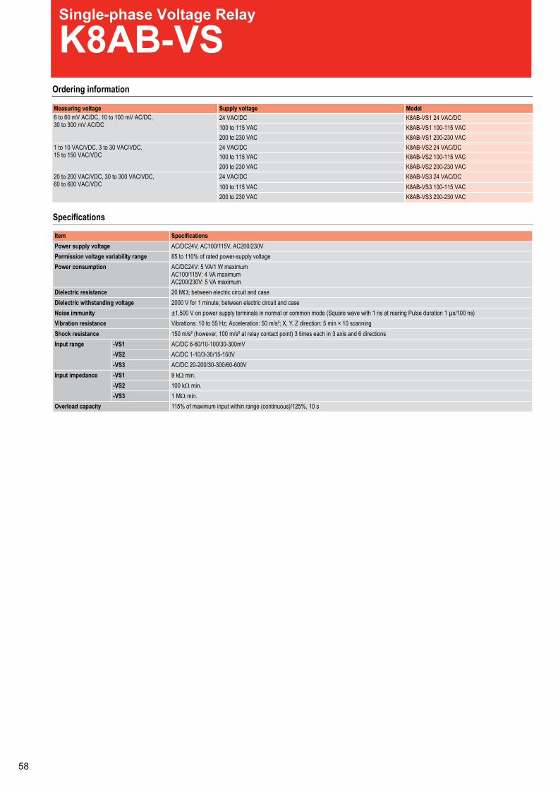
Single-phase Voltage Relay
K8AB-VSOrdering information
Measuring voltage Supply voltage Model6 to 60 mV AC/DC, 10 to 100 mV AC/DC,30 to 300 mV AC/DC
24 VAC/DC K8AB-VS1 24 VAC/DC100 to 115 VAC K8AB-VS1 100-115 VAC200 to 230 VAC K8AB-VS1 200-230 VAC
1 to 10 VAC/VDC, 3 to 30 VAC/VDC,15 to 150 VAC/VDC
24 VAC/DC K8AB-VS2 24 VAC/DC100 to 115 VAC K8AB-VS2 100-115 VAC200 to 230 VAC K8AB-VS2 200-230 VAC
20 to 200 VAC/VDC, 30 to 300 VAC/VDC,60 to 600 VAC/VDC
24 VAC/DC K8AB-VS3 24 VAC/DC100 to 115 VAC K8AB-VS3 100-115 VAC200 to 230 VAC K8AB-VS3 200-230 VAC
Specifications
Item SpecificationsPower supply voltage AC/DC24V, AC100/115V, AC200/230VPermission voltage variability range 85 to 110% of rated power-supply voltagePower consumption AC/DC24V: 5 VA/1 W maximum
AC100/115V: 4 VA maximumAC200/230V: 5 VA maximum
Dielectric resistance 20 MΩ; between electric circuit and caseDielectric withstanding voltage 2000 V for 1 minute; between electric circuit and caseNoise immunity ±1,500 V on power supply terminals in normal or common mode (Square wave with 1 ns at rearing Pulse duration 1 µs/100 ns)Vibration resistance Vibrations: 10 to 55 Hz; Acceleration: 50 m/s²; X, Y, Z direction: 5 min × 10 scanningShock resistance 150 m/s² (however, 100 m/s² at relay contact point) 3 times each in 3 axis and 6 directionsInput range -VS1 AC/DC 6-60/10-100/30-300mV
-VS2 AC/DC 1-10/3-30/15-150V-VS3 AC/DC 20-200/30-300/60-600V
Input impedance -VS1 9 kΩ min.-VS2 100 kΩ min.-VS3 1 MΩ min.
Overload capacity 115% of maximum input within range (continuous)/125%, 10 s
Single-phase Voltage Relay
K8AB-VWOrdering information
Measuring voltage Supply voltage Model6 to 60 mV AC/DC, 10 to 100 mV AC/DC,30 to 300 mV AC/DC
24 VAC/DC K8AB-VW1 24 VAC/DC100 to 115 VAC K8AB-VW1 100-115 VAC200-230 VAC K8AB-VW1 200-230 VAC
1 to 10 V AC/DC, 3 to 30 V AC/DC,15 to 150 V AC/DC
24 VAC/DC K8AB-VW2 24 VAC/DC100 to 115 VAC K8AB-VW2 100-115 VAC200 to 230 VAC K8AB-VW2 200-230 VAC
20 to 200 V AC/DC, 30 to 300 V AC/DC,60 to 600 V AC/DC
24 VAC/DC K8AB-VW3 24 VAC/DC100 to 115 VAC K8AB-VW3 100-115 VAC200 to 230 VAC K8AB-VW3 200-230 VAC
Specifications
Item SpecificationsPower supply voltage AC/DC24V, AC100/115V, AC200/230VPermission voltage variability range 85 to 110% of rated power-supply voltagePower consumption AC/DC24V: 5 VA/1 W maximum
AC100/115V: 4 VA maximumAC200/230V: 5 VA maximum
Dielectric resistance 20 MΩ; between electric circuit and caseDielectric withstanding voltage 2000 V for 1 minute; between electric circuit and caseNoise immunity ±1,500 V on power supply terminals in normal or common mode (Square wave with 1 ns at rearing Pulse duration 1 µs/100 ns)Vibration resistance Vibrations: 10 to 55 Hz; Acceleration: 50 m/s²; X, Y, Z direction: 5 min × 10 scanningShock resistance 150 m/s² (however, 100 m/s² at relay contact point) 3 times each in 3 axis and 6 directionsInput range -VW1 AC/DC 6-60/10-100/30-300mV
-VW2 AC/DC 1-10/3-30/15-150V-VW3 AC/DC 20-200/30-300/60-600V
Input impedance -VW1 9 kΩ min.-VW2 100 kΩ min.-VW3 1 MΩ min.
Overload capacity 115% of maximum input within range (continuous)/125%, 10 s

Phase-sequence Phase-loss Relay
K8AB-PHOrdering information
Specifications
Rated input voltage Model200 to 500 VAC K8AB-PH1
Ambient operating temperature -20 to 60°C (with no condensation or icing)Storage temperature -40 to 70°C (with no condensation or icing)Altitude 2,000 m max.Voltage fluctuation range 85 to 110% of rated input voltageInput frequency 50/60 Hz ±5 Hz (AC power supply)Output relays Resistive load 6 A at 250 VAC (cosφ = 1), 6 A at 30 VDC (L/R = 0 ms)
Inductive load 1 A at 250 VAC (cosφ = 0.4), 1 A at 30 VDC (L/R = 7 ms)Minimum load 10 mA at 5 VDCMaximum contact voltage 250 VACMaximum contact current 6 A ACMaximum switching capacity 1,500 VAMechanical life 10,000,000 operationsElectrical life Make: 50,000 times, break: 30,000 times
Terminal screw tightening torque 1.2 NmDegree of protection Terminal section: IP20, rear case: IP40Case color Munsell 5Y8/1 (ivory)Case material ABS resin (self-extinguishing resin) UL94-V0Weight 200 gMounting Mounted to DIN-rail or via M4 screwsRated input voltage Non-isolated 200 to 500 VAC (15 VA)Phase-sequence, phase-loss operating time 0.1 s max. (value when rated operating voltage changes quickly from 0 to 100%)
(relays are normally ON and turn OFF for phase-sequence or loss phase errors)Resetting method Automatic resetInput frequency 45 to 65 HzInput impedance 100 kΩ min.Indicators Power (PWR): Green LED, relay output (RY): Yellow LEDOutput relays One SPDT relay (6 A at 250 VAC, resistive load)Size in mm (H × W × D) 90 × 22.5 × 100
Item Specifications
0
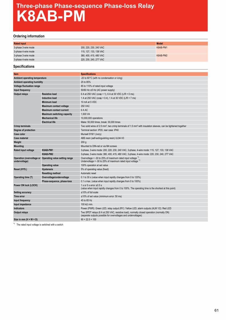
Phase-sequence Phase-loss Relay
K8AB-PHOrdering information
Specifications
Rated input voltage Model200 to 500 VAC K8AB-PH1
Ambient operating temperature -20 to 60°C (with no condensation or icing)Storage temperature -40 to 70°C (with no condensation or icing)Altitude 2,000 m max.Voltage fluctuation range 85 to 110% of rated input voltageInput frequency 50/60 Hz ±5 Hz (AC power supply)Output relays Resistive load 6 A at 250 VAC (cosφ = 1), 6 A at 30 VDC (L/R = 0 ms)
Inductive load 1 A at 250 VAC (cosφ = 0.4), 1 A at 30 VDC (L/R = 7 ms)Minimum load 10 mA at 5 VDCMaximum contact voltage 250 VACMaximum contact current 6 A ACMaximum switching capacity 1,500 VAMechanical life 10,000,000 operationsElectrical life Make: 50,000 times, break: 30,000 times
Terminal screw tightening torque 1.2 NmDegree of protection Terminal section: IP20, rear case: IP40Case color Munsell 5Y8/1 (ivory)Case material ABS resin (self-extinguishing resin) UL94-V0Weight 200 gMounting Mounted to DIN-rail or via M4 screwsRated input voltage Non-isolated 200 to 500 VAC (15 VA)Phase-sequence, phase-loss operating time 0.1 s max. (value when rated operating voltage changes quickly from 0 to 100%)
(relays are normally ON and turn OFF for phase-sequence or loss phase errors)Resetting method Automatic resetInput frequency 45 to 65 HzInput impedance 100 kΩ min.Indicators Power (PWR): Green LED, relay output (RY): Yellow LEDOutput relays One SPDT relay (6 A at 250 VAC, resistive load)Size in mm (H × W × D) 90 × 22.5 × 100
Item Specifications
Three-phase Phase-sequence Phase-loss Relay
K8AB-PMOrdering information
Specifications
Rated input Model3-phase 3-wire mode 200, 220, 230, 240 VAC K8AB-PM13-phase 4-wire mode 115, 127, 133, 138 VAC3-phase 3-wire mode 380, 400, 415, 480 VAC K8AB-PM23-phase 4-wire mode 220, 230, 240, 277 VAC
Ambient operating temperature -20 to 60°C (with no condensation or icing)Ambient operating humidity 25 to 85%Voltage fluctuation range 85 to 110% of rated input voltageInput frequency 50/60 Hz ±5 Hz (AC power supply)Output relays Resistive load 6 A at 250 VAC (cosφ = 1), 6 A at 30 VDC (L/R = 0 ms)
Inductive load 1 A at 250 VAC (cosφ = 0.4), 1 A at 30 VDC (L/R = 7 ms)Minimum load 10 mA at 5 VDCMaximum contact voltage 250 VACMaximum contact current 6 A ACMaximum switching capacity 1,500 VAMechanical life 10,000,000 operationsElectrical life Make: 50,000 times, break: 30,000 times
Crimp terminals Two solid wires of 2.5 mm², two crimp terminals of 1.5 mm² with insulation sleeves, can be tightened togetherDegree of protection Terminal section: IP20, rear case: IP40Case color Munsell 5Y8/1 (ivory)Case material ABS resin (self-extinguishing resin) UL94-V0Weight 200 gMounting Mounted to DIN-rail or via M4 screwsRated input voltage K8AB-PM1 3-phase, 3-wire mode: 200, 220, 230, 240 VAC, 3-phase, 4-wire mode: 115, 127, 133, 138 VAC
K8AB-PM2 3-phase, 3-wire mode: 380, 400, 415, 480 VAC, 3-phase, 4-wire mode: 220, 230, 240, 277 VACOperation (overvoltage orundervoltage)
Operating value setting range Overvoltage = -30 to 25% of maximum rated input voltage *1
Undervoltage = -30 to 25% of maximum rated input voltage *1
*1 The rated input voltage is switched with a switch
Operating value 100% operation at set valueReset (HYS.) Hysteresis 5% of operating value (fixed)
Resetting method Automatic resetOperating time (T) Overvoltage/undervoltage 0.1 to 30 s (value when input rapidly changes from 0 to 120%)
Phase-sequence, phase-loss 0.1 s max. (value when input rapidly changes from 0 to 100%)Power ON lock (LOCK) 1 s or 5 s error ±0.5 s
(value when input rapidly changes from 0 to 100%. The operating time is the shortest at this point)Setting accuracy ±10% of full scaleTime error ±10% of set value (minimum error: 50 ms)Input frequency 45 to 65 HzInput impedance 100 kΩ min.Indicators Power (PWR): Green LED, relay output (RY): Yellow LED, alarm outputs (ALM 1/2): Red LEDOutput relays Two SPDT relays (6 A at 250 VAC, resistive load), normally closed operation (normally ON)
(separate outputs possible for overvoltages and undervoltages)Size in mm (H × W × D) 90 × 22.5 × 100
Item Specifications
1

Three-phase Asymmetry and Phase-sequence Phase-loss Relay
K8AB-PAOrdering information
Specifications
Rated input Model3-phase 3-wire mode 200, 220, 230, 240 VAC K8AB-PA13-phase 4-wire mode 115, 127, 133, 138 VAC3-phase 3-wire mode 380, 400, 415, 480 VAC K8AB-PA23-phase 4-wire mode 220, 230, 240, 277 VAC
Ambient operating temperature -20 to 60°C (with no condensation or icing)Storage temperature -40 to 70°C (with no condensation or icing)Altitude 2,000 m max.Voltage fluctuation range 85 to 110% of rated input voltageInput frequency 50/60 Hz ±5 Hz (AC power supply)Output relays Resistive load 6 A at 250 VAC (cosφ = 1), 6 A at 30 VDC (L/R = 0 ms)
Inductive load 1 A at 250 VAC (cosφ = 0.4), 1 A at 30 VDC (L/R = 7 ms)Minimum load 10 mA at 5 VDCMaximum contact voltage 250 VACMaximum contact current 6 A ACMaximum switching capacity 1,500 VAMechanical life 10,000,000 operationsElectrical life Make: 50,000 times, break: 30,000 times
Crimp terminals Two solid wires of 2.5 mm², two crimp terminals of 1.5 mm² with insulation sleeves, can be tightened togetherDegree of protection Terminal section: IP20, rear case: IP40Case color Munsell 5Y8/1 (ivory)Case material ABS resin (self-extinguishing resin) UL94-V0Weight 200 gRated input voltage K8AB-PA1 3-phase, 3-wire mode: 200, 220, 230, 240 VAC, 3-phase, 4-wire mode: 115, 127, 133, 138 VAC
K8AB-PA2 3-phase, 3-wire mode: 380, 400, 415, 480 VAC, 3-phase, 4-wire mode: 220, 230, 240, 277 VACAsymmetry operation(ASY.)
Operating value setting range Asymmetry rate: 2 to 22%Operating value 100% operation at set value
Asymmetry operating value = rated input voltage × asymmetry set value [%]The asymmetry operation will function when the difference between the highest and lowest voltage phases equals or exceeds theasymmetry operating value
Reset (HYS.) Hysteresis 5% of operating value (fixed)Resetting method Automatic reset
Operating time (T) Asymmetry 0.1 s to 30 s (value when input rapidly changes from 0 to 120%)Phase-sequence, phase-loss 0.1 s max. (value when input rapidly changes from 0 to 100%)
Power ON lock (LOCK) 1 s or 5 s (value when input rapidly changes from 0 to 100%. The operating time is the shortest at this point)Setting accuracy ±10% of full scaleTime error ±10% of set value (minimum error: 50 ms)Input frequency 45 to 65 HzInput impedance 100 kΩ min.Indicators Power (PWR): Green LED, relay output (RY): Yellow LED, alarm outputs (ALM 1/2): Red LEDOutput relays One SPDT relay (6 A at 250 VAC, resistive load), normally closed operation (normally ON)Size in mm (H × W × D) 90 × 22.5 × 100
Item Specifications
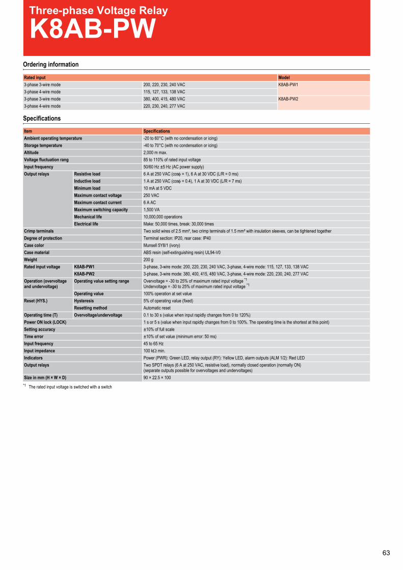
Three-phase Voltage Relay
K8AB-PWOrdering information
Specifications
Rated input Model3-phase 3-wire mode 200, 220, 230, 240 VAC K8AB-PW13-phase 4-wire mode 115, 127, 133, 138 VAC3-phase 3-wire mode 380, 400, 415, 480 VAC K8AB-PW23-phase 4-wire mode 220, 230, 240, 277 VAC
Ambient operating temperature -20 to 60°C (with no condensation or icing)Storage temperature -40 to 70°C (with no condensation or icing)Altitude 2,000 m max.Voltage fluctuation rang 85 to 110% of rated input voltageInput frequency 50/60 Hz ±5 Hz (AC power supply)Output relays Resistive load 6 A at 250 VAC (cosφ = 1), 6 A at 30 VDC (L/R = 0 ms)
Inductive load 1 A at 250 VAC (cosφ = 0.4), 1 A at 30 VDC (L/R = 7 ms)Minimum load 10 mA at 5 VDCMaximum contact voltage 250 VACMaximum contact current 6 A ACMaximum switching capacity 1,500 VAMechanical life 10,000,000 operationsElectrical life Make: 50,000 times, break: 30,000 times
Crimp terminals Two solid wires of 2.5 mm², two crimp terminals of 1.5 mm² with insulation sleeves, can be tightened togetherDegree of protection Terminal section: IP20, rear case: IP40Case color Munsell 5Y8/1 (ivory)Case material ABS resin (self-extinguishing resin) UL94-V0Weight 200 gRated input voltage K8AB-PW1 3-phase, 3-wire mode: 200, 220, 230, 240 VAC, 3-phase, 4-wire mode: 115, 127, 133, 138 VAC
K8AB-PW2 3-phase, 3-wire mode: 380, 400, 415, 480 VAC, 3-phase, 4-wire mode: 220, 230, 240, 277 VACOperation (overvoltageand undervoltage)
Operating value setting range Overvoltage = -30 to 25% of maximum rated input voltage *1
Undervoltage = -30 to 25% of maximum rated input voltage *1
*1 The rated input voltage is switched with a switch
Operating value 100% operation at set valueReset (HYS.) Hysteresis 5% of operating value (fixed)
Resetting method Automatic resetOperating time (T) Overvoltage/undervoltage 0.1 to 30 s (value when input rapidly changes from 0 to 120%)Power ON lock (LOCK) 1 s or 5 s (value when input rapidly changes from 0 to 100%. The operating time is the shortest at this point)Setting accuracy ±10% of full scaleTime error ±10% of set value (minimum error: 50 ms)Input frequency 45 to 65 HzInput impedance 100 kΩ min.Indicators Power (PWR): Green LED, relay output (RY): Yellow LED, alarm outputs (ALM 1/2): Red LEDOutput relays Two SPDT relays (6 A at 250 VAC, resistive load), normally closed operation (normally ON)
(separate outputs possible for overvoltages and undervoltages)Size in mm (H × W × D) 90 × 22.5 × 100
Item Specifications
OMRON ASIA P A CIF IC PT E . LTD.
2/F King’s Court Bldg II, 2129 Chino Roces Ave.Corner Dela Rosa St. Makati City, Philippines Tel: (02) 811-2831~36 Fax: (02) 811-2583 Website: www.omron-ap.com.ph Email: [email protected]
Authorized Distributor