Section-6.-Specifications-4.pdf - City Of Cebu
40
Technical Specifications ITEM 101 – REMOVAL OF STRUCTURES AND OBSTRUCTIONS 101.1 Description This Item shall consist of the removal wholly or in part, and satisfactory disposal of all buildings, fences, structures, old pavements, abandoned pipe lines, and any other obstructions which are not designated or permitted to remain, except for the obstructions to be removed and disposed off under other items in the Contract. It shall also include the salvaging of designated materials and backfilling the resulting trenches, holes, and pits. 101.2 Construction Requirements 101.2.1 General The Contractor shall perform the work described above, within and adjacent to the roadway, on Government land or easement, as shown on the Plans or as directed by the Engineer. All designated salvable material shall be removed, without unnecessary damage, in sections or pieces which may be readily transported, and shall be stored by the Contractor at specified places on the project or as otherwise shown in the Special Provisions. Perishable material shall be handled as designated in Subsection 100.2.2 Nonperishable material may be disposed off outside the limits of view from the project with written permission of the property owner on whose property the material is placed. Copies of all agreements with property owners are to be furnished to the Engineer. Basements or cavities left by the structure removal shall be filled with acceptable material to the level of the surrounding ground and, if within the prism of construction, shall be compacted to the required density. 101.2.2 Removal of Existing Bridges, Culverts, and other Drainage Structures All existing bridges, culverts and other drainage structures in use by traffic shall not be removed until satisfactory arrangements have been made to accommodate traffic. The removal of existing culverts within embankment areas will be required only as necessary for the installation of new structures. Abandoned culverts shall be broken down, crushed and sealed or plugged. All retrieved culvert for future use as determined by the Engineer shall be carefully removed and all precautions shall be employed to avoid breakage or structural damage to any of its part. All sections of structures removed which are not designated for stockpiling or re-laying shall become the property of the Government and be removed from the project or disposed off in a manner approved by the Engineer. Unless otherwise directed, the substructures of existing structures shall be removed down to the natural stream bottom and those parts outside of the stream shall be removed down to at least 300 mm (12 inches) below natural ground surface. Where such portions of existing structures lie wholly or in part within the limits for a new structure, they shall be removed as necessary to accommodate the construction of the proposed structure. Steel bridges and wood bridges when specified to be salvaged shall be carefully dismantled without damaged. Steel members shall be match marked unless such match marking is waived by the Engineer. All salvaged material shall be stored as specified in Subsection 101.2.1.
-
Upload
khangminh22 -
Category
Documents
-
view
2 -
download
0
Transcript of Section-6.-Specifications-4.pdf - City Of Cebu
Technical Specifications
ITEM 101 – REMOVAL OF STRUCTURES AND OBSTRUCTIONS 101.1 Description
This Item shall consist of the removal wholly or in part, and satisfactory disposal of all
buildings, fences, structures, old pavements, abandoned pipe lines, and any other obstructions which are not designated or permitted to remain, except for the obstructions to be removed and disposed off under other items in the Contract. It shall also include the salvaging of designated materials and backfilling the resulting trenches, holes, and pits.
101.2 Construction Requirements
101.2.1 General
The Contractor shall perform the work described above, within and adjacent to the roadway, on Government land or easement, as shown on the Plans or as directed by the Engineer. All designated salvable material shall be removed, without unnecessary damage, in sections or pieces which may be readily transported, and shall be stored by the Contractor at specified places on the project or as otherwise shown in the Special Provisions. Perishable material shall be handled as designated in Subsection 100.2.2 Nonperishable material may be disposed off outside the limits of view from the project with written permission of the property owner on whose property the material is placed. Copies of all agreements with property owners are to be furnished to the Engineer. Basements or cavities left by the structure removal shall be filled with acceptable material to the level of the surrounding ground and, if within the prism of construction, shall be compacted to the required density. 101.2.2 Removal of Existing Bridges, Culverts, and other Drainage Structures
All existing bridges, culverts and other drainage structures in use by traffic shall not
be removed until satisfactory arrangements have been made to accommodate traffic. The removal of existing culverts within embankment areas will be required only as necessary for the installation of new structures. Abandoned culverts shall be broken down, crushed and sealed or plugged. All retrieved culvert for future use as determined by the Engineer shall be carefully removed and all precautions shall be employed to avoid breakage or structural damage to any of its part. All sections of structures removed which are not designated for stockpiling or re-laying shall become the property of the Government and be removed from the project or disposed off in a manner approved by the Engineer.
Unless otherwise directed, the substructures of existing structures shall be removed
down to the natural stream bottom and those parts outside of the stream shall be removed down to at least 300 mm (12 inches) below natural ground surface. Where such portions of existing structures lie wholly or in part within the limits for a new structure, they shall be removed as necessary to accommodate the construction of the proposed structure.
Steel bridges and wood bridges when specified to be salvaged shall be carefully
dismantled without damaged. Steel members shall be match marked unless such match marking is waived by the Engineer. All salvaged material shall be stored as specified in Subsection 101.2.1.
Technical Specifications
Structures designated to become the property of the Contractor shall be removed from the right-of-way.
Blasting or other operations necessary for the removal of an existing structure or
obstruction, which may damage new construction, shall be completed prior to placing the new work, unless otherwise provided in the Special Provisions.
101.2.3 Removal of Pipes Other than Pipe Culverts
Unless otherwise provided, all pipes shall be carefully removed and every precaution
taken to avoid breakage or damaged. Pipes to be relaid shall be removed and stored when necessary so that there will be no loss of damage before re-laying. The Contractor shall replace sections lost from storage or damage by negligence, at his own expense.
101.2.4 Removal of Existing Pavement, Sidewalks, Curbs, etc.
All concrete pavement, base course, sidewalks, curbs, gutters, etc., designated for
removal, shall be: (1) Broken into pieces and used for riprap on the project, or (2) Broken into pieces, the size of which shall not exceed 300 mm (12 inches) in
any dimension and stockpiled at designated locations on the project for use by the Government, or
(3) Otherwise demolished and disposed off as directed by the Engineer. When
specified, ballast, gravel, bituminous materials or other surfacing or pavement materials shall be removed and stockpiled as required in Subsection 101.2.1, otherwise such materials shall be disposed off as directed.
There will be no separate payment for excavating for removal of structures and
obstructions or for backfilling and compacting the remaining cavity.
101.3 Method of Measurement When the Contract stipulates that payment will be made for removal of obstructions
on lump-sum basis, the pay item will include all structures and obstructions encountered within the roadway. Where the contract stipulates that payment will be made for the removal of specific items on a unit basis, measurement will be made by the unit stipulated in the Contract.
Whenever the Bill of Quantities does not contain an item for any aforementioned
removals, the work will not be paid for directly, but will be considered as a subsidiary obligation of the Contractor under other Contract Items. 101.4 Basis of Payment
The accepted quantities, measured as prescribed in Section 101.3, shall be paid for
at the Contract unit price or lump sum price bid for each of the Pay Items listed below that is included in the Bill of Quantities which price and payment shall be full compensation for removing and disposing of obstructions, including materials, labor, equipments, tools and incidentals necessary to complete the work prescribed in this Item. The price shall also include backfilling, salvage of materials removed, their custody, preservation, storage on the right-of-way and disposal as provided herein.
Technical Specifications
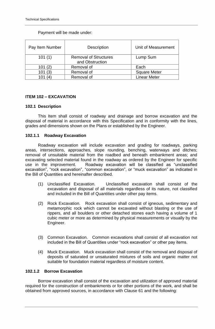
Payment will be made under:
Pay Item Number
Description
Unit of Measurement
101 (1) Removal of Structures and Obstruction
Lump Sum
101 (2) Removal of Each
101 (3) Removal of Square Meter
101 (4) Removal of Linear Meter
ITEM 102 – EXCAVATION
102.1 Description This Item shall consist of roadway and drainage and borrow excavation and the
disposal of material in accordance with this Specification and in conformity with the lines, grades and dimensions shown on the Plans or established by the Engineer.
102.1.1 Roadway Excavation
Roadway excavation will include excavation and grading for roadways, parking areas, intersections, approaches, slope rounding, benching, waterways and ditches; removal of unsuitable material from the roadbed and beneath embankment areas; and excavating selected material found in the roadway as ordered by the Engineer for specific use in the improvement. Roadway excavation will be classified as “unclassified excavation”, “rock excavation”, “common excavation”, or “muck excavation” as indicated in the Bill of Quantities and hereinafter described.
(1) Unclassified Excavation. Unclassified excavation shall consist of the
excavation and disposal of all materials regardless of its nature, not classified and included in the Bill of Quantities under other pay items.
(2) Rock Excavation. Rock excavation shall consist of igneous, sedimentary and
metamorphic rock which cannot be excavated without blasting or the use of rippers, and all boulders or other detached stones each having a volume of 1 cubic meter or more as determined by physical measurements or visually by the Engineer.
(3) Common Excavation. Common excavations shall consist of all excavation not
included in the Bill of Quantities under “rock excavation” or other pay items. (4) Muck Excavation. Muck excavation shall consist of the removal and disposal of
deposits of saturated or unsaturated mixtures of soils and organic matter not suitable for foundation material regardless of moisture content.
102.1.2 Borrow Excavation
Borrow excavation shall consist of the excavation and utilization of approved material
required for the construction of embankments or for other portions of the work, and shall be obtained from approved sources, in accordance with Clause 61 and the following:
Technical Specifications
(1) Borrow, Case 1 Borrow Case 1 will consist of material obtained from sources designated
on the Plans or in the Special Provisions. (2) Borrow, Case 2
Borrow Case 2 will consist of material obtained from sources provided by the Contractor.
The material shall meet the quality requirements determined by the Engineer unless
otherwise provided in the Contract.
102.2 Construction Requirements 102.2.1 General
When there is evidence of discrepancies on the actual elevations and that shown on
the Plans, a pre-construction survey referred to the datum plane used in the approved Plan shall be undertaken by the Contractor under the control of the Engineer to serve as basis for the computation of the actual volume of the excavated materials.
All excavations shall be finished to reasonably smooth and uniform surfaces. No
materials shall be wasted without authority of the Engineer. Excavation operations shall be conducted so that material outside of the limits of slopes will not be disturbed. Prior to excavation, all necessary clearing and grubbing in that area shall have been performed in accordance with Item 100, Clearing and Grubbing.
102.2.2 Conservation of Topsoil
Where provided for on the Plans or in the Special Provisions, suitable topsoil
encountered in excavation and on areas where embankment is to be placed shall be removed to such extent and to such depth as the Engineer may direct. The removed topsoil shall be transported and deposited in storage piles at locations approved by the Engineer. The topsoil shall be completely removed to the required depth from any designated area prior to the beginning of regular excavation or embankment work in the area and shall be kept separate from other excavated materials for later use. 102.2.3 Utilization of Excavated Materials
All suitable material removed from the excavation shall be used in the formation of the embankment, subgrade, shoulders, slopes, bedding, and backfill for structures, and for other purposes shown on the Plans or as directed.
The Engineer will designate as unsuitable those soils that cannot be properly
compacted in embankments. All unsuitable material shall be disposed off as shown on the Plans or as directed without delay to the Contractor.
Only approved materials shall be used in the construction of embankments and
backfills. All excess material, including rock and boulders that cannot be used in
embankments shall be disposed off as directed. Material encountered in the excavation and determined by the Engineer as suitable
for topping, road finishing, slope protection, or other purposes shall be conserved and utilized as directed by the Engineer.
Technical Specifications
Borrow material shall not be placed until after the readily accessible roadway excavation has been placed in the fill, unless otherwise permitted or directed by the Engineer. If the Contractor places moré borrow than is required and thereby causes a waste of excavation, the amount of such waste will be deducted from the borrow volume. 102.2.4 Prewatering
Excavation areas and borrow pits may be prewatered before excavating the material.
When prewatering is used, the areas to be excavated shall be moistened to the full depth, from the surface to the bottom of the excavation. The water shall be controlled so that the excavated material will contain the proper moisture to permit compaction to the specified density with the use of standard compacting equipment. Prewatering shall be supplemented where necessary, by truck watering units, to ensure that the embankment material contains the proper moisture at the time of compaction.
The Contractor shall provide drilling equipment capable of suitably checking the
moisture penetration to the full depth of the excavation. 102.2.5 Presplitting
Unless otherwise provided in the Contract, rock excavation which requires drilling
and shooting shall be presplit.
Presplitting to obtain faces in the rock and shale formations shall be performed by: (1) drilling holes at uniform intervals along the slope lines, (2) loading and stemming the holes with appropriate explosives and stemming material, and (3) detonating the holes simultaneously.
Prior to starting drilling operations for presplitting, the Contractor shall furnish the
Engineer a plan outlining the position of all drill holes, depth of drilling, type of explosives to be used, loading pattern and sequence of firing. The drilling and blasting plan is for record purposes only and will not absolve the Contractor of his responsibility for using proper drilling and blasting procedures. Controlled blasting shall begin with a short test section of a length approved by the Engineer. The test section shall be presplit, production drilled and blasted and sufficient material excavated whereby the Engineer can determine if the Contractor’s methods are satisfactory. The Engineer may order discontinuance of the presplitting when he determines that the materials encountered have become unsuitable for being presplit.
The holes shall be charged with explosives of the size, kind, strength, and at the
spacing suitable for the formations being presplit, and with stemming material which passes a 9.5 mm (3/8 inch) standard sieve and which has the qualities for proper confinement of the explosives.
The finished presplit slope shall be reasonably uniform and free of loose rock.
Variance from the true plane of the excavated backslope shall not exceed 300 mm (12 inches); however, localized irregularities or surface variations that do not constitute a safety hazard or an impairment to drainage courses or facilities will be permitted.
A maximum offset of 600 mm (24 inches) will be permitted for a construction working
bench at the bottom of each lift for use in drilling the next lower presplitting pattern.
102.2.6 Excavation of Ditches, Gutters, etc. All materials excavated from side ditches and gutters, channel changes, irrigation
ditches, inlet and outlet ditches, toe ditchers, furrow ditches, and such other ditches as may
Technical Specifications
be designated on the Plans or staked by the Engineer, shall be utilized as provided in Subsection 102.2.3.
Ditches shall conform to the slope, grade, and shape of the required cross-section,
with no projections of roots, stumps, rock, or similar matter. The Contractor shall maintain and keep open and free from leaves, sticks, and other debris all ditches dug by him until final acceptance of the work.
Furrow ditches shall be formed by plowing a continuous furrow along the line staked
by the Engineer. Methods other than plowing may be used if acceptable to the Engineer. The ditches shall be cleaned out by hand shovel work, by ditcher, or by some other suitable method, throwing all loose materials on the downhill side so that the bottom of the finished ditch shall be approximately 450 mm (18 inches) below the crest of the loose material piled on the downhill side. Hand finish will not be required, but the flow lines shall be in satisfactory shape to provide drainage without overflow.
102.2.7 Excavation of Roadbed Level
Rock shall be excavated to a depth of 150 mm (6 inches) below subgrade within the
limits of the roadbed, and the excavation backfilled with material designated on the Plans or approved by the Engineer and compacted to the required density.
When excavation methods employed by the Contractor leave undrained pockets in
the rock surface, the Contractor shall at his own expense, properly drain such depressions or when permitted by the Engineer fill the depressions with approved impermeable material.
Material below subgrade, other than solid rock shall be thoroughly scarified to a
depth of 150 mm (6 inches) and the moisture content increased or reduced, as necessary, to bring the material throughout this 150 mm layer to the moisture content suitable for maximum compaction. This layer shall then be compacted in accordance with Subsection 104.3.3. 102.2.8 Borrow Areas
The Contractor shall notify the Engineer sufficiently in advance of opening any
borrow areas so that cross-section elevations and measurements of the ground surface after stripping may be taken, and the borrow material can be tested before being used. Sufficient time for testing the borrow material shall be allowed.
All borrow areas shall be bladed and left in such shape as to permit accurate
measurements after excavation has been completed. The Contractor shall not excavate beyond the dimensions and elevations established, and no material shall be removed prior to the staking out and cross-sectioning of the site. The finished borrow areas shall be approximately true to line and grade established and specified and shall be finished, as prescribed in Clause 61, Standard Specifications for Public Works and Highways, Volume 1. When necessary to remove fencing, the fencing shall be replaced in at least as good condition as it was originally. The Contractor shall be responsible for the confinement of livestock when a portion of the fence is removed. 102.2.9 Removal of Unsuitable Material
Where the Plans show the top portion of the roadbed to be selected topping, all
unsuitable materials shall be excavated to the depth necessary for replacement of the selected topping to the required compacted thickness.

Technical Specifications
Where excavation to the finished graded section results in a subgrade or slopes of unsuitable soil, the Engineer may require the Contractor to remove the unsuitable material and backfill to the finished graded section with approved material. The Contractor shall conduct his operations in such a way that the Engineer can take the necessary cross-sectional measurements before the backfill is placed.
The excavation of muck shall be handled in a manner that will not permit the
entrapment of muck within the backfill. The material used for backfilling up to the ground line or water level, whichever is higher, shall be rock or other suitable granular material selected from the roadway excavation, if available. If not available, suitable material shall be obtained from other approved sources. Unsuitable material removed shall be disposed off in designated areas shown on the Plans or approved by the Engineer.
102.3 Method of Measurement
The cost of excavation of material which is incorporated in the Works or in other
areas of fill shall be deemed to be included in the Items of Work where the material is used. Measurement of Unsuitable or Surplus Material shall be the net volume in its original
position. For measurement purposes, surplus suitable material shall be calculated as the
difference between the net volume of suitable material required to be used in embankment corrected by applying a shrinkage factor or a swell factor in case of rock excavation, determined by laboratory tests to get its original volume measurement, and the net volume of suitable material from excavation in the original position. Separate pay items shall be provided for surplus common, unclassified and rock material.
The Contractor shall be deemed to have included in the contract unit prices all costs
of obtaining land for the disposal of unsuitable or surplus material.
102.4 Basis of Payment The accepted quantities, measured as prescribed in Section 102.3 shall be paid for at
the contract unit price for each of the Pay Items listed below that is included in the Bill of Quantities which price and payment shall be full compensation for the removal and disposal of excavated materials including all labor, equipment, tools, and incidentals necessary to complete the work prescribed in this Item.
Payment will be made under:
Pay Item Number
Description
Unit of Measurement
102 (1) Unsuitable Excavation Cubic Meter 102 (2) Surplus Common Excavation Cubic Meter 102 (3) Surplus Rock Excavation Cubic Meter 102 (4) Surplus Unclassified Excavation Cubic Meter
Item 105 – SUBGRADE PREPARATION
105.1 Description
This Item shall consist of the preparation of the subgrade for the support of overlying
structural layers. It shall extend to full width of the roadway. Unless authorized by the
Technical Specifications
Engineer, subgrade preparation shall not be done unless the Contractor is able to start immediately the construction of the pavement structure.
105.2 Material Requirements
Unless otherwise stated in the Contract and except when the subgrade is in rock cut,
all materials below subgrade level to a depth 150 mm or to such greater depth as may be specified shall meet the requirements of Section 104.2, Selected Borrow for Topping. 105.3 Construction Requirements 105.3.1 Prior Works
Prior to commencing preparation of the subgrade, all culverts, cross drains, ducts
and the like (including their fully compacted backfill), ditches, drains and drainage outlets shall be completed. Any work on the preparation of the subgrade shall not be started unless prior work herein described shall have been approved by the Engineer.
105.3.2 Subgrade Level Tolerances
The finished compacted surface of the subgrade shall conform to the allowable
tolerances as specified hereunder: Permitted variation from + 20 mm design LEVEL OF SURFACE - 30 mm Permitted SURFACE IRREGULARITY MEASURED BY 3-m STRAIGHT EDGE
30 mm
Permitted variation from design CROSSFALL OR CAMBER
+
0.5 %
Permitted variation from design LONGITUDINAL GRADE over 25 m length
± 0.1 %
105.3.3 Subgrade in Common Excavation
Unless otherwise specified, all materials below subgrade level in earth cuts to a
depth 150 mm or other depth shown on the Plans or as directed by the Engineer shall be excavated. The material, if suitable, shall be set side for future use or, if unsuitable, shall be disposed off in accordance with the requirements of Subsection 102.2.9.
Where material has been removed from below subgrade level, the resulting surface
shall be compacted to a depth of 150 mm and in accordance with other requirements of Subsection 104.3.3.
All materials immediately below subgrade level in earth cuts to a depth of 150 mm, or
to such greater depth as may be specified, shall be compacted in accordance with the requirements of Subsection 104.3.3.
105.3.4 Subgrade in Rock Excavation
Technical Specifications
Surface irregularities under the subgrade level remaining after trimming of the rock excavation shall be leveled by placing specified material and compacted to the requirements of Subsection 104.3.3. 105.3.5 Subgrade on Embankment After the embankment has been completed, the full width shall be conditioned by removing any soft or other unstable material that will not compacted properly. The resulting areas and all other low sections, holes, or depressions shall be brought to grade with suitable material. The entire roadbed shall be shaped and compacted to the requirements of Subsections 104.3.3. Scarifying, blading, dragging, rolling, or other methods of work shall be performed or used as necessary to provide a thoroughly compacted roadbed shaped to the cross-sections shown on the Plans. 105.3.6 Subgrade on Existing Pavement
Where the new pavement is to be constructed immediately over an existing Portland
Cement concrete pavement and if so specified in the Contract the slab be broken into pieces with greatest dimension of not more than 500 mm and the existing pavement material compacted as specified in Subsection 104.3.3, as directed by the Engineer. The resulting subgrade level shall, as part pavement construction be shaped to conform to the allowable tolerances of Subsection 105.3.2 by placing and compacting where necessary a leveling course comprising the material of the pavement course to be placed immediately above.
Where the new pavement is to be constructed immediately over an existing asphalt
concrete pavement or gravel surface pavement and if so specified in the Contract the pavement shall be scarified, thoroughly loosened, reshaped and recompacted in accordance with Subsection 104.3.3. The resulting subgrade level shall conform to the allowable tolerances of Subsection 105.3.2. 105.3.7 Protection of Completed Work
The Contractor shall be required to protect and maintain at his own expense the entire work within the limits of his Contract in good condition satisfactory to the Engineer from the time he first started work until all work shall have been completed. Maintenance shall include repairing and recompacting ruts, ridges, soft spots and deteriorated sections of the subgrade caused by the traffic of the Contractor’s vehicle/equipment or that of the public.
105.3.8 Templates and Straight-edges
The Contractor shall provide for use of the Engineer, approved templates and straight-edges in sufficient number to check the accuracy of the work, as provided in this Specification.
105.4 Method of Measurement
105.4.1 Measurement of Items for payment shall be provided only for:
1. The compaction of existing ground below subgrade level in cuts of common material as specified in Subsection 105.3.3.
Technical Specifications
2. The breaking up or scarifying, loosening, reshaping and recompacting of existing pavement as specified in Subsection 105.3.6. The quantity to be paid for shall be the area of the work specified to be carried out and accepted by the Engineer.
105.4.2 Payment for all work for the preparation of the subgrade, including shaping to the
required levels and tolerances, other than as specified above shall be deemed to be included in the Pay Item for Embankment.
105.5 Basis of Payment
The accepted quantities, measured as prescribed in Section 105.4, shall be paid for
at the appropriate contract unit price for Pay Item listed below that is included in the Bill of Quantities which price and payment shall be full compensation for the placing or removal and disposal of all materials including all labor, equipment, tools and incidentals necessary to complete the work prescribed in this Item.
Payment will be made under:
Pay Item Number
Description
Unit of Measurement
105 (1) Subgrade Preparation (Common Material)
Square Meter
105 (2) Subgrade Preparation (Existing Pavement)
Square Meter
105 (3) Subgrade Preparation (Unsuitable Material)
Square Meter
ITEM 200 – AGGREGATE SUBBASE COURSE 200.1 Description
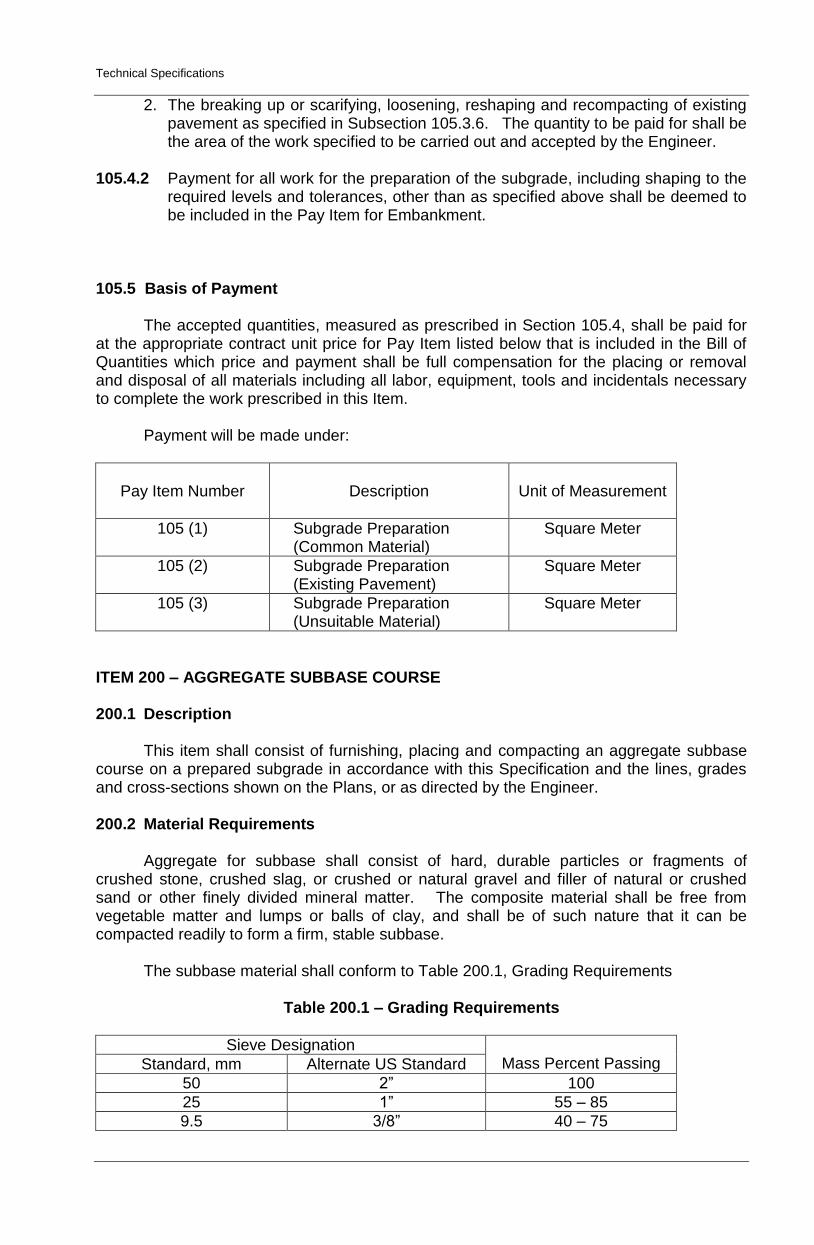
This item shall consist of furnishing, placing and compacting an aggregate subbase course on a prepared subgrade in accordance with this Specification and the lines, grades and cross-sections shown on the Plans, or as directed by the Engineer. 200.2 Material Requirements Aggregate for subbase shall consist of hard, durable particles or fragments of crushed stone, crushed slag, or crushed or natural gravel and filler of natural or crushed sand or other finely divided mineral matter. The composite material shall be free from vegetable matter and lumps or balls of clay, and shall be of such nature that it can be compacted readily to form a firm, stable subbase. The subbase material shall conform to Table 200.1, Grading Requirements
Table 200.1 – Grading Requirements
Sieve Designation Mass Percent Passing Standard, mm Alternate US Standard
50 2” 100
25 1” 55 – 85
9.5 3/8” 40 – 75
Technical Specifications
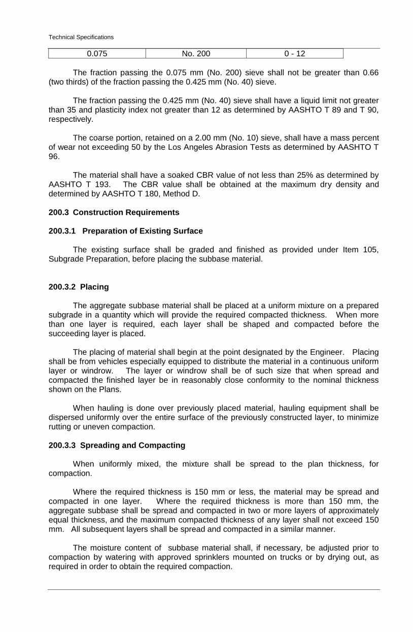
0.075 No. 200 0 - 12
The fraction passing the 0.075 mm (No. 200) sieve shall not be greater than 0.66 (two thirds) of the fraction passing the 0.425 mm (No. 40) sieve. The fraction passing the 0.425 mm (No. 40) sieve shall have a liquid limit not greater than 35 and plasticity index not greater than 12 as determined by AASHTO T 89 and T 90, respectively. The coarse portion, retained on a 2.00 mm (No. 10) sieve, shall have a mass percent of wear not exceeding 50 by the Los Angeles Abrasion Tests as determined by AASHTO T 96. The material shall have a soaked CBR value of not less than 25% as determined by AASHTO T 193. The CBR value shall be obtained at the maximum dry density and determined by AASHTO T 180, Method D. 200.3 Construction Requirements 200.3.1 Preparation of Existing Surface
The existing surface shall be graded and finished as provided under Item 105, Subgrade Preparation, before placing the subbase material. 200.3.2 Placing
The aggregate subbase material shall be placed at a uniform mixture on a prepared subgrade in a quantity which will provide the required compacted thickness. When more than one layer is required, each layer shall be shaped and compacted before the succeeding layer is placed.
The placing of material shall begin at the point designated by the Engineer. Placing
shall be from vehicles especially equipped to distribute the material in a continuous uniform layer or windrow. The layer or windrow shall be of such size that when spread and compacted the finished layer be in reasonably close conformity to the nominal thickness shown on the Plans.
When hauling is done over previously placed material, hauling equipment shall be
dispersed uniformly over the entire surface of the previously constructed layer, to minimize rutting or uneven compaction. 200.3.3 Spreading and Compacting
When uniformly mixed, the mixture shall be spread to the plan thickness, for compaction.
Where the required thickness is 150 mm or less, the material may be spread and
compacted in one layer. Where the required thickness is more than 150 mm, the aggregate subbase shall be spread and compacted in two or more layers of approximately equal thickness, and the maximum compacted thickness of any layer shall not exceed 150 mm. All subsequent layers shall be spread and compacted in a similar manner.
The moisture content of subbase material shall, if necessary, be adjusted prior to
compaction by watering with approved sprinklers mounted on trucks or by drying out, as required in order to obtain the required compaction.
Technical Specifications
Immediately following final spreading and smoothening, each layer shall be
compacted to the full width by means of approved compaction equipment. Rolling shall progress gradually from the sides to the center, parallel to the centerline of the road and shall continue until the whole surface has been rolled. Any irregularities or depressions that develop shall be corrected by loosening the material at these places and adding or removing material until surface is smooth and uniform. Along curbs, headers, and walls, and at all places not accessible to the roller, the subbase material shall be compacted thoroughly with approved tampers or compactors.
If the layer of subbase material, or part thereof, does not conform to the required
finish, the Contractor shall, at his own expense, make the necessary corrections. Compaction of each layer shall continue until a field density of at least 100 percent of
the maximum dry density determined in accordance with AASHTO T 180, Method D has been achieved. In-place density determination shall be made in accordance with AASHTO T 191. 200.3.4 Trial Sections
Before subbase construction is started, the Contractor shall spread and compact trial sections as directed by the Engineer. The purpose of the trial sections is to check the suitability of the materials and the efficiency of the equipment and construction method which is proposed to be used by the Contractor. Therefore, the Contractor must use the same material, equipment and procedures that he proposes to use for the main work. One trial section of about 500 m2 shall be made for every type of material and/or construction equipment/procedure proposed for use.
After final compaction of each trial section, the Contractor shall carry out such field
density tests and other tests required as directed by the Engineer. If a trial section shows that the proposed materials, equipment or procedures in the
Engineer’s opinion are not suitable for subbase, the material shall be removed at the Contractor’s expense, and a new trial section shall be constructed.
If the basic conditions regarding the type of material or procedure change during the
execution of the work, new trial sections shall be constructed.
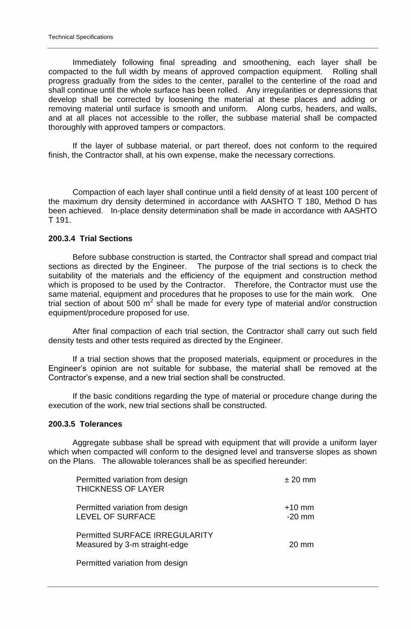
200.3.5 Tolerances
Aggregate subbase shall be spread with equipment that will provide a uniform layer which when compacted will conform to the designed level and transverse slopes as shown on the Plans. The allowable tolerances shall be as specified hereunder:
Permitted variation from design THICKNESS OF LAYER
± 20 mm
Permitted variation from design LEVEL OF SURFACE
+10 mm -20 mm
Permitted SURFACE IRREGULARITY Measured by 3-m straight-edge
20 mm
Permitted variation from design
Technical Specifications
CROSSFALL OR CAMBER ±0.3%
Permitted variation from design LONGITUDINAL GRADE over 25 m in length
±0.1%
200.4 Method of Measurement
Aggregate Subbase Course will be measured by the cubic meter (m3). The quantity to be paid for shall be the design volume compacted in-place as shown on the Plans, and accepted in the completed course. No allowance will be given for materials placed outside the design limits shown on the cross-sections. Trial sections shall not be measured separately but shall be included in the quantity of subbase herein measured.
200.5 Basis of Payment
The accepted quantities, measured as prescribed in Section 200.4, shall be paid for at the contract unit price for Aggregate Subbase Course which price and payment shall be full compensation for furnishings and placing all materials, including all labor, equipment, tools and incidentals necessary to complete the work prescribed in this Item.
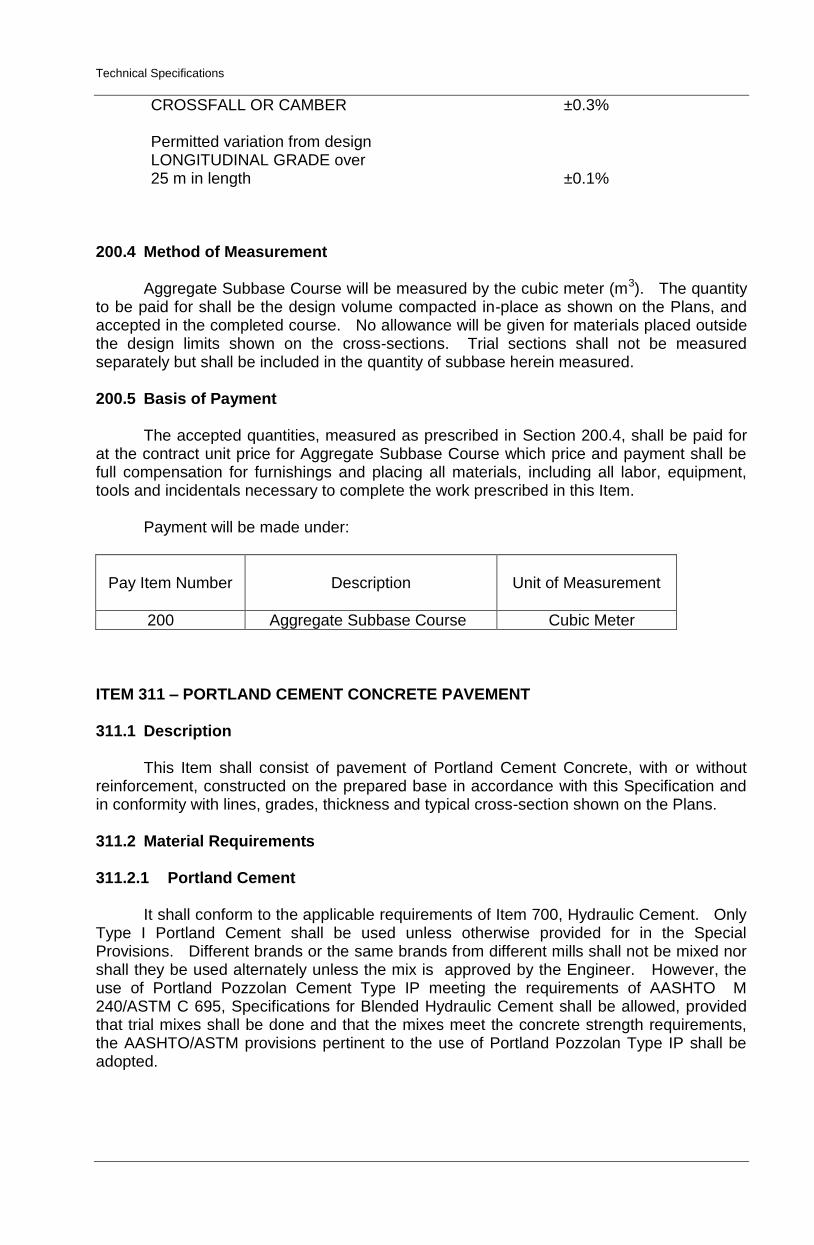
Payment will be made under:
Pay Item Number
Description
Unit of Measurement
200 Aggregate Subbase Course Cubic Meter
ITEM 311 – PORTLAND CEMENT CONCRETE PAVEMENT
311.1 Description
This Item shall consist of pavement of Portland Cement Concrete, with or without
reinforcement, constructed on the prepared base in accordance with this Specification and in conformity with lines, grades, thickness and typical cross-section shown on the Plans.
311.2 Material Requirements
311.2.1 Portland Cement
It shall conform to the applicable requirements of Item 700, Hydraulic Cement. Only
Type I Portland Cement shall be used unless otherwise provided for in the Special Provisions. Different brands or the same brands from different mills shall not be mixed nor shall they be used alternately unless the mix is approved by the Engineer. However, the use of Portland Pozzolan Cement Type IP meeting the requirements of AASHTO M 240/ASTM C 695, Specifications for Blended Hydraulic Cement shall be allowed, provided that trial mixes shall be done and that the mixes meet the concrete strength requirements, the AASHTO/ASTM provisions pertinent to the use of Portland Pozzolan Type IP shall be adopted.
Technical Specifications
Cement which for any reason, has become partially set or which contains lumps of caked cement will be rejected. Cement salvaged from discarded or used bags shall not be used.
Samples of Cement shall be obtained in accordance with AASHTO T 127.
311.2.2 Fine Aggregate
It shall consist of natural sand, stone screenings or other inert materials with similar
characteristics, or combinations thereof, having hard, strong and durable particles. Fine aggregate from different sources of supply shall not be mixed or stored in the same pile nor used alternately in the same class of concrete without the approval of the Engineer.
It shall not contain more than three (3) mass percent of material passing the 0.075
mm (No. 200 sieve) by washing nor more than one (1) mass percent each of clay lumps or shale. The use of beach sand will not be allowed without the approval of the Engineer.
If the fine aggregate is subjected to five (5) cycles of the sodium sulfate soundness
test, the weighted loss shall not exceed 10 mass percent. The fine aggregate shall be free from injurious amounts of organic impurities. If
subjected to the colorimatic test for organic impurities and a color darker than the standard is produced, it shall be rejected. However, when tested for the effect of organic impurities of strength of mortar by AASHTO T 71, the fine aggregate may be used if the relative strength at 7 and 28 days is not less than 95 mass percent.
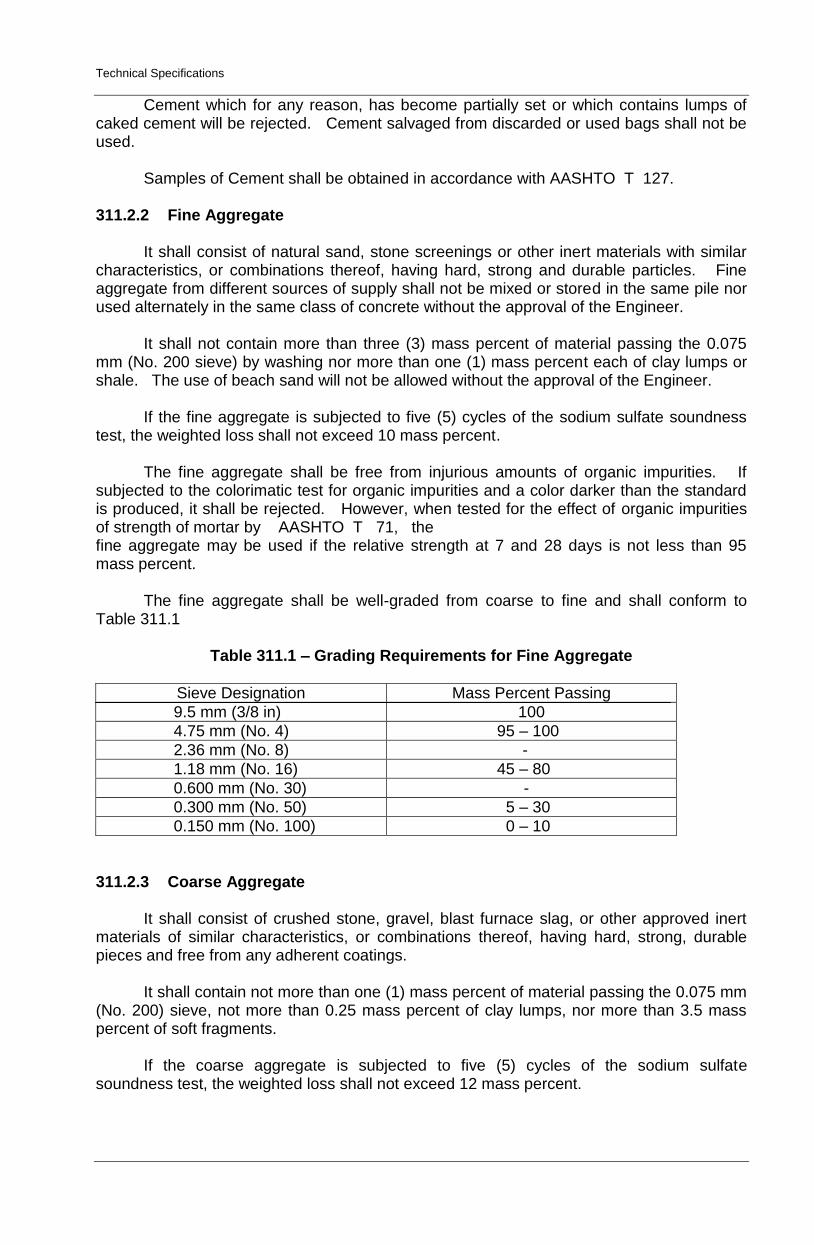
The fine aggregate shall be well-graded from coarse to fine and shall conform to
Table 311.1
Table 311.1 – Grading Requirements for Fine Aggregate
Sieve Designation Mass Percent Passing
9.5 mm (3/8 in) 100
4.75 mm (No. 4) 95 – 100
2.36 mm (No. 8) -
1.18 mm (No. 16) 45 – 80
0.600 mm (No. 30) -
0.300 mm (No. 50) 5 – 30
0.150 mm (No. 100) 0 – 10
311.2.3 Coarse Aggregate
It shall consist of crushed stone, gravel, blast furnace slag, or other approved inert
materials of similar characteristics, or combinations thereof, having hard, strong, durable pieces and free from any adherent coatings.
It shall contain not more than one (1) mass percent of material passing the 0.075 mm
(No. 200) sieve, not more than 0.25 mass percent of clay lumps, nor more than 3.5 mass percent of soft fragments.
If the coarse aggregate is subjected to five (5) cycles of the sodium sulfate
soundness test, the weighted loss shall not exceed 12 mass percent.
Technical Specifications
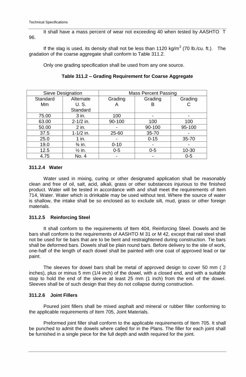
It shall have a mass percent of wear not exceeding 40 when tested by AASHTO T 96.
If the slag is used, its density shall not be less than 1120 kg/m3 (70 lb./cu. ft.). The
gradation of the coarse aggregate shall conform to Table 311.2. Only one grading specification shall be used from any one source.
Table 311.2 – Grading Requirement for Coarse Aggregate
Sieve Designation Mass Percent Passing
Standard Mm
Alternate U. S.
Standard
Grading A
Grading B
Grading C
75.00 3 in. 100 - -
63.00 2-1/2 in. 90-100 100 100
50.00 2 in. - 90-100 95-100
37.5 1-1/2 in. 25-60 35-70 -
25.0 1 in. - 0-15 35-70
19.0 ¾ in. 0-10 - -
12.5 ½ in. 0-5 0-5 10-30
4.75 No. 4 - - 0-5
311.2.4 Water Water used in mixing, curing or other designated application shall be reasonably clean and free of oil, salt, acid, alkali, grass or other substances injurious to the finished product. Water will be tested in accordance with and shall meet the requirements of Item 714, Water. Water which is drinkable may be used without test. Where the source of water is shallow, the intake shall be so enclosed as to exclude silt, mud, grass or other foreign materials. 311.2.5 Reinforcing Steel It shall conform to the requirements of Item 404, Reinforcing Steel. Dowels and tie bars shall conform to the requirements of AASHTO M 31 or M 42, except that rail steel shall not be used for tie bars that are to be bent and restraightened during construction. Tie bars shall be deformed bars. Dowels shall be plain round bars. Before delivery to the site of work, one-half of the length of each dowel shall be painted with one coat of approved lead or tar paint. The sleeves for dowel bars shall be metal of approved design to cover 50 mm ( 2 inches), plus or minus 5 mm (1/4 inch) of the dowel, with a closed end, and with a suitable stop to hold the end of the sleeve at least 25 mm (1 inch) from the end of the dowel. Sleeves shall be of such design that they do not collapse during construction. 311.2.6 Joint Fillers
Poured joint fillers shall be mixed asphalt and mineral or rubber filler conforming to
the applicable requirements of Item 705, Joint Materials. Preformed joint filler shall conform to the applicable requirements of Item 705. It shall
be punched to admit the dowels where called for in the Plans. The filler for each joint shall be furnished in a single piece for the full depth and width required for the joint.
Technical Specifications
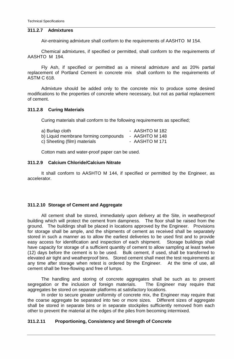
311.2.7 Admixtures Air-entraining admixture shall conform to the requirements of AASHTO M 154. Chemical admixtures, if specified or permitted, shall conform to the requirements of
AASHTO M 194. Fly Ash, if specified or permitted as a mineral admixture and as 20% partial
replacement of Portland Cement in concrete mix shall conform to the requirements of ASTM C 618. Admixture should be added only to the concrete mix to produce some desired modifications to the properties of concrete where necessary, but not as partial replacement of cement. 311.2.8 Curing Materials Curing materials shall conform to the following requirements as specified;
a) Burlap cloth - AASHTO M 182 b) Liquid membrane forming compounds - AASHTO M 148 c) Sheeting (film) materials - AASHTO M 171
Cotton mats and water-proof paper can be used. 311.2.9 Calcium Chloride/Calcium Nitrate
It shall conform to AASHTO M 144, if specified or permitted by the Engineer, as
accelerator.
311.2.10 Storage of Cement and Aggregate
All cement shall be stored, immediately upon delivery at the Site, in weatherproof building which will protect the cement from dampness. The floor shall be raised from the ground. The buildings shall be placed in locations approved by the Engineer. Provisions for storage shall be ample, and the shipments of cement as received shall be separately stored in such a manner as to allow the earliest deliveries to be used first and to provide easy access for identification and inspection of each shipment. Storage buildings shall have capacity for storage of a sufficient quantity of cement to allow sampling at least twelve (12) days before the cement is to be used. Bulk cement, if used, shall be transferred to elevated air tight and weatherproof bins. Stored cement shall meet the test requirements at any time after storage when retest is ordered by the Engineer. At the time of use, all cement shall be free-flowing and free of lumps.
The handling and storing of concrete aggregates shall be such as to prevent segregation or the inclusion of foreign materials. The Engineer may require that aggregates be stored on separate platforms at satisfactory locations.
In order to secure greater uniformity of concrete mix, the Engineer may require that the coarse aggregate be separated into two or more sizes. Different sizes of aggregate shall be stored in separate bins or in separate stockpiles sufficiently removed from each other to prevent the material at the edges of the piles from becoming intermixed. 311.2.11 Proportioning, Consistency and Strength of Concrete
Technical Specifications
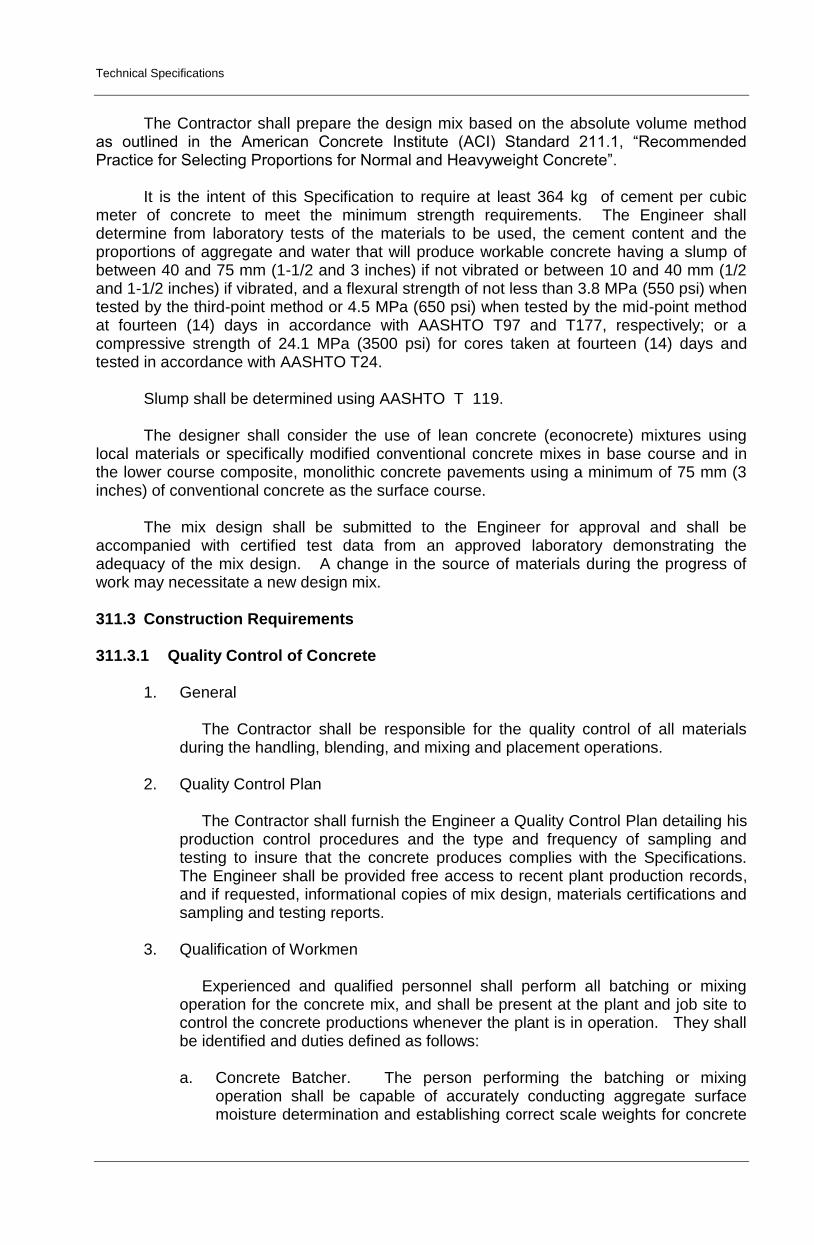
The Contractor shall prepare the design mix based on the absolute volume method
as outlined in the American Concrete Institute (ACI) Standard 211.1, “Recommended Practice for Selecting Proportions for Normal and Heavyweight Concrete”.
It is the intent of this Specification to require at least 364 kg of cement per cubic
meter of concrete to meet the minimum strength requirements. The Engineer shall determine from laboratory tests of the materials to be used, the cement content and the proportions of aggregate and water that will produce workable concrete having a slump of between 40 and 75 mm (1-1/2 and 3 inches) if not vibrated or between 10 and 40 mm (1/2 and 1-1/2 inches) if vibrated, and a flexural strength of not less than 3.8 MPa (550 psi) when tested by the third-point method or 4.5 MPa (650 psi) when tested by the mid-point method at fourteen (14) days in accordance with AASHTO T97 and T177, respectively; or a compressive strength of 24.1 MPa (3500 psi) for cores taken at fourteen (14) days and tested in accordance with AASHTO T24.
Slump shall be determined using AASHTO T 119. The designer shall consider the use of lean concrete (econocrete) mixtures using
local materials or specifically modified conventional concrete mixes in base course and in the lower course composite, monolithic concrete pavements using a minimum of 75 mm (3 inches) of conventional concrete as the surface course.
The mix design shall be submitted to the Engineer for approval and shall be
accompanied with certified test data from an approved laboratory demonstrating the adequacy of the mix design. A change in the source of materials during the progress of work may necessitate a new design mix.
311.3 Construction Requirements 311.3.1 Quality Control of Concrete
1. General
The Contractor shall be responsible for the quality control of all materials during the handling, blending, and mixing and placement operations.
2. Quality Control Plan
The Contractor shall furnish the Engineer a Quality Control Plan detailing his production control procedures and the type and frequency of sampling and testing to insure that the concrete produces complies with the Specifications. The Engineer shall be provided free access to recent plant production records, and if requested, informational copies of mix design, materials certifications and sampling and testing reports.
3. Qualification of Workmen
Experienced and qualified personnel shall perform all batching or mixing operation for the concrete mix, and shall be present at the plant and job site to control the concrete productions whenever the plant is in operation. They shall be identified and duties defined as follows: a. Concrete Batcher. The person performing the batching or mixing
operation shall be capable of accurately conducting aggregate surface moisture determination and establishing correct scale weights for concrete
Technical Specifications
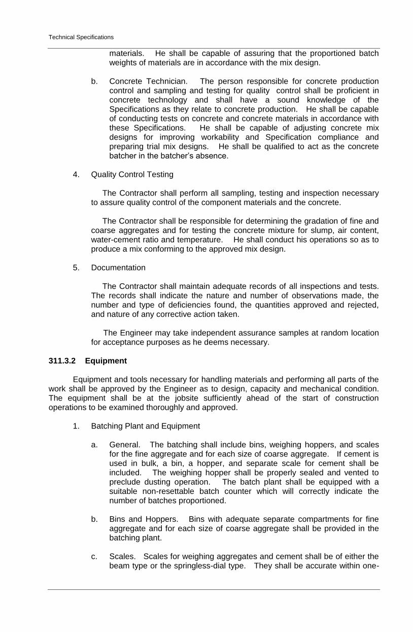
materials. He shall be capable of assuring that the proportioned batch weights of materials are in accordance with the mix design.
b. Concrete Technician. The person responsible for concrete production
control and sampling and testing for quality control shall be proficient in concrete technology and shall have a sound knowledge of the Specifications as they relate to concrete production. He shall be capable of conducting tests on concrete and concrete materials in accordance with these Specifications. He shall be capable of adjusting concrete mix designs for improving workability and Specification compliance and preparing trial mix designs. He shall be qualified to act as the concrete batcher in the batcher’s absence.
4. Quality Control Testing
The Contractor shall perform all sampling, testing and inspection necessary to assure quality control of the component materials and the concrete. The Contractor shall be responsible for determining the gradation of fine and coarse aggregates and for testing the concrete mixture for slump, air content, water-cement ratio and temperature. He shall conduct his operations so as to produce a mix conforming to the approved mix design.
5. Documentation
The Contractor shall maintain adequate records of all inspections and tests. The records shall indicate the nature and number of observations made, the number and type of deficiencies found, the quantities approved and rejected, and nature of any corrective action taken.
The Engineer may take independent assurance samples at random location for acceptance purposes as he deems necessary.
311.3.2 Equipment
Equipment and tools necessary for handling materials and performing all parts of the work shall be approved by the Engineer as to design, capacity and mechanical condition. The equipment shall be at the jobsite sufficiently ahead of the start of construction operations to be examined thoroughly and approved.
1. Batching Plant and Equipment
a. General. The batching shall include bins, weighing hoppers, and scales for the fine aggregate and for each size of coarse aggregate. If cement is used in bulk, a bin, a hopper, and separate scale for cement shall be included. The weighing hopper shall be properly sealed and vented to preclude dusting operation. The batch plant shall be equipped with a suitable non-resettable batch counter which will correctly indicate the number of batches proportioned.
b. Bins and Hoppers. Bins with adequate separate compartments for fine
aggregate and for each size of coarse aggregate shall be provided in the batching plant.
c. Scales. Scales for weighing aggregates and cement shall be of either the
beam type or the springless-dial type. They shall be accurate within one-
Technical Specifications
half percent (0.5%) throughout the range of use. Poises shall be designed to be locked in any position and to prevent unauthorized change.
Scales shall be inspected and sealed as often as the Engineer may deem necessary to assure their continued accuracy.
d. Automatic Weighing Devices. Unless otherwise allowed on the Contract,
batching plants shall be equipped with automatic weighing devices of an approved type to proportion aggregates and bulk cement.
2. Mixers.
a. General. Concrete may be mixed at the Site of construction or at a central plant, or wholly or in part in truck mixers. Each mixer shall have a manufacturer’s plate attached in a prominent place showing the capacity of the drum in terms of volume of mixed concrete and the speed of rotation of the mixing drum or blades.
b. Mixers at Site of Construction. Mixing shall be done in an approved mixer
capable of combining the aggregates, cement and water into a thoroughly mixed and uniform mass within the specified mixing period and discharging and distributing the mixture without segregation on the prepared grade. The mixer shall be equipped with an approved timing device which will automatically lock the discharge lever when the drum has been charged and released it at the end of the mixing period. In case of failure of the timing device, the mixer may be used for the balance of the day while it is being repaired, provided that each batch is mixed 90 seconds. The mixer shall be equipped with a suitable nonresettable batch counter which shall correctly indicate the number of the batches mixed.
c. Truck Mixer and Truck Agitators. Truck mixers used for mixing and
hauling concrete, and truck agitators used for hauling central-mixed concrete, shall conform to the requirements of AASHTO M 157.
d. Non-Agitator Truck. Bodies of non-agitating hauling equipment for
concrete shall be smooth, mortar-tight metal containers and shall be capable of discharging the concrete at a satisfactory controlled rate without segregation.
3. Paving and Finishing Equipment
The concrete shall be placed with an approved paver designed to spread, consolidate, screed and float finish the freshly placed concrete in one complete pass of the machine in such a manner that a minimum of hand finishing will be necessary to provide a dense and homogeneous pavement in conformance with the Plans and Specifications. The finishing machine shall be equipped with at least two (2) oscillating type transverse screed. Vibrators shall operate at a frequency of 8,300 to 9,600 impulses per minute under load at a maximum spacing of 60 cm.
4. Concrete Saw
Technical Specifications
The Contractor shall provide sawing equipment in adequate number of units and power to complete the sawing with a water-cooled diamond edge saw blade or an abrasive wheel to the required dimensions and at the required rate. He shall provide at least one (1) stand-by saw in good working condition and with an ample supply of saw blades.
5. Forms
Forms shall be of steel, of an approved section, and of depth equal to the thickness of the pavement at the edge. The base of the forms shall be of sufficient width to provide necessary stability in all directions. The flange braces must extend outward on the base to not less than 2/3 the height of the form. All forms shall be rigidly supported on bed of thoroughly compacted material during the entire operation of placing and finishing the concrete. Forms shall be provided with adequate devices for secure setting so that when in place, they will withstand, without visible spring or settlement, the impact and vibration of the consolidation and finishing or paving equipment.
311.3.3 Preparation of Grade
After the subgrade of base has been placed and compacted to the required density, the areas which will support the paving machine and the grade on which the pavement is to be constructed shall be trimmed to the proper elevation by means of a properly designed machine extending the prepared work areas compacted at least 60 cm beyond each edge of the proposed concrete pavement. If loss of density results from the trimming operations, it shall be restored by additional compaction before concrete is placed. If any traffic is allowed to use the prepared subgrade or base, the surface shall be checked and corrected immediately ahead of the placing concrete.
The subgrade or base shall be uniformly moist when the concrete is placed.
311.3.4 Setting Forms
1. Base Support.
The foundation under the forms shall be hard and true to grade so that the form when set will be firmly in contact for its whole length and at the specified grade. (Any roadbed, which at the form line is found below established grade, shall be filled with approved granular materials to grade in lifts of three (3) cm or less, and thoroughly rerolled or tamped.) Imperfections or variations above grade shall be corrected by tamping or by cutting as necessary.
2. Form Setting
Forms shall be set sufficiently in advance of the point where concrete is being placed. After the forms have been set to correct grade, the grade shall be thoroughly tamped, mechanically or by hand, at both the inside and outside edges of the base of the forms. The forms shall not deviate from true line bv more than one (1) cm at any point.
3. Grade and Alignment
Technical Specifications
The alignment and grade elevations of the forms shall be checked and corrections made by the Contractor immediately before placing the concrete. Testing as to crown and elevation, prior to placing of concrete can be made by means of holding an approved template in a vertical position and moved backward and forward on the forms. When any form has been disturbed or any grade has become unstable, the form shall be reset and rechecked.
311.3.5 Conditioning of Subgrade or Base Course
When side forms have been securely set to grade, the subgrade or base course shall be brought to proper cross-section. High areas shall be trimmed to proper elevation. Low areas shall be filled and compacted to a condition similar to that of surrounding grade. The finished grade shall be maintained in a smooth and compacted condition until the pavement is placed.
Unless waterproof subgrade or base course cover material is specified, the subgrade
or base course shall be uniformly moist when the concrete is placed. If it subsequently becomes too dry, the subgrade or base course shall be sprinkled, but the method of sprinkling shall not be such as to form mud or pools of water.
311.3.6 Handling, Measuring and Batching Materials
The batch plant site, layout, equipment and provisions for transporting material shall
be such as to assure a continuous supply of material to the work. Stockpiles shall be built up in layers of not more than one (1) meter in thickness. Each layer shall be completely in place before beginning the next which shall not be allowed to “cone” down over the next lower layer. Aggregates from different sources and of different grading shall not be stockpiled together.
All washed aggregates and aggregates produced or handled by hydraulic methods,
shall be stockpiled or binned for draining at least twelve (12) hours before being batched. When mixing is done at the side of the work. aggregates shall be transported from
the batching plant to the mixer in batch boxes, vehicle bodies, or other containers of adequate capacity and construction to properly carry the volume required. Partitions separating batches shall be adequate and effective to prevent spilling from one compartment to another while in transit or being dumped. When bulk cement is used, the Contractor shall use a suitable method of handling the cement from weighing hopper to transporting container or into the batch itself for transportation to the mixer, with chute, boot or other approved device, to prevent loss of cement, and to provide positive assurance of the actual presence in each batch of the entire cement content specified.
Bulk cement shall be transported to the mixer in tight compartments carrying the full
amount of cement required for the batch. However, if allowed in the Special Provisions, it may be transported between the fine and coarse aggregate. When cement is placed in contact with the aggregates, batches may be rejected unless mixed within 1-1/2 hours of such contact. Cement in original shipping packages may be transported on top of the aggregates, each batch containing the number of sacks required by the job mix.
The mixer shall be charged without loss of cement. Batching shall be so conducted
as to result in the weight to each material required within a tolerance of one (1) percent for the cement and two (2) percent for aggregates.
Technical Specifications
Water may be measured either by volume or by weight. The accuracy of measuring the water shall be within a range of error of not over than one (1) percent. Unless the water is to be weighed, the water-measuring equipment shall include an auxiliary tank from which the measuring tank shall be equipped with an outside tap and valve to provide checking the setting, unless other means are provided for readily and accurately determining the amount of water in the tank. The volume of the auxiliary tank shall be at least equal to that of the measuring tank.
311.3.7 Mixing Concrete
The concrete may be mixed at the site of the work in a central-mix plant, or in truck mixers. The mixer shall be of an approved type and capacity. Mixing time will be measured from the time all materials, except water, are in the drum. Ready-mixed concrete shall be mixed and delivered in accordance with requirements of AASHTO M 157, except that the minimum required revolutions at the mixing speed for transit-mixed concrete may be reduced to not less than that recommended by the mixer manufacturer. The number of revolutions recommended by the mixer manufacturer shall be indicated on the manufacturer’s serial plate attached to the mixer. The Contractor shall furnish test data acceptable to the Engineer verifying that the make and model of the mixer will produce uniform concrete conforming to the provision of AASHTO M 157 at the reduced number of revolutions shown on the serial plate.
When mixed at the site or in a central mixing plant, the mixing time shall not be less
than fifty (50) seconds nor more than ninety (90) seconds, unless mixer performance tests prove adequate mixing of the concrete is a shorter time period.
Four (4) seconds shall be added to the specified mixing time if timing starts at the
instant the skip reaches its maximum raised positions. Mixing time ends when the discharge chute opens. Transfer time in multiple drum mixers is included in mixing time. The contents of an individual mixer drum shall be removed before a succeeding batch is emptied therein.
The mixer shall be operated at the drum speed as shown on the manufacturer’s
name plate attached on the mixer. Any concrete mixed less than the specified time shall be discarded and disposed off by the Contractor at his expense. The volume of concrete mixed per batch shall not exceed the mixer’s nominal capacity in cubic metre, as shown on the manufacturer’s standard rating plate on the mixer, except that an overload up to ten (10) percent above the mixer’s nominal capacity may be permitted provided concrete test data for strength, segregation, and uniform consistency are satisfactory, and provided no spillage of concrete takes place.
The batches shall be so charged into the drum that a portion of the mixing water shall
be entered in advance of the cement and aggregates. The flow of water shall be uniform and all water shall be in the drum by the end of the first fifteen (15) seconds of the mixing period. The throat of the drum shall be kept free of such accumulations as may restrict the free flow of materials into the drum.
Mixed concrete from the central mixing plant shall be transported in truck mixers,
truck agitators or non-agitating truck specified in Subsection 311.3.2, Equipment. The time elapsed from the time water is added to the mix until the concrete is deposited in place at the Site shall not exceed forty five (45) minutes when the concrete is hauled in non-agitating trucks, nor ninety (90) minutes when hauled in truck mixers or truck agitators, except that in hot weather or under other conditions contributing to quick hardening of the concrete, the maximum allowable time may be reduced by the Engineer.
Technical Specifications
In exceptional cases and when volumetric measurements are authorized for small project requiring less than 75 cu.m. of concrete per day of pouring, the weight proportions shall be converted to equivalent volumetric proportions. In such cases, suitable allowance shall be made for variations in the moisture condition of the aggregates, including the bulking effect in the fine aggregate. Batching and mixing shall be in accordance with ASTM C 685, Section 6 through 9.
Concrete mixing by chute is allowed provided that a weighing scales for determining
the batch weight will be used. Retempering concrete by adding water or by other means shall not be permitted,
except that when concrete is delivered in truck mixers, additional water may be added to the batch materials and additional mixing performed to increase the slump to meet the specified requirements, if permitted by the Engineer, provided all these operations are performed within forty-five (45) minutes after the initial mixing operation and the water-cement ratio is not exceeded. Concrete that is not within the specified slump limits at the time of placement shall not be used. Admixtures for increasing the workability or for accelerating the setting of the concrete will be permitted only when specifically approved by the Engineer.
311.3.8 Limitation of Mixing
No concrete shall be mixed, placed or finished when natural light is insufficient,
unless an adequate and approved artificial lighting system is operated. During hot weather, the Engineer shall require that steps be taken to prevent the
temperature of mixed concrete from exceeding a maximum temperature of 900F ( 320C) Concrete not in place within ninety (90) minutes from the time the ingredients were
charged into the mixing drum or that has developed initial set shall not be used. Retempering of concrete or mortar which has partially hardened, that is remixing with or without additional cement, aggregate, or water, shall not be permitted.
In order that the concrete may be properly protected against the effects of rain before
the concrete is sufficiently hardened, the Contractor will be required to have available at all times materials for the protection of the edges and surface of the unhardened concrete.
311.3.9 Placing Concrete
Concrete shall be deposited in such a manner to require minimal rehandling. Unless truck mixers or non-agitating hauling equipment are equipped with means to discharge concrete without segregation of the materials, the concrete shall be unloaded into an approved spreading device and mechanically spread on the grade in such a manner as to prevent segregation. Placing shall be continuous between transverse joints without the use of intermediate bulkheads. Necessary hand spreading shall be done with shovels, not rakes. Workmen shall not be allowed to walk in the freshly mixed concrete with boots or shoes coated with earth or foreign substances.
When concrete is to be placed adjoining a previously constructed lane and
mechanical equipment will be operated upon the existing lane, that previously constructed lane shall have attained the strength for fourteen (14) day concrete. If only finishing equipment is carried on the existing lane, paving in adjoining lanes may be permitted after three (3) days.
Concrete shall be thoroughly consolidated against and along the faces of all forms
and along the full length and on both sides of all joint assemblies, by means of vibrators
Technical Specifications
inserted in the concrete. Vibrators shall not be permitted to come in contact with a joint assembly, the grade, or a side form. In no case shall the vibrator be operated longer than fifteen (15) seconds in any one location.
Concrete shall be deposited as near as possible to the expansion and contraction
joints without disturbing them, but shall not be dumped from the discharge bucket or hopper into a joint assembly unless the hopper is well centered on the joint assembly. Should any concrete material fall on or be worked into the surface of a complete slab, it shall be removed immediately.
311.3.10 Test Specimens
As work progresses, at least one (1) set consisting of three (3) concrete beam test
specimens, 150 mm x 150 mm x 525 mm or 900 mm shall be taken from each 330 m2 of pavement, 230 mm depth, or fraction thereof placed each day. Test specimens shall be made under the supervision of the Engineer, and the Contractor shall provide all concrete and other facilities necessary in making the test specimens and shall protect them from damage by construction operations. Cylinder samples shall not be used as substitute for determining the adequacy of the strength of concrete.
The beams shall be made, cured, and tested in accordance with AASHTO T 23 and
T 97. 311.3.11 Strike-off of Concrete and Placement of Reinforcement Following the placing of the concrete, it shall be struck off to conform to the cross-section shown on the Plans and to an elevation such that when the concrete is properly consolidated and finished, the surface of the pavement will be at the elevation shown on the Plans. When reinforced concrete pavement is placed in two (2) layers, the bottom layer shall be struck off and consolidated to such length and depth that the sheet of fabric or bar mat may be laid full length on the concrete in its final position without further manipulation. The reinforcement shall then be placed directly upon the concrete, after which the top layer of the concrete shall be placed, struck off and screeded. Any portion of the bottom layer of concrete which has been placed more then 30 minutes without being covered with the top layer shall be removed and replaced with freshly mixed concrete at the Contractor’s expense. When reinforced concrete is placed in one layer, the reinforcement may be firmly positioned in advance of concrete placement or it may be placed at the depth shown on the Plans in plastic concrete, after spreading by mechanical or vibratory means. Reinforcing steel shall be free from dirt, oil, paint, grease, mill scale and loose or thick rust which could impair bond of the steel with the concrete.
311.3.12 Joints Joints shall be constructed of the type and dimensions, and at the locations required
by the Plans or Special Provisions. All joints shall be protected from the intrusion of injurious foreign material until sealed.
1. Longitudinal Joint
Deformed steel tie bars of specified length, size, spacing and materials shall be placed perpendicular to the longitudinal joints, they shall be placed by approved mechanical equipment or rigidly secured by chair or other approved
Technical Specifications
supports to prevent displacement. Tie bars shall not be painted or coated with asphalt or other materials or enclosed in tubes or sleeves. When shown on the Plans and when adjacent lanes of pavement are constructed separately, steel side forms shall be used which will form a keyway along the construction joint. Tie bars, except those made of rail steel, may be bent at right angles against the form of the first lane constructed and straightened into final position before the concrete of the adjacent lane is placed, or in lieu of bent tie bars, approved two-piece connectors may be used. Longitudinal formed joints shall consist of a groove or cleft, extending downward from and normal to, the surface of the pavement. These joints shall be effected or formed by an approved mechanically or manually operated device to the dimensions and line indicated on the Plans and while the concrete is in a plastic state. The groove or cleft shall be filled with either a premolded strip or poured material as required. The longitudinal joints shall be continuous, there shall be no gaps in either transverse or longitudinal joints at the intersection of the joints. Longitudinal sawed joints shall be cut by means of approved concrete saws to the depth, width and line shown on the Plans. Suitable guide lines or devices shall be used to assure cutting the longitudinal joint on the true line. The longitudinal joint shall be sawed before the end of the curing period or shortly thereafter and before any equipment or vehicles are allowed on the pavement. The sawed area shall be thoroughly cleaned and, if required, the joint shall immediately be filled with sealer. Longitudinal pavement insert type joints shall be formed by placing a continuous strip of plastic materials which will not react adversely with the chemical constituent of the concrete.
2. Transverse Expansion Joint
The expansion joint filler shall be continuous from form to form, shaped to subgrade and to the keyway along the form. Preformed joint filler shall be furnished in lengths equal to the pavement width or equal to the width of one lane. Damaged or repaired joint filler shall not be used. The expansion joint filler shall be held in a vertical position. An approved installing bar, or other device, shall be used if required to secure preformed expansion joint filler at the proper grade and alignment during placing and finishing of the concrete. Finished joint shall not deviate more than 6 mm from a straight line. If joint fillers are assembled in sections, there shall be no offsets between adjacent units. No plugs of concrete shall be permitted anywhere within the expansion space.
3. Transverse Contraction Joint/Weakened Joint
When shown on the Plans, it shall consist of planes of weakness created by forming or cutting grooves in the surface of the pavement and shall include load transfer assemblies. The depth of the weakened plane joint should at all times not be less than 50 mm, while the width should not be more than 6 mm. a. Transverse Strip Contraction Joint. It shall be formed by installing a
parting strip to be left in place as shown on the Plans.
Technical Specifications
b. Formed Groove. It shall be made by depressing an approved tool or device into the plastic concrete. The tool or device shall remain in place at least until the concrete has attained its initial set and shall then be removed without disturbing the adjacent concrete, unless the device is designed to remain in the joint.
c. Sawed Contraction Joint. It shall be created by sawing grooves in the
surface of the pavement of the width not more than 6 mm, depth should at all times not be less than 50 mm, and at the spacing and lines shown on the Plans, with an approved concrete saw. After each joint is sawed, it shall be thoroughly cleaned including the adjacent concrete surface.
Sawing of the joint shall commence as soon as the concrete has hardened sufficiently to permit sawing without excessive ravelling, usually 4 to 24 hours. All joints shall be sawed before uncontrolled shrinkage cracking takes place. If necessary, the sawing operations shall be carried on during the day or night, regardless of weather conditions. The sawing of any joint shall be omitted if crack occurs at or near the joint location prior to the time of sawing. Sawing shall be discounted when a crack develops ahead of the saw. In general, all joints should be sawed in sequence. If extreme condition exist which make it impractical to prevent erratic cracking by early sawing, the contraction joint groove shall be formed prior to initial set of concrete as provided above.
4. Transverse Construction Joint
It shall be constructed when there is an interruption of more than 30 minutes in the concreting operations. No transverse joint shall be constructed within 1.50 m of an expansion joint, contraction joint, or plane of weakness. If sufficient concrete has been mixed at the time of interruption to form a slab of at least 1.5 m long, the excess concrete from the last preceding joint shall be removed and disposed off as directed.
5. Load Transfer Device
Dowel, when used, shall be held in position parallel to the surface and center line of the slab by a metal device that is left in the pavement. The portion of each dowel painted with one coat of lead or tar, in conformance with the requirements of Item 404, Reinforcing Steel, shall be thoroughly coated with approved bituminous materials, e.g., MC-70, or an approved lubricant, to prevent the concrete from binding to that portion of the dowel. The sleeves for dowels shall be metal designed to cover 50 mm plus or minus 5 mm (1/4 inch), of the dowel, with a watertight closed end and with a suitable stop to hold the end of the sleeves at least 25 mm (1 inch) from the end of the dowel. In lieu of using dowel assemblies at contraction joints, dowel may be placed in the full thickness of pavement by a mechanical device approved by the Engineer.
311.3.13 Final Strike-off (Consolidation and Finishing)
1. Sequence
Technical Specifications
The sequence of operations shall be the strike-off and consolidation, floating and removal of laitance, straight-edging and final surface finish. Work bridges or other devices necessary to provide access to the pavement surface for the purpose of finishing straight-edging, and make corrections as hereinafter specified, shall be provided by the Contractor. In general, the addition of water to the surface of the concrete to assist in finishing operations will not be permitted. If the application of water to the surface is permitted, it shall be applied as fog spray by means of an approved spray equipment.
2. Finishing Joints
The concrete adjacent to joints shall be compacted or firmly placed without voids or segregation against the joint material assembly, also under and around all load transfer devices, joint assembly units, and other features designed to extend into the pavement. Concrete adjacent to joints shall be mechanically vibrated as required in Subsection 311.3.9, Placing Concrete. After the concrete has been placed and vibrated adjacent to the joints as required in Subsection 311.3.9, the finishing machine shall be brought forward, operating in a manner to avoid damage or misalignment of joints. If uninterrupted operation of the finishing machine, to over and beyond the joints causes segregation of concrete, damage to, or misalignment of the joints, the finishing machine shall be stopped when the front screed is approximately 20 cm (8 inches) from the joint. Segregated concrete shall be removed from in front of and off the joint. The front screed shall be lifted and set directly on top of the joint and the forward motion of the finishing machine resumed. When the second screed is close enough to permit the excess mortar in front of it to flow over the joint, it shall be lifted and carried over the joint. Thereafter, the finishing machine may be run over the joint without lifting the screeds, provided there is no segregated concrete immediately between the joint and the screed or on top of the joint.
3. Machine Finishing
a. Non-vibratory Method. The concrete shall be distributed or spread as soon as placed. As soon as the concrete has been placed, it shall be struck off and screeded by an approved finishing machine. The machine shall go over each area of pavement as many times and at such intervals as necessary to give the proper compaction and leave a surface of uniform texture. Excessive operation over a given area shall be avoided. The tops of the forms shall be kept clean by an effective device attached to the machine and the travel of the machine on the forms shall be maintained true without wobbling or other variation tending to affect the precision finish.
During the first pass of the finishing machine, a uniform ridge of concrete shall be maintained ahead of the front screed in its entire length.
b. Vibratory Method. When vibration is specified, vibrators for full width
vibration of concrete paving slabs, shall meet the requirements in Subsection 311.3.2, Equipment. If uniform and satisfactory density of the concrete is not obtained by the vibratory method at joints, along forms, at structures, and throughout the pavement, the Contractor will be required to furnish equipment and method which will produce pavement conforming to
Technical Specifications
the Specifications. All provisions in item (a) above not in conflict with the provisions for the vibratory method shall govern.
4. Hand Finishing
Hand finishing methods may only be used under the following conditions:
a. In the event of breakdown of the mechanical equipment, hand methods may be used to finish the concrete already deposited on the grade.
b. In narrow widths or areas of irregular dimensions where operations of the
mechanical equipment is impractical, hand methods may be used.
Concrete, as soon as placed, shall be struck off and screeded. An approved portable screed shall be used. A second screed shall be provided for striking off the bottom layer of concrete if reinforcement is used. The screed for the surface shall be at least 60 cm (2 feet) longer than the maximum width of the slab to be struck off. It shall be of approved design, sufficiently rigid to retain its shape, and constructed either of metal or other suitable material shod with metal. Consolidation shall be attained by the use of suitable vibrator or other approved equipment. In operation, the screed shall be moved forward on the forms with a combined longitudinal and transverse shearing motion, moving always in the direction in which the work is progressing and so manipulated that neither end is raised from the side forms during the striking off process. If necessary, this shall be repeated until the surface is of uniform texture, true to grade and cross-section, and free from porous areas.
5. Floating
After the concrete has been struck off and consolidated, it shall be further smoothed, trued, and consolidated by means of a longitudinal float, either by hand or mechanical method.
a. Hand Method. The hand-operated longitudinal float shall be not less than
365 cm (12 feet) in length and 15 cm (6 inches) in width, properly stiffened to prevent flexibility and warping. The longitudinal float, operated from foot bridges resting on the side forms and spanning but not touching the concrete, shall be worked with a sawing motion while held in a floating position parallel to the road center line, and moving gradually from one side of the pavement to the other. Movement ahead along the center line of the pavement shall be in successive advances of not more than one-half the length of the float. Any excess water or soupy material shall be wasted over the side forms on each pass.
b. Mechanical Method. The mechanical longitudinal float shall be of a design
approved by the Engineer, and shall be in good working condition. The tracks from which the float operates shall be accurately adjusted to the required crown. The float shall be accurately adjusted and coordinated with the adjustment of the transverse finishing machine so that a small amount of mortar is carried ahead of the float at all times. The forward screed shall be adjusted so that the float will lap the distance specified by
Technical Specifications
the Engineer on each transverse trip. The float shall pass over each areas of pavement at least two times, but excessive operation over a given area will not be permitted. Any excess water or soupy material shall be wasted over the side forms on each pass.
c. Alternative Mechanical Method. As an alternative, the Contractor may use
a machine composed of a cutting and smoothing float or floats suspended from and guided by a rigid frame. The frame shall be carried by four or more visible wheels riding on, and constantly in contact with the side forms. If necessary, following one of the preceding method of floating, long handled floats having blades not less than 150 cm (5 feet) in length and 15 cm (6 inches) in width may be used to smooth and fill in open-textured areas in the pavement. Long-handled floats shall not be used to float the entire surface of the pavement in lieu of, or supplementing, one of the preceding methods of floating. When strike off and consolidation are done by the hand method and the crown of the pavement will not permit the use of the longitudinal float, the surface shall be floated transversely by means of the long-handled float. Care shall be taken not to work the crown out of the pavement during the operation. After floating, any excess water and laitance shall be removed from the surface of the pavement by a 3-m straight-edge or more in length. Successive drags shall be lapped one-half the length of the blade.
6. Straight-edge Testing and Surface Correction
After the floating has been completed and the excess water removed, but while the concrete is still plastic, the surface of the concrete shall be tested for trueness with a 300 cm long straight-edge. For this purpose, the Contractor shall furnish and use an accurate 300-cm straight-edge swung from handles 100 cm (3 feet) longer than one-half the width of the slab. The straight-edge shall be held in contact with the surface in successive positions parallel to the road center line and the whole area gone over from one side of the slab to the other as necessary. Advances along the road shall be in successive stages of not more than one-half the length of the straight-edge. Any depressions found shall be immediately filled with freshly mixed concrete, struck off, consolidated and refinished. High areas shall be cut down and refinished. Special attention shall be given to assure that the surface across joints meets the requirements for smoothness. Straight-edge testing and surface corrections shall continue until the entire surface is found to be free from observable departures from the straight-edge and the slab conforms to the required grade and cross-section.
7. Final Finish
If the surface texture is broom finished, it shall applied when the water sheen has practically disappeared. The broom shall be drawn from the center to the edge of the pavement with adjacent strokes slightly overlapping. The brooming operation should be so executed that the corrugations produced in the surface shall be uniform in appearance and not more than 1.5 mm in depth. Brooming shall be completed before the concrete is in such condition that the surface will be unduly roughened by the operation. The surface thus finished shall be free from rough and porous areas, irregularities, and depressions resulting from improper handling of the broom. Brooms shall be of the quality size and construction and be operated so as to produce a surface finish meeting the approval of the Engineer. Subject to satisfactory results being obtained and approval of the Engineer, the Contractor will be permitted to substitute mechanical brooming in lieu of the manual brooming herein described.
Technical Specifications
If the surface texture is belt finished, when straight-edging is complete and water sheen has practically disappeared and just before the concrete becomes non-plastic, the surface shall be belted with 2-ply canvass belt not less than 20 cm wide and at least 100 cm longer than the pavement width. Hand belts shall have suitable handles to permit controlled, uniform manipulation. The belt shall be operated with short strokes transverse to the center line and with a rapid advances parallel to the center line. If the surface texture is drag finished, a drag shall be used which consists of a seamless strip of damp burlap or cotton fabric, which shall produce a uniform of gritty texture after dragging it longitudinally along the full width of pavement. For pavement 5 m or more in width, the drag shall be mounted on a bridge which travels on the forms. The dimensions of the drag shall be such that a strip of burlap or fabric at least 100 cm wide is in contact with the full width of pavement surface while the drag is used. The drag shall consist of not less than 2 layers of burlap with the bottom layer approximately 15 cm wider than the layer. The drag shall be maintained in such condition that the resultant surface is of uniform appearance and reasonably free from grooves over 1.5 mm in depth. Drag shall be maintained clean and free from encrusted mortar. Drags that cannot be cleaned shall be discarded and new drags be substituted. Regardless of the method used for final finish, the hardened surface of pavement shall have a coefficient of friction of 0.25 or more. Completed pavement that is found to have a coefficient of friction less than 0.25 shall be grounded or scored by the Contractor at his expense to provide the required coefficient of friction.
8. Edging at Forms and Joints
After the final finish, but before the concrete has taken its initial set, the edges of the pavement along each side of each slab, and on each side of transverse expansion joints, formed joints, transverse construction joints, and emergency construction joints, shall be worked with an approved tool and rounded to the radius required by the Plans. A well – defined and continuous radius shall be produced and a smooth, dense mortar finish obtained. The surface of the slab shall not be unduly disturbed by tilting the tool during the use. At all joints, any tool marks appearing on the slab adjacent to the joints shall be eliminated by brooming the surface. In doing this, the rounding of the corner of the slab shall not be disturbed. All concrete on top of the joint filler shall be completely removed. All joints shall be tested with a straight-edge before the concrete has set and correction made if one edge of the joint is higher than the other.
311.3.14 Surface Test
As soon as the concrete has hardened sufficiently, the pavement surface shall be
tested with a 3-m straight-edge or other specified device. Areas showing high spots of more than 3 mm but not exceeding 12 mm in 3 m shall be marked and immediately ground down with an approved grinding tool to an elevation where the area or spot will not show surface deviations in excess of 3 mm when tested with 3 m straight-edge. Where the departure from correct cross-section exceeds 12 mm, the pavement shall be removed and replaced by and at the expense of the Contractor.
Technical Specifications
Any area or section so removed shall be not less than 1.5 m in length and not less
than the full width of the lane involved. When it is necessary to remove and replace a section of pavement, any remaining portion of the slab adjacent to the joints that is less than 1.5 m in length, shall also be removed and replaced. 311.3.15 Curing
Immediately after the finishing operations have been completed and the concrete has sufficiently set, the entire surface of the newly placed concrete shall be cured in accordance with either one of the methods described herein. Failure to provide sufficient cover material of whatever kind the Contractor may elect to use, or the lack of water to adequately take care of both curing and other requirements, shall be a cause for immediate suspension of concreting operations. The concrete shall not be left exposed for more than ½ hour between stages of curing or during the curing period.
In all congested places, concrete works should be designed so that the designed
strength is attained. 1. Cotton of Burlap Mats
The surface of the pavement shall be entirely covered with mats. The mats used shall be of such length (or width) that as laid they will extend at least twice the thickness of the pavement beyond the edges of the slab. The mat shall be placed so that the entire surface and the edges of the slab are completely covered. Prior to being placed, the mats shall be saturated thoroughly with water. The mat shall be so placed and weighted down so as to cause them to remain in intimate contact with the covered surface. The mat shall be maintained fully wetted and in position for 72 hours after the concrete has been placed unless otherwise specified.
2. Waterproof Paper
The top surface and sides of the pavement shall be entirely covered with waterproof paper, the units shall be lapped at least 45 cm. The paper shall be so placed and weighted down so as to cause it to remain in intimate contact with the surface covered. The paper shall have such dimension but each unit as laid will extend beyond the edges of the slab at least twice the thickness of the pavement, or at pavement width and 60 cm strips of paper for the edges. If laid longitudinally, paper not manufactured in sizes which will provide this width shall be securely sewed or cemented together, the joints being securely sealed in such a manner that they do not open up or separate during the curing period. Unless otherwise specified, the covering shall be maintained in place for 72 hours after the concrete has been placed. The surface of the pavement shall be thoroughly wetted prior to the placing of the paper.
3. Straw Curing
When this type of curing is used, the pavement shall be cured initially with burlap or cotton mats, until after final set of the concrete or, in any case, for 12 hours after placing the concrete. As soon as the mats are removed, the surface and sides of the pavement shall be thoroughly wetted and covered with at least 20 cm of straw or hay, thickness of which is to be measured after wetting. If the straw or hay covering becomes displaced during the curing period, it shall be replaced to the original depth and saturated. It shall be kept thoroughly saturated with water for 72 hours and thoroughly wetted down during
Technical Specifications
the morning of the fourth day, and the cover shall remain in place until the concrete has attained the required strength.
4. Impervious Membrane Method
The entire surface of the pavement shall be sprayed uniformly with white pigmented curing compound immediately after the finishing of the surface and before the set of the concrete has taken place, or if the pavement is cured initially with jute or cotton mats, it may be applied upon removal of the mass. The curing compound shall not be applied during rain. Curing compound shall be applied under pressure at the rate 4 L to not more than 14 m2 by mechanical sprayers. The spraying equipment shall be equipped with a wind guard. At the time of use, the compound shall be in a thoroughly mixed condition with the pigment uniformly dispersed throughout the vehicle. During application, the compound shall be stirred continuously by effective mechanical means. Hand spraying of odd widths or shapes and concrete surface exposed by the removal of forms will be permitted. Curing compound shall not be applied to the inside faces of joints to be sealed, but approved means shall be used to insure proper curing at least 72 hours and to prevent the intrusion of foreign material into the joint before sealing has been completed. The curing compound shall be of such character that the film will harden within 30 minutes after application. Should the film be damaged from any cause within the 72 hour curing period, the damaged portions shall be repaired immediately with additional compound.
5. White Polyethylene Sheet
The top surface and sides of the pavement shall be entirely covered with polyethylene sheeting. The units used shall be lapped at least 45 cm. The sheeting shall be so placed and weighted down so as to cause it to remain intimate contact with the surface covered. The sheeting as prepared for use shall have such dimension that each unit as laid will extend beyond the edges of the slab at least twice the thickness of the pavement. Unless otherwise specified, the covering shall be maintained in place for 72 hours after the concrete has been placed.
311.3.16 Removal of Forms After forms for concrete shall remain in place undisturbed for not less than twenty
four (24) hours after concrete pouring. In the removal of forms, crowbars should be used in pulling out nails and pins. Care should be taken so as not to break the edges of the pavement. In case portions of the concrete are spalled, they shall be immediately repaired with fresh mortar mixed in the proportion of one part of Portland Cement and two parts fine aggregates. Major honeycomb areas will be considered as defective work and shall be removed and replaced at the expense of the Contractor. Any area or section so removed shall not be less than the distance between weakened plane joint nor less than the full width of the lane involved.
311.3.17 Sealing Joints
Joints shall be sealed with asphalt sealant soon after completion of the curing period
and before the pavement is opened to traffic, including the Contractor’s equipment. Just prior to sealing, each joint shall be thoroughly cleaned of all foreign materials including membrane curing compound and the joint faces shall be clean and surface dry when the seal is applied.
Technical Specifications
The sealing material shall be applied to each joint opening to conform to the details
shown on the Plans or as directed by the Engineer. Material for seal applied hot shall be stirred during heating so that localized overheating does not occur. The pouring shall be done in such a manner that the material will not be spilled on the exposed surfaces of the concrete. The use of sand or similar material as a cover for the seal will not be permitted.
Preformed elastomeric gaskets for sealing joints shall be of the cross-sectional
dimensions shown on the Plans. Seals shall be installed by suitable tools, without elongation and secured in placed with an approved lubricant adhesive which shall cover both sides of the concrete joints. The seals shall be installed in a compressive condition and shall at time of placement be below the level of the pavement surface by approximately 6 mm.
The seals shall be in one piece for the full width of each transverse joint.
311.3.18 Protection of Pavement
The Contractor shall protect the pavement and its appurtenances against both public
traffic and traffic caused by his own employees and agents. This shall include watchmen to direct traffic and the erection of and maintenance of warning signs, lights, pavement bridges or cross-overs, etc. The Plans or Special Provisions will indicate the location and type of device or facility required to protect the work and provide adequately for traffic.
All boreholes after thickness and/or strength determinations of newly constructed
asphalt and concrete pavements shall be immediately filled/restored with the prescribed concrete/asphalt mix after completion of the drilling works.
Any damage to the pavement, occurring prior to final acceptance, shall be repaired or
the pavement be replaced.
311.3.19 Concrete Pavement – Slip Form Method
If the Contract calls for the construction of pavement without the use of fixed forms, the following provisions shall apply:
1. Grade
After the grade or base has been placed and compacted to the required density, the areas which will support the paving machine shall be cut to the proper elevation by means of a properly designed machine. The grade on which the pavement is to be constructed shall then be brought to the proper profile by means of properly designed machine. If the density of the base is disturbed by the grading operation, it shall be corrected by additional compaction before concrete is placed. The grade should be constructed sufficiently in advance of the placing of the concrete. If any traffic is allowed to use the prepared grade, the grade shall be checked and corrected immediately before the placing of concrete.
2. Placing Concrete
The concrete shall be placed with an approved slip-form paver designed to spread, consolidate, screed and float-finish the freshly placed concrete in one complete pass of the machine in such a manner that a minimum of hand finish will be necessary to provide a dense and homogenous pavement in
Technical Specifications
conformance with the Plans and Specifications. The machine shall vibrate the concrete for the full width and depth of the strip of pavement being placed. Such vibration shall be accompanied with vibrating tubes or arms working in the concrete or with a vibrating screed or pan operating on the surface of the concrete. The sliding forms shall be rigidly held together laterally to prevent spreading of the forms. The forms shall trail behind the paver for such a distance that no appreciable slumping of the concrete will occur, and that necessary final finishing can be accomplished while the concrete is still within the forms. Any edge slump of the pavement, exclusive of edge rounding, in excess of 6 mm shall be corrected before the concrete has hardened. The concrete shall be held at a uniform consistency, having a slump of not more than 40 mm (1-12/ inches). The slip form paver shall be operated with as nearly as possible a continuous forward movement and that all operations of mixing, delivering and spreading concrete shall be coordinated so as to provide uniform progress with stopping and starting of the paver held to a minimum. If, for any reason, it is necessary to stop the forward movement of the paver the vibratory and tamping elements shall also be stopped immediately. No tractive force shall be applied to the machine, except that which is controlled from the machine.
3. Finishing
The surface smoothness and texture shall meet the requirements of Subsections 311.3.13 and 311.3.14.
4. Curing
Unless otherwise specified, curing shall be done in accordance with one of the methods included in Subsection 311.3.15. The curing media shall be applied at the appropriate time and shall be applied uniformly and completely to all surfaces and edges of the pavement.
5. Joints
All joints shall be constructed in accordance with Subsection 311.3.12.
6. Protection Against Rain
In order that the concrete may be properly protected against rain before the concrete is sufficiently hardened, the Contractor will be required to have available at all times, materials for the protection of the edges and surface of the unhardened concrete. Such protective materials shall consist of standard metal forms or wood planks having a nominal thickness of not less than 50 mm (2 inches) and a nominal width of not less than the thickness of the pavement at its edge for the protection of the pavement edges, and covering material such as burlap or cotton mats, curing paper or plastic sheeting materials for the protection of the surface of the pavement. When rain appears imminent, all paving operations shall stop and all available personnel shall begin placing forms against the sides of the pavement and covering the surface of the unhardened concrete with the protective covering.
311.3.22 Acceptance of Concrete
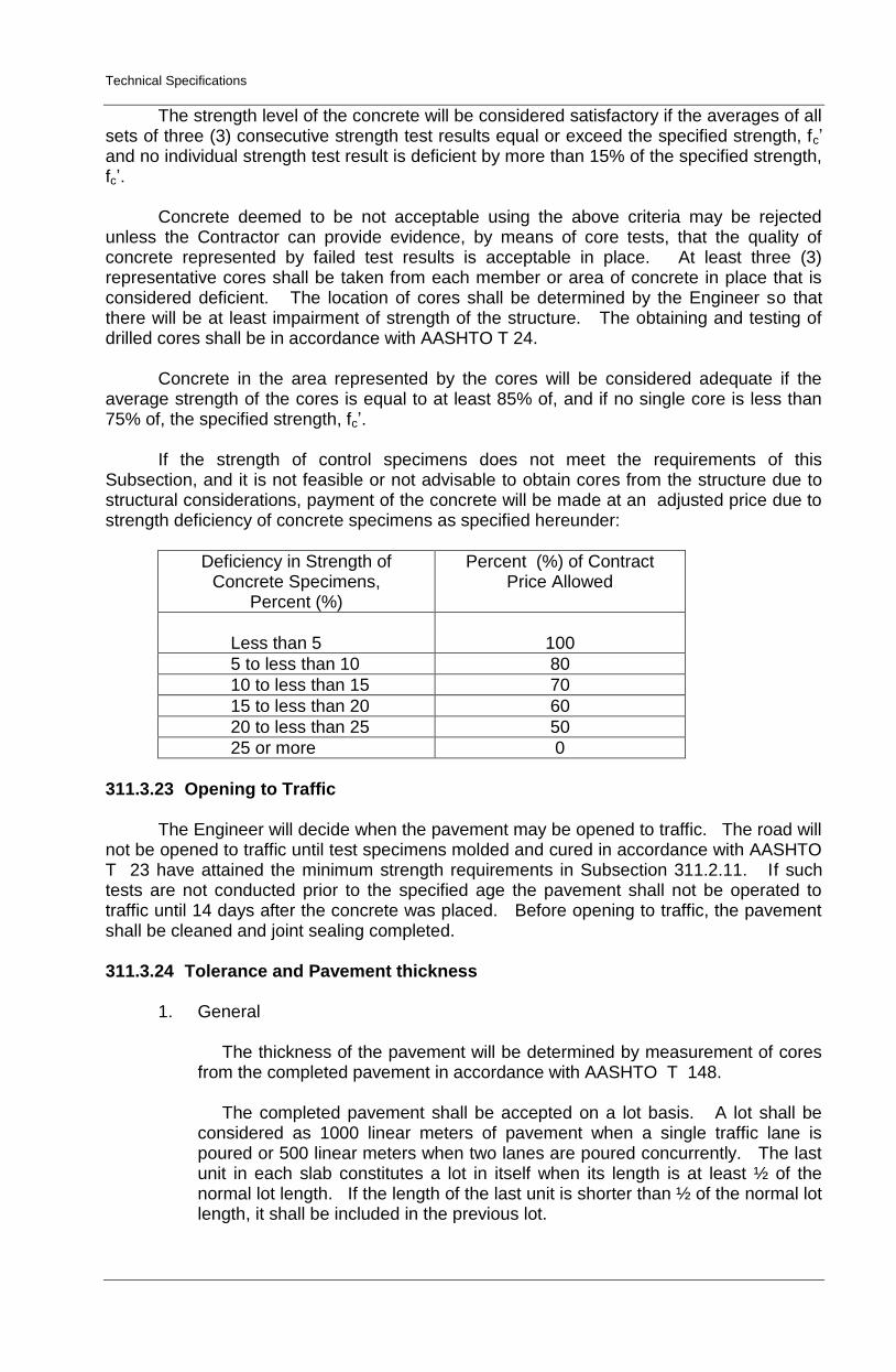
Technical Specifications
The strength level of the concrete will be considered satisfactory if the averages of all sets of three (3) consecutive strength test results equal or exceed the specified strength, fc’ and no individual strength test result is deficient by more than 15% of the specified strength, fc’.
Concrete deemed to be not acceptable using the above criteria may be rejected
unless the Contractor can provide evidence, by means of core tests, that the quality of concrete represented by failed test results is acceptable in place. At least three (3) representative cores shall be taken from each member or area of concrete in place that is considered deficient. The location of cores shall be determined by the Engineer so that there will be at least impairment of strength of the structure. The obtaining and testing of drilled cores shall be in accordance with AASHTO T 24.
Concrete in the area represented by the cores will be considered adequate if the
average strength of the cores is equal to at least 85% of, and if no single core is less than 75% of, the specified strength, fc’.
If the strength of control specimens does not meet the requirements of this
Subsection, and it is not feasible or not advisable to obtain cores from the structure due to structural considerations, payment of the concrete will be made at an adjusted price due to strength deficiency of concrete specimens as specified hereunder:
Deficiency in Strength of Concrete Specimens,
Percent (%)
Percent (%) of Contract Price Allowed
Less than 5 100
5 to less than 10 80
10 to less than 15 70
15 to less than 20 60
20 to less than 25 50
25 or more 0
311.3.23 Opening to Traffic
The Engineer will decide when the pavement may be opened to traffic. The road will
not be opened to traffic until test specimens molded and cured in accordance with AASHTO T 23 have attained the minimum strength requirements in Subsection 311.2.11. If such tests are not conducted prior to the specified age the pavement shall not be operated to traffic until 14 days after the concrete was placed. Before opening to traffic, the pavement shall be cleaned and joint sealing completed.
311.3.24 Tolerance and Pavement thickness
1. General
The thickness of the pavement will be determined by measurement of cores from the completed pavement in accordance with AASHTO T 148. The completed pavement shall be accepted on a lot basis. A lot shall be considered as 1000 linear meters of pavement when a single traffic lane is poured or 500 linear meters when two lanes are poured concurrently. The last unit in each slab constitutes a lot in itself when its length is at least ½ of the normal lot length. If the length of the last unit is shorter than ½ of the normal lot length, it shall be included in the previous lot.

Technical Specifications
Other areas such as intersections, entrances, crossovers, ramp, etc., will be grouped together to form a lot. Small irregular areas may be included with other unit areas to form a lot.
Each lot will be divided into five (5) equal segments and one core will be obtained
from each segment in accordance with AASHTO T 24.
2. Pavement Thickness
It is the intent of this Specification that the pavement has a uniform thickness as called for on the Plans for the average of each lot as defined. After the pavement has met all surface smoothness requirements, cores for thickness measurements will be taken. In calculating the average thickness of the pavement, individual measurements which are in excess of the specified thickness by more than 5 mm will be considered as the specified thickness plus 5 mm and measurement which are less than the specified thickness by more than 25 mm shall not be included in the average. When the average thickness for the lot is deficient, the contract unit price will be adjusted for thickness in accordance with paragraph (3 below). Individual areas within a segment found deficient in thickness by more than 25 mm shall be evaluated by the Engineer, and if in his judgment, the deficient areas warrant removal, they shall be removed and replaced by the Contractor with pavement of the specified thickness at his entire expense. However, if the evaluation of the Engineer is that the deficient area should not be removed and replaced, such area will not be paid. When the measurement of any core is less than the specified thickness by more than 25 mm, the actual thickness of the pavement in this area will be determined by taking additional cores at no less than 5 m intervals parallel to the center line in each direction from the affected location until a core is found in each direction, which is not deficient in thickness by more than 25 mm. The area of slab for which no payment will be made shall be the product of the paving width multiplied by the distance along the center line of the road between transverse sections found not deficient in thickness by more than 25 mm. The thickness of the remainder of the segment to be used to get the average thickness of each lot shall be determined by taking the average thickness of additional cores which are not deficient by more than 25 mm.
3. Adjustment for Thickness
When the average thickness of the pavement per lot is deficient, payment for the lot shall be adjusted as follows:
Deficiency in the Average Thickness per lot (mm)
Percent (%) of Contract Price Per Lot
0 – 5 100% payment
6 – 10 95% payment
11 – 15 85% payment
16 – 20 70% payment
21 – 25 50% payment
More than 25 Remove and replace/ No payment
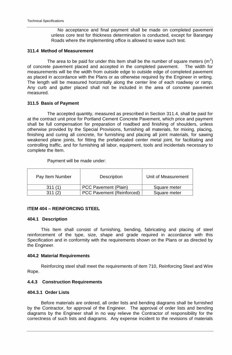
Technical Specifications
No acceptance and final payment shall be made on completed pavement unless core test for thickness determination is conducted, except for Barangay Roads where the implementing office is allowed to waive such test.
311.4 Method of Measurement
The area to be paid for under this Item shall be the number of square meters (m2)
of concrete pavement placed and accepted in the completed pavement. The width for measurements will be the width from outside edge to outside edge of completed pavement as placed in accordance with the Plans or as otherwise required by the Engineer in writing. The length will be measured horizontally along the center line of each roadway or ramp. Any curb and gutter placed shall not be included in the area of concrete pavement measured. 311.5 Basis of Payment
The accepted quantity, measured as prescribed in Section 311.4, shall be paid for
at the contract unit price for Portland Cement Concrete Pavement, which price and payment shall be full compensation for preparation of roadbed and finishing of shoulders, unless otherwise provided by the Special Provisions, furnishing all materials, for mixing, placing, finishing and curing all concrete, for furnishing and placing all joint materials, for sawing weakened plane joints, for fitting the prefabricated center metal joint, for facilitating and controlling traffic, and for furnishing all labor, equipment, tools and incidentals necessary to complete the Item.
Payment will be made under:
Pay Item Number
Description
Unit of Measurement
311 (1) PCC Pavement (Plain) Square meter
311 (2) PCC Pavement (Reinforced) Square meter
ITEM 404 – REINFORCING STEEL 404.1 Description
This Item shall consist of furnishing, bending, fabricating and placing of steel reinforcement of the type, size, shape and grade required in accordance with this Specification and in conformity with the requirements shown on the Plans or as directed by the Engineer. 404.2 Material Requirements
Reinforcing steel shall meet the requirements of item 710, Reinforcing Steel and Wire Rope.
4.4.3 Construction Requirements 404.3.1 Order Lists
Before materials are ordered, all order lists and bending diagrams shall be furnished by the Contractor, for approval of the Engineer. The approval of order lists and bending diagrams by the Engineer shall in no way relieve the Contractor of responsibility for the correctness of such lists and diagrams. Any expense incident to the revisions of materials
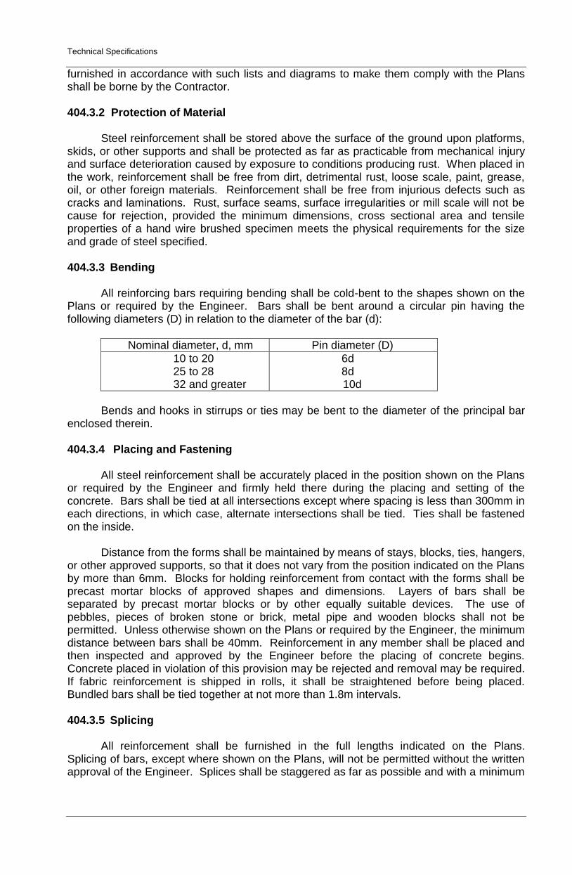
Technical Specifications
furnished in accordance with such lists and diagrams to make them comply with the Plans shall be borne by the Contractor. 404.3.2 Protection of Material
Steel reinforcement shall be stored above the surface of the ground upon platforms, skids, or other supports and shall be protected as far as practicable from mechanical injury and surface deterioration caused by exposure to conditions producing rust. When placed in the work, reinforcement shall be free from dirt, detrimental rust, loose scale, paint, grease, oil, or other foreign materials. Reinforcement shall be free from injurious defects such as cracks and laminations. Rust, surface seams, surface irregularities or mill scale will not be cause for rejection, provided the minimum dimensions, cross sectional area and tensile properties of a hand wire brushed specimen meets the physical requirements for the size and grade of steel specified.
404.3.3 Bending
All reinforcing bars requiring bending shall be cold-bent to the shapes shown on the
Plans or required by the Engineer. Bars shall be bent around a circular pin having the following diameters (D) in relation to the diameter of the bar (d):
Nominal diameter, d, mm Pin diameter (D)
10 to 20 25 to 28 32 and greater
6d 8d
10d
Bends and hooks in stirrups or ties may be bent to the diameter of the principal bar
enclosed therein.
404.3.4 Placing and Fastening
All steel reinforcement shall be accurately placed in the position shown on the Plans or required by the Engineer and firmly held there during the placing and setting of the concrete. Bars shall be tied at all intersections except where spacing is less than 300mm in each directions, in which case, alternate intersections shall be tied. Ties shall be fastened on the inside.
Distance from the forms shall be maintained by means of stays, blocks, ties, hangers,
or other approved supports, so that it does not vary from the position indicated on the Plans by more than 6mm. Blocks for holding reinforcement from contact with the forms shall be precast mortar blocks of approved shapes and dimensions. Layers of bars shall be separated by precast mortar blocks or by other equally suitable devices. The use of pebbles, pieces of broken stone or brick, metal pipe and wooden blocks shall not be permitted. Unless otherwise shown on the Plans or required by the Engineer, the minimum distance between bars shall be 40mm. Reinforcement in any member shall be placed and then inspected and approved by the Engineer before the placing of concrete begins. Concrete placed in violation of this provision may be rejected and removal may be required. If fabric reinforcement is shipped in rolls, it shall be straightened before being placed. Bundled bars shall be tied together at not more than 1.8m intervals.
404.3.5 Splicing
All reinforcement shall be furnished in the full lengths indicated on the Plans.
Splicing of bars, except where shown on the Plans, will not be permitted without the written approval of the Engineer. Splices shall be staggered as far as possible and with a minimum
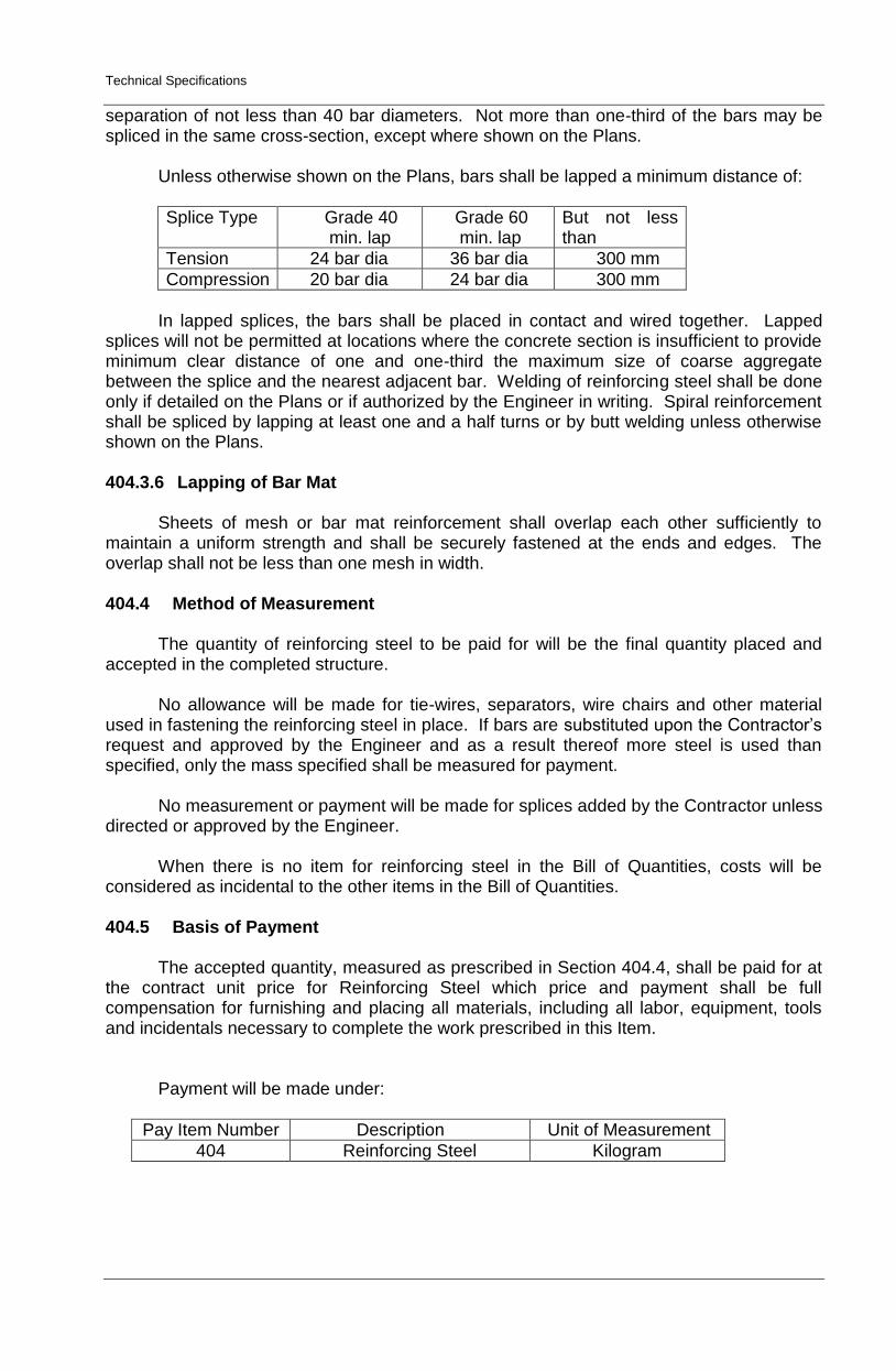
Technical Specifications
separation of not less than 40 bar diameters. Not more than one-third of the bars may be spliced in the same cross-section, except where shown on the Plans.
Unless otherwise shown on the Plans, bars shall be lapped a minimum distance of:
Splice Type Grade 40 min. lap
Grade 60 min. lap
But not less than
Tension 24 bar dia 36 bar dia 300 mm
Compression 20 bar dia 24 bar dia 300 mm
In lapped splices, the bars shall be placed in contact and wired together. Lapped
splices will not be permitted at locations where the concrete section is insufficient to provide minimum clear distance of one and one-third the maximum size of coarse aggregate between the splice and the nearest adjacent bar. Welding of reinforcing steel shall be done only if detailed on the Plans or if authorized by the Engineer in writing. Spiral reinforcement shall be spliced by lapping at least one and a half turns or by butt welding unless otherwise shown on the Plans.
404.3.6 Lapping of Bar Mat
Sheets of mesh or bar mat reinforcement shall overlap each other sufficiently to
maintain a uniform strength and shall be securely fastened at the ends and edges. The overlap shall not be less than one mesh in width.
404.4 Method of Measurement
The quantity of reinforcing steel to be paid for will be the final quantity placed and
accepted in the completed structure.
No allowance will be made for tie-wires, separators, wire chairs and other material used in fastening the reinforcing steel in place. If bars are substituted upon the Contractor’s request and approved by the Engineer and as a result thereof more steel is used than specified, only the mass specified shall be measured for payment.
No measurement or payment will be made for splices added by the Contractor unless
directed or approved by the Engineer.
When there is no item for reinforcing steel in the Bill of Quantities, costs will be considered as incidental to the other items in the Bill of Quantities.
404.5 Basis of Payment
The accepted quantity, measured as prescribed in Section 404.4, shall be paid for at
the contract unit price for Reinforcing Steel which price and payment shall be full compensation for furnishing and placing all materials, including all labor, equipment, tools and incidentals necessary to complete the work prescribed in this Item.
Payment will be made under:
Pay Item Number Description Unit of Measurement
404 Reinforcing Steel Kilogram

Technical Specifications