
Architectural & Structural General & Particular Specification
Upload
khangminh22Category
view
0download
0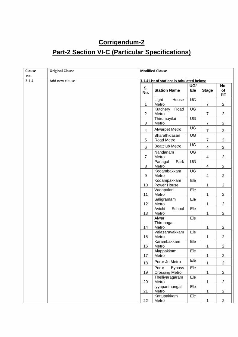
Corrigendum-2
Part-2 Section VI-C (Particular Specifications)
Clause no.
Original Clause Modified Clause
3.1.4 Add new clause 3.1.4 List of stations is tabulated below:
S. No.
Station Name UG/ Ele Stage
No. of PF
1 Light House Metro
UG 7 2
2 Kutchery Road Metro
UG 7 2
3 Thirumayilai Metro
UG 7 2
4 Alwarpet Metro UG 7 2
5 Bharathidasan Road Metro
UG 7 2
6 Boatclub Metro UG 4 2
7 Nandanam Metro
UG 4 2
8 Panagal Park Metro
UG 4 2
9 Kodambakkam Metro
UG 4 2
10 Kodampakkam Power House
Ele 1 2
11 Vadapalani Metro
Ele 1 2
12 Saligramam Metro
Ele 1 2
13 Avichi School Metro
Ele 1 2
14
Alwar Thirunagar Metro
Ele
1 2
15 Valasaravakkam Metro
Ele 1 2
16 Karambakkam Metro
Ele 1 2
17 Alappakkam Metro
Ele 1 2
18 Porur Jn Metro Ele 1 2
19 Porur Bypass Crossing Metro
Ele 1 2
20 Thelliyaragaram Metro
Ele 1 2
21 Iyyapanthangal Metro
Ele 1 2
22 Kattupakkam Metro
Ele 1 2

23 Kumanan Chavadi Metro
Ele 1 2
24 Karayan Chavadi Metro
Ele 1 2
25 Mullaithottam Metro
Ele 1 2
26 Poonamallee Metro
Ele 1 2
27 Poonamallee Bypass Metro
Ele 1 2
3.2.4.2 The Contractor shall note that there will be
phased commissioning of the CMRL Phase 2. All
the works related to phased commissioning and
changes required for inter phase and final
commissioning shall also form part of the work.
The Contractor shall note that there will be phased
commissioning of the CMRL Phase 2. All the works
related to phased commissioning and changes
required for interface and final commissioning shall
also form part of the work.
3.5.1 The services provided by other contractors and
interface scope of work od respective
contractors are detailed in Appendix 2P of PS.
The services provided by other contractors and
interface scope of work of respective contractors
are detailed in Appendix 2P of PS.
3.5.6 UPS & Battery Back-up: UPS supply will be
provided to S&TC contractor at a shared location
in UPS room or suitable location with suitable
dual feeder and circuit breaker at Stations,
OCC,DCC, BOCC by MEP Contractor.
UPS & Battery Back-up: UPS supply will be
provided to PSD contractor at a shared location in
UPS room or suitable location with suitable dual
feeder and circuit breaker at Stations, OCC, BOCC
by MEP Contractor.
3.7.1 The facilities shown in the contract drawings
shall be provided by the Employer to the
Contractor for the on-site work on the dates set
out in the Appendix 2A. In the event that the
Contractor wishes to use such facilities he shall
take into account the dates of availability of such
facilities as set out in the appendix in his
programming and planning of the Works.
The facilities shown in the contract drawings shall
be provided by the Employer to the Contractor for
the on-site work on the dates set out in the Tender
document Part 1. In the event that the Contractor
wishes to use such facilities he shall take into
account the dates of availability of such facilities as
set out in the appendix in his programming and
planning of the Works.
3.7.3.1 Poonamallee Depot
premises
For warehouse,
Contractors Office and
for Engineer office
(Engineer Office only
for Stage 1- From the
pre-construction stage
till end of DLP of Stage
1)
1500 sq m
vacant land in
the Depot
premises will be
provided by the
employer for the
said duration.
Near to Nandanam-
Engineer office
(Engineer Office only
for Stage 2- From the
pre-construction stage
OR from the end of
Contractor shall
make his own
arrangements at
his own cost
Poonamallee Depot
premises
For warehouse,
Contractors Office and
for Engineer office
(Engineer Office only for
Stage 1- From the pre-
construction stage till
end of DLP of Stage 1)
1500 sq m
vacant land in
the Depot
premises will be
provided by the
employer for the
said duration
(stage 1 to
stage 7).
Near to Nandanam-
Engineer office
(Engineer Office only
for Stage 4 & 7- From
the pre-construction
stage OR from the end
of stage 1, till End of
Stage 7)
Contractor shall
make his own
arrangements at
his own cost

DLP of stage 1, till End
of DLP of Stage 2)
4.2.4 For the purposes of Reliability and Availability
calculations, the Contractor shall assume that
the service operating hours are 19 hours per day
(05:00 to 00:00) for 365 days a year. The
availability of the PSD System shall be
demonstrated by the Contractor in accordance
with the processes defined in the Specification.
The Reliability and Availability figure as
described in Para below shall be reached by the
end of the stabilization period from revenue
operation. The Reliability and Availability figures
shall be calculated monthly after the stabilization
period, and the contractor shall demonstrate that
the figures are met in 6 consecutive months of
observation. If the figure is not met in 6
consecutive months by the end of DLP period
then the DLP for that section shall be extended
by 1 month each for all PSDs of that stage, every
time till the requirement of achieving figures for
6 consecutive months is reached.
For the purposes of Reliability and Availability
calculations, the Contractor shall assume that the
service operating hours are 19 hours per day (05:00
to 00:00) for 365 days a year. The availability of the
PSD System shall be demonstrated by the
Contractor in accordance with the processes
defined in the Specification. The Reliability and
Availability figure as described in Para below shall
be reached by the end of the stabilization period
from revenue operation. The Reliability and
Availability figures shall be calculated after the
stabilization period, and the contractor shall
demonstrate that the figures are met over 6
consecutive months of observation. If the figure is
not met over 6 consecutive months by the end of
DLP period then the DLP for that section shall be
extended by 1 month each for all PSDs of that
stage, every time till the requirement of achieving
figures over 6 consecutive months is reached.
4.6.8 The DCU system, Open commands shall comply
to SIL 3. The All doors closed, and locked signal
and Interlock override signals and its associated
hardware as a whole shall comply to SIL 4. The
Vital Signalling Interface shall be SIL 4.
The DCU system, Open/close commands shall
comply to SIL 3. The All doors closed, and locked
signal and Interlock override signals and its
associated hardware as a whole shall comply to SIL
4. The Vital Signalling Interface shall be SIL 4.
4.9.8 The In the event that the ALL DOORS CLOSED
AND LOCKED safety signal is not confirmed, the
Automatic Re-open function of the BSD shall
cause the BSD(s) that have not been proved
closed to re-open. The door re-opening width
shall be adjustable from 100mm to 500mm and
the time delay for re-closing the door shall be
adjustable from 0 to 30 seconds.
In the event that the ALL DOORS CLOSED AND
LOCKED safety signal is not confirmed, the
Automatic Re-open function of the BSD shall cause
the BSD(s) that have not been proved closed to re-
open. The door re-opening width shall be adjustable
from 100mm to full opening width and the time
delay for re-closing the door shall be adjustable
from 0 to 30 seconds.
4.9.9 New clause added The BSD shall be capable of operating in
maximum loaded condition, including TVS fans
operation.
4.11.2 The noise levels at 1m from the platform edge on
any platform resulting from operation of the
MSDs shall not exceed 73 dB (A) fast response
when all doors are operating on an empty
platform with finishes.
The noise levels at 1m from the platform edge on
any platform resulting from operation of the BSDs
shall not exceed 73 dB (A) fast response when all
doors are operating on an empty platform with
finishes.
4.12.1 (e) Wind pressure because of a maximum of 200
kmph cyclonic wind in any direction in Elevated
platforms (For full Height PSDs)
Wind pressure because of a maximum of 200 kmph
cyclonic wind in any direction in Elevated platforms
(For Half Height PSDs)

4.12.3 The MSDs shall be capable of operating in the
above loading conditions except the loading
generated by pressure by the train movement.
The MSDs shall be capable of operating in the
maximum loading with or without a standstill
train in the platform.
The BSDs shall be capable of operating in the
above loading conditions except the loading
generated by pressure by the train movement. The
BSDs shall be capable of operating in the maximum
loading with or without a standstill train in the
platform.
4.12 Add new sub Clause 4.12.6 4.12.6 Covering the structural design finite element analysis report shall be submitted to Engineer for NoNO.
4.13.3 (iii) It shall be minimized smoke and heat emission and shall be free from toxic gases
It shall minimise smoke and heat emission and shall be free from toxic gases
4.13.4 (ii) The Surface linings will achieve Class 0 (national
class) or Class B – S3, d2 (European class)
surface spread of flame in accordance with
International Building Code (IBRC). Materials
will also be compliant with the UK Fire
Precautions (Sub-surface Railway Stations)
Regulations 2009 and or material/product
classified as Class A2-s3, d2 or better in
accordance with BS EN 13501-1:2002 Fire
classification of construction products and
building elements, Part 1 – Classification using
data from reaction to fire tests.
The Surface linings will achieve Class 0 (national
class) or Class B – S3, d2 (European class) surface
spread of flame in accordance with International
Building Code (IBRC). Materials shall also be
compliant with the UK Fire Precautions (Sub-
surface Railway Stations) Regulations 2009 and or
material/product classified as Class A2-s3, d2 or
better in accordance with BS EN 13501-1:2002 Fire
classification of construction products and building
elements, Part 1 – Classification using data from
reaction to fire tests.
4.13.5 (i) The cables shall be 600/1000V for power cables
and 300/500V for control and signal cables. The cables shall be rated for 600/1000V for power
cables and 300/500V for control and signal cables.
5.3.3.7 The All Doors Closed and Locked signal shall
work, based on the actual Realtime status of the
doors of that Platform.
The PSD system shall provide the following signals as a minimum under fail safe conditions to the Signalling system: • All Doors Closed & Locked Signals: Confirms
that all door sets are closed and mechanically
locked, as determined by the All Doors Closed
& Locked Safety Loop going through every door
set of the façade. The All Doors Closed and
Locked signal shall work, based on the actual
Realtime status of the doors of that Platform.
5.3.4.4 Individual Door Inhibition from the ATS shall
NOT be enforced in this mode. The inhibition of the Rolling Stock door based
on the PSD status shall function normally.
5.4.1 Any single equipment failure or cable link failure
shall not cause any effect on the operation of
more than one PSD Bi-parting Sliding Door
corresponding to a car of Rolling stock (Rolling
stock is having 4 passenger doors per car),
except the All doors closed and locked signal.
Any single equipment failure or cable link failure
shall not cause any effect on the operation of more
than one PSD Bi-parting Sliding Door
corresponding to a car of Rolling stock (Rolling
stock is having 4 passenger doors per car), except
the All doors closed and locked signal and door
close/open commands.
5.6.1 CBTC system is required to include local and
remote maintenance and real time diagnostic
capabilities to detect and react to various
equipment failure types. The remote diagnostic
capabilities shall be available at OCC, BOCC,
and to permit authorized personnel to interrogate
PSD system is required to include local and remote
maintenance and real time diagnostic capabilities to
detect and react to various equipment failure types.
The remote diagnostic capabilities shall be
available at OCC, BOCC, and to permit authorized
personnel to interrogate the status of equipments

the status of equipments and provide active fault
diagnosis and isolation. It shall be possible to
remotely download the maintenance and
diagnostic-related data.
and provide active fault diagnosis and isolation. It
shall be possible to remotely download the
maintenance and diagnostic-related data.
5.9.7 The MSDs shall have push bar for opening from
the track side. From the Platform side, the MSDs
shall be opened using the Staff Protection Key
(SPK) of the Signalling.
The MSDs shall have push bar for opening from the
track side. From the Platform side, the MSDs shall
be opened using the Staff Protection Key (SPK) of
the Signalling. The interlock design between the
SPK and MSD shall of subjected to NoNO of
Engineer.
5.10.1 The Bi-parting Sliding Doors can be inhibited by
Signalling System or from the Station Control
Room Workstation.
The Bi-parting Sliding Doors can be inhibited by
Signalling System (ATS Workstation) from the
Station Control Room and OCC/BOCC.
5.14.3 Isolate: In this position, the BSD shall be
electrically isolated from Opening. The door leaf
shall be mechanically locked in Close position
and shall not be capable of Operating electrically
or using the push bar from the track side. The
Door closed and locked signal shall convey the
original position of the doors lock and closed
condition.
Override: In this position, the BSD shall be
electrically isolated from Opening. The door leaf
shall be mechanically locked in Close position
and shall not be capable of Operating electrically
or using the push bar from the track side. The
Door closed and locked signal shall convey the
original position of the doors lock and closed
condition..
Isolate: In this position, the BSD shall be
electrically isolated from Opening. The Door closed
and locked signal shall convey the original position
of the doors lock and closed condition.
Override: In this position, the BSD shall be electrically isolated from Opening. The Door closed and locked signal shall be bypassed to bridge the ADCL loop. The override signal to signalling system shall be made available.
5.15.8 The Summary Lamp for MSD shall be like the
EED. Additionally summary lamp shall be
provided on the track side for EED providing high
visibility from the track side/ tunnels. Platform
side light can be like that of EED
The Summary Lamp for MSD on platform side
shall be like the EED. Additionally summary lamp
shall be provided on the track side for MSD
providing high visibility from the track side/ tunnels.
5.16.4 The MCP shall have specialized key matching
the rotary switch to changeover the PSD mode
from Auto to Manual.
The MCP shall have specialized key and matching
rotary switch (latching) to changeover the PSD
mode from Auto to Manual.
5.16.5 The MCP shall also be provided with specialized
key matching the rotary switch to Override the
PSD All Doors Closed and Locked Signal.
The MCP shall also be provided with specialized
key and matching rotary switch (non-latching
spring loaded) to Override the PSD All Doors
Closed and Locked Signal.
5.18.6 The minimum reopening distance shall be
adjustable from 0.3 m to full width. The time
between closing attempts shall be adjustable.
The minimum reopening distance shall be
adjustable from 0.1 m to full width. The time
between closing attempts shall be adjustable.
6.4.3.3 All safety critical equipments shall be designed,
manufactured and validated to Safety Integrity
level 4 as defined in the CENELEC standard
All doors closed and locked signal (ADCL) and
Interlock Override signals and its associated
hardware as a whole shall be designed and

EN50126, EN50128, and EN 50129.The
Contractor shall submit report that the safety of
Door Control Unit meets SIL 3.
validated to Safety Integrity level 4 as defined in
the CENELEC standard EN50126, EN50128, and
EN 50129.The Contractor shall submit report that
the safety of Door Control Unit and open/close
commands meets SIL 3.
6.14.4 (3rd bullet)
The All doors close and locked lamp contact for
‘balance 3 car PSD’, which shall be proved in
series with the 3-car PSD. Currently these future
contacts shall be wired on kept in logically close
condition by the existing PSD supplier.
The All doors close and locked lamp contact for
‘balance 3 car PSD’, which shall be proved in series
with the 3-car PSD. Currently these future contacts
shall be wired and kept in logically close condition
by the existing PSD supplier.
6.15.3 The Gap filler shall have sufficient rigidity against
vertical movement so that deflection under the
weight of a passenger does not create additional
trip hazard or permit a passenger’s foot to
become trapped between the vehicle and barrier
threshold. The floor surface at the barrier
doorway threshold shall be of slip-resistant
material as described and tested in accordance
with EN 16584-3. The gap filler shall be able to
withstand the impact of likely hits by the rolling
stock for a train approaching the station stopping
or running through the platform without
damaging itself or the rolling stock surface.
The Gap filler shall have sufficient rigidity against
vertical load so that deflection under the weight of
a passenger does not create additional trip hazard
or permit a passenger’s foot to become trapped
between the vehicle and barrier threshold. The floor
surface at the barrier doorway threshold shall be of
slip-resistant material as described and tested in
accordance with EN 16584-3. The gap filler shall be
able to withstand the impact of likely hits by the
rolling stock for a train approaching the station
stopping or running through the platform without
damaging itself or the rolling stock surface.
6.15.6 In exceptional cases, suitable entrapment
detection system to be installed by the PSD
Contractor, to achieve the above requirements;
this system, where installed, apart from
triggering a conspicuous alarm in the ATS
workstation of Signalling system in OCC/BOCC
and SCR, shall also prevent the departure of the
train from the platform, if entrapment is detected.
The detection system design shall incorporate
features to minimize false activation/alarm.
In exceptional cases, suitable entrapment detection
system to be installed by the PSD Contractor, to
achieve the above requirements; this system,
where installed, apart from triggering a conspicuous
alarm in the ATS workstation of Signalling system
and PSD workstation in OCC/BOCC and SCR,
shall also prevent the departure of the train from the
platform, if entrapment is detected. The detection
system design shall incorporate features to
minimize false activation/alarm.
7.1.1 The purpose of the Interface Specifications is to
provide Other Contractor involved in the
interface with a clear overview of the purpose
and functionality of each interface. It provides a
framework such that Other Contractor can set to
work in a co-operative way to produce the
interfacing standard. Details of the interfaces
with the PSD System are found in the Interface
Specifications in Appendix 2P
The purpose of the Interface Specifications is to
provide Other Contractor involved in the interface
with a clear overview of the purpose and
functionality of each interface. It provides a
framework such that Other Contractor can set to
work in a co-operative way to produce the
interfacing standard. Details of the interfaces with
the PSD System are found in the Interface
Specifications in Appendix2P. Contractor wise
interface Appendices are given in Appendix 2P
as tabulated below;
APPENDIX 2P
1 Appendix
2P-1 Interface protocol between
Rolling stock and Platform
Screen Doors (PSD) System
2 Appendix
2P-2 Interface protocol between
Signalling and Train Control

system (S&TC) and Platform
Screen Doors (PSD) system
3 Appendix
2P-4A Interface protocol between
Civil (UG) and Platform
Screen Doors (PSD) system
(Full Height)
4 Appendix
2P-4B
Interface protocol between
Civil (Elevated) and Platform
Screen Doors (PSD) system
(Half Height)
5 Appendix
2P-5
Interface protocol between
Track and Platform Screen
Doors (PSD) system
6 Appendix
2P-6A
Interface protocol between
MEP(UG) and Platform
Screen Doors (PSD) system
(Full Height)
7 Appendix
2P-6B
Interface protocol between
MEP (Elevated) and
Platform Screen Doors
(PSD) system (Half Height)
8 Appendix
2P-7
Interface protocol between
VAC and Platform Screen
Doors (PSD) system (Full
Height)
9 Appendix
2P-78
Interface protocol between
TVF and Platform Screen
Doors (PSD) system (Full
Height)
10.6.5.3
SN Position/ Category
Total work experience
( min number of
years)
Experience in similar works (
min number of
years)
1 Project Manager
22 10
2 Engineering Manager
15 8
3 PSD Design Engineers
10 5
4 Interface Manager
15 8
5 Procurement Engineer
10 5
6 Installation Manager
15 8
7 Installation Engineers
10 5
8 Project Quality Manager
15 8
SN Position/Category
Total work experience
( min number of
years)
Experience in similar works (
min number of
years)
1 Project Manager 22 12
1A Deputy Project Manager
18 10
2 Engineering Manager
15 8
3 PSD Design Engineers
10 5
4 Interface Manager
15 8
5 Procurement Engineer
10 5
6 Installation Manager
15 8
7 Installation Engineers
10 5
8 Project Quality Manager
15 8

9 Project Quality Engineers
10 5
10
OHSE Manager (Accident Prevention Officer)
15 8
11 OHSE Engineer
10 5
12 Testing and Commissioning Engineers
10 5
13 Testing and Commissioning Manager
15 8
14 DLP manager 15 8
15 DLP Engineers 10 5
9 Project Quality Engineers
10 5
10
OHSE Manager (Accident Prevention Officer)
15 8
11 OHSE Engineer 10 5
12 Testing and Commissioning Engineers
10 5
13 Testing and Commissioning Manager
15 8
14 DLP manager 15 8
15 DLP Engineers 10 5
10.6.7.1.1 All cables shall be installed as per the ducting
plans, wherever such ducts are not provided the
cables shall be laid & installed in accordance
with the standards. Refer Appendix 2J & 2K of
this PS.
All cables shall be installed as per the ducting plans,
wherever such ducts are not provided the cables
shall be laid & installed in accordance with the
standards. Refer Appendix 2J & 2K of this PS.
10.6.7.2.1 Cables shall be used in accordance with the
requirements of Appendix 2K of this PS.
Cables shall be used in accordance with the
requirements of Appendix 2K of this PS.
The mock-up shall be shipped to Chennai in
advance after the manufacturing along with the
set of PSD used for prototype testing
The additional set for mock-up shall be shipped to
Chennai in advance. The set of PSD for prototype
testing shall be shifted to the location where the
it is to be tested.
11.11 Equipment field Trial (complete clause) Not Used
11.14.2 All failures and service interruptions shall be
logged during the tests on completion and the
MTBMA and MTBSAF etc. shall be calculated.
The Contractor shall demonstrate that all
performance requirements in Chapter 4 of the
PS are met.
All failures and service interruptions shall be logged
during the tests on completion and the MCBF,
MTBSAF etc. shall be calculated. The Contractor
shall demonstrate that all performance
requirements in Chapter 4 of the PS are met.
13.3.5 (b) Data logging, retrieval and preservation. Not Used
13.3.6 Add New sub clause 13.3.6 (f) Add 13.3.6 (f) Data logging, retrieval and
preservation.
14.2.12.3 Disputes between the PSC Contractor and other
Project Contractor shall be resolved by the FRB.
Disputes between the PSD Contractor and other
Project Contractor shall be resolved by the FRB.
14.2.12.5 Upon identification of the failure cause, the
contractor shall check for similar potential
failures in other installation of the stage and
rectify the issue in other locations before the
reputation of the failure.
Upon identification of the failure cause, the
contractor shall check for similar potential failures in
other installation of the stage and rectify the issue
in other locations before the repetition of the
failure.
14.4.1.3 The scope of maintenance activities shall
include all scheduled and unscheduled
maintenance required including all routine
inspections and service overhauls at trackside
The scope of maintenance activities shall include all
scheduled and unscheduled maintenance required
including all routine inspections and service
overhauls at trackside and in

on trains and in workshops/lab/repair center.
Maintenance work shall include fault finding
following report of incidents and repair of items
of equipment changed out in the course of fault
rectification and imparting on-job training and
guidance for employer’s maintenance personnel
but excluding any Contractor’s liability for work
to be carried out under the requirements of the
Defects Liability Period.
workshops/lab/repair center. Maintenance work
shall include fault identification following report of
incidents and repair of items of equipment changed
out in the course of fault rectification and imparting
on-job training and guidance for employer’s
maintenance personnel but excluding any
Contractor’s liability for work to be carried out under
the requirements of the Defects Liability Period.
14.5.1.7 The PSD contractor must ensure that in case
Operating System and/or the HW
platform/Servers provided by them are
compatible to the newer versions/platform of OS
and HW. If not, they must make provisions to
upgrade their existing SW applications
The PSD contractor must ensure that Operating
System and/or the HW platform/Servers provided
by them are compatible to the newer
versions/platform of OS and HW.
14.7.1.1 The Contractor shall provide three kinds of
manuals Operation, Maintenance & Training
manuals, to the Employer for use by supervisory,
Training and technical staff of the Operator. 12
Months prior to completion of Stage 1, the
Contractor shall deliver to the Employer the
Preliminary Operation and Maintenance
manuals in 3 copies. The Final updated manuals
shall be delivered to the Employer 06 months
before the completion of Stage 1. These
manuals shall have been submitted to and
reviewed with no objection by the Engineer prior
to delivery to the Employer. The number of
copies shall be adequate to meet the
requirements of copies for maintenance staff
and for deployment in all technical rooms for
various stages of the project. The exact number
will be decided by the Engineer 08 months
before the ROD of each stage.
The Contractor shall provide three kinds of manuals
Operation, Maintenance & Training manuals, to the
Employer for use by supervisory, Training and
technical staff of the Operator. 12 Months prior to
completion of Stage 1, the Contractor shall deliver
to the Employer the Preliminary Operation and
Maintenance manuals in 3 copies. The Final
updated manuals shall be delivered to the Employer
06 months before the completion of Stage 1. These
manuals shall have been submitted to and reviewed
with no objection by the Engineer prior to delivery
to the Employer. The number of copies shall be
adequate to meet the requirements of copies for
operation and maintenance staff and for
deployment in all technical rooms for various stages
of the project. The exact number will be decided by
the Engineer 08 months before the ROD (revenue
operation date) of each stage.
Appendices Complete appendices replaced with new ones. The new appendices are attached herewith

APPENDIX -2N
SCHEDULE OF DIMENSIONS
CMRL

Note: This is Draft document for information. This
might undergo changes during the approval process.
CHENNAI METRO RAIL LIMITED
SCHEDULE OF DIMENSIONS FOR
STANDARD GAUGE
(1435 mm)
CMRL PHASE 2 PROJECT
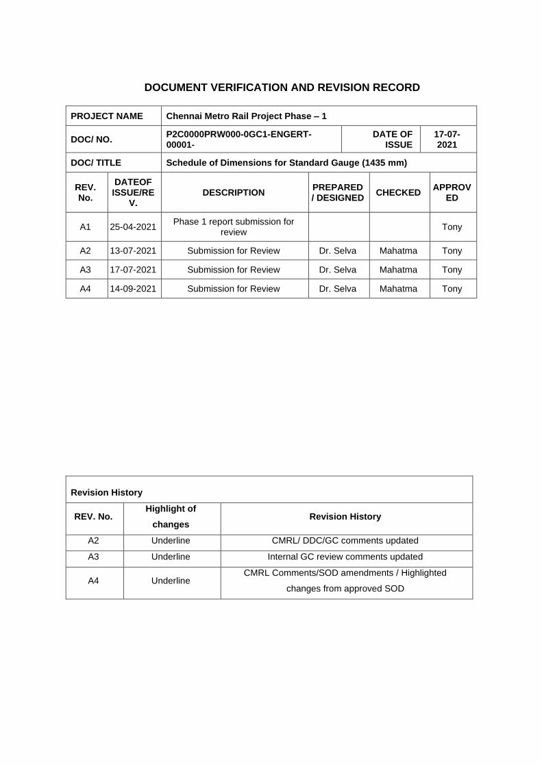
DOCUMENT VERIFICATION AND REVISION RECORD
PROJECT NAME Chennai Metro Rail Project Phase – 1
DOC/ NO. P2C0000PRW000-0GC1-ENGERT-00001-
DATE OF ISSUE
17-07-2021
DOC/ TITLE Schedule of Dimensions for Standard Gauge (1435 mm)
REV. No.
DATEOF ISSUE/RE
V. DESCRIPTION
PREPARED / DESIGNED
CHECKED APPROV
ED
A1 25-04-2021 Phase 1 report submission for
review Tony
A2 13-07-2021 Submission for Review Dr. Selva Mahatma Tony
A3 17-07-2021 Submission for Review Dr. Selva Mahatma Tony
A4 14-09-2021 Submission for Review Dr. Selva Mahatma Tony
Revision History
REV. No. Highlight of
changes Revision History
A2 Underline CMRL/ DDC/GC comments updated
A3 Underline Internal GC review comments updated
A4 Underline CMRL Comments/SOD amendments / Highlighted
changes from approved SOD

TABLE OF CONTENTS
DESCRIPTION PAGE NO.
CHAPTER- I GENERAL
1.1 SPACING OF TRACKS .............................................................................................................. 3
1.2 CURVES..................................................................................................................................... 3
1.3 BUILDING AND STRUCTURES ................................................................................................ 4
1.4 KINEMATIC ENVELOPE............................................................................................................ 6
1.5 STRUCTURE GAUGE ............................................................................................................... 6
1.6 EXTRA CLEARANCES ON CURVES ........................................................................................ 7
1.7 MINIMUM TRACK SPACING ON CURVES ............................................................................... 9
1.8 SPECIAL OPERATING CONDITION ....................................................................................... 10
1.9 ADDITIONAL OPERATING CONDITION FOR ELEVATED & AT GRADE SECTION 11
1.10 WALKWAY CLAUSE DELETED .............................................................................................. 11
1.11 GRADIENT ............................................................................................................................... 11
1.12 PROVISIONS IN PLATFORM EDGE OTHER THAN PSD LOCATION ................................... 11
CHAPTER-2 STATION YARDS
2.1 SPACING OF TRACKS AT STATIONS .................................................................................... 13
2.2 PLATFORMS ........................................................................................................................... 13
2.3 GRADIENTS ............................................................................................................................ 14
2.4 INTERLOCKING AND SIGNAL GEAR ..................................................................................... 14
2.5 POINTS & CROSSINGS .......................................................................................................... 15
2.6 SUPER ELEVATION AND SPEED AT STATIONS ON CURVES WITH
............................................................. TURNOUTS OF CONTRARY AND SIMILAR FLEXURE.
15
2.7 ADDITIONAL CLEARANCE FOR PLATFORMS ON CURVES ............................................... 16
CHAPTER 3 ROLLING STOCK
3.1 PASSENGER ELECTRIC MULTIPLE UNITS. ......................................................................... 17
3.2 LOCOMOTIVES AND ENGINEERING SERVICE VEHICLES ................................................. 18
CHAPTER 4 OVERHEAD ELECTRIC TRACTION-25 KV AC 50HZ
4.1 ELECTRICAL CLEARANCES FOR UNDER GROUND ........................................................... 19
4.2 ELECTRICAL CLEARANCES FOR AT GRADE AND ELEVATED SECTIONS ....................... 20
CHAPTER 5 PLATFORM SCREEN DOORS
5.1 FITMENT .................................................................................................................................. 22
5.2 SETTING OUT DIMENSION UNDERGROUND FULL HEIGHT PSD ...................................... 22
5.3 SETTING OUT DIMENSION ELEVATED HALF HEIGHT PSD ................................................ 22

APPENDIX NO. DESCRIPTION PAGE NO.
Appendix – 1 Permissible Speed, Cant and Minimum Track Spacing on Curves Underground (Tunnels), Elevated and At Grade section
23
Appendix – 2 Extra Horizontal Shift on Curves 24
Appendix – 3 Cant Effect on Structure Gauge – Horizontal At grade and Elevated Reference para 1.7.2
26
Appendix – 3 (TNL) Cant Effect on Structure Gauge – Horizontal Underground sections (Rectangular Box Tunnel)
27
Appendix – 3A Cant Effect on Kinematic Envelope – Horizontal At Grade and Elevated Sections
28
Appendix–3A (TNL) Cant Effect on Kinematic Envelope Underground Sections (Rectangular Box Tunnel) 29
Appendix – 4 Lateral and Vertical Shift of Centre of Circular Tunnel for different Cant values
30
Appendix – 5 Additional clearance for platforms on Curves Underground, elevated and at Grade stations
31

LIST OF FIGURES
1 Figure No. CMSG–1 Kinematic Envelope (At grade and Elevated Sections) 32
2 Figure No. CMSG–1 (TNL)
Kinematic Envelope–Underground Sections (Tunnels, Through & Semi through Girder Bridges)
33
3 Figure No. CMSG–1A Kinematic Envelope at 55kmph -At grade and Elevated Sections on Tangent track at Stations.
34
4 Figure No. CMSG–2 Structure Gauge – At Grade and Elevated Sections 35
5 Figure No. CMSG–2 (TNL)
Structure Gauge –Circular tunnel (5800mm Dia) Through & Semi through Girder Bridges, and Rectangular box tunnel on tangent track.
36
6 Figure No. CMSG–3 Shift of the Centre of circular tunnel due to rotation of Tunnel to provide cant
37
7 Figure No. CMSG–4 Effect of cant on structure Gauge 38
8 Figure No. CMSG–4A Effect of cant on Kinematic envelope 39
9 Figure No. CMSG–5 Effect of vertical curve on structure gauge 40
10 Figure No. CMSG-6 Structural clearance at elevated / at grade station with side platforms
41
11 Figure No. CMSG-6 (TNL)
Structural clearance at underground station with side platforms
42
12 Figure No. CMSG-7 Structural clearance at elevated / at grade station with island platforms
43
13 Figure No. CMSG-7 TNL
Structural clearance at underground station with island platforms
44
14 Figure No. CMSG-8 Structural clearance Platform screen door for underground stations
45
15 Figure No. CMSG-9 Structural clearance Platform screen door for Elevated stations
46
16 Figure No. CMSG-10 Provision at platform edge for future developments
47

PREAMBLE
The Schedule of Dimensions for Chennai Metro Standard Gauge has been prepared based on
following factors.
1. The Kinematic envelope and other infringements have been calculated for the 2900mm wide and
3900 mm high Rolling Stock, based on the Kinematic envelope calculations. The Track and Car
maintenance shall confirm to the clearances indicated therein during the period these stocks are in
operation.
2. The clearances are based on the assumption that windows are sealed, and doors are closed
during movement/operation.
3. Track shall be maintained to the tolerance taken for calculation of Kinematic envelope.
4. The Structure Gauge indicated in the SOD shall not to be violated under any circumstances
except Platform coping and Platform Screen Doors.
5. The Kinematic envelope indicated in the SOD shall not to be violated under any circumstances.
6. The Car Kinematic Envelope for 55 kmph shall be applied only within the confines of stations. At
all other locations, the full 80 kmph shall be used for determining the Structure gauge and electrical
clearances.
7. Maximum operating Speed at Platform shall be 55 kmph and Kinematic Envelope will not be
infringed under any circumstances.
8. No workmen / equipment / structure are allowed between Car and structure gauge during
operation of trains.
9. This SOD pertains to ballast less track only.
Kinematic Envelope is abbreviated as KE and Standard Gauge as SG in the document.

CHENNAI METRO RAIL LIMITED
SCHEDULE OF DIMENSIONS
STANDARD GAUGE (1435 MM GAUGE)
INTRODUCTION
The dimensions given in this document are to be observed in all new works on 1435 mm gauge
(STANDARD GAUGE), unless prior sanction has been obtained from the Railway Board through the
Commissioner of Railway safety to execute works which infringe this Schedule of Dimensions
This Schedule of Dimensions is applicable to Under Ground, Elevated and At-Grade sections of
Chennai Metro which shall be with 25 kV AC Traction system and Over Head current collection.
The Schedule of Dimensions (SOD) has been divided into four chapters as under
Chapter-1 General
Chapter-2 Station Yards
Chapter-3 Rolling stock
Chapter 4 Electric Traction
Chapter 5 Platform Screen doors

CHAPTER 1 – GENERAL
1.1 SPACING OF TRACKS 1.11.1 Minimum distance centre to centre of tracks without any structure between tracks for tangent
(straight) track for:
a) Under Ground Sections 3500 mm
b) Elevated & At Grade Sections 3650 mm
Note: See Appendix-1 for minimum track centres distances on curves
1.2 CURVES
1.2.1 Horizontal curves
Minimum radius of curves (horizontal)
i) On main running lines
a) Under Ground Sections 200 m (Minimum)
b) Elevated and At-Grade Sections 120 m (Minimum) & 190m (Desirable)
ii) Depot and other Lines 100 m (Minimum)
iii) At passenger stations 1000m
iv) Length of circular curve 15 m (Minimum) & 20m (Desirable)
v) Type of Transition Curve Clothoid
vi) Length of Transition Curve 15 m (Minimum) 20 m (Desirable)
Note: For curves of radius less than 190 m, check rails to be provided.
1.2.2 Vertical curves
Minimum radius of curves (horizontal)
i) Minimum radius of curves 1500m
ii) Minimum length of curve 15 m (Minimum) & 20m (Desirable)
iii) Type of Curve Circular
iv) Minimum distance between
two curves 15m
1.2.3 CANT
i) Maximum cant 110m
ii) CANT deficiency (Max) 85 mm
iii) CANT Gradient 1 in 440 (Minimum) 1 in 720 (Desirable)
iv) Rate of change of CANT 44mm/s (Minimum)
35 mm/s (Desirable)
v) Rate of change of CANT deficiency 44mm/s (Minimum)
35 mm/s (Desirable)
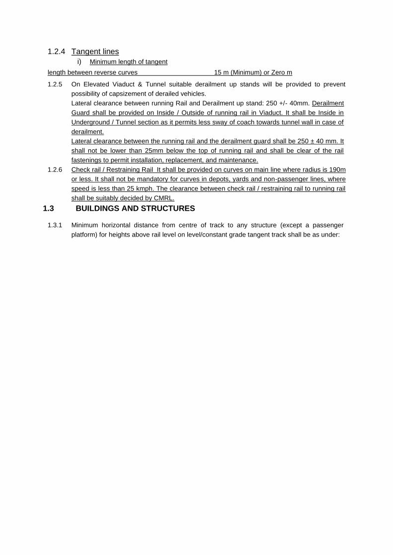
1.2.4 Tangent lines
i) Minimum length of tangent
length between reverse curves 15 m (Minimum) or Zero m
1.2.5 On Elevated Viaduct & Tunnel suitable derailment up stands will be provided to prevent
possibility of capsizement of derailed vehicles.
Lateral clearance between running Rail and Derailment up stand: 250 +/- 40mm. Derailment
Guard shall be provided on Inside / Outside of running rail in Viaduct. It shall be Inside in
Underground / Tunnel section as it permits less sway of coach towards tunnel wall in case of
derailment.
Lateral clearance between the running rail and the derailment guard shall be 250 ± 40 mm. It
shall not be lower than 25mm below the top of running rail and shall be clear of the rail
fastenings to permit installation, replacement, and maintenance.
1.2.6 Check rail / Restraining Rail It shall be provided on curves on main line where radius is 190m
or less. It shall not be mandatory for curves in depots, yards and non-passenger lines, where
speed is less than 25 kmph. The clearance between check rail / restraining rail to running rail
shall be suitably decided by CMRL.
1.3 BUILDINGS AND STRUCTURES
1.3.1 Minimum horizontal distance from centre of track to any structure (except a passenger
platform) for heights above rail level on level/constant grade tangent track shall be as under:

a) Under Ground Sections
i) Circular tunnels
S No Height from rail level Horizontal distance from C.L. of track
i) Rail Level to 65mm Upto 1465 mm
ii) 65mm to 200mm 1465mm increasing to 1585mm
iii) 200 mm to 305 mm 1585mm
iv) 305 mm to 940 mm 1585mm increasing to 1670 mm
v) 940 mm to 1095 mm 1670mm increasing to 1675 mm
vi) 1095 mm to 3305 mm 1675 mm increasing to 1740 mm
vii) 3305 mm to 3965 mm 1740 mm decreasing to 1250 mm
viii) 3965 mm to 4775 mm 1250mm
ix) 4775 mm to 4920 mm 1250 mm decreasing to zero along an arc of circle of
radius of 2900 mm
Also refer to drawing No. CMSG-2 (TNL)
ii) Rectangular Box Tunnels
S No Height from rail level Horizontal distance from C.L. of track
i) Rail Level to 65mm Upto 1465 mm
ii) 65 mm to 200 mm 1465mm increasing to 1585mm
iii) 200 mmm to 305mm 1585mm
iv) 305 mmm to 940 mm 1585mm increasing to 1670 mm
v) 940 mmm to 1095 mm 1670mm increasing to 1675 mm
vi) 1095 mm to 3305 mm 1675 mm increasing to 1740 mm
vii) 3305 mm to 3965 mm 1740mm decreasing to 1250 mm
viii) 3965 mm to 4838 mm 1250 mm
Also refer to Drawing No. CMSG-2(TNL)
b) Elevated and At-Grade Sections
S No Height from rail level Horizontal distance from C.L. of track
i) Rail Level to 65 mm Upto 1465 mm
ii) 65 mm to 200 mm 1465 mm increasing to 1640mm
iii) 200 mm to 305 mm 1640mm
iv) 305 mm to 930 mm 1640mm increasing too 1735 mm
v) 930 mm to 1095 mm 1735 mm increasing to 1740 mm
vi) 1095 mm to 3310 mm 1740 mm increasing to 1825 mm
vii) 3310 mm to 3775 mm 1825 mm decreasing to 1546mm
viii 3775 mm to 6250mm 1546mm
Also refer to Drawing No.CMSG-2
Notes for (a) and (b) above:
i) Extra clearance shall be provided for curves as laid down at para 1.6.
ii) The term 'structure' covers any item including light ones like ladders, isolated posts,
cables etc. erected alongside the track.
iii) Minimum lateral clearance for OHE masts for tangent track shall be 2150 mm from
Centre of the nearest track.

1.4 KINEMATIC ENVELOPE
The Kinematic Envelope for level or constant grade tangent track, refer to:
a) Drawing No. CMS G-1 for At-Grade Track and Elevated Sections.
b) Drawing No. CMS G-1(TNL) for Tunnels, Through & Semi through Girder Bridges.
c) Drawing No CMSG-1A For Kinematic Envelope at 55 KMPH speed on Level or Constant
Grade Tangent Track at Station Area.
1.5 STRUCTURE GAUGE
1.5.1 Under Ground Sections
The Structure Gauge (Fixed Structure Line) has been arrived at by allowing a minimum
mechanical clearance of 100 mm to the derived Kinematic Envelope and minimum electrical
clearance of 270 mm from 25 KV live parts conforming to the stipulations in Chapter- 4 of this
SOD.
Refer to Drawing No. CMSG-2(TNL) Rev 4 for Structure Gauge for Tunnels, Through & Semi
through Girder Bridges for level or constant grade tangent track.
Note: Extra allowance shall be provided for curves as laid down at para 1.6.
1.5.2 Elevated Sections
The Structure Gauge (Fixed Structure Line) has been arrived at by allowing minimum
mechanical clearance of 150 mm to Kinematic Envelope and minimum electrical clearance of
320 mm from 25 KV live parts conforming to the stipulations in chapter-4 of this SOD.
For Structure Gauge on Elevated Sections for level or constant grade tangent track, refer to
Drawing No. CMSG-2
Note: Extra allowance shall be provided for curves as laid down at para 1.6
1.5.3 At-Grade Sections
The Structure Gauge (Fixed Structure Line) has been arrived at by allowing minimum
mechanical clearance of 150 mm to the derived Kinetic Envelope and minimum electrical
clearance of 320 mm from 25 KV live parts, conforming to stipulations in chapter 4 of this SOD.
For Structure Gauge on At-Grade Sections (outside stations)
for level or constant grade tangent track, refer to Figure No. CMSG-2.
Note: Extra allowance shall be provided for curves as laid down at para 1.6
1.6 EXTRA CLEARANCES ON CURVES
Abbreviations used in para 1.6:
C is the distance between centres of bogies in metres.
C1 is the coach (vehicle) length in metres,
R is the radius of curve in metres,
Ca is the Cant applied in mm,
h is the height from rail level in mm and
g is the distance between centres of rails in mm
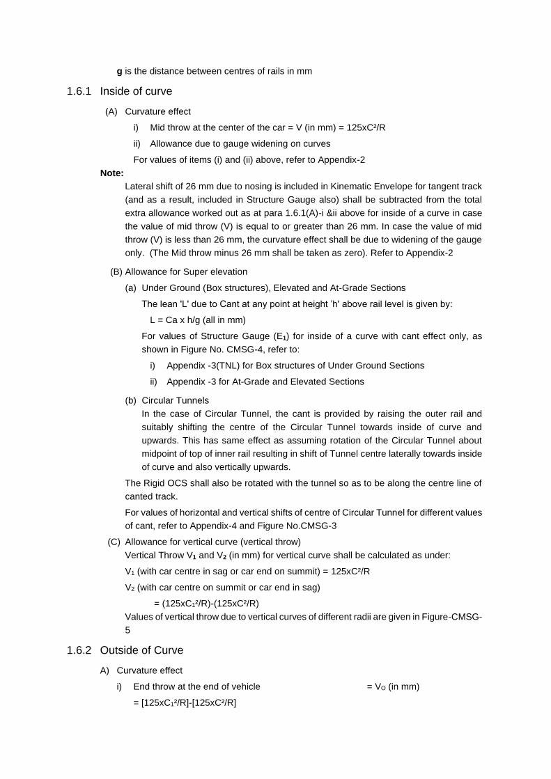
1.6.1 Inside of curve
(A) Curvature effect
i) Mid throw at the center of the car = V (in mm) = 125xC²/R
ii) Allowance due to gauge widening on curves
For values of items (i) and (ii) above, refer to Appendix-2
Note:
Lateral shift of 26 mm due to nosing is included in Kinematic Envelope for tangent track
(and as a result, included in Structure Gauge also) shall be subtracted from the total
extra allowance worked out as at para 1.6.1(A)-i &ii above for inside of a curve in case
the value of mid throw (V) is equal to or greater than 26 mm. In case the value of mid
throw (V) is less than 26 mm, the curvature effect shall be due to widening of the gauge
only. (The Mid throw minus 26 mm shall be taken as zero). Refer to Appendix-2
(B) Allowance for Super elevation
(a) Under Ground (Box structures), Elevated and At-Grade Sections
The lean 'L' due to Cant at any point at height ’h' above rail level is given by:
L = Ca x h/g (all in mm)
For values of Structure Gauge (E1) for inside of a curve with cant effect only, as
shown in Figure No. CMSG-4, refer to:
i) Appendix -3(TNL) for Box structures of Under Ground Sections
ii) Appendix -3 for At-Grade and Elevated Sections
(b) Circular Tunnels
In the case of Circular Tunnel, the cant is provided by raising the outer rail and
suitably shifting the centre of the Circular Tunnel towards inside of curve and
upwards. This has same effect as assuming rotation of the Circular Tunnel about
midpoint of top of inner rail resulting in shift of Tunnel centre laterally towards inside
of curve and also vertically upwards.
The Rigid OCS shall also be rotated with the tunnel so as to be along the centre line of
canted track.
For values of horizontal and vertical shifts of centre of Circular Tunnel for different values
of cant, refer to Appendix-4 and Figure No.CMSG-3
(C) Allowance for vertical curve (vertical throw)
Vertical Throw V1 and V2 (in mm) for vertical curve shall be calculated as under:
V1 (with car centre in sag or car end on summit) = 125xC²/R
V2 (with car centre on summit or car end in sag)
= (125xC1²/R)-(125xC²/R)
Values of vertical throw due to vertical curves of different radii are given in Figure-CMSG-
5
1.6.2 Outside of Curve
A) Curvature effect
i) End throw at the end of vehicle = VO (in mm)
= [125xC1²/R]-[125xC²/R]

ii) Allowance due to gauge widening on curves
iii) Additional nosing due to gauge widening on curves
The values of items (i) to (iii) are shown in Appendix-2
B) Allowance for Superelevation
a) Elevated, At-Grade and box Sections of under ground
The lean' 'L' due to Cant at any point at height 'h' above rail level is given by:
L = (-) Ca x h/g (all in mm)
-ve sign indicates relief due to cant or reduction in clearance required.
Note:
Full relief for lean due to cant (Ca) is to be taken into account only for calculation of track
spacing without any structure between tracks. In case there is a structure adjacent to track,
relief for lean is to be taken into account only if the cant provided is greater than 50 mm and
shall be limited to a value =(Ca - 50) x h/g.
Values of Structure Gauge (F1) on outside of curve with cant effect only (as shown in Figure
NoCMSG-4), refer to:
i) Appendix 3(TNL) for Under Ground Sections (Rectangular Box)
ii) Appendix 3 for Elevated and At-Grade Sections
b) Circular Tunnels
In the case of Circular Tunnel, the cant is provided by raising the outer rail and suitably
shifting the centre of the Circular Tunnel towards inside of curve and upwards. This has
same effect as assuming rotation of the Circular Tunnel about mid point of top of inner rail
resulting in shift of Tunnel centre laterally towards inside of curve and also vertically
upwards
The Rigid OCS shall also be rotated with the tunnel so as to be along the centre line of
canted track.
For values of horizontal and vertical shifts of centre of Circular Tunnel for different values
of cant, refer to Appendix-4 and Figure No. CMSG-3
c) Allowance for vertical curve (vertical throw)
The provisions at para 1.6.1 (C) above shall be applicable in this case also.
1.7 MINIMUM TRACK SPACING ON CURVES
Under Ground, Elevated and At-Grade Sections
The worst case will be when the end of a bogie carriage on the inner track is opposite the
centre of a similar carriage on the outer track.
1.7.1 Without any structure between tracks
The minimum track spacing on curves without any-structure between tracks shall be the sum
of the following:
i) (E + F),
ii) T1 (Extra lateral allowance due to curvature on inside of curve)
iii) T2 (Extra lateral allowance due to curvature on outside of curve)

iv) Minimum clearance between adjacent Kinematic Envelopes stipulated is as under:
a) 200 mm for Under-Ground Sections
b) 300 mm for Elevated and At-Grade Sections
Where,
'E' is the distance from vertical axis of centre line of canted track to canted Kinematic Envelope
on inside of curve at a height 'h' (from rail level) for a given cant (Figure No.CMSG-4A) and
'F' is the distance from vertical axis of centre line of canted track to canted Kinematic Envelope
on outside of curve at a height 'h' (from rail level) for a given cant (Figure No.CMSG-4A).
Notes:
i) The value of 'F', calculated from the formula at Figure NO. CMSG-4A includes full relief
due to cant.
ii) The sum of 'E' and 'F' for same height (which are with cant effect only), shall be the
maximum of values calculated for various heights from rail level.
For value of E,F,T1 and T2 Refer Appendix 2,3A,3A (TNL) and drawing No CMSG -4A..
1.7.2 With a structure between adjacent tracks
The minimum track spacing on curves with a structure between tracks shall be the sum of the
following:
i) (E1 + T1) Minimum clearance to the structure from centre line of track on inside of curve
(for outer track)
ii) (F1 + T2) Minimum clearance to the structure from centre line of track on outside of curve
(for inner track)
iii) Width of structure between adjacent tracks (measured across the tracks).
Where,
E1 is the horizontal distance from vertical axis of centre line of track to canted Structure Gauge
on inside of curve for a given cant,
F1 is the horizontal distance from vertical axis of centre line of track to canted Structure Gauge
on outside of curve for a given cant,
T1 is extra lateral allowance due to curvature on inside of curve and
T2 is extra lateral allowance due to curvature on outside of curve
Notes:
a) The values of 'E1' and 'F1' for a given cant Ca, shall each be the maximum of values at
different heights of structure from rail level. In case the cant provided is greater than 50
mm on inner track, the value of F1 shall be for the cant of. (Ca-50) mm. In case the
cant provided is 50 mm or less on inner track, the value of F1, shall be for ZERO cant.
b) Minimum track spacing, so worked out with a structure between the adjacent tracks shall
not be less than that calculated as per para 1.7.1 for tracks without any structure between
adjacent tracks.
For values of E1,F1,T1 and T2, refer to the Appendix 2,3 & 3 (TNL) and Drawing No. CMSG-4
1.8 SPECIAL OPERATING CONDITIONS: (COMMON FOR UNDERGROUND
AS WELL AS ELEVATED AND AT GRADE)
1.8.1. Schedule maintenance of permanent way will be performed outside service hours only.
1.8.2. In view of chance of collision of derailed train with the train coming from other direction,
adequate measures shall be taken to restrict lateral movement of derailed vehicles. Proper
communication facilities should also be available at the stations.
1.8.3. All the coaches will be provided with sealed windows, to prevent limbs and heads of passengers
projecting outside the train. The passengers vehicles will be provided with automatic remote
controlled double leaf doors with their control from drivers cab. Until all doors are proved closed,
it will not be possible to start the train. Likewise until the train has come to the stop, it will not
be possible to energize the door opening circuits.
1.8.4. Since minimum clearance with fully worn wheel and under fully loaded condition from rail level
for bogie mounted equipment is 75mm, the vehicles with this minimum clearance only will run
on Chennai Metro Rail network.
1.8.5. In the event of trains running through stations without stopping, the train speed shall be limited
to 55 km/h
1.8.6. Patrolling of the section to be done during extreme winter and summer to monitor effect of
Climate, Temperature variation on Track during outside service hours/ non-operation hours.
1.8.7. The corridor when fully functional will not have way side signalling as train protection will be by
ATP. However, in the initial period, till cab signalling system is fully commissioned, there will be
way side signalling which should be so located near the masts that proper visibility to the
motorman is ensured considering the alignment.
1.8.8. No movement shall be made with springs in deflated conditions except for the emergency
movement to Depot at suitable speed to be decided after necessary oscillation trials.
1.8.9. Provision of space shall be provided for the railway authority to access the train car from
backside to frontside or vice versa during emergency when train stops midway between
stations.
1.9 ADDITIONAL OPERATING CONDITION FOR ELEVATED AND AT GRADE
SECTION
1.9.1 In case of elevated corridor, the track is expected to be on the surface and passing through
populated areas and there are chances of people passing through the track. Considering this
fact, to prevent the access to the track by sections will be robustly fenced.
1.9.2 The speed of train at platforms on elevated or At Grade sections shall be restricted to 40kM/h
(Instead of 55kM/h) when the wind speed is more than 70kM/h, but less than 90kM/h. When
the wind speed exceeds 90kM/h trains will be brought to a halt at platform until the wind speed
is again consistently below 90kM.h, CMRL shall ensure observance of stipulation laid down
above in the operation procedure.
1.10 Walkway - Deleted
1.11 GRADIENT
1.11.1 The maximum grade (compensated) shall be 4%
Note (i) There will be no change of gradient in transition portion of curves.
(ii) The gradient will be compensated for curvature at the rate of 0.04% per degree of
curve.
1.11.2 Maximum permissible gradient on turnouts on Ballastless track 2.5%
Note:
(i) There shall be no change of grade on and within 15m of any turnout on ballastless
track.
(ii) In case of turnouts on gradient, there shall be no horizontal curve on and within 15m of
any turnout on ballastless track.

1.12 PROVISIONS IN PLATFORM EDGE OTHER THAN PSD LOCATION
1.12.1 PSD shall be provided at platform edge for the purpose of passenger safety. it shall be provided
only in the train operation location of 3 car platform edge. All other platform edge location shall
be protected by means of the following.
a) Half height fixed aluminium panel or Glass fixed to stainless steel balusters or perforated
panel fixed to stainless steel balusters shall be for the elevated station refer drawing
CMSG-09.
b) 2hrs fire rated full height block work shall be provided for the underground station refer
drawing CMSG-10.

CHAPTER 2 - STATION YARDS
2.1 SPACING OF TRACKS AT STATIONS
Minimum spacing of tracks at station on straight and on curve of radius of 1000 M and flatter,
without any structure between tracks:
At-Grade, Elevated and Under-Ground Stations 3900 mm
2.2 PLATFORMS IN STRAIGHT ALIGNMENT
2.2.1 Maximum horizontal distance from centre of track to
HH PSD threshold for elevated/At grade section 1520
PSD threshold for Underground section 1515
2.2.2 Minimum horizontal distance from centre of track to
HH PSD threshold for elevated/At grade section 1515
PSD threshold for Underground section 1510
Notes:
a) Platform faces shall be flared away smoothly from the centre line of the track at either
end for a distance of 1500 mm so as to give from centre of track a dimension:
• 1575 ± 5 for Under Ground Stations
• 1590 ± 5 for At-Grade and Elevated Stations
b) For additional clearance for platforms on curves, refer to para 2.7
c) For Platforms provided with Platform screen doors in UG & Elevated stations, flaring of
platform faces is not required.
2.2.3 Height above rail level for passenger platform:
Maximum Minimum
1095 mm 1085 mm
2.2.4 Structure Clearance on Platform:
(i) Minimum horizontal distance of any isolated structure on a
passenger platform from the edge of coping if Platform screen door
is not provided.
2500mm
(ii) Minimum horizontal distance of any continuous structure on a
passenger platform from the edge of coping, if platform screen door
is not provided.
3000mm
(iii) Minimum horizontal distance of any isolated structure on a
passenger platform from the edge of coping, if Platform Screen Door
is provided
2000mm
(iv) Minimum horizontal distance of any continuous structure on a
passenger platform from the edge of coping, if Platform Screen Door
is provided
2450mm
Notes:

The structure on the platform is treated as isolated if the length along the platform length is
2000 mm or less. Any structure having a length exceeding 2000 mm is treated as continuous
structure.
2.2.5 For Structure Gauge at stations, refer to following figures
a) For Under Ground Station Figure No.CMSG-6(TNL) & 7 (TNL)
b) For At-Grade and Elevated Stations Figure No.CMSG-6 & 7
2.2.6 For Kinematic Envelope at Station, refer to Drawing –CMSG-1 A (Ref para 1.4.c Chapter-1)
2.2.7 In the event of Train Running-through stations without stopping, the train speed shall be limited
to 55 kmph (Ref para 1.8.5 Chapter-1)
2.3 GRADIENTS
2.3.1 Station Yards
Gradient in station yards, unless special safety devices are adopted and / or special rules
enforced to prevent accidents in accordance with approved special instructions shall be as
under:
a) Maximum gradient 1 in 400
b) Desirable Level
Note:
There shall be no change of gradient in platform track.
2.4 INTERLOCKING AND SIGNAL GEAR
Maximum height above rail level of any part of interlocking or signal gear on either side of
centre of track subject to the restrictions embodied in Note below shall be as under: -(a) For
Under Ground Stations
• From CL of track to 1330 mm 25mm
• From 1330 mm to 1465 mm 25 mm rising to 65 mm
• From 1465 mm to 1585 mm 65 mm rising to 200 mm
(b) For At Grade and Elevated Stations
• From C.L. of track to 1330 mm 25mm
• From 1330 mm to 1465 mm 25 mm increasing to 65 mm
• From 1465 mm to 1640 mm 65 mm increasing to 200 mm
Note:
Except for check rails of ordinary and diamond crossings, or wing rails and point rails of
crossings leading to snag dead ends, or such parts of signaling gear as are required to be
actuated by the wheels. No gear or track-fittings shall project above rail level for a distance of
229 mm outside and 140 mm inside the gauge face of the rails.
2.5 POINTS & CROSSINGS
i) Maximum clearance of check rail opposite nose of crossing 42mm
ii) Minimum clearance of check rail opposite nose of crossings 37 mm
iii) Minimum clearance of wing rail at nose of crossings 41 mm
iv) Minimum clearance between toe of open switch and stock rail. 160 mm
v) Minimum radius of curvature for slip points, turnouts of crossover roads.
a) For passenger running lines 190 m
b) For Depot lines and other than passenger running lines 100 m
vi) Minimum angle of crossing (ordinary) 1 in 9 (Desirable)
1 in 7 (Minimum)
vii) Diamond crossings not to be flatter than 1 in 4.5
Note:
a) The above restrictions shall not apply to moveable diamond crossings
b) There must be no change of superelevation (of outer over inner rail) between points 18 m
outside toe of switch rail and nose of crossings respectively, except in the case of special
crossing leading to snag dead-ends or under circumstances as provided for in item 2.6
below
2.6 SUPERELEVATION AND SPEED AT STATIONS ON CURVES WITH
TURNOUTS OF CONTRARY AND SIMILAR FLEXURE.
2.6.1 Main line:
Subject to the permissible run through speed based on the standard of interlocking, the
equilibrium super elevation, calculated for the speed of the fastest train may be reduced by a
maximum amount of 85 mm without reducing speed on the main fine.
2.6.2 Turnouts:
i) Curves of contrary flexure
The equilibrium superelevation (s) in mm should be = (1510/127)(V² / R); Where, R =
radius of turnout in metres and V is speed on turnout in kmph.
The permissible negative superelevation on the turnout (which is also the actual
superelevation of the main line) may then be = (85 - s) mm
ii) Curves of Similar flexure
The question of reduction or otherwise of superelevation on the main line must necessarily
be determined by the administration concerned. In the case of a reverse curve close
behind the crossing of a turnout, the superelevation may be run out at the maximum of 1
mm in 440 mm
2.7 ADDITIONAL CLEARANCE FOR PLATFORMS ON CURVES
The additional clearance for platforms on curves is shown at Appendix-5
2.7.1 Detail of Stations in Curve
Platforms located in curves shall be fitted with a Gap Filler wherever necessary to maintain the
minimum stepping distance of 75 mm without contacting the train in normal condition. The Gap
Filler shall be of elastic nature and flexible to allow train contact.
Notes:
There will be no Gauge widening and Super elevation in Platform/Station area.

CHAPTER 3-ROLLING STOCK
3.1 PASSENGER ELECTRIC MULTIPLE UNITS.
1. a) Maximum length of car body (Length over body) 21638 mm
b) The length of car body may be increased to
(without exceeding the KE given in this SOD)
21840mm
c) The maximum width of the car body 2900 mm
d) Height of car body (Excluding Pantograph) 3900mm
2 Minimum pantograph locked down height from Rail
level.
4048mm
3. Distance between bogie centres 14850 ± 250 mm
4. Kinematic Envelope for level tangent track
(i) For Underground Sections Figure No CMSG-1 (TNL)
(ii) For At-Grade and Elevated Sections Figure No.CMSG-1
(iii) For all Stations with normal secondary
suspension at 55km/h
Figure No.CMSG-1A
5. Minimum clearance from rail level with fully worn
wheel defected air spacing and under fully loaded
condition for bogie mounted equipment
75mm
6 The Minimum clearance from rail level in worst
conditions such as fully worn wheel, deflated air
spring and under fully loaded condition etc for body
mounted equipment.
100mm
7 Wheel
a) Maximum wheel gauge back-to-back distance 1360mm
b) Minimum wheel gauge back-to-back distance 1358 mm
8 a) Maximum diameter on the tread measured
at 70 mm from the wheel gauge face
860mm
b) Minimum diameter on the tread measured
at 70·mm from the wheel gauge face
780mm
9 a) Minimum projection for flange of new wheel
measured from tread at 70 mm from the wheel
gauge face
28 mm*
b) Maximum projection for flange of worn wheel
measured from tread at 70 mm from the wheel
gauge face
36mm*
10 a) Maximum thickness of flange of wheel.
measured from wheel gauge face at 18 mm
from outer edge of flange
32.5 mm*

b) Minimum thickness of flange of wheel measured
from wheel gauge face at 18 mm from outer
edge of flange
22mm*
11 Minimum width of wheel 134mm*
12 Incline of tread 1 in 20
13 Floor Height
a) Maximum height above rail level for floor
of any unloaded Car
1120 mm
b) Minimum height above rail level for floor of
any fully loaded car
1087 mm
14 a) Maximum height of centre coupler above rail
level for unloaded car
815mm
b) Minimum height of centre coupler above rail
level for fully loaded car
740mm
15 Maximum length over couplers 22600mm
16 Maximum length of rigid wheelbase for single bogie 2600 mm
3.2 LOCOMOTIVES AND ENGINEERING SERVICE VEHICLES
Other items of rolling stock, viz shunting locomotives, OHE maintenance and inspection cars,
emergency re-railing van, track machines, etc., used on Chennai Metro System (Standard
Gauge) will conform with the Kinematic Envelope of the Passenger Electric Multiple Units as
shown in Figure No CMSG-1(TNL) for Under Ground sections and Figure No. CMSG 1 for
Elevated and At-Grade sections.
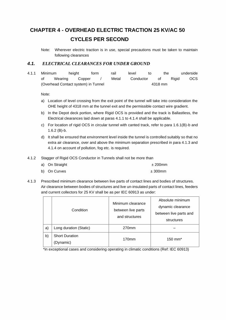
CHAPTER 4 - OVERHEAD ELECTRIC TRACTION 25 KV/AC 50
CYCLES PER SECOND
Note: Wherever electric traction is in use, special precautions must be taken to maintain
following clearances
4.1. ELECTRICAL CLEARANCES FOR UNDER GROUND
4.1.1 Minimum height form rail level to the underside
of Wearing Copper / Metal Conductor of Rigid OCS
(Overhead Contact system) in Tunnel 4318 mm
Note:
a) Location of level crossing from the exit point of the tunnel will take into consideration the
OHE height of 4318 mm at the tunnel exit and the permissible contact wire gradient.
b) In the Depot deck portion, where Rigid OCS is provided and the track is Ballastless, the
Electrical clearances laid down at paras 4.1.1 to 4.1.4 shall be applicable.
c) For location of rigid OCS in circular tunnel with canted track, refer to para 1.6.1(B)-b and
1.6.2 (B)-b.
d) It shall be ensured that environment level inside the tunnel is controlled suitably so that no
extra air clearance, over and above the minimum separation prescribed in para 4.1.3 and
4.1.4 on account of pollution, fog etc. is required.
4.1.2 Stagger of Rigid OCS Conductor in Tunnels shall not be more than
a) On Straight ± 200mm
b) On Curves ± 300mm
4.1.3 Prescribed minimum clearance between live parts of contact lines and bodies of structures.
Air clearance between bodies of structures and live un-insulated parts of contact lines, feeders
and current collectors for 25 KV shall be as per IEC 60913 as under:
Condition
Minimum clearance
between live parts
and structures
Absolute minimum
dynamic clearance
between live parts and
structures
a) Long duration (Static) 270mm –
b) Short Duration
(Dynamic) 170mm 150 mm*
*in exceptional cases and considering operating in climatic conditions (Ref: IEC 60913)

4.1.4 Prescribed minimum- clearance between live parts of contact lines and bodies of vehicles
Minimum Air clearance between bodies of vehicles and the live un-insulated parts of the
contact line or feeders for 25 KV
Condition Clearance (mm)
a) Long duration (Static) 290mm
b) Short Duration (Dynamic) 190mm
4.1.5 Maximum width of pantograph - Under dynamic condition.
The Kinematic Envelope for the underground system with Ballastless track is shown in Figure
CMSG-1(TNL). The pantograph adopted should be such that its actual half KE width does not
exceed 820 mm and 980 mm at the top and bottom respectively in pantograph raised condition
for a contact wire height of 4318 mm to fulfil electrical clearance as per item 4.1.3
Note:
These limits would not apply to special locations like insulated overlaps and out of run wires.
4.2. ELECTRICAL CLEARANCES FOR AT–GRADE AND LEVATED SECTIONS
4.2.1 Minimum vertical distance between any live bare conductor (overhead equipment or
pantograph) and any earthed structure or other bodies (rolling stock. Over bridges, signal
gantries etc.)
Condition For Flexible OHE
a) Long duration (Static) 320mm
b) Short Duration (Dynamic) 270mm
Note:
A minimum vertical distance of 340 mm shall normally be provided between rolling stock and
contact wire to allow for a 20 mm temporary raising of the tracks during maintenance.
Wherever the allowance required for track maintenance exceeds 20mm, the vertical distance
between rolling stock and contact wire shall correspondingly be increased.
4.2.2 Minimum lateral distance between any bare live conductor (over head equipment or
pantograph) or any earthed structure or other bodies (rolling stock, over bridges, signal
gantries etc.)
Condition For Flexible OHE
i) Long duration (Static) 320mm
ii) Short Duration (Dynamic) 220mm
4.2.3 Height of contact wire:
Minimum height from rail level to the underside of live Conductor wire.
i) Under bridges and in tunnels 4800mm
ii) In the open 5000mm
iii) At level crossings 5500mm
iv) In running and carriage sheds wherever staff are
expected to work on the roof of rolling stock 5200mm
Maximum height from rail level to the underside of live Conductor wire (corresponding to the
maximum height of the train pantograph collecting range)
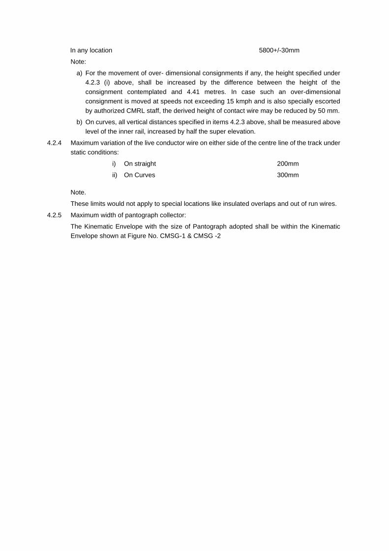
In any location 5800+/-30mm
Note:
a) For the movement of over- dimensional consignments if any, the height specified under
4.2.3 (i) above, shall be increased by the difference between the height of the
consignment contemplated and 4.41 metres. In case such an over-dimensional
consignment is moved at speeds not exceeding 15 kmph and is also specially escorted
by authorized CMRL staff, the derived height of contact wire may be reduced by 50 mm.
b) On curves, all vertical distances specified in items 4.2.3 above, shall be measured above
level of the inner rail, increased by half the super elevation.
4.2.4 Maximum variation of the live conductor wire on either side of the centre line of the track under
static conditions:
i) On straight 200mm
ii) On Curves 300mm
Note.
These limits would not apply to special locations like insulated overlaps and out of run wires.
4.2.5 Maximum width of pantograph collector:
The Kinematic Envelope with the size of Pantograph adopted shall be within the Kinematic
Envelope shown at Figure No. CMSG-1 & CMSG -2

CHAPTER 5 - PLATFORM SCREEN DOORS
5.1. FITMENT
All underground stations shall be equipped with full height platform screen doors & all the
elevated stations shall be equipped with half height PSD and the opening is linked to door
operation on the rolling stock.
5.2. SETTING OUT DIMENSIONS- UNDERGROUND FULL HEIGHT PSD
Minimum Platform screen door width 2000 mm*
Minimum Platform screen door height 2150 mm
Minimum Platform screen door threshold offset from track centreline –
straight track
1510 mm (see para
2.2.2)
Minimum Platform screen door panel offset from track centre line – straight
track 1557 mm
Minimum Platform screen door header offset from track centre line – straight
track 1519 mm
Minimum Station platform height –finished architectural level 1090 mm
5.3. SETTING OUT DIMENSIONS- ELEVATED STATION- HALF HEIGHT PSD
Minimum Platform screen door width 2000 mm *
Minimum platform door height 1500 mm
Minimum Platform screen door threshold offset from track centre line-
Straight track
1520 mm
Minimum Platform screen door panel offset from track centre line-
Straight track
1550 mm
Minimum Platform screen door equipment assembly box offset from
track centre line- Straight track
1520 mm
Minimum Station platform height -finished architectural level 1090 mm
Notes
• Assumed stopping accuracy of +/ - 300 mm
• The offset in curve applies to the point of the MSO (Motorized Screen
Door) + EED (Emergency Egress Door) set (which is straight) which is
nearest to the track centreline.
• The leaning due to cant deficiency in station (no cant) at 55 kmph (outside
curve effect) is already included in the KE.
• The deflector attached to the bottom of the sliding door shall be designed
in order not to protrude beyond the door threshold.
• Platforms located in curves shall be fitted with gap filler as specified in
para.2.7.1 .
• For Curved Platform, additional curve allowance as per Appendix-5 to be
considered.
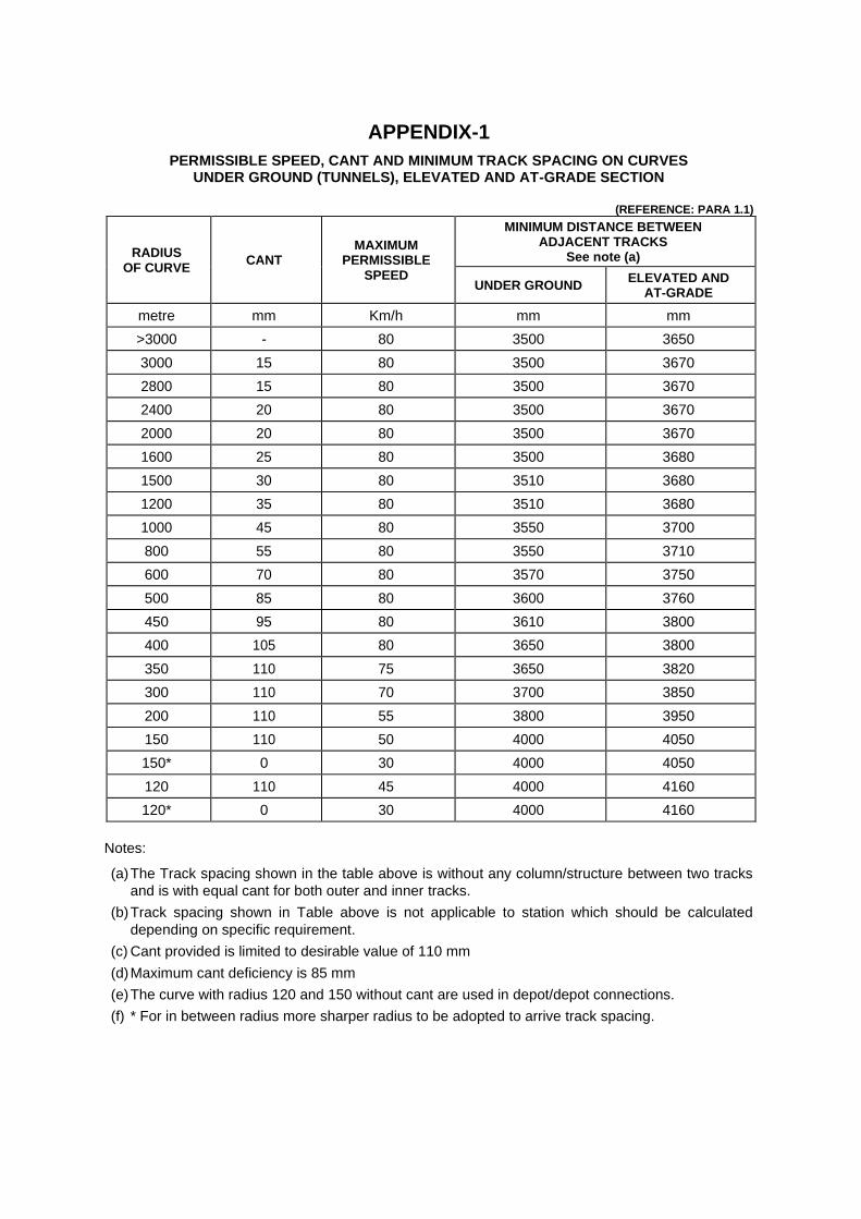
APPENDIX-1
PERMISSIBLE SPEED, CANT AND MINIMUM TRACK SPACING ON CURVES UNDER GROUND (TUNNELS), ELEVATED AND AT-GRADE SECTION
(REFERENCE: PARA 1.1)
RADIUS OF CURVE
CANT MAXIMUM
PERMISSIBLE SPEED
MINIMUM DISTANCE BETWEEN ADJACENT TRACKS
See note (a)
UNDER GROUND ELEVATED AND
AT-GRADE
metre mm Km/h mm mm
>3000 - 80 3500 3650
3000 15 80 3500 3670
2800 15 80 3500 3670
2400 20 80 3500 3670
2000 20 80 3500 3670
1600 25 80 3500 3680
1500 30 80 3510 3680
1200 35 80 3510 3680
1000 45 80 3550 3700
800 55 80 3550 3710
600 70 80 3570 3750
500 85 80 3600 3760
450 95 80 3610 3800
400 105 80 3650 3800
350 110 75 3650 3820
300 110 70 3700 3850
200 110 55 3800 3950
150 110 50 4000 4050
150* 0 30 4000 4050
120 110 45 4000 4160
120* 0 30 4000 4160
Notes:
(a) The Track spacing shown in the table above is without any column/structure between two tracks
and is with equal cant for both outer and inner tracks.
(b) Track spacing shown in Table above is not applicable to station which should be calculated
depending on specific requirement.
(c) Cant provided is limited to desirable value of 110 mm
(d) Maximum cant deficiency is 85 mm
(e) The curve with radius 120 and 150 without cant are used in depot/depot connections.
(f) * For in between radius more sharper radius to be adopted to arrive track spacing.

APPENDIX-2
EXTRA HORIZONTAL SHIFT ON CURVES (CURVATURE EFFECT)
INSIDE OF CURVE
REFERENCE : PARA 1.6.1
RADIUS
MID-
THROW
(28500/R)
NOSING
INCLUDED IN
K E/
STRUCTURE
GAUGE FOR
TANGENT
TRACK
EXTRA
GAUGE
TOLERANCE
ON CURVES
EXTRA
HORIZONTAL
SHIFT ON
CURVE
REMARKS
(metres) (mm) (mm) (mm) (mm)
R (V) (N) (G) (T1)
120 237.5 26.0 9.0 221
150 190.0 26.0 9.0 173
175 162.9 26.0 9.0 146
200 142.5 26.0 9.0 126 (G) EXTRA
GAUGE
TOLERANCE ON
CURVES
SHARPER THAN
1000 M RADIUS:
9 mm FOR
CURVES WITH
RADIUS
SHARPER THAN
500 M AND
5mm FOR
CURVES WITH
RADIUS OF 500 M
TO LESS THAN
1000M.
T1=V-N+G for V
EQUAL TO
OR GREATER
THAN (N) AND
T1 = G for V < (N)
250 114.0 26.0 9.0 97
300 95.0 26.0 9.0 78
350 81.4 26.0 9.0 64
400 71.3 26.0 9.0 54
450 63.3 26.0 9.0 46
500 57.0 26.0 5.0 36
600 47.5 26.0 5.0 27
700 40.7 26.0 5.0 20
800 35.6 26.0 5.0 15
900 31.7 26.0 5.0 11
1000 28.5 26.0 0.0 3
1200 23.8 26.0 0.0 0
1500 19.0 26.0 0.0 0
1600 17.8 26.0 0.0 0
2000 14.3 26.0 0.0 0
2400 11.9 26.0 0.0 0
2800 10.2 26.0 0.0 0
3000 9.5 26.0 0.0 0
>3000 9.5 26.0 0.0 0
Mid throw (in mm) V = (125 x C2) /R = 28500/R
Where 'C' is the distance between bogies centers = 14.850+0.250=15.100m OR 14.850 -
0.250=14.600 m.
The worst case will be with C=15.100 m
R is the radius of curve in metres.
Mid throw (in mm) V = (125 x C2) / R = 28500/R
For in between radius more sharper radius to be adopted

APPENDIX-2
EXTRA HORIZONTAL SHIFT ON CURVES (CURVATURE EFFECT)
OUTSIDE OF CURVE
REFERENCE : PARA 1.6.2
RADIUS
END-
THROW
(33525/R)
EXTRA
GAUGE
TOLERANCE
ON CURVES
EXTRA NOSING
DUE TO EXTRA
GAUGE
TOLERANCE
EXTRA
HORIZONTAL
SHIFT ON
CURVE
REMARKS
(metres) (mm) (mm) (mm) (mm)
R (Vo) (G) (EN) (T2)
120 279.4 9.0 2.3 291
150 223.5 9.0 2.3 235
175 191.6 9.0 2.3 203
200 167.6 9.0 2.3 179
(G) EXTRA GAUGE
TOLERANCE ON
CURVES SHARPER
THAN 1000 M RADIUS:
9 mm FOR CURVES
WITH RADIUS
SHARPER THAN
500 M AND
5mm FOR CURVES
WITH RADIUS OF
500 M TO LESS
THAN 1000M.
T2 = Vo + G + EN
EN=Gx0.251986301
250 134.1 9.0 2.3 145
300 111.8 9.0 2.3 123
350 95.8 9.0 2.3 107
400 83.8 9.0 2.3 95
450 74.5 9.0 2.3 86
500 67.1 5.0 1.3 73
600 55.9 5.0 1.3 62
700 47.9 5.0 1.3 54
800 41.9 5.0 1.3 48
900 37.3 5.0 1.3 44
1000 33.5 0.0 0.0 34
1200 27.9 0.0 0.0 28
1500 22.4 0.0 0.0 22
1600 21.0 0.0 0.0 21
2000 16.8 0.0 0.0 17
2400 14.0 0.0 0.0 14
2800 12.0 0.0 0.0 12
3000 11.2 0.0 0.0 11
>3000 11.2 0.0 0.0 0
End throw (in mm) Vo = (125 x C12) /R - (125 x C2)/R = 33525/R
Where 'C' is the distance between bogie centers = 14.850+0.250=15.100m OR 14.850-0.250=14.600 m.
The worst case will be with C=14.600
‘C1’ is length of coach in meters = 21.940 m and ‘R’ is radius of curve in meters.
For in between radius more sharper radius to be adopted.

APPENDIX-3 CANT EFFECT ON STRUCTURE GAUGE-HORIZONTAL AT-GRADE AND ELEVATED
REFERENCE: PARA 1.7.2 REFERENCE: PARA 1.7.2
ALL FIQURES ARE IN MM
Height above rail level measured →
perpendicular to plane of track
Distance from centre line of track to →
Structure Gauge for tangent track
h = 305 h = 930 h = 3310 h = 3775 h= 6250
ab= 1640 ab = 1735 ab = 1825 ab=1546 ab = 1546
Cant
Angle
Degrees
Sin cos tan E1 F1 H1 H2 E1 F1 H1 H2 E1 F1 H1 H2 E1 F1 H1 H2 E1 F1 H1 H2
110 4.178 0.073 0.997 0.07 1658 1613 479 240 1798 1663 1109 856 2061 1579 3489 3223 1817 1267 3933 3707 1997 1087 6401 6176
105 3.987 0.07 0.998 0.07 1657 1615 471 243 1795 1666 1101 860 2051 1590 3481 3228 1805 1280 3926 3711 1977 1108 6395 6180
100 3.797 0.066 0.998 0.07 1657 1616 463 246 1793 1670 1093 863 2040 1602 3474 3232 1793 1293 3919 3714 1957 1129 6389 6184
95 3.607 0.063 0.998 0.06 1656 1618 455 249 1790 1673 1085 867 2030 1613 3466 3236 1780 1305 3912 3718 1936 1150 6382 6188
90 3.417 0.06 0.998 0.06 1655 1619 447 252 1787 1676 1077 870 2019 1624 3458 3240 1768 1318 3905 3721 1916 1171 6376 6192
85 3.227 0.056 0.998 0.06 1655 1620 439 255 1785 1680 1069 873 2008 1636 3450 3245 1756 1331 3899 3724 1895 1192 6370 6196
80 3.037 0.053 0.999 0.05 1654 1622 431 258 1782 1683 1061 877 1998 1647 3442 3249 1744 1344 3892 3728 1875 1213 6363 6199
75 2.847 0.05 0.999 0.05 1653 1623 424 261 1779 1687 1053 880 1987 1658 3434 3253 1732 1357 3885 3731 1855 1234 6357 6203
70 2.657 0.046 0.999 0.05 1652 1624 416 264 1776 1690 1044 884 1976 1670 3426 3257 1719 1369 3878 3734 1834 1255 6350 6207
65 2.467 0.043 0.999 0.04 1652 1625 408 267 1773 1693 1036 887 1966 1681 3418 3261 1707 1382 3871 3737 1814 1276 6343 6210
60 2.277 0.04 0.999 0.04 1651 1627 400 270 1771 1697 1028 890 1955 1692 3410 3265 1695 1395 3863 3741 1793 1296 6336 6214
55 2.087 0.036 0.999 0.04 1650 1628 392 273 1768 1700 1020 894 1944 1703 3402 3269 1682 1407 3856 3744 1773 1317 6330 6217
50 1.898 0.033 0.999 0.03 1649 1629 384 276 1765 1703 1012 897 1934 1714 3394 3273 1670 1420 3849 3747 1752 1338 6323 6220
45 1.708 0.03 1 0.03 1648 1630 376 278 1762 1707 1004 900 1923 1726 3385 3277 1658 1433 3842 3750 1732 1359 6316 6224
40 1.518 0.026 1 0.03 1648 1631 368 281 1759 1710 996 904 1912 1737 3377 3280 1645 1445 3835 3753 1711 1380 6309 6227
35 1.328 0.023 1 0.02 1647 1632 360 284 1756 1713 987 907 1901 1748 3369 3284 1633 1458 3827 3756 1690 1401 6302 6230
30 1.138 0.02 1 0.02 1646 1634 353 287 1753 1716 979 910 1890 1759 3361 3288 1621 1471 3820 3759 1670 1422 6294 6233
25 0.949 0.017 1 0.02 1645 1635 345 290 1750 1719 971 914 1880 1770 3352 3292 1608 1483 3813 3761 1649 1442 6287 6236
20 0.759 0.013 1 0.01 1644 1636 337 293 1747 1723 963 917 1869 1781 3344 3296 1596 1496 3805 3764 1629 1463 6280 6239
15 0.569 0.01 1 0.01 1643 1637 329 296 1744 1726 955 920 1858 1792 3335 3299 1583 1508 3798 3767 1608 1484 6273 6242
10 0.379 0.007 1 0.01 1642 1638 321 299 1741 1729 946 923 1847 1803 3327 3303 1571 1521 3790 3770 1587 1505 6265 6245
5 0.19 0.003 1 0 1641 1639 313 302 1738 1732 938 927 1836 1814 3319 3306 1558 1533 3783 3772 1567 1525 6258 6247
0 0 0 1 0 1640 1640 305 305 1735 1735 930 930 1825 1825 3310 3310 1546 1546 3775 3775 1546 1546 6250 6250
REFER TO FIGURE: CMSG-4 E1 = [ab+(h x tan )] x cos
F1=[ab-(h x tan )] x cos
H1 = (Ca/2) + (h/cos )+(Ab-h x tan )x sin
H2 = (Ca/2) + (h/cos )-(ab+h x tan ) x sin
ab = Ab = Distance from center line of vehicle to Structure gauge for Tangent Track at height 'h' from rail level
ac = Distance from center line of canted track to Structure Gauge for Tangent track at height 'h' from rail level.
bc = hxtan =Lateral increment due to cant (measured along the line parallel to line joining top of rails).

APPENDIX - 3 (TNL) CANT EFFECT ON STRUCTURE GAUGE-HORIZONTAL UNDER GROUUND SECTIONS (RECTANGULAR BOX TUNNELS)
REFERENCE: PARA 1.7.2
Height above rail level measured →
perpendicular to plane of track
Distance from centre line of track to →
Structure Gauge for tangent track
h = 305 h = 940 h = 3305 h = 3965 h= 4838
ab= 1585 ab = 1670 ab = 1740 ab=1250 ab = 1250
Cant
Angle
Degrees
Sin cos tan E1 F1 H1 H2 E1 F1 H1 H2 E1 F1 H1 H2 E1 F1 H1 H2 E1 F1 H1 H2
110 4.178 0.073 0.997 0.073 1603 1559 475 244 1734 1597 1114 871 1976 1495 3478 3224 1536 958 4101 3918 1599 894 4971 4789
105 3.987 0.07 0.998 0.0697 1602 1560 467 247 1731 1601 1106 874 1966 1506 3470 3229 1523 971 4095 3921 1583 911 4966 4792
100 3.797 0.066 0.998 0.0664 1602 1561 459 249 1729 1604 1099 877 1955 1517 3463 3233 1510 985 4089 3924 1568 927 4960 4795
95 3.607 0.063 0.998 0.063 1601 1563 452 252 1726 1608 1091 881 1944 1529 3455 3236 1497 998 4083 3926 1552 943 4955 4797
90 3.417 0.06 0.998 0.0597 1600 1564 444 255 1723 1611 1083 884 1934 1540 3448 3240 1484 1011 4077 3928 1536 959 4949 4800
85 3.227 0.056 0.998 0.0564 1600 1565 436 258 1720 1614 1075 887 1923 1551 3440 3244 1471 1025 4072 3931 1520 976 4943 4802
80 3.037 0.053 0.999 0.0531 1599 1567 429 261 1717 1618 1067 890 1913 1562 3433 3248 1458 1038 4066 3933 1505 992 4937 4805
75 2.847 0.05 0.999 0.0497 1598 1568 421 263 1715 1621 1059 893 1902 1574 3425 3252 1445 1052 4060 3936 1489 1008 4932 4807
70 2.657 0.046 0.999 0.0464 1597 1569 413 266 1712 1625 1051 897 1891 1585 3417 3256 1432 1065 4054 3938 1473 1024 4926 4810
65 2.467 0.043 0.999 0.0431 1597 1570 405 269 1709 1628 1044 900 1881 1596 3409 3260 1420 1078 4048 3940 1457 1041 4920 4812
60 2.277 0.04 0.999 0.0398 1596 1572 398 272 1706 1631 1036 903 1870 1607 3402 3263 1407 1091 4042 3942 1441 1057 4914 4815
55 2.087 0.036 0.999 0.0364 1595 1573 390 275 1703 1635 1028 906 1859 1618 3394 3267 1394 1105 4035 3944 1425 1073 4908 4817
50 1.898 0.033 0.999 0.0331 1594 1574 382 277 1700 1638 1020 909 1848 1630 3386 3271 1381 1118 4029 3946 1410 1089 4902 4819
45 1.708 0.03 1.000 0.0298 1593 1575 375 280 1697 1641 1012 912 1838 1641 3378 3274 1368 1131 4023 3948 1394 1105 4896 4821
40 1.518 0.026 1.000 0.0265 1593 1576 367 283 1694 1645 1004 915 1827 1652 3370 3278 1355 1145 4017 3950 1378 1121 4889 4823
35 1.328 0.023 1.000 0.0232 1592 1578 359 286 1691 1648 996 919 1816 1663 3362 3281 1342 1158 4010 3952 1362 1138 4883 4825
30 1.138 0.02 1.000 0.0199 1591 1579 351 288 1688 1651 988 922 1805 1674 3354 3285 1329 1171 4004 3954 1346 1154 4877 4827
25 0.949 0.017 1.000 0.0166 1590 1580 344 291 1685 1654 980 925 1794 1685 3346 3288 1315 1184 3998 3956 1330 1170 4871 4829
20 0.759 0.013 1.000 0.0132 1589 1581 336 294 1682 1657 972 928 1784 1696 3338 3292 1302 1197 3991 3958 1314 1186 4864 4831
15 0.569 0.01 1.000 0.0099 1588 1582 328 297 1679 1661 964 931 1773 1707 3330 3295 1289 1211 3985 3960 1298 1202 4858 4833
10 0.379 0.007 1.000 0.0066 1587 1583 320 299 1676 1664 956 934 1762 1718 3321 3298 1276 1224 3978 3962 1282 1218 4851 4835
5 0.19 0.003 1.000 0.0033 1586 1584 313 302 1673 1667 948 937 1751 1729 3313 3302 1263 1237 3972 3963 1266 1234 4845 4836
0 0 0 1.000 0 1585 1585 305 305 1670 1670 940 940 1740 1740 3305 3305 1250 1250 3965 3965 1250 1250 4838 4838
REFER TO FIGURE: CMSG-4
E1 = [ab+(h x tan )] x cos
F1 = [ab-(h x tan )] x cos
H1 = (Ca/2)+(h/cos )+(Ab-h x tan )x sin H2 = (Ca/2)+(h/cos )-(ab+h x tan ) x sin
ab = Ab=Distance from center line of vehicle to Structure gauge for Tangent Track at height 'h' from rail level
ac=Distance from center line of canted track to Structure Gauge for Tangent track at height 'h' from rail level.
bc = hxtan =Lateral increment due to cant (measured along the line parallel to line joining top of rails).

APPENDIX - 3A CANT EFFECT ONN KINEMATIC ENVELOPE-HORIZONTAL AT-GRADE AND ELEVATED SECTIONS
REF: PARA 1.7.1
Height above rail level measured →
Perpendicular to plane of track
Distance from centre line of
track to K.E. for tangent track →
h = 938 h = 997 h = 1130 h = 2878 h = 3296 h = 4014 h = 4866 h = 5018
ab = 1582 ab = 1584 ab = 1590 ab = 1658 ab = 1658 ab = 1225 ab = 1220 ab = 880
Cant
Angle
Degrees
Sin
cos
tan E F H1 H2 E F H1 H2 E F H1 H2 E F H1 H2 E F H1 H2 E F H1 H2 E F H1 H2 E F H1 H2
110 4.178 0.073 0.997 0.073 1646 1509 1106 875 1652 1507 1165 934 1668 1503 1298 1066 1863 1444 3046 2805 1894 1413 3463 3221 1514 929 4148 3969 1571 862 4997 4819 1243 512 5124 4996
105 3.987 0.07 0.998 0.07 1643 1513 1098 878 1649 1511 1157 937 1665 1508 1290 1069 1854 1454 3039 2808 1883 1426 3456 3225 1501 943 4142 3972 1555 879 4992 4822 1227 529 5120 4997
100 3.797 0.066 0.998 0.066 1641 1516 1091 881 1647 1514 1150 940 1661 1512 1283 1072 1845 1464 3031 2812 1873 1436 3449 3229 1488 956 4136 3974 1540 895 4986 4825 1210 546 5115 4999
95 3.607 0.063 0.998 0.063 1638 1520 1083 884 1644 1518 1142 943 1658 1516 1275 1075 1836 1474 3024 2815 1862 1447 3441 3233 1475 970 4131 3976 1524 911 4981 4827 1194 563 5111 5000
90 3.417 0.06 0.998 0.06 1635 1523 1076 887 1641 1522 1135 946 1655 1520 1268 1078 1827 1484 3017 2819 1852 1459 3434 3236 1462 984 4125 3979 1508 928 4975 4830 1178 579 5107 5002
85 3.227 0.056 0.998 0.056 1632 1527 1068 890 1638 1525 1127 949 1651 1524 1260 1081 1817 1493 3009 2823 1841 1470 3427 3240 1449 997 4119 3981 1492 944 4969 4832 1161 596 5102 5003
80 3.037 0.053 0.999 0.053 1629 1530 1060 893 1635 1529 1120 952 1648 1628 1253 1084 1808 1503 3002 2826 1830 1481 3419 3244 1436 1011 4113 3983 1476 960 4964 4835 1145 613 5098 5004
75 2.847 0.05 0.999 0.05 1627 1533 1053 896 1632 1533 1112 955 1644 1532 1245 1087 1799 1513 2994 2830 1820 1492 3412 3247 1423 1024 4107 3986 1460 977 4958 4837 1128 630 5093 5006
70 2.657 0.046 0.999 0.046 1624 1537 1045 899 1629 1536 1104 957 1641 1536 1237 1090 1790 1523 2987 2833 1809 1503 3404 3251 1410 1038 4101 3988 1444 993 4952 4839 1112 646 5088 5007
65 2.467 0.043 0.999 0.043 1621 1540 1038 902 1625 1540 1097 960 1637 1540 1230 1093 1780 1533 2979 2836 1798 1515 3397 3254 1397 1051 4096 3990 1428 1009 4947 4841 1095 663 5084 5008
60 2.277 0.04 0.999 0.04 1618 1543 1030 904 1622 1543 1089 963 1634 1544 1222 1096 1771 1542 2972 2840 1788 1526 3389 3258 1384 1065 4090 3992 1412 1026 4941 4844 1079 680 5079 5009
55 2.087 0.036 0.999 0.036 1615 1547 1023 907 1619 1547 1082 966 1630 1548 1215 1099 1762 1552 2964 2843 1777 1537 3382 3261 1370 1078 4083 3994 1396 1042 4935 4846 1062 697 5074 5010
50 1.898 0.033 0.999 0.033 1812 1550 1015 910 1616 1550 1074 969 1627 1552 1207 1102 1752 1562 2956 2847 1766 1548 3374 3264 1357 1091 4077 3996 1380 1058 4929 4848 1046 713 5069 5011
45 1.708 0.03 1.000 0.03 1809 1553 1007 913 1613 1554 1066 972 1623 1556 1199 1105 1743 1571 2949 2850 1755 1559 3366 3268 1344 1105 4071 3998 1364 1074 4923 4850 1029 730 5064 5012
40 1.518 0.026 1.000 0.026 1806 1557 1000 916 1610 1557 1059 975 1619 1560 1192 1107 1734 1581 2941 2853 1745 1570 3359 3271 1331 1118 4065 4000 1348 1091 4917 4852 1013 747 5060 5013
35 1.328 0.023 1.000 0.023 1803 1560 992 919 1607 1560 1051 978 1616 1563 1184 1110 1724 1591 2933 2856 1734 1581 3351 3274 1318 1132 4059 4002 1332 1107 4910 4854 996 763 5055 5014
30 1.138 0.02 1.000 0.02 1600 1563 984 921 1603 1564 1043 980 1612 1567 1176 1113 1715 1600 2925 2859 1723 1592 3343 3277 1305 1145 4053 4004 1316 1123 4904 4856 980 780 5049 6015
25 0.949 0.017 1.000 0.017 1597 1566 977 924 1600 1567 1036 983 1608 1571 1169 1116 1705 1610 2918 2863 1712 1603 3335 3281 1291 1158 4046 4006 1300 1139 4898 4858 963 797 5044 5015
20 0.759 0.013 1.000 0.013 1594 1569 969 927 1597 1571 1028 986 1605 1575 1161 1119 1696 1620 2910 2866 1702 1614 3328 3284 1278 1172 4040 4007 1284 1155 4892 4859 946 813 5039 5016
15 0.569 0.01 1.000 0.01 1591 1573 961 930 1594 1574 1020 989 1601 1579 1153 1122 1687 1629 2902 2869 1691 1625 3320 3287 1265 1185 4033 4009 1268 1172 4885 4861 930 830 5034 5017
10 0.379 0.007 1.000 0.007 1588 1576 953 933 1591 1577 1012 991 1597 1582 1146 1124 1677 1639 2894 2872 1680 1636 3312 3290 1252 1198 4027 4011 1252 1188 4879 4863 913 847 5029 5017
5 0.19 0.003 1.000 0.003 1585 1579 946 935 1587 1581 1005 994 1594 1586 1138 1127 1668 1648 2886 2875 1669 1647 3304 3293 1238 1212 4021 4012 1236 1204 4873 4864 897 863 5023 5018
0 0 0 1.000 0 1582 1582 938 938 1584 1584 997 997 1590 1590 1130 1130 1658 1658 2878 2878 1658 1658 3296 3296 1225 1225 4014 4014 1220 1220 4866 4866 880 880 5018 5018
REFER TO FIGURE: CMSG-4
E = [ab+(h x tan )] x cos
F = [ab-(h x tan )] x cos
H1 = (Ca/2)+(h/cos )+(Ab-h x tan )x sin
H2 = (Ca/2)+(h/cos )-(ab+h x tan ) x sin
ab = Ab=Distance from center line of vehicle to K.E. for Tangent Track at height 'h' from rail level
ac = Distance from center line of canted track to K.E. for Tangent track at height 'h' from rail level.
bc = hxtan =Lateral increment due to cant (measured along the line parallel to line joining top of rails).

APPENDIX - 3A (TNL)
CANT EFFECT ON KINEMATIC ENVELOPE UNDER GROUND SECTIONS (RECTANGULAR BOX TUNNELS)
REF: PARA 1.7.2
Height above rail level measured →
perpendicular to plane of track h = 947 h = 1130 h = 2885 h = 3287 h = 4005 h = 4158 h = 4318
Distance from centre line of
track to K.E. for tangent track → ab = 1570 ab = 1576 ab = 1629 ab = 1629 ab = 1089 ab = 980 ab = 820
Cant Angle
Sin cos tan E F H1 H2 E F H1 H2 E F H1 H2 E F H1 H2 E F H1 H2 E F H1 H2 E F H1 H2
110 4.178 0.073 0.997 0.073 1635 1497 1114 885 1654 1489 1297 1067 1835 1415 3051 2814 1864 1385 3452 3215 1378 794 4129 3970 1280 674 4273 4131 1132 503 4421 4302
105 3.987 0.07 0.998 0.07 1632 1500 1106 888 1651 1494 1289 1070 1826 1424 3044 2817 1854 1396 3445 3218 1365 808 4124 3972 1267 688 4269 4132 1118 518 4417 4303
100 3.797 0.066 0.998 0.066 1629 1504 1099 891 1647 1498 1282 1073 1816 1434 3037 2821 1843 1408 3438 3222 1352 821 4118 3974 1253 702 4264 4134 1104 532 4413 4304
95 3.607 0.063 0.998 0.063 1626 1507 1091 894 1644 1502 1274 1076 1807 1444 3029 2824 1833 1419 3430 3226 1339 835 4113 3976 1240 716 4259 4136 1090 547 4409 4305
90 3.417 0.06 0.998 0.06 1624 1511 1084 897 1641 1506 1267 1079 1798 1454 3022 2828 1822 1430 3423 3229 1326 848 4108 3978 1226 730 4254 4137 1076 561 4404 4306
85 3.227 0.056 0.998 0.056 1621 1514 1076 900 1637 1510 1259 1082 1789 1464 3015 2831 1811 1441 3416 3233 1313 862 4102 3980 1213 744 4249 4139 1062 576 4400 4307
80 3.037 0.053 0.999 0.053 1618 1518 1069 902 1634 1514 1252 1085 1780 1474 3007 2835 1801 1453 3409 3236 1300 875 4097 3982 1199 758 4244 4140 1048 590 4395 4308
75 2.847 0.05 0.999 0.05 1615 1521 1061 905 1630 1518 1244 1088 1770 1484 3000 2838 1790 1464 3401 3240 1287 889 4092 3983 1185 772 4239 4142 1033 605 4391 4309
70 2.657 0.046 0.999 0.046 1612 1524 1054 908 1627 1522 1237 1091 1761 1494 2992 2841 1780 1475 3394 3243 1273 902 4086 3985 1172 786 4234 4143 1019 619 4386 4310
65 2.467 0.043 0.999 0.043 1609 1528 1046 911 1623 1526 1229 1094 1752 1503 2985 2845 1769 1486 3387 3246 1260 916 4081 3987 1158 800 4229 4144 1005 633 4382 4311
60 2.277 0.04 0.999 0.04 1606 1531 1039 914 1620 1530 1222 1096 1742 1513 2977 2848 1758 1497 3379 3250 1247 929 4075 3989 1144 814 4224 4146 991 648 4377 4312
55 2.087 0.036 0.999 0.036 1603 1534 1031 917 1616 1534 1214 1099 1733 1523 2970 2851 1748 1508 3372 3253 1234 942 4070 3990 1131 828 4218 4147 977 662 4373 4313
50 1.898 0.033 0.999 0.033 1600 1538 1023 919 1613 1538 1207 1102 1724 1533 2962 2854 1737 1519 3364 3256 1221 956 4064 3992 1117 842 4213 4148 963 677 4368 4313
45 1.708 0.03 1.000 0.03 1598 1541 1016 922 1609 1542 1199 1105 1714 1542 2955 2858 1726 1530 3357 3259 1208 969 4058 3993 1103 856 4208 4149 948 691 4363 4314
40 1.518 0.026 1.000 0.026 1595 1544 1008 925 1605 1546 1191 1108 1705 1552 2947 2861 1716 1541 3349 3263 1195 983 4052 3995 1090 870 4203 4151 934 705 4358 4315
35 1.328 0.023 1.000 0.023 1592 1548 1001 928 1602 1549 1184 1111 1695 1562 2939 2864 1705 1552 3341 3266 1182 996 4047 3996 1076 883 4197 4152 920 720 4353 4315
30 1.138 0.02 1.000 0.02 1589 1551 993 931 1598 1553 1176 1113 1686 1571 2932 2887 1694 1563 3334 3269 1168 1009 4041 3998 1062 897 4192 4153 906 734 4348 4316
25 0.949 0.017 1.000 0.017 1585 1554 985 933 1594 1557 1168 1116 1677 1581 2924 2870 1683 1574 3326 3272 1155 1023 4035 3999 1049 911 4186 4154 891 748 4343 4316
20 0.759 0.013 1.000 0.013 1582 1557 978 936 1591 1561 1161 1119 1667 1591 2916 2873 1672 1585 3318 3275 1142 1036 4029 4000 1035 925 4181 4155 877 763 4338 4317
15 0.569 0.01 1.000 0.01 1579 1561 970 939 1587 1565 1153 1122 1658 1600 2909 2876 1662 1596 3311 3278 1129 1049 4023 4001 1021 939 4175 4156 863 777 4333 4317
10 0.379 0.007 1.000 0.007 1576 1564 962 942 1583 1568 1145 1125 1648 1610 2901 2879 1651 1607 3303 3281 1115 1062 4017 4003 1008 952 4169 4156 849 791 4328 4317
5 0.19 0.003 1.000 0.003 1573 1567 955 944 1580 1572 1138 1127 1639 1619 2893 2882 1640 1618 3295 3284 1102 1076 4011 4004 994 966 4164 4157 834 806 4323 4318
0 0 0 1.000 0 1570 1570 947 947 1576 1576 1130 1130 1629 1629 2885 2885 1629 1629 3287 3287 1089 1089 4005 4005 980 980 4158 4158 820 820 4318 4318
REFER TO FIGURE: CMSG-4A
E = [ab+(h x tan )] x cos
F= [ab-(h x tan )] x cos
H1 = (Ca/2)+(h / cos )+(Ab-h x tan )x sin
H2=(Ca/2)+(h/cos )-(ab+h x tan ) x sin
ab=Ab=Distance from center line of vehicle to K.E. for Tangent Track at height 'h' from rail level & ac = Distance from center line of canted track to K.E. for Tangent track at height 'h' from rail level.
bc = hxtan =Lateral increment due to cant (measured along the line parallel to line joining top of rails).

APPENDIX - 4
CHENNAI METRO LATERAL AND VERTICAL SHIFT OF CENTRE OF CIRCULAR TUNNEL
FOR DIFFERENT CANT VALUES
(WITH D1 = 780 mm) REFER TO FIGURE: CMSG-3 AND PARA Nos. 1.6.1 (B)-b AND 1.6.2 (B)-b
All figures are in mm
Cant Sin =
Cant/1510 Angle Angle
Lateral Shift of tunnel centre=X
Vertical shift of tunnel centre = Y
REMARKS
mm Degrees Degrees mm Mm
(a) The cant is provided by raising the outer rail which will mean, rotating the tunnel about the mind point of top of inner rail.
(b) ‘X’ is lateral shift of the centre of the tunnel towards inside of the curve
X=2 x { (r-D1)/sin } x {sin (/2)} x cos (90- - /2)
(c) ‘Y’ is the vertical shift of the centre of the tunnel (upwards)
Y=2 x { (r-D1)/sin } x {sin /2} x sin (90 - - /2) where,
‘r’ is internal radius of the circular tunnel=2800 mm
D1 = depth from rail level to invert of circular tunnel=780 mm
= angle of rotation = sin-1 (cant/g) and
= angle subtended by line joining top of two rails and the line joining midpoint of top of inner rail and the centre of circular Tunnel.
=tan-1 [(r-D1) / (g/2)] in degrees= 69.5061
g=Centre to centre of rails = 1510 mm
110 0.07285 4.1776 69.5061 149 50
105 0.06954 3.9874 69.5061 142 48
100 0.06623 3.7972 69.5061 135 46
95 0.06291 3.6071 69.5061 129 43
90 0.0596 3.417 69.5061 122 41
85 0.05629 3.227 69.5061 115 39
80 0.05298 3.037 69.5061 108 37
75 0.04967 2.847 69.5061 101 35
70 0.04636 2.657 69.5061 94 33
65 0.04305 2.4671 69.5061 88 31
60 0.03974 2.2773 69.5061 81 28
55 0.03642 2.0874 69.5061 74 26
50 0.03311 1.8976 69.5061 67 24
45 0.0298 1.7077 69.5061 61 22
40 0.02649 1.5179 69.5061 54 19
35 0.02318 1.3282 69.5061 47 17
30 0.01987 1.1384 69.5061 40 15
25 0.01656 0.9486 69.5061 34 12
20 0.01325 0.7589 69.5061 27 10
15 0.00993 0.5692 69.5061 20 7
10 0.00662 0.3794 69.5061 13 5
5 0.00331 0.1897 69.5061 7 2
0 0 69.5061 0 0


APPENDIX – 5
ADDITIONAL CLERANCE FOR PLATFORMS ON CURVES UNDER GROUND, ELEVATED AND AT GRADE STATIONS
REF PARA 2.7
EXTRA CLERANCE
RADIUS
INSIDE OF CURVE OUTSIDE OF CURVE
AT CENTRE LINE OF BOGIES AT EDGE OF OPEN DOOR NEAREST TO C.L. OF BOGIES AT END OF
COACH AT EDGE OF OPEN DOOR, FARTHEST FROM CL OF BOGIES
MID THROW
=28500/R NOSING
ADDITIONAL
CLERANCE
ADDITIONAL CLEARANCE (ROUNDED OFF TO NEAREST 5 mm) (i)
THROW
=28498/R
NOSING
= 13x 0.073/10.97
Additional clearance
ADDITIONAL CLEARANCE (ROUNDED OFF TO NEAREST 5 mm) (8)
END THROW
=33525/R
THROW
=19340/R
NOSING
= 13x9.59/10.97
DIFFERENCE BETWEEN N AND N2
ADDITIONAL CLEARANCE
ADDITIONAL CLEARANCE (ROUNDED OFF TO NEAREST 5
mm) (8)
R V N V-N V-N V3 N1 V3-(N-N1) V3-(N-N1) V0 V4 N2 N-N2 V4-(N-N2) V4-(N-N2)
Metre mm mm mm mm mm mm mm mm mm mm mm mm mm Mm
1 2 3 4a 4 5 6 7a 7 8 9 10 11 12a 12
3000 9.5 13.0 -3.5 0 9.5 1.0 -2.5 0 11 6.4 11.4 1.6 4.8 5
2800 10.2 13.0 -2.8 0 10.2 1.0 -1.8 0 12 6.9 11.4 1.6 5.3 5
2400 11.9 13.0 -1.1 0 11.9 1.0 -0.1 0 14 8.1 11.4 1.6 6.4 5
2000 14.3 13.0 1.3 0 14.2 1.0 2.3 0 17 9.7 11.4 1.6 8.0 10
1800 15.8 13.0 2.8 5 15.8 1.0 3.9 5 19 10.7 11.4 1.6 9.1 10
1600 17.8 13.0 4.8 5 17.8 1.0 5.8 5 21 12.1 11.4 1.6 10.5 15
1500 19.0 13.0 6.0 10 19.0 1.0 7.0 10 22 12.9 11.4 1.6 11.3 15
1200 23.8 13.0 10.8 15 23.7 1.0 11.8 15 28 16.1 11.4 1.6 14.5 15
1000 28.5 13.0 15.5 20 28.5 1.0 16.5 20 34 19.3 11.4 1.6 17.7 20
NOTES: 1. For outside of curve, the difference between clearance required at coach end that at the farthest door edge is less than 25 mm. As half width of coach at ends is at least 25 mm less than that at door locations, additional clearance to be provided is additional clearance required at the farthest door edge
(column 12).
2. Values of additional clearances (columns 4, 7 and 12) are rounded off to the nearest 5 mm.
3. Negative values of additional clearance are taken as Zero in the columns 4 and 7 with rounded off figures.
4. Extra clearance for curve:
(a) Inside of curve:
V = (125C2/R)=28500/R with C=15.10 m for the worst case.
V3=[(125)x(15.12 – 4x0.8732)/R]=28498/R
N1=Nx(X)/(C1/2)=13 x 0.873/10.97=1.03 mm
Minimum distance ‘X’ for the nearest edge of an open door from centre line of Bogies is 0.873 metre. Higher of (i) column 4 and (ii) column 7 shall be adopted
(b) Outside of curve
V0=(125C12/R)-(125C2/R)=3352/R for coach end with C=14.6 metres and C1 =2x10.97 metres.
V4=125x(19.18x19.18-14.6x14.6)/R = 19340/R for farthest edge of end door in open position with
C1=2x9.590=19.18 metres and C=14.60 metres for the worst case.
N2=Nosing at the farthest edge of an open door=N x (X)/(C1/2) = 13x9.59/ 10.97 mm = 11.3 mm
R = Radius of curve in metres
Maximum distance (X) for the farthest edge of open door from centre line of two Bogies=9.590 M.
5. There will be no superelevation on curves In platform Portion


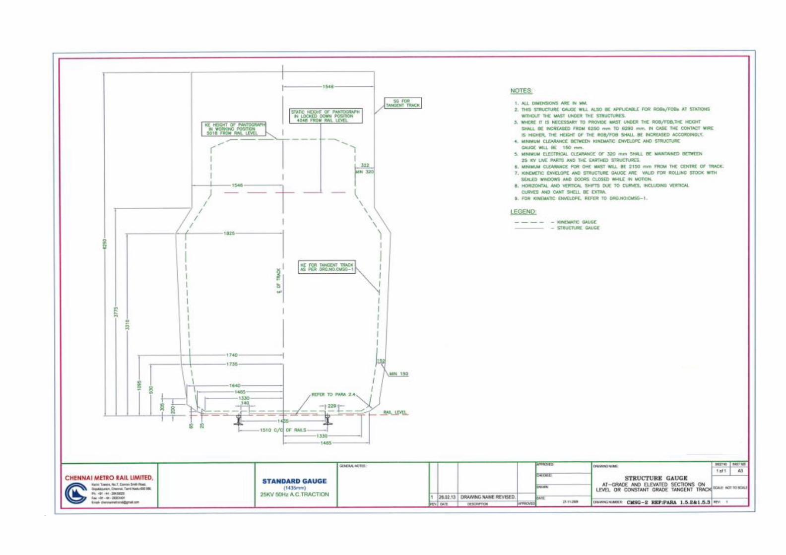

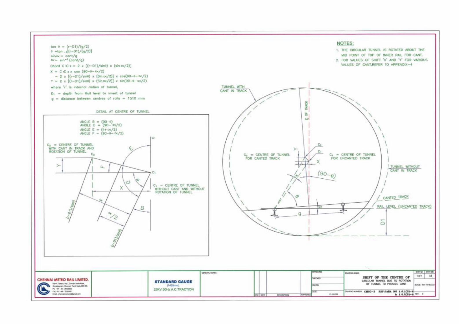


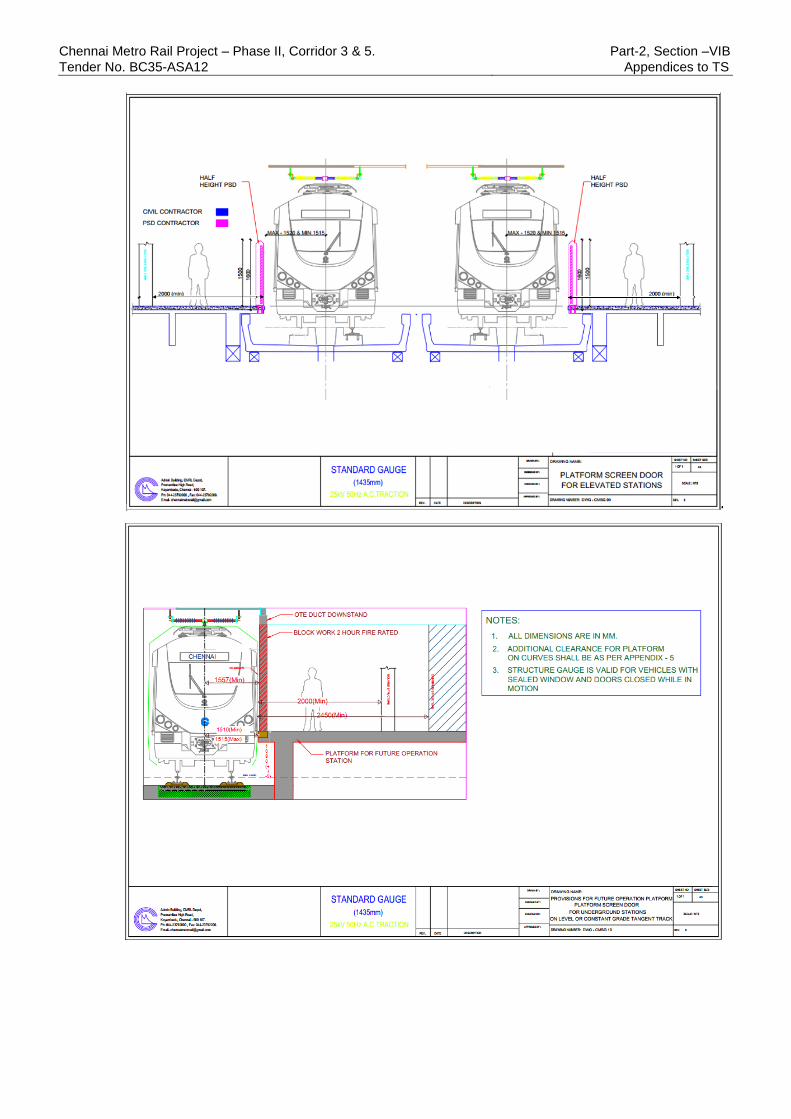
Chennai Metro Rail Project – Phase II, Corridor 3 & 5. Part-2, Section –VIB
Tender No. BC35-ASA12 Appendices to TS

Chennai Metro Rail Project – Phase II, Corridor 3 & 5. Part-2, Section –VIB
Tender No. BC35-ASA12 Appendices to TS
APPENDIX 2P
LIST OF INTERFACE APPENDICES
1 Appendix 2P-1 Interface protocol between Rolling stock and
Platform Screen Doors (PSD) System
2 Appendix 2P-2 Interface protocol between Signalling and Train
Control system (S&TC) and Platform Screen Doors
(PSD) system
3 Appendix 2P-4A Interface protocol between Civil (UG) and Platform
Screen Doors (PSD) system (Full Height)
4 Appendix 2P-4B Interface protocol between Civil (Elevated) and
Platform Screen Doors (PSD) system (Half Height)
5 Appendix 2P-5 Interface protocol between Track and Platform
Screen Doors (PSD) system
6 Appendix 2P-6A Interface protocol between MEP(UG) and Platform
Screen Doors (PSD) system (Full Height)
7 Appendix 2P-6B Interface protocol between MEP (Elevated) and
Platform Screen Doors (PSD) system (Half Height)
8 Appendix 2P-7 Interface protocol between VAC and Platform Screen
Doors (PSD) system (Full Height)
9 Appendix 2P-8 Interface protocol between TVS and Platform Screen
Doors (PSD) system (Full Height)
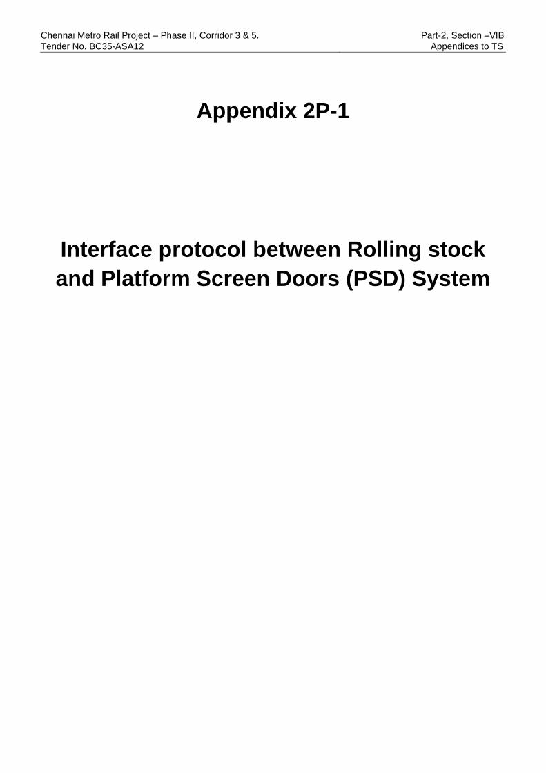
Chennai Metro Rail Project – Phase II, Corridor 3 & 5. Part-2, Section –VIB
Tender No. BC35-ASA12 Appendices to TS
Appendix 2P-1
Interface protocol between Rolling stock
and Platform Screen Doors (PSD) System

Chennai Metro Rail Project – Phase II, Corridor 3 & 5. Part-2, Section –VIB
Tender No. BC35-ASA12 Appendix -2P to TS
CMRL/Rev. A Page 15 of 117 May 2022
Rolling stock- Platform Screen Doors (PSD) CONTRACTS:
1 INTRODUCTION
1.1 General
1.1.1 This section describes the interface requirements between Rolling Stock (RS) Contract
and Platform Screen Doors (PSD) Contractor.
1.1.2 The Platform Screen Doors (PSD) system will be awarded as a separate multiple
contracts for in all the three corridors of Phase 2 and in-between the corridors as inter-
corridor operation. There will be a four PSD contracts and three Rolling stock contracts
for the complete Phase 2. The Contractor shall interface accordingly with all the PSD and
all the RS contractors of Phase 2.
1.1.3 The contractors shall ensure that all the requirements of the Metro Railway General Rules
2020 are duly met by incorporating appropriate alarms, remote commands and other
features.
1.1.4 The Contractors as above shall ensure that all requirements of the Specification
pertaining to interfaces are properly satisfied.
1.1.5 All Interface Meetings, unless specifically approved by CMRL shall be held at CMRL site
and they shall be given sufficient notice to attend the meeting.
1.1.6 Each contractor shall be responsible for interface identification, establishment,
construction and testing works either in the capacity as the Lead Contractor or
Participating Contractor.
1.1.7 The requirements specified herein are by no means exhaustive and it remains the
responsibility of the Contractors to develop and execute an interface plan during
execution of the work to ensure that:
a) All interface issues between the different contracts are satisfactorily resolved
b) Supply, installation and testing of equipment and software are fully co-ordinated
c) All equipment supplied in the contract are fully compatible with each other
d) UTO mode of operation, Non UTO modes of operation and all other degraded
mode of operation shall be achieved with all its inherent features in the mainline
and in all depots of CMRL Phase 2.
e) All the system tolerances at the interface shall meet the requirements of the
respective specifications relating to the interface points
f) Interface contractors shall mutually respect each other’s project timelines with
respect to the interface requirements.
g) Interface contractors shall finalize their respective interface equipment only after
clear agreement on interface requirements with the other designated contractors.
h) Interface contractors shall ensure that in any case, no equipment of their system
shall be put into production or installation without meeting the interface

Chennai Metro Rail Project – Phase II, Corridor 3 & 5. Part-2, Section –VIB
Tender No. BC35-ASA12 Appendices to TS
CMRL/Rev. A May 2022
requirements spelt out in this Appendix or in the Technical Specification of
respective contracts.
i) Test procedures, troubleshooting manuals and any other documentation shall be
updated with technical details from of each contractor and shall be submitted to
CMRL
1.1.8 The trains shall be designed, tested and commissioned such that they will be operated
in UTO mode from the initial stage of passenger service. Hence, there is no dedicated
operator cabins in the train.
1.1.9 UTO mode of operation and other Non-UTO modes shall be achieved by all designated
contractors right after the commissioning of train by the Rolling Stock contractor.
1.1.10 All the trains of the CMRL phase 2 project shall be capable of being operated within
specifically the sections of Corridor 3, Corridor 4 and Corridor 5 and also inter-operable
between Corridor 3, Corridor 4 and Corridor 5 of CMRL Phase 2 project. The trains shall
be capable of operating in Bi-directional way during passenger services & during
commissioning in all these corridors, in the related depots and other related lines. All the
systems and Interface contractors shall design their equipment for the same.
1.2 Interface Management
1.2.1 RS Contractor shall be the Lead Contractor. The Lead Contractor will be responsible to
initiate, plan, coordinate and produce jointly with the Participating Contractors all the
required interfaces and interface design documents and interface progress reports for
submission to CMRL for acceptance. The Lead Contractor will also prepare and issue all
interface meeting of minutes after incorporating PSD Contractors comments within 3
days of the meeting and provide bi-weekly interface progress reports to all the
participating contractors for information. Later, forwarding of issued minutes of meeting
and bi-weekly interface progress reports to concerned Contractors shall be lead
contractor’s responsibility.
1.2.2 PSD contractor will be the participating contractor. The Participating Contractors shall
collaborate fully with the Lead Contractor in the development and finalization of the
interface design, joint production of the interface documents and interface progress
reports.
1.2.3 All the participating contractors shall ensure that copy of the Interface design documents
submitted to CMRL.
1.2.4 The costs for all interface design and testing works shall be deemed to be included in the
Contract sum of respective contracts regardless of the actual extent of effort required or
expended by the Contractor.
1.2.5 The Contractors shall be fully responsible for the management and control of his
subcontractors in relation to all interfacing activities carried out under the Contract.
1.2.6 The interface design currently shall be functional for 3 car configuration train. The system
capability, interface design, the Input output points, command buttons, Data
communication telegram fields, Communication network bandwidth designs etc shall be
Chennai Metro Rail Project – Phase II, Corridor 3 & 5. Part-2, Section –VIB
Tender No. BC35-ASA12 Appendices to TS
CMRL/Rev. A May 2022
designed with a provision for extending the car configuration from 3 car to 6 car with
minimum changes. The details of the future three additional cars of the 6 Car
configuration shall also be incorporated in the initial design.
The rake formation shall generally be as follows:
3-Car rake: DMC+TC+DMC (67% Traction power)
Future 6-car rakes will have the following configuration:
6-car rake: DMC+TC+MC + MC+TC+DMC (67% traction power)
1.2.7 The PSD Contractor shall provide necessary support and modifications in their system,
to resolve all pending or new interface related issues arising during the operation of the
trains till completion of RS Contractor defect Notification period. RS Contractor shall
provide necessary support and modifications in their system, to resolve all pending or
new interface related issues arising during the operation of trains till completion of PSD
Contractor’s defect liability/Notification period for the respective corridors of the CMRL
Phase 2.
1.2.8 Both RS and PSD contractors shall ensure that complete and detailed logs of the signals
exchanged regarding this interface shall be retrievable on demand for diagnostics from
the OCC, BCC and DCC control panels.
1.2.9 Where-ever requirements of OCC are mentioned in this chapter, the same shall mean to
be implemented for both Operations Control Center (OCC) and Backup Control Center
(BCC) for the respective corridor.
1.2.10 STC Contractor shall prepare a comprehensive Operating Modes and Principle
Document (OMPD). RS, PSD and TETRA, Telecommunication Contractors will provide
required inputs to the STC Contractor in preparation of the document. The traction
contractors and Tunnel Ventilation Contractors will also assist STC Contractor in
preparation of the documents. CMRL will provide necessary inputs such as standard
operating procedure. The document shall establish the principles related to system and
interface design under normal, degraded and emergency modes of operation. For each
operating principle, the document shall describe the scenario, action to be taken by
operator and system in a structured process flow chart. The additional requirement
generated while preparing OMPD document shall be treated as the requirement within
the contract without any cost implication.
1.2.11 PSD Contractor and the RS contractor shall prepare a joint compliance matrix for this
interface specification which includes the relevant clauses of the Metro Railway General
Rules 2020, especially in UTO operation related and submit to CMRL for review.
1.3 Train Operating Modes
General System Description
1.3.1 The train-borne Automatic Train Control (ATC) system will consist of Unattended Train
Operation (UTO), Driverless train operation (DTO), Automatic Train Operation (ATO)
system and Automatic Train Protection (ATP), RM, ROS, Cut out.

Chennai Metro Rail Project – Phase II, Corridor 3 & 5. Part-2, Section –VIB
Tender No. BC35-ASA12 Appendices to TS
CMRL/Rev. A May 2022
1.3.2 Rolling Stock will be fitted with all ATP, ATO, UTO system. The UTO system will conform
up-to Grade of Automation 4 (GoA4) as defined in IEC 62290-1.
1.4 Requirement of standardisation of certain aspects of rolling stock related to PSD
interface to enable inter-operability with PSDs among ARE-02, ARE-03 and ARE-04
(non-exhaustive list).
1.4.1 The exterior layout of the three rolling stocks shall be the same for the following
characteristics
a) Rake’s inter-door distances of any two corresponding doors of all rolling stocks
shall be the same. (centre to centre distance)
b) The width of the doors (1400 mm or the value mentioned in RS contract)
c) The location of Emergency Egress Device (EED), Emergency Ingress Device,
Crew switch and parking brake release lever
1.4.2 The width of the rolling stock car (at the passenger floor level) in static condition, in the
passenger door area, shall be same for all the three types of Rolling stocks of Phase 2.
1.4.3 The door numbering strategy of all the three types of Rolling stock of Phase 2 shall be
maintained the same for all PSD related communication telegrams with Signalling.
1.4.4 The Operator Keys related to RS doors (that for opening the RS door from inside or
outside mechanically and that for isolation of the train door) shall be the same for all the
three types of Rolling stocks of Phase 2
1.5 Interface Requirements
1.5.1 RS contractor shall provide KE and door drawings (door position, width & pitch) of train
to PSD contractor for placement of Platform Screen Doors and shall share the location
of Emergency Egress Device (EED)/ Emergency Ingress Device, Crew switch and
parking brake release lever with the PSD Contractor and also share their operating
mechanism. The access for these equipments with respect to the PSD shall be analysed
and agreed upon by both the contractors in view of the stopping accuracy band of
±300mm.
1.5.2 The rolling stock contractor shall share the details of the Operator key/keys of the rolling
stock for door opening, from outside and inside and for manual door isolation. The details
shall include the profile of the key, available manufacturers, License/ approval for the
manufacturing or procurement of the particular keys etc. The details shall be adequate
and shall authorise the PSD contractor to manufacture or procure the key in a rightful
legal manner for usage in CMRL PSD system. PSD contractor shall procure/manufacture
the key and use in PSD system, so that Operators can use the same set of key for similar
functionalities in RS door and PSD door. Necessary approval shall be taken from CMRL
before the procuring/ manufacturing.

Chennai Metro Rail Project – Phase II, Corridor 3 & 5. Part-2, Section –VIB
Tender No. BC35-ASA12 Appendices to TS
CMRL/Rev. A May 2022
1.5.3 Signalling system shall be the medium between RS system & PSD system for electronic
command/status signals. Both RS & PSD Contractors shall provide necessary signals to
the STC Contractor for proper functioning.
1.5.4 RS and PSD contractor shall prepare the numbering scheme of the RS doors and PSD
doors respectively for the door specific information communication through Signalling
system. The numbering shall be independent of the car identifier number/alphabet and
shall be in a manner that irrespective of the direction of travel, the number which points
to a particular door does not change.
1.5.5 The train passenger door matching with the corresponding Platform screen doors shall
be designed for future 6 car train from the initial design stage itself. Adequate precaution
shall be taken to identify the numbering the doors in sequence to match the PSD doors
when the platform active cab change is done. Similarly, the details of the future three
additional cars of the 6 Car configuration shall also be incorporated in the initial design.
1.5.6 RS and PSD Contractors shall exchange the defective/Isolated train door and PSD door
information, through signalling system so that if a particular train door is
defective/isolated, the corresponding PSD shall not open and vice versa. The function
shall include both Audio and visual in their respective panels to facilitate passengers.
1.5.7 Not Used.
1.5.8 Door synchronization:
The doors of the PSD and the RS shall synchronize, in the very similar manner, while
opening and closing, irrespective of the combination of suppliers of PSD (four suppliers in
Phase 2) or RS (three suppliers in Phase 2). All the PSD suppliers and the Rolling stock
suppliers shall arrive at the synchronization parameters (transmission timing, processing
time, delays etc) to ensure the same. The synchronization timings shall be validated in the
CMRL test track to ensure similar behaviour for any combination of RS and PSD
contractors. The timing diagram from STC contractor shall also be considered for the
calculation.
1.5.9 The design of the passenger door control system shall ensure that the train passenger
doors open before the PSDs open and PSD doors close before closure of train passenger
doors. The operation of the “Door Close” pushbutton/ door close command from
UTO/ATO shall broadcast an audible warning in each saloon, signifying that both the
PSD doors and passenger doors shall subsequently close.
1.5.10 After the pre-set time, adjustable between 0 and 5 seconds, following the finish of the
audible warning, the control system shall synchronously “Close and Latch” all the
passenger doors and PSD on the corresponding side. The design of the passenger door
control system shall ensure that the PSD doors close before the train passenger doors
close.
1.6 Integrated Testing and Commissioning:
1.6.1 RS, STC, Telecom TETRA and PSD contractors shall jointly setup an integrated test bed
at CMRL premise to arrange for the integration testing of various subsystems, as a
Chennai Metro Rail Project – Phase II, Corridor 3 & 5. Part-2, Section –VIB
Tender No. BC35-ASA12 Appendices to TS
CMRL/Rev. A May 2022
minimum but not limited to ATS, ATO, on-board CCTV management system by signalling
contractor, On-board passenger information system, on-board driver display units,
TCMS, On-board NVR, RTR-DMS by RS contractors, station passenger information
systems etc of the Telecom contractors, SCADA of PSD systems. The test bed shall have
provision for testing the actual softwares over the actual hardware. Necessary train
running mimicking simulator shall be provided by the SIG contractor to simulate a train
running. RS contractors shall provide necessary simulators to simulate various failure
and operational scenarios in the TCMS pertaining to the Interface data.
1.6.2 This integrated test bed shall be designed in a manner that it mimics the real-world test
scenario.
1.6.3 This test bed can share the hardware from the hardware test bed, if envisaged in
respective contracts. The tests for vital interface tests and the tests pertaining to the
driving parameters of the train or ATO are excluded from this test bed scope.
1.6.4 This test bed shall be used for the initial preliminary type tests of the interface, regression
tests, software tests after modifications, preliminary interface tests pertaining to stage
integration etc. This test bed shall not completely replace the original testing using the
train.
1.6.5 RS, STC, Telecom -TETRA & PSD Contractors shall perform Joint Integration Test and
tests shall include but not limited to traction and braking control, precision stopping, turn
back, jog function, door operation, PSD, train wake up and PA/PIS functioning test,
remote command & control for Rolling Stock monitoring & troubleshooting from OCC to
train and safety related test etc. All contractors shall jointly produce a protocol document
for Integrated Testing and Commissioning.
1.6.6 Integrated testing of each train shall comply with the accepted international standards
agreed between the Contractors and agreed with the CMRL.
1.6.7 Joint Integration testing specific to each train shall be done at the rolling stock factory,
depot and main line of CMRL to ensure satisfactory performance of all train control, STC,
telecom - TETRA and PSD interfaces.
1.6.8 This Joint Integration tests subsequently shall be signed-off jointly by the Rolling Stock,
Signaling & Train Control, Telecom-TETRA and PSD Contractors.
1.6.9 For UTO and other non-UTO modes of operation, the Joint Integration test between the
Rolling Stock, Signaling & Train Control, Telecommunications and PSD Contractors shall
include tests on mainline to confirm below minimum features:
a) realization of demanded acceleration rate, deceleration rate, Jerk in all UTO and
non-UTO modes of operation,
b) train stopping accuracy in stations, wet rail conditions/adhesion levels
c) synchronization with PSDs,
d) automatic train operation with all the train controls from OCC/DCC,
e) Train RTR-DMS data transmission to OCC server and display of fault information
at OCC and Depot controller console
Chennai Metro Rail Project – Phase II, Corridor 3 & 5. Part-2, Section –VIB
Tender No. BC35-ASA12 Appendices to TS
CMRL/Rev. A May 2022
f) Verification of alarms and other vital information transmission from train to OCC
and vice versa.
g) Passenger to OCC communication and vice versa
h) Train radio verification
i) Automatic route related passenger announcements in train
j) Pre-recorded and manual announcement from OCC
k) Streaming of CCTV videos of train in OCC & DCC.
l) Any other tests necessitated by the technical specification of the interfacing
contractors.
RS contractor shall highlight any other required interface testing in the test plan.
1.6.10 All the above requirements shall be tested in all the sections of Corridor 3, corridor 4 and
corridor 5 and their extensions if any.
1.6.11 UTO shall be the predominant mode of operations. Contractor shall develop and submit
the detailed scheme for tests (in addition to the tests mentioned in Appendix C required
to be done for the safe and reliable operation in UTO mode. Contractor shall successfully
conduct these tests. CMRL shall witness these tests.
1.6.12 These above tests mentioned shall be completed before the start of the Rolling Stock
Burn-in trials for each train individually.
1.7 INTERFACE- Division of Responsibility
RS Contractor shall coordinate with PSD Contractors in order to achieve the functional
and operational requirements of the system. The roles and activities of the Contractors
shall broadly include minimum but not limited to those mentioned in table below. Apart
from the below table, RS and PSD contractors shall also adhere to all the requirements
of Appendix C and their referred sub-clauses of ERTS mentioned in this Appendix C.

Chennai Metro Rail Project – Phase II, Corridor 3 & 5. Part-2, Section –VIB
Tender No. BC35-ASA12 Appendices to TS
CMRL/Rev. A May 2022
S.No. Item PSD Contractor RS Contractor
1 Kinematic envelope,
height of train floor
(in unloaded and
fully loaded
condition) and car
width of RS
SoD document shall
be complied.
PSD contractor shall design
the PSD taking this into
account.
RS contractor shall furnish the
KE details at platforms and the
car width details to the PSD
contractor.
2 The PSD façade
layout
PSD contractor shall design
the PSD taking this into
account.
RS contractor shall provide the
general arrangement drawing of
RS exterior which indicates, the
door widths, inter door distances,
train door widths, its pitch,
location of Emergency Egress
Device (EED)/Emergency ingress
device, crew switch, and parking
brake release lever
3 The Operator Key
details related to
doors.
PSD contractor shall use the
key profile provided by the
RS contractor in PSD for
similar functions comparing
to RS doors.
RS contractor shall provide the
Lock & key details, Lock & key
licences, authorization for the
PSD contractor to
procure/manufacture the key and
lock with same profile for PSD
4 The PSD and RS
Door numbering
scheme
RS and PSD contractor shall
agree on the door numbering
scheme of PSD and RS.
All the door
inhibition/obstruction
telegrams through Signalling
system shall follow this
scheme.
RS and PSD contractor shall
agree on the door numbering
scheme of PSD and RS.
All the door inhibition/obstruction
telegrams through Signalling
system shall follow this scheme.
5 Door synchronization RS and PSD contractor shall
assess the processing time,
transmission time, polling
cycle etc and estimate the
system delay in the door
operation actuation (duly
taking input from STC
contractor) and synchronize
the doors
RS and PSD contractor shall
assess the processing time,
transmission time, polling cycle
etc and estimate the system
delay in the door operation
actuation (duly taking input from
STC contractor) and synchronize
the doors
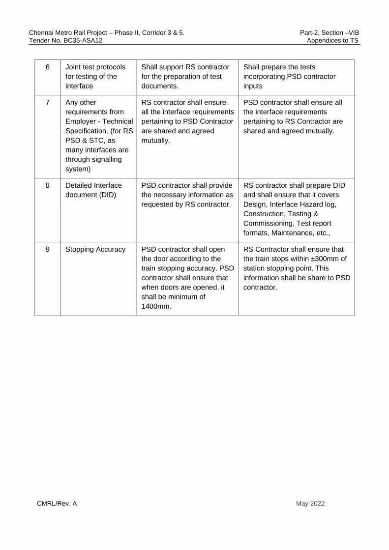
Chennai Metro Rail Project – Phase II, Corridor 3 & 5. Part-2, Section –VIB
Tender No. BC35-ASA12 Appendices to TS
CMRL/Rev. A May 2022
6 Joint test protocols
for testing of the
interface
Shall support RS contractor
for the preparation of test
documents.
Shall prepare the tests
incorporating PSD contractor
inputs
7 Any other
requirements from
Employer - Technical
Specification. (for RS
PSD & STC, as
many interfaces are
through signalling
system)
RS contractor shall ensure
all the interface requirements
pertaining to PSD Contractor
are shared and agreed
mutually.
PSD contractor shall ensure all
the interface requirements
pertaining to RS Contractor are
shared and agreed mutually.
8 Detailed Interface
document (DID)
PSD contractor shall provide
the necessary information as
requested by RS contractor.
RS contractor shall prepare DID
and shall ensure that it covers
Design, Interface Hazard log,
Construction, Testing &
Commissioning, Test report
formats, Maintenance, etc.,
9 Stopping Accuracy PSD contractor shall open
the door according to the
train stopping accuracy. PSD
contractor shall ensure that
when doors are opened, it
shall be minimum of
1400mm.
RS Contractor shall ensure that
the train stops within ±300mm of
station stopping point. This
information shall be share to PSD
contractor.

Chennai Metro Rail Project – Phase II, Corridor 3 & 5. Part-2, Section –VIB
Tender No. BC35-ASA12 Appendices to TS
CMRL/Rev. A May 2022
Appendix-2P2
Interface protocol between Signalling and
Train Control system (S&TC) and
Platform Screen Doors (PSD) system

Chennai Metro Rail Project – Phase II, Corridor 3 & 5. Part-2, Section –VIB
Tender No. BC35-ASA12 Appendix -2P to TS
CMRL/Rev. A Page 15 of 117 May 2022
Appendix 2P-2
Interface protocol between Signalling and Train Control system (S&TC)
and Platform Screen Doors (PSD) system
1 INTRODUCTION
1.1 General
1.1.1 This specification covers the interface requirements between Signalling & Train Control
Contract ASA-04 and Platform Screen Doors Contract(s).
1.1.2 This document shall be read in conjunction with the relevant paragraphs of the General
Specification. The Contractors shall ensure all requirements of the General Specification
and PS pertaining to interfaces are fully resolved and implemented.
1.1.3 In the event of a conflict between any provisions of the respective Particular Specification
and this specification, the requirements of this Interface Specification shall prevail.
2 Interface Responsibilities
2.1.1 The responsibility for specification and provision of the requirements for the works that
interface with Designated Contractors’ equipment are tabulated in corresponding section
of the document.
2.1.2 The requirements specified herein are by no means exhaustive and it remains the
Contractors responsibilities to develop and execute jointly an Interface Plan after the
commencement of the works and throughout the execution of works, to ensure that:
a) All interfacing issues between the two Contracts are satisfactorily resolved.
b) Supply, installation and testing of equipment and software are fully co-ordinated.
c) That all equipment supplied under the Contracts is fully compatible with each other,
whilst meeting the requirements of the respective Specifications.
d) All the construction tolerances at the interface shall meet the requirements of the
respective specifications relating to the interface points
e) Interface contractors shall mutually respect each other’s project timelines with respect
to the interface requirements.
f) Interface contractors shall finalize their respective interface equipment only after clear
agreement on interface requirements with the other designated contractors.
g) Interface contractors shall ensure that in any case, no equipment of their system shall
be put into production or installation without meeting the interface requirements spelt
out in this Appendix or in the Technical Specification.
h) Test procedures, troubleshooting manuals and any other documentation shall be
updated with technical details from each contractor and shall be submitted to CMRL

Chennai Metro Rail Project – Phase II, Corridor 3 & 5. Part-2, Section –VIB
Tender No. BC35-ASA12 Appendices to TS
CMRL/Rev. A May 2022
3 Interface Management
3.1.1 Signalling and Train Control Contractor shall be the Lead Contractor. The Lead Contractor
shall be responsible to initiate, plan, coordinate and produce jointly with the Participating
Contractors all the required interfaces and interface design documents and interface
progress reports for submission to The Engineer/ CMRL for acceptance. The Lead
Contractor shall also prepare and issue all interface meeting of minutes within 3 days of
the meeting and provide bi-weekly interface progress reports to all the participating
contractors for information. Later, forwarding of issued minutes of meeting and bi-weekly
interface progress reports to concerned Contractors shall be lead contractor’s
responsibility.
3.1.2 PSD contractor(s) shall be the participating contractor. The Participating Contractors shall
collaborate fully with the Lead Contractor in the development and finalization of the
interface design, joint production of the interface documents and interface progress
reports.
3.1.3 All the participating contractors shall ensure that copy of the Interface design documents
are submitted to the Engineer/CMRL.
3.1.4 The costs for all interface design and testing works shall be deemed to be included in the
Contract sum of respective contracts regardless of the actual extent of effort required or
expended by the Contractor.
3.1.5 The Contractors shall be fully responsible for the management and control of their
respective subcontractors in relation to all interfacing activities carried out under the
Contract.
3.1.6 Where-ever requirements of OCC are mentioned in this chapter, the same shall mean to
be implemented for both Operations Control Centre (OCC) and Backup Control centre
(BOCC).
3.1.7 STC Contractor and the PSD contractor(s) shall prepare a joint compliance matrix for this
interface specification and relevant clauses of the Metro Railway General Rules 2020, EN
62290-1,2 especially that of UTO operation (GoA 4 operation) related and submit to CMRL
for review.
4 Interface Requirements
4.1.1 STC Contractor shall prepare a comprehensive Operating Modes and Principle Document
(OMPD). RS, PSD and TETRA, Telecommunication Contractors will provide required
inputs to the STC Contractor in preparation of the document. The PS/OHE contractors and
Tunnel Ventilation Contractors will also assist STC Contractor in preparation of the
documents. CMRL will provide necessary inputs such as standard operating procedure.
The document shall establish the principles related to system and interface design under
normal, degraded and emergency modes of operation. For each operating principle, the
document shall describe the scenario, action to be taken by operator and system in a

Chennai Metro Rail Project – Phase II, Corridor 3 & 5. Part-2, Section –VIB
Tender No. BC35-ASA12 Appendices to TS
CMRL/Rev. A May 2022
structured process flow chart. The additional requirement generated while preparing
OMPD document shall be treated as the requirement within the contract without any cost
implication.
4.1.2 Any single point failure in equipments, relays or communication/cable links in the interface
shall not cause any effect on the proper functioning of this Interface.
4.1.3 Both the contractors shall ensure that the equipments and the associated devices are
immune to EMI/RFI and do not cause any EMI/RFI issues to the other system.
4.1.4 Signalling-PSD Interface to support RS- PSD Interface: All the functional interfaces
between the Rolling stock and PSD is through Signalling system. The signalling system
shall interface with the PSD system and the Rolling stock system to implement all these
interfaces. The interface document between Rolling stock and PSD is described in
Appendix 2P-1.
4.1.5 PSD Open Close commands- Functional details: The PSD Open and close commands
shall be from three sources.
• From the train, after it stopped within the prescribed stopping position
• From the Operator, as a command from the ATS workstation.
• From the Operator, as a command from the Manual Control Panel (MCP) of PSD.
4.1.6 In all the above scenarios, the Interface shall be devised that
• Proper door synchronization is ensured.
• Proper safety is ensured for vital commands.
• All door inhibition commands are respected.
4.1.7 PSD control from Train: Once the train stops in the prescribed stopping window (docked),
and the on-board ATC provides door authorization for the train doors, train doors and PSDs
can be opened and closed by the Train Operator (in manual mode) or the ATO/UTO
equipment of the train borne signalling in a synchronized manner. This facility shall be
functional even when the ATS system is in failed/non-functional condition. The
performance requirements (transmission time, Operation time etc) specified in the
respective particular specifications shall be adhered to.
4.1.8 PSD control from ATS: The operator shall be provided with facilities in the ATS
workstation at OCC, BOCC and SCR for Opening and closing the doors of the PSD and
the Train doors in a synchronized manner. The stoppage of a train in the stopping window
and door authorization by the train borne signalling shall be ensured as a precondition for
enabling this control. This control will be useful if the direct communication from the train
borne to PSD system fails or when the Operator requires to open and close the Train doors
and PSD to meet any operational requirements.
4.1.9 PSD (and train door) control from Manual Control Panel: The operator shall be
provided with facilities in the Manual control Panel at Platform for Opening and closing the
doors of the PSD and the Train doors in a synchronized manner. Manual control panel can
be used for Opening and closing PSDs irrespective of availability of correct docking of the
train, on that platform. But whenever the train is in the docked condition with door

Chennai Metro Rail Project – Phase II, Corridor 3 & 5. Part-2, Section –VIB
Tender No. BC35-ASA12 Appendices to TS
CMRL/Rev. A May 2022
authorization from the train borne ATC, If MCP is operated, the train doors also shall get
operated synchronously with PSD.
4.1.10 Staff Access Passenger Door (SAPD) Opening from ATS: The first and the last door of
a train (on both sides) are assigned as Staff Access Passenger Door to access the interior
of the train. Operator shall be provided with facility in ATS from OCC/BOCC or SCR to
open and close one or more Staff Access passenger door of a train. Whenever a Staff
Access passenger door is Opened, the corresponding PSD also shall Open (only the
corresponding doorway) if the train is physically in the prescribed stopping position on a
platform.
4.1.11 The contractors shall prepare a detailed functional interface description for door Open and
close functions with all overlapping and conflicting scenarios and submit to the Engineer
for NoNO.
4.1.12 PSD and Train Door numbering: All communication telegrams between Signalling
system & Rolling stock as well as communication telegrams between Signalling system &
PSD system shall be based on fixed numbering of train and PSD doors. The door numbers
shall not change based on the direction of travel and the active cab details.
4.1.13 All the communication telegrams shall be provided with fields corresponding to 6-car trains.
Based on the relative position of the 3-car PSD on the 6 car platform, the beginning and
the sequence of the numbering shall be identified.
4.1.14 PSD - Train door inhibition function: Whenever a PSD door or a train door is
‘unavailable’ the corresponding door of the PSD or train also needs to be inhibited. The
unavailability of a door can be because of any fault causing non-operation of a particular
doorway which causes inhibition from the system or is isolated by the Operator using the
Operator key or is inhibited by the Operator from the ATS or TCMS system.
4.1.15 PSD to Train information: The inhibition information to train doors corresponding to a
particular platform shall be communicated immediately once the train leaves the previous
platform. Any change in the status of PSD doors to train, including change of platform, if
any, shall be updated on real time basis.
4.1.16 Train to PSD information: The inhibition information to PSDs corresponding to the train
doors shall be communicated for the next approaching train. Any change in the status of
train doors, including change in approaching train ID, shall be updated to the PSD system
on real time basis.
4.1.17 The operator shall be provided facility in ATS to inhibit or override an already inhibited door
(PSD or train door) with no restriction on time or location of train. The information to the
corresponding door of the other system (PSD or train door system) shall be communicated
immediately after these operator interventions.
4.1.18 The system shall be capable of handling the ATS triggered inhibition to match the door
opening strategy of the timetable as per the provisions for the operator in the timetable
editor.
4.1.19 Any operator intervention to reroute the trains or re-sequence the trains, the train doors
and PSDs shall be provided with updated information on real time basis.

Chennai Metro Rail Project – Phase II, Corridor 3 & 5. Part-2, Section –VIB
Tender No. BC35-ASA12 Appendices to TS
CMRL/Rev. A May 2022
4.1.20 All the information on door inhibition, if triggered on any platform, shall be communicated
to the on-board passenger information systems as well as station passenger information
systems appropriately.
4.1.21 Vital communication (SIL 4 system related) between Signalling and PSD: Some of
the communications shall be safety rated between the signalling system and the PSD
system. Door Open enable for two type (3 car & 6 car) configurations from signalling, all
doors closed and locked signal, Interlock override signal from PSD to be communicated
vitally and in a very safe manner.
4.1.22 Not used
4.1.23 All vital communication shall follow the fail-safe principles, including double cutting, where
applicable.
4.1.24 All vital communication shall be interfaced through potential free relay contacts. Multiple relays shall be used for ensuring safety and integrity of the communication. Adequate redundancy shall be built into to avoid failure of the interface owing to any single interfacing relay failure.
4.1.25 The signalling system contractor shall design the interface and advise the PSD
contractor(s) to follow. The design shall be standardized for all types of PSD.
4.1.26 Door Open enable for 3 car and balance 3 car (for 6 car operation) shall be separate circuit
with separate sets of Interfacing relays. Currently only the 3-car circuit will be wired by the
PSD contractor(s). The balance 3 car area will be installed with same or different PSD
make in future. In the Signalling system, wiring shall be done for both circuits to meet both
3 car and 6 car operation concurrently. The balance 3 car circuit shall be inhibited in
software or hardware till 6 car operation starts in future.
4.1.27 Opening of PSD by the train and by the operator through ATS shall require the door open
enable signal. The opening of PSD from the Manual control panel shall not require the
enable signal from Signalling as the MCP opening of PSD is an internal feature of PSD.
4.1.28 The open enable signals shall be provided by the SIL 4 vital safety systems of Signalling duly for appropriate car configuration of the train, ensuring the docking of train in the prescribed stopping window.
4.1.29 “All doors closed and locked” (ADCL) signal shall be continuously provided by the PSD
system as a vital signal communicating all doors including the sliding doors, emergency
egress doors and manual secondary doors (track access doors) as closed and locked.
4.1.30 “All doors closed and locked” signal shall be different for 3 car PSD area and for the
Balance 3 car area. The circuit and relays for supporting 3 car operation and Balance 3
car area (for 6 car operation) shall be segregated. Currently, only the 3 car PSD will be
operational. The future circuit for Balance 3 car area (supporting 6 car) shall be wired in
Signalling system but disabled in the software or hardware.
4.1.31 “All Doors closed and Locked” for each Manual secondary door shall be separate ADCL
from the normal ADCL of a PSD. The ADCL for manual secondary door shall be
independent for each MSD, to be interlocked with the respective Staff Protection Key of
Signaling.

Chennai Metro Rail Project – Phase II, Corridor 3 & 5. Part-2, Section –VIB
Tender No. BC35-ASA12 Appendices to TS
CMRL/Rev. A May 2022
4.1.32 “All door closed and locked” signals from PSD system shall be read by the SIL 4 vital safety
systems of Signalling and shall be processed for the starting of train from the platform.
4.1.33 The “Interlock override” signal from the PSD system shall be read by the SIL 4 vital safety
systems of Signalling.
4.1.34 The Local door override signal can be created by PSD system when the Operator places
any one or more doors (sliding door) in the override position. The overridden door will
bridge all doors closed and locked signal for that particular sliding door but shall also
provide the local door override signal to the signalling system.
4.1.35 The Interlock override signal can also be provided by the PSD system when the operator
triggers the override signal from the MCP using a non-latching, self-normalising rotatory
switch. Accordingly, the Signalling system will impose a speed limit of 20 kmph, for trains
being received on the Platform, using the interlock over-ride feature.
4.1.36 When the All doors closed and locked signal is not available, the signalling system shall
stop the trains at the approach to the stations or in platform area. When the interlock
override signal is available ,along with all doors closed and locked, system shall generate
a Temporary speed restriction of 20 kmph. The following table explains the scenario;
All doors
closed and
locked Signal
Local door
override
Signal
(from LCP)
Interlock
Override
Signal
(from MCP)
Signalling
behaviour
Remarks
Yes No - Full speed for trains NO failure condition
No No - Stop train A failure/ obstruction/
opening occurred
Yes Yes - 20 kmph TSR with
audible warning
Failure but Operator
intervention done.
No Yes - Stop train A second failure/
obstruction/ opening
occurred after first failure
intervened by operator.
No - Yes 20 kmph TSR with
audible warning
Failure but Operator
intervention done.
No - No Stop train A failure/ obstruction/
opening occurred
4.1.37 Based on the system design, interface design, and safety case, the contractors shall
propose to increase or decrease the vital information to be transferred as a part of this
Interface. Such proposals shall be submitted to the Engineer for NoNO before
commencement of implementation works.
4.1.38 Door Open and Close command (Signalling to PSD): The Open and close command
from Signalling to PSD shall be separate.
4.1.39 The communication between signalling and PSD systems for Door Open and Door close
shall be based on electrical signals exchange using potential free relays (with sufficient

Chennai Metro Rail Project – Phase II, Corridor 3 & 5. Part-2, Section –VIB
Tender No. BC35-ASA12 Appendices to TS
CMRL/Rev. A May 2022
double cutting and redundancies) as proposed by the Signalling contractor. The Open and
close commands shall comply to minimum SIL 3 requirements.
4.1.40 The door Open/close command for the Staff Access Passenger Door (SAPD) shall be
separate from that of the complete platform door Open. For a platform, the Open/close
circuity shall cater for as a minimum to
• 3 car Open/Close circuit
• Balance 3 car Open/close circuit
• SAPD 1 Open/close circuit
• SAPD 2 Open/Close circuit
• SAPD 3 Open/close circuit (For 6 car Operation)
• SAPD 4 Open/close circuit (For 6 car Operation)
4.1.41 (a) Communication between Signalling (ATS) and PSD systems: The protocol for the
exchange of information between Signalling and PSD system including door inhibition
details and status/alarms of various parts of PSD, including the description of various fields
and their contents will be proposed by signalling contractor which the PSD contractor has
to follow. The complete details to be finalised through the interface forum.
4.1.41 (b) The inhibition signals shall be communicated between Signalling and PSD systems
in agreed manner. Whenever a status change occurs for PSD doors or train doors the
information shall be re-sent to the Train or PSD system by the Signalling system on a real time
basis as mentioned in relevant paragraphs of this document.
4.1.42 The open/close status of each door shall be communicated to the Signalling
system by the PSD system. This shall include all the sliding doors, Emergency doors and
all manual secondary doors (track access doors). The ATS shall suitably display the
information in a layout in the ATS screen which the Operator can select and see in OCC
and SCR as a openable window. The information shall address to each door so that the
Operator is able to identify the precise number and location of the Open or close door. The
communication shall independently address each sliding door, each emergency door and
each manual secondary door. The overall status summary shall be indicated in the Line
overview of the ATS itself.
4.1.43 Health status of each doors, driving mechanisms, and other critical status shall
be communicated to the Signalling system by PSD systems. All the health-related alarms
from the PSD system shall be suitably displayed in the ATS system. Any pre-failure alarms
from PSD (over current detection of any motors etc), if any, shall also be displayed in the
ATS system for the Operator.
4.1.44 The unauthorized opening of sliding doors, Emergency doors and manuals
secondary doors shall be appropriately prioritised in the ATS alarm list.
4.1.45 Door obstruction information shall be communicated by the PSD system to the
Signalling system. Signalling system shall use this information for appropriate display in
the ATS system, and to provide trigger to CCTV system for auto pop-up of video stream.
4.1.46 Door synchronization of train Doors and PSD doors: The doors of the PSD
and the train shall synchronize on a predefined manner, while opening and closing,
irrespective of the combination of suppliers of PSD contractors or Rolling Stocks (three in

Chennai Metro Rail Project – Phase II, Corridor 3 & 5. Part-2, Section –VIB
Tender No. BC35-ASA12 Appendices to TS
CMRL/Rev. A May 2022
Phase 2). All the PSD suppliers and the Rolling stock suppliers shall arrive at the
synchronization parameters (actual transmission timing, processing time, delays etc) to
ensure the same. The synchronization timings shall be validated in the CMRL test track to
ensure similar behaviour for any combination of RS and PSD contractors. The timing
diagram from STC contractor is also part of this interface. The Signalling contractor shall
coordinate for this synchronization as the common link between all RS and PSD suppliers.
4.1.47 Failure modes affecting the PSD-Signalling Interface: In the case of ATS
failure, the functioning of Signalling PSD interface shall work which includes opening and
closing of the PSD doors, except the Door Open/Close command from ATS and the door
inhibition functions. At the time of ATS failure inhibitions applied on any door because of
the failure of any RS doors shall be released.
4.1.48 In the case of ATS failure, if the train is docked and door authorisation is
available from the on-board ATC, the synchronous opening and closing of train doors and
PSD doors by ATC or by the Operator from the MCP shall function.
4.1.49 Any single point failure in Interlocking or ATC shall NOT cause any effect on
the proper functioning of all interface functionalities.
4.1.50 The Actuation time for various critical signals: Signalling system shall
ensure that PSD related commands in ATP, ATO, DTO and UTO mode shall be transferred
between On-board ATC or Interlocking to PSD directly or by faster route so that response
time from instance of giving command from on-board ATC to reach the PSD system shall
be less than 1000 milli seconds.
4.1.51 The PSD system shall ensure that once the command from the Signalling is
received, the PSD door opening shall start within 500 milli seconds.
4.1.52 PSD system shall ensure that once the PSD doors are closed and locked, the
All Doors Closed and Locked Signal shall be provided to Signalling within 300 milli
seconds.
4.1.53 Once the All Doors closed and locked signal is received from the PSD system,
the Signalling shall not take more than 300 milli second to initiate the command for the
movement of the train, if all other departure conditions are met.
4.1.54 Workstations at OCC, BOCC: The PSD contactor shall provide the details of
the PSD remote diagnostics workstation in OCC and BOCC. The signalling contractor shall
incorporate the same in the layout, console design and ergonomic study and provide
network.
4.1.55 PSD Interface panel: The signalling contractor shall design, procure, install
and commission the PSD interfacing panel at the PSD equipment room. The Signalling
contractor shall do the wiring of this cabinet from the signalling system till the Interfacing
relays and the communication ports. The PSD contractor shall do the wiring from the
Interfacing relays and the communication ports to their control systems.
4.1.56 This panel shall have communication ports and relay interfaces for all vital and
non-vital communication of Signalling system with PSD systems. The vital and non-vital
circuits shall be completely segregated internally.
Chennai Metro Rail Project – Phase II, Corridor 3 & 5. Part-2, Section –VIB
Tender No. BC35-ASA12 Appendices to TS
CMRL/Rev. A May 2022
4.1.57 Physical Key Interlocking- Manual Secondary Door: The manual secondary
doors shall have special locks to open from the platform side. The special locks shall only
open with the staff protection key of the section. The signalling contractor and the PSD
contractor(s) shall interface to ensure the compatibility of staff protection key in the lock of
manual secondary Doors. The provision of special locks on MSDs is in the scope of the
PSD Contractor. The PSD Contractor shall also interface with the Signaling Contractor, to
ensure the compatibility of the Special Locks on MSDs with the respective Staff Protection
Key of the Signaling system.
INTERFACE- Division of Responsibility
Signalling Contractor shall coordinate with PSD contractor(s) in order to achieve the
functional and operational requirements of the system. The roles and activities of the
Contractors shall broadly be as under as the minimum but not limited to those mentioned
in table below. Apart from the below table, the contractors shall also adhere to all the
Interface specifications (as above) and the GS and PS requirements.

Chennai Metro Rail Project – Phase II, Corridor 3 & 5. Part-2, Section –VIB
Tender No. BC35-ASA12 Appendices to TS
CMRL/Rev. A May 2022
S.No
ST/PS
Item Signalling Contractor PSD contractor
01 Relative position of
PSD on platform and
door numbering
Shall incorporate the same
in all interface
communications
Shall provide the numbering
and incorporate the same in
all interface communications.
02 OMPD Shall coordinate and
prepare
Shall provide inputs.
03 Vital communication
and circuitry
Shall identify the
communication links jointly
and design the interface
circuit
Shall identify the
communication links jointly
and follow the interface circuit
04 Non- vital
communication
Shall identify the
communication links jointly
and propose the
communication protocols
and network parameters
Shall identify the
communication links jointly
and follow the communication
protocols and network
parameters
05 Workstations layouts
in OCC, SCC BOCC
Shall integrate into overall
OCC/ SCC/BOCC
ergonomic study
Shall provide details.
06 Space proofing for
Interfacing panel
To provide inputs Shall accommodate in
equipment layouts
07 Joint testing on
Integration test
platform
Shall coordinate and
establish the integrated test
platform,for testing the
working of the ATS-PSD
interface through required
simulation of various
situations, in an off-line
mode.
Shall coordinate and provide
feeds from PSD side, to set
up the integration test
platform for offline testing
08 Joint Construction
methodology and
installation
sequencing
Shall prepare any joint
coordination required for
construction methodology or
installation
Shall coordinate and provide
inputs for the same.
09 PSD positioning in
relation to Platform
centre & Signal
Stopping Position
In Co-Ordination with Civil &
Track Contractors, to agree
on Platform Centre co-
ordinates & chainage and
decide the normal stopping
Shall install the PSD façade,
based on platform centre and
the Signal Stopping Point,
duly ensuring perfect
alignment of PSD façade with
corresponding Train doors

Chennai Metro Rail Project – Phase II, Corridor 3 & 5. Part-2, Section –VIB
Tender No. BC35-ASA12 Appendices to TS
CMRL/Rev. A May 2022
S.No
ST/PS
Item Signalling Contractor PSD contractor
01 Relative position of
PSD on platform and
door numbering
Shall incorporate the same
in all interface
communications
Shall provide the numbering
and incorporate the same in
all interface communications.
02 OMPD Shall coordinate and
prepare
Shall provide inputs.
03 Vital communication
and circuitry
Shall identify the
communication links jointly
and design the interface
circuit
Shall identify the
communication links jointly
and follow the interface circuit
04 Non- vital
communication
Shall identify the
communication links jointly
and propose the
communication protocols
and network parameters
Shall identify the
communication links jointly
and follow the communication
protocols and network
parameters
05 Workstations layouts
in OCC, SCC BOCC
Shall integrate into overall
OCC/ SCC/BOCC
ergonomic study
Shall provide details.
06 Space proofing for
Interfacing panel
To provide inputs Shall accommodate in
equipment layouts
07 Joint testing on
Integration test
platform
Shall coordinate and
establish the integrated test
platform,for testing the
working of the ATS-PSD
interface through required
simulation of various
situations, in an off-line
mode.
Shall coordinate and provide
feeds from PSD side, to set
up the integration test
platform for offline testing
point , in consultation with
the PSD Contractor
10 Joint Testing plan
Joint testing plan shall be
prepared and conducted to
validate the design
coordination to check the
functionalities.
Shall coordinate to prepare
the test document and
participate in the test.
11 Joint maintenance
plan
Shall prepare the joint
maintenance plan.
Shall provide the inputs for
the same.

Chennai Metro Rail Project – Phase II, Corridor 3 & 5. Part-2, Section –VIB
Tender No. BC35-ASA12 Appendices to TS
CMRL/Rev. A May 2022
APPENDIX-2P-4A
Interface protocol between Civil (UG) and
Platform Screen Doors (PSD) system
(Full Height)
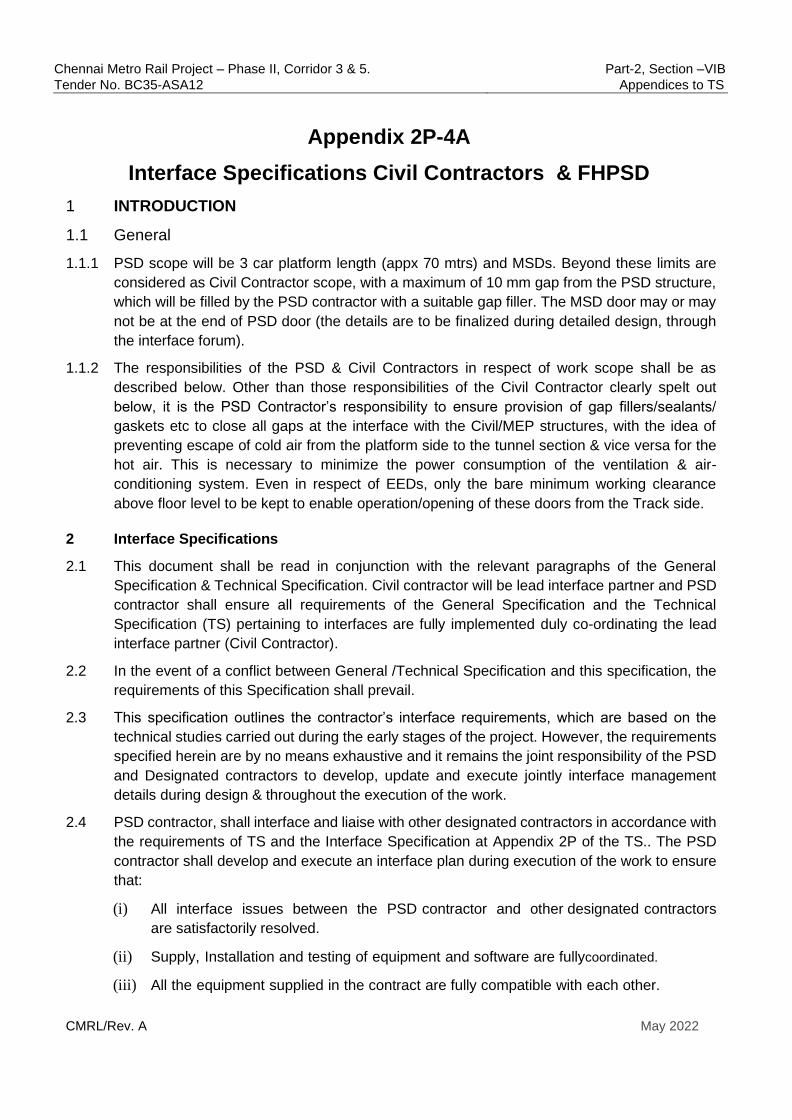
Chennai Metro Rail Project – Phase II, Corridor 3 & 5. Part-2, Section –VIB
Tender No. BC35-ASA12 Appendices to TS
CMRL/Rev. A May 2022
Appendix 2P-4A
Interface Specifications Civil Contractors & FHPSD
1 INTRODUCTION
1.1 General
1.1.1 PSD scope will be 3 car platform length (appx 70 mtrs) and MSDs. Beyond these limits are
considered as Civil Contractor scope, with a maximum of 10 mm gap from the PSD structure,
which will be filled by the PSD contractor with a suitable gap filler. The MSD door may or may
not be at the end of PSD door (the details are to be finalized during detailed design, through
the interface forum).
1.1.2 The responsibilities of the PSD & Civil Contractors in respect of work scope shall be as
described below. Other than those responsibilities of the Civil Contractor clearly spelt out
below, it is the PSD Contractor’s responsibility to ensure provision of gap fillers/sealants/
gaskets etc to close all gaps at the interface with the Civil/MEP structures, with the idea of
preventing escape of cold air from the platform side to the tunnel section & vice versa for the
hot air. This is necessary to minimize the power consumption of the ventilation & air-
conditioning system. Even in respect of EEDs, only the bare minimum working clearance
above floor level to be kept to enable operation/opening of these doors from the Track side.
2 Interface Specifications
2.1 This document shall be read in conjunction with the relevant paragraphs of the General
Specification & Technical Specification. Civil contractor will be lead interface partner and PSD
contractor shall ensure all requirements of the General Specification and the Technical
Specification (TS) pertaining to interfaces are fully implemented duly co-ordinating the lead
interface partner (Civil Contractor).
2.2 In the event of a conflict between General /Technical Specification and this specification, the
requirements of this Specification shall prevail.
2.3 This specification outlines the contractor’s interface requirements, which are based on the
technical studies carried out during the early stages of the project. However, the requirements
specified herein are by no means exhaustive and it remains the joint responsibility of the PSD
and Designated contractors to develop, update and execute jointly interface management
details during design & throughout the execution of the work.
2.4 PSD contractor, shall interface and liaise with other designated contractors in accordance with
the requirements of TS and the Interface Specification at Appendix 2P of the TS.. The PSD
contractor shall develop and execute an interface plan during execution of the work to ensure
that:
(i) All interface issues between the PSD contractor and other designated contractors
are satisfactorily resolved.
(ii) Supply, Installation and testing of equipment and software are fully coordinated.
(iii) All the equipment supplied in the contract are fully compatible with each other.

Chennai Metro Rail Project – Phase II, Corridor 3 & 5. Part-2, Section –VIB
Tender No. BC35-ASA12 Appendices to TS
CMRL/Rev. A May 2022
3 Interface Management Plan
3.1 Within 90 days of notification from the Engineer of the identity of each designated contractor,
the PSD contractor shall develop and submit to the Engineer for review an Interface
Management Plan that is mutually acceptable to both, the PSD contractor and other
designated contractors. The Interface Management Plan shall:
(i) Identify the sub-systems as well as the civil works and facilities with interfacing
requirements.
(ii) Define the authority and responsibility of PSD contractor and other designated
contractors (and any relevant sub-contractors’) staff involved in interface management
and development.
(iii) Include considerations of the Interface hazard analysis.
(iv) Specify the configuration and version control procedures in accordance with PSD
contractor and other designated contractor (and any relevant sub-Contractors’) quality
management system; and
(v) Address the design, supply, installation, testing and commissioning programme of the
contracts to meet the key dates of each contract, and highlight any programme risks
requiring management attention.
3.2 Once the Interface Management Plan has been reviewed by the Engineer, PSD contractor
shall coordinate with other interface contractors and ensure the feasibility of proposed interface
management plan. If any difficulty in developing a mutually acceptable Interface Management
Plan, contractor shall approach the Engineer immediately to resolve the same. Once Interface
management plan is mutually agreed, PSD contractor shall execute the works in accordance
with the Interface Management Plan.
The Interface Specification appended to the TS as Appendix 2P, shall form the basis of the
Interface management plan for the designated contractors mentioned therein. However, this
does not relieve PSD contractor’s obligation to identify any new interface requirements to meet
this specification.
The PSD Contractor shall align to The Engineer’s Master Interface management plan.
3.3 Interfaces exist between PSD contractor and Designated contractors for systems, where the
systems are mutually dependent, or interactive for satisfactory and safe operation. PSD
contractor shall maintain close coordination/ interface during design, manufacturing, testing,
commissioning, integrated testing, trial run and defect liability period with the designated
contractors and consultants who may be working in the project, whether or not especially
mentioned in the contract. PSD contractor shall perform all design duties and provide all
materials, equipment and labour to ensure the satisfactory accomplishment of interface of the
systems for which PSD contractor is responsible.
(i) It shall be the responsibility of PSD Contractor to settle all disagreements with the
designated contractors. If such disagreement cannot be resolved , despite having made
all reasonable efforts, then the decision of the Engineer shall be final .
Chennai Metro Rail Project – Phase II, Corridor 3 & 5. Part-2, Section –VIB
Tender No. BC35-ASA12 Appendices to TS
CMRL/Rev. A May 2022
(ii) PSD contractor shall submit and maintain all agreed Interface Documents as specified
in the General Specification. At all stages of the work, all interfaces shall be discussed
and agreed upon, through the Engineer, between PSD contractor and other designated
contractors.
(iii) It shall be the responsibility of PSD contractor that interface requirements be agreed,
accepted and endorsed by stakeholders as early as possible. Contractual delays and
consequential implications as a result of delay in such co-ordination on account of
reasons attributable to PSD contractor, as concluded by Engineer, shall be the sole
responsibility of PSD contractor.
4 Coordination
4.1 Technical Coordination
(i) PSD contractor shall be responsible for identifying information required from other
designated contractors and/ or the Engineer and providing information in a timely
manner to other Interfacing contractors and the Engineer.
(ii) PSD contractor shall communicate and coordinate with the Engineer and ensure that
all interfacing details are reviewed with notice of no objection by the Engineer. Major
coordination works include but not limited to:
(1) PSD installation- structural attachments to station and platform elements to
support PSD,
(2) Physical routing of all pipe work, cable containment and associated ancillaries,
supports, secondary steel and structural attachments,
(3) Layouts of PSD Room taking cognizance of lighting (to include maintained
emergency lighting), ECS, drainage, S&TC interface panel, LV cabling, earthing
provisions installed by others,
(4) Coordination with S&TC Contractor within Signaling equipment room.
5 FH PSD/PED design Interface
5.1 Station drawings layout and delivery route plan
5.1.1 PSD contractor is responsible to design FH PSD/PED as per station latest Good For
Construction (GFC) drawings. The design also to suit straight or curved platform including
expansion joints wherever applicable.
5.1.2 PSD contractor and Civil contractor shall interface for the agreement of planned delivery route
and execution plan.
5.2 FH PSD/PED load and fixing details.
5.2.1 Civil contractor to indicate minimum clear distance between platform edge & the PSD base
plate fixing holes PSD Contractor shall accordingly finalise the PSD fixing arrangements,
base plate, fixing bolt sizes etc, duly also considering the load to be transferred to the

Chennai Metro Rail Project – Phase II, Corridor 3 & 5. Part-2, Section –VIB
Tender No. BC35-ASA12 Appendices to TS
CMRL/Rev. A May 2022
supporting surface.
5.2.2 PSD Contractor will share the loading levels in all the axes at the PSD mounting point (this
will include the load transferred to platform edge recess at the bottom as well as the load
transferred to the mounting plate at the top, from the PSD top fixing arrangements ). They
will also indicate the fixing bolt sizes & spacing from platform edge. Engineer/DDC will review
the safety of the structure, based on inputs provided by the PSD Contractor.
5.2.3 PSD contractor to design the base plate size, thickness, and bolt sizes as per their design
requirements.
5.2.4 The Civil Contractor shall design the continuous top fixing plate (typically 200x16mm),
suspended from a plate/angle integral with the OTE Duct, in order to accommodate the top
fixing arrangements of the PSD, duly taking into account the loads in various axes transferred
by the PSD to the Civil Contractor’s continuous fixing plate. The position of the continuous
fixing plate at the top, as explained above, has to respect the horizontal & vertical spacing
from (a) track centre and (b) from the rail top respectively, as per requirements of horizontal
& vertical spacing indicated by the PSD Contractor, for maintaining the SOD requirements
(Appendix - 2 ‘N’).
5.2.5 Respective Contractors to ensure any support and fixing as well as structures erected by
them, do not encroach in to train kinematic envelop area and satisfy the Schedule of
Dimensions (SOD) requirements (Appendix - 2 ‘N’).
5.2.6 During FHPSD design stage, PSD Contractor to advise the fixing hole positions along the full
length of the PSD, for the bottom fixing arrangements. Both Contractors will jointly attempt
(subject to the adjustment margin available in PSD installation) to minimize need for cutting
through rebars.
5.3 Access and delivery route layout and timeline programme.
5.3.1 PSD contractor shall share the required information for the preparation of master
layout of access and delivery route with timeline programme and coordinate the
same with the Civil contractor, who will prepare the commonly agreed layout.
5.4 PSD equipment room
5.4.1 PSD equipment room shall be mostly part of signaling room and required minimum area of
15Sqm will be set apart in the combined room, for PSD requirements. PSD contractor to design
their equipment layout and interface the same with Designated contractors.
5.4.2 The equipment room is to be shared between PSD & Signaling. Both Contractors have to
agree on the combined equipment layout , including wall mounted sub-assemblies and the
agreed drawing has to be submitted to the Engineer, for his comments, if any.
5.4.2.1 PSD contractor to share the structural loads of the PSD Equipment room due to the self-weight
of the Platform Screen Control Cubicle (PSCC), PSD -Signaling interface panel and Power
Distribution Panel (PDP-2) etc, to Civil works contractor for the design of false flooring.
5.5 PSD layout interface
5.5.1 PSD contractor has the responsibility to design the PSD/Fixed Panel/EED/DED/MSD layout in
line with SOD requirements (Appendix - 2 ‘N’).

Chennai Metro Rail Project – Phase II, Corridor 3 & 5. Part-2, Section –VIB
Tender No. BC35-ASA12 Appendices to TS
CMRL/Rev. A May 2022
5.5.2 PSD Contractor to ensure that the position of PSD is in line with train stopping locations, and
coordinate the same with Designated contractor to finalize the train stopping location.
5.5.3 The PSD Contractor will install the PSD Façade at the nominated place for 3 car train length
from end to end and it is for the Civil Contractor to close the rest of the area from the PSD
outer structural members, leaving a maximum gap of upto 10mm, which shall be closed with a
suitable filler material by the PSD Contractor.
5.5.4 For the 3 car length (appx 70 mtrs) of the Platform, it is the PSD Contractor’s responsibility to
ensure that cold air does not escape from platform side to the track side and vice versa. Other
than the works agreed to be done by the Civil Contractor, as per the interface agreement, it is
the PSD Contractor’s responsibility to provide all required sealants & gap fillers with suitable
fire-retardant materials, between PSD structures & Civil structures, to achieve this requirement
of preventing loss of cold air from platform side to track side.
5.5.5 PSD Contractor to coordinate with civil works contractor for the integration of PSD with the
Civil structures at either end of the PSD scope.
5.6 Coordination of Combined service drawings
5.6.1 PSD contractor shall participate or organize a coordination meeting with Designated
Contractors to agree their cable routing layout, PSD equipment room cable routing layout, etc.,
but not limited to this scope. These will be suitably reflected in the Combined Service Drawings.
PSD Contractor to give number & types of cables, their sizes, bending radii, minimum
separation between different cable types (like power & data cables). It is for the MEP
Contractor to provide the necessary main cable routes to suit PSD requirements, from SER to
SCR and from SER to PSD platform level till entry to the header box and also to be extended
to the MSDs at both ends of each platform. PSD Contractor shall also co-ordinate with the Civil
Contractor regarding matching with architectural finishes of the Station, in respect of PSD
structural members & over all colour scheme & appearance matching with the architectural
finishes of the Station.
5.7 FH PSD interface during Installation stage
5.7.1 Work area access for PSD/MSD
5.7.1.1 PSD contractor to collect & verify the as built details of Platform edge as well as the recess
(distance from track centre & height above actual rail level) .
5.7.1.2 PSD contractor to collect & verify the as built details of continuous steel plate provided below
the OTE duct by the Civil Contractor , for PSD upper top fixing arrangements(distance from
track centre & height above actual rail level) and ensure that these are as per PSD
requirements.
5.7.1.3 Should also collect the reference coordinates of the Station from Civil Contractor and adjust
the PSD design as per actual site conditions (civil as well as track). The PSD contractor shall
obtain the train stopping point in consultation with the Civil Contractor and the Signalling
contractor.
5.7.1.4 Civil Contractor to ensure that platform edge is within 1510-1515 mm of track centre , as per
SOD (Appendix - 2 ‘N’), for the full length, before asking PSD Contractor to take over the work
area for PSD installation. The heights of the platform recess to be as per mutually agreed

Chennai Metro Rail Project – Phase II, Corridor 3 & 5. Part-2, Section –VIB
Tender No. BC35-ASA12 Appendices to TS
CMRL/Rev. A May 2022
interface drawings and the area where the PSD base plates are to be fixed is to be levelled,
before handing over to PSD Contractor.
5.7.1.5 All items shall be delivered to site in batches as required based on installation phase. However,
a temporary storage area with a minimum size of appx 150 Sq.mtrs is required at the platform
level to store the delivered items prior to installation. Hence PSD contractor to ensure the
agreed area provided by civil works contractor, during takeover of work area.
5.7.2 Setting out of PSD/EED/DED/MSD layout
5.7.2.1 Setting out of the FHPSD System shall be derived from the Station Centre Line Coordinates
(to be provided by the Civil Contractor) and the Kinematic Envelope (to be obtained from the
Rolling Stock Contractor).
5.7.2.2 The PSD contractor shall obtain the train stopping point in consultation with the Civil Contractor
and the Signalling contractor. The PSD contractor shall also obtain the reference co-ordinates
at the platform as per PSD installation requirements and also obtain the platform center point.
5.7.2.3 Civil contractor to ensure that, the finished floor level from the top of the rail shall be 1090 ± 5
mm, but within 1.5 m from the edge of the platform recess where the EED is located, the floor
level shall be reduced by 6 mm when the threshold finish level of the PSD is 1090 mm. PSD
contractor to advise the same. This vertical gap of 6 mm, to be closed by the PSD Contractor,
with a suitable sealant.
5.7.2.4 The checking of any setting out of any line or level by the Engineer shall not in any way relieve
PSD contractor of his responsibility for the correctness thereof and PSD contractor shall
carefully protect and preserve all benchmarks, sight rails, pegs and other things used in setting-
out the Works.
5.7.2.5 MSD is proposed only at the edge of platform, so MSD may or may not be at end panel of
PSD. PSD contractor to ensure that integration of PSD/MSD and its control system and cable
through agreed cable routing to be done considering the position of MSD away from PSD end
panel. In respect of the MSDs, for the door loop circuit, the cables are to be taken through
over-head cable trays to be provided by MEP Contractor, which needs to be co-ordinated with
them. Where required, the cables may have to be taken through a race way (to be provided
by the PSD Contractor); laying of cables for the entire length and its termination in the
termination box of the respective MSD, is in the scope of the PSD Contractor. The finishing of
the race-way viz-a -viz the finished platform flooring, has to be suitably -co-ordinated with the
Ciivil Contractor.
5.7.3 Work area access for PSD room
5.7.3.1 PSD contractor to ensure that the PSD room shall be to the level of finishes to degree three
level completion before taking over of PSD room from the designated contractor.
5.7.3.2 PSD contractor shall ensure that the setting out of plant or equipment permits it to fit into the
space allocated and allows access for maintenance and replacement purposes.
5.7.3.3 PSD contractor to ensure that the PSD room false flooring and false ceiling if any shall be as
per the coordinated Combined service drawings with Designated contractor.
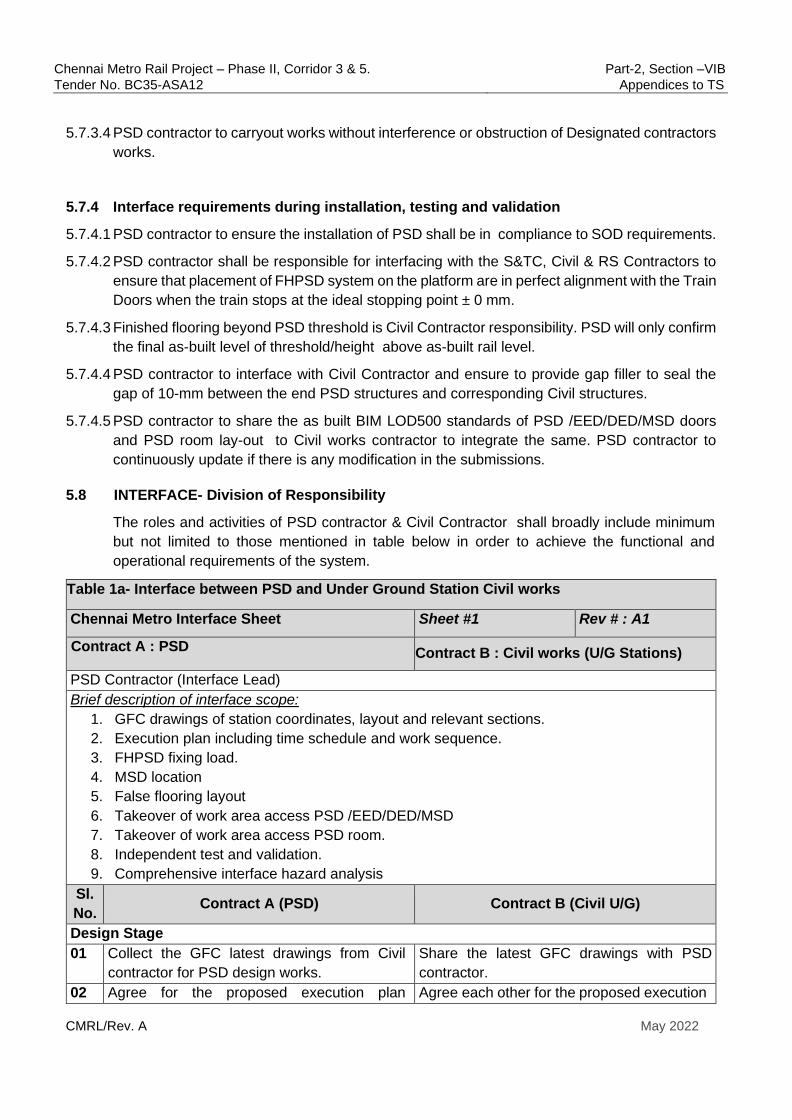
Chennai Metro Rail Project – Phase II, Corridor 3 & 5. Part-2, Section –VIB
Tender No. BC35-ASA12 Appendices to TS
CMRL/Rev. A May 2022
5.7.3.4 PSD contractor to carryout works without interference or obstruction of Designated contractors
works.
5.7.4 Interface requirements during installation, testing and validation
5.7.4.1 PSD contractor to ensure the installation of PSD shall be in compliance to SOD requirements.
5.7.4.2 PSD contractor shall be responsible for interfacing with the S&TC, Civil & RS Contractors to
ensure that placement of FHPSD system on the platform are in perfect alignment with the Train
Doors when the train stops at the ideal stopping point ± 0 mm.
5.7.4.3 Finished flooring beyond PSD threshold is Civil Contractor responsibility. PSD will only confirm
the final as-built level of threshold/height above as-built rail level.
5.7.4.4 PSD contractor to interface with Civil Contractor and ensure to provide gap filler to seal the
gap of 10-mm between the end PSD structures and corresponding Civil structures.
5.7.4.5 PSD contractor to share the as built BIM LOD500 standards of PSD /EED/DED/MSD doors
and PSD room lay-out to Civil works contractor to integrate the same. PSD contractor to
continuously update if there is any modification in the submissions.
5.8 INTERFACE- Division of Responsibility
The roles and activities of PSD contractor & Civil Contractor shall broadly include minimum
but not limited to those mentioned in table below in order to achieve the functional and
operational requirements of the system.
Table 1a- Interface between PSD and Under Ground Station Civil works
Chennai Metro Interface Sheet Sheet #1 Rev # : A1
Contract A : PSD Contract B : Civil works (U/G Stations)
PSD Contractor (Interface Lead)
Brief description of interface scope:
1. GFC drawings of station coordinates, layout and relevant sections.
2. Execution plan including time schedule and work sequence.
3. FHPSD fixing load.
4. MSD location
5. False flooring layout
6. Takeover of work area access PSD /EED/DED/MSD
7. Takeover of work area access PSD room.
8. Independent test and validation.
9. Comprehensive interface hazard analysis
Sl.
No. Contract A (PSD) Contract B (Civil U/G)
Design Stage
01 Collect the GFC latest drawings from Civil
contractor for PSD design works.
Share the latest GFC drawings with PSD
contractor.
02 Agree for the proposed execution plan Agree each other for the proposed execution

Chennai Metro Rail Project – Phase II, Corridor 3 & 5. Part-2, Section –VIB
Tender No. BC35-ASA12 Appendices to TS
CMRL/Rev. A May 2022
including work area sequence of access,
Installation coordination plan showing the
space / input requirement and timeline of
programme
plan including sequence & details of work
area access, Installation coordination plan
showing the space / input requirement and
timeline of programme.
03 Share and agree the design load on the bolts
in various axes for fixing of FHPSD at platform
edge, in respect of bottom mounting
arrangements.
Share and agree the locations, fixing details,
requirements, tolerances of FHPSD bottom
fixing arrangements including platform end
recess finished level, its distance from track
centre etc.
Verify the station elements for the provided
load, locations, and method statements.
Shall design the platform edge recess
accordingly.
04 Share and agree the design load in various
axes on the top fixing plate, in respect of the
top fixing arrangements of the FHPSD.
Shall also share the requirements of height
above rail level & distance of the top plate
centre from track centre, with applicable
tolerances, to suit FHPSD mounting
arrangements
Shall design a continuous steel plate
(typically 200 mmx16mm thick), suitably
suspended from the OTE slab above, based
on FHPSD load levels as well as installation
tolerances
05 Verify and agree the MSD locations. Verify and agree the MSD locations. In line
with emergency evacuation and maintenance
access.
06 Shall furnish the installation location and
method of Platform Screen Doors Manual
Control Panel on platform level.
Shall validate the locations of Platform screen
doors Manual control panel and incorporate
these in the Combined Services Drawings.
Installation stage
07 Shall verify the same and do the PSD
installation accordingly.
Shall provide the reference co-ordinates of
the platform for PSD installation
requirements. Shall also advise the stopping
position of the train and centre of platform.
08 Ensure the following during takeover of work
area.
a) Platform edge of base concrete is crack
free, and smooth surface, also there should
not be floor screed/finishes into the space
underneath the PSD base plates area. PSD
mounting recess at platform edge, to be
suitable for PSD installation requirements.
Ensure following during handover of work
area.
a) Platform edge of base concrete is crack
free, and smooth surface, also there should
not be floor screed/finishes into the space
underneath the PSD base plates area. PSD
bottom mounting surface as per agreed
interface drawing and fulfilment of SOD
requirement (Appendix-2N) in respect of
spacing from Track Centre to Platform edge
as well as to the recess, has to be ensured
for the full platform length, before the work
area is offered to PSD Contractor for
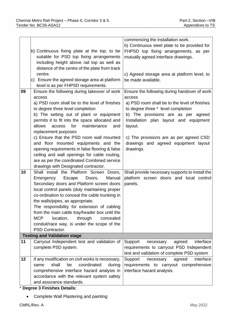
Chennai Metro Rail Project – Phase II, Corridor 3 & 5. Part-2, Section –VIB
Tender No. BC35-ASA12 Appendices to TS
CMRL/Rev. A May 2022
b) Continuous fixing plate at the top, to be
suitable for PSD top fixing arrangements
including height above rail top as well as
distance of the centre of the plate from track
centre.
c) Ensure the agreed storage area at platform
level is as per FHPSD requirements.
commencing the installation work.
b) Continuous steel plate to be provided for
FHPSD top fixing arrangements, as per
mutually agreed interface drawings.
c) Agreed storage area at platform level, to
be made available.
09 Ensure the following during takeover of work
access
a) PSD room shall be to the level of finishes
to degree three level completion
b) The setting out of plant or equipment
permits it to fit into the space allocated and
allows access for maintenance and
replacement purposes
c) Ensure that the PSD room wall mounted
and floor mounted equipments and the
opening requirements in false flooring & false
ceiling and wall openings for cable routing,
are as per the coordinated Combined service
drawings with Designated contractor.
Ensure the following during handover of work
access
a) PSD room shall be to the level of finishes
to degree three * level completion
b) The provisions are as per agreed
Installation plan layout and equipment
layout.
c) The provisions are as per agreed CSD
drawings and agreed equipment layout
drawings.
10 Shall install the Platform Screen Doors,
Emergency Escape Doors, Manual
Secondary doors and Platform screen doors
local control panels (duly maintaining proper
co-ordination to conceal the cable trunking in
the walls/pipes, as appropriate.
The responsibility for extension of cabling
from the main cable tray/header box until the
MCP location, through concealed
conduit/race way, is under the scope of the
PSD Contractor.
Shall provide necessary supports to install the
platform screen doors and local control
panels.
Testing and Validation stage
11 Carryout Independent test and validation of
complete PSD system.
Support necessary agreed interface
requirements to carryout PSD Independent
test and validation of complete PSD system
12 If any modification on civil works is necessary,
same shall be coordinated during
comprehensive interface hazard analysis in
accordance with the relevant system safety
and assurance standards.
Support necessary agreed interface
requirements to carryout comprehensive
interface hazard analysis.
* Degree 3 Finishes Details:
• Complete Wall Plastering and painting
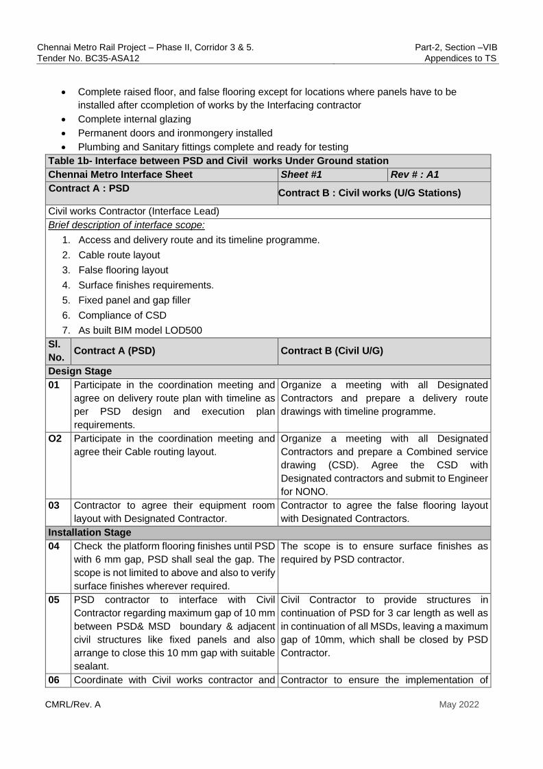
Chennai Metro Rail Project – Phase II, Corridor 3 & 5. Part-2, Section –VIB
Tender No. BC35-ASA12 Appendices to TS
CMRL/Rev. A May 2022
• Complete raised floor, and false flooring except for locations where panels have to be
installed after ccompletion of works by the Interfacing contractor
• Complete internal glazing
• Permanent doors and ironmongery installed
• Plumbing and Sanitary fittings complete and ready for testing
Table 1b- Interface between PSD and Civil works Under Ground station
Chennai Metro Interface Sheet Sheet #1 Rev # : A1
Contract A : PSD Contract B : Civil works (U/G Stations)
Civil works Contractor (Interface Lead)
Brief description of interface scope:
1. Access and delivery route and its timeline programme.
2. Cable route layout
3. False flooring layout
4. Surface finishes requirements.
5. Fixed panel and gap filler
6. Compliance of CSD
7. As built BIM model LOD500
Sl.
No. Contract A (PSD) Contract B (Civil U/G)
Design Stage
01 Participate in the coordination meeting and
agree on delivery route plan with timeline as
per PSD design and execution plan
requirements.
Organize a meeting with all Designated
Contractors and prepare a delivery route
drawings with timeline programme.
O2 Participate in the coordination meeting and
agree their Cable routing layout.
Organize a meeting with all Designated
Contractors and prepare a Combined service
drawing (CSD). Agree the CSD with
Designated contractors and submit to Engineer
for NONO.
03 Contractor to agree their equipment room
layout with Designated Contractor.
Contractor to agree the false flooring layout
with Designated Contractors.
Installation Stage
04 Check the platform flooring finishes until PSD
with 6 mm gap, PSD shall seal the gap. The
scope is not limited to above and also to verify
surface finishes wherever required.
The scope is to ensure surface finishes as
required by PSD contractor.
05 PSD contractor to interface with Civil
Contractor regarding maximum gap of 10 mm
between PSD& MSD boundary & adjacent
civil structures like fixed panels and also
arrange to close this 10 mm gap with suitable
sealant.
Civil Contractor to provide structures in
continuation of PSD for 3 car length as well as
in continuation of all MSDs, leaving a maximum
gap of 10mm, which shall be closed by PSD
Contractor.
06 Coordinate with Civil works contractor and Contractor to ensure the implementation of
Chennai Metro Rail Project – Phase II, Corridor 3 & 5. Part-2, Section –VIB
Tender No. BC35-ASA12 Appendices to TS
CMRL/Rev. A May 2022
agree the coordinated CSD. agreed CSD drawings.
Testing and Validation stage
07 Share the as built BIM model Synchronize the information with master as
built BIM model.

Chennai Metro Rail Project – Phase II, Corridor 3 & 5. Part-2, Section –VIB
Tender No. BC35-ASA12 Appendices to TS
CMRL/Rev. A May 2022
APPENDIX-2P-4B
Interface protocol between Civil (Elevated)
and Platform Screen Doors (PSD) system
(Half Height)

Chennai Metro Rail Project – Phase II, Corridor 3 & 5. Part-2, Section –VIB
Tender No. BC35-ASA12 Appendices to TS
CMRL/Rev. A May 2022
Appendix 2P-4B
Interface Specifications Civil Contractors & HHPSD:
1 General
PSD scope will be 3 car platform length and MSDs. Beyond these limits are considered as
Civil Contractor scope, with a maximum of 10 mm gap from the PSD structure, which will be
filled by the PSD contractor with a suitable gap filler. The MSD door may or may not be at the
end of PSD door (the details are to be finalized during detailed design, through the interface
forum).
2 Interface Specifications
2.1 This document shall be read in conjunction with the relevant paragraphs of the General
Specification & Technical Specification. Civil contractor will be the lead contractor and PSD
contractor shall ensure all requirements of the General Specification and the Technical
Specification (TS) pertaining to interfaces are fully implemented duly co-ordinating with the
lead interface partner (Civil Contractor).
2.2 In the event of a conflict between General /Technical Specification and this specification, the
requirements of this Specification shall prevail.
2.3 This specification outlines the contractor’s interface requirements, which are based on the
technical studies carried out during the early stages of the project. However, the requirements
specified herein are by no means exhaustive and it remains the joint responsibility of the PSD
and Designated contractors to develop, update and execute jointly interface management
details during design & throughout the execution of the work.
2.4 PSD contractor shall interface and liaise with other designated contractors in accordance with
the requirements of TS and Interface Specification at Appendix 2P of this TS. The PSD
contractor shall develop and execute an interface plan during execution of the work to ensure
that:
(i) All interface issues between the PSD contractor and other designated contractors are
satisfactorily resolved.
(ii) Supply, Installation and testing of equipment and software are fully coordinated.
(iii) All the equipment supplied in the contract are fully compatible with each other.
3 Interface Management Plan
3.1 Within 60 days of notification from the Engineer of the identity of each designated contractor,
the PSD contractor shall develop and submit to the Engineer for review an Interface
Management Plan that is mutually acceptable to both, the PSD contractor and other
designated contractors. The Interface Management Plan shall:
(i) Identify the sub-systems as well as the civil works and facilities with interfacing

Chennai Metro Rail Project – Phase II, Corridor 3 & 5. Part-2, Section –VIB
Tender No. BC35-ASA12 Appendices to TS
CMRL/Rev. A May 2022
requirements.
(ii) Define the authority and responsibility of PSD contractor and other designated
contractors (and any relevant sub-contractors’) staff involved in interface management
and development.
(iii) Include considerations of the Interface hazard analysis.
(iv) Specify the configuration and version control procedures in accordance with PSD
contractor and other designated contractor (and any relevant sub-Contractors’) quality
management system; and
(v) Address the design, supply, installation, testing and commissioning programme of the
contracts to meet the key dates of each contract, and highlight any programme risks
requiring management attention.
3.2 Once the Interface Management Plan has been reviewed by the Engineer, PSD contractor,
as lead, shall coordinate with other interface contractors and ensure the feasibility of proposed
interface management plan. If any difficulty in developing a mutually acceptable Interface
Management Plan, contractor shall approach the Engineer immediately to resolve the same.
Once Interface management plan is mutually agreed, PSD contractor shall execute the works
in accordance with the Interface Management Plan.
3.3 The Interface Specification appended to the TS as Appendix 2P, shall form the basis of the
Interface management plan for the designated contractors mentioned therein. However, this
does not relieve PSD contractor’s obligation to identify any new interface requirements to meet
this specification.
3.4 The PSD Contractor shall align to The Engineer’s Master Interface management plan.
3.5 Interfaces exist between PSD contractor and Designated contractors for systems, where the
systems are mutually dependent, or interactive for satisfactory and safe operation. PSD
contractor shall maintain close coordination/ interface during design, manufacturing, testing,
commissioning, integrated testing, trial run and defect liability period with the designated
contractors and consultants who may be working in the project, whether or not especially
mentioned in the contract. PSD contractor shall perform all design duties and provide all
materials, equipment and labour to ensure the satisfactory accomplishment of interface of the
systems for which PSD contractor is responsible.
(i) It shall be the responsibility of PSD Contractor, as lead contractor, to settle all
disagreements with the designated contractors. If such disagreement cannot be
resolved by lead contractor, despite having made all reasonable efforts, then the
decision of the Engineer shall be final.
(ii) PSD contractor shall submit and maintain all agreed Interface Documents as specified
in the General Specification. At all stages of the work, all interfaces shall be discussed
and agreed upon, through the Engineer between PSD contractor and other designated
contractors.
(iii) It shall be the responsibility of PSD contractor that interface requirements be agreed,
accepted and endorsed by stakeholders as early as possible. Contractual delays and
consequential implications as a result of delay in such co-ordination on account of

Chennai Metro Rail Project – Phase II, Corridor 3 & 5. Part-2, Section –VIB
Tender No. BC35-ASA12 Appendices to TS
CMRL/Rev. A May 2022
reasons attributable to PSD contractor, as concluded by Engineer, shall be the sole
responsibility of PSD contractor.
4 Coordination
4.1 Technical Coordination
(i) PSD contractor, as lead, shall be responsible for identifying information required from
other designated contractors and/ or the Engineer and providing information in a timely
manner to other Interfacing contractors and the Engineer.
(ii) PSD contractor shall communicate and coordinate with the Engineer and ensure that
all interfacing details are reviewed with notice of no objection by the Engineer. Major
coordination works include but not limited to:
(1) PSD installation- structural attachments to station and platform elements to
support PSD,
(2) Physical routing of all pipe work, cable containment and associated ancillaries,
supports, secondary steel and structural attachments,
(3) Layouts of PSD Room taking cognizance of lighting (to include maintained
emergency lighting), ECS, drainage, S&TC interface panel, LV cabling, earthing
provisions installed by others,
(4) Coordination with S&TC Contractor within Signaling equipment
room.
5 HH PSD/PED design Interface
5.1 Station drawings layout and delivery route plan
5.1.1 PSD contractor, as lead, is responsible to design HH PSD/PED as per station latest Good For
Construction (GFC) drawings. The design also to suit straight or curved platform including
expansion joints wherever applicable.
5.1.2 PSD contractor and Civil contractor shall interface for the agreement of planned delivery route
and execution plan.
5.2 HH PSD/PED load and fixing details.
5.2.1 Civil contractor to indicate minimum clear distance between platform edge & the PSD fixing
holes PSD Contractor shall accordingly finalise the PSD fixing arrangements, base plate,
fixing bolt sizes etc, duly also considering the load to be transferred to the supporting surface.
5.2.2 PSD Contractor will share the loading levels in all the axes at the PSD mounting points. They
will also indicate the fixing bolt sizes & spacing from platform edge. Engineer/DDC will review
the safety of the structure, based on inputs provided by the PSD Contractor.
5.2.3 PSD contractor to design the base plate size, thickness, and bolt sizes as per their design
requirements.

Chennai Metro Rail Project – Phase II, Corridor 3 & 5. Part-2, Section –VIB
Tender No. BC35-ASA12 Appendices to TS
CMRL/Rev. A May 2022
5.2.4 Respective Contractors to ensure any support and fixing as well as structures erected by
them, do not encroach in to train kinematic envelop area and satisfy the Schedule of
Dimensions (SOD) requirements.
5.2.5 During HHPSD design stage, PSD Contractor to advise the fixing hole positions along the full
length of the PSD. Both Contractors will jointly attempt (subject to the adjustment margin
available in PSD installation) to minimize need for cutting through rebars.
6 Co-ordination is also required to ensure that platform edge finishing (recess on which
PSD is mounted) is suitable for PSD installation (as per mutually agreed interface
drawings) and also that the height above rail level of the PSD mounting surface as well
as its lateral distance from Track Centre, are as per mutually agreed interface drawings
and also respecting the requirements of Schedu/le of Dimensions.
6.1.1
5.3 Access and delivery route layout and timeline programme;
5.3.1 PSD contractor, shall share the required information for the preparation of master layout of
access and delivery route with timeline programme and coordinate the same with all designed
contractor to prepare the commonly agreed layout.
5.4 PSD equipment room
5.4.1.1 PSD equipment room shall be mostly along with signaling room and required a minimum area
of 15Sqm. PSD contractor to design their equipment layout and interface the same with
Designated contractors.
5.4.1.2 The equipment room is to be shared between PSD & Signaling. Both Contractors have to
agree on the combined equipment layout , including wall mounted sub-assemblies and the
agreed drawing has to be submitted to the Engineer, for his comments, if any.
5.4.1.3 PSD contractor to share the structural loads of the PSD Equipment room due to the self-
weight of the Platform Screen Control Cubicle (PSCC), PSD -Signaling interface panel and
Power Distribution Panel (PDP-2) to Civil works contractor for the design of false flooring.
5.5 PSD layout interface
5.5.1 PSD contractor has the responsibility to design the PSD/Fixed Panel/EED/DED/MSD layout
in line with SOD requirements.
5.5.2 PSD Contractor to ensure that the position of PSD is in line with train stopping locations, and
coordinate the same with Designated contractor to finalize the train stopping location.
5.5.3 The PSD Contractor will install the PSD Facade at the nominated place for 3 car train length
from end to end and it is for the Civil Contractor to close the rest of the area from the PSD
outer structural members, leaving a maximum gap of upto 10mm, which shall be closed with
a suitable filler material by the PSD Contractor.
5.5.4 PSD Contractor to coordinate with Civil works contractor for the integration of PSD with the
Civil structures at either end of the PSD scope.
5.6 Coordination of Combined service drawings
Chennai Metro Rail Project – Phase II, Corridor 3 & 5. Part-2, Section –VIB
Tender No. BC35-ASA12 Appendices to TS
CMRL/Rev. A May 2022
5.6.1 PSD contractor shall participate or organize a coordination meeting with Designated
Contractors to agree their cable routing layout, PSD equipment room cable routing layout,
etc., but not limited to this scope. These will be suitably reflected in the Combined Service
Drawings. PSD Contractor to give number & types of cables, their sizes, bending radii,
minimum separation between different cable types (like power & data cables). It is for the
MEP Contractor to provide the necessary main cable routes to suit PSD requirements, from
SER to SCR and from SER to PSD cable trunking under the platform coping trays (through
structural openings). PSD Contractor shall also co-ordinate with the Civil Contractor regarding
matching with architectural finishes of the Station, in respect of race-way arrangements from
PSD Cable trunking under the platform coping, until the respective MSD and also in respect
of PSD structural members & over all color scheme & appearance matching with the
architectural finishes of the Station.
5.6.2 The space available for PSD cable routing beneath the Platform slab in side platform stations
as well as island platform stations, is indicated in the sketches at Annexure A to this appendix.
In the L shaped brackets provided by Civil Contractor , PSD Contractor has to design the
cable routing for both Power & data cables. As per separation/EMC requirements required
GI pipes/conduits have to be supplied & installed by the PSD Contractor in these brackets
for data/power cables as the case may be, with openings in the GI Pipe/conduit at required
intervals, to take out the data & power cables inside each ASD mechanism/EED/DED
termination box (as the case may be). Necessary coring holes to bring these cables above
platform slab, is to be done by the PSD Contractor, in consultion with the Civil Contractor,
duly taking care to avoid damage to any re-enforcement bars of the concetre (as far as
possible).
5.6.3 In respect of the MSDs, for the door loop circuit, the cables are to be taken beneath the
Platform slab, brought up through coring holes and then through a race way (to be provided
by the PSD Contractor), bring the cable near the termination box of the respective MSD. The
finishing of the race-way viz-a -viz the finished platform flooring, has to be suitably -co-
ordinated with the Ciivil Contractor
5.7 HH PSD interface during Installation stage
5.7.1 Work area access for PSD/MSD
5.7.1.1 PSD contractor to collect & verify the as built details of Platform edge recess (distance from
track centre & height above actual rail level) . Should also collect the reference coordinates
of the Station from Civil Contractor and adjust the PSD design as per actual site conditions
(civil as well as track).
5.7.1.2 Civil Contractor to ensure that platform edge is within 1515-1520 mm of track centre, as per
SOD, for the full length, before asking PSD Contractor to take over the work area for PSD
installation. The heights of the platform recess to be as per mutually agreed interface
drawings and the area where the PSD base plates are to be fixed is to be levelled, before
handing over to PSD Contractor.
5.7.1.3 All items shall be delivered to site in batches as required based on installation phase.
However, a temporary storage area with a minimum size of appx. 150 sq.mtrs is required at

Chennai Metro Rail Project – Phase II, Corridor 3 & 5. Part-2, Section –VIB
Tender No. BC35-ASA12 Appendices to TS
CMRL/Rev. A May 2022
the platform level to store the delivered items prior to installation. Hence PSD contractor to
ensure the agreed area provided by civil works contractor, during takeover of work area.
5.7.2 Setting out of PSD/EED/DED/MSD layout
5.7.2.1 Setting out of the HHPSD System shall be derived from the Station Centre Line Coordinates
(to be provided by the Civil Contractor) and the Kinematic Envelope (to be obtained from the
Rolling Stock Contractor).
5.7.2.2 The PSD contractor shall obtain the train stopping point in consultation with the Civil
Contractor and the Signalling contractor. The PSD contractor shall also obtain the reference
co-ordinates at the platform as per PSD installation requirements and also obtain the platform
center point.
5.7.2.3 Civil contractor to ensure that, the finished floor level from the top of the rail shall be 1090 ±
5 mm, but within 1.5 m from the edge of the platform recess where the EED is located, the
floor level shall be reduced by 6 mm when the threshold finish level of the PSD is 1090 mm.
PSD contractor to advise the same. This vertical gap of 6 mm, to be closed by the PSD
Contractor, with a suitable sealant.
5.7.2.4 The checking of any setting out of any line or level by the Engineer shall not in any way relieve
PSD contractor of his responsibility for the correctness thereof and PSD contractor shall
carefully protect and preserve all benchmarks, sight rails, pegs and other things used in
setting-out the Works.
5.7.2.5 MSD is proposed only at the edge of platform, so MSD may or may not be at end panel of
PSD. PSD contractor to ensure that integration of PSD/MSD and its control system and cable
through agreed cable routing to be done considering the position of MSD away from PSD
end panel. PSD contractor to agree with civil contractor for coring of holes and execute the
same.
5.7.3 Work area access for PSD room
5.7.3.1 PSD contractor to ensure that the PSD room shall be to the level of finishes to degree three
level completion before taking over of PSD room from the designated contractor.
5.7.3.2 PSD contractor shall ensure that the setting out of plant or equipment permits it to fit into the
space allocated and allows access for maintenance and replacement purposes.
5.7.3.3 PSD contractor to ensure that the PSD room false flooring and false ceiling if any shall be as
per the coordinated Combined service drawings with Designated contractor.
5.7.3.4 PSD contractor to carryout works without interference or obstruction of Designated
contractors works
5.7.4 Interface requirements during installation, testing and validation
5.7.4.1 PSD contractor to ensure the installation of PSD shall be in compliance to SOD
requirements.
5.7.4.2 PSD Contractor, during PSD installation stage, will indicate coring holes requirement for
cable entry to the Civil Contractor. The coring shall be done by PSD Contractor, under the
guidance of Civil Contractor.
5.7.4.3 PSD contractor shall be responsible for interfacing with the S&TC, Civil & RS Contractors to

Chennai Metro Rail Project – Phase II, Corridor 3 & 5. Part-2, Section –VIB
Tender No. BC35-ASA12 Appendices to TS
CMRL/Rev. A May 2022
ensure that placement of HHPSD system on the platform are in perfect alignment with the
Train Doors when the train stops at the ideal stopping point ± 0 mm.
5.7.4.4 Finished flooring beyond PSD threshold is Civil Contractor responsibility. PSD will only
confirm the final as-built level of threshold/height above as-built rail level.
5.7.4.5 PSD contractor to interface with Civil Contractor and ensure to provide gap filler to seal the
gap of 10-mm between the end PSD structures and corresponding Civil structures.
5.7.4.6 PSD contractor to share the as built BIM LOD500 standards of PSD /EED/DED/MSD doors
and PSD room lay-out to Civil works contractor to integrate the same. PSD contractor to
continuously update if there is any modification in the submissions.

Chennai Metro Rail Project – Phase II, Corridor 3 & 5. Part-2, Section –VIB
Tender No. BC35-ASA12 Appendices to TS
CMRL/Rev. A May 2022
5.8 INTERFACE- Division of Responsibility
The roles and activities of PSD contractor & Civil Contractor shall broadly include minimum
but not limited to those mentioned in table below in order to achieve the functional and
operational requirements of the system.
Table 1a- Interface between PSD and Elevated Station Civil works
Chennai Metro Interface Sheet Rev
# : A1
Contract A : PSD Contract B : Civil works (Elevated Stations)
PSD Contractor (Interface Lead)
Brief description of interface scope:
1. GFC drawings of station coordinates, layout and relevant sections.
2. Execution plan including time schedule and work sequence.
3. HHPSD fixing load.
4. MSD location
5. False flooring layout
6. Takeover of work area access PSD /EED/DED/MSD
7. Takeover of work area access PSD room.
8. Independent test and validation.
9. Comprehensive interface hazard analysis
Sl.
No. Contract A (PSD) Contract B (Civil Elevated)
Design Stage
01 Collect the GFC latest drawings from Civil
contractor for PSD design works.
Share the latest GFC drawings with PSD
contractor.
02 Agree for the proposed execution plan
including work area sequence of access,
Installation coordination plan showing the
space / input requirement and timeline of
programme
Agree each other for the proposed execution
plan including sequence & details of work
area access, Installation coordination plan
showing the space / input requirement and
timeline of programme.
03 Share and agree the design load on the bolts
in various axes for fixing of HHPSD at platform
edge, in respect of bottom mounting
arrangements.
Share and agree the locations, fixing details ,
requirements, tolerances of HHPSD bottom
fixing arrangements including platform end
recess finished level, its distance from track
Verify the station elements for the provided
load, locations, and method statements.
Shall design the platform edge recess
accordingly.

Chennai Metro Rail Project – Phase II, Corridor 3 & 5. Part-2, Section –VIB
Tender No. BC35-ASA12 Appendices to TS
CMRL/Rev. A May 2022
centre etc.
04 Verify and agree the MSD locations. Verify and agree the MSD locations. In line
with emergency evacuation and maintenance
access.
05 Shall furnish the installation location and
method of Platform Screen Doors Local
Control Panel on platform level.
Shall validate the locations of Platform screen
doors Manual control panel and incorporate
these in the Combined Services Drawings.
Installation stage
06 Ensure the following during takeover of work
area.
a) Platform edge of base concrete is crack
free, and smooth surface, also there
should not be floor screed/finishes into the
space underneath the PSD base plates
area. PSD mounting recess at platform
edge, to be suitable for PSD installation
requirements.
b). Ensure the agreed storage area at platform
level is as per HHPSD requirements
Ensure following during handover of work
area
a). Platform edge of base concrete is crack
free, and smooth surface, also there should
not be floor screed/finishes into the space
underneath the PSD base plates area. PSD
bottom mounting surface as per agreed
interface drawing and fulfilment of SOD
requirement (Appendix-2P) of spacing from
Track Centre to Platform edge as well as to
the recess, has to be ensured for the full
platform length, before the work area is
offered to PSD Contractor for commencing
the installation work.
b) Agreed storage area at platform level, to
be made available.
07 Ensure the following during takeover of work
access
a) PSD room shall be to the level of finishes
to degree three level completion
b) The setting out of plant or equipment
permits it to fit into the space allocated and
allows access for maintenance and
replacement purposes
c) Ensure that the PSD room wall mounted
and floor mounted equipments and the
opening requirements in false flooring & false
ceiling and wall openings for cable routing,
are as per the coordinated Combined service
drawings with Designated contractor.
Ensure the following during handover of work
access
a) PSD room shall be to the level of finishes
to degree three * level completion
b) The provisions are as per agreed
Installation plan layout and equipment
layout.
c) The provisions are as per agreed CSD
drawings and agreed equipment layout
drawings.
08 Coring holes requirement for cable entry shall
be done by PSD Contractor, under the
Both Contractors will jointly attempt to
minimize need for cutting through rebars.
Chennai Metro Rail Project – Phase II, Corridor 3 & 5. Part-2, Section –VIB
Tender No. BC35-ASA12 Appendices to TS
CMRL/Rev. A May 2022
guidance of Civil Contractor.
09 Shall install the Platform Screen Doors,
Emergency Escape Doors, Manual
Secondary doors and Platform screen doors
local control panels (duly maintaining proper
co-ordination to conceal the cable trunking in
the walls/pipes, as appropriate.
The responsibility for extension of cabling
from the main cable tray under platfrom edge
until the MCP location, through concealed
conduit/race way, is under the scope of the
PSD Contractor.
Shall provide necessary supports to install the
platform screen doors and local control
panels.
Testing and Validation stage
10 Carryout Independent test and validation of
complete PSD system.
Support necessary agreed interface
requirements to carryout PSD Independent
test and validation of complete PSD system
11 If any modification on civil works is necessary,
same shall be coordinated during
comprehensive interface hazard analysis in
accordance with the relevant system safety
and assurance standards.
Support necessary agreed interface
requirements to carryout comprehensive
interface hazard analysis.
* Degree 3 Finishes Details:
• Complete Wall Plastering and painting
• Complete raised floor, and false flooring except for locations where panels have to be
installed after ccompletion of works by the Interfacing contractor
• Complete internal glazing
• Permanent doors and ironmongery installed
• Plumbing and Sanitary fittings complete and ready for testing
Table 1b- Interface between PSD and Civil works Elevated station
Chennai Metro Interface Sheet Rev # :
A1
Contract A : PSD Contract B : Civil works (Elevated)
Civil works Contractor (Interface Lead)
Brief description of interface scope:
1. Access and delivery route and its timeline programme.
2. Cable route layout
3. False flooring layout
4. Surface finishes requirements.

Chennai Metro Rail Project – Phase II, Corridor 3 & 5. Part-2, Section –VIB
Tender No. BC35-ASA12 Appendices to TS
CMRL/Rev. A May 2022
5. Fixed panel and gap filler
6. Compliance of CSD
7. As built BIM model LOD500
Sl.
No. Contract A (PSD) Contract B (Civil Elevated)
Design Stage
01 Participate in the coordination meeting and
agree on delivery route plan with timeline as
per PSD design and execution plan
requirements.
Organize a meeting with all Designated
Contractors and prepare a delivery route
drawings with timeline programme.
O2 Participate in the coordination meeting and
agree their Cable routing layout.
Organize a meeting with all Designated
Contractors and prepare a Combined service
drawing (CSD). Agree the CSD with
Designated contractors and submit to Engineer
for NONO.
03 Contractor to agree their equipment room
layout with Designated Contractor.
Contractor to agree the false flooring layout
with Designated Contractors.
Installation Stage
04 Check the platform flooring finishes until PSD
with 6 mm gap, PSD shall seal the gap. The
scope is not limited to above and also to verify
surface finishes wherever required.
The scope is to ensure surface finishes as
required by PSD contractor.
05 PSD contractor to interface with Civil
Contractor regarding maximum gap of 10 mm
between PSD& MSD boundary & adjacent
civil structures like fixed panels and also
arrange to close this 10 mm gap with suitable
sealant.
Civil Contractor to provide structures in
continuation of PSD for 3 car length as well as
in continuation of all MSDs, leaving a maximum
gap of 10mm, which shall be closed by PSD
Contractor.
06 Coordinate with Civil works contractor and
agree the coordinated CSD.
Contractor to ensure the implementation of
agreed CSD drawings.
Testing and Validation stage
07 Share the as built BIM model Synchronize the information with master as
built BIM model.
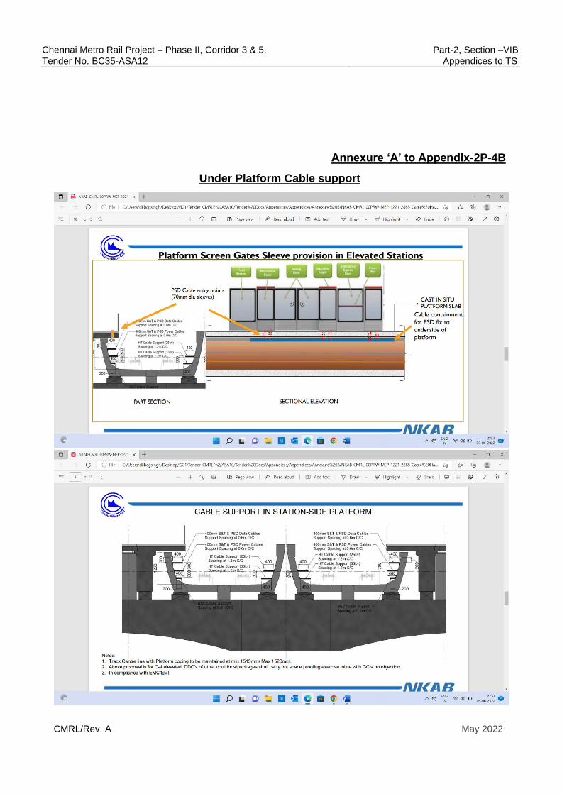
Chennai Metro Rail Project – Phase II, Corridor 3 & 5. Part-2, Section –VIB
Tender No. BC35-ASA12 Appendices to TS
CMRL/Rev. A May 2022
Annexure ‘A’ to Appendix-2P-4B
Under Platform Cable support
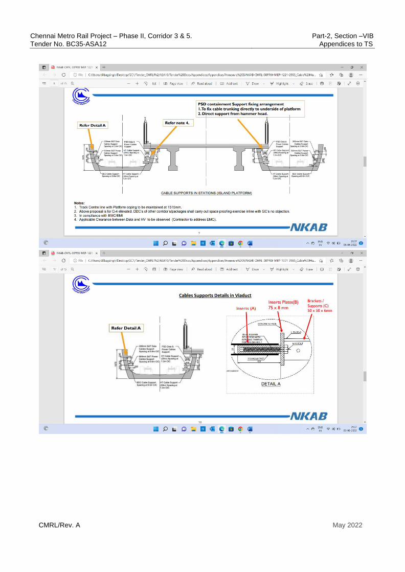
Chennai Metro Rail Project – Phase II, Corridor 3 & 5. Part-2, Section –VIB
Tender No. BC35-ASA12 Appendices to TS
CMRL/Rev. A May 2022

Chennai Metro Rail Project – Phase II, Corridor 3 & 5. Part-2, Section –VIB
Tender No. BC35-ASA12 Appendices to TS
CMRL/Rev. A May 2022
APPENDIX-2P-5
Interface protocol between Track and
Platform Screen Doors (PSD) system
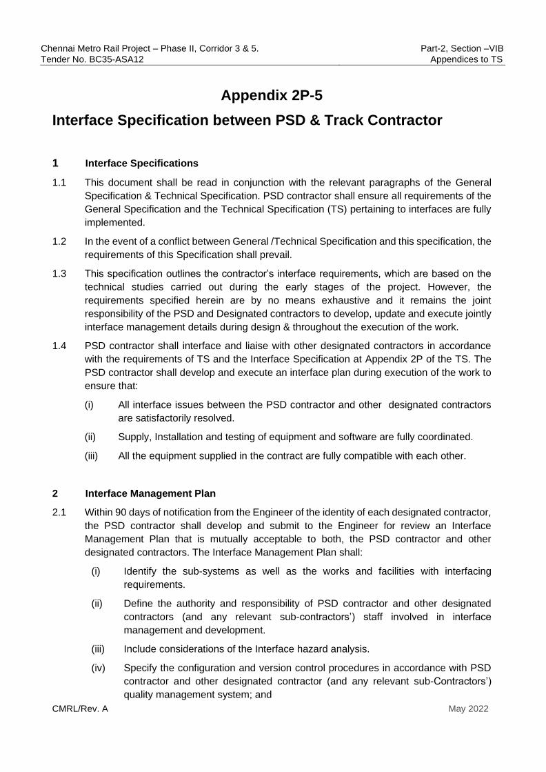
Chennai Metro Rail Project – Phase II, Corridor 3 & 5. Part-2, Section –VIB
Tender No. BC35-ASA12 Appendices to TS
CMRL/Rev. A May 2022
Appendix 2P-5
Interface Specification between PSD & Track Contractor
1 Interface Specifications
1.1 This document shall be read in conjunction with the relevant paragraphs of the General
Specification & Technical Specification. PSD contractor shall ensure all requirements of the
General Specification and the Technical Specification (TS) pertaining to interfaces are fully
implemented.
1.2 In the event of a conflict between General /Technical Specification and this specification, the
requirements of this Specification shall prevail.
1.3 This specification outlines the contractor’s interface requirements, which are based on the
technical studies carried out during the early stages of the project. However, the
requirements specified herein are by no means exhaustive and it remains the joint
responsibility of the PSD and Designated contractors to develop, update and execute jointly
interface management details during design & throughout the execution of the work.
1.4 PSD contractor shall interface and liaise with other designated contractors in accordance
with the requirements of TS and the Interface Specification at Appendix 2P of the TS. The
PSD contractor shall develop and execute an interface plan during execution of the work to
ensure that:
(i) All interface issues between the PSD contractor and other designated contractors
are satisfactorily resolved.
(ii) Supply, Installation and testing of equipment and software are fully coordinated.
(iii) All the equipment supplied in the contract are fully compatible with each other.
2 Interface Management Plan
2.1 Within 90 days of notification from the Engineer of the identity of each designated contractor,
the PSD contractor shall develop and submit to the Engineer for review an Interface
Management Plan that is mutually acceptable to both, the PSD contractor and other
designated contractors. The Interface Management Plan shall:
(i) Identify the sub-systems as well as the works and facilities with interfacing
requirements.
(ii) Define the authority and responsibility of PSD contractor and other designated
contractors (and any relevant sub-contractors’) staff involved in interface
management and development.
(iii) Include considerations of the Interface hazard analysis.
(iv) Specify the configuration and version control procedures in accordance with PSD
contractor and other designated contractor (and any relevant sub-Contractors’)
quality management system; and
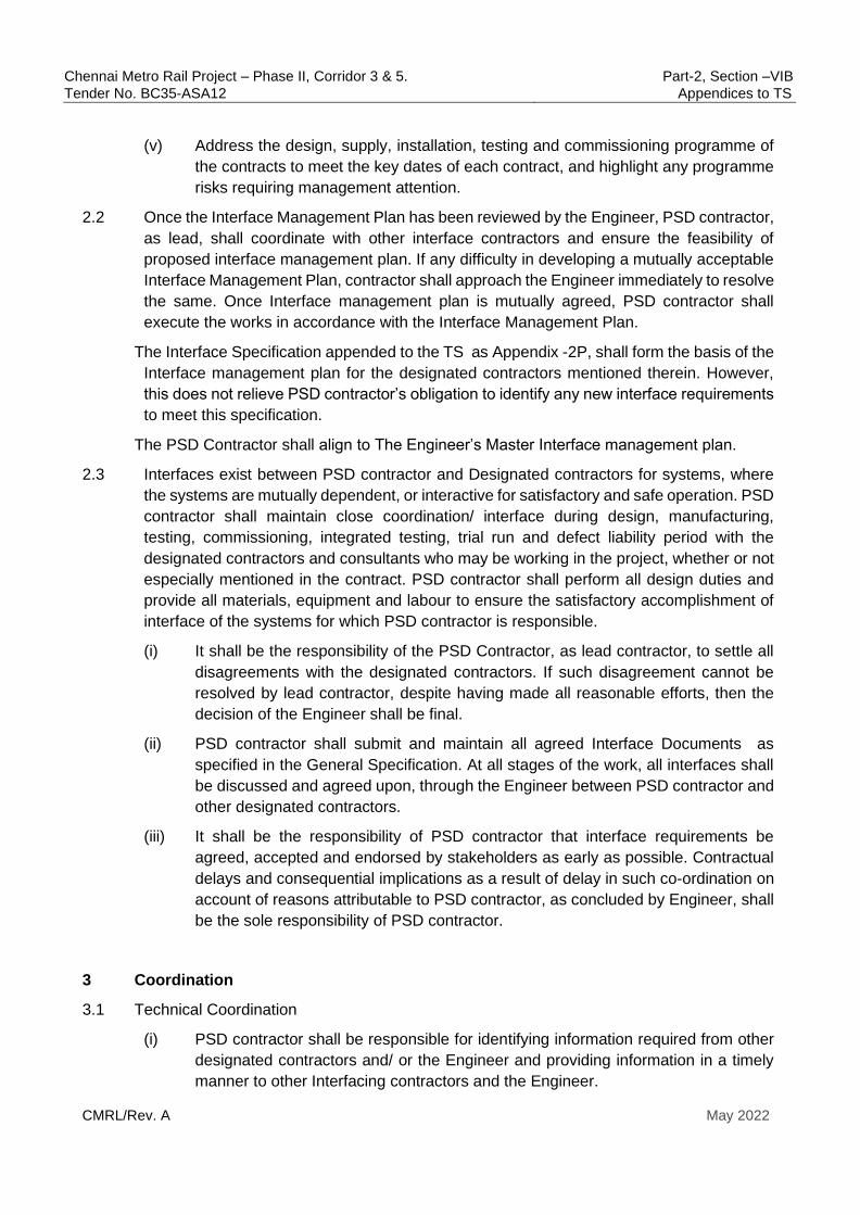
Chennai Metro Rail Project – Phase II, Corridor 3 & 5. Part-2, Section –VIB
Tender No. BC35-ASA12 Appendices to TS
CMRL/Rev. A May 2022
(v) Address the design, supply, installation, testing and commissioning programme of
the contracts to meet the key dates of each contract, and highlight any programme
risks requiring management attention.
2.2 Once the Interface Management Plan has been reviewed by the Engineer, PSD contractor,
as lead, shall coordinate with other interface contractors and ensure the feasibility of
proposed interface management plan. If any difficulty in developing a mutually acceptable
Interface Management Plan, contractor shall approach the Engineer immediately to resolve
the same. Once Interface management plan is mutually agreed, PSD contractor shall
execute the works in accordance with the Interface Management Plan.
The Interface Specification appended to the TS as Appendix -2P, shall form the basis of the
Interface management plan for the designated contractors mentioned therein. However,
this does not relieve PSD contractor’s obligation to identify any new interface requirements
to meet this specification.
The PSD Contractor shall align to The Engineer’s Master Interface management plan.
2.3 Interfaces exist between PSD contractor and Designated contractors for systems, where
the systems are mutually dependent, or interactive for satisfactory and safe operation. PSD
contractor shall maintain close coordination/ interface during design, manufacturing,
testing, commissioning, integrated testing, trial run and defect liability period with the
designated contractors and consultants who may be working in the project, whether or not
especially mentioned in the contract. PSD contractor shall perform all design duties and
provide all materials, equipment and labour to ensure the satisfactory accomplishment of
interface of the systems for which PSD contractor is responsible.
(i) It shall be the responsibility of the PSD Contractor, as lead contractor, to settle all
disagreements with the designated contractors. If such disagreement cannot be
resolved by lead contractor, despite having made all reasonable efforts, then the
decision of the Engineer shall be final.
(ii) PSD contractor shall submit and maintain all agreed Interface Documents as
specified in the General Specification. At all stages of the work, all interfaces shall
be discussed and agreed upon, through the Engineer between PSD contractor and
other designated contractors.
(iii) It shall be the responsibility of PSD contractor that interface requirements be
agreed, accepted and endorsed by stakeholders as early as possible. Contractual
delays and consequential implications as a result of delay in such co-ordination on
account of reasons attributable to PSD contractor, as concluded by Engineer, shall
be the sole responsibility of PSD contractor.
3 Coordination
3.1 Technical Coordination
(i) PSD contractor shall be responsible for identifying information required from other
designated contractors and/ or the Engineer and providing information in a timely
manner to other Interfacing contractors and the Engineer.
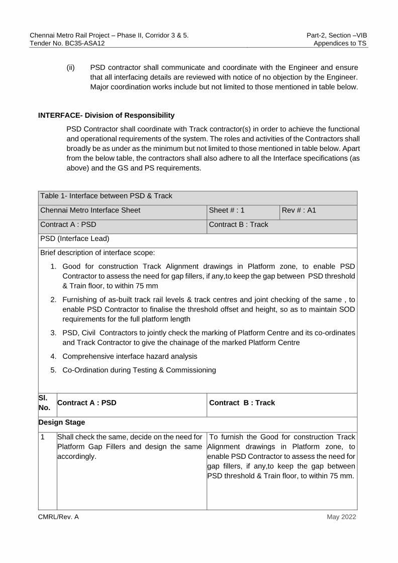
Chennai Metro Rail Project – Phase II, Corridor 3 & 5. Part-2, Section –VIB
Tender No. BC35-ASA12 Appendices to TS
CMRL/Rev. A May 2022
(ii) PSD contractor shall communicate and coordinate with the Engineer and ensure
that all interfacing details are reviewed with notice of no objection by the Engineer.
Major coordination works include but not limited to those mentioned in table below.
INTERFACE- Division of Responsibility
PSD Contractor shall coordinate with Track contractor(s) in order to achieve the functional
and operational requirements of the system. The roles and activities of the Contractors shall
broadly be as under as the minimum but not limited to those mentioned in table below. Apart
from the below table, the contractors shall also adhere to all the Interface specifications (as
above) and the GS and PS requirements.
Table 1- Interface between PSD & Track
Chennai Metro Interface Sheet Sheet # : 1 Rev # : A1
Contract A : PSD Contract B : Track
PSD (Interface Lead)
Brief description of interface scope:
1. Good for construction Track Alignment drawings in Platform zone, to enable PSD
Contractor to assess the need for gap fillers, if any,to keep the gap between PSD threshold
& Train floor, to within 75 mm
2. Furnishing of as-built track rail levels & track centres and joint checking of the same , to
enable PSD Contractor to finalise the threshold offset and height, so as to maintain SOD
requirements for the full platform length
3. PSD, Civil Contractors to jointly check the marking of Platform Centre and its co-ordinates
and Track Contractor to give the chainage of the marked Platform Centre
4. Comprehensive interface hazard analysis
5. Co-Ordination during Testing & Commissioning
Sl.
No. Contract A : PSD Contract B : Track
Design Stage
1
Shall check the same, decide on the need for
Platform Gap Fillers and design the same
accordingly.
To furnish the Good for construction Track
Alignment drawings in Platform zone, to
enable PSD Contractor to assess the need for
gap fillers, if any,to keep the gap between
PSD threshold & Train floor, to within 75 mm.
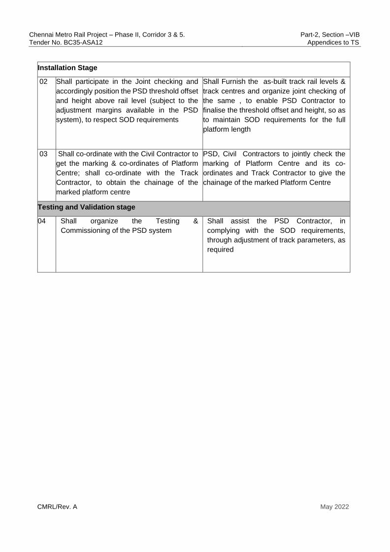
Chennai Metro Rail Project – Phase II, Corridor 3 & 5. Part-2, Section –VIB
Tender No. BC35-ASA12 Appendices to TS
CMRL/Rev. A May 2022
Installation Stage
02 Shall participate in the Joint checking and
accordingly position the PSD threshold offset
and height above rail level (subject to the
adjustment margins available in the PSD
system), to respect SOD requirements
Shall Furnish the as-built track rail levels &
track centres and organize joint checking of
the same , to enable PSD Contractor to
finalise the threshold offset and height, so as
to maintain SOD requirements for the full
platform length
03 Shall co-ordinate with the Civil Contractor to
get the marking & co-ordinates of Platform
Centre; shall co-ordinate with the Track
Contractor, to obtain the chainage of the
marked platform centre
PSD, Civil Contractors to jointly check the
marking of Platform Centre and its co-
ordinates and Track Contractor to give the
chainage of the marked Platform Centre
Testing and Validation stage
04 Shall organize the Testing &
Commissioning of the PSD system
Shall assist the PSD Contractor, in
complying with the SOD requirements,
through adjustment of track parameters, as
required
Chennai Metro Rail Project – Phase II, Corridor 3 & 5. Part-2, Section –VIB
Tender No. BC35-ASA12 Appendices to TS
CMRL/Rev. A May 2022
Appendix-2P-6A
Interface protocol between MEP (UG) and
Platform Screen Doors (PSD) system (Full
Height)

Chennai Metro Rail Project – Phase II, Corridor 3 & 5. Part-2, Section –VIB
Tender No. BC35-ASA12 Appendices to TS
CMRL/Rev. A May 2022
Appendix 2P-6A
Interface Specification between FHPSD & MEP Contractor
1 Interface Specifications
1.1 This document shall be read in conjunction with the relevant paragraphs of the General
Specification & Technical Specification. PSD contractor shall ensure all requirements of the
General Specification and the Technical Specification (TS) pertaining to interfaces are fully
implemented.
1.2 In the event of a conflict between General /Technical Specification and this specification, the
requirements of the General/Technical Specification shall prevail.
1.3 This specification outlines the contractor’s interface requirements, which are based on the
technical studies carried out during the early stages of the project. However, the
requirements specified herein are by no means exhaustive and it remains the joint
responsibility of the PSD and Designated contractors to develop, update and execute jointly
interface management details during design & throughout the execution of the work.
1.4 PSD contractor, as lead, shall interface and liaise with other designated contractors in
accordance with the requirements of TS and the Interface Specification at Appendix-2P of
the TS. The PSD contractor shall develop and execute an interface plan during execution of
the work to ensure that:
(i) All interface issues between the PSD contractor and other designated
contractors are satisfactorily resolved.
(ii) Supply, Installation and testing of equipment and software are fully coordinated.
(iii) All the equipment supplied in the contract are fully compatible with each other.
2 Interface Management Plan
2.1 Within 60 days of notification from the Engineer of the identity of each designated contractor,
the PSD contractor shall develop and submit to the Engineer for review an Interface
Management Plan that is mutually acceptable to both, the PSD contractor and other
designated contractors. The Interface Management Plan shall:
(i) Identify the sub-systems as well as the works and facilities with interfacing
requirements.
(ii) Define the authority and responsibility of PSD contractor and other designated
contractors (and any relevant sub-contractors’) staff involved in interface
management and development.
(iii) Include considerations of the Interface hazard analysis.

Chennai Metro Rail Project – Phase II, Corridor 3 & 5. Part-2, Section –VIB
Tender No. BC35-ASA12 Appendices to TS
CMRL/Rev. A May 2022
(iv) Specify the configuration and version control procedures in accordance with PSD
contractor and other designated contractor (and any relevant sub-Contractors’)
quality management system; and
(v) Address the design, supply, installation, testing and commissioning programme of
the contracts to meet the key dates of each contract, and highlight any programme
risks requiring management attention.
2.2 Once the Interface Management Plan has been reviewed by the Engineer, PSD contractor
shall coordinate with other interface contractors and ensure the feasibility of proposed
interface management plan. If any difficulty in developing a mutually acceptable Interface
Management Plan, contractor shall approach the Engineer immediately to resolve the same.
Once Interface management plan is mutually agreed, PSD contractor shall execute the
works in accordance with the Interface Management Plan.
The Interface Specification appended to the TS as Appendix-2P, shall form the basis of the
Interface management plan for the designated contractors mentioned therein. However, this
does not relieve PSD contractor’s obligation to identify any new interface requirements to
meet this specification.
The PSD Contractor shall align to The Engineer’s Master Interface management plan.
2.3 Interfaces exist between PSD contractor and Designated contractors for systems, where the
systems are mutually dependent, or interactive for satisfactory and safe operation. PSD
contractor shall maintain close coordination/ interface during design, manufacturing, testing,
commissioning, integrated testing, trial run and defect liability period with the designated
contractors and consultants who may be working in the project, whether or not especially
mentioned in the contract. PSD contractor shall perform all design duties and provide all
materials, equipment and labour to ensure the satisfactory accomplishment of interface of
the systems for which PSD contractor is responsible.
(i) It shall be the responsibility of the PSD Contractor, as lead contractor, to settle all
disagreements with the designated contractors. If such disagreement cannot be
resolved by lead contractor, despite having made all reasonable efforts, then the
decision of the Engineer shall be final .
(ii) PSD contractor shall submit and maintain all agreed Interface Documents as
specified in the General Specification. At all stages of the work, all interfaces shall be
discussed and agreed upon, through the Engineer between PSD contractor and other
designated contractors.
(iii) It shall be the responsibility of PSD contractor that interface requirements be agreed,
accepted and endorsed by stakeholders as early as possible. Contractual delays and
consequential implications as a result of delay in such co-ordination on account of
reasons attributable to PSD contractor, as concluded by Engineer, shall be the sole
responsibility of PSD contractor.
3 Coordination
3.1 Technical Coordination
Chennai Metro Rail Project – Phase II, Corridor 3 & 5. Part-2, Section –VIB
Tender No. BC35-ASA12 Appendices to TS
CMRL/Rev. A May 2022
(i) PSD contractor shall be responsible for identifying information required from other
designated contractors and/ or the Engineer and providing information in a timely
manner to other Interfacing contractors and the Engineer.
(ii) PSD contractor shall communicate and coordinate with the Engineer and ensure that
all interfacing details are reviewed with notice of no objection by the Engineer. Major
coordination works include but not limited to:
1) Physical routing of all pipe work, cable containment and associated
ancillaries, supports
2) Layouts of PSD Room taking cognizance of lighting (to include maintained
emergency lighting), ECS, drainage, S&TC interface panel, LV cabling, earthing &
cable routing provisions installed by others,
3.2 Earthing and Bonding
3.2.1 MEP Contractor to provide one Main Earth Terminal (MET) at one end of each platform, for
PSD contractor to earth all PSD metal work. At both ends of the each platform, the
AEC/BEC/Return Rail are to be connected to the Station main earth by the Power Supply &
OHE Contractor. This will ensure that PSD metal work & train body are at same potential
and there is no need to provide an insulating layer to isolate the PSD end of the platform
from main building earth. PSD Contractor shall check & ensure this through the PS & OHE
Contractor.
3.2.2 The cable tray will be extended by the MEP Contractors upto PSD room and station control
room and until the entry point to header box and till all the MSDs (at the platform end). PSD
contractor’s responsibility is to install of all control and power cables and provide the
connections to individual devices within PSD room and also to individual doors on the
platform. The extension of the cables to MSDs from the overhead cable trays, through
appropriate race-ways as required, is in the scope of the PSD Contractor.
PSD Contractor will provide necessary tail cables conduits & supports and needs to
coordinate with designated contractors for laying of cable tray along the full length of PSD
and upto both sides MSD locations.
3.2.3 PSD Contractor to ensure through joint checking with the MEP as well as Power Supply &
OHE Contractor that, the MET earth resistance value is less than 1 ohm (<1.0 ohm) ; PSD
Contractor shall also ensure that the lead resistance of the connection from main MET
terminals in the PSD equipment room, Station Control Room as well as at the end of each
platform until the Station main earth , is within the prescribed limits and meets the earthing
requirements of PSD equipment as well as PSD Façade metal work.
3.2.4 Earth Bar in the PSD Equipment room , Station Control room as well as each Platform end,
shall be provided by MEP (The method of terminating PSD earth connections on these Earth
bars, shall be mutually agreed between the PSD & MEP Contractors).
3.3 UPS Power Supply for PSD:
3.3.1 The PSD Contractor shall specify the static condition load as well as operating electrical
loads of the PSD system. PSD Contractor also to specify the number of UPS outlets required
for the PSD and the termination details of the UPS Power supply outlets through circuit

Chennai Metro Rail Project – Phase II, Corridor 3 & 5. Part-2, Section –VIB
Tender No. BC35-ASA12 Appendices to TS
CMRL/Rev. A May 2022
breakers as applicable. The MEP Contractor shall design the UPS system, based on these
requirements. The PSD Contractor shall lay the required number of cables between the UPS
termination point (as mutually agreed) until the PSD equipment room. The electrical
characteristics of the interconnecting cable, shall be mutually agreed.
3.4 EMI/EMC issues
3.4.1 The PSD Contractor shall ensure that the equipment to be supplied & installed, meets the
emission & compatibility requirements as specified in the Contract. The two contractors to
agree on the method of checking and resolving EMC issues, if any, based on the EMC
requirements as per respective contracts.
Table 1- Interface between PSD & MEP (U/G)works
Chennai Metro Interface Sheet Sheet # : 1 Rev # : A1
Contract A : PSD Contract B : MEP (U/G)
PSD (Interface Lead)
Brief description of interface scope:
1. Power requirements for FH PSD.
2. Provision for cable containment within station premises.
3. Installation of cables and PSD equipment’s in stations.
4. Time schedule/Work Sequence
5. Earthing provision for PSD façade & Equipment room cabinets.
6. UPS provision for PSD loads
7. EMC issues resolution
8. Independent test and validation.
9. Comprehensive interface hazard analysis
Sl.
No. Contract A Contract B
Design Stage
01
Shall furnish electrical load requirements
for the PSD Equipment’s. Shall also
propose number of UPS outlets for PSD
load in UPS room, details of protecting
CBs etc.
Shall include the same in power load calculation
and facilitate uninterruptible power supply. The
details of UPS outlets for PSD load in UPS
room, protection CBs etc to be mutually agreed
between the two Contractors.
02 Shall furnish the number of cables,,
dimensions, weight and quantity of cable
trays as well as minimum separation
between them, in respect of connectivity
between SER and SCR and between SER
Shall design the cable routing arrangements
and number of cable trays, based on the
technical requirements of the PSD Contractor
and in co-ordination with the Station Civil
Contractor in respect of space-proofing, cut-

Chennai Metro Rail Project – Phase II, Corridor 3 & 5. Part-2, Section –VIB
Tender No. BC35-ASA12 Appendices to TS
CMRL/Rev. A May 2022
and entry point to header box, outs in walls & Civil structures etc.
03 Shall furnish the earthing arrangements &
termination arrangements for earthing the
PSD metal work on the platforms,
(including MSDs) as also for the PSD
cabinets/work stations in the equipment &
control rooms.
Shall design the earthing arrangement &
termination arrangements, as per the
requirements of the PSD Contractor.
04 Shall furnish the EMI/EMC parameters of
the PSD equipment, as specified in the
Contract. Both Contractors to agree on
the methodology of checking & resolving
EMC issues, that might arise during the
progress of the works
Shall furnish the EMI/EMC parameters of the
MEP equipment, as specified in the Contract.
Both Contractors to agree on the methodology
of checking & resolving EMC issues, that might
arise during the progress of the works
Installation stage
05 a) Shall furnish the detailed drawings of
PSD equipment to be installed in SER
and SCR.
b) Shall furnish the detailed drawings &
locations of equipment to be installed like
PSD, EED, MSD as well as MCPs.
a) Shall provide the main cable tray upto PSD
equipment room, SCR and upto the entry point
to header box and also to MSD location to cover
all PSDs & EEDs & ,MSDs for the full usable
length of the platform
b) Shall work together and provide the cable
trays , in co-ordination with the civil contractor.
06 Shall verify the provision of earthing
earth bars and leads from the earth bars
till the Station Main Earth.
Shall design earths and MET earth bars for
Platform screen doors (at all the agreed locations
and as per agreed design, one on each platform
at the ends of PSD and one in the Equipment
room as well as Station Control Room), for
earthing the PSD metal work as also PSD
equipments in the Equipment & Control rooms.
Shall also provide the earth leads from these
earth bars until Station Main Earth..
07 Shall install all control and power cables
and provide the connections to individual
devices. Extension of cabling from the
main cable tray to individual Sliding
Doors, EEDs as well as MSDs, through
concealed conduiting/ race way till the
end device, is in PSD contractor scope,
including till the MCPs.
Cable trays shall be provided in the platform area
till entry to header box, till all the MSDs as well
as till the SER as well as SCR
08 Shall lay the cable to take the UPS power
from UPS room and extend the power to
Shall provide the required UPS output
terminations through circuit breakers , in the

Chennai Metro Rail Project – Phase II, Corridor 3 & 5. Part-2, Section –VIB
Tender No. BC35-ASA12 Appendices to TS
CMRL/Rev. A May 2022
the PSD equipment room. UPS room.
09 Shall work in close co-ordination with
MEP Contractor, to ensure smooth
progress of works, duly avoiding damage
to structures / Equipment / Cables,
already installed.
Shall make out a schedule for sequencing of
works and associated duration, with a view to
provide proper site access to PSD Contractor, to
ensure smooth progress of works , duly avoiding
damage to structures / Equipment / Cables
already installed.
Testing and Validation stage
10
(a) Shall check that the values are within
the agreed limits
(b) Shall ensure through PS & OHE
Contractor that the return rails/AEC &
BEC are bonded together and connected
to Station main earth at both ends of the
platform.
(C ) Shall attend the joint test and ensure
that the continuity & lead resistance
values , meet the earthing requirements
of the PSD System.
a) Shall provide joint test results of main earth
pit with the PS & OHE Contractor, in support of
the value being less than 1 ohm.
(b) Shall also ensure the connection of return
rails/AEC/BEC to the Station main earth at both
ends of the platform
(C ) Shall organise joint test of earth lead
resistance from Main earth bars at each Platform
end/SCR/SER until the main earth pit and
demonstrate that the value meets the earthing
requirements of the PSD system.
11 The interconnecting cable should be
jointly tested by the two Contractors.
Shall test the PSD cable between equipment
room & UPS room and switch on the UPS power,
as per jointly agreed work schedule.
12
Carryout Independent test and validation
of complete PSD system.
Support necessary agreed interface
requirements to carryout PSD Independent test
and validation of complete PSD system
13
If any modification on MEP works
becomes necessary, same shall be
coordinated during comprehensive
interface hazard analysis in accordance
with the relevant system safety and
assurance standards.
Support necessary agreed interface
requirements to carryout comprehensive
interface hazard analysis.
14
In case any EMC issues are identified
during Testing & Commissioning, both
Contractors to co-ordinate, analyse the
problem and take corrective measures
for their part based on EMC
specifications of their Contract.
In case any EMC issues are identified during
Testing & Commissioning, both Contractors to
co-ordinate, analyse the problem and take
corrective measures for their part based on EMC
specifications of their Contract.

Chennai Metro Rail Project – Phase II, Corridor 3 & 5. Part-2, Section –VIB
Tender No. BC35-ASA12 Appendices to TS
CMRL/Rev. A May 2022
APPENDIX-2P-6B
Interface protocol between MEP (Elevated)
and Platform Screen Doors (PSD) system

Chennai Metro Rail Project – Phase II, Corridor 3 & 5. Part-2, Section –VIB
Tender No. BC35-ASA12 Appendices to TS
CMRL/Rev. A May 2022
Appendix 2P-6B
Interface Specification between HHPSD & MEP Contractor
1 Interface Specifications
1.1 This document shall be read in conjunction with the relevant paragraphs of the General
Specification & Technical Specification. PSD contractor shall ensure all requirements of the
General Specification and the Technical Specification (TS) pertaining to interfaces are fully
implemented.
1.2 In the event of a conflict between General /Technical Specification and this specification, the
requirements of the General/Technical Specification shall prevail.
1.3 This specification outlines the contractor’s interface requirements, which are based on the
technical studies carried out during the early stages of the project. However, the
requirements specified herein are by no means exhaustive and it remains the joint
responsibility of the PSD and Designated contractors to develop, update and execute jointly
interface management details during design & throughout the execution of the work.
1.4 PSD contractor, as lead, shall interface and liaise with other designated contractors in
accordance with the requirements of TS and the Interface Specification at Appendix 2P of
the TS. The PSD contractor shall develop and execute an interface plan during execution of
the work to ensure that:
(i) All interface issues between the PSD contractor and other designated contractors
are satisfactorily resolved.
(ii) Supply, Installation and testing of equipment and software are fully coordinated.
(iii) All the equipment supplied in the contract are fully compatible with each other.
2 Interface Management Plan
2.1 Within 60 days of notification from the Engineer of the identity of each designated contractor,
the PSD contractor shall develop and submit to the Engineer for review an Interface
Management Plan that is mutually acceptable to both, the PSD contractor and other
designated contractors. The Interface Management Plan shall:
(i) Identify the sub-systems as well as the works and facilities with interfacing
requirements.
(ii) Define the authority and responsibility of PSD contractor and other designated
contractors (and any relevant sub-contractors’) staff involved in interface
management and development.
(iii) Include considerations of the Interface hazard analysis.

Chennai Metro Rail Project – Phase II, Corridor 3 & 5. Part-2, Section –VIB
Tender No. BC35-ASA12 Appendices to TS
CMRL/Rev. A May 2022
(iv) Specify the configuration and version control procedures in accordance with PSD
contractor and other designated contractor (and any relevant sub-Contractors’)
quality management system; and
(v) Address the design, supply, installation, testing and commissioning programme of
the contracts to meet the key dates of each contract, and highlight any programme
risks requiring management attention.
2.2 Once the Interface Management Plan has been reviewed by the Engineer, PSD contractor
shall coordinate with other interface contractors and ensure the feasibility of proposed
interface management plan. If any difficulty in developing a mutually acceptable Interface
Management Plan, contractor shall approach the Engineer immediately to resolve the same.
Once Interface management plan is mutually agreed, PSD contractor shall execute the
works in accordance with the Interface Management Plan.
The Interface Specification appended to the TS as Appendix 2P, shall form the basis of the
Interface management plan for the designated contractors mentioned therein. However, this
does not relieve PSD contractor’s obligation to identify any new interface requirements to
meet this specification.
The PSD Contractor shall align to The Engineer’s Master Interface management plan.
2.3 Interfaces exist between PSD contractor and Designated contractors for systems, where the
systems are mutually dependent, or interactive for satisfactory and safe operation. PSD
contractor shall maintain close coordination/ interface during design, manufacturing, testing,
commissioning, integrated testing, trial run and defect liability period with the designated
contractors and consultants who may be working in the project, whether or not especially
mentioned in the contract. PSD contractor shall perform all design duties and provide all
materials, equipment and labour to ensure the satisfactory accomplishment of interface of
the systems for which PSD contractor is responsible.
(i) It shall be the responsibility of the PSD Contractor, as lead contractor, to settle all
disagreements with the designated contractors. If such disagreement cannot be
resolved by lead contractor, despite having made all reasonable efforts, then the
decision of the Engineer shall be final .
(ii) PSD contractor shall submit and maintain all agreed Interface Documents as
specified in the General Specification. At all stages of the work, all interfaces shall
be discussed and agreed upon, through the Engineer between PSD contractor and
other designated contractors.
(iii) It shall be the responsibility of PSD contractor that interface requirements be agreed,
accepted and endorsed by stakeholders as early as possible. Contractual delays and
consequential implications as a result of delay in such co-ordination on account of
reasons attributable to PSD contractor, as concluded by Engineer, shall be the sole
responsibility of PSD contractor.
3 Coordination
3.1 Technical Coordination

Chennai Metro Rail Project – Phase II, Corridor 3 & 5. Part-2, Section –VIB
Tender No. BC35-ASA12 Appendices to TS
CMRL/Rev. A May 2022
(i) PSD contractor shall be responsible for identifying information required from other
designated contractors and/ or the Engineer and providing information in a timely
manner to other Interfacing contractors and the Engineer.
(ii) PSD contractor shall communicate and coordinate with the Engineer and ensure that
all interfacing details are reviewed with notice of no objection by the Engineer. Major
coordination works include but not limited to:
1) Physical routing of all pipe work, cable containment and associated
ancillaries, supports
2) Layouts of PSD Room taking cognizance of lighting (to include maintained
emergency lighting), ECS, drainage, S&TC interface panel, LV cabling,
earthing & cable routing provisions installed by others,
3.2 Earthing and Bonding
3.2.1 MEP Contractor to provide one Main Earth Terminal (MET) at one end of each platform, for
PSD contractor to earth all PSD metal work. At both ends of the each platform, the
AEC/BEC/Return Rail are to be connected to the Station main earth by the Power Supply &
OHE Contractor. This will ensure that PSD metal work & train body are at same potential
and there is no need to provide an insulating layer to isolate the PSD end of the platform
from main building earth. PSD Contractor shall check & ensure this through the PS & OHE
Contractor.
3.2.2 The cable tray will be extended by the MEP Contractors upto PSD room & Station control
room and until the entry point to the cable supports under the platform coping. PSD
contractor’s responsibility is to install all control and power cables and provide the
connections to individual devices within PSD room and also to individual doors on the
platform. The extension of the cables to MSDs from the main cable trunking under the
platform coping, through appropriate race-ways as required, is in the scope of the PSD
Contractor.
PSD Contractor will provide necessary tail cables conduits & supports and needs to
coordinate with designated contractors for laying of cable tray along the full length of PSD
and upto both sides MSD locations.
3.2.3 PSD Contractor to ensure through joint checking with the MEP as well as Power Supply &
OHE Contractor that, the MET earth resistance value is less than 1 ohm (<1.0 ohm) ; PSD
Contractor shall also ensure that the lead resistance of the connection from main MET
terminals in the PSD equipment room, Station Control Room as well as at the end of each
platform until the Station main earth , is within the prescribed limits and meets the earthing
requirements of PSD equipment as well as PSD Façade metal work.
3.2.4 Earth Bar in the PSD Equipment room , Station Control room as well as each Platform end,
shall be provided by MEP (The method of terminating PSD earth connections on these Earth
bars, shall be mutually agreed between the PSD & MEP Contractors).
3.3 UPS Power Supply for PSD:
3.3.1 The PSD Contractor shall specify the static condition load as well as operating electrical
loads of the PSD system. PSD Contractor also to specify the number of UPS outlets required

Chennai Metro Rail Project – Phase II, Corridor 3 & 5. Part-2, Section –VIB
Tender No. BC35-ASA12 Appendices to TS
CMRL/Rev. A May 2022
for the PSD and the termination details of the UPS Power supply outlets through circuit
breakers as applicable. The MEP Contractor shall design the UPS system, based on these
requirements. The PSD Contractor shall lay the required number of cables between the UPS
termination point (as mutually agreed) until the PSD equipment room. The electrical
characteristics of the interconnecting cable, shall be mutually agreed.
3.4 Heat load for Air-Conditioning
3.4.1 The PSD Contractor shall advise the heat load generated by PSD equipment in the SER.
Also the locations of cabinets/panels etc inside the room. The MEP shall take this into
account in designing the Air-Conditioning system for the PSD equipment room and also in
locating the AC ducts etc in such a manner as to avoid water condensation over PSD
cabinets/panels.
3.5 EMI/EMC issues
3.5.1 The PSD Contractor shall ensure that the equipment to be supplied & installed, meets the
emission & compatibility requirements as specified in the Contract. The two contractors to
agree on the method of checking and resolving EMC issues, if any, based on the EMC
requirements as per respective contracts.
Table 1- Interface between PSD & MEP works
Chennai Metro Interface Sheet Sheet # : 1 Rev # : A1
Contract A : PSD Contract B : MEP
PSD (Interface Lead)
Brief description of interface scope:
1. Power requirements for HH PSD.
2. Provision for cable containment within station premises.
3. Installation of cables and PSD equipment’s in stations.
4. Time schedule/Work Sequence
5. Earthing provision for PSD façade & Equipment room cabinets.
6. UPS provision for PSD loads
7. EMC issues resolution
8. Independent test and validation.
9. Comprehensive interface hazard analysis
Sl.
No. Contract A Contract B
Design Stage
01
Shall furnish electrical load requirements for
the PSD Equipment’s. Shall also propose
number of UPS outlets for PSD load in UPS
room, details of protecting CBs etc.
Shall include the same in power load
calculation and facilitate uninterruptible power
supply. The details of UPS outlets for PSD load
in UPS room, protection CBs etc to be mutually
agreed between the two Contractors.
02 Shall furnish the number of cables,,
dimensions, weight and quantity of cable trays
Shall design the cable routing arrangements
and number of cable trays, based on the

Chennai Metro Rail Project – Phase II, Corridor 3 & 5. Part-2, Section –VIB
Tender No. BC35-ASA12 Appendices to TS
CMRL/Rev. A May 2022
as well as minimum separation between them,
in respect of connectivity between SER and
SCR and between SER and entry point to the
cable supports under the Platform coping,
technical requirements of the PSD Contractor
and in co-ordination with the Station Civil
Contractor in respect of space-proofing, cut-
outs in walls & Civil structures etc.
03 Shall furnish the earthing arrangements &
termination arrangements for earthing the
PSD metal work on the platforms, (including
MSDs) as also for the PSD cabinets/work
stations in the equipment & control rooms.
Shall design the earthing arrangement &
termination arrangements, as per the
requirements of the PSD Contractor.
04 PSD shall advise the heat load generated by
PSD equipment in the SER. Also the locations
of cabinets/panels etc inside the room
Shall take this into account in designing the Air-
Conditioning system for the PSD equipment
room and also in locating the AC ducts etc in
such a manner as to avoid water condensation
over PSD cabinets/panels.
05 Shall furnish the EMI/EMC parameters of the
PSD equipment, as specified in the Contract.
Both Contractors to agree on the methodology
of checking & resolving EMC issues, that
might arise during the progress of the works
Shall furnish the EMI/EMC parameters of the
MEP equipment, as specified in the Contract.
Both Contractors to agree on the methodology
of checking & resolving EMC issues, that might
arise during the progress of the works
Installation stage
06 b) Shall furnish the detailed drawings of PSD
equipment to be installed in SER and
SCR.
b) Shall furnish the detailed drawings &
locations of equipment to be installed like
PSD, EED, MSD as well as MCPs.
a) Shall provide the main cable tray upto PSD
equipment room, SCR and upto the entry point
to the cable trunking beneath the platform coping
,to cover all PSDs & EEDs & MSDs for the full
usable length of the platform
b) Shall work together and provide the cable
trays , in co-ordination with the civil contractor.
07 Shall verify the provision of earthing earth
bars and leads from the earth bars till the
Station Main Earth.
Shall design earths and MET earth bars for
Platform screen doors ( at all the agreed
locations and as per agreed design, one on each
platform at the ends of PSD and one in the
Equipment room as well as Station Control
Room ), for earthing the PSD metal work as also
PSD equipments in the Equipment & Control
rooms. Shall also provide the earth leads from
these earth bars until Station Main Earth..
08 Shall install all control and power cables and
provide the connections to individual devices.
Provision of conduits of required sizes and at
required spacing ,based on EMC
requirements, over the cable tray supports
Cable trays shall be provided in the platform area
till entry to cable trunking beneath the Platform
coping , as well as till the SER as well as SCR

Chennai Metro Rail Project – Phase II, Corridor 3 & 5. Part-2, Section –VIB
Tender No. BC35-ASA12 Appendices to TS
CMRL/Rev. A May 2022
beneath the Platform coping is in the scope
of the PSD Contractor. Extension of cabling
from the main cable trunking beneath the
Platform coping, to individual Sliding Doors,
EEDs as well as MSDs, through concealed
conduiting/ race way till the end device, is in
PSD contractor scope, including till the
MCPs.
09 Shall lay the cable to take the UPS power
from UPS room and extend the power to the
PSD equipment room.
Shall provide the required UPS output
terminations through circuit breakers , in the
UPS room.
10 Shall work in close co-ordination with MEP
Contractor, to ensure smooth progress of
works, duly avoiding damage to structures /
Equipment / Cables, already installed..
Shall make out a schedule for sequencing of
works and associated duration, with a view to
provide proper site access to PSD Contractor, to
ensure smooth progress of works , duly avoiding
damage to structures / Equipment / Cables
already installed.
Testing and Validation stage
11
(a) Shall check that the values are within the
agreed limits
(b) Shall ensure through PS & OHE
Contractor that the return rails/AEC & BEC
are bonded together and connected to
Station main earth at both ends of the
platform.
(C ) Shall attend the joint test and ensure that
the continuity & lead resistance values , meet
the earthing requirements of the PSD
System.
a) Shall provide joint test results of main earth
pit with the PS & OHE Contractor, in support of
the value being less than 1 ohm.
(b) Shall also ensure the connection of return
rails/AEC/BEC to the Station main earth at both
ends of the platform
(C ) Shall organise joint test of earth lead
resistance from Main earth bars at each Platform
end/SCR/SER until the main earth pit and
demonstrate that the value meets the earthing
requirements of the PSD system.
12 The interconnecting cable should be jointly
tested by the two Contractors.
Shall test the PSD cable between equipment
room & UPS room and switch on the UPS power,
as per jointly agreed work schedule.
13
Carryout Independent test and validation of
complete PSD system.
Support necessary agreed interface
requirements to carryout PSD Independent test
and validation of complete PSD system
14
If any modification on MEP works becomes
necessary, same shall be coordinated during
comprehensive interface hazard analysis in
accordance with the relevant system safety
and assurance standards.
Support necessary agreed interface
requirements to carryout comprehensive
interface hazard analysis.

Chennai Metro Rail Project – Phase II, Corridor 3 & 5. Part-2, Section –VIB
Tender No. BC35-ASA12 Appendices to TS
CMRL/Rev. A May 2022
15
In case any EMC issues are identified during
Testing & Commissioning, both Contractors
to co-ordinate, analyse the problem and take
corrective measures for their part based on
EMC specifications of their Contract.
In case any EMC issues are identified during
Testing & Commissioning, both Contractors to
co-ordinate, analyse the problem and take
corrective measures for their part based on EMC
specifications of their Contract.
APPENDIX-2P-7
Interface protocol between VAC and
Platform Screen Doors (PSD) system
(Full Height)
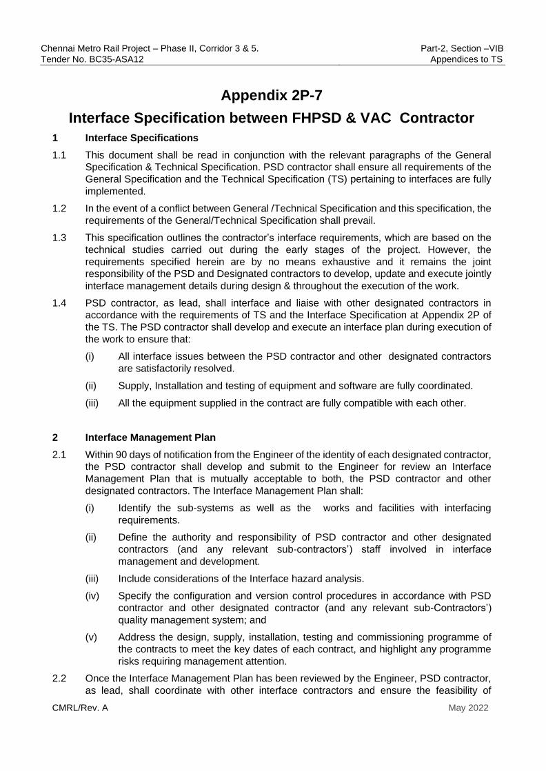
Chennai Metro Rail Project – Phase II, Corridor 3 & 5. Part-2, Section –VIB
Tender No. BC35-ASA12 Appendices to TS
CMRL/Rev. A May 2022
Appendix 2P-7
Interface Specification between FHPSD & VAC Contractor
1 Interface Specifications
1.1 This document shall be read in conjunction with the relevant paragraphs of the General
Specification & Technical Specification. PSD contractor shall ensure all requirements of the
General Specification and the Technical Specification (TS) pertaining to interfaces are fully
implemented.
1.2 In the event of a conflict between General /Technical Specification and this specification, the
requirements of the General/Technical Specification shall prevail.
1.3 This specification outlines the contractor’s interface requirements, which are based on the
technical studies carried out during the early stages of the project. However, the
requirements specified herein are by no means exhaustive and it remains the joint
responsibility of the PSD and Designated contractors to develop, update and execute jointly
interface management details during design & throughout the execution of the work.
1.4 PSD contractor, as lead, shall interface and liaise with other designated contractors in
accordance with the requirements of TS and the Interface Specification at Appendix 2P of
the TS. The PSD contractor shall develop and execute an interface plan during execution of
the work to ensure that:
(i) All interface issues between the PSD contractor and other designated contractors
are satisfactorily resolved.
(ii) Supply, Installation and testing of equipment and software are fully coordinated.
(iii) All the equipment supplied in the contract are fully compatible with each other.
2 Interface Management Plan
2.1 Within 90 days of notification from the Engineer of the identity of each designated contractor,
the PSD contractor shall develop and submit to the Engineer for review an Interface
Management Plan that is mutually acceptable to both, the PSD contractor and other
designated contractors. The Interface Management Plan shall:
(i) Identify the sub-systems as well as the works and facilities with interfacing
requirements.
(ii) Define the authority and responsibility of PSD contractor and other designated
contractors (and any relevant sub-contractors’) staff involved in interface
management and development.
(iii) Include considerations of the Interface hazard analysis.
(iv) Specify the configuration and version control procedures in accordance with PSD
contractor and other designated contractor (and any relevant sub-Contractors’)
quality management system; and
(v) Address the design, supply, installation, testing and commissioning programme of
the contracts to meet the key dates of each contract, and highlight any programme
risks requiring management attention.
2.2 Once the Interface Management Plan has been reviewed by the Engineer, PSD contractor,
as lead, shall coordinate with other interface contractors and ensure the feasibility of

Chennai Metro Rail Project – Phase II, Corridor 3 & 5. Part-2, Section –VIB
Tender No. BC35-ASA12 Appendices to TS
CMRL/Rev. A May 2022
proposed interface management plan. If any difficulty in developing a mutually acceptable
Interface Management Plan, contractor shall approach the Engineer immediately to resolve
the same. Once Interface management plan is mutually agreed, PSD contractor shall
execute the works in accordance with the Interface Management Plan.
The Interface Specification appended to the TS as Appendix 2P, shall form the basis of the
Interface management plan for the designated contractors mentioned therein. However, this
does not relieve PSD contractor’s obligation to identify any new interface requirements to
meet this specification.
The PSD Contractor shall align to The Engineer’s Master Interface management plan.
2.3 Interfaces exist between PSD contractor and Designated contractors for systems, where the
systems are mutually dependent, or interactive for satisfactory and safe operation. PSD
contractor shall maintain close coordination/ interface during design, manufacturing, testing,
commissioning, integrated testing, trial run and defect liability period with the designated
contractors and consultants who may be working in the project, whether or not especially
mentioned in the contract. PSD contractor shall perform all design duties and provide all
materials, equipment and labour to ensure the satisfactory accomplishment of interface of
the systems for which PSD contractor is responsible.
(i) It shall be the responsibility of the PSD Contractor, as lead contractor, to settle all
disagreements with the designated contractors. If such disagreement cannot be
resolved by lead contractor, despite having made all reasonable efforts, then the
decision of the Engineer shall be final .
(ii) PSD contractor shall submit and maintain all agreed Interface Documents as
specified in the General Specification. At all stages of the work, all interfaces shall
be discussed and agreed upon, through the Engineer between PSD contractor and
other designated contractors.
(iii) It shall be the responsibility of PSD contractor that interface requirements be agreed,
accepted and endorsed by stakeholders as early as possible. Contractual delays and
consequential implications as a result of delay in such co-ordination on account of
reasons attributable to PSD contractor, as concluded by Engineer, shall be the sole
responsibility of PSD contractor.
3 Coordination
3.1 Technical Coordination
(i) PSD contractor, as lead, shall be responsible for identifying information required from
other designated contractors and/ or the Engineer and providing information in a
timely manner to other Interfacing contractors and the Engineer.
(ii) PSD contractor shall communicate and coordinate with the Engineer and ensure that
all interfacing details are reviewed with notice of no objection by the Engineer. Major
coordination works include but not limited to:
INTERFACE- Division of Responsibility
PSD Contractor shall coordinate with VAC contractor(s) in order to achieve the functional and operational requirements of the system. The roles and activities of the Contractors shall broadly be as under as the minimum but not limited to those mentioned in table below. Apart

Chennai Metro Rail Project – Phase II, Corridor 3 & 5. Part-2, Section –VIB
Tender No. BC35-ASA12 Appendices to TS
CMRL/Rev. A May 2022
from the below table, the contractors shall also adhere to all the Interface specifications (as above) and the GS and PS requirements.
Table 1- Interface between FH PSD & VAC works
Chennai Metro Interface Sheet Sheet # : 1 Rev # : A1
Contract A : PSD Contract B: VAC
PSD (Interface Lead)
Brief description of interface scope:
1. Heat Load of the PSD system as well as the lay-out of cabinets & panels in the
Equipment room, to enable the VAC Contractor to design the VAC system as per PSD
heat loads and in a way to avoid condensation over PSD cabinets & panels
2. Co-Ordination during installation stage
3. Provision of VAC system in time to meet the Testing & Commissioning needs of the PSD
system
4. Comprehensive interface hazard analysis
5. Co-Ordination during Testing & Commissioning
S.
No. Contract A Contract B
Design Stage
01
To furnish the Heat Load of the PSD system
as well as the lay-out of cabinets & panels in
the Equipment room, to enable the VAC
Contractor to design the VAC system as per
PSD heat loads and in a way to avoid
condensation over PSD cabinets & panels.
To Design the VAC system, based on
inputs provided by the PSD Contractor.
Installation Stage
02 Shall install the PSD system , duly taking care
to avoid damage to VAC equipment, piping &
ducts
Shall install the VAC system , duly taking
care to avoid condensation over PSD
cabinets/panels and also taking care to
avoid damage to PSD cabinets/panels/
cables/cable trays as well as Platform PSD
equipment
Testing and Validation stage
Chennai Metro Rail Project – Phase II, Corridor 3 & 5. Part-2, Section –VIB
Tender No. BC35-ASA12 Appendices to TS
CMRL/Rev. A May 2022
03
Shall organize the Testing & Commissioning
of the PSD system
Shall arrange for commissioning of VAC
system as per PSD T&C schedule and
provide all necessary assistance during
T&C stage, to ensure smooth functioning
of the VAC System
APPENDIX-2P-8
Interface protocol between TVS and
Platform Screen Doors (PSD) system
(Full Height)
Chennai Metro Rail Project – Phase II, Corridor 3 & 5. Part-2, Section –VIB
Tender No. BC35-ASA12 Appendices to TS
CMRL/Rev. A May 2022
Appendix 2P-8
Interface Specification between FHPSD & TVS Contractor
1 Interface Specifications
1.1 This document shall be read in conjunction with the relevant paragraphs of the General
Specification & Technical Specification. PSD contractor shall ensure all requirements of the
General Specification and the Technical Specification (TS) pertaining to interfaces are fully
implemented.
1.2 In the event of a conflict between General /Technical Specification and this specification, the
requirements of the General/Technical Specification shall prevail.
1.3 This specification outlines the contractor’s interface requirements, which are based on the
technical studies carried out during the early stages of the project. However, the
requirements specified herein are by no means exhaustive and it remains the joint
responsibility of the PSD and Designated contractors to develop, update and execute jointly
interface management details during design & throughout the execution of the work.
1.4 PSD contractor, as lead, shall interface and liaise with other designated contractors in
accordance with the requirements of TS and the Interface Specification at Appendix - 2P of
the TS.. The PSD contractor shall develop and execute an interface plan during execution
of the work to ensure that:
(i) All interface issues between the PSD contractor and other designated contractors
are satisfactorily resolved.
(ii) Supply, Installation and testing of equipment and software are fully coordinated.
(iii) All the equipment supplied in the contract are fully compatible with each other.
2 Interface Management Plan
2.1 Within 60 days of notification from the Engineer of the identity of each designated contractor,
the PSD contractor shall develop and submit to the Engineer for review an Interface
Management Plan that is mutually acceptable to both, the PSD contractor and other
designated contractors. The Interface Management Plan shall:
(i) Identify the sub-systems as well as the works and facilities with interfacing
requirements.
(ii) Define the authority and responsibility of PSD contractor and other designated
contractors (and any relevant sub-contractors’) staff involved in interface
management and development.
(iii) Include considerations of the Interface hazard analysis.

Chennai Metro Rail Project – Phase II, Corridor 3 & 5. Part-2, Section –VIB
Tender No. BC35-ASA12 Appendices to TS
CMRL/Rev. A May 2022
(iv) Specify the configuration and version control procedures in accordance with PSD
contractor and other designated contractor (and any relevant sub-Contractors’)
quality management system; and
(v) Address the design, supply, installation, testing and commissioning programme of
the contracts to meet the key dates of each contract, and highlight any programme
risks requiring management attention.
2.2 Once the Interface Management Plan has been reviewed by the Engineer, PSD contractor,
as lead, shall coordinate with other interface contractors and ensure the feasibility of
proposed interface management plan. If any difficulty in developing a mutually acceptable
Interface Management Plan, contractor shall approach the Engineer immediately to resolve
the same. Once Interface management plan is mutually agreed, PSD contractor shall
execute the works in accordance with the Interface Management Plan.
The Interface Specification appended to the TS as Appendix -2P, shall form the basis of the
Interface management plan for the designated contractors mentioned therein. However, this
does not relieve PSD contractor’s obligation to identify any new interface requirements to
meet this specification.
The PSD Contractor shall align to The Engineer’s Master Interface management plan.
2.3 Interfaces exist between PSD contractor and Designated contractors for systems, where the
systems are mutually dependent, or interactive for satisfactory and safe operation. PSD
contractor shall maintain close coordination/ interface during design, manufacturing, testing,
commissioning, integrated testing, trial run and defect liability period with the designated
contractors and consultants who may be working in the project, whether or not especially
mentioned in the contract. PSD contractor shall perform all design duties and provide all
materials, equipment and labour to ensure the satisfactory accomplishment of interface of
the systems for which PSD contractor is responsible.
(i) It shall be the responsibility of the PSD Contractor, as lead contractor, to settle all
disagreements with the designated contractors. If such disagreement cannot be
resolved by lead contractor, despite having made all reasonable efforts, then the
decision of the Engineer shall be final .
(ii) PSD contractor shall submit and maintain all agreed Interface Documents as
specified in the General Specification. At all stages of the work, all interfaces shall
be discussed and agreed upon, through the Engineer between PSD contractor and
other designated contractors.
(iii) It shall be the responsibility of PSD contractor that interface requirements be agreed,
accepted and endorsed by stakeholders as early as possible. Contractual delays and
consequential implications as a result of delay in such co-ordination on account of
reasons attributable to PSD contractor, as concluded by Engineer, shall be the sole
responsibility of PSD contractor.
3 Coordination
3.1 Technical Coordination

Chennai Metro Rail Project – Phase II, Corridor 3 & 5. Part-2, Section –VIB
Tender No. BC35-ASA12 Appendices to TS
CMRL/Rev. A May 2022
(i) PSD contractor, as lead, shall be responsible for identifying information required from
other designated contractors and/ or the Engineer and providing information in a
timely manner to other Interfacing contractors and the Engineer.
(ii) PSD contractor shall communicate and coordinate with the Engineer and ensure that
all interfacing details are reviewed with notice of no objection by the Engineer. Major
coordination works include but not limited to:
INTERFACE- Division of Responsibility
PSD Contractor shall coordinate with TVS contractor(s) in order to achieve the functional and
operational requirements of the system. The roles and activities of the Contractors shall
broadly be as under as the minimum but not limited to those mentioned in table below. Apart
from the below table, the contractors shall also adhere to all the Interface specifications (as
above) and the GS and PS requirements.
Table 1- Interface between FH PSD & TVS works
Chennai Metro Interface Sheet Sheet # : 1 Rev # : A1
Contract A: PSD Contract B: TVS
PSD (Interface Lead)
Brief description of interface scope:
1. Details of pressure effects on the PSD due to train running as well as operation of TVS
fans.
2. Comprehensive interface hazard analysis
3. Co-Ordination during Testing & Commissioning
S. No. Contract A Contract B
Design Stage
01
Shall get the details of pressure effects
on PSD induced by train piston effect
when train is entering in the station or
running through the Station and design
the PSD and its mounting
arrangements accordingly
Shall provide the details of pressure effects
on PSD induced by train piston effect when
train is entering into the station or running
through the Station
02 Shall take these pressure effects into
account while designing the PSD
system & its operational parameters
Shall provide the details of pressure
exerted on the PSD system due to
operation of TVS Fans in various
modes
Testing and Validation stage
03 Shall jointly organize testing of PSD
operation under various scenarios of
Shall support the conduct of the joint
test by creating various TVS
operational scenarios and participate

Chennai Metro Rail Project – Phase II, Corridor 3 & 5. Part-2, Section –VIB
Tender No. BC35-ASA12 Appendices to TS
CMRL/Rev. A May 2022
TVS Operation in the joint test

Chennai Metro Rail Project – Phase II, Corridor 3 & 5. Part-2, Section –VIB
Tender No. BC35-ASA12 Appendices to TS
CMRL/Rev. A May 2022
APPENDIX 2T
RAMS REQUIREMENTS
(FH & HHPSD)

Chennai Metro Rail Project – Phase II, Corridor 3 & 5. Part-2, Section –VIB
Tender No. BC35-ASA12 Appendices to TS
CMRL/Rev. A May 2022
Appendix 2T
RAMS Requirements (FH & HHPSD )
1. Introduction
1.1 The Chennai Metro Phase II Project is to be developed applying the highest standards for
Reliability Availability, Maintainability and Safety (RAMS).
RAMS is two folded:
(i) The Safety activity is about risk management. Basically, risks must be managed (i.e.
identified, assessed and mitigated) then closed before Revenue Service. Most of the System
Safety activities are performed before Revenue Service in such a way to ensure safety from
day one.
(ii) The RAM activity is about ensuring a high level of system dependability in order to
achieve best service to passengers. A defined level of service to passengers shall be offered
at Revenue Service time and shall grow over the years.
1.2 This document addresses these two aspects and also indicates both the Safety Targets and
the RAM Targets, i.e. the actual values to be reached. Furthermore, a specific Appendix deals
with the Software RAMS Assurance Requirements.
2. Purpose of the document
2.1 The present document presents the main requirements of RAMS to be developed for the
Project. The purpose of this document is to define the main principles that the Contractor
shall implement to manage the system RAMS requirements throughout the Project.
2.2 These principles regarding the management of system RAMS requirements throughout the
project shall apply to any Contractor/ Subcontractor involved in the development of the
Project’s RAMS-related systems/subsystems.
2.3 The goal of RAMS management is to prevent the occurrence of random faults and systematic
faults over the whole System lifecycle in order to ensure a high level of service to passengers.
2.4 Therefore, this document covers RAMS and quality, methodological and technical,
operational and managerial issues of the safety-related systems/subsystems.
3. Scope of the document
This document details the requirements with respect to RAMS.

Chennai Metro Rail Project – Phase II, Corridor 3 & 5. Part-2, Section –VIB
Tender No. BC35-ASA12 Appendices to TS
CMRL/Rev. A May 2022
(i) The requirements defined within this document shall apply to the System, including its
interfaces with Civil Works in general and to all safety-related systems in particular.
(ii) Generally speaking, the Contractor shall demonstrate and implement his ability to
conform to all phases of the RAMS management process from the System
Requirements to the System Validation activities. The RAMS Requirements pointing to
O&M activities shall also be identified by the Contractor.
In order to picture this, a model of the Transportation System lifecycle is found in Appendix
of this document. The Appendix also gives the corresponding Project stakeholders’ safety
responsibilities based on the Standards.
3.1 Abbreviations
ALARP As Low As Reasonably Practicable
E&M Electrical & Mechanical
FMECA Failure Mode Effects Criticality Analysis
FRACAS Failure Reporting Analysis and Corrective Action System
HL Hazard Log
HVAC Heating, Ventilation, and Air Conditioning
IHA Interface Hazard Analysis
ISA Independent Safety Assessor
LRU Line Replaceable Unit
MCBFF Mean Cycles Between Functional Failures
MEP Mechanical, Electrical and Plumbing
MTBSAF Mean time between service affecting failures
MTTR Mean time to repair
OSHA Operating & Support Hazard Analysis
PHA Preliminary Hazard Analysis
QA Quality Assurance
RBD Reliability Block Diagram
SHA System Hazard Analysis
T&C Testing and Commissioning

Chennai Metro Rail Project – Phase II, Corridor 3 & 5. Part-2, Section –VIB
Tender No. BC35-ASA12 Appendices to TS
CMRL/Rev. A May 2022
3.2 Definitions
Accident An unintended event or series of events that results in death, injury, loss of a system
or service, or environmental damage.
Availability
The ability of a product / equipment / system to be in a state to perform a required
function under given conditions at a given instant of time or over a given time interval
assuming that the required external resources are provided.
Failure rate Number of failures per period, distance or cycle.
Hazard A physical situation with a potential for human injury.
Maintainability
The probability that a given active maintenance action, for an item under given
conditions of use can be carried out within a stated time interval when the maintenance
is performed under stated conditions and using stated procedures and resources.
Maintainer The entity that shall be responsible for the maintenance of the Transportation system
Mean time to
repair Is the average time taken to restore a faulty module/line replaceable unit back to
working condition. This will include the time to access the defective unit (access time),
time taken to localize the fault & time taken to complete the corrective action by means
of repair/adjustment/re-configuration or substitution. It assumes that the Maintainer
has the requisite skills to localize the fault and to repair it; it also assumes that all
requisite tools & test equipment as well as spare units are readily available at site, for
use by the Maintainer in his task.
Mean time
between service
affecting failures
Is the mean time interval between two successive failures of a LRU/Module , taking
into account the total hours for which the system is used for train operations.
Operator The entity that shall be responsible for the operation of the Transportation System, or
the shadow operator when applicable.
Plan
Specifies the preconditions, documents, persons involved, equipment required, time
schedule, sequence and actions required for the task to be done.
Reliability
The probability that the system or subsystem shall perform satisfactorily for a given
period of time when used under stated conditions.
Review Covers all activities to perform a thorough examination of a document related to a
defined subject
Risk The probable rate of occurrence of a hazard causing harm and the degree of severity
of the harm.
Safety Freedom from unacceptable risk of harm.
Safety critical Necessary to achieve Safety.
Safety Lifecycle
The activities occurring during a period of time that starts when a system is conceived
and ends when the system is no longer available for use, is decommissioned and is
disposed.

Chennai Metro Rail Project – Phase II, Corridor 3 & 5. Part-2, Section –VIB
Tender No. BC35-ASA12 Appendices to TS
CMRL/Rev. A May 2022
Safety Regulatory
Authority
. EN 50126-1 give the following definition for the Safety Regulatory Authority : “Often a
national government body responsible for setting or agreeing the safety requirements
for a railway and ensuring that the railway complies with the requirements.”
SubContractor A subsystem supplier responsible for design, manufacture, delivery, installation, and
commissioning of a subsystem.
System System comprises subsystems, which are combined in the system to fulfil required
functions under given conditions.
Transportation
System The Metro System object of the Project.
Validation
Confirmation by examination and provision of objective evidence that the particular
requirements for a specific intended use have been fulfilled.
Verification Confirmation by examination and provision of objective evidence that the specified
requirements have been fulfilled.
3.3 References
STANDARDS SUBJECT
IEC 62278 Same as EN
50126-1
Railway Applications - The Specification and Demonstration of Reliability,
Availability, Maintainability and Safety (RAMS)
EN 50128 Railway Applications - Communication, Signalling and Processing Systems -
Software for Railway Control And Protection Systems
IEC 62425 Same as EN
50129
Railway Applications - Communication, Signalling and Processing Systems -
Safety Related Electronic Systems For Signalling
EN 50159 Railway applications - Communication, signalling and processing systems -
Safety-related communication in transmission systems
IEC 62267 Same as EN
62267
Railway applications – Automated urban guided transport (AUGT) – Safety
Requirements
IEC 61703:2001
Same as EN 61703
Mathematical expressions for reliability, availability, maintainability and
maintenance support terms
IEC 62290-1:2014
Same as EN 62290-1
Railway applications – Urban guided transport management and command/control
systems – Part 1: System principles and fundamental concepts (as applicable)
IEC 62290-2:2014
Same as EN 62290-2
Railway Applications - Urban Guided Transport Management and
Command/Control Systems - Part 2: Functional Requirements Specification (as
applicable)
IEEE 1474.1:2004 Communications-Based Train Control (CBTC) Performance and Functional
Requirements
IEEE 1474.2:2003 User Interface Requirements in Communications Based Train Control (CBTC)
Systems

Chennai Metro Rail Project – Phase II, Corridor 3 & 5. Part-2, Section –VIB
Tender No. BC35-ASA12 Appendices to TS
CMRL/Rev. A May 2022
NFPA 130: 2014 Standard for Fixed Guideway Transit and Passenger Rail Systems.
ISO 9000:2005 Quality management systems – Fundamentals and vocabulary
ISO 9001:2008 Quality management systems – Requirements
ISO/IEC 90003:2004 Software engineering - Guidelines for the application of ISO 9001:2000 to
computer software

Chennai Metro Rail Project – Phase II, Corridor 3 & 5. Part-2, Section –VIB
Tender No. BC35-ASA12 Appendices to TS
CMRL/Rev. A May 2022
4. System Assurance Plan
4.1 Within ninety (90) days of the date of the signing of the contract, the Contractor shall provide
a System Assurance Plan. The System Assurance Plan shall be a standalone document. The
Contractor shall seek the Notice of No Objection of the System Assurance Plan from the
Engineer..
4.2 The System Assurance Plan shall demonstrate that the organisation, resources and
procedures exist to manage all system assurance activities that the Contractor shall be
responsible for.
4.3 The System Assurance Plan shall take account of:
(a) The design of the railway;
(b) Interfaces within the works and between the works and Civil Works;
(c) Interfaces to works provided by other Designated Contractors;
(d) Testing and inspection procedures associated with the works; and
(e) Commissioning and handover procedures associated with the works.
4.4 The subjects to be covered in the System Assurance Plan shall include, but not be limited to,
the following:
(i) The scope and purpose of the System Safety Plan;
(ii) The scope and purpose of the System RAM Plan;
(iii) The method of dealing with interfaces between the System Safety Plan and
the System RAM Plan;
(iv) The Contractor's proposals for internal and Subcontractor system assurance and
safety audits.
4.5 The Contractor shall be responsible for the review and acceptance of Subcontractor’s System
Assurance Plans to ensure consistency in approach with his own System Assurance Plan.
4.6 The Contractor shall monitor the performance of each Subcontractor on a regular basis, for
compliance with the system assurance activities identified in the System Assurance Plan.
5. Interaction with the Employer/ISA 5.1 The Contractor shall provide the requisite information, documentation, clarification,
justification and access to facilities when requested for the following:
5.2 The Employer and / or the ISA shall carry out audits in the premises of the Contractor and /
or Subcontractors when the Employer and / or the ISA deem it necessary.
5.3 If deemed necessary, the Employer and / or the ISA may perform any audits or tests in
addition to those planned by the Contractor in his plans.
5.4 All submissions and / or comments made by the ISA should be considered and addressed
to the satisfaction of the ISA, by the Contractor throughout the project.
Chennai Metro Rail Project – Phase II, Corridor 3 & 5. Part-2, Section –VIB
Tender No. BC35-ASA12 Appendices to TS
CMRL/Rev. A May 2022
6. Requirements for Safety Assurance
6.1 General Safety Requirements
6.1.1 Safety risk management shall include those risks related to the prevention of death, injury
and material loss (i.e. property and/or environmental damage).
6.1.2 The Contractor shall carry out pro-active identification of hazards relating to the works and
wherever reasonably practical, hazards shall be eliminated at the design stages.
6.1.3 Where it is not reasonably practical to eliminate such hazards at the design stage, risk
assessment shall be carried out to ensure that the risks associated with residual hazards are
in order of precedence:
i. Minimised at the design stage.
ii Mitigated wherever possible, and;
iii Can be subsequently managed.
6.1.4 The basis of safety risk management shall follow the “as low as reasonably practicable”
(ALARP) principle as stipulated in Standard EN 50126-1.
6.1.5 The Contractor shall pay attention to the management of safety at all the system interfaces
and the means by which adequate safety justification of the system shall be assured at
various stages in the system life cycle.
6.1.6 In order to ensure a seamless approach to safety management of all aspects of thePSD
System, the Contractor shall assist the Employer to identify all risks arising from the Operation
and Maintenance of the works and shall bring all such risks to the attention of the Employert
via a separate document called SRAC: Safety Related Application Conditions.
6.1.7 The Contractor shall consider human factors in his safety studies and demonstrate that the
design is consistent with the minimisation of human delay and error, so far as is reasonably
practicable, and the optimisation of the efficiency of operatives. This demonstration is carried
out using recognised techniques of ergonomics, human error and task analysis with suitable
reference to the proposed method of operating the PSD System. Assumptions concerning
procedures and staffing arrangements shall be clearly defined by the Contractor.
6.1.8 The Contractor shall develop and maintain a system Hazard Log for all identified hazards and
this hazard log shall form part of the Proof of Safety documentation.
6.1.9 The Contractor shall support the Employer in securing the necessary safety approvals from
relevant Safety Authority like the Employer’s Independent Safety Assessor & The
Commissioner for Metro Rail Safety (CMRS) One approach relies on cross- acceptance by
the Safety Authority of the Safety Cases from other projects, which have been assessed,
reviewed and approved by an independent agency or other recognised competent body.
Whichever approach is adopted, the Contractor is responsible for providing the appropriate
level of documentation., justification, clarification to convince the relevant Safety Authority as
to the inherent safety of the System, as per the specifications.
Chennai Metro Rail Project – Phase II, Corridor 3 & 5. Part-2, Section –VIB
Tender No. BC35-ASA12 Appendices to TS
CMRL/Rev. A May 2022
6.1.10 For all systems containing software, the Contractor shall apply the Standard EN 50128 over
their whole lifecycle.
6.2 Organisational Safety Requirements
6.2.1 The Contractor’s organisation shall include a Safety Assurance Manager.
6.2.2 The Safety Assurance Manager shall be independent from the teams in charge of the Design,
Construction, Manufacturing and T&C and report directly to the Project Manager.
6.2.3 To perform his tasks, the Safety Assurance Manager shall be supported by safety engineers
who shall be under his direct management.
6.3 Technical Safety Requirements
6.3.1 The technical requirements which are described here below correspond to general
guidelines. These guidelines shall be developed further by the Contractor when the contract
is awarded.
6.3.2 Development Lifecycle and Documentation;
• All the phases constituting the development V-cycle implemented by the Contractor shall
be detailed in terms of:
• Objectives of the phase;
• Methodologies used to carry out the phase;
• Input documentation;
• Output documentation.
6.3.3 The Contractor shall produce and maintain a Traceability Matrix that demonstrates that all
requirements have been achieved and no untraceable material has been included.
6.4 System Safety Plan
6.4.1 The Contractor shall produce and maintain a System Safety Plan. The System Safety Plan shall
be a standalone document.
6.4.2 The Contractor shall seek the notice of no objection of the Engineer, for the System Safety Plan
.
6.4.3 The subjects to be covered in the System Safety Plan and the associated system safety works
to be carried out by the Contractor shall include, but not be limited to, the following:
• Referenced safety standards and documents,
• Safety management principles,
• Safety Policy,
• Description of the systems,
• Safety organisation,
• Independence of Safety Team,

Chennai Metro Rail Project – Phase II, Corridor 3 & 5. Part-2, Section –VIB
Tender No. BC35-ASA12 Appendices to TS
CMRL/Rev. A May 2022
• Safety responsibility,
• Requirement for competence of key personnel,
• Safety requirements,
• Safety and Risk Acceptance Criteria,
• Safety V-cycle,
• Safety documentation and deliverables,
• Template of safety analysis
• Safety Case methodology,
• Safety Approval process,
• Monitoring and control of safety programme,
• Ongoing Management of Safety.
6.5 Safety Policy
6.5.1 The Contractor shall set down his approach and commitment to safety in a statement of safety
policy endorsed by senior management.
6.5.2 Safety and Risk Acceptance Criteria
6.5.2.1 The risk acceptance criteria are driven by the Risk Assessment
Matrix (see hereafter): risks shall be mitigated until an acceptable level.
6.5.2.2 To demonstrate the risk has been reduced ALARP, the following
criteria shall be used (in order of priority):
• show compliance with international standards.
• use of product already accepted by internationally recognised
railways agency
• perform a Cost Benefit Analysis
6.5.2.3 The Cost Benefit Analysis should be used as less as possible; priority
shall be given to technical argument.
6.6 Design
6.6.1 Preliminary Hazard Analysis
6.6.1.1 The Contractor shall produce and maintain a Preliminary Hazard Analysis.The
Preliminary Hazard Analysis shall be a standalone document.
6.6.1.2 The Contractor shall seek the notice of no objection of his Preliminary Hazard
Analysis by the Engineer.

Chennai Metro Rail Project – Phase II, Corridor 3 & 5. Part-2, Section –VIB
Tender No. BC35-ASA12 Appendices to TS
CMRL/Rev. A May 2022
6.6.1.3 The purpose of the Preliminary Hazard Analysis shall be to identify and record all
reasonably foreseeable hazards in the operation of the works and assess the risk
that each hazard represents to this operation.
6.6.1.4 The Contractor shall manage the process of hazard identification and initial risk
assessment with input from all involved parties.
6.6.2 Hazard Log
6.6.2.1 The outputs of the Preliminary Hazard Analysis shall be recorded by the Contractor in a
System Hazard Log. The System Hazard Log shall be a standalone document.
6.6.2.2 The Contractor shall seek the notice of no objection of his System Hazard Log by the Client.
6.6.2.3 The System Hazard Log shall be in the form of a database that can be used to track progress
in the implementation of mitigating actions and provide an easily accessible reference for
the future O&M Entity of all actions taken with respect to any hazard of any type in any
location for any area of activity.
6.6.2.4 The Contractor shall maintain the System Hazard Log and identify and record actions
proposed to mitigate hazards against all involved parties.
6.6.2.5 The System Hazard Log shall be fed by sub-system Hazard Logs and the result of system
wide safety analysis.
6.6.2.6 The Contractor shall expedite and record in the System Hazard Log the responses to all
identified mitigating actions from all involved parties and report progress to the Engineer on
a regular basis.This shall be continued till the involved party confirms mitigation of the
hazard to acceptable levels, along with details of mitigation measures.
6.6.2.7 The Contractor shall prepare a Hazard Review Procedure that shall cover all the processes
applicable to the establishment, development and maintenance of the System Hazard Log
including the process of identifying and adding a new hazard and new mitigating measures.
6.6.2.8 The Hazard Review Procedure shall include the process for communicating safety
requirements applicable to other Contractors, obtaining their agreement and recording their
evidence of compliance. In the event of failure to agree, the matter shall be referred to the
Engineer.
6.6.2.9 The Hazard Review Procedure shall be submitted to the Engineer for review and notice of
no objection.
6.6.2.10 The final risk assessment, acceptance of mitigation and close out of hazards shall conform
to the approved safety and risk acceptance criteria.
6.6.2.11 Basically:
• Each hazard recorded in the System Hazard Log that can be addressed before Service
Trial shall be closed prior to commencement of Service Trial;

Chennai Metro Rail Project – Phase II, Corridor 3 & 5. Part-2, Section –VIB
Tender No. BC35-ASA12 Appendices to TS
CMRL/Rev. A May 2022
• If any hazard record in the System Hazard Log cannot be closed before Service Trial,
then it shall be demonstrated that the Hazard is addressed sufficiently to allow safe
Service Trial and;
• Each hazard record shall be closed before Revenue Service and the System Hazard
Log shall be handed over to the Employer complete in all respects prior to the
commencement of Revenue Service.
6.6.2.12 Handover shall include a fully functional soft copy of the database together with all
passwords, supporting software and instructions on its use and further development during
Revenue Service.
6.6.3 Design safety studies
6.6.3.1 The purpose of the Design Safety Studies is to document the process of design to ensure
that it incorporates the general principle of minimising risk in design as a first priority.
6.6.3.2 Design Safety Studies shall be prepared by the Contractor for system and sub- system
elements that are considered to be safety critical and that require hazard analysis to a greater
level of detail and with a greater level of knowledge of the Detailed Design of the hardware
and software components that may affect the safety of the system and sub-system designs.
6.6.3.3 The Design Safety Studies shall be commissioned using recognized quantitative and
qualitative techniques which may be expected to include , according to specific requirements,
6.6.3.3.1 At the beginning of the Design and Build stage, the Contractor shall perform a
Preliminary Hazard Analysis. This analysis can be based on his experience of
similar systems but shall take into account the specificities of the Project,
especially the environmental conditions;
6.6.3.3.2 At interim design stage, the Contractor shall carry out a functional FMECA: this
analysis shall assess the consequence of the failure of each function performed
by each system. The purpose of this analysis is to identify the criticality of the
function and allocate the appropriate SIL. This allocation shall be summarised in
the SIL Allocation Report. Criteria for allocation of SIL are described hereafter.
6.6.3.4 The Contractor shall then perform detailed Hazard Analyses:
• System Hazard Analysis (SHA);
• Interface Hazard Analysis (IHA);
• Operating and Support Hazard Analysis (OSHA).
6.6.3.5 The traceability shall be done with the design document to ensure the exhaustiveness of
the analyses.
6.6.3.6 The Hazard Analyses shall be considered tin he following modes:
• Normal operations including maintenance;
• Degraded modes of operation;
• Emergency situations.
6.6.3.7 The purpose of these safety analyses shall be to identify the Safety Requirements to be
Chennai Metro Rail Project – Phase II, Corridor 3 & 5. Part-2, Section –VIB
Tender No. BC35-ASA12 Appendices to TS
CMRL/Rev. A May 2022
implemented by design or operation/maintenance procedure.
6.6.3.8 Each hazard identified during these safety analyses shall be logged in the hazard log(s), the
closure of the hazards shall be done when the evidence is given that the requirements are
met.
6.6.3.9 During the IHA, the Contractor shall identify the safety requirements to be met by other
systems.
6.6.3.10 Additional safety studies are required for safety critical components:
• FMECA at component level;
• Fault Tree Analysis to demonstrate the wrong side failure rate corresponding to the SIL;
• Quantitative Risk Assessment to demonstrate frequency of hazards has been reduced to an acceptable level.
6.6.4 Safety Critical Items List
6.6.4.1 The Safety Critical Items List shall identify the equipment whose failure directly impacts
safety. This list shall be prepared based on the results of the FMECA and the Fault Tree
Analysis.
6.6.4.2 The Contractor shall produce a Safety Critical Items List. The Safety Critical Items List shall
be a standalone document.
6.6.4.3 The Contractor shall seek the notice of no objection of the Engineer of his Safety Critical
Items List.
6.6.5 Design safety case
6.6.5.1 By the end of the Detailed Design Stage, the Contractor shall produce a Design Safety Case
which shall summarize the safety analyses and bring the evidence:
6.6.5.1.1 That the overall risk criteria for the works have been addressed satisfactorily at
the Detailed Design stage and that the Detailed Design proposals are mutually
compatible with such risk criteria.
6.6.5.1.2 That all safety critical systems have been identified at the Detailed Design stage
and the apportionment of risk factors between the major systems and sub-
systems support the overall safety criteria approved in the System Safety Plan.
6.6.5.1.3 That the results of the Design Safety Studies have been incorporated into the
design, and shall be carried forward into the Final Design, manufacturing and
installation processes.
6.6.5.1.4 That where management by operating and/or maintenance procedure or other
management control measures have been identified during the Design Safety
Studies, auditable methods by which such measures shall be introduced into
operating/maintenance provisions have been established.
Chennai Metro Rail Project – Phase II, Corridor 3 & 5. Part-2, Section –VIB
Tender No. BC35-ASA12 Appendices to TS
CMRL/Rev. A May 2022
6.6.5.1.5 That robust process has been implemented to validate the safety critical aspects
of software design.
6.6.5.1.6 That processes for assessing the potential safety impact of design changes
exist.
6.6.5.2 The technical section of the Design Safety Case shall address but not be limited to the
following subjects:
• Status of the design of the works.
• The standards used in the design which are related to safety.
• The assumptions concerning how the item or items of equipment shall be used and/or
maintained.
• Conformance of sub-systems and component items of equipment to the risk criteria
specified within the core safety management section.
• Status of all system and or sub-system internal and external interfaces.
• Specification of any on-site testing and integrated system testing parameters that
shall be required to be met in order that the item or items may be demonstrated to
function safely as an individual item or item(s) and or as part of a system and or sub-
system.
6.6.5.3 The format of the Design Safety Case should be identical to the one of the Safety Case (see
hereafter).
6.6.5.4 As an annex of the Design Safety Case, the Contractor shall submit the updated System
Hazard Log showing the hazards have all been mitigated at design stage.
6.6.6 Manufacturing and Installation
6.6.6.1 The Manufacturing and Installation section of the System Safety Plan shall cover safety
considerations for all manufacturing and installation activities both on and or off site and shall
include, but not be limited to, the following elements.
• The identification of the safety management organisation to be used during the
manufacturing and installation stages including the provision of appropriate levels of
site management, supervision and safety personnel.
• The arrangements for ensuring that the results of the Design Safety Studies shall be
carried forward into the manufacturing and installation processes.
• The processes by which the safety impact of changes occurring during the
manufacturing and or installation stages shall be assessed.
• The formulation and implementation of safe systems of work to carry out the required
activities and the issue of the necessary procedures, rules and regulations to secure
implementation of such safe systems of work.
• The specification of all training needs arising from the requirements for safe working
procedures.
6.6.6.2 FRACAS shall be established by the Contractor to provide a documented history of problems
Chennai Metro Rail Project – Phase II, Corridor 3 & 5. Part-2, Section –VIB
Tender No. BC35-ASA12 Appendices to TS
CMRL/Rev. A May 2022
and failures that occur during manufacture, construction and installation and commercial
operation stage. It shall indicate how and why each problem arose and present corrective
action options.
6.6.6.3 FRACAS shall be implemented by the Contractor for monitoring the safety and RAM
performance of the equipment, during manufacture, installation, testing and commissioning
into operation and also the maintenance of the Works to provide feedback to the design of
this equipment.
6.6.6.4 FRACAS shall be used to monitor the performance of components and to identify patterns of
failures so that corrective action can be taken.
6.6.6.5 In addition, FRACAS shall be used:
• To promote reliability growth of equipment beyond achievement of the target values,
• To consolidate failure data of equipment for reference of design review, and
• To verify the capacity and possible decline of equipment performance during the
T&C, trial run and revenue operation in order to ensure the reliability level of
equipment is sustainable.
6.6.7 On-Site Testing and Integrated System Testing
6.6.7.1 The On-site Testing and Integrated System Testing section of the System Safety Plan shall
demonstrate as a minimum the following requirements.
• That the safety management organisation to control the on-site Testing and
Integrated System Testing is in place.
• That the scope of activities to be carried out during the on-site Testing and Integrated
System Testing period covers all Safety Critical functions.
• That the segregation of on-site Testing and Integrated System Testing activities from
residual construction and installation activities shall be implemented.
• That the procedures required to conduct the on-site Testing and Integrated System
Testing activities safely, including where necessary, the protection measures for any
part of the railway which may be in operation shall be implemented.
• That the processes which are to be implemented to validate the safety critical aspects
of software installation and testing shall be implemented.
• That the processes required to assess the safety implications of the results of tests
and inspections carried out during the periods of on-site Testing and Integrated
System Testing activities shall be implemented.
• That the processes required to control and validate the safety implications of
modifications carried out during the period of on-site Testing and Integrated System
Testing activities shall be implemented.
• That the arrangements which are to be utilised to record, report and investigate
accidents and incidents together with the systems necessary to formulate and
implement measures to prevent reoccurrence shall be implemented.
• That effective control shall be implemented in respect of the activities of all other
Chennai Metro Rail Project – Phase II, Corridor 3 & 5. Part-2, Section –VIB
Tender No. BC35-ASA12 Appendices to TS
CMRL/Rev. A May 2022
Contractors.
6.6.7.2 For the period of Service Trial, the System Safety Plan shall describe specific activities to be
carried out, such as validation of safety related procedure.
6.6.7.3 The period of Service Trial shall include as a minimum the following activities:
• Demonstration of system performance and adherence to timetables by running a
simulated revenue service at progressively increasing levels of service.
• Evaluation of the effectiveness of normal operating procedures including those that
deal with minor disruptions and staff unavailability.
• Evaluation of the effectiveness of system fault reporting, fall back systems, operating
procedures and maintenance responses in the event of a number of system failures
and degraded operating scenarios by simulating such scenarios during simulated
revenue service.
• Evaluation of the effectiveness of operating procedures and other incident
management responses in the event of a serious incident including but not limited to
fire by simulating such scenarios during simulated revenue service.
6.7 Proof of Safety
6.7.1 The Contractor is responsible for providing the Proof of Safety, taking into account inputs
from the Operator and Maintenance wings
6.7.2 The Proof of Safety shall demonstrate that the works are fit for the purpose of commencing
Revenue Service.
6.7.3 The Proof of Safety shall make traceable reference to system documentation that shall
demonstrate as a minimum the following requirements have been met.
(i) That the works have been manufactured, installed and tested up to and including
Integrated System Testing in a manner to ensure that the PSD System can be
operated and maintained within the parameters of risk as approved in the Design
Safety Case and that there are no safety issues outstanding.
(ii) That the recommended safety performance criteria and safety thresholds for the safe
operation and maintenance of the works have been set.
(iii) That the standards and specifications upon which the safe operation and maintenance
of the works are based have been met.
(iv) That the safe systems of work, rules and procedures required to operate and maintain
the works within the defined parameters of risk as approved in the Design Safety Case
have been verified.
6.8 Ongoing Management of Safety
6.8.1 The Ongoing Management of Safety section of the System Safety Plan shall describe the
process by which the management of safety issues passes from the control of the Contractor
under the System Safety Plan to the Operator under the Operational Safety Plan.
6.8.2 Especially, Change Management Procedures shall be prepared by the Contractor for the
Engineer’s review and notice of no objection.
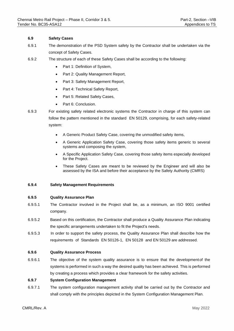
Chennai Metro Rail Project – Phase II, Corridor 3 & 5. Part-2, Section –VIB
Tender No. BC35-ASA12 Appendices to TS
CMRL/Rev. A May 2022
6.9 Safety Cases
6.9.1 The demonstration of the PSD System safety by the Contractor shall be undertaken via the
concept of Safety Cases.
6.9.2 The structure of each of these Safety Cases shall be according to the following:
• Part 1: Definition of System,
• Part 2: Quality Management Report,
• Part 3: Safety Management Report,
• Part 4: Technical Safety Report,
• Part 5: Related Safety Cases,
• Part 6: Conclusion.
6.9.3 For existing safety related electronic systems the Contractor in charge of this system can
follow the pattern mentioned in the standard EN 50129, comprising, for each safety-related
system:
• A Generic Product Safety Case, covering the unmodified safety items,
• A Generic Application Safety Case, covering those safety items generic to several systems and composing the system,
• A Specific Application Safety Case, covering those safety items especially developed for the Project.
• These Safety Cases are meant to be reviewed by the Engineer and will also be assessed by the ISA and before their acceptance by the Safety Authority (CMRS)
6.9.4 Safety Management Requirements
6.9.5 Quality Assurance Plan
6.9.5.1 The Contractor involved in the Project shall be, as a minimum, an ISO 9001 certified
company.
6.9.5.2 Based on this certification, the Contractor shall produce a Quality Assurance Plan indicating
the specific arrangements undertaken to fit the Project’s needs.
6.9.5.3 In order to support the safety process, the Quality Assurance Plan shall describe how the
requirements of Standards EN 50126-1, EN 50128 and EN 50129 are addressed.
6.9.6 Quality Assurance Process
6.9.6.1 The objective of the system quality assurance is to ensure that the development of the
systems is performed in such a way the desired quality has been achieved. This is performed
by creating a process which provides a clear framework for the safety activities.
6.9.7 System Configuration Management
6.9.7.1 The system configuration management activity shall be carried out by the Contractor and
shall comply with the principles depicted in the System Configuration Management Plan.

Chennai Metro Rail Project – Phase II, Corridor 3 & 5. Part-2, Section –VIB
Tender No. BC35-ASA12 Appendices to TS
CMRL/Rev. A May 2022
6.9.7.2 The System Configuration Management Plan shall address the configuration management in
terms of configuration control, problem reporting, change control, media control and
configuration management tools.
6.9.8 Project Management
6.9.8.1 It is the Contractor’s responsibility to ensure the systems are developed, tested and delivered
on time.
6.9.8.2 To do so, a Detailed Work Schedule shall be created and maintained in order to identify and
control every single task to be performed.
6.9.8.3 From this schedule it shall be possible to identify critical paths, slippage and resources,
including the tasks related to the safety process.
6.9.8.4 As part of any overall reporting mechanism to the Employer, progress information shall be
included relating to the PSD Syatem. In addition to submitting an updated Detailed Work
Schedule the Contractor shall indicate which phases are not started, in progress or completed.
6.9.8.5 The Progress Report shall also provide information regarding the safety activities, to ensure
their progress is consistent with the progress of design activities.
6.9.9 Hold Point between Installation and T&C activities
6.9.9.1 For the safety of T&C activities, installation completion should be confirmed and approved by
the Engineer, prior to starting tests.
6.9.9.2 An installation checklist prepared and maintained by the Contractor shall be counter-signed by
the Engineer, after the satisfactory completion of each part constituting a system.
6.9.9.3 On satisfactory completion of all installation checklists (including safety- related items) for a
group of works, the relevant authority shall issue an Installation Clearance Certificate which is
a prerequisite to commence System, Subsystems or Component T&C.
6.9.9.4 The Design Safety Case and the System Hazard Log showing the evidence that the hazards
have been mitigated at design stage is required to start the installation activity, the T&C activity.
6.9.9.5 Any non-conformity shall be identified and analysed from a safety point of view before the
authorisation is granted to carry out dynamic testing.
6.9.9.6 In the event of a safety related non-conformity is covered by a procedure during the testing
period, this procedure shall be reviewed and notice of no objection obtained from the Engineer.
6.9.10 T&C activities
6.9.10.1 The safety procedures for T&C shall be specified in the relevant testing procedures of each
T&C Plan, including, where necessary, the protection measures for any part of the railway
system which are already in operation.
6.9.10.2 In the period of T&C, modifications on design or installation may become necessary when non-
conformance to the safety validation occurs. If modifications in design are needed, they shall
follow the procedures of both the System Development Plan and the System Configuration
Management Plan.

Chennai Metro Rail Project – Phase II, Corridor 3 & 5. Part-2, Section –VIB
Tender No. BC35-ASA12 Appendices to TS
CMRL/Rev. A May 2022
6.10 Safety Targets
6.10.1 Risk Definition and Categorisation
Since safety is about managing risk, risk must be first defined.
6.10.1.1 Risk is defined as a combination between the frequency of occurrence of hazard(s) and
severity of the corresponding hazard(s).
6.10.1.2 Hazards shall be categorised according to both their frequency of occurrence and their
severity as per the EN 50126-1 approach.
6.10.2 Frequency of Occurrence of Hazards
6.10.2.1 The following categories shall be used to classify the frequency of occurrence of hazards:
Category Frequency per year
Description
A
Frequent
> 10
Likely to occur frequently. The hazard will be continually
experienced.
(>10 times per year).
B
Probable
< 10 > 1
Will occur several times. The hazard can be expected to
occur often.
(>1 time per year)
C
Occasional
< 1 > 0.1
Likely to occur several times in the system lifecycle. The
hazard can be expected to occur several times.
(>1 time in 10 years).
D
Rare
< 0.1 > 0.01
Likely to occur in the system life cycle. The hazard can
be expected to occur a few times in the life cycle of the
system.
(>1 time in 100 years).
E
Unlikely
< 0.01 > 0.001
Not expected to occur with the system life cycle. The
hazard is not expected to occur in the life cycle of the
system.
(>1 time in 1,000 years).
F
Remote
< 0.001 > 0.0001
Very unlikely to occur within the system life cycle. (>1
time in 10,000 years).
G
Improbable
< 0.0001 > 0.00001
Extremely unlikely to occur within the system life cycle.
(>1 time in 100,000 years).
H Incredible < 0.00001 Not conceivably possible. It can be assumed that the
hazard may not occur during the whole system life.
(<1 time in 100,000 years).
Table 1: Frequency of Occurrence of Hazards

Chennai Metro Rail Project – Phase II, Corridor 3 & 5. Part-2, Section –VIB
Tender No. BC35-ASA12 Appendices to TS
CMRL/Rev. A May 2022
6.10.3 Severity of Hazards
6.10.3.1 Thus, the following levels shall be used to classify the severity of the consequences of the
hazards. Consequences taken into account are consequences for people, system and
environment.
7
8
Table
2:
Severity of Hazards
6.10.4 Risk Assessment Matrix
6.10.4.1 As shown in the matrix below, frequency of occurrence and severity of the consequences are
combined together in order to further process the risks as per EN 50126-1. The following
matrix presents the possible combinations of frequency of occurrence and severity of the
consequences of the hazards. It also presents the various zones of acceptability of the risk.
Severiy
4-Insignificant 3-Marginal 2-Critical 1-Catastrophic
Fre
qu
en
cy
A-Frequent R2 R1 R1 R1
B-Probable R2 R2 R1 R1
C-Occasional R3 R2 R1 R1
D-Rare R3 R3 R2 R1
E-Unlikely R4 R3 R2 R2
F-Remote R4 R4 R3 R2
G-Improbable R4 R4 R3 R3
H-Incredible R4 R4 R4 R4
Severity level
Consequences for people or environment Consequences for service
1
Catastrophic
Fatalities and/or multiple severe injuries and/or
major damage to the environment.
-
2
Critical
Single fatality and
/or severe injury and/or significant damage to
the environment.
Loss of a major system
3
Marginal
Minor injury and/or significant threat to the
environment Severe system(s) damage
4 Insignificant Possible minor injury Minor system damage
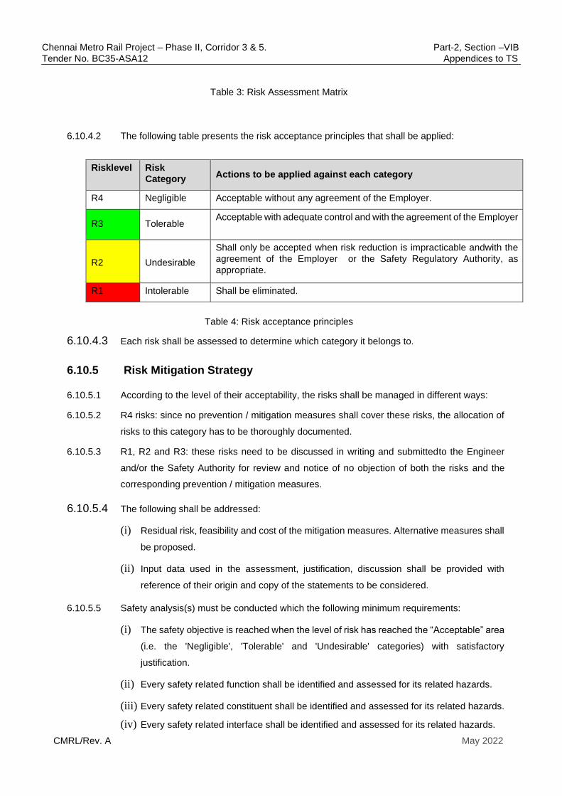
Chennai Metro Rail Project – Phase II, Corridor 3 & 5. Part-2, Section –VIB
Tender No. BC35-ASA12 Appendices to TS
CMRL/Rev. A May 2022
Table 3: Risk Assessment Matrix
6.10.4.2 The following table presents the risk acceptance principles that shall be applied:
Risk level Risk
Category Actions to be applied against each category
R4 Negligible Acceptable without any agreement of the Employer.
R3 Tolerable Acceptable with adequate control and with the agreement of the Employer
R2
Undesirable
Shall only be accepted when risk reduction is impracticable and with the
agreement of the Employer or the Safety Regulatory Authority, as
appropriate.
R1 Intolerable Shall be eliminated.
Table 4: Risk acceptance principles
6.10.4.3 Each risk shall be assessed to determine which category it belongs to.
6.10.5 Risk Mitigation Strategy
6.10.5.1 According to the level of their acceptability, the risks shall be managed in different ways:
6.10.5.2 R4 risks: since no prevention / mitigation measures shall cover these risks, the allocation of
risks to this category has to be thoroughly documented.
6.10.5.3 R1, R2 and R3: these risks need to be discussed in writing and submitted to the Engineer
and/or the Safety Authority for review and notice of no objection of both the risks and the
corresponding prevention / mitigation measures.
6.10.5.4 The following shall be addressed:
(i) Residual risk, feasibility and cost of the mitigation measures. Alternative measures shall
be proposed.
(ii) Input data used in the assessment, justification, discussion shall be provided with
reference of their origin and copy of the statements to be considered.
6.10.5.5 Safety analysis(s) must be conducted which the following minimum requirements:
(i) The safety objective is reached when the level of risk has reached the “Acceptable” area
(i.e. the 'Negligible', 'Tolerable' and 'Undesirable' categories) with satisfactory
justification.
(ii) Every safety related function shall be identified and assessed for its related hazards.
(iii) Every safety related constituent shall be identified and assessed for its related hazards.
(iv) Every safety related interface shall be identified and assessed for its related hazards.

Chennai Metro Rail Project – Phase II, Corridor 3 & 5. Part-2, Section –VIB
Tender No. BC35-ASA12 Appendices to TS
CMRL/Rev. A May 2022
6.10.6 Links between Safety Objectives and SILs
6.10.6.1 The following links shall be used:
(i) Functions which failure can lead to an R1 risk with catastrophic consequences shall
be supported with SIL4 constituents.
(ii) Functions which failure can lead to an R1 risk with critical and marginal consequences
shall be supported with SIL3 constituents.
(iii) Functions which failure can lead to an R3 or R2 risk shall be supported with SIL2
constituents.
(iv) Functions which failure can lead to an R4 risk shall be supported with SIL1
constituents.
6.10.7 Implementation of SIL4, SIL3, SIL2 and SIL1 constituents
6.10.7.1 Equipment shall have a SIL at least equal to the functions it implements.
6.10.7.2 As a minimum, SIL4, SIL3, SIL2 and SIL1 constituents shall comply with the following
requirements.
(i) Compliance to standards: EN 50126-1, EN 50129, EN 50128, EN 50159 Standards shall
be complied with.
(ii) Quality assurance: Quality of the constituents shall be verified according to a Quality
Assurance Plan over the construction and operation phases.
(iii) Safety assurance: Safety of the constituents shall be demonstrated according to a
System Safety Plan over the construction and operation phases.
6.10.8 Safety Techniques to be used.
6.10.8.1 Recognised techniques used in the railway application for implementation of SIL4 or SIL3
constituents are as follows:
(i) “Fail safe” technique: a constituent (or component) of a system is built on "fail safe"
technique when a failure of this constituent cannot lead to a more permissive status of
that system. For example, a failure of a fail- safe relay cannot lead to a green signal
when the signal should be red. For this technique there is no mathematical estimate of
the level of safety of a constituent. The constituent is considered of SIL4 once every
hypothesis is verified. It is assumed that the SIL4 component complies as per safety
requirements inside the limits of its specification.
(ii) “Checked safety” technique: a constituent (or component) of a system is built on
"checked safety" technique when certain failures of this constituent can be detected
by another independent device. This independent device reads a safety status of the
constituent. When the safety status becomes unsafe due to certain failures of the
constituent, the independent device inhibits the outputs of the constituent. This

Chennai Metro Rail Project – Phase II, Corridor 3 & 5. Part-2, Section –VIB
Tender No. BC35-ASA12 Appendices to TS
CMRL/Rev. A May 2022
independent device can be built on "fail safe" technique.
(iii) “Probabilistic safety” technique: A constituent (or component) of a system is built on
"Probabilistic safety" technique when it can be demonstrated that failures cannot
happen more often than a certain limit. This limit must be considered as sufficient. This
technique shall be handled carefully.
(iv) For the implementation of SILx functions by the means of “probabilistic safety”, the
frequency rate of dangerous failure per operating hour is given in the following table: -
Safety Integrity
Level
Frequency rate of dangerous
failure per operating hour
(i) 4 ≥ 10-9 to < 10-8
(ii) 3 ≥ 10-8 to < 10-7
(iii) 2 ≥ 10-7 to < 10-6
(iv) 1 ≥ 10-6 to < 10-5
Table 5: SIL Safety Targets
6.10.8.2 “Safety concept” approach of the programmable electronic equipment safety equipment use
safety concepts of the sort defined above. Safety analysis and demonstration shall include:
(i) The identification and description of the safety concept used,
(ii) The definition of the hypothesis on which safety relies,
(iii) The complete and precise definition of the safety technique used,
(iv) The safety criteria and requirements to be abided by,
(v) The methods of verification and validation that need to be unfolded to assure safety,
(vi) The specific program plan to be unfolded for ensuring safety,
(vii) The identification of the techniques or mechanisms that have not yet been proven
as safe by a certification body.
6.10.8.3 Use of “safety software” Safety software, i.e. executing SIL4 or SIL3 functions shall be
developed and demonstrated safe according to EN 50128. The use of formal methods for

Chennai Metro Rail Project – Phase II, Corridor 3 & 5. Part-2, Section –VIB
Tender No. BC35-ASA12 Appendices to TS
CMRL/Rev. A May 2022
demonstrating that the software is error free is highly recommended.
6.10.8.4 Use of “proven safety techniques” Only proven safety technique shall be allowed to be used
for the Project. The safety techniques to be used shall be presented by the Contractor. Proven
safety techniques are those that:
(i) Have been already approved as safe by an independent competent party.
(ii) Have been used successfully in revenue service for at least two years since the end of
guarantee of the system, at the date of the Contractor’s bid.
(iii) Allow to be easily customized to the needs of a new project.
6.10.8.5 Techniques not complying with those requirements or for which the documentation
establishing compliance with the present requirements is not available or insufficient shall be
rejected.
6.10.9 Safety Deliverables
As a minimum, the following documents shall be delivered by the Contractor:
(i) System Assurance Plan
(ii) System Safety Plan
(iii) Preliminary Hazard Analysis
(iv) Hazard Analyses (SHA, IHA, OSHA)
(v) Traceability Matrix
(vi) FMECA (functional and component levels)
(vii) Fault Tree Analysis
(viii) Safety Critical Items List
(ix) Quantitative Risk Assessment
(x) SIL Allocation Report
(xi) System Hazard Log
(xii) Design Safety Case
(xiii) Safety Case
(xiv) SRAC: Safety Related Application Conditions
6.10.10 Safety Targets:
6.10.10.1 The DCU Software that controls many safety features of PSD Functioning, shall meet SIL 2
requirements, as a minimum.
6.10.10.2 The Drive circuit of Sliding doors, starting from the PSD-Signaling Safety Relays based interface
panel, shall be fully wired with double cutting arrangements of controlling relay contacts

Chennai Metro Rail Project – Phase II, Corridor 3 & 5. Part-2, Section –VIB
Tender No. BC35-ASA12 Appendices to TS
CMRL/Rev. A May 2022
6.10.10.3 The design of the system that detects over-current drawn by the Sliding door motors and
automatically trips the current to the motors on detection of over-laod (due to an obstacle or
any other reason )has to meet SIL 3 requirements
6.10.10.4 The All doors closed & locked loop from the PSD side being input to the Signaling CBTC
system, shall be a SIL 4 rated design, including use of highly reliable & rugged door close &
locked contacts, proved on both limbs of the Safety Loop. This Safet Loop, shall like wise
prove the closed & locked status of all Sliding Doors, EEDs, DEDs & MSDs.
6.10.10.5 The PSD part of the Sinaling-PSD interface panel that executes the Door Open & Door Close
commands (for all Sliding doors or the end doors for maintenance access) shall incorporate
highly rugged & reliable Relays that are Safety Rated and also a proven arrangement as
adopted in other Metro Systems for similar Safety applications. The circuit diagram for
controlling the Opening/Closing of Sliding doors shall incorporate the controlling relay
contacts on both lims of the circuit. The choice of relays, their rating and the interface circuit
design is subject to a notice of no objection from the Engineer.
6.11 Requirements for RAM Assurance
6.11.1 General RAM Requirements
6.11.1.1 The Contractor shall demonstrate that his design meets both the RAM requirements specified
for the PSD system, as under.
6.11.1.2 To demonstrate this, it is necessary for the Contractor to take into consideration the effect of
potential failures of system components, corrective and preventive maintenance times and
redundancies built into the design.
6.11.1.3 The Contractors shall follow the Standard EN 50126-1 approach over the whole system
lifecycle.
6.11.1.4 The Contractor shall demonstrate in his, Systems/Subsystems or Components RAM Studies
and RAM Validation Studies that the RAM Targets are reached.
6.11.1.5 The System RAM Plan and RAM analyses shall be developed to a lifecycle model in
accordance with EN 50126-1.
6.11.1.6 As for Safety, the RAM requirements rely on the Contractor’s Quality Assurance. Therefore,
the Quality Assurance requirements set for Safety are applicable for RAM also.
6.11.2 Organisational RAM Requirements
6.11.2.1 The Contractor’s organisation shall include a RAM Assurance Manager.
6.11.2.2 The RAM Assurance Manager shall be independent from the teams in charge of the Design,
Construction, Manufacturing and T&C and report directly to the Project Manager.
6.11.2.3 To perform his tasks, the RAM Assurance Manager shall be supported by RAM engineers
who shall be under his direct management.

Chennai Metro Rail Project – Phase II, Corridor 3 & 5. Part-2, Section –VIB
Tender No. BC35-ASA12 Appendices to TS
CMRL/Rev. A May 2022
6.11.3 Technical RAM Requirements
6.11.3.1 The technical requirements which are described here below correspond to general
guidelines. These guidelines shall be developed further by the Contractor when the contract
is awarded.
6.11.4 Development Lifecycle and Documentation
6.11.4.1 Please refer to the System Safety Assurance Requirements.
6.11.5 System RAM Plan
6.11.5.1 The Contractor shall produce and maintain a System RAM Plan. The System RAM Plan
shall be a standalone document.
6.11.5.2 The Contractor shall seek the Notice of No Objection of the Engineer for the System RAM
Plan
6.11.5.3 The subjects to be covered in the System RAM Plan and the associated system RAM works
to be carried out by the Contractor shall include, but not be limited to, the following:
6.11.5.4 Referenced RAM standards and documents,
(i) RAM management principles,
(ii) Description of the systems,
(iii) The organisation and resources put into place for performing the RAM analyses,
(iv) Independence of RAM Team,
(v) RAM responsibility,
(vi) Requirement for competence of key personnel,
(vii) RAM requirements,
(viii) The RAM objectives of the systems/subsystems which are part of the works,
(ix) RAM V-cycle,
(x) The description of the methodology and tools to be used for RAM analyses,
(xi) The mission profile taken into account to perform the RAM calculation,
(xii) Assessing that RAM Targets are met,
(xiii) Performing RAM assessments for any potential alternative designs,
(xiv) Verification and validation of all RAM analyses performed,
(xv) Validation of RAM requirements during manufacture, installation, commissioning and
maintenance
(xvi) RAM documentation and deliverables.
6.11.6 Data Collection and Operation Assumptions
Chennai Metro Rail Project – Phase II, Corridor 3 & 5. Part-2, Section –VIB
Tender No. BC35-ASA12 Appendices to TS
CMRL/Rev. A May 2022
6.11.6.1 The data collection activity has to be carried out for equipment which are already in revenue
service. The objective is to be able to base the reliability prediction on field data which are
more representative than theoretical reliability figures.
6.11.6.2 The determination of operation assumptions corresponds to a refinement of the mission
profile. It provides additional data to be considered in the RAM predictions
6.11.7 Reliability Block Diagrams
6.11.7.1 For each system, a Reliability Block Diagram shall be prepared to model the architecture and
highlight the redundancies. This will be the basis for end-to-end reliability of sub-systems as
well as the entire PSD system.
6.11.8 RAM Allocation
6.11.8.1 The RAM allocation is based on the Reliability Block Diagrams. Each block is allocated a
RAM target to ensure the overall RAM target for the system shall be met.
6.11.8.2 The appropriateness of the architecture shall be verified at this stage by checking that each
component receives a realistic reliability target.
6.11.8.3 The Contractor shall produce a RAM Allocation Report, as part of the System RAM Plan.
6.11.8.4 The Contractor shall seek the Notice of No Objection of the Engineer for the System RAM
Plan.
6.11.9 Failure Mode, Effects and Criticality Analysis
6.11.9.1 The FMECA is performed in parallel of the RBD activity in order to analyse the consequences
of a failure of each equipment of the system.
6.11.9.2 This analysis aims to identify the equipment which are critical for the reliability of the system
and assess the need for redundancy.
6.11.10 Reliability and Availability Prediction
6.11.10.1 The reliability and availability prediction is based on a down to top approach:
6.11.10.2 the reliability of each equipment is predicted based on field data or theoretical failure rate of
components;
6.11.10.3 the reliability of a system is predicted by injecting the equipment failure rate in the RBD;
6.11.10.4 availability is derived, using the MTTR and the reliability. 6.11.10.5 The RAM Analysis and Prediction Report shall give predictions of system reliability,
availability and maintainability based on data collected.
6.11.10.6 The Contractor shall produce a RAM Analysis and Prediction Report. The RAM Analysis and
Prediction Report shall be a standalone document.
6.11.10.7 The Contractor shall seek the notice of no objection from the Engineer, for the RAM Analysis
and Prediction Report.

Chennai Metro Rail Project – Phase II, Corridor 3 & 5. Part-2, Section –VIB
Tender No. BC35-ASA12 Appendices to TS
CMRL/Rev. A May 2022
6.11.11 Reliability Critical Items List
6.11.11.1 The Reliability Critical Items List shall identify the equipment whose failure directly impacts
the reliability objectives. This list shall be prepared based on the result of the FMECA and
the RBDs.
6.11.11.2 The Contractor shall produce a Reliability Critical Items List. The Reliability Critical Items List
shall be an essential part of the RAM Analysis & Prediction Report.
6.11.11.3 The Contractor shall seek the notice of no objection from the Engineer, to the Reliability
Critical Items List , as part of the RAM Analysis & Prediction Report
6.11.12 Maintainability Prediction
6.11.12.1 For each Line Replaceable Unit (LRU), a Mean Time To Repair (MTTR) shall be estimated
by the Contractor, taking into account the accessibility and the complexity of the equipment.
6.11.12.2 For each LRU, the weight, dimensions and the need for special maintenance tools shall be
provided by the Contractor.
6.11.13 Spare Parts Quantity Calculation
6.11.13.1 The requirement of quantity of spares for each LRU/LLRU (lowest level line replaceable unit)
shall be worked out on completion of detailed design, based on the principles enunciated
under the Section “Spares” of this Specification.
6.11.13.2 Where the RAMS prediction report indicates that the failure rate of an item is too low (based
on actual field records in similar projects under comparable environmental conditions), the
quantity can be reduced below the minimum requirement of 10%, with the notice of no
objection from the Engineer. Convesely, where the RAMS Prediction report or the
performance during the actual DLP period of 2 years, indicates a failure rate higher than the
failure rate assumed in the RAMS prediction report, the quantity of spares for that item shall
be suitably increased above the minimum requirement of 10%, to last for the same duration
worked out ,based on failure rates indicated in the RAMS prediction report, in the section
forming part of the scope of the Contract.
6.11.14 RAM Analysis & Prediction Report
6.11.14.1 The Contractor shall submit a RAM Analysis & Prediction Report at the end of the Design
phase, summarizing the activities which have been carried out. The RAM Analysis &
Prediction Report shall be a standalone document.
6.11.14.2 The Contractor shall seek the notice of no objection to the RAM Analysis & Prediction
Report , from the Engineer..
6.11.14.3 The report shall provide the evidence that the technical choices (architecture, equipment)
shall make it possible to achieve the contractual RAM targets.
Chennai Metro Rail Project – Phase II, Corridor 3 & 5. Part-2, Section –VIB
Tender No. BC35-ASA12 Appendices to TS
CMRL/Rev. A May 2022
6.11.14.4 In the event the system does not comply with RAM targets, design will not be accepted by
the Engineer and manufacturing shall not be authorised to begin until improvement in the
design are proposed as proof of achievement of the RAM targets.
6.11.15 Manufacturing and Installation
6.11.15.1 In the event where some design modifications become necessary as a result of new
developments during the manufacturing or installation, the impact on RAM performance shall
be assessed by the Contractor. It shall be demonstrated that the achievement of the RAM
targets is not jeopardized by the modifications of the design.
6.11.16 Failure Recording and Corrective Action System
6.11.16.1 FRACAS shall be established by the Contractor as described in the System Safety Assurance
Requirements.
6.11.17 RAM Demonstration Plan
6.11.17.1 At least 90 days of the commencement of service trials, , the Contractor shall provide a RAM
Demonstration Plan. The RAM Demonstration Plan shall be a standalone document. This
document shall explain the proposed detailed methodology to assess the RAM performance,
viz-a-viz the RAM targets,
6.11.17.2 The Contractor shall seek the notice of no objection from the Engineer for the RAM
Demonstration Plan .
6.11.17.3 The RAM Demonstration Plan shall be used to prove and monitor RAM during the Service
Trial period and subsequently during the revenue service period.
6.11.17.4 The Contractor shall also review Subcontractors’ RAM Demonstration Plans to ensure that
these are compatible with system level tests and that all major system level issues have been
addressed.
6.11.17.5 The Contractor shall perform a series of RAM demonstrations for the works, as described in
the RAM Demonstration Plan.
6.11.17.6 The Contractor shall provide the required assistance for this activity including mobilisation
of equipment and resources.
6.11.17.7 The Contractor shall record and review the information generated during the RAM
demonstration period and provide an assessment of the demonstration in terms of achieving
the RAM requirements.
6.11.17.8 The outcome of the RAM demonstrations shall be presented in a RAM Demonstration Report,
which is subject to the notice of no objection of the Engineer.
6.11.18 Maintainability Demonstration

Chennai Metro Rail Project – Phase II, Corridor 3 & 5. Part-2, Section –VIB
Tender No. BC35-ASA12 Appendices to TS
CMRL/Rev. A May 2022
6.11.18.1 The demonstration aims to confirm the MTTR by measuring the actual times needed for
replacing the LRU, knowing that during design phase, maintainability predictions have been
carried out by the Contractor to determine the MTTR of the Line Replaceable Units (LRU).
6.11.18.2 This demonstration is performed on a sample basis; detailed modalities shall be described in
the RAM Demonstration Plan.
6.11.19 On-Site Testing and Integrated System Testing
6.11.19.1 This period shall give the opportunity to identify the requirements and facilitate the
mobilization of equipment and resources needed for the RAM performance follow-up and to
record the first trends of the RAM performance and allowing the detection of any RAM issue
at an early stage.
6.11.19.2 This period is part of the system’s debugging, and it is not part of the RAM performance
demonstration period.
6.11.20 Service Trial and Guarantee Period
6.11.20.1 The Contractor shall continue to implement system assurance activities during the Service
Trial and after the transition to Revenue Service including, but not limited to, the following
requirements.
6.11.20.2 During the Defects Notice Period, day to day monitoring of the RAM performance shall be
carried out and the findings shall be used to enable systematic means of data analysis and
recording of the RAM performance.
6.11.20.3 A monthly RAM Performance Report shall be issued to the Employer during the guarantee
period to provide the evidence of the achievement of the RAM targets .The format of this
Report shall be included in the RAM demonstration plan and is subject to notice of no
objection from the Engineer.
6.11.20.4 In the event where a system does not meet its RAM targets, the Contractor shall proceed to
failure root-cause investigation and rectification or retrofit.
6.11.21 RAM Targets
6.11.21.1 The RAM Targets provided herein are meant to ensure the Railway Systems have a high
level of dependability.The targets have been set to correspond to the current state of the art
for these types of systems.
6.11.21.2 The following targets must be understood as applicable criteria , for the RAM Demonstration
period.
6.11.21.3 The method of classification of failures, based on their impact on train operations and the
corresponding Mean Time between service affecting failures (MTBSAF) shall be as under
(for calculating total service hours , it is assumed that the Metro will be operating for 19 hours

Chennai Metro Rail Project – Phase II, Corridor 3 & 5. Part-2, Section –VIB
Tender No. BC35-ASA12 Appendices to TS
CMRL/Rev. A May 2022
a day.
S.
No
Failure
category
System failure
mode Effect on operation MTBSAF
1 Significant Total failure Operation non possible on the
whole corridor or delay in
operation more than 2 hours at
system level or closure of a
station for more than 1 day
34675 for both Up &
Down lines put together
2 Major Critical functional
failure
Local failure of the traffic
requiring an intervention on the
track (viaduct or tunnel) on to
recover the normal mode of
operation (e.g. handle of the
switches, etc.) or delay in
operation between 15 minutes
and 2 hours at system level or
closure of a station during a
period of time between 2 hours
and 1 day
>10 000h for both Up &
Down lines put together
3 Minor Non-critical
functional failure
Local failure of the traffic
occurring a delay in operation
comprised between 2 minutes
and 15 minutes at system level
and requiring a distant action to
recover the normal mode of
operation (from SCR or OCC)
> 2 000 h for for both Up
& Down lines put
together
4 Negligible Negligible
functional failure,
Local failure of the traffic
occurring a delay of less than 2
minutes in operation at system
level
> 1 000 h for for both Up
& Down lines put
together
6.11.21.4 The objective in respect of mean cycles between failures shall be as under:
Mean Cycles between Failures (MCBF) for PSD
A doorset cycle is defined as one complete open and close operation of one
pair of doors. The Mean Cycles Between Failures shall be 300,000 doorset
cycles. The MCBF shall be calculated using the following equations:
Total No. of Doorset Cycles
MCBF=---------------------------------------------------------
No. of Failures
6.11.21.5 In this clause, the term "failure" shall apply to any event which results in the inability of the
PSD to perform its intended function, either through shut down or through impaired
performance which is not in accordance with the performance criteria. It shall include the
failure of primary indications and the alarm system, but shall exclude those incidents due to
the loss of external inputs (e.g. loss of external power supply) or failures which would not
affect the operations of PSD. The use of alternative means of control via the PSD Local
Control Panel shall not be included in the evaluation of MCBF for each doorset.
Chennai Metro Rail Project – Phase II, Corridor 3 & 5. Part-2, Section –VIB
Tender No. BC35-ASA12 Appendices to TS
CMRL/Rev. A May 2022
6.11.21.6 The resulting objectives of the reliability for the PSD are to be achieved respectively at the
end of the stabilization period of one year from the revenue service and during the
stabilization period.
During the stabilization period of 9 months, the objectives of PSD reliability (MTBSAF and
MCBF) for each platform are to improve as followed:
a. After 3 months of operation, the reliability objectives divided by 3
b. After 6 months of operation, the reliability objectives divided by 2
c. After 9 months of operation, the reliability objectives
6.11.21.7 Availability Objective
System = PSD A > 99.8% for Up & Down lines put together
For the purposes of availability calculations, the Contractor shall assume that the service
operating hours are 19 hours per day (04:30 am to 11:30 pm), for 365 days a year.
In all availability calculations the following access times shall be assumed:
a. 60 minutes for equipment located in equipment rooms or on the platform that are
accessible during traffic hours; and
b. 10 hours for trackside equipment or equipment located such that it is only accessible
during non-traffic hours.
6.11.22 RAM Deliverables
6.11.22.1 As a minimum, the following documents shall be delivered by the Contractor:
(i) System RAM Plan
(ii) Reliability Block Diagrams as part of RAM Analysis & Prediction Report
(iii) RAM Allocation Report as part of RAM Analysis & Prediction Report
(iv) FMECA
(v) RAM Analysis and Prediction Report
(vi) Reliability Critical Items List as part of RAM Analysis & Prediction Report
(vii) RAM Demonstration Plan
(viii) RAM Demonstration Report
(ix) Monthly RAM Performance Report as per format agreed through the RAM Demonstration Report
Copyright © 2022 FDOKUMEN


![vf[ky Hkkjrh; vk;qfoZKku laLFkku] iVuk Corrigendum - AIIMS ...](https://static.fdokumen.com/doc/165x107/631a41301e5d335f8d0b7fb5/vfky-hkkjrh-vkqfozkku-lalfkku-ivuk-corrigendum-aiims-.jpg)
