Contribution to Quality-driven Evolutionary Software ... - CORE
274
Universidad Politécnica de Madrid Escuela Técnica Superior de Telecomunicaciones Departamento de Ingeniería de Sistemas Telemáticos PhD Thesis Contribution to Quality-driven Evolutionary Software Development Process for Service-Oriented Architecture Author: Jose Luis Arciniegas Herrera Telecommunication Engineer Advisor: Juan Carlos Dueñas Lopez Ph.D. in Telecommunication Engineering 2006
-
Upload
khangminh22 -
Category
Documents
-
view
1 -
download
0
Transcript of Contribution to Quality-driven Evolutionary Software ... - CORE

Universidad Politécnica de Madrid
Escuela Técnica Superior de Telecomunicaciones
Departamento de Ingeniería de Sistemas Telemáticos
PhD Thesis
Contribution to Quality-driven Evolutionary Software Development Process for Service-Oriented Architecture
Author: Jose Luis Arciniegas Herrera Telecommunication Engineer
Advisor: Juan Carlos Dueñas Lopez Ph.D. in Telecommunication Engineering
2006


Título: Contribution to Quality-driven Evolutionary Software Development Process for Service-Oriented Architecture.
Autor: Jose Luis Arciniegas Herrera
Director: Juan Carlos Dueñas López
TRIBUNAL CALIFICADOR Presidente:
Vocales:
Secretario:
Realizado el acto de defensa y lectura de Tesis en Madrid, el día de de . CALIFICACIÓN: El presidente Los Vocales
El secretario


Dedicado a
mi esposa Maite, mi hijo Luis y a mis padres


Resumen La calidad es un elemento clave para el éxito de cualquier sistema. En el ámbito de las Tecnologías de la Información y las Comunicaciones, los rápidos avances técnicos se traducen en que los usuarios demandan más productos y servicios, y de mayor calidad. En particular, los sistemas TIC orientados a servicios (dominio de esta tesis) se basan en la puesta de una o varias funciones a disposición de un número de usuarios potencialmente muy elevado; las exigencias de calidad de estos servicios se ven favorecidas por este gran número de usuarios. Los procesos de desarrollo de los servicios deben de tener en cuenta estas exigencias de calidad. Este trabajo propone una mejora en los modelos del proceso de desarrollo del software basada en la teoría del desarrollo evolutivo de software. El objetivo principal es mantener y mejorar la calidad del software, el mayor tiempo posible y con el mínimo esfuerzo y coste. El proceso propuesto está apoyado en otros métodos conocidos en la literatura, como los métodos ágiles de desarrollo del software. Otro elemento clave en esta tesis es el denominado “arquitectura del software orientado a servicios”, o arquitecturas orientadas a servicios. Se sabe que la arquitectura del software juega un papel importante en la calidad. Frente a los enfoques convencionales, las arquitecturas orientadas a servicios aportan un grado mayor de flexibilidad del sistema, al entenderlo como una agregación de servicios, cada uno de ellos como un ente autónomo, compacto y que puede ser mejorado e integrado con mayor facilidad. El modelo propuesto en esta tesis para el desarrollo de software evolutivo hace énfasis en la calidad de los servicios. Para ello, se redefinen algunos principios del desarrollo evolutivo y se proponen nuevos procesos que complementan a los existentes, procesos como: evaluación de la arquitectura, conformidad de la arquitectura y recuperación de la arquitectura. Cada uno de estos procesos se ha probado con casos de estudio donde se consideran algunos de los aspectos de calidad del software más demandados en el dominio de los servicios, tales como: el rendimiento, la seguridad y la capacidad de evolución. Se podrían considerar más aspectos de calidad de la misma forma que los anteriores, pero se entiende que estos aspectos de calidad permiten demostrar la viabilidad del enfoque con suficiente profundidad.

Resumen - Abstract
Contribution to Quality-driven ESD for SOA
ii
Resumen extendido Motivación Durante los últimos años, la calidad se ha demostrado como un elemento clave para el éxito de un producto o servicio que contenga software (al igual que prácticamente cualquier otro producto o servicio de ingeniería). El software debe estar preparado para las nuevas necesidades de sus usuarios (o consumidores), tales como: la aplicación de nuevas tecnologías, tiempo de competición en el mercado más corto, crecimiento del número de usuarios, etc. Estos factores afectan a la forma en la que las empresas desarrollan el software y es allí donde están los nuevos retos. Si bien existen métodos de desarrollo muy bien establecidos, la realidad nos indica que éstos deben ser adaptados a esta nueva situación. Por consiguiente, se deben de crear nuevos modelos para mejorar la productividad y la calidad del software; para estos nuevos métodos es necesario cambiar tanto los procesos de desarrollo como las prácticas y tecnologías usadas. En primer lugar, se hace necesario clarificar el concepto de calidad del software. En esta tesis se presentan los puntos de vista de varios autores. Sin embargo, para nosotros es de crucial importancia la relación entre la calidad y la metodología en el proceso de desarrollo de un sistema. Consideramos la metodología como el mecanismo básico para la mejora de la calidad y la productividad del desarrollo. Sin embargo la metodología es un campo muy amplio de estudio, que incluye la gestión de proyectos, análisis, especificación, diseño, pruebas, aseguramiento de la calidad, etc. En esta tesis se han considerado dos tipos de metodologías de desarrollo del software: las tradicionales (TSD) y las evolutivas (ESD), las primeras normalmente incluyen un proceso largo, formal y documentado, mientras que las evolutivas tratan de reducir el grado de formalismo y documentación. En el proceso de desarrollo del software tradicional (TSD) los productos se entregan con un cierto nivel de calidad, medido en términos de los requisitos iniciales. Sin embargo, la calidad decrece con el paso del tiempo, y este es el motivo –mantener la calidad- el que justifica la fase de mantenimiento. Lastimosamente, el mantenimiento del software es uno de los procesos más costosos del software y los productos suelen ser retirados en relativamente poco tiempo. Dentro de las metodologías para TSD, nosotros hemos considerado: el modelo en cascada de Bennington 1956 y Royce 1970, el modelo V de IABG y el Ministerio Federal de Defensa Alemán 1992, el modelo rapido (RAD) de Martin 1991 y McConnell 1994, el modelo iterativo de Brooks 1975, el modelo en espiral de Boehm 1988, el modelo en espiral Win-Win de Boehm 1998, el modelo de desarrollo concurrente de Davis y Sitaram 1994, el modelo de entrega por etapas de McConnell 1996 y el modelo de proceso unificado (UP) de Kruchten 1996, Booch, Jacobson y Rumbaugh 1998. Los procesos de desarrollo del software evolutivos (ESD) aparecen como respuesta a la “crisis del software” de los años 60, 70 y 80, cuando muchos proyectos software no

Resumen - Abstract
Contribution to Quality-driven ESD for SOA
iii
llegaron a buen fin, es decir, acabaron fuera de presupuesto o fuera del tiempo de planificación (o se cancelaron antes de finalizar). Inicialmente, esta crisis fue definida en términos de productividad pero luego también se resalto la importancia de la calidad del software. Los ESD permiten la mejora de la calidad, reduciendo el coste total e incrementando el tiempo de vida del software. Para ello parten de dos principios básicos: la entrega temprana del producto y la posibilidad de hacer cambios de forma controalda durante el mantenimiento, con el fin de mejorar el software de forma continua. Las metodologías ESD más conocidas son las siguientes: Programación extrema (XP) de Beck, Cunningham y Jeffries 1999, Scrum de Takeuchi y Nonaka 1986, Stherland y Schwaber 1995, gestión de proyectos evolutivos (Evo) de Gilb 1976, la familia de métodos Crystal de Cockburn 2001, desarrollo guiado por características (FDD) de Batory 2003, Coad, Lefebvre y DeLuca 2000), el método de desarrollo de sistemas dinámico (DSDM) de Stapleton 1997), El desarrollo del software adaptativo de Highsmith 2000, el modelado ágil de Ambler 2002, el desarrollo dirigido o asistido (lean) (LD) de Charette 2001 y el desarrollo de software dirigido (LSD) de Mary y Tom Poppendieck 2001. Por otro lado, en los años 60 también se introdujo el concepto de arquitectura del software por Edsger Dijkstra. Este concepto no se incorporó con todas sus implicaciones al proceso de desarrollo hasta inicios de los 90s. La arquitectura del software se organiza normalmente mediante vistas, como las presentadas por Kruchten [1]. Actualmente, nos encontramos con la aparición de un estilo arquitectónico orientado a solucionar los problemas relacionados con el desarrollo y evolución de los servicios (entendidos como aplicaciones distribuidas sobre una red de comunicaciones - siendo Internet la más relevante). Desde el punto de vista de la arquitectura de software, se define servicio como una función bien definida, auto-contenida, y que no depende del entorno o estado de otros servicios. Las arquitecturas orientadas a servicios (Services Oriented Architectures-SOA) pueden considerarse como un estilo arquitectónico diferenciado de los anteriores, que ofrece la ventaja de ser adaptado en corto tiempo y que puede dar, por tanto solución a algunos de los problemas en el desarrollo de software, particularmente a algunos problemas relacionados con la calidad. Un servicio puede estar compuesto o configurado por uno o varios componentes (o activos) arquitectónicos. La configuración de servicios conforma una SOA [2]. Los servicios tienen una relación muy cercana con las características de calidad, normalmente un servicio mejora cierto atributo de calidad de un producto. Una SOA trata a todas sus partes como servicios independientes, y bajo este esquema, un atributo de calidad podría estar asociado a uno o varios (pocos) servicios. De forma ideal, mejorar un atributo de calidad se puede conseguir medianta la modificación –mejora de uno o varios pocos servicios. Por otro lado, se puede mejorar la calidad de un producto software reduciendo inteligentemente el tamaño del sistema. Para ello se utilizan técnicas como la reconstrucción de software (“refactoring”) o la eliminación de código duplicado. Estas actividades no se pueden realizar de forma efectiva si no existe una buena y actualizada descripción o modelo arquitectónico. La recuperación, la visualización cualitativa y cuantitativa, y la evaluación de la arquitectura del sistema permiten detectar fallos,

Resumen - Abstract
Contribution to Quality-driven ESD for SOA
iv
conflictos, limitaciones y partes duplicadas de un sistema. De esta forma, el proceso de evaluación de la arquitectura juega un papel importante en la valoración del sistema completo, servicios o activos. Usualmente la salida del proceso de evaluación se convierte en la entrada de un proceso de adaptación del sistema en busca de mejores niveles de caliad. Un condicionante más en este entorno de trabajo, es que las organizaciones necesitan reducir su esfuerzo en el proceso de desarrollo para reducir sus costes. En el ámbito de la ingeniería del software, una de las estrategias para lograrlo es la reutilización; hasta el momento se ha prestado poca atención a los procesos de recuperación de activos de sistemas ya desarrollados por la misma organización, o por otras entidades externas o terceras partes (por ejemplo, una comunidad de fuente abierta. La reutilización de buen código puede incrementar la calidad total del sistema. Una de las ideas de ESD es la rápida entrega del producto, y para ello proponemos reducir el tiempo de desarrollo reutilizando activos que han sido desarrollados previamente. Para nosotros, el éxito del ESD depende de la clara definición de los requisitos haciendo énfasis en los atributos de calidad, la construcción de una arquitectura de referencia, una adecuada recuperación y selección de activos, y una detección rápida de posibles limitaciones, errores o conflictos. En este proceso de creación de servicios software, siguiendo el estilo arquitectónico SOA y mediante procesos evolutivos, y en orden a garantizar el cumplimiento de ciertos niveles de calidad, y a la vez reducir en lo posible los esfuerzos de desarrollo, aparece otra actividad a la que tradicionalmente se ha prestado poca atención desde el ámbito de la arquitectura del software: los estándares, la comprobación de que se cumplen o no, la identificación de activos que cumplen con los estándares, y la reutilización de estos activos en la arquitectura. Hemos definido un proceso que permite lograr estos objetivos y le hemos llamado “proceso de evaluación de conformidad” o conformidad (siguiendo los procesos de comprobación de conformidad mediante pruebas existentes en la literatura). Una vez citados los diferentes procesos arquitectónicos fundamentales a los que la tesis doctoral contribuye a elaborar, se hace clara la necesidad de una completa orquestación de estos procesos con el fin de que puedan ser aplicados de una manera adecuada (indicando los métodos, técnicas y herramientas de soporte necesarios). Esta tesis propone un nuevo proceso basado en las metodologías ESD, y que integra los procesos arquitectónicos fundamentales. Que-ES (Quality-driven ESD for SOA) es el modelo propuesto en esta tesis, que se ilustra en la Figura 1. Esencialmente, Que-ES se usa para aprender a partir de sistemas disponibles y, con ese conocimiento, ayuda en el descubrimiento de nuevas demandas y hacer estimaciones.

Resumen - Abstract
Contribution to Quality-driven ESD for SOA
v
Figura 1 Desarrollo del software evolutivo orientado a la calidad para arquitectura orientada a
servicios (Que-ES) Que-ES hace énfasis en los requisitos no funcionales. En el estándar ISO 9126 [3] se definen los requisitos de calidad más representativos. Este estándar puede ser tomado como una referencia, aunque en esta tesis sólo se han tomado las siguientes características de calidad para su estudio: el rendimiento, la seguridad y la capacidad de evolución. Estas tres características de calidad se consideran críticas en el contexto de los servicios y por consiguiente en las SOA. En resumen, en el contexto de la tesis, se estudian tres dominios de la ingeniería del software: las arquitecturas orientadas a servicios, la evolución de los sistemas, y los requisitos no funcionales del software, cada uno de ellos se analiza de manera independiente. Entendemos que el éxito de la propuesta es hallar el punto de convergencia entre SOA y los ESD para mejorar la calidad de los sistemas. Con esta intención, esta tesis reúne métodos, técnicas, procesos y herramientas con el fin de contribuir el área de conocimiento de las metodologías evolutivas (ESD). Para ello, hemos introducido algunos procesos que han sido usados por las metodologías tradicionales (TSD) para mejorar las evolutivas, como son: la evaluación, la conformidad y la recuperación de las arquitecturas. Además hemos enfocado el trabajo a un área de aplicación específica (SOA), que pretende mejorar algunas de las características actuales del software, tales como, la flexibilidad, adaptabilidad, capacidad de cambios, mejor tratamiento de la calidad, etc. Objetivos Objetivo general La presente tesis aborda varios temas: la calidad del software, el desarrollo del software tradicional, el desarrollo del software evolutivo y las arquitecturas del software, entre otros. Del estudio de estos temas, han surgidos varias interrogantes. Por ejemplo, actualmente se sabe que el papel de las arquitectura software es indiscutible en el

Resumen - Abstract
Contribution to Quality-driven ESD for SOA
vi
desarrollo software, lo que se hace aún más notable en los procesos de evaluación del software, pero la mayoría de los sistemas se evalúan únicamente con respecto a aspectos funcionales. Creemos que la calidad del software depende en gran parte en su arquitectura, no solamente en sus aspectos funcionales, sino también en el cumplimiento de los requisitos no funcionales. Las propuestas clásicas no están preparadas para la evaluación y adaptación del software, frente a la calidad (expresada en términos de requisitos no funcionales), en un contexto de rápida evolución. Esta tesis propone un modelo enfocado en la calidad del software soportado en la teoría del desarrollo evolutivo (ESD). Por ejemplo en los servicios TIC, características como el rendimiento, seguridad y evolución tienen una importancia creciente. El rendimiento, debido a que cada vez hay más servicios y más usuarios que los demandan, y por lo tanto los servidores necesitan soportar una gran cantidad de servicios y usuarios. Seguridad debido a que los usuarios necesitan mayor protección de sus datos. Y la capacidad de evolución porque los servicios deben ser adaptables a los cambios en los requisitos y el entorno. Una de las primeras preguntas que nos hacemos es: ¿por qué los atributos de calidad son importantes en un sistema? Y la siguiente e inmediata pregunta es: ¿por qué los atributos de calidad son importantes en la arquitectura software? O ¿Qué tan importante son los atributos de calidad en la arquitectura software? En los casos de estudio (escenarios) tratamos de averiguar cómo afectan los atributos de calidad a la arquitectura de un sistema y tratamos de “aislar” las características de calidad sin que esto afecte de forma fundamental a los aspectos funcionales. Creemos que las arquitecturas orientadas a servicios pueden ser una opción porque los servicios son activos arquitectónicos bien definidos y auto contenidos. Esta tesis propone usar SOA como estilo arquitectónico básico para mejorar la calidad del software. Otra interrogante importante es ¿cómo podemos encontrar los activos software adecuados para soportar los aspectos de calidad? De nuevo, la arquitectura software juega un papel crucial: si necesitamos seleccionar los mejores activos para un sistema, es necesario conocer su arquitectura y la pregunta se transforma en: ¿cómo podemos identificar activos arquitectónicos ya existentes en relación con algunos aspectos de calidad? Una de las situaciones más frecuentes es reutilizar activos, debidos a que estos ya han sido sometidos a ciertas comprobaciones de calidad. Las experiencias de los últimos años en los enfoques de familias de productos aseguran que reutilizando activos arquitectónicos la calidad del software mejora. Por consiguiente aparece otra pregunta: ¿Cómo se puede mejorar la calidad con la reutilización del software? Además, existe cada vez más software abierto que podría ser un buen candidato a la reutilización, pero en la mayoría de los casos no se conoce su calidad, por lo cual ¿cómo podemos valorar un software de código de fuente abierta? O aún más, ¿cómo podemos reutilizar activos provenientes de proyectos de fuente abierta? No se trata de una tarea fácil, debido a que este tipo de proyectos usualmente tiene ciertas limitaciones en la documentación y un limitado soporte técnico (a voluntad del autor). Por otro lado, ¿qué procesos existen relacionados con los atributos de calidad, con el fin de identificar, evaluar, reutilizar o adaptar activos arquitectónicos? Normalmente los

Resumen - Abstract
Contribution to Quality-driven ESD for SOA
vii
procesos de desarrollo tradicional concentran el esfuerzo en resolver aspectos funcionales, sin embargo las nuevas tendencias tratan de resolver aspectos de calidad; por ejemplo en los procesos de desarrollo evolutivo se usa la evaluación rápida y continua con realimentación para identificar fallos o restricciones del sistema. Pero aún así, trataremos de verificarlo y así resolver las siguientes interrogantes: ¿pueden los ESD mejorar la calidad del software? Y ¿cómo puede ESD resolver problemas de adaptación? Resumiendo, esta tesis tiene como objetivo general: proponer un soporte metodológico para la calidad (rendimiento, seguridad y capacidad de evolución) de las arquitecturas orientadas a servicios, basado en los métodos del desarrollo evolutivo de software. Objetivos específicos Una metodología es el conjunto de métodos, principios, procesos y procedimientos de una disciplina en particular, en este caso el ESD. En un alto nivel de abstracción, los procesos más relevantes se ilustran en la Figura 1. En el caso de los TSD el proceso se inicia con la definición de los requisitos funcionales y no funcionales, luego se diseñan varias vistas arquitectónicas que conforman el modelo arquitectónico. Después de lo cual, la arquitectura debe ser implementada o construida (integración y despliegue) implementando, adaptando, reutilizando o componiendo un sistema con activos arquitectónicos. Finalmente el sistema debe ser probado o monitorizado con el fin de conocer que está de acuerdo con los requisitos iniciales. Siempre estos procesos son manejados por los participantes y dependen en gran modo del dominio del mismo (contexto). El principal aporte de los ESD es que estos procesos deben ejecutarse lo más rápido posible con el fin de obtener una pronta realimentación para repetir estos procesos cuantas veces sea necesario. Los procesos tradicionalmente asociados al mantenimiento dejan de estar fuera del ámbito del desarrollo; con los ESD, se reconoce la naturaleza cambiante del software. Los TSD parecen adecuados en el caso de implementaciones de nuevas funcionalidades, sin embargo cuando los requisitos no funcionales son el centro de atención, se hacen necesarias otras actividades con el fin de garantizar un mejor nivel de calidad. En la Figura 1, cuando el foco de atención son las características de calidad, se trabaja con vistas arquitectónicas del sistema. Estas vistas corresponden a las partes del sistema relacionadas con un atributo específico de calidad; lo que conlleva varias ventajas, la reducción de complejidad, el análisis se concentra en un aspecto específico y las posibles modificaciones en principio no deben afectar a los aspectos funcionales. Esta independencia de atributos de calidad puede lograrse mediante las SOA. Hay varios retos específicos que juntos contribuyen para el logro del objetivo general propuesto en esta tesis. Por ejemplo, la evaluación de la arquitectura permite una realimentación rápida, incluso sin estar disponible una primera versión del sistema final. La evaluación de la arquitectura debe ser también una parte esencial de los ESD, pero cuando el foco de atención son los requisitos de calidad, ¿cómo debe ser evaluado el software? Tratando de resolver este interrogante nos planteamos el primer objetivo específico así: Proponer un método de evaluación de la arquitectura software para sistemas orientados a servicios que considere aspectos de calidad.

Resumen - Abstract
Contribution to Quality-driven ESD for SOA
viii
En el mismo sentido, cuando estamos comparando aspectos de calidad entre sistemas o incluso entre activos, esta comparación debe de realizarse con respecto a un estándar o un sistema de referencia. Por consiguiente, necesitamos un método de conformidad con dos requisitos adicionales a los métodos ya existentes: este método debe ser rápido, dado que debe poderse utilizar en etapas tempranas del proceso de desarrollo (con la arquitectura) y debe ser específico para aspectos de calidad. De lo anterior, surge un segundo objetivo específico: Proponer un método de conformidad de la arquitectura del software para sistemas orientados a servicios que considere aspectos de calidad. De cara a lograr tiempos de desarrollo más cortos se reutilizan elementos software, bien comprados (Commercial-Off-The-Shelf COTS), bien creados en la propia organización, o bien disponibles como código de fuente abierta. Pero, ¿cómo podemos obtener buenos activos software de los proveedores o de proyectos de fuente abierta? Usualmente los COTS se construyen para requisitos a medida o personalizados, y por otro lado los proyectos de fuente abierta resuelven problemas específicos. De cualquier manera, las soluciones implementadas pueden ser consideradas como cajas negras. Pero ¿cómo podemos reutilizar soluciones implementadas con “pequeños” cambios? O más complejo aún: ¿cómo podemos reutilizar activos de soluciones implementadas? Obviamente se necesita conocer en primer término la arquitectura de la solución implementada. Este proceso se conoce como recuperación de la arquitectura del software. Además se hace preciso extraer activos relacionados con requisitos de calidad, por lo cual enunciamos el siguiente objetivo específico: Proponer un método de recuperación de la arquitectura software para sistemas orientados a servicios que considere aspectos de calidad. Por otro lado, el mantenimiento es un concepto que ha ido cambiando, sobre todo al tener en cuenta los aspectos de calidad. Actualmente, los usuarios demandan más calidad para los mismo servicios, por lo cual el mantenimiento debe ir asociado a un continuo aumento de la calidad del sistema. ESD nació con esa premisa, pero por el momento no ha aportado soluciones completas. En esta tesis contribuimos a extender y profundizar los ESD, involucrando algunas estrategias y procedimientos para el mantenimieto y evolución de los sistemas con el fin de capturar los nuevos requisitos de calidad. De lo anterior, un último objetivo específico será perseguido en esta tesis: Proponer un método para el mantenimiento y evolución del software para sistemas orientados a servicios que considere aspectos de calidad. Lógicamente, cada uno de los métodos propuestos deben ser validados; de cara a esta validación hemos propuesto un subconjunto de todas las posibles características de calidad del software. Las características seleccionadas son: el rendimiento, la seguridad y la capacidad de evolución. Sin embargo otras características se pueden analizar de manera similar; esto es, los procesos definidos en esta tesis pueden ser considerados como una guía. Así mismo, se han seleccionado algunos escenarios reales que sirven como ejemplo para ilustrar como usar los métodos. Los escenarios escogidos son:
• Validación del método de evaluación de la arquitectura software con respecto al rendimiento en el dominio de los sistemas de tiempo real no críticos.

Resumen - Abstract
Contribution to Quality-driven ESD for SOA
ix
• Validación del método de conformidad de la arquitectura software con respecto a la seguridad en el dominio de los sistemas orientados a servicios.
• Validación del método de recuperación de la arquitectura software con respecto a la seguridad en el dominio de los sistemas orientados a servicios.
• Validación del método de mantenimiento y evolución de la arquitectura software con respecto a la capacidad de evolución en el dominio de los sistemas orientados a servicios.
Principales contribuciones de la tesis Las siguientes son las contribuciones más importantes de esta tesis: El modelo Que-ES Que-ES es un modelo de proceso de desarrollo software evolutivo para arquitecturas orientadas a servicios. Que-ES está basado en otros modelos ESD, pero a diferencia de los anteriormente publicados, este integra algunos procesos esenciales de los modelos TSD. Que-ES promueve la utilización de métodos ágiles con la inclusión de procesos y documentación básicos. Que-ES es un conjunto de modelos (de descripción (QDM), de proceso (QPM), de negocio (QBM) y de organización (QOM)), que conforman una completa ESD metodología. Sin embargo, en esta tesis concentramos la atención en los modelos de proceso por tener un ámbito más técnico. Principios de Que-ES Basado en los principios de los ESD y el “manifiesto de los métodos ágiles” [4], Que-ES ha definido 5 grupos de principios fundamentales, los primeros cuatro grupos basados en modelo BAPO [5] (Negocio, arquitectura, proceso y organización) y un grupo adicional de principios esenciales como marco general de los anteriores. Los principios definidos en Que-ES son: Principios esenciales
• Simplicidad en todos los sentidos • Proveer una realimentación rápida • Cuanto más complejo o crítico, más detalle y esfuerzo • Pensar en cambios futuros • Entender quienes son los participantes
Principios de arquitectura • Arquitectura orientada a servicios • Promover los cambios • Modelar con un propósito • El contenido es lo más importante
Principios de proceso • Ciclos cortos iterativos y evaluados • Entrega tan pronto como sea posible • Proceso adaptable y adecuado • Desarrollo guiado por características de calidad
Principios de negocio • Medir el impacto de negocio

Resumen - Abstract
Contribution to Quality-driven ESD for SOA
x
• Comunicación entre los participantes • Considerar el valor de todos los participantes y de la calidad del producto como
variables • Tener en cuenta las tecnologías actuales • Tener en cuenta las tendencias actuales
Principios de organización • Comunicación directa entre los participantes • Calidad del trabajo • Equipos de trabajo auto-organizados • Trabajar juntos
El modelo de negocio Que-ES (QBM) QBM es un conjunto de guías de negocio acerca de cómo obtener beneficios de los productos software. Para ello QBM se basa en los 5+5 principios (esenciales y de negocios). QBM esta muy relacionado con los procesos de calidad y evolución del sistema (QPM y QOM). En QBM una vez más, la comunicación entre los participantes es un factor relevante, siendo altamente recomendable la comunicación persona a persona aunque la tendencia está en la utilización de la infraestructura de telecomunicación, a través de tele-conferencias y reuniones virtuales. Otro aspecto que debe ser tratado en QBM es la estimación del impacto de negocio, en este punto, el papel del QPM en los procesos de análisis y evaluación es muy importante para la toma de decisiones. En CM, FDD o DSDM se recomienda el consejo de expertos de negocios para esta labor, aunque también puede dedicarse un grupo de trabajo para ello. El modelo de organización Que-ES (QOM) QOM son una serie de guías para la organización del equipo de trabajo. Están basadas en los 5+4 principios (esenciales y de organización). La organización es muy importante sobre todo en el caso de sistemas grandes (complejos o críticos) donde hay un gran número de personas que deben trabajar en conjunto. Sin embargo uno de los principios de organización sugiere equipos auto organizados, debido a que la organización depende en gran parte de las personas y como estas pueden trabajar de mejor manera y para ello no hay una formula maestra para todos, así un esquema puede ser válido para una organización pero para otra no. En los ESD se sugieren algunas alternativas, por ejemplo en XP un esquema más participativo pero con asignación de responsabilidades, Scrum define algunos roles pero no son obligatorios, CC por su parte define roles de acuerdo con la complejidad del sistema. También hay propuestas en los ESD con esquemas más definidos como el caso del FDD con una estructura concreta de organización o DSDM donde se definen varios roles. El modelo de descripción Que-ES (QDM) QDM permite la descripción del sistema tan pronto como sea posible. QDM está organizado en varios paquetes que siguen los 5+4 principios (esenciales y de arquitectura). Los paquetes considerados en este modelo son: Participantes y el entorno, requisitos, arquitectura e implementación (ver Figura 2). Todos los paquetes están directamente relacionados lo cual permite una rápida realimentación y evolución dinámica del sistema. La idea es que cualquier cambio producido en algunos de los paquetes debe ser fácilmente rastreado a los otros.

Resumen - Abstract
Contribution to Quality-driven ESD for SOA
xi
Requisitos Implementación
Arquitectura
Participantes y el entorno
Figura 2 Modelo de descripción (QDM)
El modelo de proceso Que-ES (QPM) QPM es un modelo de proceso evolutivo basado en iteraciones cortas y entregas rápidas. QPM tiene como objetivo la calidad del sistema, y para ello sigue los 5+4 principios (esenciales y de proceso) del Que-ES. QPM define las actividades que deben llevarse a cabo en el proceso de desarrollo. A diferencia de otros procesos, en el QPM el sistema se divide en servicios que deben ser tratados de forma independiente. Las actividades definidas en QPM permiten el rastreo de trazas en ambas direcciones (hacia adelante y atrás) entre sus elementos. El objetivo de QPM es obtener subsistemas claramente definidos y estructurados de tal manera que puedan ser implementados independientemente. Además, lo ideal es que estos subsistemas puedan ser adaptados, o reutilizados y que sean de fácil integración (composición). La Figura 3 muestra las actividades definidas en QPM, siguiendo la notación de SPEM [6] para mejor compresión del mismo. En el QDM hacemos énfasis en la utilización de la arquitectura software como elemento fundamental de descripción del sistema, y punto central para el modelo de proceso QPM, que es un modelo guiado por características de calidad. QPM incluye entre otros los siguientes métodos: evaluación de la arquitectura (QAA), recuperación de la arquitectura (QAR), conformidad de la arquitectura (QAC) y además define algunas tácticas para el proceso de mantenimiento y evolución del software (QM&E).

Resumen - Abstract
Contribution to Quality-driven ESD for SOA
xii
QPM
<<Disciplina>>Definición de requisitos
<<Disciplina>>Evaluación
<<Disciplina>>Recuperación de los requisitos
<<Disciplina>>Diseño de la arquitectura
<<Disciplina>>Conformidad
<<Disciplina>>Gestión de configuración
<<Disciplina>>Recuperación de la arquitectura
<<Disciplina>>Implementación
<<Disciplina>>Pruebas
<<Disciplina>>Gestión de cambios
Dominio de ingeniería
Ingeniería inversa
Calidad
Evolución
<<Disciplina>>Análisis
Figura 3 Modelo de proceso (QPM)
Evaluación de la arquitectura según Que-ES (Que-ES Architecture Assessment, QAA) QAA es un método orientado a la evaluación de arquitecturas software orientadas a servicios, con relación a un aspecto de calidad. QAA hace énfasis en análisis comparativos con el fin de seleccionar la mejor opción de entre las arquitecturas propuestas. La evaluación es un proceso complementario al proceso de análisis. En el análisis se realiza la verificación y validación de cada una de las partes del sistema, mientras que en la evaluación se hace un análisis comparativo de diferentes alternativas de solución (arquitectura o implementaciones). El proceso de evaluación determina cual es la solución mas adecuada entre diferentes alternativas. Esta tesis hace énfasis en la evaluación de arquitecturas debido a que garantizan la calidad del software y una rápida realimentación al equipo de trabajo. Conocer la arquitectura tiene otras ventajas adicionales como por ejemplo la detección temprana de fallos o de limitaciones del sistema, cuando se complete su desarrollo.

Resumen - Abstract
Contribution to Quality-driven ESD for SOA
xiii
En la Figura 4 se presenta el modelo conceptual de QAA, donde se han identificado los diferentes elementos que se deben de tener en cuenta durante el proceso de evaluación, tal como: objetivos, foco, ASR, validación, flujo de trabajo, métodos y técnicas, evaluación, etc.
Participantes
Hito del ciclo de vida
Objetivos
Foco
ASR
Flujo de trabajo
DecisionesConsejos Negociaciones
Métodos y técnicas Evaluación
Valoración
Arquitectura SistemaRequisitos
-define1..*1
1..* -determina1..*
*-selecciona*
*
-definen
*
-tiene1..*-tiene1..*
-tiene
1..*
-tiene1..*
-tiene
1..*
-tiene1..*
1..*
-informa
1..*
1..*
-informa 1..*
1..*
-informa 1..*
-parte de 1..*-incluye 1..*
1..*-selecciona
1..*
-produce
1..* 1..*
1..*
-parte de
1..*
1..*
-parte de 1..*
1..*
-parte de
1..*
1..*
1..*
1..*
-determina
1..*
1..*-ejecuta1..*
1..*
-parte de
1..*
1..*
-informa
1..*
Figura 4 Modelo conceptual de QAA
El proceso de evaluación puede ser considerado como un proyecto muy corto (solo unos pocos días u horas). Sin embargo, los elementos definidos en el modelo conceptual deben estar articulados de una manera apropiada, por lo cual debe definirse un flujo de trabajo, con la definición de las actividades que deben realizarse para lograr una evaluación lo más eficiente posible. El flujo de trabajo definido en esta tesis está compuesto por las siguientes fases: preparación, priorización de requisitos, filtrado de la arquitectura, análisis, acuerdo, documentación y revisión (ver Figura 5). El flujo de trabajo debe estar apoyado por un conjunto de métodos y técnicas específicas para cada dominio o contexto del sistema. Así mismo es altamente deseable que los métodos y las técnicas utilizadas estén soportados por herramientas que agilicen el proceso.

Resumen - Abstract
Contribution to Quality-driven ESD for SOA
xiv
Figura 5 Flujo de trabajo QAA
El proceso de evaluación o valoración debe ser realizado con respecto a uno o más objetivos específicos y guiado por el flujo de trabajo definido. La evaluación de la arquitectura es una actividad de verificación de la arquitectura software que asegura si los requisitos arquitectónicamente significativos (ASR) se satisfacen o no. Por lo cual la evaluación se concentra en la valoración de la estructura, textura y conceptos relacionados con la arquitectura. La evaluación se dirige de acuerdo a los resultados del análisis (validación) y la participación activa de los participantes a través de consejos, decisiones y negociaciones. El principal resultado de la evaluación es un informe donde se hace la comparación de las diferentes alternativas propuestas. Hay que aclarar que el proceso de evaluación no evalúa la arquitectura completa del sistema, sino una parte de ella (las vistas), centrada por los objetivos o específicos ASR. Usando QAA, se pueden obtener otros posibles resultados, como por ejemplo: el mejor entendimiento de la arquitectura, mejor entendimiento entre los participantes, identificación temprana de las limitaciones o posibles fallos y riegos de las arquitecturas candidatas. El flujo de trabajo propuesto está basado en prácticas y experiencia de la industria en la evaluación de arquitecturas [7] y [8], este flujo de trabajo puede ser considerado como un método iterativo de evaluación de las arquitecturas con respecto a un atributo de calidad específico. QAA se ha probado y validado en un caso de estudio, en este caso la evaluación se realizó con respecto al rendimiento de un sistema con características de tiempo real no críticas. Las sub-características analizadas fueron: la utilización de los recursos y la planificabilidad, aspectos relevantes en el contexto de los sistemas de tiempo real. En el caso de estudio, los métodos propuestos fueron especializados al contexto y dominio, pero QAA puede usarse en otros dominios o enfocarse a otras características de calidad.

Resumen - Abstract
Contribution to Quality-driven ESD for SOA
xv
Recuperación de la arquitectura según Que-ES (Que-ES Architecture Recovery, QAR) QAR es el tercero de los métodos guiados por las características de calidad propuestos en esta tesis; éste analiza sistemas ya implementados con el fin de recuperar su arquitectura. QAR sigue una dirección opuesta al flujo normal de desarrollo del software, con el fin de promover la reutilización de sistemas y activos ya existentes. Las actividades de recuperación vienen motivadas por la necesidad de reutilizar gran cantidad de software de buena calidad que se ha desarrollado anteriormente. Dentro de una organización a este software se le conoce como “legado” (legacy). El legado es importante en el proceso de aprendizaje debido que a partir de él se pueden detectar buenas y malas prácticas del proceso de desarrollo. Una arquitectura recuperada puede constituirse en la fuente de información de entrada para un proceso posterior de evaluación o conformidad, usando QAA o QAC, donde la arquitectura recuperada sería una alternativa de solución. Sin embargo, la mayor utilidad de QAR reside en la detección de activos que puedan ser reutilizados o adaptados en nuevas implementaciones. Una condición necesaria para la recuperación de la arquitectura el sistema es tener disponible –al menos- el código fuente, siendo deseable tener la mayor cantidad de documentación de diseño e incluso de requisitos. Este tipo de sistemas se han denominado “sistemas accesibles”. En algunos casos los sistemas tienen partes realizadas por terceros y cuyo código no está disponible por razones legales, esas partes se consideran cajas negras. QAR puede usarse para diferentes propósitos: para recuperar el legado de un sistema, para recuperar activos realizados dentro de la misma organización, para recuperar activos realizados por terceras partes (COTS) o para recuperar activos o sistemas provenientes de proyectos de fuente abierta. Usos adicionales son: la recuperación de la arquitectura de sistemas candidatos para ser analizados en QAA o QAC, para mejorar la visualización de la estructura de un sistema (como apoyo en el proceso de aprendizaje), para documentar sistemas cuando la información no esta disponible, para analizar la evolución de los sistemas, y para construir vistas arquitectónicas, entre otros. En la Figura 6 se ilustran los principales elementos que conforman el modelo conceptual de QAR. Los objetivos, foco y los participantes determinan el flujo de trabajo, los métodos y las técnicas que pueden ser utilizados. Hemos considerado a QAR un proceso combinado de lo concreto a lo abstracto (bottom-up) y de lo abstracto a lo concreto (top-down). Inicialmente QAR parte de lo concreto a lo abstracto, dado que inicialmente sólo tenemos el código fuente, una documentación limitada e información acerca de la tecnología usada. Pero una vez analizada esa información, es necesario usar técnicas de lo abstracto a lo concreto con el fin de identificar posibles partes que cumplen una funcionalidad determinada. Por lo cual en QAR es importante determinar muy claramente los objetivos y foco perseguidos en la recuperación y concentrar el esfuerzo en los elementos asociados con esa vista arquitectónica. QAR fue pensado para obtener vistas arquitectónicas, y a partir de ahí tratar de identificar activos arquitectónicos. Los activos arquitectónicos según su origen pueden ser clasificados en
Resumen - Abstract
Contribution to Quality-driven ESD for SOA
xvi
activos de legado, activos hechos en casa, activos de terceras partes y activos de fuente abierta.
Métodos y técnicas
Arquitectura
Sistema
1..*
-informa
1..*
1-produce
1
Participantes
Objetivos
Foco
Flujo de trabajo Recuperación
Activos
Consejos
Información de expertos Documentación disponible Patrones
1..*
-define1..*
1..* -determina1..*
1..*
-determina
1..*
1..*
-selecciona
1..*
1..*-ejecuta1..*
1..*
-informa 1..*
1..*
-informa 1..*
1..*
-informa
1..*1*
1..*
-produce 1..*
1..*
-parte de
1..*1
-produce
*
Figura 6 Modelo conceptual de QAR
Una vez se recuperan los activos usando QAR, estos deben ser evaluados usando QAA o QAC según sea el caso. El resultado de esta evaluación es obtener un juicio real del activo, información acerca de cómo puede ser reutilizado, cómo puede ser adaptado o por el contrario si debe ser descartado sugiriendo reconstruir uno nuevo que remplace al existente. Sin embargo, el éxito de QAR depende de algunas entradas externas fuera de su control, como es el caso de la documentación disponible, el sistema en sí, posibles relaciones del sistema con patrones arquitectónicos o información de expertos en el área o del sistema en particular. El flujo de trabajo de QAR es un compendio de varios métodos encontrado en la literatura. La Figura 7 muestra las diferentes actividades que hay que desarrollar así como las entradas y salidas. Las entradas requeridas para el QAR son: la documentación disponible, el código fuente, información de configuración del sistema, patrones, el sistema en ejecución y la información de expertos. Hemos definido los siguientes procesos para la recuperación de la arquitectura: extracción de la información, extracción de la vista estática, extracción de la vista dinámica, abstracción y finalmente presentación. QAR proporciona varios resultados parciales: un modelo conceptual de la arquitectura que se pretende recuperar, una arquitectura preliminar (vistas estática y dinámica), una arquitectura refinada y finalmente una arquitectura recuperada que es una vista de la arquitectónica del sistema la cual idealmente debe ser lo más cercana posible a la arquitectura real diseñada.
Resumen - Abstract
Contribution to Quality-driven ESD for SOA
xvii
Extracción de la información
Arquitectura recuperada
PatronesPresentación
Información de expertos
Arquitectura refinada
Abstracción
Sistema en ejecución
Arquitectura preliminar
Extracción de la vista estática
Modelo conceptual
Código fuente, información de gestión de configuración
Documentación disponible
Extracción de la vista dinámica
Figura 7 Flujo de trabajo de QAR
QAR se ha validado en el mismo contexto y dominio que QAC, pero además la recuperación de la arquitectura se realizó teniendo en cuenta implementaciones disponibles de proyectos de código abierto realizados por terceros. De forma similar, QAR se ha especializado para este contexto de aplicación. Conformidad de la arquitectura según Que-ES (Que-ES Architecture Conformance, QAC) QAC es un método guiado por las características de calidad. Este método evalúa arquitecturas software orientadas a servicios con respecto a un estándar o recomendación de referencia. QAC hace una análisis comparativo con el fin de verificar el grado de cumplimiento de la arquitectura que se está analizando con relación a un estándar o recomendación. QAC es una disciplina que puede usarse para garantizar la compatibilidad, la facilidad de integración, la portabilidad, la interoperabilidad, la facilidad para remplazar partes del software y, lógicamente, la conformidad. QAC puede ser usado además como una ayuda para la detección de activos en la arquitectura relacionados con requisitos no funcionales, para comparar activos

Resumen - Abstract
Contribution to Quality-driven ESD for SOA
xviii
arquitectónicos específicos con respecto a un estándar, como una manera de adaptar la arquitectura del sistema a la evolución de los estándares o viceversa y para mantener actualizada la arquitectura. QAC es un tipo de QAA, en consecuencia su modelo conceptual y flujo de trabajo pueden ser utilizados, teniendo en cuenta que una de las arquitecturas es un modelo de referencia para la comparación. Sin embargo, se han definido algunos elementos adicionales y específicos para QAC, tales como: estándar, conformidad, coincidencias, diferencias, etc. Una parte de este modelo conceptual se muestra en la Figura 8.
-Evaluación Valoración
1..* 1..*
ConformidadCumplimiento
Coincidencias Diferencias
SSA-SCA SCA-SSA
1..* 1..*
-tiene 0..*1..*
-tiene 0..*1..*
Figura 8 Modelo conceptual de QAC basado en QAA
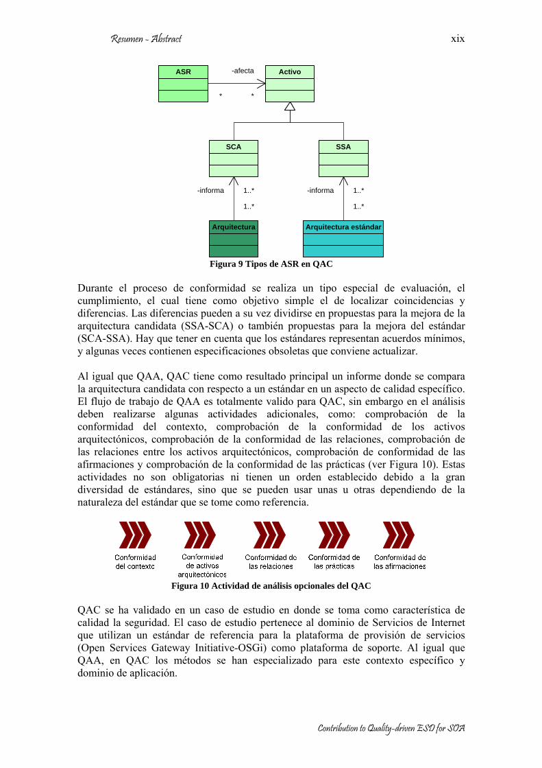
Los estándares son, en general, documentos detallados donde se incluyen las recomendaciones acerca de un área o dominio de interés, esas recomendaciones pueden ser obligatorias u opcionales y a la vez pueden ser específicas o generales dependiendo de si afectan o no a uno o varios elementos del dominio. Un estándar es específico para un contexto, así que cada estándar define sus propios conceptos, notaciones, convenciones y condiciones. Usualmente un estándar define unas prácticas producto de experiencias reconocidas, estas prácticas pueden ser: procesos, guías, patrones o escenarios que han sido probados en la industria en implementaciones reales. La mayoría de los elementos del modelo conceptual de QAC tienen la misma connotación del modelo conceptual de QAA. Sin embargo, dos nuevos tipos de Activos deben ser tratados independientemente, los activos candidatos significativos (SCA) y los activos estándar significativos (SSA) (ver Figura 9). La diferencia entre ellos es básicamente su procedencia, los SCA son activos que provienen de la arquitectura candidata y los SSA son activos del estándar. Por lo tanto, QAC se reduce a la comparación entre SCA y SSA con el fin de encontrar coincidencias y diferencias; para ello QAC puede hacer uso de diferentes métodos o técnicas, por ejemplo ontologías, algoritmos numéricos y gráficos, comparación sintáctica, métricas, etc.
Resumen - Abstract
Contribution to Quality-driven ESD for SOA
xix
Activo
1..*
-informa 1..*
Arquitectura Arquitectura estándar
1..*
-informa 1..*
SCA SSA
ASR
*
-afecta
*
Figura 9 Tipos de ASR en QAC
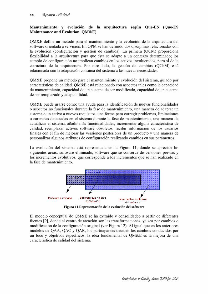
Durante el proceso de conformidad se realiza un tipo especial de evaluación, el cumplimiento, el cual tiene como objetivo simple el de localizar coincidencias y diferencias. Las diferencias pueden a su vez dividirse en propuestas para la mejora de la arquitectura candidata (SSA-SCA) o también propuestas para la mejora del estándar (SCA-SSA). Hay que tener en cuenta que los estándares representan acuerdos mínimos, y algunas veces contienen especificaciones obsoletas que conviene actualizar. Al igual que QAA, QAC tiene como resultado principal un informe donde se compara la arquitectura candidata con respecto a un estándar en un aspecto de calidad específico. El flujo de trabajo de QAA es totalmente valido para QAC, sin embargo en el análisis deben realizarse algunas actividades adicionales, como: comprobación de la conformidad del contexto, comprobación de la conformidad de los activos arquitectónicos, comprobación de la conformidad de las relaciones, comprobación de las relaciones entre los activos arquitectónicos, comprobación de conformidad de las afirmaciones y comprobación de la conformidad de las prácticas (ver Figura 10). Estas actividades no son obligatorias ni tienen un orden establecido debido a la gran diversidad de estándares, sino que se pueden usar unas u otras dependiendo de la naturaleza del estándar que se tome como referencia.
Figura 10 Actividad de análisis opcionales del QAC
QAC se ha validado en un caso de estudio en donde se toma como característica de calidad la seguridad. El caso de estudio pertenece al dominio de Servicios de Internet que utilizan un estándar de referencia para la plataforma de provisión de servicios (Open Services Gateway Initiative-OSGi) como plataforma de soporte. Al igual que QAA, en QAC los métodos se han especializado para este contexto específico y dominio de aplicación.
Resumen - Abstract
Contribution to Quality-driven ESD for SOA
xx
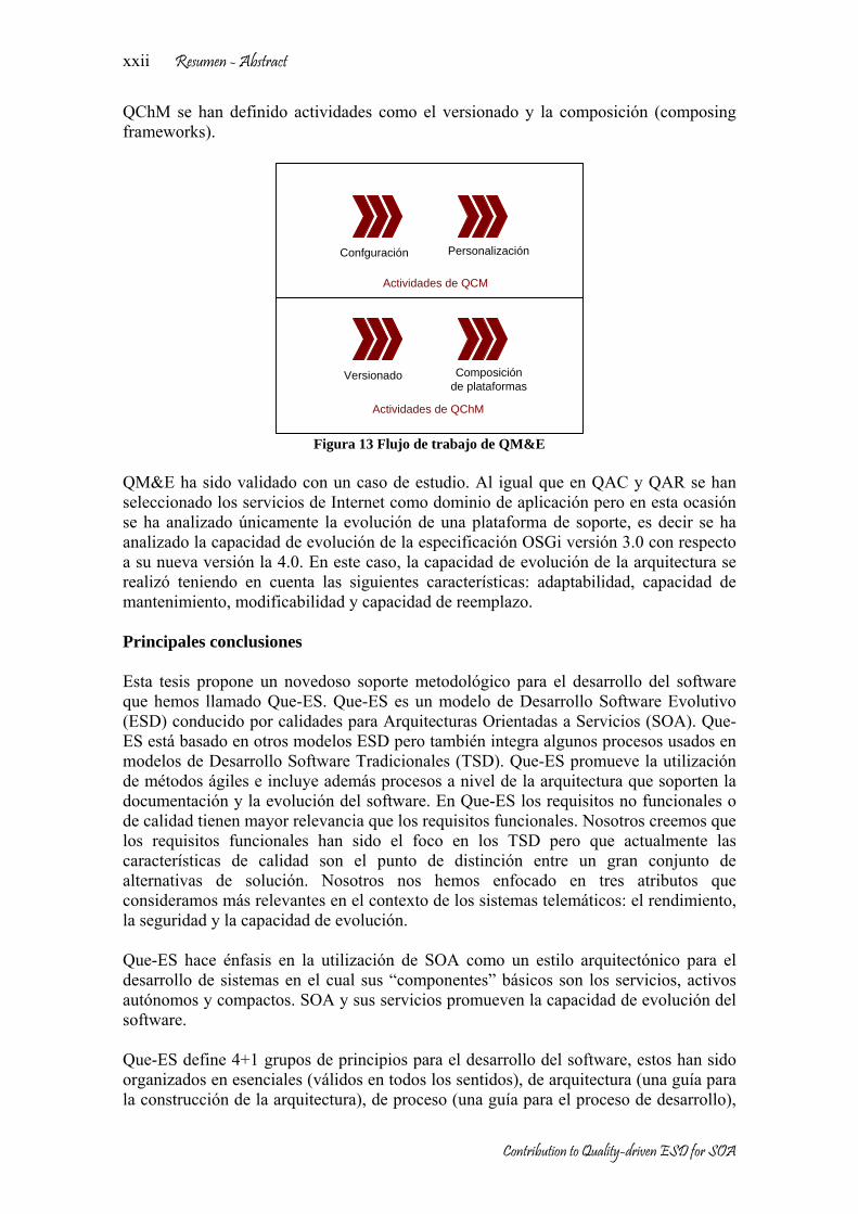
Mantenimiento y evolución de la arquitectura según Que-ES (Que-ES Maintenance and Evolution, QM&E) QM&E define un método para el mantenimiento y la evolución de la arquitectura del software orientada a servicios. En QPM se han definido dos disciplinas relacionadas con la evolución (configuración y gestión de cambios). La primera (QCM) proporciona flexibilidad a la arquitectura para que ésta se adapte a un contexto determinado; los cambio de configuración no implican cambios en los activos involucrados, pero sÍ de la estructura de la arquitectura. Por otro lado, la gestión de cambios (QChM) está relacionada con la adaptación continua del sistema a las nuevas necesidades. QM&E propone un método para el mantenimiento y evolución del sistema, guiado por características de calidad. QM&E está relacionado con aspectos tales como la capacidad de mantenimiento, capacidad de un sistema de ser modificado, capacidad de un sistema de ser remplazado y adaptabilidad. QM&E puede usarse como: una ayuda para la identificación de nuevas funcionalidades o aspectos no funcionales durante la fase de mantenimiento, una manera de adaptar un sistema o un activo a nuevos requisitos, una forma para corregir problemas, limitaciones o carencias detectadas en el sistema durante la fase de mantenimiento, una manera de actualizar el sistema, añadir más funcionalidades, incrementar alguna característica de calidad, reemplazar activos software obsoletos, recibir información de los usuarios finales con el fin de mejorar las versiones posteriores de un producto y una manera de personalizar algunos atributos de configuración realizando cambios en sus parámetros. La evolución del sistema está representada en la Figura 11, donde se aprecian las siguientes áreas: software eliminado, software que se conserva de versiones previas y los incrementos evolutivos, que corresponde a los incrementos que se han realizado en la fase de mantenimiento.
Figura 11 Representación de la evolución del software
El modelo conceptual de QM&E se ha extraído y consolidadeo a partir de diferentes fuentes [9], donde el centro de atención son las transformaciones, ya sea por cambios o modificación de la configuración original (ver Figura 12). Al igual que en los anteriores modelos de QAA, QAC y QAR, los participantes deciden los cambios conducidos por un foco y objetivos específicos, la idea fundamental de QM&E es la mejora de una característica de calidad del sistema.

Resumen - Abstract
Contribution to Quality-driven ESD for SOA
xxi
Figura 12 Modelo conceptual de QM&E
Existen varios tipos de transformaciones dependiendo del origen y la dirección en la que se apliquen: transformaciones hacia delante para mejora de las características funcionales y no funcionales y transformaciones hacia atrás, cuando una versión más avanzada ocasiona conflictos, limitaciones, dependencias no deseadas y otros problemas por lo cual se debe volver a una versión anterior más estable. Las transformaciones tienen asociado un registro que almacena todos los cambios efectuados, este registro posee tres partes esenciales: auditoria para llevar la cuenta de todos los cambios realizados, estadísticas para hacer estimaciones y medir el impacto de los cambios y la documentación para sincronizar la documentación del sistema con los cambios efectuados. Entre los métodos más utilizados para las transformaciones se encuentra la reconstrucción (refactoring), la fabricación (factoring) y la reconstrucción de la arquitectura (rearchitecting). La reconstrucción es una técnica para la reestructuración del código, añadiendo, corrigiendo, borrando o limpiado partes del código para su mejora, propuesta inicialmente en [10] y actualmente muy acogida en los métodos ágiles. La fabricación y la reconstrucción de la arquitectura han sido definidas en esta tesis como técnicas muy relacionadas con la reconstrucción, así la fabricación construye nuevos activos que adaptan o mejoran aspectos funcionales o no funcionales mientras que la reconstrucción de la arquitectura modifica a un alto nivel de abstracción la configuración de la arquitectura, esto es, modificando, añadiendo, corrigiendo, eliminando, limpiando, componiendo o mejorando algún activo arquitectónico del sistema. El flujo de trabajo gestiona las versiones del sistema y los cambios a través de todo el ciclo de vida del software. El flujo de trabajo controla cómo, cuándo y dónde deben realizarse las transformaciones. Hemos ubicado diferentes actividades de QM&E (ver Figura 13) así por ejemplo para QCM se han definido actividades muy relacionadas con el ciclo de vida de un producto: configuración y personalización. Así mismo para
Resumen - Abstract
Contribution to Quality-driven ESD for SOA
xxii
QChM se han definido actividades como el versionado y la composición (composing frameworks).
Versionado Composición de plataformas
Actividades de QCM
Actividades de QChM
Confguración Personalización
Figura 13 Flujo de trabajo de QM&E
QM&E ha sido validado con un caso de estudio. Al igual que en QAC y QAR se han seleccionado los servicios de Internet como dominio de aplicación pero en esta ocasión se ha analizado únicamente la evolución de una plataforma de soporte, es decir se ha analizado la capacidad de evolución de la especificación OSGi versión 3.0 con respecto a su nueva versión la 4.0. En este caso, la capacidad de evolución de la arquitectura se realizó teniendo en cuenta las siguientes características: adaptabilidad, capacidad de mantenimiento, modificabilidad y capacidad de reemplazo. Principales conclusiones Esta tesis propone un novedoso soporte metodológico para el desarrollo del software que hemos llamado Que-ES. Que-ES es un modelo de Desarrollo Software Evolutivo (ESD) conducido por calidades para Arquitecturas Orientadas a Servicios (SOA). Que-ES está basado en otros modelos ESD pero también integra algunos procesos usados en modelos de Desarrollo Software Tradicionales (TSD). Que-ES promueve la utilización de métodos ágiles e incluye además procesos a nivel de la arquitectura que soporten la documentación y la evolución del software. En Que-ES los requisitos no funcionales o de calidad tienen mayor relevancia que los requisitos funcionales. Nosotros creemos que los requisitos funcionales han sido el foco en los TSD pero que actualmente las características de calidad son el punto de distinción entre un gran conjunto de alternativas de solución. Nosotros nos hemos enfocado en tres atributos que consideramos más relevantes en el contexto de los sistemas telemáticos: el rendimiento, la seguridad y la capacidad de evolución. Que-ES hace énfasis en la utilización de SOA como un estilo arquitectónico para el desarrollo de sistemas en el cual sus “componentes” básicos son los servicios, activos autónomos y compactos. SOA y sus servicios promueven la capacidad de evolución del software. Que-ES define 4+1 grupos de principios para el desarrollo del software, estos han sido organizados en esenciales (válidos en todos los sentidos), de arquitectura (una guía para la construcción de la arquitectura), de proceso (una guía para el proceso de desarrollo),

Resumen - Abstract
Contribution to Quality-driven ESD for SOA
xxiii
de organización (una guía para la mejor organización de los participantes) y de negocio (porque el software tienen que pensarse también como oportunidades de negocio). De acuerdo con los principios, Que-ES se ha dividido en 4 modelos (descripción (QDM), proceso (QPM), negocio (QBM) y organización (QOM)) los cuales en su conjunto constituyen una completa metodología. Cada uno de estos modelos ha sido descrito en esta tesis, pero nuestro mayor esfuerzo se ha dedicado al modelo de proceso. Nosotros creemos que las características de calidad son controladas de mejor manera a nivel de la arquitectura, por esta razón, Que-ES promueve la utilización de modelos arquitectónicos para el desarrollo del software. Los métodos arquitectónicos son el núcleo de las principales contribuciones de esta tesis: Evaluación de la arquitectura (QAA), recuperación de la arquitectura (QAR), conformidad de la arquitectura (QAC) y mantenimiento y evolución (QM&E). QAA evalúa la arquitectura con respecto a un específico aspecto de calidad. Además, QAA hace un análisis comparativo con el fin de seleccionar la mejor arquitectura de un conjunto de alternativas. QAC también evalúa la arquitectura pero en este caso verifica si la arquitectura candidata está en conformidad con un estándar o recomendación de facto. QAR permite analizar implementaciones existentes con el fin de obtener su arquitectura (lo más cercana a la real). QAR sigue una dirección opuesta al flujo normal del proceso de desarrollo y promueve la reutilización de sistemas o activos software. Finalmente, QM&E es un método para mejorar la adaptabilidad, capacidad de modificación y reutilización de activos arquitectónicos durante la fase de mantenimiento. Que-ES es un modelo que ha sido probado parcialmente con algunos casos de estudio. Que-ES ha sido especializado para un escenario, característica de calidad y contexto en particular. Los métodos especializados pueden ser considerados como contribuciones adicionales en esta tesis. Los métodos de Que-ES especializados pueden ser tomados como una guía para otras características no funcionales.

Resumen - Abstract
Contribution to Quality-driven ESD for SOA
xxiv
Abstract The quality of software is a key element for the successful of a system. Currently, with the advance of the technology, consumers demand more and better services. Models for the development process also have adapted to new requirements. In the particular case of service oriented systems (domain of this thesis), where an unpredictable number of user are there, which can to access to services. This work proposes an improvement in the models for the process of development of the software based on the theory of the development of evolutionary software. The main objective is to maintain and improve the quality of software as long as possible and with the minimum effort and cost. Usually, this process is supported on methods known in the literature as software development agile methods. Other key element in this thesis is the service oriented software architecture. Software architecture plays an important role in the quality of any software system. The Service oriented architecture adds the service flexibility, the services are autonomous and compact assets, and they can be improved and integrated with better facility. The proposed model in this thesis for evolutionary software development makes emphasis in the quality of services. Therefore, some principles of evolutionary development are redefined and new processes are introduced, such as: architecture assessment, architecture recovery and architecture conformance. Every new process will be evaluated with case studies considering quality aspects. They have been selected according to the market demand, they are: the performance, security and evolutionability. Other aspects could be considered of the same way than the three previous, but we considering these quality attributes are enough to demonstrate the viability of our proposal.

Acknowledgments First and foremost, I would like to gratefully acknowledge the trust and invaluable direction and support from my advisor, Juan Carlos Dueñas López. This work would not have been made possible without his help. I wish to thank the friendship and collaboration of current and previous members of the Engineering software Group at DIT/UPM whom I have had the pleasure of working with. I would like to emphasize the excellent working atmosphere with Rodrigo, Jose Luis, Manu, Jose Fernán, Chema, Victor, Miguel, Carlos, Jorge, Arantza, Lourdes, Carol, Hugo, Felix, Jorge and Rubén five year sharing the same laboratory, thank by support me. Similarly, I would like to thank the external friendship and collaboration Juan Antonio, José, Daniel, Juan Pedro, Ruth from TRECOM project. Jose Luis, Antonio, Agustín from the CARTS project, Miguel Angel, Fernando, Tor, Jens, Claudio, René, Eila and big list from members of Families, Osmose and Serious projects, their help in the implementation and validation of the work presented in this dissertation. This thesis not has been made possible without the presence of a lot very good colleagues and friends. I should to say another big profit was meat them. My friends of DIT, Ana, Sandra, Omaira, Hyldeé, Ivan, Hector, Pablo, Hamilton, Jaime, Julio, Marco and Sergio, my in-door football team Dante, Carlos, Toti, Fran, Guillermo, Jose Fernando, Chevi, Nelson, Roney, Sidney and Daniel. To July for her efficiency work in the laboratory. To my colleagues from Departamento de Telemática of the Universidad del Cauca in Colombia, current and previous members, and friends from FIET and Unicauca. To my friends, in Colombia. And my “new” friends with who share unforgettable moments during more than five years in Spain, Mayte and Juanlu, Mary Luz and Jose, Mar and Jose, Cris and Santi, Susana and Alberto, Kika, Valle, Mark, Juan Maria, José Ramón, Nuria and Teemu. Some Institutions also have my gratefulness: The Universidad del Cauca (Colombia), Xfera, Departamento de Sistemas Telemáticos of the Universidad Politécnica de Madrid and Ministerio de Ciencia y Tecnología (Spain), who gave me, economical support during my stay in Spain. Bless god the new technologies, Internet and phonecard allowing staying in contact with my family and friends in Colombia and other countries. Last but not least, the biggest gratitude to my wife Maite and specially to my son Luis, that was born during this thesis work, they were with me in Madrid with their uncalculated love and support, and after with my parents, brothers and relatives in the distance. They have supported and given me strength to carry on this work during these years, all that not has been possible without their patient and understanding.

Acknowledgments
Contribution to Quality-driven ESD for SOA
xxvi

Table of contents
RESUMEN I
RESUMEN EXTENDIDO II
ABSTRACT XXIV
ACKNOWLEDGMENTS XXV
TABLE OF CONTENTS XXVII
CHAPTER 1 INTRODUCTION 1
1.1. MOTIVATION 1 1.2. OBJECTIVES 7 1.2.1. GLOBAL OBJECTIVE 7 1.2.2. SPECIFIC OBJECTIVES 9 1.3. CONTRIBUTIONS 12 1.4. ORGANIZATION OF THIS THESIS 12
CHAPTER 2 STATE OF THE ART 15
2.1. SERVICE-ORIENTED ARCHITECTURES 15 2.1.1. SOFTWARE ARCHITECTURE 15 2.1.2. SERVICE-ORIENTED ARCHITECTURE SPECIFICATIONS 18 2.2. SYSTEM EVOLUTION 25 2.2.1. CURRENT ESD METHODOLOGIES 25 2.2.2. ARCHITECTURE-BASED REASONING TECHNIQUES 30 2.3. NON-FUNCTIONAL REQUIREMENTS OF SOFTWARE 35 2.3.1. PERFORMANCE 40 2.3.2. SECURITY 42 2.3.3. EVOLVABILITY 45 2.4. CONCLUSIONS 50
CHAPTER 3 ESD MODEL 51
3.1. INTRODUCTION AND MOTIVATION 51 3.2. QUE-ES PRINCIPLES 53 3.3. QUE-ES DESCRIPTION 57 3.3.1. QUE-ES DESCRIPTION MODEL (QDM) 57 3.3.2. QUE-ES PROCESS MODEL (QPM) 60 3.3.3. QUE-ES ORGANIZATION MODEL (QOM) 65 3.3.4. QUE-ES BUSINESS MODEL (QBM) 66 3.4. COMPARATIVE ANALYSIS BETWEEN TSD AND ESD 66 3.5. CONCLUSIONS 78

Table of contents
Contribution to Quality-driven ESD for SOA
xxviii
CHAPTER 4 QUE-ES ARCHITECTURE ASSESSMENT (QAA) 79
4.1. INTRODUCTION 79 4.2. QAA CONCEPTUAL MODEL 81 4.3. QAA WORKFLOW 84 4.4. QAA METHODS, TECHNIQUES AND TOOLS 87 4.5. ARCHITECTURE ASSESSMENT FOR THE PERFORMANCE OF A SOFT REAL TIME SYSTEM. 91 4.5.1. REAL-TIME SYSTEMS BACKGROUND 92 4.5.2. INSTANTIATION OF QAA FOR PERFORMANCE ASSESSMENT IN SOFT REAL-TIME SYSTEMS 93 4.5.3. METHODS AND TECHNIQUES 95 4.5.4. TOOLS 98 4.5.5. A CASE STUDY (SCADA SYSTEM) 101 4.6. CONCLUSIONS 107
CHAPTER 5 QUE-ES ARCHITECTURE RECOVERY (QAR) 109
5.1. INTRODUCTION 109 5.2. QAR CONCEPTUAL MODEL 111 5.3. QAR WORKFLOW 114 5.4. QAR METHODS, TECHNIQUES AND TOOLS 116 5.5. ARCHITECTURE RECOVERY FOR THE SECURITY IN INTERNET SERVICES 119 5.5.1. BACKGROUND OF SECURITY STANDARDS IN INTERNET SERVICES 119 5.5.2. INSTANTIATION OF QAR FOR SECURITY IN INTERNET SERVICES 122 5.5.3. CASE STUDY (SECURITY IN THE OSGI FRAMEWORK) 123 5.6. CONCLUSIONS 131
CHAPTER 6 QUE-ES ARCHITECTURE CONFORMANCE (QAC) 133
6.1. INTRODUCTION 133 6.2. QAC CONCEPTUAL MODEL 136 6.3. QAC WORKFLOW 140 6.4. QAC METHODS, TECHNIQUES AND TOOLS 143 6.5. ARCHITECTURE CONFORMANCE FOR THE SECURITY IN INTERNET SERVICES. 145 6.5.1. INSTANTIATION OF QAC FOR SECURITY IN INTERNET SERVICES 146 6.5.2. METHODS AND TECHNIQUES 148 6.5.3. TOOLS 149 6.5.4. CASE STUDY (REMOTE MANAGEMENT FOR DEPLOYMENT OF SERVICES -RMDS) 149 6.6. CONCLUSIONS 161
CHAPTER 7 QUE-ES MAINTENANCE AND EVOLUTION (QM&E) 163
7.1. INTRODUCTION 163 7.2. QM&E CONCEPTUAL MODEL 166 7.3. QM&E WORKFLOW 170 7.4. QM&E METHODS, TECHNIQUES AND TOOLS 174 7.4.1. FOR FORWARDTRANSFORMATION 174 7.4.2. FOR BACKWARDTRANSFORMATION: 175 7.5. M&E ON SOA, CASE STUDY (EVOLUTION FROM OSGI R3 TO OSGI R4). 176 7.5.1 CASE STUDY GENERAL DESCRIPTION 176 7.5.2. DESCRIPTION OF THE CHANGES 179

Table of contents
Contribution to Quality-driven ESD for SOA
xxix
7.5.3 ASSESSMENT OF THE EVOLUTION BETWEEN OSGI R3 AND R4 185 7.6. CONCLUSIONS 192
CHAPTER 8 CONCLUSIONS AND FURTHER WORK 195
8.1 CONCLUSIONS AND MAIN CONTRIBUTIONS 195 8.2 FURTHER WORK 199
BIBLIOGRAPHY 201
ANNEX A LIST OF ACRONYMS 217
ANNEX B QUE-ES FIGURES COMPENDIUM 221
ANNEX C INQUIRY ABOUT OSGI UTILIZATION 227
ANNEX D CURRICULUM VITAE 229
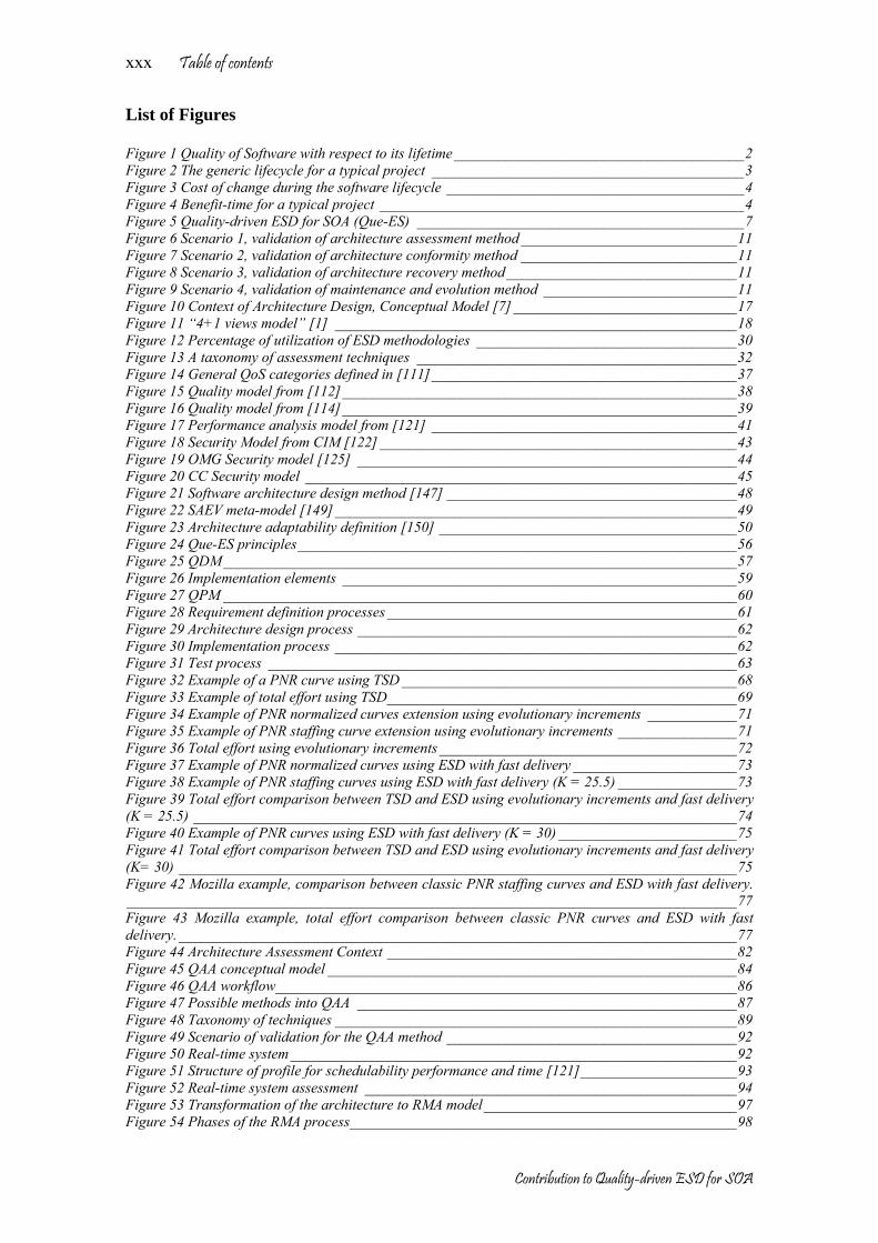
Table of contents
Contribution to Quality-driven ESD for SOA
xxx
List of Figures Figure 1 Quality of Software with respect to its lifetime_______________________________________2 Figure 2 The generic lifecycle for a typical project __________________________________________3 Figure 3 Cost of change during the software lifecycle ________________________________________4 Figure 4 Benefit-time for a typical project _________________________________________________4 Figure 5 Quality-driven ESD for SOA (Que-ES) ____________________________________________7 Figure 6 Scenario 1, validation of architecture assessment method _____________________________11 Figure 7 Scenario 2, validation of architecture conformity method _____________________________11 Figure 8 Scenario 3, validation of architecture recovery method_______________________________11 Figure 9 Scenario 4, validation of maintenance and evolution method __________________________11 Figure 10 Context of Architecture Design, Conceptual Model [7] ______________________________17 Figure 11 “4+1 views model” [1] ______________________________________________________18 Figure 12 Percentage of utilization of ESD methodologies ___________________________________30 Figure 13 A taxonomy of assessment techniques ___________________________________________32 Figure 14 General QoS categories defined in [111]_________________________________________37 Figure 15 Quality model from [112]_____________________________________________________38 Figure 16 Quality model from [114]_____________________________________________________39 Figure 17 Performance analysis model from [121] _________________________________________41 Figure 18 Security Model from CIM [122] ________________________________________________43 Figure 19 OMG Security model [125] ___________________________________________________44 Figure 20 CC Security model __________________________________________________________45 Figure 21 Software architecture design method [147] _______________________________________48 Figure 22 SAEV meta-model [149]______________________________________________________49 Figure 23 Architecture adaptability definition [150] ________________________________________50 Figure 24 Que-ES principles___________________________________________________________56 Figure 25 QDM_____________________________________________________________________57 Figure 26 Implementation elements _____________________________________________________59 Figure 27 QPM _____________________________________________________________________60 Figure 28 Requirement definition processes _______________________________________________61 Figure 29 Architecture design process ___________________________________________________62 Figure 30 Implementation process ______________________________________________________62 Figure 31 Test process _______________________________________________________________63 Figure 32 Example of a PNR curve using TSD _____________________________________________68 Figure 33 Example of total effort using TSD_______________________________________________69 Figure 34 Example of PNR normalized curves extension using evolutionary increments ____________71 Figure 35 Example of PNR staffing curve extension using evolutionary increments ________________71 Figure 36 Total effort using evolutionary increments________________________________________72 Figure 37 Example of PNR normalized curves using ESD with fast delivery ______________________73 Figure 38 Example of PNR staffing curves using ESD with fast delivery (K = 25.5) ________________73 Figure 39 Total effort comparison between TSD and ESD using evolutionary increments and fast delivery (K = 25.5) _________________________________________________________________________74 Figure 40 Example of PNR curves using ESD with fast delivery (K = 30) ________________________75 Figure 41 Total effort comparison between TSD and ESD using evolutionary increments and fast delivery (K= 30) ___________________________________________________________________________75 Figure 42 Mozilla example, comparison between classic PNR staffing curves and ESD with fast delivery.__________________________________________________________________________________77 Figure 43 Mozilla example, total effort comparison between classic PNR curves and ESD with fast delivery.___________________________________________________________________________77 Figure 44 Architecture Assessment Context _______________________________________________82 Figure 45 QAA conceptual model _______________________________________________________84 Figure 46 QAA workflow______________________________________________________________86 Figure 47 Possible methods into QAA ___________________________________________________87 Figure 48 Taxonomy of techniques ______________________________________________________89 Figure 49 Scenario of validation for the QAA method _______________________________________92 Figure 50 Real-time system____________________________________________________________92 Figure 51 Structure of profile for schedulability performance and time [121]_____________________93 Figure 52 Real-time system assessment __________________________________________________94 Figure 53 Transformation of the architecture to RMA model__________________________________97 Figure 54 Phases of the RMA process____________________________________________________98

Table of contents
Contribution to Quality-driven ESD for SOA
xxxi
Figure 55 Integration of CARTS tool with other architectural design tools ______________________100 Figure 56 Description of basic process using CARTS tool ___________________________________100 Figure 57 Description of advance process using CARTS tool ________________________________101 Figure 58 Context diagram of SCADA system ____________________________________________102 Figure 59 Architecture of SCADA system, logical view [229] ________________________________103 Figure 60 SCADA system, alternative 1 _________________________________________________103 Figure 61 SCADA system, alternative 2 _________________________________________________103 Figure 62 Technique 1 results, Alternative 1 _____________________________________________105 Figure 63 Technique 1 results, Alternative 2 (CPU)________________________________________106 Figure 64 Technique 1 results, Alternative 2 (Controller) ___________________________________106 Figure 65 Example of CARTS reports___________________________________________________107 Figure 66 QAR conceptual model ______________________________________________________112 Figure 67 Asset classification _________________________________________________________112 Figure 68 Concerns_________________________________________________________________113 Figure 69 Available documentation classification _________________________________________113 Figure 70 QAR workflow_____________________________________________________________115 Figure 71 Scenario of validation for QAR method _________________________________________119 Figure 72 Quality aspects in security ___________________________________________________120 Figure 73 Security countermeasures____________________________________________________122 Figure 74 QAR for security in Internet services ___________________________________________123 Figure 75 Preliminary Oscar Framework core____________________________________________125 Figure 76 Refined Security Oscar Architecture ___________________________________________126 Figure 77 Recovered OSGi security architecture __________________________________________127 Figure 78 Security conceptual reference model ___________________________________________129 Figure 79 Security reference architecture________________________________________________129 Figure 80 Security reference architecture: Communication Countermeasures (detailed functionality)_129 Figure 81 Security reference architecture: Account Management Services (detailed functionality) ___130 Figure 82 Security reference architecture: Authorization Services (detailed functionality)__________130 Figure 83 Security reference architecture: Authentication Services (detailed functionality) _________130 Figure 84 Typical structure of a standard________________________________________________137 Figure 85 Types of ASR in QAC _______________________________________________________138 Figure 86 New inputs for Method and Techniques into QAC _________________________________139 Figure 87 Relationship between assessment and conformance________________________________140 Figure 88 QAC workflow ____________________________________________________________141 Figure 89 Architecture conformance analysis ____________________________________________143 Figure 90 Taxonomy of architecture conformance techniques ________________________________144 Figure 91 Scenario of validation for QAC method _________________________________________145 Figure 92 QAC for security in Internet services (Instantiation part 1)__________________________147 Figure 93 QAC for security in Internet services (Instantiation part 2)__________________________147 Figure 94 QAC for security in Internet services (Instantiation part 3)__________________________148 Figure 95 Taxonomy of tactics [126] ___________________________________________________148 Figure 96 Distributed residential environment ____________________________________________149 Figure 97 Proposed architecture for the scenario _________________________________________152 Figure 98 Mapping between CIM (DMTF) and OSGi with respect to security ___________________155 Figure 99 Authentication and authorization countermeasure mapping _________________________156 Figure 100 Accounting countermeasure mapping _________________________________________157 Figure 101 Communication countermeasure mapping ______________________________________157 Figure 102 Tactics used on QAC for the scenario _________________________________________159 Figure 103 Second candidate architecture for the scenario __________________________________160 Figure 104 Scenario. Detailed view of interaction of components. Permission Bundle Management __160 Figure 105 Evolutionary incremental software____________________________________________166 Figure 106 Ideal ESD _______________________________________________________________167 Figure 107 M&E Conceptual model ____________________________________________________168 Figure 108 Transformation classification________________________________________________170 Figure 109 States of asset deployment lifecycle ___________________________________________171 Figure 110 States during configuration management _______________________________________171 Figure 111 Extra-activities for configuration management __________________________________172 Figure 112 States during changing management __________________________________________173 Figure 113 Extra-activities for changing management______________________________________174 Figure 114 Scenario of validation for the QE&M method ___________________________________176
Table of contents
Contribution to Quality-driven ESD for SOA
xxxii
Figure 115 OSGi Specification, release 3 ________________________________________________178 Figure 116 OSGi Specification, release 4 ________________________________________________179 Figure 117 OSGI R3 layers___________________________________________________________180 Figure 118 OSGi R4 layers ___________________________________________________________180 Figure 119 Bundles life cycle [37] _____________________________________________________182 Figure 120 Bundles life cycle [371] ____________________________________________________182 Figure 121 Measurement of easy-to-learn parameters in OSGi specification ____________________188 Figure 122 Error treatment, customization of functionalities and missed functionalities in OSGi_____189 Figure 123 Effort in learning and correction of errors in OSGi_______________________________189 Figure 124 Capacities most relevant in OSGi framework____________________________________190 Figure 125 Use of functionalities OSGi in the applications __________________________________191 Figure 126 Utilization of open source OSGi implementations ________________________________192

Table of contents
Contribution to Quality-driven ESD for SOA
xxxiii
List of Tables Table 1 Comparison between component models.......................................................................................24 Table 2 Survey of assessment techniques[75] ............................................................................................32 Table 3 Qualities defined in ISO 9126 [3] .................................................................................................37 Table 4 Quality model defined in COCOTS [113] .....................................................................................38 Table 5 Mozilla project overview ...............................................................................................................76 Table 6 Analysis results for Alternative 1.................................................................................................105 Table 7 Analysis results for Alternative 2 (CPU).....................................................................................106 Table 8 Analysis results for Alternative 2 (Controller) ............................................................................106 Table 9 Commonalities between CIM (part of security) and OSGi..........................................................153 Table 10 Extracted requirements from conformance process between OSGi standard and CIM (DMTF)..................................................................................................................................................................154 Table 11 Relation of M&E attributes with respect to some criteria of OSGi specification......................186 Table 12 Additional criteria for OSGi specification ................................................................................187

Table of contents
Contribution to Quality-driven ESD for SOA
xxxiv

Chapter 1 Introduction
This chapter defines the context of this thesis. The first section shows the motivation of this work, which focuses in the software quality, evolutionary software development and service oriented architectures. The second section presents the main objectives pursued by this work. The third section sums up the principal contributions. And finally, this chapter describes the organization of this dissertation.
1.1. Motivation During the last years, the quality of software has been a key element for its success. Consumers require software systems with high quality. The software should be prepared for new demands, new underlying technologies, more exigent consumers, competition in shorter time to market, growing number of users, etc. All these factors affect the way companies develop software. How systems can be built with high quality in accordance with the new challenges? Well-established methods and processes are revealing not to be successful in this new situation. Therefore changes are needed: changes in the development process, changes in the involved technologies and practices. New models should be created in order to improve the productivity and quality. First is the definition of “Quality”. The quality refers to how good something or somebody is. In computer science quality has several different interpretations:
• In [11] the quality means "fitness for use". In this case the quality depends of the final user.
• In [12] the quality means "conforming to specifications". In this case the quality depends of the specifications, but they are not always what the final user wants.
• In [13] the quality has two dimensions: "must-be quality" and "attractive quality". In this case depends of the final user and supporters respectively.
• In [14] the quality means "value to some person". It is the relative opinion of a final user in a context (who is the person).
Other authors extend the quality concept based on the previous definitions, for example, Roger Pressman, Watts Humphrey, Al Davis and others extend the “Conforming to specifications” idea, adding that the quality also should be measurable. Capers Jones and Robert Glass extend the “Fitness for use” concept and define quality in terms of attributes. In the IEEE Glossary of Software Engineering Terminology quality is defined in two dimensions as in [15], and finally James Bach, Ed Yourdon and others extends “Value to some person”, introducing the notion that the software quality needs to be “Good enough”. There is a close relation between quality and the used methodology for system development. A methodology is a codified set of recommended practices that defines the orchestration of the software development. The methodology is the mechanism that
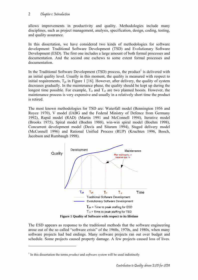
Chapter 1. Introduction
Contribution to Quality-driven ESD for SOA
2
allows improvements in productivity and quality. Methodologies include many disciplines, such as project management, analysis, specification, design, coding, testing, and quality assurance. In this dissertation, we have considered two kinds of methodologies for software development: Traditional Software Development (TSD) and Evolutionary Software Development (ESD). The first one includes a large amount of both formal processes and documentation. And the second one eschews to some extent formal processes and documentation. In the Traditional Software Development (TSD) process, the product1 is delivered with an initial quality level. Usually in this moment, the quality is measured with respect to initial requirements, Tpt in Figure 1 [16]. However, after delivery, the quality of system decreases gradually. In the maintenance phase, the quality should be kept up during the longest time possible. For example, Ti1 and Ti2 are two planned boosts. However, the maintenance process is very expensive and usually in a relatively short time the product is retired. The most known methodologies for TSD are: Waterfall model (Bennington 1956 and Royce 1970), V model (IABG and the Federal Ministry of Defence from Germany 1992), Rapid model (RAD) (Martin 1991 and McConnell 1994), Iterative model (Brooks 1975), Spiral model (Boehm 1988), win-win spiral model (Boehm 1998), Concurrent development model (Davis and Sitaram 1994), Staged delivery model (McConnell 1996) and Rational Unified Process (RUP) (Kruchten 1996, Booch, Jacobson and Rumbaugh 1998).
Figure 1 Quality of Software with respect to its lifetime
The ESD appears as response to the traditional methods that the software engineering arose out of the so called “software crisis” of the 1960s, 1970s, and 1980s, when many software projects had bad endings. Many software projects ran out over budget and schedule. Some projects caused property damage. A few projects caused loss of lives.
1 In this dissertation the terms product and software system will be used indistinctly

Chapter 1. Introduction
Contribution to Quality-driven ESD for SOA
3
The software crisis was originally defined in terms of productivity, but evolved to emphasize quality. The ESD processes allow improving the quality, reducing the total cost and increasing the product lifetime. Figure 1, Figure 2, Figure 3 and Figure 4 illustrate this tendency, these empirical curves are based on Putnam-Norden-Rayleigh (PNR) curves for TSD and agile method theory [19] for ESD. From Figure 1 two evident conclusions are deduced:
• The products using ESD are earlier delivered than TSD, because ESD makes emphasis in rapid delivery (Tpe < Tpt).
• The quality in the ESD increases during the maintenance time, because ESD assumes changes after delivery, for example the improvements in Ti1 and Ti2.
The most known methodologies for ESD are: eXtreme Programming (XP) (Beck, Cunningham and Jeffries 1999), Scrum (Takeuchi and Nonaka 1986, Stherland and Schwaber 1995), Evolutionary Project Management (Evo) (Gilb 1976), Crystal Methods (Cockburn 2001), Feature Driven Development (FDD) (Batory 2003, Coad, Lefebvre, DeLuca 2000), Dynamic Systems Development Method (DSDM) (Stapleton 1997), Adaptive Software Development (Highsmith 2000), Agile Modeling (Ambler 2002), Lean Development (LD) (Charette 2001) and Lean Software Development (LSD) (Mary and Tom Poppendieck 2001). Figure 2 shows the costs in the different phases of the TSD process (thin line) and of the ESD process (thick line). In the picture, the curves illustrate clearly the motivation of the industry, by decreasing cost in maintenance and by reducing cost and effort during repairing software. Figure 2 presents a generic cycle for the expenditure of manpower over the whole project; these curves are modeled with the function of Putnam-Norden-Rayleigh, more known as PNR curve. The peaks of the curves occur when the product is delivered (time to peak staffing), being Tpt and Tpe for TSD and ESD respectively.
% of total EffortCost
Time
Development
Maintenance
Traditional Software DevelopmentEvolutionary Software Development
Tpe Tpt
Figure 2 The generic lifecycle for a typical project
Some studies regarding cost, estimating time and effort are presented in [17] and [18]. All studies assert that an early detection of possible problems means less effort and cost. Also, early detection means more effort in the architecture design. Figure 3 shows the cost of change in the TSD compared with respect to the ESD. In the development phase,

Chapter 1. Introduction
Contribution to Quality-driven ESD for SOA
4
changes in the TSD are cheaper than the ESD. But during the maintenance phase, the cost in the TSD increases quicker than in the ESD [19].
Cost of change
Development
Maintenance
TimeTraditional Software DevelopmentEvolutionary Software Development
Tpe Tpt
Figure 3 Cost of change during the software lifecycle
Figure 4 describes the benefits in a typical project. The benefits of a project start when the company recovers the investment. The ESD tries to increase the relation benefit-time. Benefit-time starts when sales or revenues are equal to expenses; this point is known as break-even point. The benefit-time finishes when the maintenance costs raise over the benefits and in consequence the product should be retired. Figure 4 shows the benefit-time for the TSD and the ESD. Two important conclusions are deduced.
• Break-even point in the TSD is earlier than the ESD (Tt1 < Te1), because the ESD puts the biggest effort during the development phase (See Figure 2), focused in the people, iterative, early delivery, intensive communication and continuous feedback.
• The benefit-time in the TSD is shorter than the ESD (Tt2 – Tt1 < Te2 – Te1), because the ESD offers a better manner to improve the quality during the maintenance phase. The ESD should be adaptable and predictable.
Total EffortCost
Time
Development
Maintenance
Tt1
Break-even point
Te1
Traditional Software DevelopmentEvolutionary Software DevelopmentBenefits
Tt2 Te2
Benefit-time in TSD
Benefit-time in ESD
Figure 4 Benefit-time for a typical project
The ESD process is focused on the quality of software. In traditional products, the concentration of effort in only one quality attribute usually introduces unexpected
Chapter 1. Introduction
Contribution to Quality-driven ESD for SOA
5
problems in other qualities or functionalities. These potential problems can be more visible at the architecture, which is long treated in the software architecture theory. The concept of software architecture was introduced by Edsger Dijkstra (1960s) and largely has increased in popularity since the early 1990s, due to activity within industrial players such as Rational Software Corporation and Microsoft. The software architecture refers to the theory behind the actual design of computer software. In the same way as a building architects set the principles and goals of a building project as the basis for the draftsman's plans, so too, a software architect sets out the software architecture as a basis for actual system design specifications. The software architecture is commonly organized in views; the most known views are presented by Kruchten in [1], which are analogous to the different types of blueprints made in common architecture. Some possible views are: functional/logic view, code view, development/structural view, concurrency/process/thread view, physical/deployment view and user action/feedback view. Architectural reasoning is a key in this thesis. The architecture is a central means to reuse to integrate systems or parts of systems and control the evolution of the quality of the system. These processes are only possible if the system is well documented and if its architecture is available. Currently, there are several architectural patterns that can be considered as references [20]. Also, several component models are in the market (EJB, CCM, .NET, OSGi, WebServices and others). Component models define in big part how the system architecture is. A clear tendency encouraging from software architecture nowadays is for software evolving into services. A service is a function that is well-defined, self-contained, and does not depend on the context or state of other services. So it can be said that service architecture (being Service-Oriented Architectures (SOA) just a case of them) are a domain architectural style. It offers some benefits, such as the possibility for adaptation and changes in short time. SOA isolates parts of the system into services, then, we can improve several quality attributes only to one service, almost without affecting other parts of the system. The SOA goal is to achieve loose coupling among service provides and service consumers. A service can be composed or configured by one or more architectural assets. A service is the endpoint of a connection. Also, a service has some type of underlying computer system that supports the connection offered. The combination of services, internal and external to an organization, makes up a SOA [2]. Services have a close relationship with qualities, usually a service improves certain quality in a product, for example, when you contract internet access, other complementary services are “needed” as security or performance. In these cases functionalities take a second place. The quality of software can be also increased by reducing the size of the software. So, refactoring and removing duplicated parts in the existing code base are keys by increasing quality. These activities cannot be done effectively if the architecture is not guiding the process. In fact, system requirements change continuously, and therefore the ESD should have a continuous feedback. The system or assets should evolve in the same direction than the changes and new demands. A key aspect is the qualitative and quantitative visualization of the system structure, because it allows detecting bugs,
Chapter 1. Introduction
Contribution to Quality-driven ESD for SOA
6
conflicts, limitations and duplicated parts. In this sense, the assessment process plays a relevant role to assess complete system, services or assets. The output of the assessment process becomes into the input to a continuous system adaptation. On the other hand, the organizations need to reduce the effort in development process; obviously it has a direct relation to cost. For this reason, more and more industries try to reuse existing products, so we need an asset recovery process in order to reuse software pieces. In addition, the software can be obtained from a third-party (for example open source) or software that has not been constructed by a physically “near-by” colleague. Reusing good software can increase the total quality. One idea of the ESD is the quickest incremental delivery. We propose to reduce development time by reusing previously implemented assets. For us, the success of the ESD depends of a clear definition of requirements making emphasis in quality attributes, the construction of a reference architecture, a suitable selection of reusable assets and a quick detection of possible limitations, conflicts and errors. Other trend concerns needs from the market to integrate different services into a single system, and the connection of services imply sharing information between them. Integration requires that services must be compliant to certain standards. In other words we need to develop or to buy services from a third-party (outsourced software) in conformance with certain standard. Therefore, a conformance process should be defined. Once mentioned these different architectural reasoning processes, it is clear that the market needs a complete orchestration among the different processes for software development in order to apply them in adequate way (techniques, process, methods and tools). This thesis proposes a new process based on the ESD, by improving the limitations of previous ESDs, especially as regards quality. The Quality-driven ESD for SOA (Que-ES) model proposed in this thesis is shown in Figure 5. Essentially, the Que-ES is useful to learn from available systems and, with this knowledge, helps in the discovering of new demands and makes estimations.
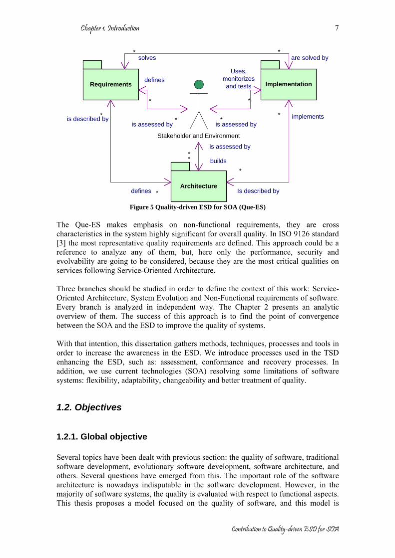
Chapter 1. Introduction
Contribution to Quality-driven ESD for SOA
7
Requirements Implementation
Architecture
Stakeholder and Environment
*
*
* *
*
*
**
*
**
* implements
Is described bydefines
is described by
builds
solves
Uses, monitorizes and tests
defines
is assessed byis assessed by
is assessed by
are solved by
Figure 5 Quality-driven ESD for SOA (Que-ES)
The Que-ES makes emphasis on non-functional requirements, they are cross characteristics in the system highly significant for overall quality. In ISO 9126 standard [3] the most representative quality requirements are defined. This approach could be a reference to analyze any of them, but, here only the performance, security and evolvability are going to be considered, because they are the most critical qualities on services following Service-Oriented Architecture. Three branches should be studied in order to define the context of this work: Service-Oriented Architecture, System Evolution and Non-Functional requirements of software. Every branch is analyzed in independent way. The Chapter 2 presents an analytic overview of them. The success of this approach is to find the point of convergence between the SOA and the ESD to improve the quality of systems. With that intention, this dissertation gathers methods, techniques, processes and tools in order to increase the awareness in the ESD. We introduce processes used in the TSD enhancing the ESD, such as: assessment, conformance and recovery processes. In addition, we use current technologies (SOA) resolving some limitations of software systems: flexibility, adaptability, changeability and better treatment of quality.
1.2. Objectives
1.2.1. Global objective Several topics have been dealt with previous section: the quality of software, traditional software development, evolutionary software development, software architecture, and others. Several questions have emerged from this. The important role of the software architecture is nowadays indisputable in the software development. However, in the majority of software systems, the quality is evaluated with respect to functional aspects. This thesis proposes a model focused on the quality of software, and this model is

Chapter 1. Introduction
Contribution to Quality-driven ESD for SOA
8
supported on evolutionary software development. We believe that the quality of software depends in large part on its software architecture. However the classical approaches to software architecture are not prepared for the rapid evolution and the growing interest of the market on the quality of software and its flexible adaptation. For example in telematics systems2, characteristics as performance, security and evolution qualities have so much relevance. Performance, because more services are deployed and more users demand more services, so servers need to support a huge amount of services and users. Security, because users need more protection. Evolvability, because the services should be adapted to new requirements or environments. In this dissertation we assumed that functional aspects can be solved. They can be obtained from a third party or can be developed in-house. One of the first questions that we ask ourselves is: why quality attributes are important in the system? And the next immediate questions are: why quality aspects are important in the software architecture? Or how much quality is important in the software architecture? In the case studies (scenarios), we try to check how the quality affects to the software architecture, and try “to isolate” the quality without affecting functional aspects. From the architectural standpoint, and also from the market perspective, the use of SOA can be a valid option, because the services are the architectural assets with better cohesion level (well-defined and self-contained). Therefore, SOA will be relevant in the quality of software. This thesis proposes SOA as core supporting the enhancement of the quality of software. Other important question is: how can we find adequate assets able to support the quality aspects? Again, the software architecture plays a crucial role, if you need to select the best asset for a system, you need to know its architecture, and the question becomes in: how can we identify architectural assets in relation with quality aspects? So, an asset respository should be available to enable candidate configurations. The most frequent situation is to reuse assets, because they have already been submitted to certain quality tests. The experience in system families3 asserts that by reusing architectural assets, the system quality improves. In consequence, other question appears: how can reused architectural assets improve the system quality? In addition, there is a growing community that is producing open source code, every day more and more projects appear with open source code, but not all available code has good quality, so, how can be assessed an open source code? Or in some depth, how can assets be reused from open source projects? It is not easy work, because source code projects usually have other related limitations, such as poor documentation and limited support.
2 Telematics systems are thereof considered as the branch of engineering dealing with the common part to computer science (informatics) and telecommunications. Thus, it is the application of computer-based systems to telecommunication, and at the same time the development of distributed computer of software systems using networks. 3 The terms “product family” and “product line” will be indistinguishable used in this thesis.

Chapter 1. Introduction
Contribution to Quality-driven ESD for SOA
9
On the other hand, which are the processes related with quality attributes in order to identify, assess, reuse, or adapt architectural assets? We need models dealing with a better management of assets in the software architecture and in a consequence in the system. Usually, traditional development process concentrates our effort in solving functional aspects, however new tendencies enable to solve quality aspects, for example, an evolutionary process using a quick assessment and a continuous feedback to identify failures or restrictions of the system. But the evolutionary process is not the panacea. We will check it, and try to solve the next question: Can ESD improve the quality of software? And how can it solve adaptation problems? Summing up, this thesis has as general objective: To propose a methodological supporting for quality (performance, security and evolution) of the Service-Oriented Architectures based on the Evolutionary Software Development method. As was shown in Figure 5, the new ESD model proposes several processes that should be considered; some of them have been documented in the literature. However, the emphasis in this work is the analysis with special conditions of quality requirements. Better treatments of non-functional requirements increase the quality in a system. The domain in this project is the telematics systems, i.e. increasing quality to the new telematics services following SOA. Other systems will not be analyzed.
1.2.2. Specific objectives A methodology is composed of methods, principles, process and procedures followed in a particular discipline, in this case the evolutionary development. At a high abstraction level, the most relevant processes that should be considered are shown in Figure 5. The traditional development process starts by defining functional and non-functional requirements. The next process is to design several views of architectural models. Then, the system architecture should be implemented or composed (integration and deployment), by implementing, adapting, reusing or composing a system with architectural artifacts. Finally, the system should be tested or monitored in order to know if it is in agreement with the initial requirements. Always these processes are managed by stakeholders and depend in a great way of their specific domain. So, the main goal of the evolutionary development is that these processes should be performed as soon as possible; in order to obtain an early feedback and repeat the same process several times if it is required. Perhaps, the traditional development is suitable when new functionalities are implemented; however, when quality requirements are the center of attention, other activities emerge to guarantee better quality levels. In Figure 5, when the focus is the quality requirements, only architectural views could be described about the system. Extracting a part of system, related with a specific quality topic offers several advantages, such as: the complexity decreases, concentration in one specific issue and possible modifications do not affect to the functional aspects. The independence of quality attributes can be achieved by using the SOA pattern.

Chapter 1. Introduction
Contribution to Quality-driven ESD for SOA
10
In addition, for ESD the maintenance process changes of direction with respect to the traditional approaches. In ESD, the maintenance process means a continuous process improving the system, adapting it to new requirements and enhancing the quality of services. There are several specific challenges that together enable to achieve the general objective. For example, the software architecture assessment allows a quick feedback about an architectural blueprint. Therefore, an architectural assessment is an essential part into the evolutionary development. But when the center of attention is a quality requirement, how is the software architecture assessment? Trying to solve this question, the first specific objective appears:
1. To propose a software architecture assessment method for the services-oriented systems considering quality aspects.
At the same sense, when we are comparing quality aspects among systems or in some cases among architectural assets, this comparison can be performed with respect to standards or one reference system. Subsequently, we need a conformance method, but two additional requirements are needed, this method should be fast, so it should be applied in the first phases of development process (architectural level), and it should be specific to quality aspects, so a second specific objective arises about both of them:
2. To propose a software architecture conformance method for the services-oriented systems considering quality aspects.
Nowadays, more and more organizations reuse software, some prefer to buy software pieces (COTS) and others prefer to use open source code. But, how can we obtain good assets from suppliers or from open source projects? Usually, COTS components are made for customized requirements and open source systems are made to solve specific problems. In any way, the implemented solutions can be considered as black boxes. But, how can we reuse implemented solution with “little” changes? Or more complex yet, how can we reuse assets from implemented solutions? Obviously, we need to know the architecture from the implemented solution. This process is known as the software architecture recovery. In addition, we want to extract assets related with quality requirements; therefore, our third specific objective is:
3. To propose a software architecture recovery method for services-oriented systems considering quality aspects.
On the other hand, the maintenance is a concept that has been changing, introducing shades with respect to quality. Nowadays users demand more quality for the same services. The maintenance means to increase the quality of service. The evolutionary development was born with this premise, but this theory does not offer a complete solution yet. We try to do a contribution, involving some strategies and procedures, by monitoring or testing the system in order to catch new demanded requirements.
4. To propose a software maintenance and evolution method for services-oriented systems considering quality aspects.

Chapter 1. Introduction
Contribution to Quality-driven ESD for SOA
11
Every method will be validated with respect to a certain quality characteristic (performance, security and evolvability), but any other quality could be analyzed. For the validation we have selected some scenarios that reveal how methods could be used. Although performance, security and evolution are present in almost all systems, we will choose a specific domain the closest to real scenarios. The next four specific scenarios are proposed in order to validate the proposed methods (see Figure 6, Figure 7, Figure 8 and Figure 9).
• Validation of the software architecture assessment method with respect to the performance on the domain of soft real-time systems.
• Validation of the software architecture conformance method with respect to the security on the domain of service oriented systems.
• Validation of the software architecture recovery method with respect to the security on the domain of service oriented systems.
• Validation of the software maintenance and evolution method with respect to the evolvability on the domain of service oriented systems.
Figure 6 Scenario 1, validation of architecture assessment method
Qualityrequirements
(security)
Architecture view(system based on services)
ArchitectureConformity
Architecture modelling
Figure 7 Scenario 2, validation of architecture conformity method
Figure 8 Scenario 3, validation of architecture recovery method
Figure 9 Scenario 4, validation of maintenance and evolution method

Chapter 1. Introduction
Contribution to Quality-driven ESD for SOA
12
1.3. Contributions The main contributions of this thesis are:
• The Que-ES model is introduced. Que-ES is an evolutionary software development model for service oriented architecture. Que-ES is based on other ESD models but it integrates some processes used on TSD. Que-ES promotes agile methods but includes basic documentation and processes. Que-ES is quality-driven model. It includes methods for: architecture assessment (AA), architecture conformance (AC) and architecture recovery (AR). Also, it defines some tactics for Maintenance and Evolution (M&E).
• The Que-ES AA method is a quality-driven method. It evaluates SOAs with respect to a specific quality aspect. Que-ES AA makes a comparative analysis in order to choose the best architecture from a set of alternatives.
• The Que-ES AC method is quality-driven. It evaluates SOAs with respect to a standard or de facto recommendation. Que-ES AC makes a comparative analysis in order to check if the candidate architecture is in conformance with a standard recommendation.
• The Que-ES AR method is also quality-driven. It analyzes implemented systems in order to obtain the closest real architecture. Que-ES RA follows an opposite direction to normal flows in the development process, Que-ES AR promotes the reusability of existing systems and assets.
• The Que-ES M&E defines some tactics for adaptation, modification and reuse of service oriented software.
• The Que-ES model has been proved in some scenarios. As result of these scenarios, some SOA guidelines have been obtained, which can be considered as added contributions. The obtained guidelines can be used as generic models for a particular quality aspect. In this case the most significant for telematics systems has been considered: performance, security and evolvability.
1.4. Organization of this Thesis The different chapters of this dissertation address the subjects that are described below. Chapter 2 introduces some studied systems that are related to the work presented here, including mechanisms, protocols, techniques, and architectures. From their analysis we extracted the basic capabilities to be provided, as well as some interesting ideas for the design and implementation of the architecture. Also this chapter identifies the current state about the selected area, the quality requirements, software evolution, software architecture, architecture assessment, architecture conformance and architecture recovery. Chapter 3 is the description of Que-ES model; it is an evolutionary software development model for service oriented architecture. Que-ES is based on other ESD models but it integrates some processes used on TSD. Que-ES promotes agile methods but includes basic documentation and processes. Chapter 4 proposes the Que-ES AA. It is a generic quality-driven model for architectural assessment. In addition, Chapter 4 presents a case study for Que-ES AA validation, architecture assessment with respect to the performance of a soft real time system. Chapter 5 proposes the Que-ES AR. It is a generic quality-driven model for architectural recovery. In addition, Chapter 5 presents

Chapter 1. Introduction
Contribution to Quality-driven ESD for SOA
13
a case study for Que-ES AR validation, architecture recovery with respect to security of Internet services. Chapter 6 proposes the Que-ES AC. It is a generic quality-driven model for architectural conformance. Also, Chapter 6 presents a case study for Que-ES AC validation, architecture conformity with respect to the security of Internet services. Chapter 7 proposes the Que-ES M&E. It is a generic quality-driven model for architectural maintenance and evolution. Furthermore, Chapter 7 presents a case study for its validation on Internet services domain. Finally, Chapter 8 summarizes the main conclusion and future works.

Chapter 1. Introduction
Contribution to Quality-driven ESD for SOA
14

Chapter 2 State of the art
The state of the art provides the rationale and context for this thesis, so each section is a fundamental part for understanding the objectives proposed. This chapter has been organized in three sections: Service-oriented architectures, where concepts related with the SOA are clarified. System Evolution, where a current vision of the software evolution is presented. And finally, Non-functional requirements of software are explained from an architectural viewpoint.
2.1. Service-Oriented Architectures One essential part of the software development is the architecture. In the first part of this section the most relevant elements of the software architecture are defined. On the other hand, at the end of 1990s the Common Object Request Broker Architecture (CORBA) and the Distributed Component Object Model (DCOM) appeared, introducing the concept of services as part of the architecture. Currently the SOA is a new pattern in the software architecture. The SOA has a nearby relationship with the Component Based Software Development (CBSD). In the second part of this section, related concepts about the SOA are clarified. In addition, some component models are analyzed by emphasizing how they support the SOA.
2.1.1. Software architecture Defining software architecture is not an easy task, there are several definitions in the literature [7], [21], [22], [23], [24] and others; the formalization of the software architecture depends on several factors, for example: the degree of abstraction, the elements of information included, the modeling style, the stakeholders (ranging from users to maintenance staff) and so on. But the most important information that the architecture conveys, and this is agreed by all definitions, is about the structure of the system under development. Jazayeri proposes in [24]: “Software architecture is a set of concepts and design decisions about the structure and texture of software that must be made prior to concurrent engineering to enable effective satisfactions of architecturally significant explicit functional and quality requirements and implicit requirements of the product family, the problem, and the solution domains”. Other definition is presented by Martignano [21] about the actual usage of architecture: “The software architecture level of design is a structural issue that includes the organization of a system as a composition of components; global control structures; the protocols for communication, synchronization, and data access, the assignment of functionality to design elements; the compositions of design elements; physical distribution; scaling and performance; dimensions of evolution; and selection among design alternatives”.

Chapter 2. State of the art
Contribution to Quality-driven ESD for SOA
16
Shaw and Garlan present other definition [22]: “Overall association of system capability with components; components are modules, and interconnections among modules that are handled in a variety of ways; operators guide the composition of system from subsystem”. Perhaps, the most general definition is found in the IEEE Std 1471 [23]: “Software architecture is the fundamental organization of a system embodied in its components, their relationships to each other and to the environment and the principles guiding its design and evolution” Studying the relationship between architecture and other elements of the development, two questions arise: How is the architecture different of the requirement specification? And how is the architecture different of other design elements? For the first question, it should be noticed the architecture is in the field of the solution to the problem, while the requirement specification (or domain models) is part of the description of the problem to be solved. Therefore, the software architecture contains technical elements for the solution of the problem, although it may extend the domain analysis models. As regards the second question, design is the process of defining the architecture, components, interfaces, and other characteristics of a system or component. At high level the software architecture is a product of the design process, but design also is composed by other abstraction levels, such as: the detailed design phase focuses on algorithms and data structures, and the semantic framework composed by programming language primitives such as numbers, characters, pointers, and threads of control. The main advantages of architecture-based software development are, as can be found in the literature, the capability for communication, the capability for analysis, using the architecture as a guide or roadmap for product(s) development, and organizing the concurrent development. The software architecture is independent of the development process, tools or experiences. If the architecture is well done, the system usually has the correct functionalities and desired quality requirements. In the SARA project [7], it is presented a conceptual model of the software architecture (see Figure 10). In this model a system may be a single application, a subsystem of another system, a system of systems, a product line or product family, etc. A system is designed to operate in a specific environment. That environment exerts influences (or, forces) on the system. These influences can be developmental, operational, political or social. A system is designed for direct or indirect use of people that become stakeholders in requirements, design, construction, and deployment of the system. System stakeholders inhabit the environment of the system (at least in the sense of the information and the control flow). Stakeholders include the system’s client, its end users, its developers, maintainers, component vendors, administrators, owners and operators. The concerns can be specific, functional and non-functional or more general concerns needs, goals, preferences, business objectives or opportunities. The concerns of the stakeholders are analyzed by the architect and are represented by specific architecturally significant requirements (ASR) identified and negotiated by architect with the stakeholders. The architect creates the architecture description prescribing the architecture realized by the system that will address the concerns of the stakeholders

Chapter 2. State of the art
Contribution to Quality-driven ESD for SOA
17
when used in the environment for which it was designed. Once the system has been built the architecture description should describe the actual system that should be consistent with the architecture that abstracts, i.e. with the essential properties of the system.
Environment System Architect
Stakeholder ConcernsArchitecturally
SignificantRequirements
ArchitectureDescriptionArchitecture
designed for
Inhabits
has 1..*
use
addressed by
addresses 1..*
addressed by
addresses 1..*
addressed by
addresses 1..*
implements
prescribes/describes
created by
negotiates
designs has 1
has 1..* has 1..*
analyzes
represent
influence
realizes
abstracts
creates
identified by
includes
part of
Figure 10 Context of Architecture Design, Conceptual Model [7]
A similar conceptual model is presented in the IEEE Std 1471 [23], that is centered on architectural description, but no standard architecture, architectural processes, nor methods are presented. The software architecture specifies the structure of the system under development. This structure can be complex, especially because several viewpoints are considered at the same time. The concept of architectural view tries to organize this large set of information about the system, making partitions on it. Perhaps, the most widely used model has been proposed by P. Kruchten [1], known as “4+1 views of architecture”. This model organizes a description of the software architecture using five concurrent views (see Figure 11), each of which addresses a specific set of concerns of interest to different stakeholders in the system. Architects capture their design decisions in four views (logical, process, physical and development) and use the fifth view to illustrate and validate them (scenarios). The “4+1 views model” is a generic model, however it has been used with success in object oriented methods and in design notations (UML [25]). The relevance of each view depends of the domain [26][27], for example, for real time systems, the logical, process and physical views are essential to describe resources (processors, data, communication resources, etc) and behavior (time, activity sequences, constrains, blocking, etc)

Chapter 2. State of the art
Contribution to Quality-driven ESD for SOA
18
Figure 11 “4+1 views model” [1]
Other important definitions related with software architecture are presented by A. Ran in [28]: Scope (characterizing to a type of system), concerns (independent for every system lifecycle), requirements (architecturally significant requirements), component domains (independent or loosely dependent design decisions), structures (partition of software into components), views (used to understand and to analyze the system), texture (fine grain of detail) and concepts (selection of concepts used about the system).
2.1.2. Service-Oriented Architecture specifications The SOA is an architectural pattern that represents software functionality as discoverable services on a network. An architectural definition of a SOA might be “an application architecture within which all functions are defined as independent services with well-defined invokable interfaces, which can be called in defined sequences to form business processes” [2]. Services can be described, bound and invoked locally or distributedly in a transparent way. Therefore, the SOA provides a platform to perform services with the following characteristics: loosely-coupled, location transparency and protocol independency. In SOA, the architectural components can be divided into services and containers. A SOA is essentially a collection of services connected together in a seamless manner [2]. The communication can involve either simple data passing or it could be composed by two or more services coordinating some activity. Some means of connecting services to each other are needed [29]. So, when the number of services increases, the number of connections grows exponentially. Therefore, one issue of the SOA is to manage connections in a suitable way. The service concept is not a new one; it is applied in several component models. But the SOA includes other concepts that should be considered for inclusion in software architecture: Services. A service is a function that is well-defined, self-contained, and does not depend on the context or state of other services. A service is the endpoint of a connection. Also, a service has some type of underlying computer system that supports the connection offered [2] [29]. Connections. A basic idea of connection is presented in the RFC 2616 [30], where connection is defined as: a transport layer, virtual circuit established between two programs for the purpose of communication.

Chapter 2. State of the art
Contribution to Quality-driven ESD for SOA
19
Interfaces. In general, an interface is a device or a system that unrelated entities use to interact. A component can implement multiple interfaces. A service offers a behavior that is provided by a component for use by any other component based only on the interface contract. Currently, the most accepted definition in the SOA context is: an interface is an abstraction of a service that only defines the operations supported by that service (publicly accessible variables, procedures, or methods), but not their implementations [31]. The SOA has a strong foundation on the CBSD (Component Based Software Development). The CBSD has been proposed as a means of reducing costs while accelerating software development. The CBSD proceeds by composing software systems from reusable components (often black-box and third-party). In W3C [32] SOA is defined as “a set of components which can be invoked, and whose interface descriptions can be published and discovered”. In the CBSD context the design process starts with the partitioning of the system requirements into logical “components” or “sub-systems”. Usually this partition is driven by clustering services to reflect the desired functionality and quality attributes (e.g. safety, performance, security, availability etc.), so, a component offers a set of services. As result of this partition, the system architecture is obtained. This architecture at a high level is divided in components, and in depth, every component is divided into services (SOA). An interesting viewpoint is shown in [33] which presents the relationship between SOA and quality attributes. In [33] SOA is considered as the bridge between mission/business goals and a software-intensive system. The SOA is an application environment and the CBSD are the technologies that are currently used to implement SOA solutions. There are several widely deployed component models with different degree of formalization and support of SOA. The most known models are: .NET [34], EJB (Enterprise JavaBeans) [35], CCM (CORBA Component Model) [36], OSGi (Open Source Gateway Initiative) [37] and WebServices [32]. Every component model is specialized in certain domain. Depending of the system and its context, one model or another could be used. In the new ESD model, the component models will be used into the next processes:
• In the architectural assessment process, they allow a better selection of a specific component model.
• In the architectural conformance process, where a component model can be taken as a reference.
• In the architectural recovery process, a component model could be taken into account to understand the architecture of the original system.
In the SOA context, there is a special interest about how the component models can support it. In the next paragraphs we present an overview about that fact. In addition, at the final of this section a comparison table is going to be presented taking into account the next parameters for each component model: basic-unit, taxonomy, connectors, interfaces, composition, deployment, configuration and SOA support.

Chapter 2. State of the art
Contribution to Quality-driven ESD for SOA
20
COM, DCOM, COM+ and .NET model COM (Microsoft 1995) was the first introducing the concept of component as pieces of binary code written in any programming language. A COM component can be shown through their interfaces, however their scope are limited to the Windows environment. COM is a run time model therefore it does not defined deployment activities. DCOM extends COM to distributed systems, COM+ extends DCOM with persistence and transaction services (MTS). .NET [31] [34] changes its philosophy, trying to solve limitations of their predecessors (mainly the lack of interoperability). In this sense the scheme is similar to EJB. .NET defines an intermediate language similar to Java byte code, called Microsoft Intermediate Language (MSIL), that allows the introspection capacity. .NET defines the Common Language Runtime (CLR) that has the same role than the Java virtual machine. The .NET success is that the program contains the components information and their relations with other components. This information is generated in compilation time and required in execution time. A .NET component is defined as a set of modules that correspond to a traditional DLL, however in compilation time a manifest is generated, it is a component descriptor that contains all the information about its assembly (methods, events, code, meta-data and resources). .NET as COM are models focused in run time. The components are units for deployment, versioning and management. When a .NET component is deployed it is called assembly, as the ejb-jar in EJB. The assemblies support meta-data allowing contracts between components. Contracts are used to add new functional and non-functional requirements. Java component Model - Enterprise JavaBeans (EJB) EJB [35] (Sun Microsystems 1997) is an evolution of technology based on the Java programming language for the development and deployment of distributed systems, client-server, in particular. EJBs have been designed to be used as services, for example: transaction, security, database connectivity, and others. They were proposed to obtain scalable, transactional, multi-user, multiplatform, customized, and secure applications. EJB provides the mechanism to interact applications with relational databases through the object-persistence technologies. In addition EJB has a container which manages the persistence (CMP) and relationships (CMR) between their beans. EJB distinguishes components in run time and components in construction time, but does not define how its assembling solution is. EJB was created with the support of graphic environments, some examples are: SunOne [38], IBM Web Sphere [39], BEA WebLogic [40], OpenEJB [41], and other commercial and free distributed frameworks. The ejb-jar is defined as a deployment unit. It is a set of packaged files and a descriptor (using XML specification [42]). An ejb-jar is a component ready to be delivered and deployed using specialized tools. The descriptor contains information about the ejb-jar structure and a contract between supplier and consumer. Also, the descriptor can be used for configuration activities.

Chapter 2. State of the art
Contribution to Quality-driven ESD for SOA
21
In J2EE 1.3 has defined three types of EJBs: Sessions Beans (represents a single client), Entity Beans (represents a business object in a persistent storage mechanism) and Message-driven beans (it is able bean to listen for JMS messages asynchronously). CORBA Component Model (CCM). CCM (OMG 1999) emerges from CORBA. CCM was thought for distributed components. It was done for application development during composition and design time. CCM reduces the complexity in CORBA based on similar mechanisms from EJB. However, there are few implementation of CCM or they are in development, for example OpenCCM [41]. CCM specification extends both the object model and the interfaces IDL from CORBA. A component is defined as an abstract unit with interfaces. An interface is defined with a special language, the Component Implementation Definition Language (CIDL). CCM has defined homes as construction components. Homes manage components’ instance lifecycle (creation, finding and destruction). Homes are typed components and can be extended from other components (simple inheritance); each home manages component types. CCM defines navigation properties allowing discovery and connecting dynamically other components. In CCM one type of components is defined as service. A service is equivalent to a stateless EJB session bean. The services have the following properties: no state, no identity and behavior. Other component types are: session, process and entity. CCM defines containers. The client can only use services through containers, services as: security, persistence, transaction, events, control lifecycle and so on. CCM defines the concept of connection as a reference to an object, but does not define connection to components. In this case CCM uses interfaces to accept multiple connections. Optionally, connections can be defined using a descriptor (a file in XML format), which only has the initial configuration of the application; in run time this descriptor is ignored. CCM defines three package and deployment levels: A CCM component, a component package and a software system of components. Open Source Gateway initiative (OSGi) Model OSGí (OSGi Alliance, 2000) is an open specification for multiple services in local area networks and devices [37]. OSGi was designed to be used in a big number of devices and requires little memory for operation. OSGi is based on Java technology. In OSGi there are two levels of components, similar to EJB, a service is the basic unit of composition (in run time) and the bundle is the unit of deployment (construction time). A bundle is a set of services that can be deployed in one unit. A service is defined by its interfaces and implemented as a service object. The services use bundles to achieve its functionalities. The OSGi framework is capable to request new required bundles, always and when they are available in run time. In OSGi an application is a set of bundles containing services.
Chapter 2. State of the art
Contribution to Quality-driven ESD for SOA
22
The OSGi service framework is made by a set of bundles that cooperate in order to provide a service. A service is registered in an object called ServiceReference that encapsulates the properties and other meta-information about the service object it represents. A bundle contains the next elements: resources (files .class of java, html, icons, etc) that implement zero or more services, the manifest (a file .jar that provides information about the bundle) that contain the description, dependences between resources (optional), a special class as activator and finally, documentation related with the bundle (optional). A developer creates a service by implementing its interface and registers it into the ServiceReference. The service interface is a specification of public methods of service. In addition some basic services are defined such as: security, persistence, user management, etc. The OSGi framework allows bundles to select an available implementation at run-time through the service registry. The register service receives notifications about the state of services, or looks up existing services to adapt to the current capabilities of the device. Web Services (WS) Model WS model (W3C 2002) [32] is an evolution of the classic client-server model for distributed applications, with a special emphasis on services offered by an agent. A client requests a service and a provider (server) is in charge to put the service in disposition. A WS is not a component, for its description has been defined in five view points, so: Message Oriented Model (MOM), Resource Oriented Model (ROM), Policy Model (PM), Management Model (MM) and Service Oriented Model (SOM). SOM has a close relationship with ROM, when a service is associated with a resource. At the functional level, MOM describes the service behavior and resources. And the messages are the internal and external communication medium. In WS, a service is defined as a set of coherent actions between a client and a provider. A service has an identification, a contract between provider and client which is defined with a special semantic (a file in XML format), and an interface where their actions are defined. A service executes a task (set of actions) after receiving a message or when a state change has happened. Also in WS, a choreography is defined, which is a pattern defining sequences and conditions. Multiples WS cooperate and interchange information in order to perform a function. For configuration and management of resources, two models are used: the PM is focused in quality and security characteristics. The MM manages resources, such as, metrics, a management interface, a configuration state, a lifecycle and an identifier. WS uses XML in the data interchange of messages and descriptions, SOAP for data construction and WSDL as the language for description of services. WS uses XML to create a robust connection. A WS can be transformed to any language, object model and message system. Implementations can be done using COM, JMS, CORBA, COBOL, or others.

Chapter 2. State of the art
Contribution to Quality-driven ESD for SOA
23
In addition, with the introduction of the Universal Description Discovery and Integration (UDDI) [43] the potential of WS has been incremented. UDDI allows a set of services for description and discovery of business, organization and providers. It is based on standard technologies such as HTTP, XML, XML schema and SOAP. Comparison summary Table 1 summarizes the main characteristics of each component model.

Chapter 2. State of the art
Contribution to Quality-driven ESD for SOA
24
Table 1 Comparison between component models
COM, DCOM and COM+
.NET EJB CCM OSGi WebServices
Basic Unit Binary component Component Enterprise-Bean Container
CORBA component Bundle Services
WebService
Taxonomy Modules Modules Sessions Message-drivers Entities
Homes Services Sessions Process Entities
System Framework Classloader Name-space Bundle-object Bundle-context
Services
Connectors and interfaces
Interfaces (IUnknow) Attributes Methods Source of events
Contracts Ports (methods, properties, sources and sinks of events)
Ports (attributes, facets, receptacles, source of events and sink of events)
Interfaces (static and dynamic)
Interfaces Messages
Composition Containment Aggregation
Containment Aggregation
During composition time and run time
Containers Package Agents
Deployment and configuration
dll
dll Manifest Contracts
Ejb-jar Descriptor
.aar Descriptors (.ccd, .csd o .cad)
.jar bundles manifest
Agents Services Descriptions
SOA support Yes Yes Yes Yes Yes Yes Other issues Limited for Windows
environments Limited for Windows environments
Whole acceptation on the market for client-server. Version 3.0 simplifies models and deployment
Standard model Getting market Share on specific domains Robust but complex model.
OSGi complements the EJB component model For embedded systems, soft real time, consumer electronics, mobile, etc.
Can be transformed to other component model Used mainly for business integration

Chapter 2. State of the art
Contribution to Quality-driven ESD for SOA
25
2.2. System Evolution The ESD tries to keep the quality of software and reduce the total costs of development and increase the product lifetime. Therefore, the ESD should have a continuous feedback and should use a set of methodological strategies in order to obtain this objective. Current strategies propose several methodologies, such as: Evo, Scrum, DSDM, XP, AM and others. Some strategies are also called agile methods, because they put emphasis in coding and little effort in the design and documentation. These methodologies do not include processes as: architectural assessment, architectural conformance or architectural recovery. These processes are considered as tendencies in the software architecture. In the next sub-sections, we will perform a brief overview of these current methodologies and finally present the architecture-based reasoning techniques.
2.2.1. Current ESD methodologies The most known methodologies are: Evo, Scrum, DSDM, XP, FDD, ASD, Crystal Methods, LD, LSD, AM and AMDD. In the next paragraphs, we are going to perform a brief description about them. Evolutionary Project Management (Evo) (Gilb 1976) The Evo method [44] [45] [46] [47] consists of common sense ideas and principles organized into a practical method applicable to several types of processes, such as: planning, project, management, development, creativity and thinking. Evo has as central elements: Stakeholder values, product quality goals & development resource budgets; solutions; impact estimation; evolutionary plan; functions, and definitions. The most important principles proposed in Evo method are:
• Understand who are the stakeholders. • All stakeholder values and product qualities are variable. • Use an impact estimation table to identify potential solutions. • A step-by-step plan to improvements in product quality ‘Evolutionary delivery
plan’ for delivering. • Real-time feedback to improvements, learning, locate challenges, technology
and techniques. • Learn during development.
Scrum (Takeuchi and Nonaka 1986, Stherland and Schwaber 1995) The SCRUM [48] [49] is an enhancement of the iterative and incremental approach to delivering object-oriented software. SCRUM is a methodology for management, enhancement and maintenance of an existing system or production prototype.

Chapter 2. State of the art
Contribution to Quality-driven ESD for SOA
26
Phases and characteristics of SCRUM methodology are: • SCRUM is divided in three phases: planning (vision, financing, requirements
and architectural design), sprints (coding, unit tests and integration tests) and closure (system tests and acceptation tests).
• The first and final phases (Planning and Closure) consist of defined processes, where inputs and outputs are well defined. The knowledge of how to do these processes is explicit. The flow is linear, with some iterations in the planning phase.
• The intermediate phase (Sprint) is an empirical process. Many of the processes in the sprint phase are unidentified or uncontrolled. It is treated as a black box that requires external controls. Accordingly, controls, including risk management, are put on each iteration of the Sprint phase to avoid chaos while maximizing flexibility.
• Sprints are nonlinear and flexible. An available, explicit process knowledge can be used; otherwise, tacit knowledge and trial and error can be used to build process knowledge. Sprints are used to evolve the final product.
• The project is open to the environment until the Closure phase. The deliverable can be changed at any time during the Planning and Sprint phases of the project. The project remains open to environmental complexity, including competitive, time, quality, and financial pressures, throughout these phases.
• The deliverable is determined during the project based on the environment. Dynamic Systems Development Method (DSDM) (Stapleton 1997) DSDM [50] [51] became the framework of Rapid Application Development (RAD). DSDM can complement methodologies as XP, RUP, Microsoft Solutions Framework, or combinations of all of them. DMSD is based on the next principles:
• Active user involvement is imperative. • DMSD teams must be empowered to make decisions. • The focus is on frequent delivery of products. • Fitness for business purpose is the essential criterion for acceptance of
deliverables. • Interactive and incremental development is necessary to converge on an accurate
business solution. • All changes during development are reversible. • Requirements are baselined at a high level. • Testing is integrated throughout the lifecycle. • A collaborative and cooperative approach between all stakeholders is essential.
In DSDM, the time and resources are constant, i.e. iterations have deadlines. An iteration finishes when its time is consumed. In order that results are guaranteed, requirements are expressed in terms of “MoSCoW” rules: Must have, Should have, Could have or Want to have but won't have this time around. DSDM consists of five phases: Viability study; business study; the functional model iteration; design and version iteration, and implementation.

Chapter 2. State of the art
Contribution to Quality-driven ESD for SOA
27
eXtreme Programming (XP) (Beck, Cunningham and Jeffries 1999) XP [19] is one of the most popular and used ESD. In XP, four variables are identified in the development process: cost, time, quality and scope. The first three are considered unpredictable and the scope variable is used as a control mechanism. Less scope makes it possible to deliver better quality. It also lets delivering sooner or cheaper. XP is founded on four values: communication, simplicity, feedback and courage. The practices of XP define it as a discipline, where the most relevant are: the planning game (to make a rough plan quickly and refine it as things become clearer), pair programming, continuous testing, refactoring (improving code without changing functionality), simple design, collective code ownership, continuous integration, on-site customer, small and frequent releases, 40-hour week, coding standards, system metaphor (for description of the system) and the team in the same place (open space). Feature Driven Development (FDD) (Lefebvre, DeLuca 2000) FDD is an iterative and adaptive method [52] [53]. FDD development consists of the two main stages: discovering list of features to implement and feature-by-feature implementation. The FDD methodology supports the design and construction phases. FDD does not necessarily implement Feature Oriented Programming (FOP) [54], FOP is a design methodology and tools for program synthesis. FOP is concentrated in the users. The principles of FDD are: a system is required to build more complex systems (scalability of the systems), a simple process, logical steps (immediate results), feature based development process, short and iterative cycles. FDD has five sequential processes: develop an overall model, build a features list, plan by feature, design by feature and build by feature. The last two processes are iterative and support rapid adaptations. Every process has an entry criteria, tasks, verification and exit criteria. Adaptive Software Development (ASD) (Highsmith 2000) ASD [55] surges as an alternative to Common Maturity Model (CMM) to solve growing complexity. ASD is based in the concept of emergent order, is a property of complex adaptive systems, generally associated with living entities and their relationships, whose principles help us to understand fields as diverse as ecology and organizational management. ASD assumes that the client necessities are always variable. The key aspects in ASD are: mission artifacts (documents), inherently iterative lifecycle and time boxes (short cycles with delivery by feature). The lifecycle is based on components; three phases are identified: speculate, collaborate and learn. ASD does not propose a method for development process, ASD is a philosophy, adaptive culture, uncertainty and changes are the natural state. ASD makes emphasis in the learning, revision of the quality. ASD can be complementary for other agile methods such as for example XP.
Chapter 2. State of the art
Contribution to Quality-driven ESD for SOA
28
Crystal Methods (CM) (Cockburn 2001) CM [56] is a family of methods classified by their complexity (size and criticism), CM disposes of a color code for size: Crystal Clear (CC) less than 8 people, Crystal Yellow (CY) between 8 and 20 people, Crystal Orange (CO) between 20 and 50 people, Crystal Red (CR) between 50 and 100, and possibly in the future, Blue and Violet. With respect to criticality, the systems can be Comfort (C), Discretional money (D), Essential money (E) and Lives (L). In other words, criticality measures what happens if the system is down, discomfort (C), to lose few money (D), to lose a lot of money (E), in the worse case to lose human lives (L). C, D, E and L have associate a number, indicating the number of people affected. The most documented method is CC [57]. CC can be used in small projects D6 to E8 and D10. The values of CC are: frequent delivery, reflective improvement, osmotic communication, personal safety, focus, easy access to expert users, technical environment with automated tests, configuration management, and frequent integration. CC does not require strategies or techniques but some of them can be used, for example, project interviews, reflective meetings, pair programming, etc. CC can be used in combination with other methods as: Scrum, XP or other agile methods. Lean Development (LD) (Charette 2001) and Lean Software Development (LSD) (Mary and Tom Poppendieck 2001) LD was inspired in the success of Japanese automobile manufacturing industry in the 1980s (ITABHI, Inc). Charette [58] extends traditional methodology's view of change from a risk of loss to be controlled with restrictive management practices to a view of change as producing opportunities to be pursued using risk entrepreneurship. This process has as precept, to remove waste with constant improvements. The values of LD are: satisfaction of the client has the maximal priority, the success depends of the active participation of the client, every project is an effort of the group, all can be changed, domain solutions, complement not built, 80% of the solution today is better than 100% tomorrow, make small tasks, the necessity determines the technology, increments means new services and LD has a limit. LD has evolved to LSD [59] where their values have been redefined. The LSD values are: removing waste, amplifying the acknowledge (feedback, iterations, synchronization, set-based development), deciding as late as possible (options thinking, the last responsible moment, making decisions), delivering as soon as possible (pull systems, queuing theory, cost of delay), giving to be able to team (self determination, motivation, leadership, expertise), integrity (perceived integrity, conceptual integrity, refactoring, testing) and seeing the whole systems (measurements, contracts). LD and LSD have been thought to complement other methods such as XP, Scrum, DSDM, Crystal and others.

Chapter 2. State of the art
Contribution to Quality-driven ESD for SOA
29
Agile Modeling (AM) (Ambler 2002) AM is “chaordic” (chaos and order) [60] [61], practice-based methodology for effective modeling and documentation of software-based systems. The AM methodology is a collection of practices, guided by principles and values, meant to be applied by software professionals on a day-to-day basis. The goals of AM are [60]:
• To define and show how to put into practice: a collection of values; principles and practices pertaining to effective and light-weight modeling.
• To address the issue of how to apply modeling techniques on software projects taking an agile approach, such as: XP, DSDM, SCRUM or XP Explained (XPE).
• To address the issue of how to model effectively on a Unified Process (UP) project, common instantiations of which include the Rational Unified Process (RUP) and the Enterprise Unified Process (EUP).
Agile version of Model Driven Development (AMDD) (Ambler 2003) Model Driven Development (MDD) is an approach to software development where extensive models are created before source code is written. With AMDD [62] a little bit of modeling is done and then a lot of coding, iterating back when you need to. AMDD defines the next activities:
• Initial modeling identifies some high-level requirements as well as the scope of the release (what you think the system should do).
• Model storming involves a few people, usually just two or three, who discuss an issue while sketching on paper or a whiteboard (free-form diagrams).
• Reviews, optionally choose to hold model reviews and even code inspections, this is a complex labor but it is essential to quality assurance.
• Implementation is where your team will spend the majority of its time. During development it is quite common to model storm for several minutes and then code, following common coding practices such as Test-Driven Design (TDD) and refactoring, for several hours and even several days at a time. A code refactoring is a small improvement to its source code that improves its design without adding new functionality [63].
Practical experience with ESD methodologies [64] and [65] perform a comparative analysis between ESD methodologies. In addition, [64] presents a statistics about their utilization as follows (see Figure 12) XP with a 38%, after that FDD with a 23%, ASD with a 22%, DSDM with a 19%, CC with a 8%, LD with a 7%, Scrum with a 3% and the others together 9%. For this reason, the number of XP programming experiences and documentation is predominant compared with others. This does not mean that XP is the best methodology, but it the most extended ESD.
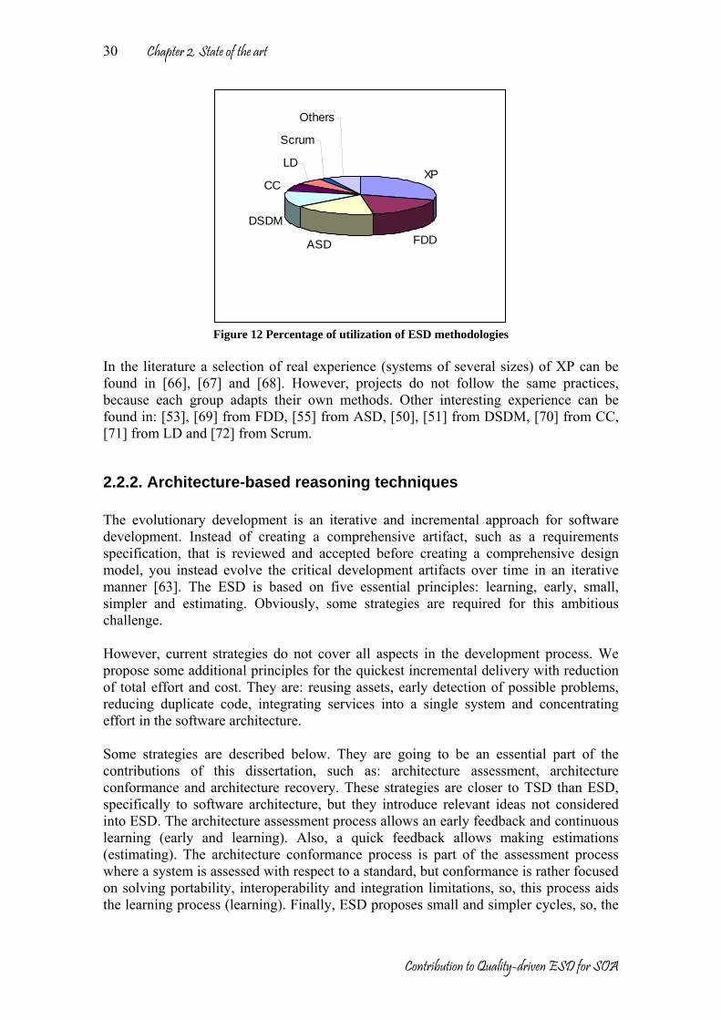
Chapter 2. State of the art
Contribution to Quality-driven ESD for SOA
30
XP
FDDASD
DSDM
CC
LD
Scrum
Others
Figure 12 Percentage of utilization of ESD methodologies
In the literature a selection of real experience (systems of several sizes) of XP can be found in [66], [67] and [68]. However, projects do not follow the same practices, because each group adapts their own methods. Other interesting experience can be found in: [53], [69] from FDD, [55] from ASD, [50], [51] from DSDM, [70] from CC, [71] from LD and [72] from Scrum.
2.2.2. Architecture-based reasoning techniques The evolutionary development is an iterative and incremental approach for software development. Instead of creating a comprehensive artifact, such as a requirements specification, that is reviewed and accepted before creating a comprehensive design model, you instead evolve the critical development artifacts over time in an iterative manner [63]. The ESD is based on five essential principles: learning, early, small, simpler and estimating. Obviously, some strategies are required for this ambitious challenge. However, current strategies do not cover all aspects in the development process. We propose some additional principles for the quickest incremental delivery with reduction of total effort and cost. They are: reusing assets, early detection of possible problems, reducing duplicate code, integrating services into a single system and concentrating effort in the software architecture. Some strategies are described below. They are going to be an essential part of the contributions of this dissertation, such as: architecture assessment, architecture conformance and architecture recovery. These strategies are closer to TSD than ESD, specifically to software architecture, but they introduce relevant ideas not considered into ESD. The architecture assessment process allows an early feedback and continuous learning (early and learning). Also, a quick feedback allows making estimations (estimating). The architecture conformance process is part of the assessment process where a system is assessed with respect to a standard, but conformance is rather focused on solving portability, interoperability and integration limitations, so, this process aids the learning process (learning). Finally, ESD proposes small and simpler cycles, so, the
Chapter 2. State of the art
Contribution to Quality-driven ESD for SOA
31
architecture recovery process results in reducing time in development and reducing complexity in big systems (small and simpler). Architecture Assessment The architecture assessment is the activity of checking the architecture to ascertain whether it satisfies the architecturally significant requirements; therefore assessment concentrates mainly on the evaluation of structure, texture, and concepts with respect to these requirements, also called quality attributes or quality requirements. ISO 9126 [3] defines a set of quality characteristics (functionality, reliability, efficiency, usability, maintainability and portability), organized as groups of related characteristics; it is usually taken as a basis for the description of quality requirements of a certain system. However, there is no precise definition of architecturally significant requirements; some hints to identify them can be found in [24]:
• Requirements that cannot be allocated to a single component or to a small set of them, but can be done through the whole system, usually in system properties and quality requirements.
• Requirements that deal with properties of different kinds of components (for example, naming and referring principles).
• Requirements about management or manipulation of multiple components (for example, modes of operation).
An architecture assessment method based on current experience and industrial practices on software architecture is presented in [7] and [8]. The assessment process is defined as a sequence of activities: preparation, prioritization, filtering, analysis, agreement, documentation and review. The output of the process is a validated architectural model with respect to the requirements and quality characteristics [73]. The assessment techniques are known in the software engineering as activities for “verification and validation”. Validation is the process of checking that the system under development meets its requirements, while verification is the process of checking if a product of a development phase conforms to the constraints specified at the beginning of this phase. Then, a software assessment technique is an operational procedure for the evaluation of a software-related product (documentation, code, architectural model, final system, etc) with respect to a certain characteristic; its aims are to check if the product meets a certain (functional or quality) requirement. A taxonomy of conventional techniques is presented in the Figure 13 [74]. It classifies the techniques into four primary categories: informal, static, dynamic and formal. The primary categories are further divided into secondary categories. The usage of mathematical and logic formalisms by the techniques in each primary category increases from informal to formal from left to right. Likewise, the complexity also increases as the primary category becomes more formal.

Chapter 2. State of the art
Contribution to Quality-driven ESD for SOA
32
Assessment Techniques
Informal Static Dynamic Formal
Audit Desk Checking Documentation Checking Face Validation Inspections Reviews Walkthroughs
Cause - Effect Graphing Control Analysis
Calling Structure AnalysisConcurrent Process AnalysisControl Flow AnalysisState Transition Analysis
Data Analysis Data Dependency AnalysisData Flow Analysis
Semantic Analysis Structural Analysis Symbolic Evaluation Traceability Assessment
Special Input TestingBoundary Value TestingEquivalence Partitioning TestingExtreme Input TestingInvalid Input TestingReal-Time Input TestingSelf-Driven Input TestingStress TestingTrace-Driven Input Testing
Statistical Techniques
Induction Inductive Assertions Inference Lambda Calculus Logical Deduction Predicate Calculus Predicate TransformationProof of Correctness
Prototyping
Figure 13 A taxonomy of assessment techniques However, only a few of them have been used in practice for architectural models. Table 2 surveys some of them [75]; all are suitable for eliciting different kind of information and capable of checking different requirements. Table 2 Survey of assessment techniques[75] Family Technique Generality Detail
level Phase Target
Questionnaire General Coarse Early Artifact, process Checklist Domain-specific Varied Middle Artifact, process
Questioning
Scenarios System-specific Medium Middle Artifact Metrics General, domain-specific Fine Middle Artifact Measuring Experiments Domain-specific Varied Early Artifact
If few techniques have been found for architecture assessment, no techniques have been thought for SOA; in this project, we propose to build a complete strategy assessing the quality of the SOA. Architecture Conformance Nowadays, there is a variety of hardware architectures, networks, programming languages, operating systems and middleware. The standards try to establish some rules or recommendations for better integration between heterogeneous technologies in order to improve their interoperability. MDA (Model Driven Architecture) [76] [77] [78] [79] was created to solve integration and portability problems between models. MDA proposes a process to map a PIM (Platform Independent Model) into a PSM (Platform Specific Model) and also the reverse process, at different level of abstraction, but MDA does not say anything about the conformance between the implemented system and its PIM. In the context of the MDA, conformance means interoperability. Although two implementations may utilize incompatible technologies or incompatible mappings to the same technology, they will share a common conceptual design with respect to their standard PIM. Usually, the system architecture is a candidate solution for a specific problem. This possible solution can be analyzed and assessed. However, there is not a process about

Chapter 2. State of the art
Contribution to Quality-driven ESD for SOA
33
how to compare a candidate architecture with respect a standard. The next situations could be found in the application of the conformance checking process:
• The system architecture fulfills completely a standard (the most unusual situation).
• The system architecture fulfills a part of a standard (the most common situation). • The system architecture takes the standard as reference but the architecture is
adapted (variation of standard, good solutions, but difficult to reuse or integrate). • The system architecture goes beyond the standard (detecting lacks in the
standard). • The system architecture is totally different with respect to standard (new ideas,
but they are not standard). Architectural conformance tries to measure how the relationship between the system architecture and a standard is. The conformance detects differences and coincidences with respect to the standards. Another type of conformance is found in the maintenance phase, where the development team needs to compare the system evolution, i.e. consistency checking (Modifiability). In [80] and [81], are presented some rules to compare consistency between models. Conformance can be checked at components or assets level, in [82] a technique has been proposed in order to compare assets. The Common Criteria (CC) (ISO/IEC 15408) presents a methodology for evaluation and conformance of Information Technology Security [83], and the SARA project [7] presents a guide for software architecture review and assessment, where a reference model for reviewing a software architecture is defined. However, a general architecture conformance process has not been defined in the literature. In this dissertation we propose a generic architecture conformance process. Architecture Recovery The architectural recovery process provides some high-level views by extracting and abstracting a subset of the software entities. Architecture recovery or reconstruction can be seen as a discipline within the reverse engineering domain that aims at the recovery of the software architecture from an implemented system [84] [85] [86]. The architectural recovery allows the software visualization, it can be described as analyzing a subject system (a) to identify the system’s components and their interrelationships, (b) to create representations of a system in another form at a higher level of abstraction and (c) to understand the program execution and the sequence in which it occurred [87] [88]. Reverse engineering was defined in [89] as, the process of analyzing a subject system to identify the components and their relationships of a system and create representations of the system in another form or at a higher level of abstraction. In [90], reverse engineering is divided in three activities:
• Extract: extracting relevant information from system software, system experts and system history.
• Abstract: abstracting extracted information to a higher (design) level. • Present: presenting abstracted information in a developer-friendly way, taking
into account his or her current topic of interest.

Chapter 2. State of the art
Contribution to Quality-driven ESD for SOA
34
Architectural recovery may be processed in a bottom-up or a combined manner (top-down + bottom-up). Bottom-up approaches start with low level knowledge (program sources, documentation, used technology and so on.) and provide abstraction techniques to recover a system’s architecture based on analysis of source code [91] [92] [93] [94]. Combined approaches start with high level knowledge (“real world” knowledge, domain knowledge, etc.), produce a model of this information and try to find model concepts instances in the system implementation [95]. For example, in complex systems, significant architectural information should be extracted, and as a result of this process another architectural model is obtained containing only the important classes [96], this is possible using some architectural rules for model understanding, consistency checking and reverse engineering [97]. Some approaches to architecture recovery [84] [85] [86] [89] [91] have been used for:
• Reconstruction of the architecture descriptions for systems that are poorly documented or when the documentation is not available.
• The evaluation of the conformance of the as-built architecture to the as-documented architecture.
• The analysis and understanding of the existing system architecture to enable the modification by satisfying new requirements and eliminating software deficiencies.
• In the system evolution as a starting point of the new desired architecture. • Identification of components (usable pieces), to reuse or establish an
architecture-based software product family. • The understanding of the architectural dependencies. • The recovery of the system legacy. The legacy is typically complex and difficult
to change, having evolved over decades and having passed through many developers.
The key of the recovery architecture is to understand the architecture. This process is known in the literature as “software visualization”. The software visualization can be defined as the use of crafts of typography, graphics design, animation, and cinematography with modern human-computer interaction and computer graphics technology to facilitate both the human understanding and effective use of computer software [98]. The software visualization provides an overview of the whole data, static [99] and dynamic [100] [101] [102] views, both are obtained from the architecture recovery discipline, the first one is based on the relationships between system components and the second one is based on information from the analysis of recorded or monitored program execution, i.e., focusing on run-time analysis [87] [103] [104] [105]. In [106] are identified four architectural views because a single view is rarely sufficient for understanding a software system. The main focus in the reverse engineering has been the identification and modeling of the structure of a program by means of code examination, (static and dynamic views), a complete description of the system needs metrics, patterns and methods supported by tools. There are many metrics, methods and tools for views [91] [105] (static, dynamic or a combination of them). The advantage of measurement is that, in general, measurements are a good indicator for important external behavioral attributes and could be used for the assessment of quality in terms of non-functional requirements, such as maintainability, reliability, reusability, usability, performance and others [107] [108].

Chapter 2. State of the art
Contribution to Quality-driven ESD for SOA
35
Gathering previous techniques and process, we propose to build a generic strategy for the architecture recovery of systems or assets.
2.3. Non-functional requirements of software Nowadays applications and services have a set of functionalities and qualities. Usually, the service functionality is satisfactorily covered, so quality of service takes major value. Qualities are considered in the classical software engineering as part of non-functional requirements. In the next paragraphs, the most important works about the quality of service will be presented and the role of the quality in the requirement engineering will be clarified. Software requirements are handled as a whole in the requirements engineering discipline. But identifying a requirement is not easy task. During the development process, in the requirement phase, it is frequently confused requirements with false requirements. In [109] and [110] are cleared some concepts about true and false requirements. “Requirements give information to the system designers and to a wide range of stakeholders. They state what the stakeholders want the system to achieve.” In [15] a requirement is defined as: (1) “A condition or capability needed by a user to solve a problem or achieve an objective.” (2) “A condition or capability that must be met or possessed by a system or system component to satisfy a contract, standard, specification, or other formally imposed document.” (3) “A documented representation of a condition or capability as in (1) or (2).” False requirements occur when the requirement specification contains statements which are not really what is needed or desired. This happens when: the requirements are not stated in a quantified and measurable way or design ideas are used in place of the true requirements. Requirements can be classified into several types, as follows: 1. Functional requirements: they describe what a system has to ‘do’, the essence of a
system, its mission and fundamental functionality. 2. Non-functional requirements: they are requirements that constrain the design of a
system, but do not describe a service that the system must provide. Non-functional requirements can be classified in: • Performance requirements: the performance levels that the stakeholders want as
their objectives. How good? These can be further classified as: o Qualities: how well the system performs, for example: usability,
availability and customer satisfaction. o Resource savings (cost): the required improvement in resource
utilization, relative economic and other resource savings compared to defined benchmarks. These are known simply as “Savings”.

Chapter 2. State of the art
Contribution to Quality-driven ESD for SOA
36
o Workload capacities: how much the system performs. In other words, the required capacity of the system processes. For example, system peak processing volumes, speeds of execution and data storage capacity.
• Resource requirements: the levels of resources that stakeholders plan to expend to develop and operate a system. Resources have to be balanced against the stakeholders perceived values gained from the system functions and the system performance levels.
• Design constraints: any design ideas that must be included in the system design. • Condition constraints: Condition constraints are often used to capture system-
level constraints (for example, the system must be legal in Europe). Some essential conditions of the requirements are:
• A requirement can be not quantifiable, but testable for presence. • Otherwise it should be quantifiable (on a scale of measure).
Other consideration about requirements is the system vision, i.e. the future direction for a system, sometimes the requirements can be at the highest level, desirable characteristic in the future. System vision is very important to system evolution. Requirements are a multidimensional set of end-state needs. The satisfaction of every requirement is a big challenge, because the satisfaction of one requirement in some cases affects others into negative way, it is evident in quality requirements, for example changes in the security of the system affect to the performance and vice verse. The fit of design to requirements is not likely to be perfect, thus there is a negotiation between them. Trade-offs must be made and maybe, the requirements have to be amended. In the evolutionary development, trade-off is necessary and besides it should be a quick process. It is essential to keep control of what is understood as the critical requirements. Critical requirements, by definition, are those which if not met, threaten the survival of the entire system. In this dissertation our focus are quality characteristics, they have been well defined in [3] (see Table 3). In [111] a meta-model has been presented by supporting modeling general QoS4 concepts in UML notation (see Figure 14).
4 QoS (Quality of Service) has the same connotation in [111] that Quality in [3]. The concept of quality was discussed in chapter 1.

Chapter 2. State of the art
Contribution to Quality-driven ESD for SOA
37
Table 3 Qualities defined in ISO 9126 [3]
Characteristics Sub-characteristics Suitability Accuracy Interoperability Compliance
Functionality
Security Maturity Fault tolerance
Reliability
Recoverability Understandability Learnability
Usability
Operability Time behavior Efficiency Resource behavior Analyzability Changeability Stability
Maintainability
Testability Adaptability Installability Conformance
Portability
Replaceability
Figure 14 General QoS categories defined in [111]
In [111] the next QoS are considered: • Performance: Performance makes reference to the timeliness aspects of how
software systems behave, and this includes different types of QoS characteristics such as: latency, throughput, efficiency and demand. Sometimes it is referred to

Chapter 2. State of the art
Contribution to Quality-driven ESD for SOA
38
the relationship between the services provided and the utilization of resources: memory and CPU consumptions.
• Dependability: Dependability is the property of computer systems such that reliance can justifiably be placed on the service it delivers. It includes QoS characteristics such as: availability and reliability.
• Functionality. As was defined in [3] the functionality is a set of attributes that bear on the existence of a set of functions and their specified properties. The functions are those that satisfy stated or implied needs. It includes QoS characteristics such as: security and integrity
• Coherence: Coherence includes characteristics about concurrent and temporal consistency of data and software elements.
In [112] is proposed a quality model (see Figure 15) based on:
• Execution characteristics • Lifecycle characteristics
Figure 15 Quality model from [112]
Other non-functional requirement classification is found in COCOTS (Constructive Commercial-Off-The-Shelf) [113]. This studies how the COTS (Commercial-Off-The-Shelf) impacts over the system development. COCOTS makes emphasis in the cost prediction into lifecycle of the system. However, source code from COTS components is not available and therefore version control or adaptation is not possible; this is called “component volatility”. COCOTS also defines a quality model (see Table 4). Table 4 Quality model defined in COCOTS [113] Correctness Price Portability Understandability Performance Product Version Security Maturity Installation Flexibility Compatibility Functionality Ease to
use Availability Vendor support Training Vendor
concessions
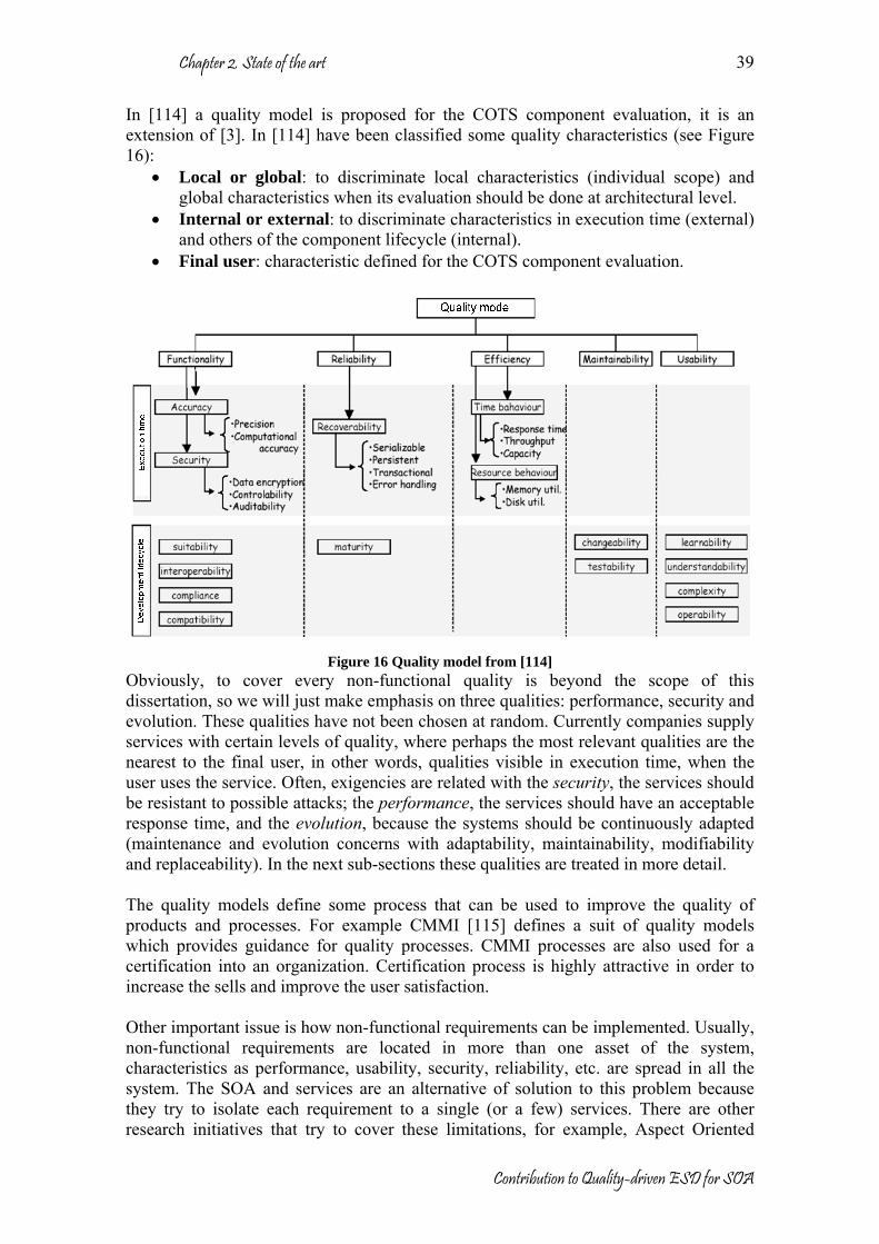
Chapter 2. State of the art
Contribution to Quality-driven ESD for SOA
39
In [114] a quality model is proposed for the COTS component evaluation, it is an extension of [3]. In [114] have been classified some quality characteristics (see Figure 16):
• Local or global: to discriminate local characteristics (individual scope) and global characteristics when its evaluation should be done at architectural level.
• Internal or external: to discriminate characteristics in execution time (external) and others of the component lifecycle (internal).
• Final user: characteristic defined for the COTS component evaluation.
Figure 16 Quality model from [114]
Obviously, to cover every non-functional quality is beyond the scope of this dissertation, so we will just make emphasis on three qualities: performance, security and evolution. These qualities have not been chosen at random. Currently companies supply services with certain levels of quality, where perhaps the most relevant qualities are the nearest to the final user, in other words, qualities visible in execution time, when the user uses the service. Often, exigencies are related with the security, the services should be resistant to possible attacks; the performance, the services should have an acceptable response time, and the evolution, because the systems should be continuously adapted (maintenance and evolution concerns with adaptability, maintainability, modifiability and replaceability). In the next sub-sections these qualities are treated in more detail. The quality models define some process that can be used to improve the quality of products and processes. For example CMMI [115] defines a suit of quality models which provides guidance for quality processes. CMMI processes are also used for a certification into an organization. Certification process is highly attractive in order to increase the sells and improve the user satisfaction. Other important issue is how non-functional requirements can be implemented. Usually, non-functional requirements are located in more than one asset of the system, characteristics as performance, usability, security, reliability, etc. are spread in all the system. The SOA and services are an alternative of solution to this problem because they try to isolate each requirement to a single (or a few) services. There are other research initiatives that try to cover these limitations, for example, Aspect Oriented
Chapter 2. State of the art
Contribution to Quality-driven ESD for SOA
40
Programming (AOP) introduces several ideas to solve cross-requirements. The main ideas of AOP are presented in [116], but AOP is not a complete solution and should be complemented with other concepts such as SOA or CBSE. In [117] is presented a model based on layers where Separation of Concerns (SoC), CBSE, MDA and AOP are put together. In addition, [118] and [119] present interesting works about how AOP improves the quality attributes of the systems.
2.3.1. Performance As was mentioned in [111] and [120], performance makes reference to the timeliness aspects of how software systems behave, and this includes different types of QoS characteristics: latency, throughput, efficiency and demand.
• Throughput: Throughput refers to the number of event responses handled during an observation interval. These values determine a processing rate.
• Latency: Latency refers to a time interval during which a response to an event must arrive.
• Efficiency: The capability of the software to produce their results with the minimum resource consumption.
• Demand: Demand is the characterization of how much of a resource or a service is needed.
The Throughput is an abstract QoS. In [111] are considered three types of throughputs: The input-data-throughputs represents the arrival rate of user data input channel, software or hardware, averaged over a time interval. The rate unit for this throughput is bit/sec. The communication-throughput represents the rate of user data output to a channel averaged over a time interval. The units and direction of rate are the same as the input-data-throughput. Finally, the processing-throughput represents the amount of processing able to be performed in a period of time. The unit of rate is instructions/sec. The Latency includes two characteristics for the description of latencies. The characteristic latency is based on a general dimension for the description of latencies for any kind of software elements. The characteristic turn-around is specific for the description of the absolute limit on time required in fulfilling a job task or service, or to represent the time required to perform a specific task, in the worst case. The Efficiency characteristics allow representing the execution time requirements for responding to each event. The resource-utilization characteristic only describes the utilization in a single action. The demand characteristics reuse this characteristic to describe general demands of resources. Specializations of resource-utilization describe the utilization of computation, communication, and memory resources. Efficiency includes a general characteristic for the specification of QoS policies. The Demand characteristics combine the resource-utilization characteristics with arrival patterns characteristics for the description of the amount of resources needed. The types of arrival pattern (periodic, irregular, bounded, busty and unbounded) and their dimensions define arrival-pattern. The dimensions are the interval (period of pattern arrival), jitter (the difference of pattern arrival from cycle to cycle), and burst size (the maximum number of occurrences in the time interval).

Chapter 2. State of the art
Contribution to Quality-driven ESD for SOA
41
In [121] is presented a meta-model for performance analysis, primarily based on determining the rate at which a system can perform its function given that it has finite resources with finite QoS characteristics. It provides facilities for:
• Capturing performance requirements within the design context. • Associating performance-related QoS characteristics with selected elements of a
UML model. • Specifying execution parameters which can be used by modeling tools to
compute predicted performance characteristics. • Presenting performance results computed by modeling tools or found in testing.
From the architectural view-point [121] it can be more useful to estimate the performance of a system instance and to determinate how the system can be improved. Performance measures for a system include resource utilizations, waiting times, execution demands (for CPU cycles or seconds) and response times (the actual or wall-clock time to execute a scenario step or scenario). Each measure may be defined in different versions, several of which may be specified in the same model, such as: a required value, an assumed value, an estimated value and a measured value.
Figure 17 Performance analysis model from [121]
Performance analysis model is presented in Figure 17, where the performance context specifies one or more scenarios that are used to explore various dynamic situations involving a specific set of resources. A scenario is a sequence of one or more scenario steps. The steps are ordered and conform to a general precedence/successor relationship. A step is an increment in the execution of a particular scenario that takes may use resources to perform its function. In general, a step takes finite time to execute. It is related to other steps in predecessor/successor relationships. A resource is an abstracted view of passive or active resource, which participates in one or more scenarios of the performance context. A ProcessingResource is a device, such as a processor, interface device or storage device, which has processing steps allocated to it by the deployment of the system. And a PassiveResource is a resource protected by an access mechanism (e.g., a semaphore), which is accessed during the execution of an

Chapter 2. State of the art
Contribution to Quality-driven ESD for SOA
42
operation. It may be shared by multiple concurrent resource operations. It may represent either a physical device or a logical protected-access entity. A workload specifies the intensity of demand for the execution of a specific scenario as well as the required or estimated response times for that workload. The specification of the workload depends on its subtype open or closed workload. An openworkload is a workload that is modeled as a stream of requests that arrive at a given rate in some predetermined pattern (such as Poisson arrivals) and a closedworkload is a workload characterized by a fixed number of active or potential users or jobs which cycle between executing the scenario, and spending an external delay period (sometimes called “think time”) outside the system, between the end of one response and the next request.
2.3.2. Security In [3], security is the capability of covering different subjects such as the protection of entities, and access to resources. QoS characteristics included in this capability are access control and confidentiality. Security is pervasive, affecting many components of a system, including some that are not directly related with the security. In contrast, other system components are directly related with security, they form specific services, such as, the authentication service, the authorization service and others. Some security functionalities taken into account in this thesis are: identification and authentication; authorization and access control; security auditing; security of communication; non-repudiation, and administration of security information. The assets of an enterprise need to be protected against perceived threats. The amount of protection the enterprise is prepared to pay for depends on the value of the assets, and the threats that need to be countered. The security policy needed to protect against these threats may also depend on the environment and how vulnerable the assets are in this environment. Despite the security does not have formally a defined profile, there are several organizations that research about security, as: OMG, W3C, IETF, DMTF, and others. In the next paragraphs, we are going to present a summary about how is treated the security in each organization. Figure 18 presents a security model extracted from [122], [123] and [124]. Common Information Model (CIM) is a model proposed by DMTF (Desktop Management Task Force) where security concepts are defined and mapped to UML diagrams. In CIM, security aspects are associated with services, components and resources. The CIM security model is certainly not complete, but it does provide commonly needed classes from which vendor products may derive their specific information models. Future CIM work is expected to continue to expand on the foundation set of classes in this CIM Schema. The objective of the CIM security model is to provide a set of relationships between the various representations of users, their credentials, the managed elements that represent the resources, and the resource managers involved in system user administration. Thus, the CIM security model adds to the pre-existing set of requirements for the introduction of a “top” object class in the CIM Core Model. The introduction of ManagedElement and the associations that reference it, provide a foundation for the linkages between the User and Security Model and the

Chapter 2. State of the art
Contribution to Quality-driven ESD for SOA
43
ManagedSystemElement derived classes that represent system components and resources. (See Core Model)
ManagedElement
SecurityService
(See User Model(Security Services))
ManagedSystemElement
(See Core Model)
(See Core Model)
LogicalElement
(See Core Model)
EnabledLogicalElement
Service
(See Core Model)
AuthenticationService
(See User Model(Security Services))
VerificationService
(See User Model(Security Services))
CredentialManagementService(See User Model
(Security Services))
ServiceAccessPoint
(See Core Model)
CredentialManagementSAP
(See User Model(Security Services))
CertificateAuthority
(See User Model(PublicKey))
LocalCredentialManagementService
(See User Model(SecurityServices))
AuthorizationService
(See User Model(Security Services))
KerberosKeyDistributionCenter
(See User Model(Kerberos))
PublicKeyManagementService
(See User Model(PublicKey))
SharedSecretService
(See User Model(SharedSecret))
Notary
(See User Model(SecurityServices)
AccountManagementService
(See User Model(Account))
Credential
(See User Model(Credential))
KerberosTicket(See User Model(Kerberos))
PublicKeyCertificate
(See User Model(PublicKey))
UnsignedPublicKey(See User Model(PublicKey))
SharedSecret
(See User Model(SharedSecret))
NamedSharedIKESecret
(See User Model(SharedSecret))
AuthenticationRequirement (D)
(See User Model (DeprecatedAuthentication))
Account
(See User Model(Account)
AccessControlInformation (D)
(See User Model(Deprecated Access Control)
Privilege
(See User Model(Authorization))
SecuritySensitivity
(See User Model(Authorization)
Identity
(See User Model(Identity))
BioMetricCredential
(See User Model(BioMetric))
PrivilegeManagementService
(See User Model(Security Services))
StorageHardwareIDMananagementService
(See User Model (Identity))
StorageHardwareID
(See User Model(Identity))
GatewayPathID
(See User Model(Identity))
Association
AggregationAssociation with WEAK reference
Inheritance
Aggregation with WEAK reference
w
w
* Equivalent to: 0 .. nComposition Aggregation
Figure 18 Security Model from CIM [122]
The OMG has proposed a security specification [125], called Security Service Specification, where it is detailed how secure services should be implemented in distributed systems. It defines several concepts and proposes some strategies to solve classical security problems. In the OMG, security means protection of an information system from unauthorized attempts to access information or interfere with its operation. It is concerned with: confidentiality, integrity, accounting and availability. Figure 19 shows the relationship between the main objects visible in different views for three types of security functionality.
• Authentication of principals and security associations (which includes authentication between clients and targets) and message protection.
• Authorization and access control, i.e., the principal being authorized to have privileges or capabilities and control of access to objects.
• Accountability, auditing of security-related events and using non-repudiation to generate and check evidence of actions.
The security service specification has introduced one key concept, the Credential, it is visible for the application after authentication, for setting or obtaining privileges and capabilities, for access control, and it is available for service implementers.

Chapter 2. State of the art
Contribution to Quality-driven ESD for SOA
44
Figure 19 OMG Security model [125]
Figure 20 shows the security reference model proposed in [126]. It gives a high level view of the concepts and the key relations between them. It extends the model from the Common Criteria (CC) [83] by introducing techniques and their relevance for the entities in the system. The CC relies on two key concepts. Firstly, entities must be correctly authenticated. This implies that the real identity of the requesting entity is verified to an acceptable level of certainty. Secondly, the system must implement enforcement of authorizations defined for the assets using access control mechanisms. The CC considers as qualities confidentiality, availability and integrity that leads to the imposition of security countermeasures such as authentication, authorization and accounting.

Chapter 2. State of the art
Contribution to Quality-driven ESD for SOA
45
Entity
Application
Threat
Trust
IdentityHas
Access Control
Enforce
Authentication
User
Asset
Authorisastion
Information Component
Claimed identity
Role
Has
Has
Trust building means
EstablishCan cause violation
May compromise
Organisation
Owner
CertificateSupport
Countermeasure
Impose
Relies upon
Figure 20 CC Security model
The Web security is treated in W3C [127], as a complex topic, by encompassing computer system security, network security, authentication services, message validation, personal privacy issues, and cryptography. The W3C [128] is involved in the development of several protocols that relate to web security. Presently, the main areas of work include: digital signature, the HTTP/1.1 protocol, electronic commerce initiatives, web services security, XML encryption, XML key management specification, extensible access control markup language, secure assertion markup language, web services security, ebXML message service and others. The W3C also produces software reference implementations that demonstrate the use of security measures.
2.3.3. Evolvability The capacity of evolution or evolvability of software plays a role important during maintenance time in two senses: reduction of the total cost during maintenance and the extension of the lifetime of software. However, evolvability has not a clear definition because it affects several quality and functional characteristics, i.e. to improve the evolvability implies an improvement in other qualities. In this section, we try to clarify this evolvability aspect but in special, we try to find the relationship between the evolvability and the software architecture. There is not precise definition about evolvability, some the definitions found in the literature are listed below:
• Evolvability can be described as the ability to anticipate the locations of changes in a system [129].
• Evolvability is the capability of a software product to be evolved to continue to serve its customer in a cost effective way [130].
Evolvability is a quality very close to maintainability but with some differences. Some authors consider maintainability is for fine-grained changes while evolvability is for
Chapter 2. State of the art
Contribution to Quality-driven ESD for SOA
46
coarse-grained (structural changes) [131]. In [130] considers also evolvability more general quality than maintainability. In addition, some metrics for measure of evolvability are presented. In this sense evolvability is more important for the person who changes software while maintainability is more relevant for one who uses it. Evolvability relates to other characteristics such as: maintainability, adaptability, modifiability and replaceability but also other characteristics have a close relation such as: portability, flexibility, integrability, reusability, extensibility, traceability, variability, tailorability and monitorability. However, nowadays there are not clear definitions of every one of these characteristics and in some cases are confused or interpreted as equals. In the next paragraphs, some of the most common definitions are cited: Maintainability is the capability of the software product to be modified. Modifications may include corrections, improvements or adaptations of the software to changes in environment, and in requirements and functional specification (the effort needed to be modified). Maintainability concerns with other characteristics as was defined in [3]:
• Analyzability is the capability of the software product to be diagnosed for deficiencies or causes of failures in the software, or for the parts to be modified to be identified.
• Changeability: the capability of the software product to enable a specified modification to be implemented.
• Stability is the capability of the software product to avoid unexpected effects from modifications of the software.
• Maintainability compliance is the capability of the software product to adhere to standards or conventions relating to maintainability.
• Testability: the capability of the software product to be validated. Adaptability: there is not a clear definition of adaptability; some of the definitions found in the literature are shown below:
• Attributes of software that bear on the opportunity for its adaptation to different specified environments without applying other actions or means than those provided for this purpose for the software considered in section A.2.6.1 of [3].
• Adaptability then refers to the ability of the system to make adaptations. Adaptation involves three tasks: environment change detection, system change recognition and ability to effect the change in order to generate the new system (system change) [132].
• Adaptability is the capacity of the system to adjust its behavior according to changing of the environments [5].
• Adaptability at implementation level is also defined as easy changeability of programs [15].
Replaceability is the attribute of software that bears on the opportunity and effort of using it replacing other software in the environment of that software [3]. Modifiability is the ease with which a software system can be modified to changes in the environment, requirements or functional specification. Modifiability excludes the correction of implementation errors and changes in the quality requirements of the system [133] [134].

Chapter 2. State of the art
Contribution to Quality-driven ESD for SOA
47
Portability is the capability of the software product to be transferred from one environment to another. The environment may include organizational, hardware or software environment. Portability concerns with adaptability, installability, conformance and replaceability [3]. In [112] portability is also related with mobility and nomadicity. Flexibility, about flexibility there are several interpretations in order to provide one answer to pressure for change, such as:
• In [135] defines technology flexibility as the characteristics of technology that allow or enable adjustments or other changes to the business process. Technology flexibility includes factors as modularity, change acceptance, and consistency in the structural flexibility and rate of response, expertise, and coordination of actions in the process flexibility
• [136] proposes two related software flexibility concepts: system adaptability and system versatility. System adaptability is the capability to modify the system to cope with major changes in business processes with little or no interruption to business operations. System versatility (or system robustness) is the capability of the system to allow flexible procedures to deal with exceptions in processes and procedures.
• [137] deals with the issue of flexibility in technical, organizational, and human perspectives. They classify flexibility into four dimensions: process flexibility, interorganizational flexibility, flexible management and knowledge, and flexible task allocation. They further proposed conceptual solutions for achieving flexible workflow support.
Integrability refers to the ease with which separately developed elements (including those developed by third parties) can be made to work together to fulfill the software's requirements [138] Reusability: about reusability the next definitions were found:
• Reusability is the ability to use all or the greater part of the same programming code or system design in another application. In computer science and software engineering, reusability is the likelihood a segment of structured code can be used again to add new functionalities with slight or no modification. Reusability implies some explicit management of build, packaging, distribution, installation, configuration, deployment, maintenance and upgrade issues. If these issues are not considered, software may appear to be reusable from the design point of view, but will not be reused in practice [139].
• Software reuse is the process of implementing or updating software systems using existing software assets [140]. In this case, software assets, or components, include all software products, from requirements and proposals, to specifications and designs, to user manuals and test suites. Anything that is produced from a software development effort can potentially be reused [141].
Extensibility is the capacity to be easily augmented from the outside by clients [142]. Traceability is the ability to document and follow the life of a concept throughout system development. It is forward directed (post traceability: describing the deployment and use of a concept) as well as backward directed (pre traceability: describing the origin and evolution of a concept) [143].

Chapter 2. State of the art
Contribution to Quality-driven ESD for SOA
48
Variability, according to [144], the differences among products are managed by delaying design decisions, thereby introducing variation points, which again are bound to a particular variant or variants. A variation point identifies a location at which a variation can occur in the system [145]. Tailorability is the ability to customize and configure components, but also to add new components to the system and combining services of multiple components in novel ways [146]. Monitorability is the systems property to support measurement (of performance and resource usage, for example), watching for failures, chase up security violations or monitoring of user behavior, is an essential property for a maintainable system [146]. We are going to consider evolvability in terms of maintainability, adaptability, modifiability and replaceability. We consider evolvability as transversal quality because it is affected for the other quality: functionality, reliability, usability, efficiency, composability, etc. and obviously for the previous list (portability, flexibility, integrability, reusability, extensibility, traceability, variability, tailorability and monitorability). On other hand, the evolvabiliy of the systems is in close relation with the architecture. The architecture was created to fill the gap during the evolution, because the architecture supports the transformation of the system without traumatic processes. An example of this relation is shown in [147] (see Figure 21) where the architecture is the tool for feedback, to make estimations and guide the transformations during the lifecycle of the software. In [148] the role of the architecture is also the center for the evolution, in this case, the evolution is achieved through the utilization of metrics and patterns on the architecture of the systems in order to make predictions and improve the quality.
Figure 21 Software architecture design method [147]
In [149] it is presented an architectural model for evolution called Software Architecture EVolution (SAEV); SAEV manages the changes of the architectural elements and their

Chapter 2. State of the art
Contribution to Quality-driven ESD for SOA
49
impact. In the meta-model shown in Figure 22 it is illustrated the relation between architectural elements with the evolution strategy which leads some rules of evolution. In SAEV the next concepts have been defined:
• Architectural element: It represents any element of software architecture. It can be for example a configuration, a component, a connector, interface, etc.
• Invariant: it represents the architectural element’s constraint which must be respected throughout its lifecycle. Any change in the architecture must maintain the correctness of this invariant.
• Evolution operation: is an operation which can be applied to the architectural element or to its sub-elements and which cause its evolution. The following evolution operations were identified: Addition, deletion, modification and substitution.
• Evolution Rule: describes the execution of an operation on a given architectural element. It expresses the necessary conditions to execute this operation as well as the rules to be triggered if necessary on the other architectural elements, to propagate the rule impacts.
• Evolution strategy: We associate with each architectural element an evolution strategy. A strategy gathers the whole of the evolution rules which describe all the evolution operations that can be applied to this architectural element.
• Evolution manager: is an actor, representing the processing system of SAEV. Its role is intercepting the events emanating from the designer or the evolution rules towards an architectural element. Then it triggers the execution of the corresponding evolution rules, according to the evolution strategy associated with this architectural element.
Figure 22 SAEV meta-model [149]
Other approximations of software architecture model for evolvability are presented in [150], but only adaptability characteristic is modeled. In this case the software architecture adaptability is the degree to which software architecture is adaptable to the change requirement in stakeholders’ objectives measured in terms of impact on software architecture elements. In an adaptable architecture, the elements (components and connectors) of software architecture need to make reactions in order to satisfy change requirements. These actions are called as Software Architecture Actions (SAAction) that are related to the domain of system. One change requirement (ChangeReq) that impacts on the system is defined as a dimension of the adaptability, for example “users require

Chapter 2. State of the art
Contribution to Quality-driven ESD for SOA
50
that the quality record is changeable” is one dimension of the system adaptability (see Figure 23).
Figure 23 Architecture adaptability definition [150]
In any case, the previous works show clearly the relevant role of the architecture during maintenance and evolution because changes or transformations usually are driven by the architecture; in consequence the architecture is the support for evolvability.
2.4. Conclusions The next conclusions have been extracted from this chapter: The SOA is an architectural pattern inspired into the advantages of the services, for better adaptability, scalability, compatibility, interoperability and composability of a software system. However, the SOA is a new model that still is an open area of research. In the literature there are really few methodologies for use SOA as model in the development process. Nowadays, the software systems are more dynamic, the TSD is not enough prepared for the new vertiginous changes, therefore new activities, such as, assessment, conformance and recovery, should be adapted in order to achieve these challenges. The ESD was created to solve the limitations of the TSD but the ESD does not solve all the problems. The ESD must be improved in order to achieve the initial proposed objective. Finally, the current market requires better quality in their products. The development process should be prepared for new demand of quality using adequate methods, techniques and tools. The traditional development oriented to functional aspects must evolve prioritizing the quality of the systems, quality driven development.

Chapter 3 ESD Model
In this chapter, we are going to present the Que-ES model. It is the proposed ESD model in this dissertation. Que-ES incorporates the advantages found in current ESD process, methods and techniques and some of the most used and useful TSD practices. Que-ES is based on principles from current ESD process, but new principles have been introduced in order to carry out a better cohesion between ESD and activities from TSD. Que-ES is a full methodology conformed by a set of models: Que_ES Description Model (QDM), Que-ES Process Model (QPM), Que-ES Business Model (QBM) and Que-ES Organization Model (QOM). In this chapter, we will discuss about the more important aspects of each of them. However, this dissertation will focus on the QDM and QPM. QBM and QOM are also important for a correct application of Que-ES model but they are beyond of this work. This chapter has been organized in five parts. The first part concerns to the introduction and motivation of the proposed model. In the second part the principles of the Que-ES are defined. In the third part a brief description of the Que-ES model is presented. In the fourth part a comparative analysis between ESD and TSD is done. And in the fifth part, conclusions of this chapter are presented.
3.1. Introduction and motivation As it was discussed in the chapter 1, the ESD appears as response to the software crisis of the 1960s, 1970s, and 1980s, when many software projects had bad endings. The software crisis was originally defined in terms of productivity, but evolved to emphasize quality. Nowadays, the ESD emerges supported by the known agile methods over the TSD, because the response time to final user in the current market is extremely fast, as the user and the industry need solutions in short time with high level of quality. In chapter 1 several assertions were done. Now, we are going to find some explanations about how are they dealt with by ESD. In addition, we are going to present the alternatives proposed by Que-ES model. Some assertions from chapter 1 are cited below:
• The ESD processes improve the quality, reduce the total cost and increase the product lifetime.
• The ESD eschew both formal process paperwork and documentation. • The products using ESD are delivered earlier than TSD, because ESD makes
emphasis in rapid delivery. • The quality in the ESD increases during the maintenance time, because ESD
assumes changes after delivery. • An early detection of possible problems means less effort and cost. • In the development phase, changes in the TSD are cheaper than in the ESD. But
during the maintenance phase, the cost in the TSD increases quicker than in the ESD.
• Break-even point in the TSD is earlier than in the ESD.
Chapter 3. ESD Model
Contribution to Quality-driven ESD for SOA
52
• The benefit-time in the TSD is shorter than in the ESD. • Refactoring and removing duplicated parts in the existing code base are keys to
increase quality. • The assessment process becomes into the input to a continuous system
adaptation (continuous feedback). • A recovery process is required in order to reuse software pieces or complete
systems, by reducing the effort and cost during the development phase. • The success of the ESD depends of a clear definition of requirements making
emphasis in quality attributes, the construction of a reference architecture, a suitable selection of reusable assets and a quick detection of possible limitations, conflicts and errors.
• A conformance process is required in order to integrate different services into a single system, and connect more services sharing information between them. Integration is only possible if assets, components or systems are compliant to certain standards.
• The market needs a complete orchestration among the different processes for software development in order to apply them in an adequate way (techniques, process, methods and tools).
Some of the previous assertions have been treated for the current ESD and others have been considered into TSD. In the chapter 2 were analyzed some of the most known methodologies for ESD, such as: eXtreme Programming (XP) (Beck, Cunningham and Jeffries 1999), Scrum (Takeuchi and Nonaka 1986, Stherland and Schwaber 1995), Evolutionary Project Management (Evo) (Gilb 1976), Crystal Methods (Cockburn 2001), Feature Driven Development (FDD) (Batory 2003, Coad, Lefebvre, DeLuca 2000), Dynamic Systems Development Method (DSDM) (Stapleton 1997), Adaptive Software Development (Highsmith 2000), Agile Modeling (AM) (Ambler 2002), Lean Development (LD) (Charette 2001) and Lean Software Development (LSD) (Mary and Tom Poppendieck 2001). Each one has principles, processes, methods and tools. In this chapter we are going to extract the most significant aspects that can be used taking into account quality driven development and service oriented architecture. Que-ES gathers methods, techniques, processes and tools in order to increase the awareness in the ESD. We introduce processes used in the TSD enhancing the ESD, such as: assessment, conformance and recovery processes. In addition, we use current technologies (SOA) solving some limitations of software systems: flexibility, adaptability, changeability, better treatment of quality and so on. The success of this approach is to find the point of convergence between the SOA and the ESD to improve the quality of systems.

Chapter 3. ESD Model
Contribution to Quality-driven ESD for SOA
53
3.2. Que-ES principles In the community of ESD an agreement has been got about the rationale of the ESD. Initially, this agreement was signed by a group of experts from the ESD world, known as the “agile manifesto” [4] and currently it has been ratified by a huge list of people and organizations. The Que-ES principles have been based on the twelve principles defined in the agile manifest. But other ideas have been taken from the current agile models and TSD. In the next paragraphs the main ideas of agile methods are presented. The first part from Evo [44] [45] [46] [47], which was not part of the initial agile manifesto, centers its attention in the stakeholders as an essential part in the evolution; making estimations; a planned improvement of the product quality; real-time feedback, learning during development and early results (the system is divided in small subsystems, that must be carried out in one week). At the same way, Scrum [48] [49] introduces the next ideas: An adaptable process where both technical and business challenges converge and suggest that every increment must be both assessed and documented (inspected, adjusted, tested, documented and built on). DMSD [50] [51] makes also emphasis in the stakeholders (active users and empowered collaborative work team), an iterative and incremental development, reversible changes, requirements at the high level and testing throughout the lifecycle. XP [19] has five complementary principles; they are an extension or refinement of the agile manifesto. XP makes emphasis in simplicity (the simplest solution that works), communication among development team and customers and automated testing, XP promotes continues changes during development, but its success depends of quality of the work (qualified teamwork). The principles of FDD [52] [53] are more focused to the business layer modeling and the development process: scalability of the systems, a simple process, logical steps (immediate results), feature-driven development, short and iterative cycles. ASD [55] assumes that the client necessities are always variable (adaptive environment and continuous learning). The key aspects in ASD are: mission-driven, risk driven, change-tolerance and component-based development, inherently iterative lifecycle and time boxes (short cycles with delivery by feature). CM [56] [57] emphasizes in the responsive to change, therefore in their principles new ideas are introduced such as: more feedback, osmotic communication (face-to-face) and reflective improvement. In addition, CM takes into account the complexity of system (size and risk), more ceremony for more criticality. For LD [58], the stakeholder has the maximal priority; the success depends of the active participation of the client. LD evolves into LSD [59] adding new ideas, which are reflected in their principles, such as: eliminate waste, comprehensive testing,

Chapter 3. ESD Model
Contribution to Quality-driven ESD for SOA
54
refactoring, measure business impact, decide as late as possible, deliver as soon as possible and empower to team. Finally, AM [60] [61] and AMDD [62] define a collection of core principles (for AMDD) and supplementary principles (for special environments); some of them have been adopted from XP. The primary goal of AM is the software development and the second goal is to think on future changes. However, AM makes also emphasis on executive documents (the content is more important), to keep artifacts or models (legacy of the system) if they are required and open and honest communication among stakeholders. The principles defined in Que-ES are part of contributions of this dissertation, some of them are improved from the current ESDs and other are contributed by the current tendencies. Que-ES principles have been grouped in 4+1 types, four of them based on the BAPO model [5] (see Figure 24): Architecture (construction of the system), Process (development process), Business (strategies, resources, vision, costs, etc.), Organization (human resources) and Essential (generic principles). The first four are concerned with relevant dimensions of software engineering [5] and the Essential are valid principles for all them. Architecture principles. Deal with technical means to build the software. Unlike current ESD, we consider architecture as part essential for description, construction and understanding the software. Therefore, some ESD principles must be adapted to deal with this direction. They are:
1. Service oriented architecture. The software partition defines the rationale for the composition, evolution, complexity reduction, functionality distribution and better treatment of quality. Services have been created to increase the flexibility, cohesion, scalability, portability, and integration. Nowadays, services are one of the most suitable architectural elements to build software.
2. Embrace changes. Welcome changing requirements, the changes allow refinement and increasing the quality of a system. We distinguish two kinds of changes: Fine-tune changes; in this case, refactoring is used as the technique to altering the original code. Usually, small changes do not affect the basic architecture and in this case, codification has the priority. Structural changes, in this case, we recommend an open architecture, where the architecture must be designed for possible changes. In both cases, they must be reversible.
3. Model with a purpose. Use models only when they are required. At the high level of abstraction, the architectural model is required. Detailed design is only desirable for complex or critical systems.
4. Content is more important. Any given model could have several ways to be represented. The architecture is the way to present a model, thinking in the solution. We propose a soft-architecture where strong rules in the notation or syntax can be eschewed.
Process principles. Deal with roles, responsibilities, and relationships within software development. The next principles should be considered during the software development lifecycle.

Chapter 3. ESD Model
Contribution to Quality-driven ESD for SOA
55
1. Assessed iterative short cycles. Every cycle must be executed as short as possible. Small cycles motivate to make evolutionary requirements and systems. In addition, they must be objective-driven, planned and assessed, taken into account the user satisfaction.
2. Delivery as fast as possible. An early delivery increases the motivation for all stakeholders and early positive feedback.
3. Suitable and adaptable process. Learn during development, some process can be modified or refined in order to achieve more effectiveness or accuracy. The process is also a variable that depends of the system, context, stakeholders or used technologies.
4. Quality-driven development. It means that the system quality has pre-emption with respect to functional aspects during the development process.
Business principles. Deal with the way to make profit from the products. The business principles define the strategies for market and optimization of resources (human and material). The proposed principles are:
1. Measure business impact. To estimate the business impact is not easy task and it is even worse in large projects. However, with ESD, the short cycles and continuous assessment, increases the probability of success; this estimation is part of risk management. During the development phase, assessment is the mechanism to measure business impacts, while during the maintenance phase, monitoring and testing should be used in order to obtain the real impact.
2. Communication. Promote direct communication among stakeholders. Face-to-face conversation is the most effective communication mean. However, it needs other directives: openness, honestity and accessibility.
3. All stakeholder value and product quality are variable. The evolution of the stakeholder value and product quality is characteristic for ESD. The success of ESD is to achieve the client satisfaction.
4. Take into account current technologies. Some non-functional requirements are often related with particular technologies. To select the best ones, is the challenge for the industry.
5. Take into account current tendencies. Thinking on the future tendencies is part of business (for example; outsourcing, open source, services, etc).
Organization principles. Deal with the actual mapping of roles and responsibilities to organizational structures
1. Communication. Promote direct communication among members of teamwork. Ones more, face-to-face conversation is the most effective communication, but in addition, it should be agile (few minutes) and immediate (a doubt should be quickly solved) and must be documented (supported in electronic media).
2. Work quality. It means order, defined purposes, clear objectives and short goals. 3. Self-organized teams. The teamwork must be cooperative, collaborative,
empowered and trying to keep the motivation. Organization depends of complexity of system (number of people involved). Hierarchical structures should be eschewed. In addition, the team must self-adjust its behavior according to the context.
4. Work together. Not necessarily, pair programming as in XP. An integrated group is more productive and efficient than isolated people.

Chapter 3. ESD Model
Contribution to Quality-driven ESD for SOA
56
Essential principles. The essential principles of Que-ES must be taken into account on the other dimensions as generic rules. They have been extracted and extended from the agile manifesto and other ESDs, such as: XP, Evo, AM, DMSD and CM. The essential principles are:
1. Assume simplicity. Simplicity in all senses, the simplest solution is the best solution (Business), keep your models as simple as possible (architecture), design for current interactions (Process) and self-organized teams (Organization).
2. Provide a rapid feedback for learning. The time between an action and the feedback on that action is critical in all sense. The stakeholder feedback is crucial for business, process, architecture and organization. Feedback allows to learn during the development and maintenance period. The experience can be used to discover, refine or refuse businesses, processes, architectures and organizations.
3. The more complexity and criticality, more ceremony required; the complexity of a system depends of its size (measured by the number of people required for a solution) and its criticality that can be measured in terms of the consequences as a result of a defect in the system.
4. Think on future changes. When the project is still under development, new ideas emerge that can be used on the future, such as new business, new models, new processes or new way of organization. In short, when you are working on your system you need to keep an eye on the future.
5. Understand who the stakeholders are. Know who are the stakeholders, their capabilities, strengths and weaknesses, allows a better effective use of the human resources. In addition, a better knowledge of our client and their conditions, concerns and requirements allows a better satisfaction.
Figure 24 Que-ES principles

Chapter 3. ESD Model
Contribution to Quality-driven ESD for SOA
57
3.3. Que-ES description Based on the previous principles we are going to describe the different proposed models. The Que-ES model is divided in four models, each one with their respective suggested methods, techniques, and tools. We will put special emphasis in the Que-ES process and architecture models that are the major contributions in this dissertation. The other proposed models are briefly explained (Business and Organization). The principles and some fundamental ideas are going to be discussed along this chapter.
3.3.1. Que-ES Description Model (QDM) QDM allows describing the full system. It is organized by several packages as is illustrated in Figure 25. The QDM must be in agreement with the 5+4 principles (essential and architecture). Four packages have been considered in QDM taken into account the 5+4 principles: Stakeholders & Environment, Requirements, Architecture and Implementation. The objective of QDM is the description of the system in a way as simple as possible; no tedious documents are recommended by QDM. The four basic packages are fundamental for any system, they allow to concentrate the attention in the relevant aspects of the system; user needs, solution modeling at different abstraction levels and evolutionary solutions. All elements are directly related among them, allowing a rapid feedback and dynamic evolution. Any change occurred in one of the packages, can be easily traceable in the other elements.
Requirements Implementation
Architecture
Stakeholders and
Environment
Figure 25 QDM
A description of the elements of QDM is presented below: Requirements It was widely discussed in the chapter 2. Requirements are the collection of necessities of the client. A categorized and prioritized list of requirements is required [151] [152] [153]. In [153] a UML meta-model for requirements is presented. It is a generic model in the context of system family engineering, but it can be used in other contexts. In [153] the requirements are treated in different levels of abstraction, a detailed taxonomy in order to simplify the complexity is proposed, mechanisms for control, management
Chapter 3. ESD Model
Contribution to Quality-driven ESD for SOA
58
and evolution have been provided and a complete set of possible relationships between requirements has been defined. The main contribution of this work is the reusability of requirements. It is supported with a multi-user tool [154], which also, has a remote repository where the requirements are stored. Functional and non-functional aspects should be classified and prioritized following the recommendation in [153]. The prioritized list of requirements will be used into other elements. The most important requirements should be implemented in first place, in order to achieve a positive feedback and quick satisfaction of the user. Despite functional aspects are the skeleton of a system, non-functional aspects take an important role in the evolutionary systems, because they can be the difference with respect to other alternatives from the business viewpoint. In addition, we consider that functional aspects can be covered in the first steps of the development using previous implementations (reusability) or developed by a third party. Architecture The architecture was also discussed in the chapter 2. Architecture offers several advantages: think in the solution from an early phase of development, an understandable description of the solution, static view of the system, dynamic view of the system, several abstraction levels depending of the complexity of the system, abstraction of concepts and ideas, and so on. Currently a new architectural style is been used, service-oriented architectures (SOA) which also covers some limitations of architectural designs. SOA divides a system in independent services connected through their interfaces. SOA allows an easy integration and portability of assets. A UML profile for description of SOA is presented in [155], which defines the most important element in an architecture based on services. In [155] a conceptual model is defined and the different elements are stereotyped. No new concepts appear in this profile. Elements as service, consumer, provider, channel, etc. are taken from service oriented solutions. The main contribution in this profile is the suitable interrelationship among their elements. We have chosen SOA because it offers close features with respect to architecture and essential principles. Implementation Implementation is the real representation of an architecture (Software and hardware involved, i.e. source code, database, network, processors, memory, etc). For Que-ES the implementation has the same value than the requirements or the architecture. The priority of one or another depends of the context. For example in the beginning of a project, the high-priority is assigned to requirements, in the development the high-priority is the architecture and in the second place is the implementation or during the maintenance phase, implementation has the high-priority.
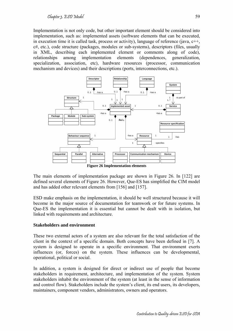
Chapter 3. ESD Model
Contribution to Quality-driven ESD for SOA
59
Implementation is not only code, but other important element should be considered into implementation, such as: implemented assets (software elements that can be executed, in execution time it is called task, process or activity), language of reference (java, c++, c#, etc.), code structure (packages, modules or sub-systems), descriptors (files, usually in XML, describing each implemented element or comments along of code), relationships among implementation elements (dependences, generalization, specialization, association, etc), hardware resources (processor, communication mechanism and devices) and their descriptions (ports, interconnections, etc.).
Implemented asset
LanguageDescriptor
Resource
Resource specification
Service
System
Behaviour sequence
Sequential Parallel Alternative Processor DeviceCommunication mechanism
Structure
ModulePackage Sub-system
Relationship
-has1
-specifies
1
-is part of11..*
-has a0..1
1
-has a0..1
1
-has a0..1
1
-has a
0..11
-has a
0..1
1
-has a0..1
1
0..1
-has a
1
Figure 26 Implementation elements
The main elements of implementation package are shown in Figure 26. In [122] are defined several elements of Figure 26. However, Que-ES has simplified the CIM model and has added other relevant elements from [156] and [157]. ESD make emphasis on the implementation, it should be well structured because it will become in the major source of documentation for teamwork or for future systems. In Que-ES the implementation it is essential but cannot be dealt with in isolation, but linked with requirements and architecture. Stakeholders and environment These two external actors of a system are also relevant for the total satisfaction of the client in the context of a specific domain. Both concepts have been defined in [7]. A system is designed to operate in a specific environment. That environment exerts influences (or, forces) on the system. These influences can be developmental, operational, political or social. In addition, a system is designed for direct or indirect use of people that become stakeholders in requirement, architecture, and implementation of the system. System stakeholders inhabit the environment of the system (at least in the sense of information and control flow). Stakeholders include the system’s client, its end users, its developers, maintainers, component vendors, administrators, owners and operators.

Chapter 3. ESD Model
Contribution to Quality-driven ESD for SOA
60
3.3.2. Que-ES Process Model (QPM) QPM is an evolutionary process model based on iterative short cycles and fast delivery. QPM has as a goal the quality of system (quality-driven development). The QPM must be in agreement with the 5+4 principles (essential and process). QPM defines the activities that should be carried out into the development process in order to build a system from requirements to implementation. In QPM, a system is divided in several small subsystems (services), each one should be treated in one cycle. The activities defined by QPM allow bidirectional traceability among the elements defined in the QDM (see Figure 27). To express the different processes of our model in a normalized non-ambiguous way, the SPEM specification [6] was used. The QPM objective is to obtain small subsystems clearly defined and structured that can be independently implemented, adapted, composed or reused. QPM was thought to develop, adapt, compose and reuse assets. In complex or critical systems several levels of abstraction are required. In the first phases, a high level of abstraction is required, where the total requirements of the system are specified and a high-level architecture is defined. After that, a partition of the systems must be done in order to obtain subsystems. The final objective is obtain small subsystems (assets) that can be independently treated, so partition process is an iterative process that should be done each time it is required.
QPM
<<Discipline>>Requirement definition
<<Discipline>>Assessment
<<Discipline>>Requirement recovery
<<Discipline>>Architecture design
<<Discipline>>Conformance
<<Discipline>>Configuration management
<<Discipline>>Architecture recovery
<<Discipline>>Implementation
<<Discipline>>Test
<<Discipline>>Change management
Domain engineering
Reverse engineering
Quality
Evolution
<<Discipline>>Analysis
Figure 27 QPM

Chapter 3. ESD Model
Contribution to Quality-driven ESD for SOA
61
QPM processes are presented in groups: Domain engineering, reverse engineering, quality and evolution. The processes defined in QPM are: Domain engineering Development processes have been grouped and ordered in the forward engineering sense: requirements definition, architecture design, implementation and test. Each process is executed by the stakeholders in a specific context. Domain engineering is a mature area in the software engineering. QPM uses these processes in a simplified way according with the ESD as follows: Requirements definition identifies user needs. As result the requirements are obtained, the requirements are a prioritized list of user needs and a set of definitions (glossary) in agreement with the context (environment). A complete guide for requirement engineering is presented by [153]. There the main phases in requirements definition are: elicitation (discovering of user needs) and specification (documenting requirements clearly and accurately) (see Figure 28).
Requirement elicitation
Requirement definition
Requirement specification
Stakeholders and environment
Requirements
Figure 28 Requirement definition processes
Architecture design process has as objective to build the architecture in concordance with the requirements defined. The architecture can have different levels of abstraction depending of the complexity of the system. A partition process is required in order to reduce the complexity and obtain reusable assets [158]. The architecture could be described in different views [1] but two essential products are required: static architecture describing the structure of the system and dynamic architecture describing the behavior of the system. The processes defined in the architecture design are shown in Figure 29.

Chapter 3. ESD Model
Contribution to Quality-driven ESD for SOA
62
Static architecture design
Architecture design
Dynamic architecture design
Stakeholders and environment
Architecture Architecture view guidelines
Architecture partition
Figure 29 Architecture design process
The Implementation process obtains the final software from the design description (architecture). Some reusability practices are recommended, for example: try to reuse available assets, compose solutions from implemented assets, adapt implemented assets in order to fulfill the new requirements, develop assets (only if it is required), and deployment of assets taking into account the special conditions of its environment. The processes defined in the implementation are shown in Figure 30.
Asset development
Implementation
Asset adaptation
Stakeholders and environment
Implementation
Asset composition Asset deployment
Figure 30 Implementation process
Test often spends more than 50% of the required effort during the traditional development process. The implementations should be continually tested, in each cycle in QPM. A profile for testing is proposed by [159], where the most important elements have been defined: test context, test case, test component, defaults and verdicts. These concepts are grouped into concepts for test architecture, test data, test behavior and time. In this profile also, some processes are recommended, such as: validation actions, log actions, final actions and so on. However, the profile does not define a complete process for testing; in [160] a model for testing is presented in the context of product line. The fundamental test processes are illustrated in Figure 31. The success of the testing process is a suitable support on tools, such as Junit [161] or Tree and Tabular Combined Notation version 3 (TTCN-3) [162] and [163].

Chapter 3. ESD Model
Contribution to Quality-driven ESD for SOA
63
Test definition
Test
Data test
Stakeholders and environment
Behaviour test
Test escenarios
Structure test
Figure 31 Test process
Quality Quality should be considered in all activities to deliver to the final users. Quality should be adopted as a culture in all dimensions of Que-ES model (architecture, process, organization and business). Specifically in QPM, quality is referred as a set of processes that allow building systems with certain conditions of quality. The processes for quality defined in QPM guarantee top-quality products. Processes as Analysis (quality in the solutions), Assessment (quality with respect to other alternatives) and Conformance (quality compared with respect to standards or references) are the mechanisms proposed by QPM, supporting the quality of the products. The Quality of products has a direct relationship with requirements and the architecture. High quality means solutions that satisfy all and each requirement, where the architecture is the most suitable representation of the solution. A product with top-qualities has more possibilities than others to be accepted in the market. In addition, it is prepared for possible changes and configurations (evolution). A quality product is a product where their parts are accessible, flexible, understandable (clearly defined) and ready to be reused. In addition, the quality of products is not only guaranteed when functional functionalities are achieved. Non-functional aspects must be treated as the same way. In particular, the quality processes defined into QPM are focused to non-functional aspects, as defined in ISO 9126 [3] and discussed into chapter 2. The quality of products can only be guaranteed if, and only if it is measured in any way. The quality characteristics should be quantified and after that, they must be submitted to processes of analysis, assessment or conformance in order to be verified, validated or compared. Analysis allows the refinement of requirements, architecture or implementation taking into account the concerns of the stakeholders in a determinate context. Two phases are parts of the analysis process: verification and validation.
Chapter 3. ESD Model
Contribution to Quality-driven ESD for SOA
64
Assessment complements the analysis process, comparing with alternative solutions at architecture or implementation level. In addition, assessment determines the best-scored solution among different alternatives. Conformance, it is also a specialized assessment type, but in this case, the comparison is made with respect to a standard. Conformance can be applied at architecture or implementation level. At the end of the conformance process, it determines the degree of fulfillment of the solution with respect to the standard. These disciplines are part of the contribution of this dissertation and will be detailed in chapters 4 and 6. Reverse engineering Two disciplines have been defined by the QPM for reverse engineering. They are mechanisms to recover and reuse previous experiences. The disciplines defined here are: requirement recovery, that enriches the requirement database from previous solutions and architecture recovery, which enriches the architectural asset repository discovering reusable assets or discovering architectural patterns in a solution. Both disciplines encourage stakeholders to use previous assets. In addition, architecture recovery process may rescue poor documented solutions. It can be applied to preserve the system legacy, to maintenance labors or to obtain the architecture from a developed system by a third party (for example, from open source community or from close nearby colleagues). These disciplines are part of the contribution of this dissertation and will be described in chapters 5. Evolution Two disciplines have been defined by the QPM in order to take into account the evolution of the systems: configuration management and change management. Configuration management allows some variations of existing elements (requirements, architectural assets or implemented assets). Configuration does not only introduce changes in the elements, but the evolution of the some systems is possible with some changes in the configuration. For example, variation in the priority the requirements, variation in the relationship between assets, variation in the structure, etc. Change management. The changes in requirements, architecture or implementation should be managed in order to register the tendency of the market, user needs, introduction of new functionalities or introduction of new quality conditions. There are different levels of changes, for example, small changes in implementation that do not affect to architecture or requirements, medium changes affecting to the implementation and in some cases affect to architecture, and big changes that affect to implementation, architecture and requirements. These disciplines are part of the contribution of this dissertation and will be described in chapter 7.

Chapter 3. ESD Model
Contribution to Quality-driven ESD for SOA
65
3.3.3. Que-ES Organization Model (QOM) QOM is a set of guidelines about how the teamwork should be organized. QOM must be based on the 5+4 principles (essential and organization). The organization of the teamwork depends of the complexity of the system, for a complex system where a big group of people is involved, the organization is essential for achieving the objectives. However, one of the organization principles suggests self-organized teams, because an organization model can be valid for a team but not for another. It depends of the involved people and the way they work. ESD recommends some organizational structures. For example in XP [19] all the members of the teamwork can propose, suggest or make contributions to any part of the system, as XP suggests pair programming for implementation, verifiers for testing, technical consultant for communication with the client, a coach for coordination, a tracker for traceability and a project leader for management. XP also recommends assignation of responsibilities for everybody and the same open place where the teamwork is located. Scrum [48] defines some roles for the stakeholders (master scrum, project owner, client, manager, user and scrum team). However, the scrum team is a self-organized group; scrum does not make suggestions about its organization. CM [56] [57] defines also some roles for the stakeholders depending of the complexity of the system, for example for CC: sponsor, senior designer, expert user, programmer designer, business expert, coordinator, verifier and writer. In addition, CM stands out on the “osmotic communication” among stakeholders and the accessibility to experts. FDD [52] suggests the most concrete structure in organization, it is composed by three roles categories: Core roles (project manager, chief architect, domain experts, development manager, chief programmers and class owners), Supporting roles (release manager, language guru, build engineer, toolsmith and system admin) and additional roles (testers, deployers and tech writers). In FDD a member of the team can have several roles and one role can be shared by several people. DSDM [50] [51] defines fifteen roles; the most important are: Programmer, senior programmers and tester for development (analysis, design, programming and test). Technical coordinator, ambassador user, advisor user, project manager, team leader, visionary, executive sponsor, facilitator, specialist roles and scribe for management and business labors. The previous organization models are only examples, every team should find the best structure. In some cases, the organization is unpredictable, for example in open source community, several people that can be located in remote place shares work, pieces of code, designs, repositories, etc. In the open source community, the success lays on the permanent communication through networks and the flexibility of distributed and multi-user tools. All ESD models coincide in the improvement of the communications (personal or virtual) among the stakeholders.

Chapter 3. ESD Model
Contribution to Quality-driven ESD for SOA
66
This dissertation does not prescribe any specific organization model, as it is beyond of the scope of this thesis, but the adoption of the ESD models where appropriate is recommended (considering criticality and size of work as suggested in CC). However, for large and critical projects, the organization models from TSD could be the best option.
3.3.4. Que-ES Business Model (QBM) QBM is a set of business guidelines about how make profit from products. QBM must be based on the 5+5 principles (essential and business). QBM is in close relationship with the quality and evolution processes from QPM and QOM. QBM depends of the changes and the vision of the new demands, in this sense evolution processes serve strategically as information points. Moreover, two key aspects must be taking into account in QBM, the available resources and the stakeholders. The profit depends in big way of a balance between them. In QBM once more the communication between stakeholders is a relevant factor. Nowadays this communication should be face-to-face, but in the future will be also re-emplaced by virtual face-to-face meetings. In addition, other important topic treated in the QBM is the business impact estimation. Analysis and assessment processes can be used from QPM for this proposal. Perhaps a “wizard” is needed to predict the impacts of the future requirements. But, it is the most creative part, really the wizard is a guru (business expert) as is suggested in CM, FDD or DSDM. In some cases, the wizard is the same teamwork talking about the possible impacts. This dissertation does not propose any business model, it is beyond of the scope of this thesis. However, it is recommended to consider explicitly the business impact of the system under development, the recording of effort and allocation to architectural assets and, if it is possible, the allocation of value (present and future) to all of then and the analysis of how they affect the business issues (and cost) for evolution.
3.4. Comparative analysis between TSD and ESD In Chapter 1 some motivations about using ESD instead of TSD were presented. Perhaps the biggest motivation is the improvement of quality, reducing the total cost and increasing the product lifecycle. In this sense some studies have been proposed with respect to estimation of cost, estimation of lifecycle and some measures of the quality of the product in the context of the TSD. The most known models are: COCOMO [164], COCOMO II [165], Bayesian [166], Checkpoint [167], PRICE-S [168], SEER [169] and PNR [170]. All of them measure some characteristics of software (size, personnel, environment, complexity, constrains, etc) and estimated cost, effort, quality, schedule, risk, maintenance, reliability, etc. the most used are PNR, COCOMO I and II. We consider PNR model for our analysis because it presents a description of behavior of the systems during development and maintenance time, which are the periods where
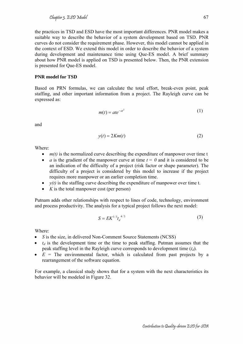
Chapter 3. ESD Model
Contribution to Quality-driven ESD for SOA
67
the practices in TSD and ESD have the most important differences. PNR model makes a suitable way to describe the behavior of a system development based on TSD. PNR curves do not consider the requirement phase. However, this model cannot be applied in the context of ESD. We extend this model in order to describe the behavior of a system during development and maintenance time using Que-ES model. A brief summary about how PNR model is applied on TSD is presented below. Then, the PNR extension is presented for Que-ES model. PNR model for TSD Based on PRN formulas, we can calculate the total effort, break-even point, peak staffing, and other important information from a project. The Rayleigh curve can be expressed as:
2
)( atatetm −= (1)
and
)(2)( tKmty = (2) Where:
• m(t) is the normalized curve describing the expenditure of manpower over time t • a is the gradient of the manpower curve at time t = 0 and it is considered to be
an indication of the difficulty of a project (risk factor or shape parameter). The difficulty of a project is considered by this model to increase if the project requires more manpower or an earlier completion time.
• y(t) is the staffing curve describing the expenditure of manpower over time t. • K is the total manpower cost (per person)
Putnam adds other relationships with respect to lines of code, technology, environment and process productivity. The analysis for a typical project follows the next model:
3/43/1dtEKS = (3)
Where: • S is the size, in delivered Non-Comment Source Statements (NCSS) • td is the development time or the time to peak staffing. Putman assumes that the
peak staffing level in the Rayleigh curve corresponds to development time (td). • E = The environmental factor, which is calculated from past projects by a
rearrangement of the software equation. For example, a classical study shows that for a system with the next characteristics its behavior will be modeled in Figure 32.

Chapter 3. ESD Model
Contribution to Quality-driven ESD for SOA
68
0
5
10
15
20
25
30
35
0 0,5 1 1,5 2 2,5 3 3,5 4 4,5 5 5,5 6 6,5 7 7,5 8 8,5 9
Time (years)
y(t) y(t)
td
Figure 32 Example of a PNR curve using TSD
Where:
• S ≈ 90000 NCSS • td = 2.44 years • y(td) = 29 (number of persons in the peak staffing)
The previous values are the average value for software projects. The value of a can be calculated from m(t) function, by computing the first derivation and finding the maximum value, that is:
)21()(' 22
ataetm at −= − (4)
td occurs when m’(t) = 0, then
221
dta =
(5)
So:
• a = 0.0839828 • m(td) = 0.12428 • K = 117 • E = 5600
In the same way the total effort for the same example is shown in Figure 33. It is also known as the cumulative Rayleigh curve that can be obtained by integration of the equation (2).

Chapter 3. ESD Model
Contribution to Quality-driven ESD for SOA
69
0
50
100
150
200
250
00,7
5 1,5 2,25 3
3,75 4,5 5,2
5 66,7
5 7,5 8,25 9
Time (years)
Tota
l effo
rt
Total effort TSD
Figure 33 Example of total effort using TSD
Different values of a, K and td will give different sizes and shapes of the Rayleigh curve. The previous analysis has been though for development and maintenance time. The td (time in the peak staffing) is the moment when the development phase has finished and the maintenance phase begins, as was shown in Figure 32. The PNR model assumes that in the first maintenance phases, the major part of errors introduced in development are corrected, some gaps of functionalities are fixed and small functionalities can be developed. Gradually these activities decrease over time. Classic PNR curves are not suitable model for ESD, because they do not take into account the previous experiences, evolution of the software. And also, they are not a suitable model to open source projects, because in open source communities, the staff is distributed and dynamic, in addition, it can be carry out several tasks at the same time. Extension of PNR model for Que-ES In the next situation the same conditions than the classic PNR model, but we consider some improvements during maintenance phase, that is, evolution of the software taking into account significant evolutionary improvements. We are going to analyze its behavior, in PNR curves to maintenance phase taken into account significant improvements. So the new expenditure manpower m(t) will be:
)()()()()()( 3210 tititititmtm n+++++= K (6) or
∑=
+=n
jjo titmtm
1)()()(
(7)

Chapter 3. ESD Model
Contribution to Quality-driven ESD for SOA
70
Where m0(t) is the traditional PNR curve and ij(t) are the significant evolutionary improvements during the maintenance phase. j is natural number identifying the significant evolutionary improvement and n is the total number of improvements. We define ij(t) as other PNR curve, but it is affected by the original curve and actual conditions in the introduced time (taking into account the previous conditions). ij(t) is defined by a staggered function as is shown below.
⎪⎩
⎪⎨⎧
Δ= Δ−
−
2
)(
0)(
1jj ta
jjjj etatm
ti ∞<≤
<≤
tt
tt
j
j0
(8)
Where aj is the effort for the improvement j, mj-1(t) is the previous expenditure manpower and tj is the time when ij is introduced, then:
jj ttt −=Δ (9) With these definitions, the first improvement will be described by:
)()()( 10 titmtm += (10) and
211 )(
1101 )()()( ttaettatmti −−−= (11)
The a1 will be calculated the same way as we calculate a0 from i1(t) to tj ≤ t < ∞, then
]]))[((2)2[()(' 111011]2)[(
111110 tataatttttemti tataat −+−−−= −+− (12)
Where m1 is a constant,
211
101taeaam −= (13)
i1max(t) occurs when i1’(t) = 0 to tj ≤ t < ∞, then
1
02
1
11 )(2
2ttta
ttttta
−−
−−
= (14)
For the same example, a0 = 0.084 and assuming a ∆t = 0.75 years and t1 = 2.75 years. so a1 will be equal to 0.687. In order to simplify the model for the example, we assume the same conditions for other increments, that is: a1 = a2 = a3 =… = ai. We compute the improvements to t2 = 3.5, and t3 = 4. The behavior is shown in Figure 34.

Chapter 3. ESD Model
Contribution to Quality-driven ESD for SOA
71
0
0,02
0,04
0,06
0,08
0,1
0,12
0,14
0,16
0 0,5 1 1,5 2 2,5 3 3,5 4 4,5 5 5,5 6 6,5 7 7,5 8 8,5 9
Time (years)
m(t)
i=0i=1i=2i=3
Figure 34 Example of PNR normalized curves extension using evolutionary increments
In Figure 34 are shown four different curves, for i = 0 (PNR classic), i = 1, i = 2, and i = 3; to hypothetical improvements 1 to 3 respectively. The staffing curve with 3 improvements is shown in Figure 35.
0
5
10
15
20
25
30
35
40
0 0,5 1 1,5 2 2,5 3 3,5 4 4,5 5 5,5 6 6,5 7 7,5 8 8,5 9
Time (years)
y(t) y(t)
Figure 35 Example of PNR staffing curve extension using evolutionary increments
The number of people increases close to the peak of every increment, so a higher number of people are obtained for the second and third improvements (35 manpower). A comparison between the total effort for i = 0 and i = 3 is shown in Figure 36.

Chapter 3. ESD Model
Contribution to Quality-driven ESD for SOA
72
0
50
100
150
200
250
300
350
00,7
5 1,5 2,25 3
3,75 4,5 5,2
5 66,7
5 7,5 8,25 9
Time (years)
Tota
l effo
rt
Total effort (i = 0)Total effort (i = 3)
Figure 36 Total effort using evolutionary increments
At the maintenance time the total effort is increased by the additional effort of uncharged people into the improvements. (6 manpower more in the new peak staffing around td2 ≈ 3.75 and td3 ≈ 4.25) As conclusion of this part, it is obvious the growing of the cost in maintenance time when the product is improved in order to keep a certain level of quality. Extension of PNR model for Que-ES with fast delivery This extension will be described for the same situation using ESD with fast delivery, i.e. the same group working using ESD in development phase, for the same project around 90000 NCSS. In ESD we consider the next conditions: delivery each three months (0.25 years), as is suggested in XP [19], but this model can also be used with shorter delivering as is recommended by Scrum, Evo, Crystal and others. We suppose the same increments, being every increment around 10000 NCSS, so, in the complete project around 90000 NCSS will be delivered at 2.25 years after the increment ninth, a little early than using TSD. In this case for the same example: a0 = 0.084, ∆t = 0.25 years and t1 = 0.25 years, so a1 = 8. Assuming the same conditions for all evolutionary increments, that is: a1 = a2 = a3 =… = ai. We compute the improvements to t2 = 0.5, t3 = 0.75, …, t9 = 2.25, …, and t16 = 4. The behavior of m(t) and y(t) are shown in Figure 37 and Figure 38, respectively.

Chapter 3. ESD Model
Contribution to Quality-driven ESD for SOA
73
0
0,1
0,2
0,3
0,4
0,5
0,6
0
0,5 1
1,5 2
2,5 3
3,5 4
4,5 5
5,5 6
6,5 7
7,5 8
Time (years)
m(t)
i=0i=1i=2i=3i=5i=6i=7i=8i=9i=10i=11i=12i=13i=14i=15i=16i=17
Figure 37 Example of PNR normalized curves using ESD with fast delivery
0
5
10
15
20
25
30
35
0
0,42
0,83
1,25
1,67
2,08 2,5
2,92
3,33
3,75
4,17
4,58 5
5,42
5,83
6,25
6,67
7,08 7,5
7,92
Time (years)
y(t) y(t) TSD
y(t) ESD
tp
Figure 38 Example of PNR staffing curves using ESD with fast delivery (K = 25.5)
Note that the curve has been done taken into account the same number of people (around 29 people in the peak staffing). Some other observations are:
• The effort for every improvement is always less than using TSD, it is also verified calculating the total effort shown in Figure 39.
• The value of K (total effort per person) is reduced from 117 to 25.5. If K decreases the fact risk factor increases (aj), so we should be very careful, because the risk factor is only controlled by the teamwork, and depends on the people, more NCSS per person in order to reduce the time.

Chapter 3. ESD Model
Contribution to Quality-driven ESD for SOA
74
• The total effort is quickly reduced after the last increment. However, additional increments could be done and always the total effort will be less than using TSD.
• Comparing Figure 35 and Figure 38 in maintenance time, at the same period of time with t equal 4 years and with the same staff. In the first one, 3 improvements are done while in the second, 7 improvements have been executed; each increment leads to improve the functionality or quality.
• Figure 37 and Figure 38 show 16 evolutionary increments, but could be more; the limit of increments depends on the business break point.
0
200
400
600
800
1000
1200
1400
1600
0
0,5 1
1,5 2
2,5 3
3,5 4
4,5 5
5,5 6
6,5 7
7,5 8
Time (years)
Tota
l effo
rt
Total Effort to TSDTotal Effort to ESD
Figure 39 Total effort comparison between TSD and ESD using evolutionary increments and fast
delivery (K = 25.5) An increment of the K in ESD maintaining the other variables in the same conditions implies that more people should be involved. However, the example (K = 30) in Figure 40 and Figure 41 shows that using ESD the number of people is increased during development phase but during maintenance phase the effort has a considerable reduction. The behavior in this case is clearly defined in Figure 40; in the first part of development the total effort is less (less documentation and design), but after that the effort increases fast until final delivery, however, during maintenance time the effort is reduced to a level lower than TSD.

Chapter 3. ESD Model
Contribution to Quality-driven ESD for SOA
75
0
5
10
15
20
25
30
35
40
0
0,42
0,83
1,25
1,67
2,08 2,5
2,92
3,33
3,75
4,17
4,58 5
5,42
5,83
6,25
6,67
7,08 7,5
7,92
Time (years)
y(t) y(t) TSD
y(t) ESD
Figure 40 Example of PNR curves using ESD with fast delivery (K = 30)
0
200
400
600
800
1000
1200
1400
1600
0
0,5 1
1,5 2
2,5 3
3,5 4
4,5 5
5,5 6
6,5 7
7,5 8
Time (years)
Tota
l effo
rt
Total Effort to TSDTotal Effort to ESD
Figure 41 Total effort comparison between TSD and ESD using evolutionary increments and fast
delivery (K= 30) In the next example some real figures are taken to our model. There are many examples; some of them are often in open source communities where the people collaborate directly to the code modification. We consider as an example the Mozilla browser [171]. Nowadays Mozilla, is a project with more than 96 modules, and more than 30 million of NCSS. Probably, in this Mozilla project more than 700 people have participated, (this number has been taken considering the number of contributions in the CVS repository -see [171] and [172]). The number of people is not easy to calculate because the number of stakeholders in an open source project is dynamic and there is not a register about that. In the hypothetical situation considering Mozilla a project developed with TSD (30 million of NCSS and 700 people involved), the behavior should be described by Figure 42. In this situation the a0 = 0.02768, K = 4904.95 and td = 4.25 years (when the version 1.0 was delivered).

Chapter 3. ESD Model
Contribution to Quality-driven ESD for SOA
76
We have considered as good real example for ESD, because it is an open source project with evolutionary increments. In addition, the information about Mozilla evolution has been registered into its CVS repository. For our analysis, each version delivered has been considered as evolutionary increment. A summary about how has been its development is presented in the Table 5 Periods Date Description 1st period 03/1998
03/1999 Netscape source code is freely available, Mozilla starts from Netscape source as an open source project, but it is re-build from the scratch. The first version available was called Milestone 3. We treat this period of the same way as TSD. ao= 0.02768 This value is obtained using classic PNR curves for 4.25 years, S = 30000000 NCSS and y(t) = 700 manpower (estimated values for Mozilla version 1.0).
2nd period 03/1999 06/2002
Approximately every month is delivered a new evolutionary version, since Milestone 3 to Milestone 18, Mozilla 0.6 to Mozilla 1.0. ai= 72
3rd period 06/2002 06/2004
Approximately every three months a new version is delivered. Since Mozilla 1.1 to Mozilla 1.7 ai= 8
4th period 06/2004 05/2005
Approximately every moth is delivered a new version, but they are small changes, usually solving bags found in the previous versions and solving security problems. Since Mozilla 1.7.1 to Mozilla 1.7.8. ai= 72
Table 5 Mozilla project overview In Figure 42 also, the real behavior is described, in the real curve are some periods with more activity than others. A characteristic of an open source project is that the participation is unpredictable, because several groups are working in cooperation, in several branches at the same time. It is clear that in the biggest peak staffing several groups are working together, for instance at the time with t = 3.25, it is the moment of the highest peak staffing. In that moment, three new versions are working almost at the same time. We calculate the effort in this period approximately to 2.33 times more than the activity in the td of hypothetical situation with TSD. i.e. in the peak staffing around 1631 manpower are working. With this information we calculate the constant K for the real curve, so K = 213.57

Chapter 3. ESD Model
Contribution to Quality-driven ESD for SOA
77
0
200
400
600
800
1000
1200
1400
1600
1800
0,00
0,42
0,83
1,25
1,67
2,08
2,50
2,92
3,33
3,75
4,17
4,58
5,00
5,42
5,83
6,25
6,67
7,08
7,50
Time (years)
y(t) y(t) TSD
y(t) ESD
Figure 42 Mozilla example, comparison between classic PNR staffing curves and ESD with fast
delivery. However, the most notable result is the total effort in this project, i.e. the area under de curve from the real and hypothetical situation. This result is also illustrated in Figure 43. In the hypothetical situation more than 45000 manpower have been required while the real situation shows that approximately 16000 manpower were used. That means that by using ESD and collaborative techniques from open source communities for software development, the total effort has been decreased in almost a third part. Obviously, the total cost was decreased at the same proportion. Mozilla project is a good example of collaborative practices for software development and also we believe that the successful of Mozilla is in the introduction evolutionary increments in faster time (every month or in some periods at most every three months) as in ESD is recommended.
0
5000
10000
15000
20000
25000
30000
35000
40000
45000
50000
0,00
0,42
0,83
1,25
1,67
2,08
2,50
2,92
3,33
3,75
4,17
4,58
5,00
5,42
5,83
6,25
6,67
7,08
7,50
Time (years)
Tota
l effo
rt
Total Effort to TSDTotal Effort to ESD
Figure 43 Mozilla example, total effort comparison between classic PNR curves and ESD with fast
delivery.

Chapter 3. ESD Model
Contribution to Quality-driven ESD for SOA
78
3.5. Conclusions In this chapter the Que-ES model is presented, which is the proposed development process for ESD in this dissertation. Several contributions have been presented in this chapter, such as:
• The principles of Que-ES model categorized in 4+1 types. Que-ES principles have been organized in order to achieve an easy learning and better understanding (essential principles, architectural, process, organization and business principles).
• The description of Que-ES model grouped by 4 models: Architecture, Process, Business and Organization in agreement with the Que-ES principles.
• The behavior of Que-ES model is represented as an extension of PNR curves, Que-ES curves are a mathematical model for description of the behavior during the lifecycle (development and maintenance). Que-ES model proposes quick delivery by reducing the total effort per person (K), however that implies a increment of the risk factor (aj). aj factor only can be controlled by teamwork during the development lifecycle. In consequence, Que-ES introduces new processes in order to decrease the total effort. In section 3.3.2 (QPM), the introduced Que-ES processes are summarized and in the next chapters they are described in detail.
• Finally, an analytical comparison between TSD and ESD model is done. The comparison has been carried out taken into account classic and real examples. This analysis encourages the application of evolutionary increments, one of the principles defined on Que-ES (process and essential principles).

Chapter 4. Que-ES Architecture Assessment
Contribution to Quality-driven ESD for SOA
79
Chapter 4 Que-ES Architecture Assessment (QAA)
This chapter describes the QAA discipline. It is a fundamental part in order to guarantee the quality of a system as was defined by QPM and therefore, an essential part into the evolutionary development. QAA allows a quick feedback about a particular quality aspect. QAA proposes a methodological background for software assessment, where a generic workflow is presented. This method makes emphasis into quality aspects considering service-oriented architectures. This chapter is organized by six sections as follows: The first section shows the introduction and motivations of QAA, which focuses on the architecture assessment taking into account the QPM for service-oriented architectures. The second section presents the conceptual model of QAA, where all elements involved during QAA process are defined. The third section defines the proposed QAA workflow. The fourth section makes a short analysis about methods, techniques and tools supporting QAA process. The fifth section presents a case study where it is applied and validated. Finally, the last section summarizes the principal contributions of this chapter.
4.1. Introduction QAA is a discipline from QPM to guarantee the quality of solutions with respect to other alternatives (Assessment). Each solution must be analyzed with appropriated methods and techniques (Analysis). Analysis and Assessment were defined in Chapter 3 as two complementary disciplines. Analysis allows the refinement of requirements, architecture or implementation taking into account the concerns of the stakeholders in a certain context. Two phases are parts of the analysis process: verification and validation. Assessment complements the analysis process, comparing with alternative solutions at requirement, architecture or implementation level. In addition, assessment determines the best-optioned solution among different alternatives. Requirements, architecture and implementation could be assessed, as was illustrated in Figure 5 from Chapter 1. The stakeholders perform the assessment process in a specific environment. This chapter is focused to assessment of architecture, but this model can be extended to other areas such as requirements and implementation. The requirements assessment is part of requirement engineering. A complete guide for requirement engineering is presented by [153], where two phases, verification and validation have been defined. In addition, the assessment process could be used to compare the new requirements with respect to previous ones (evolution of the requirements). The verification phase concerns the checking that the requirements are consistent, complete and correct and the validation phase concerns checking that the requirements meet user needs and expectations [153].

Chapter 4. Que-ES Architecture Assessment
Contribution to Quality-driven ESD for SOA
80
The architecture assessment is done in order to verify, validate and compare a proposed solution with respect to other alternatives or with respect to their requirements. It is key for the correct selection of an architecture, guarantees the quality of solution and allows a rapid feedback for the teamwork. It is an essential principle of Que-ES and logically for QPM. The implementation assessment is done in order to verify, validate and compare the implemented solutions with respect to the architecture or with respect to requirements. The first one is executed to determinate the quality of implementations. It is key when we find implemented assets from third parties (open source community, in-house or COTS). The result of this process is only relevant for the teamwork. And the second one is often done when the product is delivered to client. Usually, this process is executed by an inspector, interventor or external verifier. It is key in order to guarantee the complete satisfaction of the client. The architecture assessment allows stakeholders to learn about the structure of a solution. If the stakeholders know the structure, they are able to detect possible faults, gaps or errors in short time. In addition, if a change is produced, the teamwork will know what asset or assets could be affected. The architecture assessment can also use configuration information, because changes in the configurations can affect the normal operation of the systems, or also can affect non-functional characteristics of the system. The architecture assessment can be used to assess the effect when changes in configuration have been carried out. Several topics can be assessed to the same system. In QAA, each topic should be considered on an independent way. It is especially useful when non-functional characteristics are assessed. The architecture assessment should be a quantified process. The assessment can only be done when some measures about a certain topic have been taken. In this direction, architecture assessment should be supported by methods and techniques that allow obtaining relevant data from the architecture. This information will be used in the process of verification, validation and comparison. There are a big set of methods specialized in different contexts or for different purposes. In section 4.4 the most representative methods studied are presented. These methods can be used by QAA depending of the assessment objectives. For example, for general purpose can be used BAPO [5] model, ATAM [8] or SAA [147]. Some of them specialized in the architecture views as AQA [173], for reviews as SARB [174], or for business as QFD [175]. And other methods for specific domain as ARID [176] [177] for preliminary software designs, RMA [178] for real-time systems, and in the catalogue of methods and processes of ESAPS [179], CAFÉ [180] and FAMILES [181] projects other architecture methods have been collected for system families or product lines. Any method and technique should be supported by an adequate tool. Tools play a relevant role in the quality-driven development, because they guarantee a rapid and suitable feedback. In this chapter some tools that should be used in the architecture assessment discipline will be analyzed. The architecture assessment method can be used in other domains. The techniques and tools depend of topic to be assessed. Both techniques and tools should be also in

Chapter 4. Que-ES Architecture Assessment
Contribution to Quality-driven ESD for SOA
81
concordance with that context. The assessment process can be applied into any architecture; however it has a special advantage when this is SOA, because the services can be independently assessed. The assessment can be applied to intermediate results or only for a specific aspect in the system (functional or non-functional). The advantages of SOA are reflected in the assessment process, because isolated (self-contained) services allow a more accurate assessment for quality aspects. On the other hand, the organization should not have just a repository of assets, this repository is more valuable when they have been assessed already. The reusability of assets depends in a big way on the quality of the assets previously implemented. Reusing assets not always has advantages, because some times the adaptation process to make small modifications requires a big effort almost comparable to the effort made if assets are built from the scratch. The assessment process reduces the learning time and aids in the adaptation process. In addition, the assessment process can be used in the selection of assets from third-party. In this chapter the context of architecture assessment is presented, a generic workflow method for architecture assessment is proposed and its validation with a case study. For the case study, we have selected a specific technical domain, soft-real time systems. And we have also chosen the performance as our topic to be assessed. In consequence, some specific techniques and tools have been considered in order to obtain an appropriated method.
4.2. QAA Conceptual Model A software architecture assessment is performed against one or more objectives [7]. The architecture assessment may use as input: QDM elements, guidelines, methods, techniques and others. The result of an assessment is a report and other outcomes [182] (see Figure 44). The principal objective of architecture assessment is to verify, validate and compare a proposed solution (architecture) with respect to other alternatives or with respect to their requirements. The candidate architectures are relevant in the evolutionary development because can contain potential future changes, so candidate architectures can be a possible evolution of the same system. In consequence, the architecture is the subject of an architecture assessment process. However, the QAA process needs specific guidelines, so particular objectives must be defined, and in some cases some policies or principles should be taken into account. The architecture is the essential part (it is a subject of the process) of QDM but other important data can be obtained from requirements, implementation or concerns from the stakeholders. The QDM’s elements are external elements that play a relevant role during QAA. They were defined in Chapter 3. In the course of a QAA process, the participants may execute one or more methods or techniques.

Chapter 4. Que-ES Architecture Assessment
Contribution to Quality-driven ESD for SOA
82
Figure 44 Architecture Assessment Context
Figure 44 represents the context of the QAA. It summarizes the proposals of architecture assessment. QAA context takes as support the conceptual model of architectural description given in [23]. Figure 44 also presents the minimal conditions for the application of QAA, i.e. the inputs of the QAA are desirable but some minimal inputs are required: from QDM the architecture and stakeholders; from guidelines, the objectives, and finally some methods and techniques should be available. Figure 45 presents the QAA conceptual model where concepts and elements involved in the architecture assessment are defined [73]. Architecture assessment process is applied to a lifecycle milestone. Initially, lifecycle milestone was thought for the domain engineering disciplines (Requirements definition, architecture design, implementation and test) and evolution disciplines (configuration management and change management) but it has been also extended for reverse engineering disciplines (requirement recovery and architecture recovery). The context of QAA process changes depending on the lifecycle milestone and influences on the objectives of the assessment, for example the conditions of a system could be different during development, runtime or maintenance phase. In addition, Que-ES model proposes small cycles and the architecture assessment could be done during each cycle if it is required. The QAA objectives may also be defined by the stage of the project in its lifecycle or determined by the stakeholders. The objectives in QAA process could be to determinate the quality of the architecture, identify opportunities for improvements or improve communication between stakeholders.

Chapter 4. Que-ES Architecture Assessment
Contribution to Quality-driven ESD for SOA
83
QAA process should be focused on specific aspects of the architecture. The focus could include: a specific requirement (functional or non-functional), the partitioning of the system responsibilities, the fit of the architecture to the problem or mission statement, the identification of skills to implement the system, verification of scenarios representing the critical functionality of the system or overall feasibility and specific risks of the architecture [7]. In addition, the focus determines which methods and techniques may be applied during the QAA process. When objectives and focus have been defined, only some part of the architecture needs to be considered (architectural views). The architectural view only considers some Architecturally Significant Requirements (ASR). ASR is a subset of requirements that affect significantly to the architecture. However, there is no precise definition of ASR; some hints to identify them can be found in [24]. The assessment process can be considered as a short project (few days when the process is applied the first time, after that, during the next lifecycle and with adequate tools this process can be reduced to hours) where all the elements defined in the QAA conceptual model need to be collected in an appropriate way (documentation, outcomes, activities, objectives, ASR, etc). The workflow defines activities of QAA process in order to perform them efficiently. The workflow is divided into a set of phases (Preparation, prioritizing requirements, filtering architecture, analysis, agreement, documentation and review). The workflow enacts one or more methods/techniques to address the assessment objectives. Different methods are appropriate for meeting different objectives. A complete workflow is presented in [7]. A method or technique establishes a set of criteria that are concrete means of judging whether the assets, and thus the architecture, meet a particular objective. The methods or techniques verify and validate (analysis process) a particular asset with respect to the criteria. The results from analysis (valuation) may be aggregated or otherwise incorporated into the architecture assessment (report). As was mentioned before that, the assessment is done against one or more objectives and led by the workflow. Architectural assessment is the activity of checking the software architecture that ascertains whether it satisfies the ASRs; therefore the assessment concentrates on the evaluation of structure, texture and concepts related, such as quality attributes. In addition, assessment is addressed by the results of analysis process (valuation) and the active participation of the stakeholders through concerns, decisions and trade-off. The main result of an assessment is a report by comparing some alternatives of solution (pros/contras). The assessment process does not consider the complete architecture, only one view concerned to specific ASRs. But other outcomes can be obtained from assessment, a better understanding of the architecture, better communication with the stakeholders, better understanding of architecture limitation and risk, etc. The stakeholders have different concerns that are addressed by the system. Some stakeholders may have concerns specific to system architecture, and some stakeholders are concerned with the properties and quality of the architecture description. Concerns may range from the very specific (e.g., functional and non-functional requirements) to the very general (e.g., needs, goals, preferences, business objectives and opportunities) [7].

Chapter 4. Que-ES Architecture Assessment
Contribution to Quality-driven ESD for SOA
84
The stakeholders make also decisions, for example, they can suggest a new alternative of solution, changes or disregard some parts of the architecture, include or disregard ASRs. The decisions of stakeholders concern also to the configuration or future changes (evolution of the system). The stakeholders decide when the assessment process finish and when the new one is required. Finally, the trade-off is the product of continued discussions among stakeholders with respect to what is the best candidate architecture. The best alternative is not always the best solution for the architect or for developers, but other interests are involved in the trade-off process, such as: market strategy, policies of owners, technologies, etc.
Stakeholders
Lifecycle milestone
Objetives
Focus
ASR
Workflow
DecisionsConcerns Trade-off
Methods and Techniques Valuation
Assessment
Architecture SystemRequirements
-defines1..*1
1..* -determine1..*
*-select*
*
-defines
*
-has1..*
-has1..*
-has
1..*
-has1..*
-has
1..*
-has1..*
1..*
-inform
1..*
1..*
-informs 1..*
1..*
-informs 1..*
-part of 1..*-include 1..*
1..*-selects
1..*
-produces
1..* 1..*
1..*
-result in
1..*
1..*
-results in1..*
1..*
-result in
1..*
1..*
1..*
1..*
-determine
1..*
1..*-enacts1..*
1..*
-results in
1..*
1..*
-informs
1..*
Figure 45 QAA conceptual model
4.3. QAA workflow The QAA workflow is based on current experience and industrial practices on software architecture, architectural assessment [8] and the SARA project results [7]. This workflow adapts mature techniques to be used at the architecture phase. A fundamental change in the ways to create, to describe and to analyze software architectures are promoted in this section. Rather, our main goal is to encourage and widespread the assessment by providing a sensible, adaptable and easy to follow method, and tools to facilitate the process.

Chapter 4. Que-ES Architecture Assessment
Contribution to Quality-driven ESD for SOA
85
The QAA workflow can be considered a method to evaluate architectures with respect to a specific quality aspect [3]. QAA workflow performs a comparative analysis in order to choose the best architecture from a set of alternatives. In order to foresee if certain architecture will be able to meet the quality requirements, some techniques can be applied. Most of them are dynamic techniques that require model execution and are intended for evaluating the model based on its execution behavior. As regards architecture, dynamic techniques rely on the development of an executable model or prototype, so the application of prototypes, experiments or simulation models to the architecture of a software system is allocated to the “symbolic execution” techniques. The QAA workflow is defined as a series of iterative activities: preparation, prioritizing ASRs, filtering, analysis, agreement, documentation and review. As result an assessed architectural model with respect to the requirements and quality characteristics is obtained [73]. Preparation Preparation takes as inputs the requirement documentation, domain analysis models and architectural views. The preparation phase defines the objectives of assessment, the scope, impact and duration; also in some cases cost and planning are considered. Especially important for the assessment process is to get several possible architectural models for the system, in order to compare them. Currently, there are no absolute scales for quality of software systems, but different systems can be compared with respect to a certain quality. Also preparation defines the group of stakeholders attending in the architectural assessment process. Prioritizing requirements The architect alone or preferably the stakeholders allocate each requirement to the six quality characteristics defined in [3] (functionality, reliability, efficiency, usability, maintainability and portability), rank each requirement and the quality characteristics and establish feasible combinations of accomplishment for each of the requirements and quality characteristics for the system. At the end of this phase a prioritized ASR list is obtained. Filtering In agreement with the objectives defined in preparation, only a set of ASR will be analyzed. This selection depends of the quality aspect object of the assessment. Filtering begins with the most important ASR, after that, looks for available information in the architecture, and finally proceeds to review the architectural view for each assets and connectors. Filtering reduces the complexity of the analysis by leaving the relevant elements and estimates the impact of the unknown elements, in isolation. At the end of filtering phase the relevant architectural elements are obtained and their relations with respect to ASRs, the ASRs are associated to one quality aspect and their impacts. Analysis The analysis uses the available methods or techniques on the reduced architecture (architectural view only considering the relevant ASRs) to measure their parameters. This step depends on the specific requirement or quality characteristic; for some of them there are absolute values (for example, the end-to-end response time), for others,

Chapter 4. Que-ES Architecture Assessment
Contribution to Quality-driven ESD for SOA
86
relative values (for example, design cohesion metrics results); and for others only human judgment (for example, usability aspects). Agreement Some concerns, decisions and trade-offs must be taken after analysis in order to chose the best available architecture. Usually in the agreement phase is reflected the priorities of ASRs. Each ASR should be analyzed and compared with alternatives if they are available. Documentation A report containing a summary of results from previous phases is collected into the documentation phase, containing information such as: objectives, prioritized ASR with respect to a specific quality aspect, architectural views, analysis results and the decisions taken. This report should be available and surveyed for teamwork and it is desirable to be known by all the stakeholders. Also the information is mapped back to architectural models for traceability purposes. Review During the development process, more information is obtained, and in some cases it is more accurate. For example, the timing information provided at the architectural design phase is very rough; at detailed design better values can be predicted, and at the implementation (once some of the components have been codified) actual measures can be got. All this information must be referred back to the architectural model, and as values can be significantly different than predicted, at least the analysis, agreement and documentation phases must be reconsidered.
Preparation
Prioritizing requirements
Analysis
Architecture Asessment
Documentation
ReviewAgreementFiltering architecture
Workflow
Dependences Figure 46 QAA workflow

Chapter 4. Que-ES Architecture Assessment
Contribution to Quality-driven ESD for SOA
87
4.4. QAA Methods, Techniques and Tools Depending of the QAA objectives, specific methods and techniques are required. Each method has associated a set of steps, techniques, input data and results. In some cases methods have a special notation (formal methods). In QAA, a method establishes the process for architecture analysis and the techniques allow estimating, calculating or simulating some expected results. After that, the results should be studied, i.e. verified and validated. In the analysis process each ASR must be valuated by checking whether the architecture under assessment satisfies that ASR or not. The results of applied methods are part of the assessment report. Some methods and techniques are supported under a set of tools. Usually the methods and techniques are applied in a particular context and topic; they are usually supported on specific tools. As was presented in the chapter 2, methods and techniques can be categorized. In Figure 47 the range of possible methods is presented. In general methods can be formal or informal. However, in the context of quality characteristic analysis, the methods are classified as qualitative and quantitative. Informal methods are carried out during meetings, but nowadays they are often informal reviews through internet using chat, e-meeting or e-mail. Informal methods are among the most commonly used. They are called informal because the tools and approaches used rely heavily on human reasoning and subjectivity without stringent mathematical formalism. The “informal” label does not imply any lack of structure or formal guidelines for the use of the methods; in fact, these methods are applied using well structured approaches under formal guidelines and they can be very effective if employed properly. They are supported on interviews, checklist, documentation checking, face validation, inspection or walkthrough. Formal methods are supported on established guidelines and aided on mathematical models; they are supported on inductions, inferences, calculus or measurements. Nowadays, formal methods cannot be applied to complex architectures. However, formal methods serve as the foundation for other techniques. Qualitative methods should be supported in comparisons with previous experiences. These methods can be used to perform a judgment about the architecture analyzed. Quantitative methods are supported in metrics. These methods are used to perform predictions or estimations.
Figure 47 Possible methods into QAA
Chapter 4. Que-ES Architecture Assessment
Contribution to Quality-driven ESD for SOA
88
Each method can use one or more techniques. There are several types of techniques; in Figure 48 a taxonomy is presented. Basically, the classification was done taking into account the way in which techniques obtain their results.
• Interview-based techniques are often used to gather information quickly. ESD promotes this type of techniques because it is the most effective communication among stakeholders. In addition, individual interviews can be used to solve politically or emotionally difficult contexts.
• Questionnaire-based techniques are lists of open questions applicable to all kinds of architectures, regarding both the process and the software architecture product. Questionnaires are developed for the specific models that contain the architecture; [183] contains some example of questionnaires that can be applied to use cases, use case diagrams, sequence diagrams, and class diagrams (for example, those included in the logical view of architecture).
• Checklist-based techniques are used to reuse the know-how from previous reviews: typical problems, problem areas, overlooked issues and coverage of the review.
• Scenario-based techniques describe a specific interaction between a stakeholder and the system; they are very useful in order to enact or predict the behavior of architecture in the presence of changes (change case). The possible scenarios can be decomposed into: use case (typical ways to use the system), growth (covering anticipated changes), exploratory (extreme changes that take the system to its limits) and critical case (scenario in extreme conditions).
• Analysis-based techniques are used to check the static or dynamic architectural views. Analysis techniques are essential in the architecture assessment process, because reflect the state of the architecture, such as: understandability, portability, localization of complexity, cohesion, coupling, behavior, etc.
• Metrics-based techniques are quantitative interpretations about observable measurements on the architectural models. Their advantage is that they provide unambiguous, specific values; the drawback is that there is no direct and proven correlation between metric values and quality requirements. Often the metric results are obtained from views in the development or physical views. Some metrics are: size, complexity, modularity, cohesion, and coupling.
• Simulation-based techniques are used to verify and validate the behavior of an architecture. Perhaps they are the most accurate techniques but also the most expensive (require an additional effort building them). Simulation techniques are supported into complex mathematical data and equations in order to imitate the real behavior of the system. In practice, simulation is extremely difficult because the real system is subject to an almost infinite number of influences.
• Prototyping-based or Experiment-based techniques. A prototype is a partial and operational model of a system (focused on a small set of properties). It is essential that the prototype can be executed, so testing techniques can be used on the prototype as if it was the final system. The advantages are that the prototype behavior relates to actual use of the system, more than to its structure, the assumptions are clearer than those for metrics and can be derived directly from scenarios. On the other hand, they need additional development work, they represent an additional maintenance track, and their results may not be accurate or correlate to the results of the final system. Some promising results have been obtained through the development of behavioral models using state-charts in the specification that can afterwards be used for testing. Prototyping is a mature

Chapter 4. Que-ES Architecture Assessment
Contribution to Quality-driven ESD for SOA
89
practice in the software engineering from the hardware engineering, for example, in [184] is presented a model for rapid prototyping.
• Probing about alternatives. This technique compares among several candidate solutions in order to choose the best alternative.
Figure 48 Taxonomy of techniques
Perhaps the most general method is presented in BAPO model. BAPO [5] is an evaluation framework for software product family engineering, it was executed in ESAPS [179], CAFÉ [180] and FAMILIES [181] projects, It has defined four-dimensional axes, Business, Architecture, Process, Organization (BAPO)
• Business, how to make profit from products. • Architecture, technical means to build the software. • Process, roles, responsibilities, and relationships within software development. • Organization, actual mapping of roles and responsibilities to organizational
structures. The purpose of the BAPO model is to: serve as a benchmark for effective software product family engineering, support the assessments of software product family engineering for capability evaluations of software production units, divisions, or companies and support the improvement of software product family engineering, which involves producing assessments and improvements plans. In BAPO, every dimension is structured in five levels, and has its respective relevant aspects that should be taken into account in the evaluation process. BAPO dimensions can be used in anywhere environment and domain, but it is specialized into system families. Other works have been proposed by the Carnegie Mellon and Software Engineering Institute (SEI), the most known are: Architecture Tradeoff Analysis Method (ATAM) [8] [176] and Software Architecture Analysis Method (SAAM) [176] [185]. SAAM was the method previous to ATAM by the same authors. SAAM provides support for quality characteristic assessment, such as: modifiability, flexibility and maintainability but can be also used for portability, extensibility, integrability and functional aspects. ATAM is a general purpose assessment method for the architecture of software systems. In the new adaptation, its name reflects the fact that trade-off analysis is always required. The purpose of ATAM is to assess the consequences of architectural decisions in the light of quality attribute requirements (attribute interaction and their interdependencies). Essentially, ATAM discovers potential risks within the architecture of software systems. ATAM uses scenarios-based and analysis-based techniques. ATAM has several extensions for example:

Chapter 4. Que-ES Architecture Assessment
Contribution to Quality-driven ESD for SOA
90
• For reviewing preliminary software designs (components or subsystems): Architecture Review for Intermediate Design (ARID) [176].
• For product-family architectures: Holistic Product Line Architecture Assessment (HoPLAA) [186] or Family-Architecture Analysis Method (FAAM) [187].
• For analyzing the costs, benefits and schedule implications of architectural decisions: Cost-Benefits Analysis Method (CBAM) [188] [189] [190].
• For business information systems and embedded systems: Architectural-Level Modifiability Analysis (ALMA) [191] [133].
• For an architecture selection process by comparing the fitness of architecture candidates based on business goals: Software Architecture Comparison Analysis method (SACAM) [192].
The University of Groningen presents other alternative: the Software Architecture Assessment (SAA) [147]. SAA proposes that an assessment must be done after each design iteration. This assessment has as objectives: quality attribute satisfaction, stakeholders satisfaction and software system acquisition. SAA was built for software product line but it can also be used in other domains. It uses scenario-based techniques but for estimation of quality attributes recommends simulation, mathematical models, metrics and experiences. In addition SAA considers important the evaluation of the changes to estimate the effects [193] [194] AT&T Bell Laboratories presents other proposal the Software Architecture Review Board (SARB) [174]. The SARB follows a standard procedure for conducting reviews. This is an extensive review, conducted by four or five reviewers, designed to explore all the nooks and crannies of the architecture. The architects prepare a problem statement as well as documentation of the architecture, and give them to the reviewers about two weeks before the review. The review is conducted on-site, and usually lasts about two days. MITRE Corporation proposes the Architecture Quality Assessment (AQA) method [173]. AQA provides a means to conduct architectural evaluations. AQA can be used during all the lifecycle of a system. It considers only architectural aspects. AQA is based on a conceptual reference which defines the architecture architectural description, views, architectural elements, components, etc. The evaluation process is centered on quality aspects and detection of risks. The quality aspects considered are understandability, feasibility, openness, maintainability, evolvability and client satisfaction. Parnas & Weiss [195] proposed a method to find defects in designs called Active Design Reviews. It is a method based on questionnaires techniques. In an active review, the architect writes a set of specific questions about the architecture. The questions are assigned to different reviewers, according to each reviewer’s expertise and current role. The questionnaire should focus the attention of the reviewer on the issue that he knows about. Each reviewer can concentrate on his part of the review independently and in parallel with all the others. The purpose of an active review is to make it as easy as possible for the reviewers to find errors in the architecture and to assure full participation by all reviewers, taking advantage of their different strengths. The reviewers answer the questions based on his knowledge and the provided documentation. They send the answers to the architect, and then they meet so the architect can get further clarification about the responses.
Chapter 4. Que-ES Architecture Assessment
Contribution to Quality-driven ESD for SOA
91
Other option is the Quality Function Deployment (QFD) [175]. QFD is a set of development tools that were developed in Japan to transfer the concepts of quality control from the manufacturing process into the development process. QFD is most oriented to business area. QFD uses a matrix where the issues are listed, described and prioritized. This matrix is used during the trade offs to take decisions, measure impacts and make predictions. The matrix is built from the documentation of the project and using scenarios. QFD allows an early identification of risks and tries to increase the satisfaction of the client. Other interesting ideas have been presented in [196], [197] and [198] called method the Desk Review. It is a review where the reviewers work completely independent each other. They study the material, and send comments to the architects. There are no meetings and no review leader needed. Desk review is used for code inspection but may be used for other purposes as well. Similarly in [199] two dimensions for analysis, business and architecture are covered. It considers cost estimations, requirement analysis and impact. The proposed method allows clarifying trade-offs and make choices by using interviews and checklists. There are other methods for specific domains, such as for example Rate Monotonic Analysis (RMA) [178] which was created to analyze hard real-time systems. RMA provides a mathematical and scientific model for reasoning about schedulability. In hard real-time systems, where the top most important requirements are described and means of temporal restrictions and response times, RMA allows validating the system before its implementation [27]. If the architects can handle the information needed to perform the RMA and attach it to the architectural models, the RMA can be applied as an analysis technique in the architectural assessment process. RMA follows the main ideas of ATAM in the context of real-time systems by using scenarios (situations). In the catalogue of methods and processes of ESAPS [179], CAFÉ [180] and FAMILES [181] projects, other assessment architecture methods have been collected. For example: Software architecture assessment by Nokia, Ericsson and Blekinge Institute of Technology [200], architectural mismatches analysis by Fraunhofer IESE [201], IESE PulSE Method (DSSA) by Fraunhofer IESE [202], Architecture evaluation by ICT Norway [203] Quality-driven Architecture Design and quality Analysis (QADA) by VTT [204] and others.
4.5. Architecture assessment for the performance of a soft real time system. This section presents a scenario of validation using the QAA model for architectural-level performance assessment for soft real-time systems [205] (see Figure 6). In this case we use the Rate Monotonic Analysis (RMA) [206] which has an effective set of techniques for time analysis and a method that allow using these techniques adequately. The method and techniques have been implemented in an analysis tool. In addition, we show a complete guide of how to make the architectural assessment of a Supervisory Control and Data Acquisition (SCADA), which is relatively stable in the industry for the last thirty years [207].

Chapter 4. Que-ES Architecture Assessment
Contribution to Quality-driven ESD for SOA
92
Figure 49 Scenario of validation for the QAA method
4.5.1. Real-time systems background A real-time system is defined as one in which the correctness of its output(s) depends not only upon the logical computations carried out but also upon the time at which the result are delivered to the external interface. In other words, a real-time computation is considered wrong (not just late!) if the results are generated at the wrong time [208] (see Figure 50).
Real-time system(State)Input Output
Output = f (Input, State)
Environment
Real-time system(State)Input Output
Output = f (Input, State)
Environment
Figure 50 Real-time system
Traditionally the real-time systems are modeled with certain characteristics, parameters, notations and using specific techniques. Aspects related with the time, deadlines, performance and schedulability should be treated. These elements must be reflected in the architecture in order to be assessed. In [121] has defined a conceptual model for schedulability, performance and time with the main concepts, elements, quality attributes and their relationships. It is a resource-oriented model for real-time systems. This profile can be used as a starting point for architectural description of real-time systems (see Figure 51).

Chapter 4. Que-ES Architecture Assessment
Contribution to Quality-driven ESD for SOA
93
Figure 51 Structure of profile for schedulability performance and time [121]
On the other hand, there are several classes of real-time systems: soft, hard, firm, time-oriented, event-oriented, distributed, centralized, etc. For this reason is not possible to create a generic situation for all real-time systems, rather the most common situations can be analyzed [178], such as, for example, handling periodic events, shared data, aperiodic events, etc. In our context, we only consider soft real-time systems for their architectural assessment. The description and characterization of real-time system is well known, but in a high abstraction level (architectural design) only skilled designers are able of know. Some methodological guidelines can be used for the architectural description of real-time systems, for example: ROPES by [26] or PPOOA by [157] [209]. Both have extensions of UML for the architecture description. We assume that the architectural description is an area widely known and therefore we focus on the validation of the proposed method in this chapter. The main idea is to carry out a quick assessment of the proposed architecture and compare with alternatives.
4.5.2. Instantiation of QAA for performance assessment in soft real-time systems
Architecture is the blueprint for a system, and the carrier of the system’s quality attributes, but complex software systems require being modifiable and having good performance. Experience has shown that the quality attributes of large software systems live principally in the system software architecture.

Chapter 4. Que-ES Architecture Assessment
Contribution to Quality-driven ESD for SOA
94
In Figure 45 was defined the conceptual model of QAA. In the case of performance for soft real-time systems this model has defined some specific concepts. Figure 52 shows the new elements found based on the conceptual model.
Stakeholders
Lifecycle milestone
Objetives
Focus
ASR
Workflow
DecisionsConcerns Trade-off
Methods and Techniques Valuation
Assessment
Architecture SystemRequirements
-defines1..*1
1..* -determine1..*
*-select*
*
-defines
*
-has1..*
-has1..*
-has
1..*
-has1..*
-has
1..*
-has1..*
1..*
-inform
1..*
1..*
-informs 1..*
1..*
-informs 1..*
-part of 1..*-include 1..*
1..*-selects
1..*
-produces
1..* 1..*
1..*
-result in
1..*
1..*
-results in1..*
1..*
-result in
1..*
1..*
1..*
1..*
-determine
1..*
1..*-enacts1..*
1..*
-results in
1..*
1..*
-informs
1..*
Execution
Performance and
schedulability
RMA method and techniques
Architecture quality
Resources, event sequence and activities.
Architecture description with
real-time conditionsReal-time system
Real-time requirements
QAA workflow method
Utilization test Verify response time Assessing capacity
Figure 52 Real-time system assessment
Performance quality is a property only visible when the system is in run-time, in consequence the lifecycle milestone will be in execution time. This is a hard condition at architectural level because the architecture does not have real values about execution, then, we need to make estimations (behavior prediction) taken into account previous experiences. In the implementation phase these estimations become in additional requirements or in some cases in design constrains. Several estimations should be performed at this level of architecture, for this reason, we consider that QAA could be trusty used only in soft real-time systems. In our case, the general objective of the assessment is to determinate the quality of the architecture with respect to performance for soft real-time systems. Therefore, the architecture assessment should focus on the behavior of the system. The behavior at architectural level is described using the dynamic views. Several sub-characteristics are associated with performance: throughput, latency, efficiency and demand [121] and [210]. However, in real-time systems the demand attributes have special interest, such as schedulability and utilization. Therefore, we are going to focus in schedulability and utilization analysis. Schedulability take into

Chapter 4. Que-ES Architecture Assessment
Contribution to Quality-driven ESD for SOA
95
account aspects such as: assigned assets to a resource, the processes and threads, the process priorities, the arrival rates of messages or events to those processes, and timing requirements such as deadlines and execution times. Based on that information, an analysis must be carried out regarding scheduling, utilization, throughput, etc. The assessment focus selects a subset of Architecturally Significant Requirement (ASR) to be considered in the assessment process. An ASR is an appropriate refinement of the system requirements that are specific in terms of the desired system properties plus a justification of how achieving these properties of the architecture are influenced. For real-time systems the ASR are related with events sequences, activities and resources.
• An event sequence is a time-ordered sequence of events arising from the same stimulus. The events are characterized by nine parameters: name, type (external, internal or timed), mode, pattern (periodic, bounded, bursty or unbounded), period, time requirement (hard, soft or firm), blocking time, deadline and the activities associated as responses to the event [178].
• An activity is the lowest decomposition of a response, a segment of a response in which the properties that affect allocation of system resources do not change. Activities have these parameters: name, jitter tolerance, associated resource, atomic, user, execution time and priority [157] [209].
• And a resource represents a software or hardware component of a system. A resource has three parameters: name, type (CPU, device, database, or coordination mechanism, such as, buffer, semaphore, mailbox, rendezvous or transporter) and schedulability policy (fixed priority, FIFO, interrupt masking protocol, so on).
The QAA focus determines which methods and techniques to apply, in this case based on the Rate Monotonic Analysis (RMA) theory [178]. As a result, valuations of ASR, Architecturally Significant Decisions (ASD) are identified. However, there are other approaches that can be used for schedulability, such as Deadline Monotonic Analysis DMA [211] or EDF [212]. A method or technique establishes a set of criteria that are concrete means of judging whether the assets, and thus the architecture, meet a particular objective. Selection of these criteria follows from the refinement of the review objectives, relative to the particular type of assessment, and associated stakeholders. A method provides a way of analyzing particular assets with respect to the criteria, leading to results for these criteria (valuations). These results from the method may be aggregated or otherwise incorporated into the architecture assessment (report). Finally after valuation, assessment and selection, it is necessary a trade-off with stakeholders, with the purpose to obtain the best option. The QAA workflow method defines the workflow adopted for applying one or more methods/techniques to address the assessment objectives.
4.5.3. Methods and techniques In order to foresee if certain architecture will be able to meet the performance requirements, some techniques have been applied. Most of them are dynamic techniques

Chapter 4. Que-ES Architecture Assessment
Contribution to Quality-driven ESD for SOA
96
that require model execution and are intended for evaluating the model based on its execution behavior. These techniques can be applied to mission-critical systems, such as hard real-time systems. The problem is that they offer approximate results (i.e. non analytic). And if human lives, for example, are to be dependent on the proper execution of the system, the approximate assessment techniques are not enough, but “stronger” techniques are required. Rate Monotonic Analysis (RMA) [206] is a mathematical approach that helps to ensure that real-time systems meet its schedulability requirements. This method provides accurate results (exact results when the data provided is realistic), is based on sound mathematical principles, and solves time responsiveness requirements, which are the most important for real-time systems. Initially, RMA confirms schedulability for activities in a single-processor real-time system with hard deadlines; obviously we can apply these techniques in soft real-time systems. It assumes that each activity repeats periodically and requires a fixed amount of processor execution time within that period. The period is the interarrival interval for a periodic event sequence. Reasoning with RMA requires the system to conform to the assumptions presented above. These assumptions are highly restrictive and few real systems, if any, conform to all of them. The interplay between research and application has resulted in the extension of the basic theory in several ways to make it more broadly applicable. However, RMA has not a direct relationship with the architectural level, for this reason we only recommend use architecture assessment on soft real-time systems. In [178] is assumed that the information about the system is available, and after that some phases are defined in order to perform the schedulability analysis. So at architectural level it is not obvious and some cases the information is missing. Figure 53 makes the link between the architectural description and the analysis method using RMA for real-time systems. RMA data model is obtained from the architecture and some assumptions from the stakeholders. The assumptions are identified based on previous experiences. The RMA data model is a simple model, where the relevant information of the architecture is collected. Resources are obtained from the static view (physical and deployment), events and activities are obtained from the dynamic view (process view), and the relationships among them are obtained from the static view (logical view). In addition, RMA should be applied over a specific scenario. The scenario is defined by the architecture and represented with the RMA data model. Usually the scenarios represent critical parts of the system, not necessarily all the system should be considered into the scenario. The scenario is not necessarily a real-time system; RMA can be applied to measure schedulability and resource utilization of diverse applications, for example to calculate the resource utilization of a Web server. In the context of the RMA method [178] several scenarios have been classified into six general groups (periodic events, share common data, aperiodic events, controlling jitter, message passing paradigms and multiprocess and distributed systems). Each group considers several situations and each situation can be treated or solved in a different

Chapter 4. Que-ES Architecture Assessment
Contribution to Quality-driven ESD for SOA
97
way (implementations). A situation is a particular case of system into a group, for example, the “share common data” has two situations which depend on the number of shared resources. An implementation defines a key solution strategy for the specific situation. The analysis accuracy depends of an adequate representation of the architecture into a scenario. Each scenario (implementation in terms of Klein [178]) should be analyzed in a different way.
Static view Dynamic view
Architecture
Resources
Stak
ehol
ders
Activities
is a sequence ofhas associated a
RMA data model
Events
Sce
nario
s
RMA situation
RMA techniques
Valuation
Figure 53 Transformation of the architecture to RMA model When the scenario is totally defined, RMA techniques can be applied, for this we have considered only the most known RMA techniques [178]. Nowadays, there are a extend set of techniques derived from the classic RMA for specific proposes. The classic RMA is a pessimistic analysis, the new adaptations of techniques try to solve this limitation and extend the number of scenarios analyzed. In the CARTS project [213], it has been defined a process to apply the RMA techniques. This process was divided into tree phases (see Figure 54): Phase 1 Utilization test. Two basic techniques can be used to obtain a general sense for schedulability. A successful test guarantees that timing requirements will be met, and unsuccessful tests mean that a more precise method should be tried.
• Technique 1, computing the utilization bound for the entire situation. • Technique 2, computing the utilization bound for each event when deadlines are
within the period. Phase 2 Verify response time. Four techniques can be used for a precise schedulability assessment.

Chapter 4. Que-ES Architecture Assessment
Contribution to Quality-driven ESD for SOA
98
• Technique 3, the response time and processes in execution are graphically illustrated. The visual analysis is done as a simulation tool, showing the behavior of each activity, time intervals when the activity is in execution, blocking times, its deadline and distinction for different cycles
• Technique 4, calculating response time when deadlines are within the period, computes the worst-case response time, when deadlines are not greater than the period and there is no blocking time.
• Technique 5, calculating response time with arbitrary deadlines and blocking, computes the worst-case response time for event sequences with deadlines that can be beyond the end of the period and also incur in blocking delays.
• Technique 6, calculating response time when priorities vary, computes the worst-case response time for event sequences in which responses can be implemented with more than one priority and with arbitrary deadlines.
Phase 3 Assessing Capacity. It is a set of techniques providing guidelines to modify a design that either has spare capacity or has not met its time requirements.
• Technique 7, calculating spare capacity, computes the time amount that can be added to one event while maintaining a timing guarantee for a specific lower priority event.
• Technique 8, calculating growth, by increasing time usage of all events, computes the scale factor that the current design could be increased before the system start missing timing requirements.
• Technique 9, eliminating overrun, computing the time amount that must be eliminated, while a specified event fulfills its time requirements.
Figure 54 Phases of the RMA process
There are many types of real-time system analysis techniques based on RMA; nevertheless, those which have demonstrated major reliability and acceptance are: the utilization test, the response time analysis and the assessing capacity, which have a support of a mature theory [178] [208] [214] [215]. RMA has demonstrated to be one the most reliable analysis methods. There are other related theories such as Deadline Monotonic Analysis (DMA), that is used for analysis of periodic scheduling jobs where the deadline coincides with the next required execution to start [211] or Earliest Deadline First (EDF), uses a scheduler that makes decisions based on importance of each scheduling job, but the importance is continuously re-examined within the dynamic context of execution of the system containing the scheduler [212], and several specific techniques and methods but these not are adequate when analyzing architectural models because all of them must be applied when the system is implemented.
4.5.4. Tools

Chapter 4. Que-ES Architecture Assessment
Contribution to Quality-driven ESD for SOA
99
Nowadays there are tools for analysis in different levels or for specific domain. Nevertheless, few of these tools are able to assess the architecture, especially if they deal with real-time systems. In the real-time systems context the assessment is usually delayed to the last phases of the software development cycle. The next tools are available for scheduling analysis at level of detailed design: MAST [216], RapidRMA [217], TimeWiz [218] and others. They allow scheduling analysis by using classic RMA, worst-case response time and some other techniques. In addition, some scenarios have been taken in account. However, their GUIs are complex and in sometimes confusing, requiring an expert for their correct use. In the CARTS project [213] an architecture assessment tool for real-time systems was developed. The main goal of this tool was the quickly validation of the architecture by the analyzer. The tool identifies possible critical points, suggests modifications and chooses the best solution for a particular real-time system. The CARTS tool allows the mapping between the architecture into the RMA data model (see Figure 53). In addition, the main RMA techniques can be used, including graphical representation of the system (simulation-like). The tool [219] was designed taken into account OMG [121] recommendations. It can obtain information from design tools where the architecture has been described, for example from PPOOA toolset [209], Rational Rose [220] or Poseidon [221] (see Figure 55). The activities that can be executed using the CARTS tool are described in Figure 56 and Figure 57. Basically, these activities can be grouped in two processes, basic and advanced process. Basic process has been divided into tree main activities: validate input data, classify the architecture and generate RMA tables. These activities have as objectives: detects input data errors (validation report), determines and locates the architecture into a specific group, situation and implementation [178] i.e. locate the architecture in particular scenario (location), and create RMA tables which are a system representation in RMA context (transformation). The advanced process leads the RMA analysis techniques, that is, it aids the analyst during the phases defined in Figure 54. Phase 1 is implemented in the verify utilization activity. Phase 2 is implemented in the verify response time activity. Finally, phase 3 is implemented with the activities compute spare capacity and compute scale factor, both when all events meet their deadlines, and the eliminate overrun activity, when any event misses its deadline. Every activity has as result, calculations, graphics or simulations, which should be included in the analysis report.
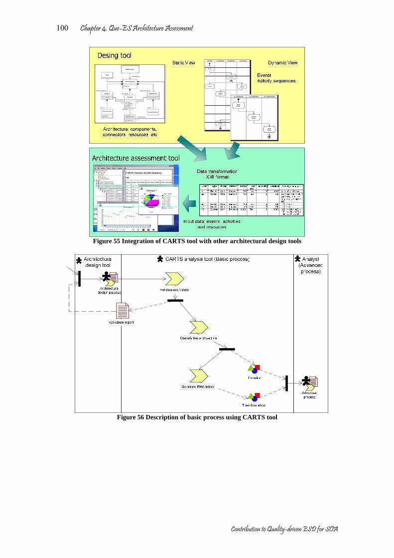
Chapter 4. Que-ES Architecture Assessment
Contribution to Quality-driven ESD for SOA
100
Figure 55 Integration of CARTS tool with other architectural design tools
Figure 56 Description of basic process using CARTS tool
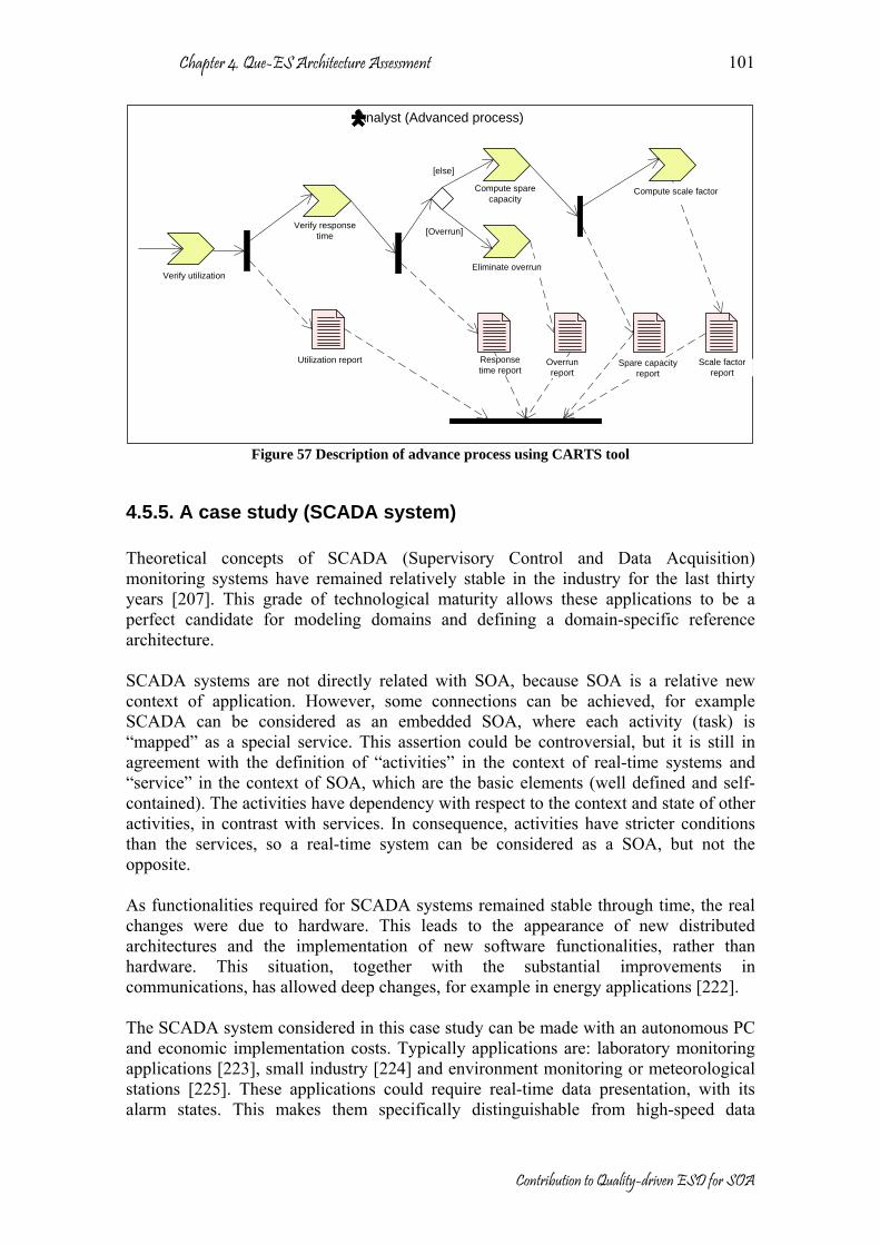
Chapter 4. Que-ES Architecture Assessment
Contribution to Quality-driven ESD for SOA
101
Analyst (Advanced process)
Eliminate overrun
Scale factor report
Spare capacity report
Overrun report
Response time report
Utilization report
Compute scale factorCompute spare capacity
Verify response time
Verify utilization
[Overrun]
[else]
Figure 57 Description of advance process using CARTS tool
4.5.5. A case study (SCADA system) Theoretical concepts of SCADA (Supervisory Control and Data Acquisition) monitoring systems have remained relatively stable in the industry for the last thirty years [207]. This grade of technological maturity allows these applications to be a perfect candidate for modeling domains and defining a domain-specific reference architecture. SCADA systems are not directly related with SOA, because SOA is a relative new context of application. However, some connections can be achieved, for example SCADA can be considered as an embedded SOA, where each activity (task) is “mapped” as a special service. This assertion could be controversial, but it is still in agreement with the definition of “activities” in the context of real-time systems and “service” in the context of SOA, which are the basic elements (well defined and self-contained). The activities have dependency with respect to the context and state of other activities, in contrast with services. In consequence, activities have stricter conditions than the services, so a real-time system can be considered as a SOA, but not the opposite. As functionalities required for SCADA systems remained stable through time, the real changes were due to hardware. This leads to the appearance of new distributed architectures and the implementation of new software functionalities, rather than hardware. This situation, together with the substantial improvements in communications, has allowed deep changes, for example in energy applications [222]. The SCADA system considered in this case study can be made with an autonomous PC and economic implementation costs. Typically applications are: laboratory monitoring applications [223], small industry [224] and environment monitoring or meteorological stations [225]. These applications could require real-time data presentation, with its alarm states. This makes them specifically distinguishable from high-speed data

Chapter 4. Que-ES Architecture Assessment
Contribution to Quality-driven ESD for SOA
102
acquisition applications such as, for example, audio or video [226], which involve different implementations. Other real case studies were considered in the CARTS project for architecture assessment. For example:
• The CCSS#7 Trunk Signaling [213]. This is an example of the characterizing the performance of a component of the Italtel OPM Virtual switch, which handle the functionality’s of the CCSS#7 (Common Channel Signaling System No. 7) trunk signaling.
• Part of the Integrated Objects System (IOS) of ARTAL technologies [227], which is a real-time multiprocessor system utilized for complex data visualization, monitoring, command and control applications and test benches for integration, validation and certification in the ground segment of satellite communications.
• The Autonomous Underwater Vehicle (AUV) control systems of QinetiQ [228]. SCADA system architectural description A SCADA system is responsible of getting input signal from sensors, which sense the controlled system in real-time; make the fitting process, transforming input signal into control information, the sensors and status information can include temperatures, pressures, volumes, levels or any other type that a sensor can detect; this information is measured, processed, interpreted and stored into database, and finally it is shown to the user, who should perform an adequate action. In addition, the user can manage actions, i.e. activation and deactivation of sensors, alarms ranges configuration and start and halt of system. The Figure 58 shows its context diagram.
Figure 58 Context diagram of SCADA system
The component of SCADA system is grouped by sub-systems, these components are represented in Figure 59. A detailed description is shown in [229].

Chapter 4. Que-ES Architecture Assessment
Contribution to Quality-driven ESD for SOA
103
Figure 59 Architecture of SCADA system, logical view [229]
Preparation The objective of this assessment is to find the best architecture for the SCADA system from the schedulability viewpoint. Not other aspect has been considered. The components shown in Figure 59 can be implemented and deployed in different resources. We present two possible physical architectures (See Figure 60 and Figure 61), which we are going to be compared in the assessment process.
Processor
Sensor
Figure 60 SCADA system, alternative 1
Figure 61 SCADA system, alternative 2
Prioritizing requirements The SCADA system has several functionalities and requirements, which are specified in the requirement of the system. We classify and prioritize the requirements in agreement with the ISO9126 six quality characteristics [3]. Filtering the architecture After that, only a set of requirements is selected, all of them related with schedulability aspect. In the case of real-time system context the critical requirements are reflected in critical events with constrains in response time. Below are only described the highest priority events:

Chapter 4. Que-ES Architecture Assessment
Contribution to Quality-driven ESD for SOA
104
• Data capture (high): Send reading command to a data acquisition board, add temporal tag to raw data (in electrical units), update time value for next reading and captured data is stored, with its temporal tag, into a buffer.
• Raw data process (high): Get captured data and temporal tag from a buffer, check hardware error condition, send query to Process_Variables to obtain conversion function, range limits and alarm limits, check that the electrical value is in range, convert the electrical value to engineering units, check that the engineering units value is within the allowed limits, consult if it was previously in alarmed state, when there is a new alarm or alarm return send message to a buffer, send update message to a buffer, send the processed data to a buffer and send alarm message or return to a buffer.
• Processed Data Transport (high): Get data in engineering units from a buffer and introduce them into the database.
• Alarm logging (high): Get alarm message or return from a buffer and the correspondent alarm situation or return is logged into database.
• Sensor gain change (medium): Analysis of the received command, identification of the change as a hardware change, store change message into a buffer, deactivate sensor, send message to the Input_Handlers, and perform gain change and sensor activation.
The previous prioritized list of events corresponds to critical events (with real-time conditions). The parameter values of each event, activity and resource are not here, but should be specified completely. For example the event Data capture (e1) is illustrated below. It has associated a sequence of activities:
• a1 = send reading command to a data acquisition board • a2 = add temporal tag to raw data (in electrical units) • a3 = update time value for next Reading • a4 = captured data is stored, with its temporal tag, in the Raw_Data buffer
Event Type Mode Pattern Period Time Req. Deadline Activity sequence e1 Timed One Periodic 1000 Hard 1000 a1-> a2 -> a3 -> a4 Activities Jitter Resource Atomic User Time Priority a3 0 CPU Yes Process3 5 78 Resource Type Policy CPU CPU Fixed priority Analysis In the analysis we use the method and techniques defined in the section 4.5.3 and the CARST tool. In our case study there are two possible physical architectures (see Figure 60 and Figure 61), therefore, is necessary to carry out an independent analysis for each one. Analysis of the SCADA system, alternative 1 The basic process (see Figure 56) validates the input data and locate the system into three groups, but the most close scenario is related with the group “message passing paradigm”, situation “using sequential message handler” and implementation “make each message handler a process“ defined in [178]. This alternative was analyzed in the advanced process.

Chapter 4. Que-ES Architecture Assessment
Contribution to Quality-driven ESD for SOA
105
In the advanced process it is only available the technique 1 for phase 1, technique 6 for phase 2 and technique 9 for phase 3. The results of the different phases are:
• Phase 1. Technique 1 (Figure 62) does not ensure schedulability. • Phase 2. Using technique 6, we identify the events missing their deadlines (see
Table 6). • Phase 3. We use technique 9 to calculate the execution time that should be
reduced in order to the system be schedulable. Table 6 Analysis results for Alternative 1 Id Event Worse-Case
Response Time e1 Data capture 500.0 e10 Database update Misses its deadline e11 Screen update 82.0 e2 Raw data process 69.0 e5 Sensor gain change Misses its deadline e9 Database query Misses its deadline
Figure 62 Technique 1 results,
Alternative 1 Analysis of the SCADA system, alternative 2. We apply the same process for alternative 2. In this case each resource must be analyzed separately (CPU and controller). The basic process locates the system into group “multiprocess and distributed systems”, situation “multiprocess” (the system has two CPU´s), and implementation “determining end-to-end resource schedulability”. Now, in the advanced process the techniques available are: technique 1 and 2 for phase 1, technique 3, 4, 5 and 6 for phase 2 and technique 7 and 8 for phase 3. The results are shown below:
• Phase 1. Techniques 1 and 2 do not assure that the system is schedulable, but they show that processors usage is far lower than 100% (see Figure 63 and Figure 64).
• Phase 2. We can use technique 3, 4, 5 or 6, which calculates response time. With these techniques we identify what events meet their deadlines. Therefore, the system is schedulable (see Table 7 and Table 8).
• Phase 3. Finally we could use techniques 7 and 8, which calculate new extra execution times guarantying system schedulability.

Chapter 4. Que-ES Architecture Assessment
Contribution to Quality-driven ESD for SOA
106
Table 7 Analysis results for Alternative 2 (CPU) Id Event Worse-Case
Response Time e1 Data capture 92.0 e10 Database update 786.0 e11 Screen update 82.0 e2 Raw data process 69.0 e5 Sensor gain
change 597.0
e9 Database query 1385.0 Figure 63 Technique 1 results, Alternative 2
(CPU) Table 8 Analysis results for Alternative 2 (Controller) Id Event Worse-Case
Response Time e1 Data capture 45.0 e5 Sensor gain
change 66.0
Figure 64 Technique 1 results, Alternative 2
(Controller) Agreement The next step is to compare the suggested architectures and assess in order to agree the best option. In the first alternative, we have modified some parameters from initial design; these modifications constrain the architectural design and in consequence also the implementation. The solution is possible but the conditions for the implementation phase have been made more restrictive. In the second alternative, the system is schedulable with the initial values; in addition an increment into the execution time of some events is possible preserving the system schedulability. However, this solution is more expensive because requires two processors. Other solutions for the same system are possible. Some changes can be: modifying other parameters, for instance, periods, priorities or deadlines, activities assigned to a resource, increasing the number of processors and so on. Documentation The documentation has an important role in each activity achieved. However, the documentation should be automatically generated while it is possible. The CARTS tool [213] was designed with the idea of reduce effort in documentation. It creates several reports, such as: validation report, utilization report, response time report and others. They are illustrated in Figure 56 and Figure 57. The reports are an executive documentation with the most relevant information of the assessment process (see Figure 65).

Chapter 4. Que-ES Architecture Assessment
Contribution to Quality-driven ESD for SOA
107
Utilization reportResponse time report
Simulation report
General report
Figure 65 Example of CARTS reports
Review The review should be done several times; the basic idea of review is the rapid feedback for learning (one of the essential principles defined on Que-ES). The review refines the candidate architecture. In this special case for real-time system, some values have been estimated (execution times, periods, deadlines or others) but after the first assessment results some values were changed in order to get the candidate architecture closer to real solution. For example in the SCADA system, alternative 1, some changes are required to become the system schedulable, in [205], [213] and [230] are presented a complete case study.
4.6. Conclusions The software architecture value is related to its capabilities for early assessment; estimations can be applied even at this early point in development, but tools must be easy to use (and not be time-consuming) so different scenarios and models can be checked. Accuracy of results is not the key point, but ease of use, and the possibility of taking values from architectural models. This chapter proposes a QAA as the methodological support for architectural assessment, and shows a complete case study that validates the method (one of the objectives proposed in this dissertation). QAA is a quality-driven discipline, essential in the QPM for a quickest feedback and continuous learning. The QAA model has been proved in some scenarios. As result of these scenarios, some guidelines have been obtained, which can be considered as added contributions. The

Chapter 4. Que-ES Architecture Assessment
Contribution to Quality-driven ESD for SOA
108
obtained guidelines are related with schedulability aspect in the domain of real-time systems. The main contributions of this chapter are summarized as follows:
• A methodological support has been presented for architecture assessment in the context of the evolutionary software development.
• A conceptual model about architecture assessment is presented, where the most relevant elements are defined and explained.
• QAA allows the extraction of architectural views with respect to a specific quality attribute.
• A generic workflow method to assess architectures is presented. The workflow has been validated in a specific domain (soft real-time systems) and applied over a quality characteristic (schedulability). However, it could be extended to other domains.
• In the case study it was necessary to extend the generic model; and other contributions were obtained, as:
o An instantiation of conceptual model with respect to schedulability in real-time systems was obtained.
o A methodological guideline for architecture assessment of real time systems with respect to performance was presented, based on RMA.
o The guideline is supported in a tool for architecture assessment of real-time systems.
o The case study has been selected because it is a system very used and proved for industry and it is a good model for other similar real-time systems.

Chapter 5 Que-ES Architecture Recovery (QAR)
This chapter describes the QAR discipline. The QAR provides architectural views by extracting and abstracting a subset of the software entities. In evolutionary development, the legacy of previous experiences is important in the process of continuous learning. Architecture recovery or reconstruction can be seen as a discipline within the reverse engineering domain that aims at recovery of the software architecture from an implemented system [84] [85] [86]. The recovered architecture can be used for future designs as a reference point (on good or bad practices). The recovered architecture can be considered in QAA or QAC process as a candidate solution. However, the major advantage of the recovery architecture process is the identification of potential architecture assets that can be reused in new implementations. QAR defines a generic workflow for architecture recovery. This method makes emphasis into quality aspects considering service-oriented architectures. This chapter is organized in six sections as follows: the first section shows the introduction and motivations of QAR, which focuses on the architecture recovery taking into account the QPM for service-oriented architectures. The second section presents the conceptual model of QAR, where all elements involved during the QAR discipline are defined. The third section defines the proposed workflow method by QAR. The fourth section makes a short analysis about methods, techniques and tools supporting QAR. The fifth section presents a case study where the QAR method is applied and validated. Finally, the last section sums up the principal contributions of this chapter.
5.1. Introduction QAR is a quality-driven discipline that proposes methodological guidelines for architecture recovery in the context of services-oriented architectures. QAR enriches the architecture asset repository by discovering reusable assets. In addition QAR discovers architecture patterns from previous implementations. Architecture recovery is part of the reverse engineering which was defined in [89] as: “The process of analyzing a subject system to identify the components and their relationships of a system and create representations of the system in another form or at a higher level of abstraction” We consider architecture recovery and reconstruction as similar activities, as was defined in [84] [85] [86]: “Software architecture recovery is a discipline within the reverse engineering domain that aims at recovery of the software architecture from an implemented system.” A suitable evolution software depends of an adequate management of previous implemented systems. However, not all implementations can be recovered. QAR can be
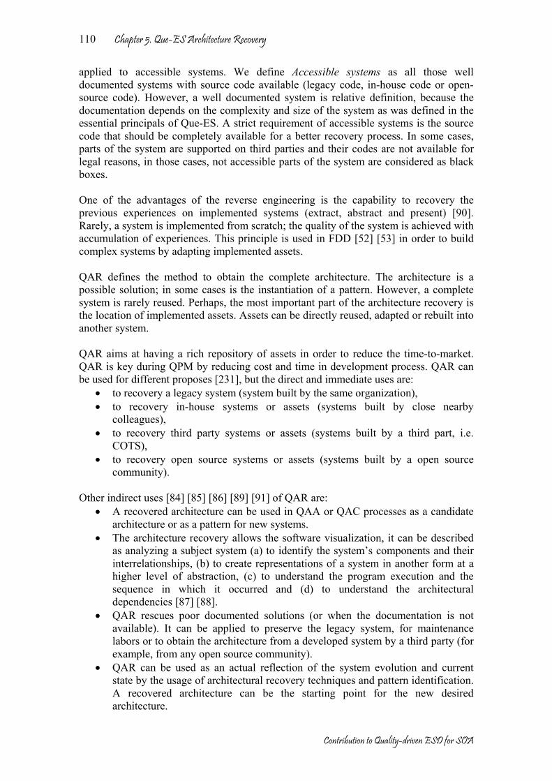
Chapter 5. Que-ES Architecture Recovery
Contribution to Quality-driven ESD for SOA
110
applied to accessible systems. We define Accessible systems as all those well documented systems with source code available (legacy code, in-house code or open-source code). However, a well documented system is relative definition, because the documentation depends on the complexity and size of the system as was defined in the essential principals of Que-ES. A strict requirement of accessible systems is the source code that should be completely available for a better recovery process. In some cases, parts of the system are supported on third parties and their codes are not available for legal reasons, in those cases, not accessible parts of the system are considered as black boxes. One of the advantages of the reverse engineering is the capability to recovery the previous experiences on implemented systems (extract, abstract and present) [90]. Rarely, a system is implemented from scratch; the quality of the system is achieved with accumulation of experiences. This principle is used in FDD [52] [53] in order to build complex systems by adapting implemented assets. QAR defines the method to obtain the complete architecture. The architecture is a possible solution; in some cases is the instantiation of a pattern. However, a complete system is rarely reused. Perhaps, the most important part of the architecture recovery is the location of implemented assets. Assets can be directly reused, adapted or rebuilt into another system. QAR aims at having a rich repository of assets in order to reduce the time-to-market. QAR is key during QPM by reducing cost and time in development process. QAR can be used for different proposes [231], but the direct and immediate uses are:
• to recovery a legacy system (system built by the same organization), • to recovery in-house systems or assets (systems built by close nearby
colleagues), • to recovery third party systems or assets (systems built by a third part, i.e.
COTS), • to recovery open source systems or assets (systems built by a open source
community). Other indirect uses [84] [85] [86] [89] [91] of QAR are:
• A recovered architecture can be used in QAA or QAC processes as a candidate architecture or as a pattern for new systems.
• The architecture recovery allows the software visualization, it can be described as analyzing a subject system (a) to identify the system’s components and their interrelationships, (b) to create representations of a system in another form at a higher level of abstraction, (c) to understand the program execution and the sequence in which it occurred and (d) to understand the architectural dependencies [87] [88].
• QAR rescues poor documented solutions (or when the documentation is not available). It can be applied to preserve the legacy system, for maintenance labors or to obtain the architecture from a developed system by a third party (for example, from any open source community).
• QAR can be used as an actual reflection of the system evolution and current state by the usage of architectural recovery techniques and pattern identification. A recovered architecture can be the starting point for the new desired architecture.

Chapter 5. Que-ES Architecture Recovery
Contribution to Quality-driven ESD for SOA
111
• During the maintenance phase, QAR obtains the system architecture, and after that, the system can be corrected or improved. In addition, QAR can detect possible lacks or gaps in the implemented system (preventive maintenance).
• QAR can be used to build architecture views. For example, QAR locates assets related of the same topic, functional or non-functional aspects.
• QAR can be used to learn from previous experiences. One of advantages of the architecture is its understandability. The abstraction of the concepts is fundamental for fast learning.
• QAR can be used to evaluate the conformance of the as-built architecture to the as-documented architecture.
• QAR can be used to locate commonalities and variation points in the context of system family engineering [232].
In this chapter is presented the context of QAR, and a generic workflow method for architecture recovery is proposed. The proposed workflow method makes emphasis into quality aspects considering service-oriented architectures. QAR has been validated in the case study for service-oriented architectures. In this case the security aspect was dealt with. Security has got to be one of the main forces for evolution and adaptation of systems. A practical view of architectural evolution, supported by after-deployment evolution, is that of service-oriented systems where one of the services implementations is found unsafe (after a security attack usually). There the evolution of the parts of the whole system is performed isolatedly so, in time, each of the system deployments can offer a different actual configuration (based on the evolution of each of the parts). What can be learnt from complex problems like the security, is that there are no fixed, pre-package solutions because not all of the problems are known in advance: there is a need for evolution, and in order to keep it under control, architecture must evolve. In the case study, we are going to analyze the security on the OSGi [37] service platform middleware implementation. We will recover its architecture (from the security viewpoint). OSGi is a services-oriented and distributed middleware which offers basic services and utilities (package admin, user admin, start level, permission admin, etc). The applications are also services that are implemented and deployed on it. The security in OSGi should be implemented as a service, more exactly as a set of services that guarantee the security. In Chapter 6 more details about the OSGi structure (Specification version 3) are presented, and in Chapter 7, the evolution of OSGi is illustrated and analyzed.
5.2. QAR Conceptual Model The QAR has been devised for diverse proposes as was described in the previous section. In Figure 66, the architectural elements related to QAR are shown. Some of them have been defined in previous chapters. The principal objective is the software architecture recovery. However, QAR objectives are leaded for the stakeholders who introduce specific objectives, such as for example, recovery of assets related with a functional aspect, or recovery of an architectural view driven by qualities. The focus is established for the objectives, and each quality concerns with specific sub-characteristics that should be considered into QAR.
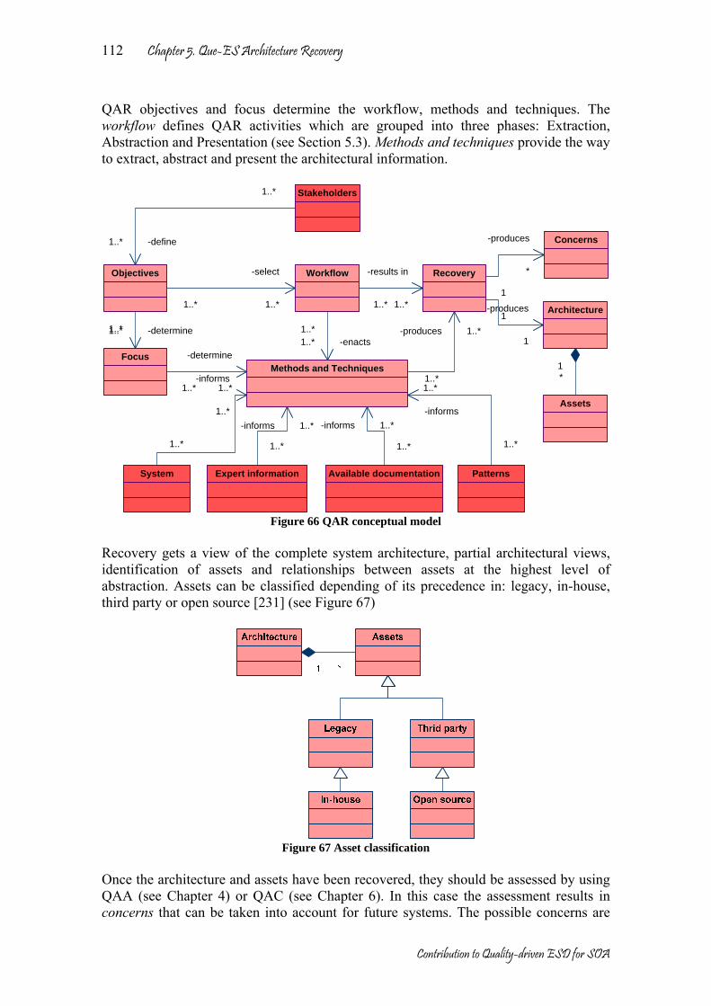
Chapter 5. Que-ES Architecture Recovery
Contribution to Quality-driven ESD for SOA
112
QAR objectives and focus determine the workflow, methods and techniques. The workflow defines QAR activities which are grouped into three phases: Extraction, Abstraction and Presentation (see Section 5.3). Methods and techniques provide the way to extract, abstract and present the architectural information.
Methods and Techniques
Architecture
System
1..*
-informs
1..*
1-produces
1
Stakeholders
Objectives
Focus
Workflow Recovery
Assets
Concerns
Expert information Available documentation Patterns
1..*
-define1..*
1..* -determine1..*
1..*
-determine
1..*
1..*
-select
1..*
1..*-enacts1..*
1..*
-informs 1..*
1..*
-informs 1..*
1..*
-informs
1..*1*
1..*
-produces 1..*
1..*
-results in
1..*1
-produces
*
Figure 66 QAR conceptual model
Recovery gets a view of the complete system architecture, partial architectural views, identification of assets and relationships between assets at the highest level of abstraction. Assets can be classified depending of its precedence in: legacy, in-house, third party or open source [231] (see Figure 67)
Figure 67 Asset classification
Once the architecture and assets have been recovered, they should be assessed by using QAA (see Chapter 4) or QAC (see Chapter 6). In this case the assessment results in concerns that can be taken into account for future systems. The possible concerns are
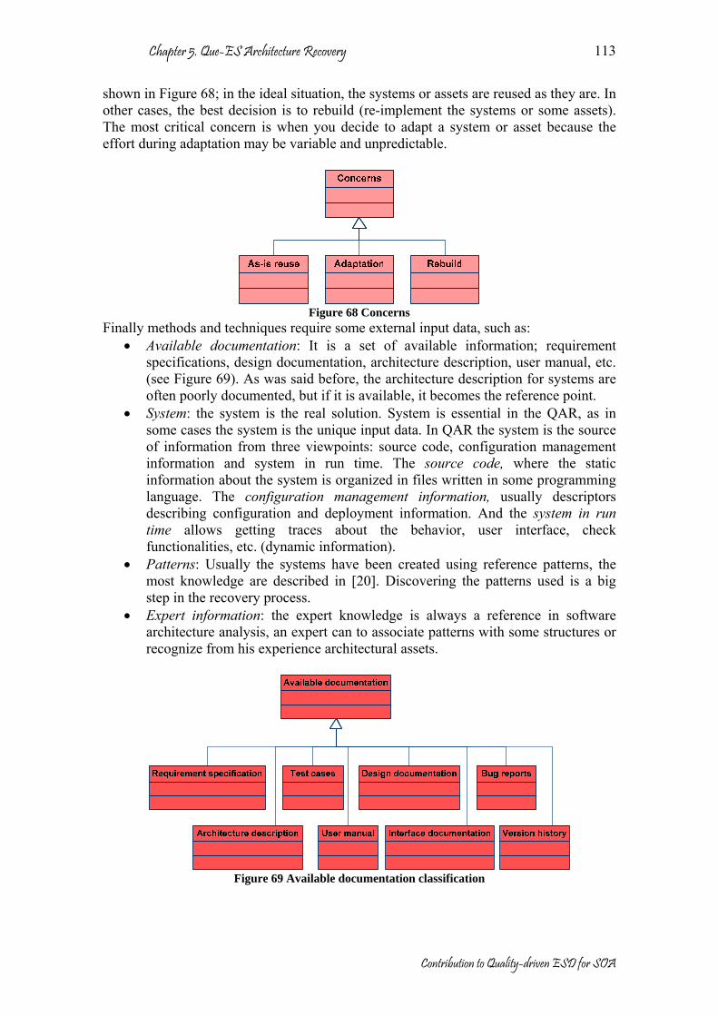
Chapter 5. Que-ES Architecture Recovery
Contribution to Quality-driven ESD for SOA
113
shown in Figure 68; in the ideal situation, the systems or assets are reused as they are. In other cases, the best decision is to rebuild (re-implement the systems or some assets). The most critical concern is when you decide to adapt a system or asset because the effort during adaptation may be variable and unpredictable.
Figure 68 Concerns
Finally methods and techniques require some external input data, such as: • Available documentation: It is a set of available information; requirement
specifications, design documentation, architecture description, user manual, etc. (see Figure 69). As was said before, the architecture description for systems are often poorly documented, but if it is available, it becomes the reference point.
• System: the system is the real solution. System is essential in the QAR, as in some cases the system is the unique input data. In QAR the system is the source of information from three viewpoints: source code, configuration management information and system in run time. The source code, where the static information about the system is organized in files written in some programming language. The configuration management information, usually descriptors describing configuration and deployment information. And the system in run time allows getting traces about the behavior, user interface, check functionalities, etc. (dynamic information).
• Patterns: Usually the systems have been created using reference patterns, the most knowledge are described in [20]. Discovering the patterns used is a big step in the recovery process.
• Expert information: the expert knowledge is always a reference in software architecture analysis, an expert can to associate patterns with some structures or recognize from his experience architectural assets.
Figure 69 Available documentation classification

Chapter 5. Que-ES Architecture Recovery
Contribution to Quality-driven ESD for SOA
114
5.3. QAR workflow About recovery, reconstruction, reverse engineering and visualization of software, several methods were found in the literature. In [232] is presented a summary about the most known (Kazman [86], Krikhaar [90], Boucetta [95], Guo [233], Riva [234] [235], Sartipi [236], CELLEST project [100] [237] and others). Every method defines phases for its application and in some cases they are supported by tools. Gathering previous experiences, we propose to build a generic strategy for the architecture recovery of systems or assets. The QAR workflow is based on several methods [86] [90] [95] [100] [233] [235] [236] and [237]. Figure 70 shows the QAR workflow which is made up of five input data, five processes, and four significant results [232] [231]. The input data required for the QAR are: available documentation, source code and configuration management information, system in run-time, patterns and expert information. The input data has been defined in the conceptual model (see section 5.2). The processes that should be achieved in QAR are: Information extraction, its input data are the available documentation and source code. This process can be aided by experts [90], by obtaining information from user documentation [238], using techniques such as gathering [95], lexical analysis [86] or pattern matching [236]. The information extraction objective is to obtain a conceptual model of the system. This process depends on the quality of the available documentation and source code comments, for well documented systems this process can be quickly performed, in our case we try to seek information in relationship with the architecture, not necessarily complete information, i.e. quality of the documentation is more important than quantity, for example phrases as, “this system is a client server”, “the systems was build in layers” or “the system is based on the standard …” can be more important that extend documentation, but in poor documented projects, the information extraction from the source code can be a tedious labor, in this case we recommend to skip this process and try obtain this information from static and dynamic views. An interesting report about quality and quantity information in open source projects was presented in [239].

Chapter 5. Que-ES Architecture Recovery
Contribution to Quality-driven ESD for SOA
115
Figure 70 QAR workflow
Static-view extraction is the most common approach in the reengineering process. By using tools, the system static view is obtained from source code (classes, packages, interfaces, relationships between them and other relevant architectural elements). Sometimes this model is complemented by information from the conceptual model [90]. As a result of this process an architectural static view is obtained [240]. Usually, the extraction of architecture static-view is performed importing the structure of the files into a tool, in a first approximation of the architecture it is based on the structure of imported folders; they are often the initial organization of packages or services of an architecture. We analyze each folder of independently manner in order to reduce the complexity of the system. In this analysis, the relationships and dependencies between the classes or interfaces are found. However other dependencies or relationships can be found between packages, these relationships are used for the construction of architecture in a high level of abstraction. Other good tip in the recovery process is the association of names of packages, classes or interfaces (Ontologies), the names describe in certain manner one of these elements and can be key for its association, for example if we are

Chapter 5. Que-ES Architecture Recovery
Contribution to Quality-driven ESD for SOA
116
finding elements related with security aspects, names as: permissions, encryption, authentication or similar, we presume that they have a relation with security. In abstraction, two essential objectives should be carried out: 1) Reduce the complexity of the preliminary architecture, by increasing the abstraction level and obtaining non-detailed elements and 2) filter the preliminary architecture to the topic of interest (e.g., communication, security). As a result of the abstraction process, a refined architecture is obtained. Abstraction is not easy task without help of a good structure of the source code and previous knowledge of the system domain (experts). In this process, MDA can be used, because in this context, the preliminary architecture can be a representation of the platform specific model (PSM). So the refined architecture can be abstracted by mapping the PSM to the platform independent model (PIM). Finally in presentation, once the refined architecture is obtained, it is polished by experts and supported with reference patterns (see [90], [236], [233], [241]). As result of this process, the recovered architecture is obtained, so that it represents the “as-built” architecture (set of architectural views regarding different architectural aspects or parts). The QAR obtains as partial results: conceptual model or system meta-architecture. In MDA context [76] conceptual model is called Conceptual Independent Model (CIM). Conceptual model is a set of concepts and the relationship between them. The preliminary architecture is made up of static and dynamic views of the system. The refined architecture comprises abstracted views of the preliminary architecture used to isolate certain architectural aspect. Finally, the recovered architecture is annotated with the help of experts and patterns.
5.4. QAR Methods, Techniques and Tools Numerous recovery methods exist in the literature [232]. This section focuses on those methods that have extensively guided our research. For example, Boucetta [95] presents a method composed of three main phases:
• Gathering the domain knowledge of the information system with help of domain experts.
• Using software tools to automatically generate a preliminary system architecture from the source code.
• Refining the architecture by constructing a matrix linking the results of the first and the second step to establish the mappings between the domain knowledge and the initial architecture components.
Albeit similar, Kazman in [86] divides the recovery process for large systems (such as product lines) in four phases:
• Extraction of static and dynamic domain knowledge using lexical analysis, parsing, and semantic analyzers.
• Database construction. • Fusion of static and dynamic views. • Architectural view composition to let users visualize, interact with, and interpret
the system.

Chapter 5. Que-ES Architecture Recovery
Contribution to Quality-driven ESD for SOA
117
Krikhaar [90] describes a software architecture recovery method based on Relation Partition Algebra that consists of sets, binary relations, part-of relations and operations. It provides a sound formal foundation for the activity composed of four phases:
• Extracting the domain knowledge from source code, experts, and system history. • Abstracting the extracted information to a higher design level. • Presenting the abstracted information in a developer-friendly way, taking into
account his or her current topic of interest. • Improving the architecture of the existing system incrementally.
The approach proposed by Guo [233] relies on the definition of structures to be searched for (patterns). These structures are supposed to contain both domain and solution knowledge. The phases are:
• Developing a pattern recognition plan serving as a reference architecture. • Extracting a model from source code. • Detecting and evaluating pattern instances. • Reconstructing and analyzing the architecture.
Riva [234] [235] includes reorganization (also called refactoring) activities as part of the architecture recovery tasks:
• Experts define architectural concepts based on which the source code model is extracted.
• An architectural model is abstracted. • Improvement plans for architecture documents are created. • Architecture is analyzed. • Source code is reorganized to reflect the improved architecture.
Sartipi [236] relies on an architectural description language for the execution of the architecture recovery activities:
• The software system is parsed into source code entities. • The system architecture is extracted and analyzed by formulating an abstract
pattern of the architecture in the form of an Architectural Query Language (AQL) query based on experts’ domain knowledge, system document inspection, and/or source model analysis. AQL is used to describe the high-level abstraction of the system in terms of modules and interconnections.
• Unresolved source model entities can be distributed among the blocks of the architecture and the entities in the blocks can be selectively moved between the blocks based on overall closeness between the entities or user inspection.
The CELLEST project [100] presented a method for recovering user interfaces of legacy systems based on the code analysis of the system-user interaction [237]. The input of the reverse-engineering phase is a recorded trace of the user interaction with the legacy interface and the output is a state transition model specifying the unique legacy interface screens (states) and the possible commands (transitions) leading from one screen to another. CELLEST uses a tool to support reverse engineering in terms of state-transition models.. It consists of the following phases:
• System-user interaction traces are un-intrusively collected by a middleware. • The dynamic behavior of the system interface is reverse engineered in terms of
the screens and the navigation it allows through them.

Chapter 5. Que-ES Architecture Recovery
Contribution to Quality-driven ESD for SOA
118
• Task specific navigation paths are analyzed to extract a model of the task in terms of the interface navigation and the information exchange and an appropriate web-based interface is constructed by wrapping this navigation and enabling its execution through a standard web browser.
This method can be classified as an architecture recovery technique focused on the domain of user interaction. It considers the dynamic behavior in the recovery process. Architectural Recovery tools Most of the aforementioned methods are performed manually [244]. For large systems and for product lines, the manual application of these methods leads to poor results. Usually tools are needed to support the architectural recovery process to aid in the extraction, manipulation, and interpretation of architectural information.. Several categories of tools are listed below:
• Manual-driven tools such as: Portable Book Shelf (PBS) [97] [245], Rigi [99], SHriMP [246] [247], KLOCwork inSight Tool [248] and Bowman and Associated [249].
• Tools supporting query languages such as: Dali [91], ARMIN [84], Architectural Recovery Tool (ART) [94], Rose/Architect [250] [251], Architecture reconstruction method (ARM) [233], Nimeta [234] [235] and Mitre [242] for writing patterns to automatically build aggregations.
• Tools supporting clustering and data mining, such as the tools proposed in the Software Architecture Reconstruction method (SAR) [90], Architectural recovery method [95], Data mining [236], Oblique lifting [252] and X-Ray [253].
• Tools allowing architectural recovery from source code, in order to create class diagrams and, in some cases, activity diagrams automatically, such as PBS toolkit [97] [245], Argo/UML [254], Poseidon for UML [221], Bauhaus toolkit [255] [256], DIVOOR/CodeCrawler [257] [258] [259], Fujaba [260] [261], Imagix4D [262], Rational [220], Visual Paradigm [263] and Eclipse/Omondo [264].
• Tools providing mechanisms for fine-grained inspection and verification of software by exposing the results of sophisticated whole-program analysis, see for example, Jinsight [101] [102] [265], CodeSurfer [266] [267], Columbus/CAN [268] [269] [270], CONCEPT [88] [271] [272], GSEE [273] [274], Red Hat Source-Navigator [275], SniFF++ [276] [277] and Scientific Toolworks [278].
The tools try to analyze source code made in different programming language, but C (Rigi, PSB, Bauhaus, ARMIN, Dali, ART, Nimeta, ArgoUML and others), Java (SHriMP, ARMIN, Rose, Eclipse, ArgoUML and others), and C++ (ARMIN, Dali, Rose, Eclipse, ArgoUML and others) are the most frequent languages supported, but other languages such as C#, Ada, Perl and others are also considered.

Chapter 5. Que-ES Architecture Recovery
Contribution to Quality-driven ESD for SOA
119
5.5. Architecture recovery for the security in Internet services The security is one of the quality aspects that should be guaranteed in telematics systems, in special when they use Internet for communications or when are accessed by users through Internet. In this section, we are going to analyze this situation in a particular scenario. The case study is a specific case of security in Internet services but it can be extended to other similar situations [232] (see Figure 71).
Figure 71 Scenario of validation for QAR method
A quality development does not always start from scratch. We use QAR to detect implemented security assets of previous systems. The scenario is based on OSGi standard framework. We apply QAR on the implemented OSGi frameworks in order to select the best implementation; some implementations of OSGi specification are available in the open source community, for example, Oscar [279], Knopflerfish [280] or Equinox [281], the last one is included in version 3.0 of Eclipse. One of the purposes of QAR is the location of assets that can be used in other systems. Security assets is not the exception, the objective of this case study is the location of security assets in the OSGi specification. Security is a extend area, where several attributes should be guaranteed, in addition security aspects are a vertical characteristic of any systems. In addition after the location of security assets, some limitation of OSGi framework can be found, in this case we try to define the missed assets and suggest how they can be implemented. The location of security assets is absolutely relevant for any system such as is described in the next section.
5.5.1. Background of security standards in Internet services The standards considered in this analysis were briefly summarized in section 2.3.2. Where the most important aspects of security in CIM [122], security in the CC [83], security specification of OMG [125], and security in W3C [128] were mentioned. Security standards present alternative solutions to prevent potential attacks in a wide range of situations. Each recommendation presents architectural elements that could be considered during QAC. In practice, not all elements will be used or required by a system. For this reason the selection of one or another standard during QAC process depends of the architectural assets involved in the candidate architecture. After a thorough analysis of every standard and taken into account the model proposed by Fægri, a conceptual model is proposed [232]. Fægri [126] presents a model in the highest abstraction level for quality driven architecture design; it includes three sub models (security, architecture and decision).

Chapter 5. Que-ES Architecture Recovery
Contribution to Quality-driven ESD for SOA
120
The conceptual model proposed in this section is an extension of [126] taking into account the standard recommendations. This model can be a reference for construction of secure solutions. However in this case, the conceptual model has been used for the correct selection of a standard during the architecture conformance process. In [3] security was defined in terms of access control and confidentiality, that is, security should take into account aspects such as: identification, authentication, authorization, accounting, not-repudiation, protection of the information during communications and administration of security information. In Figure 72 is presented the quality aspects concerns to security [125].
Figure 72 Quality aspects in security
• Availability. Use of the system cannot be maliciously denied to authorized users. • Confidentiality. Information is disclosed only to users authorized to access it. • Accountability. Users are accountable for their security-relevant actions. A
particular case of this is non-repudiation, where responsibility for an action cannot be denied.
• Integrity. Information is modified only by users who have the right to do so, and only in authorized ways. It is transferred only between intended users and in intended ways.
Taken into account other initiatives, such as: IETF [282], Web Service [29], Java Security [283], and others [284] [285] [286] [287] and [288]; other aspects have been considered and required in order to complement the security aspects of a system. They can be grouped in the Administration of security information. For example, defining and setting security policies, configuration, learning from attacks (register and management of previous malicious incidences), etc. All they are also needed in order to guarantee quality aspects of the whole system. In Figure 73 are shown the countermeasures used to guarantee previous aspects of security [289] [290] [291] [292] [293] and [294]. These countermeasures deal with identification and access control, such as: Authorization, Authentication and Accounting. In addition, the communication channel must be guaranteed, e.g. message confidentiality, message integrity, etc. Identification countermeasures The identification is the first aspect considered in secure systems. Currently there are a large range of alternatives for identification from a simple password to complex biometric technologies for detection of principals [125]. The identification of the user is crucial for the treatment during access control. In secure systems, profiles of users are defined and in agreement with them, the access, permission and privileges are

Chapter 5. Que-ES Architecture Recovery
Contribution to Quality-driven ESD for SOA
121
established. The concept of principal is introduced in [125] as a human user or system entity that is registered in and is authentic to the system. Currently, the systems can be acceded by users (humans) or in some cases for other systems, services or devices, for example, when a service needs services from another. The principal is a generic way to represent a user (humans, organizations, systems, services, devices, objects or any other system entity) that requests access to a system. The control access countermeasures can be concentrated in: authorization, authentication and accounting. In this document access control countermeasures have been defined as:
• Authorization deciding whether a principal can access an object (system, service or resource), normally using the identity (defined in terms of credentials) and/or other privilege attributes of the principal (such as: role, groups, security clearance) and the control attributes of the target object (stating which principals, or principals with which attributes) can access it [125].
• Authentication of principals to verify they are who they claim to be [125]. • Accounting is the process of collecting, interpreting, and reporting cost and
charging-oriented information on service usage. This process was divided into the following sub-processes: metering, pricing, charging, and billing [294]. Accounting is defined also in terms of auditing of security-related events and using non-repudiation to generate and check evidence of actions [125]. However, the term accounting in this document will be used as a synonym of the metering. Metering is the process of measuring and collecting resource usage information, related to a single customer’s service utilization.
Communication countermeasures At the same way, the most relevant aspects dealt with the communications can be concentrated in the countermeasures: security of communication between objects and encryption. Security of communication between objects, which is often over insecure a lower communication layer. This requires trust to be established between the client and the target, which may require authentication of clients to targets and authentication of targets to clients. It also requires integrity protection and (optionally) confidentiality protection of messages in transit between objects [125]. Encryption is a mechanism for information protection, particularly in communications, where algorithms are used to scramble data which make it unreadable to everyone except the recipient. Encryption was used primarily to ensure secrecy in important communications, such as those of spies, military leaders, and diplomats. However, encryption has been expanded to other applications, such as: authentication, digital signatures, electronic voting, digital cash and so on.

Chapter 5. Que-ES Architecture Recovery
Contribution to Quality-driven ESD for SOA
122
Countermeasure
Identification Communication
Access control
Authentication Authorization Accounting
1*
1*
Figure 73 Security countermeasures
5.5.2. Instantiation of QAR for security in Internet services The instantiation of QAR for security in Internet services is shown in Figure 74. It is based on the conceptual model illustrated in Figure 66. In the instantiation there are not so many differences with respect to the general conceptual model. Basically the major effort is concentrated on the objectives and focus where the main proposal of the QAR is defined. In this case focus is related with security aspects. In addition, we must take into account the special conditions in the Internet services. The same scenario can be implemented using a large range of technologies. A possible solution is by using OSGi as a framework for services. In consequence, an additional assessment is required in order to evaluate whether a given implementation is in conformance with the OSGi specification (see chapter 6). The available documentation will depend on the information offered in the implementation (manuals, description, bugs, etc.). The intention in this case is not the recuperation of the completed architecture. We are interested in specific assets related with security aspects. At the end of the QAR process the implemented assets are recovered and possible lacks in the implementation are located.

Chapter 5. Que-ES Architecture Recovery
Contribution to Quality-driven ESD for SOA
123
Methods and Techniques
Architecture
System
1..*
-informs
1..*
1-produces
1
Stakeholders
Objectives
Focus
Workflow Recovery
Assets
Concerns
Expert information Available documentation Patterns
1..*
-define1..*
1..* -determine1..*
1..*
-determine
1..*
1..*
-select
1..*
1..*-enacts1..*
1..*
-informs 1..*
1..*
-informs 1..*
1..*
-informs
1..*1*
1..*
-produces 1..*
1..*
-results in
1..*1
-produces
*
Security aspects:availability
accountabilityintegrity and
confidentiality
Distributed system
Architecture recovery
QAR workflow
OSGi specificationOpen source
projects
Open-source security assets
Figure 74 QAR for security in Internet services
Usually, the stakeholders who have taken part in the development of the system (design, constructions and deployment) are not present in the QAR process. In open source initiatives the stakeholders are in a big and dynamic community. New members can join at any moment. The level of knowledge in each member is very heterogeneous. QAR can be used for new members during the learning process. In open source projects, the input data will be: the current version of the system, the source code and some documentation. On the other hand, in open source systems, potential security risks are multiplied because the system is accessible for everybody. Potential attackers can easily locate vulnerabilities because its code and description are known. In the next subsections, we try to located potential risks for an implemented OSGi framework.
5.5.3. Case study (security in the OSGi framework) We select OSGi framework as case study because it is a excellent framework where Internet services could be implemented. A short summary of OSGi was presented in Chapter 2 and a complete architecture of OSGi framework will be presented in Chapter 7, in this section we analyze an implementation of OSGi specification (release 3) since security viewpoint. Therefore, we need to identify the best implemented OSGi framework by considering security support. The security depends both of the system in question and the environment in which the system operates (domain). The objectives should be defined taking into account the specific domain and in agreement with the stakeholders concerns. QAR allows detecting improvements for OSGi to become a secure framework based on standard specifications. Other important results are the identification of security gaps.

Chapter 5. Que-ES Architecture Recovery
Contribution to Quality-driven ESD for SOA
124
We propose new security assets or the adaptation of third party assets in order to improve the implemented solution. There are several OSGi implementations,. we selected Oscar as an accessible system because we considered it as the most active community. Oscar is an open source implementation of the OSGi framework specification [37]; the goal is to provide a compliant and complete implementation of the standard. Oscar is intended to implement the framework portion of the OSGi specification and currently is not yet 100% compliant with the OSGi specification, but it implements most of the specified functionality. Standard OSGi service implementations are also provided in some cases, with the eventual goal of providing all standard OSGi services (hopefully with the help of other contributors). Oscar is a project available in [279]. This case study has been realized considering the release oscar-1.0.0.jar. OSGi has defined a set of open-standard software application interfaces (APIs) for building open-services gateways, including residential gateways. It has been implemented for connecting the coming generation of smart consumer and business appliances with Internet-based services [295]. Application of QAR on Oscar In agreement with the QAR workflow (see Figure 70), this section presents its application considering the security as quality attribute. Unfortunately, Oscar’s architecture is not well documented, and then an architectural recovery process should be done for checking conformance with OSGi standard. In this case, the OSGi standard architecture was taken as reference. Input data Available documentation and source code. Oscar source code and documentation are available in [279]. The documentation considered as input data is listed below:
• OSGi specification [37]. • Instructions for installing and running Oscar. • Instructions for using Oscar. • Changes made to Oscar. • A simple OSGi tutorial. • Description of the security aspects of Oscar. • Descriptions of the included bundles. • Description of the Oscar shell service bundle. • A simple document discussing some of Oscar’s design issues. • Issues regarding Oscar’s implementation. • Instructions for building Oscar.
System in run-time. Oscar framework was installed, executed and tested over a PC Intel Pentium 4 CPU 2.8 Ghz and 1.0 GB of RAM with Linux Debian version 2.4.22. However, Oscar is a framework and its behavior depends of the services that it supports. Patterns. In the chapter 2 “Reference Architecture” of the OSGi specification [37] a general architecture is proposed, it can be considered as a point of reference. In addition, some others pattern for specific context are proposed such as: the service gateway model for residential gateways, industrial model for network services, self-
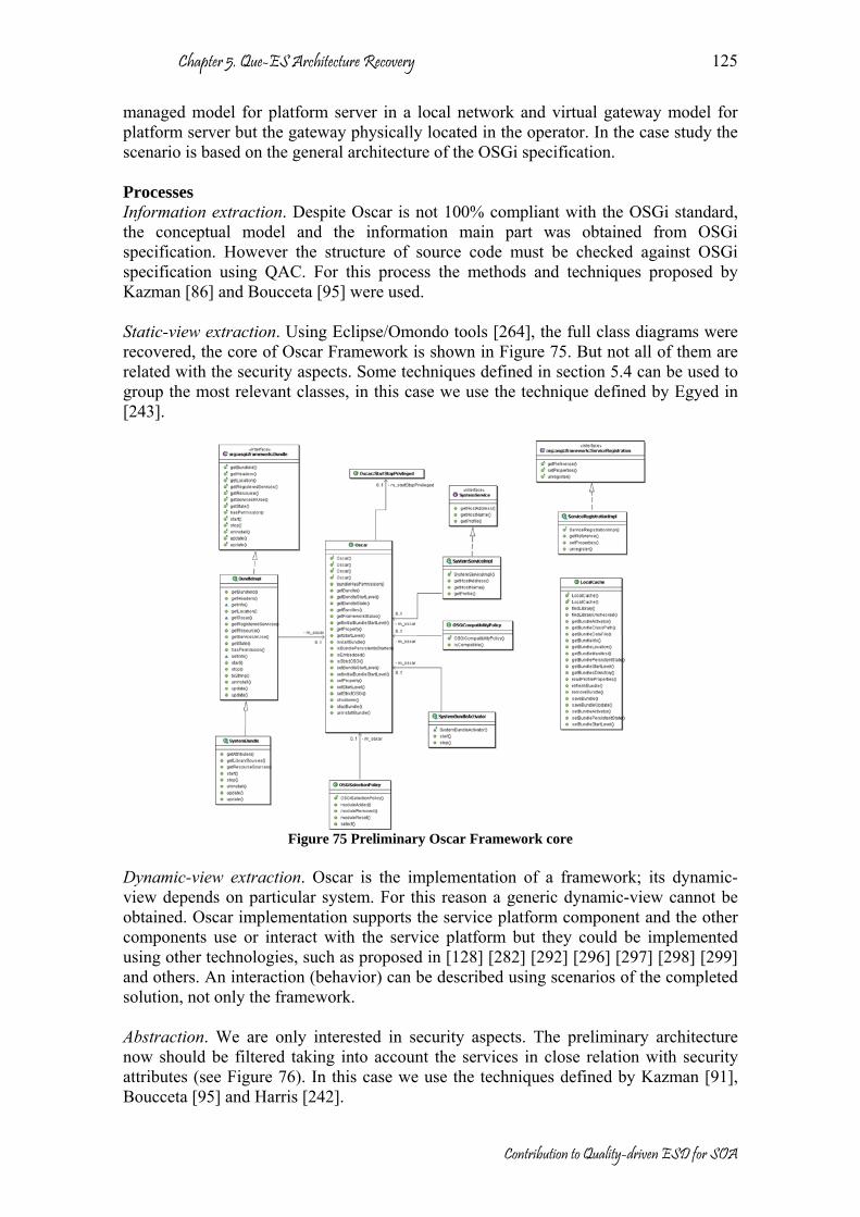
Chapter 5. Que-ES Architecture Recovery
Contribution to Quality-driven ESD for SOA
125
managed model for platform server in a local network and virtual gateway model for platform server but the gateway physically located in the operator. In the case study the scenario is based on the general architecture of the OSGi specification. Processes Information extraction. Despite Oscar is not 100% compliant with the OSGi standard, the conceptual model and the information main part was obtained from OSGi specification. However the structure of source code must be checked against OSGi specification using QAC. For this process the methods and techniques proposed by Kazman [86] and Boucceta [95] were used. Static-view extraction. Using Eclipse/Omondo tools [264], the full class diagrams were recovered, the core of Oscar Framework is shown in Figure 75. But not all of them are related with the security aspects. Some techniques defined in section 5.4 can be used to group the most relevant classes, in this case we use the technique defined by Egyed in [243].
Figure 75 Preliminary Oscar Framework core
Dynamic-view extraction. Oscar is the implementation of a framework; its dynamic-view depends on particular system. For this reason a generic dynamic-view cannot be obtained. Oscar implementation supports the service platform component and the other components use or interact with the service platform but they could be implemented using other technologies, such as proposed in [128] [282] [292] [296] [297] [298] [299] and others. An interaction (behavior) can be described using scenarios of the completed solution, not only the framework. Abstraction. We are only interested in security aspects. The preliminary architecture now should be filtered taking into account the services in close relation with security attributes (see Figure 76). In this case we use the techniques defined by Kazman [91], Boucceta [95] and Harris [242].

Chapter 5. Que-ES Architecture Recovery
Contribution to Quality-driven ESD for SOA
126
Figure 76 Refined Security Oscar Architecture
Presentation. The OSGi specification offers a complete high-level of abstraction about the framework. A mapping between implementation and specification has been done to achieve the recovered architecture (see Figure 77). This phase is supported by QAC process (see section 6.5.1 instantiation of QAC for security in Internet services).

Chapter 5. Que-ES Architecture Recovery
Contribution to Quality-driven ESD for SOA
127
org.osgi.util
org.osgi.service
device log
provisioningpackageadminpermissionadmin
startlevel
useradmin
wireadmin
tracker
org.osgi.frameworkjava.security.Permission
url
OSCAR implementation
Third party implementation
Not implemented
Figure 77 Recovered OSGi security architecture
Architectural Recovery Results Conceptual model. Conceptual model is fully detailed in OSGi specification [37]. No new elements have been defined. Preliminary Architecture. The Oscar core (static view) is shown in Figure 75. It presents a part of the Oscar class diagram. Refined Architecture. Figure 76 shows a class diagram with the most relevant classes and interfaces related with security aspects (authorization, user, roles and groups). Recovered Architecture. In high abstract level, OSGi could be seen as a set of services and utilities; OSGi is supported on a basic core (Framework) and aided by Java components [283]. In the Figure 77, a static architecture is shown, it is organized by services and utilities, but only packages related with security aspects have been considered. The obtained architecture of Oscar framework could be compared with the OSGi specification. We use QAC (see Chapter 6) in order to verify its architecture conformance. The most important results are summarized below:
• Proposal for enhancement of Oscar: as a product of the difference between OSGi standard and Oscar some services are required (adaptation or implementation of some components from OSGi implementations or other services), they are: device, wireadmin, useradmin and log were adapted by third party, and permissionadmin and provisioning was missed out, therefore, they should be implemented in order to obtain a whole security architecture. On the other hand, the basic framework is fully implemented and no lacks were found.
• Proposal for OSGi standard: no lacks were found. • Commonalities: Some common assets were found, they are: basic framework,
and the next services and utilities: startlevel, url, packageadmin and tracker. Figure 77 shows in different color the services implemented, so: in dark-gray, Oscar assets; in light-gray, third party assets, and in white color not implemented assets (this assets was implemented by Telvent and UPM in the OSMOSE project [300]).

Chapter 5. Que-ES Architecture Recovery
Contribution to Quality-driven ESD for SOA
128
Recovery concerns The service platform implementation follows the OSGi standard. However, it does not offer some security services, therefore several problems appear:
• the platform implementation is not fully compliant to the specification, • the missed elements must be identified and after that implemented or adopted, • the security services mandated by the reference architecture of the platform may
not be enough for some specific services or some scenarios, therefore the reference architecture must be extended,
• the missed security aspects can be covered by other security architecture, for example the Common Information Model (CIM) by DMTF [122],
• the elements in the CIM/DMTF security architecture must be checked against the security services in the OSGi specification,
• both CIM/DMTF security assets that are not available in the OSGi specification and assets that are defined in the OSGi specification but not in the available implementation must be provided,
• these new assets could be eventually chosen from Open Source communities, • the missed assets could be reused or adapted from existed implementations, in
any case they should be adapted to OSGi domain, • the security elements are delegated in the architecture to a well defined region,
that can be allocated to a server dealing with the security aspects, plus a mechanism for the after-delivery deployment of services, and
• a mechanism for the management and tracking of security threats must be in place in order to follow the evolution of the security aspects of the system.
With the previous concerns it is clear the limitations with respect to security aspects of the OSGi specification (version 3) [37]. In consequence, an additional model should be constructed in order to fill this gap. In the next paragraphs, we define a security reference model build as a set of services supported in the OSGi framework. Construction of a Security Reference Model (SRM) QAR and QAC processes allow identifying some lacks and new requirements. With this information a Security Reference Model (SRM) can be proposed. This new model gets in commonalities and variabilities from DMTF, OMG, CC, W3C, IETF and Java security. A SRM unifies concepts and defines a new reference architecture with respect to security (see Figure 78, Figure 79, Figure 80, Figure 81, Figure 82 and Figure 83). SRM was one of the results of the OSMOSE project [300], where the model was designed, implemented and tested.
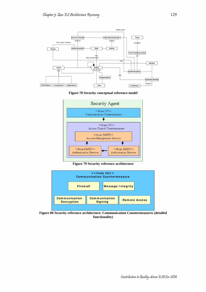
Chapter 5. Que-ES Architecture Recovery
Contribution to Quality-driven ESD for SOA
129
Entity
Application
Threat
Trust
IdentityHas
Access Control
Enforce
Authentication
User
Asset
Authorisastion
Information Component
Claimed identity
Role
Has
Has
Trust building means
EstablishCan cause violation
May compromise
Organisation
Owner
CertificateSupport
Countermeasure
Impose
Relies upon
Figure 78 Security conceptual reference model
Figure 79 Security reference architecture
<<from CC>>
Communication Countermeasure
Firewall
CommunicationSigning
Communication Encryption Remote Access
Message Integrity
<<from CC>>Communication Countermeasure
Firewall
CommunicationSigning
Communication Encryption Remote Access
Message Integrity
Figure 80 Security reference architecture: Communication Countermeasures (detailed
functionality)

Chapter 5. Que-ES Architecture Recovery
Contribution to Quality-driven ESD for SOA
130
<<from DMTF>>Account Management Services
<<from OMG>>Non-repudiation
Credentials
<<from OMG>>Auditing Channel
<<from OMG>>Auditing Decision
<<from DMTF>>Account
<<from DMTF>>Account Management Services
<<from OMG>>Non-repudiation
Credentials
<<from OMG>>Auditing Channel
<<from OMG>>Auditing Decision
<<from DMTF>>Account
Figure 81 Security reference architecture: Account Management Services (detailed functionality)
<<from DMTF>>
Authorisation Services
<<from OSGi>>Permission Bundle
Management
<<-->>Policy Rule
Checker Service
<<from DMTF>>Privilege
ManagementService
<<from DMTF-Container>>Identity Access
<<from DMTF>>Authorisation Services
<<from OSGi>>Permission Bundle
Management
<<-->>Policy Rule
Checker Service
<<from DMTF>>Privilege
ManagementService
<<from DMTF-Container>>Identity Access
Figure 82 Security reference architecture: Authorization Services (detailed functionality)
<<from DMTF>>
Authentication Services
<<from DMTF>>Credential Management
Service
<<from DMTF>>Authentication Rule
Checker Service
<<from DMTF>>Storage Hardware ID Management Service
<<from DMTF>>Authentication Services
<<from DMTF>>Credential Management
Service
<<from DMTF>>Authentication Rule
Checker Service
<<from DMTF>>Storage Hardware ID Management Service
Figure 83 Security reference architecture: Authentication Services (detailed functionality)
The majority of elements have been defined in the CIM specification, but some of them are introduced as contribution from OMG, CC, IETF, W3C and other. These new components are described as follows:
• Non-repudiation. In the legal sense an alleged signatory to a document is always able to repudiate a signature that has been attributed to him or her. In the crypto sense, non-repudiation is a property achieved through cryptographic methods which prevents an individual or entity from denying having performed a particular action related to data (such as mechanisms for non-rejection or authority origin); for proof of obligation, intent, or commitment; or for proof of ownership) [301]
• Audit Decision. In telecommunication, the term audit has the following meanings: 1. A record of both completed and attempted accesses and service. 2. Data in the form of a logical path linking a sequence of events, used to trace the transactions that have affected the contents of a record. 3. A chronological record of system activities to enable the reconstruction and examination of the sequence of events and/or changes in an event [302].
Chapter 5. Que-ES Architecture Recovery
Contribution to Quality-driven ESD for SOA
131
• Firewall. A system designed to prevent unauthorized access to or from a private network. Firewalls can be implemented in both hardware and software, or a combination of both. Firewalls are frequently used to prevent unauthorized Internet users from accessing private networks connected to the Internet, especially intranets. All messages entering or leaving the intranet pass through the firewall, which examines each message and blocks those that do not meet the specified security criteria [302].
• Communication confidentiality. Confidentiality has been defined by ISO [303] as “ensuring that information is accessible only to those authorized to have access” and is one of the cornerstones of information security.
• Remote access. The ability to log onto a network from a distant location. The remote access software dials in directly to the network server. The only difference between a remote host and workstations connected directly to the network is slower data transfer speeds [302].
5.6. Conclusions One of the objectives proposed in this dissertation has been reached in this chapter, that is, a software architecture recovery method considering quality aspects. The QAR model has been proved in a scenario. As a result of this scenario a security architecture has been proposed, which can be considered as an added contribution. The obtained architecture is related with security aspects in the domain of Internet services. QAR can be used to check implementations, i.e. identification of lacks and new requirements in order to improve the implementations. QAR can also be used to recover the description of system architecture, so several views could be obtained. It is a very common problem in poor documented systems (legacy, third party or open source solutions). It is a complex process that allows to abstract and to visualize a system from lower level to other more easy to be understood. The main contributions of this chapter are summarized as follows:
• A methodological support has been presented for architecture recovery in the context of the evolutionary software development.
• A conceptual model about architecture recovery is presented, where the most relevant elements are defined and explained.
• A generic workflow method to recover architectures is presented. • The workflow method has been validated in a specific domain (Internet services)
and applied over a quality characteristic (security). • QAR is based on mature processes, methods, techniques and tools. • In the case study, the SRM was proposed, and other derived contributions were
obtained: o An instantiation of conceptual model with respect to security in Internet
services. o A methodological guideline for architecture recovery of Internet services
with respect to security was presented. o An OSGi implementation has been studied and its architecture has been
recovered.

Chapter 5. Que-ES Architecture Recovery
Contribution to Quality-driven ESD for SOA
132
o A conformance process was performed between Oscar implementation and OSGi standard focused on security aspect.
o New security requirements were identified to Oscar implementation in order to provide a full compliance implementation with respect to OSGi Standard into security aspects.
o New security requirements were identified to OSGi based on CIM specification, in order to provide a full and trusted standard with respect to security aspect.
o The SRM was proposed to improve CIM model; it considers standards as OMG, CC, IETF and others. The SRM was partially validated with a real scenario (only some quality aspects have been covered in the validation process). The scenario presented is a full system with a set of security requirements which is implemented using OSGi (Oscar) technology and other complementary technologies deployed on Oscar (WS-Security, XML Security and others). In future works other scenarios can be implemented in order to validate other parts of the proposed SRM for OSGi.

Chapter 6 Que-ES Architecture Conformance (QAC)
This chapter describes the QAC discipline. It is a fundamental part to guarantee the quality of a system as was defined by QPM and therefore, an essential part into the evolutionary development. Conformance is a particular type of assessment; in this case the architecture is compared with respect to a standard. Conformance process determines the degree of fulfillment of the architecture against a specific standard. QAC is a discipline that can be used as a reference to the architecture conformance process, in order to guarantee compliance, compatibility, integrability, portability, replaceability and interoperability. QAC defines a generic workflow for architecture conformance. The proposed workflow method makes emphasis into quality aspects considering service-oriented architectures. This chapter is organized in six sections as follows: The first section shows the introduction and motivations of QAC, which focuses on the architecture conformance taking into account the QPM for service-oriented architectures. The second section presents the conceptual model of QAC, where all elements involved during QAC discipline are defined. The third section defines the proposed workflow method by QAC. The fourth section makes a short analysis about methods, techniques and tools supporting QAC. The fifth section presents a case study where QAC method is applied and validated. Finally, the last section sums up the principal contributions of this chapter.
6.1. Introduction QAC is a quality-driven discipline that proposes methodological guidelines for architecture conformance in the context of services-oriented architectures. The QAA guarantees the quality of solutions with respect to other candidate architectures. QAA allows a rapid feedback, however if we have a standard for comparison QAC accelerates the assessment process, because the candidate architecture is only compared with this reference. In QAA several comparisons could be performed before taking the decision about the best solution. Conformance has been defined in different ways. Usually, it is used for traceability between specification, design and implementation, and it is often used for tests. Conformance has been defined in terms of correctness [304], fidelity [305], compliance [306] and [307], completeness [308] or semantic harmony [309]. However, in [3] conformance has been defined as: “Attributes of software that make the software adhere to standards or conventions relating to portability.”

Chapter 6. Que-ES Architecture Conformance
Contribution to Quality-driven ESD for SOA
134
Conformance is and has been applied at implementation level. In that case, it is executed in order to measure the degree of fulfillment of the solution (implementation) against a standard, regulation or other specification. Conformance has a big incidence in the business area, because it gives confidence to users, consumers, manufactures, service providers and regulators. In some cases conformance is made obligatory by government regulations in order to check whether products, services, material, processes, systems and personnel measure up to the requirements of standards, regulations or other specifications [303]. We define architecture conformance as follows: Software architecture conformance is a type of assessment, where the architecture is compared with respect to a standard. Conformance process determines the degree of fulfillment of the architecture with respect to the standard. In addition, we extend conformance objectives. So architecture conformance guarantees compliance, compatibility, integrability, portability, replaceability and interoperability. Often, these terms are confused. In this dissertation, we consider the next definitions: Compliance Compliance is the capacity of the software product to be verified for the fulfillment of a rule, condition, requirement, standard or recommendation. For example “the year 2000 compliance”, means that neither performance nor functionality is affected by dates prior to, during and after the year 2000. Compatibility Compatibility is the ability of two or more systems or components to perform their required functions while sharing the same hardware or software environment [15]. Integrability Integrability refers to the ease with which separately developed elements (including those developed by third parties) can be made to work together to fulfill the software requirements [75]. Portability Portability is the capability of the software product to be transferred from one environment to another [15]. Replaceability Replaceability is the capability of the software product to be used in place of another specified software product for the same purpose in the same environment [3]. Interoperability Interoperability is the capability of the software product to interact with one or more specified systems [3]. QAC can be used as:
• a hold for the identification of non-functional requirements or system quality factors, described by quality models such as ISO-9126 [3],

Chapter 6. Que-ES Architecture Conformance
Contribution to Quality-driven ESD for SOA
135
• a way to compare some specific architectural aspects of the system against reference architectures published by standardization bodies (understanding them in a broad sense) by means of architectural conformance checking,
• a means to externalize the detailed design, implementation and test of the assets in the architecture that are closer to the reference architectures for the intended architectural aspects,
• a way to adapt the evolution of the system architecture to the evolution of reference architectures for some aspects, or
• a vehicle to support the dynamic evolution of running systems after deployment and keep their architectures updated.
UML [25] is largely used for the description of an architecture, so it is a standard language of description, and for this reason the notation, convention and conditions are often expressed using UML. At the same way, MDA [76] [77] [78] [79] could help in the conformance process because the architectures can be in different abstraction levels, obviously the comparison should be performed at same abstraction level. So UML could be used for architecture description; and MDA could be used to transform architectures to the adequate abstraction level. No other proposals such as ATAM [8], SAA [147], ALMA [193] [194], SARA [7], BAPO [5], or SACAM [192] consider architecture conformance. For them, the architecture conformance can be an objective in the assessment process. In this chapter we consider architecture conformance as a key aspect in QPM. Perhaps the closest process is defined in SACAM. It is a process based on comparisons. However, SACAM is only limited for business goals. In QAC, it is defined a complete workflow method for architecture conformance. Architecture conformance uses methods and techniques during the comparison process in order to locate commonalities and differences. We will analyze the different alternatives that depend on the domain, topic or special conditions. Architecture conformance is relatively a new concept; there are not many available methods or techniques and probably no tools. In addition, QAC can be used to locate commonalities and variation points in the context of system family engineering [232]. At the same way than QAA, QAC has been thought for SOA but it can be used with any other architecture style. While QAA guarantees the easy reuse of assets or systems, QAC goes a step beyond, because it guarantees the satisfaction in comparison with certain standard. If an asset is in concordance with a standard, it can be used or reused without adaptations. Also, QAC can be used during the implementation phase or for certification processes, where the implemented assets are compared with respect to certain standard. The validation of the QAC is done with a case study. We will use QAC in order to verify the conformance between OSGi specification and a security standard. OSGi was proposed as a standard in 2000, but there are other standards that cover security aspects in deep. For example, CIM model by DMTF [122], security model by OMG [125], Security model by Common Criteria [83]. Perhaps the most representative architectural model with respect to security is presented as part of CIM model. We consider this model as our reference point. In the case study, we are going to present the architecture conformance between OSGi standard with respect to security model proposed in CIM.
Chapter 6. Que-ES Architecture Conformance
Contribution to Quality-driven ESD for SOA
136
In this chapter, it is presented the context of architecture conformance, a generic workflow method for architecture conformance is proposed, and its validation. For the case study, we have selected the security as our topic of analysis. In consequence some specific techniques and tools have been considered in order to obtain an appropriate result.
6.2. QAC Conceptual Model Conformance is a type of assessment; in consequence, the conceptual model of QAA (see Figure 44 and Figure 45) is valid for QAC. However, QAC has additional issues that should be considered (see Figure 85, Figure 86 and Figure 87). The software architecture conformance is also made against one or more objectives. But “standards” are an additional required input. The conformance report shows the coincidences and differences between the candidate architecture and the standard architecture. Usually, the standard has been proposed in order to guarantee a level of quality. The standards are agreements by international or national organizations, where the most usual ad-hoc concepts or practices are formally specified. Standards are a basis for comparison, a reference point against other things can be evaluated. They set the measure for all conformance process. In the telecommunication and computer science areas, some international organizations in charge of standardization processes are IEEE, ANSI, ISO, OMG, W3C, IETF, etc. Standards are continuously reviewed and sometimes updated in concordance with innovations. A standard is defined in [303] as follows: “Standards are documented agreements containing technical specifications or other precise criteria to be used consistently as rules, guidelines, or definitions of characteristics, to ensure that materials, products, processes and services are fit for their purpose”. In Figure 84 we have outlined the typical content of a standard. However, it is not mandatory; we use this schema only as general template for conformance process. For example, some standards define only concepts, others defines process (practices), etc. A standard is a document where there are included assertions about a topic, and the assertions can be mandatory or optional. The assertions can be classified as: basic if affect only to a specific basic element, or can be general if they affect to more than one element. In the standard are defined the basic elements that should be included in the architecture. In addition are defined the relationships between them. A standard is specified to a certain domain; therefore the context in this domain is clearly defined. If it is required, some concepts and their notation, conventions and external conditions are defined. The external conditions can contain rules or legal policies, physical constrains, etc. Usually, standard also defines some practices; they are product of practical experiences. Practices can be processes, guidelines, patterns or scenarios than have been proved by the industry in several real implementations. For example, in the next paragraph from OSGi specification [37]:

Chapter 6. Que-ES Architecture Conformance
Contribution to Quality-driven ESD for SOA
137
“In the OSGi Service Platform, bundles are the only entities for deploying Java-based applications. A bundle is comprised of Java classes and other resources which together can provide functions to end users and provide components called services to other bundles, called services. A bundle is deployed as a Java ARchive (JAR) file. JAR files are used to store applications and their resources in a standard ZIP-based file format.” We can identify:
• Assertions: “bundles are the only entities for deploying Java-based applications”
• Basic Elements: “bundles”, “classes”, “resources”, “services”, etc. • Relationships: “A bundle is comprised of Java classes and other resources” • Practices: “JAR files are used to store applications and their resources in a
standard ZIP-based file format”, the standard in this case uses a pattern, (standard format).
• Context: “In the OSGi Service Platform,…bundles… provide functions to end users… called services”.
Standard-Mandatory : Boolean
Assertions
Basic General
Basic Elements Relationships-relate
0..* *
Context
Practices
Patterns
Concepts Conventions Notations External conditions
1-inhabits*
1
-has
1..*
-has
1..* 1
-has1..*
1
Figure 84 Typical structure of a standard
The principal objective of architecture conformance is to evaluate compliance between the candidate architecture against a standard. For QAC, the lifecycle, focus and ASR have the same connotation than for QAA. They depend of the quality attribute to be evaluated. For example, performance and security qualities are related with execution time lifecycle milestones, while adaptability or replaceability qualities are related with design, implementation and maintenance lifecycle milestone. At the same way, focus and ASR concentrate the attention on specific aspects defined in the objectives (see section 4.2).

Chapter 6. Que-ES Architecture Conformance
Contribution to Quality-driven ESD for SOA
138
Each ASR affects to one or several assets of the architecture. However, two new types of assets should be treated independently, Significant Candidate Assets (SCA) and Significant Standard Assets (SSA). Basically, the differences between them are their precedence: SCA from the candidate architecture and SSA from the standard architecture (see Figure 85). The conformance process needs SCA and SSA to compare and identify differences and coincidences, some methods and techniques can be used in order to achieve this objective, such as: Ontology based algorithms that allow the search of common assets in an architecture [75], Numerical and graph-based algorithms to reduce complexity, Use cases to isolate parts of a system, Comparison of abstract syntax tree of similar systems, Measurement of similarities using metrics (internal or external as was defined in [3] to measure quality aspects) and so on.
Asset
1..*
-informs 1..*
Architecture Standard architecture
1..*
-informs 1..*
SCA SSA
ASR
*
-affects
*
Figure 85 Types of ASR in QAC
The defined workflow for QAA is also valid for QAC. The same phases should be achieved. However, other extra activities must be executed [232]. The complete workflow is presented in Section 6.3. The methods and techniques analyze the standard and candidate architecture by comparing or finding relationships between their assets. Two new external inputs for methods and techniques are required: standard and standard architecture. The quality attributes can be defined in several standards; each one can represent a specific scenario or different architectural viewpoint. During QAC one or more standards related with the same quality characteristic can be taken into account. In addition, the standard architecture from the standard is required. However, it is not always described in the standard specifications. More details about methods and techniques are presented in section 6.4. The QAC applicability conditions are the same that QAA, i.e. the information from QDM and some methods and techniques should be available. In addition, for QAC a standard architecture for specific context should be available. We have assumed that the architecture and standard architecture are available during QAC. However, this condition is not always true and an architecture recovery process (QAR) is required. The architecture recovery is described in chapter 5.

Chapter 6. Que-ES Architecture Conformance
Contribution to Quality-driven ESD for SOA
139
Methods and Techniques
Architecture
System Standard
Standard architecture
1..*
-informs
1..*
1..*
-informs
1..*
1..*
-informs 1..*
1..*
-informs 1..*
-designs1..*
-has
1..*
-designs1..*
-has
1..*
Figure 86 New inputs for Method and Techniques into QAC
Conformance is a type of assessment (see Figure 87). During architecture conformance a special validation is done (compliance), which has a simple objective, to locate commonalities or differences. Commonalities (SCA ∩ SSA) correspond to the set of assets that have been defined in the candidate architecture in the same way than in the standard. Obviously, uncommon assets are located in the differences. The differences take an interest value when the stakeholders take decisions. They are:
• Proposal for enhancement of SCA (SSA-SCA): as a product of the difference between SSA and SCA, new requirements are identified and some lacks can be located in the candidate architecture.
• Proposal for standard (SCA-SSA): as a product of the difference between SCA and SSA, some lacks may be located in the standard; it is a frequent case when the candidate architecture goes beyond the scope of the standard.
In the context of system family engineering, commonalities have an important role, because they allow to locate the common part in the system family (common assets). In addition, the variation points can be located. QAC detects the differences between similar assets. So considering a system’s architecture as SCA and the family reference architecture as the SSA, the same results can be obtained. Basically in QAC, the stakeholder identifies concerns about the candidate architecture as suggestions about what changes should be introduced in order to make some assets conform to certain standard. However, some decisions or trade-offs are also done. The standards are not always the panacea, and in some cases the standard contains obsolete recommendations about something. The stakeholder must take some decisions about the convenience or not of using a certain part of the standard or in some cases the stakeholder should chose the best recommendation among several standard specifications. The main result of architecture conformance is its report by comparing some alternatives of solution (pros/contras) with respect to certain standards. In the same way than QAA, QAC does not consider the complete architecture to be only one view concerned to specific ASRs. Other secondary outcomes can be obtained from QAC, for example: a better understanding of the architecture, better communication with the stakeholders, detection of architecture limitation and risk and others.

Chapter 6. Que-ES Architecture Conformance
Contribution to Quality-driven ESD for SOA
140
-Valuation Assessment
1..* 1..*
ConformanceCompliance
Commonalities Differences
SSA-SCA SCA-SSA
1..* 1..*
-has 0..*1..*
-has 0..*1..*
Figure 87 Relationship between assessment and conformance
6.3. QAC workflow The defined workflow for QAA (see Section 4.3) is also valid for QAC. The same phases should be achieved. However, other extra activities must be executed (see Figure 88) [232]. The QAC workflow can be considered as a method for architecture conformance process with respect to a specific quality characteristic [3]. In section 4.3 it was defined the QAA workflow as a series of iterative activities: preparation, prioritizing ASRs, filtering, analysis, agreement, documentation and review. In the next paragraph we are going to present the additional activities in QAC.
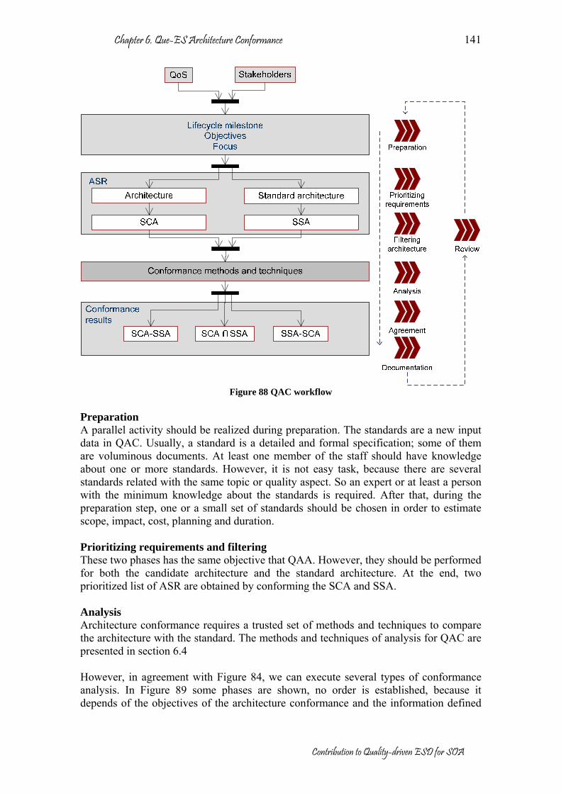
Chapter 6. Que-ES Architecture Conformance
Contribution to Quality-driven ESD for SOA
141
Figure 88 QAC workflow
Preparation A parallel activity should be realized during preparation. The standards are a new input data in QAC. Usually, a standard is a detailed and formal specification; some of them are voluminous documents. At least one member of the staff should have knowledge about one or more standards. However, it is not easy task, because there are several standards related with the same topic or quality aspect. So an expert or at least a person with the minimum knowledge about the standards is required. After that, during the preparation step, one or a small set of standards should be chosen in order to estimate scope, impact, cost, planning and duration. Prioritizing requirements and filtering These two phases has the same objective that QAA. However, they should be performed for both the candidate architecture and the standard architecture. At the end, two prioritized list of ASR are obtained by conforming the SCA and SSA. Analysis Architecture conformance requires a trusted set of methods and techniques to compare the architecture with the standard. The methods and techniques of analysis for QAC are presented in section 6.4 However, in agreement with Figure 84, we can execute several types of conformance analysis. In Figure 89 some phases are shown, no order is established, because it depends of the objectives of the architecture conformance and the information defined

Chapter 6. Que-ES Architecture Conformance
Contribution to Quality-driven ESD for SOA
142
in the standard. The conformance relates to the standard; that means nothing out of the standard can be assessed for conformance. Context conformance, in this case only concepts, notations, conventions and external conditions are verified. This kind of conformance is often used for specific standard language, or in a process where is used a specific notation. The critical part is “concept conformance” because semantic conformance is required. Notation, conventions and external conditions can be analyzed using syntactic conformance. Context conformance has as result compliances with respect to concepts, notations, conventions and external conditions, but in addition, other important results are detected such as new concepts, inconsistencies and similarities can be found in the candidate architecture. Architectural asset conformance, it is a validation where the assets are checked. Two issues should be validated; presence of the asset and verification of that asset is in conformance to the standard specification. Architectural asset conformance has as result: the list of assets in conformance, list of missed assets, and a list of assets that are in the architecture but their description is not in conformance. In addition new assets can be found in the candidate architecture, they have special interest because need a special justification. Relationship conformance, at the same way the relationships among assets should be verified. In first place the presence of this relationship and for other way the consistency, type of relationship, navigability, visibility, multiplicity, etc. Relationship conformance has as result: the list of relationship in conformance, missed relationships, and inconsistency of some relationships. At the same as assets, new relationships can be defined. New assets and relationships are outside of the conformance analysis, because cannot be compared. In the future, they can be considered as extension of the standard, of course, after the normal process for standardization. Practice conformance. Standards define also processes, guidelines, patterns, etc. that can be used in the candidate architecture. In some cases are recommendations that should be analyzed in the specific context. For example ISO 9000 [303] and CMMI [115] specifications defined some practices that should be used during development in order to guarantee quality of the products. Practice conformance has as result the conformance or not of one specific practice. Assertion conformance. It is very similar to requirement assessment, because assertions in practice are special requirements that must be supported in the architecture. Assertion conformance has as result the conformance or not of one specific assertion.

Chapter 6. Que-ES Architecture Conformance
Contribution to Quality-driven ESD for SOA
143
Architecture Conformance
Context conformance
Assertion conformance
Practice conformance
Relationship conformance
Architectural asset
conformance
Figure 89 Architecture conformance analysis
Agreement and documentation During agreement and documentation the main results of QAC should be reflected, that is, the commonalities and differences. In addition, the concerns, trade-offs and decisions must also be included. The concerns obtained in QAC become relevant inputs to improve future architectures or standards. Review As results of concerns and possible trade-offs and decisions, the process can be reviewed several times if is required. The process of revision takes importance for the evolution of the software, in this case in two directions: evolution of the software architecture and evolution of the standards. Architecture conformance is a good mechanism to learn and enhance previous experiences.
6.4. QAC Methods, Techniques and Tools At the same way than QAA, we are going to present in this section the methods and techniques available for QAC. Some methods and techniques were found, but all of them related with a specific topic or with a specific scenario and domain. They should be used depending of the objectives proposed in the QAC. Each method can use one or more techniques. In some cases techniques are supported on tools. In architecture conformance a reduced type of techniques was found (see Figure 90). This classification is based on the previous classification of assessment techniques (see Figure 13). Static architecture conformance is applied under the static architecture view. Two static techniques can be executed: Semantic verifies the real meaning of the architecture assets, i.e. if its description, operations, attributes, etc. are conform to standard. And syntactic verifies associations, dependences and generalizations among the architecture assets. Dynamic architecture conformance is applied under the dynamic architecture view, where the behavior is checked. In order to reduce the complexity the behavior is proved on partial scenarios, i.e. interaction among a part of architecture assets.

Chapter 6. Que-ES Architecture Conformance
Contribution to Quality-driven ESD for SOA
144
Figure 90 Taxonomy of architecture conformance techniques
During the review of the documentation found in the literature, we found that the general assessment methods can be used for conformance process. Such as: BAPO [5], ATAM [8] [176] and SARA [7]. However, no methods or techniques have been proposed for architecture conformance. In ALMA [133] [191] for modifiability analysis some comparisons between the architectures was proposed (assessment of architecture evolution). Some techniques are used to detect commonalities and differences: equivalence classes and classification. They can be used for static architecture conformance. In SACAM [192], is presented a process for comparison of business goal between architectures, therefore SACAM can be used in the conformance process in that direction. SACAM uses tactics defined in [75], architecture styles [310] and patterns [20] as indicators to evaluate if a quality attribute is supported. In SAA [147] [193] [194] it is defined a process of elicitation where the best architecture is selected. Elicitation is basically a top-down process of comparison of architectures, but the criteria of comparison depends only of the analyst. No techniques are proposed. Emmerinch [311] presents a model to identify the issue of standard compliance. This method is used to verify compliance of specification with respect to standard documentation, the mechanism used to identify the noncompliant elements and the properties to which they fail to comply. The identification is done from UML class diagram (static conformance). Practices, properties and policies are checked. Sørumärd [312] identifies four relevant strategies for development process conformance, they are based on: interviews [313], computer-support enactment [314], statistical process control [315] and event-stream comparisons [316]. In addition, Sørumärd proposes a model to measure the conformance process. It is based on deviation vector technique applied to resources and products obtained during development process. The deviation vector represents the measured parameters. In [312] two parameters have been considered: time and quality in the development process. Dae-Kyoo Kim [317] presents a method for conformance evaluation between UML model (class diagrams) and design patterns. Kim makes evaluation both in syntactic and semantic conformance. This model is supported in the concept of roles [318]. Roles can be used to get scenarios with respect to a specific aspect.

Chapter 6. Que-ES Architecture Conformance
Contribution to Quality-driven ESD for SOA
145
Nguyen [309] presents an interesting proposal for semantic conformity between documents. This model tries to find the concordance and consistence of documents during development process by finding causal dependences between documents (document traceability). However, this idea can be extrapolated for standard domains, because a standard is also a document. Nguyen measures two parameters: traceability and consistency analysis. The techniques used are based in logics, for example: model checking, formal framework, hypertext, abstract dependence graph, static checking and so on. A tool supporting this method is presented in [319]. Gnesi [320] contributes in dynamic conformance for UML statecharts. This work is based on mathematical basis, input/output transition systems. However, it was developed for testing conformance between specification and implementation. For a reliable conformance both specification and implementation scenarios should be represented into statecharts and after that, transformed to input/output labeled transition systems. Basically, the main relations between input and output are proved in small experiments. At architectural level, the real response of a transition cannot be obtained. However the logical process can be checked. Other works have been found in relation with conformance process. However, they are focused to the implementation [321] [322] [323] [324]. Basically, they propose conformance test (black-box test) for implementation against its specification in order to detect errors and inconsistencies. On the other hand, the used vocabulary in the architectural description and the standard plays an important role during QAC, because the definition of concepts is one of the mechanisms to relate the architecture with certain standard.
6.5. Architecture conformance for the security in Internet services. The relevant role of the security at Internet services was treated in chapter 5, section 5.5. The background, context and scenario are the same for this case. Nevertheless, other viewpoint is introduced. We use QAC in order to detect possible security gaps in the candidate architecture. QAC allows a better analysis of security aspects taking into account some recommendations from standard specifications (See Figure 91).
Figure 91 Scenario of validation for QAC method
The first candidate architecture is so far to be the definitive solution. Usually, the first candidate architecture considers only functional aspects, and quality aspects are leave out in the second place. However, at the architectural level, QAC aids to locate relevant quality aspects in early phases of development.

Chapter 6. Que-ES Architecture Conformance
Contribution to Quality-driven ESD for SOA
146
This scenario was focused on security aspects but other aspect can be analyzed. The scenario was large treated in the Families [181] and Osmose [300] projects. In Families project, the basic security concepts was located by using QAC, while in Osmose project, a partial implementation was achieved. This section has been organized in four parts. First an instantiation of architecture conformance process for security aspects is shown. After that, two parts present the techniques and tools used. And at the end, a brief description of the case study and their main results are presented.
6.5.1. Instantiation of QAC for security in Internet services In agreement with the conceptual model from QAA (see Figure 45) and the conceptual model from QAC (see Figure 85, Figure 86 and Figure 87) the instantiation of QAC for security in Internet services is presented in Figure 92, Figure 93 and Figure 94. In this case the stakeholders are people that in a direct or indirect way are involved in the conformance process. However, usually a reduced group of them participates actively in QAC process (architects, evaluators, and in some cases developers and accreditors). The domain considered is of distributed systems. Nowadays, the evolution of software design is towards distributed systems supported in services through Internet. In this context new and more threats and vulnerabilities appear, such as: exploits, attacks, accreditation, etc. Both security and performance qualities are visible during run-time, in consequence the lifecycle milestone is execution and the treatment is similar to performance (see section 4.5.2). At the same way, the conformance objective is to improve the quality of the architecture. However in this case, the focus is the security. In section 5.5.1 was presented the aspects that should be covered by the security: accountability, availability, integrity and confidentiality. In this case, the ASR will be related with the countermeasures that make a system to be a secure one (identification and communication countermeasures). The requirements depend of the specific system and its context. In this case, we have analyzed the security in a distributed system. The security is a transversal quality that affects several architectural assets of a system. A good strategy is to locate assets that could be eventually attacked, such as: principals, resources, databases, files, objects, messages, etc. And after that, the behavior of the systems should be analyzed in several scenarios. The scenarios locate the critical security situations.

Chapter 6. Que-ES Architecture Conformance
Contribution to Quality-driven ESD for SOA
147
Figure 92 QAC for security in Internet services (Instantiation part 1)
Figure 93 illustrates some particularities of the external input data, methods and techniques for security in Internet services. The studied standards have been chosen after a meticulous quest of standard specification about security in the special domain (Internet services). An excellent selection of methods and techniques for measurement of security topics is presented in [126]. They are classified into detection, prevention and recovery tactics. A explanation will be presented in section 6.5.2.
Figure 93 QAC for security in Internet services (Instantiation part 2)
Finally, Figure 94 shows the particular methods used in architecture conformance. These methods are generic for any quality aspect. Both workflow and compliance methods have been explained in section 6.3 and section 6.4. Obviously, they should be guide by the objectives of QAC.

Chapter 6. Que-ES Architecture Conformance
Contribution to Quality-driven ESD for SOA
148
Figure 94 QAC for security in Internet services (Instantiation part 3)
6.5.2. Methods and techniques A set of methods and techniques for measurement of security aspects is presented in [126]. They are classified into detection, prevention and recovery tactics (see Figure 95).
Figure 95 Taxonomy of tactics [126]
Detection means to determine that something is happening or has happened. It does not affect the system’s direct resistance towards an attack. However, the detection tactic can have a great value in many system environments. For example, it may enable continuous improvement of system security. By examining unwanted incidents that have happened, the system can be tuned to counter these kinds of incidents in the future. Three kinds of tactics can be used for detection: Monitoring, Logging and Embedded data integrity. Prevention tactics are used to reduce the probability of unwanted incidents by creating barriers that potential enemies cannot circumvent. There will never be fully secure systems, so prevention principles intend to reduce the probability of successful attacks. Figure 95 shows eight different specializations of this tactic that can be used in order to accomplish this, possibly in combination, such as: Access control, Service provider, Obfuscation, Compartmentalisation, Single access point, Fairness, Controlled exposure and End-to-end security. Recovery is the last main group of tactics. It seeks to address security concerns by reducing the consequence (or negative impact) of incidents. Three sub-groups of recovery tactics are illustrated: Fail-secure, Redundancy and Liability transfer. Each tactic can be implemented in several ways. The definition of the tactics and a wide range of possible patterns are presented in [126]. These patterns are the most usual implementations of the tactics.

Chapter 6. Que-ES Architecture Conformance
Contribution to Quality-driven ESD for SOA
149
6.5.3. Tools In section 6.5.2, the most important methods and techniques used for detection, prevention and recovery were identified in order to protect a system against possible attacks. At architectural level, when the system has not been built yet, we only can check the presence or not of some of previous tactics. The security of a system depends of the correct usage of one or more of this tactics. Some tools can be used to test tactics when the system is in execution. For example: Nessus [325], NeWT [326], Retina [327], Ethereal [328], Internet scanner [329] and others. They can be used for auditing a system. These tools scan the system and try to detect security holes. There are other tools that simulate attacks and put a system under prove, such as: fragroute [330], dsniff [331], THC [332] and others.
6.5.4. Case study (Remote Management for Deployment of Services -RMDS)
Nowadays, there is a big demand of services that can be provided remotely through Internet. However, Internet is an environment hostile with a diverse range of risks. This case study analyzes the security aspects that should be covered in a distributed residential environment [333]. In this case the final users dispose of a service gateway and a service platform, which allow receiving and using service from diverse providers. Figure 96 shows a classical scenario of distributed residential environment based on the OSGi standard [37].
Operator Service Provider
Service Deployment
Manager
AggregatorGateway
Networkprovider
Service Platform
ServiceGateway
Remote user
Internet
System manager
Figure 96 Distributed residential environment
RMDS is a distributed system managing the service during their deployment. The service deployment can be performed by the system manager or the remote user. In consequence management of principals is required (privileges, profiles, permission, etc), because user or services interact with the system or among them. In this scenario, the security can be compromised of several ways, for example spoofing, sniffing, platform damage and other kinds of attacks.

Chapter 6. Que-ES Architecture Conformance
Contribution to Quality-driven ESD for SOA
150
This case study was analyzed in OSMOSE [300] and FAMILIES [181] projects. In this chapter we are going to present the conformance analysis by using QAC. RMDS is complex system and several situations should be analyzed, in this section only one scenario is going to be treated. Other scenarios were considered in the aforementioned projects. Scenario description of the RMDS A System Manager deploys a new service component (bundle) within the reference architecture of a remote platform (Service Gateway). The deployment is made through Internet, this mean that there are several security critical aspects (such as users authentication, user authorization, channel authentication, integrity measure, data encryption and message signing), that must be taken into account. In this scenario, the next unwanted actions can be found:
• Message spoofing, Identity supersede: In this scenario, spoofing can appears, when someone tries to send a request message to the service gateway with the credentials of the system manager, in order to achieve the authentication as system manager on the service gateway.
• Message sniffing: The credentials can be obtained from message request sent through Internet. Some malicious attack can be done against the service gateway, by using these credentials.
• Platform damage: A malicious component can be deployed over the service gateway (like a Trojan horse).
• Exploit information from platform: A malicious component deployed on the platform, can damage/change information stored on the service gateway. Also, information can be collected from the service platform.
In consequence the next countermeasures could be used:
• System manager authentication: A proof of the data origin must be provided in the request message. This proof of data origin must include the credentials of the system manager. These credentials are verified by means of the “Authentication Rule Checker Service”. This will proof the identity of the system manager, and in consequence its authentication on the service gateway is validated. The “Remote Access Service” must obtain the credentials of the system manager, and provide them to the “Authentication Rule Checker Service”.
• System manager authorization: The credentials of the system manager are used also for authorization purposes. The credentials are provided to the “Identity Access” in order to validate the assigned privileges to the system manager within the service gateway. If the system manager has the appropriate privileges the service gateway will do the requested operation.
• Validation of the integrity of the message: The integrity of the message must be guaranteed in order to avoid the identity supersede of the system manager on request messages. The integrity of the message must be achieved by means of the inclusion of the system manager’s signature and the inclusion of time stamp information in the request message sent to the service gateway. The “Message Integrity” must check that both signature and time stamp are valid both together.
• Admin privileges on the system to allow installation: The “Identity Access” must also check that the system manager has the required privileges (permissions) for achieving the requested deployment service of the service

Chapter 6. Que-ES Architecture Conformance
Contribution to Quality-driven ESD for SOA
151
gateway. The system manager privileges are set on the “User Admin Service”. The system manager requires the “Admin Permission” in order to deploy a component in the service gateway.
• Confidentiality of the message: The confidentiality of the message is provided by means of message encryption. The system manager encrypts the request message with an encryption algorithm. The “Communication Encryption” service must de-encrypt the message. In order to achieve that, the service gateway must have the required information for de-encrypt the request message.
The section 6.3 was defined the QAC workflow, in this section, we are going to underline analysis phase. Other phases are equally important, but they were treated as in chapter 4. Below, some phases are packaged together and briefly described. Preparation, prioritization requirements and filtering the architecture In this case study, the candidate architecture is based on the OSGi specification [37]. In consequence the major part of QAC will be dedicated to verify the conformance between OSGi and the chosen security standard. In this case security does not have an absolute standard. The security standard selected was CIM [122], this specification has defined the major part of architectural assets found in the literature. However, the security aspects defined in the section 5.5.1 will be also considered. The CIM from DMTF was considered as the most general standard for security. There are different views of the security architecture (conceptual, static and dynamic). In special, dynamic conformance was not included in this analysis because the behavior is not available. In agreement with section 6.5.1, the instantiation of QAC is valid for the scenario. However, not all security aspects have been considered in the proposed scenario. In this case, the focus will be integrity and confidentiality and the countermeasures will be related with authorization, authentication and communication. Other security aspects are beyond the scope of this scenario. Proposed architecture The architecture of scenario is based on the OSGi support, for example the service gateway uses some services defined in the OSGi specification, such as: permission admin and user admin. In addition, Figure 97 shows other services required from third parties, for example in the control center: web server (Axis from Apache project: http://ws.apache.org/axis/) or deployment service (JBones, deployment bundle http://forge.os4os.org/projects/jbones/).

Chapter 6. Que-ES Architecture Conformance
Contribution to Quality-driven ESD for SOA
152
Figure 97 Proposed architecture for the scenario
QAC analysis Figure 97 shows the first candidate architecture. The OSGi framework is the essential component; several services are supported on it. Therefore, the security of the scenario depends on a big way of the security of the OSGi platform, because almost the major part of the scenario is supported on it. However, OSGi was not designed to prevent possible attacks. OSGi makes suggestions about security, where some OSGi and Java services are used. OSGi does not define security architecture, protocols, encryption mechanisms or other security aspects. The QAC analysis will be focused on how OSGi specification can support security aspect. In the next analysis, we are going to compare OSGi specification with respect to CIM security model. Context conformance Context conformance verifies the compliance between concepts, notations, conventions, and external conditions. OSGi is a technology based on the Java language and technology. In Java security aspects, basic concepts and external conditions are considered at the same way than standards, in this case very similar to the CIM security model. OSGi adopts these concepts. Table 9 shows a mapping about concepts between OSGi [37] and CIM [122] specifications, but it is not a direct correspondence, as little differences were found.
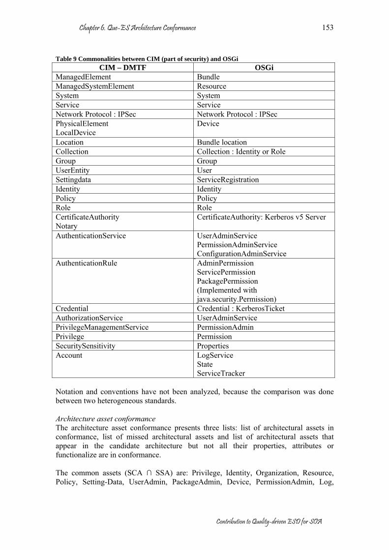
Chapter 6. Que-ES Architecture Conformance
Contribution to Quality-driven ESD for SOA
153
Table 9 Commonalities between CIM (part of security) and OSGi
CIM – DMTF OSGi ManagedElement Bundle ManagedSystemElement Resource System System Service Service Network Protocol : IPSec Network Protocol : IPSec PhysicalElement LocalDevice
Device
Location Bundle location Collection Collection : Identity or Role Group Group UserEntity User Settingdata ServiceRegistration Identity Identity Policy Policy Role Role CertificateAuthority Notary
CertificateAuthority: Kerberos v5 Server
AuthenticationService UserAdminService PermissionAdminService ConfigurationAdminService
AuthenticationRule AdminPermission ServicePermission PackagePermission (Implemented with java.security.Permission)
Credential Credential : KerberosTicket AuthorizationService UserAdminService PrivilegeManagementService PermissionAdmin Privilege Permission SecuritySensitivity Properties Account LogService
State ServiceTracker
Notation and conventions have not been analyzed, because the comparison was done between two heterogeneous standards. Architecture asset conformance The architecture asset conformance presents three lists: list of architectural assets in conformance, list of missed architectural assets and list of architectural assets that appear in the candidate architecture but not all their properties, attributes or functionalize are in conformance. The common assets (SCA ∩ SSA) are: Privilege, Identity, Organization, Resource, Policy, Setting-Data, UserAdmin, PackageAdmin, Device, PermissionAdmin, Log,

Chapter 6. Que-ES Architecture Conformance
Contribution to Quality-driven ESD for SOA
154
Tracker and URL. Similar to the concepts, assets have not a precise mapping. The list of missed assets is shown in Table 10. Table 10 Extracted requirements from conformance process between OSGi standard and CIM (DMTF) Conceptual model Static architecture SSA-SIA OrganizationalEntity
Notary AdminDomain AccountManagementService
Certificate Credential
SIA-SSA Framework Device Manager
Provisioning service StartLevel service WireAdmin service
Proposal for enhancement of OSGi standard (SSA-SCA): As a product of the difference between CIM from DMTF and OSGi specification, new elements/assets are identified. Two types of requirements are needed in the conceptual model and in the static architecture. In the conceptual model the following elements are required:
• OrganizationalEntity is a type of ManagedElement that represents an Organization or an OrgUnit (organization unit or part of an organization), it could be composed of organizations or organization units (collections) with a defined structure.
• Notary is a service for credential management used in authentication service. • AdminDomain describes the system domain (context). • AccountManagementService is a type of security service in charge of managing
the accounting issues in the system. In the static architecture the next components are required:
• Certificate authority is a service for credential management used in the authentication service. It is a trusted third party organization or company that issues digital certificates used to create digital signatures and public-private key pairs (unsigned public key and public key certificate). The role of the Certificate Authority in this process is to guarantee that the individual granted the unique certificate is, in fact, who he or she claims to be.
• Credential, is a type of ManagedElement. In cryptography, a credential is a subset of access permissions (developed with the use of media-independent data) attesting to, or establishing, the identity of an entity, such as a birth certificate, driver's license, mother's maiden name, social security number, fingerprint, voice print, or other biometric parameter(s).
Proposal for CIM-DMTF standard (SCA-SSA): In the same way than the product of the difference between OSGi Standard and CIM, the following lacks have been detected: In the conceptual model the next elements are required:
• Framework, A framework is a reusable, “semi-complete” application that can be specialized to produce custom applications [334].
• Device Manager, In OSGi, device manager service detects registration of Device services and is responsible for associating these devices with an appropriate Driver service. These tasks are done with the help of Driver Locator services and

Chapter 6. Que-ES Architecture Conformance
Contribution to Quality-driven ESD for SOA
155
the Driver Selector service that allows a device manager to find a Driver bundle and install it.
In the static architecture the next components are required:
• Provisioning service, is a service registered with the Framework that provides information about the initial provisioning to the Management Agent.
• StartLevel service, allows Management Agent to manage a start level assigned to each bundle and the active start level of the Framework. A start level is defined to be a state of execution in which the Framework exists.
• WireAdmin service, is an administrative service that is used to control a wiring topology in the OSGi Service Platform. It is intended to be used by user interfaces or management programs that control the wiring of services in an OSGi Service Platform.
Relationships conformance OSGi and CIM security do not have a direct relation because they are standards for different proposes. Figure 98 shows in a high level of abstraction the correspondence between CIM (security part) and OSGi. In both proposals some basic services were found, but their relationships are not the same, CIM model defines only two layers for security, the defined services are supported on a common core, i.e. authentication, authorization and accounting depends of CIM core. In OSGi the role of CIM core is replaced by OSGi framework and Java security. In OSGi, there are a close relationship between authentication and authorization. In addition, accounting is not clearly defined; in any case it is located on the top layer. Practices conformance Practices conformance detects the presence or not of some practices defined in the standard. With respect to security the most important practices have been defined in section 5.5.1 (See Figure 73).
Figure 98 Mapping between CIM (DMTF) and OSGi with respect to security
OSGi distributes and manages the security on several services (see Figure 98). Figure 99, Figure 100 and Figure 101 show in depth the element related to each security aspect (see section 5.5.1). In these figures the next convention was used:
• CIM security extra-functionalities are presented in gray color; they are not supported in the OSGi standard. In the real scenario these components could be required (their functionalities could be supported by a third party, for example using Web Service Security -WSS) [29].

Chapter 6. Que-ES Architecture Conformance
Contribution to Quality-driven ESD for SOA
156
• The OSGi security extra-functionalities are illustrated in light-gray, however, they are valid for OSGi context. OSGi is service oriented and these components allow to register and to manage services.
• Common assets are represented in white color. These components have not an accurate equivalence, but after our analysis we have found clear similarities and commonalities.
The illustrated elements are defined in their respective standards.
Figure 99 Authentication and authorization countermeasure mapping

Chapter 6. Que-ES Architecture Conformance
Contribution to Quality-driven ESD for SOA
157
Figure 100 Accounting countermeasure mapping
Figure 101 Communication countermeasure mapping
Assertion conformance

Chapter 6. Que-ES Architecture Conformance
Contribution to Quality-driven ESD for SOA
158
Assertion conformance verifies presence or not of specific assertions suggested in the standard. In this case the OSGi specification makes several recommendations about the security, but it does not specify their implementation. For example, some assertions are:
• “… a Management Agent must have AdminPermission in order to manage. The communications between a Management Agent and any remote system must be carefully examined. Mutual authentication, confidentiality, and message integrity checks should be used.”
• “The Framework security model is based on the Java 2 specification [283]. If security checks are performed, they must be done according to the Java Security Architecture for JDK 1.2.”
OSGi has based its security in permission, and has defined three types: admin, service and package permission. Several services have been involved in order to insure security; for example, PermissionAdmin, UserAdmin, Device Manager, and others. The architecture proposed in the scenario involves some of these elements in agreement with OSGi suggestions. Agreement Considering CIM model suggestions and OSGi suggestions, the main candidate architecture is so far to guarantee the security in a hostile environment. In consequence, other candidate architecture is required; this new architecture should consider assets from a third party. In Figure 103 it is illustrated a possible alternative using Web services and XML security. Documentation The QAC result is a document with the commonalities and differences, as was presented in previous sections. The documentation is part of the QAA workflow, but also, other processes are proposed for QAC, such as: context conformance, architectural asset conformance, relationship conformance, etc. If these processes are performed, they should be documented. Review During the review other alternative architecture was proposed (see Figure 103). It has considered the previous suggestions during QAC analysis. During the review, also a mapping between the described tactics into [126] and the considered tactics into the case study (see Figure 102) was done.

Chapter 6. Que-ES Architecture Conformance
Contribution to Quality-driven ESD for SOA
159
Figure 102 Tactics used on QAC for the scenario
Figure 102 shows the set of tactics that the architecture candidate should take into account. In gray boxes (prevention tactics), tactics that have been considered with major priority and in white boxes, tactics that must be considered interesting to be tackled, but that are going to be considered optional. In the second candidate architecture complementary technology for previous detected lacks has been used, so: bundles permission can be remotely managed through a Web Services Support bundle (Axis + WS-Security). With Axis support, a communication channel can be established between Control Center and Service Platform (use of SOAP over HTTP). In order to guarantee Integrity and Confidentiality of the communications end-to-end through Internet WS-Security is required, and will be implemented by means of previously mentioned Communication Countermeasures. A set of required technologies are required for encryption and signing of SOAP messages (XML Encryption, XML Signature implementations from Apache community and JCE implementation from The Legion of the Bouncy Castle community).

Chapter 6. Que-ES Architecture Conformance
Contribution to Quality-driven ESD for SOA
160
Figure 103 Second candidate architecture for the scenario
The Permission Bundle Management interacts with the specified OSGi Permission Admin Service in order to manage bundles permissions. These permissions assigned to bundles are used for authorization purposes on the Service Platform, for new bundles deployed on the system at run-time. Bundles permissions are stored on a Security Policy File containing information in a format that can be interpreted by the Security Manager included with the Java Virtual Machine who is the entity in charge of checking the policy defined for the system. Figure 104 represents a detailed view of relationships among components of the Service Platform.
Figure 104 Scenario. Detailed view of interaction of components. Permission Bundle Management
The same security tests were executed on the improved scenario, without errors. Thus, if we consider the security enhancements as potential components to be added to the OSGi specification, as well as to the available implementations (such as Oscar); we can propose the security enhancements as a potential way for the evolution of the service gateway with respect to security requirements.

Chapter 6. Que-ES Architecture Conformance
Contribution to Quality-driven ESD for SOA
161
6.6. Conclusions QAC process is a mechanism to evaluate, assess and check architectures. The main contributions of conformance process are: identification of improvements (lacks and new requirements) to architectures, identification of suggestion for standard recommendations, and identification of commonalities. QAC can be also used for QAA proposes. In that case, QAC allows a faster assessment process and it is mechanism to learn from a standard. The standards are product of mature experiences, for this reason the effort in the comparison process is substantially reduced. This chapter proposes QAC as a methodological support for architectural conformance, and shows a complete case study that validates the method. QAC is a quality-driven discipline, essential in the QPM for a quickest feedback and continuous learning. One of the objectives proposed in this dissertation has been reached in this chapter, that is, a software architecture conformance method considering quality aspects is proposed and validated. The QAC model has been proved in some scenarios. As result of these scenarios, some guidelines have been obtained, which can be considered as added contributions. The obtained patterns are related with security aspect in the domain of Internet services. The main contributions of this chapter are summed up as follow:
• A methodological support has been presented for architecture conformance in the context of the evolutionary software development.
• A conceptual mode about architecture conformance is presented, where the most relevant elements are defined and explained.
• A generic workflow method to assess conformance is presented. It can be used in any domain. In this case, it was validated in a specific domain (Internet services) and applied over a quality characteristic (security).
• Other results was obtained from the case study, such as: o An instantiation of conceptual model with respect to security in Internet
services. o A methodological guideline for architecture conformance of Internet
services with respect to security, it is based on security tactics. o The case study has been specially selected, it is a system where is
reflected the next-generation of services on Internet services. In this scenario the security is one of the most relevant aspects.
o A complete conformance process was done between OSGi Standard and CIM specification (security part) with respect to security aspect.
o New security requirements for OSGi and CIM were identified in order to provide a full and trusted standard into security aspect.

Chapter 6. Que-ES Architecture Conformance
Contribution to Quality-driven ESD for SOA
162
Chapter 7 Que-ES Maintenance and Evolution (QM&E)
In QPM, some disciplines related with evolution were defined (configuration and change management). Configuration activities provide flexibility allowing the system to be adapted to special conditions, for example, the availability of specific components of the operating system; thus, no changes are performed to the architecture during configuration activities, but the behavior or the system can be modified up to a certain extent. On the other hand, when new requirements appear, the system must be changed and these changes may affect to the system implementation, the architecture, or both. This chapter introduces QM&E, which concerns quality characteristics such as maintainability, modifiability, adaptability, and replaceability. We also define a generic workflow for maintenance and evolution, supported by domain engineering, quality and reverse engineering disciplines. The proposed workflow method puts emphasis on quality aspects of service-oriented architectures. This chapter is organized in six sections as follows: the first section shows the introduction and motivations of QM&E, which focuses on the maintenance and evolution for service-oriented architectures. The second section presents the conceptual model of QM&E, where all elements involved during configuration management and change management disciplines are defined. The third section defines the proposed workflow method by QM&E. The fourth section makes a short analysis about methods, techniques and tools that can be used in supporting of QM&E. The fifth section presents a case study where the QM&E method is applied and validated. Finally, the last section summarizes the main contributions of this chapter.
7.1. Introduction Software evolution is not a new discipline; several authors have studied this topic since more than 30 years ago. For example, Lehman introduces several contributions such as: the laws of software evolution [335], SPE classification [336], the uncertainty principle [337], FEAST [338] and others [339]. Lehman also asserts that evolution is not different if TSD or ESD are applied [339], but evolution support is one of the still open problems in software engineering. The system family approach solves part of this problem using common concepts, common assets and locating variation points [5]; the variability in can be handled by using a large number of strategies, ranging from controlling the system configuration [340], to the support of dynamic updating procedures [341]. In [342] [343] technical and functional types of variability are considered (technical variability, comprising all kinds of variability that exist in the system infrastructure, concretion and realization of the product line and functional variability, defining functional and quality characteristics of the system). However, the solutions provided by the system family engineering are not enough, since they solve the “variability in space”, but not the “variability in time” problem. So, the available methods, techniques and tools must be adapted in order to support the extended system lifecycle that

Chapter 7. Que-ES Maintenance and Evolution
Contribution to Quality-driven ESD for SOA
164
includes software evolution. In this chapter, we introduce a new process to support the evolution. Que-ES Configuration Management (QCM) is a quality-driven discipline that proposes methodological guidelines to manage the software configuration in the context of services-oriented architectures. The QCM focuses on the software adaptability. In this dissertation we have considered the next definition of adaptability: Adaptability Attributes of software that bear on the opportunity for its adaptation to different specified environments without applying other actions or means than those provided for this purpose for the software considered in section A.2.6.1 of [3]. On the other side, Que-ES Change Management (QChM) is a quality-driven discipline that proposes methodological guidelines to manage the software changes (other than configuration adaptations) in the context of services-oriented architectures. The QChM concerns the software maintainability, modifiability, and replaceability. QChM provides flexibility to software so it can be adapted to new requirements by introducing new assets, correcting faults, modifying assets or replacing some assets for others. In this dissertation we consider the next definitions for maintainability, modifiability and replaceability: Maintainability Maintainability is the capability of the software product to be modified. Modifications may include corrections, improvements or adaptations of the software to changes in environment, and in requirements and functional specification [3]. Modifiability The modifiability of a software system is the ease with which it can be modified to changes in the environment, requirements or functional specification [133]. Replaceability Attributes of software that bear on the opportunity and effort of using it replacing other software in the environment of that software [3]. Adaptability, maintainability, modifiability and replaceability have been dealt with in software engineering, but there are few published and stable works about the influence of these aspects on the software architecture. Some of the most relevant approaches are cited below. In [344] a method for assessment of software architecture with respect to adaptability is presented. This proposal is based on three processes: the observation of the systems, continuous planning and deployment of the changes. The observation of the system in execution is very important during maintenance and evolution, being a requirement for learning and continuous feedback., In [132] the adaptation is attributed to changes on the environment, so it implies that three activities should be performed: to determinate the cause of the changes, to locate the changes in the system and to estimate the change effect. For all these authors, adaptation of the software is an inevitable process. However, what is the adaptability in the architecture? In [150] a definition of architecture adaptability is proposed as “the degree to which software architecture is

Chapter 7. Que-ES Maintenance and Evolution
Contribution to Quality-driven ESD for SOA
165
adaptable to the change requirement in stakeholders’ objectives measured in terms of impact on software architecture elements”. Therefore, the adaptability can be measured in two dimensions in a specific scenario: impact on the software architecture (size of the impact) and adaptability degree of the software architecture (size of the change). The impact of the changes exhibits a direct relationship with the complexity and size of the system; [345] demonstrates that the adaptability of the system decreases when the system complexity increases. In [346] and [347], some additional metrics for adaptability of the architecture are introduced, such as syntactic, semantic, contextual and quality of the adaptation. [348] tries to clarify the concept of maintainability by taking it in three levels of abstraction: system (business), architecture (quality attributes) and component (modifiability, integrability and testability). [348] classifies quality attributes into execution and evolution qualities based on the standard ISO9126; in special, evolution qualities should be taken into account during the maintenance phase (flexibility, modifiability, testability, integrability, reusability, extensibility, portability, traceability, variability, tailorability and monitorability). In addition, the impact of evolution qualities at system, architecture and components levels is presented. In [147] some strategies for quantitative measurement of maintainability of software architecture are introduced. The maintainability should be measured by locating the changes; however, finding the location of changes is not an easy work, the role of the architecture is in this case very relevant because each new requirement has a direct relationship with the architecture and in consequence with the evolution of the system [134]. Also in [147] the next changes have been considered: adding new components, adding new plug-ins to existing components and changing existing component code. Finally, in [350] is presented a method for analysis of modifiability for software architecture, this method is based on ALMA [193]. ALMA distinguishes two viewpoints (conceptual and development) into two level of abstraction (micro-architecture and macro-architecture). In any case, an assessment process for the evaluation of the change is required; QAA can be applied in this situation to determinate the impact of the changes, make estimations, concerns and trade-offs in order to take the best decision. The QCM and QChM disciplines should be supported in architecture-based software development processes, where the software architecture behaves as the center for maintenance and evolution. QM&E can be used as:
• a hold for the identification of new functional and non-functional requirements during maintenance phase,
• a way to adapt assets or a complete system to new requirements, • a way to correct some problems, limitations or gaps of the system during the
maintenance phase, • a way to updating the system towards new needs by adding assets or replacing
obsolete assets, • a way to receive feedback from users in order to improve the system in new
versions or

Chapter 7. Que-ES Maintenance and Evolution
Contribution to Quality-driven ESD for SOA
166
• a way to customize some attributes by configuring some parameters. QM&E has been validated in the case study for service-oriented architectures. In the case study, we are going to analyze the capability for evolution of the system during its maintenance time. In this chapter, the context of change and configuration management is presented and its effect on the architecture; also, a generic workflow method for changes and configuration is proposed. In order to obtain appropriate results, some specific techniques and tools have been considered for the case study.
7.2. QM&E Conceptual Model Nowadays the M&E are still the most expensive tasks of the software engineering [351]. In addition, the developers usually do not like modify something which was created with a lot of work or, in the worse case, modify something that was done by a third party. Furthermore, the results can be very ungrateful when the software is on the last part of its lifecycle. We demonstrated in chapter 3 that at the end of the software lifecycle, the effort and invested cost in maintenance may be bigger than build from scratch new software. To discover the precise point in which maintenance tasks must stop is key in an organization that maintains software systems. ESD tries to extend the software lifecycle. The strategy in ESD lays in the prediction of new requirements before than the final user, i.e. by planning of future changes and foreseeing of typical user needs. In addition, ESD promotes the continuous learning. Evolutionary incremental software is shown in the Figure 105 (boxes represent software assets, wherever their status are), where three areas have been identified: removed software, conserved software and evolutionary incremental software. Removed software corresponds to software of the previous version that was eliminated into the next version. Conserved software (core) is the software kept as it is. Finally, evolutionary incremental software is the added software; we consider both new software and modified software as evolutionary incremental software. New software can also be incorporated from third party. Increments are an old idea from incremental model, which is an iterative approach where multiple development cycles take place. Evolutionary software introduces a learning process; so evolutionary incremental versions are not simply increments, as they take into account the previous experience. Each iteration could eventually introduce modifications if they are required.
Figure 105 Evolutionary incremental software

Chapter 7. Que-ES Maintenance and Evolution
Contribution to Quality-driven ESD for SOA
167
A hypothetical situation in evolutionary software is shown in the Figure 106. Some important observations are:
• In dark-gray are shown the four versions of the system 1. In white are shown the three version of system 2. And in light-gray are shown the two version of system 3. However the system 2 and system 3 have common elements from system 1. This is a frequent situation for example in operating systems.
• For example we can consider that System 1 becomes in System 2 when more than 50% of system core is removed. This percentage depends of the organization and marketing strategy.
• Special evolution was found when the initial core was completely removed. In the example, it occurs in the System 2, version 3 (S2-V3).
• In this simple model, small modifications or instable versions have not been considered. However, they can be relevant in the learning process.
Figure 106 Ideal ESD
M&E relates every element defined in ESD (see Figure 24 and Figure 27), because the evolution can be fostered from different directions: architecture, business, process or organization. Dart [9] is one of the first models for Configuration and Change management, some concepts of this model are still valid, such as: construction, components, structure, controlling and others. Christensen proposes the Ragnarok model [352] for management of configuration and version control, this model places strong emphasis on traceability and reproducibility. Sarma [353] and Nguyen [354] present alternatives for configuration management; the main contribution is the information synchronization of the changes through a repository during the complete software lifecycle. Similar work is presented by Volzer [355] but it is focused on changes management, Spinellis [356] presents a list of recommendations for version control, Staples [357] for changes control in the context of product line software, German [358] for fine-grained software modifications or Estublier [359] for the impact of changes during evolution.

Chapter 7. Que-ES Maintenance and Evolution
Contribution to Quality-driven ESD for SOA
168
The aforementioned publications introduce new ideas about the configuration and changes management that complement the Dart’s model [9]. We present a conceptual model based on these experiences in Figure 107. The core of the QM&E conceptual model are the transformations, we consider any transformation of the system as part of the M&E process. In Dart’s model [9] several activities and elements have been defined such as: Construction, Structure, Components, Team and others. We find some differences with respect to Que-ES model, for example we consider the construction as part of QPM, the structure of the system in Que-ES model is the architecture (static and dynamic), the concept of components in Que-ES model is evolved into architectural assets and services and the team concept is extended to stakeholders in order to include all the people involved during the software development and not only developers. However, the major differences are the processes for configuration; Darts considers three basic configuration processes (Auditing, Accounting and Controlling) by mixing configuration and change management activities.
Figure 107 M&E Conceptual model
As in QAA, QAC or QAR, the stakeholders decide the changes driven for a particular focus. Usually this decision is taken by part of stakeholders (project manager, engineers, testers, quality manager or customer), and these decisions are always influenced by the user needs and market strategies. The objective and focus is quality-driven, i.e. the stakeholders define one quality to improve, then define the objectives and focus accordingly. Usually the objectives and focus have been detected at the end of an assessment process, when limitations, gaps or errors have been identified. The workflow manages the versions of a system and changes throughout its lifecycle. In [9] the workflow controls how, when and where transformations (changes) are made. The workflow will be explained in depth in section 7.3.

Chapter 7. Que-ES Maintenance and Evolution
Contribution to Quality-driven ESD for SOA
169
The methods and techniques are a set of strategies for transformation, such as: refactoring, composition, replacing, update, etc. Some of them are described in section 7.4. Obviously, the methods and techniques are applied to assets, services or to the complete system. In some cases these transformations affect to the original architecture of the system, but this is not a desirable situation. If the architecture of a system has been changed, we consider the system has evolved to become into other system There are some types of Transformations depending on their origin and direction; a classification is presented in Figure 108. Transformations have different motivations, such as, for example changes in the hardware, business, organization or software. Transformation are associated with a register where the information about configuration and changes is stored. Auditing, Accounting and Documentation are part of the register.
• Auditing keeps an audit trail of the system and its processes. • Accounting gathers statistics about the system and its processes. • Documentation synchronizes the information of the systems with respect to the
changes. From the classical concepts of maintenance, transformations can be: ForwardTransformation and BackwardTransformation. ForwardTranformation collects the transformation in order to improve some functional or non-functional attribute. We have considered three types of forward transformations:
• FineEvolution, we consider here the set of changes that could be made to software code assets: bugs, moves, additions, deletions, modifications, comments and cleaning.
• MergerEvolution, is a type of transformation when a system become in part of another, in this type of the transformation the system can be considered as an asset (black box) where the interfaces and data interchanges should be well defined. Usually, previous to the merge, the system interfaces or (input and output) data formats can be modified. In addition, other neighbor assets can be affected, so they could also be modified.
• ConfigurationEvolution is related with configuration changes, not software modifications, but changes in parameters, values, defect conditions and connections are included.
• ForkEvolution occurs when the original system is divided into two or more derived systems. For example when the system is adapted for other context or in large systems, parts of the system become in independent systems.
BackwardTranformation: not all ForwardTransformations are successful; in fact, conflicts, limitations, dependencies and other problems are very common during the evolution. We have considered three types of backward transformations:
• SteppingBack, in some cases the changed introduces into new versions are catastrophic, in these cases the better option is to come back to a previous stable version.
• AssetRecovery, in some cases we are interested in part of previous systems to solve a conflict or problem. AssetRecovery extracts operative assets from implemented systems. However, the extracted asset should be adapted in order to be reused. This topic was widely explained in chapter 5.

Chapter 7. Que-ES Maintenance and Evolution
Contribution to Quality-driven ESD for SOA
170
• ConfigurationRecovery is the reverse transformation of ConfigurationEvolution. In some cases, the setting information should be recovered from previous versions.
Figure 108 Transformation classification
7.3. QM&E workflow The workflow manages the configuration and evolution of a system. In addition, the workflow uses some methods and techniques in order to control the transformations (forward and backward). The QM&E makes emphasis in the continuous feedback during the maintenance phase. In this section we identify the typical activities in that period of time. In the software engineering, these processes are related to configuration and control of versions. However, workflow does not have an explicit sequence to be performed; for example FineEvolution or SteppingBack can be executed after a detection of an error, and ConfigurationEvolution or ConfigurationRecovery can occur when something in the context change. These transformations are unpredictable and should be carried out as soon as possible. Some other transformation could be planned (think on future changes) for example MergerEvolution, ForkEvolution or AssetRecovery. The last three, we recommend performing these kind of activities periodically as were proposed into the process principles (assessed iterative short cycles). Generally, software systems are not flexible enough “plug-and-play” and may require significant effort to adapt them to new demands [360]. Besides, transformations in products (evolution) imply new versions, so upgrading to a new version of the product poses several risks: unforeseen effects in the system, incompatibilities, non-required extra-functionalities, conflicts with other systems or components, and additional requirements in memory, processor and operating support. At a lower level of abstraction, in the SOA, services provide a relatively cheap and cost-effective solution for extensibility, integration and flexibility of software. So, services are suitable elements for QM&E. The workflow during QM&E is closely related with the lifecycle of the assets after delivery (maintenance phase). During the asset deployment lifecycle, the product can change its state [361] [362] (see Figure 109). The basic defined states are:

Chapter 7. Que-ES Maintenance and Evolution
Contribution to Quality-driven ESD for SOA
171
• Non-registered, is the state previous to delivery, the product is totally implemented, tested and assessed, but it has not been deployed.
• Available, after deployment the system is available in a specific domain, i.e. the product is ready to be used.
• Disabled, the system is deployed but not is accessible to be used. • Retired, when a product is not used anymore, it can be definitely retired. Both
files and registers are removed.
Figure 109 States of asset deployment lifecycle
However, other action states should be defined to describe configuration management:
• Active, the asset, service or system is in execution or it is been used for other system.
• In-Configuration, the asset, service or system is been configured. Configuration is an extra-activity defined in QCM.
• In-Customization, the asset, service or system is been customized. Customization is an extra-activity defined in QCM.
Available
Activation Customization
Deactivation
Configuration
In-Configuration In-CustomizationActive
Setting configuration Setting customization Figure 110 States during configuration management
Extra-activities related with QCM In [361] and [362] the configuration and deployment activities of the product lifecycle are defined (see Figure 111). Deployment is a complex area that not has been covered in this chapter. The activities related with deployment are: Delivery, Activation, Deactivation, Retreat, Shutdown, Wake up, Customization and Configuration. The first six activities affect only to the implementation but the last two can affect to the architecture.
Customization is a special configuration process that allows changing parameters or properties of the product while it is in execution (Active state), for example, to change the user interface of an application. Configuration process allows changing functional characteristics or properties of the product when it is in Available state, for example, to change some periodic functions as online update or store information into database.

Chapter 7. Que-ES Maintenance and Evolution
Contribution to Quality-driven ESD for SOA
172
Configuration Customization
Configuration Management
Figure 111 Extra-activities for configuration management
At the same way, other action states should be defined to describe changing management (See Figure 112), such as:
• In-Upgrade, the asset, service or system is being improved to a new version, increasing its functionalities or qualities.
• Overwriting, in some case the same version of the asset, service or system should be installed again, for example when the current version is corrupted for some reason, in these cases the same version is overwritten in the system.
• Under-Test, the asset, service or system is been tested, in order to validate its functionalities and qualities.
• Under-Review, when the asset, service or system has a problem, error or limitation, it should be corrected.
When a asset, service or system is upgraded, the new versions (alpha and beta), should be tested, this is performed in Under-Test state after which they can be updated into Non-register state or reviewed into Under-Review state when some conflicts, dependencies or limitations have been located. The control of versions needs some extra-activities to solve this problem. In order to perform the adequate action during the upgrade, a register of versions should be used. The minimal register is composed by three values (a, b, c): a is the original version, b is the current version and c is the new version [363], Five different situations can occur:
• a = x, b = x, c = x; original, current and new versions are equal. • a = x, b = y, c = y; current and new versions are equal, but of the original
version is different. • a = x, b = y, c = x; original and new versions are equal, but the current version
is other. • a = x, b = x, c = y; original and current versions are equal, but of the new
version is different. • a = x, b = y, c = z; original, current and new versions are different.

Chapter 7. Que-ES Maintenance and Evolution
Contribution to Quality-driven ESD for SOA
173
Upgrade
Non-Registered
Available
AvailableOverwriting
In-Upgrade
In-Upgrade
Under-Test
Under-review
Available Disabled
Upgrade
Update
(x, y, x)
(x, y, y)
(x, x, x)
(x, x, y)
(x, y, z)
Several situation can occur after In-Upgrade state, the next notation is used to distinguish them (a, b, c).a = original versionb = current versionc = new version
Ok Reproved
Test
Update review
Figure 112 States during changing management
Extra-activities related with QChM In [361] and [362] the activities related to changes of the product are presented (see Figure 113). Versioning: A product evolves increasing their functional or non-functional properties, improving quality features, resolving some possible conflicts or solving dependences. Usually, every increment generates a new version of the product. Composing Frameworks: is the capacity of a component to join with one or several components and create a new product or an application [364] [365]. The frameworks are increasingly recognized as very useful products in the paradigm of SOA. A framework can have different roles depending on the context. A framework is made with certified products, so, frameworks do not need a previous adaptation.
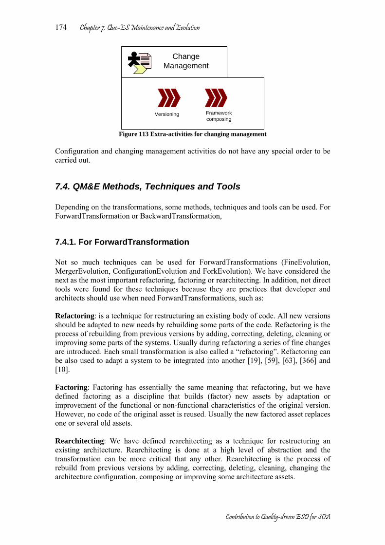
Chapter 7. Que-ES Maintenance and Evolution
Contribution to Quality-driven ESD for SOA
174
Change Management
Versioning Framework composing
Figure 113 Extra-activities for changing management
Configuration and changing management activities do not have any special order to be carried out.
7.4. QM&E Methods, Techniques and Tools Depending on the transformations, some methods, techniques and tools can be used. For ForwardTransformation or BackwardTransformation,
7.4.1. For ForwardTransformation Not so much techniques can be used for ForwardTransformations (FineEvolution, MergerEvolution, ConfigurationEvolution and ForkEvolution). We have considered the next as the most important refactoring, factoring or rearchitecting. In addition, not direct tools were found for these techniques because they are practices that developer and architects should use when need ForwardTransformations, such as: Refactoring: is a technique for restructuring an existing body of code. All new versions should be adapted to new needs by rebuilding some parts of the code. Refactoring is the process of rebuilding from previous versions by adding, correcting, deleting, cleaning or improving some parts of the systems. Usually during refactoring a series of fine changes are introduced. Each small transformation is also called a “refactoring”. Refactoring can be also used to adapt a system to be integrated into another [19], [59], [63], [366] and [10]. Factoring: Factoring has essentially the same meaning that refactoring, but we have defined factoring as a discipline that builds (factor) new assets by adaptation or improvement of the functional or non-functional characteristics of the original version. However, no code of the original asset is reused. Usually the new factored asset replaces one or several old assets. Rearchitecting: We have defined rearchitecting as a technique for restructuring an existing architecture. Rearchitecting is done at a high level of abstraction and the transformation can be more critical that any other. Rearchitecting is the process of rebuild from previous versions by adding, correcting, deleting, cleaning, changing the architecture configuration, composing or improving some architecture assets.

Chapter 7. Que-ES Maintenance and Evolution
Contribution to Quality-driven ESD for SOA
175
Refactoring uses reverse engineering processes, after which the quality processes (QAA and QAC) can be applied. Quality processes can suggest that the recovered asset or system is not good enough for the requirements, and in this case a refactoring process is discarded and factoring should be used. Factoring uses the same methods, techniques and tools of the domain engineering processes; however the main difference is that factoring is focused on the adaptation or improvement of existing systems. Any of the techniques proposed can be performed without support of special tool, however it is very convenient the utilization of the same tools for software development (IDE’s) with support of version control. In this case the tools are mainly used for synchronization of documentation and maybe for potential BackwardTranformation support.
7.4.2. For BackwardTransformation: BackwardTranformations are very common practices in systems under test, because certain changes have been introduced but their effects are still unknown. In major part of the cases some errors, conflicts or limitations are discovered in this phase. BackwardTransformation guarantee the stability of the system with certain level of quality. SteppingBack, is big “undo” when a unsuccessful ForwardTransformations occur. In this case is very useful the inclusion of version control tool as support. These types of tools are able to recover the previous version without major traumatic effects. The most known tool on open source community is Concurrent Versions System CVS [367] [368], but numerous tools can be found for specific IDE’s, languages or operating systems. Other complementary techniques are proposed in [369] in support of the versioning, such as:
• Changeset support: A versioning system group can be grouped by related changes, so that they appear as a single logical entity.
• Line-wise history: Allows to recover the complete evolution of one single item into a versioning system.
• Release tagging: It is a simple technique for tagging of a release in order to identify the release and support for analysis, traceability and testing.
• Branching and Merging: it is natural process when using the system under study to make a new branch of the program, and to merge changes later on.
• Collaboration Style: Versioning systems were developed out of the need to handle concurrent modifications of a system by several developers. Thus the collaboration policy enforced by the versioning system has an influence on the development style of applications, in the same way merging or branching does. There are two main collaboration strategies: concurrent development and file locking. One allows any developer to make changes to any file, while the other imposes the developer to first check out a file, change it, and commit it again.
For ConfigurationRecovery some management tools could be used, this tools stores the profiles where the configuration is saved into a database. The profiles can be recovered if it is required. However, configuration information depends in big way of the application (user profiles, some setting environment variables, context, etc), for these reason ConfigurationRecovery is usually leaved to the application or operating system

Chapter 7. Que-ES Maintenance and Evolution
Contribution to Quality-driven ESD for SOA
176
responsibility. In some operating systems the manager of user profiles control the main configuration values, the user can change certain values through tools or in some cases for simple handling of text files. For example in Linux operating system offers a big list of tools for configuration (package management tools, system state analysis, multiplexing configuration managers, task administration tools, configuration storage schemes and others [370]). Similarly other tools can be found for other operating systems or for special systems or domains. Finally, for AssetRecovery was largely explained on QAR; in chapter 5, several methods, techniques and tools were proposed.
7.5. M&E on SOA, Case study (Evolution from OSGi R3 to OSGi R4). This section presents a scenario of validation using the QE&M model on SOA (see Figure 114). There are several examples of service oriented systems, but most of them are supported in the same framework, so the validation on a framework is more representative than on a particular application. We have chosen OSGi as a case study, because it is one of the frameworks for SOA with a higher potential for penetration in the market. We analyze the OSGi evolution from the release 3 [37] to release 4 [371] [372], being these two releases the last ones to this date. In this case we are going to focus on evolvability aspects; attributes that should be taken into account during the maintenance and evolution. In the next sections we are going to analyze these aspects in the context of the OSGi framework (the framework itself can be considered as a platform for domain design).
Figure 114 Scenario of validation for the QE&M method
Obviously, the OSGi framework is not a final application, so its users are software architects, developers, analysts, designers and testers that create services on it. In consequence, a different viewpoint for M&E than the classical one should be considered. In this case the framework does not have an user interface, but the way to use it is by following its rules for services, and calling the primitive services it offers. With this rather unconventional view of use of the framework, we are going to perform an assessment on the M&E aspects that have been affected from OSGi release 3 to release 4.
7.5.1 Case study general description In the section 2.1.2 an overview of OSGi framework was presented, In addition, in sections 5.5. and 6.5 was analyzed the security aspects of OSGi R3 [37]. This section we are going to evaluate the evolution of the architecture of the specifications OSGi R3 to OSGi R4 [371] from the evolvability viewpoint.

Chapter 7. Que-ES Maintenance and Evolution
Contribution to Quality-driven ESD for SOA
177
A complete view of the OSGi architecture is presented in Figure 115. The framework is the core of OSGi. It provides a general-purpose, secure, and managed Java framework that supports the deployment of extensible and downloadable applications known as bundles [37]. The OSGi R3 framework is a package where more than twenty classes allow the management of bundles. Over the framework, the services and utilities can be used depending of the specific system. For example in the section 5.5.5 it was identified some services and utilities relevant only for security aspects. In [375] it is described how OSGi becomes in an attractive application server, and the main areas where OSGi has been used are also presented, such as: Residential internet gateways, mobile phones, vehicle industry, desktop applications , consumer electronics, service provisioning, embedded appliances, industrial computers, telematics, high-end servers, automation and others. Nowadays, more than 100 companies use OSGi as a framework for different applications. Some of the products based on the OSGi framework are: Atinav Inc. (avelink, service platform) [376], Connected Systems (embedded systems) [377], Echelon (LonWorks, to control networking platform) [378], Espial (graphical application manager) [379], Gatespace Telematics AB (Ubiserv, ubiquitous systems) [380], IBM (SMF, service management framework) [381], ProSyst Software (embedded systems) [382], Samsung (residential gateway) [383], Siemens VDO Automotive (automotive electronics and mechatronics) [384] and others. However, OSGi R3 has some limitations; some of them were located in the case study of chapter 6 with respect to security. In addition, other limitations were discovered by several organizations. For this reason, an evolution of OSGi R3 was required. OSGi R4 makes a big effort in organization of the OSGi framework [371]. Some new ideas are introduced and some concepts clarified about how the framework works. In Figure 116 the OSGi R4 is shown. The transformation of OSGi R3 to OSGi R4 is a good example of rearchitecting, because new assets have been included, others have been retired and some changes to the original configuration have been performed. Obviously, the essential structure is conserved in order to guarantee compatibility between versions.

Chapter 7. Que-ES Maintenance and Evolution
Contribution to Quality-driven ESD for SOA
178
org.osgi.util
org.osgi.service
device log
provisioningpackageadmin
permissionadmin
startlevel
useradmin
wireadmin
tracker
org.osgi.frameworkjava
url
cm io
http
prefs metatype
upnp
measurementxml
jini
positionVersion 1.0Version 1.0Version 1.1Version 1.1
Version 1.0Version 1.0Version 1.0Version 1.1Version 1.1
Version 1.0Version 1.0Version 1.0Version 1.0Version 1.2Version 1.1
Version 1.0Version 1.2Version 1.0
Version 1.0Version 1.0
Figure 115 OSGi Specification, release 3
The main change is inside the core framework, because it is enriched with some services and utilities that in previous versions were an external part of the framework. In addition, there is an identification of roles for OSGi framework. It is organized on several layers: security, module life cycle and services. Big and small transformations were done from OSGi R3 to R4 (FineEvolution and MergerEvolution). In consequence R4 will be a transition version because the old services and utilities conceptually moved to framework, such as: packageadmin, starlevel, url and others, should be physically (in the same folder) moved as part of the framework. In addition, possibly more services will be integrated. However the main transformation from R3 to R4 is the conception of each element (service, utility or layer) as an independent part, in consequence they could evolve also into independent directions.
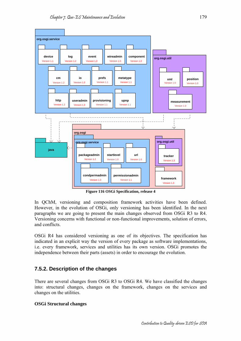
Chapter 7. Que-ES Maintenance and Evolution
Contribution to Quality-driven ESD for SOA
179
org.osgi
org.osgi.util
org.osgi.util
org.osgi.service
org.osgi.service
device log
provisioning
packageadmin
permissionadmin
startlevel
useradmin
wireadmin
tracker
javaurl
cm io
http
prefs metatype
upnp measurement
xml
component
position
Version 1.1Version 1.0
Version 1.2
Version 1.2
Version 1.1Version 1.1Version 1.0Version 1.2
Version 1.1
Version 1.0
Version 1.0
Version 1.0
Version 1.0
Version 1.2Version 1.1
Version 1.0
Version 1.3
Version 1.1 Version 1.0
Version 1.0
eventVersion 1.0
condpermadminVersion 1.0 framework
Version 1.3
Figure 116 OSGi Specification, release 4
In QChM, versioning and composition framework activities have been defined. However, in the evolution of OSGi, only versioning has been identified. In the next paragraphs we are going to present the main changes observed from OSGi R3 to R4. Versioning concerns with functional or non-functional improvements, solution of errors, and conflicts. OSGi R4 has considered versioning as one of its objectives. The specification has indicated in an explicit way the version of every package as software implementations, i.e. every framework, services and utilities has its own version. OSGi promotes the independence between their parts (assets) in order to encourage the evolution.
7.5.2. Description of the changes There are several changes from OSGi R3 to OSGi R4. We have classified the changes into: structural changes, changes on the framework, changes on the services and changes on the utilities. OSGi Structural changes
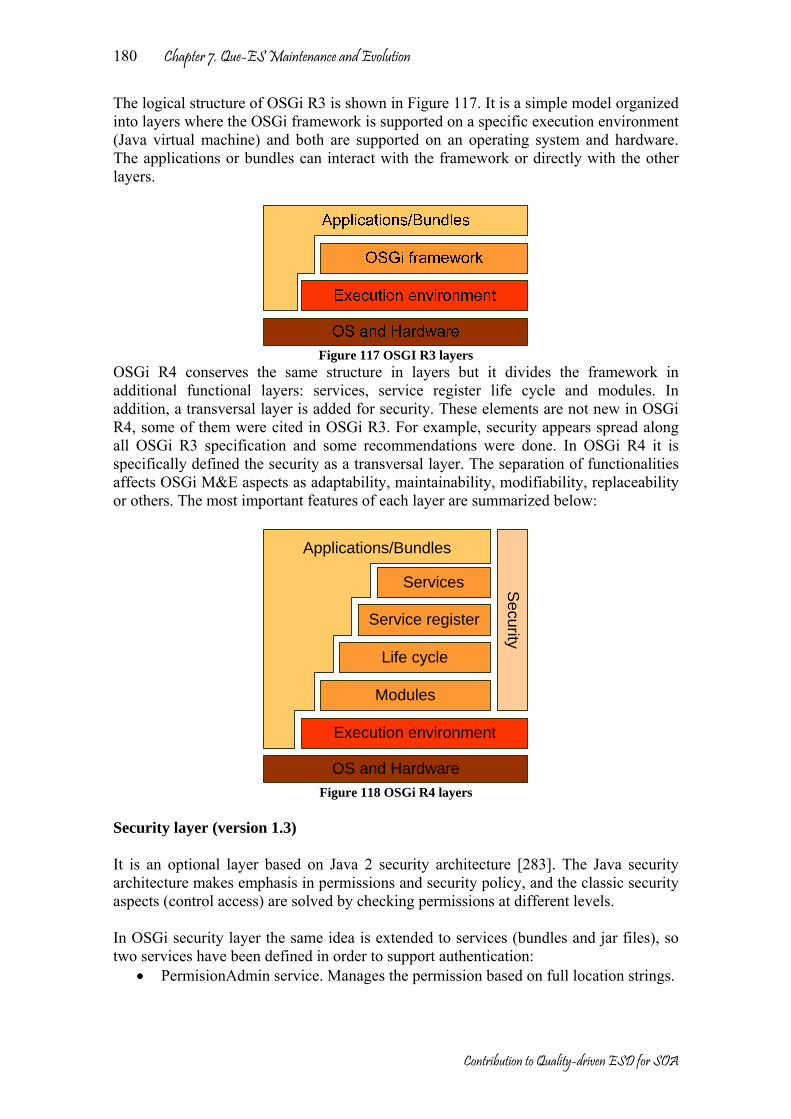
Chapter 7. Que-ES Maintenance and Evolution
Contribution to Quality-driven ESD for SOA
180
The logical structure of OSGi R3 is shown in Figure 117. It is a simple model organized into layers where the OSGi framework is supported on a specific execution environment (Java virtual machine) and both are supported on an operating system and hardware. The applications or bundles can interact with the framework or directly with the other layers.
Figure 117 OSGI R3 layers
OSGi R4 conserves the same structure in layers but it divides the framework in additional functional layers: services, service register life cycle and modules. In addition, a transversal layer is added for security. These elements are not new in OSGi R4, some of them were cited in OSGi R3. For example, security appears spread along all OSGi R3 specification and some recommendations were done. In OSGi R4 it is specifically defined the security as a transversal layer. The separation of functionalities affects OSGi M&E aspects as adaptability, maintainability, modifiability, replaceability or others. The most important features of each layer are summarized below:
Services
Service register
Life cycle
Modules
Security
Execution environment
OS and Hardware
Applications/Bundles
Figure 118 OSGi R4 layers
Security layer (version 1.3) It is an optional layer based on Java 2 security architecture [283]. The Java security architecture makes emphasis in permissions and security policy, and the classic security aspects (control access) are solved by checking permissions at different levels. In OSGi security layer the same idea is extended to services (bundles and jar files), so two services have been defined in order to support authentication:
• PermisionAdmin service. Manages the permission based on full location strings.
Chapter 7. Que-ES Maintenance and Evolution
Contribution to Quality-driven ESD for SOA
181
• ConditionalPermissionAdmin service. Manages the permissions based on a comprehensive conditional model, where the conditions can check for location or signer.
In addition, other mechanisms have been proposed to digital signature, for example, a special structure, restrictions and manifest are defined to jar files. Some signing algorithms, certificates and distinguished names are also included. Modules layer (version 1.3) The OSGi Framework provides a generic and standardized solution for Java modularization. It is a potent alternative similar to JBoss [373] or NetBeans [374]. Modularization was created in order to improve packaging, deploying, and validating applications and components. The OSGi framework defines a unit of modularization, called a bundle. Bundles can share Java packages among an exporter bundle and an importer bundle in a well-defined way. Many bundles can share a single virtual machine (VM). Within this VM, bundles can hide packages and classes from other bundles, as well as share packages with other bundles. The key mechanism to hide and share packages is the Java class-loader that loads classes from a sub-set of the bundle-space using well-defined rules. Each bundle provides information through a manifest file. It uses headers to specify information that the framework needs. The manifest headers include metadata such as: Bundle-RequiredExecutionEnvironment, Bundle-ManifestVersion, Bundle-SymbolicName, Bundle-Version, Import-Package Header, Export-Package, Exporting and Importing a Package, Interpretation of Legacy Bundles and so on. In addition, OSGi provides mechanisms for: wiring among bundles (resolving process), management during run-time (class loading), interaction with native libraries, localization (internationalization), version validation, definition of optional mechanism, dependence of bundles, association of a bundle to a host (fragment bundle), extension of bundle functionalities to perform reserved actions of system bundle (extension bundle) and security. Life cycle layer (version 1.3) The Life cycle layer provides an API to control the security and life cycle operations of bundles. The layer is based on the module and security layer. In addition, the Life cycle layer is related with the Service register that will be described in the service layer. The states of bundled life cycle are shown in Figure 119 and Figure 120. No new states are introduced but a new transition is added “update/refresh” for installed state. On the other way the distinction of explicit transition and automatic transition disappear in order to increase the management power during the whole life cycle.

Chapter 7. Que-ES Maintenance and Evolution
Contribution to Quality-driven ESD for SOA
182
Installed
ResolvedUninstalled
Starting
Active
Stopping
install
stop
start
uninstall
resolve
update
uninstall
Automatic transition
Explicit transition
Figure 119 Bundles life cycle [37]
Installed
Resolved
Uninstalled
Starting
Active
Stopping
install
stop
start
updaterefresh
Figure 120 Bundles life cycle [371]
To manage the bundle life cycle, the framework uses basic elements defined in the OSGi framework core: Bundle, bundle context, bundle activator, bundle event, framework event, bundle listener, synchronous bundle listener, framework listener, bundle exception and system bundle. The life cycle management was considered part of M&E activities (see Figure 109, Figure 110 and Figure 112). Essentially they describe the same life cycle. However, they have some differences; additional states (Figure 119). Non-register, In-Upgrade, Overwriting, Under-Test, Under-Review and Disabled states. Other differences are: Available state joins installed and resolved states, Active joins the Starting, Active and Stopping stated during execution time. Finally, Retired state is the same state than

Chapter 7. Que-ES Maintenance and Evolution
Contribution to Quality-driven ESD for SOA
183
Uninstalled. But the big difference is that the evolution in this life cycle is not considered. Service layer (version 1.3) The OSGi service layer works in cooperation with the life cycle layer. The service layer was made in order to manage the bundles (services), that is, bundles can register services, search for them, or receive notifications when their registration state changes. The main contributions of the service layer are:
• Exposes service objects registered with the framework to other bundles installed in the OSGi environment.
• Avoids creating unnecessary dynamic service dependencies between bundles. • Registers and unregisters service objects dynamically. • Identifies a service over multiple framework restarts (Persistent Identity). • Listens to events generated by the framework to clean up and remove stale
references. • Configures dynamically services at runtime to change its behavior. As an
example, a configurable Http Service may support an option to set the port number.
• Checks permission over registered services. The service layer has associated some elements from the OSGi framework core: Service, service registry, service reference, service registration, service permission, service factory, service listener, service event and filter. Changes on the OSGi Framework (version 1.3) Three new classes have been introduced: AllServiceListener to listen state changes of the services when some event happens, BundlePermission to provide the appropriate bundle permissions and Version to control bundle and package versions. And one class has been deprecated because it was moved to Configuration admin (Configurable). Some classes have been extended to enrich their functionality or in other cases have been modified in order to correct previous limitations or conflicts. Some changes were identified in AdminPermission, Bundle, BundleEvent, Constants, Filter, FrameworkEvent, InvalidSyntaxException and ServiceReference. Experiences with implementations of OSGi R3 drove to the incorporation of some services and utilities. They are often used for any application. Currently in OSGi R4 they are conserved at the same location than in OSGi R3, but implicitly considered part of the OSGi framework. The Services and utilities “moved” to framework are: permissionadmin, startlevel, url, packageadmin and tracker. In addition a new service has been added to this group condpermadmin. Conditional Permission Admin (condpermadmin) complements certain features of Permission Admin (permissionadmin). It was introduced to adapt OSGi security model to Java 2 security architecture. It provides a security model based on a very general model of conditional permissions.
Chapter 7. Que-ES Maintenance and Evolution
Contribution to Quality-driven ESD for SOA
184
The Package Admin (packageadmin) has been extended to support the new bundle types introduced in the module layer by adding features to export bundles and improve the management of dependences among bundles. Tracker makes tracking the registration, modification, and unregistration of services much easier. The new version has introduced the getTrackingCount method. The getTrackingCount method is intended to efficiently detect changes in a Service Tracker at any moment in time. Every time the Service Tracker is changed, it must increase the tracking count. Changes on the OSGi services The main changes are: Introduction of three new services, component, event and condpermadmin. The last one (condpermadmin) is described as part of OSGi framework. One service has been deprecated (jini). In addition, seven have been modified: cm, pref, metatype, http, packageadmin, provisioning and upnp. Other minor changes have been done to log, device and useradmin in order to clarify some concepts. Finally, four of the oldest services have been “moved” to OSGi framework: startlevel, url, permissionadmin and packageadmin. A short summary about introduced changes (new services and services modified) are listed below: Declarative services (component) version 1.0 provides a model for publishing, finding and binding to OSGi services during runtime. This model simplifies the process of activation and deactivation of bundles and process of memory management. For OSGi a component is a normal Java class contained within a bundle. This package allows handling of components. The Event admin service (event) version 1.0 provides an inter-bundle communication mechanism. It is based on an event-publish-and-subscribe model, popular in many message based systems. This model simplifies the programming of an event source and an event handler, management of dependencies between event sources and event handlers and synchronization of events. The Configuration Admin service (cm) version 1.2 manages the configuration data of bundles when they are active in the OSGi Framework. With respect to version 1.1, configuration admin has added three new classes ConfigurationEvent, ConfigurationListener and ConfigurationPermission. The first two to receive the Configuration Admin key events and the last one to administrative permissions similar to Admin Permission. The preference service (pref) version 1.3 provides additional support to persistence data in an OSGi environment. In this service only a method was added to preferences interface (removeNode) so a user root node can be removed when a user has been removed. The OSGi Metatype (metatype) service version 1.1 provides mechanisms to describe and provide access to information of attributes, objects and metatype for a specific bundle. Metatype service was expanded to new services MetaTypeInformation and MetaTypeService. Both are used to gather metatype information from bundles through a

Chapter 7. Que-ES Maintenance and Evolution
Contribution to Quality-driven ESD for SOA
185
XML file. A standardized XML schema is used to define Metatypes as well as related instances. The Http service (http) version 1.2 provides users with access to services on the Internet and other networks. http does not introduce many changes, this version was updated to support the Java 1.4 nested exception methods. The Provisioning service (provisioning) version 1.1 provides information about initial provisioning to the Management agent (initial request URL in order to be provisioned). The management agent has been defined as a bundle that is responsible for managing a Service Platform under the control of a Remote Manager. In addition an OSGi-specific secure protocol is defined based on HTTP. The UPnP API Package (upnp) version 1.1 specifies how OSGi bundles can be developed that interoperates with UPnP™ (Universal Plug and Play) devices and UPnP control points. In version 1.1 a new class was added (UnPException) to catch errors. And an interface was also added that represents a Status Variable (UPnPStateVariable). Changes on the OSGi utilities The most relevant change is the “movement” of tracker as part of the OSGi framework. No other changes have been found.
7.5.3 Assessment of the evolution between OSGi R3 and R4 In agreement with Figure 107 during M&E, several elements play an important role: stakeholders, system and architecture. However M&E is not possible without the definition of some objectives, focus and the definition of the workflow allowing the application of some methods and techniques for the transformations (evolution) of the system. In the next paragraphs we are going to identify each one of these elements and try to analyze the main transformation of the OSGi specification. Stakeholders; in this case study is a reduced group because the framework specification is addressed for developers of applications, frameworks and system services, and architects. System; in this case is not defined a specific application, because OSGi is a framework where the applications are build on top. And the Architecture; OSGi framework has a defined static architecture divided in layers, such as was illustrated in Figure 117 and Figure 118. The dynamic architecture depends on the application. In addition, evolvability has a direct relation with other intrinsic properties of OSGi specifications; for example composability, encapsulability, managementability, security and deploymentability are properties of special interest in OSGi domain. The success of OSGi lies on its flexibility for remote management, life cycle management, open integration of protocols and standards (SNMP, CMISE, CIM, OMA DM, etc.), dynamic software updates, remote control/maintenance/diagnosis, platform-independence, horizontal deployment features and a standardized number of services and utilities. In OSGi R4 some properties have been improved, such as: a flexible software component model, reusability of software modules and secure authorization rules.

Chapter 7. Que-ES Maintenance and Evolution
Contribution to Quality-driven ESD for SOA
186
However, other criteria are in close relation with the evolution [348] (flexibility, testability, integrability, etc), see Table 11. However the evolution is also in close relation with the process of observation, user satisfaction and continuous learning; for this reason some other criteria (effectiveness, satisfaction, learneability, safety, trustfulness, accessibility, universality, usefulness) should be taken into account from the point of view of the user [349] (see Table 12).
Table 11 Relation of M&E attributes with respect to some criteria of OSGi specification Evolvability Attributes Criteria A
dapt
abili
ty
Mai
ntai
nabi
lity
Mod
ifiab
ility
Rep
lace
abili
ty
Composability + + + Encapsulability + + + Managementability + + Security + Deploymentability + + Flexibility + + + + Testability + Integrability + + + + Reusability + + + Extensibility + + + Portability + + + Variability + + Tailorability + + Monitorability + Traceability +

Chapter 7. Que-ES Maintenance and Evolution
Contribution to Quality-driven ESD for SOA
187
Table 12 Additional criteria for OSGi specification
Factors Criteria E
ffec
tiven
ess
Satis
fact
ion
Lea
rnea
bilit
y
Safe
ty
Tru
stfu
lnes
s
Acc
essi
bilit
y
Uni
vers
ality
Use
fuln
ess
Composability + + + Encapsulability + + + Managementability + + + + Security + + + + + Deploymentability + + + Flexibility + + + + + Testability + + + Integrability + + + Reusability + + + + + Extensibility + + + + Portability + + + + + Variability + + + + Tailorability + + + + + Monitorability + + + Traceability + + +
Table 11 and Table 12 show that evolvability attribute has relation with other attributes, weakness or advantages of these factors allow the prediction of system transformations. One inquiry for detection of evolvability attributes of the OSGi framework was designed, as presented in the Annex 3. This questionnaire has been addressed to software developers and architects with experience in applications built upon the OSGi specification. In other words, the test users who answer the inquiry were experts of OSGi of different Spanish organizations (Telvent, Telefonica I+D, and UPM). As shown in [385], in order to get conclusions about system evolution, the opinion of some few experts is enough for a reasonable study. The following figures show the main results of the inquiry. The question results have been grouped depending on the type of information they refer to. The results are presented in the bar chart where X axis shows the questions (Q1, Q2, Q3, …, etc., see Annex 3) and Y axis, the responses of the inquiry are presented in percentages, the possible response are listed on the right side of the bar chart. In Figure 121 some parameters were measured, such as: number of elements understood, number of elements identified by the user, number of elements whose purpose is correctly described by the user, etc. In this case we consider as separate element each part of the OSGi specification (functional or non-functional assets, layers, services or utilities). In agreement with the results, the OSGi specification is easy to understand (Q1 and Q3), the elements are easy to identify (Q2), the elements have suitable documentation (Q4) at least 30% of the elements have a correct documentation but almost 60% of elements have a badly structured documentation (Q6 and Q11), the

Chapter 7. Que-ES Maintenance and Evolution
Contribution to Quality-driven ESD for SOA
188
total of the test users say that less than 40% of the solutions to detected problems have been provided for them (Q8), the basic elements that the user should know to become efficient (Q9) are less than 50%. Other questions show less clear results; for example, 50% of test users recognize that less than 40% of the elements have been tested (Q5), the number of used elements is less than 70% (Q7 and Q10).
0%
10%
20%
30%
40%
50%
60%
70%
80%
90%
100%
Q1 Q2 Q3 Q4 Q5 Q6 Q7 Q8 Q9 Q10 Q11
>90%(70–89)%(40-69)% (0-39)%
Figure 121 Measurement of easy-to-learn parameters in OSGi specification
With respect to error treatment, customized elements and missed elements, Figure 122 shows some results. The detection and correction of errors (Q12) is very poor, more than 70% of the test users say that less than 5 errors were found and corrected (Q13); perhaps the developers and architects are not interested in the detection and correction of errors (Q14). In addition, not so much elements have been customized, which means that the OSGi specification is accepted without modifications (Q15). The opinions with respect to missed elements are varied (Q16); and they depend on the application domain, for example for residential internet gateways, mobile phones, vehicle industry is seem to be right, but several security lacks have been detected, which may hinder its adoption for more critical systems.

Chapter 7. Que-ES Maintenance and Evolution
Contribution to Quality-driven ESD for SOA
189
0%
10%
20%
30%
40%
50%
60%
70%
80%
90%
100%
Q12 Q13 Q14 Q15 Q16
More< 20< 5No
Figure 122 Error treatment, customization of functionalities and missed functionalities in OSGi
Figure 123 shows some data about the time spent in learning and error correction. With respect to time spent to correct an error, the major part of the test users spend days in the correction of errors (Q17). On the other hand, the time spent to understand and read the documentation is variable because depends of the complexity of the element (Q18 and Q19).
0%
10%
20%
30%
40%
50%
60%
70%
80%
90%
100%
Q17 Q18 Q19
Not answereddaysSeveral hoursfew hoursSome minutes
Figure 123 Effort in learning and correction of errors in OSGi

Chapter 7. Que-ES Maintenance and Evolution
Contribution to Quality-driven ESD for SOA
190
Some other characteristics related with the implementation, but also very important for the architecture and the evolution are shown in Figure 124. In this direction the test users assert that OSGi is very convenient for composition (Q20), encapsulation (Q21), adaptation (Q22) and deployment (Q25), but has serious limitations in management (Q23) and security (Q24).
0%
10%
20%
30%
40%
50%
60%
70%
80%
90%
100%
Q20 Q21 Q22 Q23 Q24 Q25
BadMediumGoodExcellent
Figure 124 Capacities most relevant in OSGi framework
In Figure 125 questions about each of the elements in the standard are divided into “required” or “optional”. In addition, we detect the elements not used. In consequence, the next list corresponds to the most used elements of OSGi specification: Framework API (Q26), Log Service (Q32), Http Service (Q37), Modules layer (Q50), Life cycle layer (Q51), Service layer (Q52) and Service registry layer (Q53). The framework and the cited services are the most stable parts of OSGi specification from R3 to R4; curiously four layers were considered as essential elements in OSGi, however they were formally introduced into OSGi R4. In the other hand, the next list corresponds to the less used elements: Preferences Service (Q38), Wire Admin service (Q39), Metatype (Q40), Service Component (Q41), UPnP API (Q42), Measurement (Q47) and Position (Q48). The reason of the not utilization of previous elements is not clear, but we assume that application domain is the main reason, although other factors can be also valid, such as: documentation not clear, lack of application examples, difficulty in the understanding of these functionalities, etc. Finally, the other elements are considered optional, as they depend heavily on the kind of application. Previous results can be used to make estimations on the architecture evolution. For example, it is expected the consolidation of some services (Log and Http), it is detected the necessity of improvements in others (Preference service, Wire Admin services) and maybe the retirement of the less used service (jini service).

0%
10%
20%
30%
40%
50%
60%
70%
80%
90%
100%
Q26 Q27 Q28 Q29 Q30 Q31 Q32 Q33 Q34 Q35 Q36 Q37 Q38 Q39 Q40 Q41 Q42 Q43 Q44 Q45 Q46 Q47 Q48 Q49 Q50 Q51 Q52 Q53
Not usedOptionalRequired
Figure 125 Use of functionalities OSGi in the applications

Chapter 7. Que-ES Maintenance and Evolution
Contribution to Quality-driven ESD for SOA
192
Finally, in the inquiry, we also detect the most used open source OSGi implementations, these results are shown in Figure 126, Oscar is the most used with a 48%, but close to the second place Knopflerfish with a 31%.
46%
31%
15%
8%
0%
5%
10%
15%
20%
25%
30%
35%
40%
45%
50%
Oscar Knopflerfish Equinox Other
Figure 126 Utilization of open source OSGi implementations
7.6. Conclusions In this chapter a methodological quality driven support for maintenance and evolution is presented (QM&E). It is composed by a conceptual model, a workflow model, and a survey of methods, techniques and tools. QM&E is validated in a case study where the evolution of a framework architecture is analyzed (the OSGi specification). The main contributions of this chapter are summarized below:
• This chapter underlines the role of the architecture as the pillar for maintenance and evolution of the software.
• The transformations (changes and configuration variations) during maintenance and evolution can be controlled by and applied to the architecture in order to prolong the lifecycle of the software.
• The quality improvements are the most frequent changes during maintenance and evolution time.
• In the case study, we try to discover the evolution of OSGi specification, this evolution is analyzed with respect to adaptability, maintainability, modifiability and replaceability. With this proposal, some special methods and techniques were considered.
• The results of the case study validate the QM&E, in addition some other interesting results were obtained, such as: the detection of OSGi limitations from the previous version and the prediction of OSGi tendencies.
• QM&E allows a rapid detection of limitations of systems during maintenance time; as it allows a rapid feedback and continuous learning process.
Chapter 7. Que-ES Maintenance and Evolution
Contribution to Quality-driven ESD for SOA
193
• The case study presents also criteria to measure the utilization and discover tendencies of OSGi to support services. An inquiry was performed in order to obtain the experience of other groups that have used the OSGi specification as a framework for their applications.
• Several limitations of OSGi R3 were located; some of them have been solved in the specification of OSGi R4, for example the best organization of services and utilities or the definition of layers for better control of the services. In addition some OSGi tendencies were identified; for example, the most used elements represent a measure of the maturity of the framework, while less used elements means potential limitations or possible problems that should be corrected.
• The process of continuous learning of OSGi framework has been assessed through an inquiry. The results of the inquiry show that several aspects can be improved in future versions, such as: the documentations of some elements; support into the correction of gaps or errors, security, management, etc.

Chapter 7. Que-ES Maintenance and Evolution
Contribution to Quality-driven ESD for SOA
194

Chapter 8. Conclusions and forward work
Contribution to Quality-driven ESD for SOA
195
Chapter 8 Conclusions and further work
In this chapter, the more important conclusions of this dissertation are presented, the main contributions are summarized and some future works are identified. This work collects the main contributions of five years of participation in research projects with the DIT-UPM (Departamento de Ingeniería Telemática – Universidad Politécnica de Madrid). However, the proposed processes are feasible to improve. ESD promotes the changes; the biggest future work is the continuous adaptation and refinement of the Quality-driven ESD for SOA (Que-ES).
8.1 Conclusions and main contributions Que-ES is a novel methodology for ESD that gathers several tendencies from other ESD and TSD. The biggest difference with respect to other is the focus in quality characteristics and the support on software architecture. ESD methodology is a big area of knowledge and several of their topics could be enhanced. Que-ES is an alternative that try to cover some gaps of the ESD methodologies. Que-ES is an evolutionary software development model for service oriented architectures. Que-ES is based on other ESD models but it integrates some processes used on TSD. Que-ES promotes agile methods but includes the architecture process supporting the documentation and evolution. Que-ES is quality-driven model which means that non-functional or quality requirements are more relevant than functional requirements. We believe that functional requirements have been the focus on TSD, however the qualities of software are the point of difference between several alternatives of solution on a particular domain. In Addition, qualities have a direct incidence in the architecture and in consequence affect to the solution. We consider the quality in two senses, quality of product and quality in the process. We introduce some quality processes to improve the quality of the product and extend the lifecycle of the software. Que-ES is an agile methodology with some contributions of TSD. We study the current ESD methodologies and find some limitations that have been partially solved with mature TSD. However, TSD is not enough prepared for rapid evolution of the current applications. We try to adapt TSD ideas to ESD principles. We promote the architecture as an engine for all Que-ES models, because the architecture is the bridge between the specification (requirements) and the final solution (implementation), a good architecture guarantees a good solution, flexible adaptation, understandable documentation for all the stakeholders, close relation with quality attributes and rapid evolution. In addition, these characteristics are encouraged by using SOA as the specific environment of application. SOA is a type of architecture inspired into the advantages of the services, as autonomous and compact assets, for better adaptability, scalability, compatibility, interoperability, composability and evolvability of a software system. Que-ES is grouped in four models: Que-ES Description Model (QDM), Que-ES Process Model (QPM), Que-ES Organizational Model (QOM) and Que-ES Business Model

Chapter 8. Conclusions and forward work
Contribution to Quality-driven ESD for SOA
196
(QBM). The models follow some principles also defined in this thesis (Que-ES principles). All models together allow an agile description, design, implementation, test, assessment, organization, business opportunity, maintenance and evolution of software systems. However this thesis only focuses in QPM, where new methods, techniques and tools were introduced. In particular, we propose several QPM methods for Architecture Assessment (QAA), Architecture Recovery (QAR), Architecture Conformance (QAC) and Maintenance and Evolution (QM&E). QAA, QAR, QAC and QM&E are complementary disciplines, because all can be used during development and maintenance time. QPM do not define the sequence of each one, but together can to improve both the quality of the process and the quality of the product. The proposed QPM methods have been validated in real context and specific scenarios, all have been developed as partial result of public Spanish or European projects (CARTS, TRECOM, FAMILIES and OSMOSE). In addition, these case studies have produced some additional contributions with instanced models for specific context and qualities, such as: A specific QAA for performance in the context of real-time systems, a specific QAC for security, a specific QAR for security and a specific QM&E for evolvability, the last three in the context of internet services. Other particular conclusions extracted from each chapter are listed below: Chapter 2 makes a compendium about the main related works to Que-ES model; the next topics have been considered: the software architecture, component models, service-oriented architecture (SOA), evolutionary software methodologies (agile methods), quality models, and three qualities (performance, security and evovability). The main conclusions of Chapter 2 are:
• We clarify in this chapter the concept of the architecture and its incidence in all development process. In addition a special pattern was presented, SOA which presents several advantages with respect to adaptability, scalability, compatibility, interoperability and composability attributes.
• A comparative analysis of component models is presented. We try to find the
relationship between component models and identify which of them support services. Table 1 summarizes this analysis.
• The main contributions of the current ESD are presented, ESDs share some
basic principles defined into the “agile manifesto” but each one defines certain additional principles. It is impossible to say, which of them is the best, because all have been successful tested in particular domain or context. In addition, the organization should be prepared for its utilization; a successful agile method in one organization does not guarantee the successful in another.
• At the end of the chapter 2, some quality models were presented, the problem in
quality characteristics is inherent, because the definitions of each one are often confused and mixture, some standards try to make a consensus but some quality characteristics are transversals in all the systems and their incidences can affect to the entire system. Isolate qualities in a system can be a good strategy to simplify the analysis but it is only one viewpoint, the systems should be

Chapter 8. Conclusions and forward work
Contribution to Quality-driven ESD for SOA
197
analyzed from several views and scenarios in order to obtain the closest information to real incidence.
Chapter 3 presents Que-ES proposal, this chapter defines the principles of Que-ES based on the ESD methodologies and the software architecture. The four Que-ES models are described. And finally an analytic comparison between ESD and TSD models is performed. The main conclusions of Chapter 3 are:
• The Que-ES principles are defined; they are the core of all Que-ES models. In addition, the objectives and the general description of each model have been presented, but not all models have been completely detailed.
• From the analytic comparative study some other additional conclusion can be
extracted. ESD can decrease the total cost in the software development, but it is possible if the teamwork and the methods are prepared and organized for ESD. Que-ES introduces some processes in order to reduce the risks of ESD models. In addition, it presents a mathematical model for the description of the software lifecycle.
The chapter 4, 5, 6 and 7 present four quality-driven processes; they are guided by Que-ES principles (QAA, QAR, QAC and QM&E). We believe that all of them are fundamental in the development and maintenance processes. Each process is in close relation with the software architecture. QAA, QAR, QAC and QM&E have three essential parts: the conceptual model that describes all involved elements into the process,, workflow method that defines the steps to follows and a case study specializing the generic processes for a context, domain and specific quality (however, other specializations can be obtained). The workflow enacts some methods, techniques and tools. The main conclusions of Chapters 4, 5, 6 and 7 are:
• Chapter 4 presents a complete description of QAA for the comparative assessment of architectures for the same solution. QAA is a quality-driven discipline and promote the quickest feedback and continuous learning. QAA can be also used to make estimations. In addition, the case study is specialized on soft-real time systems and the schedulability attribute.
• Chapter 5 presents a complete description of QAR for the recovery of the
architecture from “accessible systems”. QAR can be used for recovery the legacy of one system, for location of potentially reusable assets and for documentation (poor documented systems). In addition, the case study is specialized on Internet service and the security attribute. In this case, the security of an implementation of OSGi specification (release 3) is evaluated. We locate the elements that have been implemented in conformance with the standard and some missed elements were identified. In addition, a security reference model (SRM) is proposed; it is a generic architecture for security in Internet services. The SRM was partially validated with a real scenario. The scenario presented a system with a set of security requirements which is implemented using OSGi (Oscar) technology and other complementary technologies deployed on Oscar (WS-Security, XML Security and others).
Chapter 8. Conclusions and forward work
Contribution to Quality-driven ESD for SOA
198
• Chapter 6 presents a complete description QAC for the conformance between the candidate architecture and a standard. QAC is a type of QAA discipline. QAC can be also used to make improvements, suggestions and identification of commonalities. In addition, the case study is specialized on Internet service and the security attribute. In this case study the conformance between OSGi specification (release 3) and CIM (part of security) is assessed. Both security architectures (architectural views) are obtained from their respective standard and after that they are compared; some gaps are located and some recommendations are proposed.
• Chapter 7 presents a complete description of QM&E for the maintenance and
evolution of the software. In QM&E two disciplines are involved: configuration management and change management. QM&E can be used to prolong the lifetime of the software. QM&E was validated in the evolution of OSGi release 3 to OSGi release 4, in this case evolvability of OSGi was assessed. The case study allowed the detection of some lacks into the OSGi release 3 and how in the release 4 has solved them, but not each of them has been corrected, so some limitations are still without solution.
In this dissertation, we define in general way Que-ES but not all elements have been study in depth. In the next items, we try to underline the more important contributions:
• Que-ES defines 4+1 groups of principles for software development; they have been organized on essential (valid in all senses), architecture (a guide for architecture construction), process (a guide for development process), organization (a guide for better stakeholder organization) and business (a guide for business goals).
• In agreement with the Que-ES principles, Que-ES proposes four models
(description (QDM), process (QPM), business (QBM) and organization (QOM)) that together form a complete ESD methodology. Each one of this model have been described in this dissertation but we concentrate our effort in the process model.
• Que-ES encourages the utilization of architectural methods for software
development in order to manage the quality attributes of software products. The architectural methods are the core of the main contributions in this dissertation, such as: Que-ES Architecture Assessment (QAA), Que-ES Architecture Recovery (QAR), Que-ES Architecture Conformance and Que-ES Maintenance and Evolution (QM&E).
• The QAA method is a quality-driven method for evaluation of architectures with
respect to a specific quality aspect. QAA makes a comparative analysis in order to choose the best architecture from a set of alternatives.
• The QAR method is a quality-driven method. It analyzes implemented systems
in order to obtain the closest real architecture. QAR follows an opposite direction that normal flow of the development process, QAR promotes the reusability of existing systems and assets.
Chapter 8. Conclusions and forward work
Contribution to Quality-driven ESD for SOA
199
• The QAC method is a quality-driven method that allows the evaluation of architectures but in this case, it is made with respect to a standard or de facto recommendation. QAC makes a comparative analysis in order to check if the candidate architecture is in conformance with a standard recommendation.
• The QM&E is a quality-driven method for adaptation, modification and reuse of
architectural assets, during maintenance phase.
• The Que-ES model has been validated in some case studies. In each particular context the Que-ES methods have been instantiated for specific scenarios. Instantiated Que-ES methods can be considered as additional contributions of this dissertation. Each instantiation was done with respect to one quality attribute; but the instantiations can be considered as guidelines for other quality aspects. In this dissertation, performance, security and evolvability have been analyzed, because we consider them as quality attributes more significant for telematics systems.
8.2 Further work Several proposed aspects in Que-ES have not been entirely treated in this thesis. For example: the QOM and the QBM models. In Chapter 3, only some basic ideas are proposed that must be studied in detail in future projects. In addition, as it was previously said, all processes are feasible to be improved. However, we identify the next immediate further works:
• Guidelines for the QOM and QBM are required. Strategies as collaborative systems could be used but they also depend on the context and domain. It is now an open area.
• A mathematical model was used to perform a comparative analysis between
ESD and TSD. We regard previous works for TSD and adapt this model for ESD. However, only ideal evolutionary increments were considered. The effects of proposed QPM methods have not been measured yet. An extension of the mathematical model can be carried out in future work.
• All proposed methods can be improved and enriched with the experience of
more case studies; it is a continuous work in order to guarantee the quality of the process. Perhaps in the future new technologies, methods, techniques or tools could be introduced.
• The models have been validated with real case studies, but other quality aspects,
other contexts of application, other tools or other techniques could be used in order to improve or consolidate the proposed methods. Obviously, the methods and techniques should be supported on tools. In this thesis a big collection of tools have been cited and in some cases some of them have been built. But an integrate environment is desirable for their application. For example, in the future, we will try to integrate the used tools in the Eclipse platform, once the basic elements have been described here.
Chapter 8. Conclusions and forward work
Contribution to Quality-driven ESD for SOA
200
• Some of this further works are going to be considered into several European projects (SERIOUS, COSI, OSIRIS and others). We are going to continue working on the enrichment of Que-ES methodology in the cited projects where DIT-UPM is going to participate. In any case, some other contributions from third party to Que-ES will be welcomed.

Contribution to Quality-driven ESD for SOA
Bibliography
1. Kruchten, P. Architectural Blueprints - The “4+1” View Model of Software Architecture. Rational Software Corp. Canada, 1995.
2. SOA. Web Services and Service-Oriented Architecture. http://www.service-architecture.com/ Last visited date at 10/01/2006.
3. ISO/IEC JTC1/SC7/WG6 N461. Information Technology – Software product quality – Part 1: Quality Model, Part 2: External Metrics, Part 3: Internal Metrics, Part 4: Quality In Use Metrics. ISO/IEC 9126, November 1999.
4. Beck, K. Beedle, M. van Bennekum, A. Cockburn, A. Cunnimgham, W. Fowler, M. Grenning, J. Highsmith, J. Hunt, A. Jeffries, J. Kern, J. Marick, J. Martin, R. Mellor, S. Schwaber, K. Sutherland, J and Thomas, D. Principles behind the Agile Manifesto. 2001. Available in http://agilemanifesto.org/principles.html.
5. van der Linden, F., Bosch, J., Kamsties, E., Känsälä, K., Obbink, H.: Software Product Family Evaluation. In: Nord, R.(Ed): Software Product Lines. Proceedings Third International Conference SPLC 2004, Boston, MA. Lecture Notes in Computer Science, 3154. pp. 110-129. Springer, Berlin Heidelberg. 2004.
6. OMG: Software Process Engineering Metamodel Specification. Version 1.1. Object Management Group, Needham, MA. January, 2005.
7. Obbink, J.H. Kruchten, Kozaczynski, W. Postema, H. Ran, A, Dominick, L. Kazman, R. Hilliard, R. Tracz, W and Kahane, E. Software Architecture Review and Assessment (SARA) Report, Version 1.0. February, 2002.
8. Kazman, R. Klein, M. and Clemens, P. ATAM: Method for Architecture Evaluation. Technical report. CMU/SEI-2000-TR-004. Software Engineering Institute, USA, 2000.
9. Dart, S. Concepts in Configuration Management Systems. Proceeding of the Third Int’l software Configuration Management Workshop, pp. 1-18, June 1991.
10. Opdyke, W. Refactoring Object-Oriented Frameworks, PhD thesis, University of Illinois at Urbana Champaign, 1992.
11. Juran, J and Gryna, F. Juran's Quality Control Handbook. McGraw-Hill; 3d edition. 1974. 12. Crosby, P. Philip Crosby Associates. http://www.philipcrosby.com/ Last visited date at
10/01/2006. 13. Kano, N. Seraku. Takashi, F. and Tsuji, S. Attractive Quality and Must-Be Quality. The Journal
of the Japanese Society for Quality Control, 14(2): p. 39-48. January 1984 14. Weinberg, G. Quality Software Management, Volume 1. Dorset House, 1991. 15. IEEE Std 610.12-1990. IEEE standard glossary of software engineering terminology. 10 Dec
1990. 16. Krikhaar, R. Software Evolution, Refactoring, Improvement of Operational & Usable Systems
(SERIOUS). Full Project Proposal version 2.1. ITEA project with reference ITEA if04032. 2005. 17. Sommerville, I. Software Engineering 7th edition. Addison Wesley and Pearson Education. USA.
2004. 18. Jacobson, I. Griss, M. and Jonsson, P. Software Reuse. Architecture, Process and Organization
for Business Success. Addison Wesley. USA. 1998. 19. Beck, K. Extreme Programming Explained: Embrace Change. Reading, Addison Wesley, 1999. 20. Gamma, E. Helm, R. Johnson, R. and Vlissides, J. Design Patterns, Elements of reusable Object-
oriented software. Addison-Wesley, 1995. 21. Martignano, M. ESA software engineering standards issue 2. ESA Board for software
standardisation and control (BSSC). ESA. Netherlands, 1991. 22. Shaw, M. and Garlan, D. Software Architecture: perspectives on an emerging discipline,
Prentice Hall, Upper Saddle River, 1996. 23. IEEE Standard 1471-2000. IEEE Recommended practice for architectural description of
software-intensive systems. The Institute of Electrical and Electronics Engineers, USA, 2000. 24. Jazayeri, M. Ran, A and van del Linden, F. Software architecture for product families. Addison
Wesley, 2000. 25. OMG. Object Management Group. Unified Modeling Language Specification v.1.5, UML
Revision Task Force (formal/2003-03-01). January, 2003. 26. Douglass, B. Doing Hard Time, Development Real-time systems with UML, Objects,
Frameworks, and patterns. Addison Wesley, 1999.
Bibliography
Contribution to Quality-driven ESD for SOA
202
27. Gomaa, H. Designing Concurrent, Distributed, and Real-Time Applications with UML. Addison Wesley, 2000.
28. Ran, A. “ARES Conceptual Framework for Software Architecture” in M. Jazayeri, A. Ran, F. van der Linden (eds.), “Software Architecture for Product Families Principles and Practice”, Addison Wesley, 2000.
29. Barry, D. Web Services and Service-Oriented Architectures: The Savvy Manager's Guide. Morgan Kaufmann Publishers. USA. 2003.
30. Fielding, R. Gettys, J. Mogul, J. Frystyk, H. Masinter, L. Leach, P and Berners-Lee, T. IETF RFC 2616, Hypertext Transfer Protocol -- HTTP/1.1, June 1999. Available in http://www.ietf.org/rfc/rfc2616.txt.
31. Szyperski, C. Component software, beyond object-oriented programming. In ACM Press/Addison Wesley, Second edition. 2002.
32. W3C. Web Services Activity. http://www.w3.org/2002/ws/ Last visited date at 10/01/2006. 33. O’Brien, L. Bass, L. and Merson, P. Quality Attributes and Service-Oriented Architectures. The
Software Engineering Institute and Carnegie Mellon University. September 2005. 34. Microsoft .NET. http://www.microsoft.com/net/ Last visited date at 10/01/2006. 35. J2EE. Enterprise JavaBeans Technology. http://java.sun.com/products/ejb/ Last visited date at
10/01/2006. 36. OMG. CORBA Component Model specification. Object Management Group (OMG). Document
is formal/02-06-65, June 2002. 37. OSGi. Open Services Gateway Initiative. OSGI Service Platform, Specification Release 3.0,
March 2003. 38. SUN. Sun Java System Application Server.
http://wwws.sun.com/software/products/appsrvr/home_appsrvr.html Last visited date at 10/01/2006.
39. IBM. Web sphere software. http://www-306.ibm.com/software/websphere/ Last visited date at 10/01/2006.
40. BEA. BEA WebLogic Server. http://www.bea.com/framework.jsp?CNT=index.htm&FP=/content/products/server Last visited date at 10/01/2006.
41. ObjectWeb. OpenCCM - The Open CORBA Component Model Platform. http://openccm.objectweb.org/ Last visited date at 10/01/2006.
42. W3C. XML, Extensible Markup Language. http://www.w3.org/XML/ Last visited date at 10/01/2006.
43. OASIS UDDI 2004. UDDI Specification technical committee. 2004. http://uddi.org. Last visited date at 10/01/2006.
44. Gilb, T. Software metrics. Chartwell-Bratt, 1976. 45. Gilb T. Evolutionary development. ACM SIGSOFT Software Engineering Notes, Volume 6
Issue 2. April 1981. 46. Gilb, T. Principles of Software Engineering Management. Reading, Addison-Wesley, 1988. 47. Gilb, K. Evolutionary Project Management & Product Development. Evo how successful people
manage projects delivering stakeholder values. Requirements, Project Planning. 2004. 48. Schwaber, K. The Scrum development process. Proceedings of the OOPSLA’95 Workshop on
Business Object Design and Implementation, Austin, 1995. 49. Takeuchi and Nonaka. The new product development game. Harvard Business Review, pp. 137-
146, January-February 1986. 50. Stapleton, J. Dynamic Systems Development Method – The method in practice. Addison
Wesley, 1997. 51. DSDM Consortium. Framework for Business Centered Development. http://www.dsdm.org/
Last visited date at 10/01/2006. 52. Coad, P. Lefebvre, E. and DeLuca, J. Java modeling in color with UML: Enterprise components
and process. Prentice Hall, 2000. 53. Feature Driven Development http://www.featuredrivendevelopment.com/ Last visited date at
10/01/2006. 54. Batory, D. A tutorial on Feature Oriented Programming and Product Lines. Proceedings of the
25th International Conference on Software Engineering, ICSE’03, 2003. 55. Highsmith, J. Adaptive software development: A collaborative approach to managing complex
systems. New York, Dorset House, 2000. 56. Crystal Methodologies. http://crystalmethodologies.org/ Last visited date at 10/01/2006.
Bibliography
Contribution to Quality-driven ESD for SOA
203
57. Cockburn, A. Crystal Clear. A human-powered methodology for small teams, including The Seven Properties of Effective Software Projects. Addison Wesley Professional. Nov 24, 2004.
58. Charette, R. The Foundation Series on Risk Management, Volume II: Foundations of Lean Development, Cutter Consortium, Arlington, 2001.
59. Poppendieck, M. Lean Development. http://www.agilealliance.org/articles/ Last visited date at 10/01/2006.
60. Ambler, S. An Introduction to Agile Modeling (AM). 2005-2006. Available in http://www.agilemodeling.com/essays/introductionToAM.htm
61. Hock, D. Birth of the Chaordic Age. Berrett-Koehler Publisher, Inc. 1999. 62. Ambler, S. Agile Model Driven Development (AMDD). 2005-2006. Available in
http://www.agilemodeling.com/essays/amdd.htm 63. Ambler, S. Evolutionary Database Development. 2003-2004. Available in
http://www.agiledata.org Last visited date at 10/01/2006. 64. Charette, R. The decision is in: Agile versus Heavy Methodologies. Cutter Consortium,
Executive Update, 2(19). 2004, Available in http://www.cutter.com/freestuff/epmu0119.html 65. Abrahamsson, P. Salo, O. Ronkainen, J. and Warsta, J. Agile software development methods,
Review and analysis. VTT Publications 478. 2002 66. Lippert, M. Roock, S. and Wolf, H. eXtreme Programming in Action: Practical Experiences
from Real World Projects. Wiley publishers. 2002. 67. Anderson, A. Beattie, R. Beck, K. Bryant, D. DeArment, M, Fowler, M. Fronczak, M. Garzaniti,
R. Gore, D. Hacker, B. Handrickson, C. Jeffries, R. Joppie, D. Kim, D. Kowalsky, P. Mueller, D. Murasky, T. Nytter, R. Pantea, A. and Thomas, D. Chrysler goes to “extremes”. Case study distributed computing. October, 1998.
68. Schuh, P. Recovery, Redemption, and Extreme programming. IEEE Software 18(6). pp. 26 – 32. 2001.
69. Palmer, S and Felsing, J. A practical guide to Feature-Driven Development. Upper Saddle River, NJ, Prentice-Hall. 2002.
70. Cockburn, A. Agile Software Development Joins the “Would be” Crowd. Cutter IT Journal 15 (1). pp. 6-12. 2002.
71. Poppendieck. Lean Software Development. Poppendieck LLC. http://www.poppendieck.com Last visited date at 10/01/2006.
72. Rising, L. and Janoff, N. The Scrum software development process for small teams. IEEE Software 17(4): pp. 26-32. 2000.
73. Arciniegas, J. and Dueñas, J. Método de Evaluación Arquitectónica para Sistemas de Tiempo Real. Revista de la Asociación de Técnicos de Informática NOVATICA. Nov/Dic 2002.
74. Balci, O. Verification, validation and testing. The handbook of simulation. J. Banks (ed). John Wiley and sons, 1997.
75. Bass, L. Clemens, P. and Kazman, R. Software architecture in practice. Addison Wesley, 1998. 76. OMG. Model driven architecture (MDA) Architecture board ORMSC July 9, 2001. 77. Flater D. Impact of Model-Driven Standards. National Institute of Standards and Technology.
2001. 78. Kleppe, A. Warmer, J and Bast, W. MDA Explained: The Model Driven Architecture™:
Practice and Promise. Addison Wesley. April 21, 2003 79. Oya M. MDA and System Design. Presentation at “MDA Information Day” during the OMG
technical meeting. April 2002. 80. Selonen P. and Xu J. Validation UML Models against Architectural Profiles. ESEC/FSE’03
September 1-5, Helsinki, Finland. 2003. 81. Egyed, A “Consistent Adaptation and Evolution of Class Diagrams during Refinement,”
Proceedings of the 7th International Conference on Fundamental Approaches to Software Engineering (FASE), Barcelona, Spain, March 2004.
82. Murphy, G. Notkin, D. and Sullivan, K. Software reflexion models: Bridging the gap between design and implementation. IEEE TSE, 27(4):364{380, Apr. 2001.
83. Common Criteria for Information Technology Security Evaluation, Part 1: Introduction and general model, Version 2.2, 2004. Available in http://www.commoncriteria.org
84. O’Brien, L., Stoermer, C., Verhoef, C. Software Architecture Reconstruction: Practice Needs and Current Approaches; CMU/SEI-2002- TR-024 ADA407795. 2002.
85. Stoermer,C. O’Brien, L and Verhoef, C. Practice Patterns for Architecture Reconstruction. Working Conference on Reverse Engineering, Richmond, VA, USA, October 29th - November 1st, 2002.

Bibliography
Contribution to Quality-driven ESD for SOA
204
86. Kazman, R. O’Brien, L.and Verhoef, C. Architecture Reconstruction Guidelines, 3rd Edition (CMU/SEI-2002-TR-034). November 2003.
87. Rilling, J and Lizotte, M. Position Paper: Challenges in Visualizing and Reconstructing Architectural Views. Second IEEE International Workshop on Visualizing Software for Understanding and Analysis. IEEE Computer Society. Amsterdam,, Netherlands. 22nd September 2003.
88. Rilling, J. Li, H.F. and Goswami, D. Predicate-based dynamic slicing of message passing programs Source Code Analysis and Manipulation. Proceedings. Second IEEE International Workshop on , 1 Oct. 2002.
89. Chikofsky, E. and Cross, J. Reverse Engineering and Design Recovery: A taxanomy. IEEE Software, pages 13-17, January 1990.
90. Krikhaar, R. Software Architecture Reconstruction, Ph.D. Thesis, University of Amsterdam, 1999.
91. Kazman, R. Jeromy, S. Playing Detective: Reconstructing Software Architecture from Available Evidence, Technical Report CMU/SEI-97-TR-010, Software Engineering Institute, Carnegie Mellon University, Pittsburgh, October 1997.
92. Jerding, D. and Rugaber, S. Using Visualization for Architectural Localization and Extraction. Proceedings of the fourth Working Conference on Reverse Engineering, IEEE Computer Society, pp. 56-65., Amsterdam, the Netherlands, October 6-8, 1997
93. Abowd, G. Goel, A. Jerding, D. McCracken, M. Moore, Murdock, W. Potts, C. Rugaber, S. Wills, L. MORALE Mission Oriented Architectural Legacy Evolution. Proceedings of the International Conference on Software Maintenance’97, Bari, Italy, September 29-October 3, 1997.
94. Tonella, R. Fiutem G. and Antoniol, G. Augmenting Pattern-Based Architectural Recovery with Flow Analysis: Mosaic - A Case Study. Proceedings of the Working Conference on Reverse Engineering, IEEE. 1996.
95. Boucetta, S. Hadjami Ben Ghezala, H and Kamoun, F. Architectural Recovery and Evolution of Large Legacy Systems. Proceedings of IWPSE99 International Workshop on the Principles of Software Evolution. Japan. July 16 and 17, 1999.
96. Egyed, A. Automated abstraction of class diagrams. ACM Transaction on Software. Engineering Methodology. 11(4): pp. 449-491. 2002.
97. Finnigan, Holt, Kalas, Kerr, Kontogiannis, Mueller, Mylopoulos, Perelgut, Stanley, and Wong, The Portable Bookshelf, IBM Systems Journal, Vol. 36, No. 4, pp. 564-593, November 1997.
98. Stasko, J. Domingue, Brown, J. and Price, B. editors. Software Visualization - Programming as a Multimedia Experience. The MIT Press. 1998.
99. The Rigi Tool. Available in http://www.rigi.csc.uvic.ca/ Last visited date at 10/01/2006. 100. Stroulia, E., El-Ramly, M, Inglinski, P and Sorenson, P. User Interface Reverse Engineering in
Support of Interface Migration to the Web. Automated Software Engineering, 3 10, 271-301. Kluwer Academic Publishers. 2003.
101. De Pauw, W., Mitchell, N., Robillard, M., Sevitsky, G., and Srinivasan, H. Drive-by Analysis of Running Programs, Proceedings for Workshop on Software Visualization, International Conference on Software Engineering, Toronto. May 12-13, 2001.
102. Sevitsky, G. de Pauw, W. Konuru, R. An information exploration tool for performance analysis of Java programs. Technology of Object-Oriented Languages and Systems. TOOLS 38. Proceedings, 12-14 March 2001.
103. Muccini, H. Bertolino, A. and Inverardi, P. Using Software Architecture for Code Testing. IEEE Transactions on Software Engineering, vol. 30, no. 3, March 2004.
104. Harrold, M.J. Testing: A Roadmap. Proceeding ACM ICSE 2000 Conference, The Future of Software Engineering. Finkelstein, A. ed., pp. 61-72, 2000.
105. Stroulia, E. and Systä, T. Dynamic Analysis For Reverse Engineering and Program Under-standing. Applied Computing Reviews. ACM Press. 2002.
106. Kruchten, P.: The Rational Development Process: An Introduction. Addison-Wesley, 1999. 107. Munson, J. Khoshgoftaar, T. Measuring Dynamic Program Complexity. IEEE Software, pp. 48-
55. November 1992. 108. Nikora, A.P.; Munson, J. C. Understanding the nature of software evolution. Software
Maintenance, 2003. ICSM 2003. Proceedings. International Conference on, 22-26 Sept. 2003. 109. Gilb, T. Towards the Engineering of Requirements. Result Planning Ltd. 1997. Available in
http://www.gilb.com/Pages/2ndLevel/gilbdownload.html 110. Gilb, T. Competitive Engineering. A Handbook for System and software engineering
management using planguage. Result Planning Ltd. 2003.

Bibliography
Contribution to Quality-driven ESD for SOA
205
111. OMG. UML Profile for Modeling Quality of Service and Fault Tolerance Characteristics and Mechanisms. OMG Final Adopted Specification. September 16, 2004
112. Preiss, O., Wegmann, A., Wong, J. On Quality Attribute Based Software Engineering. In: Euromicro Conference. pp. 114 -120.Varsovia, Poland, September 2001.
113. Abts, C., Boehm, B. and Bailey Clark, B. COCOTS: a COTS software integration cost model. In: 11th European Software Control and Metrics Conference jointly with the 3rd Software Certification Program in Europe conference (ESCOM-SCOPE 2000). Munich, Germany, April 2000.
114. Bertoa, M.F., Vallecillo, A. Quality attributes for COTS components. In: Proceedings of 6th Workshop on Quality Approaches in Object-Oriented Software Engineering (QAOOSE 2002), Malaga, Spain June, 2002.
115. CMMI Product Team: Capability Maturity Model Integration (CMMI) Version 1.1: CMMI for Systems Engineering and Software Engineering (CMMI-SE/SW, V1.1), Staged Representation Technical Report CMU/SEI-2002-TR-002. Carnegie Mellon University, Software Engineering Institute, Pittsburgh, PA. 2002.
116. Kiczales, G. Lamping, J. Mendhekar, A. Maeda, C. Videira-Lopes, C. Loingtier, J. and Irwin, J. Aspect-Oriented Programming. In Proc. of ECOOP. Springer-Verlag, 1997.
117. Silaghi, R.; and Strohmeier, A. Integrating CBSE, SoC, MDA, and AOP. Proceedings. Seventh IEEE International in a software development method Enterprise Distributed Object Computing Conference. pp. 136 - 146. 16-19 Sept. 2003.
118. Laddad, R. Aspect-oriented programming will improve quality. Software, IEEE. Volume 20, Issue 6, pp.:90 - 91. Nov.-Dec. 2003.
119. Shah, V. and Hill, F. An aspect-oriented security framework. Proceedings DARPA Information Survivability Conference and Exposition, 2003. Volume 2, pp. 143 - 145. 22-24 April 2003.
120. Pignaton, P. Contribución al modelado de aspectos de gestión de aplicaciones distribuidas basadas en componentes en el marco de la arquitectura MDA (Model Driven Architecture). Tesis doctoral. Universidad Politécnica de Madrid. 2004.
121. OMG. UML Profile for Schedulability, Performance, and Time Specification. Version 1.1. December 2004.
122. DMTF. Core Specification 2.9. (UML diagram Preliminary release). July, 2004. 123. DMTF. CIM User and Security Model White Paper. 2003 124. Bumpus, W. Sweitzer, J. Thompson, P. Westerinen, A and Williams, R. Common Information
Model. Implementing the Object Model for Enterprise Management. Wiley Computer Publishing. USA. 2000.
125. OMG. Security Service Specification Version 1.8. March 2002. 126. Fægri, T. E and Hallsteinsen, S. A reference architecture for security in system families. In
FAMILIES Research book, T. Käkölä and J. Dueñas, Editors. Springer Verlang. 2005. 127. Shin, S. Secure Web services. JavaWorld. 2003. 128. W3C. Security Resources. 1999. Available in http://www.w3.org/Security/ Last visited date at
10/01/2006. 129. Sünbül, A. Weber, H. and Padberg, J. Evolutionary development of business process centered
architectures using component technologies. Transactions of the SDPS. Vol. 5, No. 3, pp. 13-24. September 2001.
130. Cook, S. He, J. and Harrison, R. Dynamic and static views of software evolution. In Proceedings of IEEE International Conference on Software Maintenance. 7-9 Nov. 2001. pp.592 - 601. 2001.
131. Weiderman, N. Bergey, J. Smith, D. and Tilley, S. Approaches to legacy System Evolution. Technical Report CMU/SEI-97-TR-014. Carnegie Mellon University, Pittsburgh, PA, 1997.
132. Subramanian, N., and Chung, L. Software Architecture Adaptability - An NFR Approach. In the Proceedings of International Workshop on Principles of Software Evolution, Vienna, September 2001.
133. Bengtsson, P. Lassing, N. Bosch, J. and van Vliet, H. Architecture-level modifiability analysis (ALMA). Journal of Systems and Software 69(1-2). pp. 129-147. 2004.
134. Lassing, N. Bengtsson, P. Bosch, J. Rijsenbrij, D. and van Vliet, H. Modifiability through Architecture Analysis. Landelijk Architectuur Congres LAC'2000 - Amsterdam, 23-24 Nov. 2000. Available in http://www.citeseer.ist.psu.edu/470886.html
135. Nelson, K. M. et al., Technology flexibility: conceptualization, validation, and measurement. In Proceedings of the HICSS97. 1997.
136. Zhao, J. and Leon. Intelligent Agents for Flexible Workflow Systems. In Proceedings of the AIS Americas Conference on Information Systems, Baltimore, Maryland, August 14-16, 1998.
Bibliography
Contribution to Quality-driven ESD for SOA
206
137. Deiters, W. Goesmann, T. and Löffeler, T. Flexibility in Workflow Management: Dimensions and Solutions. International Journal of Computer Systems Science and Engineering, Vol 15, No 5, pp. 303-313. September 2000.
138. Bass, L.; Clements, P.; & Kazman, R. Software Architecture in Practice, Second ed. Reading, MA: Addison-Wesley, 2003.
139. Wikipedia la inciclopedia libre. Available in http://es.wikipedia.org/wiki/Portada Last visited date at 10/02/2006.
140. Department of Defense. Software Reuse Executive Primer, Falls Church, VA, April, 1996. 141. Department of the Navy. DON Software Reuse Guide, NAVSO P-5234-2, 1995. 142. Millstein, T. Reconciling Software Extensibility with Modular Program Reasoning. PhD Thesis
on computer Science & Engineering. University of Washington. 2003. 143. Anastasopoulos, M. Bayer, J. Flege, O. and Gacek, C. A Process for Product Line Architecture
Creation and Evaluation, PuLSE-DSSA, IESE, IESE-Report 038.00/E, June 2000. 144. Bosch, J. Florijn, G. Greefhorst, D. Kuusela, J. Obbink, H.and Pohl, K.Variability Issues in
Software Product Lines. In Proceedings of the 4th International Workshop on Product Family Engineering, PFE-4. Bilbao, Spain: European Software Institute (ESI), pp. 11 - 19. 2001.
145. Salicki S.and Farcet, N.Expression and usage of the Variability in the Software Product Lines. In Proceedings of the 4th International Workshop on Product Family Engineering. Bilbao, Spain: European Software Institute (ESI), pp. 287 - 297. 2001.
146. Vidger, M. The Evolution, Maintenance and Management of Component-based Systems. Boston:Addison-Wesley, 2001.
147. Bosch, J. and Bengtsson, P. Assessing Optimal Software Architecture Maintainability. The fifth European Conference on Software Maintainability and Reengineering, September 2000.
148. Gustafsson, J. Paakki, J. Nenonen, L. and Verkamo, A.I. Architecture-centric software evolution by software metrics and design patterns. In Proceedings of the Sixth European Conference on Software Maintenance and Reengineering. 11-13 March 2002. pp. 108 - 115. 2002.
149. Sadou, N. Tamzalit, D. and Oussalah, M. A unified approach for software architecture evolution at different abstraction levels. Eighth International Workshop on Principles of Software Evolution, 5-6 Sept. 2005. pp. 65 - 68. 2005.
150. Liu; X. and Wang; Q. Study on Application of a Quantitative Evaluation Approach for Software Architecture Adaptability. Fifth International Conference on Quality Software, 2005. (QSIC 2005) pp.265 - 272. 2005.
151. Cerón, R. Arciniegas, J. Ruiz, J. Dueñas. J. A Meta-model for Requirements Engineering in System Family Context. International Workshop on Requirements Reuse in System Family Engineering. Co-located with International Conference on Software Reuse 8. Carlos III University of Madrid, Madrid, Spain. July 5, 2004.
152. Cerón, R. Arciniegas, J. Ruiz, J. Dueñas. J. Bermejo, J. and Capilla, R. Architectural Modelling in Product Family Context. First European Workshop, EWSA 2004, St Andrews, UK, May 21-22, 2004.
153. Cerón, R. Dueñas. J. Serrano, E. and Capilla, R. A meta-model for requirements engineering in system family context for software process improvement using CMMI. In Bomarious, F. and Komi-Sirviö, S. (Eds): Product Focused software process improvement. Proceedings 6th International Conference PROFES 2005, Oulu, Finland. Lecture Notes in Computer Science, 3547. pp. 173-188. Springer, Berlin Heidelberg. 2005.
154. Cerón, R. Valsera, F. Arciniegas, J. Ruiz, J. Dueñas. J. ENAGER - A Tool for Requirements Engineering in System Family Context. International Workshop on Requirements Reuse in System Family Engineering. Co-located with International Conference on Software Reuse 8. Carlos III University of Madrid, Madrid, Spain. July 5, 2004.
155. Johnston, S. UML 2.0 Profile for Software Services. IBM April 2005. 156. Arciniegas, J. and Serrano C. MRDP: Un Modelo de Referencia para Desarrollo de Sistemas
Telemáticos. Proceedings Segundas Jornadas Iberoamericanas de Ingeniería de Requisitos y Ambientes Software. Instituto Tecnológico de Costa Rica y El Programa Iberoamericano de Ciencia y Tecnología para el Desarrollo. Costa Rica. March, 1999.
157. Fernández, J. An Architecture Style for Objects Oriented Real-Time Systems. Fifth International Conference on Software Reuse. Victoria (Canada). IEEE Computer Society, 1998.
158. OMG: Reusable Asset Specification. Final Adopted Specification. Object Management Group, Needham, MA. June, 2004.
159. OMG: UML 2.0 Testing Profile Specification. Version 2.0. Object Management Group, Needham, MA. April, 2004.

Bibliography
Contribution to Quality-driven ESD for SOA
207
160. Mellado, J. Estrategias de prueba de líneas de producto de sistemas de tiempo real especificados con diagramas de estados jerárquicos. Tesis doctoral, Universidad Politécnica de Madrid. ETSI de Telecomunicación, Departamento de Telemática. 2004.
161. Junit. http://www.junit.org Last visited date at 10/01/2006. 162. ETSI European Standard (ES) 201 873-1 version 2.2.1: The Testing and Test Control Notation
version 3 (TTCN-3); Part 1: TTCN-3 Core Language. Also published as ITU-T Recommendation Z.140. February, 2003.
163. Grabowski, J. Hogrefe, D. Réthy, G. Schieferdecker, I. Wiles, A. and Willcock, C. An Introduction into the Testing and Test Control Notation (TTCN-3). Computer Networks, Volume 42, Issue 3, Elsevier, June 2003.
164. Boehm, B. Software Engineering Economics. Prentice Hall, 1981. 165. Boehm, B., Clark, B., Horowitz, E., Westland, C., Madachy, R., Selby, R. Cost Models for
Future Software Life-cycle Processes: COCOMO 2.0. Annals of Software Engineering Special Volume on Software Process and Product Measurement, J.D. Arthur and S.M. Henry (Eds.), J.C. Baltzer AG, Science Publishers, Amsterdam, The Netherlands, Vol 1, pp. 45 - 60. 1995.
166. Chulani, S. Incorporating Bayesian Analysis to Improve the Accuracy of COCOMO II and Its Quality Model Extension. Ph.D. Qualifying Exam Report, University of Southern California, Feb 1998.
167. Jones, C. Applied Software Measurement. McGraw Hill. 1997. 168. Park R. The Central Equations of the PRICE Software Cost Model. 4th COCOMO Users’ Group
Meeting, November 1988. 169. Jensen R. An Improved Macrolevel Software Development Resource Estimation Model.
Proceedings 5th ISPA Conference, pp. 88-92. April 1983. 170. Putnam, L. and Myers, W. Measures for Excellence. Yourdon Press Computing Series.1992. 171. Mozilla project: http://www.mozilla.org Last visited date at 10/01/2006. 172. CVS Analysis for the Mozilla project. April 2003 Available in
http://libresoft.dat.escet.urjc.es/cvsanal/mozilla-cvs/ Last visited date at 10/01/2006. 173. Hilliard, R. Kurland, M. and Litvintchouuk, S. MITRE's Architecture Quality Assessment. In
1997 MITRE Software Engineering and Economics Conference. 1997. 174. Kazman, R. AT&T Best Current Practices: Software Architecture Validation. Available in
http://www.cgl.uwaterloo.ca/~rnkazman/att.ps 175. ReVelle, J. Moran, J. and Cox, C. The QFD Handbook. John Wiley and Sons, Inc. New York.
1998. 176. Clements, P. Kazman, R. and Klein, M. Evaluating Software Architectures. Methods and case
studies. Addison-Wesley. USA. 2001. 177. Clements, P. and Northrop L. Active Reviews for Intermediate Designs (ARID). Software
Engineering Institute (SEI) http://www.sei.cmu.edu/architecture/products_services/arid.html 178. Klein, M. Ralya, T. Pollak, B. Obenza, R. and González, M. A practitioner’s handbook for real
time analysis, Guide to rate monotonic analysis for real-time systems. Kluwer Academic Publishers. 1993.
179. ESAPS. Engineering Software Architectures, Process and Platforms for System-Families. ITEA project (Information Technology for European Advancement) ITEA ip99005. http://www.esi.es/en/Projects/esaps/esaps.html
180. CAFÉ. From Concepts to Application in System-Family Engineering. ITEA project (Information Technology for European Advancement) ITEA ip00004. http://www.esi.es/en/Projects/Cafe/Cafe.html
181. FAMILIES. FAct-based Maturity through Institutionalisation Lesson-learned and Involved Exploration of System-family engineering. ITEA project (Information Technology for European Advancement) ITEA ip02009. 2003-2005 http://www.esi.es/en/Projects/Families/famMain.html
182. Dueñas J. and Arciniegas, J. CARTS hard real-time systems assessment method and tool. 1er. CARTS Workshop on Advanced Real-time Technologies Aranjuez Octubre 2002.
183. Carr, T. and Balci, O. Verification and validation of object-oriented artefacts throughout the simulation model development life cycle. Proceedings of the 2000 Winter Simulation Conference, J. A. Jones, R. R. Barton, K. Kang, P. A. Fishwick (eds). 2000.
184. Luqi, L. and Steigerwald, R. Rapid software prototyping. Proceedings of the Twenty-Fifth Hawaii. International Conference on System Sciences, 1992. Volume II, pp. 470 - 479. 1992.
185. Kazman, R. Bass, L. Webb, M. and Abowd, G. SAAM: a method for analyzing the properties of software architectures. In ICSE ’94: Proc. 16th Int. Conf. Software Engineering, pp. 81–90, Sorrento, Italy, 1994.

Bibliography
Contribution to Quality-driven ESD for SOA
208
186. Olumofin, F and Misic, V. Extending the ATAM architecture evaluation to product line architectures. Fifth working IEEE/IFIP Conference on Software Architecture (WICSA 5), Pittsburgh, Pennsylvania, USA, 6-9 November 2005.
187. Dolan, T. Ph.D. Thesis, Architecture Assessment of Information-System Families, Department of Technology Management, Eindhoven University of Technology, February 2002.
188. CBAM: Cost Benefit Analysis Method. Available in http://www.sei.cmu.edu/activities/architecture/products_services/cbam.html
189. Kazman, R. In, H. and Chen, H. From requirements negotiation to software architecture decisions. Information & Software Technology 47(8). pp. 511-520. 2005.
190. Moore, M. Kazman, R. Klein, M. and Asundi, J. Quantifying the Value of Architecture Design Decisions: Lessons from the Field. ICSE 2003. pp. 557-563. 2003
191. Lassing, N. Bengtsson, P. van Vliet, H. and Bosch, J. Experiences with ALMA: Architecture-Level Modifiability Analysis. Journal System Software. 61, 1, pp. 47-57. 2002.
192. Stoermer, C. Bachmann, F. and Verhoef, C. SACAM: The Software Architecture Comparison Analysis Method. Technical Report. CMU/SEI-2003-TR-006. 2003.
193. Bengtsson, P. Lassing, N. Bosch, J. and van Vliet, H. Analyzing Software Architectures for Modifiability. Technical Report HK-R-RES-00/11-SE. Software Engineering Competence Center (SE2C). May 2000. Available in http://citeseer.ist.psu.edu/bengtsson00analyzing.html
194. Lassing, N. Bengtsson, P. van Vliet, H. and Bosch, J. Experiences with SAA of Modifiability: Högskolan Karlskrona/Ronneby Technical Report HK-R-RES-00/10-SE. 2000.
195. Parnas, D. and Weiss, D. Active design reviews: Principles and practices. 8th International Conference on Software Engineering, pp. 215-222, 1985.
196. Freedman, D and Weinberg, G. Handbook of Walkthroughs, Inspections, and Technical Reviews: Evaluating Programs, Projects, and Products, Dorset House, 1990.
197. Gilb, T. Graham and Finzi, S. Software Inspections, Addison-Wesley, 1993 198. Votta, L. Does Every Inspection Need a Meeting? Proceedings of the 1st ACM SIGSOFT
symposium on Foundations of Software Engineering, Los Angeles, 1993. 199. de With P. and van Dijk, G. Architectures Assessment for Practical Management of System
Architectures. Proceedings of PROGRESS 2002 PROGram for Research on Embedded Systems & Software. 2002.
200. Nokia, Ericsson, Blekinge Institute of Technology. ESAPS CWD1.1: Architecture Analysis and Modelling. Sections 3 - 5, 7. 2002
201. Fraunhofer IESE. ESAPS CWD1.1: Architecture Analysis and Modelling. Section 6 Architectural Mismatches Analysis. 2002
202. Fraunhofer IESE. CAFÉ CWD2.3 Design for Quality Chapter 2.3 IESE PuLSE method. 2004. 203. ICT Norway. CAFÉ CWD2.3 Design for Quality Chapter 3.1 Architecture evaluation at DNV
software. 2004 204. Niemelä, E. Matinlassi, M. and Taulavuori, A. Practical evaluation of software product family
architectures. In Proceedings of The third Software Product Line Conference SPLC 2004, pp. 130–145, Boston, MA, Aug/Sep 2004.
205. Arciniegas , J. Cerón, R. Ruiz, J. Martínez, V. and Dueñas, J. A Case Study Of Performance Analysis For Real-Time Systems. The IASTED International Conference on Software Engineering (SE 2004) as part of the Twenty-Second IASTED International Multi-Conference on Applied Informatics Innsbruck, Austria. February 17-19, 2004.
206. Liu, C. and Layland, J. Scheduling algorithms for multiprograming in a hard real-time environment. Journal of the Association for Computing Machinery, 20, 1, ACM, 1973.
207. Sciacca, S. and Block, W. Advanced SCADA Concepts. IEEE Computer Applications in Power. Jan. 1995.
208. Rajkumar, R. Synchronization in real-time systems, A priority inherence approach. Kluwer Academic Publishers, 1991.
209. Fernández, J. PPOOA, Processes Pipelines in Object Oriented Architectures. http://www.ppooa.com.es/ Last visited date at 10/01/2006.
210. Grace Lewis et al. SMART: The Service-Oriented Migration and Reuse techniques. 2005. 211. Leung, J. and Whitehead, J. On the complexity of fixed-priority scheduling of periodic, real-time
tasks. Performance evaluation (Netherlands). 1982. 212. Dertouzos. M, Aloysious K. and Mok, L. Multiprocessor on-line scheduling of hard real-time
tasks. IEEE Transactions on Software Engineering. 1989. 213. CARTS. Computer Aided Architectural Analysis for Real Time Systems. IST project
(Information Society Technologies) IST1999-20608. http://www.tcpsi.es/carts

Bibliography
Contribution to Quality-driven ESD for SOA
209
214. Li, C. Bettati, R. and Zhao, W. Response time analysis for distributed real-time Systems with busrty job arrivals. Department of Computer Science. Texas A & M University. 1996.
215. Mueller, F. Real-Time Schedulability Analysis for Ada. Humbolt University Berlin. 2000. 216. MAST. Modelling and Analysis Suite for Real-Time Applications. Cantabria University.
Available in http://mast.unican.es/ Last visited date at 10/01/2006. 217. RapidRMA. Formerly PERTS, Prototyping Environment for Real-Time Systems. Tri-Pacific
Software, Inc. Available in http://www.tripac.com/html/tech-bkgd-rma.html 218. TimeWiz. An Architectural Modeling, Analysis, and Simulation Environment for Real-Time
Systems. TimeSys Corp. http://www.bitpipe.com/detail/PROD/1103108492_503.html 219. Arjonilla, A. CARTS: The tool. Proceedings of the 1st CARTS Workshop on Advanced Real-
Time Technologies. Aranjuez, Madrid, Spain. October 2002. 220. Rational Software. Available in http://www-306.ibm.com/software/rational/ Last visited date at
10/01/2006. 221. Poseidon for UML. Available in http://www.gentleware.com Last visited date at 10/01/2006. 222. Jacobs, P. and Pluvinage, D. DIMOS: Distributed Monitoring System from Specifications to
Delivery, the Realization of a Nuclear Power Plant Supervision System Using HOOD and Ada. In L.Boullart and J.A. de Puente, International Workshop on Real-time Programming, Pergamon Press, 1992.
223. Alvarez, B. Desarrollo de un sistema de monitorización de procesos para laboratorio. Proyecto Fin de Carrera ETSI Telecomunicación, Universidad Politénica de Madrid, 1993.
224. Garcia, J. Relización en Ada del software de un sistema de adquisición de datos para una pequeña industria. Proyecto Fin de Carrera ETSI Telecomunicación, Universidad Politénica de Madrid, 1993
225. Booch, G. Objects solutions. Managing the Object-Oriented Project. Addison Wesley, Menlo Park, CA. 1996.
226. Bunnell, M. Real-time data acquisition. Dr.Dobb’s Journal. June 1995. 227. Barroso, J. Artal technologies. CARTS tool for scalable software components on distributed
architecture. “1st CARTS Workshop on Advanced Real-Time Technologies” Proceedings. Aranjuez, Madrid, Spain. October 2002.
228. Brookman, C. and Mason, B. QinetiQ Modeling the Feasibilities of Autonomous Underwater Vehicle (AUV) Control Systems. Proceedings of the 1st CARTS Workshop on Advanced Real-Time Technologies. Aranjuez, Madrid, Spain. October 2002.
229. Fernández, J. An Example of Application of PPOOA and PAP to a SCADA System. Deliverable 2.3. CARTS project. Sept, 2001.
230. Arciniegas, J. and Dueñas, J. SCADA Case study. Internal report, CARTS project, Deliverable 9.2.1. DIT-UPM, 2002.
231. Knodel, J. John, I. Ganesan, D. Pinzger, M. Usero, F. Arciniegas, J. and Riva, C. Asset Recovery and Incorporation into Product Lines. To be published in WCRE 2005 The 12th Working Conference on Reverse Engineering. Pittsburgh, Pennsylvania, USA (Carnegie Mellon). 8-11 nov 2005.
232. Arciniegas, J. Dueñas, J. Ruiz, J. Cerón, R. Bermejo, J. and Oltra, M. Architecture reasoning in support of system family evolution; an example on security, in FAMILIES Research book, T. Käkölä and J. Dueñas, Editors. To be published by Springer. 2006.
233. Guo, G. Atlee, J. and Kazman, R. A Software Architecture Reconstruction Method. Proceedings of the First Working IFIP Conference on Software Architecture (WICSA1), San Antonio, Texas, February 22-24, pp. 225-243. 1999.
234. Riva, C. Reverse Architecting: An Industrial Experience Report, Proceedings of the Seventh Working Conference on Reverse Engineering, Brisbane, Australia, pp. 42-50, November 23-25, 2000.
235. Riva, C. View-based Software Architecture Reconstruction. PhD Thesis. Vienna University of Technology. 2004.
236. Sartipi, K. and Kontogiannis, K. A Graph Pattern Matching Approach to Software Architecture Recovery, Proceedings of the IEEE International Conference on Software Maintenance (ICSM 2001), Florence, Italy, pp 408-419, November 7-9, 2001.
237. El-Ramly, M. Iglinski, P. Stroulia, E. Sorenson, P. Matichuk, B. Modeling the system-user dialog using interaction traces. Proceedings of the Eighth Working Conference on Reverse Engineering, 2-5 Oct. 2001.
238. John, I and Dörr, J. Elicitation of Requirements from User Documentation, Ninth International Workshop on Requirements Engineering: Foundation for Software Quality. Refsq '03. Klagenfurt/Velden, Austria.16 -17 June 2003.

Bibliography
Contribution to Quality-driven ESD for SOA
210
239. Rainer, A. Gale, S. Evaluating the Quality and Quantity of Data on Open Source Software Projects. The First International Conference on Open Source Systems. Genova, Italy, July 11 - 15, 2005.
240. Ahmed E. Hassan and Richard C. Holt, Architecture Recovery of Web Applications. Proceedings of the International Conference on Software Engineering, Orlando, Florida, pp. 19-25, May 2002.
241. Feijs, L, Krikhaar, R., and Van Ommering, R., A Relational Approach to Support Software Architecture Analysis, Software Practice and Experience, Vol 28(4), pp. 371-400, April 1998.
242. Harris, D. R. Reubenstein, H. B. and Yeh, A. S. Recognizers for Extracting Architectural Features from Source Code. Proceedings of the 2nd Working Conference on Reverse Engineering, 1995.
243. Egyed, A. Compositional and Relational Reasoning During Class Abstraction. Proceedings of the 6th International Conference on the Unified Modeling Language (UML), San Francisco, USA, October 2003.
244. Laine, P. The Role of Software Architecture in Solving Fundamental Problems in Object-Oriented Development of Large Embedded Systems, Proceedings of the Working IEEE/IFIP Conference on Software Architecture. Amsterdam, The Netherlands, pp 14-23, August 28-31, 2001.
245. The Portable Bookshelf; http://www.swag.uwaterloo.ca/pbs/ Last visited date at 10/01/2006. 246. Storey, M-A.. Best, C. and Michaud, J. SHriMP Views: An Interactive and Customizable
Environment for Software Exploration, Proceedings of International Workshop on Pro-gram Comprehension (IWPC ’2001), May 2001.
247. SHriMP Views, http://www.thechiselgroup.org/ Last visited date at 10/01/2006. 248. KLOCwork inSight, http://www.klocwork.com/products/insight.asp Last visited date at
10/01/2006. 249. Bowman, T.; Holt, R. C.; & Brewster, N. V. Linux as a Case Study: Its Extracted Soft-ware
Architecture. Proceedings of the 21st International Conference on Software Engineering. Los Angeles, CA, May 16-22, pp. 555-563. New York, NY: ACM Press, 1999.
250. Egyed, A. and Kruchten, P. Rose/Architecture: A Tool to Visualize Architecture. HICSS 1999, 32nd Annual Hawaii International Conference on System Sciences (HICSS-32), 5-8 January, 1999.
251. Egyed, A. Automated abstraction of class diagrams. ACM Trans. Softw. Eng. Methodol. 11(4): 449-491. 2002.
252. Bril, R.J. Feijs, L.M.G. Glas, A. Krikhaar, R.L. Winter, T. Hiding expressed using relation algebra with multi-relations-oblique lifting and lowering for unbalanced systems Software Maintenance and Reengineering, 2000. Proceedings of the Fourth European , 29 Feb.-3 March 2000
253. Mendonça, N and Kramer, J. Architecture Recovery for Distributed Systems, SWARM Forum at the Eight Working Conference on Reverse Engineering, Stuttgart, Germany, October 2001.
254. Argo/UML Available in http://argouml.tigris.org/ Last visited date at 10/01/2006. 255. Koschke, R. Simon, D. Hierarchical Reflection Models. Proceedings of the Working Conference
on Reverse Engineering, IEEE Computer Society Press, 2003. 256. Bauhaus toolkit. Available in http://www.iste.uni-stuttgart.de/ps/bauhaus/index-english.html
Last visited date at 10/01/2006. 257. Ducasse, S. Lanza, M. and Bertuli, R. High-level Polymetrics Views of Condensed Run-time
Information Published in the CSMR 2004 Proceedings of the 8th European Conference on Software Maintenance and Reengineering. pp. 309 - 318, IEEE Computer Society, 2004.
258. Lanza, M. CodeCrawler-lessons learned in building a software visualization tool. Proceedings of the Seventh European Conference on Software Maintenance and Reengineering, pp. 26-28 March 2003.
259. DIVOOR/CodeCrawler. Available in http://www.iam.unibe.ch/~scg/Research/CodeCrawler/index.html Last visited date at 10/01/2006.
260. Niere, J. Recovering Design Elements in Large Software Systems. Proceedings of the 6th Workshop Software Reengineering (WSR), Bad Honnef, Germany, May 2004.
261. Fujaba. Available in http://www.uni-paderborn.de/cs/fujaba/ Last visited date at 10/01/2006. 262. Imagix4D. Available in http://www.imagix.com/index.html Last visited date at 10/01/2006. 263. Visual Paradigm. Available in http://www.visual-paradigm.com/index.php Last visited date at
10/01/2006. 264. Eclipse/Omondo. Available in http://www.omondo.com/ Last visited date at 10/01/2006.

Bibliography
Contribution to Quality-driven ESD for SOA
211
265. Jinsight. Available in http://www.research.ibm.com/jinsight Last visited date at 10/01/2006. 266. Anderson, P.; Reps, T.; Teitelbaum, T.; Design and implementation of a fine-grained software
inspection tool Software Engineering, IEEE Transactions on ,Volume: 29 , Issue: 8 , Aug. 2003 267. CodeSurfer. Available in http://www.grammatech.com/products/codesurfer/index.html 268. Vidacs, L. Beszedes, A. Ferenc, R. Columbus schema for C/C++ preprocessing Software
Proceedings of the Eighth European Conference on Maintenance and Reengineering, (CSMR 2004). 24-26 March 2004.
269. Ferenc, R. Beszedes, A. Tarkiainen, M. and Gyimothy, T. Columbus - reverse engineering tool and schema for C++. Proceedings. International Conference on Software Maintenance, 3-6 Oct. 2002.
270. Columbus/CAN. Available in http://www.frontendart.com/ Last visited date at 10/01/2006. 271. Rilling, J. Seffah, A. Bouthlier, C. The CONCEPT project - applying source code analysis to
reduce information complexity of static and dynamic visualization techniques. Proceedings of the First International Workshop on Visualizing Software for Understanding and Analysis. 26 June 2002.
272. CONCEPT Available in http://www.cs.concordia.ca/~rilling/html/concept.shtml Last visited date at 10/01/2006.
273. Favre, J. A New Approach to Software Exploration: Back-packing with GSEE. European Conference on Software Maintenance and Reengineering (CSMR’2002), 2002.
274. GSEE. Available in http://www-adele.imag.fr/~jmfavre/GSEE/ Last visited date at 10/01/2006. 275. Red Hat Source-Navigator. Available in http://sourcenav.sourceforge.net/ Last visited date at
10/01/2006. 276. Klaus, M. Simplifying Code Comprehension for Legacy Code Reuse. Wind River Sys-tems.
Embedded Developers Journal. April 2002. 277. SniFF++. Available in http://www.windriver.com/products/development_tools/ide/sniff_plus/
Last visited date at 10/01/2006. 278. Scientific Toolworks. Available in http://www.scitools.com/index.php. Last visited date at
10/01/2006. 279. Oscar. An OSGi framework implementation. Available in http://oscar-osgi.sourceforge.net/ Last
visited date at 10/01/2006. 280. Knopflerfish. An OSGi framework implementation. Available in http://www.knopflerfish.org/ Last visited
date at 10/01/2006. 281. Equinox. An OSGi framework implementation. Available in http://www.eclipse.org/equinox/
Last visited date at 10/01/2006. 282. IETF, Internet Engineering Task Force. http://www.ietf.org Last visited date at 10/01/2006 283. Gong, L. The Java Security Architecture for JDK 1.5. Version 1.2, Sun Microsystems, October
1998. Available in http://java.sun.com/security/ 284. Graff, M. and van Wyk, K. Secure Coding, Principles and practices. O’reily.USA. 2003. 285. SOFTEC Project. Technology Roadmap on Software Intensive Systems, The Vision of ITEA;
ITEA Office, March 2001 286. Ministerio de Administraciones Públicas de España. Aplicaciones utilizadas para el ejercicio de
Potestades, Criterios de Seguridad; España. Febrero 2003 287. NSA National Security Agency. Controlled Access Protection Profile, Version 1.d, Information
Systems Security Organisation; 9800 Savage Road, Fort George G. Meade, MD 20755-6000, October 1999.
288. Wreski, D. Linux Security Administrator’s Guide, v0.98, 22 August 1998. Available in http://www.nic.com/~dave/SecurityAdminGuide/SecurityAdminGuide.html
289. ISO/IEC. Information Technology – Security Techniques – Entity Authentication Mechanisms; Part 1: General Model. International Organization Standardization, Genève, Switzerland, Tech. Rep. ISO/IEC 9798–1, 2nd ed., 1991.
290. Sovio, S. Asokan, N. and Nyberg, K. Defining Authorization Domains Using Virtual Devices. 2003.
291. Pras, A. van Beijnum, B. Sprenkels, R. and Parhonyi, R. Internet Accounting. IEEE Communication magazine. May 2001.
292. IETF Working Group in AAA, Authentication, Authorization and Accounting. Available in http://www.ietf.org/html.charters/aaa-charter.html
293. Whittaker, J. Why Secure Applications Are Difficult to Write IEEE Security and Privacy. 2003. 294. ISO 7498-4: Information Processing Systems - Open Systems Interconnection - Basic Reference
Model - Part 4: Management Framework. Geneva, 1989.

Bibliography
Contribution to Quality-driven ESD for SOA
212
295. Debe ir despues de ISO Gong, L. A software architecture for open service gateways. Embedded systems. IEEE internet computing. January – February. 2001.
296. Apache Software Fundation. http://www.apache.org Last visited date at 10/01/2006. 297. Legion of the Bouncy Castle. http://www.bouncycastle.org/ Last visited date at 10/01/2006. 298. OASIS consortium. http://www.oasis-open.org Last visited date at 10/01/2006. 299. JCP, Java Community Process http://www.jcp.org Last visited date at 10/01/2006. 300. OSMOSE Open Source Middleware for Open Systems in Europe. ITEA project (Information
Technology for European Advancement) ITEA ip02003. 2003-2005. http://www.itea-osmose.org
301. McCullagh, A. Caelli, W. Non-Repudiation in the Digital Environment. First Monday 5(8): 2000. available in http://www.firstmonday.org/issues/issue5_8/mccullagh/index.html
302. WebOpedia. Online dictionary available in http://www.webopedia.com/ Last visited date at 10/01/2006.
303. ISO International Organization for Standardization. http://www.iso.org/iso/en/ISOOnline.frontpage Last visited date at 10/01/2006
304. Basili, V. The Experience Factory and its Relationship to Other Improvement Paradigms. In Proc. of the Fourth European Software Engineering Conference, Springer Verlag 1993.
305. Fagan, M. Advances in Software Inspections. IEEE Transactions on Software Engineering, 12(7) pp. 744-751, July 1986.
306. Ince, D. ISO 9001 and Software Quality Assurance. Mc-Graw Hill, 1994. 307. Pulk, M. Weber, C. Curtis, B and Chrissis, M. The Capability Maturity Model. Addison-Wesley,
1995. 308. Fagan, M. Design and code inspections to reduce errors in program development. IBM Systems
Journal, 15(3). pp. 182-211, 1979. 309. Nguyen, T and Munson, E. A Model for Conformance Analysis of Software Documents.
Proceedings of the Sixth International Workshop on Principles of Software Evolution (IWPSE’03). IEEE Computer society. 2003.
310. Klein, M. and Kazman, R. Attribute-Based Architectural Styles (CMU-SEI-99-TR-022, ADA371802). Pittsburgh, PA: Software Engineering Institute, Carnegie Mellon University, 1999.
311. Emmerich, W. Finkelstein, A. Antonelli, S. Armitage, S. and Stevens, R. Managing Standards Compliance. IEEE Transactions on software engineering, vol. 25, no. 6, Nov./Dec. 1999
312. Sørumgård, S. Verification of Process Conformance in Empirical Studies of Software Development. Ph.D. thesis, Norwegian University of Science and Technology. 1997.
313. Basili, V. and Weiss, D. A Methodology for Collecting Valid Software Engineering Data. IEEE Transactions on Software Engineering, 10(6). pp. 728-737, November 1984.
314. Zelkowitz, M. and Wallace, D. Models of Software Experimentation. Presented at the ISERN meeting in Sydney, Australia, September 1996.
315. Card, D. Statistical Process Control for Software? IEEE Software. 11 #3. pp. 95-97. May 1994. 316. Cook, J. and Wolf, A. Toward Metrics for Process Validation. In Proc. of Third International
Conference on the Software Process, Reston, Virginia, USA, 1994. 317. Kim, D. Evaluating conformance of UML Models to Design Patterns. IEEE. 2005. 318. Kim, D. France, R. Ghosh, S and Song, E. A Role-Based Metamodeling Approach to Specifying
Design Patterns. Proceedings of the 27th Annual International Computer Software and Applications Conference (COMPSAC’03). IEEE Computer Society. 2003.
319. Nguyen, T and Munson, E. A Formalism for Conformance Analysis and Its Applications. Proceedings of the Second International Conference on Software Engineering and Formal Methods (SEFM’04). IEEE Computer Society. 2004.
320. Gnesi, S. Latella, D. and Massik, M. Formal Test-case Generation for UML Statecharts. Proceedings of the Ninth IEEE International Conference on Engineering Complex Computer Systems Navigating Complexity in the e-Engineering Age. IEEE. 2004.
321. Nentwich, C. Emmerich, W.and Finkelstein, A. Static consistency checking for distributed specifications. Proceedings of the 16th Annual International Conference on Automated Software Engineering, (ASE 2001). pp. 115 - 124. 26-29 Nov. 2001.
322. Garstecki, L. Generation of conformance test suites for parallel and distributed languages and APIs. Proceedings of the Eleventh Euromicro Conference on Parallel, Distributed and Network-Based Processing (Euro-PDP’03). IEEE Computer Society. 2003.
323. Xiang, X. Shi, Y and Guo, L. A Conformance Test Suite of Localized LOM Model. Proceedings of the The 3rd IEEE International Conference on Advanced Learning Technologies (ICALT’03). IEEE Computer Society. 2003.

Bibliography
Contribution to Quality-driven ESD for SOA
213
324. Pyhälä, T and Heljanko, K. Specification Coverage Aided Test Selection. Proceedings of the Third International Conference on Application of Concurrency to System Design (ACSD’03). IEEE Computer Society. 2003.
325. Nessus tool. Tenable Network Security. Available in http://www.nessus.org/features/ Last visited date at 10/01/2006.
326. NeWT tool. Tenable Network Security. Available in http://www.tenablesecurity.com/products/newt.shtml Last visited date at 10/01/2006.
327. Retina Network Security Scanner tool. eEye Research Team. Available in http://www.eeye.com/html/Products/Retina/index.html Last visited date at 10/01/2006.
328. Ethereal tool. Gerald Combs. Available in http://www.ethereal.com/ Last visited date at 10/01/2006.
329. Internet scanner tool. Internet Security Systems (ISS). Available in http://www.iss.net/products_services/enterprise_protection/vulnerability_assessment/scanner_internet.php Last visited date at 10/01/2006.
330. Fragrout tool. Available in http://www.monkey.org/~dugsong/fragroute/ Last visited date at 10/01/2006.
331. Dsniff tool. Available in http://naughty.monkey.org/~dugsong/dsniff/ Last visited date at 10/01/2006.
332. The Hacker’s Choice (THC) tool. Available in http://www.thc.org/releases.php Last visited date at 10/01/2006.
333. Oltra, M. Bermejo, J. Dueñas, J. Arciniegas, J. Acuña, C. and Díaz, C. Análisis de aspectos de seguridad en plataformas de servicios de gestión remota. XIV Jornadas Telecom I+D 2004, Madrid 23 al 25 de Noviembre. 2004.
334. Johnson, R and Foote, B. Designing Reusable Classes. Journal of Object-Oriented Programming. SIGS, 1, 5 June/July. 1988.
335. Lehman M. Programs, Life Cycles and Laws of Software Evolution. Proceeding of the IEEE, Special Issue on Software Engineering, vol. 68, no. 9, pp.1060–1076. Sept. 1980.
336. Cook S. Harrison R. Lehman M. and Wernick P. Evolution in Software Systems: Foundations of the SPE Classification Scheme. Software Maintenance. and Evolution, to appear 2005.
337. Lehman, M. The role and impact of assumptions in software development, maintenance and evolution. Proceeding of the IEEE International workshop on software evolvability. 2005.
338. FEAST Feedback, Evolution and Software Technology. 1999. http://www-dse.doc.ic.ac.uk/~mml/feast/ Last visited date at 30/01/2006.
339. Lehman, M. and Ramil, J. Software evolution – Background, theory, practice. Elsevier 2003. Available in http://www.ComputerScienceWeb.com Last visited date at 30/01/2006.
340. Andersson, J. and Bosch, J. Development and use of dynamic product-line architectures. IEE Proc.-Software, Vol. 152, No. 1, February 2005.
341. Oreizy, P. Medvidovic, N. and Taylor, R.N. Architecture-based runtime software evolution. Proceeding of the ACM. Int. Conf. on Software Engineering (ICSE), April 1998
342. Halmans, G. and Pohl, K. Modellierung der Variabilität einer Software-Produktfamilie, Proc. Modellierung 2002, p. 63-74. Lecture Notes in Informatics, 2002.
343. von der Maßen, T. and Lichter, H. Modeling Variability by UML Use Case Diagrams. Proceedings in International Workshop on Requirements Engineering for Product Lines September 9, 2002.
344. Oreizy, P. Gorlick, M. Taylor, R. Heimbigner, D. Johnson, G. Medvidovic, N. Quilici, A and Rosenblum, D. A. Wolf. An Architecture-Based Approach to Self-Adaptive Software, IEEE Intelligent Systems, vol. 14, no. 3, pp. 54-62. May/June 1999.
345. Rotaru, O.P. and Dobre, M. Reusability metrics for software components. The 3rd ACS/IEEE International Conference on Computer Systems and Applications. 2005.
346. Chung, L., and Subramanian, N. Process-Oriented Metrics for Software Architecture Adaptability , In the Proceedings of ISRE, 2001.
347. Subramanian, N and Chung, L. Metrics for Software Adaptability. Available in http://www.citeseer.ist.psu.edu/416889.html
348. Matinlassi, M. and Niemelä E. The impact of maintainability on component-based software systems Proceedings. 29th Euromicro Conference, 1-6 Sept. 2003. pp. 25 - 32, 2003.
349. Seffah, A. Donyaee, M. and Kline, R. Usability and quality in use measurement and metrics: An integrative model. Human-Centered Software Engineering group. Concordia University. 2003. Available in http://hci.cs.concordia.ca Last visited date at 10/01/2006.

Bibliography
Contribution to Quality-driven ESD for SOA
214
350. Lassing, N. Rijsenbrij, D. and van Vliet, Using UML in Architecture-Level Modifiability Analysis. ICSE 2001 Workshop on Describing Software Architecture with UML, pp. 41-46. IEEE, 2001.
351. Land, R. Larsson, S. Crnkovic, I. Interviews on Software Integration. MRTC report ISSN 1404-3041 ISRN MDH-MRTC-177/2005-1-SE. Mälardalen Real-Time Research Centre, Mälardalen University, April 2005.
352. Christensen, H.B. The Ragnarok architectural software configuration management model. Proceedings of the 32nd Annual Hawaii International Conference on System Sciences, 1999. HICSS-32. 5-8 Jan. 1999
353. Sarma, A. Noroozi, Z. van der Hoek, A. Palantir: raising awareness among configuration management workspaces. Proceedings of 25th International Conference on Software Engineering. pp. 444 - 454. 3-10 May 2003. 2003.
354. Nguyen, T.N.; Munson, E.V.; Boyland, J.T.; Thao, C. Configuration management for designs of software systems. ECBS '05. 12th IEEE International Conference and Workshops on the Engineering of Computer-Based Systems, pp. 236 – 243. 4-7 April 2005.
355. Volzer, H.; MacDonald, A.; Atchison, B.; Hanlon, A.; Lindsay, P.; Strooper, P. SubCM: a tool for improved visibility of software change in an industrial setting Software Engineering. IEEE Transactions on Volume 30, Issue 10, pp. 675 - 693. Oct. 2004.
356. Spinellis, D. Version Control Systems. Software, IEEE Volume 22, Issue 5, pp. 107 – 109. Sep-Oct. 2005.
357. Staples, M. Change control for product line software engineering. Proceedings of the 11th Asia-Pacific Software Engineering Conference. pp. 572 – 573. 30 Nov.-3 Dec. 2004.
358. German, D.M. An empirical study of fine-grained software modifications. Proceedings. 20th IEEE International Conference on Software Maintenance. pp. 316 – 325. 11-14 Sept. 2004.
359. Estublier, J. Leblang, D. van der Hoek, A. Conradi, R. Clemm, G.R. Tichy, W. Wiborg-Weber, D. Impact of Software Engineering Research on the Practice of Software Configuration Management. IEEE TOSEM, 2005.
360. CBSENet Component Based Software Engineering Network. IST (Information Society Technologies) project. 2001-2003. http://www.cbsenet.org/ Last visited date at 10/01/2006.
361. Martinez, J.F. Contribución a la gestión de configuración en servicios avanzados de telecomunicación con componentes distribuidos. Tesis doctoral. Universidad Politécnica de Madrid. 2001.
362. Ruiz, J. Arciniegas, J. Cerón, R. Bermejo, J. and Dueñas, J. A framework for resolution of deployment dependencies in Java-enabled service gateways. FIDJI 2003 International Workshop on scientiFic engIneering of Distributed Java applIcations. Luxembourg, Luxembourg. November 27-28, 2003.
363. Bailey, E. Maximum RPM, Taking the Red Hat Package Manager to the Limit. Red Hat, Inc. 2000. Available in http://www.rpm.org/max-rpm/ Last visited date at 10/02/2006.
364. Crnkovic, I. and Larsson, M. Component-Based Software Engineering: Building Systems from Components, Software Engineering Notes, May, ACM SIGSOFT. 2002.
365. Crnkovic, I. and Larsson, M. Building Reliable Component-Based Software Systems. Artech House publisher 2002.
366. Fowler, M. Beck, K. Brant, J. Opdyke, W. and Roberts, D. Refactoring: Improving the Design of Existing Code, Addison-Wesley. 1999.
367. Bar, M. and Fogel, K. Open Source Development with CVS, 3rd Edition. Paraglyph Press. 2003. Available under the GNU General Public License at http://cvsbook.red-bean.com/OSDevWithCVS_3E.pdf
368. CVS. Concurrent Versions System. http://www.nongnu.org/cvs/ Last visited date at 20/02/2006. 369. Robles, G. Amor, J. Gonzalez-Barahona, J. and Herraiz, I. Evolution and growth in large libre
software projects. Eighth International Workshop on Principles of Software Evolution. 5-6 Sept. 2005. pp. 165 - 174. 2005.
370. Browne, C. Linux System Configuration Tools. Available in http://cbbrowne.com/info/linuxsysconfig.html Last visited date at 20/02/2006.
371. OSGi. Open Services Gateway Initiative. OSGI Service Platform, Core Specification Release 4.0, Draft July 2005.
372. OSGi. Open Services Gateway Initiative. OSGI Service Platform, Service Compendium Release 4.0, Draft July 2005.
373. JBoss. Inc. http://Jboss.com Last visited date at 10/01/2006. 374. NetBeans community. http://www.netbeans.org Last visited date at 10/01/2006.

Bibliography
Contribution to Quality-driven ESD for SOA
215
375. OSGI Alliance. The OSGi Service Platform - Dynamic services for networked devices. http://www.osgi.org Last visited date at 10/01/2006.
376. Atinav AveLink Inc. http://www.avelink.com/osgi/index.htm Last visited date at 10/01/2006. 377. Connected Systems. Inc http://www.connectedsys.com/ Last visited date at 10/01/2006. 378. Echelon Corporation. http://www.echelon.com/ Last visited date at 10/01/2006. 379. Espial group Inc. http://www.espial.com/ Last visited date at 10/01/2006. 380. Gatespace Telematics AB. http://www.gatespacetelematics.com/ Last visited date at 10/01/2006. 381. IBM Service Management Framework (SMF). http://www-306.ibm.com/software/wireless/smf/
Last visited date at 10/01/2006. 382. ProSyst Software. http://www.prosyst.com/osgi.html,
http://www.prosyst.com/products/tools.html Last visited date at 10/01/2006. 383. Samsung Electronics Co., Ltd. Samsung Service Provider. http://www.samsung.com/ Last
visited date at 10/01/2006. 384. Siemens VDO Automotive AG. http://www.siemensvdo.com/home Last visited date at
10/01/2006. 385. Woolrych, A. and Cockton, G. Why and When Five Test Users aren’t Enough. 2001.

Contribution to Quality-driven ESD for SOA

Contribution to Quality-driven ESD for SOA
Annex A List of Acronyms
Acronyms Means AA Architecture Assessment AC Architecture Conformance ALMA Architecture-Level Modifiability Analysis AM Agile Modeling AMDD Agile version of Model Driven Development AQA Architecture Quality Assessment AR Architecture Recovery ARID Architecture Review For Intermediate Design ASD Architecturally Significant Decisions ASD Adaptive Software Development ( ASR Architecturally Significant Requirements ATAM Architecture Tradeoff Analysis Method BAPO Business, Architecture, Process and Organization CAFÉ From Concepts to Application in System-Family Engineering (ITEA
project) CARTS Computer Aided Architectural Analysis for Real Time Systems (IST
project) CBAM Cost Benefit Analysis Method CBSD Component Based Software Development CC CC means Crystal Clear in the context of ESD, and CC means Common
Criteria in the context of CMMI CCM CORBA Component Model CIDL Component Implementation Definition Language CIM Common Information Model CLR Common Language Runtime CM Crystal Methods CO Crystal Orange COCOTS Constructive Commercial-Off-The-Shelf COM Component Object Model CORBA Common Object Request Broker Architecture COTS Commercial-Off-The-Shelf CR Crystal Red CVS Concurrent Versions System CY Crystal Yellow D&C Deployment and Configuration DCOM Distributed Component Object Model DIT Departamento de Ingeniería Telemática DLL Dynamic Link Library, Dynamic Link Loader DMA Deadline Monotonic Analysis DMTF Distributed Management Task Force DSDM Dynamic Systems Development Method
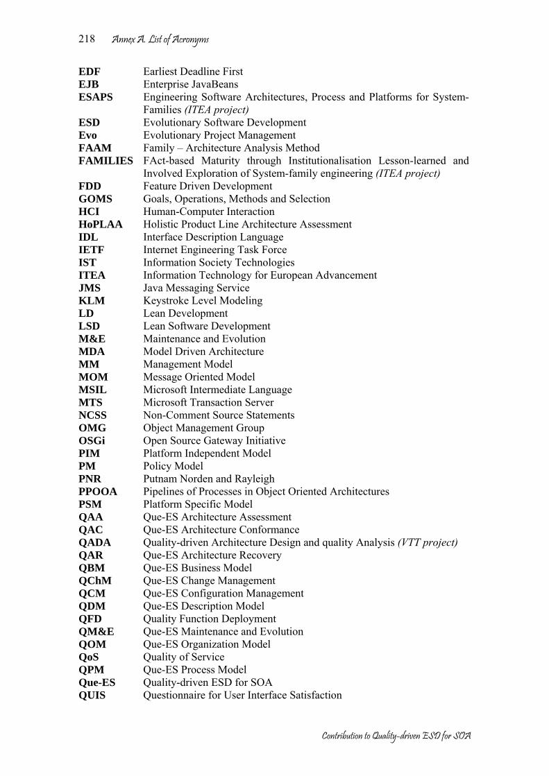
Annex A. List of Acronyms
Contribution to Quality-driven ESD for SOA
218
EDF Earliest Deadline First EJB Enterprise JavaBeans ESAPS Engineering Software Architectures, Process and Platforms for System-
Families (ITEA project) ESD Evolutionary Software Development Evo Evolutionary Project Management FAAM Family – Architecture Analysis Method FAMILIES FAct-based Maturity through Institutionalisation Lesson-learned and
Involved Exploration of System-family engineering (ITEA project) FDD Feature Driven Development GOMS Goals, Operations, Methods and Selection HCI Human-Computer Interaction HoPLAA Holistic Product Line Architecture Assessment IDL Interface Description Language IETF Internet Engineering Task Force IST Information Society Technologies ITEA Information Technology for European Advancement JMS Java Messaging Service KLM Keystroke Level Modeling LD Lean Development LSD Lean Software Development M&E Maintenance and Evolution MDA Model Driven Architecture MM Management Model MOM Message Oriented Model MSIL Microsoft Intermediate Language MTS Microsoft Transaction Server NCSS Non-Comment Source Statements OMG Object Management Group OSGi Open Source Gateway Initiative PIM Platform Independent Model PM Policy Model PNR Putnam Norden and Rayleigh PPOOA Pipelines of Processes in Object Oriented Architectures PSM Platform Specific Model QAA Que-ES Architecture Assessment QAC Que-ES Architecture Conformance QADA Quality-driven Architecture Design and quality Analysis (VTT project) QAR Que-ES Architecture Recovery QBM Que-ES Business Model QChM Que-ES Change Management QCM Que-ES Configuration Management QDM Que-ES Description Model QFD Quality Function Deployment QM&E Que-ES Maintenance and Evolution QOM Que-ES Organization Model QoS Quality of Service QPM Que-ES Process Model Que-ES Quality-driven ESD for SOA QUIS Questionnaire for User Interface Satisfaction
Annex A. List of Acronyms
Contribution to Quality-driven ESD for SOA
219
RMA Rate Monotonic Analysis RMDS Remote Management for Deployment of Services ROM Resource Oriented Model ROPES Rapid Object-oriented Process for Embedded Systems SAA Software Architecture Assessment SAAM Software Architecture Analysis Method SACAM Software Architecture Comparison Analysis Method SARA Software Architecture Review and Assessment SARB Software Architecture Review Board SCADA Supervisory Control and Data Acquisition SCA Significant Candidate Asset SEI Software Engineering Institute SOA Service-Oriented Architecture SOAP Simple Object Access Protocol SOM Service Oriented Model SPEM Software Process Engineering Metamodel SSA Significant Standard Asset SUMI Software Usability Measurement Inventory TSD Traditional Software Development TTCN-3 Tree and Tabular Combined Notation version 3 UML Unified Modeling Language UPM Universidad Politécnica de Madrid W3C World Wide Web Consortium WS Web Services WSDL Web Service Description Language XML Extensible Markup Language XP eXtreme Programming

Annex A. List of Acronyms
Contribution to Quality-driven ESD for SOA
220

Contribution to Quality-driven ESD for SOA
Annex B Que-ES figures compendium
This annex is a summary of figures of the most important methods defined in this thesis
Requirements Implementation
Architecture
Stakeholder and Environment
*
*
* *
*
*
**
*
**
* implements
Is described bydefines
is described by
builds
solves
Uses, monitorizes and tests
defines
is assessed byis assessed by
is assessed by
are solved by
Fig. 1 Quality driven ESD for SOA (Que-ES)
Fig. 2 Que-ES principles

Annex B. Que-ES figures compendium
Contribution to Quality-driven ESD for SOA
222
Requirements Implementation
Architecture
Stakeholders and
Environment
Fig. 3 Que-ES Description Model (QDM)
QPM
<<Discipline>>Requirement definition
<<Discipline>>Assessment
<<Discipline>>Requirement recovery
<<Discipline>>Architecture design
<<Discipline>>Conformance
<<Discipline>>Configuration management
<<Discipline>>Architecture recovery
<<Discipline>>Implementation
<<Discipline>>Test
<<Discipline>>Change management
Domain engineering
Reverse engineering
Quality
Evolution
<<Discipline>>Analysis
Fig. 4 Que-ES Process Model (QPM)
Requirement elicitation
Requirement definition
Requirement specification
Stakeholders and environment
Requirements
Fig. 5 Requirement definition discipline

Annex B. Que-ES figures compendium
Contribution to Quality-driven ESD for SOA
223
Static architecture design
Architecture design
Dynamic architecture design
Stakeholders and environment
Architecture Architecture view guidelines
Architecture partition
Fig. 6 Architecture design discipline
Asset development
Implementation
Asset adaptation
Stakeholders and environment
Implementation
Asset composition Asset deployment
Fig. 7 Implementation discipline
Test definition
Test
Data test
Stakeholders and environment
Behaviour test
Test escenarios
Structure test
Fig. 8 Test discipline

Annex B. Que-ES figures compendium
Contribution to Quality-driven ESD for SOA
224
Preparation
Prioritizing requirements
Analysis
Architecture Asessment
Documentation
ReviewAgreementFiltering architecture
Workflow
Dependences Fig. 9 Que-ES Architecture Assessment (QAA)
Fig. 10 Que-ES Architecture Conformance (QAC)

Annex B. Que-ES figures compendium
Contribution to Quality-driven ESD for SOA
225
Fig. 11 QAC additional activities
Information extraction
Recovered Architecture
PatternsPresentation
Expert information
Refined Architecture
Abstraction
Dynamic-view extraction
System in run time
Preliminar architecture
Static-view extraction
Available documentation
Conceptual model
Source code, Configuration management information
Architecture Recovery
Fig. 12 Que-ES Architecture Recovery (QAR)

Annex B. Que-ES figures compendium
Contribution to Quality-driven ESD for SOA
226
Versioning Framework composing
QCM Activities
QChM Activities
Configuration Customization
Maintenance and Evolution
Fig. 13 Que-ES Maintenance and Evolution (QM&E)

Annex C. Inquiry about OSGi utilizationy
Contribution to Quality-driven ESD for SOA
227
Annex C Inquiry about OSGi utilization
The OSGi specification release 4, has defined a framework, 18 services and 4 utilities. In addition, the platform has been divided in layers: services, service registry, life cycle, modules and security over them applications (bundles) are built. In the next inquiry, we have considered each part of platform as an independent element (framework, layers, services and utilities). Oscar Knopflerfish Equinox Other (which) Used OSGi implementation
Application domain (for example, residential internet gateways, mobile phones, vehicle industry, desktop applications, etc): Parameter ID (0-39)% (40-69)% (70–89)% >90% Number of elements understood Q1 Number of elements identified by the user Q2 Number of elements where their purpose is correctly described by the user
Q3
Number of elements for which there is a correct documentation
Q4
Number of elements tested Q5 Number of elements successfully understood after accessing documentation
Q6
Number of elements used Q7 Number of solutions provided in case of error Q8 Number of basic elements that the user should know
Q9
Number of elements that the user does not use
Q10
Use of the manual, system help or documentation
Q11
Parameter ID No < 5 < 20 More Number of error detected Q12 Number of input errors successfully corrected by user
Q13
Number of attempts to correct input errors Q14 Number of elements successfully customized Q15 Number of elements missed Q16 Parameter ID Some
minutes few hours Several
hours days
Time spent to correct an error Q17 Time to understand completely a specific element
Q18
Time spent using help and documentation Q19

Annex C. Inquiry about OSGi utilizationy
Contribution to Quality-driven ESD for SOA
228
Capacity ID Excellent Good Medium Bad Composition Q20 Encapsulation Q21 Adaptation Q22 Management Q23 Security Q24 Deployment Q25 List the element of OSGi specification: Element ID Required Optional Not used Framework API Q26 Admin service Q27 StartLevel service Q28 Conditional Permission Admin
Q29
Permission Admin service
Q30
URL Stream and Content Handlers API
Q31
Log Service Q32 Configuration Admin service
Q33
Device Access Q34 User Admin service Q35 IO Connector Q36 Http Service Q37 Preferences Service Q38 Wire Admin service Q39 Metatype Q40 Service Component Q41 UPnP API Q42 Provisioning Service Q43 Event Admin Q44 XML Parser service Q45 Service Tracker Q46 Measurement Q47 Position Q48 Security layer Q49 Modules layer Q50 Life cycle layer Q51 Service layer Q52 Service registry layer Q53 Additional comments:

Annex D. Curriculum Vitae
Contribution to Quality-driven ESD for SOA
Annex D Curriculum vitae
PERSONAL INFORMATION: Names: José Luis Last name: Arciniegas Herrera DNI: X-3495018-F
Passport: 76 319 265 de Popayán - Colombia
Place and birthday: Ipiales (Nariño) - Colombia, 18/04/1974
Address: Calle Pradillo 10, 4B 28002 Madrid – Spain
Telephone: (+34) 91 336 7366 ext 3034
Fax: (+34) 91 336 7333 e-mail: [email protected] EDUCATION: 1992 - 1997 Universidad del Cauca. Colombia
Electronics and Telecommunications Engineer. "Graphical tool for Specification Model". FIET (Electronic and Telecommunication Engineering School).
1998 - 1999 Universidad del Cauca. Colombia Network and Telematics Services Specialist. IPET (Electronic and Telecommunication Post-degree Institute).
2000 – Present Universidad Politécnica de Madrid. Spain Ph.D. Student – DIT (Department of Telematics System Engineering).
WORK EXPERIENCE: 1997 – Present Teacher and Research Assistant - Departmento de Telemática –
Universidad del Cauca – Popayan, Colombia. 2000 Chief – Departmento de Telemática – Universidad del Cauca – Popayan,
Colombia RESEARCH EXPERINCE: 1997 - 1998 Developer and designer. SSCC (Switching Supervision System) project
supported by ALCATEL and TELECOM (Colombia). 1998 – 2000 Project leader - GETWeb (Web-based integrated Telecommunication
Management) project supported by Research Vice-rectory OJ-VRI-99. Universidad del Cauca. Popayan. Colombia. http://polaris.dit.upm.es/~jlarci/Getweb_English.htm
2000-2002 Research Assistant - CARTS (Computer Aided Architectural Analysis of Real-Time Systems) project of IST program (Information Society Technologies). IST-1999-20608. http://www.tcpsi.es/carts/
2003 - Present Research Assistant - TRECOM (Embedded, component-based, reliable and distributed Real-time Systems) project supported by the Ministry of

Annex D. Curriculum Vitae
Contribution to Quality-driven ESD for SOA
230
Science and Technology of Spain. TIC2002-04123-C03. http://trecom.upv.es/
2003 – 2005 Research Assistant - FAMILIES (FAct-based Maturity through Institutionalisation Lesson-learned and Involved Exploration of System-family engineering). ITEA project (Information Technology for European Advancement) ITEA ip02009. http://www.esi.es/en/Projects/Families/famMain.html
2003 - 2005 Research Assistant - OSMOSE (Open Source Middleware for Open Systems in Europe), ITEA project (Information Technology for European Advancement) ITEA ip02003. http://www.itea-osmose.org/
2005 - Present Research Assistant - SERIOUS (Software Evolution, Refactoring, Improvement of Operational & Usable Systems), ITEA project (Information Technology for European Advancement) ITEA if04032. http://www.hitech-projects.com/euprojects/serious/
SHORT STAYS: 1999 (15/09-20/10) Department of Computer Science. University of Oviedo. Spain. 2005 (01/05-31/08) VTT Electronics. Technical Research Centre of Finland. Finland AWARDS: 2002 – 2003 Granted by FUNDETEL (Rogelio Segovia Foundation) and the Entity
Xfera (Spain) 2003 – Present Granted by Ministry of Science and Technology (Spain), FPI program -
TRECOM project TIC TIC2002-04123-C03-01. MEMBERSHIPS: 1996 – Present IEEE member (Institute of Electrical and Electronics Engineers) 1997 – Present ACIEM member (Colombian Association of Electricians, Mechanics,
Electronics and related Engineers) 1998 – Present OMG member (Object Management Group) 1999 – Present DMTF member (Distributed Management Task Force) PUBLICATIONS:
1. Jose L. Arciniegas, Juan C. Dueñas, Jose L. Ruiz, Rodrigo Cerón, Jesús Bermejo, and Miguel A. Oltra, Architecture reasoning in support of system family evolution; an example on security, in FAMILIES Research book, T. Käkölä and J. Dueñas, Editors. To be published in Springer.2006.
2. Jens Knodel, Isabel John, Dharmalingam Ganesan, Martin Pinzger, Fernando Usero, Jose L. Arciniegas, and Claudio Riva. Asset Recovery and Incorporation into Product Lines. Submitted in WCRE 2005 The 12th Working Conference on Reverse Engineering. Pittsburgh, Pennsylvania, USA (Carnegie Mellon). 8-11 nov 2005.
3. Miguel A. Oltra, Jesús Bermejo, Juan C. Dueñas, José L. Arciniegas, Carlos Acuña, Cristina Díaz. Análisis de aspectos de seguridad en plataformas de servicios de gestión remota. XIV Jornadas Telecom I+D 2004, Madrid 23 al 25 de Noviembre. 2004.
4. Rodrigo Cerón, Francisco Valsera, Jose L. Arciniegas, Jose L. Ruiz, Juan C. Dueñas. ENAGER - A Tool for Requirements Engineering in System Family Context. International Workshop on Requirements Reuse in System Family Engineering. Co-located with International Conference on Software Reuse 8. Carlos III University of Madrid, Madrid, Spain. July 5, 2004.

Annex D. Curriculum Vitae
Contribution to Quality-driven ESD for SOA
231
5. Rodrigo Cerón, Jose L. Arciniegas, Jose L. Ruiz, Juan C. Dueñas. A Meta-model for Requirements Engineering in System Family Context. International Workshop on Requirements Reuse in System Family Engineering. Co-located with International Conference on Software Reuse 8. Carlos III University of Madrid, Madrid, Spain. July 5, 2004.
6. Rodrigo Cerón , José L. Arciniegas , José L. Ruiz , Juan C. Dueñas , Jesús Bermejo and Rafael Capilla. "Architectural Modelling in Product Family Context". First European Workshop, EWSA 2004, St Andrews, UK, May 21-22, 2004.
7. Juan C. Dueñas, Julio Mellado, Rodrigo Cerón, José L. Arciniegas, José L. Ruiz and Rafael Capilla. “Model driven testing in Product Family Context”. First European Workshop on Model Driven Architecture with Emphasis on Industrial Application, University of Twente, Enschede, The Netherlands. March 17-18, 2004.
8. José L. Arciniegas , Rodrigo Cerón, José L. Ruiz, Víctor Martínez and Juan C. Dueñas. “A Case Study of Performance Analysis for Real-Time Systems”. The IASTED International Conference on Software Engineering (SE 2004) as part of the Twenty-Second IASTED International Multi-Conference on Applied Informatics Innsbruck, Austria. February 17-19, 2004.
9. José L. Ruiz, Juan C. Dueñas, Tomás de Miguel, José L. Arciniegas, Rodrigo Cerón. “Web-based programming assignments with real-time marks and recommendations”. The IASTED International Conference on Web-Based Education (WBE 2004) Innsbruck, Austria. February 16-18, 2004.
10. Jose L. Ruiz, Jose L. Arciniegas, Rodrigo Cerón, Jesús Bermejo, Juan C. Dueñas. “A framework for resolution of deployment dependencies in Java-enabled service gateways”. FIDJI 2003 International Workshop on scientiFic engIneering of Distributed Java applIcations. Luxembourg, Luxembourg. November 27-28, 2003.
11. José L. Arciniegas, Juan C. Dueñas. “Método de Evaluación Arquitectónica para Sistemas de Tiempo Real”. NOVATICA The journal of ATI (Computing Technicians Association), is the oldest informatics publication in Spain. Nov/Dic 2002.
12. Juan C. Dueñas L., José L. Arciniegas H. “CARTS hard real-time systems assessment method and tool” 1er. CARTS Workshop on Advanced Real-time Technologies Aranjuez – Spain. Oct. 2002.
13. Álvaro Rendón G., José Luis Arciniegas H., Javier García P. y Víctor Mondragón M. “Integración de Agentes CMIP en un Entorno de Gestión Basado en CORBA y la Web” Cuba Jul. 2000.
14. Jose Luis Arciniegas H., Julio Cesar Aristizabal y Ruben Dario Rojas “Gestión de Telecomunicaciones Utilizando la Plataforma OSIMIS”. I International congress of Electrical and Electronic Engineering. Industrial University of Santander. Bucaramanga – Colombia. Mar. 2000
15. Álvaro Rendón G., José Luis Arciniegas H. y Jairo Andrés Díaz S. “Plataforma de Gestión Integrada de Redes y Servicios Basada en CORBA y la Web”. XIV National congress and V Latin-American of Telecommunication ANDICOM 99. CINTEL (Telecommunications and Research Centre), Cartagena – Colombia. Nov. 1999.
16. Jose Luis Arciniegas H. , Carlos Enrique Serrano C. "MRDP: Un Modelo de Referencia para Desarrollo de Sistemas Telemáticos". II Ibero-American Workshop of Requirement Engineering and Software Environment. Instituto Tecnológico de Costa Rica in collaboration with CYTED (Ibero-American program of Science and Technology for Development). Costa Rica. Mar. 1999
17. Jose Luis Arciniegas H., Iván H. Hernandez D. Fernando Vélez V. "¿Qué son los Servicios Públicos? Telefonía". University of Cauca. Popayan - Colombia Oct. 1998
18. Jose Luis Arciniegas H. Fernando Vélez V. "El Paradigma de la Orientación a Objetos". Computing Engineering School. University Antonio Nariño. Popayan- Colombia. Oct. 1998
19. Jose Luis Arciniegas H. "El Ambiente Linux una Alternativa para Desarrollo de Aplicaciones Software". Computing Engineering School. University Antonio Nariño. Popayan - Colombia. Abril de 1998

Annex D. Curriculum Vitae
Contribution to Quality-driven ESD for SOA
232
20. Jose Luis Arciniegas H., Virginia Solarte M., "Herramienta Gráfica para el Modelo de Especificaciones". Pre-degree Monograph. University of Cauca. Popayan - Colombia. Jul. 1997.
21. Jose Luis Arciniegas H. "Adaptación y Generación de Nuevas Tecnologías". IV National Workshop of Electrical and Electronic Engineering. University of North. Barranquilla - Colombia. Aug. 1995.
TECHNICAL REPORTS CARTS
1. J. L. Arciniegas, J. C. Dueñas. Architectural Assessment Methods. Deliverable 3.1, UPM-WP03-0012-1. CARTS project. DIT-UPM, 2000.
2. J. C. Dueñas, J. L. Arciniegas. An introduction to software architecture. Internal report, UPM-WP03-0101-1. CARTS project. DIT-UPM, 2001.
3. J. L. Arciniegas, J. C. Dueñas. Architecture Assessment for RTS. Deliverable 3.1, UPM-WP03-0101-2.CARTS project. DIT-UPM, 2001.
4. J. C. Dueñas, J. L. Arciniegas. Meeting slides Toulouse Jan. 2001. Technical report, UPM-WP03-0101-3.CARTS Project.
5. J. L. Arciniegas, J. C. Dueñas Architectural assessment supports Deliverable 6.1, UPM-WP06-0501. CARTS project. DIT-UPM, 2001
6. J. L. Arciniegas, J. C. Dueñas CARTS Architectural Analysis Tool, Fast User Guide Deliverable 6.2.1, UPM-WP06-1001-1.CARTS project. DIT-UPM, 2001
7. J. L. Arciniegas, J. C. Dueñas Architectural Arciniegas et Dueñas, 2002] User Guide and recommendations Deliverable 6.2.2, UPM-WP06 0402-2. CARTS project. DIT-UPM, 2002.
8. J. L. Arciniegas, J. C. Dueñas Architectural Example 1, CCSS#7 Trunk Signaling. Internal report, UPM-WP09 0501. CARTS project. DIT-UPM, 2001
9. J. L. Arciniegas, J. C. Dueñas Architectural Other tools_characterists and Restriction. Internal report, UPM-WP09 0501. CARTS project. DIT-UPM, 2001
10. J. L. Arciniegas, J. C. Dueñas Architectural Arciniegas et Dueñas, 2000] Study_Cases. Internal report, UPM-WP09 1101. CARTS project. DIT-UPM, 2001
11. J. L. Arciniegas, J. C. Dueñas Architectural Arciniegas et Dueñas, 2002] SCADA study_Case. Deliverable 9.3.1, UPM-WP09 0402-1. CARTS project. DIT-UPM, 2002
12. J. L. Arciniegas, J. C. Dueñas Architectural Arciniegas et Dueñas, 2002] IOS study_Case. Deliverable 9.3.2, UPM-WP09 0402-2. CARTS project. DIT-UPM, 2002
FAMILIES
1. José L. Arciniegas, Juan C. Dueñas, Jesús Bermejo, Miguel A. Oltra. Families Project, Task 2.3 CWD Tool support for System Family Engineering - Architecture tools. DIT-UPM and TELVENT, 2005.
2. José L. Arciniegas, Juan C. Dueñas, José L. Ruiz and Rodrigo Cerón. Families Project, Task 3.2 CWD System family security. Requirements, Architecture, Components, Testing, Operation and Maintenance - Aspect oriented execution qualities focused on security and deployment. DIT-UPM, 2005.
3. José L. Arciniegas, Juan C. Dueñas, Rodrigo Cerón, José M. Márquez and Jason Mansell. Families project, Task 4.4 CWD Case Study: Evaluation of a variability management tool in MDA context. DIT-UPM, TELVENT and ESI, 2005.
4. José L. Arciniegas, Juan C. Dueñas, Rodrigo Cerón, José L. Ruiz, Families project, Task 5.2 CWD Assets recovery in system family. DIT-UPM, 2005.
OSMOSE
1. Miguel A. Oltra and José L. Arciniegas. Osmose project, WP 2 Security Framework (Architecture and API). TELVENT and DIT-UPM, 2005.

Annex D. Curriculum Vitae
Contribution to Quality-driven ESD for SOA
233

Annex D. Curriculum Vitae
Contribution to Quality-driven ESD for SOA
234