Palaeomagnetic study of the Xitle-Pedregal de San Angel lava ...
Upload
independentCategory
view
6download
0
RESEARCH ARTICLE
Construction dynamics of a lava channel
Andrew J. L. Harris & Massimiliano Favalli &Francesco Mazzarini & Christopher W. Hamilton
Received: 4 January 2008 /Accepted: 9 July 2008 / Published online: 16 August 2008# Springer-Verlag 2008
Abstract We use a kinematic GPS and laser range findersurvey of a 200 m-long section of the Muliwai a Pele lavachannel (Mauna Ulu, Kilauea) to examine the constructionprocesses and flow dynamics responsible for the channel–levee structure. The levees comprise three packages. Thebasal package comprises an 80–150 m wide ′a′a flow inwhich a ∼2 m deep and ∼11 m wide channel becamecentred. This is capped by a second package of thin(<45 cm thick) sheets of pahoehoe extending no more than50 m from the channel. The upper-most package compriseslocalised ′a′a overflows. The channel itself contains twoblockages located 130 m apart and composed of leveechunks veneered with overflow lava. The channel wasemplaced over 50 h, spanning 30 May–2 June, 1974, withthe flow front arriving at our section (4.4 km from the vent)8 h after the eruption began. The basal ′a′a flow thicknessyields effusion rates of 35 m3 s−1 for the opening phase,with the initial flow advancing across the mapped section at∼10 m/min. Short-lived overflows of fluid pahoehoe thenbuilt the levee cap, increasing the apparent channel depth to4.8 m. There were at least six pulses at 90–420 m3 s−1,causing overflow of limited extent lasting no more than5 min. Brim-full flow conditions were thus extremely short-lived. During a dominant period of below-bank flow, flow
depth was ∼2 m with an effusion rate of ∼35 m3 s−1,consistent with the mean output rate (obtained from thetotal flow bulk volume) of 23–54 m3 s−1. During pulses,levee chunks were plucked and floated down channel toform blockages. In a final low effusion rate phase, lavaponded behind the lower blockage to form a syn-channelpond that fed ′a′a overflow. After the end of the eruptionthe roofed-over pond continued to drain through the lowerblockage, causing the roof to founder. Drainage emplacedinflated flows on the channel floor below the lowerblockage for a further ∼10 h. The complex processesinvolved in levee–channel construction of this short-livedcase show that care must be taken when using channeldimensions to infer flow dynamics. In our case, the fullchannel depth is not exposed. Instead the channel floormorphology reflects late stage pond filling and drainagerather than true channel-contained flow. Components of thecompound levee relate to different flow regimes operatingat different times during the eruption and associated withdifferent effusion rates, flow dynamics and time scales. Forexample, although high effusion rate, brim-full flow wasmaintained for a small fraction of the channel lifetime, itemplaced a pile of pahoehoe overflow units that account for60% of the total levee height. We show how time-varyingvolume flux is an important parameter in controllingchannel construction dynamics. Because the complexhistory of lava delivery to a channel system is recordedby the final channel morphology, time-varying flowdynamics can be determined from the channel morphology.Developing methods for quantifying detailed flux historiesfor effusive events from the evidence in outcrop is thereforehighly valuable. We here achieve this by using high-resolution spatial data for a channel system at Kilauea. Thisstudy not only indicates those physical and dynamiccharacteristics that are typical for basaltic lava flows on
Bull Volcanol (2009) 71:459–474DOI 10.1007/s00445-008-0238-6
Editorial responsibility: J. White.
A. J. L. Harris (*) : C. W. HamiltonHIGP/SOEST, University of Hawaii,1680 East-West Road,Honolulu, HI 96822, USAe-mail: [email protected]
M. Favalli : F. MazzariniIstituto Nazionale di Geofisica e Vulcanologia, Sezione di Pisa,Via della Faggiola 32,Pisa, Italy

Hawaiian volcanoes, but also a methodology that can bewidely applied to effusive basaltic eruptions.
Keywords Lava channel . Levees . Effusion rates .
Flow dynamics
Introduction
A lava channel can be defined as a stream of fluid lavacontained within marginal zones of static (i.e., solid andstationary) lava or levees. Incipient channels may lacklevees, with early channels in Kilauea’s 1974 and 1823flows being marked by parallel zones of ′a′a formingwithin pahoehoe sheets (Soule et al. 2004). Through timethe character of both the channel and the levees evolves andmore complex structures develop (Lipman and Banks 1987;Naranjo et al. 1992; Kilburn and Guest 1993; Soule et al.2004). Passage of the parental flow in which the channeldevelops will leave simple, initial levees (Sparks et al.1976; Lipman and Banks 1987). Other levees may then bebuilt on top of the initial levees. Overflow levees (Sparks etal. 1976) will form by lava spilling out of the channel anddraping over existing levees to increase the levee heightand, if overflow reaches the edge of the initial levees, theirwidth (e.g., Bailey et al. 2006). Accretionary levees (Sparkset al. 1976) will also form by smearing of ductile lava at themargins of the channel-contained stream onto the levee topsand walls. This then welds to form solid levees, with texturesthat usually show elongation of welded clasts in the down-flow direction (e.g., Kilburn and Guest 1993; Woodcock andHarris, 2006). Accretion may also form lateral benches, ornested levees, within the main channel (e.g., Lipman andBanks 1987; Linneman and Borgia 1993; Kilburn and Guest1993). Variations in flow level due, for example, tooscillations in the erupted volume flux or lava pondingbehind channel blockages to starve lower reaches of supply,as well as down-channel surges following blockage failure,will cause channel flux and flow level to vary. This will thusresult in the construction of compound levees, inner-wallcoatings and syn-channel structures such as lateral benches(e.g., Lipman and Banks 1987; Naranjo et al. 1992; Kilburnand Guest 1993; Bailey et al. 2006; Woodcock and Harris2006). Time varying flow dynamics will result in theconstruction of a complex channel with levee morphologyvarying over short temporal and spatial scales (e.g., Lipmanand Banks 1987; Kilburn and Guest 1993).
Levee construction thus results from multiple processes,each of which remove lava from the flowing volume andtransfers it to the stationary (levee) components of the flow(Glaze and Baloga 2006). Identifying the characteristicmorphology of each component, and the flow dynamicsthat led to their construction, is therefore essential in
reconstructing the eruption processes, flow dynamics andflow rates that led to their emplacement. This applies notonly to terrestrial flows, but also planetary flows (e.g.,Glaze and Baloga 2006, 2007). Here we complete adetailed morphological and volumetric analysis of achannel active during Kilauea’s 1969–1974 eruption(Swanson et al. 1979; Tilling et al. 1987). Specifically weexamine the channel built during the 30 May–2 June 1974lava fountaining events of this eruption. This channelcrosses the Chain of Craters Road at the Muliwai a Peleoverlook, from which the channel gains its name (Fig. 1).Although the lifetime of this channel was short, its finalform shows considerable complexity resulting from thehighly variable supply of lava to the channel. Thesecomplexities are only revealed by high spatial resolutionmapping and reflect the role of four flow regimes inconstructing the final, compound, channel form, thesebeing: (1) passage of the initial flow, (2) varying flow ratesin an increasingly mature channel, (3) late-stage syn-channel ponding behind blockages, and (4) post-eruptionpond drainage.
The May–June 1974 channel-fed flow
Tilling et al. (1987, p. 441–442) indicate that the flow inwhich the Muliwai a Pele channel developed was emplacedbetween 30 May and 2 June, 1974. Beginning during thenight of 30 May fountaining at Mauna Ulu (the main vent)fed flows, which cascaded down all sides of the shield thathad built around the vent (Tilling et al. 1987). Most of thelava extended southward, with the main flow descendingthe two fault scarps of Poliokeawe and Holei Pali (Fig. 1).Overflows ended at Mauna Ulu around 02:00 (HawaiianStandard Time) on 2 June (Tilling et al. 1987), giving anemplacement duration of around 50 h. The resulting flowextended 8.6 km from the vent, and comprised a 5.8-km-long channelized zone feeding a 2.8-km-long distal zone ofdispersed ′a′a flow (Fig. 1). The channel is cut, 4.4 kmfrom the vent, by the Chain of Craters Road. Here, a seriesof channel units and morphologies that are characteristic ofthe section above the road are well exposed. We thusselected a ∼200 m long section extending north from theroad for our analysis (Fig. 2).
Field data collection and DEM generation
Our field survey involved differential Global PositioningSystem (GPS) measurements that were obtained in kine-matic mode, a laser range finder total station, and detailedmapping. Kinematic GPS was used to collect x,y,z data forthe levees. The base station and rover were set to record
460 Bull Volcanol (2009) 71:459–474

data every second, with the rover first walking all contactsand then a rough grid with a spacing of 5–7 m. For thechannel interior the laser range finder total station was used,with points on the channel floor and walls being collectedfrom 11 survey points on the channel banks. Survey pointswere located with the kinematic GPS and linked using fore-and back-sights. In addition, 11 fixed tie points weremeasured from each station to tie the surveys together. Thekinematic GPS data were post-processed using differential(rover to base station), L1/L2, and SP3 precise orbit filecorrections and then filtered to remove all measurementswith >0.05 m residual accuracy error [see Ashtech (2002)for full processing details]. A total of ∼92,000 filtered GPSpoints were collected over the 47,000 m2 area of the levees,and ∼10,000 laser points were obtained over the 2,260 m2
area of the channel interior. The GPS and laser rangerfinder data had instrumental errors of 0.05 and 0.5 m,respectively. In addition, stratigraphic logs of the channellevees and interior were made every ∼15 m along thesection. This involved description of all unit morphologies,as well as their thickness (measured with tape-measure).This was supported by unit mapping using a hand-heldGPS (Fig. 2) and vesicularity measurements using themethod of Houghton and Wilson (1989).
Using the GPS and total station data we constructeda DEM with a vertical and horizontal resolution of 1 m.For laser-derived points inside the channel this wasachieved by triangulation. For the GPS-derived pointsacross the levees we used TOPOGRID, an algorithmimplemented by ARCGIS [see Hutchinson (1989) fordetails]. The two DEMs were then merged and the unitmap obtained using the hand-held GPS was overlain(Fig. 3). The DEM was then used to obtain unit volumeand channel depths by projecting unit surfaces beneathoverlying units. Finally, cross-sections were drawn alongGPS-lines that could be projected across both channelbanks (Fig. 4). A down-channel section was also drawnusing the GPS lines taken down the channel rims and floor(Fig. 5). All profiles have a resolution of at-least ten pointsper meter and therefore have a resolution of a fewcentimeters.
The channel
The channel section includes two blockages. These are95 and 225 m up-channel of the Chain of Craters Road(Fig. 2). On the basis of channel morphology, we split thechannel section into two: (1) an upper section, between thetwo blockages, and (2) a lower section extending fromthe Chain of Craters Road to the lower blockage (Fig. 2).The channel is wider across the upper section, being 11–17 m-wide in comparison to 9–13 m across the lower
Mauna Ulu(0km)
CoC Road(4.4km)
Poliokeawe(5.2km)
Channel Exit(5.8km)
Flow Front(8.6km)
Holei Pali(8.0km)
1 km
N
Mauna Ulu
19o
20o
-155o
Fig. 1 Outline map of the 30 May to 2 June 1974 Mauna Uluchannel-fed flow. Lava flow to the West marked “Lava Flow of 1974”is pre-existing pahoehoe erupted earlier in the year. Red and bluesections mark the channelized and dispersed flow sections of the 30May–2 June flow, respectively, and black dot locates the Muliwai aPele overlook on the Chain of Craters (CoC) Road. Black box locatesstudy area enlarged in Fig. 2. Topographic map base is USGS 7.5-minmap sheet of Makaopuhi Crater (North American Datum of 1983projected onto 1,000 m grid, UTM Zone 5). Contour interval is 100 ft(30.48 m). Location of the main map on the island of Hawaii is givenas inset
Bull Volcanol (2009) 71:459–474 461

section. The thickness of undrained lava residing withinthe channel is also greater across the upper section (3.1–4.3 m) than in the lower section (2.4–3.4 m). Although theregional slope is 2.1° to the south, the upper section of theflow was emplaced on a terrain that was also tilted by 1° tothe west.
Levee stratigraphy, dimensions and volume
The channel levees comprise three main packages: (1) basal′a′a, (2) pahoehoe overflow, and (c) ponded ′a′a overflow(Fig. 2).
Basal package
The lower-most (basal) package comprises a simple, single,′a′a unit (Fig. 6a). Although it is exposed along the entire
length of the western bank, along the eastern bank it is onlyexposed within 150 m of the Chain of Craters Road (Figs. 2and 3). Above this point, although it is buried by overlyingunits, its edge is apparent from a 1.3 m-high scarp plasteredby the overlying units (Fig. 6b). The basal unit is 80 to115 m-wide, and has an edge thickness of ∼1.6 m,thickening to ∼3 m at the unit centre. Most of thisthickening occurs within 10–20 m of the flow margin, sothat (although undulating with local pits and hollows) thetop of this unit is generally flat lying, even where emplacedon the westward sloping upper section (Fig. 4). The bulkvolume of the basal unit emplaced along this section is4.3×104 m3.
Pahoehoe overflow package
The pahoehoe overflow package forms a near-channel capon the basal unit (Fig. 4). The pahoehoe units that comprise
C h a i n o f C r a t e r s R o a d
B
B
Basal Unit
Transitional phh*
Slabby pahoehoe
Ponded 'a'a overflow
B Blockage
Basal Unit: Buried
*with slabby flow fronts
L o
w e
r
2138900
2138800
2138700
2138600
2138500
269600 269700 269800 269900
A
A`
B
B`
C
C`
D
D`
E`
E
F
F `
U p
p e
r
S e
c t
i o n
1
12
s
3
a
b
c
B
4
Local dam
100 m
N
Fig. 2 GPS-based geological map of the Muliwai a Pele channel atthe Chain of Craters Road. Zone within area marked by the brokenblack lines locates the study area, and lettered sections locate leveeprofiles given in Fig. 4. a, b and c locate channel floor profiles givenin Fig. 10, and numbers indicate different ponded ′a′a overflow units.′a′a overflow unit marked s is an ooze-out of late stage, spiny
pahoehoe from the core of unit 2. Although the basal unit comprises asingle unit, the transitional pahoehoe (phh) mapped in this figurecomprises multiple units, where up to six flow fronts can be identifiedwithin the mapped package. These flow fronts are not mapped here,but are marked in the Fig. 4 profiles
462 Bull Volcanol (2009) 71:459–474

this package have a sheet-like form and extend no morethan 50 m from the channel (typically 25–35 m, Fig. 2).This means that, along all of the west bank and the lowersection of the east bank, their flow fronts remain within thelimits of the basal unit. An exception occurs where thechannel is located close to the eastern edge of the basal unitin the upper portion of our section. Here the basal unitbecomes completely covered (Fig. 4). The package thusforms a near-channel pile with a maximum thickness of∼3 m at the channel rim thinning to just a few tens ofcentimeters at the package margin, so that they form a coneon top of the basal unit with slope of 5–7° (Fig. 4) and atotal bulk volume of 1.4×10⁴ m3.
Surfaces are typically smooth with folds and ropes. Flowfronts, however, are often broken up into slabs that havebeen rafted and titled to form frontal zones of slabbypahoehoe (Fig. 6b–c). Surfaces also show signs oftransitional behaviour into ′a′a with localized, embryonic,′a′a swirls developing as isolated clasts or pockets ofseveral clasts firmly attached to the surrounding pahoehoe.Flow fronts are inflated, but are typically thin, ranging inthickness from 5 to 60 cm.
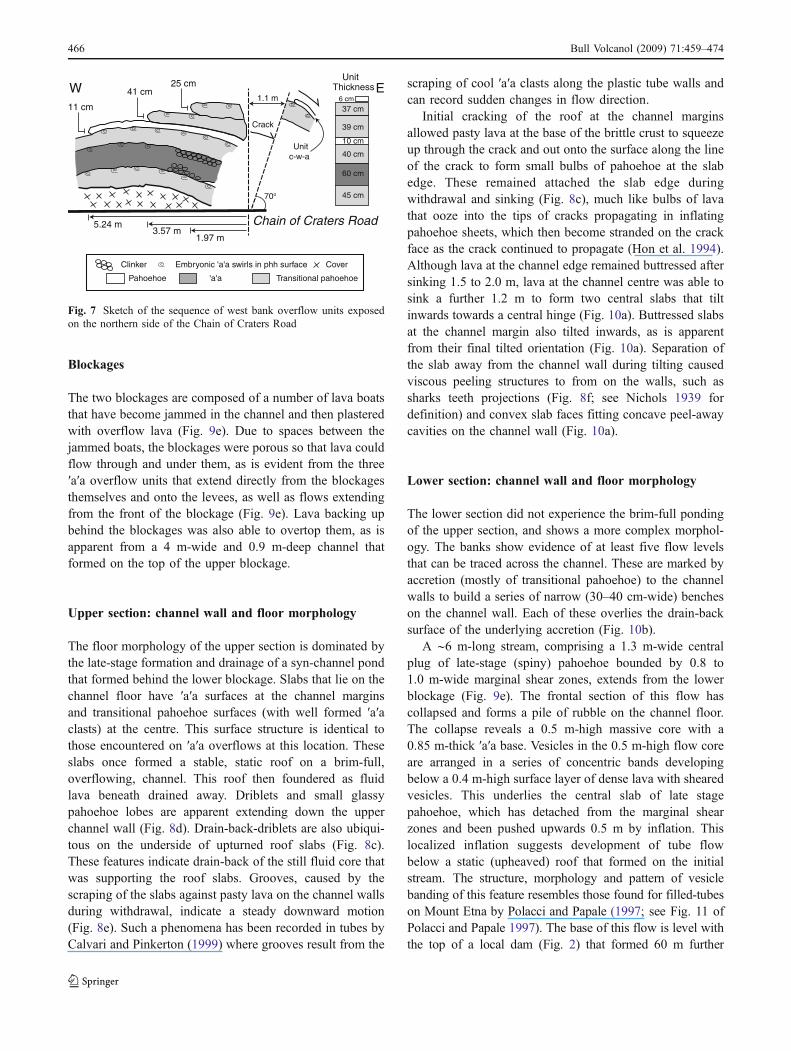
The sequence of flow units that comprise this package iswell exposed at the Chain of Craters Road. The 2.3 m-highcut does not extend down to the basal unit, and thereforedoes not penetrate the full thickness of pahoehoe overflowunits. However, in the up-channel west bank cut, six unitsare exposed (Fig. 7). Four are transitional pahoehoe unitswith rough surfaces containing embryonic ′a′a swirls.Vesicularities are 40–60% with (typically spherical)vesicles showing a gradation from a high number densityof small bubbles at each unit exterior, to a low numberdensity of larger bubbles across the interior, sometimes
forming a central gas blister, as noted in spongy pahoehoeby Walker (1989). Unit thicknesses are quite similar for thetransitional pahoehoe overflow units spanning the range37–45 cm. Of the remaining two units, one is a 10 cm-thickpahoehoe sheet and the second a 60 cm-thick ′a′a flow(Fig. 7).
Where the pahoehoe sheets have poured over the∼1.6 m-high edge of basal unit in the upper section theyform flows that run for short distances parallel to the mainchannel, following the edge of the basal unit (Fig. 2) andsometimes displaying shallow, incipient (Soule et al. 2004)secondary channels feeding flow fronts of slabby pahoehoe(Fig. 6b).
Overflow units that just, or fail to, attain the channel rimare thinner than their over bank counterparts, typicallyforming channel-wall-accreted sheets that are 10 cm or lessin thickness (e.g., unit c-w-a, Fig. 7). Near the channel, allpahoehoe overflow units show surface fabrics (stretchedsurface vesicles and lava clots) that point back into thechannel, indicating drain-back (Fig. 8a). Wall-accretedsheets of pahoehoe and ′a′a blebs also show sub-horizontal stretching down-channel (Fig. 8b), indicatingemplacement from the margins of a stream surface thatwas receding when accretion was active. The developmentof wall-accreted sheets to build layers of lava plaster isalso a common process in lava tubes (Calvari andPinkerton 1999). Wall accretions described here also havea similar morphology to those described in Etneanchannels by Kilburn and Guest (1993) and on Lanzoroteby Woodcock and Harris (2006). Such layering thusappears to be a common feature in a channel or tubesubject to variable flow levels, with each layer marking adistinct flow level.
West Bank View
East Bank View
C h a i n o f C r a t e r s R o a d
Direction ofWest Bank View
Direction ofEast Bank View
Basal Unit (initial levees)
Slabby pahoehoe from behind upper blockage
Ponded 'a'a overflow (pond-fed overflow levee)
Transitional pahoehoe (pulse-fed overflow levee)
Fig. 3 Perspective views of theMuliwai a Pele channel at theChain of Craters Road (seeFig. 2 for scale) generated bydraping the geological map ofFig. 2 over the DEM
Bull Volcanol (2009) 71:459–474 463

Just above the Chain of Craters Road, as well as justdown flow of the upper blockage, a number of large lavaboats are apparent on the channel banks; all are within∼20 m of the channel rim (Fig. 9a). We term these lavaboats following Lipman and Banks (1987) to clarify theirorigin: their being composed of levee chunks that havebeen plucked from the channel banks, rafted down-flowand floated onto, or over, the channel bank during high(over-bank) flow levels. This contrasts with lava balls,which are hail-stone-like concretions of lava formed by
accretion of lava layers during rolling of a clot or clast overa sticky surface. The lava boats are between 1 and 3 m wideand 0.4–1.75 m-high, and are all draped with thin, smoothsheets of pahoehoe overflow (Fig. 9a).
Cracks cutting through the pahoehoe overflow packageare apparent within ∼5 m of the channel rim (Fig. 9b).These run parallel to the channel, with one being wellexposed at the Chain of Craters Road in the up-channelwest bank cut. Here a crack opens to width of 1.1 m andcuts the full exposure of pahoehoe overflow units, with theinboard block toppling into the channel (Fig. 7). Cracksopened while the thin overflow units were still fluid,allowing the molten core of the pahoehoe units to flowinto the cracks (Fig. 9c). Thus, cracks opened shortly afterthe emplacement of the pahoehoe overflow, there being justsufficient time to allow no more than a thin (cm-thick)surface crust to form on the pahoehoe before crack opening.
Ponded ′a′a overflow package
Above the lower blockage the channel bank sequence iscapped by ′a′a that has overflowed from the channel(Fig. 4). Four units can be identified in the ′a′a overflowsequence (units 1–4, Fig. 2). The first unit (unit 1, Fig. 2) isidentical on both sides of the channel. It extends 75–85 mup-channel from the lower blockage, has a limited extent,extending no more than 23 m from the channel (notreaching the edge of the pahoehoe overflows) and has alobate margin (Figs. 2 and 3). It also thins up-channel, theflow margin being 1.6 m thick just up-channel of the lowerblockage, and 0.5 m-thick at its origin. Further up-flow(just below the upper blockage) this unit is apparent as rollof ′a′a plastered to the channel rim (Fig. 9d) so that the unittakes on the form of an accreted, nested, levee (cf., B–B′and C–C′, Fig. 4).
Units 2 and 3 overlie unit 1 and were fed by flowoozing from sources within, or just behind, the lowerblockage (Fig. 2). Proximally, both units 2 and 3 havesimilar morphologies to streams of toothpaste lava de-scribed by Rowland and Walker (1987) and the slab-crustedflows of Guest and Stofan (2005). Proximally the unit 2stream is characterised by a central slab of spiny pahoehoebounded by ′a′a shear zones that, with distance, breaks-upto form a stream of tilted slabs. This feeds a lobe of ′a′awith a thickness of up to 2.1 m, which has spread over thesurface of the basal unit (Figs. 2 and 6a). Near theblockage, in a final flow phase, lobes of late-stage spinypahoehoe have oozed from the margins of unit 2 (unit s,Fig. 2). Unit 3 has a similar morphology to unit 2,comprising a central slab of spiny pahoehoe bounded bymarginal shear zones feeding a 0.7 m-high flow front of′a′a and spiny pahoehoe slabs. This unit extends ∼30 mfrom the lower blockage down the east bank. These ′a′a
Lateral 'a'a flowfrom upper blockage800
795
790
785
B‘B
High stand 'a'a veneer accreted to channel wall marking high
stand of pond Lava boat
800
795
790
785
D D‘Blockage
Basal Unit
'A'a over-flow fromblockage
Pre-Existing Lava Surface
800
795
790
785
C C‘
Pondedoverflow
Localized core ooze-outto form spiney phh lobe
PahoehoeOverflow
800
795
790
785
E E‘
800
795
790
785
WEST EAST
A‘A
Blockage
Lateral 'a'a flowfrom upper blockage
Slabby phh overflow from lava pondedbehind upper blockage
800
795
790
785
Hei
ght A
bove
Sea
-Lev
el (
m)
-50 -40 -30 -20 -10 0 10 20 30 40 50
Distance from Channel Center Line (m)
Basal UnitPahoehoe Overflow Sheets
Pre-Existing Lava Surface
F F‘
Initial Channel in Basal Unit
Final Level of Channel Fill
'a'a'a'a
Subsided surface of pondfollowing partial drainage
Basal Unit
Pahoehoe OverflowSheets Final Level of Channel Fill
Initial Channel in Basal Unit
B
B
Fig. 4 Channel cross-sections (see Fig. 2 for profile locations)
464 Bull Volcanol (2009) 71:459–474

overflows cover the bank-parallel cracks (Fig. 9c), meaningthat they happened after the phase of bank failure.
Lava dammed by the upper blockage fed the final ′a′aoverflow unit (unit 4, Fig. 2). The source of the flow is theblockage itself. Distally, the stream is ∼5 m wide, isbounded by 0.5 m high ′a′a levees and comprises a 1.3 m-wide central plug of slabby pahoehoe bounded by ∼1.5 mwide shear zones of ′a′a. The stream runs down the scarp
caused by the near-channel presence of the basal ′a′a unitmargin, before spreading to form a pad of ′a′a and brokenpahoehoe slabs (Fig. 6d). Unit 4 extends 55 m from thechannel and has a 0.8 m-high flow front that extends ontothe pre-existing flow surface (Profiles A–A′, B–B′, Fig. 4).Whereas the three ′a′a overflow units formed behind thelower blockage have a combined volume of 3,000 m3, thatextending from the upper blockage has a volume of 700 m3.
800
795
790
0 25 50 75 100 125 150 175 200 225
Hei
ght A
bove
Sea
-Lev
el (
m)
Down-Section Distance (m)
UpperBlockage
LowerBlockage
Brim-Full Ponded Section Tubes
Inflated Section
Former Levelof Ponded Section
Floor
Right-BankLeft-Bank
North South
RoadCut
Initial (non-overflowing)Pond Level
Collapsed Flow Frontof Blockage Flow
Tube-Fed Flowfrom Pond
Final (overflowing)Pond Level
Pond Filling
Drained
Un-Drained
Underlying Suface
Ponded Overflow
Fig. 5 Down-channel profilefrom upper blockage to Chainof Craters Road. Profiles wereobtained by walking the GPSdown each bank, and then downthe channel centre line
Basal 'a'a Unit
Lower Blockage
Pre-Existing Pahoehoe Surface
Ponded 'a'a Overflow(Unit 2)
Pahoehoe (sheet)Overflow
s
Ponded 'a'a Overflow
(Unit 1)
PahoehoeOverflow sheet with
slabby flow front
Scarp markburied basal unit
b b
b
Crack
Basal 'a'a Unit
PahoehoeOverflow
Pre-Existing Slabby Pahoehoe Surface
PahoehoeOverflow
Sheet
Pre-Existing Pahoehoe Surface
Ponded 'a'a Overflow(Unit 4)
~40 m
~35 m
55 m
~45 m
(a) (b)
(c) (d)
Fig. 6 a West bank channel section at the lower blockage (laser-rangefinder and operator are located on blockage) showing basal ′a′a unitoverlain by sheets of pahoehoe overflow and ′a′a overflow frombehind the blockage (unit 2, Fig. 2). ′a′a overflow also contains slabsof spiny pahoehoe, and has marginal ooze-outs of late stage spinypahoehoe, marked s. b East bank at upper section showing slaby flowfront of pahoehoe overflow unit overlain by ′a′a overflow from flowponding behind lower blockage. Pahoehoe overflows mantle the basal
′a′a unit, which is apparent as a scarp, within which small islands ofthe basal unit (marked “b”) are exposed. c Surface of west bankoverflow sheets just below lower blockage, showing near-bank crackdue to inward toppling of levee. d East bank overflow of ′a′a fromupper blockage (unit 4, Fig. 2) showing channelized sectioncomprising central plug of slaby pahoehoe bounded by shear zonesof ′a′a feeding a lobate pad of ′a′a and pahoehoe slabs
Bull Volcanol (2009) 71:459–474 465
Blockages
The two blockages are composed of a number of lava boatsthat have become jammed in the channel and then plasteredwith overflow lava (Fig. 9e). Due to spaces between thejammed boats, the blockages were porous so that lava couldflow through and under them, as is evident from the three′a′a overflow units that extend directly from the blockagesthemselves and onto the levees, as well as flows extendingfrom the front of the blockage (Fig. 9e). Lava backing upbehind the blockages was also able to overtop them, as isapparent from a 4 m-wide and 0.9 m-deep channel thatformed on the top of the upper blockage.
Upper section: channel wall and floor morphology
The floor morphology of the upper section is dominated bythe late-stage formation and drainage of a syn-channel pondthat formed behind the lower blockage. Slabs that lie on thechannel floor have ′a′a surfaces at the channel marginsand transitional pahoehoe surfaces (with well formed ′a′aclasts) at the centre. This surface structure is identical tothose encountered on ′a′a overflows at this location. Theseslabs once formed a stable, static roof on a brim-full,overflowing, channel. This roof then foundered as fluidlava beneath drained away. Driblets and small glassypahoehoe lobes are apparent extending down the upperchannel wall (Fig. 8d). Drain-back-driblets are also ubiqui-tous on the underside of upturned roof slabs (Fig. 8c).These features indicate drain-back of the still fluid core thatwas supporting the roof slabs. Grooves, caused by thescraping of the slabs against pasty lava on the channel wallsduring withdrawal, indicate a steady downward motion(Fig. 8e). Such a phenomena has been recorded in tubes byCalvari and Pinkerton (1999) where grooves result from the
scraping of cool ′a′a clasts along the plastic tube walls andcan record sudden changes in flow direction.
Initial cracking of the roof at the channel marginsallowed pasty lava at the base of the brittle crust to squeezeup through the crack and out onto the surface along the lineof the crack to form small bulbs of pahoehoe at the slabedge. These remained attached the slab edge duringwithdrawal and sinking (Fig. 8c), much like bulbs of lavathat ooze into the tips of cracks propagating in inflatingpahoehoe sheets, which then become stranded on the crackface as the crack continued to propagate (Hon et al. 1994).Although lava at the channel edge remained buttressed aftersinking 1.5 to 2.0 m, lava at the channel centre was able tosink a further 1.2 m to form two central slabs that tiltinwards towards a central hinge (Fig. 10a). Buttressed slabsat the channel margin also tilted inwards, as is apparentfrom their final tilted orientation (Fig. 10a). Separation ofthe slab away from the channel wall during tilting causedviscous peeling structures to from on the walls, such assharks teeth projections (Fig. 8f; see Nichols 1939 fordefinition) and convex slab faces fitting concave peel-awaycavities on the channel wall (Fig. 10a).
Lower section: channel wall and floor morphology
The lower section did not experience the brim-full pondingof the upper section, and shows a more complex morphol-ogy. The banks show evidence of at least five flow levelsthat can be traced across the channel. These are marked byaccretion (mostly of transitional pahoehoe) to the channelwalls to build a series of narrow (30–40 cm-wide) bencheson the channel wall. Each of these overlies the drain-backsurface of the underlying accretion (Fig. 10b).
A ∼6 m-long stream, comprising a 1.3 m-wide centralplug of late-stage (spiny) pahoehoe bounded by 0.8 to1.0 m-wide marginal shear zones, extends from the lowerblockage (Fig. 9e). The frontal section of this flow hascollapsed and forms a pile of rubble on the channel floor.The collapse reveals a 0.5 m-high massive core with a0.85 m-thick ′a′a base. Vesicles in the 0.5 m-high flow coreare arranged in a series of concentric bands developingbelow a 0.4 m-high surface layer of dense lava with shearedvesicles. This underlies the central slab of late stagepahoehoe, which has detached from the marginal shearzones and been pushed upwards 0.5 m by inflation. Thislocalized inflation suggests development of tube flowbelow a static (upheaved) roof that formed on the initialstream. The structure, morphology and pattern of vesiclebanding of this feature resembles those found for filled-tubeson Mount Etna by Polacci and Papale (1997; see Fig. 11 ofPolacci and Papale 1997). The base of this flow is level withthe top of a local dam (Fig. 2) that formed 60 m further
Clinker Embryonic 'a'a swirls in phh surface Cover
Pahoehoe 'a'a Transitional pahoehoe
Crack
W E
Chain of Craters Road
70o
UnitThickness
1.97 m3.57 m
5.24 m
1.1 m11 cm
41 cm25 cm
37 cm
39 cm
10 cm
40 cm
60 cm
45 cm
6 cm
Unitc-w-a
Fig. 7 Sketch of the sequence of west bank overflow units exposedon the northern side of the Chain of Craters Road
466 Bull Volcanol (2009) 71:459–474

down channel (Figs. 5 and 9b). The upstream face of thedam is 1.3 m-high and is plastered with drain-back dribletsand stalactites, as described for lava tubes by Calvari andPinkerton (1999). Two open tube entrances are apparent onthe east and west bank sides of the dam. The eastern tube fed ashort (8 m-long, 2 m-wide) flow on the channel floor with asurface of spiny pahoehoe. The western tube fed a longer flow,which is truncated 15 m down-channel to reveal a 2.5 m-widetube, with a 0.3 m-thick roof and a 0.85 m-high empty headspace. This is apparent in our Fig. 10c cross-section. It seems
that lava flowing through the blockage formed a tube whichfed a local pond with a thick, static, surface crust onto whichthe later flow was emplaced. The pond was then drained bytubes forming at its front, with withdrawal causing thesurface crust to founder, thus removing support for theoverlying flow and causing its flow front to fail (Fig. 5).
The channel floor between the lower blockage and thelocal dam is composed of upheaved slabs of transitionalpahoehoe emplaced by flow moving through the blockageafter the lower section pond drained. Slabs show inflation
Fig. 8 a Pahoehoe and ′a′aaccreted to the inner wall (westside) of the channel just belowlower blockage, showing evi-dence of 5 different flow levels(see Fig. 10b for section), drain-back and pulling of drain-backblebs in the down flow direc-tion. Section is ∼4 m high. bClose up of accreted ′a′a unit atbase of section photographed ina. Note, pulling of blebs indown flow direction (blebs alsoplunge downwards slightly in-dicating accretion from a reced-ing surface) and bulbous benchof accreted lava (V′) during shortperiod of flow at a steady level.Features are identical to the“lineations and flute-like protru-sions” found accreted to leveewalls on Etna following drain-back (Fig. 3.12 of Kilburn andGuest 1993). c Block of surfacecrust forming on lava pondedbehind lower blockage, showingplastic tearing of underside dueto separation of the underlyingfluid layer during drainage. At-tached to the upper edge is abulbous ooze out of spinypahoehoe that squeezed onto thesurface when the crust wasforming atop the pond. Sectionis ∼1 m wide. d Drain-backfeatures on the west wall of theupper channel section. eGrooves and tearing (shark’steeth) structures on the east wallof the upper channel section.Section is ∼1 m high. f Well-developed shark’s teeth on thewest wall of the upper channelsection. Euro for scale is 2.2 cmin diameter
Bull Volcanol (2009) 71:459–474 467
along an axis running down-channel (Figs. 9b and 10b).Crack morphologies in the inflated unit show the charac-teristic inflation clefts and banding of crack faces asdescribed by Hon et al. (1994; Fig. 9f), confirming thatupheaval resulted from inflation of this channel floor unit.
Below the lower section dam, the channel floor exhibitstwo lateral benches (nested levees) on the eastern side ofthe channel (Fig. 10c). The innermost bench is 2 m wide, iscomposed of pahoehoe and has become tilted inwardstowards the channel centre due to post-emplacement lava
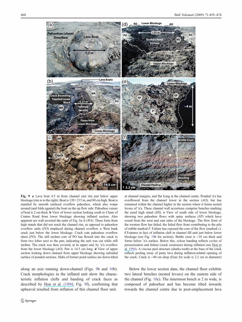
Fig. 9 a Lava boat 4.5 m from channel east rim just below upperblockage (rim is to the right). Boat is 120×215m, and 80 cm high. Boat ismantled by smooth surfaced overflow pahoehoe, which also warpsaround (and folds against) the boat on the up flow side. Pahoehoe veneerof boat is 2 cm thick. b View of lower section looking south to Chain ofCraters Road from lower blockage showing inflated section. Alsoapparent are wall accreted the units of Fig. 8a–b (WA). These form fromhigh stands that did not reach the channel rim, as opposed to pahoehoeoverflow units (PO) emplaced during channel overflow. c West bankcrack just below the lower blockage. Crack cuts pahoehoe overflowsheet (PO). The still molten core of PO has flowed into the crack toform two lobes next to the pen; indicating the unit was cut while stillmolten. The crack was then covered, at its upper end, by ′a′a overflowfrom the lower blockage (AO). Pen is 14.5 cm long. d View of uppersection looking down channel from upper blockage showing subsidedsurface of ponded sections. Slabs of former pond surface are down-tilted
at channel margins, and flat lying at the channel centre. Ponded ′a′a hasoverflowed from the channel lower in the section (AO), but hasremained within the channel higher in the section where it forms nestedlevees of ′a′a. These channel wall accretions comprise benches markingthe pond high stand (HS). e View of south side of lower blockage,showing two pahoehoe flows with spiny surfaces (SP) which haveoozed from the west and east sides of the blockage. The flow front ofthe western flow has failed, the failed flow front contributing to the pileof rubble marked F. Failure has exposed the core of the flow (marked c).f Features in face of inflation cleft in channel fill unit just below lowerblockage (see Fig. 10b for section). Brittle crust is ∼10 cm thick andforms below ′a′a surface. Below this, colour banding reflects cycles ofpressurization and failure (crack extension) during inflation (see Hon etal. 1994). A viscous peel structure (sharks tooth) at the base of the crackreflects peeling away of pasty lava during inflation-related opening ofthe crack. Crack is ∼40 cm deep (Euro for scale is 2.2 cm in diameter)
468 Bull Volcanol (2009) 71:459–474

withdrawal. To this down-tilted bench a 1.4-m-wide,horizontally lying, bench of ′a′a has been accreted. Withinthis nested channel, resides the inflated, tube-fed flow fromthe local pond (Fig. 10c). The multiple generations ofnested levees again attest to changes in flow level, witheach new bench being accreted as the flow level recededand the stream narrowed.
Emplacement dynamics
Given the duration of the events that fed this channel, theentire sequence that comprises our channel section was
emplaced over no more than 50 h. The first event in theconstruction of the channel–levee sequence was the arrivalof an ′a′a flow fed by fountaining at Mauna Ulu. After theflow front had passed through our section, the flow marginsbegan to stagnate to form initial ′a′a levees either side of ajuvenile channel. These initial levees were 30 to 50 m wide,were essentially flat-topped and formed either side of a 9.7–12.3 m wide channel. They are now exposed as our basal′a′a unit (Figs. 2 and 4). These are the equivalent of theinitial levees of Sparks et al. (1976), or the early levees ofLipman and Banks (1987), where stagnant lava zonesforming at the margins of an advancing zone of dispersed′a′a flow determine the width and location of the channel.
V`
>1.5 m
Clinker Embryonic 'a'a swirls in phh surface
Grooves
Sharks teethDriblets & micro-phhflows
Pahoehoe 'a'a Transitional phh Accreted bench(nested levee)
W E
40o
0.6 m
1.2 m
Brim full level during overflow of intra-blockage pond'a'a overflow 'a'a overflow
4.6 m9.5 m
A: Sinking, followedby butressing & rolling
B: Unbutressed sinking,with final phase of slabtilting about a central hinge
1.2 m20o
0.7 mcc
1.3 m
26o
Blocks fromfront of tilted
shelf
B
A A
Lateral Shelf Lateral ShelfCentral Slab
0.5 m
cc: Viscous peeling structure -Shelf has convex face that fitsconcave face of wall from which it has pealed.
b: Bud of lava oozed from coreonto surface when crack initially opened; bud solidifies to move with slab onto which it has oozed.
b
22o
1.5 m
I 36o2 m
III52o
0.8 m
IV0.7 m
V
inflationcleft
32o 40o1.5 m
32o
crack
Inflated channel fill22o
V`
V
IV
III
II
I
45o
wall-accreted sheets
4.25 m
2.5 m
0.9 m 1.1 m
1.75 m
42o
2.3 m
1.7 m
0.9 m
1.3 m
0.9 m Lava Tube
2.6 m
1.5 m
30o 30o
34o
Projected edgeof filled channel
inflationcleft
C: Channel wall failure tocause blocks to roll inwardinto the channel & cracks toopen along inner edge of block.
D: Lateral bench at margin oflate stage syn-channel flow caused by accretion of 'a'a &trans. phh at stream margin.
Inflated channel fill
drainback
DC
C
0.5 m
0.3 m
6.8 m
15 cm 7 cm
drainback
(a)
(b)
(c)
crack
0.7 m
1.15 m
0.35 m
Fig. 10 Channel floor cross-sections (see Fig. 2 for profilelocations)
Bull Volcanol (2009) 71:459–474 469

The channel remained in a stable position for the remainderof the eruption, but was further constructed by a series ofpulses that caused over-bank flow to emplace the pahoehoeoverflow units.
To account for the number of overflow units exposed insection at the Chain of Craters road cut (Fig. 7), at least sixoverflow events must have occurred at this location. Afurther five pulses are apparent from wall-accreted sheetson the channel inner walls. These were flow pulses that didnot attain the level of the channel rim, and thus did notoverflow (Fig. 10b). The thin, sheet-like morphology ofthese units, plus their limited extent and drain-backfeatures, indicate that the overflows were fed by short-livedpulses of fluid lava. During each pulse, lava moved a shortdistance away from the channel, with near-channel lavadraining back into the channel as the pulse passed throughand out of this channel section.
We infer that the lava boats stranded on the channellevees were floated out of the channel during pulse-fedoverflow. The levee-stranded boats were then covered by athin veneer of lava (Fig. 9a). These veneers form smooth-surfaced pahoehoe sheets that (1) extend over the boats, (2)are continuous with overflow units that surround the boatsand to which the veneers are rooted, and (3) show surfacefabrics consistent with lava flowing off of the boats oncethey were in-situ. Overflowing pahoehoe that flowed overand around the boats, before draining back into the channel,must thus have submerged the boats. To achieve this, thepulses must have overflowed the channel by a depth of at-least 0.5 m, this being the typical height of the strandedlava boats. However, supply must have been of extremelyshort duration because the flows extended just 25 to 35 mfrom the channel, before the flow fronts (starved of supply)stalled and proximal sections (suddenly robbed of supply)flowed back into the channel.
Between each pulse, a longer phase of below-bank flowdominated. During these phases, levee support was reducedand they began to fail—toppling into the channel andcausing channel-parallel cracks to open in the levees—asare evident at the lower section above the Chain of CratersRoad (Figs. 7 and 9b). Lava withdrawal and failure musthave been rapid to allow just a thin crust to develop on thepahoehoe overflow sheets before they were cut (Fig. 9c).The failed levee chunks were then vulnerable to plucking(see Lipman and Banks 1987) during the next pulse, thesubsequent pulse rafting levee chunks down channel tobecome jammed at channel constrictions. These formedpermeable blockages around, and through, which subse-quent pulses could flow, but against which further chunkscould become trapped. The embayed form of the sectionabove the lower blockage (Fig. 2) indicates chunks werelikely removed from this channel section to form theembayments and contribute to the lower blockage.
In a final phase of low effusion rate flow, lava percolatingthrough the upper blockage began to pond behind the lowerblockage, steadily filling the upper section (Fig. 5). Giventhe slope of the levee rim across this section, the lower-most portion of this section overflowed first to feed two ′a′aflows that extended laterally away from the channel (units2–3, Fig. 2). Further filling caused overflow to affect zonesfurther up channel from the blockage, so that ′a′a overflowconditions began to move up-channel (unit 1, Fig. 2).However, because the pond surface was flat lying, asopposed to the up-channel-sloping levee rims (Fig. 5), up-channel overflow units were not able to attain the level oftheir down-channel counterparts. The overflow unit thusthins up-channel to pinch out ∼50 m below the lowerblockage (Fig. 5), with the segment just below the upperblockage not experiencing overflow of the ponded volume.Instead, the pond level remained within the channel to formaccreted benches on the levee walls marking its high stand(Figs. 4b and 9d). This final phase of pond-related overflowthus was able to build a roughly horizontal levee rim alongthe upper section, marking the former horizontal high-standof the ponded surface (Fig. 5). We note that the lowersection, which did not undergo brim-full ponding, has leveerims that exhibit a down-channel slope that is parallel tothat of the regional (underlying) slope (Fig. 5).
Viscous surface forms (spiny pahoehoe, transitionalpahoehoe and ′a′a) in the pond-fed overflow units indicatethat overflow involved lava with a more protracted coolinghistory. This indicates that residence in the pond gave thelava increased time to cool, crystallize and thus developgreater viscosity in comparison to the smooth-surfacedpahoehoe of the underlying pulse-fed overflow units. Thislonger residence time also allowed the development oflarger vesicles, probably by coalesence (Cashman et al.1994; Herd and Pinkerton 1997), whose walls thenstretched and tore across the flowing surface to create thespines apparent on the surface of these flows.
With termination of supply, flow through the lowerblockage exceeded input from up-channel and the pond beganto slowly drain through the lower blockage. By that point, athick roof had formed—now represented by the down-hingedand failed slabs of transitional pahoehoe apparent on the floorof the upper section (Fig. 10a). Rapid drainage (e.g., bycatastrophic destruction of the blockage) would have causedthe roof to become suddenly unsupported, to fail and shatterupon collapsing into the channel. Instead, the roof slabssubsided slowly, dragging downwards over molten lava leftplastered to the channel walls to form grooves in the pastywall lava (Fig. 8e). In the final phase of subsidence, themarginal roof sections became supported, with the centralsector subsiding further, before all roof slabs slowly toppledinwards, the central slabs hinging downwards along a centralline (Fig. 10a). At the end of drainage, a 2–3 m deep layer of
470 Bull Volcanol (2009) 71:459–474

lava remained on the channel floor of the upper section witha horizontal final surface, suggesting that some undrainedponded lava remained beneath (Fig. 5).
The complex processes that involved late stage drainagethrough the lower blockage resulted in a complicated floormorphology across the lower section. This appears to haveinvolved at least three processes. First, lava drainingthrough the lower blockage formed a secondary pondbehind a dam forming ∼60 m down channel from thelower blockage (Fig. 5). This appears to have been fed byflow moving beneath the blockage. Lava moving throughthe mid-section of the blockage then formed a short (6 m-long) tube-fed flow on top of this pond. The pond thendrained through two tubes active in the dam to emplace thedrained volume as inflated, tube-fed units on the channelfloor further down flow (Fig. 10c). Drainage of the pondremoved support for the solidified superimposed flows,causing their distal sections to collapse (Figs. 5 and 9e).Further drainage through tubes active beneath the lowerblockage caused lava to next ooze into the lower channelsection forming an inflated unit, with a prominent inflationcleft orientated down-channel. This was emplaced withinthe drained lower section pond (Fig. 10b). As a result, thischannel section also remained undrained, with the final filllevel being the result of complex filling processes due todrainage through the lower blockage in the final phase ofthe channel’s life.
Effusion rates, volume loss to the levees and time scales
The effusion rate model that we propose to describe thechannel’s construction is given in Fig. 11. The model
begins with a moderate effusion rate phase during whichthe basal ′a′a unit was emplaced. Following Sparks et al.(1976) and Lipman and Banks (1987) we assume that,shortly after the flow front passed through this location,broad zones of marginal ′a′a stalled to define the initiallevees and thus the channel width. During an early stage ofhigh lava supply, flow in the initial channel would likelyhave been level with the top of the stalling margins(Lipman and Banks 1987). Thus, during the early stage ofchannelized flow, we take channel depth (h) to be equal tothe thickness of the basal unit (which forms the initiallevees) and use Jeffreys (1925) equation to estimate theeffusion rate (Er) during flow in the initial channel using(Dragoni 1989):
Er ¼ wh3rg sin að Þ� nhð Þ ð1Þwhere w, ρ, g and α are channel width, lava density,acceleration due to gravity, and underlying slope, with nbeing a shape dependent constant (eight for semi-circularchannels, three for wide channels) and η being viscosity.The thickness of the basal unit was obtained from the DEMby stripping off the overflow units and estimating the basalunit thickness (=initial levee height) down the flow centre-line. This gives an initial depth for brim-full channel-contained flow of 2.0±0.4 m. We use this with the meanchannel width (11±1.3 m), a dense rock density of 2,600 kgm−3 corrected for a vesicularity of 50% (to give a bulkdensity of 1,320 kg m−3) and an underlying slope of 2.1°.For viscosity, Moore (1987) and Heslop et al. (1989) haveestimated 100–1,000 Pa s and 85–140 Pa s for channelizednear-vent lava at Mauna Loa and Kilauea, respectively.Moore’s (1987) data show an increase to ∼1,000 Pa saround 12 km from vent. This is consistent with Muraseand McBirney (1973) and Shaw et al. (1968) who give aviscosity of 1,000–10,000 Pa s for basalt at ∼1,100°C(compared with an eruption temperature of ∼1,150°C). Forlava ∼4 km from the vent, we thus consider an intermediatevalue (500 Pa s) appropriate. These values yield, for theinitial channel forming within the basal unit, an effusionrate of 35±20 m3 s−1.
Given the 4.3×10⁴ m3 volume obtained for the basal unitover this 200 m long section, volume loss to the initiallevees was 215 m3 per meter of advance. At an effusion rateof ∼35 m3 s−1 this means that the entire basal unit couldhave been emplaced in as little as 20 min, with the flowfront advancing across the section at a maximum velocityof ∼10 m/min. This compares with typical flow frontadvance velocities measured for lava flows from Pu′u ′O′oadvancing through Royal Gardens (Kilauea) of 1–5 m/min,increasing to 2–30 m/min during surges (Wolfe et al. 1988).Given such flow front advance rates, the flow would havearrived at this location (4.4 km from the vent) 7–8 h afterthe eruption began. Thus, the basal unit was emplaced over
50
100
150
200
250
10 20 30 40 50 60
(A) Opening phase: dispersed 'a'a flow and development of initial levees(B1) Short-duration pulses construct overflow levees (B2) Waning effusion so that final pulses do not overflow(C) Development of ponds behind blockages at lower effusion rates (D) Post-eruption partial drainage of ponds by lava oozing through blockages
A B1 B2 C D
Time (hours)
Effu
sion
Rat
e (m
s )
3
-1
Eruption EndsBasal Unit:flow fronttransit time
MOR
Fig. 11 Schematic showing effusion regime that led to the construc-tion of each component of the Muliwai a Pele channel at the Chain ofCraters Road
Bull Volcanol (2009) 71:459–474 471

a short, moderate effusion rate, opening phase. The lavaarrived at this location 7–8 h after the fountaining eventsbegan at Mauna Ulu.
This open phase of emplacement was followed by aphase of variable flow during which short-lived, but higheffusion rate, lava pulses emplaced fluid sheets of over-bank pahoehoe of limited extent. Higher effusion rates mayhave resulted from the establishment of a channel at thevent, concentrating the fountain fed flow which hadpreviously been dispersed, the “voluminous overflows”having initially caused lava to “cascade down all sides ofthe Mauna Ulu shield” (Tilling et al. 1987, p. 441) therebydispersing the flow. In this case the total volume fluxerupted from the vent and supplied to all active overflowsmay stay stable, yet that supplied to a single channel (thelocal effusion rate, Er) may increase as the flow becomesconcentrated in one, rather than many, channels. Anotherpossibility is that variation in fountaining intensity and/orrate of vent overflow could have caused short-lived pulsesin supply to the channel, where gas pistoning within thefeeder lake was commonly observed prior to the channelemplacement event (Tilling et al. 1987). Gas pistoningcould, for example, have led to short-term increases inthe rate of vent overflow and supply to the channel.Assuming a channel depth equal to the height differencebetween the channel rim and the bottom of the basal unitwe estimate a channel depth of 4.8±0.3 m and aneffusion rate of 420±120 m3 s−1 for brim-full flow duringpulses. Because the channel contains an unknownthickness of undrained lava we cannot be certain of theactual flow depth during pulses. The loose constraint onflow depth during these pulses means that the best we cansay is that flow increased to a few hundred cubic metersper second during each of the pulses that fed over-bankflow.
Given the total volume of the overflow package (1.4×10⁴ m3), volume loss to overflow levees was 70 m3 permeter of advance or (for six overflow units) ∼12 m3 permeter per pulse. At effusion rates of a few hundred cubicmeters per second, the entire sequence could have beenemplaced in just a few (∼5) minutes. The overflows werethus extremely short-lived events, with typical (inter-overflow) flow levels being marked by syn-channel(below-bank) high stand marks. At least six other (lowereffusion rate) pulses occurred towards the end of thisphase causing an increase in the level of the channellava, but not sufficient to cause overflow. These pulsesinstead left coatings of lava plastered to the channelwalls and built nested levees. Flow levels between eachpulse were likely a little lower than these high stands,where the lower-most nested levee (apparent as lateralbench just up-channel of the Chain of Craters Road,Fig. 10c) gives a flow depth of ∼2 m, i.e., a depth similar
to that during the initial flow. This depth thus gives asimilar effusion rate to that obtained during the initial flowemplacement, i.e., ∼35 m3 s−1. These effusion rates areconsistent with the mean output rate (MOR) for this flow.If we use the total flow area of 1.38 km2, a typicalthickness of 3–7 m and eruption duration of 50 h, weobtain a MOR of 23–54 m3 s−1. We thus prefer a typicalflow rate of 35 m3 s−1 during below-bank flow, which waspunctuated by short-lived high effusion rate pulses duringwhich the channel became overwhelmed for brief periodsto feed overflow.
Given the drain-back features and limited extent of theassociated overflows, the passage of each pulse was swift,each pulse representing down-channel passage of a discreteslug of lava fed by a short increase in supply to the channel.Given volume loss to levee construction of 12 m3 per meterof advance during each pulse, to extend 4.4 km the eventwould require eruption of at-least 5×10⁴ m3 of lava, which atan effusion rate of 200 m3 s−1 would represent ∼4 min ofincreased effusion. To extend to the channel exit at 5.6 kmwould require eruption of 5×10⁵ m3 in ∼5.5 min. Equation 1gives a flow velocity of 125–190 m/min during each pulse,which would mean that the pulse would be of the order of500 to 1,000 m long.
In a final low effusion rate phase, roofed-over pondsdeveloped between the blockages that formed during thepulsing phase of effusion. Flow occurred through tubesdeveloping through and beneath the blockages. The volumeflux through a pipe draining the pond can be calculatedusing the Hagen–Poiseuille Equation (White 2006):
Q ¼ pr4�8h
� �ΔHrgð Þ=L½ � ð2Þ
in which r is tube radius, ΔH is the height differencebetween the pond surface and the draining tube and L isthe length of the blockage through which the tube extends,the right hand term being the pressure gradient (δp/δx)along the pipe. Given the dimensions and location of thetube exposed below the lower blockage, r=0.5 m, ΔH=5 m and L=20 m, we obtain Q of 0.15 m3 s−1. Drainagewas thus slow, with the drained volume of the uppersection (2.2×10³ m3) taking 4 h to drain at these effusionrates.
Once the supply from the vent ceased, drainageproceeded without replenishment to partially empty thepond. This drainage rate likely slowed with time, with Eq. 2predicting a volume flux which decreases with time as thepond level (ΔH), and thus pressure, decreases to aminimum (calculated using Eq. 1) of 0.05 m3 s−1, givinga maximum drainage time of 12 h. Low effusion rateactivity due to oozing of lava through the blockagestherefore likely continued for between 4 and 12 h aftersupply to the channel ceased (Fig. 11).
472 Bull Volcanol (2009) 71:459–474
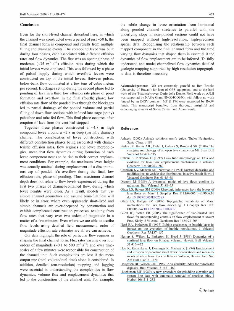
Conclusion
Even for the short-lived channel described here, in whichthe channel was constructed over a period of just ∼50 h, thefinal channel form is compound and results from multiplefilling and drainage events. The compound levee was builtduring four phases, each associated with different effusionrates and flow dynamics. The first was an opening phase ofmoderate (∼35 m3 s−1) effusion rates during which theinitial levees were emplaced. This was followed by a phaseof pulsed supply during which overflow levees wereconstructed on top of the initial levees. Between pulses,below-bank flow dominated at a few tens of cubic metersper second. Blockages set up during the second phase led toponding of lava in a third low effusion rate phase of pondformation and overflow. In the final (fourth) phase, loweffusion rate flow of the ponded lava through the blockagesled to partial drainage of the ponded volume and partialfilling of down flow sections with inflated late stage (spiny)pahoehoe and tube-fed flow. This final phase occurred aftereruption of lava from the vent had stopped.
Together these phases constructed a ∼4.8 m highcompound levee around a ∼2.8 m deep (partially drained)channel. The complexities of levee construction, withdifferent construction phases being associated with charac-teristic effusion rates, flow regimes and levee morpholo-gies, mean that flow dynamics during formation of eachlevee component needs to be tied to their correct emplace-ment conditions. For example, the maximum levee heightwas actually attained during emplacement of a discontinu-ous cap of ponded ′a′a overflow during the final, loweffusion rate, phase of ponding. Thus, maximum channeldepth does not relate to flow levels experienced during thefirst two phases of channel-contained flow, during whichlevee heights were lower. As a result, models that usesimple channel geometries and assume brim-full flow willlikely be in error, where even apparently short-lived andsimple channels are over-deepened by construction andexhibit complicated construction processes resulting fromflow rates that vary over two orders of magnitude in amatter of a few minutes. Even where we are able to ascribeflow levels using detailed field measurement, order ofmagnitude effusion rate estimates are all we can achieve.
Our data highlight the role of particular flow regimes inshaping the final channel form. Flux rates varying over fourorders of magnitude (∼0.1 to 500 m3 s−1) and over time-scales of a few minutes were responsible for construction ofthe channel unit. Such complexities are lost if the meanoutput rate (total volume/total time) alone is considered. Inaddition, detailed (cm-resolution) mapping and loggingwere essential in understanding the complexities in flowdynamics, volume flux and emplacement dynamics thatled to the construction of the channel unit. For example,
the subtle change in levee orientation from horizontalalong ponded channel stretches to parallel with theunderlying slope in non-ponded sections could not havebeen mapped without high-resolution, high-precisionspatial data. Recognising the relationship between eachmapped component in the final channel form and the timevarying flow dynamics that shaped them is essential if thedynamics of flow emplacement are to be inferred. To fullyunderstand and model channelized flow dynamics detailedgeologic mapping supported by high-resolution topograph-ic data is therefore necessary.
Acknowledgements We are extremely grateful to Ben Brooks(University of Hawaii) for loan of GPS equipment, and to the hardwork of the (Pistoiese) rover: Dario delle Donne. Field work by AJLHwas supported by NASA Grant NNG04GO64G, with follow up workfunded by an INGV contract; MF & FM were supported by INGVfunds. This manuscript benefited from thorough, insightful andencouraging reviews of Sonia Calvari and Adam Soule.
References
Ashtech (2002) Ashtech solutions user’s guide. Thales Navigation,Santa Clara, p 184
Bailey JE, Harris AJL, Dehn J, Calvari S, Rowland SK (2006) Thechanging morphology of an open lava channel on Mt. Etna. BullVolcanol 68:497–515
Calvari S, Pinkerton H (1999) Lava tube morphology on Etna andevidence for lava flow emplacement mechanisms. J VolcanolGeotherm Res 90:263–280
Cashman KV, Mangan MT, Newman S (1994) Surface degassing andmodifications to vesicle size distributions in active basalt flows. JVolcanol Geotherm Res 61:45–68
Dragoni M (1989) A dynamical model of lava flows cooling byradiation. Bull Volcanol 51:88–95
Glaze LS, Baloga SM (2006) Rheologic inferences from the levees oflava flows on Mars. J Geophys Res 111:E09006.1–E09006.10doi:10.1029/2005JE002585
Glaze LS, Baloga SM (2007) Topographic variability on Mars:implications for lava flow modelling. J Geophys Res 112:E08006 doi:10.1029/2006JE002879
Guest JE, Stofan ER (2005) The significance of slab-crusted lavaflows for understanding controls on flow emplacement at MountEtna, Sicily. J Volcanol Geotherm Res 142:193–205
Herd RA, Pinkerton H (1997) Bubble coalesence in basaltic lava: itsimpact on the evolution of bubble populations. J VolcanolGeotherm Res 75:137–157
Heslop S, Wilson L, Pinkerton H, Head J (1989) Dynamics of aconfined lava flow on Kilauea volcano, Hawaii. Bull Volcanol51:415–432
Hon K, Kauahikaua J, Denlinger R, Mackay K (1994) Emplacementand inflation of pahoehoe sheet flows: observations and measure-ments of active lava flows on Kilauea Volcano, Hawaii. Geol SocAm Bull 106:351–370
Houghton BF, Wilson CJN (1989) A vesicularity index for pyroclasticdeposits. Bull Volcanol 51:451–462
Hutchinson MF (1989) A new procedure for griddding elevation andstream line data with automatic removal of spurious pits. JHydrol 106:211–232
Bull Volcanol (2009) 71:459–474 473

Jeffreys H (1925) The flow of water in an inclined channel ofrectangular section. Phil Mag 49:793–807
Kilburn CRJ, Guest JE (1993) Aa lavas of Mount Etna, Sicily. In:Kilburn CRJ, Luongo G (eds) Active lavas: monitoring andmodeling. UCL, London, pp 73–106
Linneman SR, Borgia A (1993) The blocky andesitic lava flows ofArenal volcano, Costa Rica. In: Kilburn CRJ, Luongo G (eds)Active lavas: monitoring and modelling. UCL, London, pp 25–72
Lipman PW, Banks NG (1987) Aa flow dynamics, Mauna Loa. UGSGProf Pap 1350:1527–1567
Moore HJ (1987) Preliminary estimates of the rheological propertiesof 1984 Mauna Loa lava. UGSG Prof Pap 1350:1569–1588
Murase T, McBirney AR (1973) Properties of some common igneousrocks and their melts at high temperatures. Geol Soc AmericaBulletin 84:3563–3592
Naranjo JA, Sparks RSJ, Stasiuk MV, Moreno H, Ablay GJ (1992)Morphological, structural and textural variations in the 1988–1990 andesite lava of Lonquimay Volcano, Chile. Geol Mag 129(6):657–678
Nichols RL (1939) Surficial banding and shark’s-tooth projections inthe cracks of basaltic lava. Am J Sci 237(8):188–194
Polacci M, Papale P (1997) The evolution of lava flows fromephemeral vents at Mount Etna: insights from vesicle distributionand morphological studies. J Volcanol Geotherm Res 76:1–17
Rowland SK, Walker GPL (1987) Toothpaste lava: characteristics andorigin of a lava structural type transitional between pahoehoe andaa. Bull Volcanol 49:631–641
Shaw HR, Wright TL, Peck DL, Okamura R (1968) The viscosity ofbasaltic magma: an analysis of field measurements in Makaopuhilava lake, Hawaii. Am J Sci 266:225–264
Soule SA, Cashman KV, Kauahikaua JP (2004) Examining flowemplacement through the surface morphology of three rapidlyemplaced, solidified lava flows, Kilauea Volcano, Hawaii. BullVolcanol 66:1–14
Sparks RSJ, Pinkerton H, Hulme G (1976) Classification and formationof lava levees on Mount Etna, Sicily. Geology 4:269–271
Swanson DA, Duffield WA, Jackson DB, Peterson DW (1979)Chronological narrative of the 1969–71 Mauna Ulu eruptionof Kilauea Volcano, Hawaii. US Geol Surv Prof Pap 1056:1–55
Tilling RI, Christiansen RL, Duffield WA, Endo ET, Holcomb RT,Koyanagi RY, Peterson DW, Unger JD (1987) The 1972–1974Mauna Ulu eruption, Kilauea volcano: an example of quasi-steady-state magma transfer. UGSG Prof Pap 1350:405–469
Walker GPL (1989) Spongy pahoehoe in Hawaii: a study of vesicle-distribution patterns in basalt and their significance. BullVolcanol 51:199–209
White FM (2006) Viscous fluid flow. McGraw-Hill, New York, p 629Wolfe EW, Neal CA, Banks NG, Duggan TJ (1988) Geologic
observations and chronology of eruptive events. USGS ProfPap 1463:1–97
Woodcock D, Harris AJL (2006) The dynamics of a channel-fed lavaflow on Pico Partido volcano, Lanzarote: evidence for ahydraulic jump? Bull Volcanol 69:207–125
474 Bull Volcanol (2009) 71:459–474
Copyright © 2022 FDOKUMEN