CONSTANT SPEED ENGINE CONROD SOFT VALIDATION & OPTIMIZATION
11
International Journal of Design and Manufacturing Technology (IJDMT), ISSN 0976 – 6995(Print), ISSN 0976 – 7002(Online) Volume 5, Issue 1, January - April (2014), pp. 01-11 © IAEME 1 CONSTANT SPEED ENGINE CONROD SOFT VALIDATION & OPTIMIZATION Anand. D. Dantale 1 , Ashok J. Keche 2 1 Mechanical Engineering Department, MIT, Aurangabad (M.S), India 2 Associate Professor, Mechanical Engineering Department, MIT, Aurangabad (M.S), India ABSTRACT The constant speed four stroke reciprocating engine Connecting rod is subjected to variable loading when Engine is in operating condition. Proper optimization of connecting rod is critical for the engine Performance, vibration level & balancing of overall engine. The stresses in Connecting rod are not constant during its operating condition. The stress varies in one complete cycle. The connecting rod traditionally were designed and analyzed under Static axial loading condition. The Quasi-dynamic approach has a considerable effect in design optimization of connecting rod. The finite element analysis of four stroke Diesel engine is considered. Structural systems of connecting rod can be easily analyzed using Finite Element techniques. So firstly a proper a CAD model is developed Pro/E Wildfire 4.0. Then the Finite element analysis is done to determine the Von Mises stresses in the existing connecting rod for the given loading conditions using Finite Element Analysis software ANSYS. The optimization of conrod is done based on the results and validated. Keyword : Constant Speed, Soft Validation, Optimization, Conrod & Finite Element Analysis. 1. INTRODUCTION A connecting rod undergoes a very complex motion, and is subjected to a complex, time varying axial and bending loads. The details of the analytical vector approach to determine the inertia loads and its reactions are used for determining the inertia loads. Such stress analysis in true operating loads is critical to any durability or optimization study of a INTERNATIONAL JOURNAL OF DESIGN AND MANUFACTURING TECHNOLOGY (IJDMT) ISSN 0976 – 6995 (Print) ISSN 0976 – 7002 (Online) Volume 5, Issue 1, January - April (2014), pp. 01-11 © IAEME: http://www.iaeme.com/IJDMT.asp Journal Impact Factor (2014): 1.7910 (Calculated by GISI) www.jifactor.com IJDMT © I A E M E
Transcript of CONSTANT SPEED ENGINE CONROD SOFT VALIDATION & OPTIMIZATION

International Journal of Design and Manufacturing Technology (IJDMT), ISSN 0976 – 6995(Print),
ISSN 0976 – 7002(Online) Volume 5, Issue 1, January - April (2014), pp. 01-11 © IAEME
1
CONSTANT SPEED ENGINE CONROD SOFT VALIDATION
& OPTIMIZATION
Anand. D. Dantale1, Ashok J. Keche
2
1Mechanical Engineering Department, MIT, Aurangabad (M.S), India
2Associate Professor, Mechanical Engineering Department, MIT, Aurangabad (M.S), India
ABSTRACT
The constant speed four stroke reciprocating engine Connecting rod is subjected to
variable loading when Engine is in operating condition. Proper optimization of connecting
rod is critical for the engine Performance, vibration level & balancing of overall engine. The
stresses in Connecting rod are not constant during its operating condition. The stress varies in
one complete cycle. The connecting rod traditionally were designed and analyzed under
Static axial loading condition. The Quasi-dynamic approach has a considerable effect in
design optimization of connecting rod. The finite element analysis of four stroke Diesel
engine is considered. Structural systems of connecting rod can be easily analyzed using Finite
Element techniques. So firstly a proper a CAD model is developed Pro/E Wildfire 4.0. Then
the Finite element analysis is done to determine the Von Mises stresses in the existing
connecting rod for the given loading conditions using Finite Element Analysis software
ANSYS. The optimization of conrod is done based on the results and validated.
Keyword : Constant Speed, Soft Validation, Optimization, Conrod & Finite Element
Analysis.
1. INTRODUCTION
A connecting rod undergoes a very complex motion, and is subjected to a complex,
time varying axial and bending loads. The details of the analytical vector approach to
determine the inertia loads and its reactions are used for determining the inertia loads. Such
stress analysis in true operating loads is critical to any durability or optimization study of a
INTERNATIONAL JOURNAL OF DESIGN AND MANUFACTURING TECHNOLOGY (IJDMT)
ISSN 0976 – 6995 (Print)
ISSN 0976 – 7002 (Online)
Volume 5, Issue 1, January - April (2014), pp. 01-11
© IAEME: http://www.iaeme.com/IJDMT.asp
Journal Impact Factor (2014): 1.7910 (Calculated by GISI)
www.jifactor.com
IJDMT
© I A E M E

International Journal of Design and Manufacturing Technology (IJDMT), ISSN 0976 – 6995(Print),
ISSN 0976 – 7002(Online) Volume 5, Issue 1, January - April (2014), pp. 01-11 © IAEME
2
connecting rod. Normally in static analysis, the loads acting at the Small ends & big end of
the connecting rod are equal in magnitude and are in static equilibrium. In case of quasi-
dynamic analysis, the loads at the two ends may not be equal. It is equal only when at any
instant in time, the inertia load resulting from both translational and angular velocity with
acceleration are considered are in equilibrium. The quasi-dynamic analyses are repeated
based on time-varying dynamic input data. The analysis is referred to as ‘quasi-dynamic’.
The dynamic load analysis is used for fatigue behavior of the connecting rod. The bending
moment is derived from bending stress having a function of load at the CG normal to the
connecting rod longitudinal axis plus the angular and linear acceleration components normal
to this axis. Variation of each of these three quantities over one complete rotation is identical
to the variation in two revolutions of crankshaft. The axial load variation, needs to be
considered over the two revolution of crankshaft as in case of Four stroke Engines the power
stoke as a high impact of gas load. The connecting rod considered is of diesel Engine. The
actual Pressure Variations on the piston is measured in combustion chamber over number of
engine cycles.
2. LITERATURE REVIEW
Yoo et al. [1] performed shape optimization of an engine connecting rod using
variation equations of elasticity, and an ad joint variable technique to calculate shape design
sensitivities of stress. The results were then used in an iterative optimization algorithm to
numerically solve for an optimal design solution. Serag et al. [2] developed approximate
mathematical formulae to define connecting rod weight and cost as objective functions as
well as constraints. The optimization was achieved using a geometric programming
technique. Sarihan and Song [3] optimized the wrist pin end of an engine connecting rod with
an interference fit. The load cycle that was used consisted of compressive gas load
corresponding to a maximum torque and a tensile load corresponding to maximum inertia
load. The modified Goodman equation with alternating and mean octahedral shear stress was
used for fatigue analysis. Pai [4] presented an approach to optimize the shape of a connecting
rod subjected to a load cycle which consisted of the inertia load deducted from gas load as
one extreme and peak inertia load exerted by the piston assembly mass as the other extreme.
A finite element routine was first used to calculate the displacements and stresses in the rod,
which were then used in another routine to calculate the total life. Fatigue life was defined as
the sum of crack initiation and crack growth lives, with crack growth life obtained using
fracture mechanics. Change in the material, resulting in a significant reduction in machining
cost, was the key factor in cost reduction. As a result, in this optimization problem the cost
and the weight were dealt with separately. The structural factors considered for weight
reduction during the optimization include the buckling load factor, stresses under the loads,
bending stiffness, and axial stiffness. Cost reduction is achieved by using C-70 steel, which is
fracture crackable.
Sonsino and Esper [5] discussed the fatigue design of sintered connecting rods. They
did not perform optimization of the connecting rod. They performed preliminary FEA
followed by production of a prototype. Fatigue tests and experimental stress analysis were
performed on this prototype. In order to verify that the design was safe under fatigue, they
computed the allowable stress amplitude at critical locations, taking the R-ratio, the stress
concentration, and statistical safety factors into account, and ensured that maximum stress
amplitudes were below the allowable stress amplitude. Serag et al [6] developed are
approximate mathematical formulae to define connecting rod weight and cost as objective
International Journal of Design and Manufacturing Technology (IJDMT), ISSN 0976 – 6995(Print),
ISSN 0976 – 7002(Online) Volume 5, Issue 1, January - April (2014), pp. 01-11 © IAEME
3
functions and also the constraints. The optimization was achieved using a Geometric
Programming technique. The compression stress, the bearing pressure at the crank and the
piston pin ends were constrained.
3. OBJECTIVES
In present study the multi cylinder diesel engine connecting rod is considered for
optimization. The objectives involved are:
1. To model a connecting rod using Pro/E
2. To perform quasi-dynamic finite element analysis.
3. To identify the area where optimization of weight can be performed without having
any effect on safety margins.
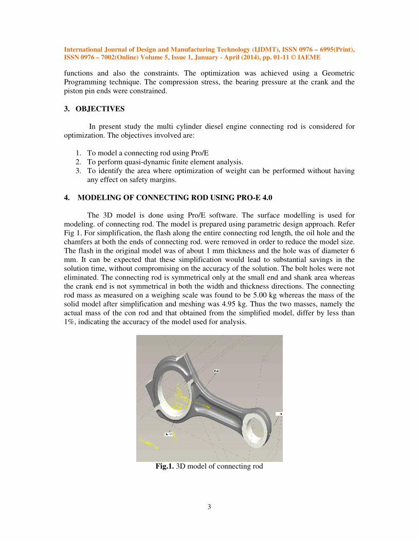
4. MODELING OF CONNECTING ROD USING PRO-E 4.0
The 3D model is done using Pro/E software. The surface modelling is used for
modeling. of connecting rod. The model is prepared using parametric design approach. Refer
Fig 1. For simplification, the flash along the entire connecting rod length, the oil hole and the
chamfers at both the ends of connecting rod. were removed in order to reduce the model size.
The flash in the original model was of about 1 mm thickness and the hole was of diameter 6
mm. It can be expected that these simplification would lead to substantial savings in the
solution time, without compromising on the accuracy of the solution. The bolt holes were not
eliminated. The connecting rod is symmetrical only at the small end and shank area whereas
the crank end is not symmetrical in both the width and thickness directions. The connecting
rod mass as measured on a weighing scale was found to be 5.00 kg whereas the mass of the
solid model after simplification and meshing was 4.95 kg. Thus the two masses, namely the
actual mass of the con rod and that obtained from the simplified model, differ by less than
1%, indicating the accuracy of the model used for analysis.
Fig.1. 3D model of connecting rod
International Journal of Design and Manufacturing Technology (IJDMT), ISSN 0976 – 6995(Print),
ISSN 0976 – 7002(Online) Volume 5, Issue 1, January - April (2014), pp. 01-11 © IAEME
4
5. TO PERFORM QUASI-DYNAMIC FINITE ELEMENT ANALYSIS
The Engine & conrod specification is as follows
Table 1.1 Engine Specifications
Engine type V- type, stationary
Power 1200 HP
Number of cylinders 16
Engine speed 1500 rpm
Material 42CrMoS4N
Ultimate strength 890 Mpa
Yield strength 640 Mpa
Module of Elasticity 2.1e5
Mpa
Poisson’s ratio 0.3
Density 7850 kg/m3
Mass of con rod 5.0 kg
Length (c-c) 275 mm
Dia. of big end 103 mm
Dia. of small end 50 mm
The components of forces acting on the connecting rod ends in the X and Y directions
are obtained; they can be resolved into components along the connecting rod length and
normal to it. The components of the inertia load acting at the centre of gravity can also be
resolved into similar components. Depending upon the magnitudes of the forces acting on the
connecting rod a few positions of the crank were selected, so that the FEA could be
performed at only the selected crank positions. The connecting rod as it undergoes a complete
cycle consists of two components, the bending stress component and the axial stress
component. The bending stress depends on the bending moment, which is a function of the
load at the C.G. normal to the connecting rod axis, as well as the components of the angular
acceleration and linear acceleration normal to the connecting rod axis. The variation of each
of these three quantities over first revolution of crankshaft is similar to the second revolution
of crankshaft in case of four stoke engine. The axial load variation does not follow this
pattern. One cycle of axial load variation consists of the entire two revolution of crank angle.
This is due to the variation in the gas load, one cycle of which consists of two revolution of
crankshaft.
The meshing was carried out using Hyper Mesh software, which automatically decides the
size of mesh in different areas of the model. The finite element mesh was generated using
parabolic tetrahedral elements 4 mm (42184 elements)
5.2 Load application and boundary conditions The forces acting on the two ends of the connecting rod were calculated for different
angular positions of the crank. The crank positions, for which the axial (tensile / compressive)
load acting on the con rod was maximum. Maximum tensile load position and the maximum
compressive load position.
International Journal of Design and Manufacturing Technology (IJDMT), ISSN 0976 – 6995(Print),
ISSN 0976 – 7002(Online) Volume 5, Issue 1, January - April (2014), pp. 01-11 © IAEME
5
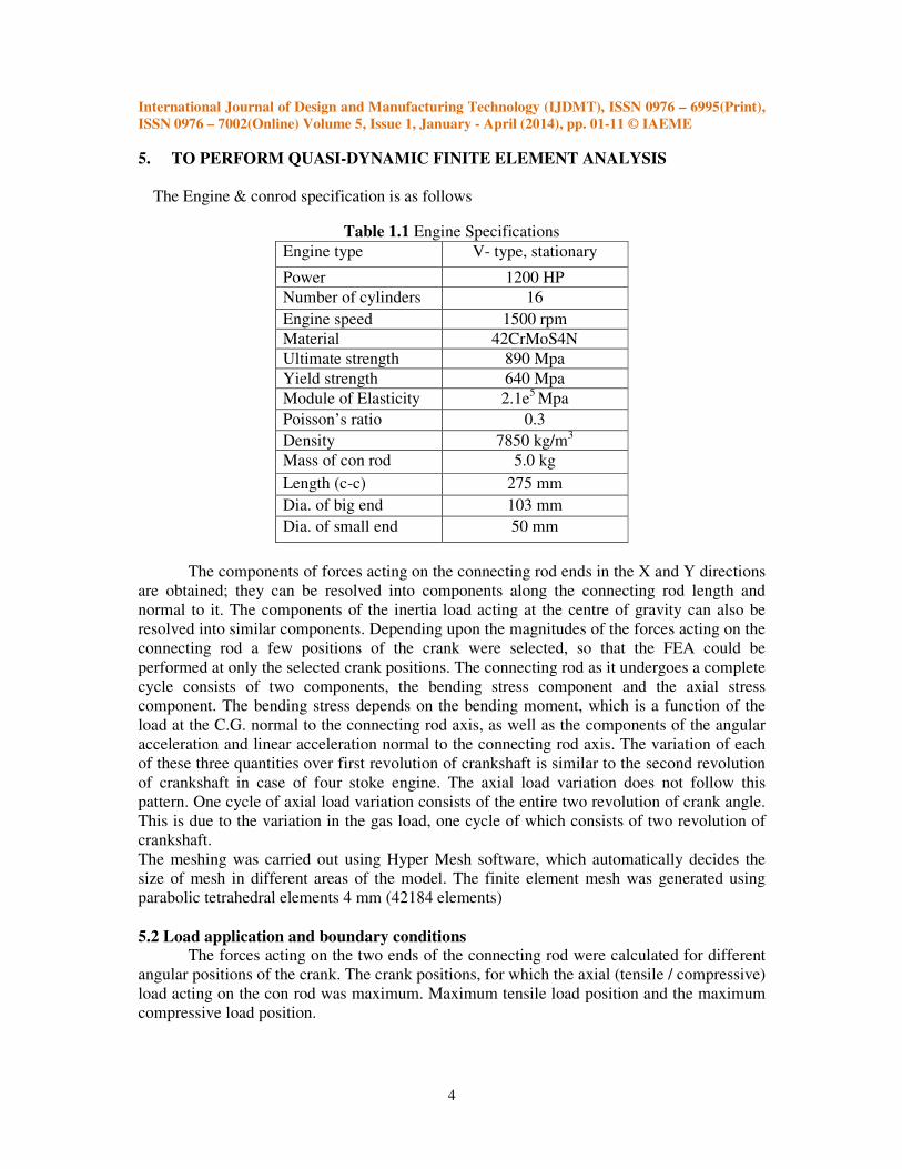
5.2.1 Maximum Tensile loading of the connecting rod This corresponds to the crank position of 3600. For the tensile loading, both the ends
of the conrod were assumed to be subjected to a sinusoidal distributed load over the contact
surface area spanning over 1800, as shown in Maximum compressive loading of the con rod:
This corresponds to the crank angle position of 0◦ For this case the recommended load
distribution is a uniform load distribution acting over a contact area of spanning over 1200.
Fig.2. Tensile loading of the connecting rod
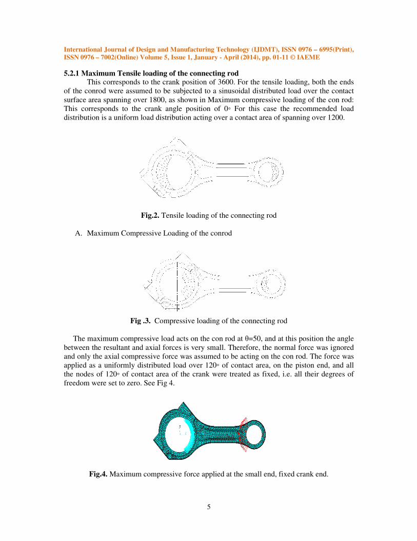
A. Maximum Compressive Loading of the conrod
Fig .3. Compressive loading of the connecting rod
The maximum compressive load acts on the con rod at θ=50, and at this position the angle
between the resultant and axial forces is very small. Therefore, the normal force was ignored
and only the axial compressive force was assumed to be acting on the con rod. The force was
applied as a uniformly distributed load over 120◦ of contact area, on the piston end, and all
the nodes of 120◦ of contact area of the crank were treated as fixed, i.e. all their degrees of
freedom were set to zero. See Fig 4.
Fig.4. Maximum compressive force applied at the small end, fixed crank end.
International Journal of Design and Manufacturing Technology (IJDMT), ISSN 0976 – 6995(Print),
ISSN 0976 – 7002(Online) Volume 5, Issue 1, January - April (2014), pp. 01-11 © IAEME
6
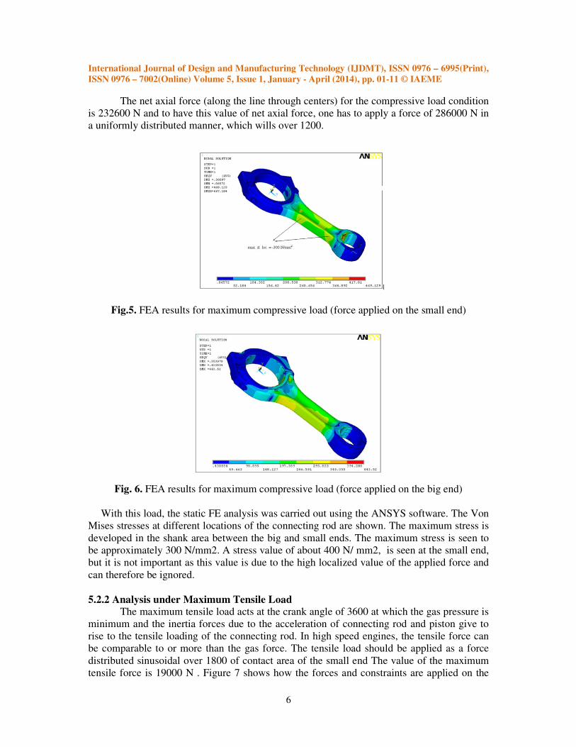
The net axial force (along the line through centers) for the compressive load condition
is 232600 N and to have this value of net axial force, one has to apply a force of 286000 N in
a uniformly distributed manner, which wills over 1200.
Fig.5. FEA results for maximum compressive load (force applied on the small end)
Fig. 6. FEA results for maximum compressive load (force applied on the big end)
With this load, the static FE analysis was carried out using the ANSYS software. The Von
Mises stresses at different locations of the connecting rod are shown. The maximum stress is
developed in the shank area between the big and small ends. The maximum stress is seen to
be approximately 300 N/mm2. A stress value of about 400 N/ mm2, is seen at the small end,
but it is not important as this value is due to the high localized value of the applied force and
can therefore be ignored.
5.2.2 Analysis under Maximum Tensile Load
The maximum tensile load acts at the crank angle of 3600 at which the gas pressure is
minimum and the inertia forces due to the acceleration of connecting rod and piston give to
rise to the tensile loading of the connecting rod. In high speed engines, the tensile force can
be comparable to or more than the gas force. The tensile load should be applied as a force
distributed sinusoidal over 1800 of contact area of the small end The value of the maximum
tensile force is 19000 N . Figure 7 shows how the forces and constraints are applied on the

International Journal of Design and Manufacturing Technology (IJDMT), ISSN 0976 – 6995(Print),
ISSN 0976 – 7002(Online) Volume 5, Issue 1, January - April (2014), pp. 01-11 © IAEME
7
connecting rod. Because the tensile load is less important in this work, the distribution of the
force was simplified and treated as uniform.
Fig.7. Application of force and constraints for maximum tensile load
Fig.8. FEA result for maximum tensile loading force of 19 KN
(force applied on the small end)
Fig. 9. FEA results for maximum compressive load (force applied on the big end)
International Journal of Design and Manufacturing Technology (IJDMT), ISSN 0976 – 6995(Print),
ISSN 0976 – 7002(Online) Volume 5, Issue 1, January - April (2014), pp. 01-11 © IAEME
8
6. RESULT & DISCUSSION OF QUASI-DYNAMIC FINITE ELEMENT ANALYSIS
6.1 Finite Element Analysis
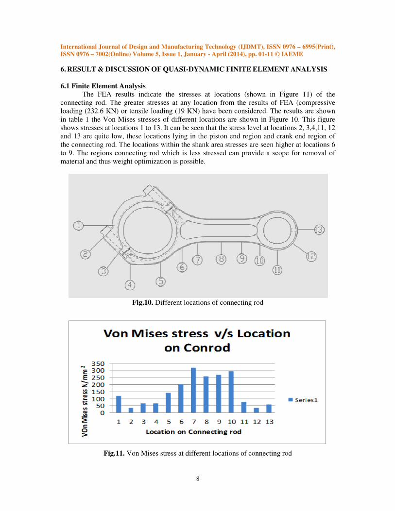
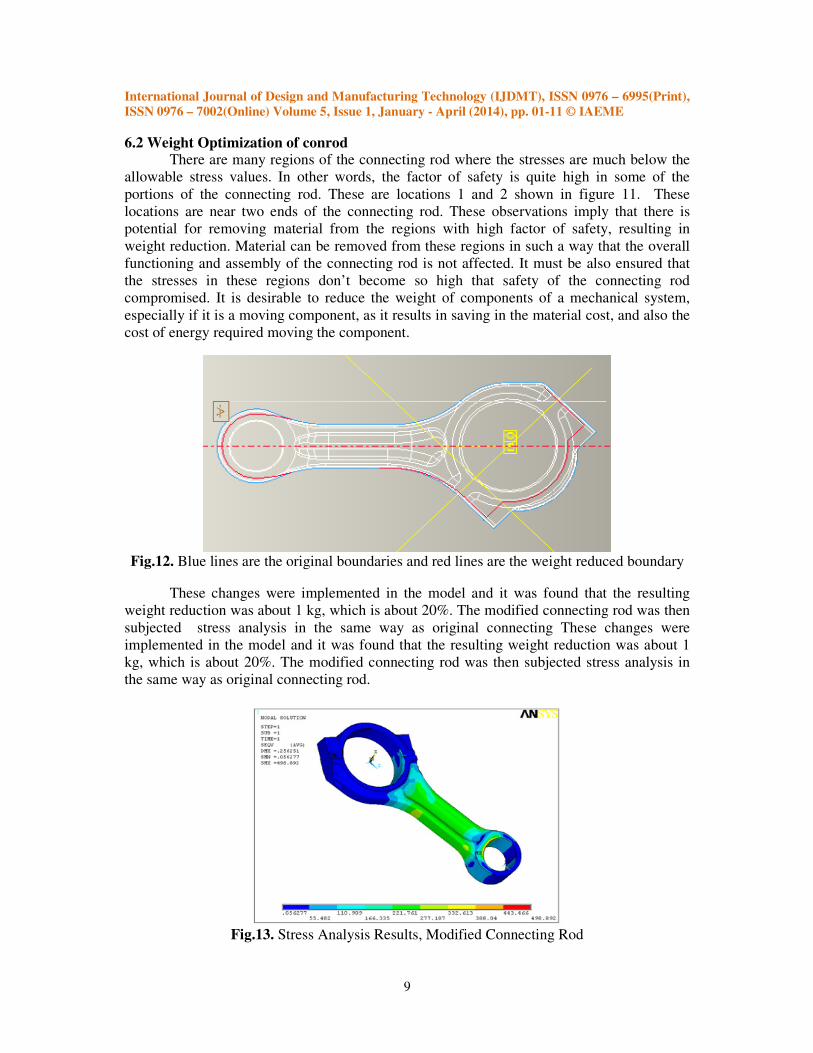
The FEA results indicate the stresses at locations (shown in Figure 11) of the
connecting rod. The greater stresses at any location from the results of FEA (compressive
loading (232.6 KN) or tensile loading (19 KN) have been considered. The results are shown
in table 1 the Von Mises stresses of different locations are shown in Figure 10. This figure
shows stresses at locations 1 to 13. It can be seen that the stress level at locations 2, 3,4,11, 12
and 13 are quite low, these locations lying in the piston end region and crank end region of
the connecting rod. The locations within the shank area stresses are seen higher at locations 6
to 9. The regions connecting rod which is less stressed can provide a scope for removal of
material and thus weight optimization is possible.
Fig.10. Different locations of connecting rod
Fig.11. Von Mises stress at different locations of connecting rod
International Journal of Design and Manufacturing Technology (IJDMT), ISSN 0976 – 6995(Print),
ISSN 0976 – 7002(Online) Volume 5, Issue 1, January - April (2014), pp. 01-11 © IAEME
9
6.2 Weight Optimization of conrod There are many regions of the connecting rod where the stresses are much below the
allowable stress values. In other words, the factor of safety is quite high in some of the
portions of the connecting rod. These are locations 1 and 2 shown in figure 11. These
locations are near two ends of the connecting rod. These observations imply that there is
potential for removing material from the regions with high factor of safety, resulting in
weight reduction. Material can be removed from these regions in such a way that the overall
functioning and assembly of the connecting rod is not affected. It must be also ensured that
the stresses in these regions don’t become so high that safety of the connecting rod
compromised. It is desirable to reduce the weight of components of a mechanical system,
especially if it is a moving component, as it results in saving in the material cost, and also the
cost of energy required moving the component.
Fig.12. Blue lines are the original boundaries and red lines are the weight reduced boundary
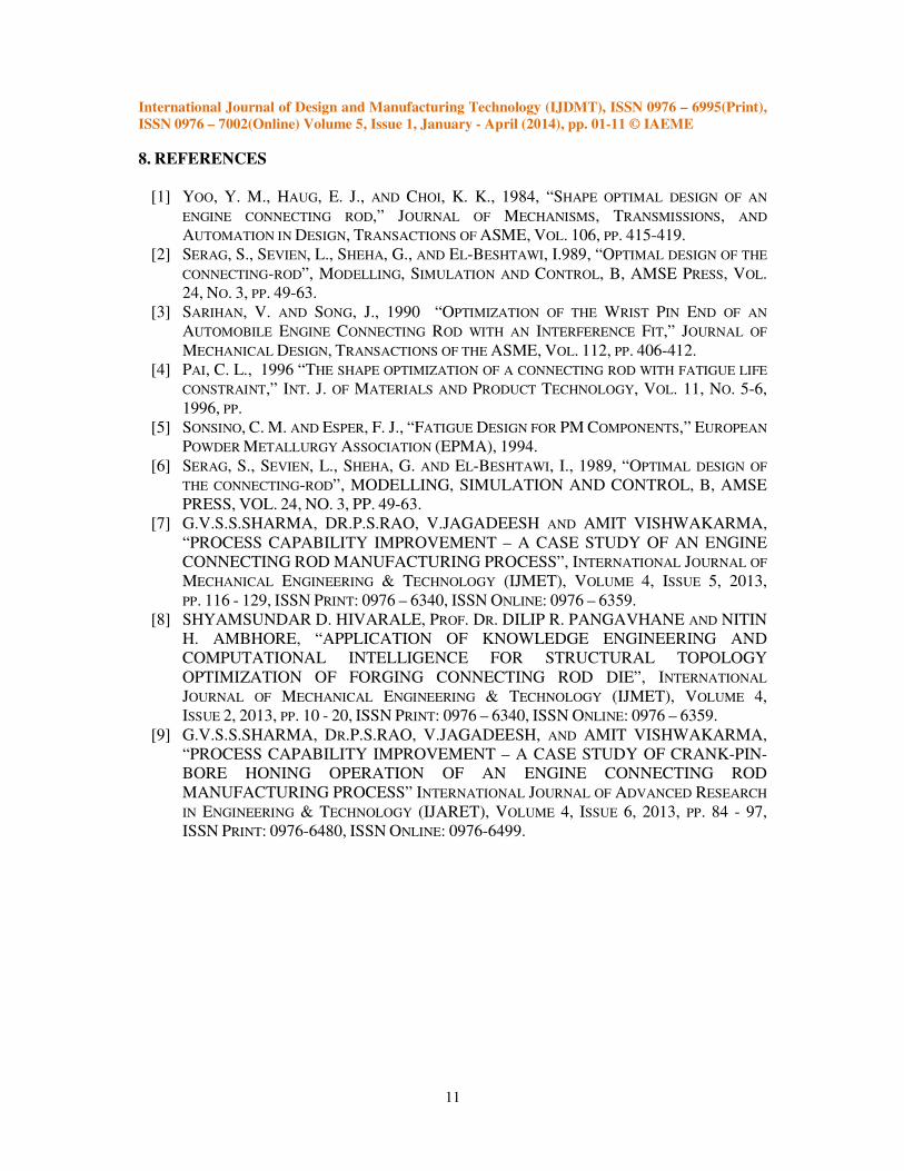
These changes were implemented in the model and it was found that the resulting
weight reduction was about 1 kg, which is about 20%. The modified connecting rod was then
subjected stress analysis in the same way as original connecting These changes were
implemented in the model and it was found that the resulting weight reduction was about 1
kg, which is about 20%. The modified connecting rod was then subjected stress analysis in
the same way as original connecting rod.
Fig.13. Stress Analysis Results, Modified Connecting Rod

International Journal of Design and Manufacturing Technology (IJDMT), ISSN 0976 – 6995(Print),
ISSN 0976 – 7002(Online) Volume 5, Issue 1, January - April (2014), pp. 01-11 © IAEME
10
The modified conrod compressive, load on small end, big end fixed, maximum stress
= 300 N/mm2. Figures 13 to 14 show the FEA results for different cases of force application
and boundary conditions. It can be seen from these figures that the stresses within the regions
from which the material was removed, are somewhat higher, but still quite less. The
maximum stresses remain almost the same as earlier which means that even with the removal
of material, the connecting rod remains safe.
Fig.14. Stress analysis results, modified connecting rod
The compressive, load on big end, small end fixed, maximum stress = 320 N/mm2. It
can be seen that removal of material from those regions of the connecting rod, which are
under less stress, can result in substantial weight reduction without compromising on the
safety of the connecting rod. About 20% (1kg) reduction in mass of the connecting rod was
achieved. This being a 16 cylinder engine, the total reduction in the mass of the connecting
rods will be about 16 kg, which is very substantial.
7. CONCLUSION
The constant speed engine conrod soft validation & optimization is carried out using
dynamic Load analysis method. The FEA results are used for optimization of conrod. The
optimized design of this connecting rod was acceptable, because as the factor of safety for
any crank angle location on connecting rod was higher than the endurance strength of forged
steel used. The 20 % reduction in weight, reduced the overall engine balancing requirement
by 20% hence reduction in Vibration levels, better engine performance & overall higher
efficiency is achieved.
International Journal of Design and Manufacturing Technology (IJDMT), ISSN 0976 – 6995(Print),
ISSN 0976 – 7002(Online) Volume 5, Issue 1, January - April (2014), pp. 01-11 © IAEME
11
8. REFERENCES
[1] YOO, Y. M., HAUG, E. J., AND CHOI, K. K., 1984, “SHAPE OPTIMAL DESIGN OF AN
ENGINE CONNECTING ROD,” JOURNAL OF MECHANISMS, TRANSMISSIONS, AND
AUTOMATION IN DESIGN, TRANSACTIONS OF ASME, VOL. 106, PP. 415-419.
[2] SERAG, S., SEVIEN, L., SHEHA, G., AND EL-BESHTAWI, I.989, “OPTIMAL DESIGN OF THE
CONNECTING-ROD”, MODELLING, SIMULATION AND CONTROL, B, AMSE PRESS, VOL.
24, NO. 3, PP. 49-63.
[3] SARIHAN, V. AND SONG, J., 1990 “OPTIMIZATION OF THE WRIST PIN END OF AN
AUTOMOBILE ENGINE CONNECTING ROD WITH AN INTERFERENCE FIT,” JOURNAL OF
MECHANICAL DESIGN, TRANSACTIONS OF THE ASME, VOL. 112, PP. 406-412.
[4] PAI, C. L., 1996 “THE SHAPE OPTIMIZATION OF A CONNECTING ROD WITH FATIGUE LIFE
CONSTRAINT,” INT. J. OF MATERIALS AND PRODUCT TECHNOLOGY, VOL. 11, NO. 5-6,
1996, PP.
[5] SONSINO, C. M. AND ESPER, F. J., “FATIGUE DESIGN FOR PM COMPONENTS,” EUROPEAN
POWDER METALLURGY ASSOCIATION (EPMA), 1994.
[6] SERAG, S., SEVIEN, L., SHEHA, G. AND EL-BESHTAWI, I., 1989, “OPTIMAL DESIGN OF
THE CONNECTING-ROD”, MODELLING, SIMULATION AND CONTROL, B, AMSE
PRESS, VOL. 24, NO. 3, PP. 49-63.
[7] G.V.S.S.SHARMA, DR.P.S.RAO, V.JAGADEESH AND AMIT VISHWAKARMA,
“PROCESS CAPABILITY IMPROVEMENT – A CASE STUDY OF AN ENGINE
CONNECTING ROD MANUFACTURING PROCESS”, INTERNATIONAL JOURNAL OF
MECHANICAL ENGINEERING & TECHNOLOGY (IJMET), VOLUME 4, ISSUE 5, 2013,
PP. 116 - 129, ISSN PRINT: 0976 – 6340, ISSN ONLINE: 0976 – 6359.
[8] SHYAMSUNDAR D. HIVARALE, PROF. DR. DILIP R. PANGAVHANE AND NITIN
H. AMBHORE, “APPLICATION OF KNOWLEDGE ENGINEERING AND
COMPUTATIONAL INTELLIGENCE FOR STRUCTURAL TOPOLOGY
OPTIMIZATION OF FORGING CONNECTING ROD DIE”, INTERNATIONAL
JOURNAL OF MECHANICAL ENGINEERING & TECHNOLOGY (IJMET), VOLUME 4,
ISSUE 2, 2013, PP. 10 - 20, ISSN PRINT: 0976 – 6340, ISSN ONLINE: 0976 – 6359.
[9] G.V.S.S.SHARMA, DR.P.S.RAO, V.JAGADEESH, AND AMIT VISHWAKARMA,
“PROCESS CAPABILITY IMPROVEMENT – A CASE STUDY OF CRANK-PIN-
BORE HONING OPERATION OF AN ENGINE CONNECTING ROD
MANUFACTURING PROCESS” INTERNATIONAL JOURNAL OF ADVANCED RESEARCH
IN ENGINEERING & TECHNOLOGY (IJARET), VOLUME 4, ISSUE 6, 2013, PP. 84 - 97,
ISSN PRINT: 0976-6480, ISSN ONLINE: 0976-6499.