Configuration & Operation Manual - ITT PRO Services
216
Configuration & Operation Manual PumpSmart ® Control Solutions PS220 v6
-
Upload
khangminh22 -
Category
Documents
-
view
1 -
download
0
Transcript of Configuration & Operation Manual - ITT PRO Services

Configuration & Operation ManualPumpSmart® Control Solutions PS220 v6

PS220 Configuration & Operation Guide
1 PS220
Get
tin
g
Star
ted
Congratulations on the purchase of your PumpSmart® PS220 .
Leveraging our 160+ years in pump design, manufacture, and operation, ITT Gould’s Pumps has one goal; improving the profitability of your plant operations. Our products and services target your biggest issues to increase process uptime, reduce maintenance costs , and lower operating energy costs.
The PumpSmart® PS220 integrates a world leading ABB variable frequency drive with decades of pump control logic, that has been field tested on tens of thousands of applications worldwide. The PumpSmart® PS220 variable speed pump control system provides real-time control and protection of your pumps while also providing valuable process insight. By protecting against unplanned pump failure due to process upsets, ITT Gould’s Pumps can keep your process running longer and reduce an may eliminate un-planned repair activities. In addition, through the “Right-Sizing” of your pump to your system, we can reduce not only your energy consumption, but the wear and tear on your pumps and process system.
Since 1999 the PumpSmart® patented logic has been the world leader in changing process control with pump protection for pumping systems. From single pump applications to multi-pump applications, the PumpSmart® PS220 can accurately control to Pressure, Flow, SmartFlow® , TDH, Level, and temperature with up to 6 pumps working together.
For additional information on the PumpSmart PS220 please take the time to review, and understand the safe installation, operation and maintenance guidelines provided in the ABB ACS880 Hardware Manual., or visit www.ittproservices.com.
The PS220 has been designed for safe and reliable operation when properly installed, applied and maintained in accordance with the instructions in the ACS880 Hardware Manual and PS220 Configuration and Operation Guide. ITT Monitoring and Control shall not be liable for physical injury, damage or delays caused by failure to follow these instructions.

PS220 Configuration & Operation Guide
PS220 2
Gettin
g
Started
Important Safety Reminder Page 03PS220 Wizards Page 05 Basic Startup Page 07 SmartFlow Page 18 Process Control Page 34 Pump and VFD Page 43 protection Multipump Page 64 Multivariable Page 68Options and Features Page 72 Parameter Restore Page 159Appendices Page 161 Keypad Use A-1 Page 161 Fault Tracing A-2 Page 167 Parameter Listing A-3 Page 178 Miscellaneous Page 199 Multipump connections Page 206 Basic Wiring & Installation A-4 Page 207 Quick Reference • Wall mount units Page 211 • Floor mount units Page 213

PS220 Configuration & Operation Guide
3 PS220
Get
tin
g
Star
ted
Products manufactured and furnished by ITT Monitoring and Control will provide safe, trouble-free service when properly installed, maintained and operated. We have an extensive network of experienced sales and service professionals to assist in maximizing your satisfaction with our products.
Safe installation, operation and maintenance of ITT’s equipment are essential end user responsibilities. The ACS880 Hard-ware Manual and PS220 Configuration and Operation Guide identify specific safety risks that must be considered at all times during the life of the product. Understanding and adhering to these safety warnings is mandatory to ensure person-nel, property and/or the environment will not be harmed. Adherence to these warnings alone, however, is not sufficient; it is expected that the end user will also comply with industry and corporate safety standards. Identifying and eliminating unsafe installation, operation and maintenance practices is the responsibility of all individuals involved in the installation, operation and maintenance of industrial equipment.
Safety Symbol and Signal Word Explanation:
IMPORTANT SAFETY REMINDER
This is the dangerous voltage alert symbol. It warns of high voltage which can cause death or physical injury. Obey all safety messages that follow this symbol to avoid possible injury or death.
This is the safety alert symbol. It is used to alert you to potential personal injury hazards. Obey all safety messages that follow this symbol to avoid possible injury or death.
DANGER indicates a hazardous situation which, if not avoided, will result in death or serious injury.
DANGER
WARNING indicates a hazardous situation which, if not avoided, could result in death or serious injury.
WARNING
CAUTION indicates a hazardous situation which, if not avoided, may result in minor or moderate injury.
CAUTION
NOTICE used without the safety alert symbol addresses practices which, if not avoided, may result in property damage.
NOTICE

PS220 Configuration & Operation Guide
PS220 4
Gettin
g
Started
With respect to PumpSmart drives and the operation of pumping equipment the following risks bear reinforcement above and beyond normal safety precautions:
Never work on the PS220 drive, the motor cable or the motor when main power is applied. After switching off the input power, always wait 5 minutes to allow drive internal capacitors to discharge before working on the drive, the motor or the motor cable. Failure to do so will result in serious injury or death.
DANGER
Do not work on control cables when power is applied to the drive or to external control circuits. Externally supplied control circuits may cause dangerous voltages inside the drive even if the main power on the drive is switched off. Failure to do so will result in serious injury or death.
DANGER
All electrical installation and maintenance work must be undertaken by a qualified electrician only. Failure to do so could result in serious injury or death.
WARNING
Operation of any pumping system with a blocked suction and discharge must be avoided in all cases. Opera-tion, even for a brief period under these conditions, can cause superheating of internal pumpage and result in a violent explosion. All necessary measures must be taken by the end user to ensure this condition does not occur. Failure to do so could result in serious injury or death.
WARNING
Never operate rotating equipment unless all protective coupling and shaft guards are in place. Personal injury may occur if the driven equipment is operated without coupling and shaft guards. Failure to do so could result in serious injury or death.
WARNING
Handle the unit carefully. The PS220 is heavy. Do not lift it alone. Wall Mounted Units: Do not lift the PS220 by the front cover. Place the unit only on its back. Floor Mounted Units: Lift the PS220 by the lifting lugs only. Do not tilt the unit. The unit will overturn from a tilt of about 6 degrees. Use extreme caution when maneuvering a unit that has been placed on wheels.
Failure to do follow these instructions could result in serious injury or death or damage to the equipment
WARNING

PS220 Configuration & Operation Guide
5 PS220
Get
tin
g
Star
ted
PumpSmart PS220 Wizard MenuThe PumpSmart PS220 utilizes a time saving versatile range of configurations to make initial setup incredibly easy. The PS220 wizards have been designed to cover a wide range of common applications for pumping systems used around the world.
The table below lists all of the Wizards that are in this section. Each section will describe the steps that you will need to follow to properly configure the function(s) and will show step by step screen shots as you progress from beginning to end. Additional information may also be shown, to assist you along the way, such as the table of all parameters used with the function.
A thorough detailed explanation of each functions capability and use are in the individual Features & Function section in this manual.
When reconfiguring the Pumpsmart PS220 it is highly recommended to restore the parameters to the original factory default settings. Please use the PARAMATER RESTORE assistant shown in the Menu Tree below.
PS220 Wizard Menu Tree
Basic Startup
SmartFlow
Process Control
Pump & VFD Protection
Multi-pump
Multivariable
Parameter Restore
Keypad Use
Fault Tracing
Parameter List
Miscellaneous
Options & Features
Appendix

PS220 Configuration & Operation Guide
PS220 6
Basic
Startup
THIS PAGE IS INTENTIONALLY LEFT BLANK

PS220 Configuration & Operation Guide
7 PS220
Bas
ic
Star
tup
Basic Startup WizardThe PumpSmart PS220’s default mode of operation utilizes the Electric Motor connected and will run the Pump using the Basic Speed Control Functionality. The Basic Startup will configure the Pumpsmart PS220 with the language you select, allow you to define the motor characteristic, execute a Motor ID, and verify correct motor rotation. You will then select the start/stop method, the operating speed range, and the method used to send the speed set point reference for the system to work.
This procedure provides a baseline for all of the Pumpsmart function-ality to properly perform. It MUST be performed prior to any other functions/ features can be configured.
This functionality can only be configured with the Pumpsmart PS220 Configuration Wizard.
To access this Wizard, from the Home Screen follow the path: MENU>PS220 Configuration>Basic Startup>
The steps that you will perform are as follows:1. Configure the Motor Parameters.2. Configure Basic Startup information.
The Screen Shots that follow will show you step by step, from start to finish as you progress, how to configure this functionality.

PS220 Configuration & Operation Guide
PS220 8
Basic
Startup
Motor Parameter Configuration WizardThe Pumpsmart PS220 will not operate unless the Electric Motor connected is configured with all necessary information required.
The steps that you will perform are as follows:1. Configure the Motor Setup2. Perform the Motor ID Run3. Perform a Motor Jog for Direction
DIIL PermissiveThe PS220 will not run the motor unless the Permissive input [DIIL] is closed (24Vdc). This includes performing the Motor ID Run. If not closed a warning message will appear on the keypad display:
The PS220 drive will come from the factory with a jumper between the DIIL input and 24Vdc. See Appendix A-4, Instrument Wiring, for details on wiring this switch.
NOTE – The DIIL Permissive input cannot be defeated through a parameter setting. If your application does not use a Permissive switch input, leave the factory jumper in place. Refer to Appendix A-4, Instrument Wiring, for details.
Safe Torque OffThe PS220 will not run the motor unless the Safe Torque Off (STO) is closed. The Safe Torque Off inputs are typically used for the external E-Stop circuit. If theE-Stop is active (STO open) the keypad will display:
The PS220 drive will come from the factory with jumpers installed between the STO Output and Inputs 1 and 2. If an E-Stop push button is installed in the STO circuit be sure the E-Stop is not activated.
Fault Safe Torque Off - A5A0
Detail for the following Motor Setup will come from the motor nameplate. Be sure that if the motor is a dual wound motor you select the voltage and full load amps for the motor as wired.

PS220 Configuration & Operation Guide
9 PS220
Bas
ic
Star
tup
1. Configure the Motor Setup
1. Enter the mains Supply voltage 2. Configure the Motor Full Load Amps/ Current (FLA)
3. Configure the Motor Nominal Voltage 4. Enter the Motor Nominal Frequency
5. Configure the Motor full load RPM (Slip Speed)
6. Configure the Motor nominal power (HP or kW)

PS220 Configuration & Operation Guide
PS220 10
Basic
Startup
2. Perform a Motor ID RUNThe PumpSmart PS220 drive uses specific motor details to create a mathematical model of the motor. This model enables more accurate motor control and is created by using the motor data you have just entered. It will be magnetizing the motor from 20 to 60 seconds at zero speed. This is called a Standstill ID run as the motor will not turn. It is also referred to as a MAG ID, or ID Run. Once all the motor data has been entered, you will see the following warning flash on the top of the screen:
This warning indicates that a Motor Identification run is required before the pump may be operated.
Note – Although the motor may not appear to respond to the start command. There may be an audible high-pitched sound coming from the motor which is normal.
A warning message, “ID run Active” will be displayed during the ID. Once the ID run has completed, the message “ID DONE” will be displayed.
Note – If the motor is repaired or replaced in the future, a Motor Identification run must be performed again to maintain the accuracy of the PumpSmart drive.
The following procedure, while not spinning the mo-tor, will energize the motor. All safety precautions must be followed before initiating the Motor ID run. Failure to do so could result in serious injury or death.
WARNING
1.
2. 3.

PS220 Configuration & Operation Guide
11 PS220
Bas
ic
Star
tup
3. Perform a Motor Jog for DirectionJogging the pump motor for correct rotation can be accomplished through the Motor Jog function. The Pumpsmart PS220 will rotate at 60 RPM and continue to do so until the rotation is confirmed to be correct (or incorrect). If incorrect the drive will prompt you to correct the rotation and then ask you to start it again to then confirm that rotation is correct. It will always run at only 60RPM.
Note. If it is determined that the rotation direction is incorrect there is no need to change any wiring on the (motor) load side of the PS220 to correct the rotation. When answered as incorrect it is all auto-matically corrected by an internal Pumpsmart PS220 setting.
Never work on the Pumpsmart PS220, the motor cable or the motor when main power is applied. After switching off the input power, always wait 5 minutes to al-low drive internal capacitors to discharge before working on the drive, the motor, or the motor cable. Failure to do so will result in serious injury or death.
DANGER
The Screen Shots below follow the sequence when the initial rotation is incorrect. If rotation correct only screens 1, 2.and 3, and 8 will apply. If the motor rotation is incorrect select No and run the rotation check again, where screens 4-8 will apply.
1. 2. 3.
4. 5. 6.
7. 8.

PS220 Configuration & Operation Guide
PS220 12
Basic
Startup
Jogging the Motor Checking the pump motor for correct rotation can be accomplished through the Motor Jog function. The Pumpsmart PS220 will rotate at 60 RPM and continue to do so until the rotation is confirmed to be correct (or incorrect). If incorrect the PS220 will prompt you to correct the rotation and then request to re-start it and confirm that rotation is correct. It will always only operate at 60RPM. Once you conform the rotation to be correct it will automatically stop.
Note. There is no need to change any wiring on the (motor) load side of the Pumpsmart PS220 to correct the rotation. It is all done by and internal parameter.
Never work on the PS220 drive, the motor cable or the motor when main poweris applied. After switching off the input power, always wait 5 minutes to allow drive internal capacitors to discharge before working on the drive, the motor, or the motor cable. Failure to do so will result in serious injury or death.
Motor JogRotation Re-checkingChecking the motor for correct rotation can be done initially by using the Basic Startup Wizard. The motor will run at 60RPM until the operator confirms the correct rotation. If it is incorrect the drive will automatically reverse it. If it is desired to run the jog function an additional time, the drive start/stop source must be in Keypad. If originally set to something other than keypad you must run the Basic wizard again, changing the start/stop source to Keypad. Be sure to complete the Basic wizard when doing this. Then run the Basic wizard again to cause the Jog function to be available. The jog function can be simulated using parameters as well. See this procedure outline below. This procedure is for a Pump that CANNOT be run in REVERSE.To recheck the rotation, you will need to follow the steps outlined below:
NOTE: ALL IDENTICAL SAFEY PRECAUTIONS SHOULD BE TAKEN AND FOLLOWED AS NOTED IN THE BASIC STARTUP SECTION PRIOR TO PERFORMING THIS FUNCTION AGAIN 1. Place the drive in Local Control, if it is in remote.2. Set parameters 30.11 and 30.12 to 60 RPM. Please remember or document what they were set to originally.3. Press the Green Start button and watch for rotation.4. Press the Red Stop button. If the rotation is NOT correct go to step5, otherwise go to step 6.5 . Go to parameter 99.16 and change the setting to reverse phase V and W The 2 choices are (0) UVW and (1) UWV. Repeat steps 3 and 4.6. Set parameters 30.11 and 30.12 back to original settings.7. Place the drive back to the original control mode of Remote if necessary.
This procedure is for a Pump that CAN be run in REVERSE
1. Place the drive in Local Control, if it is in remote. (Manual speed control)2. Press the Green Start button and watch for rotation. (The reference may be adjusted if desired)3. Press the Red Stop button. If the rotation is NOT correct go to step 4, otherwise go to step 5.4. Go to parameter 99.16 and change the setting to reverse phase V and W The 2 choices are (0) UVW and (1) UWV. Repeat steps 2 and 3.5. Place the drive back to the original control mode of Remote if necessary

PS220 Configuration & Operation Guide
13 PS220
Bas
ic
Star
tup
4. Configure the Start and Stop source. PumpSmart is designed to operate in Remote mode (REM/LOC pushbutton). At this point you will determine how PumpSmart starts and stops in Remote mode. By default it is set to Keypad, where the green pushbutton starts PumpSmart and the red pushbutton stops it. Other choices are available. Refer to the “Start/Stop” section in this manual for the details on these choices. Note - when in LOC PumpSmart will start/stop only by the keypad Start/Stop pushbuttons.
1. “ARROW RIGHT” then “ARROW DOWN” to change start/ stop source.
2. “SAVE” 3. “Next”
5. Configure Minimum SpeedBy default, the minimum speed is set to 25% of the motor nameplate speed entered earlier. Since pumps only devel-op pressure at the square of the operating speed caution is to be taken to make sure that the minimum speed is high enough to prevent the pump from “dead heading”. A “Dead Head Test” can be performed or you can contact your authorized Pump Sales Engineer to determine this speed if you are unsure. Refer the section “Dead Head” in this manual for more details on this topic.
1. “ARROW RIGHT” To change
2. “SAVE” to continue
The Maximum Speed by default is configured to the motor nameplate speed. Since pumps develop pressure at the square of the operating speed, and the Power consumed at the cube of the speed, caution is to be taken to make sure that the maximum speed is within all limits of the pumping system to prevent damage that may occur. Contact your authorized Pump Sales Engineer to determine this speed if you are unsure.
Assure that the system operating conditions are within the capabil-ities (e.g. speed, pressure, temperature, power, etc.) of the driven equipment as rated by the manufacturer. Exceeding any of these limits could result in failure of pumping system components resulting in serious physical injury and damage to equipment

PS220 Configuration & Operation Guide
PS220 14
Basic
Startup
6. Configure the Operating ModeAt this point you determine if you will be running PumpSmart in Speed Control or in Process Control (PID). If you select Speed Control your next prompt will be to ask where the speed reference is to come from. If you select Process Control here you will be prompted to go on to the Process Control wizard where you will determine the process set-point (reference, ex.: PSI, GPM, etc.) source in the Process Control wizard.
7. Configure a Speed Set-point Source (Control Reference) The Pumpsmart PS220 can be configured for the setpoint to be sourced in one of three ways:1. Keypad 2. Analog Input (AI1, AI2)3. Fieldbus Control
Keypad is the default setting when configuring the Pumpsmart PS220 for the first time.
If using an analog input (4-20mA or 0-10Vdc) go to the next page to see an analog input setup.
If using Fieldbus as a speed reference please refer to the Fieldbus Quick Start Guide for instructions on setting this up.
Once determined press Select to continue.

PS220 Configuration & Operation Guide
15 PS220
Bas
ic
Star
tup
When Using an Analog Input Reference:An analog input signal can be sent into the Pumpsmart PS220 from a PLC, DCS or other form of higher level control system.
A 4-20mA or 0-10Vdc analog signal will need to be wired into either analog input 1 or analog input 2. Note: the following detail speaks about analog input 1 but setup for analog input 2 is identical.
“AI scaled at AI min” refers to the speed value (RPM) that corresponds to the minimum input value of the reference signal (4mA). This is defaulted to 0 RPM.
“AI scaled at AI max” refers to the speed value (RPM) that corresponds to the maximum input value of the reference signal (20mA). This is defaulted to 0 RPM. While it can be set to any value by the user it is typically set to the motor nameplate speed or slip speed.
NOTE: The PS220 analog inputs are default to current type inputs. If your input reference signal provided is a DC Voltage type of signal you will need to change the analog input jumper (J1, or J2) to voltage in addition to setting its corresponding parameters in group 12 to voltage. Please refer to the options and features section for proper parameter settings of the drive.
1. “ARROW RIGHT” to change 2. “ARROWS” to change 3. “Save”
1. “ARROW RIGHT” to change 2. “ARROWS” to change 3. “Save” 4. “Next”

PS220 Configuration & Operation Guide
PS220 16
Basic
Startup
Basic Wizard Complete Once the speed reference is configured the Basic Wizard is complete. At this point you can exit to the home screen, set a speed reference and run the pump, or you may run any of the other PumpSmart wizards (ex.: SmartFlow, Pump Protection, Multipump, etc.).

PS220 Configuration & Operation Guide
17 PS220
Smar
tFlo
w
THIS PAGE IS INTENTIONALLY LEFT BLANK

PS220 Configuration & Operation Guide
PS220 18
SmartFlo
w
Basic SmartFlowBasic SmartFlow utilizes a complex algorithm that will calculate the actual flow of the pump it is connected to. External sensors are not required in a Basic SmartFlow application. Any manufacturer’s centrifugal pump may work with Smartflow.
Basic SmartFlow is designed for low to medium specific speed pumps, under 3000NS. A pump with a specific speed under 3000 will have the following characteristics.
1. Power rises as flow increases with no “dips or bumps” in the power curve. 2. The power value at shut off is at least 25% less than the power at BEP (Best Efficiency Point).
See the figure to the right for these characteristics.
Advanced SmartFlowThe PumpSmart PS220 may be utilized on pumps that do meet the criteria mentioned previously for Basic Smart Flow. In these cases it will require configuring Advanced SmartFlow.
To configure the Advanced SmartFlow functionality, additional pumping system information will be required. Suction and discharge pressures readings are required for the advanced algorithms to function successfully. This infor-mation is also used to configure the information needed for the Smart TDH functionality.
SmartFlow Configuration Wizard

PS220 Configuration & Operation Guide
19 PS220
Smar
tFlo
w Configuring Basic or Advance SmartFlowTo access the SmartFlow Wizard, from the Home Screen follow the path: MENU>PS220 Configuration>SmartFlow.
The screen shots that follow will show you step by step as you progress, from start to finish as you progress, how to configure this functionality
The steps to be performed are:1. Configure the Flow Unit2. Configure the Pump Specific Properties3. Configure Fluid Specific Gravity 4. Execute a Smartflow Tune5. Exit the Wizard
A. Select Basic SmartFlow from the SmartFlow menu listB. Select the unit of measurement to be used
A B
The SmartFlow unit selection identifies what units SmartFlow will display in. It also will be used for providing the necessary Pump Pro-tection and input to other internal functions when required.
Note – The SmartFlow unit can be set independently from units that may have already been used for the language selected at first startup.
The information required for this configuration can be found on the Pump Performance Curve. See the figure on page 17 for an example of a typical Pump Performance Curve.
C. Configure the Pump Type
Note – For magnetic drive pumps with metallic containment shell select Mag Drive. For non-metallic shells select SS Centrifugal as the Pump Type. PD pumps must be centrifugal. They cannot be a piston pump.
SS Centrifugal – Single Suction Centrifugal
DS Centrifugal – Double Suction Centrifugal
Mag Drive – Magnetic Drive Pump
PD Pump – Positive Displacement (Gear Pump)
C

PS220 Configuration & Operation Guide
PS220 20
SmartFlo
w
Configuring Basic or Advance SmartFlow D. Configure the BEP FLOW value.E. Configure the PUMP RATED SPEED value.
BEP Flow is the flow at Best Efficiency Point.
Rated Speed is the speed indicated on the Pump Curves. It may not necessarily be the motor’s full load speed.
See the figure on page 26.D E
F. Configure the BEP POWER value.G. Configure the SO POWER value.
F G
BEP Power is the power at Best Efficiency Point.
SO Power is Shut Off Power. This is the power at zero flow.
See the figure on page 17.
Configure the Fluids Specific Gravity’s SourceSG Rated permits the user to set the SG value in the next screen. Use this when the curves were generated at SG 1 but the process is other than 1. (NOTE: if the curves were generated at the correct SG value then leave SG Rated (next screen) at 1.
SG Calc (T) enables PumpSmart to calculate the SG value when it is based on a 4-20mA temperature input. AI requires a 4-20mA input from a SG transmitter.
DI permits the user to enter two SG values and use a digital input to select between one or the other.

PS220 Configuration & Operation Guide
21 PS220
Smar
tFlo
w A. SG RATED (Fixed)The default value for Specific Gravity [SG] is 1.0. If the curves were generated at 1 but the process is other than 1 then you must enter the correct SG value here. If the curves were generated at the corrected SG value than you must leave this value at 1 even though the SG may not be 1, else you will correct for SG twice. If the Specific Gravity varies by more than 5% throughout the process run then a correction method will be necessary (AI, DI, Temp (T)).
B. Specific Gravity (Variable) 1. Fluid Temperature measured with Transmitter:When changes in the SG are directly related to changes of the fluid temperature, the PumpSmart PS220 can monitor a temperature transmitter, using an Analog Input, to correct for SG changes.
NOTE: WHEN USING AN ANALOG INPUT FOR A TEMPERATURE INPUT YOU WILL NEED TO SCALE THIS INPUT AS THE ANALOG INPUT IS NOT CONFUGURED USING THIS WIZARD. ONCE THE SMARTFLOW WIZARD IS COMPLETED YOU CAN SET UP THE ANALOG INPUT BY GOING TO: MENU>PS220 Configuration>I/O Configuration>Select the Analog Input 1 (OR 2)
A. Select SG CALC (T)B. Configure the SO POWER value.
A B
Configuring the use of this transmitter will require the following steps to be performed:
1. “ARROW RIGHT” button to change the value2. “ARROWS” to configure the value3. “Save” button to continue
Once each step is completed, use the “ARROW DOWN” button to go to the next line on the page. Selecting “Next” at the bottom of each page will bring you to the next page requiring configuration.

PS220 Configuration & Operation Guide
PS220 22
SmartFlo
w
B. Specific Gravity (Variable) cont’d
C. Configure fluid TEMP Rated.D. Configure fluid TEMP MIN.E. Configure fluid TEMP MID.F. Configure fluid TEMP MAX.
These four temperature values will relate to four SG values which you will put in next.
C D
E F
G. Configure fluid SG Rated.H. Configure fluid SG MINI. Configure fluid SG MID.J. Configure fluid SG MAX.
These four points are in relationship to the four temperature values enter in the previous steps.
G H
I J

PS220 Configuration & Operation Guide
23 PS220
Smar
tFlo
w B. Specific Gravity (Variable) cont’d 2. Specific Gravity measured directly with a SG Transmitter:Specific Gravity values that vary linearly, can be measured directly with a SG transmitter. This transmitter must be connected to an analog Input.
NOTE: An unused analog input will need to be used for this method of SG correction. If you are unsure what analog inputs have and have not been used please check the settings of the Analog Inputs in use by going to: MENU>PARAMATERS> Complete List>Scroll down to Group 76>Select and View 76.01 & 02. If available they will show “NOT SELECTED”. You may have to add an Extension Card to use an additional input. (Not provided as standard)
The steps you will need to perform are:1. Configure the measurement source as an AI.2. Configure the Identity of the AI to be used.3. Configure the Min scaled value of the SG.4. Configure the Max scaled value of the SG.
A. Select the measurement source as an AI.B. Configure the SO POWER value.
A B
C. Configure the input source to an open analog input. D. Configure the Min scaled value of the SG.E. Configure the MAX scaled value of the SG.
C D
The values for minimum and maximum scaled input will be the values that the SG transmitter is calibrated to.
E

PS220 Configuration & Operation Guide
PS220 24
SmartFlo
w
B. Specific Gravity (Variable) cont’d 3. Two Rated Specific Gravities (Dual):Use this method of SG correction when the SG is constant during the process run but when you have two different processes with distinct SG values that you run through the same pump. Example, shift A you run product A with SG 0.85 and shift B you run product B with SG1.05. In this case two SG values are loaded into PumpSmart and a digital input is used to select between product A or B.
Any available unused digital input can be used to toggle between two predefined Specific Gravity values. SG 1 and SG 2.
In this setup SG MIN will be used for one SG value and SG MAX will be used for the second SG value.
The steps you will need to perform are:1. Configure the Digital Input to be used:2. Configure the Min SG value3. Configure the Min SG value4. Proceed to SmartFlow Tune
A. Configure Digital Input is to be used.
A
B. Select which digital input is to be used to switch between SG values.C. Configure the Min SG value.
B C
D. Configure the Max SG valueE. Proceed to SmartFlow Tune.
D E
PS220 Configuration & Operation Guide
25 PS220
Smar
tFlo
w 1B. Advanced SmartFlow & Smart TDH Configuration Please refer to the Features & Options section in this manual for a detailed explanation of this functionality. This Wizard will show the step by step instructions to configure this functionality for use.
To access this Wizard, from the Home Screen follow the path: MENU>PS220 Configuration>SmartFlow> Advanced SmartFlow>
1. The steps to be performed to configure Advanced SmartFlow & for SmartTDH are: 1. Configure the Flow Unit (Same as Basic ) 2. Configure the Pump Specific Properties (Same as Basic )3. Configure the Calculation Method (Specific for Advanced)4. Configure the Pumping System Information (More Info Required)5. Configure Transmitter(s) and Analog Input(s) (More info required)6. Configure Fluid Specific Gravity(Same as Basic )
Note: Steps 1, 2, & 6 will not be shown as they are identical to the Basic Smartflow configuration. Please refer to Basic Smartflow for additional detailed information in the Index, or you can start with the Basic Smartflow Configuration Wizards and add these steps as you progress.
The Screen Shots that follow will show you step by step as you progress, from start to finish, how to configure this functionality
3. Configure the Calculation Method
The Calculation Method defines how the PS220’s advanced Smartflow algorithm works. There are 2 methods. 1. Brake Horse Power/Total Dynamic Head” [BHP/TDH].
BHP/TDH: This choice will calculate the SmartFlow flow value using a combination of the Brake Horse Power (BHP) and Total Dynamic Head (TDH). This should be used if the power curve has “dips or bumps”. See SmartFlow limitations at the beginning of this SmartFlow section.
2. Total Dynamic Head [TDH].
TDH: This choice will calculate flow utilizing the differential pressure of the system. This should be used if your power curve is very flat. See SmartFlow limitations.
A combination BHP/TDH may also be used.

PS220 Configuration & Operation Guide
PS220 26
SmartFlo
w
4. Configure the Pumping System InformationNOTE:Each step will require you to use the:1. “ARROW RIGHT” button to change the value2. “ARROWS” to configure the value3. “Save” button to continue
Once each step is completed, use the “ARROW DOWN” button to go to the next line on the page. Selecting “Next” at the bottom of each page will bring you to the next page requiring configuration.
A. Configure the PATM (Planetary Atmosphere)B. Configure the BEP TDH
NOTES: 1. Both BHP and TDH require the input of suction and discharge pressure. These values can come into PumpSmart either as a differential pressure transmitter (one transmitter connected to both the discharge and suction of the pump), or separate Suction and Discharge transmitters. While the first methods requires only one analog input the second method will require two analog inputs.
2. BHP is shown on the screen to the right, however, it is NOT A VALID OPTION.
PATM is the local barometric pres-sure at the location of the pump. (14.7 psi is nominal).
BEP TDH is the Total Dynamic Head value at Best Effeminacy. This value should be on the pump curve, or you can contact your local pump supplier for this value.
A B
C. Configure SO TDH valueD. Configure the Suction Diameter
The pump Total Dynamic Head at the Shut Off (zero flow) condition at rated speed. This should be found on the pump curve, or you may contact your local pump supplier.
The Suction Diameter is the diame-ter of the suction side of the pump. Find this on the pump curve.
C D

PS220 Configuration & Operation Guide
27 PS220
Smar
tFlo
w
E. Configure Discharge DiameterF. Configure the Delta Z value
The Discharge Diameter is the di-ameter of the discharge side of the pump. Find this on the pump curve.
DELTA Z is a measurement between the center line of the suction inlet and the center of the discharge pressure transmitter’s measuring element.
5. Configure the Transmitter(s) and Analog Inputs to be used for the TDH calculations.There are 2 selection choices for this setup:
A. When using a Differential Pressure Transmitter.
A. Select Yes to Differential Pressure (DP) transmitterB. Configure the DP transmitter source
A B
C. Select the DP transmitterD. Select the analog input that your DP transmitter is located
C D
E F

PS220 Configuration & Operation Guide
PS220 28
SmartFlo
w
E. Enter the minimum pressure for the transmitter’s 4mA.F. Enter the maximum pressure value for the transmitter’s 20mA.
The min and max values are in pres-sure format and are the values that the transmitter is calibrated in.
E F
G. Determine the Specific Gravity.
See the Specific Gravity section under Basic SmartFlow setup.
G
B. Configure the use of separate Discharge and Suction Transmitters
Use this method when you are using a separate pressure transmitter for the suction and discharge sides of the pump. Note, this will take two analog inputs.
We will first set up the discharge transmitter.
A. Select No when asked about using a DP transmitterB. Select Discharge Source
A B

PS220 Configuration & Operation Guide
29 PS220
Smar
tFlo
w
C. Select the source of the discharge transmitter from the listD. Select the source of the suction transmitter
C D
E. Select the source of the suction transmitter from the listF. Press SAVE
E F
G. Determine if your suctions side transmitter is an absolute transmitter or not.H. Select the units of measurement for the suction side transmitter.
G H

PS220 Configuration & Operation Guide
PS220 30
SmartFlo
w
I. Select the units of measurement for the discharge side transmitterJ. Enter the scaling detail for the suction and discharge transmitters
Scaling detail is the same as to what the transmitters are ranged to. This may be stamped on the side of the transmitter or can be read using a HART transmitter reading device.
I J
K. Determine your specific gravity setup
K
NOTE:During the configuration of Process Control, a suction or discharge pressure transmitter will be shown as PROC TRANS1. There is no need to re-configure this. Please move on to the next screen.
An unused Analog Input (AI) will need to be used for either of these 2 choices to function correctly. Please check the settings of the Analog Inputs currently in use by going to: MENU>PARAMATERS> Complete List>Scroll down to Group 76>Select and View 76.01 & 02. If available they will show “ NOT SELECTED”. You may have to add an Extension Card to use additional inputs. (Not provided as standard)
See the Specific Gravity section under Basic SmartFlow setup.

PS220 Configuration & Operation Guide
31 PS220
Smar
tFlo
w SmartFlow Tune SmartFlow can have an accuracy of ±5% of rated flow at rated speed. This is made possible by conducting a SmartFlow Tune. The SmartFlow Tune is conducted against a closed discharge valve and will take no more than 35 seconds. If it is unable to successfully conduct a tune in this time it will fail and you will need to understand why it did so. This tune will run pumps 50HP and less at 33%, 60%, and 100% speed, capturing the true pump power at each point. If the pump is larger than 50HP then PumpSmart will capture the power at 33% and 60% only, using the Laws of Affinity to calculate the 100% speed power.
Please refer to the Options & Functions section in this manual for a detailed explanation of this functionality. This Wizard will show the step by step instructions to configure this functionality for use.
To access this Wizard, from the Home Screen follow the path: MENU>PS220 Configuration>SmartFlow> Tune SmartFlow
The Screen Shots that follow will show you step by step as you progress, from start to finish, how to config-ure this functionality
Prior to executing this function:1. All Suction and Discharge piping should be secure and ready for Pump startup.2. Pump and motor aligned and coupled with coupling guard intact.3. Suction line needs to be completely flooded and all air vented completely from the pump through to the discharge side.4. Discharge valve or isolation valve and any bypass piping need to be completely closed.5. For seal-less pumps having liquid lubricated bearings consult with the manufacturer verify if the pump can be run for 35 seconds against a closed discharge valve with the liquid that is to be pumped at the speeds noted below.
Notes:1. It is recommended to set 74.01 to keypad prior to running the tune. Once completed revert back to the original setting.2. Motor HP’s above 50 HP (37KW) will not run above 60% speed3. The tune function will automatically fault if it does not complete in 35 seconds4. Pumps with motors 5 HP or less should be run for 30 minutes prior to running the tune function in an effort to lubricate the seals. 5. Acceleration rates for PID Tuning should remain at default until after running the SmartFlow Tune6. If the tune function cannot be performed the algorithm will use the affinity laws. 7. Do not run a SmartFlow Tune on any pump in a Multipump system.8. Do not try to run a Smartflow Tune on a running pump.
Failure to follow the guidelines in this section can result in serious physical injury, death and/or equipment damage.
Never operate rotating equipment unless all protective coupling and shaft guards are in place. Personal injury may occur if the driven equipment is operated without coupling and shaft guards.
Observe all CAUTIONS and WARNINGS highlighted in the ABB ACS880 Hardware Manual, and the Pumpsmart PS220 Configuration Manual prior to starting.

PS220 Configuration & Operation Guide
PS220 32
SmartFlo
w
Execute the SmartFlow Tune NotesIf you are already in the SmarFlow Wizard this SmarFlow tuning will be part of the setup process. Use the Tune SmartFlow Wizard when needing to conduct a tune to correct for wear. A. From The SmartFlow menu select Tune SmartFlowB. Select Yes to run SmartFlow
A B
C. Complete display instructions and press the green start buttonD. Watch progress of SmartFlow tune (in seconds)
If in the Basic wizard you selected a different source for start/stop than keypad you will need to use that source to initiate the SmartFlow tune. If unavailable, you can change parameter 74.01 to keypad and con-duct the tune, after which you can change it back to what you initially had selected.
C D
E. SmartFlow is complete.
E

PS220 Configuration & Operation Guide
33 PS220
Pro
cess
C
on
tro
l
THIS PAGE IS INTENTIONALLY LEFT BLANK

PS220 Configuration & Operation Guide
PS220 34
Process
Co
ntro
l
Process Control Wizard This section will configure the Pumpsmart PS220 to be used in single pump mode with the process control PID functionality. It will require feedback from an analog transmitter(s) (sensor(s)) scaled feedback that will need to be wired and sent into the drive’s input(s). If selected as SmartFlow Control a flow transmitter is not required.
This Wizard will show the step by step instructions to configure this functionality for use.
This functionality can be configured with the Pumpsmart PS220 Configuration Wizard.
To access this Wizard, from the Home Screen follow the path: MENU>PS220 Configuration>Process Control>
The individual steps that will be performed are:1. Configure the Process Control Mode2. Configure the Sleep Mode3 Configure the PID Tuning settings
The Screen Shots that follow will show you step by step, from start to finish as you progress, how to configure this functionality.

PS220 Configuration & Operation Guide
35 PS220
Pro
cess
C
on
tro
l 1. Configure the Process Control Mode. The individual steps that will be performed are:
1. Configure the Operating Mode 2. Configure the Unit Selection3. Configure the Transmitter Location 4. Configure the Transmitter Information Detail5. Configure the Setpoint Limits6. Configure the Setpoint Source7. Configure the Dual Setpoint (Optional)
1. Configure the Operating ModeThe PumpSmart PS220 will need to be configured to operate in a specific Process Control mode (ex.: pressure, flow, level, temperature).
Note: Basic Startup MUST be completed prior to running this Wizard.
Your choices are:
1. Pressure: PumpSmart will maintain constant pressure to a setpoint.2. Flow: PumpSmart will maintain a constant flow to a setpoint.3. SmartFlow: PumpSmart will maintain a constant flow using it’s SmartFlow internal flow calculation to a setpoint. No transmitter is required.4. Level: PumpSmart will maintain a constant level to a setpoint.5. Temperature: PumpSmart will maintain a constant temperature of a process set temperature.6. Smart TDH: Pumpsmart will maintain a constant TDH using the internal TDH calculation to a setpoint. It will require a stable suction pressure. No transmitter is required. A. Select the type of PID control you wish to set up.
A

PS220 Configuration & Operation Guide
PS220 36
Process
Co
ntro
l
B. Select the units of measurement to be used
B
The configuration of the PumpSmart PS220’s unit selection will determine the units of measure-ment used to control the pump, the set-point, and the actual feedback from the transmitter.
Possibilities include: PSI (DEFAULT), M- Meters BAR, FT–FEET, Mpa – Mega Pascals, GPM – Gal-lons per Minute, M³/hr. – Cubic meters per hour,BPH – Barrels per Hour, L/s – Liters per second, °F – Degrees Fahrenheit, °C – Degrees Celsius
C. Select the transmitter physical location D. Select the transmitter’s analog input location
The configuration of transmitter location on the Pumpsmart PS220 identifies whether the transmitter is on the suction side of the piping system or on the discharge.
When choosing suction side, the PS220 will automatically invert the PID output signal. (A rising value will increase the speed of the pump to maintain the process setpoint).
Refer to the “Regulation Mode” in this manual for more information
C D
E. Enter the engineering units minimum valueF. Enter the engineering units maximum value
E F
Minimum and maximum values are the engineering units associated with 4mA and 20mA respectively.

PS220 Configuration & Operation Guide
37 PS220
Pro
cess
C
on
tro
l
NOTES:1. If the transmitter provided requires DC Voltage please refer to the Analog Input section in this manual, for proper parameter settings (parameter group 12) for the drives analog input. A Jumper connection on the hardware will need to be moved. (J1, or J2)
2. Differential pressure flowmeters [e.g. orifice plate, venturi, etc.] do not produce signals that are linear with flowrate. The PumpSmart PS220 cannot accommodate these types of flowmeters. In most cases the transmitter can provide square root extraction.
3. Refer to the transmitter manufacturers documentation for the proper wiring instruction and to determine the correct scaled values. This information may also be printed on the device itself.
4. The software automatically defines the selected analog input to “PROC TRANS 1” as the primary process transmitter for the system.
G. Enter the minimum set-point valueH. Enter the maximum set-point value
G H
The set-point limits, SETPOINT MIN and SETPOINT MAX, are the values, below and above, that the system cannot be operated at. These can be different from the scaled values configured for use.
If the process variable chosen is SmartFlow, then only SETPOINT MIN and SETPOINT MAX are shown and need to be defined. SETPOINT MIN will typically be zero while SETPOINT MAX should be set at a value equal to the maximum flow of the pump. Be sure that you complete the SmartFlow wizard prior to running your process or the feedback will be incorrect.
I. Select the set-point sourceJ. If selecting Analog Input in step I then you must scale the input
I J
If selecting an analog input as the set-point 1 source you will be re-quired to scale the signal coming in. Ex.: 4mA = 0, 20mA = 100
K. Enable a second set-point source
K
This is an optional selection that will allow you to configure PumpSmart for a second set-point source. Selecting between set-point sources 1 and 2 is done using digital input 3. Refer to the “Dual Setpoint” section in this manu-al for more information.
If selecting an analog input here you will again need to scale the input signal. (not shown here)

PS220 Configuration & Operation Guide
PS220 38
Process
Co
ntro
l
2. Configure Sleep By default Sleep is turned on. Sleep is often referred to as Min Speed Sleep and is typically used in pres-sure control applications. It can prevent prolonged pumping at “Dead Head” or below minimum flow for the pump. After placing the pump in a sleep state PumpSmart continues to monitor the pressure actual value, automatically restarting the pump when necessary to maintain set-point.
In some cases, over time with pump wear, a pump will need to run at a slightly higher speed than mini-mum speed to hold set-point when there is zero demand. Intelligent Sleep, in conjunction with Smart-Flow recognizes that there is zero demand and that the pump is running near minimum speed. The combination of these two items causes PumpSmart to place the pump in sleep mode, waking the pump up when there is again demand. Please refer to the Features & Functions section in this manual for a detailed explanation of this function-ality. This Wizard will show the step by step instructions to configure this functionality for use.
This functionality can be configured with the Pumpsmart PS220 Configuration Wizard.
To access this Wizard, from the Home Screen follow the path: MENU>PS220 Configuration>Process Control> Sleep
The individual steps that will be performed are: 1. Configure the Sleep Mode2. Configure the Sleep Value3. Configure the Restart Value4. Configure the Sleep Delay5. Configure the Restart Delay
NOTE:Each step will require you to use the:1. “ARROW RIGHT” button to change the value2. “ARROWS” to configure the value3. “Save” button to continue
Once each step is completed, use the “ARROW DOWN” button to go to the next line on the page. Selecting “Next” at the bottom of each page will bring you to the next page requiring configuration.
The Screen Shots that follow will show you step by step, from start to finish as you progress, how to configure this functionality.
1. Configure the sleep Mode.The choices are:1. Off2. Min Speed (default)3. Intelligent Sleep

PS220 Configuration & Operation Guide
39 PS220
Pro
cess
C
on
tro
l
A. Select the type of Sleep control you would like
A
Min Speed is the default setting. With this choice the pump will Sleep when the values of “Sleep Value”, “Minimum Speed”, and the “Sleep Delay” have all been achieved. Intelligent Sleep will use the above criteria in addition to SmartFlow to determine when the pump is to be placed into Sleep.
A Dead Head test is strongly recom-mended to be performed to correctly set the minimum speed. Refer to the sections “Minimum Speed” and “Dead Head” in this manual.
Note: If using “Minimum Speed” for use in the “Alarm & Control Pump Pro-tection Response” Min Speed Sleep is not an available choice. See “Intelligent Sleep”
Additional Wizards may need to be run when configuring the Intelligent Sleep selection to function correctly:
1. SmartFlow Wizard if being used for this value for flow.2. Pump & VFD Protection Wizards if an external flowmeter is used that is not the primary process control transmitter selected previously.
B. Enter the Sleep Value in percentC. Enter the Restart Value in percent
B C
The Sleep Value is defined as the per-cent of set-point above the set-point you want the drive to go into sleep mode. Ex.: If your set-point is 100 and you want it to go to sleep if above 102PSI for the Sleep Delay period of time, set Sleep Value at 102%.
Restart value is described as the per-cent of set-point you would like the pump to wake up. Ex.: if the pressure drops below 90PSI then set Restart Value at 90%.
D. Enter the Sleep Delay in secondsE. Enter the Wake Delay in seconds
D E
The pressure actual must be above the set-point by the Sleep Value, the pump running at minimum speed, and for the Sleep Delay time to cause the pump to go to sleep.
The pressure actual must be below the Restart Value for the Restart Delay time for the pump to awake from sleep.

PS220 Configuration & Operation Guide
PS220 40
Process
Co
ntro
l
3. PROCESS TUNE WIZARD (PI Tuning) The Pumpsmart PS220’s PI tuning will allow you to fine tune the reaction of the pumping system to the process control setpoint. Depending on the Process control mode selected in the “Operating Mode”, defaults settings have been applied to simplify this fine tuning if needed.
Please Refer to the Tuning section in this manual for a detailed explanation of this functionality beginning on page 161. This Wizard will show the step by step instructions to configure this functionality for use.
You may also access this function directly from the Home Screen follow the path: MENU>PS220 Configuration>Process Control> Process Tune
The individual steps that will be performed are:
1. Configure the Accell Time2. Configure the Decell Time3. Configure the Proportional Gain4. Configure the Integral Time
NOTE:Each step will require you to use the:1. “ARROW RIGHT” button to change the value2. “ARROWS” to configure the value3. “Save” button to continue
Once each step is completed, use the “ARROW DOWN” button to go to the next line on the page. Selecting “Next” at the bottom of each page will bring you to the next page requiring configuration.
The Screen Shots that follow will show you step by step, from start to finish as you progress, how to configure this functionality.
A. Configure the Acceleration TimeB. Configure the Deceleration Time
A B
The default setting for both the decel-eration and acceleration is 5 seconds. It can be adjusted as necessary. Range is from 0-1800 seconds.
NOTE: Setting the acceleration time short (0-2 seconds) may cause inter-mittent over current trips. Setting the deceleration time short (0-3 seconds) may cause intermittent DC Bus Over-voltage faults.
Large changes is the deceleration and acceleration may have an effect on your gain and integral response.

PS220 Configuration & Operation Guide
41 PS220
Pro
cess
C
on
tro
l
C. Configure the desired GainD. Configure the desired Integral time
C D
The default setting for both gain and integral are based on the selected operating mode. The range for Gain is .1 to 100. The lowest increment is tenths.
The Integral setting range is 0 to 32767 seconds.

PS220 Configuration & Operation Guide
PS220 42
Pum
p &
VFD
Pro
tection
THIS PAGE IS INTENTIONALLY LEFT BLANK
PS220 Configuration & Operation Guide
43 PS220
Pum
p &
VFD
Pr
ote
ctio
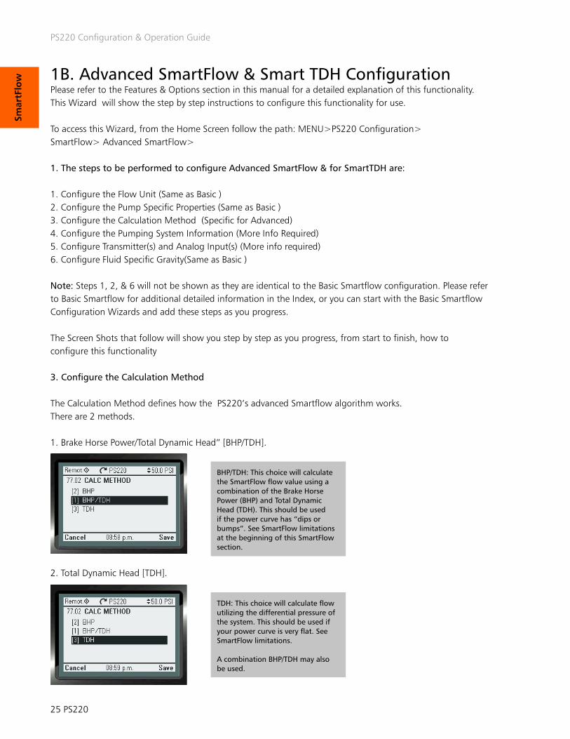
n Pump & VFD Protection Wizard The PS220 Pump & VFD functionality can be configured to fully identify, notify, control, and prevent a pump in a system that may operate in an underload, overload conditions, and all of the adverse conditions of dry-run, dead-head, minimum flow, runout and cavitation. It can also provide the pumping system protection to ensure that indirect damage from conditions such as over pres-sure, water hammer, and liquid temperature rise will not occur. The onboard logic can also monitor external devices that are an integral part of the pump-ing system to add an additional level of protection as well. Since the core functionality of the Pumpsmart PS220 is that it is a Variable Frequency Drive (VFD), it also provides the ability to identify and react to the most common electrical system upsets such as Undervoltage, Overvoltage, Overcurrent, Stall, Underload and Overtemp.
Please refer to the Features & Functions section in this manual for a more detailed explanation of all of this functionality. This Wizard will show the step by step instructions to configure this functionality for use.
This functionality can be configured with the Pumpsmart PS220 Configuration Wizard.
To access this Wizard, from the Home Screen follow the path: MENU>PS220 Configuration>Pump & VFD Protection
The Screen Shots that follow will show you step by step, from start to finish as you progress, how to configure each of these choices of functionality.

PS220 Configuration & Operation Guide
PS220 44
Pum
p &
VFD
Pro
tection
1. Basic Pump Protection.The Basic Pump Protection functionality uses the Process Control feedback to determine when upset conditions may be occurring in the system. Depending on the Process Control Mode selected it may be considered “Sensorless”.
Basic Pump Protection declares a protection event when the pump is running at full speed, an error greater than permitted exist, and both conditions exist for a protection delay period. Because the VFD must get to full speed to declare a Basic Pump Protect this form of protection is not available in Speed Control. It can be used only with PID control.
This event could be the result of a number of upset conditions both internal and external of the pump. While PumpSmart cannot determine what the cause of the event is it will provide a desired notification and response if the event occurs.
2. Advanced Pump Protection. The Advanced Pump Protection functionality uses the Pumpsmart PS220’s feedback from SmartFlow to determine when upset conditions may be occurring in the system. This protection is considered to be “Sensorless”. At the user’s discursion a flow meter may or may not be used in place of SmartFlow for the min flow and run out conditions of this protection. Dry Run will always require SmartFlow setup.
NOTE: The Basic Pump Protection and Advanced Pump Protection should not be both used together.
1. Configure Basic Pump Protection OR1. Configure Advanced Pump Protection A. Configure flowmeter [OPTIONAL] B. Configure Minimum Flow Control C. Configure Dry Run Control D. Configure Runout Control
Additionally Basic and Advanced (Sensorless) Pump Protection parameter settings can be found in group 79.

PS220 Configuration & Operation Guide
45 PS220
Pum
p &
VFD
Pr
ote
ctio
n Configure Basic Pump Protection This functionality can be configured with the Pumpsmart PS220 Configuration Wizard.
To access this Wizard, from the Home Screen follow the path: MENU>PS220 Configuration>Pump & VFD Protection>Pump Protection>Yes>
The individual steps that will be performed are:
1. Enable the Basic Pump Protection function.2. Configure the Response.3. Configure the Limit. 4. Exit Basic Pump Protection Wizard
NOTE:Some steps will require you to use the:1. “ARROW RIGHT” button to change the value2. “ARROWS” to configure the value3. “Save” button to continue
Once that step is completed, use the “ARROW DOWN” button to go to the next line on the page. Selecting “Next” at the bottom of each page will bring you to the next page requiring configuration.
1. Configure enabling of the Basic Pump Protection
A. Enable Basic Pump ProtectionB. Select the type of protection desired
A B

PS220 Configuration & Operation Guide
PS220 46
Pum
p &
VFD
Pro
tection
C. Select the desired action (response)
C
Disabled - The PumpSmart PS220 will not respond. The pump will continue to run at the maximum allowed speed while not achieving the set-point requirement. This is the Default.
Warning - The PumpSmart PS220 will issue the warning message “Basic Pump Protection”. The pump will continue to run at the maximum allowed speed while not achieving the set-point requirement.
Alarm & Control - The PumpSmart PS220 will either:Issue a warning message, and either run at minimum speed or stop, based on how STP DELAY MIN SPD is set (coming up in two screens).
PumpSmart may be configured to automatically retry to overcome the fault conditions up to a maximum of 19 times before a hard Fault is issued. The Fault will have to be reset, and the drive manually restarted. Refer to the “Fault Tracing” section for further information.
D. Select the desired action (response)E. Select if you would like to use Sensorless Protection
D E
The Pump Protection limit is the value, in percent of the actual set-point, below where the system is allowed to run, at or below, before the Basic Pump Protection Function becomes active. The default value is 97%. Ex.: with a value of 97%, if the process actual value drops below 97% of the set-point for the PROTECTION DELAY then a Pump Protect will be declared.
Selecting No for Sensorless Protection will take you directly to the Protection Options screen. This same screen is found when setting Yes here, but only after two more additional screens.
Selecting Yes here starts Advance Pump Protection configuration.

PS220 Configuration & Operation Guide
47 PS220
Pum
p &
VFD
Pr
ote
ctio
n
2. Configure Advanced (Sensorless) Pump Protection The Advanced Pump Protection uses a full array of the PumpSmart PS220’s sensorless feedback, from SmartFlow to Smart TDH in identifying upset conditions that may occur in the system. This configuration will use these values of Dry Run, Minimum Flow and Runout Flow, along with response types you establish, to define the systems reaction to these events.Please refer to the Features & Functions section in this manual for a detailed explanation of this functionality. This Wizard will show the step by step instructions to configure this functionality for use.
NOTE:The Keypad will show the specific warning and alarm message signifying when they occur. The list of events will be as follows:
This functionality can be configured with the Pumpsmart PS220 Configuration Wizard.
To access this Wizard from the Home Screen, follow the path: MENU>PS220 Configuration>Pump & VFD Protection>Pump Protection>Select>Next
Specific parameters associated with Advance Pump Protection can be found in group 79. Screen Shots that follow will show you step by step, from start to finish, how to configure this functionality.
The description, along with the screenshots below, will show the steps you will take from start to finish to configure this functionality.
The individual steps that will be performed are:1. Configure the choice for Advanced Pump Protection.2. Configure the Flow feedback source.3. Configure the Response to Minimum Flow. 4. Configure the Minimum Flow Value.5. Configure the Dry Run Response.6. Configure the Runout Flow Response. 7. Configure the Runout Flow Value.
A. Select Yes or No for having access to an external flow meter signal
A
Selecting No here will take you directly to the Protection Options screen. Selecting Yes will request additional de-tails on the flow meter, including if the flow meter has already been assigned as the primary process input. If not the primary process input you will be asked to define which analog input the meter is connected to and what is the scaling for the meter input.
NOTE: Yes cannot be used for individu-al pump protection when the pump is part of a Multipump configuration.
NOTE 2: An unused AI will need to be used for this choice to function correctly. Please check the settings of the Analog Inputs in use by going to: MENU>PARA-MATERS> Complete List>Scroll down to Group 76>Select and View 76.01&02. If available they will show “NOT SELECTED”. You may have to add an Extension Card to use an additional input. (Not provided as standard)

PS220 Configuration & Operation Guide
PS220 48
Pum
p &
VFD
Pro
tection
B. Select the Min Flo Control action
B
C. Select Min Flow value
C
Alarm & Control - The PumpSmart PS220 will either: Issue a warning mes-sage, and either run at minimum speed or stop, based on how STP DELAY MIN SPD is set (coming up in two screens).
For Min Flow and Run Out conditions PumpSmart may be configured to automatically retry to overcome the fault conditions up to a maximum of 19 times before a hard Fault is issued. The Fault will have to be reset, and the drive manually restarted. Refer to the “Fault Tracing” section for further information. Automatic Retries is not available for Dry Run conditions.
D. Select Dry Run Control response
D
Dry Run factor (Not a step)The Dry Run factor is for “fine tuning” the Dry Run fault feature. It should only be adjusted during initial commissioning of the Dry Run control functionality. Normally this parameter requires no adjustment but is available should it be required. If it is adjusted it should only be increased at 1/100th at a time.

PS220 Configuration & Operation Guide
49 PS220
Pum
p &
VFD
Pr
ote
ctio
n
Configure Runout Flow ResponseWhen a pump produces flow well beyond the Best Efficiency Flow rate that it was designed for it is referred to as Runout. The NPSHa (Net Positive Suction Head Available) is usually less than the NPSHr (Net Positive Suction Head Required) at this operating condition which can lead to severe damage to pump internals and the suction piping system. A conservative estimate for a runout condition to occur is at 110-125% of the Best Efficiency Point Flow [BEP Flow].
The Pumpsmart PS220’s only response when using the Runout Protection is to provide a warning.
The following image illustrates both Minimum Flow and Runout Flow on a pump performance curve.
Min Flow
Runout Flow
Configure Runout Flow Value

PS220 Configuration & Operation Guide
PS220 50
Pum
p &
VFD
Pro
tection
Configure Pump Protection Options Please Refer to the Features & Functions section in this manual for a detailed explanation of this functionality. This Wizard will show the step by step instructions to configure this functionality for use.
This functionality can be configured with the Pumpsmart PS220 Configuration Wizard.
To access this Wizard from the Home Screen, follow the path: MENU>PS220 Configuration>Pump & VFD Protection>Secondary Protection>
Screen Shots that follow will show you step by step, from start to finish, how to configure this functionality
The individual steps that will be performed are:1. Configure the Protection Delay2. Configure Speed Override Pump Protection 3. Configure the Pump Fault Reset Delay4. Configure the Config Speed Min Setting5. Configure the Stop Delay at Min Speed6. Configure the Pump Fault Reset NOTE:Choices 1-5 will apply to all of the Pump Protection Functions except where noted. They will not be applicable to any VFD or Motor protection. The VFD Protection Options are covered in the section “VFD Auto-Reset” on page 50
1. Configure the Protection Delay:The Pumpsmart PS220 can be configured to delay the reaction time that The PS220 will wait until activating the control of any of the protection features.Notes: 1. The default is 0 which deactivates the function. The Maximum setting is 200 seconds, and the Minimum is 1 second.
2. Configure the Speed Override Pump Protection setting.The Pumpsmart PS220 can be configured to allow all of the Pump Protection configured to be active when the Speed Override function is also active. The Default value is “Disabled”

PS220 Configuration & Operation Guide
51 PS220
Pum
p &
VFD
Pr
ote
ctio
n
3. Configure the Pump Fault Auto Reset: The Pumpsmart PS220 can be configured to “Auto-Reset” up to a set number of times when the “Alarm & Control” choice has been configured for the “Protection Response“ for any Pump Protection function.This function is not available for the Secondary Protection A or B functionality.
Notes:A. The Default value is 0, which deactivate the function. The range is (0-19).
The PS220 will automatically end the retry attempts and end any further attempts when the system runs for more than 5 minutes, continuously, without the event(s) re-occurring.
4. Configure the Pump Fault Reset Delay The Pump Fault Reset Delay can be configured to delay the time that the PS220 will wait until Auto-Restarting after a Pump Protection “Alarm and Control” action has been taken.
Notes: 1. The default is 60 seconds. The range is 0 - 3600 seconds.
5. Configure the Config Speed Min setting. The Pumpsmart PS220 can be configured to run to a “Config Speed Min “ speed choice when “Alarm and Control” has been configured as the Response for the Pump Protection selection. The choices are:1. The Minimum Speed set in Parameter 30.11. ( SPD=MIN)2. ZERO (0) RPM or to stop. ( Speed =0)
Notes:1. This choice cannot be selected for individual Responses. This is applied “globally” when selected.2. This selection should not be used if “Min-Speed” is selected for the PID sleep function in process control. The sleep function will need to be change to “INTELL SLEEP”
6. Configure the Stop Delay Min Speed.The Pumpsmart PS220 can be configured to come to a full stop and Fault off when using Secondary Protection. When “Config Speed Min” = “Min Speed”, once the drives begins to run at “Min Speed” and this time frame expires, the Pumpsmart PS220 will issue a fault and stop. The message “Sec # Alarm” will display and be captured in the event log. This is not a re-settable fault. It will have to be reset and manually restarted.
(# = The ID of the Protection configured, A or B)

PS220 Configuration & Operation Guide
PS220 52
Pum
p &
VFD
Pro
tection
Secondary Protection Wizard Secondary Protection uses onboard Digital Input switch connections from any external device, such as a flow, pressure, or level switch, or other type of “Dry-Contact” out from any device such as a PLC. It can provide a type of permissive or “ Go-No Go” inter-lock capabilities with the pumping system. Please Refer to the Features & Functions section in this manual for a detailed explanation of this functionality. This Wizard will show the step by step instructions to configure this functionality for use.
This functionality can be configured with the Pumpsmart PS220 Configuration Wizard.
To access this Wizard from the Home Screen, follow the path: MENU>PS220 Configuration>Pump & VFD Protection>Secondary Protection>
The individual steps that will be performed are:1. Configure the use Secondary Protection A or B.2. Configure the Protection Response.3. Configure the Digital Input to be used.4. Exit the Wizard. The Screen Shots that follow will show you step by step, from start to finish, how to configure this functionality.
1. Configure the use of Secondary Protection A or B.
2. Configure the Protection Response.
NOTE: YOU MAY SEE THIS WARNING AS SOON AS YOU CONFIGURE THE RESPONSE SELECTION SELECT “HIDE” AND CONTINUE .
A Secondary Protect condition exist when 24Vdc is removed from a Secondary Protect digital input. If 24Vdc is returned to this input the PS220 will automatically start up again.

PS220 Configuration & Operation Guide
53 PS220
Pum
p &
VFD
Pr
ote
ctio
n
3. Configure the Digital Input to be used.
Notes:DI4 is the default selection for Secondary Protection A
DI5 is the default selection for Secondary Protection A
An unused Digital Input (DI) will need to be configured for either of these 2 choices to function. Please check the settings of the Digital Inputs currently in use by going to: MENU>Parameters> Complete List>Scroll down to Group 76>Select and View 76.09 through 76.14. If available for configuration, “ NOT SELECTED” will be shown. An Extension Card will need to be added and configured if they are all in use. TO CONFIGURE SECONDARY PROTECTION B FOLLOW THE SAME STEPS AND CONFIGURE CHOICE B in Step 2 above.
4. Exit the Wizard

PS220 Configuration & Operation Guide
PS220 54
Pum
p &
VFD
Pro
tection
Condition Monitoring Wizard The Pumpsmart PS220 has the ability to monitor two separate channels of information. This information can be from any of its analog transmitters connected or from the onboard VFD and PUMP ACTUAL signals selected from specific parameter Groups. Once the source(s) have been identified you will have the ability to set both a Warning and Alarm limit level on the High AND the Low Values and choose a form of response properly suited for the pumping system.Please Refer to the Features & Functions section in this manual for a detailed explanation of this functionality. This Wizard will show the step by step instructions to configure this functionality for use.
This functionality can be configured with the Pumpsmart PS220 Configuration Wizard.
To access this Wizard from the Home Screen, follow the path: MENU>PS220 Configuration>Pump & VFD Protection>Condition Monitoring
The individual steps that will be performed are:1. Configure the Condition 1 Source. 2. Configure the Condition 1 Warning Limits High and/or Low Values. 3. Configure the Condition 1 Warning Alarm High and/or Low Values.4. Configure the Condition 1 Response. 5. Configure the Condition 1 Response Delay time. 6. Configure the Min Speed Stop Delay time. 7. Configure the Hysteresis Value8. Exit the Wizard
The Screen Shots that follow will show you step by step, from start to finish, how to configure this functionality.
1. Configure the Condition 1 Source. Note: The units will display on the remaining screens when you select the source
NOTE: A Condition Warning will only place a warning on the display, and may be used to turn on a relay if assigned.Only a Condition Alarm can cause a Min Speed, Sleep, or Fault action.

PS220 Configuration & Operation Guide
55 PS220
Pum
p &
VFD
Pr
ote
ctio
n
2. Configure the Condition 1 Warning Limits High and/or Low Value:
3. Configure the Condition 1 Response.
Once you configure the response you may receive this message. Select “Hide” and continue. Read the note
4. Configure the Condition 1 Alarm Limits High and/or Low Value
5. Configure the Condition 1 Response Delay time. The Default is 20 Seconds. The range is 0-3600 seconds.

PS220 Configuration & Operation Guide
PS220 56
Pum
p &
VFD
Pro
tection
6. Configure the Min Speed Stop Delay time.The Default is 20 Seconds. The range is 0- 3600 seconds.
7. Configure the Hysteresis Value.The Default is .20 of the units chosen. The range is (0-9999
To Configure a Second Condition:
Note:For the configuration of the Second Condition only these steps 1-5 would need to be followed.
1. Configure the Condition 2 Source. 2. Configure the Condition 2 Warning Limits High and/or Low Values. 3. Configure the Condition 2 Warning Alarm High and/or Low Values.4. Configure the Condition 2 Response. 5. Exit the Wizard
NOTE FOR CONDITION RESPONSE CONFIGURATION IN STEP 4 ABOVE:You may have to change the configuration of Parameter 80.19 to allow Monitoring of the values when the Pumpsmart PS220 is either onlye When Running or Always. The default is ALWAYS.
This change will need to be done manually by accessing that specific parameter directly:
From the HOME SCREEN: MENU>Parameters>Complete List>Arrow Down to GROUP 80>80.19> Edit>Save
See the screen shots below:
8. Exit the Wizard

PS220 Configuration & Operation Guide
57 PS220
Pum
p &
VFD
Pr
ote
ctio
n Flow Bypass Recirculation Wizard Flow Bypass RecirculationThe PS220’s Flow Bypass Recirculation function will allow for a triggered event that can be used to control the opening and closing of a minimum flow bypass valve that may be required in a pumping system. An available Relay Out can be used with this function to send the signals to external devices when required to operate.This functionality uses the Minimum Flow value sensed from either SmartFlow or from an external flow meter.
This Wizard will show the step by step instructions to configure this functionality for use.
This functionality can be configured with the Pumpsmart PS220 Configuration Wizard.
The individual steps that will be performed are:1. Configure the use of the Flow Bypass Recirculation function. 2. Configure the FLOW BYPASS Source. 3. Configure the FLOW BYPASS On flow rate. 4. Configure the FLOW BYPASS OFF RATIO5. Configure the ON DELAY time. 6. Configure the OFF DELAY time. 7. Configure the Flow Relay Start Delay time. 8. Exit the Wizard.
The Screen Shots that follow will show you step by step, from start to finish, how to configure this functionality. 1. To access this Wizard from the Home Screen, follow the path: MENU>PS220 Configuration>Pump & VFD Protection>Condition Monitoring>Next>No
2. Configure the FLOW BYPASS SOURCE.
1. “ARROW RIGHT” To change 1. “ARROW DOWN” To select 2. “SAVE” to continue
“NEXT”
Flow Bypass is especially useful when it is necessary to run the pump below its minimum flow. When PumpSmart identifies that the flow is below the pump’s minimum flow value it will turn on a digital output (used to open a bypass valve). The bypass line is typically sized to flow the minimum flow value at the required head pres-sure. Once the flow is detected as 2.1 times the minimum flow then PumpSmart will turn off the digital output (close the valve).

PS220 Configuration & Operation Guide
PS220 58
Pum
p &
VFD
Pro
tection
1. “ARROW DOWN” To change value 2. “SAVE” to continue
1. “ARROW RIGHT” To change 1. “ARROW DOWN” To select 2. “SAVE” to continue 3. “NEXT”
3. Configure the FLOW BYPASS ON flow rate: This can be a different value than what is already defined in Parameter 79.09 for MIN FLOW.
4. Configure the FLOW BYPASS OFF RATIO
1. “ARROW RIGHT” To change 1. “ARROW DOWN” To change value 2. “SAVE” to continue 3. “NEXT”
5. Configure the ON DELAY Time.The time duration for the Flow Bypass to activate a relay, once the Bypass Flow value is achieved, and the FLOW RELAY START DELAY time expires.
2.1 times min flow is the default value. Assuming that the bypass is sized to pass minimum flow at the required head then when the valve closes at 2.1 times the min flow value the pump will be left with a flow of 1.1 times the minimum flow.

PS220 Configuration & Operation Guide
59 PS220
Pum
p &
VFD
Pr
ote
ctio
n
1. “ARROW RIGHT” To change 2. “ARROWS” to change value 3. “SAVE” to continue
6. Configure the OFF DELAY time.The time duration for the Flow Bypass to deactivate a relay, once the value of the formu-la ((“FLOW BYPASS ON”) X (“FLOW BYPASS OFF RATIO”)) is reached.
7. Configure the FLOW RELAY START DELAY time:
1. “ARROW RIGHT” To change 2. “ARROWS” to change value 3. “SAVE” to continue4. “NEXT”
8. Exit the Wizard

PS220 Configuration & Operation Guide
PS220 60
Pum
p &
VFD
Pro
tection
VFD Protection Wizard The PumpSmart PS220 can be configured to protect the PS220 and to protect the motor from common electrical faults. By default, most all of the selections are set to Fault.
Please Refer to the Features & Functions section in this manual for a detailed ex-planation of this functionality. This Wizard will show the step by step instructions to configure this functionality for use.
This functionality can be configured with the Pumpsmart PS220 Configuration Wizard.
To access this Wizard from the Home Screen, follow the path: MENU>PS220 Configuration>Pump & VFD Protection>VFD Protection>
The individual steps that will be performed are:1. Access the VFD Protection Wizard 2. Configure the Maximum current 3. Configure the Overvoltage control 4. Configure the Undervoltage control5. Configure the Autoreset selection6. Configure the Number of trials 7. Configure the Total Trials time 8. Configure the Delay time
The Screen Shots that follow will show you step by step, from start to finish, how to configure this functionality.
1. Access the VFD Protection Wizard

PS220 Configuration & Operation Guide
61 PS220
Pum
p &
VFD
Pr
ote
ctio
n
2. Configure Maximum current: !!CAUTION: SEE THE APPENDIX!!
3. Configure the Overvoltage control: The default is set to ON
4. Configure the Undervoltage control.The default is ON
5. Configure the Autoreset selection:The default for all each is Disabled. (Bit in BOLD is set to 0)
1. “ARROW RIGHT” To change 2. “ARROWS” right to change Bit value 3. “ARROW DOWN” to next Bit (repeat step 2)
3. “SAVE” to continue4. “NEXT”
Maximum current is a user determined maximum current value that the drive will not go over. Setting this too low may make the pump unable to start if the pump has a lot of inertia to over-come, or in some cases may not permit the pump to reach full speed. Be sure to check for proper operation for both instances.

PS220 Configuration & Operation Guide
PS220 62
Pum
p &
VFD
Pro
tection
1. “ARROW RIGHT” To change 2. “ARROWS” to change value 3. “NEXT”
6. Configure the Number of trials. The default is 0. You may have up to 5 trial attempts.
7. Configure Total trials time:
1. “ARROW RIGHT” To change 2. “ARROWS” to change value 3. “NEXT”
8. Configure the Delay time:
1. “ARROW RIGHT” To change 2. “ARROWS” to change value 3. “NEXT”
Note:If the ”Number of trials” and the “Delay time” exceeds the ”Total trials time” the PS220 will not be able to reset automatically. The fault will need to be reset manually.
Before you activate this function, make sure that no dangerous situations can occur. The function resets the drive automatically and continues operation after a Fault. This can result in severe equipment damage or physical injury.

PS220 Configuration & Operation Guide
63 PS220
Mu
ltip
um
p
THIS PAGE IS INTENTIONALLY LEFT BLANK

PS220 Configuration & Operation Guide
PS220 64
Mu
ltipu
mp
PS220 Configuration & Operation Guide
Multipump Wizard Please refer to page 107 of Features & Functions section in this manual for a detailed explanation of this functionality. This Wizard will show the step by step instructions to configure this functionality for use.
This functionality can be configured with the Pumpsmart PS220 Configuration Wizard.
To access this Wizard from the Home Screen, follow the path: MENU>PS220 Configuration>Multipump
The individual steps that will be performed are:1. Configure the Multipump Mode 2. Configure the Pump Address(s)3. Configure the Lead/Lag Switch Hours4. Configure the Value Increase and Decrease Values 5. Configure the Stage and Destage Method 6. Configure the Stage Proof Time7. Configure the De-Stage Proof Time8. Configure the Min Pumps On 9. Configure the Max Pumps On 10. Configure Stage/De-Stage Values for Pumps 2, 3 etc.11. Exit the Wizard
The Screen Shots that follow will show you step by step as you progress, from start to finish as you progress, how to configure this functionality
NOTE: When Configuring Multiple Pumps to be used in your system you will need to follow these steps on each PS220 installed. However, all of the settings will be identical except for step 2 on the next page.
1. Configure the Multipump Mode

PS220 Configuration & Operation Guide
65 PS220
Mu
ltip
um
p
PS220 Configuration & Operation Guide
2. Configure the Pump Address(S)
1. “ARROW RIGHT” To change 2. “ARROWS” to change value 3. “Save”3. “Next
NOTES:1. PumpSmart addressing must use contiguous numbers, example; 1,2,3,4. There can not be a missed address number in the sequence. 2. All PumpSmart drives are programmed exactly the same with exception of the address. Each PS220 must have a unique address.
1. “ARROW RIGHT” To change 2. “ARROWS” to change value 3. “Save”3. “Next”
3. Configure the Lead/Lag Switch Hours Setting this to zero will turn off Lead/Lag alternation.
1. “ARROW RIGHT” To change 2. “ARROWS” to change value 3. “Save”
4. Configure the Value Increase and Decrease Values: The defaults are 5%
1. “ARROW RIGHT” To change 2. “ARROWS” to change value 3. “Save”
5. Configure the Stage and Destage Method The default value is SPEED
Value decrease is the amount of error (difference between set-point and actual) before PumpSmart will want to start the next lag pump.Value Increase is the amount of active set-point increase per pump added. As pumps are added they will experi-ence additional frictional loss. Value Increase compensates for additional frictional losses. See Pressure Boost on page 112.Speed and Torque stage based on an error (Value Decrease) + Stage Speed and Proof Time. Process Value staging is typically used in level control applications and stages pumps on/off at particular levels.

PS220 Configuration & Operation Guide
PS220 66
Mu
ltipu
mp
1. “ARROW RIGHT” To change 2. “ARROWS” to change value 3. “Save”
6. Configure the STAGE PROOF TIME: The default is 20
1. “ARROW RIGHT” To change 2. “ARROWS” to change value 3. “Save”
7. Configure the DESTAGE PROOF TIME The default value is 20 seconds.
8. Configure the MIN PUMPS ON
1. “ARROW RIGHT” To change 2. “ARROWS” to change value 3. “Save”
9. Configure MAX PUMPS ON:
1. “ARROW RIGHT” To change 2. “ARROWS” to change value 3. “Save”
10. Configure the Stage/De-Stage Values for Pumps 2, 3 etc
1. “ARROW RIGHT” To change 2. “ARROWS” to change value 3. “Save”4. “ARROW DOWN”5. Repeat steps 1-3 for the remaining pumps 3-6.6. “Next”
11. Exit the Wizard
NOTE:Once you have completed the Multipump Configuration Wizard you MUST send a setpoint reference change from the source selected in Basic Startup, from and to each and every drive. This will ensure that the reference changes on each drives keypad display. It confirms that the PS220’s are communicating with each other. It should take 3-4 seconds for this change to visibly register across all of the individual drive’s keypads.

PS220 Configuration & Operation Guide
67 PS220
Mu
ltiv
aria
ble
THIS PAGE IS INTENTIONALLY LEFT BLANK

PS220 Configuration & Operation Guide
PS220 68
Mu
ltivariable
Multivariable Control Wizard The Pumpsmart PS220’s Multivariable Control function will allow the Primary Process Controls Setpoint to be varied, and or offset, using a second continuous type signal.
Note: This is only available for Single Pump Applications. Please refer to page 115 of the Features & Functions section in this manual for a detailed explanation of this functionality. This Wizard will show the step by step instructions to configure this functionality for use.
This functionality can be configured with the Pumpsmart PS220 Configuration Wizard.
To access this Wizard from the Home Screen, follow the path: MENU>PS220 Configuration>Multivariable>
The individual steps that will be performed are:1. Enable the Multivariable Control Functionality2. Configure the source for the Secondary process transmitter3. Configure the Scale of the the Secondary process transmitter4. Configure the Limits of Operation5. Exit the Wizard
The Screen Shots that follow will show you step by step, from start to finish, how to configure this functionality.
1. Enable the Multivariable Control Functionality
“ARROW RIGHT” “ARROW DOWN” “SAVE”
“NEXT”

PS220 Configuration & Operation Guide
69 PS220
Mu
ltiv
aria
ble 2. Configure the source for the Secondary process transmitter
3. Configure the Scale of the the Secondary Process Transmitter
1. “ARROW RIGHT” to change 2. “ARROWS” to change value 3. “Save”
1. “ARROW RIGHT” to change 2. “ARROWS” to change value 3. “Save” 4. “Next”
4. Configure the Limits of Operation The limits of operation define the full interaction between the Analog Input you have selected in the previous step with the Primary Reference. Please refer to the example at the end of this section for assistance with the individual limit steps.
A. Configure the Level 1
1. “ARROW RIGHT” to change2. “ARROWS” to change values3. “Save”
B. Configure the SPT LO
1. “ARROW RIGHT” to change2. “ARROWS” to change values3. “Save”
C. Configure the LO INTRCPT
1. “ARROW RIGHT” to change2. “ARROWS” to change values3. “Save

PS220 Configuration & Operation Guide
PS220 70
Mu
ltivariable
D. Configure the LEVEL 2
1. “ARROW RIGHT” to change2. “ARROWS” to change values3. “Save”
E. Configure the SPT HI
1. “ARROW RIGHT” to change2. “ARROWS” to change values3. “Save”
F. Configure the Hi INTRCPT
1. “ARROW RIGHT” to change2. “ARROWS” to change values3. “Save”4. “Next”
5. Exit the Wizard
4. Configure the Limits of Operation (cont’d)
Below is the example that is also shown in the Functions and Features to assist you.Note: This is only available for Single Pump Applications.
EXAMPLE – A pump configured for constant pressure draws from a tank. The level in the tank varies greatly, and occasion-ally drops enough that the pump begins to cavitate. The Basic Pump Protection on the PS220 would limit the speed of the pump or shut it off. Using the Multivariable Control feature would allow for pumping to continue, but at a reduced and allowable rate to prevent any harm to the pump, or the pumping system.
A suction pressure transmitter would need to be added and wired into an unused Anaolog Input (AI2 in this example). AI1 has already been configured for the primary control of the pump. The AI2 signal would then be configured such that when the suction pressure is sufficient, the PumpSmart unit would run to its current reference. When the suction pressure dropped below a certain value it would start to change/offset the setpoint based on the new scaling. In this case it would begin to lower the set point.
When configuring the Multivariable Control function, it is helpful to plot how you will want your set-point to behave in relation to the seconds analog inputs signal.
We suggest using diagrams like the one shown below:
In the diagram, the set-point is 50psi. When the secondary process transmitter (TX2) is below 5ft (LEVEL 1) of tank level, it will begin to scale back the set-point linearly from 50psig to 10psi (SP LO) at 2ft (LO INTRCPT). When the secondary process transmitter (TX2) reaches 16ft of tank level(Level 2), it will increase the set-point linearly from 50psi to 75psi (SP HI) at 18ft (HI INTRCPT).
Note:To Disable this Functionality you MUST re-run the Basic Startup and Process Control Wizards.

PS220 Configuration & Operation Guide
71 PS220
Op
tio
ns
&
Feat
ure
s
THIS PAGE IS INTENTIONALLY LEFT BLANK

PS220 Configuration & Operation Guide
PS220 72
Op
tion
s &
Features
FUNCTIONS & FEATURES The Function & Features section of the manual provides a detailed explanation on off all of the functionality provided on the Pumpsmart PS220. Each Feature will provide a list with descriptions of all parameters used for the individual function to operate. Some of this information is duplicated in the Wizard setup section.
Analog Inputs 74Analog Outputs 76Auto Restart Functions 77 Power Failure Reset 77 Pump Protections 77 VFD 78Condition Monitoring 79Control Modes (New) 82Critical Speeds Lockouts 85Dead Head (NEW) 86Digital Inputs (New) 87 Energy Savings Calculator 88Faults Functions VFD 89Fieldbus 90Flow Totalizer 90Speed Control 91Language (New) 91Local Lock (New) 91Local/Remote Control (New) 91Locking 91Motor Thermal Protection 91 Multipump 92 Transmitter connections 92 Minimum and Maximum number of pumps 93 Stage & Destage 94 Lead-Lag Switching 96 Pressure Boost 100 Externally Powering Control Board 101Parameter Backup/Restore 102Process Control Functions 102 Advanced Pressure Control ( system curve compensation) 102 Multivariable Control 103 Regulation Mode 106 Sleep Function 106 SMARTCONTROL (New) (Torque control) 109Priming Delay 111Pump Protection 112 Basic Pump Protection 112 Advanced Pump Protection (Centrifugal) 114 Secondary Protection 119 Positive Displacement Pump Protection 121 Min Flow Bypass 122

PS220 Configuration & Operation Guide
73 PS220
Op
tio
ns
&
Feat
ure
s
Real Time Clock 123Reference 124Relay Outputs 126Safe Torque Off 127 Signal Supervision (Sensor Failure) 128Setpoints 129 Basic 129 Dual Setpoints 129 External Setpoints 129SMARTFLOW (Sensorless Flow) 130SMARTFLOW TUNE 137SMART TDH (Sensorless Total Dynamic Head) 138Specific Gravity/ Specific Gravity Correction 140Speed Override 143Start Delay 144Start/Stop 144Stop Function 147Tuning (Process Control PID) 147Underload 150VFD PROTECTION 151Water Functions 153 Pump Cleaning Sequence (PCS) 153 Pipe Cleaning 156 Pipe Fill ( revised) 156 Snore Function 157Restoring Defaults (New) 159

PS220 Configuration & Operation Guide
PS220 74
Op
tion
s &
Features
Analog Inputs The PumpSmart PS220 has two configurable analog inputs as standard. By default, both inputs are current sourced and set to 4 to 20 mA. Each can be independently changed to a 0 to 10Vdc voltage sourced input by changing a jumper position on the control board (J1 and J2). Each input can be also be undependably filtered, inverted, and scaled. The number of analog inputs can be increased to five by installing an optional FIO-11 I/O extension card in slot 3 on the control board. When using many of the PS220 Configuration wizards the inputs that you need will automatically be configured. If you need to incorporate additional inputs that have not yet been configured to complete your configuration, you can use the 8. I/O Configuration wizard to assign the all I/O. This Wizard will allow you to add the FIO-11 I/O extension card.
To add the FIO-11 I/O extension card from the home view follow the path: MENU>PS220 Configuration> I/O Configuration>Yes >
To get to the wizard from the home view follow the path: MENU>PS220 Configuration> I/O Configuration>-No( if you do not have the extension Module)>
Potential analog input assignments are found in the group 76 table below. Electrical settings and scaling for integrated analog inputs are done in group 12 (next table).
1. Identify what the Individual Analog Input will be used for, or its Name configuration. These choices are listed in the table below.
Parameter Name Value/Range NOTES
76.01 AI1 CONFIG PROC TRANS 2 Used with Multivariable control.
PROC TRANS 1 The primary process transmitter. The units and transmitter scaling AI1 Max and AI1 Min must also be set.
EXT SETPOINT1 Used when fixed or variable setpoint is sent via an external source to setpoint 1
EXT SETPOINT2 Used when fixed or variable setpoint is sent via an external source to setpoint 2
FLOWMETER Used when a flow meter is selected for use with Sensorless Pump Protection,
DISCH PRESSURE Used with Advanced SmartFlow. Identifies the location of the discharge pressure transmitter.
SUCTION PRESS Used with Advanced SmartFlow. Identifies the location of the suction pressure transmitter.
DIFF PRESS Used with Advanced SmartFlow. Identifies the location of the differential pressure transmitter.
TEMPERATURE Used when a temperature transmitter is being used for SG / VISC correction.
VISC/SG VALUE Used if setting SG or VISC directly using an analog input.
SPD OVRRD REF Used when setting a speed override reference.

PS220 Configuration & Operation Guide
75 PS220
Op
tio
ns
&
Feat
ure
s
GROUP 12 ANALOG INPUTS DESCRIPTION
12.15 AI1 UNIT SELECTION Selects the unit for readings and settings related to analog input AI1. Note: This setting must match the corresponding hardware setting on the drive control unit. See Basic Wiring drawing in appendix A4. (mA or V)
12.17 AI1 MIN Defines the minimum value for analog input AI1. Set the value actually sent to the drive when the analog signal from the external source / transmitter is at its mini-mum setting. (0-22mA or 0-10V)
12.18 AI1 MAX Defines the maximum value for analog input AI1. Set the value actually sent to the drive when the analog signal from the external source / transmitter is at its maxi-mum setting. (0-22mA or 0-10V)
12.19 AI1 SCALED AT AI1 MIN Defines the real internal value that corresponds to the minimum analog input AI1 value defined by parameter 12.17 AI1 min. (0-32768.000)
12.20 AI1 SCALED AT AI1 MAX Defines the real internal value that corresponds to the maximum analog input AI1 value defined by parameter 12.18 AI1 max. (0-32768.000)
12.25 AI2 UNIT SELECTION Selects the unit for readings and settings related to analog input AI2. Note: This setting must match the corresponding hardware setting on the drive control unit (see the hardware manual of the drive). Control board reboot (either by cycling the power or through parameter 96.08 Control board boot) is required to validate any changes in the hardware settings. (mA or V)
12.27 AI2 MIN Defines the minimum value for analog input AI2. Set the value actually sent to the drive when the analog signal is at its minimum setting. (0-22mA or 0-10V)
12.28 AI2 MAX Defines the maximum value for analog input AI2. Set the value actually sent to the drive when the analog signal is at its maximum setting. (0-22mA or 0-10V)
12.29 AI2 SCALED AT AI2 MIN Defines the real value that corresponds to the minimum analog input AI2 value defined by parameter 12.27 AI2 min. (0-32768.000)
12.30 AI2 SCALED AT AI2 MAX Defines the real value that corresponds to the maximum analog input AI2 value defined by parameter 12.28 AI2 max. (0-32768.000)
NOTE: To change from Current sourced to Voltage sourced on the individual inputs change the Jumpers as follows: J1 for AI1 and J2 for AI2. See the Pic below:
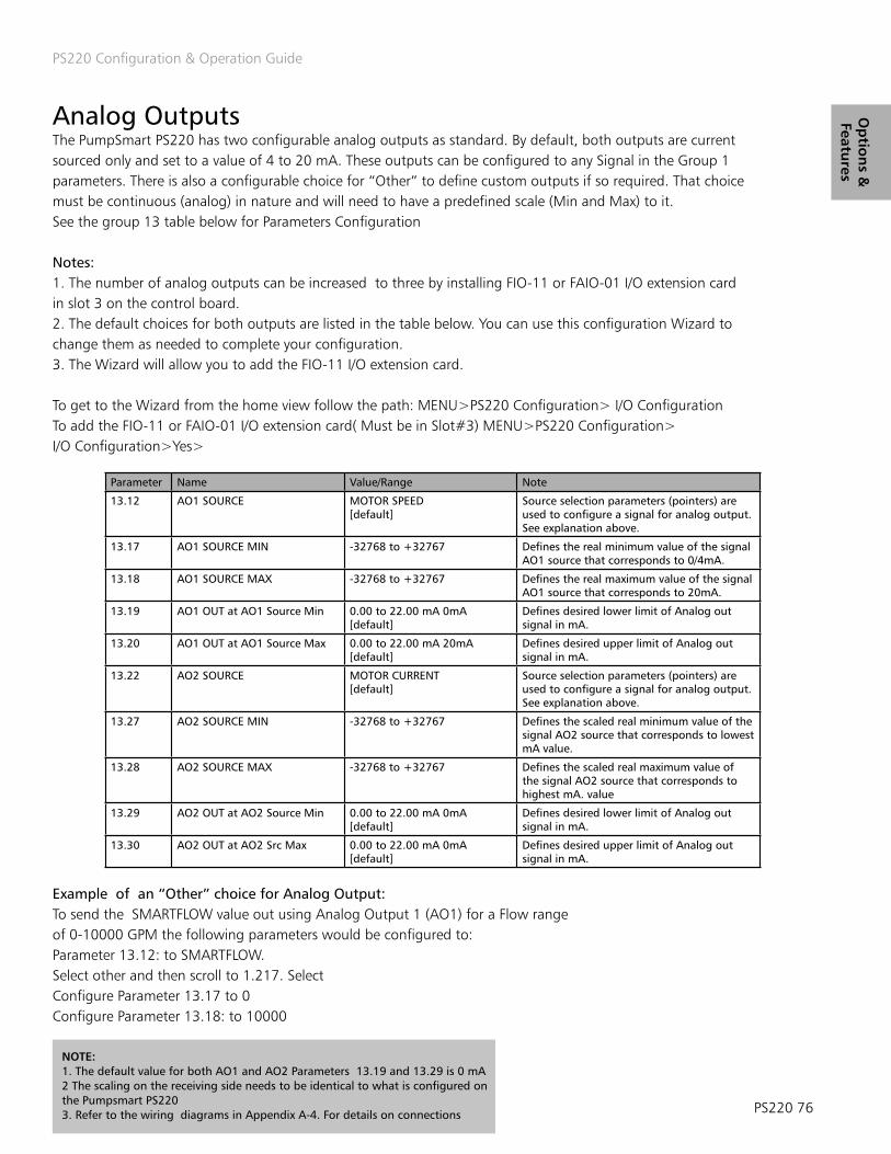
PS220 Configuration & Operation Guide
PS220 76
Op
tion
s &
Features
Parameter Name Value/Range Note
13.12 AO1 SOURCE MOTOR SPEED[default]
Source selection parameters (pointers) are used to configure a signal for analog output. See explanation above.
13.17 AO1 SOURCE MIN -32768 to +32767 Defines the real minimum value of the signal AO1 source that corresponds to 0/4mA.
13.18 AO1 SOURCE MAX -32768 to +32767 Defines the real maximum value of the signal AO1 source that corresponds to 20mA.
13.19 AO1 OUT at AO1 Source Min 0.00 to 22.00 mA 0mA [default]
Defines desired lower limit of Analog out signal in mA.
13.20 AO1 OUT at AO1 Source Max 0.00 to 22.00 mA 20mA [default]
Defines desired upper limit of Analog out signal in mA.
13.22 AO2 SOURCE MOTOR CURRENT[default]
Source selection parameters (pointers) are used to configure a signal for analog output. See explanation above.
13.27 AO2 SOURCE MIN -32768 to +32767 Defines the scaled real minimum value of the signal AO2 source that corresponds to lowest mA value.
13.28 AO2 SOURCE MAX -32768 to +32767 Defines the scaled real maximum value of the signal AO2 source that corresponds to highest mA. value
13.29 AO2 OUT at AO2 Source Min 0.00 to 22.00 mA 0mA [default]
Defines desired lower limit of Analog out signal in mA.
13.30 AO2 OUT at AO2 Src Max 0.00 to 22.00 mA 0mA [default]
Defines desired upper limit of Analog out signal in mA.
Analog Outputs The PumpSmart PS220 has two configurable analog outputs as standard. By default, both outputs are current sourced only and set to a value of 4 to 20 mA. These outputs can be configured to any Signal in the Group 1 parameters. There is also a configurable choice for “Other” to define custom outputs if so required. That choice must be continuous (analog) in nature and will need to have a predefined scale (Min and Max) to it. See the group 13 table below for Parameters Configuration
Notes:1. The number of analog outputs can be increased to three by installing FIO-11 or FAIO-01 I/O extension card in slot 3 on the control board. 2. The default choices for both outputs are listed in the table below. You can use this configuration Wizard to change them as needed to complete your configuration. 3. The Wizard will allow you to add the FIO-11 I/O extension card.
To get to the Wizard from the home view follow the path: MENU>PS220 Configuration> I/O ConfigurationTo add the FIO-11 or FAIO-01 I/O extension card( Must be in Slot#3) MENU>PS220 Configuration> I/O Configuration>Yes>
Example of an “Other” choice for Analog Output: To send the SMARTFLOW value out using Analog Output 1 (AO1) for a Flow range of 0-10000 GPM the following parameters would be configured to: Parameter 13.12: to SMARTFLOW.Select other and then scroll to 1.217. Select Configure Parameter 13.17 to 0Configure Parameter 13.18: to 10000
NOTE: 1. The default value for both AO1 and AO2 Parameters 13.19 and 13.29 is 0 mA2 The scaling on the receiving side needs to be identical to what is configured on the Pumpsmart PS2203. Refer to the wiring diagrams in Appendix A-4. For details on connections

PS220 Configuration & Operation Guide
77 PS220
Op
tio
ns
&
Feat
ure
s Auto Restart The PS220 can be configured to automatically restart on conditions such as Power Failure, VFD faults, and Pump Protection faults. It can be set to reset fault(s) to a limited number of sequential attempts. If after these attempts the Fault condition did not clear or could not be reset the drive will produce a “Hard” Fault and will have to be manually reset. See the Section on Fault Tracing in this Manual for further information on how to restart the drive after these events.
By enabling 74.02 AUTO RESTART, 31.14 AUTO RESET TRIALS or 79.05 PUMP FAULT RESET functions the driven equipment will automatically restart from either a power failure or fault condition if a start signal is present. All precautions should be taken to ensure the driven equipment can be automatically restarted. Failure to follow these instructions may result in physical injury or equipment damage.
WARNING
Power Failure Auto-Restart The PS220 can be configured to start automatically following a power failure by configur-ing the following parameters:
Parameter Name Value/Range Note
74.02 AUTO RESTART OFF [default] ON
Must be set to ON.
NOTE: Auto-Restart will not function with the “Keypad” , or any “Fieldbus” combination is configured for parameter 74.01, or when in “Local” Control Mode.
Pump Protection Auto-Reset The PS220 can be configured to automatically reset a pre-defined pump related fault. If this condition occurs, the pump will ether go to its minimum speed, or fully stop for a limited duration. After this time frame it will automatically re-start. If the condition has cleared the pump will resume normal operation. If the condition remains the PS220 will continue to run this protection routine until the number of attempts has expired. After this time the PS220 will issue a Fault and stop. It will be required to be manually reset. See the Section on Fault Tracing in this Manual for further information on how to restart the drive after these events.
Please refer to the Pump and VFD Wizard for more specific detail on how to set these parameters with your pumping system:
To access this Wizard from the home view, follow the path: MENU>PS220 Configuration> Pump &VFD Protection>Protection Options>

PS220 Configuration & Operation Guide
PS220 78
Op
tion
s &
Features
79.01 Basic Pump Protect Control Disabled (default)AlarmAlarm & Control
Needs to be set to Alarm and Control to allow auto-resetting.
79.05 PUMP FAULT RESET 1-19 0 [default]
Indicates number of automatic fault resets. Selection range is 0 – 19. Needs to be great-er than 0 to allow auto-resetting.
79.06 PUMP RESET DELAY 0-3600 seconds60 [default]
Defines the time that the PS220 will wait after an alarm and control condition before attempting an error reset. Setting Range = 0-3600 sec.
79.08 Min Flow Control Disabled (default)AlarmAlarm & Control
Defines how the drive will react when a Min Flow condition occurs. Alarm and Control will operate according to 79.16.
79.14 & 15 Secondary Protect Control (A & B)
Disabled (default)AlarmAlarm & Control
Defines how the drive will react when a Sec Protect A or B condition occurs. Alarm and Control will operate according to 79.16.
79.16 Config Speed Min SPD=MINSPDSPD=0 [default]
Selecting SPD=MINSPD will result in the drive staying at minimum speed when an ALARM & CONTROL condition exists between resets. Selecting SPD=0 will result in the drive stop-ping completely when an ALARM & CONTROL condition exists.
Following are the Parameters typically used for this Auto-Reset functionality to work properly:
VFD Auto Reset The Pumpsmart PS220 can be configured to automatically reset specific VFD related faults. The drive will follow a routine of faulting, waiting, and automatically resetting up to five time within a pre-determined amount of time. After this time if the condition)s) still is exists the Pumpsmart PS220 drive will issue a “Hard” fault and will have to be manually restarted. Please refer to the Pump and VFD Wizard for more specific detail on how to set these parameters with your pumping system. To access this wizard from the home view, follow the path: MENU>PS220 Configuration> Pump &VFD Protection>VFD Protection
Parameter Name Value/Range Note
31.12 AUTO RESET SELECTION 0000 [default]
Selects faults that are auto-matically reset. The parameter is a 16-bit word with each bit corresponding to a fault type. Whenever a bit is set to 1, the corresponding fault isAutomatically reset.
31.14 NUMBER OF TRIALS 0 – 5 0 [default]
Defines the number of automatic resets allowed. A setting of zero disables this function.
31.15 TOTAL TRIAL TIME 1 – 600 sec180 [default]
Defines the allowable time period for counting and resetting a fault. This param-eter limits the number resets in Parameter 31.14 which can occur within this time period.
31.16 DELAY TIME 0 – 120 sec0 sec [default]
Defines the time that the PS220 will wait before at-tempting an auto reset of the VFD FAULTS selected in 31.12
BIT Fault
0 OVERCURRENT
1 OVERVOLTAGE
2 UNDERVOLTAGE
3 AI SUPERVISION
4 SUPPLY UNIT

PS220 Configuration & Operation Guide
79 PS220
Op
tio
ns
&
Feat
ure
s Condition Monitoring The Pumpsmart PS220 has the ability to monitor two separate channels of information. This information can be from any of its analog or from the onboard VFD and PUMP ACTUAL signals selected from specific parameter Groups. Once the source(s) have been identified you will have the ability to set both a Warning and Alarm limit level on the High and the Low Values and choose a form of response properly suited for the pumping system.

PS220 Configuration & Operation Guide
PS220 80
Op
tion
s &
Features
Overall Summary of warning and alarm actions is as follows. Warning messages will automatically appear on the keypad and the event will be captured in the event log.
Alarms can be configured as follows:1. Alarm and notify. The system will continue to run .
2. Alarm, Notify, and run at a Min SpeedThe PS220 will run at the Min Speed until a time value expires. After this time, if the condition still exists, it will Fault off.
3. Alarm, Notify and Sleep. It will “Sleep” and then “Wake” based on sleep settings. (See Process Control - Sleep)
4. Alarm, Notify, Hard Fault OFF (Stop).
When the PS220 Faults off it will need to be reset. Auto Resetting of Condition Monitoring alarms is not functional (See Fault Tracing/Fault Reset on how to reset the fault)
Note: Refer to the graphic below to better understand the interaction of parameters 80.21 and 80.22 function. These configuration settings when an event will clear.
HysteresisHysteresis is the difference between when an alarm condition is declared and when it will turn off. This enables an alarm to turn on at one value and turn off at a different value.
Figure 4.5: Condition Hysteresis Notice at the COND1 ALARM LIM HI the Alarm does not activate until the condition crosses into the red boundary, but remains activated until it leaves the yellow boundary. The Condition Low Alarm will not activate because the condition never crosses the Low limit.
The Condition Monitoring function can be setup using the Pump & VFD Protection wizard. From the home screen follow the path :MENU>PS220 Configuration>Pump & VFD Protection>Condition Monitoring

PS220 Configuration & Operation Guide
81 PS220
Op
tio
ns
&
Feat
ure
s
The Parameters used in configuring the condition monitoring function are listed in the table below .
Parameter Name Value/Range NOTES
80.0480.10
COND 1 SOURCECOND 2 SOURCE
None [Default] Flow Actual Pressure Actual Level Actual SpeedTorque Power Current Tempera-ture SmartFlowPROC TRANS 1PROC TRANS 2
Select the source of the signal to be monitored. The source can either be from an external transmitter wired to an avail-able analog input or it can be an internal signal as selected by the parameter number.
80.0580.11
COND 1 WRN LIM HI COND 2 WRN LIM HI
-10000 to +100000 [default]
The high value of the warning limit. A warning occurs if the monitored signal rises above this value for longer than the response delay (par 80.16). Inactive if set to 0.
80.0680.12
COND 1 WRN LIM LOCOND 2 WRN LIM LO
-10000 to +10000 0 [default]
The low value of the warning limit. A warning occurs if the monitored signal drops below this value for longer than the response delay (par 80.16). Inactive if set to 0.
80.0780.13
COND 1 ALARMCOND 2 ALARM
DISABLED [default] Protection is inactive.
ALARM ONLY Selecting ALRM ONLY will configure PumpSmart to issue a Key-pad or DCS notice and will trigger a Relay Output (if config-ured) if an ALRM LIM HI or ALRM LIM LO condition is detected. No further action is taken.
MIN SPD Selecting MIN SPD will configure PS220 to drop to 30.11 MIN SPEED and issue a Keypad warning and trigger a Relay Output (if configured) if an ALRM LIM HI or ALRM LIM LO condition is detected. If the alarm does not reset itself after the MIN SPD STP DLY (parameter 80.18) the PS220 will fault.
SLEEP The PS220 will shut down and go into a sleep mode if an ALRM LIM HI or ALRM LIM LO condition is detected. Refer to Sleep Mode Functions for further details.
FAULT The PS220 faults if an ALRM LIM HI or ALRM LIM LO condition is detected. A Keypad notice is issued and a Relay Output is triggered (if configured).
80.0880.14
COND 1 ALRM LIM HICOND 2 ALRM LIM HI
-10000 to +10000 0 [default]
The high value of the alarm limit. An alarm occurs if the monitored signal rises above this value for longer than the condition response delay (par 80.16). Inactive if set to 0.
80.0980.15
COND 1 ALRM LIM LOCOND 2 ALRM LIM LO
-10000 to +10000 0 [default]
The low value of the alarm limit. An alarm occurs if the monitored signal drops below this value for longer than the response delay (par 80.16). Inactive if set to 0.
80.16 COND RESP DELAY 0-3600 sec20 sec [default]
The delay period prior to activation of a COND 1 or COND 2 WRN OR ALRM
80.1780.20
PROC TRANS 1 UNITSPROC TRANS 2 UNITS
None [default] Select from the available 13 options.
80.18 MIN SPD STP DLY 0-3600 sec60 sec [default]
The time period which the PS220 will operate at min speed during an alarm condition if it does not reset. If the time peri-od expires the PS220 will fault.
80.19 CONDITION ENABLE When running Always [Default]
Allows selection of when condition monitoring warnings and alarms to be triggered.
80.21 COND 1 HYSTERESIS -10000 to +10000 0 [default]
Defines the value for the condition 1 source window in the units selected for COND 1 ALRM LIM HI and COND 1 ALRM LIM LO. While operating inside the Cond 1 Hi alarm window or Cond 1 Lo alarm window the Cond 1 Hi or Lo alarm will not reset until the cond 1 source operates outside the window.
80.22 COND 2 HYSTERESIS -10000 to +10000 0 [default]
Defines the value for the condition 2 source window in the units selected for COND 2 ALRM LIM HI and COND 2 ALRM LIM LO. While operating inside the Cond 2 Hi alarm window or Cond 2 Lo alarm window the Cond 2 Hi or Lo alarm will not reset until the cond 2 source operates outside this window.
CAUTION: Parameter 80.19 is a setting that allows the monitoring of the Condition Values to be always on or only on when the Pump is physically running(Rotating).
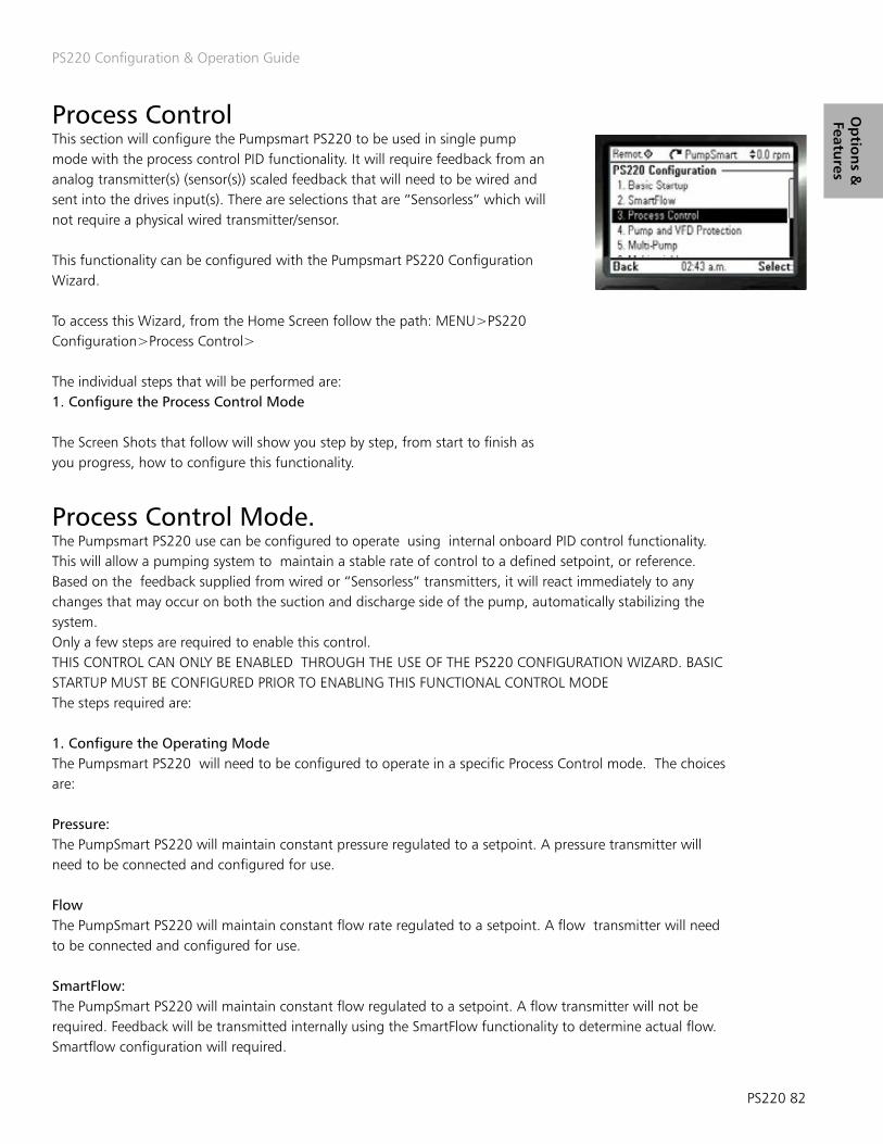
PS220 Configuration & Operation Guide
PS220 82
Op
tion
s &
Features
Process Control This section will configure the Pumpsmart PS220 to be used in single pump mode with the process control PID functionality. It will require feedback from an analog transmitter(s) (sensor(s)) scaled feedback that will need to be wired and sent into the drives input(s). There are selections that are “Sensorless” which will not require a physical wired transmitter/sensor.
This functionality can be configured with the Pumpsmart PS220 Configuration Wizard.
To access this Wizard, from the Home Screen follow the path: MENU>PS220 Configuration>Process Control>
The individual steps that will be performed are:1. Configure the Process Control Mode
The Screen Shots that follow will show you step by step, from start to finish as you progress, how to configure this functionality.
Process Control Mode. The Pumpsmart PS220 use can be configured to operate using internal onboard PID control functionality. This will allow a pumping system to maintain a stable rate of control to a defined setpoint, or reference. Based on the feedback supplied from wired or “Sensorless” transmitters, it will react immediately to any changes that may occur on both the suction and discharge side of the pump, automatically stabilizing the system.Only a few steps are required to enable this control. THIS CONTROL CAN ONLY BE ENABLED THROUGH THE USE OF THE PS220 CONFIGURATION WIZARD. BASIC STARTUP MUST BE CONFIGURED PRIOR TO ENABLING THIS FUNCTIONAL CONTROL MODEThe steps required are:
1. Configure the Operating ModeThe Pumpsmart PS220 will need to be configured to operate in a specific Process Control mode. The choices are:
Pressure:The PumpSmart PS220 will maintain constant pressure regulated to a setpoint. A pressure transmitter will need to be connected and configured for use.
FlowThe PumpSmart PS220 will maintain constant flow rate regulated to a setpoint. A flow transmitter will need to be connected and configured for use.
SmartFlow:The PumpSmart PS220 will maintain constant flow regulated to a setpoint. A flow transmitter will not be required. Feedback will be transmitted internally using the SmartFlow functionality to determine actual flow. Smartflow configuration will required.

PS220 Configuration & Operation Guide
83 PS220
Op
tio
ns
&
Feat
ure
s
Level:The PumpSmart PS220 will maintain constant level regulated to a setpoint. A level, (or pressure that can be convert-ed to level), transmitter will need to be connected and configured for use.
Temperature:The PumpSmart PS220 will maintain constant temperature of the process fluid regulated to a setpoint. A tempera-ture transmitter will need to be connected and configured for use.
Smart TDH: Pumpsmart will maintain a constant Total Dynamic Head (TDH) using internal TDH calculations to a setpoint. It will not require the use of a transmitter if the suction pressure is relatively stable. If the suction pressure does vary this control mode will require both a suction and discharge transmitter to be connected, and fully config-ured for use. It will also require the configuration of the Advanced SmartFlow Functionality.
2. Configure the Unit SelectionThe configuration of the Pumpsmart PS220’s unit selection will determine the labeling used to control the pump, the setpoint, and the actual feedback from the transmitter. Following are the available units based on your selection in 1 above.
Control Mode Units available for selectionPressure Smart TDH
PSI (DEFAULT)
FT – FEET
Mpa – Mega Pascals
M - Meters
BAR
Level Pressure (#) # = can be converted to level
Ft – Feet (DEFAULT)
In – Inches
M – Meters
Cm – Centimeters
Flow SmartFlow
GPM – Gallons per Minute (DEFAULT)
M³/hr. – Cubic meters per hour
BPH – Barrels Per Hour
L/s – Liters per second
Temperature °F – Degrees Fahrenheit (DEFAULT)
°C – Degrees Celsius
3. Configure the Transmitter Location The configuration of transmitter location on the Pumpsmart SP220 identifies whether the transmitter is on the suction side of the piping system or on the discharge.
Note:When choosing suction side, the software will automatically invert the actual signal. (A rising value will increase the speed of the pump to maintain the process setpoint). Check to be sure that the transmitter being used does not do this as standard.
Refer to the “Regulation Mode” in this manual for more information

PS220 Configuration & Operation Guide
PS220 84
Op
tion
s &
Features
PS220 Configuration & Operation Guide
4. Configure the Transmitter Information Detail Configure the physical identity of the Analog Input’s transmitter, AI#, used for the Control Mode.
NOTES1. # = The identification of the Analog Inputs physical wired connection. AI1,2 etc. 2. When Selecting the Analog Input make sure that it is connected to the correct input (see analog input wiring diagrams at the back of this manual.)
Configure the minimum scaled value of the AI# transmitters signal. “AI# scaled at AI# min” refers to the transmitters value that corresponds to the minimum of the signal or the 4mA scaled value. This is defaulted to 0.
Configure the maximum scaled value of the AI# transmitters signal.
“AI# scaled at AI# max” refers to the transmitters value that corresponds to the maximum of the signal or the 20mA scaled value. The default value is 100.
NOTES1. If the transmitter used provides a dc voltage signal (example; 2-10Vdc or 0-10Vdc) please refer to the Analog Input section of the manual for setting an analog input to a dc voltage input type. A Jumper connection on the hardware will need to be moved. (J1, or J2)
2. Differential pressure flowmeters [e.g. orifice plate, venturi, etc.] do not produce signals that are linear with flowrate. PumpSmart cannot provide square root extraction in this case. Check the flow transmitter for its ability to provide this square root extraction function.
3. Refer to the transmitter manufacturers documentation for the proper wiring instruction and to determine the correct scaled values. This information may also be printed on the device itself.
4. The software automatically defines the selected analog input to “PROC TRANS 1” as the primary process transmitter for the system.
Configure the Setpoint Limits. The setpoint limits, SETPOINT MIN and SETPOINT MAX, are the values, below and above, that the system cannot be operated at. These can be different from the scaled values configured for use.
If the process variable chosen is SmartFlow , then only SETPOINT MIN and SETPOINT MAX are shown and need to be defined. SETPOINT MIN will typically be zero while SETPOINT MAX should be set at a value equal to the maximum flow of the pump. Be sure that you complete the SmartFlow wizard prior to running your process or the feedback will be incorrect.
Configure the Setpoint Minimum and Maximum Detailed Information on how configure the Setpoint Limits can be found in the Appendix. Please refer to “Setpoints”
Configure the Setpoint Source The source can be selected from the PS220’s Keypad, an Analog Input or a Fieldbus Control command.Detailed Information on how configure the Setpoint Source can be found in the Appendix. Please refer to “Setpoints”
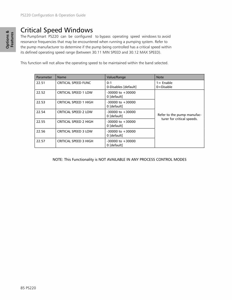
PS220 Configuration & Operation Guide
85 PS220
Op
tio
ns
&
Feat
ure
sPS220 Configuration & Operation Guide
Critical Speed Windows The PumpSmart PS220 can be configured to bypass operating speed windows to avoid resonance frequencies that may be encountered when running a pumping system. Refer to the pump manufacturer to determine if the pump being controlled has a critical speed within its defined operating speed range (between 30.11 MIN SPEED and 30.12 MAX SPEED).
This function will not allow the operating speed to be maintained within the band selected.
Parameter Name Value/Range Note
22.51 CRITICAL SPEED FUNC 0-10-Disables [default]
1= Enable 0=Disable
22.52 CRITICAL SPEED 1 LOW -30000 to +300000 [default]
Refer to the pump manufac-turer for critical speeds.
22.53 CRITICAL SPEED 1 HIGH -30000 to +300000 [default]
22.54 CRITICAL SPEED 2 LOW -30000 to +300000 [default]
22.55 CRITICAL SPEED 2 HIGH -30000 to +300000 [default]
22.56 CRITICAL SPEED 3 LOW -30000 to +300000 [default]
22.57 CRITICAL SPEED 3 HIGH -30000 to +300000 [default]
NOTE: This Functionality is NOT AVAILABLE IN ANY PROCESS CONTROL MODES

PS220 Configuration & Operation Guide
PS220 86
Op
tion
s &
Features
Dead Head Dead Heading is a term used to define when a pump is running at “A Zero Flow Rate” AND producing pressure in the discharge piping. When this occurs, the pump is also generating work in Horsepower. Depending on the HP of the pump this pressure generated can be a large value. The HP generated for all centrifugal Pumps follow the Affinity Laws. The Pressure generated will be directly proportional to the square of the running speed, and HP will be to the cube of the speed.This can be the result of:1. A pump that is “undersized” that cannot generate enough pressure to move fluid to the end point in the discharge.2. A discharge valve that has been closed inadvertently or has failed in the closed position.3. A blockage or Clog in the discharge line preventing any flow from exiting the discharge end of the piping.
When using the Pumpsmart PS220’s PID Pressure or Smart THD Control Logic this can be completely avoided by performing the “Dead Head Test”.
This test will require the wired pressure sensor (Pressure PID)/gauge (SmartTDH) on this discharge end of the piping that is placed down-stream of (before) a discharge valve. That valve will need to be able to be complete-ly closed with no path for any re-circulation back to the suction. The suction line will also need to be completely open and flooded with all air vented out of the pump. When all of these conditions are met you will need to do the following.
NOTE: All Configuration should be completed prior to this step EXCEPT for pump protection.
1. Open the Suction Valve.2. Vent all air out of the discharge side and what may be inside the pump.3. Open the Discharge Valve 100% 4. On the PS220 Set Parameter 30.11 (Min Speed) to no less than 25% of the nameplate speed of the motor.5. Enter the setpoint that you will be using that run the system.6. Issue a start command. The PS220 will then run at a speed to maintain the setpoint for your system.7. Slowly close the discharge valve until its 100% closed.8. Document the speed the PS220 runs at when the valve is 100% closed.9. Issue a STOP command. 10. Set Min Speed in 30.11 to at least 100 RPM above the value from Step 8.11. Open the discharge valve 100%
If “Min Speed Sleep” has been configured using The Process Control Wizard. This system is now configured correctly so that it will never “Dead Head”
12. Finish Configuration adding the Pump Protection as required.

PS220 Configuration & Operation Guide
87 PS220
Op
tio
ns
&
Feat
ure
s
Group 76 ANALOG I/O CONFIG DESCRIPTION76.09 DI1 Selects the Digital input 1 function
76.10 DI2 Selects the Digital input 2 function
76.11 DI3 Selects the Digital input 3 function
76.12 DI4 Selects the Digital input 4 function
76.13 DI5 Selects the Digital input 5 function
76.14 DI6 Selects the Digital input 6 function
76.15 DIO1 Selects whether DIO1 is used as a digital output or input, or a frequency input.
76.16 DIO2 Selects whether DIO2 is used as a digital output or input, or a frequency input.
Digital Inputs
Digital Inputs/Outputs The Pumpsmart PS220 has 6 Digital inputs. They can be inverted and forced on/off as required. There are 2 additional points that can be assigned as either an input or an output. These two additional points are TTL in nature and are good for a maximum of 200mA load. By default all are set to Not Used. An additional digital input labeled DIIL can be used as a drive permissive. This input has a jumper from 24Vdc installed at the factory.The preferred defaults for these are as follow:
DI1 Auto Start/StopDI2 Hand Start/StopDI3 Dual SetpointsDI4 Secondary Protection ADI5 Secondary Protection BDI6 Fault Reset
Most all of the functional uses for these are configured with the PS220 Configuration Wizards.
Caution must be taken when configuring them manually. It is possible to configure the same Digital Input for more than one function.
A digital input that displays the status of “IN USE” cannot be changed manually with the I/O Wizard. Only inputs which display the status of “NOT SELECTED” can be configured with the I/O Wizard, To manually configure an input, from the Home View follow the path: MENU>PS220 Configuration>I/O Con-figuration>No>Digital I/O (or Yes if you are configuring the FIO-11optional Extension Module)> Digital I/O
NOTE: This PS220 Configuration Wizard CANNOT be used to change or modify any of the Estop or Safe Torque Off functionality that is already in use on the Pumpsmart PS220.
The steps that you will perform:
1. Configure the Digital Input by NumberThere are 6 digital inputs that can be selected.NOTE: You may only select an input that shows a status of “NOT SELECTED”2. Configure the Digital Inputs Function.There are 8 choices for the Function that this digital Input will be used for.Note: The description “IN USE” will display if that Input is already configured. It cannot be changed with this Wizard.
NOTE: The DIIL must have 24Vdc in for the VFD to run. If the DIIL is missing 24Vdc a message stating “Run Permissive Missing” will be displayed.

PS220 Configuration & Operation Guide
PS220 88
Op
tion
s &
Features
Energy Savings Calculator The Pumpsmart PS220 can calculate the energy savings as compared to a constant speed pump application. To enable this function to perform properly, local energy costs and comparative application information must be entered.
Enter the local energy cost in $ (local currency) per kWh into parameter 84.03Enter the average nominal power rating of the comparable fixed speed pump into parameter 84.04. Typically this would be the same HP as the fixed speed motor.This can be determined from the fixed speed pump performance curve at the rated condition of the pump. Do not enter the Nameplate HP of the motor.
One of the benefits of using PumpSmart is its ability to have the pump “SLEEP” when demand is not present. Parameter 84.05 SAVINGS OPTION 2 allows these savings to be computed while the pump is “Sleeping”. SAVINGS OPTION 1 only computes the energy savings while the pump is running.
Parameter Name Value/Range Note
84.03 $/kWh 0-1.000 [default]
Example: If the utility cost per energy unit is $0.06 per kWh then a value of 0.06 would be entered.
84.04 BASELINE POWER 0-1000 Hp0 [default]
Enter the average nominal power of the comparable fixed speed pump.
84.05 ENERGY SAVE METHOD SAVINGS OP 1 [default] SAVINGS OP 2
Defines if the savings should be tracked only when the pump is running (OP1) or also during “Sleep Mode” (OP2).
84.06 ENERGY SAVE RESET DISABLED [default] RESET
Allows resetting the savings to zero.
84.07 KWH AT RESET 0-50000 [default]
84.08 OP HRS AT RESET Read Only Parameter Operating hours since last reset.
NOTE: For languages other than English (US) 84.04 BASELINE POWER is entered in KW and 84.03 is Euro/KW.

PS220 Configuration & Operation Guide
89 PS220
Op
tio
ns
&
Feat
ure
s Fault Functions The PumpSmart PS220 can be configured for various motor and variable speed drive hardware and electrical faults. By default, most all of these are set to Fault.See the VFD Auto-Reset section for details on how these can be reset.
Parameter Name Value/Range Note(s)31.19 MOTOR PHASE LOSS NO ACTION
FAULT [default]Selects how the PS220 reacts when a Motor Phase loss is detected. IN SCALR MODE THIS NEEDS TO BE CHA-GNED TO NO ACTION
31.20 EARTH FAULT NO ACTIONWARNINGFAULT [default]
Selects how the drive reacts when an earth fault or cur-rent unbalance is detected in the motor or the motor cable.
31.21 SUPPLY PHASE LOSS NO ACTIONFAULT [default]
Selects how the drive reacts when a supply phase loss is detected.
31.23 WIRING OR EARTH FAULT
No Action FAULT[default]
Selects how the drive reacts to incorrect input power and motor cable connection.
31.24 STALL FUNCTION NO ACTIONWARNINGFAULT[default]
Selects how the drive reacts to a motor stall condition. Stall protection is activated if• The drive exceeds the stall current limit (31.25 Stall current limit), AND• the motor speed is below the level set by parameter 31.26 Stall speed limit, AND• the conditions above have been true longer than the time set by parameter 31.28 Stall time.
31.25 STALL CURRENT LIMIT 0-1600% 200% [default]
31.26 STALL SPEED LIMIT 0-10000 rpm150 rpm [default]
31.28 STALL TIME 0-3600 sec20s [default]
31.35 MAIN FAN FLT FUCN NO ACTIONWARNINGFAULT[default]
Selects how the drive reacts when a main cooling fan fault is detected.
31.36 AUX FAN FLT BYP OffTemp Bypass
Temporarily suppresses auxiliary fan faults. NEMA12 / IP55 wall mount drives have an auxiliary fan built into the front cover as standard. If the fan is sticking or dis-connected, the control program first generates a warn-ing, then a fault. If it is necessary to operate the drive without the front cover (for example, during commis-sioning), this parameter can be activated to temporarily suppress the fault.Notes:• The parameter must be activated within 2 minutes of control unit reboot (either by cycling the power or by parameter 96.08).• The parameter only suppresses the fault, not the warning.• The parameter will be in effect until the auxiliary fan is reconnected and detected, or until the next control unit reboot.
31.42 OVERCURRENT FLT LIM
0-30000A Sets a custom motor current fault limit. The drive auto-matically sets an internal motor current limit according to the drive hardware. The internal limit is appropriate in most cases, but this parameter can be used to set a lower current limit, for example, to protect against pump run out conditions. With this parameter at 0.0 A, only the internal limit is in force.
It is not recommended to change any of these from Fault to No Action or Warning. Serious Injury or Death May occur.
WARNING

PS220 Configuration & Operation Guide
PS220 90
Op
tion
s &
Features
Fieldbus Control Please refer to the ITT PS220 Fieldbus Configuration Guides. This Section is Omitted in this Manual. Embedded Fieldbus Interface The embedded fieldbus interface functionality is dedicated to the PS220’s Multipump functionality and cannot be used for communication with an external control system. Modbus RTU communication is available by using the FSCA -01 fieldbus adapter.See the Fieldbus Control Above
Flow Totalizer The PS220 can totalize a flow rate to provide a total amount of product after a period of time. Input for the totalizer can be from an external flow meter or from SmartFlow. The PS220’s Totalizer function can be used in a “Batch Operation” when a defined total flow volume is required to be pumped. When the Batch is completed the PS220 with stop the pump. A new start command will need to be issued to pump and the batch Volume to be cleared..
Notes1. The Flow Totalizer function will not operate in Multi-Pump mode.2. SmartFlow may be required, or an external flow meter may be used for the totalizer function.3. The total pumped volume will update every minute and is only a whole number.
Parameter Name Value/Range Notes84.01 TOTL SYS VOL STPT 0.0 [default]
0.0 – 999999.0Set the total volume of the batch that needs to be pumped.Units are based on unit selection in SMARTFLOW setup wizard
84.02 TOTAL VOLUME RESET
DISABLED [default]ENABLE
Resets the total pumped volume displayed in parameter 1.228. The reset can also be done via a pre-configured digital input. Use the I/O Configuration Wizard
1.228 TOTAL PMP VOLUME READ ONLY Displays the total pumped volume in the units selected using SmartFlow.

PS220 Configuration & Operation Guide
91 PS220
Op
tio
ns
&
Feat
ure
s Local Lock: The Pumpsmart PS220 has the capability of “locking” the Local/Remote buttons function. This feature is particularly useful when the drive’s start/stop is set to a remote location. Once activated a user cannot switch the drive from Remote to Local. To activate, access Parameter 19.17. “Yes” activates the “Local Lock” Function. It is “Unlocked “by default. Choice of “No”.
Language English American is the default language. On the Pumpsmart PS220. Units of power are in HP. English (UK) notation refers to British English, with units of power in kW.The language selection between English (US) and English (UK) is configured in the Basic Startup Wizard upon first powering up of the drive. Once a selection is made, the language selection option does not reappear in the basic startup wizard. It can be changed with Parameter 96.01
Local Control (Speed Control) The PS220 is intended to be run in remote mode. When in LOCAL control mode the PS220 will only operate in the manual speed control mode using all functions on the PS220 keypad. This includes controlling both the start/stop function and the reference speed setting. Local control bypasses all Pumpsmart PS220 control logic and functions except for ALL VFD PROTECTION which will remain intact.
Refer to Appendix A-1 Keypad use regarding keypad operation and toggling between LOCAL and REMOTE control modes.
Locking The PS220 does not have the capability of locking or passcode/password protecting the configured settings. It is always “open” by default and cannot be changed.
Motor Thermal Protection The PS220 features two separate motor temperature monitoring functions. The default method of protection is a motor temperature thermal model created by the PS220. Upon power up, the PS220 model uses the value set internally as the ambient temperature to calculate the temperature of the motor. The thermal model can be user adjusted if required. You can view the Motor Temperature in Parameter 35.01.If you wish to change the Motor Temperature Measuring method or how the protection is configured please Contact your Authorized ITT PumpSmart Application Engineer

PS220 Configuration & Operation Guide
PS220 92
Op
tion
s &
Features
Multipump Process Transmitter Connections There are two methods to allow the physical process transmitter(s) when using the PID control Modes on the PS220 Pumpsmart to function properly. While a 24Vdc power supply located on one of the VFDs can be used as a transmitter power source, it is recommended that an external 24Vdc supply be used. In this way if that VFD is taken out of service the transmitter will still be powered. This external power supply should be 50mA or more.
Depending on the transmitter you may be able to link as many as four PS220 drive on a single transmitter. If your Mulipump system is larger than four pumps then it is suggested that you use a 4-20mA splitter, attaching three PS220 drives on each of the splitter’s two outputs.1. A single transmitter wired “in-series” to all drives. (Refer to External 24VDC connections below, and wiring diagram example).
– + + + + + +
– – –
– Power supply [24Vdc]
2. A transmitter connected to each drive. (Recommended)
Note – This method cannot be used on with Flow control.

PS220 Configuration & Operation Guide
93 PS220
Op
tio
ns
&
Feat
ure
s
Notes:1. Analog Supervision is “Mandatory” and will require configuration. (Refer to Analog input supervision)2. The Multipump functionality uses only the running Master’s Process Transmitter’s feedback signal(s). When the lead is switched or if the Master’s/(Lead’s) Pump/Motor/Drive combination were to fault, the software automatically switches to use all of the connections on the Pump/Motor/Drive combination that it switched the Master/(Lead) to. This will include the Primary Process Transmitter and any transmitters used for functionality, including pump protection.
Minimum and Maximum number of pumpsThe Pumpsmart PS220 can be set up to operate a minimum number of pumps and also to limit the maximum number of pumps when required.The Maximum number of pumps is 6, the Minimum number of pumps is 1.
Example: 1. For a Duplex Multipump system where you only run 1 pump, and the second Pump is installed as a Back-up or spare: set Both Max and Min Pumps to 1. They both should be given a start command.
Settings for the min and max number of pumps are available in the MULTIPUMP wizard which can be accessed in the PS220 configuration menu. To access this configuration setting from the home screen, follow the path: MENU>PS220 Configuration>MULTIPUMP

PS220 Configuration & Operation Guide
PS220 94
Op
tion
s &
Features
Staging PumpsBASIC THEORY OF STAGINGThe PS220 Pumpsmart Multipump staging logic works based on 4 criteria:1. A Pump is available with a Start Command Issued2. System Pressure Decrease Value3. Pump Speed4. Stage Proof Time.
Once a the Master/Lead Pump is running, the Multipump Control will stage the first Follower/Lag pump when the system pressure drops to the value of “Pressure Decrease”, the Master/Lead pumps running speed reaches its” Stage Speed” and the “Stage Proof Time” has expired (all have to be valid during the proof period) the Follower/Lag will start. It will ramp and tune together with the Master and both of them will synchronize to the same running speeds. Any remaining pumps in the system that are available and have Start Commands will behave in the same fashion as the system demand continues to increase. Only the number set with Parameter 81.33 (“ Max Pumps On”) will be allowed to stage and run.
Notes:1. Staging values for up to 6 pumps are set to default values in the PS220 Multipump Functionality. For both Speed and Torque, they are set to 98% of Max Speed (Parameter 30.12)2. If you are using Torque/Smart Control in lieu of Speed (Parameter 81.04) They should be changed to 65%.3. If you are using Process Variable you should “draw out”, and well define these stage values for all pumps. The default values WILL NOT WORK PROPERRLY4. If any Follower/Lag faults off, that pump will immediately stop, and the system will start the next available lag. 5. If the Master/Lead faults the Master will be transferred to the running first running lag and will synchronize the system.
Stage and Destage Proof TimesThere is a default value set in the PS220 Multipump Functionality for “Stage Proof Time”. It is 20 Seconds. Stage Proof Time is the length of time the system must be experiencing a large error and be running at a high speed, before a new lag pump will be staged on. Note:For High Pressure controlled system it is recommend shortening this to no more than 3-5 seconds. A significant drop in pressure may occur when the second pump stages as the system balances.

PS220 Configuration & Operation Guide
95 PS220
Op
tio
ns
&
Feat
ure
s De-Staging PumpsBASIC THEORY OF DE-STAGINGThe PS220 Pumpsmart Multipump de-staging logic works based on 4 criteria:1. Follower/Lag Pump is running 2. System Pressure Value3. Pump Speed4. De-Stage Proof Time.
Once a Follower/Lag Pump(s) is(are) running, the Multipump Control will de-stage the last Follower/Lag pump(s) when the system pressure increases to the value of Pressure Setpoint Actual, the Master/Lead pump and any running Followers/Lags have reduced in speed to the “De-Stage Speed” (based on quanti-ty of pumps running, Destage 3,2 etc.)), and the ”De-stage Proof Time” has expired (all have to be valid during the proof period) the last Follower/Lag will de-stage. It will ramp to off and the remaining pumps will tune together with the Master until they all synchronize to the same running speeds. Any remaining pumps in the system that are available and have Start Commands will behave in the same fashion as the system demand continues to decrease.
PAR 81.02
PAR 81.09 PAR 81.10 PAR 81.11
There is a default value set in the PS220 Multipump Functionality for De-Stage Proof Time. It is 20 Seconds.
Notes:1. De-Staging values for up to 6 pumps are set to default values in the PS220 Multipump Functionality.For both Speed and Torque, these values are set to % of “Max Speed” (Parameter 30.12)
Notes:2. If you are using Torque/Smart Control in lieu of Speed (Parameter 81.04) They should be changed to the following:
Name Value NotesDestage 2 60% Test all values.
These are system dependent
Destage 3 70% Test all values. These are system dependent
Destage 4 80% Test all values. These are system dependent
Destage 5 86% Test all values. These are system dependent
Destage 6 90% Test all values. These are system dependent
Notes:3. If you are using Process Variable you should “draw out” and well define these De-stage values for all pumps. The default values MAY NOT WORK PROPERLY.
Name Value NotesDestage 2 75% Adjust based on
Static HeadDestage 3 85% Adjust 5% Higher
than Destage 2
Destage 4 92% Adjust 3% Higherthan Destage 3
Destage 5 94% Adjust 3% Higherthan Destage 4
Destage 6 96% Test all values. These are system dependent
Destage Torqe TableDestage Speed Table

PS220 Configuration & Operation Guide
PS220 96
Op
tion
s &
Features
Lead-Lag Switching 1. Definitions: 1. Master: The PS220’s designation for the Lead pump. This can be referred to as the Lead Pump2. Follower: The PS220’s designation for the Follower Pump. This can be referred to as the Lag PumpBoth of these are completely independent of the PS220’s assigned values of the individual Pump Addresses 1, 2, 3, 4, 5 & 6 3. Pump Address. This is the Physical Addresses of each of the drives connected together using the D2D connections on the drive. Parameter 60.02.
All of the Pumpsmart PS220’s MUST be wired together sequentially or the system will not work correctly. See the Diagrams in the back of the manual. Jumper switch J3 must be in the On position for drives at the end positions of the D2D network. J3 for all middle drives must be in the Off position. See drawings in the back of this manual for detail.
Basic Theory of Lead Lag Switching Alternation of the Master/Lead to Follower/Lag, functionality on the Pumpsmart PS220 in the Multi-pump control mode is accomplished in one of the following ways .
1. Individual accrued pump runtime.The Pumpsmart PS220 has an internal counter that accrues individual pump run-time. The running Master will transfer its status to the next “ Available Follower” based on a time window configured with parameter 81.31, “SWITCH LEAD TIME”. The default is 48 hours. In theory, the next “Follower” in the sequence of Pump Addresses 1-2-3-4 etc. should be the pump that the lead status would be switched to. The PS220 has additional logic that will equally balance the runtime of all follower pumps. As such the “Available” Follower pump with lowest accrued run time will become the Master.Parameter 81.41 “FOLLOWER SWITCH FACTOR” can be used to balance lags pumps with significantly “unequal” run times.
Notes: 1. “Available” is defined as any “Follower” Pump in sequence with a “Start Received” status. This status is visible in pa-rameter 1.233 and is displayed on one of the multipump home screens. See the Home Screens in one the section that follow.2. The next pump in sequence may not be the next one to be switched to. The Multipump internal counter works inde-pendently from the drives operating hours displayed in parameter 1.224 until the software sees that all of the run times have equaled out.
2. Fault or Stop When the running Master/Lead is stopped or faults off line, the transfer of the Master status will immediately switch to the next “Available” Follower/Lag pump. It will always follow the sequence ring of 1-2-3-4-5-6 and not follow hours run time.
3. Sleep CyclesBased on the number of times the Master/Lead drive has completed the “Sleep” function, configured in Parameter 81.36 “SWITCH LEAD SLP COUNT”, it will transfer Master/Lead status to the “Available” Follower/Lag pump with low-est run time when the switch needs to occur. See 1 above.
4. Manual Switch On the Running Master you can access Parameter 81.32 and switch the Master Status to any “Available” pump. If not “Available” the switch selection will not function.

PS220 Configuration & Operation Guide
97 PS220
Op
tio
ns
&
Feat
ure
s
The Following table identifies the parameters used in Lead Lag Switching:
Parameter Name Value/Range Notes81.31 SWITCH LEAD TIME 0-10,000 Hours
48 [default]This is the number of hours that a pump is running be- fore switching the LEAD designation to the next pump. Setting “0” disables the switching function, including automatic switching during a drive or pump protection fault.
81.36 LEAD SLEEP SWITCH CNT 0 – 655350-[default]
This is the number of times that the Master has gone into Sleep mode before it will switch the Lead to the next available Follower/Lag.
81.23 MULTIPUMP RUNTIME RST ENABLEDISABLE [default]
Resets the multi-pump counter to zero
81.41 Follower Switch Balance Factor
0-1002 (Default)
This allows for the automatic balancing of lag pumps if used on a system with significantly un-equal run times. It will use this number as a multi-plier of the switch hours to offset the unequal time differences.
1.238 MULTIPUMP RUNTIME 0 – 65535 mins Pump runtime in multi-pump operation.

PS220 Configuration & Operation Guide
PS220 98
Op
tion
s &
Features
MULTIPUMP HOME SCREENS The PS220 has as standard four predefined home screens. You switch from one screen to another by using the right or left arrow keys. One of these screens is dedicated to Multipump operation and shows the mode, pump address, and start command status. The following screen shots document the detail of parameters that have been pre-configured to display on the keypad display when running the PS220 Multipump Control Function.
M/F mode:The information displayed will either be “D2D master” or ”D2D” follower. It will display “D2D master” as soon as it has been given the start command and is running. It will never show “D2D Follower” if a current master is running. PUMP ADDRESS: This is the physical address configured in the PS220 hardware. This does not change with the changing of the Mode status. To be able to determine what pump should start next if the D2D master is running then, “In Theory” if this ID is the one that is running and it is a D2D Master the next addressed Drive should run next. REMEMBER the switching logic can override this if the run time on the lags are not equal (3 or more pump system)
START COMMAND: This information will either show “Start Received” or “Start Not Received”.None of the pumps will start unless they have received a Start command. A drive that has been issued a start command may not be running as the Multipump logic determines when it is needed to run.
MULTIPUMP MENU TREE Below is the chronologic list of steps that the Pumpsmart PS220 Multipump Wizard follow during the configuration of the system. The Section in the Wizards has each and every screen shot shown for easy step by step instructions. Please refer to Page 63 in this manual.
To access this Wizard from the Home Screen, follow the path: MENU>PS220 Configuration>Multipump>

PS220 Configuration & Operation Guide
99 PS220
Op
tio
ns
&
Feat
ure
s
NOTE: When Configuring Multiple Pumps to be used in your system you will need to follow these steps on each PS220 installed. However, all of the settings will be identical except for step 2 below.
1. Configure the Multipump Mode “Synchronous” enables the Multipump Functionality.2. Configure the Pump Address(1-6)NOTES: 1. This Pump address MUST entered in same fashion as the PS220’s are wired with the D2D connections. Refer to the wiring diagrams in this manual (PAGE 206). They must be wired in the 1-2-3-4-5-6 ring configuration. 2. Configuring the remaining Pumps will only require this number to be changed to 2,3,4, 5 or 6. 3. Configure the Lead/Lag Switch Hours The default value is 48 Hours4. Configure the Value Increase and Decrease Values: The default values are 5% 5. Configure the Stage and Destage Method The default value is SPEED. Options included are Process Value (for Level Control) and Torque. The Torque selection will require the Miscellaneous Wizard to be run for Torque control 6. Configure the STAGE PROOF TIME: The default value is 20 seconds. 7. Configure the DESTAGE PROOF TIME The default value is 20 seconds.8. Configure the MIN PUMPS ON The default is 1 9. Configure MAX PUMPS ON The default value is 4. 10. Configure the Stage/De-Stage Values for Pumps 2, 3 etc. The default values are as shown. Validate all during comissioning.
11. Exit the Wizard and repeat for the remaining Pumps.
12. Follow instruction below:
Once you have completed the Multipump Configuration Wizard you MUST send a setpoint reference change from the source selected in Basic Startup, from and to each and every drive. This will ensure that the reference changes on each drive’s keypad display. It confirms that the PS220’s are communicating with each other. It should take 3-4 seconds for this change to visibly register across all of the individual drive’s keypads.
Parameter Description Default Setting81.09 Stage 2 Value 98%81.10 Stage 3 Value 98%
81.11 Stage 4 Value 98%81.17 Stage 5 Value 98%81.18 Stage 6 Value 98%81.13 De-Stage 2 Value 75%81.14 De-Stage 3 Value 85%81.15 De-Stage 4 Value 92%81.21 De-Stage 5 Value 94%81.22 De-Stage 6 Value 98%

PS220 Configuration & Operation Guide
PS220 100
Op
tion
s &
Features
Pressure Boost In a constant pressure system often times the systems design pressure setpoint is set to compensate for the maximum frictional losses at maximum flow. This practice will ensure that every user on the system receives the required pressure no matter what the flow rate. However, in times of normal or reduced capacity, excess pressure is generated that provides little useful work and reduces the overall Flow Economy of the pumps. This means that typically in a multi-pump system, excess pressure may be wasted when more than 2 or more pumps are designed to run to satisfy system pressure requirements when only 1 may need to run to satisfy lower de-mand and at a reduced speed. See the Diagram Below:
The Pumpsmart PS220 can optimize a constant pressure multi-pump system by adding a “boost pressure” to the pressure setpoint as pumps are staged on and subtracting it as pumps are staged off in these types of systems. As each lag pump is brought online, indicating an increase in flow, PumpSmart will automatically increase the pressure setpoint as set by parameters 81.02 ”VALUE DECREASE” and 81.03 “VALUE INCREASE”.
The amount of pressure increase to the setpoint is determined by the following formula:(1 + VALUE INCREASE – VALUE DECREASE)
EXAMPLE: In a 4-pump system the set-point is 100psi:The VALUE INCREASE is 10%The VALUE DECREASE is 5%.Based on the formula the set-point increase equals = 1+0.10-0.05 = 1.05When 2 pumps are running the pressure set-point = 100psig x 1.05 = 105psi. When 3 pumps are running the pressure set-point = 105psi x 1.05 = 110psi.When 4 pumps are running the pressure set-point = 110psi x 1.05 = 116psi.
Parameter Name Value/Range Notes81.02 VALUE DECREASE 0-100%
5% [default]Drop in set-point required before lag pump is started.
81.03 VALUE INCREASE 0-100%Defaults to same value as 81.02 VALUE DECREASE
Increase in set-point when a lag pump is started. To maintain a constant set-point as a minimum the VALUE INCREASE should be equal to the VALUE DECREASE. To increase the pressure set-point the VALUE INCREASE should be higher than the VALUE DECREASE.

PS220 Configuration & Operation Guide
101 PS220
Op
tio
ns
&
Feat
ure
s External 24V DC Power Sourcing 1. Control Board.There is NO NEED to use a remote power source to power the PS220 Pumpsmart Drives control power Boards/Circuits. It should be used only if the keypad needs to remain active if the drive were to lose Mains Supply Power.
The control board requires 24VDC ±10%, typical current consumption is 250mA and maximum current consumption with optional modules is 1200mA.When externally powering the control board parameter 95.04 CTRL BOARD SUPPLY must be set to EXTER-NAL 24VDC to avoid warnings displayed when the main supply power is disconnected.
Parameter Name Value/Range Notes95.04 CTRL BOARD SUPPLY INTERNAL 24VDC [default]
EXTERNAL 24VDCBy selecting EXTERNAL 24 the PS220 is instructed that the control board is being externally powered.
Restoring Factory DefaultsThe Pumpsmart PS220 has the ability to be completely reset back to the original factory defaults. This will erase all of the current settings that may have become corrupt are that you may be hav-ing trouble with during the normal operation of the system.
Please use the PumpsmartPS220 Wizard to accomplish this. From the home screen follow the path: MENU>PS220 Configuration>Parameter Restore>”SELECT YES” An additional method to completely restore the PS220 to factory default is to enter parameter group 96.06 and select Clear All.

PS220 Configuration & Operation Guide
PS220 102
Op
tion
s &
Features
Restoring a parameter backup 1. Switch the Control Panel to “Local” Control2. Backups menu, MENU>Backups>use the Arrow keys to select the backup file you want to restore from.3. Arrow Down to “Restore All Parameters”4. Push “Select”5. Wait until the restore is completed. An animation is shown on the control panel during the restoring process. The control panel automatically returns to the Backups menu.6. Switch Control Panel Back to original Mode.
Process Control Functions Advanced Pressure Control ( System Curve Compensation)In a single pump application the PS220 can increase the pressure setpoint to match a systems resistance curve. The pressure setpoint will be maintained until the pump speed continues to increase to the PRESS INC SPEED. If demand in the system increases, forcing the pump to speed up beyond the PRESS INC SPEED this function will increase the setpoint associated with the system up to maximum speed of the pumping system (Parameter 30.12). The rate of increasing pressure is determined by the PRESS INC % which is the increase in the pressure setpoint at maximum speed (parameter 30.12). The percent increase is linear over the remaining speed, up to full speed.The Formula for this is: (Pressure Increase Max)/(Pressure Setpoint)=Press Inc %
EXAMPLE - If the setpoint of this system is 15psi [34.65ft @ 1.0 SG] and the system resistance increases 10psig at the maximum flow rate, or roughly 67% of the set-point (10/15=.67), parameter 75.23 would be set as 67%.
Parameter Name Value/Range Notes75.22 PRESS INCR SPEED 0-3600 RPM
1200 RPM [default]This is the speed at which system curve compensation begins. At speeds below this, no compensation for increased resistance is made.
75.23 PRESS INCR % 0-100%0% [default]
This is the amount that PumpSmart will have increased the set-point at maximum speed.
Note: This is only available in single pump operation.

PS220 Configuration & Operation Guide
103 PS220
Op
tio
ns
&
Feat
ure
s Multivariable Control The Pumpsmart PS220’s Multivariable Control function will allow the Primary Process Controls Setpoint to be manipulated with the use of a second variable. This second variable may be from an analog input, or from one of the many continuous type signals found in group 1.Note: This functionality is only available for Single Pump Applications.
This functionality can be configured with the Pumpsmart PS220 Configuration Wizard.
To access this Wizard from the Home Screen, follow the path: MENU> PS220 Configuration>Multivariable>
1. Enable the Multivariable Control FunctionalityBasic startup must be performed prior to configuring this function. When running this Wizard, a message will prompt you to do this if you have not already.
2. Configure the source for the Secondary process transmitterThe Secondary Process Transmitter is the device that will measure the conditions that affect how the PS220 will adjust the active setpoint (reference). Your choices are from any unused Analog Input, AI1, AI2, etc.. This selection requires that it has not already been used in other functionality. When Selecting this Analog , it will be automatically identified as “Proc Trans 2” in the configuration settings
To be sure if it has not been configured for use previously. check the Analog Input Settings in Group76. To access this from the Home View follow the path: MENU> Parameters>Complete List>Scroll down to Group 76 AI/AO Config>
3. Configure the Scale of the Secondary Process TransmitterThe Minimum and Maximum values of the “Electrical Values” will be established. These are in mA or VDC. Refer to the section on Analog Inputs for more detailed information.
4. Configure the Limits of OperationThe limits of operation define the full interaction between the Analog Input you have selected in the previous step with the Primary Setpoint (Reference). Please refer to the example at the end of this section for assistance with the individual limit steps.A. Configure the Level 1B. Configure the SPT LOC. Configure the LO INTRCPTD. Configure the LEVEL 2E. Configure the SPT HIF. Configure the Hi INTRCPT

PS220 Configuration & Operation Guide
PS220 104
Op
tion
s &
Features
Below is the example that is also shown in the Functions and Features to assist you.
EXAMPLE – A pump configured for constant pressure draws from a tank. The level in the tank varies greatly, and occasionally drops enough that the pump begins to cavitate. The Basic Pump Protection on the PS220 would limit the speed of the pump or shut it off. Using the Multivariable Control feature would allow for pumping to continue, but at a reduced and allowable rate to prevent any harm to the pump, or the pumping system.
A suction pressure transmitter would need to be added and wired into any unused Analog Input (AI2 in this example). AI1 has already been configured for the primary control of the pump. The AI2 signal would then be configured such that when the suction pressure is sufficient, the PS220 would be controlled to the setpoint (reference) value chosen. When the suction pressure dropped below a certain value it would start to change/offset the setpoint reference) based on the new scaling. In this case it would begin to lower the set point.
When configuring the Multivariable Control function, it is helpful to plot how you will want your set-point to behave in relation to the seconds analog inputs signal.
We suggest using diagrams like the one shown below:
In the above diagram, the set-point(reference) is 50psi. When the secondary process transmitter (TX2) is below 5ft (LEVEL 1) of tank level, it will begin to scale back the set-point linearly from 50psig to 10psi (SP LO) at 2ft (LO INTRCPT). When the secondary process transmitter (TX2) reaches 16ft of tank level(Level 2), it will increase the set-point linearly from 50psi to 75psi (SP HI) at 18ft (HI INTRCPT).
Note:To Disable this functionality, you MUST re-run the Basic Startup and Process Control Wizards.

PS220 Configuration & Operation Guide
105 PS220
Op
tio
ns
&
Feat
ure
s
The Table below lists all of the parameters for this functionality:
Parameter Name Value/Range Notes75.24 MULTIVAR CTL OFF [default]
ONSet to “ON” to enable the Multivariable functionality
75.25 MULTIVAR REF SOURCE
Analog Input 1Analog Input 2
This parameter defines the source used in the Multivariable control function. Choices are from any available Analog Input. The selected Input will need to be fully configured as “Proc Trans 2”
75.26 LEVEL 1 Range: 0-99990 [default]
This is the first level in which the Multivariable control function will scale the set-point as it is defined by the LO INTRCPT value and SP LO value. LEVEL 1 is defined in units of the secondary process variable.
75.27 SP LO Range: ±200000 [default]
This is the lower limit set-point as related to LO IN- TRCPT. SP LO is defined in units of the primary process variable or RPM when in speed control.
75.28 LO INTRCPT Range: 0-99990 [default]
This is the lower limit level in which the Multivariable func-tion will scale the set-point as defined by the SP LO value. LO INTRCPT is defined in units of the secondary process variable.
75.29 LEVEL 2 Range: 0-9999100 [default]
This is the upper level in which the Multivariable control function will scale the set-point as it is defined by the HI INTRCPT value and SP HI value. LEVEL 2 is defined in units of the secondary process variable.
75.30 SP HI Range: ±200000 [default]
This is the upper limit set-point as related to HI IN- TRCPT. SP HI is defined in units of the primary process variable or RPM when in speed control.
75.31 HI INTRCPT Range: 0-99990 [default]
This is the upper limit level in which the Multivariable func-tion will scale the set-point as defined by the SP HI value. HI INTRCPT is defined in units of the secondary process variable.

PS220 Configuration & Operation Guide
PS220 106
Op
tion
s &
Features
Regulation Mode The transmitter location identifies whether the transmitter is on the suction side of the pump or on the discharge.
NOTE: When choosing suction side, the software will automatically invert the actual signal. A rising value will increase the speed of the pump to maintain the process setpoint, typically used in level control application is sumps below grade. Check to be sure that the transmitter being used does not do this as standard.
The regulation mode is automatically setup in the PROCESS CONTROL wizard. The common selection is NORMAL, where the drive anticipates an increase in the process condition when pump speed is increased. If the regulation mode is set to INVERSE, the process condition is expected to increase with a decrease in pump speed. An example of Inverse use is when conducting suction side level conrol. In this case you want the pump to speed up if the level is above the set-point. (Opposite of dis-charge side pressure control.)
Parameter Name Value/Range Notes40.31 REGULATION MODE
(PID1 Deviation inversion)0=NORMAL [default] 1=INVERSE
Inverse is normally used for control of suction side systems.
Sleep This section refers to minimum speed sleep, and is most commonly used in constant pressure applications. Sleep is a function that that can be configured on the PS220 that will allow the pump to auto-matically stop pumping while still completely satisfying the process control function assigned to it. This onboard logic will prevent pumping at “DeadHead” or below minimum flow of the pump. When demand continues again it will automatically restart to maintain the pumping systems setpoint. The choices available for this function are:
1. Off 2. Min Speed (default) 3. Intelligent Sleep
1. When choosing off, the Sleep function is disabled. When the demand in the system decreases, the pump will continue to run down to the minimum speed set in parameter 30.11. A “Dead Head” test is strongly recommended to be performed to correctly set the minimum speed.Refer to the Options & Features section for “Dead Head”

PS220 Configuration & Operation Guide
107 PS220
Op
tio
ns
&
Feat
ure
s Sleep (cont’d) 2. Min Speed is the default setting. When set properly the drive will sleep as described above. With this choice the pump will Sleep when the 3 values of “Sleep Value”, “Minimum Speed”, and the “Sleep Delay” have all been achieved. A Dead Head test is strongly recommended to be performed to correctly determine minimum speed. Refer to the sections “Minimum Speed” and “Dead Head” in this manual.
Note:When using “Minimum Speed” in the “Alarm & Control Pump Protection Response” to be Min Speed, Sleep is not an available choice. See “Intelligent Sleep”Additional Wizards may need to be run when configuring the Intelligent Sleep selection to function correctly:
1. SmartFlow Wizard if being used for this value for flow.2. Pump & VFD Protection Wizards if an external flowmeter is used that is not the primary process control transmitter selected previously.
When selecting Min Speed, the “Meshing Gears” animation will be displayed.
3. In time a pump may wear causing the minimum speed required to maintain set-point to be higher. Intelligent Sleep not only monitors the speed of the pump but also the SmartFlow value to determine if it is time to place the VFD into sleep. Intelligent Sleep will utilize the pumps minimum flow value set up using an external flow meter, or the value of the minimum flow configured with SmartFlow. With this choice the pump will Sleep when the 3 values of “Sleep Value”, “Minimum Flow”, and the “Sleep Delay” have all been achieved.
When selecting Intelligent Sleep, the “Meshing Gears” animation will be displayed.
This choice will require other Wizards to be run:1. SmartFlow, if it is being used for this value for flow.2. Pump Protection, if an external flowmeter is used that is not the primary process control transmitter selected previously.
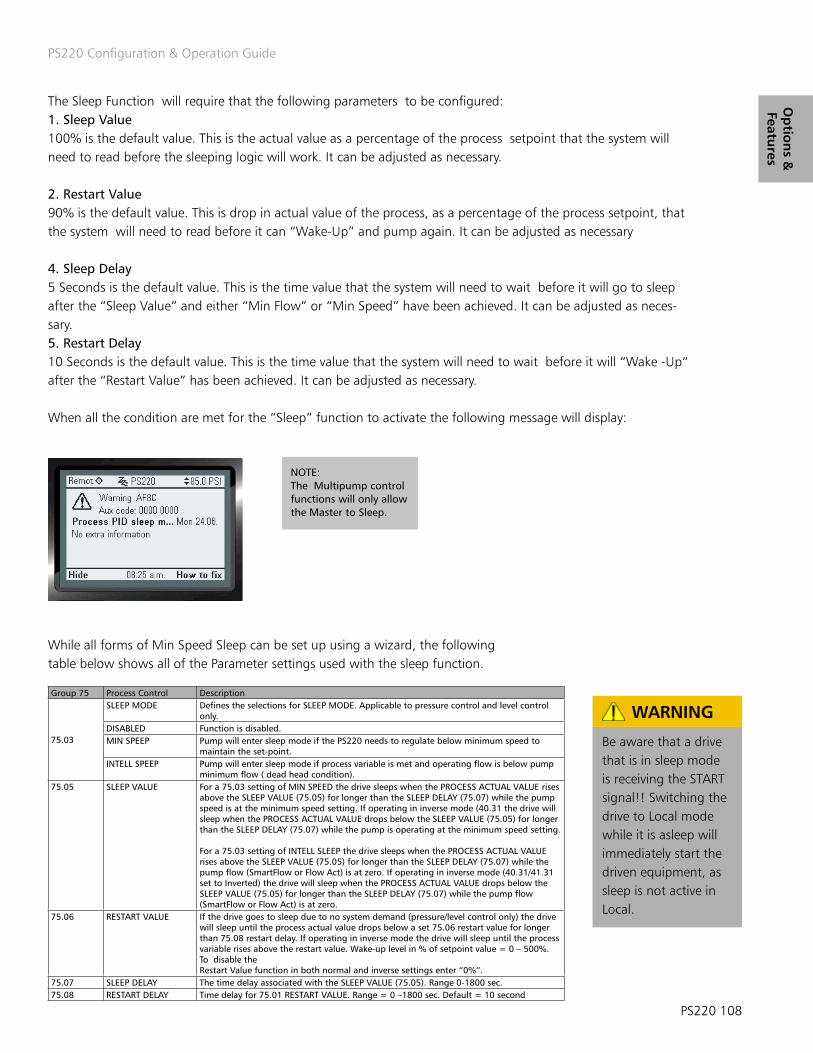
PS220 Configuration & Operation Guide
PS220 108
Op
tion
s &
Features
The Sleep Function will require that the following parameters to be configured:1. Sleep Value100% is the default value. This is the actual value as a percentage of the process setpoint that the system will need to read before the sleeping logic will work. It can be adjusted as necessary.
2. Restart Value90% is the default value. This is drop in actual value of the process, as a percentage of the process setpoint, that the system will need to read before it can “Wake-Up” and pump again. It can be adjusted as necessary 4. Sleep Delay5 Seconds is the default value. This is the time value that the system will need to wait before it will go to sleep after the “Sleep Value” and either “Min Flow” or “Min Speed” have been achieved. It can be adjusted as neces-sary.5. Restart Delay 10 Seconds is the default value. This is the time value that the system will need to wait before it will “Wake -Up“ after the “Restart Value” has been achieved. It can be adjusted as necessary.
When all the condition are met for the “Sleep” function to activate the following message will display:
NOTE:The Multipump control functions will only allow the Master to Sleep.
While all forms of Min Speed Sleep can be set up using a wizard, the following table below shows all of the Parameter settings used with the sleep function.
Group 75 Process Control Description
75.03
SLEEP MODE Defines the selections for SLEEP MODE. Applicable to pressure control and level control only.
DISABLED Function is disabled.MIN SPEEP Pump will enter sleep mode if the PS220 needs to regulate below minimum speed to
maintain the set-point.INTELL SPEEP Pump will enter sleep mode if process variable is met and operating flow is below pump
minimum flow ( dead head condition).75.05 SLEEP VALUE For a 75.03 setting of MIN SPEED the drive sleeps when the PROCESS ACTUAL VALUE rises
above the SLEEP VALUE (75.05) for longer than the SLEEP DELAY (75.07) while the pump speed is at the minimum speed setting. If operating in inverse mode (40.31 the drive will sleep when the PROCESS ACTUAL VALUE drops below the SLEEP VALUE (75.05) for longer than the SLEEP DELAY (75.07) while the pump is operating at the minimum speed setting.
For a 75.03 setting of INTELL SLEEP the drive sleeps when the PROCESS ACTUAL VALUE rises above the SLEEP VALUE (75.05) for longer than the SLEEP DELAY (75.07) while the pump flow (SmartFlow or Flow Act) is at zero. If operating in inverse mode (40.31/41.31 set to Inverted) the drive will sleep when the PROCESS ACTUAL VALUE drops below the SLEEP VALUE (75.05) for longer than the SLEEP DELAY (75.07) while the pump flow (SmartFlow or Flow Act) is at zero.
75.06 RESTART VALUE If the drive goes to sleep due to no system demand (pressure/level control only) the drive will sleep until the process actual value drops below a set 75.06 restart value for longer than 75.08 restart delay. If operating in inverse mode the drive will sleep until the process variable rises above the restart value. Wake-up level in % of setpoint value = 0 – 500%. To disable theRestart Value function in both normal and inverse settings enter “0%”.
75.07 SLEEP DELAY The time delay associated with the SLEEP VALUE (75.05). Range 0-1800 sec.75.08 RESTART DELAY Time delay for 75.01 RESTART VALUE. Range = 0 –1800 sec. Default = 10 second
Be aware that a drive that is in sleep mode is receiving the START signal!! Switching the drive to Local mode while it is asleep will immediately start the driven equipment, as sleep is not active in Local.
WARNING
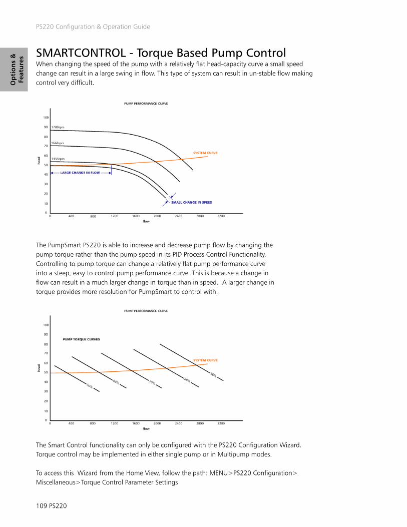
PS220 Configuration & Operation Guide
109 PS220
Op
tio
ns
&
Feat
ure
s SMARTCONTROL - Torque Based Pump Control When changing the speed of the pump with a relatively flat head-capacity curve a small speed change can result in a large swing in flow. This type of system can result in un-stable flow making control very difficult.
The PumpSmart PS220 is able to increase and decrease pump flow by changing the pump torque rather than the pump speed in its PID Process Control Functionality. Controlling to pump torque can change a relatively flat pump performance curve into a steep, easy to control pump performance curve. This is because a change in flow can result in a much larger change in torque than in speed. A larger change in torque provides more resolution for PumpSmart to control with.
The Smart Control functionality can only be configured with the PS220 Configuration Wizard. Torque control may be implemented in either single pump or in Multipump modes.
To access this Wizard from the Home View, follow the path: MENU>PS220 Configuration> Miscellaneous>Torque Control Parameter Settings

PS220 Configuration & Operation Guide
PS220 110
Op
tion
s &
Features
The steps that you will follow to configure this functionality are as follows:
1. Configure the use of Torque (SmartControl) for PID Process ControlBoth “EXT2 control mode” AND “EXT1 CONTROL MODE” need to be configured to (3) Torque
2. Configure the Torque Ramp up and Ramp down times.This is the time the PS220 will use to start regulating using the PID control. 5 seconds is recommended. Both the Ramp up and Down should be set to the same value.
3. Configure the Max Torque Value. The value shown will be the Maximum Speed of the Motor.The value for Torque will need to be Percent (%). This the Maximum Torque Value that the PS220 will regulate to in PID control.It should not be set any higher than 150%.
4. Exit the Wizard.
5. Setting Stage and Destage Torque Values in Multipump.Configure the Stage and De-stage values to the values as shown in the table below. Only configure the values for the total number of pumps in use in the pumping system. Note: This step is not required for single Pump Smart Control.
Parameter Description Recommended Setting Notes81.09 Stage 2 Value 75% Validate during commissioning81.10 Stage 3 Value 75% Validate during commissioning81.11 Stage 4 Value 75% Validate during commissioning81.17 Stage 5 Value 75% Validate during commissioning81.18 Stage 6 Value 75% Validate during commissioning81.13 De-Stage 2 Value 65% Validate during commissioning81.14 De-Stage 3 Value 70% Validate during commissioning81.15 De-Stage 4 Value 75% Validate during commissioning81.21 De-Stage 5 Value 80% Validate during commissioning81.22 De-Stage 6 Value 85% Validate during commissioning

PS220 Configuration & Operation Guide
111 PS220
Op
tio
ns
&
Feat
ure
s
TO “TURN OFF” Smart Control, reverting to Speed PID Control, you will follow the identical steps noted above and configure the settings as follows:
1. Configure the use of Speed for PID Process ControlConfigure Both “EXT2 control mode” AND “EXT1 CONTROL MODE” to SPEED.
2. Configure the Speed Ramp up and Ramp down times.Configure both values to 0 Seconds.
3. Configure the Max Speed Value. Configure the Max Speed value to the Motor Slip Speed used in Basic startup. You may view this in Parameter 99.09 to ensure that the correct value will be used. 4. Exit the Wizard 5. Access the PS220 MultiPump Control Wizard.Re-Configure the Stage and De-stage values to the values as shown in the table below. Only con-figure the values for the total number of pumps in use in the pumping system.
Parameter Description Recommended Setting Notes81.09 Stage 2 Value 98% Default setting81.10 Stage 3 Value 98% Default setting81.11 Stage 4 Value 98% Default setting81.17 Stage 5 Value 98% Default setting81.18 Stage 6 Value 98% Default setting81.13 De-Stage 2 Value 75% Validate during commissioning81.14 De-Stage 3 Value 80% Validate during commissioning81.15 De-Stage 4 Value 85% Validate during commissioning81.21 De-Stage 5 Value 90% Validate during commissioning81.22 De-Stage 6 Value 92% Validate during commissioning
Priming DelayThis feature is designed to allow Self-Priming pumps sufficient time to prime. The Pumpsmart PS220 will run at full speed for a preset time period. During this time frame all configured PumpSmart pump protections are suspended. Once the priming delay time has elapsed all protection logic becomes active again. A warning message “Priming” will be displayed and acknowledged by the Ps220.
Parameter Name Value/Range Notes75.02 PRIMING DELAY 0-6000 Seconds
0 [default]This delay is active on every pump start, including Multipump. During this time frame all of the control logic is completely disabled.

PS220 Configuration & Operation Guide
PS220 112
Op
tion
s &
Features
Pump Protection The Pumpsmart PS220’s Pump Protection functionality can be configured to fully identify, notify, control, and pre-vent a pump that may operate in underload, overload, dry-run, dead-head, minimum flow, runout and cavitation. It can also provide the pumping system protection to ensure that indirect damage from conditions such as over pressure, water hammer, and liquid temperature rise will not occur. The onboard logic can also monitor external devices that are an integral part of the pumping system to add an additional level of protection as well.
There are individual forms of Pump Protection that can be configured on the Pumpsmart PS220. Each one is de-scribed in detail in this manual. They are listed below.
Basic Pump Protection.
The Basic Pump Protection functionalities purpose is to identify and react to a pumping system conditions when three events occur while in the process control mode (any choice of control). Depending on the Process Control Mode may be considered to be “Sensorless”.
1. The pump is running at a predetermined high rate of speed, as a percentage of maximum speed.2. The process controls setpoint is under achieving by a preset percentage. Set-point is not being met.3. A predetermined time period has expired when both 1 and 2 area active.
This event could be the result of a number of upset conditions both internal and external of the pump. The Pumpsmart PS220 cannot determine what the cause of the event is but it will provide the desired notification and response if the event does occur.
Notes1. The PumpSmart PS220 Keypad will display an alarm or fault message “Basic Pump Prot. Alarm” when this event occurs.2. Basic Pump Protection is not available in Basic Speed Control.
This functionality can be configured with the Pumpsmart PS220 Configuration Wizard.
To access this Wizard, from the Home Screen follow the path: MENU>PS220 Configuration>Pump & VFD Protec-tion>Pump Protection>Yes> Follow the prompts

PS220 Configuration & Operation Guide
113 PS220
Op
tio
ns
&
Feat
ure
s Pump Protection (cont’d) The individual steps that will be performed are:
1. Configure enabling of Basic Pump Protection.
2. Configure the Response when this event is active.There are three choices. They are described below.
1. Disabled:The Pumpsmart PS220 will not respond. The pump will continue to run at the maximum allowed speed and while not achieving the setpoint requirement. This is the Default.
2. WARNING: The Pumpsmart PS220 will issue a warning message of “Basic Pump Protection”. The pump will continue to run at the maximum allowed speed. If the conditions change the PS220 will operate as normal and the message will no longer display.
3. ALARM AND/OR CONTROL:The Pumpsmart PS220 will either : A. Issue a warning message, and either run at minimum speed or stop. It can be configured to automati cally re-start after a delay period and then run to maintain the process setpoint. It can be configured to follow this routine a set number of times before a hard Fault is issued. The Fault will have to be reset, and manually restarted. Refer to the “Protection Options” and the “Fault Tracing” section for further information.
B. A hard Fault is issued and it will stop. The fault message will be displayed and it will have to be reset, and manually restarted. Refer to the “Fault Tracing” section for further information.
3. Configure the Protection Limit.The Pump Protection limit is the value, in percent of the actual setpoint, below where the system will declare a Basic Pump Protection event. The default value is 97%.Example:In process Control Mode your system setpoint is 100. 97% of this value is 97 PSI. The Protection Limit will become active when the actual value reading of the process is below 97 PSI.
4. Exit Basic Pump Protection Wizard

PS220 Configuration & Operation Guide
PS220 114
Op
tion
s &
Features
2. Advanced Pump Protection. The Advanced Pump Protection functionality uses the fully array of the Pumpsmart PS220’s feedback from SmartFlow and Smart TDH in identifying upset conditions that may occur in the system. This configuration will use these values of Dry Run, Minimum Flow and Runout Flow, along with the responses you establish, to define the systems reaction to these events. This protection is considered to be “Sensorless”. A flow meter can also be used for this protection.
NOTE: 1. The Basic Pump Protection choice and the Advanced Pump Protection choice should not both be used together.2. The Keypad will show the specific warning and alarm message signifying when they occur. The list of events will be as follows:
EVENT ID Description Type E100 Dry Run FaultE101 Cond1 LO Alarm FaultE102 Cond1 HI Alarm FaultE103 Cond2 LO Alarm FaultE104 Cond2 HI Alarm FaultE105 Pump Cleaning Retry FaultE106 Pump Protect FaultE107 SMARTFLOW OVER FLOW FaultE108 Over Pressure FaultE109 Tune Time Out FaultE10A Min Flow Fault FaultE10B Pump Jammed FaultE10D Basic Pump Protection FaultE20A Tune Failed FaultD200 Pump Snoring WarningE226 Stage Time Out Alarm WarningE200 Dry Run WarningE201 Sec. A Protect WarningE202 Sec. B Protect WarningE203 Cond1 HI Warning WarningE204 Cond1 LO Warning WarningE205 Pump Protect WarningE206 Tune in Progress WarningE207 Tune Complete WarningE208 Min Flow Warning WarningE209 PIP FILL ERROR WarningE20B Basic Pump Prot. Retry WarningE20C Min Flow Retry WarningE20D RunOut WarningE20E Sec. A Protect Alarm WarningE20F Sec. B Protect Alarm WarningE210 Basic Pump Prot. Alarm WarningE211 Cond2 LO Warning WarningE212 Pipe Clean Timeout WarningE213 Speed Override WarningE214 Cond2 HI Warning WarningE215 Pump Cleaning Running WarningE216 Pump Cleaning Retry WarningE217 Pump Cleaning Warning WarningE218 Pump Cleaning( RT) Running WarningE219 Total system flow completed WarningE21A Bypass Valve Open WarningE21B Pipe Clean Running WarningE21C Pipe Fill Running WarningE21D Pipe Fill WarningE21E Cond1 HI Alarm WarningE21F Cond1 LO Alarm WarningE220 Cond2 HI Alarm WarningE221 Condition Sleep WarningE222 Cond2 LO Alarm WarningE223 PID Low Demand WarningE224 Start Delay Active WarningE225 Priming ON Warning
This functionality can be configured with the Pumpsmart PS220 Configuration Wizard.
To access this Wizard from the Home Screen, follow the path: MENU>PS220 Configuration>Pump & VFD Protection>Pump Protection>No> Follow the prompts

PS220 Configuration & Operation Guide
115 PS220
Op
tio
ns
&
Feat
ure
s
The table below will list all of the parameters used with the Basic and the Advanced Pump Protection functionality.
Group 79 Pump Protection Description
79.01
PUMP PROTECT CTRL Actual process value is lower than protection limit (79.02) for protection delay (79.03) and PS220 is at (max speed – 10 rpm) for the protection delay.
DISABLED [DEFAULT] Protection is disabledWARNING The PS220 generates a warning only “Pump Protect”; no other action is taken.ALARM AND CONTROL The PS220 generates a warning “Pump Protect” and controls according to the setting of 79.16 CONFIG MIN SPD.
79.02 PROTECTION LIMIT This is the protection limit for the process value at which Pump Protect Ctrl (79.01) activates when pump is at max speed for the protection delay. Setting range: 0.0 – 100.0% of setpoint. Default is 3%
79.03 PROTECTION DELAY This is the protection delay period prior to activation of Pump Protect Ctrl (79.01). Also applies to Secondary Protect A/B, Min Flow, Dry Run and Run Out Ctrl. Must be greater than 0.0 to activate protection. Setting range: 0– 200 sec. Default is 0
79.04 SP OVRRD PMP PROT Selects if pump protection warning and faults are enabled or disabled when speed override is initiated.DISABLED [DEFAULT]ENABLED
79.05 PUMP FAULT RESET Indicates number of automatic fault resets. Selection range is 0 – 19. When set to “0” Error Reset is disabled. Time between resets is parameter 79.06 Pump Reset Delay. Manual intervention is required if fault is still active after set number of resets has been achieved. The counter will reset if a stop command is issued, fault is manually reset or the drive has been operating nor-mally for 5 minutes. The drive reaction to the fault will be according to parameter Config min speed (79.16) setting. Pump Fault Reset is applicable to parameters 79.01 and 79.08. A Dry Run Fault must be manually reset. Default is 0
79.06 PUMP RESET DELAY Defines the time that the PS220 will wait after an alarm and control condition before attempting an error reset. Setting Range = 0 -3600 sec. Default is 60 Seconds
79.07 Q ACT SOURCE Identifies the source of the flow readings used for the pump protection feature.SMARTFLOW [DEFAULT] Logic uses the PumpSmart calculated flow valueFLOW METER Logic uses an external flow meter that is configured in Group 76.
79.08 MIN FLOW CTRL If enabled and the actual flow is less than the min flow (corrected for speed) for the protection delay (79.03) a minimum flow condition is detected.
DISABLED [DEFAULT] Protection is disabled.WARNING The PS220 generates a “Min Flow Warning” only; no other action is taken unless relay outputs are configured.ALARM AND CONTROL The PS220 generates a “Min Flow” warning or fault and controls according to the setting of Config min speed (79.16). The fault
is re-settable if (79.05) Pump Fault Reset is active. Relay Outputs may be configured to activate.79.09 MIN FLOW Defines the safe minimum flow of the pump. This minimum flow correlates to the 77.04 Rated Speed.79.10 DRY RUN CTRL If enabled and the actual flow is less than the dry run criteria for the protection delay (79.03) a dry run condition is detected.
DISABLED [ DEFAULT] Protection is disabled.FAULT The drive faults and the motor coasts to a stop. A fault message is generated “Dry Run”. This fault is not resettable by Pump
Fault Reset (79.05). Relay Outputs may be configured to activate.WARNING The PS220 generates a dry run warning only; no other action is taken unless relay outputs are configured.
79.11 DRY RUN FACTOR Coefficient for determining dry-run power, Range= 0 – 2.00 Default is .9579.12 RUNOUT CTRL If enabled and the actual flow is greater than the Runout flow (corrected for speed) for the protection delay 79.03, a Runout
condition is detected.DISABLED [ DEFAULT] Protection is disabled.WARNING The PS220 generates a Runout warning only; no other action is taken.
79.13 RUNOUT FLOW Defines the maximum flow of the pump. This maximum flow correlates to the 77.04 Rated Speed.
To configure the Advanced Pump Protection the individual steps that will be performed are:
1. Configure the choice for Advanced Pump Protection.2. Configure the use of an external flow meter as the flow feedback source.There are two choices for this configuration:A. No ( Default). Utilizes the Smartflow functionality to determine flow values. B. Yes. This choice requires an external flowmeter. If a Flowmeter was not configured when the Process Control Wizard was completed it will need to be added and configured. This Wizard will continue and guide you through the steps in adding and fully configuring it for use.NOTE: THIS CHOICE CANNOT BE USED FOR PUMP PROTECTION ON AN INDIVIDUAL PUMP IN MUTIPUMP CONTROL
NOTES1. If you are unsure how to configure the external Flow Meter please refer to the Analog Input configuration section in this manual.
2. An unused Analog Input will need to be used for this choice to function correctly. Please check the settings of the Analog Inputs in use by going to: MENU>PARAMATERS> Complete List>Scroll down to Group 76>Select and view 76.01&02. If available “ NOT SELECTED” will be displayed. You may have to add an Extension Card to use an additional input.

PS220 Configuration & Operation Guide
PS220 116
Op
tion
s &
Features
3. Configure the Response to Minimum Flow.There are three choices for this response:
A. Disabled (Default)The Pumpsmart PS220 will continue to run. There will not be any indication of this event.
B. Warning. The Pumpsmart PS220 will continue to run. The warning message “ Min Flow Warning” will display. The event will be stored in the Event Log. It will continue to indicate the warning until the flow increases to a value above minimum flow.
C. Alarm & ControlThe Pumpsmart PS220 will indicate that the pump is running at or below minimum flow with a message “ Min Flow Warning”. After the response delay time has expired. The event will be stored in the Event Log. The PS220 will then re-spond based on the Protections Options. If a hard fault ( if configured) occurs it will display the message “Min Flow Fault”. It will have to be reset and manually restarted. Please refer to the sections “Protection Options” and “Fault Tracing” in this manual.
4. Configure the Minimum Flow ValueThis value should be the minimum flow value as recommend by the Pump Manufacturer. It should be at the rated speed full speed of the pump. There is a graphic below which depicts this value on a performance curve.For more detailed information on Minimum Flow please refer to the section on Minimum Flow in this manual.
5. Configure the Response to Dry Run.For more detailed information on Dry Run please refer to the sections of “Dry Run” and “Dead Head” in this manual. NOTE: Dry Run protection requires that SmartFlow be set up and a successful SmartFlow tune be completed.
The choices are:1. Disabled (Default) The Pumpsmart PS220 will continue to run. There will not be any indication of this event.
2. Fault.The information entered with the Smartflow configuration Wizard will automatically determine the value used for this protection’s response. The Pumpsmart PS220 will fault off with the message “Dry Run Fault” after the Response Delay time configured with the “Protection Options” has expired. It will be stored in the event log. This fault is not an Auto-re-settable fault. The PS220 will have to be reset, and manually restarted. Please refer to the “Protection Options” and “Fault Tracing” sections in this manual.
Dry Run factor Adjustment (Not a step)The Dry Run factor is for “fine tuning” the Dry Run fault feature. It should only be adjusted during initial commissioning to test the Dry Run Response function. Normally this parameter requires no adjustment. When adjustment may be required this value should only be changed in increments of 1/100th at a time.
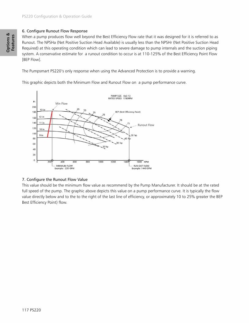
PS220 Configuration & Operation Guide
117 PS220
Op
tio
ns
&
Feat
ure
s
6. Configure Runout Flow ResponseWhen a pump produces flow well beyond the Best Efficiency Flow rate that it was designed for it is referred to as Runout. The NPSHa (Net Positive Suction Head Available) is usually less than the NPSHr (Net Positive Suction Head Required) at this operating condition which can lead to severe damage to pump internals and the suction piping system. A conservative estimate for a runout condition to occur is at 110-125% of the Best Efficiency Point Flow [BEP Flow].
The Pumpsmart PS220’s only response when using the Advanced Protection is to provide a warning.
This graphic depicts both the Minimum Flow and Runout Flow on a pump performance curve.
7. Configure the Runout Flow ValueThis value should be the minimum flow value as recommend by the Pump Manufacturer. It should be at the rated full speed of the pump. The graphic above depicts this value on a pump performance curve. It is typically the flow value directly below and to the to the right of the last line of efficiency, or approximately 10 to 25% greater the BEP Best Efficiency Point) flow.
Min Flow
Runout Flow

PS220 Configuration & Operation Guide
PS220 118
Op
tion
s &
Features
The table below lists all of the parameters used with the Basic and Advanced Pump Protection functionality.
Group 79 Pump Protection Description
79.01
PUMP PROTECT CTRL Actual process value is lower than protection limit (79.02) for protection delay (79.03) and PS220 is at (max speed – 10 rpm) for the protection delay.
DISABLED [DEFAULT] Protection is disabledWARNING The PS220 generates a warning only “Pump Protect”; no other action is taken.ALARM AND CONTROL The PS220 generates a warning “Pump Protect” and controls according to the setting of 79.16 CONFIG MIN SPD.
79.02 PROTECTION LIMIT This is the protection limit for the process value at which Pump Protect Ctrl (79.01) activates when pump is at max speed for the protection delay. Setting range: 0.0 – 100.0% of setpoint. Default is 3%
79.03 PROTECTION DELAY This is the protection delay period prior to activation of Pump Protect Ctrl (79.01). Also applies to Secondary Protect A/B, Min Flow, Dry Run and Run Out Ctrl. Must be greater than 0.0 to activate protection. Setting range: 0– 200 sec. Default is 0
79.05 PUMP FAULT RESET Indicates number of automatic fault resets. Selection range is 0 – 19. When set to “0” Error Reset is disabled. Time between resets is parameter 79.06 Pump Reset Delay. Manual intervention is required if fault is still active after set number of resets has been achieved. The counter will reset if a stop command is issued, fault is manually reset or the drive has been operating nor-mally for 5 minutes. The drive reaction to the fault will be according to parameter Config min speed (79.16) setting. Pump Fault Reset is applicable to parameters 79.01 and 79.08. A Dry Run Fault must be manually reset. Default is 0
79.06 PUMP RESET DELAY Defines the time that the PS220 will wait after an alarm and control condition before attempting an error reset. Setting Range = 0 -3600 sec. Default is 60 Seconds
79.07 Q ACT SOURCE Identifies the source of the flow readings used for the pump protection feature.SMARTFLOW [DEFAULT] Logic uses the PumpSmart calculated flow valueFLOW METER Logic uses an external flow meter that is configured in Group 76.
79.08 MIN FLOW CTRL If enabled and the actual flow is less than the min flow (corrected for speed) for the protection delay (79.03) a minimum flow condition is detected.
DISABLED [DEFAULT] Protection is disabled.WARNING The PS220 generates a “Min Flow Warning” only; no other action is taken unless relay outputs are configured.ALARM AND CONTROL The PS220 generates a “Min Flow” warning or fault and controls according to the setting of Config min speed (79.16). The fault
is re-settable if (79.05) Pump Fault Reset is active. Relay Outputs may be configured to activate.79.09 MIN FLOW Defines the safe minimum flow of the pump. This minimum flow correlates to the 77.04 Rated Speed.79.10 DRY RUN CTRL If enabled and the actual flow is less than the dry run criteria for the protection delay (79.03) a dry run condition is detected.
DISABLED [ DEFAULT] Protection is disabled.FAULT The drive faults and the motor coasts to a stop. A fault message is generated “Dry Run”. This fault is not resettable by Pump
Fault Reset (79.05). Relay Outputs may be configured to activate.WARNING The PS220 generates a dry run warning only; no other action is taken unless relay outputs are configured.
79.11 DRY RUN FACTOR Coefficient for determining dry-run power, Range= 0 – 2.00 Default is .9579.12 RUNOUT CTRL If enabled and the actual flow is greater than the Runout flow (corrected for speed) for the protection delay 79.03, a Runout
condition is detected.DISABLED [ DEFAULT] Protection is disabled.WARNING The PS220 generates a Runout warning only; no other action is taken.
79.13 RUNOUT FLOW Defines the maximum flow of the pump. This maximum flow correlates to the 77.04 Rated Speed.

PS220 Configuration & Operation Guide
119 PS220
Op
tio
ns
&
Feat
ure
s Secondary Protection Secondary Protection uses the Pumpsmart PS220’s onboard Digital Input connections to determine if an external event has happened. Examples might include loss of flow, loss of pressure, valve closed, etc. There are two that are available to be used with this function. Externally connected devices, such as flow, pressure, and level switches, and “Dry-Con-tact” outputs devices such as a PLC and DCS can be configured for use with this protection. They can be used as a type of a permissive or “ Go-NoGo” providing inter-lock capabilities with the pumping system.
This functionality can be configured with the Pumpsmart PS220 Configuration Wizard.
To access this Wizard from the Home Screen, follow the path: MENU>PS220 Configuration>Pump & VFD Protec-tion>Secondary Protection>
The individual steps that will be performed are:
1. Configure the use of Secondary Protection A or B or both.2. Configure the Protection Response.Please refer to the “Protection Options” for the details of the responses available with Secondary protection.The selection choices are:1. Disabled2. Alarm3. Alarm and Control
NOTE:This message may appear as you configure this function with the Wizard. Select “Hide” and continue. This message is the result of the Digital Input is showing “Open”. It may be wired incorrectly or the device is in an “Open-state”. This is quite normal. Select “Hide” to continue.

PS220 Configuration & Operation Guide
PS220 120
Op
tion
s &
Features
3. Configure the Digital Input to be used.Notes:Digital Input 4 (DI4) is the default selection for Secondary Protection ADigital Input 5 (DI5) is the default selection for Secondary Protection B
Any unused Digital Input (DI) can be configured for use with this function. Please check the settings of the Digital Inputs currently in use by going to: MENU>Parameters> Complete List>Scroll down to Group 76>Select and View 76.09 through 76.14. If available “ NOT SELECTED” will be displayed. An Extension Card will need to be added and configured if they are all in use.
The Table below list all of the Parameters used with the Secondary Protection Wizard functionality. Parame-ters may be manually configured if required for a particular application. The description of these parameters are also listed in the index under Parameter Listings.
Group 76 Analog I/O Config Description76.09 DI1 Selects the Digital input 1 function76.10 DI2 Selects the Digital input 2 function76.11 DI3 Selects the Digital input 3 function76.12 DI4 Selects the Digital input 4 function76.13 DI5 Selects the Digital input 5 function76.14 DI6 Selects the Digital input 6 function76.15 DIO1 Selects whether DIO1 is used as a digital output or input, or a frequency input. (Not powered)76.16 DIO2 Selects whether DIO2 is used as a digital output or input, or a frequency input. (Not Powered)Group 79 Pump Protection Description79.03 PROTECTION DELAY This is the protection delay period prior to activation of Pump Protect Ctrl (79.01). Also ap-
plies to Secondary Protect A/B, Min Flow, Dry Run and Run Out Ctrl. Must be greater than0.0 to activate protection. Setting range: 0– 200 sec. Default is 0
79.05 PUMP FAULT RESET Indicates number of automatic fault resets. Selection range is 0 – 19. When set to “0” Error Reset is disabled. Time between resets is parameter 79.06 Pump Reset Delay. Manual interven-tion is required if fault is still active after set number of resets has been achieved. The counter will reset if a stop command is issued, fault is manually reset or the drive has been operating normally for 5 minutes. The drive reaction to the fault will be according to parameter Config min speed (79.16) setting. Pump Fault Reset is applicable to parameters 79.01 and 79.08. A Dry Run Fault must be manually reset. Default is 0
79.06 PUMP RESET DELAY Defines the time that the PS220 will wait after an alarm and control condition before at-tempting an error reset. Setting Range = 0 -3600 sec. Default is 60 Seconds
79.09 MIN FLOW Defines the safe minimum flow of the pump. This minimum flow correlates to the 77.04 Rated Speed.
79.14 SECONDARY PROTECT A Loss of digital input 5 (DI5) for protection delay (79.03).DISABLED [DEFAULT] Protection is disabledALARM The PS220 generates a warning only “Secondary Protect A”; no other action is taken. Relay
Outputs may be configured to activate.ALARM AND CONTROL The PS220 generates a warning “Secondary Protect A” and controls according to the setting
of Config min speed 79.16 If DI5 then closes, the fault will be reset and the drive will restart. Relay Outputs may be configured to activate.
MOTOR TEMP To be selected when a Motor Temp input is used at DI6. Parameter 35.11 Supervision 1 Source must be set to select the source where the Motor Temp is read. Parameter 35.10 Supervision 1 Protection must be set to “Warning”.
79.15 SECONDARY PROTECT B Loss of digital input 5 (DI5) for protection delay (79.03). See 79.14 for selection choices79.16 CONFIG MIN SPEED Defines the reaction of the drive when the PS220 tries to regulate at a speed at or below min
speed.SPEED = 0 The drive will stay at min speed until Stop Delay Min Speed expires. A fault will then occur..
SPEED = MIN SPEED The PS220 will stay at this speed until the transient clears or unit is manually shutdown; unless a fault occurs.
79.17 STP DELAY MIN SPD The time period the drive will stay at min speed before stopping. Range = 0–1800 sec. Func-tions when 79.16 is set to Speed=0. Becomes active if the setpoint would result in regulation below min speed, closed valve condition in pressure control and Secondary Protect A & B.

PS220 Configuration & Operation Guide
121 PS220
Op
tio
ns
&
Feat
ure
s POSITIVE DISPLACEMENT PUMP PROTECTION Positive displacement or progressive cavity pumps are different from a centrifugal pump in that they are considered constant torque loads. The torque for this type of pump is independent of the operating speed. In general the torque is directly proportional to discharge head which makes monitoring for high torque an effective method of dead-head /shut-off pump protection. Additionally, certain types of pumps use the fluid being pumped as lubrication. When a pump is exposed to a dry-run condition the internal parts can rub also causing high torque. Pump Protection for con-stant torque loads can be accomplished with the Condition Monitoring Function.NOTE - When operating a constant torque load the drive must be rated for heavy duty use. This generally requires going to the next larger PS220 size.
The Condition Monitoring function has the ability to monitor the motor torque. High and low limits can be configured to warn and ultimately fault the pump. To determine the proper torque limits consult the pump manufacture’s for recommended guidelines.
This functionality is designed to compliment and be in addition to the existing pres-sure relieving safety devices. This form of protection is not intended to substitute the pump manufacture’s rec- ommended pressure relief protection. Failure to follow these instructions may result in physical injury or equipment damage.
WARNING
Parameter Name Value/Range Notes80.01 OR 80.07
COND 1 SOURCECOND 2 SOURCE
MOTOR TORQUE This value is a % of motor nominal torque.
80.0580.11
COND 1 WRN LIM HI COND 2 WRN LIM HI
-10000 to +100000 [default]
The high value of the warning limit. A warning occurs if the mon-itored signal rises above this value for longer than the response delay (par 80.16) . Inactive if set to 0.
80.0680.12
COND 1 WRN LIM LO COND 2 WRN LIM LO
-10000 to +100000 [default]
The low value of the warning limit. A warning occurs if the mon-itored signal drops below this value for longer than the response delay (par 80.16). Inactive if set to 0.
80.07 COND 1 ALARM DISABLED [default] Protection is inactive.80.13 COND 2 ALARM ALARM Selecting ALRM ONLY will configure PumpSmart to issue a Keypad
or DCS notice and will trigger a Relay Output (if configured) if an ALRM LIM HI or ALRM LIM LO condition is detected. No furtheraction is taken
FAULT The PS220 faults if an ALRM LIM HI or ALRM LIM LO condition is detected. A Keypad or DCS notice is issued and a Relay Output is triggered (if configured).
80.0880.14
COND 1 ALRM LIM HI COND 2 ALRM LIM HI
-10000 to +100000 [default]
The high value of the alarm limit. An alarm occurs if the monitored signal rises above this value for longer than the condition response delay (par 80.16). Inactive if set to 0.
80.0980.15
COND 1 ALRM LIM LO COND 2 ALRM LIM LO
-10000 to +100000 [default]
The low value of the alarm limit. An alarm occurs if the monitored signal drops below this value for longer than the response delay (par 80.16). Inactive if set to 0.
80.16 COND RESP DELAY 0 sec20 sec [default]
The delay period prior to activation of a COND I or COND 2 WRN OR ALRM. It is recommended that this interval be set to zero.
The pump will automatically restart once the Secondary Protection Fault has cleared and the digital input contact is closed.
CAUTION
MENU>PS220 Configuration>PUMP & VFD PROTECTION

PS220 Configuration & Operation Guide
PS220 122
Op
tion
s &
Features
Flow Bypass Recirculation The PS220’s Flow Bypass Recirculation function will allow for a triggered event that can be used to control the opening and closing of a minimum flow bypass valve that may be required in a pumping system. An available Relay Out can be used with this function to send the signals to external devices when required to operate.This functionality uses the Minimum Flow value sensed from either SmartFlow or from an external flow meter. The Table below lists the parameter that are used in this configuration.
Parameter Name Setting Notes75.16 Flow Bypass Source Off( Default)
Flow ActualSmartflowProc TX2
Defines the flow signal for the Bypass function
75.17 Flow Bypass on Flow Value
0 (Default)(0-100000)
The set flowrate value used to trigger the function to operate. Units are as selected with the flow signal
75.18 Flow Bypass Off Ratio 2.1 (Default)(0-5)
Defined as a percentage of the “Bypass On flow value” when to close.
75.19 On Delay 1 Default(0-1800 Seconds)
Time for the logic to turn on the relay
75.20 Off Delay 1 Default (0-1800 Seconds)
Time for the logic to turn off the relay
75.21 Relay Start Delay 15 (Default)(0-200 Seconds)
Time for the Logic to activate the “Flow Bypass Open” Warning Message to Open the Bypass and to energize the selected relay. The relay will turn and off based on the time settings of 75.19 and 75.20
Notes1. A warning Message will Flash “Bypass Valve Open” when the relay energizes and continue to flash until it closes. 2. The Value of 75.17 “Flow Bypass On Flow Value” can be a different value than what is already defined in Parameter 79.09 for MIN FLOW. 75.17 will be internally corrected proportionally to the change in speed with the Pump Affinity Laws(Q1/Q2 = N1/N2 where Q = Flow and N = Speed).
This function can be configured with the PS220 Configuration wizards.To access the Flow Bypass Recirculation Wizard from the Home View, follow the path: MENU> PS220 Configuration>PUMP & VFD PROTECTION >Condition Monitoring>Next>Next>
1. Configure the use of the function by choosing Yes2. Select the FLOW BYPASS SOURCE: 3. Define the FLOW BYPASS ON Flow rate: Remember this can be a different value than what is already defined in Parameter 79.09 for MIN FLOW4. Set the FLOW BYPASS OFF RATIO5. Set the ON DELAY: Defines the time duration for the Flow Bypass to activate the relay after the minimum flow value has been reached after the duration of FLOW RELAY START DELAY expires.
6. Set the OFF DELAY: Defines the time duration for the Flow Bypass to deactivate the relay after the product of FLOW BYPASS ON x FLOW BYPASS OFFRATIO is reached.
5. Set the FLOW RELAY START DELAY:

PS220 Configuration & Operation Guide
123 PS220
Op
tio
ns
&
Feat
ure
s Real Time Clock The PS220 has a built-in Real-time clock on Board. There are many ways that you can set and display this information .
The time and date display settings determine how the time stamps are formatted to view on screen and in the event logs. The clock is powered by a battery on the backside of the panel underneath the battery cover. At an ambient temperature of 77 °F , the change interval of the real-time clock battery is approximately 10 years. Battery type used is CR2032.
To configure the real time clock settings from the Home View, follow the path: MENU>SETTINGS>DATE & TIME

PS220 Configuration & Operation Guide
PS220 124
Op
tion
s &
Features
Reference/Setpoint Source The Reference or the Setpoint that Pumpsmart PS220 will be maintaining will need to be entered. The keypad included is the default choice. An external source can be used that may require wiring with proper scaling values (minimum and maximum). The PS220 also has the capability to establish limits of the overall scaling to prevent operations below and above thresholds for any particular system when using Process Control. The configuration Wizards that are part of the Basic Startup and Process Control will guide you through this configuration.
This functional setting can only be configured using the PS220 Configuration Wizards. To access this form the Home View, follow the paths:
For Speed Control: MENU>PS220 Configuration>BASIC Startup>
For Process Control: MENU>PS220 Configuration> Process Control> (Push select or next 5 times)
The steps you will need to go through will be as follows.
Configuring the setpoint source. The choices are:1. Keypad (Default) 2. Analog Input (AI1, AI2)3. Fieldbus Control
1.Keypad:This is the default setting when configuring the drive for the first time. To enter a set-point using the keypad you must be on one of the Home screens. The set-point is displayed in the upper right corner of the display, and depending on which Home screen you are on it may also be displayed on one of the three display lines. To enter a set-point value use the up and down keys. You may also change the set-point quicker by pressing the Options soft key and selecting Reference.
2.Analog Input:An analog signal can be sent into the drive, from a PLC, DCS or another form of controller. The signal will need to be wired into any unused analog input AI1, or AI2.
For ANALOG ANY AI:“AI# scaled at AI min” refers to the speed value that corresponds to the minimum of the signal or the 4mA scaled value. This is defaulted to 0 RPM.
“AI# scaled at AI1 max” refers to the speed value that corresponds to the maximum of the signal or the 20mA scaled value. This is typically the motor nameplate speed or slip speed.
( # = refers to the choice of the physical number of the AI used)
NOTE: If your input wired signal provided is DC Voltage please refer to the options and features section for proper parameter settings of the drive. A Jumper connection on the hardware will need to be moved. (J1, or J2) This is shown in the wiring diagrams.

PS220 Configuration & Operation Guide
125 PS220
Op
tio
ns
&
Feat
ure
s
Configuring the setpoint for Process Control in any mode will require two additional settings after the configuration of the transmitter. These will scale the setpoint separately from that of the transmitter. This scale will provide the limits on how low, or high, a setpoint can be, to prevent operation at values that could be detrimental to the pumping systems.
To get to this screen directly to change the setpoint min and max:MENU>PS220 Configuration> Process Control> (Push select or next 5 times)
NOTE: IF you do not set a reference to the Pumpsmart PS220 drive will run at the minimum speed that had been configured in parameter 30.11. A warning message will not display if the reference is 0. In Process control mode it may run to maintain the reference but will not speed up higher than this value. As you may have set up a Minimum Setpoint during configuration.
Setting/Adjusting the Reference The reference can only be set and adjusted by the choice you have selected during configuration.If you chose the Keypad ( default) you can use the Keypad for entry of the running speed. You can edit it on the Home Screen whenever you see the symbol to the left to the reference. On the Home Screen the up and down arrow keys of the keypad will directly adjust your speed reference as viewed in the upper right corner of the display.
By accessing it from the Home Screen using the path: Option> Reference> Select it may be adjusted quicker than holding down the arrow keys. See the Screen below
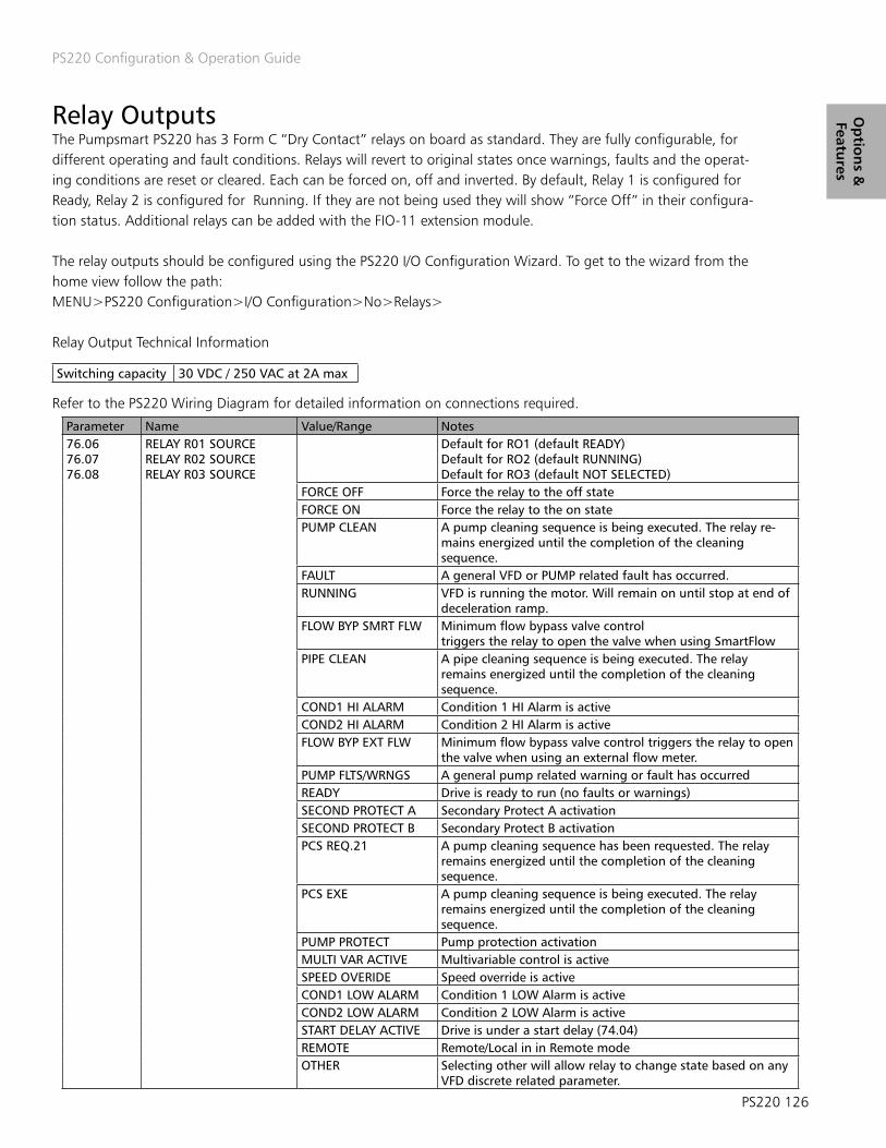
PS220 Configuration & Operation Guide
PS220 126
Op
tion
s &
Features
Relay Outputs The Pumpsmart PS220 has 3 Form C “Dry Contact” relays on board as standard. They are fully configurable, for different operating and fault conditions. Relays will revert to original states once warnings, faults and the operat-ing conditions are reset or cleared. Each can be forced on, off and inverted. By default, Relay 1 is configured for Ready, Relay 2 is configured for Running. If they are not being used they will show “Force Off” in their configura-tion status. Additional relays can be added with the FIO-11 extension module.
The relay outputs should be configured using the PS220 I/O Configuration Wizard. To get to the wizard from the home view follow the path:MENU>PS220 Configuration>I/O Configuration>No>Relays>
Relay Output Technical Information
Refer to the PS220 Wiring Diagram for detailed information on connections required.
Switching capacity 30 VDC / 250 VAC at 2A max
Parameter Name Value/Range Notes76.0676.0776.08
RELAY R01 SOURCERELAY R02 SOURCERELAY R03 SOURCE
Default for RO1 (default READY)Default for RO2 (default RUNNING)Default for RO3 (default NOT SELECTED)
FORCE OFF Force the relay to the off stateFORCE ON Force the relay to the on statePUMP CLEAN A pump cleaning sequence is being executed. The relay re-
mains energized until the completion of the cleaning sequence.
FAULT A general VFD or PUMP related fault has occurred.RUNNING VFD is running the motor. Will remain on until stop at end of
deceleration ramp.FLOW BYP SMRT FLW Minimum flow bypass valve control
triggers the relay to open the valve when using SmartFlowPIPE CLEAN A pipe cleaning sequence is being executed. The relay
remains energized until the completion of the cleaning sequence.
COND1 HI ALARM Condition 1 HI Alarm is activeCOND2 HI ALARM Condition 2 HI Alarm is activeFLOW BYP EXT FLW Minimum flow bypass valve control triggers the relay to open
the valve when using an external flow meter.PUMP FLTS/WRNGS A general pump related warning or fault has occurredREADY Drive is ready to run (no faults or warnings)SECOND PROTECT A Secondary Protect A activationSECOND PROTECT B Secondary Protect B activationPCS REQ.21 A pump cleaning sequence has been requested. The relay
remains energized until the completion of the cleaning sequence.
PCS EXE A pump cleaning sequence is being executed. The relay remains energized until the completion of the cleaning sequence.
PUMP PROTECT Pump protection activationMULTI VAR ACTIVE Multivariable control is activeSPEED OVERIDE Speed override is activeCOND1 LOW ALARM Condition 1 LOW Alarm is activeCOND2 LOW ALARM Condition 2 LOW Alarm is activeSTART DELAY ACTIVE Drive is under a start delay (74.04)REMOTE Remote/Local in in Remote modeOTHER Selecting other will allow relay to change state based on any
VFD discrete related parameter.

PS220 Configuration & Operation Guide
127 PS220
Op
tio
ns
&
Feat
ure
s Safe Torque Off Detection The PS220 is equipped with two on board Safe Torque off inputs that are located on the control board. Safe Torque Off means that when one or both of the inputs are lost the PS220 will remove the IGBT gates from being able to fire, thereby keeping the motor from turning. When either of the inputs are lost the motor and pump will cost to a stop. It will not follow the deceleration ramp.
The Safe Torque Off input on the PS220 VFD is typically used for the E-Stop, where the E-Stop must break and make the two inputs simultaneously. You can not brake and make one input while leaving the other high all the time. Additionally, IN1 and IN2 must be fed from OUT 1, not 24Vdc.
The drive monitors the status of the Safe torque off input, and parameter 31.22 selects which indications are giv-en when the signals are lost. (The parameter does not affect the operation of the Safe torque off function itself). For more information on the Safe torque off function, see the basic wiring diagram in appendix A-4 and the ABB ACS880 Hardware manual
Note:1. Jumpers are installed at the factory between OUT1 and In1 and OUT1 and In2. If using the safe torque –off remove jumpers and replace with appropriate contact blocks or safe torque – off switch.2. Both inputs must be close for drive to run motor.
Parameter Name Value/Range Notes31.22 STO Indication Fault / Fault [default]
Fault / WarningFault / Event Warning / Warning Event / EventNo Indication
Selects which indications are given when one or both Safe torque off (STO) signals are switched off or lost. The indications also depend on whether the drive is running or stopped when this occurs.

PS220 Configuration & Operation Guide
PS220 128
Op
tion
s &
Features
Transmitter/Process Sensor Failure If any Analog Transmitter connected to the PS220 fails the unit can be configured to react based on the settings available. The default for this option is “No-Action”. The choices are as follows:NO ACTION – The PS220 will continue to run to maintain the process requirement.FAULT - The PS220 will fault and stop. This fault can be automatically reset. Refer to section on Automatic Reset -VFD Faults & Process Sensor Fault.WARNING – The PS220 will issue a warning message and continue to run to maintain the process requirement.LAST SPEED – The PS220 will issue a warning message and continue to run at the last speed it was running when the sensor failed.SPEED REF SAFE – The PS220 will issue warning and run at the speed defined by parameter 22.41 “Speed ref safe”. “Speed Ref Safe” by Default is 0.
You can further define the failure values (above and below the default values) for these reactions to occur and how you want to drive to react to the failure mode of low, high or both. These reactions can be independent for each sensor attached. See Parameter Group 30.
Selecting the choice of ”NO Action” may result in running a pump up to full speed. If using the Multipump functionality it may run all of the additional pumps that have start commands initiated to try to regulate to the process setpoint.
DANGER | WARNING | DANGER
Parameter Name Value/Range Notes12.03 ANALOG INPUT SUPERVISION
FUNCTIONNO ACTION [default] FAULTWARNING LAST SPEEDSPEED REF SAFE
Defines action taken upon failure of an analog input. Failure messages indicate which input channel has failed.
12.04 AI SUPERVISION SELECTION 0000…11110000 [default]
Each corresponding bit allows selection of minimum and maximum limit supervision. User may enable/disable each of the limit types.Bit Fault
0 AI1<MIN LIMIT1 AI1>MAX LIMIT2 AI2<MIN LIMIT3 AI2>MAX LIMIT

PS220 Configuration & Operation Guide
129 PS220
Op
tio
ns
&
Feat
ure
s Set-points: Dual The Pumpsmart PS220 can be configured to use two separate and distinct setpoints. The setpoint methods and references can be configured in the same fashion that is described in the Setpoint section. This is also a step in Basic Start Up that was not covered by the Wizards. The PS220 will require Digital Input settings to be configured to toggle between the two setpoints. The choices are: 1. Digital Input 3, (The default) or any other unused Digital Input.2. A Fieldbus command.
Setup can be done through the PROCESS CONTROL wizard or with the BASIC STARTUP wizard.
To access wither of these Wizards from the Home View follow the paths:MENU>PS220 Configuration>Process Control> OR
For Speed Control MENU>PS220 Configuration>Basic Startup>Basic Drive Setup>
The table below shows that Digital Input 3 is defaulted to be used for the Dual Setpoint Function
Parameter Name Value/Range Notes76.11 DI3 DUAL STPT SEL This is the Default setting for this parameter. This selection will
use setup digital input DI3 to toggle between set-point 1 and set-point 2. DI3 low is Setpoint 1;DI3 High is Setpoint2
EXAMPLE: Process Control PID with the primary 4- 20 mA Transmitter wired to AI1 with the primary set point, which can be varied wired to AI2. Either Analog Input can be either Current or voltage.
Note: The effect is a straight relationship with the maximum set-point value corresponds to the maximum signal [i.e. 20 mA or 10 VDC] while the minimum set-point value corresponds to the minimum signal [0/4mA or 0/2 VDC].
Parameter Name Value/Range Notes76.01 AI1 CONFIG Proc Trans 1 AI 1 used for PID control76.02 AI2 CONFIG EXT T Setpoint AI2 used for EXT 1 Setpoint
( It can be varied)

PS220 Configuration & Operation Guide
PS220 130
Op
tion
s &
Features
SmartflowBasic SmartFlowThe PumpSmart PS220 utilizes a complex algorithm that will calculate the actual flow of the pump. External sensors are not required with Basic SmartFlow. Any manufacturers pump will work with Smartflow. Basic SmartFlow is designed for low to medium specific speed pumps, under 3000NS. A pump with a specific speed under 3000 will have the following characteristics.
1. Power rises as flow increases with no “dips or bumps” in the power curve. 2. The power value at shut off is at least 25% less than the power at BEP ( Best Efficiency Point).
Advanced SmartFlowFor pumps that do not meet the criteria for Basic Smartflow the Advanced SmartFlow function configuration will be required. This will require added instrumentation to provide the necessary running feedback to the PumpSmart PS220 and additional pump and pumping system information. The configuration Wizard will guide you through this step by step.
Basic & Advanced SmartFlow limitations1. Dynamically changing specific gravity values must be provided to PumpSmart. This can be done using a digital input, an analog input, or a temperature input. Please refer to the Specific Gravity section for the details on the SG correction methods available.2. A stable Specific Gravity of +/- 5% will not require any corrections.3. If the values from the performance curve have been corrected for a SG value other than do not use these values.4. SmartFlow cannot not be used with viscous fluids that have a viscosity greater than 20CP. SmartFlow can-not be used on applications where the viscosity is changing during the pump run.
The SmartFlow functionality can be configured with the Pumpsmart PS220 Configuration Wizard.
To access this Wizard from the Home Screen, follow the path: MENU>PS220 Configuration>SmartFlow>
1. To Configure Basic SmartFlow the following steps will be performed: 1. Configure the Flow Unit The SmartFlow unit selection identifies what units SmartFlow will display in. It also will be used for provid-ing the necessary Pump Protection and input to other internal functions when required.
Note:The SmartFlow unit can be set independently from units that may have already been used for the language selected at first startup.

PS220 Configuration & Operation Guide
131 PS220
Op
tio
ns
&
Feat
ure
s Smartflow (cont’d)2. Configure the Pump Specific Properties
1. Configure the Pump TypeThe choices are: SS Centrifugal – Single Suction CentrifugalDS Centrifugal – Double Suction CentrifugalMag Drive – Magnetically Driven PumpMetal or Non metallicMagnetically driven pumps with metallic containment shell select Mag Drive. For non-metallic shells select SS Centrifugal as the Pump Type.PD Pump – Positive Displacement (Gear Pump)
2. Configure the BEP FLOW value. This is the Best Efficiency Flow value form the pump curve.
3. Configure the PUMP RATED SPEED value.
4. Configure the BEP POWER value.This is the Best Efficiency Power value from the pump curve at the rated diameter of the impeller.
5. Configure the SO POWER value.This is the Shutoff Power value from the pump curve at the rated diameter of the impeller. When running the Tune function this value can be viewed and updated for better accuracy.
The information required for the configuration steps above can be found on a Manufacturers Pump Performance Curve. See the chart below as an example of a typical Pump Performance Curve
3. Configure Fluid Specific Gravity Please refer to Specific Gravity section in this manual for the detailed information required to complete this step. Note: If the pump curves are already compensated for the Specific Gravity leave the value of SG in PumpSmart at 1 or you will double compensate the SG.
4. Execute a Smart flow TunePlease refer to the Smartflow Tune section in this manual for detailed information on how to execute this step.
5. Exit the Wizard

PS220 Configuration & Operation Guide
PS220 132
Op
tion
s &
Features
Typical Pump Performance Curve
Note:1. The RATED SPEED must be less than or equal to the setting in parameter 30.12 (Maximum Speed) or you will need to adjust this parameter to allow the tune function to work properly.2. All values entered need to be at Specific Gravity (SG)1.0 or water-like.

PS220 Configuration & Operation Guide
133 PS220
Op
tio
ns
&
Feat
ure
s
2. To Configure Advanced SmartFlow the following steps will be performed:
1. Configure the Flow Unit (Same as Basic )
2. Configure the Pump Specific Properties (Same as Basic )Steps 1and 2 are not shown below as they are identical to the Basic Smartflow configuration. Please refer to Basic Smartflow above.
3. Configure the Calculation Method The Calculation Method defines how the Pumpsmart PS220’s Advanced Smartflow algorithm use the information from the Pumping system. There are 2 methods.
1. Brake HorsePower/Total Dynamic Head” [BHP/TDH]. This choice will calculate the SmartFlow flow value using a combination of the BHP and TDH. This should be used if the power curve has “dips or bumps”. See Smartflow limitations
2. Total Dynamic Head [TDH]. This choice will calculate flow utilizing the differential pressure of the system. This should be used if your power curve is very flat. See Smartflow limitations.
NOTES: 1. Both choices will require either a Differential Pressure transmitter (Discharge-Suction) or separate Suction and Discharge transmitters.2. BHP is shown on the screen below, however, it is but is NOT A VALID OPTION.
4. Configure the additional information on Pumping System.
1. Configure the PATM.This is the local barometric pressure at the location of the pump. (14.7 psi is normal) 2. Configure the BEP TDHThis is the Total Dynamic Head at the Best Efficiency Flow, at the rated speed, of the Pump.3. Configure the SO TDH.The pump Total Dynamic Head at the Shut Off (zero flow) condition at rated speed.4. Configure the SUCTION DIA. The pumps Suction Flange Diameter.5. Configure the DISCHARGE DIA. The pumps Discharge Flange Diameter.6. Configure the DELTA Z.This is the dimension of the discharge pressure gauges height above the centerline of the suction piping.
NOTES:See the figure above to locate these values depicted on a typical pump curve.Please note the “Units of Measure” required in each step above.

PS220 Configuration & Operation Guide
PS220 134
Op
tion
s &
Features
5. Configure Transmitter(s) and Analog Input(s) for TDH calculations (More info required than Basic Smartflow)There are 2 selection choices available.
1. Configure the use of a Differential Pressure Transmitter.This step is only required if you do not have separate suction and discharge transmitters.A. Select the Analog Input that will be used.B. Configure the Analog for useC. Configure the Minimum and Maximum scaled values.
2. Configure the use of separate Discharge and Suction Transmitters A. For the Discharge Transmitter1. Select the Analog Input that will be used.2. Configure the Analog Input for use as Discharge pressure. If you have already configured a discharge transmitter with the Process Control Wizard, please select “PROC TTANS 1” and skip to step B below. You will not have to reconfigure the use of this transmitter. 3. Configure the Minimum and Maximum scaled values. 4. Configure the Unit of measure for the transmitter
B. For the Suction Transmitter1. Select the Analog Input that will be used.2. Configure the Analog Input for use3. Configure the transmitter will read in Gage or Absolute pressure.Absolute pressure does not correct for the local Barometric pressure.3. Configure the Minimum and Maximum scaled values
NOTE:An unused Analog Input (AI) will need to be used for either of these 2 choices in step 5 to function correctly. Please check the settings of the Analog Inputs currently in use by going to: MENU>PARAMATERS> Complete List>Scroll down to Group 76>Select and View 76.01&02. If available “ NOT SELECTED” will be displayed. You may have to add an Extension Card to use additional inputs.
6. Configure Fluid Specific Gravity Please refer to Specific Gravity section in this manual for the detailed information required to complete this step. It can be found on page 140.
7. Execute a Smart flow TunePlease refer to the Smartflow Tune section in this manual for detailed information on how to execute this step. It can be found on page 137.
8. Exit the Wizard

PS220 Configuration & Operation Guide
135 PS220
Op
tio
ns
&
Feat
ure
s
The Table below lists all of the Parameters used for both Basic and Advanced Smart Flow.There are several parameters listed that are not used with the PS220 configuration Wizard functionality. They can be manually configured if required for a particular application. The description of these parameters are also listed in the index under Parameter Listings.
Group 77 Smartflow Description77.01 PUMP TYPE Defines the type of pump being used.
DISABLED Disables the SmartFlow functionSS CENTRIFUGAL Centrifugal type loads – use for single suction impellersDS CENTRIFUGAL Centrifugal type loads – use for double suction impellersMAG DRIVE Centrifugal type loads with magnetic drive (eddy current) losses
77.02 CALC METHOD Selects the calculation method depending on the power curve shape. A suction and dis- charge transmitter or differential pressure transmitter is required for BHP/TDH and TDH
BHP [ DEFAULT] Select BHP for a constantly rising power curve.BHP/TDH Select BHP/TDH for a non-constantly rising power curve.TDH Select TDH if power curve is flat.
77.03 BEP FLOW Flow at the pump Best Efficiency Point (BEP) at rated speed and viscosity. Range: 0-10,000.77.04 PUMP RATED SPD Speed at which pump data (QBEP, PBEP, and PSO) is entered. Range 0 – 18000 Rpm Scalar mode
units are Hz. Default = MAXIMUM SPEED.77.05 BEP POWER Power at the pump Best Efficiency Point (BEP) at rated speed and viscosity at SG = 1.0. Range 0 –
3000.00.77.06 SO POWER Power at the pump shut-off condition (SO) at rated speed and viscosity at SG = 1.0. Range: 0 –
3000.00.77.07 BEP TDH The pump total dynamic head at the best efficiency capacity at rated speed.77.08 SO TDH The pump total dynamic head at closed valve condition at rated speed.77.09 SUCTION DIA Pump nominal suction diameter If LANGUAGE = ENGLISH (US), the units are in inches. MM for all
other languages. Range 0.00 – 1000.00.77.10 DISCHARGE DIA Pump nominal discharge diameter If LANGUAGE = ENGLISH (US), the units are in inches. MM for all
other languages. Range 0.00 – 1000.00.77.11 DELTA Z The suction and discharge pressure gage height differential with respect to a datum; e.g. the datum
is the centerline of the pump suction flange for BB and OH pumps. If LANGUAGE = ENGLISH (US), the units are in Ft. M for all other languages. Range 0.0 – 1000.0.
77.12 TDH The input speed to output speed ratio. Range 0.00 – 20.00. Used for pumps with belt drives.77.13 DP SOURCE Identifies the configured analog input to be used for the differential pressure source. Refer to Group
76 PumpSmart I/O.NOT USED [DEFAULT]PROC TRANS 1 Select if using the primary process transmitterPROCE TRANS 2 Select if using the secondary process transmitterDIFFERENTIAL PRESSURE Select if using a differential pressure transmitter.
77.14 DISC PRES SOURCE Identifies the configured analog input to be used for the discharge pressure source. Refer to Group 76 PumpSmart I/O.
NOT USED [DEFAULTPROC TRANS 1 Select if using the primary process transmitterPROCE TRANS 2 Select if using the secondary process transmitterDISCHARGE PRESSURE Select if using a separate suction pressure transmitter.
77.15 SUC PRES SOURCE Identifies the configured analog input to be used for the discharge pressure source. Refer to Group 76 PumpSmart I/O.
NOT USED [DEFAULTPROC TRANS 1 Select if using the primary process transmitterPROCE TRANS 2 Select if using the secondary process transmitterS PRESSURE Select if using a separate suction pressure transmitter.
77.20 CALC SO SOURCEAFFINITY [DEFAULT] Estimates power at shut-off using the affinity laws.TUNED VALUE Uses the power at shut-off characteristic curve developed during the tune function.TUNE PumpSmart estimates power for a shut-off characteristic curve by increasing speed and monitoring
power while pump is held with a closed discharge valve. A warning message is displayed on the keypad WARNING TUNING. A relay output is activated and Fieldbus Alarm Word is set (if configured). Once the Tune process is complete the drive will shut down and must be manually restarted.
77.22 P MAG CORR Eddy current correction factor for magnetic drive pumps at rated speed (77.04). Visible only if 77.01 TYPE = MAG DRIVE. Range: 0.00 – 100.00. If LANGUAGE = ENGLISH (US), the unitsare in BHP. KW for all other languages.
77.23 QACT FILTER Defines the filter time constant for QACT. Range is 0-10 sec.77.34 MECH LOSS Mechanical loss correction factor if the losses are greater than 20%-30% of the overall pump power
consumed. For example if seal drag on 1HP pump is 0.2 hp, it will impact accuracyof the Smartflow values. A mechanical loss correction will help improve the accuracy ofsmartflow.
Group 78 Fluid Properties Description78.01 PATM The local barometric pressure.78.02 SG SEL Selects SG source

PS220 Configuration & Operation Guide
PS220 136
Op
tion
s &
Features
This is an example of a typical Pump Performance Curve.

PS220 Configuration & Operation Guide
137 PS220
Op
tio
ns
&
Feat
ure
s SMARTFLOW TUNE FUNCTION A SMARTFLOW tune function will calibrate the necessary information to compensate for mechanical losses, volumetric efficiency, casting defects, pump wear, eddy current losses, and general pump performance defects that can have an effect on the total pump efficiency that will not show up on a standard performance curve. Once the tune function is initiated the drive will start and ramp up the motor and stop briefly to gather informa-tion at 33%, 60% and 100% of the motor nameplate speed. It will automatically stop when it has completed.
To access the SmartFlow Tune function from the home screen, follow the path: Menu> PS220 Configuration> Smartflow>Tune Smartflow
NOTE: The tune function can be run at any time.
!!!CAUTION!!!Prior to executing the Tune function:1. All Suction and Discharge piping should be secure and ready for Pump startup.2. Pump and motor aligned and coupled with coupling guard intact.3. Suction line needs to be completely flooded and all air vented from the pump.4. Discharge valve and any bypass piping needs to be completely closed.5. For seal-less pumps having liquid lubricated bearings consult with the manufacturer and the customer to verify if the pump can be run for 35 seconds against a closed discharge valve with the liquid that is to be pumped at the speeds noted below.
General Notes:1. It is recommended to set 74.01 to keypad prior to running the tune. Once completed revert back to the as configured setting.2. Motor HP’s above 50 HP (37KW) will not run above 60% speed.3. The tune function will automatically fault if it does not complete in 35 seconds.4. Pumps with motors 15 HP or less should be run for 30 minutes prior to running the tune function. 5. Acceleration rates for PID Tuning should remain at default until after running the Smartflow Tune.6. If the tune function cannot be performed the algorithm will use the affinity laws. 7. Do not run a SmartFlow Tune on any pump configured in Multipump control.8. Do not try to run a Smartflow Tune on any pump while running.
NOTE: Failure to follow the guidelines in this section can result in serious physical injury, death and/or equipment damage.

PS220 Configuration & Operation Guide
PS220 138
Op
tion
s &
Features
Smart TDH (Sensorless Total Dynamic Head) The Pumpsmart PS220 can calculate the Total Dynamic Head (TDH) of a pump using information configured using the Advanced Smartflow Wizard. Suction and discharge sensors typically are required to use this functionality. Should the pumping system maintain a relatively stable suction pressure (+-5%) the additional sensors will not be required. Refer to the Advanced Smartflow section for more detailed information on this requirement.
Smart TDH PID Control The Pumpsmart PS220 can regulate to the TDH of a pump using the information gathered when running the Advanced Smartflow Wizard as noted in the Smart TDH section. It will require the Control Mode configured using the Process Control Wizard to be set to Smart TDH.
To access the Process Control Wizard from the Home View, follow the path: MENU>PS220 Configuration>Process Control> Typical Pumping system behave in the following fashions with the interaction between a System Curve and a Pump Curve.
1. A small speed change with a pump with a relatively flat head-capacity curve can lead to large swings in flow They are very hard to control with any variable speed drive with standard PID control.

PS220 Configuration & Operation Guide
139 PS220
Op
tio
ns
&
Feat
ure
s SMARTCONTROL By regulating to pump torque values in lieu of speed with a traditional PID controlled system Pumpsmart PS220’s PID control will control pump flow precisely eliminating any oscillations or “hunting”.The use of this functionality allows for the Pumpsmart PS220 to be used and with any system that traditionally could not be controlled with a “Flat Pump Curve” & “Flat System Curve”. This is depicted in the graphic above.
The graphic above depicts how using torque changes the slop of the interaction between the Pump curve and the System curve. This allows for the precise control mentioned above.
The Pumpsmart PS220 can be configured to use the Smart Control Functionality using the PS220 Configuration Wizard.To access the wizard from the Home Screen, follow the path:MENU>PS220 Configuration>Miscellaneous>Torque Control Parameter Settings>Select
See the table below for the parameters that are used for this functionality.The screen shots that follow will show the steps to take from start to end.

PS220 Configuration & Operation Guide
PS220 140
Op
tion
s &
Features
Specific Gravity Specific Gravity is not always a constant value in a given pumping system. It can be a different value if a pump is used on batch application or vary widely based on the temperature or the process fluids.SMARTFLOW, Smart TDH, and significant portions of the Pumpsmart PS220 Control and Protection logic will need to use this feedback as the values change in order to maintain the performance and accuracy of these functions. The Specific Gravity Variable feature of the PS220 is that it can account for these types of changes as follows:
A. SG RATED (Fixed)The default value for Specific Gravity [SG] is 1.0. The Smartflow Wizard will allow you to change this during configuration of SmartFlow. It may be accessed directly by going to parameter 78.03( SG Rate).If the Specific Gravity varies by more than 5% a correction method will be necessary as the accuracy of the value of Smartflow will be decreased.
B. Specific Gravity (Variable)
1. Fluid Temperature measured with Transmitter:When changes in the Specific Gravity are directly related to changes of the fluid’s temperature, the PumpSmart PS220 can monitor a temperature transmitter, and use values to update the calculated flow continuously. An unused Analog Input will be required. To calculate the variable Specific Gravity based on temperature changes, six points of data are required.TEMP MAX @ S.G. MAXTEMP RATE @ S.G. RATETEMP MIN @ S.G. MIN.This data can be found in most fluid handling property manuals.
NOTE:Configuration of the Analog Transmitter used for Variable Specific Gravity will not be a step in the Smart-flow Wizard. This can be configured using the I/O wizard. To access this from the Home View follow the path: MENU>PS220 Configuration>I/O Configuration>Select the Analog Input #> Please refer to page 74 in this manual for more information on this Wizard.
2. Specific Gravity measured directly with a Transmitter:Specific Gravity values that vary linearly, can be measured directly with a transmitter, using an Analog Input to use the values in the internal Smartflow calculations.
Notes:1. Complete configuration of the Specific Gravity’s Analog Transmitter will not be accomplished with the Smart-flow Wizard. The Identity of the transmitter will need to be configured with the PS220 I/O Configuration Wizard. To access this from the Home View follow the path: MENU>PS220 Configuration>I/O Configuration>Select the Analog Input #> Please refer to page 74 in this manual for more information on this Wizard.
2. An unused AI will need to be used for either of these 2 choices to function correctly. Please check the settings of the Analog Inputs in use by going to: MENU>PARAMATERS> Complete List>Scroll down to Group 76>Select and View 76.01&02. If available, the status “ NOT SELECTED” will be displayed. You may have to add an Extension Card to use an additional input.

PS220 Configuration & Operation Guide
141 PS220
Op
tio
ns
&
Feat
ure
s Specific Gravity (cont’d) 3. Two Rated Specific Gravities (Dual):A digital input can be used to toggle between two pre-defined Specific Gravity’s. When the Digital Input is open SG Min is used. When the Digital input closed SG Max is used. The default Digital Input for the function is DI5. Any available Digital Input can be configured for this selection.
The steps to be performed for each of these 3 selections are shown below:
1. Configure the Specific Gravity’s source A. SG RATED (Fixed)1. Configure the Rated SG value. This value can be changed as required.
B. Specific Gravity (Variable) 1. Fluid Temperature measured with Transmitter: 1. Configure fluid TEMP Rated. 2. Configure fluid TEMP MIN. 3. Configure fluid TEMP MID. 4. Configure fluid TEMP MAX. 5. Configure fluid SG Rated. 6. Configure fluid SG MIN. 7. Configure fluid SG MID. 8. Configure fluid SG MAX. Please note the units of Measure that are required for Temperature. 2. Specific Gravity measured directly with a Transmitter: 1. Configure the measurement source as an AI. 2. Configure the Identity of the AI to be used as a SG transmitter. Any available analog Input can be selected for use. (see note 2 above) 3. Configure the Minimum scaled value of the Specific Gravity. 4. Configure the Maximum scaled value of the Specific Gravity.
C. Two Rated Specific Gravities (Dual): 1. Configure the Digital Input to be used. The default for use with this function is Digital Input 5. Any available Input may be used. 2. Configure the Min Specific Gravity value 3. Configure the Min Specific Gravity value
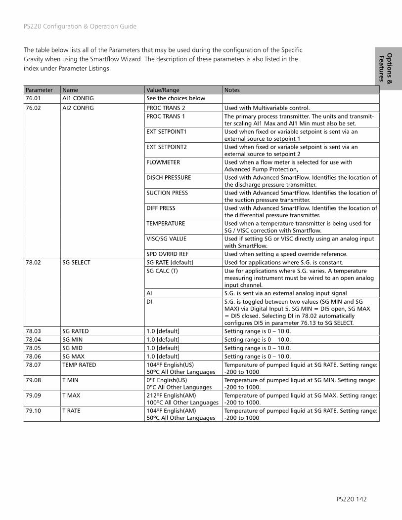
PS220 Configuration & Operation Guide
PS220 142
Op
tion
s &
Features
The table below lists all of the Parameters that may be used during the configuration of the Specific Gravity when using the Smartflow Wizard. The description of these parameters is also listed in the index under Parameter Listings.
Parameter Name Value/Range Notes76.01 AI1 CONFIG See the choices below
76.02 AI2 CONFIG PROC TRANS 2 Used with Multivariable control.PROC TRANS 1 The primary process transmitter. The units and transmit-
ter scaling AI1 Max and AI1 Min must also be set.EXT SETPOINT1 Used when fixed or variable setpoint is sent via an
external source to setpoint 1EXT SETPOINT2 Used when fixed or variable setpoint is sent via an
external source to setpoint 2FLOWMETER Used when a flow meter is selected for use with
Advanced Pump Protection,DISCH PRESSURE Used with Advanced SmartFlow. Identifies the location of
the discharge pressure transmitter.SUCTION PRESS Used with Advanced SmartFlow. Identifies the location of
the suction pressure transmitter.DIFF PRESS Used with Advanced SmartFlow. Identifies the location of
the differential pressure transmitter.TEMPERATURE Used when a temperature transmitter is being used for
SG / VISC correction with Smartflow.VISC/SG VALUE Used if setting SG or VISC directly using an analog input
with SmartFlow.SPD OVRRD REF Used when setting a speed override reference.
78.02 SG SELECT SG RATE [default] Used for applications where S.G. is constant.SG CALC (T) Use for applications where S.G. varies. A temperature
measuring instrument must be wired to an open analog input channel.
AI S.G. is sent via an external analog input signalDI S.G. is toggled between two values (SG MIN and SG
MAX) via Digital Input 5. SG MIN = DI5 open, SG MAX= DI5 closed. Selecting DI in 78.02 automatically configures DI5 in parameter 76.13 to SG SELECT.
78.03 SG RATED 1.0 [default] Setting range is 0 – 10.0.78.04 SG MIN 1.0 [default] Setting range is 0 – 10.0.78.05 SG MID 1.0 [default] Setting range is 0 – 10.0.78.06 SG MAX 1.0 [default] Setting range is 0 – 10.0.78.07 TEMP RATED 104ºF English(US)
50ºC All Other LanguagesTemperature of pumped liquid at SG RATE. Setting range: -200 to 1000
79.08 T MIN 0ºF English(US)0ºC All Other Languages
Temperature of pumped liquid at SG MIN. Setting range:-200 to 1000.
79.09 T MAX 212ºF English(AM)100ºC All Other Languages
Temperature of pumped liquid at SG MAX. Setting range: -200 to 1000.
79.10 T RATE 104ºF English(AM)50ºC All Other Languages
Temperature of pumped liquid at SG RATE. Setting range: -200 to 1000

PS220 Configuration & Operation Guide
143 PS220
Op
tio
ns
&
Feat
ure
s Speed Override The Pumpsmart PS220 can be taken out of its primary control mode of operation and placed into complete MANUAL control. If primary control is PID process control it will be bypassed and the drive will run at a predefined speed.
The Speed Override function can be initiated through a wide range of choices. These choices are listed in the table below:Notes:1. All of the Pump Protection Logic is functional during this time when Parameter 79.04 is enabled.2. The Message “WARNING SPEED OVERRIDE” will appear on the display and continue to flash when this function is activated.3. This function is very similar to “Local Control”.
This functionality can be configured with the Pumpsmart PS220 Configuration Wizard.
To access this Wizard, from the Home Screen follow the path: MENU>PS220 Configuration>Miscellaneous>Speed Override Parameter settings.
The Table below list all of the Parameters used for the Speed Override Function. The description of these parameters are also listed in the index under Parameter Listings.
Parameter Name Choices NotesDisabled [Default] DisabledDI5 Enabled when digital input DI5 is closed [1].DI5(INV) Enabled when digital input DI5 is open [0]. When closed
[1] primary control mode is active.DI3 Enabled when digital input DI3 is closed [1].DI3(INV) Enabled when digital input DI3 is open [0]. When closed
[1] primary control mode is active.HOA Enabled when the Hand function is initiated by closing
[1] digital input DI2. HOA must be configured in 12.01 START/STOP.
Fieldbus Speed Override is enabled by a Fieldbus command. Refer to Fieldbus Manual for details.
74.06 SPD OVERRIDE REF Keypad (default) The source of the Speed Override References (Default value).
AI1 AI2AI1 OPT AI2 OPTAI3 OPT
Defines analog input as the speed override reference. The corresponding analog input must be configured for SPD OVRRD in parameters using the I/O CONIGURATION wizard.
Fieldbus Speed Override reference is defined by a Fieldbus command. Refer to Fieldbus Manual for details.
79.04 SP OVRRD PMP PROT Enabled [Default] Disabled
Enables or disables pump protection warnings and faults when speed override is activated.
Note: When selecting a Digital Input please make sure that it is unused by another configuration setting. You can view 76.11 and 76.15 to see if they are “Not Selected”
When placing the drive in Speed Override and disabling pump protection functionality all pump protection except E-stop/permissive and keypad failure become inactive. Make sure override speed is not excessive for the application.
NOTICE

PS220 Configuration & Operation Guide
PS220 144
Op
tion
s &
Features
Start Delay This feature is designed to delay the pump from starting once a start command has been received. When a start signal is received the drive will delay starting by a set amount of time. Examples:1. A generator is used for the Power Supply for Backup when a power failure occurs. Once the generator starts it take a few seconds for the power to stabilize. If this drive was trying to run during this time period it would fault off.2. Oil needs to circulate to the bearings of a pump before it can rotate. Once the start command is issued, it would start a circulation system first (A “Run Status Relay” would need be used in addition to this), then start the pump after this delay has expired.
Parameter Name Value/Range Notes74.04 START DELAY 0-9999 Seconds
0 [default]This is the time period the drive will delay starting the pump once a start signal is received. This will work in Local or Remote.
Starting & Stopping Starting and Stopping the Pumpsmart PS220 can be accomplished by many methods
The default is the keypad pictured to the right. If there is a solid green light on the keypad just above and to the left of the left arrow key, you should be ready to run the drive. SHOW A SCREEN SHOT OF THIS SEE RED ARROW BELOW
LOCAL and REMOTE control: When in LOCAL control the drive will run completely in manual mode and bypass all Pumpsmart PS220 control settings. It will run in manual speed control and can only be started and stopped with the Red and Green keypad buttons. The running speed can only be adjusted by the arrow up and down keys.When in REMOTE control all of the PS220 Functionality is active and the drive will execute its primary control (example PID pressure control).
To verify if the drive is in LOCAL or REMOTE, check the top left-hand corner of the keypad display. The current mode, either “Local” or “Remote” will be displayed. if neither Local or Remote is displayed then the drive is in Remote with a remote sourced set-point. A diamond symbol will appear next to the word Local/Remote if the basic start command is assigned to the keypad.
All the PS220 pump protection Features are designed to operate in REMOTE mode.
Never operate rotating equipment unless all protective coupling and shaft guards are in place. Personal injury may occur if the driven equipment is operated without coupling and shaft guards.
WARNING
Observe all CAUTIONS and WARNINGS highlighted in the ACS880 Hardware Manual, PS220 Configuration and Operation Guide and Installation, Operation and Maintenance Guide for the applied driven equipment prior to starting.
WARNING

PS220 Configuration & Operation Guide
145 PS220
Op
tio
ns
&
Feat
ure
s
The steps required to switch from Remote to Local mode.
Loc/Rem
1: H-O-A DI1,2. This is the most common External Switch Combination used on the PS220
Functions:Control at one external locations.EXT Location1: DI1 is assigned to AutoDI2 is assigned to Hand(Speed Override)All switches are normally open
The Diagram also show an E-Stop switch connected to DIIL
2: H-O-A DI1 – 2W DI5. This is a commonly requested External Switch Combination used on the PS220
Functions:Control at two external locations.EXT Location 1: Hand-Off-Auto. DI1 is assigned to Auto, DI2 is as-signed to Hand(Speed Override)EXT2 Location 2: DI5 is assigned to Auto. This combination requires a pre-assigned switch (DI3) to switch between these 2 Auto Choices. DI3 High selects Auto DI1, DI3 Low selects Auto DI5
All switches are normally open

PS220 Configuration & Operation Guide
PS220 146
Op
tion
s &
Features
The table below lists all of the choices that can be configured for the start and stop method on the PS220. The Digital Inputs assignments are automatically configured when using the PS220 configuration Wizard for this function.
Parameter Name Value/Range Notes74.01 START/STOP KEYPAD [default] Start /Stop controlled via the Keypad
2 WIRE DI1 Control at one external location via 2-Wire switch assigned to DI1. Normally open
3W DI1P,2P Control at one external location via 3-Wire pulse start assigned to DI1 and pulse stop assigned to DI2. DI2 will be “normally closed”
HOA DI1,2 Control Used for Hand-Off-Auto. DI1is assigned to Auto; DI2 is assigned to Hand (Speed Override).Both are normally open.
HOA DI1,2 – DI5 Control at two external locations.EXT1: Hand-Off-Auto. DI1 is assigned to Auto, DI2 is assigned to Hand(Speed Over)EXT2: Auto. 2-Wire switch is assigned to DI5. This combination requires a preassigned switch (DI3) to switch between these 2 choices.All switches are normally open
DI1P,2P - DI5 Control at two external locations.EXT1: 3-W pulse start assigned to DI1 and pulse stop assigned to DI2. Di2 will be “normally closed” EXT2: Auto is a 2-Wire start/stop switch assigned to DI5. Normally open.
This requires a preassigned switch (DI3) to switch between these 2 choices.
HOA DI1,2 – FB Control at two external locations.EXT1: Hand-Off-Auto. DI1 is assigned to Auto, DI2 is assigned to Hand(Speed Override).EXT2: Fieldbus is the second control location.This requires a preassigned switch (DI3) to switch between these choices. Normally closed
2W DI1 – 2W DI5 Control at two external locations.EXT1: 2-Wire assigned to DI1.EXT2: 2-Wire switch at DI5.This requires a preassigned switch (DI3) to switch between these choices.All switches are “normally closed”
FIELDBUS Start via Fieldbus control word. External control location 1 only.
DI1P,2P - FB Control at two external locations. EXT1: 3-Wire pulse start DI1 and pulse stop DI2. EXT2: Fieldbus control word. This requires a preassigned switch (DI3) to switch between these choices
The drive can still be started locally at the keypad when put into LOCAL mode. Installing any remote switch and putting it in the OFF position does not completely lock the drive from starting. Only the Drive Permissive Digital Input DIL can disable the drive in both REMOTE and LOCAL modes.

PS220 Configuration & Operation Guide
147 PS220
Op
tio
ns
&
Feat
ure
s Stop Method By default, the Pumpsmart PS220 will “Ramp Stop” when commanded or when a fault occurs.The two parameters listed in the table below define how the PS220 will come to a stop based on a stop command (21.03) or based on an E-Stop command (21.04).
Parameter Name Value/Range Notes21.03 STOP FUNCTION RAMP STOP [default]
COAST STOPSelects how the motor will stop.
21.04 EMERG Stop Function RAMP STOP [default] COAST STOP
Selects how the motor will stop with Fault or ESTOP.
TUNING The Pumpsmart PS220 utilizes onboard PID control when running in any Process Control Mode. The two primary controlling functions are the Proportional Gain and the Integration time. The interaction of these properly configured settings allow for the running speed of the pump to quickly stabilize when the pump is turned on, and when there are gradual or rapid changes in the systems demand. The Tuning parameter settings that are associated by default with the Control Mode selected while using the Process Control Tune Wizard may not be optimal for your application thereby causing unstable control. The Proportional Gain and the Integration Time will need to be “Fine Tuned” to alleviate this condition. Every pumping system is unique and this is very common.
Following are a few “Rules of thumb” that can be followed as you adjust the parameters settings. You will need to access the Tune Wizard to accomplish this.
These are in order of what to adjust first. After each adjustment you should wait a few minutes for the reaction to take effect.
1. Rapid speed swings, or oscillations known as “Hunting” may be occurring. The audible “whining” of the drive as it increases/decreases in speed by a large RPM value can be heard. The Integral time will need to be increase. This should be done in increments of .5 seconds at a time.
2. When “Hunting” occurs as an “Overshoot” only, with the speed then coming down gradually, then the Proportional gain will need to be lowered. This should be done in decrements of .2 to .5.
3. When “Hunting” occurs only an “Undershoot” then the Proportional Gain should be increased. This should be done in increments of .2 to .5.
4. When there is minimal “Hunting” but still a lengthy time period before stable speed is achieved to maintain the pro-cess set-point, the Integral Time should be decreased. This should be in decrements of .5 seconds at a time. Notes1. For level control application the Integral Time is very dependent on the size of the pump and the volumetric size of the vessel pumping to/from. The default settings are preconfigured for large pumps with large vessels. This integral setting of 320 seconds will need to be lowered to something in the area of 10-15 seconds as a starting point for vessels under 500GPM.2. The changing of the values of Proportional Gain and Integral Time may require several iterations to obtain the optimum results.3. “Start-up” conditions usually are quite different than “steady state” running conditions. Be sure to tune for both start up (upset condition) and for running conditions (steady state condition).

PS220 Configuration & Operation Guide
PS220 148
Op
tion
s &
Features
The following figures show examples of Properly and Improperly Tuned systems. Properly Tuned SystemThis system has the appropriate Proportional gain and Integration Time.
Properly tuned system. There is both a slight overshoot and undershoot. This is a depiction of the “Ideal “ scenario you should expect.

PS220 Configuration & Operation Guide
149 PS220
Op
tio
ns
&
Feat
ure
s
Improperly Tuned System. The Proportional Gain is too high and the Integration Time is too short.
Improperly Tuned systemThe Integration Time is too long
Note - Air in the system may cause a condition that looks like oscillation or hunting. Be sure all air is purged from the system before attempting tuning.
This functionality can be configured with the Pumpsmart PS220 Configuration Wizard.
To access this Wizard from the Home Screen, follow the path: MENU>PS220 Configuration>Process Control>Process Tune

PS220 Configuration & Operation Guide
PS220 150
Op
tion
s &
Features
Underload (Freewheel) The Pumpsmart PS220 has the ability to monitor the Motor load continuously and can be configured to react when the load suddenly drops. Typically, this is a result of a de-coupling between the motor and the pump.
The Figure below depicts some of the parameters that will need to be configured for this function.
This function will need to be configured manually. To access the required parameters from the Home View, follow the path: Menu> Parameters> Complete List> Group 37>
The steps that will need to be performed are:
1. Configure the actual load to be monitored. Parameter 37.02. The recommended selection is (2) Motor Current.
2. Configure the reaction when the load drops. Parameter 37.04. The recommended selection is (2) Fault
3. Configure the 5 “x” axis motor speeds used as the intersection points with the monitored values. These are Parameters 37.11 through 37.15. Refer to the Graphic above.
NOTES1. Parameters 37.12,13 and 14 on not shown on the graphic.2. The settings for Parameters 37.21 through 25 should not have to be changed. 3. Parameters not mentioned do not apply to this function
Parameter Description Default in RPM of the Motor
Recommendation Notes
37.11 1st X Axis Intersection Point 150 See Notes Should be 10% of Max Motor Speed37.12 2nd X Axis Intersection Point 750 See Notes Should be 50% of Max Motor Speed37.13 3rd X Axis Intersection Point 1290 See Notes Should be 72% of Max Motor Speed37.14 4th X Axis Intersection Point 1500 See Notes Should be 83% of Max Motor Speed37.15 5th X Axis Intersection Point 1800 See Notes Should be 100% of Max Motor Speed
4. Configure the time period before the drive will react when an underload condition exits. The Default is 20 Seconds. The Ranges is 0-10,000 seconds.

PS220 Configuration & Operation Guide
151 PS220
Op
tio
ns
&
Feat
ure
s VFD PROTECTION Since the core functionality of the Pumpsmart PS220 is that of a Variable Frequency Drive (VFD) , it also provides the ability to configure the on board electrical parameters to provide a very high degree of Drive and Motor protection. It will identify and react to the most common electrical system upsets such as Undervoltage, Over-voltage, Overcurrent, Stall, Underload and Overtemp. Faults can be automatically re-set faults which can prevent “Nuisance Trips”. The default settings for most all of the protection selections are set to Fault. The settings that can be configured are as follows.
1. Maximum current:This value is predefined in the drive automatically during the setup of Basic Startup Wizard. This value should only be adjusted DOWN. An example of this would be if you installed a Pump with a non- overloading motor you could lower this value to prevent tripping. (higher amp-draw at higher flow rates,)
2. Overvoltage control: This parameter enables the overvoltage control of the DC Bus. Fast braking of a high inertia load causes the volt-age to rise to the overvoltage control limit. To prevent the DC voltage from exceeding the limit, the overvoltage controller automatically decreases the braking torque.
3. Undervoltage control: This parameter enables the undervoltage control of the DC Bus. If the DC voltage drops due to input power cut off, the motor torque will automatically be decreased in order to keep the voltage above the lower limit. By decreasing the motor torque, inertia of the load will cause regeneration back into the drive. This mechanism acts as a power-loss ride-through function.
4. Auto reset selection: (See also Fault Auto-Reset VFD)This parameter setting selects faults which can be automatically reset. Auto reset selection is a 16-bit word with each bit corresponding to a fault type. Whenever a bit is set to “1”, the corresponding fault can be automatically reset.
5. Number of trials: This parameter setting defines the maximum number of resets allowed to be attempted in the time specified by Total trials time. As many as 5 attempts can be made. Setting of zero disables this function.
6. Total trials time:This parameter setting defines the allowable time period for the counting and resetting of the electrical fault conditions configured. This parameter also limits the number of resets allowed during this time period.
7. Delay time:This parameter setting defines the time that the PS220 will wait before attempting an autoreset of the VFD Faults selected in Autoreset selection.

PS220 Configuration & Operation Guide
PS220 152
Op
tion
s &
Features
The VFD Protection can be configured with the Pumpsmart PS220 Configuration Wizard.
To access this Wizard from the Home Screen, follow the path: MENU>PS220 Configuration>Pump & VFD Protection>VFD Protection>
The table below shows all of the parameters used for the VFD protection. Additional Motor parameters are described in the index under the Parameter Listing for the Groups 30 and 31.
Group 30 Limits Description30.17 MAXIMUM CURRENT Defines the maximum allowed motor current. Once this value is achieved the motor will not
increase to higher in speed. 30.20 MAXIMUM TORQUE Defines the maximum torque for the motor. Once this value is achieved motor will not
increase in speed. 30.30 OVERVOLTAGE CONTROL Enables the overvoltage control of the intermediate DC link. Fast braking of a high inertia load
causes the voltage to rise to the overvoltage control limit. To prevent the DC voltage from exceeding the limit, the overvoltage controller automatically decreases the braking torque.Note: If the drive is equipped with a brake chopper and resistor, or a regenerative supplyunit, the controller must be disabled.
30.31 UNDERVOTLAGE CONTROL Enables the undervoltage control of the intermediate DC link. If the DC voltage drops due to input power cut off, the undervoltage controller will automatically decrease the motor torque in order to keep the voltage above the lower limit. By decreasing the motor torque, the inertia of the load will cause regeneration back to the drive, keeping the DC link charged and preventing an undervoltage trip until the motor coasts to a stop. This will act as a power-loss ride-through functionality in systems with high inertia, such as a centrifuge or a fan.
Group 31 Fault Functions Description31.12 AUTORESET SELECTION Selects faults that are automatically reset. The parameter is a 16-bit word with each bit
corresponding to a fault type. Whenever a bit is set to 1, the corresponding fault is automatically reset.
31.14 NUMBER OF TRIALS Defines the maximum number of automatic resets that the drive is allowed to attempt within the time specified by 31.15 Total trials time. If the fault persists, subsequent reset attempts will be made at intervals defined by 31.16 Delay time. The faults to be automatically reset are defined by 31.12 Autoreset selection.
31.15 TOTAL TRIALS TIME Defines a time window for automatic fault resets. The maximum number of attempts made during any period of this length is defined by 31.14 Number of trials. If the ”Number of trials” and the “Delay time” exceeds the ”Total trials time” the PS220 will not be able to reset automatically. The fault will need to be reset manually.
31.16 DELAY TIME Defines the time that the drive will wait after a fault (or a previous reset attempt) before attempting an automatic reset. See parameter 31.12 Autoreset selection.
Before you activate any part or parts of this function, proceed with extreme caution. This function resets the drive automati-cally and continues automatic operation after a Fault. This may result in severe equipment damage and/or physical injury and death.
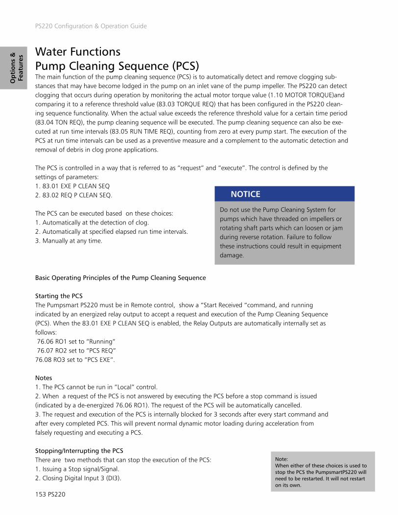
PS220 Configuration & Operation Guide
153 PS220
Op
tio
ns
&
Feat
ure
s Water Functions Pump Cleaning Sequence (PCS) The main function of the pump cleaning sequence (PCS) is to automatically detect and remove clogging sub-stances that may have become lodged in the pump on an inlet vane of the pump impeller. The PS220 can detect clogging that occurs during operation by monitoring the actual motor torque value (1.10 MOTOR TORQUE)and comparing it to a reference threshold value (83.03 TORQUE REQ) that has been configured in the PS220 clean-ing sequence functionality. When the actual value exceeds the reference threshold value for a certain time period (83.04 TON REQ), the pump cleaning sequence will be executed. The pump cleaning sequence can also be exe-cuted at run time intervals (83.05 RUN TIME REQ), counting from zero at every pump start. The execution of the PCS at run time intervals can be used as a preventive measure and a complement to the automatic detection and removal of debris in clog prone applications.
The PCS is controlled in a way that is referred to as “request” and “execute”. The control is defined by the settings of parameters:1. 83.01 EXE P CLEAN SEQ2. 83.02 REQ P CLEAN SEQ.
The PCS can be executed based on these choices:1. Automatically at the detection of clog.2. Automatically at specified elapsed run time intervals.3. Manually at any time.
Do not use the Pump Cleaning System for pumps which have threaded on impellers or rotating shaft parts which can loosen or jam during reverse rotation. Failure to follow these instructions could result in equipment damage.
NOTICE
Basic Operating Principles of the Pump Cleaning Sequence
Starting the PCS The Pumpsmart PS220 must be in Remote control, show a “Start Received “command, and running indicated by an energized relay output to accept a request and execution of the Pump Cleaning Sequence (PCS). When the 83.01 EXE P CLEAN SEQ is enabled, the Relay Outputs are automatically internally set as follows: 76.06 RO1 set to “Running” 76.07 RO2 set to “PCS REQ”76.08 RO3 set to “PCS EXE”.
Notes 1. The PCS cannot be run in “Local” control.2. When a request of the PCS is not answered by executing the PCS before a stop command is issued (indicated by a de-energized 76.06 RO1). The request of the PCS will be automatically cancelled.3. The request and execution of the PCS is internally blocked for 3 seconds after every start command and after every completed PCS. This will prevent normal dynamic motor loading during acceleration from falsely requesting and executing a PCS.
Stopping/Interrupting the PCSThere are two methods that can stop the execution of the PCS:1. Issuing a Stop signal/Signal.2. Closing Digital Input 3 (DI3).
Note:When either of these choices is used to stop the PCS the PumpsmartPS220 will need to be restarted. It will not restart on its own.

PS220 Configuration & Operation Guide
PS220 154
Op
tion
s &
Features
Disabling the PCSTo completely disable this function is must be turned off manually by setting parameter 83.01 EXE P CLEAN SEQ to “NOT SEL”.
PCS in Multipump Applications In Multipump Synchronous control, only one pump shall be permitted to execute the PCS at a time. The other pump(s) shall be held in queue until they individually become available to execute their PCS routines.
PCS Parameter Configuration Settings:
The following parameter settings are used to configure the Pump Cleaning Sequence.
Note:Setting parameter 83.02 is set to TORQ or TORQ OR RUN TIME will require a “Torque Test to be performed to ensure that the setting for parameter 83.03 TORQUE REQ is suited for the application.
The test can be done as follows:1. Switch to “LOCAL” Keypad Control.2. Start the Pump by pressing the Green Start Button.3. Set the Speed Reference to Max Speed and let the pump run to full speed. Check and validate that the pump is pumping with a “normal level” in the sump or the suction side tank and it is maintaining a stable flow.4. View/Record the value of Parameter 1 .10 MOTOR TORQUE in %. Multiply this value by 1.2. The factor 1.2 cor-responds to the expected increased torque that can be expected when a clog may occur. Use this calculated value when you configure parameter 83.03 TORQUE REQ.5. Stop the PS220 with the Red Stop Button.6. Switch back to REMOTE control.

PS220 Configuration & Operation Guide
155 PS220
Op
tio
ns
&
Feat
ure
s
Parameter Name Value/Range Notes30.12 MAXIMUM SPEED 0-18000 RPM
Motor Nominal Speed [default]
Defines the allowable maximum speed. Default setting is parameter 99.09 Motor FL Rpm. No high-er value that the full load rpm should be used or the pump motor may overheat.
30.11 MINIMUM SPEED 0-18000 RPM25% Motor Nominal Speed [default]
Defines the minimum speed range. No lower value than 60% of nominal speed shall be set, since the risk of clogging increases with reduced speed.
23.12 ACCEL TIME 0-18000 Seconds5 [default]
Defines the fast acceleration time. No lower value than2.0 sec shall be set, since stress on the impeller and shaft increases with reduced ACCEL TIME.
23.13 DECEL TIME 0-18000 Seconds5 [default]
Defines the fast deceleration time. No lower value than4.0 sec shall be set, since stress on the impeller and shaft increases with reduced DECEL TIME.
83.01 EXE P CLEAN SEQ Defines how the cleaning sequence is executed. Drive relay output R03 energizes upon execution. RO3 remains energized during the cleaning sequence. The PCS operates in REMOTE mode only.
NOT SEL (DEFAULT) The pump cleaning sequence is disabled.P CTRL DI3 The pump cleaning system is executed by the pump
controller setting the drive digital input DI3 from 0 to 1.PS220 The pump cleaning system is executed by the PS220 itself.
83.02 REQ P CLEAN SEQ Defines what triggers the request of the pump cleaning sequence. Upon request the relay output RO2 energizes and remains energized until the execution of the sequence is completed.
NOT SEL (DEFAULT) The pump cleaning sequence is disabled if 83.01 is set to PS220 and 83.02 is set to NOT SEL. If 83.01 is set to P CTRL DI3 and 83.02 is set to NOT SEL the pump controller and pump controller logic are used to control the PCS. The capability to analyze torque and/or run time are disabled.
TORQ The request is triggered when 1.10 MOTOR TORQUE exceeds the value set in 83.03 TORQ REQ for the 83.04 TON REQ. The fulfillment is monitored and analyzed by the drive.
RUN TIME This request is triggered when 1.226 PMP CLN RUN TIME exceeds the value set in 83.05 RUN TIME REQ. The fulfillment is monitored and analyzed by the drive.
TORQ OR RUN TIME This request is triggered when either motor torque or run time is fulfilled as described above.83.03 TORQUE REQ 0.0-200.0%
120% [default]Defines the motor torque threshold value in % above nominal motor torque which is required to trigger a pump cleaning sequence.
83.04 TON REQ 0-100 Seconds 5s [default] Time period before the pump cleaning sequence can be triggered.83.05 RUN TIME REQ 0.1-100.0 Hours
2hrs [default]Defines the run time which must be met before the pump cleaning sequence can be requested if configured in 83.02 REQ P CLEAN SEQ. The 1.226 PMP CLN RUN TIME is reset to zero after every stop command and after every completed cleaning sequence.
83.06 NUM OF CYCLES 1-102 [default]
Defines the number of cycles the pump cleaning system performs for each execution.
83.07 FWD RUN SPD 0.0-100.0%100% [default]
Defines the forward running speed in % of 30.12 MAXIMUM SPEED.
83.08 FWD RUN TIME 0.0-100.0 Seconds 7s [default]
Defines the forward running time of the cleaning sequence.
83.09 FWD RUN ACC 0.0-100.0 Seconds 1s [default]
Defines the forward acceleration in the cleaning cycle.
83.10 FWD RUN DEC 0.0-100.0 Seconds 2s [default]
Defines the forward deceleration in the cleaning cycle. No lower value than 2 sec shall be set to avoid overstress of the impeller and shaft.
83.11 ZERO SPEED PAUSE 0.0-100.0 Seconds 7s [default]
Defines the zero speed pause in the cleaning sequence when switching from forward to reverse rotation.
83.12 REV RUN SPD 0.0-100.0%80% [default]
Defines the reverse running speed in % of 30.12 MAXIMUM SPEED. No higher value than 80% shall be set to avoid overstress of the impeller and shaft.
83.13 REV RUN TIME 0.0-100.0 Seconds 7s [default]
Defines the reverse running time of the cleaning sequence.
83.14 REV RUN ACC 0.0-100.0 Seconds 2s [default]
Defines the reverse acceleration in the cleaning cycle. No higher value than 2 sec shall be set to avoid overstress of the impeller and shaft.
83.15 REV RUN DEC 0.0-100.0 Seconds 01s [default]
Defines the reverse deceleration in the cleaning cycle.
83.16 SEQUENCE TIMER 0-100 Seconds 30s [default]
Applies to 83.01 setting of PS220 only. If the time period for requesting a new PCS (after a PCS sequence has been completed) is less than the SEQUENCE TIMER setting then the 83.17 SEQUENCE COUNTER shall be enabled.
83.17 SEQUENCE COUNTER 0-105 [default]
Applies to 83.01 setting of PS220 only. The maximum number of sequences which are allowed after the SEQUENCE COUNTER has been activated. If the drive requests another PCS after the maximum allowed sequences has been attained then the 83.18 SEQUENCE EXCEED function shall be activated.
83.18 SEQUENCE EXCEED Applies to 83.01 setting of PS220 only. After the 83.17 SEQUENCE COUNTER has reached the maximum allowed sequences and a new PCS is requested this settable action is initiated. Default is Fault.
DISABLED The SEQUENCE EXCEED function is disabled and there is no limitation on the number of PCS requests and executions.
WARNING The Keypad displays a warning PUMP CLOGGED and the PCS function is disabled. The drive continues to function in its normal configured state. A relay output is energized and Fieldbus 3.11 PS Condition Word Bit 02 “PUMP CLOGGED” is set (if configured).
FAULT [default] The drive faults and must be manually reset The Key- pad displays a fault PUMP CLOGGED. A relay output is energized.

PS220 Configuration & Operation Guide
PS220 156
Op
tion
s &
Features
Pipe Cleaning The PS220’s Pipe Cleaning function will allow for a high flow flushing of the discharge piping system. This should aid in reducing sedimentation that may have accumulated in the piping and help reduce wear on the piping system over time. The PS220 can be configured to execute the pipe clean sequence on every start, or strictly based on actual accumulated pump/motor running hours. The pump will be run at full speed when this function is executed.
The Pipe Cleaning functionality can be configured with the Pumpsmart PS220 Configuration Wizard. To access this Wizard, from the Home Screen follow the path: MENU>PS220 Configuration>Water Functions>Pipe Cleaning Function>
The table below lists all of the Parameters used in this function.
Parameter Name Value/Range Notes83.21 ENABLE ON START DISABLE [default]
ENABLE ON START ENABLE ON TIME
Defines if the pipe cleaning function is executed on every start or time.
83.22 PIPE CLEAN TIME INTVL 0 – 10000 hrs.100 hrs. [default]
Time interval between each pipe cleaning cycle if 83.21 is set to ENABLE ON TIME.
83.23 PIPE CLEAN CYCLE TIME 0-1800 Seconds600 [default]
Defines how long the pipe cleaning sequence is executed for.
Pipe Fill The PS220’s Pipe Fill function allows the gradual filling of an empty discharge piping system when a pumping system is initially started. This will dramatically reduce the impact of any “water hammer” and prevent a “run- out” flow condition as the system will be gradually filling. The pipe fill function can be set to a specific speed and a set time duration. It also has the ability to be turned off automatically and start performing basic process control when a pre-determined value of the primary process control parameter is reached. The Pipe Fill function can be accessed up using the WATER FUNCTIONS wizard. To get to the wizard from the home screen follow the path:MENU>PS220 Configuration>Water Functions>Pipe Fill Function>
Parameter Name Value/Range Notes83.24 PIPE FILL ENABLE DISABLE [default]
ENABLEThis parameter enables the pipe fill function when the drive is started.
83.25 PIPE FILL TIME 0 – 65000 sec.50 sec. [default]
Defines how long the pipe fill function should execute.
83.26 PIPE FILL SPEED 0-20000 RPM 1000 [default]
Defines the speed the drive should run at when the pipe fill function is being executed.
83.27 Pipe Fill Stop Value Default is 0 Defines the value actual used in the primary PID control mode to shut off the fill function. This value will override the value in 83.25. The units are the same as defined in PID Units

PS220 Configuration & Operation Guide
157 PS220
Op
tio
ns
&
Feat
ure
s Snore The PS220’s snore function overrides the stop level while emptying a tank for the purpose of removing oil & grease and other floating debris from the surface of the liquids in a vessel. This eliminates the need to pump down and clean the sump manually. The snore function can be setup using the WATER FUNCTIONS wizard. To access the wizard from the home screen, follow the path:
MENU>PS220 Configuration>Water Functions>Snore
Parameter Name Value/Range Notes83.19 SNORE TIME 0-10000 hrs.
0 hrs. [default]Defines the elapsed time before the Snore function is activated. Range: 0 – 10,000 hrs. Default is zero hrs which disables this function.
83.20 TORQUE COEFF 0.0 – 1.000.85 [default]
Defines the torque coefficient setting needed to terminate the snore function. This is expressed as a percentage of the normal running torque. Range: 0.00 – 1.00.

PS220 Configuration & Operation Guide
PS220 158
Parameter
Resto
re
THIS PAGE IS INTENTIONALLY LEFT BLANK

PS220 Configuration & Operation Guide
159 PS220
Para
met
er
Res
tore
Restoring Factory Defaults Wizard The Pumpsmart PS220 has the ability to be completely reset back to the original factory defaults. This will erase all of the current settings that may have become corrupt are that you may be having trouble with during the normal operation of the system. This function can also be used when you relocate and re-connect the Pumpsmart to a different piece of equipment.
Please use the PumpsmartPS220 Wizard to accomplish this.
From the home screen follow the path :MENU>PS220 Configuration>Parameter Restore>”SELECT YES”
The steps that you will perform:1. Perform a Parameter Restore2. Exit the Wizard3. Clear all Parameters4. Power cycle the PS2205. Reconfigure the PS220
The Screen Shots that follow will show you step by step as you progress, from start to finish as you progress, how to configure this functionality.
1. Perform a Parameter Restore
“Select” “Yes” 2. Exit the Wizard
3. Clear all Parameters From the Home Screen follow the path: MENU>Parameters>Complete List> ARROW UP to “96 System”>
“EDIT” “SAVE”
4. Power cycle the PS2205. Reconfigure the PS220
An additional way to conduct a com-plete factory restore is to use parameter 96.06 Parameter Restore>Clear All.Regardless of what method you use to restore the PS220 you should follow with a power cycle.

PS220 Configuration & Operation Guide
PS220 160
Keyp
ad U
se
THIS PAGE IS INTENTIONALLY LEFT BLANK
3. Clear all Parameters From the Home Screen follow the path: MENU>Parameters>Complete List> ARROW UP to “96 System”>

PS220 Configuration & Operation Guide
161 PS220
Key
pad
Use
Keypad Basics1 Left Soft Key Usually used for exiting and canceling. Its function in a given situa-
tion is shown by the Softkey selection in the bottom left corner of the display. Holding down the key exits each view in turn until you are back in the Home view.
2 Status LED
3 Stop Used to stop the drive in LOCAL mode. To use in REMOTE mode set parameter 74.01 to KEYPAD
4 USB Connector The USB connector is used for connecting the control panel to a PC. When connected, the control panel acts as an USB adapter for data transfer between the PC tool and the drive.
5 Local / Remote The location key (Loc/Rem) is used to switch the control between the control panel (Local) and remote connections (Remote). When switching from Remote to Local while the drive is running, the drive keeps running at the same speed. When switching from Local to Remote, the status of the remote location is adopted.
6 Start Used to start the drive in LOCAL mode. To use in REMOTE mode set parameter 74.01 to KEYPAD
7 Arrow Keys The up and down arrow keys are used to highlight selections in menus and selection lists, to scroll up and down on text pages, and to adjust values when, for example, setting the time, entering a passcode or changing a parameter value.The left and right arrow keys are used to move the cursor left and right in parameter editing and to move forward and backward in assistants
8 Help The help key (?) opens a help page for certain drive functions and faults.
9 Right Soft Key The right softkey is usually used for selecting, accepting and confirming. The function of the right softkey in a given situation is shown by the softkey selection in the bottom right corner of the display.
Green, continuous The drive is functioning normally.
Green, flickering Data is transferred between the PC tool and drive through the USB connection of the control panel.
Green, blinking Used to stop the drive in LOCAL mode. To use in REMOTE mode set parameter 74.01 to KEYPAD
Red, continuous There is an active fault in the drive.
Blue, Bluetooth interface is enabled. It is in discoverable mode and ready for pairing.
Blue, flickering Data is transferred through the Bluetooth interface of the control panel.
Keypad Use - Appendix A1 Attach the control panel directly to the drive or use a separate mounting kit (cabinet door mounting).To attach the control panel:1. Place its bottom end into the bottom of the slot in the drive (A),2. Pivot the control panel and push the upper part (B) until you hear a click.
To detach the control panel:1. Release the control panel by pressing the clip (B),2. Pull the upper end of the control panel out of the slot in the drive.

PS220 Configuration & Operation Guide
PS220 162
Keyp
ad U
se
1 Control Location • Local – The drive is in local control and controlled from the keypad.• Remote – the drive is in remote control and start / stop is based on parameter 74.01.• No Text – The drive is in local control but controlled from another device and not the keypad.
2 Softkey selection Displays the function of the softkeys.
3 Clock Displays the current time. Can be changed through the settings menu.
4 Reference value The reference value, which can be speed, frequency or a process variable ( pressure , flow etc.) is displayed with units.
5 Drive Name If a name has been given, it is displayed at the top pane. By default, it is PS220. You can change the name in the Settings menu.
6 Status icon Indicates the status of the drive and the motor. The direction of the arrow indicates forward (clockwise) or reverse (counter-clockwise) rotation.
Display
Status Icon Animation Drive Status
- Stopped
- Stopped, start inhibited
Blinking Stopped, start command given but start inhibited
Blinking Faulted
Blinking Running, at reference, but the reference value is 0
Rotating Running, not at reference
Rotating Running, at reference
Shortcut Available in Effect
any view Save a screenshot. Up to fifteen images can be stored in the control panel memory. To download images, connect a PC to the keypad using a mini USB cable.
any view Adjust backlight brightness.
any view Adjust display contrast.
Home view Adjust reference.
Key ShortcutsThe table below lists key shortcuts and combinations. Simultaneous key presses are indicated by the plus sign (+).

PS220 Configuration & Operation Guide
163 PS220
Key
pad
Use Home View
The main view of the control panel is called the Home view. In the Home view, you can view the current status of both Pump and VFD values. The Pumpsmart PS220 Home View has 4 pages of 3 predefined lines of signal status as standard. Each are customizable, and fully editable. The Home View configuration is saved to the drive whenever you change it. The maximum total number of signals displayed is 9 to 21, depending on the view selected for each signal. In the example below, three Home view pages are used, showing different display formats allowing only 1 per page.
Default home views for Speed control, Process control, SmartFlow and Multipump are setup. Press the arrows keys to scroll through the menu. You can return to the Home view from any view except special screens by holding down the left softkey.
HelpWhen pressing the “Question Mark Button” it will open a help page. The page may describe how to resolve a message displayed or provide information on a particular setting. It also may not pro-vide information to aid the user.

PS220 Configuration & Operation Guide
PS220 164
Keyp
ad U
se
Parameter AccessIn the Parameters menu, you can access, view and edit parameters. In each sub-menu, you can edit a parameter by highlighting it and pressing “Edit”.
Complete listIn the Complete list sub-menu, all parameter groups are listed in numerical order. If you select a parameter group, all parameters in that group are listed. Parameter numbers are always displayed in this sub-menu.
For every bottom on the bottom of the screen will be the minimum and maximum scaled values that are allowed to be selected. The “ARROW” keys allow you to move in all 4 directions for to edit values easily.
There are distinct parameters that may be “read-only” and can only be viewed by pressing “View”. The values shown cannot be modified.

PS220 Configuration & Operation Guide
165 PS220
Key
pad
Use
FavoritesIn the Favorites sub-menu, only user-selected parameters are listed. The order is determined by the parameter number.
ModifiedIn the Modified sub-menu, only the parameters whose values differ from the defaults are listed. The order is determined by the parameter number.
To Change the PS220 name that display on the top-center of the keypad display.

PS220 Configuration & Operation Guide
PS220 166
Fault Tracin
g
THIS PAGE IS INTENTIONALLY LEFT BLANK

PS220 Configuration & Operation Guide
167 PS220
Fau
lt T
raci
ng APPENDIX A2 - FAULT Warnings
The section lists most all of the Pumpsmart PS220 Fault and Warning messages that may occur and display. It will describe in detail:1. How to access the list of all current and historical events on the PS220 unit. 2. Describe in User Friendly Terms what the event was/is.3. Describe in User Friendly terms the list of possible causes of each event.4. Describe in User Friendly Terms the list of corrective action(s) that may be necessary to correct the event from re-occurring if started again.5. Describe to how Reset each event to run the PS220 successfully again.
All electrical installation and maintenance work must be undertaken by a qualified electrician only. Failure to do so could result in serious injury or death.
WARNING
Warnings:Warnings, and the messages displayed are common. The PS220 Pumpsmart will not stop and it will not have to be reset. The Warning and its message can be hidden by pressing the HIDE key as shown. There will be a green LED flashing on the keypad signifying that there is as active warning green. The Warning and message will reappear in one minute if running conditions remain unchanged. If the condition which caused the warning is resolved the warning will turn off on its own. It will, however, be logged in the event log.
Faults:Faults and the messages displayed are not common but do and will occur. They will stop the PS220 Pumpsmart drive and prevent it from being able to be restarted and run again. As described above certain faults are inter-nally re-set. Those faults, at this point, should have gone past the point of auto-re-setting and are now “Hard Faults”. Corrective action in all cases is now required.
Warning and Fault messages are presented in tables below and include information on the cause and remedy for each case. Most Warning and Fault conditions can be identified and cured with this information. If not, contact an authorized ITT – Gould’s Pumps Factory Service Representative.Do not attempt any measurement, parts replacement or other service procedure not described in the installation or programming guide. Such action will void guarantee, endanger correct operation, and increase downtime and expense.
Note:This section does not cover all warnings and faults. It is intended to be used in conjunction with the standard ACS880 Firmware manual which can be found on the Internet.

PS220 Configuration & Operation Guide
PS220 168
Fault Tracin
g
Fault HistoryThe Fault history can be viewed in the Event log. When a Fault is detected, it is stored in the Event Log History.
Accessing the Event Log:
The last 32 fault and warnings are stored in the drives event logs. They are date and time stamped so they can be used for analysis. Details of each event can be reviewed by pressing the key below the word “Details”
There are multiple ways to reset or clear an active fault:

PS220 Configuration & Operation Guide
169 PS220
Fau
lt T
raci
ng 1. If the fault is still active it can be reset by hitting the key below the word “reset.”
2. A wired digital input can be cycled (low to high). Any available Digital input can be set up using the I/O Configuration wizard. 3. Fieldbus control can be used. The proper configuration settings will have to be setup and communicated to the drive. If using Filedbus Start/stop a fault cannot be reset via the keypad or with a digital input. It must be reset with a Fieldbus command. Please refer to the Fieldbus Quick start guide for more information.4. The event log can be used to view fault(s) that need to be reset and reset them there.5. Using an approved PC based tool (ABB Drive Composer) connected to the drives input.6. A Bluetooth device that can run the ABB DRIVETUNE App5. All Power can be cycled off to the drive, then wait until the keypad goes dark, and then apply all power on again.
Note: Depending on how you may have set up Pump and VFD Protection with the Pump & VFD Protection Wizard there may be active faults that are in the process of automatical-ly resetting themselves. Please wait until the duration that was set has expired before trying to reset and restart the Pumpsmart PS220 again. It will need to be restarted in the same fashion as it was before the event(s) that may have caused the fault to occur.
Table A2 - 1 PS220 Pump Warning Messages Each warning message on the keypad displays the warning name as well as and unique code. The messages are listed in the ascending order of their fault codes
CODE (HEX)
WARNING CAUSE WHAT TO DO
D200 PUMP SNORING Pump Snoring sequence is being executed
• Warning will clear automatically after the Snore function is executed.• If a Snore in not intended, then verify settings in group 85 (85.19 and 85.20) and disable the function.
E200 DRY RUN(PROGRAMMABLE FAULT FUNCTION 79.10)
The pump is operating in a dry running condition (loss of suction).
• Open the suction valve.• Check suction line for blockages.•Foot valve not opening on suction lift applications.• Pump not primed.• Pump is air locked, purge air from system•Check for excessive amount of entrained air in suction system
SECONDARY A PROTECT(PROGRAMMABLE FAULT FUNCTION 79.14)
Loss of digital input 4 (DI4) or digital input 5 (DI5) for protection delay (79.03).
• Instrumentation wired to digital input 4 or 5 (pressure switch, level switch, flow switch, temperature switch etc.) has tripped.
E202 SECONDARY B PROTECT (PROGRAMMABLE FAULT FUNCTION 79.15)
E203 CONDITION1 HI WARNING(PROGRAMMABLE FAULT FUNCTION 80.05)
The signal level for General Condition Sensor has exceeded 80.05/ 80. 11 COND 1/2 WRN LIM HI for more than the condition response delay set in parameter 80.16
• Investigate cause of condition• Check parameter settings of 80.05/80.11 COND 1/2 WRN LIM HI
E204 CONDITION 2 HI WARNING(PROGRAMMABLE FAULT FUNCTION 80.11)
E205 PUMP PROTECT(PROGRAMMABLE FAULT FUNCTION 79.01)
The actual process value is lower than protection limit (79.02) for protection delay (79.03) and the PS220 is at max speed (30.12) for the protection delay.
• Open the suction valve.• Open the discharge valve.• Check suction conditions (dry running, low level).• Check suction line for blockages (clogged strainer, debris, check valve not open).• Check discharge line for blockages (debris, check valve not open).• Check if flow rate is excessive (cavitation
E206 TUNE IN PROGRESS A SmartFlow tune is being executed
•Wait for Tune to complete.• If a tune is not desired, push the stop button and verify parameter 77.20 is not set to TUNE.
E207 TUNE COMPLETE A SmartFlow tune is success-fully completed.
• No action necessary. Process to the next desired function or operation.
E208 MIN FLOW WARNING(PROGRAMMABLE FAULT FUNCTION 79.08)
The pump is operating below the safe continuous flow rate in 79.09.
• Check discharge line for blockages (debris, check valve not opened).• Check setting of parameter 79.09• If using a flow meter check flow meter output/calibration • Check Smartflow settings • Re-tune SmartFlow.•Check pump for wear.
E209 PIPE FILL ERROR Unable to complete a Pipe fill sequence.
• Verify parameters 83.25 and 83.26• Verify that the PS220 is not current limited and is able to reach speed set up in 83.26• Verify that another warning or fault is not active. This can be seen in the event log.
E20B BASIC PUMP PROT RETRY Basic Pump Protect is in the process of retrying to make set-point. Requires that Retries are enabled in Pump Protection wizard.
• No action• If unsuccessful after multiple retries look for plugged suction or discharge.
E20C MIN FLOW RETRY PumpSmart is retrying to get above min flow value. Re-quires that Retries be enabled in Pump Protection wizard.
•No action•If unsuccessful after multiple retries look for plugged suction or discharge.

PS220 Configuration & Operation Guide
PS220 170
Fault Tracin
g
CODE (HEX)
WARNING CAUSE WHAT TO DO
E20D RUNOUT(PROGRAMMABLE FAULT FUNCTION 79.12)
The pump is operating at a flow rate above the value set in 79.13 • Check for additional larger discharge line branches that may have been added or opened to piping.• Check for broken discharge piping•Slowly close discharge valve or restrict discharge output • Check setting of parameter 79.13• Re-tune Smart flow.• If using a flow meter check flow meter output and calibration.
E20E SECONDARY A PROTECT ALARM(PROGRAMMABLE FAULT FUNCTION 79.14)
Loss of digital input 4 (DI4) or digital input 5 (DI5) for protection delay (79.03). Note: Other Digital inputs may have been configured for this function. Check 76.09-76.16
• Instrumentation wired to digital input 4 or 5 (pressure switch, level switch, flow switch, temperature switch, etc.) has tripped or has failed.• Check Digital input power source
Note: Other Digital inputs may have been configured for this function. Check 76.09-76.16
E20F SECONDARY B PROTECT ALARM (PROGRAMMABLE FAULT FUNCTION 79.15)
E210 BASIC PUMP PROTECT ALARM(PROGRAMMABLE FAULT FUNCTION 79.01)
E211 CONDITION 2 LO WARNING The signal level for General Condition Sensor has dropped below 80. 12 COND 2 WRN LIM LO
• Investigate cause of condition• Check parameter settings of 80.12
E212 PIPE CLEAN TIME OUT Unable to complete the pipe clean sequence. • Check parameter settings of 83.22 and 83.23• Verify that the PS220 is not current limited and is able to reach maximum speed set up in 30.12• Verify that another warning or fault is not active. This can be seen in the event log.
E213 SPEED OVERRIDE(PROGRAMMABLE FUNCTION 74.05)
Speed override function has been enabled. • The Speed Over ride function is running. Waring message only. Check that Speed Override Pump protection is active (79.04) if required to protect the pump.
E214 CONDITION 1 LO WARNING The signal level for General Condition Sensor has dropped below 80.06 COND 2 WRN LIM LO
• Investigate cause of condition• Check parameter settings of 80.06
E215 PUMP CLEANING RUNNING Pump clean sequence is being executed. • Check parameter 83.01 and 83.02 to verify that the cleaning sequence is executing as intended.
E216 PUMP CLEANING RETRY Pump clean sequence has re-executed. It did not unclog in the previous try.
• PS220 try will continue to run the sequence until the pump is unclogged. If the number of cycles set up in 83.06 has exceeded and the pump is still clogged, the PS220 will respond based on parameter 83.18.
E217 PUMP CLEANING WARNING Pump clean sequence is being executed. • Check parameter 83.01 and 83.02 to verify that the cleaning sequence is executing as intended.
E218 PIPE CLEANING (RT) RUNNING
Pipe clean sequence is being executed. • Pipe clean function is setup by parameters 83.21, 83.22 and 83.23.
TOTAL SYSTEM FLOW COMPLETED
The pump has completed pumping the total volume set in parame-ter 84.01.
• The flow totalizing function is setup by parameters 84.01 and 84.02.• Verify that the pumped volumes are based on the above settings ( within the stated Ps220’s published accuracy limits)
E220 COND 2 HI ALARM (PRO-GRAMMABLE FAULT FUNCTION 80.13)
The signal level for General Condition Sensor has exceeded80.14 COND 2 ALAMR LIM HI
• Investigate cause of condition• Check parameter settings of 80.13 and 80.14
E221 CONDITION SLEEP (PROGRAMMABLE FAULT FUNCTION 80.07 OR 80.13)
A Condition 1 or Condition 2 sensor has exceeded the alarm limits. • Investigate cause of condition• Check parameter settings of 80.0,7 80.08,80.09, 80.13, 80.14 and 80.15
E222 COND 2 LO ALARM (PROGRAMMABLE FAULT FUNCTION 80.13)
The signal level for General Condition Sensor has fallen below 80.15 COND 1 ALAMRM LIM HI
• Investigate cause of condition• Check parameter settings of 80.13 and 80.15
E223 PID LOW DEMAND Requested set-point requires the pump to run at a lower speed than minimum speed (30.11). This warning typically happens only in SmartFlow Control mode.
• Lower the minimum speed value• Raise the set-point value
E224 START DELAY ACTIVE Start delay has been enabled. The start command has been given and PumpSmart is currently under a start delay condition.
• No action• Once delay period is complete the pump will start running.
E225 PRIMING ON Pump is running the priming function. It will run at full speed with all logic and protection turned off internally.
Warning only. It will run every time it starts for the duration set in 75.02
E226 STAGE TIMEOUT ALARM Staging / Destaging proof time exceeded. Check 81.38-81.39. Cycle the start commandReboot the control board with Parameter 96.08
E21A BYPASS VALVE OPEN The PS220’s minimum flow bypass valve control has triggered the relay to open a bypass valve.
• Warning message only. NOTE: When the bypass closes there will not be a message stating this.
E21B PIPE CLEAN RUNNING The PS220 is executing a pipe clean sequence. • Verify that the sequence if operating based on parameter settings 83.21, 83.22 & 83.23
E21C PIPE FILL RUNNING The PS220 is executing the pipe fill function. • Warning message only.
E21D PIPE FILL Pipe fill sequence is being executed. • Warning message only.
E21E COND 1 HI ALARM(PROGRAMMABLE FAULT FUNCTION 80.07)
The signal level for General Condition Sensor has exceeded 80.08 COND 1 ALAMRM LIM HI
• Investigate cause of condition• Check parameter settings of 80.07 and 80.08
E21F COND 1 LO ALARM (PROGRAMMABLE FAULT FUNCTION 80.07)
The signal level for General Condition Sensor has fallen below 80.09 COND 1 ALAMRM LIM HI
• Investigate cause of condition• Check parameter settings of 80.07 and 80.09

PS220 Configuration & Operation Guide
171 PS220
Fau
lt T
raci
ng Table A2 - 1 PS220 Pump Fault Messages
Each Fault message on the keypad displays the fault name as well as and unique code. The faults are listed in the ascending order of their fault codes. A fault will cause the drive the stop the pump.
CODE (HEX)
WARNING CAUSE WHAT TO DO
E100 DRY RUN(PROGRAMMABLE FAULT FUNCTION 79.10)
The pump is operating in a dry running condition (loss of suction).
• Check parameter for correct vale 79.11• If using a flow Meter check meter output.• Re tune SmartFlow.• Check Pump for wear• See Pump Protect E106 for additional remedies
E101 COND 1 HI ALARM(PROGRAMMABLE FAULT FUNCTION 80.07)
The signal level for General Condition Sensor has exceed-ed 80.08 COND 1 ALAMRM LIM HI
• Investigate cause of condition• Check parameter settings of 80.07 and 80.08
E102 COND 1 LO ALARM (PROGRAMMABLE FAULT FUNCTION 80.07)
The signal level for General Condition Sensor has fallen below 80.09 COND 1 ALAMRM LIM HI
• Investigate cause of condition• Check parameter settings of 80.07 and 80.09
E103 COND 2 HI ALARM (PROGRAMMABLE FAULT FUNCTION 80.13)
The signal level for General Condition Sensor has exceeded 80.14 COND 2 ALAMR LIM HI
• Investigate cause of condition• Check parameter settings of 80.13 and 80.14
E104 COND 2 LO ALARM (PROGRAMMABLE FAULT FUNCTION 80.13)
The signal level for General Condition Sensor has fallen below 80.15 COND 1 ALAMRM LIM HI
• Investigate cause of condition• Check parameter settings of 80.13 and 80.15
E105 PUMP CLEANING RETRY Pump clean sequence failed to unclog the pump within the maximum number of retries set in parameter 83.18.
• Run additional cleaning sequences.• Dismantle pump and clean manually
E106 PUMP PROTECT(PROGRAMMABLE FAULT FUNCTION 79.01)
The actual process value is lower than protection limit (79.02) for protection delay (79.03) and the PS220 is at max speed (30.12) for the protection delay.
• Open the suction valve.• Check suction line for blockages.• Foot valve not opening on suction lift applications.• Pump not primed.• Pump is air locked, purge air from system.• Check discharge piping for breaks or excessive leaks.• Check for excessive amount of entrained air in suction system• Check for additional discharge line branches that may have been added to piping.• Check discharge piping static height compared to TDH output of the pump.
E107 SMARTFLOW OVERFLOW Error in the SmartFlow calcula-tion routine
• Check Smartflow input parameters in group 77• Perform another Smartflow tune.• Contact the PumpSmart application team.
E108 OVER PRESSURE Pump is running at a pressure above requested.
• This may happen if the drive minimum speed is set too high relative to the speed required to make set-point pressure. Adjust minimum speed down as required.
E109 TUNE TIMED OUT The Smartflow tune unable to be completed within 35 seconds.
• Check discharge valve is fully closed prior to starting the tune and conduct another tune. • Check pump is able to get to maximum speed 30.12. for pumps lower than 50HP / 37KW and 60% of maximum speed for larger pumps.
E10A MIN FLOW FAULT(PROGRAMMABLE FAULT FUNCTION 79.08)
The pump is operating below the safe continuous flow rate.
• Open the discharge check valve• Check discharge line for blockages (debris, check valve not opened).• Check setting of parameter 79.09 • If using a flow meter check flow meter output/calibration• Re tune SmartFlow.• Check pump for wear.
E10B PUMP JAMMED Pump is clogged • Run additional cleaning sequences.• Dismantle pump and clean manually.
E10C PID LOW DEMAND The PS220 requires operating at a speed below minimum speed to maintain the set-point.
• Check reference is not set to 0• Minimum speed 30.11 is set to low for the application.• Pump may be oversized for the system.• Check 75.03• Check 79.16 is set to match 75.03
E10D BASIC PUMP PROTECTION Basic Pump Protect occurs when the pump is running full speed and PumpSmart is not able to achieve set-point.
• Verify suction side is not plugged.• Verify that source is not running low/dry.
E20A TUNE FAILED The SmartFlow tune failed • Check discharge valve is closed• Check pump is not current limited and achieve the required speed for the tune process. • Consider decreasing acceleration ramp time in parameter 23.12.

PS220 Configuration & Operation Guide
PS220 172
Fault Tracin
g
Table A2- 3 PS220 Variable speed drive and motor warning messages Each warning message on the keypad displays the warning name as well as and unique code. The messages are listed in the ascending order of their fault codes
CODE (HEX)
WARNING CAUSE WHAT TO DO
A2B1 Overcurrent Output current has exceeded internal fault limit.
• Check motor load.• Check acceleration times in parameter group 23 Speed reference ramp (speed control), 26 Torque reference chain (torque control)• check parameters 46.01 Speed scaling,• Check motor and motor cable (including phasing and delta/star connection). Check there are no contactors opening and closing in motor cable.• Check that the start-up data in parameter in Basic startup wizard (group 99) corresponds to the motor rating plate.• Check that there are no power factor correction capacitors or surge absorbers in motor cable.
A2B3 Earth leakage Drive has detected load un-balance typically due to earth fault in motor or motor cable.
• Check there are no power factor correction capacitors or surge absorbers in motor cable.• Check for an earth fault in motor or motor cables by measuring the insulation resistances of motor and motor cable. Try running the motor in scalar control mode if allowed. (See parameter 99.04 Motor control mode.)• If no earth fault can be detected, contact your local ITT representative.
A2B4 Short circuit Short-circuit in motor cable(s) or motor.
• Check motor and motor cable for cabling errors.• Check there are no power factor correction capacitors or surge absorbers in motor cable. • Perform Scalar Test
A2BA IGBT overload Excessive IGBT junction to case temperature. This warning protects the IGBT(s) and can be activated by a short circuit in the motor cable.
• Check motor cable. Check ambient conditions.• Check air flow and fan operation. Check heatsink fins for dust pick-up.• Check motor power against drive power.
A3A1 DC link overvoltage Intermediate circuit DC voltage too high (when the drive is stopped).
• Check the supply voltage setting (parameter 95.01 Supply voltage). Note that the wrong setting of the parameter may cause the motor to rush uncontrollably, or may overload the brake chopper or resistor.• Check the supply voltage.• With A3A1 or A3A2 on parallel- connected inverter modules, the auxiliary code indicates the affected module. The format of the code is 0x000X XX00, where “XXX” specifies the channel on the BCU control unit.• If the problem persists, contact your local ITT repr sentative.
A3A2 DC link undervoltage Intermediate circuit DC voltage too low (when the drive is stopped).
A3AA DC not charged The voltage of the intermedi-ate DC circuit has not yet risen to operating level.
A480 Motor cable overload Calculated motor cable temperature has exceeded warning limit.
• Check the settings of parameters 35.61and 35.62.• Check the dimensioning of the motor cable in regard to required load.
A490 Incorrect temperature sensor setup
Sensor type mismatch • Check the settings of temperature source parameters 35.11 and 35.21 against 91.21 and 91.24.
A491 External temperature 1(Editable message text)
Measured temperature 1 has exceeded warning limit.
• Check the value of parameter 35.02 Measured temperature 1.• Check the cooling of the motor (or other equipment whose temperature is being measured).• Check the value of 35.13 Temperature 1 warning limit.
A4A0 Control board temperature Control unit temperature is excessive.
• Check the auxiliary code. See actions for each code below.
(none) Temperature above warning limit
• Check ambient conditions. Check air flow and fan operation.• Check heatsink fins for dust pick-up.
1 Thermistor broken • Contact an ITT service representative for control unit replacement.

PS220 Configuration & Operation Guide
173 PS220
Fau
lt T
raci
ng
CODE (HEX)
WARNING CAUSE WHAT TO DO
A4A1 IGBT overtemperature Estimated drive IGBT tempera-ture is excessive.
• Check ambient conditions. Check air flow and fan operation.• Check heatsink fins for dust pick-up. Check motor power against drive power.
A580 PU communication Communication errors detect-ed between the drive control unit and the power unit.
• Check the connections between the drive control unit and the power unit.• Check the auxiliary code (format XXXY YYZZ). With parallel-connected modules, “Y YY” specifies the affected BCU control unit channel (0: broadcast). “ZZ” specifies the error source• Check fan operation and connection. Replace fan if faulty.• The auxiliary code identifies the fan (1: Auxiliary fan 1, 2: Auxiliary fan 2). Check auxiliary fan(s) and connection(s). Replace faulty fan.• Make sure the front cover of the drive module is in place and tightened. If the commissioning of the drive requires that the cover is off, this warning will be generated even if the corresponding fault is defeated. Replace Drive cover is necessary.
A581 Fan Cooling fan feedback missing.
A582 Auxiliary fan missing An auxiliary cooling fan (con-nected to the fan connectors on the control unit) is stuck or disconnected.
A5A0 Safe torque offProgrammable warning:31.22 STO indication run/stop
Safe torque off function is ac-tive, i.e. safety circuit signal(s) connected to connector XSTO is lost.
• Check safety circuit connections. For more information, see appropriate drive hardware manual.
A6A5 No motor data Parameters in group 99 have not been set.
• Check that all the required parameters in group 99 have been set.• Note: It is normal for this warning to appear during the start-up and continue until the motor data is entered.
A6A6 Supply voltage unselected The supply voltage has not been defined.
• Set supply voltage in parameter 95.01 Supply voltage.
A6D1 FBA A parameter conflict The drive does not have a functionality requested by a PLC, or requested functionality has not been activated.
• Check PLC programming.• Check settings of parameter groups 50 Fieldbus adapter (FBA) and 54 FBA B settings.
A6D2 FBA B parameter conflict The drive does not have a functionality requested by a PLC, or requested functionality has not been activated.
• Check PLC programming.• Check settings of parameter groups 50 Fieldbus adapter (FBA) and 54 FBA B settings.
A6E5 AI parametrization The current/voltage hardware setting of an analog input does not correspond to pa-rameter settings.
• Check the auxiliary code. The code identifies the analog input whose settings are in conflict.• Adjust either the hardware setting (on the drive control unit) or parameter 12.15/12.25.• Note: Control board reboot (either by cycling the power or through parameter• 96.08 Control board boot) is required to validate any changes in the hardware settings.
A780 Motor stallProgrammable warning:31.24 Stall function
Motor is operating in stall region because of e.g. exces-sive load or insufficient motor power.
• Check motor load and drive ratings. Check fault function parameters.
A7AA Extension AI parameterization
The hardware current/voltage setting of an analog input (on an I/O extension module) does not correspond to parameter settings.
• Adjust either the hardware setting on the module or the parameter to solve the mismatch.• Note: Control board reboot (either by cycling the power or through parameter 96.08 Control board boot) is required to validate any changes in the hardware settings.
A7C1 FBA A communicationProgrammable warning:50.02 FBA A comm loss func
Cyclical communication between drive and fieldbus adapter module A or between PLC and fieldbus adapter module A is lost.
• Check status of fieldbus communication. See user documentation of fieldbus interface.• Check cable connections.• Check if communication master is able to communicate.
Each warning message on the keypad displays the warning name as well as and unique code. The messages are listed in the ascending order of their fault codes.
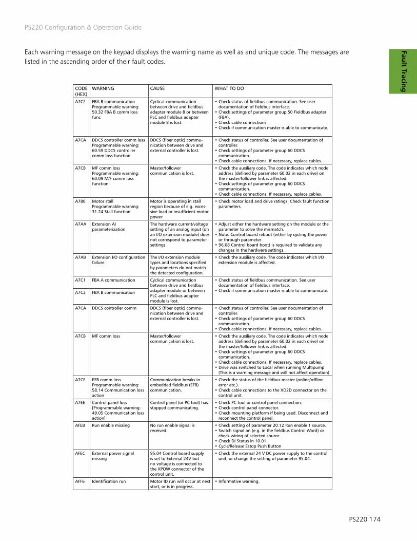
PS220 Configuration & Operation Guide
PS220 174
Fault Tracin
gCODE (HEX)
WARNING CAUSE WHAT TO DO
A7C2 FBA B communicationProgrammable warning:50.32 FBA B comm loss func
Cyclical communication between drive and fieldbus adapter module B or between PLC and fieldbus adapter module B is lost.
• Check status of fieldbus communication. See user documentation of fieldbus interface.• Check settings of parameter group 50 Fieldbus adapter (FBA).• Check cable connections.• Check if communication master is able to communicate.
A7CA DDCS controller comm loss Programmable warning:60.59 DDCS controllercomm loss function
DDCS (fiber optic) commu-nication between drive and external controller is lost.
• Check status of controller. See user documentation of controller.• Check settings of parameter group 60 DDCS communication.• Check cable connections. If necessary, replace cables.
A7CB MF comm lossProgrammable warning:60.09 M/F comm loss function
Master/follower communication is lost.
• Check the auxiliary code. The code indicates which node address (defined by parameter 60.02 in each drive) on the master/follower link is affected.• Check settings of parameter group 60 DDCS communication.• Check cable connections. If necessary, replace cables.
A780 Motor stallProgrammable warning:31.24 Stall function
Motor is operating in stall region because of e.g. exces-sive load or insufficient motor power.
• Check motor load and drive ratings. Check fault function parameters.
A7AA Extension AI parameterization
The hardware current/voltage setting of an analog input (on an I/O extension module) does not correspond to parameter settings.
• Adjust either the hardware setting on the module or the parameter to solve the mismatch.• Note: Control board reboot (either by cycling the power or through parameter• 96.08 Control board boot) is required to validate any changes in the hardware settings.
A7AB Extension I/O configuration failure
The I/O extension module types and locations specified by parameters do not match the detected configuration.
• Check the auxiliary code. The code indicates which I/O extension module is affected.
A7C1 FBA A communication Cyclical communication between drive and fieldbus adapter module or between PLC and fieldbus adapter module is lost.
• Check status of fieldbus communication. See user documentation of fieldbus interface.• Check if communication master is able to communicate.A7C2 FBA B communication
A7CA DDCS controller comm DDCS (fiber optic) commu-nication between drive and external controller is lost.
• Check status of controller. See user documentation of controller.• Check settings of parameter group 60 DDCS communication.• Check cable connections. If necessary, replace cables.
A7CB MF comm loss Master/follower communication is lost.
• Check the auxiliary code. The code indicates which node address (defined by parameter 60.02 in each drive) on the master/follower link is affected.• Check settings of parameter group 60 DDCS communication.• Check cable connections. If necessary, replace cables. • Drive was switched to Local when running Multipump (This is a warning message and will not affect operation)
A7CE EFB comm lossProgrammable warning:58.14 Communication loss action
Communication breaks in embedded fieldbus (EFB) communication.
• Check the status of the fieldbus master (online/offline error etc.).• Check cable connections to the XD2D connector on the control unit.
A7EE Control panel loss[Programmable warning:49.05 Communication loss action]
Control panel (or PC tool) has stopped communicating.
• Check PC tool or control panel connection.• Check control panel connector.• Check mounting platform if being used. Disconnect and reconnect the control panel.
AFEB Run enable missing No run enable signal is received.
• Check setting of parameter 20.12 Run enable 1 source. • Switch signal on (e.g. in the fieldbus Control Word) or check wiring of selected source. • Check DI Status in 10.01• Cycle/Release Estop Push Button
AFEC External power signal missing
95.04 Control board supply is set to External 24V but no voltage is connected to the XPOW connector of the control unit.
• Check the external 24 V DC power supply to the control unit, or change the setting of parameter 95.04.
AFF6 Identification run Motor ID run will occur at next start, or is in progress.
• Informative warning.
Each warning message on the keypad displays the warning name as well as and unique code. The messages are listed in the ascending order of their fault codes.

PS220 Configuration & Operation Guide
175 PS220
Fau
lt T
raci
ng Table A2- 4 PS220 Variable speed drive and motor Fault messages
Each warning message on the keypad displays the warning name as well as and unique code. The messages are listed in the ascending order of their fault codes
CODE (HEX)
WARNING CAUSE WHAT TO DO
2310 Overcurrent Output current has exceeded internal fault limit.
• Check motor connections to make sure there are no leads touching grounded areas.• Check acceleration times in parameter group 23 Speed reference ramp 31.42 Overcurrent fault limit, 46.01 Speed scaling, 46.02 Frequency scaling and 46.03 Torque scaling.• Check motor and motor cable (including phasing and delta/star connection). Check there are no contactors opening and closing in motor cable.• Check that the start-up data in parameter group 99 corresponds to the motor rating plate.• Check that there are no power factor correction capacitors or surge absorbers in motor cable.
2330 Earth leakage Programmable fault: 31.20 Earth fault
Drive has detected load un-balance typically due to earth fault in motor or motor cable.
• Check there are no power factor correction capacitors or surge absorbers in motor cable.• Check for an earth fault in motor or motor cables by measuring the insulation resistances of motor and motor cable. Try running the motor in scalar control mode if allowed. (See parameter 99.04 Motor control mode.)• If no earth fault can be detected, contact your local ITT representative.
3130 Input phase loss Programmable fault: 31.21 Supply phase loss
Intermediate circuit DC voltage is oscillating due to missing input power line phase or blown fuse.
• Check input power line fuses. Check for loose power cable connections.• Check for input power supply imbalance.
3181 Wiring or earth fault Programmable fault: 31.23 Wiring or earth fault
The drive hardware is supplied from a common DC bus.
• Switch off the protection in parameter• 31.23.
Incorrect input power and motor cable connection
• Check the power connections.
Drive has detected load un-balance typically due to earth fault in motor or motor cable.
• Check there are no power factor correction capacitors or surge absorbers in motor cable.• Check for an earth fault in motor or motor cables by measuring the insulation resistances of motor and motor cable. Try running the motor in scalar control mode if allowed. (See parameter 99.04 Motor control mode.)
3210 DC link overvoltage Excessive intermediate circuit DC voltage.
• Check that overvoltage control is on (parameter 30.30 Overvoltage control). Check that the supply voltage matches the nominal input voltage of the drive. Check the supply line for static or transient overvoltage.• Check deceleration time.
3220 DC link undervoltage Intermediate circuit DC voltage is not sufficient because of a missing supply phase, blown fuse or fault in the rectifier bridge.
• Check supply cabling, fuses and switchgear.• With parallel-connected modules, check the auxiliary code (format XXXY YYZZ). “Y YY” specifies through which BCU control unit channel the fault was received.
3280 Standby timeout Automatic restart failed • Check the condition of the supply (voltage, cabling, fuses, switchgear).
3381 Output phase loss Pro-grammable fault: 31.19 Motor phase loss
Motor circuit fault due to missing motor connection (all three phases are not connected).
• Connect motor cable. • Perform Motor Megger Test to check motor phases
4000 Motor cable overload Calculated motor cable temperature has exceeded warning limit.
• Check the settings of parameters 35.61• and 35.62.• Check the dimensioning of the motor cable in regard to required load.
4290 Cooling Drive module temperature is excessive.
• Check ambient temperature. If it exceeds 40 °C (104 °F), ensure that load current does not exceed derated load capacity of drive. See appropriate Hardware manual. Check drive module cooling air flow and• fan operation.• Check inside of cabinet and heatsink of drive module for dust pick-up. Clean whenever necessary.
4981 External temperature 1(Editable message text)
Measured temperature 1 has exceeded fault limit.
• Check the value of parameter 35.02 Measured temperature 1.• Check the cooling of the motor (or other equipment whose temperature is being measured).• Check the value of parameter 35.12 Temperature 1 fault limit.
5081 Auxiliary fan broken An auxiliary cooling fan (con-nected to the fan connectors on the control unit) is stuck or disconnected.
• Check the auxiliary code. The auxiliary code identifies the fan (1: Auxiliary fan 1, 2: Auxiliary fan 2).• Check auxiliary fan(s) and connection(s). Replace faulty fan.• Make sure the front cover of the drive module is in place and tightened. If the commissioning of the drive requires that the cover is off, activate parameter 31.36 Aux fan fault bypass within 2 minutes from control unit reboot to temporarily suppress the fault. Replace faulty cover if needed

PS220 Configuration & Operation Guide
PS220 176
Fault Tracin
g
Each warning message on the keypad displays the warning name as well as and unique code. The messages are listed in the ascending order of their fault codes.
CODE (HEX)
WARNING CAUSE WHAT TO DO
5093 Rating ID mismatch The hardware of the drive does not match the informa-tion stored in the memory unit. This may occur e.g. After a firmware update or memory unit replacement.
• Cycle the power to the drive. • Cycle the control board in Parameter 96.01 (change to 1)
5681 PU communication The way the control units 24vDC is connected does not correspond to parameter setting.
• Check setting of 95.04 Control board supply.
Communication errors detect-ed between the drive control unit and the power unit.
• Check the connection between the control unit and the power unit.
64A5 Licensing fault Running the control program is prevented either because a restrictive license exists, or because a required license is missing.
• Record the auxiliary codes of all active licensing faults and contact your ITT representative for further instructions.
64B0 Memory unit detached The memory unit was de-tached when the control unit was powered.
• Switch off the power to the control unit and reinstall the memory unit.• In case the memory unit was not actually removed when the fault occurred, check that the memory unit is properly inserted into its connector and its mounting screw is tight. Reboot the control unit (using parameter 96.08 Control board boot) or by cycling power. If the problem persists, contact your local ITT representative.
6581 Parameter system Parameter load or save failed. • Try forcing a save using parameter 96.07 Parameter save manually. Retry.
65A1 FBA A parameter conflict The drive does not have a functionality requested by PLC, or requested functionality has not been activated.
• Check PLC programming.• Check settings of parameter groups 50 Fieldbus adapter (FBA) and 51 FBA A settings.
7080 Option module comm loss Communication between drive and an option module is lost.
• Check that all option modules are properly seated in their slots.• Check that all option modules or slot connectors are not damaged. To pinpoint the problem, try installing the modules into different slots one at a time.
7081 Control panel loss Programmable fault: 49.05 Communication loss action
Control panel (or PC tool) has stopped communicating.
• Check PC tool or control panel connection.• Check control panel connector. Disconnect and reconnect the control panel.

PS220 Configuration & Operation Guide
177 PS220
Fau
lt T
raci
ng Each Fault message on the keypad displays the fault name as well as and unique code. The faults are listed in the
ascending order of their fault codes. A fault will cause the drive the stop the pump.
CODE (HEX)
WARNING CAUSE WHAT TO DO
7084 Panel/PC tool version conflict
The current version of the control panel and/or PC tool does not support a function. (For example, older panel versions cannot be used as a source of external reference.)
• Update control panel and/or PC tool. Contact your local ABB representative if necessary.
7121 Motor stall Programmable fault: 31.24 Stall function
Motor is operating in stall region because of e.g. exces-sive load or insufficient motor power.
• Check motor load and drive ratings. Check fault function parameters.
7310 Overspeed Motor is turning faster than highest allowed speed due to incorrectly set minimum/maximum speed.
• Check minimum/maximum speed settings, parameters 30.11 Minimum speed and 30.12 Maximum speed. • Check motor disconnect to make sure is closed
Incorrect estimated speed. • Check the status of motor current measurement.• Perform a Normal, Advanced or Advanced Standstill ID run instead of, for example, a Reduced or Standstill ID run. See parameter 99.13 ID run requested.
7582 MF comm loss Programmable fault: 60.09 M/F comm loss function
Master/followercommunication is lost.
• Check cables between Master and follower• Check node address and other setup parameters in Multipump wizard• Replace cables. • Drive is in Local in Multipump
80A0 AI supervisionProgrammable fault:12.03 AI supervision function
An analog signal is outside the limits specified for the analog input.
• Check signal level at the analog input.• Check the wiring connected to the input.• Check the minimum and maximum limits of the input in parameter group 12 Standard AI.
FB11 Memory unit missing No memory unit is attached to the control unit.
• Power down the control unit.• Check that the memory unit is properly inserted into the control unit.
The memory unit attached to the control unit is empty.
• Power down the control unit. Attach a memory unit (with the appropriate firmware) to the control unit.
FB12 Memory unit incompatible The memory unit attached to the control unit is incompatible.
• Power down the control unit. Attach a compatible memory unit.
FB13 Memory unit FWincompatible
The firmware on the attached memory unit is incompatible with the drive.
• Power down the control unit.• Attach a memory unit with compatible firmware.
FB14 Memory unit FW load failed The firmware on the attached memory unit could not be loaded to the drive.
• Power down the control unit.• Check that the memory unit is properly inserted into the control unit.• If the problem persists, replace the memory unit.

PS220 Configuration & Operation Guide
PS220 178
Parameter
List
To follow are parameters most often requiring some level of access to for the purpose of adjusting the PS220
variable speed drive. This section is not intended to cover all parameters that the user may see in the PS220 drive. It is intended that this section be used in conjunction with the fault section of the standard ABB ACS880 Firmware
manual which can be found online.

PS220 Configuration & Operation Guide
179 PS220
Para
met
er
List
GROUP 1 ACTUAL VALUES DESCRIPTION Scaling1.01 MOTOR SPEED Measured or estimated motor speed (-30000 – 30000 RPM)
See parameter 46.011.02 MOTOR SPEED ESTIMATED Estimated motor speed in rpm. (-30000 – 30000 RPM)
1.03 MOTOR SPEED % Motor speed displayed as a percent of the synchronous speed. (0-1000.00%) 10=1%
1.04 ENCODER 1 SPEED FILTER Speed of encoder 1 in rpm. -
1.05 ENCODER 2 SPEED Speed of encoder 1 in rpm. -
1.06 OUTPUT FREQUENCY Estimated drive output frequency in Hz. (0-500) See parameter 46.02
1.07 MOTOR CURRENT Measured (absolute) motor current in A. (0-30000) See parameter 46.05
1.08 MOTOR CURRENT % OF MOTOR NOM Shows the value of 01.07 Motor Current used in percent. (0-1000) 1=1%
1.10 MOTOR TORQUE Motor torque in percent of the nominal motor torque. (0-1600) See parameter 46.03
1.11 DC VOLTAGE Measured DC link voltage. (0.00-2000.00V) 10=1
1.13 OUTPUT VOLTAGE Calculated motor voltage in V AC.0-2000V) 1=1V
1.14 OUTPUT POWER Drive output power. The unit is selected by parameter 96.16 Unit selection. (0-32767Kw or hp)
See parameter 46.04
1.15 OUTPUT POWER % OF MOTOR NOM Shows the value of 01.14 Output power in percent of the nominal power of the motor. (0-300.00%)
10=1%
1.17 MOTOR SHAFT POWER Estimated mechanical power at motor shaft. The unit is selected by parameter 96.16 Unit Selection. (0-32767.00kW or hp)
1=1 unit
1.18 INVERTER GWh MOTORING Amount of energy that has passed through the drive (towards the motor) in full giga-watt-hours. The minimum value is zero. (0-32767 GWh)
1=1 GWh
1.19 INVERTER MWh MOTORING Amount of energy that has passed through the drive (towards the motor) in full mega-watt-hours. Whenever the counter rolls over, 01.18 Inverter GWh motoring is incremented. The minimum value is zero. (0-999 mwH)
1=1 mwH
1.20 INVERTER kWh MOTORING Amount of energy that has passed through the drive (towards the motor) in full kilo-watt-hours. Whenever the counter rolls over, 01.19 Inverter MWh motoring is incremented. The minimum value is zero. (*0-999 kWh)
10=1 kWh
1.21 U-PHASE CURRENT Measured U-phase current. (0-3000 A)
See parameter 46.051.22 V-PHASE CURRENT Measured V-phase current. (0-3000 A)
1.23 W-PHASE CURRENT Measured W-phase current. (0-3000 A)
1.24 FLUX ACTUAL % Used flux reference in percent of nominal flux of motor. (0-200%) 1=1%
1.25 INU MOMENTARY cos Momentary cosphi of the drive. (-1.00 – 1.00) 100=1
1.29 SPEED CHANGE RATE Rate of actual speed change. Positive values indicate acceleration, negative values indicate deceleration. See also parameters 31.32 Emergency ramp supervision, 31.33 Emergency ramp supervision delay, 31.37 Ramp stop supervision and 31.38 Ramp stop supervision delay. (-15000-15000 rpm/s)
1=1 rpm/s
1.30 NORMAL TORQUE SCALE Torque that corresponds to 100% of nominal motor torque. The unit is selected by param-eter 96.16 Unit selection. Note: This value is copied from parameter 99.12 Motor nominal torque if entered. Otherwise the value is calculated from other motor data. (0.00 – xxx N-m or lb-ft)
1=1 unit
1.31 AMBIENT TEMPERATURE Measured temperature of incoming cooling air. The unit is selected by parameter 96.16 Unit Selection. (-40 -200.0 °C or °F)
1=1%
1.32 INVERTER GWh REGENERATING Amount of energy that has passed through the drive (towards the supply) in full giga-watt-hours. The minimum value is zero. (0-32767)
1=1 GWh
1.33 INVERTER MWh REGENERATING Amount of energy that has passed through the drive (toward the supply) in full mega-watt-hours. Whenever the counter rolls over, 01.32 Inverter GWh regenerating is increment-ed. The minimum value is zero. (0-999 MWh)
1=1 MWh
1.34 INVERTER kWh REGENERATING Amount of energy that has passed through the drive (towards the supply) in full kilo-watt-hours. Whenever the counter rolls over, 01.33 Inverter MWh regenerating is increment-ed. The minimum value is zero. (0-999 kWh)
1=1 kWh
1.35 MOT-REGEN ENERGY GWh Amount of net energy (motoring energy – regenerating energy) that has passed through the drive in full gigawatthours. (-32768 – 32767 GWh)
1=1 GWh
1.36 MOT-REGEN ENERGY MWh Amount of net energy (motoring energy – regenerating energy) that has passed through the drive in full megawatthours. Whenever the counter rolls over, 01.35 Mot – regen energy GWh is incremented or decremented. (-999-999 MWh)
1=1 MWh
1.37 MOT-REGEN ENERGY kWh Amount of energy (motoring energy - regenerating energy) that has passed through the drive in full kilowatt-hours. Whenever the counter rolls over, 01.36 Mot - regen energy MWh is incremented or decremented. (-999-999 kWh)
1=1 kWh
1.61 ABS MOTOR SPEED USED Absolute value of 01.01 Motor speed used. (0.0-30000.00 rpm) See parameter 46.01
1.62 ABS MOTOR SPEED % Absolute value of 01.03 Motor speed %. (0.00-1000.00%) 10=1%
1.63 ABS OUTPUT FREQENCY Absolute value of 01.06 Output frequency. (0.00-500.00 Hz) See parameter 46.02
1.64 ABS MOTOR TORQUE Absolute value of 01.10 Motor torque. (0.0-1600.0%) See parameter 46.03
1.65 ABS OUTPUT POWER Absolute value of 01.14 Output power. (0.00-32767.00 kW or hp) 1=1 unit
1.66 ABS OUTPUT POWER % MOTOR NOM Absolute value of 01.15 Output power % of motor nom. (0.00-300.00%) 10=1%
1.68 ABS MOTOR SHAFT POWER Absolute value of 01.17 Motor shaft power. (0.00-32767.00 kW or hp) 1=1 unit
1.70 AMBIENT TEMPERATURE % Measured temperature of incoming cooling air. The amplitude range of 0…100% corre-sponds to 0…60 °C or 32…140 °F. See also 01.31 Ambient temperature. (-200.00-200.00%)
1=1%
APPENDIX A3 - Parameter List

PS220 Configuration & Operation Guide
PS220 180
Parameter
List
GROUP 1 ACTUAL VALUES DESCRIPTION Scaling1.71 STEP-UP MOTOR CURRENT Estimated motor current in A when a step-up transformer is in use. The value is calculated
from parameter 01.07 using the step-up transformer ratio (95.40) and sine filter values 99.18 and 99.19. (0.00-30000.00 A)
See parameter 46.051.72 U-PHASE RMS CURRENT U-phase rms current. (0.00-30000.00 A)
1.73 V-PHASE RMS CURRENT V-phase rms current. (0.00-30000.00 A)
1.74 W-PHASE RMS CURRENT W-phase rms current. (0.00-30000.00 A)
1.200 FLOW REF Reference for flow control. (0-32767)
1=1
1.201 FLOW ACTUAL Actual flow feedback (0-32767)
1.202 PRESS REF Reference for pressure control (0-32767)
1.203 PRESS ACTUAL Actual pressure feedback (0-32767)
1.204 LEVEL REF Reference for level control (0-32767)
1.205 LEVEL ACTUAL Actual level feedback (0-32767)
1.206 TEMP REF Reference for temperature control (0-32767)
1.207 TEMP ACTUAL Actual temperature feedback (0-32767)
1.208 PUMP SPEED Actual speed of pump, rpm. Will be different than motor speed if belt drive or gear drive is used.
1.209 SPECIFIC GRAVITY Specific gravity of pumped liquid
1.210 VISCOSITY Value of viscosity being used by SmartFlow
1.212 SETPOINT 1 Setpoint #1 value.
1.213 MULTIPUMP FEEDBACK Summed process feedback of all drives as seen by drive in a Multipump system. Typically used in Multipump Flow control.
1.214 MULTI VAR SETPOINT Calculated setpoint calculated by the PS220. Result setpoint when influenced by the second variable of Multivariable control.
1.215 SETPOINT 2 Setpoint #2 value
1.216 PROC TX2 Current value of process transmitter 2. Normally used in multivariable control.
1.217 SMARTFLOW PS220’s calculated Pump flow output
1.218 SMART TDH PS220’s calculated total dynamic head
1.219 BEP Current operating efficiency as compared to best efficiency point
1.220 FLOW ECONOMY A relative measure of pumping efficiency.
1.223 ENERGY SAVINGS Calculated energy savings since last reset for Energy Savings Option 1 or 2
1.224 RUN TIME Elapsed time counter in hrours since last reset. Runs whenever drive is powered.
1.225 KWH SINCE RST kWh counter, kWh since last reset
1.226 PMP CLN RUN TIME Run time for the pump cleaning sequence when runtime is selected in 83.02 REQ P CLEAN SEQ. Resets to zero after a stop command and after completion of a cleaning cycle
1.227 SYSTEM FLOW Total flow rate for all pumps running in a Multipump system
1.228 TOTAL PMP VOLUME Totalized Flow value for a single pump.
1.229 TOTAL SYSTEM VOLUME Total flow of all pumps when operated in Multipump.
1.230 PROC TX1 Signal value of the Primary Process transmitter.
1.231 MULTIPUMP SETPOINT Setpoint seen by the master or follower in a Multipump system.
1.233 START COMMAND Indication of whether a start command has been received by the PS220 or not.
1.234 EXT SETPOINT 1 External Setpoint 1 ( Analog signal) sent to the drive
1.235 EXT SETPOINT 2 External Setpoint 2 ( Analog signal) sent to the drive
1.236 WAKEUP CONDITION 2 VALUE Wake up value for condition 2 if alarm response is set to sleep.
1.237 WAKEUP CONDITION 1 VALUE Wake up value for condition 1 if alarm response is set to sleep.
1.238 MULTIPUMP RUNTIME Provides the length of time this pump has run in Multipump.

PS220 Configuration & Operation Guide
181 PS220
Para
met
er
List
GROUP 3 INPUT REFERENCES DESCRIPTION Scaling3.01 PANEL REFERENCE Reference given from the control panel or PC tool. (-100000.00-1000000.00) 1=10
3.02 PANEL REFERENCE 2 Remote reference given from the control panel or PC tool. (-30000.00-30000.00) 1=10
3.05 FB A REFERENCE 1 Reference 1 received through fieldbus adapter A. (-100000.00-100000.00) 1=10
3.06 FB A REFERENCE 2 Reference 2 received through fieldbus adapter A. (-100000.00-100000.00) 1=10
3.07 FB B REFERENCE 1 Reference 1 received through fieldbus adapter B. (-100000.00-100000.00) 1=10
3.08 FB B REFERENCE 2 Reference 2 received through fieldbus adapter B. (-100000.00-100000.00) 1=10
3.09 EFB B REFERENCE 1 Scaled reference 1 received through the embedded fieldbus interface. The scaling is defined by 58.26 EFB ref1 type. (-30000.00-30000.00)
1=10
3.10 EFB B REFERENCE 2 Scaled reference 2 received through the embedded fieldbus interface. The scaling is defined by 58.27 EFB ref2 type. (-30000.00-30000.00)
1=10
3.11 DDCS CONTROLLER REF 1 Reference 1 received from the external (DDCS) controller. The value has been scaled accord-ing to parameter 60.60 DDCS controller ref1 type.See also section External controller interface. (-30000.00-30000.00)
1=10
3.12 DDCS CONTROLLER REF 2 Reference 2 received from the external (DDCS) controller. The value has been scaled accord-ing to parameter 60.60 DDCS controller ref1 type.(-30000.00-30000.00)
1=10
3.13 M/F or D2D REF1 Master/follower reference 1 received from the master. The value has been scaled according to parameter 60.10 M/F ref1 type. See also section Master/follower functionality. (-30000.00-30000.00)
1-10
3.14 M/F or D2D REF2 Master/follower reference 1 received from the master. The value has been scaled according to parameter 60.10 M/F ref1 type. (-30000.00-30000.00)
1-10
3.30 FB A REFERENCE 1 INT32 (-2147483648-2147483647) Missing description 1=1
3.31 FB A REFERENCE 2 INT32 (-2147483648-2147483647) 1=1
3.51 Panel reference defined in the application program. (-100000.00-100000.00) 1=10
3.200 MUTIPUMP SPEED REF (0-10000 RPM) 1=1
3.201 MULTIPUMP TORQUE REF (-300-300%) 1=1
3.202 FOLLOWER_SETPOINT (877.5-3510.0 rpm) ?
3.203 APPL_STATUS_BITS (0-32767) 1=1
3.204 TORQ REF (-300-300%) 1=1
3.205 SPEED REF (0-10000 rpm) 1=1
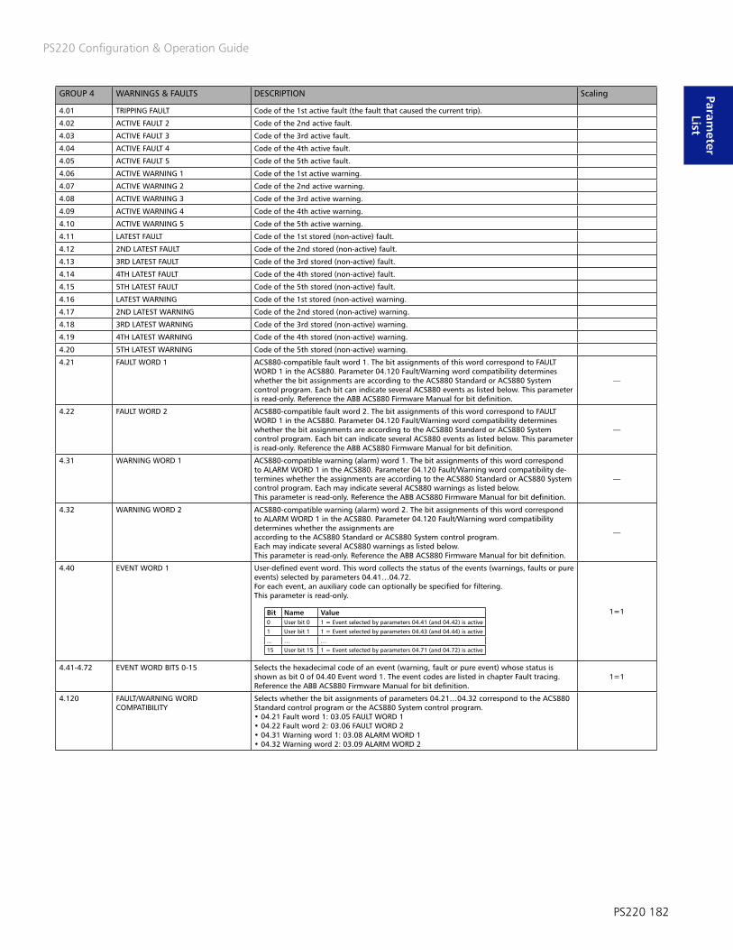
PS220 Configuration & Operation Guide
PS220 182
Parameter
List
GROUP 4 WARNINGS & FAULTS DESCRIPTION Scaling
4.01 TRIPPING FAULT Code of the 1st active fault (the fault that caused the current trip).
4.02 ACTIVE FAULT 2 Code of the 2nd active fault.
4.03 ACTIVE FAULT 3 Code of the 3rd active fault.
4.04 ACTIVE FAULT 4 Code of the 4th active fault.
4.05 ACTIVE FAULT 5 Code of the 5th active fault.
4.06 ACTIVE WARNING 1 Code of the 1st active warning.
4.07 ACTIVE WARNING 2 Code of the 2nd active warning.
4.08 ACTIVE WARNING 3 Code of the 3rd active warning.
4.09 ACTIVE WARNING 4 Code of the 4th active warning.
4.10 ACTIVE WARNING 5 Code of the 5th active warning.
4.11 LATEST FAULT Code of the 1st stored (non-active) fault.
4.12 2ND LATEST FAULT Code of the 2nd stored (non-active) fault.
4.13 3RD LATEST FAULT Code of the 3rd stored (non-active) fault.
4.14 4TH LATEST FAULT Code of the 4th stored (non-active) fault.
4.15 5TH LATEST FAULT Code of the 5th stored (non-active) fault.
4.16 LATEST WARNING Code of the 1st stored (non-active) warning.
4.17 2ND LATEST WARNING Code of the 2nd stored (non-active) warning.
4.18 3RD LATEST WARNING Code of the 3rd stored (non-active) warning.
4.19 4TH LATEST WARNING Code of the 4th stored (non-active) warning.
4.20 5TH LATEST WARNING Code of the 5th stored (non-active) warning.
4.21 FAULT WORD 1 ACS880-compatible fault word 1. The bit assignments of this word correspond to FAULT WORD 1 in the ACS880. Parameter 04.120 Fault/Warning word compatibility determines whether the bit assignments are according to the ACS880 Standard or ACS880 System control program. Each bit can indicate several ACS880 events as listed below. This parameter is read-only. Reference the ABB ACS880 Firmware Manual for bit definition.
—
4.22 FAULT WORD 2 ACS880-compatible fault word 2. The bit assignments of this word correspond to FAULT WORD 1 in the ACS880. Parameter 04.120 Fault/Warning word compatibility determines whether the bit assignments are according to the ACS880 Standard or ACS880 System control program. Each bit can indicate several ACS880 events as listed below. This parameter is read-only. Reference the ABB ACS880 Firmware Manual for bit definition.
—
4.31 WARNING WORD 1 ACS880-compatible warning (alarm) word 1. The bit assignments of this word correspond to ALARM WORD 1 in the ACS880. Parameter 04.120 Fault/Warning word compatibility de-termines whether the assignments are according to the ACS880 Standard or ACS880 System control program. Each may indicate several ACS880 warnings as listed below.This parameter is read-only. Reference the ABB ACS880 Firmware Manual for bit definition.
—
4.32 WARNING WORD 2 ACS880-compatible warning (alarm) word 2. The bit assignments of this word correspond to ALARM WORD 1 in the ACS880. Parameter 04.120 Fault/Warning word compatibility determines whether the assignments areaccording to the ACS880 Standard or ACS880 System control program.Each may indicate several ACS880 warnings as listed below.This parameter is read-only. Reference the ABB ACS880 Firmware Manual for bit definition.
—
4.40 EVENT WORD 1 User-defined event word. This word collects the status of the events (warnings, faults or pure events) selected by parameters 04.41…04.72.For each event, an auxiliary code can optionally be specified for filtering.This parameter is read-only.
1=1
4.41-4.72 EVENT WORD BITS 0-15 Selects the hexadecimal code of an event (warning, fault or pure event) whose status is shown as bit 0 of 04.40 Event word 1. The event codes are listed in chapter Fault tracing. Reference the ABB ACS880 Firmware Manual for bit definition.
1=1
4.120 FAULT/WARNING WORD COMPATIBILITY
Selects whether the bit assignments of parameters 04.21…04.32 correspond to the ACS880 Standard control program or the ACS880 System control program.• 04.21 Fault word 1: 03.05 FAULT WORD 1• 04.22 Fault word 2: 03.06 FAULT WORD 2• 04.31 Warning word 1: 03.08 ALARM WORD 1• 04.32 Warning word 2: 03.09 ALARM WORD 2
Bit Name Value0 User bit 0 1 = Event selected by parameters 04.41 (and 04.42) is active
1 User bit 1 1 = Event selected by parameters 04.43 (and 04.44) is active
... … …
15 User bit 15 1 = Event selected by parameters 04.71 (and 04.72) is active

PS220 Configuration & Operation Guide
183 PS220
Para
met
er
List
GROUP 5 DIAGNOSTICS DESCRIPTION Scaling5.01 ON-TIME COUNTER On-time counter. The counter runs when the drive is powered. (0-65535 days) 1=1 day
5.02 RUN-TIME COUNTER Motor run-time counter. The counter runs when the inverter modulates. (0-65535 days) 1=1 day
5.04 FAN ON-TIME COUNTER Running time of the drive cooling fan. Can be reset from the control panel by keeping Reset depressed for over 3 seconds. (0-65535 days) 1=1 day
5.09 TIME FROM POWER-UP 500-microsecond ticks elapsed since the last boot of the control unit. (0-4294967295) 1=1
5.11 INVERTER TEMPERATURE Estimated drive temperature in percent of fault limit. The actual trip temperature varies according to the type of the drive. (40.0-160.0%) • 0.0% = 0 °C (32 °F) • 94% approx. = Warning limit• 100.0% = Fault limit
1=1%
5.22 DIAGNOSTIC WORD 3 Diagnostic word 3.
1=1
5.41 MAIN FAN SERVICE COUNTER Displays the age of the main cooling fan as a percentage of its estimated lifetime. The estimate is based on the duty, operating conditions and other operating parameters of the fan. When the counter reaches 100%, a warning is generated. Can be reset from the control panel by keeping Reset depressed for over 3 seconds. (0-150%)
1=1%
5.42 AUX. FAN SERVICE COUNTER Displays the age of the auxiliary cooling fan as a percentage of its estimated lifetime. The estimate is based on the duty, operating conditions and other operating parameters of the fan. When the counter reaches 100%, a warning is generated. Can be reset from the control panel by keeping Reset depressed for over 3 seconds. (0-150%)
1=1%
GROUP 6 WARNINGS & FAULTS DESCRIPTION Scaling
6.01 MAIN CONTROL WORD The main control word of the drive. The bit assignments of the word are as described in the ACS880 Firmware Manual. This parameter is read-only. 1=1
6.02 APPLICATION CONTROL WORD Reference the ABB ACS880 Firmware Manual for parameter definition.
6.03 FBA A TRANSPARENT CONTROL WORD Displays the unaltered control word received from the PLC through fieldbus adapter A when a transparent communication profile is selected eg. by parameter group 51 FBA A settings. This parameter is read-only. (00000000h-FFFFFFFFh)
1=1
6.04 FBA B TRANSPARENT CONTROL WORD Displays the unaltered control word received from the PLC through fieldbus adapter B when a transparent communication profile is selected eg. by parameter group 54 FBA B settings. See section Control word and Status word in the ACS880 Firmware Manual. This parameter is read-only. (00000000h-FFFFFFFFh)
1=1
6.05 EFBA TRANSPARENT CONTROL WORD Displays the unaltered control word received from the PLC through the embedded fieldbus interface when a transparent communication profile is selected in parameter 58.25 Control profile . See section The Transparent profile in the ACS880 Firmware Manual. This parameter is read-only. (00000000h-FFFFFFFFh)
1=1
6.11 MAIN STATUS WORD Main status word of the drive. Parameter is read-only. (0000h-FFFFh) 1=1
6.16 DRIVE STATUS WORD 1 Drive status word 1. This parameter is read-only. See the ACS880 Firmware Manual for bit assignment. 1=1
6.17 DRIVE STATUS WORD 2 Drive status word 2. This parameter is read-only. See the ACS880 Firmware Manual for bit assignment. 1=1
6.18 START INHIBIT STATUS WORD Start inhibit status word. This word specifies the source of the inhibiting condition that is preventing the drive from starting. After the condition is removed, the start command must be cycled. See bit-specific notes. See also parameter 06.25 Drive inhibit status word 2, and06.16 Drive status word 1, bit 1. This parameter is read-only. See the ACS880 Firmware Manual for bit assignment. (0000h-FFFFh)
1=1
6.19 SPEED CONTROL STATUS WORD This parameter is read-only. See the ACS880 Firmware Manual for bit assignment. (0000h-FFFFh) 1=1
6.20 CONSTANT SPEED STATUS WORD Constant speed/frequency status word. Indicates which constant speed or frequency is active (if any). See also parameter 06.19 Speed control status word, bit 7, and section Constant speeds/frequencies (page 43). This parameter is read-only. See the ACS880 Firmware Manual for bit assignment. (0000h-FFFFh)
1=1
6.21 DRIVE STATUS WORD 3 This parameter is read-only. See the ACS880 Firmware Manual for bit assignment. (0000h-FFFFh) 1=1
6.25 DRIVE INHIBIT STATUS WORD 2 This word specifies the source of the inhibiting condition that is preventing the drive from starting. After the condition is removed, the start command must be cycled. See bit-specific notes. See also parameter 06.18 Start inhibit status word, and 06.16 Drive status word 1, bit 1. This parameter is read-only. See the ACS880 Firmware Manual for bit assignment. (0000h-FFFFh)
1=1
6.29-6.118 VARIOUS ACS880 CONTROL AND STATUS WORDS
Reference the ABB ACS880 Firmware Manual for parameter definition. All ACS880 parame-ters may not be supported. —
6.200 PUMP STATUS Pump Status word 1=1
6.201 PUMP WATER FEATURE CW Control Word for initiating PumpSmart water functions 1=1
6.202 PUMP WATER FEATURE SW Status Word for the PumpSmart water functions 1=1
6.203 PUMPSMART ALARM WORD 1 Alarm word 1 (16 bit) 1=1
6.204 PUMPSMART ALARM WORD 2 Alarm word 2 (16 bit) 1=1
Bit Name Value0…10 Reserved
11 Fan command 1 = Drive fan is rotating above idle speed
12 Fan service counter 1 = Drive fan service counter has reached its limit
13…15 Reserved

PS220 Configuration & Operation Guide
PS220 184
Parameter
List
GROUP 7 SYSTEM INFORMATION Reference the ACS880 Firmware Manual for detail
GROUP 10 DIGITAL INPUT AND RELAY OUTPUT STATUS
DESCRIPTION
10.01 DI STATUS Displays the electrical status of digital inputs DIIL and DI6…DI1. The activation/deactivation delays of the inputs (if any are specified) are ignored. A filtering time can be defined by parameter 10.51 DI filter time. Bits 0…5 reflect the status of DI1…DI6; bit 15 reflects the status of the DIIL input. Example: 1000000000010011b = DIIL, DI5, DI2 and DI1 are on, DI3, DI4 and DI6 are off. This parameter is read-only.
10.02-10.16 DI DELAYS Reference the ABB ACS880 Firmware Manual for parameter definition. All ACS880 parameters may not be supported.
10.21 RO STATUS Status of relay outputs RO8…RO1.
10.24-10.99 SOURCE DELAYS Example: 00000001b = RO1 is energized, RO2…RO8 are de-energized.
GROUP 11 STANDARD DIO, FI, FO DESCRIPTION11.1-11.59 DIO SOURCE AND DELAYS Reference the ABB ACS880 Firmware Manual for parameter definition. All ACS880 parameters may not be
supported.
GROUP 12 ANALOG INPUTS DESCRIPTION12.01 AI TUNE Triggers the analog input tuning function. Connect the signal to the input and select the appropriate tuning
function.
12.03-12.05 AI SUPERVISION FUNCTIONS Reference the ABB ACS880 Firmware Manual for parameter definition.
12.11 AI1 ACTUAL VALUE Displays the value of analog input AI1 in mA or V (depending on whether the input is set tocurrent or voltage by a hardware setting). (0-22mA)
12.12 AI1 SCALED VALUE Displays the value of analog input AI1 after scaling. This parameter is read only. (0-32767.000)
12.15 AI1 UNIT SELECTION Selects the unit for readings and settings related to analog input AI1. Note: This setting must match the corre-sponding hardware setting on the drive control unit. See Basic Wiring drawing in appendix A4. (mA or V)
12.17 AI1 MIN Defines the minimum value for analog input AI1. Set the value actually sent to the drive when the analog signal from the external source / transmitter is at its minimum setting. (0-22mA or 0-10V)
12.18 AI1 MAX Defines the maximum value for analog input AI1. Set the value actually sent to the drive when the analog signal from the external source / transmitter is at its maximum setting. (0-22mA or 0-10V)
12.19 AI1 SCALED AT AI1 MIN Defines the real internal value that corresponds to the minimum analog input AI1 value definedby parameter 12.17 AI1 min. (0-32768.000)
12.20 AI1 SCALED AT AI1 MAX Defines the real internal value that corresponds to the maximum analog input AI1 value defined by parameter 12.18 AI1 max. (0-32768.000)
12.21 AI2 ACTUAL VALUE Displays the value of analog input AI2 in mA or V (depending on whether the input is set tocurrent or voltage by a hardware setting). This parameter is read-only. (0-22.000mA or 0-10.00V)
12.22 AI2 SCALED VALUE Displays the value of analog input AI2 after scaling. This parameter is read-only. (0-32767.000)
12.25 AI2 UNIT SELECTION Selects the unit for readings and settings related to analog input AI2.Note: This setting must match the corresponding hardware setting on the drive control unit (see the hardware manual of the drive). Control board reboot (either by cycling the power or through parameter 96.08 Control board boot) is required to validate any changes in the hardware settings. (mA or V)
12.27 AI2 MIN Defines the minimum value for analog input AI2. Set the value actually sent to the drive when the analog signal is at its minimum setting. (0-22mA or 0-10V)
12.28 AI2 MAX Defines the maximum value for analog input AI2. Set the value actually sent to the drive when the analog signal is at its maximum setting. (0-22mA or 0-10V)
12.29 AI2 SCALED AT AI2 MIN Defines the real value that corresponds to the minimum analog input AI2 value defined by parameter 12.27 AI2 min. (0-32768.000)
12.30 AI2 SCALED AT AI2 MAX Defines the real value that corresponds to the maximum analog input AI2 value defined by parameter 12.28 AI2 max. (0-32768.000)
GROUP 13 ANALOG INPUTS DESCRIPTION13.11 AO1 ACTUAL VALUE Displays the value of AO1 in mA. This parameter is read-only. (0.000-22.000mA)
13.12 AO1 SOURCE Selects a signal to be connected to analog output AO1. Alternatively, sets the output to excitation mode to feed a constant current to a temperature sensor. Default source is Motor Speed Used.
13.16 AO1 FILTER TIME Defines the filtering time constant for analog output AO1 in seconds. Default value is 0.100 seconds.
13.17 AO1 SOURCE MIN Defines the real minimum value of the signal that corresponds to the minimum required AO1 output value. This is the engineering unit value for the minimum current value defined in parameter 13.19. (-32768.0 – 32768.0)
13.18 AO1 SOURCE MAX Defines the real maximum value of the signal that corresponds to the maximum required AO1 output value. This is the engineering unit value for the maximum current value defined in parameter 13.20. (-32768.0 – 32768.0)
13.19 AO1 OUT AT AO1 SRC MIN Defines the minimum output current value for analog output AO1. (0-22.000mA)
13.20 AO1 OUT AT AO1 SRC MAX Defines the minimum output current value for analog output AO1. (0-22.000mA)
13.21 AO2 ACTUAL VALUE Defines the maximum output current value for analog output AO1. (0-22.000mA)
13.22 AO2 SOURCE Selects a signal to be connected to analog output AO2. Alternatively, sets the output to excitation mode to feed a constant current to a temperature sensor. Default source is Motor Current.
13.27 AO2 FILTER TIME Defines the filtering time constant for analog output AO2 in seconds. Default value is 0.100 seconds.
13.27 AO2 SOURCE MIN Defines the real minimum value of the signal that corresponds to the minimum required AO2 output value. This is the engineering unit value for the minimum current value defined in parameter 13.29. (-32768.0 – 32768.0)
13.28 AO2 SOURCE MAX Defines the real maximum value of the signal that corresponds to the maximum required AO2 output value. This is the engineering unit value for the maximum current value defined in parameter 13.30. (-32768.0 – 32768.0)
13.29 AO2 OUT AT AO2 SRC MIN Defines the minimum output value for analog output AO2. (0-22.000mA)
13.30 AO2 OUT AT AO2 SRC MAX Defines the maximum output value for analog output AO2. (0-22.000mA)
13.91-13.92 AO1 AND AO2 DATA STORAGE
Reference the ABB ACS880 Firmware Manual for parameter definition. All ACS880 parameters may not be supported.

PS220 Configuration & Operation Guide
185 PS220
Para
met
er
List
GROUP 14 I/O EXTENSION MODULE 1 DESCRIPTION14.01 MODULE 1 TYPE Activates (and specifies the type of) I/O extension module 1. NOTE: PumpSmart only sup-
ports the FIO-11 module which must be located in Slot 3. Select No Option here.
14.02-14.93 Reference the ABB ACS880 Firmware Manual for parameter definition. All ACS880 parameters may not be supported.
GROUP 15 I/O EXTENSION MODULE 2 DESCRIPTION15.01 MODULE 1 TYPE Activates (and specifies the type of) I/O extension module 1. NOTE: PumpSmart only sup-
ports the FIO-11 module which must be located in Slot 3. Select No Option here.
15.02-15.93 Reference the ABB ACS880 Firmware Manual for parameter definition. All ACS880 parame-ters may not be supported.
GROUP 16 I/O EXTENSION (SLOT 3) DESCRIPTION16.01 MODULE 3 TYPE Activates (and specifies the type of) I/O extension module 1. NOTE: PumpSmart only sup-
ports the FIO-11 module. Select FIO-11 here.
16.02 MODULE 3 LOCATION Specifies the slot (1…3) on the control unit of the drive into which the I/O extension module is installed. NOTE PumpSmart must have the FIO-11 module physically loaded into slot 3 only. Select Slot 3 here.
16.03 MODULE 3 STATUS Displays the status of I/O extension module 3. This should display FIO-11 (An FIO-11 module has been detected and is active.) See the ACS880 Firmware Manual for additional details.
16.05-16.93 Reference the ABB ACS880 Firmware Manual for parameter definition.
GROUP 19 OPERATING MODE DESCRIPTION19.01 ACTUAL CONTROL MODE Displays the operating mode currently used. This is a read only parameter. Default value is
Speed. (Speed, Torque)
19.11-19.16 Reference the ABB ACS880 Firmware Manual for parameter definition. All ACS880 parame-ters may not be supported.
19.17 LOCAL CONTROL DISABLE Enables/disables local control (start and stop buttons on the control panel, and the local controls on the PC tool). WARNING! Before disabling local control, ensure that the control panel is not needed for stopping the drive.
19.20 SCALAR CONTROL REFERENCE UNIT Selects the reference type for scalar motor control mode. Default is RPM. (RPM, Hz)
19.200 EXT 1 CONTROL MODE Selects the external 1 control mode. Default is Speed (Speed, Torque)
GROUP 20 RUN ENABLE STOP MODE DESCRIPTION20.01 EXT 1 COMMANDS Selects the source of start, stop and direction commands for external control location 1
(EXT1).
20.02-20.10 Reference the ABB ACS880 Firmware Manual for parameter definition. All ACS880 parame-ters may not be supported.
20.11 RUN ENABLE STOP MODE Selects the way the motor is stopped when the run enable signal switches off. Default is Coast. Coast stops by switching off the output semiconductors of the drive. The motor coasts to a stop. Ramp stops along the active deceleration ramp. (Coast or Ramp)
20.12-20.30 Reference the ABB ACS880 Firmware Manual for parameter definition. All ACS880 parame-ters may not be supported.
GROUP 21 STOP MODE DESCRIPTION20.01-20.02 Reference the ABB ACS880 Firmware Manual for parameter definition. All ACS880 parame-
ters may not be supported.
20.03 STOP MODE Selects the way the motor is stopped when a stop command is received. Default is Coast. Coast stops by switching off the output semiconductors of the drive. The motor coasts to a stop. Ramp stops along the active deceleration ramp. (Coast or Ramp)
20.04-20.20 Reference the ABB ACS880 Firmware Manual for parameter definition. All ACS880 parame-ters may not be supported.
GROUP 23 SPEED RAMP SETUP DESCRIPTION23.01-23.11 NOTE: Parameters in group 23 are set by the PumpSmart wizards and should not be altered
by the user. Descriptions for group 23 parameters can be found in the ACS880 firmware manual.
23.12 ACCELERATION TIME Defines acceleration time. (Range = 0-1800 sec). Default is 5 sec.
23.13 DECELERATION TIME Defines the deceleration time. (Range = 0-1800 sec). Default is 5 sec.
23.14-23.42 NOTE: Parameters in group 23 are set by the PumpSmart wizards and should not be altered by the user. Descriptions for group 23 parameters can be found in the ACS880 firmware manual.
GROUP 28 FREQUENCY REFERENCE CHAIN DESCRIPTION28.01-28.51 NOTE: Parameters in group 23 are set by the PumpSmart wizards and should not be altered
by the user. Descriptions for group 23 parameters can be found in the ACS880 firmware manual.
28.52 CRITICAL FREQUENCY 1 LOW Defines the low limit for critical frequency 1. Note: This value must be less than or equal to the value of 28.53 Critical frequency 1 high. Default value is 0. (0-500.00 Hz)
28.53 CRITICAL FREQUENCY 2 HIGH Defines the high limit for critical frequency 1. Note: This value must be greater than or equal to the value of 28.52 Critical frequency 1 high. Default value is 0. (0-500.00 Hz)
28.54 CRITICAL FREQUENCY 2 LOW Defines the low limit for critical frequency 2. Note: This value must be less than or equal to the value of 28.55 Critical frequency 2 high. Default value is 0. (0-500.00 Hz)
28.55 CRITICAL FREQUENCY 2 HIGH Defines the high limit for critical frequency 2. Note: This value must be greater than or equal to the value of 28.54 Critical frequency 2 low. Default value is 0. (0-500.00 Hz)
28.56 CRITICAL FREQUENCY 3 LOW Defines the low limit for critical frequency 3. Note: This value must be less than or equal to the value of 28.57 Critical frequency 1 high. Default value is 0. (0-500.00 Hz)
28.57 CRITICAL FREQUENCY 3 HIGH Defines the high limit for critical frequency 3. Note: This value must be greater than or equal to the value of 28.56 Critical frequency 3 high. Default value is 0. (0-500.00 Hz)
28.71-28.97 NOTE: Parameters in group 23 are set by the PumpSmart wizards and should not be altered by the user. Descriptions for group 23 parameters can be found in the ACS880 firmware manual.

PS220 Configuration & Operation Guide
PS220 186
Parameter
List
GROUP 30 LIMITS DESCRIPTION30.11 MINIMUM SPEED Defines the minimum allowed speed.
30.12 MAXIMUM SPEED Defines the maximum allowed speed.
30.17 MAXIMUM CURRENT Defines the maximum allowed motor current. Once this value is hit the motor will not go higher in speed. Therefore set-point may not be met.
30.20 MAXIMUM TORQUE User can define the maximum torque for the motor. Once this value is hit the motor will not go higher in speed. Therefore set-point may not be met.
30.30 OVERVOLTAGE CONTROL Enables the overvoltage control of the intermediate DC link. Fast braking of a high inertia load causes the voltage to rise to the overvoltage control limit. To prevent the DC voltage from exceeding the limit, the overvoltage controller automatically decreases the braking torque.Note: If the drive is equipped with a brake chopper and resistor, or a regenerative supply unit, the controller must be disabled.
30.31 UNDERVOTLAGE CONTROL Enables the undervoltage control of the intermediate DC link. If the DC voltage drops due to input power cut off, the undervoltage controller will automatically decrease the motor torque in order to keep the voltage above the lower limit. By decreasing the motor torque, the inertia of the load will cause regeneration back to the drive, keeping the DC link charged and preventing an undervoltage trip until the motor coasts to a stop. This will act as a pow-er-loss ride-through functionality in systems with high inertia, such as a centrifuge or a fan.
GROUP 31 FAULT FUNCTIONS DESCRIPTION
31.12 AUTORESET SELECTION Selects faults that are automatically reset. The parameter is a 16-bit word with each bit corresponding to a fault type. Whenever a bit is set to 1, the corresponding fault is automatically reset.
31.14 NUMBER OF TRIALS Defines the maximum number of automatic resets that the drive is allowed to attempt within the time specified by 31.15 Total trials time. If the fault persists, subsequent reset attempts will be made at intervals defined by 31.16 Delay time. The faults to be automatical-ly reset are defined by 31.12 Autoreset selection.
31.15 TOTAL TRIALS TIME Defines a time window for automatic fault resets. The maximum number of attempts made during any period of this length is defined by 31.14 Number of trials.Note: If the fault condition remains and cannot be reset, each reset attempt will generate an event and start a new time window. In practice, if the specified number of resets(31.14) at specified intervals (31.16) take longer than the value of 31.15, the drive will con-tinue to attempt resetting the fault until the cause is eventually removed.
31.16 DELAY TIME Defines the time that the drive will wait after a fault (or a previous reset attempt) beforeattempting an automatic reset. See parameter 31.12 Autoreset selection.
31.19 MOTOR PHASE LOSS Selects how the drive reacts when a motor phase loss is detected.
31.20 EARTH FAULT Selects how the drive reacts when an earth fault or current unbalance is detected in the motor or the motor cable.
31.21 SUPPLY PHASE LOSS Selects how the drive reacts when a supply phase loss is detected.
31.22 STO INDICATION RUN/STOP Selects which indications are given when one or both Safe torque off (STO) signals are switched off or lost. The indications also depend on whether the drive is running or stopped when this occurs.
31.23 WIRING OR EARTH FAULT Selects how the drive reacts to incorrect input power and motor cable connection (i.e. input power cable is connected to drive motor connection).Note: The protection must be disabled with drive/inverter hardware supplied from a com-mon DC bus.
31.30 OVERSPEED TRIP MARGIN Defines, together with 30.11 Minimum speed and 30.12 Maximum speed, the maximum allowed speed of the motor (overspeed protection). If actual speed (90.01 Motor speed for control) exceeds the speed limit defined by parameter 30.11 or 30.12 by more than the value of this parameter, the drive trips on the 7310 Overspeed fault.
31.35 MAIN FAN FAULT FUNCTION Selects how the drive reacts when a main cooling fan fault is detected.
31.36 AUX FAN FAULT BYPASS Temporarily suppresses auxiliary fan faults.Certain drive types (especially those protected to IP55) have an auxiliary fan built into the front cover as standard.If the fan is sticking or disconnected, the control program first generates a warning (A582 Auxiliary fan missing), then a fault (5081 Auxiliary fan broken).If it is necessary to operate the drive without the front cover (for example, during commis-sioning), this parameter can be activated to temporarily suppress the fault. Note:• The parameter must be activated within 2 minutes of control unit reboot (either by cycling the power or by parameter 96.08).• The parameter only suppresses the fault, not the warning.• The parameter will be in effect until the auxiliary fan is reconnected and detected, or until the next control unit reboot.
31.42 OVERCURRENT FAULT LIMIT Sets a custom motor current fault limit.The drive automatically sets an internal motor current limit according to the drive hardware. The internal limit is appropriate in most cases, but this parameter can be used to set a lower current limit, for example, to protect a permanent magnet motor from demagnetization.With this parameter at 0.0 A, only the internal limit is in force.

PS220 Configuration & Operation Guide
187 PS220
Para
met
er
List
GROUP 35 MOTOR THERMAL PROTECTION DESCRIPTION35.1 MOTOR ESTIMATED TEMPERATURE Displays the motor temperature as estimated by the internal motor thermal protection mod-
el (see parameters 35.50…35.55). The unit is selected by parameter 96.16 Unit selection. This parameter is read-only.
35.2 MEASURED TEMPERATURE 1 Displays the temperature received through the source defined by parameter 35.11 Tem-perature 1 source. The unit is selected by parameter 96.16 Unit selection. Note: With a PTC sensor, the unit is ohms. This parameter is read-only.
35.11 TEMPERATURE 1 SOURCE Selects the source from which measured temperature 1 is read. Usually this source is from a sensor connected to the motor controlled by the drive, but it could be used to measure and monitor a temperature from other parts of the process as long as a suitable sensor is used.
35.12 TEMPERATURE 1 FAULT LIMIT Defines the fault limit for temperature monitoring function1. When measured temperature 1 exceeds the limit, the drive trips on fault 4981 External temperature. The unit is selected by parameter 96.16 Unit selection. Note: With a PTC sensor, the unit is ohms.
35.13 TEMPERATURE 1 WARNING LIMIT Defines the warning limit for temperature monitoring function 1. When measured tempera-ture 1 exceeds this limit, a warning (A491 External temperature) is generated. The unit is selected by parameter 96.16 Unit selection. Note: With a PTC sensor, the unit is ohms.
GROUP 40 PROCESS PID 1 DESCRIPTION
40.1 PROCESS PID OUTPUT ACTUAL
40.2 PROCESS ACTUAL
40.3 SETPOINT ACTUAL
40.4 PROCESS PID DEVIATION ACTUAL
40.32 SET 1 GAIN
40.33 SET 1 INTEGRATION TIME
GROUP 49 PANEL PORT COMMUNICATION DESCRIPTION49.4 COMMUNICATION LOSS TIME Sets a timeout for control panel (or PC tool) communication. If a communication break lasts
longer than the timeout, the action specified by parameter 49.05 Communication loss action is taken.
49.5 COMMUNICATION LOSS ACTION Selects how the drive reacts to a control panel (or PC tool) communication break.
49.14 PANEL SPEED REFERENCE UNIT Defines the unit for speed reference when given from the control panel.
GROUP 50 FIELDBUS ADAPTER (SLOT2) DESCRIPTION50.1 FBA A ENABLE Enables/disables communication between the drive and fieldbus adapter A, and specifies the
slot the adapter is installed into.
50.2 FBA A COMM LOSS FUNC Selects how the drive reacts upon a fieldbus communication break. The time delay is defined by parameter 50.03 FBA A comm loss t out.
50.3 FBA A COMM LOSS T OUT Defines the time delay before the action defined by parameter 50.02 FBA A comm loss func is taken. Time count starts when the communication link fails to update the message.As a rule of thumb, this parameter should be set to at least 3 times the transmit interval of the master.
50.13 FBA A CONTROL WORD Displays the raw (unmodified) control word sent by the master (PLC) to fieldbus adapter A if debugging is enabled by parameter 50.12 FBA A debug mode. This parameter is read-only.
50.14 FBA A REFERENCE 1 Displays raw (unmodified) reference REF1 sent by the master (PLC) to fieldbus adapter A if debugging is enabled by parameter 50.12 FBA A debug mode. This parameter is read-only.
50.15 FBA A REFERENCE 2 Displays raw (unmodified) reference REF2 sent by the master (PLC) to fieldbus adapter A if debugging is enabled by parameter 50.12 FBA A debug mode. This parameter is read-only.
50.16 FBA A STATUS WORD Displays the raw (unmodified) status word sent by fieldbus adapter A to the master (PLC) ifdebugging is enabled by parameter 50.12 FBA A debug mode. This parameter is read-only.
50.17 FBA A ACTUAL VALUE 1 Displays raw (unmodified) actual value ACT1 sent by fieldbus adapter A to the master (PLC) ifdebugging is enabled by parameter 50.12 FBA A debug mode. This parameter is read-only.
50.18 FBA A ACTUAL VALUE 2 Displays raw (unmodified) actual value ACT2 sent by fieldbus adapter A to the master (PLC) if debugging is enabled by parameter 50.12 FBA A debug mode. This parameter is read-only.
GROUP 51 FIELDBUS ADAPTER SETTING (SLOT2)
DESCRIPTION
51.1 FBA A TYPE Displays the type of the connected fieldbus adapter module. 0 = Module is not found or is not properly connected, or is disabled by parameter 50.01 FBA A enable; 1 = FPBA; 32 = FCAN; 37 = FDNA; 101 = FCNA, 128 = FENA-11/21; 135 = FECA; 136 = FEPL; 485 = FSCA. This parameter is read-only.
51.27 FBA A PAR REFRESH Validates any changed fieldbus adapter module configuration settings. After refreshing, the value reverts automatically to Done.Note: This parameter cannot be changed while the drive is running.
51.28 FBA A PAR TABLE VER Displays the parameter table revision of the fieldbus adapter module mapping file (stored in the memory of the drive). In format axyz, where ax = major table revision number; yz= minor table revision number. This parameter is read-only.
51.29 FBA A DRIVE TYPE CODE Displays the drive type code in the fieldbus adapter module mapping file (stored in the memory of the drive). This parameter is read-only.
51.30 FBA A MAPPING FILE VER Displays the fieldbus adapter module mapping file revision stored in the memory of the drive in decimal format. This parameter is read-only.
51.31 D2FBA A COMM STATUS Displays the status of the fieldbus adapter module communication.
51.32 FBA A COMM SW VER Displays the patch and build versions of the adapter module firmware in format xxyy, where xx = patch version number, yy = build version number. Example: C802 = 200.02 (patch version 200, build version 2).
51.33 FBA A APPL SW VER Displays the major and minor versions of the adapter module firmware in format xyy, where x = major revision number, yy = minor revision number. Example: 300 = 3.00 (major version 3, minor version 00).
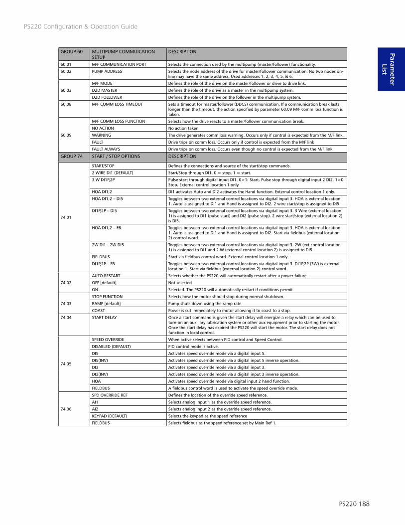
PS220 Configuration & Operation Guide
PS220 188
Parameter
List
GROUP 60 MULTIPUMP COMMUICATION SETUP
DESCRIPTION
60.01 M/F COMMUNICATION PORT Selects the connection used by the multipump (master/follower) functionality.
60.02 PUMP ADDRESS Selects the node address of the drive for master/follower communication. No two nodes on-line may have the same address. Used addresses 1, 2, 3, 4, 5, & 6.
60.03
M/F MODE Defines the role of the drive on the master/follower or drive to drive link.
D2D MASTER Defines the role of the drive as a master in the multipump system.
D2D FOLLOWER Defines the role of the drive on the follower in the multipump system.
60.08 M/F COMM LOSS TIMEOUT Sets a timeout for master/follower (DDCS) communication. If a communication break lasts longer than the timeout, the action specified by parameter 60.09 M/F comm loss function is taken.
60.09
M/F COMM LOSS FUNCTION Selects how the drive reacts to a master/follower communication break.
NO ACTION No action taken
WARNING The drive generates comm loss warning. Occurs only if control is expected from the M/F link.
FAULT Drive trips on comm loss. Occurs only if control is expected from the M/F link
FAULT ALWAYS Drive trips on comm loss. Occurs even though no control is expected from the M/F link.
GROUP 74 START / STOP OPTIONS DESCRIPTION
74.01
START/STOP Defines the connections and source of the start/stop commands.
2 WIRE DI1 (DEFAULT) Start/Stop through DI1. 0 = stop, 1 = start.
3 W DI1P,2P Pulse start through digital input DI1. 0>1: Start. Pulse stop through digital input 2 DI2. 1>0:Stop. External control location 1 only.
HOA DI1,2 DI1 activates Auto and DI2 activates the Hand function. External control location 1 only.
HOA DI1,2 – DI5 Toggles between two external control locations via digital input 3. HOA is external location 1. Auto is assigned to DI1 and Hand is assigned to DI2. 2 wire start/stop is assigned to DI5.
DI1P,2P – DI5 Toggles between two external control locations via digital input 3. 3 Wire (external location 1) is assigned to DI1 (pulse start) and DI2 (pulse stop). 2 wire start/stop (external location 2) is DI5.
HOA DI1,2 – FB Toggles between two external control locations via digital input 3. HOA is external location 1. Auto is assigned to DI1 and Hand is assigned to DI2. Start via fieldbus (external location 2) control word.
2W DI1 - 2W DI5 Toggles between two external control locations via digital input 3. 2W (ext control location 1) is assigned to DI1 and 2 W (external control location 2) is assigned to DI5.
FIELDBUS Start via fieldbus control word. External control location 1 only.
DI1P,2P – FB Toggles between two external control locations via digital input 3. DI1P,2P (3W) is externallocation 1. Start via fieldbus (external location 2) control word.
74.02
AUTO RESTART Selects whether the PS220 will automatically restart after a power failure.
OFF [default] Not selected
ON Selected. The PS220 will automatically restart if conditions permit.
74.03
STOP FUNCTION Selects how the motor should stop during normal shutdown.
RAMP [default] Pump shuts down using the ramp rate.
COAST Power is cut immediately to motor allowing it to coast to a stop.
74.04 START DELAY Once a start command is given the start delay will energize a relay which can be used to turn-on an auxiliary lubrication system or other aux equipment prior to starting the motor. Once the start delay has expired the PS220 will start the motor. The start delay does not function in local control.
74.05
SPEED OVERRIDE When active selects between PID control and Speed Control.
DISABLED (DEFAULT) PID control mode is active.
DI5 Activates speed override mode via a digital input 5.
DI5(INV) Activates speed override mode via a digital input 5 inverse operation.
DI3 Activates speed override mode via a digital input 3.
DI3(INV) Activates speed override mode via a digital input 3 inverse operation.
HOA Activates speed override mode via digital input 2 hand function.
FIELDBUS A fieldbus control word is used to activate the speed override mode.
74.06
SPD OVERRIDE REF Defines the location of the override speed reference.
AI1 Selects analog input 1 as the override speed reference.
AI2 Selects analog input 2 as the override speed reference.
KEYPAD (DEFAULT) Selects the keypad as the speed reference
FIELDBUS Selects fieldbus as the speed reference set by Main Ref 1.

PS220 Configuration & Operation Guide
189 PS220
Para
met
er
List
GROUP 75 PROCESS CONTROL DESCRIPTION75.02 PRIMING DELAY Setting range is 0 – 6000 sec. When the drive is starting from 0 rpm this parameter delays
pump protection warnings or faults (79.01, 79.08, 79.10, 79.12, 79.14, 79.15, 80.07, and 80.13) for the setting time. Once the priming delay time is complete the protection delay (79.03) becomes functional. During the priming delay the pump runs at the maximum speed setting since it cannot achieve the set point.
75.03
SLEEP MODE Defines the selections for SLEEP MODE. Applicable to pressure control and level control only.
DISABLED Function is disabled.
MIN SPEEP Pump will enter sleep mode if the PS220 needs to regulate below minimum speed to main-tain the set-point.
INTELL SPEEP Pump will enter sleep mode if process variable is met and operating flow is below pumpminimum flow ( dead head condition).
75.05 SLEEP VALUE For a 75.03 setting of MIN SPEED the drive sleeps when the PROCESS ACTUAL VALUE rises above the SLEEP VALUE (75.05) for longer than the SLEEP DELAY (75.07) while the pump speed is at the minimum speed setting. If operating in inverse mode (40.31 the drive will sleep when the PROCESS ACTUAL VALUE drops below the SLEEP VALUE (75.05) for longer than the SLEEP DELAY (75.07) while the pump is operating at the minimum speed setting.
For a 75.03 setting of INTELL SLEEP the drive sleeps when the PROCESS ACTUAL VALUE rises above the SLEEP VALUE (75.05) for longer than the SLEEP DELAY (75.07) while the pump flow (SmartFlow or Flow Act) is at zero. If operating in inverse mode (40.31/41.31 set to Inverted) the drive will sleep when the PROCESS ACTUAL VALUE drops below the SLEEP VALUE (75.05) for longer than the SLEEP DELAY (75.07) while the pump flow (SmartFlow or Flow Act) is at zero.
75.06 RESTART VALUE If the drive goes to sleep due to no system demand (pressure/level control only) the drive will sleep until the process actual value drops below a set 75.06 restart value for longer than 75.08 restart delay. If operating in inverse mode the drive will sleep until the process variable rises above the restart value. Wake-up level in % of setpoint value = 0 – 500%. To disable the Restart Value function in both normal and inverse settings enter “0%”.
75.07 SLEEP DELAY The time delay associated with the SLEEP VALUE (75.05). Range 0-1800 sec.
75.08 RESTART DELAY Time delay for 75.01 RESTART VALUE. Range = 0 –1800 sec. Default = 10 second
75.16
FLOW BYPASS SOURCE Selects the signal source for activating the bypass relay.
OFF [DEFAULT] Function is disabled.
FLOW ACTUAL Select this option if an external flow meter signal is being used to control the bypass valve relay output.
SMARTFLOW Select this options if SmartFlow is being used to control the bypass valve relay output.
75.17 FLOW BYPASS ON Sets the RELAY BYPASS SOURCE (75.16) value for activating the relay bypass. Defines the safe minimum flow of the pump. This minimum flow correlates to the RATED SPD (77.04). For other speeds the allowable min flow is corrected proportionally to the change in speed.Range = 0 – 100,000
75.18 FLOW BYPASS OFF RATIO Defines the flow ratio for closing the bypass valve. Bypass valve closes when QACT / QMIN CORR >= RELAY BYPASS OFF. The default is 2.1. The range is 0.0 – 5.0.
75.19 ON DELAY The delay associated with RELAY BYPASS ON (75.17). Range 0 – 1800 sec. Default = 1 sec.
75.20 OFF DELAY The delay associated with RELAY BYPASS OFF (75.18). Range 0 – 1800 sec. Default = 1 sec.
75.21 FLOW RELAY START DELAY The time period for which the actual flow must be below the corrected minimum flow in order to issue a minimum flow warning and activate a Relay Output. Range 0 – 200 sec.
75.24
MULTIVAR CTL Selects the PS220 Multivariable Control feature. Utilizes one auxiliary process transmitter to offset the set-point.
OFF [DEFAULT] Disables Multivariable control
ON Multivariable control is active
75.26 LEVEL 1 Process Transmitter 2 Low value offset @ Level 1. Below this value is where offset begins fortransmitter.
75.27 SPT LO Set-point corresponding to the LO INTRCPT.
75.28 LO INTRCPT This is the process transmitter 2 value that STPT LO is given for (at Level 1).
75.29 LEVEL 2 Process Transmitter 2 High value offset @ Level 2.
75.30 SPT HI Set-point corresponding to the HI INTRCPT.
75.31 HI INTRCPT This is the Process Transmitter 2 value that SP HI is given for (at Level 2).

PS220 Configuration & Operation Guide
PS220 190
Parameter
List
GROUP 76 ANALOG I/O CONFIG DESCRIPTION
76.06
RO1 SOURCE Selects the PS220 status to be indicated through relay outputs 1 The relay energizes when the status meets the setting.
NOT SELECTED
READY Drive is ready to run the motor.
RUNNING Drive is running the motor.
FORCE ON Force the Relay output to a Normally closed
PUMP CLEAN A pump cleaning sequence is being executed. The relay remains energized until the completion of the cleaning sequence.
-FAULT A general VFD or PUMP related fault has occurred.
FLOW BYP SMRT FLW Minimum flow bypass valve control Triggers the relay to open the valve when using SmartFlow
PIPE CLEAN A pipe cleaning sequence is being executed. The relay remains energized until the comple-tion of the cleaning sequence.
COND1 HI ALARM Condition 1 HI Alarm is active
COND2 HI ALARM Condition 2 HI Alarm is active
FLOW BYP EXT FLW Minimum flow bypass valve control Triggers the relay to open the valve when using an external flow meter.
PUMP FLTS/WRNGS A general pump related warning or fault has occurred
SECND PRTECT A Secondary Protect A activation
SECND PRTECT B Secondary Protect B activation
PCS REQ A pump cleaning sequence has been requested. The relay remains energized until the completion of the cleaning sequence.
PCS EXE A pump cleaning sequence is being executed. The relay remains energized until the completion of the cleaning sequence.
PUMP PROTECT Pump protection activation
COND1 LOW ALARM Condition 1 LOW Alarm is active
COND2 LOW ALARM Condition 2 LOW Alarm is active
MULTI VAR ACTIVE Multivariable control is active
SPEED OVERIDE Speed override is active.
OTHER Selecting other will allow relay to change state based on the parameter selection.
76.07 RO2 SOURCE Selects the PS220 status to be indicated through relay outputs 2 The relay energizes when the status meets the setting. Options same at RO1
76.08 RO3 SOURCE Selects the PS220 status to be indicated through relay outputs 3 The relay energizes when the status meets the setting. Options same as RO1
76.09 DI1 Selects the Digital input 1 function
76.10 DI2 Selects the Digital input 2 function
76.11 DI3 Selects the Digital input 3 function
76.12 DI4 Selects the Digital input 4 function
76.13 DI5 Selects the Digital input 5 function
76.14 DI6 Selects the Digital input 6 function
76.15 DIO1 Selects the DIO1 function.
76.16 DIO2 Selects whether DIO2 is used as a digital output or input, or a frequency input. Options same as DIO1
76.17 DIO1 OUTPT SOURCE Selects the PS220 status to be indicated through relay outputs 1 The relay energizes when the status meets the setting. Selection list is same as Relay outputs.
76.18 DIO2 OUTPT SOURCE Selects the PS220 status to be indicated through relay outputs 1 The relay energizes when the status meets the setting. Selection list is same as Relay outputs.

PS220 Configuration & Operation Guide
191 PS220
Para
met
er
List
GROUP 77 SMARTFLOW DESCRIPTION
77.01
PUMP TYPE Defines the type of pump being used.
DISABLED Disables the SmartFlow function
SS CENTRIFUGAL Centrifugal type loads – use for single suction impellers
DS CENTRIFUGAL Centrifugal type loads – use for double suction impellers
MAG DRIVE Centrifugal type loads with magnetic drive (eddy current) losses
77.02
CALC METHOD Selects the calculation method depending on the power curve shape. A suction and dis-charge transmitter or differential pressure transmitter is required for BHP/TDH and TDH
BHP [ DEFAULT] Select BHP for a constantly rising power curve.
BHP/TDH Select BHP/TDH for a non-constantly rising power curve.
TDH Select TDH if power curve is flat.
77.03 BEP FLOW Flow at the pump Best Efficiency Point (BEP) at rated speed and viscosity. Range: 0-10,000.
77.04 PUMP RATED SPD Speed at which pump data (QBEP, PBEP, and PSO) is entered. Range 0 – 18000 Rpm Scalar mode units are Hz. Default = MAXIMUM SPEED.
77.05 BEP POWER Power at the pump Best Efficiency Point (BEP) at rated speed and viscosity at SG = 1.0. Range 0 – 3000.00.
77.06 SO POWER Power at the pump shut-off condition (SO) at rated speed and viscosity at SG = 1.0. Range: 0 – 3000.00.
77.07 BEP TDH The pump total dynamic head at the best efficiency capacity at rated speed.
77.08 SO TDH The pump total dynamic head at closed valve condition at rated speed.
77.09 SUCTION DIA Pump nominal suction diameter If LANGUAGE = ENGLISH (US), the units are in inches. MM for all other languages. Range 0.00 – 1000.00.
77.10 DISCHARGE DIA Pump nominal discharge diameter If LANGUAGE = ENGLISH (US), the units are in inches. MM for all other languages. Range 0.00 – 1000.00.
77.11 DELTA Z The suction and discharge pressure gage height differential with respect to a datum; e.g. the datum is the centerline of the pump suction flange for BB and OH pumps. If LANGUAGE =ENGLISH (US), the units are in Ft. M for all other languages. Range 0.0 – 1000.0.
77.12 TDH The input speed to output speed ratio. Range 0.00 – 20.00. Used for pumps with belt drives.
77.13
DP SOURCE Identifies the configured analog input to be used for the differential pressure source. Refer to Group 76 PumpSmart I/O.
NOT USED [DEFAULT]
PROC TRANS 1 Select if using the primary process transmitter
PROCE TRANS 2 Select if using the secondary process transmitter
DIFFERENTIAL PRESSURE Select if using a differential pressure transmitter.
77.14
DISC PRES SOURCE Identifies the configured analog input to be used for the discharge pressure source. Refer toGroup 76 PumpSmart I/O.
NOT USED [DEFAULT
PROC TRANS 1 Select if using the primary process transmitter
PROCE TRANS 2 Select if using the secondary process transmitter
DISCHARGE PRESSURE Select if using a separate suction pressure transmitter.
77.15
SUC PRES SOURCE Identifies the configured analog input to be used for the discharge pressure source. Refer toGroup 76 PumpSmart I/O.
NOT USED [DEFAULT
PROC TRANS 1 Select if using the primary process transmitter
PROCE TRANS 2 Select if using the secondary process transmitter
S PRESSURE Select if using a separate suction pressure transmitter.
77.20 CALC SO SOURCE
AFFINITY [DEFAULT] Estimates power at shut-off using the affinity laws.
TUNED VALUE Uses the power at shut-off characteristic curve developed during the tune function.
TUNE PumpSmart estimates power for a shut-off characteristic curve by increasing speed and monitoring power while pump is held with a closed discharge valve. A warning message is displayed on the keypad WARNING TUNING. A relay output is activated and Fieldbus Alarm Word is set (if configured). Once the Tune process is complete the drive will shut down and must be manually restarted.
77.22 P MAG CORR Eddy current correction factor for magnetic drive pumps at rated speed (77.04). Visible only if 77.01 TYPE = MAG DRIVE. Range: 0.00 – 100.00. If LANGUAGE = ENGLISH (US), the units are in BHP. KW for all other languages.
77.23 QACT FILTER Defines the filter time constant for QACT. Range is 0-10 sec.
77.34 MECH LOSS Mechanical loss correction factor if the losses are greater than 20%-30% of the overall pumppower consumed. For example if seal drag on 1HP pump is 0.2 hp, it will impact accuracy of the Smartflow values. A mechanical loss correction will help improve the accuracy of smartflow.

PS220 Configuration & Operation Guide
PS220 192
Parameter
List
GROUP 78 FLUID PROPERTIES DESCRIPTION78.01 PATM The local barometric pressure.
78.02 SG SEL Selects SG source
SG RATED [DEFAULT] Uses the value parameter 78.03 SG RATED
SG CALC (T) Calculates SG as a function of temperature using the SG Calculation logic.
AI – ANALOG INPUT SG is set via an analog input signal (refer to Group 76 setup). Linear scale: 4mA=SG MIN, 20mA = SG MAX.
DI – DIGITAL INPUT SG can be toggled between parameter 78.04 SG MIN and 78.06 SG MAX via user defined digital input.
78.03 SG RATED Specific Gravity, Rated. Setting range is 0.00 – 10.00.
78.04 SG MIN Specific Gravity, Minimum. Setting range is 0.00 – 10.00.
78.05 SG MID Specific Gravity, Midway. Setting range is 0.00 – 10.00.
78.06 SG MAX Specific Gravity, Maximum. Setting range is 0.00 – 10.00.
78.07 TEMP RATED Temperature, Rated. If LANGUAGE = ENGLISH (US), the units are in F Deg (default = 104), C Deg (default = 40) for all other languages. Setting range: -200.0 – 1000.0.
78.08 TEMP MIN Temperature, minimum. If LANGUAGE = ENGLISH (US), the units are in F Deg. (default = 0), C Deg (default = -18) for all other languages. Setting range: -200.0 – 1000.0.
78.09 TEMP MID Temperature, midway. If LANGUAGE = ENGLISH (US), the units are in F Deg. (default =104), C Deg (default = 40) for all other languages. Setting range: -200.0 – 1000.0.
78.10 TEMP MAX
GROUP 79 PUMP PROTECTION DESCRIPTION
79.01
PUMP PROTECT CTRL Actual process value is lower than protection limit (79.02) for protection delay (79.03) and PS220 is at (max speed – 10 rpm) for the protection delay.
DISABLED [DEFAULT] Protection is disabled
WARNING The PS220 generates a warning only “Pump Protect”; no other action is taken.
ALARM AND CONTROL The PS220 generates a warning “Pump Protect” and controls according to the setting of 79.16 CONFIG MIN SPD.
79.02 PROTECTION LIMIT This is the protection limit for the process value at which Pump Protect Ctrl (79.01) activates when pump is at max speed for the protection delay. Setting range: 0.0 – 100.0% of setpoint. Default is 3%
79.03 PROTECTION DELAY This is the protection delay period prior to activation of Pump Protect Ctrl (79.01). Also applies to Secondary Protect A/B, Min Flow, Dry Run and Run Out Ctrl. Must be greater than 0.0 to activate protection. Setting range: 0– 200 sec. Default is 0
79.04
SP OVRRD PMP PROT Selects if pump protection warning and faults are enabled or disabled when speed override is initiated.
DISABLED [DEFAULT]
ENABLED
79.05 PUMP FAULT RESET Indicates number of automatic fault resets. Selection range is 0 – 19. When set to “0” Error Reset is disabled. Time between resets is parameter 79.06 Pump Reset Delay. Manual intervention is required if fault is still active after set number of resets has been achieved. The counter will reset if a stop command is issued, fault is manually reset or the drive has been operating normally for 5 minutes. The drive reaction to the fault will be according to parameter Config min speed (79.16) setting. Pump Fault Reset is applicable to parameters 79.01 and 79.08. A Dry Run Fault must be manually reset. Default is 0
79.06 PUMP RESET DELAY Defines the time that the PS220 will wait after an alarm and control condition before attempting an error reset. Setting Range = 0 -3600 sec. Default is 60 Seconds
79.07
Q ACT SOURCE Identifies the source of the flow readings used for the pump protection feature.
SMARTFLOW [DEFAULT] Logic uses the PumpSmart calculated flow value
FLOW METER Logic uses an external flow meter that is configured in Group 76.
79.08
MIN FLOW CTRL If enabled and the actual flow is less than the min flow (corrected for speed) for the protection delay (79.03) a minimum flow condition is detected.
DISABLED [DEFAULT] Protection is disabled.
WARNING The PS220 generates a “Min Flow Warning” only; no other action is taken unless relay outputs are configured.
ALARM AND CONTROL The PS220 generates a “Min Flow” warning or fault and controls according to the setting ofConfig min speed (79.16). The fault is re-settable if (79.05) Pump Fault Reset is active. Relay Outputs may be configured to activate.
79.09 MIN FLOW Defines the safe minimum flow of the pump. This minimum flow correlates to the 77.04 Rated Speed.
79.10
DRY RUN CTRL If enabled and the actual flow is less than the dry run criteria for the protection delay (79.03) a dry run condition is detected.
DISABLED [ DEFAULT] Protection is disabled.
FAULT The drive faults and the motor coasts to a stop. A fault message is generated “Dry Run”. Thisfault is not resettable by Pump Fault Reset (79.05). Relay Outputs may be configured to activate.
WARNING The PS220 generates a dry run warning only; no other action is taken unless relay outputs are configured.
79.11 DRY RUN FACTOR Coefficient for determining dry-run power, Range= 0 – 2.00 Default is .95

PS220 Configuration & Operation Guide
193 PS220
Para
met
er
List
GROUP 79 PUMP PROTECTION DESCRIPTION
79.12
RUNOUT CTRL If enabled and the actual flow is greater than the Runout flow (corrected for speed) for theprotection delay 79.03, a Runout condition is detected.
DISABLED [ DEFAULT] Protection is disabled.
WARNING The PS220 generates a Runout warning only; no other action is taken.
79.13 RUNOUT FLOW Defines the maximum flow of the pump. This maximum flow correlates to the 77.04 Rated Speed.
79.14
SECONDARY PROTECT A Loss of digital input 5 (DI5) for protection delay (79.03).
DISABLED [DEFAULT] Protection is disabled
ALARM The PS220 generates a warning only “Secondary Protect A”; no other action is taken. RelayOutputs may be configured to activate.
ALARM AND CONTROL The PS220 generates a warning “Secondary Protect A” and controls according to the setting of Config min speed 79.16 If DI5 then closes, the fault will be reset and the drive will restart. Relay Outputs may be configured to activate.
MOTOR TEMP To be selected when a Motor Temp input is used at DI6. Parameter 35.11 Supervision 1 Source must be set to select the source where the Motor Temp is read. Parameter 35.10 Supervision 1 Protection must be set to “Warning”.
79.15 SECONDARY PROTECT B Loss of digital input 5 (DI5) for protection delay (79.03).
CONFIG MIN SPEED Defines the reaction of the drive when the PS220 tries to regulate at a speed at or below minspeed.
SPEED = 0 The drive will stay at min speed until Stop Delay Min Speed setting times out; the unit will then shutdown.
79.12 SPEED = MIN SPEED The PS220 will stay at this speed until the transient clears or unit is manually shutdown; unless a fault occurs.
79.17 STP DELAY MIN SPD The time period the drive will stay at min speed before stopping. Range=0–1800 sec. Functions when 79.16 is set to Speed=0. Becomes active if the setpoint would result in regulation below min speed, closed valve condition in pressure control and Secondary Protect A & B.
GROUP 80 CONDITION MONITORING DESCRIPTION80.01 CONDITION STATUS A 1 indicates the condition is active
80.02 CONDITION 1 LVL Displays Condition 1 value
80.03 CONDITION 2 LVL Displays Condition 2 value
80.04 COND 1 SOURCE Select the source of the signal to be monitored. The source can either be from an external transmitter wired to an available analog input or it can be an internal signal as selected by the parameter number.
80.05 COND 1 WRN LIM HI The high value of the warning limit. A warning occurs if the monitored signal rises above thisvalue for longer than the response delay (par 80.16). Inactive if set to 0. Range is 0-10000.
80.06 COND 1 WRN LIM LO The low value of the warning limit. A warning occurs if the monitored signal drops below this value for longer than the response delay (par 80.16). Inactive if set to 0. Range is 0-10000.
80.07
COND 1 ALARM Select response to an active condition alarm.
DISABLED Protection is inactive.
ALARM ONLY Selecting ALRM ONLY will configure PumpSmart to issue a Keypad or DCS notice and will trigger a Relay Output (if configured) if an ALRM LIM HI or ALRM LIM LO condition is detect-ed. No further action is taken.
MIN SPD Selecting MIN SPD will configure PS220 to drop to 30.11 MIN SPEED and issue a Keypad warning and trigger a Relay Output (if configured) if an ALRM LIM HI or ALRM LIM LO condition is detected. If the alarm does not reset itself after the MIN SPD STP DLY (parameter 80.18) the PS220 will fault.
SLEEP The PS220 will shut down and go into a sleep mode if an ALRM LIM HI or ALRM LIM LO condition is detected. Refer to Sleep Mode Functions for further details.
FAULT The PS220 faults if an ALRM LIM HI or ALRM LIM LO condition is detected. A Keypad notice is issued and a Relay Output is triggered (if configured).
80.08 COND 1 ALARM LIM HI The high value of the alarm limit. An alarm occurs if the monitored signal rises above this value for longer than the condition response delay (par 80.16). Inactive if set to 0. Range is 0-10000.
80.09 COND 1 ALARM LIM LO The low value of the alarm limit. An alarm occurs if the monitored signal drops below this value for longer than the response delay (par 80.16). Inactive if set to 0. Range is 0-10000.
80.10 COND 2 SOURCE Select the source of the signal to be monitored. The source can either be from an external transmitter wired to an available analog input or it can be an internal signal as selected by the parameter number.
BIT FUNCTION DESCRIPTION
0 Enabled
1 Cond1 High Alarm
2 Cond1 High Warning
3 Cond1 Low Warning
4 Cond1 Low Alarm
5 Cond2 High Alarm
6 Cond2 High Warning
7 Cond2 Low Warning
8 Cond 2 Low Alarm
13 Sleep Active
14 Min Speed Active

PS220 Configuration & Operation Guide
PS220 194
Parameter
List
GROUP 80 CONDITION MONITORING DESCRIPTION80.11 COND 2 WRN LIM HI The high value of the warning limit. A warning occurs if the monitored signal rises above this
value for longer than the response delay (par 80.16). Inactive if set to 0. Range is 0-10000.
80.12 COND 2 WRN LIM LO The low value of the warning limit. A warning occurs if the monitored signal drops below this value for longer than the response delay (par 80.16). Inactive if set to 0. Range is 0-10000.
80.13
COND 2 ALARM Select response to an active condition alarm.
DISABLED Protection is inactive.
ALARM ONLY Selecting ALRM ONLY will configure PumpSmart to issue a Keypad or DCS notice and will trigger a Relay Output (if configured) if an ALRM LIM HI or ALRM LIM LO condition is detect-ed. No further action is taken.
MIN SPD Selecting MIN SPD will configure PS220 to drop to 30.11 MIN SPEED and issue a Keypad warning and trigger a Relay Output (if configured) if an ALRM LIM HI or ALRM LIM LO condition is detected. If the alarm does not reset itself after the MIN SPD STP DLY (parameter 80.18) the PS220 will fault.
SLEEP The PS220 will shut down and go into a sleep mode if an ALRM LIM HI or ALRM LIM LO condition is detected. Refer to Sleep Mode Functions for further details.
FAULT The PS220 faults if an ALRM LIM HI or ALRM LIM LO condition is detected. A Keypad notice isissued and a Relay Output is triggered (if configured).
80.14 COND 2 ALARM LIM HI The high value of the alarm limit. An alarm occurs if the monitored signal rises above this value for longer than the condition response delay (par 80.16). Inactive if set to 0. Range is 0-10000.
80.15 COND 2 ALARM LIM LO The low value of the alarm limit. An alarm occurs if the monitored signal drops below this value for longer than the response delay (par 80.16). Inactive if set to 0. Range is 0-10000.
80.16 COND RESP DELAY The delay period prior to activation of a COND 1 or COND 2 WRN OR ALRM
80.17 PROC TRANS1 UNITS Select units from the available 13 options.
80.18 MIN SPD STP DLY The time period which the PS220 will operate at min speed during an alarm condition if it does not reset. If the time period expires the PS220 will fault.
80.19 CONDITION EN Allows selection of when condition monitoring warnings and alarms to be triggered.
80.20 PROC TRANS2 UNITS Select units from the available 13 options.
80.21 COND 1 HYSTERESIS Defines the value for the condition 1 source window in the units selected for COND 1 ALRM LIM HI and COND 1 ALRM LIM LO. While operating inside the Cond 1 Hi alarm window or Cond 1 Lo alarm window the Cond 1 Hi or Lo alarm will not reset until the cond 1 source operates outside the window.
80.22 COND 2 HYSTERESIS Defines the value for the condition 2 source window in the units selected for COND 2 ALRM LIM HI and COND 2 ALRM LIM LO. While operating inside the Cond 2 Hi alarm window or Cond 2 Lo alarm window the Cond 2 Hi or Lo alarm will not reset until the cond 2 source operates outside this window.
GROUP 81 MULTIPUMP DESCRIPTION
81.01
MODE Selects how multiple PS220 units operate together in parallel to satisfy the set-point.
DISABLED [DEFAULT] Multipump control is disabled.
SYNCHRONOUS Lag pumps start as needed and all pumps regulate to the set-point at the same speed or torque. Note: it is recommended that all pumps be identical.
81.02 VALUE DECREASE Defines how much the set point can drop before the next lag pump is started. Setting range = 0.0 – 100.0% of set point.
81.03 VALUE INCREASE Defines the increase in set point when a lag pump starts. This value is cumulative with each lag pump that turns on. Setting range = 0.0 – 100.0% of set point.The default setting for 81.03 is equal to the value set in 81.02.
81.04
STAGE/DESTAGE METHOD Selects the method of staging or destaging pumps in a multipump system.
SPEED Pumps are staged and destaged based on speed and value decrease.
TORQUE Pumps are staged and destaged based on torque and value decrease.
PROCESS VARIABLE Pumps are staged and destaged based on the process variable values.
81.09 STAGE 2 Selects the control parameter value at which lag pump 1 should be turned on. Setting range = 0.0 – 100.0% of MAXIMUM SPEED or 0.0 – 100.0% of MOTOR NOM TORQUE.
81.10 STAGE 3 Selects the control parameter value at which lag pump 2 should be turned on. Setting range = 0.0 – 100.0% of MAXIMUM SPEED or 0.0 – 100.0% of MOTOR NOM TORQUE.
81.11 STAGE 4 Selects the control parameter value at which lag pump 3 should be turned on. Setting range = 0.0 – 100.0% of MAXIMUM SPEED or 0.0 – 100.0% of MOTOR NOM TORQUE.
81.13 DESTAGE 2 Selects the control parameter value at which lag pump 1 should be turned off. Setting range = 0.0 – 100.0% of MAXIMUM SPEED or 0.0 – 100.0% of MOTOR NOM TORQUE.
81.14 DESTAGE 3 Selects the control parameter value at which lag pump 2 should be turned off. Setting range = 0.0 – 100.0% of MAXIMUM SPEED or 0.0 – 100.0% of MOTOR NOM TORQUE.
81.15 DESTAGE 4 Selects the control parameter value at which lag pump 3 should be turned off. Setting range = 0.0 – 100.0% of MAXIMUM SPEED or 0.0 – 100.0% of MOTOR NOM TORQUE.
81.17 STAGE 5 Selects the control parameter value at which lag pump 4 should be turned on. Setting range = 0.0 – 100.0% of MAXIMUM SPEED or 0.0 – 100.0% of MOTOR NOM TORQUE.
81.18 STAGE 6 Selects the control parameter value at which lag pump 5 should be turned on. Setting range = 0.0 – 100.0% of MAXIMUM SPEED or 0.0 – 100.0% of MOTOR NOM TORQUE.
81.21 DESTAGE 5 Selects the control parameter value at which lag pump 4 should be turned off. Setting range = 0.0 – 100.0% of MAXIMUM SPEED or 0.0 – 100.0% of MOTOR NOM TORQUE.
81.22 DESTAGE 6 Selects the control parameter value at which lag pump 5 should be turned off. Settingrange = 0.0 – 100.0% of MAXIMUM SPEED or 0.0 – 100.0% of MOTOR NOM TORQUE.
81.23 MULTIPUMP RUNTIME RESET Reset operating hours in multipump operation.

PS220 Configuration & Operation Guide
195 PS220
Para
met
er
List
GROUP 81 MULTIPUMP DESCRIPTION81.31 SWITCH LEAD TIME Defines the time the lead unit will run before a new unit is deemed the lead unit. If set to
zero the alternating function is disabled; including alternating during a fault. For the equiv-alent of disabling the alternating function but allowing alternation during a fault set the range to 99999.0 (equivalent to 11.5 years).
81.32 SWITCH LEAD Selections are disabled (default), pump 1, pump 2, pump 3, pump 4, pump 5 and pump 6. Manual switch of lead-lag pumps; after manual switch occurs, this parameter returns to disabled. Manual switch shall function through only the master keypad.
81.33 MAX PUMPS ON Defines Maximum # of pumps that can run at any one time, any node address.
81.34 MIN PUMPS ON Defines Min # of pumps that can run at any one time, any node address.
81.36 SWITCH LEAD SLP COUNT Defines the # of times the lead pump goes in to a sleep mode before transferring lead status to the next pump. Set parameter 81.31 to 0.
81.38 DESTAGE PROOF TIME Time in which conditions for destaging must occur before pump is actually destaged. De-stage value and value decrease value must be met. Setting range 0-900 seconds. Default is 20 seconds. This parameter provides a “bumpless” change in PV when destaging a pump or switching the lead pump manually or automatically. Range = 0 – 150 sec. Default = 30 sec.
81.39 STAGE PROOF TIME Time in which conditions for staging must occur before pump is actually staged. Stage value and value decrease must be met. Setting range 0-360 seconds.
GROUP 83 WATER FUNCTIONS DESCRIPTION
83.01
EXE P CLEAN SEQ Defines how the cleaning sequence is executed. Drive relay output R03 energizes upon exe-cution. RO3 remains energized during the cleaning sequence. The PCS operates in REMOTE mode only. Overwrites RO3 Default.
NOT SELECTED [DEFAULT] The pump cleaning sequence is disabled.
P CTRL DI3 The pump cleaning system is executed by the pump controller setting the drive digital input DI3 from 0 to 1.
PS220 The pump cleaning system is executed by the PS220.
83.02
REQ P CLEAN SEQ Defines what triggers the request of the pump cleaning sequence. Upon request the relay output RO2 energizes and remains energized until the execution of the sequence is completed. Overwrites RO2 Default.
NOT SELECTED [DEFAULT] The pump cleaning sequence is disabled if 83.01 is set to PS220 and 83.02 is set to NOT SEL. If 83.01 is set to P CTRL DI3 and 83.02 is set to NOT SEL the pump controller and pump controller logic are used to control the PCS – thus the drive’s capability to analyze torque and/or run time are not utilized.
TORQUE The request is triggered when 1.10 MOTOR TORQUE % exceeds the value set in 83.03 TORQ REQ for the 83.04 TON REQ. The fulfillment is monitored and analyzed by the drive.
RUN TIME This request is triggered when 1.227 PMP CLN RUN TIME exceeds the value set in 83.05 RUN TIME REQ. The fulfillment is monitored and analyzed by the drive.
TORQ OR RUN TIME This request is triggered when either motor torque or run time is fulfilled as described above
83.03 TORQUE REQ Defines the motor torque threshold value in % of nominal motor torque which is required to trigger a pump cleaning sequence. Range: 0.0 – 200.0%.
83.04 TON REQ The motor torque must exceed the 83.03 TORQUE REQ for this time period before the pump cleaning sequence can be triggered. Range is 0 - 100 sec.
83.05 RUN TIME REQ Defines the run time which must be met before the pump cleaning sequence can be request-ed if configured in 83.02 REQ P CLEAN SEQ. The 1.226 PMP CLN RUN TIME is reset to zero after every stop command and after every completed cleaning sequence. Range: 0.1 – 100.0 hrs.
83.06 NUM OF CYCLES Defines the number of cycles the pump cleaning system performs for each execution. Range: 1–10
83.07 FWD RUN SPD Defines the forward running speed in % of MAXIMUM SPEED. Range: 0.0 – 100.0%.
83.08 FWD RUN TIME Defines the forward running time of the cleaning sequence. Range: 0.0 – 100.0 sec.
83.09 FWD RUN ACC Defines the forward acceleration in the cleaning cycle. Range: 0.0 – 100.0 sec.
83.10 FWD RUN DEC Defines the forward deceleration in the cleaning cycle. Range: 0.0 – 100.0 sec. No lower value than 2 sec shall be set to avoid overstress of the impeller and shaft.
83.11 ZERO SPEED PAUSE Defines the zero speed pause in the cleaning sequence when switching from forward to reverse rotation. Range: 0.0 – 100 sec.
83.12 REV RUN SPD Defines the reverse running speed in % of MAXIMUM SPEED. No higher value than 80% shall be set to avoid overstress of the impeller and shaft. Range: 0.0 – 100.0%.
83.13 REV RUN TIME Defines the reverse running time of the cleaning sequence. Range: 0.0 – 100.0 sec.
83.14 REV RUN ACC Defines the reverse acceleration in the cleaning cycle. No higher value than 2 sec shall be set to avoid overstress of the impeller and shaft. Range: 0.0 – 100.0 sec.
83.15 REV RUN DEC Defines the reverse deceleration in the cleaning cycle. Range: 0.0 – 100.0 sec.
83.16 SEQUENCE TIMER Applies to 83.01 setting of PS220 only. If the time period for requesting a new PCS (after a PCS sequence has been completed) is less than the SEQUENCE TIMER setting then the 83.17SEQUENCE COUNTER shall be enabled. Range: 0 – 100 sec
83.17 SEQUENCE COUNTER Applies to 83.01 setting of PS220 only. The maximum number of sequences which are allowed after the SEQUENCE COUNTER has been activated. If the drive requests another PCS after the maximum allowed sequences has been attained then the 83.18 SEQUENCE EXCEED function shall be activated. Range: 0 – 10 sequences.

PS220 Configuration & Operation Guide
PS220 196
Parameter
List
GROUP 83 WATER FUNCTIONS DESCRIPTION83.18 SEQUENCE EXCEED Applies to 83.01 setting of PS220 only. After the 83.17 SEQUENCE COUNTER has reached the
maximum allowed sequences and a new PCS is requested this settable action is initiated.
DISABLED The SEQUENCE EXCEED function is disabled and there is no limitation on the number of PCS requests and executions.
WARNING The Keypad displays a warning PUMP CLOGGED and the PCS function is disabled. The drivecontinues to function in its normal configured state. A relay output is energized (if config-ured).
FAULT [DEFAULT] The drive faults and must be manually reset The Keypad displays a fault PUMP CLOGGED. A relay output is energized (if configured).
83.19 SNORE TIME Defines the elapsed time before the Snore function is activated. Range: 0 – 10,000 hrs. Default is zero hrs which disables this function.
83.20 TORQUE COEFF Defines the torque coefficient setting needed to activate the snore function. Range: 0.00 – 1.00
83.21
PIPE CLEAN ENABLE Enables the pipe clean function. The pump will ramp to maximum speed for the cycle time. If the pump is running and the Pipe clean function is enabled and triggered by the expira-tion of the Pipe Clean On Time a Pipe Clean Cycle is performed. Once the cleaning cycle is completed the pump returns to normal operation.
DISABLED [DEFAULT] Disables the pipe clean function.
ENABLE ON START Enables the pipe clean function upon each start command if set to Enable on Start
ENABLE ON TIME Enables the pipe clean function based on expiration of the time setting if set to Enable on Time.
83.22 PIPE CLEAN TIME INTERVAL The time setting used for the Enable on Time. Once the setting is reached a pipe clean func-tion is started. Range 0 – 10,000 hrs.
83.23 PIPE CLEAN CYCLE TIME The time spent at maximum speed during the cleaning cycle. Range 0 - 1800 sec.
83.24
PIPE FILL ENABLE Enable the pipe fill function
DISABLE [DEFAULT] Disable the pipe fill function
ENABLE Enable the pipe fill function
83.25 PIPE FILL TIME Time that the pipe fill function is activated
83.26 PIPE FILL SPEED Speed at which the pump will operate at during pipe fill.
GROUP 84 TOTALIZER AND ENGERY SAVINGS DESCRIPTION84.01 TOTL SYS VOL STPT Defines the totalized system volume set point. Range = 999999. Default = 0 = Disabled.
Also defines pump response to the total system volume set point. If par 1.228< total volume set point pumps will continue to regulate to the process variable. Once par 1.229 >= total system volume set point all pumps will turn off
84.02
TOTL VOLUME RESET Resets actual signal 1.228 TOTAL PMP VOLUME.
DISABLED [DEFAULT] This is the default selection.
RESET If selected, actual signal 1.228 is reset to 0 and the parameter will return to disabled.
84.03 $/KWHR Cost of energy in $. For English(Am) = $; other languages = €
84.04 BASELINE POWER Baseline Power (HP (English Am) or kW (all other languages) for a conventional fixed speed system. Setting range = 0.0 – 1000.0.
84.05 ENERGY SAVE METHD Defines if the savings should be tracked only when the pump is running (OP1) or also during automatic shutdown (OP2).
84.06 ENERGY SAVE RESET Resets the savings to zero.
84.07 KWH AT RESET Total kWh since last reset. Add to parameter 1.225 kWh to obtain total kWh. Viewable only.
84.08 OPER. HRS SINCE RESET Operating hours since last reset.
84.13 RESET OPER HOURS Resets operating hours.
GROUP 95 HARDWARE CONFIGURATION DESCRIPTION95.01 SUPPLY VOLTAGE Selects the supply voltage range. This parameter is used by the drive to determine the nomi-
nal voltage of the supply network. The parameter also affects the current ratings and the DC voltage control functions (trip and brake chopper activation limits) of the drive.WARNING! An incorrect setting may cause the motor to rush uncontrollably, or the brake chopper or resistor to overload. Note: The selections shown depend on the hardware of the drive. If only one voltage range is valid for the drive in question, it is selected by default.
95.04 CONTROL BOARD SUPPLY Specifies how the control unit of the drive is powered.
INTERNAL 24VDC This is the default selection
EXTERNAL 24VDC Select this option if The drive control unit is powered from an external power supply.

PS220 Configuration & Operation Guide
197 PS220
Para
met
er
List
GROUP 96 SYSTEM DESCRIPTION96.01 LANGUAGE Selects the language of the parameter interface and other displayed information when
viewed on the control panel.Notes:• Not all languages supported.• This parameter does not affect the languages visible in the Drive composer PC tool.
96.02 PASS CODE Pass codes can be entered into this parameter to activate different access levels.
96.03 ACCESS LEVELS ACTIVE Shows which access levels have been activated by passcodes entered into parameter 96.02 Pass code. This parameter is read-only.
96.07 PARAMETER SAVE MANUALLY Saves the valid parameter values to permanent memory. This parameter should be used to store values sent from a fieldbus, or when using an external power supply to the control board as the supply might have a very short hold-up time when powered off.Note: A new parameter value is saved automatically when changed from the PC tool or control panel but not when altered through a fieldbus adapter connection.
96.16 UNIT SELECTION Selects the unit of parameters indicating power, temperature and torque. This is already setup during the startup process in the BASIC STARTUP WIZARD.
96.20 TIME SYNC PRIMARY SOURCE Defines the 1st priority external source for synchronization of the drive’s time and date.
GROUP 99 MOTOR DATA DESCRIPTION99.03 MOTOR TYPE Selects the motor type. Note: This parameter cannot be changed while the drive is running.
99.04 MOTOR CONTROL MODE Selects motor control mode. Available options are DTC and Scalar. Default is DTC and Scalar is only recommended if DTC is unavailable for any reason as reduced PumpSmart PS220functionality will be available in SCALAR mode.
99.06 MOTOR NOMINAL CURRENT Defines the nominal motor current. Must be equal to the value on the motor rating plate. If multiple motors are connected to the drive, enter the total current of the motors.Notes:• Correct motor operation requires that the magnetizing current of the motor does not exceed 90% of the nominal current of the drive.• This parameter cannot be changed while the drive is running.
99.07 MOTOR NOMINAL VOLTAGE Defines the nominal motor voltage supplied to the motor. This setting must match the value on the rating plate of the motor. This parameter cannot be changed while the drive is running.
99.08 MOTOR NOMINAL FREQUENCY Defines the nominal motor frequency. This setting must match the value on the rating plate of the motor.Note: This parameter cannot be changed while the drive is running.
99.09 MOTOR NOMINAL SPEED Defines the nominal motor speed. The setting must match the value on the rating plate of the motor.Note: This parameter cannot be changed while the drive is running.
99.10 MOTOR NOMINAL POWER Defines the nominal motor power. The setting must match the value on the rating plate of the motor. The unit is selected by parameter 96.16 Unit selection. Note: This parameter cannot be changed while the drive is running.

PS220 Configuration & Operation Guide
PS220 198
Miscellan
eou
s
THIS PAGE IS INTENTIONALLY LEFT BLANK

PS220 Configuration & Operation Guide
199 PS220
Mis
cella
neo
us Miscellaneous Wizard
This Wizard will configure the Pumpsmart PS220 functionality for :1. Speed Override2. Torque Control (SmartControl) 3. Advanced Pressure control ( System Curve Compensation)
Configure Speed Override Parameter settings Please Refer to the Features & Functions section in this manual for a detailed explanation of this functionality. This Wizard will show the step by step instructions to configure this functionality for use.
To access this Wizard, from the Home Screen follow the path: MENU>PS220 Configuration> Miscellaneous>Speed Override Parameter settings
The steps that you will perform:1. Configure the method to activate the Speed Override function2. Configure the Speed Override Reference source3. Configure the Speed Override Default speed4. Configure the setting for “Pump Protection” when this function is activated.5. Exit the Wizard
The Screen Shots that follow will show you step by step as you progress, from start to finish as you progress, how to configure this functionality
1. Configure the method to activate the Speed Override function
1. “ARROW RIGHT” To change 2. “ARROWS” to change value 3. “Save”

PS220 Configuration & Operation Guide
PS220 200
Miscellan
eou
s
2. Configure the Speed Override Reference source
1. “ARROW RIGHT” To change 2. “ARROWS” to change value 3. “Save”
3. Configure the Speed Override Default speed
1. “ARROW RIGHT” To change 2. “ARROWS” to change value 3. “Save”
4. Configure the setting for “Pump Protection” when Speed Override is activated.
1. “ARROW RIGHT” to change 2. “ARROWS” to change value 3. “Save”4. “Next”
5. Exit the Wizard
NOTE: Min and Max speeds set in the Basic wizard will limit speeds set here.
NOTE: Unless enabled here, any pump protection set will be active during speed override. enabling here causes all pump protections to be turned off during speed override. If you need the pump to run under any circumstance you may need to disable pump protection here.

PS220 Configuration & Operation Guide
201 PS220
Mis
cella
neo
us Torque Control Parameter settings Wizard
Configure the Torque Control Parameter settings Wizard“Turning On & Off” Please Refer to the Features & Functions section in this manual for a detailed explanation of this functionality. This Wizard will show the step by step instructions to configure this functionality for use.
To access this Wizard, from the Home Screen follow the path: MENU>PS220 Configuration>Miscellaneous>Torque Control parameter settings
The steps that you will perform:1. Configure the use of Torque (SmartControl) for PID Process Control2. Configure the Torque Ramp up and Ramp down times3. Configure the Max Torque value4. Exit the Wizard ####See note at the end of this section to “Turn Off” Torque and revert back to Speed####
The Screen Shots that follow will show you step by step as you progress, from start to finish as you progress, how to configure this functionality
1. Configure the use of Torque (SmartControl) for PID Process Control
1. “ARROW RIGHT” to change 2. “ARROWS DOWN” to change value to (3) Torque 3. “Save”
NOTE: “EXT2 control mode” AND “EXT1 CONTROL MODE” need to be configured to (3) Torque

PS220 Configuration & Operation Guide
PS220 202
Miscellan
eou
s
2. Configure the Torque Ramp up and Ramp down times
1. “ARROW RIGHT” to change 2. “ARROWS DOWN” to change value to 5 Seconds 3. “Save”
NOTE: Both the “Torque Ramp up” and Torque Ramp Down” values need to be configured to 5 seconds.
3. Configure the Max Torque Value.
1. “ARROW RIGHT” to change 2. “ARROWS” to change value to no more than 150 3. “Save”4. “Next”
4. Exit the Wizard.

PS220 Configuration & Operation Guide
203 PS220
Mis
cella
neo
us TO “TURN OFF” Torque Control, reverting to Speed PID
Control, you will follow the identical steps noted above and configure the settings as follows:
1. In step 1 set both value to “SPEED” 2. In step 2 set Both values to 0 Seconds
3. In step 3 set this value to the Motor Slip Speed used in Basic startup. You may view this in Paramater 99.09.

PS220 Configuration & Operation Guide
PS220 204
Miscellan
eou
s
2. In step 2 set Both values to 0 Seconds
Configure Advanced Pressure Control Please Refer to the Features & Functions section in this manual for a detailed explanation of this functionality. This Wizard will show the step by step instructions to configure this functionality for use.
To access this Wizard, from the Home Screen follow the path: MENU>PS220 Configuration>Miscellaneous>Advanced Pressure Control
The steps that you will perform:1. Activate the functionality2. Configure the speed when the function will become active3. Configure the Percentage increase.4. Exit the Wizard
The Screen Shots that follow will show you step by step as you progress, from start to finish as you progress, how to configure this functionality
1. Activate the functionality 2. Configure the speed when the function will become active
3. Configure the Percentage Pressure Setpoint increase.
A. “ARROW RIGHT” To change B. “SAVE” to continue.
4. Exit the Wizard

PS220 Configuration & Operation Guide
205 PS220
Ap
pen
dix
APPENDIX A4 - Wiring and Reference Guides
THIS PAGE IS INTENTIONALLY LEFT BLANK

PS220 Configuration & Operation Guide
PS220 206
K05741A SHEET 1 OF 1REV
1Issue
-
PS220 Mul�-Pump Connec�ons
Drawing is not to scaleDimensions in inches [mm] Checked: BDECOOK 10-28-16
Drawn: HCLT 10-28-16
PS220 - Multi-Pump Connections
1B
2A
3BG
ND
1B
2A
3BG
ND
...
...
...
...
3.3 nF
≥ 630 V AC
XD
2D6 - Drive Arrangement
XD
2D
XD
2DJ3 J3 J3
1B
2A
3BG
ND
1B
2A
3BG
ND
1B
2A
3BG
ND
XD
2D
XD
2D
XD
2D 1B
2A
3BG
ND
3 - Drive Arrangement
Drive -1 Drive -2 Drive -6
Drive -1 Drive -2 Drive -3
1B
2A
3BG
ND
1B
2A
3BG
ND
XD
2D
XD
2D
2 - Drive Arrangement
Drive -1 Drive -2
RS-485 Connections between PS220 Drives
3.3 nF
≥ 630 V AC
OFF ON OFF ON
J3OFF ON
J3 J3
OFF ON
J3OFF ON
J3
OFF ON
OFF ON
(See Note 1) (See Note 1)
(See Note 1) (See Note 1)
(See Note 1)NOTES:1. For drive-to-drive link (XD2D) connections use Belden 8770, 18 AWG, 3 conductor, shielded cable, or equivalent.
OFF ON

PS220 Configuration & Operation Guide
207 PS2204-20 mA Signal
(Externally Sourced)
Multiple Transmitters/Jumpers
Example-2-wire process transmitter and remote 4-20 mA reference (setpoint) signal from PLC or DCS.
I
PT (+)
(-)
(-)
(+)
XAITerminal Block
+VREF1234567
-VREFAGNDAI1+
XD24Terminal Block
12345
+24VDDICOM+24VDDIOGND
(+)
(-)
(+)
(-)
Example: Pressure Control Application
(+)
(-)
(+)
(-)
!! NOTE !!The DIIL is a drive permissive and must be closed (24Vdc) for the drive to operate. If your application does not require a Drive
Permissive, DIIL may be bypassed by jumping DIIL to XD24 connections #2 or #4
(+)
(-)
XSTO XDI XDIO XR03XD24
XPOW
XAIJ1,J2
XAOXD2D
XRO2
XRO1X204
X203
X12
X205
X202
X208
X13
J3,J6
Jumpers are installed at the factory. If using safe torque-off remove jumpers and replace with appropriate contact blocks or safe torque-off switch. Note, both inputs must be closed for drive to run motor. See
Hardware Manual for detail on wiring Safe Torque-Off.
!! NOTE !!
Reference voltage and analog inputs
XRO1, XRO2, XRO3 Relay outputs
External power input
Safe torque-off
XPOW
XAO Analog outputs
Drive-to-drive link
XD24
XDIO
XD2D
Digital interlock
Digital input/outputs
Digital InputsXDI
XSTO
On Board Connections
J1, J2 Analog Input Current/Voltage Configuration
PT
PT
IU
XPO
WX
AI
XA
OX
D2
DX
RO
1X
RO
2X
R0
3X
D2
4X
DIO
XD
IX
STO
+
External 120VAC
+24VDC
Common
AI1-AI2+AI2-
XAITerminal Block
+VREF1234567
-VREFAGNDAI1+AI1-AI2+AI2-
DIIL
XD24Terminal Block
12345
+24VDDICOM+24VDDIOGND
DIIL
XAITerminal Block
+VREF1234567
-VREFAGNDAI1+AI1-AI2+AI2-
AI1+
AI1 -
AI2+
AI2 -
AI1
AI2
AI1
AI2
AI2
AI1
I=Current U=Voltage
Example-non 2-wire (4-wire) process or reference signal connections. These are signals where the 24Vdc for the loop is powered by the remote device. Examples include PLC, DCS, flow meter, etc.
Expose the shield of the control wire cable and slide a conductive clamp onto the cable. Connect clamp to the grounding lugs in the
conduit box.
JUMPERSWhen PumpSmart is powering a 2-wire process transmitter, the current loop must be
completed with a jumper from the PS220 analog input negative terminal to XD24-5. In cases where multiple transmitters are powered you may jumper between each analog
input negative then to XD24-5.
Jumper
Example: Pressure Control Application w/ Vibration Tx
NOTICEAll instrumentation shielding mustbe terminated at grounding lugsprovided by the PS220. Do not
terminate Shielding at sensor end.
K05637A SHEET 1 OF 2REV
0Issue
-
PS220 Basic Wiring PS220
Drawing is not to scaleDimensions in inches [mm]
Checked:BDECOOK 10-28-16
Drawn: HCLT 10-28-16
PS220 BASIC WIRING
Instruments Loop Powered By PumpSmart
Example: Pressure Control Application
E-Stop
Sheild
GroundingClamp
Sheilded Control Wire
Controlconnections
Description
2 differential analog inputs(XAI)"Green"
Current input: 4(0) to 20 mARIN: 100 ohmVoltage input: 2(0) to 10 VRIN: 200 KohmResolution: 11 bit + sign bit
2 differential analog outputs (XAO) "Green "
0 to 20 mA, RLOAD <500 ohmFrequency range: 0-300 HzResolution: 11 bit + sign bit
6 digitalinputs (XDI) "Blue"
Input type: NPN/PNP (DI1 to DI5), NPN (DI6)DI6 (XDI:6) can alternatively be used as aninput for a PTC thermistor
Digital input interlock (XD24) "Blue"
Input type: NPN/PNP
2 digital inputs/outputs (XDIO) "Blue"
As input:24 V LOGIC LEVELS:"0" <5 V, "1"> 15 VRIN: 2.0 KohmFiltering:0.25 msAs output:Total output current from 24 V DC is limited to 200 mACan be set as pulse train input and output
3 relay outputs (XRO1, XRO2, XRO3) "Red"
250 V AC/30 V DC, 2A
Safe torque-off (XSTO) "Gold"
For the drive to start, both connections must be closed.
Drive-to-drive link (XD2D) "Gray"
Physical layer: EIA-485 (RS485)
Built-in Modbus EIA-485 (RS485)
Assistant control panel/ PC tool connection
Connector:RJ-45
+24VI External 24 VDC Power Input24VDC 2A MaximumGND
1 VREF(+) AI Reference Voltage10VDC2 VREF(-)
3 AGND AI Reference Ground10VDC Ref
4 4-20mA Analog Input(1)Proc Trans 1-Primary Control Instrument5
6 4-20mA Analog Input(2)Proc Trans 2-Secondary Control Instrument7
1 AO1Motor speed rpm 0 to 20 mA, R L <500 ohm
2 AGND
3 AO2Motor current 0 to 20 mA, R L <500 ohm
4 AGND
1 B
Drive-to-drive link or built-in Modbus2 A
3 BGND
11 NC Ready 250 V AC/30 V DC 2A
12 COM
13 NO
NC Running 250 V AC/30 V DC 2A
22 COM
23 NO
NC Faulted (-1) 250 V AC/30 V DC 2A
32 COM
33 NO
1 DIIL E Stop/Drive Permissive
2 +24VD +24 V DC 200 mA
3 DICOM Digital input ground
4 +24VD +24 V DC 200 mA
5 DIOGND Digital input/output ground
1 DI01 Output: Ready
2 Output: Running
1 DI1 2 Wire Start/Stop (Auto)
2 Hand/Jog
3 Dual Setpoint
4 Secondary Pump Protect A
5 Secondary Pump Protect B
6 Fault Reset
1 OUT1
Safe torque-off. Both circuits must be closed for the drive to start.
2 SGND
3 IN1
4
X12 Safety functions module connection
X13 Control panel connection
X205 Memory unit connection
XAI2
1
1
2
Key:Metal Pin Pair
Jumpers
21
31
X202
X203
X204
Fibre optic module connection
Fieldbus module connection
Analog IO Extension module connection
J3 Drive-to-drive link termination switch
J6 Ground selection switch
DI2
DI3
IN2
DI02
DI4
DI5
DI6

PS220 Configuration & Operation Guide
PS220 2084-20 mA Signal
(Externally Sourced)
Multiple Transmitters/Jumpers
Example-2-wire process transmitter and remote 4-20 mA reference (setpoint) signal from PLC or DCS.
I
PT (+)
(-)
(-)
(+)
XAITerminal Block
+VREF1234567
-VREFAGNDAI1+
XD24Terminal Block
12345
+24VDDICOM+24VDDIOGND
(+)
(-)
(+)
(-)
Example: Pressure Control Application
(+)
(-)
(+)
(-)
!! NOTE !!The DIIL is a drive permissive and must be closed (24Vdc) for the drive to operate. If your application does not require a Drive
Permissive, DIIL may be bypassed by jumping DIIL to XD24 connections #2 or #4
(+)
(-)
XSTO XDI XDIO XR03XD24
XPOW
XAIJ1,J2
XAOXD2D
XRO2
XRO1X204
X203
X12
X205
X202
X208
X13
J3,J6
Jumpers are installed at the factory. If using safe torque-off remove jumpers and replace with appropriate contact blocks or safe torque-off switch. Note, both inputs must be closed for drive to run motor. See
Hardware Manual for detail on wiring Safe Torque-Off.
!! NOTE !!
Reference voltage and analog inputs
XRO1, XRO2, XRO3 Relay outputs
External power input
Safe torque-off
XPOW
XAO Analog outputs
Drive-to-drive link
XD24
XDIO
XD2D
Digital interlock
Digital input/outputs
Digital InputsXDI
XSTO
On Board Connections
J1, J2 Analog Input Current/Voltage Configuration
PT
PT
IU
XPO
WX
AI
XA
OX
D2
DX
RO
1X
RO
2X
R0
3X
D2
4X
DIO
XD
IX
STO
+
External 120VAC
+24VDC
Common
AI1-AI2+AI2-
XAITerminal Block
+VREF1234567
-VREFAGNDAI1+AI1-AI2+AI2-
DIIL
XD24Terminal Block
12345
+24VDDICOM+24VDDIOGND
DIIL
XAITerminal Block
+VREF1234567
-VREFAGNDAI1+AI1-AI2+AI2-
AI1+
AI1 -
AI2+
AI2 -
AI1
AI2
AI1
AI2
AI2
AI1
I=Current U=Voltage
Example-non 2-wire (4-wire) process or reference signal connections. These are signals where the 24Vdc for the loop is powered by the remote device. Examples include PLC, DCS, flow meter, etc.
Expose the shield of the control wire cable and slide a conductive clamp onto the cable. Connect clamp to the grounding lugs in the
conduit box.
JUMPERSWhen PumpSmart is powering a 2-wire process transmitter, the current loop must be
completed with a jumper from the PS220 analog input negative terminal to XD24-5. In cases where multiple transmitters are powered you may jumper between each analog
input negative then to XD24-5.
Jumper
Example: Pressure Control Application w/ Vibration Tx
NOTICEAll instrumentation shielding mustbe terminated at grounding lugsprovided by the PS220. Do not
terminate Shielding at sensor end.
K05637A SHEET 1 OF 2REV
0Issue
-
PS220 Basic Wiring PS220
Drawing is not to scaleDimensions in inches [mm]
Checked:BDECOOK 10-28-16
Drawn: HCLT 10-28-16
PS220 BASIC WIRING
Instruments Loop Powered By PumpSmart
Example: Pressure Control Application
E-Stop
Sheild
GroundingClamp
Sheilded Control Wire
Controlconnections
Description
2 differential analog inputs(XAI)"Green"
Current input: 4(0) to 20 mARIN: 100 ohmVoltage input: 2(0) to 10 VRIN: 200 KohmResolution: 11 bit + sign bit
2 differential analog outputs (XAO) "Green "
0 to 20 mA, RLOAD <500 ohmFrequency range: 0-300 HzResolution: 11 bit + sign bit
6 digitalinputs (XDI) "Blue"
Input type: NPN/PNP (DI1 to DI5), NPN (DI6)DI6 (XDI:6) can alternatively be used as aninput for a PTC thermistor
Digital input interlock (XD24) "Blue"
Input type: NPN/PNP
2 digital inputs/outputs (XDIO) "Blue"
As input:24 V LOGIC LEVELS:"0" <5 V, "1"> 15 VRIN: 2.0 KohmFiltering:0.25 msAs output:Total output current from 24 V DC is limited to 200 mACan be set as pulse train input and output
3 relay outputs (XRO1, XRO2, XRO3) "Red"
250 V AC/30 V DC, 2A
Safe torque-off (XSTO) "Gold"
For the drive to start, both connections must be closed.
Drive-to-drive link (XD2D) "Gray"
Physical layer: EIA-485 (RS485)
Built-in Modbus EIA-485 (RS485)
Assistant control panel/ PC tool connection
Connector:RJ-45
+24VI External 24 VDC Power Input24VDC 2A MaximumGND
1 VREF(+) AI Reference Voltage10VDC2 VREF(-)
3 AGND AI Reference Ground10VDC Ref
4 4-20mA Analog Input(1)Proc Trans 1-Primary Control Instrument5
6 4-20mA Analog Input(2)Proc Trans 2-Secondary Control Instrument7
1 AO1Motor speed rpm 0 to 20 mA, R L <500 ohm
2 AGND
3 AO2Motor current 0 to 20 mA, R L <500 ohm
4 AGND
1 B
Drive-to-drive link or built-in Modbus2 A
3 BGND
11 NC Ready 250 V AC/30 V DC 2A
12 COM
13 NO
NC Running 250 V AC/30 V DC 2A
22 COM
23 NO
NC Faulted (-1) 250 V AC/30 V DC 2A
32 COM
33 NO
1 DIIL E Stop/Drive Permissive
2 +24VD +24 V DC 200 mA
3 DICOM Digital input ground
4 +24VD +24 V DC 200 mA
5 DIOGND Digital input/output ground
1 DI01 Output: Ready
2 Output: Running
1 DI1 2 Wire Start/Stop (Auto)
2 Hand/Jog
3 Dual Setpoint
4 Secondary Pump Protect A
5 Secondary Pump Protect B
6 Fault Reset
1 OUT1
Safe torque-off. Both circuits must be closed for the drive to start.
2 SGND
3 IN1
4
X12 Safety functions module connection
X13 Control panel connection
X205 Memory unit connection
XAI2
1
1
2
Key:Metal Pin Pair
Jumpers
21
31
X202
X203
X204
Fibre optic module connection
Fieldbus module connection
Analog IO Extension module connection
J3 Drive-to-drive link termination switch
J6 Ground selection switch
DI2
DI3
IN2
DI02
DI4
DI5
DI6

PS220 Configuration & Operation Guide
209 PS220
STOP
According to IEC664, the connection of the motor thermistor to a digital input requires double orreinforced insulation between motor live parts and the thermistor. Reinforced insulation entails a
clearance and creeping distance of 8 mm (0.31 in ) for 400/500 VAC input voltages. If the thermistor assembly does not fulfill the requirements, the other I/O terminals of the drive must be protected againstcontact, or a thermistor relay must be used to isolate the thermistor from the digital input. Failure to follow these instructions may result in serious personal injury and/or equipment damage.
Note: Set Start/Stop to 2 Wire DI1
This configuration enables the user to toggle between two different control locations. An example of this would be if the customer has one Start/Stop switch located at the pump (REM) and the another in the control room (LOC). When digital input 3 is activated the start/stop source is the pump (REM).
Note:Set Start/Stop 12.01 to 2W DI 1- 2WDI5
Note:Set start/stop to HOA DI1,2-D15
LOCALIZED / REMOTE SELECTOR SWITCHDI3 OPEN = LOCAL
DI3 CLOSED = REMOTE
Note: Set Start/Stop to 3W DI1P, D12PNote: Set Start/Stop to HOA
Motor
T
Note: Set Parameter 35.11 to Thermistor
Toggles between minimumand maximum SG values
Note:Set Start/Stop to either DI5, DI5 (INV), DI3 or DI3 (INV)Inverse setting activates speed override when switch is open
ThermistorRelay
XDITerminal Block
123456
XD24Terminal Block
12345J6
+24VDDICOM+24VDDIOGND
Ground selection switch
XDITerminal Block
XD24Terminal Block
J6 Ground selection switch
OFFAUTO
HAND START
STOP
XDITerminal Block
XD24Terminal Block
HANDAUTO
XDITerminal Block
XDITerminal Block
XD24Terminal Block
Motor
10nfT
XDITerminal Block
XD24Terminal Block
XDITerminal Block
XD24Terminal BlockAlternate
LocationAt DI3
XD24Terminal Block
Open =SG Min.Closed = SG Max.
Note: Configure DI5 = SG Select
START
Be Sure J6 is in the ON position (Default)
00X
X00
00X
X0000X
X00
STOP START
STOP START
STOP START
SG1 SG2
Be Sure J6 is in the ON position (Default)
This configuration enables the user to toggle between two different control locations. An example of this would be if the customer has one hand-off-Auto switch in the field (by the pump) and requires that in hand mode the pump be run from the local station and in Auto mode the pump be controlled by a remote location.
123456
12345J6
+24VDDICOM+24VDDIOGND
Ground selection switch
123456
123456
123456
123456
1234561
23456
123456
12345J6
+24VDDICOM+24VDDIOGND
Ground selection switch
12345J6
+24VDDICOM+24VDDIOGND
Ground selection switch
12345J6
+24VDDICOM+24VDDIOGND
Ground selection switch
12345J6
+24VDDICOM+24VDDIOGND
Ground selection switch
12345J6
+24VDDICOM+24VDDIOGND
Ground selection switch1
2345J6
+24VDDICOM+24VDDIOGND
Ground selection switch
12345J6
+24VDDICOM+24VDDIOGND
Ground selection switch
XDITerminal Block
XD24Terminal Block
XDITerminal Block
XD24Terminal Block
OFF ON
OFF ON
LOCAL REMOTE
OFF HANDAUTO
STOP START
LOCAL REMOTE
OFF
START/STOPfrom Control Room
!! NOTE !!The DIIL is a drive permissive and must be closed (24Vdc) for the drive to operate. If your application does not require a Drive
Permissive, DIIL may be bypassed by jumping DIIL to XD24 connections #2 or #4
!! NOTE !!The DIIL is a drive permissive and must be closed (24Vdc) for the drive to operate. If your application does not require a Drive
Permissive, DIIL may be bypassed by jumping DIIL to XD24 connections #2 or #4
!! NOTE !!The DIIL is a drive permissive and must be closed (24Vdc) for the drive to operate. If your application does not require a Drive
Permissive, DIIL may be bypassed by jumping DIIL to XD24 connections #2 or #4
!! NOTE !!The DIIL is a drive permissive and must be closed (24Vdc) for the drive to operate. If your application does not require a Drive
Permissive, DIIL may be bypassed by jumping DIIL to XD24 connections #2 or #4
K05637A SHEET 2 OF 2REV
0Issue
-
PS220 Basic Wiring PS220
Drawing is not to scaleDimensions in inches [mm] Checked: BDECOOK 10-28-16
Drawn: HCLT 10-28-16
WARNING
Optional Thermistor For Motor Protection
Start / Stop Options - Dual External Control Locations
Dual Start/Stop Locations Example : Speed Override when H-O-A switch in Hand Mode
3 Wire Start /Stop H-O-AOption 1: Motor Thermistor Relay Option 2: Motor Thermistor
2 Wire Start /Stop
Start / Stop Options - Single External Control Locations
Digital Specific Gravity Selection ( SG Select )Speed Override Option
[Momentary Push Buttons]
i
DIIL
DI1DI2DI3DI4DI5DI6
DI1DI2DI3DI4DI5DI6
DIIL
DI1DI2DI3DI4DI5DI6
DI1DI2DI3DI4DI5DI6
DI1DI2DI3DI4DI5DI6
DI1DI2DI3DI4DI5DI6
DI1DI2DI3DI4DI5DI6
DI1DI2DI3DI4DI5DI6
DI1DI2DI3DI4DI5DI6
DIIL
DIILDIIL
DIILDIIL
DIILDIIL

PS220 Configuration & Operation Guide
PS220 210
STOP
According to IEC664, the connection of the motor thermistor to a digital input requires double orreinforced insulation between motor live parts and the thermistor. Reinforced insulation entails a
clearance and creeping distance of 8 mm (0.31 in ) for 400/500 VAC input voltages. If the thermistor assembly does not fulfill the requirements, the other I/O terminals of the drive must be protected againstcontact, or a thermistor relay must be used to isolate the thermistor from the digital input. Failure to follow these instructions may result in serious personal injury and/or equipment damage.
Note: Set Start/Stop to 2 Wire DI1
This configuration enables the user to toggle between two different control locations. An example of this would be if the customer has one Start/Stop switch located at the pump (REM) and the another in the control room (LOC). When digital input 3 is activated the start/stop source is the pump (REM).
Note:Set Start/Stop 12.01 to 2W DI 1- 2WDI5
Note:Set start/stop to HOA DI1,2-D15
LOCALIZED / REMOTE SELECTOR SWITCHDI3 OPEN = LOCAL
DI3 CLOSED = REMOTE
Note: Set Start/Stop to 3W DI1P, D12PNote: Set Start/Stop to HOA
Motor
T
Note: Set Parameter 35.11 to Thermistor
Toggles between minimumand maximum SG values
Note:Set Start/Stop to either DI5, DI5 (INV), DI3 or DI3 (INV)Inverse setting activates speed override when switch is open
ThermistorRelay
XDITerminal Block
123456
XD24Terminal Block
12345J6
+24VDDICOM+24VDDIOGND
Ground selection switch
XDITerminal Block
XD24Terminal Block
J6 Ground selection switch
OFFAUTO
HAND START
STOP
XDITerminal Block
XD24Terminal Block
HANDAUTO
XDITerminal Block
XDITerminal Block
XD24Terminal Block
Motor
10nfT
XDITerminal Block
XD24Terminal Block
XDITerminal Block
XD24Terminal BlockAlternate
LocationAt DI3
XD24Terminal Block
Open =SG Min.Closed = SG Max.
Note: Configure DI5 = SG Select
START
Be Sure J6 is in the ON position (Default)
00X
X00
00X
X0000X
X00
STOP START
STOP START
STOP START
SG1 SG2
Be Sure J6 is in the ON position (Default)
This configuration enables the user to toggle between two different control locations. An example of this would be if the customer has one hand-off-Auto switch in the field (by the pump) and requires that in hand mode the pump be run from the local station and in Auto mode the pump be controlled by a remote location.
123456
12345J6
+24VDDICOM+24VDDIOGND
Ground selection switch
123456
123456
123456
123456
1234561
23456
123456
12345J6
+24VDDICOM+24VDDIOGND
Ground selection switch
12345J6
+24VDDICOM+24VDDIOGND
Ground selection switch
12345J6
+24VDDICOM+24VDDIOGND
Ground selection switch
12345J6
+24VDDICOM+24VDDIOGND
Ground selection switch
12345J6
+24VDDICOM+24VDDIOGND
Ground selection switch1
2345J6
+24VDDICOM+24VDDIOGND
Ground selection switch
12345J6
+24VDDICOM+24VDDIOGND
Ground selection switch
XDITerminal Block
XD24Terminal Block
XDITerminal Block
XD24Terminal Block
OFF ON
OFF ON
LOCAL REMOTE
OFF HANDAUTO
STOP START
LOCAL REMOTE
OFF
START/STOPfrom Control Room
!! NOTE !!The DIIL is a drive permissive and must be closed (24Vdc) for the drive to operate. If your application does not require a Drive
Permissive, DIIL may be bypassed by jumping DIIL to XD24 connections #2 or #4
!! NOTE !!The DIIL is a drive permissive and must be closed (24Vdc) for the drive to operate. If your application does not require a Drive
Permissive, DIIL may be bypassed by jumping DIIL to XD24 connections #2 or #4
!! NOTE !!The DIIL is a drive permissive and must be closed (24Vdc) for the drive to operate. If your application does not require a Drive
Permissive, DIIL may be bypassed by jumping DIIL to XD24 connections #2 or #4
!! NOTE !!The DIIL is a drive permissive and must be closed (24Vdc) for the drive to operate. If your application does not require a Drive
Permissive, DIIL may be bypassed by jumping DIIL to XD24 connections #2 or #4
K05637A SHEET 2 OF 2REV
0Issue
-
PS220 Basic Wiring PS220
Drawing is not to scaleDimensions in inches [mm] Checked: BDECOOK 10-28-16
Drawn: HCLT 10-28-16
WARNING
Optional Thermistor For Motor Protection
Start / Stop Options - Dual External Control Locations
Dual Start/Stop Locations Example : Speed Override when H-O-A switch in Hand Mode
3 Wire Start /Stop H-O-AOption 1: Motor Thermistor Relay Option 2: Motor Thermistor
2 Wire Start /Stop
Start / Stop Options - Single External Control Locations
Digital Specific Gravity Selection ( SG Select )Speed Override Option
[Momentary Push Buttons]
i
DIIL
DI1DI2DI3DI4DI5DI6
DI1DI2DI3DI4DI5DI6
DIIL
DI1DI2DI3DI4DI5DI6
DI1DI2DI3DI4DI5DI6
DI1DI2DI3DI4DI5DI6
DI1DI2DI3DI4DI5DI6
DI1DI2DI3DI4DI5DI6
DI1DI2DI3DI4DI5DI6
DI1DI2DI3DI4DI5DI6
DIIL
DIILDIIL
DIILDIIL
DIILDIIL

PS220 Configuration & Operation Guide
211 PS220
PS220 INSTALLATION QUICK REFERENCE - WALL MOUNT UNITS ACS880-ITT01 NEMA 1 / NEMA 12 ACS880-ITT01 IP21 / IP55
Check the mechanical and electrical installation of the drive before start-up Go through thechecklist together with another person
WARNING! Only quali�ed electricians are allowed to carry out the work described below Follow the complete safety instructions of the drive. Ignoring the safety instructions can cause injury or death. Open the main disconnector of the drive and lock it to open position. Measure to ensure that the drive is not powered.
Check that...1. The ambient operating conditions meet the speci�cation in chapter Technical data.2. If the drive will be connected to an IT (ungrounded) supply network : Optional EMC �lters of type +E200 and +E202 have been disconnected. Consult ABB for the instructions.3. If the drive has been stored over one year : The electrolytic DC capacitors in the DC link of the drive have been reformed.4. There is an adequately sized protective earth (ground) conductor between the drive and the switchboard.5. There is an adequately sized protective earth (ground) conductor between the motorand the drive.6. All protective earth (ground) conductors have been connected to the appropriateterminals and the terminals have been tightened (pull conductors to check).7. The supply voltage matches the nominal input voltage of the drive. Check the type designation label.8. The input power cable has been connected to appropriate terminals, the phase order is right, and the terminal have been tightened (pull conductors to check).9. Appropriate supply fuses and disconnector have been installed.10. The motor cable has been connected to appropriate terminals, the phase order is right, and the terminals have been tightened (pull conductors to check).11. The brake resistor cable (if present) has been connected to appropriate terminals, and the terminals have been tightened (pull conductors to check)12. The motor cable (and the resistor cable, if present) has been routed away from other cables)13. No power factor compensation capacitors have been connected to the motor cable.14. The control cables (if any) have been connected to the control unit.15. If a drive bypass connection will be used : The direct-on-line contactor of the motor and the drive output contactor are either mechanically or electrically interlocked (cannot be closed simultaneously).16. There are no tools, foreign objects or dust from drilling inside the drive.17. Drive and motor connection box covers are in place.18. The motor and the driven equipment are ready for start-up.
Frame
Cable lead-throughs L1,L2,L3,T1/U,T2/V,T3/W Grounding
terminals
The information provided on this sheet is for Installation reference only. Please refer to the ACS880 Installation Manual for additional installation details
Ă* Wire size T (Wire screw) IT
(Terminalnut)
Max.wire size
pcs in. kcmil/AWG M... lbf-ft in. M... AWG lbf-ft
R1 2 0.67 18...10 - 0.4 0.31 - - 4 1.3
R2 2 0.67 18...10 - 0.4 0.31 - - 4 1.3
R3 2 0.83 20...6 - 1.3 0.39 - - 4 1.3
R4 2 0.94 20...2 - 2.4 0.70 - - 4 2.1
R5 2 1.26 10...2/0 M8 11 0.70 - - 2 2.1
R6 2 1.77 4...300 MCM M10 22.1 1.18 - - 350 MCM 7.2
R7 2 2.133/0...400 MCM(4...300 MCM)
M1029.5
(22.1**) 1.18 - - 350 MCM 7.2
R8 4 1.77 2 x (1/0...300 MCM) M10 29.5 1.18 M10 17.7 2x350 MCM 7.2
R9 4 2.13 2 x (3/0...400 MCM) M12 51.6 1.18 M10 17.7 2x350 MCM 7.2
FrameIP21 UL type 1
H1mm
H2mm
Wmm
Dmm
Weightkg
H1in.
H2in.
Win.
Din.
Weightlb
R1 409 370 155 226 6 16.11 14.57 6.10 8.89 13
R2 409 370 155 249 8 16.11 14.57 6.10 9.80 18
R3 475 420 172 261 10 18.71 16.54 6.77 10.28 22
R4 576 490 203 274 18.5 22.70 19.30 7.99 10.80 41
R5 730 596 203 274 23 28.74 23.46 7.99 10.79 51
R6 726 569 251 357 45 28.60 22.40 9.92 14.09 99
R7 880 600 284 365 55 34.70 23.60 11.22 14.37 121
R8 963 681 300 386 70 37.90 26.82 11.81 15.21 154
R9 955 680 380 413 98 37.59 26.77 14.96 16.27 216
FrameIP55 UL type 12
H1mm
H2mm
Wmm
Dmm
Weightkg
H1*in.
H3in.
W**in.
Din.
Weightlb
R1 450 - 162 292 6 17.72 - 6.38 11.50 20
R2 450 - 161 315 8 17.72 - 6.38 12.40 18
R3 525 - 180 327 10 20.70 - 7.09 12.87 22
R4 576 - 203 344 18.5 22.70 - 7.99 13.54 41
R5 730 - 203 344 23 28.73 - 7.99 13.54 51
R6 726 - 252 421 45 28.60 - 9.92 16.46 99
R7 880 - 284 423 55 34.66 - 11.18 16.65 121
R8 963 - 300 452 72 37.90 - 11.81 17.78 159
R9 - 380 100 37.59 - 14.96 18.78 220
H1 Height with cable entry boxH2 Height without cable entry box (option +P940)H3 Height with hoodW Width with cable entry boxD Depth with cable entry box* Hood increases height with 155 mm (6.10 in) in frames R4 to R8 and with 230 mm (9.06 in) in frame R9.** Hood increases height with 23 mm (0.91 in) in frames R4 and R5,40 mm (1.57 in) in frames R6 and R7 and 50 mm (1.97 in) in frames R8 and R9.Note 1: For more information on dimensions, see chapter Dimension drawings.Note 2: For dimensions of option +P940 and +P944, SEE ACS880-01 +P940/+P944 drives for cabinet installation supplement (3AUA0000145446 [English]).Note 3: For dimensions of option +C135, see �ange mounting kit installation supplement (3AXD50000019100 [English]). For weights of the drive without cable entry box see ACS880-01
Cable Entry
Basic Dimensions & Weights
Review the entire hardware manual prior to Installation. Failure to follow these instructions may result in serious personal injury, death and/or equipment damage
L1 L2 L3R- UDC+
R+ UDC- T1/U T2/V T3/W
2a
PE2b
PE(PE) (PE) L1 L3L2
3 4
5
U1 W1V1
ACS880-01
3~M
1 Fuses and disconnect supplied by customer
2
3
Use a separate grounding PE cable (2a) or a cable with a separate PE conductor (2b) if the conductivity of the shield does not meet the requirements for the PE conductor.
360-degree grounding is recommended if shielded cable is used. Ground the other end of the input cable shield or PE conductor at the distribution board.
4 360-degree grounding is required.
5Use a separate grounding cable if the shield does not meet the requirements of IEC 61439-1 and there is no symmetrically constructed grounding conductor in the cable
Note:If there is a symmetrically constructed grounding conductor on the motor cable in addition to the conductive shield, connect the grounding conductor to the grounding terminal at the drive and motor ends.Do not use an asymmetrically constructed motor cable for motors above 30kW. Connecting its fourth conductor at the motor end increases bearing currents and causes extra wear.
min 200 mm (8 in.) 90°
Motor cable
min 500 mm (20 in.)
Input power cable
Control cables
Power cable
Motor cable
min 300 mm (12 in.)
* maximum cable diameter accepted. Cable connector inside diameter: 34 "(frames R1 and R2),
1" (R3). For the lead-through plate hole diameters, see chapter dimension drawings.** 525...690 V drives
Frame
Cable lead-throughs L1,L2,L3,T1/U,T2/V,T3/W Grounding
terminals
Ă* Wire size T (Wire screw) IT
(Terminalnut)
Max.wire size
pcs mm mm 2 M... N. m mm M... N. m mm 2 N. m
R1 2 17 0.75...6 - 0.6 8 - - 25 1.8
R2 2 17 0.75...6 - 0.6 8 - - 25 1.8
R3 2 21 0.5...16 - 1.7 10 - - 25 1.8
R4 2 24 0.5...35 - 3.3 18 - - 25 2.9
R5 2 32 6...70 M8 15 18 - - 35 2.9
R6 2 45 25...150 M10 30 30 - - 185 9.8
R7 2 5495...240
(25...150**) M1040
(30**) 30 - - 185 9.8
R8 4 45 2 x (50...150) M10 40 30 M10 24 2x185 9.8
R9 4 54 2 x (95...240) M12 70 30 M10 24 2x185 9.8
* maximum cable diameter accepted. For the lead-through plate hole diameters, see chapter dimension drawings.** 525...690 V drivesNote: When you use a cable size smaller than what is accepted by the terminal, remove the terminal and use suitable cable lugs for connecting the cable directly under the head of the bolt.
300 mm (11.81 in.)
200 mm (7.87 in.)
Drive
PS220 Installation Quick Reference Wall Mount Units
Drawing is not to scaleDimensions in inches
[mm]
Drawn: HCLT 8-08-16SHEET
1 OF 1 B04933A REV0
Issue-
Checked: BDECOOK 8-08-16
A
B
Free Space Required for Vantilation 7.9"[200]TYP
2.0"[51]TYP
12"[305]
Refer to Hardware Manual Technical
Data for application guidelines outside of
the above listed limits
IP21~NEMA1IP55~NEMA 12
5-95% RELATIVE HUMIDITY
NO CONDENSATIONNO CORROSIVE GASES
104 ĀF (40 ĀC)MAX IN
NO DIRECT SUNLIGHT
3300 ft (1000M)
5 ĀF (-15 ĀC)MIN
! WARNING
Cooling Air FlowSide View
Control/Power Wiring Layout
Mains/Power Wiring
955 477
Installation ChecklistChecklist
P Rservices
Pump Smart R
I
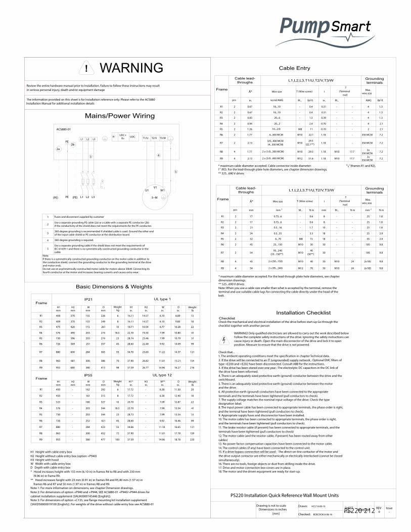
PS220 Configuration & Operation Guide
PS220 212
Check the mechanical and electrical installation of the drive before start-up Go through thechecklist together with another person
WARNING! Only quali�ed electricians are allowed to carry out the work described below Follow the complete safety instructions of the drive. Ignoring the safety instructions can cause injury or death. Open the main disconnector of the drive and lock it to open position. Measure to ensure that the drive is not powered.
Check that...1. The ambient operating conditions meet the speci�cation in chapter Technical data.2. If the drive will be connected to an IT (ungrounded) supply network : Optional EMC �lters of type +E200 and +E202 have been disconnected. Consult ABB for the instructions.3. If the drive has been stored over one year : The electrolytic DC capacitors in the DC link of the drive have been reformed.4. There is an adequately sized protective earth (ground) conductor between the drive and the switchboard.5. There is an adequately sized protective earth (ground) conductor between the motorand the drive.6. All protective earth (ground) conductors have been connected to the appropriateterminals and the terminals have been tightened (pull conductors to check).7. The supply voltage matches the nominal input voltage of the drive. Check the type designation label.8. The input power cable has been connected to appropriate terminals, the phase order is right, and the terminal have been tightened (pull conductors to check).9. Appropriate supply fuses and disconnector have been installed.10. The motor cable has been connected to appropriate terminals, the phase order is right, and the terminals have been tightened (pull conductors to check).11. The brake resistor cable (if present) has been connected to appropriate terminals, and the terminals have been tightened (pull conductors to check)12. The motor cable (and the resistor cable, if present) has been routed away from other cables)13. No power factor compensation capacitors have been connected to the motor cable.14. The control cables (if any) have been connected to the control unit.15. If a drive bypass connection will be used : The direct-on-line contactor of the motor and the drive output contactor are either mechanically or electrically interlocked (cannot be closed simultaneously).16. There are no tools, foreign objects or dust from drilling inside the drive.17. Drive and motor connection box covers are in place.18. The motor and the driven equipment are ready for start-up.
Frame
Cable lead-throughs L1,L2,L3,T1/U,T2/V,T3/W Grounding
terminals
The information provided on this sheet is for Installation reference only. Please refer to the ACS880 Installation Manual for additional installation details
Ă* Wire size T (Wire screw) IT
(Terminalnut)
Max.wire size
pcs in. kcmil/AWG M... lbf-ft in. M... AWG lbf-ft
R1 2 0.67 18...10 - 0.4 0.31 - - 4 1.3
R2 2 0.67 18...10 - 0.4 0.31 - - 4 1.3
R3 2 0.83 20...6 - 1.3 0.39 - - 4 1.3
R4 2 0.94 20...2 - 2.4 0.70 - - 4 2.1
R5 2 1.26 10...2/0 M8 11 0.70 - - 2 2.1
R6 2 1.77 4...300 MCM M10 22.1 1.18 - - 350 MCM 7.2
R7 2 2.133/0...400 MCM(4...300 MCM)
M1029.5
(22.1**) 1.18 - - 350 MCM 7.2
R8 4 1.77 2 x (1/0...300 MCM) M10 29.5 1.18 M10 17.7 2x350 MCM 7.2
R9 4 2.13 2 x (3/0...400 MCM) M12 51.6 1.18 M10 17.7 2x350 MCM 7.2
FrameIP21 UL type 1
H1mm
H2mm
Wmm
Dmm
Weightkg
H1in.
H2in.
Win.
Din.
Weightlb
R1 409 370 155 226 6 16.11 14.57 6.10 8.89 13
R2 409 370 155 249 8 16.11 14.57 6.10 9.80 18
R3 475 420 172 261 10 18.71 16.54 6.77 10.28 22
R4 576 490 203 274 18.5 22.70 19.30 7.99 10.80 41
R5 730 596 203 274 23 28.74 23.46 7.99 10.79 51
R6 726 569 251 357 45 28.60 22.40 9.92 14.09 99
R7 880 600 284 365 55 34.70 23.60 11.22 14.37 121
R8 963 681 300 386 70 37.90 26.82 11.81 15.21 154
R9 955 680 380 413 98 37.59 26.77 14.96 16.27 216
FrameIP55 UL type 12
H1mm
H2mm
Wmm
Dmm
Weightkg
H1*in.
H3in.
W**in.
Din.
Weightlb
R1 450 - 162 292 6 17.72 - 6.38 11.50 20
R2 450 - 161 315 8 17.72 - 6.38 12.40 18
R3 525 - 180 327 10 20.70 - 7.09 12.87 22
R4 576 - 203 344 18.5 22.70 - 7.99 13.54 41
R5 730 - 203 344 23 28.73 - 7.99 13.54 51
R6 726 - 252 421 45 28.60 - 9.92 16.46 99
R7 880 - 284 423 55 34.66 - 11.18 16.65 121
R8 963 - 300 452 72 37.90 - 11.81 17.78 159
R9 - 380 100 37.59 - 14.96 18.78 220
H1 Height with cable entry boxH2 Height without cable entry box (option +P940)H3 Height with hoodW Width with cable entry boxD Depth with cable entry box* Hood increases height with 155 mm (6.10 in) in frames R4 to R8 and with 230 mm (9.06 in) in frame R9.** Hood increases height with 23 mm (0.91 in) in frames R4 and R5,40 mm (1.57 in) in frames R6 and R7 and 50 mm (1.97 in) in frames R8 and R9.Note 1: For more information on dimensions, see chapter Dimension drawings.Note 2: For dimensions of option +P940 and +P944, SEE ACS880-01 +P940/+P944 drives for cabinet installation supplement (3AUA0000145446 [English]).Note 3: For dimensions of option +C135, see �ange mounting kit installation supplement (3AXD50000019100 [English]). For weights of the drive without cable entry box see ACS880-01
Cable Entry
Basic Dimensions & Weights
Review the entire hardware manual prior to Installation. Failure to follow these instructions may result in serious personal injury, death and/or equipment damage
L1 L2 L3R- UDC+
R+ UDC- T1/U T2/V T3/W
2a
PE2b
PE(PE) (PE) L1 L3L2
3 4
5
U1 W1V1
ACS880-01
3~M
1 Fuses and disconnect supplied by customer
2
3
Use a separate grounding PE cable (2a) or a cable with a separate PE conductor (2b) if the conductivity of the shield does not meet the requirements for the PE conductor.
360-degree grounding is recommended if shielded cable is used. Ground the other end of the input cable shield or PE conductor at the distribution board.
4 360-degree grounding is required.
5Use a separate grounding cable if the shield does not meet the requirements of IEC 61439-1 and there is no symmetrically constructed grounding conductor in the cable
Note:If there is a symmetrically constructed grounding conductor on the motor cable in addition to the conductive shield, connect the grounding conductor to the grounding terminal at the drive and motor ends.Do not use an asymmetrically constructed motor cable for motors above 30kW. Connecting its fourth conductor at the motor end increases bearing currents and causes extra wear.
min 200 mm (8 in.) 90°
Motor cable
min 500 mm (20 in.)
Input power cable
Control cables
Power cable
Motor cable
min 300 mm (12 in.)
* maximum cable diameter accepted. Cable connector inside diameter: 34 "(frames R1 and R2),
1" (R3). For the lead-through plate hole diameters, see chapter dimension drawings.** 525...690 V drives
Frame
Cable lead-throughs L1,L2,L3,T1/U,T2/V,T3/W Grounding
terminals
Ă* Wire size T (Wire screw) IT
(Terminalnut)
Max.wire size
pcs mm mm 2 M... N. m mm M... N. m mm 2 N. m
R1 2 17 0.75...6 - 0.6 8 - - 25 1.8
R2 2 17 0.75...6 - 0.6 8 - - 25 1.8
R3 2 21 0.5...16 - 1.7 10 - - 25 1.8
R4 2 24 0.5...35 - 3.3 18 - - 25 2.9
R5 2 32 6...70 M8 15 18 - - 35 2.9
R6 2 45 25...150 M10 30 30 - - 185 9.8
R7 2 5495...240
(25...150**) M1040
(30**) 30 - - 185 9.8
R8 4 45 2 x (50...150) M10 40 30 M10 24 2x185 9.8
R9 4 54 2 x (95...240) M12 70 30 M10 24 2x185 9.8
* maximum cable diameter accepted. For the lead-through plate hole diameters, see chapter dimension drawings.** 525...690 V drivesNote: When you use a cable size smaller than what is accepted by the terminal, remove the terminal and use suitable cable lugs for connecting the cable directly under the head of the bolt.
300 mm (11.81 in.)
200 mm (7.87 in.)
Drive
PS220 Installation Quick Reference Wall Mount Units
Drawing is not to scaleDimensions in inches
[mm]
Drawn: HCLT 8-08-16SHEET
1 OF 1 B04933A REV0
Issue-
Checked: BDECOOK 8-08-16
A
B
Free Space Required for Vantilation 7.9"[200]TYP
2.0"[51]TYP
12"[305]
Refer to Hardware Manual Technical
Data for application guidelines outside of
the above listed limits
IP21~NEMA1IP55~NEMA 12
5-95% RELATIVE HUMIDITY
NO CONDENSATIONNO CORROSIVE GASES
104 ĀF (40 ĀC)MAX IN
NO DIRECT SUNLIGHT
3300 ft (1000M)
5 ĀF (-15 ĀC)MIN
! WARNING
Cooling Air FlowSide View
Control/Power Wiring Layout
Mains/Power Wiring
955 477
Installation ChecklistChecklist
P Rservices
Pump Smart R
I

PS220 Configuration & Operation Guide
213 PS220
PS220 INSTALLATION QUICK REFERENCE - FLOOR MOUNT UNITS ACS880-07 IP22 / 42 and IP54
Framesize
Number of holesin the lead-through plate forthe power cables.Hole diameter 60 mm.
Terminals L1,L2,L3,U2,V2,W2,UDC+/R+,
UDC- and R-Grounding Terminals
Max. phaseconductor
size
mm 2
Bolt sizeTightening
torque Bolt sizeTightening
torque
R6 6 185M10 20...40 N. m
M10 30...44 N. m
R7 6 185
R8 6 1x240 or2x185
M12 50...75 N. mR9 9 3x240
R10 12 3x240 or4x185
R11 12 3x240 or4x185
Drive type Framesize
IEC 1) US 2)
Cu cable type AI cable type Cu cable type
mm 2 mm 2 AWG/kcmil per phase
U N = 400V
ACS880-07-0105A-3 R6 3x50 3x70 1
ACS880-07-0145A-3 R6 3x95 3x120 2/0
ACS880-07-0169A-3 R7 3x120 3x150 3/0
ACS880-07-0206A-3 R7 3x150 3x240 250 MCM
ACS880-07-0246A-3 R8 2 x (3x70) 2 x (3x95) 300 MCM
ACS880-07-0293A-3 R8 2 x (3x95) 2 x (3x120) 2 x 3/0
ACS880-07-0363A-3 R9 2 x (3x120) 2 x (3x185) 2 x 4/0
ACS880-07-0430A-3 R9 2 x (3x150) 2 x (3x240) 2 x 250 MCM
ACS880-07-0505A-3 R10 3 x (3x95) 3 x (3x150) 2x500 MCM or 3x250 MCM
ACS880-07-0585A-3 R10 3 x (3x120) 3 x (3x185) 2x600 MCM or 3x300 MCM
ACS880-07-0650A-3 R10 3 x (3x150) 3 x (3x240) 2x700 MCM or 3x350 MCM
ACS880-07-0725A-3 R11 3 x (3x185) 4 x (3x185) 3x500 MCM or 4x300 MCM
ACS880-07-0820A-3 R11 3 x (3x240) 4 x (3x240) 3x600 MCM or 4x400 MCM
ACS880-07-0880A-3 R11 3 x (3x240) 4 x (3x240) 3x600 MCM or 4x400 MCM
U N = 500V
ACS880-07-0096A-5 R6 3x50 3x70 1
ACS880-07-0124A-5 R6 3x95 3x95 2/0
ACS880-07-0156A-5 R7 3x120 3x150 3/0
ACS880-07-0180A-5 R7 3x150 3x185 250 MCM
ACS880-07-0240A-5 R8 2 x (3x70) 2 x (3x95) 300 MCM
ACS880-07-0260A-5 R8 2 x (3x70) 2 x (3x95) 2 x 2/0
ACS880-07-0302A-5 R9 2 x (3x120) 2 x (3x185) 2 x 250 MCM
ACS880-07-0361A-5 R9 2 x (3x120) 2 x (3x185) 2 x 250 MCM
ACS880-07-0414A-5 R9 2 x (3x150) 2 x (3x240) 2 x 250 MCM
ACS880-07-0460A-5 R10 3 x (3x95) 3 x (3x150) 2x400 MCM or 3x4/0
ACS880-07-0503A-5 R10 3 x (3x95) 3 x (3x150) 2x500 MCM or 3x250 MCM
ACS880-07-0583A-5 R10 3 x (3x120) 3 x (3x185) 2x600 MCM or 3x300 MCM
ACS880-07-0635A-5 R10 3 x (3x150) 3 x (3x240) 2x700 MCM or 3x350 MCM
ACS880-07-0715A-5 R11 4 x (3x185) 4 x (3x185) 3x500 MCM or 4x300 MCM
ACS880-07-0820A-5 R11 4 x (3x240) 4 x (3x240) 3x600 MCM or 4x400 MCM
U N = 690V
ACS880-07-0061A-7 R6 3x25 3x35 4
ACS880-07-0084A-7 R6 3x35 3x50 3
ACS880-07-0098A-7 R7 3x50 3x70 2
ACS880-07-0119A-7 R7 3x70 3x95 1/0
ACS880-07-0142A-7 R8 3x95 3) 3x120 2/0
ACS880-07-0174A-7 R8 3x120 3) 2 x (3x70) 4/0
ACS880-07-0210A-7 R9 3x185 2 x (3x95) 300 MCM
ACS880-07-0271A-7 R9 3x240 2 x (3x120) 400 MCM
ACS880-07-0330A-7 R10 2 x (3x120) 3 x (3x120) 2x250 MCM or 3x2/0
ACS880-07-0370A-7 R10 2 x (3x120) 3 x (3x120) 2x300 MCM or 3x3/0
ACS880-07-0425A-7 R11 3 x (3x95) 3 x (3x120) 2x350 MCM or 3x4/0
ACS880-07-0470A-7 R11 3 x (3x95) 3 x (3x150) 2x400 MCM or 3x4/0
ACS880-07-0522A-7 R11 3 x (3x120) 3 x (3x185) 2x500 MCM or 3x250 MCM
ACS880-07-0590A-7 R11 3 x (3x150) 3 x (3x185) 2x600 MCM or 3x300 MCM
ACS880-07-0650A-7 R11 3 x (3x150) 3 x (3x240) 2x700 MCM or 3x350 MCM
1. The cable sizing is based on max. 9 cables laid on a cable ladder side by side, three ladder type trays one on top of the other, ambient temperature 30ĀC, PVC insulation, surface temperature 70ĀC (EN 60204-1 and IEC 60364-5-52/2001). For other conditions, size the cables according to local saftey regulations, appropriate input voltage and the load current of the drive.2. The cable sizing is based on NEC Table 310-16 for copper wires, 75ĀC (167ĀF) wire insulation ar 40ĀC (104ĀF) ambient temperature. Not more than three current-carryoing conductors in raceway or cable or earth (directly buried). For other conditions, size the cable according to local saftey regulations, appropriate input voltage and the load current of the drive.
Installation checklistCheck that...1. The ambient operating conditions meet the speci�cation in chapter Technical data.2. The drive cabinet has been �xed to �oor, and if necessary due to vibration etc, also from top to the wall or roof.3. The cooling air will �ow freely in and out of the drive cabinet.4. If the drive will be connected to an IT (ungrounded) or a corner grounded TN network: The optional EMC �lter (+E200, +E202) of the drive (if any) has been disconnected. 5. If the drive has been stored over one year: The electrolytic DC capacitors in the DC link of the drive have been reformed. See Converter module capacitor reforming instructions (3BFE64059629 [English])6. There is an adequately sized protective earth (ground) conductor between the drive and the switchboard and the conductor has been connected to appropriate terminal. Proper grounding has been measured according to the regulations.7. There is an adequately sized protective earth (ground) conductor between the motorand the drive and the conductor has been connected to appropriate terminal. Proper grounding has been measured according to the regulations.8. Only for drives with option +D150: There is an adequately sized protective earth (ground) conductor between the user-installed brake resistor and the drive and the conductor has been connected to appropriate terminal. Proper grounding has been measured according to the regulations.9. The supply voltage matches the nominal input voltage of the drive. Check the type designation label.10. The voltage setting of the auxiliary voltage transformer (T21) is correct.11. The input power cable has been connected to appropriate terminals, the phase order is right, and the terminal have been tightened (pull conductors to check).12. The motor cable has been connected to appropriate terminals, the phase order is right, and the terminals have been tightened (pull conductors to check).13. The motor cable (and the resistor cable, if present) has been routed away from other cables)14. No power factor compensation capacitors have been connected to the motor cable.15. If a drive bypass connection will be used : The direct-on-line contactor of the motor and the drive output contactor are either mechanically or electrically interlocked (cannot be closed simultaneously).16. The external brake resistor (if present) has been connected to the appropriate terminals, and the terminals have been tightened (pull the conductors to check.)17. The brake resistor cable has been routed away from other cables.18. The control cables have been connected to the appropriate terminals, and the terminals have been tightened (pull the conductors to check.)19. There are no tools, foreign objects or dust from drilling inside the drive.20. All shrouds and cover of the motor connection box are in place. Cabinet doors have been closed.21. The motor and the driven equipment are ready for start.
IEC
Typical power cable sizesReview the entire hardware manual prior to Installation. Failure to follow these instructions may result in serious personal injury, death and/or equipment damage
The information provided on this sheet is for Installation reference only. Please refer to the ACS880 Installation Manual for additional installation details
min 200 mm (8 in.) 90Ā
Motor cable
min 500 mm (20 in.)
Input power cable
Control cables
Power cable
Motor cable
min 300 mm (12 in.)Drive
PS220 Installation Quick Reference Floor Mount Units
Drawing is not to scaleDimensions in inches
[mm]
Drawn: HCLT 5-11-16SHEET
1 OF 1 B04934A REV0
Issue-
Checked: Brad 5-24-16
Refer to Hardware Manual Technical
Data for application guidelines outside of
the above listed limits
IP21~NEMA1IP55~NEMA 12
5-95% RELATIVE HUMIDITY
NO CONDENSATIONNO CORROSIVE GASES
104 ĀF (40 ĀC)MAX IN
NO DIRECT SUNLIGHT
3300 ft (1000M)
5 ĀF (-15 ĀC)MIN
! WARNING
Control/Power Wiring Layout
Front Side Above*
mm in. mm in. mm in.
150 5.91 - - 400 15.75
*measured from the base plate of the cabinet top. Note: 320 mm (12.28 in.) is required for fan replacement of IP54 cabinets.
>_400 mm(15.75 in.)
320 mm (12.28 in.)
Door opening:IP22/42 IP54
R6...R8: 400 mm (15.75 in.)R9...R11: 800 mm (31.50 in.)
Frame size
Height 1)
Width 2) Depth 3) WeightIP22/42 IP54
mm in. mm in. mm in. mm in. kg lb
R6 2145 84.45 2315 91.14 430 16.93 673 26.50 240 530
R7 2145 84.45 2315 91.14 430 16.93 673 26.50 250 560
R8 2145 84.45 2315 91.14 430 16.93 673 26.50 265 590
R9 2145 84.45 2315 91.14 830 32.68 698 27.48 375 830
R10 2145 84.45 2315 91.14 830 32.68 698 27.48 530 1170
R11 2145 84.45 2315 91.14 830 32.68 698 27.48 580 1280
1) For marine contruction (option +C121) extra height is 10 mm (0.39 in.)due to the fastening bars at the bottom of the cabinet.2) Extra width with brake resistors (option +D151): SAFURxxxFxxx 400 mm (15.75 in.). 2xSAFURxxxFxxx 800 mm (19.68 in.). Extra width for frames R6 to R8 with EMC �lter (option +E202): 200 mm (7.87 in.). Total width of R6 to R9 frame sizes with molded case circuit breaker (option +F289) is 830 mm (32.68 in.)3) For drives with marine fastening bars (option +C121): Depth is 757 mm.
L1/U1
L2/V1
L3/W1
T1/U2
T2/V2
T3/W2
~
~
5
6
U2 V2 W2
U1 W1V1
3~M
UDC-R-
UDC+R+
R- UDC+R+ UDC-
3
L1 L2 L3
4
10
1a
PE
PE(PE) (PE) L1 L2 L3
2
1b
1) Use a separate grounding PE cable (1a) or a cable with a seperate PE conductor (1b) if the conductivity of the shield does not meet the requirements for the PE conductor.2) 360-degree grounding is recommended if shielded cable is used. Ground the other end of the input cable shield or PE conductor at the distribution board.3) 360-degree grounding is required.4) Line contactor (option +F250)5) Common mode �lter (option +E208)6) du/dt �lter or sine �lter (options +E205 and +E206)7) Use a separate grounding cable if the shield does not meet the requirements of IEC 61439-1 and there is no symmetically constructed grounding conductor in the cable.8) Terminals of frame R9 cabinet:
9) Drive module10) Fast acting fuses are required to protect drive. Fuse operating times should be less than 0.1 sec. UL-Standard T/L type fuses IEC-Standard gG or aR type fuses Refer to Technical Data Section for details
R- UDC+R+ UDC-
Mains/Power Wiring
**Disconnect / fusing provided by ITT on extended enclosure ACS880-07
Standard Cable EntryIP22/42 & IP54ACS880-07 are all bottom Entry/exit
Input and Motor Cable terminal sizes (per phase) and tightening torques are given below. The maximum allowed width of the cable lug is 1.5 inches.
*M10 is the extended enclosure: 30...44 Nm tightening torqueThe maximum width of cable lug is 38 mm.
Framesize
Terminals L1,L2,L3,U2,V2,W2,UDC+/R+,UDC- and R- Grounding Terminals
Max. phaseconductor
size
AWG/kcmil
Busbar bolt size - Hole spacing
Tighteningtorque
bf-ft
Bolt size
Tighteningtorque
bf-ft
R6350 MCM M10 ( 3
8") x 2-1.75"
15...30
M10 ( 38") 22...32
R7
R8 1x500 MCM or2x350 MCM M12 ( 7
16") x 2-1.75"
37...55R9 2x500 MCM
R10 1x500 MCM or4x350 MCM M12 ( 7
16") x 4-1.75"
R11 1x500 MCM or4x350 MCM
US
NEMA1/NEMA12

PS220 Configuration & Operation Guide
PS220 214
Framesize
Number of holesin the lead-through plate forthe power cables.Hole diameter 60 mm.
Terminals L1,L2,L3,U2,V2,W2,UDC+/R+,
UDC- and R-Grounding Terminals
Max. phaseconductor
size
mm 2
Bolt sizeTightening
torque Bolt sizeTightening
torque
R6 6 185M10 20...40 N. m
M10 30...44 N. m
R7 6 185
R8 6 1x240 or2x185
M12 50...75 N. mR9 9 3x240
R10 12 3x240 or4x185
R11 12 3x240 or4x185
Drive type Framesize
IEC 1) US 2)
Cu cable type AI cable type Cu cable type
mm 2 mm 2 AWG/kcmil per phase
U N = 400V
ACS880-07-0105A-3 R6 3x50 3x70 1
ACS880-07-0145A-3 R6 3x95 3x120 2/0
ACS880-07-0169A-3 R7 3x120 3x150 3/0
ACS880-07-0206A-3 R7 3x150 3x240 250 MCM
ACS880-07-0246A-3 R8 2 x (3x70) 2 x (3x95) 300 MCM
ACS880-07-0293A-3 R8 2 x (3x95) 2 x (3x120) 2 x 3/0
ACS880-07-0363A-3 R9 2 x (3x120) 2 x (3x185) 2 x 4/0
ACS880-07-0430A-3 R9 2 x (3x150) 2 x (3x240) 2 x 250 MCM
ACS880-07-0505A-3 R10 3 x (3x95) 3 x (3x150) 2x500 MCM or 3x250 MCM
ACS880-07-0585A-3 R10 3 x (3x120) 3 x (3x185) 2x600 MCM or 3x300 MCM
ACS880-07-0650A-3 R10 3 x (3x150) 3 x (3x240) 2x700 MCM or 3x350 MCM
ACS880-07-0725A-3 R11 3 x (3x185) 4 x (3x185) 3x500 MCM or 4x300 MCM
ACS880-07-0820A-3 R11 3 x (3x240) 4 x (3x240) 3x600 MCM or 4x400 MCM
ACS880-07-0880A-3 R11 3 x (3x240) 4 x (3x240) 3x600 MCM or 4x400 MCM
U N = 500V
ACS880-07-0096A-5 R6 3x50 3x70 1
ACS880-07-0124A-5 R6 3x95 3x95 2/0
ACS880-07-0156A-5 R7 3x120 3x150 3/0
ACS880-07-0180A-5 R7 3x150 3x185 250 MCM
ACS880-07-0240A-5 R8 2 x (3x70) 2 x (3x95) 300 MCM
ACS880-07-0260A-5 R8 2 x (3x70) 2 x (3x95) 2 x 2/0
ACS880-07-0302A-5 R9 2 x (3x120) 2 x (3x185) 2 x 250 MCM
ACS880-07-0361A-5 R9 2 x (3x120) 2 x (3x185) 2 x 250 MCM
ACS880-07-0414A-5 R9 2 x (3x150) 2 x (3x240) 2 x 250 MCM
ACS880-07-0460A-5 R10 3 x (3x95) 3 x (3x150) 2x400 MCM or 3x4/0
ACS880-07-0503A-5 R10 3 x (3x95) 3 x (3x150) 2x500 MCM or 3x250 MCM
ACS880-07-0583A-5 R10 3 x (3x120) 3 x (3x185) 2x600 MCM or 3x300 MCM
ACS880-07-0635A-5 R10 3 x (3x150) 3 x (3x240) 2x700 MCM or 3x350 MCM
ACS880-07-0715A-5 R11 4 x (3x185) 4 x (3x185) 3x500 MCM or 4x300 MCM
ACS880-07-0820A-5 R11 4 x (3x240) 4 x (3x240) 3x600 MCM or 4x400 MCM
U N = 690V
ACS880-07-0061A-7 R6 3x25 3x35 4
ACS880-07-0084A-7 R6 3x35 3x50 3
ACS880-07-0098A-7 R7 3x50 3x70 2
ACS880-07-0119A-7 R7 3x70 3x95 1/0
ACS880-07-0142A-7 R8 3x95 3) 3x120 2/0
ACS880-07-0174A-7 R8 3x120 3) 2 x (3x70) 4/0
ACS880-07-0210A-7 R9 3x185 2 x (3x95) 300 MCM
ACS880-07-0271A-7 R9 3x240 2 x (3x120) 400 MCM
ACS880-07-0330A-7 R10 2 x (3x120) 3 x (3x120) 2x250 MCM or 3x2/0
ACS880-07-0370A-7 R10 2 x (3x120) 3 x (3x120) 2x300 MCM or 3x3/0
ACS880-07-0425A-7 R11 3 x (3x95) 3 x (3x120) 2x350 MCM or 3x4/0
ACS880-07-0470A-7 R11 3 x (3x95) 3 x (3x150) 2x400 MCM or 3x4/0
ACS880-07-0522A-7 R11 3 x (3x120) 3 x (3x185) 2x500 MCM or 3x250 MCM
ACS880-07-0590A-7 R11 3 x (3x150) 3 x (3x185) 2x600 MCM or 3x300 MCM
ACS880-07-0650A-7 R11 3 x (3x150) 3 x (3x240) 2x700 MCM or 3x350 MCM
1. The cable sizing is based on max. 9 cables laid on a cable ladder side by side, three ladder type trays one on top of the other, ambient temperature 30ĀC, PVC insulation, surface temperature 70ĀC (EN 60204-1 and IEC 60364-5-52/2001). For other conditions, size the cables according to local saftey regulations, appropriate input voltage and the load current of the drive.2. The cable sizing is based on NEC Table 310-16 for copper wires, 75ĀC (167ĀF) wire insulation ar 40ĀC (104ĀF) ambient temperature. Not more than three current-carryoing conductors in raceway or cable or earth (directly buried). For other conditions, size the cable according to local saftey regulations, appropriate input voltage and the load current of the drive.
Installation checklistCheck that...1. The ambient operating conditions meet the speci�cation in chapter Technical data.2. The drive cabinet has been �xed to �oor, and if necessary due to vibration etc, also from top to the wall or roof.3. The cooling air will �ow freely in and out of the drive cabinet.4. If the drive will be connected to an IT (ungrounded) or a corner grounded TN network: The optional EMC �lter (+E200, +E202) of the drive (if any) has been disconnected. 5. If the drive has been stored over one year: The electrolytic DC capacitors in the DC link of the drive have been reformed. See Converter module capacitor reforming instructions (3BFE64059629 [English])6. There is an adequately sized protective earth (ground) conductor between the drive and the switchboard and the conductor has been connected to appropriate terminal. Proper grounding has been measured according to the regulations.7. There is an adequately sized protective earth (ground) conductor between the motorand the drive and the conductor has been connected to appropriate terminal. Proper grounding has been measured according to the regulations.8. Only for drives with option +D150: There is an adequately sized protective earth (ground) conductor between the user-installed brake resistor and the drive and the conductor has been connected to appropriate terminal. Proper grounding has been measured according to the regulations.9. The supply voltage matches the nominal input voltage of the drive. Check the type designation label.10. The voltage setting of the auxiliary voltage transformer (T21) is correct.11. The input power cable has been connected to appropriate terminals, the phase order is right, and the terminal have been tightened (pull conductors to check).12. The motor cable has been connected to appropriate terminals, the phase order is right, and the terminals have been tightened (pull conductors to check).13. The motor cable (and the resistor cable, if present) has been routed away from other cables)14. No power factor compensation capacitors have been connected to the motor cable.15. If a drive bypass connection will be used : The direct-on-line contactor of the motor and the drive output contactor are either mechanically or electrically interlocked (cannot be closed simultaneously).16. The external brake resistor (if present) has been connected to the appropriate terminals, and the terminals have been tightened (pull the conductors to check.)17. The brake resistor cable has been routed away from other cables.18. The control cables have been connected to the appropriate terminals, and the terminals have been tightened (pull the conductors to check.)19. There are no tools, foreign objects or dust from drilling inside the drive.20. All shrouds and cover of the motor connection box are in place. Cabinet doors have been closed.21. The motor and the driven equipment are ready for start.
IEC
Typical power cable sizesReview the entire hardware manual prior to Installation. Failure to follow these instructions may result in serious personal injury, death and/or equipment damage
The information provided on this sheet is for Installation reference only. Please refer to the ACS880 Installation Manual for additional installation details
min 200 mm (8 in.) 90Ā
Motor cable
min 500 mm (20 in.)
Input power cable
Control cables
Power cable
Motor cable
min 300 mm (12 in.)Drive
PS220 Installation Quick Reference Floor Mount Units
Drawing is not to scaleDimensions in inches
[mm]
Drawn: HCLT 5-11-16SHEET
1 OF 1 B04934A REV0
Issue-
Checked: Brad 5-24-16
Refer to Hardware Manual Technical
Data for application guidelines outside of
the above listed limits
IP21~NEMA1IP55~NEMA 12
5-95% RELATIVE HUMIDITY
NO CONDENSATIONNO CORROSIVE GASES
104 ĀF (40 ĀC)MAX IN
NO DIRECT SUNLIGHT
3300 ft (1000M)
5 ĀF (-15 ĀC)MIN
! WARNING
Control/Power Wiring Layout
Front Side Above*
mm in. mm in. mm in.
150 5.91 - - 400 15.75
*measured from the base plate of the cabinet top. Note: 320 mm (12.28 in.) is required for fan replacement of IP54 cabinets.
>_400 mm(15.75 in.)
320 mm (12.28 in.)
Door opening:IP22/42 IP54
R6...R8: 400 mm (15.75 in.)R9...R11: 800 mm (31.50 in.)
Frame size
Height 1)
Width 2) Depth 3) WeightIP22/42 IP54
mm in. mm in. mm in. mm in. kg lb
R6 2145 84.45 2315 91.14 430 16.93 673 26.50 240 530
R7 2145 84.45 2315 91.14 430 16.93 673 26.50 250 560
R8 2145 84.45 2315 91.14 430 16.93 673 26.50 265 590
R9 2145 84.45 2315 91.14 830 32.68 698 27.48 375 830
R10 2145 84.45 2315 91.14 830 32.68 698 27.48 530 1170
R11 2145 84.45 2315 91.14 830 32.68 698 27.48 580 1280
1) For marine contruction (option +C121) extra height is 10 mm (0.39 in.)due to the fastening bars at the bottom of the cabinet.2) Extra width with brake resistors (option +D151): SAFURxxxFxxx 400 mm (15.75 in.). 2xSAFURxxxFxxx 800 mm (19.68 in.). Extra width for frames R6 to R8 with EMC �lter (option +E202): 200 mm (7.87 in.). Total width of R6 to R9 frame sizes with molded case circuit breaker (option +F289) is 830 mm (32.68 in.)3) For drives with marine fastening bars (option +C121): Depth is 757 mm.
L1/U1
L2/V1
L3/W1
T1/U2
T2/V2
T3/W2
~
~
5
6
U2 V2 W2
U1 W1V1
3~M
UDC-R-
UDC+R+
R- UDC+R+ UDC-
3
L1 L2 L3
4
10
1a
PE
PE(PE) (PE) L1 L2 L3
2
1b
1) Use a separate grounding PE cable (1a) or a cable with a seperate PE conductor (1b) if the conductivity of the shield does not meet the requirements for the PE conductor.2) 360-degree grounding is recommended if shielded cable is used. Ground the other end of the input cable shield or PE conductor at the distribution board.3) 360-degree grounding is required.4) Line contactor (option +F250)5) Common mode �lter (option +E208)6) du/dt �lter or sine �lter (options +E205 and +E206)7) Use a separate grounding cable if the shield does not meet the requirements of IEC 61439-1 and there is no symmetically constructed grounding conductor in the cable.8) Terminals of frame R9 cabinet:
9) Drive module10) Fast acting fuses are required to protect drive. Fuse operating times should be less than 0.1 sec. UL-Standard T/L type fuses IEC-Standard gG or aR type fuses Refer to Technical Data Section for details
R- UDC+R+ UDC-
Mains/Power Wiring
**Disconnect / fusing provided by ITT on extended enclosure ACS880-07
Standard Cable EntryIP22/42 & IP54ACS880-07 are all bottom Entry/exit
Input and Motor Cable terminal sizes (per phase) and tightening torques are given below. The maximum allowed width of the cable lug is 1.5 inches.
*M10 is the extended enclosure: 30...44 Nm tightening torqueThe maximum width of cable lug is 38 mm.
Framesize
Terminals L1,L2,L3,U2,V2,W2,UDC+/R+,UDC- and R- Grounding Terminals
Max. phaseconductor
size
AWG/kcmil
Busbar bolt size - Hole spacing
Tighteningtorque
bf-ft
Bolt size
Tighteningtorque
bf-ft
R6350 MCM M10 ( 3
8") x 2-1.75"
15...30
M10 ( 38") 22...32
R7
R8 1x500 MCM or2x350 MCM M12 ( 7
16") x 2-1.75"
37...55R9 2x500 MCM
R10 1x500 MCM or4x350 MCM M12 ( 7
16") x 4-1.75"
R11 1x500 MCM or4x350 MCM
US
NEMA1/NEMA12

Visit our website for the latest version of this document and more information:http://www.ittproservices.com
ITT Goulds Pumps Inc. 240 Fall Street Seneca Falls, NY 13148 USA
©2019 ITT Corporation The original instruction is in English. All non-English instructions are translations of the original instruction.
Form IOM.PS220.en-US.2019-09