Conference Paper - International Nuclear Information System ...
26
Conference Paper Atomic Energy of Canada Limited 2251 Speakman Drive Mississauga, Ontario Canada L5K 1B2 Énergie Atomique du Canada Limitée 2251 rue Speakman Mississauga (Ontario) Canada L5K 1B2 Hyland Bronwyn - Reactor Physicist Prepared by Rédigé par Edwards Geoffrey W R - Reactor Physicist Reviewed by Vérifié par Radford Darren D. - Manager, Computational Reactor Physics Approved by Approuvé par SCENARIOS FOR THE TRANSMUTATION OF ACTINIDES IN CANDU REACTORS COMPANY WIDE CW-123700-CONF-010 Revision 1 2010/10/14 UNRESTRICTED 2010/10/14 ILLIMITÉ
-
Upload
khangminh22 -
Category
Documents
-
view
3 -
download
0
Transcript of Conference Paper - International Nuclear Information System ...
Conference Paper
Atomic Energy ofCanada Limited
2251 Speakman DriveMississauga, OntarioCanada L5K 1B2
Énergie Atomique duCanada Limitée
2251 rue SpeakmanMississauga (Ontario)Canada L5K 1B2
Hyland Bronwyn - ReactorPhysicist
Prepared byRédigé par
Edwards Geoffrey W R - ReactorPhysicist
Reviewed byVérifié par
Radford Darren D. - Manager,Computational Reactor Physics
Approved byApprouvé par
SCENARIOS FOR THETRANSMUTATION OFACTINIDES IN CANDUREACTORS
COMPANY WIDE
CW-123700-CONF-010
Revision 1
2010/10/14UNRESTRICTED
2010/10/14ILLIMITÉ
1
SCENARIOS FOR THE TRANSMUTATION OF ACTINIDES IN CANDU REACTORS
Bronwyn Hyland1 Brian Gihm
Atomic Energy of Canada Limited Atomic Energy of Canada Limited
Chalk River Laboratories 2251 Speakman Drive
Chalk River, Ontario, Canada, K0J 1J0 Mississauga, Ontario, Canada, L5K 1B2
Tel. 613-584-3311, Fax. 613-584-8198 Tel. 905-823-9040, Fax. 905-403-7376
E-mail: [email protected] E-mail: [email protected]
ABSTRACT
With world stockpiles of used nuclear fuel increasing, the need to address the long-term utilization of this resource
is being studied. Many of the transuranic (TRU) actinides in nuclear spent fuel produce decay heat for long
durations, resulting in significant nuclear waste management challenges. These actinides can be transmuted to
shorter-lived isotopes to reduce the decay heat period or consumed as fuel in a CANDU reactor.
Many of the design features of the CANDU reactor make it uniquely adaptable to actinide transmutation. The
small, simple fuel bundle simplifies the fabrication and handling of active fuels. Online refuelling allows precise management of core reactivity and separate insertion of the actinides and fuel bundles into the core. The high
neutron economy of the CANDU reactor results in high TRU destruction to fissile-loading ratio.
This paper provides a summary of actinide transmutation schemes that have been studied in CANDU reactors at
AECL, including the works performed in the past [1-4]. The schemes studied include homogeneous scenarios in
which actinides are uniformly distributed in all fuel bundles in the reactor, as well as heterogeneous scenarios in
which dedicated channels in the reactor are loaded with actinide targets and the rest of the reactor is loaded with
fuel.
The transmutation schemes that are presented reflect several different partitioning schemes. Separation of americium, often with curium, from the other actinides enables targeted destruction of americium, which is a main
contributor to the decay heat 100 to 1000 years after discharge from the reactor. Another scheme is
group-extracted transuranic elements, in which all of the transuranic elements, plutonium (Pu), neptunium (Np),
americium (Am), and curium (Cm) are extracted together and then transmuted. This paper also addresses ways of
utilizing the recycled uranium, another stream from the separation of spent nuclear fuel, in order to drive the
transmutation of other actinides.
Keywords: minor actinides, transmutation, nuclear waste management, CANDU, heavy water reactor, transuranic actinides, spent fuel, recycled uranium, plutonium reduction, americium, and curium.
1 Corresponding author
CANDU
is a registered trademark of Atomic Energy of Canada Limited (AECL).

2
1. INTRODUCTION
Nuclear energy has been an important source of electricity generation in many parts of the world in the past century
and its weighting in the total energy mix in the future is expected to maintain at least the current level, and
potentially increase dramatically [5]. A consequence of this trend is that the generation of used nuclear fuel will
maintain its current pace and could increase significantly in the future. The increasing stockpile of used nuclear fuel
introduces challenges in nuclear waste management.
Many of the transuranic (TRU) actinides in nuclear spent fuel are long-lived isotopes that produce decay heat long
after they are discharged from the reactor. The time scale involved in this process is much longer than a human
lifespan, leading to significant nuclear waste management challenges.
A CANDU reactor offers attractive solutions for effectively dealing with used nuclear fuel from a light water reactor
(LWR) fleet. Many of the design features of the CANDU reactor make it uniquely adaptable to actinide
transmutation as well as utilization of LWR used fuel with minimal reprocessing. The most significant feature is the
high neutron economy resulting from the heavy water moderator, which allows a high TRU destruction rate relative
to the fissile loading because more neutrons are available for transmutation rather than being parasitically absorbed
in the moderator. Another important feature of a CANDU reactor is that the refuelling is performed on-power and
separately for each fuel channel. This allows actinide targets to only occupy desired locations in the reactor and the residency time of the targets to be adjusted separately from regular fuel bundles. Online refuelling also allows
precise management of core reactivity, and further increases the neutron economy relative to batch refuelling.
Lastly, the small and simple fuel bundle simplifies the fabrication and handling of active fuels. CANDU fuel
bundles are short in length (49.52 cm) and light in weight (~21 kg), consisting of either 37 pins or 43 pins
(CANFLEX® fuel) that simplify the fabrication and handling of the bundles. These characteristics also enable a
CANDU fuel bundle to function as a target carrier with minimal or no design change to the bundle.
The actinide transmutation methods discussed in this paper are listed below:
5 to 60% (volume) Am/Cm loaded in the centre pin of fuel bundle,
14 to 25 wt% Am/Cm in an inert matrix placed in 30 periphery channels while the core is fuelled with recycled
uranium (RU) from reprocessed used LWR fuel at 0.9 wt% enrichment,
Americium mixed with low enriched uranium (LEU) loaded in the full core, and
Group extracted TRU transmutation.
It should be noted that all scenarios presented in this paper are at the research stage and much further development and engineering work would be required to bring these concepts into reality.
2. ACTINIDE TRANSMUTATION SCHEMES
One of the key strategies to deal with a long-lived actinide, for example Am-241, is to transmute it (see Figure 1).
The transmutation causes decay heat generation to occur in relatively shorter period after the used fuel is discharged
from the reactor so that monitoring duration of the waste is comparable to human lifespan. There are several
different ways of introducing Am/Cm into a CANDU reactor for transmutation. As shown in Figure 1, the
transmutation of Am-241 follows several pathways that affect the decay heat production of the spent fuel, and result in the production of isotopes of curium and plutonium. In the first step, a neutron captures onto Am-241, creating
Am-242 or Am-242m.
Several different pathways are available after the initial neutron capture. Am-242m has a high fission cross-section,
so by this path the Am can be transmuted by fission. In the second pathway the Am-242 beta decays into Cm-242.
The Cm-242 then alpha decays with a relatively short half-life (163 days), and some of the original americium will
end up as Pu-238. The Am-242m can also neutron capture to Am-243, and a second neutron capture creates
Am-244 or Am-244m. The Am-244 nuclides both have short half-lives and beta decay to Cm-244. Cm-244 has a
relatively short half-life, and alpha decays to Pu-240. Am-242m can also decay by electron capture to Pu-242. The
isotopes Cm-242, Cm-244 and Pu-238 all have an impact on the decay heat of the spent fuel.
CANFLEX
® is a registered trademark of AECL and the Korea Atomic Energy Research Institute (KAERI).

3
Am-242m, Cm-245, Pu-239, and Pu-241 are the fissile isotopes. The other isotopes act as a poison, capturing
neutrons and reducing the coolant void reactivity (CVR) of the bundle (if located in the central element). This
process breeds plutonium through the path shown in Figure 1.
With regard to curium production, for schemes with relatively short irradiation time (a few years) the curium that is created is the low-mass, short-lived curium isotopes, Cm-242 and Cm-244. These isotopes have short half-lives on
the same time scale as fission products, and once produced in the used fuel the curium could be stored and decayed
similar to fission products, rather than put into long-term storage or further transmuted.
The destruction of transuranic elements (Pu, Np, Am, Cm) is achieved through fission, resulting in fewer minor
actinides requiring long-term waste disposal. The calculations presented here were carried out using WIMS-AECL
[6] with a nuclear data library with Z up to 96.
2.1 Heterogeneous Method (Target Pin)
As part of an effort to investigate transmutation schemes that correspond to different reprocessing scenarios, an
investigation was made of scenarios in which americium and curium are not separated out from lanthanides
(elements with Z= 57 to 71) during reprocessing. This would greatly reduce the complexity of the partitioning
scheme and potentially significantly reduce the cost of reprocessing. The transmutation scheme involved this
mixture of Am/Cm/Ln being combined with an inert matrix; zirconia (ZrO2) was used in this study. This
Am/Cm/Ln in zirconia material was then placed in the centre pin of a CANFLEX fuel bundle and irradiated in a
CANDU 6 reactor simulation. The fuel bundle design is shown in Figure 2.
The rest of the fuel bundle was comprised of 1.0% LEU. This bundle design allows for the transmutation of
americium and curium while reducing the coolant void reactivity. The isotopic composition of the Am/Cm/Ln
Am-241
432.2 y
Pu-238
87.7 y
Pu-240
6563 y
Pu-242
3.7E5 y
Am-242
16.02 h
-, EC
Am-243
7370 y
EC (17%)
Am-242m141 y
IT
(n, f )
(n, γ)
Cm-242
162.8 d
Cm-244
18.10 y
- 83%
(n, γ)
(n, f )
(n, γ)
(n, f ) Am-24410.1 h-
Am-244m26 m-
Pu-241
14.4 y
-
Pu-243
5 h
-
(n, γ) (n, γ) (n, γ) (n, γ)Pu-239
2.4E5 y
(n, γ)
(n, f ) (n, f )
Am, Cm and Lnin zirconia
LEU
Hyland-1
Hyland-2
4
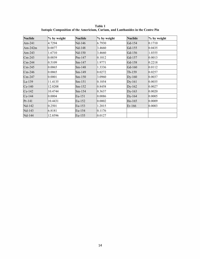
mixture is given in Table 1. This used nuclear fuel is from a light water reactor (LWR), which was cooled for
10 years before reprocessing. The LWR had an initial enrichment of 4 wt% U-235 and an exit burnup of
50 MWd/kg initial heavy elements (IHE). Only nuclides of interest to reactor physics, that is those with significant
neutron cross-sections, are contained in the WIMS-AECL library that was used for the study; other lanthanides
present in the spent fuel have been ignored in this work.
The amount of Am/Cm/Ln in the centre pin was varied between 5% and 60% by volume. To obtain greater
destruction of Am/Cm, the centre pin cases were designed so that the centre pin is recycled into a fresh bundle.
Demountable bundles have been in use at the National Research Universal (NRU) research reactor, located at the
Chalk River Laboratories, for many years. This demountable element fuel concept is employed in this study. While
this technology is well proven for the research reactor application, further development would be needed to
implement this concept in power reactors. After the first irradiation, the centre pin would be removed and placed in
a new bundle containing fresh LEU in the remaining pins.
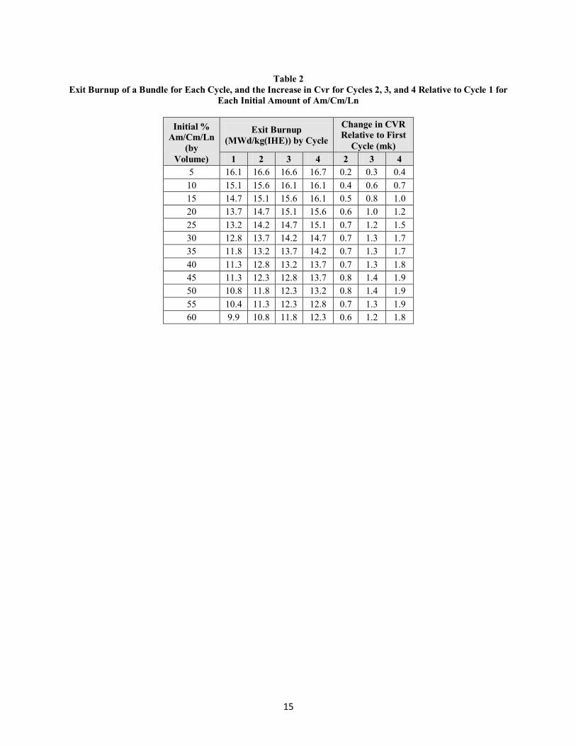
Each successive irradiation will have a lower amount of neutron absorber in the centre pin; thus, the exit burnup will
increase and there will be less of a reduction of the coolant void reactivity. In this concept the reactor would contain bundles with the centre pin at different irradiations (i.e., some bundles would be undergoing the first cycle, and
others the second or third irradiation cycles), such that this effect averages out over the whole reactor. This study
has examined four recycles of the centre pin. The exit burnup and effect on CVR are given in Table 2. The
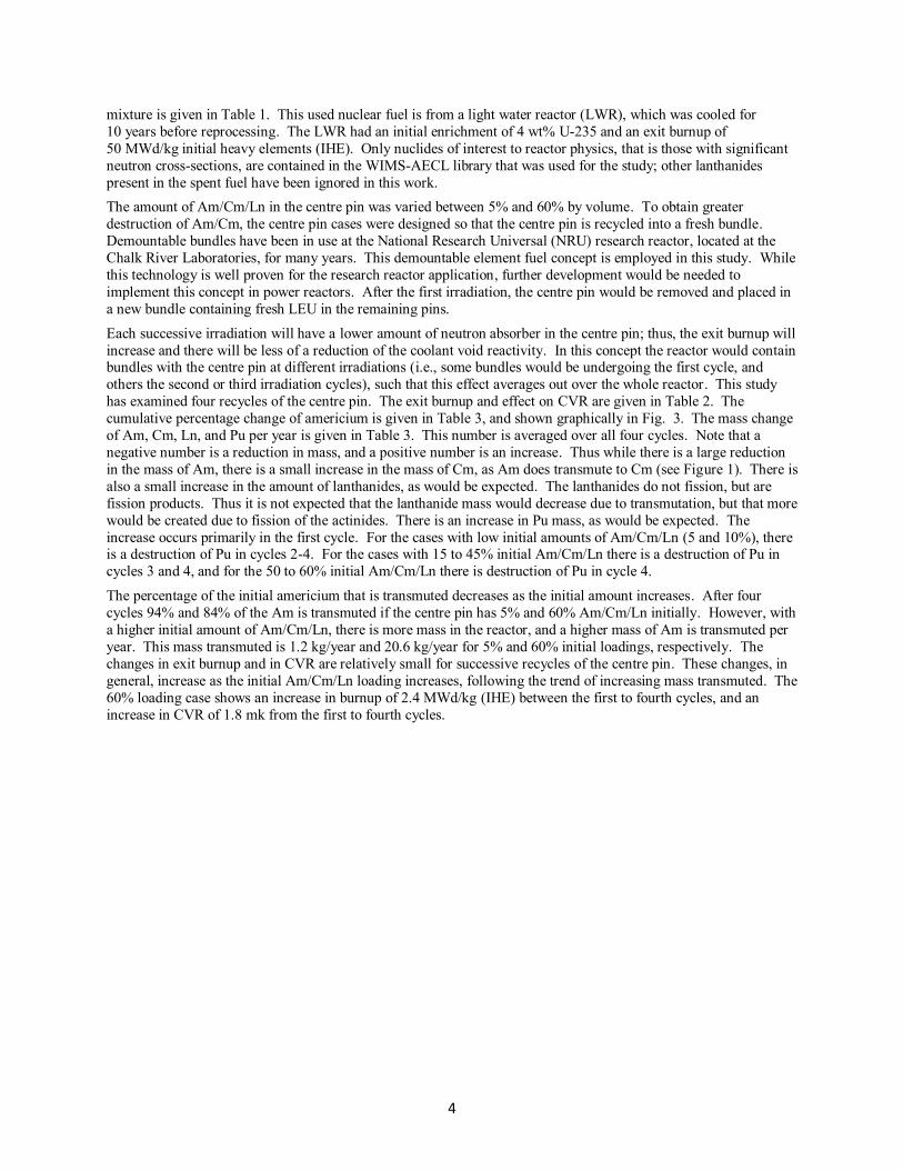
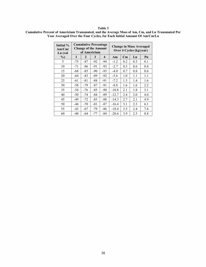
cumulative percentage change of americium is given in Table 3, and shown graphically in Fig. 3. The mass change
of Am, Cm, Ln, and Pu per year is given in Table 3. This number is averaged over all four cycles. Note that a
negative number is a reduction in mass, and a positive number is an increase. Thus while there is a large reduction
in the mass of Am, there is a small increase in the mass of Cm, as Am does transmute to Cm (see Figure 1). There is
also a small increase in the amount of lanthanides, as would be expected. The lanthanides do not fission, but are
fission products. Thus it is not expected that the lanthanide mass would decrease due to transmutation, but that more
would be created due to fission of the actinides. There is an increase in Pu mass, as would be expected. The
increase occurs primarily in the first cycle. For the cases with low initial amounts of Am/Cm/Ln (5 and 10%), there is a destruction of Pu in cycles 2-4. For the cases with 15 to 45% initial Am/Cm/Ln there is a destruction of Pu in
cycles 3 and 4, and for the 50 to 60% initial Am/Cm/Ln there is destruction of Pu in cycle 4.
The percentage of the initial americium that is transmuted decreases as the initial amount increases. After four
cycles 94% and 84% of the Am is transmuted if the centre pin has 5% and 60% Am/Cm/Ln initially. However, with
a higher initial amount of Am/Cm/Ln, there is more mass in the reactor, and a higher mass of Am is transmuted per
year. This mass transmuted is 1.2 kg/year and 20.6 kg/year for 5% and 60% initial loadings, respectively. The
changes in exit burnup and in CVR are relatively small for successive recycles of the centre pin. These changes, in
general, increase as the initial Am/Cm/Ln loading increases, following the trend of increasing mass transmuted. The
60% loading case shows an increase in burnup of 2.4 MWd/kg (IHE) between the first to fourth cycles, and an
increase in CVR of 1.8 mk from the first to fourth cycles.
5
2.2 Heterogeneous Method (Target Channel)
In this scenario a CANDU 6 core is fuelled with 0.9% fissile RU and peripheral channels around the outside of the
reactor (30 channels total) are fuelled with Am/Cm in an inert matrix (Figure 4) [7]. The isotopic composition of
Am and Cm in spent fuel used in the analysis was taken from the used fuel database maintained by the Nuclear Energy Agency and is shown below. The data set used is Takahama-3 47.03 GWd/MT(IHE). The used fuel was
decayed for 30 years, and then the Am and Cm were separated out. The burnup achieved for the RU is
12.2 MWd/kg(IHE).
The peripheral channels are selected for the Am/Cm transmutation in this analysis because of their minimal effect on
the reactor operation in a CANDU 6 reactor. The portions of Am/Cm in the inert matrix fuel (IMF) mixture are
14%, 19%, 26%, and 35% by weight. Silicon carbide (SiC) has been used as the IMF material in this model. SiC
has been used in this study as it is easy to implement into the models. The choice of the inert matrix is not important
at this stage; any material that is transparent to neutrons is suitable from the standpoint of the physics work done
here. If this fuel cycle were to be developed further, a study would be done to determine the most suitable inert matrix.
Full core time-average calculations have been performed for the Am/Cm target core using RFSP version 3.04.01 to
examine the maximum channel and bundle powers. The maximum channel and bundle powers for the time average
case are 6660 kW and 790 kW respectively. An instantaneous model, which generates random ages for the fuel
channels, was used to analyze the power increase that occurs when refuelling the reactor, referred to as the refuelling
ripple. The maximum channel and bundle powers for the refuelling ripple are 7080 kW and 845kW respectively.
These values are all within normal CANDU reactor operating conditions.
Hyland-3

6
Four different bundle designs were modelled for the Am/Cm carrier. The bundle designs are 21-element,
24-element, and 30-element bundles and the 43-element CANFLEX bundle. These bundles each have a different
mass of heavy elements. There is a lower mass of heavy elements in the bundles with fewer elements. The mass of
heavy elements per fuel bundle are 1.06, 1.21, 1.52, and 1.79 kg/bundle for the 21, 24, 30-element and CANFLEX
(43-element) bundles respectively, for a composition of 19wt% Am and Cm.
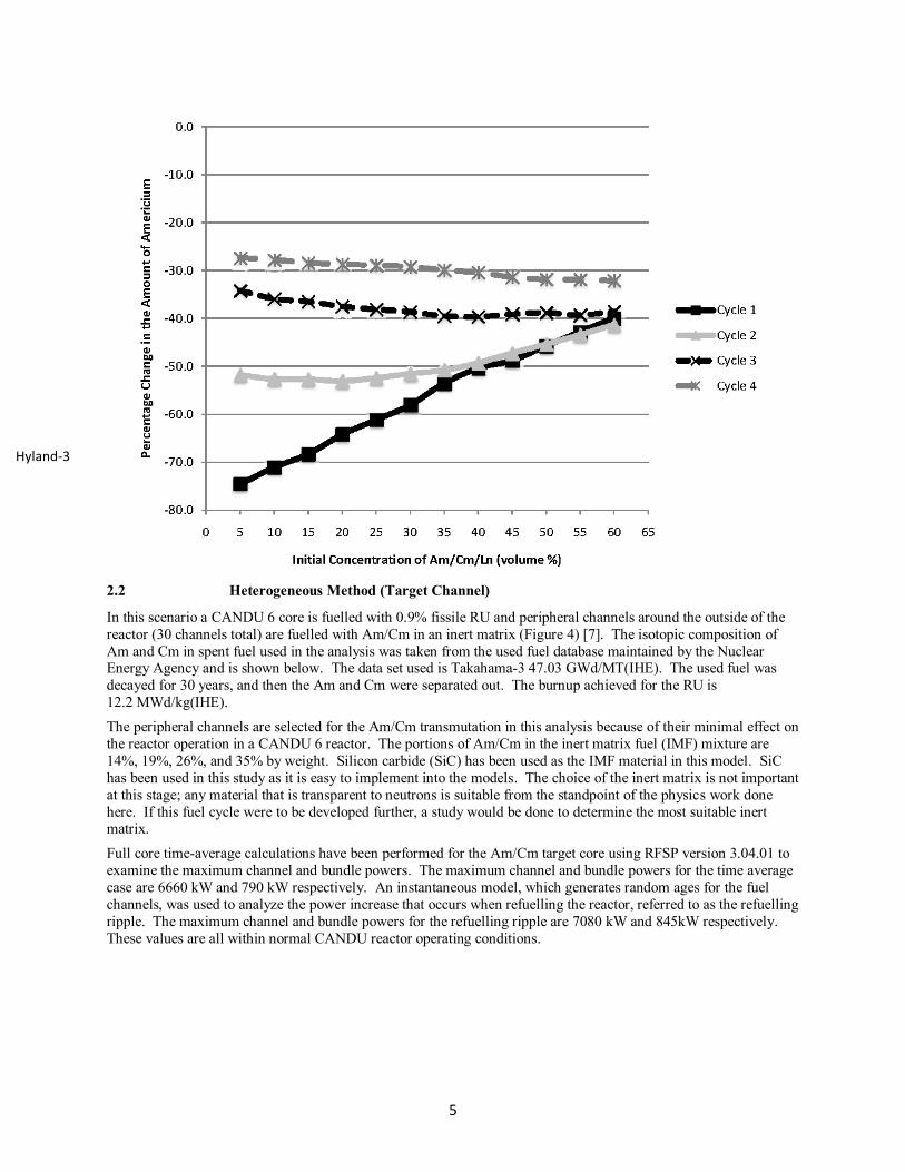
Figure 5 shows the relationship between the support ratio (SR) and the destruction of americium using a
30-peripheral channel loading scheme. A support ratio of 4 means that americium produced by 4 GWe of LWR
reactors can be loaded into 1 GWe of CANDU 6 reactors. This plot is for the CANFLEX fuel bundle but the
relationship is the same for all of the bundle designs. A lighter fuel bundle has a shorter residence time to achieve the same percentage of Am/Cm transmutation as that for a heavier bundle. However, with a lighter fuel bundle, less
mass of Am/Cm can be fuelled in the reactor. For a given bundle with a given initial loading of Am/Cm, to obtain a
higher transmutation of Am, the bundle needs to sit in the reactor for a longer period of time. However, if the
bundle is in the reactor for a longer time, then the mass throughput of Am (kg Am loaded into the reactor per year)
will be lower, thus the support ratio will be lower.
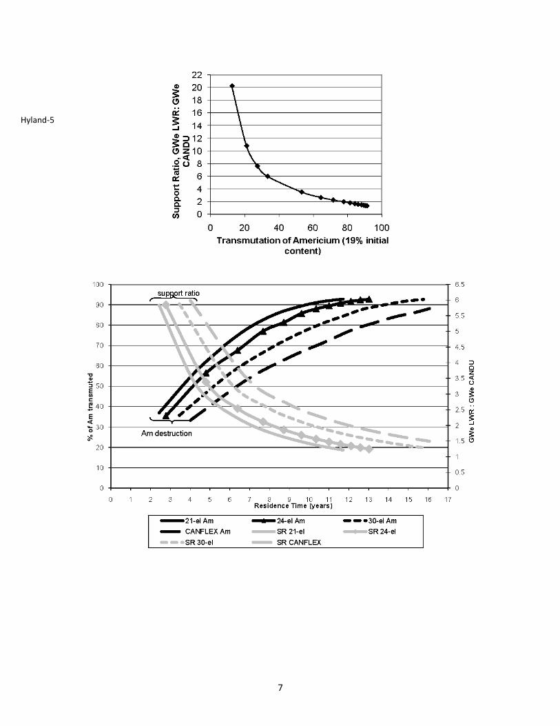
The graph in Figure 6 shows the link between the percentage of Am that can be transmuted and the support ratio,
and how the heavier bundles require a longer residence time to achieve an equivalent destruction. If a high support
ratio is desired, then a lower destruction rate is obtained; conversely if a high percent transmutation of Am is desired
then more GWe of CANDU reactors are required. Support ratios, for once-through applications in fuel cycles, serve as an indication of how much minor actinides are loaded into the reactors in the various scenarios. An effective
strategy to burn Am (and other minor actinides) would need to balance throughput and the actual quantity of MA
that is transmuted.
A heavier bundle allows more Am to be input in to the CANDU reactor at one time, but a longer irradiation time is
required to achieve the same Am/Cm destruction. Therefore for a chosen destruction and support ratio the residence
time can be chosen by selecting a lighter or heavier fuel bundle design.
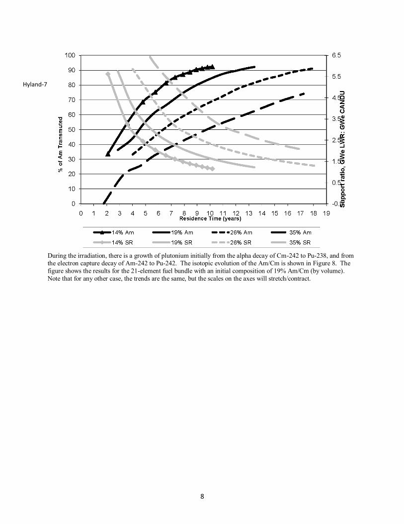
Varying the initial amount of Am/Cm in the bundle produces the same relationship as shown in Figure 6. The
amounts of Am/Cm that were modelled are 14%, 19%, 26%, and 35% by weight. Figure 7 shows the effect of residence time on the destruction of Am/Cm and on the support ratio. The calculations varying the initial
concentration are for the CANFLEX fuel bundle design only. This provides another means to choose the fuel
design, whereby the initial Am/Cm concentration of the bundle can be chosen for a particular fuel bundle, support
ratio/% destruction, and residence time. If there are factors that put a limit on the residence time of a fuel bundle in
a reactor, then choosing a lighter bundle would allow a fuel cycle option to achieve the same support ratio and
transmutation of Am as with a heavier bundle.
Am and Cm in IMF
0.9% RU
Hyland-4
7
Hyland-5
8
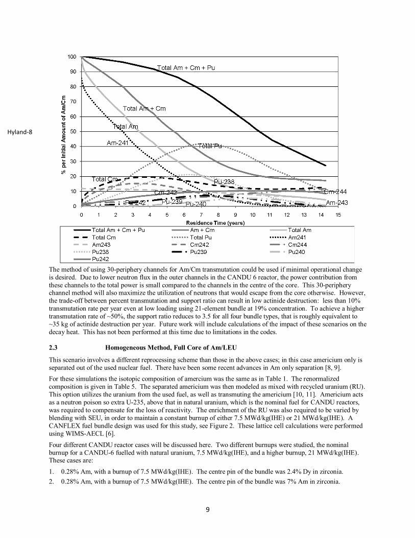
During the irradiation, there is a growth of plutonium initially from the alpha decay of Cm-242 to Pu-238, and from
the electron capture decay of Am-242 to Pu-242. The isotopic evolution of the Am/Cm is shown in Figure 8. The
figure shows the results for the 21-element fuel bundle with an initial composition of 19% Am/Cm (by volume).
Note that for any other case, the trends are the same, but the scales on the axes will stretch/contract.
Hyland-7
9
The method of using 30-periphery channels for Am/Cm transmutation could be used if minimal operational change
is desired. Due to lower neutron flux in the outer channels in the CANDU 6 reactor, the power contribution from
these channels to the total power is small compared to the channels in the centre of the core. This 30-periphery channel method will also maximize the utilization of neutrons that would escape from the core otherwise. However,
the trade-off between percent transmutation and support ratio can result in low actinide destruction: less than 10%
transmutation rate per year even at low loading using 21-element bundle at 19% concentration. To achieve a higher
transmutation rate of ~50%, the support ratio reduces to 3.5 for all four bundle types, that is roughly equivalent to
~35 kg of actinide destruction per year. Future work will include calculations of the impact of these scenarios on the
decay heat. This has not been performed at this time due to limitations in the codes.
2.3 Homogeneous Method, Full Core of Am/LEU
This scenario involves a different reprocessing scheme than those in the above cases; in this case americium only is
separated out of the used nuclear fuel. There have been some recent advances in Am only separation [8, 9].
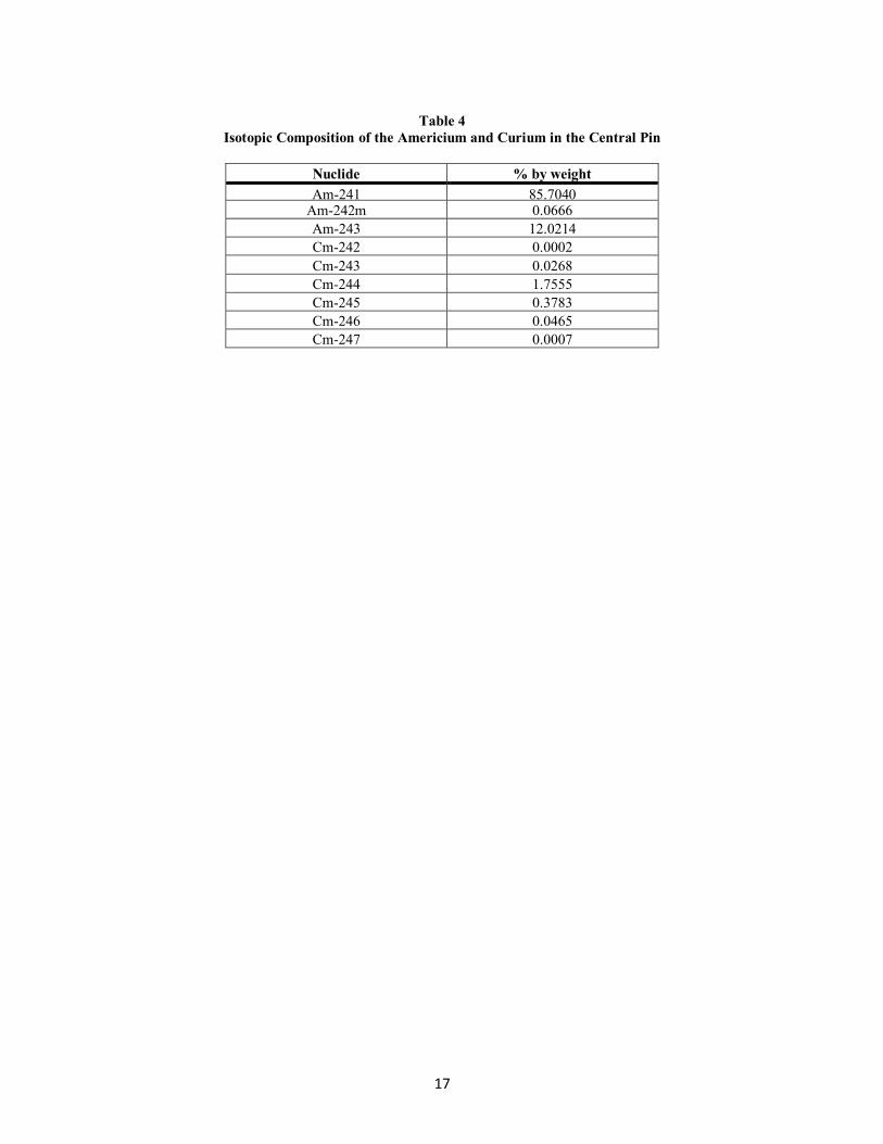
For these simulations the isotopic composition of amercium was the same as in Table 1. The renormalized
composition is given in Table 5. The separated americium was then modeled as mixed with recycled uranium (RU).
This option utilizes the uranium from the used fuel, as well as transmuting the americium [10, 11]. Americium acts
as a neutron poison so extra U-235, above that in natural uranium, which is the nominal fuel for CANDU reactors,
was required to compensate for the loss of reactivity. The enrichment of the RU was also required to be varied by
blending with SEU, in order to maintain a constant burnup of either 7.5 MWd/kg(IHE) or 21 MWd/kg(IHE). A
CANFLEX fuel bundle design was used for this study, see Figure 2. These lattice cell calculations were performed
using WIMS-AECL [6].
Four different CANDU reactor cases will be discussed here. Two different burnups were studied, the nominal
burnup for a CANDU-6 fuelled with natural uranium, 7.5 MWd/kg(IHE), and a higher burnup, 21 MWd/kg(IHE). These cases are:
1. 0.28% Am, with a burnup of 7.5 MWd/kg(IHE). The centre pin of the bundle was 2.4% Dy in zirconia.
2. 0.28% Am, with a burnup of 7.5 MWd/kg(IHE). The centre pin of the bundle was 7% Am in zirconia.
Hyland-8
10
3. 0.28% Am, with a burnup of 21 MWd/kg(IHE). The centre pin of the bundle was 1.3% Dy in zirconia.
4. 0.28% Am, with a burnup of 21 MWd/kg(IHE). The centre pin of the bundle was 3.7% Am in zirconia.
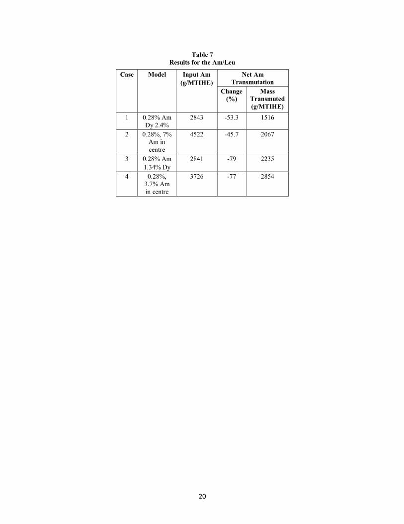
The results for the four cases are given in Tables 6 to 8. These four cases have a neutron poison in the centre pin of the fuel bundle in order to lower the CVR. Cases 2 and 4, with Am in the centre pin, enable the maximum amount
of Am transmutation (2067 and 2854 g/MTIHE) although the fraction of Am transmuted is the lowest (45% and
77%) for a given burnup. The reduction in the fractions of Am transmuted is less significant at the higher burnup,
77% versus 79%.
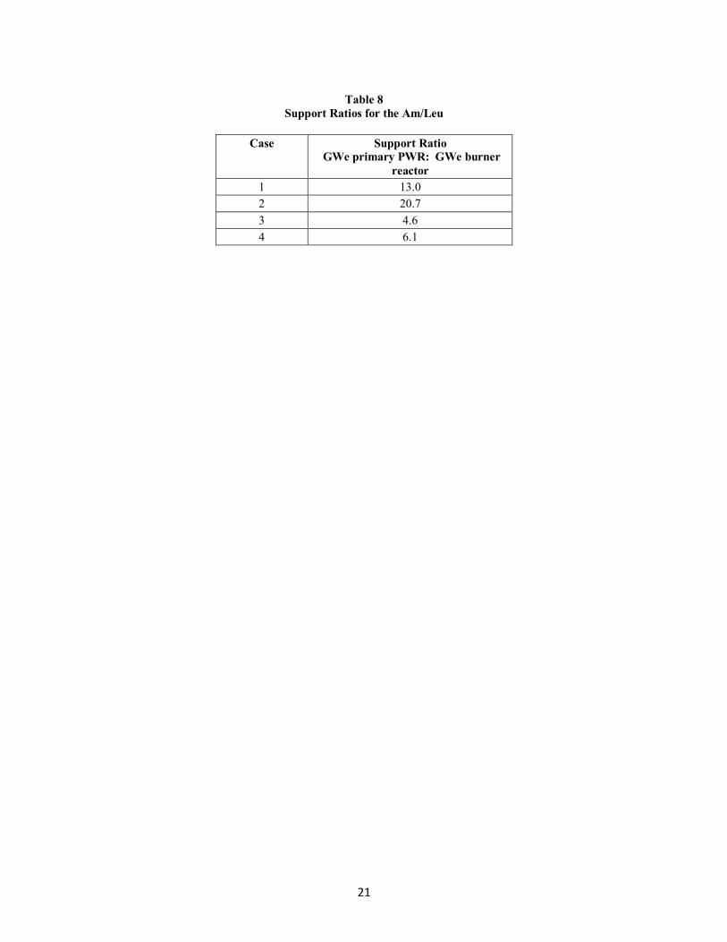
The support ratios are given in Table 8. Up to 20.7 GWe of primary LWR can be supported for one GWe of CANDU reactor (case 2). However, it should be noted that the fraction of Am transmuted in this case is lower. For
the higher transmutation fraction cases (cases 3 and 4), up to 6.1 GWe of primary PWR can be supported.
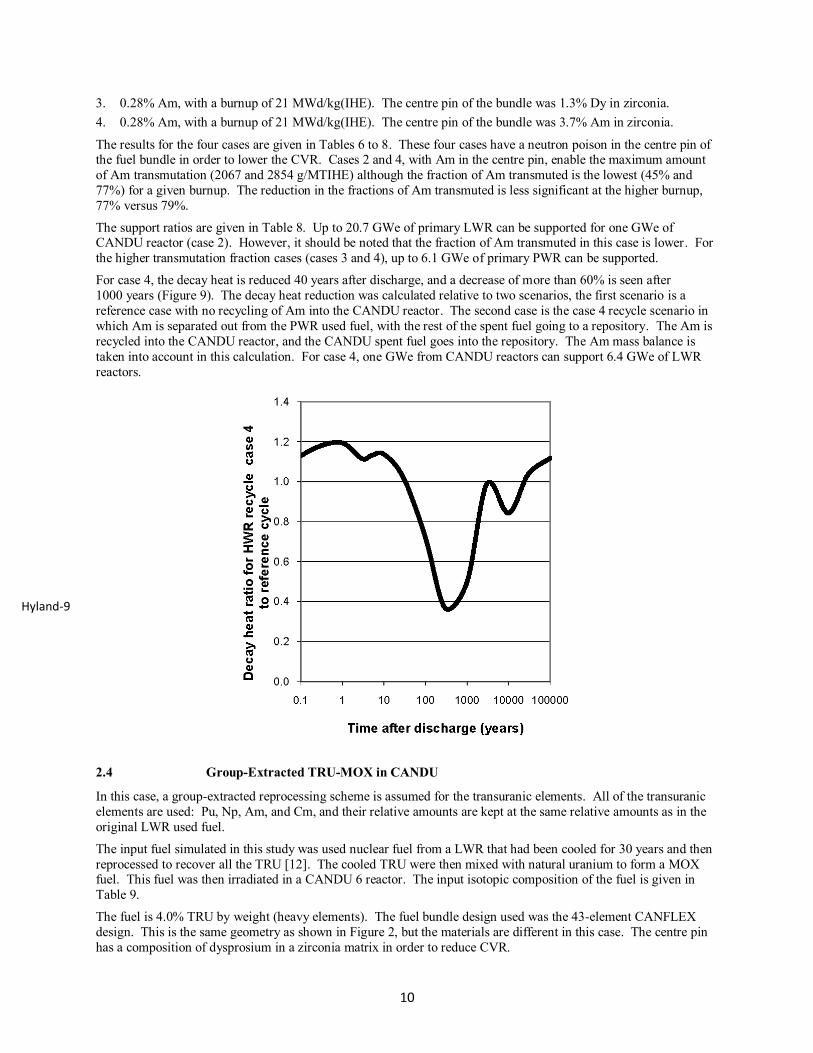
For case 4, the decay heat is reduced 40 years after discharge, and a decrease of more than 60% is seen after
1000 years (Figure 9). The decay heat reduction was calculated relative to two scenarios, the first scenario is a
reference case with no recycling of Am into the CANDU reactor. The second case is the case 4 recycle scenario in
which Am is separated out from the PWR used fuel, with the rest of the spent fuel going to a repository. The Am is
recycled into the CANDU reactor, and the CANDU spent fuel goes into the repository. The Am mass balance is
taken into account in this calculation. For case 4, one GWe from CANDU reactors can support 6.4 GWe of LWR
reactors.
2.4 Group-Extracted TRU-MOX in CANDU
In this case, a group-extracted reprocessing scheme is assumed for the transuranic elements. All of the transuranic
elements are used: Pu, Np, Am, and Cm, and their relative amounts are kept at the same relative amounts as in the
original LWR used fuel.
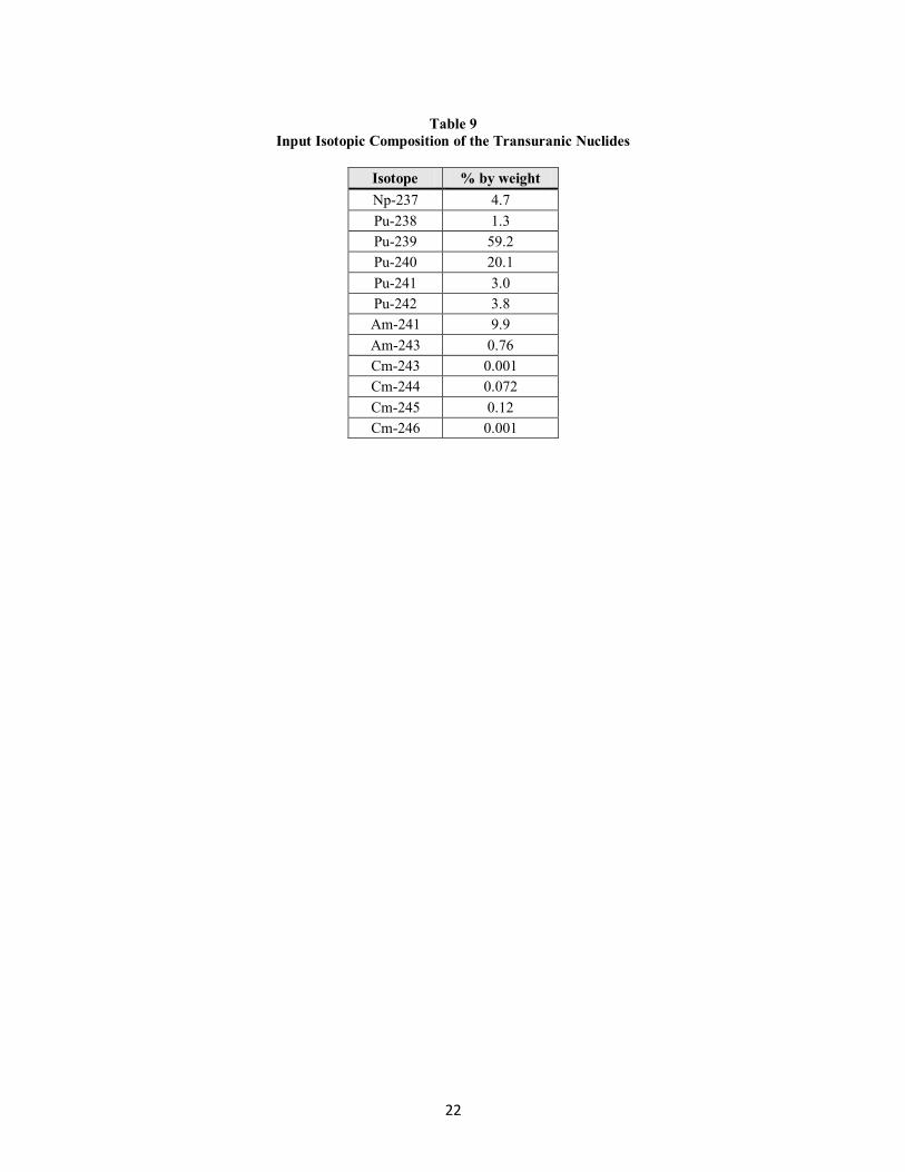
The input fuel simulated in this study was used nuclear fuel from a LWR that had been cooled for 30 years and then
reprocessed to recover all the TRU [12]. The cooled TRU were then mixed with natural uranium to form a MOX fuel. This fuel was then irradiated in a CANDU 6 reactor. The input isotopic composition of the fuel is given in
Table 9.
The fuel is 4.0% TRU by weight (heavy elements). The fuel bundle design used was the 43-element CANFLEX
design. This is the same geometry as shown in Figure 2, but the materials are different in this case. The centre pin
has a composition of dysprosium in a zirconia matrix in order to reduce CVR.
Hyland-9
11
Lattice cell calculations were performed using WIMS-AECL [6] and full-core modelling used the RFSP computer
code [13]. The exit burnup of the fuel was 43.4 MWd/kg(IHE). This gave a total TRU transmutation of 42%. The
percentage of each isotope transmuted and the mass transmuted per year are given in Table 10. Note for this table a
positive value is a destruction and a negative value is a creation. There is an increase in curium mass, but it should
be noted that most curium isotopes are short-lived and contribute to the decay heat on the same time scale as the
fission products.
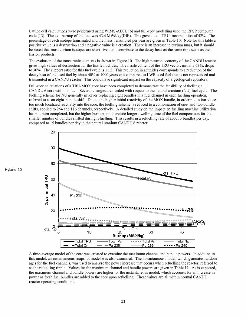
The evolution of the transuranic elements is shown in Figure 10. The high neutron economy of the CANDU reactor
gives high values of destruction for the fissile nuclides. The fissile content of the TRU vector, initially 63%, drops
to 30%. The support ratio for this fuel cycle is 11.2. This reduction in actinides corresponds to a reduction of the
decay heat of the used fuel by about 40% at 1000 years exit compared to LWR used fuel that is not reprocessed and
transmuted in a CANDU reactor. This could have significant impact on the capacity of a geological repository.
Full-core calculations of a TRU-MOX core have been completed to demonstrate the feasibility of fuelling a
CANDU 6 core with this fuel. Several changes are needed with respect to the natural uranium (NU) fuel cycle. The
fuelling scheme for NU generally involves replacing eight bundles in a fuel channel in each fuelling operation, referred to as an eight-bundle shift. Due to the higher initial reactivity of the MOX bundle, in order not to introduce
too much localized reactivity into the core, the fuelling scheme is reduced to a combination of one- and two-bundle
shifts, applied to 264 and 116 channels, respectively. A detailed study on the impact on fuelling machine utilization
has not been completed, but the higher burnup and therefore longer dwelling time of the fuel compensates for the
smaller number of bundles shifted during refuelling. This results in a refuelling rate of about 3 bundles per day,
compared to 15 bundles per day in the natural uranium CANDU 6 reactor.
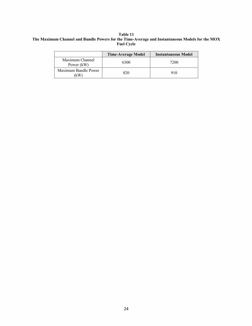
A time-average model of the core was created to examine the maximum channel and bundle powers. In addition to
this model, an instantaneous snapshot model was also examined. The instantaneous model, which generates random
ages for the fuel channels, was used to analyze the power increase that occurs when refuelling the reactor, referred to
as the refuelling ripple. Values for the maximum channel and bundle powers are given in Table 11. As is expected,
the maximum channel and bundle powers are higher for the instantaneous model, which accounts for an increase in
power as fresh fuel bundles are added to the core upon refuelling. These values are all within normal CANDU
reactor operating conditions.
Hyland-10

12
3. CONCLUSION
In this paper, several different actinide transmutation schemes in a CANDU reactor were presented. These methods
are classified under two categories: heterogeneous and homogeneous actinide loading in CANDU reactors. In the
former method, actinides are confined to target pins or bundles and loaded in the reactor separately from the rest of
fuel. In the homogenous methods, actinides are homogeneously mixed with fuel and placed in all channels in the
reactor.
The advantages of these methods are that they require minimal operational and fuel changes in existing CANDU
reactors. In the case of using the centre pin of the bundle to carry the actinides, the concept is very similar to the
“low void reactivity fuel” (LVRF) CANDU fuel design that contains a centre neutron absorber and slightly enriched
uranium in the remaining fuel pins. In the heterogeneous channel method where actinide target bundles are placed
in dedicated transmutation channels of the reactor, the periphery channels are selected to minimize the operational
effect while utilizing neutrons in the reflector region. On-power refuelling capability of a CANDU reactor allows
the residence time of actinide targets to differ significantly from fuel bundles. With high neutron fluence, very high
destruction of the actinides can be achieved. The disadvantage of this scheme is that the total amount of actinide
destruction is limited since only small part of the reactor is being used for actinide transmutation. The
heterogeneous methods are suitable when there are numbers of existing CANDU reactors that can support a LWR
fleet.
Two different homogeneous actinide fuels are presented in this paper corresponding to different actinide partitioning
schemes: separated Am mixed with LEU, and group-extracted actinides mixed with natural uranium. Significant
actinide mass destruction can be achieved using whole core loading of these homogeneous actinide fuels. The
actinide transmutation in a single CANDU reactor is in the order of several kilograms per year, achieving the
support ratio between 11~20 depending on the actinide-partitioning scheme. The limitation in the homogeneous
method is that the fuel and targets are subject to the same neutron fluence, lowering the fraction of actinides
destroyed during the irradiation in the core. The discharge actinide fuel may require secondary reprocessing and
transmutation to achieve high destruction comparable to the heterogeneous methods. A higher fuel burnup will
increase the actinide destruction fraction.
Several different strategies are being studied to maximize the CANDU reactor utilization for actinide destruction.
The currently existing CANDU reactors can process small quantities of actinides without significant operational
changes. This paper has not examined actinide destruction using thorium as a fuel matrix, rather than uranium.
Thorium is anticipated to be a better transmutation matrix than uranium because fewer higher mass actinides would
be produced during irradiation and valuable U-233 would be produced for subsequent recycle.
4. REFERENCES
[1] Boczar, P.G., et al., 1996, “Advanced CANDU Systems for Plutonium Destruction”, NATO Advanced
Research Workshop on Advanced Nuclear Systems Consuming Excess Plutonium, Moscow, Russia.
[2] Chan, P.S.W., et al., 1997, “CANDU- A Versatile Reactor for Plutonium Disposition or Actinide
Burning”, Global ’97 Conference on Future Nuclear Systems, Yokohama, Japan.
[3] Hyland, B., and Dyck, G.R., 2007, “Actinide Burning in CANDU Reactors”, Global ’07 Conference on
Advanced Nuclear Fuel Cycles and Systems, Boise, Idaho.
[4] Hyland, B. et al., 2009, “Transmutation of Americium in Light and Heavy Water Reactors”, Global 2009
Conference on The Nuclear Fuel Cycle: Sustainable Options and Industrial Perspectives, Paris, France.
[5] OECD/NEA, 2008, “Nuclear Energy Outlook 2008”, Nuclear Energy Agency.
[6] Altiparmakov, D., 2008, "New Capabilities of the Lattice Code WIMS-AECL", PHYSOR-2008,
International Conference on Reactor Physics, Nuclear Power: A Sustainable Resource, Interlaken,
Switzerland.
[7] Hyland, B, et al., 2008, “Transmutation of Actinides in CANDU Reactors”, OECD/NEA Information
Exchange Meeting on Partitioning and Transmutation, Japan.
[8] Modolo, G., et al., 2009, “Selective Separation of Americium (III) from Curium (III), Californium(III),
and Lanthanides(III) by the LUCA Process”, Global 2009 Conference on The Nuclear Fuel Cycle:
Sustainable Options and Industrial Perspectives, Paris, France.
13
[9] Modolo, G., et al., 2008, “Development and Demonstration of a New SANEX Process for Actinide
(III)/Lanthanide (III) Separation Using a Mixture of CyMe4BTBP and TODGA as Selective Extractant”,
Proceedings of the 10th Information Exchange Meeting on Partitioning and Transmutation, Mito, Japan,
October 2008.
[10] Del Cul, G.D., et al., 2009, “Analysis of the Reuse of Uranium Recovered from the Reprocessing of
Commercial LWR Spent Fuel”, ORNL/TM-2007/207, ORNL/GNEP/LTR-2008-002, January 2009.
[11] Ellis, R.J., 2007, “Prospects of Using Reprocessed Uranium in CANDU Reactors, in the US GNEP
Program,” The American Nuclear Society and the European Nuclear Society 2007 International
Conference on Making the Renaissance Real, November 11–15, 2007, Washington, D.C. Trans. Am.
Nucl. Soc .97, 107–108.
[12] Forsberg, C.W. et al., 2004, “Can Thermal Reactor Recycle Eliminate the Need for Multiple
Repositories?” 8th OECD/NEA Information Exchange Meeting on Partitioning and Transmutation,
Las Vegas.
[13] Rouben, B., 2002, “RFSP-IST, The Industry Standard Tool Computer Program for CANDU Reactor Core Design and Analysis”, Proceedings of the 13th Pacific Basin Nuclear Conference, Shenzhen, China,
2002 October 21-25.
14
Table 1
Isotopic Composition of the Americium, Curium, and Lanthanides in the Centre Pin
Nuclide % by weight Nuclide % by weight Nuclide % by weight
Am-241 4.7294 Nd-146 6.7930 Gd-154 0.1710
Am-242m 0.0077 Nd-148 3.4660 Gd-155 0.0435
Am-243 1.6710 Nd-150 3.4660 Gd-156 1.0355
Cm-243 0.0039 Pm-147 0.1012 Gd-157 0.0013
Cm-244 0.5109 Sm-147 1.9771 Gd-158 0.2218
Cm-245 0.0065 Sm-148 1.3336 Gd-160 0.0112
Cm-246 0.0065 Sm-149 0.0272 Tb-159 0.0257
Cm-247 0.0001 Sm-150 3.0960 Dy-160 0.0037
La-139 11.4135 Sm-151 0.1054 Dy-161 0.0035
Ce-140 12.0208 Sm-152 0.8458 Dy-162 0.0027
Ce-142 10.4744 Sm-154 0.3637 Dy-163 0.0020
Ce-144 0.0004 Eu-151 0.0086 Dy-164 0.0005
Pr-141 10.4431 Eu-152 0.0002 Ho-165 0.0009
Nd-142 0.2501 Eu-153 1.2015 Er-166 0.0003
Nd-143 6.8181 Eu-154 0.1176
Nd-144 12.8596 Eu-155 0.0127
15
Table 2
Exit Burnup of a Bundle for Each Cycle, and the Increase in Cvr for Cycles 2, 3, and 4 Relative to Cycle 1 for
Each Initial Amount of Am/Cm/Ln
Initial %
Am/Cm/Ln
(by
Volume)
Exit Burnup
(MWd/kg(IHE)) by Cycle
Change in CVR
Relative to First
Cycle (mk)
1 2 3 4 2 3 4
5 16.1 16.6 16.6 16.7 0.2 0.3 0.4
10 15.1 15.6 16.1 16.1 0.4 0.6 0.7
15 14.7 15.1 15.6 16.1 0.5 0.8 1.0
20 13.7 14.7 15.1 15.6 0.6 1.0 1.2
25 13.2 14.2 14.7 15.1 0.7 1.2 1.5
30 12.8 13.7 14.2 14.7 0.7 1.3 1.7
35 11.8 13.2 13.7 14.2 0.7 1.3 1.7
40 11.3 12.8 13.2 13.7 0.7 1.3 1.8
45 11.3 12.3 12.8 13.7 0.8 1.4 1.9
50 10.8 11.8 12.3 13.2 0.8 1.4 1.9
55 10.4 11.3 12.3 12.8 0.7 1.3 1.9
60 9.9 10.8 11.8 12.3 0.6 1.2 1.8
16
Table 3
Cumulative Percent of Americium Transmuted, and the Average Mass of Am, Cm, and Ln Transmuted Per
Year Averaged Over the Four Cycles, for Each Initial Amount Of Am/Cm/Ln
Initial %
Am/Cm/
Ln (vol
%)
Cumulative Percentage
Change of the Amount
of Americium
Change in Mass Averaged
Over 4 Cycles (kg/year)
1 2 3 4 Am Cm Ln Pu
5 -75 -87 -92 -94 -1.2 0.2 0.3 0.1
10 -71 -86 -91 -93 -2.7 0.5 0.6 0.4
15 -68 -85 -90 -93 -4.0 0.7 0.8 0.6
20 -64 -83 -89 -92 -5.6 1.0 1.1 1.1
25 -61 -81 -88 -91 -7.2 1.3 1.4 1.6
30 -58 -79 -87 -91 -8.8 1.6 1.6 2.2
35 -54 -76 -85 -90 -10.8 2.1 1.8 3.1
40 -50 -74 -84 -89 -12.7 2.4 2.0 4.0
45 -49 -72 -83 -88 -14.3 2.7 2.1 4.9
50 -46 -70 -81 -87 -16.4 3.1 2.3 6.1
55 -43 -67 -79 -86 -18.4 3.5 2.4 7.4
60 -40 -64 -77 -84 -20.6 3.9 2.5 8.8
17
Table 4
Isotopic Composition of the Americium and Curium in the Central Pin
Nuclide % by weight
Am-241 85.7040 Am-242m 0.0666
Am-243 12.0214
Cm-242 0.0002
Cm-243 0.0268
Cm-244 1.7555
Cm-245 0.3783
Cm-246 0.0465
Cm-247 0.0007

18
Table 5
Input Isotopic Composition of the Americium from the Used Nuclear Fuel
Isotope % by Weight
Am-241 73.8
Am-242m 0.12
Am-243 26.1

19
Table 6
Parameters for the Am/Leu
Case Model Input
Amount of
U-235 (wt%)
Burnup
(MWd/kg(IHE))
1 0.28% Am
Dy 2.4%
1.01 7.5
2 0.28%, 7%
Am in centre
1.04 7.5
3 0.28% Am
1.34% Dy
1.34 20.9
4 0.28%, 3.7%
Am in centre
1.36 21.1
20
Table 7
Results for the Am/Leu
Case Model Input Am
(g/MTIHE)
Net Am
Transmutation
Change
(%)
Mass
Transmuted
(g/MTIHE)
1 0.28% Am
Dy 2.4%
2843 -53.3 1516
2 0.28%, 7% Am in
centre
4522 -45.7 2067
3 0.28% Am
1.34% Dy
2841 -79 2235
4 0.28%, 3.7% Am
in centre
3726 -77 2854
21
Table 8
Support Ratios for the Am/Leu
Case Support Ratio
GWe primary PWR: GWe burner
reactor
1 13.0
2 20.7
3 4.6
4 6.1
22
Table 9
Input Isotopic Composition of the Transuranic Nuclides
Isotope % by weight
Np-237 4.7
Pu-238 1.3
Pu-239 59.2
Pu-240 20.1
Pu-241 3.0
Pu-242 3.8
Am-241 9.9
Am-243 0.76
Cm-243 0.001
Cm-244 0.072
Cm-245 0.12
Cm-246 0.001

23
Table 10
The Amounts of the Transuranic Nuclides that are Transmuted in the Tru-Mox Scenario
Nuclide % Transmuted Mass Transmuted
(kg/year)
Np-237 51.0 18.9
Total Np 48.1 17.9
Pu-238 -206.6 -21.2
Pu-239 78.6 348.4
Pu-240 2.4 3.8
Pu-241 -68.8 -16.5
Pu-242 -128.2 -38.4
Total Pu 41.1 276.8
Am-241 84.2 65.8
Am-243 -221.1 -13.3
Total Am 62.2 52.4
Cm-242 -6.1
Cm-243 -2774.4 -0.22
Cm-244 -1676.5 -9.5
Cm-245 -158.6 -0.15
Cm-246 -1706.0 -0.13
Total Cm -2374.4 -16.1
Total
TRU
41.9 330.2
24
Table 11
The Maximum Channel and Bundle Powers for the Time-Average and Instantaneous Models for the MOX
Fuel Cycle
Time-Average Model Instantaneous Model
Maximum Channel
Power (kW) 6300 7200
Maximum Bundle Power
(kW) 820 910

25
Figure 1 THE TWO MAIN TRANSMUTATION PATHWAYS OF AM-241
Figure 2 DESIGN FOR CANFLEX FUEL BUNDLE WITH CENTRE ACTINIDE TARGET
Figure 3 PERCENTAGE CHANGE IN THE AMOUNT OF AMERICIUM AS A FUNCTION OF INITIAL
AMOUNT OF Am/Cm/Ln, FOR EACH CYCLE
Figure 4 SCHEMATIC DIAGRAM OF THE Am/Cm TARGET MODEL OF A CANDU 6 CORE
Figure 5 RELATIONSHIP BETWEEN THE SUPPORTRATIO AND THE TRANSMUTATION OF Am FOR
THE CANFLEX BUNDLE WITH 19% INITIAL CONCENTRATION OF Am/Cm BY VOLUME
Figure 6 THE % TRANSMUTATION OF AMERICIUM AND SUPPORT RATIO VS. RESIDENCE TIME
FOR EACH OF THE FOUR DIFFERENT FUEL BUNDLES
Figure 7 THE % TRANSMUTATION OF AMERICIUM AND SUPPORT RATIO VS. RESIDENCE TIME
FOR EACH OF THE FOUR DIFFERENT INTIAL AMOUNTS OF Am/Cm
Figure 8 ISOTOPIC EVOLUTION OF THE SIGNIFICANT TRANSURANIC NUCLIDES IN THE Am/Cm
FUEL FOR THE 21-ELEMENT FUEL BUNDLE WITH AN INITIAL COMPOSITION OF 19%
Am/Cm BY VOLUME
Figure 9 THE RATIO OF THE DECAY HEAT FOR THE SCENARIO CASE 4 TO THE REFERENCE CASE
WITH NO AM RECYCLE
Figure 10 THE ISOTOPIC EVOLUTION OF TRU DURING TRANSMUTATION IN THE CANDU REACTOR


![[CONFERENCE PAPER] Bipolar Bozuklukta BDT](https://static.fdokumen.com/doc/165x107/63328d1f4e0143040300b9b3/conference-paper-bipolar-bozuklukta-bdt.jpg)