
Computer Architecture - Daniel Page
17
Computer Architecture Daniel Page Department of Computer Science, University Of Bristol, Merchant Venturers Building, Woodland Road, Bristol, BS8 1UB. UK. [email protected] October 7, 2021 Keep in mind there are two PDFs available (of which this is the latter): 1. a PDF of examinable material used as lecture slides, and 2. a PDF of non-examinable, extra material: the associated notes page may be pre-populated with extra, written explaination of material covered in lecture(s), plus anything with a “grey’ed out” header/footer represents extra material which is useful and/or interesting but out of scope (and hence not covered). Notes: Notes:
-
Upload
khangminh22 -
Category
Documents
-
view
0 -
download
0
Transcript of Computer Architecture - Daniel Page

Computer Architecture
Daniel Page
Department of Computer Science,University Of Bristol,
Merchant Venturers Building,Woodland Road,
Bristol, BS8 1UB. UK.〈[email protected]〉
October 7, 2021
Keep in mind there are two PDFs available (of which this is the latter):1. a PDF of examinable material used as lecture slides, and
2. a PDF of non-examinable, extra material:I the associated notes page may be pre-populated with extra, written explaination of
material covered in lecture(s), plusI anything with a “grey’ed out” header/footer represents extra material which is
useful and/or interesting but out of scope (and hence not covered).
Notes:
Notes:

COMS10015 lecture: week #5
I Agenda: brief, high-level overview of
ARMv7-A [11] { ARM Cortex-A7 ⊂
i.e., a real-world ISA which1. is a RISC-like design but not RISC per se,2. relates to a load-store architecture with word size w = 32 (i.e., 32-bit).
http://en.wikipedia.org/wiki/File:Raspberry-Pi-2-Bare-BR.jpg
© Daniel Page 〈[email protected]〉Computer Architecture git # f401bfc0 @ 2021-10-07
Notes:
• The goal here comes with quite a strong caveat: this can only ever be an overview, since the topic is a) far too large and b) ideallyexplored in more depth via hands-on, practical methods. That said, the ubiquity of ARM means there is a huge amount of usefulmaterial online: some examples include
– training courses, e.g.,http://www.davespace.co.uk/arm
– documentation, e.g.,https://heyrick.eu/armwiki
• ARM changed their branding circa 2017: although officially one should write “Arm” rather than “ARM”, we will continue to use thelatter. Depending on the context, either term is still imprecise because it can be used to mean an ISA (st. ARMvx⇒ ARM architectureversion x ' ISA version x), or a micro-architecture (e.g., ARMx (x ∈ {1, 2, . . . , 11}), Cortex-A/R/Mx and SCx00).
• The naming conventions ARM uses for ISAs and micro-architecture has, over time, become very complicated! There is an overview here
http://community.arm.com/groups/processors/blog/2011/11/02/arm-fundamentals-introduction-to-understanding-arm-processors
or in [6]. Wikipedia also maintains an organised list of micro-architecture at
http://en.wikipedia.org/wiki/List_of_ARM_microarchitectures
COMS10015 lecture: week #5
I Using the ISA demands we consider an associated tool-chain
high-levelsource code
compiler low-levelsource code
assemblermachine code
because the interface is basically toward the RHS:I although there are various ARM-specific tool-chains, e.g.,I ARM Developer Suite (ADS),I ARM Development Studio (DS), orI Kali MDK-ARM,
I we’ll use an open source, GCC-based alternative, butI this demands gas-style assembly language
so beware if you see an example somewhere else!
© Daniel Page 〈[email protected]〉Computer Architecture git # f401bfc0 @ 2021-10-07
Notes:
• The fact there are multiple possible tool-chains, assemblers specifically, highlights an important point: we’re mainly interested insemantics of instructions, and so the ISA, not how an assembly language syntax describes said instruction. That’s not to say we won’tcover some gas syntax, but it will be less overt than in a dedicated study of assembly language programming.
• The definitive reference for gas ishttp://www.gnu.org/software/binutils/manual
which outlines ARM-specific details in Section 9.4.
• The file names used for assembly language programs guide how they should be processed:– a file with the suffix .s should be processed by gas, whereas– a file with the suffix .S needs pre-processing, and would normally be processed by gcc (and then automatically by gas).

ARMv7-A: state (1)Registers: general-purpose
I ARMv7-A specifies [11, Section A2.3] a 16-entry general(ish)-purpose register file
r0r1r2r3r4r5r6r7r8r9r10r11r12r13r14r15
a1a2a3a4v1v2v3v4v5v6v7v8ipsp
lrpc
≡
calle
rsa
veca
llee
save
argument/return value passingor scratch register
Intra-Procedure (IP) scratch registerStack Pointer (SP)Link Register (LR)Program Counter (PC)
notingI some clearly do have special-purpose roles, butI are generally-addressable, meaning the instruction set is (more or less) orthogonal.
© Daniel Page 〈[email protected]〉Computer Architecture git # f401bfc0 @ 2021-10-07
Notes:
• Although PC is available as a general-purpose register, instructions that use r15 (or pc) as a target often have additional orspecial-purpose semantics (see, e.g., [11, Section A2.3.1]).
• You might see a larger quote for the number of general-purpose registers; usually this is because the banked (or shadowed) registershave been included.
• The Procedure Call Standard for the ARM Architecture (AAPCS) [13] stipulates that– r9 (alias sb) may be used as the Static Base (SB),– r9 (alias tr) may be used as the Thread Register (TR),– r10 (alias sl) may be used as the Stack Limit (SL),– r11 (alias fp) may be used as the Frame Pointer (FP), and– r12 (alias ip) is reserved for use by the linker,
where the use of r9 is basically platform specific; the cases above relate to 1) platforms that use position-independent data (cf. PIC), and2) thread-local storage [3] respectively. A platform that doesn’t define a use for r9 allows it to be used as an additional callee-saveregister.
ARMv7-A: state (2)Registers: special-purpose
I ARMv7-A specifies [11, Section B1.3.3] two special-purpose registers1. a Current Program Status Register (CPSR), plus2. a Saved Program Status Register (SPSR)
with the latter only accessible in privileged modes.I Note thatI the format of both CPSR and SPSR is
01234567891015161920232425262728293031
N Z C V Q IT J GE IT E A I F T M
I transfer instructions can move a special-purpose register to
mrs r0, cpsr 7→ GPR[0]← CPSR
and frommsr cpsr, r0 7→ CPSR← GPR[0]
general-purpose registers, andI writing to CPSR in user mode is limited.
© Daniel Page 〈[email protected]〉Computer Architecture git # f401bfc0 @ 2021-10-07
Notes:
• You may see the term Application Program Status Register (APSR) used in certain contexts, e.g., per [11, Section A2.4]; this is often away to distinguish between restricted access to CPSR available in user mode, and the full access in privileged mode, so it is usuallyreasonable to translate APSR as “CPSR in user mode” or “CPSR from the perspective of application programs”.
• In detail:– N flag records negative result,– Z flag records zero result,– C flag records carry,– V flag records overflow in non-DSP operations,– Q flag records overflow (and saturation) in DSP operations,– IT controls Thumb-2 conditional execution,– GE controls NEON comparisons,– E controls the endian’ness of memory accesses to data (instruction fetches are little-endian),– A enables (A = 0) or disables (A = 1) imprecise aborts,– I enables (I = 0) or disables (I = 1) IRQ-based interrupts,– F enables (F = 0) or disables (F = 1) FIQ-based interrupts,– T ‖ J indicates the instruction mode, st.
T ‖ J =
00(2) = ARM mode01(2) = Thumb mode10(2) = Jazelle mode
– M indicates the processor mode, st.
M =
10000(2) = user mode10001(2) = FIQ mode10010(2) = IRQ mode10011(2) = supervisor mode10110(2) = monitor mode10111(2) = abort mode11010(2) = hypervisor mode11011(2) = undefined mode11111(2) = system mode

ARMv7-A: state (3)Memory
I ARMv7-A specifies [11, Chapter A3] a memory model with a byte-addressable,232-element address space:
232− 1
0
4GiB
low(er)addresses
high(er)addresses
© Daniel Page 〈[email protected]〉Computer Architecture git # f401bfc0 @ 2021-10-07
Notes:
ARMv7-A: state (3)Memory
I ARMv7-A specifies [11, Chapter A3] a memory model with rules wrt.1. alignment [11, Section A3.2] st.
32-bit ARM instructions : aligned to 4-byte boundary16-bit Thumb instructions : aligned to 2-byte boundary8-bit Jazelle instructions : aligned to 1-byte boundary
32-bit words : aligned to 4-byte boundary16-bit half-words : aligned to 2-byte boundary8-bit bytes : aligned to 1-byte boundary
and2. endian’ness [11, Section A3.3], st.I instruction access is little-endian, andI data access can be big-endian or little-endian.
3. ...
© Daniel Page 〈[email protected]〉Computer Architecture git # f401bfc0 @ 2021-10-07
Notes:

ARMv7-A: instructions (1)Encoding
ARMv7-A instruction formats [11, Chapter A5]
Pp
034567891011121314151617181920212223242526272831
cond 0 0 I opcode S rn rd operand}
data processing
cond 0 0 0 0 0 0 A S rn rd rs 1 0 0 1 rm}
“short” multiply
cond 0 0 0 0 1 U A S rdhi rdlo rs 1 0 0 1 rm}
“long” multiply
cond 0 0 0 1 0 B 0 0 rn rd 0 0 0 0 1 0 0 1 rm}
swap
cond 0 1 I P U B W L rn rd off}
single-shot memory access
cond 1 0 0 P U B W L rn list}
multi-shot memory access
cond 0 0 0 P U 1 W L rn rd off 1 S H 1 off}
half-word memory access: immediate value offset
cond 0 0 0 P U 0 W L rn rd 0 0 0 0 1 S H 1 rm}
half-word memory access: register value offset
cond 1 0 1 L off}
branch
cond 0 0 0 1 0 0 1 0 1 1 1 1 1 1 1 1 1 1 1 1 0 0 0 1 rn}
branch-exchange
cond 1 1 0 P U N W L rn crd coproc off}
co-processor data transfer
cond 1 1 1 0 opcode crn crd opcode coproc 0 crm}
co-processor data operation
cond 1 1 1 0 opcode L crn crd opcode coproc 1 crm}
co-processor register transfer
cond 1 1 1 1 imm}
software interrupt
© Daniel Page 〈[email protected]〉Computer Architecture git # f401bfc0 @ 2021-10-07
Notes:
• The ARM instruction encoding, and how it is typically presented, obviously evolves in line with the ISA itself. The example(s) listedhere represent a “traditional” sub-set of formats you may see elsewhere. Whereas these previously captured everything possible, now amore general presentation (per [11, Chapter A5]) copes better with the complexity of the modern ISA.
• There are a few things to note– most formats suggest 3-address style instructions,– the formats are designed in assist decoding in the sense that common fields are aligned at common offsets, and– the large number of formats is (arguably) a more of a CISC-like (vs. RISC-like) characteristic.
• One important feature of the formats is the restrictions they place on any immediate (including offset) operands: note, for example that– an ALU-type immediate operands is limited to 12 bits (of which one can only use 8, since the other 4 control the barrel shifter),– a branch offset is limited to 24 bits.
ARMv7-A: instructions (2)Data processing
I Standard data processing (e.g., ALU-like) [11, Section A4.4] are available with obvioussemantics, e.g.,
add r0, r1, #1 7→ GPR[0]← GPR[1] + 1(10)
add r0, r1, r2 7→ GPR[0]← GPR[1] + GPR[2]adc r0, r1, r2 7→ GPR[0]← GPR[1] + GPR[2] + CPSR[C]and r0, r1, r2 7→ GPR[0]← GPR[1] ∧GPR[2]eor r0, r1, r2 7→ GPR[0]← GPR[1] ⊕GPR[2]orr r0, r1, r2 7→ GPR[0]← GPR[1] ∨GPR[2]
noting thatI by default, most such instructions don’t update flags in CPSR, butI updates are enabled by an ‘s’ suffix, e.g.,
adds r0, r1, r2 7→{
GPR[0]← GPR[1] + GPR[2]CPSR← f (CPSR,GPR[1] + GPR[2])
© Daniel Page 〈[email protected]〉Computer Architecture git # f401bfc0 @ 2021-10-07
Notes:
• Use of the ‘s’ suffix signals some special semantics when r15 (or pc) is used as the target. For example, whereas
sub r14, r14, #4 7→ GPR[14]← GPR[14] − 4(10)
subs r14, r14, #4 7→
GPR[14]← GPR[14] − 4(10)CPSR← f (CPSR,GPR[14] − 4(10))
we instead have that
subs r15, r14, #4 7→{
GPR[15]← GPR[14] − 4(10)CPSR← SPSR
i.e., SPSR (for the current mode) is copied directly into CPSR, rather than there being an update to flags in CPSR.
• Multiplication [11, Section A4.4.3] is a sort of a special case, in the sense there is1. a “short” 32 × 32→ 32 bit multiplication
mul r0, r1, r2 7→ GPR[0]← GPR[1] ·GPR[2]
which truncates the 64-bit result, i.e., forms a result from the least-significant 32-bit half, and2. a “long” 32 × 32→ 64 bit multiplication
umull r0, r1, r2, r3 7→ GPR[0] ‖ GPR[1]← GPR[2] ·GPR[3]
which uses a 4-address instruction format to capture the 64-bit result in two registers (noting the multiplication is now unsigned).
There are also various Multiply-ACcumulate (MAC) variants, whereby a third, additional operand is added to the product computed.

ARMv7-A: instructions (3)Data processing
I The “flexible second operand” [11, Section A4.4.1] can take four forms, namely1. an unshifted immediate value, e.g.,
add r0, r1, #1 7→ GPR[0]← GPR[1] + 1(10)add r0, r1, #0xF 7→ GPR[0]← GPR[1] + F(16)
2. an unshifted register value, e.g.,
add r0, r1, r2 7→ GPR[0]← GPR[1] + GPR[2]
3. a register value shifted by an immediate value, e.g.,
add r0, r1, r2, lsl #1 7→ GPR[0]← GPR[1] + (GPR[2]� 1(10))add r0, r1, r2, lsr #1 7→ GPR[0]← GPR[1] + (GPR[2]� 1(10))add r0, r1, r2, ror #1 7→ GPR[0]← GPR[1] + (GPR[2]≫ 1(10))
4. a register value shifted by a register value, e.g.,
add r0, r1, r2, lsl r3 7→ GPR[0]← GPR[1] + (GPR[2]� GPR[3])add r0, r1, r2, lsr r3 7→ GPR[0]← GPR[1] + (GPR[2]� GPR[3])add r0, r1, r2, ror r3 7→ GPR[0]← GPR[1] + (GPR[2]≫ GPR[3])
© Daniel Page 〈[email protected]〉Computer Architecture git # f401bfc0 @ 2021-10-07
Notes:
• In concrete terms, this is realised by placing a barrel shifter inline with the second ALU input: it acts as a sort of “pre-ALU” that can beoperated in one of seven different modes, namely
lsl = logical left-shiftasl = arithmetic left-shiftlsr = logical right-shiftasr = arithmetic right-shiftror = right-rotaterrx = right-rotate with extend
Since there is no notion of an arithmetic left-shift, asl and lsl behave in the same way. Clearly a left-rotate by x bits can be achievedusing right-rotate by 32 − x bits; it is not possible to right-rotate by 0 bits.Beyond this, the right-rotate with extend mode perhaps needs further explanation. Basically, rrx and ror #1 are the same except thatthe former is applied to a 33-bit value formed from the operand and CPSR[C].
• Clearly there are some constraints on the shift distance:– for shifts by an immediate value this is 5-bit, meaning a distance of 0 ≤ x < 25 = 32 bits, while– for shifts by an register value this is 8-bit: the least-significant byte is used as the distance, meaning a distance of 0 ≤ x < 28 = 255 bits (whether or
not this makes sense for larger x).
• There are various use-cases for this behaviour, including– efficient multiplication by constants,– for scaling (of offsets) within various addressing modes, and– formation of constant values beyond those directly encodable as literals (due to restrictions on the bits available).
The latter is really important, although managed by the assembler in most cases. The idea is that the 12-bit immediate for ALU-typeinstructions (which includes mov, for example) is split so 8 bits are used as an immediate and 4 to control the barrel shifter. At face value
this seems an odd choice. Even 12 bits gives 212 = 4096 values, which isn’t large: 8 bits gives even less at 28 = 256. However, sincethese 256 values can be rotated by any distance, the number of values actually representable is much larger.
ARMv7-A: instructions (4)Data processing
I A small set of comparisons is available, i.e.,
cmp r0, r1 7→ CPSR← f (CPSR,GPR[0] −GPR[1])cmn r0, r1 7→ CPSR← f (CPSR,GPR[0] + GPR[1])tst r0, r1 7→ CPSR← f (CPSR,GPR[0] ∧GPR[1])teq r0, r1 7→ CPSR← f (CPSR,GPR[0] ⊕GPR[1])
whichI only update flags in CPSR (i.e., no result is produced in a general-purpose register), andI all have an implicit update suffix (i.e., cmps or similar is not required).
© Daniel Page 〈[email protected]〉Computer Architecture git # f401bfc0 @ 2021-10-07
Notes:

ARMv7-A: instructions (5)Data movement
I Standard data movement instructions are available with obvious semantics, e.g.,1. immediate-to-register and register-to-register moves, e.g.,
mov r0, #1 7→ GPR[0]← 1(10)mov r0, r1 7→ GPR[0]← GPR[1]mvn r0, r1 7→ GPR[0]← ¬GPR[1]
and2. single-shot memory accesses [11, Section A4.6], e.g.,
ldr r0, [ r1 ] 7→ GPR[0]← MEM[GPR[1]]4
str r0, [ r1 ] 7→ MEM[GPR[1]]4 ← GPR[0]
plus ...
© Daniel Page 〈[email protected]〉Computer Architecture git # f401bfc0 @ 2021-10-07
Notes:
ARMv7-A: instructions (6)Data movement
I ... a suite of1. multi-shot memory accesses [11, Section A4.7], e.g.,
ldm r0, { r1, r2, r3 } 7→
GPR[1]← MEM[GPR[0] + 0(10)]4
GPR[2]← MEM[GPR[0] + 4(10)]4
GPR[3]← MEM[GPR[0] + 8(10)]4
stm r0, { r3, r2, r1 } 7→
MEM[GPR[0] + 0(10)]4 ← GPR[1]MEM[GPR[0] + 4(10)]4 ← GPR[2]MEM[GPR[0] + 8(10)]4 ← GPR[3]
and2. multi-shot stack memory accesses, e.g.,
push { r1, r2 } 7→
t← SP − (2 · 4(10))MEM[t + 0(10)]4 ← GPR[1]MEM[t + 4(10)]4 ← GPR[2]SP← SP − (2 · 4(10))
pop { r1, r2 } 7→
t← SPMEM[t + 0(10)]4 ← GPR[1]MEM[t + 4(10)]4 ← GPR[2]SP← SP + (2 · 4(10))
in a range of addressing modes [11, Chapter A8.55].
© Daniel Page 〈[email protected]〉Computer Architecture git # f401bfc0 @ 2021-10-07
Notes:
• In the multi-shot case, the register list is encoded as a bit-set x, st. if xi = 1 then GPR[i] is accessed, otherwise it is not. This has someimplications, namely a) the order of registers names in the list makes no difference (the access order is always low-to-high), and b)using a register name more than once makes no difference (although it is always termed a register list, in reality it’s a register set). Oneobvious restriction is enforced: the base register cannot be included in the register list for some addressing modes, e.g.,
ldm r0!, r0, r1, r2
would be disallowed.
• If you interpret the semantics of various ldm-based addressing modes, one rule-of-thumb is that lower (resp. higher) register numbersare always stored at lower (resp. higher) addresses in memory. Per the above, this is true no matter what order registers are included inthe register list.
• A nice short-hand for the register list allows ranges to be specified: we have that
ldm r0, r1, r2, r3, r4, r9 ≡ ldm r0, r1-r4, r9
for example.
• Although there is no example here, multi-shot load and store instructions allow an analogy of the ‘s’ suffix wrt. arithmetic. Thisaddressing mode (e.g., see [11, Section B9.3.5]) will be triggered it a ‘^’ suffix is added to the register list, e.g.,
ldm r0, r1, r2, r3, r4, r9 ^
and implies altered semantics as follows:1. for a PC-loading ldm instruction it means CPSR is copied from SPSR, and2. for a non PC-loading ldm instruction or a stm instruction, the user mode registers are accessed (rather than banked registers relating to the
current, non-user mode).

ARMv7-A: instructions (7)Data movement
I For a flavour of the address modes available, consider variants relating to1. access granularity (based on a suffix)
ldrb r0, [ r1 ] 7→ GPR[0]← ext320 (MEM[GPR[1]]1)
ldrsb r0, [ r1 ] 7→ GPR[0]← ext32± (MEM[GPR[1]]1)ldrh r0, [ r1 ] 7→ GPR[0]← ext32
0 (MEM[GPR[1]]2)ldrsh r0, [ r1 ] 7→ GPR[0]← ext32± (MEM[GPR[1]]2)
2. indexed, scaled, pre- and post- auto-indexing access types (based on some syntax)
str r0, [ r1 ] 7→ MEM[GPR[1]]4 ← GPR[0]str r0, [ r1, r2 ] 7→ MEM[GPR[1] + GPR[2]]4 ← GPR[0]str r0, [ r1, r2, lsl #1 ] 7→ MEM[GPR[1] + (GPR[2]� 1(10))]4 ← GPR[0]
str r0, [ r1, r2 ]! 7→{
MEM[GPR[1] + GPR[2]]4 ← GPR[0]GPR[1]← GPR[1] + GPR[2]
str r0, [ r1 ], r2 7→{
MEM[GPR[1]]4 ← GPR[0]GPR[1]← GPR[1] + GPR[2]
including immediate versions of each case.
© Daniel Page 〈[email protected]〉Computer Architecture git # f401bfc0 @ 2021-10-07
Notes:
• Recall that an address x is said to be w aligned if it is a multiple of w; byte, half-word and word alignment therefore mean w = 1, w = 2,and w = 4 respectively, plus we can formal say that x is aligned iff. x ≡ 0 (mod w). Prior to ARMv6, memory access had to be aligned toan appropriate w: if you load a 16-bit half-word, e.g.,
ldrh r0, [ r1 ]
then the effective address x must be a multiple of 2, otherwise, if x is unaligned (i.e., x . 0 (mod w)), an exception results. ARMv6relaxed this restriction by allowing an unaligned access.As an aside, and ignoring Thumb mode, instruction fetches still require aligned addresses. Since all instructions use a 32-bit format,there is a requirement that PC mod 4 = 0 (i.e., LSB2(PC) = 0). This prevents, for example, performing a branch to an unaligned addresswhich is sort of “half way through” a value instruction.
ARMv7-A: instructions (8)Data movementI The multi-shot accesses come in four (suffixed) types, namely
1. Increment After (IA), e.g.,
stmia r0!, { r1, r2 } 7→
t← GPR[0]MEM[t + 0(10)]4 ← GPR[1]MEM[t + 4(10)]4 ← GPR[2]GPR[0]← GPR[0] + (2 · 4(10))
2. Decrement After (DA), e.g.,
stmda r0!, { r1, r2 } 7→
t← GPR[0] − (2 · 4(10)) + 4(10)MEM[t + 0(10)]4 ← GPR[1]MEM[t + 4(10)]4 ← GPR[2]GPR[0]← GPR[0] − (2 · 4(10))
3. Increment Before (IB), e.g.,
stmib r0!, { r1, r2 } 7→
t← GPR[0] + 4(10)MEM[t + 0(10)]4 ← GPR[1]MEM[t + 4(10)]4 ← GPR[2]GPR[0]← GPR[0] + (2 · 4(10))
4. Decrement Before (DB), e.g.,
stmdb r0!, { r1, r2 } 7→
t← GPR[0] − (2 · 4(10))MEM[t + 0(10)]4 ← GPR[1]MEM[t + 4(10)]4 ← GPR[2]GPR[0]← GPR[0] − (2 · 4(10))
© Daniel Page 〈[email protected]〉Computer Architecture git # f401bfc0 @ 2021-10-07
Notes:
• IA-type accesses are the default, meaning, for example, that
stm r0!, { r1, r2 } ≡ stmia r0! { r1, r2 }.
• One can characterise a stack (then termed the stack discipline) as– “full”, meaning SP points at the last used element (i.e., ToS), vs.– “empty”, meaning SP points at the next free element,
and– “descending”, meaning it grows downward, vs.– “ascending”, meaning it grows upward,
There are aliases for the native multi-shot load and store instructions which model these types of stack: although a full descendingstack is a usual default (e.g., per [13]), you can use
– ldmfd and stmfd to mean ldmdb and stmia,– ldmed and ldmed to mean ldmda and stmib,– ldmfa and stmfa to mean ldmib and stmda, and– ldmea and stmea to mean ldmia and stmdb.
Based on this description, it should be clear that in fact
push { r1, r2 } ≡ stmdb sp!, { r0, r1 }pop { r1, r2 } ≡ ldmia sp!, { r0, r1 }
since these (pseudo-)instructions assume a full descending stack.

ARMv7-A: instructions (9)Control-flow
I Both branch and branch-and-link instructions [11, Section A4.3] are available, i.e.,
b label 7→ PC← PC + δ(PC,&label)b r0 7→ PC← GPR[0]
bl function 7→{
LR← PC + 4PC← PC + δ(PC,&function)
bl r0 7→{
LR← PC + 4PC← GPR[0]
noting that1. label-based (resp. register-based) branches are relative (resp. absolute), and2. returning (from a function is simple: just update PC directly via
mov pc, lr
or use a dedicated instruction (since ARMv4), namely
bx lr
but there are no conditional branches ...
© Daniel Page 〈[email protected]〉Computer Architecture git # f401bfc0 @ 2021-10-07
Notes:
• A relative branch is limited wrt. the maximum distance (or offset) that be be realised. Actually computing that maximum needs quitesome detail. Recall that both the branch and branch-and-link instructions are encoded using a format with a 24-bit, signed immediate.The actual distance is computed as
δ(PC, label) − 8
to accommodate the effect of pipelining; during decoding, the resulting immediate is sign-extended. Since this will always yield amultiple of 32-bits (or 4 bytes) due to the need for alignment of PC, the 2 LSBs do not need to be stored and so 2 more MSBs can be. As aresult, the offset is limited by
−225 ≤ x < 225 − 1
words which is to say it can be (roughly) ±32MB. Clearly that might not always be enough, but certainly it gives enough range for mostcommon use-cases.
• gas supports a special “full stop” (or “dot”) symbol which refers to the current address. As such,
b .
is a branch instruction to the current address, or, if you prefer, a branch with zero offset from the current value of PC: you could alsoterm this an infinite loop!
ARMv7-A: instructions (10)Control-flow
I ... eh?!I every instruction is conditionally executed, using predicated execution [11, Section A8.3],I every instruction I has a 4-bit code identifying a predicate p; you can model execution via
if p = true then I else nop
I the predicates are based on flags in CPSR, and specified as a suffix, e.g.,
addcs r0, r1, r2 7→ if CPSR[C] = 1 then add r0, r1, r2 else nopbne label 7→ if CPSR[Z] = 0 then b label else nop
© Daniel Page 〈[email protected]〉Computer Architecture git # f401bfc0 @ 2021-10-07
Notes:
• The concept of predicated execution isn’t unique to ARM processors; there is an analogue in the Intel Itanium processor [4], forexample, that represents a more general approach.

ARMv7-A: instructions (11)Control-flow
ARMv7-A instruction predicates [11, Table A8-1]
Pp
Code Mnemonic Description Predicate0000(2) eq equal CPSR[Z] = 10001(2) ne not equal CPSR[Z] = 00010(2) cs (or hs) carry set (or unsigned higher or same) CPSR[C] = 10011(2) cc (or lo) carry clear (or unsigned lower ) CPSR[C] = 00100(2) mi negative CPSR[N] = 10101(2) pl positive CPSR[N] = 00110(2) vs overflow CPSR[V] = 10111(2) vc no overflow CPSR[V] = 01000(2) hi unsigned higher CPSR[C] = 1 ∧ (CPSR[Z] = 0)1001(2) ls unsigned lower CPSR[C] = 0 ∨ (CPSR[Z] = 1)1010(2) ge signed greater-than or equal CPSR[N] = CPSR[V]1011(2) lt signed less-than CPSR[N] , CPSR[V]1100(2) gt signed greater-than CPSR[Z] = 0 ∧ (CPSR[N] = CPSR[V])1101(2) le signed less-than or equal CPSR[Z] = 1 ∨ (CPSR[N] , CPSR[V])1110(2) al always true1111(2) nv never false
© Daniel Page 〈[email protected]〉Computer Architecture git # f401bfc0 @ 2021-10-07
Notes:
ARMv7-A: instructions (12)Control-flow
Listing
Pp
1 int gcd( int a, int b ) {2 while( a != b ) {3 if( a > b ) {4 a -= b;5 }6 else {7 b -= a;8 }9 }
1011 return a;12 }
Listing
Pp
1 loop: cmp r0, r1 ; eq if a == b2 ; lt if a < b3 ;4 beq done ; if eq, goto done5 ;6 blt skip ; if lt, goto skip7 sub r0, r0, r1 ; true branch: a = a - b8 b loop ; goto loop9 skip: sub r1, r1, r0 ; false branch: b = b - a
10 b loop ; goto loop11 ;12 done: ;
I Note that:I for short sequences, we avoid explicit branches (making the pipeline more effective), butI depending on the pipeline there is a n > 0 cycle penalty for fetching then discarding an
instruction, plusI quite often the long sequence will need to update and/or test CPSR, but this may prevent
correct predication.
© Daniel Page 〈[email protected]〉Computer Architecture git # f401bfc0 @ 2021-10-07
Notes:
• The fact there is a penalty for fetching and discarding each instruction whose predicate fails, it could be the case that a long predicatedsequence takes longer to execute than a single branch (which is somewhat counter-intuitive if you have assumed not executed implieszero execution time).

ARMv7-A: instructions (12)Control-flow
Listing
Pp
1 int gcd( int a, int b ) {2 while( a != b ) {3 if( a > b ) {4 a -= b;5 }6 else {7 b -= a;8 }9 }
1011 return a;12 }
Listing
Pp
1 loop: cmp r0, r1 ; ne if a != b2 ; gt if a > b3 ; lt if a < b4 ;5 subgt r0, r0, r1 ; if gt, true branch: a = a - b6 sublt r1, r1, r0 ; if lt, false branch: b = b - a7 bne loop ; if ne, goto loop
I Note that:I for short sequences, we avoid explicit branches (making the pipeline more effective), butI depending on the pipeline there is a n > 0 cycle penalty for fetching then discarding an
instruction, plusI quite often the long sequence will need to update and/or test CPSR, but this may prevent
correct predication.
© Daniel Page 〈[email protected]〉Computer Architecture git # f401bfc0 @ 2021-10-07
Notes:
• The fact there is a penalty for fetching and discarding each instruction whose predicate fails, it could be the case that a long predicatedsequence takes longer to execute than a single branch (which is somewhat counter-intuitive if you have assumed not executed implieszero execution time).
ARMv7-A: instructions (13)Control-flow
I gcc uses the -mabi to select betweenI apcs-gnu,I atpcs,I aapcs,I aapcs-linux, andI iwmmxt
function calling conventions.I To be AAPCS [13] compliant, we must
1. ensure the implementations of each public interface (i.e., function) conform to the standard,2. maintain various stack limits and alignment [13, Section 5.2.1.1],3. observe rules about use of the ip register [13, Section 5.3.1.1], and4. use standard rules for data types and their layout (e.g., function arguments)
plus it’s useful to gdb-friendly re. back-tracing.
© Daniel Page 〈[email protected]〉Computer Architecture git # f401bfc0 @ 2021-10-07
Notes:
• A (somewhat) subtle point is that AAPCS only places constraints on the public interface: internal functions cannot be linked against, soyou can basically do what you want!
• In some more detail, but still less than [13] itself:– The stack model used is full-descending.– The stack pointer must (universally) be a) within the stack extent, and b) be word aligned (i.e., sp ≡ 0 (mod 4)); at a public interface, it must (also)
be double-word aligned (i.e., sp ≡ 0 (mod 8)).– ipmay be used by the linker between callee and caller (e.g., to cope with the limited range of immediate in the use of bl), but used as a caller-save
scratch register otherwise.– The caller-save registers a1 through a4 are used to pass arguments (resp. return values) from (resp. to) callee (resp. caller) per [13, Sections 5.4
and 5.5]; the return type dictates which registers are used, and note that use of more than 4 arguments dictates spilling the excess only.– the callee must preserve v1 through v5 plus v6 (where appropriate), v7, v8 and sp st. the state on return to the caller matches that before the call.
Note that AAPCS does not enforce use of a frame pointer, but clearly it can be used by GCC so needs to be considered re. consistency.

ARMv7-A: instructions (14)Control-flow
Listing
Pp
1 int callee( int a,2 int b,3 int c,4 int d,5 int e ) {67 int x, y, z;8 ...9 return ...;
10 }1112 void caller() {13 ...14 int r = callee( ... );15 ...16 }
Listing
Pp
1 callee: mov ip, sp ; save stack pointer2 stmfd sp!, {v1-v7, fp, ip, lr, pc} ; save callee-save GPRs3 ; create stack frame4 sub fp, ip, #4 ; set frame pointer5 sub sp, sp, #12 ; create local variable space67 ldr v1, [ fp, #4 ] ; load argument #58 ... ; function body9
10 ldmea fp, {v1-v7, fp, sp, pc } ; restore callee-save GPRs11 ; destroy stack frame12 ; return1314 caller: ...15 push {a1-a4} ; save caller-save GPRs16 mov a1, ... ; set argument #117 mov a2, ... ; set argument #218 mov a3, ... ; set argument #319 mov a4, ... ; set argument #420 str ..., [ sp, #-4 ]! ; push argument #521 bl callee ; call22 mov ..., a1 ; save return value23 add sp, sp, #4 ; discard argument #524 pop {a1-a4} ; restore caller-save GPRs25 ...
© Daniel Page 〈[email protected]〉Computer Architecture git # f401bfc0 @ 2021-10-07
Notes:
• The frame layout produced by caller and callee can be illustrated as follows
| ... | <~ higher addresses+-------------+| [arg a-1] || ... || [arg 1] || [arg 0] |+-------------+| pc | <- fp| lr || sp || fp || [gpr r-1] || ... || [gpr 1] || [gpr 0] |+-------------+| [local l-1] || ... || [local 1] || [local 0] | <- sp+-------------+| ... | <~ lower addresses
noting that– components in brackets are optional (e.g., only some arguments might be pushed into the frame since some are communicated via registers, only
some general-purpose callee-save registers actually need to be saved, only space for actual local variables need be allocated), and– any arguments into the frame can be accessed via a positive offset from fp.
• There are some reasonable questions about callee:– Why push ip not sp? At the point ip is pushed their value is equal, so this at least works; ip is used because sp cannot be in the register list and
used as the base address which is written-back to.– Why not use Using ldmea, for instance, allows us to unwind the frame based on the frame pointer: pop implicitly uses the stack pointer.– Why not destroy the local variable space (i.e., include add sp, sp, #12)? We don’t need to, because the previous stack pointer is restored when
the frame is unwound via ldmea.– Where is the return (i.e., why no mov pc, lr)? This is achieved when unwinding the frame via ldmea: the previous lr is restored into pc.
• gcd has no frame per se: we’ve eliminated so much, that there is no need. On one hand this is great since it’s therefore more efficient,but on the other hand it confuses gdb so we need to take care. For example, imagine we execute the program until a break point we setat (the entry to) gcd. The command info stackwould likely produce sane output for foo, but then become confused because theframe for gcd, since there is no frame, looks the same as that for foo. That’s fine of course, as long as we interpret the output correctly(i.e., don’t believe the suggestion that the stack is corrupt in some way).
ARMv7-A: instructions (14)Control-flow
Listing
Pp
1 int gcd( int a, int b ) {2 while( a != b ) {3 if( a > b ) {4 a -= b;5 }6 else {7 b -= a;8 }9 }
1011 return a;12 }1314 void foo() {15 ...16 int r = gcd( 10, 20 );17 ...18 }
Listing
Pp
1 gcd: cmp a1, a2 ; ne if a != b2 ; gt if a > b3 ; lt if a < b4 ;5 subgt a1, a1, a2 ; if gt, true branch: a = a - b6 sublt a2, a2, a1 ; if lt, false branch: b = b - a7 bne gcd ; if ne, goto gcd8 ;9 mov pc, lr ; return
1011 foo: ...12 mov a1, #10 ; set a1 = a = 1013 mov a2, #20 ; set a2 = b = 2014 bl gcd ; call15 ... ; use a1 = r = gcd( 10, 20 )
© Daniel Page 〈[email protected]〉Computer Architecture git # f401bfc0 @ 2021-10-07
Notes:
• The frame layout produced by caller and callee can be illustrated as follows
| ... | <~ higher addresses+-------------+| [arg a-1] || ... || [arg 1] || [arg 0] |+-------------+| pc | <- fp| lr || sp || fp || [gpr r-1] || ... || [gpr 1] || [gpr 0] |+-------------+| [local l-1] || ... || [local 1] || [local 0] | <- sp+-------------+| ... | <~ lower addresses
noting that– components in brackets are optional (e.g., only some arguments might be pushed into the frame since some are communicated via registers, only
some general-purpose callee-save registers actually need to be saved, only space for actual local variables need be allocated), and– any arguments into the frame can be accessed via a positive offset from fp.
• There are some reasonable questions about callee:– Why push ip not sp? At the point ip is pushed their value is equal, so this at least works; ip is used because sp cannot be in the register list and
used as the base address which is written-back to.– Why not use Using ldmea, for instance, allows us to unwind the frame based on the frame pointer: pop implicitly uses the stack pointer.– Why not destroy the local variable space (i.e., include add sp, sp, #12)? We don’t need to, because the previous stack pointer is restored when
the frame is unwound via ldmea.– Where is the return (i.e., why no mov pc, lr)? This is achieved when unwinding the frame via ldmea: the previous lr is restored into pc.
• gcd has no frame per se: we’ve eliminated so much, that there is no need. On one hand this is great since it’s therefore more efficient,but on the other hand it confuses gdb so we need to take care. For example, imagine we execute the program until a break point we setat (the entry to) gcd. The command info stackwould likely produce sane output for foo, but then become confused because theframe for gcd, since there is no frame, looks the same as that for foo. That’s fine of course, as long as we interpret the output correctly(i.e., don’t believe the suggestion that the stack is corrupt in some way).

An Aside: influence of the tool-chain
I Beware: in various situations, you might not end up with the machine-code youexpected, e.g.,1. clearly one cannot encode
mov r0, #0xFFFFFFFF
since the 32-bit literal specified cannot be accommodated, but the same result can be obtainedvia
mvn r0, #0
2. a pseudo-instruction looks like an instruction, but may be translated into (or an alias for)something else ...
3. ... the nop pseudo-instruction has various possible encodings, such as mov r0, r0, whereasexamples like
ldr r0, =literalldr r0, =label
are dealt with by the assembler byI trying to form a 1-instruction encoding (resp. address), likely via mov, otherwiseI generating a real ldr instruction from a relative address in the (managed) literal-pool.
© Daniel Page 〈[email protected]〉Computer Architecture git # f401bfc0 @ 2021-10-07
Notes:
ARMv7-A extensions (1)Thumb and Thumb-2
I ARMv7-A includes support for the “sub-ISAs” Thumb (and Thumb-2):1. the ARM instruction set has 32-bit fixed-length formats, and2. the Thumb instruction set has “reduced” 16-bit fixed-length formats
I Question: why?!I Answer: code density and memory access cost, e.g.,I Thumb (resp. Thumb-2) can improve the number of instructions per unit of memory, andI 16-bit instructions allow a narrower memory interface, or, conversely, fewer memory accesses
per instruction
both of which are important in embedded contexts (cf. power consumption).
© Daniel Page 〈[email protected]〉Computer Architecture git # f401bfc0 @ 2021-10-07
Notes:

ARMv7-A extensions (2)Thumb and Thumb-2
I This isn’t really variable-length encoding:I The processor is either in ARM mode or in Thumb mode (st. the decoder works differently)
allowing a choice.I A change of mode is invoked by a bx instruction; the mode is reflected by CPSR[T] flag in
CPSR.
I Internally, there is only one set of micro-instructions but the two ISAs allow theirspecification in different ways:I the easiest metaphor is the 16-bit instructions being a form of “short-hand” for the 32-bit
instructions,I often they are 2-address rather than 3-address, andI a sub-set of features is available (e.g., no predicated execution, can’t access all registers).
© Daniel Page 〈[email protected]〉Computer Architecture git # f401bfc0 @ 2021-10-07
Notes:
• Other processor designs now include similar techniques; for example the MIPS16e ISA is a similar concept (as used in MIPS processors).
• Technologies like IBM CodePack [10] (as used in PowerPC processors) go further by compressing instructions at compile-time, thendecompressing them at run-time.
ARMv7-A extensions (3)Jazelle
I Recall:I Java source code is compiled into bytecode, which is then executed (or interpreted) by a Java
Virtual Machine (JVM).I It does so via the analogy of a fetch-decode-execute cycle in software, meaning it is portable
but inefficient. (both of which stem from an extra layer below software, above hardware).I Ahead-Of-Time (AOT) and Just-In-Time (JIT) compilation technologies help mitigate this
issue:I JVM monitors program being interpreted, e.g., using a counter to record how often a method is called.I It identifies which parts of the program are executed most often, i.e. the hot-spots.I The hot-spots are dynamically re-compiled; the program is modified so a more efficient version replaces
the original hot-spot.I After a warm-up period, the program will execute more efficiently.
I In both dynamic and static cases, two options are viable:1. hosted, whereby the re-compiled program is executed by the JVM (i.e., is bytecode),2. native, whereby the re-compiled program is executed by the underlying hardware (i.e., is machine code).
© Daniel Page 〈[email protected]〉Computer Architecture git # f401bfc0 @ 2021-10-07
Notes:

ARMv7-A extensions (4)Jazelle
I ARMv7-A includes support for the “sub-ISA” Jazelle:1. processor mode exposed as CPSR[J] and entered via bxj instruction,2. overload state with Java-specific semantics
r0 to r3 7→ Java stackr4 7→ Java this pointerr6 7→ Java stack pointer
3. overload fetch stage to dynamically translate (some) Java bytecode into ARMv7-A instructions.
I Question: why?!I Answer:I translated bytecode is executed more efficiently,I bytecode can benefit from instruction cache,I no storage overhead resulting from translation (e.g., vs. JIT-based approach),I ...
© Daniel Page 〈[email protected]〉Computer Architecture git # f401bfc0 @ 2021-10-07
Notes:
• The exact functionality covered by this feature, and associated terminology, has evolved over time: although differing wrt. remit andtechnical detail, Jazelle Direct Bytecode eXecution (DBX), Jazelle Runtime Compilation Target (RCT), and Thumb ExecutionEnvironment (ThumbEE) all relate to similar concepts up to a point. That said, ARM deprecated use of the most modern variant,namely ThumbEE, circa 2011: subsequent ISAs, e.g., ARMv8, no longer include it.
ARMv7-A extensions (5)Co-processor interface
I The ARMv7-A co-processor interface [11, Section A2.9]
CP#0 CP#1 CP#15
CPU CP#15
GPR[15]
...
GPR[1]
GPR[0]
CPR[15, 15]
...
CPR[15, 1]
CPR[15, 0]
ExecuteDecodeFetch Memoryaccess
Writeback ExecuteDecodeFetch Memory
accessWriteback
MEMMEM
supports extension of the ISA, whereI there are upto 16 on-chip co-processors (cf. devices) attached,I each has (upto) 16 registers, which are addressable (cf. ports) by the processor,I each has an load-store style interface with memory,I when an instruction for a given co-processor is fetched, it executes it rather than the processor.
© Daniel Page 〈[email protected]〉Computer Architecture git # f401bfc0 @ 2021-10-07
Notes:
• The notation doesn’t matter a lot, but, just to be clear, we’ve used CPR[i, j] to denote the j-th register of co-processor i.
• When a co-processor instruction is fetched but there is no co-processor attached, this causes an undefined instruction exception: as wellas simply making sense, this allows the co-processor function to be emulated in software to allow compatibility.
• The fact that the co-processor interface doesn’t assume there is a particular co-processor attached means a lot of flexibility in terms ofactually doing so: some processor models will have some co-processors, and others lack them.
– some processors use co-processors #10 and #11 to add (single- and double-precision) floating-point operations to the ISA (i.e., they represent anoptional floating-point unit) via the Vector Floating Point (VFP) design,
– co-processor #14 is sometimes used to support addition of debugging interfaces (plus functionality such as breakpoints, as used by gdb),– co-processor #15 is normally used as a way to support general system control and configuration,– beyond this, non-reserved co-processor numbers can be used to implement any application-specific additions you want: one example is the
MOVE [12] co-processor for video encoding.
Per [11, Chapter 3], the Cortex-A8 uses co-processor #15 as described above: for example, this allows control and configuration of thecaches and MMU.
ARMv7-A extensions (6)Co-processor interface
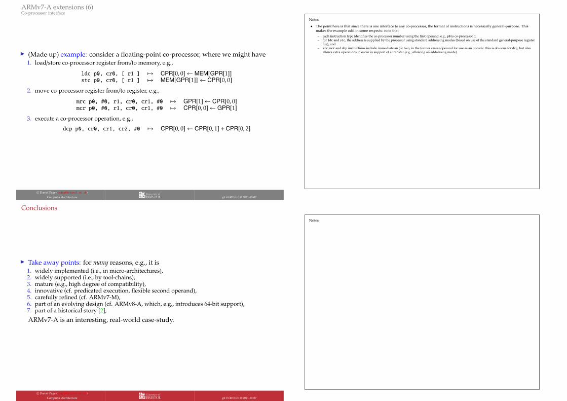
I (Made up) example: consider a floating-point co-processor, where we might have1. load/store co-processor register from/to memory, e.g.,
ldc p0, cr0, [ r1 ] 7→ CPR[0, 0]← MEM[GPR[1]]stc p0, cr0, [ r1 ] 7→ MEM[GPR[1]] ← CPR[0, 0]
2. move co-processor register from/to register, e.g.,
mrc p0, #0, r1, cr0, cr1, #0 7→ GPR[1]← CPR[0, 0]mcr p0, #0, r1, cr0, cr1, #0 7→ CPR[0, 0]← GPR[1]
3. execute a co-processor operation, e.g.,
dcp p0, cr0, cr1, cr2, #0 7→ CPR[0, 0]← CPR[0, 1] + CPR[0, 2]
© Daniel Page 〈[email protected]〉Computer Architecture git # f401bfc0 @ 2021-10-07
Notes:
• The point here is that since there is one interface to any co-processor, the format of instructions is necessarily general-purpose. Thismakes the example odd in some respects: note that
– each instruction type identifies the co-processor number using the first operand, e.g., p0 is co-processor 0,– for ldc and stc, the address is supplied by the processor using standard addressing modes (based on use of the standard general-purpose register
file), and– mrc, mcr and dcp instructions include immediate an (or two, in the former cases) operand for use as an opcode: this is obvious for dcp, but also
allows extra operations to occur in support of a transfer (e.g., allowing an addressing mode).
Conclusions
I Take away points: for many reasons, e.g., it is1. widely implemented (i.e., in micro-architectures),2. widely supported (i.e., by tool-chains),3. mature (e.g., high degree of compatibility),4. innovative (cf. predicated execution, flexible second operand),5. carefully refined (cf. ARMv7-M),6. part of an evolving design (cf. ARMv8-A, which, e.g., introduces 64-bit support),7. part of a historical story [2],
ARMv7-A is an interesting, real-world case-study.
© Daniel Page 〈[email protected]〉Computer Architecture git # f401bfc0 @ 2021-10-07
Notes:

Additional Reading
I Wikipedia: ARM. url: https://en.wikipedia.org/wiki/ARM_architecture.
I S.P. Dandamudi. “Chapter 8: ARM Architecture”. In: Guide to RISC Processors for Programmers and Engineers. Springer, 2004.
I A. N. Sloss, D. Symes, and C. Wright. “Chapter 2: ARM processor fundamentals”. In: ARM System Developer’s Guide: Designingand Optimizing System Software. Elsevier, 2004.
I A. N. Sloss, D. Symes, and C. Wright. “Chapter 3: Introduction to the ARM instruction set”. In: ARM System Developer’s Guide:Designing and Optimizing System Software. Elsevier, 2004.
I A. N. Sloss, D. Symes, and C. Wright. “Chapter 6: Writing and optimizing ARM assembly code”. In: ARM System Developer’sGuide: Designing and Optimizing System Software. Elsevier, 2004.
© Daniel Page 〈[email protected]〉Computer Architecture git # f401bfc0 @ 2021-10-07
Notes:
References
[1] Wikipedia: ARM. url: https://en.wikipedia.org/wiki/ARM_architecture (see p. 65).
[2] Wikipedia: ARM Holdings. url: https://en.wikipedia.org/wiki/Arm_Holdings (see p. 63).
[3] Wikipedia: Thread local storage. url: https://en.wikipedia.org/wiki/Thread-local_storage (see p. 10).
[4] S.P. Dandamudi. “Chapter 7: Itanium Architecture”. In: Guide to RISC Processors for Programmers and Engineers. Springer,2004 (see p. 36).
[5] S.P. Dandamudi. “Chapter 8: ARM Architecture”. In: Guide to RISC Processors for Programmers and Engineers. Springer, 2004(see p. 65).
[6] A. N. Sloss, D. Symes, and C. Wright. “Appendix C: Processors and architecture”. In: ARM System Developer’s Guide:Designing and Optimizing System Software. Elsevier, 2004 (see p. 6).
[7] A. N. Sloss, D. Symes, and C. Wright. “Chapter 2: ARM processor fundamentals”. In: ARM System Developer’s Guide:Designing and Optimizing System Software. Elsevier, 2004 (see p. 65).
[8] A. N. Sloss, D. Symes, and C. Wright. “Chapter 3: Introduction to the ARM instruction set”. In: ARM System Developer’sGuide: Designing and Optimizing System Software. Elsevier, 2004 (see p. 65).
[9] A. N. Sloss, D. Symes, and C. Wright. “Chapter 6: Writing and optimizing ARM assembly code”. In: ARM SystemDeveloper’s Guide: Designing and Optimizing System Software. Elsevier, 2004 (see p. 65).
[10] A. Orpaz and S. Weiss. “A study of CodePack: optimizing embedded code space”. In: Hardware/Software (CODES). 2002,pp. 103–108 (see p. 54).
[11] ARM Architecture Reference Manual: ARMv7-A and ARMv7-R edition. Tech. rep. DDI-0406C. ARM Ltd., 2014. url:http://infocenter.arm.com/help/topic/com.arm.doc.ddi0406c/index.html (see pp. 5, 9–13, 15, 17–21, 25, 27, 28, 33,35, 37, 59, 60).
[12] MOVE Co-processor Technical Reference Manual. Tech. rep. DDI-0235. ARM Ltd., 2004. url:http://infocenter.arm.com/help/topic/com.arm.doc.ddi0235c/index.html (see p. 60).
[13] Procedure Call Standard for the ARM Architecture. Tech. rep. IHI-0042E. ARM Ltd., 2012. url:http://infocenter.arm.com/help/topic/com.arm.doc.ihi0042e/index.html (see pp. 10, 32, 43, 44).
© Daniel Page 〈[email protected]〉Computer Architecture git # f401bfc0 @ 2021-10-07
Notes: