computation method: Effect of cutting variation Multi-objective optimization of wire electrical...
12
http://pib.sagepub.com/ Manufacture Engineers, Part B: Journal of Engineering Proceedings of the Institution of Mechanical http://pib.sagepub.com/content/early/2014/03/20/0954405414523593 The online version of this article can be found at: DOI: 10.1177/0954405414523593 March 2014 published online 20 Proceedings of the Institution of Mechanical Engineers, Part B: Journal of Engineering Manufacture Abolfazl Golshan, Danial Ghodsiyeh and Sudin Izman computation method: Effect of cutting variation Multi-objective optimization of wire electrical discharge machining process using evolutionary Published by: http://www.sagepublications.com On behalf of: Institution of Mechanical Engineers can be found at: Manufacture Proceedings of the Institution of Mechanical Engineers, Part B: Journal of Engineering Additional services and information for http://pib.sagepub.com/cgi/alerts Email Alerts: http://pib.sagepub.com/subscriptions Subscriptions: http://www.sagepub.com/journalsReprints.nav Reprints: http://www.sagepub.com/journalsPermissions.nav Permissions: http://pib.sagepub.com/content/early/2014/03/20/0954405414523593.refs.html Citations: What is This? - Mar 20, 2014 OnlineFirst Version of Record >> at Politecnico di Torino on March 27, 2014 pib.sagepub.com Downloaded from at Politecnico di Torino on March 27, 2014 pib.sagepub.com Downloaded from
Transcript of computation method: Effect of cutting variation Multi-objective optimization of wire electrical...

http://pib.sagepub.com/Manufacture
Engineers, Part B: Journal of Engineering Proceedings of the Institution of Mechanical
http://pib.sagepub.com/content/early/2014/03/20/0954405414523593The online version of this article can be found at:
DOI: 10.1177/0954405414523593
March 2014 published online 20Proceedings of the Institution of Mechanical Engineers, Part B: Journal of Engineering Manufacture
Abolfazl Golshan, Danial Ghodsiyeh and Sudin Izmancomputation method: Effect of cutting variation
Multi-objective optimization of wire electrical discharge machining process using evolutionary
Published by:
http://www.sagepublications.com
On behalf of:
Institution of Mechanical Engineers
can be found at:ManufactureProceedings of the Institution of Mechanical Engineers, Part B: Journal of EngineeringAdditional services and information for
http://pib.sagepub.com/cgi/alertsEmail Alerts:
http://pib.sagepub.com/subscriptionsSubscriptions:
http://www.sagepub.com/journalsReprints.navReprints:
http://www.sagepub.com/journalsPermissions.navPermissions:
http://pib.sagepub.com/content/early/2014/03/20/0954405414523593.refs.htmlCitations:
What is This?
- Mar 20, 2014OnlineFirst Version of Record >>
at Politecnico di Torino on March 27, 2014pib.sagepub.comDownloaded from at Politecnico di Torino on March 27, 2014pib.sagepub.comDownloaded from
Original Article
Proc IMechE Part B:J Engineering Manufacture1–11� IMechE 2014Reprints and permissions:sagepub.co.uk/journalsPermissions.navDOI: 10.1177/0954405414523593pib.sagepub.com
Multi-objective optimization of wireelectrical discharge machining processusing evolutionary computationmethod: Effect of cutting variation
Abolfazl Golshan1, Danial Ghodsiyeh2 and Sudin Izman3
AbstractThis article focuses on comparing the performance of brass wire and zinc-coated brass wire that are widely used as thewire electrode in wire electrical discharge machining. To this end, an evolutionary computation method is presentedbased on non-dominated sorting genetic algorithm in order to find an optimization of rough cutting of the Ti-6Al-4V tita-nium alloy with the aid of response surface methodology modeling. This research examines the effects of three processparameters, namely, pulse on-time, pulse off-time, and peak current on the process outputs, that is, material removalrate, sparking gap, and white layer thickness. The obtained results indicated that zinc-coated wire was more predictableand it showed more reliable response in the experimental and modeling results. Additionally, the optimization results forboth wires demonstrated the high performance of non-dominated sorting genetic algorithm approach to obtain thePareto optimal set of solutions.
KeywordsWire electrical discharge machining, brass wire, zinc-coated brass wire, response surface methodology, non-dominatedsorting genetic algorithm
Date received: 2 June 2013; accepted: 13 January 2014
Introduction
Wire electrical discharge machining (WEDM) is athermo-electrical process in which material is eroded bya series of sparks between the workpiece and the wireelectrode (tool).1 In this process, there is no contactbetween the workpiece and electrode; therefore, materi-als of any hardness can be cut as long as they can con-duct electricity.2 The movement of wire is controllednumerically to achieve the desired three-dimensionalshape and accuracy of the workpiece. That can makeWEDM one of the best choices for precision machiningas well as for machining supper hard materials andcomplex shapes.3
Since the early 1970s, brass has become the mostcommonly used electrode material for WEDM. It wasdue to two properties: good dimensional accuracy andhigh electrical conductivity.4 Brass electrical dischargemachining (EDM) wire is a combination of copper andzinc, typically alloyed in the range of 63–65% Cu and35–37% Zn. The addition of zinc provides significantlyhigher tensile strength, a lower melting point and higher
vapor pressure rating. Since brass wires cannot be effi-ciently fabricated with any higher concentration of zinc,the logical next step was the development of coatedwires, sometimes called plated or ‘‘stratified’’ wire.They typically have a core of brass or copper, for con-ductivity and tensile strength, and are electroplatedwith a coating of pure or diffused zinc for enhancedspark formation and flush characteristics but coatedwires are costly almost twice of brass.5 As a result, uti-lizing brass wire is more economically acceptable unlessthe advantages of coated wire are really irresistible.
1Department of Mechanical Engineering, Faculty of Engineering, Universiti
Putra Malaysia, Serdang, Malaysia2Department of Mechanics and Aerospace, Politecnico di Torino, Torino,
Italy3Department of Materials, Manufacturing & Industrial Engineering, Faculty
of Mechanical Engineering, Universiti Teknologi Malaysia, Skudai, Malaysia
Corresponding author:
Danial Ghodsiyeh, Department of Mechanics and Aerospace, Politecnico
di Torino, 10129 Torino, Italy.
Email: [email protected]
at Politecnico di Torino on March 27, 2014pib.sagepub.comDownloaded from
Among different factors that play an important role inimprovement of the overall performance of WEDM,the evolution of materials for the wire that is employedin WEDM is the most important one. In addition, thecost of the wire is only about 10% of the total operatingcost of the WEDM process; therefore, it can be consid-ered as completely cost-effective to evaluate the proper-ties of the wire used for optimization of the overallperformance of the process. The literature contains justa few studies that have been focused on comparing thewires in different aspects.4,6–8 As a result, there is a needfor specifically evaluating and comparing the character-istics of the wires performance in the WEDM process.
Antar et al.6 presented the study on workpiece pro-ductivity and integrity when WEDMing nickel-basedsuperalloy and titanium alloy, and it was found that anincrease in productivity of about 40% for nickel-basedsuperalloy and about 70% for titanium alloy was possi-ble when replacing standard uncoated brass wire withusing Cu core coated wires diffusion annealed underthe same operating parameters. In terms of recast layerthickness, better results were achieved using the coatedwire for both roughing and trim operation haveobtained. Actually with machining with coated wire,about 25% thinner recast for nickel-based superalloyand about 40% thinner for titanium alloy have pro-duced. Poros and Zaborski7 found that increase of dis-charge time can affect cutting speed and materialremoval rate (MRR) significantly by 62% for brasswire electrode and 138% for zinc-coated brass wire.Therefore, according to different researches, the cuttingspeed of the zinc-coated wire is almost twice of thebrass wire because the exterior zinc coating of the elec-trode has a lower melting temperature than the corematerial (brass). Hence, the zinc is overheated and eva-porated in the presence of a pulse. The evaporation actsas a heat sink, which helps to reduce the wire tempera-ture and improve the effectiveness of the WEDM pro-cess. Consequently, the cutting speed can increase upto 50% for zinc-coated brass wires.4
The most important performance measures inWEDM are MRR, workpiece surface quality, and kerfwidth (cutting width). The kerf width can be used todetermine the dimensional accuracy of the finishedpart; additionally, it puts a limitation on the internalcorner radius to be produced in WEDM operations.9 InWEDM operations, using MRR, the rate of productionand the economics of machining can be determined.When the machining parameters are being set, the desir-able condition is the minimum kerf width with the max-imum MRR. In addition, a technological challenge inWEDM is controlling the surface quality. In WEDM—at the machined surface of the workpiece—a multi-layered heat-affected zone is created whose upper recastlayer is known as the ‘‘white layer,’’ which crystallizesfrom the un-expelled molten metal at high speed. Thislayer is directly in contact with the environment, andthe micro cracks (if any) are typically restricted only tothis layer. It is undesirable to have a white layer on the
surface of the workpiece that is machined by WEDM;it is because this layer makes the surface completely sus-ceptible to fatigue failure. Several studies have been car-ried out to find thoroughly the properties and theformation mechanism of the white layer; although littleresearch10 has been focused on modeling the process asa problem of correlating the dominant input parametersof the WEDM process with the white layer depth as themachining performance or criterion. As a result, thisarticle attempts to develop a mathematical model ofwhite layer depth, kerf width, and MRR and analyzeextensively the impacts of the dominant input processparameters on the same responses in the process ofWEDM.
Evidently, in the context of WEDM, it is extremelydifficult even for a skilled operator to achieve an opti-mal performance criterion. This is due to existence ofmany variables in the WEDM process and its multifa-ceted and stochastic nature.11 The problem will be evenmore complicated in the case of multi-objective optimi-zation, that is, more than one objective must be opti-mized simultaneously. Multi-objective optimizationproblems can be solved using evolutionary computa-tional algorithms such as genetic algorithms (GAs) andparticle swarm optimization.12 According to the litera-ture,13,14 several studies have been conducted to find anoptimized condition for the machining parametersusing evolutionary computational algorithms such asGAs and particle swarm optimization (PSO).
One of the most widely employed algorithms formulti-objective optimization is non-dominating sortinggenetic algorithm-II (NSGA-II). Many researchershave employed NSGA-II to optimize machining para-meters in WEDM process.15–19 Kondayya and GopalaKrishna15 discussed a simultaneous optimization of theMRR and the surface roughness using the NSGA-II.Debabrata et al.16 carried out the multi-objective opti-mization of WEDM to maximize the MRR and mini-mize tool wear using NSGA-II. Prasad and GopalaKrishna17 developed a response surface model to corre-late EDM process parameters with MRR and surfaceroughness. And finally, non-dominated solutions wereobtained by response surface model–based NSGA-IItechnique. Baraskar et al.18 adopted NSGA-II to opti-mize machining parameters in EDM considering sur-face roughness and MRR as the output parameters.Moreover, there are some methods, which successfullymodeled WEDM-like feed-forward back-propagationneural network (BPNN)20 and normalized radial basisfunction network (NRBFN) with enhanced and tradi-tional k-means clustering techniques.21 Saha et al.19
proposed a multi-objective optimization using a neuro-genetic technique to optimize the cutting speed and kerfwidth in WEDM processing of TiC-reinforced compo-site. The technique was developed through hybridiza-tion of a radial basis function network (RBFN) andnon-dominated sorting genetic algorithm (NSGA-II).
However, to the best of our knowledge, in the litera-ture, there is not any research attempting to optimize
2 Proc IMechE Part B: J Engineering Manufacture
at Politecnico di Torino on March 27, 2014pib.sagepub.comDownloaded from
machining parameters in WEDM of Ti-6Al-4V withrespect to the MRR, kerf width, and white layer thick-ness (WLT) objectives. Therefore, this article aims toobtain the optimum machining conditions for WEDMof Ti-6Al-4V for maximum MRR and minimum kerfwidth and WLT based on NSGA-II approach for bothwires. Experiments, based on central composite design(CCD), were carried out to study the effect of variousparameters, namely, pulse-on time, pulse-off time, andpeak current on response parameters for both wires.Using response surface methodology (RSM), mathe-matical models for the objectives are obtained from theexperimental data. Finally, a NSGA-II is used to obtainthe Pareto optimal set of solutions for both wires.
Experimental work
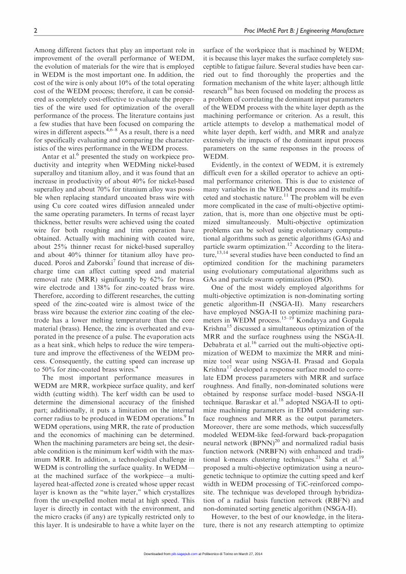
In this research, a series of experiments on titaniumalloy Ti-6AL-4V with the nominal chemical composi-tion of 6.3 Al, 4.1 V, 0.18 Fe, 0.182 O, and 0.03 Si inmass percent and balance titanium were conductedusing a Sodick series AQ 537L CNC WEDM machine.The yield strength of Ti-6Al-4V is 840 MPa, its ulti-mate tensile strength is 910 MPa, and its hardness is 45HRC. A brass wire and a zinc-coated brass wire wereused as tools and compared to each other. Some char-acteristics of brass wire and zinc-coated brass wire arepresented in Table 1. Servo voltage, wire speed, wiretension, and flushing pressure were kept as 40 V, 15 m/min, 600 g, and 55 bar, respectively. The machiningvoltage was set as 120 V. Deionized water was used asdielectric fluid. Figure 1 presents the basic features ofthe WEDM setup. Furthermore, the kerf width and thesparking gap (SG) were investigated using the setup, asshown in Figure 1.
The input parameters and their initial settings areselected based on the existing literature and some initialinvestigations. Three significant factors in the roughmachining process are considered in this study: thepulse on-time, the pulse off-time, and the peak current.The low, middle, and high levels of these three para-meters are presented in Table 2.
Design Expert 7.0.0 software was employed for thestatistical design of the experiments and the data analy-sis. The WEDM process was investigated using thestandard RSM design known as CCD. Generally, foreach factor, the central point is assumed 0, and thedesign is considered symmetric around this point. The
star points are located at the face of the cube portionon the design that corresponds to an a-value of 1. Thisis usually referred to as a face centered, CCD. In thecases in which there are three variables (n = 3), pointson a cube represent the CCD. The points (runs) areincluding 2n (2 3 3 = 6) star points, 2n (23 = 8) fac-torial points, and 3 center points (three replications).Table 3 presents the experimental plan and results withthree factors and three levels.
In each experimental run, the MRR, SG, and WLTwere measured. In each trial, a 10 mm length of cuttingwas made on 10 mm thickness of the workpieces. Thefollowing equation has been used to compute the MRRvalue
MRR (mm3=s)=Wi �Wj
T3pð1Þ
where Wi and Wj signify weights of workpiece materialbefore and after machining (g), respectively. T denotesmachining time (s) and p represents the density of Ti-6Al-4V (0.00442 g/mm3). A precise balance Mettler(92SM-202A DR) with high accuracy of 1023 g wasused to measure the weight of the workpiece required.The kerf width was measured using a Mitutoyo ProfileProjector PJ-3000 to compute the SG, and the follow-ing equation is used to determine the SG value
SG (mm)=average of kerf width� diameter ofwire
2
ð2Þ
Table 1. General characteristics of brass wire and zinc-coatedbrass wire.
Characteristics Brass Zinc-coated brass
Wire diameter 0.25 0.25Type symbol P (hard) ZWire diameter tolerance (mm) 60.001 60.001Minimum tensile strength (MPa) 980 883Minimum fracture load (N) 48.2 43.3Minimum conductivity (%) 22 20
Figure 1. Basic features of WEDM setup.
Table 2. Rough cutting parameters and their levels.
Parameters Symbol Levels
Low(21)
Center(0)
High(1)
Pulse on-time (ms) Ton 8 9 10Pulse off-time (ms) Toff 6.5 7.5 8.5Peak current (A) Ip 32 36 40
Golshan et al. 3
at Politecnico di Torino on March 27, 2014pib.sagepub.comDownloaded from
A field emission scanning electron microscope(FESEM) (Philips XL40) was used to analyze and mea-sure the thickness of the altered surface (recast layer).Samples were thoroughly cleaned with acetone andthen mounted exposing an area of approximately 2 3
25 mm with resin and hardener in a mold. The mountedspecimens were then ground and polished. Polishing isperformed to have mirror finish on the transverse sec-tion, and subsequently, these faces are etched withKroll’s reagent (2% hydrofluoric acid + 10% nitricacid + 88% water) for 10–15 s. Henceforth, thesesamples were seen with the help of a field emissionscanning electron microscope. The white layers fromthe photographs are easily identified. The depths ofwhite layers were measured carefully from the micro-graph, and averages of readings were taken for eachexperimental run.
Experimental results
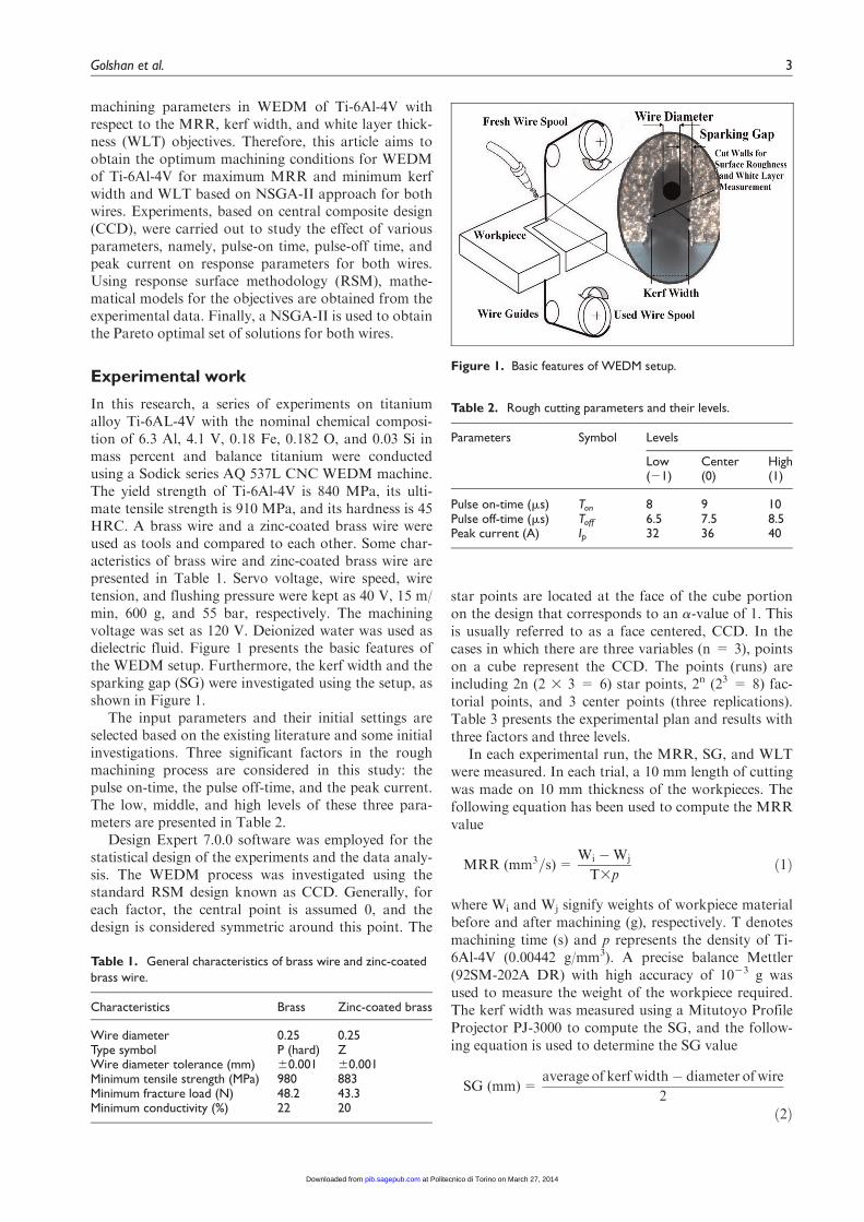
In these experiments, it was observed that due to lowthermal conductivity in titanium alloy material, highflushing pressure is absolutely necessary for roughmachining; otherwise, the short-circuit phenomenonwill cause to wire breakage. Figure 2 shows the cuttingline while machining titanium alloy Ti-6Al-4V in nor-mal flushing pressure. This figure shows that in theabsence of high flashing pressure, cutting line cannotcontinue more than 1 mm.
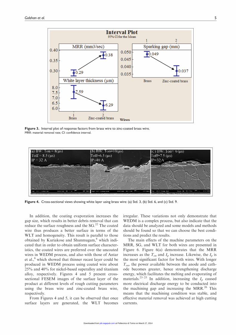
Figure 3 presents the interval plot of each responsefrom brass wire to zinc-coated brass wire based on theexperimental results (Table 3) using Minitab 16 soft-ware. Figure 3 demonstrates that the mean MRRsusing brass wire and zinc-coated brass wire were 0.29
and 0.38 mm3/s, respectively. Thus, the percentageincrease of the mean MRR from brass wire to zinc-coated brass wire was +31.03. Likewise, the percent-age increase of the SG and WLT from brass wire tozinc-coated brass wire were 224.49 and 217.13, respec-tively. The MRR of the zinc-coated wire is more thanthat of the brass wire because the exterior zinc coat-ing of the electrode has a lower melting temperaturethan the core material (brass). Therefore, the zinc isoverheated and evaporated in the presence of a pulse.The evaporation acts as a heat sink; it reduces thewire temperature and improves the effectiveness ofthe WEDM process. Consequently, the cutting speedincreases by up to 50% as more intense thermal flowsare enabled.4
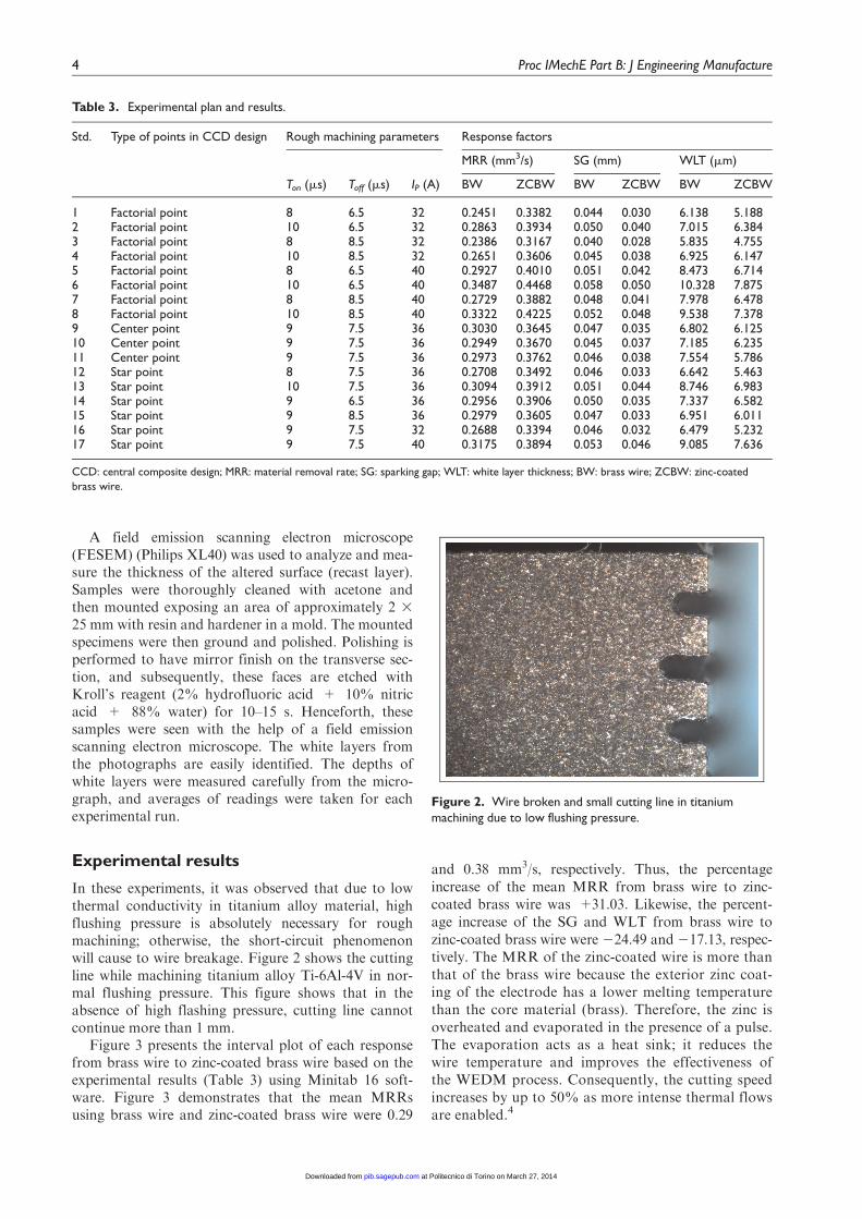
Table 3. Experimental plan and results.
Std. Type of points in CCD design Rough machining parameters Response factors
MRR (mm3/s) SG (mm) WLT (mm)
Ton (ms) Toff (ms) IP (A) BW ZCBW BW ZCBW BW ZCBW
1 Factorial point 8 6.5 32 0.2451 0.3382 0.044 0.030 6.138 5.1882 Factorial point 10 6.5 32 0.2863 0.3934 0.050 0.040 7.015 6.3843 Factorial point 8 8.5 32 0.2386 0.3167 0.040 0.028 5.835 4.7554 Factorial point 10 8.5 32 0.2651 0.3606 0.045 0.038 6.925 6.1475 Factorial point 8 6.5 40 0.2927 0.4010 0.051 0.042 8.473 6.7146 Factorial point 10 6.5 40 0.3487 0.4468 0.058 0.050 10.328 7.8757 Factorial point 8 8.5 40 0.2729 0.3882 0.048 0.041 7.978 6.4788 Factorial point 10 8.5 40 0.3322 0.4225 0.052 0.048 9.538 7.3789 Center point 9 7.5 36 0.3030 0.3645 0.047 0.035 6.802 6.12510 Center point 9 7.5 36 0.2949 0.3670 0.045 0.037 7.185 6.23511 Center point 9 7.5 36 0.2973 0.3762 0.046 0.038 7.554 5.78612 Star point 8 7.5 36 0.2708 0.3492 0.046 0.033 6.642 5.46313 Star point 10 7.5 36 0.3094 0.3912 0.051 0.044 8.746 6.98314 Star point 9 6.5 36 0.2956 0.3906 0.050 0.035 7.337 6.58215 Star point 9 8.5 36 0.2979 0.3605 0.047 0.033 6.951 6.01116 Star point 9 7.5 32 0.2688 0.3394 0.046 0.032 6.479 5.23217 Star point 9 7.5 40 0.3175 0.3894 0.053 0.046 9.085 7.636
CCD: central composite design; MRR: material removal rate; SG: sparking gap; WLT: white layer thickness; BW: brass wire; ZCBW: zinc-coated
brass wire.
Figure 2. Wire broken and small cutting line in titaniummachining due to low flushing pressure.
4 Proc IMechE Part B: J Engineering Manufacture
at Politecnico di Torino on March 27, 2014pib.sagepub.comDownloaded from
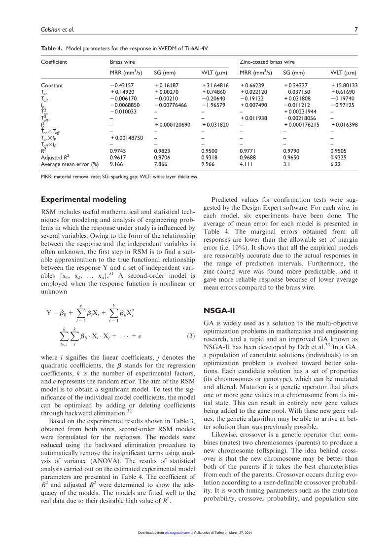
In addition, the coating evaporation increases thegap size, which results in better debris removal that canreduce the surface roughness and the SG.22 The coatedwire thus produces a better surface in terms of theWLT and homogeneity. This result is parallel to thoseobtained by Kuriakose and Shunmugam,8 which indi-cated that in order to obtain uniform surface character-istics, the coated wires are preferred over the uncoatedwires in WEDM process, and also with those of Antaret al.,6 which showed that thinner recast layer could beproduced in WEDM process using coated wire about25% and 40% for nickel-based superalloy and titaniumalloy, respectively. Figures 4 and 5 present cross-sectional FESEM images of the surface layer of theproduct at different levels of rough cutting parametersusing the brass wire and zinc-coated brass wire,respectively.
From Figures 4 and 5, it can be observed that oncesurface layers are generated, the WLT becomes
irregular. These variations not only demonstrate thatWEDM is a complex process, but also indicate that thedata should be analyzed and some models and methodsshould be found so that we can choose the best condi-tions and predict the results.
The main effects of the machine parameters on theMRR, SG, and WLT for both wires are presented inFigure 6. Figure 6(a) demonstrates that the MRRincreases as the Ton and Ip increase. Likewise, the Ip isthe most significant factor for both wires. With longerTon, the power available between the anode and cath-ode becomes greater, hence strengthening dischargeenergy, which facilitates the melting and evaporating ofmaterials.23–25 In addition, increasing the Ip causedmore electrical discharge energy to be conducted intothe machining gap and increasing the MRR.26 Thismeans that the machining condition was stable, andeffective material removal was achieved at high cuttingcurrents.
Figure 3. Interval plot of response factors from brass wire to zinc-coated brass wire.MRR: material removal rate; CI: confidence interval.
Figure 4. Cross-sectional views showing white layer using brass wire: (a) Std. 3, (b) Std. 6, and (c) Std. 9.
Golshan et al. 5
at Politecnico di Torino on March 27, 2014pib.sagepub.comDownloaded from

Figure 6(b) shows that the Ton and Ip have more sig-nificant effects on the SG compared to the Toff. This out-come agrees with the results obtained by Tosun et al.9 andKanlayasiri and Boonmung.27 In addition, the Ton and Ipare in direct relationship to the SG, that is, increasing theTon and Ip significantly increases the SG. The reason isthat with the increase of discharge duration, the overcutduring discharge is also increased.28 Increasing the peakcurrent also increases the energy of each discharge, whichleads to producing wider and deeper craters.
From Figure 6(c), it can be concluded that the maineffect of Ip is being labeled as number one in rankingamong all the three factors on the WLT for both wires.It can be seen that Toff has little effect on the WLT forboth wires. These results are similar to those obtainedby Newton et al.29 and Ghodsiyeh et al.,30 whichdemonstrated the Ip and Ton as the driving factors indetermining average recast layer thickness and alsoindicated that Toff did not display a significant effecton the average recast layer thickness.
Figure 5. Cross-sectional views showing white layer using zinc-coated brass wire: (a) Std. 3, (b) Std. 6, and (c) Std. 9.
Figure 6. Main effects plot for the mean responses for brass wire and zinc-coated brass wire: (a) MRR, (b) SG, and (c) WLT.MRR: material removal rate; SG: sparking gap; WLT: white layer thickness.
6 Proc IMechE Part B: J Engineering Manufacture
at Politecnico di Torino on March 27, 2014pib.sagepub.comDownloaded from
Experimental modeling
RSM includes useful mathematical and statistical tech-niques for modeling and analysis of engineering prob-lems in which the response under study is influenced byseveral variables. Owing to the form of the relationshipbetween the response and the independent variables isoften unknown, the first step in RSM is to find a suit-able approximation to the true functional relationshipbetween the response Y and a set of independent vari-ables {x1, x2, . xn}.
31 A second-order model isemployed when the response function is nonlinear orunknown
T=b0 +Xk
i=1
biXi +Xk
i=1
biiX2i
Xk
ii41
Xk
j
bij �Xi �Xj + � � � + e ð3Þ
where i signifies the linear coefficients, j denotes thequadratic coefficients, the b stands for the regressioncoefficients, k is the number of experimental factors,and e represents the random error. The aim of the RSMmodel is to obtain a significant model. To test the sig-nificance of the individual model coefficients, the modelcan be optimized by adding or deleting coefficientsthrough backward elimination.32
Based on the experimental results shown in Table 3,obtained from both wires, second-order RSM modelswere formulated for the responses. The models werereduced using the backward elimination procedure toautomatically remove the insignificant terms using anal-ysis of variance (ANOVA). The results of statisticalanalysis carried out on the estimated experimental modelparameters are presented in Table 4. The coefficient ofR2 and adjusted R2 were determined to show the ade-quacy of the models. The models are fitted well to thereal data due to their desirable high value of R2.
Predicted values for confirmation tests were sug-gested by the Design Expert software. For each wire, ineach model, six experiments have been done. Theaverage of mean error for each model is presented inTable 4. The marginal errors obtained from allresponses are lower than the allowable set of marginerror (i.e. 10%). It shows that all the empirical modelsare reasonably accurate due to the actual responses inthe range of prediction intervals. Furthermore, thezinc-coated wire was found more predictable, and itgave more reliable response because of lower averagemean errors compared to the brass wire.
NSGA-II
GA is widely used as a solution to the multi-objectiveoptimization problems in mathematics and engineeringresearch, and a rapid and an improved GA known asNSGA-II has been developed by Deb et al.33 In a GA,a population of candidate solutions (individuals) to anoptimization problem is evolved toward better solu-tions. Each candidate solution has a set of properties(its chromosomes or genotype), which can be mutatedand altered. Mutation is a genetic operator that altersone or more gene values in a chromosome from its ini-tial state. This can result in entirely new gene valuesbeing added to the gene pool. With these new gene val-ues, the genetic algorithm may be able to arrive at bet-ter solution than was previously possible.
Likewise, crossover is a genetic operator that com-bines (mates) two chromosomes (parents) to produce anew chromosome (offspring). The idea behind cross-over is that the new chromosome may be better thanboth of the parents if it takes the best characteristicsfrom each of the parents. Crossover occurs during evo-lution according to a user-definable crossover probabil-ity. It is worth tuning parameters such as the mutationprobability, crossover probability, and population size
Table 4. Model parameters for the response in WEDM of Ti-6Al-4V.
Coefficient Brass wire Zinc-coated brass wire
MRR (mm3/s) SG (mm) WLT (mm) MRR (mm3/s) SG (mm) WLT (mm)
Constant 20.42157 + 0.16187 + 31.64816 + 0.66239 + 0.24227 + 15.80133Ton + 0.14920 + 0.00270 + 0.74860 + 0.022120 20.037150 + 0.61690Toff 20.006170 20.00210 20.20640 20.19122 + 0.031808 20.19740Ip 20.0068850 20.00776466 21.96579 + 0.007490 20.011212 20.97125T2
on 20.010033 – – – + 0.00231944 –T2
off – – – + 0.011938 20.00218056 –I2p – + 0.000120690 + 0.031820 – + 0.000176215 + 0.016398Ton3Toff – – – – – –Ton3IP + 0.00148750 – – – – –Toff3IP – – – – – –R2 0.9745 0.9823 0.9500 0.9771 0.9790 0.9505Adjusted R2 0.9617 0.9706 0.9318 0.9688 0.9650 0.9325Average mean error (%) 9.166 7.866 9.966 4.111 3.1 6.22
MRR: material removal rate; SG: sparking gap; WLT: white layer thickness.
Golshan et al. 7
at Politecnico di Torino on March 27, 2014pib.sagepub.comDownloaded from

to find reasonable settings for the problem class beingworked on.
The mutation and crossover operators of NSGA-IIhave remained unchanged, but the working process ofthe selection operator differs from the simple GA. Theselection operator is aided in the act of selection bycrowded-comparison operator based on ranking that isdone, in turn, according to non-domination level andcrowding distance.33 The algorithm flowchart ofNSGA-II is illustrated in Figure 7.
Optimization results
To optimize the process parameters and obtain thedesired outputs (maximum MRR, minimum SG, andminimum WLT), a multi-objective optimization wasperformed. The three-objective optimization functionsare formulated as follows
Maximize f(x)f g and minimize g(x), h(x)f g s:t x X
ð4Þ
where x represents the WEDM process parameters; x= x1, x2, x3 (x1 = Ton, x2 = Toff, and x3 = Ip); X sig-nifies all feasible values of the WEDM process para-meters; and the functions f(x), g(x), and h(x) stand forthe formulated RSM models (Table 4) for the MRR,SG, and WLT, respectively.
The NSGA-II was applied in MATLAB 7.12.0, andthe control factors of the NSGA-II were modified toimprove the performance. These control parametersproduced the optimal solutions and a satisfactory levelof convergence. As the NSGA-II parameters, inter-mediate crossover with crossover probability of 0.9 and
Gaussian mutation with mutation probability of 0.1were used. Intermediate crossover is a method onlyapplicable to real variables (and not binary variables).The Gaussian mutation operator is advantageous sinceit is very flexible and supports both fine tuning of solu-tions and searching the domain. A total of 250 genera-tions were generated to obtain the true optimalsolution. All the parameters for NSGA-II were sum-marized in Table 5. The Pareto frontiers of the 100non-dominated solutions for the three responses andboth the brass wire and zinc-coated brass wire are pre-sented in Figure 8.
As can be seen from the graphs, no solution in thePareto optimal front is better than any other as they arenon-dominated solutions. For better understanding, thethree-dimensional Pareto optimal front is plotted in atwo-dimensional objective space for viewing, as shownin Figure 8(b) and (c).
Figure 8(b) shows that the minimum SG is close to0.04 mm for brass wire and close to 0.028 mm for zinc-coated brass wire, with a corresponding MRR of0.2379 mm3/s for brass wire and MRR of 0.3162 mm3/sfor zinc-coated brass wire. The other combinations ofparameters will result in better MRR but higher SG forboth wires. It can be derived from Figure 8(c) that ahigher MRR will result in a higher WLT for both wires.The lowest WLT is close to 5.56 mmm with MRR of0.2379 mm3/s for brass wire and is close to 4.77 mmmwith MRR of 0.3162 mm3/s for zinc-coated brass wire.If a higher MRR is desired, some higher value for WLTshould be accepted.
Compared to other multi-objective algorithms,Nawaz Ripon et al.34 made a comparison betweenNSGA-II and Pareto archived evolution strategy(PAES), niched Pareto genetic algorithm (NPGA), vec-tor evaluated genetic algorithm (VEGA), and strengthPareto evolutionary algorithm (SPEA). This compari-son was made based on five benchmark test prob-lems,35 in which NSGA-II found better non-dominatedsolutions with a greater convergence and diversity inmost cases. Moreover, NSGA-II was compared to dif-ferential evolution (DE) by Kukkonen and Lampinen36
based on five multi-objective benchmark functions thathad been presented by Zitzler et al.35 The obtained
Figure 7. Flowchart for the NSGA-II algorithm.
Table 5. Control parameters of the NSGA-II.
Parameters Value/type
Population size 100Maximum generation number 250Crossover type IntermediateCrossover probability 0.9Mutation type GaussianMutation probability 0.1
8 Proc IMechE Part B: J Engineering Manufacture
at Politecnico di Torino on March 27, 2014pib.sagepub.comDownloaded from

results indicated that on four out of the five benchmarkfunctions, NSGA-II performed better than the DE, interms of diversity and extent of the solutions.Additionally, Saha et al.21 made a comparison betweenNSGA-II and weighted sum method in WEDM pro-cessing of TiC-reinforced composite. The resultsobtained from weighted sum method were inferior toNSGA-II. In this study, we focused on comparing the
performance of brass wire and zinc-coated brass wireto optimize machining parameters in WEDM process-ing of Ti-6Al-4V using NSGA-II. As can be seen in allcurves in Figure 8, non-dominated solutions have agood convergence and diversity, which tends to demon-strate the suitability of the NSGA-II method in solvingthis multi-objective optimization problem. Moreover,the Pareto optimal front of zinc-coated brass wire wasmore uniform than that of brass wire, which tends toconfirm that the zinc-coated brass wire was more pre-dictable in WEDM process.
Furthermore, non-dominated optimal solutions thatform the Pareto front in objective function space canbe analyzed in decision variable space.37 The particlesrepresenting optimal set of decision variables given inFigure 8 are mapped into the decision variable space(i.e. Ton, Toff, and Ip), as shown in Figure 9. It can beseen from Figure 9 that the optimal machining para-meters occur along the boundary of the decision vari-able space for brass wire, that is, for all Ton between 8and 10 ms, for Toff between 6.5 and 8.5 ms, and for Ipbetween 32 and 40 A. Likewise, in the case of zinc-coated brass wire, the optimal machining parameters ofTon and Ip occur along the boundary of the decisionvariable space but the optimal values of Toff occur
Figure 8. Pareto frontier of optimal MRR, SG, and WLT in WEDM process: (a) Three-dimensional Pareto optimal front, (b) MRRand SG, and (c) MRR and WLT.MRR: material removal rate; SG: sparking gap; WLT: white layer thickness.
Figure 9. Decision variable space for optimal machiningparameters in WEDM.
Golshan et al. 9
at Politecnico di Torino on March 27, 2014pib.sagepub.comDownloaded from
around 6.5 or 8.5 ms. This tends to confirm that therange levels of the Toff selected could be wider for zinc-coated wire.
Conclusion
This study focuses on comparing the performance ofbrass wire and zinc-coated brass wire in WEDM processof Ti-6Al-4V titanium alloy using experimental, statisti-cal modeling and multi-objective optimization results.The following conclusions were drawn from this study:
1. The percentage increase of the mean MRR, SG,and WLT from brass wire to zinc-coated brass wirewere +31.03, 224.49, and 217.13, respectively.
2. The WLTs of the workpieces cut with brass wireare much thicker than those cut with the zinc-coated wire because the zinc-coated brass wireimproves debris removal.
3. The Ton, Toff, and Ip are the most important para-meters that influence the response variables. TheMRR is most significantly affected by the Ton andIp for both wires. Also, the Ton and Ip have moresignificant effects than the Toff on the SG andWLT when either wire is used.
4. Empirical equations to predict the MRR, SG, andWLT are obtained for both wires using RSM.Confirmation runs verify that the developed math-ematical models are accurate, and the predictedvalues agree closely with the experimental values.Zinc-coated wire was found more predictable withmore reliable response.
5. NSGA-II was used to obtain the Pareto optimalset of solutions for both wires. The observedresults with both wire types demonstrate the suit-ability of the NSGA-II method in solving thismulti-objective optimization problem. The Paretooptimal front of zinc-coated brass wire was moreuniform, which confirmed that the zinc-coatedbrass wire was more predictable compared to brasswire in WEDM process.
6. This study can be extended in the future by chang-ing the work materials or applying different opti-mization methods.
Declaration of conflicting interests
The authors declare that there is no conflict of interest.
Funding
This research received no specific grant from any fund-ing agency in the public, commercial, or not-for-profitsectors.
References
1. Rao RV and Pawar PJ. Modelling and optimization of
process parameters of wire electrical discharge
machining. Proc IMechE, Part B: J Engineering Manu-
facture 2009; 223(11): 1367–1506.2. Ho KH, Newman ST and Allen RD. STEP-NC compli-
ant information modelling for wire electrical discharge
machining component. Proc IMechE, Part B: J Engineer-
ing Manufacture 2005; 219: 777–784.3. Hsieh JF. Modelling tool path in wire electric discharge
machining using Denavit–Hartenberg notation. Proc
IMechE, Part B: J Engineering Manufacture 2011; 225:
1063–1072.4. Prohaszka J, Mamalis AG and Vaxevanidis NM. The
effect of electrode material on machinability in wire
electro-discharge machining. J Mater Process Tech 1997;
69(1–3): 233–237.5. Ghodsiyeh D, Golshan A and Shirvanehdeh JA. Review
on current research trends in wire electrical discharge
machining (WEDM). Indian J Sci Tech 2013; 6(2):
154–168.6. Antar MT, Soo SL, Aspinwall DK, et al. Productivity
and workpiece surface integrity when WEDM aerospace
alloys using coated wires. Procedia Eng 2011; 19: 3–8.7. Poros D and Zaborski S. Semi-empirical model of effi-
ciency of wire electrical discharge machining of hard-to-
machine materials. J Mater Process Tech 2009; 209:
1247–1253.8. Kuriakose S and Shunmugam MS. Characteristics of
wire-electro discharge machined Ti6Al4V surface. Mater
Lett 2004; 58(17–18): 2231–2237.9. Tosun N, Cogun C and Tosun G. Study on kerf and
material removal rate in wire electrical discharge machin-
ing based on Taguchi method. J Mater Process Tech
2004; 152(3): 316–322.10. Puri AB and Bhattacharyya B. Modeling and analysis of
white layer depth in a wire-cut EDM process through
response surface methodology. Int J Adv Manuf Tech
2005; 25: 301–307.11. Sarkar S, Ghosh K, Mitra S, et al. An integrated
approach to optimization of WEDM combining single-
pass and multipass cutting operation. Mater Manuf Pro-
cess 2010; 25(8): 799–807.12. Coello CA and Becerra RL. Evolutionary multiobjective
optimization in materials science and engineering. Mater
Manuf Process 2009; 24(2): 119–129.13. Chandrasekaran M, Muralidhar M, Krishna CM, et al.
Application of soft computing techniques in machining
performance prediction and optimization: a literature
review. Int J Adv Manuf Tech 2010; 46(5–8): 445–464.14. Yusup N, Zain AM and Hashim SZM. Evolutionary tech-
niques in optimizing machining parameters: review and
recent applications. Expert Syst Appl 2012; 39: 9909–9927.15. Kondayya D and Gopala Krishna A. An integrated evo-
lutionary approach for modelling and optimization of
wire electrical discharge machining. Proc IMechE, Part
B: J Engineering Manufacture 2011; 225: 549–567.16. Debabrata M, Pal SK and Partha S. Modeling of electri-
cal discharge machining process using back propagation
neural network and multi-objective optimization using
non-dominating sorting genetic algorithm-II. J Mater
Process Tech 2007; 186(1–3): 154–162.17. Prasad DVSSSV and Gopala Krishna A. Empirical mod-
eling and optimization of wire electrical discharge
machining. Int J Adv Manuf Tech 2009; 43: 914–925.18. Baraskar SS, Banwait SS and Laroiya SC. Multiobjective
optimization of electrical discharge machining process
10 Proc IMechE Part B: J Engineering Manufacture
at Politecnico di Torino on March 27, 2014pib.sagepub.comDownloaded from
using a hybrid method.Mater Manuf Process 2013; 28(4):348–354.
19. Saha P, Tarafdar D, Pal SK, et al. Multi-objective opti-mization in wire-electro-discharge machining of TiC rein-forced composite through Neuro-Genetic technique. ApplSoft Comput 2013; 13: 2065–2074.
20. Saha P, Singha A, Pal SK, et al. Soft computing modelsbased prediction of cutting speed and surface roughnessin wire electro-discharge machining of tungsten carbidecobalt composite. Int J Adv Manuf Tech 2008; 39: 74–84.
21. Saha P, Tarafdar D, Pal SK, et al. Modeling of wireelectro-discharge machining of TiC/Fe in situ metalmatrix composite using normalized RBFN with enhancedk-means clustering technique. Int J Adv Manuf Tech
2009; 43: 107–116.22. Dauw DF and Albert L. About the evolution of wire tool
performance in wire EDM. CIRP Ann: Manuf Techn
1992; 41(1): 221–225.23. Tosun N and Cogun C. Analysis of wire erosion and
workpiece surface roughness in wire electrical dischargemachining. Proc IMechE, Part B: J Engineering Manu-
facture 2003; 217: 633–642.24. Tzeng CJ, Yang YK, Hsieh MH, et al. Optimization of
wire electrical discharge machining of pure tungsten usingneural network and response surface methodology. ProcIMechE, Part B: J Engineering Manufacture 2011; 225:841–852.
25. Jia Y, Kim BS, Hu DJ, et al. Parametric study on near-dry wire electrodischarge machining of polycrystallinediamond-coated tungsten carbide material. Proc IMechE,
Part B: J Engineering Manufacture 2010; 224: 185–193.26. Sadeghi M, Razavi H, Esmaeilzadeh A, et al. Optimiza-
tion of cutting conditions in WEDM process using regres-sion modelling and Tabu-search algorithm. Proc IMechE,
Part B: J Engineering Manufacture 2011; 225: 1825–1834.27. Kanlayasiri K and Boonmung S. Effects of wire-EDM
machining variables on surface roughness of newly
developed DC 53 die steel: design of experiments andregression model. J Mater Process Tech 2007; 192–193:459–464.
28. Yu PH, Lee HK, Lin YX, et al. Machining characteristicsof polycrystalline silicon by wire electrical dischargemachining. Mater Manuf Process 2011; 26(12): 1443–1450.
29. Newton TR, Melkote SN, Watkins TR, et al. Investiga-tion of the effect of process parameters on the formationand characteristics of recast layer in wire-EDM of Inconel718.Mat Sci Eng A: Struct 2009; 513–514: 208–215.
30. Ghodsiyeh D, Golshan A and Izman S. Multi-objectiveprocess optimization of wire electrical discharge machin-ing based on response surface methodology. J Braz Soc
Mech Sci 2014; 36(2): 301–313.31. Montgomery DC. Design and analysis of experiments. 7th
ed.Singapore: John Wiley & Sons, 2009, pp.207–264.32. Noordin MY, Venkatesh VC, Sharif S, et al. Application
of response surface methodology in describing the perfor-mance of coated carbide tools when turning AISI 1045steel. J Mater Process Tech 2004; 145: 46–58.
33. Deb K, Pratap A, Agarwal S, et al. A fast and elitist mul-tiobjective algorithms: NSGA-II. IEEE T Evolut Comput
2002; 6: 182–197.34. Nawaz Ripon KS, Kwong S and Man KF. A real-coding
jumping gene genetic algorithm (RJGGA) for multiobjec-tive optimization. Inform Sciences 2007; 177: 632–654.
35. Zitzler E, Deb K and Thiele L. Comparison of multiob-jective evolutionary algorithms: empirical results. Evol
Comput 2000; 8(2): 173–195.36. Kukkonen S and Lampinen J. An extension of general-
ized differential evolution for multi-objective optimiza-tion with constraints. Lect Notes Comput Sc 2004; 3242:752–761.
37. Teixidor D, Ferrer I, Ciurana J, et al. Optimization ofprocess parameters for pulsed laser milling of micro-channels on AISI H13 tool steel. Robot Cim: Int Manuf
2013; 29: 209–218.
Golshan et al. 11
at Politecnico di Torino on March 27, 2014pib.sagepub.comDownloaded from