Efficiency & Modernization Advisory Panel Kickoff Meeting ...
Upload
independentCategory
view
0download
0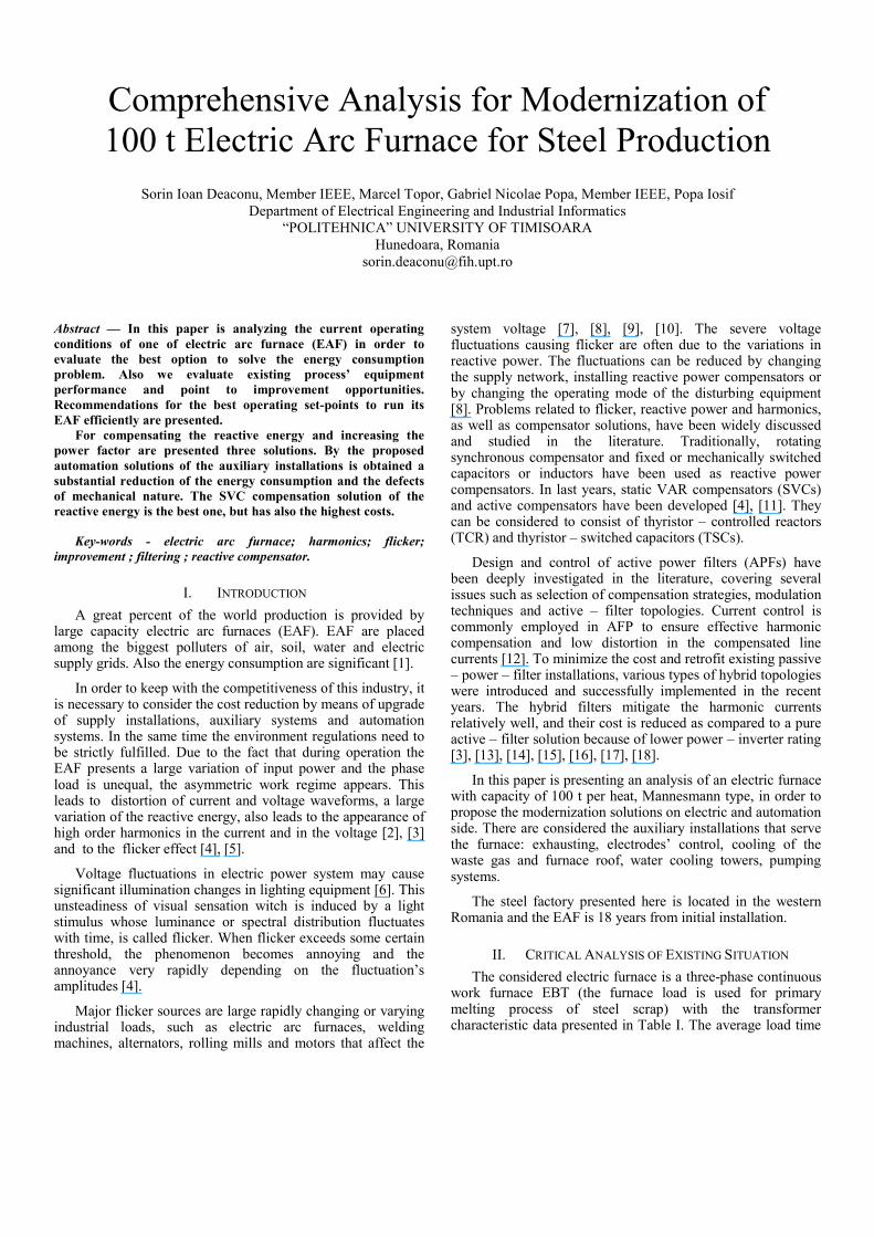
Comprehensive Analysis for Modernization of 100 t Electric Arc Furnace for Steel Production
Sorin Ioan Deaconu, Member IEEE, Marcel Topor, Gabriel Nicolae Popa, Member IEEE, Popa Iosif
Department of Electrical Engineering and Industrial Informatics “POLITEHNICA” UNIVERSITY OF TIMISOARA
Hunedoara, Romania [email protected]
Abstract — In this paper is analyzing the current operating conditions of one of electric arc furnace (EAF) in order to evaluate the best option to solve the energy consumption problem. Also we evaluate existing process’ equipment performance and point to improvement opportunities. Recommendations for the best operating set-points to run its EAF efficiently are presented.
For compensating the reactive energy and increasing the power factor are presented three solutions. By the proposed automation solutions of the auxiliary installations is obtained a substantial reduction of the energy consumption and the defects of mechanical nature. The SVC compensation solution of the reactive energy is the best one, but has also the highest costs.
Key-words - electric arc furnace; harmonics; flicker; improvement ; filtering ; reactive compensator.
I. INTRODUCTION A great percent of the world production is provided by
large capacity electric arc furnaces (EAF). EAF are placed among the biggest polluters of air, soil, water and electric supply grids. Also the energy consumption are significant [1].
In order to keep with the competitiveness of this industry, it is necessary to consider the cost reduction by means of upgrade of supply installations, auxiliary systems and automation systems. In the same time the environment regulations need to be strictly fulfilled. Due to the fact that during operation the EAF presents a large variation of input power and the phase load is unequal, the asymmetric work regime appears. This leads to distortion of current and voltage waveforms, a large variation of the reactive energy, also leads to the appearance of high order harmonics in the current and in the voltage [2], [3] and to the flicker effect [4], [5].
Voltage fluctuations in electric power system may cause significant illumination changes in lighting equipment [6]. This unsteadiness of visual sensation witch is induced by a light stimulus whose luminance or spectral distribution fluctuates with time, is called flicker. When flicker exceeds some certain threshold, the phenomenon becomes annoying and the annoyance very rapidly depending on the fluctuation’s amplitudes [4].
Major flicker sources are large rapidly changing or varying industrial loads, such as electric arc furnaces, welding machines, alternators, rolling mills and motors that affect the
system voltage [7], [8], [9], [10]. The severe voltage fluctuations causing flicker are often due to the variations in reactive power. The fluctuations can be reduced by changing the supply network, installing reactive power compensators or by changing the operating mode of the disturbing equipment [8]. Problems related to flicker, reactive power and harmonics, as well as compensator solutions, have been widely discussed and studied in the literature. Traditionally, rotating synchronous compensator and fixed or mechanically switched capacitors or inductors have been used as reactive power compensators. In last years, static VAR compensators (SVCs) and active compensators have been developed [4], [11]. They can be considered to consist of thyristor – controlled reactors (TCR) and thyristor – switched capacitors (TSCs).
Design and control of active power filters (APFs) have been deeply investigated in the literature, covering several issues such as selection of compensation strategies, modulation techniques and active – filter topologies. Current control is commonly employed in AFP to ensure effective harmonic compensation and low distortion in the compensated line currents [12]. To minimize the cost and retrofit existing passive – power – filter installations, various types of hybrid topologies were introduced and successfully implemented in the recent years. The hybrid filters mitigate the harmonic currents relatively well, and their cost is reduced as compared to a pure active – filter solution because of lower power – inverter rating [3], [13], [14], [15], [16], [17], [18].
In this paper is presenting an analysis of an electric furnace with capacity of 100 t per heat, Mannesmann type, in order to propose the modernization solutions on electric and automation side. There are considered the auxiliary installations that serve the furnace: exhausting, electrodes’ control, cooling of the waste gas and furnace roof, water cooling towers, pumping systems.
The steel factory presented here is located in the western Romania and the EAF is 18 years from initial installation.
II. CRITICAL ANALYSIS OF EXISTING SITUATION The considered electric furnace is a three-phase continuous
work furnace EBT (the furnace load is used for primary melting process of steel scrap) with the transformer characteristic data presented in Table I. The average load time
for charge is about 121.7 min with an average of 32170 t monthly steel production.
The supply installation initially was designed to feed three furnaces from which one was removed after 30 years of work. In replacement of the old furnace, a new three-phased electric arc furnace is build for steel treatment.
The characteristics of the transformer for this LF furnace are given in Table I.
TABLE I.
EBT transformer 75 MVA Rated capacity 75 MVA
HV 30 kV LV 0.75 kV Position 15
Connection HV Delta
Connection LV Delta / Wye
Impedance 0.0365 p.u.
EAF LF transformer 50 MVA
Rated capacity 50 MVA
HV 30 kV
LV 0.6907 kV
Position 15
Connection HV Delta / Wye
Connection LV Delta / Delta
Overload capacity 30%
Short circuit voltage 6.45%
The automation of the melting process was achieved by the Mannesmann Company considering the minimization of the process time by maximizing the active power of the arc.
The electric diagram of the supply installation is presented in fig. 1. The compensation filtering and balancing equipment (CFBE) is connected on the medium voltage side (30kV).
Figure 1. Power supply diagram.
By T1 and T2 were noted the power transformers from the power station, T3 is the transformer of the furnace C1 (EBT), T4 and T5 the transformers of the furnaces for steel’s treatment and alloy C2 and C3 (LF) and by E, the electrodes. The furnaces’ currents and voltages are acquired from the 30 kV bus-bars which, by means of the automated block (AB) and the (PLC) which controls the entire process, is analyzed and controlled the compensation and filtration installation (CFBE), aiming the reduction of the currents’ and voltages’ deformation level, increase of the power factor and reduction or even elimination of the current and voltage superior harmonics. The furnaces’ geometric dimensions are presented in table II.
TABLE II.
Concept EBT DIMENSIONS LF DIMENSIONS mm mm
Furnace Shell Diameter 5.548 2.886 Electrode Diameter 600 350 Pitch Circle 1.350 1.005 Electrode to Wall 1.799 766 Electrode to Electrode 569 520 Slag Allowance Height 260 200 The electrode consumption is calculated, as follows:
Gt
hd105G
tI065.0C t5n
2ave
S ⋅⋅⋅⋅+⋅⋅
= − , (1)
where: CS is specific electrode consumption ⎟⎠
⎞⎜⎝
⎛t
kg, Iave average
secondary current (kA), G gross weigh charge (t), d electrode diameter (mm), h distance between electrodes (mm), tn net time per charge (hours), tt total heat time (hours).
The flicker problem is analyzed in accordance to the percentage decrease in voltage at the point of common coupling (PCC) when furnace goes from open circuit condition to short circuit on all three phases, expressed as short circuit voltage depression (SCVD) with:
100V
VVSCVD
OC
SCOC ⋅−
= (2)
where VOC is voltage at open circuit conditions (V) and VSC voltage at short circuit condition (V).
The study was made separately for the two melting moments: the melt itself (early melt) and the refining (late melt).
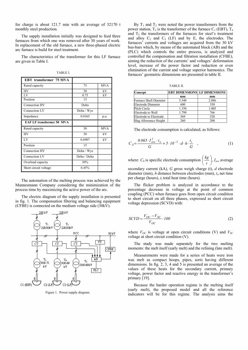
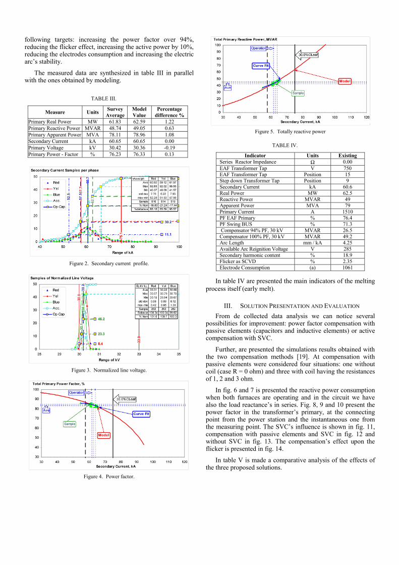
Measurements were made for a series of heats were iron was melt as compact hoops, pipes, sorts having different dimensions. In fig. 2, 3, 4 and 5 is presented an average of the values of these heats for the secondary current, primary voltage, power factor and reactive energy in the transformer’s primary [19].
Because the harder operation regime is the melting itself (early melt), the proposed model and all the reference indicators will be for this regime. The analysis aims the
following targets: increasing the power factor over 94%, reducing the flicker effect, increasing the active power by 10%, reducing the electrodes consumption and increasing the electric arc’s stability.
The measured data are synthesized in table III in parallel with the ones obtained by modeling.
TABLE III.
Measure Units Survey Average
Model Value
Percentage difference %
Primary Real Power MW 61.83 62.59 1.22 Primary Reactive Power MVAR 48.74 49.05 0.63 Primary Apparent Power MVA 78.11 78.96 1.08 Secondary Current kA 60.65 60.65 0.00 Primary Voltage kV 30.42 30.36 -0.19 Primary Power - Factor % 76.23 76.33 0.13
Figure 2. Secondary current profile.
Figure 3. Normalized line voltage.
Figure 4. Power factor.
Figure 5. Totally reactive power
TABLE IV.
Indicator Units ExistingSeries Reactor Impedance Ω 0.00EAF Transformer Tap V 750EAF Transformer Tap Position 15Step down Transformer Tap Position 9Secondary Current kA 60.6Real Power MW 62.5Reactive Power MVAR 49Apparent Power MVA 79Primary Current A 1510PF EAF Primary % 76.4PF Swing BUS % 71.3Compensator 94% PF, 30 kV MVAR 26.5Compensator 100% PF, 30 kV MVAR 49.2Arc Length mm / kA 4.25Available Arc Reignition Voltage V 285Secondary harmonic content % 18.9Flicker as SCVD % 2.35Electrode Consumption (a) 1061
In table IV are presented the main indicators of the melting
process itself (early melt).
III. SOLUTION PRESENTATION AND EVALUATION From de collected data analysis we can notice several
possibilities for improvement: power factor compensation with passive elements (capacitors and inductive elements) or active compensation with SVC.
Further, are presented the simulations results obtained with the two compensation methods [19]. At compensation with passive elements were considered four situations: one without coil (case R = 0 ohm) and three with coil having the resistances of 1, 2 and 3 ohm.
In fig. 6 and 7 is presented the reactive power consumption when both furnaces are operating and in the circuit we have also the load reactance’s in series. Fig. 8, 9 and 10 present the power factor in the transformer’s primary, at the connecting point from the power station and the instantaneous one from the measuring point. The SVC’s influence is shown in fig. 11, compensation with passive elements and SVC in fig. 12 and without SVC in fig. 13. The compensation’s effect upon the flicker is presented in fig. 14.
In table V is made a comparative analysis of the effects of the three proposed solutions.
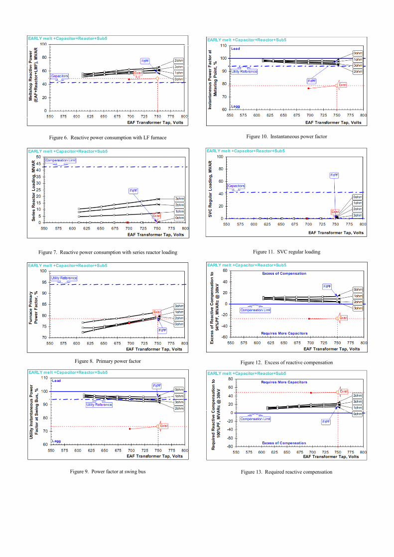
Figure 6. Reactive power consumption with LF furnace
Figure 7. Reactive power consumption with series reactor loading
Figure 8. Primary power factor
Figure 9. Power factor at swing bus
Figure 10. Instantaneous power factor
Figure 11. SVC regular loading
Figure 12. Excess of reactive compensation
Figure 13. Required reactive compensation
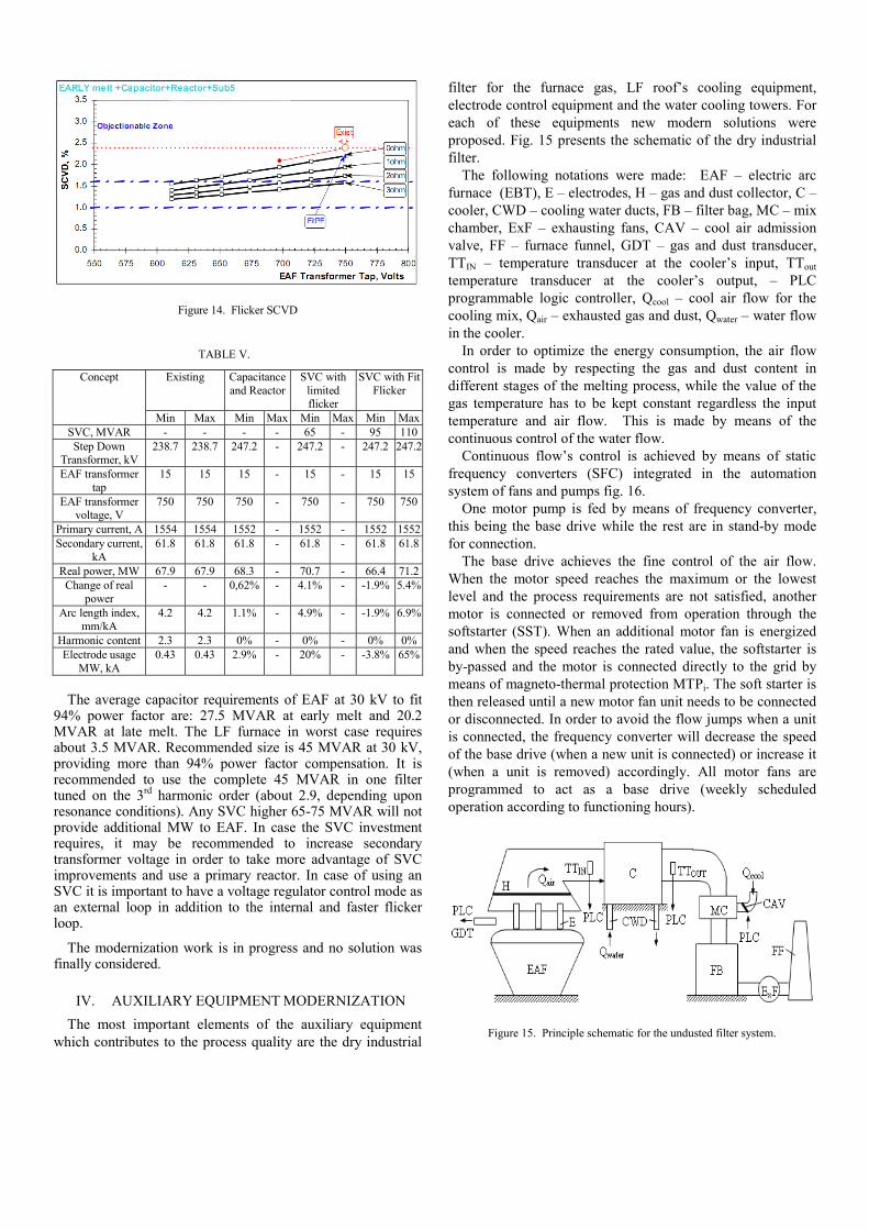
Figure 14. Flicker SCVD
TABLE V.
Concept Existing Capacitance and Reactor
SVC with limited flicker
SVC with Fit Flicker
Min Max Min Max Min Max Min MaxSVC, MVAR - - - - 65 - 95 110Step Down
Transformer, kV 238.7 238.7 247.2 - 247.2 - 247.2 247.2
EAF transformer tap
15 15 15 - 15 - 15 15
EAF transformer voltage, V
750 750 750 - 750 - 750 750
Primary current, A 1554 1554 1552 - 1552 - 1552 1552Secondary current,
kA 61.8 61.8 61.8 - 61.8 - 61.8 61.8
Real power, MW 67.9 67.9 68.3 - 70.7 - 66.4 71.2Change of real
power - - 0,62% - 4.1% - -1.9% 5.4%
Arc length index, mm/kA
4.2 4.2 1.1% - 4.9% - -1.9% 6.9%
Harmonic content 2.3 2.3 0% - 0% - 0% 0%Electrode usage
MW, kA 0.43 0.43 2.9% - 20% - -3.8% 65%
The average capacitor requirements of EAF at 30 kV to fit
94% power factor are: 27.5 MVAR at early melt and 20.2 MVAR at late melt. The LF furnace in worst case requires about 3.5 MVAR. Recommended size is 45 MVAR at 30 kV, providing more than 94% power factor compensation. It is recommended to use the complete 45 MVAR in one filter tuned on the 3rd harmonic order (about 2.9, depending upon resonance conditions). Any SVC higher 65-75 MVAR will not provide additional MW to EAF. In case the SVC investment requires, it may be recommended to increase secondary transformer voltage in order to take more advantage of SVC improvements and use a primary reactor. In case of using an SVC it is important to have a voltage regulator control mode as an external loop in addition to the internal and faster flicker loop.
The modernization work is in progress and no solution was finally considered.
IV. AUXILIARY EQUIPMENT MODERNIZATION The most important elements of the auxiliary equipment
which contributes to the process quality are the dry industrial
filter for the furnace gas, LF roof’s cooling equipment, electrode control equipment and the water cooling towers. For each of these equipments new modern solutions were proposed. Fig. 15 presents the schematic of the dry industrial filter.
The following notations were made: EAF – electric arc furnace (EBT), E – electrodes, H – gas and dust collector, C – cooler, CWD – cooling water ducts, FB – filter bag, MC – mix chamber, ExF – exhausting fans, CAV – cool air admission valve, FF – furnace funnel, GDT – gas and dust transducer, TTIN – temperature transducer at the cooler’s input, TTout temperature transducer at the cooler’s output, – PLC programmable logic controller, Qcool – cool air flow for the cooling mix, Qair – exhausted gas and dust, Qwater – water flow in the cooler.
In order to optimize the energy consumption, the air flow control is made by respecting the gas and dust content in different stages of the melting process, while the value of the gas temperature has to be kept constant regardless the input temperature and air flow. This is made by means of the continuous control of the water flow.
Continuous flow’s control is achieved by means of static frequency converters (SFC) integrated in the automation system of fans and pumps fig. 16.
One motor pump is fed by means of frequency converter, this being the base drive while the rest are in stand-by mode for connection.
The base drive achieves the fine control of the air flow. When the motor speed reaches the maximum or the lowest level and the process requirements are not satisfied, another motor is connected or removed from operation through the softstarter (SST). When an additional motor fan is energized and when the speed reaches the rated value, the softstarter is by-passed and the motor is connected directly to the grid by means of magneto-thermal protection MTPi. The soft starter is then released until a new motor fan unit needs to be connected or disconnected. In order to avoid the flow jumps when a unit is connected, the frequency converter will decrease the speed of the base drive (when a new unit is connected) or increase it (when a unit is removed) accordingly. All motor fans are programmed to act as a base drive (weekly scheduled operation according to functioning hours).
Figure 15. Principle schematic for the undusted filter system.
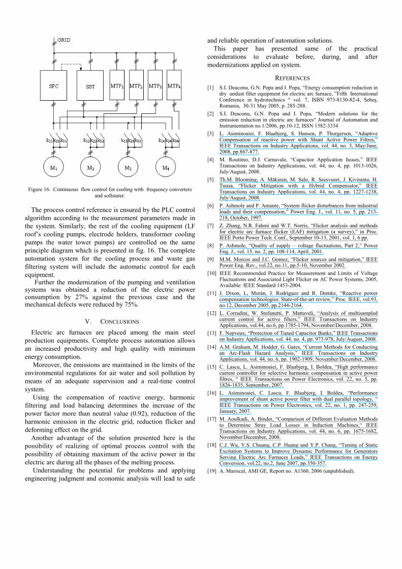
Figure 16. Continuous flow control for cooling with frequency converters and softstater.
The process control reference is ensured by the PLC control algorithm according to the measurement parameters made in the system. Similarly, the rest of the cooling equipment (LF roof’s cooling pumps, electrode holders, transformer cooling pumps the water tower pumps) are controlled on the same principle diagram which is presented in fig. 16. The complete automation system for the cooling process and waste gas filtering system will include the automatic control for each equipment.
Further the modernization of the pumping and ventilation systems was obtained a reduction of the electric power consumption by 27% against the previous case and the mechanical defects were reduced by 75%.
V. CONCLUSIONS Electric arc furnaces are placed among the main steel
production equipments. Complete process automation allows an increased productivity and high quality with minimum energy consumption.
Moreover, the emissions are maintained in the limits of the environmental regulations for air water and soil pollution by means of an adequate supervision and a real-time control system.
Using the compensation of reactive energy, harmonic filtering and load balancing determines the increase of the power factor more than neutral value (0.92), reduction of the harmonic emission in the electric grid, reduction flicker and deforming effect on the grid.
Another advantage of the solution presented here is the possibility of realizing of optimal process control with the possibility of obtaining maximum of the active power in the electric arc during all the phases of the melting process.
Understanding the potential for problems and applying engineering judgment and economic analysis will lead to safe
and reliable operation of automation solutions. This paper has presented same of the practical
considerations to evaluate before, during, and after modernizations applied on system.
REFERENCES [1] S.I. Deaconu, G.N. Popa and I. Popa, “Energy consumption reduction in
dry undust filter equipment for electric arc furnace, ”Fifth International Conference in hydrotechnics “ vol. 7, ISBN 973-8130-82-4, Sebeş, Romania, 30-31 May 2005, p. 285-288.
[2] S.I. Deaconu, G.N. Popa and I. Popa, “Modern solutions for the emission reduction in electric arc furnaces“ Journal of Automation and Instrumentation no.1/2006, pp.10-12, ISSN 1582-3334
[3] L. Asiminoaiei, F. Blaabjerg, S. Hansen, P. Thorgersen, “Adaptive Compensation of reactive power with Shunt Active Power Filtres,” IEEE Transactions on Industry Applications, vol. 44, no. 3, May/June, 2008, pp.867-877.
[4] M. Routimo, D.J. Carnavale, “Capacitor Application Issues,” IEEE Transactions on Industry Applications, vol. 44, no. 4, pp. 1013-1026, July/August, 2008.
[5] Th.M. Blooming, A. Mäkinen, M. Salo, R. Seesvuori, J. Kiviranta, H. Tuusa, “Flicker Mitigation with a Hybrid Compensator,” IEEE Transactions on Industry Applications, vol. 44, no. 4, pp. 1227-1238, July/August, 2008.
[6] P. Ashmole and P. Amante, “System flicker disturbances from industrial loads and their compensation,” Power Eng. J., vol. 11, no. 5, pp. 213-218, October, 1997.
[7] Z. Zhang, N.R. Fahmi and W.T. Norris, “Flicker analysis and methods for electric arc furnace flicker (EAF) mitigation (a survey),” in Proc. IEEE Porto Power Tech. Conf., September 10-13, 2001, vol. 1, 6 pp.
[8] P. Ashmole, “Quality of supply – voltage fluctuations, Part 2,” Power Eng. J., vol. 15, no. 2, pp. 108-114, April, 2001.
[9] M.M. Morcos and J.C. Gomez, “Flicker sources and mitigation,” IEEE Power Eng. Rev., vol.22, no.11, pp.5-10, November 2002.
[10] IEEE Recommended Practice for Measurement and Limits of Voltage Fluctuations and Associated Light Flicker on AC Power Systems, 2005, Available: IEEE Standard 1453-2004.
[11] J. Dixon, L, Morán, J. Rodríguez and R. Domke, “Reactive power compensation technologies: State-of-the-art review,” Proc. IEEE, vol.93, no.12, December 2005, pp.2144-2164.
[12] L. Corradini, W. Stefanutti, P. Mattaveli, “Analysis of multisampled current control for active filters,” IEEE Transactions on Industry Applications, vol.44, no.6, pp.1785-1794, November/December, 2008.
[13] F. Nepveux, “Protection of Tuned Capacitor Banks,” IEEE Transactions on Industry Applications, vol. 44, no. 4, pp. 973-978, July/August, 2008.
[14] A.M. Graham, M. Hodder, G. Gates, “Current Methods for Conducting an Arc-Flash Hazard Analysis,” IEEE Transactions on Industry Applications, vol. 44, no. 6, pp. 1902-1909, November/December, 2008.
[15] C. Lascu, L. Asiminoaiei, F. Blaabjerg, I. Boldea, “High performance current controller for selective harmonic compensation in active power filtres, “ IEEE Transactions on Power Electronics, vol. 22, no. 5, pp. 1826-1835, September, 2007.
[16] L. Asiminoaiei, C. Lascu, F. Blaabjerg, I. Boldea, “Performance improvement of shunt active power filter with dual parallel topology, “ IEEE Transactions on Power Electronics, vol. 22, no. 1, pp. 247-259, January, 2007.
[17] M. Aoulkadi, A. Binder, “Comparison of Different Evaluation Methods to Determine Stray Load Losses in Induction Machines,“ IEEE Transactions on Industry Applications, vol. 44, no. 6, pp. 1675-1682, November/December, 2008.
[18] C.J. Wu, Y.S. Chuang, C.P. Huang and Y.P. Chang, “Tuning of Static Excitation Systems to Improve Dynamic Performance for Generators Serving Electric Arc Furnaces Loads,” IEEE Transactions on Energy Conversion, vol.22, no.2, June 2007, pp.350-357.
[19] A. Mariscal, AMI GE, Report no. A1360, 2006 (unpublished).
Copyright © 2022 FDOKUMEN