Component-based hardware/software co-verification for building trustworthy embedded systems
12
Component-based hardware/software co-verification for building trustworthy embedded systems q Fei Xie a, * , Guowu Yang a , Xiaoyu Song b a Department of Computer Science, Portland State University, Portland, OR 97207, USA b Department of Electrical and Computer Engineering, Portland State University, Portland, OR 97207, USA Available online 27 September 2006 Abstract We present a novel component-based approach to hardware/software co-verification of embedded systems using model checking. Embedded systems are pervasive and often mission-critical, therefore, they must be highly trustworthy. Trustworthy embedded systems require extensive verification. The close interactions between hardware and software of embedded systems demand co-verification. Due to their diverse applications and often strict physical constraints, embedded systems are increasingly component-based and include only the necessary components for their missions. In our approach, a component model for embedded systems which unifies the concepts of hardware IPs (i.e., hardware components) and software components is defined. Hardware and software components are verified as they are developed bottom-up. Whole systems are co-verified as they are developed top-down. Interactions of bottom-up and top-down verification are exploited to reduce verification complexity by facilitating compositional reasoning and verification reuse. Case studies on a suite of networked sensors have shown that our approach facilitates major verification reuse and leads to order-of-magnitude reduc- tion on verification complexity. Ó 2006 Elsevier Inc. All rights reserved. Keywords: Component-based embedded systems; Component model; Components; Model checking; Compositional reasoning; Hardware/software co-verification; Verification reuse 1. Introduction Embedded systems are pervasive in the infrastructure of our society for diverse tasks such as studying environmen- tal phenomena, instrumenting and managing large-scale systems, and aiding security. An embedded system often consists of a generic processor, mission-specific hardware modules, and software modules that execute on the proces- sor and interact with hardware modules. Embedded systems are usually strictly constrained in computation, memory, bandwidth, and power. To lower production and deployment costs, embedded systems are often equipped with slow processor, small memory, rudimentary radio, and limited battery. These constraints require that for a given mission, only the necessary hard- ware and software modules be loaded into an embedded system. This makes component-based development an appealing and appropriate approach to embedded system development. For instance, the well-known TinyOS (Hill et al., 2000) run-time system for networked sensors, an emerging type of deeply embedded systems, is component- based. Embedded systems are often mission-critical, deployed in large quantity, and difficult to access after deployment. Therefore, they must be highly trustworthy. Embedded systems often support concurrency intensive operations such as simultaneous monitoring, computation, and com- munication. However, locks and monitors commonly used to safeguard concurrent operations are often not used in embedded systems due to computational costs. Thus, 0164-1212/$ - see front matter Ó 2006 Elsevier Inc. All rights reserved. doi:10.1016/j.jss.2006.08.015 q This research was supported by Semiconductor Research Corporation, Contract RID 1356.001. * Corresponding author. Tel.: +1 503 725 2403; fax: +1 503 725 3211. E-mail addresses: [email protected] (F. Xie), [email protected] (G. Yang), [email protected] (X. Song). www.elsevier.com/locate/jss The Journal of Systems and Software 80 (2007) 643–654
-
Upload
independent -
Category
Documents
-
view
3 -
download
0
Transcript of Component-based hardware/software co-verification for building trustworthy embedded systems

www.elsevier.com/locate/jss
The Journal of Systems and Software 80 (2007) 643–654
Component-based hardware/software co-verificationfor building trustworthy embedded systems q
Fei Xie a,*, Guowu Yang a, Xiaoyu Song b
a Department of Computer Science, Portland State University, Portland, OR 97207, USAb Department of Electrical and Computer Engineering, Portland State University, Portland, OR 97207, USA
Available online 27 September 2006
Abstract
We present a novel component-based approach to hardware/software co-verification of embedded systems using model checking.Embedded systems are pervasive and often mission-critical, therefore, they must be highly trustworthy. Trustworthy embedded systemsrequire extensive verification. The close interactions between hardware and software of embedded systems demand co-verification. Dueto their diverse applications and often strict physical constraints, embedded systems are increasingly component-based and include onlythe necessary components for their missions. In our approach, a component model for embedded systems which unifies the concepts ofhardware IPs (i.e., hardware components) and software components is defined. Hardware and software components are verified as theyare developed bottom-up. Whole systems are co-verified as they are developed top-down. Interactions of bottom-up and top-downverification are exploited to reduce verification complexity by facilitating compositional reasoning and verification reuse. Case studieson a suite of networked sensors have shown that our approach facilitates major verification reuse and leads to order-of-magnitude reduc-tion on verification complexity.� 2006 Elsevier Inc. All rights reserved.
Keywords: Component-based embedded systems; Component model; Components; Model checking; Compositional reasoning; Hardware/softwareco-verification; Verification reuse
1. Introduction
Embedded systems are pervasive in the infrastructure ofour society for diverse tasks such as studying environmen-tal phenomena, instrumenting and managing large-scalesystems, and aiding security. An embedded system oftenconsists of a generic processor, mission-specific hardwaremodules, and software modules that execute on the proces-sor and interact with hardware modules.
Embedded systems are usually strictly constrained incomputation, memory, bandwidth, and power. To lowerproduction and deployment costs, embedded systems
0164-1212/$ - see front matter � 2006 Elsevier Inc. All rights reserved.
doi:10.1016/j.jss.2006.08.015
q This research was supported by Semiconductor Research Corporation,Contract RID 1356.001.
* Corresponding author. Tel.: +1 503 725 2403; fax: +1 503 725 3211.E-mail addresses: [email protected] (F. Xie), [email protected]
(G. Yang), [email protected] (X. Song).
are often equipped with slow processor, small memory,rudimentary radio, and limited battery. These constraintsrequire that for a given mission, only the necessary hard-ware and software modules be loaded into an embeddedsystem. This makes component-based development anappealing and appropriate approach to embedded systemdevelopment. For instance, the well-known TinyOS (Hillet al., 2000) run-time system for networked sensors, anemerging type of deeply embedded systems, is component-based.
Embedded systems are often mission-critical, deployedin large quantity, and difficult to access after deployment.Therefore, they must be highly trustworthy. Embeddedsystems often support concurrency intensive operationssuch as simultaneous monitoring, computation, and com-munication. However, locks and monitors commonly usedto safeguard concurrent operations are often not usedin embedded systems due to computational costs. Thus,

644 F. Xie et al. / The Journal of Systems and Software 80 (2007) 643–654
to build trustworthy embedded systems, they must beextensively verified.
Due to strict design constraints of embedded systems,to achieve better performance, hardware and softwaremodules must closely interact and the trade-off betweenhardware and software must be exploited. This demandshardware/software co-design and, therefore, hardware/software co-verification of embedded systems.
Model checking (Clarke and Emerson, 1981; Quielle andSifakis, 1982) is a powerful formal verification methodwhich has great potentials in hardware/software co-verifica-tion of embedded systems. It provides exhaustive statespace coverage for the systems being verified. A stumblingblock to scalable application of model checking to co-veri-fication is the intrinsic complexity of model checking. Thenumber of possible states and execution paths in a real-world system can be extremely large, which makes naiveapplication of model checking intractable and requires statespace reduction. Co-verification of an embedded systeminvolves its hardware and software, which makes state spacereduction more challenging.
Compositional reasoning (Abadi and Lamport, 1995) is apowerful state space reduction algorithm. Using composi-tional reasoning, model checking of a property on a systemis accomplished by decomposing the system into compo-nents, checking component properties locally on the compo-nents, and deriving the system property from the componentproperties. Compositional structures of embedded systemsmay greatly simplify application of compositional reasoningto hardware/software co-verification.
We propose a novel component-based approach to hard-ware/software co-verification for building trustworthyembedded systems. Embedded systems are structured fol-lowing a component model that unifies the concepts ofhardware IPs (Jacome and Peixoto, 2001) (i.e., hardwarecomponents) and software components (Heineman andCouncill, 2001; Szyperski, 2002). In this model, verifiedproperties of hardware and software components areassociated with the components. Selection of componentsfor reuse is based on their functionalities and also theirverified properties. A special type of components, bridge
components, are introduced, which inter-connect hardwareand software components and bridge their semantics gaps.
Our approach to co-verification is a synergistic integra-tion of bottom-up component verification and top-downsystem verification. Hardware and software componentsare verified as they are developed bottom-up. Propertiesof a primitive component are directly model-checked whileproperties of a composite component are checked on itsabstractions constructed from verified properties of itssub-components. A system is verified top-down as it isdeveloped through recursive partitions into its compo-nents. The partitions reuse components as possible. Veri-fied properties of the reused components are used inconstructing the abstractions for verifying properties ofthe system or higher-level components. Our approach isbased on translation-based co-verification (Xie et al.,
2005) where software and hardware modules of a systemare translated into a formal model-checkable language,integrated, and model-checked. Translation-based co-veri-fication provides a common formal semantics basis forconducting compositional reasoning across hardware/soft-ware boundaries and the basic mechanisms for verifyingprimitive components and abstractions of systems or com-posite components.
The contributions of our approach include the compo-nent model for embedded systems that unifies hardwareIPs and software components, unified component propertyspecification, and seamless integration of co-verificationinto component-based development of embedded systems.Our approach has great potentials in building trustworthyembedded systems by enabling effective co-verification.Case studies have shown that it achieves major verificationreuse and order-of-magnitude reduction on verificationcomplexity.
The rest of this paper is organized as follows. In Section2, we provide the background of our work. We define thecomponent model for embedded systems, which unifieshardware IPs and software components, in Section 3. InSection 4, we present our component-based approach toco-verification and illustrate it with case studies on a suiteof networked sensors. We discuss related work in Section 5and conclude in Section 6.
2. Background
In this section, we first briefly introduce the component-based development of hardware and software. We then dis-cuss our previous work on translation-based co-verificationand on bottom-up verification of software components.
2.1. Component-based development
In both hardware and software industries, there is acommon trend of developing systems via assembly ofcomponents (Jacome and Peixoto, 2001; Heineman andCouncill, 2001; Szyperski, 2002). (In hardware industry,component-based development is known as IntellectualProperty (IP) based development.) A main objective ofcomponent-based development is to reuse design anddevelopment efforts. To achieve this objective, it is requiredthat components capture reusable concepts in an applica-tion domain and have standard interfaces that export theirfunctionalities. As verification becomes increasingly impor-tant in system development, it is also desired to reuseverification efforts.
2.2. Translation-based co-verification
In Xie et al. (2005), we have developed a translation-based approach to co-verification of embedded systemsusing model checking. Hardware and software modulesof an embedded system are automatically translated intothe input formal language of a state-of-the-art model

F. Xie et al. / The Journal of Systems and Software 80 (2007) 643–654 645
checker. The semantics of hardware and software specifica-tion languages are simulated by the semantics of the targetformal language. We interface the formal models of hard-ware and software modules by inserting a bridge module
that bridges the gap between the hardware and softwaresemantics. The bridge module interacts with the hardwareand software modules following the hardware and softwaresemantics, respectively. It propagates events across hard-ware/software boundaries, for instance, generating soft-ware messages or invoking procedures upon hardwareinterrupts and producing hardware signals upon valuechanges in certain software variables. The bridge moduleis specified in a bridge specification language and translatedinto the formal language.
We reduce co-verification complexity by (1) leveragingstate space reduction algorithms of the target model check-ers, (2) applying reduction algorithms in translation andpreserving validity of the reductions when interfacing for-mal models of hardware and software modules, and (3)compositional reasoning across the bridge module.
This translation-based approach has been implementedfor co-verification of software designs in ExecutableUML (xUML) (Mellor and Balcer, 2002) and hardwaredesigns in Verilog (Thomas and Moorby, 1991). The imple-mentation integrates two translation-based model check-ers: FormalCheck (Kurshan, 1998) and ObjectCheck (Xieet al., 2002), both of which are based on the COSPANmodel checker (Hardin et al., 1996). FormalCheck is acommercial tool for hardware verification. ObjectCheckwas developed in our previous work for verification ofexecutable software designs in xUML. xUML has anasynchronous interleaving message-passing semantics. InxUML, a system consists of object instances which interactvia asynchronous message-passing. A system execution isan interleaving of state transitions of these object instances,i.e., at any moment only one object instance progresses.
2.2.1. Bridge specification
For translation-based co-verification of an embeddedsystem, a specification of the bridge module is required,which specifies how to interface the software and hardwaremodules: (1) what software procedure calls or messages aretriggered by hardware interrupts; (2) what hardware signalsare generated when a procedure call returns or a message isreceived; (3) what variables in software modules aremapped to hardware signals; (4) what are the schedulingpolicies for software modules, for instance, interrupt prior-ities and preemption policies. Translation of the bridgespecification depends on the software and hardware mod-ules since it refers to semantic entities in both the softwareand hardware modules. (See Fig. 9 for an example bridgespecification.)
2.2.2. Unified property specification
In co-verification, a unified property specification lan-guage for both hardware and software is needed. We havedeveloped such a language for co-verification of software
modules in xUML and hardware modules in Verilog. Thislanguage is presented in terms of a set of property tem-plates that have intuitive meanings and also have rigorousmappings to x-automata templates written in S/R (Hardinet al., 1996), the input formal language of the COSPAN(Hardin et al., 1996) model checker. (In S/R, both systemsand properties are formulated as x-automata.) An exampleof such a template is
AfterðeÞ EventuallyðdÞ
where the enabling condition e and the discharging conditiond are propositional logic predicates declared over semanticentities in hardware or software modules. The semanticmeaning is that after each occurrence of e there eventuallyfollows an occurrence of d. Although similar to the LTL for-mula G(e! XF(d)), our property does not require a secondd in case that the discharge condition d is accompanied by asecond e, whereas an initial e is not discharged by an accom-panying d. This asymmetry meets many requirements ofsoftware specification. (On account of this asymmetry, ourproperty cannot be expressed in LTL.)
Our property specification language is linear time, withthe expressiveness of x-automata (Kurshan, 1994). Theproperty templates define parameterized automata. Newtemplates are formulated as needed by defining theirmappings into S/R. A property in this language consistsof (1) declarations of propositional predicates over seman-tic entities in software and hardware modules, and (2)declarations of temporal assertions. A temporal assertionis declared by instantiating a property template: each argu-ment of the template is realized by a propositional expres-sion composed from the declared propositional predicates.(See Section 3 for example properties specified in thislanguage.)
2.3. Bottom-up verification of software components
In Xie and Browne (2003), we have developed a bottom-up approach to verification of software components andsystems composed from these components. For a primitivecomponent (a component that is built from scratch), itsproperties are directly model-checked. The properties of acomposite component (a system is also a compositecomponent), instead of being directly verified on thecomponent, are verified on its abstractions. The abstrac-tion for checking a property on a composite componentis constructed from verified properties of the sub-compo-nents. A sub-component property is included the abstrac-tion if (1) it is related to the property to be checked onthe composite component by cone-of-influence analysis(Kurshan, 1994), (2) its assumptions are enabled, i.e.,implied by the properties of other sub-components andthe environment assumptions of the composite component,and (3) it is not involved in circular reasoning among thesub-component properties.
How to verify a property on a primitive component oron the abstraction of a composite component depends on
Done_Ack Done
646 F. Xie et al. / The Journal of Systems and Software 80 (2007) 643–654
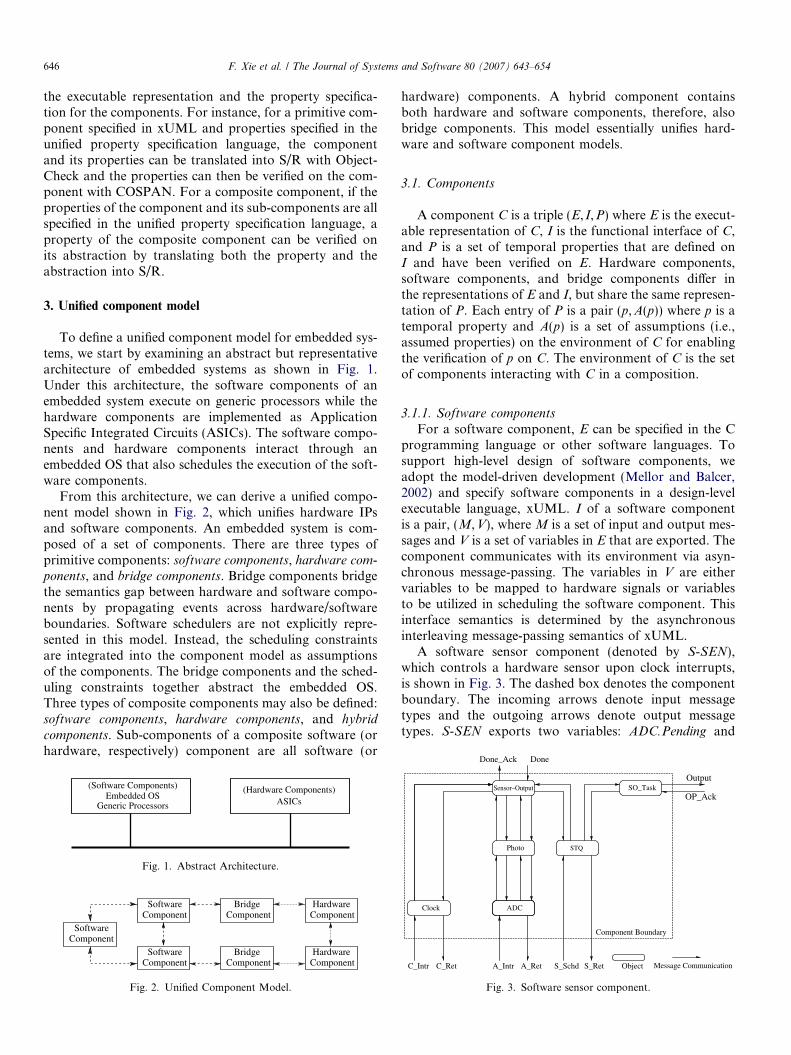
the executable representation and the property specifica-tion for the components. For instance, for a primitive com-ponent specified in xUML and properties specified in theunified property specification language, the componentand its properties can be translated into S/R with Object-Check and the properties can then be verified on the com-ponent with COSPAN. For a composite component, if theproperties of the component and its sub-components are allspecified in the unified property specification language, aproperty of the composite component can be verified onits abstraction by translating both the property and theabstraction into S/R.
3. Unified component model
To define a unified component model for embedded sys-tems, we start by examining an abstract but representativearchitecture of embedded systems as shown in Fig. 1.Under this architecture, the software components of anembedded system execute on generic processors while thehardware components are implemented as ApplicationSpecific Integrated Circuits (ASICs). The software compo-nents and hardware components interact through anembedded OS that also schedules the execution of the soft-ware components.
From this architecture, we can derive a unified compo-nent model shown in Fig. 2, which unifies hardware IPsand software components. An embedded system is com-posed of a set of components. There are three types ofprimitive components: software components, hardware com-ponents, and bridge components. Bridge components bridgethe semantics gap between hardware and software compo-nents by propagating events across hardware/softwareboundaries. Software schedulers are not explicitly repre-sented in this model. Instead, the scheduling constraintsare integrated into the component model as assumptionsof the components. The bridge components and the sched-uling constraints together abstract the embedded OS.Three types of composite components may also be defined:software components, hardware components, and hybrid
components. Sub-components of a composite software (orhardware, respectively) component are all software (or
Embedded OS(Hardware Components)
ASICs
(Software Components)
Generic Processors
Fig. 1. Abstract Architecture.
Component
Software
ComponentSoftware
Component
ComponentSoftware
ComponentBridge
ComponentBridge
HardwareComponent
Hardware
Fig. 2. Unified Component Model.
hardware) components. A hybrid component containsboth hardware and software components, therefore, alsobridge components. This model essentially unifies hard-ware and software component models.
3.1. Components
A component C is a triple (E, I,P) where E is the execut-able representation of C, I is the functional interface of C,and P is a set of temporal properties that are defined onI and have been verified on E. Hardware components,software components, and bridge components differ inthe representations of E and I, but share the same represen-tation of P. Each entry of P is a pair (p,A(p)) where p is atemporal property and A(p) is a set of assumptions (i.e.,assumed properties) on the environment of C for enablingthe verification of p on C. The environment of C is the setof components interacting with C in a composition.
3.1.1. Software components
For a software component, E can be specified in the Cprogramming language or other software languages. Tosupport high-level design of software components, weadopt the model-driven development (Mellor and Balcer,2002) and specify software components in a design-levelexecutable language, xUML. I of a software componentis a pair, (M,V), where M is a set of input and output mes-sages and V is a set of variables in E that are exported. Thecomponent communicates with its environment via asyn-chronous message-passing. The variables in V are eithervariables to be mapped to hardware signals or variablesto be utilized in scheduling the software component. Thisinterface semantics is determined by the asynchronousinterleaving message-passing semantics of xUML.
A software sensor component (denoted by S-SEN),which controls a hardware sensor upon clock interrupts,is shown in Fig. 3. The dashed box denotes the componentboundary. The incoming arrows denote input messagetypes and the outgoing arrows denote output messagetypes. S-SEN exports two variables: ADC.Pending and
Object
Clock
SO_Task
ADC
Photo STQ
Sensor–Output
Component Boundary
A_IntrC_Intr C_Ret A_Ret S_Schd S_Ret Message Communication
OP_Ack
Output
Fig. 3. Software sensor component.

Fig. 4. Properties of software sensor.
R_Ret
Int_to_RFM
Generic_Comm
GC_Task RFM
Data_Ack
Data
Sent Sent_Ack
N_Ret
NTQ
N_Schd R_Intr
Fig. 5. Software network component.
Fig. 6. Properties of software network.
F. Xie et al. / The Journal of Systems and Software 80 (2007) 643–654 647
STQ.Empty. A set of properties that have been verified onS-SEN are shown in Fig. 4. The properties assert that S-
SEN repeatedly outputs and correctly handles the outputhandshakes. The assumptions assert that the environmentof S-SEN correctly responses to the output handshakes,correctly generates clock and sensor interrupts, and cor-rectly schedules the software tasks in S-SEN. The propertyspecification is intuitive, for instance, the first statementclaims that S-SEN outputs repeatedly if it receives clockinterrupts repeatedly and the second statement claims thatafter an output, S-SEN will not output unless after anacknowledgment is received.
A software network component (denoted by S-NET) isshown in Fig. 5. It exports two variables: NTQ.Empty
and RFM.Pending. The verified properties of S-NET areshown in Fig. 6. These properties assert that S-NET repeat-edly sets and clears the RFM.Pending variable if it receivesdata messages repeatedly and it correctly handles the inputhandshakes. The assumptions assert that the environmentof S-NET correctly conducts the input handshakes,responses to the value changes of RFM.pending with inter-rupts, and schedules the software tasks in S-NET.
3.1.2. Hardware components
For a hardware component, E can be specified in Veri-log or other hardware specification languages. In ourstudy, we assume that E is specified in Verilog. I consistsof a set of signals that the hardware component importsfrom or exports to its environment. A hardware compo-nent communicates with its environment through theexported or imported signals in I. This interface semantics

Fig. 8. Properties of hardware components.
Fig. 9. A bridge component example.
d_rdy
88
SENSOR NETWORK
reset
system
CLOCK
intr_n
clock
stop
dout
din
start
intr_c
start_s
intr_s
Fig. 7. Basic hardware components.
648 F. Xie et al. / The Journal of Systems and Software 80 (2007) 643–654
is determined by the synchronous clock-driven semantics ofVerilog.
The interfaces of three hardware components, clock,sensor, and network (denoted by H-CLK, H-SEN, andH-NET, respectively) are shown in Fig. 7. The incomingarrows denote imported signals and the outgoing arrowsdenote exported signals. A set of verified properties ofthe three components are shown in Fig. 8. The propertiesof H-CLK assert that H-CLK generates interrupts repeat-edly. The properties of H-SEN assert that after H-SEN isstarted, it will generate an interrupt eventually and it willnot generate the interrupt unless after it is started. Theproperties of H-NET assert that (1) after H-NET receivesdata, it will eventually generate a transmission completeinterrupt and it will not generate the interrupt unless afterit is started and (2) if H-NET receives data repeatedly, ittransmits repeatedly.
3.1.3. Bridge components
Bridge components inter-connect hardware and soft-ware components. They extend the concept of bridge mod-ule (introduced in Xie et al. (2005) and briefly discussed inSection 2.2.1) by allowing multiple bridge components in asystem. This enables more flexible composition of hard-ware and software components and creation of compositecomponents include both hardware and software sub-components. The interface of a bridge component is a pair(IH, IS). IH is a synchronous shared-variable interfacefor interacting with hardware components and IS is anasynchronous message-passing interface for interactingwith software components. The interface of the bridgecomponent is determined by the hardware and softwarecomponents that it connects. E of a bridge component isspecified in the bridge specification language discussed inSection 2.2.1.
We illustrate the concept of bridge component by defin-ing a bridge component that inter-connects S-SEN, H-
CLK, and H-SEN. The bridge component is shown inFig. 9. The interface of the bridge component is derivedfrom the interfaces of S-SEN, H-CLK, and H-SEN byincluding the same messages and signals but reversing theirinput/output directions. The executable specification of thebridge component defines: (1) how hardware signals aremapped to software messages, for instance, the hardwareclock interrupt, intr_c, is mapped to the C_Intr messageof the software clock; (2) how software variables aremapped to hardware signals, for instance, the On variableof the ADC object is mapped to the start signal of the hard-ware sensor; (3) the interrupt priorities, for instance, bothinterrupts are of the same priority; (4) messages that initi-ate software tasks, for instance, the Schedule message ofthe STQ object, and the conditions under which the tasksare ready to be scheduled.
The bridge components not only abstract the hardware/software interfaces, but also abstract part of the embeddedOS by providing necessary information about what are thesoftware tasks that need to be scheduled to execute andtheir enabling conditions. Software schedulers are notexplicitly specified in this component model. Instead,scheduling policies are specified as assumptions of the soft-ware components. The embedded OS determines the sched-uling polices.
3.1.4. Hybrid components
Hybrid components package hardware and softwarecomponents into reusable units since hardware and soft-ware components are often closely related and reusedtogether, e.g., a device and its driver. A hybrid componentmay have only a software interface if its hardware can becompletely encapsulated or it may have a hybrid hard-ware/software interface similar to the interface of a bridgecomponent. (Examples of hybrid components are given inSection 4.)

Bridge
H–CLK H–SEN H–NET
S–SEN S–NET
Bridge
Fig. 10. A basic sensor system.
Table 1Time and memory usages for verifying the properties of primitivecomponents
Components Time (s) Memory (megabyte)
S-SEN 18.66 8.49S-NET 18.06 9.11H-CLK 0.21 3.38H-SEN 0.22 3.39H-NET 0.22 3.39
F. Xie et al. / The Journal of Systems and Software 80 (2007) 643–654 649
3.2. Composition
A composite component, C = (E, I,P), is composedfrom a set of simpler components, C0 = (E0, I0,P0),. . .,Cn�1 = (En�1, In�1,Pn�1), as follows. E is constructed fromE0,. . .,En�1 by connecting E0, . . ., En�1 through I0, . . ., In�1.I may be a hardware interface, a software interface, or ahybrid hardware/software interface depending what typesof components C0, . . ., Cn�1 are. Essentially, I includesthe semantic entities from I0, . . ., In�1 that are needed forC to interact with its environment or for specification ofscheduling constraints of C. We discuss how to establishproperties of a composite component from properties ofits sub-components in Section 4.
4. Component-based co-verification
In this section, we present our approach to component-based co-verification of embedded systems and illustratesthis approach with its application to a suite of networkedsensors. Our approach seamlessly integrates verificationinto the component-based development lifecycle of embed-ded systems and is a synergistic integration of bottom-upcomponent verification and top-down system verification.
The component-based development lifecycle for anembedded system family consists of three major activities,basic component development, system development, and new
component development. Basic component developmenttakes place when the family is created. As the family evolves,system development and new component development arerepeated as needed and often interleave.
4.1. Bottom-up verification of basic components
When an embedded system family is created, its primi-tive hardware and software components are identified bydomain analysis and developed from scratch. These primi-tive components can be further composed bottom-up todevelop basic composite components of the family.
For verification of basic components, we extend the bot-tom-up approach developed in Xie and Browne (2003).Properties of the components are formulated accordingto domain analysis. A primitive hardware (or software,respectively) component is verified using FormalCheck(or ObjectCheck) through translation of the componentand its properties into S/R. Properties of a composite com-ponent are verified by checking the properties on abstrac-tions of the composite component. The verification isagain through translation into S/R.
4.1.1. Verification of primitive components
A domain analysis on the family of networked sensorsbased on UC Berkeley motes (Hill et al., 2000) identifies aset of primitive components of the family. The set includesthree hardware components: H-CLK, H-SEN, and H-NET,and two software components: S-SEN and S-NET, whichhave been defined in Section 3. We have verified H-CLK,
H-SEN, and H-NET with FormalCheck and we have alsoverified S-SEN and S-NET with ObjectCheck. The timeand memory usages for these verification runs are shownin Table 1. The properties of the components are verifiedunder their corresponding environment assumptions.
4.1.2. Verification of a basic sensor system
After the primitive components of the sensor system fam-ily are developed, the natural next step is to develop a basicsensor system from these components so that these compo-nents can be evaluated in a system context. Note that a sys-tem is also a composite component. Fig. 10 shows how thebasic components are composed bottom-up into a basic sys-tem. H-CLK generates periodical interrupts to S-SEN.Upon a clock interrupt, S-SEN starts H-SEN. WhenH-SEN finishes sensing, it interrupts S-SEN to pass sensorreadings to S-SEN. S-SEN sends sensor readings toS-NET. If H-NET is free, S-NET delivers a data packet toH-NET. After the packet is transmitted, H-NET interruptsS-NET to report the transmission. The hardware and soft-ware components are connected via two bridge components.
Formulating the properties of the bridge componentsand their assumptions is straightforward. Properties (orassumptions, respectively) of the software and hardwarecomponents that are formulated on the interactions withthe bridge components are essentially assumptions (orproperties) of the bridge components. For instance, thesecond group of properties (or assumptions, respectively)of S-SEN in Fig. 4, which are formulated on the clockinterrupts generated by the bridge component betweenS-SEN and hardware and their responses from S-SEN,are assumptions (or properties) of the bridge component.The properties of the two bridge components are verifiedusing 3.76 s and 6.03 megabyte and 0.66 s and 4.07 mega-byte, respectively.
A system-level property P1 to be verified on the basicsensor system is shown in Fig. 11. P1 asserts that the basicsensor system transmits on the network repeatedly.

Fig. 11. Repeated transmission property.
Fig. 13. No consecutive 1’s property.
Fig. 12. Comp. properties that imply P1.
650 F. Xie et al. / The Journal of Systems and Software 80 (2007) 643–654
Repeated setting and clearing of a flag in H_NET indicatesrepeated transmission. To verify P1, we construct anabstraction of the basic sensor system as follows:
1. A system in the S/R language is constructed to abstractthe sensor system. For each hardware or software com-ponent, a S/R process is introduced. The S/R processsimulates the interface of the component. Within theconstraint of the interface, the S/R process behavesnon-deterministically. Essentially, we translate the inter-face of the component into S/R. All these S/R processesare composed together through the simulated interfacesas how the components are composed in Fig. 10.
2. Starting from P1, a cone-of-influence analysis isconducted on verified properties of the hardware andsoftware components based on the component interfacesand the component composition graph. All componentproperties related to P1 by the analysis are included inthe abstraction. They are used to constrain the S/Rsystem: A property of a hardware or software compo-nent is translated to a S/R process and composed withthe S/R process abstracting the component.
The constrained S/R system is the abstraction. Note thatto include a related component property into the abstrac-tion, two conditions must be validated: (1) the assumptionsof the property are implied by the properties of other com-ponents, which can be validated via a simple model check-ing run; (2) the property does not involve in circularreasoning among component properties. Circular reason-ing can be avoided using the following methods (but notlimited to them): (1) avoid using an assumption that createsa dependency cycle; (2) use temporal induction proposedby McMillan (1999); or (3) use the compositional reasoningrule proposed by Amla et al. (2001).
The abstraction constructed includes the properties ofS-SEN in Fig. 4, the properties of S-NET in Fig. 6, theproperties of the hardware components in Fig. 8, and theproperties of the bridge components. The assumptions ofS-SEN and S-NET are satisfied by the properties of thehardware components through the conversion of the bridgecomponents. S-SEN and S-NET satisfy the handshake-related properties of each other. The properties of thehardware, software, and bridge components shown inFig. 12 imply P1. (Note that S-SEN.Output is mapped toS-NET.Data.) The implication relationship is establishedby model checking P1 on the abstraction, which takes0.1 s and 3.40 megabyte.
The abstraction is conservative. If the property holds onthe abstraction, it holds on the system; otherwise, theabstraction can be refined by verifying additional compo-nent properties and including them into the abstraction.If the property does not hold on the system, error trace
analysis and abstraction refinement are likely to uncoverthe cause. (See below for an example of bug detection.)Verification of additional properties are rarely needed forwidely reused components.
This approach to abstraction construction extends theapproach in Xie and Browne (2003) and constructsabstractions of embedded systems composed of hardware,software, and bridge components. It is enabled by the uni-fied component model and the unified component propertyspecification. An abstraction of a composite componentthat is not a complete system is constructed the same wayexcept that an additional S/R process is added to create aclosed S/R system. This S/R process is constrained by theenvironment assumptions of the composite component.
The second property P2 to be verified on the basic sys-tem is shown in Fig. 13. P2 asserts that there are no consec-utive 1’s in the transmission sequence numbers. Weconstruct an abstraction for verifying P2. However, nocomponent properties are included since no componentproperties related to P2 have been verified.
This abstraction need to be refined. The componentproperties needed for verifying P2 are introduced basedon domain knowledge. An abstraction is constructed fromthe component properties assuming they hold. If P2 issuccessfully verified on the abstraction, the componentproperties are then verified. The following properties areintroduced for S-SEN: there are no consecutive 1’s in thesequence numbers of the outputs of S-SEN and S-SEN
will not output a new sensor reading unless after itreceives transmission acknowledgment for the previousreading. (For conciseness, the formal property specifica-tions are not shown.) The verification of the new propertyof S-SEN detects a bug in S-SEN: S-SEN may output anew sensor reading to S-NET although S-NET has notacknowledged the transmission of the last sensor reading.

F. Xie et al. / The Journal of Systems and Software 80 (2007) 643–654 651
The bug is fixed. The property is successfully verified on thecorrected S-SEN. For conciseness, the properties of othercomponents are not shown. After all new component prop-erties are successfully verified, we can conclude that P2
holds on the basic system.
4.2. Top-down system verification
New systems in the embedded system family are devel-oped top-down. Given its functional requirements, a systemis partitioned into hardware and software components. Thepartition is guided by domain knowledge and considers theavailable components. The interface of each component isdefined and its properties are specified. If there is a compo-nent available that matches the interface and the properties,the component can be reused. If there is no matching com-ponent, the component is either developed from scratch as aprimitive component or further partitioned.
Verification is integrated in the top-down systemdevelopment. As a composite component is decomposedinto its sub-components, the sub-component propertiesare formulated. The properties of the composite compo-nent are verified on its abstractions constructed from thesub-component properties assuming the sub-componentproperties hold. If the properties of the compositecomponents are successfully verified on the abstraction,the top-down system development proceeds; otherwise,the decomposition or the sub-component properties arerevised. For a reusable sub-component, if the requiredproperties has been verified on the sub-component, nothingneed to be done; otherwise, the properties are verified onthe component top-down. For a new primitive component,its properties are verified by directly model checking its exe-cutable representation. For a new composite component,its properties are verified as it is further partitioned top-down. If the properties of a component cannot be verified,the component design or the previous decompositions arerevised.
4.2.1. Verification of multi-sensor systemWe illustrate top-down system verification by verifying a
multi-sensor system. The functional requirement of thissystem is that it should properly control multiple hardwaresensors, for instance, a temperature sensor and a humiditysensor. The sensor system can be partitioned into hardwareand software components as shown in Fig. 14. It can beobserved that the multi-sensor system reuses the existingcomponents with a new bridge component that connects
S–NET
H–CLK H–SEN 1 H–SEN 2 H–NET
S–SEN
BridgeBridge
Fig. 14. Multi-sensor system.
S-SEN, H-CLK, and the two hardware sensors. Upon aclock interrupt, S-SEN starts both hardware sensors. Uponcompletion of sensing, each sensor interrupts and passesdata to S-SEN.
We verify P1 on the multi-sensor system. (For simplicity,hereafter, we only verify P1 on sensor systems.) All compo-nents of the system, except the new bridge component, arereusable and their properties have been verified. Propertiesof the bridge component (not shown for conciseness) areformulated the same way as those of the bridge compo-nents in the basic system. They are verified using 10.24 sand 6.05 megabyte. The abstraction of the multi-sensorsystem for verifying P1 is constructed from the componentproperties. P1 was successfully verified on the abstractionusing 0.1 s and 3.40 megabyte.
4.2.2. Verification of encryption-enabled sensor system
Development of new sensor systems may introduce newcomponents. For instance, to develop a security enhancedsensor network, it is desired that some sensors in a sensornetwork be able to encrypt the sensor readings beforetransmitting the readings. Based on the requirement ofsuch a sensor system, the system can be partitioned intoits components as shown in Fig. 15. A hardware encoder,H-ENC and its software controller, S-ENC are introduced.In system execution, S-SEN passes sensor readings to S-
ENC which invokes H-ENC to encrypt the sensor readings.The interface of S-ENC is defined as follows: input mes-
sage types = {Raw, Encoded_Ack, E_intr}, output messagetypes = {Raw_Ack, Encoded, E_Ret}, and externally visiblevariables = {ENC.Pending}. The properties of S-ENC forverifying P1 on the whole system are shown in Fig. 16.The properties assert that S-ENC outputs encoded datarepeatedly if it inputs raw data repeatedly and it correctlyhandles the input and output handshakes. The assumptionsassert that the environment correctly handles the hand-shakes with S-ENC and generates interrupts to S-ENC inresponse to its encoding requests. The interface of H-ENC
and the properties of H-ENC for verifying P1 are also for-mulated (not shown for conciseness). The properties of S-
ENC are verified on its executable using 0.24 s and3.57 megabyte while verification of H-ENC takes 0.22 sand 3.39 megabyte. A new bridge component connectingS-ENC and H-ENC is introduced. Its properties are verifiedusing 0.18 s and 3.56 megabyte. The abstraction forverifying P1 on the encryption-enabled sensor system isconstructed from the properties of its components. P1 is
Bridge
H–NETH–SENH–CLK
S–NETS–SEN S–ENC
H–ENC
Bridge Bridge
Fig. 15. Encryption-enabled sensor system.

Fig. 16. Properties of software encoder.
Bridge
S–NETS–ENC
H–ENC H–NET
Bridge
Fig. 17. Encryption-enabled network comp.
Fig. 18. Properties of E-NET.
Table 2Time and memory usage comparison
Usages Basic Multi Encrypting
TB Time (s) 31272.8 – –TB Mem. (megabyte) 1660.62 – –CB Time (s) 41.89 10.34 0.77CB Mem. (megabyte) 9.11 6.05 3.57
652 F. Xie et al. / The Journal of Systems and Software 80 (2007) 643–654
successfully verified on the abstraction using 0.13 s and3.56 megabyte.
4.3. Integrated bottom-up and top-down verification of new
components
Verification of new components exploits the interactionof bottom-up and top-down verification. New componentsmay be introduced and verified in top-down developmentof new systems, such as S-ENC and H-ENC, and theymay also be introduced and verified through bottom-upcomponent development due to technology advances, suchas new sensing and communication modules.
The new components can be further composed withexisting components or among themselves to constructlarger composite components bottom-up. For instance,S-ENC, S-NET, H-ENC, and H-NET can be composedinto an encryption-enabled network component, E-NET,as shown in Fig. 17. S-NET and H-NET have been verifiedbottom-up as basic components. S-ENC and H-ENC hasbeen verified in top-down verification of the encryption-enabled sensor system. Based on their properties, E-NET
is verified bottom-up. The interface of E-NET includesthe following messages: Raw and Raw_Ack for interactionwith other components and E_Intr, N_Schd, R_Intr,E_Ret, N_Ret, and R_Ret for specification of schedulingconstraints. The properties of E-NET are shown in
Fig. 18. The properties assert that E-NET repeatedlytransmits if there are inputs repeatedly and that it properlyhandles input handshakes. The assumptions assert that theenvironment correctly handles the handshakes with E-NET
and respects the scheduling constraints of E-NET. Theproperties are successfully verified on an abstraction ofE-NET, constructed from the verified properties ofS-NET, S-ENC, H-NET, H-ENC, and the two bridgecomponents. The verification takes 0.13 s and 3.55 mega-byte. E-NET and its properties can then be reused inbuilding new sensor systems.
4.4. Evaluation
We evaluate our approach to component-based co-verification by comparing the time and memory usagesfor verifying P1 on the three sensor systems: the basic sys-tem, the multi-sensor system, and the encryption-enabledsensor system using this approach with the time and mem-ory usages for verifying the three systems using the basictranslation-based approach discussed in 2.2. The compari-son is shown in Table 2. (CB denotes the component-basedapproach, TB denotes the translation-based approach, and

F. Xie et al. / The Journal of Systems and Software 80 (2007) 643–654 653
‘‘-’’ denotes running out of memory.) All verification runsare conducted on a SUN workstation with dual CPUs at1 GHZ and 2 GB physical memory. The time (or memory,respectively) usage of verifying a system using the compo-nent-based approach is the sum (or max) of the time (ormemory) usages of verifying the new components and theabstraction. It can be observed that the component-basedapproach has order-of-magnitude reduction on the verifica-tion time and memory usages for verifying the basic sensorsystem. The reductions on the multi-sensor system and theencryption-enabled sensor system are more significant sincethe translation-based approach runs out of memory onboth systems while the component-based approach achievesmajor reuse of verification efforts and only requires to verifythe new hardware, software, and bridge components andthe abstractions of the two systems. The component-basedapproach requires the extra cost of abstraction constructionand the manual effort of formulating component propertieswhich, we believe, can be greatly reduced by domain knowl-edge and are compensated by being able to verify systemsthat cannot be verified, otherwise.
5. Related work
There has been much research on component-basedhardware and software development (Jacome and Peixoto,2001; Heineman and Councill, 2001; Szyperski, 2002). Afundamental problem in component-based development ishow to derive the properties of compositions from theproperties of components, including correctness properties,performance properties, real-time properties, etc. A well-known project targeting this problem in component-basedsoftware development is the PACC initiative from CMU/SEI: Predictable Assembly from Certifiable Components(CMU/SEI; Wallnau, 2003). The vision of PACC is thatsoftware components have certified properties (for example,performance) and the behavior of systems assembled fromcomponents is predictable. Our project shares the samevision as PACC while extending this vision by (1) defininga component model for embedded systems that unifieshardware and software components and (2) formally estab-lishing the properties of an embedded system from theproperties of its hardware and software components.
There has also been research on component-based soft-ware engineering for embedded systems such as (Crnkovic,2005), focusing on embedded software. Due to the closeinteractions between hardware and software of embeddedsystems, there is a desire to reason about hardware andsoftware components under a unified component model.
Co-verification of embedded systems falls into twomajor categories: co-simulation and formal co-verification.Our approach belongs to the latter. Hardware/software co-simulation of embedded systems is supported by industrialtools such as Mentor Graphics and academic projects suchas Ptolemy (Berkeley). Co-simulation does not provideexhaustive state space coverage and may be insufficientfor building highly trustworthy embedded systems.
Various formal languages have been proposed for speci-fying embedded systems, e.g., Hybrid Automata (Aluret al., 1996), LOTOS (van Eijk et al., 1989), Co-designFinite State Machines (CFSMs) (Balarin et al., 1996), andpetri-net based languages such as PRES (Cortes et al.,2000). Hybrid automata and CFSMs have been directlymodel-checked. LOTOS and PRES have been verified viatranslation to directly model-checkable languages. Ourapproach differs by supporting specification of hardwareor software components in their native languages andexploiting compositional structures of embedded systemsfor co-verification.
Formal co-verification with model checking providesexhaustive state space coverage while may suffer from statespace explosion. There has been much research (Abadi andLamport, 1995; Alur and Henzinger, 1999; McMillan,1999; Amla et al., 2001) on compositional reasoning inmodel checking of hardware systems or software systems.Our approach builds on the previous work on composi-tional reasoning. It differs from the previous work in thatit applies compositional reasoning across the hardware/software boundary. This is enabled by the componentmodel for embedded systems which unifies hardware IPsand software components and the unified component prop-erty specification. This is also enabled by translation-basedco-verification which provides a common formal semanticsbasis for compositional reasoning and provides the basicmechanisms for verifying primitive hardware or softwarecomponents and abstractions of systems or compositecomponents.
There has also been research on formal verification ofIP-based hardware systems (Karlsson et al., 2004) and ofcomponent-based software systems (Chaki et al., 2003;Xie and Browne, 2003). Our work differs by co-verifyinghardware and software components of embedded systems.
6. Conclusions and future work
We have presented a component-based approach tohardware/software co-verification of embedded systemsusing model checking. This approach has great potentialin building highly trustworthy embedded systems. Itachieves major verification reuse and order-of-magnitudereduction on co-verification complexity, therefore, enablingco-verification of more complex embedded systems. Itseffectiveness roots in seamless integration of verificationinto the component-based development lifecycle of embed-ded systems and exploitation of their compositional struc-tures. As the next step, we plan to further automate ourapproach in system decomposition and property formula-tion, by leveraging domain knowledge such as compositionpatterns of embedded systems.
Acknowledgements
We gratefully acknowledge the contributions and helpfrom James C. Browne, Robert P. Kurshan, and Vladimir

654 F. Xie et al. / The Journal of Systems and Software 80 (2007) 643–654
Levin. We also thank Haera Chung and Ranajoy Nandifor their help.
References
Abadi, Martin, Lamport, Leslie, 1995. Conjoining specifications.TOPLAS 17 (3), 507–534.
Alur, Rajeev, Henzinger, Thomas, 1999. Reactive modules. FMSD 15 (1),7–48.
Alur, Rajeev, Henzinger, Thomas A., Ho, P.H., 1996. Automatic symbolicverification of embedded systems. IEEE TSE 22 (3), 181–201.
Amla, Nina, Emerson, Allen. E., Namjoshi, Kedar S., Trefler, Richard.2001. Assume-guarantee based compositional reasoning for synchro-nous timing diagrams. In: Proceedings of TACAS.
Balarin, F., Hsieh, H., Jurecska, A., Lavagno, L., Sangiovanni-Vincentelli,A., 1996. Formal verification of embedded systems based on CFSMnetworks. In: Proceedings of DAC.
Berkeley. Ptolemy project. Available from: <http://ptolemy.eecs.berkeley.edu/index.htm>.
Chaki, Sagar, Clarke, Edmund, Groce, Alex, Jha, Somesh, Veith, Helmut.2003. Modular verification of software components in C. In: ICSE.
Clarke, Edmund M, Allen Emerson, E., 1981. Design and synthesis ofsynchronization skeletons using branching time temporal logic. In:Proceedings of Logic of Programs Workshop.
CMU/SEI. The PACC (Predictable Assembly from Certifiable Compo-nents) initiative. Available from: <http://www.sei.cmu.edu/pacc>.
Cortes, Luis Alejandro, Eles, Petru, Peng, Zebo, 2000. Formal coverifi-cation of embedded systems using model checking. In: Proceedings ofEUROMICRO.
Crnkovic, Ivica, 2005. Component-based software engineering for embed-ded systems. In: ICSE.
Hardin, Ronald H., Har’El, Zvi, Kurshan, Robert P., 1996. COSPAN. In:Proceedings of CAV.
Heineman, George T., Councill, William T. (Eds.), 2001. Component-Based Software Engineering: Putting the Pieces Together. Addison-Wesley, Reading, MA.
Hill, Jason, Szewczyk, Robert, Woo, Alec, Hollar, Seth, Culler, David E.,Pister, Kristofer S.J., 2000. System architecture directions for net-worked sensors. In: Proceedings of ASPLOS.
Jacome, Margarida F., Peixoto, Helvio P., 2001. A survey of digital designreuse. IEEE Design and Test of Computers 18 (3), 98–107.
Karlsson, Daniel, Dles, Petru, Peng, Zebo, 2004. A formal verificationmethodology for IP-based designs. In: Proceedings of DSD.
Kurshan, Robert P., 1994. Computer-Aided Verification of CoordinatingProcesses: The Automata-Theoretic Approach. Princeton UniversityPress, Princeton, NJ.
Kurshan, Robert P., 1998. FormalCheck User Manual. Cadence.McMillan, Ken L., 1999. A methodology for hardware verification using
compositional model checking. Cadence Design Systems Technicalreports.
Mellor, Stephen J., Balcer, Marc J., 2002. Executable UML: A Founda-tion for Model Driven Architecture. Addison Wesley, Reading, MA.
Mentor Graphics. Seamless. Available from: <http://www.mentor.com>.Quielle, Jean Pierre, Sifakis, Joseph, 1982. Specification and verification of
concurrent systems in CESAR. In: Proceedings of Symposium onProgramming.
Szyperski, Clemens, 2002. Component Software – Beyond Object-Oriented Programming. Addison Wesley, Reading, MA.
Thomas, Donald E., Moorby, Philip R., 1991. The VERILOG HardwareDescription Language. Kluwer Academic Publishers, Dordrecht.
van Eijk, P.H.J., Vissers, C.A., Diaz, M. (Eds.), 1989. The FormalDescription Technique LOTOS. Elsevier, Amsterdam.
Wallnau, Kurt C., 2003. A technology for predictable assembly fromcertifiable components. Technical report, CMU/SEI-2003-TR-009.
Xie, Fei, Browne, James C., 2003. Verified systems by composition fromverified components. In: Proceedings of ESEC/FSE.
Xie, Fei, Levin, Vladimir, Browne, James C., 2002. Objectcheck: a modelchecking tool for executable object-oriented software system designs.In: Proceedings of FASE.
Xie, Fei, Song, Xiaoyu, Chung, Haera, Nandi, Ranajoy, 2005. Transla-tion-based co-verification. In: Proceedings of MEMOCODE.