Component-Based Design: A Summary and Scheme for ...
22
Component-Based Design: A Summary and Scheme for Implementation Anton C. Harfmann and Paul J. Bauser 189 issue 02, volume 02 international journal of architectural computing IJAC 2-2_3 proof 16-7-04 3:46 pm Page 189
-
Upload
khangminh22 -
Category
Documents
-
view
1 -
download
0
Transcript of Component-Based Design: A Summary and Scheme for ...
Component-BasedDesign:A Summary and Schemefor ImplementationAnton C. Harfmann and Paul J. Bauser
189issue 02, volume 02international journal of architectural computing
IJAC 2-2_3 proof 16-7-04 3:46 pm Page 189

Component-Based Design:A Summary and Scheme for ImplementationAnton C. Harfmann and Paul J. Bauser
This paper summarizes the major advantages ofcomponent-based design as a paradigm for handling alldesign and construction information about a buildingat every stage of design.The paper reviews some ofthe current issues that plague the building design andconstruction industry.The component-based paradigmis reviewed as a model that reunites the fragmentedbuilding industry and as a solution for dealing withvast amounts of information that accretes during thedesign-construction process. Based on interviews witharchitects, engineers, contractors and fabricators aswell as on-site documentation of construction wefeature the design and construction of the main stairin the Rosenthal Center for Contemporary Artdesigned by Zaha Hadid as a specific case study toillustrate the viability of component-based design andto highlight the obstacles challenging itsimplementation.
190
IJAC 2-2_3 proof 16-7-04 3:46 pm Page 190
1. Introduction
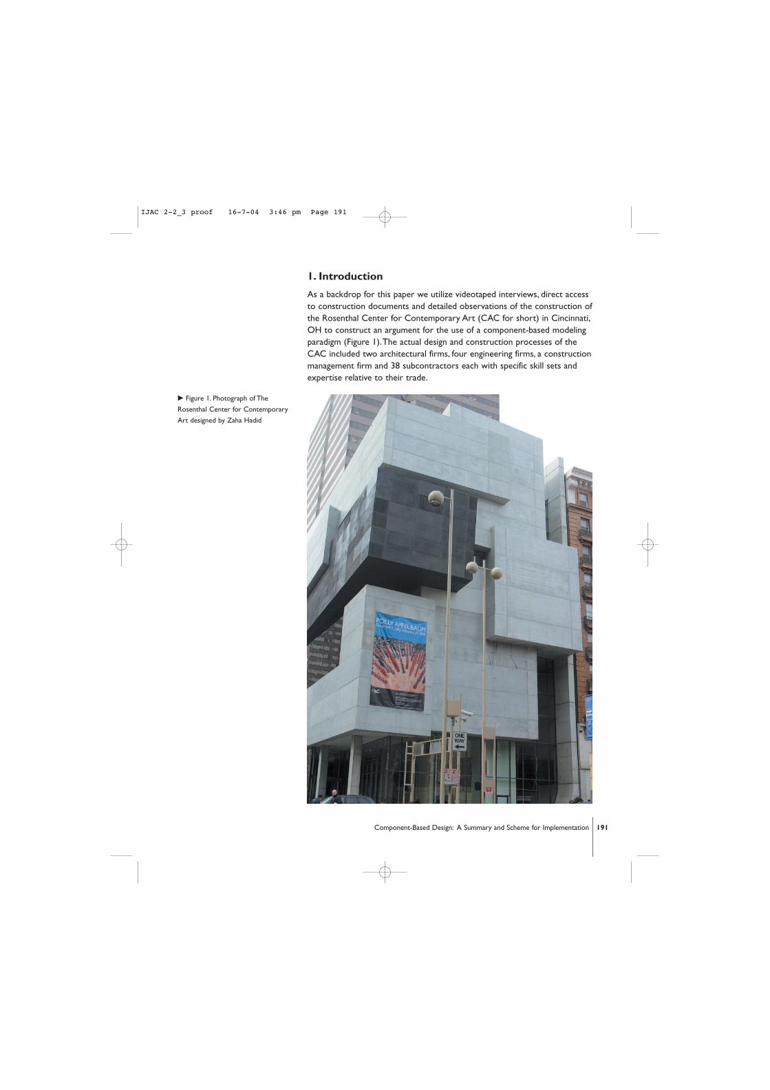
As a backdrop for this paper we utilize videotaped interviews, direct accessto construction documents and detailed observations of the construction ofthe Rosenthal Center for Contemporary Art (CAC for short) in Cincinnati,OH to construct an argument for the use of a component-based modelingparadigm (Figure 1).The actual design and construction processes of theCAC included two architectural firms, four engineering firms, a constructionmanagement firm and 38 subcontractors each with specific skill sets andexpertise relative to their trade.
c Figure 1. Photograph of The
Rosenthal Center for Contemporary
Art designed by Zaha Hadid
191Component-Based Design: A Summary and Scheme for Implementation
IJAC 2-2_3 proof 16-7-04 3:46 pm Page 191
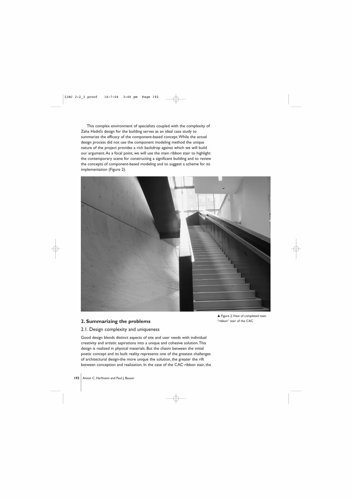
This complex environment of specialists coupled with the complexity ofZaha Hadid’s design for the building serves as an ideal case study tosummarize the efficacy of the component-based concept.While the actualdesign process did not use the component modeling method the uniquenature of the project provides a rich backdrop against which we will buildour argument.As a focal point, we will use the main ribbon stair to highlightthe contemporary scene for constructing a significant building and to reviewthe concepts of component-based modeling and to suggest a scheme for itsimplementation (Figure 2).
2. Summarizing the problems
2.1. Design complexity and uniqueness
Good design blends distinct aspects of site and user needs with individualcreativity and artistic aspirations into a unique and cohesive solution.Thisdesign is realized in physical materials. But the chasm between the initialpoetic concept and its built reality represents one of the greatest challengesof architectural design-the more unique the solution, the greater the riftbetween conception and realization. In the case of the CAC ribbon stair, the
192 Anton C. Harfmann and Paul J. Bauser
m Figure 2.View of completed main
“ribbon” stair of the CAC
IJAC 2-2_3 proof 16-7-04 3:46 pm Page 192

design begins as a conceptual ramp stitching together a series of verticallystacked gallery volumes (Figure 3).
Code limitations prevented the use of a continuous ramp in the spaceavailable on the site.This constraint eventually led to the design of a veryshallow stair which would become the abstract solution.The architectstogether with the structural engineer and construction manager beganexploring various solutions to convert the idealistic concept of a “ribbon ofcirculation” [1] into a physical stair capable of transporting people safely.The dynamism of this concept is one of the most complex and memorablefeatures of the building but the uniqueness of the solution required a largeinvestment in design, engineering and fabrication.
2.2. Fragmentation and multiple representations
The numerous individuals with specific expertise in discrete areas ofknowledge has led to an unprecedented fragmentation of the buildingdesign/construction industry. Complicating the issue of fragmentation is thefact that most of the individuals contributing specific expertise to theprocess have developed their own methods for conveying the specifics
m Figure 3. Ribbon Stair ramp concept
193Component-Based Design: A Summary and Scheme for Implementation
IJAC 2-2_3 proof 16-7-04 3:46 pm Page 193

about their design input to the process resulting in a many “islands ofautomation” [2] In the CAC ribbon stair, the final solution consists ofparallel box beams serving as structure and railing for the various spans thatrange from 55 to 75 feet.While Hadid will always view the actual stair as anelegant floating ribbon, numerous unique representations were required tobring the stair into reality.The engineer’s “view” of the stair included finiteelement analysis, the local architects visualized the stair as aspatial/volumetric assembly, and the steel fabricator described the stair asseries of individual plates and welds (Figure 4).
2.3. Redesign/Discovery
Horst Rittel defined design as a “wicked problem” owing perhaps to the factthat design is not a simple algorithm. It does not simply accept variables and
194 Anton C. Harfmann and Paul J. Bauser
. Figure 4.Artistic view,Architect’s
drawings, Fabricator’s drawings
. Figure 5. Suspended stair, and
bearing brackets for stair
IJAC 2-2_3 proof 16-7-04 3:46 pm Page 194
then produce a solution. Design is iterative and accomplished designersconsistently revise concepts in search of better solutions.This was the casein the design process for the CAC stair.As previously described the stairwas a conceptual ramp floating in space.With this in mind the engineersproduced a series of plausible iterations capable of translating the idea intophysical reality. Solutions considered included suspending the stair fromcables or bearing the stair on wall-mounted brackets [3] (Figure 5).
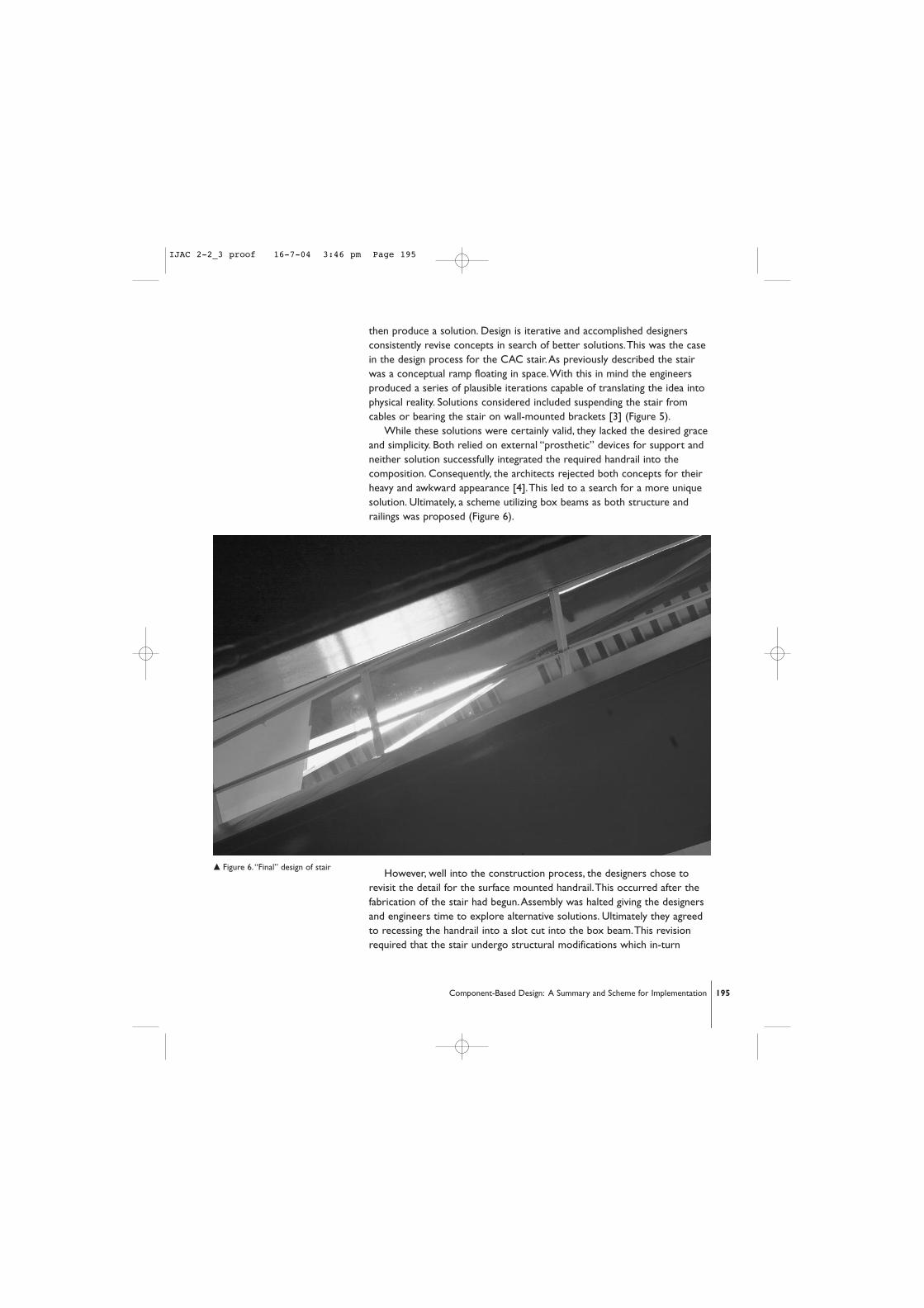
While these solutions were certainly valid, they lacked the desired graceand simplicity. Both relied on external “prosthetic” devices for support andneither solution successfully integrated the required handrail into thecomposition. Consequently, the architects rejected both concepts for theirheavy and awkward appearance [4].This led to a search for a more uniquesolution. Ultimately, a scheme utilizing box beams as both structure andrailings was proposed (Figure 6).
However, well into the construction process, the designers chose torevisit the detail for the surface mounted handrail.This occurred after thefabrication of the stair had begun.Assembly was halted giving the designersand engineers time to explore alternative solutions. Ultimately they agreedto recessing the handrail into a slot cut into the box beam.This revisionrequired that the stair undergo structural modifications which in-turn
m Figure 6.“Final” design of stair
195Component-Based Design: A Summary and Scheme for Implementation
IJAC 2-2_3 proof 16-7-04 3:46 pm Page 195

altered the fabrication strategies.This “tweaking of the design” [5] or“circling around a problem” [6] until an appropriate solution is discoveredperfectly illustrates the non-algorithmic, iterative nature of design.
While this is not an uncommon event in design it does represent aconsiderable challenge for designers. In the current climate of buildingdesign and construction it is difficult to quickly and fully comprehend theimplications of decisions to “remodel”.As a result, superior solutions maygo unexplored because of the difficulty inherent in attempting to implementchanges late in the game. In the case of the CAC stair, there existed anunusually strong relationship between the design architect (Zaha Hadid) thearchitect of record (KZF Design), the structural engineers (THP Ltd.), theconstruction managers (Turner Construction) and the fabricators (SouthernOhio Fabricators).The commitment to the design in this case wasunprecedented which allowed the revised rail to be accomplished. In mostconventional practices however, this type of change would require too largean investment due to the coordination between all the various parties.
3.A summary of component-based design
3.1.The component paradigm
The component paradigm is the accurate and complete modeling of a designusing the least common denominator of individual components.While this isnot a new concept, this paradigm offers a direct response to the problems ofcomplexity, fragmentation and redesign [7] [8] [9] [10] [11] [12] [13] [14][15] [16].This method of modeling has a long history for solving complexthree-dimensional with a limited scope, such as aircraft engine design andpower plant design [17]. Until recently, however, this method has not beenwidely deployed in the building industry.Where attempts have been made tomodel every component of construction on substantial projects they haveproven to be very useful. For example, the construction management firmresponsible for realizing the Letterman Digital Arts Center used accurate 3-D modeling of individual components to pre-build the design.The model wasmined for construction inconsistencies and interferences uncovering manyerrors that would otherwise have occurred during construction.Thisultimately saved the owner hundreds of thousands of dollars and potentialdelays in the project schedule [18].
The basic concepts behind the component paradigm are straightforwardand simple. Components are geometrically accurately modeled solids.Theuse of solid modeling supports interference checking which helps avoid thecreation of physical impossibilities.The solid model also supports the use ofBoolean operations for modifying components (drilling holes, cutting etc.) Inthe case of the CAC stair, the first floor run consists of 2000+ individualcomponents from plates and welds to handrails and screws.These individualcomponents are modeled and interconnected in a component network(Figure 7).
196 Anton C. Harfmann and Paul J. Bauser
IJAC 2-2_3 proof 16-7-04 3:46 pm Page 196

Once components are instantiated, the designer and contractor can collectcomponents into sub-groups in order to reflect any number of inquiriesincluding construction sequence and structural behavior. In the case of the boxbeam shown in the figure, all plates and welds that make up the right-hand railcan be grouped together as a single entity.This allows the translation of theentire rail in the model or the isolation of the rail for structural analysis.Aparallel component grouping is the common plate from which they are all cut.The fabricator strategically arranged the pieces on a 10’ wide plate to minimizewaste. It is very likely that a single raw plate provides components for manydifferent parts of the stair. By externalizing these collections each componentcan be linked to multiple groups. So the plate that forms the shape of the railas an architectural element is also grouped with other plates cut from a10’wide sheet and is part of a larger group called the box beam, which in turnis part of an even larger collection called stair, and so on.
3.2. Single model – multiple perspectives
At the heart of this paradigm is the concept of the single model. For thesingle model to be effective, it must allow for incomplete data while design
197Component-Based Design: A Summary and Scheme for Implementation
m Figure 7. Partial model of stair and
related component network
IJAC 2-2_3 proof 16-7-04 3:46 pm Page 197

is in a fluid state. It must also support abstract views throughout the entiredesign process.At early stages of design, the gesture of the ribbon modelcould serve as a sort of “spatial formwork.” The spatial model wouldeventually be discarded once the major components describing the form areinstantiated.All abstracted views could be calculated by parsing thecomponent network based on the desired view. For example, a typicalvisitor to the CAC is not likely to be aware of the hundreds of welds thathold the stair together.The individual unconsciously filters out that level ofdetail when walking through the space. Likewise, a “design” view of thecomplete stair in the component-based model could filter out theconnection components in order to yield a broader, more experientialperspective. In a similar manner, the structural engineer constructs anabstract view in order to perform structural analysis at various stages of thedesign process. Initially, the ribbon gesture could utilize rules of thumb toanalyze the simple geometry of span.As components are instantiated, theMoment of Inertia of the box-beam/rails could be calculated based on theapproximate dimensions of the evolving stair. In this case, the feasibility ofvarious concepts could be quickly explored using simple calculations todetermine which specific solutions for the box-beam will support the 65foot span of the stair most efficiently. In the final analysis the actualgeometry of the plates can be utilized in calculations to assess deflectionand overall stiffness (Figure 8).
. Figure 8. Complete geometric
model with calculated views of stair
illustrating spatial, engineering, and
fabrication views
198 Anton C. Harfmann and Paul J. Bauser
IJAC 2-2_3 proof 16-7-04 3:46 pm Page 198
3.3. External reasoning
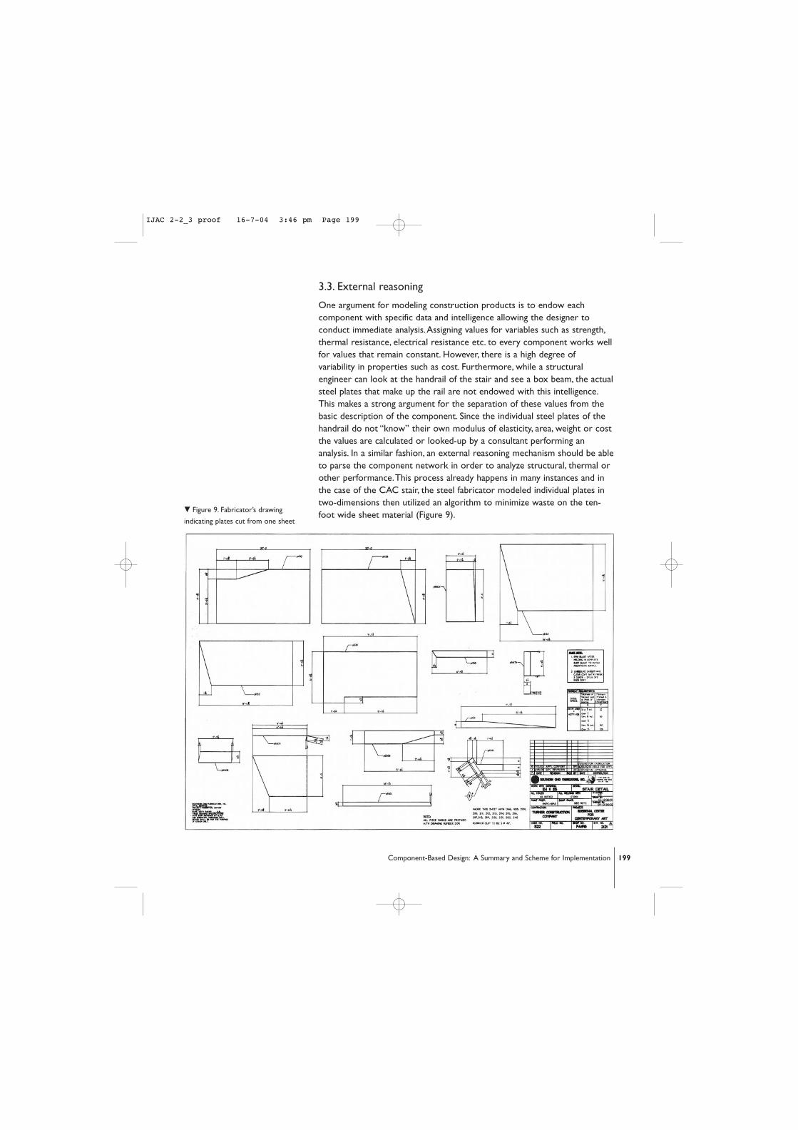
One argument for modeling construction products is to endow eachcomponent with specific data and intelligence allowing the designer toconduct immediate analysis.Assigning values for variables such as strength,thermal resistance, electrical resistance etc. to every component works wellfor values that remain constant. However, there is a high degree ofvariability in properties such as cost. Furthermore, while a structuralengineer can look at the handrail of the stair and see a box beam, the actualsteel plates that make up the rail are not endowed with this intelligence.This makes a strong argument for the separation of these values from thebasic description of the component. Since the individual steel plates of thehandrail do not “know” their own modulus of elasticity, area, weight or costthe values are calculated or looked-up by a consultant performing ananalysis. In a similar fashion, an external reasoning mechanism should be ableto parse the component network in order to analyze structural, thermal orother performance.This process already happens in many instances and inthe case of the CAC stair, the steel fabricator modeled individual plates intwo-dimensions then utilized an algorithm to minimize waste on the ten-foot wide sheet material (Figure 9).
. Figure 9. Fabricator’s drawing
indicating plates cut from one sheet
199Component-Based Design: A Summary and Scheme for Implementation
IJAC 2-2_3 proof 16-7-04 3:46 pm Page 199

3.4. Product/manufacturer links
For the component paradigm to be most useful it is necessary to separateindividual product information from the model and replace it with dynamiclinks from the component network to the product manufacturer. In thisscenario, the manufacturer of an individual building product would supply anaccurate geometric model of their component for inclusion in the network.The architect would choreograph the use of the product in design and useother products, such as bolts, to attach it to neighboring elements.The boltswould also be downloaded from a specific manufacturer’s site. Once placedin the model, the component retains its link to the manufacturer who isresponsible for maintaining a site providing up-to-date information on cost,availability and other behavioral properties.
As an example of this strategy in application consider one of the lightfixtures mounted in the handrail of the CAC stair (Figure 10) The designerwould select an appropriate light fixture to integrate into the design of therail.The three-dimensional model would be available as a downloadablegeometry of parts with a specific and unique catalogue number.
When analysis of the model is required, such as cost, the relevantreasoning mechanism is applied to assess the final cost of the assembly.Thisis accomplished by traversing the component network and then tracing thelight fixture’s link to its manufacturer’s site where information about cost isretrieved. If the lighting manufacturer changes the price or availability of thefixture this information is passed to the architect through this query of themodel. If a link cannot be traced or if a product becomes unavailable thedesigner is alerted and has ample opportunity to reconsider alternatives. By
m Figure 10. Recessed light in handrail
of the CAC stair
200 Anton C. Harfmann and Paul J. Bauser
IJAC 2-2_3 proof 16-7-04 3:46 pm Page 200
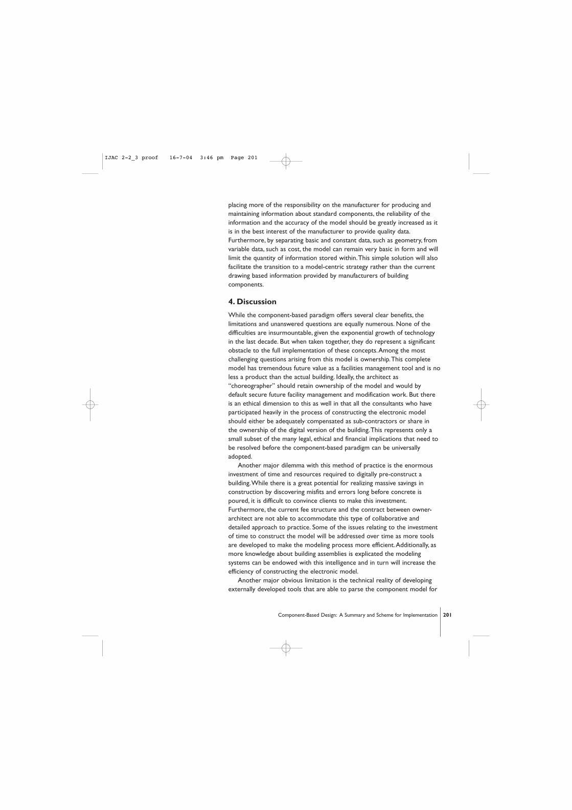
placing more of the responsibility on the manufacturer for producing andmaintaining information about standard components, the reliability of theinformation and the accuracy of the model should be greatly increased as itis in the best interest of the manufacturer to provide quality data.Furthermore, by separating basic and constant data, such as geometry, fromvariable data, such as cost, the model can remain very basic in form and willlimit the quantity of information stored within.This simple solution will alsofacilitate the transition to a model-centric strategy rather than the currentdrawing based information provided by manufacturers of buildingcomponents.
4. Discussion
While the component-based paradigm offers several clear benefits, thelimitations and unanswered questions are equally numerous. None of thedifficulties are insurmountable, given the exponential growth of technologyin the last decade. But when taken together, they do represent a significantobstacle to the full implementation of these concepts.Among the mostchallenging questions arising from this model is ownership.This completemodel has tremendous future value as a facilities management tool and is noless a product than the actual building. Ideally, the architect as“choreographer” should retain ownership of the model and would bydefault secure future facility management and modification work. But thereis an ethical dimension to this as well in that all the consultants who haveparticipated heavily in the process of constructing the electronic modelshould either be adequately compensated as sub-contractors or share inthe ownership of the digital version of the building.This represents only asmall subset of the many legal, ethical and financial implications that need tobe resolved before the component-based paradigm can be universallyadopted.
Another major dilemma with this method of practice is the enormousinvestment of time and resources required to digitally pre-construct abuilding.While there is a great potential for realizing massive savings inconstruction by discovering misfits and errors long before concrete ispoured, it is difficult to convince clients to make this investment.Furthermore, the current fee structure and the contract between owner-architect are not able to accommodate this type of collaborative anddetailed approach to practice. Some of the issues relating to the investmentof time to construct the model will be addressed over time as more toolsare developed to make the modeling process more efficient.Additionally, asmore knowledge about building assemblies is explicated the modelingsystems can be endowed with this intelligence and in turn will increase theefficiency of constructing the electronic model.
Another major obvious limitation is the technical reality of developingexternally developed tools that are able to parse the component model for
201Component-Based Design: A Summary and Scheme for Implementation
IJAC 2-2_3 proof 16-7-04 3:46 pm Page 201

the information they need to function. Over the past 40 years, each of thevarious building design related disciplines has developed specific tools to aidin their analysis.These computer programs would require significantreprogramming or the development of translation engines to convertinformation from the shared model into a usable format for the existingsoftware.This is also not an insurmountable obstacle but it does represent amajor investment in capital and time to develop the paradigm.
5.A scheme for implementation
Currently, software such as ArchiCAD, Revit and Microstation endow theindividual component with a series of specific attributes.This allows otherbuilt-in applications to perform analyses on the objects created.The logicalconclusion to this type of development is already evolving as an unwieldyand cumbersome universal single tool for the description and analysis of abuilding.While modular and integrated, these systems are unable toperform analysis on buildings modeled with competitor software. Such aproprietary approach forces third party software developers to chooseone application for which to develop a module, and then partner with thatvendor in order to enhance that package. Unfortunately, that analytical toolwill only prove useful for those buildings modeled within that system,essentially limiting designers’ freedom to explore multiple softwarepackages.
Using the same argument that intelligence should not reside with theindividual components but rather with the expert who is analyzing theelement we suggest the adoption of a “simple” model.This can be definedby boundary representation, constructive solid geometry representation orbounding volume and multi resolution representation [19], given that thesetechniques adequately support interference checking of components. In thiscase, only a description of the geometry, the ID and the link to a source isstored in the shared model.All other data is stored externally. Forexample, an individual steel plate should have only a simple list ofdescriptors in the shared model (Figure 11):
ID (primary Key)Name (in this case – steel plate)Geometry as defined by its boundary, solid or volume representation Source(s) link (in this case the manufacturer or supplier of the plate)
If the modeling of the elements is standardized according to a simpleopen standard, such as STEP or BMXML [20] [21] [22] then all reasoningand intelligence can be developed independently by the consultants.Thisstrategy represents a fairly straightforward way to transition to the singleshared model. Developers such as Autodessys,Autodesk, Graphisoft andBentley need only provide a “save as” function to export the model and
202 Anton C. Harfmann and Paul J. Bauser
IJAC 2-2_3 proof 16-7-04 3:46 pm Page 202

component network into an accepted generic format in much the samemanner as exporting .dxf files.This strategy avoids the necessity ofcomplete software overhauls, [23] and it allows vendors to continue thedevelopment of analytical modules while opening the possibility for thedesigner to model or read the model using the software of his/herchoosing.
In order for this strategy to succeed there must be only one modelwith only one “master modeler,” responsible for instantiating or modelingcomponents as information from consultants is obtained. Furthermore, thislevel of detail may require the inclusion of a construction managerconsultant and perhaps even the pre-selection of the contractor to assistin the final modeling of the component-based virtual building.This doesalter the scope of work on the part of the architect but this relationshipbetween owner, architect and contractor already occurs frequently. In fact,in the case of the CAC the construction managing firm was chosen by theclient at roughly the same time Hadid was chosen as the design architectand KZF was chosen as the architect of record.This team approach alreadyproves to be an invaluable strategy for the development of significantarchitecture, and can be further exploited by eliminating redundant work.
203Component-Based Design: A Summary and Scheme for Implementation
m Figure 11. Record of individual
component
IJAC 2-2_3 proof 16-7-04 3:46 pm Page 203

5.1. Implementation example
As a way to explore the implementation of this concept we modeled theCAC stair component-by-component using the non-architecturally specificsoftware package, formZ. Using this generic geometric model we exploredthe development of the component network and how this simple networkcould support analysis by outside consultants.The 3-D model of the stairand its corresponding component network are shown in Figure 12.
The next section of this paper includes an exploration of three differentreadings of the component networks to illustrate how each externalevaluation or analysis can be accomplished independently.The first examplefocuses on a structural interpretation of the model.The second considershow a cost consultant would analyze the model and the third offers analternative to producing conventional contract documents and workingdrawings utilizing the model as the sole source of information.
5.1.1. Structural analysis
We make a fundamental argument that knowledge about any building
m Figure 12. Component model with
corresponding network
204 Anton C. Harfmann and Paul J. Bauser
IJAC 2-2_3 proof 16-7-04 3:46 pm Page 204

product should reside outside the material. For example, one of the 1/2”plates of steel need not contain any knowledge or intelligence about itself.Structural properties and/or specific information about its physical behaviorare stored externally.This frees the component to be used in multiplesituations without having to create a new component type for eachalternative orientation or use. For example, a flat plate of steel used as thetop plate in the box beam may have the same cross section as one of theinternal web stiffeners.While they may share the same geometry and mayeven be cut from the same sheet of material, they serve explicitly differentpurposes.The structural engineer analyzing the assembly is able to inferfrom the position of the plates that the plate at the top is largelyresponsible for resisting compressive forces in the box beam and that theplates along the sides are there to reduce the buckling tendencies of theweb plates. In the same manner, the structural engineer would therefore beresponsible for assigning the component in the model to an appropriategrouping based on its behavior.This data is stored in separate tables underthe structural consultants “view” of the model (Figure 13).
Specific data about the strength of the steel and its specific propertiescan be obtained by tracing the source link. In this case, the source link willbe both the AISC code which determines the allowable stress for thematerial and the specific distributor of the steel plate, Riverfront Steel. It is
m Figure 13. Component model with
external consultant collections and
links to resources
205Component-Based Design: A Summary and Scheme for Implementation
IJAC 2-2_3 proof 16-7-04 3:46 pm Page 205

unnecessary for this collection to be part of the shared model as theengineer is ultimately responsible for the performance of the stair. Byallowing the engineer to retain these “structural collections” theirinvestment and knowledge is protected as well.
5.1.2. Cost analysis
Perhaps the most compelling argument for this separation of informationabout the components can be seen when one considers cost. In currentpractice, a cost consultant reviews a design and analyzes cost based on theinformation available.At the early stages of design the cost is determinedusing simple square foot multipliers and as the design progresses morespecific analytical strategies are employed.At the completion of design, whenall components are instantiated, the cost consultant could simply trace eachof the source links to the manufacturer who is responsible for maintainingthe cost of the plate.The user of the system is then able to collect or groupcomponents by trade or material in order to apply appropriate labor costs.In our case, the cost consultant could group the steel plate together with allstructural steel in order to obtain a detailed estimate or an actual bid fromsteel fabricators.This eliminates concerns of the model being dated becausethe data about cost is dynamically obtained from the manufacturer.
5.1.3. Construction documents
One inherent advantage of the highly detailed component model is that thebuilding is essentially pre-constructed.With the complete geometricdescription of each component and its relationships to others in an assembly,the model can be queried for dimensions, material descriptions andspecifications. Rather than the architect producing a series of drawings fromthe model and posting them on the web for view, the entire electronicmodel should be available to the contractor as well.This concept has alreadybeen tested in two-dimensional form using open standards such as SVG [24]and in three-dimensional form using VRML [25]. Using simple section toolsand strategically using the layers within the software, the contractor couldsimply cut a section of the desired part of the model, then query the lengthof the segments etc. to produce the drawing needed for that particularaspect of the construction. Furthermore, since each component has a directlink to the manufacturer, the contractor can access specifications etc. directlyfrom the source.This represents an alternative to providing traditionalcontract documents for conveying construction information.
5.2. Future implementation
Our next steps will be to model a very simple structure using this paradigmand to construct the logic behind the component network.We will utilizeexisting database software such as Access or mySQL as a foundation to
206 Anton C. Harfmann and Paul J. Bauser
IJAC 2-2_3 proof 16-7-04 3:46 pm Page 206
build the various collections of components according to different points ofview.We anticipate developing this simple model with conventional 3-Dmodeling software then linking it to a database in order to build severalanalytical tools.The intent is to develop a proof of concept model thatillustrates the development of external reasoning tools and the viability ofthe overall concept.
6. Conclusion
The component-based paradigm recognizes that all buildings must ultimatelybe constructed by assembling thousands of individual elements such as nuts,bolts, plates, beams and studs.With individual components as the leastcommon denominator, the paradigm argues that the digital environmentoffers the possibility to design and construct an entire buildingelectronically.The virtual construct would support the development of asingle shared model and would eliminate the conventional practice ofproducing two-dimensional drawings to describe a three-dimensionalconstruct. In this paradigm, the contractor would produce drawings directlyfrom the model and query the model for details and other specificinformation.The obvious benefits of this approach include bettercoordination and design integration of the systems in a building as well asthe elimination of foreseeable errors that currently plague the industry dueto multiple representations and duplicate information. Other benefitsinclude the use of the model as a facilities management tool and the abilityto use the modeling environment to check for design interferences andother flaws or misalignments.While the limitations discussed are numerousand significant, this paradigm represents a method that could have asignificant positive impact on the design and construction of buildings. It isunderstood that the current relationships between owner, architect,consultants and contractor would be challenged and redefined.Nevertheless, this strategy exploits the increasing capacity of the computerand offers an opportunity to reunite the severely fragmented building designand construction industry.
References1. Gaskin, E., Imagine Building:The Rosenthal Center for Contemporary Art,Video
Documentary,The Center for the Study of Practice, University of Cincinnati,2003.
2. Cohen, J., Communication and design with the Internet : a guide for architects,planners and building professionals,W.W. Norton, 2000.
3. Manning, S., Imagine Building:The Rosenthal Center for Contemporary Art,VideoDocumentary,The Center for the Study of Practice, University of Cincinnati,2003.
4. Monroe, M., Imagine Building:The Rosenthal Center for Contemporary Art,VideoDocumentary,The Center for the Study of Practice, University of Cincinnati,2003.
207Component-Based Design: A Summary and Scheme for Implementation
IJAC 2-2_3 proof 16-7-04 3:46 pm Page 207
5. Manning, S., Imagine Building:The Rosenthal Center for Contemporary Art,VideoDocumentary,The Center for the Study of Practice, University of Cincinnati,2003.
6. Beeler, D., Imagine Building:The Rosenthal Center for Contemporary Art,VideoDocumentary,The Center for the Study of Practice, University of Cincinnati,2003.
7. Eastman, C., Modeling of Buildings: Evolution and Concepts,Automation inConstruction,Vol. 1, No. 2, 1992, pp. 99-109.
8. Eastman, C. and Jeng,T.S.,A Database Supporting Evolutionary Product ModelDevelopment for Design, Automation in Construction,Vol. 8, No. 3, 1999, pp. 305-323.
9. Eastman, C., Building Product Models: Computer Environments, Supporting Design andConstruction, CRC Press, 1999.
10. Harfmann,A.C. and Chen, S.S., Building Representation Within a ComponentBased Paradigm, From Research to Practice, in: Proceedings of 1990 ACADIAConference, 1990, pp. 117-127.
11. Harfmann,A.C., Majkowski, B. and Chen, S.S.,A Component-Based Approach toBuilding Product Representation and Design Development, in: CAAD Futures ‘93,1993, pp. 437-452.
12. Harfmann,A.C. and Chen, S.S,“Component-Based Building Representation forDesign and Construction”, Automation in Construction,Vol. 1, No. 4 1993, pp. 339-350.
13. Karstila, K., Björk, B.C. and Hannus, M., A Conceptual Framework for Design andConstruction Information,The Computer Integrated Future, CIB W78 Seminar,September, 1991.
14. Clayton, M.J.,Teicholz, P., Fischer, M. and Kunz, J.,Virtual Components Consistingof Form, Function and Behavior, Automation in Construction,Vol. 8, No. 3, 1999, pp.351-367.
15. Ibrahim, M. and Krawczyk, R.,The Level of Knowledge of CAD Objects withinthe Building Information Model, in: Proceedings of 2003 ACADIA Conference, 2003,pp. 172-177.
16. Tolman, F.P., Product modeling standards for the building and constructionindustry: past, present and future, Automation in Construction,Vol. 8, No. 3, 1999,pp. 227-235.
17. Borkin, H.J., McIntosh, J.F. and Turner, J.A.,The Development of Three-Dimensional Spatial Modeling Techniques for the Construction of Nuclear PowerPlants, SIGGRAPH-ACM Quarterly Report,August, 1978, pp. 26-30.
18. Brady,T., Boryslawski, M.,Wynne, J., Isreal, F., and Williams, P., Shared Model CaseStudy: Lucasfilm Digital Arts Campus,Technology in Architectural Practice,Connecting the Dots: Understanding the Emerging Digital Design Building Process,AIA2003, http://www.aia.org/tap/
19. Cagan, J. Shimada, K. and Yin, S.,A Survey of Computational Approaches to Three-Dimensional Layout Problems, Computer-Aided Design,Vol. 34, No. 8, 2002, pp.597-611.
20. Tolman, F.P., Product Modeling Standards for the Building and ConstructionIndustry: Past, Present and Future, Automation in Construction,Vol. 8, No. 3, 1999,pp. 227-235.
21. Pahle, R., Juyal, M. and Ozel, F., Data Modeling of Buildings with BMXML, in:Proceedings of 21th eCAADe Conference, 2003, pp. 533-540.
22. Snyder, J. and Flemming, U., Information Sharing in Building Design, in: Proceedingsof the Eighth International Conference on Computer Aided Architectural Design Futures,1999.
208 Anton C. Harfmann and Paul J. Bauser
IJAC 2-2_3 proof 16-7-04 3:46 pm Page 208

23. Bentley, K. and Workman, B., Does the Building Industry Really Need to Start Over? AResponse to AutoDesk’s BIM/Revit proposal for the Future, Bentley SystemsIncorporated,White paper.
24. Donath, D., Richter, K., and Hansen, S., Internet Based Support for ArchitecturalPlanning Processes, International Journal of Architectural Computing,Vol. 01, No. 03,2003, pp. 361-373.
25. Campbell, D.A.,Architectural Construction Documents on the Web:VRML as aCase Study, Automation in Construction,Vol. 9, No. 1, 2000, pp. 129-138.
209Component-Based Design: A Summary and Scheme for Implementation
Anton C. Harfmann1 and Paul J. Bauser2,University of Cincinnati, 2624 Clifton Avenue, Cincinnati, Ohio [email protected]@email.uc.edu
IJAC 2-2_3 proof 16-7-04 3:46 pm Page 209

IJAC 2-2_3 proof 16-7-04 3:46 pm Page 210