


Compendium: Introduction to course TDT4290 Customer Driven ...
78
The Norwegian University of Science and Technology (NTNU) Faculty of Information Technology, Mathematics and Electrical Engineering (IME) Department of Computer and Information Science (IDI) Postal address: NO-7491 TRONDHEIM Telephone: 73 59 34 40 Telefax: 73 59 44 66 TITLE Compendium: Introduction to course TDT4290 Customer Driven Project, Autumn 2013 EMPLOYER IDI, NTNU REVISED BY Reidar Conradi, Jon Atle Gulla, Jon Espen Ingvaldsen, Steinar Hagen, Geir Solskinnsbakk, Andreas D. Landmark, Anh Nguyen Duc and Sobah Abbas Petersen, Hans Moen COURSE TDT4290 Customer Driven Project VERSION V2 Friday, 06 September 2013 PAGES 78 (http://www.idi.ntnu.no/emner/tdt4290/docs/TDT4290-compendium-2013.pdf )
-
Upload
khangminh22 -
Category
Documents
-
view
1 -
download
0
Transcript of Compendium: Introduction to course TDT4290 Customer Driven ...

The Norwegian University of Science and Technology (NTNU) Faculty of Information Technology, Mathematics and Electrical Engineering (IME) Department of Computer and Information Science (IDI)
Postal address: NO-7491 TRONDHEIM Telephone: 73 59 34 40 Telefax: 73 59 44 66 TITLE
Compendium: Introduction to course TDT4290 Customer Driven Project, Autumn 2013
EMPLOYER
IDI, NTNU REVISED BY
Reidar Conradi, Jon Atle Gulla, Jon Espen Ingvaldsen, Steinar Hagen, Geir Solskinnsbakk, Andreas D. Landmark, Anh Nguyen Duc and Sobah Abbas Petersen, Hans Moen
COURSE TDT4290 Customer Driven Project
VERSION V2 Friday, 06 September 2013
PAGES 78
(http://www.idi.ntnu.no/emner/tdt4290/docs/TDT4290-compendium-2013.pdf)

2
Table of contents 1 INTRODUCTION ____________________________________________________________ 5
1.1 GENERAL INFORMATION__________________________________________________________5 1.2 GOAL AND RATIONALE OF THE COURSE ______________________________________________8 1.3 REQUIRED KNOWLEDGE__________________________________________________________9
2 MOTIVATION ON PROJECT WORK AND GROUP DYNAMICS _________________ 10 2.1 ABOUT THE COURSE____________________________________________________________10 2.2 PROJECT WORK IN A DIDACTIC PERSPECTIVE _________________________________________10 2.3 TRAINING IN GROUP DYNAMICS ___________________________________________________11
3 ADMINISTRATIVE INFORMATION __________________________________________ 12 3.1 WORK LOAD __________________________________________________________________12 3.2 TIMELINE ____________________________________________________________________12 3.3 GROUP ASSIGNMENTS___________________________________________________________12 3.4 RATING OF PROJECT WORK _______________________________________________________14 3.5 SUPERVISION AND MEETINGS _____________________________________________________14 3.6 PRE-DELIVERY FOR EXAMINER AND WRITING COURSE __________________________________15 3.7 FINAL PRESENTATION AND DEMONSTRATION ON NOVEMBER 21 __________________________16 3.8 ANTI-PLAGIARISM _____________________________________________________________16 3.9 COPYRIGHT OR INTELLECTUAL PROPERTY RIGHTS (IPR)________________________________17 3.10 COURSE REFLECTION, EVALUATION AND FEEDBACK __________________________________17
APPENDIX A – THE PROJECT PLAN ____________________________________________ 19 A1. OVERALL PROJECT PLAN ________________________________________________________19 A2. CONCRETE PROJECT WORK PLAN __________________________________________________20 A3. PROJECT ORGANIZATION ________________________________________________________21 A4. TEMPLATES AND STANDARDS ____________________________________________________21 A5. VERSION CONTROL PROCEDURES__________________________________________________21 A6. DOCUMENTATION OF PROJECT WORK ______________________________________________21 A7. QUALITY ASSURANCE (QA) _____________________________________________________22 A8. TEST PLAN ___________________________________________________________________23
APPENDIX B – SUGGESTION FOR APPENDICES IN YOUR PROJECT PLAN ________ 24 B1. PARTNERS _____________________________________________________________________24 B2. CONCRETE PROJECT PLAN _________________________________________________________24 B3. DETAILED PHASE PLANS __________________________________________________________24 B4. TABLE FOR HANDLING OF RISKS ____________________________________________________24 B5. TABLE FOR EFFORT REGISTRATION __________________________________________________25
APPENDIX C – CONTENT OF THE PHASE/SPRINT DOCUMENTS/CHAPTERS ______ 27 C1. INTRODUCTION _________________________________________________________________27 C2. PLANNING ___________________________________________________________________27 C3. PRE-STUDY OF THE PROBLEM SPACE VS. SOLUTION SPACE _______________________________27 C4. LIFECYCLE MODEL: WATERFALL VS. AGILE? _________________________________________28 C5. REQUIREMENTS SPECIFICATIONS __________________________________________________28 C6. ESTIMATION OF REALIZATION EFFORT OF A USE-CASE MODEL ____________________________29 C8. PROGRAMMING _______________________________________________________________30 C9. TESTING_____________________________________________________________________31

3
C10. INTERNAL AND EXTERNAL DOCUMENTATION________________________________________32 C11. EVALUATION ________________________________________________________________32 C12. PROJECT PRESENTATION AND DEMONSTRATION______________________________________33 C13. APPENDICES ________________________________________________________________33
4 APPENDIX D – ADMINISTRATIVE AND TECHNICAL RESOURCES _____________ 34 D4.1 OFFICE RESOURCES ___________________________________________________________34 D4.2 TECHNICAL RESOURCES _______________________________________________________34
D4.2.1. Workstations _________________________________________________________ 34 D4.2.2. Source Control Management_____________________________________________ 34 D4.2.4. Use of collaboration technology in the project _______________________________ 34
5 APPENDIX E – SCRUM – A POPULAR AGILE METHOD________________________ 36 E5.1. PRODUCT BACKLOG ____________________________________________________________36 E5.2. SPRINT PLANNING MEETING______________________________________________________36
E5.2.1. Daily Scrum status meeting ______________________________________________ 37 E5.2.2. Irregularities _________________________________________________________ 37 E5.2.3. Sprint review meeting___________________________________________________ 37 E5.2.4. How do I prepare a project for Scrum (short tutorial) _________________________ 37
6 APPENDIX F – USE-CASE BASED EFFORT ESTIMATION ______________________ 39 F6.1. INTRODUCTION TO USE-CASE ESTIMATION ___________________________________________39 F6.2. MORE ON THE ESTIMATION METHOD _______________________________________________39 F6.3. A MINI-DISCUSSION ____________________________________________________________40 F6.4. REFERENCES__________________________________________________________________40 F6.5. APPENDIX: A SMALL USE-CASE DIAGRAM, WITH EXTRA COMMENTS _______________________41 F6.6. ADD-ON TO USE-CASE EXAMPLE___________________________________________________42
7 APPENDIX G – PROJECT DESCRIPTIONS ____________________________________ 45 7.1 ACANDO AS __________________________________________________________________45 7.2 ETRØNDELAG AT SØR-TRØNDELAG FYLKESKOMMUNE WITH SINTEF ICT __________________47 7.3 FRI PROGRAMVARE I SKOLEN OG ISELIN LABS ________________________________________49 7.4 GRIDMEDIA TECHNOLOGIES AS ___________________________________________________50 7.5 NETLIGHT AS_________________________________________________________________52 7.6 NAV HJELPEMIDDELSENTRAL SØR-TRØNDELAG______________________________________53 7.7 WELLVIS AS__________________________________________________________________54 7.8 DRAGVOLL HELSE- OG VELFERDSSENTER (TRONDHEIM KOMMUNE) _______________________56 7.9 FUNDATOR AS / THE NORWEGIAN COASTAL ADMINISTRATION (KYSTVERKET) ______________57 7.10 HELGELANDSKRAFT – MARKEDSDIVISJONEN________________________________________58 7.11 NORWEGIAN CENTER FOR INTEGRATED CARE AND TELEMEDICINE (NST) _________________59 7.12 POLITIETS DATA OG MATERIELLTJENESTE __________________________________________60 7.13 SOFTWARE INNOVATION _______________________________________________________61 7.14 SYKLISTENES LANDSFORENING I TRONDHEIM _______________________________________62 7.15 ADRESSEAVISEN AS___________________________________________________________63 7.16 SINTEF / SIMLINK __________________________________________________________66 7.17 THE DIRECTORATE OF HEALTH, DEPARTMENT OF THE HEALTH PORTAL ___________________67 7.18 SINTEF / THE NATIONAL COMPETENCE CENTER FOR ULTRASOUND AND IMAGE GUIDED THERAPY _________________________________________________________________________69 7.19 SINTEF V/LEVIN _____________________________________________________________70 7.20 SINTEF V/DINGSØYR _________________________________________________________73 7.21 AALBERG AUDIO___________________________________________________________74
8 APPENDIX H – STUDENT LISTS AND GROUPS________________________________ 76

4
9 APPENDIX I- KICK-OFF ROOMS FOR GROUPS _______________________________ 77 Any writing error will be rewarded by 10 NOK upon first time repeating, and any logical error by 50 NOK similarly. Please contact R. Conradi in person at any time.

5
1 Introduction
1.1 General information This master-level course TDT4290 Customer Driven Project deals with a project assignment that is mandatory for all computer science (“Datateknikk”) students in their 4th study year at NTNU/IDI, typically with 50-75 and mostly Norwegian students. In addition comes participants from the two-year, international master program in Information Systems at IDI (with 10-15 students from all over the world), plus Erasmus and other guest students (usually a handful of Europeans). This compendium contains all the necessary information for this course, the assignments (one for each project-group), and a suggested outline for the final project report. In addition, some examples of what a project plan should contain. Practical information regarding project-group composition, dates etc. can also be found on the web page of the course (http://www.idi.ntnu.no/emner/tdt4290/). All students should check this web page for updates. In case of mismatch between information in this compendium, information given during lectures, by email, and on the above web page, the last updated information should be regarded as correct. The following IDI people are involved with this course: Course responsibles: Prof. Reidar Conradi Course responsible conradi<##>idi.ntnu.no tel 918.97029 Prof. Jon Atle Gulla Course co-responsible jag<##>idi.ntnu.no tel 913.47759 Andreas D. Landmark Practical coordinator andreala<##>idi.ntnu.no tel 988.07021 Group advisors:
Name Picture Email contact Telephone Prof. Reidar Conradi
conradi<##>idi.ntnu.no 918.97029
Adj. Associate Prof. Babak A. Farshchian
baf<##>idi.ntnu.no 992.86869
PhD-stud. Hans Moen
hans.moen<##>idi.ntnu.no 735.50613

6
PhD-stud. Anh Nguyen Duc
anhn<##>idi.ntnu.no 483.48496
PhD-stud. Soudabeh Khodambashi
soudabek<##>idi.ntnu.no 735.50629
PhD-stud. Tosin D. Oyetoyan
tosindo<##>idi.ntnu.no 405.65642
PhD-stud. Muhammad Asif
muhamma<##>idi.ntnu.no 735.93671
PhD-stud. Meng Zhu
Zhumeng<##>idi.ntnu.no 735.51189
Students will be divided in project groups of 5-6 students (detail in Section 3.3). Each group will be allocated an advisor from IDI - either a faculty member, a postdoc, or a PhD student - plus a main customer representative. The mandate of the advisor: The group’s advisor serves as a one-person “steering committee” for your project. His/her responsibility is to keep an eye on the main process of the work, and to oversee that sufficient contact with the customer is maintained. The advisor must therefore regularly receive updated status

7
reports, copies of relevant work plans and technical documents from the group, so that all this can be discussed in a weekly advisor meeting. In addition, the group should have several, weekly internal meetings, and regular customer meetings (detail in Section 3.5),

8
1.2 Goal and rationale of the course The goal of course TDT4290 is to teach you and your fellow students – by working in groups –software engineering (SE) skills in the context of a development project to make a realistic prototype of an Information System (IS) “on contract” for a real-world customer. Each project group is initially given a one-page project assignment from an external customer. All the phases of a typical IS/IT project are covered, e.g. project management and planning, pre-study, requirements, design, programming, testing, evaluation and documentation, but no “maintenance”. However, we do not accept customers that just want the group to write a “summary and evaluation” of some hot topic, with no ensuing implementation. And inversely, we do not want customers that come with pre-made requirements, and just want the group to complete a pre-designed system architecture. Due to resource constraints, the focus should nevertheless be on the “early” lifecycle phases, i.e., project planning, pre-study, requirements specifications and system design – but the exact focus and emphasis will be decided by the group, in dialog with their customer. For instance, groups with focus on the early phases should not omit making a working prototype of some system parts. On the other hand, “programming-eager” groups may try to make a rather complete prototype, e.g. by applying agile iterations in Scrum-style (see C.4 and Appendix F). The important issue is that the group clearly justify their decisions, and that there is a logical flow in the project report from start to end of all the phases, and that all the phases and iterations build naturally on each other. Each group should write a project report in English, and hold a presentation and demonstration of the final prototyped product for the customer, while an external examiner (censor) is present. If a fundamental disagreement with the customer arises, the group has, if needed, “the final word” since the group members gets the credit through a final exam (report) worth 15 Sp. But such a dead-lock situation has hardly happened in the 40 years that this course has been arranged! However, the group and their advisor should do what is possible to resolve any major disagreements. Conflicts are to be explained, negotiated and resolved (managed), as this is part of the real world work. It is therefore crucial that the group is focused and has a good dialog with the customer.
9
1.3 Required Knowledge Required theories and methods for making large and long-lived SE/IS systems are mostly covered in previous, bachelor-level courses. This knowledge base is supplemented by a double seminar on group dynamics, and four guest lectures on project management, Scrum, IT architecture, and use-case based effort estimation. In addition, we arrange a course in presentation techniques and a seminar on technical writing. Since 2008 in this course, the students have been encouraged to use the Agile software development method so-called “Scrum”. Given the time constraints of this student project, there is hardly time for more than 2-3 increments, called “sprints” in Scrum. Many groups have since 2008 chosen an agile development model and had good results. As mentioned above, the structure of the final project report must reflect the choice of overall lifecycle model, i.e. waterfall vs. iterative/agile development methods.

10
2 Motivation on Project Work and Group Dynamics
2.1 About the Course The goal of this course is to teach fundamental software engineering skills through realistic training in software development and project management. You will have the opportunity to apply the knowledge you have gained previously is your studies. During this course, you will experience situations that will require: • Decision, solving and design and development of a relatively large and complex system. • Creative and collaborative problem solving. Earlier in your studies, the tasks have been smaller
and more well-defined. In this project, there are (conflicting) decisions to be made. You will have to show creativity, be pragmatic and be capable of solving fuzzy tasks under heavy time and resource constraints; i.e. fast decision making under great uncertainity.
• Coordination of efforts and distibution of work and responsibilities. • Project management, cooperation, decisions, follow-ups, and a dispute resolution. • Ability to adapt to no-ideal working situations. • Planning and execution of plans. This involves creation of project plans and registration and
monitoring of effort and resource usage. • You must handle difficult customers. They can be unreliable and/or unavailable. They might
change directions, come up with new ideas, and have an unclear picture of what they really want. An important part of this course is to manage the group project, so that the results match the customer’s needs, even though the situation may turn difficult. This requires routines for quality control. Each group should deliver a project plan with resources and milestones, coupled to quantitative measures, and use both “dry” verification (mainly reviews) and “wet” testing.
• Structuring of requirements specifications. • Documentation. The project documents must be complete, well structured and target the
technical knowledge level of the customer. • Defend decisions that are taken on behalf of the customer. You should document all delays,
overruns, and weaknesses, so that they can be explained and argumented. Ideally, all decisions should match conditions coming from the customer (the customer has the right to complain on any aberration that is not his/her fault).
• To present (and sell) the final product for the customer / external examiner. Under the final presentation and demonstration, it is important to give the customer a complete and good impression of the system delivered.
2.2 Project work in a didactic perspective Several evaluations have been carried out of previous versions of TDT4290 (i.e. ”Systemering prosjektarbeid” and “Programmering prosjektarbeid”). These evaluations are generally very positive. See Markus Sorge: ”Evaluering av prosjektundervisningen ved IDI, NTNU”, Program for lærerutdanning, NTNU, spring 2000, 63p, http://www.idi.ntnu.no/undervisning/siving/docs/prosjektevaluering.pdf. Technology is experience-based knowledge – composed and refined over many years − to be able to satisfy human-societal needs in a cost-effective way. Engineering is the process of combining and applying suitable technologies to construct spesific means, such as houses, food, clothing, roads, bridges, vehicles, books, sewing machines − and recently − computer- and information systems. That is, an engineer creates new reality (e.g., kitchen tables) − not only studies the existing one (e.g., a humming bee in a forest). Engineering requires a domain-specific methodology (a technology itself) for how to describe the actual context − being farming, bridge-building, or banking. An engineer will apply scientific insight

11
(both technical and social), combined with knowledge and experience from many sources – all representing different technologies. It is often a strong relationship between what is being constructed and the available time, budget, and tools / methods. Because of the substantial complexity and diversity of the engineering work and the characteristics of the processes, it is often necessary for several people to work together. That means that engineering has a social dimension, since it is executed as group work. Cooperative and communicative skills are therefore essential. Project work in teams is an important part of the engineering discipline. Your study program at NTNU is among the ones with most emphasis on project work. Project work means on the one hand that you need to make an agreement with a customer (customer / organization) about what should be constructed. On the other hand, you have to design and implement technical solutions that satisfy the elicited constraints and requirements. You also have to consider changes over time, as most customers are not sure about what they really want, what their ... may want in the future or they may anyway change opinion. As a consequence, the proposed unfinished solution must be modified. The project groups must also be well organized and effective, and try to avoid destructive internal conflicts. All this means that you will get a hectic work situation – sometimes at the edge of chaos. You have to combine your theoretical knowledge from previous courses to solve specific and practical problems. You have to use a considerable amount of effort in cooperation, communication, planning, and improvisation and show capabilities of working under pressure. Your project will give you essential training to become a professional software engineer. Feedback from industry says, that it is almost impossible to get more done in 3 months than what such a group of students is capable of. Further, software engineers from NTNU are useful from day one: they posses the theoretical knowledge and know how to work efficiently in teams. So, the expectations are great from all participants: the IDI department, lecturers, advisors, external customers and of course the students themselves. The project report (written in English) should not be more than 200 pages, exclusive appendices and graphics. If your group experiences that some of the team members are not participating satisfactorily, you should immediately contact your advisor. If you experience other minor problems, the advisor is the one to contact. However, most (minor) problems are to live with; in fact, it is a part of the course to learn to deal with such issues in a project. So, welcome to an interesting and hectic semester in this course!
2.3 Training in group dynamics Good teamwork and group dynamics are essential for the success of any collaborative project. Therefore, ”social” skills are of upmost importance to become a successful project co-worker. A seminar on group dynamics is planned as a part of this course, to support the project groups to learn more about team work and group dynamics. In addition to the seminar, the following time slots should be used wisely to create a good team atmosphere among your group, particularly at the beginning of the project.

12
3 Administrative information
3.1 Work load NTNU has officially an autumn semester with 19 weeks, and a spring semester with 21 weeks. Of the former 19 weeks, two are spent on continuation exams (and immatriculation etc.), and three are spent on exams in December − which you don't have. This implies 17 "study weeks" in the autumn semester, each of 40 person-hours (work-hours) per student. This again corresponds to 340 (17 * 25% * 40) person-hours per student for a "15-Sp" course (50% of 30-Sp semester total). Note that an hour has 60, not 45 minutes. Since this project runs in 14 weeks (really 13.6) instead of 17 weeks, the weekly effort per student then be adjusted to 40 * 50% * 17/14 = 24.3 person-hours. Furthermore, the official web page of the course − http://www.ntnu.edu/studies/courses/TDT4290/2013 − specifies 24 weekly person-hours per student, but this is for 14 weeks. So let us round off to 25 person-hours per week and student, i.e., 350 person-hours per student for totally 14 weeks. For a project group of 5-6 students, the available effort per group will lie between 1750 and 2100 person-hours, including own reading, meetings, lectures, and seminars. Earlier projects have shown that it is possible to deliver really good results within that timeframe. It is important that everyone is honest and registers all effort (as person-hours) spent on the project. This means that the project documents must show the real work load. Effort overruns will result in less sparetime for you personally and less time for other courses. Inflated work effort does not affect the grades given in this course!
3.2 Timeline This is the preliminary time plan for the activities of this course. For further details and updates check It’s Learning.
3.3 Group assignments We expect about 90 students in total. This gives in total 17 groups with 5-6 students per group. Each group is preallocated to one customer and one group advisor. The groups should therefore have a tight cooperation with their advisor. Group assignments are essentially made randomly. This is done intentionally to create groups where the members generally do not know each other beforehand. This is a typical situation in a real life, especially when working as a consultant. Since many of the students in the course are foreign, with limited or no knowledge to Norwegian language, the lectures and seminars will be held in English.

13
Table 1 – Overview of groups, customers and advisors
Group Customer Title Advisor 1 Acando AS Cloud backed mobile app for
communication within Acando Reidar Conradi
2 eTrøndelag at Sør-Trøndelag Fylkeskommune with SINTEF ICT
Virtual walls – walls that tell us stories Reidar Conradi
3 Fri programvare i skolen og Iselin Labs
Framework for creating web based educational games
Babak Farshchian
4 Gridmedia Technologies AS
Geelix Expo Viewer Anh Nguyen Duc
5 Netlight AS Rock Concert Audience as a Screen Anh Nguyen Duc 6 NAV
Hjelpemiddelsentral Sør-Trøndelag
BoligApp (HouseApp), with opportunities to draw, take pictures and insert objects in different rooms.
Anh Nguyen Duc
7 Wellvis AS Development of Drilling Engineering Software
Soudabeh Khodambashi
8 Dragvoll health & welfare center
Communication platform for the future of nursing
Soudabeh Khodambashi
9 Fundator AS / The Norwegian Coastal Administration (Kystverket)
Pocket Ship Radar (Augmented Reality) Soudabeh Khodambashi
10 Helgelandskraft – Markedsdivisjonen
Power control game Tosin Oyetoyan
11 Norwegian Center for Integrated Care and Telemedicine (NST)
Patients Trajectories (PAsTAs) Visualization and Dialog
12 Politiets data og materielltjeneste
Automatic License Plate Recognition Muhammad Asif
13 Software Innovation Document organizer components for ProArc
Muhammad Asif
14 Syklistenes Landsforening i Trondheim
CountMe: Mobile app for counting cyclists and pedestrians
15 Adresseavisen AS Automatic Import of Completed Ads Meng Zhu 16 SINTEF / SIMLINK Smart-token app development Meng Zhu 17 The Directorate of
Health, Department of the Health Portal
National Integration Platform for Citizen Centric eHealth in Norway
Meng Zhu
18 SINTEF / The national competence center for ultrasound and image guided therapy
USNeuroNav App Anh Nguyen Duc
19 SINTEF v/Levin
Smart application for revealing public transit travel patterns
Tosin Oyetoyan
20 SINTEF v/Dingsøyr Applikasjon for utvikling av framtidens Muhammad Asif

14
arbeidsplass - RFID-måling av bevegelsesmønstre, digital representasjon og analyse
21 AALBERG AUDIO (School of Entrepreneurship NTNU)
Innovative guitar controlling system
3.4 Rating of project work The project work will be evaluated based on the quality of the project report and presentation delivered at the end of the course and the students’ reflections on the project work:
• The project report and presentation will be 95% of the marks. • The reflection report will contribute to 5% of the marks.
The project report must be written in English, and the presentation must be done in English,. Both the project report and the presentation count towards the grade in an integrated way (they are not formally weighted against each other). How the group actually has worked, technical problems, customer behaviour and availability, etc. are a part of the reflections report . The group is asked to deliver a 1-2 page report, reflecting upon their experiences during the project and reflecting upon what they had learned and how they could have done things differently. The focus of this part is on the process rather than the product. This report is due at the end of the course and will be evaluated by the group advisor and the course coordinator. The following criteria are evaluated in an integrated way: • Whether the group has solved the given assignment, according to the customer’s objectives of
the project. • Reasonable grounds for decisions taken. • Logical flow in the report. • Visibility of limitations done. • Layout and structure readability. • The students’ ability to reflect on the process during the project. The criterias are not formally weighted against each other. Note that since the presentation counts towards the grade, it is important that you maintain a functioning version of your program in case you (the group) appeal the result (grade). If an appeal is made, you will have to make your presentation for the new examiner, including demonstration of the program.
3.5 Supervision and meetings Your very first group-internal meeting is scheduled for the same day as the kick-off day. Each of you should introduce yourself to the others in the group, and try get the group organized for the first customer meeting the following hours. It is up to you! Furthermore, your group should have a main advisor meeting with your advisor once a week, normally lasting one hour. Such meetings will have a group-specific content, but share a template agenda from Appendix A.7. All written documents for such meetings (agenda, weekly status report, phase-spesific documents etc.) must be delivered on paper or by email to the advisors before 14:00 the day before. In Appendix A – Project plan, you will find more information about such meetings.
15
Thus, during the first, pre-planned advisor meeting between your group and your advisor on Wednesday (see room/time in Appendix I), you will have to agree upon when and where the weekly advisor meetings shall take place for the rest of the semester. The group is responsible for booking a meeting room for these meetings (possibly helped by the advisor). During this hour, the advisor will also focus on the teamwork and group dynamics aspects and support you to establish a good group atmosphere. How to book a room for a meeting: You can book a room by contacting Ellen Solberg at the IDI information desk. It is recommended that you send an email to Ellen.Solberg<##>idi.ntnu.no or by phone 73 59 34 40. It is wise to suggest 2-3 alternatives times for the meeting, because many of the rooms may already be booked. Always give Ellen Solberg a note if you not are using a reserved room. A suggestion of an email: Regarding the “TDT4290 - Customer Driven Project” we would like to book a room for X persons. We would like one of the following times (in prioritised order) 1. date, from-to 2. 3.
Best regards, …
It is also possible to book some rooms through the room reservation site “Romres” (https://romres.ntnu.no/). This reservation page is only accessible from users on the NTNU-intranet. Customer meetings are held when needed, starting on the kick-off day (see rooms in Appendix I). The next customer meetings arranged in dialog with the customer, but the group is responsible for booking a room and other logistics. We recommend taking more contact with the customer, before the second advisor meeting in the following week. You will probably also need several weekly, internal group meetings. So try to book a fixed room once or twice a week during the semester. Note: Before the first advisor, the group is collectively responsible for making a written resume of the first customer meeting held on the kick-off day. This resume should be sent by email to the persons involved (group members, advisor, customer) later on the same day. So take good notes of this first customer meeting!
3.6 Pre-delivery for examiner and writing course You are required to submit a copy of the Abstract, Introduction, the Pre-study and the Choice-of-Lifecycle-model chapters to the external examiner (censor) and technical writing teacher by the 14th of October. These chapters are normally not in their final stage and will not be used as part of the final assessment. It is only to let the external examiner be better prepared. The technical writing teacher will also provide feedback on the chapters, as well as get a general feel for which topics to discuss in the plenary session. In addition to the chapters mentioned earlier, the groups are required to include the outline of the full report (Table of Contents). The Table of Contents should not be too detailed, but must contain enough detail to understand how each chapter is structured and what the final focus of each section should be. This delivery should be electronic to the group’s supervisor (by the end of October 8th).
16
Remember that you are the “consultants” that invites to a presentation of your work. You should be proud of your product and give it the publicity it deserves. Create a flyer to catch the attention of the audience, and send this to the customer, the advisors, and others that might be interested - such as local TV/radio, Universitetsavisa, Adresseavisen etc. - well ahead of the presentation.
3.7 Final presentation and demonstration on November 21 The projects will be presented and demonstrated at NTNU on Thursday, November 21, between 09:15 and 16:00. All groups have to make their presentations in English. Room: If the project demonstration requires special facilities (such as virtual reality or cave equipment), the groups can also book and have the presentation in other rooms. If your group needs to have the presentation in a specific room, please notify the course coordinator (Andreas D. Landmark). Remember that the room must have space for 10-15 persons. The time and place for each presentation, will be published on the course webpage. Laptop: Most groups use one of their personal laptops for the demonstration. If your group do not have a suitable laptop for the presentation, please notice drift<##>idi.ntnu.no two weeks before the presentation. A beamer will be made available in all presentation rooms. Copying project documents: We want four printed and bound copies of the project report. The costs for copying and binding four complete project reports are covered by IDI. Copying should be carried out, at the latest, one day before the final presentation (e.g. on Nov. 20 or before). In addition, one electronic (PDF) copy, identical to the printed and bound version, should be e-mailed to [email protected]. Delivery of final report: Four bounded paper copies of the final report (with implementations on attached CDs / DVDs) should be delivered on the same day as the presentation. The customer should get one of the copies, and the three others should be delivered at the IDI information desk. If the information desk is closed at the time your presentation is finished, contact the practical course coordinator. The four printed copies of the report will be distributed to:
• Customer • Examiner • IDI archive • Advisor
In addition, the course coordinator should also receive a digital single-file, .pdf-format copy of the entire final report by as an e-mail attachment. On the CDs / DVDs, you should include the final report as a .pdf-file, with relevant implementations enclosed (source code etc.). All this should be documented by a Readme.txt file.
3.8 Anti-plagiarism The rules for this are very strict, see §36 in "Forskrift om studier ved NTNU" (page 23 in “Studiehåndbok for Sivilingeniørstudiet 2011-12”) regarding cheating and http://www.lovdata.no/all/hl-20050401-015.html#4-7
17
See also http://www.idi.ntnu.no/grupper/su/publ/ese/plagiarism.html.
3.9 Copyright or Intellectual Property Rights (IPR) For the entire lifetime of this course, it has been "unclear", although rather frictionless, which “legal person” actually owned the IPR for the produced work, typically a project report and associated software. The Norwegian copyright law stands in LOV-1961-05-12-2 (http://www.lovdata.no/all/nl-19610512-002.html), and follows the Berne Convention for the Protection of Literary and Artistic Work from 1886. Note: In Norway there is no need for a © symbol as in USA. Patents on software does not apply in Europe, but can be awarded in USA. Your employer owns the copyrights for software written as part of your employment contract (EØS rule). IPR can be dealt with in four ways:
1. Just letting all parties (students, advisors, companies, anybody) do whatever they want with the work and with no explicit rules, just as now and compliant with the principle that scientific results (including implementation) shall be open and free of charge to everybody. However, legally and by default (Berne convention), the copyright (or IPR) belongs to those (the students) that have their names on the front page of the actual work.
2. Modifying NTNU's new IPR policy, aimed at covering master's theses - alone or in a group - but not project (i.e. pre-master) reports, see http://www.ntnu.no/studieavd/skjema/standardavtale07e.doc, 2p, dated 2007-08-28.
3. Using a revised, liberal and BSD-inspired IPR policy (about free and open software), formulated and adapted by Reidar Conradi in August 2008: http://www.idi.ntnu.no/grupper/su/publ/ese/new-standardavtale08e.doc. It is a combination of point 1) and 2).
4. Applying NTNU’s new IPR policy (also) for the TDT4290 project course, possibly revising point 2): The original IPR policy proposal was drafted by NTNU’s legal advisor Morten Øien, but withdrawn at its board meeting on June 12, 2008, awaiting vital clarifications, see http://www.ntnu.no/styret/saker_prot/12.06.08web/46.08 vedl.pdf, 12p. NTNU’s IPR policy was finally approved at its board meeting on June 6, 2010; see NTNU’s S-sak 36/10: http://www.ntnu.no/styret/saker_prot/09.06.10web/36.10.pdf, 12p.
NTNU generally tries to coordinate its IPR policy with that of the University of Oslo from October 19, 2010: http://www.uio.no/for-ansatte/arbeidsstotte/fa/kontraktinngaaelse/ipr-politikk-191010.pdf, 16p. See also proposed extensions from the “Sejersted-II committee” at University of Oslo from May 20, 2011: http://www.hf.uio.no/imv/om/dok/2011/instituttstyret/SAK192011Høringsnotat fra rektor.pdf, 5p. Check also what law professor Olav Torvund from University of Oslo has written in his interesting blog on IPRs and other issues: http://blogg.torvund.net/. See finally some overall comments from June 2008 by Reidar Conradi in: http://www.idi.ntnu.no/~conradi/IT-debate/ip-politikk-ntnu-26jun08.html, 6p.
3.10 Course reflection, evaluation and feedback We intend to do a systematic evaluation of this project course. For this purpose, a “student reference group” must be established among the course participants. The course will be evaluated in the following ways:

18
• Student surveys: individual students will be asked to fill in a questionnaire at the begining and at the end of the course. The questionnaires at the beginning of the course will be used to gather data on the students’ expectatations and the questionnaires at the end will be used to gather data on if the students’ expectations have been met and other relevant feedback frpom the students.
• Mid-term assessment by advisors: the advisors will be asked to provide a mid-term assessment on how their project group(s) are progressing and notify if they forsee any challenges with their groups.
• Customer feedback: Customers will be asked to fill in a short questionnaire at the beginning and at the end of the course. These will be used to gather data on if and how the customers’ expectations have been met and to guage customer satisfaction with their project group and the course in general.
The feedback received from the different parties will be used to improve the course for the future students.

19
Appendix A – The project plan This section gives an example of how to structure a project plan. The project plan is a dynamic document that will evolve and change throughout the whole project. The project plan regulates the administrative part of the project and guides the project. Depending on the type of lifecycle model you use you will have to structure the project plan differently.
A1. Overall project plan Recommended content of the project plan (“project directive”): • Project name • Project sponsor (customer) • Partners including responsible third party providers • Background for the project: software system development • Measurement of project effects, i.e. goals like:
Reduce the time it takes to create a daily production report with 3 hours… 30% cost reduction of… 40% increase in sales… etc.
The effect measures are typically stated by the project sponsor, but it is likely that the group has to take the initiative to specify these in detail.
• General terms. What are your limitations, tool selections, organizational demands from the customer, resources etc.?
• Based on the planned effort: How many person-hours are to be used? • Schedule of results. When should deliverables be available as milestones or sprints/iterations?

20
A2. Concrete project work plan Recommended content: • phases/sprints • activities • milestones • person-hours per activity and phase + lectures + project management The project plan (in form of a Gantt diagram) can be attached as appendices. It is also recommended to attach the detailed plan of the phases as appendices. The workload (measured in %) of this course is normally scattered out on different project phases, as shown in table 2. A suggestion of a relative workload is found in column “Norm”, while the experiences from groups 1 to 7 in 1997 are found in the subsequent columns. As you can see from the table, the relative workload varies a lot from group to group. This is a normal variation and is caused by the different assignments, the groups working differently, and that it is not strictly defined what each phase should contain. The suggestions given in “Norm” are a good starting point for the project plan. For projects based on iterative development like Scrum, you will have to incorporate the phases which are needed into each sprint into the documents for each sprint. Table 2: Relative workload for waterfall-like project.
Phase\ Share in % Norm Gr.1 Gr.2 Gr.3 Gr.4 Gr.5 Gr.6 Gr.7 Project management
10 - - - - - - -
Lectures and self study
10 - - - - - - -
Planning 7 9 5 9 9 4 5 6 Pre study 15 24 14 26 21 17 22 38 Requirements specification
20 26 34 25 25 18 24 24
Design 15 27 19 15 18 22 19 9 Programming and documentation
13 6 25 11 14 31 23 14
Project evaluation 5 2 2 7 5 3 2 4 Presentation and demonstration
5 6 1 7 8 5 5 5
Ideas to the content of the different phases are found in Appendix B. It is also recommended to look at previous project reports, which can be found at the web site of the course.
21
A3. Project organization Recommended content: • An organizational diagram of how the group is organized • Roles, i.e., project leader, system analysis, system architect, system designer, test leader,
customer contact, QA responsible, etc. Try to be inventive in role allocation! • Responsibilities of the different roles • Weekly schedule
A4. Templates and standards The group should create templates for all relevant document types. Even though it will take some time to create these in the beginning, the group will benefit from these in two ways: 1) the layout will be correct when creating project documents and 2) reduction of irritation and stress within the group. Templates ought to be made for: • phase documents • agenda for meetings • weekly status reports for the advisor meetings • etc. The group should also create pragmatic standards for: • organisation of files • naming of files • coding style • etc.
A5. Version control procedures The group must create a systematic procedure for version control for all textual documents, source code, etc., see Appendix D.4.2.3 on actual tools like CVS, SVN, Make etc.
A6. Documentation of project work Internal project meetings Try to have internal meetings at least once per week. In these meetings you should present the status, coordinate activities, divide tasks, and check the “mood” of the project. Set up an agenda and write precise minutes for each meeting. Internal reports A typical internal report: • Person-hours - used and remaining (according to plan) • Activities - done and remaining • Achieved and not achieved milestones. These are important progress indicators. Reporting of person-hours used should be done in written form to a specified time, e.g. as a part of the weekly reports.

22
A7. Quality Assurance (QA) QA assumes that the relevant product qualities have been identified, so that the development process can be tailored to achieve these, e.g. reliability, performance, usefulness etc. There exists an ISO-standard for this (ISO 9126). More information can be found on Wikipedia, see http://en.wikipedia.org/wiki/ISO_9126 Time of response Make agreements with the customer. There should be time of response on: • Approval of minutes of customer meeting (e.g. 24 hours) • Feedback on phase documents the customer would like for review (max 48 timer) • Approval of phase documents (max 48 hours) • Answer to a question (e.g. 24 hours) • To get agreed documents etc (e.g. 24 hours) • Other Routines for producing high quality internally This has something to do with how you organize the specification and programming work, e.g. user involvement, “pair programming”, design examination, etc. The number of people involved should be weighed against available resources. Routines for approval of phase documents Specify how you are going to approve the phase results (deliverable), which mainly consists of the phase documents. It is natural to involve the customer in the approval of pre-studies and requirements specification (or whatever you might call these documents). You must, as stated earlier, agree upon a time of response with the customer. Calling for a meeting with the customer For all the meetings with the customer you should send a call for the meeting, specifying time, place, intention (result), agenda, and background documents. It is vital to specify what preparations you expect of the customer and the group before the meeting. You have to agree with the customer how long in advance the calling for meeting should be sent, e.g. at 12:00 two working days before the meeting is going to take place. Minutes of a customer meeting You must write a summary of the meetings with the customer. It is vital that you write down decisions, actions (what, who, and deadline), clarifications etc. that are important for further work in the project. The customer must approve the minutes of the meeting, to make sure there where no misunderstanding of decisions made etc. The minutes of meetings are part of the “contract” with the customer. In normal working life it is not uncommon that the minutes of meetings are part of the contract document with the customer. In the project plan you should specify when the summary of the meeting should be done, when it is to be given to the customer for approval, how to distribute (e-mail, fax etc.) and expected time of response from the customer. It ought to be written by 12:00 o’clock the following day and should be distributed as soon as possible when you are done with internal approval within the group. It is vital that you get an approval as soon as possible to avoid misunderstandings. Calling for the weekly advisor meeting between the group and its advisors 12:00 o’clock the day before the meeting, with print out of all needed paper.

23
Agenda for the weekly meeting with the advisor - a template that is to be followed 1. Approval of agenda 2. Approval of minutes of meeting from last advisor meeting 3. Comments to the minutes from last customer meeting or other meetings 4. Approval of the status report, which may be structured as follows:
4.1 Summary 4.2 Work done in this period Status of the documents that are being created Meetings Other activities 4.3 Problems – what is interfering with the progress or taking resources? Problems are often risks that have taken effect. 4.4 Planning of work for the next period Meetings Activities 4.5 Other
5. Review/approval of attached phase documents 6. Other issues are listed here… 7. Other issues The status report (see Section 4.1-4.5 above) should be handed in as a separate document. Minutes of the weekly meeting with the advisors Is attached to the next calling for meeting and is a fixed subject on the agenda.
A8. Test plan The project has to have an overall test plan, which either can be part of the project plan or as a test document (the latter is recommended, see Appendix C6).

24
Appendix B – Suggestion for appendices in your project plan
B1. Partners Owners, target audience, customer representative(s), project group, advisors. For each person, record: • name • address • phone number • e-mail • etc.
B2. Concrete project plan The current project plan and old project plans. By also keeping the old plans the group can see how they have evolved and also possible learn from previous experience.
B3. Detailed phase plans A detailed description of what each phase consists of. When ending a phase, the next phase is fine planned in detail. The detailed plans for each phase are put here and not in the end of last phase document.
B4. Table for handling of risks
Project nn
Nr Activity Risk factor Consequents Probability. Strategy and actions Deadline Responsible Which of the
activities of the project are affected
Catching the name of the risk factors
Start with H, M or L before describing the consequences
H, M or L Select strategy: Avoid, Transfer, Reduce, or Accept. Then on the next lines describe the measures
Set a clear deadline for ...
Give one person the responsibility
1 All Hans is involved in UKA
H: The quality of the project results will decrease
M Reduce Assign delimited tasks to Hans with clear deadlines
Continues Project leader
L = Low, M = Medium, H = High

25
B5. Table for effort registration All projects needs to register the effort spent by each project participant on the different activities (e.g. Prestudy, Programming etc.) and in what period (week 1, week 2 etc.). This is needed to ensure that the project is on track according to the project plan. A weekly registration or periodization is common. So each of you must weekly report - in a so-called time sheet – seven data items per relevant activity and period: project group no, person name, date of registration, period no, activity name or id, your effort spent and given in person-hours (possibly zero). Make a template time-sheet for this information as soon as possible (a textual email-message format will do), and establish reporting procedures from the very project start. The reported effort data should be delivered ca. two days before the weekly advisor meeting. The project manager (or a delegated person) should be responsible to collect and synthesize the individual effort data into an updated project effort-matrix on a spread-sheet. The matrix data will be used to regularly monitor the planned (or estimated) effort vs. the actual one for the whole project. This matrix has time (period number) as the horizontal dimension, and activity as the vertical dimension. Each matrix cell contains a number measured in person-hours (ph). So very early in the project, as part of making a Project Plan, you must break down the project’s total available or estimated effort (ca. 1700 person-hours) into a dozen main activities or phases, which again are allocated to periods (week no 1-13), cf. Appendix A2. Naturally, activities belonging to the last part of the project cannot be broken down in detail in the start. Thus the project plan must be adjusted over time. Example: Assume that we have a software project with three estimated activities (A1-A3) over three time periods (T1-T3): - A1. Prestudy, whose estimated effort is 40 ph (person-hours). - A2. Requirements, with 40 ph. - A3. Implementation, with 20 ph. - A. Total of 100 ph.
The project has an unspecified number of participants, so our project manager must keep track of the total resource usage (effort, time).
Version 1: Initial effort-matrix with very uneven effort estimates in the three periods: Group no: ... Date: ... Activity\ Period T1 T2 T3 Activity
sums A1. Pre-study 40 40 A2. Requirement 40 40 A3. Implementation 20 20 Period sums
40 40 20 100
Comment: It makes sense to overlap the three activities a bit, to get a more even effort distribution over the three periods.

26
Version 2: Reconciled matrix version, where the three “diagonal” ph-estimates (40, 40, 20) are spread out to get a more even effort distribution over time - please discuss the revised ph-estimates
Group no: ... Date: ... Activity\ Period T1 T2 T3 Activity
sums A1. Pre-study 20 10 10 40 A2. Requirement 10 20 10 40 A3. Implementation 0 (OK) 5 15 20 Period sums 30 35 35 100
Version 3: Now introducing estimated (E:) vs. actual (A:) effort per period (T1-T3), both per
running period (as above) and accumulated over several periods (see after the “/”-symbol in the below effort-matrix):
Group no: ... Date: ... Activity\Period Start T1 T2 T3 Activity
sums Activity comments
A1. Pre-study E:20 A:0
E: 20/20 A: 13/13
E: 10/30 A:12/25
E: 10/40 A: ??/??
E: */40 A: ..
...
A2. Requirement E=10 A=0
E: 10/10 A: 11/11
E: 20/30 A::19/30
E: 10/40 A: ??/??
E: */40 A: ..
...
A3. Implementation E=0 A=0
E: 0/ 0 A: 2/ 2
E: 5/ 5 A: 7/ 9
E: 15/20 A: ??/??
E: */20 A: ..
...
Period sums E=30 A=0
E:30/30 A: 26/26
E: 35/65 A: 38/64
E:35/100 A: ??/??
E: */100 A: ..
...
Period comments A1 delayed A3 before
A1 delayed A3 before
... ...
* means irrelevant Let us assume that two time periods (T1-T2) have passed, with T3 just about to start. Observation: in activity A1 after time T2 the Estimated running effort is 10 ph and the estimated accumulated effort (i.e. including T1) is 20+10 = 30 ph. However, the Actual effort for A1/T2 is 12 ph, and the accumulated effort is 13+12 = 25 ph. So it seems that A1 is a bit behind the estimated effort (“plan”) – but that can have many valid reasons. We are only measuring resource usage (effort, time), not the actual state of the software under development! Ex. what advice will you give to all the activities A1-A3 for the last T3 period?
27
Appendix C – Content of the phase/sprint documents/chapters This appendix contains information about what the different phase documents (or report chapters) should include. See also former project reports for more details. That is, it is common to divide a software project into the following 13 (or so) phases, whose documentation then becomes a chapter in your final project report: C1. Introduction C2. Planning C3. Pre-study of the problem space vs. solution space C4. Choice of lifecycle-model: waterfall vs. agile? C5. Requirements specifications C6. Estimation of realization effort for use-case model C7. Construction/ design C8. Programming C9. Testing C10. Documentation C11. Evaluation C12. Presentation and demonstration C13. Appendices If an agile lifecycle model is chosen, like in Scrum, we recommend one “phase” (or report chapter) per Scrum-sprint, typically 2-3 such. These “Scrum phases” will then replace the waterfall phases C5-C10. Below you will find some more information on what each phase document is expected to contain. Note that the group can also select another phasing.
C1. Introduction Write a good, one-page abstract early, and explain the overall context, motivation, demands and results.
C2. Planning See appendix A – Project plan.
C3. Pre-study of the problem space vs. solution space The preliminary studies are vital for the group to obtain a good understanding of the total problem. Here, you will have to describe the problem at hand. You should describe the current system and the planned solutions (text, workflow, use-case scenarios, information flow, and other graphical presentations you can use). It is all about getting a good understanding of the challenges ahead! The group should investigate if existing and potentially competing solutions exists on the market. If such solutions exist, they should be described. You should also describe alternative solutions that fully or partially require custom implementations. The group must also set up evaluation criteria that form the basis for choice of a solution. Software by third party software providers (as OSS or COTS) should be actively pursued as candidates for implementation of large parts of your software system, see http://sourceforge.net

28
In cases where existing components can be applied as modules in the project solution, a simple cost-benefit analysis should be carried out. Summary:
• Describe the main business requirements, both functional and non-functional, that will constitute the requirements for the final solution and its functionality. These requirements will later form the base for later formalization of requirements. Try also to make use-case diagrams to express the major functional requirements, cf. the simple effort-estimation method in Appendix F.
• Describe the situation and solutions of today (“as-is”) • Describe the wanted situation and its possible solutions (“to-be”) • Evaluation criteria • Market investigations • Description of alternative solutions • Evaluation of alternative solutions, including adjusted requirements and potential costs
and benefits. • Choice of solution, in dialog with customer.
To conclude, the pre-study should have two main deliveries:
- A (partly) prioritized set of requirements – cf. the Scrum “backlog”. - A proposed system architecture to enable a fast break-down (modularization) of the technical
work This is also the time to revise your project plan, possible due to use-case based estimation or clear choices of 3rd party software.
C4. Lifecycle model: waterfall vs. agile? For the realization of the recommended requirements above, the groups are fairly free to choose between a waterfall or an agile lifecycle model to make a prototype for this project. However, some of the assignments do require use of agile development methods, and the customer will anyhow like to have his/her hand on the steering wheel. The concept of waterfall development and its properties are considered known from previous courses, and are not covered here. See also phase descriptions in sections C5-C10 below. Use of the agile methodology called Scrum is covered briefly in Appendix E and by the lecture on September 17th.
C5. Requirements Specifications
In the requirements specification phase, it is important to explicitly state the system requirements and link them to the business requirements from the pre-study phase. Typically, requirements are divided into functional and non-functional requirements. Structure the requirements such that the presentation is well organized. Some persons like to enumerate requirements (R1, R2 ...), which may create “boring” reading where it is easy to lose track of the content. The advantage with numbering is that it is then easy to separate the requirements from the rest of the text, each becomes explicit, and you achieve traceability and structure.

29
Use a lot of figures! Good figures say more than a thousand words. We strongly recommend making use-case diagrams here, also because we then can make quick and reliable estimates of the ensuing design, programming and test effort (Appendix F). Before requirements are stabilized, you should give an overview of the software architecture. This means including figures that show how separate modules are related. Prototype-diagrams of the user interfaces are often very helpful for communicating with the customer.
Suggested outline of a more detailed Requirements specifications The IEEE (Institute of Electrical and Electronics Engineers) have made a good recommendation paper on recommended practices for writing requirements specifications which can be found on; (http://ieeexplore.ieee.org/iel4/5841/15571/00720574.pdf). If you are using this recommendation, please note that it is designed as a general-purpose software requirement specification plan and that some parts may not be relevant for your project. The outline of the IEEE software requirement specification is:
Table of Contents
1. Introduction 1.1 Purpose 1.2 Scope 1.3 Definitions, acronyms, and abbreviations 1.4 References 1.5 Overview
2. Overall description 2.1 Product perspective 2.2 Product functions 2.3 User characteristic 2.4 Constraints 2.5 Assumptions and dependencies
3. Specific non-functional requirements (e.g. performance requirements, database requirements, security, reliability etc.) Appendices Index Glossary
C6. Estimation of realization effort of a use-case model For TDT4290 Customer-driven Project, IDI, NTNU - by Reidar Conradi, Aug. 2011. See also Appendix F for an extended presentation; here comes the short one. Use-case based effort estimation is a very simple and cheap method to estimate the remaining implementation effort of a requirements specification, when the latter is expressed as a set of “upgraded” use-case diagrams. This means that a textual specification (resembling “pseudo-code”) must be added to the graphical actor and use-case models. The actors and use-cases must then be categorised as Simple, Average, and Complex - by you. An effort estimate in person-hours can now be calculated, by you or by a spread-sheet tool (www.idi.ntnu.no/grupper/su/publ/reidar/uc-ProjectEstimateMethod-2011-v2.xls). It typically takes 30 minutes for you to execute the entire method, given that "upgraded" use-case diagrams are available. And only six “numbers” need to be given by you!
30
Example: Appendix F contains a small use-case diagram with 3 actors and 10 use-cases. All 3 actors are termed Complex. Further, 2 of the use-cases are termed Simple, 3 are Average, and 5 are Complex. We then multiply the actor numbers with the “cost points” 1,2,3 for respectively Simple, Average, Complex actors, i.e. 1*0 + 2*0 + 3*3 - or totally 9 actor points. We similarly multiply the use-case numbers with the cost points 5,10 and15 for respectively Simple, Average, Complex use-cases, i.e. 5*2 +10*3+15*5 or totally 115 cost points. The sum is 9+115 = 124 cost points, which should be multiplied by a Productivity factor to get real person-hours. For small systems like yours, this factor can be set to 10. Thus, the estimated implementation effort becomes124*10 = ca. 1250 person-hours (+- 20%)! C7. Construction / Design Construction is all about getting a vague system description, to a specific and detailed description that can be implemented and realized. A client-server software system typically includes three tiers: 1. User interface 2. Business or application logic 3. Database or file system Pseudo-code and UML are useful for describing solutions in the construction phase. Regardless of which type of development strategy is chosen, (waterfall, incremental) most software implementation projects start with system architecture and a sketch of the desired design, in order to ease later division into parts. The project most likely will be further developed later, so a “modular” design is to prefer. Designing a modular system also makes testing much more easily, since defects can be tracked down to individual modules.
C8. Programming In the very beginning of the project a lot of important technical decisions have to be made. This is vital for the remainder of the project, but there are certain practices that make it all easier. General knowledge about programming is expected to be covered in previous courses. Depending on the actual project commitment, this project might require that the team members learn new programming language(s), new concepts of programming, various technical skills etc. The group have to plan how to obtain this knowledge, maybe in cooperation with the customer and the advisor. Best practices The code you write might be used as a base for further development, and may also be used by the other team members. Inside the group, it will also be practical to have common design and code conventions that all group members understand and practice. If the customer has a coding convention, they probably would like you to use it also. Knowledge to and use of patterns is also useful when it comes to programming. This is briefly covered in previous courses, but examples of patterns from architecture and coding are found practically anywhere on the internet. A good book resource on patters is “Design Patterns: Elements

31
of Reusable Object-Oriented Software”, see also: http://en.wikipedia.org/wiki/Gang_of_Four_(software) Legal issues Please observe that some freeware or trialware licenses of code editors etc. states that is it prohibited to use them to write code for commercial use. Check the license of the software that you decide to use in the project, and discuss it with the customer if there are such clauses that you might be in conflict with. Technical support tools Versioning control and backup CVS / SVN tools should, as mentioned in Appendix A5, be used for all technical artefacts (UML-diagrams, code, test data, etc.) and documents in the project. When you set up a development environment, make sure to set up a functional versioning system with backup as well. You never know when you might need it! It is possible to use CVS/SVN on IDI, for more info, contact the Gurutjenesten in the P-15 building. Coding style How to write source code should also be specified. Such documentation should typically contain: • Programming conventions, e.g. in use by the customer • Standards for commenting source code. • Show examples of source for how the programming conventions look like in practise. The source code should be commented and documented so well, that the customer easily can make modifications and build on your work after the project is finished. At the end of your project, the source code and necessary resources should be included on the CD / DVD attached to the project report, supplemented with a Readme.txt file.
C9. Testing Testing is usually planned and carried out in five parts: 1. Overall test plan – This should be created as the last part of the requirement specification phase. 2. A plan for each test that need to be carried out. – This should be done in the end of the
construction phase. 3. Creation of detailed test specifications or checklists for each test. – This should be done in the
end of the construction phase. 4. Execution of tests, including correction of defects, re-testing and documentation of test results. 5. Approval of test results When you create a test plan it is important to specify: • Which tests should be carried out? • Which tests should contain checklists? (Checklists are most common for entity and module
testing) • Which tests should contain detailed specifications? (Detailed test specifications are common for
testing systems, integrations, usability and acceptance) • Who are the test persons? (Project, customer, others,..) • When should the tests be carried out? • Who are responsible for carrying out detailed test specifications and check lists? The level of detail should fit the nature of your project.

32
The detailed test specifications should contain: • Test descriptions (the operations that should be carried out) • Data that will be tested (input and expected output) Tests carried out Description Unit test (programming phase)
Testing of the smallest units in the project, i.e., user interface, methods, stored procedures, objects, classes, etc.
Modul test (design phase)
Entities integrated into bigger software components. Modules are tested to assure that the coordination and communication between the entities are as expected.
System test (requirement phase)
All modules that together form a complete version of the system should be tested. The systems are tested to assure that the coordination and communication between models are as expected.
Integration test (design pahse)
This is a complete test of the system and its interfaces to the world around. The last defects should be found and it should be verified that the system behaves well according to the requirement specifications. In some projects integration and system tests are merged.
Tests carried out by the end users
Usability tests (non functional)
These are tests that assure that the interaction between users and the system is as expected. The goal is to get user friendly applications.
Acceptance tests (non functional)
Here, the end users should test if the system and its user interface to its environment are as expected. Based on this acceptance test, the management or customer make decisions on whether the product should be used or not.
When testing, you should perform the test after completing a phase/design/component etc. This is very close to the V-model used in software development. For more information about this, the Wikipedia article gives a good introduction (http://en.wikipedia.org/wiki/V-Model_(software_development)).
C10. Internal and external documentation A user- and installation-guide for the final product must also be created. It should include an installation guide, which describe the installation process step by step. Note, that your system and its installation will be tested by your advisor. Hint: start on the documentation as soon as possible, as it describes the current state of the project for the project team.
C11. Evaluation The groups decide themselves what to include in the project evaluation, but we recommend including the following elements: 1. The internal process and results: How have you worked together as a team? What have you done
well? What have you not done so well? What would you have done differently? Conflicts that arose and how these were handled? Did you reach the project goals? What did you learn?

33
2. The customer and the project task: How was the communication with the customer? How did you experience the project assignment?
3. The advisors: How was communication with the advisors? Was the supervision good enough? How could the course be improved to next year?
4. Further work: Give an estimate for how much effort that is necessary to complete the product / project.
5. Suggestions for improvement. What is missing to make this course better for both students, customers and advisors.
It is important to describe hidden problems that can have affected the work but is not shown in the project report. Make sure that you also describe any additional work that is not shown in the project report.
C12. Project presentation and demonstration To be used in Section 3.7. The start-up is divided into three parts:
1. Presentation Explain the project assignment and goals Problems and priorities Which solution did you choose? What were the alternatives? Why did you choose the final solution? A description of the final solution Some final reflections
2. Demo Show your implemented prototype and its main functionalities.
3. Questions: max 5 minutes Total: 45 minutes
Remember to give a hand-out of the presentation to your advisor, customer and external examiner (censor) at the presentation.
C13. Appendices These may - for instance – include the following, but see also section C10 above: 1. User and installation guides (cf. external documentation?) 2. Technical/internal documents (cf. internal documentation?) 3. Other, e.g. special material provided by the customer. 4. Possible contracts and non-disclosure agreements.

34
4 APPENDIX D – Administrative and Technical Resources This chapter presents an overview over the resources available during the project work.
D4.1 Office Resources Printouts The group has a quota of 500 pages each.
Photo Copying
All the documents you deliver during the project period can be copied for free at the main copier in IT-154. The secretaries at the information desk will give you the password to operate the copier.
Telephone If you need to use a phone as a part of you project work, please contact the course coordinator or your advisor.
Telefax You have access to a fax machine (73 59 44 66) at IDI (ITV-254). Ask at the information desk.
Homepage The course webpage contains a lot of important information. It should therefore be checked frequently, see www.idi.ntnu.no/emner/tdt4290/
D4.2 Technical Resources
D4.2.1. Workstations Fourth year computer science students have access to the 5th floor in the P15 building. Additionally IDI technical group offers virtual servers for all the groups to host/run any special software necessary that is not available on the normal servers available to students. If technical problems occur or you have particular needs regarding the computers, contact the IDI technical group, drift<##>idi.ntnu.no
D4.2.2. Source Control Management It is usually essential for groups to maintain some sort of source control management. We will not advise on a specific tool, but not that groups have had success with CVS, SVN, Git, Mercurial, Arch and Bazaar in the past. It is worth to keep in mind that CVS and SVN both adopts a centralised repository design, a lot of developers are shifting towards distributed repositories due to weaknesses in a centralised design. Distributed alternatives to look at would be such as Git (and github), Mercurial, Arch and Bazaar (all open source).
D4.2.4. Use of collaboration technology in the project The groups are encouraged to use some kind of collaboration technology (file sharing, defect registration etc.) to coordinate the different tasks among group the members. There exist several tools for this. The following is a list with some of the more well-known software packages for collaboration and information gathering:

35
Gathering of static information on the web: Mediawiki: Open-source program for gathering static information on the web. Example of use: wikipedia.org Management software for defects etc: Trac: Great for registration of defects, things to be done etc. Open-source. Example of use: http://trac.edgewall.org/report Sharing of files: Microsoft Sharepoint: For sharing of files, documents etc. Commercial, but is available to NTNU students for free, under special licensing rules. Example of use: http://office.microsoft.com/nb-no/sharepointserver/HA101672721044.aspx Dropbox is another popular example, http://www.dropbox.com Additionally Stud.ntnu.no offers group areas: http://www.stud.ntnu.no/kundesenter/

36
5 Appendix E – SCRUM – a popular agile method Written by Torgeir Dingsøyr, PhD, SINTEF/IDI; Aug. 2008. Scrum is an iterative planning and execution method for software development, is based on the “Agile Manifesto” (http://agilemanifesto.org/). Scrum is based a series of increments of Sprints, being focused efforts for a limited period toward concrete goals. The concept originates from the mechanical engineering industry. Due to limitations in time in this project, there are not room for more than just a few sprints. Most textbooks and tutorials state that the sprints should take approximately 30 days, sprints of 14 days are becoming more widespread. For a small enough set of tasks, sprints of shorter duration also goes well.
The basic workflow in Scrum development Drawing taken from: http://www.mountaingoatsoftware.com/Scrum
E5.1. Product backlog The other key concept of Scrum is the product backlog, or just the backlog. The product backlog is the list containing all functionality in the product. This should be made in the initial phase of the project, but it can be altered and changed throughout the project as the requirements evolve. The backlog must not be mistaken with the requirements specifications. Consider the backlog as a more informal document.
E5.2. Sprint planning meeting Before beginning a new sprint you should have a sprint planning meeting. This meeting is attended by the product owner (customer), the Scrum master and the rest of the Scrum team. The meeting could also be open for any interested. During the meeting the Scrum team and the product owner should come to agreement over which features and functions that have the highest priority. Based on this, the Scrum team should be able to determine which task they will move from the product backlog to the sprint backlog. The Scrum

37
team and the product owner should collectively define a sprint goal, a short description of what the sprint will achieve. This goal will later be discussed during the sprint review meeting. After the sprint planning meeting, the Scrum team will have to discuss how much they are able to commit during the sprint. This might lead to renegotiation with the product owner, but it will always be up to the team how much they can achieve during the sprint. The Scrum team organization is well suited for a group of students, because none of the traditional software engineering roles like programmer, architect, designer or tester exist. Instead the Scrum team is focusing on collectively complete the tasks within the sprint.
E5.2.1. Daily Scrum status meeting The daily Scrum(-meeting) should be held every day during a sprint. Usually these meetings are held in the morning, so that the team members can plan the rest of the day. Anyone can attend these meetings, but others than the team members are only allowed to listen. The daily Scrum should not be used as a meeting for problem solving; this should rather be discussed after the meeting only by the involved team members. During the daily Scrum every team member should answer the three following questions:
1. What did you do yesterday? 2. What will you do today? 3. Are there any impediments in your way?
The daily Scrum is not a status update, it is more like a commitment to the other team members of what you will do till the next day, and what you have done since last meeting. The good thing about having a daily Scrum meeting is that it helps the team to see how important these commitments are to themselves and the team. Since this is a student project, and you all have other courses to attend (and students are not known to work from 08-16 either) it is not always possible to have a daily Scrum meeting every day or in the morning. The team have to work out a solution that every team member feel comfortably and in the same time makes it possible to monitor the progress of each team member.
E5.2.2. Irregularities Most likely there will sometimes be impediments between the scheduled plans and what is actually committed from the team members. Impediments could have many and various causes but it is the Scrum masters responsibility to resolve them as soon as possible. In cases where the impediments regard the Scrum master, he or she takes responsibility so that someone else is solving them. In more extreme cases (one on the team is not doing his workload, serious illness etc.) the team should contact the advisors of the course.
E5.2.3. Sprint review meeting After each sprint a sprint review meeting is held. This is an informal meeting, which typically can consist of a demo of the new features made during the sprint. As for the other meetings this one is also open for everyone interested, but the Scrum team, Scrum master and the customer should normally participate this meeting. During the sprint review meeting the project is assed against the sprint goal.
E5.2.4. How do I prepare a project for Scrum (short tutorial) First you transcribe the requirements of the requirements specification to a list called the Product Backlog Then, for each sprint, you make a prioritized list called a Sprint Backlog.
38
E5.2.4.1. The team The product owner is usually the contact person with the customer. The product owner administrates the product backlog The Scrum master is similar to a project manager, but is not the same as a project manager.
E5.2.4.2. During sprints The first day of a new sprint is used to create and analyse the sprint backlog. This is revised with the product owner before the work begins. Every day during the sprint, the group have a meeting called the daily sprint, or sometimes the daily stand-up. This meeting should not take long, and should for all members of the group answer the following three questions: 1. What have you done since the last meeting? 2. What will you do between now and the next meeting? 3. Are there any threats, or anything preventing you from doing what you have planned?
E5.2.4.3. Recommended online resources about Scrum Tutorial on agile development by Geir Ketil Hansen, SINTEF IKT Software Process Improvement Conference (EuroSPI 2006), October 2006 http://www.idi.ntnu.no/grupper/su/publ/geirkjetil/eurospi06-slides-agile-hanssen.pdf Mountain Goat Software is a training and consultant company that provide several free articles about Scrum: http://www.mountaingoatsoftware.com/Scrum_articles A brief tutorial on how to prepare a project for Scrum: http://www.softhouse.se/Uploades/Scrum_eng_webb.pdf Wikipedia article with several links and citations: http://en.wikipedia.org/wiki/Scrum_(development)
39
6 Appendix F – Use-case based effort estimation Written for NTNU course TDT4290 Project-Driven Project. by Bente C. D. Anda, UiO and adapted by Reidar Conradi, IDI in 2001-2011. www.idi.ntnu.no/grupper/su/publ/reidar/tdt4290-usecase-estim-final-23aug11-rc.doc
F6.1. Introduction to use-case estimation It is quite hard to get a useful (i.e. reliable) cost or effort estimate (measured in system size or work effort) to implement a set of high-level requirements, when almost no design decisions have been made. IBM et al. developed in the 1970s a Function Point (FP) method (http://www.functionpoint.com/) to convert ER- and flow-diagrams into Function Points (FPs), which can be converted into Lines-Of-Code (LOC), and then person-hours. The FP method has recently been adapted for use-cases by Univ. of Linkøping (Karner 1993), Univ. of Oslo (Anda et al., 2001) and NTNU (Mohagheghi et al., 2005). Use-case based effort estimation aims to predict the implementation effort - in person-hours - of a requirements specification, given as a set of textually “upgraded” (also called “structured”) use-case diagrams. Such an estimate covers all remaining design and programming work, plus unit and module testing. Our industrial results have so far demonstrated satisfactory precision (+-20 %) for systems of moderate size, i.e. about 3000 person-hours or 20,000 Java-LOC. We need your help: to try out and improve this estimation method, which only takes 30 minutes per “upgraded” use-case-diagram. The added text (“pseudo code”) in the diagrams will anyhow be useful during remaining implementation work! Some background: other estimation methods include the Delphi approach, i.e. letting 3-5 "human experts" try to agree upon a common prediction - or simply use the median. There is also the Work Breakdown into Subsystems, which at least assumes a high-level design specification. Furthermore, estimates done by human experts often fares better than estimates built on formal models. Lastly, Prof. Magne Jørgensen at the Simula Research Laboratory outside Oslo claims that the industrial overrun of cost- or schedule estimates in software projects is about 30% - and has remained so for 30 years (Jørgensen 2005)! Findings from the literature: An industrial software developer spends 40% of his time on Requirements and Design, 20% on Programming, and 40% on Testing and documentation. Given a work year of 1500 person-hours, he/she will annually produce 4 lines of C-code (C-LOC) per person-hour for mega-LOC systems. This means 6000 C-LOC or 3500 equivalent Java-LOC, or 60 Function Points per year per person. The number of defects "injected" by programmers in this software is about 4 per Function Point, or 40 defects per 1000 C-LOC, or 240 (6*40) defects totally per year. Of these defects, 204 (85 %) are pre-release ones, each costing 1-3 person-hours to correct. However, 36 (15%) of the defects will survive into the first release, and each will later cost 10-30 person-hours to correct (Jones 2007). This means that almost half the programming effort goes to defect correction!
F6.2. More on the estimation method The idea behind use-case based estimation is to add textual specifications, written in "pseudo-code", to document and thus upgrade the graphical actor and use-case models. This extra textual information is used to classify each upgraded actor and use-case model as either Simple, Average, or

40
Complex - respectively with "cost points" 1, 2, 3 for actors and 10, 15, 20 cost points for use cases. From the aggregated and weighted cost points, a total effort estimate in real person-hours can be produced. The estimation method takes only 30 minutes to perform, based upon upgraded use-case diagrams. The estimation method may also use a spreadsheet (www.idi.ntnu.no/grupper/su/publ/reidar/uc-ProjectEstimateMethod-2011-v2.xls), or you can do the conversion yourself with a pen and pencil in the same time. You should later compare (“cross-check”) the effort estimate against the person-hours actually consumed in the total design, programming and testing of each use-case, or accumulated for all the use-cases.
F6.3. A mini-discussion
Challenges: How to achieve incremental maintenance - i.e., not only for the first release? How to handle reuse from 3rd party software providers, such as Open Source Software (OSS) and Commercial-Off-The-shelves Software (COTS)? And how to scale up to larger systems: - student software has Productivity of 10-12, the smallish “office” systems in the Anda paper have a Productivity of 25-30, while the Ericsson telecom systems in the Mohagheghi paper have a Productivity of 60-70.
F6.4. References
(Anda et al., 2001) Bente Anda, Hege Dreiem, Dag I. K. Sjøberg, and Magne Jørgensen: ”Estimating Software Development Effort Based on Use Cases-Experiences from Industry”, In Martin Gogolla and Cris Kobryn (Eds.): Proc. 4th International Conference on The Unified Modeling Language, Modeling Languages, Concepts, and Tools (UML’2001), Toronto, Canada, Oct. 1-5, 2001, Springer Verlag Lecture Notes in Computer Science, Vol. 2185, ISBN 3-540-42667-1, pp. 487-502, DOI: http://dx.doi.org/10.1007/3-540-45441-1_3. (Jones 1997) Capers Jones: Software Quality – Analysis and Guidelines for Success. 1997, Boston, MA: International Thomson Computer Press (a pearl of industrial data for mega-LOC systems). (Jørgensen 2005) Magne Jørgensen: A review of studies on expert estimation of software development effort. Journal of Systems and Software 70(1-2): 37-60 (2005). (Karner 1993) Gustav Karner: Metrics for Objectory. Diploma thesis, University of Linköping, Sweden. No. LiTHIDA-Ex-9344:21. December 1993. (Mohagheghi et al., 2005) Parastoo Mohagheghi, Bente Anda, Reidar Conradi: “Effort estimation of use cases for incremental large-ware Development Effort Based on Use Cases-Experiences from Industry”, In Gruia-Catalin Roman, William G. Griswold, and Bashar Nuseibeh (Eds.): Proc. 27th International Conference on Software Engineering (ICSE’2005), 15-21 May 2005, St. Louis, Missouri, USA, ACM Press, pp. 303-311, DOI: http://doi.acm.org/10.1145/1062455.10516.
41
F6.5. Appendix: A small use-case diagram, with extra comments A more detailed explanation of some points in the estimation method stands below
1. Make first a well-structured, textual requirement spesification, with requirements numbered e.g. as Ra-b.y (a,b:letters, y:digit). This is assumed made on beforehand.
2. Make a graphical use-case diagram in the usual way. That is, an actor is depicted as a
“match-stick” figure, and a use-case as an “oval”. Lines or arrows between these symbols show relations between the underlying entities.
3. Upgrade the graphical diagrams with textual specification for the actors and users. The actual
use-case diagram has 10 use-cases and 3 actors (see example later). You must therefore make textual descriptions for totally 13 entities, see below.
4. For each participating actor, categorize him/her as easy, average, or complex:
a. A simple actor relates to a single system with a defined programming interface (API). b. An average actor relates to either another system through a communication protocol, e.g.
TCP / IP, or communicates to another actor via a textual interfa ce. c. A complex actor communicates via a graphical interface. d. Count up the number of actors in each category.
Ex. Here, the 3 actors are all persons who shall communicate with the system through a graphical interface. Thus, we have 3 complex actors (all are complex, so we do not need textual actor descriptions to clarify this).
5. Similarly, for each use-case, categorize it as simple, average, or complex, depending on the number of major or alternative transactions in the event flow. A transaction is defined as an event, that occurs between an actor and a system: a. A simple use-case has 3 or fewer transactions. b. An average use-case has 4 to 7 transactions. c. A complex use-case has 8 or more transactions. d. Count up the number of use-cases in each category.
Ex. The use-case "Transfer application to another clerk" is one of 10 such, and is marked in the diagram with **. It contains totally10 transactions -- 7 in normal event flow and 3 in its only variation flow (5a1-5a3). This use-case must therefore be categorized as complex. The other 9 use-cases are up to you to categorize. The spread-sheet has tentatively been filled up with 5 complex use-cases, 3 average and 2 simple.
6. A total of 21 (!!) context factors to express the effect of technical and environmental issues. These must be provided by you in the general case. In the spread-sheet, all these are just pre-set to 3, i.e. “neutral”, giving an overall multiplicative context factor of 1. So just drop these!
7. Summing up: We first multiply the actor numbers (0,0,3) with “cost points” 1,2,3 for respectively Simple,Average,Complex actors, i.e. 1*0 + 2*0 + 3*3 - or totally 9 such points. We then multiply the use-case numbers (2,3,5) with cost points 5,10,15 for respectively Simple,Average,Complex use-cases, i.e. 5*2 + 10*3 + 15*5 or totally 115 points. The total is 9+115 = 124 so-called Use-case-Cost-Points (UCP). Congratulations, you are now done!! That is, only six “numbers” on actors and use-cases must be provided by you!
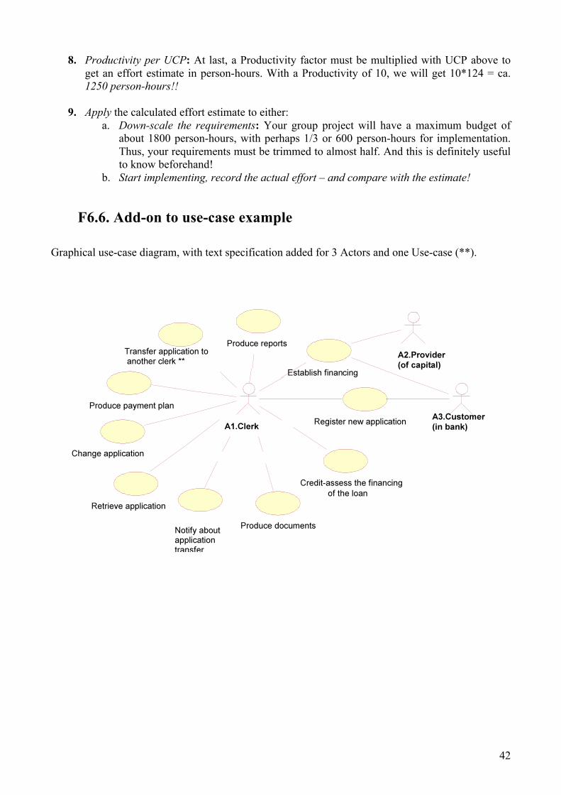
42
8. Productivity per UCP: At last, a Productivity factor must be multiplied with UCP above to get an effort estimate in person-hours. With a Productivity of 10, we will get 10*124 = ca. 1250 person-hours!!
9. Apply the calculated effort estimate to either: a. Down-scale the requirements: Your group project will have a maximum budget of
about 1800 person-hours, with perhaps 1/3 or 600 person-hours for implementation. Thus, your requirements must be trimmed to almost half. And this is definitely useful to know beforehand!
b. Start implementing, record the actual effort – and compare with the estimate!
F6.6. Add-on to use-case example Graphical use-case diagram, with text specification added for 3 Actors and one Use-case (**).
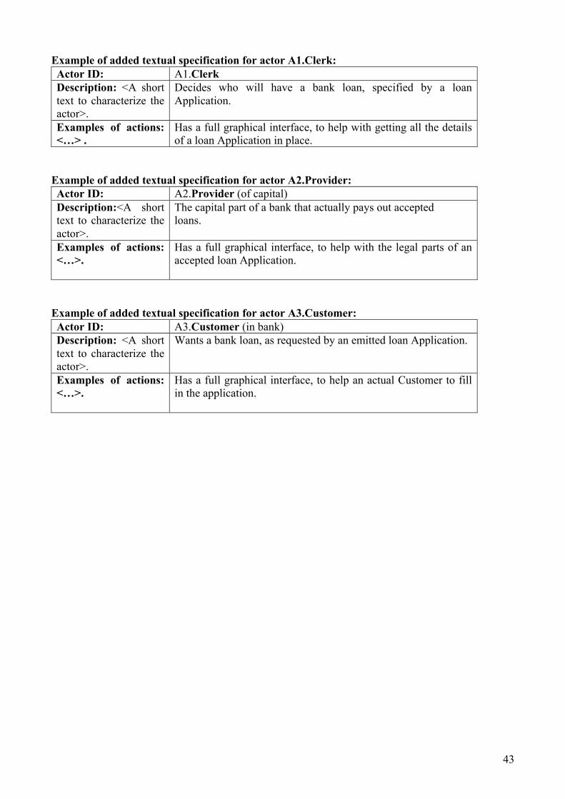
43
Example of added textual specification for actor A1.Clerk: Actor ID: A1.Clerk Description: <A short text to characterize the actor>.
Decides who will have a bank loan, specified by a loan Application.
Examples of actions: <…> .
Has a full graphical interface, to help with getting all the details of a loan Application in place.
Example of added textual specification for actor A2.Provider: Actor ID: A2.Provider (of capital) Description:<A short text to characterize the actor>.
The capital part of a bank that actually pays out accepted loans.
Examples of actions: <…>.
Has a full graphical interface, to help with the legal parts of an accepted loan Application.
Example of added textual specification for actor A3.Customer: Actor ID: A3.Customer (in bank) Description: <A short text to characterize the actor>.
Wants a bank loan, as requested by an emitted loan Application.
Examples of actions: <…>.
Has a full graphical interface, to help an actual Customer to fill in the application.

44
Example of added textual specification for a simple use-case: Use-case name: Transfer loan Application to another clerk. ** Actors related: Clerk (only one actor). Trigger: <Event that starts this uses-case>.
Some parts of an Application need to be discussed by other clerks.
Pre-conditions: <that must be satisfied before the use-case can start execution>.
The actual clerk must be logged on the system.
Post-conditions: <that must be satisfied before the use-case can finish execution>.
The Application must be stored in the database with a valid and consistent state, and has been assigned to a specific clerk or a group of similar clerks.
Normal event flow: <A list of transactions that will be executed in a normal event flow of the use-case>.
1. The clerk announces that he/she will transfer an Application under treatment to another clerk.
2. The system presents the name of the applicant and the reference number of his/her Application.
3. The clerk checks all this information. 4. The system presents a list over suitable groups of
clerks and the customers now assigned to each group.
5. The clerk proposes another clerk, and possibly a second one just in case.
6. The (previous) clerk asks the system to transfer the Application to the proposed clerk.
7. The system transfers the Application to the proposed (new) clerk.
Variations in the event flow: <A list with descriptions of possible transaction variations (not necessarily errors) in the normal flow of the use-case>.
5a. The previous clerk may order the system to generate an email message to notify the new clerk about the transferred Application.
5a1. The previous clerk asks for such notification. 5a2. The system generates an email message to the
new clerk. 5a3. The use-case continues from point 7.
Related information Comments on the description of event flow:
• The event flow shall be described as a list of transactions on the form: <no> <event description>. • An <event description> shall be on the form: <actor> <verb> <direct object> <prepositional sentence> • Such an <event description> may be one or more of the following:
o An actor sends a request or data to the system. o The system validates the received data. o The system changes its internal state. o The system responds to the actor with the result.

45
7 Appendix G – Project Descriptions
7.1 Acando AS Title: Cloud backed mobile app for communication within Acando Customer (Company): Acando AS Address: Postboks 8829 7481 Trondheim Assignment text: Acando Norway has several channels of communication, some internal and some external. Employees may during their busy days not have time to pay attention to all channels and as such miss news announcements and not being aware of all which happens in the company. The goal of this project is to collect information from all these channels in an internal mobile app. The project consists of three main areas: Backend The backend will check the various channels and report any new posts to the users’ apps, as well as update the original posts with comments and likes (for those channels which support this). The channels are:
• News module on the Acando intranet • Employees blog on the Acando intranet • Technical blog (public) • Acando Norway’s Facebook account • Acando Norway’s Twitter account • The public calendar on the Acando intreanet
Integration The backend needs to be integrated with the apps in way which is reliable and handle situations such as when the user’s mobile device is offline when updates are first available and downtime on the backend. Mobile app The app should allow the user to choose which channels should appear in a feed and which should result in a notification. For those channels which support it, the user should be able to like posts and send replies. Ideally it should support the Android, iOS and Windows Phone 8 platforms. Technology The backend and integration should be implemented on the Windows Azure PaaS platform, using (if found applicable) components like the Azure Servicebus, distributed cache and blob storage. The Acando intranet (SharePoint-based) is not hosted in the cloud and a secure integration with this on premise solution is a central challenge to be handled in this project. Process Acando will serve as the customer of the project and the student group will work as a team developing the solution for Acando. Agile development process with features in a product backlog will be prioritized by the product owner role in Acando.

46
Contact details: Name: Lars Bjørnar Listhaug Tlf: +47 922 43 752 Mobile: +47 922 43 752 Fax: E-mail: [email protected] Name: Christian Rygg Tlf: +47 924 33 995 Mobile: +47 924 33 995 Fax: E-mail: [email protected]

47
7.2 eTrøndelag at Sør-Trøndelag Fylkeskommune with SINTEF ICT
Title: Virtual walls – walls that tell us stories Customer: eTrøndelag at Sør-Trøndelag Fylkeskommune with SINTEF ICT Address: Erling Skakkegt. 14, 7013 Trondheim Assignment text: The assignment relates to the EU-IST project TAG CLOUD (www.tagcloudproject.eu). TAG CLOUD will develop innovative digital solutions with the aim to increase the engagement of people in culture and cultural heritage. The main aspects that will be investigated are: new interaction interfaces with cultural artefacts, user as a contributor and personalized information. In Norway, the focus is “culture in the landscape”, i.e. the discovery of cultural memories that we meet when walking around in cities, in villages and in the nature. The goal of this assignment is to develop a tool to create and interact with “virtual walls”. The idea stems from Væggen1
in Copenhagen (http://vaeggen.copenhagen.dk/dk/). Væggen is a large multitouch screen allowing people to tell, share and experience stories. We would like to explore the concept of wall as means to discover and share cultural stories related to buildings and places. It is however not practical to install and maintain physical walls such as Væggen all around. Instead we propose a digital representation of walls, that we call virtual wall. The assignment will build upon interactive pictures for the realization of virtual walls. The tool that will be develop should include support for:
• Managing virtual walls: creation/deletion; retrieval according to location, popularity, topics and other metadata (e.g. author)
• Managing stories: adding stories through a click on a specific place on the wall, filtering stories according to popularity, topics and other metadata (e.g. duration)
• Social interaction: sharing walls (possibly stories) for editing, adding comments to walls and stories.
• Promotion through social networks: sharing walls and stories through social networks (e.g. Facebook, Twitter)
The tool should be available for PC, tablet and mobile allowing experience at home and on site. The assignment should specify a system architecture that fits this requirement and select technologies that simplify development on several platforms. The assignment will realized the tool for one device type, preferably tablet. The tool thinglink (http://www.thinglink.com) supports some of the proposed functionality, but we wish to go further. In particular, the dynamic generation of a wall is needed for the filtering of stories. Our ultimate goal is to connect the wall with the personalization back-end that will be developed in TAG-CLOUD allowing to provide recommendations to the users. More information: As an example, we have started to develop a draft wall for Nidarosdomen using thinglink (http://www.thinglink.com/scene/397385278152507392). A presentation is also available at https://www.dropbox.com/l/GjCOoSqHoAmMEGg6P0axxa Additional notes: All documentation (report and code comments) should be written in English. The results should be made open source. 1Væggen is the danish word for ”Wall”.

48
Contact details: Name: Gro Anita Mortensen, adviser at eTrøndelag Mobile: +47 414 38 469 Fax: +47 73 86 60 01 E-mail: [email protected] Name: Jacqueline Floch, senior scientist at SINTEF ICT Mobile: +47 930 08 536 Fax: +47 73 59 43 02 E-mail: [email protected]

49
7.3 Fri programvare i skolen og Iselin Labs Title: Framework for creating web based educational games Customer (Company): Fri programvare i skolen og Iselin Labs Address: Fri programvare i skolen¨ Postboks 66 Blindern¨ 0313 Oslo Assignment text: We wish to develop a web based framework that make it easy to create online educational games. We would like the students create the framework, create a demo game which demonstrates most of the features and an administration tool so that people can easily put together a game. The framework should be develop using html5 and other web based technology (f.ex Bootstrap, Node.js) so that it will easily work on most types for computers¨ tablets and smart phones and be highly responsive. We have designed and implemented some of the architecture in Java (as java application), but the students are free to suggest andØor design it differently. If there is time it would also be interesting to experiment using technology like Phonegap to make the clients look like native applications. Contact details: Name: Arnt Ove Gregersen Tlf: Mobile: 41516264 Fax: Email: [email protected]

50
7.4 Gridmedia Technologies AS Title: Geelix Expo Viewer Customer (Company): Gridmedia Technologies AS Address: Bakklandet, 7130 Brekstad Assignment text: Geelix® is an online serious game education, design, development and publishing service. The large amount of high quality 3D models needed to make a computer game is a significant and difficult design/production challenge for any game development project. Approximately 67% of the cost of making a computer game is related to designing and producing high quality 3D models. The purpose of the Geelix Expo Viewer is to easily show/expo many 3D models in an environment that is similar to the finished game. Figure 1 is an initial example where we have a simple world consisting of a background cube-mapped texture (mountains and sky), a bump mapped ground plane, and a few 3D models. The user can (with this tool) view 3D models in an environment like this, change properties, play animations, add models, walk around in the world, etc. We will provide the 3D rendering engine, with tutorials and example source code. The students can improve upon the designs (ref. Figure 1). We need an expo viewer solution. We wish to use Microsoft Visual Studio, C++, MFC, COM/RPC and DirectX in this project.
Figure 1. Geelix Expo Viewer.
Contact details: Name: Joanna Emiline Holthe Tlf: +47 47642452 Mobile: +47 47642452 Fax: +1 661-952-1182 E-mail: [email protected] Name: Ole-Ivar Holthe Tlf: +47 47703253

52
7.5 Netlight AS Title: Rock Concert Audience as a Screen Customer (Company): Netlight AS Address: Storgata 8, N-0155 Oslo Assignment text: The cell phone screens of the rock concert audience becomes the pixels of a giant screen. Audience members at a concert have downloaded a simple app to their cell phone, and registered this through a simple GUI. There is a screen on the stage behond the artists. On top of the screen there is a simple camera, taking pictures 5 times a second. The audience are at occasions instructed to hold up their cell phones with their screens toward the stage, similar to holding up a lighter. The server-side of the apps deliver control-signals, instructing the app when to show something. Usually filling the entire screen with a single colour, at full light intensity. The apps are synced with the control signals, which is a simple list of instructions (e.g. all pixels white, max strength) at a certain time intervall (1583 - 1802 seconds), and is specific to each app/phone. At startup, each app is alone in lighting up in a time intervall, and the server-side kan map where a mobile is in the image/grid from the camera. Goals: Handle timing and syncing issues between multiple independent units. Division and simplification of the problem. Generating test-data. Implementing image processing, and mapping of mocked apps/units to locations in the crowd as a function of time. Discuss issues related to the goals. Discuss generalisation of solution and possible uses of framework outside of rock concert domain. Proof of concept should include client side implementation, server-side control, mapping of return image from apps to grid, playback of video. Integration of all submodules for proof of concept demonstration is desirable, but comes second in favour of making sure to implement all submodules. In which case, mocking must be used. The goals/requirements of the project may be tweaked/moulded by customer to accomodate/utilize the skill set of the specific group members. Contact details: Name: Peder Kongelf Mobile: 92255909 E-mail: [email protected]

53
7.6 NAV Hjelpemiddelsentral Sør-Trøndelag Title: BoligApp (HouseApp), with opportunities to draw, take pictures and insert objects in different rooms. Customer (Company): NAV Hjelpemiddelsentral Sør-Trøndelag Address: Assignment text: In NAV Hjelpemiddelsentral we participate in many projects, and we install aids in existing homes and apartments. In this field we could need a digital tool, an app for iPad / iPhone, where we could have the ability to sketch and draw up how aids will look in one particular room (bathroom, bedroom, hallway, living room, trap, kitchen, entrance etc. ). Approach applications for this solution are like IKEA's kitchen drawing and the MagicPlan app. To subscript the room, we will use a device's camera to take a picture of the room (360 º), and get this up as a sketch with current measurement or where we can entered it. In the diagram it must be possible to put in different elements in the housing, for exampl toilet, sink, shower / bath, stairs, doors, bed, cupboard, table, door frames etc. It is important that we can define the size of these products, since it is impossible to make a standard size. In addition it is desirable to related aids located on hjelpemiddeldatabasen.no (most aid is there with size and specifications) to the app, in order to take objects into the sketch and / or type size and space requirements. All modifications and installations in homes and apartments must follow TEK10. This means that the requirements of the Planning and Construction Control Act must be easy to find and implement the sketch (for example. Cirkle so is needed to reverse). Implementation of data: The project group must create / propose how data from the hjelpemiddeldatabasen.no could be implemented so the measure will be correct on all devices in the app. Exporting: Drawings / sketches must be possible to send to other tablets and phones with the app installed for review and possible editing. At the same time it must be possible to send it by e-mail. Background for Ipad / Iphone: For the time being, NAV only approve Apples phones or tablets, and these are used by NAV employees in their daily work helping clients. Contact details: Name: NAV Hjelpemiddelsentral S-T, Lars Kristian Sundset Tlf: 73438504 Mobile: 951 66 149 E-mail: [email protected] Name: NAV Hjelpemiddelsentral S-T, Eli Nordvik Tlf: 73 43 84 94 Mobile: 928 61 051 E-mail: [email protected]

54
7.7 Wellvis AS Title: Development of Drilling Engineering Software Customer (Company1): Wellvis AS Dyrborgveien 23, 7020 Trondheim Assignment text: Methods to recover oil and gas have developed towards more advanced horizontal and 3D well profiles worldwide. With increasing well reach, operational limitations such as drill string mechanical and hydraulic forces must be engineered and visualised to avoid critical and dangerous failures. We seek to build a software package that can perform the different calculations and visualize the results efficiently combining latest technology in drilling and computer science. Current systems are typically built on OS specific clients and servers. We believe web technologies evolving today, like HTML5 and WebGL, can be used to make a better and more flexible user interface. We need a database interface to extract data from 3rd party sources, and a database to store and share own data. See Figure 1. The process relies on data from several sources, and adopting standards for data exchange would improve efficiency and reduce the potential for human errors. In future versions it could be beneficial for the user to be able to run the whole system on site, ex. in operations on remote locations with limited internet connection. This means that careful database design and export and import functionality will be an important part of the task.
Figure 1: Program environment: planning, execution and reporting of engineering and operation.

55
Figure 2:Umbrella software – Operational Well Integrity Model.
Contact details: Manager: Øyvind Pedersen (Computer software) Mobile: 90883568 E-mail: [email protected] Name: Bjørn Brechan Mobile: 91821601 E-mail: [email protected] Name: Sigbjørn Sangesland Mobile: 91897308 E-mail: [email protected] 1Under stiftelse

56
7.8 Dragvoll Helse- og velferdssenter (Trondheim kommune) Title: Communication platform for the future of nursing Customer (Company): Dragvoll health & welfare center Address: Gamle Jonsvannsveien 51, 7048 Trondheim Assignment text: Communication platform We want that the management, employees and relatives can keep in contact whit eachother true an app. Communication between management and employees is amongst other:
- Information about courses and other professionalism stuff they can attend to. - Information about working hours, planning of their working day and what is happening true
the day and week on the unit. - Information about social activities - General information
Communication between the managemement/employees and relatives can be amongst other:
- Information about their loved ones (general information about how their day has been, if they need something, economy and so on)
- Information about what is happening at the unit - Contactinformation, person of contact and so on.
Contact details: Name: Hildegunn Sletvold (manager of professionalism) Tlf: 72548440 Mobile: 90934759 Fax: 72548441 E-mail: [email protected] E-mail: [email protected] Name: Karine Lee Blomstrøm (head of unit) Tlf: 72548440 Mobile: 99429332 Fax: 72548441 E-mail: [email protected] E-mail: [email protected]

57
7.9 Fundator AS / The Norwegian Coastal Administration (Kystverket)
Title: Pocket Ship Radar (Augmented Reality) Customer (Company): Fundator AS / The Norwegian Coastal Administration (Kystverket) Address: Brattørkaia 11, 4 etg, 7010 Trondheim Assignment text: The project group will be assigned to develop and productize an augmented reality app which will project ship positions based on AIS1 data, as well as lanterns, weather sensors, ports, and other maritime points of interest on a mobile device with camera and position sensory systems. The recommended starting point is forking an open source project called Mixare2 and tailoring and branding it for this specific use case, however other implementation alternatives can be discussed and evaluated. Data will be made available through web services. A proof of concept is available for demonstration and as a foundation for further development.
Figur 1: Proof of concept screen capture Disciplines expected to be involved are project management including planning, risk management, execution and reporting, as well as agile methodology, software architecture, programming, testing, graphics, branding and marketing, distribution planning, and customer involvement. Technologies involved are Java, Android, geographic data, web services and JSON. Contact details: Name: Andreas Ravnestad Phone: 73545915 Mobile: 917 00 891 E-mail: [email protected] Name: Terje Hellesvik Phone: 73 54 59 13 Mobile: 938 15 592 E-mail: [email protected] 1 http://www.kystverket.no/Maritime-tjenester/Meldings--og-informasjonstjenester/Automatisk-identifikasjonssystem-AIS/ 2 http://www.mixare.org/

58
7.10 Helgelandskraft – Markedsdivisjonen Title: Power control game Customer (Company): Helgelandskraft – Markedsdivisjonen Address: Industrivegen 7, 8654 Mosjøen Assignment text: The idea is to make a casual game for mobile devices focused around controlling power production from hydro plants trough a power grid to large industry customers and regular consumers, or some other casual game involving power grids, hydro plants and/or other themes around hydro power. The application should also provide the user with power preservation tips, like a tip on loading screens or the splash screen when opening the game. Tips like: “19-21 °C is a good inside temperature. For each degree you lower the temperature you’ll save 5% of the energy used for heating up your living space. You can lower the temperature even more in rooms you normally don’t use.” The application should be developed for iOS and Android. We’ll provide the students with the required equipment needed for iOS-development if they don’t have it, and an android phone if they need it. The application should be designed for the tips and the language to easily be changed. Contact details: Name: Arild Markussen, Markedssjef Tlf: 75100235 Mobile: 91131771 E-mail: [email protected] Name: Espen Skarsbø Olsen, IT-konsulent Tlf: 75100239 Mobile: 97744476 E-mail: [email protected]

59
7.11 Norwegian Center for Integrated Care and Telemedicine (NST)
Title: Patients Trajectories (PAsTAs) Visualization and Dialog Customer (Company): Norwegian Center for Integrated Care and Telemedicine (NST) Address: University Hospital of North Norway Telemedicine P.O. Box 35 9038 Tromsø Assignment text: Design and implement a web-based application in Java (or HTML5), that visualizes a patient’s trajectory with the use of data from electronic health-care records (EHR). A patient trajectory is a sequence of (possibly parallel) health care events, in the context of receiving public health services such as hospitalization, visits to an outpatient clinic or a General practitioner (GP), etc. These events are connected to specific times or intervals of times in the patient’s life. The overall objective of the application is to visualize one patient’s trajectory for a specific time interval, in a way that the patient can easily recognize (e.g like the timeline in Facebook). The system should be able to ask the patient for feedback about specific health care events, and for a sequence of events. The EHR data will be made available in an Event-Stream format, see https://www.ntnu.no/wiki/pages/viewpage.action?pageId=55739223 The detailed specifications for the user interface for the prototype system will be based on a report from a user-design-workshop to be held in the first half of September 2013, and on input from a patient - researcher group. Both patients and researchers are defined as users of this application. For more information on the PAsTAs project, see http://telemed.no/pastas-pasientforloep.5219575-247951.html Contact details: Name: Per Schrader, Norwegian Centre for Integrated care and Telemedicine Mobile: 91354527 E-mail: [email protected] Name: Gro Berntsen, Norwegian Centre for Integrated care and Telemedicine Mobile: 90518895 E-mail: [email protected] Name: Aslak Steinsbekk, NTNU Department of Public Health and General Practice Mobil: 41559076 E-mail: [email protected]

60
7.12 Politiets data og materielltjeneste Title: Automatic License Plate Recognition Customer (Company): Politiets data og materielltjeneste. Address: Assignment text: Every day in Norway, a large number of unwanted vehicles travel our roads. These vehicles can be reported stolen, missing road tax or insurance, or reported wanted by the police in connection with crime. Police forces out on road patrol requires as much information about oncoming vehicles as possible, in order to successfully identify and stop vehicles that are not allowed to travel the road. We want the the project to investigate how and what technological solutions can aid the police patrol with this task. An application that can recognise license plates belonging to oncoming vehicles whilst moving and check the result against databases in order to identify the vehicle and collect additional information concerning the vehicle, such as warrants and other inquiries. The application must alert the police patrol when a relevant vehicle is encountered. This will aid the police in their effort for a safer community. As a result of this project, we want the students to provide us with a prototype, based on requirements given by the police. This wil amongst others include the following tasks: Assess current technology in the market, such as QFree. Ascertain which technology is considered best-of-breed, and attempt to use this or similar technology in the prototype. Discuss with police representatives and assist with the requirements specification based on the needs of the representatives. Develop a prototype application: Verifiy and test the use of Automatic License Plate Recognition (ANPR). How should information concerning a vehicle be presented to the police patrol? How should the police patrol be alerted? The level of severity could demand different actions by the application, and the user interface should handle such differences. Develop mockups of relevant web services (e.g. Autosys with Statens Vegvesen, Warrants with the police) and search for recognised license plates through these web services. Contact details: Name: Unn Aursøy Tlf: 90612416 Mobile: 90612416 Fax: E-mail: [email protected] Name: Gyrd Norvoll Tlf: 99390378 Mobile: 99390378 Fax: E-mail: [email protected]

61
7.13 Software Innovation Title: Document organizer components for ProArc Customer (Company): Software Innovation Address: Visitor address: Rolfsbuktveien 4C, 1364 Fornebu, Norway (Oslo) Postal address: Postboks 156, 1325 Lysaker, Norway Assignment text: ProArc is a document control solution for the industry that helps companies organize, store and utilize their documents (typically technical and administrative documentation with high demands for traceability and security). Today, ProArc contains a component that reads a defined CSV/XML list of dynamically defined metadata about a set of documents, as well as the documents themselves. A package consisting of HTML files and a Java based menu component is then generated and sent to a recipient for standalone usage of the documents. A typical use case is generating a full set of documentation for a new oil rig, including all technical documentation for the project (drawings, design docs, etc.) as well as an index linking all of this documentation together. Today this is done in as a set of linked files of various formats. This component needs to be replaced with a more modern and flexible solution. The proposed delivery is:
• A well-documented interim format for document metadata and documents • A .NET component that reads a metadata set and a document package and parses these to the
interim format • A set of .NET components that outputs the interim format to various user-readable package
formats such as html (with different media stylesheets), pdf, doc, excel, etc. • A standalone demo application utilizing these components and their capabilities
It’s important that the components themselves are implemented in a way that makes them usable both as parts of a standalone parser application and as components in a server based solution (i.e. within the main product). As output formats, both structured packages (an index file with a listing, and the files themselves as a catalogue) and single file solutions (where the documents are included into a single file along with the index) are of interest. On ProArc: http://www.software-innovation.com/en/application/ProArc/pages/default.aspx Contact details: Name: Audun Kvasbø Tlf: 93264586 E-mail: [email protected] Name: Erling Henningstad Mobile: +4793418757 E-mail: [email protected]

62
7.14 Syklistenes Landsforening i Trondheim Title: CountMe: Mobile app for counting cyclists and pedestrians Customer (Company): Syklistenes Landsforening i Trondheim Address: Trondheim Assignment text: Develop an Android application for manual counting of cyclists and pedestrians. The primary goal is to replace the paper based method used by the road authorities. A secondary goal is to enhance manual counting by supporting crowd sourcing, where ordinary citizens can do the counting. The app shall support manual counting of cyclists and pedestrians, with indication of direction of travel (left / right) along a section of road infrastructure. Two variants of the application shall be developed:
1. A mobile app to be used by professionals from the road administration. The position of the counting session shall be determined by a look-up in the official road database (veg ID) based on the geo coordinates of the smart phone. Data from the counting session shall be formatted according to the standard defined by the road administration, and transferred to the national database. No filtering or approval process is required. We plan for two iterations of field tests involving personnel from the local road administration toward the end of the project period.
2. A system for Crowd Sourcing is developed. The same user interface for counting as the Pro version is sought, but this version is to be used by ordinary citizens. Road ID lookup should be supported. The measurements are sent from the smart phone to a server for storage and processing. Optional identification of the user via social networks (e.g. Facebook, Google+) should be supported. The server system should be developed with functionality for filtering out spurious measurements, displaying results on a map, crediting users for approved measurements, and optionally transferring approved measurements to the national database (by authorized personnel only). Field tests involving ordinary users should be included, preferably in an iterative development cycle.
Only open source software shall be used, and all results should be Open Source. Contact details: Name: Richard Torbjørn Sanders (senior researcher at SINTEF ICT) Mobile: 930 58 954 E-mail: [email protected] (aka [email protected])

63
7.15 Adresseavisen AS Title: Automatic Import of Completed Ads Customer (Company): Adresseavisen AS Address: Industriveien 13, 7080 Heimdal Assignment text: Adresseavisen is in need of an automatic system to receive and handle imports of completed ads. These ads are typically production PDF-files. These files need to be handled, and forwarded to the correct internal production system, as well as an order needs to be created in the internal order system. Also, in addition to this, data about the ad needs to be saved in our ad system called Webassistenten, so that we can serve the ads data to different front ends, such as adressa.no. We need some sort of general import service, so that all the different customer systems can send pdf-files and data automatically. For this current project we want to test with real estate ads first. There is no specification present on how to develop this import service, as there are currently no systems to integrate with. The only requirements we have for this assignment is that:
1. You develop using modern .NET technologies. 2. Develop a service in which
a. Receives a pdf and saves it in the correct location. b. Handles the data supplied with the ad, and inserts it in an existing database for real
estate ads. c. Creates an order in the internal order system.
3. The service must be general (interfaced), which means that only “plugins” needs to be developed in order to expand the service to handle different types of ads than real estate ads.
Specific required details The new import system is a service, which facilitates the real estate agents to make bookings in Adresseavisen without having to go to Adresseavisens self-service system for bookings. The import system provides an interface (preferred ASP.NET MVC4 or greater) which allows the real estate agent to send a file, along with a collection of data. The relevant datafields are listed below. The service stores the pdf at a distinct location, decided by an identifier for the real-estate agency, and a product identifier for which product the real estate agent wants to book the ad in. The import system then stores all the datafields in the Webassistenten database, table “Prospekt”. The import system then adds the selected booking dates in the Webassistenten database, table “ProspektHarBestilling”. In order to do so, the order needs to be inserted in Adresseavisens order system Alda first. Use an existing function in Webassistenten to do this. Then, a module needs to be selected in order to reserve the correct amount of space on the page. In order to select the correct module, the new import system must offer a webservice to the real estate agency back system, to facilitate the real estate agent to book the correct module for the correct product at the correct date. At the end of the cycle, the received production PDF must be stored in a new given folder for pickup by the production system, which sends the PDF to print. Summary of required system functionality Import system service Will receive a pdf-file, along with this data (* = obligatory):
1. EiendomsmeglerId*
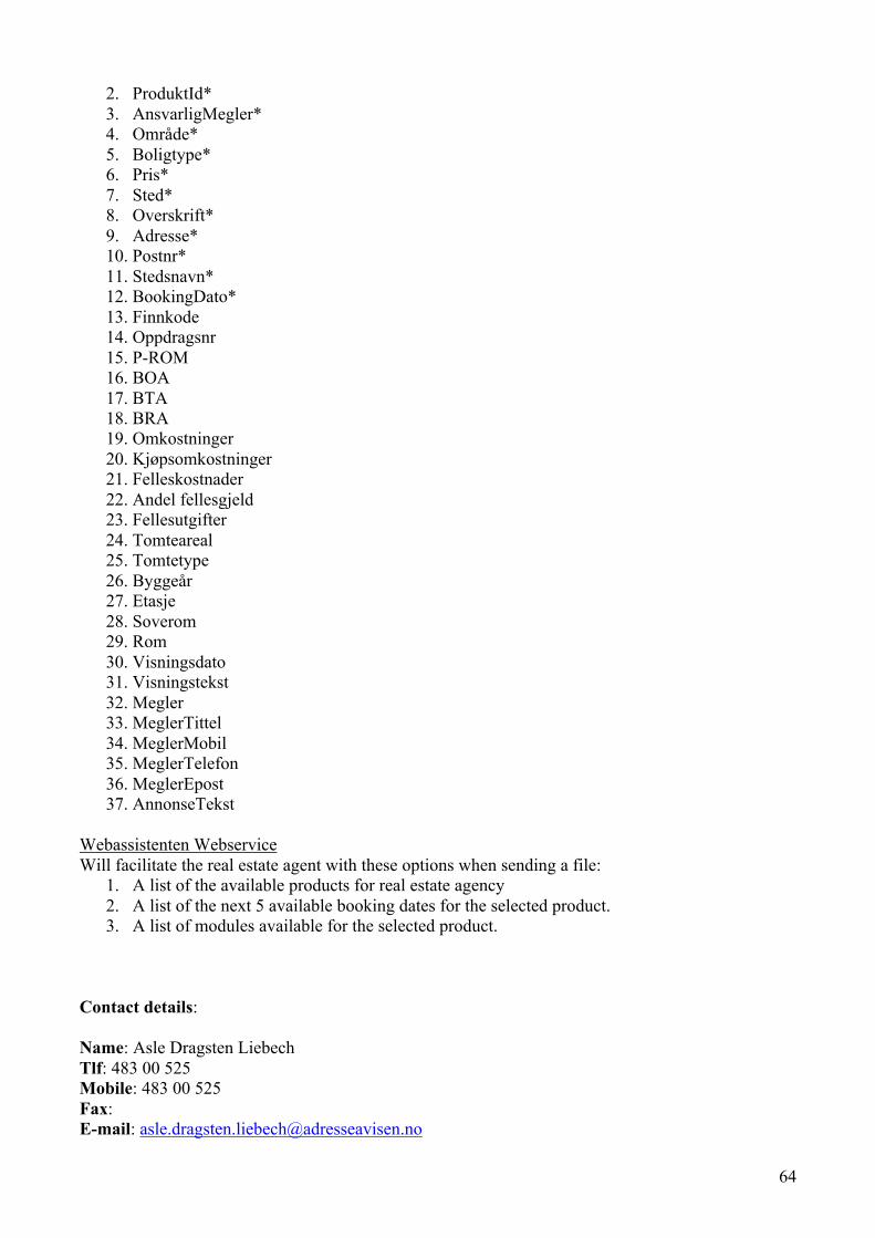
64
2. ProduktId* 3. AnsvarligMegler* 4. Område* 5. Boligtype* 6. Pris* 7. Sted* 8. Overskrift* 9. Adresse* 10. Postnr* 11. Stedsnavn* 12. BookingDato* 13. Finnkode 14. Oppdragsnr 15. P-ROM 16. BOA 17. BTA 18. BRA 19. Omkostninger 20. Kjøpsomkostninger 21. Felleskostnader 22. Andel fellesgjeld 23. Fellesutgifter 24. Tomteareal 25. Tomtetype 26. Byggeår 27. Etasje 28. Soverom 29. Rom 30. Visningsdato 31. Visningstekst 32. Megler 33. MeglerTittel 34. MeglerMobil 35. MeglerTelefon 36. MeglerEpost 37. AnnonseTekst
Webassistenten Webservice Will facilitate the real estate agent with these options when sending a file:
1. A list of the available products for real estate agency 2. A list of the next 5 available booking dates for the selected product. 3. A list of modules available for the selected product.
Contact details: Name: Asle Dragsten Liebech Tlf: 483 00 525 Mobile: 483 00 525 Fax: E-mail: [email protected]

66
7.16 SINTEF / SIMLINK Title: Smart-token app development Customer (Company): SINTEF / SIMLINK Address: Strindveien 4, Trondheim Assignment text: SIMLINK (A Spinout Company of Telenor and SINTEF) has developed some concepts for improving the work flow of health personnel in a hospital setting. SINTEF is given the role of exploring these ideas further, and would like to develop an App for demonstration of these concepts. The underlying idea consists of using id-cards to support touch-based wireless authentication of personnel towards health-related information systems. This requires development of a secure "Smart-token" id card with the following functions:
- Printed ID card - Standard NFC / Smart chip / Magnetic stripe functionality - NFC reader functionality - Bluetooth/ Wi-Fi for proximity interaction - Fingerprint reader (optional)
SIMLINK has developed a prototype of such a secure Smart-Token. However this token can be produced in many form factors and there is a need for studying the usage of such a token further before such a token is produced. SINTEF would like to explore the possibilities of such a token by developing an App emulating a Smart-token with interaction towards different health information systems Development will be based on an Android NFC phone (Samsung S3). There exists an early prototype of the app that needs to be enhanced. The smart-token should read passive NFC tags and act as a touch-based wireless authenticator of personnel towards health-related information systems. The assignment will be in close cooperation with SINTEF.
Contact details: Name: Leendert Wienhofen (98245177) Steinar Brede (99286867) E-mail: [email protected] [email protected]

67
7.17 The Directorate of Health, Department of the Health Portal Title: National Integration Platform for Citizen Centric eHealth in Norway Customer (Company): The Directorate of Health, Department of the Health Portal Address: Universitetsgata 2, Oslo Assignment text: Background The Directorate of Health has a national the task of digitalizing Norwegian healthcare, both by providing coordinated services for specialist healthcare (hospitals) and by providing digital services for citizens in general and patients specifically. Examples of such services are ePrescriptions, that is implemented on a national basis, the National Summare Care Record, that will go live in Trondheim in August 2013, and the citizen centric health portal (helsenorge.no) that has been live since June 2011. National eHealth projects are complex, long running and costly. There are obvious reasons for this. Among these are the complexity and criticality of healthcare, and the scale that national eHealth services represents. At the same time, the trends in technology development and consumer adaption of new technology continue to develop. Moderate prices and consumer friendly devices that monitor individuals’ health and wellness are increasingly becoming available in the market space. Combined with a continuous increase in digital competence in the population, they will influence citizens’ behavior and perspective on their own health situation in the future. In addition to this, private providers develop great eHealth solutions with consumer and patient orientation. Medhelp.org and Healthvault.com are only two among many examples. Ambient assisted living has the potential of revolutionizing life for senior citizens with failing health. The relevant question is: How can the substantial and long running eHealth projects of the government sector connect to and leverage the dynamics in the market and consumer behavior? The answer under investigation is the National Integration Platform (NIP) for Citizen Centric eHealth in Norway. Assignment The assignment is to plan, design and describe a NIP, and to develop a prototype. The task such a platform should fulfil is to offer interoperability with third party solutions based on available application programmable interfaces (APIs). All third party solution providers must adhere to specified and standardized rules regarding authentication, security model, messaging and privacy to interact with the NIP. The intention of such a platform is to enable the following:
• Citizens’ ability to publish information they produce from devices in their possession and third party software solutions, including smart phone and tablet apps, into the government run citizen centric health portal (helsenorge.no)
• Citizens’ ability to fetch information about themselves from helsenorge.no to import it into third party software solutions of their own choosing

68
The assignment is to describe the architecture and major components of the NIP, how it will function on the “outside” regarding third party integration, and on the “inside” regarding integration with helsenorge.no. It is also essential that the solution adhere to Norwegian privacy regulation and information security. Its requirements for integration should also encourage privacy by design within third party solutions. The prototype should make use of one or more use cases to demonstrate how interaction is performed, how privacy and security concerns are managed and how the end user experience will be. Contact details: Name: Helge T. Blindheim Tlf: 466 75 321 Mobile: 466 75 321 Fax: E-mail: [email protected]

69
7.18 SINTEF / The national competence center for ultrasound and image guided therapy
Title: USNeuroNav App Customer (Company): SINTEF / The national competence center for ultrasound and image guided therapy Address: Olav Kyrres gt. 9, MTFS in the 4th floor southern part, Trondheim Assignment text: The national competence center for ultrasound and image guided therapy was established in 1995 and is a collaboration between SINTEF, NTNU and St Olav University Hospital. Within the center ultrasound-based navigation technology is being developed and used in various clinical fields in order to guide surgical instruments safely into the human body (similar to GPS navigation). One of the main challenges in order to make use of this technology is sufficient knowledge about interpreting ultrasound images. Each week unique data material is collected within the center. If presented in an easy and knowledgeable way, selected parts of the anonymous material can be used to teach relevant groups to interpret ultrasound images in an entertaining manner. An App for mobile devices (iOS and maybe Android) (and maybe also a web-site) has a huge potential in this regard.
In addition to presenting the available material it’s natural to investigate the possibility for extending the app to a serious game. The possibilities are almost endless but some basic suggestions could be to learn ultrasound interpretations of brain images by presenting:
• Anatomy – The user sees an ultrasound image as well as names of anatomical structures and is challenged to drag each name onto the correct structure.
• Pathology – The user sees ultrasound images of varies tumors and is asked to identify the tumor and state the type (multiple choice).
• Tumor borders – Some tumor types have diffuse border to normal tissue. The user sees such images and is asked to draw the border.
A scoring system should be developed and based on the available data material; random questions, tutorials and skills validation can be generated. This can be made very advanced with global user profiles and benchmarking but it’s probably vise to start easy. It should also be easy to generate and upload new material and when new cases become available the users are notified and asked it they would like to download the new material. Contact details: Name: Frank Lindseth (SINTEF and NTNU) Tlf: 92809372 Mobile: 92809372 E-mail: [email protected] Name: Ole Solheim (neurosurgeon at St Olavs university hospital) Tlf: 99569422 Mobile: 99569422 E-mail: [email protected]

70
7.19 SINTEF v/Levin Title: Smart application for revealing public transit travel patterns Customer (Company): SINTEF v/Levin Address: SINTEF Technology and society, Trondheim Assignment text: The largest cities in Norway are experiencing increased traffic congestion on road network. The political ambition is to take all future growth in traffic volume on slow modes (walking and biking) and public transit3. A major challenge with this political ambition is that we have limited knowledge of problematic areas, measures and the effects of measures for pedestrians, cyclist and public transit users. SINTEF is involved in a research project SMiO (Smidig Mobilitet i Oslo) where a central idea is to find new data sources that will enable transport planners to identify problems and make changes to the public transit system. The traditional way of discovering travel patterns is thorough telephone interviews, this is costly and time consuming for the person being called. A possible new source of data for transport planners is the smart phone. Smart phones have several sensors that can find you location (GPS, WiFi, Cell Towers), measure accelerations and the phones have a good interface for communication with the user. The Norwegian Public Roads Administration is interested in campaigns for reducing car traffic by encouraging walking and cycling. Such an campaign could be executed as an competition, where the users compete against each other to provide the most data on cycling or walking. Both in SMiO and in a user campaigns, the same or similar technology may be used to simplify the process, or make the users able to provide better and more data. The assignment is hence to describe, plan and prototype functional programming libraries and an app that shows how a smart phone (Android or IPhone) can be used as a collection unit for travel patterns. Also included is the design for a backend system to store the data and prepare the data for analysis. The primary goal is to make such an application as privacy friendly as possible. The reason for this is that providing an app that promotes privacy will make it less challenging to recruit public transit user to provide data. The Norwegian data protection authority has several documents related to how smart phone app could promote privacy4 and promote safe tracking5. The SMiO project, and campaign competitions, have different and maybe excluding privacy issues, that should be considered and taken into account. System concept A user is requited to download and use an application that tracks the users travel pattern. A travel pattern consists of a starting point, route taken and an end point. A typical travel survey only looks at start and end points of a trip, but using a smart phone one can log the whole route, including any via-point on the route. For example if a user makes a detour to shop groceries, it can be detected and recorded by the application. At the end of each travel the user will be show the trips that she/he has conducted and asked to provide any additional required information. Alternatively, the user may wait until the end of the day. This require the application to detect stops, travel time between stops, and one could even 3 http://www.ntp.dep.no/2014-2023/pdf/2013_01_10_NTP_2012_forslag_nasjonal_transportplan.pdf (page 23) 4 http://www.datatilsynet.no/Teknologi/Europeiske-personvernmyndigheter-med-felles-uttalelse-om-mobilapplikasjoner1/ 5 http://www.datatilsynet.no/Teknologi/Sporing/

71
consider providing suggestions for travel mode used (walking, cycling, public transport/motorized vehicle). After the user have checked if the correct stops and modes were chosen, the user can trigger upload of the data to a server. An case of a walking/cycling campaign, uploading the original suggested mode could also be of interest. The transmitted data is to be stored and prepared for analysis. so that the data can be used to better plan public transit routes. The main focus on data transmission is to allow for transfer of the data safely (encryption schemes and key management). Another goal is to give the user (through the app) a possibility to check how much information the user has contributed with and compare her/him-self against other users (gamification), for instance through use of high score lists or similar. For the use in competitions/campaign, the use of social medias should also be considered to try to make participation in the competition more fun, or used to generate more interest. This can be done through several techniques, for instance through «achievements» and the ability to share such on the users Facebook or Google+ site. Another possible functionality is that the public transit planners are to check out data in order to use the data for specific analysis. Thus the user can be presented with an overview of which analysis his/her data has contributed to. The major Challenges
1. Safe logging of travel information and travel patterns on the device, including encryption and key management.
2. Privacy issues and challenges, especially when considered in conjunction with
«gamification» and when the methodology is used in competitions.
3. Identify stops and travel modes used between stops. Preferably with low battery consumption.
4. Gamification, Identify and plan achievements to use for optimal generation of interest.
5. App design that can work on two platforms (Android and Iphone), that require low level access to sensors on the device.
Contact details: Name: Tomas Levin Tlf: 977 90 916 Mobile: 977 90 916 Fax: E-mail: [email protected] Name: Jo Skjermo Tlf: 922 36 618 Mobile: 922 36 618 Fax: E-mail: [email protected]

73
7.20 SINTEF v/Dingsøyr Tittel: Applikasjon for utvikling av framtidens arbeidsplass - RFID-måling av bevegelsesmønstre, digital representasjon og analyse Kunde: SINTEF v/Dingsøyr Adresse: Strindveien 4, 7465 Trondheim Oppgave: Framtidens arbeidsplass vil kjennetegnes av en integrering mellom fysiske løsninger, ny teknologi og avansert samhandling. Det SINTEF-initierte prosjektet “K2 – morgendagens arbeidsplass” tar utgangspunkt i at kunnskapsintensiv verdiskaping primært skjer i tett synkronisert flyt og samvirke mellom aktører (digitalt og fysisk). Ett av hovedmålene i prosjektet er å utvikle metoder og verktøy for å kunne utvikle fysiske velfungerende løsninger som støtter opp under arbeidsprosessene, og denne oppgaven er midt i kjernen av denne problemstillingen. RFID-teknologi (gjerne i kombinasjon med GPS) er i rask utvikling og målinger ved bruk av denne har en rekke anvendelsesområder som spenner fra adgangskontroll (bygninger, festivaler), betalingsløsninger, pakkesporing, industrielle produksjonsprosesser, sykehusdrift til måling av menneskelige kroppsfunksjoner og aktivitet. Formålet med denne oppgaven er å utvikle en pilot av et verktøy som kan brukes til å kartlegge, analysere og representere bevegelsesmønstre på arbeidsplasser. Verktøyet vil være et viktig hjelpemiddel for utvikling av framtidens kontorløsninger ved at man får en representasjon av det sosiale nettverket og samhandlingsmønstre på en arbeidsplass. Oppgaven vil omfatte følgende aktiviteter: 1. Utarbeide bruker-case – i dialog med brukerbedrifter. 2. Utarbeide design, kartlegge og vurdere hvilken RFID-teknologi som er egnet for piloten. 3. Utvikling av web-grensesnitt for analyse og representasjon. 4. Gjennomføring av pilotstudie i en utvalgt bedrift. 5. Evaluering av løsning og anbefalinger for videre utvikling. Oppgaven gjennomføres innenfor prosjektet ”K2 – morgendagens arbeidsplass” – deltakende bedrifter er SINTEF, Odfjell Drilling, Sparebank 1 SR-Bank, SmartWorks, Totalreform, Mellomrom Arkitekturpsykologi og Modulvegger. SINTEF Teknologi og samfunn har prosjektledelsen ved Morten Hatling. Kontaktperson for oppgaven vil være Torgeir Dingsøyr, SINTEF IKT. Kontaktdetaljer: Navn: Torgeir Dingsøyr Mobil: 930 08 714 Epost: [email protected] Navn: Morten Hatling Mobil: 93087709 Epost: [email protected]

74
7.21 AALBERG AUDIO Title: Innovative guitar controlling system Customer (Company): AALBERG AUDIO (School of Entrepreneurship NTNU) Address: Sem Sælands vei 5 Assignment text: Context The startup company AALBERG AUDIO from NTNUs School of Entrepreneurship is developing a new and innovative guitar controlling system with international potential. Development partners include SINTEF, Nordic Semiconductor and Eggs Design (formerly Kadabra Design). Problem Description The concept of the product is to extend the control of the guitar effects and provide new and creative play opportunities with a wireless controller attached to the guitar and a software app (for tablet or phone). The product is threefold; guitar effects (stompbox), wireless controller and app. This must be ground in software and human computer interaction and software engineering. The group will address technical challenges like: which programming language (e.g. Java, Objective C, HTML5)? Which application framework (e.g PhoneGap)? Which components (e.g. libraries) and/or applications is it best to reuse and which to develop? Design patterns (e.g., MVC)? Moreover the group will have to achieve the following tasks: • Prototype development • Prototype evaluation with at least 10 users.
Results A functioning prototype and extended knowledge about to develop and/or evaluate such software products
Supplerende opplysninger:
Dette er en idé med sterkt potensiale fra NTNUs entreprenørskole og har fått støtte fra Innovasjon Norge, NTNU Discovery og vunnet Venture Cup Midt-Norge. Produktet skal lanseres i slutten av året/starten på neste år. Vi er i kontakt med butikk-kjeder både i Norge og USA. Gitarister som har sagt at dette systemet har potensial inkluderer Terje Rypdal, Arnt Egil Rånes (DDE) og tidligere Gåte gitarist Magnus Børmark.
Contact details: Name: Aleksander Torstensen Tlf: Mobile: 99772232 Fax: E-mail: [email protected] Name: Rune Aalberg Alstad Tlf: Mobile: 986 04 231

76
8 Appendix H – Student lists and groups Please note, that the below allocation lists are preliminary, i.e. they may be incomplete and/or incorrect. The final allocation of students to groups may be adjusted, due to updated information about students’ whereabouts, being revealed as late as September 15th! Because the deadline for enrolling is after the start of the course, this list might change. Table 3 – Group list v1.3. See Table 1 for assigned customer and advisor. # Last name First name E-mail Group 1 Jerre Magnus [email protected] 1 2 Ræder Johan Georg Cyrus [email protected] 1 3 Vaktdal Kjersti Marie [email protected] 1 4 Khatri Bodh Bahadur [email protected] 1 5 Frøystad Christian [email protected] 2 6 Rogstad Odd Fredrik Mørch [email protected] 2 7 Stastny Simon [email protected] 2 8 Nergård Knut [email protected] 2 9 Flakstad Andreas Arning [email protected] 3 10 Hærum Eivind [email protected] 3 11 Ringset Peter Køste [email protected] 3 12 Thevarajah Nitharshaan [email protected] 3 13 Fielding Victor [email protected] 4 14 Holter Vegard Lundberg [email protected] 4 15 Randby Simon Glisic [email protected] 4 16 Thafvelin Nicolay N [email protected] 4 17 Søraa Agnethe [email protected] 5 18 Jovac Milos [email protected] 5 19 Dohnalek Tomas [email protected] 5 20 Bednarik Jan [email protected] 5 21 Faret Jørgen [email protected] 6 22 Reitan Johan [email protected] 6 23 Milosavljevic Nenad [email protected] 6 24 Stefanovic Dusan [email protected] 6 25 Fagerbekk Tomas Albertsen [email protected] 7 26 Hoang Tintin Trong [email protected] 7 27 Syversen Tina Christin [email protected] 7 28 Rai Pawan Chamling [email protected] 7 29 Hjelle Henrik [email protected] 8 30 Mæhlum Arne [email protected] 8 31 Svensson Mats Krüger [email protected] 8 32 Heintz Aleksander [email protected] 8 33 Ellingsberg Anette [email protected] 9 34 Henninen Bjørn Ingemann [email protected] 9 35 Mosand Andreas Rong [email protected] 9 36 Stålesen Alf Magnus [email protected] 9 37 Eldhuset Anders Wold [email protected] 10 38 Hellan Solveig [email protected] 10 39 Løge Marte Dybevik [email protected] 10 40 Stølen Martin [email protected] 10

77
41 Dølvik Bjørn [email protected] 12 42 Snare Kristian Sjursønn [email protected] 12 43 Jose Dawn Alphonse [email protected] 12 44 Christensen Jo Are [email protected] 13 45 Haug Børge Olav [email protected] 13 46 Lekang Rolf Erik Heggem [email protected] 13 47 Hamborg Truls Bjørnar S [email protected] 15 48 Lam Hong-Dang [email protected] 15 49 Sigholt Erlend Løkken [email protected] 15 50 Skjervold Audun [email protected] 15 51 Kvissel Eivind [email protected] 16 52 Prochazka Tomas [email protected] 16 53 Sandvik Anders Olsen [email protected] 17 54 Zalewski Sebastian [email protected] 17 55 Di Santo Emanuele [email protected] 17 56 Bekkevold Marthe Frogner [email protected] 18 57 Hagen Kristoffer [email protected] 18 58 Weie Stian [email protected] 18 59 Bakke Sofia Nascimento [email protected] 19 60 Haatveit Lars Stenvik [email protected] 19 61 Rønnekleiv Henrik Renander [email protected] 19 62 Voll Kristina [email protected] 19 63 Nguyen Anh Chi Do [email protected] 19 64 Andreassen Espen [email protected] 20 65 Johansen Sindre Ilebekk [email protected] 20 66 Van Blokland Bart Iver [email protected] 20 9 Appendix I- Kick-off rooms for groups Detailed group allocation will be done in the information meeting on the kick-off day and documented on the course webpage.
Table 4 – Kick-off rooms for groups and customers, 21.08:
Group Room Time 1 EL Rom E204 13:15 2 EL Rom E304 13:15 3 EL Rom F204 13:15 4 GK1 13:15 5 H Rom 415 13:15 6 L1-‐320 13:15 7 S Rom 922 13:15 8 VE Rom 245B 13:15 9 VE22 13:15 10 ITV 354 13:15 11 R Rom B1-‐120 14:15 (!) 12 R Rom B1-‐122 13:15 13 R Rom B1-‐124 13:15 14 R Rom B1-‐126 13:15 15 R Rom BU1-‐104 13:15 16 R Rom BU1-‐106 13:15

78
17 R Rom BU1-‐108 13:15 18 R Rom BU1-‐110 13:15 19 KJL24 13:15 20 ITV 242 13:15 21 iArbeid (ITV) 13:15 Room search: http://www.ntnu.no/studieinformasjon/rom/ http://www.ntnu.no/kart/no_cache/soek/ Table 5 - Advisory session, 23.08, meeting times and location for each group:
Extra rooms: EL Rom E304, EL Rom F204, H Rom 415 Room search: http://www.ntnu.no/studieinformasjon/rom/ http://www.ntnu.no/kart/no_cache/soek/
Advisor Reidar Conradi
Babak Farshchian
Anh Nguyen Duc
Soudabeh Khodambashi
Tosin Oyetoyan
Muhammad Asif
Meng Zhu
Rooms ITV242 ITV354 VE Rom 245B
EL Rom E204 KJL4 R59 S Rom 922
08:15 09:15 1 3 4 10 12 15 10:15 2 5 19 13 16 11:15 6 20 17 12:15 18
13:15 – 14:00
Another day
7, 8, 9 11 14