Comparison of flux creep an nonlinear Ej approach for analysis of vortex motion in superconductors
7
arXiv:cond-mat/0003396v1 [cond-mat.supr-con] 24 Mar 2000 Comparison of flux creep and nonlinear E − j approach for analysis of vortex motion in superconductors D. V. Shantsev 1,2 , A. V. Bobyl 1,2 , Y. M. Galperin 1,2 , and T. H. Johansen 1, ∗ 1 Department of Physics, University of Oslo, P. O. Box 1048 Blindern, 0316 Oslo, Norway 2 A. F. Ioffe Physico-Technical Institute, Polytekhnicheskaya 26, St.Petersburg 194021, Russia Two commonly accepted approaches for simulations of thermally-activated vortex motion in su- perconductors are compared. These are (i) the so-called flux creep approach based on the expression E = vB relating the electric field E to the velocity v of the thermally-activated flux motion and the local flux density B, and (ii) the approach employing a phenomenological nonlinear current-voltage curve, E(j ). Our results show that the two approaches give similar but also distinctly different behaviors for the distributions of current and flux density in both a long slab and thin strip geom- etry. The differences are most pronounced where the local B is small. Magneto-optical imaging of a YBa2Cu3O 7-δ thin film carrying a transport current was performed to compare the simulations with experimental behavior. It is shown that the flux creep approach describes the experiments far better than simulations based on the E(j ) approach. PACS numbers: 74.25.Ha, 74.60.Ge, 74.76.Bz I. INTRODUCTION The term flux creep is used to describe a thermally- activated motion of flux lines in superconductors. This motion is characterized by a velocity strongly dependent on the local current density. In high-temperature su- perconductors (HTSCs), the flux creep can be specially pronounced because of small flux pinning energies and high temperatures. 1,2 An account of the flux creep is therefore crucially important for understanding the time- dependent magnetic behavior of HTSCs. In the literature one finds numerous papers making use of flux creep anal- ysis to describe the evolution of flux and current density distributions, current-voltage curves, magnetization and magnetic susceptibilities for superconductors of various shapes. 3–7 Interestingly, there exist today two commonly accepted approaches for the analysis of thermally-activated flux motion. The first one, the so-called flux creep approach, assumes a particular microscopic pinning mechanism, which defines the pinning energy U and its dependence on the local values of current density j and flux density B. The velocity of the thermally-activated flux motion, v, then determines the local electric field according to E = vB. The second approach, on the other hand, em- ploys a phenomenological nonlinear current-voltage re- lation, E(j ). For brevity, we will call this the E − j approach. The present paper is devoted to a detailed compari- son of these two approaches. We carry out numerical simulations for the most conventional choice of E(j ) and U (j, B) and set focus on the clear differences in the result- ing behavior. The numerical findings are then compared to current density distributions measured in YBaCuO films using magneto-optical imaging of flux density pro- files. Distinct features in the observed current distribu- tions allow us to conclude which approach gives the more realistic description. II. THE TWO APPROACHES To compare the two approaches we consider a one- dimensional flux creep problem where the flux moves along the x direction, the magnetic induction B is di- rected along the z-axis, while the electric field E is par- allel to the y-axis. The Maxwell equation has then the form ∂B ∂t = − ∂E ∂x . (1) In the flux creep approach, since it represents an activa- tion process, the velocity of the vortex motion is given by v = v c e −U(j,B)/kT , (2) where v c is the velocity when U = 0. In the case that the pinning energy has a logarithmic dependence on the cur- rent, U (j, B)= U c ln(j cU /j ), it follows that the electric field equals E = v c B (j/j cU ) Uc/kT . (3) In the E − j approach, the phenomenological E(j ) re- lation is usually chosen in the power law form, E = E c (j/j cE ) n , (4) with n ≫ 1, and where j cE and E c are constants with di- mension of current density and electric field, respectively. Comparing Eqs. (4) and (3) one can see that the expo- nent n in the E − j approach plays the same role as the ratio U c /kT in the flux creep model. However, even if n = U c /kT , there still remains an important difference. In Eq. (3) one has E ∝ B, i.e., the electric field induced by the vortex motion is proportional to the number of 1
-
Upload
independent -
Category
Documents
-
view
0 -
download
0
Transcript of Comparison of flux creep an nonlinear Ej approach for analysis of vortex motion in superconductors

arX
iv:c
ond-
mat
/000
3396
v1 [
cond
-mat
.sup
r-co
n] 2
4 M
ar 2
000
Comparison of flux creep and nonlinear E − j approach for analysis of vortex motion
in superconductors
D. V. Shantsev1,2, A. V. Bobyl1,2, Y. M. Galperin1,2, and T. H. Johansen1,∗
1Department of Physics, University of Oslo, P. O. Box 1048 Blindern, 0316 Oslo, Norway2A. F. Ioffe Physico-Technical Institute, Polytekhnicheskaya 26, St.Petersburg 194021, Russia
Two commonly accepted approaches for simulations of thermally-activated vortex motion in su-perconductors are compared. These are (i) the so-called flux creep approach based on the expressionE = vB relating the electric field E to the velocity v of the thermally-activated flux motion and thelocal flux density B, and (ii) the approach employing a phenomenological nonlinear current-voltagecurve, E(j). Our results show that the two approaches give similar but also distinctly differentbehaviors for the distributions of current and flux density in both a long slab and thin strip geom-etry. The differences are most pronounced where the local B is small. Magneto-optical imaging ofa YBa2Cu3O7−δ thin film carrying a transport current was performed to compare the simulationswith experimental behavior. It is shown that the flux creep approach describes the experiments farbetter than simulations based on the E(j) approach.
PACS numbers: 74.25.Ha, 74.60.Ge, 74.76.Bz
I. INTRODUCTION
The term flux creep is used to describe a thermally-activated motion of flux lines in superconductors. Thismotion is characterized by a velocity strongly dependenton the local current density. In high-temperature su-perconductors (HTSCs), the flux creep can be speciallypronounced because of small flux pinning energies andhigh temperatures.1,2 An account of the flux creep istherefore crucially important for understanding the time-dependent magnetic behavior of HTSCs. In the literatureone finds numerous papers making use of flux creep anal-ysis to describe the evolution of flux and current densitydistributions, current-voltage curves, magnetization andmagnetic susceptibilities for superconductors of variousshapes.3–7
Interestingly, there exist today two commonly acceptedapproaches for the analysis of thermally-activated fluxmotion. The first one, the so-called flux creep approach,assumes a particular microscopic pinning mechanism,which defines the pinning energy U and its dependenceon the local values of current density j and flux densityB. The velocity of the thermally-activated flux motion,v, then determines the local electric field according toE = vB. The second approach, on the other hand, em-ploys a phenomenological nonlinear current-voltage re-lation, E(j). For brevity, we will call this the E − japproach.
The present paper is devoted to a detailed compari-son of these two approaches. We carry out numericalsimulations for the most conventional choice of E(j) andU(j, B) and set focus on the clear differences in the result-ing behavior. The numerical findings are then comparedto current density distributions measured in YBaCuOfilms using magneto-optical imaging of flux density pro-files. Distinct features in the observed current distribu-tions allow us to conclude which approach gives the morerealistic description.
II. THE TWO APPROACHES
To compare the two approaches we consider a one-dimensional flux creep problem where the flux movesalong the x direction, the magnetic induction B is di-rected along the z-axis, while the electric field E is par-allel to the y-axis. The Maxwell equation has then theform
∂B
∂t= −∂E
∂x. (1)
In the flux creep approach, since it represents an activa-tion process, the velocity of the vortex motion is givenby
v = vce−U(j,B)/kT , (2)
where vc is the velocity when U = 0. In the case that thepinning energy has a logarithmic dependence on the cur-rent, U(j, B) = Uc ln(jcU/j), it follows that the electricfield equals
E = vcB (j/jcU )Uc/kT . (3)
In the E − j approach, the phenomenological E(j) re-lation is usually chosen in the power law form,
E = Ec (j/jcE)n , (4)
with n ≫ 1, and where jcE and Ec are constants with di-mension of current density and electric field, respectively.
Comparing Eqs. (4) and (3) one can see that the expo-nent n in the E − j approach plays the same role as theratio Uc/kT in the flux creep model. However, even ifn = Uc/kT , there still remains an important difference.In Eq. (3) one has E ∝ B, i.e., the electric field inducedby the vortex motion is proportional to the number of
1

moving vortices. In the E−j approach, Eq. (4), this pro-portionality is absent. As a result, the two approachesbecome different if all parameters, jcU , jcE , and Ec areindependent of B, which is the conventional assumption.8
In the E − j approach at n → ∞ the electric fieldtends to zero for j < jcE , while it becomes infinitely largefor j > jcE . This situation is equivalent to the critical-state model characterized by the critical current densityjcE . Similarly, for Uc/kT → ∞ the flux creep approachreproduces the critical-state model with critical currentdensity jcU . Therefore, in the limit Uc/kT, n → ∞, andjcU = jcE both approaches become equivalent. Accord-ingly, their difference is expected to grow as n and Uc/kTbecomes smaller.
To complete the set of equations one needs also a rela-tion between the flux and current density. Let us assumethat the superconductor has infinite extension along they-axis, the direction of current, and occupies the region−w ≤ x ≤ w. In the z-direction it can be either infinite(a slab), or very thin (a strip) with thickness d ≪ w.With the magnetic field Ba applied along z, the flux andcurrent density can in both cases be considered uniformin this direction. Making the common assumption thatB = µ0H , one has for a slab that
µ0j = −∂B/∂x . (5)
For a thin strip the Biot-Savart law yields
B(x) = Ba +dµ0
2π
∫ w
−w
j(u)
u − xdu . (6)
It is convenient to invert the latter equation, whichgives11
j(x) =2
πdµ0
∫ w
−w
B(x′) − Ba
x − x′
√
w2 − x′2
w2 − x2dx′
+IT
πd√
w2 − x2, (7)
where IT is the transport current.In the numerical simulations we solve the set of equa-
tions (1), (3) for the flux-creep approach, and (1), (4)for the E − j approach, respectively. The relation be-tween B and j is taken from Eq. (5) for the case of aslab, and from Eq. (7) in the thin strip geometry. Thecritical current densities, jcU and jcE , are assumed to beB-independent.
III. NUMERICAL RESULTS
A. Comparison with exact solution
As a check of the quality of our numerical simulationscheme we compared numerical results for the E − j ap-proach with an exact analytical solution, which can beobtained in the slab case. Assume that at t = 0 a finite
external magnetic field is suddenly turned on. The fluxdensity distribution can then be expressed as a functionof a single scaling parameter as long as the flux frontspenetrating from opposite sides do not overlap. WithE ∝ jn, the scaling law has the form9
B(x, t) = af(ξ), ξ = (w − x)a−n−1
n+1 t−1
n+1 . (8)
Here
f(ξ) =Φ (ξ/ξ0)
Φ(0), Φ(z) =
∫ 1
z
dx (1 − x2)1
n−1 , (9)
where ξ0 is given by the equation
ξn+10 [Φ(0)]
n−1= 2n(n + 1)/(n − 1)
Note that f(ξ0) = 0, and hence ξ = ξ0(n) describes theadvance of the flux front.
0.0 0.5 1.0 1.5 2.00.0
0.2
0.4
0.6
0.8
1.0
n=3n=11
f(ξ)
ξ
FIG. 1. Normalized B-profiles obtained by numerical simu-lations for a slab described by Eq. (4) with n = 3 and n = 11.The profiles, which are plotted in the scaling variable ξ de-fined in Eq. (8), correspond to five different times after a stephas occured in Ba. The collapse among the curves agrees fullywith our analytical solution.
Shown in Fig. 1 are simulated profiles of the flux den-sity B(ξ) in a slab using n = 3 and n = 11. Both graphscontain five curves corresponding to different points intime t between 5τ and 104τ , where τ = B2
a/(µ0jcEEc).Notice the Bean model like linearity in the profiles forn = 11, and the clear non-linearity for n = 3. Showntogether with these curves is also the analytic solutionf(ξ), given by Eq. (9). The collapse within each familyof curves demonstrates an excellent agreement, and givesconfidence in the numerical procedures.
B. Slab with a transport current
In the following we present simulation results assum-ing that a transport current, linearly increasing in time,
2
is passed through an initially zero-field-cooled supercon-ductor. The choice of parameters is dJT /dt = 10−3jcvc
where JT (t) =∫ w
−w j(x, t) dx is the transport current per
unit height, jc ≡ jcU = jcE , and Uc/kT = n = 5. More-over, we let Ec = 0.2vcµ0jcw, which gives approximatelythe same average electric field in the superconductor forboth the flux creep and E − j approach.
-0.3
-0.2
-0.1
0.0
0.1
0.2
0.3
flux creep approach- SLAB -
B /
Bc
-1.0 -0.5 0.0 0.5 1.00.0
0.1
0.2
0.3
x / w
j / j c
FIG. 2. Temporal evolution of current and flux density dis-tribution in a slab with an increasing transport current. Thegraphs are obtained using the flux creep approach. The pro-files correspond to currents JT /Jc = 0.07, 0.14, 0.20, 0.27,0.29, where Jc = 2wjc. The dotted line marks the edge of thesuperconductor. Arrows indicate the direction of time.
Figures 2 and 3 present the time development of thecurrent and flux density distributions in the case of aslab.10 In the flux penetrated region, which gradually ex-pands from the edges, both approaches lead to B-profilesthat are essentially linear, and a fairly constant currentdensity. The slab has a central region where both B andj vanish. As JT (t) increases, the flux penetrates deeper,and the current becomes distributed more uniformly. Al-though the overall behavior resembles that of the Beanmodel, one can also see clear deviations, in particular inthe current distributions.
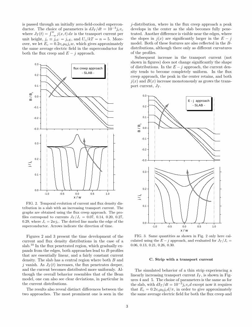
The results also reveal distinct differences between thetwo approaches. The most prominent one is seen in the
j-distribution, where in the flux creep approach a peakdevelops in the center as the slab becomes fully pene-trated. Another difference is visible near the edges, wherethe slopes in j(x) are significantly larger in the E − jmodel. Both of these features are also reflected in the B-distributions, although there only as different curvaturesof the profiles.
Subsequent increase in the transport current (notshown in figures) does not change significantly the shapeof distributions. In the E − j approach, the current den-sity tends to become completely uniform. In the fluxcreep approach, the peak in the center retains, and bothj(x) and B(x) increase monotonously as grows the trans-port current, JT .
-0.3
-0.2
-0.1
0.0
0.1
0.2
0.3
E - j approach- SLAB -
B /
Bc
-1.0 -0.5 0.0 0.5 1.00.0
0.1
0.2
0.3
x / w
j / j c
FIG. 3. Same quantities as shown in Fig. 2 only here cal-culated using the E− j approach, and evaluated for JT /Jc =0.06, 0.13, 0.21, 0.26, 0.30.
C. Strip with a transport current
The simulated behavior of a thin strip experiencing alinearly increasing transport current IT , is shown in Fig-ures 4 and 5. The choise of parameters is the same as forthe slab, with dIT /dt = 10−3jcvcd except now it requiresthat Ec = 0.2vcµ0jcd/π, in order to give approximatelythe same average electric field for both the flux creep and
3

the E− j approach. Comparing the results with the pre-vious slab case, one immediatlely sees differences in theshape of the profiles. The j(x) in a strip is always finiteeverywhere even at small currents, where the flux pen-etration is only partial. Furthermore, B(x) is stronglynonlinear and has peaks at the edges. Both these fea-tures are well known also in the Bean model behavior fora thin strip.11,12
-1.02 -0.51 0.00 0.51 1.02
-0.6
-0.3
0.0
0.3
0.6
flux creep approach- STRIP -
B /
Bc
-1.0 -0.5 0.0 0.5 1.00.0
0.1
0.2
0.3
0.4
x / w
j / j c
FIG. 4. Temporal evolution of flux and current density dis-tribution in a thin strip with an increasing transport current.The flux creep approach is used to calculate the graphs. Theprofiles correspond to the current values IT /Ic = 0.10, 0.18,0.24, 0.28, 0.31, 0.33, where Ic = 2wd jc. The dotted linemarks the edge of the superconductor. Arrows indicate thedirection of time.
As in the slab case, we observe also here a significantdifference between the distributions obtained from theflux creep and the E − j approach. Firstly, the two ap-proaches give opposite sign for the slope of j(x) in thepenetrated regions near the edges. Secondly, only thecreep approach leads to a central peak in j(x) at largecurrents. Hence, while in the E− j approach the j(x) re-mains concave throughout, the creep approach predicts agradual change from a concave to a convex profile. Con-trary to the case of a slab, differences are also clearlyseen in the flux distributions. In particular, the creep ap-
proach predicts a much steeper slope near the flux front.
Interestingly, we found that although the two ap-proaches lead to quite different spatial distributions, theintegral characteristics of the strip, such as current-voltage curves, are only weakly sensitive to the differ-ences. This is demonstrated in Fig. 6, which shows theintegral current-voltage curves obtained using both ap-proaches. The curves for n = 5 correspond to the j-distributions shown in the previous figures. The electricfield was determined as P/IT , where the dissipated powerP per unit length of the strip was calculated by integrat-ing the product j(x)E(x) over the strip cross-section.11
-0.60
-0.30
0.00
0.30
0.60 E - j approach- STRIP -
B /
Bc
-1.0 -0.5 0.0 0.5 1.00.0
0.1
0.2
0.3
j / j c
x / w
FIG. 5. Same quantities as shown in Fig. 4 only here cal-culated using the E − j approach, and evaluated for IT /Ic =0.08, 0.14, 0.20, 0.26, 0.32, 0.35.
In the log-log plot the current-voltage curves displaya clear crossover at E ≈ 0.002Ec. At large currents theintegral E(j) curve shows a power law behavior E ∝ jn′
,where n′ is an “integral” exponent. We find that n′
slightly exceeds Uc/kT in the flux creep approach. Inthe E − j approach n′ is equal to the “local” exponentn and the integral E(j) curves merge the local E(j)’sshown by straight lines. At small currents the integralE(j) curve also shows a power law behavior, althoughwith a much smaller n′ which seemingly does not dependon n or Uc/kT .
4

D. Discussion
Both approaches describe the same physical situation:in response to the transport current the flux lines enterthe sample from the edge and then move some distancebefore getting pinned or annihilated in the sample’s cen-ter. Thus, near the edges the flux motion is always morepronounced. Consequently, E has a maximum there. Inthe E − j approach, the local current density is an ex-plicit function of the local electric field. Therefore, j(x)follows E(x) and monotonously decreases from the edgestowards the center. On the other hand, in the flux creepapproach, j(x) is related to v(x) = E(x)/B(x) by Eq. (2),and, hence depends also on the flux distribution. In par-ticular, j(x) is relatively small at the strip edges where|B| is maximal, see Fig. 4(a).
1E-3
0.01
0.1
0.2 0.60.4
n = 5n = 15E
/ E
c
j / jc
FIG. 6. Current-voltage curves for a strip obtained by nu-merical simulations in the flux creep approach (solid line) andin the E− j approach (dashed line). Results for two differentn = Uc/kT are shown. Straight lines show the local E(j)curve for the E − j approach, Eq. (4).
IV. EXPERIMENTAL RESULTS AND
DISCUSSION
A YBa2Cu3O7−δ (YBCO) film of 200 nm thicknesswas prepared by dc magnetron sputtering on LaAlO3
substrate.13 Using photo-lithography a strip of dimen-sions 500×100 µm2 was formed and equipped with Agcontact pads for injection of a transport current. Thecurrent was applied in pulses of 40 ms duration whilethe temperature was kept at 20 K in an optical cryostat.Magneto-optical images were recorded with 33 ms expo-sure time during the current pulse. From the images wedetermine the z-component of B in the plane of the fer-rite garnet magneto-optical indicator, which we estimateto be located 10 µm above the YBCO film.
Shown in Fig. 7(a) are the measured B-distributions.Because of the finite distance between the indicator andthe superconductor, these profiles are not easily com-pared to the results of the simulations. However, since
the j-profiles showed more distict differences between thecreep and E − j approach, the measured B-profiles wereconverted to sheet current distributions, J(x) = dj(x), inthe strip. An inversion scheme described in Ref. 14 andfurther developed elsewhere15 was employed.
-15
-10
-5
0
5
10
15 (a)
B (
mT
)
-50 -25 0 25 500
10
20
30
40
50 4.5 A
4.0 A
3.4 A
3.0 A
2.2 A
1.0 A
(b)
J (k
A/m
)
x (µm)
FIG. 7. (a) Flux density distributions in a thin YBCO stripcarrying transport currents up to 4.5 A. The measurementswere obtained using magneto-optical imaging. (b) Sheet cur-rent distributions inferred by inversion of the B(x) profiles.
Profiles of the sheet current are shown in Fig. 7(b)for a range of transport currents up to 4.5 A. Evidently,they fit quite well to the simulated results of the creepapproach shown in Fig. 4. In particular, one easily recog-nizes the characteristic change from a concave to a convexcurrent distribution as IT increases. The E−j approach,on the other hand, appears not to be able to give an ad-equate description of the flux dynamics in the presentexperiment.
Although being the better model, one can still see con-siderable discrepancies between the experimental curvesand the flux-creep approach simulations. One exampleis the peak of j(x) in the strip center at large currents,a feature the experiments could not reproduce. Unfor-tunately, a current of 4.8 A caused fatal damage to thesample, and we were not able to measure distributions
5

under the conditions where a central peak might becomeapparent.
-50 0 50
-10
-5
0
5
10
15
20
J (kA/m
)B (
mT
)
x (µm)-10
0
10
20
30
(a)
-50 0 50
-10
-5
0
5
10
15
20
J (kA/m
)B (
mT
)
x (µm)-10
0
10
20
30
(b)
-50 0 50
-10
-5
0
5
10
15
20(c)
J (kA/m
)B (
mT
)
x (µm)-10
0
10
20
30
FIG. 8. Sheet current (solid lines) and the flux density(dashed lines) distributions in a thin strip: experiment (a)and simulations in the flux creep approach (b) and simula-tions in the E − j approach (c). The strip was first exposedto a very high magnetic field which subsequently was reducedto zero. After that a transport current of 2 A was applied.The experimental data were obtained from magneto-opticalimages of a YBCO strip.
As an alternative way to create a peak in J where B
changes sign, we carried out a different experiment. Herethe strip (a new YBCO sample prepared by the samemethod) was initially in the remanent state after firstbeing exposed to a very high magnetic field. After thatthe strip was subjected to a transport current of 2 A.The resulting flux and current distributions are shown inFig. 8(a). One sees that in the left half of the strip thereis a wide region with a large and nearly constant currentdensity. Within this region one finds that J(x) indeedhas a peak located close to the point where B = 0.
A new set of simulations was made for this special statewith combined magnetization currents and IT . The simu-lations aimed to reproduce the exact experimental steps:First, the strip was exposed to a perpendicular magneticfield applied as a pulse of 70 mT amplitude with 1 s of lin-ear increase and 1 s of linear decay. Then, after one moresecond, the strip was subjected to a transport currentpulse with 1 ms rise time. During the current pulse, 20 msafter turn-on, the magneto-optical image was taken. Forthis particular time, Figs. 8(b) and (c) present the numer-ically obtained distributions for the flux creep approachand E − j approach, respectively. The following modelparameters were used: n = Uc/kT = 5, Ic = 25 A, andvc = 10 m/s. Again, only the flux creep approach gives apeak in the current profile, and now we find an excellentagreement with the experimental results.
A remaining discrepancy between the flux-creep ap-proach simulations and the experimental curves is thatthe gradient of J(x) near the strip edge is larger in theexperiments. This holds true also for simulations madewith other values of the power Uc/kT . We believe thatour photo-lithographic technology does not reduce thefilm quality much more than up to a distance 1-2 µmfrom the edge. This is also consistent with the magneto-optical images, which show that the current flow alongthe strip is highly uniform on scales larger than 5 µm.Therefore, the discrepancy between experiment and sim-ulations indicates that the vortex behavior is more com-plicated than assumed in the present flux creep model.The experimentally observed suppression of J near theedge where |B| is maximal, can be interpreted as a |B|-induced reduction of the critical current density jcU , orthe pinning energy Uc. This interpretation, however, failsto account for a similar suppression of J observed pre-viously in the remanent state after current pulse.16 Analternative explanation able to cope with both observa-tions is a heat dissipation due to vortex motion which isalways most intensive near the strip edges.
V. CONCLUSIONS
Numerical simulations have been carried out in orderto compare two commonly accepted approaches for anal-ysis of flux motion in superconductors; (i) the flux creepapproach, and (ii) the approach based on a non-linearE(j) curve. We have shown that if the critical cur-
6

rent density is field-independent, these approaches pre-dict similar but also distinctly different current and fluxdistributions. The difference is most pronounced in theregions where the local flux density B is small. The sim-ulation results were compared with the real current dis-tributions in a YBCO strip carrying a transport current.The experimental data were obtained by using magneto-optical imaging. The comparison shows clearly that theflux creep approach provides the better description of theflux motion in the strip.
ACKNOWLEDGMENTS
The financial support from the Research Council ofNorway (NFR), and from NATO via NFR is gratefullyacknowledged. We are grateful to Bjørn Berling for amany-sided help and to E. H. Brandt for a discussion.
∗ Email: [email protected] Y. Yeshurun and A. P. Malozemoff, Phys. Rev. Lett. 60,2202 (1988).
2 Y. Yeshurun, A. P. Malozemoff, and A. Shaulov, Rev. Mod.Phys. 68, 911 (1996).
3 H. G. Schnack, R. Griessen, J. G. Lensink, C. J. van derBeek, and P. H. Kes, Physica C 197, 337 (1992).
4 L. Burlachkov, D. Giller, and R. Prozorov, Phys. Rev. B58, 15067 (1998).
5 A. Gurevich and E. H. Brandt, Phys. Rev. Lett. 73, 178(1994).
6 E. H. Brandt, Phys. Rev. B 49, 9024 (1994).7 E. H. Brandt, Phys. Rev. B 58, 6506 (1998).8 The approaches would become equivalent for a specialchoice of the parameters involved. In particular, if Ec is pro-portional to B, or if the critical current densities are relatedto each other as jcE(B) = jcU (B)B−1/n with n = Uc/kT .
9 Y. M. Galperin and T. H. Johansen, unpublished.10 Movies of time development of B(x), j(x), and E(x) dis-
tributions are presented athttp://www.fys.uio.no/faststoff/ltl/results/creep
11 E. H. Brandt, and M. Indenbom, Phys. Rev. B 48, 12893(1993).
12 E. Zeldov, J. R. Clem, M. McElfresh, and M. Darwin, Phys.Rev. B 49, 9802 (1994).
13 S. F. Karmanenko, V. Y. Davydov, M. V. Belousov, R. A.Chakalov, G. O. Dzjuba, R. N. Il’in, A. B. Kozyrev, Y. V.Likholetov, K. F. Njakshev, I. T. Serenkov, O. G. Vendic,Supercond. Sci. Technol. 6, 23 (1993).
14 T. H. Johansen, M. Baziljevich, H. Bratsberg, Y. Galperin,P. E. Lindelof, Y. Shen, and P. Vase, Phys. Rev. B 54, 16264 (1996).
15 A. V. Bobyl et al., unpublished.16 M. E. Gaevski, A. V. Bobyl, D. V. Shantsev, S. F. Karma-
nenko, Y. M. Galperin, T. H. Johansen, M. Baziljevich, H.Bratsberg, Phys. Rev. B 59, 9655 (1999)
7


![=`jR]ej dYZWed Re Wf]] eYc`ee]V - Daily Pioneer](https://static.fdokumen.com/doc/165x107/6338adcea6d952c89b0061e7/jrej-dyzwed-re-wf-eyceev-daily-pioneer.jpg)
![Ej Arq Soft200405[1]](https://static.fdokumen.com/doc/165x107/631a67acd5372c006e037ada/ej-arq-soft2004051.jpg)