Comparison between different methods of islanding detection for photovoltaic symmetric systems
6
Comparison between different methods of islanding detection for photovoltaic symmetric systems Giovanna Santamaría, Ramón Alonso, Eneko Sansinenea, Leire Arrizubieta, Pedro García de Madinabeitia Jesús María Aguirre, S.A. (JEMA) Lasarte-Oria - SPAIN g.santamarí[email protected], [email protected], [email protected], [email protected], [email protected] Abstract-This paper shows an analysis of the methodologies used to detect the islanding operating of the three-phase grid connected photovoltaic inverters. In some countries, the operating regulation before islanding conditions is not specified enough. Now the new operating procedures try to integrate the guidelines which the distributed generating systems must follow in order to reach an optimum operation under islanding conditions. Nevertheless, there is still a lack of regulation in this sense. In order to analyze the different detection methods, some simulations have been carried out. This document pretends to establish a test guideline, necessary to validate the islanding detection systems which are integrated inside the photovoltaic inverters, in order to ensure a correct operation of them. That is why the results of real tests of JEMA’s photovoltaic inverters have been included. I. INTRODUCTION The three phase photovoltaic inverters generally are fed to the distribution grid. Some times, in the distribution grid occur faults that produce that voltage values, in the connection point, goes out of normal margins of grid voltage, or even, that this voltage disappears totally. An islanding situation occurs when the grid voltage, produced by a generation system, disappears but this system continues operating, providing power to the local loads that are connected in the same point of the grid. This can damage other equipments, loads or even, to make worse the conditions that have produced the abnormal situation in the distribution system. In this situation it is necessary the inverters to be switched off, in order to not contribute to worsen the conditions that have produced the grid fault. The more generation systems are connected to a distribution grid, the more difficult it is to determinate if a fault condition has taken place. In photovoltaic systems it is necessary to implement a method for detecting this phenomenon, in order to ensure the correct behavior under islanding conditions. Certain Organizations have established some requirements that have to be applied to the distribution systems under islanding conditions, like IEEE 929-2000 “Recommended Practice for Utility Interface of Photovoltaic (PV) Systems” [2]. Some countries, have assumed this criteria, like UL 1741, in order to ensure the correct behavior of the generation system under these conditions. In those procedures have been established the test conditions for validating the islanding method implemented in the inverters. TABLE I TABLE II STANDARD IEEE P929 Nominal Voltage Disconnection Time V<50%Vn 6 cycles 50%Vn<V<88%Vn 120 cycles 88%Vn<V<106%Vn Normal behaviour 106%Vn<V<137%Vn 120 cycles V>137%Vn 2 cycles II. ISLANDING DESCRIPTION There are four cases in which the inverter is able to detect the islanding situation. In those conditions the frequency and voltage protections of the inverter disconnect it from the grid: • PV inverter produces less power than Load requirement. • PV inverter produces more power than Load requirement. • Load is mainly inductive. • Load is mainly capacitive. Standard Title IEC 61723 Ed. 1.0 “Safety guidelines for grid connected photovoltaic (PV) systems mounted on buildings” IEC 61728 Ed. 1.0 “Safety test procedures for utility grid connected photovoltaic inverters” IEC 61728 Ed. 1.0 “Electrical safety of static inverters and charge controllers for use in photovoltaic (PV) power systems” IEC 61728 Ed. 1.0 “Testing procedure – Islanding prevention measures for power conditioners used in grid connected photovoltaic (PV) power generation systems”
-
Upload
independent -
Category
Documents
-
view
0 -
download
0
Transcript of Comparison between different methods of islanding detection for photovoltaic symmetric systems

Comparison between different methods of islanding detection for photovoltaic symmetric systems
Giovanna Santamaría, Ramón Alonso, Eneko Sansinenea, Leire Arrizubieta, Pedro García de Madinabeitia
Jesús María Aguirre, S.A. (JEMA) Lasarte-Oria - SPAIN g.santamarí[email protected], [email protected], [email protected], [email protected],
Abstract-This paper shows an analysis of the methodologies used to detect the islanding operating of the three-phase grid connected photovoltaic inverters. In some countries, the operating regulation before islanding conditions is not specified enough. Now the new operating procedures try to integrate the guidelines which the distributed generating systems must follow in order to reach an optimum operation under islanding conditions. Nevertheless, there is still a lack of regulation in this sense. In order to analyze the different detection methods, some simulations have been carried out. This document pretends to establish a test guideline, necessary to validate the islanding detection systems which are integrated inside the photovoltaic inverters, in order to ensure a correct operation of them. That is why the results of real tests of JEMA’s photovoltaic inverters have been included.
I. INTRODUCTION
The three phase photovoltaic inverters generally are fed to the distribution grid.
Some times, in the distribution grid occur faults that produce that voltage values, in the connection point, goes out of normal margins of grid voltage, or even, that this voltage disappears totally.
An islanding situation occurs when the grid voltage, produced by a generation system, disappears but this system continues operating, providing power to the local loads that are connected in the same point of the grid. This can damage other equipments, loads or even, to make worse the conditions that have produced the abnormal situation in the distribution system.
In this situation it is necessary the inverters to be switched off, in order to not contribute to worsen the conditions that have produced the grid fault.
The more generation systems are connected to a distribution grid, the more difficult it is to determinate if a fault condition has taken place.
In photovoltaic systems it is necessary to implement a method for detecting this phenomenon, in order to ensure the correct behavior under islanding conditions.
Certain Organizations have established some requirements that have to be applied to the distribution systems under islanding conditions, like IEEE 929-2000 “Recommended Practice for Utility Interface of Photovoltaic (PV) Systems” [2]. Some countries, have assumed this criteria, like UL 1741, in order to ensure the correct behavior of the generation system under these conditions. In those procedures have been
established the test conditions for validating the islanding method implemented in the inverters.
TABLE I
TABLE II STANDARD IEEE P929
Nominal Voltage Disconnection Time
V<50%Vn 6 cycles
50%Vn<V<88%Vn 120 cycles
88%Vn<V<106%Vn Normal behaviour
106%Vn<V<137%Vn 120 cycles
V>137%Vn 2 cycles
II. ISLANDING DESCRIPTION
There are four cases in which the inverter is able to detect the islanding situation. In those conditions the frequency and voltage protections of the inverter disconnect it from the grid:
• PV inverter produces less power than Load requirement. • PV inverter produces more power than Load requirement. • Load is mainly inductive. • Load is mainly capacitive.
Standard Title
IEC 61723 Ed. 1.0
“Safety guidelines for grid connected photovoltaic (PV) systems mounted on buildings”
IEC 61728 Ed. 1.0
“Safety test procedures for utility grid connected photovoltaic inverters”
IEC 61728 Ed. 1.0
“Electrical safety of static inverters and charge controllers for use in photovoltaic (PV) power systems”
IEC 61728 Ed. 1.0
“Testing procedure – Islanding prevention measures for power conditioners used in grid connected photovoltaic (PV) power generation systems”
Nevertheless there are situations in which the frequency and voltage protections are not enough to ensure the correctly behavior of the inverter at islanding conditions, the so-called non detection zone (NDZ). In this area the power provided by the inverter and the power used by the load is practically the same, and the resonant frequency of the load is very close to the nominal frequency of the grid inside its normal range.
The different methods of islanding detection try to reduce at maximum the non detection zone. It is necessary to mention that in any case the probability that a grid islanding situation happens is very faint, less than 10-9 (the probability a grid fault occurs is about 10-6).
According to current normative the inverter has to be disconnected from the grid in this abnormal situation. Otherwise the inverter would continue providing energy to the grid in islanding conditions which would lead to security problems.
III. PROTECTION AGAINST ISLANDING OPERATION
Some studies which have been realized with commercial photovoltaic inverters show that under islanding conditions:
• Some inverters do not disconnect quick enough. • The presence of a distribution transformer causes
a quicker disconnection [1]. • If in any connection point exist different
photovoltaic inverters with different methods of islanding detection, disconnecting time is larger than the one used by inverters when these operate alone or with others which have the exact same technology.
Therefore, the inverter must have integrated an islanding
detection method that disconnects it from the grid under any dropping or grid operating out of range. Such method also needs to be compatible with the rest inverter’s method which is connected to the same grid.
• It cannot interfere with the disconnection method of the rest of the inverters.
• The disconnection method of the rest of the inverters must not affect the answering speed of the system before islanding conditions.
An islanding is characterized by the generators and the
loads which remain connected to the grid section where the shortage has been produced.
The load can be shaped through a parallel RLC circuit, as shown in Fig. 2. This circuit is used because it presents a resonance, which can be characterized by the resonance frequency (1) and the quality factor (2).
LC2
1fresπ
≅ (1)
LCRQ = (2)
Therefore, an islanding situation difficult to be detected
will be the one where:
• The resonance frequency of the load is the same as the grid nominal frequency.
• A quality factor close to 5, so that the band width of the resonance frequency of the load will be between ±1Hz.
• The power generated by the photovoltaic inverter is exactly the same as the one consumed by the load.
In order for the islanding detection system to be considered
valid, it will be necessary the test to be realized 10 times under the conditions mentioned above, and with a satisfactory result in all cases.
IV. DETECTION METHODS VALIDATION OF ISLANDING WORKING
The applicable legislation of photovoltaic inverters should define the evaluation test and the validation criteria to ensure the protection of the implemented methods to islanding conditions are suitable.
Hence, it must validate these methods on the possible worst case of islanding, in which the photovoltaic inverter is connected to grid at the same coupled point that a RLC load whose quality factor Qf is equal to 5, its resonant frequency is the nominal frequency and the power consumption is equal to the power given by the photovoltaic inverter. There are different methods to detect islanding situation, hardware and software, the last one has the minor NDZ. The International Energy Agency recommended two detection methods, Sandia Frequency Shift and Sandia Voltage Shift [5].
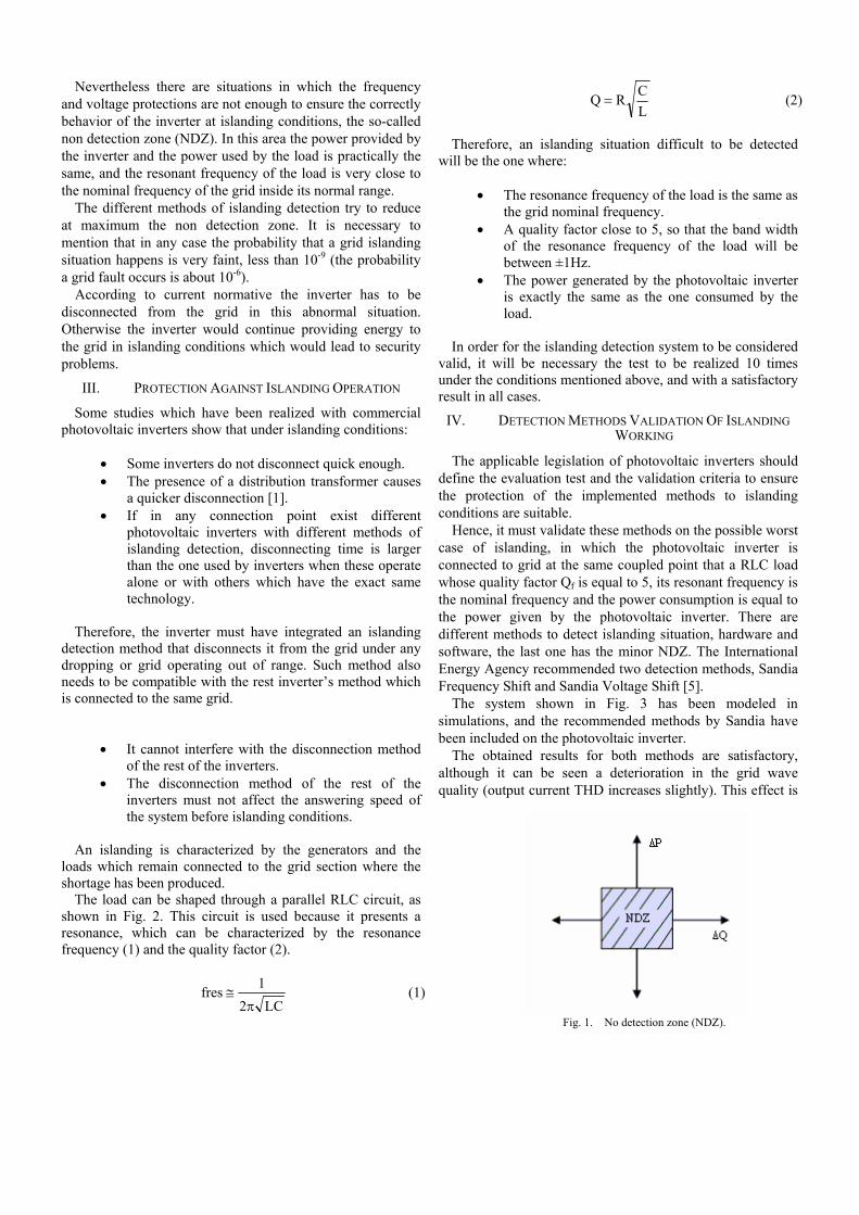
The system shown in Fig. 3 has been modeled in simulations, and the recommended methods by Sandia have been included on the photovoltaic inverter.
The obtained results for both methods are satisfactory, although it can be seen a deterioration in the grid wave quality (output current THD increases slightly). This effect is
Fig. 1. No detection zone (NDZ).
expected since both methods consist on introduce distortion in the grid voltage measured by the photovoltaic inverter.
This small distortion, introduced in the control signals, involves worsening on the given wave quality, higher worsening to higher input distortion. On the other hand, it is easier to detect the islanding situation, greater it is the introduced distortion wherefore must be an agreement between both factors: quick response on islanding working and wave quality (THD).
To avoid the worsening in the THD of the grid current, have been designed other algorithms and have been checked that it allows response speed without handicap the THD of the output current. This method also introduces little distortion, but it is only appreciable if the distribution grid is fallen. So in normal operation conditions, this distortion does not affect to the wave quality given to grid by inverters with newest control systems.
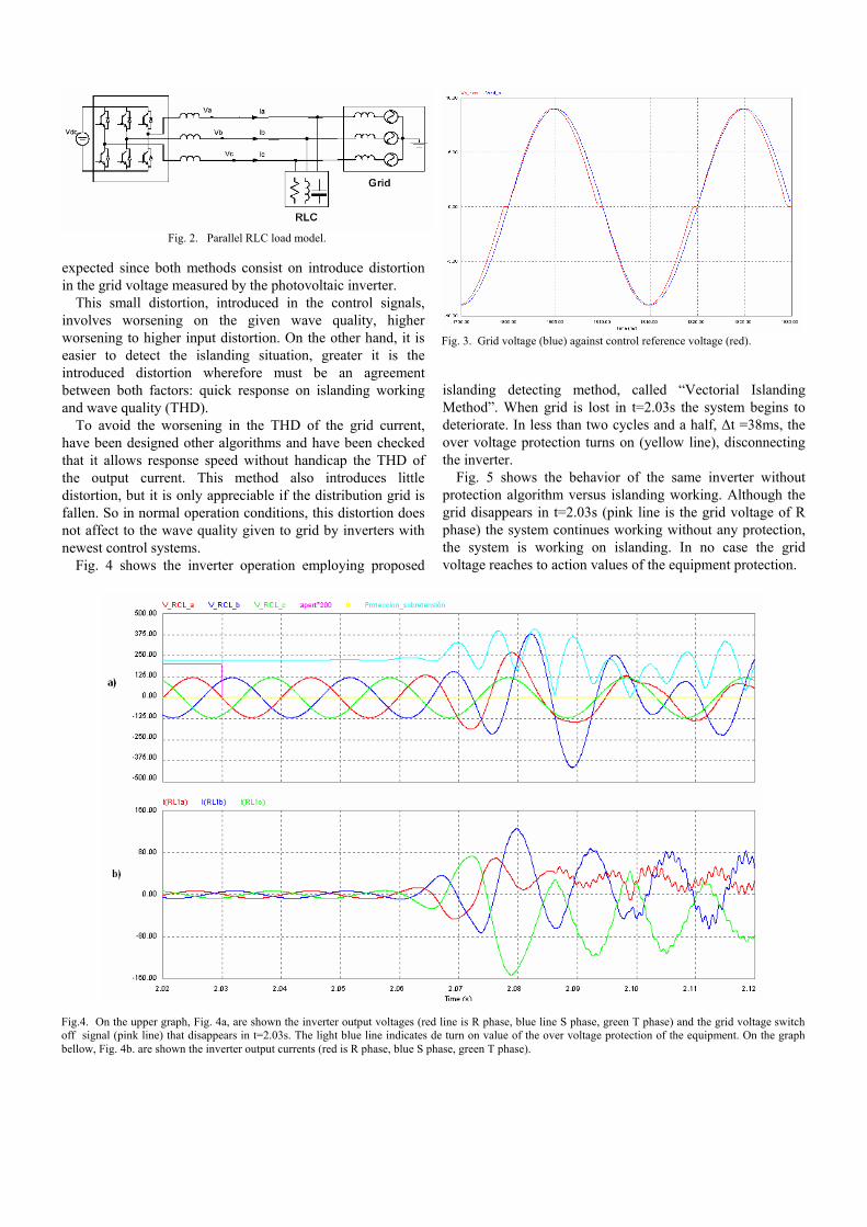
Fig. 4 shows the inverter operation employing proposed
islanding detecting method, called “Vectorial Islanding Method”. When grid is lost in t=2.03s the system begins to deteriorate. In less than two cycles and a half, Δt =38ms, the over voltage protection turns on (yellow line), disconnecting the inverter.
Fig. 5 shows the behavior of the same inverter without protection algorithm versus islanding working. Although the grid disappears in t=2.03s (pink line is the grid voltage of R phase) the system continues working without any protection, the system is working on islanding. In no case the grid voltage reaches to action values of the equipment protection.
Fig.4. On the upper graph, Fig 4a, are shown the inverter output voltages (red line is R phase, blue line S phase, green T phase) and one network voltage phase (pink line is the switch off of grid voltage) before and after the network disappears, t=2.03s. The light blue line indicates de turn on value of the over voltage protection of the equipment. On the graph bellow, Figure 4 b, are shown the inverter output currents (red is R phase, blue S phase, green T phase).
Fig. 3. Grid voltage (blue) against control reference voltage (red)
Fig. 2. Parallel RLC load model.
Fig.4. On the upper graph, Fig. 4a, are shown the inverter output voltages (red line is R phase, blue line S phase, green T phase) and the grid voltage switch off signal (pink line) that disappears in t=2.03s. The light blue line indicates de turn on value of the over voltage protection of the equipment. On the graph bellow, Fig. 4b. are shown the inverter output currents (red is R phase, blue S phase, green T phase).
Fig. 3. Grid voltage (blue) against control reference voltage (red).
V. REAL LABORATORY RESULTS
To test the system are necessary PV panels (photovoltaic arrays) and a resonant RLC load. The RLC load has to be resonant at the normal frequency operation level of the system and it has been selected according to produce a quality factor of 5. The test equipment includes an AC source, to emulate the grid behavior. This AC source allows simulating the islanding conditions in the grid. The values of testing platform components of the RLC parallel load are:
R=66 ohm (commercial component) C = 147uF (commercial component) L=40.8mH (manufactured by JEMA) The ac source is manufactured by JEMA: Variable ac
source (0-600Vac) 50Hz For monitoring the currents and voltages values a
Tektronix digital oscilloscope is used. With this capture system is possible to see the moment at the contactor is opened and the ac voltage is drop to 0%.
Two different situations have been reproduced. The first one is shown in Fig. 6. In this case the islanding protection algorithm has been activated for ensuring a correct behavior of the inverter. The inverter provides a disturbance that only appears when the grid disappears. Fig. 7 shows the current and the voltage in normal condition operation before the grid drops (the action of the algorithm does not produce any
deterioration in the current THD in normal condition). When the grid fault occurs (opening the grid contactor), under-voltage and under-frequency protections act and switch off the inverter in less than a grid cycle, as it is shown in Fig. 6.
For evaluating the islanding protection method effectiveness the test is been repeated but in this case the algorithm is inactive. Fig. 9 shows the behavior of the inverter under a grid fault situation.
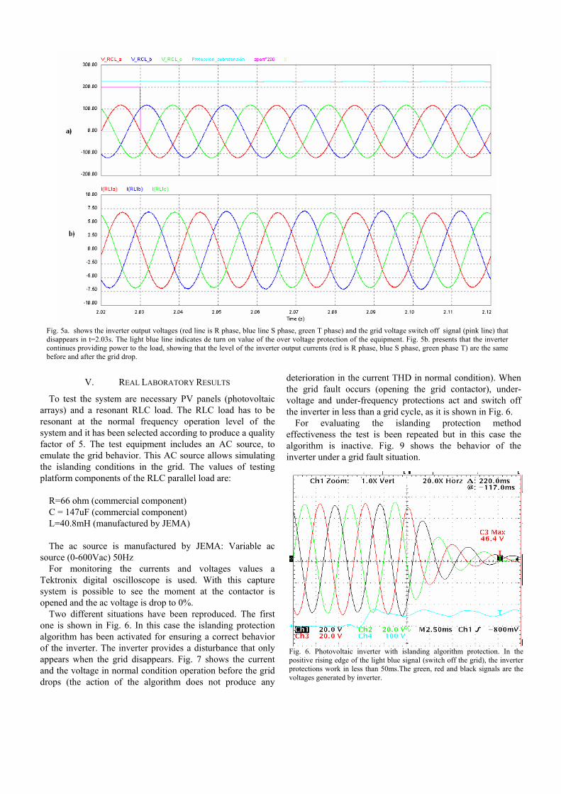
Fig. 5a. shows the inverter output voltages (red line is R phase, blue line S phase, green T phase) and the grid voltage switch off signal (pink line) that disappears in t=2.03s. The light blue line indicates de turn on value of the over voltage protection of the equipment. Fig. 5b. presents that the inverter continues providing power to the load, showing that the level of the inverter output currents (red is R phase, blue S phase, green phase T) are the same before and after the grid drop.
Fig. 6. Photovoltaic inverter with islanding algorithm protection. In the positive rising edge of the light blue signal (switch off the grid), the inverter protections work in less than 50ms.The green, red and black signals are the voltages generated by inverter.
Although the grid disappears, because the ac source contactor has been opened, the inverter continues providing power to the load and generating voltages inside the normal limits of the grid, so the frequency and voltage protections do not work. In this case the inverter is working in island, does not operate correctly.
Fig. 8 shows current and voltage phase of the inverter in normal operation conditions. In this case the THD of the current is exactly the same that in Fig. 6, when the islanding algorithm is activated.
VI. CONCLUSIONS
A systematic methodology for testing three phase PV inverter behaviour under islanding condition has been presented. This test procedure has been used for evaluating some active islanding methods, Sandia recommended ones, and other ones developed by JEMA. Experimental results support the appropriateness of the proposed overall methods, which guarantees that, the current provided by inverters have an appropriate THD in normal operation conditions, and also protect the system when an islanding situation occurs.
The particular JEMA’s algorithm has been presented and evaluated in charge of demonstrating its fitness suitability to protect the three phase PV inverter under islanding conditions.
VII. REFERENCES [1] Z. Ye, R. Walling, L. Garces, R. Zhou, L. Li and T. Wang, “Study and
Development of Anti-Islanding Control for Grid-Connected Inverters” (Subcontractor Report for National Renewable Energy Laboratory, May 2004, NREL/SR-560-36243).
[2] M.Castro Gil, L. Dávila Gómez, A. Colmenar Santos, “Sistemas fotovoltaicos conectados a red: Estandares y Condiciones Técnicas”.
[3] Francesco de Mango, Marco Liserre, Antonio Del’ L’Aquila, “Overview of Anti-Islanding Algorithms for PV-System Part II. Active Method”
[4] M. Castro Gil, L. Dávila Gomez, A. Colmenar Santos, “Sistemas Fotovoltaicos Conectados a Red: Estándares y Condiciones Técnicas”.
[5] Ward BOWER, Dr. Michael ROPP,” Evaluation of islanding detection methods for photovoltaic utility interactive power systems”
Fig. 8. The inverter is operating at normal conditions of the grid. The green signal represents the current. Yellow and pink signals are R phase inverter voltage and the grid voltage respectively
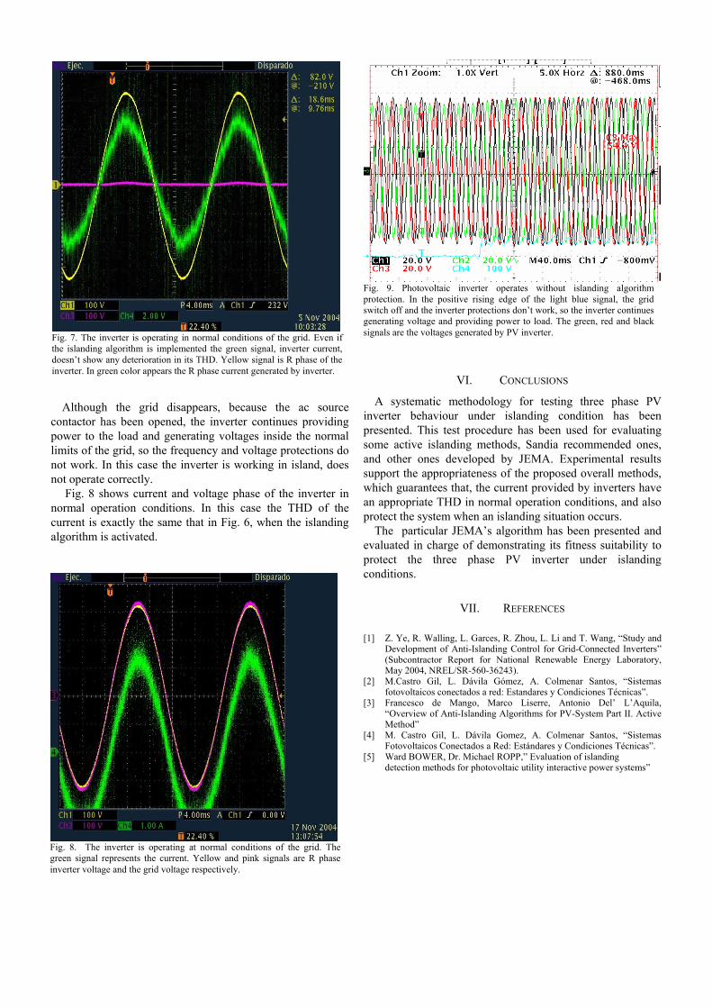
Fig. 7. The inverter is operating in normal conditions of the grid. Even if the islanding algorithm is implemented the green signal, inverter current, doesn’t show any deterioration in its THD. Yellow signal is R phase of the inverter. In green color appears the R phase current generated by inverter.
Fig. 8. The inverter is operating at normal conditions of the grid. The green signal represents the current. Yellow and pink signals are R phase inverter voltage and the grid voltage respectively.
Fig. 9. Photovoltaic inverter operates without islanding algorithm protection. In the positive rising edge of the light blue signal, the grid switch off and the inverter protections don’t work, so the inverter continues generating voltage and providing power to load. The green, red and black signals are the voltages generated by PV inverter.
Giovanna Santamaria received the Industrial Engineer degree from the University of Basque Country, Spain, in 2002. In February 2003 she joined JEMA in its R&D Department. Since then she has been working mainly on Renewable Energy area focused on photovoltaic and wind systems, motor drives, frequency converters and railways converters.
Ramón Alonso received the Industrial Engineer degree from the University of Basque Country UPV, Spain, in 1992. In 1994 he joined JEMA in its Engineering Department. Since then he has been working on power supply systems for mobile network, Renewable Energy area focused on photovoltaic and wind systems, motor drives, frequency converters, secure power systems and railways converters.
Eneko Sansinenea received the Industrial Electronic and Automatic Engineer degree from the University of Mondragon in 2006. In 2007 he joined JEMA in its R&D Department. Since then he's been working mainly on Renewable Energy area focused on photovoltaic systems, designing and developing control algorithms for solar converters.
Leire Arrizubieta received the Industrial Electronic and Automatic Engineer degree from the University of Mondragon in 2004. She was in Power Electronics Department of Ikerlan during 2 years. Then she joined JEMA in 2006 in its R&D Department. Since then she has worked on the design and development of control algorithms for solar converters, frequency converters and Static Var Compensators. June-2009 she received the Group Achievement Award MDSCC of JPL NASA.
Pedro García de Madinabeitia received in 1985 the Industrial Engineer degree from the University of Navarra, Spain, in 1985. In 1986 he was with CEIT in its Digital Control Department developing a fault line locatorFault Line Locator in HV lines. In 1989 he joined JEMA in its R&D Department. Since then he has been working on power supply systems for mobile network, power supplies for Nuclear Fusion facilities and for Particle Accelerators, Renewable Energy area focused on photovoltaic and wind systems, motor drives, frequency converters, secure power systems and railways converters. Nowadays he is the R&D Manager Department Manager.