Comparative structural response of two steel bridges constructed 100 years apart
14
This article was downloaded by: [Universidad Michoacana San Nicolas de Hidalgo], [Professor JOSE J. ALVAREZ] On: 18 January 2012, At: 12:02 Publisher: Taylor & Francis Informa Ltd Registered in England and Wales Registered Number: 1072954 Registered office: Mortimer House, 37-41 Mortimer Street, London W1T 3JH, UK Structure and Infrastructure Engineering Publication details, including instructions for authors and subscription information: http://www.tandfonline.com/loi/nsie20 Comparative structural response of two steel bridges constructed 100 years apart Humberto Varum a , Romain Sousa a , Walter Delgado a , Catarina Fernandes a , Aníbal Costa a , Jose M. Jara b , Manuel Jara b & Jose J. Álvarez b a Civil Engineering Department, University of Aveiro, Aveiro, Portugal b Civil Engineering School, University of Michoácan, Morelia, Michoácan, Mexico Available online: 23 Jul 2009 To cite this article: Humberto Varum, Romain Sousa, Walter Delgado, Catarina Fernandes, Aníbal Costa, Jose M. Jara, Manuel Jara & Jose J. Álvarez (2011): Comparative structural response of two steel bridges constructed 100 years apart, Structure and Infrastructure Engineering, 7:11, 843-855 To link to this article: http://dx.doi.org/10.1080/15732470903059390 PLEASE SCROLL DOWN FOR ARTICLE Full terms and conditions of use: http://www.tandfonline.com/page/terms-and-conditions This article may be used for research, teaching, and private study purposes. Any substantial or systematic reproduction, redistribution, reselling, loan, sub-licensing, systematic supply, or distribution in any form to anyone is expressly forbidden. The publisher does not give any warranty express or implied or make any representation that the contents will be complete or accurate or up to date. The accuracy of any instructions, formulae, and drug doses should be independently verified with primary sources. The publisher shall not be liable for any loss, actions, claims, proceedings, demand, or costs or damages whatsoever or howsoever caused arising directly or indirectly in connection with or arising out of the use of this material.
-
Upload
independent -
Category
Documents
-
view
1 -
download
0
Transcript of Comparative structural response of two steel bridges constructed 100 years apart
This article was downloaded by: [Universidad Michoacana San Nicolas de Hidalgo], [Professor JOSE J. ALVAREZ]On: 18 January 2012, At: 12:02Publisher: Taylor & FrancisInforma Ltd Registered in England and Wales Registered Number: 1072954 Registered office: Mortimer House,37-41 Mortimer Street, London W1T 3JH, UK
Structure and Infrastructure EngineeringPublication details, including instructions for authors and subscription information:http://www.tandfonline.com/loi/nsie20
Comparative structural response of two steel bridgesconstructed 100 years apartHumberto Varum a , Romain Sousa a , Walter Delgado a , Catarina Fernandes a , Aníbal Costaa , Jose M. Jara b , Manuel Jara b & Jose J. Álvarez ba Civil Engineering Department, University of Aveiro, Aveiro, Portugalb Civil Engineering School, University of Michoácan, Morelia, Michoácan, Mexico
Available online: 23 Jul 2009
To cite this article: Humberto Varum, Romain Sousa, Walter Delgado, Catarina Fernandes, Aníbal Costa, Jose M. Jara, ManuelJara & Jose J. Álvarez (2011): Comparative structural response of two steel bridges constructed 100 years apart, Structureand Infrastructure Engineering, 7:11, 843-855
To link to this article: http://dx.doi.org/10.1080/15732470903059390
PLEASE SCROLL DOWN FOR ARTICLE
Full terms and conditions of use: http://www.tandfonline.com/page/terms-and-conditions
This article may be used for research, teaching, and private study purposes. Any substantial or systematicreproduction, redistribution, reselling, loan, sub-licensing, systematic supply, or distribution in any form toanyone is expressly forbidden.
The publisher does not give any warranty express or implied or make any representation that the contentswill be complete or accurate or up to date. The accuracy of any instructions, formulae, and drug doses shouldbe independently verified with primary sources. The publisher shall not be liable for any loss, actions, claims,proceedings, demand, or costs or damages whatsoever or howsoever caused arising directly or indirectly inconnection with or arising out of the use of this material.

Comparative structural response of two steel bridges constructed 100 years apart
Humberto Varuma*, Romain Sousaa, Walter Delgadoa, Catarina Fernandesa, Anıbal Costaa, Jose M. Jarab,Manuel Jarab and Jose J. Alvarezb
aCivil Engineering Department, University of Aveiro, Aveiro, Portugal; bCivil Engineering School, University of Michoacan,Morelia, Michoacan, Mexico
(Received 2 February 2009; final version received 18 May 2009; published online 23 July 2009)
This paper presents a comparative numerical analysis of the structural behaviour and seismic performance of twoexisting steel bridges, the Infiernillo II Bridge and the Pinhao Bridge, one located in Mexico and the other inPortugal. The two bridges have similar general geometrical characteristics, but were constructed 100 years apart.Three-dimensional structural models of both bridges are developed and analysed for various load cases and severalseismic conditions. The results of the comparative analysis between the two bridges are presented in terms of naturalfrequencies and corresponding vibration modes, maximum stresses in the structural elements and maximumdisplacements. The study is aimed at determining the influence of a 1 century period in material properties,transverse sections and expected behaviour of two quite similar bridges. In addition, the influence of the bearingconditions in the global response of the Pinhao Bridge was evaluated.
Keywords: steel bridges; truss structures; seismic isolators; structural analysis; existing structures
1. Introduction
Many existing bridges were designed and built beforethe introduction of seismic codes. Recent earthquakesthat have taken place all over the world (e.g. LomaPrieta in 1989, Northridge in 1994, Kobe in 1995 andTaiwan in 1999) confirm the significant seismic vulner-ability of existing bridges and viaducts. In addition tothe human losses, damage and collapse of bridgesusually result in an important economic impact.Column damages, foundation collapses, settlementand rotation of abutments and fall of deck elementsare, among others, frequent damage in bridges due toearthquakes. Descriptions of damage in bridges andtheir causes can be found in Astaneh-Asl et al. (1994),Uang et al. (1999), Kawashima (2002), Mohele andEberhard (2003), Hsu and Fu (2004), Hashimoto et al.(2005), Eshghi and Ahari (2005) and Jara et al. (2006a).
This paper presents the main results of thenumerical analysis of two steel bridges: the PinhaoBridge located in Portugal and the Infiernillo II Bridgelocated in Mexico. Both bridges, built in differentperiods, have very similar global geometry anddimensions, but the Pinhao Bridge was built in 1903and the Infiernillo II Bridge was built recently in 2003.
A comparative analysis was performed in order toevaluate the structural behaviour and seismic perfor-mance of the two bridges, and also with the intentionof gaining knowledge about the structural behaviour
of ancient steel bridges such as the Pinhao Bridge. Inaddition, it is intended to study the possibility of usingthe design rules and techniques followed in new steelbridges, such as the Mexican bridge, in the assessmentand retrofitting of existing bridges, therefore contri-buting to its seismic vulnerability reduction. Three-dimensional (3D) structural models were developedusing the structural analysis software SAP2000 (2006).
Natural frequencies and the corresponding vibra-tion modes were determined and a seismic analysis wasdeveloped for both bridge models. The evaluation wasconducted in terms of dynamic properties, maximumstresses in the structural elements, reactions and forceson piers, for each loading case. The response of thebridges subjected to several seismic conditions and theinfluence of the bearing conditions on the globalresponse of the Pinhao Bridge was also assessed.
2. Bridge descriptions
2.1. Pinhao Bridge
The Pinhao steel bridge (see Figure 1) is located in thenorth of Portugal, between the localities of Regua andPinhao, crossing the Douro river. Its constructionbegan between 1903 and 1906, but no valid informa-tion about its date of conclusion seems to exist.According to the documents and references available(Pinto et al. 2005), no information was found about the
*Corresponding author. Email: [email protected]
Structure and Infrastructure Engineering
Vol. 7, No. 11, November 2011, 843–855
ISSN 1573-2479 print/ISSN 1744-8980 online
� 2011 Taylor & Francis
DOI: 10.1080/15732470903059390
http://www.informaworld.com
Dow
nloa
ded
by [
Uni
vers
idad
Mic
hoac
ana
San
Nic
olas
de
Hid
algo
], [
Prof
esso
r JO
SE J
. AL
VA
RE
Z]
at 1
2:02
18
Janu
ary
2012

design rules/codes used for the bridge’s design.However, considering the common practice at thetime of the bridge construction, it is strongly judgedthat the Pinhao Bridge was designed only for verticalloads. It was common practice to follow the allowablestress methodology in the design of steel elements.
Between 1933 and 1936, the bridge was subjected tominor repair work, and the reinforced concrete deckwas probably built in this period, replacing the woodsleepers that were commonly used at the time (Pintoet al. 2005). In 2006, the bridge was subjected tostructural strengthening (Faria 2008). The strengthen-ing design was developed by GEG – Gabinete deEstruturas e Geotecnia Lda (Portugal).
The characteristics of the Pinhao Bridge consideredin the analysis presented in this paper correspond tothe original conditions of the bridge, i.e. before thestructural strengthening.
The bridge (see Figure 2) consists of a total of threesimply supported spans, with a length of approxi-
mately 69.2 m each, and a short approaching span ofapproximately 12 m (Pinto et al. 2005). The super-structure of each span is a trough arch steel truss with asemi-parabolic shape and with abutments starting witha height of 2.6 m and reaching about 8.8 m at the mid-span, as is shown in Figure 3. Each span is dividedinto 16 panels according to the scheme presented inFigure 3. The panels present different lengths: the oneslocated at the endshave a lengthbetween4.20 and4.21 mand the others have a length between 4.29 and 4.31 m.
The top chords of the arch trusses are transversallybraced (superior bracing), only in the ten middlepanels. In the six extreme panels (three at each end),the chord elements are not braced to allow a minimumheight for the transit of vehicles. There are two bracingbars between each pair of floor beams, arranged in anX-shape (inferior bracing). The link between thebottom and top chords is accomplished by 17 postsand 22 diagonal elements.
In the transverse direction, the bridge structure hasapproximately 7 m width, with a concrete slab deck fortwo traffic lanes. The slab is about 4.60 m width and ithas a thickness of 0.18 m. Each span is longitudinallysupported on five stringers and on 17 floor beams inthe transverse direction. The traffic lanes are borderedby pavements of about 0.70 m width (Pinto et al.2005).
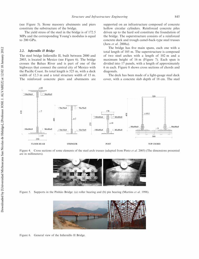
All the structural elements have built-up cross-sections that are generally composed of angles andplates. All the connections are riveted, as it was thecommon practice at the time. Figure 4 presents crosssections of some truss elements.
Each span end is supported on two simple bearings:on one side roller bearings, allowing free longitudinaldisplacements and rotations, and at the opposite side,there are two pinned bearings allowing free rotationFigure 1. General view of the Pinhao Bridge.
Figure 2. General scheme of the Pinhao Bridge structure (approaching span at left and three main spans) (Pinto et al. 2005).
Figure 3. General geometrical characteristics of the Pinhao Bridge main spans.
844 H. Varum et al.
Dow
nloa
ded
by [
Uni
vers
idad
Mic
hoac
ana
San
Nic
olas
de
Hid
algo
], [
Prof
esso
r JO
SE J
. AL
VA
RE
Z]
at 1
2:02
18
Janu
ary
2012
(see Figure 5). Stone masonry abutments and piersconstitute the substructure of the bridge.
The yield stress of the steel in the bridge is of 172.5MPa and the corresponding Young’s modulus is equalto 200 GPa.
2.2. Infiernillo II Bridge
The steel bridge Infiernillo II, built between 2000 and2003, is located in Mexico (see Figure 6). The bridgecrosses the Balsas River and is part of one of thehighways that connect the central city of Mexico withthe Pacific Coast. Its total length is 525 m, with a deckwidth of 12.3 m and a total structure width of 15 m.The reinforced concrete piers and abutments are
supported on an infrastructure composed of concretehollow circular cylinders. Reinforced concrete pilesdriven up to the hard soil constitute the foundation ofthe bridge. The superstructure consists of a reinforcedconcrete deck and trough camel-back-type steel trusses(Jara et al. 2008a).
The bridge has five main spans, each one with atotal length of 105 m. The superstructure is composedof two steel arches with a length of 102 m and amaximum height of 16 m (Figure 7). Each span isdivided into 17 panels, with a length of approximately6 m each. Figure 8 shows cross sections of chords anddiagonals.
The deck has been made of a light-gauge steel deckcover, with a concrete slab depth of 18 cm. The steel
Figure 4. Cross sections of some elements of the steel arch trusses (adapted from Pinto et al. 2005) (The dimensions presentedare in millimeters).
Figure 5. Supports in the Pinhao Bridge: (a) roller bearing and (b) pin bearing (Martins et al. 1998).
Figure 6. General view of the Infiernillo II Bridge.
Structure and Infrastructure Engineering 845
Dow
nloa
ded
by [
Uni
vers
idad
Mic
hoac
ana
San
Nic
olas
de
Hid
algo
], [
Prof
esso
r JO
SE J
. AL
VA
RE
Z]
at 1
2:02
18
Janu
ary
2012

deck serves a double purpose: it provides a frameworkfor the wet concrete, eliminating the necessity fortemporary shoring, and provides tensile reinforcementfor the hardened slab. The slab is supported on girders,spaced at 1.5 m, which off-load to floor beams withtriangular cross sections and spaced at 6 m.
The superstructure is supported on two abutmentsand four hollow-wall-type concrete piers (8.5 63.5 6 15 m3), with a thickness of 0.40 m and 0.60 min the transverse and longitudinal directions, respec-tively (Figure 9).
The Infiernillo II Bridge is located in the region ofthe highest level of seismicity in Mexico. It wasdesigned using the load factor design philosophy forthe combination of loads recommended by AASHTOstandard specifications (1998). The close location ofthe bridge to the subduction zone led to the useof multi-rotational sliding isolators, positioned atthe supports (abutments and columns), as shown inFigure 10.
Isolation systems, aimed at reducing the seismicresponse of bridges by uncoupling a structure fromdamaging effects of earthquakes, have been developed.Common isolation devices include frictional/slidingbearings, elastomeric bearings and lead rubber bear-ings. Several of these systems are combined withpassive energy devices to control isolator displace-ments. Various experimental studies have shown the
feasibility of the use of metallic yielding devices toenhance the energy dissipation capacity of structureswith stable hysteretic behaviour. Reviews of experi-mental and analytical studies are provided in Kelly(1986), Buckle and Mayes (1989), Skinner et al. (1993),Soong and Dargush (1997), Buckle (2000), Soong andSpencer (2002), Jara and Casas (2002), Kunde andJangid (2003) and Jara et al. (2006b).
2.3. General comparison between the two bridges
Tables 1 to 3 present a general comparison between thePinhao Bridge and the Infiernillo II Bridge in terms ofconstruction date, materials and general geometricalcharacteristics of the superstructure and substructureelements.
In spite of the major span length of the Infiernillo IIBridge (51%), its height/span ratio is only 15% greater
Figure 7. General geometrical characteristics of the Infiernillo II Bridge.
Figure 8. Cross sections of the truss elements.
Figure 9. Cross sections of the hollow-wall-type piers andhollow cylinders.
846 H. Varum et al.
Dow
nloa
ded
by [
Uni
vers
idad
Mic
hoac
ana
San
Nic
olas
de
Hid
algo
], [
Prof
esso
r JO
SE J
. AL
VA
RE
Z]
at 1
2:02
18
Janu
ary
2012

than the Pinhao Bridge ratio. This difference reflectsnot only the increase in the material strength, but alsothe knowledge and confidence on the design, analysisand construction methods available at the time of eachbridge construction (see Table 2).
Even though the substructure height of theInfiernillo II Bridge and the high seismicity of thesite where the bridge is located, the pier slendernessratio and the pier dimension/span ratio of theInfiernillo II Bridge are smaller than those ratiosfor the Pinhao Bridge. Current design codes demanda minimum seat length and the use of transverseshear keys for avoiding unseating-type failures, asshown in Table 2 for the Infiernillo II bridge. Incontrast, the Pinhao Bridge, designed with previouscodes, lacks transverse shear keys and appropriateseat lengths.
As was typical for a bridge located in a lowseismicity area constructed 100 years ago, no trans-verse restrainers (shear keys) were used or a minimumseat length dimension considered.
3. Structural models
3D structural models of the two bridges were devel-oped using the structural analysis software SAP2000(2006). Numerical analyses of the entire Infiernillo IIBridge and of one simple span were conducted (Jaraet al. 2008b). As a result, it can be concluded that theinterference between adjacent spans is negligible, dueto the wide existing gap between each span preventingdeck collision. The same conclusion was assumed forthe Pinhao Bridge response based on its higherstiffness. Therefore, a structural model, representativeof one span, was developed considering the geome-trical and mechanical characteristics for both bridges.Because of the great stiffness of Pinhao Bridge’s piers,the superstructure was considered supported on bear-ings fixed at their base (see Figure 11a). In contrast, thegreat flexibility of the pier-isolation subsystem of theInfiernillo Bridge is of significant importance to itsstructural response, and therefore the numerical modelconsidered is the one represented in Figure 11b (Jaraet al. 2008b). The Infiernillo Bridge numerical modelwas calibrated based on ambient vibration measure-ments, as is explained in Jara et al. (2008a).
4. Comparative numerical analysis
A comparative analysis was performed to evaluate thestructural behaviour and the seismic performance ofthe Pinhao and Infiernillo II Bridges. The bridgemodels were analysed for vertical and seismic loads.The seismic actions considered in these analyses are inaccordance with the Portuguese standard (RSA 1983)and the Mexican code edited by the Comision Federalde Electricidad (CFE 1993).
Natural frequencies, mode shapes, maximum stres-ses in the structural elements and maximum deflection,were determined for both bridges.
4.1. Dead load analysis
4.1.1. Maximum stresses in the structural elements andmaximum deflection
Table 4 presents the maximum stresses in thestructural elements of the Pinhao and Infiernillo II
Table 1. Construction date and materials.
PinhaoBridge
Infiernillo IIBridge
Constructiondate
1903 2003
fy (MPa) 172.5 257.9E (GPa) 200 200Piers Stone masonry Concrete
f 0c ¼ 25 MPa
fy: steel yield strength, f0c: concrete compressive strength, E: modulusof elasticity.
Table 2. Superstructure elements.
Pinhao BridgeInfiernillo II
Bridge
Span length (m) 69.2 105Bridge width (m) 7 12.3Truss (height/length ratio) 8.8/69.2 ¼ 0.13 16/105 ¼ 0.15Span dead weight (kN) 3647 12867Weight/area (kPa) 7.5 9.9Seat length (m) 0.5 2Shear keys on bent caps No Yes
Figure 10. Multi-rotational base isolators used in the Infiernillo II Bridge (Aguilar et al. 2006).
Structure and Infrastructure Engineering 847
Dow
nloa
ded
by [
Uni
vers
idad
Mic
hoac
ana
San
Nic
olas
de
Hid
algo
], [
Prof
esso
r JO
SE J
. AL
VA
RE
Z]
at 1
2:02
18
Janu
ary
2012
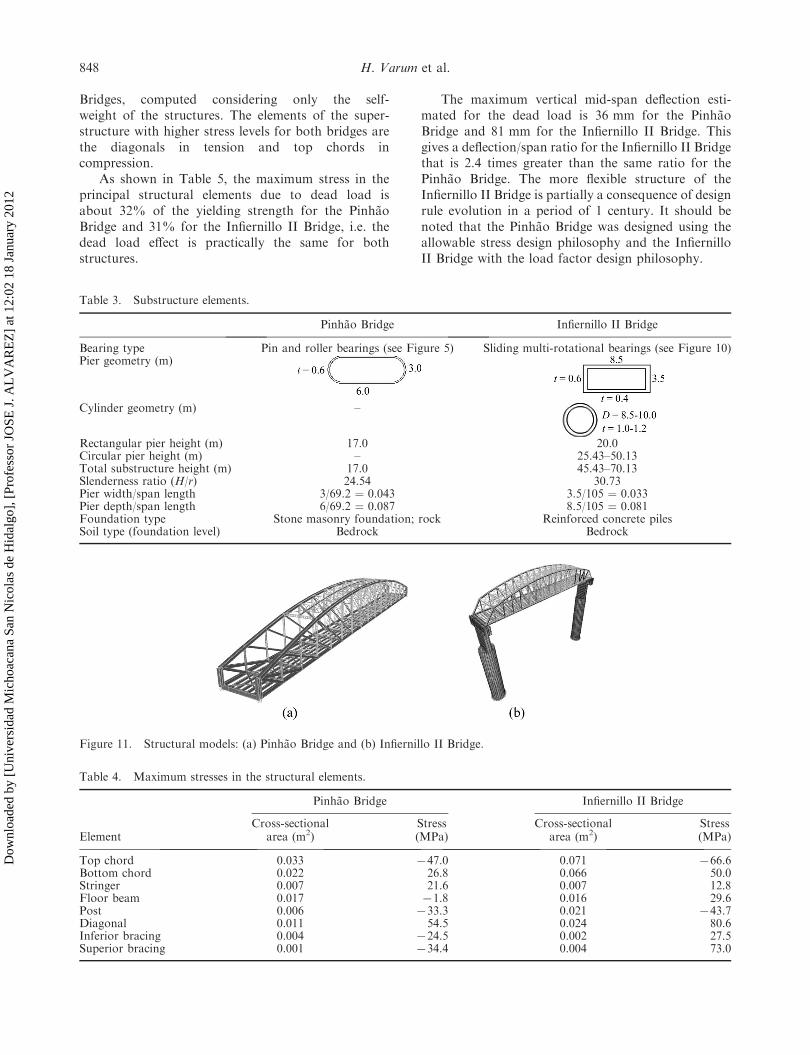
Bridges, computed considering only the self-weight of the structures. The elements of the super-structure with higher stress levels for both bridges arethe diagonals in tension and top chords incompression.
As shown in Table 5, the maximum stress in theprincipal structural elements due to dead load isabout 32% of the yielding strength for the PinhaoBridge and 31% for the Infiernillo II Bridge, i.e. thedead load effect is practically the same for bothstructures.
The maximum vertical mid-span deflection esti-mated for the dead load is 36 mm for the PinhaoBridge and 81 mm for the Infiernillo II Bridge. Thisgives a deflection/span ratio for the Infiernillo II Bridgethat is 2.4 times greater than the same ratio for thePinhao Bridge. The more flexible structure of theInfiernillo II Bridge is partially a consequence of designrule evolution in a period of 1 century. It should benoted that the Pinhao Bridge was designed using theallowable stress design philosophy and the InfiernilloII Bridge with the load factor design philosophy.
Figure 11. Structural models: (a) Pinhao Bridge and (b) Infiernillo II Bridge.
Table 4. Maximum stresses in the structural elements.
Pinhao Bridge Infiernillo II Bridge
ElementCross-sectional
area (m2)Stress(MPa)
Cross-sectionalarea (m2)
Stress(MPa)
Top chord 0.033 747.0 0.071 766.6Bottom chord 0.022 26.8 0.066 50.0Stringer 0.007 21.6 0.007 12.8Floor beam 0.017 71.8 0.016 29.6Post 0.006 733.3 0.021 743.7Diagonal 0.011 54.5 0.024 80.6Inferior bracing 0.004 724.5 0.002 27.5Superior bracing 0.001 734.4 0.004 73.0
Table 3. Substructure elements.
Pinhao Bridge Infiernillo II Bridge
Bearing type Pin and roller bearings (see Figure 5) Sliding multi-rotational bearings (see Figure 10)Pier geometry (m)
Cylinder geometry (m) –
Rectangular pier height (m) 17.0 20.0Circular pier height (m) – 25.43–50.13Total substructure height (m) 17.0 45.43–70.13Slenderness ratio (H/r) 24.54 30.73Pier width/span length 3/69.2 ¼ 0.043 3.5/105 ¼ 0.033Pier depth/span length 6/69.2 ¼ 0.087 8.5/105 ¼ 0.081Foundation type Stone masonry foundation; rock Reinforced concrete pilesSoil type (foundation level) Bedrock Bedrock
848 H. Varum et al.
Dow
nloa
ded
by [
Uni
vers
idad
Mic
hoac
ana
San
Nic
olas
de
Hid
algo
], [
Prof
esso
r JO
SE J
. AL
VA
RE
Z]
at 1
2:02
18
Janu
ary
2012
4.2. Seismic analysis
With the aim of evaluating and comparing the seismicperformance of the Pinhao and Infiernillo II Bridges,the structural models of both bridges were subjected tovarious levels of seismic loading. A modal spectralanalysis was developed according to the design spectrapresented by RSA and CFE codes.
4.2.1. Natural frequencies
The initial analyses were performed by considering thesuperstructure supported on the bearings fixed at thebase, without piers. This idealisation is justifiedbecause of the extremely high stiffness of the sub-structure of the Pinhao Bridge.
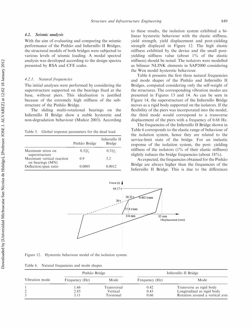
The sliding multi-rotational bearings on theInfiernillo II Bridge show a stable hysteretic andnon-degradation behaviour (Munoz 2003). According
to these results, the isolation system exhibited a bi-linear hysteretic behaviour with the elastic stiffness,yield strength, yield displacement and post-yieldingstrength displayed in Figure 12. The high elasticstiffness exhibited by the device and the small post-yielding stiffness value (about 1% of the elasticstiffness) should be noted. The isolators were modelledas bilinear NLINK elements in SAP2000 consideringthe Wen model hysteretic behaviour.
Table 6 presents the first three natural frequenciesand mode shapes of the Pinhao and Infiernillo IIBridges, computed considering only the self-weight ofthe structures. The corresponding vibration modes arepresented in Figures 13 and 14. As can be seen inFigure 14, the superstructure of the Infiernillo Bridgemoves as a rigid body supported on the isolators. If theflexibility of the piers was incorporated into the model,the third mode would correspond to a transversedisplacement of the piers with a frequency of 0.68 Hz.
The frequencies of the Infiernillo II Bridge shown inTable 6 corresponds to the elastic range of behaviour ofthe isolation system, hence they are related to theservice-limit state of the bridge. For an inelasticresponse of the isolation system, the post- yieldingstiffness of the isolators (1% of their elastic stiffness)slightly reduces the bridge frequencies (about 18%).
As expected, the frequencies obtained for the PinhaoBridge are always higher than the frequencies of theInfiernillo II Bridge. This is due to the differences
Table 5. Global response parameters for the dead load.
Pinhao BridgeInfiernillo II
Bridge
Maximum stress onsuperstructure
0.32fy 0.31fy
Maximum vertical reactionon bearings (MN)
0.9 3.2
Deflection/span ratio 0.0005 0.0012
Figure 12. Hysteretic behaviour model of the isolation system.
Table 6. Natural frequencies and mode shapes.
Vibration mode
Pinhao Bridge Infiernillo II Bridge
Frequency (Hz) Mode Frequency (Hz) Mode
1 1.66 Transversal 0.42 Transverse as rigid body2 2.85 Vertical 0.43 Longitudinal as rigid body3 3.11 Torsional 0.66 Rotation around a vertical axis
Structure and Infrastructure Engineering 849
Dow
nloa
ded
by [
Uni
vers
idad
Mic
hoac
ana
San
Nic
olas
de
Hid
algo
], [
Prof
esso
r JO
SE J
. AL
VA
RE
Z]
at 1
2:02
18
Janu
ary
2012

between the span length, the height/span ratio andmostly because of the flexibility of the pier-isolatorssubsystem. For the Infiernillo II Bridge, the modeshapes are governed by the base isolator flexibility.
4.2.2. Seismic zone location of the bridges
The Portuguese code, RSA, divides the Portugueseterritory into four zones of seismicity, zones A, B, Cand D. Zone A represents the areas of more significantseismicity and zone D represents the areas of reducedseismic risk. In addition, the RSA considers three typesof soils: types I, II and III. In the analysis presented inthis paper, it is assumed that both bridges are locatedin zone A, in medium stiffness soil (type II).Additionally, the bridges were subjected to the seismicintensity corresponding to the design spectrum of theCFE (1993), for the highest level of seismicity inMexico (zone D) and soil type II, where the InfiernilloII Bridge is actually located.
4.2.3. Seismic actions
The RSA establishes two types of seismic actions, onerepresenting earthquakes of moderate magnitude andsmall focal distance (seismic action type 1) and theother representing earthquakes of higher magnitudeand higher focal distance (seismic action type 2). InFigure 15, the design spectra (damping ¼ 2%) for thetwo action types and the acceleration level for thefundamental vibration mode of the bridges are shown.In Figure 16, the CFE design spectra for a 5%damping coefficient is illustrated. In Table 7, spectralaccelerations, estimated with both codes and for bothstructures are presented for the corresponding funda-mental frequencies (f).
The Pinhao Bridge is exposed to greater accelera-tions for the three seismic spectra considered as aconsequence of its great stiffness. The first modeaccelerations for the Infiernillo Bridge are 34%, 45%and 39% of the accelerations for the Pinhao Bridge.
Figure 13. First three vibration modes of the Pinhao Bridge.
Figure 14. First three vibration modes of the Infiernillo II Bridge.
850 H. Varum et al.
Dow
nloa
ded
by [
Uni
vers
idad
Mic
hoac
ana
San
Nic
olas
de
Hid
algo
], [
Prof
esso
r JO
SE J
. AL
VA
RE
Z]
at 1
2:02
18
Janu
ary
2012
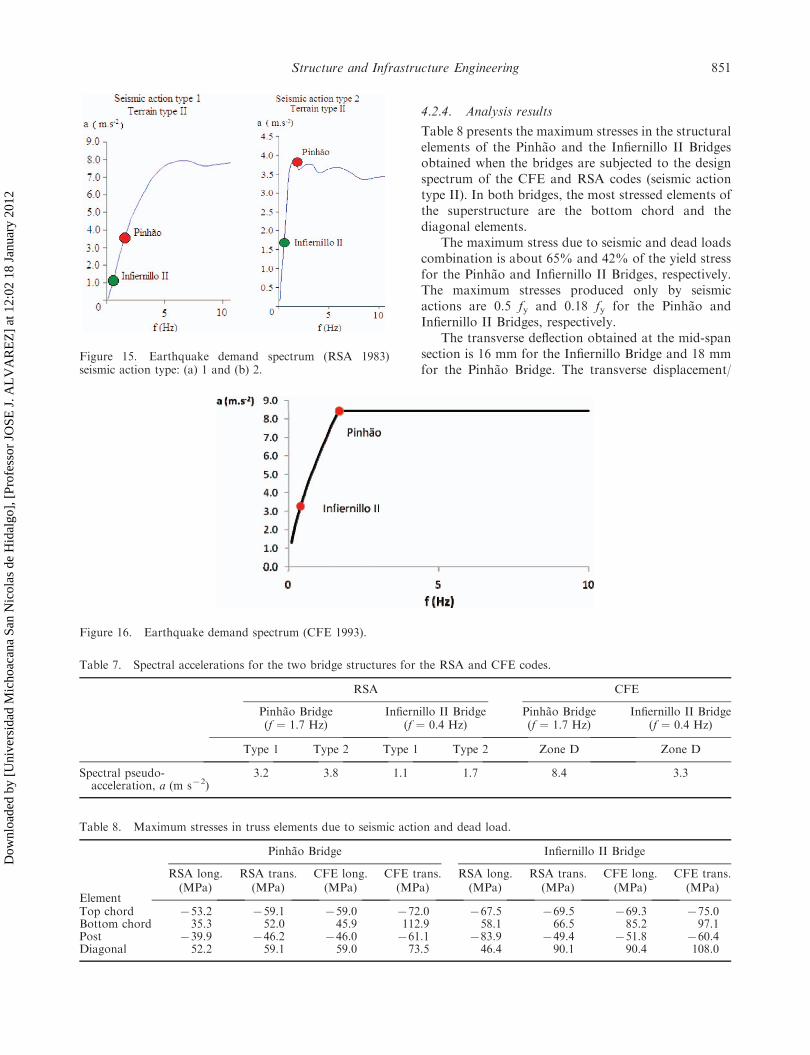
4.2.4. Analysis results
Table 8 presents the maximum stresses in the structuralelements of the Pinhao and the Infiernillo II Bridgesobtained when the bridges are subjected to the designspectrum of the CFE and RSA codes (seismic actiontype II). In both bridges, the most stressed elements ofthe superstructure are the bottom chord and thediagonal elements.
The maximum stress due to seismic and dead loadscombination is about 65% and 42% of the yield stressfor the Pinhao and Infiernillo II Bridges, respectively.The maximum stresses produced only by seismicactions are 0.5 fy and 0.18 fy for the Pinhao andInfiernillo II Bridges, respectively.
The transverse deflection obtained at the mid-spansection is 16 mm for the Infiernillo Bridge and 18 mmfor the Pinhao Bridge. The transverse displacement/
Figure 16. Earthquake demand spectrum (CFE 1993).
Table 7. Spectral accelerations for the two bridge structures for the RSA and CFE codes.
RSA CFE
Pinhao Bridge(f ¼ 1.7 Hz)
Infiernillo II Bridge(f ¼ 0.4 Hz)
Pinhao Bridge(f ¼ 1.7 Hz)
Infiernillo II Bridge(f ¼ 0.4 Hz)
Type 1 Type 2 Type 1 Type 2 Zone D Zone D
Spectral pseudo-acceleration, a (m s72)
3.2 3.8 1.1 1.7 8.4 3.3
Table 8. Maximum stresses in truss elements due to seismic action and dead load.
Element
Pinhao Bridge Infiernillo II Bridge
RSA long. RSA trans. CFE long. CFE trans. RSA long. RSA trans. CFE long. CFE trans.(MPa) (MPa) (MPa) (MPa) (MPa) (MPa) (MPa) (MPa)
Top chord 753.2 759.1 759.0 772.0 767.5 769.5 769.3 775.0Bottom chord 35.3 52.0 45.9 112.9 58.1 66.5 85.2 97.1Post 739.9 746.2 746.0 761.1 783.9 749.4 751.8 760.4Diagonal 52.2 59.1 59.0 73.5 46.4 90.1 90.4 108.0
Figure 15. Earthquake demand spectrum (RSA 1983)seismic action type: (a) 1 and (b) 2.
Structure and Infrastructure Engineering 851
Dow
nloa
ded
by [
Uni
vers
idad
Mic
hoac
ana
San
Nic
olas
de
Hid
algo
], [
Prof
esso
r JO
SE J
. AL
VA
RE
Z]
at 1
2:02
18
Janu
ary
2012
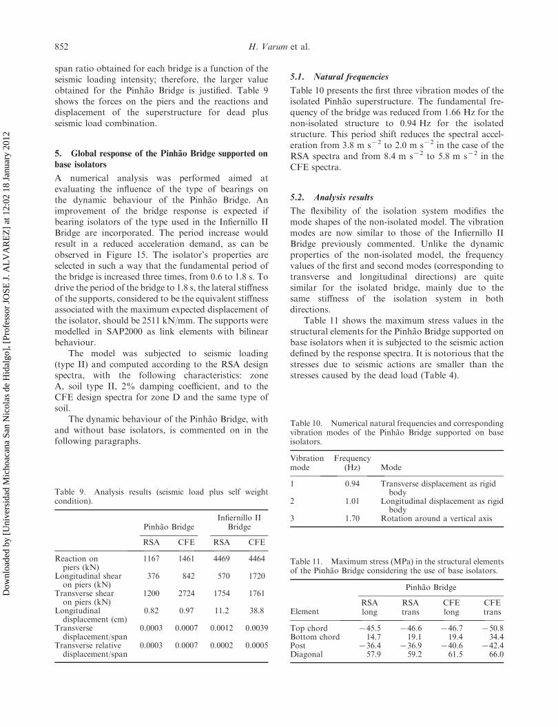
span ratio obtained for each bridge is a function of theseismic loading intensity; therefore, the larger valueobtained for the Pinhao Bridge is justified. Table 9shows the forces on the piers and the reactions anddisplacement of the superstructure for dead plusseismic load combination.
5. Global response of the Pinhao Bridge supported on
base isolators
A numerical analysis was performed aimed atevaluating the influence of the type of bearings onthe dynamic behaviour of the Pinhao Bridge. Animprovement of the bridge response is expected ifbearing isolators of the type used in the Infiernillo IIBridge are incorporated. The period increase wouldresult in a reduced acceleration demand, as can beobserved in Figure 15. The isolator’s properties areselected in such a way that the fundamental period ofthe bridge is increased three times, from 0.6 to 1.8 s. Todrive the period of the bridge to 1.8 s, the lateral stiffnessof the supports, considered to be the equivalent stiffnessassociated with the maximum expected displacement ofthe isolator, should be 2511 kN/mm. The supports weremodelled in SAP2000 as link elements with bilinearbehaviour.
The model was subjected to seismic loading(type II) and computed according to the RSA designspectra, with the following characteristics: zoneA, soil type II, 2% damping coefficient, and to theCFE design spectra for zone D and the same type ofsoil.
The dynamic behaviour of the Pinhao Bridge, withand without base isolators, is commented on in thefollowing paragraphs.
5.1. Natural frequencies
Table 10 presents the first three vibration modes of theisolated Pinhao superstructure. The fundamental fre-quency of the bridge was reduced from 1.66 Hz for thenon-isolated structure to 0.94 Hz for the isolatedstructure. This period shift reduces the spectral accel-eration from 3.8 m s72 to 2.0 m s72 in the case of theRSA spectra and from 8.4 m s72 to 5.8 m s72 in theCFE spectra.
5.2. Analysis results
The flexibility of the isolation system modifies themode shapes of the non-isolated model. The vibrationmodes are now similar to those of the Infiernillo IIBridge previously commented. Unlike the dynamicproperties of the non-isolated model, the frequencyvalues of the first and second modes (corresponding totransverse and longitudinal directions) are quitesimilar for the isolated bridge, mainly due to thesame stiffness of the isolation system in bothdirections.
Table 11 shows the maximum stress values in thestructural elements for the Pinhao Bridge supported onbase isolators when it is subjected to the seismic actiondefined by the response spectra. It is notorious that thestresses due to seismic actions are smaller than thestresses caused by the dead load (Table 4).
Table 9. Analysis results (seismic load plus self weightcondition).
Pinhao BridgeInfiernillo II
Bridge
RSA CFE RSA CFE
Reaction onpiers (kN)
1167 1461 4469 4464
Longitudinal shearon piers (kN)
376 842 570 1720
Transverse shearon piers (kN)
1200 2724 1754 1761
Longitudinaldisplacement (cm)
0.82 0.97 11.2 38.8
Transversedisplacement/span
0.0003 0.0007 0.0012 0.0039
Transverse relativedisplacement/span
0.0003 0.0007 0.0002 0.0005
Table 10. Numerical natural frequencies and correspondingvibration modes of the Pinhao Bridge supported on baseisolators.
Vibrationmode
Frequency(Hz) Mode
1 0.94 Transverse displacement as rigidbody
2 1.01 Longitudinal displacement as rigidbody
3 1.70 Rotation around a vertical axis
Table 11. Maximum stress (MPa) in the structural elementsof the Pinhao Bridge considering the use of base isolators.
Element
Pinhao Bridge
RSAlong
RSAtrans
CFElong
CFEtrans
Top chord 745.5 746.6 746.7 750.8Bottom chord 14.7 19.1 19.4 34.4Post 736.4 736.9 740.6 742.4Diagonal 57.9 59.2 61.5 66.0
852 H. Varum et al.
Dow
nloa
ded
by [
Uni
vers
idad
Mic
hoac
ana
San
Nic
olas
de
Hid
algo
], [
Prof
esso
r JO
SE J
. AL
VA
RE
Z]
at 1
2:02
18
Janu
ary
2012

Regarding the maximum stress in the structuralelements, the use of base isolators produces the stressratios presented in Table 12. In general, the use ofbase isolators led to a reduction of the maximumstresses. The structural elements most sensitive to thechange of bearings conditions are the bottom chords.This is probably due to the higher restriction of thebridge’s displacements imposed by the original bear-ings. When the Pinhao Bridge is isolated, a stressreduction of up to 43% was obtained. The stressdecrease is greater in transverse direction, while in thelongitudinal direction, the maximum reduction is24%. The CFE/RSA spectral acceleration ratiocorresponding to the non-isolated bridge is 1.32,while this ratio is reduced to 1.15 for the isolatedbridge, showing the minor influence of the seismicaction when the isolators are incorporated into thebridge.
Table 13 shows the forces on the piers and thereactions and displacement of the isolated super-structure for the dead plus seismic load combination.The response ratio of the original structure versusthe isolated one is also shown. The large ratioobtained for longitudinal shear on the piers, mainlydue to the longitudinal movement restriction ofbearings in the original model, is remarkable. It isalso important to note that the transverse relativedisplacement/span ratios of the Pinhao Bridge arequite similar to those obtained in the isolatedInfiernillo II Bridge model, despite the differences inlength of both bridges.
6. Conclusions
Two bridges, built in different periods with similargeometrical characteristics and almost the same stresslevels under dead loads, have been analysed from thepoint of view of their seismic response. The followingconclusions can be drawn:
. As a result of the comparative study, it is possibleto affirm that the truss structural system of bothbridges is very similar. The use of a light-gaugesteel deck is the main difference in both super-structures. The vertical behaviour of the bridgesis also quite similar, showing the main differencerelated to their seismic performance, the lack ofseismic details and the massive substructure usedin the Pinhao Bridge.
. In spite of the major span length and width of theInfiernillo Bridge, the height/span ratio is 46% ofthe Pinhao Bridge ratio. This difference reveals,not only the increase on the material strength,but also the confidence of the design, analysisand construction methods available at the timethe bridges were constructed.
. The same conclusion can be drawn regarding thepier slenderness ratio and the pier dimension/span ratio, despite the taller piers of the InfiernilloII Bridge and the high seismicity of the site wherethe Infiernillo II Bridge is located. As was usualfor a bridge located in a low seismicity areaconstructed 100 years ago, no transverse restrai-ners (shear keys) were used, nor was a minimumseat length dimension considered.
. The frequencies of the Pinhao Bridge are alwayshigher than the frequencies of the Infiernillo IIBridge as a result of the differences between thespan length, the height/span ratio and mostlybecause of the flexibility of the pier-isolatorssubsystem.
. Seismic stress demands in the Pinhao Bridge arelarger than those of the Infiernillo II Bridge forthe three spectra considered, exposing thedifference in dynamic properties in both bridges.
Table 12. Ratio of maximum stress with and withoutisolators.
Element
Pinhao Bridge
RSAlong.
RSAtrans.
CFElong.
CFEtrans.
Top chord 1.24 1.15 1.24 1.43Bottom chord 2.40 2.72 2.37 3.28Post 1.24 1.08 1.13 1.42Diagonal 1.19 1.09 1.12 1.35
Table 13. Isolated Pinhao model (seismic load plus self-weight condition).
Pinhao Bridge Original/isolated ratio
RSA CFE RSA CFE
Reaction on piers (kN) 1940 2218 1.23 1.34Longitudinal shear on piers (kN) 238 774 12.66 7.91Transverse shear on piers (kN) 224 748 3.96 1.98Longitudinal displacement (cm) 4.91 15.68 0.22 0.08Transverse displacement/span 0.0007 0.0007 0.43 1.00Transverse relative displacement/span 0.0001 0.00004 3 17.5
Structure and Infrastructure Engineering 853
Dow
nloa
ded
by [
Uni
vers
idad
Mic
hoac
ana
San
Nic
olas
de
Hid
algo
], [
Prof
esso
r JO
SE J
. AL
VA
RE
Z]
at 1
2:02
18
Janu
ary
2012
Even though there were similar stresses in bothbridges caused by the dead load, the maximumstresses produced by seismic actions are morethan 2.7 times for the Pinhao Bridge.
. An important stress reduction is obtained whenthe Pinhao Bridge is isolated. The stress decreaseis greater in the transverse direction. The CFE/RSA spectral acceleration ratio corresponding tothe non-isolated Pinhao Bridge is 1.32, while thisratio is reduced to 1.15 for the isolated bridge,showing the minor influence of the seismic actionwhen the isolators are incorporated into thebridge.
. The comparative analysis, in terms of seismicperformance of the two bridges, confirmed thatthe incorporation of base isolators resulted in asignificant reduction of seismic vulnerability andin the improvement of global structural beha-viour of the Pinhao Bridge. Similar results can beexpected in other bridges if this retrofittingtechnique is adopted.
Acknowledgements
The authors would like to acknowledge the GEG – Gabinetede Estruturas e Geotecnia Lda (Portugal), the OPWAYEngenharia, S.A. and the EP – Estradas de Portugal S.A.(Portugal), particularly Eng. Antonio Campos e Matos, Eng.Alberto Goncalves and Eng. Eduardo Andrade Gomes,respectively, for the data related to the Pinhao Bridge,inspections, assessment, geometry and material characterisa-tion results.
References
Aguilar, I., 2006. Comportamiento dinamico de un puentecon aisladores de base histereticos. Master Thesis,UMSNH, Mexico (in Spanish).
American Association of State Highway and TransportationOfficials (AASHTO), 1998. LRFD bridge design specifi-cations. 2nd ed. Washington, DC: AASHTO.
Astaneh-Asl, H., Bolt, B., Mc Mullin, K., and Cho, S., 1994.Seismic performance of steel bridges during the NorthridgeEarthquake. Department of Civil Engineering, Universityof California at Berkeley, UCB/CE-Steel-94/0.
Buckle, I.G., 2000. Passive control of structures for seismicloads. In: Proceedings of the 12th world conference onearthquake engineering, Auckland, New Zealand. paper2825.
Buckle, I.G. and Mayes, R.L., 1989. The application ofseismic isolation to bridges. In: Structures congress 089,seismic engineering: research and practice. New York,NY: ASCE, 633–642.
Comision Federal de Electricidad (CFE), 1993. Manual dediseno de obras civiles de la comision federal deelectricidad, diseno por sismo. Instituto de InvestigacionesElectricas de la CFE (in Spanish).
Eshghi, S. and Ahari, M.N., 2005. Performance of transpor-tation systems in the 2003 Bam, Iran, Earthquake.Earthquake Spectra, 21 (S1), S455–S468.
Faria, R.G., 2008. Procedimentos com vista a monitorizacaode estruturas – teste do sonar e ensaio da Ponte do Pinhao.Thesis (Masters). Faculty of Engineering, University ofPorto, Porto, Portugal (in Portuguese).
Hashimoto, S., Fujino, Y., and Abe, M., 2005. Damageanalysis of Hanshin Expressway Viaducts during 1995Kobe Earthquake. II: damage mode of single reinforcedconcrete piers. Journal of Bridge Engineering, 10 (1), 54–60.
Hsu, Y.T. and Fu, C.C., 2004. Seismic effect on highwaybridges in Chi Chi earthquake. Journal of Performance ofConstructed Facilities, 18 (1), 47–53.
Jara, M. and Casas, J.R., 2002. Criteria for the design ofisolated bridges, Monografıa CIMNE IS-49. CentroInternacional de Metodos Numericos en Ingenierıa,Barcelona, Espana (in Spanish).
Jara, M., Alvarez, J.J., and Jara, J.M., 2006a. Algunasdeficiencias de puentes sısmicamente vulnerables. In:Memorias del XV Congreso Nacional de IngenierıaEstructural, Puerto Vallarta, Jalisco (in Spanish).
Jara, M., Jara, J.M., and Casas, J.R., 2006b. Seismicprotection of structures with control devices, Morelia,Michoacan. Mexico: Fondo Editorial Morevallado(in Spanish).
Jara, J.M., Jara, M., and Hernandez, H., 2008a. Expectedbehavior of the Infiernillo II Bridge in Mexico. In: Sixthnational conference on bridges and highways, Charleston,South Caroline, USA, paper ID 3A1-3.
Jara, J.M., Galvan, A., Aguilar, I., Jara, M., andHernandez, H., 2008b. Seismic vulnerability of anisolated bridge in Mexico. In: 14th world conference onearthquake engineering, Beijing, China, paper ID 05-02-0109.
Jesus, A.M.P., Figueiredo, M.A.V., Ribeiro, A.S., Castro,P.M.S.T., and Fernandes, A.A., 2009. Residual LifetineAssessment of an Ancient Riveted Steel Road Bridge.Strain, 14. doi: 10.1111/j.1475-1305.2008.00596.x.
Kawashima, K., 2002. Damage of bridges resulting fromfault rupture in the 1999 Kocaeli and Dunce, Turkeyearthquakes and the 1999 Chi-Chi, Taiwan earthquake.Structural Engineering/Earthquake Engineering, 19 (2),179s–197s.
Kelly, J.M., 1986. Seismic base isolation: a review andbibliography. Soil Dynamics and Earthquake Engineering,5, 202–216.
Kunde, M.C. and Jangid, R.S., 2003. Seismic behavior ofisolated bridges: a state-of-the art review. ElectronicJournal of Structural Engineering, 3, 140–164.
Martins, M., Torres, M., and Freire, P., 1998. PontesRodoviarias Metalicas. Junta Autonoma de Estradas,Portugal, ISBN 972-8498-03-9 (in Portuguese).
Moehle, J.P. and Eberhard, M.O., 2003. Earthquakedamage to bridges. In: W.-F. Chen and L. Duan, eds.Bridge Engineering. Seismic Design. CRC Press, pp. 2-1-2-33.
Munoz, D., 2003. A bridge seismic behavior supported onmultirotational isolation system. Master Thesis, UNAM,Mexico (in Spanish).
Pinto, J., Santos, N., and Fonseca, R., 2005. Ponte metalicado Pinhao – inspeccao e elaboracao do estudo dereabilitacao da obra de arte. Porto, Portugal (inPortuguese).
RSA, 1983. Regulamento de Seguranca e accoes paraestruturas de edifıcios e pontes, Decreto-Lei no 235/83,de 31 de Maio. Porto, Portugal: Porto Editora (inPortuguese).
854 H. Varum et al.
Dow
nloa
ded
by [
Uni
vers
idad
Mic
hoac
ana
San
Nic
olas
de
Hid
algo
], [
Prof
esso
r JO
SE J
. AL
VA
RE
Z]
at 1
2:02
18
Janu
ary
2012

SAP2000, 2006. Linear and nonlinear static and dynamicanalysis and design of three-dimensional structures, Ver-sion 11. Computer and Structures, Inc.
Skinner, R.I., Robinson, W.H., and McVerry, G.H., 1993.An introduction to seismic isolation. Chichester, UK: JohnWiley & Sons.
Soong, T.T. and Dargush, G.F., 1997. Passive energydissipation systems in structural engineering. Chichester,UK: John Wiley & Sons.
Soong, T.T. and Spencer, B.F., 2002. Supplemental energydissipation: state-of-the-art and state-of-the-practice.Engineering Structures, 24 (3), 243–259.
Uang, C., Elgmanal, A., Li, W., and Chou, C., 1999. Ji-Ji,Taiwan earthquake of September 21, 1999: a briefreconnaissance report. Department of Structural Engi-neering, University of California, San Diego. Availableonline from: http://www.structures.ucsd.edu/taiwaneq/taiwan1.htm
Structure and Infrastructure Engineering 855
Dow
nloa
ded
by [
Uni
vers
idad
Mic
hoac
ana
San
Nic
olas
de
Hid
algo
], [
Prof
esso
r JO
SE J
. AL
VA
RE
Z]
at 1
2:02
18
Janu
ary
2012