Comparative Design & Analysis of a Mosque Using Steel and ...
253
1 | Page Prince Mohammad Bin Fahd University College of Engineering Department of Civil Engineering Senior Design Project (ASSE III) Fall 2015 Comparative Design & Analysis of a Mosque Using Steel and Reinforced Concrete Presented by: Hussain Ahmed Alabuo 200900408 Mohammed Essa Alabuo 200900403 Abdullan Nami Alnami 200901322 Mufarreh Mohammed Alshammary 201101147 Supervised by: Dr. Andi Asiz Eng. Danish Ahmed
-
Upload
khangminh22 -
Category
Documents
-
view
4 -
download
0
Transcript of Comparative Design & Analysis of a Mosque Using Steel and ...
1 | P a g e
Prince Mohammad Bin Fahd University
College of Engineering
Department of Civil Engineering
Senior Design Project (ASSE III)
Fall 2015
Comparative Design & Analysis of a Mosque Using
Steel and Reinforced Concrete
Presented by:
Hussain Ahmed Alabuo 200900408
Mohammed Essa Alabuo 200900403
Abdullan Nami Alnami 200901322
Mufarreh Mohammed Alshammary 201101147
Supervised by:
Dr. Andi Asiz
Eng. Danish Ahmed

2 | P a g e
ACKNWOLDGEMENT
We take this opportunity to express our profound gratitude and deep regards to our supervisors Dr.
Andi Asiz and Eng. Danish Ahmed for their exemplary guidance, monitoring and constant
encouragement throughout this project. The blessing, help and guidance given by them shall carry us
a long way in the journey of life.
We also take this opportunity to express a deep sense of gratitude to the Dean of College of
Engineering Dr. Jamal Nayfeh for his cordial support, valuable information and guidance, which
helped us in completing our engineering degree.
We would like to thank all faculty members of civil engineering department: Dr. Omar Ouda, Dr. Alaa
Salman, and Dr. Abas for the valuable information provided by them in their respective fields. We are
grateful for their cooperation during our engineering study.
We would like to thank Almulhim Consulting Engineering represented by Eng. Mohammed Jamal for
assisting in the preliminary design of mosque by AutoCAD program which was used as the main
drawing for this project.
Lastly, we thank our families, friends and all citizens of Eastern Province for their constant
encouragement and help.

3 | P a g e
ABSTRACT
The Kingdom of Saudi Arabia has been applying the Shari`ah of Islam, acting in accordance with the
Holy Qur'an and Sunnah, and making judgments based on Allah’s Shari`ah. It also strives to propagate
and call people to Islam with wisdom and fair preaching.
This is the essential cornerstone of its system, duties, and obligations, to which it pays due attention.
The Basic Law of Saudi Arabia provides for deriving power from the Holy Qur'an and Sunnah, which
rule over this Law and all other laws of the Kingdom.
It also stipulates that the Kingdom should protect the Islamic creed, apply the Shari`ah, enjoin good,
forbid evil, and call people to Allah.
The Sectors of Islamic Affairs, Da`wah, Guidance, and Endowments have been among the outstanding
pillars and essential parts of the Kingdom. Since the foundations of the kingdom were laid by King
`Abdul `Aziz Al Saud and his sons after him, the Kingdom has established, sponsored, supported, and
developed large organizations for this purpose, flourishing in the era of the Custodian of the Two Holy
Mosques, his Crown Prince, and his Second Deputy Prime Minister.
Subsequently wherever the Muslim's have gone, they built Mosques for their needs in that community
and worship Allah. Moreover mosque indeed is a great example of traditional and long lasting
buildings which civil engineers do best making a strong, stable, and sustainable buildings.
Through our civil engineering study at Prince Mohammed bin Fahd University, as well as taking the
opportunity to apply what we have studied at the university level, we decided to choose the design of
the mosque. We make Comparative Design & Analysis of a Mosque Using Steel and Reinforced
Concrete Elements design and analysis ( figure 1), including calculation of the foundation.
Our project covered by several programs such as Etabs2015, Sap2000, AutoCAD, SkiCiv, LimCon,
and steel connections.
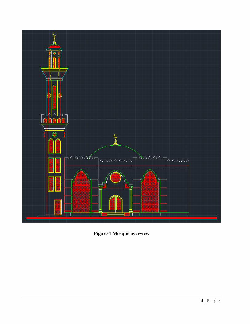
4 | P a g e
Figure 1 Mosque overview
5 | P a g e
Table of Contents
ACKNWOLDGEMENT .................................................................................................................... 2
ABSTRACT ......................................................................................................................................... 3
Table of Contents ................................................................................................................................ 5
Chapter 1: Introduction ................................................................................................................... 10
1.1 General ..................................................................................................................................... 10
1.2 The main objectives for our project are: .................................................................................. 11
1.3 Scope of the report: .................................................................................................................. 11
Chapter 2: Concrete .......................................................................................................................... 12
2.1 Loads Calculations: .................................................................................................................. 12
2.1.1 Types of loads:.................................................................................................................... 12
2.1.2 Load parameters and super imposed dead load: ................................................................. 14
2.1.3 Loads on slabs: ................................................................................................................... 14
2.2: Design of slabs ........................................................................................................................ 15
2.2.1 Types of Slab: ..................................................................................................................... 15
2.2.2 Steps to Design one way slab: ............................................................................................ 17
2.2.3 Slab Minimum Thickness: .................................................................................................. 17
2.2.4 Materials properties: ........................................................................................................... 17
2.2.5 Load Calculation: ............................................................................................................... 20
2.2.6 Flexural Design................................................................................................................... 21
2.3 Design of beams & sub beams: ................................................................................................ 26
2.3.1 Steps to Design Rectangular beam & sub beams: .............................................................. 27
2.3.2 Materials properties: ........................................................................................................... 27
2.3.3 Load calculation for sub beam: .......................................................................................... 27
2.3.4 Design of sub beams: .......................................................................................................... 28
2.3.5 Calculations of loads for beam: ....................................................................................... 39
2.3.6 Design of the beam: ......................................................................................................... 40
2.4 Design of columns .................................................................................................................... 46
2.4.1 Classification of columns: .................................................................................................. 46
2.4.3 Materials properties: ........................................................................................................ 49
2.4.4 Load Calculation: ............................................................................................................ 49
2.5 Design of dome ........................................................................................................................ 52
6 | P a g e
2.5.1 Classification of dome: .................................................................................................... 52
2.5.2 Calculations of dome: ...................................................................................................... 53
Chapter 3: Steel ................................................................................................................................. 59
3.1 Introduction: ............................................................................................................................. 61
3.2 Design Information: ................................................................................................................. 62
3.2.1 Applicable Design Codes: .................................................................................................. 62
3.2.2 Material specifications:....................................................................................................... 62
3.2.3 Load Combinations: ........................................................................................................... 63
3.3 Structural Analysis: .................................................................................................................. 64
3.3.1 Mezzanine floor beam (Girder 2-2): ................................................................................... 65
3.3.2 Roof beam (3DE): .............................................................................................................. 70
3.3.3 Dome beam (3BD): ............................................................................................................ 75
3.3.4 Column (2C): ...................................................................................................................... 80
3.4 Design: ...................................................................................................................................... 82
3.4.1 Mezzanine beam design (Girder 2-2): ................................................................................ 83
3.4.2 Roof beam design (3DE): ................................................................................................... 92
3.4.3 Dome beam design (3BD): ............................................................................................... 101
3.4.4 Column design (2C): ........................................................................................................ 110
3.4.5 ETABS drawings: ............................................................................................................. 119
3.5 Connection design: ................................................................................................................. 125
3.5.1 Connection of Mezzanine Floor: ...................................................................................... 126
3.5.2 Connection of Roof: ......................................................................................................... 140
Chapter 4: Foundation ................................................................................................................... 154
4.1 Introduction ............................................................................................................................ 154
4.2 Isolated foundation ................................................................................................................. 154
4.3 Design of Isolated Foundation: .............................................................................................. 155
Appendix .......................................................................................................................................... 162
Appendix A: Analysis & design report using ETABS 2015 ........................................................ 162
Appendix B: Steel design and modeling using ETABS 2015 ...................................................... 182
References ........................................................................................................................................ 253
7 | P a g e
List of figures Figure 1 Mosque overview ................................................................................................................... 4
Figure 2 One way slab; (a) classification; (b) reinforcement ............................................................. 15
Figure 3 Two way slab ........................................................................................................................ 16
Figure 4 1st Floor (Mezzanine floor) .................................................................................................. 18
Figure 5 Roof Floor ............................................................................................................................ 19
Figure 6 Force acting on sub-beam & reaction force ......................................................................... 29
Figure 7 Shear force ............................................................................................................................ 29
Figure 8 Bending moment .................................................................................................................. 30
Figure 9 Deflection ............................................................................................................................. 30
Figure 10 (3D) renderer and colored results ....................................................................................... 31
Figure 11 Force acting on sub-beam & reaction force. ...................................................................... 35
Figure 12 Shear force .......................................................................................................................... 35
Figure 13 Bending moment ................................................................................................................ 36
Figure 14 Deflection ........................................................................................................................... 36
Figure 15 (3D) renderer and colored results ....................................................................................... 37
Figure 16 Force acting on sub-beam & reaction force ....................................................................... 41
Figure 17 Shear force .......................................................................................................................... 41
Figure 18 Bending moment ................................................................................................................ 42
Figure 19 Deflection ........................................................................................................................... 42
Figure 20 (3D) renderer and colored results ....................................................................................... 43
Figure 21 Cross section for eccentrically loaded column. .................................................................. 46
Figure 22 Column selected for the sample of calculation is 2C Shown in the Figure ........................ 48
Figure 23 (3D) Dome structural design. ............................................................................................. 54
Figure 24 (3D) dome overview design. .............................................................................................. 55
Figure 25 Top view for 1st floor (mezzanine) .................................................................................... 56
Figure 26 Side view for 1st floor (mezzanine) ................................................................................... 57
Figure 27 Side view ............................................................................................................................ 57
Figure 28 Top view for Roof .............................................................................................................. 58
Figure 29 Front view ........................................................................................................................... 58
Figure 30 ETABS 3D drawing ........................................................................................................... 64
Figure 31 AutoCAD Drawing, for Grade 2 - Level 7m ...................................................................... 65
Figure 32 ETABS drawing, mezzanine floor, Girder 2 ...................................................................... 66
Figure 33 Input data from SkyCiv program for mezzanine floor beam ............................................. 67
Figure 34 Output data from SkyCiv program (moment) .................................................................... 68
Figure 35 Output data from SkyCiv program (shear) ......................................................................... 69
Figure 36 ETABS drawing, Roof, 3DE. ............................................................................................. 71
Figure 37 Input data from SkyCiv program for Roof beam ............................................................... 72
Figure 38 Output data from SkyCiv program (moment) .................................................................... 73
Figure 39 Output data from SkyCiv program (shear) ......................................................................... 74
8 | P a g e
Figure 40 ETABS drawing, Dome Beam (3BD). ............................................................................... 76
Figure 41 Input data from SkyCiv program for Dome beam.............................................................. 77
Figure 42 Output data from SkyCiv program (moment) .................................................................... 78
Figure 43 Output data from SkyCiv program (shear) ......................................................................... 79
Figure 44 ETABS drawing, Column 2C ............................................................................................. 81
Figure 45 Steel section properties (HE 500 B) ................................................................................... 88
Figure 46 Steel section properties (HE 400 A) ................................................................................... 97
Figure 47 Steel section properties (IPE 450) .................................................................................... 106
Figure 48 Steel section properties (HE 400 B) ................................................................................. 115
Figure 49 ETABS 3D model............................................................................................................. 119
Figure 50 Side view .......................................................................................................................... 119
Figure 51 Top view for mezzanine floor .......................................................................................... 120
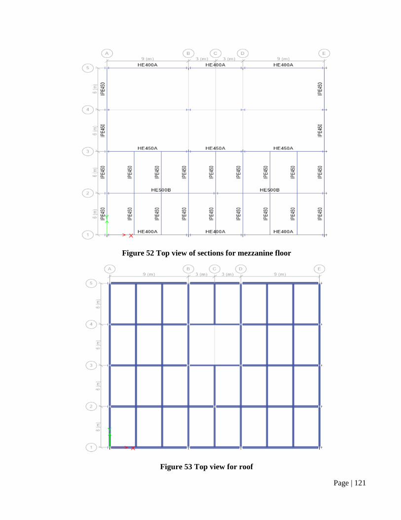
Figure 52 Top view of sections for mezzanine floor ........................................................................ 121
Figure 53 Top view for roof.............................................................................................................. 121
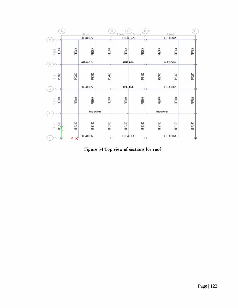
Figure 54 Top view of sections for roof ........................................................................................... 122
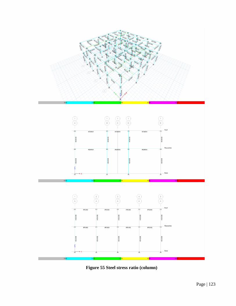
Figure 55 Steel stress ratio (column) ................................................................................................ 123
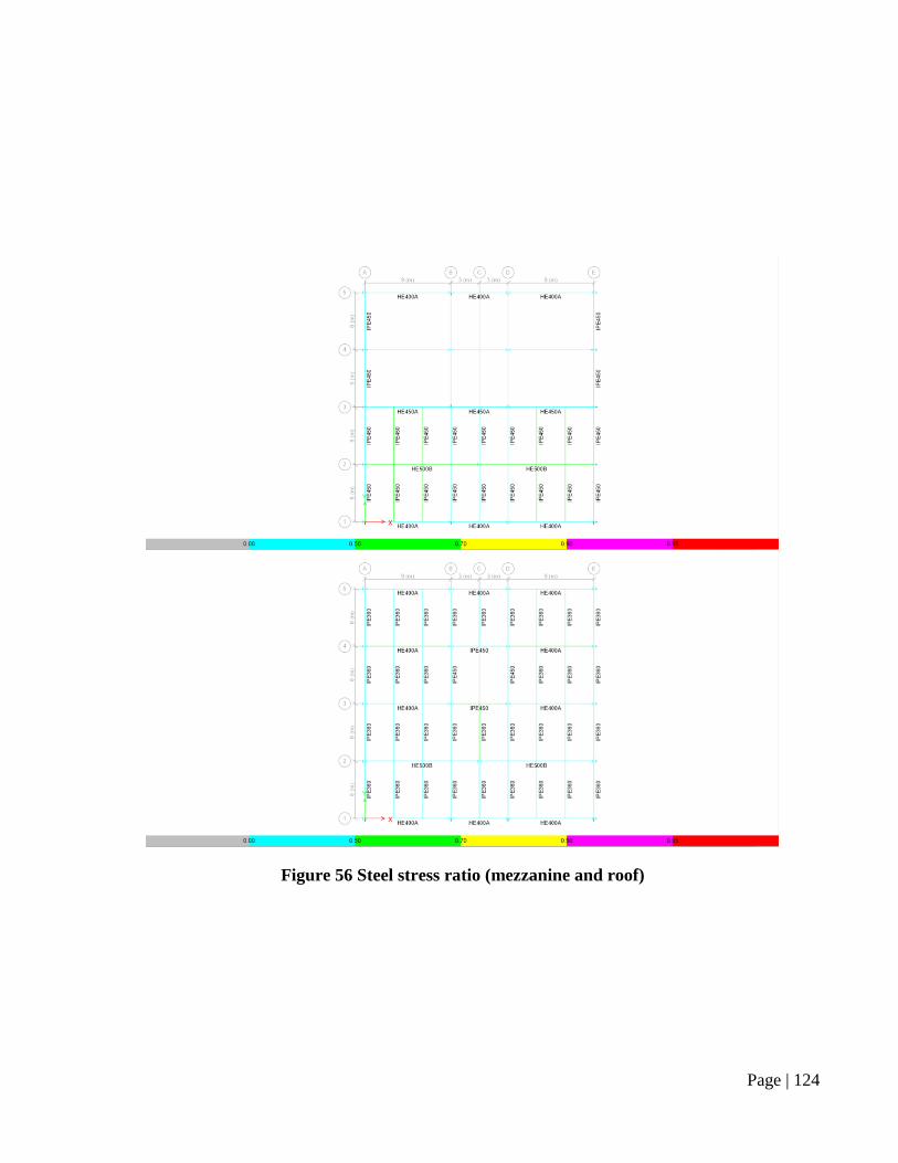
Figure 56 Steel stress ratio (mezzanine and roof) ............................................................................. 124
Figure 57 Mezzanine Floor plan - Connection ................................................................................. 126
Figure 58 Roof plan - Connection .................................................................................................... 140
Figure 59 Isolated Foundation .......................................................................................................... 154
Figure 60 Foundation thickness and height assumption ................................................................... 156
9 | P a g e
List of Tables
Table 1 Minimum thickness of one-way solid slabs ........................................................................... 17
Table 2 Properties ............................................................................................................................... 17
Table 3 Design of rectangular beam & sub-beam section for moment (simply supported beam) ..... 26
Table 4 Properties ............................................................................................................................... 27
Table 5 Properties ............................................................................................................................... 49
Table 6 Material specifications ........................................................................................................... 62
Table 7 Dead load ............................................................................................................................... 63
Table 8 Live load ................................................................................................................................ 63
Table 9 Ultimate load.......................................................................................................................... 63
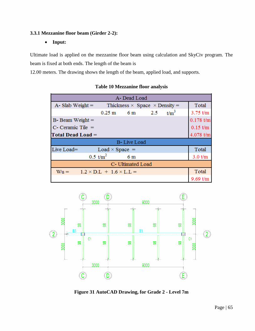
Table 10 Mezzanine floor analysis ..................................................................................................... 65
Table 11 Structural analysis for girder 2............................................................................................. 67
Table 12 Roof analysis for 3DE beam ................................................................................................ 70
Table 13 Structural analysis for 3DE beam ........................................................................................ 72
Table 14 Roof analysis for dome beam .............................................................................................. 75
Table 15 Structural analysis for 3BD beam ........................................................................................ 77
Table 16 Structural analysis for column ............................................................................................. 80
Table 17 Structural analysis for column ............................................................................................. 81
Table 18 Steel section properties (HE 500 B) .................................................................................... 83
Table 19 Steel section properties (HE 400 A) .................................................................................... 92
Table 20 Steel section properties (IPE 450) ..................................................................................... 101
Table 21 Steel section properties (HE 400 B) .................................................................................. 110

10 | P a g e
Chapter 1: Introduction
1.1 General
There are strict and detailed requirements in Sunni fiqh for a place of worship to be considered a
mosque, with places that do not meet these requirements regarded as musallas. There are stringent
restrictions on the uses of the area formally demarcated as the mosque (which is often a small portion
of the larger complex), and, in the Islamic Sharia law, after an area is formally designated as a mosque,
it remains so until the Last Day.
Many mosques have elaborate domes, minarets, and prayer halls, in varying styles of architecture.
Mosques originated on the Arabian Peninsula, but are now found in all inhabited continents. The
mosque serves as a place where Muslims can come together for salat (meaning "prayer") as well as a
center for information, education, and dispute settlement. The imam leads the congregation in prayer.
The mosque played a major part in the spread of education in the Muslim World, and the association
of the mosque with education remained one of its main characteristics throughout history, and, the
school became an indispensable appendage to the mosque. From the earliest days of Islam, the mosque
was the center of the Muslim community, a place for prayer, meditation, religious instruction, political
discussion, and a school. And anywhere Islam took hold, mosques were established, and basic
religious and educational instruction began. Once established, mosques developed into well-known
places of learning, often with hundreds, even thousands, of students, and frequently contained
important libraries In Iraq, pharmacology, engineering, astronomy and other subjects were taught in
the mosques of Baghdad, and students came from Syria, Persia and India to learn these sciences. While
at the Qarawiyin Mosque, there were courses on grammar, rhetoric, logic, mathematics, and
astronomy, and possibly history, geography and chemistry.
11 | P a g e
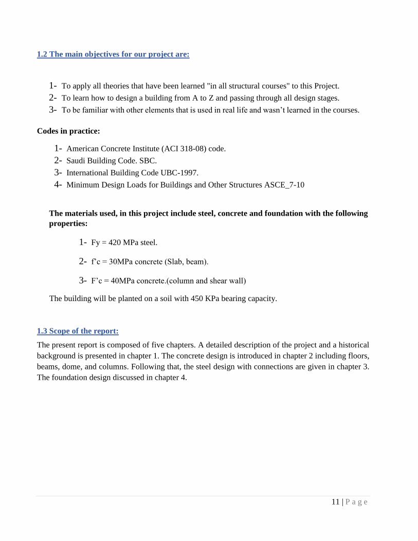
1.2 The main objectives for our project are:
1- To apply all theories that have been learned "in all structural courses" to this Project.
2- To learn how to design a building from A to Z and passing through all design stages.
3- To be familiar with other elements that is used in real life and wasn’t learned in the courses.
Codes in practice:
1- American Concrete Institute (ACI 318-08) code.
2- Saudi Building Code. SBC.
3- International Building Code UBC-1997.
4- Minimum Design Loads for Buildings and Other Structures ASCE_7-10
The materials used, in this project include steel, concrete and foundation with the following
properties:
1- Fy = 420 MPa steel.
2- f’c = 30MPa concrete (Slab, beam).
3- F’c = 40MPa concrete.(column and shear wall)
The building will be planted on a soil with 450 KPa bearing capacity.
1.3 Scope of the report:
The present report is composed of five chapters. A detailed description of the project and a historical
background is presented in chapter 1. The concrete design is introduced in chapter 2 including floors,
beams, dome, and columns. Following that, the steel design with connections are given in chapter 3.
The foundation design discussed in chapter 4.
12 | P a g e
Chapter 2: Concrete
2.1 Loads Calculations:
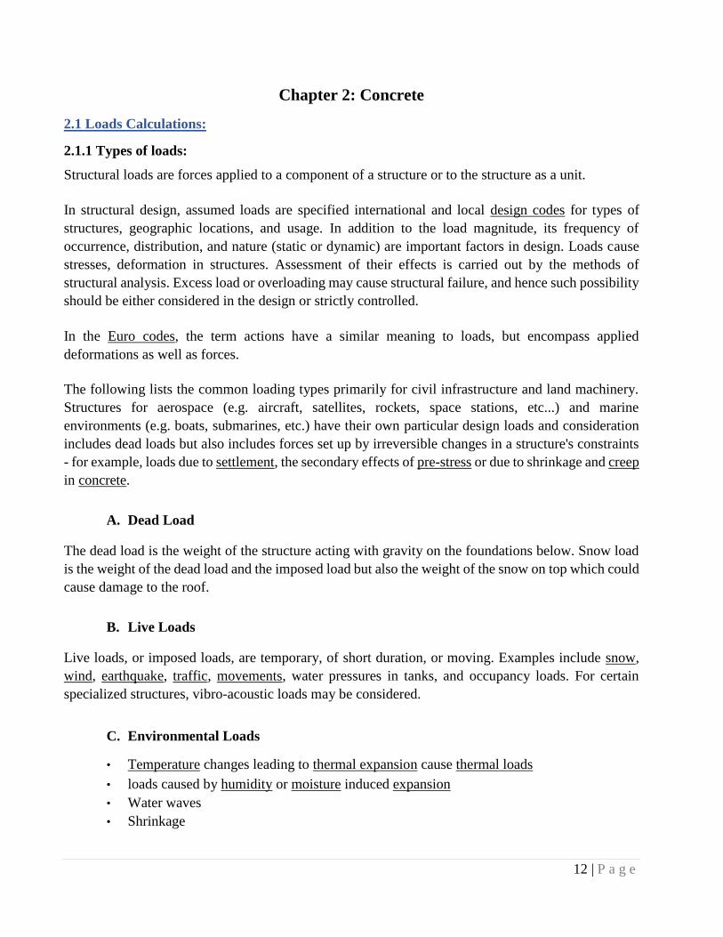
2.1.1 Types of loads:
Structural loads are forces applied to a component of a structure or to the structure as a unit.
In structural design, assumed loads are specified international and local design codes for types of
structures, geographic locations, and usage. In addition to the load magnitude, its frequency of
occurrence, distribution, and nature (static or dynamic) are important factors in design. Loads cause
stresses, deformation in structures. Assessment of their effects is carried out by the methods of
structural analysis. Excess load or overloading may cause structural failure, and hence such possibility
should be either considered in the design or strictly controlled.
In the Euro codes, the term actions have a similar meaning to loads, but encompass applied
deformations as well as forces.
The following lists the common loading types primarily for civil infrastructure and land machinery.
Structures for aerospace (e.g. aircraft, satellites, rockets, space stations, etc...) and marine
environments (e.g. boats, submarines, etc.) have their own particular design loads and consideration
includes dead loads but also includes forces set up by irreversible changes in a structure's constraints
- for example, loads due to settlement, the secondary effects of pre-stress or due to shrinkage and creep
in concrete.
A. Dead Load
The dead load is the weight of the structure acting with gravity on the foundations below. Snow load
is the weight of the dead load and the imposed load but also the weight of the snow on top which could
cause damage to the roof.
B. Live Loads
Live loads, or imposed loads, are temporary, of short duration, or moving. Examples include snow,
wind, earthquake, traffic, movements, water pressures in tanks, and occupancy loads. For certain
specialized structures, vibro-acoustic loads may be considered.
C. Environmental Loads
• Temperature changes leading to thermal expansion cause thermal loads
• loads caused by humidity or moisture induced expansion
• Water waves
• Shrinkage
13 | P a g e
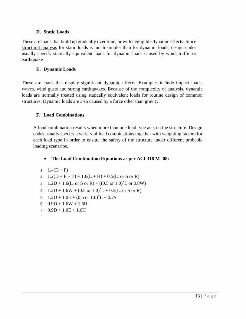
D. Static Loads
These are loads that build up gradually over time, or with negligible dynamic effects. Since
structural analysis for static loads is much simpler than for dynamic loads, design codes
usually specify statically-equivalent loads for dynamic loads caused by wind, traffic or
earthquake
E. Dynamic Loads
These are loads that display significant dynamic effects. Examples include impact loads,
waves, wind gusts and strong earthquakes. Because of the complexity of analysis, dynamic
loads are normally treated using statically equivalent loads for routine design of common
structures. Dynamic loads are also caused by a force other than gravity.
F. Load Combinations
A load combination results when more than one load type acts on the structure. Design
codes usually specify a variety of load combinations together with weighting factors for
each load type in order to ensure the safety of the structure under different probable
loading scenarios.
The Load Combination Equations as per ACI 318 M- 08:
1. 1.4(D + F)
2. 1.2(D + F + T) + 1.6(L + H) + 0.5(Lr or S or R)
3. 1.2D + 1.6(Lr or S or R) + ((0.5 or 1.0)*L or 0.8W)
4. 1.2D + 1.6W + (0.5 or 1.0)*L + 0.5(Lr or S or R)
5. 1.2D + 1.0E + (0.5 or 1.0)*L + 0.2S
6. 0.9D + 1.6W + 1.6H
7. 0.9D + 1.0E + 1.6H
14 | P a g e
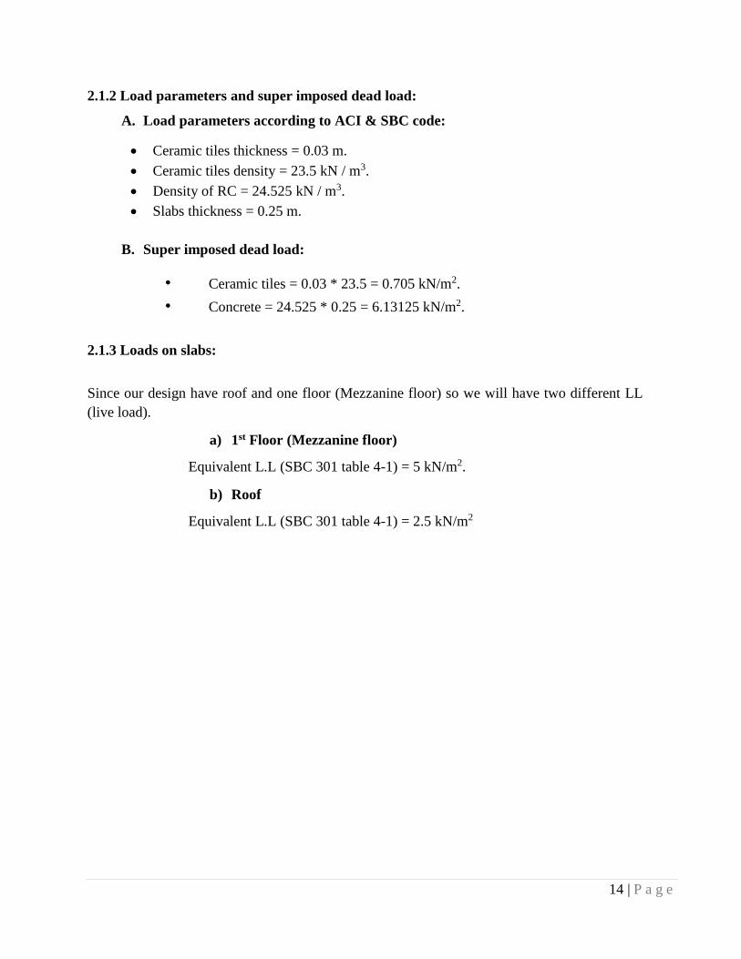
2.1.2 Load parameters and super imposed dead load:
A. Load parameters according to ACI & SBC code:
Ceramic tiles thickness = 0.03 m.
Ceramic tiles density = 23.5 kN / m3.
Density of RC = 24.525 kN / m3.
Slabs thickness = 0.25 m.
B. Super imposed dead load:
• Ceramic tiles = 0.03 * 23.5 = 0.705 kN/m2.
• Concrete = 24.525 * 0.25 = 6.13125 kN/m2.
2.1.3 Loads on slabs:
Since our design have roof and one floor (Mezzanine floor) so we will have two different LL
(live load).
a) 1st Floor (Mezzanine floor)
Equivalent L.L (SBC 301 table 4-1) = 5 kN/m2.
b) Roof
Equivalent L.L (SBC 301 table 4-1) = 2.5 kN/m2
15 | P a g e
2.2: Design of slabs
2.2.1 Types of Slab:
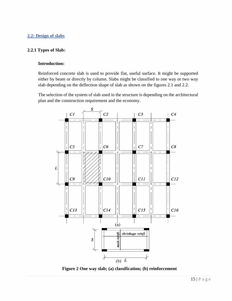
Introduction:
Reinforced concrete slab is used to provide flat, useful surface. It might be supported
either by beam or directly by column. Slabs might be classified to one way or two way
slab depending on the deflection shape of slab as shown on the figures 2.1 and 2.2.
The selection of the system of slab used in the structure is depending on the architectural
plan and the construction requirement and the economy.
Figure 2 One way slab; (a) classification; (b) reinforcement
16 | P a g e
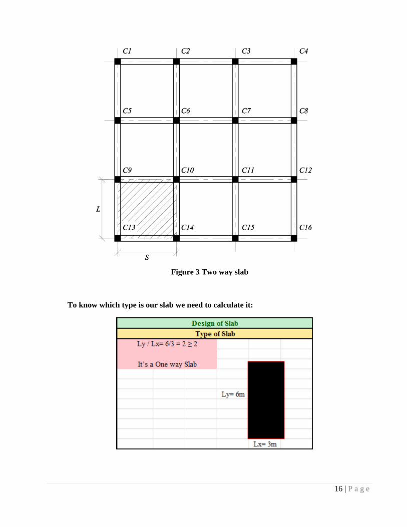
Figure 3 Two way slab
To know which type is our slab we need to calculate it:
17 | P a g e
2.2.2 Steps to Design one way slab:
Step 1: Determine the minimum required thickness of slab from table 9.5(c) ACI 318
Step 2: Determine the ultimate loads that effect on the slab.
Step 3: Determine the total factored static moment.
Step 4: Determine the required area of steel with the required
spacing.
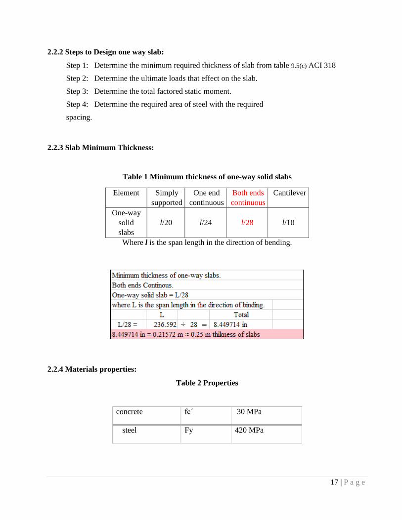
2.2.3 Slab Minimum Thickness:
Table 1 Minimum thickness of one-way solid slabs
Element Simply
supported
One end
continuous
Both ends
continuous
Cantilever
One-way
solid
slabs
l/20
l/24
l/28
l/10
Where l is the span length in the direction of bending.
2.2.4 Materials properties:
Table 2 Properties
concrete fcˊ 30 MPa
steel Fy 420 MPa
18 | P a g e
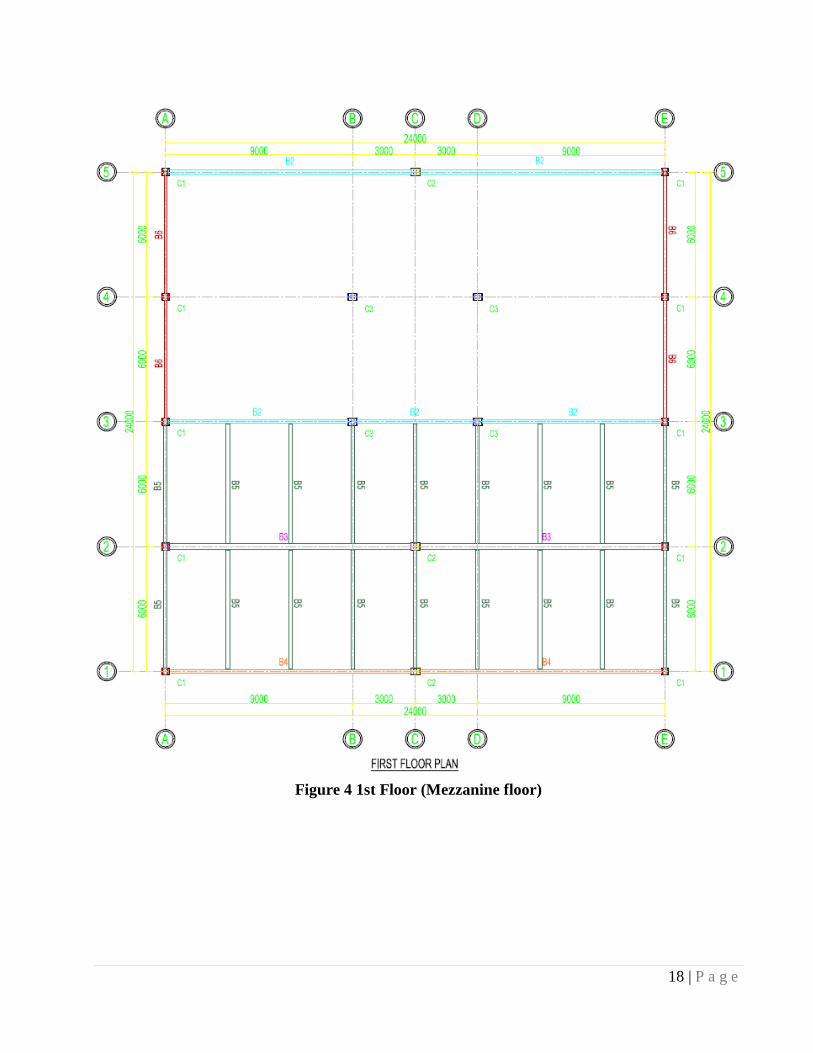
Figure 4 1st Floor (Mezzanine floor)
19 | P a g e
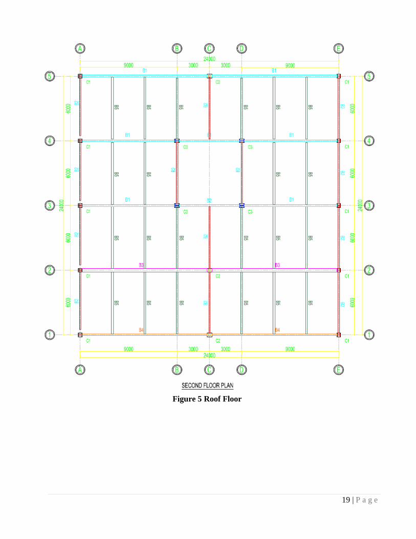
Figure 5 Roof Floor
20 | P a g e
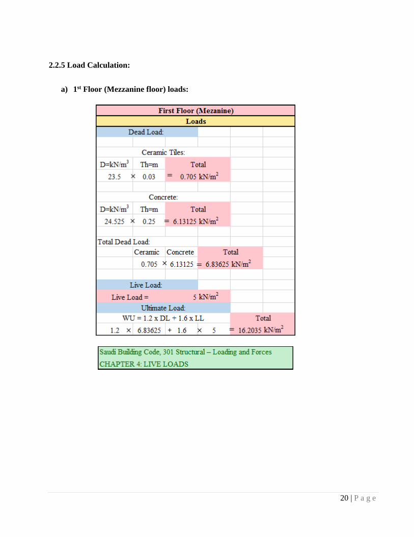
2.2.5 Load Calculation:
a) 1st Floor (Mezzanine floor) loads:
21 | P a g e
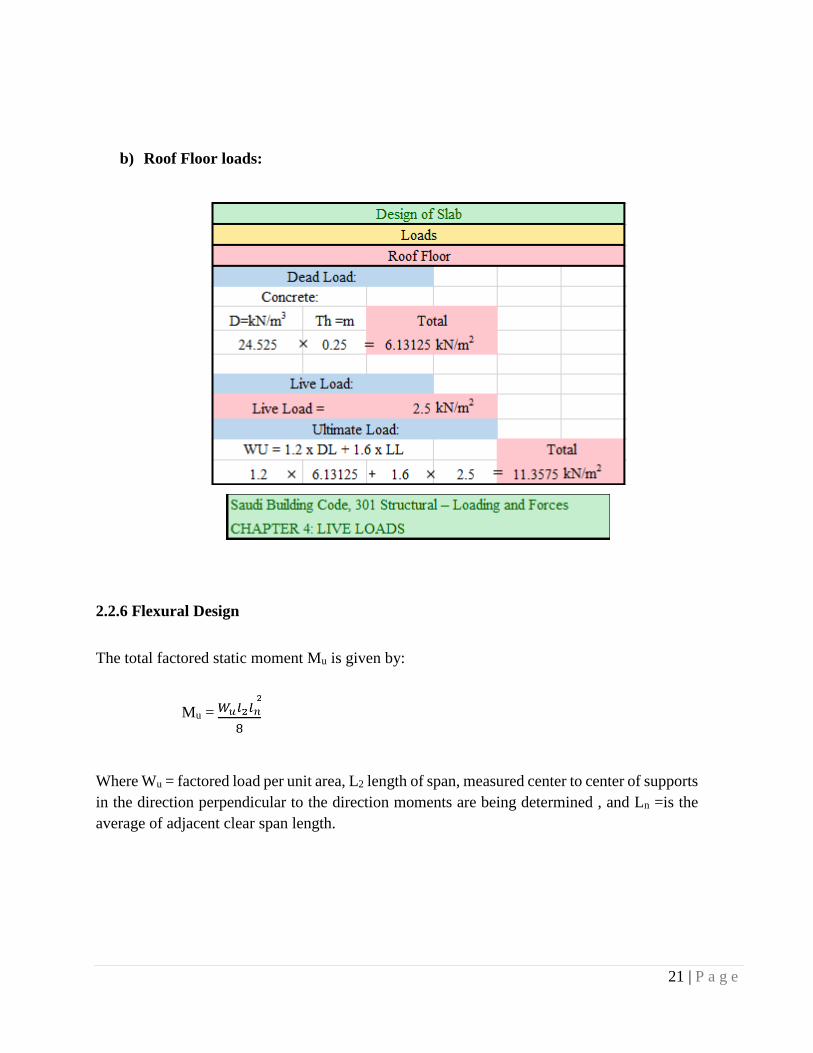
b) Roof Floor loads:
2.2.6 Flexural Design
The total factored static moment Mu is given by:
Mu =
Where Wu = factored load per unit area, L2 length of span, measured center to center of supports
in the direction perpendicular to the direction moments are being determined , and Ln =is the
average of adjacent clear span length.

22 | P a g e
a) 1st Floor (Mezzanine floor) design:
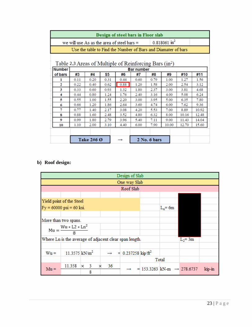
23 | P a g e
b) Roof design:
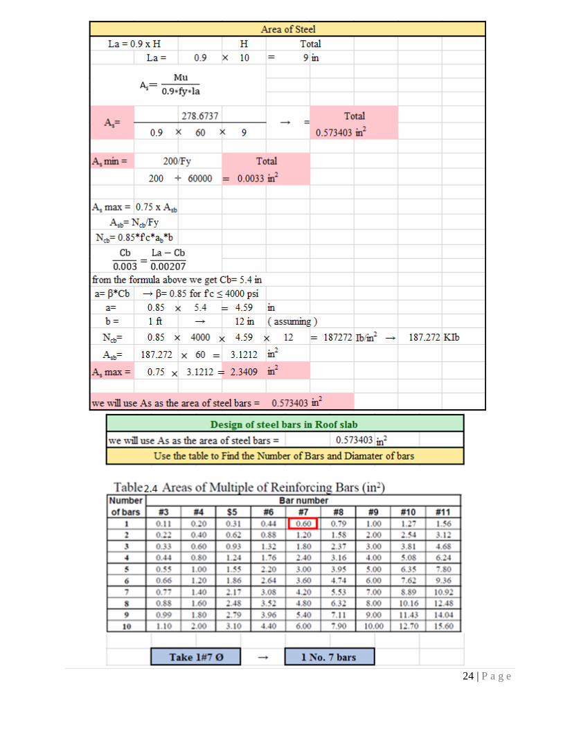
24 | P a g e
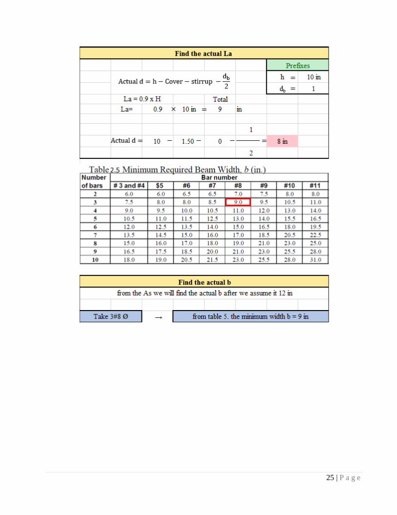
25 | P a g e
26 | P a g e
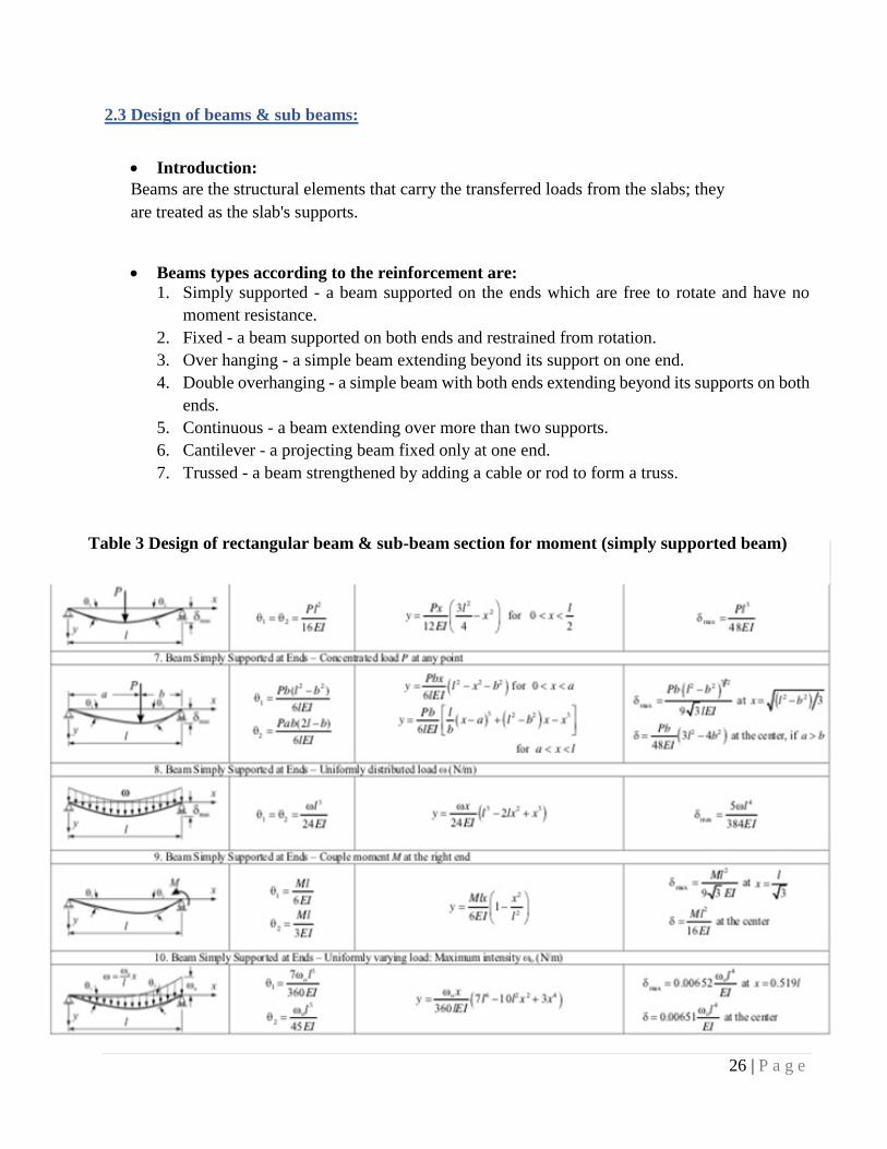
2.3 Design of beams & sub beams:
Introduction:
Beams are the structural elements that carry the transferred loads from the slabs; they
are treated as the slab's supports.
Beams types according to the reinforcement are:
1. Simply supported - a beam supported on the ends which are free to rotate and have no
moment resistance.
2. Fixed - a beam supported on both ends and restrained from rotation.
3. Over hanging - a simple beam extending beyond its support on one end.
4. Double overhanging - a simple beam with both ends extending beyond its supports on both
ends.
5. Continuous - a beam extending over more than two supports.
6. Cantilever - a projecting beam fixed only at one end.
7. Trussed - a beam strengthened by adding a cable or rod to form a truss.
Table 3 Design of rectangular beam & sub-beam section for moment (simply supported beam)

27 | P a g e
2.3.1 Steps to Design Rectangular beam & sub beams:
Step 1: Determine the minimum required depth of beam & sub beam from table 4.1 ACI 318
code then compute the width.
Step 2: Determine the ultimate load that effect on the beam & sub beam.
Step 3: Determine the total factored static moment.
Step 4: Determine the required area of steel for flexural design.
Step 5: check the ductility.
Step 6: Determine the required area of stirrups for the shear.
2.3.2 Materials properties:
Table 4 Properties
2.3.3 Load calculation for sub beam:
a) Load of Sub beam for 1st floor (mezzanine floor):
b) Load of Sub beam for Roof:
concrete fcˊ 30 MPa
steel Fy 420 MPa
28 | P a g e
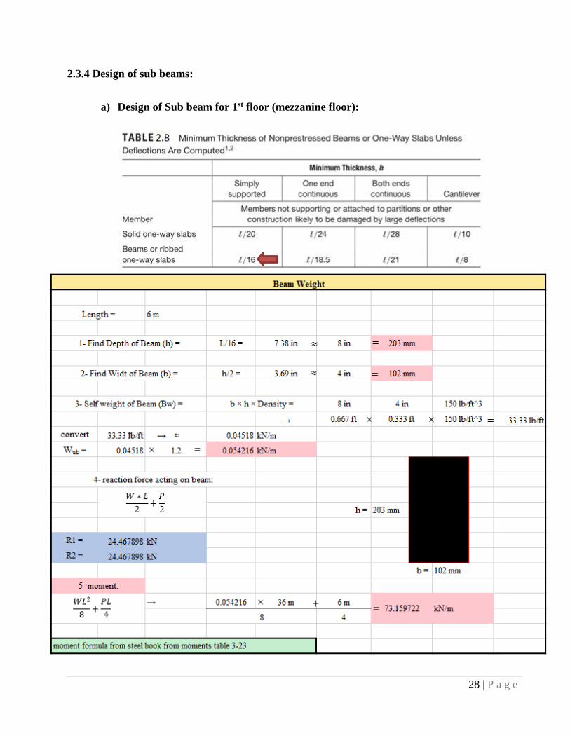
2.3.4 Design of sub beams:
a) Design of Sub beam for 1st floor (mezzanine floor):
29 | P a g e
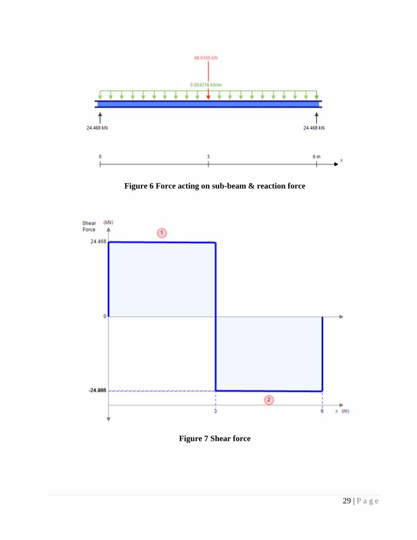
Figure 6 Force acting on sub-beam & reaction force
Figure 7 Shear force
30 | P a g e
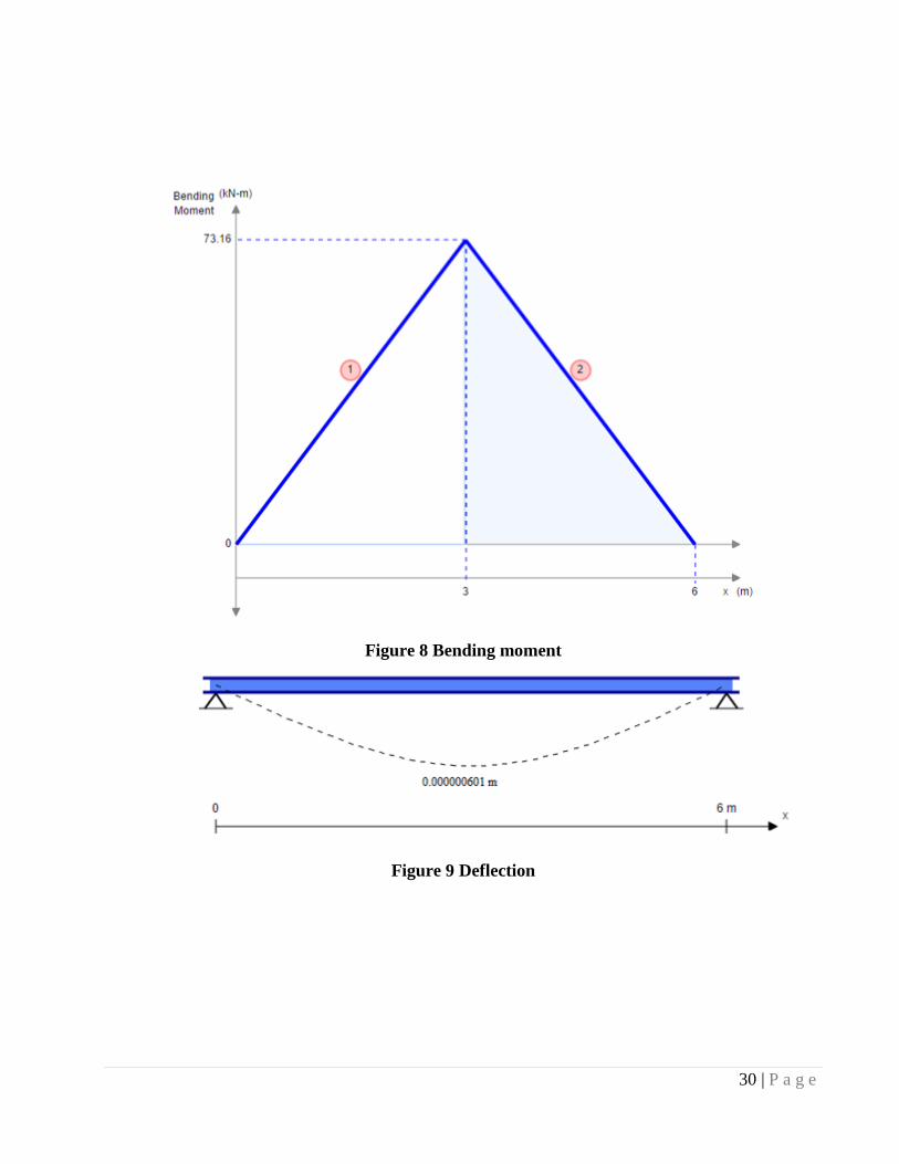
Figure 8 Bending moment
Figure 9 Deflection
31 | P a g e
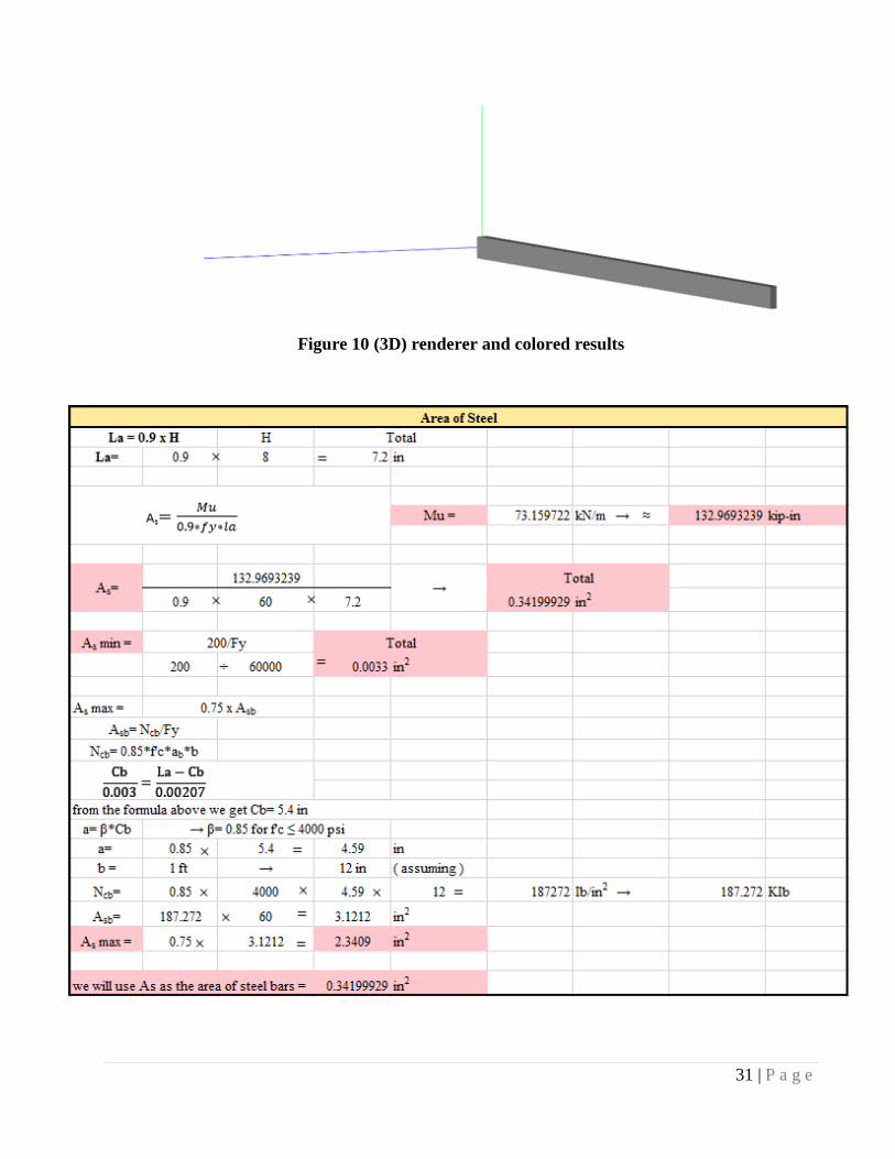
Figure 10 (3D) renderer and colored results
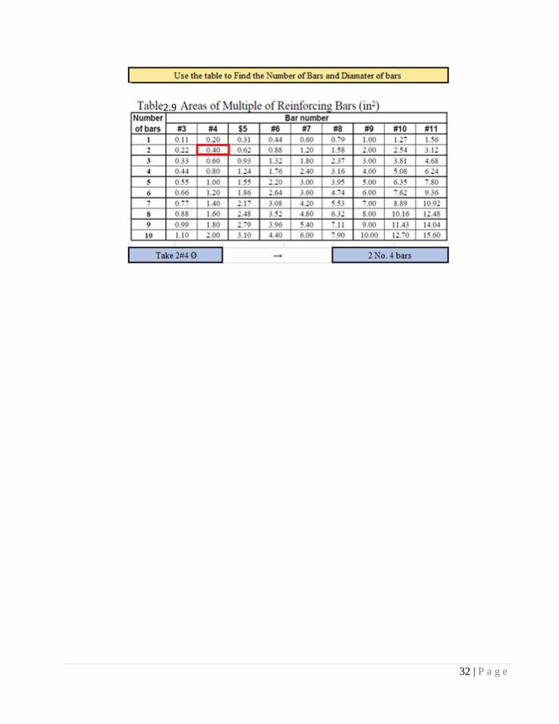
32 | P a g e
33 | P a g e
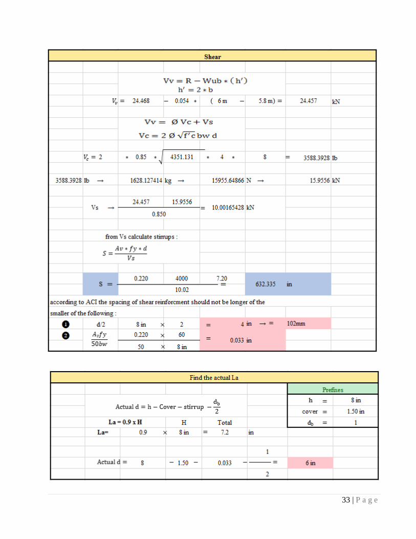
34 | P a g e
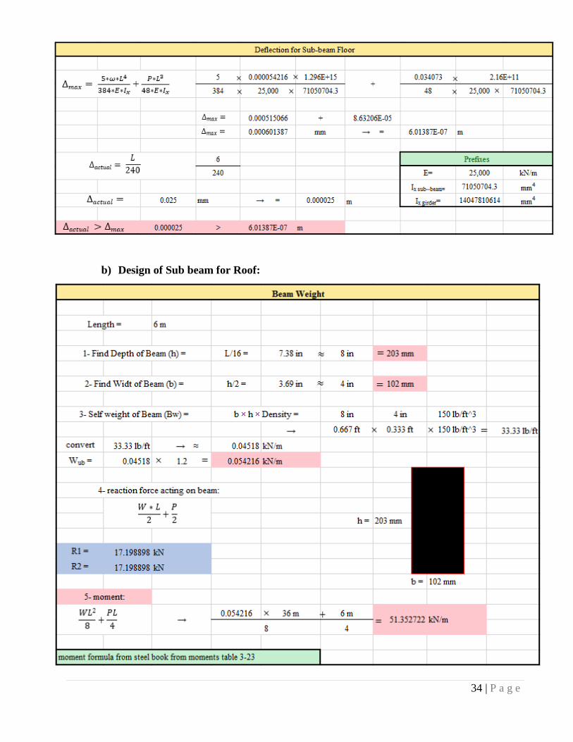
b) Design of Sub beam for Roof:
35 | P a g e
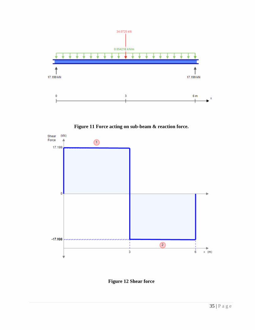
Figure 11 Force acting on sub-beam & reaction force.
Figure 12 Shear force
36 | P a g e
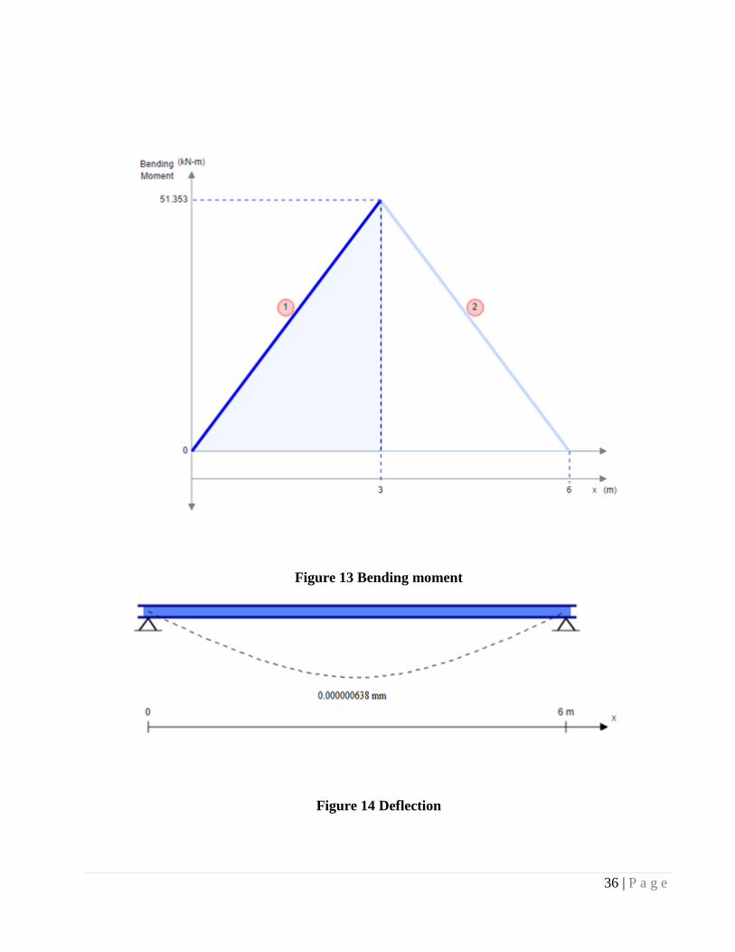
Figure 13 Bending moment
Figure 14 Deflection
37 | P a g e
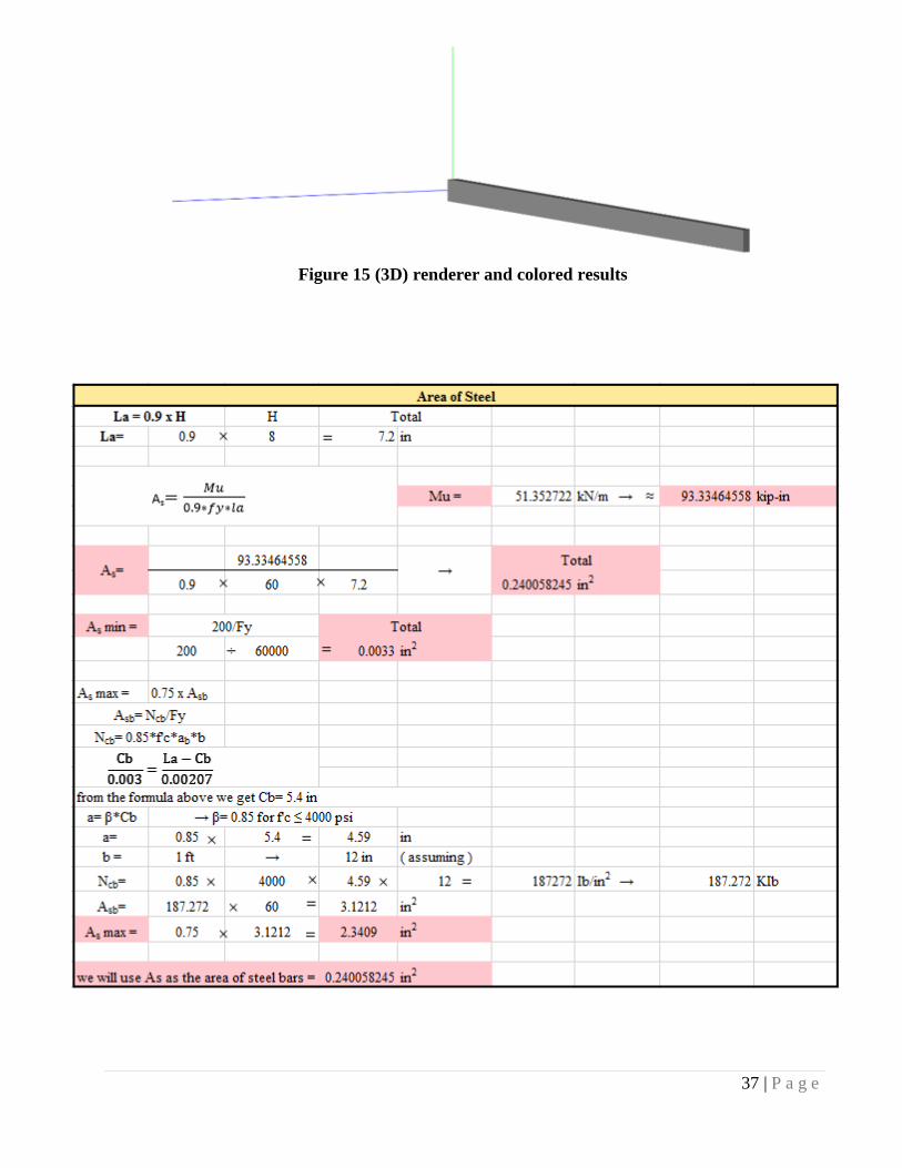
Figure 15 (3D) renderer and colored results
38 | P a g e
39 | P a g e
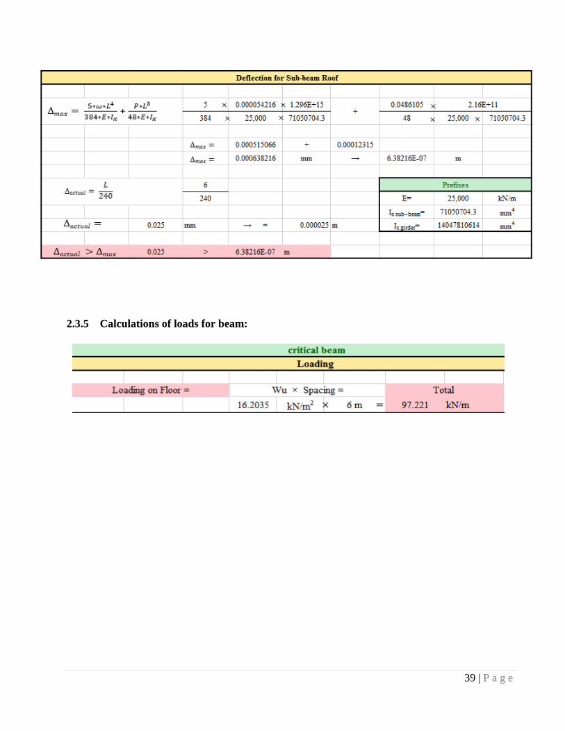
2.3.5 Calculations of loads for beam:
40 | P a g e
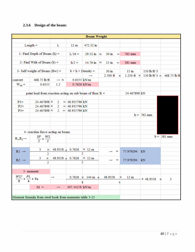
2.3.6 Design of the beam:
41 | P a g e
Figure 16 Force acting on sub-beam & reaction force
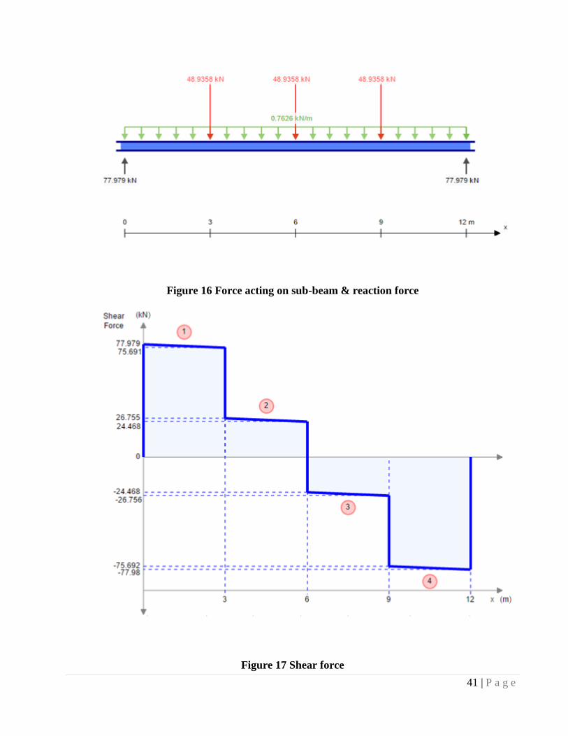
Figure 17 Shear force
42 | P a g e
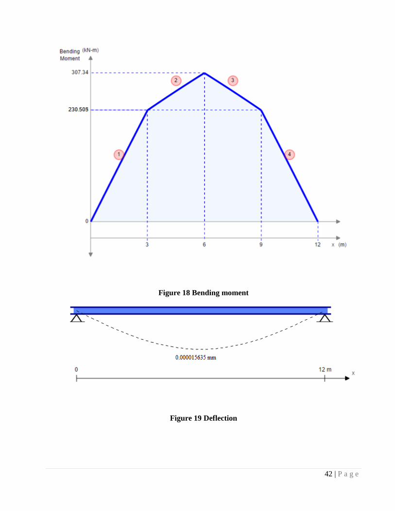
Figure 18 Bending moment
Figure 19 Deflection
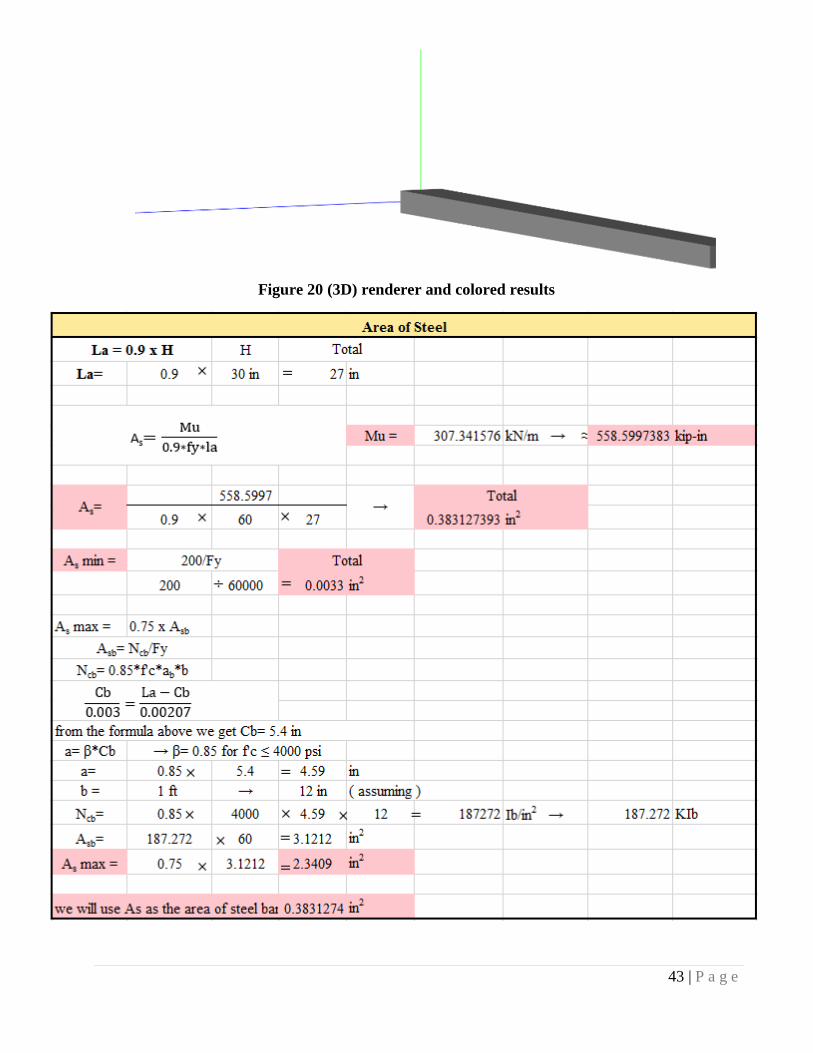
43 | P a g e
Figure 20 (3D) renderer and colored results
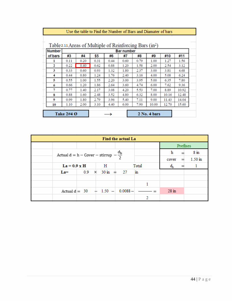
44 | P a g e
45 | P a g e
46 | P a g e
2.4 Design of columns
Columns are the third important element in structural system which are defined as members
that carry load chiefly in compression .usually columns carry bending moment as well about
one or both axis of the cross section
2.4.1 Classification of columns:
Column are generally classified according to:
a) The load acting on column:
1) Axially loaded column: where the load act at the center of the column
Section
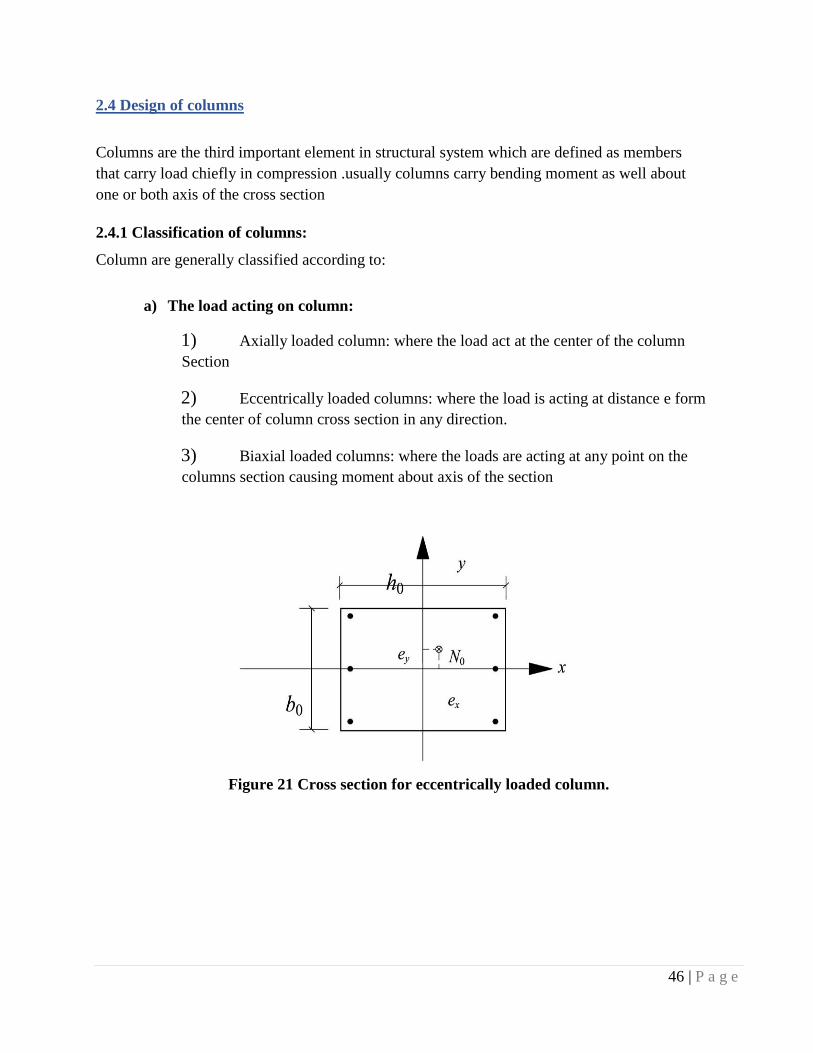
2) Eccentrically loaded columns: where the load is acting at distance e form
the center of column cross section in any direction.
3) Biaxial loaded columns: where the loads are acting at any point on the
columns section causing moment about axis of the section
Figure 21 Cross section for eccentrically loaded column.
47 | P a g e
b) The column length:
1) Short columns: where the columns failure is due to the crushing of
concrete or yielding of the steel bars under the capacity of the columns.
2) Long columns: Where the effect of the buckling and the slenderness ratio
must be taken into consideration in the design.
c) The columns ties:
1) Members reinforced with longitudinal bars and lateral ties(Rectangular columns)
2) Members reinforced with longitudinal bars and continuous spiral (circular
columns)
d) sample of calculations of rectangular columns:
Steps of design:
1) Check the type of the floor in each direction (sway or non-sway)
2) Determine the load applied and the critical load combination
3) Check if the column is slender or not.
If columns is slender finds its magnified moment, then compare this with the
calculated minimum moment:
4) Then find out the required area of steel
5) Calculate the ties or stirrup reinforcement
6) Draw the detailing of the columns
48 | P a g e
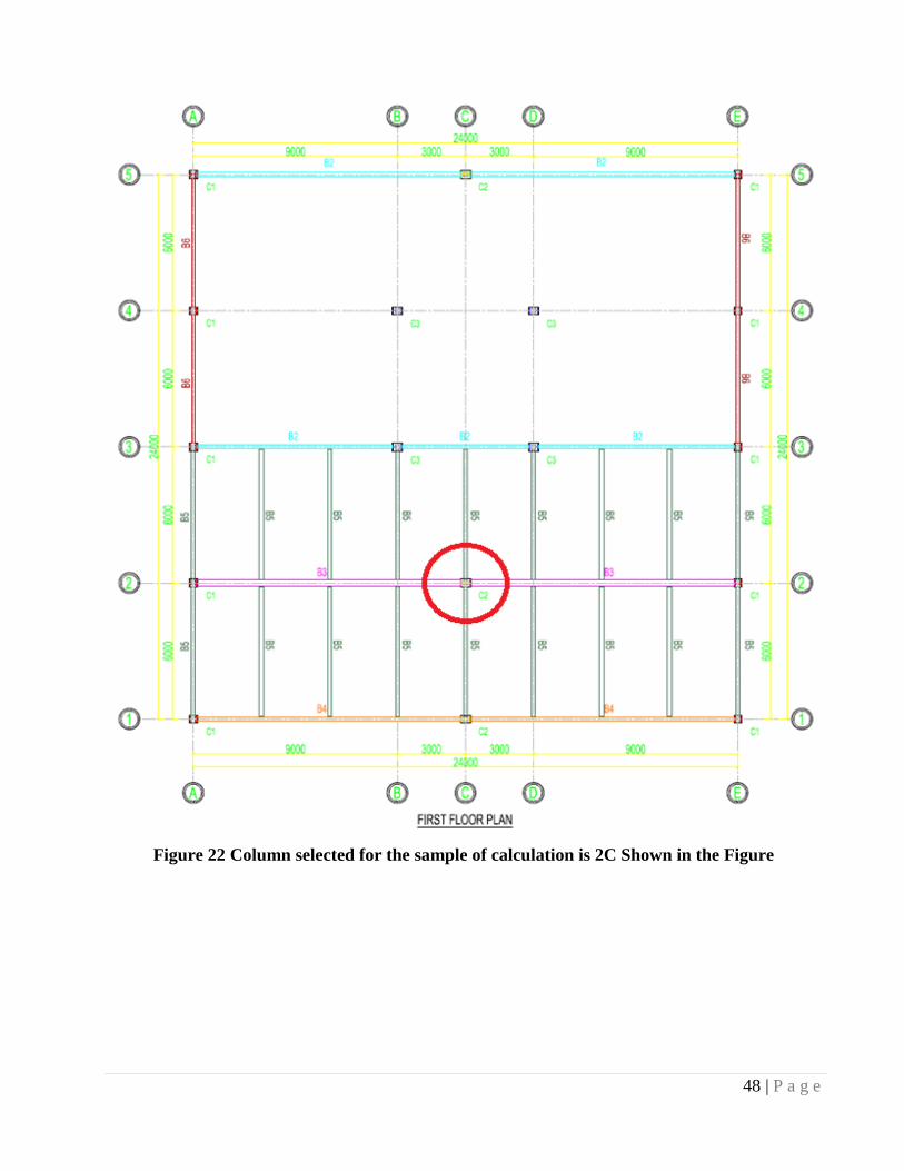
Figure 22 Column selected for the sample of calculation is 2C Shown in the Figure
49 | P a g e
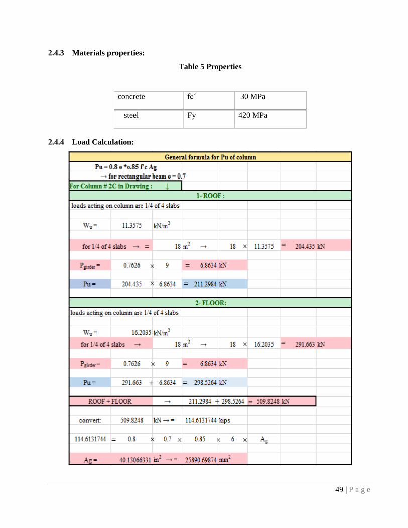
2.4.3 Materials properties:
Table 5 Properties
2.4.4 Load Calculation:
concrete fcˊ 30 MPa
steel Fy 420 MPa
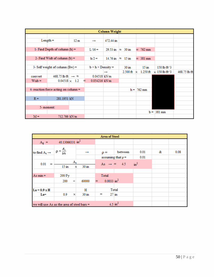
50 | P a g e
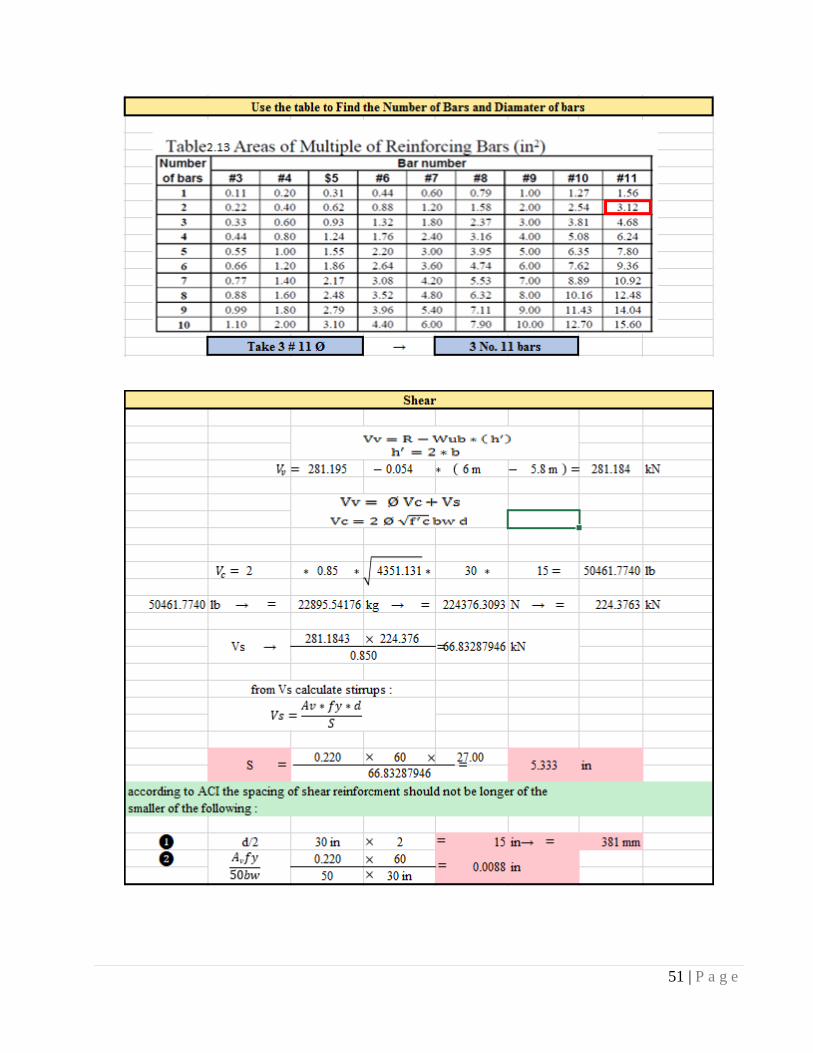
51 | P a g e
52 | P a g e
2.5 Design of dome
2.5.1 Classification of dome:
A dome is an architectural element that resembles the hollow upper half of a sphere. The precise
definition has been a matter of controversy. There are also a wide variety of forms and specialized
terms to describe them. A dome can rest upon a rotunda or drum, and can be supported by columns
or piers that transition to the dome through squinches or pendentives. A lantern may cover an
oculus and may itself have another dome.
Domes have a long architectural lineage that extends back into prehistory and they have been
constructed from mud, stone, wood, brick, concrete, metal, glass, and plastic over the centuries.
The symbolism associated with domes includes mortuary, celestial, and governmental traditions
that have likewise developed over time.
Domes have been found from early Mesopotamia, which may explain the form's spread. They are
found in Persian, Hellenistic, Roman, and Chinese architecture in the Ancient world, as well as
among a number of contemporary indigenous building traditions. They were popular in Byzantine
and medieval Islamic architecture, and there are numerous examples from Western Europe in the
middle Ages. The Renaissance style spread from Italy in the early modern period. Advancements
in mathematics, materials, and production techniques since that time resulted in new dome types.
The domes of the modern world can be found over religious buildings, legislative chambers, sports
stadiums, and a variety of functional structures.
Domes in Islamic architecture:
When he built the Messenger of Allah bless him and his mosque in Medina, was the roof of the
mobile fronds on the palm trunks, the case remained on it among the mosques was not the dome
has entered the building of mosques.
The first dome was built in Islam are Dome of the Rock mosque in Jerusalem built by the
Umayyad Caliph Abdul Malik bin Marwan year 72 AH. Muslims and was able to be transferred to
the customs of the Maghreb and Al-Andalus, and today we find a beautiful example of the city and
the valley will (State of the valley) in the east of Algeria domes that make up the foundation
element in roofing Hjradtha. And people still call in the Orient and some of Morocco on the room
or the Dome of the room
53 | P a g e
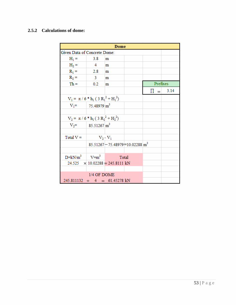
2.5.2 Calculations of dome:
54 | P a g e
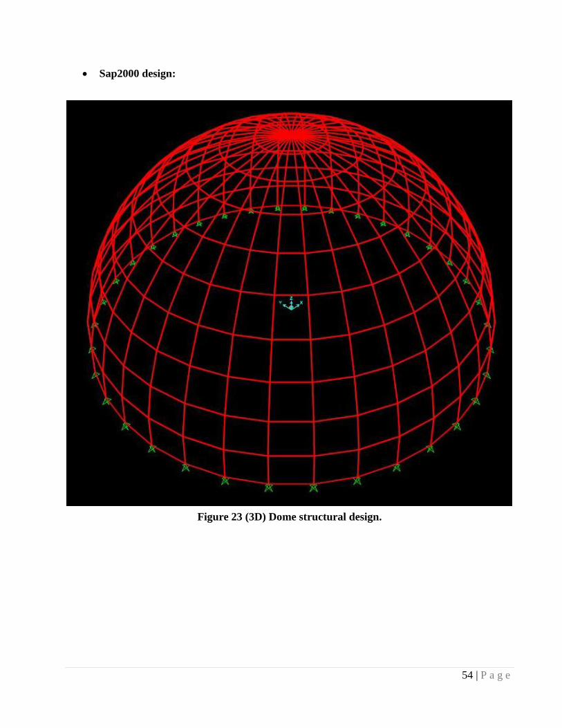
Sap2000 design:
Figure 23 (3D) Dome structural design.
55 | P a g e
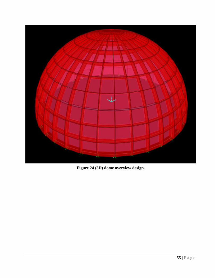
Figure 24 (3D) dome overview design.
56 | P a g e
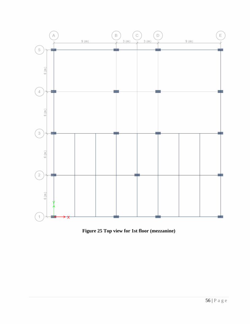
Figure 25 Top view for 1st floor (mezzanine)
Page | 57
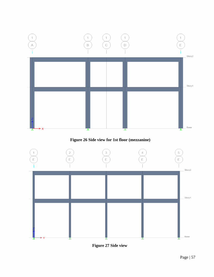
Figure 27 Side view
Figure 26 Side view for 1st floor (mezzanine)
Page | 58
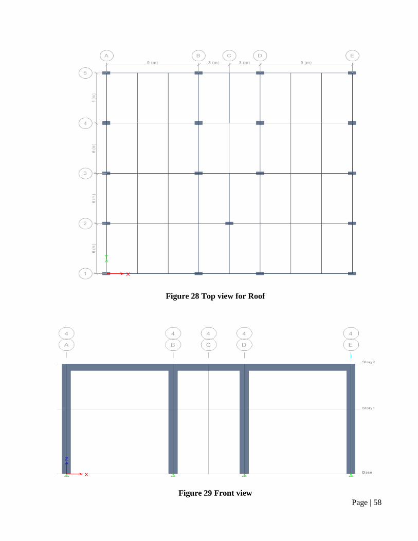
Figure 28 Top view for Roof
Figure 29 Front view
Page | 59
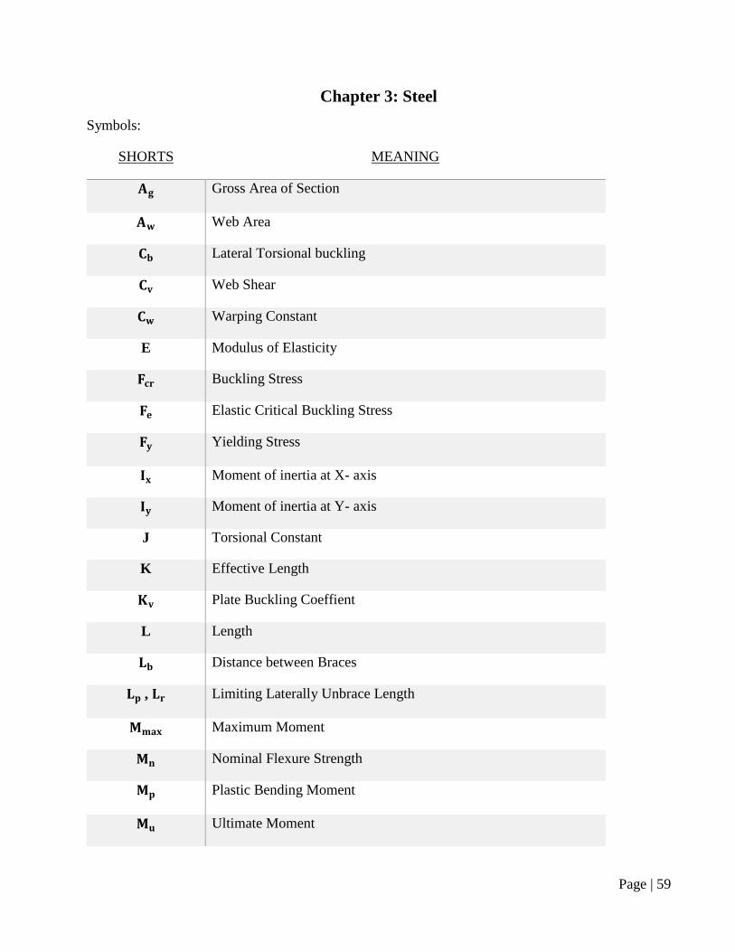
Chapter 3: Steel
Symbols:
SHORTS MEANING
𝐀𝐠 Gross Area of Section
𝐀𝐰 Web Area
𝐂𝐛 Lateral Torsional buckling
𝐂𝐯 Web Shear
𝐂𝐰 Warping Constant
E Modulus of Elasticity
𝐅𝐜𝐫 Buckling Stress
𝐅𝐞 Elastic Critical Buckling Stress
𝐅𝐲 Yielding Stress
𝐈𝐱 Moment of inertia at X- axis
𝐈𝐲 Moment of inertia at Y- axis
J Torsional Constant
K Effective Length
𝐊𝐯 Plate Buckling Coeffient
L Length
𝐋𝐛 Distance between Braces
𝐋𝐩 , 𝐋𝐫 Limiting Laterally Unbrace Length
𝐌𝐦𝐚𝐱 Maximum Moment
𝐌𝐧 Nominal Flexure Strength
𝐌𝐩 Plastic Bending Moment
𝐌𝐮 Ultimate Moment
Page | 60
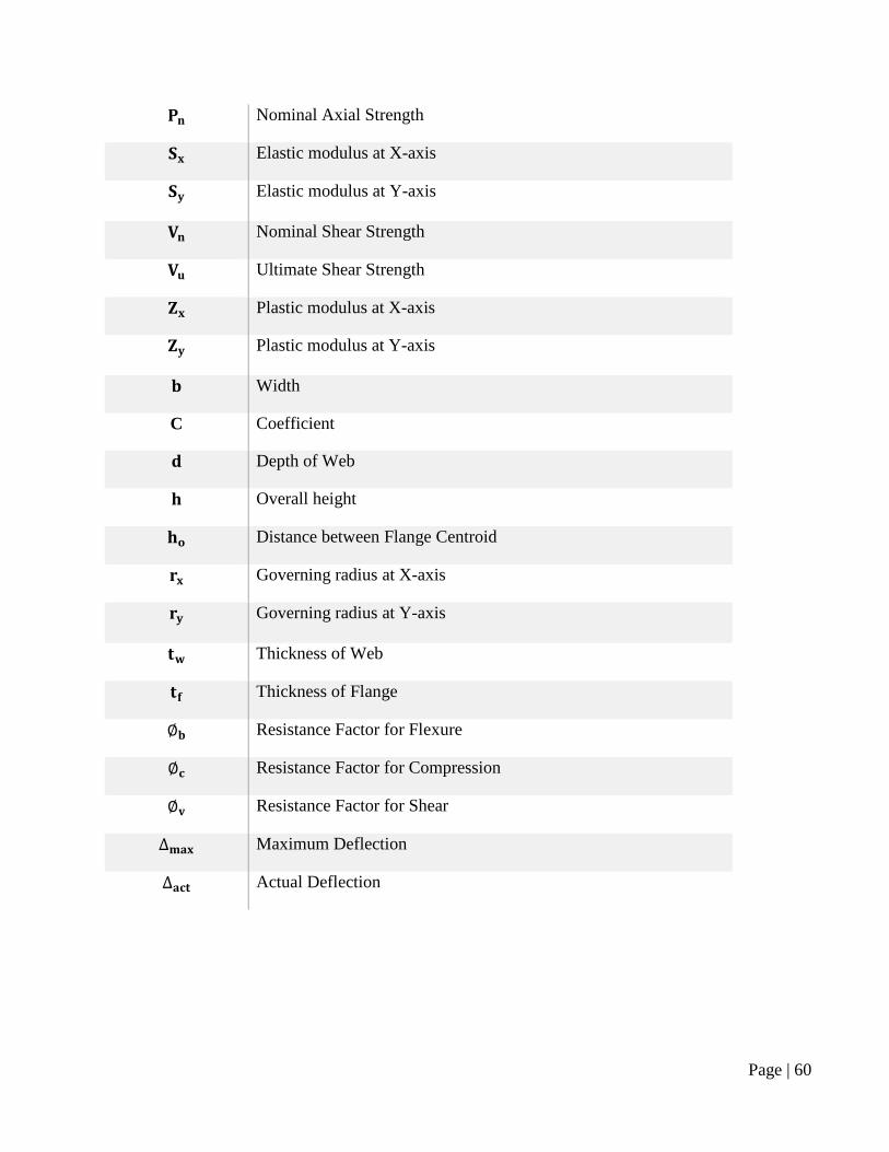
𝐏𝐧 Nominal Axial Strength
𝐒𝐱 Elastic modulus at X-axis
𝐒𝐲 Elastic modulus at Y-axis
𝐕𝐧 Nominal Shear Strength
𝐕𝐮 Ultimate Shear Strength
𝐙𝐱 Plastic modulus at X-axis
𝐙𝐲 Plastic modulus at Y-axis
𝐛 Width
C Coefficient
𝐝 Depth of Web
𝐡 Overall height
𝐡𝐨 Distance between Flange Centroid
𝐫𝐱 Governing radius at X-axis
𝐫𝐲 Governing radius at Y-axis
𝐭𝐰 Thickness of Web
𝐭𝐟 Thickness of Flange
∅𝐛 Resistance Factor for Flexure
∅𝐜 Resistance Factor for Compression
∅𝐯 Resistance Factor for Shear
∆𝐦𝐚𝐱 Maximum Deflection
∆𝐚𝐜𝐭 Actual Deflection
Page | 61
3.1 Introduction:
Steel buildings first gained popularity in the early 20th century. Their use became more widespread
during World War II and significantly expanded after the war when steel became more available. Steel
buildings have been widely accepted, in part due to cost efficiency. The range of application has
expanded with improved materials, products and design capabilities with the availability of computer
aided design software.
Steel provides several advantages over other building materials, such as wood:
Steel is a "green" product; it is structurally sound and manufactured to strict specifications and
tolerances. It is also energy efficient. Any excess material is 100% recyclable.
Steel does not easily warp, buckle, twist or bend, and is therefore easy to modify and offers
design flexibility. Steel is also easy to install.
Steel is cost effective and rarely fluctuates in price.
Steel allows for improved quality of construction and less maintenance, while offering
improved safety and resistance.
With the propagation of mold and mildew in residential buildings, using steel minimizes these
infestations. Mold needs moist, porous material to grow. Steel studs do not have those
problems.
This chapter will include three main sections: Design information, Structural analysis, and Design
process.
Page | 62
3.2 Design Information:
This section will provide the applicable design codes, material specifications, and load combinations.
3.2.1 Applicable Design Codes:
The loads as described in the design summary sheet have been applied on the structure in accordance
with:
American Institute of Steel Construction (AISC) Manual of Steel Construction/ Load and
Resistance Factor Design (LRFD).
American Institute of Steel Construction (AISC) Manual of Steel Construction/ Allowable
Strength Design (ASD).
Saudi Building Code (SBC) For Minimum Design Loads for Buildings and Other Structures
(301).
European Specifications Beams (EURONORM) 53-62.
Egyptian Building Code (EBS) For Connection design.
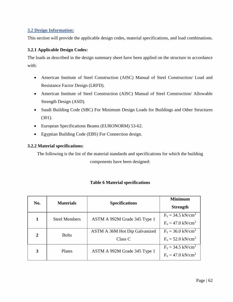
3.2.2 Material specifications:
The following is the list of the material standards and specifications for which the building
components have been designed:
Table 6 Material specifications
No. Materials Specifications Minimum
Strength
1 Steel Members ASTM A 992M Grade 345 Type 1 Fy = 34.5 kN/cm2
Fu = 47.0 kN/cm2
2 Bolts ASTM A 36M Hot Dip Galvanized
Class C
Fy = 36.0 kN/cm2
Fu = 52.0 kN/cm2
3 Plates ASTM A 992M Grade 345 Type 1 Fy = 34.5 kN/cm2
Fu = 47.0 kN/cm2

Page | 63
3.2.3 Load Combinations:
This section will provide the calculation of the load combinations. These loads are calculated in
accordance with Saudi Building Code (SBC) 301. These loads will be used in the structural analysis
of the mezzanine beam and roof beam. Dome beam needs to calculate the dome weight and added to
the load combination to do the structural analysis and dome beam design.
1- Dead Loads:
Table 7 Dead load
No. Types of Dead load Value Note
1 Slab thickness 0.25 m According to slab calculation in concrete
section.
2 Beam weight --- Steel section table.
3 Ceramic tiles 0.15 t/m Saudi Building Code (SBC) – 301
4 Dome weight 20.52 t/m According to dome calculation in concrete
section.
Note: Slab is concrete-base. Density of Concrete 2.5 t/m3
2- Live Loads:
Table 8 Live load
No. Types of Live load Value Note
1 Mezzanine 0.5 t/m2 Saudi Building Code (SBC) – 301
2 Roof 0.25 t/m2 Saudi Building Code (SBC) – 301
Ultimate Load
Table 9 Ultimate load
No. Types of Load Factor of Safety Note
1 Dead 1.2 Saudi Building Code (SBC) – 301
2 Live 1.6 Saudi Building Code (SBC) – 301
Page | 64
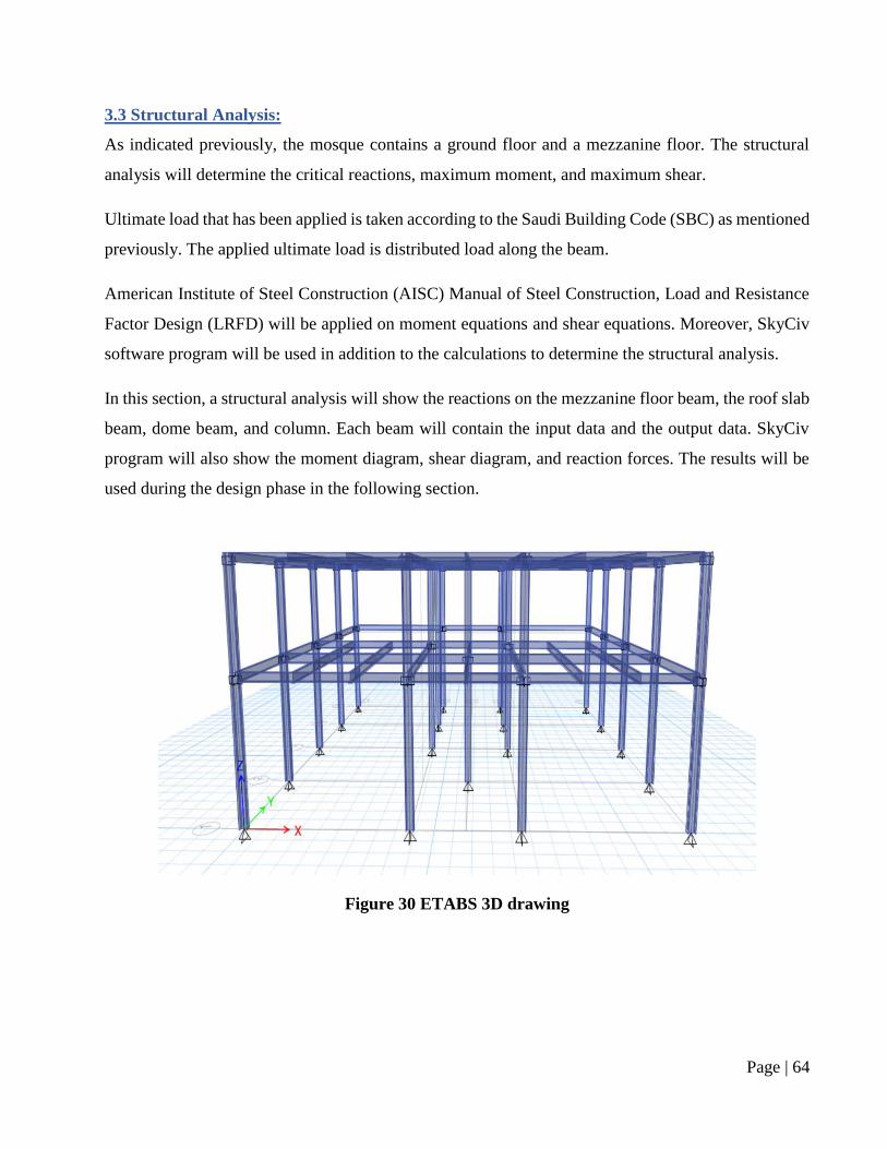
3.3 Structural Analysis:
As indicated previously, the mosque contains a ground floor and a mezzanine floor. The structural
analysis will determine the critical reactions, maximum moment, and maximum shear.
Ultimate load that has been applied is taken according to the Saudi Building Code (SBC) as mentioned
previously. The applied ultimate load is distributed load along the beam.
American Institute of Steel Construction (AISC) Manual of Steel Construction, Load and Resistance
Factor Design (LRFD) will be applied on moment equations and shear equations. Moreover, SkyCiv
software program will be used in addition to the calculations to determine the structural analysis.
In this section, a structural analysis will show the reactions on the mezzanine floor beam, the roof slab
beam, dome beam, and column. Each beam will contain the input data and the output data. SkyCiv
program will also show the moment diagram, shear diagram, and reaction forces. The results will be
used during the design phase in the following section.
Figure 30 ETABS 3D drawing
Page | 65
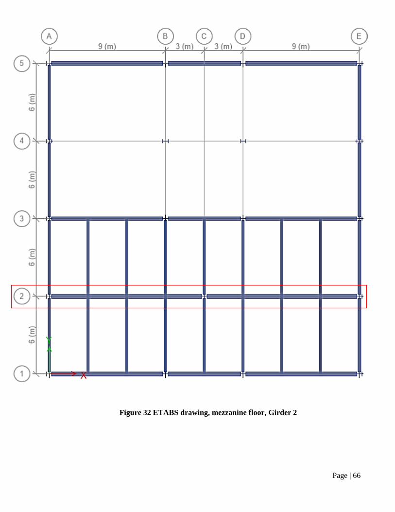
3.3.1 Mezzanine floor beam (Girder 2-2):
Input:
Ultimate load is applied on the mezzanine floor beam using calculation and SkyCiv program. The
beam is fixed at both ends. The length of the beam is
12.00 meters. The drawing shows the length of the beam, applied load, and supports.
Table 10 Mezzanine floor analysis
Figure 31 AutoCAD Drawing, for Grade 2 - Level 7m
Page | 66
Figure 32 ETABS drawing, mezzanine floor, Girder 2
Page | 67
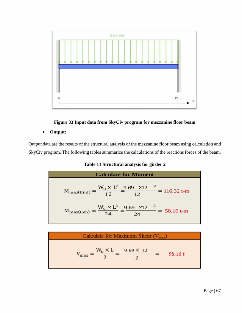
Figure 33 Input data from SkyCiv program for mezzanine floor beam
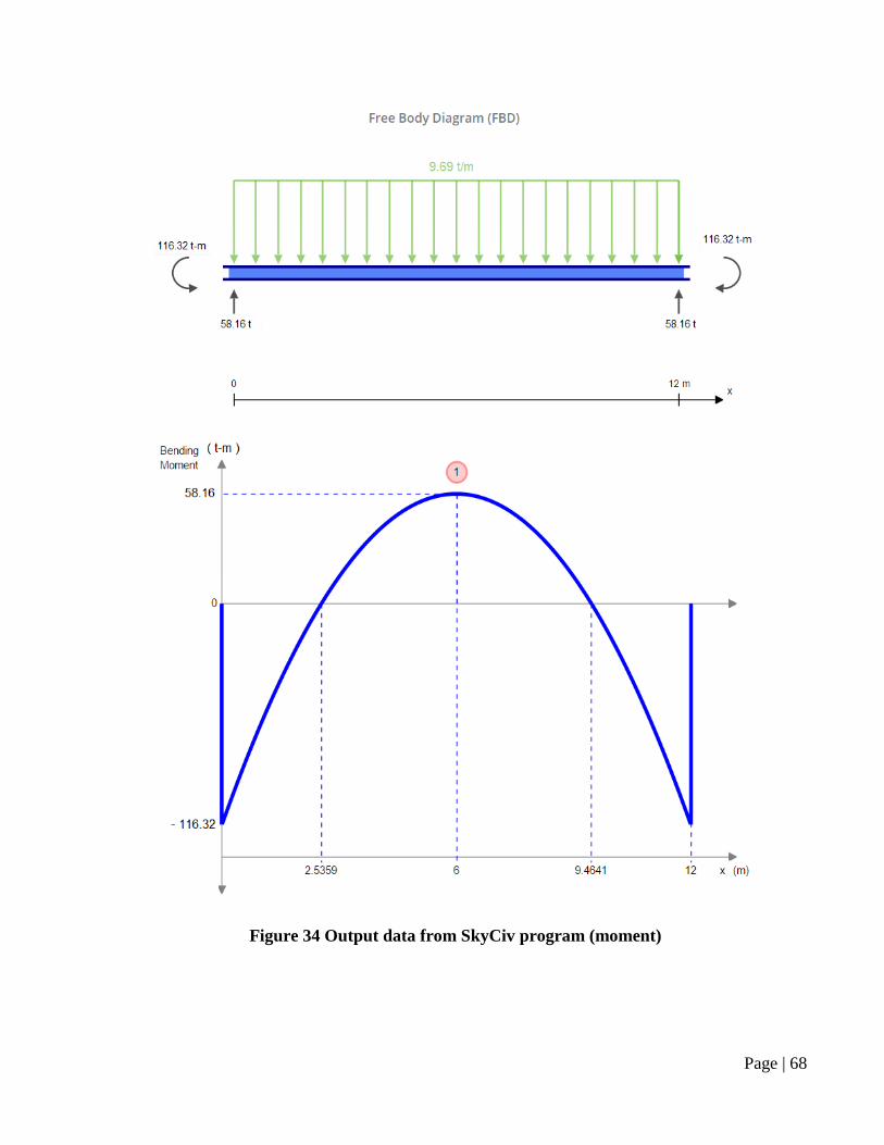
Output:
Output data are the results of the structural analysis of the mezzanine floor beam using calculation and
SkyCiv program. The following tables summarize the calculations of the reactions forces of the beam.
Table 11 Structural analysis for girder 2
9.69 12
9.69 12
12
Calculate for Moment
116.32 t-m
2458.16 t-m
Page | 68
Figure 34 Output data from SkyCiv program (moment)
Page | 69
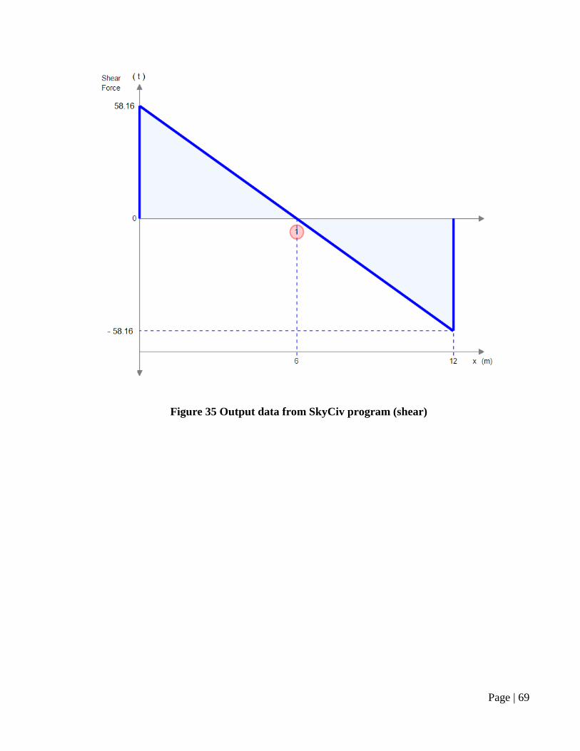
Figure 35 Output data from SkyCiv program (shear)
Page | 70
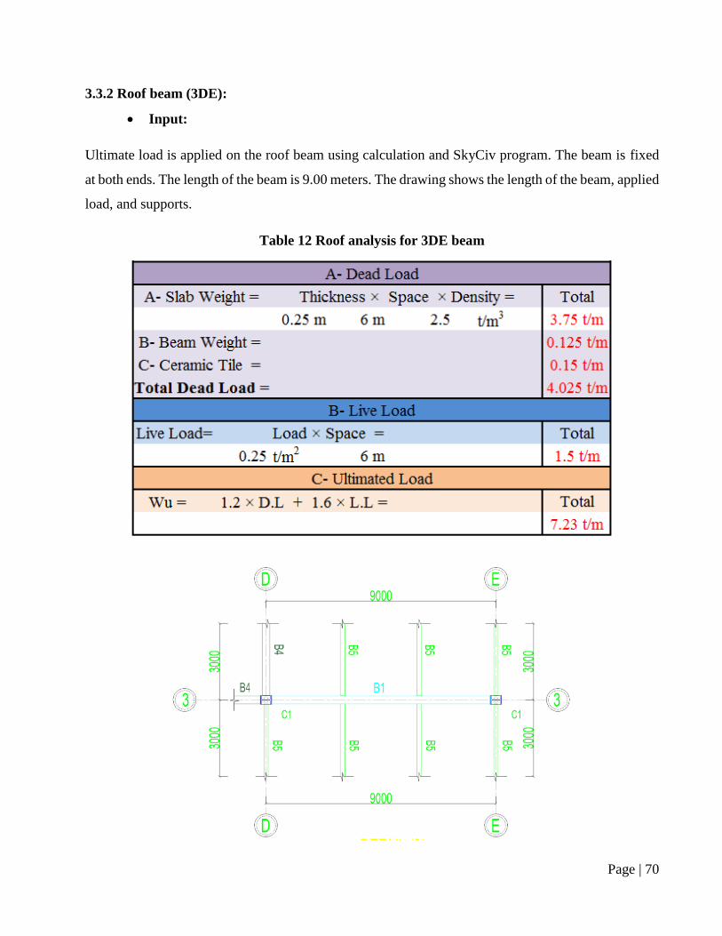
3.3.2 Roof beam (3DE):
Input:
Ultimate load is applied on the roof beam using calculation and SkyCiv program. The beam is fixed
at both ends. The length of the beam is 9.00 meters. The drawing shows the length of the beam, applied
load, and supports.
Table 12 Roof analysis for 3DE beam
Page | 71
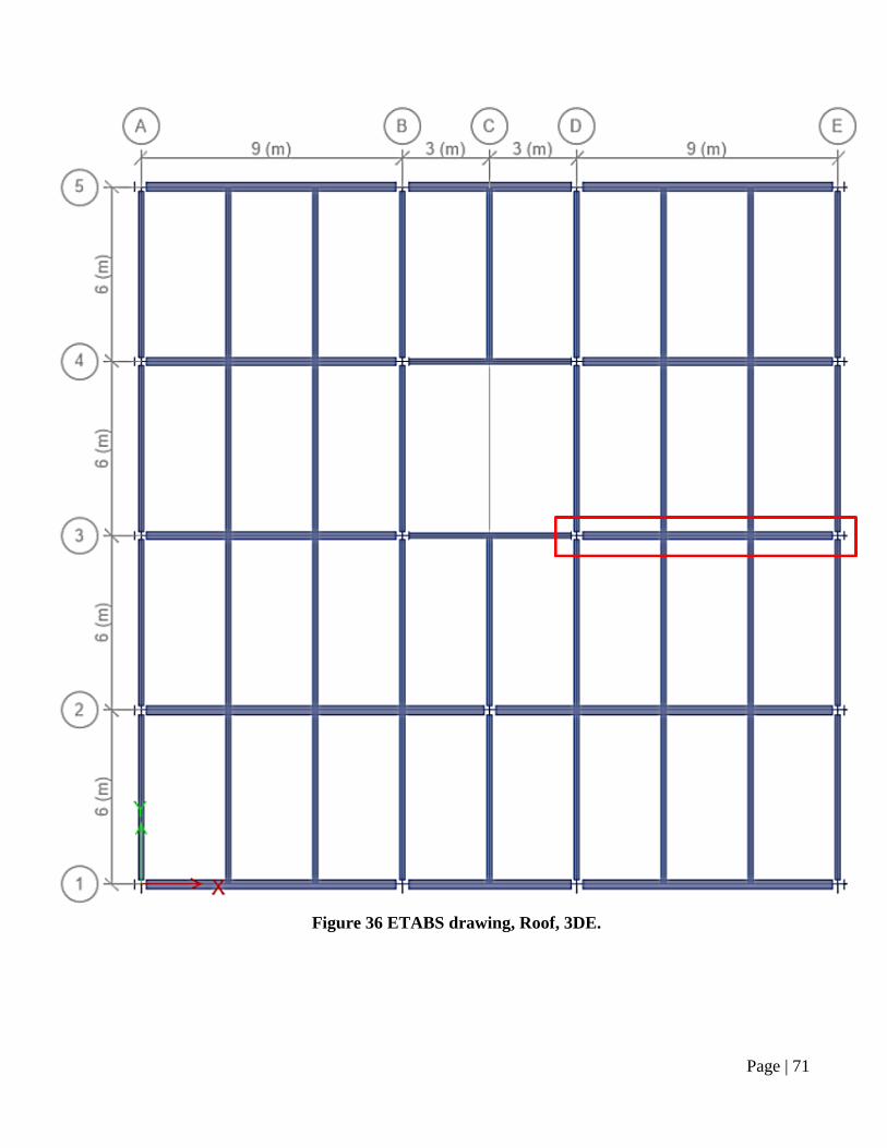
Figure 36 ETABS drawing, Roof, 3DE.
Page | 72
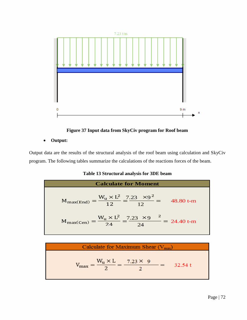
Figure 37 Input data from SkyCiv program for Roof beam
Output:
Output data are the results of the structural analysis of the roof beam using calculation and SkyCiv
program. The following tables summarize the calculations of the reactions forces of the beam.
Table 13 Structural analysis for 3DE beam
7.23 9
7.23 9
12
Calculate for Moment
48.80 t-m
2424.40 t-m
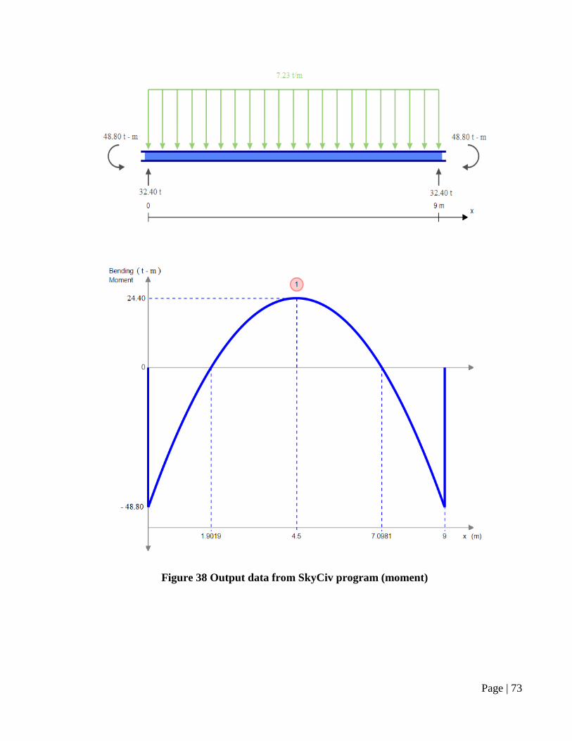
Page | 73
Figure 38 Output data from SkyCiv program (moment)
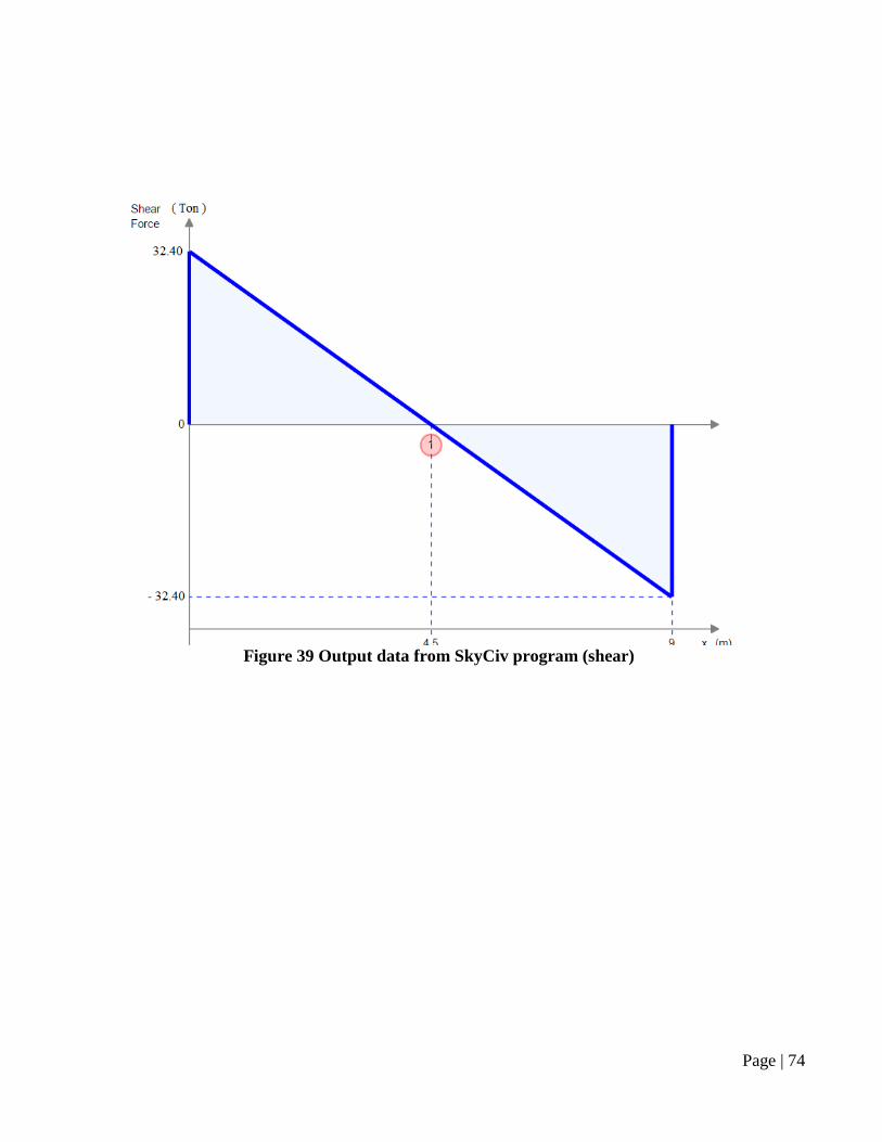
Page | 74
Figure 39 Output data from SkyCiv program (shear)
Page | 75
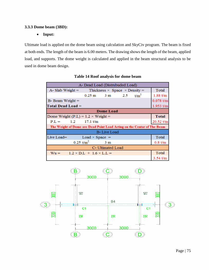
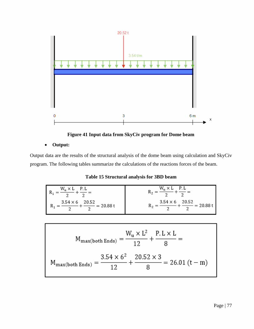
3.3.3 Dome beam (3BD):
Input:
Ultimate load is applied on the dome beam using calculation and SkyCiv program. The beam is fixed
at both ends. The length of the beam is 6.00 meters. The drawing shows the length of the beam, applied
load, and supports. The dome weight is calculated and applied in the beam structural analysis to be
used in dome beam design.
Table 14 Roof analysis for dome beam
Page | 76
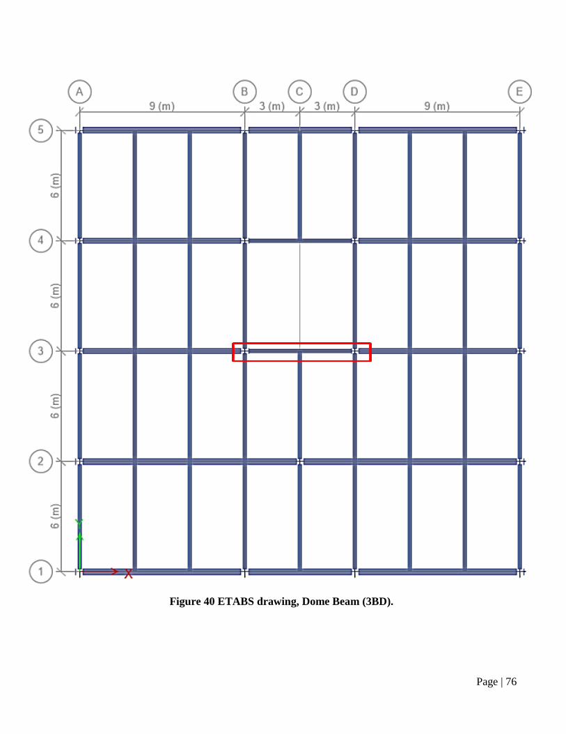
Figure 40 ETABS drawing, Dome Beam (3BD).
Page | 77
Figure 41 Input data from SkyCiv program for Dome beam
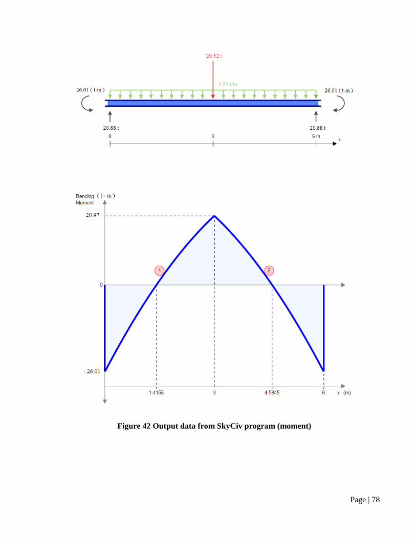
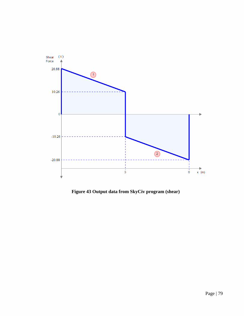
Output:
Output data are the results of the structural analysis of the dome beam using calculation and SkyCiv
program. The following tables summarize the calculations of the reactions forces of the beam.
Table 15 Structural analysis for 3BD beam
Page | 78
Figure 42 Output data from SkyCiv program (moment)
Page | 79
Figure 43 Output data from SkyCiv program (shear)
Page | 80
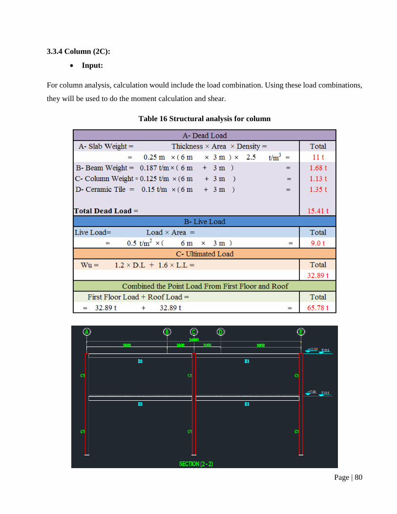
3.3.4 Column (2C):
Input:
For column analysis, calculation would include the load combination. Using these load combinations,
they will be used to do the moment calculation and shear.
Table 16 Structural analysis for column
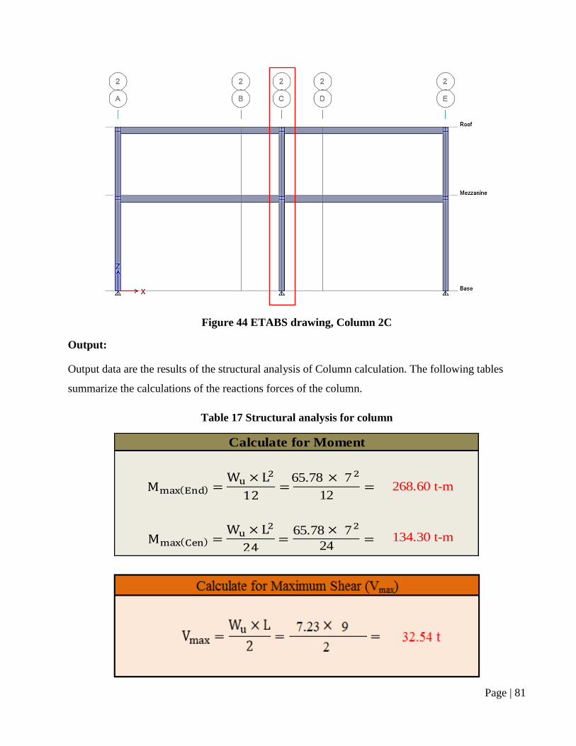
Page | 81
Figure 44 ETABS drawing, Column 2C
Output:
Output data are the results of the structural analysis of Column calculation. The following tables
summarize the calculations of the reactions forces of the column.
Table 17 Structural analysis for column
65.78 7
65.78 7
24134.30 t-m
12
Calculate for Moment
268.60 t-m
Page | 82
3.4 Design:
According to the structural analysis, the most critical analysis is the mezzanine floor beam analysis.
Its moment, shear, and reactions are the most critical. These data will be used to design the mezzanine
and roof beam. Dome beam and column have its own different output reaction.
The steel sections are taken from European Specifications Beams (EURONORM). For moment, shear,
and deflection calculations, American Institute of Steel Construction (AISC) Manual of Steel
Construction for Load and Resistance Factor Design (LRFD) is applied.
Selected steel section is shown in tables. These data are taken from the steel section properties, ETABS
software during the modeling phase, and the American Building code equations. ETABS output will
be included with the appendix.
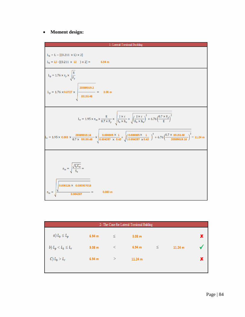
Moment design will include the lateral-torsional buckling design. Accordingly, this will check the
beam length if it is safe against lateral-torsional buckling. In next step, the nominal moment for the
selected steel section will be calculated to check and compare it with the ultimate moment from the
structural analysis.
Shear design will include web condition of the section. This will determine the web shearing strength
of the selected section. Next step, the area for the web will be calculated to use it in nominal shear
equation. In nominal shear, it will show the capability of the selected steel section against the ultimate
shear that has been mentioned previously in the structural analysis.
Deflection check is the check of the maximum allowable deflection of the structure according to the
building code with the deflection of the selected steel section. The deflection limit is calculated
according to the American Building Code.
This section will show four designs: Mezzanine beam, roof beam, dome beam, and column. Each
member will have the properties of the selected steel section, moment design, shear design, and
deflection check.
Page | 83
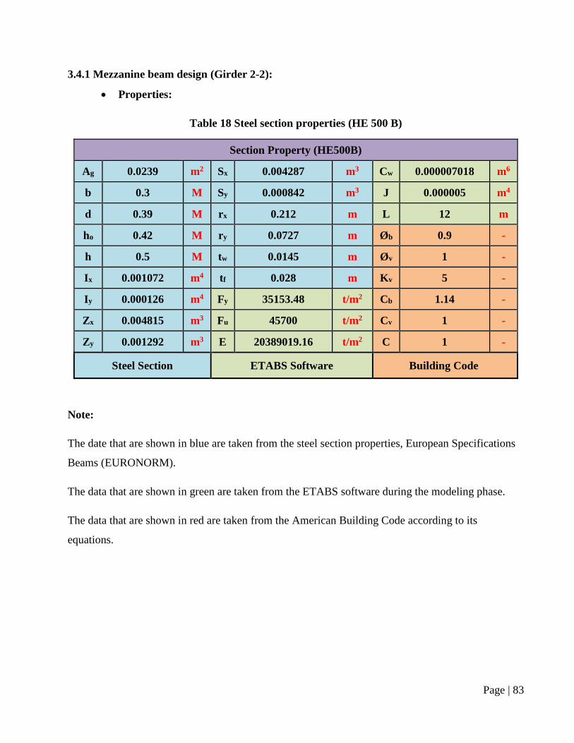
3.4.1 Mezzanine beam design (Girder 2-2):
Properties:
Table 18 Steel section properties (HE 500 B)
Section Property (HE500B)
Ag 0.0239 m2 Sx 0.004287 m3 Cw 0.000007018 m6
b 0.3 M Sy 0.000842 m3 J 0.000005 m4
d 0.39 M rx 0.212 m L 12 m
ho 0.42 M ry 0.0727 m Øb 0.9 -
h 0.5 M tw 0.0145 m Øv 1 -
Ix 0.001072 m4 tf 0.028 m Kv 5 -
Iy 0.000126 m4 Fy 35153.48 t/m2 Cb 1.14 -
Zx 0.004815 m3 Fu 45700 t/m2 Cv 1 -
Zy 0.001292 m3 E 20389019.16 t/m2 C 1 -
Steel Section ETABS Software Building Code
Note:
The date that are shown in blue are taken from the steel section properties, European Specifications
Beams (EURONORM).
The data that are shown in green are taken from the ETABS software during the modeling phase.
The data that are shown in red are taken from the American Building Code according to its
equations.
Page | 84
Moment design:
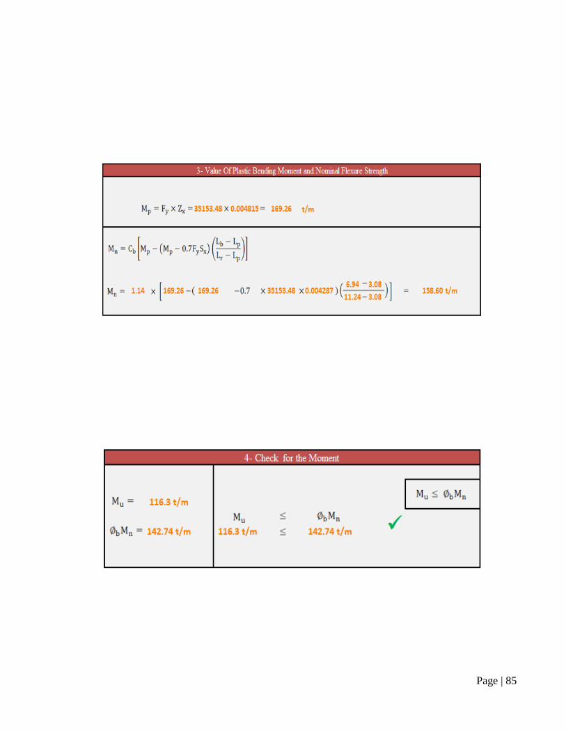
Page | 85
Page | 86
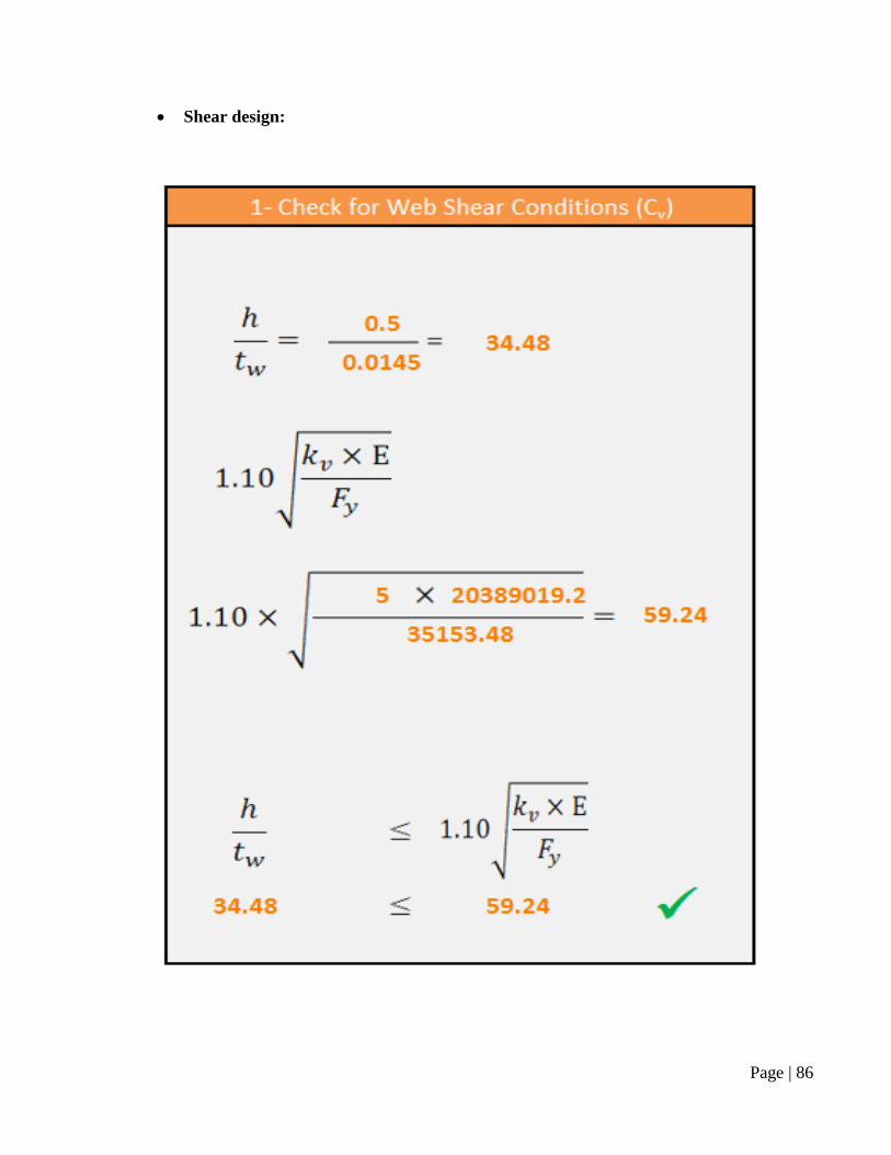
Shear design:
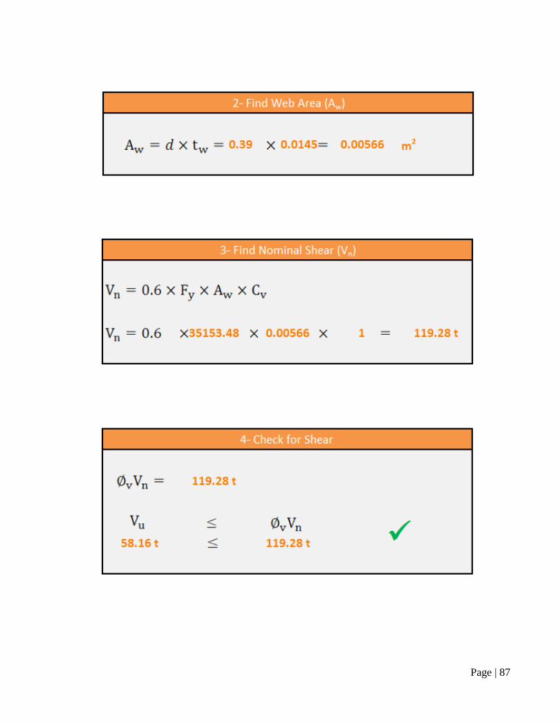
Page | 87
Page | 88
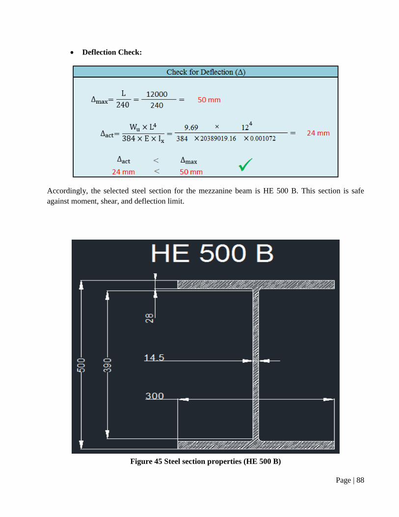
Deflection Check:
Accordingly, the selected steel section for the mezzanine beam is HE 500 B. This section is safe
against moment, shear, and deflection limit.
Figure 45 Steel section properties (HE 500 B)
Page | 89
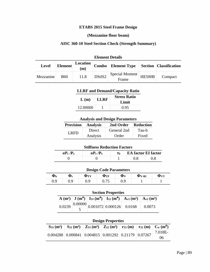
ETABS 2015 Steel Frame Design
(Mezzanine floor beam)
AISC 360-10 Steel Section Check (Strength Summary)
Element Details
Level Element Location
(m) Combo Element Type Section Classification
Mezzanine B60 11.8 DStlS2 Special Moment
Frame HE500B Compact
LLRF and Demand/Capacity Ratio
L (m) LLRF Stress Ratio
Limit
12.00000 1 0.95
Analysis and Design Parameters
Provision Analysis 2nd Order Reduction
LRFD Direct
Analysis
General 2nd
Order
Tau-b
Fixed
Stiffness Reduction Factors
αPr /Py αPr /Pe τb EA factor EI factor
0 0 1 0.8 0.8
Design Code Parameters
Φb Φc ΦTY ΦTF ΦV ΦV-RI ΦVT
0.9 0.9 0.9 0.75 0.9 1 1
Section Properties
A (m²) J (m⁴) I33 (m⁴) I22 (m⁴) Av3 (m²) Av2 (m²)
0.0239 0.00000
5 0.001072 0.000126 0.0168 0.0073
Design Properties
S33 (m³) S22 (m³) Z33 (m³) Z22 (m³) r33 (m) r22 (m) Cw (m⁶)
0.004288 0.000841 0.004815 0.001292 0.21179 0.07267 7.018E-
06
Page | 90
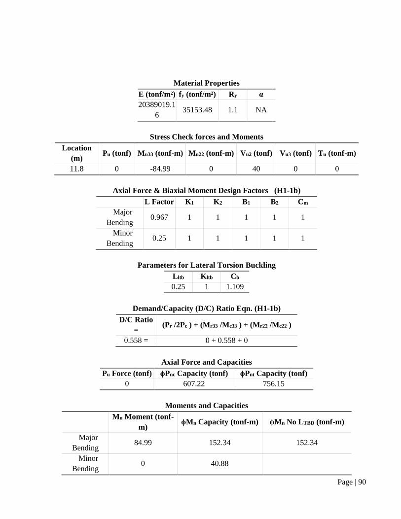
Material Properties
E (tonf/m²) fy (tonf/m²) Ry α
20389019.1
6 35153.48 1.1 NA
Stress Check forces and Moments
Location
(m) Pu (tonf) Mu33 (tonf-m) Mu22 (tonf-m) Vu2 (tonf) Vu3 (tonf) Tu (tonf-m)
11.8 0 -84.99 0 40 0 0
Axial Force & Biaxial Moment Design Factors (H1-1b)
L Factor K1 K2 B1 B2 Cm
Major
Bending 0.967 1 1 1 1 1
Minor
Bending 0.25 1 1 1 1 1
Parameters for Lateral Torsion Buckling
Lltb Kltb Cb
0.25 1 1.109
Demand/Capacity (D/C) Ratio Eqn. (H1-1b)
D/C Ratio
= (Pr /2Pc ) + (Mr33 /Mc33 ) + (Mr22 /Mc22 )
0.558 = 0 + 0.558 + 0
Axial Force and Capacities
Pu Force (tonf) ϕPnc Capacity (tonf) ϕPnt Capacity (tonf)
0 607.22 756.15
Moments and Capacities
Mu Moment (tonf-
m) ϕMn Capacity (tonf-m) ϕMn No LTBD (tonf-m)
Major
Bending 84.99 152.34 152.34
Minor
Bending 0 40.88
Page | 91
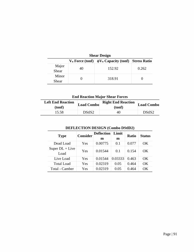
Shear Design
Vu Force (tonf) ϕVn Capacity (tonf) Stress Ratio
Major
Shear 40 152.92 0.262
Minor
Shear 0 318.91 0
End Reaction Major Shear Forces
Left End Reaction
(tonf) Load Combo
Right End Reaction
(tonf) Load Combo
15.58 DStlS2 40 DStlS2
DEFLECTION DESIGN (Combo DStlD2)
Type Consider Deflection
m
Limit
m Ratio Status
Dead Load Yes 0.00775 0.1 0.077 OK
Super DL + Live
Load Yes 0.01544 0.1 0.154 OK
Live Load Yes 0.01544 0.03333 0.463 OK
Total Load Yes 0.02319 0.05 0.464 OK
Total - Camber Yes 0.02319 0.05 0.464 OK
Page | 92
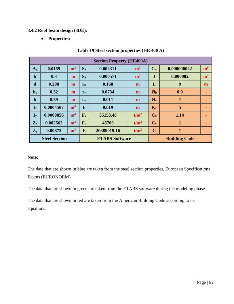
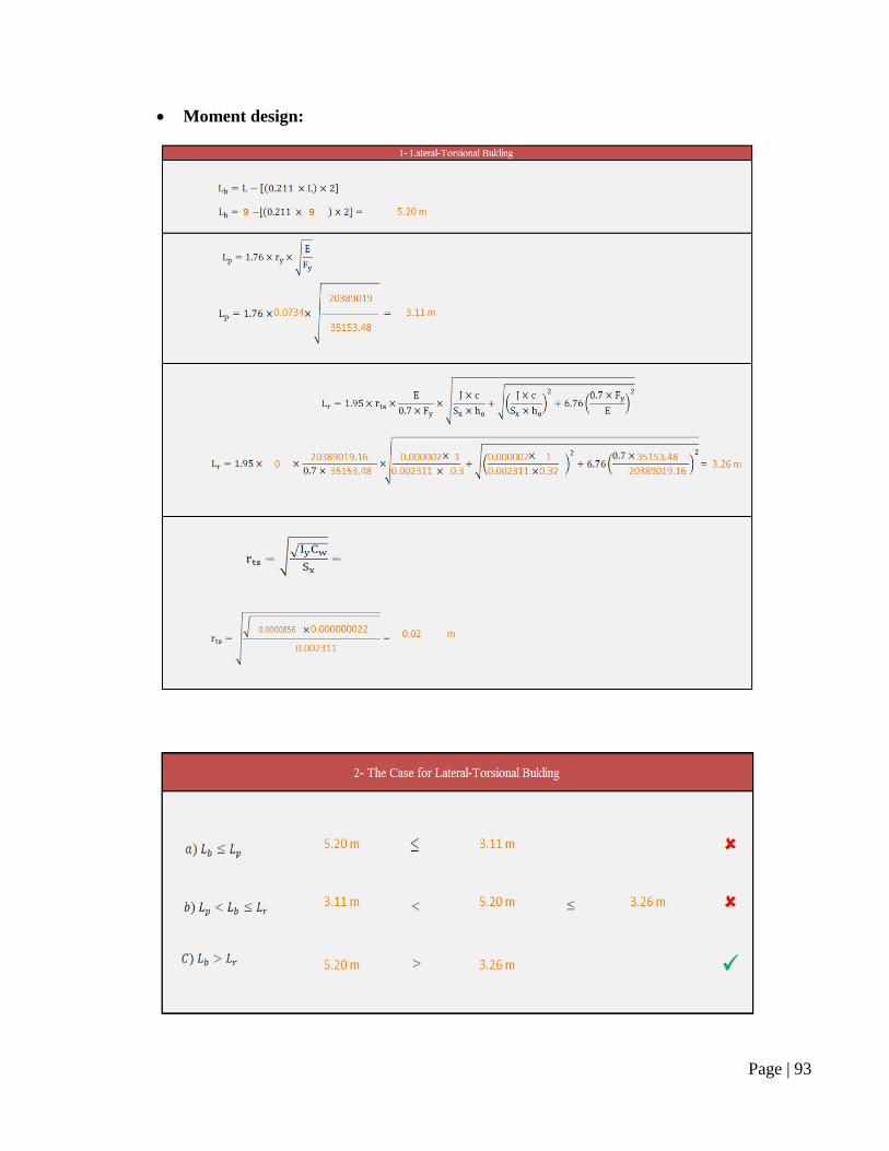
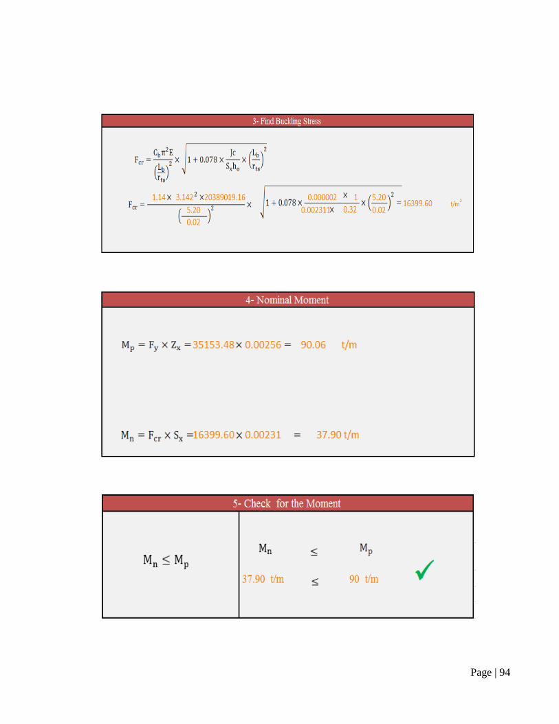
3.4.2 Roof beam design (3DE):
Properties:
Table 19 Steel section properties (HE 400 A)
Section Property (HE400A)
Ag 0.0159 m2 Sx 0.002311 m3 Cw 0.000000022 m6
b 0.3 m Sy 0.000571 m3 J 0.000002 m4
d 0.298 m rx 0.168 m L 9 m
ho 0.32 m ry 0.0734 m Øb 0.9 -
h 0.39 m tw 0.011 m Øv 1 -
Ix 0.0004507 m4 tf 0.019 m Kv 5 -
Iy 0.0000856 m4 Fy 35153.48 t/m2 Cb 1.14 -
Zx 0.002562 m3 Fu 45700 t/m2 Cv 1 -
Zy 0.00873 m3 E 20389019.16 t/m2 C 1 -
Steel Section ETABS Software Building Code
Note:
The date that are shown in blue are taken from the steel section properties, European Specifications
Beams (EURONORM).
The data that are shown in green are taken from the ETABS software during the modeling phase.
The data that are shown in red are taken from the American Building Code according to its
equations.
Page | 93
Moment design:
Page | 94
Page | 95
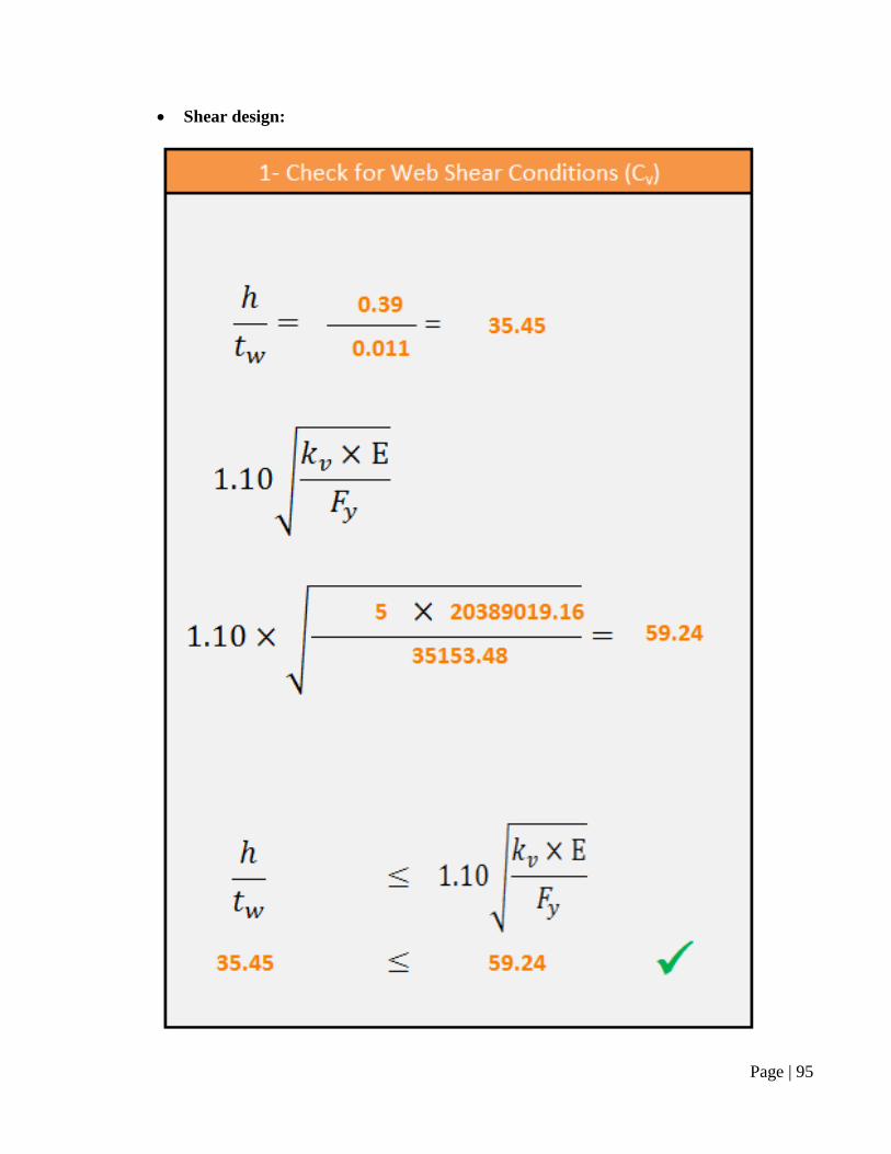
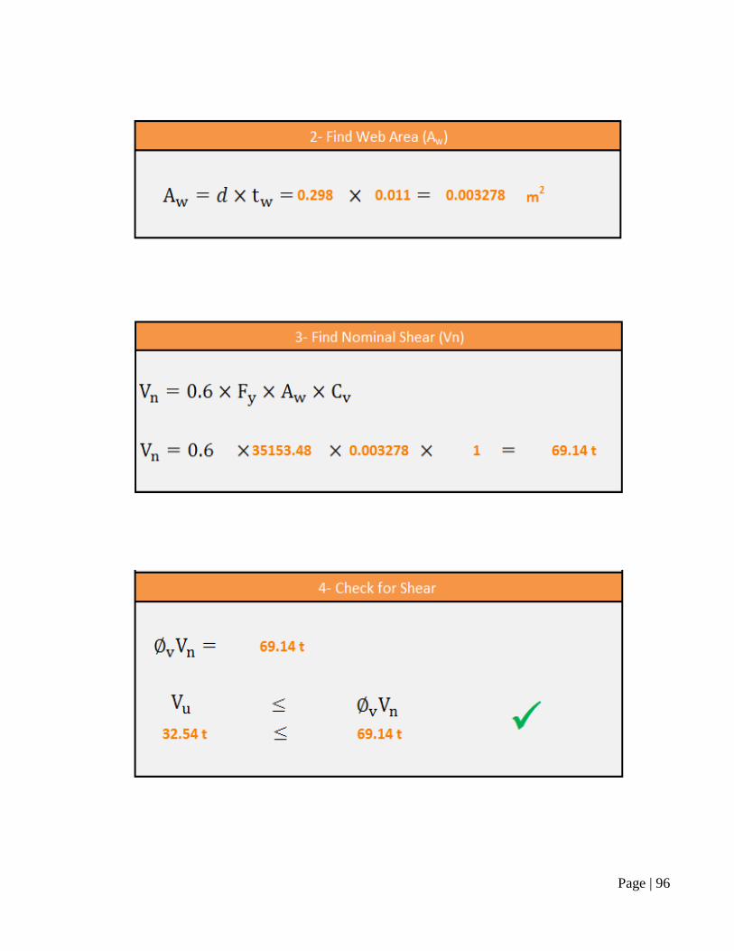
Shear design:
Page | 96
Page | 97
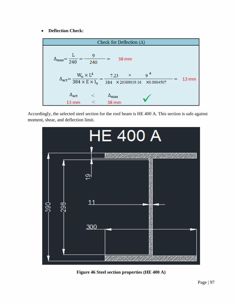
Deflection Check:
Accordingly, the selected steel section for the roof beam is HE 400 A. This section is safe against
moment, shear, and deflection limit.
Figure 46 Steel section properties (HE 400 A)
Page | 98
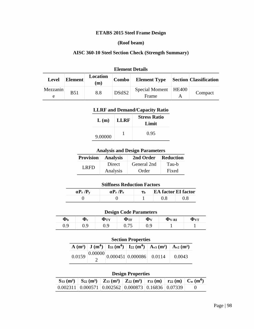
ETABS 2015 Steel Frame Design
(Roof beam)
AISC 360-10 Steel Section Check (Strength Summary)
Element Details
Level Element Location
(m) Combo Element Type Section Classification
Mezzanin
e B51 8.8 DStlS2
Special Moment
Frame
HE400
A Compact
LLRF and Demand/Capacity Ratio
L (m) LLRF Stress Ratio
Limit
9.00000 1 0.95
Analysis and Design Parameters
Provision Analysis 2nd Order Reduction
LRFD Direct
Analysis
General 2nd
Order
Tau-b
Fixed
Stiffness Reduction Factors
αPr /Py αPr /Pe τb EA factor EI factor
0 0 1 0.8 0.8
Design Code Parameters
Φb Φc ΦTY ΦTF ΦV ΦV-RI ΦVT
0.9 0.9 0.9 0.75 0.9 1 1
Section Properties
A (m²) J (m⁴) I33 (m⁴) I22 (m⁴) Av3 (m²) Av2 (m²)
0.0159 0.00000
2 0.000451 0.000086 0.0114 0.0043
Design Properties
S33 (m³) S22 (m³) Z33 (m³) Z22 (m³) r33 (m) r22 (m) Cw (m⁶)
0.002311 0.000571 0.002562 0.000873 0.16836 0.07339 0
Page | 99
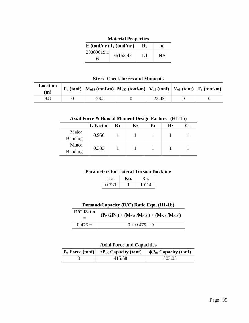
Material Properties
E (tonf/m²) fy (tonf/m²) Ry α
20389019.1
6 35153.48 1.1 NA
Stress Check forces and Moments
Location
(m) Pu (tonf) Mu33 (tonf-m) Mu22 (tonf-m) Vu2 (tonf) Vu3 (tonf) Tu (tonf-m)
8.8 0 -38.5 0 23.49 0 0
Axial Force & Biaxial Moment Design Factors (H1-1b)
L Factor K1 K2 B1 B2 Cm
Major
Bending 0.956 1 1 1 1 1
Minor
Bending 0.333 1 1 1 1 1
Parameters for Lateral Torsion Buckling
Lltb Kltb Cb
0.333 1 1.014
Demand/Capacity (D/C) Ratio Eqn. (H1-1b)
D/C Ratio
= (Pr /2Pc ) + (Mr33 /Mc33 ) + (Mr22 /Mc22 )
0.475 = 0 + 0.475 + 0
Axial Force and Capacities
Pu Force (tonf) ϕPnc Capacity (tonf) ϕPnt Capacity (tonf)
0 415.68 503.05
Page | 100
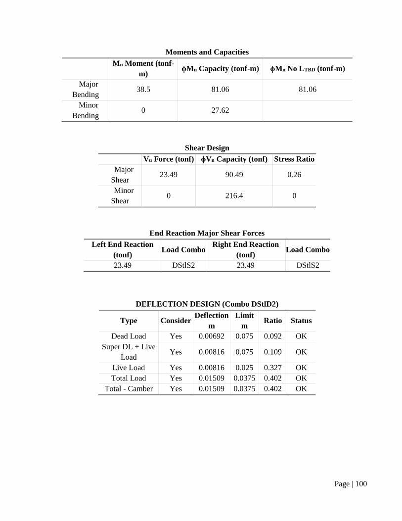
Moments and Capacities
Mu Moment (tonf-
m) ϕMn Capacity (tonf-m) ϕMn No LTBD (tonf-m)
Major
Bending 38.5 81.06 81.06
Minor
Bending 0 27.62
Shear Design
Vu Force (tonf) ϕVn Capacity (tonf) Stress Ratio
Major
Shear 23.49 90.49 0.26
Minor
Shear 0 216.4 0
End Reaction Major Shear Forces
Left End Reaction
(tonf) Load Combo
Right End Reaction
(tonf) Load Combo
23.49 DStlS2 23.49 DStlS2
DEFLECTION DESIGN (Combo DStlD2)
Type Consider Deflection
m
Limit
m Ratio Status
Dead Load Yes 0.00692 0.075 0.092 OK
Super DL + Live
Load Yes 0.00816 0.075 0.109 OK
Live Load Yes 0.00816 0.025 0.327 OK
Total Load Yes 0.01509 0.0375 0.402 OK
Total - Camber Yes 0.01509 0.0375 0.402 OK
Page | 101
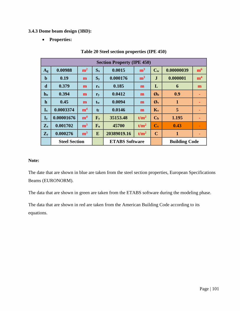
3.4.3 Dome beam design (3BD):
Properties:
Table 20 Steel section properties (IPE 450)
Section Property (IPE 450)
Ag 0.00988 m2 Sx 0.0015 m3 Cw 0.00000039 m6
b 0.19 m Sy 0.000176 m3 J 0.000001 m4
d 0.379 m rx 0.185 m L 6 m
ho 0.394 m ry 0.0412 m Øb 0.9 -
h 0.45 m tw 0.0094 m Øv 1 -
Ix 0.0003374 m4 tf 0.0146 m Kv 5 -
Iy 0.00001676 m4 Fy 35153.48 t/m2 Cb 1.195 -
Zx 0.001702 m3 Fu 45700 t/m2 Cv 0.43 -
Zy 0.000276 m3 E 20389019.16 t/m2 C 1 -
Steel Section ETABS Software Building Code
Note:
The date that are shown in blue are taken from the steel section properties, European Specifications
Beams (EURONORM).
The data that are shown in green are taken from the ETABS software during the modeling phase.
The data that are shown in red are taken from the American Building Code according to its
equations.
Page | 102
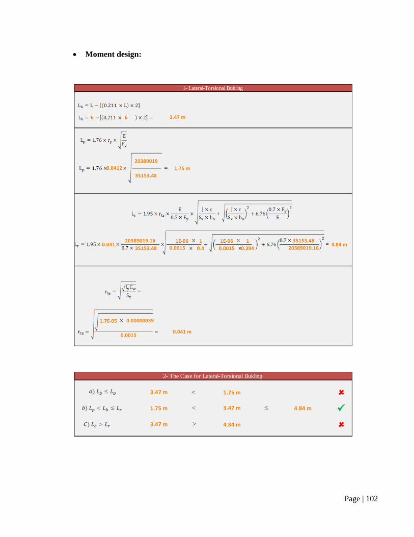
Moment design:
6 6
20389019
1.75 m
35153.48
1E-06 1 1E-06 1
35153.48 0.4 0.0015 0.394
1.7E-05 0.00000039
0.041 m0.0015
0.04120389019.16 35153.48
4.84 m0.0015 20389019.16
0.0412
1- Lateral-Torsional Bukling
3.47 m
1.75 m 3.47 m 4.84 m
3.47 m 4.84 m
2- The Case for Lateral-Torsional Bukling
3.47 m 1.75 m
Page | 103
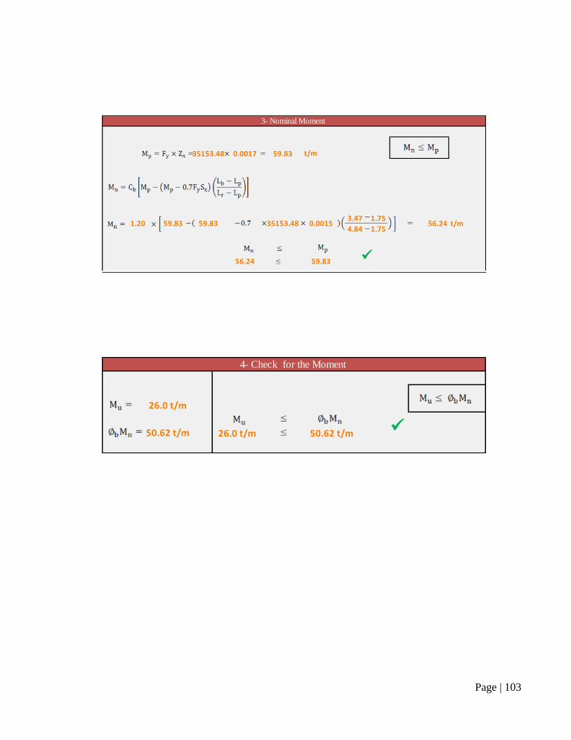
35153.48 0.0017 59.83 t/m
3.47 1.75
4.84 1.75
56.24 59.83
0.0015 56.24 t/m
35153.481.20 59.83 59.83
3- Nominal Moment
26.0 t/m 50.62 t/m
4- Check for the Moment
26.0 t/m
50.62 t/m
Page | 104
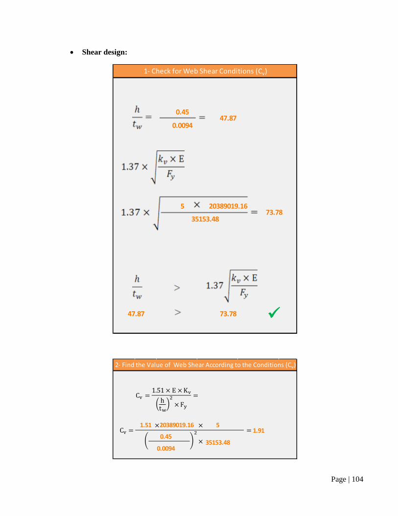
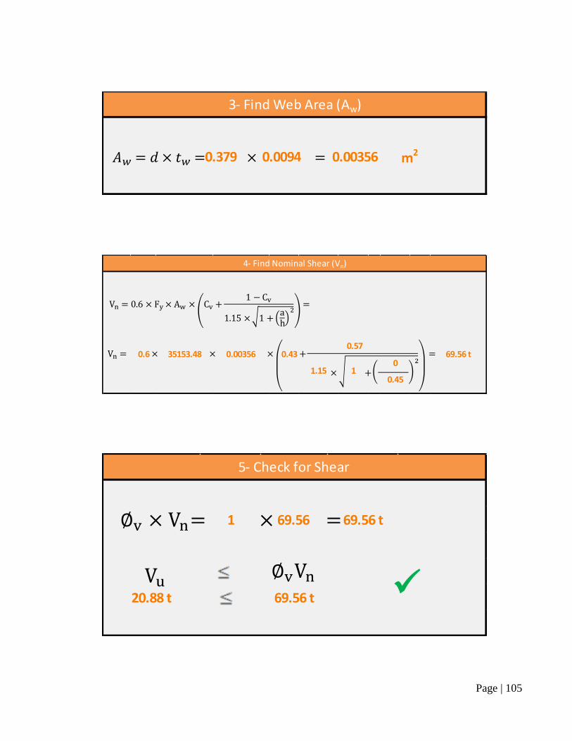
Shear design:
0.45
0.0094
5 20389019.16
47.87 73.78
35153.48
1- Check for Web Shear Conditions (Cv)
47.87
73.78
1.51 20389019.16 5
0.45
0.009435153.48
1.91
2- Find the Value of Web Shear According to the Conditions (Cv)
Page | 105
0.379 0.0094 0.00356 m2
3- Find Web Area (Aw)
0
0.45
4- Find Nominal Shear (Vn)
69.56 t35153.48 0.003560.57
1.15 1
0.430.6
1 69.56 69.56 t
20.88 t 69.56 t
5- Check for Shear
∅
∅
Page | 106
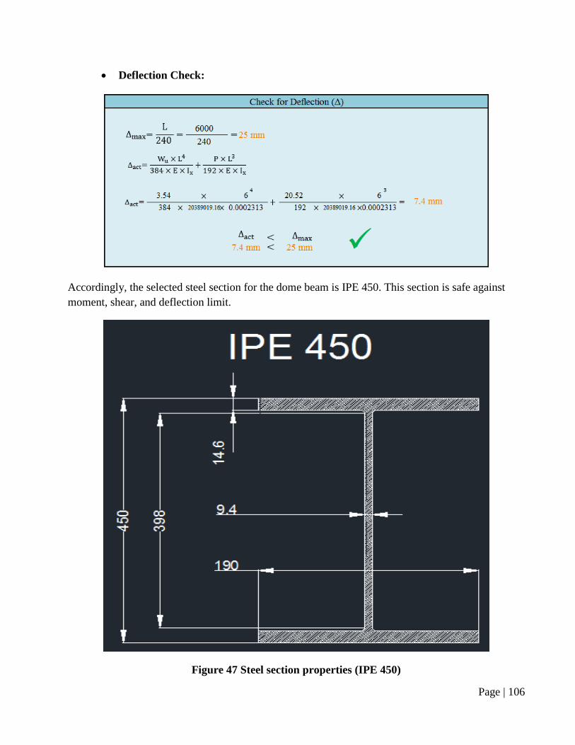
Deflection Check:
Accordingly, the selected steel section for the dome beam is IPE 450. This section is safe against
moment, shear, and deflection limit.
Figure 47 Steel section properties (IPE 450)
Page | 107
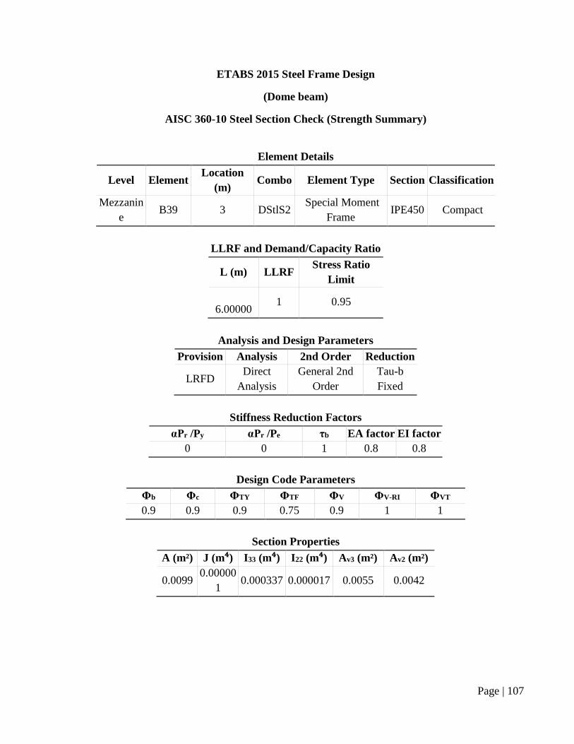
ETABS 2015 Steel Frame Design
(Dome beam)
AISC 360-10 Steel Section Check (Strength Summary)
Element Details
Level Element Location
(m) Combo Element Type Section Classification
Mezzanin
e B39 3 DStlS2
Special Moment
Frame IPE450 Compact
LLRF and Demand/Capacity Ratio
L (m) LLRF Stress Ratio
Limit
6.00000 1 0.95
Analysis and Design Parameters
Provision Analysis 2nd Order Reduction
LRFD Direct
Analysis
General 2nd
Order
Tau-b
Fixed
Stiffness Reduction Factors
αPr /Py αPr /Pe τb EA factor EI factor
0 0 1 0.8 0.8
Design Code Parameters
Φb Φc ΦTY ΦTF ΦV ΦV-RI ΦVT
0.9 0.9 0.9 0.75 0.9 1 1
Section Properties
A (m²) J (m⁴) I33 (m⁴) I22 (m⁴) Av3 (m²) Av2 (m²)
0.0099 0.00000
1 0.000337 0.000017 0.0055 0.0042
Page | 108
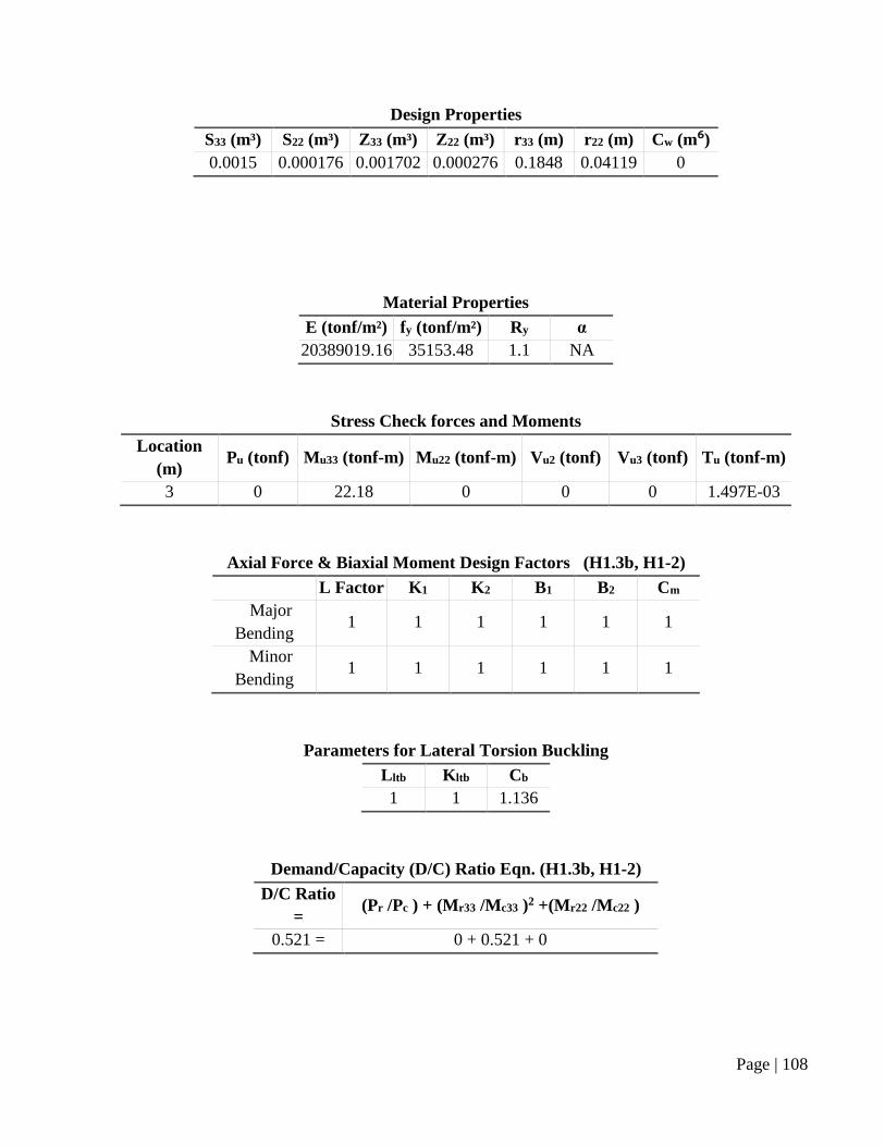
Design Properties
S33 (m³) S22 (m³) Z33 (m³) Z22 (m³) r33 (m) r22 (m) Cw (m⁶)
0.0015 0.000176 0.001702 0.000276 0.1848 0.04119 0
Material Properties
E (tonf/m²) fy (tonf/m²) Ry α
20389019.16 35153.48 1.1 NA
Stress Check forces and Moments
Location
(m) Pu (tonf) Mu33 (tonf-m) Mu22 (tonf-m) Vu2 (tonf) Vu3 (tonf) Tu (tonf-m)
3 0 22.18 0 0 0 1.497E-03
Axial Force & Biaxial Moment Design Factors (H1.3b, H1-2)
L Factor K1 K2 B1 B2 Cm
Major
Bending 1 1 1 1 1 1
Minor
Bending 1 1 1 1 1 1
Parameters for Lateral Torsion Buckling
Lltb Kltb Cb
1 1 1.136
Demand/Capacity (D/C) Ratio Eqn. (H1.3b, H1-2)
D/C Ratio
= (Pr /Pc ) + (Mr33 /Mc33 )2 +(Mr22 /Mc22 )
0.521 = 0 + 0.521 + 0
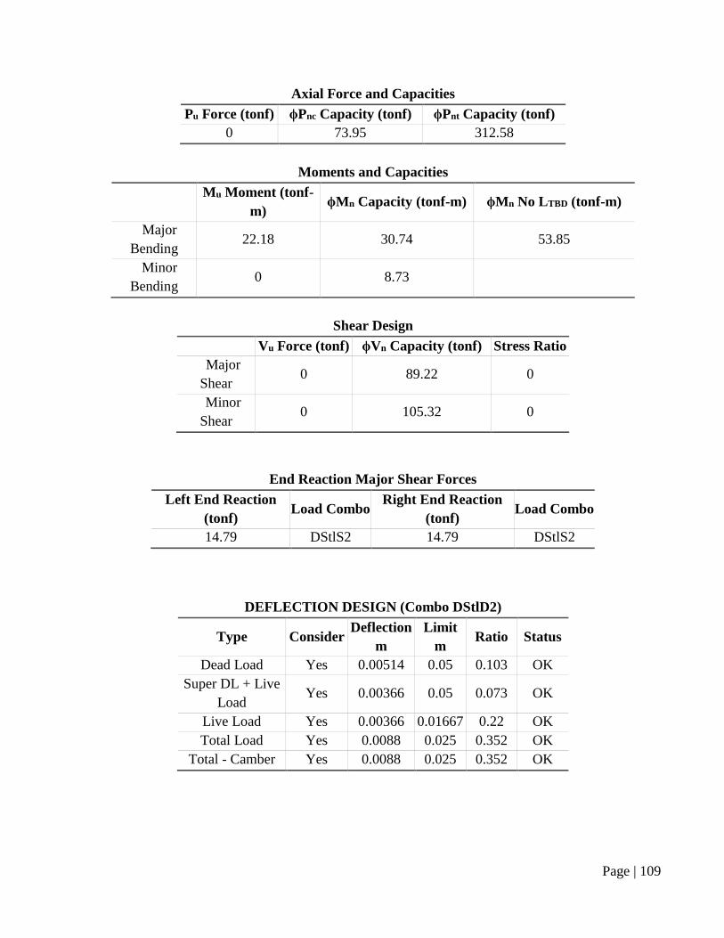
Page | 109
Axial Force and Capacities
Pu Force (tonf) ϕPnc Capacity (tonf) ϕPnt Capacity (tonf)
0 73.95 312.58
Moments and Capacities
Mu Moment (tonf-
m) ϕMn Capacity (tonf-m) ϕMn No LTBD (tonf-m)
Major
Bending 22.18 30.74 53.85
Minor
Bending 0 8.73
Shear Design
Vu Force (tonf) ϕVn Capacity (tonf) Stress Ratio
Major
Shear 0 89.22 0
Minor
Shear 0 105.32 0
End Reaction Major Shear Forces
Left End Reaction
(tonf) Load Combo
Right End Reaction
(tonf) Load Combo
14.79 DStlS2 14.79 DStlS2
DEFLECTION DESIGN (Combo DStlD2)
Type Consider Deflection
m
Limit
m Ratio Status
Dead Load Yes 0.00514 0.05 0.103 OK
Super DL + Live
Load Yes 0.00366 0.05 0.073 OK
Live Load Yes 0.00366 0.01667 0.22 OK
Total Load Yes 0.0088 0.025 0.352 OK
Total - Camber Yes 0.0088 0.025 0.352 OK
Page | 110
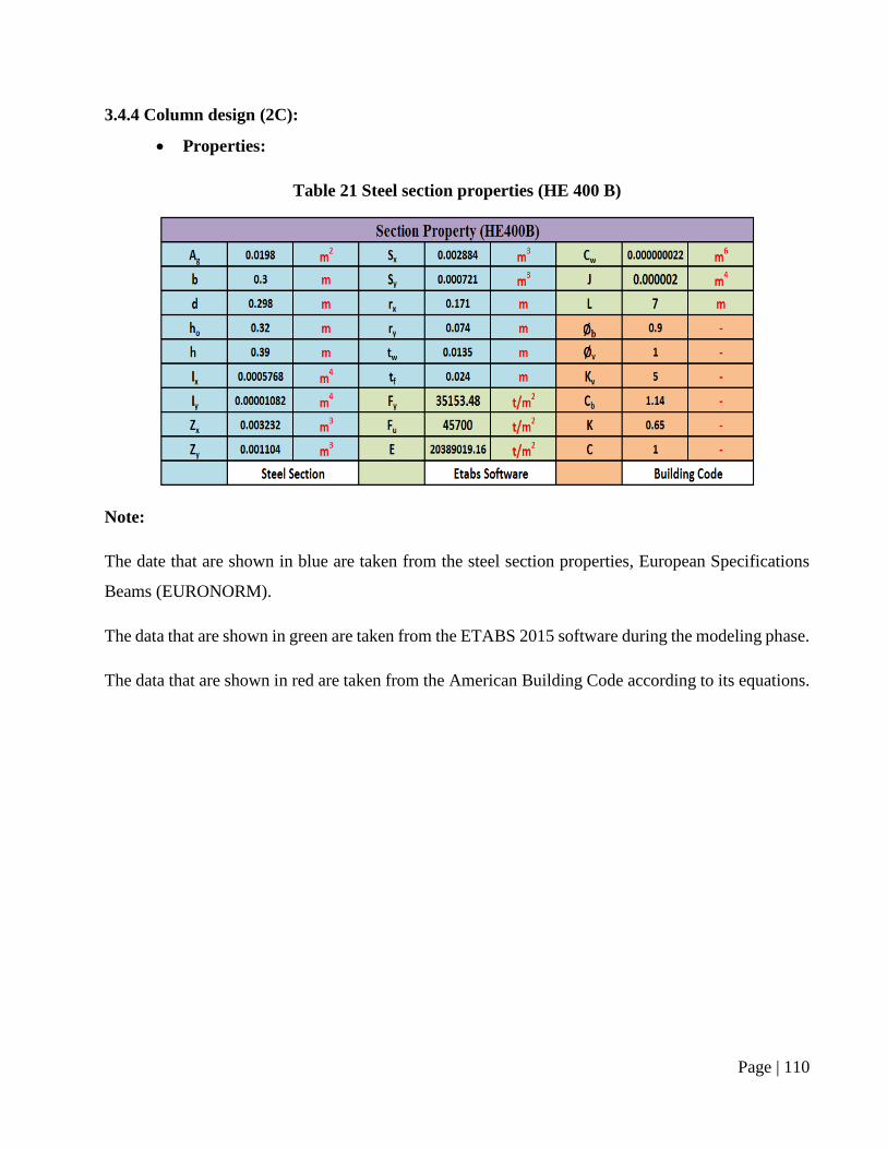
3.4.4 Column design (2C):
Properties:
Table 21 Steel section properties (HE 400 B)
Note:
The date that are shown in blue are taken from the steel section properties, European Specifications
Beams (EURONORM).
The data that are shown in green are taken from the ETABS 2015 software during the modeling phase.
The data that are shown in red are taken from the American Building Code according to its equations.
Page | 111
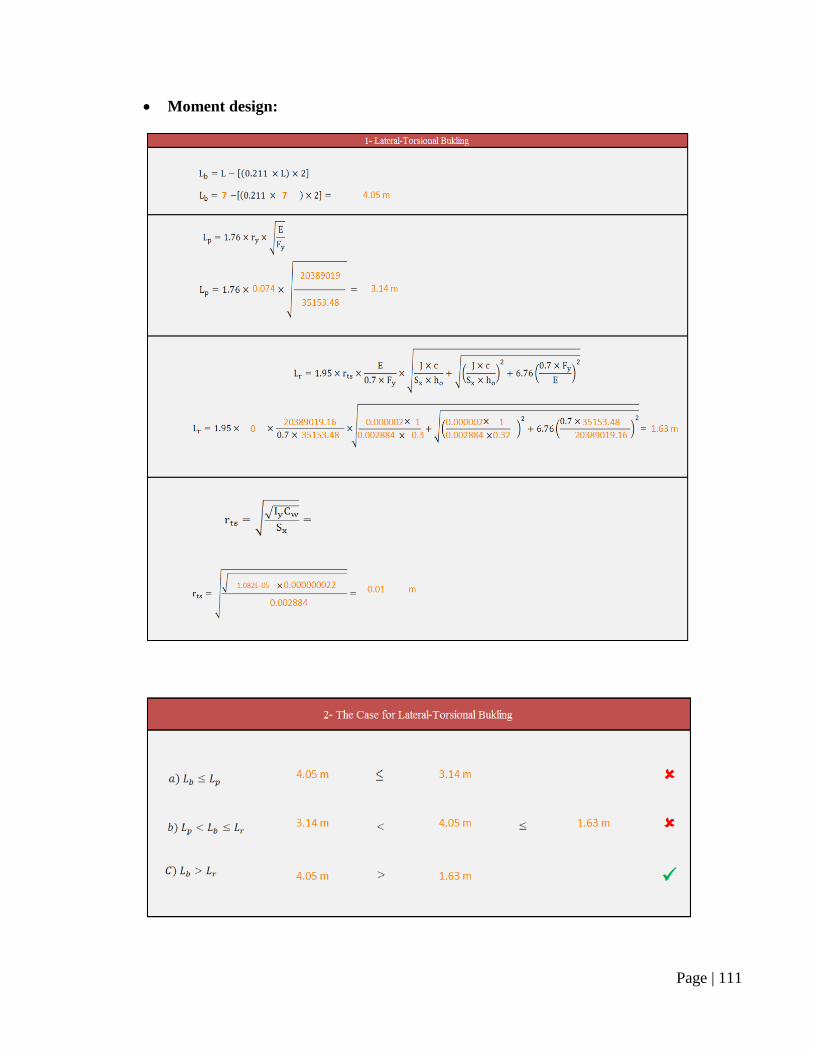
Moment design:
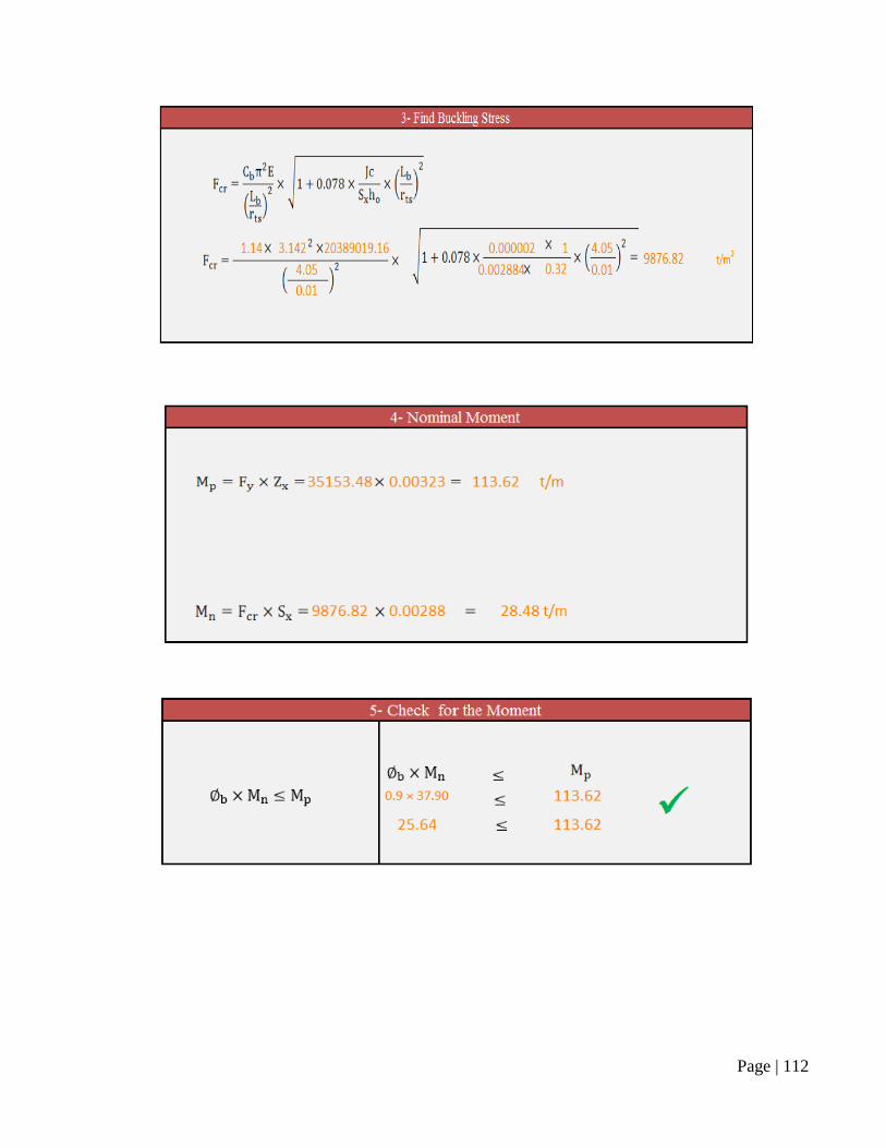
Page | 112
Page | 113
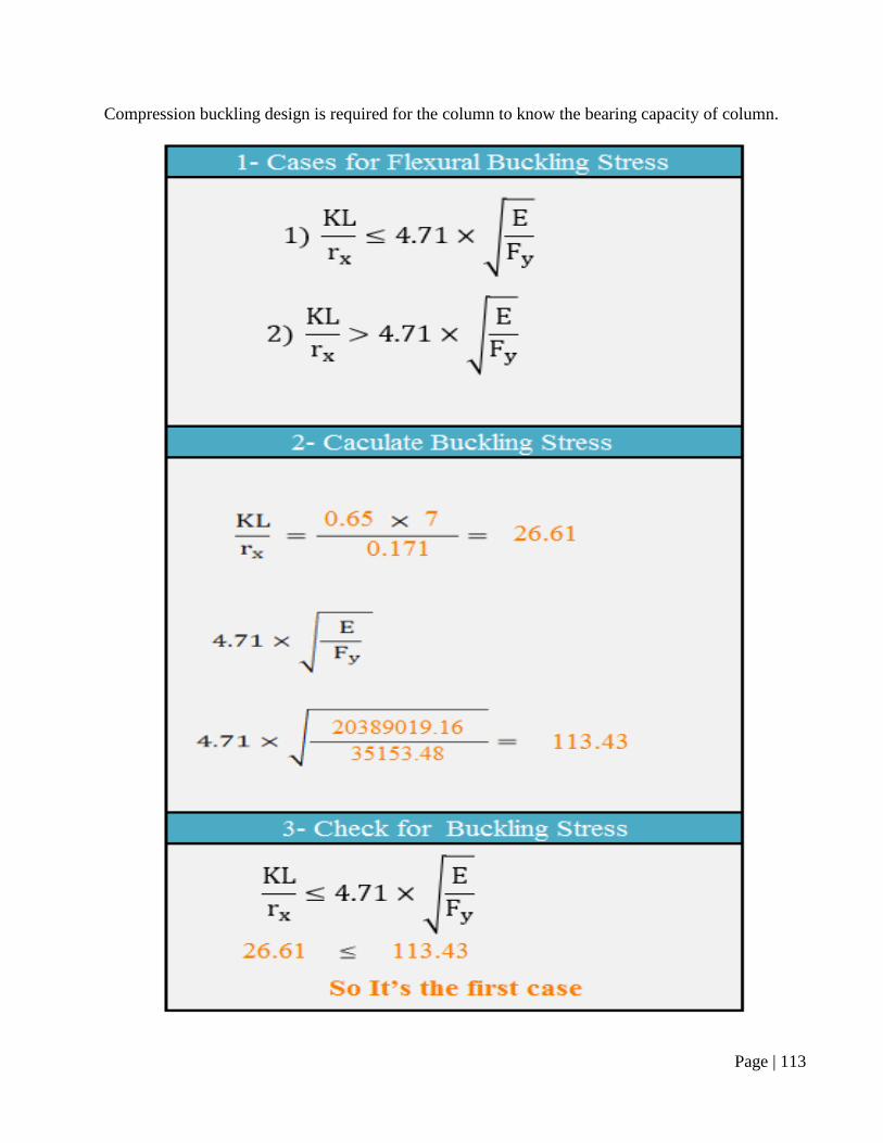
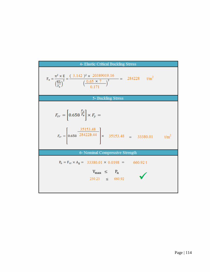
Compression buckling design is required for the column to know the bearing capacity of column.
Page | 114
Page | 115
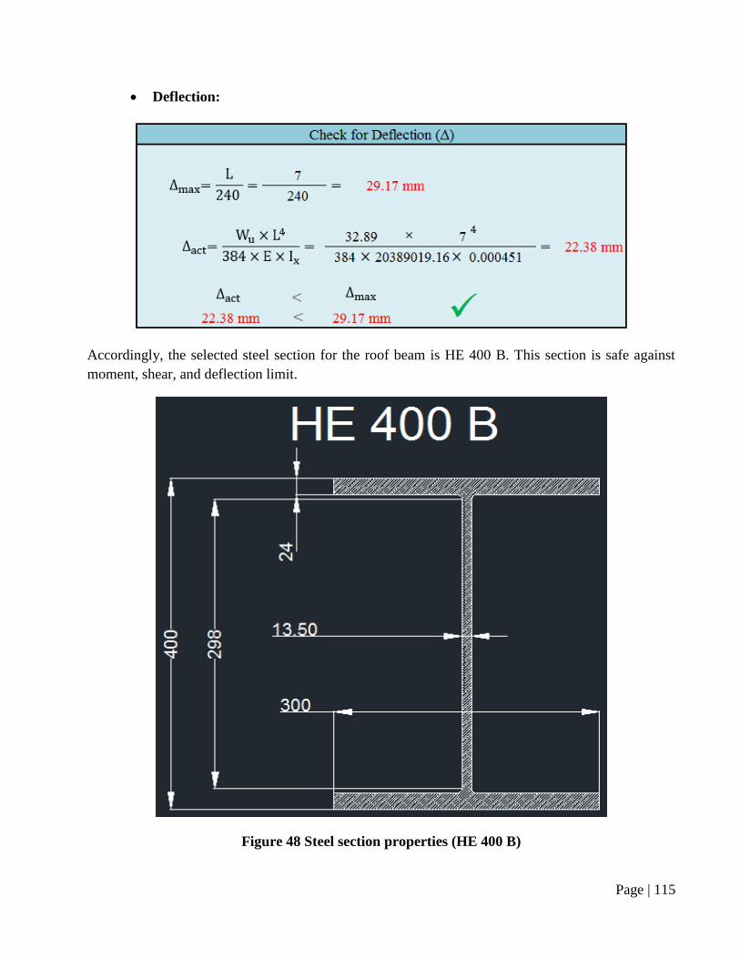
Deflection:
Accordingly, the selected steel section for the roof beam is HE 400 B. This section is safe against
moment, shear, and deflection limit.
Figure 48 Steel section properties (HE 400 B)
Page | 116
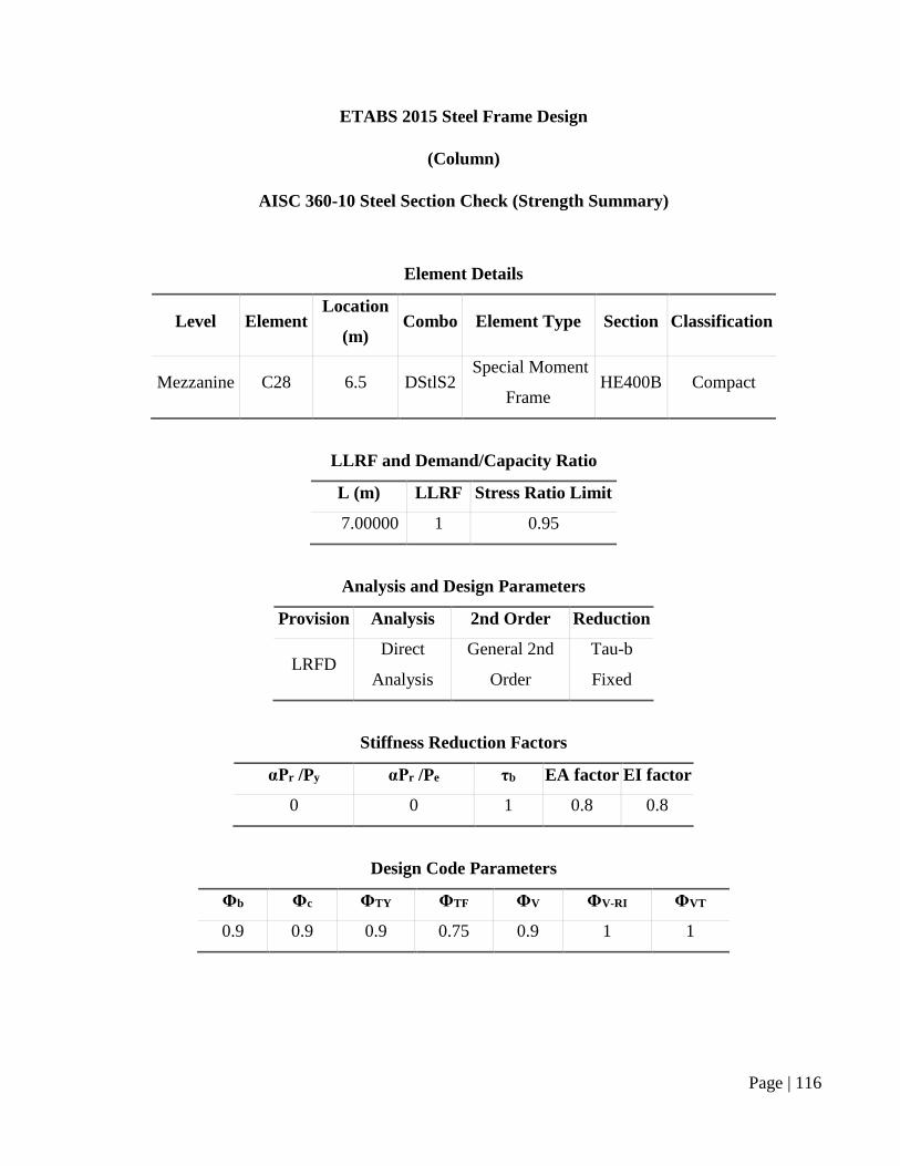
ETABS 2015 Steel Frame Design
(Column)
AISC 360-10 Steel Section Check (Strength Summary)
Element Details
Level Element Location
(m) Combo Element Type Section Classification
Mezzanine C28 6.5 DStlS2 Special Moment
Frame HE400B Compact
LLRF and Demand/Capacity Ratio
L (m) LLRF Stress Ratio Limit
7.00000 1 0.95
Analysis and Design Parameters
Provision Analysis 2nd Order Reduction
LRFD Direct
Analysis
General 2nd
Order
Tau-b
Fixed
Stiffness Reduction Factors
αPr /Py αPr /Pe τb EA factor EI factor
0 0 1 0.8 0.8
Design Code Parameters
Φb Φc ΦTY ΦTF ΦV ΦV-RI ΦVT
0.9 0.9 0.9 0.75 0.9 1 1
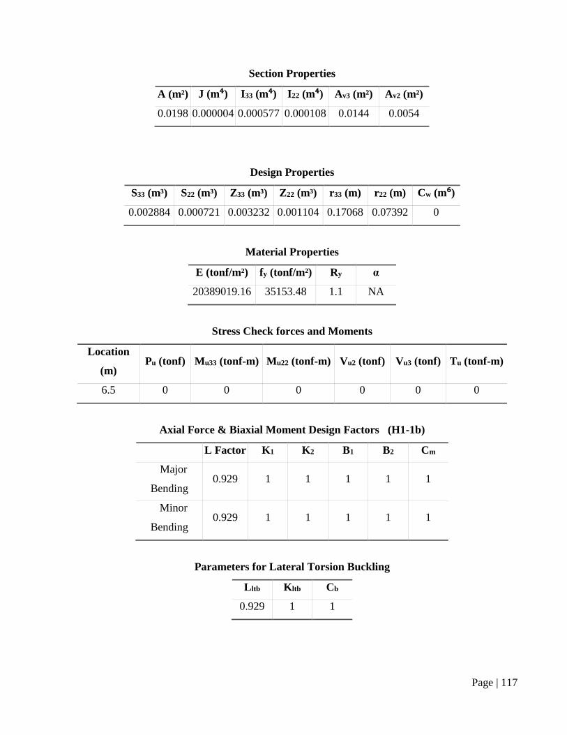
Page | 117
Section Properties
A (m²) J (m⁴) I33 (m⁴) I22 (m⁴) Av3 (m²) Av2 (m²)
0.0198 0.000004 0.000577 0.000108 0.0144 0.0054
Design Properties
S33 (m³) S22 (m³) Z33 (m³) Z22 (m³) r33 (m) r22 (m) Cw (m⁶)
0.002884 0.000721 0.003232 0.001104 0.17068 0.07392 0
Material Properties
E (tonf/m²) fy (tonf/m²) Ry α
20389019.16 35153.48 1.1 NA
Stress Check forces and Moments
Location
(m) Pu (tonf) Mu33 (tonf-m) Mu22 (tonf-m) Vu2 (tonf) Vu3 (tonf) Tu (tonf-m)
6.5 0 0 0 0 0 0
Axial Force & Biaxial Moment Design Factors (H1-1b)
L Factor K1 K2 B1 B2 Cm
Major
Bending 0.929 1 1 1 1 1
Minor
Bending 0.929 1 1 1 1 1
Parameters for Lateral Torsion Buckling
Lltb Kltb Cb
0.929 1 1
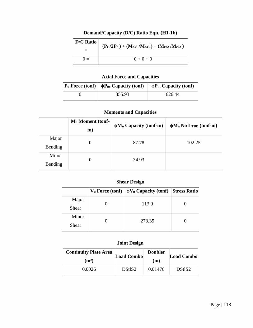
Page | 118
Demand/Capacity (D/C) Ratio Eqn. (H1-1b)
D/C Ratio
= (Pr /2Pc ) + (Mr33 /Mc33 ) + (Mr22 /Mc22 )
0 = 0 + 0 + 0
Axial Force and Capacities
Pu Force (tonf) ϕPnc Capacity (tonf) ϕPnt Capacity (tonf)
0 355.93 626.44
Moments and Capacities
Mu Moment (tonf-
m) ϕMn Capacity (tonf-m) ϕMn No LTBD (tonf-m)
Major
Bending 0 87.78 102.25
Minor
Bending 0 34.93
Shear Design
Vu Force (tonf) ϕVn Capacity (tonf) Stress Ratio
Major
Shear 0 113.9 0
Minor
Shear 0 273.35 0
Joint Design
Continuity Plate Area
(m²) Load Combo
Doubler
(m) Load Combo
0.0026 DStlS2 0.01476 DStlS2
Page | 119
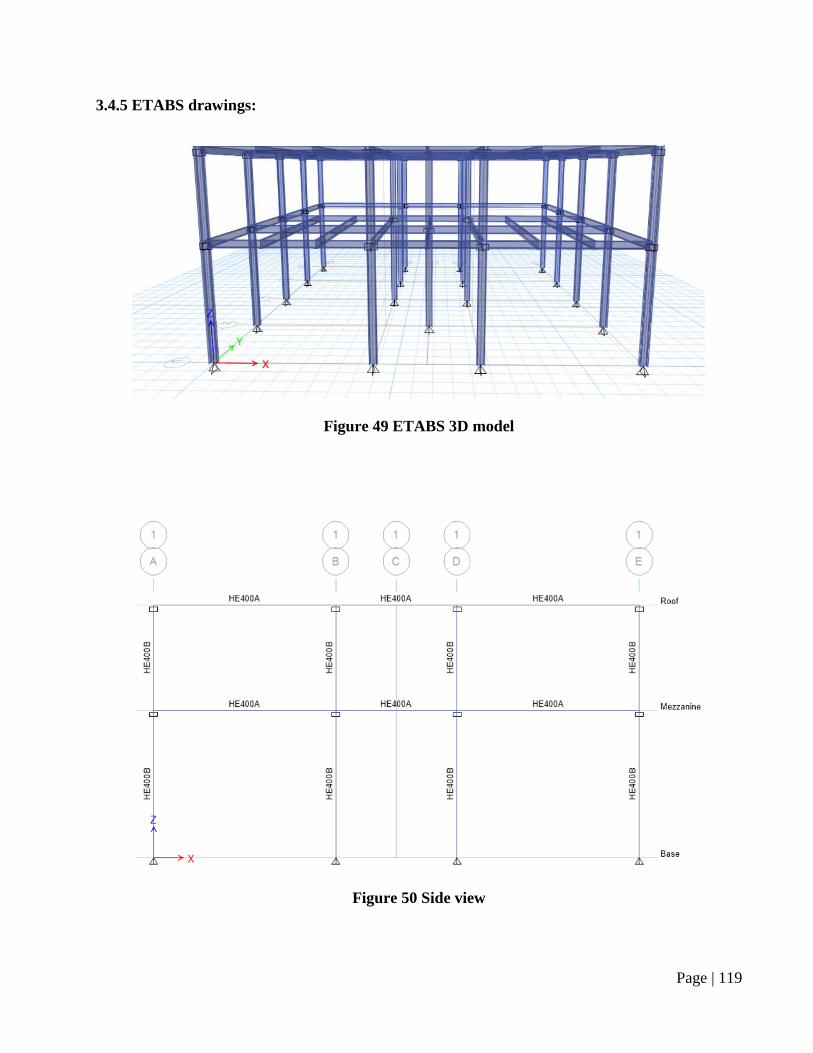
3.4.5 ETABS drawings:
Figure 49 ETABS 3D model
Figure 50 Side view
Page | 120
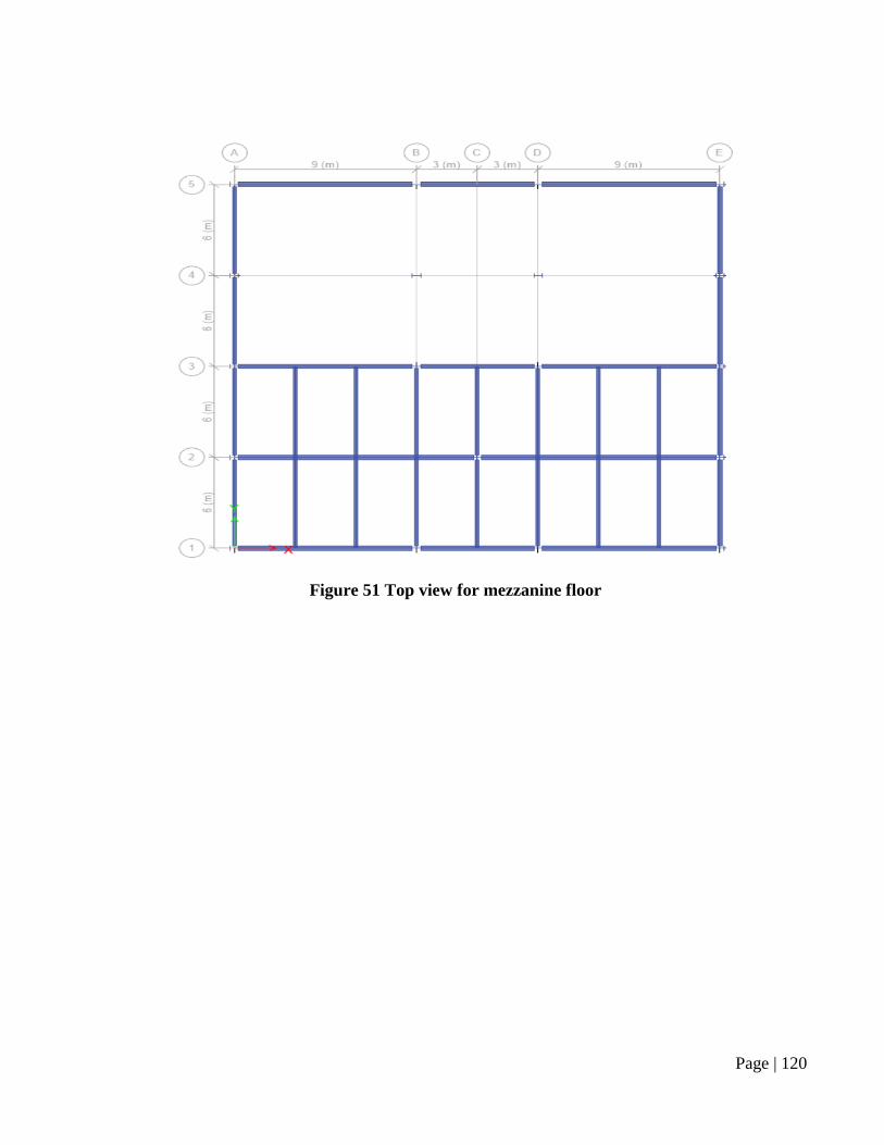
Figure 51 Top view for mezzanine floor
Page | 121
Figure 52 Top view of sections for mezzanine floor
Figure 53 Top view for roof
Page | 122
Figure 54 Top view of sections for roof
Page | 123
Figure 55 Steel stress ratio (column)
Page | 124
Figure 56 Steel stress ratio (mezzanine and roof)
Page | 125
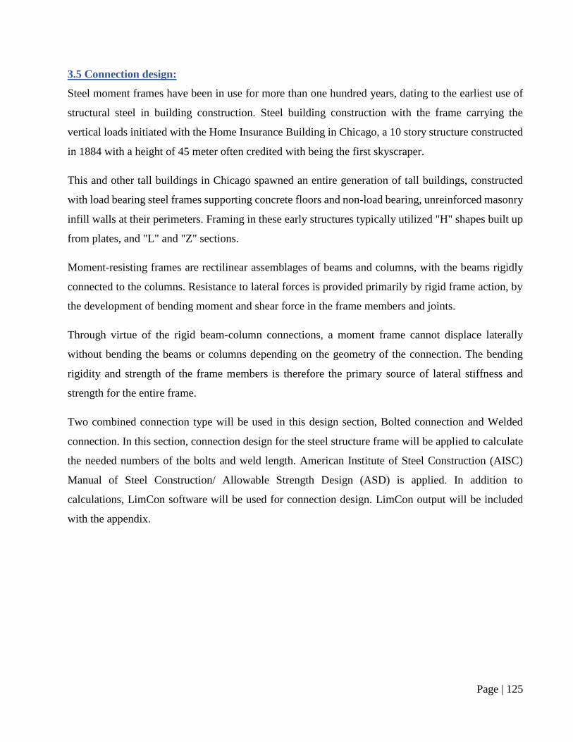
3.5 Connection design:
Steel moment frames have been in use for more than one hundred years, dating to the earliest use of
structural steel in building construction. Steel building construction with the frame carrying the
vertical loads initiated with the Home Insurance Building in Chicago, a 10 story structure constructed
in 1884 with a height of 45 meter often credited with being the first skyscraper.
This and other tall buildings in Chicago spawned an entire generation of tall buildings, constructed
with load bearing steel frames supporting concrete floors and non-load bearing, unreinforced masonry
infill walls at their perimeters. Framing in these early structures typically utilized "H" shapes built up
from plates, and "L" and "Z" sections.
Moment-resisting frames are rectilinear assemblages of beams and columns, with the beams rigidly
connected to the columns. Resistance to lateral forces is provided primarily by rigid frame action, by
the development of bending moment and shear force in the frame members and joints.
Through virtue of the rigid beam-column connections, a moment frame cannot displace laterally
without bending the beams or columns depending on the geometry of the connection. The bending
rigidity and strength of the frame members is therefore the primary source of lateral stiffness and
strength for the entire frame.
Two combined connection type will be used in this design section, Bolted connection and Welded
connection. In this section, connection design for the steel structure frame will be applied to calculate
the needed numbers of the bolts and weld length. American Institute of Steel Construction (AISC)
Manual of Steel Construction/ Allowable Strength Design (ASD) is applied. In addition to
calculations, LimCon software will be used for connection design. LimCon output will be included
with the appendix.
Page | 126
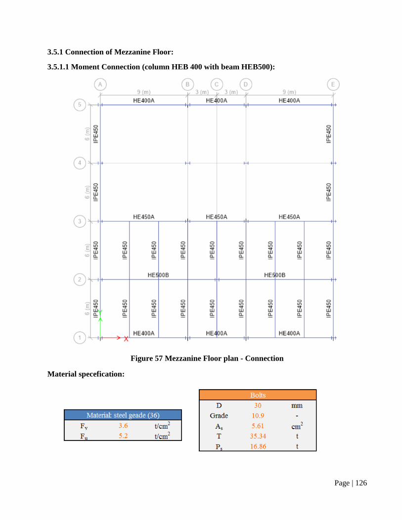
3.5.1 Connection of Mezzanine Floor:
3.5.1.1 Moment Connection (column HEB 400 with beam HEB500):
Figure 57 Mezzanine Floor plan - Connection
Material specefication:
Page | 127
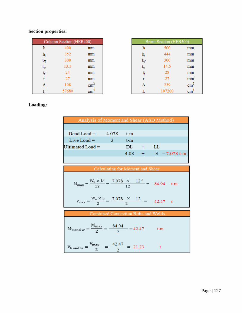
Section properties:
Loading:
Page | 128
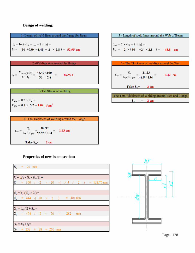
Design of welding:
Properties of new beam section:
Page | 129
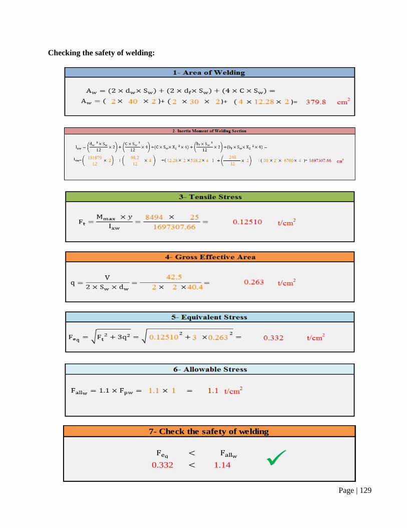
Checking the safety of welding:
7- Check the safety of welding
0.332 1.14
Page | 130
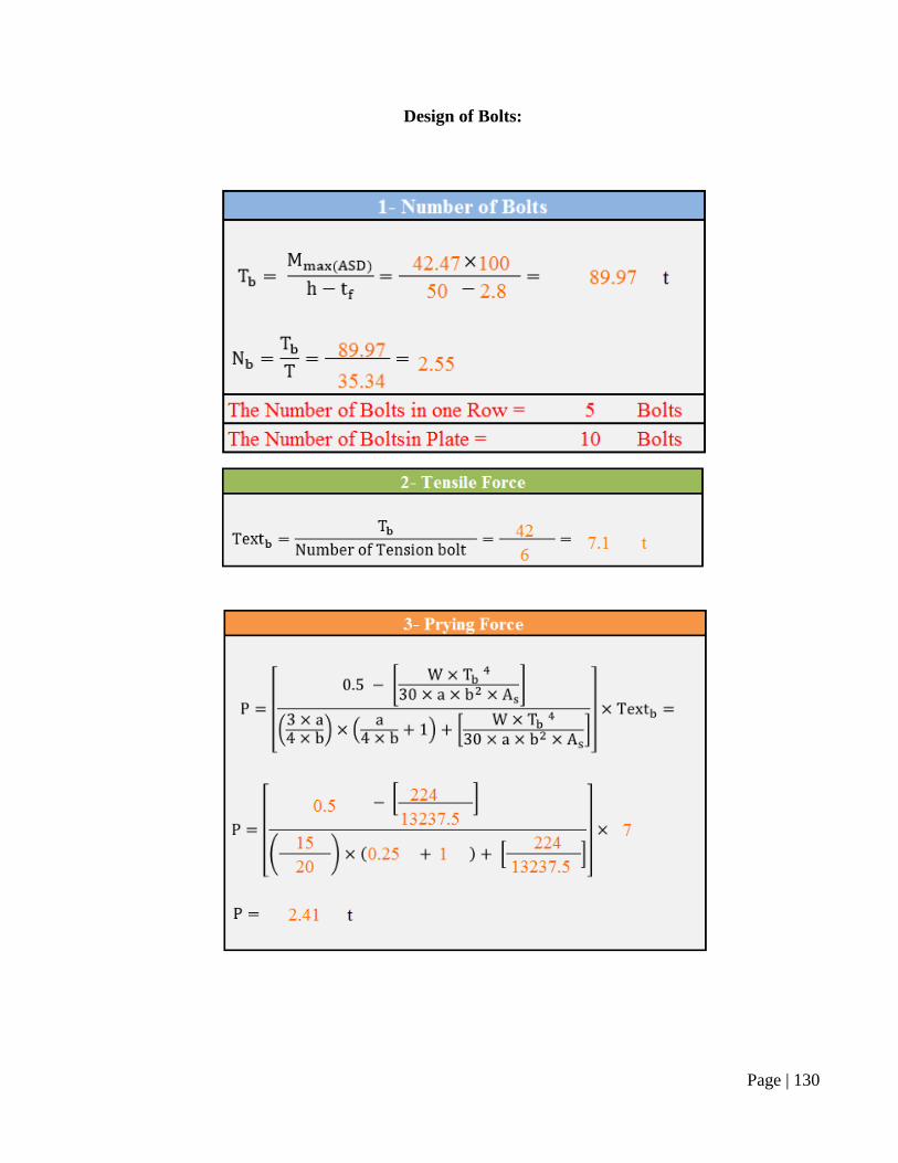
Design of Bolts:
Page | 131
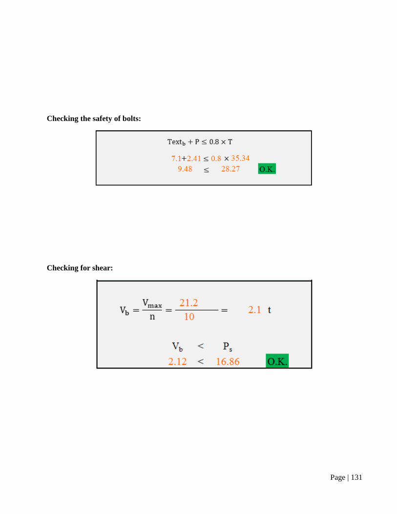
Checking the safety of bolts:
Checking for shear:
Page | 132
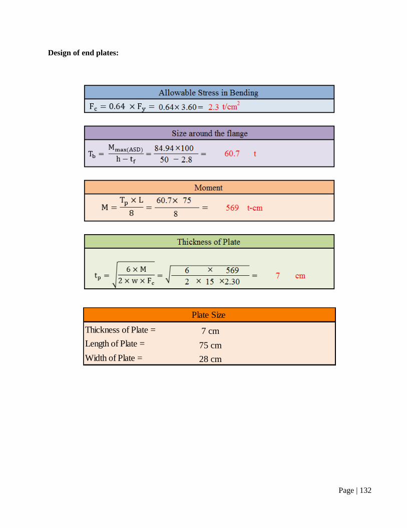
Design of end plates:
Thickness of Plate = 7 cm
Length of Plate = 75 cm
Width of Plate = 28 cm
Plate Size
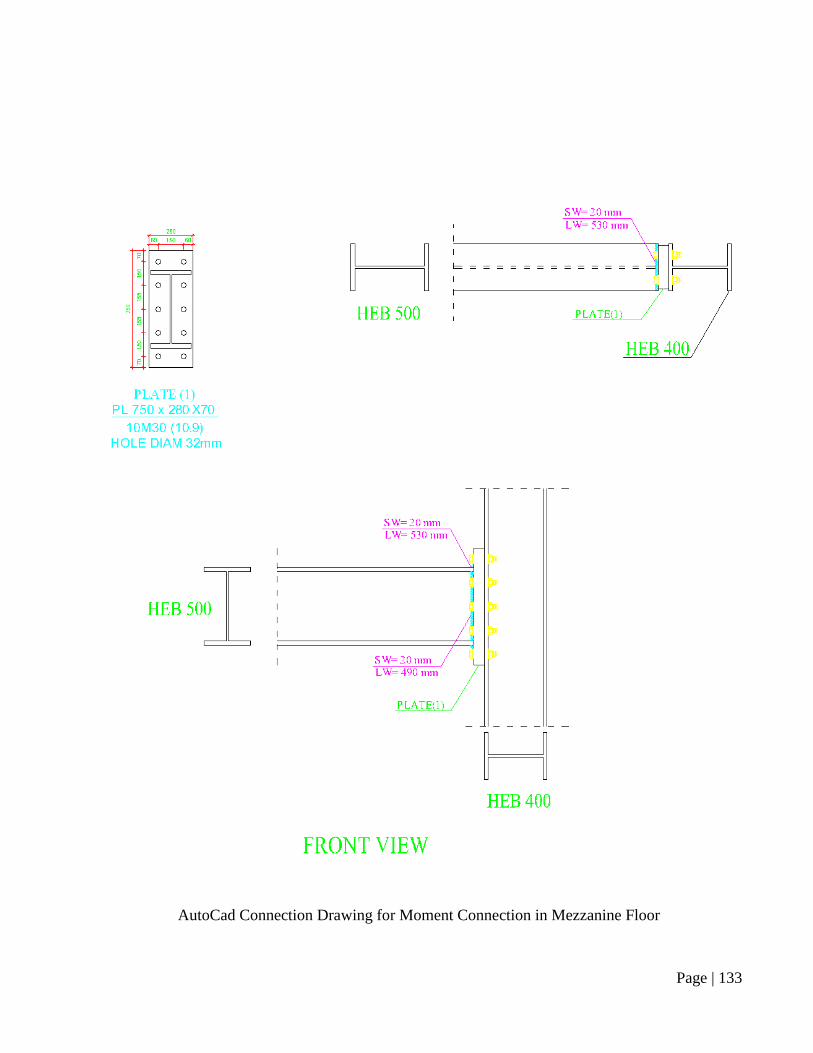
Page | 133
AutoCad Connection Drawing for Moment Connection in Mezzanine Floor
Page | 134
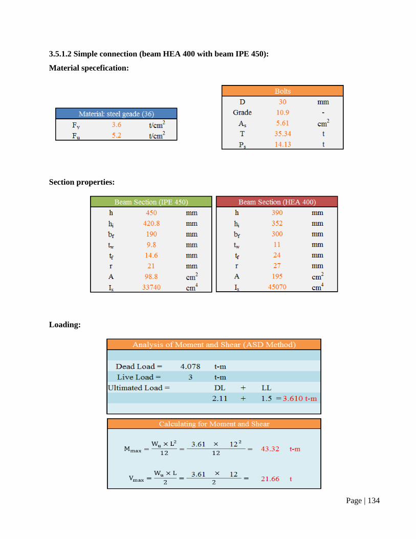
3.5.1.2 Simple connection (beam HEA 400 with beam IPE 450):
Material specefication:
Section properties:
Loading:
Page | 135
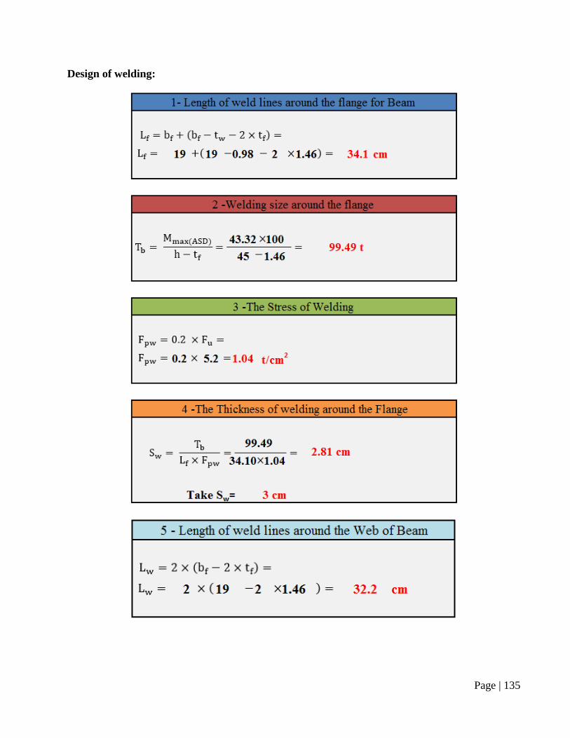
Design of welding:
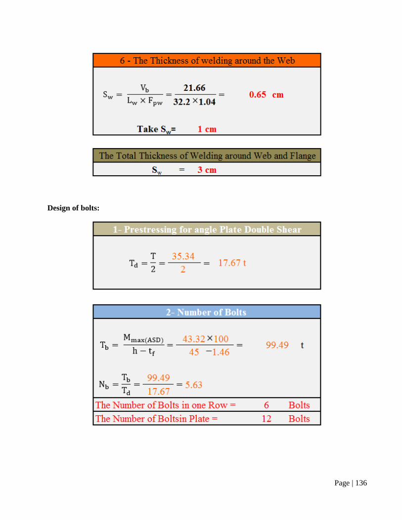
Page | 136
Design of bolts:
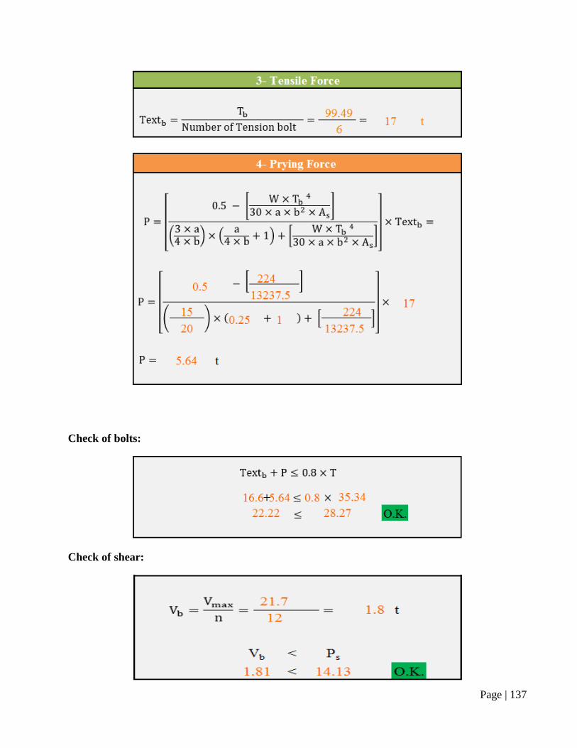
Page | 137
Check of bolts:
Check of shear:
Page | 138
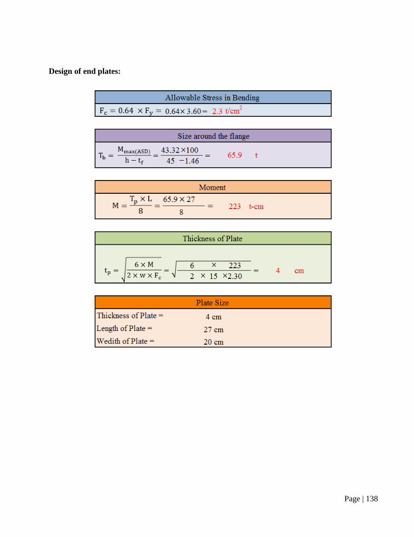
Design of end plates:
Page | 139
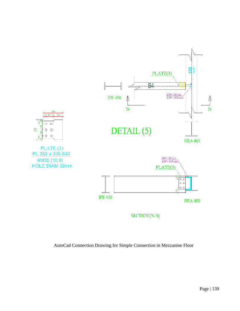
AutoCad Connection Drawing for Simple Connection in Mezzanine Floor
Page | 140
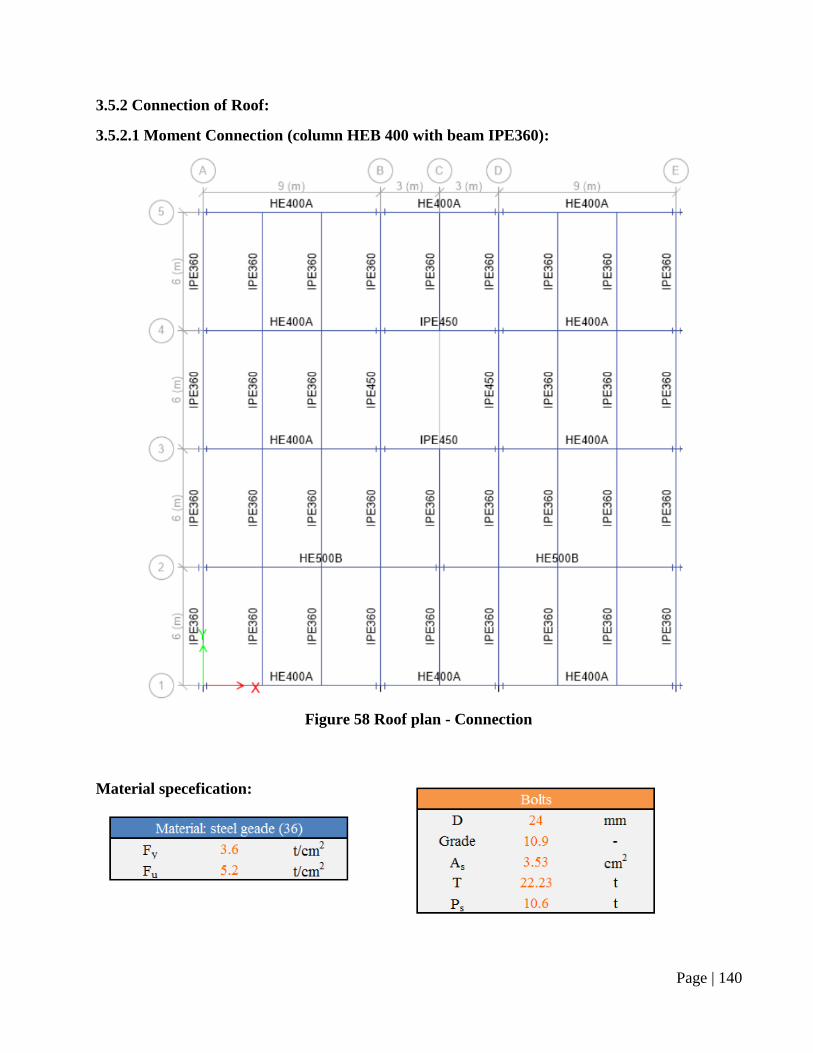
3.5.2 Connection of Roof:
3.5.2.1 Moment Connection (column HEB 400 with beam IPE360):
Material specefication:
Figure 58 Roof plan - Connection
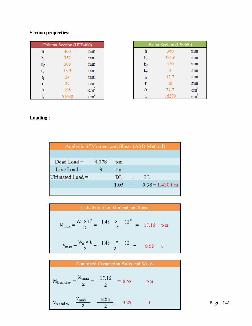
Page | 141
Section properties:
Loading :
Page | 142
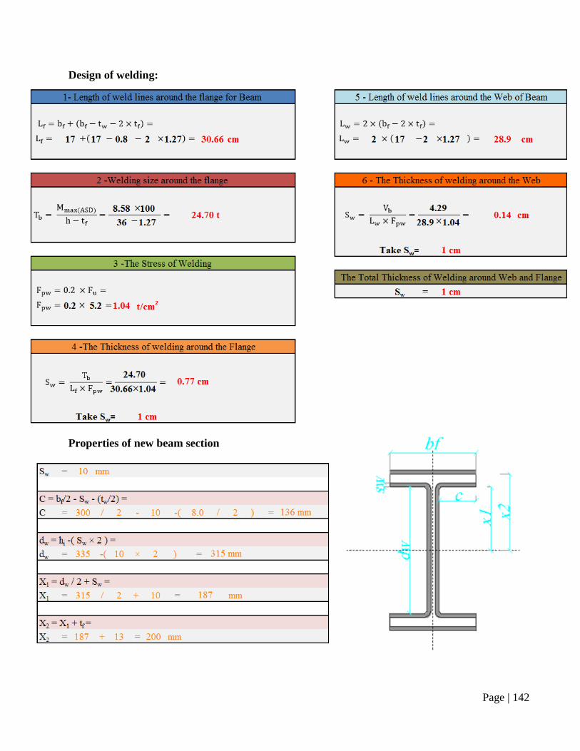
Design of welding:
Properties of new beam section
Page | 143
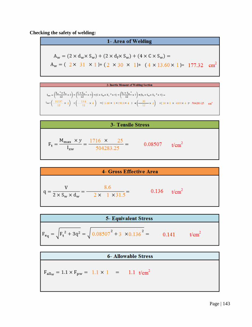
Checking the safety of welding:
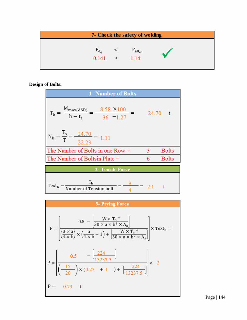
Page | 144
Design of Bolts:
7- Check the safety of welding
0.141 1.14
Page | 145
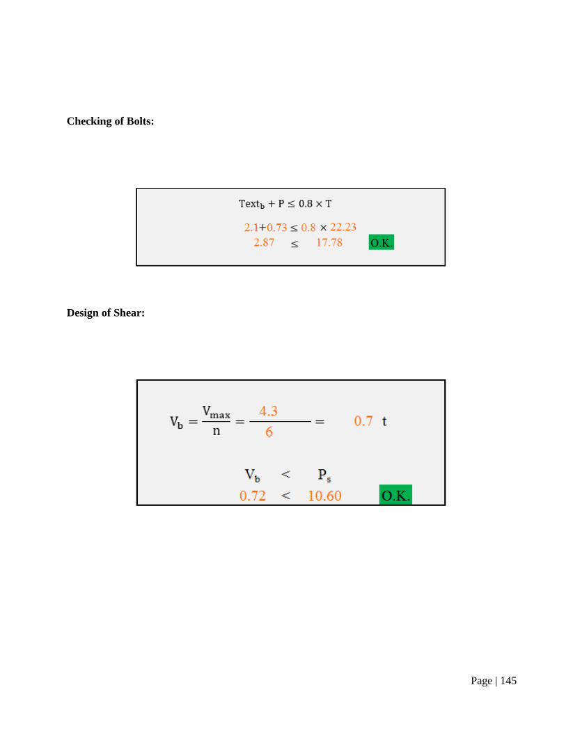
Checking of Bolts:
Design of Shear:
Page | 146
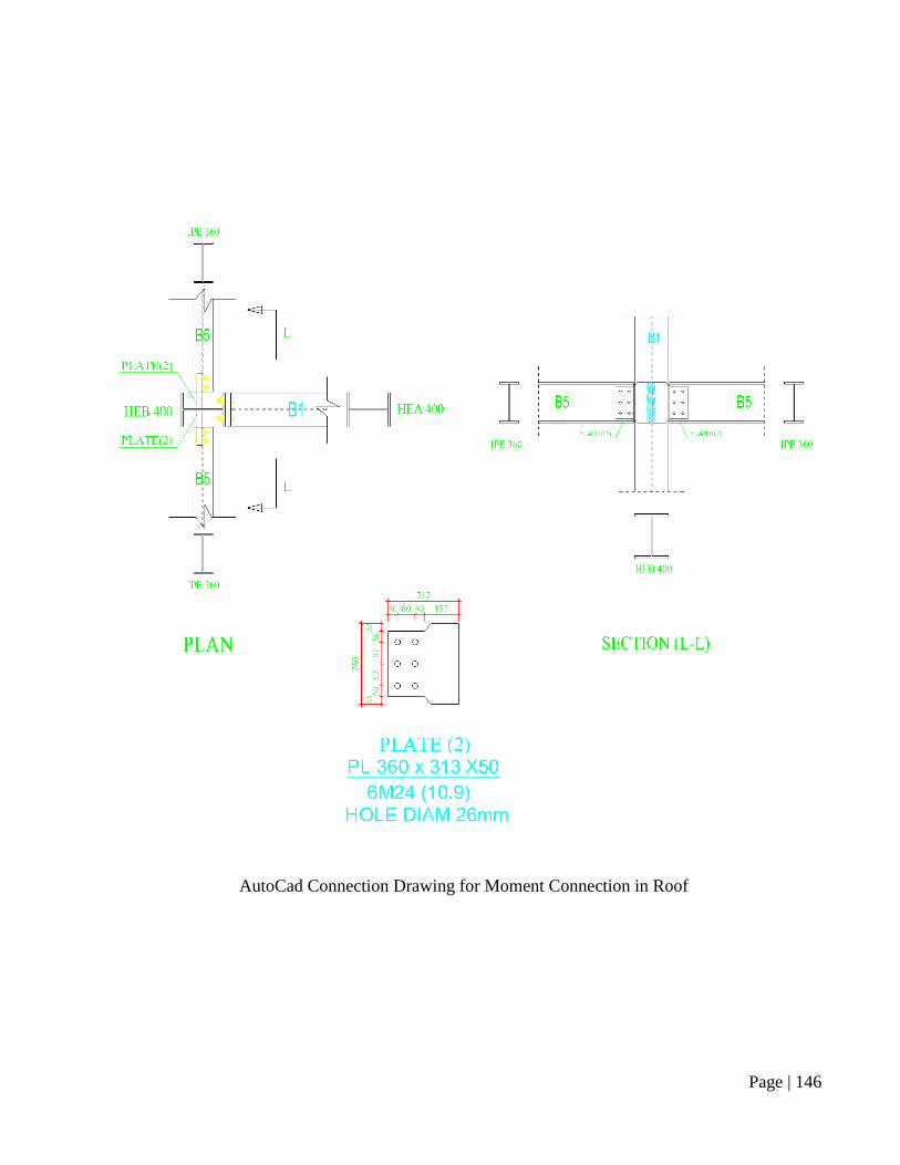
AutoCad Connection Drawing for Moment Connection in Roof
Page | 147
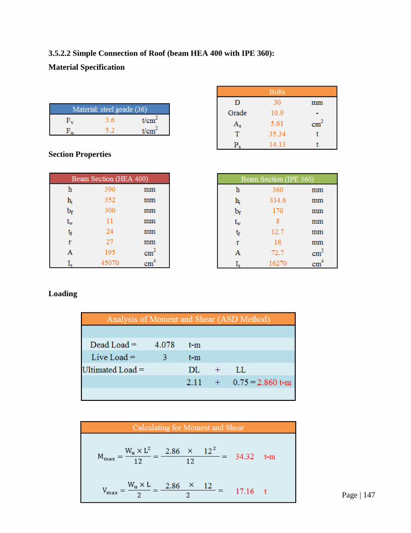
3.5.2.2 Simple Connection of Roof (beam HEA 400 with IPE 360):
Material Specification
Section Properties
Loading
Page | 148
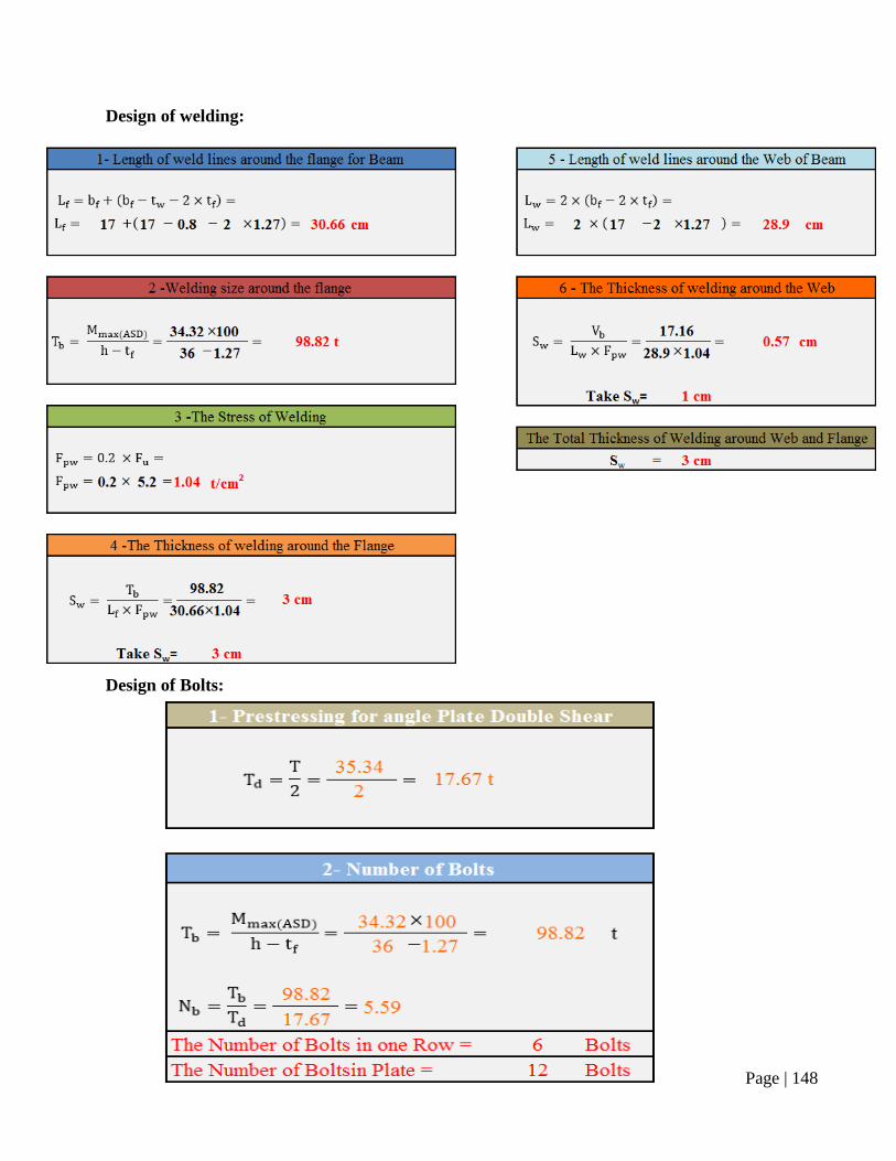
Design of welding:
Design of Bolts:
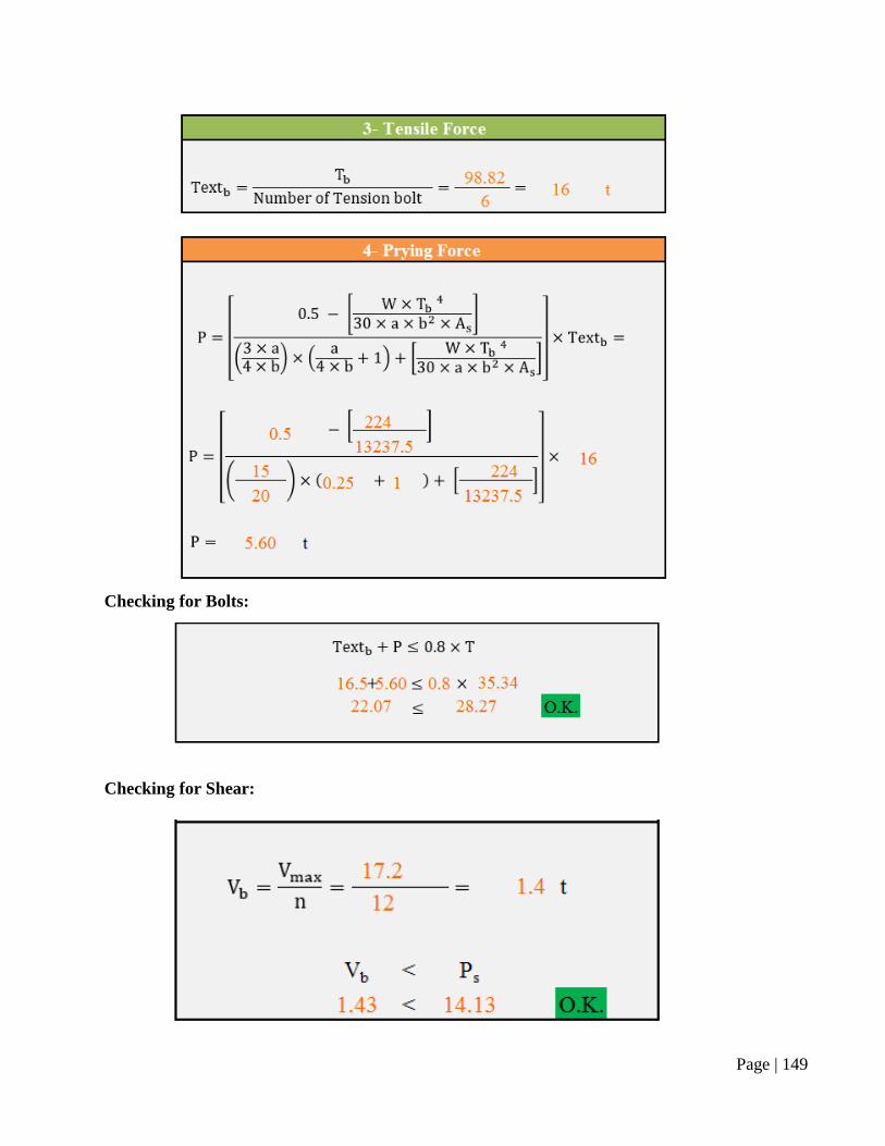
Page | 149
Checking for Bolts:
Checking for Shear:
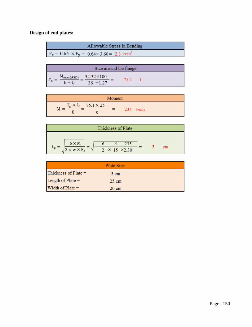
Page | 150
Design of end plates:
Page | 151
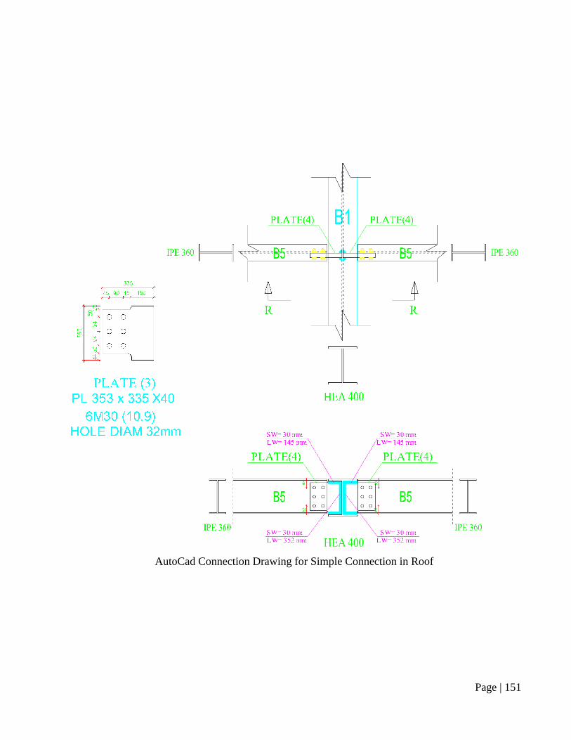
AutoCad Connection Drawing for Simple Connection in Roof
Page | 152
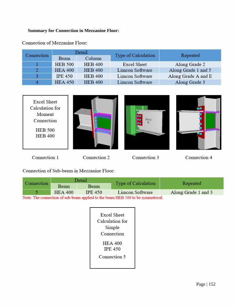
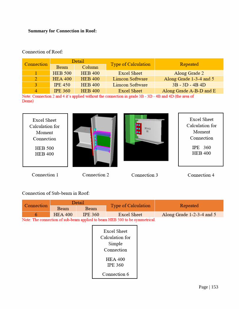
Summary for Connection in Mezzanine Floor:
Page | 153
Summary for Connection in Roof:
Page | 154
Chapter 4: Foundation
4.1 Introduction
A foundation is the element of an architectural structure which connects it to the ground, and
transfers loads from the structure to the ground. Foundations are generally considered either
shallow or deep. This chapter is made for the mosque foundation design and a shallow foundation
is going to be used for this project. This section includes the calculations and verification of the
suitable foundation system for different elements of the mosque. We will first check for isolated
foundation. If it does not work, then we will go directly for Raft foundation. In case of using raft
foundation settlements calculation is required.
4.2 Isolated foundation
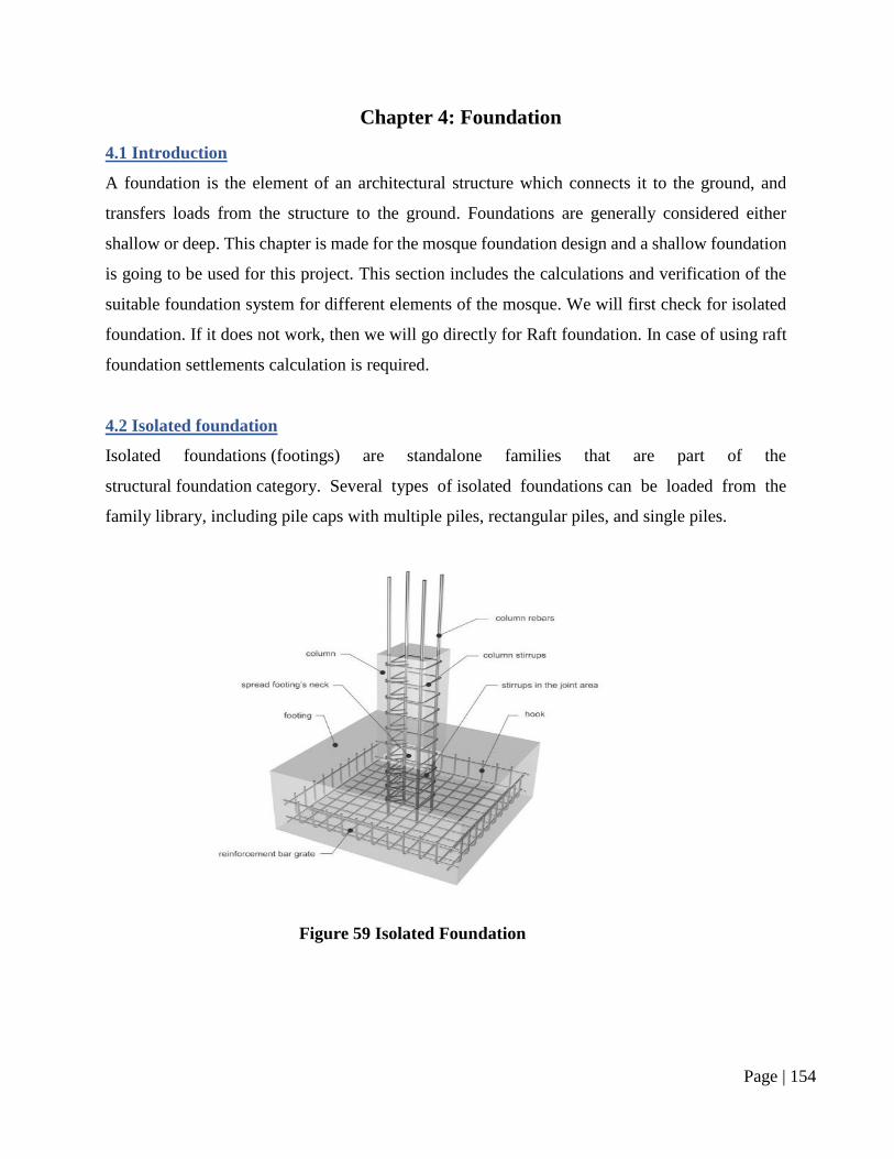
Isolated foundations (footings) are standalone families that are part of the
structural foundation category. Several types of isolated foundations can be loaded from the
family library, including pile caps with multiple piles, rectangular piles, and single piles.
Figure 59 Isolated Foundation
Page | 155
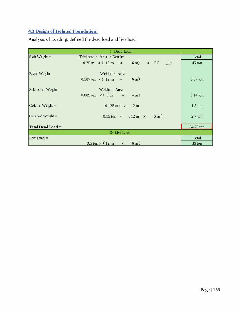
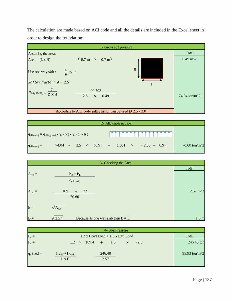
4.3 Design of Isolated Foundation:
Analysis of Loading: defined the dead load and live load
Total
0.25 m 12 m 6 m 2.5 t/m3 45 ton
0.187 t/m 12 m 6 m 3.37 ton
0.089 t/m 6 m 4 m 2.14 ton
0.125 t/m 12 m 1.5 ton
0.15 t/m 12 m 6 m 2.7 ton
54.70 ton
Live Load = Total
0.5 t/m 12 m 6 m 36 ton
Thickness × Area × Density
Beam Weight = Weight × Area
Foundation
Ceramic Weight =
Total Dead Load =
2- Live Load
Sub-beam Weight = Weight × Area
Column Weight =
1- Loading
1- Dead Load
Slab Weight =
Page | 156
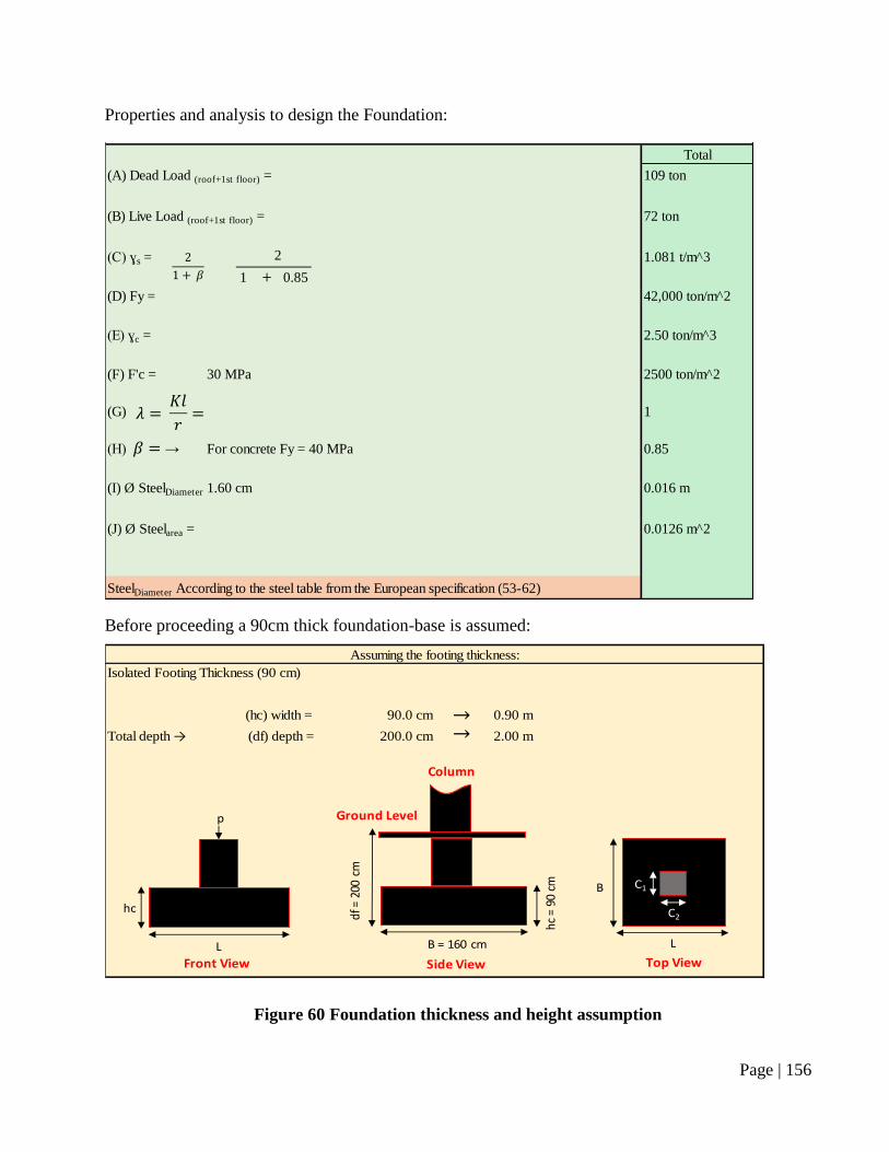
Properties and analysis to design the Foundation:
Before proceeding a 90cm thick foundation-base is assumed:
Figure 60 Foundation thickness and height assumption
Total
(A) Dead Load (roof+1st floor) = 109 ton
(B) Live Load (roof+1st floor) = 72 ton
(C) ɣs = 1.081 t/m^3
1 0.85
(D) Fy = 42,000 ton/m^2
(E) ɣc = 2.50 ton/m^3
(F) F'c = 30 MPa 2500 ton/m^2
(G) 1
(H) → 0.85
(I) Ø SteelDiameter =1.60 cm 0.016 m
(J) Ø Steelarea = 0.0126 m^2
2- Propority
For concrete Fy = 40 MPa
2
SteelDiameter According to the steel table from the European specification (53-62)
90.0 cm 0.90 m
Total depth → 200.0 cm 2.00 m
Assuming the footing thickness:
(df) depth =
(hc) width =
Isolated Footing Thickness (90 cm)
df =
200
cm
B = 160 cm
Side View
Ground Level
Column
hc =
90
cm
C2
C1
L
B
Top View
hc
L
p
Front View
Page | 157
The calculation are made based on ACI code and all the details are included in the Excel sheet in
order to design the foundation:
Assuming the area: Total
Area = (L x B) 0.7 m 0.7 m 0.49 m^2
2.5 0.49 74.04 ton/m^2
Use one way slab :
1- Gross soil pressure
3- Calculation Process
90.702
According to ACI code saftey factor can be used Ø 2.5 - 3.0
L
B
qall (net) = 74.04 2.5 0.9 1.081 2.00 0.9 70.60 ton/m^2
2- Allowable net soil
qall (net) = qall (gross) - ɣc (hc) - ɣs (df - hc)
− ( )
Total
Areq =
Areq = 109 72 2.57 m^2
B = Areq
B = 2.57 Because its one way slab then B = L 1.6 m
3- Checking the Area
PD + PL
qall (net)
70.60
Pu = Total
Pu = 1.2 109.4 1.6 72.0 246.48 ton
qu (net) = 1.2PD+1.6PL 246.48 95.93 ton/m^2
L x B 2.57
4- Soil Pressure
1.2 x Dead Load + 1.6 x Live Load
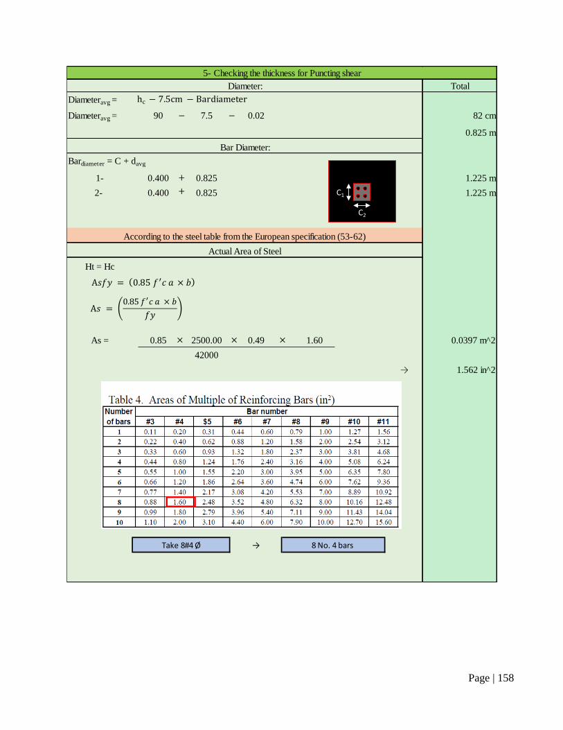
Page | 158
Total
Diameteravg =
Diameteravg = 90 7.5 0.02 82 cm
0.825 m
1- 0.400 0.825 1.225 m
2- 0.400 0.825 1.225 m
Ht = Hc
As = 0.85 2500.00 0.49 1.60 0.0397 m^2
42000
→ 1.562 in^2
→
Actual Area of Steel
Take 8#4 Ø 8 No. 4 bars
According to the steel table from the European specification (53-62)
5- Checking the thickness for Puncting shear
Diameter:
Bar Diameter:
Bardiameter = C + davg
C2
C1
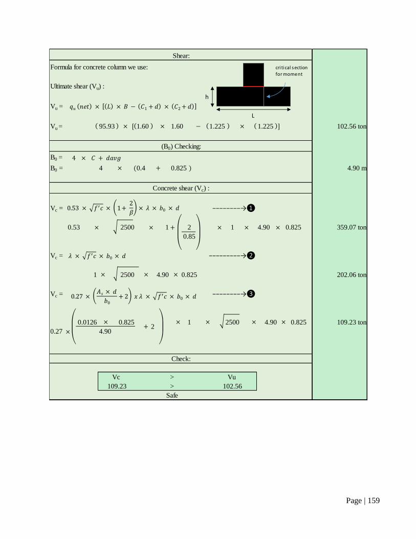
Page | 159
Vu =
Vu = 95.93 1.60 1.60 1.225 1.225 102.56 ton
B0 =
B0 = 4 0.4 0.825 4.90 m
Vc =
0.53 2500 1 2 1 4.90 0.825 359.07 ton
0.85
Vc =
1 2500 4.90 0.825 202.06 ton
Vc =
0.0126 0.825 1 2500 4.90 0.825 109.23 ton
0.27 4.90
Vc Vu
109.23 102.56
2
−−−−−−−−→❶
−−−−−−−−−→❷
−−−−−−−−→❸
Formula for concrete column we use:
(B0) Checking:
Concrete shear (Vc) :
Check:
Safe
>
Ultimate shear (Vu) :
>
Shear:
h
L
cri ti cal section
for moment
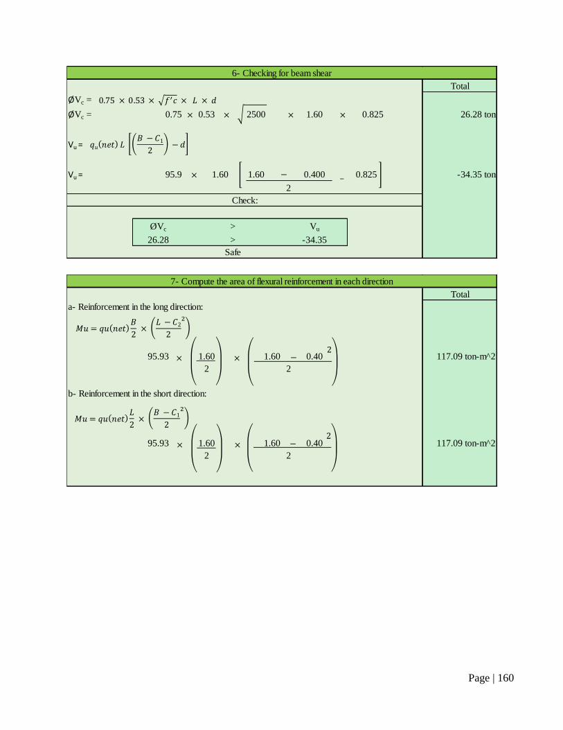
Page | 160
Total
ØVc =
ØVc = 0.75 0.53 2500 1.60 0.825 26.28 ton
Vu =
Vu = 95.9 1.60 1.60 0.400 0.825 -34.35 ton
ØVc Vu
26.28 -34.35>
Check:
2
Safe
>
6- Checking for beam shear
Total
95.93 1.60 1.60 0.40 117.09 ton-m^2
2
95.93 1.60 1.60 0.40 117.09 ton-m^2
2
7- Compute the area of flexural reinforcement in each direction
b- Reinforcement in the short direction:
a- Reinforcement in the long direction:
2
2
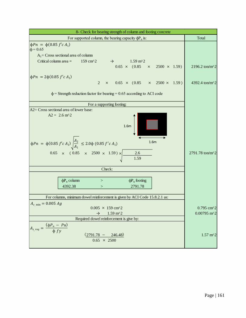
Page | 161
Total
ф = 0.65
159 cm^2 → 1.59 m^2
0.65 0.85 2500 1.59 2196.2 ton/m^2
2 0.65 0.85 2500 1.59 4392.4 ton/m^2
A2 = 2.6 m^2
0.65 0.85 2500 1.59 2.6 2791.78 ton/m^2
1.59
фPn column фPn footing
4392.38 2791.78
0.005 159 cm^2 0.795 cm^2
→ 1.59 m^2 0.00795 m^2
2791.78 246.48 1.57 m^2
0.65 2500
Required dowel reinforcement is give by:
Critical column area =
A1= Cross sectional area of column
>
>
Check:
A2= Cross sectional area of lower base:
For a supporting footing:
ф = Strength reduction factor for bearing = 0.65 according to ACI code
8- Check for bearing strength of column and footing concrete
For supported column, the bearing capacity фPn is:
For columns, minimum dowel reinforcement is given by ACI Code 15.8.2.1 as:
1.6m
1.6m
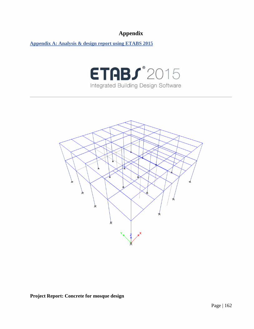
Page | 162
Appendix
Appendix A: Analysis & design report using ETABS 2015
Project Report: Concrete for mosque design
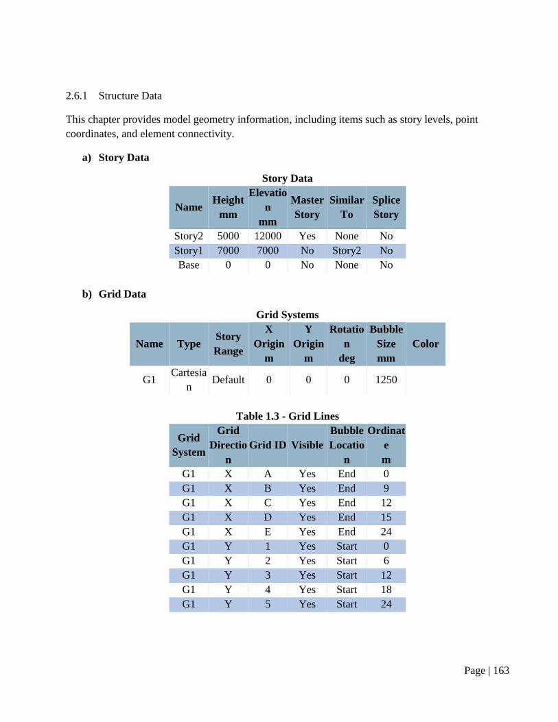
Page | 163
2.6.1 Structure Data
This chapter provides model geometry information, including items such as story levels, point
coordinates, and element connectivity.
a) Story Data
Story Data
Name Height
mm
Elevatio
n
mm
Master
Story
Similar
To
Splice
Story
Story2 5000 12000 Yes None No
Story1 7000 7000 No Story2 No
Base 0 0 No None No
b) Grid Data
Grid Systems
Name Type Story
Range
X
Origin
m
Y
Origin
m
Rotatio
n
deg
Bubble
Size
mm
Color
G1 Cartesia
n Default 0 0 0 1250
Table 1.3 - Grid Lines
Grid
System
Grid
Directio
n
Grid ID Visible
Bubble
Locatio
n
Ordinat
e
m
G1 X A Yes End 0
G1 X B Yes End 9
G1 X C Yes End 12
G1 X D Yes End 15
G1 X E Yes End 24
G1 Y 1 Yes Start 0
G1 Y 2 Yes Start 6
G1 Y 3 Yes Start 12
G1 Y 4 Yes Start 18
G1 Y 5 Yes Start 24
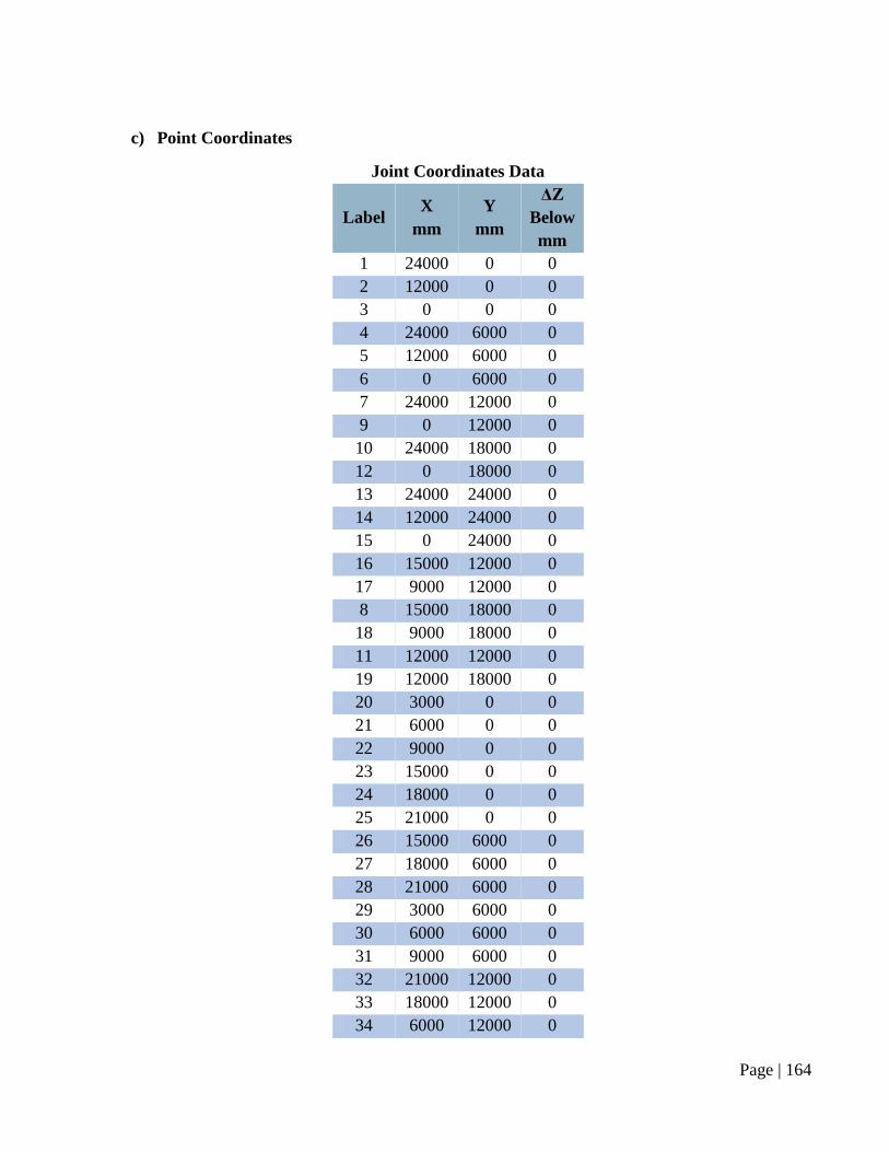
Page | 164
c) Point Coordinates
Joint Coordinates Data
Label X
mm
Y
mm
ΔZ
Below
mm
1 24000 0 0
2 12000 0 0
3 0 0 0
4 24000 6000 0
5 12000 6000 0
6 0 6000 0
7 24000 12000 0
9 0 12000 0
10 24000 18000 0
12 0 18000 0
13 24000 24000 0
14 12000 24000 0
15 0 24000 0
16 15000 12000 0
17 9000 12000 0
8 15000 18000 0
18 9000 18000 0
11 12000 12000 0
19 12000 18000 0
20 3000 0 0
21 6000 0 0
22 9000 0 0
23 15000 0 0
24 18000 0 0
25 21000 0 0
26 15000 6000 0
27 18000 6000 0
28 21000 6000 0
29 3000 6000 0
30 6000 6000 0
31 9000 6000 0
32 21000 12000 0
33 18000 12000 0
34 6000 12000 0
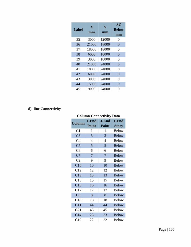
Page | 165
Label X
mm
Y
mm
ΔZ
Below
mm
35 3000 12000 0
36 21000 18000 0
37 18000 18000 0
38 6000 18000 0
39 3000 18000 0
40 21000 24000 0
41 18000 24000 0
42 6000 24000 0
43 3000 24000 0
44 15000 24000 0
45 9000 24000 0
d) line Connectivity
Column Connectivity Data
Column I-End
Point
J-End
Point
I-End
Story
C1 1 1 Below
C3 3 3 Below
C4 4 4 Below
C5 5 5 Below
C6 6 6 Below
C7 7 7 Below
C9 9 9 Below
C10 10 10 Below
C12 12 12 Below
C13 13 13 Below
C15 15 15 Below
C16 16 16 Below
C17 17 17 Below
C8 8 8 Below
C18 18 18 Below
C11 44 44 Below
C21 45 45 Below
C14 23 23 Below
C19 22 22 Below
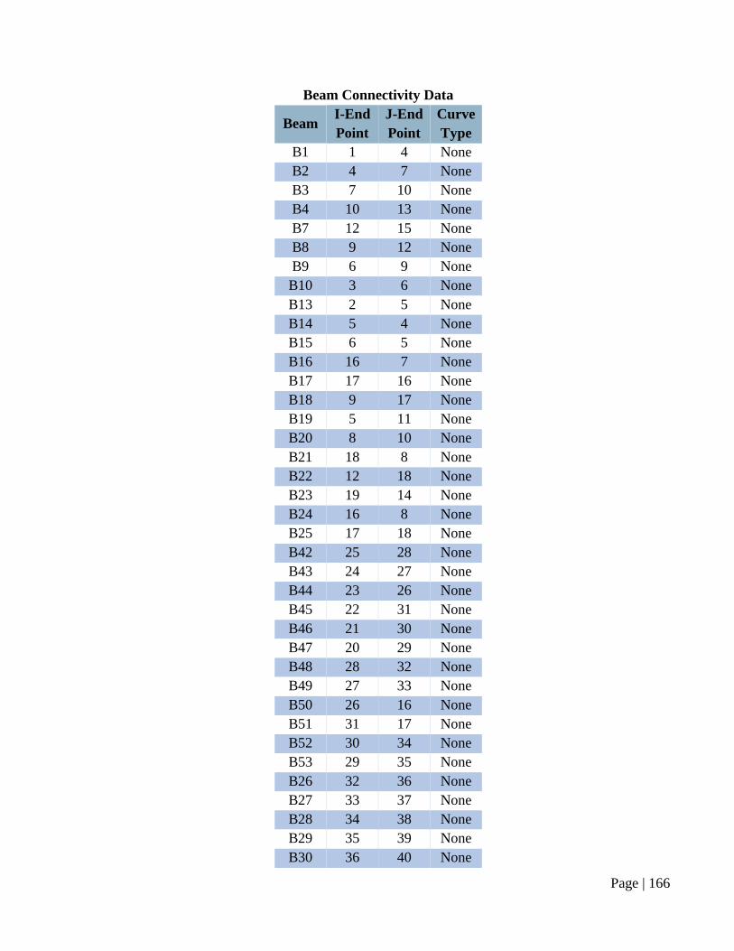
Page | 166
Beam Connectivity Data
Beam I-End
Point
J-End
Point
Curve
Type
B1 1 4 None
B2 4 7 None
B3 7 10 None
B4 10 13 None
B7 12 15 None
B8 9 12 None
B9 6 9 None
B10 3 6 None
B13 2 5 None
B14 5 4 None
B15 6 5 None
B16 16 7 None
B17 17 16 None
B18 9 17 None
B19 5 11 None
B20 8 10 None
B21 18 8 None
B22 12 18 None
B23 19 14 None
B24 16 8 None
B25 17 18 None
B42 25 28 None
B43 24 27 None
B44 23 26 None
B45 22 31 None
B46 21 30 None
B47 20 29 None
B48 28 32 None
B49 27 33 None
B50 26 16 None
B51 31 17 None
B52 30 34 None
B53 29 35 None
B26 32 36 None
B27 33 37 None
B28 34 38 None
B29 35 39 None
B30 36 40 None
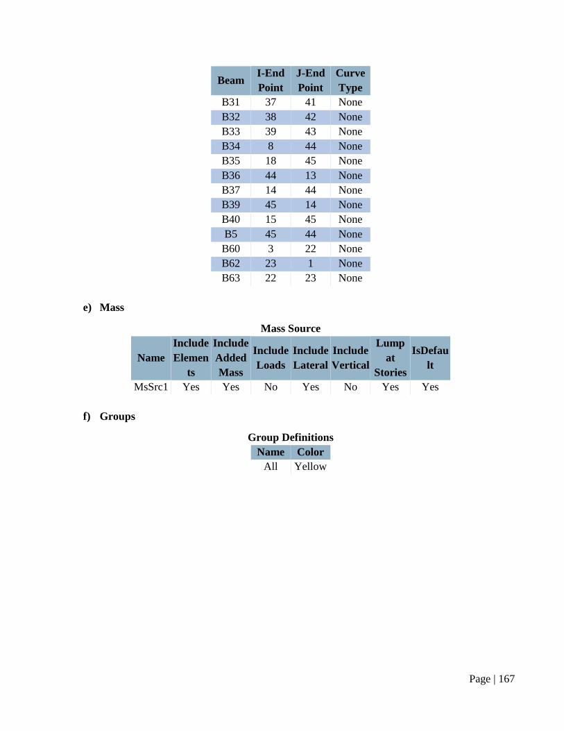
Page | 167
Beam I-End
Point
J-End
Point
Curve
Type
B31 37 41 None
B32 38 42 None
B33 39 43 None
B34 8 44 None
B35 18 45 None
B36 44 13 None
B37 14 44 None
B39 45 14 None
B40 15 45 None
B5 45 44 None
B60 3 22 None
B62 23 1 None
B63 22 23 None
e) Mass
Mass Source
Name
Include
Elemen
ts
Include
Added
Mass
Include
Loads
Include
Lateral
Include
Vertical
Lump
at
Stories
IsDefau
lt
MsSrc1 Yes Yes No Yes No Yes Yes
f) Groups
Group Definitions
Name Color
All Yellow
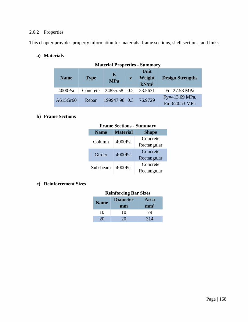
Page | 168
2.6.2 Properties
This chapter provides property information for materials, frame sections, shell sections, and links.
a) Materials
Material Properties - Summary
Name Type E
MPa ν
Unit
Weight
kN/m³
Design Strengths
4000Psi Concrete 24855.58 0.2 23.5631 Fc=27.58 MPa
A615Gr60 Rebar 199947.98 0.3 76.9729 Fy=413.69 MPa,
Fu=620.53 MPa
b) Frame Sections
Frame Sections - Summary
Name Material Shape
Column 4000Psi Concrete
Rectangular
Girder 4000Psi Concrete
Rectangular
Sub-beam 4000Psi Concrete
Rectangular
c) Reinforcement Sizes
Reinforcing Bar Sizes
Name Diameter
mm
Area
mm²
10 10 79
20 20 314
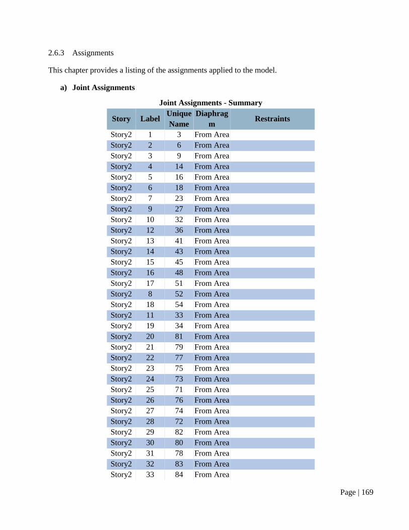
Page | 169
2.6.3 Assignments
This chapter provides a listing of the assignments applied to the model.
a) Joint Assignments
Joint Assignments - Summary
Story Label Unique
Name
Diaphrag
m Restraints
Story2 1 3 From Area
Story2 2 6 From Area
Story2 3 9 From Area
Story2 4 14 From Area
Story2 5 16 From Area
Story2 6 18 From Area
Story2 7 23 From Area
Story2 9 27 From Area
Story2 10 32 From Area
Story2 12 36 From Area
Story2 13 41 From Area
Story2 14 43 From Area
Story2 15 45 From Area
Story2 16 48 From Area
Story2 17 51 From Area
Story2 8 52 From Area
Story2 18 54 From Area
Story2 11 33 From Area
Story2 19 34 From Area
Story2 20 81 From Area
Story2 21 79 From Area
Story2 22 77 From Area
Story2 23 75 From Area
Story2 24 73 From Area
Story2 25 71 From Area
Story2 26 76 From Area
Story2 27 74 From Area
Story2 28 72 From Area
Story2 29 82 From Area
Story2 30 80 From Area
Story2 31 78 From Area
Story2 32 83 From Area
Story2 33 84 From Area
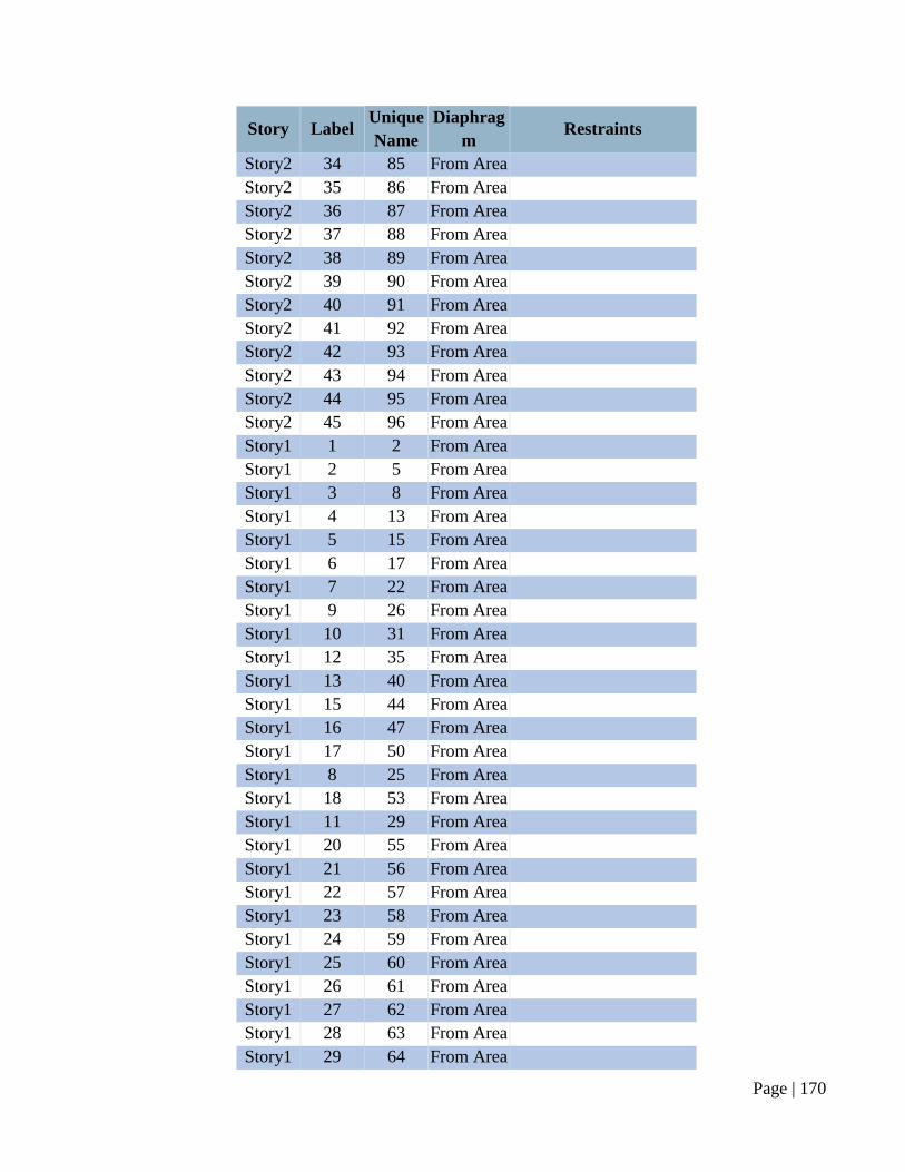
Page | 170
Story Label Unique
Name
Diaphrag
m Restraints
Story2 34 85 From Area
Story2 35 86 From Area
Story2 36 87 From Area
Story2 37 88 From Area
Story2 38 89 From Area
Story2 39 90 From Area
Story2 40 91 From Area
Story2 41 92 From Area
Story2 42 93 From Area
Story2 43 94 From Area
Story2 44 95 From Area
Story2 45 96 From Area
Story1 1 2 From Area
Story1 2 5 From Area
Story1 3 8 From Area
Story1 4 13 From Area
Story1 5 15 From Area
Story1 6 17 From Area
Story1 7 22 From Area
Story1 9 26 From Area
Story1 10 31 From Area
Story1 12 35 From Area
Story1 13 40 From Area
Story1 15 44 From Area
Story1 16 47 From Area
Story1 17 50 From Area
Story1 8 25 From Area
Story1 18 53 From Area
Story1 11 29 From Area
Story1 20 55 From Area
Story1 21 56 From Area
Story1 22 57 From Area
Story1 23 58 From Area
Story1 24 59 From Area
Story1 25 60 From Area
Story1 26 61 From Area
Story1 27 62 From Area
Story1 28 63 From Area
Story1 29 64 From Area
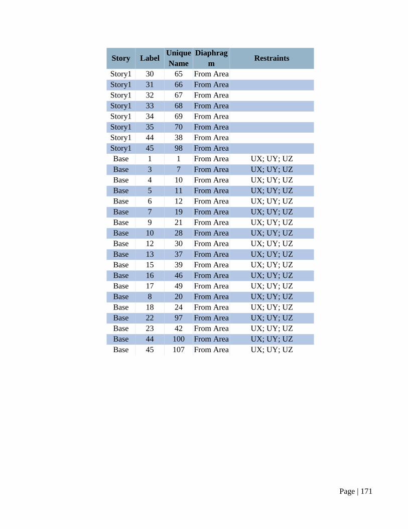
Page | 171
Story Label Unique
Name
Diaphrag
m Restraints
Story1 30 65 From Area
Story1 31 66 From Area
Story1 32 67 From Area
Story1 33 68 From Area
Story1 34 69 From Area
Story1 35 70 From Area
Story1 44 38 From Area
Story1 45 98 From Area
Base 1 1 From Area UX; UY; UZ
Base 3 7 From Area UX; UY; UZ
Base 4 10 From Area UX; UY; UZ
Base 5 11 From Area UX; UY; UZ
Base 6 12 From Area UX; UY; UZ
Base 7 19 From Area UX; UY; UZ
Base 9 21 From Area UX; UY; UZ
Base 10 28 From Area UX; UY; UZ
Base 12 30 From Area UX; UY; UZ
Base 13 37 From Area UX; UY; UZ
Base 15 39 From Area UX; UY; UZ
Base 16 46 From Area UX; UY; UZ
Base 17 49 From Area UX; UY; UZ
Base 8 20 From Area UX; UY; UZ
Base 18 24 From Area UX; UY; UZ
Base 22 97 From Area UX; UY; UZ
Base 23 42 From Area UX; UY; UZ
Base 44 100 From Area UX; UY; UZ
Base 45 107 From Area UX; UY; UZ
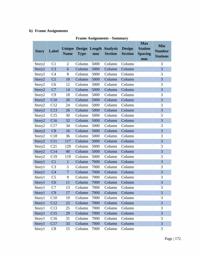
Page | 172
b) Frame Assignments
Frame Assignments - Summary
Story Label Unique
Name
Design
Type
Length
mm
Analysis
Section
Design
Section
Max
Station
Spacing
mm
Min
Number
Stations
Story2 C1 2 Column 5000 Column Column 3
Story2 C3 6 Column 5000 Column Column 3
Story2 C4 8 Column 5000 Column Column 3
Story2 C5 10 Column 5000 Column Column 3
Story2 C6 12 Column 5000 Column Column 3
Story2 C7 14 Column 5000 Column Column 3
Story2 C9 18 Column 5000 Column Column 3
Story2 C10 20 Column 5000 Column Column 3
Story2 C12 24 Column 5000 Column Column 3
Story2 C13 26 Column 5000 Column Column 3
Story2 C15 30 Column 5000 Column Column 3
Story2 C16 32 Column 5000 Column Column 3
Story2 C17 34 Column 5000 Column Column 3
Story2 C8 16 Column 5000 Column Column 3
Story2 C18 36 Column 5000 Column Column 3
Story2 C11 117 Column 5000 Column Column 3
Story2 C21 129 Column 5000 Column Column 3
Story2 C14 40 Column 5000 Column Column 3
Story2 C19 119 Column 5000 Column Column 3
Story1 C1 1 Column 7000 Column Column 3
Story1 C3 5 Column 7000 Column Column 3
Story1 C4 7 Column 7000 Column Column 3
Story1 C5 9 Column 7000 Column Column 3
Story1 C6 11 Column 7000 Column Column 3
Story1 C7 13 Column 7000 Column Column 3
Story1 C9 17 Column 7000 Column Column 3
Story1 C10 19 Column 7000 Column Column 3
Story1 C12 23 Column 7000 Column Column 3
Story1 C13 25 Column 7000 Column Column 3
Story1 C15 29 Column 7000 Column Column 3
Story1 C16 31 Column 7000 Column Column 3
Story1 C17 33 Column 7000 Column Column 3
Story1 C8 15 Column 7000 Column Column 3
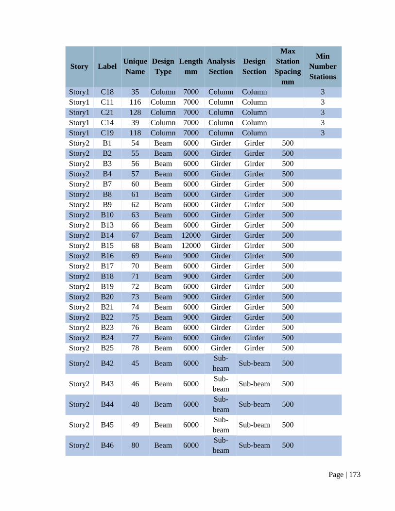
Page | 173
Story Label Unique
Name
Design
Type
Length
mm
Analysis
Section
Design
Section
Max
Station
Spacing
mm
Min
Number
Stations
Story1 C18 35 Column 7000 Column Column 3
Story1 C11 116 Column 7000 Column Column 3
Story1 C21 128 Column 7000 Column Column 3
Story1 C14 39 Column 7000 Column Column 3
Story1 C19 118 Column 7000 Column Column 3
Story2 B1 54 Beam 6000 Girder Girder 500
Story2 B2 55 Beam 6000 Girder Girder 500
Story2 B3 56 Beam 6000 Girder Girder 500
Story2 B4 57 Beam 6000 Girder Girder 500
Story2 B7 60 Beam 6000 Girder Girder 500
Story2 B8 61 Beam 6000 Girder Girder 500
Story2 B9 62 Beam 6000 Girder Girder 500
Story2 B10 63 Beam 6000 Girder Girder 500
Story2 B13 66 Beam 6000 Girder Girder 500
Story2 B14 67 Beam 12000 Girder Girder 500
Story2 B15 68 Beam 12000 Girder Girder 500
Story2 B16 69 Beam 9000 Girder Girder 500
Story2 B17 70 Beam 6000 Girder Girder 500
Story2 B18 71 Beam 9000 Girder Girder 500
Story2 B19 72 Beam 6000 Girder Girder 500
Story2 B20 73 Beam 9000 Girder Girder 500
Story2 B21 74 Beam 6000 Girder Girder 500
Story2 B22 75 Beam 9000 Girder Girder 500
Story2 B23 76 Beam 6000 Girder Girder 500
Story2 B24 77 Beam 6000 Girder Girder 500
Story2 B25 78 Beam 6000 Girder Girder 500
Story2 B42 45 Beam 6000 Sub-
beam Sub-beam 500
Story2 B43 46 Beam 6000 Sub-
beam Sub-beam 500
Story2 B44 48 Beam 6000 Sub-
beam Sub-beam 500
Story2 B45 49 Beam 6000 Sub-
beam Sub-beam 500
Story2 B46 80 Beam 6000 Sub-
beam Sub-beam 500
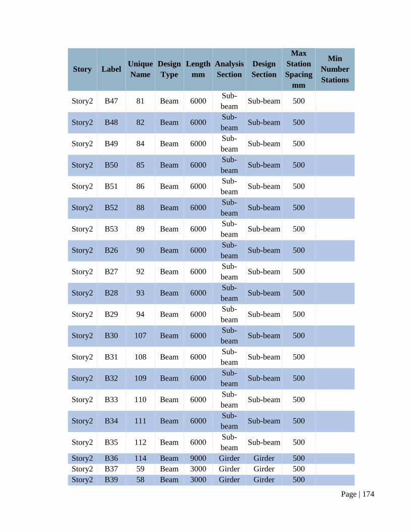
Page | 174
Story Label Unique
Name
Design
Type
Length
mm
Analysis
Section
Design
Section
Max
Station
Spacing
mm
Min
Number
Stations
Story2 B47 81 Beam 6000 Sub-
beam Sub-beam 500
Story2 B48 82 Beam 6000 Sub-
beam Sub-beam 500
Story2 B49 84 Beam 6000 Sub-
beam Sub-beam 500
Story2 B50 85 Beam 6000 Sub-
beam Sub-beam 500
Story2 B51 86 Beam 6000 Sub-
beam Sub-beam 500
Story2 B52 88 Beam 6000 Sub-
beam Sub-beam 500
Story2 B53 89 Beam 6000 Sub-
beam Sub-beam 500
Story2 B26 90 Beam 6000 Sub-
beam Sub-beam 500
Story2 B27 92 Beam 6000 Sub-
beam Sub-beam 500
Story2 B28 93 Beam 6000 Sub-
beam Sub-beam 500
Story2 B29 94 Beam 6000 Sub-
beam Sub-beam 500
Story2 B30 107 Beam 6000 Sub-
beam Sub-beam 500
Story2 B31 108 Beam 6000 Sub-
beam Sub-beam 500
Story2 B32 109 Beam 6000 Sub-
beam Sub-beam 500
Story2 B33 110 Beam 6000 Sub-
beam Sub-beam 500
Story2 B34 111 Beam 6000 Sub-
beam Sub-beam 500
Story2 B35 112 Beam 6000 Sub-
beam Sub-beam 500
Story2 B36 114 Beam 9000 Girder Girder 500
Story2 B37 59 Beam 3000 Girder Girder 500
Story2 B39 58 Beam 3000 Girder Girder 500
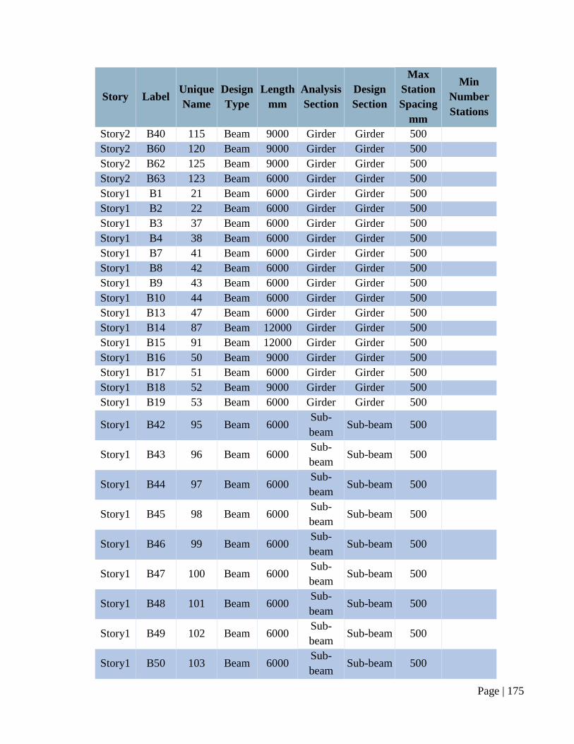
Page | 175
Story Label Unique
Name
Design
Type
Length
mm
Analysis
Section
Design
Section
Max
Station
Spacing
mm
Min
Number
Stations
Story2 B40 115 Beam 9000 Girder Girder 500
Story2 B60 120 Beam 9000 Girder Girder 500
Story2 B62 125 Beam 9000 Girder Girder 500
Story2 B63 123 Beam 6000 Girder Girder 500
Story1 B1 21 Beam 6000 Girder Girder 500
Story1 B2 22 Beam 6000 Girder Girder 500
Story1 B3 37 Beam 6000 Girder Girder 500
Story1 B4 38 Beam 6000 Girder Girder 500
Story1 B7 41 Beam 6000 Girder Girder 500
Story1 B8 42 Beam 6000 Girder Girder 500
Story1 B9 43 Beam 6000 Girder Girder 500
Story1 B10 44 Beam 6000 Girder Girder 500
Story1 B13 47 Beam 6000 Girder Girder 500
Story1 B14 87 Beam 12000 Girder Girder 500
Story1 B15 91 Beam 12000 Girder Girder 500
Story1 B16 50 Beam 9000 Girder Girder 500
Story1 B17 51 Beam 6000 Girder Girder 500
Story1 B18 52 Beam 9000 Girder Girder 500
Story1 B19 53 Beam 6000 Girder Girder 500
Story1 B42 95 Beam 6000 Sub-
beam Sub-beam 500
Story1 B43 96 Beam 6000 Sub-
beam Sub-beam 500
Story1 B44 97 Beam 6000 Sub-
beam Sub-beam 500
Story1 B45 98 Beam 6000 Sub-
beam Sub-beam 500
Story1 B46 99 Beam 6000 Sub-
beam Sub-beam 500
Story1 B47 100 Beam 6000 Sub-
beam Sub-beam 500
Story1 B48 101 Beam 6000 Sub-
beam Sub-beam 500
Story1 B49 102 Beam 6000 Sub-
beam Sub-beam 500
Story1 B50 103 Beam 6000 Sub-
beam Sub-beam 500
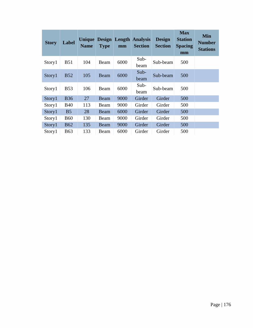
Page | 176
Story Label Unique
Name
Design
Type
Length
mm
Analysis
Section
Design
Section
Max
Station
Spacing
mm
Min
Number
Stations
Story1 B51 104 Beam 6000 Sub-
beam Sub-beam 500
Story1 B52 105 Beam 6000 Sub-
beam Sub-beam 500
Story1 B53 106 Beam 6000 Sub-
beam Sub-beam 500
Story1 B36 27 Beam 9000 Girder Girder 500
Story1 B40 113 Beam 9000 Girder Girder 500
Story1 B5 28 Beam 6000 Girder Girder 500
Story1 B60 130 Beam 9000 Girder Girder 500
Story1 B62 135 Beam 9000 Girder Girder 500
Story1 B63 133 Beam 6000 Girder Girder 500
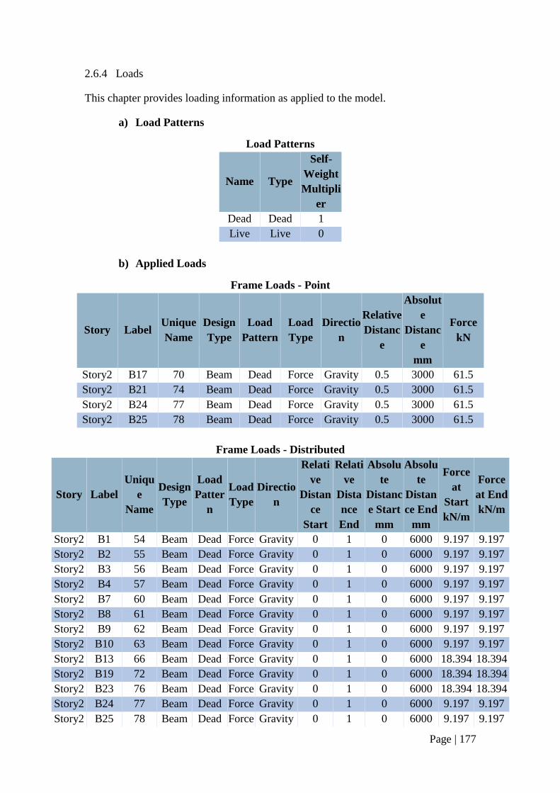
Page | 177
2.6.4 Loads
This chapter provides loading information as applied to the model.
a) Load Patterns
Load Patterns
Name Type
Self-
Weight
Multipli
er
Dead Dead 1
Live Live 0
b) Applied Loads
Frame Loads - Point
Story Label Unique
Name
Design
Type
Load
Pattern
Load
Type
Directio
n
Relative
Distanc
e
Absolut
e
Distanc
e
mm
Force
kN
Story2 B17 70 Beam Dead Force Gravity 0.5 3000 61.5
Story2 B21 74 Beam Dead Force Gravity 0.5 3000 61.5
Story2 B24 77 Beam Dead Force Gravity 0.5 3000 61.5
Story2 B25 78 Beam Dead Force Gravity 0.5 3000 61.5
Frame Loads - Distributed
Story Label
Uniqu
e
Name
Design
Type
Load
Patter
n
Load
Type
Directio
n
Relati
ve
Distan
ce
Start
Relati
ve
Dista
nce
End
Absolu
te
Distanc
e Start
mm
Absolu
te
Distan
ce End
mm
Force
at
Start
kN/m
Force
at End
kN/m
Story2 B1 54 Beam Dead Force Gravity 0 1 0 6000 9.197 9.197
Story2 B2 55 Beam Dead Force Gravity 0 1 0 6000 9.197 9.197
Story2 B3 56 Beam Dead Force Gravity 0 1 0 6000 9.197 9.197
Story2 B4 57 Beam Dead Force Gravity 0 1 0 6000 9.197 9.197
Story2 B7 60 Beam Dead Force Gravity 0 1 0 6000 9.197 9.197
Story2 B8 61 Beam Dead Force Gravity 0 1 0 6000 9.197 9.197
Story2 B9 62 Beam Dead Force Gravity 0 1 0 6000 9.197 9.197
Story2 B10 63 Beam Dead Force Gravity 0 1 0 6000 9.197 9.197
Story2 B13 66 Beam Dead Force Gravity 0 1 0 6000 18.394 18.394
Story2 B19 72 Beam Dead Force Gravity 0 1 0 6000 18.394 18.394
Story2 B23 76 Beam Dead Force Gravity 0 1 0 6000 18.394 18.394
Story2 B24 77 Beam Dead Force Gravity 0 1 0 6000 9.197 9.197
Story2 B25 78 Beam Dead Force Gravity 0 1 0 6000 9.197 9.197
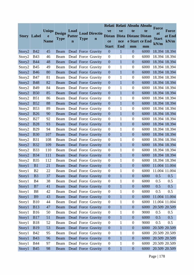
Page | 178
Story Label
Uniqu
e
Name
Design
Type
Load
Patter
n
Load
Type
Directio
n
Relati
ve
Distan
ce
Start
Relati
ve
Dista
nce
End
Absolu
te
Distanc
e Start
mm
Absolu
te
Distan
ce End
mm
Force
at
Start
kN/m
Force
at End
kN/m
Story2 B42 45 Beam Dead Force Gravity 0 1 0 6000 18.394 18.394
Story2 B43 46 Beam Dead Force Gravity 0 1 0 6000 18.394 18.394
Story2 B44 48 Beam Dead Force Gravity 0 1 0 6000 18.394 18.394
Story2 B45 49 Beam Dead Force Gravity 0 1 0 6000 18.394 18.394
Story2 B46 80 Beam Dead Force Gravity 0 1 0 6000 18.394 18.394
Story2 B47 81 Beam Dead Force Gravity 0 1 0 6000 18.394 18.394
Story2 B48 82 Beam Dead Force Gravity 0 1 0 6000 18.394 18.394
Story2 B49 84 Beam Dead Force Gravity 0 1 0 6000 18.394 18.394
Story2 B50 85 Beam Dead Force Gravity 0 1 0 6000 18.394 18.394
Story2 B51 86 Beam Dead Force Gravity 0 1 0 6000 18.394 18.394
Story2 B52 88 Beam Dead Force Gravity 0 1 0 6000 18.394 18.394
Story2 B53 89 Beam Dead Force Gravity 0 1 0 6000 18.394 18.394
Story2 B26 90 Beam Dead Force Gravity 0 1 0 6000 18.394 18.394
Story2 B27 92 Beam Dead Force Gravity 0 1 0 6000 18.394 18.394
Story2 B28 93 Beam Dead Force Gravity 0 1 0 6000 18.394 18.394
Story2 B29 94 Beam Dead Force Gravity 0 1 0 6000 18.394 18.394
Story2 B30 107 Beam Dead Force Gravity 0 1 0 6000 18.394 18.394
Story2 B31 108 Beam Dead Force Gravity 0 1 0 6000 18.394 18.394
Story2 B32 109 Beam Dead Force Gravity 0 1 0 6000 18.394 18.394
Story2 B33 110 Beam Dead Force Gravity 0 1 0 6000 18.394 18.394
Story2 B34 111 Beam Dead Force Gravity 0 1 0 6000 18.394 18.394
Story2 B35 112 Beam Dead Force Gravity 0 1 0 6000 18.394 18.394
Story1 B1 21 Beam Dead Force Gravity 0 1 0 6000 11.004 11.004
Story1 B2 22 Beam Dead Force Gravity 0 1 0 6000 11.004 11.004
Story1 B3 37 Beam Dead Force Gravity 0 1 0 6000 0.5 0.5
Story1 B4 38 Beam Dead Force Gravity 0 1 0 6000 0.5 0.5
Story1 B7 41 Beam Dead Force Gravity 0 1 0 6000 0.5 0.5
Story1 B8 42 Beam Dead Force Gravity 0 1 0 6000 0.5 0.5
Story1 B9 43 Beam Dead Force Gravity 0 1 0 6000 11.004 11.004
Story1 B10 44 Beam Dead Force Gravity 0 1 0 6000 11.004 11.004
Story1 B13 47 Beam Dead Force Gravity 0 1 0 6000 20.509 20.509
Story1 B16 50 Beam Dead Force Gravity 0 1 0 9000 0.5 0.5
Story1 B17 51 Beam Dead Force Gravity 0 1 0 6000 0.5 0.5
Story1 B18 52 Beam Dead Force Gravity 0 1 0 9000 0.5 0.5
Story1 B19 53 Beam Dead Force Gravity 0 1 0 6000 20.509 20.509
Story1 B42 95 Beam Dead Force Gravity 0 1 0 6000 20.509 20.509
Story1 B43 96 Beam Dead Force Gravity 0 1 0 6000 20.509 20.509
Story1 B44 97 Beam Dead Force Gravity 0 1 0 6000 20.509 20.509
Story1 B45 98 Beam Dead Force Gravity 0 1 0 6000 20.509 20.509
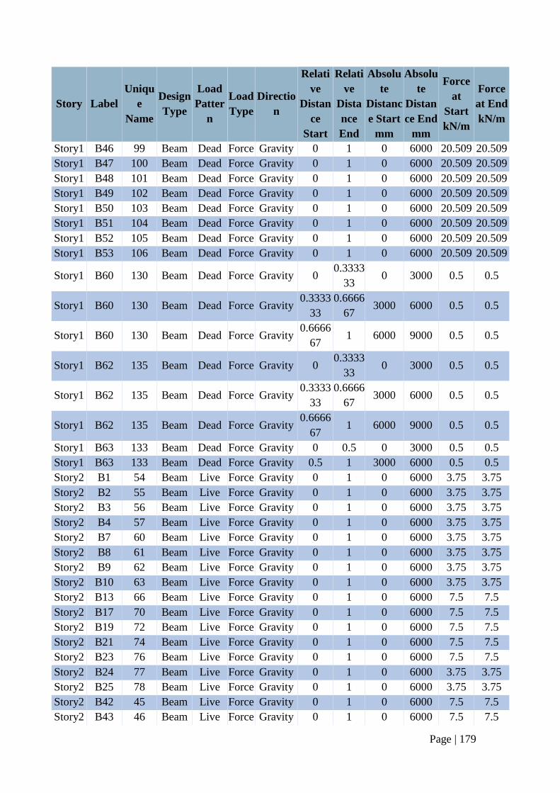
Page | 179
Story Label
Uniqu
e
Name
Design
Type
Load
Patter
n
Load
Type
Directio
n
Relati
ve
Distan
ce
Start
Relati
ve
Dista
nce
End
Absolu
te
Distanc
e Start
mm
Absolu
te
Distan
ce End
mm
Force
at
Start
kN/m
Force
at End
kN/m
Story1 B46 99 Beam Dead Force Gravity 0 1 0 6000 20.509 20.509
Story1 B47 100 Beam Dead Force Gravity 0 1 0 6000 20.509 20.509
Story1 B48 101 Beam Dead Force Gravity 0 1 0 6000 20.509 20.509
Story1 B49 102 Beam Dead Force Gravity 0 1 0 6000 20.509 20.509
Story1 B50 103 Beam Dead Force Gravity 0 1 0 6000 20.509 20.509
Story1 B51 104 Beam Dead Force Gravity 0 1 0 6000 20.509 20.509
Story1 B52 105 Beam Dead Force Gravity 0 1 0 6000 20.509 20.509
Story1 B53 106 Beam Dead Force Gravity 0 1 0 6000 20.509 20.509
Story1 B60 130 Beam Dead Force Gravity 0 0.3333
33 0 3000 0.5 0.5
Story1 B60 130 Beam Dead Force Gravity 0.3333
33
0.6666
67 3000 6000 0.5 0.5
Story1 B60 130 Beam Dead Force Gravity 0.6666
67 1 6000 9000 0.5 0.5
Story1 B62 135 Beam Dead Force Gravity 0 0.3333
33 0 3000 0.5 0.5
Story1 B62 135 Beam Dead Force Gravity 0.3333
33
0.6666
67 3000 6000 0.5 0.5
Story1 B62 135 Beam Dead Force Gravity 0.6666
67 1 6000 9000 0.5 0.5
Story1 B63 133 Beam Dead Force Gravity 0 0.5 0 3000 0.5 0.5
Story1 B63 133 Beam Dead Force Gravity 0.5 1 3000 6000 0.5 0.5
Story2 B1 54 Beam Live Force Gravity 0 1 0 6000 3.75 3.75
Story2 B2 55 Beam Live Force Gravity 0 1 0 6000 3.75 3.75
Story2 B3 56 Beam Live Force Gravity 0 1 0 6000 3.75 3.75
Story2 B4 57 Beam Live Force Gravity 0 1 0 6000 3.75 3.75
Story2 B7 60 Beam Live Force Gravity 0 1 0 6000 3.75 3.75
Story2 B8 61 Beam Live Force Gravity 0 1 0 6000 3.75 3.75
Story2 B9 62 Beam Live Force Gravity 0 1 0 6000 3.75 3.75
Story2 B10 63 Beam Live Force Gravity 0 1 0 6000 3.75 3.75
Story2 B13 66 Beam Live Force Gravity 0 1 0 6000 7.5 7.5
Story2 B17 70 Beam Live Force Gravity 0 1 0 6000 7.5 7.5
Story2 B19 72 Beam Live Force Gravity 0 1 0 6000 7.5 7.5
Story2 B21 74 Beam Live Force Gravity 0 1 0 6000 7.5 7.5
Story2 B23 76 Beam Live Force Gravity 0 1 0 6000 7.5 7.5
Story2 B24 77 Beam Live Force Gravity 0 1 0 6000 3.75 3.75
Story2 B25 78 Beam Live Force Gravity 0 1 0 6000 3.75 3.75
Story2 B42 45 Beam Live Force Gravity 0 1 0 6000 7.5 7.5
Story2 B43 46 Beam Live Force Gravity 0 1 0 6000 7.5 7.5
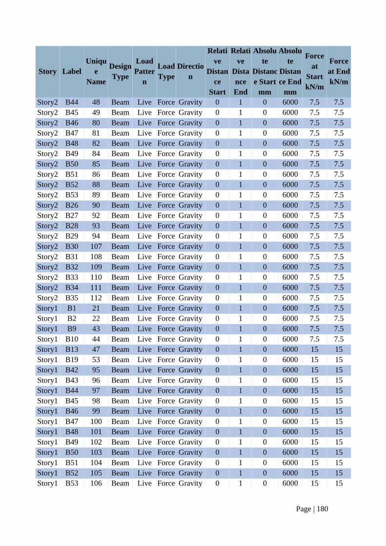
Page | 180
Story Label
Uniqu
e
Name
Design
Type
Load
Patter
n
Load
Type
Directio
n
Relati
ve
Distan
ce
Start
Relati
ve
Dista
nce
End
Absolu
te
Distanc
e Start
mm
Absolu
te
Distan
ce End
mm
Force
at
Start
kN/m
Force
at End
kN/m
Story2 B44 48 Beam Live Force Gravity 0 1 0 6000 7.5 7.5
Story2 B45 49 Beam Live Force Gravity 0 1 0 6000 7.5 7.5
Story2 B46 80 Beam Live Force Gravity 0 1 0 6000 7.5 7.5
Story2 B47 81 Beam Live Force Gravity 0 1 0 6000 7.5 7.5
Story2 B48 82 Beam Live Force Gravity 0 1 0 6000 7.5 7.5
Story2 B49 84 Beam Live Force Gravity 0 1 0 6000 7.5 7.5
Story2 B50 85 Beam Live Force Gravity 0 1 0 6000 7.5 7.5
Story2 B51 86 Beam Live Force Gravity 0 1 0 6000 7.5 7.5
Story2 B52 88 Beam Live Force Gravity 0 1 0 6000 7.5 7.5
Story2 B53 89 Beam Live Force Gravity 0 1 0 6000 7.5 7.5
Story2 B26 90 Beam Live Force Gravity 0 1 0 6000 7.5 7.5
Story2 B27 92 Beam Live Force Gravity 0 1 0 6000 7.5 7.5
Story2 B28 93 Beam Live Force Gravity 0 1 0 6000 7.5 7.5
Story2 B29 94 Beam Live Force Gravity 0 1 0 6000 7.5 7.5
Story2 B30 107 Beam Live Force Gravity 0 1 0 6000 7.5 7.5
Story2 B31 108 Beam Live Force Gravity 0 1 0 6000 7.5 7.5
Story2 B32 109 Beam Live Force Gravity 0 1 0 6000 7.5 7.5
Story2 B33 110 Beam Live Force Gravity 0 1 0 6000 7.5 7.5
Story2 B34 111 Beam Live Force Gravity 0 1 0 6000 7.5 7.5
Story2 B35 112 Beam Live Force Gravity 0 1 0 6000 7.5 7.5
Story1 B1 21 Beam Live Force Gravity 0 1 0 6000 7.5 7.5
Story1 B2 22 Beam Live Force Gravity 0 1 0 6000 7.5 7.5
Story1 B9 43 Beam Live Force Gravity 0 1 0 6000 7.5 7.5
Story1 B10 44 Beam Live Force Gravity 0 1 0 6000 7.5 7.5
Story1 B13 47 Beam Live Force Gravity 0 1 0 6000 15 15
Story1 B19 53 Beam Live Force Gravity 0 1 0 6000 15 15
Story1 B42 95 Beam Live Force Gravity 0 1 0 6000 15 15
Story1 B43 96 Beam Live Force Gravity 0 1 0 6000 15 15
Story1 B44 97 Beam Live Force Gravity 0 1 0 6000 15 15
Story1 B45 98 Beam Live Force Gravity 0 1 0 6000 15 15
Story1 B46 99 Beam Live Force Gravity 0 1 0 6000 15 15
Story1 B47 100 Beam Live Force Gravity 0 1 0 6000 15 15
Story1 B48 101 Beam Live Force Gravity 0 1 0 6000 15 15
Story1 B49 102 Beam Live Force Gravity 0 1 0 6000 15 15
Story1 B50 103 Beam Live Force Gravity 0 1 0 6000 15 15
Story1 B51 104 Beam Live Force Gravity 0 1 0 6000 15 15
Story1 B52 105 Beam Live Force Gravity 0 1 0 6000 15 15
Story1 B53 106 Beam Live Force Gravity 0 1 0 6000 15 15
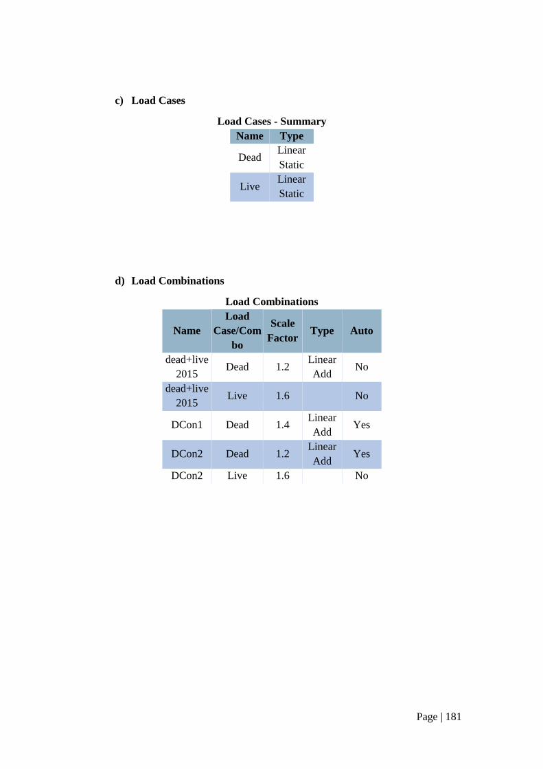
Page | 181
c) Load Cases
Load Cases - Summary
Name Type
Dead Linear
Static
Live Linear
Static
d) Load Combinations
Load Combinations
Name
Load
Case/Com
bo
Scale
Factor Type Auto
dead+live
2015 Dead 1.2
Linear
Add No
dead+live
2015 Live 1.6 No
DCon1 Dead 1.4 Linear
Add Yes
DCon2 Dead 1.2 Linear
Add Yes
DCon2 Live 1.6 No
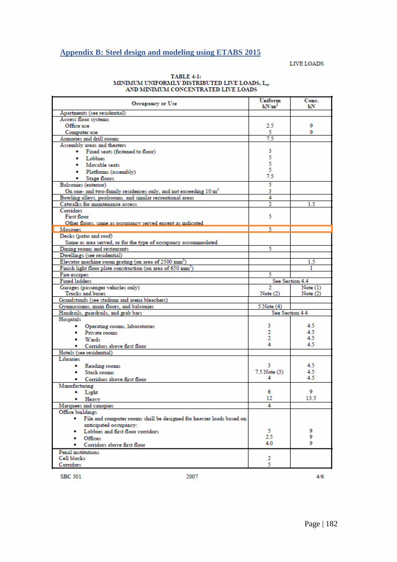
Page | 182
Appendix B: Steel design and modeling using ETABS 2015
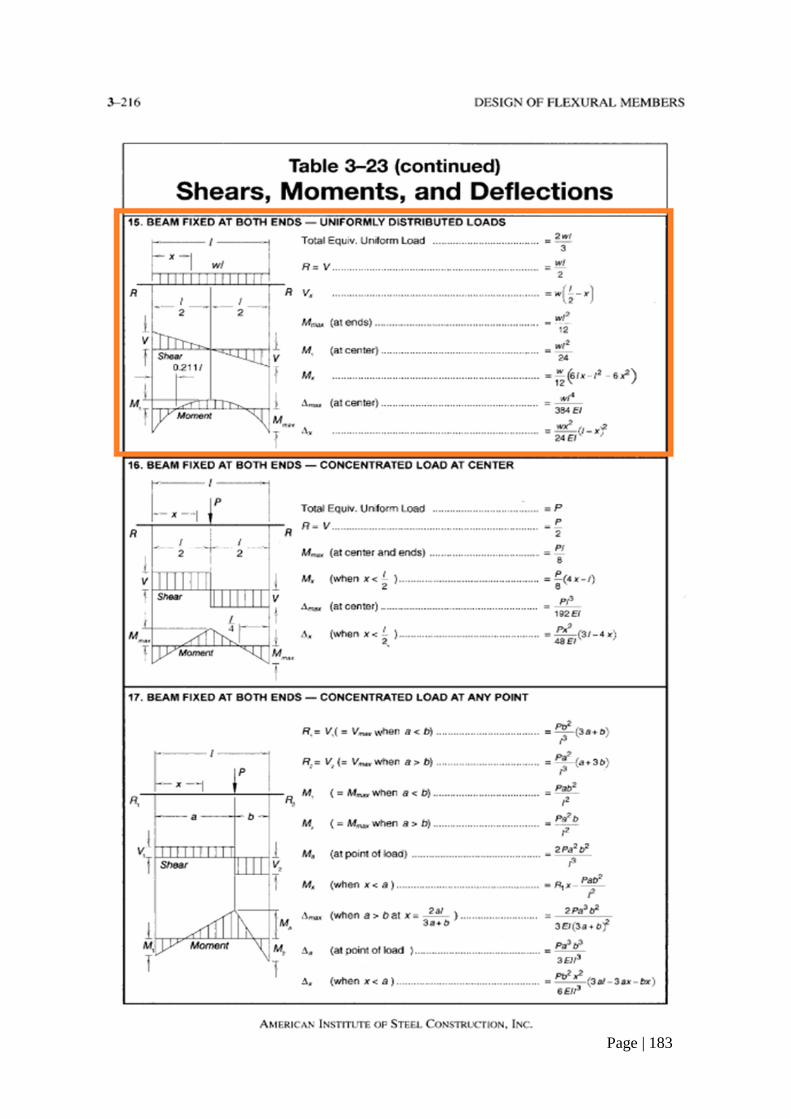
Page | 183
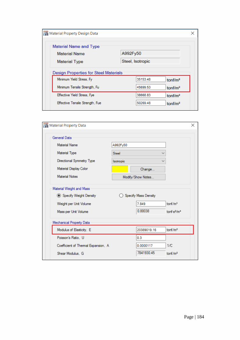
Page | 184
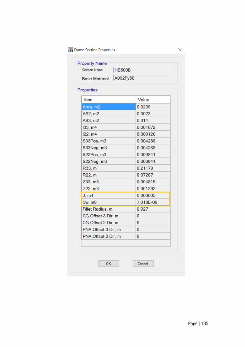
Page | 185
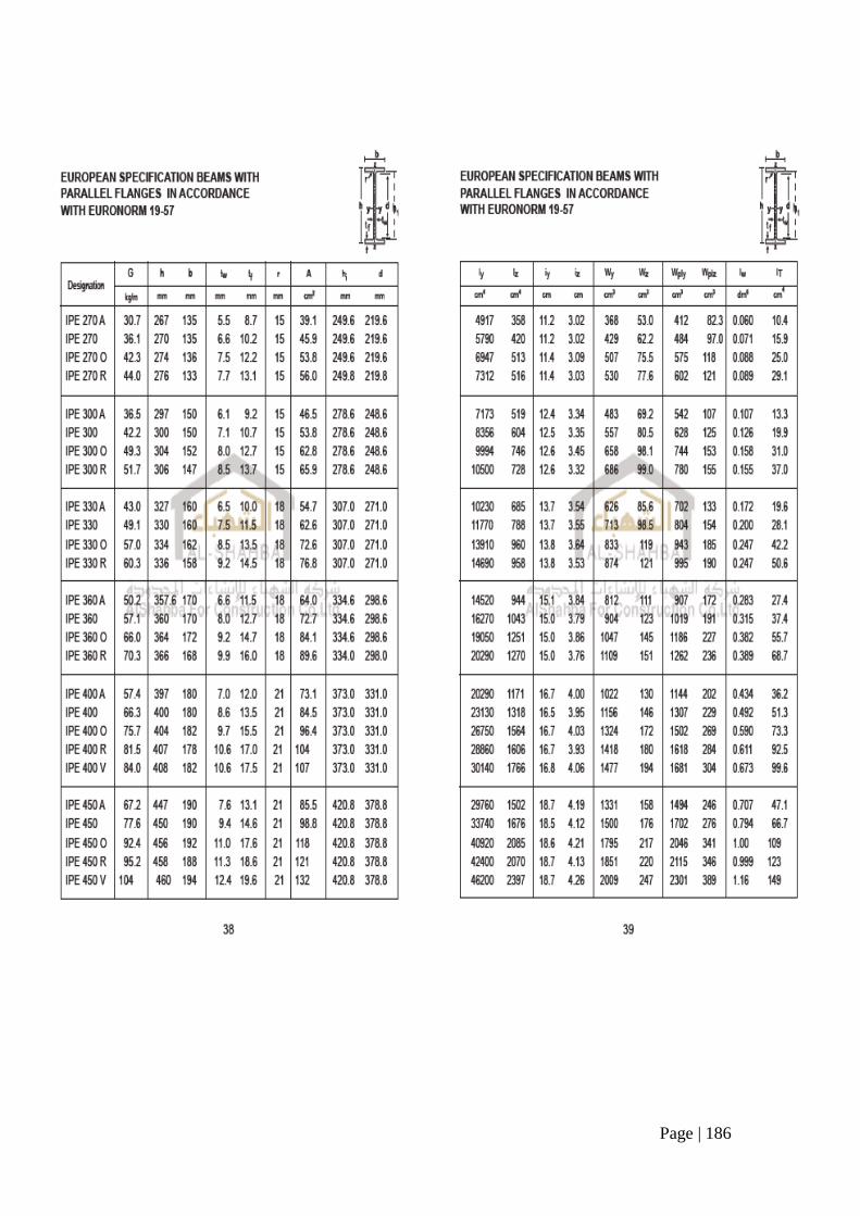
Page | 186
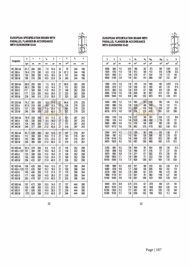
Page | 187
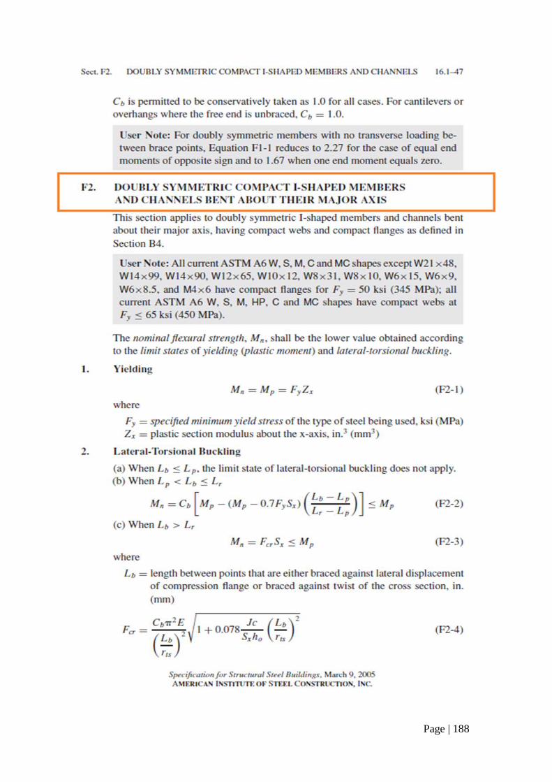
Page | 188
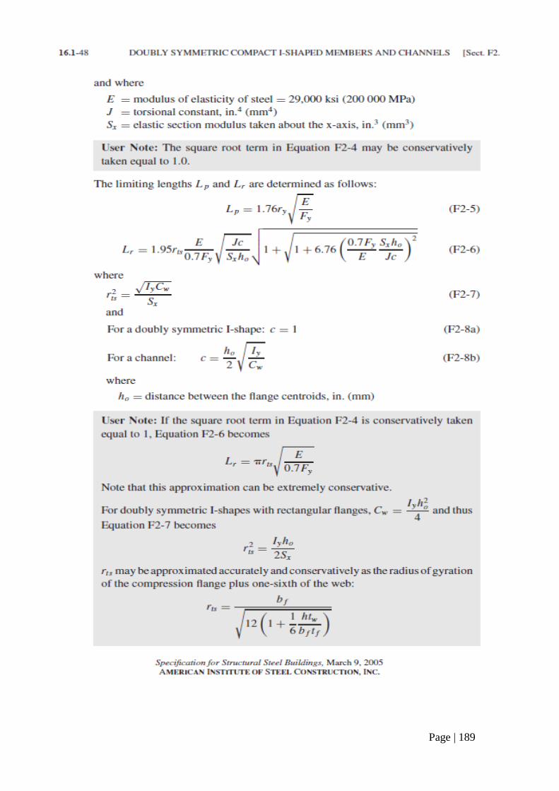
Page | 189
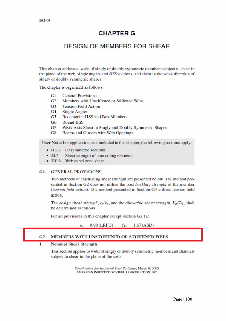
Page | 190
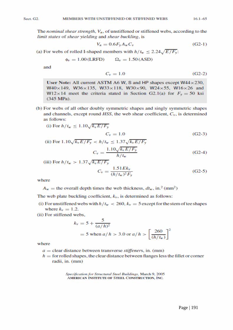
Page | 191
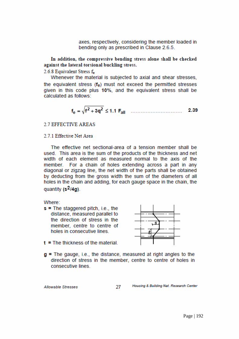
Page | 192
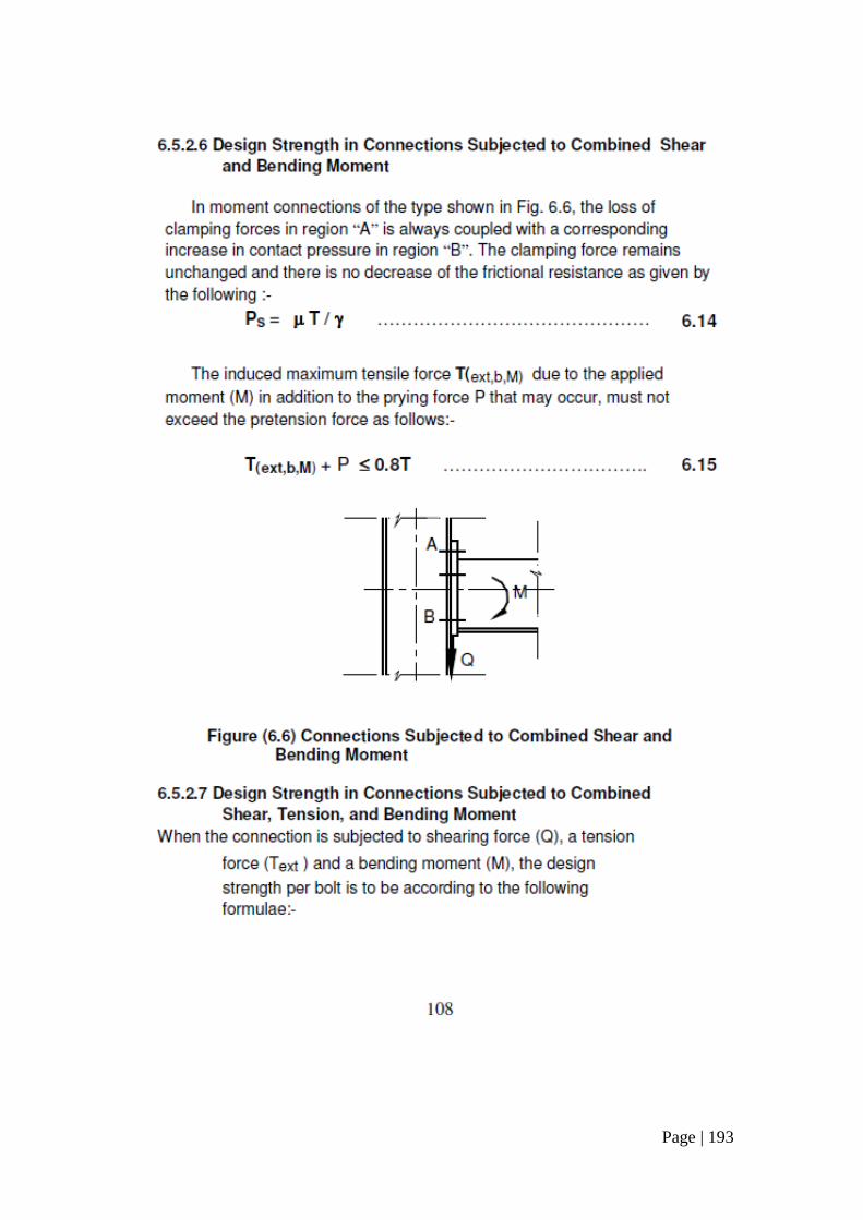
Page | 193
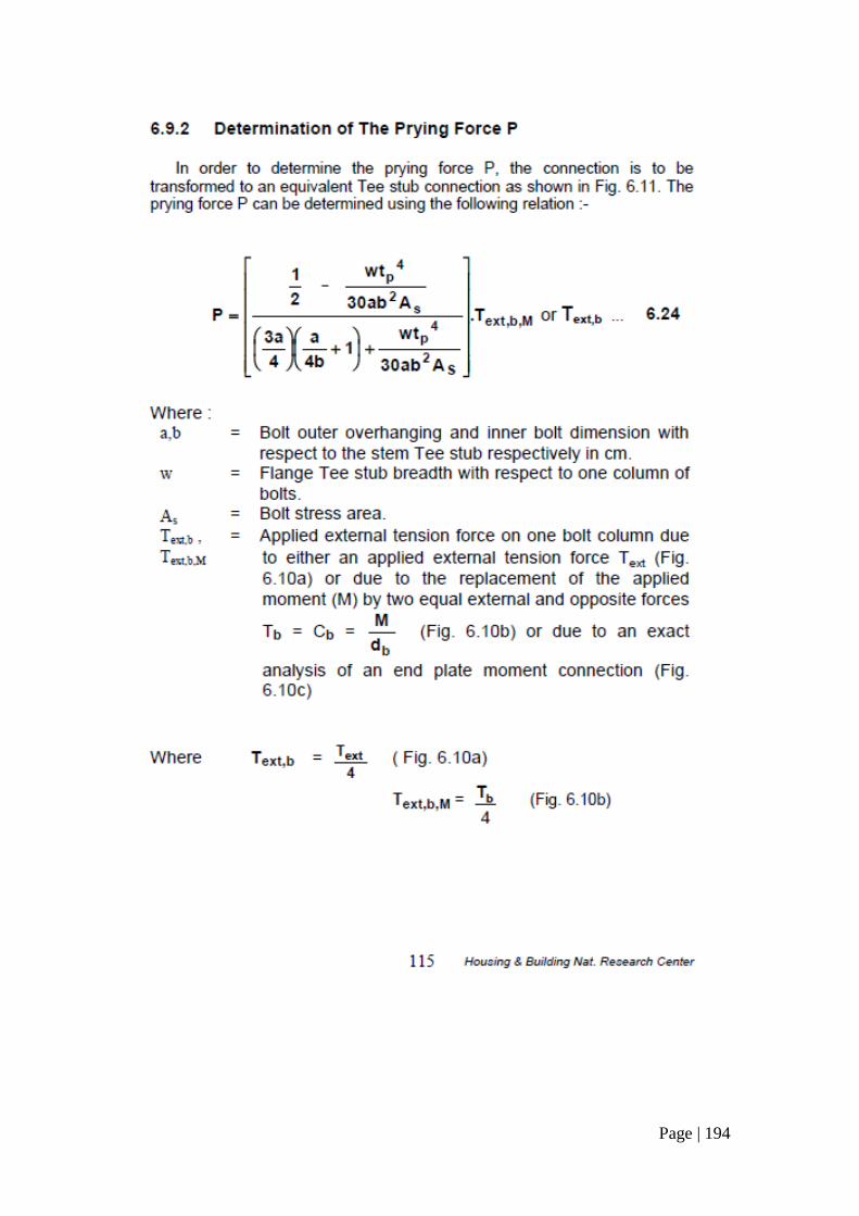
Page | 194
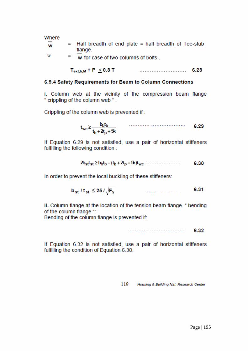
Page | 195
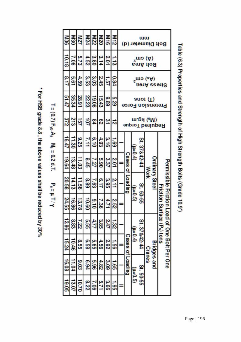
Page | 196
Page | 197
Project Report: Steel design for mosque
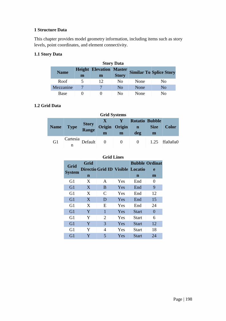
Page | 198
1 Structure Data
This chapter provides model geometry information, including items such as story
levels, point coordinates, and element connectivity.
1.1 Story Data
Story Data
Name Height
m
Elevation
m
Master
Story Similar To Splice Story
Roof 5 12 No None No
Mezzanine 7 7 No None No
Base 0 0 No None No
1.2 Grid Data
Grid Systems
Name Type Story
Range
X
Origin
m
Y
Origin
m
Rotatio
n
deg
Bubble
Size
m
Color
G1 Cartesia
n Default 0 0 0 1.25 ffa0a0a0
Grid Lines
Grid
System
Grid
Directio
n
Grid ID Visible
Bubble
Locatio
n
Ordinat
e
m
G1 X A Yes End 0
G1 X B Yes End 9
G1 X C Yes End 12
G1 X D Yes End 15
G1 X E Yes End 24
G1 Y 1 Yes Start 0
G1 Y 2 Yes Start 6
G1 Y 3 Yes Start 12
G1 Y 4 Yes Start 18
G1 Y 5 Yes Start 24
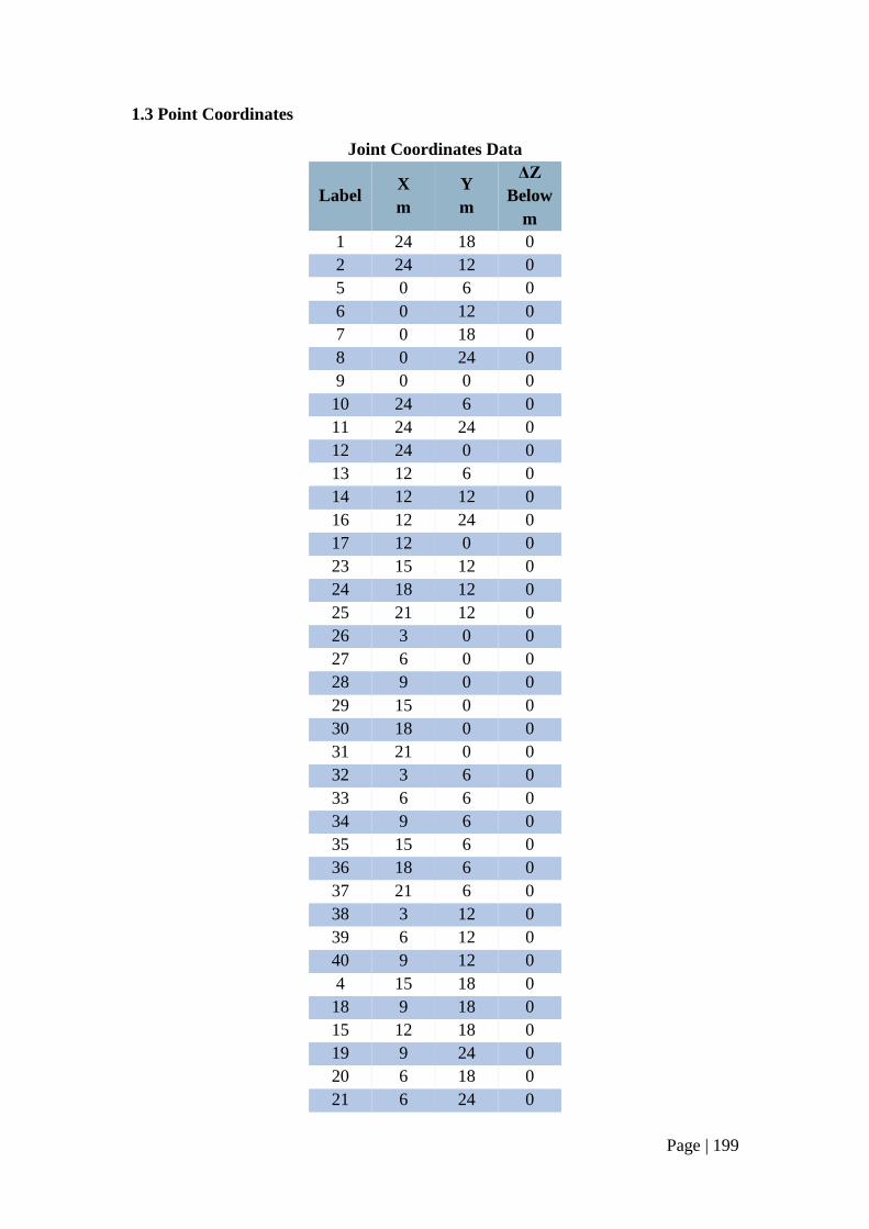
Page | 199
1.3 Point Coordinates
Joint Coordinates Data
Label X
m
Y
m
ΔZ
Below
m
1 24 18 0
2 24 12 0
5 0 6 0
6 0 12 0
7 0 18 0
8 0 24 0
9 0 0 0
10 24 6 0
11 24 24 0
12 24 0 0
13 12 6 0
14 12 12 0
16 12 24 0
17 12 0 0
23 15 12 0
24 18 12 0
25 21 12 0
26 3 0 0
27 6 0 0
28 9 0 0
29 15 0 0
30 18 0 0
31 21 0 0
32 3 6 0
33 6 6 0
34 9 6 0
35 15 6 0
36 18 6 0
37 21 6 0
38 3 12 0
39 6 12 0
40 9 12 0
4 15 18 0
18 9 18 0
15 12 18 0
19 9 24 0
20 6 18 0
21 6 24 0
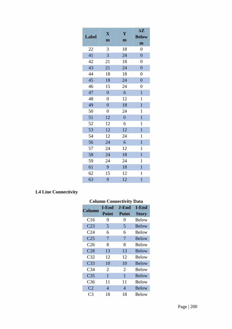
Page | 200
Label X
m
Y
m
ΔZ
Below
m
22 3 18 0
41 3 24 0
42 21 18 0
43 21 24 0
44 18 18 0
45 18 24 0
46 15 24 0
47 0 6 1
48 0 12 1
49 0 18 1
50 0 24 1
51 12 0 1
52 12 6 1
53 12 12 1
54 12 24 1
56 24 6 1
57 24 12 1
58 24 18 1
59 24 24 1
61 9 18 1
62 15 12 1
63 9 12 1
1.4 Line Connectivity
Column Connectivity Data
Column I-End
Point
J-End
Point
I-End
Story
C16 9 9 Below
C23 5 5 Below
C24 6 6 Below
C25 7 7 Below
C26 8 8 Below
C28 13 13 Below
C32 12 12 Below
C33 10 10 Below
C34 2 2 Below
C35 1 1 Below
C36 11 11 Below
C2 4 4 Below
C3 18 18 Below
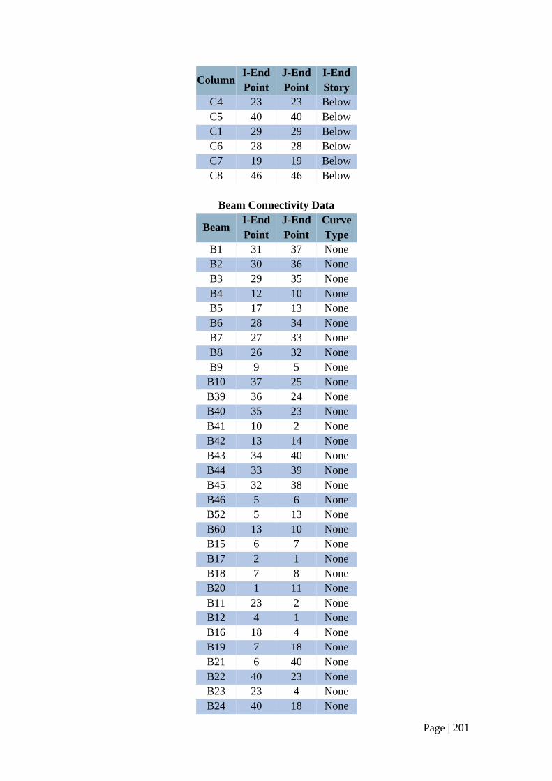
Page | 201
Column I-End
Point
J-End
Point
I-End
Story
C4 23 23 Below
C5 40 40 Below
C1 29 29 Below
C6 28 28 Below
C7 19 19 Below
C8 46 46 Below
Beam Connectivity Data
Beam I-End
Point
J-End
Point
Curve
Type
B1 31 37 None
B2 30 36 None
B3 29 35 None
B4 12 10 None
B5 17 13 None
B6 28 34 None
B7 27 33 None
B8 26 32 None
B9 9 5 None
B10 37 25 None
B39 36 24 None
B40 35 23 None
B41 10 2 None
B42 13 14 None
B43 34 40 None
B44 33 39 None
B45 32 38 None
B46 5 6 None
B52 5 13 None
B60 13 10 None
B15 6 7 None
B17 2 1 None
B18 7 8 None
B20 1 11 None
B11 23 2 None
B12 4 1 None
B16 18 4 None
B19 7 18 None
B21 6 40 None
B22 40 23 None
B23 23 4 None
B24 40 18 None
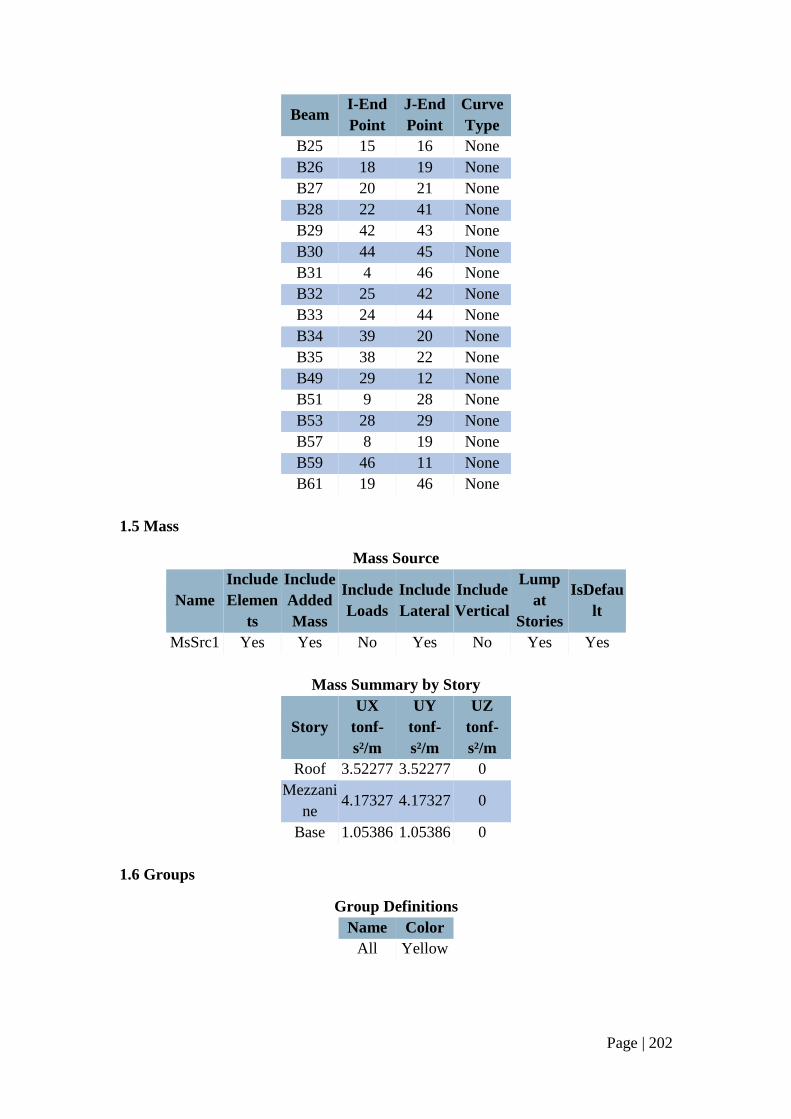
Page | 202
Beam I-End
Point
J-End
Point
Curve
Type
B25 15 16 None
B26 18 19 None
B27 20 21 None
B28 22 41 None
B29 42 43 None
B30 44 45 None
B31 4 46 None
B32 25 42 None
B33 24 44 None
B34 39 20 None
B35 38 22 None
B49 29 12 None
B51 9 28 None
B53 28 29 None
B57 8 19 None
B59 46 11 None
B61 19 46 None
1.5 Mass
Mass Source
Name
Include
Elemen
ts
Include
Added
Mass
Include
Loads
Include
Lateral
Include
Vertical
Lump
at
Stories
IsDefau
lt
MsSrc1 Yes Yes No Yes No Yes Yes
Mass Summary by Story
Story
UX
tonf-
s²/m
UY
tonf-
s²/m
UZ
tonf-
s²/m
Roof 3.52277 3.52277 0
Mezzani
ne 4.17327 4.17327 0
Base 1.05386 1.05386 0
1.6 Groups
Group Definitions
Name Color
All Yellow
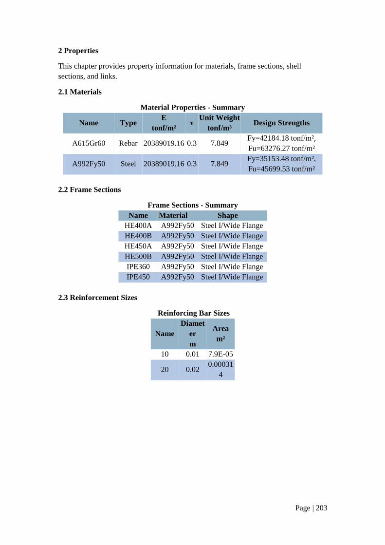
Page | 203
2 Properties
This chapter provides property information for materials, frame sections, shell
sections, and links.
2.1 Materials
Material Properties - Summary
Name Type E
tonf/m² ν
Unit Weight
tonf/m³ Design Strengths
A615Gr60 Rebar 20389019.16 0.3 7.849 Fy=42184.18 tonf/m²,
Fu=63276.27 tonf/m²
A992Fy50 Steel 20389019.16 0.3 7.849 Fy=35153.48 tonf/m²,
Fu=45699.53 tonf/m²
2.2 Frame Sections
Frame Sections - Summary
Name Material Shape
HE400A A992Fy50 Steel I/Wide Flange
HE400B A992Fy50 Steel I/Wide Flange
HE450A A992Fy50 Steel I/Wide Flange
HE500B A992Fy50 Steel I/Wide Flange
IPE360 A992Fy50 Steel I/Wide Flange
IPE450 A992Fy50 Steel I/Wide Flange
2.3 Reinforcement Sizes
Reinforcing Bar Sizes
Name
Diamet
er
m
Area
m²
10 0.01 7.9E-05
20 0.02 0.00031
4
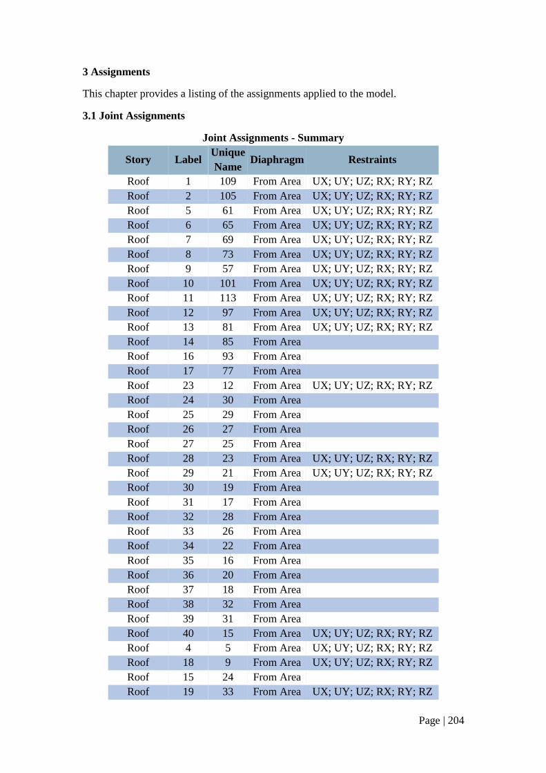
Page | 204
3 Assignments
This chapter provides a listing of the assignments applied to the model.
3.1 Joint Assignments
Joint Assignments - Summary
Story Label Unique
Name Diaphragm Restraints
Roof 1 109 From Area UX; UY; UZ; RX; RY; RZ
Roof 2 105 From Area UX; UY; UZ; RX; RY; RZ
Roof 5 61 From Area UX; UY; UZ; RX; RY; RZ
Roof 6 65 From Area UX; UY; UZ; RX; RY; RZ
Roof 7 69 From Area UX; UY; UZ; RX; RY; RZ
Roof 8 73 From Area UX; UY; UZ; RX; RY; RZ
Roof 9 57 From Area UX; UY; UZ; RX; RY; RZ
Roof 10 101 From Area UX; UY; UZ; RX; RY; RZ
Roof 11 113 From Area UX; UY; UZ; RX; RY; RZ
Roof 12 97 From Area UX; UY; UZ; RX; RY; RZ
Roof 13 81 From Area UX; UY; UZ; RX; RY; RZ
Roof 14 85 From Area
Roof 16 93 From Area
Roof 17 77 From Area
Roof 23 12 From Area UX; UY; UZ; RX; RY; RZ
Roof 24 30 From Area
Roof 25 29 From Area
Roof 26 27 From Area
Roof 27 25 From Area
Roof 28 23 From Area UX; UY; UZ; RX; RY; RZ
Roof 29 21 From Area UX; UY; UZ; RX; RY; RZ
Roof 30 19 From Area
Roof 31 17 From Area
Roof 32 28 From Area
Roof 33 26 From Area
Roof 34 22 From Area
Roof 35 16 From Area
Roof 36 20 From Area
Roof 37 18 From Area
Roof 38 32 From Area
Roof 39 31 From Area
Roof 40 15 From Area UX; UY; UZ; RX; RY; RZ
Roof 4 5 From Area UX; UY; UZ; RX; RY; RZ
Roof 18 9 From Area UX; UY; UZ; RX; RY; RZ
Roof 15 24 From Area
Roof 19 33 From Area UX; UY; UZ; RX; RY; RZ
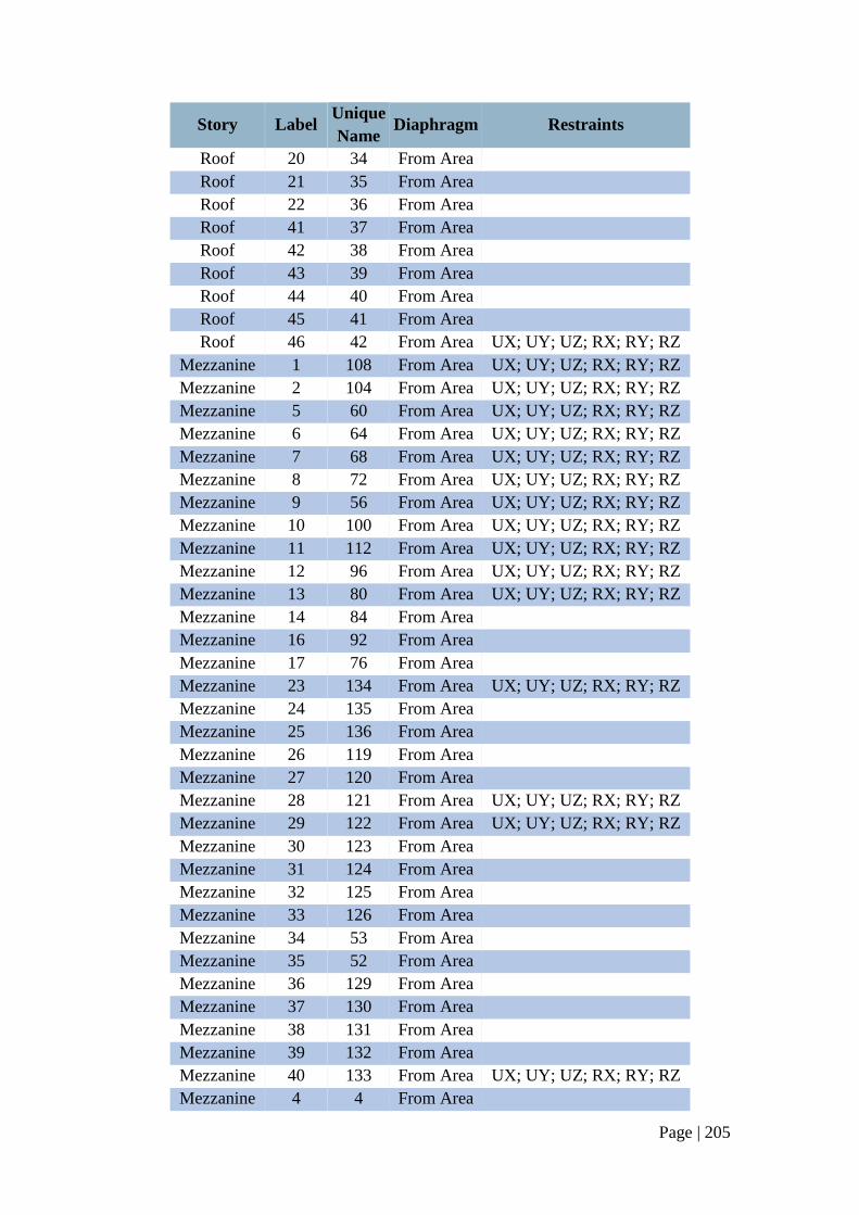
Page | 205
Story Label Unique
Name Diaphragm Restraints
Roof 20 34 From Area
Roof 21 35 From Area
Roof 22 36 From Area
Roof 41 37 From Area
Roof 42 38 From Area
Roof 43 39 From Area
Roof 44 40 From Area
Roof 45 41 From Area
Roof 46 42 From Area UX; UY; UZ; RX; RY; RZ
Mezzanine 1 108 From Area UX; UY; UZ; RX; RY; RZ
Mezzanine 2 104 From Area UX; UY; UZ; RX; RY; RZ
Mezzanine 5 60 From Area UX; UY; UZ; RX; RY; RZ
Mezzanine 6 64 From Area UX; UY; UZ; RX; RY; RZ
Mezzanine 7 68 From Area UX; UY; UZ; RX; RY; RZ
Mezzanine 8 72 From Area UX; UY; UZ; RX; RY; RZ
Mezzanine 9 56 From Area UX; UY; UZ; RX; RY; RZ
Mezzanine 10 100 From Area UX; UY; UZ; RX; RY; RZ
Mezzanine 11 112 From Area UX; UY; UZ; RX; RY; RZ
Mezzanine 12 96 From Area UX; UY; UZ; RX; RY; RZ
Mezzanine 13 80 From Area UX; UY; UZ; RX; RY; RZ
Mezzanine 14 84 From Area
Mezzanine 16 92 From Area
Mezzanine 17 76 From Area
Mezzanine 23 134 From Area UX; UY; UZ; RX; RY; RZ
Mezzanine 24 135 From Area
Mezzanine 25 136 From Area
Mezzanine 26 119 From Area
Mezzanine 27 120 From Area
Mezzanine 28 121 From Area UX; UY; UZ; RX; RY; RZ
Mezzanine 29 122 From Area UX; UY; UZ; RX; RY; RZ
Mezzanine 30 123 From Area
Mezzanine 31 124 From Area
Mezzanine 32 125 From Area
Mezzanine 33 126 From Area
Mezzanine 34 53 From Area
Mezzanine 35 52 From Area
Mezzanine 36 129 From Area
Mezzanine 37 130 From Area
Mezzanine 38 131 From Area
Mezzanine 39 132 From Area
Mezzanine 40 133 From Area UX; UY; UZ; RX; RY; RZ
Mezzanine 4 4 From Area
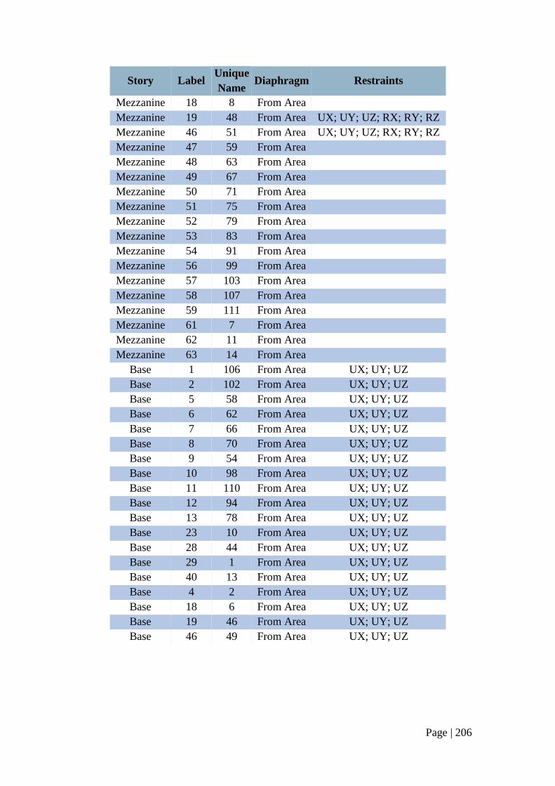
Page | 206
Story Label Unique
Name Diaphragm Restraints
Mezzanine 18 8 From Area
Mezzanine 19 48 From Area UX; UY; UZ; RX; RY; RZ
Mezzanine 46 51 From Area UX; UY; UZ; RX; RY; RZ
Mezzanine 47 59 From Area
Mezzanine 48 63 From Area
Mezzanine 49 67 From Area
Mezzanine 50 71 From Area
Mezzanine 51 75 From Area
Mezzanine 52 79 From Area
Mezzanine 53 83 From Area
Mezzanine 54 91 From Area
Mezzanine 56 99 From Area
Mezzanine 57 103 From Area
Mezzanine 58 107 From Area
Mezzanine 59 111 From Area
Mezzanine 61 7 From Area
Mezzanine 62 11 From Area
Mezzanine 63 14 From Area
Base 1 106 From Area UX; UY; UZ
Base 2 102 From Area UX; UY; UZ
Base 5 58 From Area UX; UY; UZ
Base 6 62 From Area UX; UY; UZ
Base 7 66 From Area UX; UY; UZ
Base 8 70 From Area UX; UY; UZ
Base 9 54 From Area UX; UY; UZ
Base 10 98 From Area UX; UY; UZ
Base 11 110 From Area UX; UY; UZ
Base 12 94 From Area UX; UY; UZ
Base 13 78 From Area UX; UY; UZ
Base 23 10 From Area UX; UY; UZ
Base 28 44 From Area UX; UY; UZ
Base 29 1 From Area UX; UY; UZ
Base 40 13 From Area UX; UY; UZ
Base 4 2 From Area UX; UY; UZ
Base 18 6 From Area UX; UY; UZ
Base 19 46 From Area UX; UY; UZ
Base 46 49 From Area UX; UY; UZ
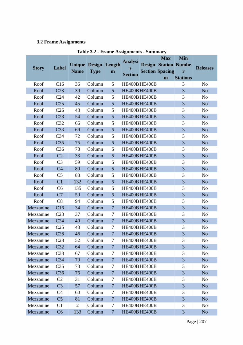
Page | 207
3.2 Frame Assignments
Table 3.2 - Frame Assignments - Summary
Story Label Unique
Name
Design
Type
Length
m
Analysi
s
Section
Design
Section
Max
Station
Spacing
m
Min
Numbe
r
Stations
Releases
Roof C16 36 Column 5 HE400B HE400B 3 No
Roof C23 39 Column 5 HE400B HE400B 3 No
Roof C24 42 Column 5 HE400B HE400B 3 No
Roof C25 45 Column 5 HE400B HE400B 3 No
Roof C26 48 Column 5 HE400B HE400B 3 No
Roof C28 54 Column 5 HE400B HE400B 3 No
Roof C32 66 Column 5 HE400B HE400B 3 No
Roof C33 69 Column 5 HE400B HE400B 3 No
Roof C34 72 Column 5 HE400B HE400B 3 No
Roof C35 75 Column 5 HE400B HE400B 3 No
Roof C36 78 Column 5 HE400B HE400B 3 No
Roof C2 33 Column 5 HE400B HE400B 3 No
Roof C3 59 Column 5 HE400B HE400B 3 No
Roof C4 80 Column 5 HE400B HE400B 3 No
Roof C5 83 Column 5 HE400B HE400B 3 No
Roof C1 132 Column 5 HE400B HE400B 3 No
Roof C6 135 Column 5 HE400B HE400B 3 No
Roof C7 50 Column 5 HE400B HE400B 3 No
Roof C8 94 Column 5 HE400B HE400B 3 No
Mezzanine C16 34 Column 7 HE400B HE400B 3 No
Mezzanine C23 37 Column 7 HE400B HE400B 3 No
Mezzanine C24 40 Column 7 HE400B HE400B 3 No
Mezzanine C25 43 Column 7 HE400B HE400B 3 No
Mezzanine C26 46 Column 7 HE400B HE400B 3 No
Mezzanine C28 52 Column 7 HE400B HE400B 3 No
Mezzanine C32 64 Column 7 HE400B HE400B 3 No
Mezzanine C33 67 Column 7 HE400B HE400B 3 No
Mezzanine C34 70 Column 7 HE400B HE400B 3 No
Mezzanine C35 73 Column 7 HE400B HE400B 3 No
Mezzanine C36 76 Column 7 HE400B HE400B 3 No
Mezzanine C2 31 Column 7 HE400B HE400B 3 No
Mezzanine C3 57 Column 7 HE400B HE400B 3 No
Mezzanine C4 60 Column 7 HE400B HE400B 3 No
Mezzanine C5 81 Column 7 HE400B HE400B 3 No
Mezzanine C1 2 Column 7 HE400B HE400B 3 No
Mezzanine C6 133 Column 7 HE400B HE400B 3 No
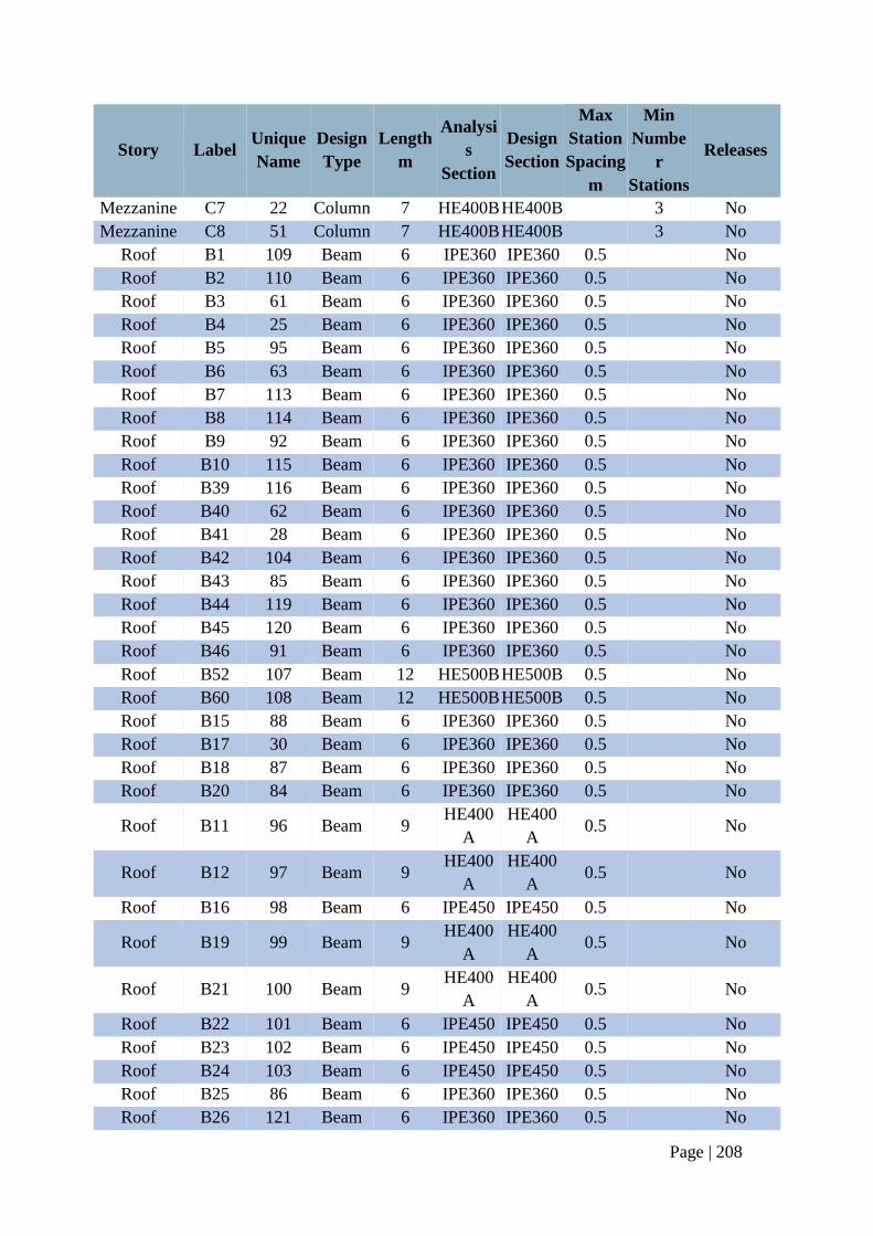
Page | 208
Story Label Unique
Name
Design
Type
Length
m
Analysi
s
Section
Design
Section
Max
Station
Spacing
m
Min
Numbe
r
Stations
Releases
Mezzanine C7 22 Column 7 HE400B HE400B 3 No
Mezzanine C8 51 Column 7 HE400B HE400B 3 No
Roof B1 109 Beam 6 IPE360 IPE360 0.5 No
Roof B2 110 Beam 6 IPE360 IPE360 0.5 No
Roof B3 61 Beam 6 IPE360 IPE360 0.5 No
Roof B4 25 Beam 6 IPE360 IPE360 0.5 No
Roof B5 95 Beam 6 IPE360 IPE360 0.5 No
Roof B6 63 Beam 6 IPE360 IPE360 0.5 No
Roof B7 113 Beam 6 IPE360 IPE360 0.5 No
Roof B8 114 Beam 6 IPE360 IPE360 0.5 No
Roof B9 92 Beam 6 IPE360 IPE360 0.5 No
Roof B10 115 Beam 6 IPE360 IPE360 0.5 No
Roof B39 116 Beam 6 IPE360 IPE360 0.5 No
Roof B40 62 Beam 6 IPE360 IPE360 0.5 No
Roof B41 28 Beam 6 IPE360 IPE360 0.5 No
Roof B42 104 Beam 6 IPE360 IPE360 0.5 No
Roof B43 85 Beam 6 IPE360 IPE360 0.5 No
Roof B44 119 Beam 6 IPE360 IPE360 0.5 No
Roof B45 120 Beam 6 IPE360 IPE360 0.5 No
Roof B46 91 Beam 6 IPE360 IPE360 0.5 No
Roof B52 107 Beam 12 HE500B HE500B 0.5 No
Roof B60 108 Beam 12 HE500B HE500B 0.5 No
Roof B15 88 Beam 6 IPE360 IPE360 0.5 No
Roof B17 30 Beam 6 IPE360 IPE360 0.5 No
Roof B18 87 Beam 6 IPE360 IPE360 0.5 No
Roof B20 84 Beam 6 IPE360 IPE360 0.5 No
Roof B11 96 Beam 9 HE400
A
HE400
A 0.5 No
Roof B12 97 Beam 9 HE400
A
HE400
A 0.5 No
Roof B16 98 Beam 6 IPE450 IPE450 0.5 No
Roof B19 99 Beam 9 HE400
A
HE400
A 0.5 No
Roof B21 100 Beam 9 HE400
A
HE400
A 0.5 No
Roof B22 101 Beam 6 IPE450 IPE450 0.5 No
Roof B23 102 Beam 6 IPE450 IPE450 0.5 No
Roof B24 103 Beam 6 IPE450 IPE450 0.5 No
Roof B25 86 Beam 6 IPE360 IPE360 0.5 No
Roof B26 121 Beam 6 IPE360 IPE360 0.5 No
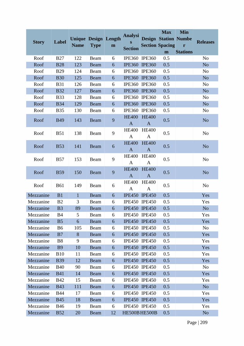
Page | 209
Story Label Unique
Name
Design
Type
Length
m
Analysi
s
Section
Design
Section
Max
Station
Spacing
m
Min
Numbe
r
Stations
Releases
Roof B27 122 Beam 6 IPE360 IPE360 0.5 No
Roof B28 123 Beam 6 IPE360 IPE360 0.5 No
Roof B29 124 Beam 6 IPE360 IPE360 0.5 No
Roof B30 125 Beam 6 IPE360 IPE360 0.5 No
Roof B31 126 Beam 6 IPE360 IPE360 0.5 No
Roof B32 127 Beam 6 IPE360 IPE360 0.5 No
Roof B33 128 Beam 6 IPE360 IPE360 0.5 No
Roof B34 129 Beam 6 IPE360 IPE360 0.5 No
Roof B35 130 Beam 6 IPE360 IPE360 0.5 No
Roof B49 143 Beam 9 HE400
A
HE400
A 0.5 No
Roof B51 138 Beam 9 HE400
A
HE400
A 0.5 No
Roof B53 141 Beam 6 HE400
A
HE400
A 0.5 No
Roof B57 153 Beam 9 HE400
A
HE400
A 0.5 No
Roof B59 150 Beam 9 HE400
A
HE400
A 0.5 No
Roof B61 149 Beam 6 HE400
A
HE400
A 0.5 No
Mezzanine B1 1 Beam 6 IPE450 IPE450 0.5 Yes
Mezzanine B2 3 Beam 6 IPE450 IPE450 0.5 Yes
Mezzanine B3 89 Beam 6 IPE450 IPE450 0.5 No
Mezzanine B4 5 Beam 6 IPE450 IPE450 0.5 Yes
Mezzanine B5 6 Beam 6 IPE450 IPE450 0.5 Yes
Mezzanine B6 105 Beam 6 IPE450 IPE450 0.5 No
Mezzanine B7 8 Beam 6 IPE450 IPE450 0.5 Yes
Mezzanine B8 9 Beam 6 IPE450 IPE450 0.5 Yes
Mezzanine B9 10 Beam 6 IPE450 IPE450 0.5 Yes
Mezzanine B10 11 Beam 6 IPE450 IPE450 0.5 Yes
Mezzanine B39 12 Beam 6 IPE450 IPE450 0.5 Yes
Mezzanine B40 90 Beam 6 IPE450 IPE450 0.5 No
Mezzanine B41 14 Beam 6 IPE450 IPE450 0.5 Yes
Mezzanine B42 15 Beam 6 IPE450 IPE450 0.5 Yes
Mezzanine B43 111 Beam 6 IPE450 IPE450 0.5 No
Mezzanine B44 17 Beam 6 IPE450 IPE450 0.5 Yes
Mezzanine B45 18 Beam 6 IPE450 IPE450 0.5 Yes
Mezzanine B46 19 Beam 6 IPE450 IPE450 0.5 Yes
Mezzanine B52 20 Beam 12 HE500B HE500B 0.5 No
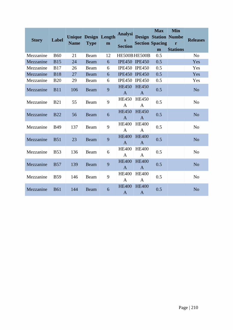
Page | 210
Story Label Unique
Name
Design
Type
Length
m
Analysi
s
Section
Design
Section
Max
Station
Spacing
m
Min
Numbe
r
Stations
Releases
Mezzanine B60 21 Beam 12 HE500B HE500B 0.5 No
Mezzanine B15 24 Beam 6 IPE450 IPE450 0.5 Yes
Mezzanine B17 26 Beam 6 IPE450 IPE450 0.5 Yes
Mezzanine B18 27 Beam 6 IPE450 IPE450 0.5 Yes
Mezzanine B20 29 Beam 6 IPE450 IPE450 0.5 Yes
Mezzanine B11 106 Beam 9 HE450
A
HE450
A 0.5 No
Mezzanine B21 55 Beam 9 HE450
A
HE450
A 0.5 No
Mezzanine B22 56 Beam 6 HE450
A
HE450
A 0.5 No
Mezzanine B49 137 Beam 9 HE400
A
HE400
A 0.5 No
Mezzanine B51 23 Beam 9 HE400
A
HE400
A 0.5 No
Mezzanine B53 136 Beam 6 HE400
A
HE400
A 0.5 No
Mezzanine B57 139 Beam 9 HE400
A
HE400
A 0.5 No
Mezzanine B59 146 Beam 9 HE400
A
HE400
A 0.5 No
Mezzanine B61 144 Beam 6 HE400
A
HE400
A 0.5 No
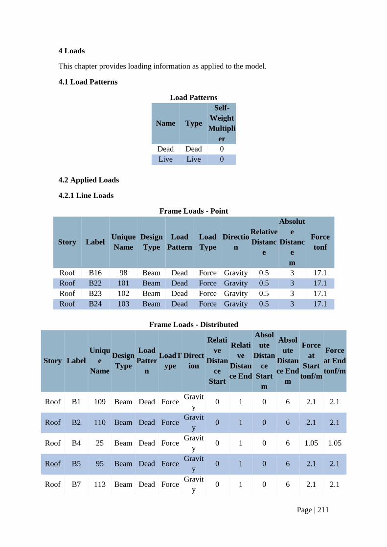
Page | 211
4 Loads
This chapter provides loading information as applied to the model.
4.1 Load Patterns
Load Patterns
Name Type
Self-
Weight
Multipli
er
Dead Dead 0
Live Live 0
4.2 Applied Loads
4.2.1 Line Loads
Frame Loads - Point
Story Label Unique
Name
Design
Type
Load
Pattern
Load
Type
Directio
n
Relative
Distanc
e
Absolut
e
Distanc
e
m
Force
tonf
Roof B16 98 Beam Dead Force Gravity 0.5 3 17.1
Roof B22 101 Beam Dead Force Gravity 0.5 3 17.1
Roof B23 102 Beam Dead Force Gravity 0.5 3 17.1
Roof B24 103 Beam Dead Force Gravity 0.5 3 17.1
Frame Loads - Distributed
Story Label
Uniqu
e
Name
Design
Type
Load
Patter
n
LoadT
ype
Direct
ion
Relati
ve
Distan
ce
Start
Relati
ve
Distan
ce End
Absol
ute
Distan
ce
Start
m
Absol
ute
Distan
ce End
m
Force
at
Start
tonf/m
Force
at End
tonf/m
Roof B1 109 Beam Dead Force Gravit
y 0 1 0 6 2.1 2.1
Roof B2 110 Beam Dead Force Gravit
y 0 1 0 6 2.1 2.1
Roof B4 25 Beam Dead Force Gravit
y 0 1 0 6 1.05 1.05
Roof B5 95 Beam Dead Force Gravit
y 0 1 0 6 2.1 2.1
Roof B7 113 Beam Dead Force Gravit
y 0 1 0 6 2.1 2.1
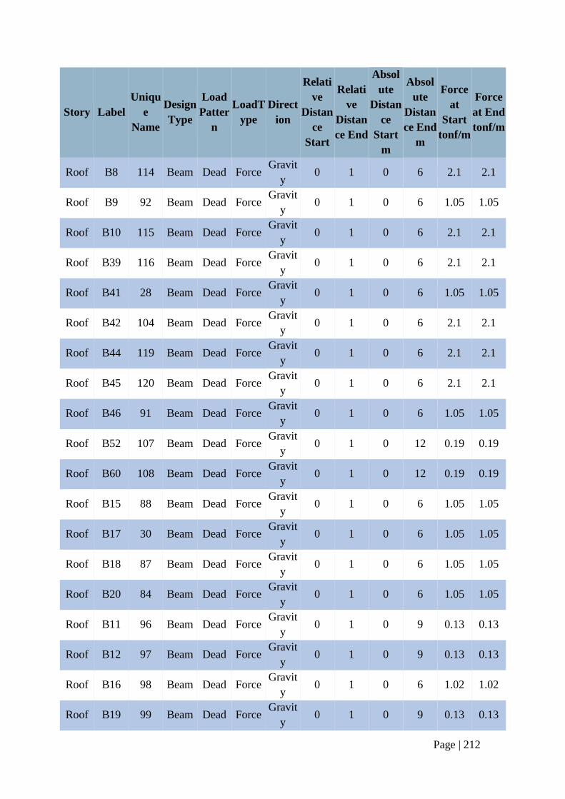
Page | 212
Story Label
Uniqu
e
Name
Design
Type
Load
Patter
n
LoadT
ype
Direct
ion
Relati
ve
Distan
ce
Start
Relati
ve
Distan
ce End
Absol
ute
Distan
ce
Start
m
Absol
ute
Distan
ce End
m
Force
at
Start
tonf/m
Force
at End
tonf/m
Roof B8 114 Beam Dead Force Gravit
y 0 1 0 6 2.1 2.1
Roof B9 92 Beam Dead Force Gravit
y 0 1 0 6 1.05 1.05
Roof B10 115 Beam Dead Force Gravit
y 0 1 0 6 2.1 2.1
Roof B39 116 Beam Dead Force Gravit
y 0 1 0 6 2.1 2.1
Roof B41 28 Beam Dead Force Gravit
y 0 1 0 6 1.05 1.05
Roof B42 104 Beam Dead Force Gravit
y 0 1 0 6 2.1 2.1
Roof B44 119 Beam Dead Force Gravit
y 0 1 0 6 2.1 2.1
Roof B45 120 Beam Dead Force Gravit
y 0 1 0 6 2.1 2.1
Roof B46 91 Beam Dead Force Gravit
y 0 1 0 6 1.05 1.05
Roof B52 107 Beam Dead Force Gravit
y 0 1 0 12 0.19 0.19
Roof B60 108 Beam Dead Force Gravit
y 0 1 0 12 0.19 0.19
Roof B15 88 Beam Dead Force Gravit
y 0 1 0 6 1.05 1.05
Roof B17 30 Beam Dead Force Gravit
y 0 1 0 6 1.05 1.05
Roof B18 87 Beam Dead Force Gravit
y 0 1 0 6 1.05 1.05
Roof B20 84 Beam Dead Force Gravit
y 0 1 0 6 1.05 1.05
Roof B11 96 Beam Dead Force Gravit
y 0 1 0 9 0.13 0.13
Roof B12 97 Beam Dead Force Gravit
y 0 1 0 9 0.13 0.13
Roof B16 98 Beam Dead Force Gravit
y 0 1 0 6 1.02 1.02
Roof B19 99 Beam Dead Force Gravit
y 0 1 0 9 0.13 0.13
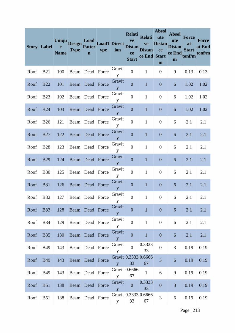
Page | 213
Story Label
Uniqu
e
Name
Design
Type
Load
Patter
n
LoadT
ype
Direct
ion
Relati
ve
Distan
ce
Start
Relati
ve
Distan
ce End
Absol
ute
Distan
ce
Start
m
Absol
ute
Distan
ce End
m
Force
at
Start
tonf/m
Force
at End
tonf/m
Roof B21 100 Beam Dead Force Gravit
y 0 1 0 9 0.13 0.13
Roof B22 101 Beam Dead Force Gravit
y 0 1 0 6 1.02 1.02
Roof B23 102 Beam Dead Force Gravit
y 0 1 0 6 1.02 1.02
Roof B24 103 Beam Dead Force Gravit
y 0 1 0 6 1.02 1.02
Roof B26 121 Beam Dead Force Gravit
y 0 1 0 6 2.1 2.1
Roof B27 122 Beam Dead Force Gravit
y 0 1 0 6 2.1 2.1
Roof B28 123 Beam Dead Force Gravit
y 0 1 0 6 2.1 2.1
Roof B29 124 Beam Dead Force Gravit
y 0 1 0 6 2.1 2.1
Roof B30 125 Beam Dead Force Gravit
y 0 1 0 6 2.1 2.1
Roof B31 126 Beam Dead Force Gravit
y 0 1 0 6 2.1 2.1
Roof B32 127 Beam Dead Force Gravit
y 0 1 0 6 2.1 2.1
Roof B33 128 Beam Dead Force Gravit
y 0 1 0 6 2.1 2.1
Roof B34 129 Beam Dead Force Gravit
y 0 1 0 6 2.1 2.1
Roof B35 130 Beam Dead Force Gravit
y 0 1 0 6 2.1 2.1
Roof B49 143 Beam Dead Force Gravit
y 0
0.3333
33 0 3 0.19 0.19
Roof B49 143 Beam Dead Force Gravit
y
0.3333
33
0.6666
67 3 6 0.19 0.19
Roof B49 143 Beam Dead Force Gravit
y
0.6666
67 1 6 9 0.19 0.19
Roof B51 138 Beam Dead Force Gravit
y 0
0.3333
33 0 3 0.19 0.19
Roof B51 138 Beam Dead Force Gravit
y
0.3333
33
0.6666
67 3 6 0.19 0.19
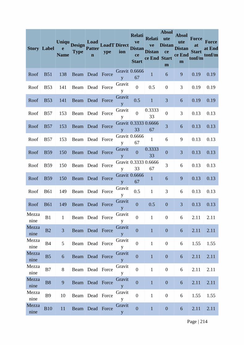
Page | 214
Story Label
Uniqu
e
Name
Design
Type
Load
Patter
n
LoadT
ype
Direct
ion
Relati
ve
Distan
ce
Start
Relati
ve
Distan
ce End
Absol
ute
Distan
ce
Start
m
Absol
ute
Distan
ce End
m
Force
at
Start
tonf/m
Force
at End
tonf/m
Roof B51 138 Beam Dead Force Gravit
y
0.6666
67 1 6 9 0.19 0.19
Roof B53 141 Beam Dead Force Gravit
y 0 0.5 0 3 0.19 0.19
Roof B53 141 Beam Dead Force Gravit
y 0.5 1 3 6 0.19 0.19
Roof B57 153 Beam Dead Force Gravit
y 0
0.3333
33 0 3 0.13 0.13
Roof B57 153 Beam Dead Force Gravit
y
0.3333
33
0.6666
67 3 6 0.13 0.13
Roof B57 153 Beam Dead Force Gravit
y
0.6666
67 1 6 9 0.13 0.13
Roof B59 150 Beam Dead Force Gravit
y 0
0.3333
33 0 3 0.13 0.13
Roof B59 150 Beam Dead Force Gravit
y
0.3333
33
0.6666
67 3 6 0.13 0.13
Roof B59 150 Beam Dead Force Gravit
y
0.6666
67 1 6 9 0.13 0.13
Roof B61 149 Beam Dead Force Gravit
y 0.5 1 3 6 0.13 0.13
Roof B61 149 Beam Dead Force Gravit
y 0 0.5 0 3 0.13 0.13
Mezza
nine B1 1 Beam Dead Force
Gravit
y 0 1 0 6 2.11 2.11
Mezza
nine B2 3 Beam Dead Force
Gravit
y 0 1 0 6 2.11 2.11
Mezza
nine B4 5 Beam Dead Force
Gravit
y 0 1 0 6 1.55 1.55
Mezza
nine B5 6 Beam Dead Force
Gravit
y 0 1 0 6 2.11 2.11
Mezza
nine B7 8 Beam Dead Force
Gravit
y 0 1 0 6 2.11 2.11
Mezza
nine B8 9 Beam Dead Force
Gravit
y 0 1 0 6 2.11 2.11
Mezza
nine B9 10 Beam Dead Force
Gravit
y 0 1 0 6 1.55 1.55
Mezza
nine B10 11 Beam Dead Force
Gravit
y 0 1 0 6 2.11 2.11
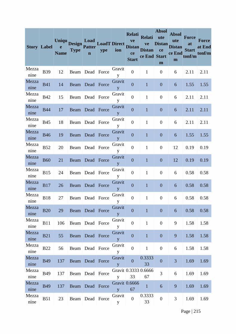
Page | 215
Story Label
Uniqu
e
Name
Design
Type
Load
Patter
n
LoadT
ype
Direct
ion
Relati
ve
Distan
ce
Start
Relati
ve
Distan
ce End
Absol
ute
Distan
ce
Start
m
Absol
ute
Distan
ce End
m
Force
at
Start
tonf/m
Force
at End
tonf/m
Mezza
nine B39 12 Beam Dead Force
Gravit
y 0 1 0 6 2.11 2.11
Mezza
nine B41 14 Beam Dead Force
Gravit
y 0 1 0 6 1.55 1.55
Mezza
nine B42 15 Beam Dead Force
Gravit
y 0 1 0 6 2.11 2.11
Mezza
nine B44 17 Beam Dead Force
Gravit
y 0 1 0 6 2.11 2.11
Mezza
nine B45 18 Beam Dead Force
Gravit
y 0 1 0 6 2.11 2.11
Mezza
nine B46 19 Beam Dead Force
Gravit
y 0 1 0 6 1.55 1.55
Mezza
nine B52 20 Beam Dead Force
Gravit
y 0 1 0 12 0.19 0.19
Mezza
nine B60 21 Beam Dead Force
Gravit
y 0 1 0 12 0.19 0.19
Mezza
nine B15 24 Beam Dead Force
Gravit
y 0 1 0 6 0.58 0.58
Mezza
nine B17 26 Beam Dead Force
Gravit
y 0 1 0 6 0.58 0.58
Mezza
nine B18 27 Beam Dead Force
Gravit
y 0 1 0 6 0.58 0.58
Mezza
nine B20 29 Beam Dead Force
Gravit
y 0 1 0 6 0.58 0.58
Mezza
nine B11 106 Beam Dead Force
Gravit
y 0 1 0 9 1.58 1.58
Mezza
nine B21 55 Beam Dead Force
Gravit
y 0 1 0 9 1.58 1.58
Mezza
nine B22 56 Beam Dead Force
Gravit
y 0 1 0 6 1.58 1.58
Mezza
nine B49 137 Beam Dead Force
Gravit
y 0
0.3333
33 0 3 1.69 1.69
Mezza
nine B49 137 Beam Dead Force
Gravit
y
0.3333
33
0.6666
67 3 6 1.69 1.69
Mezza
nine B49 137 Beam Dead Force
Gravit
y
0.6666
67 1 6 9 1.69 1.69
Mezza
nine B51 23 Beam Dead Force
Gravit
y 0
0.3333
33 0 3 1.69 1.69
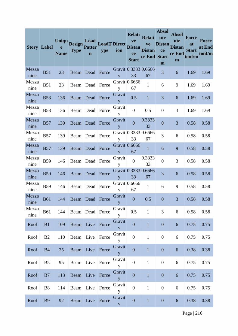
Page | 216
Story Label
Uniqu
e
Name
Design
Type
Load
Patter
n
LoadT
ype
Direct
ion
Relati
ve
Distan
ce
Start
Relati
ve
Distan
ce End
Absol
ute
Distan
ce
Start
m
Absol
ute
Distan
ce End
m
Force
at
Start
tonf/m
Force
at End
tonf/m
Mezza
nine B51 23 Beam Dead Force
Gravit
y
0.3333
33
0.6666
67 3 6 1.69 1.69
Mezza
nine B51 23 Beam Dead Force
Gravit
y
0.6666
67 1 6 9 1.69 1.69
Mezza
nine B53 136 Beam Dead Force
Gravit
y 0.5 1 3 6 1.69 1.69
Mezza
nine B53 136 Beam Dead Force
Gravit
y 0 0.5 0 3 1.69 1.69
Mezza
nine B57 139 Beam Dead Force
Gravit
y 0
0.3333
33 0 3 0.58 0.58
Mezza
nine B57 139 Beam Dead Force
Gravit
y
0.3333
33
0.6666
67 3 6 0.58 0.58
Mezza
nine B57 139 Beam Dead Force
Gravit
y
0.6666
67 1 6 9 0.58 0.58
Mezza
nine B59 146 Beam Dead Force
Gravit
y 0
0.3333
33 0 3 0.58 0.58
Mezza
nine B59 146 Beam Dead Force
Gravit
y
0.3333
33
0.6666
67 3 6 0.58 0.58
Mezza
nine B59 146 Beam Dead Force
Gravit
y
0.6666
67 1 6 9 0.58 0.58
Mezza
nine B61 144 Beam Dead Force
Gravit
y 0 0.5 0 3 0.58 0.58
Mezza
nine B61 144 Beam Dead Force
Gravit
y 0.5 1 3 6 0.58 0.58
Roof B1 109 Beam Live Force Gravit
y 0 1 0 6 0.75 0.75
Roof B2 110 Beam Live Force Gravit
y 0 1 0 6 0.75 0.75
Roof B4 25 Beam Live Force Gravit
y 0 1 0 6 0.38 0.38
Roof B5 95 Beam Live Force Gravit
y 0 1 0 6 0.75 0.75
Roof B7 113 Beam Live Force Gravit
y 0 1 0 6 0.75 0.75
Roof B8 114 Beam Live Force Gravit
y 0 1 0 6 0.75 0.75
Roof B9 92 Beam Live Force Gravit
y 0 1 0 6 0.38 0.38
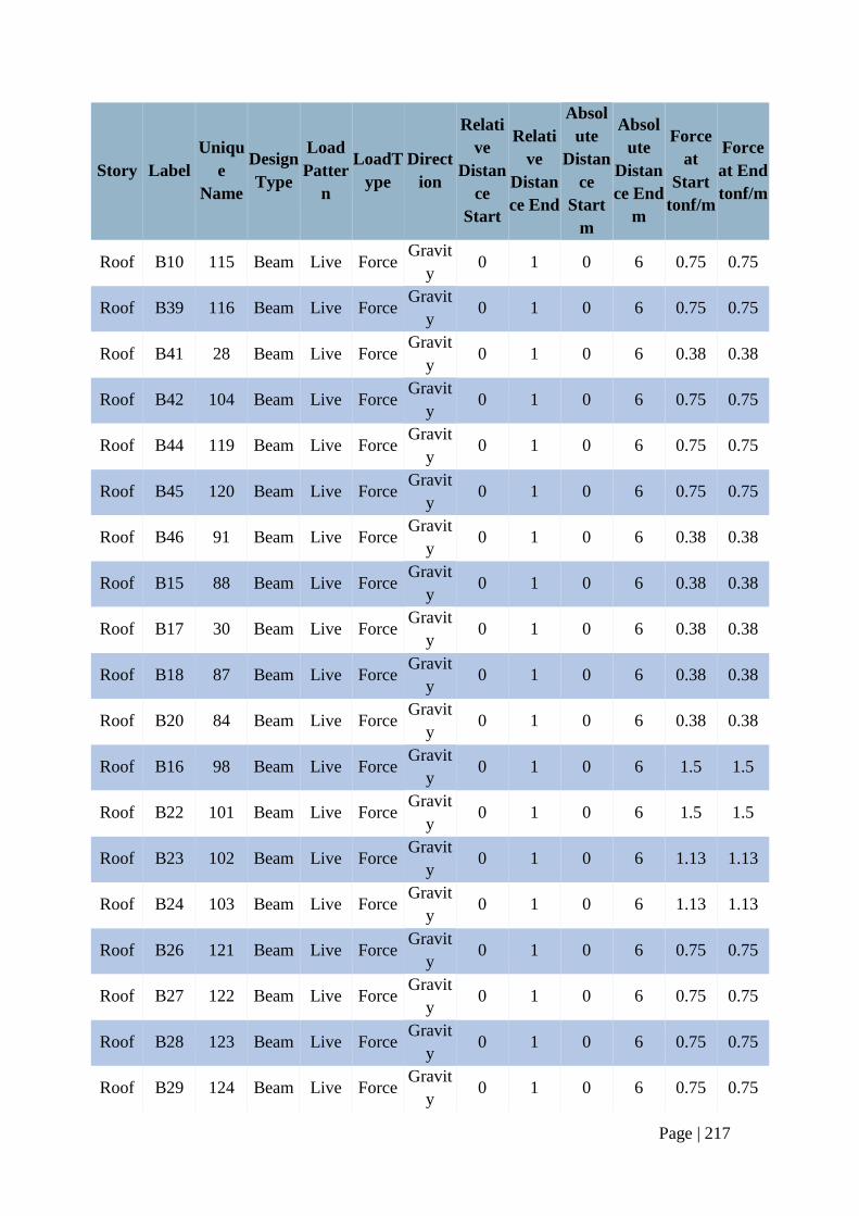
Page | 217
Story Label
Uniqu
e
Name
Design
Type
Load
Patter
n
LoadT
ype
Direct
ion
Relati
ve
Distan
ce
Start
Relati
ve
Distan
ce End
Absol
ute
Distan
ce
Start
m
Absol
ute
Distan
ce End
m
Force
at
Start
tonf/m
Force
at End
tonf/m
Roof B10 115 Beam Live Force Gravit
y 0 1 0 6 0.75 0.75
Roof B39 116 Beam Live Force Gravit
y 0 1 0 6 0.75 0.75
Roof B41 28 Beam Live Force Gravit
y 0 1 0 6 0.38 0.38
Roof B42 104 Beam Live Force Gravit
y 0 1 0 6 0.75 0.75
Roof B44 119 Beam Live Force Gravit
y 0 1 0 6 0.75 0.75
Roof B45 120 Beam Live Force Gravit
y 0 1 0 6 0.75 0.75
Roof B46 91 Beam Live Force Gravit
y 0 1 0 6 0.38 0.38
Roof B15 88 Beam Live Force Gravit
y 0 1 0 6 0.38 0.38
Roof B17 30 Beam Live Force Gravit
y 0 1 0 6 0.38 0.38
Roof B18 87 Beam Live Force Gravit
y 0 1 0 6 0.38 0.38
Roof B20 84 Beam Live Force Gravit
y 0 1 0 6 0.38 0.38
Roof B16 98 Beam Live Force Gravit
y 0 1 0 6 1.5 1.5
Roof B22 101 Beam Live Force Gravit
y 0 1 0 6 1.5 1.5
Roof B23 102 Beam Live Force Gravit
y 0 1 0 6 1.13 1.13
Roof B24 103 Beam Live Force Gravit
y 0 1 0 6 1.13 1.13
Roof B26 121 Beam Live Force Gravit
y 0 1 0 6 0.75 0.75
Roof B27 122 Beam Live Force Gravit
y 0 1 0 6 0.75 0.75
Roof B28 123 Beam Live Force Gravit
y 0 1 0 6 0.75 0.75
Roof B29 124 Beam Live Force Gravit
y 0 1 0 6 0.75 0.75
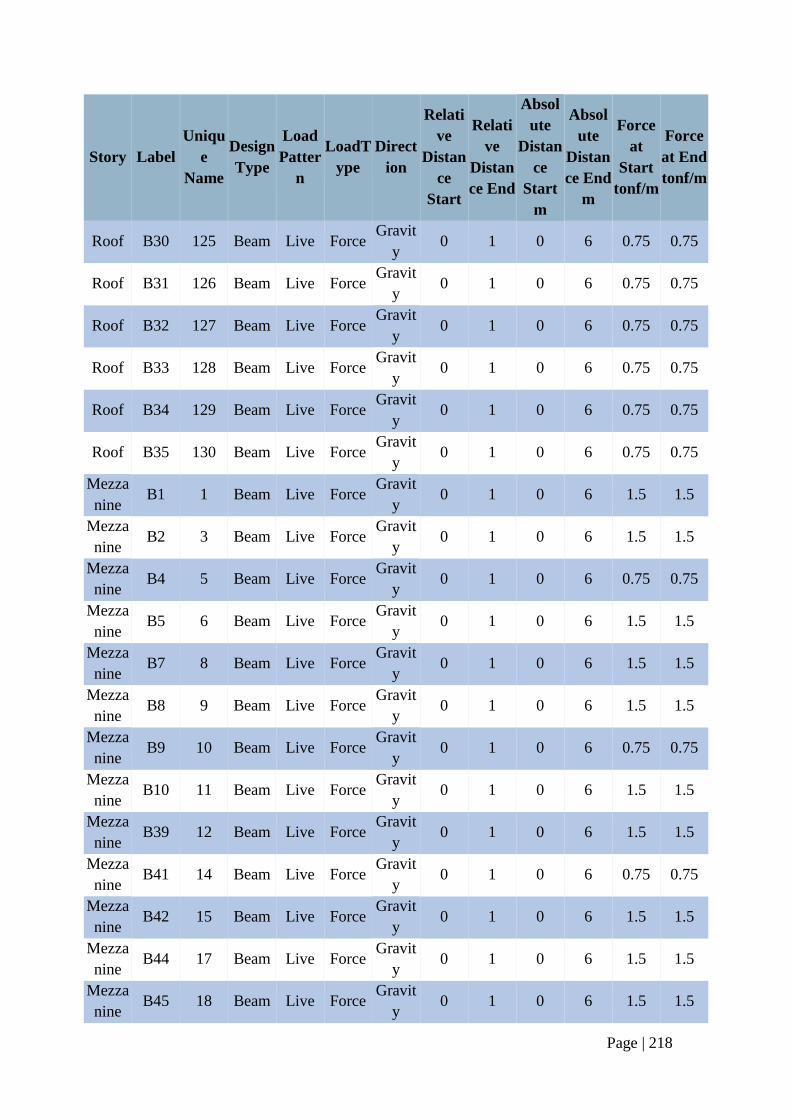
Page | 218
Story Label
Uniqu
e
Name
Design
Type
Load
Patter
n
LoadT
ype
Direct
ion
Relati
ve
Distan
ce
Start
Relati
ve
Distan
ce End
Absol
ute
Distan
ce
Start
m
Absol
ute
Distan
ce End
m
Force
at
Start
tonf/m
Force
at End
tonf/m
Roof B30 125 Beam Live Force Gravit
y 0 1 0 6 0.75 0.75
Roof B31 126 Beam Live Force Gravit
y 0 1 0 6 0.75 0.75
Roof B32 127 Beam Live Force Gravit
y 0 1 0 6 0.75 0.75
Roof B33 128 Beam Live Force Gravit
y 0 1 0 6 0.75 0.75
Roof B34 129 Beam Live Force Gravit
y 0 1 0 6 0.75 0.75
Roof B35 130 Beam Live Force Gravit
y 0 1 0 6 0.75 0.75
Mezza
nine B1 1 Beam Live Force
Gravit
y 0 1 0 6 1.5 1.5
Mezza
nine B2 3 Beam Live Force
Gravit
y 0 1 0 6 1.5 1.5
Mezza
nine B4 5 Beam Live Force
Gravit
y 0 1 0 6 0.75 0.75
Mezza
nine B5 6 Beam Live Force
Gravit
y 0 1 0 6 1.5 1.5
Mezza
nine B7 8 Beam Live Force
Gravit
y 0 1 0 6 1.5 1.5
Mezza
nine B8 9 Beam Live Force
Gravit
y 0 1 0 6 1.5 1.5
Mezza
nine B9 10 Beam Live Force
Gravit
y 0 1 0 6 0.75 0.75
Mezza
nine B10 11 Beam Live Force
Gravit
y 0 1 0 6 1.5 1.5
Mezza
nine B39 12 Beam Live Force
Gravit
y 0 1 0 6 1.5 1.5
Mezza
nine B41 14 Beam Live Force
Gravit
y 0 1 0 6 0.75 0.75
Mezza
nine B42 15 Beam Live Force
Gravit
y 0 1 0 6 1.5 1.5
Mezza
nine B44 17 Beam Live Force
Gravit
y 0 1 0 6 1.5 1.5
Mezza
nine B45 18 Beam Live Force
Gravit
y 0 1 0 6 1.5 1.5
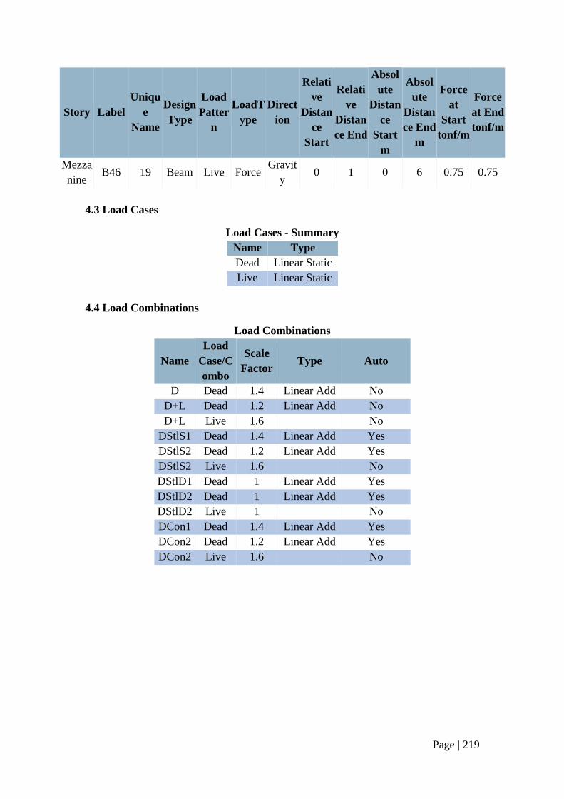
Page | 219
Story Label
Uniqu
e
Name
Design
Type
Load
Patter
n
LoadT
ype
Direct
ion
Relati
ve
Distan
ce
Start
Relati
ve
Distan
ce End
Absol
ute
Distan
ce
Start
m
Absol
ute
Distan
ce End
m
Force
at
Start
tonf/m
Force
at End
tonf/m
Mezza
nine B46 19 Beam Live Force
Gravit
y 0 1 0 6 0.75 0.75
4.3 Load Cases
Load Cases - Summary
Name Type
Dead Linear Static
Live Linear Static
4.4 Load Combinations
Load Combinations
Name
Load
Case/C
ombo
Scale
Factor Type Auto
D Dead 1.4 Linear Add No
D+L Dead 1.2 Linear Add No
D+L Live 1.6 No
DStlS1 Dead 1.4 Linear Add Yes
DStlS2 Dead 1.2 Linear Add Yes
DStlS2 Live 1.6 No
DStlD1 Dead 1 Linear Add Yes
DStlD2 Dead 1 Linear Add Yes
DStlD2 Live 1 No
DCon1 Dead 1.4 Linear Add Yes
DCon2 Dead 1.2 Linear Add Yes
DCon2 Live 1.6 No
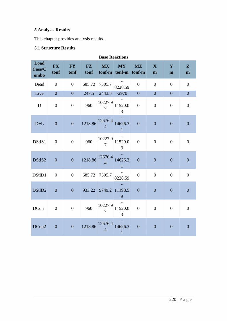
220 | P a g e
5 Analysis Results
This chapter provides analysis results.
5.1 Structure Results
Base Reactions
Load
Case/C
ombo
FX
tonf
FY
tonf
FZ
tonf
MX
tonf-m
MY
tonf-m
MZ
tonf-m
X
m
Y
m
Z
m
Dead 0 0 685.72 7305.7 -
8228.59 0 0 0 0
Live 0 0 247.5 2443.5 -2970 0 0 0 0
D 0 0 960 10227.9
7
-
11520.0
3
0 0 0 0
D+L 0 0 1218.86 12676.4
4
-
14626.3
1
0 0 0 0
DStlS1 0 0 960 10227.9
7
-
11520.0
3
0 0 0 0
DStlS2 0 0 1218.86 12676.4
4
-
14626.3
1
0 0 0 0
DStlD1 0 0 685.72 7305.7 -
8228.59 0 0 0 0
DStlD2 0 0 933.22 9749.2
-
11198.5
9
0 0 0 0
DCon1 0 0 960 10227.9
7
-
11520.0
3
0 0 0 0
DCon2 0 0 1218.86 12676.4
4
-
14626.3
1
0 0 0 0
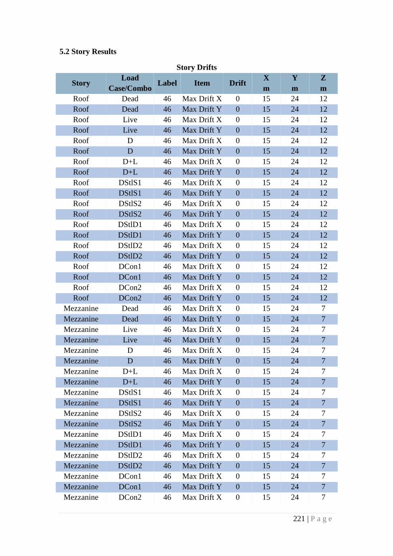
221 | P a g e
5.2 Story Results
Story Drifts
Story Load
Case/Combo Label Item Drift
X
m
Y
m
Z
m
Roof Dead 46 Max Drift X 0 15 24 12
Roof Dead 46 Max Drift Y 0 15 24 12
Roof Live 46 Max Drift X 0 15 24 12
Roof Live 46 Max Drift Y 0 15 24 12
Roof D 46 Max Drift X 0 15 24 12
Roof D 46 Max Drift Y 0 15 24 12
Roof D+L 46 Max Drift X 0 15 24 12
Roof D+L 46 Max Drift Y 0 15 24 12
Roof DStlS1 46 Max Drift X 0 15 24 12
Roof DStlS1 46 Max Drift Y 0 15 24 12
Roof DStlS2 46 Max Drift X 0 15 24 12
Roof DStlS2 46 Max Drift Y 0 15 24 12
Roof DStlD1 46 Max Drift X 0 15 24 12
Roof DStlD1 46 Max Drift Y 0 15 24 12
Roof DStlD2 46 Max Drift X 0 15 24 12
Roof DStlD2 46 Max Drift Y 0 15 24 12
Roof DCon1 46 Max Drift X 0 15 24 12
Roof DCon1 46 Max Drift Y 0 15 24 12
Roof DCon2 46 Max Drift X 0 15 24 12
Roof DCon2 46 Max Drift Y 0 15 24 12
Mezzanine Dead 46 Max Drift X 0 15 24 7
Mezzanine Dead 46 Max Drift Y 0 15 24 7
Mezzanine Live 46 Max Drift X 0 15 24 7
Mezzanine Live 46 Max Drift Y 0 15 24 7
Mezzanine D 46 Max Drift X 0 15 24 7
Mezzanine D 46 Max Drift Y 0 15 24 7
Mezzanine D+L 46 Max Drift X 0 15 24 7
Mezzanine D+L 46 Max Drift Y 0 15 24 7
Mezzanine DStlS1 46 Max Drift X 0 15 24 7
Mezzanine DStlS1 46 Max Drift Y 0 15 24 7
Mezzanine DStlS2 46 Max Drift X 0 15 24 7
Mezzanine DStlS2 46 Max Drift Y 0 15 24 7
Mezzanine DStlD1 46 Max Drift X 0 15 24 7
Mezzanine DStlD1 46 Max Drift Y 0 15 24 7
Mezzanine DStlD2 46 Max Drift X 0 15 24 7
Mezzanine DStlD2 46 Max Drift Y 0 15 24 7
Mezzanine DCon1 46 Max Drift X 0 15 24 7
Mezzanine DCon1 46 Max Drift Y 0 15 24 7
Mezzanine DCon2 46 Max Drift X 0 15 24 7
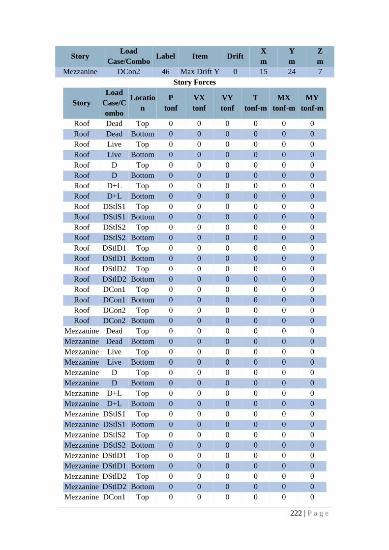
222 | P a g e
Story Load
Case/Combo Label Item Drift
X
m
Y
m
Z
m
Mezzanine DCon2 46 Max Drift Y 0 15 24 7
Story Forces
Story
Load
Case/C
ombo
Locatio
n
P
tonf
VX
tonf
VY
tonf
T
tonf-m
MX
tonf-m
MY
tonf-m
Roof Dead Top 0 0 0 0 0 0
Roof Dead Bottom 0 0 0 0 0 0
Roof Live Top 0 0 0 0 0 0
Roof Live Bottom 0 0 0 0 0 0
Roof D Top 0 0 0 0 0 0
Roof D Bottom 0 0 0 0 0 0
Roof D+L Top 0 0 0 0 0 0
Roof D+L Bottom 0 0 0 0 0 0
Roof DStlS1 Top 0 0 0 0 0 0
Roof DStlS1 Bottom 0 0 0 0 0 0
Roof DStlS2 Top 0 0 0 0 0 0
Roof DStlS2 Bottom 0 0 0 0 0 0
Roof DStlD1 Top 0 0 0 0 0 0
Roof DStlD1 Bottom 0 0 0 0 0 0
Roof DStlD2 Top 0 0 0 0 0 0
Roof DStlD2 Bottom 0 0 0 0 0 0
Roof DCon1 Top 0 0 0 0 0 0
Roof DCon1 Bottom 0 0 0 0 0 0
Roof DCon2 Top 0 0 0 0 0 0
Roof DCon2 Bottom 0 0 0 0 0 0
Mezzanine Dead Top 0 0 0 0 0 0
Mezzanine Dead Bottom 0 0 0 0 0 0
Mezzanine Live Top 0 0 0 0 0 0
Mezzanine Live Bottom 0 0 0 0 0 0
Mezzanine D Top 0 0 0 0 0 0
Mezzanine D Bottom 0 0 0 0 0 0
Mezzanine D+L Top 0 0 0 0 0 0
Mezzanine D+L Bottom 0 0 0 0 0 0
Mezzanine DStlS1 Top 0 0 0 0 0 0
Mezzanine DStlS1 Bottom 0 0 0 0 0 0
Mezzanine DStlS2 Top 0 0 0 0 0 0
Mezzanine DStlS2 Bottom 0 0 0 0 0 0
Mezzanine DStlD1 Top 0 0 0 0 0 0
Mezzanine DStlD1 Bottom 0 0 0 0 0 0
Mezzanine DStlD2 Top 0 0 0 0 0 0
Mezzanine DStlD2 Bottom 0 0 0 0 0 0
Mezzanine DCon1 Top 0 0 0 0 0 0
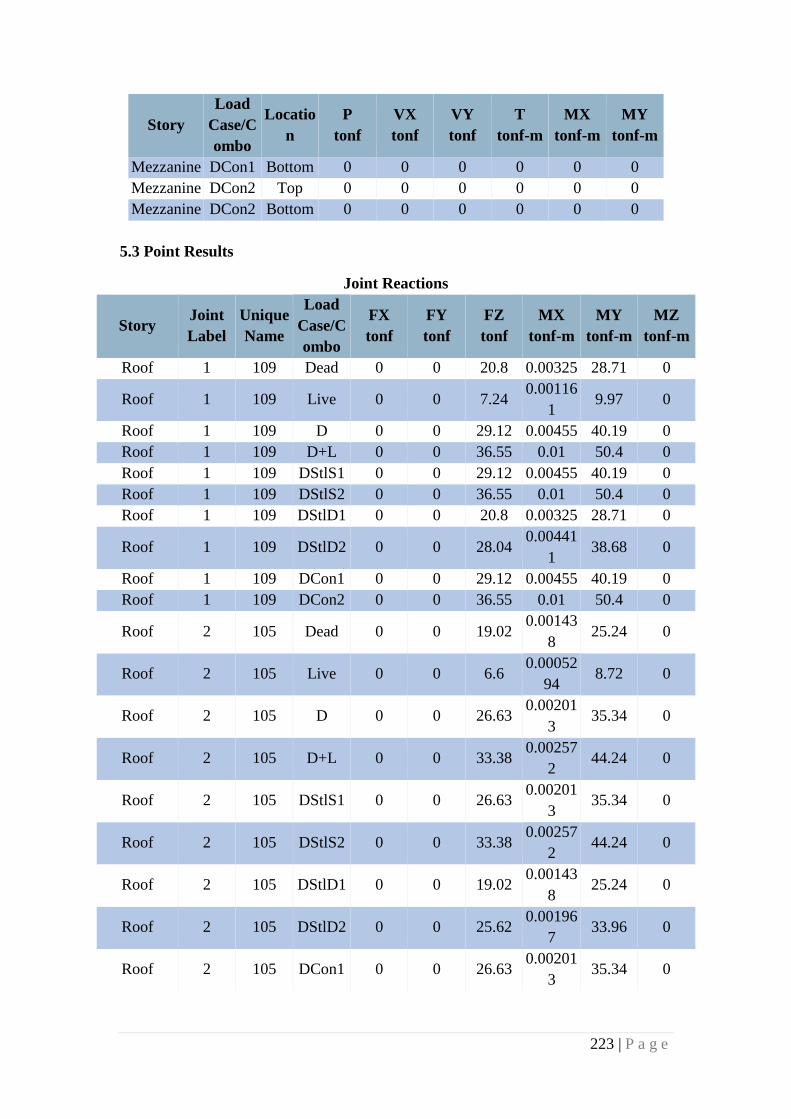
223 | P a g e
Story
Load
Case/C
ombo
Locatio
n
P
tonf
VX
tonf
VY
tonf
T
tonf-m
MX
tonf-m
MY
tonf-m
Mezzanine DCon1 Bottom 0 0 0 0 0 0
Mezzanine DCon2 Top 0 0 0 0 0 0
Mezzanine DCon2 Bottom 0 0 0 0 0 0
5.3 Point Results
Joint Reactions
Story Joint
Label
Unique
Name
Load
Case/C
ombo
FX
tonf
FY
tonf
FZ
tonf
MX
tonf-m
MY
tonf-m
MZ
tonf-m
Roof 1 109 Dead 0 0 20.8 0.00325 28.71 0
Roof 1 109 Live 0 0 7.24 0.00116
1 9.97 0
Roof 1 109 D 0 0 29.12 0.00455 40.19 0
Roof 1 109 D+L 0 0 36.55 0.01 50.4 0
Roof 1 109 DStlS1 0 0 29.12 0.00455 40.19 0
Roof 1 109 DStlS2 0 0 36.55 0.01 50.4 0
Roof 1 109 DStlD1 0 0 20.8 0.00325 28.71 0
Roof 1 109 DStlD2 0 0 28.04 0.00441
1 38.68 0
Roof 1 109 DCon1 0 0 29.12 0.00455 40.19 0
Roof 1 109 DCon2 0 0 36.55 0.01 50.4 0
Roof 2 105 Dead 0 0 19.02 0.00143
8 25.24 0
Roof 2 105 Live 0 0 6.6 0.00052
94 8.72 0
Roof 2 105 D 0 0 26.63 0.00201
3 35.34 0
Roof 2 105 D+L 0 0 33.38 0.00257
2 44.24 0
Roof 2 105 DStlS1 0 0 26.63 0.00201
3 35.34 0
Roof 2 105 DStlS2 0 0 33.38 0.00257
2 44.24 0
Roof 2 105 DStlD1 0 0 19.02 0.00143
8 25.24 0
Roof 2 105 DStlD2 0 0 25.62 0.00196
7 33.96 0
Roof 2 105 DCon1 0 0 26.63 0.00201
3 35.34 0
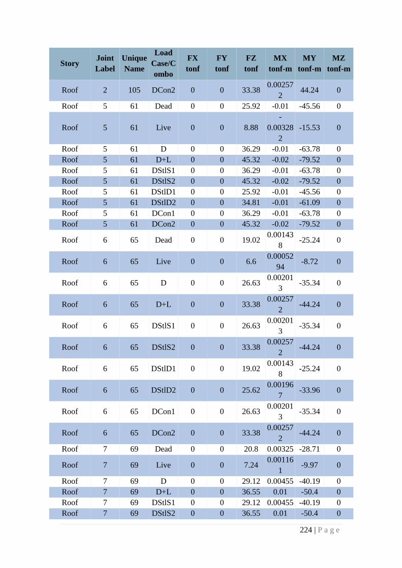
224 | P a g e
Story Joint
Label
Unique
Name
Load
Case/C
ombo
FX
tonf
FY
tonf
FZ
tonf
MX
tonf-m
MY
tonf-m
MZ
tonf-m
Roof 2 105 DCon2 0 0 33.38 0.00257
2 44.24 0
Roof 5 61 Dead 0 0 25.92 -0.01 -45.56 0
Roof 5 61 Live 0 0 8.88
-
0.00328
2
-15.53 0
Roof 5 61 D 0 0 36.29 -0.01 -63.78 0
Roof 5 61 D+L 0 0 45.32 -0.02 -79.52 0
Roof 5 61 DStlS1 0 0 36.29 -0.01 -63.78 0
Roof 5 61 DStlS2 0 0 45.32 -0.02 -79.52 0
Roof 5 61 DStlD1 0 0 25.92 -0.01 -45.56 0
Roof 5 61 DStlD2 0 0 34.81 -0.01 -61.09 0
Roof 5 61 DCon1 0 0 36.29 -0.01 -63.78 0
Roof 5 61 DCon2 0 0 45.32 -0.02 -79.52 0
Roof 6 65 Dead 0 0 19.02 0.00143
8 -25.24 0
Roof 6 65 Live 0 0 6.6 0.00052
94 -8.72 0
Roof 6 65 D 0 0 26.63 0.00201
3 -35.34 0
Roof 6 65 D+L 0 0 33.38 0.00257
2 -44.24 0
Roof 6 65 DStlS1 0 0 26.63 0.00201
3 -35.34 0
Roof 6 65 DStlS2 0 0 33.38 0.00257
2 -44.24 0
Roof 6 65 DStlD1 0 0 19.02 0.00143
8 -25.24 0
Roof 6 65 DStlD2 0 0 25.62 0.00196
7 -33.96 0
Roof 6 65 DCon1 0 0 26.63 0.00201
3 -35.34 0
Roof 6 65 DCon2 0 0 33.38 0.00257
2 -44.24 0
Roof 7 69 Dead 0 0 20.8 0.00325 -28.71 0
Roof 7 69 Live 0 0 7.24 0.00116
1 -9.97 0
Roof 7 69 D 0 0 29.12 0.00455 -40.19 0
Roof 7 69 D+L 0 0 36.55 0.01 -50.4 0
Roof 7 69 DStlS1 0 0 29.12 0.00455 -40.19 0
Roof 7 69 DStlS2 0 0 36.55 0.01 -50.4 0
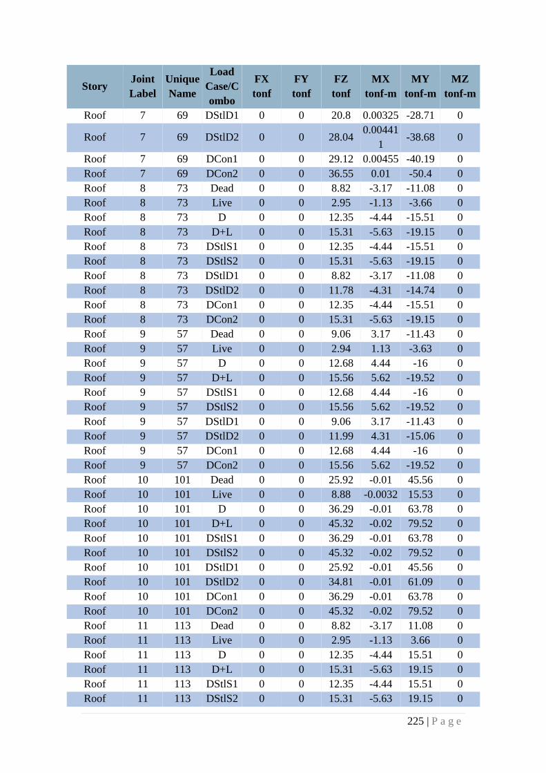
225 | P a g e
Story Joint
Label
Unique
Name
Load
Case/C
ombo
FX
tonf
FY
tonf
FZ
tonf
MX
tonf-m
MY
tonf-m
MZ
tonf-m
Roof 7 69 DStlD1 0 0 20.8 0.00325 -28.71 0
Roof 7 69 DStlD2 0 0 28.04 0.00441
1 -38.68 0
Roof 7 69 DCon1 0 0 29.12 0.00455 -40.19 0
Roof 7 69 DCon2 0 0 36.55 0.01 -50.4 0
Roof 8 73 Dead 0 0 8.82 -3.17 -11.08 0
Roof 8 73 Live 0 0 2.95 -1.13 -3.66 0
Roof 8 73 D 0 0 12.35 -4.44 -15.51 0
Roof 8 73 D+L 0 0 15.31 -5.63 -19.15 0
Roof 8 73 DStlS1 0 0 12.35 -4.44 -15.51 0
Roof 8 73 DStlS2 0 0 15.31 -5.63 -19.15 0
Roof 8 73 DStlD1 0 0 8.82 -3.17 -11.08 0
Roof 8 73 DStlD2 0 0 11.78 -4.31 -14.74 0
Roof 8 73 DCon1 0 0 12.35 -4.44 -15.51 0
Roof 8 73 DCon2 0 0 15.31 -5.63 -19.15 0
Roof 9 57 Dead 0 0 9.06 3.17 -11.43 0
Roof 9 57 Live 0 0 2.94 1.13 -3.63 0
Roof 9 57 D 0 0 12.68 4.44 -16 0
Roof 9 57 D+L 0 0 15.56 5.62 -19.52 0
Roof 9 57 DStlS1 0 0 12.68 4.44 -16 0
Roof 9 57 DStlS2 0 0 15.56 5.62 -19.52 0
Roof 9 57 DStlD1 0 0 9.06 3.17 -11.43 0
Roof 9 57 DStlD2 0 0 11.99 4.31 -15.06 0
Roof 9 57 DCon1 0 0 12.68 4.44 -16 0
Roof 9 57 DCon2 0 0 15.56 5.62 -19.52 0
Roof 10 101 Dead 0 0 25.92 -0.01 45.56 0
Roof 10 101 Live 0 0 8.88 -0.0032 15.53 0
Roof 10 101 D 0 0 36.29 -0.01 63.78 0
Roof 10 101 D+L 0 0 45.32 -0.02 79.52 0
Roof 10 101 DStlS1 0 0 36.29 -0.01 63.78 0
Roof 10 101 DStlS2 0 0 45.32 -0.02 79.52 0
Roof 10 101 DStlD1 0 0 25.92 -0.01 45.56 0
Roof 10 101 DStlD2 0 0 34.81 -0.01 61.09 0
Roof 10 101 DCon1 0 0 36.29 -0.01 63.78 0
Roof 10 101 DCon2 0 0 45.32 -0.02 79.52 0
Roof 11 113 Dead 0 0 8.82 -3.17 11.08 0
Roof 11 113 Live 0 0 2.95 -1.13 3.66 0
Roof 11 113 D 0 0 12.35 -4.44 15.51 0
Roof 11 113 D+L 0 0 15.31 -5.63 19.15 0
Roof 11 113 DStlS1 0 0 12.35 -4.44 15.51 0
Roof 11 113 DStlS2 0 0 15.31 -5.63 19.15 0
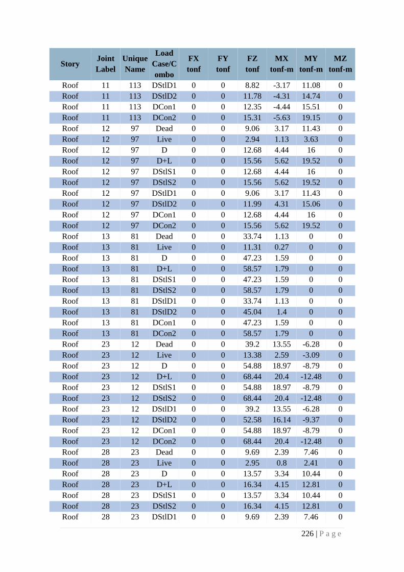
226 | P a g e
Story Joint
Label
Unique
Name
Load
Case/C
ombo
FX
tonf
FY
tonf
FZ
tonf
MX
tonf-m
MY
tonf-m
MZ
tonf-m
Roof 11 113 DStlD1 0 0 8.82 -3.17 11.08 0
Roof 11 113 DStlD2 0 0 11.78 -4.31 14.74 0
Roof 11 113 DCon1 0 0 12.35 -4.44 15.51 0
Roof 11 113 DCon2 0 0 15.31 -5.63 19.15 0
Roof 12 97 Dead 0 0 9.06 3.17 11.43 0
Roof 12 97 Live 0 0 2.94 1.13 3.63 0
Roof 12 97 D 0 0 12.68 4.44 16 0
Roof 12 97 D+L 0 0 15.56 5.62 19.52 0
Roof 12 97 DStlS1 0 0 12.68 4.44 16 0
Roof 12 97 DStlS2 0 0 15.56 5.62 19.52 0
Roof 12 97 DStlD1 0 0 9.06 3.17 11.43 0
Roof 12 97 DStlD2 0 0 11.99 4.31 15.06 0
Roof 12 97 DCon1 0 0 12.68 4.44 16 0
Roof 12 97 DCon2 0 0 15.56 5.62 19.52 0
Roof 13 81 Dead 0 0 33.74 1.13 0 0
Roof 13 81 Live 0 0 11.31 0.27 0 0
Roof 13 81 D 0 0 47.23 1.59 0 0
Roof 13 81 D+L 0 0 58.57 1.79 0 0
Roof 13 81 DStlS1 0 0 47.23 1.59 0 0
Roof 13 81 DStlS2 0 0 58.57 1.79 0 0
Roof 13 81 DStlD1 0 0 33.74 1.13 0 0
Roof 13 81 DStlD2 0 0 45.04 1.4 0 0
Roof 13 81 DCon1 0 0 47.23 1.59 0 0
Roof 13 81 DCon2 0 0 58.57 1.79 0 0
Roof 23 12 Dead 0 0 39.2 13.55 -6.28 0
Roof 23 12 Live 0 0 13.38 2.59 -3.09 0
Roof 23 12 D 0 0 54.88 18.97 -8.79 0
Roof 23 12 D+L 0 0 68.44 20.4 -12.48 0
Roof 23 12 DStlS1 0 0 54.88 18.97 -8.79 0
Roof 23 12 DStlS2 0 0 68.44 20.4 -12.48 0
Roof 23 12 DStlD1 0 0 39.2 13.55 -6.28 0
Roof 23 12 DStlD2 0 0 52.58 16.14 -9.37 0
Roof 23 12 DCon1 0 0 54.88 18.97 -8.79 0
Roof 23 12 DCon2 0 0 68.44 20.4 -12.48 0
Roof 28 23 Dead 0 0 9.69 2.39 7.46 0
Roof 28 23 Live 0 0 2.95 0.8 2.41 0
Roof 28 23 D 0 0 13.57 3.34 10.44 0
Roof 28 23 D+L 0 0 16.34 4.15 12.81 0
Roof 28 23 DStlS1 0 0 13.57 3.34 10.44 0
Roof 28 23 DStlS2 0 0 16.34 4.15 12.81 0
Roof 28 23 DStlD1 0 0 9.69 2.39 7.46 0
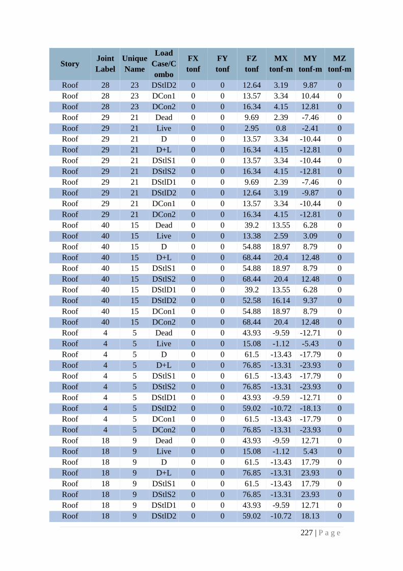
227 | P a g e
Story Joint
Label
Unique
Name
Load
Case/C
ombo
FX
tonf
FY
tonf
FZ
tonf
MX
tonf-m
MY
tonf-m
MZ
tonf-m
Roof 28 23 DStlD2 0 0 12.64 3.19 9.87 0
Roof 28 23 DCon1 0 0 13.57 3.34 10.44 0
Roof 28 23 DCon2 0 0 16.34 4.15 12.81 0
Roof 29 21 Dead 0 0 9.69 2.39 -7.46 0
Roof 29 21 Live 0 0 2.95 0.8 -2.41 0
Roof 29 21 D 0 0 13.57 3.34 -10.44 0
Roof 29 21 D+L 0 0 16.34 4.15 -12.81 0
Roof 29 21 DStlS1 0 0 13.57 3.34 -10.44 0
Roof 29 21 DStlS2 0 0 16.34 4.15 -12.81 0
Roof 29 21 DStlD1 0 0 9.69 2.39 -7.46 0
Roof 29 21 DStlD2 0 0 12.64 3.19 -9.87 0
Roof 29 21 DCon1 0 0 13.57 3.34 -10.44 0
Roof 29 21 DCon2 0 0 16.34 4.15 -12.81 0
Roof 40 15 Dead 0 0 39.2 13.55 6.28 0
Roof 40 15 Live 0 0 13.38 2.59 3.09 0
Roof 40 15 D 0 0 54.88 18.97 8.79 0
Roof 40 15 D+L 0 0 68.44 20.4 12.48 0
Roof 40 15 DStlS1 0 0 54.88 18.97 8.79 0
Roof 40 15 DStlS2 0 0 68.44 20.4 12.48 0
Roof 40 15 DStlD1 0 0 39.2 13.55 6.28 0
Roof 40 15 DStlD2 0 0 52.58 16.14 9.37 0
Roof 40 15 DCon1 0 0 54.88 18.97 8.79 0
Roof 40 15 DCon2 0 0 68.44 20.4 12.48 0
Roof 4 5 Dead 0 0 43.93 -9.59 -12.71 0
Roof 4 5 Live 0 0 15.08 -1.12 -5.43 0
Roof 4 5 D 0 0 61.5 -13.43 -17.79 0
Roof 4 5 D+L 0 0 76.85 -13.31 -23.93 0
Roof 4 5 DStlS1 0 0 61.5 -13.43 -17.79 0
Roof 4 5 DStlS2 0 0 76.85 -13.31 -23.93 0
Roof 4 5 DStlD1 0 0 43.93 -9.59 -12.71 0
Roof 4 5 DStlD2 0 0 59.02 -10.72 -18.13 0
Roof 4 5 DCon1 0 0 61.5 -13.43 -17.79 0
Roof 4 5 DCon2 0 0 76.85 -13.31 -23.93 0
Roof 18 9 Dead 0 0 43.93 -9.59 12.71 0
Roof 18 9 Live 0 0 15.08 -1.12 5.43 0
Roof 18 9 D 0 0 61.5 -13.43 17.79 0
Roof 18 9 D+L 0 0 76.85 -13.31 23.93 0
Roof 18 9 DStlS1 0 0 61.5 -13.43 17.79 0
Roof 18 9 DStlS2 0 0 76.85 -13.31 23.93 0
Roof 18 9 DStlD1 0 0 43.93 -9.59 12.71 0
Roof 18 9 DStlD2 0 0 59.02 -10.72 18.13 0
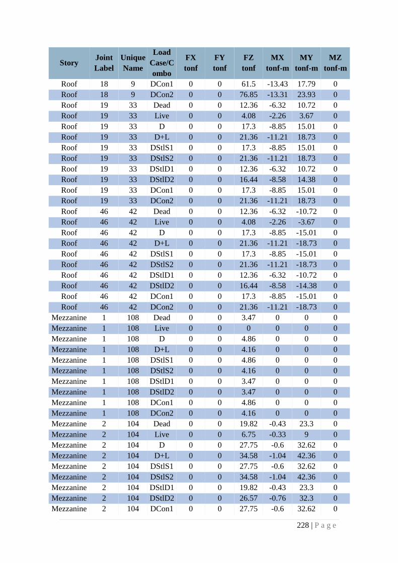
228 | P a g e
Story Joint
Label
Unique
Name
Load
Case/C
ombo
FX
tonf
FY
tonf
FZ
tonf
MX
tonf-m
MY
tonf-m
MZ
tonf-m
Roof 18 9 DCon1 0 0 61.5 -13.43 17.79 0
Roof 18 9 DCon2 0 0 76.85 -13.31 23.93 0
Roof 19 33 Dead 0 0 12.36 -6.32 10.72 0
Roof 19 33 Live 0 0 4.08 -2.26 3.67 0
Roof 19 33 D 0 0 17.3 -8.85 15.01 0
Roof 19 33 D+L 0 0 21.36 -11.21 18.73 0
Roof 19 33 DStlS1 0 0 17.3 -8.85 15.01 0
Roof 19 33 DStlS2 0 0 21.36 -11.21 18.73 0
Roof 19 33 DStlD1 0 0 12.36 -6.32 10.72 0
Roof 19 33 DStlD2 0 0 16.44 -8.58 14.38 0
Roof 19 33 DCon1 0 0 17.3 -8.85 15.01 0
Roof 19 33 DCon2 0 0 21.36 -11.21 18.73 0
Roof 46 42 Dead 0 0 12.36 -6.32 -10.72 0
Roof 46 42 Live 0 0 4.08 -2.26 -3.67 0
Roof 46 42 D 0 0 17.3 -8.85 -15.01 0
Roof 46 42 D+L 0 0 21.36 -11.21 -18.73 0
Roof 46 42 DStlS1 0 0 17.3 -8.85 -15.01 0
Roof 46 42 DStlS2 0 0 21.36 -11.21 -18.73 0
Roof 46 42 DStlD1 0 0 12.36 -6.32 -10.72 0
Roof 46 42 DStlD2 0 0 16.44 -8.58 -14.38 0
Roof 46 42 DCon1 0 0 17.3 -8.85 -15.01 0
Roof 46 42 DCon2 0 0 21.36 -11.21 -18.73 0
Mezzanine 1 108 Dead 0 0 3.47 0 0 0
Mezzanine 1 108 Live 0 0 0 0 0 0
Mezzanine 1 108 D 0 0 4.86 0 0 0
Mezzanine 1 108 D+L 0 0 4.16 0 0 0
Mezzanine 1 108 DStlS1 0 0 4.86 0 0 0
Mezzanine 1 108 DStlS2 0 0 4.16 0 0 0
Mezzanine 1 108 DStlD1 0 0 3.47 0 0 0
Mezzanine 1 108 DStlD2 0 0 3.47 0 0 0
Mezzanine 1 108 DCon1 0 0 4.86 0 0 0
Mezzanine 1 108 DCon2 0 0 4.16 0 0 0
Mezzanine 2 104 Dead 0 0 19.82 -0.43 23.3 0
Mezzanine 2 104 Live 0 0 6.75 -0.33 9 0
Mezzanine 2 104 D 0 0 27.75 -0.6 32.62 0
Mezzanine 2 104 D+L 0 0 34.58 -1.04 42.36 0
Mezzanine 2 104 DStlS1 0 0 27.75 -0.6 32.62 0
Mezzanine 2 104 DStlS2 0 0 34.58 -1.04 42.36 0
Mezzanine 2 104 DStlD1 0 0 19.82 -0.43 23.3 0
Mezzanine 2 104 DStlD2 0 0 26.57 -0.76 32.3 0
Mezzanine 2 104 DCon1 0 0 27.75 -0.6 32.62 0
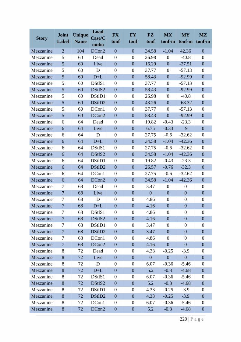
229 | P a g e
Story Joint
Label
Unique
Name
Load
Case/C
ombo
FX
tonf
FY
tonf
FZ
tonf
MX
tonf-m
MY
tonf-m
MZ
tonf-m
Mezzanine 2 104 DCon2 0 0 34.58 -1.04 42.36 0
Mezzanine 5 60 Dead 0 0 26.98 0 -40.8 0
Mezzanine 5 60 Live 0 0 16.29 0 -27.51 0
Mezzanine 5 60 D 0 0 37.77 0 -57.13 0
Mezzanine 5 60 D+L 0 0 58.43 0 -92.99 0
Mezzanine 5 60 DStlS1 0 0 37.77 0 -57.13 0
Mezzanine 5 60 DStlS2 0 0 58.43 0 -92.99 0
Mezzanine 5 60 DStlD1 0 0 26.98 0 -40.8 0
Mezzanine 5 60 DStlD2 0 0 43.26 0 -68.32 0
Mezzanine 5 60 DCon1 0 0 37.77 0 -57.13 0
Mezzanine 5 60 DCon2 0 0 58.43 0 -92.99 0
Mezzanine 6 64 Dead 0 0 19.82 -0.43 -23.3 0
Mezzanine 6 64 Live 0 0 6.75 -0.33 -9 0
Mezzanine 6 64 D 0 0 27.75 -0.6 -32.62 0
Mezzanine 6 64 D+L 0 0 34.58 -1.04 -42.36 0
Mezzanine 6 64 DStlS1 0 0 27.75 -0.6 -32.62 0
Mezzanine 6 64 DStlS2 0 0 34.58 -1.04 -42.36 0
Mezzanine 6 64 DStlD1 0 0 19.82 -0.43 -23.3 0
Mezzanine 6 64 DStlD2 0 0 26.57 -0.76 -32.3 0
Mezzanine 6 64 DCon1 0 0 27.75 -0.6 -32.62 0
Mezzanine 6 64 DCon2 0 0 34.58 -1.04 -42.36 0
Mezzanine 7 68 Dead 0 0 3.47 0 0 0
Mezzanine 7 68 Live 0 0 0 0 0 0
Mezzanine 7 68 D 0 0 4.86 0 0 0
Mezzanine 7 68 D+L 0 0 4.16 0 0 0
Mezzanine 7 68 DStlS1 0 0 4.86 0 0 0
Mezzanine 7 68 DStlS2 0 0 4.16 0 0 0
Mezzanine 7 68 DStlD1 0 0 3.47 0 0 0
Mezzanine 7 68 DStlD2 0 0 3.47 0 0 0
Mezzanine 7 68 DCon1 0 0 4.86 0 0 0
Mezzanine 7 68 DCon2 0 0 4.16 0 0 0
Mezzanine 8 72 Dead 0 0 4.33 -0.25 -3.9 0
Mezzanine 8 72 Live 0 0 0 0 0 0
Mezzanine 8 72 D 0 0 6.07 -0.36 -5.46 0
Mezzanine 8 72 D+L 0 0 5.2 -0.3 -4.68 0
Mezzanine 8 72 DStlS1 0 0 6.07 -0.36 -5.46 0
Mezzanine 8 72 DStlS2 0 0 5.2 -0.3 -4.68 0
Mezzanine 8 72 DStlD1 0 0 4.33 -0.25 -3.9 0
Mezzanine 8 72 DStlD2 0 0 4.33 -0.25 -3.9 0
Mezzanine 8 72 DCon1 0 0 6.07 -0.36 -5.46 0
Mezzanine 8 72 DCon2 0 0 5.2 -0.3 -4.68 0
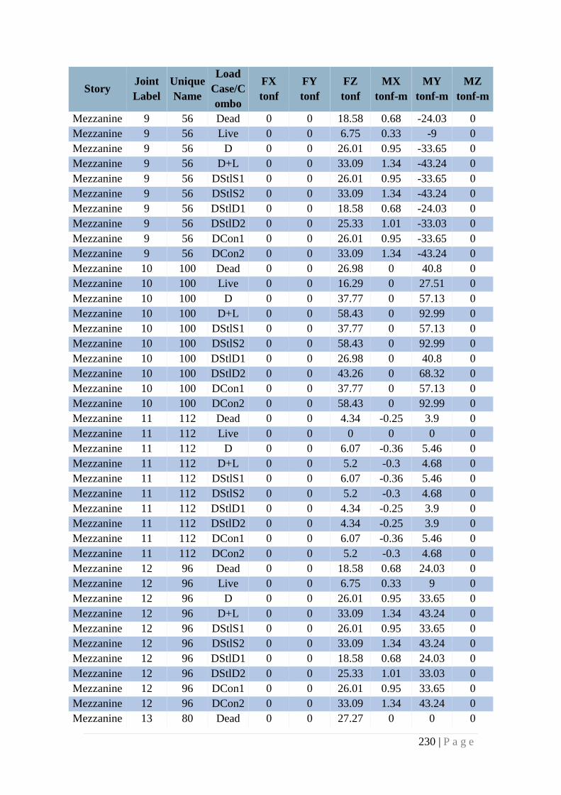
230 | P a g e
Story Joint
Label
Unique
Name
Load
Case/C
ombo
FX
tonf
FY
tonf
FZ
tonf
MX
tonf-m
MY
tonf-m
MZ
tonf-m
Mezzanine 9 56 Dead 0 0 18.58 0.68 -24.03 0
Mezzanine 9 56 Live 0 0 6.75 0.33 -9 0
Mezzanine 9 56 D 0 0 26.01 0.95 -33.65 0
Mezzanine 9 56 D+L 0 0 33.09 1.34 -43.24 0
Mezzanine 9 56 DStlS1 0 0 26.01 0.95 -33.65 0
Mezzanine 9 56 DStlS2 0 0 33.09 1.34 -43.24 0
Mezzanine 9 56 DStlD1 0 0 18.58 0.68 -24.03 0
Mezzanine 9 56 DStlD2 0 0 25.33 1.01 -33.03 0
Mezzanine 9 56 DCon1 0 0 26.01 0.95 -33.65 0
Mezzanine 9 56 DCon2 0 0 33.09 1.34 -43.24 0
Mezzanine 10 100 Dead 0 0 26.98 0 40.8 0
Mezzanine 10 100 Live 0 0 16.29 0 27.51 0
Mezzanine 10 100 D 0 0 37.77 0 57.13 0
Mezzanine 10 100 D+L 0 0 58.43 0 92.99 0
Mezzanine 10 100 DStlS1 0 0 37.77 0 57.13 0
Mezzanine 10 100 DStlS2 0 0 58.43 0 92.99 0
Mezzanine 10 100 DStlD1 0 0 26.98 0 40.8 0
Mezzanine 10 100 DStlD2 0 0 43.26 0 68.32 0
Mezzanine 10 100 DCon1 0 0 37.77 0 57.13 0
Mezzanine 10 100 DCon2 0 0 58.43 0 92.99 0
Mezzanine 11 112 Dead 0 0 4.34 -0.25 3.9 0
Mezzanine 11 112 Live 0 0 0 0 0 0
Mezzanine 11 112 D 0 0 6.07 -0.36 5.46 0
Mezzanine 11 112 D+L 0 0 5.2 -0.3 4.68 0
Mezzanine 11 112 DStlS1 0 0 6.07 -0.36 5.46 0
Mezzanine 11 112 DStlS2 0 0 5.2 -0.3 4.68 0
Mezzanine 11 112 DStlD1 0 0 4.34 -0.25 3.9 0
Mezzanine 11 112 DStlD2 0 0 4.34 -0.25 3.9 0
Mezzanine 11 112 DCon1 0 0 6.07 -0.36 5.46 0
Mezzanine 11 112 DCon2 0 0 5.2 -0.3 4.68 0
Mezzanine 12 96 Dead 0 0 18.58 0.68 24.03 0
Mezzanine 12 96 Live 0 0 6.75 0.33 9 0
Mezzanine 12 96 D 0 0 26.01 0.95 33.65 0
Mezzanine 12 96 D+L 0 0 33.09 1.34 43.24 0
Mezzanine 12 96 DStlS1 0 0 26.01 0.95 33.65 0
Mezzanine 12 96 DStlS2 0 0 33.09 1.34 43.24 0
Mezzanine 12 96 DStlD1 0 0 18.58 0.68 24.03 0
Mezzanine 12 96 DStlD2 0 0 25.33 1.01 33.03 0
Mezzanine 12 96 DCon1 0 0 26.01 0.95 33.65 0
Mezzanine 12 96 DCon2 0 0 33.09 1.34 43.24 0
Mezzanine 13 80 Dead 0 0 27.27 0 0 0
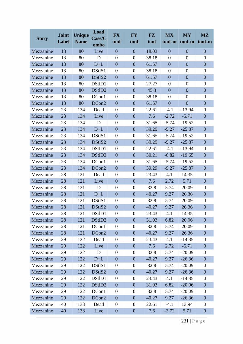
231 | P a g e
Story Joint
Label
Unique
Name
Load
Case/C
ombo
FX
tonf
FY
tonf
FZ
tonf
MX
tonf-m
MY
tonf-m
MZ
tonf-m
Mezzanine 13 80 Live 0 0 18.03 0 0 0
Mezzanine 13 80 D 0 0 38.18 0 0 0
Mezzanine 13 80 D+L 0 0 61.57 0 0 0
Mezzanine 13 80 DStlS1 0 0 38.18 0 0 0
Mezzanine 13 80 DStlS2 0 0 61.57 0 0 0
Mezzanine 13 80 DStlD1 0 0 27.27 0 0 0
Mezzanine 13 80 DStlD2 0 0 45.3 0 0 0
Mezzanine 13 80 DCon1 0 0 38.18 0 0 0
Mezzanine 13 80 DCon2 0 0 61.57 0 0 0
Mezzanine 23 134 Dead 0 0 22.61 -4.1 -13.94 0
Mezzanine 23 134 Live 0 0 7.6 -2.72 -5.71 0
Mezzanine 23 134 D 0 0 31.65 -5.74 -19.52 0
Mezzanine 23 134 D+L 0 0 39.29 -9.27 -25.87 0
Mezzanine 23 134 DStlS1 0 0 31.65 -5.74 -19.52 0
Mezzanine 23 134 DStlS2 0 0 39.29 -9.27 -25.87 0
Mezzanine 23 134 DStlD1 0 0 22.61 -4.1 -13.94 0
Mezzanine 23 134 DStlD2 0 0 30.21 -6.82 -19.65 0
Mezzanine 23 134 DCon1 0 0 31.65 -5.74 -19.52 0
Mezzanine 23 134 DCon2 0 0 39.29 -9.27 -25.87 0
Mezzanine 28 121 Dead 0 0 23.43 4.1 14.35 0
Mezzanine 28 121 Live 0 0 7.6 2.72 5.71 0
Mezzanine 28 121 D 0 0 32.8 5.74 20.09 0
Mezzanine 28 121 D+L 0 0 40.27 9.27 26.36 0
Mezzanine 28 121 DStlS1 0 0 32.8 5.74 20.09 0
Mezzanine 28 121 DStlS2 0 0 40.27 9.27 26.36 0
Mezzanine 28 121 DStlD1 0 0 23.43 4.1 14.35 0
Mezzanine 28 121 DStlD2 0 0 31.03 6.82 20.06 0
Mezzanine 28 121 DCon1 0 0 32.8 5.74 20.09 0
Mezzanine 28 121 DCon2 0 0 40.27 9.27 26.36 0
Mezzanine 29 122 Dead 0 0 23.43 4.1 -14.35 0
Mezzanine 29 122 Live 0 0 7.6 2.72 -5.71 0
Mezzanine 29 122 D 0 0 32.8 5.74 -20.09 0
Mezzanine 29 122 D+L 0 0 40.27 9.27 -26.36 0
Mezzanine 29 122 DStlS1 0 0 32.8 5.74 -20.09 0
Mezzanine 29 122 DStlS2 0 0 40.27 9.27 -26.36 0
Mezzanine 29 122 DStlD1 0 0 23.43 4.1 -14.35 0
Mezzanine 29 122 DStlD2 0 0 31.03 6.82 -20.06 0
Mezzanine 29 122 DCon1 0 0 32.8 5.74 -20.09 0
Mezzanine 29 122 DCon2 0 0 40.27 9.27 -26.36 0
Mezzanine 40 133 Dead 0 0 22.61 -4.1 13.94 0
Mezzanine 40 133 Live 0 0 7.6 -2.72 5.71 0
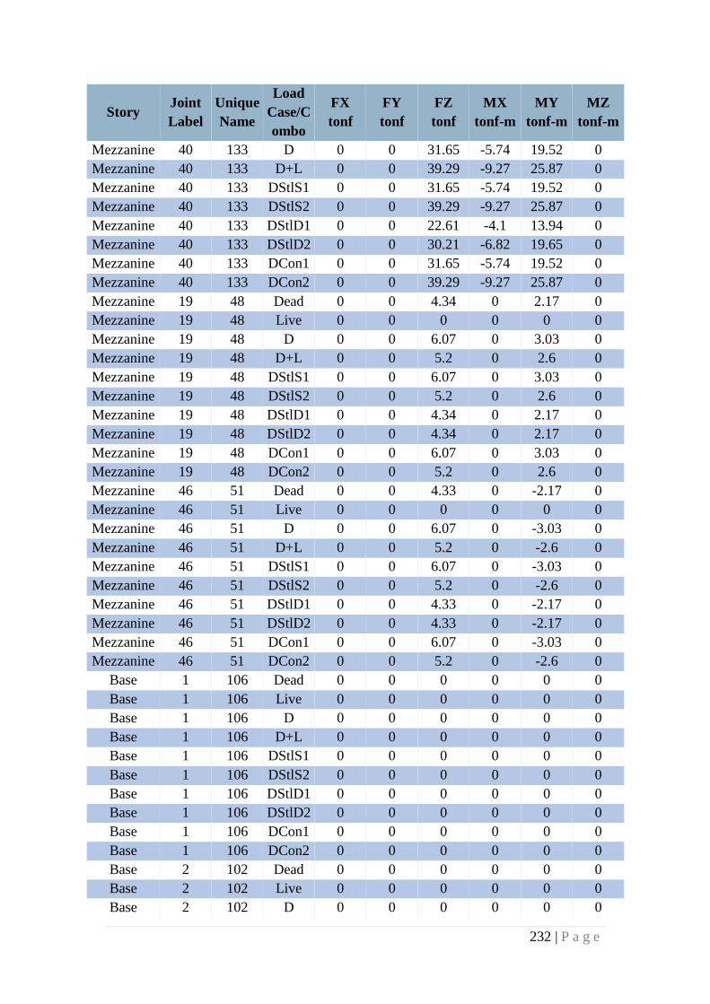
232 | P a g e
Story Joint
Label
Unique
Name
Load
Case/C
ombo
FX
tonf
FY
tonf
FZ
tonf
MX
tonf-m
MY
tonf-m
MZ
tonf-m
Mezzanine 40 133 D 0 0 31.65 -5.74 19.52 0
Mezzanine 40 133 D+L 0 0 39.29 -9.27 25.87 0
Mezzanine 40 133 DStlS1 0 0 31.65 -5.74 19.52 0
Mezzanine 40 133 DStlS2 0 0 39.29 -9.27 25.87 0
Mezzanine 40 133 DStlD1 0 0 22.61 -4.1 13.94 0
Mezzanine 40 133 DStlD2 0 0 30.21 -6.82 19.65 0
Mezzanine 40 133 DCon1 0 0 31.65 -5.74 19.52 0
Mezzanine 40 133 DCon2 0 0 39.29 -9.27 25.87 0
Mezzanine 19 48 Dead 0 0 4.34 0 2.17 0
Mezzanine 19 48 Live 0 0 0 0 0 0
Mezzanine 19 48 D 0 0 6.07 0 3.03 0
Mezzanine 19 48 D+L 0 0 5.2 0 2.6 0
Mezzanine 19 48 DStlS1 0 0 6.07 0 3.03 0
Mezzanine 19 48 DStlS2 0 0 5.2 0 2.6 0
Mezzanine 19 48 DStlD1 0 0 4.34 0 2.17 0
Mezzanine 19 48 DStlD2 0 0 4.34 0 2.17 0
Mezzanine 19 48 DCon1 0 0 6.07 0 3.03 0
Mezzanine 19 48 DCon2 0 0 5.2 0 2.6 0
Mezzanine 46 51 Dead 0 0 4.33 0 -2.17 0
Mezzanine 46 51 Live 0 0 0 0 0 0
Mezzanine 46 51 D 0 0 6.07 0 -3.03 0
Mezzanine 46 51 D+L 0 0 5.2 0 -2.6 0
Mezzanine 46 51 DStlS1 0 0 6.07 0 -3.03 0
Mezzanine 46 51 DStlS2 0 0 5.2 0 -2.6 0
Mezzanine 46 51 DStlD1 0 0 4.33 0 -2.17 0
Mezzanine 46 51 DStlD2 0 0 4.33 0 -2.17 0
Mezzanine 46 51 DCon1 0 0 6.07 0 -3.03 0
Mezzanine 46 51 DCon2 0 0 5.2 0 -2.6 0
Base 1 106 Dead 0 0 0 0 0 0
Base 1 106 Live 0 0 0 0 0 0
Base 1 106 D 0 0 0 0 0 0
Base 1 106 D+L 0 0 0 0 0 0
Base 1 106 DStlS1 0 0 0 0 0 0
Base 1 106 DStlS2 0 0 0 0 0 0
Base 1 106 DStlD1 0 0 0 0 0 0
Base 1 106 DStlD2 0 0 0 0 0 0
Base 1 106 DCon1 0 0 0 0 0 0
Base 1 106 DCon2 0 0 0 0 0 0
Base 2 102 Dead 0 0 0 0 0 0
Base 2 102 Live 0 0 0 0 0 0
Base 2 102 D 0 0 0 0 0 0
233 | P a g e
Story Joint
Label
Unique
Name
Load
Case/C
ombo
FX
tonf
FY
tonf
FZ
tonf
MX
tonf-m
MY
tonf-m
MZ
tonf-m
Base 2 102 D+L 0 0 0 0 0 0
Base 2 102 DStlS1 0 0 0 0 0 0
Base 2 102 DStlS2 0 0 0 0 0 0
Base 2 102 DStlD1 0 0 0 0 0 0
Base 2 102 DStlD2 0 0 0 0 0 0
Base 2 102 DCon1 0 0 0 0 0 0
Base 2 102 DCon2 0 0 0 0 0 0
Base 5 58 Dead 0 0 0 0 0 0
Base 5 58 Live 0 0 0 0 0 0
Base 5 58 D 0 0 0 0 0 0
Base 5 58 D+L 0 0 0 0 0 0
Base 5 58 DStlS1 0 0 0 0 0 0
Base 5 58 DStlS2 0 0 0 0 0 0
Base 5 58 DStlD1 0 0 0 0 0 0
Base 5 58 DStlD2 0 0 0 0 0 0
Base 5 58 DCon1 0 0 0 0 0 0
Base 5 58 DCon2 0 0 0 0 0 0
Base 6 62 Dead 0 0 0 0 0 0
Base 6 62 Live 0 0 0 0 0 0
Base 6 62 D 0 0 0 0 0 0
Base 6 62 D+L 0 0 0 0 0 0
Base 6 62 DStlS1 0 0 0 0 0 0
Base 6 62 DStlS2 0 0 0 0 0 0
Base 6 62 DStlD1 0 0 0 0 0 0
Base 6 62 DStlD2 0 0 0 0 0 0
Base 6 62 DCon1 0 0 0 0 0 0
Base 6 62 DCon2 0 0 0 0 0 0
Base 7 66 Dead 0 0 0 0 0 0
Base 7 66 Live 0 0 0 0 0 0
Base 7 66 D 0 0 0 0 0 0
Base 7 66 D+L 0 0 0 0 0 0
Base 7 66 DStlS1 0 0 0 0 0 0
Base 7 66 DStlS2 0 0 0 0 0 0
Base 7 66 DStlD1 0 0 0 0 0 0
Base 7 66 DStlD2 0 0 0 0 0 0
Base 7 66 DCon1 0 0 0 0 0 0
Base 7 66 DCon2 0 0 0 0 0 0
Base 8 70 Dead 0 0 0 0 0 0
Base 8 70 Live 0 0 0 0 0 0
Base 8 70 D 0 0 0 0 0 0
Base 8 70 D+L 0 0 0 0 0 0
234 | P a g e
Story Joint
Label
Unique
Name
Load
Case/C
ombo
FX
tonf
FY
tonf
FZ
tonf
MX
tonf-m
MY
tonf-m
MZ
tonf-m
Base 8 70 DStlS1 0 0 0 0 0 0
Base 8 70 DStlS2 0 0 0 0 0 0
Base 8 70 DStlD1 0 0 0 0 0 0
Base 8 70 DStlD2 0 0 0 0 0 0
Base 8 70 DCon1 0 0 0 0 0 0
Base 8 70 DCon2 0 0 0 0 0 0
Base 9 54 Dead 0 0 0 0 0 0
Base 9 54 Live 0 0 0 0 0 0
Base 9 54 D 0 0 0 0 0 0
Base 9 54 D+L 0 0 0 0 0 0
Base 9 54 DStlS1 0 0 0 0 0 0
Base 9 54 DStlS2 0 0 0 0 0 0
Base 9 54 DStlD1 0 0 0 0 0 0
Base 9 54 DStlD2 0 0 0 0 0 0
Base 9 54 DCon1 0 0 0 0 0 0
Base 9 54 DCon2 0 0 0 0 0 0
Base 10 98 Dead 0 0 0 0 0 0
Base 10 98 Live 0 0 0 0 0 0
Base 10 98 D 0 0 0 0 0 0
Base 10 98 D+L 0 0 0 0 0 0
Base 10 98 DStlS1 0 0 0 0 0 0
Base 10 98 DStlS2 0 0 0 0 0 0
Base 10 98 DStlD1 0 0 0 0 0 0
Base 10 98 DStlD2 0 0 0 0 0 0
Base 10 98 DCon1 0 0 0 0 0 0
Base 10 98 DCon2 0 0 0 0 0 0
Base 11 110 Dead 0 0 0 0 0 0
Base 11 110 Live 0 0 0 0 0 0
Base 11 110 D 0 0 0 0 0 0
Base 11 110 D+L 0 0 0 0 0 0
Base 11 110 DStlS1 0 0 0 0 0 0
Base 11 110 DStlS2 0 0 0 0 0 0
Base 11 110 DStlD1 0 0 0 0 0 0
Base 11 110 DStlD2 0 0 0 0 0 0
Base 11 110 DCon1 0 0 0 0 0 0
Base 11 110 DCon2 0 0 0 0 0 0
Base 12 94 Dead 0 0 0 0 0 0
Base 12 94 Live 0 0 0 0 0 0
Base 12 94 D 0 0 0 0 0 0
Base 12 94 D+L 0 0 0 0 0 0
Base 12 94 DStlS1 0 0 0 0 0 0
235 | P a g e
Story Joint
Label
Unique
Name
Load
Case/C
ombo
FX
tonf
FY
tonf
FZ
tonf
MX
tonf-m
MY
tonf-m
MZ
tonf-m
Base 12 94 DStlS2 0 0 0 0 0 0
Base 12 94 DStlD1 0 0 0 0 0 0
Base 12 94 DStlD2 0 0 0 0 0 0
Base 12 94 DCon1 0 0 0 0 0 0
Base 12 94 DCon2 0 0 0 0 0 0
Base 13 78 Dead 0 0 0 0 0 0
Base 13 78 Live 0 0 0 0 0 0
Base 13 78 D 0 0 0 0 0 0
Base 13 78 D+L 0 0 0 0 0 0
Base 13 78 DStlS1 0 0 0 0 0 0
Base 13 78 DStlS2 0 0 0 0 0 0
Base 13 78 DStlD1 0 0 0 0 0 0
Base 13 78 DStlD2 0 0 0 0 0 0
Base 13 78 DCon1 0 0 0 0 0 0
Base 13 78 DCon2 0 0 0 0 0 0
Base 23 10 Dead 0 0 0 0 0 0
Base 23 10 Live 0 0 0 0 0 0
Base 23 10 D 0 0 0 0 0 0
Base 23 10 D+L 0 0 0 0 0 0
Base 23 10 DStlS1 0 0 0 0 0 0
Base 23 10 DStlS2 0 0 0 0 0 0
Base 23 10 DStlD1 0 0 0 0 0 0
Base 23 10 DStlD2 0 0 0 0 0 0
Base 23 10 DCon1 0 0 0 0 0 0
Base 23 10 DCon2 0 0 0 0 0 0
Base 28 44 Dead 0 0 0 0 0 0
Base 28 44 Live 0 0 0 0 0 0
Base 28 44 D 0 0 0 0 0 0
Base 28 44 D+L 0 0 0 0 0 0
Base 28 44 DStlS1 0 0 0 0 0 0
Base 28 44 DStlS2 0 0 0 0 0 0
Base 28 44 DStlD1 0 0 0 0 0 0
Base 28 44 DStlD2 0 0 0 0 0 0
Base 28 44 DCon1 0 0 0 0 0 0
Base 28 44 DCon2 0 0 0 0 0 0
Base 29 1 Dead 0 0 0 0 0 0
Base 29 1 Live 0 0 0 0 0 0
Base 29 1 D 0 0 0 0 0 0
Base 29 1 D+L 0 0 0 0 0 0
Base 29 1 DStlS1 0 0 0 0 0 0
Base 29 1 DStlS2 0 0 0 0 0 0
236 | P a g e
Story Joint
Label
Unique
Name
Load
Case/C
ombo
FX
tonf
FY
tonf
FZ
tonf
MX
tonf-m
MY
tonf-m
MZ
tonf-m
Base 29 1 DStlD1 0 0 0 0 0 0
Base 29 1 DStlD2 0 0 0 0 0 0
Base 29 1 DCon1 0 0 0 0 0 0
Base 29 1 DCon2 0 0 0 0 0 0
Base 40 13 Dead 0 0 0 0 0 0
Base 40 13 Live 0 0 0 0 0 0
Base 40 13 D 0 0 0 0 0 0
Base 40 13 D+L 0 0 0 0 0 0
Base 40 13 DStlS1 0 0 0 0 0 0
Base 40 13 DStlS2 0 0 0 0 0 0
Base 40 13 DStlD1 0 0 0 0 0 0
Base 40 13 DStlD2 0 0 0 0 0 0
Base 40 13 DCon1 0 0 0 0 0 0
Base 40 13 DCon2 0 0 0 0 0 0
Base 4 2 Dead 0 0 0 0 0 0
Base 4 2 Live 0 0 0 0 0 0
Base 4 2 D 0 0 0 0 0 0
Base 4 2 D+L 0 0 0 0 0 0
Base 4 2 DStlS1 0 0 0 0 0 0
Base 4 2 DStlS2 0 0 0 0 0 0
Base 4 2 DStlD1 0 0 0 0 0 0
Base 4 2 DStlD2 0 0 0 0 0 0
Base 4 2 DCon1 0 0 0 0 0 0
Base 4 2 DCon2 0 0 0 0 0 0
Base 18 6 Dead 0 0 0 0 0 0
Base 18 6 Live 0 0 0 0 0 0
Base 18 6 D 0 0 0 0 0 0
Base 18 6 D+L 0 0 0 0 0 0
Base 18 6 DStlS1 0 0 0 0 0 0
Base 18 6 DStlS2 0 0 0 0 0 0
Base 18 6 DStlD1 0 0 0 0 0 0
Base 18 6 DStlD2 0 0 0 0 0 0
Base 18 6 DCon1 0 0 0 0 0 0
Base 18 6 DCon2 0 0 0 0 0 0
Base 19 46 Dead 0 0 0 0 0 0
Base 19 46 Live 0 0 0 0 0 0
Base 19 46 D 0 0 0 0 0 0
Base 19 46 D+L 0 0 0 0 0 0
Base 19 46 DStlS1 0 0 0 0 0 0
Base 19 46 DStlS2 0 0 0 0 0 0
Base 19 46 DStlD1 0 0 0 0 0 0
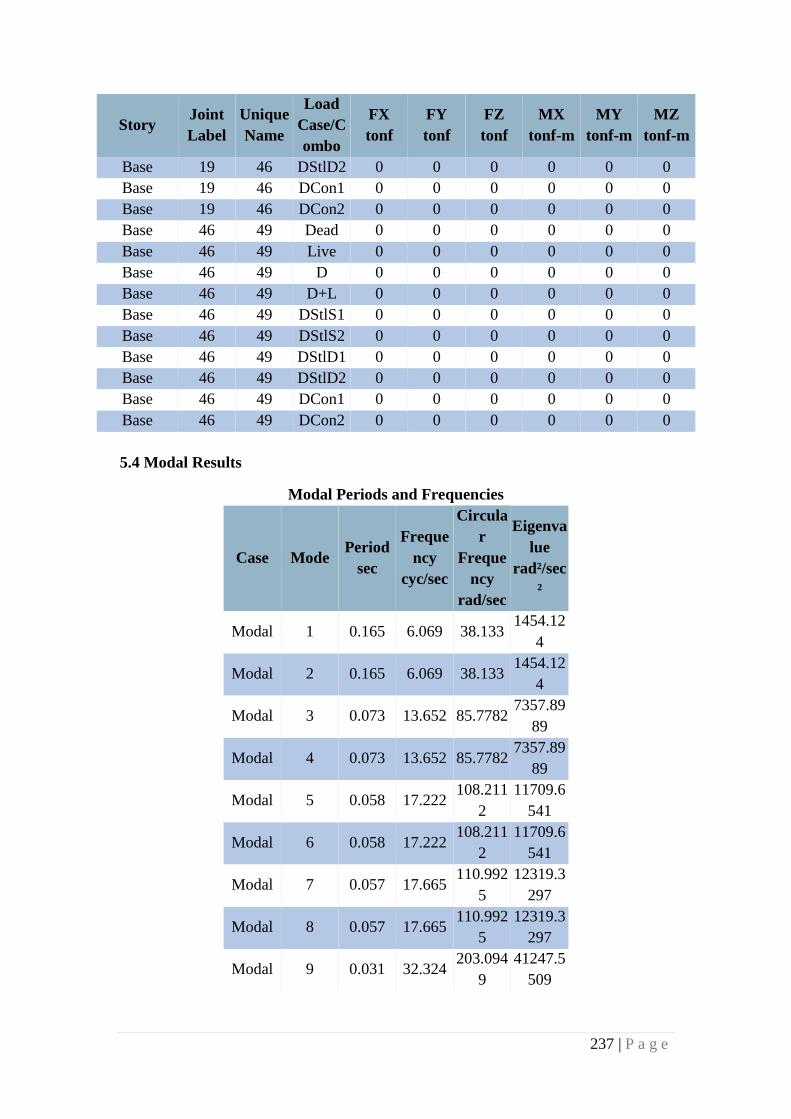
237 | P a g e
Story Joint
Label
Unique
Name
Load
Case/C
ombo
FX
tonf
FY
tonf
FZ
tonf
MX
tonf-m
MY
tonf-m
MZ
tonf-m
Base 19 46 DStlD2 0 0 0 0 0 0
Base 19 46 DCon1 0 0 0 0 0 0
Base 19 46 DCon2 0 0 0 0 0 0
Base 46 49 Dead 0 0 0 0 0 0
Base 46 49 Live 0 0 0 0 0 0
Base 46 49 D 0 0 0 0 0 0
Base 46 49 D+L 0 0 0 0 0 0
Base 46 49 DStlS1 0 0 0 0 0 0
Base 46 49 DStlS2 0 0 0 0 0 0
Base 46 49 DStlD1 0 0 0 0 0 0
Base 46 49 DStlD2 0 0 0 0 0 0
Base 46 49 DCon1 0 0 0 0 0 0
Base 46 49 DCon2 0 0 0 0 0 0
5.4 Modal Results
Modal Periods and Frequencies
Case Mode Period
sec
Freque
ncy
cyc/sec
Circula
r
Freque
ncy
rad/sec
Eigenva
lue
rad²/sec
²
Modal 1 0.165 6.069 38.133 1454.12
4
Modal 2 0.165 6.069 38.133 1454.12
4
Modal 3 0.073 13.652 85.7782 7357.89
89
Modal 4 0.073 13.652 85.7782 7357.89
89
Modal 5 0.058 17.222 108.211
2
11709.6
541
Modal 6 0.058 17.222 108.211
2
11709.6
541
Modal 7 0.057 17.665 110.992
5
12319.3
297
Modal 8 0.057 17.665 110.992
5
12319.3
297
Modal 9 0.031 32.324 203.094
9
41247.5
509
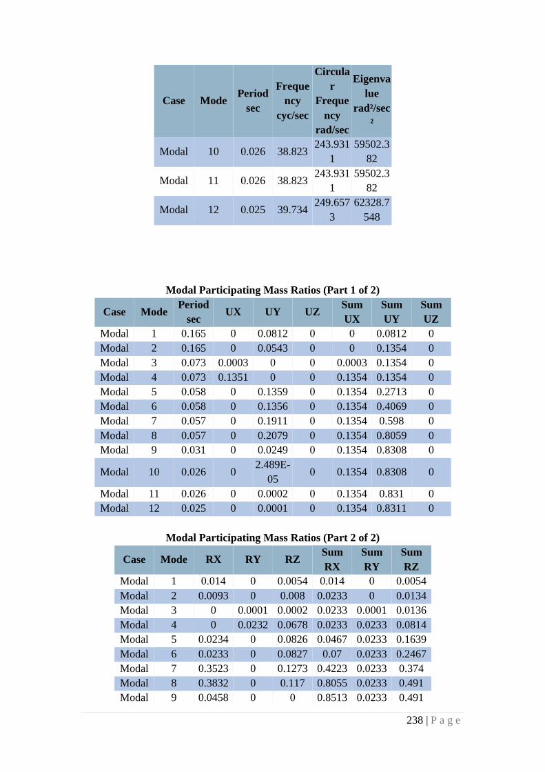
238 | P a g e
Case Mode Period
sec
Freque
ncy
cyc/sec
Circula
r
Freque
ncy
rad/sec
Eigenva
lue
rad²/sec
²
Modal 10 0.026 38.823 243.931
1
59502.3
82
Modal 11 0.026 38.823 243.931
1
59502.3
82
Modal 12 0.025 39.734 249.657
3
62328.7
548
Modal Participating Mass Ratios (Part 1 of 2)
Case Mode Period
sec UX UY UZ
Sum
UX
Sum
UY
Sum
UZ
Modal 1 0.165 0 0.0812 0 0 0.0812 0
Modal 2 0.165 0 0.0543 0 0 0.1354 0
Modal 3 0.073 0.0003 0 0 0.0003 0.1354 0
Modal 4 0.073 0.1351 0 0 0.1354 0.1354 0
Modal 5 0.058 0 0.1359 0 0.1354 0.2713 0
Modal 6 0.058 0 0.1356 0 0.1354 0.4069 0
Modal 7 0.057 0 0.1911 0 0.1354 0.598 0
Modal 8 0.057 0 0.2079 0 0.1354 0.8059 0
Modal 9 0.031 0 0.0249 0 0.1354 0.8308 0
Modal 10 0.026 0 2.489E-
05 0 0.1354 0.8308 0
Modal 11 0.026 0 0.0002 0 0.1354 0.831 0
Modal 12 0.025 0 0.0001 0 0.1354 0.8311 0
Modal Participating Mass Ratios (Part 2 of 2)
Case Mode RX RY RZ Sum
RX
Sum
RY
Sum
RZ
Modal 1 0.014 0 0.0054 0.014 0 0.0054
Modal 2 0.0093 0 0.008 0.0233 0 0.0134
Modal 3 0 0.0001 0.0002 0.0233 0.0001 0.0136
Modal 4 0 0.0232 0.0678 0.0233 0.0233 0.0814
Modal 5 0.0234 0 0.0826 0.0467 0.0233 0.1639
Modal 6 0.0233 0 0.0827 0.07 0.0233 0.2467
Modal 7 0.3523 0 0.1273 0.4223 0.0233 0.374
Modal 8 0.3832 0 0.117 0.8055 0.0233 0.491
Modal 9 0.0458 0 0 0.8513 0.0233 0.491
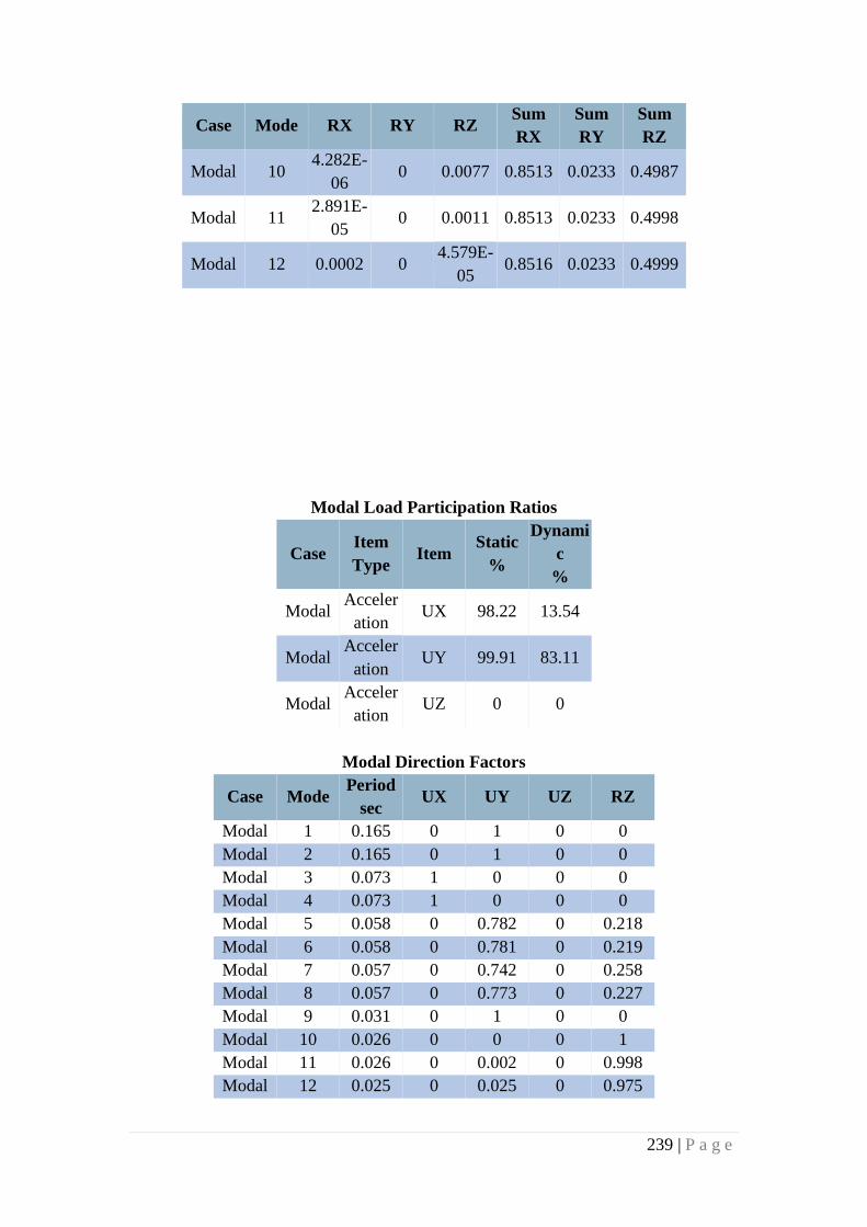
239 | P a g e
Case Mode RX RY RZ Sum
RX
Sum
RY
Sum
RZ
Modal 10 4.282E-
06 0 0.0077 0.8513 0.0233 0.4987
Modal 11 2.891E-
05 0 0.0011 0.8513 0.0233 0.4998
Modal 12 0.0002 0 4.579E-
05 0.8516 0.0233 0.4999
Modal Load Participation Ratios
Case Item
Type Item
Static
%
Dynami
c
%
Modal Acceler
ation UX 98.22 13.54
Modal Acceler
ation UY 99.91 83.11
Modal Acceler
ation UZ 0 0
Modal Direction Factors
Case Mode Period
sec UX UY UZ RZ
Modal 1 0.165 0 1 0 0
Modal 2 0.165 0 1 0 0
Modal 3 0.073 1 0 0 0
Modal 4 0.073 1 0 0 0
Modal 5 0.058 0 0.782 0 0.218
Modal 6 0.058 0 0.781 0 0.219
Modal 7 0.057 0 0.742 0 0.258
Modal 8 0.057 0 0.773 0 0.227
Modal 9 0.031 0 1 0 0
Modal 10 0.026 0 0 0 1
Modal 11 0.026 0 0.002 0 0.998
Modal 12 0.025 0 0.025 0 0.975

240 | P a g e
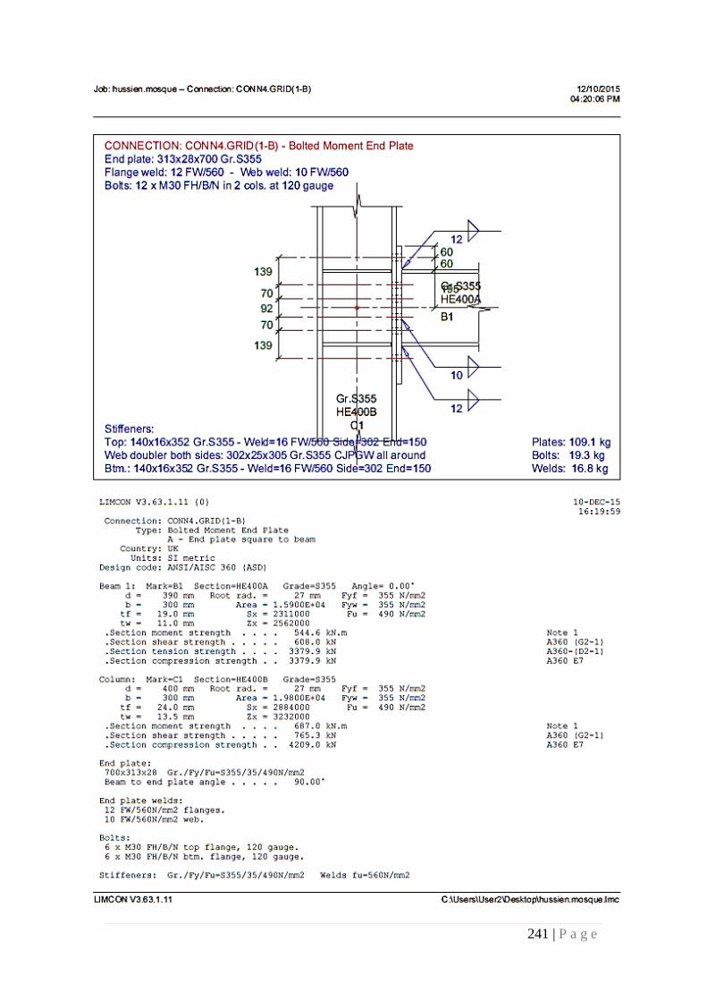
241 | P a g e
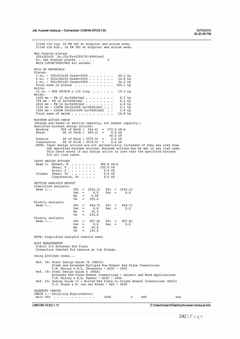
242 | P a g e
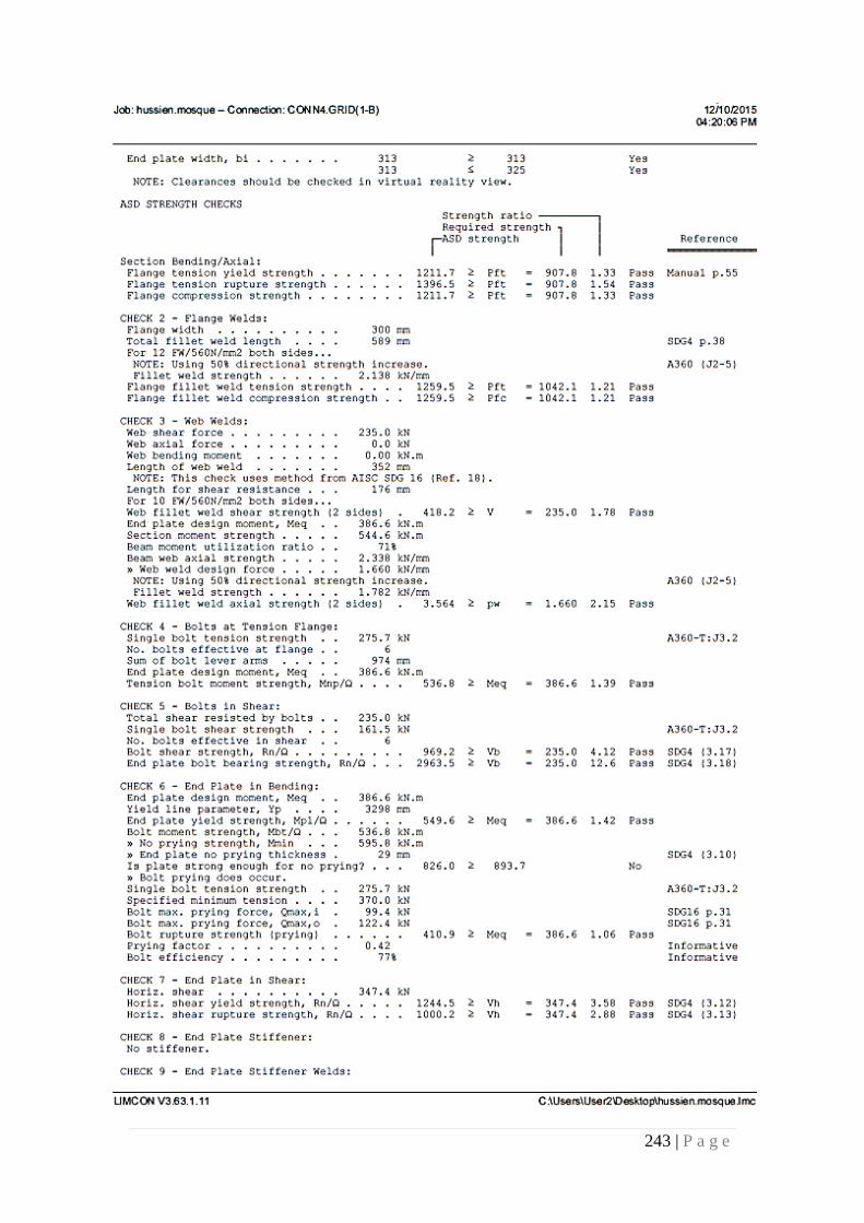
243 | P a g e
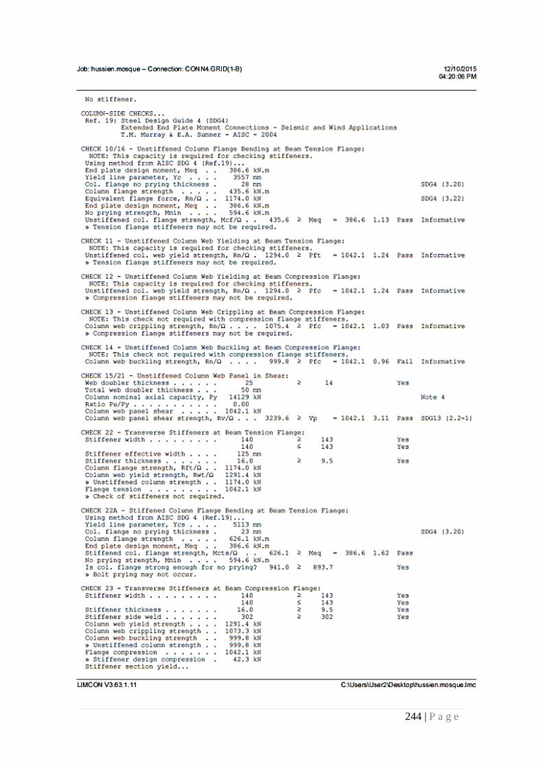
244 | P a g e
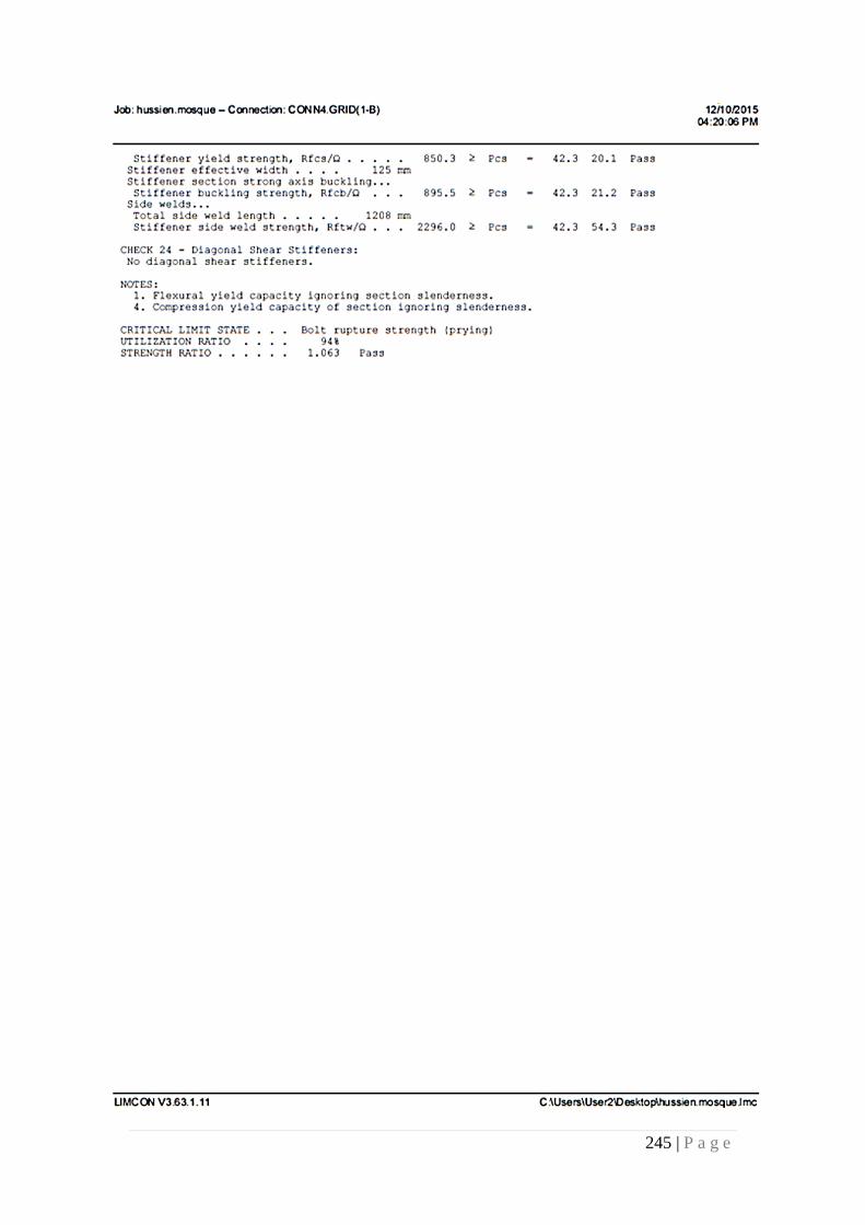
245 | P a g e
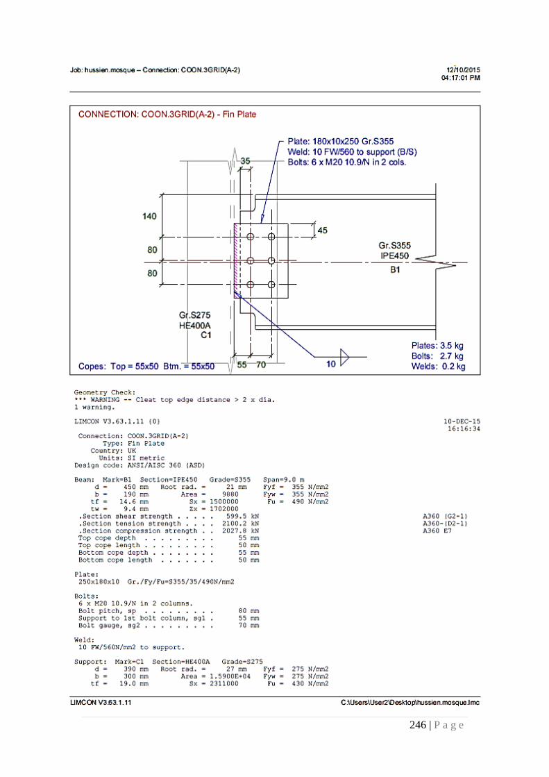
246 | P a g e
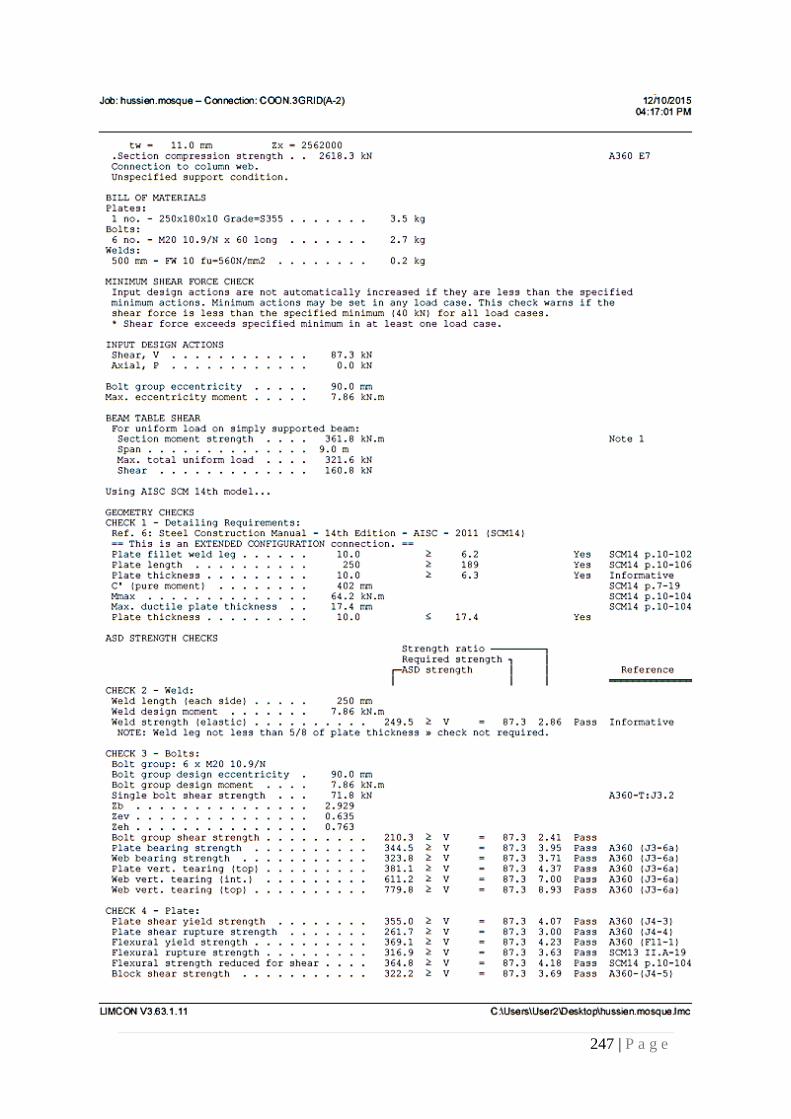
247 | P a g e
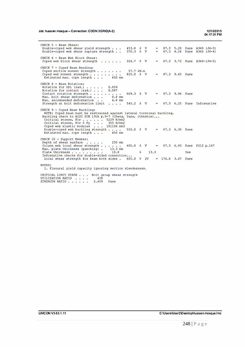
248 | P a g e
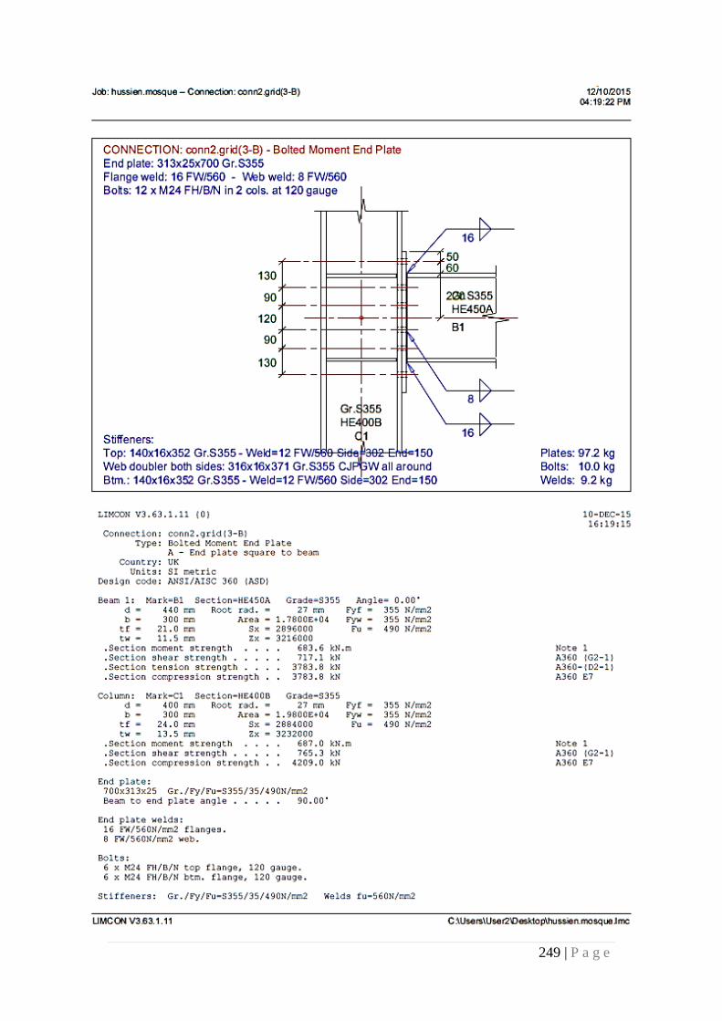
249 | P a g e
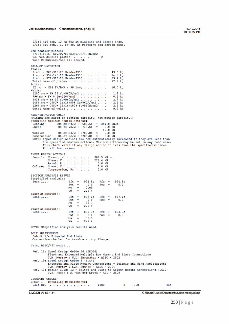
250 | P a g e
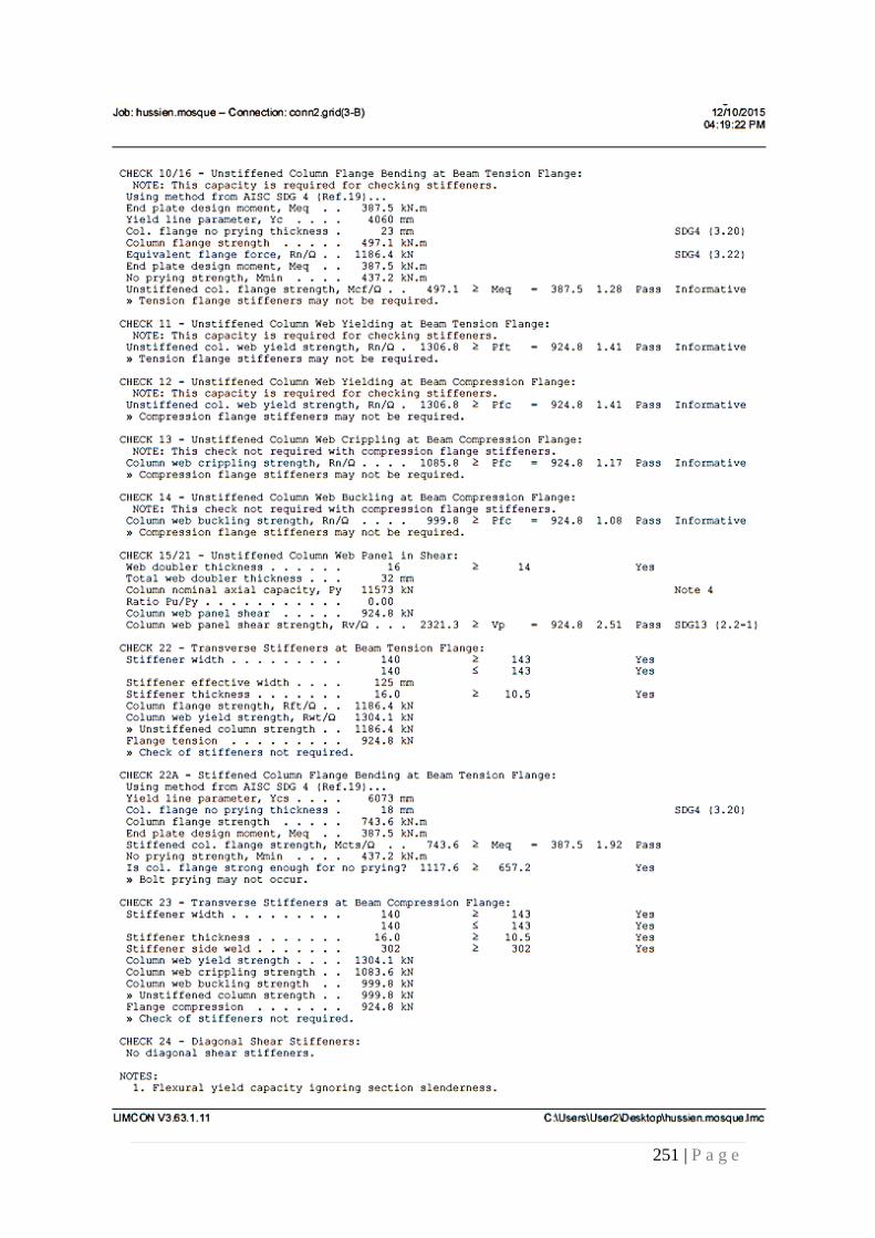
251 | P a g e
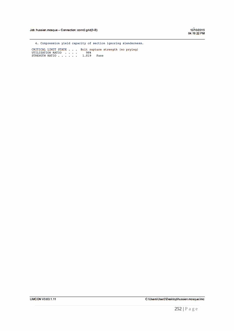
252 | P a g e
253 | P a g e
References
Lecture Notes:
Design of Steel Structures, Dr. Andi Asiz, spring 2015
Reinforced Concrete Design, Eng. Danish Ahmed, spring 2015
Intro. To Geotechnical Engineering, Dr. Alaa salman, fall 2015
Books/Articles:
Wang, C., & Salmon, C. (1985). Reinforced concrete design (4th ed.). New York:
Harper & Row.
Building code requirements for structural concrete (ACI 318-08) and commentary.
(2008). Farmington Hills, Mich.: American Concrete Institute.
/Retrieved December 26, 2015, from http://www.sbc.gov.sa .(.n.d) .كود البناء السعودي
Steel construction manual (13th ed.). (2005). Chicago, Ill.: American Institute of Steel
Construction.
Steel construction, a manual for architects, engineers and fabricators of buildings
and other steel structures. (5th ed.). (1947). New York, N.Y.: American Institute of
Steel Construction.