
Compact CAN-to-Ethernet Converter Using 32-Bit ARM® Cortex
32
5 LEDs USB 50-Pin Connector Debug Connector Microcontroller TM4C129XNCZAD Power 5.5 V to 3.3 V TPS62177DQC CAN SN65HVD256D RS485 ESD TPD4E1U06 Ethernet Connector 25-MHz Crystal MII/RMII/SPI/I2C/UART interfaces EMAC + PHY Os Spare 10-Pin ADC I/Ps and digital I/ SN65HVD72DR TI Designs Compact CAN-to-Ethernet Converter Using 32-Bit ARM® Cortex™-M4F MCU TI Designs Design Features TI Designs provide the foundation that you need • TM4C129XNCZAD 32-Bit Advanced RISC including methodology, testing, and design files to Machines (ARM) Cortex-M4F Microcontroller quickly evaluate and customize the system. TI Designs (MCU) Based help you accelerate your time to market. • Integrated 10/100 Ethernet Media Access Control (MAC) and Physical Interface Device (PHY) Design Resources • 10/100 Ethernet MAC With Advanced IEEE 1588 Precision Time Protocol (PTP) Hardware and Both Tool Folder Containing Design Files TM4C129XNCZAD Media Independent Interface (MII) and Reduced TPD4E1U06 Product Folder MII (RMII) Support SN65HVD256D Product Folder • Provision to Connect to External Boards for TPS62177 Product Folder Isolated Communication Interface and Power Over SN65HVD72DR Product Folder Ethernet (POE) INA196AIDBVR Product Folder • On-Board Non-Isolated Controller Area Network (CAN) and RS-485 PHY ASK Our E2E Experts • 50-Pin Connector for External Interface With MII WEBENCH® Calculator Tools and RMII Ethernet PHY • Expansion Connectors for Access to Communication, Analog-to-Digital Converter (ADC), Featured Applications and General Purpose Input and Output (GPIO) Interfaces • Industrial Motor Drives and Industrial Automation • 1024-KB Flash Memory and 256-KB Single-Cycle • Circuit Breakers, Protection Relays, and Panel System SRAM Mount Multi-Function Power and Energy Meters • Substation Automation Products: Remote Terminal Unit (RTU), Protection Relay, Intelligent Electronic Devices (IEDs), Converters, and Gateways • Industrial Remote Monitoring: Remote I/O and Data Loggers All trademarks are the property of their respective owners. 1 TIDU706A – January 2015 – Revised February 2015 Compact CAN-to-Ethernet Converter Using 32-Bit ARM® Cortex™-M4F MCU Submit Documentation Feedback Copyright © 2015, Texas Instruments Incorporated
-
Upload
khangminh22 -
Category
Documents
-
view
0 -
download
0
Transcript of Compact CAN-to-Ethernet Converter Using 32-Bit ARM® Cortex

5 LEDs
USB
50-P
in C
onne
ctor
Debug Connector
MicrocontrollerTM4C129XNCZAD
Power 5.5 V to 3.3 VTPS62177DQC
CANSN65HVD256D
RS485
ESDTPD4E1U06
EthernetConnector
25-MHz Crystal
MII/RMII/SPI/I2C/UART interfaces
EMAC+
PHY
OsSpare 10-Pin
ADC I/Ps and digital I/
SN65HVD72DR
TI DesignsCompact CAN-to-Ethernet Converter Using 32-Bit ARM®Cortex™-M4F MCU
TI Designs Design FeaturesTI Designs provide the foundation that you need • TM4C129XNCZAD 32-Bit Advanced RISCincluding methodology, testing, and design files to Machines (ARM) Cortex-M4F Microcontrollerquickly evaluate and customize the system. TI Designs (MCU) Basedhelp you accelerate your time to market. • Integrated 10/100 Ethernet Media Access Control
(MAC) and Physical Interface Device (PHY)Design Resources• 10/100 Ethernet MAC With Advanced IEEE 1588
Precision Time Protocol (PTP) Hardware and BothTool Folder Containing Design FilesTM4C129XNCZADMedia Independent Interface (MII) and ReducedTPD4E1U06 Product Folder MII (RMII) Support
SN65HVD256D Product Folder• Provision to Connect to External Boards forTPS62177 Product Folder
Isolated Communication Interface and Power OverSN65HVD72DR Product FolderEthernet (POE)INA196AIDBVR Product Folder
• On-Board Non-Isolated Controller Area Network(CAN) and RS-485 PHY
ASK Our E2E Experts • 50-Pin Connector for External Interface With MIIWEBENCH® Calculator Tools and RMII Ethernet PHY
• Expansion Connectors for Access toCommunication, Analog-to-Digital Converter (ADC),Featured Applications and General Purpose Input and Output (GPIO)Interfaces• Industrial Motor Drives and Industrial Automation
• 1024-KB Flash Memory and 256-KB Single-Cycle• Circuit Breakers, Protection Relays, and PanelSystem SRAMMount Multi-Function Power and Energy Meters
• Substation Automation Products: Remote TerminalUnit (RTU), Protection Relay, Intelligent ElectronicDevices (IEDs), Converters, and Gateways
• Industrial Remote Monitoring: Remote I/O and DataLoggers
All trademarks are the property of their respective owners.
1TIDU706A–January 2015–Revised February 2015 Compact CAN-to-Ethernet Converter Using 32-Bit ARM® Cortex™-M4FMCUSubmit Documentation Feedback
Copyright © 2015, Texas Instruments Incorporated
System Description www.ti.com
An IMPORTANT NOTICE at the end of this TI reference design addresses authorized use, intellectual property matters and otherimportant disclaimers and information.
1 System DescriptionA simple and effective design makes Ethernet the most popular networking solution at the physical anddata link levels of the Open Systems Interconnection (OSI) model. With high speed options and a varietyof media types to choose from, Ethernet is efficient and flexible. In addition, the low cost of Ethernethardware makes Ethernet an attractive option for industrial networking applications. The opportunity to useopen protocols such as TCP/IP over Ethernet networks offers a high level of standardization andinteroperability. The result has been an ongoing shift to the use of Ethernet for industrial control andautomation applications. Ethernet is increasingly replacing proprietary communications.
The CAN-Ethernet Converter is useful in the field of industrial drives monitoring and control as well assupervisory control and data acquisition (SCADA) systems. The same hardware can be used either as aCAN-Ethernet gateway or as a CAN-Ethernet bridge with the changes in the firmware. The CAN-Ethernetgateway is useful for monitoring remote CAN networks over Ethernet or local area network (LAN). TheCAN-Ethernet bridge is useful for the transparent coupling of CAN networks through the internet or LAN.
The reference design platform demonstrates capabilities of the TM4C129XNCZAD 32-bit ARM Cortex-M4F MCU. The design supports 10/100 Base-T and is compliant with the IEEE 802.3 standard. Thereference design operates from a single power supply (5.5-V input with an on-board regulator of 3.3 V).
CAN standard:The CAN bus was developed by BOSCH as a multi-master, message broadcast system that specifies amaximum signaling rate of 1 Mbps. Unlike a traditional network, such as USB or Ethernet, CAN does notsend large blocks of data point-to-point between the nodes under the supervision of a central bus master.In a CAN network, many short messages are broadcast to the entire network, which provides dataconsistency in every node of the system. Although CAN was originally designed for the automotiveindustry, CAN has become a popular bus in industrial applications as well.
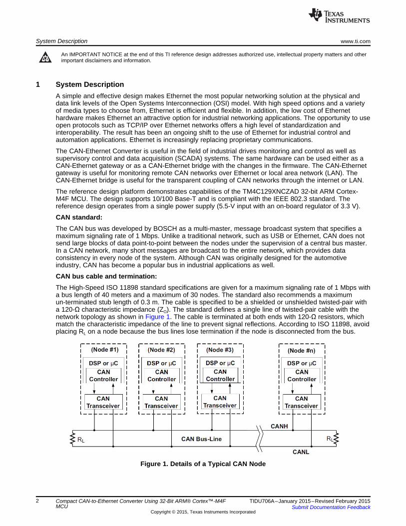
CAN bus cable and termination:The High-Speed ISO 11898 standard specifications are given for a maximum signaling rate of 1 Mbps witha bus length of 40 meters and a maximum of 30 nodes. The standard also recommends a maximumun-terminated stub length of 0.3 m. The cable is specified to be a shielded or unshielded twisted-pair witha 120-Ω characteristic impedance (ZO). The standard defines a single line of twisted-pair cable with thenetwork topology as shown in Figure 1. The cable is terminated at both ends with 120-Ω resistors, whichmatch the characteristic impedance of the line to prevent signal reflections. According to ISO 11898, avoidplacing RL on a node because the bus lines lose termination if the node is disconnected from the bus.
Figure 1. Details of a Typical CAN Node
2 Compact CAN-to-Ethernet Converter Using 32-Bit ARM® Cortex™-M4F TIDU706A–January 2015–Revised February 2015MCU Submit Documentation Feedback
Copyright © 2015, Texas Instruments Incorporated
www.ti.com Design Features
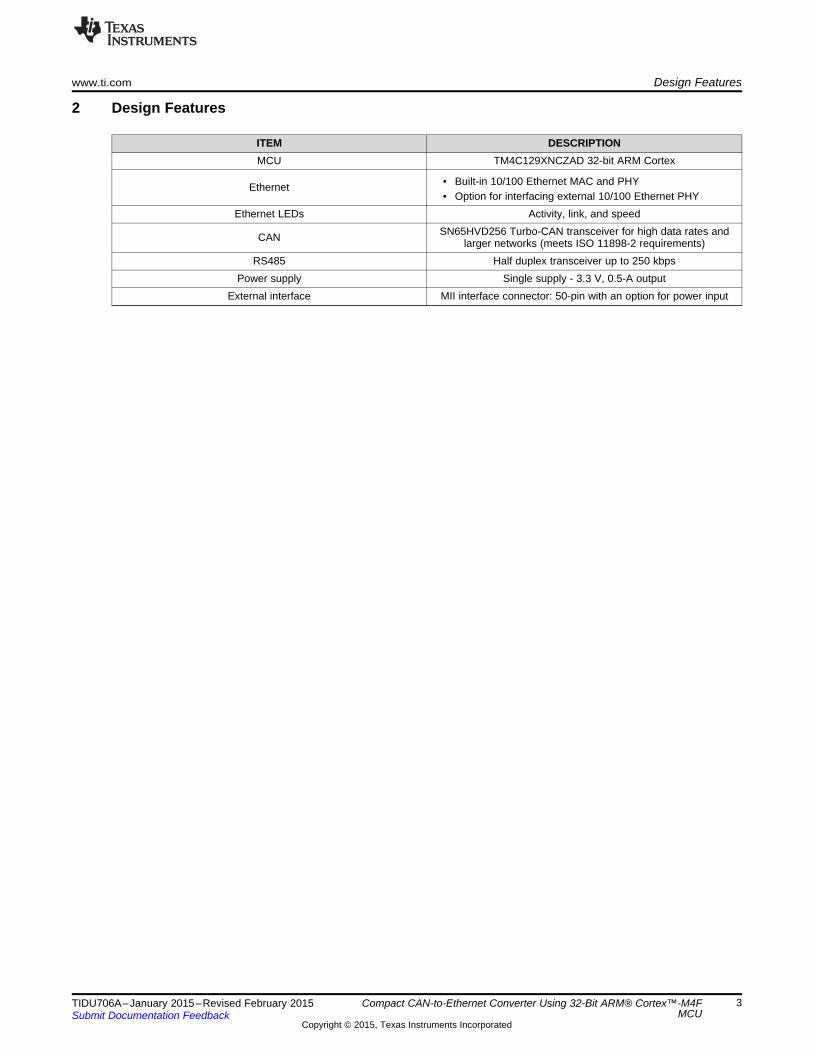
2 Design Features
ITEM DESCRIPTIONMCU TM4C129XNCZAD 32-bit ARM Cortex
• Built-in 10/100 Ethernet MAC and PHYEthernet• Option for interfacing external 10/100 Ethernet PHY
Ethernet LEDs Activity, link, and speedSN65HVD256 Turbo-CAN transceiver for high data rates andCAN larger networks (meets ISO 11898-2 requirements)
RS485 Half duplex transceiver up to 250 kbpsPower supply Single supply - 3.3 V, 0.5-A output
External interface MII interface connector: 50-pin with an option for power input
3TIDU706A–January 2015–Revised February 2015 Compact CAN-to-Ethernet Converter Using 32-Bit ARM® Cortex™-M4FMCUSubmit Documentation Feedback
Copyright © 2015, Texas Instruments Incorporated
5 LEDs
USB
50-P
in C
onne
ctor
Debug Connector
MicrocontrollerTM4C129XNCZAD
Power 5.5 V to 3.3 VTPS62177DQC
CANSN65HVD256D
RS485
ESDTPD4E1U06
EthernetConnector
25-MHz Crystal
MII/RMII/SPI/I2C/UART interfaces
EMAC+
PHY
OsSpare 10-Pin
ADC I/Ps and digital I/
SN65HVD72DR
Block Diagram www.ti.com
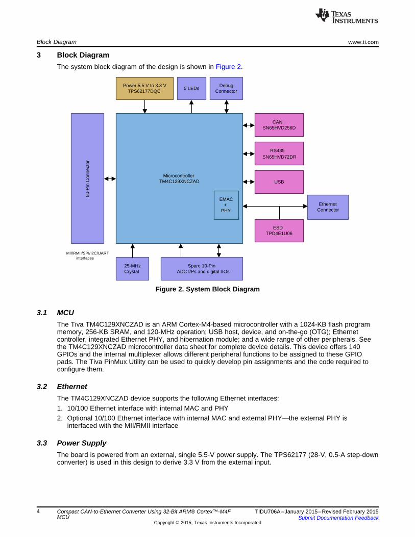
3 Block DiagramThe system block diagram of the design is shown in Figure 2.
Figure 2. System Block Diagram
3.1 MCUThe Tiva TM4C129XNCZAD is an ARM Cortex-M4-based microcontroller with a 1024-KB flash programmemory, 256-KB SRAM, and 120-MHz operation; USB host, device, and on-the-go (OTG); Ethernetcontroller, integrated Ethernet PHY, and hibernation module; and a wide range of other peripherals. Seethe TM4C129XNCZAD microcontroller data sheet for complete device details. This device offers 140GPIOs and the internal multiplexer allows different peripheral functions to be assigned to these GPIOpads. The Tiva PinMux Utility can be used to quickly develop pin assignments and the code required toconfigure them.
3.2 EthernetThe TM4C129XNCZAD device supports the following Ethernet interfaces:1. 10/100 Ethernet interface with internal MAC and PHY2. Optional 10/100 Ethernet interface with internal MAC and external PHY—the external PHY is
interfaced with the MII/RMII interface
3.3 Power SupplyThe board is powered from an external, single 5.5-V power supply. The TPS62177 (28-V, 0.5-A step-downconverter) is used in this design to derive 3.3 V from the external input.
4 Compact CAN-to-Ethernet Converter Using 32-Bit ARM® Cortex™-M4F TIDU706A–January 2015–Revised February 2015MCU Submit Documentation Feedback
Copyright © 2015, Texas Instruments Incorporated
www.ti.com Block Diagram
3.4 Non-Isolated RS485 InterfaceThis design uses the SN65HVD72DR device as the RS-485 transceiver. These type of devices are half-duplex transceivers designed for RS-485 data bus networks. Powered by a 3.3-V supply, the transceiversare fully compliant with the TIA/EIA-485A standard. This device features a wide common-mode voltagerange making the device suitable for multi-point applications over long cable runs. SN65HVD72DRdevices are optimized for signaling rates up to 250 kbps.
3.5 Non-Isolated CAN InterfaceThe SN65HVD256 Turbo-CAN transceiver is used for high data rates and large networks (the devicemeets the requirements of ISO 11898-2).
3.6 Expansion ConnectorsExpansion outputs have been provided for further use as required.
3.7 PCB Dimensions and PCB Physical LayoutThis reference design has been designed in a small-form factor, four-layer PCB with a dedicated groundand power plane.
3.8 ProgrammingTiva microcontrollers support the Joint Test Action Group (JTAG) interface for debugging andprogramming. The designer can place headers on the board and connect them to the JTAG pins on thechip (see the datasheet for pin out information). The use of an external JTAG programmer is required toconnect the PC to the board. The Tiva LaunchPad can also be used as an external programmer.
4 Featured ApplicationsThe Tiva C Series ARM Cortex-M4 microcontrollers provide top performance and advanced integration.The product family is positioned for cost-effective applications requiring significant control processing andconnectivity capabilities such as:• Network appliances, gateways, and adapters• Remote connectivity and monitoring• Security and access systems• Human-machine interface (HMI) control panels• Factory automation control• Motion control and power inversion• Electronic point-of-sale (POS) displays• Smart energy and smart grid solutions• Intelligent lighting control
The provided CAN interface can be used for the following applications:• Motor control• Power inverters• Industrial automation• Building automation networks• Automotive applications
5TIDU706A–January 2015–Revised February 2015 Compact CAN-to-Ethernet Converter Using 32-Bit ARM® Cortex™-M4FMCUSubmit Documentation Feedback
Copyright © 2015, Texas Instruments Incorporated

Circuit Design and Component Selection www.ti.com
5 Circuit Design and Component SelectionThe CAN-Ethernet converter is based on the TM4C129XNCZAD device, a 32-bit ARM Cortex-M4F core-based microcontroller. The program that runs on this microcontroller uses lwIP (lightweight IP) stack. LwIPis a widely used, open-source TCP/IP stack designed for embedded systems. LwIP was originallydeveloped by Adam Dunkels at the Swedish Institute of Computer Science and is now developed andmaintained by a worldwide network of developers.
5.1 MCUTiva C Series microcontrollers integrate a large variety of rich communication features to enable a newclass of highly connected designs with the ability to allow critical, real-time control between performanceand power. The microcontrollers feature integrated communication peripherals along with other high-performance analog and digital functions to offer a strong foundation for many different target uses,spanning from HMI to networked system management controllers.
In addition, Tiva C Series microcontrollers offer the advantages of ARM's widely available developmenttools, System-on-Chip (SoC) infrastructure, and a large user community. Additionally, thesemicrocontrollers use ARM's Thumb®-compatible Thumb-2 instruction set to reduce memory requirementsand cost. Finally, the TM4C129XNCZAD microcontroller is code-compatible to all members of theextensive Tiva C Series, providing flexibility to fit precise needs.
Some important features of the MCU are as follows:• Performance
– ARM Cortex-M4F processor core, 120-MHz operation; 150-Dhrystone million instructions persecond (DMIPS) performance, 1024-KB flash memory
– 256-KB single-cycle system SRAM, 6KB of electrically erasable programmable read-only memory(EEPROM)
• Communication interfaces– Eight universal asynchronous receivers and transmitters (UARTs); four quad synchronous serial
interface (QSSI) modules with bi-, quad-, and advanced synchronous serial interface (SSI) support;ten Inter-Integrated Circuit (I2C) modules with four transmission speeds, including high-speedmode; CAN 2.0 A male to B male (A/B) controllers; 10/100 Ethernet MAC and Ethernet PHY withIEEE 1588 PTP hardware support; and a USB 2.0 with host, device, and OTG compatibility with alow-pin interface (ULPI) option and link power management (LPM) support
• Analog support– Two 12-bit ADC modules, each with a maximum sample rate of one million samples per second
• One JTAG module with an integrated ARM serial wire debug (SWD)• 212-Ball grid array (BGA) package• Operating range (ambient)
– Industrial (–40°C to 85°C) temperature range– Extended (–40°C to 105°C) temperature range
5.2 EthernetThe TM4C129X supports 10/100 Mbps Ethernet connections. The board is designed to connect directly toan Ethernet network using RJ45 style connectors. The microcontroller contains a fully integrated EthernetMAC and PHY. This integration creates a simple, elegant, and cost-saving Ethernet circuit design.Example code is available for both the unmanaged internet protocol (uIP) and lwIP TCP/IP protocolstacks. The embedded Ethernet on this device can be programmed to act as an HTTP server, client, orboth. The design and integration of the circuit and microcontroller also enable users to synchronize eventsover the network using the IEEE1588 precision time protocol.
6 Compact CAN-to-Ethernet Converter Using 32-Bit ARM® Cortex™-M4F TIDU706A–January 2015–Revised February 2015MCU Submit Documentation Feedback
Copyright © 2015, Texas Instruments Incorporated
Current Measure
EN3
VIN2
SLEEP8
NC4
FB5
PG7
SW9
VOS10
AGND6
PGND1
PW
PD
11
TPS62177DQCU5
12
2.2K
R19
12
1K
R21
12
0
R22
12
22uF, 6.3V
C6
1 2
10uH
L1
IND-WE-7440
1 2
1 Ohm, 1%
R16
12
100K
R51
12
2.2uF 50V
C43
1
TL2
1
TL3
1
TL1
HIB
GND GND
3.3V
GND
HIB
+5V
GND
+5V
GND
12
D8
12
330
R12
12
D15
12
330
R56
GND GND
+5V
3.3V
3.3V
3.9V
D9
1SMB5915BT3G
GND
12
0.1uF
C42
12
22uF, 6.3V
C36
GND
12
0.1uF
C37
1 2
0
R49
NOTE: Pull up resistors and decoupling cap should be located near U1
NOTE: C40 and C66 must be located near pin 2 and 7 of T1
12
49.9
R10
12
49.9
R9
12
49.9
R13
12
49.9
R11
12
4.87K
R41
12
0.1uF
C22
12
0.1uF
C24
12
0.1uF
C1112
0.1uF
C13
12
4700 pF
C9
12
1M
R28
V15V15
V14V14
W13W13
V13V13
W15W15
P17P17
N16N16
R17R17
P16P16
TM4C129XNCZADU2C
TX+1
TX-2
RX+3
TERM1A4
TERM1B5
RX-6
TERM2A7
TERM2B8
CHASISSH2
CHASISSH1
J1
RJ45_NOMAG_NOLED
12
75
R2
9
12
75
R3
4
12
75
R26
12
75
R27
12
1000pF
C8
EN0TX-
EN0RX-
EN0TX+
EN0RX+
TX+_RJ45TX-_RJ45RX+_RJ45
RX-_RJ45
3.3V
GND
3.3V
3.3V
GND GND
3.3V
GND GND
GND
3.3V
GND
CHGND
CHGND
D1+1
D1-6
NC5
GN
D2
D2+3
D2-4
D3
TPD4E1U06DCK
TD+1
TCT2
TD-3
TX-14
TX+16
NC412
NC313
NC14
NC25
CMT15
RD+6
RCT7
RD-8
RX-9
RX+11
CMT10
TRANSMIT
RECEIVE
T1
HX1198FNL
CHGND
www.ti.com Circuit Design and Component Selection
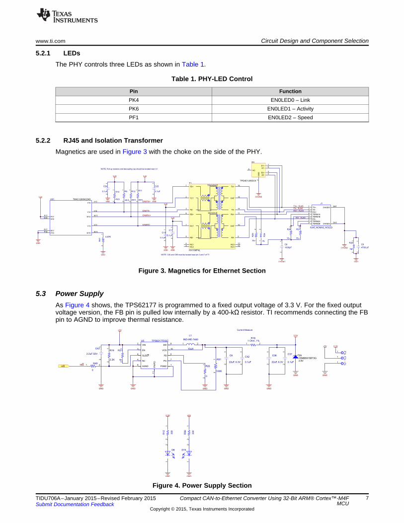
5.2.1 LEDsThe PHY controls three LEDs as shown in Table 1.
Table 1. PHY-LED Control
Pin FunctionPK4 EN0LED0 – LinkPK6 EN0LED1 – ActivityPF1 EN0LED2 – Speed
5.2.2 RJ45 and Isolation TransformerMagnetics are used in Figure 3 with the choke on the side of the PHY.
Figure 3. Magnetics for Ethernet Section
5.3 Power SupplyAs Figure 4 shows, the TPS62177 is programmed to a fixed output voltage of 3.3 V. For the fixed outputvoltage version, the FB pin is pulled low internally by a 400-kΩ resistor. TI recommends connecting the FBpin to AGND to improve thermal resistance.
Figure 4. Power Supply Section
7TIDU706A–January 2015–Revised February 2015 Compact CAN-to-Ethernet Converter Using 32-Bit ARM® Cortex™-M4FMCUSubmit Documentation Feedback
Copyright © 2015, Texas Instruments Incorporated
TXD1
GND2
VCC3
RXD4
VRXD5
CANL6
CANH7
S8
SN65HVD256D
U4
CAN1TXCAN1TX
GND
CAN1RXCAN1RX
GND
0.1µF
C30
GND
+5V
CANH
CANL
CANH
CANL
1
2
J6
CANH
CANL
3.3V
120R45
Circuit Design and Component Selection www.ti.com
5.3.1 External Component Selection for the Power SupplyThe external components must fulfill the needs of the application, but also the stability criteria of thecontrol loop of the device. The TPS62175/7 is optimized to work within a wide range of externalcomponents. The inductance and capacitance of the LC output filter must be considered together, creatinga double pole that is responsible for the corner frequency of the converter.
5.3.2 Layout Considerations for the Power SupplyThe input capacitor must be placed as close as possible to the IC pins (VIN and PGND). The inductormust be placed close to the SW pin and connect directly to the output capacitor—minimizing the loop areabetween the SW pin, inductor, output capacitor, and PGND pin. The sensitive nodes like FB and VOSmust be connected with short wires instead of nearby high dv/dt signals (for example, the SW pin). Thefeedback resistors must be placed close to the IC and connect directly to the AGND and FB pins.
5.3.3 Thermal Data for the Power SupplyThe TPS62175/7 device is designed for a maximum operating junction temperature (Tj) of 125°C.Therefore the maximum output power is limited by the power losses. As the thermal resistance of thepackage is given, the size of the surrounding copper area and a proper thermal connection of the IC canreduce the thermal resistance.
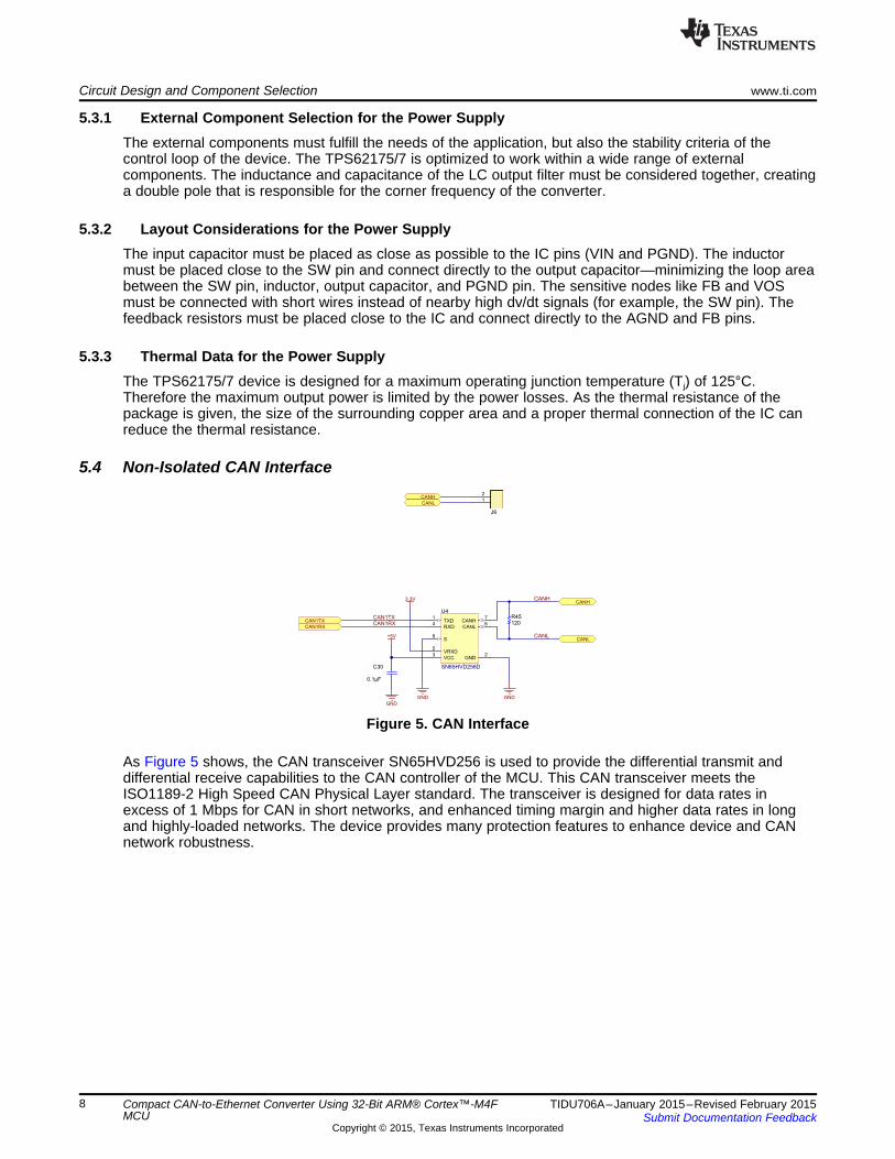
5.4 Non-Isolated CAN Interface
Figure 5. CAN Interface
As Figure 5 shows, the CAN transceiver SN65HVD256 is used to provide the differential transmit anddifferential receive capabilities to the CAN controller of the MCU. This CAN transceiver meets theISO1189-2 High Speed CAN Physical Layer standard. The transceiver is designed for data rates inexcess of 1 Mbps for CAN in short networks, and enhanced timing margin and higher data rates in longand highly-loaded networks. The device provides many protection features to enhance device and CANnetwork robustness.
8 Compact CAN-to-Ethernet Converter Using 32-Bit ARM® Cortex™-M4F TIDU706A–January 2015–Revised February 2015MCU Submit Documentation Feedback
Copyright © 2015, Texas Instruments Incorporated
1
2
3
4
5
6
J10
HEADER_TMM-103-01-G-D-RA
CAN1TX
CAN1RX
U3RTS
U3RX
U3TX
GND
TX_EN
1 2
3 4
5 6
7 8
9 10
11 12
13 14
15 16
17 18
19 20
21 22
23 24
25 26
27 28
29 30
31 32
33 34
35 36
37 38
39 40
41 42
43 44
45 46
47 48
49 50
J9
ERM8-025-05.0-L-DV-K-TR
GND GND
I2C8SCLI2C8SDASPI3CSSPI3SCKSPI3SDOSPI3SDICAN0RXCAN0TX
SPI0CSSPI0SCKSPI0SDOSPI0SDIU5TXU5RXU7TXU7RX
RESET_N
+5V
12
0
R62
1 20
R58
I2C8SCL
I2C8SDA
SPI3CS
SPI3SCK
SPI3SDO
SPI3SDI
CAN0RX
CAN0TX
RESET_N
U5TX
U5RX
U7TX
U7RX
EN0INTRN
PG0/PPS
1_5V_PS
SPI0CS
SPI0SCK
SPI0SDO
SPI0SDI
MDIOMDC
RXD3RXD2RXD0RXD1RX_DVRX_CLKRX_ER
TX_ENTXD0TXD1TXD2TXD3COLCRS
TX_CLK
TXD0
TXD1
TXD2
TXD3
COL
CRS
MDIO
MDC
TX_CLK
RXD3
RXD2
RXD0
RXD1
RX_DV
RX_CLK
RX_ER3.3V
GND
0.1
R57
0.1µF
C44
GND
MCU_ISENSEMCU_ISENSE
OU
T1
GN
D2
V+
3V
IN+
4
VIN
-5
INA196AIDBVR
U6
EN0TXEREN0TXER
EN0INTRNPG0/PPS
www.ti.com Circuit Design and Component Selection
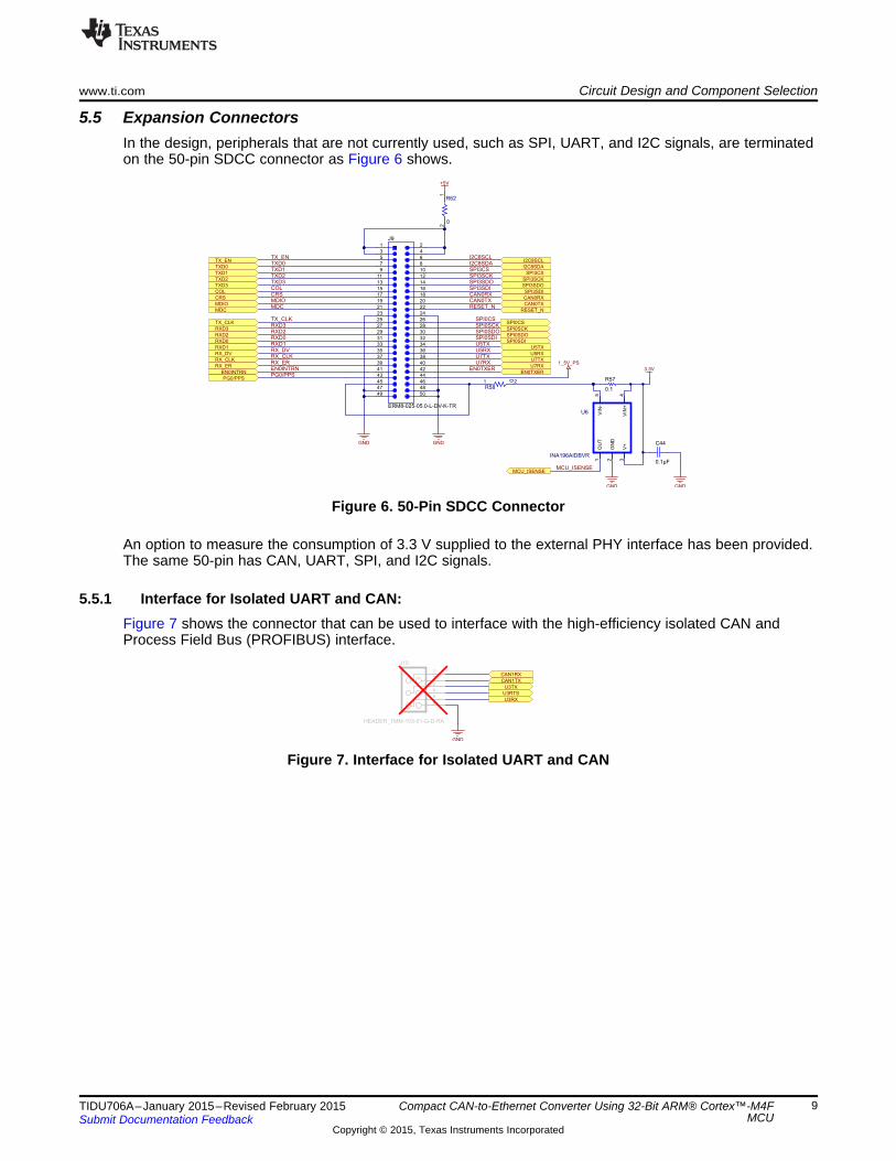
5.5 Expansion ConnectorsIn the design, peripherals that are not currently used, such as SPI, UART, and I2C signals, are terminatedon the 50-pin SDCC connector as Figure 6 shows.
Figure 6. 50-Pin SDCC Connector
An option to measure the consumption of 3.3 V supplied to the external PHY interface has been provided.The same 50-pin has CAN, UART, SPI, and I2C signals.
5.5.1 Interface for Isolated UART and CAN:Figure 7 shows the connector that can be used to interface with the high-efficiency isolated CAN andProcess Field Bus (PROFIBUS) interface.
Figure 7. Interface for Isolated UART and CAN
9TIDU706A–January 2015–Revised February 2015 Compact CAN-to-Ethernet Converter Using 32-Bit ARM® Cortex™-M4FMCUSubmit Documentation Feedback
Copyright © 2015, Texas Instruments Incorporated
1 2
3 4
5 6
7 8
9 10
J7
HEADER_2041501
TMS
TCK
TDO
TDI
3.3V
GND
EXTDBGEXTDBG
T_TRST
12
10K
R17
12
10K
R20
12
10K
R54
12
10K
R52
3.3V
ACTIVITY(GREEN)
VIN5
EN4
GND2
OUT1
OC3
TPS2051BDBVT
U3
12
10
K
R4
2
12
4.7UF 6.3V
C21
12
4.7UF 6.3V
C17
12
10K
R44
12
3300pF
C3
1 2
1M
R7
1 2
D51 2
D4
1 2
D16
GND
USB0DP
USB0DM
USB0VBUSUSB0ID
USB0EPENUSB0PLFT
$$$22985
USB_PLFT
USB_ENUSB_EN
+VBUS
GND
+5V
GND
GND
GND
GND
USB_EN
GND
GND
USB_EN
VB
1
D-
2
D+
3
ID4
G5
6
7
10 11
8
9
J5 ZX62R-AB-5P
USB0DP
USB0DM
USB0ID
USB0VBUSUSB0EPEN
USB0PLFT
3.3V
33R3533R3633R1433R15
CHGND
TP19 TP20
1 210k
R18
EXTDBG
3.3V
1 2
3 4
5 6
7 8
9 10
J3
HEADER_2041501
ADC3
ADC2
ADC1
ADC0
SPARE4
SPARE1
SPARE2
SPARE3
I2C6SCL
I2C6SDA
Circuit Design and Component Selection www.ti.com
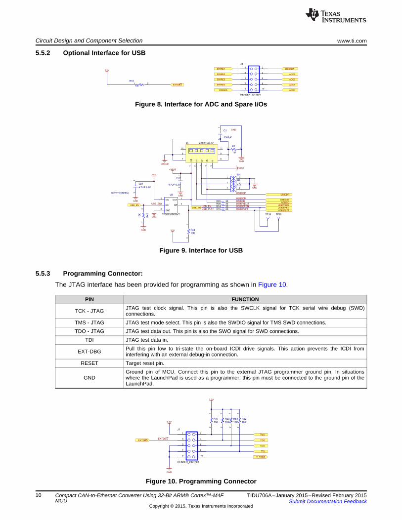
5.5.2 Optional Interface for USB
Figure 8. Interface for ADC and Spare I/Os
Figure 9. Interface for USB
5.5.3 Programming Connector:The JTAG interface has been provided for programming as shown in Figure 10.
PIN FUNCTIONJTAG test clock signal. This pin is also the SWCLK signal for TCK serial wire debug (SWD)TCK - JTAG connections.
TMS - JTAG JTAG test mode select. This pin is also the SWDIO signal for TMS SWD connections.TDO - JTAG JTAG test data out. This pin is also the SWO signal for SWD connections.
TDI JTAG test data in.Pull this pin low to tri-state the on-board ICDI drive signals. This action prevents the ICDI fromEXT-DBG interfering with an external debug-in connection.
RESET Target reset pin.Ground pin of MCU. Connect this pin to the external JTAG programmer ground pin. In situations
GND where the LaunchPad is used as a programmer, this pin must be connected to the ground pin of theLaunchPad.
Figure 10. Programming Connector
10 Compact CAN-to-Ethernet Converter Using 32-Bit ARM® Cortex™-M4F TIDU706A–January 2015–Revised February 2015MCU Submit Documentation Feedback
Copyright © 2015, Texas Instruments Incorporated
www.ti.com Software Description
6 Software DescriptionThe software provided for the CAN-Ethernet converter performs the CAN-Ethernet gateway operation.Using a PC and the CAN-Ethernet converter, the user can send and receive messages through the Telnetinterface (using a free terminal emulator application such as Tera Term). Telnet is a client-server protocolbased on a reliable connection-oriented transport. Typically, this protocol is used to establish a connectionto TCP port number 23, where a Telnet server application (telnetd) is listening. Tera Term is an open-source, free, software-implemented terminal emulator program. The example software provides testing ofthe hardware by simple character transfers via telnet to the CAN bus and vice versa. The software istested at different CAN baud rates of 10 kbps, 500 kbps, and 1 Mbps.
11TIDU706A–January 2015–Revised February 2015 Compact CAN-to-Ethernet Converter Using 32-Bit ARM® Cortex™-M4FMCUSubmit Documentation Feedback
Copyright © 2015, Texas Instruments Incorporated
USB Micro-B-plug-to-USB-A plug cable (connects to PC as a USB device)
DK-TM4C123G Development Board(Connected to USB port of PC, runs UART-CAN software example from TivaWare)
RJ45 Cable(Connecting PC to CAN-
Ethernet Converter)
5.5 V DC Power Supply (on J8)
Twisted pair connecting CANH and CANL terminals
(on J6)
120- Resistor
Test Results www.ti.com
7 Test Results
7.1 Functional Testing
Table 2. Functional Testing Values
Clock 25 MHzVCC (3 to 3.6 V) 3.31 VInternal 1.55 V 1.55 VMII interface OK
Link and activity LED OK
7.2 CAN-Ethernet Gateway Testing
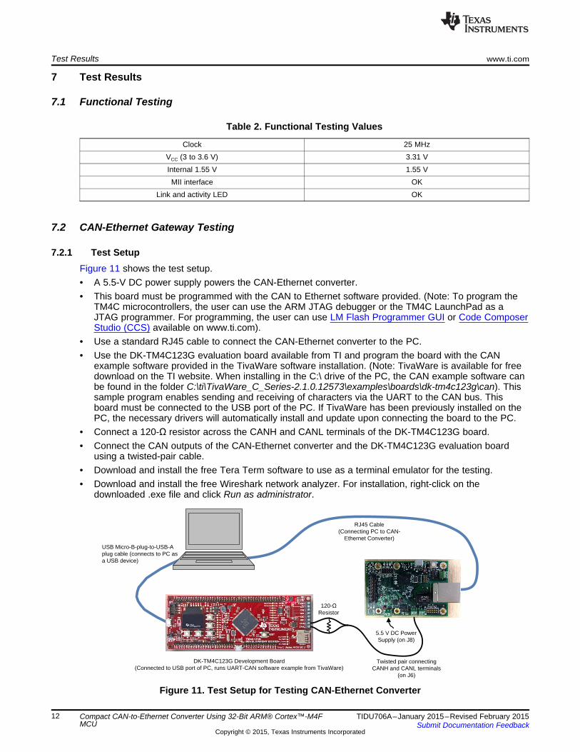
7.2.1 Test SetupFigure 11 shows the test setup.• A 5.5-V DC power supply powers the CAN-Ethernet converter.• This board must be programmed with the CAN to Ethernet software provided. (Note: To program the
TM4C microcontrollers, the user can use the ARM JTAG debugger or the TM4C LaunchPad as aJTAG programmer. For programming, the user can use LM Flash Programmer GUI or Code ComposerStudio (CCS) available on www.ti.com).
• Use a standard RJ45 cable to connect the CAN-Ethernet converter to the PC.• Use the DK-TM4C123G evaluation board available from TI and program the board with the CAN
example software provided in the TivaWare software installation. (Note: TivaWare is available for freedownload on the TI website. When installing in the C:\ drive of the PC, the CAN example software canbe found in the folder C:\ti\TivaWare_C_Series-2.1.0.12573\examples\boards\dk-tm4c123g\can). Thissample program enables sending and receiving of characters via the UART to the CAN bus. Thisboard must be connected to the USB port of the PC. If TivaWare has been previously installed on thePC, the necessary drivers will automatically install and update upon connecting the board to the PC.
• Connect a 120-Ω resistor across the CANH and CANL terminals of the DK-TM4C123G board.• Connect the CAN outputs of the CAN-Ethernet converter and the DK-TM4C123G evaluation board
using a twisted-pair cable.• Download and install the free Tera Term software to use as a terminal emulator for the testing.• Download and install the free Wireshark network analyzer. For installation, right-click on the
downloaded .exe file and click Run as administrator.
Figure 11. Test Setup for Testing CAN-Ethernet Converter
12 Compact CAN-to-Ethernet Converter Using 32-Bit ARM® Cortex™-M4F TIDU706A–January 2015–Revised February 2015MCU Submit Documentation Feedback
Copyright © 2015, Texas Instruments Incorporated
www.ti.com Test Results
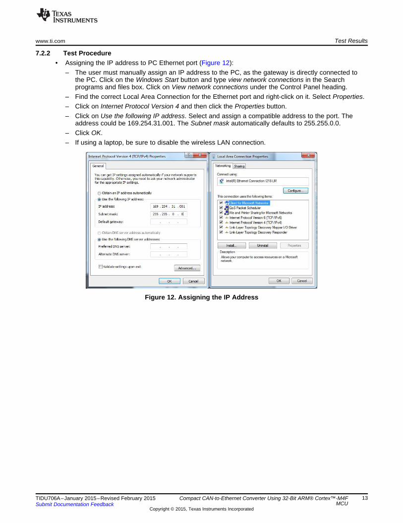
7.2.2 Test Procedure• Assigning the IP address to PC Ethernet port (Figure 12):
– The user must manually assign an IP address to the PC, as the gateway is directly connected tothe PC. Click on the Windows Start button and type view network connections in the Searchprograms and files box. Click on View network connections under the Control Panel heading.
– Find the correct Local Area Connection for the Ethernet port and right-click on it. Select Properties.– Click on Internet Protocol Version 4 and then click the Properties button.– Click on Use the following IP address. Select and assign a compatible address to the port. The
address could be 169.254.31.001. The Subnet mask automatically defaults to 255.255.0.0.– Click OK.– If using a laptop, be sure to disable the wireless LAN connection.
Figure 12. Assigning the IP Address
13TIDU706A–January 2015–Revised February 2015 Compact CAN-to-Ethernet Converter Using 32-Bit ARM® Cortex™-M4FMCUSubmit Documentation Feedback
Copyright © 2015, Texas Instruments Incorporated
Test Results www.ti.com
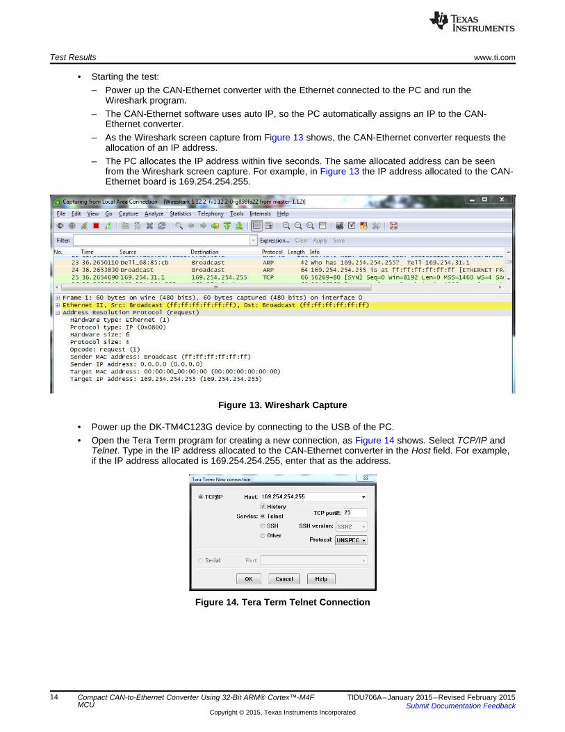
• Starting the test:– Power up the CAN-Ethernet converter with the Ethernet connected to the PC and run the
Wireshark program.– The CAN-Ethernet software uses auto IP, so the PC automatically assigns an IP to the CAN-
Ethernet converter.– As the Wireshark screen capture from Figure 13 shows, the CAN-Ethernet converter requests the
allocation of an IP address.– The PC allocates the IP address within five seconds. The same allocated address can be seen
from the Wireshark screen capture. For example, in Figure 13 the IP address allocated to the CAN-Ethernet board is 169.254.254.255.
Figure 13. Wireshark Capture
• Power up the DK-TM4C123G device by connecting to the USB of the PC.• Open the Tera Term program for creating a new connection, as Figure 14 shows. Select TCP/IP and
Telnet. Type in the IP address allocated to the CAN-Ethernet converter in the Host field. For example,if the IP address allocated is 169.254.254.255, enter that as the address.
Figure 14. Tera Term Telnet Connection
14 Compact CAN-to-Ethernet Converter Using 32-Bit ARM® Cortex™-M4F TIDU706A–January 2015–Revised February 2015MCU Submit Documentation Feedback
Copyright © 2015, Texas Instruments Incorporated
www.ti.com Test Results
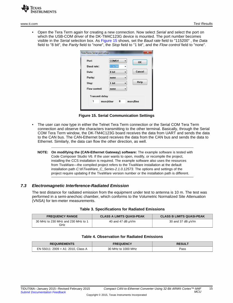
• Open the Tera Term again for creating a new connection. Now select Serial and select the port onwhich the USB-COM driver of the DK-TM4C123G device is mounted. The port number becomesvisible in the Serial selection box. As Figure 15 shows, set the Baud rate field to "115200" , the Datafield to "8 bit", the Parity field to "none", the Stop field to "1 bit", and the Flow control field to "none".
Figure 15. Serial Communication Settings
• The user can now type in either the Telnet Tera Term connection or the Serial COM Tera Termconnection and observe the characters transmitting to the other terminal. Basically, through the SerialCOM Tera Term window, the DK-TM4C123G board receives the data from UART and sends the datato the CAN bus. The CAN-Ethernet board receives the data from the CAN bus and sends the data toEthernet. Similarly, the data can flow the other direction, as well.
NOTE: On modifying the (CAN-Ethernet Gateway) software: The example software is tested withCode Composer Studio V6. If the user wants to open, modify, or recompile the project,installing the CCS installation is required. The example software also uses the resourcesfrom TivaWare—the compiled project refers to the TivaWare installation at the defaultinstallation path C:\ti\TivaWare_C_Series-2.1.0.12573. The options and settings of theproject require updating if the TivaWare version number or the installation path is different.
7.3 Electromagnetic Interference-Radiated EmissionThe test distance for radiated emission from the equipment under test to antenna is 10 m. The test wasperformed in a semi-anechoic chamber, which conforms to the Volumetric Normalized Site Attenuation(VNSA) for ten-meter measurements.
Table 3. Specifications for Radiated Emissions
FREQUENCY RANGE CLASS A LIMITS QUASI-PEAK CLASS B LIMITS QUASI-PEAK30 MHz to 230 MHz and 230 MHz to 1 40 and 47 dB μV/m 30 and 37 dB μV/m
GHz
Table 4. Observation for Radiated Emissions
REQUIREMENTS FREQUENCY RESULTEN 55011: 2009 + A1: 2010, Class A 30 MHz to 1000 MHz Pass
15TIDU706A–January 2015–Revised February 2015 Compact CAN-to-Ethernet Converter Using 32-Bit ARM® Cortex™-M4FMCUSubmit Documentation Feedback
Copyright © 2015, Texas Instruments Incorporated

Test Results www.ti.com
7.3.1 Test Result GraphsThe test is done with the TM4C129XNCZAD 32-bit ARM Cortex-M4F MCU with the internal MAC andPHY enabled. Figure 16 and Figure 17 show the graphs for horizontal and vertical polarization,respectively.
Figure 16. Horizontal Polarization
Figure 17. Vertical Polarization
16 Compact CAN-to-Ethernet Converter Using 32-Bit ARM® Cortex™-M4F TIDU706A–January 2015–Revised February 2015MCU Submit Documentation Feedback
Copyright © 2015, Texas Instruments Incorporated
www.ti.com Test Results
7.4 Electro Static Discharge (ESD), Electromagnetic Interference (EMI), andElectromagnetic Compatibility (EMC) Recommendations and Design GuidelinesThe following list provides recommendations to improve EMI performance:1. Use a guard ring for the crystal.2. Use a metal-shielded RJ-45 connector to connect the shield to chassis ground.3. Use magnetics with integrated, common-mode choking devices with the choke on the side of the PHY
(for example, the Pulse HX1198FNL).4. Do not overlap the circuit and chassis ground planes, keep them isolated. Connect the chassis ground
and system ground together using one capacitor with 4700 pF, 2 kV, 10% tolerance, and an X7R type.
17TIDU706A–January 2015–Revised February 2015 Compact CAN-to-Ethernet Converter Using 32-Bit ARM® Cortex™-M4FMCUSubmit Documentation Feedback
Copyright © 2015, Texas Instruments Incorporated
External Ethernet PHY
NOTE: To guarantee risetime requirements
MII/RMII
12
0.1uF
C23
12
0.1uF
C5
12
0.1uF
C25
21
25MHz
Y1
12
1uF
C26
12
0.01UF
C29
12
1uF
C32
12
0.01 uF
C34
12
0.1uF
C16
12
1uF
C20
12
2.2 uF
C18
12
0.01uF
C27
12
0.1uF
C31
12
0.01uF
C28
12
0.1uF
C33
12
0.1uF
C40
12
0.1uF
C38
12
0.1uF
C35
12
0.01 uF
C4
V3V3
W3W3
T6T6
U5U5
V4V4
W4W4
V5V5
R7R7
A16A16
B16B16
A17A17
B17B17
C6C6
B6B6
F2F2
F1F1
B15B15
C15C15
D14D14
C14C14
M2M2
M1M1
L2L2
K3K3
C2C2
C1C1
D2D2
D1D1
A4A4
B4B4
B3B3
B2B2
H3H3
H2H2
G1G1
G2G2
A5A5
B5B5
A7A7
B7B7
U6U6
V6V6
W6W6
T7T7
V7V7
W7W7
T8T8
U8U8
N15N15
T14T14
V11V11
M16M16
K17K17
K15K15
V12V12
U14U14
P4P4
R2R2
R1R1
T1T1
R3R3
T2T2
U2U2
V2V2
C8C8
E7E7
H17H17
F16F16
F18F18
E17E17
N1N1
K5K5
J1J1
J2J2
K1K1
K2K2
U19U19
V17V17
V16V16
W16W16
G16G16
H19H19
G18G18
J18J18
H18H18
G19G19
C18C18
B18B18
K18K18
K19K19
L18L18
L19L19
M18M18
G15G15
N19N19
N18N18
C10C10
B11B11
A11A11
B10B10
A10A10
B9B9
T12T12
U12U12
D6D6
D7D7
B13B13
C12C12
D8D8
B12B12
B8B8
A8A8
E3E3
E2E2
H4H4
M4M4
A13A13
W12W12
U15U15
M3M3
N5N5
N4N4
N2N2
V8V8
P3P3
P2P2
W9W9
R10R10
D12D12
D13D13
B14B14
A14A14
V9V9
T13T13
U10U10
R13R13
W10W10
V10V10
E18E18
F17F17
TM4C129XNCZADU2A
P18P18
T18T18
T19T19
R18R18
E19E19
D19D19
D18D18
G4G4
L8L8
L9L9
M8M8
M9M9
N10N10
V1V1
W1W1
W2W2
M10M10
K10K10
K13K13
K14K14
K6K6
K9K9
F10F10
J11J11
J12J12
H10H10
H11H11
H12H12
A1A1
A18A18
A19A19
A2A2
B1B1
B19B19
P19P19
M17M17
U18U18
F4F4
G5G5
F3F3
L10L10
L11L11
J8J8
J9J9
L12L12
M11M11
M12M12
P10P10
K11K11
K12K12
K7K7
K8K8
G10G10
H9H9
J10J10
V18V18
V19V19
W18W18
W19W19
E13E13
C5C5
H16H16
E10E10
TM4C129XNCZADU2B
12
10K
R39
1 20
R4
12
10K
R33
1 251
R31
12
0.1uF
C12
12
0.1uF
C39
12
0.1uF
C41
XOSC0
GNDX
MOSC0
GNDX2
MOSC1
RESET
HIBWAKE
CAN1RXCAN1TX
USB0DPUSB0DMUSB0VBUSUSB0IDUSB0EPENUSB0PLFT
DEBUG_RXDEBUG_TXTCKTMSTDITDO
PF1/LED2
MDIORX_DVRX_ERTX_CLK
TX_ENEN0TXEREN0INTRNCOLCRSRXD0RXD1RXD2RXD3EN0RREF_CLK
TXD0
TXD2TXD3
MDC
RESET_N
U5RXU5TX
I2C8SCLI2C8SDA
PQ7/LED_GADC3ADC2ADC1ADC0
U3RXU3TXSPI0SCKSPI0CS
U7RXRX_CLK
SPI0SDOSPI0SDI
CAN0RXCAN0TXPP6PD0/AIN15PD1/T0CCP0
U3RTSU3CTSI2C6SCLI2C6SDA
U7TX
EXTDBG
PE4
VB
AT
GND
RESET
HIB
WAKE
3.3V
GNDGNDGND GND
VDDC_1P2V_INT
GND
GND
3.3V
PF1/LED2
GND
GND GND
GND
MDIO
RX_DV
RX_ER
TX_CLK
TX_EN
EN0TXER
EN0INTRN
COL
CRS
RXD0
RXD1
RXD2
RXD3
EN0RREF_CLK
TXD0
TXD1
TXD2
TXD3
MDC
RESET_N
U5RX
U5TX
I2C8SCL
I2C8SDA
PQ7/LED_G
ADC3
ADC2
ADC1
ADC0
U3RX
U3TX
SPI0SCK
SPI0CS
U7RX
RX_CLK
SPI0SDO
SPI0SDI
CAN0RX
CAN0TX
PP6
PD0/AIN15
PD1/T0CCP0
U3RTS
U3CTS
I2C6SCL
I2C6SDA
3.3V
GND
3.3V
U7TX
EXTDBG
PE4
3.3V
SPI3CSSPI3SCKSPI3SDOSPI3SDI
1 2
3 4
SW1
RESETRESET
GND
DEBUG_RX
DEBUG_TX
TCK
TMS
TDI
TDO
SPI3CS
SPI3SCK
SPI3SDO
SPI3SDI
SPARE4
SPARE5
USB0DP
USB0DM
USB0VBUS
USB0ID
USB0EPEN
USB0PLFT
CAN1TX
CAN1RX
12
1uF
C19
T_TRST
SPARE6
EN0RREF_CLK TX_CLK
SPARE1
SPARE2
SPARE3SPARE3SPARE2SPARE1
SPARE4SPARE5SPARE6
MCU_ISENSEMCU_ISENSE
PG0/PPSPG0/PPS
33R46
TXD1
1 2
2.2K
R1
1 2
2.2K
R2
3.3V
12
2.2K
R59
12
2.2K
R61
3.3V
1.0Meg
R5
12
FB11000 OHM
33R43
12
0
R30
12
0R37
12
0R32
12
0
R38
33pFC14
33pFC15
1 20R401 20R471 20R61 20R8
2.2k
R3
2.2k
R60
33pFC45
33pFC46
33pFC47
33pFC48
GND GND GND GND
Design Files www.ti.com
8 Design Files
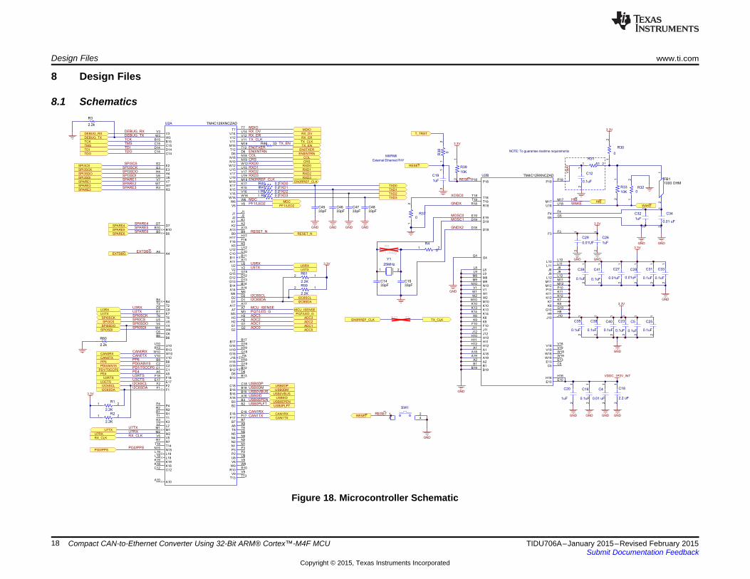
8.1 Schematics
Figure 18. Microcontroller Schematic
18 Compact CAN-to-Ethernet Converter Using 32-Bit ARM® Cortex™-M4F MCU TIDU706A–January 2015–Revised February 2015Submit Documentation Feedback
Copyright © 2015, Texas Instruments Incorporated
NOTE: Pull up resistors and decoupling cap should be located near U1
NOTE: C40 and C66 must be located near pin 2 and 7 of T1
ACTIVITY(GREEN)
SPEED(AMBER)
LINK(RED)
12
49.9
R10
12
49.9
R9
12
49.9
R13
12
49.9
R11
12
4.87K
R41
12
0.1uF
C22
12
0.1uF
C24
12
0.1uF
C1112
0.1uF
C13
12
4700 pF
C9
12D12
1 2
330
R50
12
1M
R28
VIN5
EN4
GND2
OUT1
OC3
TPS2051BDBVT
U3
12
10K
R42
12
4.7UF 6.3V
C21
12
4.7UF 6.3V
C17
V15V15
V14V14
W13W13
V13V13
W15W15
P17P17
N16N16
R17R17
P16P16
TM4C129XNCZADU2C
12
10K
R44
12
3300pF
C3
1 2
1M
R7
1 2
D51 2
D4
1 2
D16
TX+1
TX-2
RX+3
TERM1A4
TERM1B5
RX-6
TERM2A7
TERM2B8
CHASISSH2
CHASISSH1
J1
RJ45_NOMAG_NOLED
12
75
R29
12
75
R34
12
75
R26
12
75
R27
12
1000pF
C8
12D14
1 2
330
R55
12D13
1 2
330
R53
GND
USB0DP
USB0DM
USB0VBUSUSB0ID
USB0EPENUSB0PLFT
PF1/LED2
RXD3
TXD2
EN0TX-
EN0RX-
EN0TX+
EN0RX+
LED1
LED1
LED2
LED2
LED0
LED0
$$$22985
USB_PLFT
USB_ENUSB_EN
TX+_RJ45TX-_RJ45RX+_RJ45
RX-_RJ45
3.3V
GND
3.3V
3.3V
GND GND
3.3V
GND GND
GND
RXD3
TXD2
PF1/LED2
LED0
LED1
LED2
+VBUS
GND
+5V
GND
GND
GND
GND
3.3V
GND
USB_EN
GND
GND
USB_EN
GND
LED2
CHGND
CHGND
LED1
LED0
VB
1
D-
2
D+
3
ID4
G5
6
7
10 11
8
9
J5 ZX62R-AB-5P
USB0DP
USB0DM
USB0ID
USB0VBUSUSB0EPEN
USB0PLFT
3.3V
33R3533R3633R1433R15
CHGND
1 20
R24
1 20
R23
1 20
R48
TP19 TP20
D1+1
D1-6
NC5
GN
D2
D2+3
D2-4
D3
TPD4E1U06DCK
TD+1
TCT2
TD-3
TX-14
TX+16
NC412
NC313
NC14
NC25
CMT15
RD+6
RCT7
RD-8
RX-9
RX+11
CMT10
TRANSMIT
RECEIVE
T1
HX1198FNL
CHGND
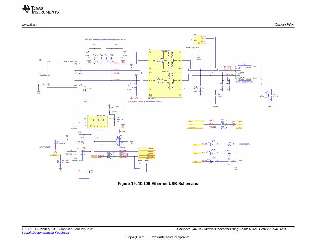
www.ti.com Design Files
Figure 19. 10/100 Ethernet USB Schematic
19TIDU706A–January 2015–Revised February 2015 Compact CAN-to-Ethernet Converter Using 32-Bit ARM® Cortex™-M4F MCUSubmit Documentation Feedback
Copyright © 2015, Texas Instruments Incorporated

GND
RS485-A
RS485-B
RS485-A
RS485-B
10µFC1
0.1µFC2
0.1µFC10
3.3V
GND
R1
RE2
DE3
D4
GND5
A6
B7
VCC8
U1
SN65HVD72DR
TXD1
GND2
VCC3
RXD4
VRXD5
CANL6
CANH7
S8
SN65HVD256D
U4
CAN1TXCAN1TX
GND
CAN1RXCAN1RX
GND
0.1µF
C30
GND
+5V
U3RTS
U3TX
U3RX
U3TX
CANH
CANL
CANH
CANL
1
2
J6
1
2
J2
CANH
CANL
RS485-A
RS485-B
1
3
2
D6DESD1P0RFW-7
1
3
2
D7DESD1P0RFW-7
1
3
2
D2DESD1P0RFW-7
1
3
2
D1DESD1P0RFW-7
GND
3.3V
CANH CANL RS485-B RS485-A
0.1µFC7
1
2
3
4
5
6
J10
HEADER_TMM-103-01-G-D-RA
CAN1TX
CAN1RX
U3RTS
U3RX
U3TX
GND
3.3V
120R45 120
R25
Design Files www.ti.com
Figure 20. CAN, RS485 Schematic
20 Compact CAN-to-Ethernet Converter Using 32-Bit ARM® Cortex™-M4F MCU TIDU706A–January 2015–Revised February 2015Submit Documentation Feedback
Copyright © 2015, Texas Instruments Incorporated
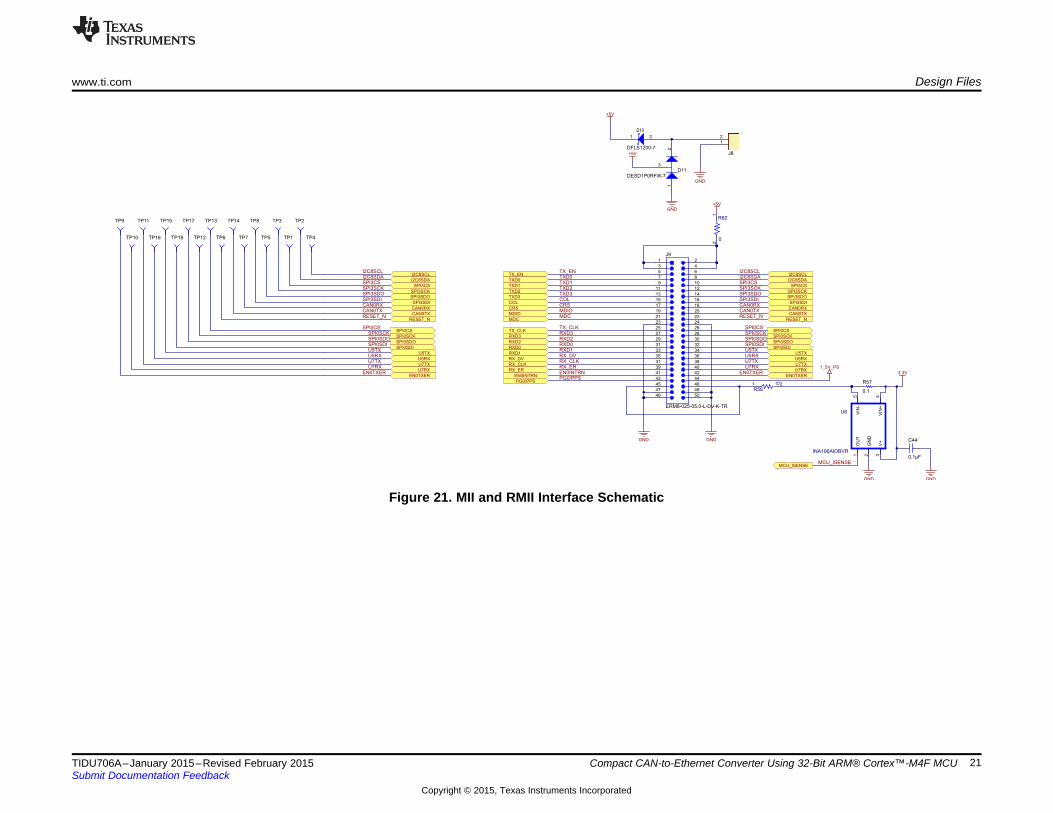
TX_EN
1 2
3 4
5 6
7 8
9 10
11 12
13 14
15 16
17 18
19 20
21 22
23 24
25 26
27 28
29 30
31 32
33 34
35 36
37 38
39 40
41 42
43 44
45 46
47 48
49 50
J9
ERM8-025-05.0-L-DV-K-TR
GND GND
I2C8SCLI2C8SDASPI3CSSPI3SCKSPI3SDOSPI3SDICAN0RXCAN0TX
SPI0CSSPI0SCKSPI0SDOSPI0SDIU5TXU5RXU7TXU7RX
RESET_N
A2
K1
D10
DFLS1200-71
2
J8
GND
+5V
12
0
R62
+5V
1 20
R58
I2C8SCL
I2C8SDA
SPI3CS
SPI3SCK
SPI3SDO
SPI3SDI
CAN0RX
CAN0TX
RESET_N
U5TX
U5RX
U7TX
U7RX
EN0INTRN
PG0/PPS
1_5V_PS
SPI0CS
SPI0SCK
SPI0SDO
SPI0SDI
MDIOMDC
RXD3RXD2RXD0RXD1RX_DVRX_CLKRX_ER
TX_ENTXD0TXD1TXD2TXD3COLCRS
TX_CLK
TXD0
TXD1
TXD2
TXD3
COL
CRS
MDIO
MDC
TX_CLK
RXD3
RXD2
RXD0
RXD1
RX_DV
RX_CLK
RX_ER3.3V
GND
0.1
R57
0.1µF
C44
GND
MCU_ISENSEMCU_ISENSE
OU
T1
GN
D2
V+
3V
IN+
4
VIN
-5
INA196AIDBVR
U6
EN0TXEREN0TXER
EN0INTRNPG0/PPS
1
3
2
D11DESD1P0RFW-7
GND
+5V
TP6
TP17
TP12
TP13
I2C8SCLI2C8SDASPI3CSSPI3SCKSPI3SDOSPI3SDICAN0RXCAN0TX
SPI0SCKSPI0SDOSPI0SDIU5TXU5RXU7TXU7RX
RESET_N
I2C8SCL
I2C8SDA
SPI3CS
SPI3SCK
SPI3SDO
SPI3SDI
CAN0RX
CAN0TX
RESET_N
U5TX
U5RX
U7TX
U7RX
SPI0CS
SPI0SCK
SPI0SDO
SPI0SDI
EN0TXEREN0TXER
TP5
TP14
TP7
TP8
TP4
TP3
TP1
TP2
TP18
SPI0CS
TP15
TP16
TP11
TP10
TP9
www.ti.com Design Files
Figure 21. MII and RMII Interface Schematic
21TIDU706A–January 2015–Revised February 2015 Compact CAN-to-Ethernet Converter Using 32-Bit ARM® Cortex™-M4F MCUSubmit Documentation Feedback
Copyright © 2015, Texas Instruments Incorporated

1 210k
R18
EXTDBG
3.3V
1 2
3 4
5 6
7 8
9 10
J7
HEADER_2041501
TMS
TCK
TDO
TDI
3.3V
GND
EXTDBGDEBUG_TX
DEBUG_RX
EXTDBG
T_TRST
12
10K
R17
12
10K
R20
12
10K
R54
12
10K
R52
3.3V
1
2
J4
1 2
3 4
5 6
7 8
9 10
J3
HEADER_2041501
ADC3
ADC2
ADC1
ADC0
SPARE4
SPARE1
SPARE2
SPARE3
I2C6SCL
I2C6SDA
Current Measure
EN3
VIN2
SLEEP8
NC4
FB5
PG7
SW9
VOS10
AGND6
PGND1
PW
PD
11
TPS62177DQCU5
12
2.2K
R19
12
1K
R21
12
0
R22
12
22uF, 6.3V
C6
1 2
10uH
L1
IND-WE-7440
1 2
1 Ohm, 1%
R16
12
100K
R51
12
2.2uF 50V
C43
1
TL2
1
TL3
1
TL1
HIB
GND GND
3.3V
GND
HIB
+5V
GND
+5V
GND
12
D8
12
330
R12
12
D15
12
330
R56
GND GND
+5V
3.3V
3.3V
3.9V
D9
1SMB5915BT3G
GND
12
0.1uF
C42
12
22uF, 6.3V
C36
GND
12
0.1uF
C37
1 2
0
R49
Design Files www.ti.com
Figure 22. Power Supply Schematic
Figure 23. Spare and Debug Schematic
22 Compact CAN-to-Ethernet Converter Using 32-Bit ARM® Cortex™-M4F MCU TIDU706A–January 2015–Revised February 2015Submit Documentation Feedback
Copyright © 2015, Texas Instruments Incorporated
www.ti.com Design Files
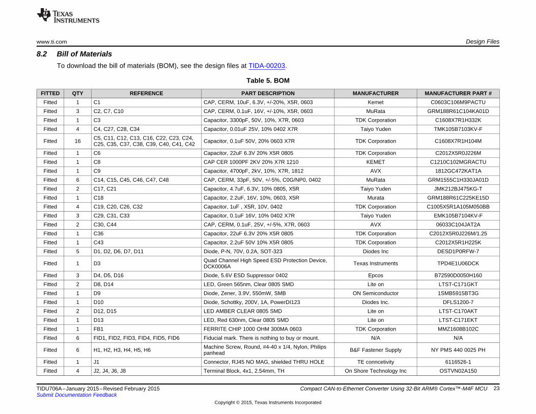
8.2 Bill of MaterialsTo download the bill of materials (BOM), see the design files at TIDA-00203.
Table 5. BOM
FITTED QTY REFERENCE PART DESCRIPTION MANUFACTURER MANUFACTURER PART #Fitted 1 C1 CAP, CERM, 10uF, 6.3V, +/-20%, X5R, 0603 Kemet C0603C106M9PACTUFitted 3 C2, C7, C10 CAP, CERM, 0.1uF, 16V, +/-10%, X5R, 0603 MuRata GRM188R61C104KA01DFitted 1 C3 Capacitor, 3300pF, 50V, 10%, X7R, 0603 TDK Corporation C1608X7R1H332KFitted 4 C4, C27, C28, C34 Capacitor, 0.01uF 25V, 10% 0402 X7R Taiyo Yuden TMK105B7103KV-F
C5, C11, C12, C13, C16, C22, C23, C24,Fitted 16 Capacitor, 0.1uF 50V, 20% 0603 X7R TDK Corporation C1608X7R1H104MC25, C35, C37, C38, C39, C40, C41, C42Fitted 1 C6 Capacitor, 22uF 6.3V 20% X5R 0805 TDK Corporation C2012X5R0J226MFitted 1 C8 CAP CER 1000PF 2KV 20% X7R 1210 KEMET C1210C102MGRACTUFitted 1 C9 Capacitor, 4700pF, 2kV, 10%, X7R, 1812 AVX 1812GC472KAT1AFitted 6 C14, C15, C45, C46, C47, C48 CAP, CERM, 33pF, 50V, +/-5%, C0G/NP0, 0402 MuRata GRM1555C1H330JA01DFitted 2 C17, C21 Capacitor, 4.7uF, 6.3V, 10% 0805, X5R Taiyo Yuden JMK212BJ475KG-TFitted 1 C18 Capacitor, 2.2uF, 16V, 10%, 0603, X5R Murata GRM188R61C225KE15DFitted 4 C19, C20, C26, C32 Capacitor, 1uF , X5R, 10V, 0402 TDK Corporation C1005X5R1A105M050BBFitted 3 C29, C31, C33 Capacitor, 0.1uF 16V, 10% 0402 X7R Taiyo Yuden EMK105B7104KV-FFitted 2 C30, C44 CAP, CERM, 0.1uF, 25V, +/-5%, X7R, 0603 AVX 06033C104JAT2AFitted 1 C36 Capacitor, 22uF 6.3V 20% X5R 0805 TDK Corporation C2012X5R0J226M/1.25Fitted 1 C43 Capacitor, 2.2uF 50V 10% X5R 0805 TDK Corporation C2012X5R1H225KFitted 5 D1, D2, D6, D7, D11 Diode, P-N, 70V, 0.2A, SOT-323 Diodes Inc DESD1P0RFW-7
Quad Channel High Speed ESD Protection Device,Fitted 1 D3 Texas Instruments TPD4E1U06DCKDCK0006AFitted 3 D4, D5, D16 Diode, 5.6V ESD Suppressor 0402 Epcos B72590D0050H160Fitted 2 D8, D14 LED, Green 565nm, Clear 0805 SMD Lite on LTST-C171GKTFitted 1 D9 Diode, Zener, 3.9V, 550mW, SMB ON Semiconductor 1SMB5915BT3GFitted 1 D10 Diode, Schottky, 200V, 1A, PowerDI123 Diodes Inc. DFLS1200-7Fitted 2 D12, D15 LED AMBER CLEAR 0805 SMD Lite on LTST-C170AKTFitted 1 D13 LED, Red 630nm, Clear 0805 SMD Lite on LTST-C171EKTFitted 1 FB1 FERRITE CHIP 1000 OHM 300MA 0603 TDK Corporation MMZ1608B102CFitted 6 FID1, FID2, FID3, FID4, FID5, FID6 Fiducial mark. There is nothing to buy or mount. N/A N/A
Machine Screw, Round, #4-40 x 1/4, Nylon, PhilipsFitted 6 H1, H2, H3, H4, H5, H6 B&F Fastener Supply NY PMS 440 0025 PHpanheadFitted 1 J1 Connector, RJ45 NO MAG, shielded THRU HOLE TE conncetivity 6116526-1Fitted 4 J2, J4, J6, J8 Terminal Block, 4x1, 2.54mm, TH On Shore Technology Inc OSTVN02A150
23TIDU706A–January 2015–Revised February 2015 Compact CAN-to-Ethernet Converter Using 32-Bit ARM® Cortex™-M4F MCUSubmit Documentation Feedback
Copyright © 2015, Texas Instruments Incorporated

Design Files www.ti.com
Table 5. BOM (continued)FITTED QTY REFERENCE PART DESCRIPTION MANUFACTURER MANUFACTURER PART #Fitted 2 J3, J7 Header, 2X5 2mm spacing Harwin Inc M22-2020505
Connector, USB micro AB Receptacle ReversedFitted 1 J5 HIROSE ELECTRIC CO. LTD. ZX62R-AB-5PSMDFitted 1 J9 CONN MICRO HS TERM STRP HDR 50 POS Samtec ERM8-025-05.0-L-DV-K-TRNot 0 J10 Header, 2mm, Low Profile 2x3 Samtec TMM-103-01-G-D-RAFitted
Fitted 1 L1 Inductor 10uH, SMD 2.8x2.8mm, 0.5A, 0.47 Ohm Wurth Electronics Inc 744029100Not Thermal Transfer Printable Labels, 0.650 W x 0.200"0 LBL1 000 per roll" BradyFitted H - 10
Fitted 5 R1, R2, R19, R59, R61 Resistor, 2.2K OHM 1/10W 5% 0603 SMD Vishay-Dale CRCW06032K20JNEAFitted 2 R3, R60 RES, 2.2k ohm, 5%, 0.063W, 0402 Vishay-Dale CRCW04022K20JNED
R4, R6, R8, R23, R24, R30, R32, R37, Panasonic ElectronicFitted 12 Resistor, 0 ohm, 1/10W, 5%, 0402 ERJ-2GE0R00XR38, R40, R47, R48 ComponentsNot 0 R5 RES, 1.0Meg ohm, 5%, 0.063W, 0402 Vishay-Dale CRCW04021M00JNEDFitted
Panasonic ElectronicFitted 1 R7 Resistor, 1M OHM 1/10W 5% 0603 SMD ERJ-3GEYJ105VComponentsPanasonic ElectronicFitted 4 R9, R10, R11, R13 Resistor, 49.9 OHM 1/10W 1% 0603 Thick ERJ-3EKF49R9VComponentsPanasonic ElectronicFitted 2 R12, R56 Resistor, 330 ohm, 1/10W, 5%, 0402 RC0402FR-07330RLComponents
Fitted 5 R14, R15, R35, R36, R46 RES, 33 ohm, 5%, 0.063W, 0402 Vishay-Dale CRCW040233R0JNEDPanasonic ElectronicFitted 1 R16 Resistor, 1 OHM 1/10W 1% 0603, Thick ERJ-3RQF1R0VComponents
Fitted 8 R17, R18, R20, R33, R39, R44, R52, R54 Resistor, 10k ohm, 1/10W, 5%, 0402 Thick Film Yageo America RC0402FR-0710KLPanasonic ElectronicFitted 1 R21 Resistor, 1K Ohm, 1/10W, 5%, SMD, Thick ERJ-3GEYJ102VComponentsPanasonic ElectronicFitted 4 R22, R49, R58, R62 Resistor, 0 OHM 1/10W 0603 SMD ERJ-3GEY0R00VComponents
Fitted 2 R25, R45 RES, 120 ohm, 1%, 0.25W, 1206 Yageo America RC1206FR-07120RLPanasonic ElectronicFitted 4 R26, R27, R29, R34 Resistor, 75 Ohm, 1/10W, 1%, SMD, Thick ERJ-3EKF75R0VComponentsPanasonic ElectronicFitted 1 R28 RES 1M OHM 5% 1206 TF ERJ-8GEYJ105VComponentsPanasonic ElectronicFitted 1 R31 Resistor, 51 ohm, 1/10W, 5%, 0402 ERJ-2GEJ510XComponentsPanasonic ElectronicFitted 1 R41 Resistor, 4.87K Ohm, 1/10W, 1%, SMD, Thick ERJ-3EKF4871VComponents
24 Compact CAN-to-Ethernet Converter Using 32-Bit ARM® Cortex™-M4F MCU TIDU706A–January 2015–Revised February 2015Submit Documentation Feedback
Copyright © 2015, Texas Instruments Incorporated
www.ti.com Design Files
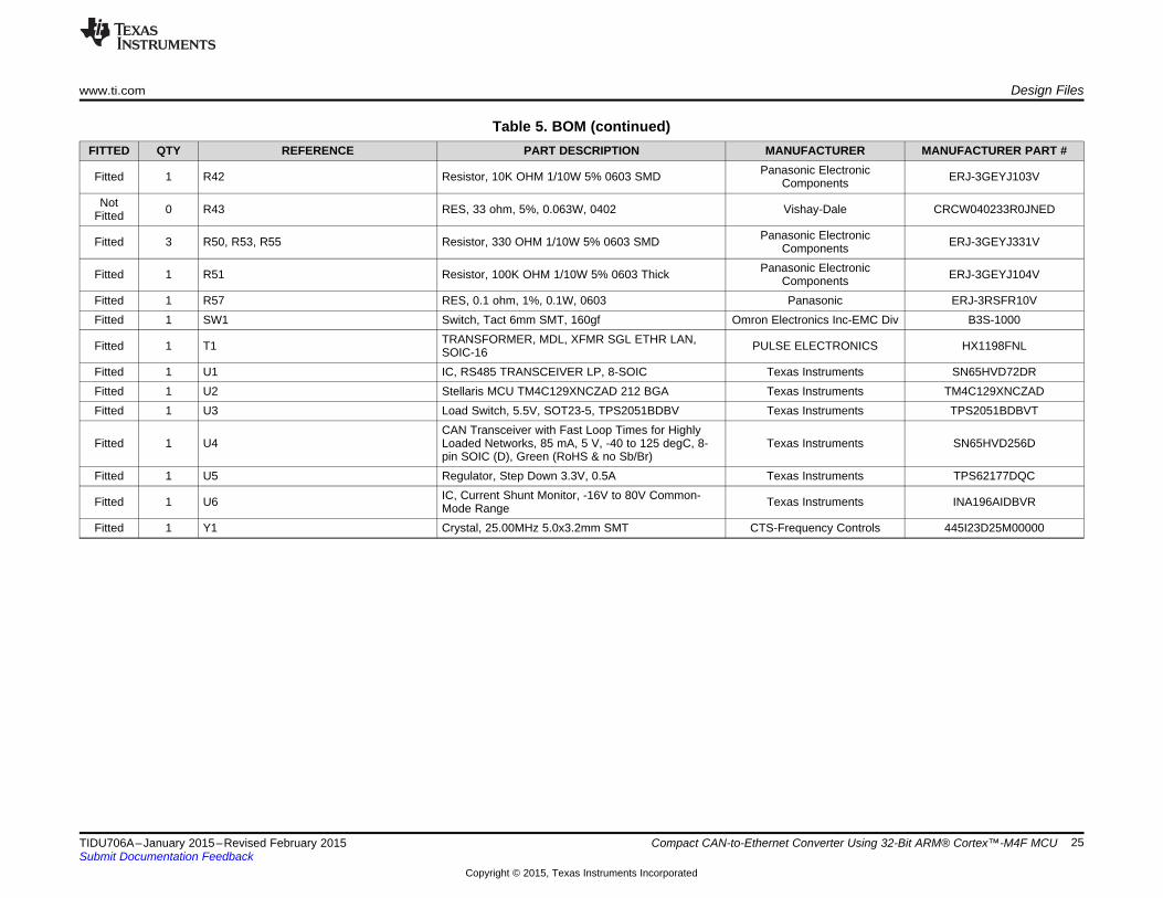
Table 5. BOM (continued)FITTED QTY REFERENCE PART DESCRIPTION MANUFACTURER MANUFACTURER PART #
Panasonic ElectronicFitted 1 R42 Resistor, 10K OHM 1/10W 5% 0603 SMD ERJ-3GEYJ103VComponentsNot 0 R43 RES, 33 ohm, 5%, 0.063W, 0402 Vishay-Dale CRCW040233R0JNEDFitted
Panasonic ElectronicFitted 3 R50, R53, R55 Resistor, 330 OHM 1/10W 5% 0603 SMD ERJ-3GEYJ331VComponentsPanasonic ElectronicFitted 1 R51 Resistor, 100K OHM 1/10W 5% 0603 Thick ERJ-3GEYJ104VComponents
Fitted 1 R57 RES, 0.1 ohm, 1%, 0.1W, 0603 Panasonic ERJ-3RSFR10VFitted 1 SW1 Switch, Tact 6mm SMT, 160gf Omron Electronics Inc-EMC Div B3S-1000
TRANSFORMER, MDL, XFMR SGL ETHR LAN,Fitted 1 T1 PULSE ELECTRONICS HX1198FNLSOIC-16Fitted 1 U1 IC, RS485 TRANSCEIVER LP, 8-SOIC Texas Instruments SN65HVD72DRFitted 1 U2 Stellaris MCU TM4C129XNCZAD 212 BGA Texas Instruments TM4C129XNCZADFitted 1 U3 Load Switch, 5.5V, SOT23-5, TPS2051BDBV Texas Instruments TPS2051BDBVT
CAN Transceiver with Fast Loop Times for HighlyFitted 1 U4 Loaded Networks, 85 mA, 5 V, -40 to 125 degC, 8- Texas Instruments SN65HVD256D
pin SOIC (D), Green (RoHS & no Sb/Br)Fitted 1 U5 Regulator, Step Down 3.3V, 0.5A Texas Instruments TPS62177DQC
IC, Current Shunt Monitor, -16V to 80V Common-Fitted 1 U6 Texas Instruments INA196AIDBVRMode RangeFitted 1 Y1 Crystal, 25.00MHz 5.0x3.2mm SMT CTS-Frequency Controls 445I23D25M00000
25TIDU706A–January 2015–Revised February 2015 Compact CAN-to-Ethernet Converter Using 32-Bit ARM® Cortex™-M4F MCUSubmit Documentation Feedback
Copyright © 2015, Texas Instruments Incorporated
Design Files www.ti.com
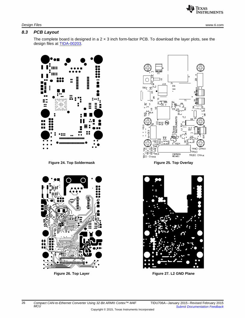
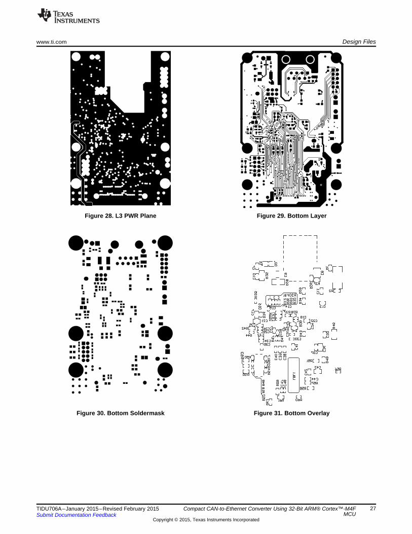
8.3 PCB LayoutThe complete board is designed in a 2 × 3 inch form-factor PCB. To download the layer plots, see thedesign files at TIDA-00203.
Figure 24. Top Soldermask Figure 25. Top Overlay
Figure 26. Top Layer Figure 27. L2 GND Plane
26 Compact CAN-to-Ethernet Converter Using 32-Bit ARM® Cortex™-M4F TIDU706A–January 2015–Revised February 2015MCU Submit Documentation Feedback
Copyright © 2015, Texas Instruments Incorporated
www.ti.com Design Files
Figure 28. L3 PWR Plane Figure 29. Bottom Layer
Figure 30. Bottom Soldermask Figure 31. Bottom Overlay
27TIDU706A–January 2015–Revised February 2015 Compact CAN-to-Ethernet Converter Using 32-Bit ARM® Cortex™-M4FMCUSubmit Documentation Feedback
Copyright © 2015, Texas Instruments Incorporated

Design Files www.ti.com
8.4 Altium ProjectTo download the Altium project files, see the design files at TIDA-00203.
Figure 32. Altium Top Layer Figure 33. Altium Bottom Layer
28 Compact CAN-to-Ethernet Converter Using 32-Bit ARM® Cortex™-M4F TIDU706A–January 2015–Revised February 2015MCU Submit Documentation Feedback
Copyright © 2015, Texas Instruments Incorporated
www.ti.com Design Files
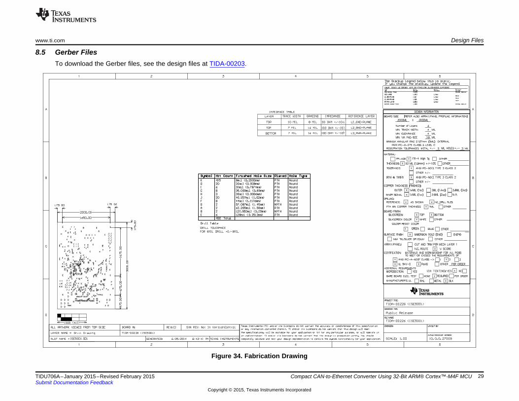
8.5 Gerber FilesTo download the Gerber files, see the design files at TIDA-00203.
Figure 34. Fabrication Drawing
29TIDU706A–January 2015–Revised February 2015 Compact CAN-to-Ethernet Converter Using 32-Bit ARM® Cortex™-M4F MCUSubmit Documentation Feedback
Copyright © 2015, Texas Instruments Incorporated
Design Files www.ti.com
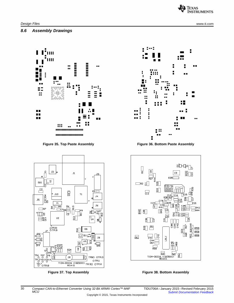
8.6 Assembly Drawings
Figure 35. Top Paste Assembly Figure 36. Bottom Paste Assembly
Figure 37. Top Assembly Figure 38. Bottom Assembly
30 Compact CAN-to-Ethernet Converter Using 32-Bit ARM® Cortex™-M4F TIDU706A–January 2015–Revised February 2015MCU Submit Documentation Feedback
Copyright © 2015, Texas Instruments Incorporated
www.ti.com Design Files
8.7 Software FilesTo download the software files, see the design files at TIDA-00203.
9 References
1. Texas Instruments, System Design Guidelines for the TM4C129x Family of Tiva™ C SeriesMicrocontrollers, Application Report (SPMA056).
2. Texas Instruments, Tiva ™ TM4C12 9X Development Board, User's Guide (SPMU360).3. Texas Instruments, Tiva™ TM4C1292NCZAD Microcontroller, Data Sheet (SPMS444).4. Texas Instruments, Tiva ™ C Series TM4C1294 Connected LaunchPad Evaluation Kit, User's Guide
(SPMU365).5. Texas Instruments, Introduction to the Controller Area Network (CAN), Application Report (SLOA101).6. Texas Instruments, Controller Area Network Physical Layer Requirements, Application Report
(SLLA270).
31TIDU706A–January 2015–Revised February 2015 Compact CAN-to-Ethernet Converter Using 32-Bit ARM® Cortex™-M4FMCUSubmit Documentation Feedback
Copyright © 2015, Texas Instruments Incorporated
IMPORTANT NOTICE FOR TI REFERENCE DESIGNS
Texas Instruments Incorporated ("TI") reference designs are solely intended to assist designers (“Buyers”) who are developing systems thatincorporate TI semiconductor products (also referred to herein as “components”). Buyer understands and agrees that Buyer remainsresponsible for using its independent analysis, evaluation and judgment in designing Buyer’s systems and products.TI reference designs have been created using standard laboratory conditions and engineering practices. TI has not conducted anytesting other than that specifically described in the published documentation for a particular reference design. TI may makecorrections, enhancements, improvements and other changes to its reference designs.Buyers are authorized to use TI reference designs with the TI component(s) identified in each particular reference design and to modify thereference design in the development of their end products. HOWEVER, NO OTHER LICENSE, EXPRESS OR IMPLIED, BY ESTOPPELOR OTHERWISE TO ANY OTHER TI INTELLECTUAL PROPERTY RIGHT, AND NO LICENSE TO ANY THIRD PARTY TECHNOLOGYOR INTELLECTUAL PROPERTY RIGHT, IS GRANTED HEREIN, including but not limited to any patent right, copyright, mask work right,or other intellectual property right relating to any combination, machine, or process in which TI components or services are used.Information published by TI regarding third-party products or services does not constitute a license to use such products or services, or awarranty or endorsement thereof. Use of such information may require a license from a third party under the patents or other intellectualproperty of the third party, or a license from TI under the patents or other intellectual property of TI.TI REFERENCE DESIGNS ARE PROVIDED "AS IS". TI MAKES NO WARRANTIES OR REPRESENTATIONS WITH REGARD TO THEREFERENCE DESIGNS OR USE OF THE REFERENCE DESIGNS, EXPRESS, IMPLIED OR STATUTORY, INCLUDING ACCURACY ORCOMPLETENESS. TI DISCLAIMS ANY WARRANTY OF TITLE AND ANY IMPLIED WARRANTIES OF MERCHANTABILITY, FITNESSFOR A PARTICULAR PURPOSE, QUIET ENJOYMENT, QUIET POSSESSION, AND NON-INFRINGEMENT OF ANY THIRD PARTYINTELLECTUAL PROPERTY RIGHTS WITH REGARD TO TI REFERENCE DESIGNS OR USE THEREOF. TI SHALL NOT BE LIABLEFOR AND SHALL NOT DEFEND OR INDEMNIFY BUYERS AGAINST ANY THIRD PARTY INFRINGEMENT CLAIM THAT RELATES TOOR IS BASED ON A COMBINATION OF COMPONENTS PROVIDED IN A TI REFERENCE DESIGN. IN NO EVENT SHALL TI BELIABLE FOR ANY ACTUAL, SPECIAL, INCIDENTAL, CONSEQUENTIAL OR INDIRECT DAMAGES, HOWEVER CAUSED, ON ANYTHEORY OF LIABILITY AND WHETHER OR NOT TI HAS BEEN ADVISED OF THE POSSIBILITY OF SUCH DAMAGES, ARISING INANY WAY OUT OF TI REFERENCE DESIGNS OR BUYER’S USE OF TI REFERENCE DESIGNS.TI reserves the right to make corrections, enhancements, improvements and other changes to its semiconductor products and services perJESD46, latest issue, and to discontinue any product or service per JESD48, latest issue. Buyers should obtain the latest relevantinformation before placing orders and should verify that such information is current and complete. All semiconductor products are soldsubject to TI’s terms and conditions of sale supplied at the time of order acknowledgment.TI warrants performance of its components to the specifications applicable at the time of sale, in accordance with the warranty in TI’s termsand conditions of sale of semiconductor products. Testing and other quality control techniques for TI components are used to the extent TIdeems necessary to support this warranty. Except where mandated by applicable law, testing of all parameters of each component is notnecessarily performed.TI assumes no liability for applications assistance or the design of Buyers’ products. Buyers are responsible for their products andapplications using TI components. To minimize the risks associated with Buyers’ products and applications, Buyers should provideadequate design and operating safeguards.Reproduction of significant portions of TI information in TI data books, data sheets or reference designs is permissible only if reproduction iswithout alteration and is accompanied by all associated warranties, conditions, limitations, and notices. TI is not responsible or liable forsuch altered documentation. Information of third parties may be subject to additional restrictions.Buyer acknowledges and agrees that it is solely responsible for compliance with all legal, regulatory and safety-related requirementsconcerning its products, and any use of TI components in its applications, notwithstanding any applications-related information or supportthat may be provided by TI. Buyer represents and agrees that it has all the necessary expertise to create and implement safeguards thatanticipate dangerous failures, monitor failures and their consequences, lessen the likelihood of dangerous failures and take appropriateremedial actions. Buyer will fully indemnify TI and its representatives against any damages arising out of the use of any TI components inBuyer’s safety-critical applications.In some cases, TI components may be promoted specifically to facilitate safety-related applications. With such components, TI’s goal is tohelp enable customers to design and create their own end-product solutions that meet applicable functional safety standards andrequirements. Nonetheless, such components are subject to these terms.No TI components are authorized for use in FDA Class III (or similar life-critical medical equipment) unless authorized officers of the partieshave executed an agreement specifically governing such use.Only those TI components that TI has specifically designated as military grade or “enhanced plastic” are designed and intended for use inmilitary/aerospace applications or environments. Buyer acknowledges and agrees that any military or aerospace use of TI components thathave not been so designated is solely at Buyer's risk, and Buyer is solely responsible for compliance with all legal and regulatoryrequirements in connection with such use.TI has specifically designated certain components as meeting ISO/TS16949 requirements, mainly for automotive use. In any case of use ofnon-designated products, TI will not be responsible for any failure to meet ISO/TS16949.IMPORTANT NOTICE
Mailing Address: Texas Instruments, Post Office Box 655303, Dallas, Texas 75265Copyright © 2015, Texas Instruments Incorporated