Commercial Self-Contained Signature Series - Trane
152
June 2021 PKG-PRC002AD-EN Product Catalog CommercialSelf-Contained SignatureSeries Water Cooled — 20 to 110 Tons Air Cooled — 25 to 60 Tons Remote Air-Cooled Condenser
-
Upload
khangminh22 -
Category
Documents
-
view
1 -
download
0
Transcript of Commercial Self-Contained Signature Series - Trane

June 2021 PPKKGG--PPRRCC000022AADD--EENN
Product Catalog
Commercial Self-ContainedSignature SeriesWater Cooled — 20 to 110 TonsAir Cooled — 25 to 60 TonsRemote Air-Cooled Condenser

©2021 Trane PKG-PRC002AD-EN
IntroductionSignature Series Self-Contained Units
• IInntteerrnnaallllyy ttrraappppeedd ddrraaiinn for low cost installation.• SSwwiinngg--oouutt VVFFDD ppaanneell wwiitthh TTRR220000 for efficient VAV operation.• TTrraannee 33--DD®® SSccrroollll ccoommpprreessssoorrss give reliable, efficient, and quiet operation• UUnniitt--mmoouunntteedd mmiiccrroopprroocceessssoorr ccoonnttrrooll with human interface panel• TTwwoo--bboolltt ccoonnnneeccttiioonn on cleanable condenser for quick, easy maintenance• WWaatteerrssiiddee vvaallvvee ppaacckkaaggee option to enhance system efficiency• SSiigghhtt ggllaasssseess with ports for viewing unit while running• TTwwoo--iinncchh ffllaatt ffiilltteerr bbooxx inside unit casing• WWaatteerrssiiddee eeccoonnoommiizzeerr (cleanable option shown)
CopyrightThis document and the information in it are the property of Trane, and may not be used orreproduced in whole or in part without written permission. Trane reserves the right to revise thispublication at any time, and to make changes to its content without obligation to notify anyperson of such revision or change.
TrademarksAll trademarks referenced in this document are the trademarks of their respective owners.
Revision History• EER/IEER ratings table is updated in the General Data chapter.
• Running edits.

PKG-PRC002AD-EN 3
Features and Benefits. . . . . . . . . . . . . . . . . . . . . . . . . . . . . . . . . . . . . . . . . . . . . . . . . . . . . . . . . . 5Features . . . . . . . . . . . . . . . . . . . . . . . . . . . . . . . . . . . . . . . . . . . . . . . . . . . . . . . . . . . . . . . . . . . . 5
Optional Features . . . . . . . . . . . . . . . . . . . . . . . . . . . . . . . . . . . . . . . . . . . . . . . . . . . . . . . . . . . . 6
Benefits . . . . . . . . . . . . . . . . . . . . . . . . . . . . . . . . . . . . . . . . . . . . . . . . . . . . . . . . . . . . . . . . . . . . . 6
Integrated Self-Contained Systems. . . . . . . . . . . . . . . . . . . . . . . . . . . . . . . . . . . . . . . . . . . . 8
3-D Scroll Compressors . . . . . . . . . . . . . . . . . . . . . . . . . . . . . . . . . . . . . . . . . . . . . . . . . . . . . 10
Application Considerations . . . . . . . . . . . . . . . . . . . . . . . . . . . . . . . . . . . . . . . . . . . . . . . . . . . 12Self-Contained Acoustical Recommendations . . . . . . . . . . . . . . . . . . . . . . . . . . . . . . . . . 12
Isolation Recommendations . . . . . . . . . . . . . . . . . . . . . . . . . . . . . . . . . . . . . . . . . . . . . . . . . 13
Free Cooling Opportunities and Alternatives . . . . . . . . . . . . . . . . . . . . . . . . . . . . . . . . . . 15
Unit Operating Limits . . . . . . . . . . . . . . . . . . . . . . . . . . . . . . . . . . . . . . . . . . . . . . . . . . . . . . . 16
Remote Air-Cooled Condenser . . . . . . . . . . . . . . . . . . . . . . . . . . . . . . . . . . . . . . . . . . . . . . . 16
Selection Procedure . . . . . . . . . . . . . . . . . . . . . . . . . . . . . . . . . . . . . . . . . . . . . . . . . . . . . . . . . . 17Selection Example . . . . . . . . . . . . . . . . . . . . . . . . . . . . . . . . . . . . . . . . . . . . . . . . . . . . . . . . . . 17
Waterside Economizer Capacity . . . . . . . . . . . . . . . . . . . . . . . . . . . . . . . . . . . . . . . . . . . . . . 18
Model Number Description . . . . . . . . . . . . . . . . . . . . . . . . . . . . . . . . . . . . . . . . . . . . . . . . . . . 20Commercial Self-Contained Signature Series . . . . . . . . . . . . . . . . . . . . . . . . . . . . . . . . . 20
General Data. . . . . . . . . . . . . . . . . . . . . . . . . . . . . . . . . . . . . . . . . . . . . . . . . . . . . . . . . . . . . . . . . . 22
Performance Data . . . . . . . . . . . . . . . . . . . . . . . . . . . . . . . . . . . . . . . . . . . . . . . . . . . . . . . . . . . . 31Airside Pressure Drops . . . . . . . . . . . . . . . . . . . . . . . . . . . . . . . . . . . . . . . . . . . . . . . . . . . . . . 31
Waterside Pressure Drop . . . . . . . . . . . . . . . . . . . . . . . . . . . . . . . . . . . . . . . . . . . . . . . . . . . . 47
Controls . . . . . . . . . . . . . . . . . . . . . . . . . . . . . . . . . . . . . . . . . . . . . . . . . . . . . . . . . . . . . . . . . . . . . 105Signature Series Self-Contained Units . . . . . . . . . . . . . . . . . . . . . . . . . . . . . . . . . . . . . . . 105
Zone Temperature Control Unit Sequence of Operation . . . . . . . . . . . . . . . . . . . . . . . 112
Supply Air Temperature Control Unit Sequence of Operation. . . . . . . . . . . . . . . . . . 113
Supply Air Tempering (Hot Water and Steam Units Only) . . . . . . . . . . . . . . . . . . . . . 114
Zone Sensor Options. . . . . . . . . . . . . . . . . . . . . . . . . . . . . . . . . . . . . . . . . . . . . . . . . . . . . . . 115
Electrical Data . . . . . . . . . . . . . . . . . . . . . . . . . . . . . . . . . . . . . . . . . . . . . . . . . . . . . . . . . . . . . . . 119Selection Procedures. . . . . . . . . . . . . . . . . . . . . . . . . . . . . . . . . . . . . . . . . . . . . . . . . . . . . . . 119
Table of Contents

4 PKG-PRC002AD-EN
Dimensional Data. . . . . . . . . . . . . . . . . . . . . . . . . . . . . . . . . . . . . . . . . . . . . . . . . . . . . . . . . . . . 122Unit Dimensions . . . . . . . . . . . . . . . . . . . . . . . . . . . . . . . . . . . . . . . . . . . . . . . . . . . . . . . . . . . 122
Refrigerant and Electrical Connections. . . . . . . . . . . . . . . . . . . . . . . . . . . . . . . . . . . . . . . 128
Hot Water Coil . . . . . . . . . . . . . . . . . . . . . . . . . . . . . . . . . . . . . . . . . . . . . . . . . . . . . . . . . . . . . 129
Steam Coil . . . . . . . . . . . . . . . . . . . . . . . . . . . . . . . . . . . . . . . . . . . . . . . . . . . . . . . . . . . . . . . . 130
Flexible Horizontal Discharge Plenum . . . . . . . . . . . . . . . . . . . . . . . . . . . . . . . . . . . . . . . 130
Airside Economizer . . . . . . . . . . . . . . . . . . . . . . . . . . . . . . . . . . . . . . . . . . . . . . . . . . . . . . . . 132
Factory-Provided/Field-Installed Zone Sensor . . . . . . . . . . . . . . . . . . . . . . . . . . . . . . . . 134
Service Clearances. . . . . . . . . . . . . . . . . . . . . . . . . . . . . . . . . . . . . . . . . . . . . . . . . . . . . . . . . 135
Weights. . . . . . . . . . . . . . . . . . . . . . . . . . . . . . . . . . . . . . . . . . . . . . . . . . . . . . . . . . . . . . . . . . . . . . 137
Mechanical Specifications . . . . . . . . . . . . . . . . . . . . . . . . . . . . . . . . . . . . . . . . . . . . . . . . . . . 139Signature Series Self-Contained Units . . . . . . . . . . . . . . . . . . . . . . . . . . . . . . . . . . . . . . . 139
Remote Air-Cooled Condenser . . . . . . . . . . . . . . . . . . . . . . . . . . . . . . . . . . . . . . . . . . . . . . 141
Self-Contained Options. . . . . . . . . . . . . . . . . . . . . . . . . . . . . . . . . . . . . . . . . . . . . . . . . . . . . 142
TTaabbllee ooff CCoonntteennttss

PKG-PRC002AD-EN 5
Features and BenefitsFeaturesStandard Features
• 20 through 110 ton industrial/commercial water-cooled, self-contained units• 25 through 60 ton industrial/commercial remote air-cooled, self-contained units• Fully integrated, factory-installed, and commissioned microelectronic controls• Improved Trane 3-D™ scroll compressor• Constant volume (CV) or variable air volume (VAV) operation• Low ambient compressor lockout adjustable control input• EISA efficiency open drip proof (ODP) and totally enclosed fan (TEFC) cooled supply fan
motor options• Emergency stop input.• Refrigeration circuits are completely factory piped and tested on water-cooled units• Factory-piped and tested, mechanically cleanable water-cooled condensers• Two-bolt removable condenser waterboxes for quick and easy cleaning• Sloped drain pans to ensure complete condensate removal (SST sloped)• Internally trapped drain connection with cleanout• Internally isolated centrifugal supply fan• Sturdy-gauge galvanized steel framework with easily removable painted galvanized steel
exterior panels• UL listing on standard options• Fan belts and grease lines are easily accessible• Access panels and clearance provided to clean both evaporator and waterside economizer
coil fins• Condensing pressure control on all variable water flow systems with valves• Shipped with protective shrink wrap covering of unit and any indoor modules shipped loose
Standard Control Features• Unit-mounted human interface panel with a two line x 40 character clear language (English,
Spanish, or French) display and a 16-function keypad that includes custom, diagnostics, andservice test mode menu keys
• Unit is equipped with phase monitor in control box. The phase monitor will protect againstphase loss, imbalance and reversal of line voltage
• Compressor lead/lag• Frostat™ coil frost protection on all units• Daytime warm-up (occupied mode) on units with heat and morning warm-up operation on all
units• Supply air static over pressurization protection on units with variable frequency drives (VFDs)• Supply airflow proving• Supply air tempering control with heating option• Supply air heating control on VAV with hydronic heating option• Mappable sensors and setpoint sources• Occupied/unoccupied switching• Timed override activation• Programmable water purge during unoccupied mode• High entering air temperature limit• Low entering air temperature limit with waterside economizer or hydronic heat

6 PKG-PRC002AD-EN
Optional Features• Trane® LCI-I Communication Interface Module: ICS interface control module• BACnet® Communication Interface Module• Generic BAS interface• Comparative enthalpy control• Ventilation override from up to five external inputs• Remote human interface controls up to four units• Waterside modulating condensing temperature control valves include factory installed piping
and control wiring• Fully integrated, factory-installed/commissioned variable frequency drive control with or
without optional integrated bypass• Waterside modulating condensing temperature control valves include factory-installed piping
and control wiring• Removable cast iron headers on cleanable waterside economizer• Refrigerant suction discharge line service (shut-off) valves• Protective coatings for the evaporator coils• Double wall construction• Stainless steel sloped drain pan• Medium efficiency throwaway filters• Through-the-door non-fused disconnect switch• Trane’s air quality Traq™ damper in airside economizer mixing box• High duct temperature thermostat• Dual electrical power connection• CO2 reset input• 2- and 4-inch filter racks for all sizes• High-capacity coils available on many models
Factory-Installed or Ship-Separate Options• Waterside economizer with factory-installed piping and controls• Flexible horizontal discharge plenum with or without factory cut holes• Heating options include hot water and steam
Field-Installed Accessories• Airside economizer control with or without mixing box• Air-Fi®Wireless Communications Interface (WCI)• Programmable sensors with or without night set back for CV and VAV systems• ICS zone sensors used with Tracer® system for zone control• Field-installed module kits available for field upgrade of controls.• Low leak dampers for 0-100 percent modulating fresh air economizer• Electric heating option
BenefitsServicing Advantages
• Factory-installed and tested options reduce field labor and installation risk, while improvingsystem reliability
• Requires less sophisticated maintenance than built-up systems
Tenant Satisfaction• Complete HVAC system on each floor minimizes tenant inconvenience during routine
maintenance
• Tenants can control system after hours to increase productivity and minimize expense
FFeeaattuurreess aanndd BBeenneeffiittss

PKG-PRC002AD-EN 7
Low First Cost• Reduce field labor, installation time, and cost with factory-packaged controls and piping
• Reduce installed tonnage up to 20 percent by taking advantage of building diversity and VAVflexibility
• Flexible air discharge arrangement matches most building configurations
Lower Installed Cost• Single point power connection
• Single point water connection
• Factory-commissioned and tested controls
• Factory-installed options
• Internally trapped drain connection
Economical Operation• Free cooling with waterside or air side economizer
• Energy savings with floor-by-floor system since only units on floors requiring cooling need tooperate
• Simple heating alternatives include perimeter radiation and fan-powered VAV
• Energy savings from the integrated water valve control using pump unloading
Assured Acoustical Performance• Flexible, horizontal discharge plenum provides smooth airflow, reducing static pressure
losses for optimum acoustical performance
• Multiple compressor design reduces acoustical levels. Scroll compressor design smooths gasflow for quieter operation
Indoor Air Quality (IAQ) Features• Stainless steel sloped drain pan option.
• Internally trapped drain connection
• Double-wall construction option
• Matte-faced fiberglass insulation
• High-efficiency throwaway filter option
• Easily cleanable evaporator, condensers, and waterside economizers
• Filter access door allows easy removal to encourage frequent filter changing
• Airside economizer with Traq™ damper allows direct measurement and control of outdoorair
Enhanced Serviceability• Self-supporting removable panels
• Quick access service panel fasteners
• Easy to adjust setpoints and operating parameters using the human interface panel on units
• Refrigerant line sight glasses in view during operation
Competitive Advantage• Increased capacity to meet today’s growing floor plates and building loads
• Compact cabinet to minimize mechanical room requirements
• Up to 17% more efficient than competitive units
FFeeaattuurreess aanndd BBeenneeffiittss

8 PKG-PRC002AD-EN
• Low leaving air temp capability to reduce fan motor energy, improve acoustical performance,and minimize duct sizes
• Factory-installed and tested microprocessor controller
Variable Frequency Drives (VFD)Variable frequency drives are factory installed, wired, and tested to provide supply fan motorspeed modulation. VFDs are quieter and more efficient than inlet guide vanes and may even beeligible for utility rebates. The VFDs are available with and without a manual integrated bypassoption, controlled through the human interface (HI) panel. Bypass control provides full nominalairflow control to CV zone setpoints, in the unlikely event of a drive failure, by manually placingthe drive in the bypass mode.
Integrated Self-Contained SystemsIntegrated Comfort System (ICS)
Trane’s Integrated Comfort System® (ICS) increases job control by combining Signature Seriesself-contained units and a Tracer® building management system. This integrated systemprovides total building comfort and control. Building owners and managers not only save energywhen using ICS. They have the ability to automate their facilities and the convenience of acontrol system interface.
Simplifying the Comfort SystemTrane’s designers combined new technology and innovation to bring you more systemcapabilities and flexibility. Our Integrated Comfort System (ICS) with HVAC equipment is easy touse, install, commission, and service.
Everything you need to know about your self-contained VAV system is available using Tracer®,Trane’s family of building automation products. Tracer is a software package that minimizescustom programming requirements and allows easy system setup and control using yourpersonal computer. By enabling all CSC units to communicate using the LonTalk® interface,transforming your heating and cooling units into a true system is made simple.
Operating data from all system components is readily available for evaluation. You can control,monitor, and service your facility—all from your personal computer. That is why all Tracercontrols have been designed to be LonTalk compatible.
The self-contained unit, as part of Trane ICS, provides powerful maintenance monitoring,control, and reporting capabilities. Tracer places the self-contained unit in the appropriateoperating mode for system on/off, night setback, demand limiting, setpoint adjustment based onoutside parameters, and much more. You can monitor unit diagnostic conditions through Tracersuch as sensor failures, loss of supply airflow, and an inoperative refrigerant circuit.
Tracer points monitored for Self-Contained• Compressor on/off status
• Ventilation status
• Condenser water flow status
• Heat status
• Supply air pressure
• Supply air temperature
• Suction temperature of each circuit
• Entering economizer water temperature
• Zone temperature
• Entering condenser water temperature
• Supply air temperature reset signal
• Morning warm-up sensor temperature
FFeeaattuurreess aanndd BBeenneeffiittss

PKG-PRC002AD-EN 9
• Entering air temperature
Tracer control points available for Self-Contained• Cooling and heating setpoints
• VAV discharge air temperature setpoints
• Supply air pressure setpoint
• Cooling and heating enable/disable
• Air economizer enable/disable
• Airside economizer minimum position
• Unit priority shutdown
Integrated Comfort with BACnet CommunicationThe Trane SC BACnet Control Interface (BCI-I) for IntelliPak Self Contained offers a buildingautomation control system with outstanding interoperability benefits. BACnet, which is anindustry standard, is an open, secure and reliable network communication protocol for controls,created by American Society of Heating, refrigerating and Air-Conditioning Engineers, Inc.(ASHRAE).
Interoperability allows application or project engineers to specify the best products of a giventype, rather than one individual supplier's entire system. It reduces product training andinstallation costs by standardizing communications across products. Interoperable systems allowbuilding managers to monitor and control IntelliPak Self Contained equipment with Tracer SC ora 3rd party building automation system. It enables integration with many different buildingcontrols such as access/intrusion monitoring, lighting, fire and smoke devices, energymanagement, and a wide variety of sensors (temperature, pressure, light, humidity, occupancy,CO2 and air velocity).
Trane Air-Fi®®Wireless CommunicationTrane Air-Fi®Wireless replaces the need for wired building controls, allowing installations to becompleted quickly with less disruption to occupants in existing buildings, while also providinggreater reliability, simplified installation and more flexibility as building spaces change. Manybuilding owners face challenges connected to maintenance and repair with traditional wiredsystems, which fail when wires are cut or disconnected or fail intermittently when damaged. Air-Fi Wireless can help optimize any building’s performance with less risk, thanks to self-repairingmesh technology that features redundant signal paths to help prevent communication failures.
Trane offers a typical 200-foot indoor signal range, with up to four times the number of paths,extending up to half-mile when unobstructed for even greater levels of signal reliability. With abattery life that’s three times what competitors offer, the lifetime battery1 eliminates the need toreplace batteries over the life of the system in most installations and saves time and money. Air-Fi Wireless is a ZigBee® Certified Building Automation solution, and the system is built on aplatform that supports BACnet® open standards. This allows customers to integrate devices inthe future when the building expands or changes. Wireless sensors are easy to move or replace,as needed, to resolve issues related to sensing accuracy, aesthetics or reconfigured spaces.
Trane Air-Fi Wireless also conforms to the IEEE 802.15.4 standard, so customers get a wirelessBAS communication system that reliably coexists with other wireless systems, includingBluetooth® and Wi-Fi®—without interference. There’s no security risk with Air-Fi Wireless,which uses a separate, secure network from those used by a building’s IT system. Air-Fi Wirelesssecures building automation networks by the use of AES-128 encryption, keys and deviceauthentication.
The Trane Air-Fi Wireless interface is available factory-installed and addressed as a designspecial to expedite installation and reduce labor and upfront costs. It also ensures higherinstallation quality that results in better building performance for customers because the work isdone in a controlled environment, making it more repeatable and consistent. To learn moreabout Trane Air-Fi Wireless technology, visit www.trane.com.
FFeeaattuurreess aanndd BBeenneeffiittss
1. Based on typical indoor operating conditions.

10 PKG-PRC002AD-EN
3-D Scroll CompressorsThe Trane 3-D® Scroll provides important reliability and efficiency benefits inherent to its design.The 3-D Scroll allows the orbiting scrolls to touch in all three dimensions forming a completelyenclosed compression chamber which leads to increased efficiency.
In addition, the orbiting scrolls only touch with enough force to create a seal, thereby resulting inno wear between the scroll involutes. The fixed and orbiting scrolls are made of high strengthcast iron, which results in less thermal distortion and minimal leakage. In addition, better partisolation has resulted in reduced compressor sound levels compared to previous designs.
Figure 1. 3-D®® scroll compressor
Features listed below optimize the compressor design and performance:
• Optimized scroll profile• Heat shield protection to reduce heat transfer between discharge and suction gas• Suction Gas Cooled Motor• Low Torque Variation• Improved sealing between condenser side and air handler side
Additional features are incorporated in the compressor design for greater compressor reliability:
• Patented design motor cap for improved motor cooling• Improved bearing alignment• Improved resistance to dry start up• Oil sight glass for evaluating proper oil levels
Low Torque VariationThe 3-D scroll compressor has a very smooth compression cycle. This means that the scrollcompressor imposes very little stress on the motor resulting in greater reliability. Low torquevariation reduces noise and vibration.
FFeeaattuurreess aanndd BBeenneeffiittss

PKG-PRC002AD-EN 11
Figure 2. Internal view, 3-D®® scroll compressor
OrbitingScroll
Rotor andStator
(Motor)
Discharge(gas outlet)
Fixed Scroll
Suction(gas inlet)
Oil Sump
Suction Gas Cooled MotorCompressor motor efficiency and reliability is further optimized with the latest scroll design. Thepatented motor cap directs suction gas over the motor resulting in cooler motor temperatures forlonger life and better efficiency.
FFeeaattuurreess aanndd BBeenneeffiittss

12 PKG-PRC002AD-EN
Application ConsiderationsSelf-Contained Acoustical Recommendations
Successful acoustical results are dependent on many system design factors.
Following are general acoustical recommendations. For more information, or if there is concernabout a particular installation, contact a professional acoustical consultant.
Location and Orientation of the Mechanical Equipment RoomLocate the equipment room adjacent to stairwells, utility rooms, electrical closets, and rest roomsif possible, to minimizes the acoustic effects and risk of workmanship or installation errors. (SSeeeeffiigguurree bbeellooww) Place the discharge and return air ductwork over these less acoustically sensitiveareas, using vertical or horizontal fresh air shafts. Consult code requirements for fresh air andsmoke purge constraints.
Figure 3. Equipment room and location and orientation
Elevator Elevator
Supply Air
Supply Air
Mechanical Room
SelfContained Unit
Bathroom
Stairwell
Return Air
Return Air DuctworkDuct the return air into the mechanical equipment room. Connect ductwork to the unit if localcode dictates. The return air ductwork must have an elbow inside the equipment room. Thiselbow will reduce sound transmissions through the return duct. Extend the ductwork from theelbow far enough to block the “line of sight” to the exterior of the equipment room. Use aminimum ductwork length of 15 feet to the equipment room exterior. Line the duct with two-inch,three-pound density insulation. Use multiple, small return ducts for better acousticalperformance to the occupied space.
Supply Air DuctworkInsulate the supply air duct with two-inch, three-pound density insulation. Extend this lining atleast 15 feet out from the equipment room wall, keeping the duct aspect ratio as small aspossible. Minimize large flat panels since they transmit sound. In addition, small aspect ratioswill minimize potential “oil canning” of the duct due to flow turbulence.
The flexible horizontal discharge plenum option helps avoid complicated ductwork transitions.Ductwork turning vanes typically improve pressure drop but degrade acoustical performance.
Recommended Maximum Air VelocitiesThe maximum recommended velocity for the discharge air duct is 2,000 fpm. The maximumrecommended velocity for the return air duct is 1,000 fpm. Limit air velocities below theseoperating points to minimize the risk of flow turbulence that causes regenerated noise. Using

PKG-PRC002AD-EN 13
round supply duct and static regain allows maximum discharge air velocities up to 3,000 fpm.Lining round supply duct also substantially lowers frequency noise attenuation. However, flowregenerated noise potential increases dramatically at air velocities over 3000 fpm.
Equipment Room Construction OptionsThe preferred equipment room wall construction is concrete block. If this is not feasible then adouble stud offset wall is suggested (See figure below).This removes physical contact that wouldtransmit sound through the equipment room wall to the occupied space. Interweave fiberglassinsulation between the wall studs. Use two layers of drywall on each side of the wall.
Workmanship details are critical to acoustical performance. Seal all wall and floor penetrationsby the ductwork, water piping, and equipment room access doors with a flexible material such ascaulk and/or gasketing to stop noise and air leaks.
Locate the equipment room door away from acoustically sensitive areas like conference rooms.The door should swing out of the equipment room, if possible, so that the low pressure in theequipment room pulls the door in to help maintain a tight seal.
Figure 4. Double stud offset wall with interwoven insulation
Equipment OptionsThe flexible horizontal discharge plenum allows multiple tested outlet options. This minimizesthe risk of acoustic and/or pressure drop problems by avoiding complex transitions close to thefan discharge.
Static Pressure Versus AcousticsDesign the system to minimize the total static pressure required from the self-contained unit fan.Typically a change in static pressure of only 0.5 inches can reduce NC level by approximately 2 or3 in the occupied space.
Isolation RecommendationsUnit
The unit fan and compressors are internally isolated. The unit fan and compressors are internallyisolated. Therefore, external isolation is not required. Consult a vibration specialist beforeconsidering external or double vibration isolation.
DuctworkDesign duct connections to the unit using a flexible material. Consult local codes for approvedflexible duct material to prevent fire hazard potential.
AApppplliiccaattiioonn CCoonnssiiddeerraattiioonnss

14 PKG-PRC002AD-EN
Piping ConnectionsRubber isolator connectors are recommended for condenser piping to prevent vibrationtransmission to or from the building plumbing. The self-contained unit is internally isolated anddoes not require additional isolation. However, ensure that proper system vibration isolationdesign prevents vibration transmission from the building plumbing to the unit. Also be sure toproperly isolate the drain line.
Condenser Water Piping
Piping Location and ArrangementProvide at least 24 inches of clearance between the piping and the unit for service. Place therisers away from the side of the unit if possible. Be sure to allow sufficient space for valves andunions between the piping and the self-contained unit. Lay out condenser piping in reversereturns to help balance the system. This is accomplished by equalizing the supply and returnpipe length. Multi-story buildings can use a direct return system with balancing valves at eachfloor. Install all heat exchangers and most cooling tower piping below the sump operating waterlevel to prevent overflow during unit and/or system shut down.
Recommended Pump LocationLocate pump downstream of the cooling tower and upstream of the self-contained unit. Thisprovides smoother and more stable unit operation.
When the tower and pump are both roof mounted, be sure to provide the necessary net positivesuction head pressure to prevent cavitation. Raise the tower or submerge the pump in a sump toprovide positive suction. To prevent an on-line pump failure, use a standby pump to avoid acomplete system shutdown.
Several partial capacity pumps or variable speed pumps can be used. Review the economics ofthese alternate pumping options.
Strainers and Water TreatmentWater strainers are required at the unit inlet to eliminate potential unit damage from dirty water.Specify a water basket-type strainer to avoid an incorrect stream strainer application. Untreatedor poorly treated water may result in equipment damage. Consult a water treatment specialist fortreatment recommendations.
Isolation ValvesInstall isolation valves at each unit before the strainer and after the condenser. This allowsperiodic servicing of the unit or strainer while allowing other units in the system to remain inoperation.
Pressure GaugesInstall pressure gauges on the inlet and outlet of the self-contained unit. Select the gauge’s scaleso that the unit design operating point is approximately mid-scale.
ThermometersInstall thermometers on the condenser water inlet and outlet lines to each unit for systemanalysis. Trane® recommends using a thermometer temperature range of 40°F to 140°F, using a2°F temperature increment.
DrainsThe unit condensate drain is internally trapped to offset the pressure differential that existsduring fan operation. Install a trapped drain in the low point of the mechanical equipment roomfloor to collect water from cleaning operations.
Condensing Pressure Control (Water-Cooled Condensers)Often cold condensing water applications between 35°F and 54°F require a condensing pressurecontrol valve. Any unit with the intermediate piping package can modulate water flow tomaintain a user-defined condensing temperature. However, to utilize this feature, the buildingwater system must be capable of operating at reduced water flow rates through the self-
AApppplliiccaattiioonn CCoonnssiiddeerraattiioonnss

PKG-PRC002AD-EN 15
contained units. It is imperative to install variable volume pumps or an external bypass in thewater distribution system.
Waterside Economizer Flow ControlUnits equipped with waterside economizer and intermediate piping package can be set up forvariable or constant water flow.
Use constant water flow setup on water systems that are not capable of unloading water supplyto the unit. The economizer and condenser valves will operate in complement to one another toprovide continuous water flow.
Use variable water flow setup with water flow systems that can take advantage of pumpunloading for energy savings. Since non-cooling operation restricts water flow during part loadeconomizing or condensing temperature control, it is imperative to install variable volumepumps or an external bypass in the water distribution system.
Figure 5. Waterside economizer flow control
Free Cooling Opportunities and AlternativesFree cooling is available with either the airside or waterside economizer options. The advantagesand disadvantages of each type are listed as follows:
Waterside EconomizerThe waterside economizer substantially reduces the compressor energy requirements because ituses the cooling water before it enters the condensers. Additional equipment room space is notrequired since the coils are contained within the overall unit dimensions.
Disadvantages include higher airside pressure drop and a higher head on condenser waterpumps.
The coils can be mechanically cleaned (optional) for ease in maintenance versus expensive anddifficult chemical cleaning methods.
Airside EconomizerThe airside economizer substantially reduces compressor, cooling tower, and condenser waterpump energy requirements using outside air for free cooling. It also reduces tower make upwater needs and related water treatment.
AApppplliiccaattiioonn CCoonnssiiddeerraattiioonnss

16 PKG-PRC002AD-EN
Disadvantages include building requirements that locate the mechanical room and self-contained unit toward an exterior wall to minimize ductwork, building barometric control, oradditional air shafts. Also, airside economizers require additional mechanical room space.
Unit Operating LimitsAirflow
The minimum recommended airflow for proper VAV system staging and temperature control is35 percent of nominal design airflow. Adjusting VAV boxes with the appropriate minimumsettings prevents the self-contained unit from operating in a surge condition at airflows belowthis point. Continuous operation in a surge condition can cause fan failure. Reference GeneralData Tables on Table 1, p. 22 for minimum airflow conditions.
Self-contained units use fixed pitch sheaves. Adjust air balancing by obtaining alternate fixedpitch sheave selections from the local Trane sales office.
Water FlowUse 3 gpm/ton for optimum unit capacity and efficiency. Use 2.5 or 2 gpm/ton to reduce pumpenergy, cooling tower, and piping costs. However, these reduced water flows may impact unitcapacity and efficiency by one or two percent. Consult General Data tables for unit specific waterflow ranges.
Remote Air-Cooled CondenserUnit Location
Unobstructed condenser airflow is essential to maintaining capacity and operating efficiency.When determining unit placement, give careful consideration to assure sufficient airflow acrossthe condenser coils. Avoid these two detrimental conditions: warm air recirculation and coilstarvation.
Both warm air recirculation and coil starvation cause reductions in unit efficiency and capacitybecause of the higher head pressure associated with them. In more severe cases, nuisance unitshutdowns will result from excessive head pressures.
ClearanceEnsure vertical condenser air discharge is unobstructed. While it is difficult to predict the degreeof warm air recirculation, a unit installed with a ceiling or other obstruction above it willexperience a capacity reduction that will reduce the maximum ambient operation limit. Nuisancehigh head pressure trips may also occur.
The coil inlet must also be unobstructed. A unit installed closer than the minimum recommendeddistance to a wall or other vertical riser will experience a combination of coil starvation and warmair recirculation. This may result in unit capacity and efficiency reductions, as well as possibleexcessive head pressures. Reference the service clearance section in the Dimensional Datachapter for recommended lateral distances.
Ambient LimitationsStandard ambient control allows operation down to 45°F with cycling of condenser fans. Unitswith the low ambient option are capable of starting and operating in ambient temperatures downto 0°F. Optional low ambient units use a condenser fan damper arrangement that controlscondenser capacity by modulating damper airflow in response to saturated condensertemperature.
Maximum ambient operating temperature of a standard condenser is 115°F. Operation at designambient above 115°F can result in excessive head pressures. For applications above 115°F,contact the local Trane sales office.
AApppplliiccaattiioonn CCoonnssiiddeerraattiioonnss

PKG-PRC002AD-EN 17
Selection ProcedureFollowing is a sample selection for a standard applied water-cooled self-contained at particularoperating conditions. Use Trane® Official Product Selection System,TOPSS™, for making allfinal selections or contact your local Trane representative.
Selection ExampleDesign Conditions
• Total gross capacity required = 420 MBh = 35 Tons
• Total sensible capacity required = 315 MBh
• Entering air temperature = 80/67°F
• Entering water temperature = 85°F
• Water flow rate = 105 gpm
• Airflow = 14,840 cfm at 2.5-inch duct static pressure
Unit includes:
• Constant volume
• Waterside economizer
• Medium velocity throwaway filters
Unit Capacities1. Determine entering air temperature dry bulb and wet bulb and entering water temperature.
2. Refer to performance Table 16, p. 54 through to find gross total and sensible capacity thatbest meets capacity requirements.
3. Apply the cfm correction factors from the capacity correction factor Table 14, p. 53 todetermine gross total and gross sensible capacities at desired cfm.
4. Multiply condenser water deltaT by the total capacity cfm correction factor to determine newcondenser water deltaT.
5. Using design cfm, determine static air pressure drops for accessories from the airsidepressure drop through . Add accessory static pressure drops to external supply and returnstatic air pressure drops. Use the total air pressure drop to determine rpm and brakehorsepower requirements from the appropriate fan curve.
NNoottee:: The fan curves include refrigerant coil and internal cabinet static loses.
6. Calculate supply fan motor heat by using the following equation: Fan motor heat (MBh) = 2.8x fan motor brake horsepower
7. Determine net total capacity and net sensible capacity by subtracting fan motor heat fromgross total capacity and gross sensible capacity.
8. Refer to Trane psychometric chart to determine leaving air temperatures.
Unit Selection• Tentatively select a 35 ton unit: Model SCWF 35.
• Refer to Table 29, p. 68 to obtain gross total and sensible unit capacities and gpm at thedesign conditions:
– Total capacity = 430.2 MBh
– Sensible capacity = 364.4 MBh
– Leaving water temperature = 95.0°F
• Since the design cfm is greater than the nominal cfm, adjust the capacities and condenserwater deltaT to reflect the higher cfm: design cfm 14,840 = +6% of nom. Cfm nominal 14,000cfm

18 PKG-PRC002AD-EN
• Refer to to obtain the capacity correction factors for +6% of nominal cfm:
– Cooling capacity multiplier = 1.009
– Sensible capacity multiplier = 1.027
• Multiply the capacities by the correction factors:
– 430.2 MBh × 1.009 = 134.07 MBh
– 364.02 MBh × 1.027 = 374.24 MBh
• The SCWF 35 meets the total and sensible design requirements.
• Multiply the deltaT of 10.0°F by the cooling capacity correction factor of 1.009 to obtain newdelta T of 10.01°F and add this to the entering water temperature to obtain the actual leavingwater temperature of 95.01°F.
• Determine static air pressure drops through the accessories at the design cfm by referring toFigure 6, p. 31 through .
• The 4-row waterside economizer = 0.360 in, and the medium velocity filters = 0.260 in. Addthis to the 2.5-inch duct static pressure for a total external static pressure of 3.12 inches. Referto the fan curve with Constant Volume, Figure 45, p. 68 to determine approximate brakehorsepower and fan rpm:
– Fan brake horsepower = 15.1 bhp (Approximately)
– Fan rpm = 1000 rpm
• Determine net capacities by subtracting fan motor heat from gross capacities:
– 2.8 x 15.1 bhp = 42.28 MBh
– Net total capacity = 430.2 MBh – 42.28 MBh = 387.92 MBh
– Net sensible capacity = 364.4 MBh – 42.28 MBh = 322.12 MBh
• Determine waterside economizer (full capacity) performance by referring to Table 28, p. 67.Use entering air of 80/67°F and entering water temperature of 55°F at 105 gpm. The tableprovides a gross total capacity of 282.1 MBh and gross sensible capacity of 277.2 MBh and60.4°F leaving water temperature at nominal cfm.
• Determine gross capacities at design cfm by applying the cfm correction factors fromwaterside economizer from Table 14, p. 53. Use the following correction factors:
– 282.1 MBh x 1.009 = 284.64 MBh
– 263.6 MBh x 1.027 = 270.72 MBh
• Apply the cooling correction factor to water deltaT to determine new deltaT of 5.45°F. (5.4 x1.009)
• Determine net capacities by subtracting fan motor heat(42.28 MBh) for net total capacity of242.36 MBh and net sensible capacities of 228.44 MBh.
Waterside Economizer Capacity1. After determining that the unit will meet the required mechanical cooling capacity, determine
the waterside economizer capacity by referring to the appropriate two-row (low capacity) orfour-row (high capacity) waterside economizer capacity found in one of the following tables:Table 16, p. 54 through Table 56, p. 93.
2. Determine entering air temperature dry bulb and wet bulb, condenser water flow (gpm), andeconomizer entering water temperature.
3. Refer to the appropriate waterside economizer table to find gross total and sensible capacityand the leaving water temperature.
4. Apply the cfm correction factor for the waterside economizer from the appropriate table todetermine the gross total and sensible capacities at the desired cfm.
5. Multiply the condenser water deltaT by the total capacity cfm correction factor to determinethe new deltaT.
6. Calculate supply fan motor heat by using the following equation: Fan motor heat (MBh) = 2.8× fan motor brake horsepower
SSeelleeccttiioonn PPrroocceedduurree

PKG-PRC002AD-EN 19
7. Determine net total and sensible capacity by subtracting fan motor heat from gross total andsensible capacity.
8. Refer to the Trane psychometric chart to determine leaving air temperatures.
SSeelleeccttiioonn PPrroocceedduurree

20 PKG-PRC002AD-EN
Model Number DescriptionCommercial Self-Contained Signature Series
Digit 1 — Unit Model
S = Self-Contained
Digit 2 — Unit Type
C = CommercialI = Industrial
Digit 3 — Condenser Medium
W = Water-cooledR = Air-cooled
Digit 4 — Development Sequence
F = Signature Series
Digit 5— Refrigerant CircuitConfigurationU = Standard CapacityV = High Capacity
Digit 6, 7 — Unit Nominal Capacity
20 = 20 Tons (water only)22 = 22 Tons (water only)25 = 25 Tons (water or air)29 = 29 Tone (water or air)30 = 30 Tons (air only)32 = 32 Tons (water only)35 = 35 Tons (water or air)38 = 38 Tons (water only)40 = 40 Tons (air only)42 = 42 Tons (water only)46 = 46 Tons (water only)50 = 50 Tons (air only)52 = 52 Tons (water only)58 = 58 Tons (water only)60 = 60 Tons (air only)65 = 65 Tons (water only)72 = 72 Tons (water only)80 = 80 Tons (water only)90 = 90 Tons (water only)C0 = 100 Tons (water only)C1 = 110 Tons (water only)
Digit 8 — Unit Voltage
6 = 200 volt/60 hz/3 ph4 = 460 volt/60 hz/3 ph5 = 575 volt/60 hz/3 ph
Digit 9 — Air Volume/Temp Control
2 = VFD and supply air temp ctrl3 = VFD w/ bypass and supply air temp ctrl4 = Constant volume, zone temp cool only5 = Constant volume, w/ zone temp heat/cool6 = Constant volume and supply air temp ctrl
Digit 10, 11 —Design Sequence
**= Factory Assigned
Digit 12 —Unit Construction
A = Vertical dischargeB = Vertical discharge with double wall
Digit 13— Flexible HorizontalDischarge Plenum TypeB = STD plenum w/ factory-cut holesC= Low plenum w/ factory-cut holesE= Std plenum w/ field-cut holesF= Low plenum w/ field-cut holesH= STD plenum double wall w/ field-cutholesJ = Low plenum double wall w/ field-cut holesK= Extended height plenum w/factory-cutholes, ship separateL = STD plenum w/factory-cut holes, shipseparateM = Low plenum w/factory-cut holes, shipseparateN = Extended height plenum w/field-cutholes, ship separateP = STD plenum w/field-cut holes, shipseparateR = Low plenum w/field-cut holes, shipseparateT= Extended height double-wall plenum w/field-cut holes, ship separateU= STD double-wall plenum w/field-cutholes, ship separateV= Low double-wall plenum w/field-cutholes, ship separateW = STD double-wall (perf) plenum w/field-cut holes (90 to110 ton only)X= Low double-wall (perf) plenum w/field-cut holes (90 to 110 ton only)Y = Extended height double-wall (perf)plenum w/field-cut holes, ship separate (90to 110 ton only)0 = None
Digit 14—Motor Type
2 = ODP motor4 = TEFC motor
Digit 15, 16 —Motor HP
05= 5 hp07= 7.5 hp10= 10 hp15= 15 hp20= 20 hp25= 25 hp30= 30 hp40= 40 hp50= 50 hp (460V, 575V only)60= 60 hp (90 to 110 ton only)
Digit 17, 18, 19 – Fan RPM
040 = 400 rpm045 = 450 rpm050 = 500 rpm052 = 525 rpm055 = 550 rpm057 = 575 rpm060 = 600 rpm065 = 650 rpm070 = 700 rpm075 = 750 rpm080 = 800 rpm085 = 850 rpm090 = 900 rpm095 = 950 rpm100 = 1000rpm105 = 1050 rpm110 = 1100 rpm115 = 1150 rpm120 = 1200 rpm125 = 1250 rpm130 = 1300 rpm135 = 1350 rpm
Digit 20— Unit Isolators
A = Steam coilB = Hot water coilC = Electric heat, 1 stageD = Electric heat, 2 stageF = Hydronic heat ctrl interfaceG = Electric heat ctrl interfaceK = Steam coil ship separate, LHL= Hot water coil ship separate, LHT = Hot water coil, high capacity, LHU = Hot water coil, high capacity, LH, shipseparate0 = None
Digit 21— Unit Isolators
A = IsopadsB = Spring isolators0 = None
Digit 22— Unit Finish
1 = Paint - Slate Gray
Digit 23— Supply Fan Options
0 = Standard fan1 = Low CFM fan
Digit 24— Unit Connection
1 = Disconnect switch2 = Terminal block3 = Dual point power (2 blocks)

PKG-PRC002AD-EN 21
Digit 25— Industrial Options
A = Protective coating evaporator coilB = Silver solderC = Stainless steel screwsD = A and BE = A and CF = B and CG = A, B, and C0 = none
Digit 26— Drain Pan Type
A = Galvanized slopedB = Stainless steel sloped
Digit 27—Waterside Economizer
A = Mechanical clean full capacity (4-row)B = Mechanical clean low capacity (2-row)C = Chemical clean full capacity (4-row)D = Chemical clean low capacity (2-row)0 = None
Digit 28— Ventilation Control
B = Airside econ w/Traq damper, top O/AC = Airside econ w/ std damper, top O/AE = Airside econ w/Traq damper &comparative enthalpy, top O/AF = Airside econ w/ std damper &comparative enthalpy, top O/AH = 2-position damper ventilation interfaceJ = Airside economizer interfaceK = Airside economizer interface w/comparative enthalpy
Digit 29—Water Piping
D = Left hand basic pipingF = Left hand Intermediate pipingK = Left hand basic w/ flow switchM = Left hand intermediate w/ flow switch0 = None
Digit 30— Condenser Tube Type
A = Standard condenser tubesB = 90/10 CuNi condenser tubes0 = None (air-cooled only)
Digit 31— Compressor Service Valves
1 = With service valves0 = None
Digit 32—Miscellaneous SystemControl1 = Time clock2 = Interface for remote HI (IPCB)3 = Dirty filter switch4 = 1 and 25 = 1 and 36 = 2 and 37 = 1, 2 and 30 = None
Digit 33 — Control Interface Options
A = Generic BAS Module; 0-5 Vdc (GBAS)B = Ventilation Override Module (VOM)D = Remote Human Interface (RHI)G = GBAS and VOMH= GBAS and RHIJ = VOM and RHIM = GBAS, VOM, and RHIN = BACnet Communications Interface (BCI)P = BCI and GBASQ = BCI and VOMR = BCI and RHIT= BCI and GBAS and VOMU= BCI and GBAS and RHIV= BCI and VOM and RHIW = BCI and GBAS and VOM and RHI0 = None1 = Lontalk Comm5 Interface (LCI)2 = LCI and GBAS3 = LCI and VOM4 = LCI and RHI5 = LCI and GBAS and VOM6 = LCI and GBAS and RHI7 = LCI and VOM and RHI8 = LCI and GBAS and VOM and RHI
Digit 34— Agency
U= UL agency listing0 = None
Digit 35— Filter Type
1 = 2” T/A w/ 2” rack2 = 2” med. eff. T/A w/ 2” rack3 = 4” bolt-on rack w/ 2” med eff. filter4 = 6” rack w/ 2” construction T/A pre-filter &4” filter space5 = 6” rack w/ 2” med. eff. T/A pre-filter & 4”filter space
Digit 36—Miscellaneous ControlOptionA = Low entering air temp. protect device(LEATPD)B = High duct temp t-stat, ship separateC= Plenum high static switch, ship separateE= A and BF= A and CH= B and CL = A, B, and C0 = None
MMooddeell NNuummbbeerr DDeessccrriippttiioonn

22 PKG-PRC002AD-EN
General DataTable 1. SCWF/SIWF water-cooled self-contained, 20 to 42 tons
Unit Size 20 22 25 29 32 35 38 42
Compressor Data
Quantity 2 2 2 1/1 1/1 3 3 2/1
Nominal Ton/comp 10 10 10 15/10 15/10 10 10 10/15
Circuits 2 2 2 2 2 3 3 3
Evaporator CoilData
Rows 2 2 3 or 6 2 4 or 6 3 4 or 6 3
Sq. Ft. 21.81 21.81 21.81 29.98 29.98 31.35 31.35 38.57
Fpf 144 144 144 144 144 144 144 144
Condenser Data
Minimum Gpm w/oEcon 36 36 36 46 46 54 54 64
Minimum Gpm w/Econ 41 41 41 60 60 65 65 64
Maximum Gpm 80 80 80 102 102 119 119 142
Evaporator FanData
Quantity 1 1 1 1 1 1 1 1
Diameter 18" 18" 18" 18" 18" 20" 20" 25"
Minimum Hp 5 5 5 5 5 5 5 7. 5
Minimum Kw (3.73) (3.73) (3.73) (3.73) (3.73) (3.73) (3.73) (5.39)
Maximum Hp 20 20 20 20 20 25 25 30
Maximum Kw (14.91) (14.91) (14.91) (18.64) (18.64) (18.64) (18.64) (22.37)
Minimum Design Cfm 6325 6325 6500 8700 8700 9100 9880 11200
Maximum Design Cfm 8500 9350 10625 12325 13600 14875 16150 17850
High CapacityOption
Rows N/A N/A 6 N/A 6 N/A 6 N/A
Optional Low FlowFan
Diameter N/A N/A N/A N/A N/A N/A 18” N/A
Min/max Design Cfm N/A N/A N/A N/A N/A N/A 6000/10625 N/A
Refrigerant Charge,lbs. R-410A(Standard
Capacity/HighCapacity)
Circuit A 19.5 19.5 21.5 24.7 28.5/29.3 21.5 23.5/26.5 22.0
Circuit B 19.5 19.5 21.5 20.5 23.5/23.5 21.5 23.5/26.5 22.0
Circuit C N/A N/A N/A N/A N/A 21.5 23.5/26.5 22.0

PKG-PRC002AD-EN 23
Table 1. SCWF/SIWF water-cooled self-contained, 20 to 42 tons (continued)
Unit Size 20 22 25 29 32 35 38 42
Capacity Steps - % 100/53/0 100/53/0 100/53/0 100/62/39/0
100/59/39/0
100/65/31/0
100/65/30/0
100/71/43/26/0
Notes:1. Compressors are Trane 3-D™ scroll.2. All units operate with R-410A. Units ships with full operating charge.3. Maximum cfm limits are set to prevent moisture carryover on the evaporator coil.4. Minimum cfm limits are set to ensure stable thermal expansion valve operation at low load conditions.5. Optional low flow fan (unit model number digit 23 = 1) is available ONLY when High Capacity option is selected (unit model number digit 5 = V).
Table 2. SCWF/SIWF water-cooled self-contained, 46-110 tons
Unit Size 46 52 58 65 72 80 90 100 110
CompressorData
Quantity 2/1 3 3 3/1 3/1 4 5 2/4 6
Nominal Ton/Comp 10/15 15 15 15/10 15/10 15 15 10/15 15
Circuits 3 3 3 4 4 4 5 6 6
Evaporator CoilData
Rows 4 or 6 2 4 or 6 3 4 or 6 6 6 or 8 6 or 8 6 or 8
Sq. Ft. 38.57 49.09 49.09 49.09 49.09 49.09 56.81 56.81 56.81
FPF 144 144 144 144 144 144 144 144 144
Condenser Data
Min GPM w/o Econ 64 84 84 102 102 112 140 168 168
Min GPM w/ Econ 64 84 84 102 102 112
Maximum GPM 142 186 186 226 226 248 300 350 350
Evaporator FanData
Quantity 1 1 1 1 1 1 1 1 1
Size (Dia.) 25" 25" 25" 27.5" 27.5" 27.5" 27.5" 27.5" 27.5"
Minimum HP 7.5 7.5 7.5 10 10 10 15 15 15
Minimum kW (5.59) (5.59) (5.59) (7.46) (7.46) (7.46) (11.19) (11.19) (11.19)
Maximum HP 30 40 40 50 50 50 60 60 60
Maximum kW (22.37) (29.84) (29.84) (37.29) (37.29) (37.29) (44.74) (44.74) (44.74)
Min Design CFM 11960 14250 15080 16900 18700 20800 17500 17500 17500
Max Design CFM 19550 22100 24650 27625 29800 29800 35000 35000 35000
High CapacityOption
Rows 6 N/A 6 N/A 6 N/A 8 8 8
Optional LowFlow Fan
Size (Dia.) 18" N/A 18" N/A 20" N/A N/A N/A N/A
Min./Max DesignCFM 7700/13600 N/A 8900/
13600 N/A 10700/16150 N/A N/A N/A N/A
GGeenneerraall DDaattaa

24 PKG-PRC002AD-EN
Table 2. SCWF/SIWF water-cooled self-contained, 46-110 tons (continued)
Unit Size 46 52 58 65 72 80 90 100 110
RefrigerantCharge— lbs. R-410A (StandardCapacity/High
Capacity)
Circuit A 24.5/28.5 21.0 26.5/31.5 22.0 24.5 28.0 24.5 24.5 24.5
Circuit B 24.5/28.5 21.0 26.5/31.5 22.0 24.5 28.0 24.5 24.5 24.5
Circuit C 24.5/28.5 21.0 26.5/31.5 22.0 24.5 28.0 24.5 24.5 24.5
Circuit D N/A N/A N/A 21.0 22.0 28.0 24.5 24.5 24.5
Circuit E N/A N/A N/A N/A N/A N/A 24.5 24.5 24.5
Circuit F N/A N/A N/A N/A N/A N/A N/A 24.5 24.5
Capacity Steps - % 100/70/41/30/0
100/65/32/0
100/65/30/0
100/71/44/24/0
100/71/43/23/0
100/73/46/20/0
100/80/40/20/0
100/75/38/19/0
100/66/33/17/0
Notes:1. Compressors are Trane 3-D™ scroll.2. All units operate with R-410A. Units ships with full operating charge.3. Maximum cfm limits are set to prevent moisture carryover on the evaporator coil.4. Minimum cfm limits are set to ensure stable thermal expansion valve operation at low load conditions.
Table 3. SCRF/SIRF air-cooled self-contained
Unit Size 25 29 30 35 40 50 60
Compressor Data
Quantity 1/1 1/1 3 3 2/1 3 4
Nominal Ton/Comp 15/10 15/10 10 10 10/15 15 15
Circuits 2 2 2 2 2 2 2
Evaporator Coil Data
Rows 4 4 3 4 4 4 6
Sq. Ft. 29.98 29.98 31.35 31.35 38.57 49.09 49.09
FPF 144 144 120 144 144 144 144
Evaporator Fan Data
Quantity 1 1 1 1 1 1 1
Size (Dia.) 18" 18" 20" 20" 25" 25" 27.5"
Minimum HP 5 5 5 5 7.5 7.5 10
Minimum kW (3.73) (3.73) (3.73) (3.73) (5.59) (5.59) (7.46)
Maximum HP 20 20 25 25 30 40 50
Maximum kW (18.64) (18.64) (18.64) (18.64) (22.37) (29.84) (37.29)
Minimum Design CFM 8700 8700 9100 9880 11960 15080 20800
Maximum Design CFM 12325 13600 14875 16150 19550 24650 29800
Refrigerant Charge See Note 2 below
Capacity Steps - % 100/62/39/0 100/59/39/0 100/65/31/0 100/65/30/0 100/70/41/30/0 100/65/30/0 100/73/46/
20/0
GGeenneerraall DDaattaa

PKG-PRC002AD-EN 25
Table 3. SCRF/SIRF air-cooled self-contained (continued)
Unit Size 25 29 30 35 40 50 60
CCRC/CIRC Unit Match 29 29 35 35 40 50 60
Notes:1. Compressors are Trane 3-D™ scroll.2. All units operate with R-410A. Units ship with a dry nitrogen holding charge. Field refrigerant system charge required. Refer toTable 5, p. 25 for
amounts required.3. Maximum cfm limits are set to prevent moisture carryover on the evaporator coil.4. Minimum cfm limits are set to ensure stable thermal expansion valve operation at low load conditions.
Table 4. CCRC/CIRC remote air-cooled condenser
Unit Size 20 29 35 40 50 60
Condenser Fan Data
Number/Type/Drive 4/Prop/Direct 4/Prop/Direct 6/Prop/Direct 6/Prop/Direct 8/Prop/Direct 8/Prop/Direct
Size (inches) 26 26 26 26 26 26
Size (mm) (660.4) (660.4) (660.4) (660.4) (660.4) (660.4)
HP ea. 1 1 1 1 1 1
Nominal CFM 18,800 21,200 35,600 39,800 46,200 56,400
Nominal (liters / sec) (8873) (10005) (16801) (18784) (21804) (26618)
Condenser Coil Data
Circuit 1 Size (in.) 1/46x71 1/64x71 2/46x71 2/46x71 2/64x71 2/64x71
Circuit 1 Size (mm) (1/1168x1803) (1/1626x1803) (2/1168x1803) (2/1168x1803) (2/1626x1803) (2/1626x1803)
Circuit 2 No./Size (in.) 1/46x71 1/46x71 1/46x71 1/64x71 1/64x71 2/64x71
Circuit 2 No./Size (mm) (1/1168x1803) (1/1168x1803) (1/1168x1803) (1/1626x1803) (1/1626x1803) (2/1626x1803)
Face Area (sq. ft.) 45.4 54.2 68 76.9 94.7 126.2
Face Area (sq.m) (4.2) (5) (6.3) (7.1) (8.8) (11.7)
Rows/fpf 4/144 4/144 4/144 4/144 4/144 4/144
Ambient TemperatureOperating Range
Standard Ambient (F) 50-115 50-115 50-115 50-115 50-115 50-115
Standard Ambient (C) (10 - 46.1) (10 - 46.1) (10 - 46.1) (10 - 46.1) (10 - 46.1) (10 - 46.1)
Low Ambient Option (F) 0-115 0-115 0-115 0-115 0-115 0-115
Low Ambient Option (C) (-17.8 - 46.1) (-17.8 - 46.1) (-17.8 - 46.1) (-17.8 - 46.1) (-17.8 - 46.1) (-17.8 - 46.1)
Note: Units ship with dry nitrogen charge. field refrigerant system charge required. See Table 5 below for amounts required.
Table 5. SCRF/SIRF air–cooled self–contained and CCRC/CIRC remote air-cooled condenser refrigerant data
SCRF/SIRF and CCRC/CIRCUnit Size 25/29 29/29 30/35 35/35 40/40 50/50 60/60
No. of Refrigerant Circuits 2 2 2 2 2 2 2
Operating Charge - lbs. R-410A 56.2/38 56.2/38 71/35.5 75/37.5 86.5/39.5 100/52 101.5/101.5
Operating Charge - kg R-410A 23.1/17 23.1/17 32.2/16.1 34/17 39.2/17.9 44.5/22.7 46/46
Cond. Storage Cap. - lbs. R-410A 51/37 51/37 74/37 74/37 74/51 102/51 102/102
GGeenneerraall DDaattaa

26 PKG-PRC002AD-EN
Table 5. SCRF/SIRF air–cooled self–contained and CCRC/CIRC remote air-cooled condenser refrigerant data(continued)
SCRF/SIRF and CCRC/CIRCUnit Size 25/29 29/29 30/35 35/35 40/40 50/50 60/60
Cond. Storage Cap. - kg R-410A 23.1/16.8 23.1/16.8 33.6/16.8 33.6/16.8 33.6/23.1 46.3/23.1 46.3/46.3
Notes:1. Refrigerant charges are listed as circuit 1 circuit 2 and provide only an estimate. Final charge requires sound field charging practice.2. Operating charge is for entire system, which includes the air–cooled self–contained, remote air–cooled condenser, and 25 feet of interconnecting
refrigerant piping.3. At conditions of 95°F (35°C), condenser storage capacity is 95% full.4. To determine the correct amount of refrigerant needed for a particular application, reference the Trane Reciprocating Refrigeration Manual.
GGeenneerraall DDaattaa

PKG-PRC002AD-EN 27
Table 6. EER/IEER ratings
Series Model EER IEER (CV) IEER (VAV) AHRI Net CoolingCapacity (Btu/h)
SIGNATURE
SCWFU20 13.0/12.8 14.5 16.0 240000
SCWFU22 13.0/12.8 14.5 16.0 240000
SCWFU25 13.9/13.7 15.0 17.1 260000
SCWFV25 14.5/14.3 15.8 18.1 280000
SCWFU29 12.8/12.6 13.9 16.7 306000
SCWFU32 13.5/13.3 14.2 18.2 346000
SCWFV32 13.3/13.1 14.4 18.6 358000
SCWFU35 13.7/13.5 14.8 17.6 396000
SCWFU38 13.8/13.6 14.6 18.1 405000
SCWFU42 13.8/13.6 15.2 17.8 460000
SCWFU46 13.9/13.7 14.9 18.3 485000
SCWFU52 13.0/12.8 15.7 16.7 545000
SCWFU58 14.0/13.8 15.0 18.4 615000
SCWFU65 13.3/13.1 14.7 17.3 690000
SCWFU72 13.5/13.3 14.5 17.9 730000
SCWFU80 14.0/13.8 14.6 19.3 820000
SCWFU90 14.1/13.9 NA 18.6 945000
SCWFUC0 14.1/13.9 NA 18.5 995000
SCWFUC1 14.0/13.8 NA 18.1 1085000
SCWFV38 14.0/13.8 14.7 18.5 415000
SCWFV46 14.1/13.9 15.1 18.8 505000
SCWFV58 14.2/14.0 15.3 18.9 640000
SCWFV72 13.5/13.3 14.5 17.9 735000
SCRFU25 10.0/9.8 11.4 13.2 296000
SCRFU29 10.1/9.9 11.4 13.2 330000
SCRFU30 10.2/10.0 12.3 13.0 374000
SCRFU35 10.4/10.2 12.0 13.5 398000
SCRFU40 10.7/10.5 12.6 13.9 465000
SCRFU50 10.3/10.1 11.8 13.3 570000
SCRFU60 10.3/10.1 11.2 14.1 790000
Notes:1. Cooling only/Electric and Hydronic Heat.2. Performance is rated at 80°F EDB/67°F EWB with 85°F EWT for water-cooled performance and 95°F ambient for air-cooled performance.3. EER, IEER and AHRI Net Cooling Capacity are tested in accordance with AHRI 340/360 (I-P) and certified to 10 CFR Part 431 from the US
Department of Energy.
GGeenneerraall DDaattaa

28 PKG-PRC002AD-EN
Table 7. SCWF/SIWF water volumes
Unit Size
Water Volume in U.S. Gallons / Liters
Without Economizer With Mech. Cleanable Econ With Chem. Cleanable Econ
Gallons Liters Gallons Liters Gallons Liters
20 9.0 34.1 17.4 65.9 16.9 64.0
22 9.0 34.1 17.4 65.9 16.9 64.0
25 9.0 34.1 17.4 65.9 16.9 64.0
29 9.0 34.1 20.5 77.6 18.8 71.2
32 9.0 34.1 20.5 77.6 18.8 71.2
35 10.0 37.9 21.9 82.9 20.2 76.5
38 10.0 37.9 21.9 82.9 20.2 76.5
42 15.0 56.8 32.2 121.9 31.4 118.9
46 15.0 56.8 32.2 121.9 31.4 118.9
52 15.0 56.8 36.9 139.7 35.9 135.9
58 15.0 56.8 36.9 139.7 35.9 135.9
65 16.0 60.6 37.9 143.5 36.9 139.7
72 16.0 60.6 37.9 143.5 36.9 139.7
80 16.0 60.6 37.9 143.5 36.9 139.7
90 22.5 85.2 50.1 189.6 N/A N/A
100 23.0 87.1 50.6 191.5 N/A N/A
110 24.0 90.8 51.6 195.3 N/A N/A
Table 8. SCWF/SIWF refrigerant circuits, number of compressors by circuit
Circuit
Unit Size 1 2 3 4 5 6
20/22/25 Ton 1- 10T 1- 10T N/A N/A N/A N/A
29/32 Ton 1- 15T 1- 10T N/A N/A N/A N/A
35/38 Ton 1- 10T 1- 10T 1- 10T N/A N/A N/A
42/46 Ton 1- 15T 1- 10T 1- 10T N/A N/A N/A
52/58 Ton 1- 15T 1- 15T 1- 15T N/A N/A N/A
60/72 Ton 1- 15T 1- 15T 1- 15T 1- 10T N/A N/A
80 Ton 1- 15T 1- 15T 1- 15T 1- 15T N/A N/A
90 Ton 1- 15T 1- 15T 1- 15T 1- 15T 1- 15T N/A
100 Ton 1-15T 1-15T 1-15T 1-15T 1-10T 1-10T
110 Ton 1- 15T 1- 15T 1- 15T 1- 15T 1- 15T 1- 15T
Note: This table depicts compressor location in unit, plan view from left corner.
GGeenneerraall DDaattaa

PKG-PRC002AD-EN 29
Table 9. SCRF/SIRF refrigerant circuits, number of compressors by circuit
Circuit 1 2
Unit Size
25/29 Ton 1-15T 1-10T
30/35 Ton 2-10T 1-10T
40 Ton 1-10T, 1-15T 1-10T
50 Ton 2-15T 1-15T
60 Ton 2-15T 2-15T
Note: This table depicts compressor location in unit, plan view from left corner.
Table 10. Filter data, water-cooled units models SCWF and SIWF
Unit Size 20- 38 tons 42-80 tons 90-110 tons
Number - Size (In.)8 - 20 x 18 12 - 25 x 20 15 - 24 x 24
4 - 20 x 20 6 - 20 x 20 3 - 24 x 12
UnitsWith HotWater Or Steam
Number - Size (In.)
4 - 16 x 20 4 - 25 x 20
n/a4 - 20 x 20 2 - 20 x 20
4 - 18 x 20 8 - 25 x 16
N/A 4 - 20 x 16
Table 11. Filter data, air-cooled units models SCRF and SIRF
Unit size 20- 35 tons 40-60 tons
Number - Size (in.)8 - 20 x 18 12 - 25 x 20
4 - 20 x 20 6 - 20 x 20
UnitsWith HotWater Or Steam
Number - Size (in.)
4 - 16 x 20 4 - 25 x 20
4 - 20 x 20 2 - 20 x 20
4 - 18 x 20 8 - 25 x 16
N/A 4 - 20 x 16
Table 12. Self-contained heating Coil
Unit Size SCWF 20 - 38 SCWF 42 - 80 SCRF 20 - 35 SCRF 40 - 60
Steam Coil
Coil Type NS NS NS NS
Rows 1 1 1 1
No./Size (inches) (2) 24 x 58 (2) 30 x 81 (2) 24 x 58) (2) 30 x 81
No./Size (mm) (2) 609.6 x 1473.2 (2) 762 x 2057.4 (2) 609.6 x 1473.2 (2) 762 x 2057.4
FPF 42 42 42 42
HotWater Coil
Coil Type 5W 5W 5W 5W
Rows 1 or 2 N/A N/A N/A
No./Size (inches) (2) 24 x 58 (2) 30 x 81 (2) 24 x 58 (2) 30 x8 1
GGeenneerraall DDaattaa

30 PKG-PRC002AD-EN
Table 12. Self-contained heating Coil (continued)
Unit Size SCWF 20 - 38 SCWF 42 - 80 SCRF 20 - 35 SCRF 40 - 60
No./Size (mm) (2) 609.6 x 1473.2 (2) 762 x 2057.4 (2) 609.6 x 1473.2 (2) 762 x 2057.4
FPF 80 or 108 80 or 108 80 or 108 80 or 108
Notes:1. Hot water and steam heating coils have Prima-Flo® fins without turbulators.2. For coil capacities, use TOPSS™ (Trane Official Product Selection Program).3. Full capacity coils consist of two coils stacked and piped in parallel.
Table 13. Waterside economizer coil physical data
Model Unit Size Type Rows FPFHeight(in)
Length(in)
SCXF 20, 22 and 25 Chemically Cleanable 2 108 40 78.5
SCXF 20, 22 and 25 Mechanical Cleanable 2 108 40 78.5
SCXF 20, 22 and 25 Chemically Cleanable 4 108 40 78.5
SCXF 20, 22 and 25 Mechanical Cleanable 4 108 40 78.5
SCXF 29 and 32 Chemically Cleanable 2 108 55 78.5
SCXF 29 and 32 Mechanical Cleanable 2 108 55 78.5
SCXF 29 and 32 Mechanical Cleanable 4 108 55 78.5
SCXF 29 and 32 Chemically Cleanable 4 108 55 78.5
SCXF 35 and 38 Chemically Cleanable 2 108 57.5 78.5
SCXF 35 and 38 Mechanical Cleanable 2 108 57.5 78.5
SCXF 35 and 38 Chemically Cleanable 4 108 57.5 78.5
SCXF 35 and 38 Mechanical Cleanable 4 108 57.5 78.5
SCXF 42 and 46 Chemically Cleanable 2 144 55 101
SCXF 42 and 46 Mechanical Cleanable 2 144 70 101
SCXF 42 and 46 Chemically Cleanable 4 144 55 101
SCXF 42 and 46 Mechanical Cleanable 4 144 70 101
SCXF 52, 58, 65, 72, 80 Chemically Cleanable 2 144 70 101
SCXF 52, 58, 65, 72, 80 Mechanical Cleanable 2 144 70 101
SCXF 52, 58, 65, 72, 80 Chemically Cleanable 4 144 70 101
SCXF 52, 58, 65, 72, 80 Mechanical Cleanable 4 144 70 101
SCXF 90, 100 and 110 Mechanical Cleanable 4 144 70 119.3
GGeenneerraall DDaattaa
PKG-PRC002AD-EN 31
Performance DataAirside Pressure Drops
The dotted line on construction filters indicates cfm where face velocity exceeds manufacturer’srecommended maximum of 300 fpm. After startup, construction filters must be replaced withmedium velocity or high velocity filters.
Air pressure drops through electric heat is 0.5 inches WC.
See “Discharge Plenum,” p. 37 for pressure drop through flexible horizontal discharge plenumand “Heating Coils,” p. 35 for pressure drop through heating coils.
For 4-inch cartridge filters, air pressure drops must be added to the external static pressuredesign point.
Figure 6. Airside pressure drop SCWF/SIWF 20, 22, 25

32 PKG-PRC002AD-EN
Figure 7. Airside pressure drop SCWF/SIWF 29, 32 and SCRF/SIRF 25, 29
Figure 8. Airside pressure drop SCWF/SIWF 35, 38 and SCRF/SIRF 30, 35
PPeerrffoorrmmaannccee DDaattaa

PKG-PRC002AD-EN 33
Figure 9. Airside pressure drop SCWF/SIWF 42, 46 and SCRF/SIRF 40
Figure 10. Airside pressure drop SCWF/SIWF 52, 58 and SCRF/SIRF 50
PPeerrffoorrmmaannccee DDaattaa

34 PKG-PRC002AD-EN
Figure 11. Airside pressure drop SCWF/SIWF 65, SCWF/SIWF 72, SCWF/SIWF 80 and SCRF/SIRF 60
Figure 12. Airside pressure drop SCWF/SIWF 90 to110 ton
0.01
0.02
0.03
0.04
0.05
0.060.070.080.090.10
0.20
0.30
0.40
0.50
0.600.700.800.901.00
15000
17500
20000
22500
25000
27500
30000
35000
37500
40000
32500
PPeerrffoorrmmaannccee DDaattaa
PKG-PRC002AD-EN 35
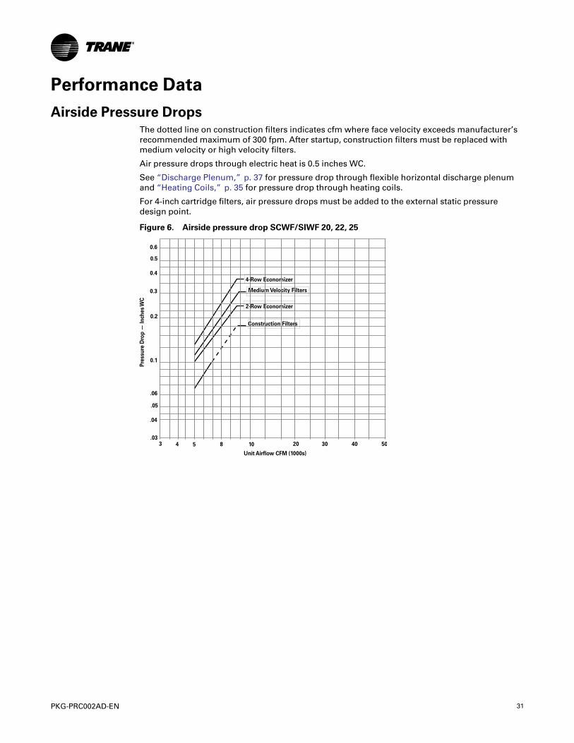
Heating CoilsFigure 13. Airside pressure drop steam coil 20 to 80 ton unit
For NS Coils
PPeerrffoorrmmaannccee DDaattaa

36 PKG-PRC002AD-EN
Figure 14. Airside pressure drop hot water coil 20 to 80 ton units
PPeerrffoorrmmaannccee DDaattaa

PKG-PRC002AD-EN 37
Discharge PlenumFigure 15. Airside pressure drop, standard height discharge plenum 20 to 38 ton unit
Figure 16. Airside pressure drop, standard height discharge plenum 42 to 80 ton unit
PPeerrffoorrmmaannccee DDaattaa

38 PKG-PRC002AD-EN
Figure 17. Airside pressure drop, low height discharge plenum 20 to 38 Ton unit
PPeerrffoorrmmaannccee DDaattaa
PKG-PRC002AD-EN 39
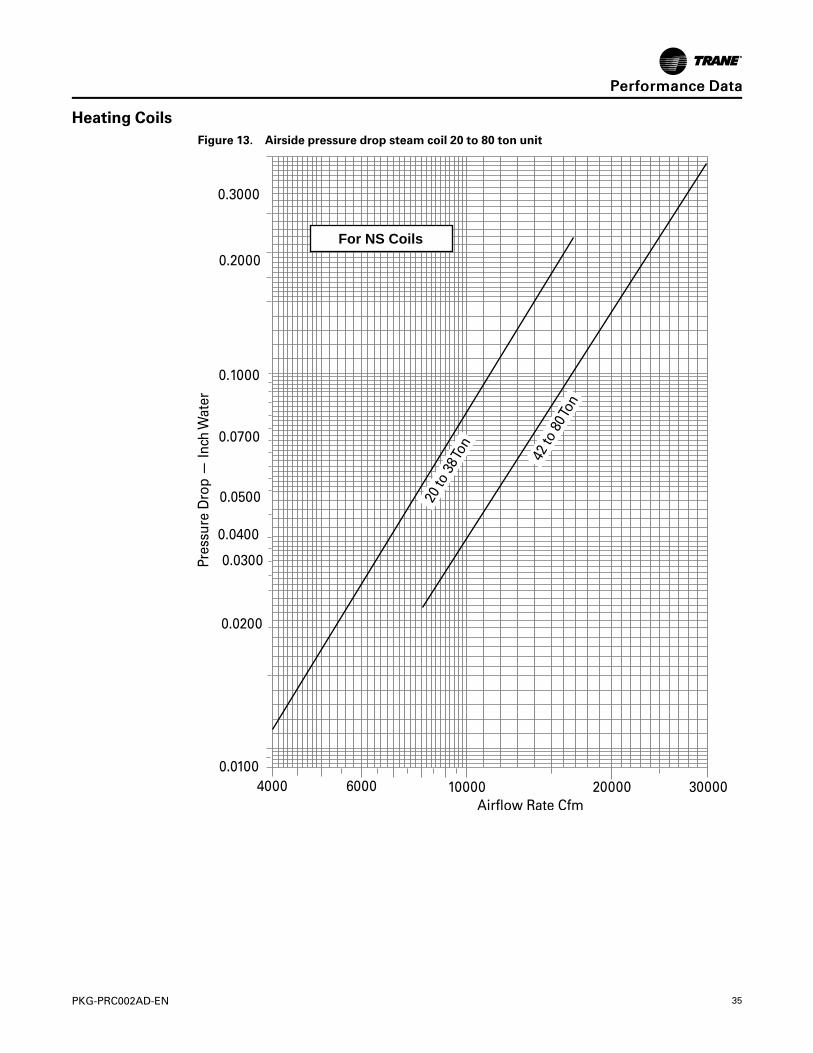
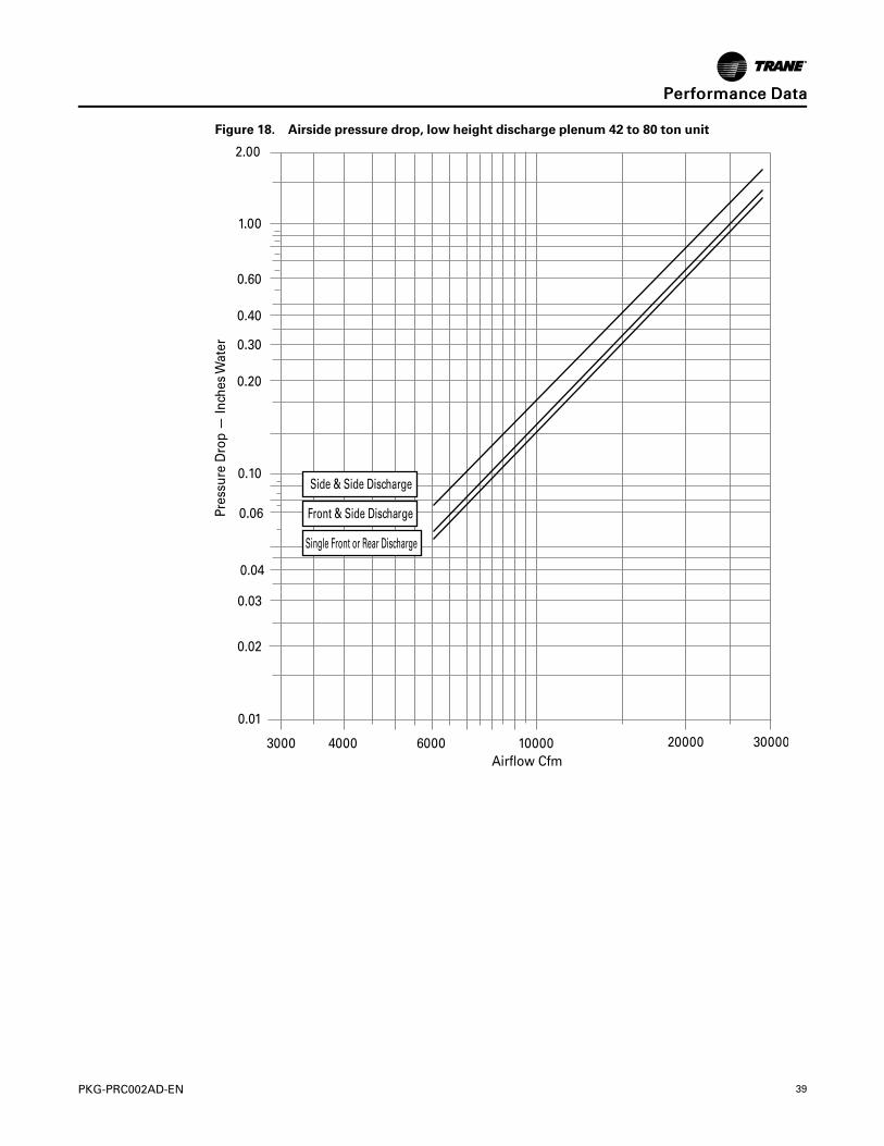
Figure 18. Airside pressure drop, low height discharge plenum 42 to 80 ton unit
PPeerrffoorrmmaannccee DDaattaa

40 PKG-PRC002AD-EN
Figure 19. Airside pressure drop extended height discharge plenum 20 to 38 ton unit
PPeerrffoorrmmaannccee DDaattaa

PKG-PRC002AD-EN 41
Figure 20. Airside pressure drop extended height discharge plenum 42 to 80 ton unit
PPeerrffoorrmmaannccee DDaattaa

42 PKG-PRC002AD-EN
Figure 21. Airside pressure drop standard height discharge plenum 90 to 100 ton unit
0.000
0.200
0.400
0.600
0.800
1.000
1.200
1.400
1.600
1.800
0 5000 10000 15000 20000 25000 30000 35000
Standard Height
y = 2E-09xR = 1
1.98
2
y = 1E-09xR = 0.9996
2.0023
2
Figure 22. Airside pressure drop low height discharge plenum 90 to 100 ton unit
1.9749
0.000
0.200
0.400
0.600
0.800
1.000
1.200
1.400
1.600
0 5000 10000 15000 20000 25000 30000 35000
Low Height
y=2E-09xR² =1
y=2E-09xR² = 1
1.98
PPeerrffoorrmmaannccee DDaattaa

PKG-PRC002AD-EN 43
Figure 23. Airside pressure drop extended height discharge plenum 90 to 100 ton unit
0.000
0.200
0.400
0.600
0.800
1.000
1.200
0 10000 20000 30000 40000
Extended Height
y = 1E - 09xR = 0.9997
2.0011
2
PPeerrffoorrmmaannccee DDaattaa

44 PKG-PRC002AD-EN
Airside Economizer with Standard DamperFigure 24. Airside pressure drop: airside economizer with standard damper 20 to 38 ton unit
PPeerrffoorrmmaannccee DDaattaa

PKG-PRC002AD-EN 45
Figure 25. Airside pressure drop: airside economizer with standard damper 42 to 80 ton unit
PPeerrffoorrmmaannccee DDaattaa

46 PKG-PRC002AD-EN
Figure 26. Airside pressure drop airside economizer with Traq™ damper
PPeerrffoorrmmaannccee DDaattaa
PKG-PRC002AD-EN 47
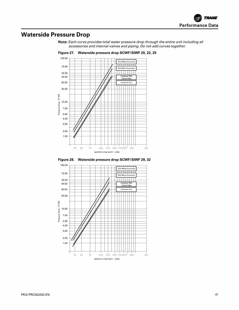
Waterside Pressure DropNNoottee:: Each curve provides total water pressure drop through the entire unit including all
accessories and internal valves and piping. Do not add curves together.
Figure 27. Waterside pressure drop SCWF/SIWF 20, 22, 25
50 75 100 125 150 175 200 250 30025�
Figure 28. Waterside pressure drop SCWF/SIWF 29, 32
50 75 100 125 150 175 200 250 30025�
PPeerrffoorrmmaannccee DDaattaa

48 PKG-PRC002AD-EN
Figure 29. Waterside pressure drop SCWF/SIWF 35, 38
50 75 100 125 150 175 200 250 30025�
Figure 30. Waterside pressure drop SCWF/SIWF 42, 46
50 75 100 125 150 175 200 250 30025�
PPeerrffoorrmmaannccee DDaattaa

PKG-PRC002AD-EN 49
Figure 31. Waterside pressure drop SCWF/SIWF 52, 58
50 75 100 125 150 175 200 250 30025�
Figure 32. Waterside pressure drop SCWF/SIWF 65
50 75 100 125 150 175 200 250 30025�
PPeerrffoorrmmaannccee DDaattaa

50 PKG-PRC002AD-EN
Figure 33. Waterside pressure drop SCWF/SIWF 72
50 75 100 125 150 175 200 250 30025�
Figure 34. Waterside pressure drop SCWF/SIWF 80
50 75 100 125 150 175 200 250 30025�
PPeerrffoorrmmaannccee DDaattaa

PKG-PRC002AD-EN 51
Figure 35. Waterside pressure drop SCWF/SIWF 90
150 175 200 225 250 275300 350 400125�
Figure 36. Waterside pressure drop SCWF/SIWF 100
150 175 200 225 250 275300 350 400125�
PPeerrffoorrmmaannccee DDaattaa
52 PKG-PRC002AD-EN
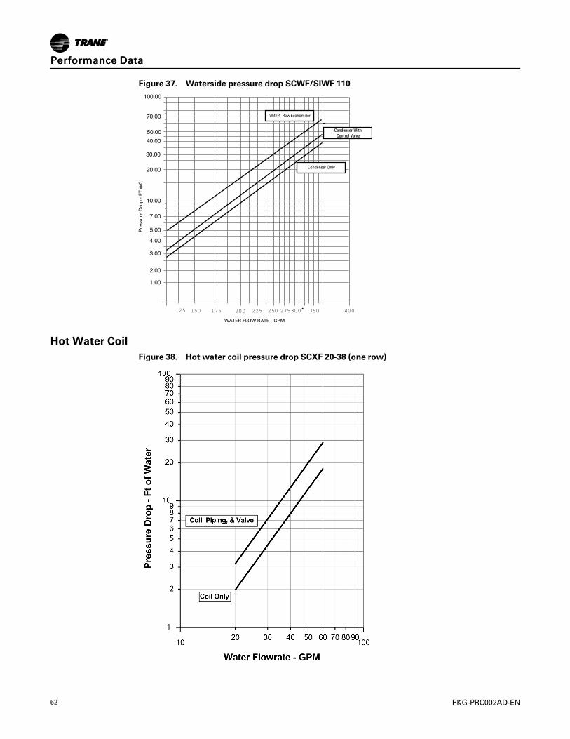
Figure 37. Waterside pressure drop SCWF/SIWF 110
150 175 200 225 250 275300 350 400125�
Hot Water CoilFigure 38. Hot water coil pressure drop SCXF 20-38 (one row)
PPeerrffoorrmmaannccee DDaattaa

PKG-PRC002AD-EN 53
Figure 39. Hot water coil pressure drop SCXF 42-80 (one row)
NNoottee:: Each curve provides total water pressure drop through the entire unit including allaccessories and internal valves and piping. Do not add curves together.
Table 14. CFM Capacity correction table
DX Cooling Waterside Economizer
Cfm Compared toRated Quantity
Cooling CapacityMultiplier
Sensible CapacityMultiplier
Cooling CapacityMultiplier
Sensible CapacityMultiplier
-20% 0.970 0.910 0.970 0.910
-10% 0.985 0.955 0.985 0.955
Std 1.000 1.000 1.000 1.000
+3% 1.005 1.014 1.005 1.014
+6% 1.009 1.027 1.009 1.027
Table 15. SCWF/SIWF water volume in U.S. gallons/liters
Unit w/o Economizer Unit with Mech. Cleanable Econ Unit with Chem. Cleanable Econ
Unit Size Gallons Liters Gallons Liters Gallons Liters
20, 22, 25 9.0 34.1 17.4 65.9 16.9 64.0
29, 32 9.0 34.1 20.5 77.6 18.8 71.2
35, 38 10.0 37.9 21.9 82.9 20.2 76.5
42, 46 15.0 56.8 32.2 121.9 31.4 118.9
PPeerrffoorrmmaannccee DDaattaa

54 PKG-PRC002AD-EN
Table 15. SCWF/SIWF water volume in U.S. gallons/liters (continued)
Unit w/o Economizer Unit with Mech. Cleanable Econ Unit with Chem. Cleanable Econ
Unit Size Gallons Liters Gallons Liters Gallons Liters
52, 58 15.0 56.8 36.9 139.7 35.9 135.9
65, 72, 80 16.0 60.6 37.9 143.5 36.9 139.7
90 22.5 85.2 50.1 189.6 N/A N/A
100 23.0 87.1 50.6 191.5 N/A N/A
110 24.0 90.8 51.6 195.3 N/A N/A
Water-Cooled Performance DataNNoottee:: Fan curves include refrigerant coil and internal cabinet static losses. To determine static
pressure to be used with these curves, add filter, economizer, flexible horizontal dischargeand heat pressure drops to external duct static pressure.
Table 16. SCWF/SIWF 20 — Economizer performance — 8,000 cfm
EnteringAir
Full Capacity Low Capacity
EnteringWater Temp EnteringWater Temp
45°F 55°F 45°F 55°F
E-DB°F
E-WB°F
Fl-owG-pm
To-talMBh
Sensi-bleMBh
LWT °F
TotalMBh
Sensi-bleMBh
LWT °F
TotalMBh
Sensi-bleMBh
LWT °F
TotalMBh
Sensi-bleMBh
LWT °F
75
62
50 210.3 189.3 53.4 132.5 132.5 60.3 140.0 135.3 50.6 92.8 92.8 58.7
60 220.8 193.7 52.4 136.2 136.2 59.5 147.0 144.0 49.9 96.1 96.1 58.2
70 228.8 197.1 51.5 138.9 138.9 59.0 152.4 146.2 49.4 98.4 98.4 57.8
67
50 265.7 160.4 55.6 155.2 119.1 61.2 175.6 114.8 52.0 102.0 88.3 59.1
60 284.6 167.9 54.5 164.4 122.4 60.5 188.4 119.7 51.3 107.8 90.3 58.6
70 299.0 173.7 53.5 171.8 125.0 59.9 198.0 123.3 50.7 112.6 92.0 58.2
72
50 339.2 133.9 58.6 221.4 92.8 63.9 224.3 90.6 54.0 146.7 64.5 60.9
60 364.8 143.3 57.2 238.3 98.5 62.9 241.1 96.5 53.0 157.3 68.0 60.2
70 383.9 150.5 56.0 251.4 103.0 62.2 253.7 101.0 52.2 165.5 70.7 59.7
80
62
50 230.9 226.2 54.2 165.6 165.6 61.6 160.2 160.2 51.4 116.1 116.1 59.6
60 239.2 234.5 53.0 170.2 170.2 60.7 166.4 166.4 50.5 120.1 120.1 59.0
70 245.2 240.6 52.0 173.5 173.5 60.0 170.7 170.7 49.9 123.0 123.0 58.5
67
50 271.3 204.6 55.9 171.1 166.8 61.8 177.8 149.8 52.1 116.4 111.3 59.7
60 288.1 211.3 54.6 178.2 169.4 60.9 189.3 154.2 51.3 120.8 115.7 59.0
70 300.9 216.5 53.6 183.7 171.4 60.2 198.1 157.5 50.7 124.2 119.1 58.5
72
50 338.5 176.3 58.5 222.0 135.4 63.9 223.8 124.8 54.0 146.2 98.8 60.8
60 363.9 185.8 57.1 238.0 140.8 62.9 240.5 130.7 53.0 156.8 102.2 60.2
70 383.0 193.1 55.9 250.6 145.1 62.2 253.1 135.2 52.2 165.0 104.8 59.7
PPeerrffoorrmmaannccee DDaattaa

PKG-PRC002AD-EN 55
Table 16. SCWF/SIWF 20 — Economizer performance — 8,000 cfm (continued)
EnteringAir
Full Capacity Low Capacity
EnteringWater Temp EnteringWater Temp
45°F 55°F 45°F 55°F
E-DB°F
E-WB°F
Fl-owG-pm
To-talMBh
Sensi-bleMBh
LWT °F
TotalMBh
Sensi-bleMBh
LWT °F
TotalMBh
Sensi-bleMBh
LWT °F
TotalMBh
Sensi-bleMBh
LWT °F
85
62
50 262.5 262.5 55.5 198.6 198.6 62.9 183.2 183.2 52.3 139.3 139.3 60.6
60 270.4 270.4 54.0 204.1 204.1 61.8 190.2 190.2 51.3 144.1 144.1 59.8
70 275.9 275.9 52.9 208.0 208.0 60.9 195.1 195.1 50.6 147.6 147.6 59.2
67
50 283.5 251.3 56.3 199.2 199.2 63.0 188.1 187.8 52.5 139.6 139.6 60.6
60 298.0 257.1 54.9 204.8 204.8 61.8 197.7 191.4 51.6 144.4 144.4 59.8
70 309.0 261.6 53.8 208.8 208.8 61.0 205.0 194.3 50.9 147.9 147.9 59.2
72
50 340.7 219.3 58.6 230.6 180.5 64.2 223.6 158.9 53.9 151.1 134.6 61.0
60 364.4 228.2 57.1 244.2 185.1 63.1 240.0 164.7 53.0 159.8 137.4 60.3
70 382.6 235.1 55.9 255.1 188.8 62.3 252.6 169.2 52.2 166.7 139.7 59.8
Table 17. SCWF/SIWF 20 — Gross cooling capacity — 8,000 cfm, 60 gpm
AmbientEnteringWater Temperature
75 85 95
EDB EWB Tot MBh Sen MBh LWT Tot MBh Sen MBh LWT Tot MBh Sen MBh LWT
75
62 234.0 197.9 84.9 225.9 194.5 94.8 216.5 190.5 104.7
67 257.5 155.5 85.7 248.4 152.0 95.6 237.8 147.9 105.5
72 283.0 112.1 86.6 272.8 108.6 96.5 260.9 104.5 106.3
80
62 234.7 234.7 84.9 226.6 226.6 94.9 217.2 217.2 104.8
67 257.8 198.7 85.8 248.8 195.2 95.6 238.3 191.2 105.5
72 282.9 155.6 86.6 272.6 152.0 96.5 260.7 148.0 106.3
85
62 236.1 236.1 85.0 228.4 228.4 94.9 219.7 219.7 104.9
67 258.3 241.8 85.8 249.3 238.3 95.7 238.8 234.3 105.5
72 283.1 199.0 86.6 272.9 195.4 96.5 261.1 191.4 106.3
PPeerrffoorrmmaannccee DDaattaa

56 PKG-PRC002AD-EN
Figure 40. SCWF/SIWF 20 — Fan performance for CV or with VFD
NNoottee:: Fan curves include refrigerant coil and internal cabinet static losses. To determine staticpressure to be used with these curves, add filter, economizer, flexible horizontal dischargeand heat pressure drops to external duct static pressure.
PPeerrffoorrmmaannccee DDaattaa

PKG-PRC002AD-EN 57
Table 18. SCWF/SIWF 22 — Economizer performance — 8800 cfm
Entering Air
Full Capacity Low Capacity
EnteringWater Temp EnteringWater Temp
45°F 55°F 45°F 55°F
EDB°F
EWB°F
FlowGpm
TotalMBh
Sen-sibleMBh
LWT°F
TotalMBh
Sen-sibleMBh
LWT°F
TotalMBh
Sen-sibleMBh
LWT°F
TotalMBh
Sen-sibleMBh
LWT°F
75
62
55 226.8 205.7 53.2 143.3 143.3 60.2 150.1 145.0 50.5 99.6 99.6 58.6
66 237.6 210.2 52.2 147.3 147.3 59.5 157.1 155.1 49.8 102.9 102.9 58.1
77 245.9 213.8 51.4 150.2 150.2 58.9 162.5 157.3 49.2 105.4 105.4 57.7
67
55 286.3 173.7 55.4 167.0 129.3 61.1 188.1 123.5 51.8 108.9 95.1 59.0
66 305.8 181.4 54.3 176.4 132.6 60.3 200.9 128.4 51.1 114.8 97.1 58.5
77 320.8 187.5 53.3 184.2 135.4 59.8 210.7 132.1 50.5 119.7 98.9 58.1
72
55 365.5 144.5 58.3 238.0 100.2 63.7 240.1 97.1 53.7 156.6 69.2 60.7
66 391.8 154.1 56.9 255.6 106.1 62.7 256.9 103.0 52.8 167.3 72.6 60.1
77 411.9 161.6 55.7 269.5 110.8 62.0 269.8 107.6 52.0 175.9 75.4 59.6
80
62
55 249.7 244.6 54.1 179.1 179.1 61.5 172.2 172.2 51.3 124.5 124.5 59.5
66 258.1 253.0 52.8 184.0 184.0 60.6 178.4 178.4 50.4 128.6 128.6 58.9
77 264.5 259.4 51.9 187.6 187.6 59.9 182.9 182.9 49.7 131.7 131.7 58.4
67
55 292.3 222.0 55.6 184.5 181.5 61.7 190.4 161.4 51.9 124.8 119.3 59.5
66 309.6 228.8 54.4 191.8 184.1 60.8 201.9 165.8 51.1 129.2 123.7 58.9
77 322.9 234.2 53.4 197.6 186.2 60.1 210.8 169.2 50.5 132.7 127.1 58.4
72
55 364.6 190.8 58.3 238.6 146.7 63.7 239.6 134.1 53.7 156.1 106.2 60.7
66 390.8 200.5 56.8 255.2 152.2 62.7 256.4 140.0 52.8 166.8 109.7 60.1
77 410.9 208.1 55.7 268.6 156.8 62.0 269.2 144.6 52.0 175.3 112.4 59.6
85
62
55 284.2 284.2 55.3 214.8 214.8 62.8 196.8 196.8 52.2 149.5 149.5 60.4
66 292.5 292.5 53.9 220.7 220.7 61.7 203.9 203.9 51.2 154.4 154.4 59.7
77 298.4 298.4 52.7 225.0 225.0 60.8 209.0 209.0 50.4 158.1 158.1 59.1
67
55 305.7 273.1 56.1 215.5 215.5 62.8 201.6 195.7 52.3 149.7 149.7 60.4
66 320.5 279.0 54.7 221.4 221.4 61.7 211.1 206.2 51.4 154.7 154.7 59.7
77 332.0 283.6 53.6 225.8 225.8 60.9 218.5 209.0 50.7 158.4 158.4 59.1
72
55 366.9 237.7 58.3 247.9 195.9 64.0 239.3 171.1 53.7 161.4 145.1 60.9
66 391.3 246.8 56.9 262.1 200.7 62.9 255.8 177.0 52.8 170.1 147.9 60.2
77 410.3 254.0 55.7 273.5 204.6 62.1 268.6 181.5 52.0 177.3 150.2 59.6
PPeerrffoorrmmaannccee DDaattaa

58 PKG-PRC002AD-EN
Table 19. SCWF/SIWF 22— Gross cooling capacity — 8,000 cfm, 66gpm
AmbientEnteringWater Temperature
75 85 95
EDB EWB Tot MBh Sen MBh LWT Tot MBh Sen MBh LWT Tot MBh Sen MBh LWT
75
62 248.0 218.1 84.2 239.4 214.5 94.1 229.3 210.3 104.0
67 272.6 169.6 84.9 262.9 165.9 94.8 251.6 161.6 104.7
72 299.2 120.0 85.7 288.2 116.3 95.6 275.6 112.0 105.4
80
62 248.8 248.8 84.2 240.2 240.2 94.1 230.1 230.1 104.0
67 273.0 218.8 84.9 263.3 215.2 94.8 252.1 210.9 104.7
72 299.0 169.5 85.7 288.1 165.8 95.6 275.5 161.5 105.4
85
62 251.2 251.2 84.3 243.3 243.3 94.2 234.4 234.4 104.2
67 273.5 267.9 85.0 264.1 259.3 94.8 252.9 252.9 104.7
72 299.3 219.0 85.8 288.5 215.3 95.6 275.9 211.0 105.4
Figure 41. SCWF/SIWF 22 — Fan performance for CV or with VFD
NNoottee:: Fan curves include refrigerant coil and internal cabinet static losses. To determine staticpressure to be used with these curves, add filter, economizer, flexible horizontal dischargeand heat pressure drops to external duct static pressure.
PPeerrffoorrmmaannccee DDaattaa

PKG-PRC002AD-EN 59
Table 20. SCWF/SIWF 25 — Economizer performance — 10,000 cfm
EnteringAir
Full Capacity Low Capacity
EnteringWater Temp EnteringWater Temp
45°F 55°F 45°F 55°F
EDB°F
E-W-B°F
Fl-owGp-m
TotalMBh
Sensi-bleMBh
LWT°F
TotalMBh
Sensi-bleMBh
LWT°F
TotalMBh
Sensi-bleMBh
LWT°F
TotalMBh
Sensi-bleMBh
LWT°F
75
62
63 250.7 229.6 53.0 159.0 159.0 60.0 164.5 158.7 50.2 109.2 109.2 58.5
75 261.4 234.1 52.0 163.2 163.2 59.4 171.1 170.9 49.6 112.6 112.6 58.0
80 265.2 235.7 51.6 164.6 164.6 59.1 173.5 171.9 49.3 113.7 113.7 57.8
67
63 316.1 193.1 55.0 183.8 144.0 60.8 205.7 136.0 51.5 118.7 104.8 58.8
75 335.6 200.8 53.9 193.5 147.5 60.2 218.1 140.7 50.8 124.5 106.8 58.3
80 342.5 203.6 53.6 197.0 148.7 59.9 222.4 142.3 50.6 126.7 107.6 58.2
72
63 404.1 160.2 57.8 262.3 110.9 63.3 262.5 106.4 53.3 170.7 75.8 60.4
75 429.9 169.5 56.5 280.2 116.9 62.5 278.7 112.1 52.4 181.4 79.2 59.8
80 439.1 172.9 56.0 286.5 119.0 62.2 284.5 114.1 52.1 185.2 80.4 59.6
80
62
63 276.9 271.1 53.8 198.7 198.7 61.3 189.1 189.1 51.0 136.5 136.5 59.3
75 285.3 279.5 52.6 203.9 203.9 60.4 195.2 195.2 50.2 140.7 140.7 58.8
80 288.2 282.4 52.2 205.6 205.6 60.1 197.2 197.2 49.9 142.2 142.2 58.6
67
63 322.6 247.4 55.2 203.9 202.9 61.5 208.1 178.0 51.6 136.8 136.8 59.3
75 339.8 254.2 54.1 211.3 205.6 60.6 219.1 182.2 50.8 141.1 134.8 58.8
80 345.9 256.6 53.6 213.9 206.5 60.3 223.1 183.7 50.6 142.6 136.4 58.6
72
63 403.2 212.1 57.8 262.8 163.2 63.3 262.0 147.5 53.3 170.2 116.9 60.4
75 428.9 221.6 56.4 279.7 168.8 62.5 278.1 153.2 52.4 180.8 120.4 59.8
80 438.1 225.0 56.0 285.8 170.9 62.1 283.9 155.2 52.1 184.6 121.6 59.6
85
62
63 315.6 315.6 55.0 238.3 238.3 62.6 216.2 216.2 51.9 163.9 163.9 60.2
75 324.1 324.1 53.6 244.6 244.6 61.5 223.0 223.0 50.9 168.9 168.9 59.5
80 326.9 326.9 53.2 246.6 246.6 61.2 225.4 225.4 50.6 170.6 170.6 59.3
67
63 337.7 304.9 55.7 239.1 239.1 62.6 220.7 214.1 52.0 164.2 164.2 60.2
75 352.4 310.7 54.4 245.3 245.3 61.5 229.7 227.2 51.1 169.2 169.2 59.5
80 357.6 312.8 53.9 247.4 247.4 61.2 233.0 228.4 50.8 170.9 170.9 59.3
72
63 404.8 264.6 57.9 273.0 218.6 63.7 261.5 188.6 53.3 175.9 160.0 60.6
75 429.2 273.6 56.4 287.4 223.4 62.7 277.6 194.2 52.4 184.5 162.8 59.9
80 438.0 276.9 55.9 292.5 225.1 62.3 283.2 196.2 52.1 187.7 163.8 59.7
PPeerrffoorrmmaannccee DDaattaa

60 PKG-PRC002AD-EN
Table 21. SCWF/SIWF 25 — Gross cooling capacity (Standard) — 10,000 cfm, 75 gpm
Entering Air
Standard Capacity
EnteringWater Temperature
75°F 85°F 95°F
EDB°F
EWB°F
TotalMBh
SensibleMBh LWT °F Total
MBhSensibleMBh LWT °F Total
MBhSensibleMBh LWT °F
75
62 274.4 243.3 83.9 263.8 238.9 93.8 251.6 233.8 103.6
67 300.4 188.5 84.6 288.5 184.0 94.5 275.0 178.9 104.3
72 328.1 132.5 85.4 314.9 128.0 95.2 299.8 122.9 105.0
80
62 277.0 277.0 84.0 266.9 266.9 93.9 255.4 255.4 103.8
67 300.9 243.6 84.7 289.1 239.1 94.5 275.6 234.0 104.3
72 328.2 188.0 85.4 315.1 183.5 95.2 300.1 178.4 105.0
85
62 290.3 290.3 84.3 281.2 281.2 94.3 270.7 270.7 104.1
67 302.0 294.8 84.7 290.4 290.1 94.5 277.3 277.3 104.4
72 328.8 243.3 85.4 315.6 238.8 95.2 300.7 233.8 105.0
Table 22. SCWF/SIWF 25 — Gross cooling capacity (High) — 10,000 cfm, 75 gpm
Entering Air
High Capacity
EnteringWater Temperature
85°F 95°F
EDB°F
EWB °F Total MBh Sensible MBh LWT °F Total MBh Sensible MBh LWT °F
75
62 - - - - - -
67 - - - - - -
72 - - - - - -
80
62 288.3 288.3 94.3 275.6 275.6 104.1
67 311.3 251.0 94.9 296.1 245.2 104.7
72 339.2 193.7 95.7 322.3 187.9 105.4
85
62 304.8 304.8 94.7 292.8 292.8 104.6
67 313.1 307.8 95.0 298.3 298.3 104.7
72 339.7 250.5 95.7 322.9 244.7 105.4
PPeerrffoorrmmaannccee DDaattaa

PKG-PRC002AD-EN 61
Figure 42. SCWF/SIWF 25 — Fan performance for CV or with VFD
PPeerrffoorrmmaannccee DDaattaa
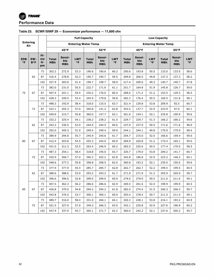
62 PKG-PRC002AD-EN
Table 23. SCWF/SIWF 29 — Economizer performance — 11,600 cfm
EnteringAir
Full Capacity Low Capacity
EnteringWater Temp EnteringWater Temp
45°F 55°F 45°F 55°F
EDB°F
EW-B°F
Fl-owG-pm
TotalMBh
Sensi-bleMBh
LWT°F
TotalMBh
Sensi-bleMBh
LWT°F
TotalMBh
Sensi-bleMBh
LWT°F
TotalMBh
Sensi-bleMBh
LWT°F
75
62
73 302.2 272.9 53.3 190.6 190.6 60.2 200.6 193.8 50.5 133.0 133.0 58.6
87 316.4 278.8 52.3 195.7 195.7 59.5 209.8 206.5 49.8 137.3 137.3 58.2
102 327.9 283.8 51.4 199.7 199.7 58.9 217.4 209.6 49.3 140.7 140.7 57.8
67
73 382.0 231.0 55.5 222.7 171.6 61.1 251.7 164.8 51.9 145.8 126.7 59.0
87 407.4 241.1 54.4 235.2 176.0 60.4 268.6 171.2 51.2 153.5 129.3 58.5
102 428.3 249.5 53.4 245.9 179.8 59.8 282.3 176.4 50.5 160.5 131.8 58.1
72
73 488.3 192.9 58.4 318.0 133.5 63.7 321.4 129.8 53.8 209.9 92.5 60.7
87 522.1 205.3 57.0 340.8 141.2 62.8 343.5 137.7 52.9 223.9 97.0 60.1
102 549.9 215.7 55.8 360.0 147.7 62.1 361.6 144.1 52.1 235.8 100.9 59.6
80
62
73 332.2 325.4 54.1 238.2 238.2 61.5 229.7 229.7 51.3 166.2 166.2 59.6
87 343.2 336.5 52.9 244.5 244.5 60.6 237.9 237.9 50.5 171.6 171.6 58.9
102 352.0 345.3 51.9 249.4 249.4 59.9 244.1 244.1 49.8 175.9 175.9 58.4
67
73 389.9 294.8 55.7 245.9 240.6 61.7 254.7 215.0 52.0 166.6 159.4 59.6
87 412.4 303.8 54.5 255.3 244.0 60.9 269.9 220.8 51.2 172.4 165.1 59.0
102 431.0 311.3 53.5 263.4 246.9 60.2 282.5 225.6 50.5 177.4 170.0 58.5
72
73 487.3 254.1 58.4 318.8 195.0 63.7 320.7 179.0 53.8 209.2 141.7 60.7
87 520.9 266.7 57.0 340.3 202.2 62.8 342.8 186.8 52.9 223.2 146.2 60.1
102 548.6 277.2 55.8 358.8 208.5 62.0 360.8 193.2 52.1 235.0 150.0 59.6
85
62
73 377.9 377.9 55.4 285.7 285.7 62.8 262.7 262.7 52.2 199.5 199.5 60.5
87 388.6 388.6 53.9 293.2 293.2 61.7 271.9 271.9 51.3 205.9 205.9 59.7
102 396.6 396.6 52.8 299.0 299.0 60.9 279.0 279.0 50.5 211.0 211.0 59.1
67
73 407.5 362.3 56.2 286.6 286.6 62.9 269.4 261.6 52.4 199.9 199.9 60.5
87 426.8 370.0 54.8 294.2 294.2 61.8 282.0 274.4 51.5 206.3 206.3 59.7
102 442.8 376.5 53.7 300.1 300.1 60.9 292.4 278.4 50.7 211.5 211.5 59.1
72
73 489.7 316.0 58.4 331.0 260.1 64.1 320.3 228.1 53.8 216.1 193.2 60.9
87 521.5 327.9 57.0 349.3 266.3 63.0 342.1 235.8 52.9 227.6 196.9 60.2
102 547.9 337.9 55.7 365.1 271.7 62.2 360.0 242.2 52.1 237.6 200.2 59.7
PPeerrffoorrmmaannccee DDaattaa

PKG-PRC002AD-EN 63
Table 24. SCWF/SIWF 29 — Gross cooling capacity — 11,600 cfm, 87 gpm
Entering AirEnteringWater Temperature
75°F 85°F 95°F
EDB°F EWB°F TotalMBh
SensibleMBh LWT °F Total
MBhSensibleMBh LWT °F Total
MBhSensibleMBh LWT °F
75
62 318.3 283.4 83.9 307.6 278.9 93.8 295.2 273.7 103.7
67 348.6 219.6 84.6 336.7 215.1 94.5 322.9 209.9 104.3
72 381.7 154.7 85.4 368.3 150.1 95.2 352.8 144.9 105.0
80
62 319.2 319.2 83.9 308.7 308.7 93.8 296.5 296.5 103.7
67 349.2 283.7 84.6 337.4 279.2 94.5 323.6 274.0 104.4
72 381.6 219.2 85.4 368.2 214.6 95.2 352.8 209.3 105.0
85
62 327.3 327.3 84.1 318.0 318.0 94.0 307.1 307.1 103.9
67 350.2 343.6 84.6 338.3 335.6 94.5 324.6 322.7 104.4
72 382.1 283.5 85.4 368.8 278.9 95.2 353.5 273.7 105.1
Figure 43. SCWF/SIWF 29 — Fan performance for CV or with VFD
NNoottee:: Fan curves include refrigerant coil and internal cabinet static losses. To determine staticpressure to be used with these curves, add filter, economizer, flexible horizontal dischargeand heat pressure drops to external duct static pressure.
PPeerrffoorrmmaannccee DDaattaa

64 PKG-PRC002AD-EN
Table 25. SCWF/SIWF 32 — Economizer performance — 12,800 cfm
EnteringAir
Full Capacity Low Capacity
EnteringWater Temp EnteringWater Temp
45°F 55°F 45°F 55°F
EDB°F
E-WB°F
Fl-owG-pm
TotalMBh
Sensi-bleMBh
LWT °F
TotalMBh
Sensi-bleMBh
LWT °F
TotalMBh
Sensi-bleMBh
LWT°F
TotalMBh
Sensi-bleMBh
LWT °F
75
62
80 325.8 296.8 53.1 206.2 206.2 60.2 214.8 207.4 50.4 142.6 142.6 58.6
96 340.9 303.2 52.1 212.0 212.0 59.4 224.4 222.7 49.7 147.3 147.3 58.1
102 345.5 305.1 51.8 213.7 213.7 59.2 227.4 223.9 49.5 148.7 148.7 57.9
67
80 410.8 250.1 55.3 239.5 186.4 61.0 268.8 177.2 51.7 155.5 136.5 58.9
96 438.2 260.9 54.1 252.7 191.1 60.3 286.5 183.8 51.0 163.6 139.3 58.4
102 446.8 264.3 53.8 257.1 192.7 60.0 292.0 185.9 50.7 166.4 140.3 58.3
72
80 524.5 207.6 58.1 341.3 144.0 63.5 343.2 138.9 53.6 223.5 99.0 60.6
96 561.3 221.1 56.7 366.1 152.2 62.6 366.3 147.1 52.6 238.5 103.8 60.0
102 572.8 225.3 56.2 374.0 154.9 62.3 373.5 149.6 52.3 243.3 105.3 59.8
80
62
80 359.2 351.8 54.0 257.7 257.7 61.4 246.7 246.7 51.2 178.3 178.3 59.5
96 371.0 363.6 52.7 264.8 264.8 60.5 255.3 255.3 50.3 184.1 184.1 58.8
102 374.6 367.2 52.3 266.9 266.9 60.2 257.8 257.8 50.1 185.9 185.9 58.6
67
80 419.5 320.1 55.5 265.0 262.1 61.6 272.1 231.7 51.8 178.6 178.6 59.5
96 443.6 329.6 54.2 275.3 265.8 60.7 287.9 237.7 51.0 184.7 176.7 58.8
102 451.2 332.6 53.8 278.6 267.0 60.5 292.9 239.6 50.7 186.7 178.6 58.7
72
80 523.3 274.5 58.1 342.0 211.3 63.6 342.5 192.3 53.6 222.8 152.4 60.6
96 560.0 288.2 56.7 365.5 219.1 62.6 365.5 200.4 52.6 237.7 157.2 60.0
102 571.4 292.5 56.2 373.1 221.7 62.3 372.7 202.9 52.3 242.5 158.7 59.8
85
62
80 409.2 409.2 55.2 309.1 309.1 62.7 282.0 282.0 52.0 214.0 214.0 60.3
96 420.9 420.9 53.8 317.6 317.6 61.6 291.8 291.8 51.1 220.9 220.9 59.6
102 424.4 424.4 53.3 320.1 320.1 61.3 294.7 294.7 50.8 223.0 223.0 59.4
67
80 439.0 394.1 56.0 310.1 310.1 62.8 288.3 279.8 52.2 214.4 214.4 60.4
96 459.6 402.3 54.6 318.6 318.6 61.6 301.4 296.0 51.3 221.3 221.3 59.6
102 466.1 404.9 54.1 321.2 321.2 61.3 305.5 297.6 51.0 223.5 223.5 59.4
72
80 526.4 342.5 58.2 355.4 282.6 63.9 342.0 245.6 53.5 230.4 208.3 60.8
96 560.6 355.2 56.7 375.4 289.3 62.8 364.8 253.6 52.6 242.5 212.2 60.1
102 571.4 359.3 56.2 381.8 291.5 62.5 371.9 256.1 52.3 246.5 213.5 59.8
PPeerrffoorrmmaannccee DDaattaa

PKG-PRC002AD-EN 65
Table 26. SCWF/SIWF 32 — Gross cooling capacity (Standard) — 12,800 cfm, 96 gpm
Entering Air
Standard Capacity
EnteringWater Temperature
75°F 85°F 95°F
EDB°F
EWB °F
TotalMBh
SensibleMBh LWT °F
TotalMBh
SensibleMBh LWT °F
TotalMBh
SensibleMBh LWT °F
75
62 360.2 320.2 83.9 346.1 314.3 93.8 330.1 307.6 103.6
67 393.6 248.1 84.6 378.0 242.1 94.4 360.2 235.4 104.2
72 429.4 174.4 85.3 412.0 168.4 95.2 392.1 161.7 104.9
80
62 363.1 363.1 84.0 349.7 349.7 93.8 334.7 334.7 103.7
67 394.3 320.2 84.6 378.7 314.3 94.4 360.9 307.6 104.3
72 429.6 247.0 85.4 412.2 241.1 95.2 392.5 234.4 104.9
85
62 380.5 380.5 84.3 368.5 368.5 94.2 354.6 354.6 104.1
67 395.3 385.9 84.6 380.1 374.2 94.5 362.8 360.9 104.3
72 430.2 319.4 85.4 412.8 313.5 95.2 393.2 306.8 104.9
Table 27. SCWF/SIWF 32 — Gross cooling capacity (High) — 12,800 cfm, 96 gpm
Entering Air
High Capacity
EnteringWater Temperature
85°F 95°F
EDB °F EWB °F Total MBh Sensible MBh LWT °F Total MBh Sensible MBh LWT °F
75
62 - - - - - -
67 - - - - - -
72 - - - - - -
80
62 364.8 364.8 94.0 350.1 350.1 103.9
67 393.8 320.0 94.6 376.1 313.3 104.4
72 427.6 246.4 95.3 407.9 239.7 105.1
85
62 385.0 385.0 94.4 371.0 371.0 104.3
67 396.1 387.1 94.7 378.9 374.8 104.5
72 429.1 319.0 95.4 409.5 312.3 105.1
PPeerrffoorrmmaannccee DDaattaa

66 PKG-PRC002AD-EN
Figure 44. SCWF/SIWF 32 —Fan performance for CV or w/VFD
PPeerrffoorrmmaannccee DDaattaa

PKG-PRC002AD-EN 67
Table 28. SCWF/SIWF 35 — Economizer performance —14,000 cfm
EnteringAir
Full Capacity Low Capacity
EnteringWater Temp EnteringWater Temp
45°F 55°F 45°F 55°F
EDB°F
EW-B°F
FlowGpm
TotalMBh
Sensi-bleMBh
LWT°F
TotalMBh
Sensi-bleMBh
LWT°F
TotalMBh
Sensi-bleMBh
LWT°F
TotalMBh
Sensi-bleMBh
LWT°F
75
62
88 335.2 309.5 52.6 212.8 212.8 59.8 216.3 208.3 49.9 143.3 143.3 58.3
105 349.5 315.4 51.7 218.4 218.4 59.2 224.9 223.6 49.3 147.5 147.5 57.8
119 358.9 319.4 51.0 221.9 221.9 58.7 230.7 225.9 48.9 150.3 150.3 57.5
67
88 425.7 260.8 54.7 246.3 194.3 60.6 274.3 179.6 51.2 157.0 137.4 58.6
105 451.9 271.0 53.6 259.2 198.8 59.9 290.2 185.6 50.5 164.7 140.1 58.1
119 469.1 277.9 52.9 268.1 202.0 59.5 300.7 189.6 50.1 170.1 142.0 57.9
72
88 544.6 216.1 57.4 354.1 149.9 63.0 350.3 141.5 53.0 228.0 100.5 60.2
105 579.2 228.9 56.0 377.7 157.7 62.2 371.3 148.9 52.1 241.7 105.0 59.6
119 602.1 237.4 55.1 393.3 162.9 61.6 385.1 153.9 51.5 250.9 107.9 59.2
80
62
88 370.3 362.2 53.4 265.9 265.9 61.0 248.2 248.2 50.6 179.2 179.2 59.1
105 381.4 373.3 52.3 272.9 272.9 60.2 255.9 255.9 49.9 184.4 184.4 58.5
119 388.6 380.5 51.5 277.3 277.3 59.7 260.8 260.8 49.4 187.8 187.8 58.2
67
88 432.4 333.5 54.8 272.4 263.1 61.2 275.7 233.7 51.3 179.5 179.5 59.1
105 455.5 342.6 53.7 282.1 277.2 60.4 290.3 239.2 50.5 184.9 176.3 58.5
119 470.9 348.7 52.9 288.7 279.6 59.9 300.2 243.0 50.0 188.6 179.9 58.2
72
88 543.4 286.3 57.3 353.7 220.4 63.0 349.6 195.1 52.9 227.3 154.2 60.2
105 577.9 299.0 56.0 376.4 228.0 62.2 370.5 202.4 52.1 241.0 158.6 59.6
119 600.6 307.6 55.1 391.9 233.1 61.6 384.3 207.4 51.5 250.1 161.5 59.2
85
62
88 422.4 422.4 54.6 319.0 319.0 62.2 283.7 283.7 51.4 215.0 215.0 59.9
105 433.8 433.8 53.3 327.3 327.3 61.2 292.5 292.5 50.6 221.3 221.3 59.2
119 440.9 440.9 52.4 332.5 332.5 60.6 298.0 298.0 50.0 225.3 225.3 58.8
67
88 451.5 410.9 55.3 319.9 319.9 62.3 290.3 281.2 51.6 215.4 215.4 59.9
105 471.1 418.7 54.0 328.3 328.3 61.3 302.1 297.2 50.8 221.7 221.7 59.2
119 484.1 423.9 53.1 333.5 333.5 60.6 310.0 300.2 50.2 225.7 225.7 58.8
72
88 544.2 357.0 57.4 365.6 294.8 63.3 348.9 248.6 52.9 232.4 209.6 60.3
105 577.1 369.2 56.0 384.6 301.2 62.3 369.7 255.9 52.0 243.8 213.2 59.6
119 599.3 377.5 55.1 397.7 305.6 61.7 383.5 260.8 51.4 251.6 215.8 59.2
PPeerrffoorrmmaannccee DDaattaa

68 PKG-PRC002AD-EN
Table 29. SCWF/SIWF 35 — Gross cooling capacity —14,000 cfm, 105 gpm
Entering AirEnteringWater Temperature
75°F 85°F 95°F
EDB°F EWB°F TotalMBh
SensibleMBh LWT °F Total
MBhSensibleMBh LWT °F Total
MBhSensibleMBh LWT °F
75
62 409.0 353.3 84.4 393.4 346.7 94.3 375.5 339.1 104.1
67 446.9 275.8 85.2 429.4 269.1 95.0 409.5 261.5 104.8
72 487.4 196.5 86.0 467.9 189.8 95.8 445.7 182.2 105.6
80
62 411.8 411.8 84.5 396.8 396.8 94.4 379.7 379.7 104.2
67 447.6 353.1 85.2 430.2 346.4 95.0 410.4 338.8 104.8
72 487.5 274.3 86.0 468.1 267.6 95.8 446.1 260.0 105.6
85
62 427.5 427.5 84.8 414.2 414.2 94.7 398.9 398.9 104.6
67 448.7 425.0 85.2 431.6 417.9 95.1 412.2 409.9 104.9
72 488.2 352.0 86.0 468.9 345.3 95.8 446.9 337.7 105.6
Figure 45. SCWF/SIWF 35 — Fan performance for CV or with VFD
NNoottee:: Fan curves include refrigerant coil and internal cabinet static losses. To determine staticpressure to be used with these curves, add filter, economizer, flexible horizontal dischargeand heat pressure drops to external duct static pressure.
PPeerrffoorrmmaannccee DDaattaa

PKG-PRC002AD-EN 69
Table 30. SCWF/SIWF 38 — Economizer performance —15,200 cfm
EnteringAir
Full Capacity Low Capacity
EnteringWater Temp EnteringWater Temp
45°F 55°F 45°F 55°F
EDB°F
EW-B°F
Fl-owG-pm
TotalMBh
Sensi-bleMBh
LWT°F
TotalMBh
Sensi-bleMBh
LWT°F
TotalMBh
Sensi-bleMBh
LWT°F
TotalMBh
Sensi-bleMBh
LWT°F
75
62
95 355.5 330.9 52.5 226.5 226.5 59.8 228.0 219.3 49.8 151.4 151.4 58.2
114 370.6 337.2 51.5 232.7 232.7 59.1 237.0 228.2 49.2 155.9 155.9 57.7
119 374.1 338.7 51.3 234.0 234.0 58.9 239.0 238.1 49.0 156.9 156.9 57.6
67
95 450.7 277.7 54.5 260.8 207.6 60.5 288.5 190.0 51.1 165.1 145.8 58.5
114 478.7 288.7 53.4 274.4 212.4 59.8 305.2 196.3 50.4 173.1 148.5 58.0
119 485.0 291.2 53.2 277.6 213.5 59.7 308.9 197.7 50.2 175.0 149.2 57.9
72
95 576.2 229.0 57.1 374.4 159.1 62.9 368.4 149.1 52.8 239.5 106.0 60.0
114 613.4 242.7 55.8 399.7 167.5 62.0 390.3 156.8 51.8 254.0 110.7 59.5
119 621.8 245.8 55.4 405.4 169.4 61.8 395.3 158.6 51.6 257.3 111.8 59.3
80
62
95 394.0 385.2 53.3 283.0 283.0 61.0 262.3 262.3 50.5 189.2 189.2 59.0
114 405.8 397.1 52.1 290.7 290.7 60.1 270.4 270.4 49.7 194.9 194.9 58.4
119 408.5 399.7 51.9 292.4 292.4 59.9 272.2 272.2 49.6 196.1 196.1 58.3
67
95 457.8 356.0 54.6 289.1 279.0 61.1 290.0 247.8 51.1 189.5 189.5 59.0
114 482.4 365.7 53.5 299.5 296.9 60.3 305.3 253.5 50.4 195.2 185.9 58.4
119 488.0 367.9 53.2 301.8 297.8 60.1 308.8 254.8 50.2 196.5 187.2 58.3
72
95 574.9 304.5 57.1 374.0 235.0 62.9 367.6 206.3 52.7 238.7 163.2 60.0
114 612.0 318.2 55.7 398.4 243.1 62.0 389.5 213.9 51.8 253.2 167.9 59.4
119 620.3 321.3 55.4 404.0 245.0 61.8 394.5 215.7 51.6 256.4 168.9 59.3
85
62
95 449.7 449.7 54.5 339.5 339.5 62.1 299.8 299.8 51.3 227.1 227.1 59.8
114 462.2 462.2 53.1 348.7 348.7 61.1 309.1 309.1 50.4 233.8 233.8 59.1
119 464.8 464.8 52.8 350.7 350.7 60.9 311.1 311.1 50.2 235.3 235.3 59.0
67
95 478.6 439.4 55.1 340.5 340.5 62.2 305.9 296.1 51.4 227.5 227.5 59.8
114 499.4 447.7 53.8 349.7 349.7 61.1 318.2 315.4 50.6 234.2 234.2 59.1
119 504.2 449.6 53.5 351.7 351.7 60.9 321.0 316.5 50.4 235.7 235.7 59.0
72
95 575.8 380.7 57.1 386.7 315.1 63.1 366.9 263.3 52.7 244.3 222.3 60.1
114 611.1 393.6 55.7 407.1 321.9 62.1 388.7 270.9 51.8 256.2 226.2 59.5
119 619.2 396.6 55.4 411.8 323.5 61.9 393.6 272.7 51.6 259.0 227.1 59.4
PPeerrffoorrmmaannccee DDaattaa

70 PKG-PRC002AD-EN
Table 31. SCWF/SIWF 38 — Gross cooling capacity (Standard) —15,200 cfm, 114 gpm
Entering Air
Standard Capacity
EnteringWater Temperature
75°F 85°F 95°F
EDB°F
EWB°F
TotalMBh
SensibleMBh
LWT °F
TotalMBh
SensibleMBh LWT °F Total
MBhSensibleMBh LWT °F
75
62 420.8 371.5 84.0 404.2 364.5 93.9 385.2 356.6 103.7
67 459.4 288.3 84.7 440.9 281.3 94.5 419.9 273.3 104.3
72 500.7 203.3 85.5 480.0 196.3 95.3 456.6 188.3 105.0
80
62 425.2 425.2 84.1 409.5 409.5 94.0 391.9 391.9 103.8
67 460.1 371.2 84.7 441.7 364.1 94.6 420.7 356.2 104.4
72 500.9 286.7 85.5 480.4 279.7 95.3 457.1 271.8 105.0
85
62 446.0 446.0 84.5 431.7 431.7 94.4 415.1 415.1 104.2
67 462.0 449.2 84.8 444.1 441.9 94.6 423.7 423.7 104.4
72 501.6 369.9 85.5 481.1 362.9 95.3 458.0 355.0 105.1
Table 32. SCWF/SIWF 38 — Gross cooling capacity (High) —15,200 cfm, 114 gpm
Entering Air
High Capacity
EnteringWater Temperature
85°F 95°F
EDB °F EWB °F Total MBh Sensible MBh LWT °F Total MBh Sensible MBh LWT °F
75
62 - - - - - -
67 - - - - - -
72 - - - - - -
80
62 421.0 421.0 94.2 402.7 402.7 104.0
67 453.4 368.8 94.8 431.3 360.4 104.5
72 493.1 284.2 95.5 468.6 275.8 105.2
85
62 444.6 444.6 94.6 427.1 427.1 104.5
67 456.0 452.2 94.8 434.7 434.7 104.6
72 493.7 367.5 95.5 469.4 359.1 105.3
PPeerrffoorrmmaannccee DDaattaa

PKG-PRC002AD-EN 71
Figure 46. SCWF/SIWF 38 — Fan performance for CV or with VFD
Figure 47. SCWF/SIWF 38—18" Low Flow Fan Option — fan performance for CV or with VFD
NNoottee:: Fan curves include refrigerant coil and internal cabinet static losses. To determine staticpressure to be used with these curves, add filter, economizer, flexible horizontal dischargeand heat pressure drops to external duct static pressure.
PPeerrffoorrmmaannccee DDaattaa

72 PKG-PRC002AD-EN
Table 33. SCWF/SIWF 42 — Economizer performance —16,800 cfm
EnteringAir
Full Capacity Low Capacity
EnteringWater Temp EnteringWater Temp
45°F 55°F 45°F 55°F
EDB°F
EW-B°F
Fl-owG-pm
TotalMBh
Sensi-bleMBh
LWT °F
TotalMBh
Sensi-bleMBh
LWT °F
TotalMBh
Sensi-bleMBh
LWT °F
TotalMBh
Sensi-bleMBh
LWT °F
75
62
105 438.5 393.8 53.4 274.5 274.5 60.2 291.1 290.3 50.5 191.1 191.1 58.6
126 457.1 401.7 52.3 281.4 281.4 59.5 302.7 295.0 49.8 196.7 196.7 58.1
142 468.6 406.6 51.6 285.4 285.4 59.0 310.0 298.0 49.4 200.0 200.0 57.8
67
105 556.7 335.0 55.6 322.8 247.5 61.1 368.9 238.2 52.0 211.6 181.4 59.0
126 591.2 348.7 54.4 339.9 253.6 60.4 390.4 246.4 51.2 221.9 184.9 58.5
142 612.2 357.2 53.6 350.8 257.5 59.9 403.6 251.5 50.7 228.7 187.3 58.2
72
105 711.9 281.0 58.6 462.2 193.6 63.8 471.3 189.6 54.0 306.1 133.9 60.8
126 757.8 297.9 57.0 494.2 204.4 62.8 499.6 199.7 52.9 325.0 140.0 60.2
142 786.0 308.5 56.1 513.6 211.0 62.2 517.1 206.0 52.3 336.6 143.8 59.7
80
62
105 480.2 470.5 54.1 343.0 343.0 61.5 331.6 331.6 51.3 238.9 238.9 59.6
126 494.6 484.9 52.9 351.6 351.6 60.6 341.5 341.5 50.4 245.9 245.9 58.9
142 503.3 493.6 52.1 356.5 356.5 60.0 347.4 347.4 49.9 250.0 250.0 58.5
67
105 566.9 426.2 55.8 354.9 346.2 61.8 566.9 426.2 55.8 354.9 346.2 61.8
126 597.1 438.3 54.5 367.9 350.9 60.8 391.2 316.4 51.2 247.4 236.8 58.9
142 615.8 445.8 53.7 375.9 353.8 60.3 403.5 321.1 50.7 252.1 241.5 58.6
72
105 710.3 368.9 58.5 462.7 281.8 63.8 470.3 259.3 54.0 305.1 203.7 60.8
126 756.0 386.0 57.0 493.0 291.9 62.8 498.5 269.3 52.9 323.9 209.7 60.1
142 784.0 396.7 56.0 511.9 298.3 62.2 515.9 275.6 52.3 335.5 213.5 59.7
85
62
105 545.5 545.5 55.4 411.4 411.4 62.8 379.0 379.0 52.2 286.7 286.7 60.5
126 559.4 559.4 53.9 421.6 421.6 61.7 390.3 390.3 51.2 295.0 295.0 59.7
142 567.3 567.3 53.0 427.4 427.4 61.0 397.0 397.0 50.6 299.9 299.9 59.2
67
105 590.8 522.7 56.3 412.7 412.7 62.9 390.9 385.8 52.4 287.3 287.3 60.5
126 616.6 533.0 54.8 423.0 423.0 61.7 406.8 392.0 51.5 295.6 295.6 59.7
142 632.5 539.5 53.9 428.9 428.9 61.0 416.8 395.8 50.9 300.5 300.5 59.2
72
105 712.7 457.3 58.6 479.1 374.9 64.1 469.3 328.9 53.9 313.2 276.2 61.0
126 756.0 473.6 57.0 504.7 383.5 63.0 497.4 338.8 52.9 328.7 281.3 60.2
142 782.8 483.8 56.0 520.7 388.9 62.3 514.8 345.1 52.3 338.5 284.5 59.8
PPeerrffoorrmmaannccee DDaattaa

PKG-PRC002AD-EN 73
Table 34. SCWF/SIWF 42 — Gross cooling capacity — 16,800 cfm, 126 gpm
Entering AirEnteringWater Temperature
75°F 85°F 95°F
EDB°F EWB°F TotalMBh
SensibleMBh LWT °F Total
MBhSensibleMBh LWT °F Total
MBhSensibleMBh LWT °F
75
62 473.6 412.8 84.1 455.6 405.0 94.0 435.0 396.1 103.8
67 517.3 322.3 84.8 497.2 314.6 94.7 474.2 305.9 104.5
72 564.5 228.2 85.6 542.0 220.4 95.4 516.5 211.7 105.2
80
62 478.4 465.0 84.2 461.4 451.2 94.1 442.1 433.6 104.0
67 518.3 414.3 84.8 498.3 405.1 94.7 475.5 396.2 104.5
72 564.7 320.8 85.6 542.4 313.1 95.4 517.0 304.4 105.2
85
62 495.8 495.8 84.5 479.7 479.7 94.4 461.4 461.4 104.3
67 520.5 492.2 84.9 500.9 476.3 94.7 478.7 457.7 104.6
72 565.7 413.3 85.6 543.5 405.6 95.4 518.1 396.9 105.2
Figure 48. SCWF/SIWF 42 — Fan performance for CV or with VFD
NNoottee:: Fan curves include refrigerant coil and internal cabinet static losses. To determine staticpressure to be used with these curves, add filter, economizer, flexible horizontal dischargeand heat pressure drops to external duct static pressure.
PPeerrffoorrmmaannccee DDaattaa

74 PKG-PRC002AD-EN
Table 35. SCWF/SIWF 46 — Economizer performance —18,400 cfm
EnteringAir
Full Capacity Low Capacity
EnteringWater Temp EnteringWater Temp
45°F 55°F 45°F 55°F
EDB°F
EW-B°F
Fl-owG-pm
TotalMBh
Sensi-bleMBh
LWT°F
TotalMBh
Sensi-bleMBh
LWT°F
TotalMBh
Sensi-bleMBh
LWT°F
TotalMBh
Sensi-bleMBh
LWT°F
75
62
115 469.0 425.0 53.2 295.0 295.0 60.1 309.1 298.4 50.4 203.6 203.6 58.5
138 488.5 433.3 52.1 302.5 302.5 59.4 321.0 315.6 49.7 209.4 209.4 58.0
142 491.5 434.5 51.9 303.5 303.5 59.3 322.8 316.3 49.5 210.3 210.3 58.0
67
115 594.6 360.1 55.3 344.7 266.9 61.0 390.9 254.1 51.8 224.1 194.0 58.9
138 630.9 374.4 54.1 362.5 273.2 60.3 413.0 262.5 51.0 234.6 197.6 58.4
142 636.3 376.6 54.0 365.3 274.2 60.1 416.4 263.8 50.9 236.3 198.2 58.3
72
115 760.7 300.9 58.2 493.5 207.5 63.6 499.2 201.2 53.7 324.1 142.3 60.6
138 808.6 318.4 56.7 526.8 218.7 62.6 528.4 211.6 52.7 343.5 148.6 60.0
142 815.8 321.1 56.5 531.8 220.3 62.5 532.8 213.1 52.5 346.4 149.6 59.9
80
62
115 515.3 504.7 54.0 368.6 368.6 61.4 353.2 353.2 51.1 254.4 254.4 59.4
138 530.5 519.8 52.7 377.9 377.9 60.5 363.6 363.6 50.3 261.7 261.7 58.8
142 532.7 522.0 52.5 379.2 379.2 60.3 365.1 365.1 50.1 262.8 262.8 58.7
67
115 605.5 459.2 55.5 380.0 374.4 61.6 394.0 330.3 51.9 255.0 243.6 59.4
138 637.2 471.8 54.2 393.5 379.2 60.7 413.9 337.9 51.0 262.9 251.4 58.8
142 642.0 473.7 54.0 395.6 380.0 60.6 417.0 339.1 50.9 264.1 252.5 58.7
72
115 759.0 396.1 58.2 493.9 303.3 63.6 498.1 276.3 53.7 323.0 217.5 60.6
138 806.6 413.9 56.7 525.5 313.9 62.6 527.3 286.6 52.6 342.3 223.7 60.0
142 813.8 416.6 56.5 530.3 315.5 62.5 531.6 288.1 52.5 345.2 224.7 59.9
85
62
115 586.3 586.3 55.2 442.1 442.1 62.7 403.6 403.6 52.0 305.3 305.3 60.3
138 601.2 601.2 53.7 453.1 453.1 61.6 415.5 415.5 51.0 314.0 314.0 59.6
142 603.4 603.4 53.5 454.7 454.7 61.4 417.2 417.2 50.9 315.3 315.3 59.4
67
115 631.8 564.1 56.0 443.5 443.5 62.7 414.9 413.1 52.2 305.9 305.9 60.3
138 658.8 574.9 54.5 454.6 454.6 61.6 431.2 419.4 51.2 314.6 314.6 59.6
142 662.8 576.6 54.3 456.2 456.2 61.4 433.7 420.3 51.1 315.9 315.9 59.4
72
115 761.0 492.1 58.2 511.5 404.5 63.9 497.1 351.2 53.6 331.7 295.6 60.8
138 806.5 509.1 56.7 538.2 413.4 62.8 526.1 361.4 52.6 347.6 300.7 60.0
142 813.3 511.6 56.5 542.2 414.8 62.6 530.5 363.0 52.5 350.0 301.5 59.9
PPeerrffoorrmmaannccee DDaattaa

PKG-PRC002AD-EN 75
Table 36. SCWF/SIWF 46 — Gross cooling capacity (Standard capacity) —18,400 cfm, 138 gpm
Entering Air
Standard Capacity
EnteringWater Temperature
75°F 85°F 95°F
EDB°F
EWB°F
TotalMBh
SensibleMBh LWT °F Total
MBhSensibleMBh LWT °F Total
MBhSensibleMBh LWT °F
75
62 502.1 444.3 83.7 482.5 435.7 93.6 460.0 425.8 103.4
67 547.6 346.5 84.4 525.6 338.1 94.2 500.4 328.7 104.0
72 596.6 243.0 85.2 571.9 234.6 94.9 544.0 225.1 104.7
80
62 512.0 500.2 83.9 494.0 486.6 93.8 473.3 471.1 103.6
67 549.0 444.5 84.4 527.0 435.7 94.3 502.1 425.9 104.1
72 597.4 344.8 85.2 572.9 336.5 95.0 545.1 327.0 104.7
85
62 538.6 538.6 84.3 521.1 521.1 94.2 500.8 500.8 104.0
67 553.0 527.5 84.5 531.8 510.3 94.3 508.2 490.0 104.2
72 598.7 446.4 85.2 574.2 438.0 95.0 546.5 428.6 104.7
Table 37. SCWF/SIWF 46 — Gross cooling capacity (High capacity) —18,400 cfm, 138 gpm
Entering Air
High Capacity
EnteringWater Temperature
85°F 95°F
EDB °F EWB °F Total MBh Sensible MBh LWT °F Total MBh Sensible MBh LWT °F
75
62 - - - - - -
67 - - - - - -
72 - - - - - -
80
62 512.9 505.5 93.8 491.2 489.4 103.7
67 549.8 455.5 94.4 523.4 445.5 104.1
72 598.4 349.5 95.1 569.1 339.5 104.8
85
62 539.8 539.8 94.2 518.7 518.7 104.1
67 553.1 530.1 94.4 528.0 507.8 104.2
72 599.3 454.2 95.1 570.1 444.2 104.8
PPeerrffoorrmmaannccee DDaattaa

76 PKG-PRC002AD-EN
Figure 49. SCWF/SIWF 46 — Fan performance for CV or with VFD
Figure 50. SCWF/SIWF 46—18" Low Flow Fan Option — fan performance for CV or with VFD
NNoottee:: Fan curves include refrigerant coil and internal cabinet static losses. To determine staticpressure to be used with these curves, add filter, economizer, flexible horizontal dischargeand heat pressure drops to external duct static pressure.
PPeerrffoorrmmaannccee DDaattaa

PKG-PRC002AD-EN 77
Table 38. SCWF/SIWF 52 — Economizer performance —20,800 cfm
EnteringAir
Full Capacity Low Capacity
EnteringWater Temp EnteringWater Temp
45°F 55°F 45°F 55°F
EDB°F
EW-B°F
Fl-owG-pm
TotalMBh
Sensi-bleMBh
LWT°F
TotalMBh
Sensi-bleMBh
LWT°F
TotalMBh
Sensi-bleMBh
LWT°F
TotalMBh
Sensi-bleMBh
LWT°F
75
62
130 546.6 489.7 53.4 341.8 341.8 60.3 363.7 361.8 50.6 238.6 238.6 58.7
156 570.0 499.6 52.3 350.4 350.4 59.5 378.3 367.7 49.9 245.6 245.6 58.1
182 588.4 507.5 51.5 356.6 356.6 58.9 390.1 372.6 49.3 250.9 250.9 57.8
67
130 694.3 417.0 55.7 402.7 307.8 61.2 461.2 297.3 52.1 264.6 226.1 59.1
156 737.5 434.2 54.5 424.2 315.4 60.4 488.3 307.6 51.3 277.6 230.6 58.6
182 771.2 447.8 53.5 441.7 321.7 59.9 509.6 315.8 50.6 288.6 234.5 58.2
72
130 887.8 350.3 58.7 576.6 241.3 63.9 589.2 236.9 54.1 382.8 167.2 60.9
156 945.5 371.6 57.1 616.7 254.8 62.9 625.0 249.6 53.0 406.6 174.9 60.2
182 990.6 388.5 55.9 647.8 265.4 62.1 653.2 259.8 52.2 425.4 181.1 59.7
80
62
130 598.2 586.1 54.2 427.0 427.0 61.6 413.9 413.9 51.4 298.2 298.2 59.6
156 616.2 604.1 52.9 437.6 437.6 60.6 426.4 426.4 50.5 306.9 306.9 58.9
182 630.1 618.1 51.9 445.4 445.4 59.9 435.8 435.8 49.8 313.5 313.5 58.4
67
130 707.0 530.2 55.9 442.3 430.2 61.8 464.9 385.4 52.2 299.4 286.4 59.6
156 744.9 545.4 54.5 458.6 436.1 60.9 489.3 394.7 51.3 309.0 295.9 59.0
182 774.8 557.5 53.5 471.5 440.8 60.2 509.2 402.3 50.6 316.7 303.6 58.5
72
130 885.8 459.3 58.6 577.3 350.6 63.9 588.0 323.6 54.0 381.6 254.0 60.9
156 943.2 480.9 57.1 615.2 363.4 62.9 623.6 336.3 53.0 405.2 261.7 60.2
182 988.1 498.1 55.9 645.6 373.7 62.1 651.7 346.4 52.2 423.9 267.8 59.7
85
62
130 679.1 679.1 55.4 512.1 512.1 62.9 473.1 473.1 52.3 357.9 357.9 60.5
156 696.3 696.3 53.9 524.8 524.8 61.7 487.2 487.2 51.2 368.3 368.3 59.7
182 708.9 708.9 52.8 534.0 534.0 60.9 497.9 497.9 50.5 376.1 376.1 59.1
67
130 736.6 649.9 56.3 513.8 513.8 62.9 488.4 480.9 52.5 358.6 358.6 60.5
156 769.0 662.9 54.9 526.6 526.6 61.8 508.5 488.6 51.5 369.0 369.0 59.7
182 794.5 673.3 53.7 535.8 535.8 60.9 524.8 494.9 50.8 376.9 376.9 59.1
72
130 888.9 569.1 58.7 597.7 466.2 64.2 586.7 410.2 54.0 391.6 344.3 61.0
156 943.3 589.5 57.1 629.7 477.0 63.1 622.2 422.8 53.0 411.1 350.7 60.3
182 986.2 606.0 55.8 655.5 485.8 62.2 650.2 432.9 52.1 427.1 355.9 59.7
PPeerrffoorrmmaannccee DDaattaa

78 PKG-PRC002AD-EN
Table 39. SCWF/SIWF 52 — Gross cooling capacity — 20,800 cfm, 156 gpm
Entering AirEnteringWater Temperature
75°F 85°F 95°F
EDB°F EWB°F TotalMBh
SensibleMBh LWT °F Total
MBhSensibleMBh LWT °F Total
MBhSensibleMBh LWT °F
75
62 575.2 503.5 83.9 555.2 494.3 93.8 532.0 483.7 103.7
67 627.2 397.2 84.6 604.9 388.7 94.5 579.1 379.0 104.3
72 684.8 279.4 85.3 659.9 270.9 95.2 631.1 261.1 105.0
80
62 577.0 577.0 83.9 557.5 557.5 93.8 534.9 534.9 103.7
67 629.0 512.7 84.6 606.9 504.2 94.5 581.2 494.5 104.4
72 685.0 395.4 85.4 660.2 386.9 95.2 631.6 377.2 105.0
85
62 590.2 590.2 84.1 573.7 573.7 94.1 556.9 556.9 104.0
67 631.3 614.1 84.6 609.2 604.8 94.5 583.5 583.5 104.4
72 686.6 511.3 85.4 661.9 502.8 95.2 633.4 493.1 105.1
Figure 51. SCWF/SIWF 52 — Fan performance for CV or with VFD
NNoottee:: Fan curves include refrigerant coil and internal cabinet static losses. To determine staticpressure to be used with these curves, add filter, economizer, flexible horizontal dischargeand heat pressure drops to external duct static pressure.
PPeerrffoorrmmaannccee DDaattaa

PKG-PRC002AD-EN 79
Table 40. SCWF/SIWF 58 — Economizer performance — 23,200 cfm
EnteringAir
Full Capacity Low Capacity
EnteringWater Temp EnteringWater Temp
45°F 55°F 45°F 55°F
EDB°F
EW-B°F
Fl-owGp-m
TotalMBh
Sensi-bleMBh
LWT°F
TotalMBh
Sensi-bleMBh
LWT°F
TotalMBh
Sensi-bleMBh
LWT°F
TotalMBh
Sensi-bleMBh
LWT°F
75
62
145 592.9 536.8 53.2 372.8 372.8 60.1 391.0 377.5 50.4 257.4 257.4 58.6
174 617.6 547.2 52.1 382.2 382.2 59.4 406.1 398.9 49.7 264.8 264.8 58.0
186 626.2 550.8 51.7 385.2 385.2 59.1 411.4 401.1 49.4 267.3 267.3 57.9
67
145 751.8 454.9 55.4 435.8 337.1 61.0 494.5 321.3 51.8 283.6 245.2 58.9
174 797.7 473.1 54.2 458.4 345.1 60.3 522.7 331.9 51.0 296.9 249.8 58.4
186 813.5 479.4 53.7 466.5 348.0 60.0 532.4 335.7 50.7 301.9 251.5 58.2
72
145 961.6 380.3 58.3 623.9 262.3 63.6 631.6 254.6 53.7 410.1 180.0 60.7
174 1022.3 402.5 56.8 666.1 276.4 62.7 668.7 267.7 52.7 434.7 188.0 60.0
186 1043.5 410.3 56.2 680.7 281.3 62.3 681.6 272.3 52.3 443.2 190.8 59.8
80
62
145 651.2 637.7 54.0 465.7 465.7 61.4 446.6 446.6 51.2 321.8 321.8 59.4
174 670.3 656.9 52.7 477.4 477.4 60.5 459.8 459.8 50.3 331.0 331.0 58.8
186 676.9 663.4 52.3 481.2 481.2 60.2 464.3 464.3 50.0 334.1 334.1 58.6
67
145 765.5 580.0 55.6 480.3 472.7 61.6 498.5 417.6 51.9 322.6 308.1 59.4
174 805.6 595.9 54.3 497.4 478.9 60.7 523.8 427.2 51.0 332.5 318.0 58.8
186 819.6 601.5 53.8 503.4 481.0 60.4 532.8 430.6 50.7 336.0 321.4 58.6
72
145 959.5 500.5 58.2 624.4 383.1 63.6 630.3 349.4 53.7 408.7 275.0 60.6
174 1019.8 523.0 56.7 664.5 396.5 62.6 667.3 362.4 52.7 433.2 282.9 60.0
186 1040.9 531.0 56.2 678.6 401.3 62.3 680.1 367.0 52.3 441.8 285.6 59.8
85
62
145 740.7 740.7 55.2 558.6 558.6 62.7 510.4 510.4 52.0 386.1 386.1 60.3
174 759.6 759.6 53.7 572.5 572.5 61.6 525.4 525.4 51.0 397.1 397.1 59.6
186 765.8 765.8 53.2 577.0 577.0 61.2 530.5 530.5 50.7 400.8 400.8 59.3
67
145 798.6 712.4 56.0 560.3 560.3 62.7 524.8 522.1 52.2 386.8 386.8 60.3
174 832.8 726.1 54.6 574.3 574.3 61.6 545.5 530.1 51.3 397.9 397.9 59.6
186 844.7 730.9 54.1 578.9 578.9 61.2 552.8 532.9 50.9 401.6 401.6 59.3
72
145 962.1 621.6 58.3 646.7 510.8 63.9 628.9 444.0 53.7 419.7 373.6 60.8
174 1019.7 643.1 56.7 680.5 522.2 62.8 665.8 457.0 52.7 439.8 380.2 60.1
186 1039.8 650.7 56.2 692.4 526.2 62.4 678.6 461.5 52.3 447.0 382.5 59.8
PPeerrffoorrmmaannccee DDaattaa

80 PKG-PRC002AD-EN
Table 41. SCWF/SIWF 58 — Gross cooling capacity (Standard capacity) —23,200 cfm, 174 gpm
Entering Air
Standard Capacity
EnteringWater Temperature
75°F 85°F 95°F
EDB°F
EWB °F
TotalMBh
SensibleMBh LWT °F Total
MBhSensibleMBh LWT °F Total
MBhSensibleMBh LWT °F
75
62 644.6 565.6 83.9 619.9 554.5 93.7 591.6 541.9 103.6
67 701.8 442.6 84.6 674.0 432.0 94.4 642.3 420.0 104.2
72 763.4 311.4 85.3 732.4 300.8 95.1 697.2 288.8 104.9
80
62 653.8 653.8 84.0 630.5 630.5 93.9 604.9 604.9 103.8
67 703.4 570.1 84.6 675.7 559.5 94.4 644.2 547.5 104.2
72 764.2 439.7 85.3 733.4 429.2 95.1 698.5 417.3 104.9
85
62 689.5 689.5 84.4 667.5 667.5 94.3 642.0 642.0 104.2
67 708.2 689.7 84.7 681.3 678.6 94.5 650.8 650.8 104.3
72 765.8 567.7 85.3 735.1 557.2 95.2 700.3 545.3 104.9
Table 42. SCWF/SIWF 58 — Gross cooling capacity (High capacity) —23,200 cfm, 174 gpm
Entering Air
High Capacity
EnteringWater Temperature
85°F 95°F
EDB°F
EWB °F Total MBh Sensible MBh LWT °F Total MBh Sensible MBh LWT °F
75
62 - - - - - -
67 - - - - - -
72 - - - - - -
80
62 654.5 654.5 94.0 627.8 627.8 103.9
67 704.1 469.9 94.1 670.6 564.8 104.4
72 764.8 444.0 95.3 727.7 431.4 105.1
85
62 692.9 692.9 94.4 666.1 666.1 104.3
67 708.1 701.6 94.6 675.6 675.6 104.4
72 766.1 575.0 95.3 729.1 562.4 105.1
PPeerrffoorrmmaannccee DDaattaa

PKG-PRC002AD-EN 81
Figure 52. SCWF/SIWF 58 — Fan performance for CV or with VFD
Figure 53. SCWF/SIWF 58—18" Low Flow Fan Option — fan performance for CV or with VFD
NNoottee:: Fan curves include refrigerant coil and internal cabinet static losses. To determine staticpressure to be used with these curves, add filter, economizer, flexible horizontal dischargeand heat pressure drops to external duct static pressure.
PPeerrffoorrmmaannccee DDaattaa

82 PKG-PRC002AD-EN
Table 43. SCWF/SIWF 65 — Economizer performance — 26,000 cfm
EnteringAir
Full Capacity Low Capacity
EnteringWater Temp EnteringWater Temp
45°F 55°F 45°F 55°F
EDB°F
EW-B°F
Fl-owG-pm
TotalMBh
Sensi-bleMBh
LWT °F
TotalMBh
Sensi-bleMBh
LWT °F
TotalMBh
Sensi-bleMBh
LWT °F
TotalMBh
Sensi-bleMBh
LWT °F
75
62
163 644.4 590.0 52.9 407.4 407.4 60.0 420.9 405.9 50.2 278.1 278.1 58.4
195 670.0 600.7 51.9 417.5 417.5 59.3 436.1 433.3 49.5 285.8 285.8 57.9
226 689.7 609.0 51.1 424.7 424.7 58.8 448.0 438.2 49.0 291.4 291.4 57.6
67
163 815.9 497.6 55.0 472.6 370.1 60.8 531.1 347.9 51.5 304.3 266.3 58.7
195 863.7 516.4 53.9 495.9 378.4 60.1 559.7 358.7 50.7 317.8 271.0 58.3
226 899.9 530.8 53.0 514.5 385.0 59.6 581.7 367.0 50.1 329.0 274.9 57.9
72
163 1043.-3 413.8 57.8 676.7 285.8 63.3 678.2 274.0 53.3 440.0 194.2 60.4
195 1106.-7 436.7 56.4 720.4 300.4 62.4 715.9 287.3 52.3 464.9 202.3 59.8
226 1155.-0 454.5 55.2 753.5 311.5 61.7 744.8 297.6 51.6 484.1 208.5 59.3
80
62
163 710.6 695.5 53.7 509.0 509.0 61.2 482.5 482.5 50.9 347.6 347.6 59.3
195 730.5 715.4 52.5 521.6 521.6 60.3 496.2 496.2 50.1 357.2 357.2 58.7
226 745.5 730.4 51.6 530.5 530.5 59.7 506.4 506.4 49.5 364.2 364.2 58.2
67
163 830.6 636.1 55.2 522.6 520.8 61.4 535.3 453.2 51.6 348.2 348.2 59.3
195 872.3 652.6 53.9 540.3 527.1 60.5 561.0 463.0 50.8 358.2 342.1 58.7
226 904.5 665.4 53.0 553.9 532.0 59.9 581.3 470.7 50.1 365.8 349.7 58.2
72
163 1041.-0 546.6 57.8 676.9 419.8 63.3 676.7 377.8 53.3 438.6 298.1 60.4
195 1104.-0 569.9 56.3 718.5 433.6 62.4 714.3 391.0 52.3 463.4 306.1 59.8
226 1152.-2 588.1 55.2 750.9 444.5 61.6 743.2 401.3 51.6 482.5 312.3 59.3
85
62
163 809.6 809.6 54.9 610.6 610.6 62.5 551.5 551.5 51.8 417.1 417.1 60.1
195 829.9 829.9 53.5 625.5 625.5 61.4 567.1 567.1 50.8 428.5 428.5 59.4
226 844.4 844.4 52.5 636.1 636.1 60.6 578.6 578.6 50.1 436.9 436.9 58.9
67
163 867.7 783.1 55.6 612.4 612.4 62.5 564.7 547.6 51.9 417.9 417.9 60.1
195 903.1 797.2 54.3 627.4 627.4 61.4 585.6 575.9 51.0 429.3 429.3 59.4
226 930.4 808.2 53.2 638.2 638.2 60.6 602.0 582.2 50.3 437.7 437.7 58.9
72
163 1043.-6 680.9 57.8 701.3 561.3 63.6 675.3 481.4 53.3 450.5 406.1 60.5
195 1103.-6 703.1 56.3 736.1 573.0 62.5 712.8 494.6 52.3 470.8 412.7 59.8
226 1149.-9 720.5 55.2 763.4 582.1 61.8 741.5 504.8 51.6 486.9 417.9 59.3
PPeerrffoorrmmaannccee DDaattaa

PKG-PRC002AD-EN 83
Table 44. SCWF/SIWF 65 — Gross cooling capacity — 26,000 cfm, 196 gpm
Entering AirEnteringWater Temperature
75°F 85°F 95°F
EDB°F EWB°F TotalMBh
SensibleMBh LWT °F Total
MBhSensibleMBh LWT °F Total
MBhSensibleMBh LWT °F
75
62 732.4 641.1 84.1 705.2 629.5 94.0 673.9 614.6 103.8
67 797.4 498.4 84.8 767.2 486.8 94.7 732.5 473.6 104.5
72 867.7 352.8 85.6 834.1 341.3 95.4 795.8 328.1 105.2
80
62 738.1 738.1 84.2 712.0 712.0 94.1 682.3 682.3 103.9
67 798.8 639.3 84.8 768.7 627.7 94.7 734.2 614.6 104.5
72 867.7 494.7 85.6 834.3 483.1 95.4 796.1 470.0 105.2
85
62 767.9 767.9 84.5 744.6 744.6 94.4 717.5 717.5 104.3
67 801.4 770.4 84.9 771.8 756.0 94.7 738.1 738.0 104.6
72 868.9 636.2 85.6 835.6 624.6 95.4 797.6 611.6 105.2
Figure 54. SCWF/SIWF 65 — Fan performance for CV or with VFD
NNoottee:: Fan curves include refrigerant coil and internal cabinet static losses. To determine staticpressure to be used with these curves, add filter, economizer, flexible horizontal dischargeand heat pressure drops to external duct static pressure.
PPeerrffoorrmmaannccee DDaattaa

84 PKG-PRC002AD-EN
Table 45. SCWF/SIWF 72 — Economizer performance — 28,000 cfm
EnteringAir
Full Capacity Low Capacity
EnteringWater Temp EnteringWater Temp
45°F 55°F 45°F 55°F
ED-B°F
E-WB°F
Fl-owGp-m
TotalMBh
Sensi-bleMBh
LWT °F
TotalMBh
Sensi-bleMBh
LWT °F
TotalMBh
Sensi-bleMBh
LWT °F
TotalMBh
Sensi-bleMBh
LWT°F
75
62
180 692.2 640.9 52.7 440.0 440.0 59.9 448.3 431.7 50.0 297.1 297.1 58.3
216 719.4 652.3 51.7 451.1 451.1 59.2 464.1 447.5 49.3 305.3 305.3 57.8
226 725.9 655.0 51.4 453.6 453.6 59.0 467.9 467.4 49.1 307.1 307.1 57.7
67
180 874.7 537.8 54.7 506.6 401.7 60.6 564.0 372.5 51.3 323.1 286.1 58.6
216 925.8 557.8 53.6 531.1 410.4 59.9 593.9 383.7 50.5 337.1 291.0 58.1
226 937.7 562.5 53.3 537.2 412.5 59.8 601.0 386.4 50.3 340.6 292.2 58.0
72
180 1117.-6 443.9 57.4 724.9 307.7 63.1 720.0 291.7 53.0 466.8 207.2 60.2
216 1185.-9 469.3 56.0 771.3 323.1 62.1 759.4 305.5 52.0 492.8 215.6 59.6
226 1201.-8 475.0 55.6 782.2 326.7 61.9 768.7 308.8 51.8 499.0 217.5 59.4
80
62
180 766.5 749.8 53.5 549.8 549.8 61.1 515.6 515.6 50.7 371.4 371.4 59.1
216 787.8 771.1 52.3 563.5 563.5 60.2 530.2 530.2 49.9 381.5 381.5 58.5
226 792.8 776.1 52.0 566.6 566.6 60.0 533.5 533.5 49.7 383.9 383.9 58.4
67
180 890.5 689.6 54.9 562.1 542.9 61.2 568.5 486.6 51.3 372.0 372.0 59.1
216 934.9 707.0 53.7 580.8 573.8 60.4 595.3 496.7 50.5 382.2 364.5 58.5
226 945.5 711.2 53.4 585.3 575.4 60.2 601.8 499.1 50.3 384.7 366.9 58.4
72
180 1114.-9 589.6 57.4 724.9 454.5 63.1 718.5 404.1 53.0 465.3 319.7 60.2
216 1183.-0 614.7 56.0 769.1 469.2 62.1 757.7 417.8 52.0 491.2 328.0 59.5
226 1198.-9 620.6 55.6 779.7 472.7 61.9 767.0 421.1 51.8 497.3 330.0 59.4
85
62
180 874.4 874.4 54.7 659.4 659.4 62.3 589.3 589.3 51.5 445.6 445.6 60.0
216 896.7 896.7 53.3 675.8 675.8 61.3 605.9 605.9 50.6 457.8 457.8 59.2
226 901.7 901.7 53.0 679.5 679.5 61.0 609.7 609.7 50.4 460.6 460.6 59.1
67
180 931.6 850.8 55.4 661.3 661.3 62.3 601.1 582.4 51.7 446.4 446.4 60.0
216 969.2 865.7 54.0 677.8 677.8 61.3 622.8 619.2 50.8 458.6 458.6 59.2
226 978.2 869.3 53.7 681.6 681.6 61.0 628.0 621.2 50.6 461.4 461.4 59.1
72
180 1118.-3 737.1 57.4 751.4 609.6 63.3 716.9 516.2 53.0 478.3 436.6 60.3
216 1182.-3 760.6 55.9 788.3 621.9 62.3 756.1 529.9 52.0 499.3 443.4 59.6
226 1197.-5 766.2 55.6 797.1 624.8 62.1 765.4 533.2 51.8 504.4 445.1 59.5
PPeerrffoorrmmaannccee DDaattaa

PKG-PRC002AD-EN 85
Table 46. SCWF/SIWF 72 — Gross cooling capacity (Standard capacity) — 28,800 cfm, 216 gpm
Entering Air
Standard Capacity
EnteringWater Temperature
75°F 85°F 95°F
EDB°F
EWB °F
TotalMBh
SensibleMBh LWT °F Total
MBhSensibleMBh LWT °F Total
MBhSensibleMBh LWT °F
75
62 777.4 692.2 83.6 747.9 679.0 93.5 714.1 664.0 103.3
67 845.6 540.4 84.3 812.5 527.8 94.1 774.7 513.6 104.0
72 919.5 377.8 85.0 882.6 365.2 94.8 840.5 350.9 104.6
80
62 789.5 789.5 83.7 761.9 761.9 93.6 731.5 731.5 103.5
67 847.7 698.2 84.3 814.7 685.7 94.2 777.0 671.4 104.0
72 920.5 536.6 85.0 883.8 524.1 94.8 842.0 509.9 104.6
85
62 833.3 833.3 84.2 806.8 806.8 94.1 776.2 776.2 104.0
67 854.0 845.5 84.4 822.0 822.0 94.2 785.6 785.6 104.1
72 922.4 695.1 85.1 885.8 682.6 94.9 844.2 668.4 104.6
Table 47. SCWF/SIWF 72 — Gross cooling capacity (High capacity) — 28,800 cfm, 216 gpm
Entering Air
High Capacity
EnteringWater Temperature
85°F 95°F
EDB°F
EWB °F Total MBh Sensible MBh LWT °F Total MBh Sensible MBh LWT °F
75
62 - - - - - -
67 - - - - - -
72 - - - - - -
80
62 763.9 763.9 93.7 732.3 732.3 103.5
67 823.7 689.6 94.2 785.2 675.1 104.0
72 895.0 528.1 94.9 852.3 513.6 104.7
85
62 807.0 807.0 94.1 776.4 776.4 103.9
67 827.3 827.3 94.3 789.8 789.8 104.1
72 896.3 686.7 95.0 853.8 672.2 104.7
PPeerrffoorrmmaannccee DDaattaa

86 PKG-PRC002AD-EN
Figure 55. SCWF/SIWF 72 — Fan performance for CV or with VFD
Figure 56. SCWF/SIWF 72 — 20" Low Flow Fan Option — fan performance for CV or with VFD
NNoottee:: Fan curves include refrigerant coil and internal cabinet static losses. To determine staticpressure to be used with these curves, add filter, economizer, flexible horizontal dischargeand heat pressure drops to external duct static pressure.
PPeerrffoorrmmaannccee DDaattaa

PKG-PRC002AD-EN 87
Table 48. SCWF/SIWF 80 — Economizer performance — 29,800 cfm
EnteringAir
Full Capacity Low Capacity
EnteringWater Temp EnteringWater Temp
45°F 55°F 45°F 55°F
ED-B°F
E-WB°F
Fl-owGp-m
TotalMBh
Sensi-bleMBh
LWT °F
TotalMBh
Sensi-bleMBh
LWT °F
TotalMBh
Sensi-bleMBh
LWT °F
TotalMBh
Sensi-bleMBh
LWT°F
75
62
200 719.8 663.3 52.2 456.0 456.0 59.6 464.0 446.9 49.6 307.0 307.0 58.1
240 746.6 674.5 51.2 466.7 466.7 58.9 479.5 462.3 49.0 314.9 314.9 57.6
248 751.3 676.5 51.1 468.4 468.4 58.8 482.2 480.6 48.9 316.2 316.2 57.6
67
200 915.9 559.9 54.2 527.8 416.0 60.3 587.4 385.5 50.9 334.7 294.7 58.3
240 966.0 579.6 53.1 552.8 424.9 59.6 616.7 396.5 50.1 349.2 299.7 57.9
248 974.5 583.0 52.9 557.1 426.4 59.5 621.7 398.4 50.0 351.7 300.6 57.8
72
200 1171.-5 464.7 56.7 760.6 321.6 62.6 750.3 303.3 52.5 486.5 215.0 59.9
240 1238.-3 489.6 55.3 805.9 336.7 61.7 788.8 316.9 51.6 511.9 223.2 59.3
248 1249.-7 493.8 55.1 813.6 339.3 61.6 795.4 319.2 51.4 516.3 224.6 59.2
80
62
200 794.7 777.5 52.9 569.7 569.7 60.7 533.0 533.0 50.3 383.7 383.7 58.8
240 815.5 798.2 51.8 583.0 583.0 59.9 547.1 547.1 49.6 393.5 393.5 58.3
248 819.0 801.7 51.6 585.1 585.1 59.7 549.4 549.4 49.4 395.2 395.2 58.2
67
200 929.2 715.3 54.3 583.4 563.2 60.8 590.6 502.1 50.9 384.4 384.4 58.8
240 973.1 732.5 53.1 601.8 592.6 60.0 617.2 512.1 50.1 394.3 375.9 58.3
248 980.7 735.5 52.9 605.0 593.8 59.9 621.8 513.9 50.0 396.0 377.7 58.2
72
200 1168.-7 614.9 56.7 759.4 472.5 62.6 748.7 418.7 52.5 484.9 330.5 59.8
240 1235.-3 639.5 55.3 803.2 487.1 61.7 787.1 432.2 51.6 510.2 338.7 59.3
248 1246.-6 643.7 55.1 810.8 489.6 61.5 793.7 434.5 51.4 514.6 340.1 59.1
85
62
200 906.2 906.2 54.1 683.3 683.3 61.8 609.1 609.1 51.1 460.4 460.4 59.6
240 927.8 927.8 52.7 699.1 699.1 60.8 625.1 625.1 50.2 472.2 472.2 58.9
248 931.3 931.3 52.5 701.7 701.7 60.7 627.8 627.8 50.1 474.1 474.1 58.8
67
200 969.0 880.5 54.7 685.2 685.2 61.9 622.3 602.9 51.2 461.2 461.2 59.6
240 1006.-1 895.3 53.4 701.2 701.2 60.8 643.6 637.3 50.4 473.0 473.0 58.9
248 1012.-5 897.8 53.2 703.8 703.8 60.7 647.3 638.7 50.2 475.0 475.0 58.8
72
200 1170.-1 766.1 56.7 783.6 631.4 62.8 747.1 533.8 52.5 496.6 450.0 60.0
240 1233.-4 789.5 55.3 820.2 643.6 61.8 785.4 547.2 51.5 517.0 456.6 59.3
248 1244.-3 793.5 55.0 826.5 645.7 61.7 791.9 549.5 51.4 520.6 457.8 59.2
PPeerrffoorrmmaannccee DDaattaa
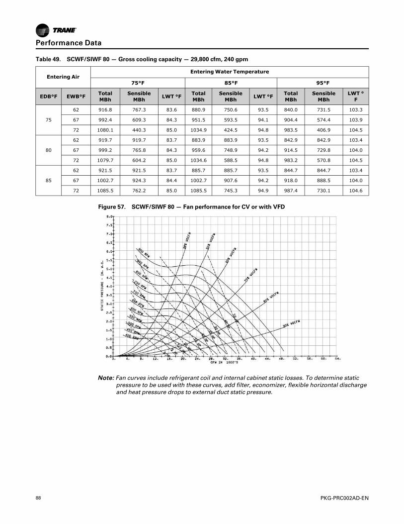
88 PKG-PRC002AD-EN
Table 49. SCWF/SIWF 80 — Gross cooling capacity — 29,800 cfm, 240 gpm
Entering AirEnteringWater Temperature
75°F 85°F 95°F
EDB°F EWB°F TotalMBh
SensibleMBh LWT °F Total
MBhSensibleMBh LWT °F Total
MBhSensibleMBh
LWT °F
75
62 916.8 767.3 83.6 880.9 750.6 93.5 840.0 731.5 103.3
67 992.4 609.3 84.3 951.5 593.5 94.1 904.4 574.4 103.9
72 1080.1 440.3 85.0 1034.9 424.5 94.8 983.5 406.9 104.5
80
62 919.7 919.7 83.7 883.9 883.9 93.5 842.9 842.9 103.4
67 999.2 765.8 84.3 959.6 748.9 94.2 914.5 729.8 104.0
72 1079.7 604.2 85.0 1034.6 588.5 94.8 983.2 570.8 104.5
85
62 921.5 921.5 83.7 885.7 885.7 93.5 844.7 844.7 103.4
67 1002.7 924.3 84.4 1002.7 907.6 94.2 918.0 888.5 104.0
72 1085.5 762.2 85.0 1085.5 745.3 94.9 987.4 730.1 104.6
Figure 57. SCWF/SIWF 80 — Fan performance for CV or with VFD
NNoottee:: Fan curves include refrigerant coil and internal cabinet static losses. To determine staticpressure to be used with these curves, add filter, economizer, flexible horizontal dischargeand heat pressure drops to external duct static pressure.
PPeerrffoorrmmaannccee DDaattaa

PKG-PRC002AD-EN 89
Table 50. 90 ton SCWF economizer performance — 30,000 cfm
Entering AirEnteringWater Temperature
45°F 55°F
EDB °F EWB °FFlowGpm Total MBh Sensible MBh LWT °F Total
MBh Sensible MBh LWT °F
75
62
180 692.7 660.1 52.7 453.3 447.2 60.0
225 732.1 676.1 51.5 471.0 464.8 59.2
270 761.4 688.1 50.6 483.4 476.9 58.6
67
180 846.1 532.2 54.4 500.1 408.8 60.5
225 916.4 558.6 53.1 534.4 420.9 59.7
270 969.4 578.7 52.2 561.0 430.0 59.2
72
180 1074.0 420.9 56.9 698.1 296.9 62.7
225 1170.0 453.7 55.4 761.5 316.7 61.8
270 1242.0 478.8 54.2 809.8 332.3 61.0
80
62
180 785.1 776.3 53.7 566.6 560.2 61.3
225 817.5 793.9 52.2 588.6 582.0 60.2
270 839.5 830.0 51.2 603.9 597.3 59.5
67
180 875.2 717.7 54.7 571.8 547.5 61.3
225 937.4 722.0 53.3 598.5 573.5 60.3
270 984.2 739.9 52.3 618.7 605.4 59.6
72
180 1072.0 575.2 56.9 704.4 453.7 62.8
225 1168.0 608.4 55.3 763.0 472.6 61.8
270 1239.0 633.7 54.1 808.7 487.3 61.0
85
62
180 897.5 889.3 54.9 679.9 673.5 62.5
225 934.0 925.4 53.3 706.0 699.5 61.3
270 959.0 950.1 52.1 724.3 717.7 60.4
67
180 931.6 875.3 55.3 681.8 671.2 62.6
225 985.2 924.1 53.7 708.2 697.2 61.3
270 1026.0 939.4 52.6 726.6 715.4 60.4
72
180 1087.0 735.6 57.0 744.7 621.7 63.3
225 1174.0 766.2 55.4 794.6 638.0 62.1
270 1241.0 790.0 54.2 833.5 650.3 61.2
PPeerrffoorrmmaannccee DDaattaa
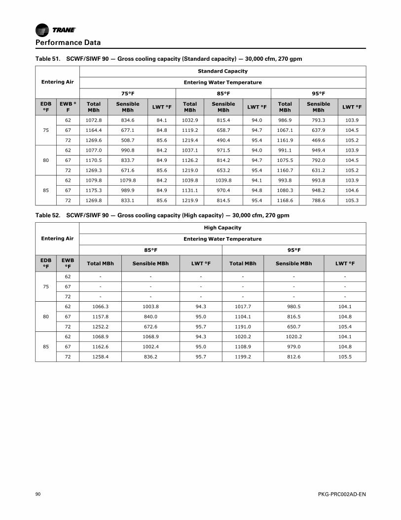
90 PKG-PRC002AD-EN
Table 51. SCWF/SIWF 90 — Gross cooling capacity (Standard capacity) — 30,000 cfm, 270 gpm
Entering Air
Standard Capacity
EnteringWater Temperature
75°F 85°F 95°F
EDB°F
EWB °F
TotalMBh
SensibleMBh LWT °F Total
MBhSensibleMBh LWT °F Total
MBhSensibleMBh LWT °F
75
62 1072.8 834.6 84.1 1032.9 815.4 94.0 986.9 793.3 103.9
67 1164.4 677.1 84.8 1119.2 658.7 94.7 1067.1 637.9 104.5
72 1269.6 508.7 85.6 1219.4 490.4 95.4 1161.9 469.6 105.2
80
62 1077.0 990.8 84.2 1037.1 971.5 94.0 991.1 949.4 103.9
67 1170.5 833.7 84.9 1126.2 814.2 94.7 1075.5 792.0 104.5
72 1269.3 671.6 85.6 1219.0 653.2 95.4 1160.7 631.2 105.2
85
62 1079.8 1079.8 84.2 1039.8 1039.8 94.1 993.8 993.8 103.9
67 1175.3 989.9 84.9 1131.1 970.4 94.8 1080.3 948.2 104.6
72 1269.8 833.1 85.6 1219.9 814.5 95.4 1168.6 788.6 105.3
Table 52. SCWF/SIWF 90 — Gross cooling capacity (High capacity) — 30,000 cfm, 270 gpm
Entering Air
High Capacity
EnteringWater Temperature
85°F 95°F
EDB°F
EWB°F Total MBh Sensible MBh LWT °F Total MBh Sensible MBh LWT °F
75
62 - - - - - -
67 - - - - - -
72 - - - - - -
80
62 1066.3 1003.8 94.3 1017.7 980.5 104.1
67 1157.8 840.0 95.0 1104.1 816.5 104.8
72 1252.2 672.6 95.7 1191.0 650.7 105.4
85
62 1068.9 1068.9 94.3 1020.2 1020.2 104.1
67 1162.6 1002.4 95.0 1108.9 979.0 104.8
72 1258.4 836.2 95.7 1199.2 812.6 105.5
PPeerrffoorrmmaannccee DDaattaa

PKG-PRC002AD-EN 91
Table 53. 100 ton SCWF— economizer performance — 32,000 cfm
Entering AirEnteringWater Temperature
45°F 55°F
EDB°F EWB°F Flow Gpm Total MBh Sensible MBh LWT °F Total MBh Sensible MBh LWT °F
75
62
200 734.1 700.0 52.3 479.8 473.6 59.8
250 773.3 715.9 51.2 497.8 491.3 59.0
300 802.9 728.1 50.3 510.4 503.4 58.4
67
200 899.4 565.6 54.0 529.6 433.7 60.3
250 969.9 592.0 52.7 564.5 445.8 59.5
300 1024.0 612.5 51.8 591.5 454.8 58.9
72
200 1143.0 447.9 56.4 742.2 315.3 62.4
250 1239.0 480.9 54.9 806.5 335.7 61.4
300 1312.0 506.2 53.7 855.2 351.4 60.7
80
62
200 831.9 822.5 53.3 599.6 593.0 61.0
250 864.1 838.8 51.9 622.0 614.9 60.0
300 886.5 876.7 50.9 637.6 630.5 59.2
67
200 928.5 741.3 54.3 605.0 579.1 61.0
250 990.6 764.9 52.9 632.0 605.5 60.0
300 1038.0 782.9 51.9 652.3 625.7 59.3
72
200 1141.0 611.4 56.4 747.5 481.6 62.5
250 1237.0 644.8 54.9 807.3 500.7 61.4
300 1310.0 835.7 53.7 878.7 688.5 60.7
85
62
200 950.8 942.0 54.5 719.5 712.8 62.2
250 987.2 978.1 52.9 746.1 739.2 61.0
300 1013.0 1003.4 51.7 764.7 757.6 60.1
67
200 987.0 928.4 54.8 721.5 710.4 62.2
250 1040.0 981.5 53.3 748.3 736.8 61.0
300 1081.0 997.2 52.2 767.0 755.2 60.1
72
200 1154.0 781.2 56.5 788.5 659.3 62.9
250 1242.0 811.8 54.9 839.3 675.7 61.7
300 1310.0 835.7 53.7 878.7 688.5 60.9
PPeerrffoorrmmaannccee DDaattaa

92 PKG-PRC002AD-EN
Table 54. SCWF/SIWF 100 — Gross cooling capacity (Standard capacity) — 32,000 cfm, 280 gpm
Entering Air
Standard Capacity
EnteringWater Temperature
75°F 85°F 95°F
EDB°F
EWB°F
TotalMBh
SensibleMBh LWT °F Total
MBhSensibleMBh LWT °F Total
MBhSensibleMBh LWT °F
75
62 1150.5 897.9 84.4 1107.1 876.9 94.3 1057.2 852.9 104.1
67 1248.6 728.6 85.1 1199.2 708.5 95.0 1142.5 685.8 104.8
72 1361.8 547.4 86.0 1306.9 527.3 95.7 1244.1 504.7 105.5
80
62 1155.0 1056.8 84.5 1111.6 1029.0 94.3 1061.7 997.2 104.2
67 1255.6 897.0 85.2 1207.4 875.7 95.0 1152.3 851.5 104.8
72 1361.4 722.8 86.0 1306.5 702.7 95.7 1243.8 680.0 105.5
85
62 1157.9 1157.9 84.5 1114.5 1114.5 94.3 1064.6 1064.6 104.2
67 1260.8 1065.5 85.2 1212.6 1044.2 95.1 1157.5 1020.0 104.9
72 1366.1 893.6 86.0 1312.4 872.4 95.8 1247.0 852.3 105.5
Table 55. SCWF/SIWF 100 — Gross cooling capacity (High capacity) — 32,000 cfm, 280 gpm
Entering Air
High Capacity
EnteringWater Temperature
85°F 95°F
EDB °F EWB °F Total MBh Sensible MBh LWT °F Total MBh Sensible MBh LWT °F
75
62 N/A N/A N/A N/A N/A N/A
67 N/A N/A N/A N/A N/A N/A
72 N/A N/A N/A N/A N/A N/A
80
62 1142.1 1059.1 94.5 1089.5 1025.7 104.4
67 1240.3 902.1 95.3 1182.1 876.5 105.0
72 1340.4 722.6 96.0 1273.6 698.7 105.7
85
62 1144.9 1144.9 94.6 1092.2 1092.2 104.4
67 1245.6 1076.8 95.3 1187.3 1050.5 105.1
72 1345.5 899.8 96.0 1280.7 874.4 105.8
PPeerrffoorrmmaannccee DDaattaa
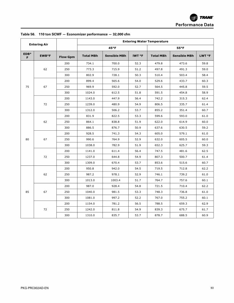
PKG-PRC002AD-EN 93
Table 56. 110 ton SCWF— Economizer performance — 32,000 cfm
Entering AirEnteringWater Temperature
45°F 55°F
EDB°F EWB°F Flow Gpm Total MBh Sensible MBh lWT °F Total MBh Sensible MBh LWT °F
75
62
200 734.1 700.0 52.3 479.8 473.6 59.8
250 773.3 715.9 51.2 497.8 491.3 59.0
300 802.9 728.1 50.3 510.4 503.4 58.4
67
200 899.4 565.6 54.0 529.6 433.7 60.3
250 969.9 592.0 52.7 564.5 445.8 59.5
300 1024.0 612.5 51.8 591.5 454.8 58.9
72
200 1143.0 447.9 56.4 742.2 315.3 62.4
250 1239.0 480.9 54.9 806.5 335.7 61.4
300 1312.0 506.2 53.7 855.2 351.4 60.7
80
62
200 831.9 822.5 53.3 599.6 593.0 61.0
250 864.1 838.8 51.9 622.0 614.9 60.0
300 886.5 876.7 50.9 637.6 630.5 59.2
67
200 928.5 741.3 54.3 605.0 579.1 61.0
250 990.6 764.9 52.9 632.0 605.5 60.0
300 1038.0 782.9 51.9 652.3 625.7 59.3
72
200 1141.0 611.4 56.4 747.5 481.6 62.5
250 1237.0 644.8 54.9 807.3 500.7 61.4
300 1309.0 670.4 53.7 853.6 515.6 60.7
85
62
200 950.8 942.0 54.5 719.5 712.8 62.2
250 987.2 978.1 52.9 746.1 739.2 61.0
300 1013.0 1003.4 51.7 764.7 757.6 60.1
67
200 987.0 928.4 54.8 721.5 710.4 62.2
250 1040.0 981.5 53.3 748.3 736.8 61.0
300 1081.0 997.2 52.2 767.0 755.2 60.1
72
200 1154.0 781.2 56.5 788.5 659.3 62.9
250 1242.0 811.8 54.9 839.3 675.7 61.7
300 1310.0 835.7 53.7 878.7 688.5 60.9
PPeerrffoorrmmaannccee DDaattaa

94 PKG-PRC002AD-EN
Table 57. SCWF 110 — Gross cooling capacity (Standard capacity) — 32,000 cfm, 300 gpm
Entering Air
Standard Capacity
EnteringWater Temperature
75°F 85°F 95°F
EDB°F
EWB°F
TotalMBh
SensibleMBh LWT °F Total
MBhSensibleMBh LWT °F Total
MBhSensibleMBh LWT °F
75
62 1272.1 959.1 84.7 1225.4 936.2 94.5 1171.5 909.9 104.4
67 1383.5 785.5 85.4 1330.6 763.5 95.3 1269.6 738.4 105.1
72 1509.1 602.0 86.3 1450.3 579.8 96.1 1382.8 554.8 105.8
80
62 1277.1 1128.6 84.7 1230.5 1105.6 94.6 1176.6 1079.3 104.4
67 1388.0 958.1 85.5 1336.2 934.9 95.3 1276.7 908.4 105.1
72 1508.7 778.9 86.3 1449.8 756.8 96.1 1382.3 731.8 105.8
85
62 1280.5 1280.5 84.7 1233.8 1233.8 94.6 1180.0 1180.0 104.5
67 1393.9 1127.7 85.5 1342.1 1104.4 95.3 1282.6 1077.8 105.2
72 1509.5 954.8 86.3 1451.3 932.0 96.1 1387.5 904.3 105.9
Table 58. SCWF 110 — Gross cooling capacity (High capacity) — 32,000 cfm, 300 gpm
Entering Air
High Capacity
EnteringWater Temperature
85°F 95°F
EDB °F
EWB °F Total MBh Sensible MBh LWT °F Total MBh Sensible MBh LWT °F
75
62 N/A N/A N/A N/A N/A N/A
67 N/A N/A N/A N/A N/A N/A
72 N/A N/A N/A N/A N/A N/A
80
62 1246.6 1123.1 94.8 1190.5 1095.8 104.6
67 1353.6 948.7 95.6 1291.6 921.1 105.4
72 1468.3 767.0 96.3 1397.6 740.9 106.1
85
62 1249.8 1249.8 94.8 1193.6 1193.6 104.7
67 1359.5 1121.6 95.6 1297.5 1094.0 105.4
72 1471.7 944.3 96.4 1403.1 916.5 106.1
PPeerrffoorrmmaannccee DDaattaa

PKG-PRC002AD-EN 95
Figure 58. SCWF 90 to 110 — Fan performance with VFD
NNoottee:: Fan curves include refrigerant coil and internal cabinet static losses. To determine staticpressure to be used with these curves, add filter, economizer, flexible horizontal dischargeand heat pressure drops to external duct static pressure.
Remote Air-Cooled Performance DataTable 59. SCRF/SIRF 25 — Gross cooling capacity —11,600 cfm
AmbientEntering Ambient Air Temperature
75 85 95 105 115
EDB EWB TotalMBh
Sensi-ble MBh
TotalMBh
Sensi-ble MBh
TotalMBh
SensibleMBh
TotalMBh
Sensi-ble MBh
TotalMBh
SensibleMBh
7062 320.6 212.6 307.4 206.9 292.3 200.5 275.5 193.4 257.6 186.0
67 352.7 155.0 337.8 149.2 320.8 142.6 302.1 135.5 282.5 128.2
75
62 320.9 270.2 307.8 264.6 292.7 258.2 276.0 251.1 258.1 243.7
67 352.6 213.0 337.7 207.2 320.8 200.7 302.2 193.6 282.7 186.3
72 386.4 154.2 369.6 148.3 350.6 141.7 330.0 134.7 308.7 127.5
80
62 322.1 317.6 309.3 306.3 294.8 294.4 278.9 278.9 264.3 264.3
67 352.9 270.8 338.0 265.1 321.2 258.6 302.6 251.5 283.2 244.2
72 386.3 212.5 369.5 206.6 350.6 200.1 330.0 193.0 308.8 185.8
85
62 333.0 333.0 322.4 322.4 309.7 309.7 295.5 295.5 280.2 280.2
67 353.3 328.5 338.5 322.8 321.9 312.3 303.7 298.2 284.8 282.2
72 386.5 270.6 369.7 264.7 350.8 258.2 330.4 251.2 309.2 244.0
PPeerrffoorrmmaannccee DDaattaa

96 PKG-PRC002AD-EN
Figure 59. SCRF/SIRF 25 — Fan performance for CV or with VFD
NNootteess::
1. For Optional low flow fan on high capacity coil.
2. Fan curves include refrigerant coil and internal cabinet static losses. To determinestatic pressure to be used with these curves, add filter, economizer, flexible horizontaldischarge and heat pressure drops to external duct static pressure.
Table 60. SCRF/SIRF 29 — Gross cooling capacity —12,800 cfm
AmbientEntering Ambient Air Temperature
75 85 95 105 115
EDB EWB TotalMBh
Sensi-ble MBh
TotalMBh
Sensi-ble MBh
TotalMBh
Sensi-ble MBh
TotalMBh
Sensi-ble MBh
TotalMBh
Sensi-ble MBh
7062 363.2 248.8 348.0 242.4 330.6 235.1 311.2 227.1 290.6 218.7
67 399.1 177.6 381.9 171.1 362.4 163.7 340.7 155.6 318.1 147.2
75
62 363.8 319.8 348.7 313.4 331.3 306.2 312.0 298.2 291.8 284.7
67 399.2 249.0 382.1 242.5 362.6 235.2 341.1 227.1 318.7 218.8
72 437.0 176.6 417.6 170.0 395.7 162.6 371.9 154.6 347.2 146.4
80
62 366.2 366.2 351.8 351.8 335.4 335.4 319.5 319.5 301.7 301.7
67 399.7 320.3 382.6 313.8 363.2 306.5 341.8 298.4 319.5 290.2
72 436.9 248.4 417.6 241.7 395.9 234.3 372.2 226.4 347.7 218.2
85
62 383.5 383.5 370.7 370.7 355.7 355.7 338.9 338.9 320.9 320.9
67 400.6 388.8 383.8 375.8 364.8 360.9 344.0 343.1 322.7 322.7
72 437.3 319.9 418.1 313.3 396.4 305.9 372.8 298.0 348.5 289.9
PPeerrffoorrmmaannccee DDaattaa

PKG-PRC002AD-EN 97
Figure 60. SCRF/SIRF 29 — Fan performance for CV or with VFD
NNoottee:: Fan curves include refrigerant coil and internal cabinet static losses. To determine staticpressure to be used with these curves, add filter, economizer, flexible horizontal dischargeand heat pressure drops to external duct static pressure.
PPeerrffoorrmmaannccee DDaattaa

98 PKG-PRC002AD-EN
Table 61. SCRF/SIRF 30 — Gross cooling capacity —14,000 cfm
AmbientEntering Ambient Air Temperature
75 85 95 105 115
EDB EWB TotalMBh
Sensi-bleMBh
TotalMBh
Sensi-bleMBh
TotalMBh
Sensi-bleMBh
TotalMBh
Sensi-bleMBh
TotalMBh
Sensi-bleMBh
7062 410.9 276.4 395.3 269.8 377.3 262.2 357.0 253.6 335.0 244.5
67 451.9 200.0 434.4 193.3 414.3 185.6 391.7 177.1 367.7 168.1
75
62 411.7 352.7 396.2 346.1 378.3 338.5 358.0 330.0 336.4 317.6
67 451.9 276.7 434.6 270.0 414.6 262.4 392.1 253.8 368.3 244.9
72 495.5 199.0 476.1 192.3 453.8 184.6 429.0 176.2 403.0 167.4
80
62 414.2 410.7 399.3 398.4 382.2 382.2 363.2 363.2 345.0 345.0
67 452.6 353.3 435.3 346.6 415.4 339.0 393.0 330.5 369.3 321.6
72 495.4 276.1 476.1 269.3 453.9 261.7 429.2 253.3 403.4 244.5
85
62 429.9 429.9 416.7 416.7 401.8 401.8 384.5 384.5 365.8 365.8
67 453.7 426.5 436.6 419.6 417.1 409.8 395.3 392.2 372.3 371.5
72 495.9 352.9 476.7 346.2 454.6 338.6 430.0 330.2 404.3 321.5
Figure 61. SCRF/SIRF 30 — Fan performance for CV or with VFD
NNoottee:: Fan curves include refrigerant coil and internal cabinet static losses. To determine staticpressure to be used with these curves, add filter, economizer, flexible horizontal dischargeand heat pressure drops to external duct static pressure.
PPeerrffoorrmmaannccee DDaattaa

PKG-PRC002AD-EN 99
Table 62. SCRF/SIRF 35 — Gross cooling capacity — 15,200 cfm
AmbientEntering Ambient Air Temperature
75 85 95 105 115
EDB EWB TotalMBh
Sensi-bleMBh
TotalMBh
Sensi-bleMBh
TotalMBh
Sensi-bleMBh
TotalMBh
Sensi-bleMBh
TotalMBh
Sensi-bleMBh
7062 435.1 298.5 418.5 291.5 399.2 283.4 377.2 274.3 353.0 264.4
67 478.2 213.4 459.5 206.2 438.0 198.1 413.5 188.9 386.9 179.0
75
62 435.8 383.5 419.2 376.5 400.0 368.4 378.0 359.3 354.2 346.1
67 478.2 298.7 459.6 291.6 438.1 283.5 413.8 274.4 387.4 264.6
72 524.0 212.2 503.1 205.0 479.1 196.8 452.1 187.7 423.1 178.0
80
62 438.4 438.4 422.6 422.6 404.5 404.5 384.6 384.6 365.0 365.0
67 478.7 383.9 460.2 376.8 438.8 368.7 414.6 359.6 388.3 349.8
72 523.9 297.9 503.1 290.8 479.2 282.6 452.3 273.5 423.4 263.9
85
62 457.3 457.3 443.7 443.7 427.3 427.3 408.4 408.4 387.5 387.5
67 479.6 468.9 461.5 454.2 440.5 436.8 416.9 416.9 391.7 391.7
72 524.3 383.5 503.6 376.3 479.7 368.2 453.0 359.1 424.3 349.5
Figure 62. SCRF/SIRF 35 — Fan performance for CV or with VFD
NNoottee:: Fan curves include refrigerant coil and internal cabinet static losses. To determine staticpressure to be used with these curves, add filter, economizer, flexible horizontal dischargeand heat pressure drops to external duct static pressure.
PPeerrffoorrmmaannccee DDaattaa

100 PKG-PRC002AD-EN
Table 63. SCRF/SIRF 40 — Gross cooling capacity — 18,400 cfm
AmbientEntering Ambient Air Temperature
75 85 95 105 115
EDB EWB TotalMBh
Sensi-bleMBh
TotalMBh
Sensi-bleMBh
TotalMBh
Sensi-bleMBh
TotalMBh
Sensi-bleMBh
TotalMBh
Sensi-bleMBh
7062 510.2 351.4 489.8 342.9 466.2 333.0 439.6 322.0 410.6 310.1
67 559.6 250.0 536.5 241.2 510.1 231.3 480.4 220.2 448.4 208.4
75
62 511.8 450.8 491.8 439.2 468.6 428.9 442.4 417.3 414.1 399.6
67 560.4 351.7 537.6 343.0 511.3 333.0 481.9 322.0 450.2 310.3
72 612.9 248.6 587.1 239.8 557.6 229.8 524.8 218.8 489.9 207.2
80
62 520.7 520.7 501.9 501.9 480.4 480.4 458.4 458.4 433.4 433.4
67 561.8 453.1 539.1 442.7 512.9 432.6 483.7 421.3 452.5 405.5
72 613.6 350.7 588.0 341.9 558.7 331.9 526.2 321.0 491.6 309.5
85
62 549.9 549.9 532.1 532.1 511.2 511.2 487.3 487.3 461.2 461.2
67 566.0 543.3 543.9 529.7 518.8 513.5 491.4 491.4 462.1 462.1
72 614.9 452.5 589.4 443.7 560.2 433.8 527.8 422.8 493.3 409.1
Figure 63. SCRF/SIRF 40 — Fan performance for CV or with VFD
NNoottee:: Fan curves include refrigerant coil and internal cabinet static losses. To determine staticpressure to be used with these curves, add filter, economizer, flexible horizontal dischargeand heat pressure drops to external duct static pressure.
PPeerrffoorrmmaannccee DDaattaa

PKG-PRC002AD-EN 101
Table 64. SCRF/SIRF 50 — Gross cooling capacity — 23,200 cfm
AmbientEntering Ambient Air Temperature
75 85 95 105 115
EDB EWB TotalMBh
Sensi-bleMBh
TotalMBh
Sensi-bleMBh
TotalMBh
Sensi-bleMBh
TotalMBh
Sensi-bleMBh
TotalMBh
Sensi-bleMBh
7062 630.0 449.1 604.6 437.9 575.3 425.1 542.4 410.9 507.0 395.7
67 689.1 320.6 660.4 309.2 627.6 296.2 591.0 282.0 552.0 266.9
75
62 632.3 572.8 607.0 561.2 578.2 545.9 545.9 531.0 511.2 515.0
67 690.2 448.5 661.6 437.1 629.1 424.2 592.8 410.0 554.2 395.0
72 752.9 317.9 720.7 306.4 684.2 293.4 644.0 279.3 601.5 264.5
80
62 641.5 666.5 617.9 641.9 593.0 616.0 564.3 586.1 533.7 554.2
67 691.8 576.0 663.4 564.6 631.0 551.8 595.2 533.2 557.0 517.6
72 753.7 446.3 721.8 434.8 685.6 421.9 645.6 407.9 603.5 393.2
85
62 676.7 703.2 654.3 679.8 628.3 652.7 598.8 622.0 566.8 588.7
67 696.8 696.3 669.1 684.4 637.7 661.6 603.2 626.6 569.0 590.9
72 755.3 574.3 723.4 562.9 687.3 550.0 647.5 536.0 605.7 521.4
Figure 64. SCRF/SIRF 50 — Fan performance for CV or with VFD
NNoottee:: Fan curves include refrigerant coil and internal cabinet static losses. To determine staticpressure to be used with these curves, add filter, economizer, flexible horizontal dischargeand heat pressure drops to external duct static pressure.
PPeerrffoorrmmaannccee DDaattaa

102 PKG-PRC002AD-EN
Table 65. SCRF/SIRF 60 — Gross Cooling capacity — 29,800 cfm
AmbientEntering Ambient Air Temperature
75 85 95 105 115
EDB EWB TotalMBh
Sensi-bleMBh
TotalMBh
Sensi-bleMBh
TotalMBh
Sensi-bleMBh
TotalMBh
Sensi-bleMBh
TotalMBh
Sensi-bleMBh
7062 882.5 546.1 845.7 528.5 804.0 508.7 757.8 486.6 708.6 463.1
67 951.8 392.7 910.3 375.5 863.5 356.0 812.1 334.6 757.8 311.9
75
62 888.6 700.0 852.3 682.5 811.1 662.7 765.6 640.9 717.3 617.8
67 962.7 540.3 921.7 522.5 875.4 502.3 824.7 480.3 771.3 456.9
72 1034.0 387.4 987.8 370.0 936.0 350.2 879.8 329.3 821.0 307.0
80
62 903.3 896.8 869.5 868.1 831.8 831.8 791.5 791.5 748.1 748.1
67 968.4 691.6 927.5 673.6 881.7 653.5 831.4 631.6 778.7 608.5
72 1046.1 532.5 1000.3 514.4 949.1 494.2 893.6 472.2 835.8 449.1
85
62 951.7 951.7 918.6 918.6 880.6 880.6 838.3 838.3 792.9 792.9
67 977.5 847.1 937.4 829.3 892.4 852.9 843.6 831.3 794.3 793.1
72 1052.6 681.9 1006.8 663.5 955.7 643.1 900.3 621.0 842.9 598.2
Figure 65. SCRF/SIRF 60 — Fan performance for CV or with VFD
NNoottee:: Fan curves include refrigerant coil and internal cabinet static losses. To determine staticpressure to be used with these curves, add filter, economizer, flexible horizontal dischargeand heat pressure drops to external duct static pressure.
PPeerrffoorrmmaannccee DDaattaa
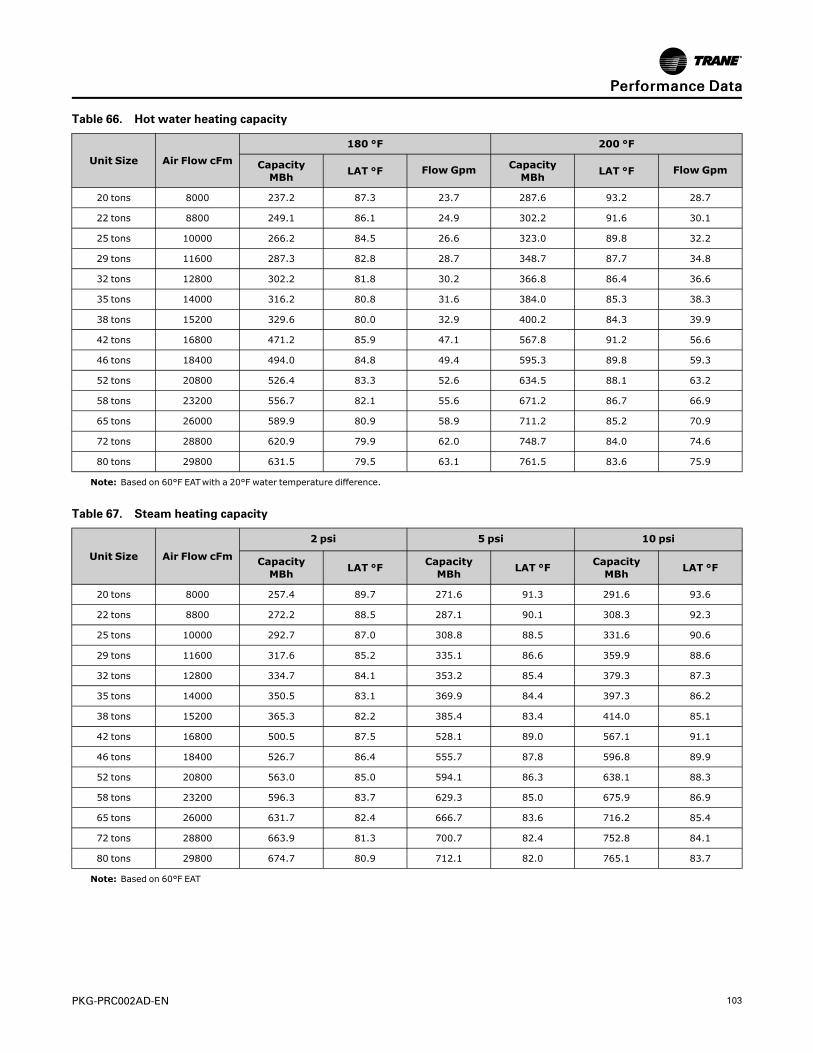
PKG-PRC002AD-EN 103
Table 66. Hot water heating capacity
Unit Size Air Flow cFm180 °F 200 °F
CapacityMBh LAT °F Flow Gpm Capacity
MBh LAT °F Flow Gpm
20 tons 8000 237.2 87.3 23.7 287.6 93.2 28.7
22 tons 8800 249.1 86.1 24.9 302.2 91.6 30.1
25 tons 10000 266.2 84.5 26.6 323.0 89.8 32.2
29 tons 11600 287.3 82.8 28.7 348.7 87.7 34.8
32 tons 12800 302.2 81.8 30.2 366.8 86.4 36.6
35 tons 14000 316.2 80.8 31.6 384.0 85.3 38.3
38 tons 15200 329.6 80.0 32.9 400.2 84.3 39.9
42 tons 16800 471.2 85.9 47.1 567.8 91.2 56.6
46 tons 18400 494.0 84.8 49.4 595.3 89.8 59.3
52 tons 20800 526.4 83.3 52.6 634.5 88.1 63.2
58 tons 23200 556.7 82.1 55.6 671.2 86.7 66.9
65 tons 26000 589.9 80.9 58.9 711.2 85.2 70.9
72 tons 28800 620.9 79.9 62.0 748.7 84.0 74.6
80 tons 29800 631.5 79.5 63.1 761.5 83.6 75.9
Note: Based on 60°F EATwith a 20°F water temperature difference.
Table 67. Steam heating capacity
Unit Size Air Flow cFm
2 psi 5 psi 10 psi
CapacityMBh LAT °F Capacity
MBh LAT °F CapacityMBh LAT °F
20 tons 8000 257.4 89.7 271.6 91.3 291.6 93.6
22 tons 8800 272.2 88.5 287.1 90.1 308.3 92.3
25 tons 10000 292.7 87.0 308.8 88.5 331.6 90.6
29 tons 11600 317.6 85.2 335.1 86.6 359.9 88.6
32 tons 12800 334.7 84.1 353.2 85.4 379.3 87.3
35 tons 14000 350.5 83.1 369.9 84.4 397.3 86.2
38 tons 15200 365.3 82.2 385.4 83.4 414.0 85.1
42 tons 16800 500.5 87.5 528.1 89.0 567.1 91.1
46 tons 18400 526.7 86.4 555.7 87.8 596.8 89.9
52 tons 20800 563.0 85.0 594.1 86.3 638.1 88.3
58 tons 23200 596.3 83.7 629.3 85.0 675.9 86.9
65 tons 26000 631.7 82.4 666.7 83.6 716.2 85.4
72 tons 28800 663.9 81.3 700.7 82.4 752.8 84.1
80 tons 29800 674.7 80.9 712.1 82.0 765.1 83.7
Note: Based on 60°F EAT
PPeerrffoorrmmaannccee DDaattaa

104 PKG-PRC002AD-EN
Table 68. Electric heat capacity
Unit Size SCWF Unit Size SCRF Heat kW Air Flow CFM Capacity MBH LAT
20 - 18 8000 61.47 67.11
22 - 18 8800 61.47 66.47
25 - 18 10000 61.47 65.69
29 25 23 11600 78.54 66.27
32 29 23 12800 78.54 65.68
35 30 27 14000 92.21 66.10
38 35 27 15200 92.21 65.62
42 - 31.5 16800 107.57 65.93
46 40 31.5 18400 107.57 64.41
52 - 39 20800 133.18 65.93
58 50 39 23200 133.18 65.31
65 - 48 26000 163.92 65.84
72 - 48 28800 163.92 65.27
80 60 48 29800 163.92 65.09
90 - 76 30000 259.54 68.01
100 - 76 32000 259.54 67.51
110 - 76 32000 259.54 67.51
Notes:1. Based on 60°F EAT2. For unit capacities at different conditions than those listed, use TOPSS (Trane Official Product Selection Program).3. Air temperature rise = kW x 3413 / (cfm x 1.085)4. Electric heat is not available on high capacity units with “Low Flow Fan” Option.
PPeerrffoorrmmaannccee DDaattaa

PKG-PRC002AD-EN 105
ControlsSignature Series Self-Contained Units
Controls are designed to work with Trane® equipment for optimum efficiency. The factoryinstalls and commissions each control component to ensure simple and reliable operation.
Furthermore, the DDC control’s modular design allows greater application flexibility using up totwelve different modules, dependent upon unit options. A customer can order exactly what thejob requires as options, instead of one large control package. And since unit features aredistributed among multiple printed circuit boards, field replacement is easy.
Depending upon unit options, units can operate as follows:
• Stand-alone
• Interface with Trane Tracer® building management system
• Interface with a generic (non-Trane) building management system.
Available Inputs and Outputs for the RTMModule (on all units with controls)BBiinnaarryy IInnppuuttss
• Emergency stop
• External auto/stop
• Unoccupied/occupied
• Dirty filter
• VAV changeover with hydronic heat
• Units with staged heat interface have 1-3 additional points
BBiinnaarryy OOuuttppuuttss
• VAV box drive max (VAV units only)
• CV unoccupied mode indicator (CV units only)
• Alarm
• Fan run request
• Water pump request (water-cooled only)
• Units with staged heat interface have 1-3 additional points
AAnnaalloogg IInnppuutt
• Airside economizer damper minimum position
AAnnaalloogg OOuuttppuutt
• Outside air damper actuator
Heat Module Option• Analog output
Generic BAS Option (GBAS)BBiinnaarryy IInnppuuttss
• Demand limit contacts
BBiinnaarryy OOuuttppuuttss
• Dirty filter relay
• Refrigeration fail relay
• Heat fail relay
• Supply fan fail relay
• Active diagnostics

106 PKG-PRC002AD-EN
AAnnaalloogg IInnppuuttss
• Occupied zone cooling setpoint
• Occupied zone heating setpoint
• Unoccupied zone cooling setpoint
• Unoccupied zone heating setpoint or minimum outside air flow setpoint
• Supply air cooling setpoint
• Supply air heating setpoint
• Supply air static pressure setpoint
Comparative Enthalpy Module (ECEM) OptionAAnnaalloogg IInnppuuttss
• Return air temperature
• Return air humidity
Ventilation Override Module (VOM) OptionBBiinnaarryy IInnppuuttss
• VOMmode A, unit off
• VOMmode B, pressurize
• VOMmode C, exhaust
• VOMmode D, purge
• VOMmode E, purge w/duct pressure control
BBiinnaarryy OOuuttppuuttss
• V.O. relay
LonTalk/Building Automation SystemThe LonTalk® Communication Interface for self-contained (LCI-I) controller expandscommunications from the unit UCM network to a Trane Tracer® Summit or a third party buildingautomation system, utilizing LonTalk, and allows external setpoint and configuration adjustmentand monitoring of status and diagnostics. The LCI-I utilizes an FTT-10A Free Topologytransceiver, which supports non-polarity sensitive, free topology wiring, which allows the systeminstaller to use star, bus, and loop architectures. This controller works in standalone mode, peer-to-peer with one or more other units, or when connected to a Trane Tracer Summit and SC or athird party building automation system that supports LonTalk.
BACnet/Building Automation SystemThe BACnet Communication Interface for self-contained (BCI-I) controller expandscommunications from the unit UCM network to Tracer SC or a third party building automationsystem, utilizing BACnet, and allows external setpoint and configuration adjustment andmonitoring of status and diagnostics. The BCI-I utilizes the BACnet defined MS/TP protocol asdefined in ASHRAE standard 135-2004. This controller works in standalone mode, with Tracer SCor when connected to a third party building automation system that supports BACnet.
Standard Unit Control FeaturesNNoottee:: All set-up parameters are preset from the factory, requiring less start-up time during
installation.
The human interface panel is easy to read and requires less time for building maintenancepersonnel to learn to interact with the unit. It features a clear language display (in English,Spanish, or French) that shows all of the self-contained unit control parameters, such as systemon/off, demand limiting type, night setback setpoints, and many other setpoints. All adjustmentsare done through the human interface keypad. Also, the human interface panel allows you tomonitor diagnostic points such as; sensor failures, supply airflow loss, and inoperativerefrigerant circuit. No special tools are required for servicing the unit. Diagnostics are held in
CCoonnttrroollss

PKG-PRC002AD-EN 107
memory, even during power loss. This allows the operator/servicer to diagnose the failure rootcause.
Unit Features• Unit-mounted human interface panel with a two line x 40 character language (English,
Spanish, or French) display and a 16-function keypad that includes CUSTOM, DIAGNOSTICS,and SERVICE TEST MODE menu keys on units.
• Compressor lead/lag• Frostat™ coil frost protection on all units• Daytime warmup (occupied mode) on units with heating options and morning warmup
operation on all units• Supply air static over-pressurization protection on units with variable frequency drives (VFDs)• Supply airflow proving• Supply air tempering control with heating option• Supply air heating control on VAV with hydronic heating option• Mappable sensors and setpoint sources• Occupied/unoccupied switching• Timed override activation• Programmable water purge during unoccupied mode
Human Interface Panel (HI)The human interface panel provides a 16-button keypad for monitoring, setting, editing andcontrolling. The HI panel is mounted in the unit’s main control panel, accessible through theunit’s control panel door.
The optional remote-mount version of the human interface (RHI) panel has all the functions ofthe unit-mounted version, except for the service mode. To use a RHI, the unit must be equippedwith the remote HI interface option (model number digit 32 = 2), which includes aninterprocessor communications bridge (IPCB).The RHI can be located up to 1,000 feet (304.8 m)from the unit. A single RHI can be used to monitor and control up to four self-contained units,each containing an IPCB.
Figure 66.
The main menus of the human interface panels are:
• STATUS is used to monitor all temperatures, pressures, humidities, setpoints, input andoutput status.
• CUSTOM key allows the user to customize a status report, consisting of up to four screens ofthe data available in the main STATUS menu.
• SETPOINT is used to edit all factory preset default setpoints.
• DIAGNOSTICS allows the user to review active and historical lists of diagnostic conditions. Atotal of 49 different diagnostics can be read at the human interface (HI) panel and the last 20diagnostics can be held in an active history buffer log at the HI panel.
• SETUP allows the user to edit control parameters, sensor selections, setpoint sourceselections, output definitions, and numerous other points in this menu. All points havefactory-preset values to keep unnecessary editing to a minimum.
CCoonnttrroollss

108 PKG-PRC002AD-EN
• CONFIGURATION allows changing of factory-preset unit configuration information. Thisinformation can be edited only if certain options are field installed or deleted from the unit.For example, if a Trane® communication interface (TCI) moduleor ventilation overridemodule (VOM) were field installed, the unit configuration will require editing to reflect thoseoptions for proper unit operation.
• SERVICE allows servicing or troubleshooting the unit by selecting component control outputssuch as compressors, fans, damper position, etc. This menu is accessible only at the unit-mounted human interface panel.
Control Sequences of Operation
Morning WarmupThis feature is available on all types of factory-installed heat units and on units with no heat. Thisfunction may still be selected to support systems with heat sources not provided by the self-contained unit. At the conclusion of unoccupied mode, the selected zone is heated to the user-defined morning warmup setpoint. The unit then is released to occupied mode. There are twotypes of morning warmup: full capacity or cycling capacity.
• Full Capacity Morning Warmup (MWU)
Full capacity morning warmup uses full heating capacity to heat the zone as quickly as possible.Full heating capacity is provided until the morning warmup setpoint is met. At this point, the unitis released to daytime mode.
• Cycling Capacity Morning Warmup (MWU)
Cycling capacity morning warmup provides gradual heating to overcome “building sink” as thezone is heated. Normal zone temperature control with varying capacity is used to raise the zonetemperature to the MWU zone temperature setpoint. Cycling capacity MWU will operate untilMWU setpoint is reached or for 60 minutes. Then the unit switches to occupied mode. Coolingwill suspend until building load conditions exceed the MWU setpoint of 3 F (1.7 C), which is fieldadjustable.
NNoottee:: When using the morning warmup option in a heating/cooling self-contained unit in a VAVsystem, it is important to maintain airflow through the unit. This can be accomplished byelectrically tying the VAV boxes to the VAV drive max output relay contacts on the unit’sRTMmodule board or by using changeover thermostats. Either of these methods willassure adequate airflow through the unit and satisfactory heating.
Ventilation Override (VOM)The user can customize up to five different override sequences (A-E) for purposes of ventilationoverride control. If more than one VOM sequence is being requested, the sequence with thehighest priority is initiated first. Priority schedule is that sequence “A” (unit off) is first, withsequence “E” (purge with duct pressure control) last.
• UUNNIITT OOFFFF sseeqquueennccee ““AA”” —When complete system shut down is required, use the followingsequence:
– Supply fan – Off
– Supply fan VFD – Off (0 Hz) (if equipped)
– Outside air dampers – Closed
– Heat – all stages – Off, Modulating heat output at 0 Vdc
– Occupied/Unoccupied output – Deenergized
– VO relay – Energized
– Exhaust fan (field-installed) - Off
– Exhaust damper (field-installed) - Closed
• PPRREESSSSUURRIIZZEE sseeqquueennccee ““BB”” — Use the following override sequence if a positivelypressured space is desired instead of a negatively pressurized space:
– Supply fan – On
– Supply fan VFD – On (60 Hz)\VAV boxes – Open (if equipped)
CCoonnttrroollss
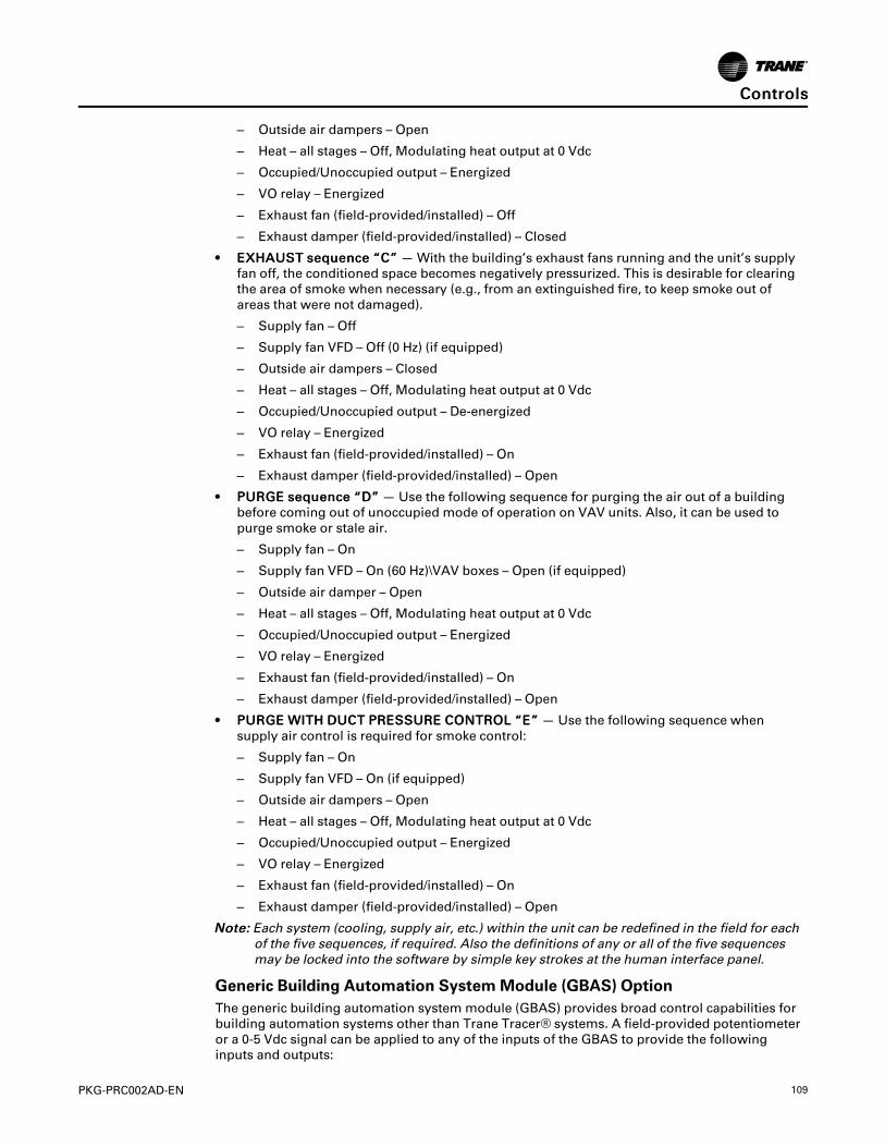
PKG-PRC002AD-EN 109
– Outside air dampers – Open
– Heat – all stages – Off, Modulating heat output at 0 Vdc
– Occupied/Unoccupied output – Energized
– VO relay – Energized
– Exhaust fan (field-provided/installed) – Off
– Exhaust damper (field-provided/installed) – Closed
• EEXXHHAAUUSSTT sseeqquueennccee ““CC”” —With the building’s exhaust fans running and the unit’s supplyfan off, the conditioned space becomes negatively pressurized. This is desirable for clearingthe area of smoke when necessary (e.g., from an extinguished fire, to keep smoke out ofareas that were not damaged).
– Supply fan – Off
– Supply fan VFD – Off (0 Hz) (if equipped)
– Outside air dampers – Closed
– Heat – all stages – Off, Modulating heat output at 0 Vdc
– Occupied/Unoccupied output – De-energized
– VO relay – Energized
– Exhaust fan (field-provided/installed) – On
– Exhaust damper (field-provided/installed) – Open
• PPUURRGGEE sseeqquueennccee ““DD”” — Use the following sequence for purging the air out of a buildingbefore coming out of unoccupied mode of operation on VAV units. Also, it can be used topurge smoke or stale air.
– Supply fan – On
– Supply fan VFD – On (60 Hz)\VAV boxes – Open (if equipped)
– Outside air damper – Open
– Heat – all stages – Off, Modulating heat output at 0 Vdc
– Occupied/Unoccupied output – Energized
– VO relay – Energized
– Exhaust fan (field-provided/installed) – On
– Exhaust damper (field-provided/installed) – Open
• PPUURRGGEE WWIITTHH DDUUCCTT PPRREESSSSUURREE CCOONNTTRROOLL ““EE”” — Use the following sequence whensupply air control is required for smoke control:
– Supply fan – On
– Supply fan VFD – On (if equipped)
– Outside air dampers – Open
– Heat – all stages – Off, Modulating heat output at 0 Vdc
– Occupied/Unoccupied output – Energized
– VO relay – Energized
– Exhaust fan (field-provided/installed) – On
– Exhaust damper (field-provided/installed) – Open
NNoottee:: Each system (cooling, supply air, etc.) within the unit can be redefined in the field for eachof the five sequences, if required. Also the definitions of any or all of the five sequencesmay be locked into the software by simple key strokes at the human interface panel.
Generic Building Automation SystemModule (GBAS) OptionThe generic building automation system module (GBAS) provides broad control capabilities forbuilding automation systems other than Trane Tracer® systems. A field-provided potentiometeror a 0-5 Vdc signal can be applied to any of the inputs of the GBAS to provide the followinginputs and outputs:
CCoonnttrroollss

110 PKG-PRC002AD-EN
• GGBBAASS AAnnaalloogg IInnppuuttss — Four analog inputs that can be configured to be any of the following:
– Occupied zone cooling
– Unoccupied zone cooling
– Occupied zone heating
– Unoccupied zone heating
– SA cooling setpoint
– SA heating setpoint
– SA static pressure setpoint
• GGBBAASS BBiinnaarryy OOuuttppuuttss — Each of the five relay outputs can be mapped to any/all of theavailable diagnostics.
• DDeemmaanndd LLiimmiittiinngg BBiinnaarryy IInnppuutt — This function is operational on units with a GBAS and isused to reduce electrical consumption at peak load times. There are two types of demandlimiting, 50% and 100%. When demand limiting is needed, mechanical cooling and heatingoperation are either partially (50%), or completely disabled (100%) to save energy. Thedemand limit definition is user definable at the human interface panel. Demand limit binaryinput accepts a field supplied switch or contact closure. When the need for demand limitinghas been discontinued, the unit’s cooling/heating functions will again become fully enabled.
Evaporator Coil Frost Protection Frostat™The Frostat™ system uses a temperature sensor on the evaporator to determine if the coil isgetting close to a freezing condition. If so, mechanical cooling capacity is shed as necessary toprevent icing.
Also, the Frostat™ system eliminates the need for hot gas bypass. It uses a suction line surfacetemperature sensor mounted near the TXV bulb location to shut off cooling when coil frostingconditions occur. The supply fan does not shut off and will de-ice the coil. Timers prevent thecompressors from rapid cycling.
Occupied/Unoccupied SwitchingThere are four ways to switch occupied/unoccupied:
1. Programmable night setback sensor
2. Field-supplied contact closure (hardwired binary input to RTM) — This input accepts a fieldsupplied switch or contacts closure such as a time clock.
3. Tracer® — The Trane Tracer® system can control the occupied/unoccupied status of the self-contained unit.
4. Factory-mounted time clock — A time clock can control the occupied/unoccupied status of theself-contained unit.
Timed Override Activation—ICSThis function is operational whenever the unit’s RTMmodule board is used as the zonetemperature sensor source, which can be set at the human interface panel. When this function isinitiated by the push of the override button on the zone sensor, the unit will switch to theoccupied mode. Unit operation (occupied mode) during timed override is terminated by a signalfrom Tracer.
Timed Override Activation—Non-ICSThis function is active whenever the unit’s RTMmodule board is selected as the zonetemperature source, which can be set at the human interface panel. When this function isinitiated by the push of the override button on the zone sensor, the unit will switch to theoccupied mode. Automatic cancellation of the timed override mode occurs after three hours ofoperation.
Low Ambient Compressor LockoutThis function will lock out the compressor if the outdoor air temperature is below the lowambient compressor lock-out temperature setpoint when using a field-installed outside air
CCoonnttrroollss

PKG-PRC002AD-EN 111
sensor. This setpoint is adjustable at the human interface panel. Compressors will lock out whenoutdoor air temperature falls below that selected temperature and will start again when thetemperature rises 5° F above the setpoint.
Comparative Enthalpy Control of Airside Economizer OptionAn optional comparative enthalpy system is used to control the operation of the economizer andmeasures the temperature and humidity of both return air and outside air to determine whichsource has lower enthalpy. This system allows true comparison of outdoor air and return airenthalpy by measurement of outdoor and return air temperatures and humidities.
NNoottee:: If comparative enthalpy is not ordered, the standard method compares outdoor airenthalpy with a fixed reference enthalpy, set through the human interface panel.
Compressor Lead/LagCompressor lead/lag is a user-selectable feature through the human interface panel available onall units. After each request for compressor operation, the lead refrigeration circuit orcompressor switches, thereby causing a more equitable or balanced run time amongcompressors.
Emergency Stop InputA binary input is provided on the unit’s RTMmodule board for installation of a field-providedswitch or contacts to immediately shutdown all unit functions.
Water Flow ControlWith compatible piping configurations, the unit can be configured to provide:
• Constant water flow with basic or intermediate piping for condenser pumping systems thatare not capable of unloading the water-pumping system.
• Variable water flow with intermediate piping only, which maximizes energy saving byunloading the water pumping system.
Head Pressure Control• Water-cooled condensers — Units that are set up for variable water flow will modulate a
water valve to maintain a user-defined condensing temperature setpoint. Condensingtemperature will be referenced utilizing factory installed sensors located at each condenser.
• Air-cooled condensers — Condenser fans will stage per a user-defined setting. If thecondenser is equipped with head pressure control (air modulation on last stage of condensercapacity), the condenser airflow will modulate to maintain condensing temperature setpoint.Condensing temperature is determined by sensors located at each condenser coil.
Water PurgeThis user-definable feature allows the user to select a purge schedule to automatically circulatewater through the economizer and condensers periodically during non-operational times. Thisallows fresh chemicals to circulate in waterside heat exchangers.
Airside Options
Variable Frequency Drive (VFD) ControlVariable frequency drives are driven by a modulating 0-10 Vdc signal from the RTMmodule. Apressure transducer measures duct static pressure, and the VFD adjusts the fan speed tomaintain the supply air static pressure within an adjustable user-defined range. The range isdetermined by the supply air pressure setpoint and supply air pressure deadband, which are setthrough the human interface panel.
Variable frequency drives provide supply fan motor speed modulation. The drives will accelerateor decelerate as required to maintain the supply static pressure setpoint.
Bypass control is offered as an option to provide full nominal airflow in the event of drive failure.Manual bypass is initiated at the human interface panel. When in the bypass mode, VAV boxeswill need to be fully opened. The self-contained unit will control heating and cooling functions to
CCoonnttrroollss

112 PKG-PRC002AD-EN
maintain setpoint from a user defined zone sensor. Supply air static pressure limit will be activein this mode.
Supply Air Static Pressure LimitThe opening of the VAV boxes are coordinated during unit start up and transition to/fromoccupied/unoccupied modes to prevent over-pressurization of the supply air duct-work.However, if for any reason the supply air pressure exceeds the user-defined supply air staticpressure limit that was set at the human interface panel, the supply fan/VFD is shut down. Thenunit is then allowed to restart up to three times. If the over-pressurization condition still occurs onthe third restart, the unit shuts down and a manual reset diagnostic sets and displays at thehuman interface panel.
Zone Temperature Control Unit Sequence of Operation1 — Occupied Zone Temperature Control
Cooling/Waterside EconomizerDuring occupied cooling mode, the waterside economizer option and mechanical coolingfunction to control zone temperature. If the entering condenser water temperature is appropriateto use “free cooling,” the economizer initiates to attempt to satisfy the cooling zone temperaturesetpoint with the compressors staging on as necessary. Minimum on/off timing of compressorsprevents rapid cycling.
Waterside economizing enables when the unit’s entering water temperature is below the unit’sentering mixed air temperature by 4°F plus the user adjustable economizer approachtemperature. The approach temperature default is 4°F and is adjustable from 0-9°F at the humaninterface (HI) panel. Waterside economizing disables when the unit’s entering water temperatureis not below the unit’s entering mixed air temperature by at least the water economizer approachtemperature. The approach temperature defaults to 4°F and is adjustable from 0-9°F at the HI.The economizer acts as the first stage of cooling. If the economizer is unable to maintain the zonetemperature setpoint, the compressor module will bring on compressors as required to meet thesetpoint.
If the unit does not include an economizer, only mechanical cooling will operate to satisfy coolingrequirements.
Cooling/Airside EconomizerDuring occupied cooling mode, the economizer option and mechanical cooling operate to controlzone temperature. If the outside air enthalpy is appropriate for airside economizing or “freecooling,” the economizer initiates to satisfy the cooling zone temperature setpoint with thecompressors staging on as necessary. Minimum on/off timing of compressors will prevent rapidcycling.
On units with an airside economizer, a call for cooling will modulate the fresh air dampers open.The rate of economizer modulation is based on deviation of the zone temperature from setpoint;i.e., the further away from setpoint, the faster the fresh air damper will open. First stage ofcooling will start after the economizer reaches full open.
Note that the airside economizer will only function freely if ambient conditions are below theenthalpy control settings or below the return air enthalpy if unit has comparative enthalpyinstalled. If outside air is not suitable for “economizing,” the fresh air dampers drive to theminimum open position. A field adjustable, factory default setting in the human interface panelor Tracer can provide the input to establish the minimum damper position.
At outdoor air conditions above the enthalpy control setting, only mechanical cooling is used andthe fresh air dampers remain at minimum position.
If the unit does not include an airside economizer, only mechanical cooling will operate to satisfycooling requirements.
Heating: ElectricOn units with electric heating, the zone temperature can be controlled to a heating setpointduring the occupied mode by cycling a single stage electric heater. Interface is provided for field
CCoonnttrroollss

PKG-PRC002AD-EN 113
supplied electric heat (up to three stages).The zone temperature heating setpoint and deadbandare user defined at the human interface panel.
Heating: Hot Water or SteamOn units with hot water or steam heating, the zone temperature can be controlled to a heatingsetpoint during the occupied mode. The zone temperature heating setpoint and deadband areuser defined at the human interface panel.
Supply Air TemperingFor hot water, steam, or electric heat units in the heat mode but not actively heating, if the supplyair temperature drops to 10°F below the occupied zone heating temperature setpoint, one stageof heat will be brought on to maintain a minimum supply air temperature. The unit transitionsout of heat mode if the supply air temperature rises to 10°F above the occupied zone heatingtemperature setpoint.
Auto ChangeoverWhen the systemmode is auto, the mode will change to cooling or heating as necessary tosatisfy the zone cooling and heating setpoints. The zone cooling and heating setpoints can be asclose as 2°F apart.
2 — Unoccupied Zone Temperature Control
Cooling and HeatingBoth cooling and heating modes can be selected to maintain unoccupied zone temperaturedeadbands. For unoccupied periods, heating, economizer operation, or compressor operationcan be selectively locked out at the human interface panel.
Supply Air Temperature Control Unit Sequence of Operation1 — Occupied Supply Air Temperature Control
Cooling/Waterside EconomizerDuring occupied cooling mode, the waterside economizer option and mechanical cooling areused to control the supply air temperature. The supply air temperature setpoint and deadbandare user defined at the human interface panel. Waterside economizing enables when the unitsentering water temperature is below the units entering mixed air temperature by 4°F plus theuser adjustable economizer approach temperature. The approach temperature default is 4°F andis adjustable from 0-9°F at the HI. Waterside economizing disables when the units entering watertemperature is not below the units entering mixed air temperature by at least the watereconomizer approach temperature.
The economizer acts as the first stage of cooling. If the economizer is unable to maintain thesupply air setpoint, the compressor module will bring on compressors as required to meet thesetpoint. If the unit does not include an economizer, only mechanical cooling will satisfy coolingrequirements.
Cooling/Airside EconomizerDuring occupied cooling mode of operation, the airside economizer option and mechanicalcooling are used to control the supply air temperature. The supply air temperature setpoint anddeadband are user-defined at the human interface panel. If the temperature of the mixed air isappropriate to use “free cooling,” the economizer initiates to satisfy the supply air setpoint. Thenif required, the mechanical cooling stages on to maintain supply air temperature setpoint.Minimum on/off timing of the mechanical cooling prevents rapid cycling.
On units with an airside economizer, a call for cooling will modulate the fresh air dampers open.The rate of economizer modulation is based on deviation of the discharge temperature fromsetpoint, i.e., the further away from setpoint, the faster the fresh air damper will open. First stageof cooling initiates after the economizer reaches full open.
Note that the airside economizer is only allowed to function freely if ambient conditions arebelow the setpoint control settings or below the return air enthalpy, if unit has the comparative
CCoonnttrroollss

114 PKG-PRC002AD-EN
enthalpy option. If outside air is not suitable for “economizing,” the fresh air dampers drive tothe minimum open position. A field adjustable, factory default setting in the human interfacepanel or Tracer can provide the input to establish the minimum damper position.
At outdoor air conditions above the setpoint or comparative enthalpy control setting, onlymechanical cooling is used and the fresh air dampers remain at minimum position.
If the unit does not include an economizer, only mechanical cooling operates to satisfy coolingrequirements.
Heating: Hot Water or SteamOn units with hot water or steam heating, the supply air temperature can be controlled to aheating setpoint during the occupied mode. The supply air temperature heating setpoint anddeadband are user defined at the human interface panel. VAV occupied heating on hot water andsteam heat units is initiated by closing a field-supplied switch or contacts connected to achangeover input on the unit’s RTMmodule board .
Supply Air Setpoint ResetSupply air reset can be used to adjust the supply air temperature setpoint on the basis of a zonetemperature or outdoor air temperature. Supply air reset adjustment is available from the humaninterface panel for supply air heating and supply air cooling control.
Reset based on outdoor air temperatureOutdoor air cooling reset is sometimes used in applications where the outdoor temperature hasa large effect on building load. When the outside air temperature is low and the building coolingload is low, the supply air setpoint can be raised, thereby preventing subcooling of critical zones.This reset can lower usage of mechanical cooling, thus savings in compressor kW, but anincrease in supply fan kWmay occur.
Outdoor air heating reset is the inverse of cooling, with the same principles applied.
For both outdoor air cooling reset and heating reset, there are three user defined parameters thatare adjustable through the human interface panel:
• Beginning reset temperature
• Ending reset temperature
• Maximum amount of temperature reset
Reset based on zone temperatureZone reset is applied to the zone(s) in a building that tends to overcool or overheat. The supplyair temperature setpoint is adjusted based on the temperature of the critical zone(s).This canhave the effect of improving comfort and/or lowering energy usage.The user-defined parametersare the same as for outdoor air reset.
Supply Air Tempering (Hot Water and Steam Units Only)When supply air temperature falls below the supply air temperature deadband low end, theheating valve modulates open to maintain the minimum supply air temperature setpoint.
2 — Unoccupied Supply Air Temperature Control — Unoccupied Zone Heating andCooling
During unoccupied mode, the unit operates to maintain zone temperature with fan cycling asneeded for building load. VAV boxes drive full open. However, unit airflow modulation controloperates to maintain duct static setpoint. The unit controls zone temperature within theunoccupied zone cooling and heating (heating units only) deadbands.
Daytime WarmupDuring occupied mode, if the zone temperature falls to a preset, user-defined zone low limittemperature setpoint, the unit is put into daytime warmup. The system changes over to CVheating, the VAV boxes drive full open. However, unit airflow modulation control operates to
CCoonnttrroollss

PKG-PRC002AD-EN 115
maintain duct static setpoint, and full heating capacity is provided until the daytime warmupsetpoint is reached. The unit is then returned to normal occupied mode.
Zone Sensor OptionsZone Temperature Sensor, BAYSENS077 (standard on all units)
This wall-mounted zone sensor ships with every Signature Series unit, CV or VAV. Additionalsensors are also available for order using the accessory model number. It includes an internalthermistor and should be mounted in the zone. This sensor is available for use with all zonesensor options to provide remote sensing capabilities.
Additional sensors shown can be ordered through Unitary Accessories (ACC)/UPG Rooftop,Packaged Heat Pump, Split System Accessories (ACC) in Job Center.
CV/VAV Programmable Zone Sensor, BAYSENS119
The BAYSENS119 programmable night set back sensor provides multi functional flexibility forboth Constant Volume and Variable Air Volume control. This electronic programmable sensorincludes auto or manual cooling and heating changeover with 7 day programming. Five tactilefeel buttons located on the sensor front panel provide interface for all programming, includinginitial setup for CV or VAV control. Sensor functionality includes up to four daily programmableperiods for Occupied/Unoccupied operation, and Override.
The dynamic LCD display indicates status for System On/Off, Heat, Cool, Fan Status, Time of Day,Occupied/Unoccupied mode, Space Temperature, Space or Discharge Air Heating and Cooling
CCoonnttrroollss

116 PKG-PRC002AD-EN
Setpoints. Additional features include Service Indication for Heat Failure, Cool Failure, FanFailure, and Test Mode if system is operating in test mode.
A Check Filter Timer function is included. Filter service countdown time can be set in one-dayincrements. Activation of the Test/Configuration button located on the bottom of the sensorperforms a sensor self-diagnostic routine and indicates hours in service.
When the BAYSENS119 is programmed for CV or VAV control, Night Setback is initiated throughthe scheduled Unoccupied time setting. When the sensor switches to Night Setback, the outdoordampers close and heating/cooling functions are enabled/disabled based on set up parameters.As building load changes, if heating/cooling functions are enabled, the Sensor energizes self-contained unit and evaporator fan operation. The unit will cycle heating/cooling operationthroughout the Unoccupied period as required to maintain Unoccupied space temperaturesetpoints. When the Unoccupied time period has expired, all heating/cooling functions return tonormal operation.
When Night Setback options are used with VAV heating/cooling, maintain airflow through theself-contained unit by electronically tying the VAV terminals to the unoccupied output relaycontacts on the self-contained units low voltage terminal board, or by using changeoverthermostats. Either of these methods will assure adequate airflow through the unit andsatisfactory temperature control of the space.
Refer to BAS-SVX17*-EN for complete installation, operation, and maintenance instructions.
NNoottee:: Additional sensors shown can be ordered through Unitary Accessories (ACC)/UPG Rooftop,Packaged Heat Pump, Split System Accessories (ACC) in Job Center.
CV—Dual Setpoint, Manual/Automatic Changeover Sensor, BAYSENS108
This zone sensor module is for use with cooling/heating CV applications. It provides thefollowing features and system control functions:
• System control switch (Heat/Auto/Off/Cool): Allows you to select heating mode, coolingmode, automatic selection of heating or cooling as required, or turn the system off.
• Fan control switch (Auto/On): Allows you to select automatic fan operation while activelyheating or cooling or continuous fan operation.
• Dual temperature setpoint levers allow you to set different cooling (blue lever) and heatingsetpoints (red lever).
• Thermometer to indicate temperature in the zone.
NNoottee:: Additional sensors shown can be ordered through Unitary Accessories (ACC)/UPG Rooftop,Packaged Heat Pump, Split System Accessories (ACC) in Job Center.
CCoonnttrroollss

PKG-PRC002AD-EN 117
CV—Dual Setpoint, Manual/Automatic Changeover Sensor with System FunctionLights, BAYSENS110
This zone sensor is for use with cooling/heating CV applications. It provides the followingfeatures and system control functions:
• System control switch to select heating mode (HEAT), cooling mode (COOL), AUTO forautomatic selection of heating or cooling as required, or OFF to turn the system off.
• Fan control switch to select automatic fan operation while actively heating or cooling (AUTO),or continuous fan operation (ON).
• Dual temperature setpoint levers for setting cooling (blue lever) or heating (red lever).
• Thermometer to indicate temperature in the zone.
• Function status indicator lights:
– SYS ON glows continuously during normal operation, or blinks if system is in test mode.
– COOL glows continuously during cooling cycles or blinks to indicate a cooling systemfailure.
– HEAT glows continuously during heating cycles or blinks to indicate a heating systemfailure.
– SERVICE blinks or glows to indicate a problem. These signals vary depending on theparticular equipment used.
NNoottee:: Additional sensors shown can be ordered through Unitary Accessories (ACC)/UPG Rooftop,Packaged Heat Pump, Split System Accessories (ACC) in Job Center.
CCoonnttrroollss

118 PKG-PRC002AD-EN
Integrated Comfort™ Systems Sensors for CV and VAV Applications
Zone Temperature Sensor with Timed Override Buttons and Local SetpointAdjustment, BAYSENS074
This zone sensor is for use with cooling/heating ICS™. It provides the following features andsystem control functions:
• Remote temperature sensing in the zone• A timed override button to move an Integrated Comfort ™ System or a building management
system from unoccupied to occupied mode.• Setpoint thumbwheel for local setpoint adjustment.• Cancel button to cancel the unoccupied override command.
NNoottee:: Additional sensors shown can be ordered through Unitary Accessories (ACC)/UPG Rooftop,Packaged Heat Pump, Split System Accessories (ACC) in Job Center.
Zone Temperature Sensor with Timed Override Buttons, BAYSENS073
Zone temperature sensor with timed override buttons, Accessory Model Number Digit 6=B,BAYSENS073
This zone sensor is for use with cooling/heating Integrated Comfort™ Systems (ICS). It providesthe following features and system control functions:
• Remote temperature sensing in the zone.• A timed override button to move an ICS or building management system from it unoccupied
to occupied mode.• Cancel button to cancel the unoccupied override command.
NNoottee:: Additional sensors shown can be ordered through Unitary Accessories (ACC)/UPG Rooftop,Packaged Heat Pump, Split System Accessories (ACC) in Job Center.
CCoonnttrroollss

PKG-PRC002AD-EN 119
Electrical DataSelection Procedures
• RLA = Rated Load Amps
• Compressor LRA = Locked Rotor Amps
• Fan Motor LRA = Locked Rotor Amps, N.E.C.Table 430 - 150
• FLA = Full Load Amps, N.E.C. Table 430 - 150
• Voltage utilization range is ±10%
Determination of Minimum Circuit Ampacity (MCA)MCA = 1.25 x largest motor amps/VFD amps (FLA or RLA) + the sum of the remaining motoramps.
Determination of Max Fuse (MFS) and Max Circuit Breaker (MCB) SizesMFS and MCB = 2.25 x largest motor amps (FLA or RLA) + the sum of the remaining motor amps.
Units with the dual power option require separate MFS and MCB calculations for each electricalcircuit: 1) fans and 2) compressors.
If the rating value calculation does not equal a standard over current protective device rating, usethe next lower standard rating as the maximum.
Table 69. Number of compressors per unit
SCRF/SIRF 25 - 29 30 - 35 40 50 60
SCWF/SIWF 20 - 25 29 - 32 35 - 38 42 - 46 52 - 58 65 - 72 80 90 100 110
10 HP 2 1 3 2 — 1 — — 2 —
15 HP — 1 — 1 3 3 4 5 4 6
Table 70. Compressor electrical data
SCWF/SIWF SCRF/SIRF
200V 460V 575V 200V 460V 575V
HP RLA LRA RLA LRA RLA LRA HP RLA LRA RLA LRA RLA LRA
10 41.4 267 18.6 142 15.8 103 10 41.4 267 18.6 142 15.8 103
15 56.9 351 25.5 197 23.1 146 15 56.9 351 25.5 197 23.1 146
Table 71. Fan motor electrical data
200V 460V 575V
HP TYPE FLA LRA FLA LRA FLA LRA
5OPD 15.3 109.0 6.6 48.0 5.2 40.0
TEFC 15.2 128.8 6.7 56.0 5.3 44.8
7.5OPD 23.3 199.0 9.7 84.8 7.8 61.4
TEFC 22.1 164.0 9.6 70.9 7.7 56.9
10OPD 29.5 260.0 12.6 118.0 10.1 72.3
TEFC 29.5 216.0 12.8 103.0 10.3 83.9
15OPD 43.4 271.0 18.9 118.0 15.1 95.9
TEFC 42.5 288.0 18.5 125.0 15.0 102.0

120 PKG-PRC002AD-EN
Table 71. Fan motor electrical data (continued)
200V 460V 575V
HP TYPE FLA LRA FLA LRA FLA LRA
20OPD 57.0 350.0 24.5 156.0 19.6 126.0
TEFC 55.5 402.0 24.2 175.0 19.4 140.0
25OPD 70.0 432.0 30.5 190.0 24.5 155.0
TEFC 71.0 523.0 30.5 188.0 24.5 140.0
30OPD 82.2 514.0 36.6 252.0 29.0 200.0
TEFC 81.0 560.0 38.0 274.0 29.2 177.0
40OPD 109.0 615.0 49.0 330.0 40.0 270.0
TEFC 111.0 758.0 47.4 320.0 38.0 280.0
50ODP N/A N/A 59.0 378.0 47.0 305.0
TEFC N/A N/A 59.0 455.0 47.2 380.0
60 ODP N/A N/A 71.0 464.0 N/A N/A
Table 72. VFD electrical data
VFD L.I.C.
Without Bypass With Bypass
HP 200V 460V 575V 200V 460V 575V
7.5 23.8 10.6 8.8 32.2 10.6 8.8
10 32.2 14 11.1 48.3 14 16.6
15 48.3 21 16.6 61.9 21 16.6
20 61.9 27.6 21.4 78.2 27.6 21.4
25 78.2 34 26.3 92 34 26.3
30 92 41 31.2 117 41 31.2
40 117 53 39.9 139.2 53 39.9
50 NA 64 50.6 n/a 64 50.6
60 NA 77 NA n/a 77 n/a
Note: Values are at the maximum VFD input rating and not the reduced motor values. L.I.C. = Line Input Current.
EElleeccttrriiccaall DDaattaa

PKG-PRC002AD-EN 121
Table 73. Electric heat electrical data
Single Stage Electric Heat
SXWF Size SXRF Size Heat Kw 200V Amps 460V Amps
20 - 18 50 21.7
22 - 18 50 21.7
25 18 50 21.7
29 25 23 63.8 27.7
32 29 23 63.8 27.7
35 30 27 75 32.5
38 35 27 75 32.5
42 - 31.5 87.4 37.9
46 40 31.5 87.4 37.9
52 - 39 108.3 46.9
58 50 39 108.3 46.9
65 - 48 133.2 57.7
72 - 48 133.2 57.7
80 60 48 133.2 57.7
Two Stage Electric Heat
Unit Size Heat 200V 460V 575V
SCWF kW Amps Amps Amps
90 76 n/a 95.39 n/a
100 76 n/a 95.39 n/a
110 76 n/a 95.39 n/a
Note: Electric heat amperage should not be considered when determining minimum circuit ampacity. The current of the unit in the heating mode willnot exceed the current of the unit in the cooling mode.
EElleeccttrriiccaall DDaattaa

122 PKG-PRC002AD-EN
Dimensional DataUnit Dimensions
Figure 67. 20 to 38 ton self-contained
AIR INLET
AIR INLET
AIR INLETAIR INLET

PKG-PRC002AD-EN 123
Figure 68. 40 to 80 ton self-contained
AIR INLET
AIR INLET
AIR INLETAIR INLET
DDiimmeennssiioonnaall DDaattaa

124 PKG-PRC002AD-EN
Figure 69. 90 to 110 ton self-contained
DDiimmeennssiioonnaall DDaattaa

PKG-PRC002AD-EN 125
Figure 70. Detail A electrical connections
Figure 71. Detail B discharge dimensions—top view shown
AIRFLOW
Table 74. Discharge dimensions inches (mm)
Unit Fan A B C D
SCWF 20–25 18 (457) 31.9 (809) 23.5 (597) 23.2 (589) 20.4 (518)
SCWF 29–32/SCRF25–29
18 (457) 31.9 (809) 23.5 (597) 23.2 (589) 20.4 (518)
SCWF 35–38/SCRF30–35
20 (508) 30.5 (775) 26.2 (665) 21.3 (540) 25.8 (654)
SCWF 42–58/SCRF40–50
25 (635) 43.8 (1111) 33.0 (838) 31.5 (800) 31.5 (800)
DDiimmeennssiioonnaall DDaattaa

126 PKG-PRC002AD-EN
Table 74. Discharge dimensions inches (mm) (continued)
Unit Fan A B C D
SCWF 65–80/SCRF60
27.5 (699) 43.5 (1105) 33.5 (851) 28.6 (727) 34.5 (876)
SCWF 90–110 27.5 (699) 50.7 (1288) 33.5 (851) 28.8 (732) 34.5 (876)
Low Flow Fan Option — Discharge Dimensions
Unit Fan A B C D
SCWF 38 18 (457) 31.9 (810) 23.5 (597) 23.2 (589) 20.4 (518)
SCWF 46 18 (457) 44.8 (1139) 23.3 (591) 36.7 (933) 20.4 (518)
SCWF 58 18 (457) 44.8 (1139) 23.3 (591) 36.7 (933) 20.4 (518)
SCWF 72/80 20 (508) 43.4 (1103) 26.2 (664) 34.8 (884) 24.6 (624)
Table 75. Unit dimensions—inches (mm)
Unit Tons AA AB AC
CCRC/CIRC 20, 29 70 1/8 (1781) 7' - 4 (2235) 7' - 4 (2235)
CCRC/CIRC 35, 40 70 1/8 (1781) 10' - 10 3/4 (3321) 7' - 4 (2235)
CCRC/CIRC 50, 60 70 1/8 (1781) 14' - 8 (4470) 7' - 4 (2235)
Figure 72. CCRC/CIRC 20 and 29
(Optional) LowAmbient Damper (One Damper per Circuit)
Refrigerant LineConnections
Frontal View
ACAB
AA
DDiimmeennssiioonnaall DDaattaa
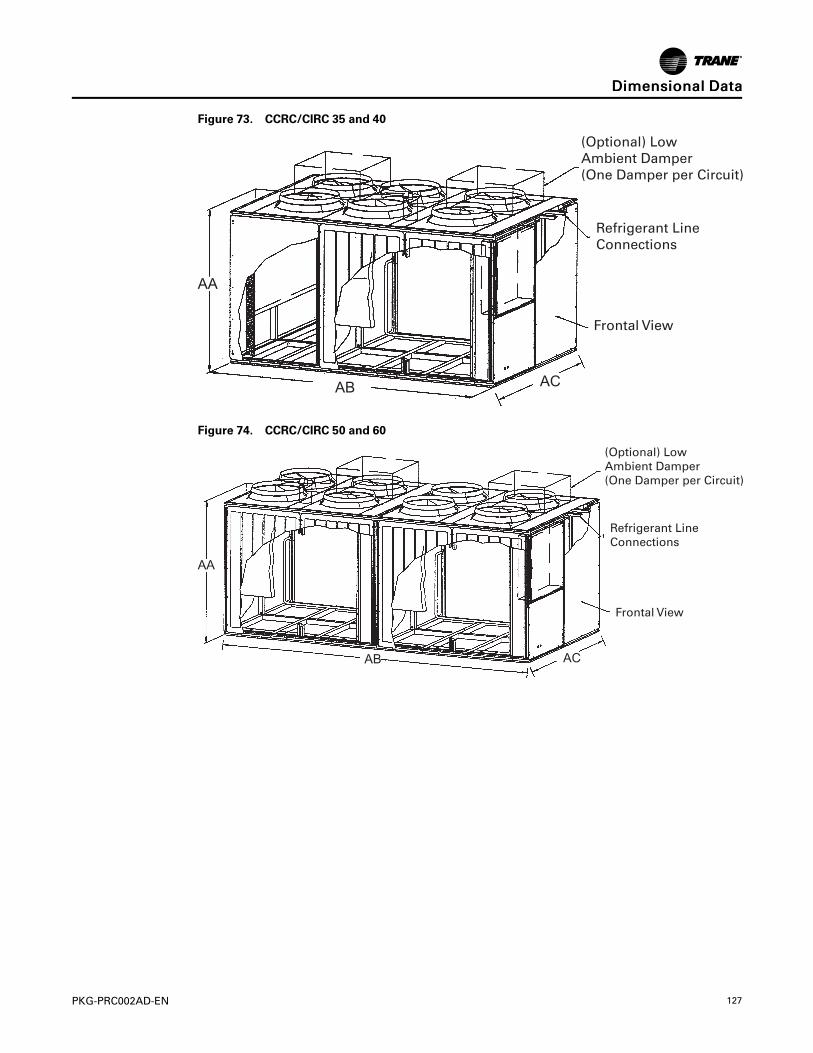
PKG-PRC002AD-EN 127
Figure 73. CCRC/CIRC 35 and 40
(Optional) LowAmbient Damper (One Damper per Circuit)
Refrigerant LineConnections
Frontal View
ACAB
AA
Figure 74. CCRC/CIRC 50 and 60
(Optional) LowAmbient Damper (One Damper per Circuit)
Refrigerant LineConnections
Frontal View
ACAB
AA
DDiimmeennssiioonnaall DDaattaa

128 PKG-PRC002AD-EN
Refrigerant and Electrical ConnectionsFigure 75. Front view, looking at control panel
Table 76. Electrical connections—inches (mm)
Unit A B C D
CCRC/CIRC 20-32 6 3/8 (162) 12 1/4 (311) 15 1/4 (387 18 1/4 (464)
CCRC/CIRC 35-40 6 3/8 (162) 12 1/4 (311) 15 1/4 (387 18 1/4 (464)
CCRC/CIRC 50-60 6 3/8 (162) 12 1/4 (311) 15 1/4 (387 18 1/4 (464)
Table 77. Refrigerant connections—inches (mm)
Unit E F G H J K L M N
CCRC/CIRC 20-29 66 7/8(1699)
14 3/8(365)
18 1/2(470)
24 3/4(629) 29 (737) 5/8(16) 7/8 (22) 5/8 (16) 7/8 (22)
CCRC/CIRC 30-50 66 7/8(1699)
14 3/8(365)
18 1/2(470)
24 3/4(629) 29 (737) 7/8 (22) 1 3/8 (35) 5/8 (16) 7/8 (22)
CCRC/CIRC 60 66 7/8(1699)
14 3/8(365)
18 1/2(470)
24 3/4(629) 29 (737) 7/8 (22) 1 3/8 (35) 7/8 (22) 1 3/8 (35)
DDiimmeennssiioonnaall DDaattaa

PKG-PRC002AD-EN 129
Hot Water CoilFigure 76. Hot water coil
Table 78. Hot water coil piping locations, inches
Unit Tons &Model Coil A B C D E F G H J
25 - 35 SXRF 29 - 38 SXWF Std 60 3/8 5 9/32 82 7/8 18 7 1/2 18 7/8 22 3/8 1 3/4 2 3/8
20 SXRF 20 - 25 SXWF Std 60 3/8 5 9/32 82 7/8 18 7 1/2 26 1/2 22 3/8 1 3/4 2 3/8
25 - 35 SXRF 29 - 38 SXWF Hi-cap 60 3/8 5 1/2 82 7/8 18 7 1/2 18 7/8 22 3/8 2 3/4 3 1/2
20 - 25 SXWF Hi-cap 60 3/8 5 1/2 82 7/8 18 7 1/2 26 1/2 14 1/8 12 3/4 2 1/2
42 - 80 SXRF/SXWF Std 72 7/8 3 11/16 104 5/8 18 7 1/2 32 3/4 22 3/8 2 3/4 3 1/2
42 - 80 SXRF/SXWF Hi-cap 72 7/8 3 7/8 104 5/8 18 7 1/2 32 3/4 14 1/8 2 3/4 3 3/8
Notes:1. All coils are factory mounted. The control valve ships loose.2. All pricing connections are 1 1/2" (38.1mm) NFT (EXT) for 1 row coils and 2 1/2" (50.8mm) NPT (EXT) for 2 row coils (high capacity).
DDiimmeennssiioonnaall DDaattaa

130 PKG-PRC002AD-EN
Steam CoilFigure 77. Steam coil
Main Control Panel
Vacuum Trap Connection
Condensate Return
Vacuum Trap ConnectionSteam Inlet Connection
Condensate ReturnAir Inlet
LK F
NM
H
J
A
CB
Table 79. Piping locations for steam coils — inches (mm)
A B C D E F G H J K L M N
UnitSizes20 - 38
60 3/8(1534)
82 7/8(2105)
18(457) — —
22 3/8(568) —
3(76)
18 1/2(470)
3 7/8(98)
5(127)
4 3/8(111)
1 1/4(32)
UnitSizes42 - 80
72 7/8(1851)
105 1/4(2680)
18(457 ) — —
13 1/4(337) —
3(76)
22 1/8(562)
6 3/8(162)
5 3/8(137)
4 3/8(111)
1 1/4(32)
Notes:1. All coils are factory mounted, piped, and wired.2. All piping connections are 1-1/2" (38.1mm) female NPT fittings.
Flexible Horizontal Discharge PlenumTable 80. Plenum dimensions—inches (mm)
Unit A B C Weight
Unit Sizes 20-38
Low 64 7/8 (1648) 95 7/8 (2435) 24 5/8 (625 ) 325 lbs. (147.4 kg)
Std. 64 7/8 (1648) 95 7/8 (2435) 32 3/8 (822) 430 lbs. (195.0 kg)
Ext. 64 7/8 (1648) 95 7/8 (2435) 45 (1143) 705 lbs. (320.0 kg)
Unit Sizes 42-80
Low 80 3/8 (2042) 119 7/8 (3045) 21 1/8 (537) 390 lbs. (176.9 kg)
Std. 80 3/8 (2042) 119 7/8 (3045) 28 5/8 (727) 540 lbs. (244.9 kg)
Ext. 80 3/8 (2042) 119 7/8 (3045) 45 (1143) 705 lbs. (320.0 kg)
* Unit Sizes 90-110
Low 80 1/2 (2044) 140 (3556) 19 5/8 (498) 430 lbs. (195.0 kg)
Std. 80 1/2 (2044) 140 (3556) 27 3/4 (704) 595 lbs. (269.9 kg)
Ext. 80 1/2 (2044) 140 (3556) 431/2 (1104.9) 795 lbs. (360.6 kg)
Note: * For 90-110 ton, plenum ship separate with field cut holes. Factory cut holes available as a design special only.
DDiimmeennssiioonnaall DDaattaa

PKG-PRC002AD-EN 131
Figure 78. Plenum dimensions
AB
C
Figure 79. 6-inch filter rack option
DDiimmeennssiioonnaall DDaattaa

132 PKG-PRC002AD-EN
Airside EconomizerFigure 80. Airside economizer dimensions
DDiimmeennssiioonnaall DDaattaa

PKG-PRC002AD-EN 133
Table 81. Airside economizer dimensions — English — (inches)
UnitMod-el A B C D E F (1) F (2)
G(1) G (2)
H(1)
H(2) J K L M
20SXWF 44 74 22.38 81.75 8.75 66.75 49.75 23.25 20.50 9.75 11.38 20.50 22.25 16 49.75
25SXRF 44 74 22.38 81.75 8.75 68.63 49.75 28.38 20.50 7.25 11.38 20.50 22.25 16 49.75
22SXW-F, 29SXWF
44 74 22.38 81.75 8.75 68.63 49.75 28.38 20.50 7.25 11.38 20.50 22.25 16 49.75
29SXRF,32
SXWF
44 74 22.38 81.75 8.75 74.25 62.75 23.25 20.50 9.75 11.38 20.50 22.25 9.50 62.75
30SXRF,35
SXRF
44 74 22.38 81.75 8.75 73.50 62.75 33 20.50 4.88 11.38 20.50 22.25 9.50 62.75
35SXW-F, 38SXWF
44 74 22.38 81.75 8.75 73.50 62.75 33 20.50 4.88 11.38 20.50 22.25 9.50 62.75
42SXWF 57.38 86.50 13.25 104.38 8.88 83.63 63.50 33 26 2.50 15 26 24.75 20.38 63.50
40SXRF,46
SXWF
57.38 86.50 13.25 104.38 8.88 94.38 63.50 28.38 26 6.88 15 26 24.75 20.38 63.50
50SXRF,60
SXRF,52-80SXWF
57.38 86.50 13.25 104.38 8.88 96.63 63.50 52 37.50 1.88 9.25 37.50 19 20.38 63.50
DDiimmeennssiioonnaall DDaattaa

134 PKG-PRC002AD-EN
Table 82. Airside economizer dimensions —metric — (mm)
Unit Model A B C D E F (1) F (2) G (1) G (2) H(1)
H(2) J K L M
20 SXWF 1118 1880 568 2076 222 1695 1264 591 521 248 283 521 565 406 1264
25 SXRF 1118 1880 568 2076 222 1743 1264 714 521 184 283 521 565 406 1264
22 SXWF, 29SXWF 1118 1880 568 2076 222 1743 1264 714 521 184 283 521 565 406 1264
29 SXRF, 32SXWF 1118 1880 568 2076 222 1886 1594 591 521 248 283 521 565 241 1594
30 SXRF, 35SXRF 1118 1880 568 2076 222 1867 1594 838 521 124 283 521 565 241 1594
35 SXWF, 38SXWF 1118 1880 568 2076 222 1867 1594 838 521 124 283 521 565 241 1594
42 SXWF 1457 2197 337 2651 225 2124 1613 838 660 64 381 660 629 518 1613
40 SXRF, 46SXWF 1457 2197 337 2651 225 2390 1613 714 660 175 381 660 629 518 1613
50 SXRF, 60SXRF, 52-80
SXWF1457 2197 337 2651 225 2454 1613 1321 953 48 235 953 483 518 1613
Factory-Provided/Field-Installed Zone SensorFigure 81. Field-Installed Zone Sensor
FRONT
4-11/16 [118,75 mm]
2-29/32 [73,55 mm]
Zone Temperature Sensor Only BAYSENS077
DDiimmeennssiioonnaall DDaattaa

PKG-PRC002AD-EN 135
Service ClearancesSelf-Contained Models SCWF, SIWF, SCRF, SIRFTable 83. Service/code clearance requirements
Side Distance—inches (mm) Purpose
Front42 (1066) (20 to 38 tons) NEC code requirements
48 (1219) (42 to 110 tons) Fan service/removal
Left 36 (914) Filter, refrigeration, and waterside components
Right
9 (229) Non VFD w/open return
18 (457) Non VFD w/ducted return
9 (229) 20 to 80 tons, w/VFD 7.5 to 50 hp
36 (914) 90 to 110 tons (motor, condensers, and refrigeration)
Inlet18 (457) (20 to 80 tons) Provides uniform airflow
36 (914) (90 to 110 tons) Provides uniform airflow
Figure 82. Top view— SCWF, SCRF, SIWF, SIRF
Air Inlet
See Table
42” (1066.8mm) (20-38 Ton)Minimum
48” (1219mm) (42-110 Ton)
ControlPanel
36” (914.4mm)Minimum
Left side
Front
Right side
NNoottee:: Units (20 to 80) with VFD contain a swing out door. Allow 48" minimum clearance.
DDiimmeennssiioonnaall DDaattaa

136 PKG-PRC002AD-EN
Remote Air-Cooled Condensers Models CCRC,CIRCFigure 83. Top view— CCRC,CIRC 20, 29
C B
D A
96” (2132 mm)
48” (1066 mm)
96” (2132 mm)
48” (1066 mm)
Control Panel
Figure 84. Top view— CCRC,CIRC 35, 40
96” (2132 mm)
48” (1066 mm)
96” (2132 mm)
48” (1066 mm)
Control Panel
C B
D A
F
E
Figure 85. Top view— CCRC,CIRC 50, 60
96” (2132 mm)
48” (1066 mm)
96” (2132 mm)
48” (1066 mm)
Control Panel
C B
D A
F
E
G
H
DDiimmeennssiioonnaall DDaattaa

PKG-PRC002AD-EN 137
Weights
Table 84. Unit weights — SCWF/SCRF/SIWF/SIRF
Unit UnitSize
BaseWeightlbs. (kg)
AirsideEconomizerlbs. (kg)
2-RowWatersideEconomizerlbs. (kg)
4-RowWatersideEconomizerlbs. (kg)
HeatingCoil Boxlbs. (kg)
6-RowEvap. Coillbs. (kg)
6-inch filterrack lbs.(kg)
SCWF/SIWF
20 3102 (1407) 430 (195) 140 (64) 340 (154) 460 (209) N/A 212 (96)
22 3102 (1407) 430 (195) 140 (64) 340 (154) 460 (209) N/A 212 (96)
25 3170 (1438) 430 (195) 140 (64) 340 (154) 460 (209) 144 (65) 212 (96)
29 3326 (1508) 500 (227) 190 (86) 390 (177) 460 (209) N/A 212 (96)
32 3514 (1594) 500 (227) 190 (86) 390 (177) 460 (209) 132 (60) 212 (96)
35 3721 (1688) 500 (227) 280 (127) 505 (229) 460 (209) N/A 212 (96)
38 3819 (1732) 500 (227) 280 (127) 505 (229) 460 (209) 138 (63) 212 (96)
42 4615 (2093) 640 (290) 255 (116) 505 (229) 600 (272) N/A 257 (117)
46 4705 (2134) 640 (290) 255 (116) 505 (229) 600 (272) 170 (77) 257 (117)
52 4892 (2219) 700 (318) 335 (152) 665 (302) 600 (272) N/A 257 (117)
58 5142 (2332) 700 (318) 335 (152) 665 (302) 600 (272) 216 (98) 257 (117)
65 5371 (2436) 800 (363) 335 (152) 665 (302) 600 (272) N/A 257 (117)
72 5491 (2490) 800 (363) 335 (152) 665 (302) 600 (272) 216 (98) 257 (117)
80 5814 (2637) 800 (363) 335 (152) 665 (302) 600 (272) N/A 257 (117)
90 6330 (2871) N/A N/A 1015 (460) N/A 255 (116) N/A
100 6840 (3103) N/A N/A 1015 (460) N/A 255 (116) N/A
110 6852 (3108) N/A N/A 1015 (460) N/A 255 (116) N/A
SCRF/SIRF
25 3231 (1465) 500 (227) N/A N/A 460 (209) N/A N/A
29 3231 (1465) 500 (227) N/A N/A 460 (209) N/A N/A
30 3321 (1506) 500 (227) N/A N/A 460 (209) N/A N/A
35 3421 (1552) 500 (227) N/A N/A 460 (209) N/A N/A
40 4294 (1948) 640 (290) N/A N/A 600 (272) N/A N/A
50 4731 (2146) 700 (318) N/A N/A 600 (272) N/A N/A
60 5288 (2399) 800 (363) N/A N/A 600 (272) N/A N/A
Notes:1. All unit weights include refrigerant, water, and controllers, electric heat and valves.2. Add 150 lbs. to total weight to obtain approximate shipping weight.3. Flexible horizontal discharge plenum option weights: 45-inch plenum = 705 lbs., Standard height plenum = 430 lbs., Low height plenum = 325 lbs.
Table 85. Unit weights — CCRC/CIRC
Unit Size ShippingWeight lbs (kg). OperatingWeight lbs.(kg)
CCRC/CIRC 20 2030 (920) 1906 (865)
CCRC/CIRC 29 2084 (945) 1960 (890)
CCRC/CIRC 32 2138 (970) 2014 (915)
CCRC/CIRC 35 3018 (1370) 2833 (1285)

138 PKG-PRC002AD-EN
Table 85. Unit weights — CCRC/CIRC (continued)
Unit Size ShippingWeight lbs (kg). OperatingWeight lbs.(kg)
CCRC/CIRC 40 3072 (1395) 2887 (1310)
CCRC/CIRC 50 3995 (1810) 3695 (1675)
CCRC/CIRC 60 4275 (1940) 3975 (1805)
Table 86. VFD weights
Without Bypass With Bypass
HP200V 460V 575V
HP200V 460V 575V
LBS Kg LBS Kg LBS Kg LBS Kg LBS Kg LBS Kg
7.5 126 57.153 114 51.710 114 51.710 7.5 215 97.522 170 77.111 170 77.111
10 126 57.153 114 51.710 126 57.153 10 215 97.522 215 97.522 215 97.522
15 152 68.946 126 57.153 126 57.153 15 220 99.790 215 97.522 215 97.522
20 152 68.946 126 57.153 126 57.153 20 220 99.790 215 97.522 215 97.522
25 152 68.946 126 57.153 126 57.153 25 250 113.398 215 97.522 215 97.522
30 177 80.286 152 68.946 152 68.946 30 250 113.398 220 99.790 220 99.790
40 177 80.286 152 68.946 152 68.946 40 290 131.542 220 99.790 220 99.790
50 NA NA 152 68.946 152 68.946 50 NA NA 250 113.398 250 113.398
60 NA NA 177 80.286 NA NA 60 NA NA 250 113.398 NA NA
Note: Weights include swing-out door.
WWeeiigghhttss

PKG-PRC002AD-EN 139
Mechanical SpecificationsSignature Series Self-Contained Units
NNootteess:: Certified DOE Performance:
• Trane Commercial Self-Contained units are tested in accordance with AHRI 340/360 (I-P).
• The net cooling capacity and EER performance are certified to 10 CFR Part 431 fromthe US Department of Energy.
Cabinet• The unit framework are formed structural members of sturdy-gauge galvanized steel. Exterior
panels are fabricated from industrial-gauge galvanized steel. The fan and compressorsections are insulated with ¾-inch (19 mm) of 1.75 lb./cu. ft. (28 kg./cu. ft.) density fiberglassinsulation.
• The unit is provided with removable panels to allow service access to compressors,condensers, fan motor, fan bearings, coils, and valves. Removable panels are secured withquick-acting fasteners. The refrigerant sight glasses are accessible during operation. Thecontrol panel door has lift-off hinges.
• The unit cabinet and any insulated ship-separate modules for indoor installation are wrappedon top and 4 sides with a recyclable, transparent, seven-mil-thick, low-density polyethyleneheat-shrink film. The film has adequate transparency for unit nameplates and labels to bereadable through the film.
• Cabinet corners shall have protective padding in place to prevent damage to the film.
• All seams and edges in the film are heat welded and adequately taped to minimize unitexposure to rain, snow, ice and road grime during shipping.
Compressors• Units have multiple compressors with independent circuits for water-cooled units and
manifolded circuits for air-cooled units.
• Compressors are manufactured by the unit manufacturer.
• Scroll compressors are heavy duty suction cooled type with suction screen, centrifugal oilpump with dirt separator, oil charging valve, and oil sight glass.
• Protective devices for low pressure, high pressure, and motor temperature are provided.
• The compressors are mounted on isolators for vibration isolation.
Phase and Voltage Monitor• Protects 3-phase equipment from phase loss, phase reversal and low voltage.
• Any fault condition will produce a Failure Indicator LED and send the unit into an auto stopcondition.
• cULus approved.
Condenser (SCWF/SIWF only)• One condenser is provided for each compressor.
• The condensers are shell-and-tube design with removable heads and mechanically cleanabletubes. Tubes are ¾-inch (19 mm) OD and constructed of copper.
• Condenser waterside working pressure is 400 psig.
• All condenser water piping including, cleanouts, are factory installed to provide singleconnections for water inlet and outlet.

140 PKG-PRC002AD-EN
Evaporator• The evaporator coil is seamless copper tubes expanded into aluminum fins. Tubes are ½-inch
(13 mm) OD with internally enhanced surfaces.
• Coil has staggered tube arrangement with intertwined circuitry and no more than 12 fins perinch.
• The drain pan is positively sloped in all directions to ensure proper condensate removal. Thedrain pan is fabricated of galvanized steel and insulated with ¾-inch (19 mm) of 1-lb. (0.5 kg)density fiberglass.
• Drain piping, including a trap with clean-out, is provided with a single-point connection to theunit’s exterior.
Refrigerant Circuit (SCWF only)• Refrigerant circuits are independent and completely piped including sight glasses,
distributors, thermal expansion valves with adjustable superheat and external equalizer, andhigh pressure relief valves with ½-inch (13 mm) flare connection.
• Filter driers ship loose for field installation.
• Unit is provided with adequate means of frost control.
• The circuits are factory dehydrated, charged with oil and R-410A refrigerant.
• Compressors are mounted on rubber-in-shear isolators for vibration isolation.
Refrigerant Circuit (SCRF/SIRF only)• Two refrigerant circuits are piped to the unit’s exterior.
• The refrigerant piping includes filter driers (shipped loose for field installation),sight glasses,distributors, thermal expansion valves with adjustable superheat and external equalizer.
• Unit is provided with adequate means of frost control.
• The circuits are factory tested, dehydrated and then charged with dry nitrogen.
• Compressors are mounted on rubber-in-shear isolators for vibration isolation.
Supply Fan• The supply fan is a single forward curved medium pressure fan secured to a solid steel shaft
with grease lubricated bearings designed for 200,000 hours. Both fan bearings have greaselines extended to a common location. The drive components include fixed pitch sheaves andmultiple V-belt sized for 130% nominal motor horsepower. All drive components areaccessible without using scaffolds or ladders.
• Supply fan motors are either open drip-proof or totally enclosed fan cooled. The motors havea standard NEMAT-frame and a service factor of 1.15. All 60 Hz motors meet the EnergyIndependence and Security Act of 2007 (EISA).
• The entire fan assembly, including drive components, is mounted on a common base. Thefan base is isolated inside the unit. The entire assembly is statically and dynamically balancedat the factory.
FiltersTwo-inch (51 mm) throwaway fiberglass filters are provided for installation during construction.
Unit Controls — DDC• Microprocessor controls are provided to control all unit functions. The control system is
suitable to control CV or VAV applications. The controls are factory-installed and mounted inthe main control panel. All factory-installed controls are fully commissioned (run tested) atthe factory. The unit has a human interface panel with 16-key keypad, a two line, 40 characterclear language (English, French, or Spanish) display as standard to provide the operator withfull adjustment and display of control data functions. The unit controls are used as a stand-alone controller or as part of a building management system involving multiple units.
MMeecchhaanniiccaall SSppeecciiffiiccaattiioonnss

PKG-PRC002AD-EN 141
• The unit is equipped with a complete microprocessor control system. This system consists oftemperature and pressure (thermistor and static pressure transducer) sensors, printed circuitboards (modules) and a unit mounted human interface panel. Modules (boards) areindividually replaceable for service ease. All microprocessors, boards, and sensors arefactory mounted, wired, and tested.
• The microprocessor boards are stand-alone DDC controls not dependent on communicationswith an on-site PC or building management network. The microprocessors are equipped withon-board diagnostics, indicating that all hardware, software, and interconnecting wiring arein proper operating condition.
• The modules (boards) are protected to prevent RFI and voltage transients from affecting theboard’s circuits. All field wiring is terminated at a separate, clearly marked terminal strip.Direct field wiring to the I/O boards is not acceptable.
• The microprocessor’s memory is nonvolatile EEPROM type requiring no battery or capacitivebackup, while maintaining all data.
• Zone sensors are available in several combinations with selectable features depending onsensor.
• The human interface panel’s keypad display character format is 40 characters x two lines. Thecharacter font is 5x7 dot matrix plus cursor. The display is supertwist liquid crystal display(LCD) with blue characters on a gray/green background which provides high visibility andinterface ease. The display format is in clear language: English, French, or Spanish.
• The keypad is equipped with 16 individual touch sensitive membrane key switches. Theswitches are divided into four separate sections and password protected to preventtampering by unauthorized personnel. The six main menus shall be STATUS, SETPOINTS,DIAGNOSTICS, SETUP, CONFIGURATION, and SERVICE MODE.
Agency ListingThe unit has the US/Canada Underwriter’s Laboratory agency listing. A Unit Interrupt Rating(Standard Short Circuit Current Rating - SCCR) of 5,000 Amp rating (up to 480V) and 25,000 Amprating (600V) is applied to the unit.
Remote Air-Cooled CondenserCabinet
• The unit framework shall be formed structural steel members of sturdy-gauge galvanizedsteel.
• Panels and access doors shall be sturdy-gauge galvanized steel.
• The unit exterior shall be phosphatized and finished with air-dried enamel paint.
Refrigerant Circuits and Controls• All sizes shall have dual refrigerant circuits and shall include an integral subcooling circuit for
each circuit.
• All necessary controls to run unit fans shall be factory installed.
• The control panel shall include fan motor contactors, terminal block connection forcompressor interlock, and 115-volt control power transformer.
Condenser Coils• The condenser coil arrangement shall be slab type.
• Coils shall be seamless 3/8-inch (10 mm) OD copper tubes expanded into aluminum fins.
• Each circuit shall include an integral subcooler.
• The coil shall be leak tested at 650 psig air pressure.
MMeecchhaanniiccaall SSppeecciiffiiccaattiioonnss

142 PKG-PRC002AD-EN
Condenser Fans and Motor• Vertical discharge direct drive fans shall be statically and dynamically balanced at the factory.
• Motors shall be three-phase with permanently lubricated ball bearings, built-in current andthermal overload protection and weathertight rain slinger over the fan shaft.
Protective Coating for Condenser Coils (Option)The condenser coil shall have a 4 to 6 mil coat of protective coating applied by a multiple dip-and-bake process.
Low Ambient Operation OptionStandard ambient control allows operation down to 50° F by cycling the condenser fans. Lowambient control damper shall allow the unit to operate down to 0°F by utilizing additional fancycling and an external damper assembly. The low ambient control damper shall include anindustrial-gauge damper assembly. The damper is controlled by the air-cooled unit’s DDCcontroller.
Louvered Coil Guards OptionThe unit coils shall be covered with a factory installed decorative louvered grill type panel forprotection.
Agency ListingThe unit shall have the US/Canada Underwriter’s Laboratory agency listing.
Self-Contained OptionsAir Volume/Temperature Control
Zone Temperature ControlThis option includes a zone sensor, microprocessor unit control module, a microprocessorcompressor controller, and a unit-mounted human interface panel. The unit operates at a designairflow based on the fan and motor drive selections.
Supply Air Temperature Control With Variable Frequency DriveThis option controls the VAV self-contained unit from the discharge air temperature using afactory mounted variable frequency drive (VFD).The VFD safely varies the fan motor speed toallow the motor to meet the dynamic requirements at the motor shaft and meet the system static.Other control components include a discharge air microprocessor controller and discharge airsensor. The microprocessor controller coordinates the economizer control and the stages ofcooling with discharge air temperature reset capabilities. The VFD receives 0-10 Vdc signal fromthe unit microprocessor based upon supply static pressure and causes the drive to accelerate ordecelerate as required to maintain the supply static pressure setpoint.
Supply Air Temperature Control With Variable Frequency Drive with BypassManual bypass control provides full nominal airflow and zone temperature control in the event ofa drive failure. The VFD with bypass is factory mounted completely wired and tested. A motoroverload relay and fuses are provided to properly size motor protection during both drive andbypass modes.
High Capacity Coils• The high capacity coil option (6 row evap) is a selectable option on unit sizes 25, 32, 38, 46, 58,
72.
• The high capacity coil option (8 row evap) is a selectable option on unit sizes 90, 100, 110.
MMeecchhaanniiccaall SSppeecciiffiiccaattiioonnss

PKG-PRC002AD-EN 143
Waterside EconomizerThe waterside economizer takes advantage of cooling tower water to either pre-cool the enteringair to aid the mechanical cooling process or, provides total system cooling if the watertemperature is low enough. Waterside economizing enables when the unit’s entering watertemperature is below the unit’s entering mixed air temperature by a minimum of 4°F plus theeconomizer’s approach temperature. The approach temperature default is 4°F and is adjustablefrom 0 to 9°F. Waterside economizing disables when the unit’s entering water temperature is notbelow the unit’s entering mixed air temperature by at least the water economizer approachtemperature. The economizer acts as the first stage of cooling. If the economizer is unable tomaintain the supply air setpoint, the unit control module brings on compressors as required tomeet the setpoint.
The waterside economizer includes a coil, modulating valves, controls, and piping withcleanouts. All components are factory installed in the unit cabinet. The coil construction is ½-inch(13 mm) OD seamless copper tubes expanded into aluminum fins. The evaporator andeconomizer coils share a common sloped (IAQ) drain pan. Drain pan options are eithergalvanized or stainless steel and insulated and internally trapped.
The waterside economizer coil options have either two or four rows with no more than 12 finsper inch. The tubes are arranged in a staggered pattern to copper supply and return headers withremovable cleanout and vent plugs. The optional mechanically cleanable economizer hasremovable cast iron headers to allow easy mechanical cleaning of the tubes. The watersideworking pressure is rated for 400 psig (2758 kPa).
Airside EconomizerUnits with the airside economizer option are equipped with the necessary control sequences touse outside air for the first stage of cooling, in occupied or unoccupied mode and when ambientconditions are favorable for economizing. Inherent in the unit controller is the ability to suppressthe setpoint below the normal unit setpoint. This allows the building to improve comfort levelswhen possible, and at the same time, optimize building mechanical cooling operation for peakoperating efficiency. An outside air temperature and relative humidity sensor are provided toallow monitoring of reference enthalpy and are field installed. Economizer operation enableswhen the outside air enthalpy is less than 25 BTU’s/lb. default (adjustable 19-28 BTU’s/lb.).During occupied mode, the outside air damper opens to 15% (adjustable 0-100%) for ventilationpurposes. Also, the ability to alter the outside air damper position to compensate for VAV supplyair modulation is inherent in the unit controls, and can be enabled by the operator.
The mixing box fabrication is sturdy-gauge galvanized steel. Opposed low leak damper bladesare fabricated from sturdy-gauge galvanized steel and rotate on rustproof nylon bushings. Afactory installed 24V modulating spring return actuator controls both damper positions.
Comparative Enthalpy ControlUnits with comparative enthalpy control are equipped with the necessary control sequences toallow using outside air for the first stage of cooling, in occupied or unoccupied mode and whenambient conditions are favorable for economizing. Inherent in the unit controller is the ability tosuppress the setpoint below the normal unit setpoint. This allows the building to improvecomfort levels when possible, and at the same time, optimize building mechanical coolingoperation for peak operating efficiency. A factory-installed control board, with field-installedoutside and return air temperature and relative humidity sensors, allows monitoring of outsideand return air. Economizer operation enables when the outside air enthalpy is 3 BTU’s/lb. lessthan the return air enthalpy. During occupied mode, the outside air damper opens to 15%(adjustable 0-100%) for ventilation purposes. Also, the ability to alter the outside air damperposition to compensate for VAV supply air modulation is inherent in the unit controls, and can beenabled by the operator.
The mixing box fabrication is sturdy-gauge galvanized steel. Opposed low leak damper bladesare fabricated from sturdy-gauge galvanized steel and rotate on rustproof nylon bushings. Afactory installed 24V modulating spring return actuator controls both damper positions.
MMeecchhaanniiccaall SSppeecciiffiiccaattiioonnss

144 PKG-PRC002AD-EN
Standard Two-Position Damper InterfaceUnits with the two-position damper interface are provided with a 0-10 Vdc control output suitablefor controlling a field-provided modulating actuator. In occupied mode, the output drives to themaximum position.
Airside Economizer InterfaceUnits with airside economizer interface are equipped with the necessary control sequences toallow using outside air for the first stage of cooling, in occupied or unoccupied mode and whenambient conditions are favorable for economizing. Inherent in the unit controller is the ability tosuppress the setpoint below the normal unit setpoint. This allows the building to improvecomfort levels when possible, and at the same time, optimize building mechanical coolingoperation for peak operating efficiency. An outside air temperature and relative humidity sensorare provided for field installation to monitor reference enthalpy. Economizer operation enableswhen the outside air enthalpy is less than 25 BTU’s/lb. (adjustable 19-28 BTU’s/lb). Duringoccupied mode, the outside air damper opens to 15% (adjustable 0-100%) for ventilationpurposes. Also, the ability to alter the outside air damper position to compensate for VAV supplyair modulation is inherent in the unit controls, and can be enabled by the operator. An analog 2-10 Vdc output (adjustable (0-10 Vdc) is provided to modulate the field-provided 30 seconddamper actuators (adjustable 1-255 seconds).
Airside Economizer Interface with Comparative EnthalpyUnits with airside economizer interface and comparative enthalpy are equipped with thenecessary control sequences to allow using outside air for the first stage of cooling, in occupiedor unoccupied mode and when ambient conditions are favorable for economizing. Inherent in theunit controller is the ability to suppress the setpoint below the normal unit setpoint. This allowsthe building to improve comfort levels when possible, and at the same time, optimize buildingmechanical cooling operation for peak operating efficiency. A factory-installed control board,with outside and return air temperature and relative humidity sensors, are provided formonitoring outside and return air. The sensors are field installed. Economizer operation enableswhen the outside air enthalpy is 3 BTU’s/lb. less than the return air enthalpy. During occupiedmode, the outside air damper opens to 15% (adjustable 0-100%) for ventilation purposes. Also,the ability to alter the outside air damper position to compensate for VAV supply air modulationis inherent in the unit controls, and can be enabled by the operator. An analog 2-10 Vdc output(adjustable (0-10 Vdc) is provided to modulate the field-provided 30-second damper actuators(adjustable 1-255 seconds).
Basic Water PipingThis option is available on units without a waterside economizer and with condenser waterapplications above 54°F that do not require condensing pressure control. Left hand waterconnections and piping are extended to the unit exterior. Manifold piping is factory installed.
Intermediate Water PipingThis option provides condensing temperature control when the unit is configured (user definedat the HI) for variable water flow with or without a waterside economizer. A two-way modulatingcontrol valve is wired and installed in the unit to maintain a specific range of water temperaturerise through the condenser when entering fluid temperature is less than 58°F. This option allowsthe compressor to operate with entering fluid temperature down to 35°F.
Waterside Economizer Flow ControlUnits equipped with a waterside economizer can be set from the human interface panel forvariable or constant water flow.
Constant Water FlowTwo-way modulating control shutoff valves are wired, controlled, and installed in the unit. Onevalve is located in the economizer’s water inlet, and the other is in the condenser bypass waterinlet. When the waterside economizer enables, the two-way valve modulates to maintain thedischarge air temperature setpoint. As the economizer valve opens, the condenser bypass valve
MMeecchhaanniiccaall SSppeecciiffiiccaattiioonnss

PKG-PRC002AD-EN 145
closes, and vice versa. Full water flow is always maintained through the condensers. Both valveswill close in the event of a power failure.
Variable Water FlowTwo-way modulating control shutoff valves are wired, controlled, and installed in the unit. Onevalve is located in the economizer’s water inlet, and the other is in the condenser bypass waterinlet. When the economizer valve is active, the condenser bypass valve closes. The economizervalve modulates, thus water flow through the unit modulates. If the water is cool enough foreconomizing, but mechanical cooling is also required, the economizer valve fully opens toestablish full water flow through the condensers. Whenever the water is too warm foreconomizing and there is a call for cooling, the economizer valve fully closes and the bypassvalve fully opens, establishing full water flow through the condensers. Full water flow is alwaysmaintained through the condensers when mechanical cooling is required. Both valves closewhenever cooling is not required and in the event of a power failure.
Water Flow SwitchA water flow switch is factory installed in the condenser water pipe within the unit. Whenever theflow switch detects a water flow loss prior to or during mechanical cooling, compressoroperation locks out and a diagnostic code displays. If water flow is restored, the compressoroperation automatically restores.
Service ValvesService valves are factory installed on each circuit before and after the compressor to allowcompressor isolation for servicing.
Heating Coils
Electric Heat• 20 to 80 tons — A single-stage, electric heating coil is factory installed with controls inside the
unit casing at the fan discharge. An open construction type coil is provided. Power to theelectric heater is factory wired to the unit’s single-point power connection.
NNoottee:: Electric heat is not available on high capacity units with low flow fan.
• 90 to 110 tons — A two-stage, electric heating coil is factory installed with controls inside theunit casing at the fan discharge. An open construction type coil is provided. Power to theelectric heater is factory wired to the unit’s single-point power connection.
Hot Water (20 to 80 ton only)The hot water heating assembly includes the coil and filter section and is factory installed on theunit’s inlet. A three-way modulating valve with actuator ships with the hot water coil rack option.The coil is a Trane type 5W, constructed of 5/8-inch (16 mm) OD copper tubes arranged in aparallel pattern. The copper tubes are expanded into aluminum fins positioned continuouslyacross the entire coil width, not exceeding 12 fins per inch. A one row or two row (high capacity)coil is available. The coil casing is galvanized steel. Coil performance is rated at a maximumworking pressure of 200 psig in accordance with ARI Standard 410. Supply and return waterheader connections are steel pipe and are accessed from the unit’s left side.
Steam (20 to 80 ton only)The steam heating assembly includes the coil and filter section, factory installed on the unit’sinlet. A two-way modulating valve, actuator, and manifold piping are also factory installed. Also,connections are provided for field installing a vacuum breaker. The coil is a Trane type NS,constructed of one inch (25 mm) OD copper tubes arranged in a parallel pattern. The coppertubes are expanded into aluminum fins positioned continuously across the entire coil width, notexceeding 42 fins per foot. The coil casing is sturdy-gauge steel. Coil performance is rated at amaximum working pressure of 100 psig in accordance with ARI Standard 410. Supply and returnsteam header connections are female tapered NPT and are accessed from the unit’s left side.Factory provided controls limit the steam coil leaving air temperature to no more than 105°F at alloperating conditions.
MMeecchhaanniiccaall SSppeecciiffiiccaattiioonnss

146 PKG-PRC002AD-EN
Electric Heat InterfaceA heat control module will be factory installed and wired for customer supplied and poweredelectric heat. This module will allow the unit to stage the customer-provided electric heat. Up tothree stages of electric heat control will be accomplished with three dry binary output rated atone amp for 115 Vac.
Hydronic Heating Control InterfaceA heat control module will be factory installed and wired for customer supplied hydronic heating.This control will be accomplished with a dry binary output, 0-10 Vdc analog control signal.
Time ClockA factory-installed programmable time clock is wired to the unoccupied mode binary input toprovide on/off control. The timer is accessible without opening the control panel door, and is aseven-day type with a maximum of four operations per day. A permanent built-in rechargeablebattery pack is provided.
Low Entering Air Temperature—Protection DeviceA thermostat limit switch is factory mounted on the unit’s entering air side with a capillary tubeserpentine across the coil face. If the temperature falls below 35°F, the fan shuts down and thewaterside economizer and/or hydronic heat valve option opens to allow full water flow. The heatoutput also energizes. A manual reset is required.
NNoottee:: This option is standard on units with a waterside economizer or hydronic heat.
Non-fused Disconnect SwitchThe unit has a factory mounted non-fused disconnect switch accessible without opening thecontrol panel door.
Dual Point Power Terminal BlocksTwo separate power terminal blocks are available to bring power to the unit; one terminal blockprovides power to the compressors and the other provides power to the fan motor and controls.
NNoottee:: A single point power terminal block is standard.
Flexible Horizontal Discharge Plenum
Low and Standard HeightUnits are provided with a ship-separate or factory installed horizontal discharge plenum thatpermits multi-directional duct connections. The plenum is insulated with two inches (51 mm) of1.75 lb. (0.79 kg) density fiberglass for sound attenuation. Discharge openings can either be fieldcut or factory cut based on duct dimensions supplied by the customer. A two-inch duct collar isprovided for field duct connections. On unit sizes 20-38 tons, the low height plenum is 24 5/8inches (625 mm) and the standard height plenum is 32 3/8 inches (822 mm). On unit sizes 42-80tons, the low height plenum is 21 1/8 inches (537 mm) and the standard height plenum is 28 5/8inches (727 mm).
Extended HeightUnits are provided with a horizontal discharge plenum that permits multi-directional ductconnections. 20 to 80 Ton extended plenum height is 45", 90 to 110 Ton extended plenum heightis 43 1/2". The plenum is insulated with four inches (102 mm) of 1.75 lb. (0.79 kg) densityfiberglass for sound attenuation. Double-wall perf is also available. Discharge openings caneither be field cut or factory cut based on duct dimensions supplied by the customer. A two-inchduct collar is provided for field duct connections.
High Duct Temperature ThermostatA factory-supplied temperature limit switch with reset element detects the supply air ducttemperature. This sensor should be field-installed downstream from the unit’s discharge in thesupply air duct. If the supply air duct temperature exceeds 240°F, the unit shuts down and
MMeecchhaanniiccaall SSppeecciiffiiccaattiioonnss

PKG-PRC002AD-EN 147
displays a diagnostic. A manual reset is required at the unit. The high duct temperature can beadjusted at the thermostat.
Plenum High Static SwitchA factory supplied sensor provides additional protection from ductwork over-pressurization. Thissensor should be field-installed downstream of the unit’s discharge in the supply air duct.
Protective CoatingCoils— Three to five mL of protective coating is applied to the coil using a multiple dip-and-bakeprocess.
Cupro-Nickel CondenserOne condenser is provided for each compressor. The condensers are a shell-and-tube designwith removable heads to allow mechanical tube cleaning. Tubes are ¾-inch (19 mm) OD andconstructed of copper cupro-nickel (90/10).
Stainless Steel Drain PanThe drain pan is positively sloped, fabricated from 304L stainless steel, and insulated with ¾-inch(19 mm) of 1-lb. (0.5 kg) density fiberglass. The drain pan contains a factory piped trap withcleanout.
Dirty Filter SensorA factory installed pressure switch senses the pressure differential across the filters. When thedifferential pressure exceeds 0.9-inches (23 mm) WG, contact closure occurs.
A field installed indicator device may be wired to relay terminals that indicate when filter serviceis required. Contacts are rated at 115 Vac and are powered by a field supplied transformer.
FiltersTwo-inch (51 mm) medium efficiency throwaway fiberglass filters are installed in the unit filtersection. Optional two-inch and four-inch filter racks may also be provided. Four-inch cartridgefilters must be field purchased for installation.
Remote Human Interface PanelThe remote human interface panel (RHI) can perform all the same functions as the unit mountedhuman interface panel, except the service mode function. A single RHI can monitor and controlup to four units. The panel includes a 2x40 character clear language (English, Spanish, or French)display, a red LED light to indicate an alarm condition, a simple 16-key keypad for making unitsetpoint and configuration changes, and hinged access door. The panel can be mounted up to5,000 feet (1524 m) from the unit and is wired to the inter-processor communications bridge(IPCB) mounted in the unit with twisted wire pair communication wiring and 24V wiring.
Generic Building Automation SystemModule (GBAS)The GBAS module is for use with a non-Trane building management system. The moduleprovides a binary input for demand limiting, four analog inputs for setpoint adjustment, and fiverelay outputs for diagnostic reporting. Inputs can use a potentiometer or 0-5 Vdc signal.
Ventilation Override Module (VOM)The VOM allows you to program the unit with up to five ventilation sequences: smoke purge,evacuation, pressurization, purge, and purge with duct control. Typically, a hard-wire short froma smoke detector or fire control panel will cause a binary input on the VOM to close, thus causingthe programmed sequence to occur.
MMeecchhaanniiccaall SSppeecciiffiiccaattiioonnss

148 PKG-PRC002AD-EN
LonTalk Communication Protocol/LCI-IThe LCI-I option (COMM5) provides interface to a Trane Integrated Comfort™ system (ICS). Itallows remote control and monitoring of the self-contained unit using a personal computerwithTracer® building management software.
BACnet Building Automation SystemThe BACnet® Communication Interface for self-contained (BCI-I) controller expandscommunications from the unit UCM network to Tracer SC or a 3rd party building automationsystem, utilizing BACnet, and allows external setpoint and configuration adjustment andmonitoring of status and diagnostics.
Air Fi Wireless Communications Interface (WCI)—Field InstalledAir Fi™Wireless Communications Interface—Provides wireless communication between theTracer™ SC, Tracer Unit Controllers and BACnet Communication Interface (BCI) modules.
MMeecchhaanniiccaall SSppeecciiffiiccaattiioonnss

PKG-PRC002AD-EN 149
NNootteess

150 PKG-PRC002AD-EN
NNootteess

PKG-PRC002AD-EN 151
NNootteess

Trane - by Trane Technologies (NYSE: TT), a global innovator - creates comfortable, energy efficientindoor environments for commercial and residential applications. For more information, please visittrane.com or tranetechnologies.com.
Trane has a policy of continuous product and product data improvements and reserves the right to change design and specifications withoutnotice. We are committed to using environmentally conscious print practices.
PKG-PRC002AD-EN 21 Jun 2021
Supersedes PKG-PRC002AC-EN (June 2020) ©2021 Trane