Commander 112 Maintenance Manual
293
Rockwell Commander 112/B/Tc/TCA REVISION 1: 23 APRIL 1977 CHANGED: 7 JANUARY 1980 MANUFACTURERSSERIALNO. ________________________ _ REGISTRATION NO. ________________________________ _ For coordination with sales and service information, Serial No. 126 thru 499 are referred to as Model 112A. At the time of issue of this Maintenance Manual, the contents were, to the best of Rockwell International's knowledge, adaquate to maintain the aircraft in a continued airworthy condition. '!' Rockwell International General Aviation Division 5001 North Rockwell Avenue Bethany, Oklahoma 73008 PIN M 112001-2 Copyright Commander Owners Group 2013 All Rights Reserved **unofficial copy**
-
Upload
khangminh22 -
Category
Documents
-
view
2 -
download
0
Transcript of Commander 112 Maintenance Manual

Rockwell Commander
112/B/Tc/TCA
REVISION 1: 23 APRIL 1977
CHANGED: 7 JANUARY 1980
MANUFACTURERSSERIALNO. ________________________ _
REGISTRATION NO. ________________________________ _
For coordination with sales and service information, Serial No. 126 thru 499
are referred to as Model 112A.
At the time of issue of this Maintenance Manual, the contents were, to the
best of Rockwell International's knowledge, adaquate to maintain the aircraft
in a continued airworthy condition.
'!' Rockwell International General Aviation Division 5001 North Rockwell Avenue Bethany, Oklahoma 73008 PIN M 112001-2
Copyright C
omm
ander Ow
ners Group 2013 All R
ights Reserved
**unofficial copy**
gmores
Typewritten Text
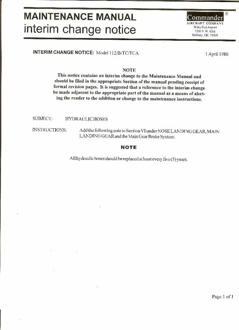
Includes Interim Change 4/1/86 and
gmores
Typewritten Text
Interim Change 2, 9/1/96

Copyright C
omm
ander Ow
ners Group 2013 All R
ights Reserved
**unofficial copy**

ROCKWELL COMMANDER 112/B/TC/TCA
MAINTENANCE MANUAL LIST OF EFFECTIVE PAGES
LIST OF EFFECTIVE PAGES
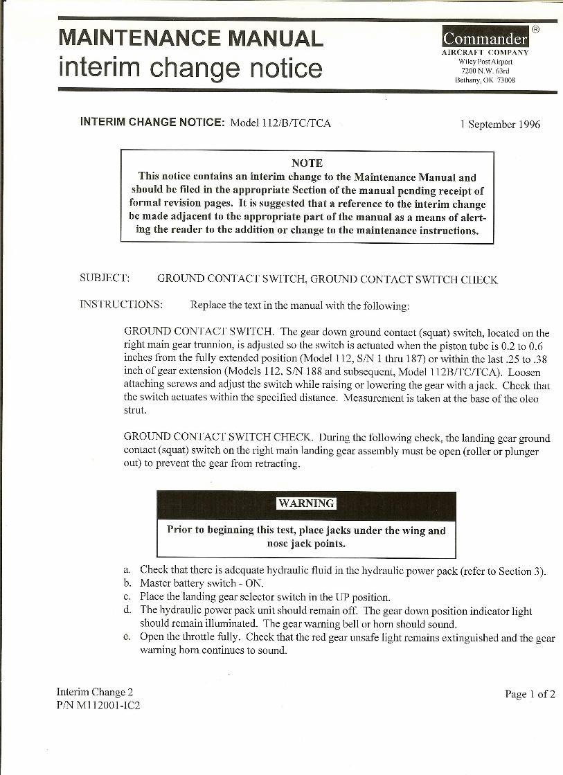
TOTAL NUMBER OF PAGES IN THIS PUBLICATION IS 287 CONSiSTING OF THE FOLLOWING:
Page Issue
*Title .................... Change 4 *A ........................ Change 4 *B ........................ Change 4 i thru iii ................ Revision 1 iv Blank ................ Revision 1 v thru vi ................. Change 2 1-1 ..................... Revision 1 1-2 ...................... Change 1 1-3 ..................... Revision 1 1-4 thru 1-5 .............. Change 3 1-6 ........ . . . . . . . . . . . .. Revision 1 1-7 thru 1-8 .............. Change 1 2-1 thru 2-5 ............. Revision 1 2-6 ...................... Change 3 2-7 ..................... Revision 1 2-8 ...................... Change 3 2-9 thru 2-10 ............ Revision 1 2-11 ..................... Change 3 2-12 .................... Revision 1
*2-13 ..................... Change 4 *2-14 ................•.•.. Change 4 2-15 ..................... Change 1 2-16 .................... Revision 1 2-17 ..................... Change 1 2-18 ..................... Change 2 2-18A ................... Change 2 2-18B Blank .... . . . . . . . . .. Change 2 2-19 thru 2-20 ............ Change 2 2-20A ................... Change 2 2- 20B Blank .......... . . .. Change 2 2-21 ..................... Change 2 2-22 thru 2-29 ........... Revision 1 2-30 thru 2-32 ............ Change 3 3-1 ...................... Change 2 3-2 ..................... Revision 1 3-3 thru 3-4 .............. Change 2 3-5 .................... Revision 1 3-6 thru 3-8 .............. Change 2
*3-9 ....................... Change 4 3-10 ...................... Change 3
*3-11 ...............••...•• Change 4 3-12 .....................• Change 1 3-13 .............•.•..•..• Change 2
*3-14 .............•...•...• Change 4 4-1 ...................... Change 2 4-2 thru 4-9 ............. Revision 1 4-10 thru 4-11 ............ Change 1 4-12 .... . . . . . . . . . . . . . . . .. Change 3 4-13 thru 4-16 ........... Revision 1 4-17 ..................... Change 1
Page Issue
4-18 thru 4-24 ........ Revision 1 4-25 ..................... Change 3 4-26 thru 4-28 ........... Revision 1 4-29 ..................... Change 3 4-30 thru 4-34 .. . ........ Change 2 5-1 ...................... Change 2 5-2 thru 5-4 ............. Revision 1 5-5 thru 5-6 .............. Change 2 5-6A .................... Change 2 5-6B Blank .............. Change 2
*5-7 thru 5-8 •.............. Change 4 5- 9 ..............•........ Change 3 5-10 thru 5-11 ........... Revision 1 5-12 Blank .............. Revision 1 6-1 .. . . . . . . . . . . . . . . . . . .. Revision 1 6- 2 thru 6- 5 .. . . . . . . . . . . .. Change 2 6- 6 thru 6-9 ............... Change 3 6-10 .................... Revision 1 6-11 ...................... Change 3 6-12 thru 6-14 ........... Revision 1 6-15 thru 6-16 ... . . . . . . . .. Change 2 6-17 thru 6-19 ........... Revision 1 6-20 . . . . . . . . . . . . . . . . . . . .. Change 3 6-21 thru 6-26 ........... Revision 1 7-1 thru 7-3 ............. Revision 1 7-4 ...................... Change 2 7-5 thru 7-7 ............. Revision 1 7-8 ...................... Change 2 7-9 ..................... Revision 1 7-10 thru 7-11 ............ Change 2 7-12 .................... Revision 1 7-13 ..................... Change 1 7-14 thru 7-20 ........... Revision 1 7-21 ..................... Change 1 7-22 ..................... Change 2 7-23 thru 7-27 ........... Revision 1 7-28 Blank .............. Revision 1 8-1 ...................... Change 1 8-2 thru 8-3 ............. Revision 1 8- 4 ...... . . . . . . . . . . . . . . .. Change 2 8-4A .................... Change 2 8-4B Blank .............. Change 2 8-5 thru 8-8 ............. Revision 1 8- 9 .. . . . . . . . . . . . . . . . . . . .. Change 1 8-10 ..................... Change 2 8-11 thru 8-12 ............ Change 1 8-13 ..................... Change 3 8-14 ..................... Change 2 8-14A ................... Change 1 8-14B Blank ............. Change 1
INSERT LATEST CHANGED PAGES. DESTROY SUPERSEDED PAGES.
*The asterisk indicates pages changed, added or deleted by the current change.
Change 4 A
Copyright C
omm
ander Ow
ners Group 2013 All R
ights Reserved
**unofficial copy**

LIST OF EFFECTIVE PAGES
MAINTENANCE MANUAL
LIST OF EFFECTIVE PAGES (CONTD)
Page Issue
8-15 thru 8-20 ........... Revision 1 8-21 ..................... Change 3 8-22 Blank .............. Revision 1 9-1 thru 9-4 ............. Revision 1 9- 5 ..................... Change 1 9-6 thru 9-8 ............. Revision 1 10-1 thru 10-6 ........... Revision 1 10-7 ..................... Change 2 10-8 Blank .............. Revision 1 10-9 thru 10-62 ......... Revision 1 10- 63 .................... Change 1 10-64 .. , ................. Change 2 10- 64A .................. Change 2 10- 64B Blank ............. Change 2 10- 65 .. . . . . . . . . . . . . . . . . .. Change 1 10- 66 .............. . . . . .. Change 2 10-66A .................. Change 2 10-66B Blank ............ Change 2 10-67 thru 10-68 .......... Change 1 10- 68A .................. Change 1 10- 68B Blank . . . . . . . . . . . .. Change 1 10-69 thru 10-70 .......... Change 2 10-70A .................. Change 3 10-70B Blank ............. Change 2 10-71 thru 10-72 ......... Revision 1 10-73 .. , ................. Change 1 10-74 .................... Change 2 10-75 .................... Change 2 10-76 Blank .............. Change 2
Change 1 ........ September 2, 1977 Change 2 .......... March 24, 1978 Change 3 ............. April 16, 1979 Change 4 ........... January 7, 1980
INSERT LATEST CHANGED PAGES, DESTROY SUPERSEDED PAGES.
*The asterisk indicated pages changed, added or deleted by the current change.
B
ROCKWELL COMMANDER
112/B/TC/TCA
Change 4
Copyright C
omm
ander Ow
ners Group 2013 All R
ights Reserved
**unofficial copy**

ROCKWELL COMMANDER 112/B/TC/TCA
MAINTENANCE MANUAL INTRODUCTION
INTRODUCTION
This Rockwell International, General Aviation Division Maintenance Manual has been prepared by the Technical Publications Department. It contains information on all aircraft systems and operating procedures required for safe and effective maintenance. It shall not be used as a substitute for sound judgement.
APPLICABLE PUBLICATIONS
1. 2. 3. 4.
Pilots Operating Handbook or Flight Manual Pilots Checklist. Illustrated Parts Catalog. Service Releases.
HOW TO GET COPIES
AUTOMATIC DISTRIBUTION
To receive future changes and revisions to this manual or to any other publication automatically, an aircraft unit must be established on the automatic distribution list maintained by the Technical Publications Department. All owners of new and used aircraft can be established on the automatic distribution list or change existing publications requirements of an aircraft unit by submitting a properly executed Technical Manual Owner Address Change Card Form (AC 1661) found in the front of all Maintenance Manuals leaving the factory. Other publications may be purchased by completing Technical Manual Order Form (AC 1658 or AC 1659). Additional information is provided in Service Information No. SI-IOI.
ADDITIONAL COPIES
Additional copies of this manual and related changes may be procured by submitting a Technical Manual Order Form (AC 1658 or AC 1659) found in the back of all Maintenance Manuals delivered from the factory.
REQUESTING MANUALS CORRECTIONS/ CHANGES
Recommended changes or corrections to this manual may be submitted by anyone using the manual. Change/ correction recommendations shall be submitted on the Publications Change Request Form (AC 1432) foundin the back of all manuals delivered from the factory.
All recommended changes will be reviewed by Customer Service, Engineering, etc., before incorporation or rejection. Additional forms may be requested from Rockwell International - General Aviation Division.
CHANGES AND REVISIONS
There are two types of changes and one type of revision used to keep this manual current. The material compiled in these changes and revisions will consist of information necessary to maintain the present equipment or new equipment added to the airplane. It is imperative that this material be inserted in the manual at the time it is received.
INTERIM CHANGE
An interim change will be distributed anytime it is necessary to forward immediate information to the holders of maintenance manuals. The interim change will consist of colored pages which are inserted in the appropriate section of the manual until formal white change pages are issued. This interim change will include deletions and/or additions of material pertinent to specific paragraphs or illustrations of the manual.
FORMAL CHANGE
A formal change will be distributed periodically, to holders of maintenance manuals, and will, in most instances, supersede previous interim changes. These changes will be page replacements and shall be inserted in the manual in accordance with the instructions given below:
1.
2.
Replace the obsolete pages in the manual with formal change pages of the same page number. Insert pages, with page numbers followed by a letter, in direct sequence with the same common numbered page, i. e ., 5-1, 5-1A, 5-2, 5-2A, 5-2B: and 5-3.
REVISIONS
The revision is distributed when over sixty percent of the manual has been changed due to major changes to equipment and/or accumulated formal changes require a revision to the manual. A revision will replace every existing page in the manual and should be inserted in the manual as follow s:
i
Copyright C
omm
ander Ow
ners Group 2013 All R
ights Reserved
**unofficial copy**

INTRODUCTION MAINTENANCE MANUAL ROCKWELL
COMMANDER 112/B/TC/TCA
1. Remove and dispose of all pages in the manual except the tab dividers and insert the new pages in each section.
IDENTIFICA TION OF CHANGED MATERIAL
Changed text will be identified by a black vertical line along the outside margin of the page, opposite revised or added material. Changed illustrations will have symbols within the border of the illustration to indicate minor changes. Major changes requiring complete redrawing of an illustration will be indicated by a black vertical line along the outside margin of the page opposite the illustration.
Revisions of text and illustrations will not have any change markings as they are treated as new pages in a new manual.
WARNINGS, CAUTIONS, AND NOTES
The following definitions apply to "WARNINGS", "CAUTIONS", and "NOTES" found throughout the manual.
ii
I WARNING I An operating procedure, practice, or condition, etc., which may result in injury or death, if not carefully observed or followed.
An operating procedure, practice, or condition, etc., which may result in damage to equipment, if not carefully observed or followed.
NOTI
An operating procedure, practice, or condition, etc., which is essential to emphasize.
WORDING
The concept of word usage and intended meaning which has been used in preparing this manual is as follows:
"Shall" has been used only when application of a procedure is mandatory. "Should" has been used only when application of a procedure is recommended. "May" and "need not" have been used only when application of a procedure is optional. 'Will" has been used only to indicate futurity, never to indicate any degree of requirement for application of a procedure.
Copyright C
omm
ander Ow
ners Group 2013 All R
ights Reserved
**unofficial copy**

ROCKWELL COMMANDER 112/B/TC/TCA
MAINTENANCE MANUAL TABLE OF CONTENTS
TABLE OF CONTENTS
SECTION PAGE
GENERAL INFORMATION ................ 1-1
II GROUND HANDLING, SERVICING, INSPECTION, AIRFRAME MAINTENANCE, LUBRICATION AND STORAGE. . . . . . . . . . . . . . . . . .. 2-1
III HYDRAULICS. . . . . . . . . . . . . . . . . . . . . . .. 3-1
IV POWER PLANT AND PROPELLER .......... 4-1
V FUEL SYSTEM ....................... 5-1
VI LANDING GEAR, WHEELS AND BRAKES. . . . .. 6-1
VII FLIGHT CONTROLS ................... 7-1
VIII INSTRUMENTS....................... 8-1
IX HEATING AND VENTILATION .... · · .... · . .. 9-1
X ELECTRICAL SYSTEM .................. 10-1
iii/iv
Copyright C
omm
ander Ow
ners Group 2013 All R
ights Reserved
**unofficial copy**

Copyright C
omm
ander Ow
ners Group 2013 All R
ights Reserved
**unofficial copy**

ROCKWELL COMMANDER 112/B/TC/TCA
MAINTENANCE MANUAL LIST OF ILL USTRA TIONS
Figure
1- 1 1- 2
2- 1 2- 2 2- 3 2- 4 2- 5 2- 6 2- 7 2- 8 2- 9 2-10 2-11 2-12 2-13 2-14 2-15 2-16
3- 1 3- 2
3- 3 3- 4 3- 5 3- 6 3- 7 3- 8
4- 1 4- 2 4- 3 4- 4 4- 5 4- 6 4- 7 4- 8 4- 9 4-10 4-11 4-12 4-13
I :=i~ 4-16
5- 1 5- 2 5- 3 5- 4 5- 5 5- 6 5- 7 5- 8
Change 2
LIST OF ILLUSTRATIONS
Title Page
General Dimensions •.•.•...•.•••.• 1- 2 Station Diagram .•.••.••.•.•.••.•• 1- 4
Internal Control Lock. . • • . . • . . • • . .. 2- 2 Mooring .........•...............• 2- 3 Jacking .........................• 2- 4 Servicing Chart ........••.....•.•• 2- 7 Hydraulic Power Pack .••....•..... 2- 8 Induction Air Filter .•••...•••...•. 2- 9 Fuel Tank Capacity .........•...•• 2-10 Inspection Intervals Chart. • • • • • • •• 2-12 Windows and Windshield Installation 2-17 Cabin Door •...............• • . •• 2-18 Baggage Door .......•...•••..••. 2-20 Wing Installation .......•...•••••. 2-22 Empennage Installation .•..••••••• 2-24 Inspection Plates and Access Covers 2-25 Lubrication Chart •.......•.••••• 2-26 Torque Values • . . . . . . • . . . . . • • • •. 2-32
Hydraulic Equipment Locator •...•. 3- 2 Hydraulic System Schematic -
Gear Retracted ••••..••.....•... 3- 3 Hydraulic System Pressure Settings Landing Gear Actuating Cylinders .• Hydraulic Power Pack ......••••. Hydraulic Gear Lines .•.•••••••. Hydraulic System Check ...•.••••• Trouble Shooting Hydraulic System .
3- 6 3- 7 3-10 3-11 3-12 3-13
Engine Assembly •.......•....•..•. 4- 2 Magneto - Cam End View .••....•.• 4- 4 Ignition Wiring. • . . . . . . • . . . . . . • . . .• 4- 6 Induction Air System •............. 4- 7 Fuel Injection System ......•......• 4- 9 Carburetor .................•.... 4-10 Exhaust Stack •.•..•..•............ 4-14 Engine Baffle Assembly •....••••.•. 4-15 Engine Control Quadrant ••••••..••• 4-17 Engine Mount •....•.••..•.•.••..•. 4-20 Engine Cowling ...•.....•......... 4-22 Detail Engine Specifications .•...... 4-25 Propeller ••.......•.........•..•. 4-28 Propeller Pitch Settings ........... 4-30 Checking Blade Angle ............. 4-30 Trouble Shooting Engine and
Propeller ..................... 4- 31
Fuel System ...................... 5- 2 Transmitter Installation . . • • • • . •. 5- 4 Fuel Calibration Table ....••••••. 5- 6 Transmitter Float Arm Adjustment. 5- 7 Fuel Gascolator ............••••• 5- 8 Finger Inlet Screen .......•.••••• 5- 9 Fuel Selector . . . . . . • . . . . . • . . • • •• 5- 9 Trouble Shooting Fuel System ••••. 5-10
Figure
6- 1 6- 2 6- 3 6- 4 6- 5 6- 6 6- 7 6- 8 6- 9 6-10 6-11 6-12
7- 1 7- 2 7- 3 7- 4 7- 5 7- 6 7- 7 7- 8 7- 9 7-10 7-12 7-11 7-13
7-14 7-15
7-16
8- 1 8- 2 8- 3 8- 4 8- 5 8- 6
9- 1
9- 2 9- 3
10-1 10-2 10- 3 10-4 10- 5 10- 6 10-7 10-8 thru 10-27
Title
Main Landing Gear •............... Main Landing G;~ar Strut Assembly .. Nose Landing Gear .•...•........•. Nose Landing Gear Strut Assembly .. Emergency Extension Valve Control. Nose Gear Shimmy Dampener ..... . Nose Wheel Steering System ...... . Wheel and Tire Assemblies •....... Tire and Strut Inflation Pressures .. . Brake Cylinder Assemblies ........ . Brake Assembly ................. . Trouble Shootin!~ The Landing Gear
System ....................... .
Control Column Aileron Controls ................ . Aileron Control Chain Location .... . Flap Controls Installation ......... . Wing Flap Warning Switch ......... . Rudder Pedal Installation ......... . Rudder Controll:, ................. . Elevator Controls ................ . Elevator T rim Controls ........... . Elevator Trim \Vheel ............. . Aileron-Rudder Interconnect Rig¢.ng Control Travel Gage Locations ..... . Control Surface Travel and Cable
Tensions ..................... . Control Surface BalanCing ........ . Cable Tensions Temperature
Conversion Chart ............. . Trouble Shootin:s Flight Control
System ...................... .
Instrument PanEl ................ . Pitot-Static System •............... Pitot-Static Test Bulb ............. . Vacuum System Installation ....... . Instrument Markings •............. Trouble Shooting Instruments and
Vacuum System ............... .
Heating and DeL:-osting System
Page
6- 4 6- 6 6- 8 6-10 6-12 6-13 6-14 6-18 6-20 6-21 6-23
6-25
7- 2 7- 5 7- 8 7- 9 7-10 7-12 7-14 7-15 7-16 7-18 7-21 7-19
7-22 7-23
7-23
7-24
8- 2 8- 4 8- 5 8- 6 8-10
8-15
Installation .........•.......... 9- 2 Valve Assembly ................ 9- 4 Cabin Ventilation System Installation 9- 6
Battery Charge Rates ............. 10- 2 Hydrometer Readings ............. 10- 2 Battery •......................... 10- 2 Alternator ........................ 10- 3 Electrical Load Chart ............. 10- 5 Bulb Replaceme:lt Guide ........... 10- 5 Circuit Breakers ................. 10- 6
See Wiring Diag:::-ams Index, Part I ..• 10- 9
v
Copyright C
omm
ander Ow
ners Group 2013 All R
ights Reserved
**unofficial copy**

LIST OF ILLUSTRATIONS MAINTENANCE MANUAL
LIST OF ILLUSTRATIONS (CONTO)
Title Page
10-28 Connector and T-Strip Locator. . .. 10-32 10-29 thru 10-38 See Wiring Diagrams Index, Part II 10-33 10-39 Connector and T-Strip Locator. . .. 10-46 10-40 thru 10-49 See Wiring Diagrams Index,Part III 10-47 10-50 thru 10-57 See Wiring Diagrams Index, Part IV 10-61
vi
ROCKWELL COMMANDER
112/B/TC/TCA
Change 2
Copyright C
omm
ander Ow
ners Group 2013 All R
ights Reserved
**unofficial copy**

ROCKWELL COMMANDER 112/B/TC/TCA
MAINTENANCE MANUAL SECTION I GENERAL
lNFORMA TION
SECTION I
GENERAL INFORMATION
T ABLE OF CONTENTS
GENERAL DESCRIPTION .................•• PRINCIPAL DIMENSIONS •..•....•.........•
General .•.••..•...•....••.....•••••.•.• Wing ••..•.............................. Horizontal Stabilizer and Elevators •.•.••• Vertical Stabilizer and Rudder ..••.•...•.• Fuselage •..•......•...........•.••....• Areas •....•••..••..••..•.•.•..•...••••
FUSELAGE AND WING ST AT IONS •.•.....•.• AIRCRAFT STRUCTURES ••.•...••.• , •.•...•
Fuselage •••••••.••••••.••..•...•.•.••••
GENERAL DESCRIPTION
Page 1-1 1-1 1-1 1-3 1 .. 3 1-3 1 .. 3 1-3 1-3 1-3 1-3
These aircraft are low-wing, single-engine aircraft designed for business and pleasure. The Models 112/B are powered by a Lycoming IO-360-C1D6, 200-horsepower engine while the Models 112TC/TCA are powered by a Lycoming T0-360-C1A6D, 21D-horsepowered engine. These aircraft use a Hartzell 2-blade, constant-speed propeller. Structural integrity, flight safety, and minimum maintenance requirements are assured by the construction and design of the major airframe components. The wing design and its position in relation to the fuselage provides the best capability and aircraft controllability desired for optimum performance. The design concept of the aircraft embodies maximum safety, minimum maintenance requirements and ease of accomplishing necessary maintenance and servicing. Access covers, doors, and quick opening engine cowling provide easy access to aircraft and engine systems components. The retractable tricycle landing gear is operated hydraulically during normal operation. Passenger and pilot comfort are assured by the design of the seating and interiors, which are completely insulated and upholstered for noise abatement, warmth and appearance. The cabin will seat up to three passenger s in addition
Wing ................................... . Empennage ••....••.•.•.•..............•
AIRCRAFT SYSTEMS •.••......••.....•.... Hydraulic System •.•..•••......•..••.... Powe r Plant •.•.•.••••.•.••..•..•....•.• Fuel System .•.....•...........•.•......• Landing Gear, Wheels, and Brakes •.....• Flight Controls ••....................... Instruments •...•••.•.•........•....••.. Heating and Ventilation .•.•...........••. Electrical System •.•.....••.......•.....
Page 1-6 1-6 1-6 1-6 1-6 1-7 1-7 1-7 1-7 1-7 1-8
to the pilot. Entrance doors located on both sides of the fuselage provide access to the cabin area. A baggage compartment, which contains 22 cubic feet of storage space, is located aft of the rear seats and is accessible through a door on the left side of the fuselage, or from the rear seats.
PRINCIPAL DIMENSIONS
GENERAL
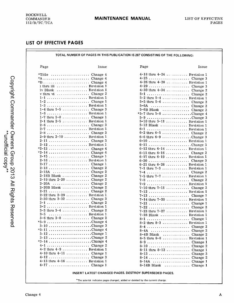
Wing Span Model 112 • . • . • . . . . . . 393.00 inches (32 '-9 ") Model 112B/TC/TCA •• 427.20 inches (35 '-7.20")
Overall Length 300.50 inches (25 '.0.50") Height to Top of Vert. Stab 101. 00 inches (8 '-5.00") Main Gear Tread
Model 112 ....•.•..• 128.44 inches (10 '-8. 44 It) Mode1112B/TC/TCA 131. 40 inches (10' -11.. 40")
Main Gear to Nose Gear Model 112 •...•••.•.. 82.97 inches (6 '-10.97") Mode1112B/TC/TCA.. 82.50 inches (6 '_10. 50 ft)
Gross Weight Model 112 (thru SiN 125) ••.•.••.•• 2550 lbs.
1-1
Copyright C
omm
ander Ow
ners Group 2013 All R
ights Reserved
**unofficial copy**

SECTION I GENERAL INFORMATION
MAINTENANCE MANUAL
1---------- 25' - O. 50"---------,1
* 32' - 9 ft
** 35' - 7.20"
* 112 * 10' - 8.44"
** 112B/TC/TCA ** 10' - 11.40"
Figure 1-1. General Dimensions
1-2
-1 8'r
ROCKWELL COMMANDER
112/B/TC /TCA
X161A7
Change 1
Copyright C
omm
ander Ow
ners Group 2013 All R
ights Reserved
**unofficial copy**

ROCKWELL COMMANDER 112/B/TC/TCA
MAINTENANCE MANUAL SECTION I GENERAL
IN FORMA TION
Model 112 (126 and subs) •.•.•••••• 26501bs. Model 112B .•..••••••.•••..••.••• 2800 lbs. Model 112TC ••••..•.•.•••...••..• 2850 Ibs. Model 112TCA • • . • . • . • . . . • . • . • • • • 2950 Ibs.
C. G. Limit, Gross Wt. FWD (Normal Category) Model 112 (thru SiN 125) ••.•.... 15. fifo MAC Model 112 (126 and subs) •...•••• 18.8% MAC Model 112B •...•....•..•..••••• 24.58% MAC Model 112TC ....•••..........•• 24.84% MAC Model 112TCA •.......•.•...••• 26.68% MAC
c. G. Limit, Gross Wt. AFT (Normal Category) Model 112 ..................... 31. 5fifo MAC Model 112/B/TC/TCA .•••••••••• 31.77% MAC
WING
Airfoil Section (Chordwise). NACA 632415 Modified Root Chord •.•........•.•.•.•..••...•... 70.30 Tip Chord
Model 112 • . . . . • . . . . . • . . . . . . • • . • • 35.15 in. Models 112B/TC/TCA •..•••••.•.•• 32. 10 in.
Mean Aerodynamic Chord Model 112 • . . • • . . . • . . . • . • • . • • . • . • 55. 05 in. Model 112/B/TC/TCA • • . • . • . • . • . • 59.84 in.
Angle of Incidence, tip ..•••••••••••••••..•. 00
Dihedral (at main spar) • . . . • . • . . • . • • • . • . . . • • 70
Aspect Ratio Model 112 . . . . • . . . . . • • • • • . • • • • • • • . . . .• 7.20 Models 112B/TC/TCA ................. 7.85
HORIZONTAL STABILIZER AND ELEVATORS
Span .................... 161. 50 in. (13 '_5. 50 If) Airfoil Section •..•••...• NACA 66-010 Modified Root Chord ..•..•••••••.••••• • • . • • •• 47. 46 in. Tip Chord ••.•.•.•••••.••••.••••••.• 18. 36 in. Mean Aerodynamic Chord ••••••••.••• 35.00 in. Angle of Incidence .•......••....••..••.... _20 Dihedral •...•... • • . . • . • • • • • • • . • • . . . . . . . • 00
Aspect Ratio .•.....••••.•••••..••.•...•• 5. 38 Taper Ratio .• . . . • • • • . . . . • . . • • . . • • • . . • . . O. 39
VERTICAL STABILIZER AND RUDDER
Airfoil Section ...•..••••••..•... NACA 66-012 Root Chord
Model 112 • . . . . . . • • • • • • • • • • • • • • • 71.20 in. Model 112B/TC/TCA •.•••••••.••• 80.70 in.
Mean Aerodynamic Chord Model 112 • . . . . . • • • . • • • • • . • . • . • • 50.90 in. Model 112B/TC/TCA ••••••••••.•• 56.81 in.
FUSELAGE
Cabin Interior - Height •.•.•..••..•..•• 49.00 in. - Width •.•.•••.•.•.•..• 47. 00 in. - Length. . . . • • . • . . . . . . .. 75.00 in. - Volume ....••......... *99 cu. ft. *Rudder pedal to back of 2nd seat.
Baggage Compartment Interior -
- Volume ••...•.•......• 22 cu. ft. 2001bs. - CapaCity .•....••...••.•
AREAS
Wing Model112 •...•..•..•....•.•.. Models 112B/TC/TCA (incl glove)
Aileron ••.........••....••......• Flaps •.....•....•.......•.•..... Horizontal Stabilizer (incl elev. ) •... Elevators (incl tabs) •••.•...•..... Vertical Stabilizer (incl rudder)
Model 112 •...•.•••••••••..... Models 112B/TC/TCA •.••....••
Rudder Model 112 •...•.•••.•.•.•.•... Models 112B/TC/TCA •...•...••
152.00 sq. ft. 163.81 sq. ft.
11. 00 sq. ft. 18.00 sq. ft. 33.64 sq. ft. 18. 00 sq. ft.
17. 00 sq. ft. 22.36 sq. ft.
5.00 sq. ft. 5.75 sq. ft.
FUSELAGE AND WING STATIONS
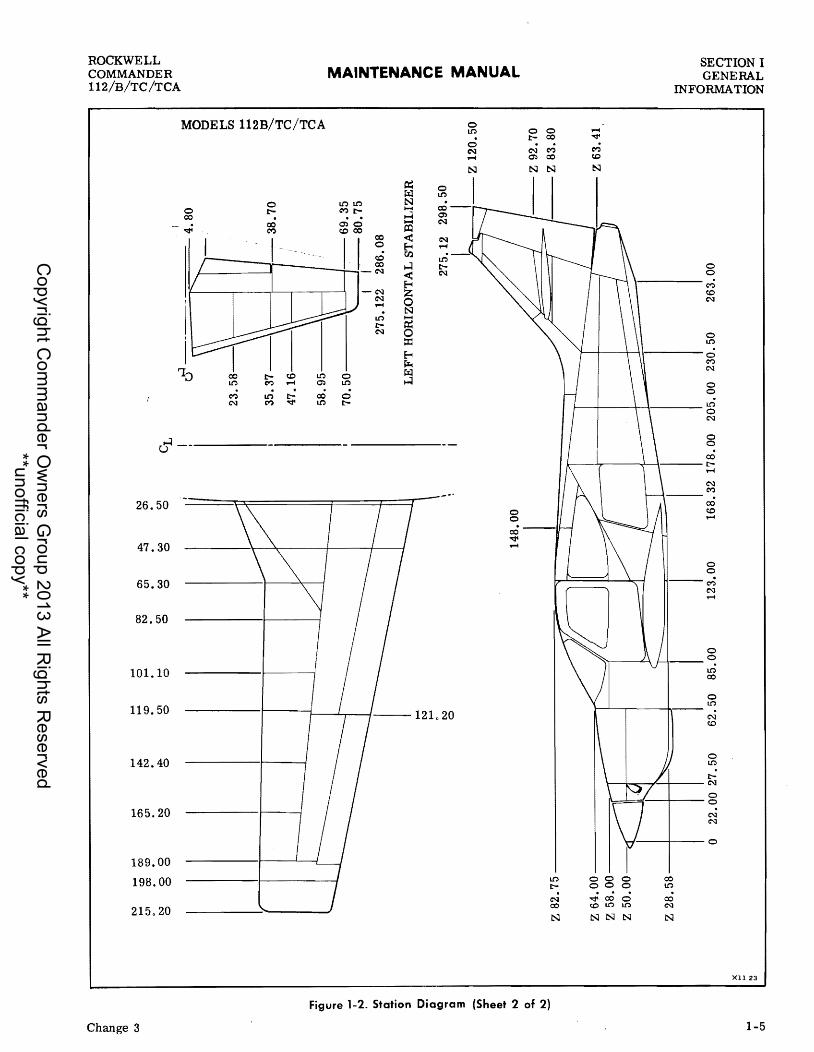
The station diagram shown in Figure 1-2 provide s a convenient method for identifying and locating reference points on major components of the fuselage and wings. These reference points are numbered in inches. The fuselage stations are numbered from zero to 298.50 inches aft of zero. Rib stations of the wing and horizontal stabilizer are measured from the centerline of the fuselage outboard, along the surface leading edge. The top of the vertical stabilizer represents the highest reference plane which is 101.00 inches above ground level. References to fuselage and wing stations numbers and Z lines are used as a means of pin- pointing the location of structural and system component installations.
AIRCRAFT STRUCTURES
FUSELAGE
The fuselage consists of the nose section, center section and aft section. The nose section extending from fuselage station 22.00 to 62.50 houses the power plant and retractable nose landing gear. Nose landing gear doors, which open and close as the gear is extended or retracted, form an aerodynamically smooth nose section during flight. The nose section is joined to the center fuselage section at fuselage station 62.50, which is also the location of the engine firewall. The center fuselage, which contains the main cabin area and baggage compartment, extends from fuselage station 62.50 to 178.00 where it is joined to the aft fuselage section. This section, which houses the seats for pilot and three passengers, has two doors that afford easy access to the aircraft from either side. The pilots area is equipped with a wide-vision windshield and large door windows to assure maximum
1-3
Copyright C
omm
ander Ow
ners Group 2013 All R
ights Reserved
**unofficial copy**

~ I
iI:o-
n ::r § ~ Co:)
."
CI c ... • -I ~
'" -a ::::!". 0 :::I
e Q' CI ... a a v; :r CD CD ....
2. ~
~
~
~ ~ ~ ~ ~ ~
CJ:) co (7.) iI:o- ~ 0 co (7.) iI:o- N
?' ~ !C !""'" ~ ?' ::J ~ ?' ;0 .....
o 0 N iI:o- c:J1 ~ c:J1 C;.:) Co:) c:J1
o 0 0 0 0 0 0 0 0 0 . , roaJ----- 4.80
- 38.70 47.16 \\1 I 58.95
70.50
I I 275.122 286.08
LEFT HORIZONTAL STABILIZER
N 0
275.12 298.50
I -- Z 120.50
Z 82.75 Z 83.80
Z 63.41
Z 28.58 I I~ J. \--- ~
o 22.00 27.50 62.50 85.00 123.00 168.32 178.00 205.00 230.50 263.00
§ ~ t-rJ t'" ~ ~ N
2 0m ~tzjtzj ozn tzj'" ~~~ ...::Jt"'-(3 Z
~ !: Z -t m Z ,. Z n m
~ ,. Z C ,. r-
~
~8~ txla: ~~ '4ztzj n~t'" >~t'"
Copyright C
omm
ander Ow
ners Group 2013 All R
ights Reserved
**unofficial copy**
ROCKWELL COMMANDER 112/B/TC/TCA
MODELS 112B/TC/TCA
'1;)
d--
26.50
47.30
65.30
82.50
101.10
119.50
142.40
165.20
189.00
198.00
215.20
r:- (C Lt'.)
M ..... CI':I
M u-) r:- cO N M '<:t' Lt'.)
MAINTENANCE MANUAL
~ PI;l N ~
...:l ~ < ~ til
...:l -< ~ 0 N -~ ::z:: ~ ~ ~ ...:l 0
Lt'.)
0 r:-
0 Lt'.)
N ..... ~ t-N
0 LI.":)
0 N .....
o o
0 0 r:-«> . N C'? CI':I «>
N
LI.":)
r:-. N 00
N
Figure 1-2. Station Diagram (Sheet 2 of 2)
Change 3
SECTION I GENERAL
IN FORMA TION
..... ~
M (C
N
o o
\----M (C
N
o Lt'.)
'l---+----+-I \---- 0 M N
o o
1---+-----+--;---- ~ N
o o «>
k----'-,...----+--\--- r:.....
o o
--M N .....
o o Lt'.)
«>
o LI.":)
r:\---r-..::,.--.'--+--- N
o I~!::=::=r--/--- 0
00 0 oo 0 ";'cO 0 (CLI.":) Lt'.)
N N N
N N
--/---0
00 Lt'.)
cO N
N
XU 23
1-5
Copyright C
omm
ander Ow
ners Group 2013 All R
ights Reserved
**unofficial copy**

SECTION I GENERAL INFORMATION
MAINTENANCE MANUAL ROCKWELL
COMMANDER 112/B/TC/TCA
pilot visibility during flight. The aft fuselage section, extending from fuselage station 178.00 to 263.00, is permanently secured to the center fuselage section and provides structural attachment points for the empennage flight surfaces and controls. This section houses the battery, hydraulic power pack unit and various control surface cables. The entire fuselage is designed to assure a strong safety margin for all flight conditions and to provide attaching structures for the wing and empennage. Sturdy aluminum flooring supported by longitudinal beams and bulkheads extends from the firewall aft through the baggage compartment. The center wing structure is attached to the fuselage so that part of the wing torque is absorbed by the fuselage structure.
WING
Each wing is of an all-metal stressed-skin construction incorporating spars, formed ribs and an integral fuel tank contained in a three- rib section, forward of the main spar. The main spar of each wing is joined at the center of the fuselage with spar cap splices. The wing is installed in the lower center fuselage section and secured to the fuselage loadbearing frames and fittings by bolts and nuts at stations 85.00, 123,00 and forward of station 148.00. Access plates located at various points on the lower skin of the wing provide access for inspection and repair of the fuel system and the flight control cabling. Landing gear fitting/retraction mechanisms are installed in the basic wing structures to provide attachment points for the main landing gear. An opening in the inboard leading edge of each wing serves as a ram air intake for the cabin ventilation system.. An electrically operated wing flap is installed between the fuselage and aileron on each wing. The flaps are attached to the aft wing spar by hinge assembliesQ Extension and retraction of the wing flaps is controlled by an electrically controlled jackscrew and torque tube arrangement. Metal ailerons, extending outboard from the flaps to wing station 189000, are attached to the aft wing spar by hinge assemblies.
EMPENNAGE
The empennage consists of the vertical and horizontal stabilizers. The vertical fin assembly is made of two separate components; an upper assembly which is mated at the horizontal stabilizer, and a lower stub assembly which is integral with the aft tailcone structure. A rudder control surface is attached to the vertical stabilizer at two hinge points. A fiberglas rudder cap contains provisions for mounting various electronic antennas and the anti-collision beacon. The horizontal stabilizer, consisting of a fixed and movable elevator surface, is attached to the lower vertical stabilizer stub assembly. The horizontal and vertical stabilizers both utilize stressed and beaded skin construction to provide maximum strength with minimum structural components. The horizontal surface is of single unit constructions with a fixed forward surface and a hinged elevator control surface.
1-6
The elevator provides mounting attachment for a fiberglass tip-fairing at each outboard end for streamlined appearance. The aft tailcone assembly is also capped by a fiberglass stinger containing mounts for a tail navigation light and lens assembly, and tail tiedown ring mounted in the vertical fin portion of the cap_ The rudder and elevators are controlled by a cable and pulley system attached to the control surface bellcrank or horn. Controllable trim tabs are installed on the elevators. A ram air intake, recessed into the center of the vertical stabilizer, provides maximum cool air for in-flight cabin ventilation.
AIRCRAFT SYSTEMS
HYDRAULIC SYSTEM
The landing gear system extension and retraction actuators are operated by the aircraft hydraulic system. Hydraulic fluid under pressure is supplied to the system by an electric hydraulic power pack unit installed in the left forward area of the aft section_ A landing gear selector switch, mounted on the instrument panel, controls the direction of fluid flow from the pump to permit gear retraction or extension. An emergency extension system is provided to operate the landing gear in the event the hydraulic system malfunctions. The gear will drop by gravity assisted by down springs. Other hydraulic components use hydrauliC fluid but are not functionally associated with the primary hydraulic system. These are the master brake cylinders, nose shimmy dampener, nose and main gear struts and wheel brakes. All of these components have self contained reservoirs and are not dependent upon the main system.
POWER PLANT
MODELS 112/B. A direct-drive 200-horsepower Lycoming IO-360-C1D6 engine is used to power the aircraft. The engine is a four-cylinder horizontallyopposed air cooled engine which employs a wet sump oil system and is equipped with fuel injection. Engine shock mounts, which dampen engine and propeller vibration, support the engine on the welded tubular engine mount bolted to the airframe firewall. On Model 112, the engine is equipped with a Hartzell HC-E2YR-1BF/F7666A all metal constant speed propeller. The Model 112B aircraft is equipped with a Hartzell HC-E2YR-1BF /F8467-7R propeller. The engine cowling consists of two fiberglass segments that are easily removed for quick access to all parts of the engine. The lower segment is attached to the forward fuselage with machine screws and is removed only when removing the engine or performing maintenance on the lower portion of the engine. The upper segment containing the oil access door is held in place to the lower segment by four Camioc latches and two studs. Adjustable cowl flaps, located in the lower segment of the engine cowl, control cylinder head
Copyright C
omm
ander Ow
ners Group 2013 All R
ights Reserved
**unofficial copy**

ROCKWELL COMMANDER 112/B/TC/TCA
MAINTENANCE MANUAL SECTION I GENERAL
INFORMATION
temperature during flight. All engine accessories except the alternator are attached to mounting pads on the engine.
MODELS 112TC/TCA. A direct-drive 210-horsepower Lycoming TO-3GO-C1A6D engine is used to .power the aircraft. The engine is a four-cylinder horizontallyopposed air cooled turbocharged engine which employs a wet sump oil system. Engine shock mounts, which dampen engine and propeller vibration, support the engine on the welded tubular engine mount bolted to the airframe firewall. The engine is equipped with a Hartzell HC-E2YR-1BF /F8467-7R all metal constant speed propeller. The engine cowling consists of two fiberglass segments that are easily removed for quick access to all parts of the engine. The lower segment is attached to the forward fuselage with screws and is removed only when removing the engine or performing maintenance on the lower portion of the engine. The upper segment containing the oil check door is held in place to the lower segment by four Camloc latches and two studs. Adjustable cowl flaps, located in the lower segment of the engine cowl, control cylinder head temperature during flight. All engine accessories except the alternator are attached to mounting pads on the engine.
FUEL SYSTEM
Fuel is stored in the integral forward wing structure • of each wing (wet wing fuel tanks) outboard of wing
station 82. 50 and extending to wing station 142. 40. The Model 112 (Serial numbers thru 125) has a fuel system capacity of 32 U. S. gallons per tank, usable. The Model 112 (Serial numbers 126 thru 155) has a fuel system capacity of 34 U. S. gallons per tank, usable. The Models 112 (Serial numbers 156 thru 499), 112B, 112TC and 112TCA has a fuel system capacity of 24 U • S. gallons per tank, usable with standard tanks installed, and 34 U. S. gallons per tank usable with optional tanks installed. The fuel tanks are serviced through filler ports located on top of both wings. Fuel is supplied from the tanks through the fuel selector valve to the fuel gascolator. From the gascolator, fuel travels through the electrically operated auxiliary fuel pump to the engine-driven fuel pump. The auxiliary fuel pump is used for engine starting and also provides fuel pressure to the engine in the event of an engine-driven fuel pump failure.
LANDING GEAR, WHEELS, AND BRAKES
The retractable tricycle landing gear is operated hydraulically. Should a failure occur in the hydraulic system an emergency system is provided for emergency extension of the gear. The gear is held in the up pOSition by hydraulic pressure lock and will freefall to the down and locked poSition if normal hydraulic system pressure is lost. Emergency extension of the main gear is accomplished by placing the emergency gear extension knob in the DOWN position to release hydraulic fluid trapped in the uplock portion of actuators. This bypasses hydraulic fluid directly to the
Change 1
hydraulic power pack reservoir allowing the gear to drop by gravity, assisted by down springs. Mechanically actuated landing gear doors enclose the main gear struts within the Wing. The nose landing gear, which retracts into a wheel well under the engine is enclosed by mechanically operated wheel well doors when the gear is retracted. The nose and main landing gear wheels are machined castings, consisting of two wheel halves. The wheel halves are not interchangeable; but the complete wheel assemblies are interchangeable according to wheel size. Disc type hydraulic brakes, attached to the main landing gear, are individually controlled by applying toe pressure to the rudder pedals at either pilot position. A parking brake, which operates from the master brake cylinder, is engaged by applying toe pressure on the rudder pedals and pulling out the PARK BRAKE control knob. The nose wheel steering system is tied to the rudder trim system and operated by depressing the rudder pedals. Initial depression of the pedal starts the nose wheel turning toward the desired direction, while further pedal pressure results in a combination of nose wheel steering and main wheel braking to turn the aircraft.
FLIGHT CONTROLS
The aircraft is equipped with a dual flight control system, which utilizes control columns, control wheels, and rudder pedals to operate the primary flight control suIiaces. Trim tabs, located on the elevators are controlled by rotating the trim tab control wheel, located in the center console. A fixed position ground adjustable trim tab, is installed on the trailing edge of the left aileron. The wing flaps are operated electrically and controlled by a switch on the lower right side of the instrument panel. An internal control lock, which may be installed in the control column, secures the ailerons and elevators in the neutral position when the aircraft is parked.
INSTRUMENTS
All instruments except magnetic compass and outside air temperature gage are installed in the main instrument panel and sub-panel areas, and are grouped according to function and ease of surveillance. All primary flight and gyro instruments are installed in the left side of the main instrument panel. Manifold pressure and tachometer gauges are mounted in the lower center area of the main panel and the remaining engine instruments are grouped horizontally ac ross the left instrument Sub-panel. Lighting for the instruments is furnished by a combination of post lights and flood lights. Optional navigation and communications equipment is located in the center and right side of the main instrument panel.
HEATING AND VENTILATION
The forced air heating and ventilation system provides heat and ventilation to the cabin area. Heat is obtained
1-7
Copyright C
omm
ander Ow
ners Group 2013 All R
ights Reserved
**unofficial copy**

SECTION I GENERAL INFORMATION
MAINTENANCE MANUAL ROCKWELL
COMMANDER 112/B/TC/TCA
from the exhaust manifold heat exchanger, located in the engine compartmellt. Ram air, obtained through air inlets in the cowling, is routed through a heat exchanger shroud around the exhaust muffler where it is heated and distributed to the defroster and cabin heat outlets. Control knobs located on the right instrument sub-panel assembly control the amount and temperature of heated air entering the cabin. Fresh air enters openings in the leading edge of the wing where it is mixed with heated air for a desired degree of warm temperature. Two individual ventilation systems provide maximum cool air for in-flight cabin ventilation. A ram air intake, recessed into the center of the vertical stabilizer, serves the overhead console. The second ventilation system utilizes the' fresh air intake openings in the leading edge of the wing to supply fresh air to the floor level outlets.
1-8
ELECTRICAL SYSTEM
The 14-volt dc electrical system obtains power from one 12-volt battery and one engine-driven 14-volt 70-amp alternator. Current is normally supplied to the system from the alternator. When alternator output is not available electrical power is supplied from the battery installed in the aft fuselage. An optional external power receptacle, located aft of th~'battery on the left side of the fuselage, may be used for connecting a 14-volt de ground power unit to the aircraft de power system for engine starting or maintenance. Aircraft without an external power receptacle should use a spare battery for serviCing purposes. The electrical system utilizes a voltage regulator, 70- ampere circuit breaker and overvoltage relay to regulate the alternator voltage and protect the electrical system.
Change 1
Copyright C
omm
ander Ow
ners Group 2013 All R
ights Reserved
**unofficial copy**

ROCKWELL COMMANDER 112/B/TC/TCA
MAINTENANCE MANUAL SECTION IT SERVICING
AND INSPECTION
SECTION II
GROUND HANDLING, SERVICING, AIRFRAME MAINTENANCE
T ABLE OF CONTENTS
GENERAL DESCRIPTION ••••••••••••..•.•.. GROUND HANDLING ....••.••.•.•...•.••...
Towing ••.•.••.••.•.••.•••••.•..•....•. Taxiing .•.••.•..•..•.••.••.•..•.••.•••. Parking •••••.••••.••.•••••••••••••••••• Mooring .••.•••••••••••••••••••••.••..•. Jacking •••.••.•.•••••••••••.••.•....•.. Leveling .•.•••••••••..•.•••.•••........•
COLD WEATHER OPERATION ••••••••.••.•• Cold Weather Maintenance Hints ••••••••••
GROUND EMERGENCY PROCEDURES •.•.•.. Engine Fires ••.•.•..••••.••.•..•..•.... Electrical Fires ••.••.•.•••••.•.••.•....
GROUND OPERATION OF ENGINE ••••••..•• Exterior Prestart Check •.•••••••..•.••• Cockpit Prestart Check .••••..•.••.•.•.. Starting Cold Engine .•••••••..••.•..•.•. Starting Hot Engine ••••••••••••••.••.••• Engine Operational Check •.••.•.•..••..•.
SYSTEM AND COMPONENT SERVICING .....
GENERAL DESCRIPTION
Page 2- 1 2- 1 2- 1 2- 2 2- 2 2- 2 2- 2 2- 3 2- 3 2- 3 2- 4 2- 4 2- 4 2- 5 2- 5 2- 5 2- 5 2- 6 2- 6 2- 6
Standard procedures for ground handling, servlCmg, inspection, airframe maintenance, lubrication and storage are included in this section. Adherence to these procedures on a scheduled basis can save many hours of maintenance and aircraft down time. When a system component requires service or maintenance other than that outlined in this section, refer to the applicable section of this manual for complete information.
GROUND HANDLING
TOWING
Movement of the aircraft on the ground may be accomplished by the following methods:
Hydraulic System •••••••••••.••.•.•..... Engine Oil System ..•....•......•...•... Engine Induction Air Filter Cleaning ....•. Fuel System ...•.•....••....•.••..•..... Landing Gear, Wheels and Brakes ..•.•..• Battery ..•.•....•...•...•.....•..... ~ ..
INSPECTION ...•.•...••..•.......•........ Inspection Checklist ...................•.
AIRFRAME MAINTENANCE .•.••....•..•.•• Airframe Sealing ••••••.•••••.••.••.•.... Fiberglass Repairs ....••.........•..•... Structural Repairs ...................... . Windshield and Windows ........•..•..... Cabin and Baggage Doors .....•.•.....•.. Seats ...•....••.•..•..•.......•........ Upholstery •.............•............... Wings .••..•....•..........•..•.•.•.... Empennage .•.•• 0 •••••••••••••••••••••••
Airframe Cleaning ...•.................. Lubrication ..........•..•....•.••.•.••. Storage .....•.......•..................
Page 2- 6 2- 8 2-10 2-10 2-11 2-13 2-14 2-14 2-14 2-14 2-15 2-16 2-16 2-20 2-21 2-23 2-23 2-24 2-24 2-30 2-30
a. Pulling and guiding with nose gear tow bar. The nose wheel may be turned a maximum of 30 degrees to the left or right of center. Nose wheel tow limits must be strictly observed to prevent nose gear damage. b. Rotating aircraft aft on main landing gear and towing backwards. The main wheels are near the center of balance, and two men can easily lower the tail and move the aircraft with little effort.
TOWING PRECAUTIONS
a. Never push, pull, or lift aircraft by use of control surfaces. b. Never use nose gear strut body or tailcone tie-down ring as an attach point for towing. c. Never place undue strain on aircraft when towing, and avoid jerky motions. ' d. Do not use ropes attached to main gear for tow-ing aircraft backwards through mud or snow.
2-1
Copyright C
omm
ander Ow
ners Group 2013 All R
ights Reserved
**unofficial copy**

SECTION II SERVICING MAINTENANCE MANUAL
ROCKWELL COMMANDER
112/B/TC/TCA AND INSPECTION
CONTROL LOCK
X221
Figure 2-1 . Internal Control Lock
TAXIING
Before attempting to taxi aircraft, maintenance personnel should be 'checked out' by qualified personnel. When it is determined that propeller area is clear, apply power to start taxi roll and perform the following checks:
a. Taxi a few feet and check brake operation. b. While taxiing, make slight turns to determine that nose wheel steering is operative. c. Avoid taxiing over ground containing loose stones, gravel, or other loose material that may cause foreign object damage to propeller, cowling, or other aircraft in the area. d. Never taxi with flaps extended. e. Minimum turning distances must be strictly observed. f. Taxi with propeller in high rpm, cowl flaps open, and observe all engine operating limits.
PARKING
Head aircraft into wind and set parking brake. Do not set parking brake during cold weather when accumulated moisture may freeze in brakes, or if brakes are overheated. Close cowl flaps, install internal control
2-2
lock (Figure 2-1) and pitot covers, and place chocks under wheels.
MOORING
Park aircraft as previously outlined. In winds up to 20 knots, secure the aircraft at tie-down rings. For winds above 20 knots, tie nose gear, main gear and tailcone, and wing tie-down ring (see Figure 2-2), and install external control surface locks, if available. Hangar aircraft when predicted wind velocity exceeds 60 knots. When mooring aircraft, use 3/4-inch manila or nylon rope and employ a clove hitch or other anti-slip knot. If manila rope is used for tie-down, allow enough slack to compensate for contraction of the rope fiber without damaging aircraft.
JACKING
Aircraft jacking should be accomplished in a hangar unless wind is calm. Place jacks under jack pads on the underside of both wings and nose jack pad near the nose gear wheel well as shown in Figure 2-3. Attach a tail support stand to the tailcone tie-down fitting and ballast as required. Raise nose and wing jacks evenly until all three wheels are clear of the
Copyright C
omm
ander Ow
ners Group 2013 All R
ights Reserved
**unofficial copy**

ROCKWELL COMMANDER 112/B/TC/TCA
MAINTENANCE MANUAL SECTION IT SERVICING
AND INSPECTION
XIS 2A
Figure 2-2. Mooring
floor and struts have fully extended. Provide adequate clearance from floor surface if landing gear cycle tests are to be made.
Check that parking brake is released prior to lowering the aircraft after maintenance.
The nose gear may be raised without the use of jacks, by lowering aft fuselage and securing with weighted tail stand.
LEVELING
Leveling of the aircraft is required for weighing and calibration of the fuel quantity indicating system. To level the airc raft, place airc raft in an enclo sed hangar. If aircraft is to be weighed, retract flaps, install control wheel lock, remove all loose equipment from the aircraft and pOSition adjustable seats in the forward position. Place scales under jack stands at wing and nose jacking points. If scales are equipped with caster wheels, block wheels to prevent movement. Raise all three jacks evenly until aircraft is high enough to permit fore and aft leveling by adjustment of the nose jack. Place a level on the exterior surface of the fuselage floor pan just aft of the nose wheel well. Minor lateral leveling adjustments can then be made by adjusting an individual wing jack. Accomplish longitudinal leveling by placing a level in a fore and aft direction on the exterior floor pan surface and adjusting the nose jack as necessary.
COLD WEATHER OPERATION
Aircraft operation in cold weather creates a need for additional maintenance practices and operating procedures that are not required in moderate temperatures. Whenever possible, shelter aircraft in a heated hangar to prevent frost, ice, and snow accumulation which requires added maintenance time to remove. These weather elements, if allowed to accumulate only a fraction of an inch in thickness on the critical airfoils and control surfaces, seriously degrades aircraft lift and flight control effectiveness. The possibility of aircraft system failures is increased when the aircraft is parked where wind driven snow or freezing rain can be forced into the engine air inlet, fuel and static vents, heater air inlets, pitot tubes and wheel wells. H aircraft is to be moored outside in extreme cold, the battery should be fully charged so it will not freeze. Make certain all vents, air inlets, static ports, etc., are covered. Make certain cowl flaps are closed. The engine should be preheated if aircraft is parked in the open when temperatures are extremely low. Locating the aircraft inSide a heated hangar is the most effective method of preheating aircraft. Auxiliary ground heating units may be used to preheat the engine. This will make starting easier and assure proper engine lubrication at the initial engine start. Use of an external power unit is recommended to conserve battery energy if your aircraft is equipped with the optional ground service receptacle. General Aviation Divisions f Service Department is available to advise operators having any particular cold weather operation problems.
COLD WEATHER MAINTENANCE HINTS
Information contained below is intended only for the purpose of supplementing existing information in this manual, when operating aircraft in cold weather. Keeping aircraft in top maintenance condition during.
2-3
Copyright C
omm
ander Ow
ners Group 2013 All R
ights Reserved
**unofficial copy**

SECTION IT SERVICING MAINTENANCE MANUAL
ROCKWELL COMMANDER
112/B/TC/TCA AND INSPECTION
BALLAST
X163
Figure 2-3. Jacking
cold weather operations can not be overstressed.
BATTERY. Battery should be maintained at full charge during cold weather to prevent freezing. After adding water in freezing temperature, charge battery to mix water and electrolyte. A frozen battery may explode when subjected to a high charge rate. Corrosive damage to the area adjacent to an exploded battery will result if the electrolyte solution is not removed. Instructions for remOving spilled electrolyte are provided in this section. The battery should be removed and stored in a warm place, if the aircraft is to remain idle for an extended period of time.
FUEL SYSTEM. Condensation is more likely to occur in cold weather due to a more rapid and positive division of moisture content from other fuel properties. If at all pOSSible, use fueling facilities that filter moisture from the fuel. If fueling facilities with filters are not available, filter fuel through a good grade chamois. Fill tanks with correct grade (octane) fuel as soon as possible after landing to reduce the possibility of condensation and ice formation in the tank. Fuel extracted from the fuel tank drains before engine starting, deserves a more critical examination when aircraft is being operated in cold weather.
POST FLIGHT MAINTENANCE. Cold weather operation demands procedures that are in addition to normal post flight maintenance procedures. The engine should be allowed to run dry by clOSing the fuel selector valve. Fill fuel tanks immediately after flight. If shelter is not available, tie aircraft down, install wing and engine compartment covers when snow is in the forecast, and be sure all openings are closed or covered.
2-4
GROUND EMERGENCY PROCEDURES
Emergency procedures must be accomplished as rapidly as possible should an emergency arise. It is therefore suggested that steps pertaining to each emergency be committed to memory in order to accelerate the procedure and minimize any possible damage. The best solution is to avoid emergenCies by following the procedures contained throughout this manual.
ENGINE FIRES
If a fire develops in the engine compartment during engine starting, continue the engine start in an attempt to blow the fire out. If the fire persists, proceed as follows:
a. Cowl flaps - CLOSE. b. Mixture control - IDLE CUTOFF. c. Fuel selector valve - OFF. d. Cabin ventilation control - CLOSED. e. Ignition and master battery switch - OFF. f. Abandon aircraft.
ELECTRICAL FIRES
Circuit breakers will automatically trip and stop the current flow to a shorted circuit. However, as a safety precaution in the event of an electrical fire, turn master battery switch OFF. Use a fire extinguisher approved for electrical fires to extinguish flame.
Copyright C
omm
ander Ow
ners Group 2013 All R
ights Reserved
**unofficial copy**
SECTION II SERVICING MAINTENANCE MANUAL
ROCKWELL COMMANDER
112/B/TC/TCA AND INSPECTION
GROUND OPERATION OF ENGINE
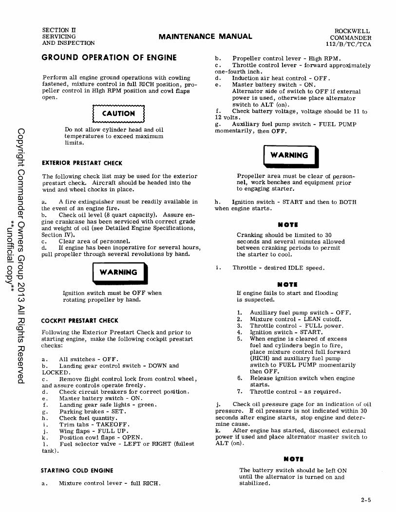
Perform all engine ground operations with cowling fastened, mixture control in full RICH position, propeller control in HIgh RPM position and cowl flaps open.
Do not allow cylinder head and oil temperatures to exceed maximum limits.
EXTERIOR PRESTART CHECK
The following check list may be used for the exterior prestart check. Aircraft should be headed into the wind and wheel chocks in place.
a. A fire extinguisher must be readily available in the event of an engine fire. b. Check oil level (8 quart capacity). Assure engine crankcase has been serviced with correct grade and weight of oil (see Detailed Engine Specifications, Section IV). c. Clear area of personnel. d. If engine has been inoperative for several hours, pull propeller through several revolutions by hand.
I WARNING I Ignition switch must be OFF when rotating propeller by hand.
COCKPIT PRESTART CHECK
Following the Exterior Prestart Check and prior to starting engine, make the following cockpit prestart checks:
a. All switches - OFF. b. Landing gear control switch - DOWN and LOCKED. c. Remove flight control lock from control wheel, and assure controls operate freely. d. Check circuit breakers for correct position. e. Master battery switch - ON. f. Landing gear safe lights - green. g. Parking brakes - SET. h. Check fuel quantity. i. Trim tabs - TAKEOFF. j. Wing flaps - FULL UP. k. Position cowl flaps - OPEN. 1. Fuel selector valve - LEFT or RIGHT (fullest tank).
STARTING COLD ENGINE
a. Mixture control lever - full RICH.
b. Propeller control lever - High RPM. c. Throttle control lever - forward approximately one-fourth inch. d. Induction air heat control - OFF. e . Master battery switch - ON.
Alternator side of switch to OFF if external power is used, otherwise place alternator switch to ALT (on).
f. Check battery voltage, voltage should be 11 to 12 volts. g. Auxiliary fuel pump switch - FUEL PUMP momentarily, then OFF.
I WARNING I Propeller area must be clear of personnel, work benches and equipment prior to engaging starter.
h. Ignition switch - START and then to BOTH when engine starts.
i.
NOT.
Cranking should be limited to 30 sec onds and several minutes allowed between cranking periods to permit the starter to cool.
Throttle - desired IDLE speed.
NOT. If engine fails to start and flooding is suspected.
1. Auxiliary fuel pump switch - OFF. 2. Mixture control - LEAN cutoff. 3. Throttle control - FULL power. 4. Ignition switch - START. 5. When engine is cleared of excess
fuel and cylinders begin to fire, place mixture control full forward (RICH) and auxiliary fuel pump switch to FUEL PUMP momentarily then OFF.
6. Release ignition switch when engine starts.
7. Throttle control - as required.
j. Check oil pressure gage for an indication of oil pressure. If oil pressure is not indicated within 30 seconds after engine starts, stop engine and determine cause. k. After engine has started, disconnect external power if used and place alternator master switch to ALT (on).
NOT.
The battery switch should be left 0 N until the alternator is turned on and stabilized.
2-5
Copyright C
omm
ander Ow
ners Group 2013 All R
ights Reserved
**unofficial copy**

SECTION IT SERVICING MAINTENANCE MANUAL
ROCKWELL COMMANDER
112/B/TC/TCA AND INSPECTION
STARTING HOT ENGINE
a. Mixture control lever - full LEAN. b. Propeller control lever - ill RPM. c. Throttle control - FULL d. Induction air heat control - OFF. e. Master battery switch - ON (alternator side of switch OFF if external power is used).
I WARNING I Propeller area must be clear of personnel, work benches and equipment prior to engaging starter.
f. Ignition switch - START and then to BOTH when engine starts.
NOIE
Cranking should be limited to 30 seconds, and several minutes allowed between cranking periods to permit the starter to cool.
g. Mixture control lever - full RICH. h. Throttle control - desired IDLE speed. i. Check oil pressure gage for an indication of oil pressure. If oil pressure is not indicated within 30 seconds after engine start, stop engine and determine causeD j. After engine has started, disconnect external power source if used, and place alternator master switch to ALT (on).
NOIE The battery switch should be left ON until the alternator is turned on and stabilized.
ENGINE OPERATIONAL CHECK
After engine start, allow engine to warm up at 1000-1200 rpm to ensure adequate cooling and engine lubrication. At completion of warm up period proceed with the engine ope rational cheCk.
INSTRUMENTS. With engine stabilized at 2200 rpm, check all engine instruments, ammeter, voltmeter (optional) and vacuum (optional).
I IGNITION. Check ignition switch grounding by retarding throttle to IDLE and turn ignition switch OFF, to check that engine will stop running. After rpm has dropped 100 to 200 rpm, turn ignition switch to BOTH.
2- 6
If magneto switches remain OFF for longer than a few seconds, after-firing may occur when magnetos are switched back to BOTH. If the engine continues to run with the ignition switch off, stop engine by placing mixture control lever in IDLE CUTOFF and check magneto ground.
PROPELLER. With engine at 2200 rpm, exercise • propeller by slowly moving pro pelle r control lever aft to reduce rpm to 1500. Return control lever full for- • ward (ill RPM) and note any indication of sluggish or erratic operation. Refer to Section IV if propeller does not operate properly.
Do not allow cylinder head and oil tempperatures to exceed operating limits.
MAGNETO CHECK. Advance throttle to 2200 rpm • and rotate ignition switch from BOTH to L (left) poSition and note rpm drop. Rotate switch back to BOTH pOSition to clear the engine. Rotate switch to R (right) pOSition and note rpm drop. Drop should not exceed 175 rpm on either magneto and should not exceed 50 rpm variation between the two magnetos.
FULL POWER. With propeller in HI RPM and • mixture control in full RICH, advance throttle to FULL open position. Tachometer should read 2700 rpm, and manifold pressure (at sea level) should be 28.6 inches mercury.
IDLE SPEED. Retard throttle lever to IDLE pOSition. Engine should run smoothly at 600 (+50, -0) rpm, without any tendency to load up.
ENGINE SHUTDOWN. Stop engine by placing mixture control lever in IDLE CUTOFF position. As soon as I propeller has stopped turning, place ignition switch in OFF position, then turn all other electrical switches OFF.
SYSTEM AND COMPONENT SERVICING
Servicing procedures contained in this section are confined to those maintenance actions that occur with routine frequency and require a reasonable short period of time to accomplish (see Figure 2-4). Servicing practices and maintenance to aircraft systems and components which require less frequent attention are contained in the appropriate section of this manual.
HYDRAULIC SYSTEM
HYDRAULIC POWER PACK. The hydraulic power pack is located in the left forward area of the aft fuselage section (see Figure 2-5). An access pal1ellocated in the baggage compartment on the left aft side affords easy access for servicing. Before removing the fill port screw, wipe fill port area with a shop towel • to remove dirt that could fall into the reservoir. Never allow reservoir to remain uncapped any longer than necessary. If reservoir is low and hydraulic fluid is not immediately available reinstall fill port screw • until hydraulic fluid is obtained. Service hydraulic reservoir as follows:
Change 3
Copyright C
omm
ander Ow
ners Group 2013 All R
ights Reserved
**unofficial copy**

ROCKWELL COMMANDER 112/B/TC/TCA
MAINTENANCE MANUAL SECTION IT SERVICING
AND INSPECTION
1. ENGINE OIL FILLER 11. BRAKE MASTER CYLINDERS 2. ENGINE OIL FILTER 12. VACUUM SYSTEM RELIEF VALVE 3. GASCOLATOR FILTER AND VACUUM FILTER CARTRIDGE 4. FUEL TANK SUMP DRAIN VALVES 13. ,INDUCTION AIR FILTER 5. FUEL TANK FILLER VALVES AND CAPS 14. NOSE GEAR STRUT INFLATING VALVE 6. FUEL SELECTOR VALVE DRAIN (112/TC) 15. NOSE TIRE :iNFLATING VALVE 7. BATTERY 16. NOSE GEAR SHIMMY DAMPENER 8. HYDRAULIC POWER PACK 17. BRAKE FLUID RESERVOIR (112B/TCA) 9. MAIN GEAR STRUT INFLATING VALVE 18. FUEL SUMP DRAIN (112B/TCA)
10. MAIN TIRE INFLATING VALVE
X22 16
Figure 2-4. Servicing Chart
2-7
Copyright C
omm
ander Ow
ners Group 2013 All R
ights Reserved
**unofficial copy**

SECTION IT SERVICING MAINTENANCE MANUAL
ROCKWELL COMMANDER
112/B/TC/TCA AND INSPECTION
a. Master battery switch - OFF. b. Remove access panel in baggage compartment.
• c. Remove fill port screw and check fluid level. Rese:l.'voir level should be maintained to the bottom
• of the fill port screw. d. Fill with hydraulic fluid (MIL- H- 5606).
• e. Install fill port screw. f. Install access panel.
ENGINE OIL SYSTEM
Eight quarts of engine lubrication oil are contained in the oil sump of the engine. The oil supply should be checked before each flight and maintained at the dipstick full mark with seasonal weight and quality of lubricating oil. Refer to Section IV for correct oil grade and weight.
OIL LEVEL CHECK AND SERVICING. The oil level dipstick is a part of the filler cap, which is located on top of the engine. Access to the filler cap is gained through a door, located on the upper surface of the engine cowling (see 2-14). Maintain oil level at full (8 quart) mark. Add oil that is of the same quality and weight of oil as that contained in the sump, and do not over fill.
OIL CHANGE. Engine lubricating oil may be changed at intervals of 100 hours of operation, provided that the filter element is changed every 50 hours. Oil that becomes dirty and contains sludge deposits should be changed regardless of time since last oil change. To change oil proceed as follows:
a. Operate engine until cylinder head temperature is within green range. b. Place container having a capacity of 8 quarts or more beneath oil drain valve. Attach hose to drain valve to prevent oil spillage on nose gear strut or other components. c. Open drain valve (push up). d. Allow engine oil to drain completely, then close drain valve (pUll down), and remove hose. e. Clean oil suction screen as outlined in this section. f. Remove and replac e full flow oil filter. g. Add eight quarts of oil and check level with dipstick to assure sump is full. h. Check drain valve for leaks.
INSPECTION AND CLEANING OF OIL SUCTION SCREEN (ELEMENT). One oil suction screen and one full flow oil filter element located within the oil system tilters out foreign material that would otherwise be carried into critical moving parts of the engine. The oil suction screen is located in the right forward end of sump near the fuel injector and the full flow oil filter element is installed on the accessory housing. The metal oil suction screen must be inspected and cleaned, while the oil filter element must be removed and replaced, at each 50 hour-interval, each time the oil is changed or whenever improper oil circulation is suspected.
2-8
X22 4
Figure 2-5. Hydraulic Power Pack
Oil Suction Screen Removal
a. Release pressure on oil system by draining oil sump. b. Remove oil suction screen plug from oil sump on right side of engine and discard gasket. c. Remove oil screen.
Full Flow Oil Filter Removal
a. Remove safety wire from bolt head at end of filter housing. b. Loosen bolt and remove filter assembly from adapter. c . Remove and discard copper gasket and any other gaskets.
Inspection and Cleaning
Check screen and filter element for evidence of metal particles and observe the amount of carbon and sludge in the oil screen and filter element. The amount of carbon and sludge build up, especially in the suction screen, are indicators of engine condition. If the buildup of this material increases progressively between oil changes the service life of the engine will be increased if the oil change time is reduced. When
Change 3
Copyright C
omm
ander Ow
ners Group 2013 All R
ights Reserved
**unofficial copy**

ROCKWELL COMMANDER 112/B/TC/TCA
MAINTENANCE MANUAL SECTION IT SERVICING
AND INSPECTION
MODEL 112B
MODEL 112
AIR FILTER HOUSING
/AIR FILTER
'~I
X2438
X222
/
/
/ /
/
/ /
/
MODEL 112TC/TCA
I
~
Am FILTER
~ " ~ Am FILTER ~ HOUSING
X2434
Figure 2- 6. Induction Air Filter
metal particles are found on either the oil suction screen or filter element, accomplish engine operational check and oil screen and filter element inspection to determine if the engine should be continued in service. To clean the engine oil screen, soak and wash screen in cleaning solvent and dry with moisture free compressed air. The filter element should be replaced; however, before replacing the filter element, remove the outer perforated paper cover; and using a sharp knife, cut through the folds of the element at both ends, close to the metal caps. Carefully unfold the pleated element and examine the material trapped in the filter for evidence of internal engine damage such as chips or particles from bearings. In new or newly overhauled engines, some small particles of metallic shavings may be found, these are generally of no consequence and should not be confused with particles produced by impacting, abrasion or pressure. When metal particles are found in the oil screen and filter element of an engine that has been in use for a period of time, accomplish the following steps:
a. Install new or cleaned oil sc reen and filter element and fill sump with new oil. b. Operate engine until cylinder head temperature is within green range. Operate engine through various power settings and observe oil pressure and oil temperature readings for erratic indication. Allow engine to run an additional 15 minutes.
c. Shut engine off. d. Drain oil sump. e. Remove screen and filter element and repeat inspection for metal particles. If metal particles are present, engine overhaul is required. Engine may be returned to service if screen and filter element are free of metal particles. Consult nearest Lycoming Representative if condition of engine is questionable.
Oil Suction Screen Installation
a. Locate new gasket on oil suction screen plug assembly and install in engine. b. Tighten plug until underside of head or flange makes contact with face of sump, then tighten to a maximum of 50 inch-pounds additional torque.
Full Flow Oil Filter Installation
a. Install new copper gasket on stud and place shell and element on stud. b. Coat rubber gaskets with clean engine oiL This allows rubber gaskets to seat properly under torque when tightening stud. c . Install flat rubber gasket on shell edge. d. Install mounting plate on stud. e. Install nylon nut on stud threads and run up finger tight against mounting plate so assembly will be held as a unit until installed on adapter.
2-9
Copyright C
omm
ander Ow
ners Group 2013 All R
ights Reserved
**unofficial copy**

SECTION n SERVICING MAINTENANCE MANUAL
ROCKWELL COMMANDER
112/B/TC /TCA AND INSPECTION
f. Install square rubber gasket in groove in mounting plate. g. Install complete assembly to adapter and torque stud to 20 to 25 foot-pounds. h. Safety wire stud to side of housing.
ENGINE INDUCTION AIR FILTER CLEANING
An induction air filter is installed in the induction air filter housing of the engine (see Figure 2- 6). This filter prevents rapid wear of engine moving parts caused by entry of fine grit and dust into the internal parts of the engine. Careful attention to the condition and proper cleaning of the engine air filter is important to long engine life. The filter should be removed and cleaned or changed at every 50 hour interval of flight time, and more often if operating in dusty areas. To clean the filter proceed as follows:
a. Remove upper section of engine cowling. b. Remove air filter from air filter box assembly , by removing attaching clamp and dust and removing screws attaching box assembly to cowling. c. Thoroughly wash filter in PS-661 cleaning sol-vent or equivalent. d. Allow filter to drain dry. e. Dip filter in clean engine oil, stand on end and allow to drain at least 16 hours. f. Wipe off excess oil and wipe down frame.
IIOT. Extra air filters should be retained so that a clean filter will be readily available.
g. Install clean air filter in air filter box assembly and reinstall air filter box assembly. h. Replace upper cowling.
FUEL SYSTEM
RE FUELING. Refuel aircraft with fueling facilities that contain filters for removing the moisture content from the fuel. If fueling faCilities with filters are not available, filter fuel through a good grade chamois. Fuel tanks should be serviced after the last flight of the day to allow maximum time for entrained moisture to reach the sumps prior to the next flight. Use only 100/130 octane, aviation grade gasoline. See Figure 2-7 for fuel tank capacity.
2-10
I WARNING I Ground aircraft and ground fuel servicing equipment to aircraft. Smoking in or around the aircraft during refueling operations is prohibited. Fire protection equipment must be immediately available.
MODEL 112 THRU 125)
FUEL 100/130 OCTANE MIN
USEABLE GAL.
~ __ -30
- 25 - 20
-15
MODEL 112 126 THRU 155)
FUEL 100/130 OCTANE MIN
USEABLE GAL.
If-32 - 27 -22
-17
MODEL 112 156 AND SUBSEQUENT) MODEL 112B/TC/TCA
FUEL 100/130 OCTANE MIN
Figure 2-7. Fuel Tank Capacity
a. Master battery switch - OFF.
X2219A
b. Remove fuel filler cap, located on top outboard surface of right wing, and fill tank until fuel level rises to filler neck. Allow fuel to settle for five minutes, then add fuel to ensure complete filling.
Do not drag refueling hoses over leading edge or other wing surfaces. This will damage painted surfaces.
IIOT.
It is recommended that a thin vinyl mat be locally fabricated to prevent damage to the paint surfaces during refueling. An approximate overall size of 12 x 22" with a 3-5/8" diameter hole near one of the 12 inch edges, to fit over the filler opening, will provide protection from nozzle scratches.
Copyright C
omm
ander Ow
ners Group 2013 All R
ights Reserved
**unofficial copy**

ROCKWELL COMMANDER 112/B/TC/TCA
MAINTENANCE MANUAL SECTION n SERVICING
AND INSPECTION
c. Replace and check security of fill port cap. d. Wash spilled fuel from wing surface with clean water. e. Repeat procedure for opposite tank.
DRAINS. On model 112/TC four fuel drains are provided at the lowest points of the fuel system to extract moisture and sediments entrapped in the system. On model 112B/TCA five drains are installed (see Figure 2-4). Draining the fuel tanks, tank sump and gascolator is accomplished by use of drain valves located adjacent to the tanks, sump or gascolator. All fuel drains except the gascolator should be drained prior to the first flight of each day. The gascolator should be drained and checked every 25 hours of operation. Drain a small quantity of fuel into a transparent container to permit inspection for presence of moisture or sediment. Fuel should be drained until all evidence of moisture or sediment disappears. Drain check the fuel system as follows:
a. Drain a fuel sample from wing tank sumps on inboard underside area of each tank. b. On model 112/TC aircraft, place fuel selector valve on interior center console on BOTH and pull to drain selector valve through bottom of fuselage. An outside assistant will be needed to obtain fuel sample.
NOI. The fuel selector remote drain valve will also permit draining of the individual tank lines by switching to either RIGHT or LEFT and pulling up on valve handle. Return fuel selector valve to RIGHT or LE FT position to prevent fuel from flowing from one tank to the other and overflowing out of tank vent line.
On model 112B/TCA aircraft drain a fuel sample from each wing tank sump located just forward of each main wheel well opening.
c . Drain fuel sample from gascolator every 25 hours of operation by pushing in on drain or by pulling drain handle as applicable. d. Visually check that all drain valves close after draining.
FUEL SYSTEM SCREENS. Filter screens incorporated in the fuel system are: finger inlet screens in both fuel tank outlet lines and a screen in the gascolator connected to the electric fuel pump, mounted on the firewall. The gascolator screen should be removed, inspected and cleaned every 100 hours of operation or sooner if improper fuel circulation is suspected. The finger inlet screens should be removed, inspected and cleaned annually unless improper fuel circulation requires immediate service to the system. See Section V for removal and cleaning instructions.
DE FUE LING. Gasoline fumes are present during defueling operation; therefore, extreme caution must be exercised to prevent fire hazards.
Change 3
WARNING I Smoking on or around the airplane is not permitted during defueling procedure. Fire protection equipment must be immediately available.
a. Ground airplane and ground any defueling equip-ment to airplane. b. Place airplane on level surface. c. Remove engine cowling. d. Disconnect fuel inlet supply line to enginedriven fuel pump. e. Connect defueling hose to fuel inlet supply line and place end of hose in fuel container. Size of container is determined by amount of fuel to be drained. f. Remove fuel tanks filler caps. g. Place fuel selector valve to BOTH. h. Place master battery switch to ON, or attach an auxiliary power unit to airplane. i. Place auxiliary fuel pump switch to FUEL PUMP. j. Place auxiliary fuel pump switch to OFF when fuel stops pumping. Drain residual fuel from all drains. k. Remove drain hose, reconnect fuel inlet supply line to engine-driven fuel pump and torque !fBI! nuts to 100 inch-pounds.
VACUUM FILTER. See Section vm for complete description and servicing.
LANDING GEAR, WHEELS AND BRAKES
STRUT SERVICING. Place airplane on jacks with gear clear of ground and inflate main gear struts to 150 psi for the Model 112 and 395 (:r 10) psi for the • Model 112B/TC/TCA to obtain correct strut extension. Nose gear strut is inflated to 90 psi for the Model 112 and 120 psi for the Model 112B/TC/TCA. The main gear strut nitrogen filler valve is installed on the side of the strut, while the nose gear strut valve is located on top of the strut. Use nitrogen gas to inflate the strut.
NOI. Moisture free compressed air may be used for temporary servicing. Reservice with nitrogen gas as soon as possible.
Check gear assembly for general cleanliness, security of mounting, and hydraulic leaks at prescribed inspection intervals. Refer to Section VI for detailed description of strut servicing. Keep chromed surface of strut wiped free of dirt and dust, using a clean lintfree cloth dampened in MIL-H- 5606 hydraulic fluid.
TIRES. Tires should be inspected for proper inflation, breaks, cuts, foreign objects in tread, flat spots, and exposed cord. Replace tire if there is any question of its reliability. Proper inflation is necessary for maximum tire life. Maintain nose wheel tire pressure at
2-11
Copyright C
omm
ander Ow
ners Group 2013 All R
ights Reserved
**unofficial copy**

SECTION IT SERVICING MAINTENANCE MANUAL AND INSPECTION
INSPECTION
PROPELLER
Spinner, bulkhead, blades and hub
ENGINE COMPARTMENT
Clean, if necessary, prior to inspection. 1. Engine oil (first 50 hours) oil screens, drain
plugs and filter element (Lycoming Service Instruction #1014).
2. Oil cooler, lines, and connections. 3. Induction air filter (Lycoming Service Instruc-
tion #1080). 4. Engine baffle condition. 5. Crankcase, acc essory section and all seals. 6. Hydraulic brake fluid reservoir. 7. Exhaust system (Lycoming Service Instruction
#1080) • 8. Engine controls and linkage. 9. Engine cowling and fasteners. 10. Engine mounts and structure.
ENGINE
1. Spark plug compression check, test and regap. 2. Gascolator screen. 3. Firewall mounted components. 4. Vacuum system (if installed). 5. Alternator belt tension (Lycoming Service In-
struction #1129). 6. Engine oil (Lycoming Service Instruction #1014). 7. Oil screens (Lycoming Service Instruction #1023). 8. Magneto timing (Lycoming Service Instruction
#1132 & 1080).
FUEL SYSTEM
1. Drain valves, vent lines and vents. 2. Filler cap, anti-siphoning valves. 3. Fuel system placards. 4. Internal tank inspection, gage transmitters. 5. Fuel line fittings, vent lines and vents. 6. Remove and clean fuel vent line drain assembly
beneath fuselage.
LANDING GEAR
1. Brakes, lines and components. 2. Strut and tire inflation checks. 3. Nose gear steering, tire, linkages, nose wheel well. 4. Gear door linkages. 5. Hydraulic power pack fluid level, service with MIL
H-5606 hydraulic fluid. 6. Nose gear and main gear inspection. 7. Parking brake system.
50 HRS
I
I
I
ROCKWELL COMMANDER
112/B/TC/TCA
INTERVAL 100 HRS
I
I
500 HRS
AS REQ'D
Figure 2-8. Inspection Intervals Chart (Sheet 1 of 2)
2-12
Copyright C
omm
ander Ow
ners Group 2013 All R
ights Reserved
**unofficial copy**
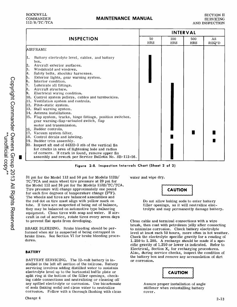
•
ROCKWELL COMMANDER 112/B/TC/TCA
MAINTENANCE MANUAL SECTION II SERVICING
AND INSPECTION
INSPECTION
~IRFRAME
1.
2. 3. 4. 5. 6. 7. 8. 9. 10. II. 12. 13. 14.
Battery electrolyte level, cables, and battery box. Aircraft exterior surfaces. Windshield and windows. Safety belts, shoulder harnesses. Exterior lights, gear warning system. Interior condition. Lubricate all fittings. Aircraft structure. Electrical wiring condition. Control system pulleys, cables and turnbuckles. Ventilation system and controls. Pitot-static system. Stall warning system. Antenna installations.
50 HRS
INTERVAL 100 HRS
500 HRS
AS REQtD
15. Flap system, tracks, hinge fittings, position switches, gear warning-flap -actuated switch, flap
16. 17. 18. 19. 20.
motor and transmission. Rudder controls. Vacuum system filter. Control decals and labeling. Rudder trim assembly. Inspect aft end of 44222-3 rib of the vertical fin for cracks in area of lightening hole and radius of corners. If crack is found, remove upper fin
• • • • assembly and rework per Service Bulletin No. SB-112-56 . I
Figure 2-8. I nspection I ntervals Chart (Sheet 2 of 2)
31 psi for the Model 112 and 50 psi for Models 112B/ TC/TCA and main wheel tire pressure at 29 psi for the Model 112 and 38 psi for the Models 112B/TC/TCA. Tire pressure will change approximately one pound for each five degrees of temperature change (50 F). The wheels and tires are balanced assemblies and the red dot on tire must align with yellow mark on tube. If tires are suspected of being out of balance, they may be balanced on automotive type balanCing equipment. Clean tires with soap and water. If aircraft is out of service, rotate tires every seven days to prevent flat spots from developing.
BRAKE BLEEDING. Brake bleeding should be performed when air is suspected of being entrapped in brake lines. See Section VI for brake bleeding procedures.
BATTERY
BATTERY SERVICING. The 12-volt battery is installed in the left aft section of the tailcone. Battery servicing involves adding distilled water to maintain electrolyte level up to the horizontal baffle plate or split ring at the bottom of the filler openings, checking cable connections and neutralizing or cleaning off any spilled electrolyte or corrosion. Use bicarbonate of soda (baking soda) and clean water to neutralize corrosion. Follow with a thorough flushing with clean
Change 4
water and wipe dry.
Do not allow baking soda to enter battery filler openings, as it will neutralize electrolyte and may permanently damage battery.
Clean cable and terminal connections with a wire brush, then coat with petroleum jelly after connecting to minimize corrosion. Check battery electrolyte level at least each 50 hour s, more often in hot weather. Check the electrolyte specific gravity for a reading of 1. 250 to 1. 280. A recharge should be made if a specific gravity of 1.250 or lower is indicated. Refer to Electrical, Section X, for recharging procedures. Also, during service checks, inspect the condition of the battery box and remove any accumulation of dirt or c orro sion.
Assure proper installation of angle stiffener when reinstalling battery cover.
2-13
Copyright C
omm
ander Ow
ners Group 2013 All R
ights Reserved
**unofficial copy**
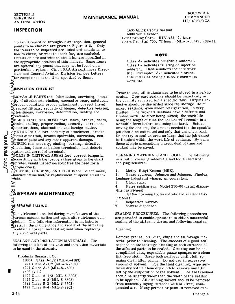
•
SECTION IT SERVICING MAINTENANCE MANUAL
ROCKWELL COMMANDER
112/B/TC/TCA AND INSPECTION
INSPECTION
To avoid repetition throughout an inspection, general points to be checked are given in Figure 2-8. Only the items to be inspected are listed and details as to how to check, or what to check for, are excluded. Details on how and what to check for are specified in the appropriate sections of this manual. Some item s are optional equipment that may not be found on a particular airplane. Check FAA Airworthiness Directives and General Aviation Division Service Letters for compliance at the time specified by them.
INSPECTION CHECKLIST
MOVABLE PARTS for: lubrication, servlCmg, securityof attachment, binding, excessive wear, safetying, proper operation, proper adjustment, correct travel, cracked fittings, security of hinges, defective bearing, cleanliness, corrOSion, deformation, sealing and tensions. FLUID LINES AND HOSES for: leaks, cracks, dents, kinks, chafing, proper radius, security, corrOSion, deteriorations, obstructions and foreign matter. METAL PARTS for: security of attachment, cracks, metal distortion, broken spotwelds, corrOSion, condition of paint and any other apparent damage. WIRING for: security, chafing, burning, defective insulation, loose or broken terminals, heat deterioration and corroded terminals. BOLTS IN CRITICAL AREAS for: correct torque in accordance with the torque values given in the chart or when visual inspection indicates the need for a torque check. FILTERS, SCREENS, AND FLUIDS for: cleanliness, contamination and/or replacement at specified intervals.
AIRFRAME MAINTENANCE
AIRFRAME SEALING
The airframe is sealed during manufacture of the various subassemblies and again after airframe completion. The follOWing information is included to assist in the maintenance and repair of the airframe to obtain a correct and lasting seal when replacing any structural parts.
SEALANT AND INSULATION MATERIALS. The following is a list of sealants and insulation materials to be used in the aircraft.
Products Research Co.
2-14
1005L Class B-1/2 (MIL-S-4383) 1221 Class A-1/2 (MIL-S-7502) 1221 Class A-2 (MIL-S-7502) 1403-G-B2 1422 Class A-1/2 (MIL-S-8802) 1422 Class A-2 (MIL-S-8802) 1422 Class B-2 (MIL-S-8802) 1422 Class B-4 (MIL-S-8802)
1435 Quick Repair Sealant 5000 White Sealer
Dow Corning Corp., RTV-732, 24 hour Coast Pro-Seal 700, 72 hour, (MIL-S-38249, Type 1).
NOTE
Class A- indicates brushable material. Class B- indicates filleting or injection material. Dash numbers indicate work life. Example: A-2 indicates a brushable material having a 2-hour maximum work life.
Prior to use, all sealants are to be stored in a refrigerator. Two- part sealants should be mixed only in the quantity required for a specific task. Surplus adhesive should be discarded since the storage life of mixed sealants, even under refrigeration, is very limited. The two-part sealants have a definite and limited work life after being mixed; the work life being the length of time the sealant will remain in a workable form before becoming too hard. Before mixing the sealant, the amount needed for the specific job should be estimated and only that amount mixed. Do not try to seal an area so large that the job cannot be finished within the work life, of sealants. By using these simple precautions a great deal of time and sealant may be saved.
CLEANING MATERIALS AND TOOLS. The following is a list of cleaning materials and tools used when applying sealants.
1. Methyl Ethyl Ketone (MEK). 2. Gauze sponges; Johnson and Johnson, Finetex, Leshner industrial wipers, or equivalent. 3. Clean rags. 4. Pyles sealing gun, Model 250-06 (using disposable cartridges). 5. Sealant forming tools-spatula and sealant fair-ing tools. 6. Inspection mirror. 7. Solvent dispenser.
SEALING PROCEDURES. The following procedures are provided to enable operators to obtain successful sealing of the airframe during and following repairs.
Cleaning
Remove grease, oil, dirt, chips and all foreign material prior to cleaning. The success of a good seal depends on the thorough cleaning of both surfaces of the affected parts to be sealed. Cleaning can be accomplished using expendable gauze sponges or a clean lint-free cloth. Scrub both surfaces until cloth remains clean after wiping. Do not use an excessive amount of solvent. For the final cleaning, wipe surfaces dry with a clean dry cloth to remove any film left by the evaporation of the solvent. The area cleaned should be slightly wider than the width of the sealant to be applied. All cleaning solvent should be removed from assembly faying surfaces with oil-free, compressed air. If any primer or paint is removed dur-
Change 4
Copyright C
omm
ander Ow
ners Group 2013 All R
ights Reserved
**unofficial copy**

ROCKWELL COMMANDER 112/B/TC/TCA
MAINTENANCE MANUAL SECTION n SERVICING
AND INSPECTION
ing the cleaning operation, paint the area after the sealing operation is completed.
Mixing
Mix the two-part sealants in accordance with the instructions on the container. Mix or stir the mixture until it is uniform in color. Keep mixture free from grease, oil, dirt, metal chips, and aU foreign objects. Mix only enough sealant necessary for completing the sealing requirements. Keep the sealant containers closed when sealant is not being used.
Frame and Rib Flanges
The edges of all frame or rib flanges are sealed with a Hllet of 1422 Class A sealant applied with a pressure gun. When used as a faying surface sealant, the surfaces must be cleaned, the sealant applied to one surface with a pressure gun or spatula, and then spread with a spatula to cover the entire faying surface area approximately 1/32 inch thick. When the surfaces are fastened together, a small excess of sealant will be extruded continuously along the joint. The extruded sealant is then faired out, leaving a smooth fillet along the length of the jOint.
Fuel Tank Structure
A 1422, Class B sealant is used to seal fuel tank areas of structural joints, stiffeners, tank walls, wing spars and tank wall fittings. Force sealant into all seams and joints with a pressure gun. Eliminate all air pockets as sealant is applied. Smooth out fillets with a fairing tool. Use a forced smearing motion, while eliminating air bubbles, to press the fillets into place. Apply a thin coat of 1422, Class A-2 or Class A-1/2 over fillets.
Fasteners
Fasteners, rivets, bolts, etc., installed through a faying surface seal within the work life of the sealant needs no further sealing. Any fastener installed through a structure where no faying surface sealant has been used shall be sealed as follows:
a. Apply 1422, Class A or B sealant to fastener upon installation. Sealant must extrude evenly around the fastener. b. Brush fastener with 1422, Class A-2 or A-1/2 sealant to form a fillet after installation.
Windows and Windshield
The windows and windShield edges are wrapped with • number CR-12-SFR single faced rubber foam. The
windows are sealed around all edges with number 5000 whi te sealer between the metal and the glass, and the windshield edges are sealed with 1221 sealer between the metal and the glass. The side windows are held in place by retainer strips and metal screws. The windshield is inserted into the upper and side channels and held in place by a lower retainer. Screws pass through the retainer and into nutplates. Should a leak occur in a window or windshield the glass should be removed
Change 1
and the tape and sealer removed and replaced. See Windshield and Window Removal and Installation.
REPAIR OF SEALANTS. Should the sealant become damaged during its work life, it may be repaired by remOving the damaged filler and applying new sealant, or reworking the fillet with a forming tool. When the damaged filler has hardened, the fillet should be repaired as follows: Remove all faulty sealant or remove sealant down to solid materials and reseal. If beyond repair, cut away complete fillet and clean and reseal the area. When removing sealant do not damage surface beneath fillet.
FIBERGLASS REPAIRS
The engine cowling and tail cone are of fiberglass construction. Also some wing tips, stabilizer tips and dorsal fairings are of fiberglass construction. The following repair procedures cover fiberglass Touchup and Surface Repairs such as blisters, open seams, delamination, cavities, small holes and minor damages that have not harmed the fiberglass cloth material. Information is also supplied to cover fiberglass Fractures and Patch Repairs such as puncture, breaks and holes that have penetrated through the structure and damaged the fiberglass cloth.
FIBERGLASS TOUCH-UP AND SURFACE REP AIRS
a. Remove wax, oil and dirt from around the dam-aged area with acetone, or MEK (Methyl Ethyl Ketone) or equivalent and remove paint to gel coat. b. Scrape damaged area with a fine blade knife or roughen sides and bottom of area with a power drill and burr attachment. Feather the surrounding edge of scratch or cavity. Do not undercut the edge. If the scratch or cavity is shallow and penetrates only the surface coat, continue to step h. c. Pour enough of resin to fill the area being worked on, into a container or onto a piece of cardboard. Use a putty knife or stick and mix an equal amount of milled fiberglass into the reSin. Add catalyst to the resin and mix thoroughly according to instructions. A hypodermic needle may be used to inject 'gel into small cavities not requiring fiberglass millings mjxed with the gel. d. Work the mixture into the damaged area. Use the sharp point of a putty knife or stick to press it into the bottom of the hole and to puncture any air bubbles which may be present. Fill the scratch or hole until area has a buildup of material l/l6-inch above surface. e. Place a piece of cellophane or waxed paper over the repair to cut off air and start the cure of gel mixture. f. Allow the gel to cure 10 to 15 minutes until it feels rubbery to the touch. Remove cellophane and trim flush with the surface using a sharp razor blade or knife. Replace cellophane and allow gel to cure 30 minutes to an hour. The patch will shrink slightly below the surface as it cures. (H wax paper is used, ascertain wax is removed from the surface of repair.) g. Rough up the bottom and edges of the hole with a power drill and burr attachment or rough sandpaper.
2-15
Copyright C
omm
ander Ow
ners Group 2013 All R
ights Reserved
**unofficial copy**

SECTION n SERVICING MAINTENANCE MANUAL
ROCKWELL COMMANDER
112iBiTCiTCA AND INSPECTION
Feather the hole into surrounding gel coat. Do not undercut. Proceed to step k., if this repair is for a large scratch or deep cavity. h. Pour a small amount of resin, add catalyst and mix thoroughly using a cutting motion rather than stirring. Do not add fibers. i. Use the tip of a putty knife or finger tip and fill the hole to lilS-inch above the surrounding surface with the gel coat mixture. j. Lay a piece of cellophane over the patch area to start the curing process. Repeat step f., and trim patch when partially cured. k. After trimming the patch, immediately place another small amount of gel coat on one edge of the patch and cover with cellophane. Use a squeegee or the back of a razor blade and squeegee the area level around the patch. Leave the cellophane on patch for two hours or overnight for complete cure. 1. Allow the patch to cure for 24 hours. Sand patched area using a sanding block with fine wet sandpaper. Finish by priming, again sanding and applying color coat.
FIBERGLASS FRACTURE AND PATCH REPAIRS
a. Remove wax, oil and dirt from around the damaged area with acetone or MEK (Methyl Ethyl Ketone) or equivalent. b. Cut away ragged edges with a key hole saw, electric saber saw or sharp lmife. Cut back to sound material. c. Remove paint three inches back from around damaged area. d. Work inside the structure and bevel the edges to approximately a 30 degree angle and rough sand the hole and the area around it. Use an 80- grit dry sandpaper and feather back for about two inches all around the hole. e. Cover a piece of cardboard or metal with cello-phane. Tape it to the outside of the structure covering the hole completely. The cellophane should face toward the inside of the structure. If the repair is on a sharp contour or shaped area, a sheet of aluminum formed to a similar contour may be placed over the area. The aluminum should be covered with cellophane. f. Prepare a patch of fiberglass mat and cloth to cover an area two inches larger than the hole. g. Mix a small amount of resin and catalyst, enough to be used for one step at a time, according to kit instructions. h. Thoroughly soak mat and cloth with catalyzed resin. Put resin on mat first and then on the cloth. Mat should be applied against structure surface with cloth on top. Both the cloth and mat may be spread out and soaked on cellophane and applied as a sandwich. Enough fiberglass cloth and mat reinforc ements should be used to replace the amount of reinfore ements removed in order to maintain the original strength. If damage occurred as a stress crack, an extra layer or two of cloth may be used to strengthen area. i. Place patch on the inside of structure over the hole. Cover with cellophane and squeegee from center to edges to remove all air bubbles and assure adhesion around the edge of hole. Air bubbles in the patch will appear white and should all be worked out to the edge.
2-16
Remove excess resin before it sets up on the part. Allow patch to cure completely. j. Remove cardboard or aluminum sheet from outside of hole and rough sand the patch and edge of hole. Feather edge the hole about two inches into undamaged area. k. Mask area around hole with tape and paper to protect the surface. Cut a piece of fiberglass mat about one inch larger than the hole and one or more pieces of fiberglass cloth two inches larger than the hole. Brush catalyzed resin over hole. Lay mat over hole and soak it with catalyzed resin. Apply additional layers of fiberglass cloth to build up patch area to the surface of structure. Soak each layer thoroughly with resin. 1. With a squeegee or broad knife, work out all air bubbles in the patch. Work from center to edge, pressing patch firmly against the structure. m. Allow the patch to cure 15 to 20 minutes until it feels rubbery to the touch. Use a sharp lmive and cut away extra cloth and mat. Cut on outside edge of feathering. Strip cut edges of structure before cure is complete, to save extra sanding. Allow patch area to cure overnight. n. Use an 80-grit sandpaper on a power sander or sanding block and blend area with surrounding surface. If any air pockets appear during the sanding operation, puncture the air pockets and fill them with catalyzed resin. A hypodermic needle may be used to fill cavities. Let patch area cure and resand. o. Mix catalyzed resin and work it into any crevices. p. Cover area with cellophane and squeegee smooth. Allow patch to cure completely before removing cellophane. Let patcA cure and resand. q. Brush or spray a coat of catalyzed resin to seal patch. Sand the patch and finish by priming. Sand the patch and apply a color coat.
NOTE
Brush and hands may be c leaned with Ren RP-70. If not available, a strong solution of detergent and water may be used.
STRUCTURAL REPAIRS
Structural repair methods should be in accordance with the requirements of the Federal Aviation Agency's "Aircraft Inspection and Repair", Manual 43.13-1 and "Aircraft Alterations", Manual 43.13-2. Any skins, frames or ribs damaged beyond repair can be ordered from the Parts Catalog.
WINDSHIELD AND WINDOWS
The windshield and cabin side windows are made from plastic; therefore, care must be exercised when servicing the aircraft to prevent scratching or otherwise damaging the window surfaces. The windshield and cabin windows may be cleaned by carefully washing with a mild commercial soap and clean water.
Copyright C
omm
ander Ow
ners Group 2013 All R
ights Reserved
**unofficial copy**

ROCKWELL COMMANDER 112/B/TC/TCA
MAINTENANCE MANUAL SECTION n SERVICING
AND INSPECTION
1. CABIN WINnoWS 2. WINDSHIELD 3. CABIN WINnow LOWER RETAINERS 4. CABIN WINDOW UPPER RETAINERS 5. CABIN WINDOW FORWARD RETAINERS
.r.;- 6. CR-12-SFR SINGLE FACED RUBBER FOAM 7. PRODUCTS RESEARCH CO., NUMBER 5000
WHITE SEALER 8. PRODUCTS RESEARCH CO., 1221 SEALER 9. WINDSHIELD RETAINER
10. RETAINER SCREWS X225
Figure 2-9. Windows and Windshield Installation
Change 1 2-17
Copyright C
omm
ander Ow
ners Group 2013 All R
ights Reserved
**unofficial copy**

SECTION n SERVICING AND INSPECTION
MODELS 112/112TC MODEL 1128·500 THRU 544 MODEL 112TCA ·13150 THRU 13249
MAINTENANCE MANUAL
~ ~ \ \ \
\ \
1. INTERIOR DOOR HANDLE 2. DOOR HANDLE ADJUSTMENT CABLE 3. PIVOT PIN 4. COTTER PIN 5. EXTERIOR DOOR HANDLE 6. DOOR LOCK 7. VENT WINDOW
Figure 2-10. Cabin Door (Sheet 1 of 3)
2-18
ROCKWELL COMMANDER
112/S/TC /TCA
fJ5 6
X22 SA
Change 2
Copyright C
omm
ander Ow
ners Group 2013 All R
ights Reserved
**unofficial copy**

ROCKWELL COMMANDER 112/B/TC /TCA
MODEL 1128·545 AND SUBSEQUENT MODEL 112TCA ·13250 AND SUBSEQUENT
MAINTENANCE MANUAL
1. INTERIOR DOOR HANDLE 2. LATCH ASSEMBLE 3. PIVOT PIN 4. COTTER PIN 5. EXTERIOR DOOR HANDLE 6. DOOR LOCK 7. VENT WINDOW
Figure 2-10. Cabin Door (Sheet 2 of 3)
Change 2
SECTION IT SERVICING
AND INSPECTION
X2243
2-18A/2-18B
Copyright C
omm
ander Ow
ners Group 2013 All R
ights Reserved
**unofficial copy**

Copyright C
omm
ander Ow
ners Group 2013 All R
ights Reserved
**unofficial copy**

ROCKWELL COMMANDER 112/B/TC/TCA
MAINTENANCE MANUAL SECTION IT SERVICING
AND INSPECTION
A
LATCH BOLT <:> EXTERIOR LATCH HANDLE ----11· /'
,~ X~ ·4\
SPACER ~~ ~/GROMMET ~ /MOUNTING PLATE
r ...... STRIKER PLATE
X2243
~ "'1 SPACER
-kLATCH ACTUATOR
~/SPRING
\.4-...,.;~r---LA TCH TONGUE '1'\
L ... ) INTERIOR COVER PLATE .~"'/
SPACER \'\. l
X229
SHIM
RECEIVER ASSEMBLY
HANDLE STRIKER
X2243
Figure 2-10. Cabin Door (Sheet 3 of 3)
Do not use gasoline, alcohol, benzene, acetone, carbon tetrachloride, deicer fluids or glass cleaning components on plastic surfaces as they will soften the plastic and cause crazing.
Avoid rubbing the plastic surface with a dry cloth since this can cause scratches and build up an electric static charge that will attract dust particles. If scratches are visible after removing dirt accumulations, finish the plastic with a quality grade of commercial wax. Apply wax in a thin even coat and carefully buff out with a soft cloth. Do not buff or polish in one area for more than a brief period of time; heat generated by rubbing the surface may soften the plastic and produce visual distortion.
REPAIR OF WINDSHIELD AND WINDOWS. Windows that are extensively damaged should be replaced rather than repaired, since even a carefully patched area will still not be as optically or structurally acceptable as the original surface.
Change 2
All repairs to plastic window surfaces shall be made in accordance with FAA Advisory Circular AC No: 43.13-1.
Windshield Removal
To remove the windshield, refer to Figure 2-9 and proceed as follows:
a. Remove screws securing retainer strip around base of windshield. b. Slowly apply hand pressure from interior side of windshield to loosen windshield from sealing compound and slide it carefully from top and side retainer channels in sldn. c. When windshield is loose, pull straight for-ward and carefully remove it from aircraft.
Windshield Installation
a. Apply Products Research Co. number 1221 (white) sealer to inside of upper and forward windshield frame channels. b. Wrap number CR-12-SFR Single faced rubber foam around edges of windshield and trim overlap as necessary. c. Carefully align and press windshield into upper
2-19
Copyright C
omm
ander Ow
ners Group 2013 All R
ights Reserved
**unofficial copy**

SECTION IT SERVICING MAINTENANCE MANUAL
ROCKWELL COMMANDER
112/B/TC/TCA AND INSPECTION
1. DOOR LOCK 2. DOOR ASSEMBLY 3. DOOR SEAL 4. STRIKER PLATE AND
ATTACHING HARDWARE 5. DOOR STOP AND
ATTACHING HARDWARE 6. HINGE ATTACHMENT
HARDWARE
X22 17
Figure 2-11. Baggage Door
and side frame channels until completely sealed. Trim plastic as necessary for fit. d. Install bottom retainer strip and secure with mounting screws. e. Clean windshield area of excess sealing com-pound, etc.
Cabin Window Removal
To remove the cabin windows, refer to Figure 2-9 and proceed as follows:
a. Remove screws securing retainer strips around windows. b. Slowly apply hand pressure from exterior side of window to loosen windows from sealing compound and carefully remove it from aircraft.
Cabin Window Installation
a. Apply Products Research Co., num~er 5000 white sealer to inside of window frame channel. b. Wrap number CR-12-SFR single faced rubber foam around edges of window and trim overlap as necessary. c. Carefully align and press window into frame channel. d. Apply Products Research Co., number 5000 white sealer to inside of window. e. Install retainers and secure with mounting screws. f. Clean window area of excess white sealer.
2-20
Cabin Door Window Removal
To remove the window from either cabin door, proceed as follows:
a. Remove interior door trim moulding by remov-ing retaining screws at outside edges. b. Remove window retainer strip screws and re-tainer. c. Gently apply hand pressure from exterior side of window to loosen seal. d. Pilot's side storm window may be removed from main window assembly by removing screw s at storm window hinge strip. Model 112B, Serial num- I bers 545 and subsequent and Model 112TCA, Serial numbers 13250 and subsequent the window may be removed from the door assembly by removing the attaching screws in the door.
Cabin Door Window Installation
Installation of the cabin door windows and cabin side windows is the same as that procedure outlined in the Cabin Window Installation paragraph.
CABIN AND BAGGAGE DOORS
Cabin Door Removal
The cabin doors may be removed simply by removing
Change 2
Copyright C
omm
ander Ow
ners Group 2013 All R
ights Reserved
**unofficial copy**

ROCKWELL COMMANDER 112/B/TC /TCA
MAINTENANCE MANUAL SECTION n SERVICING
AND INSPECTION
the cotter pins securing the pivot pins in the center of the hinges (see Figure 2-10). Support the door assembly while the pivot pins are being removed to prevent damage to the lower edge of the door or hinge points.
Cabin Door Installation
The cabin door installation is the reverse of the removal procedures.
Cabin Door Adjustment
Cabin door adjustment can be made by repositioning the upper (overhead) door latch striker hook as necessary to provide a snug fit between the door and fuselage skin. To adjust striker hook remove striker plate and spacer then rotate hook to desired position.
Change 2
Replace spacer and striker plate. The weather- strip around the perimeter of the interior door surface should be replaced as necessary to maintain a weather seal and proper fit between door and door frame.
Cabin Door Handle Removal
To remove the door handle from the door, proceed as follows:
a. Remove door upholstery. b. Remove outside handle by removing retaining screws. c. Disconnect door handle adjustment cable at the center of door by removing cotter pin and clevis pin holding two adjustment cables together. d. Remove retaining screw s and pull inside handle straight out.
2-20A/2-20B
Copyright C
omm
ander Ow
ners Group 2013 All R
ights Reserved
**unofficial copy**

Copyright C
omm
ander Ow
ners Group 2013 All R
ights Reserved
**unofficial copy**

ROCKWELL COMMANDER 112/B/TC/TCA
MAINTENANCE MANUAL SECTION n SERVICING
AND INSPECTION
Cabin Door Handle Installation.
To install door handle, proceed as follows:
a. Insert cable. b. Install inside handle with retaining screws. c. Connect door handle adjustment cable and adjust cable at handle. d. Install retaining screws in outside handle. e. Insta 11 door upholstery.
Cabin Door Handle Removal - Model 112B (Serial numbers 545 and Subsequent) and Model 112TCA (Serial numbers 13250 and Subsequent).
To remove the inside door handle from the door, proceed as follows:
a. Remove inside door handle by removing retain-ing screw.
To remove outside door handle from the door, proceed as follows:
a. Remove inside door handle b. Remove door upholstery. c . Remove latch assembly from door. d. Drill the rivets out of the outside door handle.
Cabin Door Handle Installation - Model 112B (Serial numbers 545 and Subsequent) and Model 112TCA (Serial numbers 13250 and Subsequent).
To install the inside door handle to the door, proceed as follows:
a. Install inside door handle with retaining screw.
To install outside door handle to the door, proceed as follows:
a. Attach outside door handle to door with rivets. b. Install latch assembly to door with screws. c. Install upholstery. d. Install inside door handle with retaining screw.
Cabin Door Latch Removal
To remove the door latch proceed as follows:
a. Remove door upholstery. b. Remove outside latch handle by removing retaining screw (see Figure 2-10). c. Remove all retaining screws from door latch assembly. d. Remove latch assembly by pulling straight down.
Cabin Door Latch Installation
The cabin door latch may be installed by reversing the above procedure.
Baggage Door Removal
Remove baggage door as follows:
Change 2
a. b. c.
Remove interior molding and retaining screws. Disconnect door stop (see Figure 2-11). Remove screws from hinges and remove door.
Baggage Door Installation
When fitting a new door minor trimming may be necessary on the door edges to permit a smooth tight fit. Install the door by reversing the above procedure.
SEATS
FRONT SEATS. Standard individual front seats are equipped with manually operated reclining seat backs, and manual fore and aft adjustment control. Four roller units on each front seat allow fore and aft travel of the seat after the lock pins have been disengaged from the seat tracks. Track stops limit seat travel, and it is of primary importance that the stops be secured after installing a seat unit.
I WARNING I Ensure that the track stops are properly installed on both front seat track assemblies to prevent accidental disengagement during takeoff or landing.
Additional items installed on the front seat assemblies include inertia-reel shoulder harness and adjustable head rest. The inertia- reel is mounted on the base of the seat structure, and the harness strap is routed vertically to the seat back area to exit through an opening at shoulder level.
REAR SEATS. The two rear seats are equipped with individually adjustable seat backs and optional center arm rest. A single rear seat back may be folded forward to provide an extension to the baggage area. Consult the Weight and Balance documents for load placement and baggage area limitations.
Seat Removal and Installation
The front seats may be removed by releasing the engagement pins and by removing stop pins at end of track. The rear seats may be removed by removing the front and rear frame attachment bolts that secure the seat assembly to the cabin structure. Use care when removing seat assemblies to prevent damage to the surrounding upholstery and paneling. The installation of the seats is the reverse of the removal procedures.
Seat Belts and Shoulder Harnesses
All seat belts and shoulder harness units should be inspected periodically and replaced if the straps are frayed or cut. Check that buckle latches operate properly and shoulder harness inertia-reels work smoothly. When installing seat belts, insure that the buckle-half of the belt is installed on the inboard side of the seat.
2-21
Copyright C
omm
ander Ow
ners Group 2013 All R
ights Reserved
**unofficial copy**

SECTION II SERVICING AND INSPECTION
A
B TAB FITTING
2-22
MAINTENANCE MANUAL ROCKWELL
COMMANDER II2/B/TC/TCA
AILERON BALANCE CABLE BRACKET
NASll06-14 BOLT AN960-616 WASHER MS20364-624 NUT TORQUE 95-110 IN-LBS
FWD TOP VIEW .0
•••• 0
X2212
CENTER LINE FORGING
AN174-12A BOLT AN960-416 WASHER MS20365-428 NUT TORQUE 50-70 IN-LBS
c
(f\
NASI106-13 BOLT AN960-616 WASHER MS20364- 624 NUT TORQUE 95-110 IN-LBS
X22 13
AFT ATTACH MOUNT
INBOARD FLAP ARM
~~ ____ SPARASSY
.~ AN175-6A BOLT AN960-516 WASHER MS20365-524 NUT TORQUE 60-85 IN-LBS
X22 14 X.2.2 15
Figure 2-12. Wing Installation
Copyright C
omm
ander Ow
ners Group 2013 All R
ights Reserved
**unofficial copy**

ROCKWELL COMMANDER 112/B/TC /TCA
MAINTENANCE MANUAL SECTION n SERVICING
AND INSPECTION
UPHOLSTERY
The cabin interior and baggage compartment area are completely upholstered and paneled with Royal.ite, vinyl and carpet. Fiberglass is utilized to insulate and sound proof the cabin structure.
Royalite and vinyl paneling is held in place by retainer screws, adhesive and moulding trim. Floor carpets are retained by cement, metal retainers and screws. To clean the upholstery see information under Interior Cleaning paragraph.
WINGS
WING REMOVAL. A wing can be removed easily if three men are available to handle the wing. Otherwise the wing should be supported with a sling, cradle or maintenance stand when the fastenings are loosened. When one wing is being removed, provide balance support for the remaining wing. To remove a wing assembly, refer to Figure 2-12 and proceed with the following steps:
a. Defuel aircraft per Defueling procedures in this section. b. Drain hydraulic brake and gear retraction lines. c. Remove rubber wing-butt fairing seal, and fully extend wing flaps to gain access to aft wing attach mount and wing flap torque tube fitting. d. Carefully remove front and rear seat assemblies, side paneling and carpet as necessary to gain access to spar and cabin side wall access covers. e. Disconnect wing flap from external flap actuator rods. f. Disconnect and cap fuel line through forward cabin side wall access opening. g. Carefully disconnect forward end of flap actuator and actuator bracket from aft side of wing spar (left wing spar only). h. Disconnect left wing wiring harness connector plug.
1101.
Securely tape wing-half of wiring harness to the spar web to prevent damage during wing removal.
i • Di sconnect and cap plastic pitot line coupling at spar (left wing only). j • Remove main cabin wiring harness from ad-hesive-backed fasteners. k. Disconnect and cap three landing gear power pack hydraulic lines at spar web (left wing only). 1. Disconnect and cap hydraulic brake line at spar. m. Disconnect fuel tank cross-vent line forward of spar. n. Disconnect aileron control and balance cables at turnbuckles and tag for reinstallation. o. Relieve cable tension on rudder, elevator and elevator trim control cables at turnbuckles, and remove controls cable pulley mount from spar web.
p. Remove aileron balance cable support bracket and pulley from spar web attach point. q. Remove bolts securing truss assembly to main spar and aft cabin mounts and remove assembly. Use extreme care to prevent notching of forging that truss assembly attaches to at main spar. r. Unbolt and remove forging from spar. s. Remove upper and lower spar cap bolts from left or right wing spar. t. Remove bolts from forward, center and aft wing mounts. u. Disconnect ventilation hose and cables at wing root. v. Carefully guide wing spar out of cabin structure and place wing assembly on suitable support structure.
WING INSTALLATION. Thoroughly vacuum all foreign material from the fuselage, spar carry-through structure and any other internal area where maintenance has been performed while wing assemblies were removed. Refer to Figure 2-12 and proceed with the following steps:
a. Support fuselage and wing assembly on suitable supports. b. Position wing spar in fuselage, and if new in-board skin panels have been installed, carefully check fit along fuselage and trim as necessary. c. Connect cabin ventilation hose at wing root. d. Install and bolt center wing attach shear fitting through cabin side wall access cover. e. Secure forward wing attach point. f. Position and bolt centerline forging at spar centerline. g. Install truss assembly. h. Install and torque bolts through spar cap and aileron balance cable bracket. i. Secure aft wing attach mount. j. Install controls cable pulley assembly at the spar web. k. Connect and tension all control cables per in-structions found in Section VII, Flight Controls. 1. Connect fuel tank cross-vent line at spar. m. Connect hydraulic brake line and bleed brakes per Section VI, Landing Gear. n. Connect hydraulic power pack lines at spar. o. Connect wing wiring harness and secure harness to wing spar. p. Connect pitot line. q. Assemble wing flap actuator and spar mounting bracket. r. Rig aircraft in accordance with Section VU. s. Refuel wing tank and inspect all connections for leaks. t. Fill hydraulic brake and landing gear systems. u . Check operation of fuel tank quantity gage, wing flap position gage and wing navigation light. v. Inspect wing spar area for security of all parts installed, safety wired components properly safetied and wiring harnesses properly attached to wing spar surface. Install all interior components removed during maintenance and check operation of brakes, control surfaces and landing gear.
2-23
Copyright C
omm
ander Ow
ners Group 2013 All R
ights Reserved
**unofficial copy**

SECTION n SERVICING MAINTENANCE MANUAL
ROCKWELL COMMANDER
112/B/TC/TCA AND INSPECTION
4 0-12
6
1. VERTICAL STABILIZER STUD ASSY 2. DORSAL FAIRING 3. HORIZONTAL STABILIZER TIP FAIRING 4. ELEVATOR 5. VERTICAL STABILIZER ASSY 6. VERTICAL STABILIZER CAP 7. RUDDER 8. ELEVATOR TRIM TAB 9. HORIZONTAL STABIIJZER
10. RUBBER GAP SEAL 11. STINGER ASSY 12. RUDDER TIP ASSEMBLY
X227
Figure 2-13. Empennage Installation
EMPENNAGE
VERTICAL STABILIZER REMOVAL. To remove the upper portion of the vertical stabilizer, refer to Figure 2-13 and proceed as follows:
a. Remove fiberglass stinger assembly and dis-connect tail navigation light wiring. b. Disconnect rudder cables at rudder horn. c. Remove rudder top fairing and unbolt hinge mount. d. Unbolt lower hinge. e. Remove rudder assembly. f. Remove lower dorsal fin fairing and disconnect ventilation hose, anti-collision light wiring and antenna leads. g. Unbolt upper attach mount, at horizontal stabi-lizer, through two upper-most access holes in vertical stub spar. h. Unbolt aft attach mount on rear vertical stub spar. i. Remove upper portion of vertical stabilizer.
VERTICAL STABILIZER INSTALLATION. To install the vertical stabilizer, reverse the preceding steps and check rudder control rigging in accordance with Section vn instructions.
2-24
RUDDER. Information on the removal, installation and rigging of the rudder is contained in Section vn.
HORIZONT AL STABILIZER REMOVAL. To remove the horizontal stabilizer see Figure 2-13. Remove the vertical stabilizer and rudder assembly and proceed with the following:
a. Disconnect upper end of elevator push rod bell-crank and disconnect elevator trim cables. b. Remove two forward attach bolts on upper for-ward surface of horizontal stabilizer and four aft attach bolts. c. Remove horizontal stabilizer assembly.
HORIZONTAL STABIIJZER INSTALLATION. To install the horizontal stabilizer, reverse the preceding steps and check elevator and trim tab control rigging in accordance with Section vn.
ELEVATOR. Information on the removal, installation and rigging of the elevator is contained in Section VII.
AIRFRAME CLEANING
INTERIOR CLEANING. Seats, rugs, upholstery panels, and instrument should be vacuumed frequently
Copyright C
omm
ander Ow
ners Group 2013 All R
ights Reserved
**unofficial copy**

ROCKWELL COMMANDER 112/B/TC /TCA
MAINTENANCE MANUAL
FUEL CELL ACCESS (4 EACH SIDE)
SECTION IT SERVICING
AND INSPECTION
PITOT TUBE/ACCESS COVER MOUNT
ELEVATOR TRIM ACCESS (TYPICAL BOTH SIDES)
SP AR MOUNT ACCESS
OVHD. VENTILATION ELECTRIC WffiING HARNESS ACCESS
BATTERY/HYD. POWER PACK
FLOOR-LEVEL ACCESS PLATES (3 EACH SIDE)
ACCESS PANEL
Figure 2-14. Inspection Plates and Access Covers
X22 18
2-25
Copyright C
omm
ander Ow
ners Group 2013 All R
ights Reserved
**unofficial copy**

SECTION n SERVICING AND INSPECTION
APPLICATION SYMBOL
2-26
f HAND PACK
~ LUBRICATION GUN
(HF)
CLOTH WIPE
If OIL CAN
MAINTENANCE MANUAL
SPECIFICATIONS AND TYPE OF LUBRICATION
MIL-G-81322 AIRCRAFT GREASE
ROCKWELL COMMANDER
112/B/TC/TCA
X2224
MIL-G-23827 AIRCRAFT GREASE (Top of nose gear trunnion only)
MIL-G-81322 AIRCRAFT GREASE
MIL-L-5606 HYDRAULIC FLUID
MIL-L-7870 GENERAL PURPOSE LUBRICATING OIL
Figure 2-15. Lubrication Chart (Sheet 1 of 4)
Copyright C
omm
ander Ow
ners Group 2013 All R
ights Reserved
**unofficial copy**

ROCKWELL COMMANDER 112/B/TC/TCA
MAINTENANCE MANUAL
A SEAT MECHANISM B CABIN DOOR
r 50 HOURS rr-50 HOURS
SECTION II SERVICING
AND INSPECTION
X22 20 X22 21
C ELEVATOR AND TRIM TAB ASSEMBLY
II 50 HOURS X2225
Figure 2-15. Lubrication Chart (Sheet 2 of 4)
2-27
Copyright C
omm
ander Ow
ners Group 2013 All R
ights Reserved
**unofficial copy**

SECTION n SERVICING AND INSPECTION
D BAGGAGE DOOR
~50 HOURS
F MAIN GEAR
(HF) DAILY
f 100 HOURS
MAINTENANCE MANUAL
E FLAP AND AILERON ASSEMBLY
.-50 HOURS
X2222
G MAIN GEAR DOORS
ROCKWELL COMMANDER
112/B/TC/TCA
X22 23
1{50 HOURS (50 HOURS XI67 XI68
Figure 2-15. Lubrication Chart (Sheet 3 of 4)
2-28
Copyright C
omm
ander Ow
ners Group 2013 All R
ights Reserved
**unofficial copy**
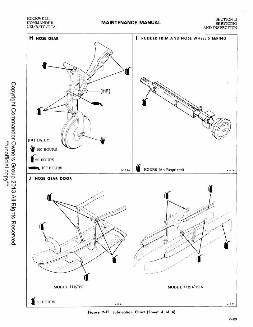
ROCKWELL COMMANDER 112/B/TC/TCA
H NOSE GEAR
MAINTENANCE MANUAL SECTION IT SERVICING
AND INSPECTION
I RUDDER TRIM AND NOSE WHEEL STEERING
~..l...---_( H F)
(HF) DAILY
f 100 HOURS
(50 HOURS
-,. 100 HOURS
J NOSE GEAR DOOR
MODEL 112/TC
(50 HOURS
f
XI65A rl HOURS (As Required) X2238
MODEL 112B/TCA
XI66 X2239
Figure 2-15. Lubrication Chart (Sheet 4 of 4)
2-29
Copyright C
omm
ander Ow
ners Group 2013 All R
ights Reserved
**unofficial copy**

SECTION n SERVICING MAINTENANCE MANUAL
ROCKWELL COMMANDER
112/B/TC/TCA AND INSPECTION
to remove surface dust. Spots and stains should be removed with products specifically manufactured for this purpose. Such products can be purchased locally. Do not use water to clean fabric surfaces, since it will spot upholstery and remove the flame- resistant chemical impregnated in the cloth.
EXTERIOR CLEANING. Prior to cleaning the exterior of the aircraft, cover the wheels, making certain the brake discs are covered. Securely attach pitot covers and install plugs or mask off all other openings. Be particularly careful to mask off all static air sources before washing or waxing. Do not apply wax or polish to the exterior surface of the aircraft for a period of 90 days after delivery, as waxes and polishes seal the paint from the air and prevent curing. If it is necessary to clean the painted surface before the expiration of the 90-day curing period, use cold or lukewarm water and a mild soap. Never use hot water or detergents. Any rubbing of the painted surface should be gentle and held to a minimum to avoid damaging the paint film. The aircraft should be washed with mild soap and wate r . Loose dirt should be flushed away with clean water before soap is applied. Harsh or abrasive soaps or detergents may cause corrosion or scratches and should never be used. Soft clean-ing cloths or a chamois should be used to prevent scratches when cleaning and polishing.
ENGINE CLEANING. Engine and cowling may be cleaned with any standard engine solvent approved for this purpose. Prior to cleaning engine, cover all openings to prevent solvent from entering engine. Spray or brush solvent over engine and wipe dry. Blow excess cleaning solution from engine with compressed air.
Do not allow commercial cleaning solvents to enter magnetos, starter, alternator or any primary component housing. Protect engine components by wrapping in suitable plastic or otherwise covering areas to prevent solvent contact.
LANDING GEAR AND WHEEL WELLS. Clean landing gear and wheel wells with a compound containing an emulsifying agent to remove oil, grease, and surface dirt. The emulsion is removed by rinsing with water or spraying with a petroleum solvent. Cover the wheel and brake during landing gear and wheel well cleaning. If a water rinse is used in cold weather, blow all water from wheel well with an air hose, to prevent freezing. Emulsion type cleaners usually contain solvents which are injurious to rubber if allowed to remain in contact for any length of time; therefore, rinse affected area immediately with water. After cleaning landing gear, wipe exposed strut piston
2-30
with a clean cloth moistened with MIL-H-5606 hydraulic fluid. To clean tires, rinse with water and scrub with a brush. Tire surface may be brightened after washing by rubbing with glycerene or applying a brush coat of commercial tire paint.
PROPELLER. Check propeller blades and hub periodically for oxidation and corrosion. Brush oxidized or corroded area with a phosphating agent to remove superficial corrosion, then remove etched and pitted area by buffing smooth with an aluminum polish. When cleaning propeller, take the following precautions:
a. Check ignition switch off. b. Make sure engine has cooled completely. c. When moving propeller, do not stand in line of blades. d. Avoid using excessive amounts of liquid cleaner as it may splatter or run down blade and enter propeller hub or engine. e. After cleaning, check area around propeller hub to be sure all cleaning solution is removed.
LUBRICATION
Lubrication requirements are shown on the Lubrication Chart (Figure 2-15). Before adding grease to fittings, wipe off the dirt. Lubricate fittings and wipe off excess. Lubricate all hinges with squirt can or brush moistened in oil. Wipe off excess oil to prevent accumulation of dirt and grit. See Section IV for propeller lubrication.
STORAGE
The aircraft is constructed of corrosion resistant ale lad aluminum; however, aluminum is subject to oxidation and must be inspected periodically for signs of corrosion. The first indication of corrosion is the formation of white depOSits or spots on unpainted surfaces. Painted surface will discolor or blister. The aircraft should be stored in a dry hangar for best preservation during long term storage.
28 DAYS OR LESS. Special preservation measures are not required for airframe and airframe components when the aircraft is to be stored for 28 days or less. However, the following procedures should be accomplished before aircraft is placed in storage.
a. Service fuel, engine oil and hydraulic systems. b. Fuel selector valve - OFF. c. Ensure all electrical switches are off. d. Install pitot cover, rubber intake plugs, gust locks and tie-down aircraft if stored outside. e. Clean and rotate tires regularly to prevent flat-spotting. f. Remove and store battery during cold weather. g. Rotate propeller through several revolutions by
Change 3
Copyright C
omm
ander Ow
ners Group 2013 All R
ights Reserved
**unofficial copy**

ROCKWELL COMMANDER 112/B/TC/TCA
MAINTENANCE MANUAL SECTION IT SERVICING
AND INSPECTION
hand once every seven days after checking ignition switch is off. h. Start engine and run up to operating tempera-tures each 14 days.
28 DAYS OR MORE. When the aircraft is to be stored for periods greater than 28 days, the general steps under the period of 28 Days Or Less, plus cleaning and polishing of the aircraft, should be followed. In addition, the engine must be prepared and stored in accordance with installation and storage details contained
Change 3
RETURNING AIRCRAFT TO SERVICE
If proper procedures have been observed during storage, very little delay will be necessary to reactivate the aircraft. Install a fully charged battery and perform a thorough inspection and preflight check. If the engine has been preserved, comply with the procedures for returning the engine to operation as detailed in the Lycoming Operator's Manual. in the Lycoming Operator's Manual.
2-31
Copyright C
omm
ander Ow
ners Group 2013 All R
ights Reserved
**unofficial copy**

•
SECTION n SERVlCING AND INSPECTION
BOLT SIZE
(see Note 1)
10-32 1/4-28 5/16-24 3/8-24 7/16-20 1/2-20 9/16-18 5/8-18 3/4-16 7/8-14 1-14 1-1/8-12 1-1/4-12
BOLT SIZE
(See Note 1)
8-32 10-24 1/4-20 5/16-18 3/8-16 7/16-14 1/2-13 9/16-12 5/8-11 3/4-10 7/8-9 1-8 1-1/8-8 1-1/4-8
NOTES:
MAINTENANCE MANUAL ROCKWELL
COMMANDER 112/B/TC/TCA
STRUCTURAL NUTS - TORQUE IN INCH-POUNDS
FINE THREAD SERIES
STANDARD TYPE NUTS
(See Note 2)
20-25 50-70 100-140 160-190 450-500 480-690 800-1000 1100-1300 2300-2500 2500-3000 3700-5500 5000-7000 9000-11000
Alternate Values AN310
(See Note 4) 20-28 50-75 100-150 160-390 450-560 480-730 800-1070 1100-1600 2300-3350 2500-4650 3700-6650 5000-10000 9000-16700
COARSE THREAD SERIES
STANDARD TYPE NUTS
(See Note 3)
12-15 20-25 40-50 80-90 160-185 234-255 400-480 500-700 700-900 1150-1600 2200-3000 3700-5000 5500-6500 6500-8000
SHEAR TYPE NUTS
MS20364, AN320 AN316, AN7502
Alternate Values AN320
12-15 '30-40 60-85 95-110
270-300 290-410 480-600 660-780 1300-1500 1500-1800 2200-3300 3000-4200 5400-6600
(See Note 4) 12-19 30-48 60-106 95-240
270-390 290-500 480-750 660-1060 1300-2200 1500-2900 2200-4400 3000-6300 5400-10000
SHEAR TYPE NUTS
MS20364, AN320, AN316
7-9 12-15 25-30 48-55 95-100 140-155 240-290 300-420 420-540 700-950 1300-1800 2200-3000 3300-4000 4000-5000
(1) AN3, AN23, AN42, AN173, MS20004, NAS334, NAS464 Series Bolts; AN502, AN503, NAS220 and NAS517 Series Screws.
2-32
(2) AN310, AN315, AN345, AN362, AN363, MS20365, AN366, NAS679, "EB", "1452", Z1200", UWN" and other self-locking nuts.
(3) AN310, AN340, MS20365, AN366 and other self-locking anchor nuts.
(4) When using AN310 and AN320 castellated nuts where alignment between bolt and cotter pin holes is not reached using normal torque values, use alternate torque values or replace nut.
These torque values are derived from oil-free cadmium-plated threads, and are recommended for all installation procedures contained in this book except where noted.
Figure 2-16. Torque Values
Change 3
Copyright C
omm
ander Ow
ners Group 2013 All R
ights Reserved
**unofficial copy**

ROCKWELL COMMANDER 112/B/TC/TCA
MAINTENANCE MANUAL SECTION III HYDRAULICS
SECTION III
HYDRAULICS
T ABLE OF CONTENTS
Page GENERAL DESCRIPTION . . . . . . . . . . . . . . . . . .. 3- 1 GENERAL MAINTENANCE PRACTICES .•... 3- 2
Functional Test Procedure ............... 3 .. 6 HYDRAULIC SYSTEM COMPONENTS ........ 3- 6
Actuating Cylinders ..................... 3- 6
GENERAL DESCRIPTION
MODEL 112 (Serial numbers thru 380). The hydraulic power supply is an integrated unit containing a reversible electric motor-driven hydraulic pump, fluid reservoir, pressure control valves, thermal relief valves, and a gear up check valve. The hydraulic power pack is located in the left forward area of the aft fuselage section. A landing gear selector switch, mounted on the instrument panel, electrically actuates the hydraulic pump in the power pack, to control direction of fluid flow to permit landing gear extension or retraction. When the landing gear selector switch is pulled out to clear a detent, and placed in the UP pOSition, the hydraulic pump is energized and hydraulic fluid is directed to the up port of each gear actuating cylinder to retract the gear. Fluid on the opposite side of each actuating cylinder is returned to the power pack fluid reservoir. When all three gears are retracted, a hydraulic actuating switch located adjacent to each actuating cylinder, de-energizes the hydraulic pump. Any loss of hydraulic pressure which allows any gear to partially extend is sensed by the respective gear uplock position switch, and the hydraulic pump is energized and the gear retracted. When the gear selector switch is placed in the DOWN pOsition, the hydraulic pump is energized and hydraulic fluid is directed to the down port of each actuating cylinder to extend the gear. When all three gears are extended and locked, piston locks on each actuating cylinder engage, and the hydraulic actuating switches de-energize the hydraulic pump. The gears are held down and locked by the piston locks on each actuating cylinder, and the overtravel in the drag brace assisted by emergency extension springs. The system is protected from
Change 2
Page Hydraulic Power Pack ................... 3- 9 Emergency Extension Valve .............. 3-11 Miscellaneous Hydraulic Components ...... 3-11
TROUBLE SHOOTING ...................... 3-12
excessive pressure by the thermal relief valve which opens to relieve pressure at 2025 to 2425 pSi. Emer- • gency gear extension is accomplished by manually actuating the emergency extension valve, located on the left side of the console. When actuated, this valve bypasses fluid from the up Side of each gear actuating cylinder to the power pack fluid reservoir. The gears then drop by gravity, assisted by the emergency extension springs. When down and locked over center three green lights are illuminated when all three downlock position switches and the three hydraulic actuating switches indicate a gear safe condition (see Section VI for Adjustment). With the emergency extension valve in the down pOSition the gear will not retract because the pressure is being relieved through the extension valve back to the reservoir and not to the actuating cylinders. Other hydraulic components using MIL-H-5606 hydraulic fluid held within self contained reservoirs are installed in the airc raft and are not functionally associated with the main hydraulic system. These components are master brake cylinders, nose shimmy dampener, nose and main gear struts and wheel brakes. (see Figure 3-1 and 3-2).
MODEL 112 (Serial numbers 381 and subsequent). MODELS 112B/TC/TCA. The hydrauliC actuating switches have been replaced by hydraulic pressure switches located in the forward fuselage section under the floor in the area of the left rear seat. These switches sense hydraulic pressure and cycle the hydraulic pump to maintain system pressure with the gear in the up or down position as applicable. Refer to Figure 3-3 for aircraft effectivity of the power pack, gear pressure switches, and pressure settings of these components.
3-1
Copyright C
omm
ander Ow
ners Group 2013 All R
ights Reserved
**unofficial copy**

SECTION ITI HYDRAULICS
MAINTENANCE MANUAL ROCKWELL
COMMANDER 112/B/TC/TCA
1. SHIMMY DAMPENER 20 BRAKE CYLINDERS 3. EMERGENCY EXTENSION VALVE 4. HYDRAULIC POWER PACK AND MANIFOLD 5. LANDING GEAR ACTUATING CYLINDERS,
NOSE AND MAIN
6. WHEEL BRAKES 7. BRAKE HYDRAULIC RESERVOIR
MODEL 112B/TCA 8. HYDRAULIC PRESSURE SWITCHES
MODEL 112 381andSubsq.). MODEL 112B/TC/TCA
X235A6
Figure 3-1. Hydraulic Equipment Locator
GENERAL MAINTENANCE PRACTICES
Cleanliness is an essential part of hydraulic system and component maintenance and repair. Small particles of dirt or other foreign materials are especially damaging to seals and surfaces of hydraulic component moving parts; therefore, every precaution must be employed to prevent contamination of hydraulic fluid. The hydraulic system must be serviced at prescribed intervals and storage containers should be kept clean and sealed. The following information is generally applicable for all hydraulic system maintenance.
a. Cap or plug all openings in hydraulic lines and component parts at time of disconnection, to prevent foreign materials from entering hydraulic system. b. Use correct safety wiring technique during re-assembly and installation of components. c. Clean hydraulic system component parts and connections in cleaning fluid, Federal SpeCification P. D. 680, and dry with moisture free air. d. Inspect component parts for cracks, nicks, burrs, scratches, scoring, and condition of threads on component parts and fittings. e. Clean hydraulic actuator cylinders, pistons, or honed internal surfaces, using light buffing compound
3-2
or crocus cloth; rub in lengthwise direction when remOving scratches or nicks. f. Replace all O-rings, seals, and scrapers at time of overhaul and installation of hydraulic components. g. Lubricate component parts and seals with clean hydraulic fluid, MIL-H-5606, prior to reassembly. h. When installing O-rings, make certain the O-ring is evenly stretched around circumference of part and not twisted in retaining groove. i. Never use force to assemble component parts. j. When pOSSible, pressure check hydraulic components for leakage prior to installation on aircraft. k. Lubricate pipe thread fittings with anti-seize compound conforming to Federal Specification TT-A-580. 1. Lubricate B-nuts with thread lubricant conform-ing to SpeCification JAN-A-669. m. Release pressure from hydrauliC lines prior to tightening a tube fitting. n. When replaCing fittings or lines, always start tube nuts with fingers, and complete tightening with a wrench. o. Always bleed hydraulic lines when replaCing hydraulic components. p. Always perform an operational check after re-placing hydrauliC system components.
Copyright C
omm
ander Ow
ners Group 2013 All R
ights Reserved
**unofficial copy**

() ::r' ~ ::s
crq (t)
l).:)
~ I ~
"'" to c: ... (1)
W I ....,
::I: "< a... ... c c:
n
V\ "<
=-(1)
3 V\ n ::r (1)
3 2-n
G) (1)
C ... ;g
~ ... c !l (1)
a...
V\ ::r (1)
~
2.. w
~
HYDRAULIC POWER PACK ASSEMBLY 0 I I HIGH PRESSURE CONTROL ~ ~ REVERSIBLE ~VALVE
- GEAR PUMP
°LOW PRESSURE CONTROL VALVE
*' DOWN
LANDING GEAR
X2314
LANDING GEAR SELECTOR SWITCH
+---_ RETRACTED
I J I / 0--
GEAR DOWN
EMERGENCY EXTENSION VALVE
o SEE FIGURE 3-3 FOR EFFECTIVITIES AND PRESSURE SETTINGS
THERMAL RELIEF VALVE (2025- 2425 PSI) ~
~~I
N OlE PRESSURE CONTROL VALVES AND THERMAL RE LIE F VALVE REMAIN IN POSITION SHOWN UNLESS PRESSURE LIMITS ARE EXCEEDED
GEAR-UP CHECK VALVE OPENS AT BEGINNING OF RETRACTION CYCLE AND THEN CLOSES TO MAINTAIN RETRACTION PRESSURE.
F······=·····=·····=······:!:··;··!::!···i:-:!I: __ ------.'::::)
112B/TC/TCA ::~ .. ~ .. ______ •
f 0 RETRACTED
:: GEAR-UP PRESSURE SWITCH --+ \ i
~ I ~ NOSE GEAR @ : ACTUATOR
~I --0 + - -0 RETRACTED
I /
I /' @/
- RETRACTION PRESSURE E;::::::::::J RETURN PRESSURE
..... ()::c ~OO ~~C1 tJj~~ ~>~ ~Ztr:l QO~ ~tr1~ ()~ >
~ » z -4 m Z » z o m
~ » z c » ~
::I1 ~U) Otr1
~Q ~O t:Z ()I-I U)~
Copyright C
omm
ander Ow
ners Group 2013 All R
ights Reserved
**unofficial copy**

C.:I I ~
()
=-
."
co c ... (I)
W I
I'-l
J: "< D..
o C
n
'" "< CIt .. (I)
3
'" n :r (I)
3 a ::::!'. n
Q (I)
D ... m )(
CD ::::. D.. (I)
D.. -'" :r (I)
!. I'-l
o -w
§ I ~ (JCl ..... ('I) '" N
°LOW PRESSURE CONTROL VALVE
UP ~
~ DOWN
, LANDING GEAR
X2314
LANDING GEAR SELECTOR SWITCH
€ IT ' =*11 LEFT MAIN GEAR o ACTUATOR
+---c:::J I /
I I
i /
1---"" EXTENDED
EMERGENCY EXTENSION VALVE
o SEE FIGURE 3-3 FOR EFFECTlVITIES AND PRESSURE SETTINGS
HYDRAULIC POWER PACK ASSEMBLY 0HIGH PRESSURE CONTROL
REVERSIBLE GEAR PUMP
"PILOT" CHECK VALVE MODEL 112 437 AND SUBS, ALL MODELS 112B/TC/TCA
i VALVE
THERMAL RELIEF VALVE (2025-2425 PSI) ,-,
NOI. PRESSURE CONTROL VALVES AND THERMAL RELIEF VALVE REMAIN IN POSITION SHOWN UNLESS PRESSURE LIMITS ARE EXCEEDED
GEAR-UP CHECK VALVE OPENS TO ALLOW RETURN OF RETRACTION PRESSURE
RIGHT MAIN GEAR t% : I ::§) ACTUATOR
°GEAR DOWN PRESSURE SWITCH c:=J----+
\ I \ I "I NOSE GEAR @ ;;:;1 J ACTUATOR EXTEND~;I
t--~ f I G//
EXTENDED
_ EXTENSION PRESSURE t···:·:·:·:·:·:·1 RETURN PRESSURE
t:dtl.l
~~ ~:j c:=~ t'"4 oS tI.l
~ » z -I m Z » z o m
~ » z c » r-
.-:;:;() tir°~ ... ,J~O ~s=() (»~ ~8~ ()~t""I >::ot""l
Copyright C
omm
ander Ow
ners Group 2013 All R
ights Reserved
**unofficial copy**

c..::> I
CJ1
."
cc c ... tD
W I
too.)
:z: "< c.. ... a c n
VI ~
~ tD 3 VI n '7 tD 3 a -n
m 3 tD ... cc tD :::J n
"<
G') tD a m ~ tD :::J CII
o :::J
VI '7 tD
~ w o -w
x :::: w
UP 6. T
DOWN ,
LANDING GEAR
X2314
LANDING GEAR SELECTOR SWITCH
€ !*I J LEFT MAIN GEAR o • , ACTUATOR
+---CJ I D ! FREE FALL I (ASSISTED BY SPRINGS) ....
GEAR DOWN
EMERGENCY EXTENSION VALVE .
o SEE FIGURE 3-3 FOR EFFECTIVITIES AND PRESSURE SETTINGS
HYDRAULIC POWER PACK ASSE MBL Y
t
o
RIGHT MAIN GEAR t .1 *! ~ ACTUATOR ,
o c:::=J---+
D i FREE FALL I
g' @ : ~ NOSE GEAR EXTEND ~ ACTUATOR
(ASSISTED BY SPRINGS) I
t--@ I
G FREE FALL
o (ASSISTED BY SPRING)
_ NORMAL RETRACTION PRESSURE
_. DUMP RETRACTION PRESSURE
..... (j::tJ ~oO ta-S=~ "S=:e (5~t%j ::tt:lt"'4 (j~t"'4 ~:::o
3: ~ 2 -I m 2 » 2 o m
3: » 2 C » r-
!:r.:1J.l -<~ t:l(j
~~ c:::o t:Z (j:::l 1J.l~
Copyright C
omm
ander Ow
ners Group 2013 All R
ights Reserved
**unofficial copy**

SECTION III HYDRAULICS
MAINTENANCE MANUAL ROCKWELL
COMMANDER 112/B/TC/TCA
Factory Production Power Pack Internal
Model Effectivity Part No. Pressure Settings Remarks UP DOWN
112 - 1 THRU 35 48823-1 1600-2000 500-800 SPARES - USE 795000-1 POWER PACK NOTE: Internal Power Pack Pressures
112 - 36 THRU 380 48823-3, -5 1600-2000 850-1250 are· set at: GEAR UP - 1800- 2000 PSIG GEAR DOWN - 600-700 PSIG
112 - 381 THRU 430 48823-5 1800-2000 850-1250 SPARES - USE 795000-1 POWER PACK Power Pack Pressures are pre-controlled EXTERNALL Y with pressure switches set at:
GEAR UP - 1425-1575 PSIG GEAR DOWN - 450-700 PSIG
112 - 431 THRU 499 795000-1 1800-2000 600-700 SPARES - USE 795000-1 POWER PACK 112B - 500 THRU 544 Power Pack Pressures are pre-controlled 112TC - 13000 THRU EXTERNALL Y with pressure switches
13149 set at: 112TCA - 13150 THRU GEAR UP - 1650 ! 50 PSIG
13194 GEAR DOWN - 500 i" 50 PSIG
112B - 545 & SUBS 795000-1 1700-2100 500-800 SPARES - USE 795000-1 POWER PACK 112TCA - 13195 THRU Power Pack Pressures are pre-controlled
13999 EXT ERNALL Y with pressure switches set at:
GEAR UP - 1650 :!- 50 PSIG GEAR DOWN - 500 i" 50 PSIG
Figure 3-3. Hydraulic System Pressure Settings
q. Always perform landing gear operational check when replacing landing gear hydraulic components. r. Clean hydraulic actuating cylinder piston rods and landing gear struts with a clean cloth moistened in hydraulic fluid, at frequent intervals.
FUNCTIONAL TEST PROCEDURE
When maintenance has been performed on the hydraulic system which necessitates an operational check of the landing gear, jack aircraft as outlined in Section 11 and perform landing gear operational check as outlined below. Functional test procedures applicable to speCific components of the hydraulic system are also incorporated in this section. Procedures contained in the preceding General Maintenance Practices must be accomplished after component repairs.
a. Connect an auxiliary dc power supply (50-amp minimum) to positive terminal on battery relay located on battery box assembly in aft fuselage area. b. Apply a 10 pound load to nose gear axle to simulate an air load condition (see Figure 3-7).
3-6
NOTE
Add 10 pounds of weight to the main gear to simUlate an air load if the hydrauliC lines have been removed or changed (see Figure 3-7) ..
c. Add MIL-H-5606 hydraulic fluid to hydraulic power pack reservoir as necessary to maintain sufficient fluid during test. d. Check all electrical switches - OFF. e. Check landing gear selector switch - DOWN. f. Master battery switch - ON and keep it on for the duration of test. g. Place throttle lever in midposition. h . Check for following conditions:
1. Gear down indicator - ILLUMINATED. 2. Red gear warning indicator - EXTIN
GUISHED. 3. Gear warning bell - SILENT.
HYDRAULIC SYSTEM COMPONENTS
ACTUATING CYLINDERS
The hydraulically operated actuating cylinders are attached to the drag brace and trunnion on the nose gear, and side brace and trunnion on the main gears. One port of each cylinder is connected to the gear up hydraulic line, and the remaining port to the gear down line. Hydraulic fluid, under pressure, is directed to the actuator cylinders by the gear selector switch located on the instrument panel. During the actuating cycle the gear up and gear down hydraulic lines act as either pressure or return lines, depending on the gear position selected.
Change 2
Copyright C
omm
ander Ow
ners Group 2013 All R
ights Reserved
**unofficial copy**

ROCKWELL COMMANDER 112/B/TC/TCA
MAIN GEAR CYLINDER
NOSE GEAR CYLINDER
PISTON DETENT
RODE
MAINTENANCE MANUAL
COVER PLATE
MODEL 112 - 1 THRU 380
SECTION III HYDRAULICS
SNAP RING
'>I/z..~_ SPRING
PISTON ~~~~~DETENT
LOCKNUT
SET SCREW
X239A
END PLUG
X239A
Figure 3-4. Landing Gear Actuating Cylinders (Sheet 1 of 2)
Change 2 3-7'
Copyright C
omm
ander Ow
ners Group 2013 All R
ights Reserved
**unofficial copy**

SECTION ill HYDRAULICS
MAINTENANCE MANUAL
MAIN GEAR CYLINDER
ROD
NOSE GEAR CYLINDER
ROD
SETSCREW
MODEL 112 - 381 AND SUBSEQUENT MODEL 112B/TC/TCA
PLUG
PISTON
Figure 3-4. Landing Gear Actuating Cylinders (Sheet 2 of 2)
3-8
ROCKWELL COMMANDER
112/B/TC/TCA
X23 IDA
X23 IDA
Change 2
Copyright C
omm
ander Ow
ners Group 2013 All R
ights Reserved
**unofficial copy**

ROCKWELL COMMANDER 112/B/TC/TCA
MAINTENANCE MANUAL SECTION III HYDRAULICS
REMOVAL
a. Jack aircraft as outlined in Section II. b. Disconnect hydraulic lines from actuating cylinders and plug or cap open lines and fittings to prevent contamination. c. Remove attaching bolts from cylinder and landing gear.
NOTE Do not disturb the setting of the rod end on the shaft.
d. Remove actuating cylinder.
MODEL 112 (Serial numbers thru 380). DISASSEMBLY AND REPAIR. Disassembly procedures apply to both main and nose gear actuating cylinders. Repair is limited to cleaning and inspection of the parts and replacement of worn or damaged parts and a-rings.
a. Loosen setscrew s and remove end caps and end plugs (see Figure 3-4). b. Withdraw shaft and piston from actuator housing. c. Remove detent cylinder valve body. d. Remove snap ring, cover plate, spring and detent from detent cylinder valve body. e. Remove and discard aU a-rings. f. Inspect and clean all parts in dry cleaning solvent and dry thoroughly. g. Inspect all internal parts and cylinder bore for \vear and damage. Replace worn or damaged parts. h. Wipe new a-rings with MIL-H-5606 hydraulic fluid prior to installation in actuator housing. i. When reassembling cylinders, install detent cylinder valve body after shaft and piston has been installed.
MODEL 112 (Serial numbers 381 and subsequent). MODELS 112B/TC/TCA. Disassembly procedures apply to both main and nose gear actuating cylinders. Repair is limited to cleaning and inspection of the parts and replacement of worn or damaged parts and 0- rings.
a. Loosen setscrews and remove end caps and end plugs (see Figure 3-4). b. Withdraw shaft and piston from actuator housing. c. Remove and discard all a-rings. d. Inspect and clean all parts in dry cleaning solvent and dry thoroughly. e . Inspect all internal parts and cylinder bore for wear and damage. Replace worn or damaged parts. f. Wipe new a-rings with MIL-H-5606 hydraulic fluid prior to installation in actuator housing.
NOI. When installing O-ring, verify that a-ring is evenly stretched around circumference of actuator housing and is not twisted in retaining groove.
INST ALLATION.
a. Place actuator in pOSition on landing gear and install attaching hardware.
Change 4
NOI.
Small end of tapered spacer must contact actuator cylinder bearing.
b. Assure swivel fittings are free to rotate. c . Connect hydraulic lines to actuators. d. Operate hydraulic power pack to purge system of air as necessary and check fluid level in reservoir. e. Fill reservoir as needed. f. Pressurize actuator and check for external leakage . g. Make preload adjustment as outlined in Section VI. h. Perform a functional test on landing gear (see Functional Test Procedures in this section).
HYDRAULIC POWER PACK
The fully-reversible electrically-driven hydraulic power pack unit is located in the left side of the aft fuselage. It contains a reversible electric motordriven hydraulic pump, reservoir, low pressure control valve, high pressure control valve, thermal relief valve and a gear-up check valve. The hydrau-lic high pressure control valve limits system pressure during retraction cycle of the gear. The hydraulic low pressure control valve limits system pressure during the extend cycle of the gear. The thermal relief valve is set to crack between 2025 and 2425 psi should the thermal expansion of hydraulic fluid exceed normal operating pressures. A gear-up check valve opens to allow retraction pressure to the gear while the hydraulic pump is running and closes when the pump is off to hold pressure in the hydraulic lines when the gear is retracted. Any problem in the proper operation of the system can be isolated by performing the Hydraulic Power Pack Check. If any of the hydraulic power pack components are malfunctioning the complete power pack unit must be removed and replaced as the components are not field adjustable or repairable. Access to the power pack unit is gained by removing the left side baggage compartment panel (see Figure 3-5). Refer to Figure 3-3 for component parts pressure settings and effectivity.
HYDRAULIC POWER PACK CHECK
a. Jack aircraft as outlined in Section II b. Connect. external power source regulated to 14.1 (± .1) volts capable of delivering 70 amperes. c. Add MIL-H-5606 hydraulic fluid to power pack fluid reservoir as required. d. Clear vent port by backing screw and washer I out to allow a 0.06 inch minimum clearance between power pack boss and bottom of rubber washer seal. e. Disconnect gear actuation lines in left wheel well at bulkhead fittings in wing rib (see Figure 3-6). f. Install 0 to 3000 psi pressure gage at each of the gear up and gear down hydraulic lines (see Figure 3- 6).
NOTE Do not disconnect emergency gear down line .
Do not loosen any line while system is pressurized.
3-9
Copyright C
omm
ander Ow
ners Group 2013 All R
ights Reserved
**unofficial copy**
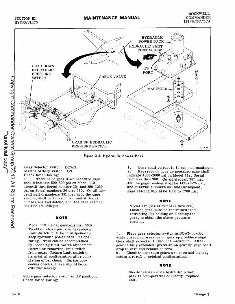
SECTION ill HYDRAULICS
MAINTENANCE MANUAL ROCKWELL
COMMANDER 112/B/TC/TCA
g. h.
i.
3-10
GEAR DOWN HYDRAULIC PRESSURE SWITCH
HYDRAULIC POWER PACK
X23 GAG
Figure 3-5. Hydraulic Power Pack
Gear selector switch - DOWN . Master battery switch - ON. Check for following: 1 . Pressure on gear down pressure gage should indicate 500-800 psi on Model 112, aircraft thru Serial number 35, and 850-1250 psi on Serial numbers 36 thru 380. On all aircraft Serial numbers 381 thru 430, the gage reading shall be 450-700 psi, and at Serial number 431 and subsequent, the gage reading shall be 450-550 psi.
NOTE
Model 112 (Serial numbers thru 380). To obtain above psi, one gear-down limit switch must be misadjusted to keep hydraulic power pack unit operating. This can be accomplished by loosening limit switch attachment screws or removing limit switch from gear. Return limit switch to its original configuration after completion of psi check. During preceding checks, there should be no external leakage.
Place gear selector switch in UP position. Check for following:
1 . Gear shall retract in 14 seconds maximum 2. Pressure on gear up pressure gage shall indicate 1600-2000 psi on Model 112, Serial numbers thru 380. On all aircraft 381 thru 430 the gage reading shall be 1425-1575 psi, and at Serial numbers 431 and SUbsequent, gage reading should be 1600 to 1700 pSi.
NOTE Model 112 (Serial numbers thru 380). Landing gear must be restrained from retracting, by holding or blocking the gear, to obtain the above pressure reading.
j. Place gear selector switch in DOWN pOSition while observing pressure on gear up pressure gage. Gear shall extend in 10 seconds maximum. After gear is fully extended, pressure on gear up gage shall drop to zero and remain at zero. k. Check to ascertain gears are down and locked, return aircraft to original configuration.
NOTE
Should tests indicate hydraulic power pack is not operating correctly, replace unit.
Change 3
Copyright C
omm
ander Ow
ners Group 2013 All R
ights Reserved
**unofficial copy**

ROCKWELL COMMANDER 112/B/TC/TCA
MAINTENANCE MANUAL SECTION III HYDRAULICS
GEAR RETRACTED I
o I
X2388 /
GEAR EXTENDED
~--.
ATTACH TEST HYDRAULIC PRESSURE GAGES TO THESE LINES
VIEW OF HYDRAULIC LINES LOOKING OUTBOARD IN LEFT WHEEL WELL
Figure 3-6. Hydraulic Gear Lines
REMOVAL
a. Master battery switch - OFF. b. Disconnect two electrical leads and label for identification. Tape ends of electrical leads to prevent shorting. c. Disconnect ground wire from airframe.
I d. Screw vent port screw down tight to prevent hydraulic fluid leakage 0
e. Disconnect hydraulic lines from hydraulic power pack. Cap lines to prevent contaminationo f. Remove hydraulic power pack by removing four attaching bolts, washers, grommets, bushings and nuts.
INST ALLATION
a. Position hydraulic power pack in place and attach with bolts, washers, grommets, bushings and nuts ~ b. Connect hydraulic lines to hydraulic power pack. c. Connect ground wire to airframe. d. Connect two electrical leads.
I e. Clear vent port by backing screw and washer out to allow a 0.06 inch minimum clearance between power pack boss and bottom of rubber washer seal.
EMERGENCY EXTENSION VALVE
An emergency extension valve is located at the left forward side of the center console. This valve bypasses hydraulic fluid from the upside of the actuators (which form the hydraulic uplock) directly to the reservoir. The gears drop by gravity, and the piston locks mechanically engage. The gears cannot be raised, and the piston down lock cannot become disengaged. EMERGENCY EXTENSION FREE- FALL TEST. With the aircraft on jacks, retract the landing gear and place the throttle in midposition. Apply a five and
Change 4
one-half pound weight to ,the axle of the nose landing gear to simulate an air load (see Figure 3-7).
a. Disconnect hydraulic power pack unit at electrical quick disconnect. b. Landing gear selector switch - DOWN. c . Push landing gear emergency valve control knob DOWN and hold. Valve and control knob is located on left forward side of center console (see Figure 6-5). d. Check for following:
e.
1 . Gear unsafe red indicator light on. 2 . Warning bell should not sound.
3. Gear free falls in a positive motion. 4. Gear safe green indicator lights on within 14 seconds after pushing emergency control knob. 5. Gear unsafe red indicator light off. 6. Return emergency control knob to its normal pOSition. 7. Master battery switch - OFF. 8. Reconnect hydraulic power pack to aircraft electrical system. 9. Master battery switch - ON. Return aircraft to normal configuration.
MISCELLANEOUS HYDRAULIC COMPONENTS
Hydraulic fluid (MIL-H-5606) is also used in other components of the aircraft that are not functionally tied to the hydraulic power pack. These components
. are the master brake cylinders, nose shimmy dampener, nose and main gear struts and wheel brakes. All of the components have their own self-contained reservoirs except the wheel brakes which, on Model 112 are supplied from the master brake cylinders. On all other Models, the brake cylinders are supplied fluid from a reservoir located forward of the engine firewall. Detailed description and servicing is con-
3-11
Copyright C
omm
ander Ow
ners Group 2013 All R
ights Reserved
**unofficial copy**

SECTION In HYDRAULICS
EMERGENCY FREE FALL TEST
5 1/2 LB WEIGHT
MAINTENANCE MANUAL ROCKWELL
COMMANDER 112/B/TC /TCA
LANDING GEAR OPERATIONAL TEST
NOTE
INCREASE WEIGHT ON NOSE WHEEL TO 10 LBS •• 10 LB WEIGHT
CABLES ATTACHED CLOSE TO AXLE
STAND WITH 2 PULLEYS
X231
Figure 3-7. Hydraulic System Check
tained in Section VI.
TROUBLE-SHOOTING
The trouble- shooting figure in this section discusses
3-12
symptoms which can be diagnosed and interprets the results in terms of probable causes and the appropriate corrective remedy to be taken. Review all probable causes given and check other listings of troubles with similar symptoms. Items are presented in sequence but not necessarily in order of probability.
Change 1
Copyright C
omm
ander Ow
ners Group 2013 All R
ights Reserved
**unofficial copy**

ROCKWELL COMMANDER 112/B/TC/TCA
TROUBLE
Gear retraction/ extension system fails to operate.
Slow gear retraction.
Change 2
MAINTENANCE MANUAL
PROBABLE CAUSE
Emergency extension valve in down position.
Landing gear ACT circuit breaker open.
Landing gear SEL circuit breaker open.
Landing gear ACT circuit wires broken.
Landing gear SEL circuit wires broken.
Ground contact switch out of adjustment or inoperative.
Battery low or dead.
Gear selector switch ground incomplete.
Gear selector switch inoperative.
Hydraulic power pack pump retraction relay inoperative.
Hydraulic power pack pump ground incomplete.
Hydraulic power pack pump inoperative.
Hydraulic fluid in power pack reservoir below operating level ..
Restriction in hydraulic lines.
Gear up pressure switch defective.
Gear down pressure switch defective.
Hydraulic fluid in reservoir below operating level.
Low battery.
Restriction in hydraulic lines.
REMEDY
SECTION III HYDRAULICS
Check visually. Reset valve.
Check visually. Reset circuit breaker.
Check visually. Reset circuit breaker.
Check wiring. Replace defective wiring. To check switches and wiring refer to Section X.
Check wiring. Replace defective wiring. To check switches and wiring refer to Section X.
Check switch. Adjust or replace switch (see Section VI). If circuit breakers continue to open, locate and repair short circuit within system. To check wiring refer to Section X.
Check specific gravity. Replace defective battery.
Check visually. Complete ground.
Check switch. Replace defective switch.
Check relay. Replace defective relay.
Check visually. Complete ground.
Check pump. Replace defective power pack unit.
Check fluid. Fill reservoir with MIL-H-5606 hydraulic fluid.
Isolate and check hydraulic lines. Clean hydraulic lines.
Check switch. Replace defective switch.
Check switch. Replace defective switch.
Check fluid. Fill reservoir with MIL-H- 5606 hydraulic fluid.
Check specific gravity. Replace defective battery.
Isolate and check hydraulic lines. Clean hydraulic lines.
Figure 3-8. Trouble Shooting Hydraulic System (Sheet 1 of 2)
3-13
• C
opyright Com
mander O
wners G
roup 2013 All Rights R
eserved **unofficial copy**
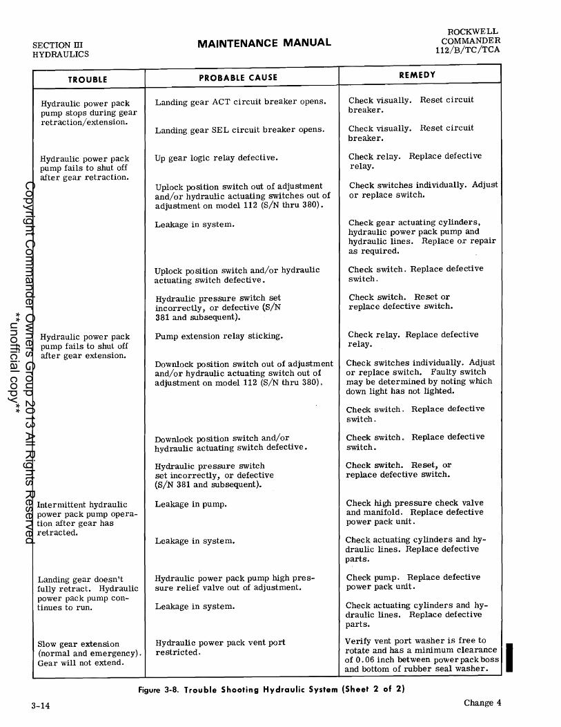
SECTION m HYDRAULICS
TROUBLE
Hydraulic power pack pump stops during gear retrac tion/ extension.
Hydraulic power pack pump fails to shut off after gear retraction.
Hydraulic power pack pump fails to shut off after gear extension.
Intermittent hydraulic power pack pump operation after gear has retracted.
Landing gear doesn't fully retract. Hydraulic power pack pump continues to run.
Slow gear extension (normal and emergency). Gear will not extend.
MAINTENANCE MANUAL
PROBABLE CAUSE
Landing gear ACT circuit breaker opens.
Landing gear SEL circuit breaker opens.
Up gear logic relay defective.
Uplock position switch out of adjustment and/or hydraulic actuating switches out of adjustment on model 112 (S/N thru 380).
Leakage in system.
Uplock position switch and/or hydraulic actuating switch defective.
Hydraulic pre ssure switch set incorrectly, or defective (S/N 381 and subsequent).
Pump extension relay sticking.
Downlock position switch out of adjustment and/or hydraulic actuating switch out of adjustment on model 112 (S/N thru 380) 0
Downlock position switch and/or hydraulic actuating switch defective.
Hydraulic pre ssure switch set incorrectly, or defective (SiN 381 and subsequent).
Leakage in pump.
Leakage in system.
Hydraulic power pack pump high pressure relief valve out of adjustment.
Leakage in system.
Hydraulic power pack vent port restricted.
REMEDY
ROCKWELL COMMANDER
112/B/TC /TCA
Check visually. Reset circuit breaker.
Check visually. Reset circuit breaker.
Check relay. Replace defective relay.
Check switches individually. Adjust or replace switch.
Check gear actuating cylinders, hydrauliC power pack pump and hydraulic lines. Replace or repair as required.
Check switch. Replace defective switch.
Check switch. Reset or replace defective switch.
Check relay. -Replace defective relay.
Check switches individually. Adjust or replace switch. Faulty switch may be determined by noting which down light has not lighted.
Check switch. Replace defective switch.
Check switch. Replace defective switch.
Check switch. Reset, or replace defective switch.
Check high pressure check valve and manifold. Replace defective power pack unit.
Check actuating cylinders and hydraulic lines. Replace defective parts.
Check pump. Replace defective power pack unit.
Check actuating cylinders and hydraulic lines. Replace defective parts.
Verify vent port washer is free to rotate and has a minimum clearance I of 0.06 inch between power pack boss and bottom of rubber seal washer.
Figure 3-8. Trouble Shooting Hydraulic System (Sheet 2 of 2)
3-14 Change 4
Copyright C
omm
ander Ow
ners Group 2013 All R
ights Reserved
**unofficial copy**

ROCKWELL COMMANDER 112/B/TC/TCA
MAINTENANCE MANUAL SECTION IV
POWER PLANT AND PROPELLER
SECTION IV
POWER PLANT AND PROPELLER
TABLE OF CONTENTS
GENERAL DESCRIPTION .........•.•••..... IGNITION SYSTEM ..................•..•..
Ignition Switch ........•...••...•.••..... Ignition System Operation .....•.•••.••... Magneto .•.••.......•.....•.....•••.•... Ignition Harness .......•..•..•••...•..•. Spark Plugs ..•..•..•..•.•.•........•...
INDUCTION AIR SYSTEM ..........••.....•. Induction Air Filter •........•..........•
FUEL INJECTION SYSTEM ................ . Servo Regulator .•..•.•.........•....•.. Flow Divider Valve .............•••..••. Air Bleed Nozzles ......•.....•........•
CARBURETOR SYSTEM .......•......•..... Carburetor ........................... . Turbocharger .......................... .
OIL SySTEM ....•.......•.••....••...•..•• Oil Cooler ..•.....•..•....••....•.•••.. Oil Screen and Filter ..•..•..•..•••....•. Engine Oil ..•..•...•...•.....•.•••.•..•.
EXHAUST SYSTEM .•.•...••••...••..•...•. Exhaust System Repair .•....•.......•...
COOLING SYSTEM •..••.........•......... Baffle Removal, Repair and Installation ....
ENGINE CONTROLS •••••......•..•.•••••••
GENERAL DESCRIPTION
Page 4- 1 4- 3 4- 3 4- 3 4- 3 4- 5 4- 6 4- 6 4- 6 4- 8 4- 8 4-10 4-10 4-11 4-11 4-11 4-11 4-12 4-12 4-12 4-13 4-13 4-13 4-13 4-13
MODELS 112/B. A direct-drive 200-horsepower Lycoming IO-360-CID6 engine is used to power the aircraft. The engine is a four-cylinder horizontallyopposed air cooled engine which employs a wet sump oil system and is equipped with fuel injection. The right bank is numbered one and three and the left bank two and four. An engine speCification chart is contained in Figure 4-12. The engine for the Model 112 is equipped with a Hartzell HC-E2YR-1BF/F7666A all metal constant speed propeller, and the engine for the Model 112B is equipped with a Hartzell HC-E2YR-1BF/F8467-7R all metal constant speed propeller. A separate manual prepared by the engine manufacturer, provides complete information concerning en-
Change 2
Page Throttle • . • • • . . . • . . . . • • • . • . • . . . • • . . . . • •. 4-17 Mixture Control .••.•••..•........•....• 4-18 Propeller Control .•....•.... . . . . . . . . . . .• 4-18 Alternate Air Control. . . . . . . . . . . . . . . . . . .. 4-18
ENGINE ACCESSORIES .............•...... 4-18 Starter. . • . • . . . • . . . . • . . . • . . . . . . . • . . . . . .. 4-18 Alternator . . . . . . . . . . . . . . . . . . . . . • . . . . . • •. 4-19 Fuel Pump ........•.•.................. 4-19
ENGINE CHANGE . . • . . • . . . . . . . . . . . . . . . . . . .. 4-19 Removal ....•........•................• 4-19 Buildup ...........•..•....•............ 4-23 Installation ....••............•.......... 4-24
ENGINE MOUNT AND COWLING ..•...•.•... 4-26 Engine Mount ....•...................... 4-26 Engine Cowling ......................•.. 4-27
ENGINE CONDITIONING HINTS ............. 4-27 Ignition ....•.•..•.............•....•... 4-27 Fuel Mixture .........................•. 4-27
PROPELLER ..........................••. 4-28 Propeller Removal •........•.•..••...... 4-28 Propeller Installation. . • . . . . • . . . . . . . . . . .• 4-29
PROPELLER GOVERNOR .................. 4-29 Propeller Governor Removal •..•.......•. 4-29 Propeller Governor Installation. . • . . • . . ••. 4-30
TROUBLE-SHOOTING ...•..•.....•........ 4-30
gine maintenance, and component disassembly, repair, and reassembly. The material contained in this manual provides information concerning this particular application of the 10-360 series engine, and the information necessary for routine field maintenance and servicing (see Figure 4-1) .
MODELS 112TC/TCA. A direct-drive 210-horsepower Lycoming TO-360-C1A6D engine is used to power the aircraft. The engine is a four-cylinder horizontallyopposed air cooled turbocharged engine which employs a wet sump oil system. The right bank is numbered one and three and the left bank two and four. An engine specification chart is contained in Figure 4-12. The engine is equipped with a Hartzell HC-E2YR-1BF/F8467-7R all metal constant speed propeller. A separate manual prepared by the engine manufac-
4-1
Copyright C
omm
ander Ow
ners Group 2013 All R
ights Reserved
**unofficial copy**

SECTION IV POWER PLANT AND PROPELLER
MAINTENANCE MANUAL ROCKWELL
COMMANDER 112/B/TC/TCA
BREATHER
THERMOSTATIC OIL BY-PASS VALVE
TACHOMETER CONNECTION
OIL TEMP. CONNECTION
MANIFOLD PRESSURE
CONNECTION
-----!---+--OIL LINE TO
~~~~ J J PROPELLER
FUEL PUMP INLET ·
MODELS 112/B
THROTTLE LEVER
OIL DRAIN
BREATHER
OIL FROM COOLER
VENT LINE CONNECTION
MODELS 112TC/TCA
MIXTURE CONTROL LEVER
OIL SUCTION SCREEN X246
TACHOMETER CONNECTION
PRESSURE CONNECTION
MIXTURE CONTROL LEVER
FUEL PUMP INLET
THERMOSTATIC OIL BY-PASS VALVE
LE LEVER
X2428
Figure 4-1. Engine Assembly
4-2
Copyright C
omm
ander Ow
ners Group 2013 All R
ights Reserved
**unofficial copy**

ROCKWELL COMMANDER 112/B/TC/TCA
MAINTENANCE MANUAL SECTION IV
POWER PLANT AND PROPELLER
turer, provides complete information concerning engine maintenance, and component disassembly, repair, and reassembly. The material contained in this manual provides information concerning this particular application of the TO-360 series engine, and the information necessary for routine field maintenance and servicing (see Figure 4-1).
IGNITION SYSTEM
IGNITION SWITCH
The ignition switch is installed in the left instrument sub-panel. This spring-loaded switch returns to the BOTH position automatically when released from the ST ART position. The ignition switch has five positions:
1-2. 3. 4. 5.
OFF - Both magnetos are grounded. R - Right magneto operating - left magneto OFF. L - Left magneto operating - right magneto OFF. BOTH - Both magnetos operating. START - Starter solenoid actuated.
I WARNING I Magneto switches must be in OFF position before rotating a propeller by hand.
The magneto(s) will be hot any time the ignition switch wires are disconnected; therefore, an unintentional engine start is possible if the propeller is rotated. To avoid this possibility, remove the high tension outlet plate from the appropriate magneto before breaking the ignition circuit.
IGNITION SYSTEM OPERATION
When the ignition switch is held in the ST ART pOSition, the starter relay closes allowing battery current to drive the starter. The left impulse magneto generates electrical impulses to fire the left upper and right lower spark plugs and automatically retards spark when starting the engine. As soon as the engine starts, the ignition switch is released from the START position and returns to the BOTH pOSition, deactivating the starter relay. The engine is now operating on both magnetos and ignition occurs in the normal advance position.
MAGNETO
MODELS 112/B. Bendix S4LN-1227 (left) impulse coupled magneto and S4LN-1209 (right) high altitude magneto are installed on the IO-360-CID6 engine (see Figure 4-2). The shielded ignition wiring is arranged so that the left magneto fires the bottom plugs in cylinders one and three and the top plugs in cylinders two and four. The right magneto provides spark for the
opposite spark plugs. The magnetos are driven at 1-1/2 times engine crankshaft speed. Each magneto contains a two-pole rotating magnet, a transformer coil and a distributor. A two-lobe cam is secured to the breaker end of the rotating magnet shaft. The distributor gear is driven at one-third magneto shaft speed. High tension current, generated in the magneto transformer secondary coil winding, is conducted to the distributor by means of a spring-loaded carbon brush and through the finger on the distributor gear to the distributor block where it is transmitted through high tension cables to the spark plugs. The left magneto, through the START position of the ignition switch, provides retarded ignition for engine starting. Interrupted battery current is permitted to flow through the primary and secondary transformer windings of the left magneto and across the spark plug electrodes, to provide high tension voltage for engine starting.
Release ignition switch if starter does not engage immediately. Starter circuit is not protected by circuit breakers.
MODELS 112TC/TCA. Bendix D4LN-2021 impulse coupled high altitude dual magneto is installed on the TO-360-ClA6D engine (see Figure 4-2). The shielded ignition wiring is arranged so that the left portion of the magneto fires the bottom plugs in cylinders one and three and the top plugs in cylinders two and four. The right portion of the magneto provides spark for the opposite spark plugs. The magneto is driven at engine crankshaft speed. Each magneto contains a two-pole rotating magnet, and a transformer and distributor for both the right and left portions of the magneto. A two-lobe cam is secured to the breaker end of the rotating magneto shaft. The distributor gears are driven at one-half magneto shaft speed. High tension current, generated in each of the two magneto transformers, is conducted to each of the distributors by means of spring-loaded carbon brushes and through the fingers on the distributor gears to the right and left distributor blocks where it is transmitted through high tension cables to the spark plugs. The magneto provides retarded ignition for engine starting. Interrupted battery current is permitted to flow through the primary and secondary transformer windings and across the spark plug electrodes to provide high tension voltage for engine starting.
Release ignition switch if starter does not engage immediately. Starter circuit is not protected by circuit breakers.
MAGNETO REMOVAL
a. Remove upper half of cowling. b. Remove high tenSion outlet cable plate from magneto.
4-3
Copyright C
omm
ander Ow
ners Group 2013 All R
ights Reserved
**unofficial copy**
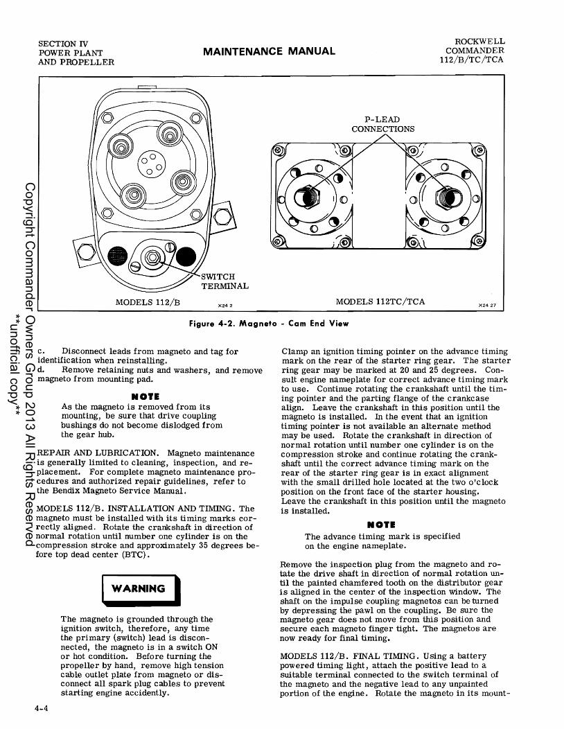
SECTION IV POWER PLANT AND PROPELLER
MAINTENANCE MANUAL ROCKWELL
COMMANDER 112/B/TC/TCA
MODELS 112/B X242.
P-LEAD CONNECTIONS
MODELS 112TC/TCA X2427
Figure 4-2. Magneto - Cam End View
c. Disconnect leads from magneto and tag for identification when reinstalling. d. Remove retaining nuts and washers, and remove magneto from mounting pad.
NOIE As the magneto is removed from its mounting, be sure that drive coupling bushings do not become dislodged from the gear hub.
REPAIR AND LUBRICATION. Magneto maintenance is generally limited to cleaning, inspection, and replacement. For complete magneto maintenance procedures and authorized repair guidelines, refer to the Bendix Magneto Service Manual.
MODELS 112/B. INSTALLATION AND TIMING. The magneto must be installed with its timing marks correctly aligned. Rotate the crankshaft in direction of normal rotation until number one cylinder is on the compression stroke and approximately 35 degrees before top dead center (BTC).
4-4
I WARNING I The magneto is grounded through the ignition switch, therefore, any time the primary (switch) lead is disconnected, the magneto is in a switch ON or hot condition. Before turning the propeller by hand, remove high tension cable outlet plate from magneto or disconnect all spark plug cables to prevent starting engine accidently.
Clamp an ignition timing pOinter on the advance timing mark on the rear of the starter ring gear. The starter ring gear may be marked at 20 and 25 degrees. Consult engine nameplate for correct advance timing mark to use. Continue rotating the crankshaft until the timing pointer and the parting flange of the crankcase align. Leave the crankshaft in this position until the magneto is installed. In the event that an ignition timing pointer is not available an alternate method may be used. Rotate the crankshaft in direction of normal rotation until number one cylinder is on the compression stroke and continue rotating the crankshaft until the correct advance timing mark on the rear of the starter ring gear is in exact alignment with the small drilled hole located at the two O'clock position on the front face of the starter housing. Leave the crankshaft in this position until the magneto is installed.
NOIE The advance timing mark is specified on the engine nameplate.
Remove the inspection plug from the magneto and rotate the drive shaft in direction of normal rotation until the painted chamfered tooth on the distributor gear is aligned in the center of the inspection window. The shaft on the impulse coupling magnetos can be turned by depreSSing the pawl on the coupling. Be sure the magneto gear does not move from this position and secure each magneto finger tight. The magnetos are now ready for final timing.
MODELS 112/B. FINAL TIWNG. USing a battery powered timing light, attach the positive lead to a suitable terminal connected to the switch terminal of the magneto and the negative lead to any unpainted portion of the engine. Rotate the magneto in its mount-
Copyright C
omm
ander Ow
ners Group 2013 All R
ights Reserved
**unofficial copy**

ROCKWELL COMMANDER 112/B/TC/TCA
MAINTENANCE MANUAL SECTION IV
POWER PLANT AND PROPELLER
ing flange to a point where the light comes on, then slowly turn it in the opposite direction until the light goes out. Bring the magneto back slowly until the light just comes on. Repeat this procedure with the second magneto.
NO"I
AC timing lights operate in the reverse manner as described above, the light goes out when the breaker points open.
After both magnetos have been timed, check to ascertain that both magnetos are set to fire together. Backoff the crankshaft a few degrees, the timing lights should go out. Bring the crankshaft slowly back in direction of normal rotation until the timing marks are in alignment. At this point, both lights should go on simultaneously.
MODELS 112TC/TCA. INSTALLATION AND TIMING. The magneto must be installed with its timing marks correctly aligned. Rotate the crankshaft in direction of normal rotation until number one cylinder is on the compression stroke and approximately 20 degrees before top dead center (BTC).
I WARNING I The magneto is grounded through the ignition switch, therefore, any time the primary (switch) lead is disconnected, the magneto is in a switch ON or hot condition. Before turning the propeller by hand, remove high tension cable outlet plate from magneto or disconnect all spark plug cables to prevent starting engine accidently.
Clamp an ignition timing pointer on the advance timing mark on the rear of the starter ring gear. The starter ring gear may be marked at 20 and 25 degrees. Consult engine nameplate for correct advance timing mark to use. Continue rotating the crankshaft until the timing pointer and the parting flange of the crankcase align. Leave the crankshaft in this position until the magneto is installed. In the event that an ignition timing pointer is not available an alternate method may be used. Rotate the crankshaft in directioJ'l of f
normal rotation until number one cylinder is on the compression stroke and continue rotating the crankshaft until the correct advance timing mark on the rear of the starter ring gear is in exact alignment with the small drilled hole located at the two 0' clock position on the front face of the starter housing. Leave the crankshaft in this position until the magneto is installed.
NOTE The advance timing mark is specified on the engine nameplate.
Remove the inspection plug from the most convenient side of magneto housing and plug from the rotor viewing location in the center of the housing. Rotate magnet drive shaft in normal direction of rotation until the painted tooth on large distributor gear is centered in the timing hole. The shaft on the impulse coupling magneto can be turned by depressing the pawl on the coupling. Observe that at this time the built in pointer just ahead of the rotor viewing window aligns with the "L" mark on the rotor. Be sure the magneto gear does not move from this position and secure magneto finger tight. The magneto is now ready for final timing.
MODELS 112TC/TCA. FINAL TIMING. Attach red lead from the timing light to left switch adapter lead, green lead of timing light to right switch adapter lead and the black lead of the timing light to the magneto housing. Rotate the magneto in its mounting flange to a point where the red timing light comes on, then slowly turn it in the opposite direction until the red light goes out indicating the left main breaker has opened. Then evenly tighten the magneto mounting clamps. Back the crankshaft up approximately 10 degrees, the timing light should come on. Bring the crankshaft slowly back in direction of normal rotation until the timing marks are in alignment, the red light should go out indicating left main breaker opening. The right main breaker, monitored by the green light, must open within ~ 2 degrees of the number one firing position.' If the right breaker does not open within the two degrees tolerance, back the engine up a few degrees and again bring the crankshaft slowly back in direction of normal rotation toward number one cylinder firing position while observing timing lights. Adjust breakers to open (timing lights out) when the timing pointer is indicating within the width of the "L" mark. After adjusting breakers recheck timing.
NO'l1
Some timing lights operate in the reverse manner as described. Check your timing light instructions.
IGNITION HARNESS
The ignition harness for each engine consists of eight shielded high tension cable assemblies. Two of the four cables from the left magneto are routed to the upper spark plugs on the left bank of cylinders, while the other two cables from the left magneto are routed to the lower spark plugs on the right bank of cylinders. Two of the four cables from the right magneto are routed to the upper spark plugs on the right bank of cylinders, and the balance of the cables from the right magneto are routed to the lower spark plugs on the left bank of cylinders (see Figure 4- 3).
CABLE REMOVAL AND INSTALLATION. Ignition cables may be removed individually or the ignition harness may be replaced as a complete unit.
4-5
Copyright C
omm
ander Ow
ners Group 2013 All R
ights Reserved
**unofficial copy**
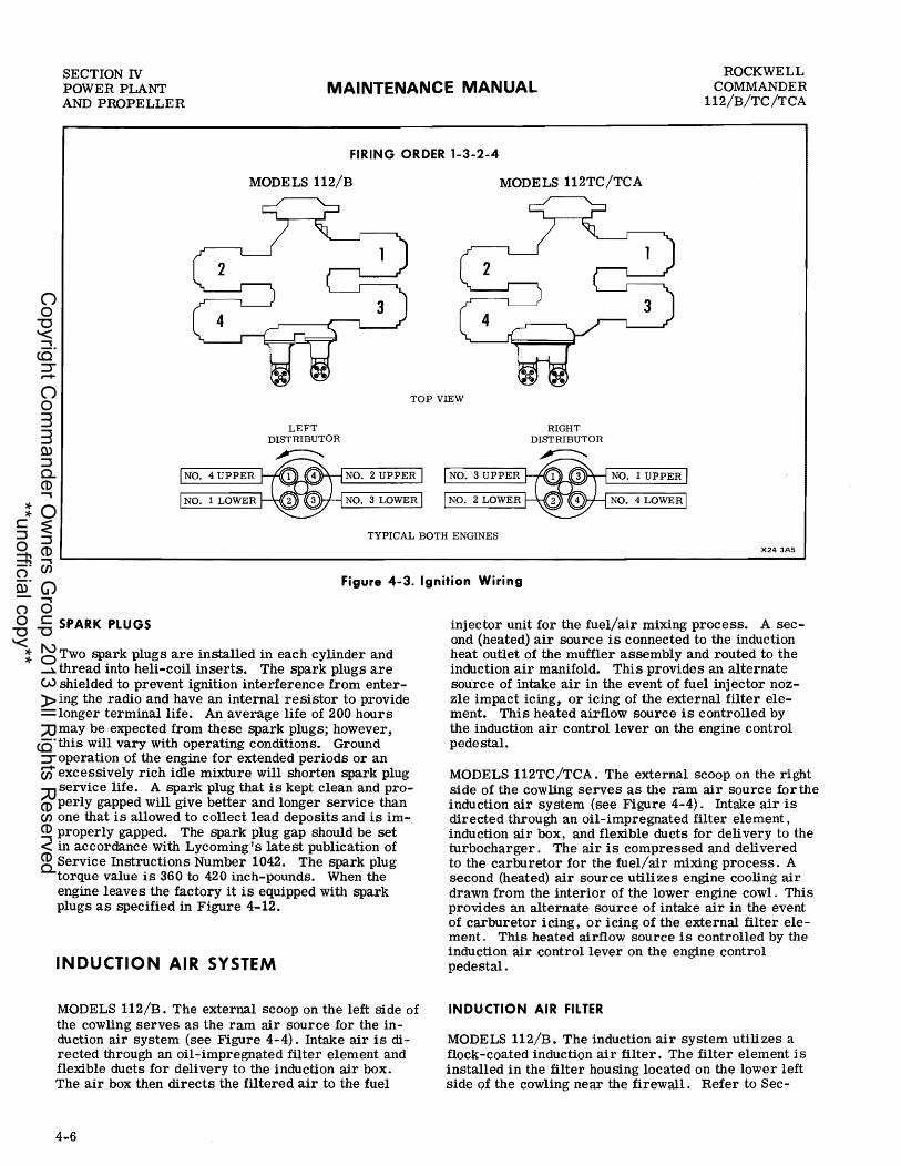
SECTION IV POWER PLANT AND PROPELLER
MAINTENANCE MANUAL ROCKWELL
COMMANDER 112/B/TC/TCA
FIRING ORDER 1-3-2-4
MODELS 112/B MODELS 112TC/TCA
TOP VIEW
NO.4 UPPER
NO.1 LOWER
LEFT DISTRIBUTOR
NO.2 UPPER
NO.3 LOWER
RIGHT DISTRIBUTOR
NO.3 UPPER t-+((l]L((~I)}\--j NO.1 UPPER
NO.2 LOWER NO.4 LOWER
TYPICAL BOTH ENGINES X243A5
Figure 4-3. Ignition Wiring
SPARK PLUGS
Two spark plugs are installed in each cylinder and thread into heli-coil inserts. The spark plugs are shielded to prevent ignition interference from entering the radio and have an internal resistor to provide longer terminal life. An average life of 200 hours may be expected from these spark plugs; however, this will vary with operating conditions. Ground operation of the engine for extended periods or an excessively rich idle mixture will shorten spark plug service life. A spark plug that is kept clean and properly gapped will give better and longer service than one that is allowed to collect lead deposits and is improperly gapped. The spark plug gap should be set in accordance with Lycoming's latest publication of Service Instructions Number 1042. The spark plug torque value is 360 to 420 inch-pounds. When the engine leaves the factory it is equipped with spark plugs as specified in Figure 4-12.
INDUCTION AIR SYSTEM
MODELS 112/B. The external scoop on the left side of the cowling serves as the ram air source for the induction air system (see Figure 4-4). Intake air is directed through an oil-impregnated filter element and flexible ducts for delivery to the induction air box. The air box then directs the filtered air to the fuel
4-6
injector unit for the fuel/air mixing process. A second (heated) air source is connected to the induction heat outlet of the muffler assembly and routed to the induction air manifold. This provides an alternate source of intake air in the event of fuel injector nozzle impact icing, or icing of the external filter element. This heated airflow source is controlled by the induction air control lever on the engine control pedestal.
MODELS 112TC/TCA. The external scoop on the right side of the cowling serves as the ram air source for the induction air system (see Figure 4-4). Intake air is directed through an oil-impregnated filter element, induction air box, and flexible ducts for delivery to the turbocharger. The air is compressed and delivered to the carburetor for the fuel/air mixing process. A second (heated) air source utilizes engine cooling air drawn from the interior of the lower engine cowl. This provides an alternate source of intake air in the event of carburetor icing, or icing of the external filter element. This heated airflow source is controlled by the induction air control lever on the engine control pedestal.
INDUCTION AIR FILTER
MODELS 112/B. The induction air system utilizes a flock-coated induction air filter. The filter element is installed in the filter housing located on the lower left side of the cowling near the firewall. Refer to Sec-
Copyright C
omm
ander Ow
ners Group 2013 All R
ights Reserved
**unofficial copy**

ROCKWELL COMMANDER 112/B/TC /TCA
MUFFLER ASSEMBLY (REF)
MODEL 112TC/TCA
MAINTENANCE MANUAL
MODEL 112B
SECTION IV POWER PLANT
AND PROPELLER
AIR FILTER HOUSING
I
AIR FILTER
/
/ /
MODEL 112
----AIR FILTER HOUSING
AIR FILTER
t---lll~-AIR FILTER
AIR FILTER HOUSING
Figure 4-4. Induction Air System
X244
X2434
4-7
Copyright C
omm
ander Ow
ners Group 2013 All R
ights Reserved
**unofficial copy**

SECTION IV POWER PLANT AND PROPELLER
MAINTENANCE MANUAL ROCKWELL
COMMANDER 112/B/TC /TCA
tion II for cleaning and installation.
MODELS 112TC/TCA. The induction air system utilizes a flock-coated induction air filter. The filter element is installed in the filter housing located on the lower right side of the cowling near the firewall. Refer to Section II for cleaning and installation.
FUEL INJECTION SYSTEM
MODELS 112/B. Filtered air is introduced into the engine through the servo regulator body, then flows into an air intake riser where it is distributed to each cylinder by individual intake pipes. The amount of air entering the engine is controlled by a throttle valve (butterfly) contained in the body of the fuel injection servo regulator. Fuel is metered and distributed to the individual cylinders by the servo regulator and fuel flow divider valve. The fuel-air ratio is determined by the pOSition of the throttle valve and air senSing functions of the servo regulator. Fuel and air are mixed within the cylinder. The fuel injection system consists of the air flow senSing and fuel control subsystems. Components of the injection system are: the servo valve, fuel control unit, fuel flow divider valve, and air bleed nozzles. The servo valve and fuel control unit are contained within the throttle body casting, installed on the engine intake manifold air inlet.
SERVO REGULATOR
MODELS 112/B. The servo regulator is the basic component of the fuel injection system. Induction air enters the throttle body, passes through the venturi and by the throttle valve and into the engine. As the air passes through the throttle body, air pres-sure is sensed by impact tubes which lead to one side of the servo regulator air diaphragm. The other Side of this diaphragm is exposed to low pressure which is sensed at the venturi throat of the throttle body (see Figure 4-5). A ball servo valve and a fuel/air diaphragm operates on the pressure differential between unmetered and metered fuel pressure. The air metering force applied to the air diaphragm of the servo regulator is directly proportional to the velocity of air flOwing through the venturi to the engine. Air velocity is controlled by the position of the throttle valve; therefore, a change in throttle setting will alter the position of the fuel/air diaphragm. This causes the position of the ball servo valve to vary. The pressure differential across the ball servo valve opposes the action of the air diaphragm and tends to open or close the ball servo valve. This provides regulated servo pressure for operation of the fuel flow divider valve which schedules a fuel flow that is correctly proportioned to the engine inlet airflow. A balanced fuel flow condition will exist when servo pressure on the fuel flow divider valve and ball servo valve is equal to the air metering force at the air di-
4-8
aphragm of the servo regulator. The richer fuel mixture required during engine idle is obtained by using a constant head spring on the lower side of the air sensing diaphragm. Fuel pump pressure, which is recorded on the engine gage unit, is taken from a port on the forward side of the servo regulator fuel control unit. Fuel flow readings are obtained from the metered fuel side of the fuel flow divider valve.
MODELS 112/B. CLEANING AND INSPECTION. The following procedures apply to cleaning and inspection of the servo regulator. Remove and clean the fuel inlet screen at the first 25 hours and each 50 hours of operation thereafter.
a. Remove upper cowling. b. Inspect servo regulator and all fuel lines for tightness and evidence of fuel leakage.
NOI. Slight fuel stains adj acent to the air bleed nozzles are normal.
c. Clean screen assembly in cleaning solvent and dry with filtered compressed air. d. Inspect screen assembly to determine service-ability. Replace screen assembly if deformed or deteriorated. e. Place new O-ring on screen assembly and install screen assembly in servo regulator. Tighten screen retainer to 35-40 inch-pounds. f. Check servo regulator for security of attach-ment. g. Check throttle, mixture, and alternate air con-trol rods, rod ends and levers for security and condition of rod ends. h. Lubricate ends of throttle shaft with instrument oil. i. Lightly lubricate rod ends of throttle, mixture, and alternate air control rods. j. Check mixture and throttle controls for freedom of operation.
MODELS 112/B. ADJUSTMENT. Adjustments to the servo regulator are confined to idle speed and mixture. If there is an appreciable amount of wind, locate aircraft in crosswind position before making idle speed and mixture adjustment., This will prevent false loading of the engine caused by the affect of wind velocity on the propeller.
a. Start and warm engine until oil and cylinder head temperatures are in normal operating range. b. Check magneto drop, see Section II. If drop is normal, proceed with idle adjustment. c. Set throttle stop-screw so engine idles at 550-650 RPM. If the RPM varies significantly after making mixture adjustment during following steps, readjust to desired RPM. d. When idling-speed has stabilized, move mixture control lever toward IDLE CUTOFF position and ob-
Copyright C
omm
ander Ow
ners Group 2013 All R
ights Reserved
**unofficial copy**

ROCKWELL COMMANDER 112/B/TC/TCA
MAINTENANCE MANUAL SECTION IV
POWER PLANT AND PROPELLER
3
2
IDLE MIXTURE ADJUST
IDLE SPEED ADJUST
1. IDLE VALVE LEVER (CONNECTED TO THROTTLE)
2. METERING JET 3. FUEL INLET 4. FUEL INLET SCREEN 5. MANUAL MIXTURE/IDLE CUT-OFF
AIR INLET
10
FUEL - AIR BLEED NOZZLE
9. FLOW DIVIDER VALVE 10. NOZZLE (ONE PER CYLINDER) 11. THROTTLE VALVE 12. IMPACT TUBE 13. BALL SERVO VALVE 14. FUEL DIAPHRAGM
6. FUEL FLOW GAGE (RT. HALF OF DUAL GAGE) 15. AIR DIAPHRAGM 7. FLOW DIVIDER 16. CONSTANT EFFORT SPRING 8. FLOW DIVIDER DIAPHRAGM 17. CONSTANT HEAD SPRING (IDLE)
MODELS 112/B X245
Figure 4-5. Fuel Iniection System
4-9
Copyright C
omm
ander Ow
ners Group 2013 All R
ights Reserved
**unofficial copy**

SECTION IV POWER PLANT AND PROPE~LER
MAINTENANCE MANUAL ROCKWELL
COMMANDER 112/B/TC /TCA
FUEL STRAINER IDLE ADJUSTING
NEEDLE VALVE
LOCK PLATE
MODELS 112TC/TCA X2431A7
Figure 4-6. Carburetor
serve tachometer for any change during leaning process. Caution must be observed to return mixture control lever to FULL RICH position before RPM drops so low engine cuts out. An increase of more than 10 RPM while leaning indicates an excessively rich idle mixture. An immediate decrease in RPM (if not preceded by a momentary increase) indicates idle mixture is too lean. e. If idle adjustment is too rich or too lean, turn idle mixture adjustment in direction required for correction, and recheck new setting. Each time an adjustment is made, engine should be run up to 2000 RPM to clear engine before making another adjustment. Monitor cylinder head and oil temperature gages to remain within limits. f. In the event the setting above does not remain stable, check the idle linkage; any looseness in the linkage will cause erratic idling. In all cases, allowance must be made for the effect of weather conditions and field density altitude during adjustments.
FLOW DIVIDER VALVE
MODELS 112/B. The fuel flow divider valve, located on the upper center of the engine, consists of a spring-loaded diaphragm actuated poppet valve'Action of the diaphragm is controlled by servo pressure from the servo regulator valve. A spring seats the fuel flow divider valve needle to retain fuel within the flow divider valve when the engine is stopped. The sensitivity obtained from fuel flow divider valve operation prevents engine rpm lag during rapid throttle movement and eliminates the need for an acceleration pump. The fuel flow divider valve directs fuel to each cylinder through individual lines connected to ports in the valve. Fuel passes through the air bleed nozzles
4-10
before entering the cylinder. A fuel line is connected between the fuel flow divider fuel flow port and a fuel flow gage, located in the instrument panel, to provide an accurate indication of metered fuel flow to the engine.
AIR BLEED NOZZLES
MODELS 112/B. An air bleed nozzle installed in each cylinder, directs fuel from the flow divider valve into the cylinder intake port. Each nozzle in-corporates an air bleed, which aids in vaporizing fuel at idle rpm by breaking the high vacuum at the intake manifold, and assures that the fuel lines from the flow divider valve are full of fuel at all times. The immediate availability of fuel in the fuel lines ensures positive engine acceleration and eliminates the need for an engine primer during engine starting. Air bleed nozzles have an identification number or letter stamped on one of the flats of the no zzle body hexagon head, which also indicates that the nozzle air bleed hole is on the opposite flat. To eliminate fuel leakage at the air bleed hole after engine shutdown, the nozzle must be installed with the identification mark facing downward. Fuel nozzles should be removed and changed when an engine is running rough and exhibits poor acceleration characteristics, not attributed to faulty ignition. When this is the case all nozzles on the appropriate engine should be removed and cleaned.
MODELS 112/B. REMOVAL AND CLEANING. Disconnect the fuel inlet line and use a deep socket to remove the nozzle. Cap the fuel line and plug hole in cylinder. Clean the air bleed nozzles as follows:
a. Wash in clean unleaded gasoline or cleaning solvent. Trichlorethylene may be used to clean nozzles that show signs of carbon buildup. b. Apply filtered compressed air at 100 psi to dis-charge port of nozzle.
Do not use wire or tools to clean nozzle orifices.
MODELS 112/B. INSTALLATION. Install air bleed nozzles in cylinders, so that identification number or letter is located on the lower side of the nozzles when tightened into engine cylinder.
[~ When replacing fuel lines and fittings, use only a fuel soluble lubricant, such as engine oil on thread fittings. 00 NOT USE ANY FORM OF THREAD COMPOUND.
Change 1
Copyright C
omm
ander Ow
ners Group 2013 All R
ights Reserved
**unofficial copy**

ROCKWELL COMMANDER 112/B/TC/TCA
MAINTENANCE MANUAL SECTION IV
POWER PLANT AND PROPELLER
CARBURETION SYSTEM
CARBURETOR
a. Connect fuel injection lines to air bleed nozzles. b. Inspect installation for evidence of crimped lines. c. Operate auxiliary fuel pump and check fittings and air bleed nozzles for evidence of leakage. d. Turn off auxiliary fuel pump and battery switch and secure cowling.
MODELS 112TC/TCA. These models are equipped with a Marvel Schebler Type HA-6 side draft, single barrel, float type carburetor equipped with a manual altitude mixture control and an idle cut-off. The idle speed aqjustment is a conventional spring-loaded needle valve.
MODELS 112TC/TCA. IDLE ADJUSTMENT. Idle adjustment may be accomplished as follows:
a. Start and warm engine until oil and cylinder head temperatures are in normal operating range. b. Check magneto drop, see Section II. If drop is normal, proceed with idle adjustment. c. Set idle adjusting needle valve (see Figure 4-6) so engine idles smoothly. d. Run up to 2000 RPM to clear engine after each adjustment before making any additional adjustments.
NOIE Engine idle speed may vary among different engines. An engine should idle smoothly without excessive vibration, and the idle speed should be high enough to maintain idling oil pressure and to preclude any possibility of engine stoppage in flight when throttle is closed.
MODELS 112TC/TCA. CARBURETOR REMOVAL. The carburetor may be removed as follow s:
a. Remove lower cowling. b. Disconnect throttle and mixture linkage. c. Disconnect and cap all fuel lines at carburetor. d. Remove bolts from turbocharger adapter and secure as necessary to allow carburetor removal. e. Remove nuts holding carburetor to engine, remove carburetor and install covers on turbocharger adapter and mounting pad.
MODELS 112TC/TCA. CARBURETOR INSTALLATION
a. Remove covers from mounting pad and turbo-charger adapter. Install carburetor on mounting studs and torque as required. b. Install turbocharger adapter and torque as required. c. Uncap and install all fuel lines.
Change 1
When replacing AI0- 5200 carburetor with another carburetor of the same number, assure needle valve assembly retainer is secured to carburetor with lockplate as shown in Figure 4- 6.
d. Connect throttle and mixture control linkage.
e.
NOI. Check throttle and mixture control for proper travel.
Install lower cowling.
MODELS 112TC/TCA. CLEANING FUEL STRAINER. The carburetor fuel strainer should be cleaned at periodic intervals, to remove strainer, proceed as follows:
a. Remove safety and remove strainer from car-buretor (see Figure 4-6). b. Wash strainer in approved solvent. c. Check strainer for deformation or breaks. d. Clean strainer chamber of any foreign material. e. Reinstall strainer, tighten and safety.
TURBOCHARGER
MODELS 112TC/TCA. A complete turbocharger systern, installed on the aft end of the engine consists of a turbine and compressor assembly and an overboost pressure relief valve. The turbocharger is utilized to increase the power output and efficiency of the engine by supplying compressed air to the engine intake system. The power to drive the turbocharger is extracted from energy in the exhaust gas. A manually controlled (interconnected with throttle) exhaust wastegate valve assembly determines the amount of boost supplied to the engine. When open, the valve allows exhaust to bypass the turbine and flow directly overboard. In the closed position, the wastegate valve diverts the exhaust gases through the turbine assembly, increasing its speed and resulting in more output of induction air from the compressor, since it is connected to the opposite end of the turbine shaft.
OIL SYSTEM
The engine is equipped with a wet sump, pressure operated oil system. The main bearings, connecting rod bearings, camshaft bearings, valve tappets, and push rods, are lubricated by positive pressure. The pistons, piston pins, cams, cylinder walls, valve rockers, valve stems and other internal moving parts are lubricated by oil collectors and oil spray. The oil pump, located in the accessory housing, draws oil
4-11
Copyright C
omm
ander Ow
ners Group 2013 All R
ights Reserved
**unofficial copy**

SECTION IV POWER PLANT AND PROPELLER
MAINTENANCE MANUAL ROCKWELL
COMMANDER 112/B/TC/TCA
through a drilled passage leading from the oil filter located in the sump. Mter passing through the pump, oil flows through a drilled passage in the engine and then through a line to the oil cooler. Oil pressure from the cooler is returned to the accessory housing where it is directed through the oil filter, contained in a cast chamber mounted on the accessory housing. If cold oil or an obstruction should restrict oil flow through the cooler, an oil cooler bypass valve will route the oil directly from the oil pump to the oil filter. The oil is then filtered through the oil filter chamber and fed through a drilled passage to the oil pressure relief valve, located in the upper right side of the crankcase forward of the accessory housing. This relief valve regulates the engine oil pressure by allowing excess oil to return to the sump, while the balance of the oil is fed to the main oil gallery in the right half of the crankcase. Oil is distributed from the main gallery, by means of separate drilled passages to each main bearing of the crankshaft. The drilled passages to the bearings are located in such a manner as to form an inertia type filter, thus ensuring that only the cleanest oil will reach the bearings. Drilled passages from the rear main bearing supply oil pressure to the crankshaft idler gears. Angular holes are drilled through the main bearings to the rod journals where sludge removal tubes are located. Oil from the main gallery also flows to the cam and valve gear passages, and is then conducted through branch passages to the hydraulic tappets and camshaft bearings. Oil travels out through the hollow push rods to the valve rocker bearings and valve stems. Oil from the bearings, accessory drives and rocker boxes returns to the sump by gravity flow, passes through the inlet oil screen and is then recirculated through the engine. Refer to Section II for oil system servicing.
OIL COOLER
MODELS 112/B. The cooler is installed on the right forward side of engine firewall and receives its cooling air from the engine nacelle compartment. Oil under pressure from the engine enters the inboard side of the cooler, passes through the cooler and back to the engine. A thermostatically operated oil cooler bypass valve causes oil to bypass the cooler in the event of congealed oil or an obstruction in the cooler. This bypass valve also routes oil directly to the suction screen until a predetermined oil temperature is reached. The oil is then routed through the cooler.
MODELS 112TC/TCA. The cooler is installed on the left forward side of engine firewall and receives its cooling air from the engine nacelle external scoop. Oil under pressure from the engine enters the inboard side of the cooler, passes through the cooler and back to the engine. A thermostatically operated oil cooler bypass valve causes oil to bypass the cooler in the event of congealed oil or an obstruction in the cooler. This bypass valve also routes oil directly to the suction screen until a predetermined oil temperature is reached. The oil is then routed through the cooler.
4-12
OIL SCREEN AND FILTER
MODELS ll2/B. Clean engine oil is assured by the use of one oil suction screen and one oil filter for the engine. The oil suction screen is located in the right side of the oil sump and the oil filter is located in a casting, bolted to the accessory housing between the magnetos. Use of this screen and filter provides dual protection for positive screening of damaging foreign material from the oil. The oil pump draws oil from the sump through the suction screen and pumps it through the oil cooler to the engine. Oil screen and filter must be cleaned each time the oil is changed or whenever improper oil circulation is suspected. Servicing instructions are provided in Section II.
MODELS 112TC/TCA. Clean engine oil is assured by the use of one oil suction sc reen and one oil filter for the engine. The oil suction screen is located on the right side of the oil sump and the oil filter is located in the accessory housing on the right side of the engine. Use of this screen and filter provides dual protection for positive screening of damaging foreign material from the oil. The oil pump draws oil from the sump through the suction screen and pumps it through the oil cooler to the engine. Oil screen and filter must be cleaned each time the oil is changed or whenever improper oil circulation is suspected. Servicing instructions are provided in Section II.
ENGINE OIL
MINERAL (MIL- L-6082B)
SAE 50 SAE 40 SAE 30 SAE 20
ASHLESS DISPERSANT (MIL-L-22851)
SAE 50 or 60 SAE 50 SAE 40 SAE 30
AMBIENT AIR TEMP.
Above 600 F 300 to gOOF 00 to 700 F Below lOoF
AMBIENT AIR TEMP.
Above 600 F 300 to gOOF 00 to 700 F Below lOoF
NOTE To promote faster seating and improved oil control, the Models 112/B were delivered from the factory with a mineraltype (non-detergent) oil installed. This break-in oil should be used for the first 50 hours only, at which time it must be drained and replaced with detergent oiL
Mter the first 25 hours of operation, drain engine oil, clean suction and oil filter screens and replace filter element. Refill the sump with non-detergent oil and use until the 50 hour mark is reached or oil consumption has stabilized, then change to detergent oil conforming to previous specifications.
Change 3
I C
opyright Com
mander O
wners G
roup 2013 All Rights R
eserved **unofficial copy**

ROCKWELL COMMANDER 112/B/TC/TCA
MAINTENANCE MANUAL SECTION IV
POWER PLANT AND PROPELLER
EXHAUST SYSTEM
MODELS 112/B. The exhaust system consists of four exhaust stacks. Each exhaust stack is attached to the exhaust port of each cylinder and extends down and attached to the muffler assembly. Each exhaust stack is attached to the muffler by special clamps that allow for expansion and contraction of the entire installation. Nuts and lock washers are used to secure each exhaust stack to the cylinders. Inspect the exhaust stacks at prescribed intervals for evidence of leakage, cracks and looseness of mounting nuts (see Figure 4-7).
MODELS 112TC/TCA. The exhaust system for each engine consists of six segments. These segments attach to the exhaust ports of the right and left banks of cylinders and extend across and aft to where they attach to the turbine section of the turbocharger. The segments of the exhaust system utilize slip joints that allow for expansion and contraction of the entire assembly. Nuts and lockwashers are used to secure the exhaust system to the exhaust ports of each cylinder. Inspect the exhaust system at prescribed intervals for evidence of leakage, cracks and looseness of mounting nuts (see Figure 4-7).
EXHAUST SYSTEM REPAIR
Components of the exhaust system which fail must be replaced, however, certain components may be repaired in accordance with FAA Advisory Circular No. AC 43. 13-1. Consult this source for repair guideline s.
Never use lead pencils, grease pencils, etc., to mark exhaust system components. Carbon deposited by these items will eventually cause cracks due to heat concentration and carbonization of the metal. Use chalk, prussion blue or India ink when necessary to mark components.
COOLING SYSTEM
Cooling air enters the engine cowling compartment through openings located in the center of cowling near the propeller. Engine baffles (Figure 4-8) direct air flow around the cooling fins of each cyliriner. Adjustable cowl flaps, located in the lower cowl, are provided to regulate engine temperature. To assure proper airflow around the engine, baffle seals and cowling must be maintained in a serviceable condition. Baffle seals which do not block the airflow at the seal location cause improper distribution of the cooling air and may result in hot spots on the cylinders.
Ground ope rate engine with cowl flaps open to prevent overheating of engine.
BAFFLE REMOVAL, REPAIR AND INSTALLATION
Removal and installation on the various baffles can be made with the engine cowling removed. Insure that any replaced baffles and seals are installed correctly and that they seal properly to direct the cooling air in the proper direction. Baffles should be replaced if damaged or cracked. However, small plate reinforcements riveted to the baffle will often prove satisfactory both to the strength and cooling requirements of the unit.
ENGINE CONTROLS
MODELS 112/B. The engine control levers (Figure 4-9) are located on the engine control quadrant and control the throttle, propeller pitch, fuel mixture and alternate air. Cables and push-pull rods connect the engine control levers to the power plant. Cover plates on the quadrant pedestal may be removed for inspection and maintenance of control cables and other equipment enclosed in the pedestal. Additionally, the complete pedestal may be removed for maintenance purposes. A friction lock is installed on the right side of the quadrant to secure the control levers in the desired pOSition, or place the desired amount of friction on the engine control levers. Engine control cables are routed through the firewall and to the engine. The individual controls are attached to the servo regulator (throttle and fuel mixture), propeller governor (propeller pitch) and induction air box (alternate air). Cable adjustments for the engine controls are made at the ball joints and clevises. Push-pull rods, ball joints and clevises should be checked for loose checknuts, nuts, freedom of operation and excessive wear. Routing of the control cables should be checked to see that cable clamps are in place and cables do not rub structure or accessories.
MODELS 112TC/TCA. The engine control levers (Figure 4-9) are located on the engine control quadrant and control the throttle, propeller pitch, fuel mixblre, turbocharger wastegate, and alternate air. Cables and push-pull rods connect the engine control levers to the power plant. Cover plates on the quadrant pedestal may be removed for inspection and maintenance of control cables and other equipment enclosed in the pedestal. Additionally, the complete pedestal may be removed for maintenance purposes. A friction lock is installed on each side of the quadrant to secure the control levers in the desired position, or place the desired amount of friction on the engine control levers. Engine control cables are routed through the firewall to the engine. The indi-
4-13
Copyright C
omm
ander Ow
ners Group 2013 All R
ights Reserved
**unofficial copy**

SECTION IV POWER PLANT AND PROPELLER
MODELS 112/B
MODELS 112TC/TCA
4-14
MAINTENANCE MANUAL
MUFFLER
Figure 4-7. Exhaust Stack
ROCKWELL COMMANDER
112/B/TC/TCA
X249A6
X2433
Copyright C
omm
ander Ow
ners Group 2013 All R
ights Reserved
**unofficial copy**

ROCKWELL COMMANDER 112/B/TC/TCA
RIGHT SIDE FORWARD
BAFF
RIGHT SIDE AFT BAFFLE
FRONT--*!BAFFLE
RIGHT FRONT BAFFLE
MODELS 112/B
MAINTENANCE MANUAL
RIGHT AFT BAFFLE
LEFT SIDE FORWARD BAFFLE
LEFT FRONT" BAFFLE
Figure 4-8. Engine Baffle Assembly (Sheet 1 of 2)
SECTION IV POWER PLANT
AND PROPELLER
LEFT SIDE AFT BAFFLE
X247
4-15
Copyright C
omm
ander Ow
ners Group 2013 All R
ights Reserved
**unofficial copy**

SECTION IV POWER PLANT AND PROPELLER
RIGHT SIDE FORWARD
BAFFLE
RIGHT LOWER
BAFFLE
MODELS 112TC/TCA
4-16
MAINTENANCE MANUAL
RIGHT FORWARD BAFFLE ASSEMBLY
BOTTOM BAFFLE ASSEMBLY
LEFT FORWARD BAFFLE ASSEMBLY
Figure 4-8. Engine Baffle Assembly (Sheet 2 of 2)
ROCKWELL COMMANDER
112/B/TC/TCA
LEFT REAR BAFFLE ASSEMBLY
LOWER BAFFLE
X2436
Copyright C
omm
ander Ow
ners Group 2013 All R
ights Reserved
**unofficial copy**

ROCKWELL COMMANDER 112/B/TC/TCA
MAINTENANCE MANUAL SECTION IV
POWER PLANT AND PROPELLER
ON
0 rD 5 OFF
C F HI It 0 U I l l C D L H
T P I H It M
N It 0 I D 0 P X U T T C T It U T L P R
E M E
I l H D E 0 L A T E to N
X24 1
Figure 4-9. Engine Control Quadrant
vidual controls are attached to the carburetor (throttle and fuel mixture), propeller governor (propeller pitch), turbocharger wastegate (throttle) and induction air box (alternate air). Cable adjustments for the engine controls are made at the
• ball joints, clevises and adapter. Push-pull rods, ball joints and clevises should be checked for loose checknuts, nuts, freedom of operation and excessive wear. Routing of the control cables should be checked to see that cable clamps are in place and cables do not rub structure or accessories.
THROTTLE
MODELS 112/B. The throttle lever located on the left side of the control quadrant is mechanically linked to the throttle arm of the fuel injection system servo regulator. A friction lock located on the right side of the quadrant provides a means of increasing friction on the throttle lever to prevent creeping. When the throttle lever is retarded to a position sufficient to actuate the micro switch located inside the quadrant, a landing gear position warning bell will sound if all landing gear are not in the down and locked position. The switch is set to activate the warning bell circuit when the engine manifold pressure is approximately 14 inches Hg. Procedures for adjusting the micro switch is provided in Section VI.
Change 1
MODELS 112TC/TCA. The throttle lever located on the left side of the control quadrant is mechanically linked to the throttle arm of the carburetor, and control arm of the turbocharger wastegate. A friction lock located on each side of the quadrant provides a means of increasing friction on the throttle lever to prevent creeping. When the throttle lever is retarded to a poSition sufficient to actuate the micro switch located inside the quadrant, a landing gear position warning bell will sound if all landing gear are not in the down and locked poSition. The switch is set to activate the warning bell circuit when the engine manifold pressure is approximately 14 inches Hg. Procedures for adjusting the micro switch is provided in Section VI.
MODELS 112/B. RIGGING. The procedure for rigging the throttle control cable is as follows:
a. Secure throttle control cable clevis end to servo regulator on engine. b. Secure throttle control cable ball joint to throttle lever in control quadrant. c . Move throttle control lever through full range of travel. Check lever hits both end stops. d. Move throttle control lever to full forward stop less 0.03 inch clearance. e. Adjust ball joint at throttle control lever until it contacts forward end stop. f. Move throttle control lever aft and ascertain
4-17
Copyright C
omm
ander Ow
ners Group 2013 All R
ights Reserved
**unofficial copy**

SECTION IV POWER PLANT AND PROPELLER
MAINTENANCE MANUAL ROCKWELL
COMMANDER 112/B/TC /TCA
it reaches opposite end stop. g. If required, make minor aqjustments at throttle control lever until it aligns with other control levers at full forward position with a 0.03 inch clearance.
MODELS 112TC/TCA. RIGGING. The procedure for rigging the throttle control cable is as follows:
a. Secure throttle control cable clevis ends to carburetor and turbocharger wastegate on engine. b. Secure throttle control cable ball joint to throttle lever in control quadrant. c . Move throttle control lever through full range of travel. Check lever hits both end stops. d. Move throttle control lever to full forward stop less 0.03 inch clearance. e. Adjust clevis ends on throttle and wastegate so throttle and wastegate contact stops simultaneously. f. Adjust ball joint at throttle control lever until it contacts forward end stop. g. Move throttle control lever aft and ascertain it reaches opposite end stop. h. If required make minor adjustments at throttle control lever until it aligns with other control levers at full forward pOSition with a 0.03 inch clearance.
MIXTURE CONTROL
MODELS 112/B. The mixture control lever is mounted on the right side of the engine control quadrant. The RICH pOSition of the mixture control lever is used for starting, takeoff, landing, and most ground operations. LEAN is used for stopping the engine. The range between RICH and LEAN permits manual leaning of the fuel mixture to obtain best power and minimum fuel consumption during flight. A fuel flow gage registers the amount of metered fuel going to the engine and aids in determining the proper mixture control setting.
MODELS 112TC/TCA. The mixture control lever is mounted on the right side of the engine control quadrant 0
The RICH position of the mixture control lever is used for starting, takeoff, landing, and most ground operations. LEAN is used for stopping the engine. The range between RICH and LEAN permits manual lean-ing of the fuel mixture to obtain best power and minimum fuel consumption during flight.
RIGGING. The procedure for rigging the mixture control cable is the same as the throttle control cable rigging.
PROPELLER CONTROL
The propeller control lever is located between the throttle and mixture control levers and is distinguished by rectangular grooved knobs. The control lever is mechanically linked to a propeller governor and controls engine rpm and propeller pitch by altering the propeller governor setting. Forward movement of the control lever decreases propeller pitch and
4-18
increases engine rpm, and aft movement increases pitch and decreases rpm. Retarding the control lever into the LO position reduces oil pressure to the propeller, allowing centrifugal force of the propeller and compressed springs to reduce propeller pitch.
RIGGING. The procedure for rigging the propeller control cable is the same as the throttle control cable rigging.
ALTERNATE AIR CONTROL
MODELS 112/B. Induction air is controlled by the forward and aft movement of the alternate air control, located on the engine control quadrant. Placing the control lever in forward (COLD) position allows filtered ram air to enter the system. This ram air is directed to the induction air box and then on into the servo regulator for the fuel/air mixing process. Placing the control lever in the aft (HOT) pOSition closes the ram air source and opens the hot air source. The hot air is provided in the event of fuel injector nozzle impact icing or icing of the external filter element.
MODELS 112TC/TCA. Induction air is controlled by the forward and aft movement of the alternate air control, located on the engine control quadrant. Placing the control lever in forward (COLD) pOsition allows filtered ram air to enter the system. This ram air is directed to the induction air box and then on into the turbocharger and carburetor for the fuel/air mixing process. Placing the control lever in the aft (HOT) pOSition closes the ram air source and opens the hot air source. The hot air is provided in the event of carburetor icing or icing of the external filter element.
RIGGING. The procedure for rigging the alternate air control cable is the same as the throttle control cable rigging.
ENGINE ACCESSORIES
STARTER
A Bendix-type starter is installed on the forward lower left side of the engine. The starter drive pinion engages the engine flywheel ring gear to provide direct cranking of the engine. The starter contactor installed on the battery box in the tailcone, is energized by a key operated, spring-loaded, ignitionstarter switch. When starting the engine, avoid energizing the starter for more than 30 seconds, and allow several minutes for the starter unit to cool between starting attempts.
INSPECTION AND REPAIR. Before removing any unit in a starting circuit, it should be first determined where the fault lies within the circuit. Check that the battery is fully charged and inspect the wiring for
Copyright C
omm
ander Ow
ners Group 2013 All R
ights Reserved
**unofficial copy**
ROCKWELL COMMANDER 112/B/TC/TCA
MAINTENANCE MANUAL SECTION IV
POWER PLANT AND PROPELLER
possible damage. Inspect all connections to the starter solenoid, ignition switch, and battery, including all ground connections. Clean and tighten all connections as required. Connect a jumper lead around any switch suspected of being defective. If the starting system functions properly using a jumper, repair or replace the bypassed switch. If the battery, wiring, and switches are satisfactory and the engine is known to be functioning properly, remove the starter and send to an authorized repair station for repair.
REMOVAL. To remove the starter from the engine, proceed as follows:
a. Remove upper and lower engine cowling. b. Disconnect electrical lead from starter terminal. c. Remove bolt attaching alternator support strut to starter. d. Remove nuts and washers from studs holding starter mounting flange. e. Remove aft inboard, and forward outboard studs from starter mounting flange.
mST ALLATION
a. Align starter mounting flange with engine pad studs and install attaching hardware. b. Torque bolt and nuts to 150-inch pounds. c. Connect electrical wires to starter. d. Check starter operation. e. Install cowling.
ALTERNATOR
A 14-volt, 70-amp alternator is installed on the forward lower right side of the engine. The alternator employs a 3-phase stator winding in which the phase windings are electrically 120 degrees apart. The rotor consists of a field coil encased between two, 4-poled interleaved sections, producing an 8-pole magnetic field with alternate North and South poles. When the rotor rotates inside the stator, an alternating current is induced in the stator windings. This
-ac current is rectified,Le., changed to dc, by silicone. diode rectifiers and delivered to the output terminal of the alternator. A ram air blast tube extending from the slip ring cover of the alternator to the forward engine baffle supplies cooling air to the alternator. A belt from the alternator pulley, to a pulley which is integral with the aft propeller flange, drives the alternator at 3.25 times the speed of the engine. Proper alternator belt tension should be maintained to provide satisfactory service (see Lycoming Service Instructions Number 1129A). For additional information concerning the alternator system, refer to Section X.
REMOVAL. To remove the alternator from the engine, proceed as follows:
a. Remove upper and lower engine cowling. b. Disconnect electrical wires from alternator and tag for identification.
c. Loosen nut attaching alternator mounting flanges to engine. d. Remove bolt and washer from alternator idler arm. e. Rotate alternator to free belt from drive pulley. f. Remove nuts, washers and bolts securing alternator to engine and lift alternator from engine.
mST AL LAT ION
a. Position alternator with drive belt seated in alternator and starter ring gear pulleys. b. Install alternator flange mounting hardware, but leave alternator free to rotate at flanges. c. Install bolt and washer in alternator idler arm and tighten belt per Lycoming Service Instruction Number 1129A). d. Tighten nuts installed in step b. e. Connect electrical wiring. f. Install cowling.
FUEL PUMP
A diaphragm type, self regulated pressure pump is installed on the aft lower left side of the engine accessory housing. This engine operated pump provides a continuous flow of fuel to the engine without pressure variations. The pump design allows the auxiliary pump to move fuel through it to the engine in the event it becomes inoperative and also for the purpose of initial engine starting. If the pump becomes inoperative, do not attempt to repair it. Remove the pump and install a new one.
REMOVAL
a. Remove upper and lower engine cowling. b. Remove two capscrews attaching fuel pump. c. Remove pump and gasket.
INST ALLATION
a. Clean engine accessory pad. b. Install new pump and gasket on accessory pad. Assure pump plunger is up to engage push rod or drive shaft will bend. c. Install two capscrews and torque to 300 inch-pounds. d. Replace cowling.
ENGINE CHANGE
REMOVAL
MODELS 112/B. The engine mount (Figure 4-10) can be removed with the engine, if deSired. If the engine is being returned to the manufacturer or will not be operated within a seven day period comply with storage instructions contained in Section II. In the following instructions, the engine is being removed from the mount.
4-19
Copyright C
omm
ander Ow
ners Group 2013 All R
ights Reserved
**unofficial copy**

SECTION IV POWER PLANT AND PROPELLER
MODELS 112/B
1. NUT 2. WASHER 3. WASHER 4. RUBBER SHOCK PAD 5. DAMPER 6. RUBBER SHOCK PAD 7. BOLT 8. NUT 9. WASHER
10. BOLT 11. ENGINE MOUNT
4-20
MAINTENANCE MANUAL
10
Figure 4-10. Engine Mount (Sheet 1 of 2)
ROCKWELL COMMANDER
1t2/B/TC/TCA
X248
Copyright C
omm
ander Ow
ners Group 2013 All R
ights Reserved
**unofficial copy**

ROCKWELL COMMANDER 112/B/TC/TCA
MODELS 112TC/TCA
1. NUT 2. WASHER 3. WASHER 4 •• RUBBER SHOCK PAD 5. DAMPER 6. RUBBER SHOCK PAD 7. BOLT 8. NUT 9. WASHER
10. BOLT 11. ENGINE MOUNT
MAINTENANCE MANUAL
Figure 4-10. Engine Mount (Sheet 2 of 2)
SECTION IV POWER PLANT
AND PROPELLER
X242$
4-21
Copyright C
omm
ander Ow
ners Group 2013 All R
ights Reserved
**unofficial copy**

SECTION IV POWER PLANT AND PROPELLER
MAINTENANCE MANUAL ROCKWELL
COMMANDER 112/B/TC/TCA
OIL TILLER ACCESS DOOR
INDUCTION AIR INTAKE
MODELS 112/B
OIL TILLER ACCESS DOOR
OIL COOLER AIR INTAKE
MODELS 112TC/TCA X241087
Figure 4-11. Engine Cowling
a. Install fuselage tail stand. b. Ignition switch - OFF. c. Remove propeller (see Propeller Removal instructions in this section). d. Remove engine cowling (see Figure 4-11). e. Drain engine oil. f. Drain fuel lines at engine. g. Disconnect oil lines from oil cooler. h. Disconnect following lines from engine and cap or plug lines and fittings:
1. Vacuum line. 2. Fuel supply line. 3. Manifold pressure and fuel flow pressure and vent lines. 4. Oil pressure gage line.
i. Disconnect induction air system. j. Disconnect flexible drive from tachometer. k. Disconnect throttle and mixture control cables from servo regulator. 1. Disconnect electrical wiring from engine. m. Disconnect engine ground wire. n. Disconnect propeller control cable from prop governor. o. Secure control cables at firewall to prevent entanglement in engine when removing engine. p. Remove muffler assembly and exhaust stacks from engine, and cover cylinder exhaust ports.
4-22
q. Attach a one-half ton (minimum) hoist to engine lifting eye and tighten hoist cable slightly to relieve weight on engine mount attach bolts. r. Disconnect oil and fuel drain lines, engine-driven fuel pump drain line and engine breather line.
Raising engine too high will place a strain on attach bolts and hinder removal.
s. Check engine to ensure all items attaching engine and accessories to airframe are disconnected. t. Remove engine mount attach bolts. u. Remove engine from airframe.
When lifting engine from mount, use extreme care to prevent damage to engine mount and airframe.
Copyright C
omm
ander Ow
ners Group 2013 All R
ights Reserved
**unofficial copy**

ROCKWELL COMMANDER 112/B/TC/TCA
MAINTENANCE MANUAL SECTION IV
POWER PLANT AND PROPELLER
MODELS 112TC/TCA. The engine mount (Figure 4-10) can be removed with the engine, if desired. If the engine is being returned to the manufacturer or will not be operated within a seven day period comply with storage instructions contained in Section IT. In the following instructions, the engine is being removed from the mount.
a . Install fuselage tail stand. b. Ignition switch - OFF. c. Remove propeller (see Propeller Removal instructions in this section). d. Remove engine cowling (see Figure 4-11). e . Drain engine oil. f. Drain fuel lines at engine. g. Disconnect oil lines from oil cooler. h. Disconnect following lines from engine and cap or plug lines and fittings:
1 . Vacuum line. 2 . Fuel supply line. 3. Manifold pressure and fuel pressure and
vent lines. 4. Oil pressure gage line.
i. Disconnect oil lines from turbocharger and cap. j. Remove turbocharger pressure relief valve elbow. k. Disconnect throttle and mixture control cables from carburetor. 1. Remove carburetor. m. Remove turbocharger strut braces. n. Disconnect flexible tachometer drive from engine. o. Disconnect electrical wiring from engine. p. Disconnect engine ground wire. q. Disconnect propeller control cable from prop governor. r. Secure control cables at firewall to prevent entanglement in engine when removing engine. s. Attach a one-half ton (minimum) hoist to engine lifting eye and tighten hoist cable slightly to relieve weight on engine mount attach bolts. t. Disconnect oil and fuel drain lines, engine drive fuel pump drain line and engine breather line.
Raising engine too high will place a strain on attach bolts and hinder removal.
u. Check engine to ensure all items attaching en-gine and accessories to airframe are disconnected. v. Remove engine mount attach bolts. w . Remove engine from airframe.
When lifting engine from mount, use extreme care to prevent damage to engine mount and airframe.
BUILDUP
MODELS 112/B. The basic engine, as received from the manufacturer, requires the addition of certain accessories, wiring, ducting, and lines prior to installation. This is accomplished during engine buildup. It is recommended that the old and new engine be located side by side, and a direct transfer of parts be made according to the sequence provided.
a. Observe following practices during engine buildup.
1. Thoroughly clean and inspect removed parts for serviceability prior to installation. 2. Do not disturb accessory pad covers, plugs, or caps from openings in new engine prior to installing accessories or making connections. 3. Use only new gaskets for equipment in-stallation. 4. Inspect hoses for swelling, chafing, cuts, or damaged ends.
b. Install parts and accessories as follows: 1. Baffles - Secure. 2. Exhaust manifold segments - Secure. 3. Alternator - Secure. 4. Oil drain valve - Secure. 5. Oil temperature bulb installed. 6. Cylinder head temperature adapter and thermocouple on left front cylinder. 7. Spark plugs· - torque top plugs to 360-420 inch-pounds, bottom plugs finger tight only (lower spark plugs torqued after engine preoiling procedure). 8. Induction air box installed at servo regu-lator. 9. Fuel pump - Secure.
10. Vacuum pump - Secure. 11. Propeller governor - Secure. 12. Inspect engine assembly for miSSing or
loose nuts and screws.
MODELS 112TC/TCA. The basic engine, as received from the manufacturer, requires the addition of certain accessories, wiring, ducting, and lines prior to installation. This is accomplished during engine buildup. It is recommended that the old and new engine be located side by side, and a direct transfer of parts be made according to the sequence provided.
a. Observe the following practices during engine buildup.
1 . Thoroughly clean and inspect removed parts for serviceability prior to installation. 2. Do not disturb accessory pad covers, plugs, or caps from openings in new engine prior to installing accessories or making connections. 3. Use only new gaskets for equipment in-stallati on . 4. Inspect hoses for swelling, chafing, cuts, or damaged ends.
b. Install parts and accessories as follows: 1. Baffles - Secure.
4-23
Copyright C
omm
ander Ow
ners Group 2013 All R
ights Reserved
**unofficial copy**

SECTION IV POWER PLANT AND PROPELLER
MAINTENANCE MANUAL ROCKWELL
COMMANDER 112/B/TC /TCA
2 . Exhaust manifold segments - Secure. 3 . Alternator - Secure. 4. Oil drain valve - Secure. 5. Oil temperature bulb installed. 6. Cylinder head temperature adapter and thermocouple on left rear cylinder. 7. Spark plugs - torque top plugs to 360-420 inch-pounds, bottom plugs finger tight only (lower spark plugs torqued after engine preoiling procedure) . 8. Fuel pump - Secure. 9. Vacuum pump - Secure. 10. Propeller governor - Secure. 11. Inspect engine assembly for missing or loose nuts and screws.
INSTALLATION
MODELS 112/B. During engine installation coat the male threads of fuel fitting with a fuel soluble lubricant such as engine oil. Use no other form of thread compound on fuel fittings. All other male thread fittings should be coated with anti-seize compound prior to connecting hoses and lines. It is recommended that engine mount pads be replaced at each routine engine change. The engine oil cooler must be soaked in cleaning solvent and cleaned by Circulating solvent through the cooler. Cooler must be completely drained before installation. A clean air filter should also be installed at time of engine installation. To install an engine, proceed as follows:
a. Drain preservative oil from engine by turning crankshaft three or four revolutions by hand. Tilt engine from side to side to facilitate draining. b. With engine hanging from hoist, align engine to mount pads and install engine mount attach bolts. Torque engine mount bolts to 450- 500 inch-pounds. Remove engine hoi st.
Use caution when installing engine to mount to prevent damage to airframe and engine mount.
c . Remove covers from cylinder exhaust ports and install aft exhaust stack segments. d. Connect following lines to engine:
1. Oil pressure gage line. 2. ManUold pressure, fuel flow pressure and vent lines. 3. Fuel supply line. 4. Vacuum inlet and outlet lines.
e. Install induction air box to servo regulator. f. Connect tachometer flexible drive to engine and tachometer. g. Connect throttle and mixture control cables to servo regulator. h. Connect electrical wiring to engine.
4-24
i. Attach engine ground wire. j. Connect propeller control cable to propeller governor. k. Install oil cooler oil lines. 1. Install cowling. m. Install propeller (see Propeller Installation in structions in this section). n. Install and torque lower spark plugs to 360-420 inch-pounds. o. Add engine oil (see Figure 4-12 for approved weight). p. Turn propeller by hand five or six revolutions. q. Rig engine controls and check for free movement and full travel range, however do not operationally check engine at this point. r. Inspect following items:
1. Alternator and magnetos in place and tight. 2. Fuel flow divider valve, injection lines, and air bleed nozzles secure. 3. Engine controls properly connected. 4. Exhaust system; clamps tight, secure at outlet port. 5. Induction air filter clean and induction air box secure. 6. Engine baffles secure. 7. Engine baffle seals free from breaks and cuts. 8. Engine compartment for loose objects (rags, tools, etc.). 9. Cowling and access doors secure and free from cracks.
10. Fuel filter and screens cleaned, installed, and safetied.
11. Fuel cells for sufficient fuel and fuel sumps drained.
A new engine has been carefully run- in and has passed a rigid final test at the factory; therefore, no further breakin is necessary. However, it is recommended that ground operation of the engine be held to a minimum and engine should be operated at minimum rpm during the first 10-hours of flight. Engine oil should be changed and filters cleaned after 10-hours of engine operation to assure that all preservative is out of the oil system.
Never run engines with cowling removed.
MODELS 112TC/TCA. During engine installation,coat the male threads of fuel fittings with a fuel soluble lubricant such as engine oil. Use no other form of thread compound on fittings. All other male thread fittings should be coated with anti-seize compound prior to connecting hoses and lines. It is recommended that engine mount pads be replaced at each routine engine change. The engine oil cooler must be soaked in cleaning solvent and cleaned by circulating solvent
Copyright C
omm
ander Ow
ners Group 2013 All R
ights Reserved
**unofficial copy**

ROCKWELL COMMANDER 112/B/TC/TCA
MAINTENANCE MANUAL SECTION IV
POWER PLANT AND PROPELLER
MODELS 112/B MODELS 112TC/TCA
Model F.A .A. Type Certificate No. Rated Horsepower Rated Speed - RPM Propeller Drive Ratio Propeller Shaft Rotation Bore, Inches Stroke, Inches Displacement, Cubic Inches Compression Ratio
Oil-Grade ,Non-detergent, Above 600F. 300F to 900F OOF to 700 F Below 100F
Oil Sump Capacity Fuel-Aviation Grade, Octane (Minimum) Injector Type Carburetor Magneto Drive, Ratio to Crankshaft
Rotation Magnetos
Tachometer Drive, Ratio to Crankshaft Rotation
Starter Drive, Ratio to Crankshaft Rotation
Alternator Drive, Ratio to Crankshaft Rotation
Vacuum Pump Drive, Ratio to Crankshaft Rotation
Propeller Gov. Drive, Ratio to Crankshaft Rotation
Spark Plug Type,
Spark Occurs (Deg. BTC) both Magnetos Firing Order Fuel Pressure (lbs. per. sq. inch)
Maximum Minimum
Oil Pressure (lbs. per. sq. inch) Desired Maximum Minimum Idling
Oil Temperature (OF) Using SAE 50 Oil Desired Maximum
Cylinder Head Temperature (OF) Maximum Recommended
Dry Weight, Lbs - Approx (w/accessories) Turbocharger
*Direction of rotation as viewed facing drive pad.
IO-360-C1D6 lE10 200 2700 1:1 Clockwise * 5.125 4.375 361.0 8.7:1
SAE 50, SAE 40 SAE 40 SAE 40, SAE 20W30 SAE 20, SAE 20W30 8 U.S. Quarts 100/130 Bendix RSA-5ADl
1. 500:1 Clockwise * S4LN-1227 (Left) S4LN -1209 (Right) 0.500:1 Clockwise * 16.556:1 Counter clockwise 3.250:1 Clockwise* 1. 300:1 Counter clockwise * 0.866:1 Clockwise * See Lycoming Service Instruc-tion No. 1042. 25 0 1-3-2-4
45.0 14.0
75 90 60 25
180 245
475 200 326.00
Figure 4-12. Detail Engine Specifications
Change 3
TO-360-C1A6D E26EA 210 2575 1 :1 Clockwise * 5.125 4.375 361.0 7.30:1
SAE 50 or 60 SAE 50 SAE 40 SAE 30 8 U.S. Quarts 100/130
Marvel Schebler HA- 6 1.000:1 Clockwise * D4LN-202l
0.500:1 Clockwise * 16.556:1 Counterclockwise * 3.250:1 Clockwise * 1. 300:1 Counterclockwi se * 0.895:1 Clockwise * See Lycoming Service Instruc-tion No. 1042. 200 1-3-2-4
8.0 -2.0
75 90 60 25
180 245
475 435 374.00 Rajay 301EI0-2
4-25
I
Copyright C
omm
ander Ow
ners Group 2013 All R
ights Reserved
**unofficial copy**

SECTION IV POWER PLANT AND PROPELLER
MAINTENANCE MANUAL ROCKWELL
COMMANDER 112/B/TC/TCA
through the cooler. Cooler must be completely drained before installation. A clean air filter should also be installed at time of engine installation. To install an
, proceed as follows:
a. Drain preservative oil from engine by turning crankshaft three or four revolutions by hand. Tilt engine from side to side to facilitate draining. b. With engine hanging from hoist, align engine to mount pads and install engine mount attach bolts. Torque engine mount bolts to 450-500 inch-pounds. Remove engine hoist.
Use caution when installing engine to mount to prevent damage to airframe and engine mount.
c. Install turbocharger strut braces. d. Install carburetor. e. Install turbocharger pressure relief valve elbow. f. Connect oil lines to turbocharger. g. Connect following lines to engine:
1 . Oil pressure gage line. 2. Manifold pressure, fuel pressure and vent lines. 3 . Fuel supply line. 4. Vacuum inlet and outlet lines.
h. Connect tachometer flexible drive to engine and tachometer. i. Connect throttle and mixture control cables to carburetor. j. Connect electrical Wiring to engine. k. Attach engine ground wire. 1. Connect propeller control cable to propeller governor. m. Install oil cooler oil lines. n. Install propeller (see Propeller Installation instructions in this section). o. Install and torque lower spark plugs to 360-420 inch-pounds. p. Add engine oil (see Figure 4-12 for approved weight) . q. Turn propeller by hand five or six revolutions. r. Rig engine controls and check for free movement and full travel range, however do not operationally check engine at this point. s. Inspect following items:
1 . Alternator and magneto in place and tight. 2. Carburetor and primer lines tight. 3. Engine controls properly connected. 4. Exhaust system; secure and free of leaks. 5. Induction air filter clean. 6. Engine baffles secure. 7 . Engine baffle seals free from breaks and cuts. 8. Engine compartment for loose objects (rags, tools, etc.). 9. Fuel filter and screens cleaned, installed, and safetied.
4-26
t.
10. Fuel cells for sufficient fuel and fuel sumps drained. Install cowling.
A new engine has been carefully run-in and has passed a rigid final test at the factory; therefore. no further breakin is necessary. However, it is recommended that ground operation of the engine be held to a minimum and engine should be operated at minimum RPM during the first 10-hours of flight. Engine oil should be changed and filters cleaned after lO-hours of engine operation to assure that all preservative is out of the oil system.
Never run engines with cowling removed.
INITIAL GROUND RUN. A newly installed engine requires careful observation at the initial ground run. If an engine instrument fails to operate within its normal range within the prescribed time, the engine should be shut down immediately and an investigation made. Special attention must be given to engine oil pressure. If oil pressure is not within the normal range immediately after engine start, stop engine immediately and determine cause before attempting another engine run. An observer should be located at a safe distance from the engine to detect any unusual noise, vibrations, or fluid leakage during the initial engine ground run.
a. Start and operate engine briefly then shutdown engine and check for fluid leaks. b. Restart engine and perform engine operational check as outlined in Section II. Check for erratic fuel pressure or oil pressure instrument readings which may be caused by air in the instrument line.
ENGINE MOUNT AND COWLING
ENGINE MOUNT
The engine mount (Figure 4-10) is a welded tubular structure attached to the firewall at five different locations. The structure serves as an engine mount and nose gear mount. The mount has four points that the engine attaches to and uses two rubber shockmounts at each point. The engine mount to firewall bolts and nuts should be tightened to a torque value of 160-190 inch- pounds.
NOTE
Whenever engine and nose landing gear mount is removed and reinstalled or replaced Proseal No. 700 or equivalent must be applied between the attach washer and the firewall.
Copyright C
omm
ander Ow
ners Group 2013 All R
ights Reserved
**unofficial copy**

ROCKWELL COMMANDER 112/B/TC /TCA
MAINTENANCE MANUAL SECTION IV
POWER PLANT AND PROPELLER
When installing the engine on the rubber shock mounts and engine mount, the shock mount bolts should be torqued to a value of 450- 500 inch-pounds. Do not over tighten the bolts or the rubber shock mount will be compressed and rendered ineffective. Inspect the mount for cracks and deteriorated shock mounts at intervals prescribed in Section II.
ENGINE SHOCK MOUNTS. The bonded rubber and metal shock mounts are designed to reduce the transmission of engine vibrations to the airframe. Oil causes deterioration of the rubber shock mount pads; therefore, pads should be frequently wiped clean with a dry cloth.
.0'. Do not clean the rubber pads with any type of cleaning solvent.
Inspect the rubber pads for evidence of separation between the pad and metal baCking, swelling, craCking, or a pronounced set of the pad. Replace worn or damaged shock mounts.
ENGINE COWLING
The engine cowling (Figure 4-11) consists of two fiberglass segments that are easily removed for quick access to all parts of the engine. The lower segment is attached to the forward fuselage with machine screws and is removed only when removing the engine or performing maintenance on the lower portion of the engine. The lower segment contains the cowl flap doors, nose gear doors and air scoops. The upper segment containing the oil access door is held in place to the lower segment by four Camloc latches and two studs. Inspect the cowling for evidenc e of holes or cracks and chafing of seals and repair as required per Section II.
REMOVAL
a. Unlatch two Camloc stud fasteners and four latches and remove upper half of cowl. b. Disconnect cowl flap control rods. c. Disconnect nose gear door control rods. d. Disconnect induction air box from inlet scoop. e. Remove rubber boot attaching cowl to oil cooler ducting. f. Disconnect landing light wire at plastic con-nector. g. Disconnect flex hose from exhaust shroud to cowl landing light housing. h. Remove screws attaching lower half of cowl to forward fuselage.
INST ALLATION
To install the cowling, reverse the removal procedures.
ENGINE CONDITIONING HINTS
IGNI'rION
Proper operation of the engine ignition system is necessary for efficient engine performance and long life. Although the ignition system will not require frequent attention, it is important to recognize and know how to correct ignition problems to eliminate the adverse effect on operating economy and flight safety. Spark plugs cause the majority of ignition problems. Normal erosion of the plug electrodes, caused by continuous firing of the plugs requires periodiC plug replacement; however, spark plug life can be reduced drastically by extended ground operation of the engine or operating the engine on an excessively rich idle mixture. Proper adjustment of the idle mixture will assure longer spark plug life. Improper magneto timing or fouled spark plugs may be the cause of an engine rpm drop when switching from both to Single magneto. It is easy to determine if an ignition problem is caused by the plugs or magneto by close observation of the engine rpm variations during the magneto check. As the speed of the engine increases the cylinder compression increases and makes it more difficult for the spark plug to fire; therefore, an rpm drop caused by defective spark plugs should decrease as the engine speed is reduced. An engine rpm drop caused by magneto malfunction or timing will not follow a change in engine speed with the same consistency as faulty spark plugs. If the magneto drop is excessive in either the L or R position, manually lean and operate the engine approximately 30 seconds. This technique will increase combustion temperature and may clear excess oil and fuel from spark plug electrodes. Return mixture to full RICH pOSition, and recheck magneto drop in L and R positions. Repetitious fouling of the spark plugs in a particular cylinder is indicative of the ignition cable break-down or low compression. The difference between the two causes, and consequently a clue to what is causing the trouble, can usually be obtained by comparing engine manifold pressure and rate of rpm drop when operating on a single magneto. Low compression is characterized by a variation in manifold pressure, slower rpm drop during 'magneto check, and rough idling.
FUEL MIXTURE
MODELS 112/B. The servo regulator fuel mixture should be maintained in proper adjustment to assure optimum engine performance and prolong spark plug life. Instructions for adjusting the servo regulator idle speed and mixture control are provided elsewhere in this section.
MODELS 112TC/TCA. The carburetor fuel mixture should be maintained in proper adjustment to assure optimum engine performance and prolong spark plug life. Instructions for adjusing the carburetor idle speed are provided elsewhere in this section.
4-27
Copyright C
omm
ander Ow
ners Group 2013 All R
ights Reserved
**unofficial copy**

SECTION IV POWER PLANT AND PROPELLER
MAINTENANCE MANUAL ROCKWELL
COMMANDER 112/B/TC/TCA
PROPELLER SPINNER
\
\
PROPELLER
AFT BULKHEAD ASSEMBLY
X2411A7
Figure 4-13. Propeller
PROPELLER
The aircraft is equipped with Hartzell, all metal HCE2YR-1BF/F7666A, constant speed, two-blade propeller for the Model 112 and a Hartzell, all metal HCE2YR-IBF/F8467-7R constant speed, two-blade propeller for Models 112B/TC and TCA. The constant speed propeller is a single-acting type in which oil pressure from the engine, boosted and regulated by a governor, is used to increase blade pitch. The natural centrifugal twisting moment of the rotating blades and the force of a spring are used to decrease blade pitch. Any repairs of metal propellers involves evaluating the damage and determining whether the repair will be a major or minor one. Federal Aviation Regulations, Part 43 (FAR 43) defines major and minor repairs and alterations and who may accomplish them. Federal A viation Regulations and the Hartzell manufacturer"s instructions must be observed.
PROPELLER REMOVAL
a. Remove screws and washers attaching propeller spinner to spinner wlkheads (see Figure 4-13). b. Remove upper and lower engine cowling to gain access to propeller attaching nuts. c. Break safety wire and back off propeller attaching nuts approximately 1/8 inch and pull prop forward
4-28
until stopped by nuts.
1101. After the propeller is separated from the engine, oil will drain from the propeller and engine cavities.
d. Remove attaching nuts and pull propeller for-\\lard to remove from engine.
PROPELLER HUB CLEANING
a. Remove forward spinner bulkhead. b. Remove cylinder retaining screws from propeller hub and remove cylinder. c. Use a solution of one part light engine oil and two parts solvent to clean exposed parts and cylinder interior. Carefully dry with compressed air and lubricate parts before reassembly. d. Install new 0- rings and gaskets. e. Reassemble cylinder to hub.
LUBRICATION. Various grease-type lubricants have been tested by the propeller manufacturer and the following types are recommended in the order listed. 1. Hartzell DG Grease
(Low temperature synthetic) 2. Gulfex A-Gulf Oil Co. 3. Aero-General Purpose
Socony Mobil Co. 4. Mobil Aero La-Hi PD-535K
Copyright C
omm
ander Ow
ners Group 2013 All R
ights Reserved
**unofficial copy**
ROCKWELL COMMANDER 112/B/TC/TCA
MAINTENANCE MANUAL SECTION IV
POWER PLANT AND PROPELLER
gocony Oil Co. 5. Stroma HT -1 (Z- 801)
Union Oil Co.
PROPELLER INSTALLATION
a. Clean engine flange. b. Clean propeller hub mounting flange and inspect mating surfaces for nicks and scratches. c. Install aft spinner bulkhead to propeller using existing propeller bolts, nuts, washers and spacers. Torque nuts to 20-24 foot-pounds. d. Mate propeller mounting flange to engine flange and install studs. e. Install propeller on engine and torque nuts to 60 to 70 foot-pounds and safety wire. f. Temporarily install forward spinner bulkhead on propeller dome. The four attaching holes in forward bulkhead are slotted for adjustment. Align two slots as closely as possible with centerline of propeller blades. Choose two holes that allow maximum adjustment in both directions. g. Install attaching bolts to forward spinner bulk-head, snugly, yet allow for movement of bulkhead for alignment. It may be necessary to use up to three washers on some bolts as hole depths vary. h. Before installing spinner on bulkheads, protect propeller blades by covering with heavy paper and wrapping with masking tape. Do not place tape directly on propeller blade finish. i. Install spinner on bulkheads. Align holes at rear of spinne r with holes in aft bulkhead and install several screws. Rotate forward bulkhead as necessary to align holes with forward holes in spinner. If necessary, use wooden dowel or similar tool for ease of alignment. j. Carefully remove spinner. k. Torque bolts installed in step g. , to 50 to 70 inch-pounds and safety wire. 1. Install spinner and torque screws to 20 to 25 inch-pounds.
LOW PITCH (HIGH RPM) STOP ADJUSTMENT
a. Remove spinner from propeller. See proce-dures under propeller removal. b. Remove forward bulkhead assembly. See Figure 4-13. c. Loosen elastic stop nut in the center and on the front of propeller cylinder. d. Rotate blades to degrees low pitch as shown in Figure 4-14. e. Adjust low pitch setting stop bolt in center of propeller cylinder to maintain degrees shown in Figure 4-14 at the 30-inch station on propeller blade. See Figure 4-15. f. Tighten elastic stop nut. g. Install spinner bulkhead and spinner in accordance with propeller installation instructions.
BLADE ANGLE DIFFERENCE CHECK
a. Remove spinner from propeller. See proce-dures under propeller removal.
Change 3
b. Measure 30 inches out from center of propeller hub and mark each blade. c. Set propeller protractor to zero reference plane by placing it on top center of propeller cylinder (see Figure 4-15). d. Place blades in a low pitch position. e. Check the angle of each blade at the 30-inch station. Blade must be horizontal and protractor reading taken on aft side of blade. f. If the blade angle difference is more than 0.2 degrees between the blades, one of the pitch change blocks must be rotated to bring the blades into the 0.2 degrees tolerance.
1101.
This means the hub must be disassembled, and therefore, the propeller must be returned to the manufacturer or nearest approved overhaul shop.
PROPELLER GOVERNOR
The propeller governor is a single-acting, centrifugal type, which boosts oil pressure from the engine and directs it to the propeller where the oil is used to increase high pitch blade angle (low rpm). High pitch blade angle is 30 degrees at the 30-inch station on propeller. A single- acting governor uses oil pres-sure to effect a pitch change in one direction only; a pitch change in the opposite direction results from a combination of centrifugal twisting moment of rotating blades and compressed springs. Oil pressure is boosted in the governor by a gear type oil pump. A pilot valve, flyweights, and a speeder-spring act together to open and close governor oil passages as required to maintain a constant engine speed. When trouble shooting the propeller-governor combination, it is recommended that a governor known to be in good condition be installed to check whether the propeller or the governor is at fault. Removal and replacement, rigging, high- speed stop adjustment, desludging, and replacement of the governor mounting I gasket are not major repairs and may be accomplished in the field. Repairs to propeller governors are classed as propeller major repairs in Federal Avia-tion Regulations which also define who may accom-plish such repairs.
NOI.
Outward physical appearance of specific governors is the same, but internal parts determine wheter oil pressure is use to increase or decrease blade pitch. Always be certain to use the correct governor.
PROPELLER GOVERNOR REMOVAL
a. Remove upper engine cowling. b. Disconnect governor control linkage at governor.
4-29
Copyright C
omm
ander Ow
ners Group 2013 All R
ights Reserved
**unofficial copy**

SECTION IV POWER PLANT AND PROPELLER
MAINTENANCE MANUAL ROCKWELL
COMMANDER 112/B/TC/TCA
MODEL LOW PITCH HIGH PITCH
112 230 (::0.10 ) 280 - 300
112B 11. 60 (.:to. 10 ) 300
112TC, 112TCA 150 (:!-0.10 ) 300
Figure 4·14. Propeller Pitch Settings
c . Remove attaching nuts and washers and remove governor assembly mounting pad. d. Remove gasket between governor and engine pad.
PROPELLER GOVERNOR INSTALLATION
a. Wipe governor and engine mounting pad clean. b . Install new gasket on mounting studs. Install gasket with raised surface of gasket screen toward governor. c. Position governor on mounting studs, aligning governor splines and splines in engine, and install mounting nuts and washers. Do not force spline engagement. Rotate engine crankshaft slightly and splines will engage smoothly when properly aligned. d. Connect governor control to governor and rig. e. Reinstall all parts removed for access.
NOIE
It is possible for either the propeller low pitch (high rpm) stop, or the governor high rpm stop to be the high rpm limiting factor. It is desirable for the governor stop to limit the high rpm at the maximum rated rpm for a particular aircraft. Due to climatic conditions, field elevation, low pitch blade angle and other considerations, an engine may not reach rated rpm on the ground. It may be necessary to readjust the governor stop after test flying to obtain maximum rated rpm when airborne.
HIGH RPM STOP ADJUSTMENT
a. Remove upper engine cowling for access to governor. b. Loosen high- speed stop screw jam nut. c. Turn stop screw in to decrease maximum rpm and out to increase maximum rpm. One full revolution of stop screw causes a change of approximately 25 rpm. d. Tighten stop screw jam nut and make propeller control linkage adjustment as necessary to maintain full travel.
4-30
(
ZERO PROPELLER PROTRACTOR
30-INCH STATION
Figure 4·15. Checking Blade Angle
e. Re- rig disconnected controls and reinstall cowling. f. Perform propeller and governor operational test. Check for smoothness and full range of operation.
PROPELLER GOVERNOR CONTROL RIGGING
a. Disconnect control end from governor. b. Place propeller control in cabin full forward, then pull back approximately 1/8-inch and lock in position. This will allow a cushion to assure full contact with governor high rpm stop screw. c. Place governor arm against high rpm stop screw. d. Loosen jam nut and adjust control rod until attaching holes align while governor arm is against high rpm stop screw. Be sure to maintain sufficient thread engagement of the control and the rod end. If necessary, shift the control in its clamps. e. Attach control rod end to governor, tighten jam nut, and install all safeties. f. Inspect propeller control for full travel.
TROUBLE-SHOOTING
The best method of trouble- shooting is to decide on the various causes of a given trouble and then to eliminate causes one by one, beginning with the most probable. The following trouble-shooting figure lists some of the most common troubles, which may be encountered in maintaining the power plant system, its probable causes and remedies. (see Figure 4-16).
Change 2
Copyright C
omm
ander Ow
ners Group 2013 All R
ights Reserved
**unofficial copy**

ROCKWELL COMMANDER 112/B/TC/TCA
TROUBLE
Engine fails to start.
Engine starts but dies, or will not idle.
Change 2
MAINTENANCE MANUAL
PROBABLE CAUSE
Improper starting procedure.
Defective fuel system.
Engine flooded.
Spark plugs fouled or improperly gapped.
Failure of magneto impulse coupling.
Defective magneto switch.
Defective ignition system.
Induction air leaks.
Vaporized fuel.
Defective fuel injector (servo regulator). (Models 112/B)
Water in fuel system.
Defective fuel system
Water in fuel system.
Insufficient fuel pressure.
Improper idle mixture adjustment.
Fouled or improperly gapped spark plugs.
Defective ignition system.
Vaporized fuel.
Defective fuel injector (servo regulator). (Models 112/B)
Defective engine.
SECTION IV POWER PLANT
AND PROPELLER
REMEDY
Review starting procedure.
Refer to Section V
Clear excess fuel.
Remove and check. Clean, test and regap.
Check by rotating propeller (ignition switch OFF). Repair or replace magneto.
Check continuity. Repair or replace.
Refer to Section X.
Visually inspect. Repair any leaks.
Most likely in hot weather, with a hot engine. Clear engine.
Refer to Bendix Maintenance Instructions for the RSA- 5AD 1.
Drain fuel samples. Drain fuel tank sumps, selector valve and gascolator.
Refer to Section V.
Drain fuel samples. Drain fuel tank sumps, selector valve and gascolator.
Adjust.
Adjust.
Remove and inspect. Clean, test and regap.
Refer to Section X.
Most likely in hot weather, with a hot engine. Clear engine.
Repair or replace fuel injector (servo regulator).
Check compression. Listen for unusual engine noises. Repair engine as required.
Figure 4-16. Trouble Shooting Engine and Propeller (Sheet 1 of 4)
4-31
Copyright C
omm
ander Ow
ners Group 2013 All R
ights Reserved
**unofficial copy**

SECTION IV POWER PLANT AND PROPELLER
TROUBLE
Engine runs roughly or will not accelerate properly.
Poor idle cutoff response
Failure to change pitch.
Failure to change pitch fully.
Sluggish response to propeller control.
MAINTENANCE MANUAL
PROBABLE CAUSE
Restriction in aircraft fuel system.
Spark plugs fouled or improperly gapped.
Defective ignition System
Defective engine.
Cracked engine mount.
Defective mounting bushings.
Worn or improperly rigged throttle or mixture controls.
Defective fuel injector (servo regulator). (Models 112/B)
Induction filter restricted.
Worn or improperly rigged mixture control.
Fuel contamination.
Control disconnected or broken.
Governor not correct for propeller. (sensing wrong).
Defective prop governor.
Defective pitch changing mechanism inside propeller or excessive blade friction.
Improper rigging of prop governor control.
Defective prop governor.
Excessive friction in pitch changing mechanism inside propeller or excessive blade friction.
ROCKWELL COMMANDER
112/B/TC/TCA
REMEDY
Refer to Section V.
Remove and check. Clean and regap. Replace if defective.
Refer to Section X.
Check compression. Listen for unusual engine noises. Repair engine as requi red.
Inspect engine mount. Replace mount.
Inspect visually. Install new mounting bushings.
Check visually. Rig properly or replace worn linkage.
Check mixture adjustments. Readjust if necessary.
Check visually. Clean filter.
Check idle cutoff stop contact. Rig properly, replace worn linkage.
Check all screens in fuel system. Drain all fuel and flush out fuel system. Clean all screens, fuel lines, and servo regulator.
Check visually. Connect or replace control.
Install correct prop governor.
Refer to governor information.
Check manually. Propeller repair or replacement is required.
Check that arm on prop governor has full travel. Rig correctly.
Refer to governor information.
Check manually. Propeller repair or replacement is required.
Figure 4-16. Trouble Shooting Engine and Propeller (Sheet 2 of 4)
4-32 Change 2
Copyright C
omm
ander Ow
ners Group 2013 All R
ights Reserved
**unofficial copy**

ROCKWELL COMMANDER tt2/B/TC /TCA
TROUBLE
Static rpm too high.
Static rpm too low.
Engine speed will not stabilize.
Oil leakage at mounting flange.
Oil leakage between hub and cylinder.
Oil leakage at any other place.
MAINTENANCE MANUAL
PROBABLE CAUSE
Prop governor high rpm stop set too high.
Defective prop governor.
Incorrect propeller or incorrect low pitch blade angle.
SECTION IV POWER PLANT
AND PROPELLER
REMEDY
See note in prop governor installation instructions. Rig correctly.
Refer to governor information.
Check aircraft specifications. Install correct propeller, with correct blade angle.
Prop governor high rpm stop set too low. See note in prop governor installation instructions. Rig correctly.
Defective prop governor.
Incorrect propeller or incorrect low pitch blade angle.
Sludge in prop governor.
Air trapped in propeller actuating cylinder. This condition may occur after the propeller has been reinstalled, or has been idle for an extended period.
Excessive friction in pitch changing mechanism inside propeller or excessive blade friction.
Defective prop governor.
Damage 0- ring seal between engine and propeller.
Foreign material between engine and propeller mating surfaces or nuts not tight.
Defective gasket or screws not tight.
Defective seals, gaskets, threads, etc., or incorrect assembly.
Refer to governor information.
Check aircraft specifications. Install correct propeller, with correct blade angle.
Refer to governor information. Desludge.
Trapped air should be purged by exerc ising the propeller several times prior to takeoff after the propeller has been reinstalled or has been idle for an extended period.
Check manually. Propeller repair or replacement is required.
Refer to governor information. Replace prop governor.
Check visually for oil leakage. Replace O-ring seal.
Check visually for oil leakage. Clean propeller and engine mating surfaces and tighten nuts properly.
Check visually for oil leakage. Replace gasket and tighten screws properly.
Check visually for oil leakage. Propeller repair or replacement is required.
Figure 4-16. Trouble Shooting Engine and Propeller (Sheet 3 of 4)
Change 2 4-33
Copyright C
omm
ander Ow
ners Group 2013 All R
ights Reserved
**unofficial copy**

SECTION IV POWER PLANT AND PROPELLER
TROUBLE
Excessi ve noise or vibration in turbocharger (Models 112TC /TCA) .
Engine will not deli ver rated power (Models 112TC /TCA) •
MAINTENANCE MANUAL
PROBABLE CAUSE
Improper bearing lubrication.
Leak in engine intake or exhaust manifold
Dirty impellor blades.
Clogged manifold system.
Foreign material lodged in compressor impellor or turbine.
Excess dirt buildup in compressor impellor or turbine.
Leak in engine intake or exhaust.
Rotating assembly bearing seizure.
Exhaust bypass butterfly not closing.
Turbocharger impellor binding, frozen or fouling housing.
Exhaust bypass valve sticking.
REMEDY
ROCKWELL COMMANDER
112/B/TC/rCA
Supply required oil pressure. Clean or replace oil line; clean oil strainer. If trouble persists, overhaul turbocharger.
Tighten loose connections or replace manifold gaskets as necessary.
Disassemble and clean.
Clean all ducting.
Disassemble and clean.
Thoroughly clean compressor assembly. Service air cleaner and check for leakage.
Tighten loose connections or replace manifold gaskets as necessary.
Overhaul turbocharger.
Rerig control.
Check bearings. Replace turbocharger.
Clean and free action.
Figure 4-16. Trouble Shooting Engine and Propeller (Sheet 4 of 4)
4-34 Change 2
Copyright C
omm
ander Ow
ners Group 2013 All R
ights Reserved
**unofficial copy**

ROCKWELL COMMANDER 112/B/TC/TCA
MAINTENANCE MANUAL SECTION V FUEL SYSTEM
SECTION V
FUEL SYSTEM
TABLE OF CONTENTS
GENERAL DESCRIPTION .•.•........•.••.•. MAINTENANCE PRECAUTIONS ...........•• SUB- SYSTEMS AND COMPONENTS •.•.•.....
Fuel Quantity Indicating System •.......... Fuel Flow Indicator .....•••.........••.• Engine Primer System, Models 112TC /TCA Auxiliary Fuel Pump •..................• Engine-Driven Fuel Pump •.....•..•.••.••
GENERAL DESCRIPTION
Page 5-1 5-1 5-3 5-3 5-5 5-5 5-5 5-5
Fuel is stored in the integral forward wing structure (wet wing fuel tank) outboard of wing station 82.50 and extending to wing station 142.40. Fuel tanks are serviced through filler ports located on top of both wings (see Figure 5-1). The filler openings of these ports incorporate an anti-Siphoning flapper valve to prevent loss of fuel if a cap is inadvertently left off or improperly secured. Fuel quantity is measured by a separate transmitter and indicator for each wing tank. The transmitters are located in the fuel tank of each wing and electrically connected to their respective fuel indicator installed in the instrument panel. An electric auxiliary fuel pump is installed on the right forward side of the engine firewall on Models 112/B and on the left forward side of the engine firewall on Models 112TC/TCA. This pump provides fuel pressure for engine starting and also provides continuous fuel pressure to the engine in the event of an enginedriven fuel pump failure. The engine-driven fuel pump provides fuel pressure to the engine under normal operating conditions. A fuel gascolator upstream of the auxiliary fuel pump filters the fuel prior to entering the fuel pumps. Other filters in the system are located at each fuel outlet line of each wing tank and at the fuel injector inlet fitting on the engine for Models 112/B and at the carburetor inlet fitting on the engine for Models 112TC/TCA. The fuel tanks are vented to atmosphere through vents at the lower outboard wing surfaces and under the fuselage. Fuel drains on the
Change 2
Page Gascolator ..............•.............. 5-5 Finger Inlet Screens .................... 5-6 Fuel Selector Valve •..•....•............ 5-6A •
FUEL liNE MAINTENANCE................ 5-7 Sealing Compounds ...................... 5-7 Leak Sealing ...•.......•............... 5-7 Resealing After Complete Skin Removal •.. 5-7
TROUBLE-SHOOTING .....•.•............. 5-9
Models 112/TC are located at each wing tank in the lower wing skin and at the fuel selector valve under the fuselage. Models 112B/TCA have fuel drains in the same wing tank locations and a fuel supply line sump drain located in each wheel well area. Service the aircraft from fuel facilities that utilize proper grounding equipment and filter systems to remove impurities and water accumulations from the bulk fuel. If filtering facilities are not available, filter the fuel through a quality grade chamois. Fuel tanks should be serviced after the last flight of each day to reduce condensation and allow any entrapped water accumulations to settle to the fuel system drains prior to the next flight. Prior to the first flight of the day the wing tank sumps and fuel selector valve/ or fuel supply line sump drains should be drained to check for the presence of water or sediment in the fuel system . There is a possibility that the wing tank sumps may contain water. Therefore, the wing tank sumps and fuel selector valve/or fuel supply line sump drains should be redrained as necessary. For fuel system servicing information, refer to Section II.
MAINTENANCE PRECAUTIONS
The establishment of safe maintenance procedures is necessary to ensure safety of personnel and prevent damage to the aircraft when performing fuel system maintenance. The principle precautions that should
5-1
Copyright C
omm
ander Ow
ners Group 2013 All R
ights Reserved
**unofficial copy**

SECTION V FUEL SYSTEM
MODELS 112/B
FUEL FILLER
CAP LEFT FUEL TANK
or-! AUXILIARY FUEL
PUMP SWITCH OFF
1:::::::::::::::::::::1 FUEL SUPPLY
~ FUEL PRESSURE
c::::::J FUEL VENT
MECHANICAL
ELECTRICAL
MAINTENANCE MANUAL
FUEL VENT
FUEL DRAIN (112 ONLY)
ENGINE -DRIVEN FUEL PUMP
_ CHECK VALVE (112B ONLY)
Figure 5-1. Fuel System (Sheet 1 of 2)
5-2
RIGHT FUEL TANK
ROCKWELL COMMANDER
112/B/TC/TCA
THROTTLE MIXTURE
O-,r-O
MANIFOLD PRESSURE/ FUEL FLOW GAGE
X253B5
Copyright C
omm
ander Ow
ners Group 2013 All R
ights Reserved
**unofficial copy**

ROCKWELL COMMANDER tt2/B/TC/TCA
MODELS 112TC/TCA
FUEL FILLER
MAINTENANCE MANUAL SECTION V FUEL SYSTEM
LEFT FUEL TANK RIGHT FUEL TANK FUEL VENT
FUEL DRAIN (112TC ONLY)
GASCOLATOR
MANIFOLD ))m~~[$1 PRESSURE/
FUEL PRESSURE GAGE
ENGINE -DRIVEN PRIMER FUEL PUMP
THROTTLE MIXTURE
O-lr-O I I I I I I I I I I I I I I I I I I I I I I I I I
SOLENOID CARBURETOR J: --~
FUEL PRIMER SWITCH
~ FUEL Am MIXTURE
t:::::::::;:;::::::::l FUEL SUPPLY
I!!"'Z"..l:ii FUEL PRESSURE
c::::::::::::J FUEL VENT
MECHANICAL
ELECTRICAL
_ CHECK VALVE (112TCA ONLY)
Figure 5-1. Fuel System (Sheet 2 of 2)
X251786
5-3
Copyright C
omm
ander Ow
ners Group 2013 All R
ights Reserved
**unofficial copy**

SECTION V FUEL SYSTEM
MAINTENANCE MANUAL ROCKWELL
COMMANDER 112/B/TC/TCA
be enforced are enumerated as follows:
1. Perform fuel system maintenance in an approv-ed work area. 2. Ground aircraft and maintenance stands to a common ground; ground attaching surfaces must not be painted. 3. Remove external power source and disconnect batteries. 4. Suspend all maintenance except fuel system maintenance, unless area is declared safe from explosi ve vapors. 5. Assure that fire extinguishing equipment is readily available. 6. Use air-driven power tools only. 7. Use explosive-proof electric lights or flashlights. 8. Wear cotton clothing to avoid possible static electricity discharge. 9. Service, defuel, and refuel aircraft as outlined in Section II. 10. Do not remove components from fuel system until replacement components or covers are available for exposed openings. 11. Always replace O-rings, seals, etc., when reinstalling fuel system components.
SUB-SYSTEMS AND COMPONENTS
FUEL QUANTITY INDICATING SYSTEM
The fuel quantity indicating system consists of fuel quantity indicators installed in the instrument panel and electrically connected to fuel quantity transmitters installed to the main spar and the fuel tanks. The fuel quantity indicating circuit is provided with two dampening resistors within the transmitters. These resistors dampen indicator needle oscillations, caused by irregular movement of the transmitter float during flight through rough air.
INDICATOR. The fuel quantity indicator, which is basically a millivoltmeter, receives input Signals from the fuel quantity transmitter and registers the amount of fuel contained in the fuel system. Detailed information on this indicator is contained in Section VIII.
TRANSMITTER. The fuel quantity transmitter is installed to the main spar and the rear center of fuel tank as shown in Figures 5-1 and 5-2. Access to the transmitter is gained by removing the inboard access cover. The transmitter contains a movable contact arm that is mechanically linked to the transmitter liquid level float arm. As the fuel level changes, the float arm repositions the contact arm on the transmitter resistance coil and varies the current flow to the fuel quantity indicator. This causes the indicator needle to deflect and register the total amount of fuel in the tank.
Removal
Removal of the fuel quantity transmitter can be accomplished through the inboard inspection cover on
5 .. 4
X251A5
Figure 5-2. Transmitter Installation
the lowe r surface of the wing.
a. Defuel aircraft as outlined in Section II. b. Remove inboard access cover. c. Disconnect electrical leads at transmitter. d. Remove attaching screws and carefully remove transmitter assembly.
Installation
The transmitter can be installed by reversing the removal procedures. Do not damage float or bend float arm when placing the transmitter into the tank mount or incorrect readings will result. Both transmitter mount and inspection cover areas must be cleaned and sealed as outlined in the paragraph on Leak Sealing.
Calibration
The fuel quantity transmitter and indicator have been calibrated at the factory and should not require recalibration; however, if for some reason the system requires recalibration, the electrical system should be carefully checked prior to recalibration. When necessary the fuel quantity indicating system is calibrated as follows:
a. Level aircraft as outlined in Section II. b. Defuel aircraft as outlined in Section II. c. Connect an auxiliary power unit to positive terminal of battery relay or bus bar. d. Turn power supply on and adjust to 14.20 (± O. 25) volts. e. Turn on master battery switch. Readjust auxiliary power unit to 14.20 (± 0.25) volts if necessary. f. Add one (1) U. S. gallon of octane fuel to tank. g. Check fuel .quantity indicator for correct reading. Indicator should read empty at 1 gallon (+ 1. 5). h. Complete the calibration (see Figure 5-3).
Copyright C
omm
ander Ow
ners Group 2013 All R
ights Reserved
**unofficial copy**

ROCKWELL COMMANDER 112/B/TC/TCA
MAINTENANCE MANUAL SECTION V FUEL SYSTEM
i. After completion of preceding steps, calibra-tion should be correct, if not, check transmitter float arm for correct down (empty) position as shown in Figure 5-4, and correct as needed. j. If system is still out of calibration, remove and replace transmitter and/or indicator.
FUEL FLOW INDICATOR
MODELS 112/B. A manifold pressuretfuel flow instrument is installed directly in front of the pilot in the instrument panel. Half of the instrument is a direct reading pressure gage calibrated to indicate gallons per hour of fuel flow. The gage is operated by a fuel pressure line from a fitting on the fuel injector flow divider. The gage is marked in gallons per hour from 4 to 20.5. A red line at 20.5 gallons per hour and 12 psi indicates the allowable maximum fuel flow range. Refer to Section VIII for additional information and maintenance.
MODELS 112TC/TCA. A manifold pressuretfuel pressure instrument is installed directly in front of the pilot in the instrument panel. Half of the instrument is a direct reading pressure gage. The gage is operated by a fuel pressure line from a fitting on the carburetor.
I The gage is marked in psi from 0 to 40. A red line at 30 psi indicates the allowable maximum fuel pressure, and a red line at 15 psi indicate s the allowable minimum fuel pressure. The green arc between 15
• and 30 psi indicates the fuel pressure operating range. Refer to Section VIII for additional information and maintenance.
ENGINE PRIMER SYSTEM, MODELS 112TC/TCA
The engine primer system consists of an electrically operated solenoid valve and tubes to connect the auxiliary fuel pump directly to cylinders numbered 1, 2 and 3 of the engine. Fuel pressure from the auxiliary fuel pump is utilized to introduce fuel directly into the cylinders. The solenoid valve is located adjacent to the auxiliary fuel pump on the left forward side of the engine firewall, and is controlled by a push button switch labeled PUSH TO PRIME which is located on the center console adjacent to the engine controls. The engine is primed by turning on the auxiliary fuel pump and momentarily depressing the primer switch. Replacement of the solenoid valve is accomplished by disconnecting and capping the fuel lines and disconnecting the electrical wiring. Then the solenoid valve can be removed by removing the attaching bolt and clamp. Maintenance and disassembly of this valve is not authorized; therefore, servicing of this valve is limited to removal and replacement.
AUXILIARY FUEL PUMP
The electric auxiliary fuel pump is located on the forward side of the firewall, and is controlled by a two-position rocker switch labeled FUEL PUMP.
Change 2
The auxiliary fuel pump is used as a boost in starting and may be used in the event of engine-driven fuel pump failure. Replacement of the auxiliary fuel pump is accomplished by disconnecting and capping the fuel lines and disconnecting the electrical wiring. Then the pump can be removed by removing the attaching screws. Maintenance and disassembly of this pump is not authorized; therefore, servicing of this pump is limited to removal and replacement.
ENGINE-DRIVEN FUEL PUMP
An engine-driven fuel pump is installed on the accessory case of the engine and is provided with a relief valve. Refer to Section IV of this manual for a detailed description and maintenance procedures for the fuel pump.
GASCOLATOR
Fuel passes through the fuel selector valve and then through the gascolator where it is filtered prior to entering the electric auxiliary fuel pump. The gascolator is mounted on the right side of the engine firewalL The gascolator screen should be removed, inspected and cleaned every 100 hours of operation or sooner if improper fuel circulation is suspected. To clean the screen proceed as follows:
GASCOLATOR SCREEN REMOVAL MODEL 112 (Serial numbers thru 220).
a. b. c. d. 5-5).
Master battery switch - OFF. Fuel selector - OFF. Open gascolator and drain fuel. Break safety wire on support nut (see Figure
e. Loosen support nut on base of gascolator, and SWing wire retainer out of way. f. Remove base and bowl from cover. g. Remove screen and gaskets and discard gaskets. h. Clean screen with cleaning solvent and dry with filtered compressed air. i. Inspect screen to determine serviceability and replace screen if deformed or deteriorated.
MODEL 112 (Serial numbers 221 and subsequent) Q
MODELS 112B/TC/TCA.
a. Master battery switch - OFF. b. Fuel selector - OFF. c. Drain fuel from gascolator by pulling tee handle fuel release. d. Break safety wire on end fitting (see Figure 5-5). e. Remove end fitting and plug. L Remove housing. go Remove screen and O-rings. h. Clean screen with cleaning solvent and dry with filtered compressed air. i. Inspect screen to determine serviceability and replace, if deformed or deteriorated.
5-5
Copyright C
omm
ander Ow
ners Group 2013 All R
ights Reserved
**unofficial copy**

SECTION V FUEL SYSTEM
MAINTENANCE MANUAL ROCKWELL
COMMANDER 112/B/TC/TCA
EFFECTIVITY CAPACITY (U.S.GAL.)
EMPTY 1/4 FULL 1/2 FULL 3/4 FULL FULL
Model 112 3.0 (+1.5) 18.0 (-1.0, +3.0) 35.0 (-2.0, +1.0) (SIN thru 125). UNUSABLE
Model 112 1.0 (+1.5) 18.0 (-1.0, +3.0) 35.0 (-2.0, +1.0) (SIN 126 - 155). UNUSABLE
Model 112 1.0 (+1.5) 13.0 (-1.0, +3.0) 25.0 (-2.0, +1.0) (SIN 156 and Subs) UNUSABLE Model 112B (SIN 500 thru 544) Model 112TC Model 112TCA (SIN 13150 thru 13249)
Optional 1.0 (+1.5) 18.0 (-1.0, +3.0) 35.0 (-2.0, +1.0) Model 112 UNUSABLE (SIN 156 and Subs) Model 112B (SIN 500 thru 544) Model 112TC Model 112TCA (SIN 13150 thru 13249)
Model 112B (SIN 1.0 (+1.5) 7.0 (-0.7 , +0.7) 13.0 (-1.0, +1.0) 19.0 (-1.5, +1.5) 25.0 (-2.0, +2.0) 545 and Subs) UNUSABLE Model 112TCA (SIN 13250 and Subs)
Optional 1.0 (+1.5) 9.5 (-1.0, +1.0) 18.0 (-1.5, +1.5) 26.5 (-2.0, +2.0) Model 112B (SIN UNUSABLE 545 and Subs) Model 112TCA (SIN 13250 and Subs)
Figure 5-3. Fuel Calibration Table
GASCOLATOR SCREEN INSTALLATION MODEL 112 (Serial numbers thru 220).
a. Replace cleaned screen or install new screen. b. Place new gaskets in gascolator. c. Swing wire retainer into place and tighten support nut. d. Safety wire support nut to wire retainer. eo Operate engine, turn fuel selector on and check for leaks.
MODEL 112 (Serial numbers 221 and subsequent). MODELS 112B/TC/TCA.
a o Replace cleaned screen or install new screen. b. Place new O-rings in gascolator. c. Place end plug and stat-o-seal into place. d. Install end fitting and tighten 0
e. Safety wire end fitting to end plugo f. Operate engine, tum fuel selector on and check for leaks.
5-6
FINGER INLET SCREENS
Finger inlet screens are located in each fuel tank outlet line to filter the fuel prior to entering the fuel selector valve and fuel pump (see Figure 5-6). The finger inlet screens should be removed, inspected and cleaned annually unless improper fuel circulation requires immediate service to the system. To clean the screens proceed as follows:
Finger Inlet Screen Removal
a. Master battery switch - OFF. b. Drain fuel system per de fueling procedures in Section IT. c. Remove screws from inboard access plate at Wing station 82.50 and remove access plate (see Figure 5-6). d. Disconnect fuel outlet tube from finger inlet screen. e. Remove finger inlet screen from fuel tank by unscrewing inlet screen.
Change 2
Copyright C
omm
ander Ow
ners Group 2013 All R
ights Reserved
**unofficial copy**

ROCKWELL COMMANDER 112/B/TC/TCA
MAINTENANCE MANUAL SECTION V FUEL SYSTEM
1101. Use care when removing finger inlet to prevent damage to sealant around fuel tank wall fitting.
f. Clean· finger inlet screen with cleaning solvent and dry with filtered compressed air. g. Inspect screen to determine serviceability and replace screen if deformed or deteriorated.
Finger Inlet Screen Installation
a. Lubricate threads of finger inlet screen with Parker Sealube or equivalent sealube conforming to requirements of MIL-L-6032.
Change 2
b. c. d. e.
1101. If sealant around the fitting of the fuel tank wall is damaged or deteriorated, replace it with PR-1422 Class B sealant.
Install finger inlet screen in fuel tank. Connect fuel outlet tube to fuel inlet screen. Install access plate. Service aircraft with fuel.
FUEL SELECTOR VALVE
A five-position fuel selector valve (see Figure 5-7) is installed in the forward section of the center console.
5-6A/5-6B
Copyright C
omm
ander Ow
ners Group 2013 All R
ights Reserved
**unofficial copy**

Copyright C
omm
ander Ow
ners Group 2013 All R
ights Reserved
**unofficial copy**

ROCKWELL COMMANDER 112/B/TC/TCA
MAINTENANCE MANUAL SECTION V FUEL SYSTEM
The valve handle controls selection of: OFF, LEFT tank, BOTH tanks, RIGHT tank and a second OFF position. On Models 112/TC the fuel selector valve handle provides a remote control for draining fuel samples from the wing tanks individually, or both tanks simultaneously, through a drain on the bottom of the fuel selector valve. Placing the valve handle in either LEFT or RIGHT position, and pulling up on the valve handle, will drain fuel from that particular tank only; the BOTH pOSition will provide simultaneous drain from both tanks. Prior to the first flight of the day, and after each refueling operation, set the selector valve on BOTH and pull the selector handle up to drain for approximately four seconds. After draining place selector in either LEFT, RIGHT or OFF position. Visually check that drain valve closes when the handle is released. Depress red tab to rear of fuel selector to select 0 FF .
NOIE
Place fuel selector valve handle in the RIGHT, LEFT or OFF position while aircraft is parked to prevent fuel from flowing out of tank vent line.
FUEL LINE MAINTENANCE
lVllL- L- 6032 may be used as a thread lubricant or to seal minor connection leaks throughout the fuel system. Apply sparingly to male fittings only, omitting the first two threads. Always insure that a sealing compound, or residue from a previously used compound, or any other foreign matter does not enter the fuel system.
Protect all drain openings and fuel outlet screens when applying sealants.
Any repair that breaks the fuel tank seal will necessitate resealing of that area of the tank. Repair parts that need sealing must be installed and riveted during the sealing operation.
SEALING COMPOUNDS
The tank sealing compounds, conSisting of Product Research base compound and accelerator should be carefully mixed in accordance with the instructions printed on their containers. Thoroughly clean all surfaces to which sealing compound is to be applied immediately prior to sealant application. Clean with small paint brush soaked with methyethylketone and wipe using clean paper towels. Always clean an
Change 4
BEND FLOAT ARM AT THIS POINT TO HOLD A 3. 5-INCH DIMENSION WITH FLOAT IN DOWN POSITION. DO NOT BEND STRAIGHT PORTIONS OF FLOAT ARM.
DO NOT
FLOAT ARM
DOWN (EMPTY) ,POSITION
X252
Figure 5-4. Transmitter Float Arm Adjustment
area larger than the finally applied sealants to provide maximum bonding. Mix accelerator before using and mix contents o~ both cans together, or use in a ratio of one part accelerator to 10 parts compound by weight.
LEAK SEALING
Determine the approximate location of the leak by visual inspection through the inspection openings in the bottom surface of the wing. After leak area is determined, drain all fuel from affected tank. See Section II for defueling procedures.
a. Remove fuel filler flapper assemblies and in-spection covers as required to repair tank leak. Sealing can be accomplished through these openings. b. Clean general area of leak with clean paper towels. Apply an even coating of Products Research PRC-1422-Al/2 with a stiff clean brush. Catalyst should be carefully mixed according to instructions on container. c . Allow the sealer to dry overnight. d. After drying, check sealer for air bubbles or thin spots. Apply additional sealer where necessary. e. The same procedures used to seal leak area should now be applied to reseal inspection opening covers (use PR-1403-G- B2) and filler flapper as- • semblies (use PRC-1422-A 1/2) at points of contact and reinstall these items. '
RESEALING AFTER COMPLETE SKIN REMOVAL
To reseal the fuel tanks after remOving or repairing the wing skin, proceed as follows:
5-7
Copyright C
omm
ander Ow
ners Group 2013 All R
ights Reserved
**unofficial copy**

SECTION V FUEL SYSTEM
MAINTENANCE MANUAL ROCKWELL
COMMANDER 112/B/TC/ TCA
MODEL 112 -1 THRU 220 MODEL 112 -221 AND SUBSEQUENT
IrJ MODELS 112B/TC
WIRE RETAINER I_...::;;;",............-TUBE
O-RIN !----':-l-:---CD
SUPPORT NUT-----:-...... ~·~~~~- SAFETY WIRE
SKET
I .... --FUEL GASCOLATOR
~--GASKET TAT-O-SEAL
JJ /AI----BASE SAFETY WIRE .. ~~t---END FITTING
DRAIN-~·X./Y
X22 GA5
Figure 5-5. Fuel Gascolator
a. Prior to installing wing tank skin, all sur-faces which receive sealant shall be cleaned and etched. b. Apply PRC-1422-A2 mixed compound to all areas of contact between skin and rib structure. c. Rivet wing tank skin in place and allow sealer to dry until tacky to touch. d. After adequate drying, sealer should be checked for air bubbles or thin spots. Applyadditional sealer as necessary •
• e. Reseal access covers with PR-1403-G-B2, and fuel quantity transmitter mounting with PRC-1422-A2 sealers and bolt in place upon completion of sealing procedures. f. Vacuum tank area thoroughly to remove all foreign matter. g. Allow sealant to cure as directed by manu-facturer.
5-8
h. Inspect and pressure check tank after sealing compound has cured (approximately 8 to 10 hours) and check for leaks.
Do not attempt to apply pre ssure to the tank without first sealing off all lines and vents, and without an adequate regulator to control pressure. Do not pressurize the tank in excess of 1/2 psi (13.8 inches of water-manometer) or structural damage may occur.
Change 4
Copyright C
omm
ander Ow
ners Group 2013 All R
ights Reserved
**unofficial copy**

ROCKWELL COMMANDER 112/B/TC/TCA
MAINTENANCE MANUAL SECTION V FUEL SYSTEM
FUEL OUTLET TUBE
o
o
o
Figure 5-6. Finger Inlet Screen
TROUBLESHOOTING
The troubleshooting figure in this section discusses symptoms which can be diagnosed and interprets the results in terms of probable causes and the appropriate corrective remedy to be taken. Review all probable causes given and check other listings of troubles with similar symptoms. Items are presented in sequence but not necessarily in order of probability.
FINGER INLET SCREEN
o 0 0
X22 3
MODELS 112/TC MODELS 112B/TCA
MODELS 112/TC AFTER INCORPORATION
OF SB-112-44A
X1611A6
Figure 5-7. Fuel Selector
Change 3 5-9
Copyright C
omm
ander Ow
ners Group 2013 All R
ights Reserved
**unofficial copy**

SECTION V FUEL SYSTEM
TROUBLE
No fue 1 flow to engine-driven fuel pump.
Fuel starvation after starting.
No fuel flow when auxiliary pump is turned on.
5-10
MAINTENANCE MANUAL
PROBABLE CAUSE
Fuel tanks empty.
Fuel line disconnected or broken.
Fuel tank outlet screens plugged.
Defective fuel selector valve.
Gascolator screen.
Fuel line plugged.
Partial fuel flow from the preceding causes.
Malfunction of engine-driven fuel pump.
Fuel vents plugged.
Defective auxiliary fuel pump switch.
Open or defective circuit breaker.
Loose connections or open circuit.
Defective auxiliary fuel pump.
ROCKWELL COMMANDER
112/B/TC/TCA
REMEDY
Check fuel quantity. Service with proper grade and amount of fueL
Inspect fuel lines. Connect or repair fuel lines.
Disconnect fuel lines from tank outlets. No fuel indicates plugged screens. Remove and clean screens and flush out tanks.
Disconnect inlet and outlet lines from valve. If fuel flows from inlet line but not through valve, it is defective. Remove and repair or replace selector valve.
Inspect screen. Clean or replace element.
Starting at fuel pump inlet, disconnect fuel lines successively until plugged line is located. Clean out or replace fuel line.
Use the preceding isolation procedures, checking for sufficient rate of flow. Use the preceding remedies.
Check pump outlet during cranking. Replace fuel pump.
Pressure check each vent line. Clean or replace vent line.
Check continuity of switch. Replace defecti ve switch.
Check visually; if not open, check continuity. Reset. Replace if defective.
Check connections and wiring. Tighten connections; repair or replace wiring.
Disconnect outlet line. With proper fuel supply to pump, fuel under pressure should flow from outlet. Replace defective pump.
Figure 5-8. Trouble Shooting Fuel System (Sheet 1 of 2)
Copyright C
omm
ander Ow
ners Group 2013 All R
ights Reserved
**unofficial copy**

ROCKWELL COMMANDER 112/B/TC /TCA
TROUBLE
No fuel quantity indication.
No fuel flow indication (Models 112/B), or no fuel pressure indication (Models 112TC /TCA)
MAINTENANCE MANUAL SECTION V FUEL SYSTEM
PROBABLE CAUSE REMEDY
Fuel tanks empty. Check fuel quantity. Service with proper grade and amount of fuel.
Engine instrument group circuit breaker open or defective.
Defective fuel quantity indicator or transmitter.
Loose connections or open circuit.
Restricted, broken or leaking line.
Defecti ve instrument.
Vapor in fuel line.
Faulty relief valve in engine-driven pump or defective pump.
Check visually; if not open, check continuity. Reset. Replace if defective.
Disconnect wire from transmitter at indicator not registering and attach it to the opposite indicator that is registering. If indicator does not register, transmitter is defective. If indicator registers, the opposite indicator is defective. Replace defective transmitter or left engine gage cluster.
Check connections and wiring. Tighten connections; repair or replace wiring.
Clear and clean line, tighten fittings, or replace if necessary.
Replace instrument.
Start and run auxiliary fuel pump until instrument registers normally.
See Remedy under fuel starvation after starting in this Figure.
Figure 5-8. Trouble Shooting Fuel System (Sheet 2 of 2)
5-11/5-12
Copyright C
omm
ander Ow
ners Group 2013 All R
ights Reserved
**unofficial copy**

Copyright C
omm
ander Ow
ners Group 2013 All R
ights Reserved
**unofficial copy**

ROCKWELL COMMANDER 112/B/TC /TCA
MAINTENANCE MANUAL SECTION VI
LANDING GEAR, WHEELS AND BRAKES
SECTION VI
LANDING GEAR, WHEELS AND BRAKES
TABLE OF CONTENTS
Page GENERAL DESCRIPTION •• . . . . . . . . . . . . . . . .• 6- 1
Operational Check •....•..•..........•.. 6- 2 MAIN LANDING GEAR •..••..••••......•..• 6- 3
Removal •.........•..........•........• 6- 3 Installation •.........••....•.••......•• 6- 5 Removal and Installation of Main Gear Doors 6- 7
NOSE LANDING GEAR •••••...••••.•...•..• 6- 7 Removal ••............••...•......••..• 6- 7 Installation •••..•....•..•.....•.....•..• 6 -11 Removal and Installation of Nose Gear Doors 6-11 Shimmy Dampener •••.......•••••.•••••• 6-11 Landing Gear Actuating Cylinders. • . . . . . •• 6-12 Nose Wheel Steering. . . . . . . . . . • . . . . . . . . •• 6-12
GENERAL DESCRIPTION
MODEL 112 (Serial numbers thru 380). The aircraft is equipped with a hydraulically operated tricycle landing gear that includes a steerable nose wheel and se1£adjusting disc brakes for the main landing gear wheels. Nose wheel steering is controlled by a cable-pulley system attached to the nose gear and rudder pedal and actuated by depressing the rudder pedals from either pilot position. The hydraulic disc brakes are operated by individual master brake cylinders attached to the rudder-brake pedals. The brakes are actuated by applying toe pressure to the top of the rudder pedals. The parking brake operates from the brake master cylinders and is actuated by a parking brake control knob. A shimmy dampener, with a self-contained hydraulic reservoir, is attached to the fixed and moveable portions of the nose gear strut to provide a dampening action of the gear. The emergency gear extension valve, located on the left side of center console, is used for emergency extension of the gear. This valve bypasses hydraulic fluid directly to the reservoir, allowing the gear to drop by gravity. Gear extension is also assisted by emergency extension springs. Piston locks on each actuating cylinder mechanically engage to provide positive downlock. The emergency gear extension knob is spring-loaded to prevent accidental operation and must be pulled out and then pushed down to operate. The main landing
Page LANDING GEAR POSITION INDICATORS AND WARNING SySTEM .................... 6-13
Position Indicator Lights •......•.•.....• 6-13 WHEELS AND BRAKES. . . . . . . . . . . . . . . . . . . .. 6-16
General Description ....................• 6-16 Main Wheel Removal and Disassembly ..•• 6-16 Main Wheel Reassembly and Installation ••. 6-17 Nose Wheel Removal and Disassembly ...•. 6-17 Nose Wheel Reassembly and Installation . . . . . . . . . . . . . • . . . . . . . . . . . . .. 6-17 Main Gear Brake System.... . . •. . . .. •. ..• 6-19
TROUBLE SHOOTING ...................... 6-24
gear, including self-adjusting disc brakes, retracts inward and upward into the wheel wells in the lower side of the wing. The nose landing gear retracts aft and upward into the wheel well. Mechanicallyoperated doors, connected to the landing gear by link assemblies, open and close during the extension and retraction cycle. When the gear is retracted the doors completely enclose the wheel well. A flat on the fixed portion of the nose gear keeps the landing gear centered when the gear is retracted. Retraction and extension of the landing gear is controlled by an electrohydraulic power pack actuated by the poSition of the landing gear selector switch. When the landing gear selector switch is placed in the UP pOSition, the landing gear retracts. When all three gears are fully retracted, a hydraulic actuating switch located adjacent to each actuating cylinder de-energizes the hydraulic pump and the gear is held up by hydraulic pressure lock. Any down movement of the gear will be sensed by it's respective uplock position switch, the hydraulic pump will be energized, and the gear will return to the full UP position. When the landing gear selector switch is placed in the DOWN pOSition, the hydraulic fluid lock is released, and hydraulic fluid is directed to the down Side of the landing gear actuating cylinders extending the gear. When all three hydraulic actuating switches and the three downlock position switches are actuated the hydraulic pump is de-energized, and each gear is held down and locked by a piston lock which engages the piston of each actu-
6-1
Copyright C
omm
ander Ow
ners Group 2013 All R
ights Reserved
**unofficial copy**

SECTION VI LANDING GEAR, WHEELS AND BRAKES
MAINTENANCE MANUAL ROCKWELL
COMMANDER 112/B/TC /TCA
ating cylinder, and by each gear drag brace held over center by the emergency extension spring. When all three hydraulic actuating switches, and three downlock position switches are actuated the three green gear safe lights will illuminate. A red gear unsafe warning light installed in the face of the glareshield, indicates a gear intransit, or a gear not down and locked. A ground contact switch on the right main gear will prevent landing gear retraction on the ground by the unintentional positioning of the landing gear selector switch to the UP position.
ALL MODELS (Except Model 112 thru 380). The aircraft is equipped with a hydraulically operated tricycle landing gear that includes a steerable nose wheel and self-adjusting disc brakes for the main landing gear wheels. Nose wheel steering is controlled by a cable-pulley system attached to the nose gear and to a rudder pedal and actuated by depressing the rudder pedals from either pilot position. The hydraulic disc brakes are operated by individual master brake cylinders attached to the rudder-brake pedals. The brakes are actuated by applying toe pressure to the top of the rudder pedals. The parking brake system operates from the brake master cylinders and is actuated by a parking brake control knob. A shimmy dampener, with a self-contained hydraulic reservoir, is attached to the fixed and moveable portions of the nose gear strut to provide a dampening action on the gear. The emergency gear extension valve, located on the left side of center console, is used for emergency extension of the gear. This valve bypasses hydraulic fluid directly to the reservoir, allowing the gear to drop by gravity. Gear extension is also assisted by emergency extension springs. The emergency gear extension knob is spring-loaded to prevent accidental operation and must be pulled out and then pushed down to operate. The main landing gear including self-adjusting disc brakes, retracts inward and upward into the wheel wells in the lower side of the wing. The nose landing gear retracts aft and upward into the wheel well. Mechanically operated doors, connected to the landing gear by link assemblies, open and close during the extension and retraction cycle. When the gear is retracted the doors completely enclose the wheel well. A flat on the fixed portion of the nose gear keeps the landing gear centered when the gear is retracted. Retraction and extension of the landing gear is controlled by an electro-hydraulic power pack actuated by the pOSition of the landing gear selector switch. When the landing gear selector switch is placed in the UP poSition the landing gear retracts. When all three gears are retracted, the hydraulic pump is de-energized and the gears are held up by hydraulic lock. The gear-up hydraulic pressure switch controls the hydraulic pump by cycling the pump to maintain pressure within preset limits and retain the gear in the full up position. When the landing gear selector switch is placed in the DOWN pOSition the hydraulic fluid lock is released, hydrauliC fluid directed to the down side of each actuating cylinder and the gears are extended to the down and locked position. When the gears are down and locked (drag brace over center) the gear down hydraulic pressure switch de-energizes the hydraulic pump. Hydraulic pressure is maintained by a check valve, and should pressure reduce below preset limits, the
6-2
hydraulic pump will be cycled by the gear down hydraulic switch. A ground contact switch, on the right main landing gear prevents landing gear retraction on the ground caused by unintentional poSitioning of the landing gear selector switch to the UP position. Landing gear pOSition indicators and a warning bell or horn • system are provided to alert the pilot when the landing gear is in the up, or down and locked position. Position indicators, both red and green are installed. The gear down position is indicated by three green lights above the gear selector switch. The red (gear warn-ing) light on the panel glareshield indicates the gear is intransit or not down and locked. There is no electrical indication of gear retraction other than all indicator lights being extinguished. When the landing gear extends to the down and locked position, the three gear poSition switches are actuated caUSing the three green lights to illuminate.
OPERATIONAL CHECK
A landing gear operational check should be performed, after an unusually hard landing, after replacement of a landing gear assembly or if a malfunction occurs in the landing gear position indicator lights.
a. Jack aircraft as outlined in Section n. b. Connect an auxiliary dc power supply, with an electrical capacitance of 50 amps minimum, to positive battery terminal of battery relay. c. Set throttle control lever to midposition. d. Clear landing gear area. e. Place landing gear selector switch in UP position and check the following:
1 • Gear safe green indicator lights - off. 2. Gear unsafe red indicator light - on. 3. Landing gear retracts within 12 seconds. 4. Hydraulic power pack shuts off when landing gear is fully retracted. 5 . Gear unsafe red indicator light - off. 6. Gear warning bell or horn - silent. •
f. Inspect gear in retracted poSition for clearance between gear and surrounding structure. Inspect hoses for clearance and freedom from binding, kinking and hydraulic leaks. g. Place landing gear selector switch in DOWN pOsition and check the following:
1 . Hydraulic power pack operating. 2. Gear unsafe red indicator light - on. 3 . Hydraulic power pack shuts off when land-ing gear is fully extended. 4 . Gear unsafe red indicator light - off. 5. Gear safe green indicator lights - on in less than 10 seconds.
NOI. During these checks it is essential to check that the hydraulic power pack runs without hesitation until the downlock is engaged and that the nose gear green safe light does not blink immediately before remaining steadily on.
h. Place landing gear selector switch in UP pOSi-tion and check the following:
Change 2
Copyright C
omm
ander Ow
ners Group 2013 All R
ights Reserved
**unofficial copy**

•
ROCKWELL COMMANDER 112/B/TC/TCA
MAINTENANCE MANUAL SECTION VI
LANDING GEAR, WHEELS AND BRAKES
1 . Landing gear retracts within 12 seconds. 2. Gear safe green indicator lights - off. 3. Hydraulic power pack - off. 4. Gear unsafe red indicator light - off when gear is fully retracted. 5. .Landing gear should remain retracted without hydraulic power pack operating or red warning light coming on for five minutes.
i. Repeat steps e. and g. , three times. j. Perform an emergency free-fall check by disconnecting hydraulic power pack at electrical quick disconnect. k. Place a five and one-half pound weight on axle of nose landing gear to simulate an air load (see Figure 3-6). 1. Place landing gear selector switch in DOWN position. m. Push emergency gear extension knob DOWN and hold. Control knob is located on left forward side of center console (see Figure 6- 5). n. Check for the following:
1 . Gear unsafe red indicator light - on. 2. Warning bell or horn should not sound. 3. Gear free-falls in a positive motion and locks within 4 seconds. 4. Gear safe green indicator lights - on. 5. Gear unsafe red indicator light - off. 6 . Return emergency lever to normal position. 7 . Master battery switch - OFF. 8. Reconnect hydraulic power pack to the aircraft electrical system. 9. Master battery switch - ON.
10. Check for hydraulic power pack operation. 11. Repeat steps 1. through 6., three (3) times.
12. Recycle gear through one (1) normal ope-ration.
o. Return aircraft to normal configuration.
MAIN LANDING GEAR
Each main landing gear installation consists of a trunnion body, yoke, side brake assembly, and a wheel and brake assembly (see Figure 6-1). The outboard end of the hydraulic actuating cylinder is attached to the trunnion and the piston rod end is attached to the upper half of the side brace assembly. During gear extenSion, the actuation cylinder rod is retracted forCing the side brace assembly to straight en out and go overcenter for a bracing effect. On Model 112 (Serial numbers thru 380), each actuation cylinder has a piston lock, which locks the actuation cylinder piston to assure a positive gear downlock. On all models (except Model 112 serial numbers thru 380), the gear is held down and locked by hydraulic lock maintained by a check valve. A spring attached to the side brace and upper trunnion forces the gear down during an emergency extension cycle. All points of the gear actuating mechanism require lubrication. Lubrication should be applied sparingly and all parts wiped clean to prevent collection of dirt (refer to Lubrication Chart, Section II) . To prevent abrasive material damage to a-rings, seals, trunnion piston
Change 2
and actuating cylinder piston rod, clean them frequently using a suitable dry type cleaning solvent. Springs that are weak, have excessive wear or corrosion must be replaced. All landing gear hinge points, bushings and retainer rings should be carefully inspected for wear and damage during each landing gear operational check. Trouble shoot the landing gear by using the charts at the back of this section along with those found at the back of Section III, and always place the aircraft on jacks prior to performing any maintenance procedures on the landing gear system.
REMOVAL
a. Jack aircraft as outlined in Section II. b. Disconnect gear emergency extension spring (see Figure 6-1). c. Disconnect gear down actuating rod at gear trunnion. d. Disconnect brake line at upper end of wheel well. e. Disconnect actuating cylinder rod end from side brace. f. Disconnect actuating cylinder from main gear assembly. g. Disconnect lower end of side brace from gear assembly. h. Remove four bolts attaching inboard side brace fitting to main spar. Side brace can be removed from airplane and separated from fitting. i. Remove four bolts attaching forward gear fitting to auxiliary spar. j. Gear assembly can be pushed back slightly, providing sufficient clearance to swing forward end of gear inboard. k. Gear assembly is free to slide forward out of aft fitting and be removed from airplane.
CLEANING, INSPECTION AND REPAIR OF MAIN GEAR
a. Clean all parts with a suitable dry type cleaning solvent. b. Inspect all bolts, bearings and bushings for ex-cess wear, corrosion and damage. c. Inspect gear trunnion and side brace links for cracks, bends or damage. d. Inspect gear emergency extension spring for excessive wear or corrosion, especially around hook portion of spring. Clean away all corrosion and repaint. Spring should be rejected if wear or corrosion exceeds one-quarter diameter of spring. e. Check spring for load tension below minimum allowable tolerance. Minimum tension of spring is 21.1 pounds pull at eight inches. Measurement is taken from inner side of each hook. f. Check general condition of each hydraulic actu-ating switch (Model 112 thru 380), pOSition switch, and wiring for fraying, poor connections or conditions that may lead to failures. g. Check side brace overcenter travel by setting side brace assembly on a surface table, and ascertaining when stop surfaces of two links touch, linkage is not less than 0.100 or more than 0.160 of an inch over center. Should distance exceed required over
6-3
Copyright C
omm
ander Ow
ners Group 2013 All R
ights Reserved
**unofficial copy**

SECTION VI LANDING GEAR, WHEELS AND BRAKES
6-4
MAINTENANCE MANUAL
SIDE BRACE ASSEMBLY
SIDE FITTING ASSEMBLY
FORWARD---.,~-.......
FITTING ASSEMBLY
0.00" CLEARANCE (0.060"/0.090" CLEARANCE MODEL - 1 THRU 380)
Figure 6-1. Main Landing Gear
ROCKWELL COMMANDER
112/B/TC/TCA
""'--........ h-EMERGENCY EXTENSION SPruNG
WHEEL AND BRAKE ASSEMBLY
X26 le
Change 2
Copyright C
omm
ander Ow
ners Group 2013 All R
ights Reserved
**unofficial copy**

ROCKWELL COMMANDER 112/B/TC/TCA
MAINTENANCE MANUAL SECTION VI
LANDING GEAR, WHEELS AND BRAKES
center travel (and bolt and bushings are tight), replace one or both links. h. Repair of landing gear is limited to recondition-ing of parts, such as replacing components, bearings and bushings, smoothing out minor nicks and scratches and repainting areas where paint has chipped or peeled.
DISASSEMBL Y OF MAIN GEAR OLEO. The main gear oleo assembly may be removed and disassembled with the gear removed or installed on the airplane.
a. Remove air and fluid from oleo, by slowly opening air valve until strut pressure has diminished (see Figure 6-2). Remove filler plug, and with a small hose, Siphon as much hydraulic fluid from the strut as possible. b. Disconnect brake line from brake cylinder. c. To disconnect piston rod from the yoke, cut and remove safety wire, remove piston rod pin retaining screw, and remove piston rod pin. d. To disconnect yoke from strut, remove knee-joint pin by removing through-bolt. e. To remove piston tube, compress piston and remove retaining ring from annular slot at bottom of strut. Carefully slide piston tube, and bearing, out of strut. The components of piston tube and bearing can then be disassembled. f. Orifice can be removed by removing retaining ring inside upper area of strut.
NOI.
Do not remove the spherical pressedin bearings in piston rod ends.
CLEANING, INSPECTION AND REPAIR OF MAIN GEAR OLEO
a. Clean all parts with a suitable dry type clean-ing solvent. b. Inspect all bearings and bushings for excess wear, corrosion, scratches and overall damage. c. Inspect retaining pins for wear and damage. d. Inspect retaining rings for cracks, burrs, etc. e. Inspect piston tube for corrosion, scratches, nicks and excessive wear. f. Visually check orifice plate up inside the strut for orifice restriction. g. Inspect air valve for general condition. h. Repair of oleo is limited to smoothing out minor scratches, nicks and dents and replacement of parts.
REASSEMBLY OF MAIN GEAR OLEO
a. If orifice plate was removed, first install the plate with countersunk side exposed (facing down), and then install retaining ring holding plate in place. b. Ascertain that piston tube assembly is properly assembled with all retaining rings, O-rings and back up rings in place and that bearing is installed on tube assembly.
Change 2
c. Lubricate all O-rings, inner and outer sur-faces of the piston tube, and inside surfaces of strut with hydraulic fluid (MIL-H-5606). d. Slide tube assembly with bearing installed, up through bottom of strut, and compress sufficiently to install retaining ring in annular slot at lower end of strut. e. Connect yoke to strut assembly in installing bushings, knee-joint pin, and through-bolt washer and nut. f. Connect piston rod to yoke by inserting piston rod pin through yoke and piston rod bearing, and installing piston rod pin retaining screw. Safety wire screw. g. Compress and extend strut several times to make sure strut will operate freely. The weight of gear wheel and yoke should allow strut to extend.
INSTALLATION 380).
(MODEL 112, Serial numbers thru
a. Install landing gear by reversing removal procedure.
NOI.
When assembling components of the landing gear, lubricate bearings, bushings and friction surfaces with proper lubricant as described in Section D.
Small end of tapered spacer must contact actuator cylinder bearing.
b. Check side brace assembly at knuckle area for clearance of 0.060 to 0.090 inch (see Figure 6-1). Push up on knuckle to check clearance.
Maximum allowable up load at side stay knuckle is 20 pounds with springs removed, and 60 pounds with two springs installed.
c. Adjust gear to obtain correct clearance by loosening jam nut on actuating cylinder rod end. d. Assure actuating cylinder lock is engaged and turn rod to obtain 0.060 to 0.090 inch clearance. e. Tighten jam nut on rod end to 95-110 inch- • pounds. Side stay of side brace assembly should be resting on stop. f. Recheck clearance per step b. g. After gear has been installed and brake line connected, bleed brakes per procedures in this section.
6-5
Copyright C
omm
ander Ow
ners Group 2013 All R
ights Reserved
**unofficial copy**

SECTION VI
LANDING GEt~MKES WHEELS AN
6-6
MANUAL MAINTENANCE
BEA~l
ROCKWELL COMMANDER
112/B/TC/TCA
BACK UP RINGS
~;::O-RING ~4 RETAINER ~~-RING
, ~-SCRAPER l~ I RmG
''--J \ mER PffiTON RETA ROD RING
. Gear Main Landing Figure 6-2. Strut ss A e mbly
Change 3
Copyright C
omm
ander Ow
ners Group 2013 All R
ights Reserved
**unofficial copy**

•
•
ROCKWELL COMMANDER 112/B/TC/TCA
MAINTENANCE MANUAL SECTION VI
LANDING GEAR, WHEELS AND BRAKES
INSTALLATION ALL MODELS (Except Model 112 serial numbers thru 380).
a. Install landing gear by reversing removal procedure.
NOTI
When assembling components of the landing gear, lubricate bearings, bushings and friction surfaces with proper lubricant as described in Section II.
b. Check side brace assembly at knuckle area to assure Side brace is resting on stop (see Figure 6-1). c. Install rod end and jam nut all the way down on threads of actuating cylinder • d. Extend actuating cylinder piston 0.30 (:t 0.03) inches for cushion. e. Install actuating cylinder to main gear by rotat-ing rod end for alignment. Assure small end of tapered spacer contacts actuator bearing.
NOTI Maintain O. 30 (~O. 03) inche s cushion as actuating cylinder is installed.
f. Tighten jam nut on rod end to 95-100 inch-pounds. Side stay of side brace assembly should be resting on stop. g. After gear has been installed and brake line connected, bleed brakes per procedures in this section.
STRUT SERVICING. After strut is assembled, a check should be made to insure that there is no binding of mating parts. With air valve removed, fully compress and fill strut with hydraulic fluid (MIL-H-5606). It may be necessary to fill under intermittent line pressure to purge all air because of entrapment under orifice plate. After purging unit of free air, install air valve and wipe down entire assembly. Charge slowly with 60 psi of nitrogen or clean dry air. Lock-off and observe unit for one minute for evidence of low pressure leakage. If none occurs, increase pressure to 500 e 25) psi. Lock-off supply and allow 15 minutes for a pressure loss check. After waiting period, there shall be no evidence of external oil leakage. If none occurs, bleed pressure to the proper strut inflation pressure as shown on Figure 6-9. Torque air valve to 150-170 inch-pounds.
REMOVAL AND INSTALLATION OF MAIN GEAR DOORS
a. With landing gear extended, disconnect door retraction rod from door by removing nut, washers, and bolt. Note number of washers on each side of rod end bearing. b. Remove screws attaching door hinge to wing panel. c. Door retraction rod may be removed from gear trunnion by removing a nut and washer. d. To install door, reverse above procedure.
Change 3
e. When connecting door retraction rod to door attach point, it is necessary that the same amount of washers be installed on both sides of rod as were removed to obtain proper clearance.
DOOR RIGGING
a. Jack airplane as outlined in Section n. b. Adjust door retraction rod at door so door will fit tight when gear is full-up. Over-tightening may result in door buckling; however, if door is too loose, it will gap in flight. c. Check rod ends for proper tightness of jam nuts.
NOSE LANDING GEAR
The nose gear consists of an oleo- pneumatic operated shock strut, drag brace assembly, torque link assembly, fork assembly, shimmy dampener, hydraulic actuator cylinder and a wheel assembly (see Figure 6- 3). The nose wheel is steerable and is controlled by a cable- pulley system and actuated by applying pressure to the rudder-brake pedals. Retraction and extension of the gear is accomplished by a hydraulic actuating cylinder attached to the trunnion and connected to the drag brace assembly as shown in Figure 6-4. The gear retracts aft into a nose wheel well located under the engine compartment. Wheel well doors, mechanically linked to the nose gear, enclose the wheel well when the gear is retracted. The torque link assembly, connected to the nose gear fork assembly and strut body, prevents the wheel from castering. The nose gear drag brace assembly and supporting structure should be inspected for evidence of damage after each hard landing and at intervals prescribed in Section II. To prevent nose gear shimmy, a dampener, with a self- contained hydraulic reservoir, is installed between the collar and torque tube of the trunnion assembly. Failure to observe nose wheel turning limits, while ground handling the airplane, may result in serious damage to the steering system and nose wheel centering mechanism. An operational check and visual inspection of the nose wheel steering and retraction mechanism should be made in the event that nose wheel is forceably turned beyond the 30 degree limit in either direction.
REMOVAL
a. Remove engine cowling as outlined in Section IV. b. Jack airplane as outlined in Section II. c. Remove nose gear down springs. d. Remove lower drag brace bolt at strut attach point. e. Disconnect nose gear steering cables. f. Disconnect rod end of actuating cylinder from trunnion. g. Cut and remove safety wire on bolts through engine mount to trunnion. Remove bolts, washers, trunnion pin retainers and roll pins.
6-7
Copyright C
omm
ander Ow
ners Group 2013 All R
ights Reserved
**unofficial copy**

SECTION VI LANDING GEAR, WHEELS AND BRAKES
NITROGEN AND HYDRAULIC FILL
PORT
TORQUE TUBE AND STEERING CABLE
ATTACHMENT HORNS
6-8
MAINTENANCE MANUAL ROCKWELL
COMMANDER 112/B/TC/ TCA
\ .-----~
~ (MODEL 112, 1 THRU 380) WITH CYLINDER LOCK ENGAGED AND DRAG BRACE RESTING ON OVERCENTER STOP, IN RELAXED CONDITION, PUSH UP ON PIVOT POINT OF DRAG BRACE ASSEMBLY. CLEARANCE AT KNUCKLE AREA SHOULD BE 0.40 TO 0.125 INCH.
HYDRAULIC ACTUATOR CYLINDER
DOWN (EXTENSION) SPRINGS
Figure 6-3. Nose Landing Gear
X265C
Change 3
Copyright C
omm
ander Ow
ners Group 2013 All R
ights Reserved
**unofficial copy**

ROCKWELL COMMANDER 112/B/TC /TCA
MAINTENANCE MANUAL SECTION VI
LANDING GEAR, WHEELS AND BRAKES
h. Remove bolts, washers and nuts securing trun-nion pins in trunnion. i. Remove trunnion pins. j. Nose gear is now free for removal.
CLEANING, INSPECTION AND REPAIR OF NOSE GEAR
a. Clean all parts with a suitable type-dry clean-ing solvent. b. Inspect all bolts, bearings and bushings for excessive wear, corrosion and damage. c. Inspect body and trunnion assembly, drag links, torque links and tension spring arm for cracks, bends or misalignment. d. Check for excessive wear or corrOSion, espe-cially around hook portion of springs. A spring should be rejected and replaced if wear or corrosion exceeds one-quarter diameter of spring. Clean away all corrosion and repaint. e. Check gear tension springs for load tensions below minimum allowable tolerances. Minimum allowable tension of inner spring is 24.8 pounds pull at 7 .69 inches and outer is 23.1 pounds pull at 7 .63 inches. Measurement is taken from inner side of each hook. If found that either spring should be rejected, replace both springs. f. Check general condition of each gear poSition switch, switch actuator, and wiring for fraying or poor condition that may lead to failures. g. Check drag link through center travel by attach-ing upper and lower drag linkS, setting them on a surface table, and ascertaining when stop surfaces of two links touch, linkage is not less than 0.120 or
• more than 0.160 of an inch through center. Should distance exceed the required (and bolt and bushing are tight), replace one or both drag links. h. Repair of shimmy dampener is limited to cleaning and replacement of O-rings. Refer to paragraph on shimmy dampener for disassembly and servicing. i. Repair of landing gear is limited to recondition-ing of parts such as replacing bearings and bushings, smoothing out minor nicks and scratches, repainting chipped or peeled areas and replacement of parts.
NOTE
When assembling any units of the landing gear, lubricate bearings, bushings and friction surfaces with the proper lubricant as described in Section ll.
DIS ASSEMBL Y OF NOSE GEAR OLEO. The nose gear oleo assembly may be removed and disassembled with the gear removed, or installed on the airplane.
a. Remove air and fluid from oleo strut. Depress air valve core pin until all air pressure has been relieved (see Figure 6-4). b. Remove bolts, washers and nuts attaching
Change 3
upper and lower torque links to strut and remove torque links. c. To drain fluid from strut, remove bolt, washers and nut from collar above fork, remove plug inside tube, and drain fluid into a container. d. Remove lower retaining ring from bottom of trunnion and body assembly and slide fork tube, upper bearing and lower bearing out from bottom. e. Remove upper retaining ring from top of trunnion and body assembly, slide orifice tube assembly out from bottom. f. To remove orifice, remove retaining ring from lower portion of orifice tube.
CLEANING, INSPECTION AND REPAIR OF NOSE GEAR OLEO
a. Clean all parts with a suitable dry-type clean-ing fluid. b. Inspect bearings and bushings for excess wear, corrosion, scratches and overall damage. c. Inspect retaining rings for cracks, burrs, etc. d. Inspect cylinder and orifice tube for corrOSion, scratches, nicks and excess wear. e. Check upper and lower cylinder bushings for looseness or turning in cylinder. L Orifice plate for hole restriction. go Inspect fork tube for corrosion, scratches, nicks or dents. h. Inspect air valve general conditions. i. Repair of oleo is limited to smoothing out minor scratches, nicks and dents and replacement of parts.
REASSEMBL Y OF NOSE GEAR OLEO
a. Ascertain that all parts are cleaned and in-spected. b. To install fork tube plug, first lubricate tube plug and O-ring with clean hydraulic fluid and install O-ring on plug. Lubricate inside wall of tube, insert plug into top of tube and push it to fork end. Align bolt holes of fork, tube and plug, and install bolt assembly. c. To assemble components of orifice tube, insert orifice plate into bottom of tube, with countersunk side of orifice hole exposed. Secure plate with retaining ring, lubricate and install O-ring on upper end of tube. d. Insert orifice tube up through bottom of cyl-inder. With tube exposed through top of cylinder, install retaining ring, locking tube in place. e. Assemble components on fork tube in proper sequence and install retaining ring at top of tube. Lubricate inner wall of cylinder with hydraulic fluid. Carefully insert tube assembly into bottom of cylinder, allowing orifice tube to guide itself into fork tube, until retaining ring can be installed in annular slot at bottom of cylinder. f. Check that bushings are installed in upper and lower torque links and then install both links. Torque link bolts should be lubricated. Tighten bolts only tight enough to prevent side play in
6-9
Copyright C
omm
ander Ow
ners Group 2013 All R
ights Reserved
**unofficial copy**

SECTION VI LANDING GEAR, WHEELS AND BRAKES
MAINTENANCE MANUAL
TORQUE TUBE
C(&
ROCKWELL COMMANDER
112/B/TC/TCA
~""'AIR VALVE CAP
J 1----AIR VALVE CORE
I-+-AIR VALVE
O...-GASKET ~?;"'-RETAINER RING O--O-RING ~-BACKUP RING
~....-ORIFICE TUBE ASSEMBLY
~
&TORQUE TUBE
'_ BEARINGS
~BODY '~ -"WASHER
~ ®-" ~ l)-RETAINER RING
. ~ ~ ~~' ·'@.8_UPPERBEARING
~~ If- ~ I' ®----ORIFICE PLATE COLLAR- 0 ~, DRAG BRACE J
~~X ASSEMBLY , IS'~-RETAINER RING
6-10
\~ i 8-..LOWER BEARING
~ I m-..O-RING
I ~--BACKVP RING
PISTON TUBE
AXLE
r~~-- ,AXLESPACER
"'-(OClt_ • .;AXLE CUP ~ lfJrWASHER
~~-+-NUT
Figure 6-4. Nose Landing Gear Strut Assembly
O-oE-O-RING
@-oE-BACKUP RING
(j:) ...... SCRAPER
~ .... RETAINER RING
X264B
Copyright C
omm
ander Ow
ners Group 2013 All R
ights Reserved
**unofficial copy**

ROCKWELL COMMANDER 112/B/TC/TCA
MAINTENANCE MANUAL SECTION VI
LANDING GEAR, WHEELS AND BRAKES
link, yet allowing free rotation. g. Service oleo strut with fluid and air per service instructions below 0
INSTALLATION MODEL 112 (Serial numbers thru 380) .
a. Install no se gear by rever sing removal pro-cedure.
NOIE When assembling components of the nose gear, lubricate bearings, bushings and friction surfaces with proper lubricant as described in Section ll.
b. Push up on pivot point of drag brace assembly and check for clearance of 0.40 to 0.125 inch at knuckle area (refer to Figure 6-3). If clearance is not within tolerances, proceed with steps c. thru h.
Maximum allowable up load at drag brace knuckle is 20 pounds with springs removed and 60 pounds with two springs installed.
c. Loosen jamb nut on hydraulic actuating cyl-inder rod end. d. Engage hydraulic cylinder lock. Drag brace assembly should rest on overcenter stop when in relaxed condition. e. Push up on pivot point of drag brace assembly and obtain a clearance of 0.40 to 0.125 inch at knuckle area. f. Tighten jamb nut on hydraulic actuating cyl-inder rod end. g. When placed in relaxed condition, drag brace assembly should rest on overcenter stop. h. Recheck clearance at knuckle area as outlined in step b.
INSTALLATION ALL MODELS (Except model 112, Serial numbers thru 380).
a o Nose gear may be installed by reversing removal procedure.
NOIE When assembling components of the nose gear, lubricate bearings, bushings and friction surfaces with proper lubricant as described in Section ll.
b. Check drag brace assembly at knuckle area to assure drag brace is resting on stop (see Figure 6-3). c. Install rod end and jam nut all the way down on threads of actuating cylinder. d. Extend actuating cylinder piston 0.250 (:!.- .03) inches for cushion. e. Install actuating cylinder to nose gear by rotat-ing rod end for alignment.
Change 3
NOIE Maintain 0.250 (:t . 03) inches cushion as actuating cylinder is installed.
f. Tighten jam nut on rod end. Drag stay of drag brace assembly should be resting on stop.
STRUT SERVICING
a. After strut is assembled with air valve assembly removed, cycle strut to check for binding. b. With strut in vertical position, compress and fill to overflowing with MIL-H-5606 hydraulic fluid. While slowly extending strut, continue to fill until fully extended. Slowly compress strut to purge entrapped air from unit. If air bubbles appear in filler port repeat sequence above until all free air is purged. c . Install air valve as sembly . d. Wipe down entire strut and slowly charge with 60 psi air. HoI d pressure for one minute. There shall be no external leakage. Slowly increase pressure to 240 psi and leave for 15 minutes. (Unit may be hori zontal.) M ter waiting period, there shall be no evidence of oil leakage.
NOIE Charge strut with nitrogen or clean dry compressed air.
e. Bleed air pressure back to proper strut infla-tion pressure. See Figure 6-9. f. Torque air valve to 100-150 inch-pounds.
REMOVAL AND INSTALLATION OF NOSE GEAR DOORS
a. Disconnect door control rod ends at doors by removing connecting hardware. b. Remove connecting hardware at hinge or hinge attach points inside cowl. c. Remove nose gear doors. d. Install nose gear doors by reversing the above procedure.
DOOR RIGGING
a. Jack aircraft as outlined in Section ll. b. With lower cowl installed, and nose gear in the up pOSition, loosen check nuts on door control rods and adjust both rods. When rods are properly adjusted, nose gear doors should be flush and with sufficient preload to assure a tight seal. c. Retighten check nuts on door control rods.
SHIMMY DAMPENER
The dampener assembly is attached to the fixed and moveable portions of the nose gear strut to provide dampening action. The dampener can work properly only when completely filled with hydraulic fluid and all air bled from the cylinder. The bleed screw is located on the aft end of the dampener assembly.
6-11
Copyright C
omm
ander Ow
ners Group 2013 All R
ights Reserved
**unofficial copy**

SECTION VI LANDING GEAR, WHEELS AND BRAKES
MAINTENANCE MANUAL ROCKWELL
COMMANDER 112/B/TC/TCA
HYDRAULIC PRESSURE IN
CONTROL KNOB
X266A5
Figure 6-5. Emergency Extension Valve Control
REMOVAL AND SERVICING
a. Remove dampener assembly from nose gear strut. b. Remove bleed screw and force out all drainable hydraulic fluid (see Figure 6- 6). c. Remove end-cap snap ring that retains piston. Remove piston and inspect 0- ring condition. Replace O-rings. d. Inspect cylinder bore for cleanliness and for absence of corrosion. e. Submerge entire dampener assembly in pan containing hydraulic fluid (MIL-H-5606 ) and work actuator rod fore and aft to force out all trapped air. f. Reinstall end cap and snap ring retainer while unit is still submerged. Work actuator rod again until all trapped air is forced out, reinstall bleed screw, and remove unit from hydraulic fluid and wipe dry. g. Check dampener action by working actuator rod fo re and aft. Motion should be smooth, with adequate resistance, and without binding at any point.
INSTAL LA TION. Install shimmy dampener by reversing removal procedure.
LANDING GEAR ACTUATING CYLINDERS
The hydraulically operated actuating cylinders are
6-12
attached to the drag brace and trunnion on the nose gear, and side brace and trunnion on the main gears. One port of each cylinder is connected to the gear up hydraulic line, and the remaining port to the gear down line. Hydraulic fluid, under pressure is directed to the actuator cylinders by the gear selector switch located on the instrument panel. During the actuating cycle the gear up and gear down hydraulic lines act as either pressure or return lines, depending on the gear position selected. See Section III for additional info r mation.
NOSE WHEEL STEERING
The nose wheel steering system is tied in with the rudder trim system and is controlled by movement of the rudder-brake pedals. A combination of cables, bungees, bellcranks, turnbuckles and pulleys operate the nose steering (see Figure 6-7).
REMOVAL
a. Jack aircraft as outlined in Section n. b. Remove upper and lower cowling. c. Relieve tension and disconnect steering cables from turnbuckles. d. Disconnect left cable end from bellcrank on rudder bar and disconnect right cable end from attaching point.
Copyright C
omm
ander Ow
ners Group 2013 All R
ights Reserved
**unofficial copy**

ROCKWELL COMMANDER 112/B/TC/TCA
MAINTENANCE MANUAL SECTION VI
LANDING GEAR, WHEELS AND BRAKES
END CAP AND ~--~~\ BEARING
ACTUATOR ROD
X267A
Figure 6-6. Nose Gear Shimmy Dampener
e. Remove pulleys located on rudder pedal shafts. f. Remove cable guards from pulley brackets located on lower portion of firewall and draw cables through from inside cabin. g. To remove forward portion of cables, dis-connect cable ends from nose gear, remove pulleys from pulley brackets and remove cables. h. Use Figure 6-7 as a guide to disassemble bungees.
INSTALLATION. Install steering cables by reversing removal procedures.
RIGGING OF NOSE WHEEL STEERING SYSTEM
a. Clamp rudder pedals in neutral position, align nose wheel to neutral pOSition and set rudder trim wheel to neutral position. b. Adjust turnbuckles until nicropress sleeves are hard against tube end of bungee, then give one additional full turn on turnbuckle.
LANDING GEAR POSITION INDICATORS AND WARNING SYSTEM
POSITION INDICATOR LIGHTS
MODEL 112 (Serial numbers thru 380). The landing gear position indicator lights are located in the instrument panel and panel glareshield. Position indicator lights consist of an individual gear-safe green light for each landing gear and one unsafe red (gearwarning) light for the landing gear system. The green lights are individually controlled by downlock position switches and hydraulic actuating switches, installed on each landing gear and will illuminate only when the corresponding landing gear is down and locked. The red unsafe (gear-warning) light is illuminated while the gear is intransit between the up and down positions and will remain illuminated if any single gear fails to lock in the extended position. There is no indication for the gear in the retracted
6-13
Copyright C
omm
ander Ow
ners Group 2013 All R
ights Reserved
**unofficial copy**

SECTION VI LANDING GEAR, WHEELS AND BRAKES
MAINTENANCE MANUAL ROCKWELL
COMMANDER 112/B/TC/TCA
1. WASHER 2. SPRING 3. TUBE 4. WIRE RETAINER 5. S·PRlNG TUBE HOUSING 6. SPRING 7. CLEVIS 8. RETAINER 9. RUDDER TRIM KNOB
10. RUDDER TRIM BELLCRANK 11. PULLEY 12. RUDDER BRAKE PEDAL SUPPORT 13. TURNBUCKLE 14. BUNGEE 15. NOSE GEAR
X2611
Figure 6-7. Nose Wheel Steering System
position. Failure of any gear to fully extend and lock will be indicated by lack of illumination of its respective gear-safe green light.
ALL MODELS (Except 112 serial numbers thru 380). The landing gear position indicator lights are located in the instrument panel and panel glareshield. Position indicator lights consist of an individual gear-safe green light for each landing gear and one unsafe red (gear-warning) light for the landing gear system. The green lights are individually controlled by downlock position switches installed on each landing gear and will illuminate only when the corresponding landing gear is down and locked. The red unsafe (gearwarning) light is illuminated while the gear is intransit between the up and down positions and will remain illuminated if any single gear fails to lock in the extended position. There is no indication for the gear in the up position. Failure of any gear to fully extend and lock will be indicated by lack of illumination of its respective green gear-safe light.
SWITCH ADJUSTMENTS. MODEL 112 (Serial numbers thru 380). All adjustments of position switches should be made with the aircraft on jacks. See Section II for Jacking Procedures. Handle the position switches with care to avoid damage. Always check indicator lights before performing switch adjustments as follows:
6-14
a. Master battery switch - ON. Keep it on for duration of check. b. Retract and extend gear through several cycles. c. Observe indicator lights. Check for illumi-nation of all three green gear-safe lights. If a green gear-safe light fails to illuminate, adjust applicable position SWitch or hydraulic actuating switch. Gear must be in the down and locked position prior to adjustment. d. Check for illumination of red unsafe (gear-warning) light during intransit gear extend cycle. Observe- that light extinguishes when gear is down and locked. If this light fails to function as outlined, check switches manually and adjust as required to complete circuit.
SWITCH ADJUSTMENTS. ALL MODELS (Except model 112 Serial numbers thru 380). All adjustments of position switches should be made with the aircraft on jacks. See Section n for JaCking Procedures. Handle the poSition switches with care to avoid damage. Always check indicator lights before performing switch adjustments as follows:
a. Master battery switch - ON. Keep it on for duration of check. b. Retract and extend gear through several cycles. c. Observe indicator lights. Check for illum-
Copyright C
omm
ander Ow
ners Group 2013 All R
ights Reserved
**unofficial copy**

• •
ROCKWELL COMMANDER 112/B/TC/TCA
MAINTENANCE MANUAL SECTION VI
LANDING GEAR, WHEELS AND BRAKES
ination of all three green gear- safe lights. If a green gear-safe light fails to illuminate, adjust applicable position sWitch. Gear must be in the down and locked position prior to adjustment. d. Check for illumination of red unsafe (gear-warning) light during intransit gear extend cycle. Observe that light extinguishes when gear is down and locked. If this light fails to function as outlined, check switches manually and adjust as required to complete circuit.
HYDRAULIC ACTUATING SWITCHES. MODEL 112 (Serial numbers thru 380). When adjusting the gear down hydraulic actuating switches assure the switches actuate when the gear is down and locked.
a. Landing gear selector switch - DOWN. b. Open nose gear downlock hydraulic actuating switch. c. Check that hydraulic power pack starts, nose gear green light is out, gear unsafe red light is illuminated, and gear warning bell or horn sounds.
110'11
Bell or horn will sound only if throttle is retarded to the idle position or flaps are extended below 25 degrees.
d. Repeat this switch operational check by opening gear downlock hydraulic actuating switch on each main gear actuating cylinder. These switches may be opened by carefully retracting switch roller arm from downlock cylinder housing. e. Adjust switches by loosening clamp around locking cylinder, of hydraulic actuating cylinder. Position switches so the roller on actuator spring falls into hole in locking cylinder when gear is in down and locked position. Switches may also be adjusted by loosening mounting screws and moving switches as required.
GEAR DOWNLOCK POSITION SWITCHES. ALL MODELS (Except Mode1112 Serial numbers thru 380). When adjusting the downlock pOSition switches, assure the switches actuate when the gear is down and locked. These switches are located at center of each drag brace.
a. Loosen attaching sc rew s holding position switch to mounting bracket, and move switch upward until deactivated. b. Appropriate green gear-safe light will go out, red unsafe light will illuminate. c. Readjust position switch so switch is activated. d. Appropriate green gear-safe light will illuminate, red unsafe light will go out.
e. f.
110'11 Do not bend or distort switch lever.
Repeat steps a. thru d. for each gear. Cycle landing gear several times. On retrac-
Change 2
tion green gear safe lights must go out, red unsafe light must illuminate. When gears are fully retracted, red unsafe light will go out. g. With gear retracted, retard throttle to idle position. Gear warning bell or horn will sound. Ad- I vance throttle, bell or horn will turn off.
110'1 Gear warning bell or horn sounds at approximately 24 inches Hg. Check setting in flight.
h. Advance throttle, extend flaps. Gear warning
• bell or horn should sound when flaps are extended 25 I degrees or more. Retract flaps. Bell or horn turns off when flaps reach 25 degrees.
GROUND CONTACT SWITCH. The gear down ground contact (squat) switch, located on the right main gear trunnion, is adjusted so the switch is actuated within the last quarter inch of gear extension. Loosen attaching screws and adjust switch while raising or lowering gear with jack. Check that switch actuates within the last quarter inch of gear extension. Measurement is taken at base of oleo strut •
GROUND CONTACT SWITCH CHECK. During the following check, the landing gear ground contact (squat) switch on the right main landing gear assembly must be closed to prevent the gear from retracting. Tape may be used to hold the switch roller arm in the closed (ground) position.
a. Landing gear selector switch - UP. b. Hydraulic power pack unit is off. Gear down position indicator lights illuminated. Gear warning • bell or horn should sound. c . Open throttle fully. Red gear- warning li ght remains illuminated and gear warning bell or horn • continues to sound.
WARNING I Turn master battery switch OFF before proceeding to next step.
d. Remove tape securing switch arm in closed position. Clear area around landing gear before proceeding. e. Master battery switch - ON. Landing gear will start to retract. Red gear-warning light illuminates. Gear warning bell or horn stops sounding, and all in- • dicator lights go out at completion of retraction cycle.
110'11 Warning bell or horn will sound only if throttle is retarded or flaps are extended below 25 degrees.
• 6-15
Copyright C
omm
ander Ow
ners Group 2013 All R
ights Reserved
**unofficial copy**

SECTION VI LANDING GEAR, WHEELS AND BRAKES
MAINTENANCE MANUAL ROCKWELL
COMMANDER 112/B/TC/TCA
f. Landing gear selector switch - DOWN. g. Return throttle to midposition.
GEAR UPLOCK POSITION SWITCHES. To adjust the gear uplock position switches, loosen the two switch attaching screw s . Adjust by moving the switch so the switch actuates when the gear is in the fully retracted position. Tighten the attaching screws.
NORMAL OPERATION TESTS - RETRACTION AND EXTENSION.
a. Jack aircraft as outlined in Section II. b. Set throttle to midposition. c. Clear landing gear area and position landing gear selector switch to UP. d. Check that green gear- safe lights are out. Red gear-warning light is on, and hydraulic power pack shuts off when gear is fully retracted. After gear has fully retracted, all indicator lights should be
• out and gear warning bell or horn should not sound. e. Landing gear selector switch - DOWN. f. Check hydraulic power pack is operating. Red gear-warning light is on, and hydraulic power pack stops after gear has fully extended. After gear has fully extended, red gear-warning light is out, and all three green gear-safe lights illuminated. Ascertain all gear downlocks fully engage.
NOI.
During these checks, it is essential to check that the hydraulic power pack runs without hesitation until all three gears are down and locked.
d. Cycle landing gear as necessary to verify proper system operation.
• GEAR WARNING BELL OR HORN THROTTLE SWITCH CHECK. With the landing gear retracted, close the throttle and che~k for the following:
a. Red gear- warning light on and gear warning • bell or horn sounds.
b. Open throttle lever to midposition. c. Check red gear-warning light out and gear
• warning bell or horn is off. d. If system is not operating properly, adjust switch as follows:
• Gear Warning Bell or Horn Throttle Switch Adjustment.
• The gear warning bell or horn throttle switch is located within the center console below the throttle control lever.
a. Remove quadrant console trim cover. b. Flight test airplane, and at a safe altitude, establish a normal descent with gear up. c. Retard throttle to manifold pressure of approximately 14 inches and mark position of throttle lever. d. With airplane on ground remove screws attaching slotted-plate to control quadrant.
6-16
e. Remove screws on forward portion of metal console cover and lift cover up enough to gain access to throttle switch. f. With a small screwdriver, loosen screws attaching switch to bracket. g. Adjust switch, tighten screws, press metal console cover down and move throttle lever to check that switch actuates at marked throttle setting. Repeat until switch actuates at desired throttle setting. h. Replace screws attaching metal console and install slotted plate on control quadrant. i. The airplane should be flown to assure light and bell or horn will actuate when throttle is reduced • below approximately 14 inches of manifold pressure, or wing flaps are extended 25 degrees or more, with landing gear retracted. j. Replace quadrant console trim cover.
WHEELS AND BRAKES
GENERAL DESCRIPTION
All landing gear wheels are machined castings, consisting of two sections called wheel halves. The wheel halves, which are secured together by bolts and nuts, are not interchangeable; but the complete wheel assemblies are interchangeable according to wheel size. The wheels operate on tapered roller bearings, which rotate in hardened steel races pressed into each wheel half. A brake disc assembly is bolted to the wheel and turns with the wheel. The disc hydraulic brakes attached to the main landing gear, are individually controlled by applying pressure to the rudder-brake pedals at either pilot position. Movement of a rudder-brake pedal operates the corresponding master brake cylinder, attached to the aft side of the rudder pedals, and applies pressure to the appropriate brake. The brakes are self-adjusting, easily checked for wear, and can be quickly overhauled by field activities.
MAIN WHEEL REMOVAL AND DISASSEMBLY
To remove and disassemble a main landing gear wheel refer to Figure 6-1 and proceed as follows:
a. Jack aircraft as outlined in Section II. b. To remove main wheel, remove two cap bolts joining brake cylinder housing and back plate, from between brake disc and wheel. c. Remove dust cover, cotter pin and axle nut. Slide wheel from axle. d" Wheel halves may be separated by first deflating tire. With tire completely deflated, remove wheel through-bolts. Pull wheel halves from tire by removing inner half from tire first, and then outer half (see Figure 6-8). e. Wheel bearing assemblies may be removed from each wheel by first removing snap rings securing grease seal retainers, then retainers, grease seals, and bearing cone. The bearing cups should be removed only for replacement.
Change 2
Copyright C
omm
ander Ow
ners Group 2013 All R
ights Reserved
**unofficial copy**

ROCKWELL COMMANDER 112/B/TC/TCA
MAINTENANCE MANUAL SECTION VI
LANDING GEAR, WHEELS AND BRAKES
INSPECTION OF MAIN WHEEL ASSEMBLY
a. Visually check all parts for cracks, distortion, defects and excessive wear. b. Check internal diameter of felt grease seals. Replace felt grease seal if surface is hard or gritty. c. Check tires for cuts, internal damage and de-te rio rat ion. do Check bearing cones and cups for wear and pitting; relubricate. e. Replace any wheel casting having visible cracks.
MAIN WHEEL REASSEMBLY AND INSTALLATION
The main landing gear wheel assemblies and the tires and tubes are individually balanced at the time of manufacture. The tire balance mark is a red dot
. placed on the casing sidewall. The tube balance mark is yellow. Align the red dot with the yellow mark when mounting tires on wheels.
a. Assuming bearing cup is installed in each wheel, install tire with tube on outer half and then join two wheel halves. b. Install wheel through-bolts and brake disc. Torque nuts to 90 inch-pounds. Inflate tire to seat beads, then adjust to correct pressure (see Figure 6-9) . c. Lubricate bearing cones with MIL-G-S1322 grease. Install bearing cones, grease seals, and seal retainer rings, and secure with snap rings. d. Slide wheel on axle and install axle nut. Lubri-cate axle nut with MIL-G-81322 grease. e. While rotating wheel, torque nut to 50 inch-pounds. While rotating wheel back off nut to 0 inchpounds. While rotating wheel retorque nut to 20-25 inch-pounds. If not in locking position, advance nut to next poSition (not to exceed 300 rotation) while rotating wheel and install cotter pin and dust cover. f. POSition brake lining back plate between wheel and brake disc and install two cap bolts joining cylinder housing and back plate assemblies.
A tire will lose one pound of pressure for each five degrees drop in temperature; therefore, tire pressure should be checked frequently and especially after wide variations in local temperature. Do not inflate tires in a warm hangar and then move the aircraft outside in the cold, as a significant loss in tire pressure will occur. Operating an aircraft with underinflated tires will cause rapid tire wear and may result in hidden tire damage and internal failure (see Figure 6-9 for proper tire and strut pressures).
NOSE WHEEL REMOVAL AND DISASSEMBLY
To remove and disassemble a nose landing gear wheel refer to Figure 6- 3 and proceed as follows:
a. Jack aircraft as outlined in Section II. b. Remove self locking nut, washer and axle bolt. c . Remove axle cups and axle and drop wheel out from fork. Axle spacers are now free for removal.
d. Wheel halves may be separated by first completely deflating tire. With tire completely deflated, remove wheel through-bolts. e. Pull wheel halves from tire by removing wheel half opposite valve stem first and then other half (see Figure 6-S). f. Wheel bearing assemblies may be removed from each wheel half by first removing snap rings that secure grease seal retainers. g. Remove retainers, grease seals and bearing cones. Bearing cup may be removed by tapping out evenly from inside. Bearing cup should not be removed except when replacement is necessary.
INSPECTION OF NOSE WHEEL ASSEMBLY
a. Visually check all parts for cracks, distortion, defects and excess wear. b. Check internal diameter of felt grease seals • Replace the felt grease seal if surface is hard or gritty. c. Check tire for cuts, internal damage and de-terioration. d. Check bearing cones and cups for wear and pitting; relubricate. e. Replace any wheel casting having visible cracks.
NOSE WHEEL REASSEMBLY AND INSTALLATION
Tires, tubes and wheels are individually balanced at the time of manufacture. The tire balance mark is a red dot on the outside of casing sidewall. The tube balance mark is usually white. Always assemble tire and tube with marks aligned.
a. Install bearing cup in each wheel half, install tire with tube on wheel half containing valve stem hole and then join two wheel halves. Install wheel through-bolts with washers and nuts to valve stem side. Torque nuts to 90 inch-pounds and inflate tire. See Figure 6-9. b. Lubricate bearing cones and install cones, grease seals, felt rings and seal retainer rings. Secure with snap rings. c. Position wheel between fork, insert axle and axle spacers and install axle cups. d. Install axle bolt, washer and nut, tighten axle nut to 50 inch-pounds and back off nut one-half turno Check axle cups for movement. Ifaxle cups move, install one AN960D416 washer under bolt head. Check wheel for free rotation. There should be a O. 000 to O. 004-inch total clearance between fork and each axle spacer.
A tire will lose one pound of pressure for each five degrees drop in temperature; therefore, tire pressure should be checked frequently and especially after wide variations in local temperature. Do not inflate tires in a warm hangar and then move the aircraft outside in the cold, as a significant loss in tire pressure will occur. Operating an aircraft with underinflated tires will cause rapid tire wear and may result in hidden tire damage and inte rnal failure (see Figure 6-9 for proper tire and strut pressures).
6-17
Copyright C
omm
ander Ow
ners Group 2013 All R
ights Reserved
**unofficial copy**

SECTION VI LANDING GEAR, WHEELS AND BRAKES
10
LEFT INSTALLATION SHOWN RIGHT INSTALLATION OPPOSITE
NOSE WHEEL
6
MAINTENANCE MANUAL
6
9 8
9 8
Figure 6-8. Wheel and Tire Assemblies
6-18
ROCKWELL COMMANDER
112/B/TC /TCA
1. SNAP RING 2. GREASE SEAL 3. FELT GREASE SEAL 4. GREASE SEAL 5. CONE BEARING 6. INNER WHEEL HALF 7. INNER TUBE 8. TffiE 9. OUTER WHEEL HALF
10. BRAKE DISC 11. WHEEL THROUGH-BOLT 12. CONE BEARING 13. GREASE SEAL 14. FELT GREASE SEAL 15. GREASE SEAL 16. SNAP RING
1. SNAP RING 2. GREASE SEAL 3. FELT GREASE SEAL 4. GREASE SEAL 5. CONE BEARING 6. WHEEL HALF 7. INNER TUBE 8. TffiE 9. WHEEL HALF
10. WHEEL THROUGH-BOLT 11. CONE BEARING 12. GREASE SEAL 13. FELT GREASE SEAL 14. GREASE SEAL 15. SNAP RING
15 X268
Copyright C
omm
ander Ow
ners Group 2013 All R
ights Reserved
**unofficial copy**

ROCKWELL COMMANDER 112/B/TC/TCA
MAINTENANCE MANUAL SECTION VI
LANDING GEAR, WHEELS AND BRAKES
MAIN GEAR BRAKE SYSTEM
The two main wheels are equipped with self-adjusting hydraulic disc brakes which are actuated by individual master cylinders attached to the rudder pedals. The brake master cylinders are attached to the pilots rudder pedals only. On model 112, both master cylinders incorporate reservoirs to supply system fluid to respective wheel brake cylinders. Since the copilots master brake cylinders lack reservoirs, they are hydraulically paired to the pilots master brake cylinders. All other models are supplied fluid from a single fluid reservoir located on the left forward side of the firewall. The brakes are actuated by applying toe pressure to the tops of the rudder pedals. The parking brake system uses a panel mounted control knob and cable connected to the parking brake valve. To apply the parking brake, depress the tops of the rudder pedals and pull the control knob (PARK BRAKE) straight out, then release toe pressure or pull the control knob out and then apply toe pressure as parking brake valve acts as a check valve and will not allow fluid to return to the master cylinders. To release the parking brake, depress the rudder pedals and push control knob to the full-in position. Aluminum tubing is used for all hydraulic brake lines except at the brake master cylinders, wheel brake cylinders and main landing gear pivot points at wing spar where flexible hoses are used.
REMOVAL OF PILOTS MASTER BRAKE CYLINDERS
a. Release parking brake. b. Reduce brake system pressure to zero. c. Disconnect brake master cylinders from top attaching points. d. Disconnect cylinders from bottom attach points. e. Disconnect hydraulic hoses from cylinder and remove cylinders. f. Plug or cap hydraulic fittings, lines and hoses to prevent contamination.
Disassembly and Repair
Figure 6-10 may be used as a guide during disassembly, repair and reassembly. Repair is limited to the replacement of parts, cleaning and adjustment. Use clean hydraulic fluid as a lubricant during reassembly of the cylinders.
INST ALLATION
To install the pilots master brake cylinders, reverse the removal procedures and fill and bleed brakes in accordance with the brake bleeding procedures.
REMOVAL OF COPILOTS BRAKE CYLINDERS
a. Release parking brake. b. Reduce brake system pressure to zero. c. Disconnect brake cylinders from top and bottom attaching points and remove cylinders. d. Disconnect hydraulic hoses from cylinders. e. Plug or cap hydraulic fittings, lines and hoses to prevent contamination.
Disassembly and Repair
Figure 6-10 may be used as a guide during disassembly, repair and reassembly. Repair is limited to the replacement of parts, cleaning and adjustment. Use clean hydraulic fluid as a lubricant during reassembly of the cylinders.
INST ALL AT ION
To install the copilots brake cylinders, reverse the removal procedures and fill and bleed brakes in accordance with the brake bleeding procedures.
REMOVAL AND DISASSEMBLY OF BRAKES
a. Release parking brake. b. Reduce brake system pressure to zero. c . Disconnect and cap brake line from brake hous-ing (see Figure 6-11). d. Remove cap bolts that join brake cylinder and back plate assembly. e. Slide brake cylinder from torque plate. f. Remove pressure plate by Sliding it off anchor bolts. g. The piston may be removed by injecting low air pressure in cylinder fluid inlet to force piston from housing. h. Check anchor bolts for wear. If anchor bolts are nicked or gouged, they should be replaced to prevent binding with pressure plate or torque plate. i. When anchor bolts are replaced they must be pressed out. j. New anchor bolts are replaced by tapping in place with a soft mallet.
Inspection and Repair of Wheel Brake Assembly
a. Clean all parts except brake linings and O-rings in dry cleaning solvent and dry thoroughly. b. Replace 0- rings at each overhaul. If their reuse is necessary, wipe with a clean cloth soaked in hydraulic fluid and carefully inspect for damage
MOT. Thorough cleaning is important. Dirt and chips are the greatest Single cause of malfunctions in the hydraulic brake system.
c. Inspect brake cylinder bore for scoring. A scored cylinder may leak or cause rapid O-ring wear. Replace scored cylinder. d. Check brake disc for grooves, scratches or pits. e. Check brake linings. Replace when worn to a minimum thickness of 3/32 of an inch. Remove lining by drilling or punching out old rivets and installing new linings using proper (#561) rivets.
ASSEMBLY AND INSTALLATION OF BRAKES
a. Lubricate piston O-ring with clean hydraulic fluid and install on piston. Slide piston in cylinder housing until flush with surface of housing. b. Slide lining pressure plate on anchor bolts of housing.
6-19
Copyright C
omm
ander Ow
ners Group 2013 All R
ights Reserved
**unofficial copy**

•
SECTION VI LANDING GEAR, WHEELS AND BRAKES
MAINTENANCE MANUAL ROCKWELL
COMMANDER 112/B/TC /TCA
NOSE GEAR TIRE PRESS. STRUT PRESS.
Tire Size (112) - 31 PSI (112) - 90 PSI
5.00 x 5 (4Ply) (l12B/TC/TCA) (112B/TC/TCA) - 50 PSI - 120 PSI
MAIN GEAR (112) - 29 PSI I (112) - 150 PSI
Tire Size i
6.00 x 6 (6 Ply) i(112B/TC/TCA) '(112B/TC/TCA) - 38 PSI i - 395 (':: 10) PSI
Figure 6-9. Tire and Strut Inflation Pressures
c. Slide cylinder assembly on torque plate. d. Position back plate between wheel and brake disc. Install bolts to secure assembly. e. Connect brake line to brake cylinder. f. Fill and bleed brake system in accordance wi th brake bleeding procedures.
BRAKE BLEEDING
Bleed Up Procedure. MODEL 112 (Serial numbers thru 380).
a. Place drip pan under pilots master cylinders to protect airplane interior, wipe off top of master cylinders and then remove left (or right) master cylinder filler plug. b. Loosen cap at bleed tee in left (or right) wing wheel well. c. Remove left brake (or right brake) assembly from landing gear as follows:
6-20
NOTE
Do not disconnect hydraulic hoses from brake assembly.
1. Disconnect clamp holding hydraulic hose on landing gear yoke. 20 Remove screws holding pressure plate against brake disc. 3. Remove bolts holding brake housing and remove brake assembly from wheel.
NOTE
Do not allow brake piston to fall out of brake housing.
4. Reinstall pressure plate on brake housing. 5. Fabricate a 1 inch by 2 inch shim from 1/4 inch plate stock. 6. Insert fabricated shim in brake assembly to prevent brake piston from falling out of brake assembly when actuating brakes. 7. Allow brake assembly to drop down, on flex hose, so brake assembly bleed port is pointing straight down.
d. Connect a transparent line to brake assembly bleed port. e. Connect a manual hydraulic pump to transparent line and force bleed brake assembly up to bleed tee in wing wheel well.
NOTE
Use MIL-H-5606 hydraulic fluid in hydraulic pump.
f. After all air bubbles have been removed from brake assembly and brake line up to bleed tee in wing wheel well, retighten cap on tee. g. Loosen cap at bleed tee on left (or right) brake line, at parking brake valve assembly. h. Put parking brake control in OFF position. i. Using manual hydraulic pump, still connected to brake assembly, continue to force bleed brake line up to bleed tee at parking brake valve assembly until air bubbles are removed. j. After air bubbles have been removed up through parking brake valve, retighten cap on parking brake valve assembly tee. k. Connect another transparent line to filler plug hole in pilots left (or right) master cylinder, using a union, and route transparent line to a collector pan.
NOTE
Do not remove drip pan from under master cylinder.
1. Using manual hydraulic pump, still connected to brake assembly, continue to force bleed brake line from main gear through parking brake valve assembly, copilot master cylinder and pilot master cylinder to remove air bubbles.
NOTE
Collector pan will begin to fill with hydraulic fluid. It is necessary to keep end of transparent line submerged in fluid to prevent air from being drawn back into brake line.
m. Bleed brake line until satisfied that all air bubbles are removed from system.
NOTE
It may be necessary to actuate pilot and copilot brake pedals to dislodge air bubbles.
n. When assured that all air bubbles are re-moved from brake line, leave transparent line submerged in collector pan. Remove transparent line from brake assembly and install cap on brake assembly bleed port.
Change 3
Copyright C
omm
ander Ow
ners Group 2013 All R
ights Reserved
**unofficial copy**

ROCKWELL COMMANDER 112/B/TC/TCA
MAINTENANCE MANUAL SECTION VI
LANDING GEAR, WHEELS AND BRAKES
COPILOT'S BRAKE CYLINDER-(DUAL INSTALLATION MODEL 112
PILOT'S BRAKE MASTER CYLINDER
PILOT & COPILOT BRAKE CYLINDER MODEL 112B/TC/TCA
1. CLEVIS 2. LOCKNUT 3. FILLER PLUG
MODEL 112 ONLY
4. SNAP RING RETAINER 5. SQUARE CUT SEAL 6. O-RINGS 7. THRUST COLLAR
Figure 6-10. Brake Cylinder Assemblies
X2610
6-21
Copyright C
omm
ander Ow
ners Group 2013 All R
ights Reserved
**unofficial copy**

SECTION VI LANDING GEAR, WHEELS AND BRAKES
MAINTENANCE MANUAL ROCKWELL
COMMANDER 112/B/TC /TCA
NOI. If transparent line is not kept submerged in fluid in collector pan, at all times, air will be drawn into brake lines.
o. Remove transparent line from pilot master cyl-inder and install filler cap. p. Wrap master cylinder filler port cap with shop towel to prevent hydraulic fluid from squirting on aircraft upholstery when pumping brakes. q. Pump brakes until pressure builds up. r. If brake is still soft, repeat steps a. through q. , until all air bubbles are removed from brake lines. s. Remove shim installed in step c. 6. t. Reinstall left (or right) brake on wheel. u. Repeat steps a. through s., for bleeding right brake lines. Vo After both left and right brake lines have been bled, remove drip pan and collector pan. w. Reinstall items removed in steps c. 1. and c. 2. x. Functional test brake system. y. Functional test landing gears by performing a gear retraction test to assure brake lines in wheel wells are clear of gear during operation.
:Mixed Bleed. MODEL 112 (Serial numbers 381 and subsequent) and MODEL 112TC (Serial numbers thru 13149) .
a. Place drip pan under pilot's master cylinders to protect aircraft interior, wipe off top of master cylinders and remove left (or right) master cylinder filler plug. b. Loosen cap on bleed tee in left (or right) wing wheel well. c. Remove left brake (or right brake) assembly from landing gear as follows:
6-22
NOI. Do not disconnect hydraulic hoses from brake assembly.
1. Disconnect clamp holding hydraulic hose on landing gear yoke. 2. Remove screws holding pressure plate against brake disc. 3. Remove bolts holding brake housing and remove brake assembly from wheel.
NOI. Do not allow brake piston to fall out of brake housing.
4. Reinstall pressure plate on brake housing. 5. Fabricate a 1 inch by 2 inch shim from 1/4 inch plate stock. 6. Insert fabricated shim in brake assembly to prevent brake piston from falling out of brake assembly when actuating brake. 7. Allow brake assembly to drop down, on flex hose, so brake assembly bleed port is pointing straight down.
d. Connect a transparent line to brake assembly bleed port. e. Connect a· manual hydraulic pump to transparent line and force bleed brake assembly up to bleed tee in wing wheel well. f. After all air bubbles have been removed from brake assembly and brake line up to bleed tee in wing wheel well, retighten cap on tee. g. Put parking brake control in OFF position. h. USing manual hydraulic pump, still connected to brake assembly, continue to force bleed brake line up to bleed tee at firewall. Bleed tee (forward of copilot's master cylinder) until air bubbles are removed. i. Pull parking brake valve to ON pOSition captivating hydraulic fluid from brake assembly bleed port to park brake valve. j. Fill pilot's master cylinder reservoir. Use caution to maintain reservoir "brim full" while "pumping" master cylinder. k. Loosen cap on firewall bleed tee and pump master cylinder until there are no bubbles at tee. 1. Retighten cap on firewall bleed tee.
NOI. Keep master cylinder reservoir full at all times.
It may be necessary to actuate co-pilot brake pedal to dislodge air bubbles.
m. When assured that all air bubbles are removed from brake line, remove transparent line from brake assembly and install cap on brake assembly bleed port. n. Place parking brake control in OFF pOSition. o. Wrap master cylinder filler port cap with shop towel to prevent hydraulic fluid from squirting on aircraft upholstery when pumping brakes. p. Pump brakes until pressure builds up. q. If brake is still soft, repeat steps a. thru p. until air bubbles are removed from brake lines. r. Reinstall left (or right) brake on wheel. s. Repeat steps a. thru r. for bleeding right brake lines. t. After both left and right brake lines have been bled, remove drip pan. u. Reinstall items removed from main gear. v. Functional test brake system. w. Functional test landing gear by performing a gear retraction test to assure brake lines in wheel wells clear gear during retraction and extension.
Brake Bleeding Procedure. MODEL 112B. MODEL 112TC (Serial numbers 13150 and Subsequent) MODEL 112TCA.
a. Use a manual pump and MIL-H-5606 hydraulic fluid. b. Install return line for manual system to top of hydraulic reservoir. c • Install supply line to bleed tee at Wing Station 66.00 left side (see Figure 1-2 for station locations. d. Parking brake - OFF. e. Using manual pump, bleed brake system to
Copyright C
omm
ander Ow
ners Group 2013 All R
ights Reserved
**unofficial copy**

ROCKWELL COMMANDER 112/B/TC/TCA
1. BLEEDER CAP 2. BLEEDER SCREW 3. O-RING 4. PISTON 5. RIVET (#561)
MODEL 112
1. BLEEDER CAP 2. BLEEDER SCREW 3. O-RING 4. PISTON 5. RIVET (#561)
112B/TC/TCA
MAINTENANCE MANUAL
6. PRESSURE PLATE 7
7. LININGS 8. BACK PLATE 9. ANCHOR BOLT
10. TORQUE PLATE
6. PRESSURE PLATE 7. LININGS 8. BACK PLATE 9. ANCHOR BOLT
10. TORQUE PLATE
Figure 6-11. Brake Assembly
7
SECTION VI LANDING GEAR,
WHEELS AND BRAKES
8
10
)(4226
8
10
)(42281
6-23
Copyright C
omm
ander Ow
ners Group 2013 All R
ights Reserved
**unofficial copy**

SECTION VI LANDING GEAR, WHEELS AND BRAKES
MAINTENANCE MANUAL ROCKWELL
COMMANDER 112/B/TC/TCA
reservoir until air bubbles are no longer evident at return line from top of reservoir. f. Parking brake - ON. g. Open bleed port at bottom of brake and bleed system until air bubbles are removed at bleed port. h. Tighten bleed port and remove supply line and cap bleed tee at W . S. 66.00 left side. i. Repeat steps b. thru h. for right side.
6-24
TROUBLE·SHOOTING
The best method of trouble-shooting is to decide on the various causes of a given trouble and then to eliminate causes one by one, beginning with the most probable. The following trouble-shooting figure lists some of the most common troubles, which may be encountered in maintaining the landing gear system, its probable causes and remedies.
Copyright C
omm
ander Ow
ners Group 2013 All R
ights Reserved
**unofficial copy**
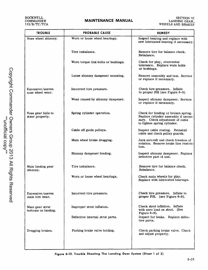
ROCKWELL COMMANDER 112/B/TC/TCA
TROUBLE
Nose wheel shimmy.
Excessive/uneven nose wheel wear.
Nose gear fails to steer properly.
Main landing gear shimmy.
Excessive/uneven main tire wear.
Main gear strut botto ms on landing.
Dragging brakes.
MAINTENANCE MANUAL
PROBABLE CAUSE
Worn or loose wheel bearings.
Tire imbalance.
Worn torque link bolts or bushings.
Loose shimmy dampener mounting.
Incorrect tire pressure.
Wear caused by shimmy dampener.
Spring cylinder operation.
Cable off guide pulleys.
Main wheel brake dragging.
Shimmy dampener binding.
Tire imbalance.
Worn or loose wheel bearings.
Incorrect tire pressure.
Improper strut inflation.
Defective internal strut parts.
Parking brake valve holding.
SECTION VI LANDING GEAR,
WHEELS AND BRAKES
REMEDY
Inspect bearing and replace with new lubricated bearing if necessary:
Remove tire for balance check. Rebalance.
Check for play, overcenter tolerance. Replace worn bolts or bushings.
Remove assembly and test. Service or replace if necessary.
Check tire pressure. Inflate to proper PSI (see Figure 6-9).
Inspect shimmy dampener. Service or replace if necessary.
Check for binding or broken spring. Replace cylinder assembly if necessary. Check adjustment of cable to tighten spring cylinder.
Inspect cable routing. Reinstall cable and check pulley guards.
Jack aircraft and check freedom of rotation. Remove brake line restriction.
Inspect shimmy dampener. Replace defective part of unit.
Remove tire for balance check. Rebalance.
Check main wheels for play. Replace with lubricated bearings.
Check tire pre ssure. Inflate to proper PSI. (see Figure 6-9).
Check strut inflation. Inflate with zero load on strut. (See Figure 6-9). Inspect for leaks. Replace defective parts.
Check parking brake valve. Check and adjust properly.
Figure 6-12. Trouble Shooting The landing Gear System (Sheet 1 of 2)
6-25
Copyright C
omm
ander Ow
ners Group 2013 All R
ights Reserved
**unofficial copy**

SECTION VI LANDING GEAR, WHEELS AND BRAKES
TROUBLE
Dragging brakes (continued)
Brakes fail to operate.
MAINTENANCE MANUAL
PROBABLE CAUSE
Worn or broken piston return spring. (in master cylinder)
Restriction in hydraulic lines or restriction in parking brake valve.
Worn, scored or warped brake discs.
Damage or accumulated dirt restricting free movement of wheel brake parts.
Leak in system.
Air in system.
Lack of fluid in master cylinders.
Master cylinder defective.
REMEDY
ROCKWELL COMMANDER
112/B/TC/TCA
If brake pedal fails to return after release and linkage is not binding, the master cylinder is faulty. Repair or replace master cylinder.
Jack up wheel to be checked. Apply and release brakes, wheel should rotate freely as soon as brakes are released. If wheel fails to rotate freely, loosen brake line at brake housing to relieve any pre ssure trapped in the line. If wheel now turns freely, the brake line is restricted or there is a restriction in the brake master cylinder. Drain brake lines and clear the inside of the brake line with filtered compressed air. Fill and bleed brakes. If cleaning the line fails to give satisfactory results, the master cylinder or parldng brake valve may be faulty and should be repaired.
Visually check discs. Replace brake discs and linings.
Check parts for freedom of movement. Clean and repair or replace parts as necessary.
Check entire system for leaks. If brake master cylinders, parking brake valve, or wheel brake assemblies are leaking, repair or replace as necessary.
Bleed system.
Check fluid level. Fill and bleed if necessary.
Repair or replace master cylinder.
Figure 6·12. Trouble Shooting The Landing Gear System (Sheet 2 of 2)
6-26
Copyright C
omm
ander Ow
ners Group 2013 All R
ights Reserved
**unofficial copy**

ROCKWELL COMMANDER 112/B/TC/TCA
MAINTENANCE MANUAL SECTION vn FLIGHT CONTROLS
SECTION VII
FLIGHT CONTROLS
TABLE OF CONTENTS
GENERAL DESCRIPTION ••....•..........•• MAINTENANCE OF FLIGHT CONTROLS ••••. FLIGHT CONTROL SYSTEMS •.•..••••.••..•
Control Column •.•...•..........••.•..• Ailerons •.•.•.•........•..••.•.......•• Aileron Trim Tab •..............•......• Wing Flaps ........................... .
GENERAL DESCRIPTION
Page 7-1 7-3 7-3 7-3 7-3 7-8 7-8
MODEL 112 (Serial numbers thru 380). The aircraft is equipped with all-metal flight control surfaces consisting of the ailerons, elevators, rudder, and wing flaps. Dual controls are provided for the ailerons, rudder and elevators. A switch on the lower right side of the instrument panel controls the electrically actuated wing flaps. Movable trim tabs installed on the elevators, are operated by a trim control wheel. The rudder trim control knob is located just to the left of the console while the elevator trim control wheel is in the center of the console. The position of the rudder trim is indicated by an indicator concentric to the control knob. The position of the elevator trim is indicated by an indicator strip viewed through a slot in the console. A fixed, ground adjustable trim tab is installed on the left aileron. The control column, control wheel, and rudder-brake pedals at the pilots and copilots position are mechanically interconnected to the push-pull rods, bellcranks, and cables which actuate the primary flight controls. All primary control surfaces are balanced to prevent surface :flutter and provide the best possible aircraft control characteristics throughout the complete range of normal flight speeds. Control cable pulley brackets are provided with guards to prevent the cable from jumping the pulley groove. The all-metal, electrically actuated wing flaps provide additional lift for shorter takeoff distances and slower landing speeds. Wing flaps may be pOSitioned at any setting between UP and DOWN by intermittent operation of the flap switch.
Page Aileron and Flap Rigging (Alternate Method) 7-10 Rudder ...•...•...•.....•..•.•.....•... 7-11 Elevators ••••••.......•...••..•.•••.••• 7-14 Elevator Trim Tabs •......•.•.......•... 7-17 Aileron-Rudder Interconnect .............. 7-18 Control Surface Balancing. . • . . . . . • . . . • . .• 7 :...20 TROUBLE SHOOTING ................... 7-21
MODEL 112 (Serial numbers 381 and subsequent). MODELS 112B/TC/TCA. The aircraft is equipped with all-metal flight control surfaces consisting of the ailerons, elevators, rudder, and wing flaps. Dual controls are provided for the ailerons, rudder, and elevators. A switch on the lower right side of the instrument panel controls the electrically actu-ated wing flaps. Movable trim tabs installed on the elevators, are operated by a trim control wheel. The rudder trim control knob is located just to the left of the console while the elevator trim control wheel is in the center of the console. The position of the rudder trim is indicated by a gage in the lower instrument sub panel on the pilot's side of the aircraft. The position of the elevator trim is indicated by an indicator strip viewed through a slot in the console. A fixed, ground adjustable trim tab is installed on the left aileron. The control column, control wheel, and rudder-brake pedals at the pilots and copilots pOSition are mechanically interconnected to the p1lshpull rods, bell crank s , and cables which actuate the primary flight controls. All primary control surfaces are balanced to prevent surface :flutter and provide the best possible aircraft control characteristics throughout the complete range of normal flight speeds. Control cable pulley brackets are provided with guards to prevent to prevent the cable from jumping the pulley groove. The all-metal, electrically actuated wing flaps provide additional lift for shorter takeoff distances and slower landing speeds. Wing flaps may be positioned at any setting between UP and DOWN by intermittent operation of the flap switch.
7-1
Copyright C
omm
ander Ow
ners Group 2013 All R
ights Reserved
**unofficial copy**

SECTION VII FLIGHT CONTROLS
MAINTENANCE MANUAL
1. SPACER 9. RETAINER RING 2. IDLER SPROCKET ASSEMBLY 10. MOUNTING 3. PILOT INPUT SPROCKET ASSEMBLY 11. ELEVATOR ARM
ROCKWELL COMMANDER
112/B/TC/TCA
4. FLANGE BEARING 12. CONTROL YOKE PIVOT BUSHING 5. UNIVE RSAL JOINT 13. AILERON CABLE PULLEY 6. O-RING 14. CONTROL YOKE 7. CONTROL WHEEL SHAFT 15. CENTER SPROCKETS 8. CONTROL WHEEL 16. CONTROL LOCK
X274
Figure 7-1. Control Column
7-2
Copyright C
omm
ander Ow
ners Group 2013 All R
ights Reserved
**unofficial copy**

ROCKWELL COMMANDER 112/B/TC/TCA
MAINTENANCE MANUAL SECTION VII FLIGHT CONTROLS
MAINTENANCE OF FLIGHT CONTROLS
Special care must be exercised when performing c"ntrol system maintenance. Emphasis shall be given to security of attachment, correct alignment of rod ends, use of correct hardware, and proper safetying. Control cables must be free of kinks, pulleys must be aligned with the cables, and guards must be installed in the pulley brackets. Position cable pulleys and route cables to avoid contact with the aircraft structure. Inspect work areas for mislaid tools or parts, which could foul the controls, and perform a functional check of the controls prior to replacement of access covers. It is recommended that a test flight be accomplished before the aircraft is released for routine ope ration when a control system component has been replaced or aircraft rigging has been altered. Rerigging the control systems will seldom be necessary if correct maintenance technique is employed when system components are removed and replaced. Do not disturb position of rod end fittings when control system components are removed, unless absolutely necessary. When this is necessary, record the amount of change required so that fittings may be returned to original position when maintenance or repair is completed. When control system components are being removed, carefully note location and position of attaching parts and hardware and return to original location or position when installing new components and parts. Complete rigging instructions are provided in succeeding paragraphs, for each flight control system. Read these instructions carefully before starting the rigging operation. Select and accomplish only those rigging steps applicable to the job requirement. Cable tensions and control surface travel measurements are contained in Figure 7 -13. Ambient temperature and temperature buildup within the airframe structure affect cable tension and must be given proper consideration when rigging control surfaces (see Figure 7 -15). The following procedures should be followed when rigging control cables.
a. Rigging should be accomplished in a hangar. When necessary to rig aircraft in the open it should be accomplished during coolest part of day with tail of aircraft pointing toward sun. H aircraft is moved into a hangar for rigging, allow 90 minutes for control cables to adjust to hangar temperature. b. Control cable tension readings should be taken near the midpoint of cable and never closer than six inches to a cable terminal or within 18 inches of a pulley or fairlead. All control surfaces must be in the streamlined position when cable tension is taken.
FLIGHT CONTROL SYSTEMS
CONTROL COLUMN
The control column which is supported by bushings and bearings is attached to the mounting yoke plate located at the forward end of the console tunnel. Control wheels are connected to control shafts that are connected to end sprockets on each end of the horizontal
control yoke (see Figure 7-1). Chains are wrapped around the end sprockets, under the center idler sprocket and around the double sprocket on the control yoke. Direct cables connect to chain-ends through a series of pulleys to the aileron bellcranks. The elevator control cables connect to elevator arms on the control column and route through a series of pulleys to the elevator bellcrank. Aileron control wheels may be removed from the control shafts by removing attaching bolts and nuts.
INST ALL AT ION OF CONT ROL COLUMN PIVOT BUSHINGS AND BEARINGS. Remove the rear seat and floorboard assembly, front seats, Royalite and metal console covers from the airplane. Use the following procedure to replace the two bearings and bushings (see Figure 7 -1).
a. Relieve tension from aileron cables at turn-buckles aft of main spar. b. Relieve tension from elevator cables at turn-buckles in tailcone. c. Remove screw, nut and three washers from each side of control column pivot. (Note the position of the three washers so they can be reinstalled in the same position). d. Bottom of control column can now be posi-tioned forward or aft to allow pivot bushings and bearings to be removed and replaced from inside of console. e. After bushings and bearings have been re-placed, align pivot points of control column with screw holes in console and replace screws, washers and nuts. f. Tighten aileron and elevator turnbuckles, check tension and rerig as necessary. (Refer to paragraphs on aileron and elevator control rigging). g. Reassemble console covers and install seats. h. Be sure all turnbuckle safety clips are proper ly installed.
INST ALLATION OF O-RING IN CONTROL TUBE COLLAR.
a. Remove hardware that attaches control tube to universal joint and remove tube (see Figure 7-1). b. Remove snap ring securing collar in mounting. Slide collar and O-ring out. c. Lubricate and install new O-ring on collar. Use clean MIL-H-5606 hydraulic fluid. d. Inspect inside surface of mounting for burrs or nicks. e. Lubricate inside surface of mounting, care-fully insert collar with O-ring installed and secure with snap ring. £. Insert control tube through collar and connect to universal joint.
AILERONS
An all- metal aileron is installed outboard of each wing flap. Each aileron operates on hinges, attached to the aft wing spar. The aileron control wheels are mechanically interconnected through a series of control chains, sprockets and cables. Control cables extend aft from the control column passing under the floor
7-3
Copyright C
omm
ander Ow
ners Group 2013 All R
ights Reserved
**unofficial copy**

SECTION vn FLIGHT CONTROLS
MAINTENANCE MANUAL ROCKWELL
COMMANDER 112/B/TC/TCA
structure and through idler pulleys to a bracket assembly. The cables are then routed through the bracket assembly and out through the wing to the aileron bellcranks. Adjustable push-pull rods connect the aileron bellcranks to the ailerons.
REMOVAL AND INST ALL AT ION OF AILERONS
a. Disconnect aileron push-pull rod at aileron. Do not change position of rod end on push- pull rod. b. Remove aileron hinge screws. c. Remove aileron from aircraft.
Installation of the aileron is the reverse of the removal procedure. In the event push-pull rod length has been altered, streamline trailing edge of opposite aileron with trailing edge of wing and flap and secure with a temporary lock. Adjust push-pull rod length to align attaching bolt hole with hole in aileron hinge fitting, when aileron is in neutral position. Recheck aileron rigging.
REMOVAL AND INSTALLATION OF AILERON CONT ROL CABLES. Remove the rear seat and floorboard assembly, front seats, Royalite and metal console covers from the airplane. Use the following procedure to remove the aileron cables (see Figure 7-2).
NOI.
To help when reinstalling aileron cables, tag each cable to identify and attach a wire to each cable end before drawing it through wing or fuselage.
a. Remove aileron bellcrank access plate (fur-thest outboard) from each wing. b. Disconnect aileron cables from turnbuckles aft of main spar. c. Disconnect cable ends from aileron bellcrank in Wings. d. Draw cables from wings into fuselage. e. To remove cables from fuselage, disconnect cables from chains at control column and very carefully feed cable ends between cable guards and pulleys mounted on control column. f. Remove cable guard from under pulleys in console. Also remove cable guards at pulleys aft of main spar. g. Cables may be drawn from console through spar and removed from airplane. h. To replace aileron cables, reverse above procedure. i. Check tenSion and re-rig per Rigging Proce-dures. j. Be sure all turnbuckle safety clips are in-stalled, all cables and cable guards are properly installed, all jam nuts tightened, then replace all parts removed for access.
REMOVAL AND INSTALLATION OF AILERON BELLCRANK.
a. Remove aileron bellcrank access plate (furthest
7-4
outboard) from wing. b. Remove screws attaching aileron stop-bracket and remove bracket (Model 112, Serial numbers thru 50). c. Disconnect aileron push- pull rod from bellcrank. d. Identify and disconnect aileron cables from bellcrank.
NOI. Cables will have to be loosened to disconnect them from the bellcrank.
e. Remove bellcrank by removing attaching hard-ware from top and bottom attaching points. f. Replace bellcrank by reversing preceding instructions. g. Recheck cable tension and re-rig as necessary.
RIGGING
NOI.
Flaps must be rigged before the ailerons. Rigging procedures are typical for both ailerons.
a. Remove rear seat and floorboard assembly to gain access to aileron turnbuckles aft of main spar. Remove bellcrank access plates on underside of Wing. b. Insert control wheel lock in control column. c. Set aileron bellcrank to neutral pOSition with alignment tool (see Figure 7-2). Alignment tool number RF 42003 for Model 112 (Serial numbers thru 50) is available from the factory. On Model 112 (Serial numbers 51 and subsequent) and Models 112B/ TC/TCA, set aileron bellcrank to neutral pOSition with rig pin. Place rig pin through hole in bellcrank support and bellcrank.
NOI. Use the alternate method rigging procedures if alignment tool RF42003 is not available, or difficulty is encountered in rigging either with the tool or rig pins.
d. Assure control chain is located as depicted in Figure 7-3. e. Adjust turnbuckle, located aft of main spar to obtain correct tension on each cable. (Refer to Figure 7-13 for correct tenSion). f. Adjust push rod to bring trailing edge of ail-eron O. 16 (± O. 12) inch above outboard end of flap. Trailing edge is now at zero position. Tighten push rod check nuts. g. Remove bellcrank alignment tool or rig pin from both ailerons and remove control wheel lock from control column. h. Rotate control wheels clockwise to deflect right aileron up and left aileron down. Adjust right aileron stop to pOSition right aileron at 25 (:: 2) degrees up for Model 112 with Serial numbers through 222 and 20 to 27 degrees up position for aircraft with Serial numbers 223 and subsequent. Left aileron should be at 9 (::!: 2) degrees down position. Tighten aileron- stop checknut.
Change 2
Copyright C
omm
ander Ow
ners Group 2013 All R
ights Reserved
**unofficial copy**
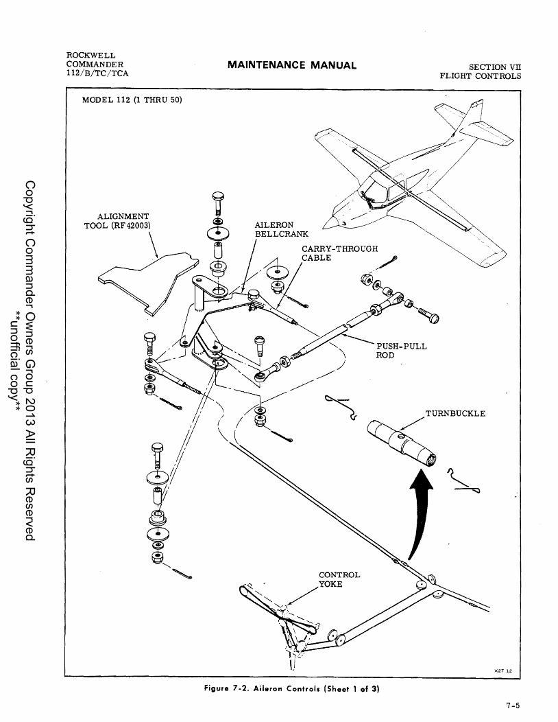
ROCKWELL COMMANDER 112/B/TC/TCA
MODEL 112 {l THRU 50}
ALIGNMENT TOOL (RF 42003)
\
MAINTENANCE MANUAL
PUSH-PULL ROD
SECTION vn FLIGHT CONTROLS
TURNBUCKLE
/
CONTROL
X27 12
Figure 7-2. Aileron Controls (Sheet 1 of 3)
7-5
Copyright C
omm
ander Ow
ners Group 2013 All R
ights Reserved
**unofficial copy**

SECTION vn FLIGHT CONT ROLS
MODEL 112·51 THRU 470
7-6
MAINTENANCE MANUAL
Figure 7-2. Aileron Controls (Sheet 2 of 3)
TURNBUCKLE
ROCKWELL COMMANDER
112/B/TC/TCA
X27 12 AS
Copyright C
omm
ander Ow
ners Group 2013 All R
ights Reserved
**unofficial copy**

ROCKWELL COMMANDER 112/B/TC/TCA
MODEL 112 - 471 AND SUBSEQUENT MODELS 112B/TC/TCA
MAINTENANCE MANUAL
,,~/ ~"t
CONTROL YOKE
Figure 7-2. Aileron Controls (Sheet 3 of 3)
SECTION vn FLIGHT CONTROLS
TURNBUCKLE
X27 1285
7-7
Copyright C
omm
ander Ow
ners Group 2013 All R
ights Reserved
**unofficial copy**

SECTION VII FLIGHT CONTROLS
MAINTENANCE MANUAL ROCKWELL
COMMANDER 112/B/TC/TCA
CONTROL CHAIN CONTROL YOKE AILERON CABLE PULLEY
X271
Figure 7-3. Aileron Control Chain Location
i. Rotate control wheels counterclockwise to de-flect left aileron up and right aileron down. Adjust left aileron stop to . obtain a 25 (2- 2) degrees up position for Model 112 with Serial numbers through 222 and 20 to 27 degrees up for aircraft with Serial numbers 223 and subsequent. Right aileron should be at 9 (2- 2) degrees down position. Tighten aileron- stop checknut. j. Check difference between left and right ailerons in the up position. There shall not be more than four degrees difference. k. Adjust aileron down stops to contact bellcrank while up stop on opposite side of aircraft is in contact with bellcrank. Tighten aileron-stop check nut on Model 112 (Serial numbers 471 and subsequent) and Models 112B/TC/TCA. 1. Be sure all turnbuckle safety clips are installed, all cables and cable guards are properly installed and all jam nuts are tightened, then replace all parts removed for access. m . Check aileron system for friction. If friction is apparent, check for following:
1. Frozen, defective or dry bearings. 2. Control surfaces improperly aligned with matching surfaces. 3. Pulleys frozen or cables rubbing.
n. Check aileron trailing edge free play at inboard end of aileron with aileron in zero degree rigging position. Check free play does not exceed 0.l2-inch.
NOTE
Do not apply more than one pound pressure to trailing edge when measuring free play.
o. Test fly aircraft and correct one wing low condition by adjusting ground adjustable trim tab. See information under Aileron Trim Tab.
AILERON TRIM TAB
A fixed-position trim tab is attached to the left aileron. A left wing high attitude may be corrected by bending the trim tab down. Bending the tab up will correct a left wing low attitude. Use forming block when bend-
7-8
ing tab, and do not bend more than O. 50-inch tab deflection in either direction.
WING FLAPS
An all-metal wing flap installed on each wing is attached to the aft wing spar and extends outboard from the fuselage to the ailerons. These wing flaps are electrically operated and controlled by a switch located on the lower right side of the instrument panel. Power from the electric motor is transmitted to the flaps through a jackscrew connected to a torque tube, and from the torque tube to the flaps with push-pull rods.
REMOV AL AND INST ALLATION OF WING FLAPS
a. Disconnect flap push-pull rod at flap. Do not change position of rod end on push-pull rod. b. Remove flap hinge bolts. c. Remove flap from aircraft.
Installation of the flap is the reverse of the removal procedure. In the event push-pull rod length has been altered, the flap will have to be completely re- rigged.
REMOV AL AND INST ALLATION OF FLAP MOTOR ASSEMBLY
a. Remove rear seat and floorboard assembly to gain access to flap motor located aft of main spar. b. Separate two connector plugs on flap assem-bly wire harness and disconnect ground wires. c. Remove hardware attaching flap motor jack-screw housing to torque tube (see Figure 7-4). d. Remove hardware attaChing forward end of flap motor assembly to spar mount bracket. e. Remove flap motor assembly. To install, reverse this procedure.
RIGGING. Remove the rear seat and floorboard assembly, and the inboard access plate located between the wings and fuselage on the under side of the wings.
110'. Left and right flaps to be rigged at the same time. Aircraft to be on jacks with landing gear clear of the ground.
a. Place a propeller protractor 12 inches aft of firewall on bottom surface of aircraft at centerline. Zero protractor. b. Position propeller protractor on flap as shown in Figure 7-11, at 1.50 inches in from outboard edge normal to flap trailing edge. Adjust push-pull rods to obtain a reading of 11-1/2 (± l) degrees. c. Note three limit switches on flap motor sup-port rod. Refer to forward SWitch as number one, center switch as number two and aft switch as number three (see Figure 7-5). d. Adjust switch number one so jackscrew collar has just actuated switch lever. Tighten setscrew.
Change 2
Copyright C
omm
ander Ow
ners Group 2013 All R
ights Reserved
**unofficial copy**

ROCKWELL COMMANDER 112/B/TC/TCA
MAINTENANCE MANUAL
1. PUSH P 2. TORQ~EULL ROD 3. SUPPOR TUBE
FLIGHi~COTION vn iNTROLS
4. LIMIT S T BEARING 5. LIMIT s:iCH
NUMBER 3 6. LIMIT SWIT CH NUMBER 2 7. FLAP MOTO~H NUMBER 1
Figure 7-4 FI . ap C ontrols Inst II . a atlon
7-9
Copyright C
omm
ander Ow
ners Group 2013 All R
ights Reserved
**unofficial copy**

SECTION VII FLIGHT CONTROLS
MAINTENANCE MANUAL ROCKWELL
COMMANDER 112/B/TC/TCA
35 DEGREE WING FLAP/ GEAR WARNING SWITCH (LIMIT SWITCH NUMBER 3)
25 DEGREE WING FLAP/ GEAR WARNING SWITCH (LIMIT SWITCH NUMBER 2)
o DEGREE WING FLAP / GEAR WARNING SWITCH (LIMIT SWITCH NUMBER 1)'
WING FLAP MOTOR
Figure 7-5. Wing Flap Warning Switch
X 27 2
e. Lower flaps to fully extended position using propeller protractor, 35 (:t 2) degrees. f. Adjust switch number three so jackscrew collar has just actuated switch lever. Tighten setscrew. g. Position flaps 10 (± 2) degrees down using protractor. h. Adjust flap position sender to obtain a reading on flap pOSition indicator in instrument panel. Reading should be within two degrees of true flap pOSition. i. Position flaps at 22-1/2 (± 2-1/2) degrees using flap pOSition indicator. j. Retract landing gear. k. Adjust switch number two so jackscrew collar has just actuated switch lever (gear warning
I bell or horn sounds). Tighten setscrew. 1. Position flaps to 35 degrees. Allow actuator to shutoff flap motor. Check gear warning bell or' horn continues to sound through flap range of 22-1/2 (:t 2-1/2) degrees to full down position. m. Check flap position indicator reading. Indi-cator should read 35 (:t 2) degrees. n. Position flaps to zero degree. Check gear
• warning bell or horn stops sounding at pOSition indicator readings between 25 degrees and 20 degrees. o. Recheck indicator zero degree reading. p. Recheck 22-1/2 (:I; 2-1/2) degrees indicator readings. q. Lower landing gear. r· Make sure all jam nuts are tightened and all switches are secure, then replace all parts removed for access.
AILERON AND FLAP RIGGING(ALTERNATE METHOD)
This alternate method of rigging ailerons and flaps is provided in the event problems are encountered
7-10
while rigging by the standard method. The ailerons and flaps will have to be rigged simultaneously when using this procedure.
a. Place propeller protractor 12 inches aft of firewall on bottom surface of aircraft at centerline (see Figure 7-11). Adjust protractor to zero degrees. Be certain protractor is not rotated 180 degrees. b. Set flaps in fully retracted position and adjust push-pull rods to obtain a reading of 11-1/2 (± 1) degrees. c. Set protractor on outboard edge of flap and reset index to zero. This Will also be zero or neutral position for ailerons. d. Place protractor on aileron surface 1.50 inches out from inboard edge of aileron normal to trailing edge. e. Loosen aileron control cables and place ground adjustable aileron tabes) in center position. f. Set aileron bellcrank so aileron push-pull rod is directly under bellcrank pivot point, see Figure 7-11. Clamp or hold bellcrank in this position. g. Adjust aileron push-pull rod to pOSition ail-eron 9 (± 2) degrees down from neutral. h. Adjust aileron stop to obtain 25 (1" 2) degrees up position on aileron for Model 112 with Serial num-I bers through 222 and 20 to 27 degrees up pOSition for aircraft with Serial numbers 223 and subsequent. i. Repeat steps f. thru h. for opposite aileron. j. Clamp a rigging bar to aileron control wheels to neutralize control wheels. k. Clamp ailerons to flaps.
NO'. Use spacer blocks on flaps if needed.
1. Assure control column chain is located as depicted in Figure 7-4. m. Adjust turnbuckle, located aft of main spar, to obtain correct tension on each cable (refer to Figure 7-14 for correct tension). m. Adjust turnbuckle, located aft of the main spar, to obtain correct tension on each cable (refer to Figure 7-14 for correct tension).
All cables should be tensiomid evenly to prevent damage at clamping pOints. Cables should be tensioned within five pounds of each other.
n. Remove any clamps, holding fixtures or rigging bars. o. Assure all turnbuckle safety clips are installed, all cables and cable guards are properly installed and all checknuts are tightened. p. Turn control wheels clockWise to deflect right aileron up and left aileron down. Check right aileron
Change 2
Copyright C
omm
ander Ow
ners Group 2013 All R
ights Reserved
**unofficial copy**
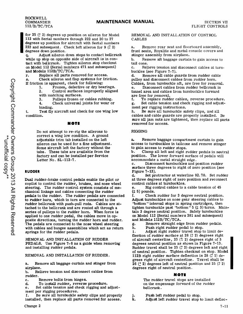
ROCKWELL COMMANDER 112/B/TC/TCA
MAINTENANCE MANUAL SECTION VII FLIGHT CONTROLS
I for 25 (:!- 2) degrees up position on aileron for Model 112 with Serial numbers through 222 and 20 to 27 degrees up position for aircraft with Serial numbers 223 and subsequent. Check left aileron for 9 (:!- 2) degrees down position. q. Adjust aileron down stops to contact bellcrank while up stop on opposite side of aircraft is in contact with be1.lcrank. Tighten aileron stop checknut on Model 112 (Serial numbers 471 and subsequent) and Models 112B/TC/TCA. r. Replace all parts removed for access. s. Check aileron and flap systems for friction. If friction is apparent, check for following:
1. Frozen, defective or dry bearings. 2. Control surfaces improperly aligned with matching surfaces. 3. Pulleys frozen or cables rubbing. 4. Check universal joints for wear or binding.
t. Test fly aircraft and check for one wing low condition.
NO'. Do not attempt to re-rig the ailerons to correct a wing low condition. A ground adjustable trim tab installed on the left aileron can be used for a fine adjustment. Some aircraft left the factory without the tabs. These tabs are available from the factory and can be installed per Service Letter No. SL-112-7.
RUDDER
Dual rudder-brake control pedals enable the pilot or copilot to control the rudder, brakes, and nose wheel steering. The rudder control system consists of mechanical linkage and cables connecting the rudder pedals to the rudder. The rudder pedals are connected to rudder bars, which in turn are connected to the rudder bellcrank with push-pull rods. Cables are attached to the bellcrank and are routed aft through a series of pulleys to the rudder horn. When force is applied to one rudder pedal, the cables move in opposite directions, turning the rudder horn and rudder. The pedals are connected to the nose wheel steering with cables and bungee assemblies which act as return springs for the rudder pedals.
REMOV AL AND INSTALLATION OF RUDDER PEDALS. Use Figure 7-6 as a guide when removing and installing rudder pedals.
REMOVAL AND INSTALLATION OF RUDDER.
a. Remove aft baggage curtain and stinger from airplane. b. Relieve tension and disconnect cables from rudder. c. Remove bolts from hinge s. d. To install rudder, reverse procedure. e. Set cable tension and check rigging and adjust-ment per rigging procedures. f. Be sure all turnbuckle safety clips and properly installed, then replace all parts removed for access.
Change 2
REMOVAL AND INSTALLATION OF CONTROL CABLES
a. Remove rear seat and floorboard assembly, front seats, Royalite and metal console covers and stinger assembly from airplane. b. Remove aft baggage curtain to gain access to tail cone. c. Relieve tension and disconnect cables at turn-buckles (see Figure 7-7). d. Remove all cable guards from rudder cable pulley and disconnect cables from rudder horn. Cables, from turnbuckle aft, are free for removal. e. DiscOlmect cables from rudder bellcrank in tunnel area and cable s from turnbuckle s forward are free for removal. f. To replace rudder cables, reverse procedure. g. Set cable tension and check rigging and adjustment per rigging instructions. h. Be sure all turnbuckle safety clips, and al1 cables and cable guards are properly installed. Be sure all jam nuts are tightened, then replace all parts removed for access.
RIGGING
a. Remove baggage compartment curtain to gain access to turnbuckles in tailcone and remove stinger to gain access to rudder stops. b. Clamp all left and right rudder pedals in neutral position. The lower forward surface of pedals will accommodate a metal strai ght edge. c. Disconnect turnbuckles and position rudder surface three degrees to right of zero position (see Figure 7-13). d. Set protractor at waterline 92.70. Set rudder at three degrees right of zero pOSition and reconnect control cables at turnbuckles. e. Rig control cables to a cable tension of 45 (± 5) pounds. f. Check rudder for 3 degree neutral position. Adjust turnbuckles on nose gear steering cables to "bottom tf internal stops in spring cartridges, then tighten turnbuckle past "bottom" 5 (± 3) turns. Maintain 3 degree neutral position. Safety turnbuckles on Model 112 (Serial numbers 381 and subsequent) and Models 112B/TC/TCA. g. Remove straight edge from rudder pedals. h. Push right rudder pedal to stop. i. Adjust right rudder travel stop to limit deflection of rudder surface at 28 (t 2) degrees right of aircraft centerline, 25 (t 2) degrees right of 3 degrees neutral position as shown in Figure 7-13. Rudder travel shall be 25 (:!- 2) degrees left and right of neutral position. Tighten checknut on stop. Model 112B right rudder surface deflection is 28 (: 1) degrees right of aircraft centerline. Travel shall be 26 e 2) degrees left of neutral position and 25 (t 2) degrees right of neutral position.
NO'. The rudder travel stops are installed on the empennage forward of the rudder bellcrank.
j. Push left rudder pedal to stop. k. Adjust left rudder travel stop to limit deflec-
7 -11
Copyright C
omm
ander Ow
ners Group 2013 All R
ights Reserved
**unofficial copy**

SECTION vn FLIGHT CONTROLS
MAINTENANCE MANUAL ROCKWELL
COMMANDER 112/B/TC/TCA
MODEL 112-1 THRU 380
5
8
r
G
1. L. H. PEDAL SUPPORT 2. R. H. PUSHROD 3. L. H. PUSHROD 4. R. H. PEDAL SUPPORT AND SHAFT 5. RUDDER PEDAL 6. RUDDER BELLCRANK 7. RUDDER TRIM BELLCRANK 8. NOSE GEAR STEERING PULLEY 9. R. H. PEDAL SUPPORT
10. L. H. PEDAL SUPPORT AND SHAFT X 27 6
Figure 7-6. Rudder Pedal Installation (Sheet 1 of 2)
tion of rudder surface as shown in Figure 7-13. Tighten checknut on stop. 1. With aircraft on jacks, retract \landing gear and check rudder system for friction. If friction is evident, check for following:
1. Frozen, defective or dry bearings. 2. Control surface improperly aligned with matching surface. 3. Pulleys frozen or cables rubbing.
m. Check turnbuckles for safety clips and make sure jam nuts are tight on rudder stops, then replace aft baggage curtain and install stinger.
RIGGING AND ADJUSTMENT OF RUDDER TRIM. MODEL 112 (Serial numbers thru 380). The rudder control system must be rigged before rigging the trim. The aircraft must be on jacks, gear clear of the ground, and nose gear steering cables slack.
7-12
a. Rotate rudder trim knob counterclockwise to stop_ Rotate knob clockwise four full turns. b. Loosen indicator disc on knob and adjust pointer to horizontal. Tighten in position. This pOSition is zero degree rudder trim (3 degrees right of rudder). c. Check rudder for zero degree rigging position. Adjust turnbuckles on nose gear steering cables (located forward of the firewall) to bottom internal stops on forward cable against nose wheel steering bungee tube 0 Tighten turnbuckles past bottom one-half turn minimum to three turns maximum to maintain zero degree position. Safety wire turnbuckles. d. Rotate trim knob counterclockwise to stop. Check rudder for left movement. Return knob to zero degree. eo Rotate trim knob clockwise to stop. Check
Copyright C
omm
ander Ow
ners Group 2013 All R
ights Reserved
**unofficial copy**

ROCKWELL COMMANDER 112/B/TC/TCA
MAINTENANCE MANUAL SECTION vn FLIGHT CONTROLS
MODEL 112 - 381 AND SUBSEQUENT MODELS 112B/TC/TCA.
1. L. H. PEDAL SUPPORT 2. R. H. PUSHROD 3. L. H. PUSHROD 4. R. H. PEDAL SUPPORT AND SHAFT 5. RUDDER PEDAL 6. RUDDER BELLCRANK .,-7. NOSE GEAR STEERING LINK 8. R. H. PEDAL SUPPORT 9. L. H. PEDAL SUPPORT AND SHAFT
10. RUDDER TRIM BUNGEE 11. RUDDER TRIM INDICATION CABLE
X276A7
Figure 7-6. Rudder Pedal Installation (She.t 2 of 2)
rudder for right movement. Return knob to zero degree. f 0 Retract gear and check left and right trim movement. g. Check free fall of nose gear to determine no friction or binding is evident.
RIGGmG AND ADJUSTMENT OF RUDDER TRIM. MODEL 112 (Serial numbers 381 and subsequent) and MODELS 112B/TC/TCA. The rudder and nose wheel steering system must be rigged before connecting rudder trim to rudder pedal torque tube arm. Aircraft must be on jacks, gear extended and clear of ground.
a. Clamp all left and right rudder pedals in neu-tral position. Lower forward surface of pedal will accommodate a metal straight edge. b. With rudder trim bungee disconnected rotate rudder trim knob right or left until hole in rudder
Change 1
trim clevis is aligned with hole in rudder trim arm on rudder pedal bar, and install hardware (see Figure 7-6). c. Remove straight edge from rudder pedals. d. Rotate trim knob clockwise to stop. With indicator at right index, connect indicator cable to rudder trim barrel nut, then tighten clamp holding indicator cable to rudder trim bracket. e. Retract landing gear. Rotate trim knob counterclockwise to stop, and check rudder for right and left movement.
IIOTE
If position of indicator is not within one needle width from left index, rerig indicator cable so extreme indicator positions will be equal distance from right and left indexes.
7-13
Copyright C
omm
ander Ow
ners Group 2013 All R
ights Reserved
**unofficial copy**

SECTION VII FLIGHT CONTROLS
MAINTENANCE MANUAL ROCKWELL
COMMANDER 112/B/TC /TCA
5---....
179.98
1. RUDDER BELLCRANK 2. PULLEY 3. R.H.RUDDER CABLE 4. L. H. RUDDER CABLE 5. RUDDER TURNBUCKLES 6. RUDDER HORN
X 27 5
Figure 7-7. Rudder Controls
f. Rotate trim knob clockwise to stop. Check rudder for right movement. Return knob to neutral. g. Check rudder pedal for freedom of movement as follows: Push right pedal to stop then return pedals to neutral. Push left pedal to stop then return rudder pedals to neutral. h. Extend landing gear. i. Rotate trim knob counterclockwise to stop, then return knob to neutral. j. Rotate trim knob clockwise to stop then return knob to neutral. k. Recheck freedom of movement per step g. above.
ELEVATORS
Each elevator is hinged at three places and attached to the aft spar of the horizontal stabilizer. The elevators are operated by the fore and aft movement of the control column. Elevator arms, attached to the control column in the console tunnel, are connected to control cables which are routed through a series of pulleys to the elevator bellcrank. The bellcrank is connected to the elevator horn with a push- pull rod. When the control wheel is moved forward or aft, the cables move in opposite directions, turning the bellcrank, which in turn pushes or pulls the control rod, causing the ele-
7-14 .
vators to move up or down. Two turnbuckles, installed in the elevator control system between fuselage stations 205.00 and 230.50, permit control cable tension adjustment.
REMOV AL AND INSTALLATION OF ELEVATORS
a. Disconnect actuator rod. b. Remove bolts at hinge. c. Remove six screws and two bolts at inboard end of elevator and remove elevator.
Installation of the elevator is the reverse of the removal procedure •.
REMOV AL AND INST ALLATION OF ELEVATOR CONTROL CABLES
a. Remove front seats, rear seat and floorboard assembly, console covers, aft baggage curtain and stinger from airplane. b. Relieve tension and disconnect cables at turn-buckles (see Figure 7-8). c. Remove cable guards from pulleys and dis-connect cables at both ends. Bolts attaching cables to elevator bellcrank are accessible through holes in aft fuselage bulkhead.
Copyright C
omm
ander Ow
ners Group 2013 All R
ights Reserved
**unofficial copy**

ROCKWELL COMMANDER 112/B/TC/TCA
MAINTENANCE MANUAL SECTION vn FLIGHT CONTROLS
4
1. ELEVATOR ARM 2. PULLEY 3. ELEVATOR OOWN CABLE 4. ELEVATOR UP CABLE 5. BULKHEAD - STATION 205 6. ELEVATOR TURNBUCKLES
STA. 92.67 7. BULKHEAD - STATION 230.50 8. ELEVATOR BELLCRANK 9. ELEVATOR HORN
X 27 8
Figure 7 -8. Elevator Controls
d. Rubber grommets will have to be pushed out of holes in fuselage bulkheads so cable ends can be drawn through holes. e. To replace elevator cables, reverse this procedure. f. Set cable tension and check rigging and adjust-ment per rigging procedures. g. Be sure all turnbuckle safety clips and all cable and cable guards are properly installed. Be sure all jam nuts are tightened, then replace all parts removed for access.
RIGGING
a. With control cables slack, adjust cortrol column and insert control lock (see Figure 7-1). b. Set elevators in zero degree rigging position by aligning elevator balance horn with horizontal stabilizer. Clamp left and right elevator in position. If both elevator balance horns do not align with the horizontal stabilizer, clamp both elevators in average
position. This average position shall be the zero rigging position. Leading edge of elevator must align with leading edge of horizontal stabilizer within O. 35-inch or :!: 2 degrees. c. Adjust control cables to a tension of 65 (-::: 5) pounds. d. Remove control column control lock and remove clamps from elevator surfaces. e. Check angular difference between left and right elevator does not exceed two degrees. f. Remove control lock from control column. g. Pull control wheel full aft to stop. Elevator stops are in aft end of tailcone at pOSition where cables connect to bellcrank (see Figure 7-11). Adjust up elevator stop cam for 30 (:!: 2) degrees up elevator. Tighten bolt and nut on up stop cam. h. Push control wheel full forward to stop. Adjust down elevator stop cam for 13 (+2, -1) degrees down elevator. Tighten bolt and nut on down stop cam. i. Assure all turnbuckle safety clips are in-stalled, all cables and cable guards are properly in-
7-15
Copyright C
omm
ander Ow
ners Group 2013 All R
ights Reserved
**unofficial copy**

SECTION VII FLIGHT CONTROLS
MAINTENANCE MANUAL ROCKWELL
COMMANDER 112/B/TC /TCA
7-16
1. ELEVATOR TRIM PUSHROD 2. JACKSCREW ASSEMBLY 3. ELEVATOR TRIM CHAIN 4. PULLEYS 5. ELEVATOR TRIM TURNBUCKLES 6. LEFT ELEVATOR TRIM CABLE 7. RIGHT ELEVATOR TRIM CABLE
3
STA. 262.75
'" STA. 179.98
8. COTTER PIN 9. SPRING
10. ELEVATOR TRIM INDICATOR STRIP 110 TRIM WHEEL SUPPORT 12. ELEVATOR TRIM WHEEL 13. PULLEYS 14. AILERON PULLEY BRACKETS 15. PHENOLIC GUIDE BLOCKS
Figure 7-9. Elevator Trim Controls
X279
Copyright C
omm
ander Ow
ners Group 2013 All R
ights Reserved
**unofficial copy**

ROCKWELL COMMANDER 112/B/TC /TCA
MAINTENANCE MANUAL SECTION VII FLIGHT CONTROLS
stalled and all jam nuts are tightened. Replace all parts removed for access.
ELEVATOR TRIM TABS
Controllable trim tabs, located on the inboard trailing edge of each elevator, are operated by an elevator trim tab control wheel installed in the center console (see Figure 7-10). A portion of the trim tab control wheel extends through the center console, and when rotated, actuates the trim tab through a mechanical linkage conSisting of cables, chains, jackscrew assembly and push rods that attach to the trim tab. Turnbuckles between fuselage stations 179. 98 and 262.75 are utilized for rigging and adjusting cable tensions. An indicator strip, visible through a slot in the console, indicates neutral, nose up or nose down positions.
REMOVAL OF ELEVATOR TRIM CONTROL WHEEL AND CABLES.
a. Remove front seats, rear seat and floorboard assembly, console covers and aft baggage curtain from airplane. b. Relieve tension and disconnect cables at turn-buckles (see Figure 7-9). c. Remove cable guards from elevator trim pulleys located in aft part of fuselage. d. Pull left, or nose down cable, down far enough to gain access to point where cable end is attached to elevator trim control chain and disconnect cable. Repeat for right, or nose up cable. e. Remove cable guard from pulley cluster loca-ted at station 179.98. f. Remove screws, nuts and washers attaching phenolic guide blocks to aileron pulley bracket, located aft of main spar. Remove guide blocks. g. Remove cable guard from pulley cluster loca-ted beneath trim wheel. h. Remove trim wheels by disconnecting eleva-tor trim indicating strip and removing cotter pins from trim wheel supports. i. Lift trim wheel up, draw cables out through console, unwrap cable s from trim wheel drum and pull cable swage pin out of drum.
INST ALL AT ION OF ELEVATOR TRIM CONTROL WHEEL AND CABLES.
a. Determine which of two elevator trim cable ends has right hand threads. This portion of cable must be used as right elevator trim cable. b. Find center of cable, (where swage pin is installed) and insert swage pin into hole in trim wheel drum (see Figure 7-10). c. Hold trim wheel up and wrap right portion of cable clockwise, four wraps, around drum (see Figure 7-10. Wrap tape around cables to temporarily hold in plac e. d. Wrap left portion of cable, counterclockwise, four wraps around drum (see Figure 7-10). Wrap tape around cables to temporarily hold in place.
e. Install trim wheel and insert cotter pins through supports. f. Route cables around trim cable pulleys as depicted in Figure 7-10 and back through console. g. Feed cables between aileron pulley bracket and install phenolic guide blocks. h. Route cables under baggage compartment floor and through pulleys at station 179.98. L With elevator trim tab neutralized, ends of trim chain should be even. Connect two rear trim cable s to trim chain. Be sure that right rear cable has left hand threads on end that screws into turnbuckle. j. Be sure cables are not crossed and are in proper pulley grooves, then clamp trim wheel in neutral position. (Neutral position is with swage pin straight up, and four cable wraps on each side). With elevator trim tab in neutral pOSition, connect cables at turnbuckles. Adjust turnbuckles to obtain correct tension on each cable. (Refer to Figure 7 -13 for correct tenSion). k. If elevator trim indicator strip has been removed, wrap end around trim wheel shaft, counterclockwise, three wraps, and install ring to secure. Hook other end of strip to spring. Assure that trim wheel is in neutral pOSition; indicator strip should indicate neutral. L Check rigging and adjustment per paragraph on Rigging and Adjustment of Elevator T rim Controls. m. Be sure turnbuckle safety clips and cable and cable guards are properly installed; then replace all parts removed for access.
REMOVAL AND INST ALL AT ION OF ELEVATOR TRIM JACKSCREW COMPONENTS
a. Remove aft baggage curtain from airplane. b. Relieve tension on elevator trim cables by loosening turnbuckles located in tailcone. (Apply tape to cable on trim wheel). c. Remove jackscrew access plates located on bottom of stabilizer. d. Disconnect chain from cable by removing master link and pull chain from around sprocket. e. Remove stop guard bracket by removing re-taining bolts. f. Drive out roll pin, then remove sprocket by unscrewing. g. Disconnect push rod from elevator and remove elevator. h. Remove internal components of jackscrew by pulling push rod aft. i. Clean parts thoroughly with cleaning solvent. j. After parts have dried, install existing jaCkscrews in existing elevator trim actuator housing and operate jackscrews through their entire range of travel. k. If any roughness is noted, inspect jackscrews for nicks or burrs. 1. If nicks or burrs are found on jaCkscrews, re-move with crocus cloth or if necessary, replace jackscrews. m. Before reassembling elevator trim actuator assemblies, lubricate jackscrew threads with molyb-
7-17
Copyright C
omm
ander Ow
ners Group 2013 All R
ights Reserved
**unofficial copy**

SECTION VII FLIGHT CONTROLS
MAINTENANCE MANUAL ROCKWELL
COMMANDER 112/B/TC/TCA
1. ELEVATOR TRIM WHEEL 2. SWAGE PIN 3. ELEVATOR TRIM CABLES
X 27 3
Figure 7-10. Elevator Trim Wheel
dentlm disulphide type lubricant (MIL-G-~1164) such as Aero Shell #17. n. Assemble and install jackscrew assembly by reversing removal steps. o. Check rigging and adjustment per paragraph on Rigging and Adjustment of Elevator Trim Controls. p. Be sure turnbuckle safety clips are properly installed, then replace all parts removed for access.
RIGGING AND ADJUSTMENT OF ELEVATOR TRIM CONTROLS
a. Install control wheel lock in con~rol column. b. Rotate elevator trim wheel until zero degree pOSition is reached. At zero degree position swage pin (Figures 7-9 and 7-10) will be at 12 o'clock position and three cable wraps will be visible on each side of swage pin. c. "', Separate control cables at turnbuckles. d. Disconnect elevator trim tab push rod at actuator jackscrew. e. Adjust actuator jackscrew to obtain a dimension of 2.05 inches between actuator housing and centerline of hole in end of jackscrew. f. Connect elevator trim tab push rod to actuator jackscrew. g. Align elevator trim tab trailing edge with elevator trailing edge at zero degree. Clamp elevator trim tabs in zero position. h. Relocate chain on actuator sprocket as required. Moving chain one tooth on sprocket will move tab 0.30' degree. 1/2 turn of actuator jackscrew will
7-18
move trim tab 3.30 f degree s. Check that angular difference between left and right elevator trim tab does not exceed, 1 degree. i. Reconnect turnbuckles. Adjust cable tension to 12-15 pounds.
After the turnbuckles have been adjusted, recheck the cable tension.
j. Be sure turnbuckle safety clips, cotter pins and .cables and cable guards are properly installed, then replace all parts removed for access. k . Remove clamps from control surfaces. 1. Turn elevator trim wheel aft until elevator trim tab is 26 (: 1) degrees down relative to elevator. m. Check pOSition of chain on left actuator sprocket and back off chain by turning trim wheel as required to install chain position stop. Recheck that stop limits tab travel to 26 (: 1) degrees down. n. Turn elevator trim wheel forward until tab is 15 e 2) degrees up relative to elevator. o. Check position of chain on left actuator sprocket and back, off chain by turning trim wheel as required to install chain position stop. Recheck that stop limits tab travel to 15 (: 2) degrees up. p. Check that both left and right trim tabs angular difference does not exceed one degree. q. Check trim tabs free play with elevators full down and full nose down trim. Trailing edge of trim tabs should not exceed a maximum of .045. r. Remove control wheel lock column.
AILERON-RUDDER INTERCONNECT
AILERON-RUDDER INTERCONNECT RIGGING. MODELS 112B/TC/TCA. The aileron and rudder systems must be properly rigged before rigging aileron-rudder interconnect.
a. Remove rear seat and floor boards. b. Install control wheel lock in control column. c. Clamp all right and le~t rudder pedals in neutral position. Lower forward surface of pedals will accommodate a metal . ht edge. d. Attach clamp and pia right (left) rudder control cable 0.65 inches forWard of flap torque tube (see Figure 7-12). e . Install right (left) spring and cable assembly (see Figure 7-12). f. Preload interconnect spring O. 50 inches, and clamp cable end to aileron balance cable. g. Install cable guards on pulley. h. Repeat steps d. through g. to install left (right) interconnect cable assembly. i. Remove straight edge from rudder pedals, and control lock from control column. j. Check aileron and rudder systems for freedom
Copyright C
omm
ander Ow
ners Group 2013 All R
ights Reserved
**unofficial copy**

ROCKWELL COMMANDER 112/B/TC/TCA
MAINTENANCE MANUAL SECTION vn FLIGHT CONTROLS
STOP ~ ADJUSTMENT
.....-ct RUDDER .
-.-~ VERT STAB. 0°
FIREWALL-I I
I-'-PANEL I I
-12'OO"~ \
PROPELLER /PROTRACTOR
~ ______________ ~~~ ______ ~t WRP
11_1/2° (!10 )
~t FLAP 0° POSITION
Figure 7-11. Control Surfaces Rigging (Sheet 1 of 2)
X27 13
7-19
Copyright C
omm
ander Ow
ners Group 2013 All R
ights Reserved
**unofficial copy**
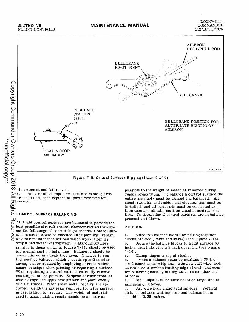
SECTION VII FLIGHT CONTROLS
MAINTENANCE MANUAL ROCKWELL
COMMANDER 112/B/TC/TCA
FUSELAGE STATION 144.26
c~~l, " ~~ FLAP MOTOR
ASSEMBLY
AILERON PUSH-PULL ROD
BELLCRANK POSITION FOR ALTERNATE RIGGING OF AILERON
X27 13 A5
Figure 7-11. Control Surfaces Rigging (Sheet 2 of 2)
of movement and full travel. k . Be sure all clamps are tight and cable guards are installed, then replace all parts removed for access.
CONTROL SURFACE BALANCING
All flight control surfaces are balanced to provide the best possible aircraft control characteristics throughout the full range of normal flight speeds. Control surface balance should be checked after painting, repair, or other maintenance actions which would alter its weight and weight distribution. Balancing articles similar to those shown in Figure 7-14, should be used for control surface balancing. Balancing should be accomplished in a draft free area. Changes to control surface balance, which exceeds specified tolerances, can be avoided by employing correct maintenance technique when painting or repairing a surface. When repainting a control surface carefully remove existing paint and primer. Suspend surface from its leading edge and apply new primer and paint evenly to all surfaces. When sheet metal repairs are required, weigh the material removed from the surface in preparation for repair. The weight of material used to accomplish a repair should be as near as
7-20
possible to the weight of material removed during repair preparation. To balance a control surface the entire assembly must be painted and balanced. All counterweights and rudder and elevator tips must be inslalled, and all push rods must be connected to trim tabs and all tabs must be taped in neutral position. To determine if control surfaces are in balance proceed as follows.
AILERON
a. Make two balance blocks by nailing together blocks of wood (lx4x7 and 4x4x4) (see Figure 7-14). b. Secure the balance blocks to a flat surface 60 inches apart allowing a 3-inch overhang (see Figure 7-14). c. Clamp hinges to top of blocks. d. Make a balance beam by marking a 36-inch 1 x 2 board at its midpoint. Attach a stiff wire hook on beam so it strikes trailing edge of unit, and counter balancing hook by nailing washers on other end of beam. e. Set midpoint of balance beam on hinge line at mid span of aileron. f. Slip wire hook under trailing edge. Vertical distance between trailing edge and balance beam should be 2.25 inches.
Copyright C
omm
ander Ow
ners Group 2013 All R
ights Reserved
**unofficial copy**

I
ROCKWELL COMMANDER 112/B/TC/TCA
MAINTENANCE MANUAL SECTION vn FLIGHT CONTROLS
MODELS 112B/TC/TCA
AILERON-RUDDER INTERCONNECT CABLE ASSEMBL!Y.!iS~~?/
RUDDER CONTROL CABLES
WING TRUSS ASSEMBLY
X'27 Jfi
Figure 7-12. Aileron-Rudder Interconnect Rigging
g. Hang a one pound weight on balance beam fourinches forward of hinge line. Aileron should balance or trailing edge should rotate up. h. Increase or decrease balance weight assembly as required to balance aileron.
ELEVATOR
a. On a flat surface secure two 3/8-inch dia-meter, 6-inch long rods 45.5 inches apart (see Figure 7-14). Allow rods to hang over edge approximately 3 inches. (A bolt may be mounted in rod ends to prevent elevator from Slipping off). b. Slide 1/4- inch bolts through center and outboard hinges of elevator. c. Position elevator over rods such that bolts rest on rods. d. Make balance beam as directed in aileron section. e. Place midpoint of balance beam over hinge line of elevator at inboard edge of tip. f. Slip wire hook under trailing edge of elevator. Vertical distance between trailing edge and balance beam should be 1. 25 inches. go Hang a I-pound weight 12.5 inches forward of hinge line. Elevator should balance or trailing edge
Change 1
should rotate up. h. Increase or decrease balance weight as required I to balance elevator.
RUDDER
a. Attach rods as described in elevator section. b. Slide 1/4-inch bolts through upper and lower hinges. Tighten with jam nuts. c. POSition rudder over rods so bolts rest on rods (see Figure 7-14). Rudder should balance or trailing edge should rotate up. d. Increase or decrease balance weight as required I to balance rudder.
TROUBLE SHOOTING
The trouble-shooting figure in this section discusses symptoms which can be diagnosed and interprets the results in terms of probable causes and the appropriate corrective remedy to be taken. Review all probable causes given and check other listings of troubles with similar symptoms. Items are presented in sequence but not necessarily in order of probability.
7-21
Copyright C
omm
ander Ow
ners Group 2013 All R
ights Reserved
**unofficial copy**
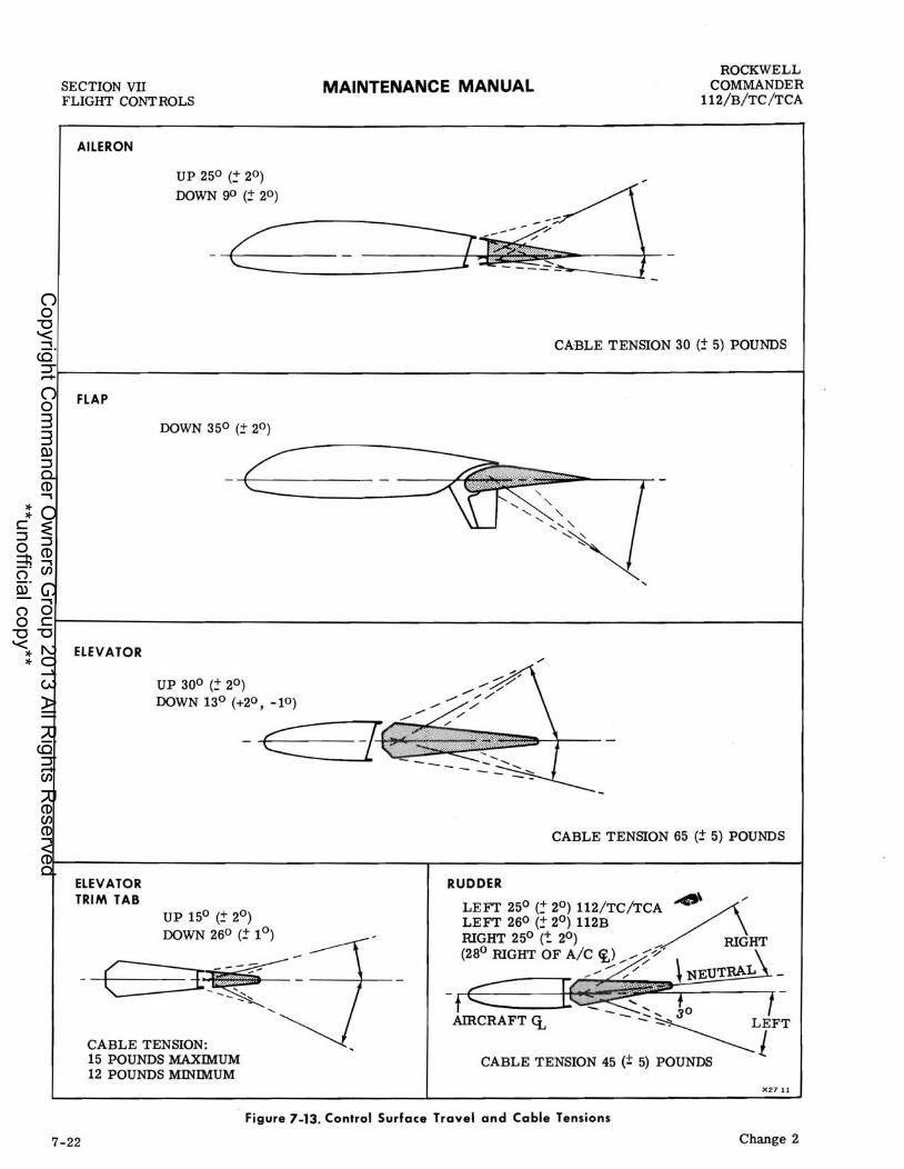
SECTION VII FLIGHT CONT ROLS
AILERON
FLAP
ELEVATOR
UP 250 (:: 20)
DOWN go (~ 20)
UP 30° (2" 2°) DOWN 13° (+2°, -10)
MAINTENANCE MANUAL ROCKWELL
COMMANDER 112/B/TC/TCA
CABLE TENSION 30 (:t 5) POUNDS
-c -f~
ELEVATOR TRIM TAB
UP 15° (~ 2°) DOWN 260 (~ 1°)
-E~--==--I~~ ~ -- :::~
CABLE TENSION: 15 POUNDS MAXIMUM 12 POUNDS MINIMUM
.......
CABLE TENSION 65 (1" 5) POUNDS
......
AIRCRAFT <L - - - ..?-~LIFT
CABLE TENSION 45 (± 5) POUNDS
X2711
Figure 7-13. Control Surface Travel and Cable Tensions
7-22 Change 2
Copyright C
omm
ander Ow
ners Group 2013 All R
ights Reserved
**unofficial copy**
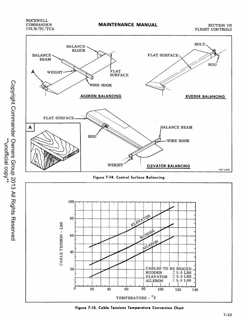
ROCKWELL COMMANDER 112/B/TC/TCA
A
U'J. ~ ...:I
Z 0 1-4 U'J. Z ~ ~
~ ...:I p:) ~ u
100
80
60
40
20
o
MAINTENANCE MANUAL SECTION vn FLIGHT CONTROLS
FLAT SURFACE
AILERON BALANCING RUDDER BALANCING
BALANCE BEAM
~~-WIRE HOOK
ELEVATOR BALANCING X27 lOA5
Figure 7-14. Control Surface Balancing
~ ~
V V ~O~~
~~~V ~ -~vy
~
V V ~O/ V -
~ ", LPf'1 V ~ -
~ ~O~~ ,. ~ V ~~ V -
V ~ V V -,. V
~V V
CABLES TO BE RIGGED _
..-V V RUDDER ~ 5.0 LBS
ELEVATOR .± 5.0 LBS _ AILERON .±5.0LBS
I I I I I 20 40 60 80 100 120 140
TEMPERATURE _ of
Figure 7-15. Cable Tensions Temperature Conversion Chart
7-23
Copyright C
omm
ander Ow
ners Group 2013 All R
ights Reserved
**unofficial copy**

SECTION VII FLIGHT CONTROLS
'rROUBLE
AILERON SYSTEM I Lost motion between control wheel and aileron.
Resistance to control wheel rotation.
Control wheels not synchroni zed.
Control wheels not horizontal when ailerons are neutral.
Incorrect aileron travel.
Correct aileron travel cannot be obtained by adjusting bellcrank stops.
FLAP SYSTEM I Flaps do not extend or retract.
MAINTENANCE MANUAL
PROBABLE CAUSE
Cable tension too low.
Broken pulley.
Cables not in place on pulleys.
Pulleys binding or rubbing.
Control column chains too tight.
Cables not in place on pulleys.
Bent aileron.
Cable tension too tight.
Incorrect control column rigging.
Incorrect aileron system rigging.
Aileron push-pull rods out of rig.
Aileron bellcrank stops incorrectly adjusted.
Incorrect rigging of control cables and/or push-pull rods.
Incorrect rigging of bellcranks.
Master battery switch OFF.
Circuit breaker out.
Defecti ve flap switch.
Defecti ve flap motor.
Defective electrical circuit.
Stripped or broken jackscrew on flap motor.
REMEDY
ROCKWELL COMMANDER
112/B/TC/TCA
Adjust cable tension as shown in Figure 7 -13.
Replac e pulley.
Install cables correctly. Check cable guards.
Replace binding pulleys. Allow for clearance if rubbing pulley brackets or cable guards.
Recheck cable tension as shown in Figure 7-13. Check chain for lubrication, excessive wear and cleanliness.
Install cables correctly.
Repair or replace aileron.
Adjust cable tension in accordance with rigging procedures.
Rig in accordance with aileron rigging procedures.
Rig in accordance with aileron ri g'ging procedures.
Rig in accordance with aileron rigging procedures.
Rig in accordance with aileron rigging procedures.
Rig in accordance with aileron rigging procedures.
Rig in accordance with aileron rigging procedures.
Turn switch ON.
Reset circuit breaker.
Replace flap switch.
Replace flap motor.
Replace defective wires.
Replace jackscrew assembly.
Figure 7-16. Trouble Shooting Flight Control System (Sheet 1 of 4)
7-24
Copyright C
omm
ander Ow
ners Group 2013 All R
ights Reserved
**unofficial copy**

ROCKWELL COMMANDER 112/B/TC /TCA
TROUBLE
Flaps fail to retract completely.
Flaps fail to extend completely.
Flaps not synchroni zed or fail to fit evenly when retracted.
Flaps on one side fail to operate.
RUDDER SYSTEM I Lost motion between rudder pedals and rudder.
Excessive resistance to rudder pedal movement.
Rudder pedals not neutral when rudder is streamlined.
Incorrect rudder travel.
MAINTENANCE MANUAL
PROBABLE CAUSE
Up limit switch incorrectly adjusted.
Incorrect rigging of torque tube and/or incorrect adjustment of push-pull rods.
Down limit switch incorrectly adjusted.
Incorrect rigging of torque tube and/or incorrect adjustment of push-pull rods.
Incorrect adjustment of push-pull rods.
Bent push-pull rods.
Bent flap.
Broken arm assembly on torque tube or broken push-pull rod.
Disconnected push-pull rod.
Cable tension too low.
Broken pulley.
Bolts attaching rudder horn weldment to rudder arm assembly loose.
Cable tension too high.
Pulleys binding or rubbing.
Rudder binding caused by faulty bushing or bent rudder arm assembly.
Rudder pedal bushings misaligned or needs lubrication.
Cables not in place on pulleys.
Bent rudder.
Rudder cables incorrectly rigged.
Rudder horn assembly stops incorrectly acljusted.
SECTION vn FLIGlIT CONTROLS
. REMEDY
Adjust in accordance with rigging procedures.
Rig in accordance with rigging procedures.
Adjust in accordance with rigging procedures.
Rig in accordance with rigging procedures.
Adjust in accordance with rigging procedures.
Straighten or replace.
Repair or replace flap.
Replace broken parts.
Connect push-pull rod, and recheck rigging procedures.
Adjust in accordance with rigging proceQures.
Replace pulley.
Tighten bolts.
Adjust cables in accordance with rigging procedures.
Replace binding pulleys. Provide clearance if rubbing pulley brackets or cable guards.
Replace bushings or rudder arm assembly.
Loosen bushings, lubricate and retighten.
Install cables correctly.
Repair or replace rudder.
Rig in accordance with rigging procedures.
Adjust in accordance with rudder rigging procedures.
Figure 7-16. Trouble Shooting Flight Control System (Sheet 2 of 4)
7-25
Copyright C
omm
ander Ow
ners Group 2013 All R
ights Reserved
**unofficial copy**

SECTION vn FLIGHT CONTROLS
TROUBLE
Continuous undamped directional oscillation in flight (feet off rudder pedals).
RUDDER TRIM SYSTEM
Trim control knob moves with excessive resistance.
Trim indicator fails to indicate correct trim position.
MAINTENANCE MANUAL
PROBABLE CAUSE
Insufficient tension on rudder centering bungees.
Friction or binding in system.
Indicator disc out of position on control knob.
ELEVATOR CONTROL SYSTEM I Lost motion between control wheel and elevators.
Resistance to elevator control movement.
Incorrect elevator travel.
Correct elevator travel cannot be obtained by adjusting bell crank stops.
Cable tension too low.
Broken pulley.
Cables not in place on pulleys.
Cable tension too high.
Pulleys binding or rubbing.
Cables not in place on pulleys.
Binding control column pivot bushings.
Bent elevator fittings.
Bushings in elevator fittings needs lubrication.
Elevator bellcrank stops incorrectly adjusted.
Elevator cables incorrectly rigged.
ELEVATOR TRIM CONTROL SYSTEM I Trim control wheel moves with excessive resistance.
Cable tension too hi gh .
Pulleys binding or rubbing.
REMEDY
ROCKWELL COMMANDER
112/B/TC/TCA
Check rigging of rudder centering bungees.
Check nose steering system for broken pulleys and/or proper lubrication.
See procedures on rudder trim rigging.
Adjust cable tension in accordance with rigging procedures.
Replace pulley.
Install cables correctly. Check cable guards.
Adjust cable tension in accordance with rigging procedures.
Replace binding pulleys. Provide clearance if rubbing pulley guards.
Install cables correctly. Check cable guards.
Lubricate pivot bushing.
Repair or replace elevator fittings.
Lubricate fittings as required to gi ve free movement.
Adjust in accordance with rigging procedures.
Rig cables in accordance with rigging procedures.
Adjust cable tension in accordance with trim control rigging procedures.
Replace binding pulleys. Provide clearance if rubbing pulley brackets or cable guards.
Figure 7-16. Trouble Shooting Flight Control System (Sheet 3 of 4)
7-26
Copyright C
omm
ander Ow
ners Group 2013 All R
ights Reserved
**unofficial copy**

ROCKWELL COMMANDER 112/B/TC/TCA
TROUBLE
Lost motion between tri m control wheel and trim tab.
Trim indicator fails to indicate correct trim position.
MAINTENANCE MANUAL
PROBABLE CAUSE
Cables not in place on pulleys.
Trim tab hinge binding.
Defecti ve trim tab jackscrew actuator.
Cable tension too low.
Broken pulley.
Cables not in place on pulleys,
Worn trim tab jackscrew actuator.
Indicator incorrectly attached to the trim wheel shaft.
SECTION vn FLIGHT CONTROLS
.' REMEDY
Install cables correctly.
Lubricate hinge. If necessary replace hinge.
Repair or replace jackscrew actuator.
Adjust tension in accordance with procedures.
Replace pulley.
Install cables correctly. Check cable guards and brackets.
Repair or replace jackscrew actuator.
Attach indicator in accordance with rigging procedures.
..
,/I
Figure 7-16. Trouble Shooting Flight Control System (Sheet 4 of 4)
7-27/7-28
Copyright C
omm
ander Ow
ners Group 2013 All R
ights Reserved
**unofficial copy**

Copyright C
omm
ander Ow
ners Group 2013 All R
ights Reserved
**unofficial copy**

ROCKWELL COMMANDER 112/B/TC/TCA
MAINTENANCE MANUAL SECTION vm INSTRUMENTS
SECTION VIII
INSTRUMENTS
T ABLE OF CONTENTS
Page GENERAL DESCRIPTION ...•...........•. .. 8- 1 INSTRUMENT SYSTEM MAINTENANCE ...... 8- 1 FLIGHT INSTRUMENTS .................... 8- 2
Pitot-Static System .... • • . . .. . .. • . . . .. .• 8- 2 Instrument Vacuum System.. .....•.. .. .•. 8- 3 Directional Gyro (Optional) .•••.....•...•• 8- 7 Attitude Gyro (Optional) .••...•............ 8- 7 Turn Coordinator (Optional).. . . . . . . . . • • . .. 8- 7 Altimeter Gage ............•..•.......•. 8- 7 Airspeed Indicator . . . . . • . . . . . . . . . . . . . . . .• 8- 7 Rate-of-Climb Indicator (Optional) .•...... 8- 8 Magnetic Compass .•..........••......•. 8- 8 8-Day Clock (Optional) .•.......•.......•. 8- 8 Electric Clock (Optional) .••.••...•••.•.•• 8- 8
POWER PLANT INSTRUMENTS .••.•.....•... 8- 8
GENERAL DESCRIPTION
The standard equipment instrument installation (Figure 8-1) provides all instruments necessary for safe and efficient operation of the aircraft. With the exception of the magnetic compass and outside air temperature gage, all instruments are installed in the main instrument panel and sub-panel areas, and are grouped according to function and ease of surveillance. Instruments are divided into three groups: Flight Instruments, Engine Instruments and Miscellaneous Instruments. All primary flight and gyro instruments are installed in the left side of the main instrument panel. Carburetor air temperature indicator, manifold pressure and tachometer gages are mounted in the lower area of the main panel and the remaining engine instruments are grouped horizontally across the left instrument sub-panel. Optional navigation and communications equipment is located in the center and right side of the main instrument panel. The lower right instrument sub-panel contains electrical system circuit breakers and heating/ventilation control knobs. The manifold pressure and tachometer gages and the flap indicator and directional gyro are individually lighted by post lights and visible from
Change 1
Engine Cluster Units ...•.•.............. Manifold Pressure/Fuel Flow Gage ...•.... Manifold Pressure/Fuel Pressure Gage .••. Tachometer Indicator ...••......•.....•.. Exhaust Gas Temperature Indicator .•..•••• Carburetor Air Temperature Indicator .•.••
MISCELLANEOUS INSTRUMENTS .....•.•.•.• Suction Gage (Optional) .•.........•.•••... Ammeter ••....•.•.•..•.•..•............ Voltmeter .....•.•....•.....•......•.... Fuel Quantity Indicators ................. . Flap Position Indicator ........•.......... Rudder Trim Position Gage ............•..
STALL WARNING SYSTEM ................ .
Page 8- 8 8- 9 8- 9 8- 9 8- 9 8- 9 8- 9 8- 9
8_
14 1 8-14 8-14A 8-14A 8-14A 8-14A
either pilots position. A dditional lighting of the instrument and sub-panel is furnished by flood lights. Instrument and flood light brilliance can be controlled by a rheostat control in the instrument panel.
INSTRUMENT SYSTEM MAINTENANCE
Unless otherwise specified, field maintenance of instrument systems is limited to removal and replacement of defective instruments, transmitters, and probes; authorized in- service adjustment of transmitters and instruments; replacement of indicator lamps; and repair of instrument systems between the instrument and signal source. Reliability of the various instruments and related systems can be maintained by routine inspection of electrical wiring for chafing, and electrical connections for security. All fluid pressure, pitot pressure, and static line connections must be tight at all times and lines must be correctly routed and secured. Instrument ports and lines disconnected during system maintenance must be capped or plugged immediately, to prevent the entrance of foreign material and consequent instrument
8-1
Copyright C
omm
ander Ow
ners Group 2013 All R
ights Reserved
**unofficial copy**

SECTION vm INSTRUMENTS
MAINTENANCE MANUAL ROCKWELL
COMMANDER l12/B/TC/TCA
3 4 5
2
19 13
1. SUCTION GAGE (OPTIONAL) 2. CLOCK (OPTIONAL) 3. AIRSPEED INDICATOR 4. ATTI'l"UDE GYRO (OPTIONAL) 5. ALTIMETER 6. MAGNETIC COMPASS 7. FLAP POSITION INDICA TOR 8. EXHAUST GAS TEMPERATURE INDICATOR
(Model 112, 226 and Subsq.) (Models 112B/TC/TCA)
9. TACHOMETER 10. OIL TEMPERATURE INDICATOR 11. OIL PRESSURE GAGE
0000
7
8
12. RATE-OF-CUMB INDICATOR (OPTIONAL) 13. CYLINDER HEAD TEMPERATURE 14. MANIFOLD PRESSURE/FUEL FLOW GAGE
MANIFOLD PRESSURE/FUEL PRESS GAGE (Models 112TC/TCA)
15. DIRECTIONAL GYRO (OPTIONAL) 16. RIGHT FUEL QUANTITY INDICATOR 17. TURN COORDINA TOR (OPTIONAL) 18. CARBURETOR AIR TEMPERATURE INDICA TOR
(Models 112TC/TCA) 19. LEFT FUEL QUANTITY INDICATOR 20. VOLTMETER 21. AMMETER 22. RUDDER TRIM GAGE
Figure 8-1. Instrument Panel
malfunction. Maintenance procedures pertaining to a specific instrument or system are contained in subsequent paragraphs. As a general rule it is recommended that the instrument signal source and means of transmission to the instrument be rung out before changing an instrument. In cases where dual instruments are installed it may be expedient to exchange instruments or instrument signal sources as a means of determining if the malfunction is in the instrument, signal source, or connecting system.
FLIGHT INSTRUMENTS
Flight instruments consist of the magnetic compass, airspeed indicator, altimeter and, optional vacuumdriven attitude and directional gyro. An electrically-
8-2
driven turn coordinator is available. A vertical speed indicator is also available as part of the pitot- static instrument system. Refer to Figure 8-1. The pitotstatic system provides pitot (impact) and static (atmospheric) air pressure to the airspeed indicator, and static air pressure to the altimeter and vertical speed indicator. The vacuum system gyros are driven by ambient air drawn into the instrument case to replace the air evacuated by the vacuum pump. The inlet air for the gyro instruments is filtered through the instrument vacuum air filter. Refer to the end of this section for vacuum system trouble- shooting procedures.
PfTOT-STATIC SYSTEM
Pitot pressure is provided by the pitot tube installed near the center of the left wing lower surface. Pitot
Copyright C
omm
ander Ow
ners Group 2013 All R
ights Reserved
**unofficial copy**

ROCKWELL COMMANDER 112/B/TC/TCA
MAINTENANCE MANUAL SECTION VIn INSTRUMENTS
system tubing is routed from the pitot head, aft to the rear spar and then inboard to the wing root (see Figure 8- 2) . From the wing root, the tubing routes through the center console area, firewall, and then the pitot pressure line is coupled to the airspeed indicator and static pressure line connected to the airspeed, altimeter and vertical speed indicator. The static pressure ports are located on both sides of the aft fuselage at station 205.00.
MAINTENANCE. flight instruments utilizing pitot static pressure are highly sensitive to pressure variations. Therefore, all tubing and line connections must be absolutely air tight to prevent erratic indications. The static system is drained by removing the sump tube located as shown in Figure 8-2, just below the alternate static valve. If required, drain the static system sump tube frequently when operating the aircraft in humid conditions. Moisture drains for the pitot system are unnecessary because of the pitot tube design and location. However, if moisture should accidentally accumulate within the lines, the static line may be purged by disconnecting the static line at the altimeter and applying 2 to 4 psi air pressure to the static line. The pitot pressure line may be purged by disconnecting the line from the airspeed indicator and applying 2 to 4 psi pressure to the line.
WARNING I Be sure that air pressure is directed toward the pitot head or static ports and not toward the instruments when purging the pitot or static system.
INSPECTION AND LEAKAGE TEST. The following procedure outlines inspection and testing of the static pressure system, assuming that the altimeter has been tested and inspected in accordance with current Federal Aviation Regulations.
a. Ensure that the static system is free from en-trapped moisture and restrictions. b. Fnsure that no alterations or deformations of airframe surface have been made that would affect relationship between air pressure in static pressure system and true ambient static air pressure for any flight configuration. c. Attach a source of suction to static pressure source opening. Figure 8- 3 shows one method of obtaining suction. d. Slowly apply suction until altimeter indicates a 1000-foot increase in altitude.
When applying or releasing suction, do not exceed the range of the vertical speed indicator or airspeed indicator.
e. Cut off suction source to maintain a closed system for one minute. Leakage shall not exceed tOO-feet of altitude loss as indicated on altimeter. f. If leakage rate is within tolerance, slowly release suction source.
NOTE
If leakage rate exceeds the maximum allowable, first tighten all connections then repeat the leakage test. If leakage rate still exceeds the maximum allowable, use the following procedure.
g. Disconnect static pressure lines from airspeed indicator and vertical speed indicator, and use suitable fittings to connect lines so altimeter is the only instrument still connected to static pressure system. h. Repeat leakage test to check whether static pressure system or removed instruments are cause of leakage. If instruments are at fault, they mu st be repaired by an appropriately rated repair station or replaced. If static pressure system is at fault, use the following procedure to locate leakage. i. Attach a source of positive pressure to static source opening.
Do not apply positive pressure with the airspeed indicator or vertical speed indicator connected to the static pressure system.
j. Slowly apply positive pressure until altimeter indicates a 1000-foot decrease in altitude, and maintain this altimeter indication while checking for leaks. Coat line connections, static pressure fittings, and static source external port opening with solution of mild soap and water, watching for bubbles to locate leaks. k. Tighten leaking connections. Repair or re-place any parts found defective. 1. Reconnect airspeed indicator and vertical speed indicator to static pressure system and repeat leakage test per steps c. through g.
INSTRUMENT VACUUM SYSTEM
Suction to operate directional and attitude gyro instruments is provided by an engine-driven vacuum pump. The vacuum pump installed on the engine accessory housing is gear-driven through a spline-type coupling. A vacuum regulator valve is used to control system pressure and is connected between the pump inlet and the instruments (see Figure 8-4). A central air filter, filters incoming air to the instruments. A suction gage, installed as part of the optional vacuum system
8-3
Copyright C
omm
ander Ow
ners Group 2013 All R
ights Reserved
**unofficial copy**
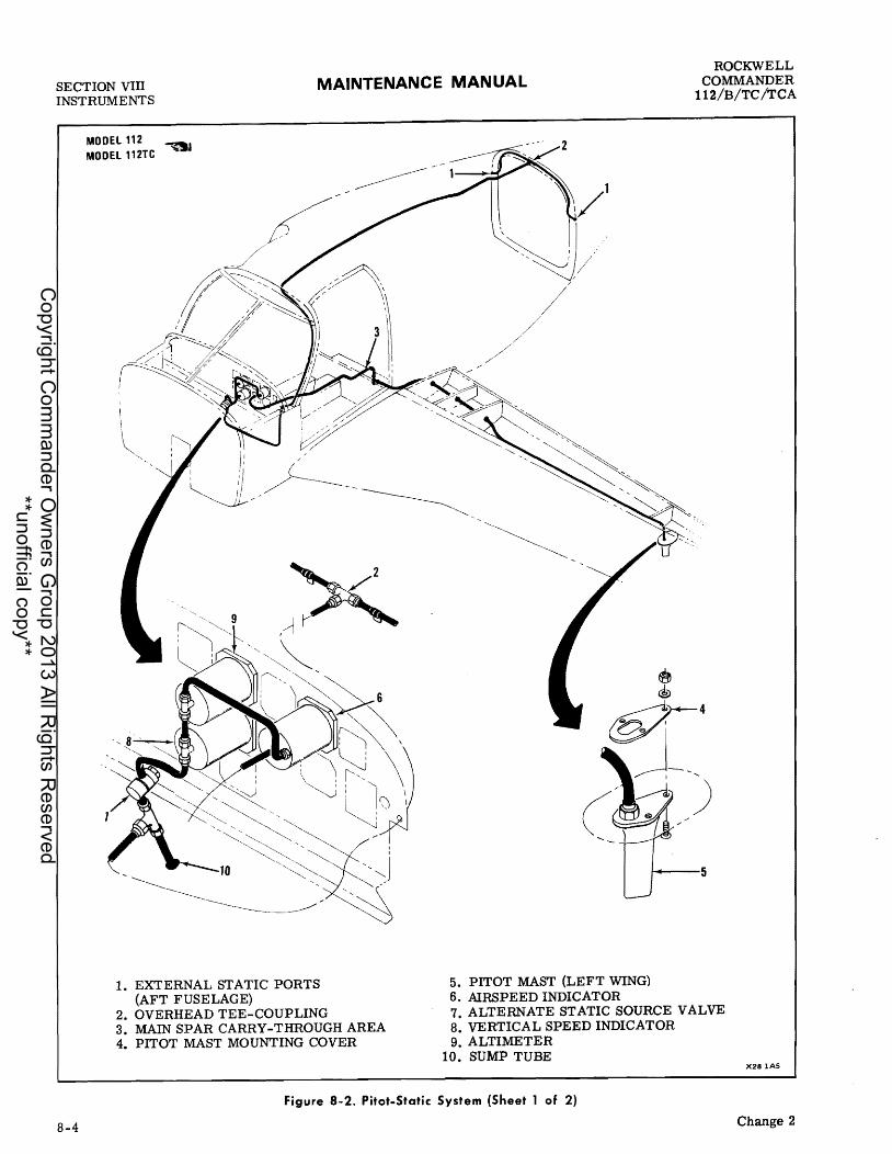
SECTION VIII INSTRUMENTS
MODEl 112 MODEL 112TC .....
MAINTENANCE MANUAL
1. EXTERNAL STATIC PORTS 5. PITOT MAST (LEFT WING) 6. AIRSPEED INDICATOR
ROCKWELL COMMANDER
112/B/TC/TCA
(AFT FUSELAGE) 2. OVERHEAD TEE-COUPLING 7. ALTERNATE STATIC SOURCE VALVE 3. MAIN SPAR CARRY-THROUGH AREA 8. VERTICAL SPEED INDICATOR 4. PITOT MAST MOUNTING COVER 9. ALTIMETER
10. SUMP TUBE X28 lAS
Figure 8-2. Pitot.Static System (Sheet 1 of 2)
8-4 Change 2
Copyright C
omm
ander Ow
ners Group 2013 All R
ights Reserved
**unofficial copy**
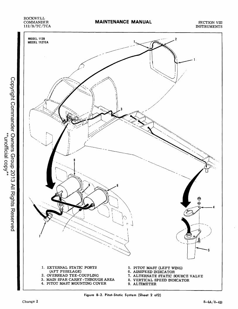
ROCKWELL COMMANDER 112/B/TC/TCA
MODEL 1128 MODEL 112TCA
1
MAINTENANCE MANUAL
1. EXTERNAL STATIC PORTS 5. PITOT MAST (LEFT WING) (AFT FUSELAGE) 6. AIRSPEED INDICATOR
SECTION vm INSTRUMENTS
2. OVERHEAD TEE-COUPLING 7. ALTERNATE STATIC SOURCE VALVE 3. MAIN SPAR CARRY -THROUGH AREA 8. VERTICAL SPEED INDICATOR 4. PITOT MAST MOUNTING COVER 9. ALTIMETER
Figure 8-2. Pitot-Static System (Sheet 2 of2)
Change 2 8-4A/8-4B
Copyright C
omm
ander Ow
ners Group 2013 All R
ights Reserved
**unofficial copy**

Copyright C
omm
ander Ow
ners Group 2013 All R
ights Reserved
**unofficial copy**

ROCKWELL COMMANDER 112/B/TC/TCA
MAINTENANCE MANUAL SECTION vm INSTRUMENTS
AN Am BULB SIMILAR TO THAT ILLUSTRATED MAY BE OBTAINED LOCALLY FROM A SURGICAL SUPPLY COMPANY. THIS IS THE TYPE USED IN MEASURING BLOOD PRESSURE.
PRESSURE
• . ~-- THICK-WALL
~CLAMP SURGICAL HOSE
PRESSURE BLEED-OFF SCREW
~~ " AIR BULB WITH
CHECK VALVES
<:J ""CLAMP SUCTION
00 NOT APPLY POSITIVE PRESSURE WITH THE AIRSPEED AND VERTICAL SPEED INDICATOR. CONNECTED TO THE STATIC SYSTEM OR DAMAGE WILL RESULT.
X282
Figure 8-3. Pitot-Static Test Bulb
monitors the system for indication of correct suction pressure. The gage indicates difference in suction before and after air passes through a gyro. This differential pressure will gradually decrease as the central filter becomes dirty, causing a lower reading on the suction gage. The various components of the vacuum system are secured by conventional clamps, mounting screws and nuts. When removing a component, remove the mounting screws and disconnect the inlet and discharge lines. When installing a vacuum system component, make sure connections are made correctly. Use thread lubricant sparingly and only on male threads. Avoid overtightening connections. Before reinstalling a vacuum pump, coat the pump drive splines lightly with a high temperature grease such as Dow Silicone Number 30 (Dow-Corning Co., Midland, Mich. ).
VACUUM REGULATOR VALVE. A vacuum regulator valve is installed in the line between the instruments and the pump. Since the pump is capable of creating more vacuum than needed, the regulator valve varies the degree of vacuum placed on the instrument system as well as protecting the system from too much vacuum. The regulator valve opens to admit air to the vacuum
pump line when the desired degree of vacuum is attained.
VACUUM FILTER. A dry-element type vacuum system filter cartridge protects the vacuum-driven gyro instruments from dust and other impurities. The filter element should be changed every 500 hours or sooner if the suction gage reading drops below 4. 5 inches of mercury.
Cleaning
The vacuum system regulator valve is adjusted to maintain 4.5 to 5.2 inches Hg. as indicated on the suction gage and cannot function properly if the air filters are dirty. The dry-type filter cartridge and the regulator valve filter should be changed and the system cleaned every 500 hours or sooner if the system requires it. In general, low-pressure, dry compressed air should be used in cleaning the system components removed from the aircraft. Components that are exposed to engine oil and dirt should be washed with Stoddard solvent, then dried with a low-pressure air blast. Check hoses for collapsed inner liners as well as external damage.
8-5
Copyright C
omm
ander Ow
ners Group 2013 All R
ights Reserved
**unofficial copy**

SECTION VIII INSTRUMENTS
8-6
MAINTENANCE MANUAL
1. PUMP DRIVE SPLINE 2. PUMP DRIVE COUPLING 3. PUMP GASKET
ROCKWELL COMMANDER
112/B/TC/TCA
4. ENGINE-DRIVEN VACUUM PUMP 5. VACUUM PUMP EXHAUST 6. FIREWALL 7. VACUUM REGULATOR AND FILTER 8. ARTIFICIAL HORIZON 9. DIRECTIONAL GYRO
10. SUCTION GAGE 11. VACUUM FILTER CARTRIDGE 12. WASHER
X283
Figure 8-4. Vacuum System Installation
Copyright C
omm
ander Ow
ners Group 2013 All R
ights Reserved
**unofficial copy**

ROCKWELL COMMANDER 112/B/TC/TCA
MAINTENANCE MANUAL SECTION vm INSTRUMENTS
Never apply compressed air to lines or components installed in the airplane. The excessive pressures will damage the gyro instruments. If an obstructed line is to be blown out, disconnect it at both ends and blow from the instrument panel out.
Vacuum Regulator Valve Adjustment
When a vacuum regulator valve adjustment is necessary, it is suggested that a suction test gage be installed as a means of verifying the accuracy of the aircraft suction gage.
a. Remove vacuum regulator filter. b. Install suction test gage in place of aircraft suction gage. c. Loosen adjusting screw checknut on regulator valve. d. With engine operating at 1800 rpm adjust regu-lator setting to obtain 5.1 c: .1)inches of mercury. e. Tighten adjusting screw checknut on regulator val ve, do not alter regulator valve setting. f. Check filter and be sure it is clean before installation. g. Operate engine at 1800 rpm and check for a gage reading of 4.5 to 5.2 inches of mercury. h. Remove test gage and connect vacuum line to aircraft suction gage and repeat step g., to check accuracy of gage.
DIRECTIONAL GYRO (OPTIONAL)
The directional gyro is operated from the instrument vacuum system. The air-driven gyro rotates with its spin axis horizontal. Due to gyroscopic inertia, the spin axis of the gyro remains constant even though the aircraft direction is changed; therefore, the relative motion between gyro and instrument case is indicated on the face of the instrument in degrees. A knob extending from the instrument is used for directional heading adjustments and caging the gyro.
ATTITUDE GYRO (OPTIONAL)
The attitude gyro indicator provides a visual reference of the aircraft attitude relative to the pitch and roll axis of the gyro. The gyro, which is air-driven and operated by the vacuum system, is installed in the left side of the instrument panel. Correct setting of the instrument vacuum system and periodic replacement of the instrument air filter are essential to accurate operation of the instrument.
TURN COORDINATOR (OP'rIONAL)
The turn coordinator consists of two instruments within one case. The turn coordinator is operated by
an electrically-driven gyro which is connected to the white airplane on the face of the indicator. The airplane, which deflects proportionally to the rate of turn, indicates that the aircraft is turning in the direction (left or right) shown by the airplane. The bank indicator is a curved, fluid-filled tube containing a ball. Gravitational and centrifugal forces position the ball within the tube to indicate correct lateral attitude for the rate of turn.
ALTIMETER
The altimeter is an absolute pressure instrument that converts atmospheric pressure to altitude using sea level as a reference base (see Figure 8- 5). As atmospheric pressure varies with changes in altitude the change in pressure is expressed on the instrument dial in feet above sea level. The altimeter has a fixed dial and is equipped with three concentrically arranged pointers with a range of 20,000 feet. The long pointer registers in 100-foot increments, the short pointer registers in 10, ODD-foot increments, and the remaining pointer registers in 1, ODD-foot increments. A movable barometric scale, visible through a small window in the main dial, indicates the barometric pressure in inches of Hg. An adjusting knob provides a means of adjusting the three pointe rs and barometric scale simultaneously to correct for changes in atmospheric pressure and to establish the proper reference to sea level. . Barometric pressure is sensed through the instrument static system.
AIRSPEED INDICATOR
MODEL 112. The airspeed indicator registers airspeed in both knots and miles-per-hour (see Figure 8-5). The indicator is operated by the pressure differential between impact air pressure from the pitot tube and barometric pressure sensed through the static system. A white arc from 54 to 109 knots (62 to 125 mph) indicates the wing flap operating range. A green arc from 61 to 143 knots (70 to 164 mph) indicates the normal operating speed. A yellow arc from 143 to 180 knots (164 to 207 mph) indicates the caution range in which all operations must be conducted with care and then only in smooth air. A red radial line at 180 knots (207 mph) indicates the maximum speed at which the aircraft may be safely flown.
MODELS 112B/TC. The airspeed indicator registers airspeed in both knots and miles-per-hour (see Figure 8-5). The indicator is operated by the pressure differential between impact air pressure from the pitot tube and barometric pressure sensed through the static system. A white arc from 51 to 109 knots (59 to 125 mph) indicates the wing flap operating range. A green arc from 56 to 143 knots (64 to 164 mph) indicates the normal operating speed. A yellow arc from 143 to 180 knots (164 to 207 mph) indicates the caution range in which all operations must be conducted with care and then only in smooth air. A red radial line at 180 knots (207 mph) indicates the maximum speed at which the aircraft may be safely flown.
MODEL 112TCA. The airspeed indicator registers
8-7
Copyright C
omm
ander Ow
ners Group 2013 All R
ights Reserved
**unofficial copy**

SECTION VIII INSTRUMENTS
MAINTENANCE MANUAL ROCKWELL
COMMANDER 112/B/TC/TCA
airspeed in both knots and miles-per-hour (see Figure 8-5). The indicator is operated by the pressure differential between impact air pressure from the pitot tube and barometric pressure sensed through the static system. A white arc from 52 to 109 knots (60 to 125 mph) indicates the wing flap operating range. A green arc from 57 to 143 knots (66 to 164 mph) indicates the normal operating speed. A yellow arc from 143 to 180 knots (164 to 207 mph) indicates the caution range in which all operations must be conducted with care and then only in smooth air. A red radial line at 180 knots (207 mph) indicates the maximum speed at which the aircraft may be safely flown.
RATE-Of-CLIMB INDICATOR (OPTIONAL)
The rate-of-climb indicator converts changes in barometric pressure to a rate of aircraft ascent or descent in feet-per-minute. Barometric pressure is sensed through the instrument static system. The indicator has a single needle and two adjoining scales, ranging from zero to 2,000 feet-per-minute to indicate rate of climb or descent from a common zero point. The 2,000 feet scales are divided into 100-foot increments. A recessed slotted screw in the lower left corner is used to zero the indicator when the aircraft is on the ground.
MAGNETIC COMPASS
The magnetic compass is a semi-floating cylinder encased in a liquid filled case with expansion provisions to compensate for temperature changes. It is mounted at eye level on the glare shield to afford better visibility and lessen the effect of vibration and magnetic influences, which cause compass deviation. It is equipped with compensating magnets that are adjustable from the front of the case. The compass should be air- swung and compensated at regular intervals and at any time equipment installations are made which may cause compass deviation. The compass is individually lighted by a small bulb which may be removed and replaced. Pivot covers on the compass allow access to adjust the compensating magnets and for the installation of the compass light.
MAGNETIC COMPASS COMPENSATION
Put airc raft in a simulated level flight attitude, see Leveling in Section no Close doors and place flaps in a retracted position. Set throttles at cruise position with engines operating.. Place all electrical switches, alternator, radio and other equipment in a mode normally used for navigational flight and proceed with the following:
a. Set adjustment screw s on compensating magnets to zero. Zero position is when dot on screw is lined up with dot on compass frame. b. Position aircraft in a magnetically north direc-tion. Adjust north-south adjustment screw until compass reads exactly north.
8-8
c . Position airc raft in a magnetically east direction. Adjust east-west adjustment screw until compass reads exactly east. d. Position airc raft in a magnetically south direc-tion. Notice resulting south error. Adjust northsouth adjustment screw so one-half of error is removed. e. Position aircraft in a magnetically west direc-tion. Notice resulting west error. Adjust eastwest adjustment screw so one-half of the error is removed. f. Position aircraft in successive magnetically 30-degree directions and record all errors on deviation card furnished with compass.
8-DAY CLOCK (OPTIONAL)
A conventional, spring-powered 8-day aircraft clock with a sweep second hand is installed in the left instrument panel. A pair of red- tipped dummy hands may be set to indicate takeoff time, estimated time of arrival, or other uses. The adjustment and winding knob is in the left lower corner of the instrument.
ELECTRIC CLOCK {OPTIONAL}
An alternate 12 volt quartz crystal clock may be installed in the same location as the 8-day clock. The clock has a second, minute and hour hand. An adjustment knob, located in the lower left corner of the instrument, adjusts the clock to the proper time of day. A pair of dummy hands may be set to indicate takeoff time, estimated time of arrival, and other uses. The knobs that set these hands are in the center of the clock. The clock is operational only when the battery switch is on. The clock must be reset to the proper time prior to each flight.
POWER PLANT INSTRUMENTS
Power plant instruments provide the means for monitoring the operation and condition of the engine and include the tachometer indicator, manifold pressure and fuel flow gage and the engine cluster units: cylinder head temperature and oil temperature indicators and oil pressure gage. These instruments are operated by fluid pressure; variations in electrical resistance created by temperature sensing probes; or, in the case of the tachometer, by a drive shaft connected to the engine accessory housing.
ENGINE CLUSTER UNITS
The engine cluster units installed in the instrument sub-panel indicate cylinder head temperature and oil temperature in degrees Fahrenheit and oil pressure in pounds per square inch (see Figure 8-5). The oil pressure unit is a direct read instrument that is con-
Copyright C
omm
ander Ow
ners Group 2013 All R
ights Reserved
**unofficial copy**

ROCKWELL COMMANDER 112/B/TC/TCA
MAINTENANCE MANUAL SECTION vm INSTRUMENTS
nected to the oil pressure outlet housing on the engine accessory case by a small oil line. Minimum and maximum allowable operating oil pressures are marked by red radial lines. A yellow arc indicates the caution range and a green arc indicates the normal operating range. The oil temperature indicator is electrically connected t6 a temperature senSing bulb installed on the oil pressure/oil cooler bypass valve. Changes in oil temperature are sensed by the bulb and transmitted to the oil temperature indicator. Temperature variations are registered as changes in electrical current flow to the indicator. Normal temperature range is indicated by yellow and green arcs. A red radial line marks the maximum allowable oil temperature. The cylinder head temperature unit is also electrically connected to a temperature sensing bulb installed in the number four cylinder (number two cylinder on Model 112B). As the cylinder head temperature increases, the resistance of the temperature bulb decreases which allows the current through the indicator to increase, which in turn causes the instrument pointer to indicate a higher temperature reading. The indicator has a green arc for the normal temperature range and has a red line to indicate the maximum operating temperature.
MANIFOLD PRESSURE/FUEL FLOW GAGE
MODELS 112/B. The manifold pressure/fuel flow gage is a dual indicating instrument. The instrument provides the means to indicate the manifold pressure of the induction air manifold and monitors the metered fuel flow rate to the engine (see Figure 8- 5). The left half of the instrument is used to indicate the manifold pressure of the induction air manifold in inches of mercury. The right half indicates gallons/hour of fuel flow. The fuel flow portion of the instrument is operated by a pressure line from a fitting on the fuel flow divider and a vent line sensing ambient pressure in the engine compartment.
MANIFOLD PRESSURE/FUEL PRESSURE GAGE
MODELS 112TC/TCA. The manifold pressure/fuel pressure gage is a dual indicating instrument. The instrument provides the means to indicate the manifold pressure of the induction air manifold and monitors the fuel pressure to the engine (see Figure 8-5). The left half of the instrument is used to indicate the manifold pressure of the induction air manifold in inches of mercurYe The right half indicates psid of fuel pressure. The fuel pressure portion of the instrument is operated by a pressure line from a fitting on the fuel flow divider and a vent line sensing ambient pressure in the engine compartment.
TACHOMETER INDICATOR
The tachometer is a mechanical indicator driven at half crankshaft speed by a flexible shaft (see Figure 8-5). Most tachometer difficulties will be found in the driveshaft. To function properly, the shaft housing must be free of kinks, dents and sharp bends. There should be no bend on a radius shorter than six
Change 1
inches, and no bend within three inches of either terminal. If a tachometer is noisy or the pointer oscillates, check the cable housing for kinks, sharp bends and damage. Disconnect the cable at the tachometer and pull it out of the housing. Check the cable for worn spots, breaks and kinks.
NOI. A kink may be detected by holding the cable vertically by one end and slowly rotating it between the fingers to feel for binding and jumpy motion.
Before replacing a tachometer cable in the housing, coat the lower two thirds with AC Type ST - 640 Speedometer cable grease or Lubriplate No. 110. Insert the cable in the housing as far as possible, then slowly rotate it to make sure it is seated in the engine fitting. Insert the cable in the tachometer, making sure it is seated in the drive shaft, reconnect the housing and torque to 50 inch-pounds.
EXHAUST GAS TEMPERATURE INDICATOR
MODEL 112 (Serial numbers 226 and subsequent), MODELS 112B/TC/TCA. An EGT indicator is installed in the instrument sub-panel, directly above the engine control levers. The indicator is used to aid the pilot in selecting various fuel-air mixtures for cruising flight at less than 75 percent power. Temperature indications for the EGT indicator are provided by a temperature probe installed in the exhaust manifold.
CARBURETOR AIR TEMPERATURE INDICATOR
MODELS 112TC/TCA. A carburetor air temperature indicator, installed in the left side of the instrument panel, is connected to a sensitive resistance bulb. This resistance bulb is installed in the induction air duct between the turbo charger and the carburetor. As the temperature of the incoming air in the induction air duct varies, the resistance in the bulb varies and the resulting variations in current are expre ssed by the indicator in terms of temperature change. The indicator range is from 0 degrees Fahrenheit to 350 degrees Fahrenheit. A red radial line at 325 degrees Fahrenheit indicates the maximum permissible operating temperature.
MISCELLANEOUS INSTRUMENTS
SUCTION GAGE (OPTIONAL)
The suction gage, installed as part of the optional vacuum system, is mounted to the extreme left side of the main instrument panel (Figure 8- 5). The gage indicates suction available for operation of the attitude and directional gyros.
8-9
Copyright C
omm
ander Ow
ners Group 2013 All R
ights Reserved
**unofficial copy**

SECTION VIII INSTRUMENTS
8-10
X2821
X2822
MAINTENANCE MANUAL ROCKWELL
COMMANDER 112/B/TC /TCA
ENGINE TACHOMETER
2700 RPM 2575 RPM
Red Line MAXIMUM (MODEL 112/B) Red Line MAXIMUM (MODELSl12TC/TCA)
MANIFOLD PRESSURE/FUEL FLOW
12 PSI Red Line MAXIMUM At 20.5 GPH
MODELS 112/B
MANIFOLD PRESSURE/FUEL PRESSURE
.,.. 42. 0 IN. Hg 15 To SO PSrD 30 PSID
Red Line Green Arc Red Line
MAXIMUM NORMAL MAXIMUM
MODELS 112TC/TCA
AIRSPEED
*54 (VSO) To 109 KTS
**61 (VSL) To 143 KTS 143 To 180 KTS
180 KTS
White Arc FLAP EXTENSION o Deg. - 35 Deg.
Green Arc NORMAL OPERATION Yellow Arc CAUTION (Smooth
Air Only) Red Line NEVER EXCEED
*VSO is power off stall speed; Gear Down, Flaps 35 Deg. **VSL ~s power off stall speed; Gear Up, Flaps 0 Deg.
MODEL 112
Figure 8·5. Instrument Markings (Sheet 1 of 5)
Copyright C
omm
ander Ow
ners Group 2013 All R
ights Reserved
**unofficial copy**

ROCKWELL COMMANDER 112/B/TC/TCA
Change 1
X2827
XU (;
X2822
X2822
MAINTENANCE MANUAL SECTION vm rnSTRUMENTS
AIRSPEED
*54 (VSO) To 109 KTS White Arc FLAP EXTENSION o Deg. - 35 Deg.
**56 (VSL) To 143 KTS Green Arc NORMAL OPERATION 143 To 180 KTS Yellow Arc CAUTION (Smooth
Air Only) 180 KTS Red Line NEVER EXCEED
*V SO is power off stall speed; Gear Down, Flaps 35 Deg. **V SL is power off stall speed; Gear Up, Flaps 0 Deg.
MODELS 112B/TC
AIRSPEED *52 (VSO) To 109 KTS White Arc FLAP EXTENSION
o Deg. - 35 Deg. **57 (VSL) To 143 KTS Green Arc NORMAL OPERATION 143 To 180 KTS Yellow Arc CAUTION (Smooth
Air Only) 180 KTS Red Line NEVER EXCEED
*VSO is power off stall speed; Gear Down, Flaps 35 Deg. **V SL is power off stall speed; Gear Up, Flaps 0 Deg.
MODEL 112TCA
CARBURETOR AIR TEMPERATURE
Red Line
MODELS 112TC/TCA
SUCTION (Optional) 4.5IN.Hg.
4 • 5 - 5. 2 IN. Hg . 5.2IN.Hg.
Red Line Green Arc Red Line
Figure 8·5. Inst~ument Markings (Sheet 2 of 5)
MAXIMUM
MINIMUM NORMAL MAXIMUM
8-11
Copyright C
omm
ander Ow
ners Group 2013 All R
ights Reserved
**unofficial copy**

SECTION VIII INSTRUMENTS
8-12
'1 80 I~ tl 100 245280 a TEMP
XU 7
X2829
, , I '~5 60 90'/ a ~ PRESS 100
Xll 8
\~I~ • 25 60 90rq
5 100 PRESS
X282486
)~. o 0 01 I
X2830
,~ a 100
PRESS
X2824
MAINTENANCE MANUAL
1000 - 1600 F 1600 - 245°F
245°F
OIL TEMPERATURE Yellow Arc Green Arc Red Line
CAUTION NORMAL MAXIMUM
MODEL 112, 112B (THRU 544), 112TC AND 112TCA (13000 THRU 13249)
100° - 160°F 1600 - 245°F
2450 F
OIL TEMPERATURE Yellow Arc Green Arc Red Line
CAUTION NORMAL MAXIMUM
MODEL 112B (545 AND SUBS) AND 112TCA (13250 AND SUBS)
25 PSI 25 - 60 PSI 60 - 90 PSI
90 PSI
25 PSI 25 - 60 PSI 60 - 90 PSI
90 PSI
OIL PRESSU RE Red Line Yellow Arc Green Arc Red Line
MODEL 112
OIL PRESSURE Red Line Yellow Arc Green Arc Red Line
MODEL 112B (500 THRU 544)
OIL PRESSU RE
MINIMUM CAUTION NORMAL MAXIMUM
MINIM:UM CAUTION NORMAL MAXIMUM
25 PSI Red Line MINIMUM 25 - 60 pSl Yellow Arc CAUTION 60 - 90 PSI Green Arc NORMAL 90 - 100 PSI Yellow Arc CA UTION
100 PSI Red Line MAXIMUM MODEL 112B (545 AND SUBS)
OIL PRESSURE 25 PSI Red Line MINIMUM
25 - 55 PSI Yellow Arc CAUTION 55 - 90 PSI Green Arc NORMAL 90 - 100 PSI Yellow Arc CAUTION
100 PSI Red Line MAXIMUM MODEL 112TC AND 112TCA (13150 THRU 13249)
Figure 8-5. Instrument Markings (Sheet 3 of 5)
ROCKWELL COMMANDER
112/B/TC/TCA
Change 1
Copyright C
omm
ander Ow
ners Group 2013 All R
ights Reserved
**unofficial copy**

ROCKWELL COMMANDER 112/B/TC/TCA
Change 3
X2824
I , /d275~ 200CYlHEAO~EMP500
Xll 9
~~ 'I • 0°475 200 CYL H TEMP. of
X283l
XII 10
X2825
, ' • Q .10 ~ 14 16
"tTS
X2832
MAINTENANCE MANUAL
OIL PRESSURE
25 PSI Red Line 25 - 50 PSI Yellow Arc 50 - 90 PSI Green Arc 90 - 115 PSI Yellow Arc
115 PSI Red Line
MINIMUM CAUTION NORMAL CAUTION MAXIMUM
MODEL 112TCA (13250 AND SUBS) MODEL 112TC AND TCA (13150 THRU 13249) AFTER INCORPORATION OF SL-112-43.
CYLINDER HEAD TEMPERATURE
Green Arc Red Line
NORMAL MAXIMUM
MODEL 112 AND 112B (500 THRU 544)
CYLINDER HEAD TEMPERATURE
Green Arc Red Line
NORMAL MAXIMUM
MODEL 112B (545 AND SUBS) AND 112TCA
VOLTMETER 10.0 11.3 Volts 11.3 - 12.0 Volts 12.0 - 15.3 Volts 15.3 - 16.0 Volts
Red Arc Yellow Arc Green Arc Red Arc
MODEL 112, THRU 470
VOLTMETER
16.0 Volts Red Line
MODEL 112, 471 AND SUBS.
MINIMUM CAUTION NORMAL MAXIMUM
MAXIMUM
MODELS 112B/TC/TCA (13150 THRU 13249)
VOLTMETER
16.0 Volts Red Line MAXIMUM
MODEL 112TCA (13250 AND SUBS)
Figure 8-5. Instrument Markings (Sheet 4 of 5)
SECTION VITI INSTRUMENTS
8-13
Copyright C
omm
ander Ow
ners Group 2013 All R
ights Reserved
**unofficial copy**

SECTION VIn INSTRUMENTS
MAINTENANCE MANUAL ROCKWELL
COMMANDER 112/B/TC /TCA
I , \ 14 .', I
I , \ II I;' "
E ' F (I,,"' 24,,,,, , 0 '--
70 70
E 4 "). F
t Af' 14 uAl
FUEL HIGHT rANK - A + FUEl lEFT TANK xu llA XlI llA
LEFT FUEL QUANTITY MODELS 112/112TC
AMMETER RIGHT FUEL QUANTITY
MODEL 112B· THRU 544 MODEL 112TCA· THRU 13249
~ I. ,/~, -E J4v"..,tll u!it;Ab.!
L.t o~ (,,41 LAuGtAiH I
FUEL LEFT TANK X2443
LEFT FUEL QUANTITY MODEL 112B· 545 AND SUBSEQUENT MODEL 112TCA ·13250 AND SUBSEQUENT
Xll12 MODELS 1121112TC MODEL 112B· THRU 544 MODEL 112TCA . THRU 13249
I I .~ Y. y, l
E j4 U!':i t;At lJ!)tA81t
II uiJ liAl GAuGtAIH t.
FUEL RIGHT TANK X2443
RIGHT FUEL QUANTITY MODEL 112B· 645 AND SUBSEUUENT MODEL 112TCA ·13250 AND SUBSEQUENT
ALTIMETER
Figure 8-5. Instrument Markings (Sheet 5 of 5)
AMMETER
The sub-panel mounted ammeter indicates current flow, in amperes, from the alternator to the battery, or from the battery to the electrical system (Figure 8-5). With the engine operating, and both halves of the split master switch ON, the ammeter indicates the rate of charge being applied to the battery. In the event of. an alternator malfunction, or if the electricalload demand exceeds the alternator output the am mete r will indicate the discharge rate of the battery.
8-14
VOLTMETER
A voltmeter, located in the instrument sub-panel, allows the pilot to monitor bus bar voltage (Figure 8- 5). When the voltmeter is used in combination with the ammeter; alternator output, battery charge or discharge rate and accurate bus bar voltage can be determined. Normal voltmeter readings should be within the green arc (12 - 15 volts). Refer to Section X for details concerning overcharging or insufficient voltage problems (as indicated by two red arcs on the voltmeter scale).
Change 2
Copyright C
omm
ander Ow
ners Group 2013 All R
ights Reserved
**unofficial copy**

ROCKWELL COMMANDER 112/B/TC/TCA
MAINTENANCE MANUAL SECTION vm ffiSTRUMENTS
FUEL QUANTITY INDICATORS
The fuel quantity indicators are used in conjunction with a float-operated variable- resistance transmitter in each fuel tank. The full tank position of the transmitter float produces a minimum resistance through the transmitter, permitting maximum current flow through quantity indicator and maximum pOinter deflection. The fuel quantity indicators, located in the sub-panel, are marked in quarter increments from empty through full (Figure 8-5).
FLAP POSITION INDICATOR
Wing flap position is electrically indicated by a gage mounted directly to the right of the flap switch. Posi.tion indications are transmitted by a sending unit which is actuated by the flap motor jackscrew in the fuselage.
RUDDER TRIM POSrnON GAGE
Rudder trim position is mechanically indicated on a dual reading gage installed directly to the right of the oil temperature indicator in the instrument cluster unit. The gage indicates both the trim position of the rudder and nose wheel. This gage is connected by a cable assembly to the rudder trim control assembly. Rudder trim indication left or right is proportionately to the movement of the rudder trim control assembly.
STALL WARNING SYSTEM
A stall warning lift detector switch is located in the leading edge of the left wing at Station 80.77. The lift detector switch is slightly spring-loaded to the open position and is closed while approaching aircraft stall speed when the air flow stagnation point moves forward enough to cause a positive pressure on the aft side of the vane, moving it forward. The lift detector switch is set to close the circuit and sound the stall warning horn at 5 to 10 knots above air craft stall speed. The horn is located on the firewall in the cabin area. External mounting screws located on each side of the switch cutout, enables the lift detector switch
Change 1
to be adjusted. Loosening the lift detector switch mounting screws allow s slight fore and aft movement of the lift detector. MOving the lift detector forward extends the stall speed indication away from stall speed. Moving the lift detector slightly aft moves the switch setting nearer the stall speed of the aircraft. Operationally check stall warning system during flight to assure warning horn sounds at 5 to 10 knots above aircraft stall speed. The stall warning circuit is supplied electrical power through a 5-amp circuit breaker on the sub-panel.
NOTE
Lift detector switch replacement is similar to the following steps; however, battery cables must be disconnected before removing detector switch.
a. Trace a light pencil mark on switch, along edge of cutout in detector switch mounting plate. This mark will be used to align detector switch during reinstallation. b. Remove screws securing detector and switch plate, and Withdraw detector switch from wing. c. Disconnect wiring and slip defective detector switch out. d. Install new detector switch and switch plate, assuring pencil marks on switch align with cutout in switch plate. e. Operationally check stall warning system in flight to assure warning horn sounds at 5 to 10 knots above actual stall speed. Adjust lift detector switch if system fails to operate properly (this step applies to Model 112 aircraft with Serial Numbers 188 through 334, 336 through 371 and 373 through 380). f. A ground check may be accomplished on Model 112 Serial numbers 335, 372, 381 and subsequent and Models 112B/TC/TCA.
1 . Place master battery switch ON . 2. Move stall circuit test switch from normal to test pOsition (test switch is located in left wheel well). 3. Hold test switch in test position and gently move lift detector switch forward and up. This completes electrical circuit and stall warning horn will sound.
8-14A/8-14B
Copyright C
omm
ander Ow
ners Group 2013 All R
ights Reserved
**unofficial copy**

Copyright C
omm
ander Ow
ners Group 2013 All R
ights Reserved
**unofficial copy**
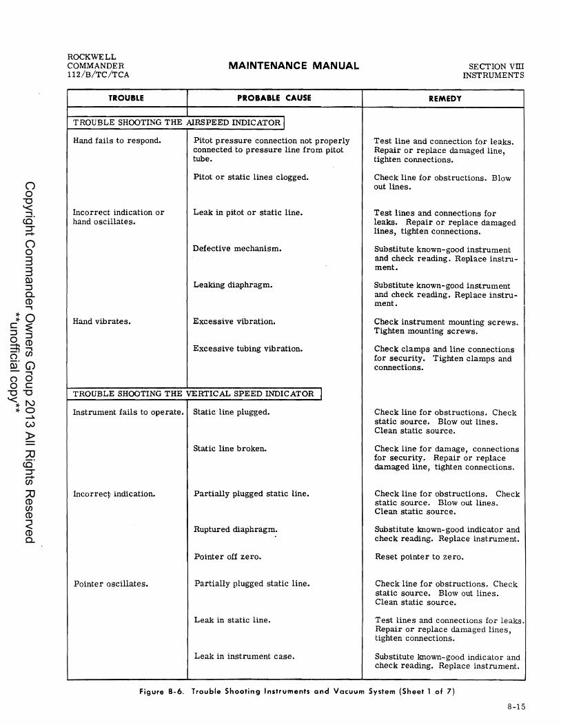
ROCKWELL COMMANDER 112/B/TC/TCA
TROUBLE
MAINTENANCE MANUAL
PROBABLE CAUSE
T ROUBLE SHOOTING THE AIRSPEED INDICATOR I Hand fails to respond.
Incorrect indication or hand oscillates.
Hand vibrates.
Pitot pressure connection not properly connected to pressure line from pitot tube.
Pitot or static lines clogged.
Leak in pitot or static line.
Defective mechanism.
Leaking diaphragm.
Excessive vibration.
Excessive tubing vibration.
TROUBLE SHOOTING THE VERTICAL SPEED INDICATOR I Instrument fails to operate. Static line plugged.
Static line broken.
Incorrecy indication. Partially plugged static line.
Ruptured diaphragm.
Pointer off zero.
Pointer oscillates. Partially plugged static line.
Leak in static line.
Leak in instrument case.
REMEDY
SECTION VIII INSTRUMENTS
Test line and connection for leaks. Repair or replace damaged line, tighten connections.
Check line for obstructions. Blow out lines.
Test lines and connections for leaks. Repair or replace damaged lines, tighten connections.
Substitute known-good instrument and check reading. Replace instrument.
Substitute known-good instrument and check reading. Replace instrument.
Check instrument mounting screws. Tighten mounting screws.
Check clamps and line connections for security. Tighten clamps and connections.
Check line for obstructions. Check static source. Blowout lines. Clean static source.
Check line for damage, connections for security. Repair or replace damaged line, tighten connections.
Check line for obstructions. Check static source. Blowout lines. Clean static source.
Substitute known-good indicator and check reading. Replace instrument.
Reset painter to zero.
Check line for obstructions. Check static source. Blowout lines. Clean static source.
Test lines and connections for leaks. Repair or replace damaged lines, tighten connections.
Substitute known-good indicator and check reading. Replace instrument.
figure 8-6. Trouble Shooting Instruments and Vacuum System (Sheet 1 of 7)
8-15
Copyright C
omm
ander Ow
ners Group 2013 All R
ights Reserved
**unofficial copy**

SECTION VIII INSTRUMENTS
TROUBLE
MAINTENANCE MANUAL
PROBABLE CAUSE
ROCKWELL COMMANDER
112/B/TC/TCA
REMEDY
TROUBLE SHOOTING THE VERTICAL SPEED INDICATOR (CONTINUED) I Hand vibrates. Excessive vibration.
Defective diaphragm.
TROUBLE SHOOTING THE ALTIMETER I Instrument fails to operate.
Incorrect indication.
Hands oscillates.
Static line plugged.
Defective mechanism.
Hands not carefully set.
Leaking diaphragm.
Pointers out of calibration.
Static pressure irregular.
Leak in airspeed or vertical speed indicator installations.
TROUBLE SHOOTING THE HEATED PITOT HEAD I Tube does not heat or clear ice.
Switch turned off.
Popped circuit breaker.
Break in wiring.
Heating element burned out.
Check mounting screws. Tighten mounting screws.
Substitute known-good indicator and check for vibration. Replace instrument.
Check line for obstructions. Check static source. Blowout lines. Clean static source.
Substitute known-good altimeter and check reading. Replace instrument.
Reset hands with knob.
Substitute known-good altimeter and check reading. Replace instrument.
Compare reading with known- good altimeter. Replace instrument.
Check lines for obstructions or leaks. Check static source. Blow out lines, tighten connections, clean static source.
Check other instruments and system plumbing for leaks and obstructions. Blowout lines, tighten connections.
Turn on switch.
Check circuit breaker. Reset circuit breaker.
Test for open circuit. Repair wiring.
Check resistance of heating element. Replace element.
Figure 8-6. Trouble Shooting Instruments and Vacuum System (Sheet 2 of 7)
8-16
Copyright C
omm
ander Ow
ners Group 2013 All R
ights Reserved
**unofficial copy**

ROCKWELL COMMANDER tt2/B/TC/TCA
TROUBLE
MAINTENANCE MANUAL
PROBABLE CAUSE
TROUBLE SHOOTING THE ATTITUDE AND DIRECTIONAL GYROS I Horizon bar fails to respond. Horizon bar does not settle. Horizon bar oscillates or vibrates excessively.
Excessive drift in either direction.
Dial spins in one direction continuously.
Central air filter dirty.
Suction relief valve improperly adjusted.
Faulty suction gage.
Vacuum pump failure.
Vacuum hose pinched or leaking.
Defective mechanism.
Insufficient vacuum.
Excessive vibration.
Low vacuum relief valve improperly adjusted.
Faulty suction gage.
Vacuum pump failure.
Vacuum hose pinched or leaking.
Operating limits have been exceeded.
Defective mechanism.
TROUBLE SHOOTING THE OIL PRESSURE GAGE j
Gage has erratic operation. Worn or bent movement.
Foreign matter in Bourdon tube.
Dirty or corroded movement.
Pointer bent and rubbing on dial, dial screw or glass.
Leak in pressure line.
REMEDY
SECTION vm INSTRUMENTS
Check filter, clean or replace.
Adjust or replace relief valve.
Substitute known-good suction gage and check gyro response. Replace suction gage.
Check pump. Replace pump.
Check hoses for damage and leaks. Repair or replace damaged hoses, tighten connections.
Substitute known- good gyro and check indication. Replace instrument.
Adjust or replace a relief valve.
Check instrument mounting.
Adjust or replace relief valve.
Substitute known-good suction gage and check gyro indication. Replace suction gage.
Check pump. Replace pump.
Check hoses for damage and leaks. Repair or replace damaged hoses, tighten connections.
Cage and reset when airplane is level.
Substitute known-good gyro and check indication. Replace instrument.
Replace instrument.
Replace instrument.
Replace instrument.
Replace instrument.
Check line for leaks and damage. Repair or replace damaged line.
Figure 8-6. Trouble Shooting Instruments and Vacuum System (Sheet 3 of 7)
8-17
Copyright C
omm
ander Ow
ners Group 2013 All R
ights Reserved
**unofficial copy**

SECTION vm INSTRUMENTS
TROUBLE
MAINTENANCE MANUAL
PROBABLE CAUSE
TROUBLE SHOOTING THE OIL PRESSURE GAGE (CONTINUED) I Gage does not register.
Gage pointer fails to return to zero.
Gage does not register properly.
Pressure line clogged.
Pressure line broken.
Fractured Bourdon tube.
Gage pointer loose on staff.
Damaged gage movement.
Foreign matter in line.
Foreign matter in Bourdon tube.
Bourdon tube stretched.
Faulty mechanism.
TROUBLE SHOOTING THE FUEL FLOW INDICATOR I Doe s not registe r.
Pointer fails to return to zero.
Incorrect or erratic reading.
Pressure line clogged.
Pressure line broken.
Fractured bellows or damaged mechanism.
Clogged snubber orifice.
Pointer loose on staff.
Foreign matter in line.
Clogged snubber orifice at fuel flow divider fitting.
Damaged bellows or mechanism.
Damaged or dirty mechanism.
Pointer bent, rubbing on dial or glass.
Leak or partial obstruction in pressure line.
REMEDY
ROCKWELL COMMANDER
112/B/TC /TCA
Check line for obstructions. Clean line.
Check line for leaks and damage. Repair or replace damaged line.
Replace instrument.
Replace instrument.
Replace instrument.
Check line for obstructions. Clean line.
Replace instrument.
Replace instrument.
Replace instrument.
Check line for obstructions. Blow out line.
Check line for leaks and damage. Repair or replace damaged line.
Replace instrument.
Replace instrument.
Replace instrument.
Check line for obstructions. Clean line.
Replace fitting.
Replace instrument.
Replace instrument.
Replace instrument.
Check line for obstructions or leaks. Blowout dirty line, repair or tighten loose connections.
Figure 8-6. Trouble Shooting Instruments and Vacuum System (Sheet 4 of 7)
8-18
Copyright C
omm
ander Ow
ners Group 2013 All R
ights Reserved
**unofficial copy**

ROCKWELL COMMANDER 112/B/TC/TCA
TROUILE
MAINTENANCE MANUAL
PROBABLE CAUSE
TROUBLE SHOOTING THE FUEL QUANTITY INDICATORS I
Failure to indicate.
Off calibration.
Sticky or sluggish indicator operation.
Erratic readings.
Fuel tanks empty.
No power to indicator or transmitter. (POinter stays below E.)
Grounded wire. (POinter stays above F.)
Low voltage.
Defective indicator.
Defective indicator.
Defective transmitter.
Low or high voltage.
Defective indicator.
Low voltage.
Loose or broken wiring on indicator or transmitter.
Defective indicator or transmitter.
Defective master switch.
TROUBLE SHooTlNGTHE TURN COORDINATOR I
Airplane portion of indicator fails to respond.
Circuit breaker popped.
Master switch OFF or switch defective.
Broken or grounded lead to indicator.
Indicator not grounded.
Defective mechanism.
SECTION VITI INSTRUMENTS
REMEDY
Check fuel quantity. Service with proper grade and amount of fuel.
Check circuit breaker, inspect for open circuit. Reset breaker, repair or replace defective wire or component.
Check for partial ground between transmitter and indicator. Repair or replace defective wire.
Check voltage at indicator. Correct voltage.
Substitute known-good indicator. Replace indicator.
Substitute known-good indicator. Replace indicator.
Substitute known-good transmitter. Recalibrate or replace.
Check voltage at indicator. Correct voltage.
Substitute known-good indicator. Replace indicator.
Check voltage at indicator. Correct voltage.
Inspect circuit wiring. Repair or replace defective wire.
Substitute known-good indicator or transmitter. Replace indicator or transmitter.
Replace switch.
Check visually. Reset breaker.
Check switch ON. Replace defective switch.
Check circuit wiring. Repair or replace defective wiring.
Check ground wire. Repair or replace defective wire.
Replace instrument.
Figure 8-6. Trouble Shooting Instruments and Vacuum System (Sheet 5 of 7)
8-19
Copyright C
omm
ander Ow
ners Group 2013 All R
ights Reserved
**unofficial copy**

SECTION VIII INSTRUMENTS
TROUBLE
MAINTENANCE MANUAL
PROBABLE CAUSE
TROUBLE SHOOTING THE TURN COORDINATOR (CONTINUED) I
Hand sluggish in returning to zero.
Pointer does not indicate proper turn.
Hand does not sit on zero.
In cold temperatures, hand fails to respond or is sluggish.
Noisy gyro.
Defective mechanism.
Low voltage.
Defective mechanism.
Gimbal and rotor out of balance.
Hand incorrectly sits on rod.
Sensitivity spring adjustment pulls hand off zero.
Oil in indicator becomes too thick.
Insufficient bearing end play.
Low voltage.
High voltage.
Loose or defective rotor bearings.
TROUBLE SHOOTING THE SUCTION GAGE f
High suction gage readings.
Low suction gage readings.
Suction gage fluctuates.
Gyro function normally - relief valve filter clogged, relief valve malfunction.
Leaks or restriction between instruments and relief valve, relief valve out of adjustment, defective pump, restriction in pump discharge line.
Central air filter dirty.
Defective gage or stiCking relief valve.
ROCKWELL COMMANDER
112/B/TC/TCA
REMEDY
Replace instrument.
Check voltage to instrument. Correct voltage.
Replace instrument.
Replace instrument.
Replace instrument.
Replace instrument.
Replace instrument.
Replace instrument.
Check voltage at instrument. Correct voltage.
Check voltage to instrument. Correct voltage.
Replace instrument.
Check valve filter, then valve. Compare gage readings with new gage. Clean valve filter, reset valve. Replace gage.
Check lines for leaks, check pump discharge volume, disconnect and test pump. Repair or replace lines, adjust or replace relief valve, repair or replace pump. Clean discharge line.
Check operation with filter removed. Clean or replace filter.
Check suction with test gage. Replace gage. Clean sticking valve with Stoddard solvent. Blow dry and test. H valve sticks after cleaning, replace it.
Figure 8-6. Trouble Shooting Instruments and Vacuum System (Sheet 6 of 7)
8-20
Copyright C
omm
ander Ow
ners Group 2013 All R
ights Reserved
**unofficial copy**
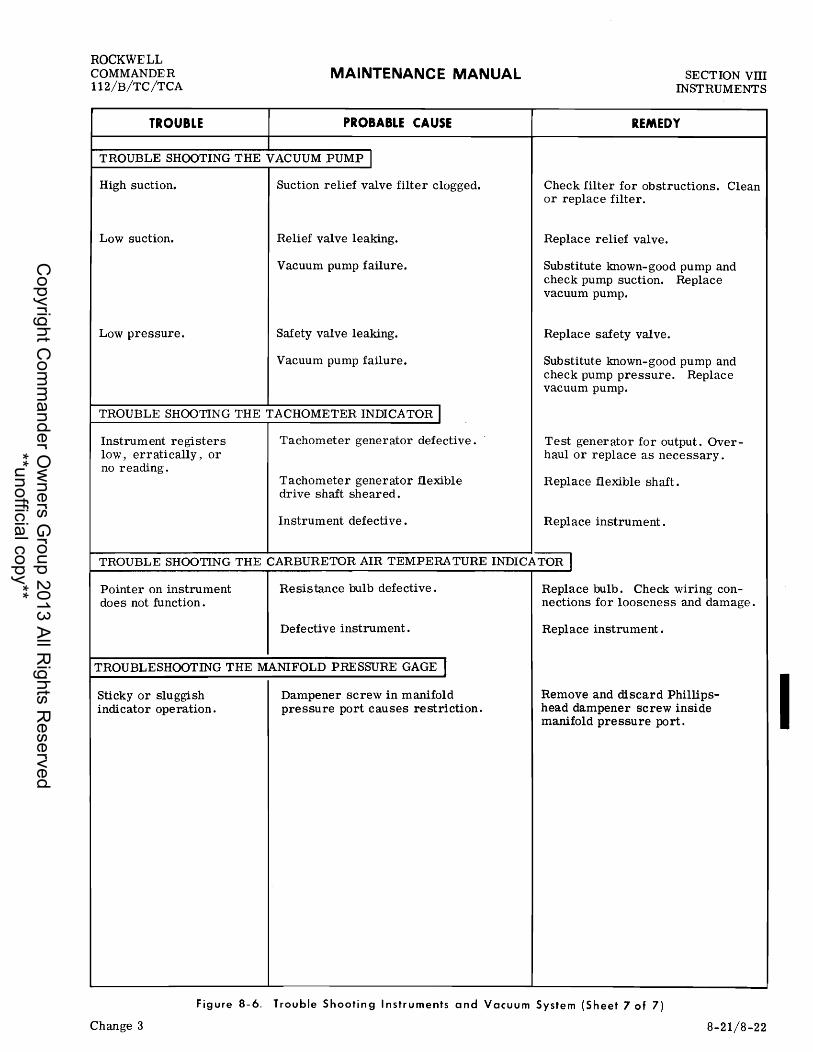
ROCKWELL COMMANDER 112/B/TC/TCA
TROUBLE
MAINTENANCE MANUAL
PROBABLE CAUSE
TROUBLE SHOOTING THE VACUUM PUMP I High suction. Suction relief valve filter clogged.
Low suction. Relief valve leaking.
Vacuum pump failure.
Low pressure. Safety valve leaking.
Vacuum pump failure.
TROUBLE SHOOTING THE TACHOMETER INDICATOR I Instrument registers low, erratically, or no reading.
Tachometer generator defective.
Tachometer generator flexible drive shaft sheared.
Instrument defective.
SECTION VIII INSTRUMENTS
REMEDY
Check filter for obstructions. Clean or replace filter.
Replace relief valve.
Substitute known-good pump and check pump suction. Replace vacuum pump.
Replace safety valve.
Substitute known- good pump and check pump pressure. Replace vacuum pump.
Test generator for output. Overhaul or replace as necessary.
Replace flexible shaft.
Replace instrument.
TROUBLE SHOOTING THE CARBURETOR AIR TEMPERA TURE INDICATOR I Pointer on instrument does not function.
Resistance bulb defective.
Defective instrument.
TROUBLESHOOTING THE MANIFOLD PRESSURE GAGE I Sticky or sluggish indicator operation.
Dampener screw in manifold pressure port causes restriction.
Replace bulb. Check wiring connections for looseness and damage.
Replace instrument.
Remove and discard Phillipshead dampener screw inside manifold pressure port.
Figure 8-6. Trouble Shooting Instruments and Vacuum System (Sheet 7 of 7)
Change 3 8-21/8-22
I C
opyright Com
mander O
wners G
roup 2013 All Rights R
eserved **unofficial copy**

Copyright C
omm
ander Ow
ners Group 2013 All R
ights Reserved
**unofficial copy**

ROCKWELL COMMANDER 112/B/TC/TCA
MAINTENANCE MANUAL SECTION IX
CABIN ENVIRONMENT AL
SECTION IX
HEATING AND VENTILATION
TABLE OF CONTENTS
GENERAL DESCRIPTION •................. Heater Operation .•.....•................
VENTILATION SYSTEM •..•................
GENERAL DESCRIPTION
Page 9-1 9-1 9-1
Cabin heating and defrosting are provided by an exhaust manifold heat exchanger, air ducts and valves, controls, and outlets. The only moving parts of the system are the valves and their controls, hence there is little mechanical wear involved. Normally, the only maintenance check required on the heating and defrosting system is careful examination to insure that the exhaust manifold and heat exchanger have no burned spots or cracks which could allow exhaust fumes to enter the system, and a check of hoses and ducting to make sure that air passages are unobstructed. Heater and defroster controls and valves should be checked periodically to insure proper operation. Refer to Figure 9-1 for heat and defrosting system details.
HEATER OPERATION
MODEL 112 (Serial Numbers 1 thru 380). The cabin heating system consists of an intake within the nose cowl landing light housing, an exchanger shroud around the exhaust muffler, and a takeoff valve assembly (Figure 9- 2) containing four separate outlet ports to direct heated air to two windshield defroster outlets or four cabin floor side outlets for interior heating. Four individual control knobs regulate the routing of the heated air. Two, labeled LEFT or RIGHT DEFROSTER, control the air to the right and left defroster ducts which are mounted on the upper surface of the instrument panel cowl deck. Two remaining control knobs, labeled LEFT or RIGHT CABIN HEAT control the amount of heated air delivered to the right and left cabin floor heater outlets.
Page Trouble Shooting The Systems ..••...•..... 9-5 Repair and Replacement of Components... .. 9-5
These control knobs are located on the right instrument sub-panel assembly. Pulling the control knobs fully out will provide the maximum amount of heated airflow while intermediate settings provide an adjustment in air temperature for individual pre,ferences.
MODEL 112 (Serial Numbers 381 and Subsequent). MODELS 112B/TC/TCA. The cabin heating system consists of an intake within the nose cowl landing light housing, an exchanger shroud around the exhaust muffler, a defroster valve assembly, and two cabin heat valve assemblies. Heated air is directed to two windshield defroster outlets or four cabin floor side outlets for interior heating. Two individual control knobs regulate the routing of the heated air. One labeled DEFROSTER, controls the flow of heated air to the right and left defroster ducts which are mounted on the upper surface of the instrument panel cowl deck. The remaining control knob, labeled CABIN HEAT controls the amount of heated air delivered to the right and left cabin floor heater outlets. These knobs are located on the right instrument sub-panel assembly. Pulling the control knobs fully out will provide the maximum amount of heated airflow, while intermediate settings provide an adjustment in air temperature for individual preferences.
VENTILATION SYSTEM
Two individual systems provide maximum cool air intake for in- flight cabin ventilation. A ram air intake, recessed into the center of the vertical stabilizer, serves four adjustable air vents installed in the overhead console. These vents are adjusted by
9-1
Copyright C
omm
ander Ow
ners Group 2013 All R
ights Reserved
**unofficial copy**

SECTION IX CABIN ENVIRONMENT AL
MAINTENANCE MANUAL ROCKWELL
COMMANDER 112/B/TC/TCA
MODEL 112, 1 THRU 380.
2
1. AMBIENT AIR INTAKE, FWD COWL 2. EXHAUST SHROUD 3. RIGHT DE FROSTER OUTLET 4. RIGHT AND LEFT DEFROSTER
GATE ASSEMBLIES 5. LE FT DE FROSTER OUTLET 6. DISTRIBUTION BOX AND
TAKEOFF VALVE
PULL ON II (9 00
LEFT RIGHT \ \ DEFROSTER __ CABIN
z'--__ 7
10
8
~7 Q DEFROSTER
7
7. CABIN FLOOR SIDE DUCT 8. AMBIENT AIR INTAKE
FROM WING 9. RIGHT AND LEFT CABIN HEAT
GATE ASSEMBLIES 10. CONTROL PANEL
Figure 9-1. Heating and Defrosting System Installation (Sheet 1 of 2)
9-2
X291
Copyright C
omm
ander Ow
ners Group 2013 All R
ights Reserved
**unofficial copy**

ROCKWELL COMMANDER 112/B/TC/TCA
MAINTENANCE MANUAL
MODEL 112, 381 AND SUBSEQUENT. MODELS 112B/TC/TCA
(r-PUllON I
'000 ) CABIN VENT CABIN HEAT
f 8
SECTION IX CABIN
ENVIRONMENT AL
1. AMBIENT AIR INTAKE, FWD COWL 5. DEFROSTER CONTROL GATE ASSEMBLY 2. EXHAUST SHROUD 6. LEFT DEFROSTER OUTLET 3. RIGHT CABIN HEAT VALVE 7. LEFT CABIN HEAT VALVE 4. RIGHT DEFROSTER OUTLET 8. CONTROL PANEL
X42260
Figure 9-1. Heating and Defrosting System Installation (She.t 2 of 2)
9-3
Copyright C
omm
ander Ow
ners Group 2013 All R
ights Reserved
**unofficial copy**

SECTION IX CABIN ENVIRONMENTAL
MODEL 112, 1 THRU 380.
9-4
MAINTENANCE MANUAL
6
1. GATE ASSEMBLY, CABIN HEAT 2. GATE ASSEMBLY, CABIN HEAT 3. BAFFLES, CABIN HEAT 4. SEPARATORS 5. BAFFLES, DEFROSTER 6. TAKEOFF ASSEMBLY 7. RIGHT DEFROSTER OUTLET ASSEMBLY 8. LEFT DEFROSTER OUTLET ASSEMBLY 9. GATE ASSEMBLY, DEFROSTER
10. GATE ASSEMBLY, DEFROSTER 11. LEFT CABIN HEAT OUTLET ASSEMBLY
RIGHT SIDE NOT SHOWN
Figure 9-2. Valve Assembly (Sheet 1 of 2)
ROCKWELL COMMANDER
112/B/TC/TCA
9
X29 2 A5
Copyright C
omm
ander Ow
ners Group 2013 All R
ights Reserved
**unofficial copy**

ROCKWELL COMMANDER 112/B/TC/TCA
MAINTENANCE MANUAL SECTION IX
CABIN ENVIRONMENT AL
MODEL 112, 381 AND SUBSEQUENT • MODELS 112B/TC/TCA
1. INLET ASSEMBLY 2. SEPARATOR 3. GATE ASSEMBLY 4. TAKEOFF ASSEMBLY
X42261
Figure 9-2. Valve Assembly (Sheet 2 of 2)
a knurled position wheel on each outlet unit. The second ventilation system utilizes two intakes, one in each inboard wing leading edge to supply fresh air to four floor-level adjustable outlets. Refer to Figure 9-3 for ventilation system components.
TROUBLE SHOOTING THE SYSTEMS
Most of the operational troubles in the heating, defrosting, and ventilating systems are caused by sticking or binding air valves and their controls, damaged air ducting, or defects in the exhaust muffler. In most cases, air valves or controls can be freed by proper lubrication. Damaged or broken parts should be repaired or replaced. When checking rigging of controls, be sure valves respond freely to control movement, and that they move through
Change 1
their full range of travel and seal properly. Check that heater hoses are properly secured and replace hoses that are burned, frayed, or crushed. If fumes are detected in the cabin, a very thorough inspection of the exhaust muffler should be accomplished. Since any holes or cracks may permit exhaust fumes to enter the cabin, replacement of defective parts is imperative because fumes constitute an extreme danger.
REPAIR AND REPLACEMENT OF COMPONENTS
Figures 9-1 through 9- 3 show the components of the heating, defrosting and ventilating systems, and may be used as a reference during replacement of parts. Burned, frayed, or crushed hose should be replaced • with new hose. Cut to length and install in the origi-nal routing. Check for proper operation and correct rigging of the valves after repair or replacement.
9-5
Copyright C
omm
ander Ow
ners Group 2013 All R
ights Reserved
**unofficial copy**

SECTION IX CABIN ENVIRONMENT AL
MODEL 112, 126 THRU 380.
MAINTENANCE MANUAL
4
ROCKWELL COMMANDER
112/B/TC/TCA
-------".
~---/:
9-6
1. OVERHEAD VENTS 2. OVERHEAD VENTILATION DUCT 3. DORSAL FIN INTAKE 4. PLATE 5. SLIDE ASSEMBLY 6. SPACER 7. PLATE
10
8. SEAL 9. WING AIR INTAKE OPENING
10. CABIN AIR VALVE 11. HEAT AND VENTILATION DUCT 12. HEATER AND CABIN AIR
INTERCONNECTING CABLE 13. AIR VENTS
Figure 9-3. Cabin Ventilation System Installation (Sheet 1 of 3)
I /' /" ~"'--
9
X293A5
Copyright C
omm
ander Ow
ners Group 2013 All R
ights Reserved
**unofficial copy**

ROCKWELL COMMANDER 112/B/TC/TCA
MAINTENANCE MANUAL
MODEL 112, 381 AND SUBSEQUENT.
1. OVERHEAD VENTS 2. OVERHEAD VENTILATION DUCT 3. DORSAL TIN INTAKE 4. PLATE 5. SLIDE ASSEMBLY 6. SPACER 7. PLATE 8. SEAL 9. WING AIR INTAKE OPENING
10. CABIN AIR VALVE 11. HEAT AND VENTILATION DUCT 12. VENTILATION CONTROL CABLE 13. HEATER CONTROL CABLE 14. AIR VENTS
Figure 9-3. Cabin Ventilation System Installation! (Sheet 2 of 3)
SECTION IX CABIN
ENVIRONMENTAL
/'
/'
6
8
X29385
9-7
Copyright C
omm
ander Ow
ners Group 2013 All R
ights Reserved
**unofficial copy**

SECTION IX CABIN ENVIRONMENT AL
MAINTENANCE MANUAL
9-8
MODELS 112B/TC/TCA
1. OVERHEAD VENTS 2. OVERHEAD VENTILATION DUCT 3. DORSAL TIN INTAKE 4. PLATE 5. SLIDE ASSEMBLY 6. SPACER 7. PLATE S. SEAL 9. WING AIR INTAKE OPENING
10. CABIN AIR VALVE 11. HEAT AND VENTILATION DUCT 12. VENTILATION CONTROL CABLE 13. HEATER CONTROL CABLE 14. AIR VENTS
Figure 9-3. Cabin Ventilation System Installation (Sheet 3 of 3)
6
ROCKWELL COMMANDER
112/B/TC /TCA
8
X29385
Copyright C
omm
ander Ow
ners Group 2013 All R
ights Reserved
**unofficial copy**

ROCKWELL COMMANDER 112/B/TC/TCA
MAINTENANCE MANUAL SECTION X ELECTRICAL
•
SECTION X
ELECTRICAL
TABLE OF CONTENTS
Page GENERAL DESCRIPTION .........•.•.••.... 10-1 POWER DISTRlBUTION ................•..•. 10-1
Battery and External Power ...•......•.•• 10-1
GENERAL DESCRIPTION
The aircraft 14-volt de electrical system is designed to provide the utmost in reliability. The 12-volt storage battery provides electric current for engine starting and a reserve source of electrical power in the event of alternator failure. A dc power receptacle, located aft of the battery on the left side of fuselage, provides a means for connecting external power to the aircraft electrical system. Aircraft Without an external power receptacle should use a spare battery for servicing purposes. To conserve the battery always use external power for starting engines when temperature is below 400 F or when performing maintenance requiring electrical power. A three-phase, 70-ampere alternator with internal diodes is instal-led on the engine and supplies the primary source of electrical power to the main bus. The internal diodes rectify ac current to dc current. The electrical By stem is protected by a voltage regulator, overvoltage relay, and 70-ampere circuit breaker. The electrical power system is protected from overload or short circuits by trip-free circuit breakers. If alternator output voltage is below bus voltage, the diodes are reversed biased and all bus loads are supplied by the battery. The dc ammeter, installed in the sub-panel, indicates the output of the alternator. All electricallyoperated motors, lighting systems, and other electrical component circuits are protected by trip-free pushto-reset circuit breakers. Each electrical system component circuit is wired so a failure within a particular circuit will not be detrimental to the operation of other electrical components. Switches and instruments
Page Alternator System ......•......•..•...... 10-3 Diagrams .....•..............•.....•.•. 10-4
required for operation of the aircraft electrical system, are installed in the instrument sub-panel.
POWER DISTRIBUTION
The l4-volt dc electrical system depends upon electrical power from three different sources: battery, external powe'r and the alternator. With the e:ngine operating and the altel"Ilator on the line, electric power from the alternator is channeled through a 70-ampere circuit breaker to the main bus. The battery and external power are connected to the circuit breaker bus through a shunt. Electrical power from the circuit breaker bus is routed to the switch bus in the instrument panel.
BATTERY AND EXTERNAL POWER
One l2-volt storage battery provides power to the circuit breaker bus through a battery contactor. The battery contactor is controlled by a two-position (BAT MASTER-OFF -ON) switch located at the extreme left of the sub-panel. PlaCing the master switch in the ON position closes the battery contactor to supply power to the circuit breaker bus from the battery or external power for Model 112, Serial numbers 188 thru 470. On Model 112, Serial numbers 471 and subsequent, Models 112B/TC/TCA, the power is supplied to the main bus from the battery or external power. Placing the master battery switch in the OFF pOSition de-energizes the battery contactor and terminates the supply of power to the electrical system.
10-1
Copyright C
omm
ander Ow
ners Group 2013 All R
ights Reserved
**unofficial copy**

SECTION X ELECTRlCAL
MAINTENANCE MANUAL ROCKWELL
COMMANDER ll2/B/TC/TCA
Check voltage and polarity of external power source before connecting power source to aircraft.
BATTERY SERVICING. Initial servicing of a dry charge battery is as follows:
a. Remove filler plugs and fill each cell with diluted sulphuric acid (1. 250 to 1. 265 specific gravity), to the bottom of the filling tubes in the battery. Use only glass, rubber or plastiC materials for containing battery electrolyte fluid during servicing,
TYPE (Rebat) AMPERES ELECTROLYTE VOLUME (QTS.)
S-25 2 2. 1 R-35 3 2.5
Figure 10-1. Battery Charge Rates
and wear protective clothing and rubber gloves when handling electrolyte to prevent personal injury. Use a solution of baking soda and water t9 neutralize any acid spilled on clothing, skin or any damageable surface. b. Locate battery and charging equipment in a well ventilated area before initiating charge. Connect battery charger to the battery, and observe proper polarity (connect battery positive terminal to charger positive circuit). c. .' Charge battery at rate shown'in Figure 10-1. Do not exe eed this rate or electrolyte gassing will occur.
10-2
Gasses given off by a battery under charging conditions are flammable.
SPECIFIC GRAVITY
CHARGED RECHARGE
1.265 - 1.285 1. 250 - Less
Figure 10-2. Hydrometer Readings
d. Check battery with a hydrometer when it will no longer accept a charge. Hydrometer reading should be 1.265 to 1. 285 at room temperature of 70 to 80 degrees F. Battery voltage should be 14. 4 v.olts with zero load on battery. Check security of terminal connections, and battery charger output voltage if hydrometer check indicates a level below 1. 265. e. All cells must have a specifiC gravity reading between 1. 265 to 1. 285 with electrolyte level at bottom of filling tubes (see Figure 10-3). If hydrometer indicates a high gravity reading, remove a small amount of electrolyte and add distilled water. Repeat as necessary to achieve proper specific gravity level. If individual cell reading is low, add higher gravity electrolyte instead of distilled water.
SERVICING BATTERY INST ALLED IN AIRCRAFT. The l2-volt battery is installed in the left side of the tailcone, and is accessible through the baggage compartment (see Figure 10-3). Loosen and remove the battery box cover for battery inspection and electrolyte level checks.. A built- in plastic carry strap is provided fo r cOllvenience in handling the battery if it becomes necessary to remove it from the battery box. Check the battery electrolyte level frequently, especially during hot weather. If visual check shows low cell level, and no electrolyte is available at this time, add distilled water to bring the cell(s) up to proper level. However, addition of water may result in as much as a 15 point difference in specific gravity reading. between cells not serviced and those receiving water in place of electrolyte.
5
1. ELECTROLYTE LEVEL INDICATOR 2. NEGATIVE TERMINAL 3. VENTED FILLER CAP 4. CARRY STRAP 5. POSITIVE TERMINAL
X 210 1
Figure 10-3. Battery
Copyright C
omm
ander Ow
ners Group 2013 All R
ights Reserved
**unofficial copy**

ROCKWELL COMMANDER 112/B/TC/TCA
MAINTENANCE MANUAL SECTION X ELECTRICAL
FIELD TERMINAL F 1
FIELD TERMINAL F2
o
BLAST TUBE
CONNECTION
~-~_j'A
Figure 10-4. Alternator
ALTERNATOR SYSTEM
X 2102
The alternator system consists of one 14-volt, 70-amp alternator, one voltage regulator, one overvoltage relay and one 70 ampere circuit breaker. The alternator is connected to the circuit breaker bus at all times and will supply current demands when output voltage exceeds battery voltageo Alternator output may vary from O-amps to 70-amps, depending upon circuit load and engine rpm. The alternator will produce a minimum of 10-amps at engine idle speed.
Alternator must not be operated on open circuit with the field winding energized. Any attempt to do so may result in damage to the alternator, regulator, or circuits.
This alternator is ventilated by air pressure. Do not operate an alternator at full output for more than 30 seconds unless adequate pressure for cooling is used. Alternators can be damaged from over heating. In general, if an alternator fails or battery voltage exceeds alternator voltage, the diodes in the alternator prevent battery or bus from motoring failed alternator and creating excessive current drain on the electrical system. If the alternator failure consists of a shorted diode, the alternator can draw excessive reverse current when its field is de-energized, and power remains on the main bus. Under this circumstance, the failed alternator might attempt to draw more than 70-amps of reverse current. If this occurs, the battery will furnish sufficient current to open the alternator circuit breaker and clear the alternator from the system.
MODELS 112/B. ALTERNATOR. A 14-volt, 70-ampere belt-driven alternator is mounted on the forward lower right side, of the engine. This alternator utilizes a sealed ball bearing at the drive end and two piece roller bearing at the slip ring end. Intake ventilation air is routed through a hose connection at the Slip ring end. Intake ventilation air is routed through a hose connection at the Slip ring end cover from the ram air pick-up on the forward engine baffling (see Figure 10-4).
MODELS 112TC/TCA. ALTERNATOR. A 14-volt, 70-ampere belt-driven alternator is mounted on the forward lower right side of the engine. This alternator utilizes a sealed ball bearing at the drive end and two piece roller bearing at the slip ring end. Intake ventilation air is drawn from the engine cooling airstream (see Figure 10-4).
1101. To maintain proper cooling, the slip ring cover should be removed when bench testing the alternator.
For additional information concerning the removal and installation of the alternator, refer to Section IV .
MODEL 112 (Serial numbers thru 470). VOLTAGE REGULATOR. The voltage regulator used in this aircraft is of a Simplified trouble free design. The regulator, mounted on the engine firewall, is used in conjunction with the alternator and is initially adjusted to set voltage at 14.1 (:!: .1) volts. Proper operation of the voltage regulator during initial adjustment must be determined by reading a calibrated preci sion voltmeter. Check the bus bar voltage by connecting the positive terminal of the voltmeter test lead to the bus bar and the negative terminal of the voltmeter test lead to one of the grounding screws on the instrument panel. Place the alternator switch to ON. Turn on navigation lights, rotating beacon and other equipment to obtain a load of 10 to 15 amperes. With engine running increase engine speed to 1550 rpm and run for a minimum of one minute before reading voltmeter. Monitor main bus bar voltage and adjust screw on voltage regulator until voltage reads 14.1 (:!: .1) volts. The adjustment screw is located under the pi a sti c plug on the regulator. If the regu-1ator can not be adjusted to the above setting, check the alternator, overvoltage relay, master switch, circuit breaker and battery. Assure these components are in good condition prior to replacing the regulator. After proper adjustment, with the engine running at 2700 rpm, the system will maintain voltage at 14.2 (2: .25) volts as read on the airplane voltmeter.
Do not interchange regulator leads and do not momentarily connect the two voltage regulator terminals together. Any attempt to do so will destroy the regulator.
10-3
Copyright C
omm
ander Ow
ners Group 2013 All R
ights Reserved
**unofficial copy**

SECTION X ELECTRICAL
MAINTENANCE MANUAL ROCKWELL
COMMANDER 112/B/TC/TCA
MODEL 112 (Serial numbers 471 and subsequent), and MODELS 112B/TC/TCA. VOLTAGE REGULATOR. The voltage regulator used in this aircraft is of a simplified trouble free design. The regulator, mounted on the left side of the fuselage just aft of the firewall, is used in conjunction with the alternator and is initially adjusted to set voltage at 14. 1 (:!:" .1) volts. Proper operation of the voltage regulator during initial adjustment must be determined by reading a calibrated precision voltmeter. Check the bus bar voltage by connecting the positive terminal of the voltmeter test lead to the bus bar and the negative terminal of the voltmeter test lead to one of the grounding screws on the instrument panel. Place the alternator switch to ON. Turn on navigation lights, rotating beacon and other equipment to obtain a load of 10 to 15 amperes. With engine running increase engine speed to 1550 rpm and run for a minimum of one minute before reading voltmeter. Monitor main bus bar voltage and adjust screw on voltage regulator until voltage reads 14.1 (:!:" .1) volts. The adjustment screw is located under the plastic plug on the regulator. If the regulator can not be adjusted to the above setting, check the alternator, overvoltage relay, master switch, circuit breaker and battery. Assure these components are in good condition prior to replacing the regulator. After proper adjustment, with the engine running at 2700 rpm, the system will maintain voltage at 14.2 (~ .25) volts as read on the airplane voltmeter.
10-4
Do not interchange regulator leads and do not momentarily connect the two voltage regulator terminals. Any attempt to do so will de stroy the regulator.
DIAGRAMS
The electrical diagrams are divided into four parts. Part I, page 10-9 applies to Model 112 (Serial numbers 6 thru 187). Part II, page 10-31 covers Model 112 (Serial numbers 188 thru 380). Part III, page 10-45 is applicable to Model 112 (Serial numbers 381 and subsequent) and Model 112TC (Serial numbers 13000 thru 13149). Part IV, page 10-59 covers Model 112B, Model 112TC (Serial numbers 13150 and subsequent) and Model 112TCA. A Wiring Diagram Index in front of each part provides the title and number of the circuit desired. Minor changes in a system are shown within the diagram by symbols, effectivity or a "NOTE".
Copyright C
omm
ander Ow
ners Group 2013 All R
ights Reserved
**unofficial copy**
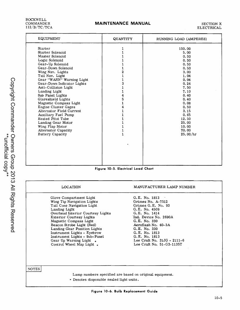
ROCKWELL COMMANDER 112/B/TC/TCA
MAINTENANCE MANUAL SECTION X ELECTRICAL
EQUIPMENT QUANTITY RUNNING LOAD (AMPERES)
Starter 1 150.00 Starter Solenoid 1 5.00 Master Solenoid 1 0.50 Logic Solenoid 1 0.50 Gear- Up Solenoid 1 0.50 Gear-Down Solenoid 1 0.50 Wing Nav. Lights 2 3.00 Tail Nav. Light 1 1. 04 Gear OW ARN" Warning Light 1 0.04 Gear-Down Indicator Lights 3 0.24 Anti-Collision Light 1 7.50 Landing Light 1 7.10 Sub Panel Lights 4 0.40 Glareshield Lights 5 0.40 Magnetic Compass Light 1 0.08 Engine Cluster Gages 4 0.50 Alternator Field Current 1 3. 15 Auxiliary Fuel Pump 1 0.65 Heated Pitot Tube 1 12.50 Landing Gear Motor 1 25.00 Wing Flap Motor 1 10.00 Alternator Capacity 1 70.00 Battery Capacity 1 25.00/hr
Figure 10-5. Electrical Load Chart
LOCATION MANUFACTURER LAMP NUMBER
NOTES I
Glove Compartment Light Wing Tip Navigation Lights Tail Cone Navigation Light Landing Light Overhead Interior Courtesy Lights Exterior Courtesy Lights Magnetic Compass Light Beacon Strobe Light (Red) Landing crear Position Lights Instrument Lights - Eyebrow Instrument Lights - Sub- Panel Gear Up Warning Light * Control Wheel Map Light *
G. E. No. 1813 Grimes No. A-7512 Grimes G. E. No. 93 G. E. No. 4509 G. E. No. 1414
"Ind. Device No. 2690A G.E. No. 330 Aeroflash No. 40-3A G.E. No. 330 G. E. No. 1813 G. E. No. 1813 Lee Craft No. 31JG - 2111-6 Lee Craft No. 51-G3-1135T
Lamp numbers specified are based on original equipment. * Denotes disposable sealed light units.
Figure 10-6. Bulb Replacement Guide
10-5
Copyright C
omm
ander Ow
ners Group 2013 All R
ights Reserved
**unofficial copy**

SECTION X ELECTRICAL
MAINTENANCE MANUAL ROCKWELL
COMMANDER 112/B/TC/TCA
*PITCH TRIM
10-6
ALTERNATOR
n I~
MODEL 112 (4 THRU 187)
II"'I~---------................. *OPTIONAL
EQUIPMENT
LANDING GEAR
n I~@:j (W)
..::::::::;/ ~
* r ,~)@(W@@@
FUEL PIlOT NAY INST
ii LITES LITES
iiii BEACON
* * AVIONICS *
LAND LITE
*
I OUTPUT FIELD ACT SEL ENG FLAPS TURN STALL START NAY NAY ADF GS MB DME XPNDR AUDIO FLAP
&HORN GP COORD WARN & Ace COMM 1 COMM 2
1 I til t 1 1 2 3 4
L LNDG GEAR UP-DOWN RELAYS HYDRAULIC POWER PACK
5 6 7
4. WING FLAP MOTOR 5. TURN COORDINATOR OR TURN &
BANK IND. 6. ST ALL WARNING HORN 7. STARTER
INO
I 8
2. GEAR POSITION IND. LIGHTS GEAR WARN LIGHT & BELL LNDG GEAR POSITION SWITCH THROTTLE & SQUAT SWITCH COURTESY & OVERHEAD LIGHTS (opt. ) FLAP ACTUATED GEAR WARN SWITCH 8. FLAP POSITION fimICATOR
3. AMMETER OIL TEMPERATURE IND. FUEL QUANTITY IND. CYL. HEAD TEMPERATURE
- ................. ALT
LANDING GEAR FLAPS
MODEL 112 (188 THRU 380)
*OPTIONAL EQUIPMENT
FUEL PHOT NAY PUMP HfAT BEACON LITES
"Ii *
AYJONICS *
XIS 12
INST LANO LITES LIH
II * *
ALT
n n r I * r In
~ Iii 'W) ~
-,\ .;~ I~® C® /~
,®) (W '--- ''-~ '@" "~)
ENG FIELD ACT SEl FLAP FLAPS TURN STALL START NAY NAY ADF GS MB OME XPNDR AUDIO OUTPUT GP &HORN INO MOTOR COORD WARN & ACC COMM 1 COMM 2
t r t 2 3 4
1. AMMETE R OIL TEMPERATURE IND. FUEL QUANTITY IND.
t 5
CYL. HEAD TEMPE RATURE
I 6
2. LNDG GEAR ACTUATION RELAYS HYDRAULIC POWER PACK
3. GEAR POSITION IND. LIGHTS GEAR WARN LIGHT & BELL LNDG GEAR POSITION SWITCH THROTTLE & SQUAT SWITCH
I 7
FLAP ACTUATED GEAR WARN SWITCH
1 8 . .
4. FLAP POSITION INDICATOR 5. WING FLAP MOTOR 6. TURN COORDINATOR OR TURN &
BANK IND. 7. STALL WARNING HORN 8. STARTER
COURTESY & OVERHEAD LIGHTS (opt.)
Figure 10-7. Circuit Breakers (Sheet 1 of 2)
X1S 12
Copyright C
omm
ander Ow
ners Group 2013 All R
ights Reserved
**unofficial copy**

ROCKWELL COMMANDER 112/B/TC/TCA
MAINTENANCE MANUAL SECTION X ELECTRICAL
MODEL 112 (381 AND SUBSEQUENT) AND MODEL 112TC
IUfcL PITOT
iiBiN NAV LITES
INST LITES
LAND RADIO LITE MASTER
ii *
* * * * * * * * *
© *PITCH
TRIM
© © © © (Q) (g)-.ol DME 1 2 XPNDR GIS ADF fWs AUDIO
* OPTIONAL EQUIPMENT
CDMM NAV
iiiiiiiiiiiiii 1 2 3 4 5 6 7
1. CARB AIR TEMP.IND. (MODEL 112TC ONLY) 2. LEFT FUEL QUANTITY IND.
VOLTMETER 3. RIGHT FUEL QUANTITY IND. 4. CYL. HEAD TEMPERATURE 5. OIL TEMPERATURE IND. 6. TURN COORDINATOR OR TURN &
BANK IND. 7 < STALL WARNING HORN 8. STARTER
COURTESY & OVERHEAD LIGHTS (opt)
8 9 10 11 12 13 14
9 0 FLAP POSITION INDICATOR 10. WING FLAP MOTOR 11. GEAR POSITION IND. LIGHTS
GEAR WARN LIGHT & BELL HYDRAULIC PRE SS SWITCHES
12. LNDG GEAR UP-DOWN RELAYS HYDRAULIC POWER PACK
13. ALTERNATOR FIELD 14. ALTERNATOR OUTPUT
MODELS 112B/TCA
* OPTIONAL EQUIPMENT
FUEL PITOT ANTI-COL NAV INST LOG STROBE PUMP HEAT LlTES-----
iifli ii *
5 6
t t 7
1
::Fli 00000 ~@) (i) DME GIS fWD AUDIO MKR
RADIO 0 0 000 MASTE R XPNDR 1 1 2 2
COMM - NAV CDMM - NAV
@)@) @@ @) @)
1 1 1 I 1 1 8 9 10 11 12 13
RADIO CIRCUIT BREAKER PANEl
1. COURTESY & OVERHEAD LIGHTS 9. RIGHT FUEL QUANTITY IND. CARB AIR TEMP IND (MODEL 112TCA) 10. TURN COORDINATOR
2. STALL WARNING HORN 11. FLAP POSITION INDICA TOR 3. CYLINDER HEAD TEMPERATURE 12. WING FLAP MOTOR 4. OIL TEMPERATURE IND. 13. LANDING GEAR SELECTOR 5. STARTER LANDING GEAR WARNING HORN 6. ALTERNATOR FIELD 14. LANDING GEAR ACTUATOR 7. ALTERNATOR OUTPUT HYDRAULIC POWER PACK 8. LEFT FUEL QUANTITY IND. AND VOLTMETER HYDRAULIC PRESS SWITCHES
Figure 10-7. Circuit Breakers (Sheet 2 of 2)
Change 2
X210 6
@)
1 14
X210 10
10-7/10-8
Copyright C
omm
ander Ow
ners Group 2013 All R
ights Reserved
**unofficial copy**

Copyright C
omm
ander Ow
ners Group 2013 All R
ights Reserved
**unofficial copy**

ROCKWELL COMMANDER 112/B/TC/TCA
MAINTENANCE MANUAL
PART I DIAGRAMS
APPLICABLE TO:
MODEL 112 AIRCRAFT WITH
SERIAL NUMBERS 6 THRU 187.
SCHEMATIC ABBREVIATION CODES
BW C NC NO GL OVHD RL SW TS 109
Light (Blue-White) Common Normally Closed Normally Open Indicator Light (green) Overhead Light Light (red) Switch Terminal Strip Wire Number
SECTION X ELECTRICAL
10-9
Copyright C
omm
ander Ow
ners Group 2013 All R
ights Reserved
**unofficial copy**

SECTION X ELECTRICAL
Figure
MAINTENANCE MANUAL
WIRING DIAGRAMS INDEX
PART I
APPLICABLE TO: MODEL 112 AIRCRAFT WITH SERIAL
NUMBERS 6 TIffiU 187.
Title
ROCKWELL COMMANDER
112/B/TC/TCA
Page
D.C. POWER IGNITION
10- 8 10- 9 10-10 10-11
LIGHTING
10-12 10-13 10-14 10-15 10-16 10-17
FUEL SYSTEM
.Alternator •.••.......•...•..••.............•..••.••..•.......•...•.•......•• 10-11
.Alternator, Internal Wiring ••.•.•.•.•.••.•..•.••....•••.....•.••.....••...••• 10-12 External Power Receptacle (Optional) ••••..•......••..••••.•...•.••....•....•• 10-13 Starter •......•••....•••...••..•.••.••.•.....•••....••.•...•••••••.•.•..... 10-14
Navigation Lights •.••••..•••.••••••••....••••.•.•.•••.•.•.•••.....•.•.....•• 10-15 Landing Light. . . . • . • . . . . . . . • • . . • . . . . . . . . . . • • . • . . . . . . . . • . • • • • . • . . . • • . • . . . . . .• 10-16 Strobe Lights •••....•.••••...••.•...•..••.•...•••..•••••••..•..•.•.•.......• 10-17 Exterior Courtesy Lights •.•.••.......••.••..••....••.••...•.•..••.•.....•..• 10-18 Interior Courtesy Lights •.•...•••••••••••.••..••••.••••.•••••...•••..•..•.•.. 10-19 Instrument Lights •.••.....•..•••••.•....•••.•••.••...•.••.•..••••......••..• 10-20
10-18 Auxiliary Fuel Pump •.••....•.•.•.......•.....•...•••.••.•••.•...•.....•..•• 10-21
LANDING GEAR
10-19 Landing Gear Actuation and Warning System ••..••.•••..•..•••••.•.•.••..•.•••• 10-22
FLIGHT CONTROL SURFACES
10-20 10-21
INSTRUMENTS
Wing Flap Actuation ...........•.••.•••...•.••......•••....••.•••.•.••..•..•• 10-23 Elevator Trim Actuation ••••..••••..••.•.•.••..••..•.••••••.••.••...••.•...•. 10-24
10-22 Engine and Fuel Gages •..•.••.....••..••••••.•..•.••.•••••••.•.•.•••••.••••• 10-25 10-23 Turn Coordinator Indicator •.•...•.•.••••.•....•......•.....•.••....•..•••.•.. 10-26 10-24 Ammeter .................................................................. 10-27
WARNING SYS'rEMS
10-25 Stall Warning Transmitter •••••..•.•••••.•••...•.•••••••...•••.••.•.•••.•••••• 10-28
MISCELLANEOUS
10-26 10-27
10-10
Cigar Lighter •••••.••••.•...•••••.•••••••.•••..••.•••••••..••.•.•.•.......• 10-29 Pitot Heate r ••••••...•....•... . . • • • . • . • . • . • . • . • . • • . . • • • . • . . • . • . • • • . • . . • . . • .• 10 - 30
Copyright C
omm
ander Ow
ners Group 2013 All R
ights Reserved
**unofficial copy**

ROCKWELL COMMANDER 112/B/TC/TCA
ALT FIELD
REGULATOR
F 1
MAINTENANCE MANUAL
239
OVER VOLTAGE RELAY
REG
0---1--111 19
ALTERNATOR
1----+--+-~ TS-1
20
18
Figure 10-8. Alternator
17
SECTION X ELECTRICAL
ALT
E
10-11
Copyright C
omm
ander Ow
ners Group 2013 All R
ights Reserved
**unofficial copy**

SECTION X ELECTRICAL
10-12
MAINTENANCE MANUAL
r-+ OUTPUT
AUX
I r~ L-__ ~_~===-r _-~
- GROUND
Figure 10-9. Alternator, Internal Wiring
ROCKWELL COMMANDER
112/B/TC/TCA
E
Copyright C
omm
ander Ow
ners Group 2013 All R
ights Reserved
**unofficial copy**
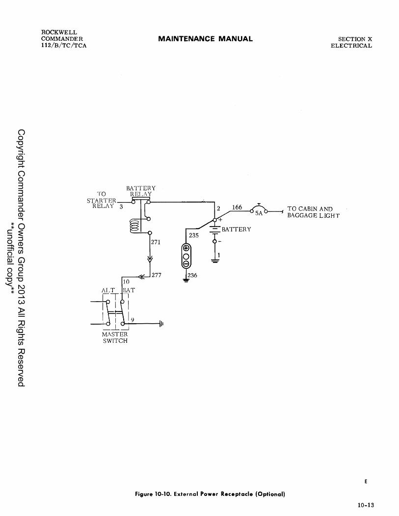
ROCKWELL COMMANDER 112/B/TC/TCA
BATTERY TO RELAY
STARTER RELAY 3
MAINTENANCE MANUAL
2 166
271
10
BAT
MASTER SWITCH
SECTION X ELECTRICAL
O------l TO CABIN AND BAGGAGE LIGHT
E
Figure 10-10. External Power Receptacle (Optional)
10-13
Copyright C
omm
ander Ow
ners Group 2013 All R
ights Reserved
**unofficial copy**

SECTION X ELECTRICAL
MAINTENANCE MANUAL
TO AMMETER ----..;;..----, CIRCUIT
STARTER
14 111-----('] 2S
10-14
LEFT MAG
START SW. 13 2S
10
TOALT FLD-~
TO OVER-VOLTAGE RELAY_~ I C"J-+"""-----III RIGHI THRU TS-l -.l MAG MASTER
SWITCH
Figure 10-11. Starter
ROCKWELL COMMANDER
112/B/TC/TCA
2 166 TO COURTESY LIGHTS
-=-BATTERY
t
E
Copyright C
omm
ander Ow
ners Group 2013 All R
ights Reserved
**unofficial copy**

ROCKWELL COMMANDER 112/B/TC/TCA
MAINTENANCE MANUAL
NAV LIGHTS
Figure 10-12. Navigation Lights
SECTION X ELECTRICAL
E
10-15
Copyright C
omm
ander Ow
ners Group 2013 All R
ights Reserved
**unofficial copy**

SECTION X ELECTRICAL
10-16
MAINTENANCE MANUAL
LAND LIGHT
Figure 10-13. Landing Light
ROCKWELL COMMANDER
112/B/TC/TCA
E
Copyright C
omm
ander Ow
ners Group 2013 All R
ights Reserved
**unofficial copy**

ROCKWELL COMMANDER 112/B/TC/TCA
AERO FLASH CKT
363
MAINTENANCE MANUAL
WHE LEN CKT
POW SUPPLY
350 349
Figure 10-14. Strobe Lights
363
359
SECTION X ELECTRICAL
POW SUPPLY
":" 343 345 344
E
10-17
Copyright C
omm
ander Ow
ners Group 2013 All R
ights Reserved
**unofficial copy**

I-" o I I-" CO
::!! CO C ~
II -o !. U'I
m )( .... II ~ cr ~
n o c ~ .... II lilt
'< !:': CO :r .... lilt
m
TO AUX. POWER RECEPTACLE CIRCUIT
166
l~ATTERY
SA
BAGGAGE LIGHT
283
86
I
TO INTERIOR COURTESY LIGHTS CIRCUIT
I J 8 ~ 286
I HOLDING RELAY __ ---1
307
118
TIME DELAY
CIRCUIT
112
trim t"'ItrI trI() ()~ ~O ~Z ()~ > t"'I
s: » z -I m Z » z (") m
s: » z c: » I""'"
I-" I-"()
"'0 ~~~ ~~() (»~ ~~trI ()trlt"'I >::ct"'l
Copyright C
omm
ander Ow
ners Group 2013 All R
ights Reserved
**unofficial copy**

ROCKWELL COMMANDER 112/B/TC/TCA
60
100
MAINTENANCE MANUAL
START & ACC
335
'--___ 14(ref. )
'----~1~01~---....I TO EXTERIOR COURTESY LIGHTS CIRCUIT
Figure 10-16. Interior Courtesy Lights
29
SECTION X ELECTRICAL
E
10-19
Copyright C
omm
ander Ow
ners Group 2013 All R
ights Reserved
**unofficial copy**

SECTION X ELECTRICAL
10-20
369
371
DIMMER CKT RELAY
r-Ju--: ---. I I
L~ 368
372
MAINTENANCE MANUAL
83
91
374
213
INST DIM
TO LANDING GEAR CIRCUIT
Figure 10-17. Instrument Lights
ROCKWELL COMMANDER
112/B/TC/TCA
E
Copyright C
omm
ander Ow
ners Group 2013 All R
ights Reserved
**unofficial copy**

ROCKWELL COMMANDER 112/B/TC/TCA
MAINTENANCE MANUAL
FUEL PUMP
Figure 10-18. Auxiliary Fuel Pump
SECTION X ELECTRICAL
E
10-21
Copyright C
omm
ander Ow
ners Group 2013 All R
ights Reserved
**unofficial copy**

...... o I ~ ~
"'n
if c .. CD -o .!.. :0 rQ :::s eo: :::s co Q CD o .. ,.. t\
C-o .. C,. :::s Q :::s a.. ~ o .. :!. :::s co \It '< (II .. CD 3
m
FLAPSW. CLOSES AT 2S' EXTENSION
GEAR WARNING
r-,.........rII--+-------' I 64 II 1151 II I BELL II 7st I IS'2( II RL I
\ 1531 II 82; I L_-.JL:~J
257
145
63
250
155
.10 ,130
125
GEAR POSITION SW,
140
144
145
257
124 1154
TO "INST" DIMMER CONTROL
214
GEA~ GEAR ACT SEL
TO 'TLAPS IIOHN" CmClll1 BREAK EH
63
I' T..~ -T -T 'T ~T S/S-4
154
DOWN LOCK MICRO SWS.
~TS-5
I:%JtI.l t""4trl trl(") ("}t-1 t-10 ClZ ~~ t""4
......
s: » Z -t m Z » z n m
s: » z c » r-
~(") ",-0::0 ttlS::O ::rs::("} ("»~ ::r~trl (,,}trlt""4 >::ot""4
Copyright C
omm
ander Ow
ners Group 2013 All R
ights Reserved
**unofficial copy**

ROCKWELL COMMANDER 112/B/TC/TCA
FLAPS
MAINTENANCE MANUAL
Figure 10-20. Wing Flap Actuation
24
FLAP MOTOR
SECTION X ELECTRICAL
NC
c LIMIT SWITCH
E
10-23
Copyright C
omm
ander Ow
ners Group 2013 All R
ights Reserved
**unofficial copy**

SECTION X ELECTRICAL
10-24
MAINTENANCE MANUAL
Figure 10-21. Elevator Trim Actuation
ROCKWELL COMMANDER
112/B/TC/TCA
E
Copyright C
omm
ander Ow
ners Group 2013 All R
ights Reserved
**unofficial copy**

ROCKWELL COMMANDER 112/B/TC/TCA
ENGINE GROUP
MAINTENANCE MANUAL SECTION X ELECTRICAL
TS-l t--+----+~
48
FUEL QUANTITY TRANSMITTERS
36 eYL HD TEMP SENDER UNIT
Figure 10-22. Engine and Fuel Gages
OIL TEMP SENDER UNIT
E
10-25
Copyright C
omm
ander Ow
ners Group 2013 All R
ights Reserved
**unofficial copy**

SECTION X ELECTRlCAL
10-26
MAINTENANCE MANUAL
TURN COORD
Figure 10-23. Turn Coordinator Indicator
ROCKWELL COMMANDER
112/B/TC/TCA
E
Copyright C
omm
ander Ow
ners Group 2013 All R
ights Reserved
**unofficial copy**

ROCKWELL COMMANDER 112/B/TC/TCA
TO MAGNETO STARTER SWITCH STARTER CIRCUIT
14
MAINTENANCE MANUAL
START &ACC
EXTERNAL
4
SHUNT TO STARTER 13
B S START SW.
TO AL T FLD--+-l"l
r---rE--------' 277 10
TO OVER-VOLTAGE RELAY I II THRU TS-l -L
MASTER SWITCH
Figure 10-24. Ammeter
SECTION X ELECTRICAL
166 TO EXTERIOR LIGHTS CIRCUIT
-=-BATTERY
t
E
10-27
Copyright C
omm
ander Ow
ners Group 2013 All R
ights Reserved
**unofficial copy**
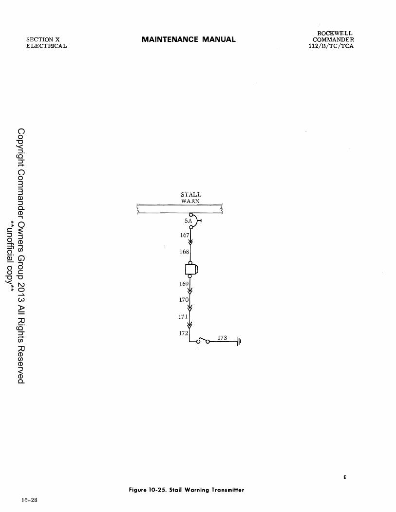
SECTION X ELECTRICAL
10-28
MAINTENANCE MANUAL
STALL WARN
_1 7_3----i/1 I
Figure 10-25. Stall Warning Transmitter
ROCKWELL COMMANDER
112/B/TC/TCA
E
Copyright C
omm
ander Ow
ners Group 2013 All R
ights Reserved
**unofficial copy**

ROCKWELL COMMANDER 112/B/TC /TCA
MAINTENANCE MANUAL
START StACe
56
r=-I . I I I I I 1
Figure 10-26. Cigar Lighter
SECTION X ELECTRICAL
E
10-29
Copyright C
omm
ander Ow
ners Group 2013 All R
ights Reserved
**unofficial copy**
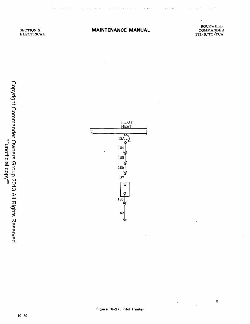
SECTION X ELECTRICAL
10-30
MAINTENANCE MANUAL
PITOT HEAT
Figure 10-27. Pitot Heater
ROCKWELL COMMANDER
112/B/TC /TCA
E
Copyright C
omm
ander Ow
ners Group 2013 All R
ights Reserved
**unofficial copy**

ROCKWELL COMMANDER 112/B/TC/TCA
MAINTENANCE MANUAL
PART II DIAGRAMS
APPLICABLE TO:
MODEL 112 AIRCRAFT WITH
SERIAL NUMBERS 188 THRU 380.
SECTION X ELECTRICAL
10-31
Copyright C
omm
ander Ow
ners Group 2013 All R
ights Reserved
**unofficial copy**

SECTION X ELECTIUCAL
MAINTENANCE MANUAL
L FWD T-STRIP "A" 2. SUB PANEL/FWD (FW & ENG) 3. AVIONICS POWER 4. INSTR. PANEL/GLARESHIELD 5. MAIN HARNESS/RIGHT WING 6. MAIN HARNESS/LEFT WING 7. STEP LIGHT RELAY 8. MAIN HARNESS/BATTERY COVER 9. AFT T-STRIP "B"
10. SUB PANEL/INSTR PANEL 11. SUB PANEL/AFT (WING & FUS) 12. INSTR. PANEL/AFT 13. INSTR. PANEL/FWD
Figure 10-28. Connector and T -Strip Locator
10-32
ROCKWELL COMMANDER
112/B/TC/TCA
X210 (\
Copyright C
omm
ander Ow
ners Group 2013 All R
ights Reserved
**unofficial copy**
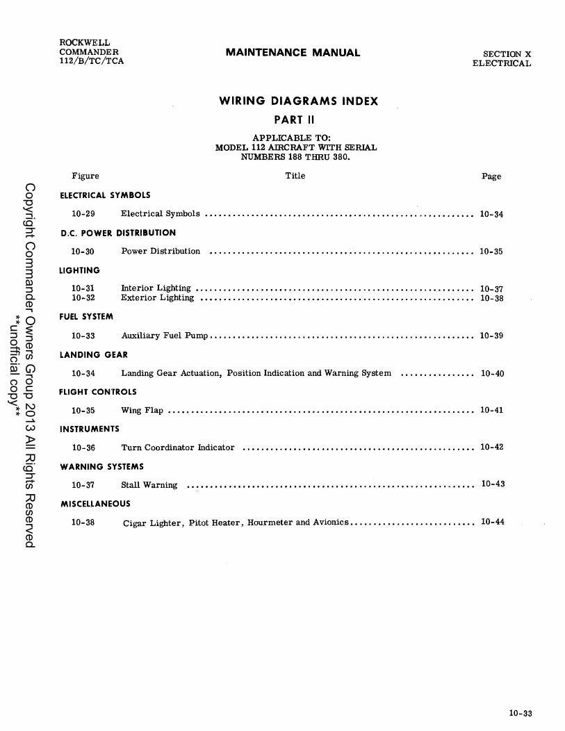
ROCKWELL COMMANDER 112/B/TC/TCA
MAINTENANCE MANUAL SECTION X ELECTRICAL
Figure
ELECTRICAL SYMBOLS
WIRING DIAGRAMS INDEX
PART II
APPLICABLE TO: MODEL 112 AmCRAFT WITH SERIAL
NUMBERS 188 THRU 380.
Title Page
10-29 Electrical Symbols •••••••...•.••••...••...•.•••.••.•.••..•••..•......•..•••• 10-34
D.C. POWER DISTRIBUTION
10-30 Power Distribution ••• . . . • • • . . . • • . . • • •• . . • • • . • • • • • • . . . . • . • . • . • . . • . • •• . . . . • .• 10-35
LIGHTING
10-31 Interior Lighting •....••••.•••.•••.•••...•.•.....•....•..•.......•.•••.•••••• 10-37 10-32 Exterior Lighting •••••.••••••...••.•••.•••••.••....•.••.••..•.......••....•• 10-38
FUEL SYSTEM
10-33 Auxiliary Fuel Pump. • • • . • • • . • • . • . . . • . • . . . • . • . • • . . . . • . . . . . . • • . . . . • • . • . • • • • • •• 10-39
LANDING GEAR
10-34 Landing Gear Actuation, Position Indication and Warning System • • . • • . . • • • • . . • •• 10-40
FLIGHT CONTROLS
10-35 Wing Flap •••••••..•.•••..•••••••••••.••••..••••.•••••.••••.•••••.•••••••••• 10-41
INSTRUMENTS
10-36 Turn Coordinator Indicator •.•.••••.•.•.•••.•••.•••••.•••••.•••.•..•.•....••• 10-42
WARNING SYSTEMS
10-37 Stall Warning • • • • • • • • • . • • • • • • • . • • . • • • • • • • • • • • . • • • • • . . • • • • • . • • . • . • • • • • . • • . •• 10-43
MISCELLANEOUS
10-38 Cigar Lighter, Pitot Heater, Hourmeter and Avionics. • . •. • • . • • • • • . • . • • • . • . • • • •• 10-44
10-33
Copyright C
omm
ander Ow
ners Group 2013 All R
ights Reserved
**unofficial copy**

SECTION X ELECTRICAL
SYMBOL
I I
• [>
• 0
?--c:>--
d'---__ --'P
q p
10-34
DESCR
CABLE- SINGLE CONDUCTOR SHIELDED
-MULT I CONDUCTOR SHIELDED
BUTT SPLICE
KNIFE DISCONNECT
CONNECTOR
TERMINAL-SOLDER TYPE MOMENTARY
-SOLDERLESS MOMENTARY
-SOLDER TYPE MAINTAINED
- SOLDERLESS MAINTAI NED
-T-STRIP OR T-BOARD SOLDER TYPE
-T-STRIP SOLDERLESS
FUSE
CIRCU IT BREAKER - PUSH PULL
-SW TYPE
G ROU NO-AIRFRAME
-CASE (INTERNAL)
RESISTO R - FI XED
- ADJUSTABLE
CAPACITOR
DIODE
MAINTENANCE MANUAL
SYMBOL
o D
o ~~-~-1 0
DESCR
LAMP
RELAY
POWER RELAY J CONTACTOR
MOTOR GENERATOR ALTERNATO R
ELECTRICAL EQUIPMENT (OTHER THAN MOTOR, GEN J ETC.)
SWITCH -S PS T
-SP 3POS
-SPDT
-DPDT
-DP 3 POS
-PUSH BUTTON PUSH TO MAKE
-PUSH TO BREAK
_PUSH BUTTON 2 CI RCUIT
Figure 10-29. Electrical Symbols
ROCKWELL COMMANDER
112/B/TC/TCA
CODE DESCR LTR
BUTT SPLCE BC
CIRCUIT BREAKER CB CtRCUI T BREAKER SWITCH CBS CONNECTOR- PLUG P
-RECPTACLE J
FUSE F
T BOARD T
GENERAL NOTES:
E.I'''''MPLE OF W/R£ COLJE:
fEPZ~2~~Jf//RE GA. L- WIRE SEGME,VT LETTER WIRE NUMBER C'/Rt:'U/T FUNCTION LETTER UNIT II/UMBER-II/UMBER I LJEAlOTEJ' lEFT AAlO A/UA./SER 2 lJEA/OTES .e'GIiT WII&V /OEII/TICAL WIRE A/L/MI3'ER .4PPE/U'J' /11/ DL/.4L (L/R) t'IRL'L/IT
• C'/Rt:'L/IT FUlI/eTIOII/ LETTER
AJ'SIGAlMEAlTJ' ARE AS' FOLLOWS:
C' - COII/TROL SL/RFACE D- IAlJ'TRL/MEII/T (OTHER TH.4/l/
FL/GHT OR EIIIGIIIIE) E- Eli/GIlliE //l/S'TRL/MEII/T F- FIIGIIT IAlS'TRL/,MEII/T S - SEAr L'OAITPOL N- NE""TII//G .17M? OE·IL'IIVG c/ - /GII/IT/O/1/ K - EA/GIIVE C'OIl/TROL. L - LIGHTI/VG M- MIS'L'EL.LAAlEOL/S EL.Ee. p- DC POWER Q - FUEt:. ""IVO Oft:. W- WARM. AAlL? EMERGEII/CY
Copyright C
omm
ander Ow
ners Group 2013 All R
ights Reserved
**unofficial copy**

ROCKWELL COMMANDER 112/B/TC/TCA
MODEL 112 188 THRU 225 .
~ £#6IN£
£N~/NE ~20VND S7RAP
~ fiREWALL
~ ~JII
n I '±:T-CA:? ~4 I I
/f'C.!"CJ r;.Y",,"£1
!'PEL
,( s/tfOl" ~ h :%
MAINTENANCE MANUAL
Figure 10-30. Power Distribution (Sheet 1 of 2)
SECTION X ELECTRICAL
TO /NTEII!/{)R -{> l.I6HTIN6 CKT
V(6)
10-35
Copyright C
omm
ander Ow
ners Group 2013 All R
ights Reserved
**unofficial copy**

SECTION X ELECTRICAL
MODEL 112 226 THRU 380
10-36
~ .t/VG/NE
£tIC/N'£ GROUND STRAP
MAINTENANCE MANUAL
/5 .-----+---------~
Figure 10-30. Power Distribution (Sheet 2 of 2)
ROCKWELL COMMANDER
112/B/TC/TCA
TO INTERIDR. LfGHTIN6 CKT
TO INTEIlIOR Ll6!1T1NG CKT
Y(6.1)
Copyright C
omm
ander Ow
ners Group 2013 All R
ights Reserved
**unofficial copy**

..... o J
W ...:J
-n cO" e ... CD .... o I
~
;:, ~
CD ~" o ... !:
CO
[ ;:,
CO
c :§
L2A??
'~Al'O
l_." f
PI
T2-:"r'~2~-~~r2r' ~ U,IIZZ ~ 0822' )
-INJ'Tr ,.MlEf i"L1700il6NTJ'-··UE.l,l
____ .J
't' RADIO 01'"
M#GI¥ET/C t'o,v""",r,r / T_ c::
GAl012(R'EF/
<'''' LH8ZR(L'£F)
\'Y -l'(
TO POWER DISTRIBUTION CIRCUIT TtJl.fE rO"K£r~o -~
o It 0 ~\ @)) r a2A22 <I: lHA2Z(L'EFJ ----1 ~ Ll1fU?O (REF)
~. ~~ 1 rL A~r) (',p ~r) OPT/<7NAL ~L 7NZZ----"1NC ' OPPCM':4L ("OilIYlc.iVofAVt'E
l7t;?'! i.I~ 22 S t I J J
i v::;;, ""'0- r-( (L FtW.:J -~-c-U2::--+~~~oJ J.) ~'[f.11r ~I~'~';A
~_t.7EZii!_~hI(' C iii] 4 7 ~ I L~~~~
L22£ GAllJ GAIl) l22{
LZft LJr 22
L'1'2 ~ 22 i198.i?2
C"/f1llV REAt)j,l/~ '-T~
I ~ \ "A:~~ _ ":'1-1 ~-,(~-(~~l
L LlZ'E~;? -l2"B22'--~lI"A22-- __ ~ y~ LVA22 ~~f:~ 2---~_ I'll __ $ 12 V
OPT/Oil/Ai 3 4 eOPILor T L (lOA?;?
6'AlD?LJ
~ 1 ENTiIA/ICE SW
1£15822 ?LISS2.?
1t.lr.A.?Z 12L1r.An IOG')f~.-r:orT l/G#~ __ _
'--~ ~NrTR P.lIV£L If" l'TE""lT- t ST£P tT~
L 78'~ JGAlO JGN/) ,'-" -22 ·i!R
---!--"-I ",:UMU v,,~'" 1 J
'4820
~~~Fn r.~ ':mJ' l:·"'l::""'CK "l." ~ ~ ~ ~ ~ ~ ~
-----RI6NT -----
L___ rOB P/lII/£t.. r:t.aao //8#T1'
T 0 !:H~ofr OISTR.18UTIDfJ
-- .--- ..
SUIP.IV£L
..... nl-Pt ~o5 ~~~
~~~ ~t11:"4 nl:%1l:"4 >~
1:%1
3: ~ Z -t m Z ,. z n m 3: ,. z c ,. r-
1:"4 I:%1CfJ (')1:%1 ~(')
~g >z 1:"4:><
Copyright C
omm
ander Ow
ners Group 2013 All R
ights Reserved
**unofficial copy**

.... o I
t..) 00
" cO' c .. 41)
o I
Co)
"" m )(
i :!. o ... r-to' ~ ::I
CD
~ sa
r-1,(2IA/.,
1"'7
ILl'IBfiIII.
~ lUI'D-I"
"ND['''' lH WING TIP
NAV LT
I C~.~~ ,~V~~ !tl ,~,4l/laAT/OII/ r ;;GNTr C6 •
,,'T~
Ef L l!'l8 14
T.46\--~ ?LElA!"
,27C'1" '[>L2'8814
rt> 17.11.0·1' ri>
QAII}-I"
tl!7D~i~)7E'" ",.[DI.
RN W,IHii TIP NAV Lr
TAIL NAV LT
1"'7
11.35818
L IVIIVG T/P .J'/"ROBE LT-
f{~~) 15' .f
F· L34.414_-1
L'[>1MI'II
70 ~7~04< " C OJ I P5
"'.,. ¥l L[91114
.H~ (
"'t.4fNEk BE.4COIIJ Pt'JWEk S-UPPLY
L?9D14 • L29t!14
k /U35'8f8 • I I
L 3 .. ,4/8
IIL,.y", RED
WHT
<1-k~
~ PED I ":'NT .e IWIIIG'
polI/£R S'UPPLY-
L' WIAtG T/I" .rTRD8£ LT-
TAIL STR08€ L T-
VEL
~I.t f?~
<k=ffL ytJ (Q)
M/iCOA/ S/"/l4ItlZER)
~ L~ :u~-2J
L 31/118
L,411/011VC iT C'BS6
1"'4
L 318/8'
t./lII/DIAJG LICilT-
tr1Ul t-ttr1 tr:j(') (')~ ~~
~~ Q><: t-t
....
~ » 2 -t m 2 l> 2 n m
~ l> 2 C l> r-
~(') tJjO~ ,;S:O ~;s:~ ('»~ 4Ztxj (')~~ >~t-t
Copyright C
omm
ander Ow
ners Group 2013 All R
ights Reserved
**unofficial copy**

ROCKWELL COMMANDER 112/B/TC/TCA
MAINTENANCE MANUAL
LLijr"c-U"R PURl" t"PS/
t{J1'A'?CJ
Figure 10-33. Auxiliary Fuel Pump
SECTION X ELECTRICAL
U(11)
10-39
Copyright C
omm
ander Ow
ners Group 2013 All R
ights Reserved
**unofficial copy**

"""" <::) I
"J:o.. <::)
."
cO' e ... (II
0 I
W ~ .... Q :I
e: :I to
Q CD Q ... ,. !l e Q =-. 0 EJ ." 0 =.. o· :I
;-Q. ;;;. Q -o' :I
Q :I Q.
:e Q ... :!. :I to CIt '< CIt -CD i
/.bfI'8.a:J
L.
c: 3
L----2D4BlO
ID6fl20
D9C2D
~'Ot20
3 4
P2
D~D
P3~ ()91l20 OlOR2D
Dle?O
.----+---- /.i7fBi?O -----t--{ ) I 2)/~#.?cJ -----(/"""" )-----£'.5'~Z;;I -------------!I---i
£'
.-----------~2)~BCL/ ------------
SA'LJ CL/A'/~/ S'W
1'+-1 ~ I C7t9?O S5CC'LJ I ~ : l~ __
S?CCL/
CBB?o-i_
trlUl t""trl trl(") (")f-3 f-3-;:g~ ~>< t""
....
3: » z -I m Z » z o m
3: » z c » r-
.... (") NO tJjs:~ ~s:~ ("»~ ::tStrl Otrlt"" >~t""
Copyright C
omm
ander Ow
ners Group 2013 All R
ights Reserved
**unofficial copy**
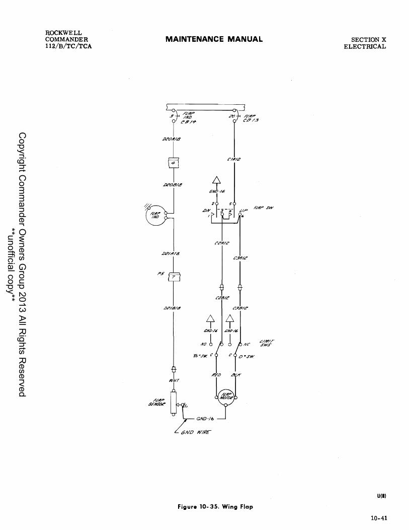
ROCKWELL COMMANDER 112/S/TC/TCA
MAINTENANCE MANUAL
Ljr Rd'r" /#,lJ t:'8/9'
.P.?t7",,/B
~ 2l?t7B/4
~ ~ CAlb-/£ 6/Y~-/16
/YO b l /Vc
3S ".I'll( C
Figure 10-:35. Wing Flap
SECTION X ELECTRICAL
U(8)
10-41
Copyright C
omm
ander Ow
ners Group 2013 All R
ights Reserved
**unofficial copy**

SECTION X ELECTRICAL
10-42
MAINTENANCE MANUAL
Figure 10-36. Turn Coordinator Indicator
ROCKWELL COMMANDER
112/B/TC/TCA
U(8)
Copyright C
omm
ander Ow
ners Group 2013 All R
ights Reserved
**unofficial copy**

ROCKWELL COMMANDER 112/B/TC/TCA
MODEL 112 4, 188 THRU 334, AND 336 THRU 380.
5TALL WARNING
HORN
MAINTENANCE MANUAL
MODEL 112 335
STALL WARNING
HORN
WI1320
SECTION X ELECTRICAL
W2A'20
STALL WARNING SWITCH
W2D20
NQIIMW2~20 NORM OPEN b (CLOSED
COMMON
GND·20
7
I W2A20~
WZ'B2.0
Q,ND~I-203_20 3 W2.EZO
l <l~ AIR
Z-20
GND.coII'TAcr Sill.
WZM20
[!W2L20
TFST 5W.
mr \NMM'
$"3 WZC2.0
~==~ P7
Figure 10-37. Stall Warning
STALL WAP.NIIIG SWITCH
U(8)
10-43
Copyright C
omm
ander Ow
ners Group 2013 All R
ights Reserved
**unofficial copy**

SECTION X ELECTRICAL
PIO I 1 Z
F28/8 ;:3818
9 .3 10
MAINTENANCE MANUAL
+0 ~ I
;' 4- 5 S 7 81
~~----------------#Y/~/JV/~~ __________________________ --J1
) -.J /~:rr ~A' C..9.5".t!?
11'/#/9'-
,,07 2
ROCKWELL COMMANDER
112/B/TC/TCA
L ==oJ
r\~ sU'.t.t
Or WA'f'1V /."8//
N/#/I!J
/0
MZA22--@
U(11)
Figure 10-38. Cigar Lighter, Pitot Heater, Hourmeter and Avionics
10-44
Copyright C
omm
ander Ow
ners Group 2013 All R
ights Reserved
**unofficial copy**

ROCKWELL COMMANDER 112/B/TC/TCA
MAINTENANCE MANUAL
PART III DIAGRAMS
APPLICABLE TO:
MODEL 112 AIRCRAFT WITH SERIAL
NUMBERS 381 AND SUBSEQUENT AND MODEL 112TC.
SECTION X ELECTRICAL
10-45
Copyright C
omm
ander Ow
ners Group 2013 All R
ights Reserved
**unofficial copy**

SECTION X ELECTRICAL
MAINTENANCE MANUAL
10-46
1. FWD T-STRIP "A" 2. SUB PANEL/FWD (FW & ENG) 3. AVIONICS POWER 40 INSTR. PANEL/GLARESHIEW 5. MAIN HARNESS/RIGHT WING 6. MAIN HARNESS/LEFT WING 7. STEP LIGHT RELAY 8. MAIN HARNESS/BATTERY COVER 90 AFT T-STRIP "B"
10. SUB PANEL/INSTR. PANEL 11. SUB PANEL/AFT (WING & FUS) 12. INSTR. PANEL/AFT 13. INSTR. PANEL/FWD
Figure 10-39. Connector and T -Strip Locator
ROCKWELL COMMANDER
112/B/TC/TCA
X2108
Copyright C
omm
ander Ow
ners Group 2013 All R
ights Reserved
**unofficial copy**

ROCKWELL COMMANDER 112/B/TC /TCA
MAINTENANCE MANUAL SECTION X ELECTRICAL
Figure
ELECTRICAL SYMBOLS
WIRING DIAGRAMS INDEX
PART III
APPLICABLE TO: MODEL 112 SERIAL NUMBERS 381 AND
SUBSEQUENT, AND MODEL 112TC
Title Page
10-40 Electrical Symbols ••.•.••.••...••....•....•..••....•.••..•..•.•...•.•••••••• 10-48
D.C. POWER DISTRIBUTION
10-41 Power Distribution • . • . . . . . . . . . • . . . . . . • . . . . . . . • • . . . . . . . • . . . . . • • . . . . . . . . . . • •• 10-49
LIGHTING
10-42 Interior Lighting •.••....•.•.•.•••••••....•••..•.•••.....•..••......•.••...•. 10-51 10-43 Exterior Lighting •••.••••..••.•••••.••••••••••••••••••..•••••.......••....•• 10-52
FUEL SYSTEM
10-44 Auxiliary Fuel Pump. • • . . . • • • • . . • • • . • . • . • . . . • . • • • • . . • • • • • . • . • . • . • • • . • . • • • • • •. 10-53
LAN DING GEAR
10-45 Landing Gear Actuation, Position Indication and Warning System •..••••••••••.•• 10-54
FLIGHT CONTROLS
10-46 Wing Flap ••.•.•••••.••...••..••.•..••...•..••...•.•••.....•.•.•...•.•...•.. 10-55
INSTRUMENTS
10-47 Turn Coordinator Indicator •....••••....•.•........ . . . . . • . . • . . . . . . . • . . . . . . . •• 10-56
WARNING SYSTEMS
10-48 Stall Warning • • • • • • . • . . . • . • . . • . • • • • • • • . . •• . • . . . . . . . . . . . . . . . • • . • . . • . . • . • . . .• 10-57
MISCELLANEOUS
10-49 Cigar Lighter, Pitot Heater, Hourmeter and Avionics •.....•.••••....•••....•••• 10-58
10-47
Copyright C
omm
ander Ow
ners Group 2013 All R
ights Reserved
**unofficial copy**

SECTION X ELECTRICAL
SYMBOL
1 I
..
• o
-
d P
q P 6
~
10-48
DESCR
CABLE- SINGLE CONDUCTOR SHIELDED
-MULTI CONDUCTOR SHIELDED
BUTT SPLICE
KNIFE DISCONNECT
CONNECTOR
TERMINAL- SOLDER TYPE MOMENTARY
-SOLDERLESS MOMENTARY
-SOLDER TYPE MAINTAINED
- SOLDERLESS MAINTAINED
-T-STRIP OR T-BOARD SOLDER TYPE
-T-STRIP SOLDERLESS
FUSE
CIRCU IT BREAKER - PUSH PULL
-SW TYPE
GRDUND-AIRFRAME
-CASE (INTERNAL)
RESISTOR-FIXED
- ADJUSTABLE
CAPACITOR
DIODE
MAINTENANCE MANUAL
SYMBOL
o
OESCR
LAMP
RELAY
POWER RELAY J CONTACTOR
MOTOR GENERATOR ALTERNATOR
ELECTRICAL EQUIPMENT (OTHER THAN MOTOR I GEN J ETC.)
SWITCH-SPST
- SP 3 POS
-SPOT
-OPOT
-DP 3 POS
-PUSH BUTTON PUSH TO MAKE
-PUSH TO BREAK
PUSH BUTTON 2 CI RCUIT
Figure 10-40. Electrical Symbols
ROCKWELL COMMANDER
112/B/TC/TCA
CODE DESCR LTR
BUTT SPLICE Be
CIRCUIT BREAKER CB CIRCUI T BREAKER SWITCH CBS CONNECTOR- PLUG P
RECPTACLE J
FUSE F
T BOARD T
GENERAL NOTES:
E..Y.#MPLE Or WIRE CLUJF:
r~pz~.?~~W/RE GA L- WIRE SEGMEVT LETTEI? WleE IIII/M81i/? C"IPL'LlIT I'"I/III(,TIOIII t.G'TTER tlIIIIT IIII/MBER - A/tlMBER I NIlIOTE.r ~E"'T AllIb A/I/MBEe .? bFAlOTES' R/G/,IT W/,IEIlI tbEA/TICAt. wtRE AlUMBER .#PPEAR.r 1M DUAt. (t./K:) L'IRL'tlIT
• t!:"IRCtl/T FtlllICTIOIl/ LETTER
.-f.rS'ltiIllMEIlITS' ARE AS' ".oaow.$':
C' - COIIITROL SURFACIF D- IAlS'TRUMEIlIT rOT/,IIFR T/,I.#III
FtlGNT oe EAlGIAlE) E- ENG/AlIF INSTRUMEIIIT F- ,t:'//G/,IT IIIIS'TetlMEA/T G - SEAR /!OA/TPOL. JI- NE.#TIIlIS AAiD OE·IL'IIIIS .t - ISA/ITIOII/ K - EA/GIAIE t'OIllTROL L - tlGIlTIAlG M- MIS't:'ELL'#A/EOtlS' ELEC'. P- PC' POIVER Q - ,t:'tlEt. /lA/D OIL W- WARIV. AII/P EMERG£MCY
Copyright C
omm
ander Ow
ners Group 2013 All R
ights Reserved
**unofficial copy**

...... o I
Hlco
:!! (Q c: .... CD
o I
!= ." o • CD .... 2 en ... ~. ac: ... o· ::::J
;; :r CD !.
o -I'IJ -
-< C;; t!
ENGINE GROUND STR,Ip
?t; FIREW~LL
T.H/" .sY~.r
%
P4A6
£',.«1
£"81'0
/5
P/ZtJ/4
r~I"~
r /'/1814
/'IJ'AI4
/"c
9 /"-'#.4'
K j % /,,74/4
J=r /"eAl!>
II( 1\ /",7'#/8 T
~ £7'20 EBAcO ""'r ,.;::;.~ '*',., r
• OA~ 'M~CM H¥,T J/YJY./"
Ef'/I'2't:J EJA>?LJ j ~~~' /"J' car '\
(~
K K;#/4
(~
,K
K""/I'/4
M~~ ~ 2 RrtlELfot's_ ;"', .:F
E.u.v C ?/LW4 b"" E9'.&"l? T ~ ~
'4 " ----I TD /mE'''' n .. I> LlQNT/H. <lKeUIT
B ,ff'," ?/A!
/:, ~.?.o
.... ,..." '/"..-
Er/ I"'Wf flU'&'
,~, ! ~
a: 9 l1j 1:-1 ...... ...... ,.N
w 0:> ......
~ ::tI c:: Hl-,...'l 0
...... ("')::tI ~oo ,~n IJ:J~~ ~>~ ("')zl1j ,01:-1 t-3trj1:-l n~ >
l1j
s: ?! z -t m Z » z (') m
s: » z c » ....
1:-1 l1jOO nl1j t-3()
~g >Z 1:-1~
Copyright C
omm
ander Ow
ners Group 2013 All R
ights Reserved
**unofficial copy**

SECTION X ELECTRICAL
MODEL 112, 471 AND SUBSEQUENT MODEL 112TC MODEL 112B, 477 ONLY
C:;)
~ ~ \!)
~ ~~ ~ <'~
~ 4.!'-)
.... ~ ~
MAINTENANCE MANUAL
'-I
~ ~ ~ ~
&
Figure 10-41. Power Distribution (Sheet 2 of 2)
10-50
ROCKWELL COMMANDER
112/B/TC/TCA
Y(6.3)
Copyright C
omm
ander Ow
ners Group 2013 All R
ights Reserved
**unofficial copy**

....... o I
U1 .......
."
cO' c ... CD
o I
.f:I,. 1'1.)
:::s (j) ~. o ... .... ca :r -:::s ca
CI)
~
,-------LZg2Z------------~
(2r2Zl:E2ZIZDZZ:fCZZ
SL:'IA22' @ l313ze ~L"Cn ~ L30Z'Z"
'"
5 i ~7: !}B#Tr
~ L3/JAZ2 LI41!!D
R~£I10lJ1M
i4A?O
M#G'I1IETIC (!,OHPA'I'I' LT-
C.4BIN ,f'EAO/A!G'LT-
TL/5E J'Ot!KFT TO POWEr? DISTKIBUT/LJN CIKCUIT
(REF)
TO FLEe BAGGAG'E
L 2'31120 L"t:JMPT. ZKXJR
L2 8 L2'41122 r-- SiY-
3 __ !.J /2 [§"B22 LI:: ('
~!' ?_. Ql [:-tJ LIt!~LI9A
7 ~ I ~ n n
W8P2- r,!l" . 'll' "ff Sf! Sf! 'm ' e ~"'A22 V .-L, Z2
P"OT aP"o;v~, _ V m822
p~"'n ,,,,.'" f ~ I COM. A'GE
I
"~BF2 EN"'" "-e--J PT LT-
ILI .. AZZ I E SW 2LlliAZZ R .>'TEPLT- i STEP LT_
f
PI
£482£1
r<4m ¥::022],2 l~'GF2'CHe2-", Q3 (j tif ~ g: g: ---LEFT------------ -------R'IGf.lT ---
L .. ~""_". SL/B PA'MFL rLOOl) UB#TJ:'
St/8 P~4./EL
TlJ POWERDI~T/W3UTltw CIflCUIT
~('):::t' 1:\:)00 ~~R ,,~=S C:S~t:\j ~~t""' Ot::lt""' >~
trl
~ ~ Z -t m Z » z n m ~ » z c » r-
t""' trl Ul Otrl ~O
~g ~Z ~>4
Copyright C
omm
ander Ow
ners Group 2013 All R
ights Reserved
**unofficial copy**

~ o I 01 t>-.:I
"" <C' c: ... (I)
o I
~
~ m )(
;-... O· ... !::
CO
! ~
CO
~ ~
C"8S 4'
~----( T,Al6 J------,
TAIL NAV LT
l?iI W1IJG TIP NAV LT
L. fWllIe PONE'£' S'(I;>PLY~
iT
STROBE 3
FL.4Sh'ER' BE.4COAI POWER .,f(l)"PL Y
L£79814
I IL35"418
P7
~ RED ---1 8Lr-t>
2L3-![B18
YEL)
<J-R!7n ~
RED I ~lIr R 1/1111/6' PtJWER S"LlPPLY-
RE.m~l~lIr Rio 'I R.r;;m~lrl WilT
~u: WilT
TIP .e ft/III/G TIP L~ ~~OBE'L~
T//IL STR<J8E L T-
FLASPER BE,AlC{]t!J (t/ERTIC'IU. ST,AlEJIt.li?ER)
L37#18
P4
£37818
LAII/DI/!/S LlGPT-
6'AlO AT SAM? LOL'ATIOA/ 1'1S" AL TFRNATcU?
tt:lUJ t"4tt:1 tt:I(') (')~ I-jl-l
21~ ~~ t"4
....
s: » 2 -I m 2 » 2 o m s: » 2 c: » r-
~(') tJj0~ ,~O I-j~R ('»~ ~Stt:l (")tt:lt"4 >~t"4
Copyright C
omm
ander Ow
ners Group 2013 All R
ights Reserved
**unofficial copy**
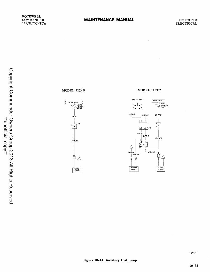
ROCKWELL COMMANDER 112/B/TC/TCA
MAINTENANCE MANUAL
MODEL 112/B MODEL 112TC
PR/ME rw-
Figure 10-44. Auxiliary Fuel Pump
SECTION X ELECTmCAL
U(11.1)
10-53
Copyright C
omm
ander Ow
ners Group 2013 All R
ights Reserved
**unofficial copy**

l-" o I
<:.TI .;..
::!! CO c: ., (I) ... o I
~ U'I
rQ :::I
~ :::I
CO
o (I)
Q ., » '" C 2-o·
... :::1
"'D o ~: o :::I
:::I
~ '" g.. o :::I
Q :::I Q..
=e Q ., :!. :::I
CO
U'I '< CIt
;; 3
c
~
DIIA20
1----2D4132.0 /ZJ9-BaJ
.---+---- /PfBRtJ ----t---<
/,7 F. =====;:;; ~8~~=~~===~~~
1JI ..cw
LaoA'
'---='-"-- CEh'R .Pt?S/)7CW /#LJ/Ch'7tJR ( SIYOW/1/ /A/ LJA/ L..:7CK .A:!5'///..:7"v )
o~ u/' - --- .tW ~,pfIf' C.aY/~
LJUC'?O ~ 413 I SW
j,.~ r c;",v..:7 rO I~ • DIBC2tJ---------t
"+------DIJS?..:7---____ --' &Y"#?..:7
r===~---;.! /' J7
P$'?A'/L7~
----I BLU
L ~k _I GJPN \7
- L-.£FA'/"'~
tr1cn t'4tr1 tr1 Ci CiI-3 1-30 ~Z Ci>:l > t'4
s: ~ Z -I m Z l> Z n m
s: l> Z C l> r-
l-" l-"Ci t.)O t13-~e5 ~~Ci Ci>~ ~@tr1 Citr1t'4 >~t"'
Copyright C
omm
ander Ow
ners Group 2013 All R
ights Reserved
**unofficial copy**

ROCKWELL COMMANDER 112/B/TC/TCA
MAINTENANCE MANUAL
y y C#,l)/6 C/Y,/J-/6
/YO 1 ! 35 '.f'N: C
GND-/h
GNO WIRE"
Figure 10-46. Wing Flap
SECTION X ELECTRICAL
Y(8.1)
10-55
Copyright C
omm
ander Ow
ners Group 2013 All R
ights Reserved
**unofficial copy**

SECTION X ELECTRICAL
10-56
MAINTENANCE MANUAL
Figure 10-47. Turn Coordinator Indicator
ROCKWELL COMMANDER
112/B/TC/TCA
V(8.1)
Copyright C
omm
ander Ow
ners Group 2013 All R
ights Reserved
**unofficial copy**

ROCKWELL COMMANDER 112/B/TC/TCA
MAINTENANCE MANUAL
STALL WARNING
HORN
TEST [iW2L2()~
rW2M20
SU/. \
TE~r NOI"tM,
Figure 10-48. Stall Warning
P7
STALL WAPltmlG 5WI TC If
SECTION X ELECTRICAL
Y(8.1)
10-57
Copyright C
omm
ander Ow
ners Group 2013 All R
ights Reserved
**unofficial copy**
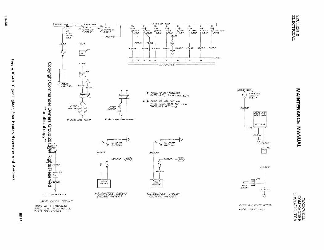
..... o I
U1 00
-n cO' c (0 .... o I
~ -0
n (Q
Q ... r
(Q :r ~ ~ ... J! a J: CD Q
~ J: o c 3 CD
~ ... Q :::s a..
» :::. o :!. n lit
~ --"
[MAI,vS:Sr
0°7.4Li W4RIII. C'B8
M/,4/8
10
~'CI6AR LlGhlTER-
641LN!O
~022B20
~P5 "T'
PITOT I'IE,4TER-
* DUAl. TlJr£ f/J:ATER
(TO CO/l/I/E/l//E/l/CE
FLee CLOCK' C'lRCU'1 T
noon liZ, 4-71 liND SLJBs: !"JODEL 112 TC.. 13020 !?AlD ,slJBS NilDEL liZ B, 477 tJNl Y
-------- AI//O!ll/CS ----------
P/TOT I'IE,4TER-
*' it' SINGJ.E TU8E NEIITIik
V-"410-Z2 --t> ~ OILPRESS. I S'WITChl~:
443,422
M2,4R2~
'*' MaDEL 112. 38/ nODEL IJ2rc.,
.. :f, MODf:L 112. 47b TII£lJ 4-99 110DEL JIlT£:_ 1304Z TJliU J3/"f9 MODEL IllB. 477 ONLY
~V--GAlO'22 -----t:>
OIL PR£J'J': S'W/TC/I--
M:!J,42?
f MW2
-@J
M.?A22
7 )MAj~fUS ) CAR8/11£
51 ~,;,:.-
£12,422
C,4R8.A/R TEMPIIVP-
DCAB
P15~
5/1/0-22
CtlRl3 TElflP
f'7(JDEL JIZ TC ONL Y
trim t"'4tr1 trI(') (')~ ~O ~Z &;~ t"'4
3: !: z -t m Z J> Z n m
3: J> Z c: J> r-
..... ~(') ",-O~ tJjE\':O ~ E\': (') ('»~ ",-Z:S ~tjtrl (,)trlt"'4 >::ot"'4
Copyright C
omm
ander Ow
ners Group 2013 All R
ights Reserved
**unofficial copy**

ROCKWELL COMMANDER 112/B/TC/TCA
MAINTENANCE MANUAL
PART IV DIAGRAMS
APPLICABLE TO:
MODEL 112B AIRCRAFT WITH SERIAL NUMBERS
477,500 AND SUBSEQUENT AND MODEL 112TCA
SECTION X ELECTRICAL
10·~59
Copyright C
omm
ander Ow
ners Group 2013 All R
ights Reserved
**unofficial copy**
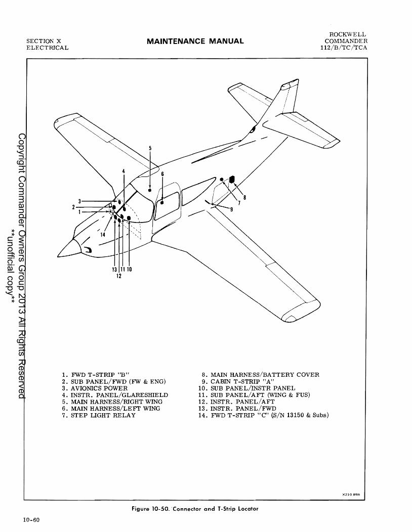
SECTION X ELECTRICAL
MAINTENANCE MANUAL
13 1110 12
1. FWD T-STRlP "B" 2. SUB PANEL/FWD (FW & ENG) 3. AVIONICS POWER 4. INSTR. PANEL/GLARESHIELD 5. MAIN HARNESS/RIGHT WING 6. MAIN HARNESS/LE FT WING
8. MAIN HARNESS/BATTERY COVER 9. CABIN T-STRIP "A"
10. SUB PANEL/INSTR PANEL 11. SUB PANEL/AFT (WING & FUS) 12. INSTR. PANEL/AFT 13. INSTR. PANEL/FWD
ROCKWELL COMMANDER
112/B/TC /TCA
7. STEP UGHT RELAY 14. FWD T-STRIP "C" (S/N 13150 & Subs)
X210 886
Figure 10-50. 'Connector and T -Strip Locator
10-60
Copyright C
omm
ander Ow
ners Group 2013 All R
ights Reserved
**unofficial copy**

ROCKWELL COMMANDER 112/B/TC/TCA
Figure
MAINTENANCE MANUAL
WIRING DIAGRAMS INDEX
PART IV
APPLICABLE TO: MODEL 112B SERIAL NUMBERS 477, 500 AND SUBSEQUENT, AND MODEL 112TCA
Title
SECTION X ELECTRlCAL
Page
ELECTRICAL SYMBOLS
10-51 Electrical Symbols •.....•..•.....•.....••••....••••...•.•••••.•.•••••••• 10-62
D.C. POWER DISTRIBUTION
10-52
LIGHTING
10-53 10-54
FUEL SYSTEM
LANDING GEAR
Power Distribution
Interior Lighting Exterior Lighting
......................................................
10-63
10-65 10-67
Fuel System Circuit ..•. • •• • . • • • • . . . . . . • • . • • . . . • • • • • • • . • • • • • • • • • • •• • • • • 10-73 Fuel Pump (see Figure 10-57) Fuel Pump and Primer (see Figure 10-57)
10-55 Landing Gear Actuation, Position Indication and Warning System... ••••••••• 10-69
FLIGHT CONTROLS
10-56 Flight Control Circuits . . . • . . . • . •• •• . . • . •• •• . .• . • • . • . • . • • • • • • •• • • • • • • •• 10-71 Wing Flap, Stall Warning and Turn Coordinator
INSTRUMENTS
Turn Coordinator Indicator (see Figure 10-56) 10-71
WARNING SYSTEMS
Stall Warning (see Figure 10-56) 10-71
MISCELLANEOUS
10-57 Miscellaneous Circuits . . • . . . . . . . . • . • . . . • • • . . . • . . • • . • . • • • • . . • • • . . . • • • • • 10-73 Cigar Lighter, Pitot Heater, Hourmeter, Fuel Pump, Fuel Pump and Primer, Carburetor Air Temperature and Electric Clock
10-61
Copyright C
omm
ander Ow
ners Group 2013 All R
ights Reserved
**unofficial copy**

SECTION X ELECTRICAL
SYMBOL
--~ I I
.. [>
• 0
-¢--c>-
d~ __ --,P
q p 6
10-62
DESCR
CABLE- SINGLE CONDUCTOR ~HIELDED
-MULTI CONDUCTOR SHIELDED
BUTT SPliCE
KNIFE DISCONNECT
CONNECTOR
TERMINAL- SOLDER TYPE MOMENTARY
-SOLDERLESS MOMENTARY
-SOLDER TYF'E MAINTAINED
- SOLDERLESS MAINTAINED
-T-STRIP 0,., T-SOARD ~LDER TYPE
-T-STRIP SOLDERLESS
FUSE
CIRCUIT B REAK£R - PUSH PULL
-SW TYPE
GROUND-AIRFRAME
-CASE (INTERNAL)
RESISTOR - Fl XED
- ADJUSTABLE
CAPAC ITO R
DIODE
MAINTENANCE MANUAL
SYMBOL
o D
;-0--/ 0
o }~-~-1 0
DESCR
LAMP
RELAY
POWER RELAY I CONTACTOR
MOTOR GENERATOR ALTERNA.TOR
ELECTRICAL EQUIPMENT (OTHER THAN MOTOR, GEN) ETC.)
SWITCH-S PST
-SP 3 POS
-SPOT
-OPOT
-oP :3 POS
-PUSH BUTTON PUSH TO MAKE
-PUSH TO BREAK
PUSH BUTTON 2 CI RCUIT
Figure 10-51. Electrical Symbols
ROCKWELL COMMANDER
112/B/TC/TCA
CODE OESCR LTR
BUTT SPL~E Be
CIRCUIT BREAKER CB CIRCUI T BREAKER SWITCH CBS CONNECTOR- PLUG P
- REC PTACL E J
FUSE F
T BOARD T
GENERAL NOTES:
r~p~2'2T~W!e€ GA L...--. WIRE SEGME»T (£77£,(( Wlet NlIM8£,e t::"1i!C'VIT Ft/lllcrtOIfl UTTER VIIIIT 41t/MHi!- ,fit/MaE,€' I /¥A!()TEr 'E~T IIII/O AllIMSEI? 2 O£,(/OTE .. RIO#T W#£A/ 10F,fITIt'IIL /V1i!F AlVM8E.#! APPFAO IA! DVIIL. (t./~) C'1'i'VIT
t:' - C'04lT~Ot. SVi!FACF D- IlI/rT,(!(.IMFI!IT ('O,.#£~ TAIA'A!
If'I./GIIT OR GWGIAlG) ,- EII/GltII£ IIIIrTRV44IrAlT 1"- 1f'(ISNT IAlS'T.eVM£NT S - SFAL" t.'OAlTeot. 11- I.I.£ATIIII$ AIIIOI)E·II:'ING .t - 1441IT101I/ K FAISINE COlI/Trot. i. - 1.1$1.1 TIN$ AII- MIS'C'Ft.lAAH'DV.t' ElEt:: ,fII- ,De:' POWG,(P Q - I'VEL AN,D ali'. W- WII,(P1t/. 1I,f/,D GMF,(P6£,f/t:'JI'
Copyright C
omm
ander Ow
ners Group 2013 All R
ights Reserved
**unofficial copy**
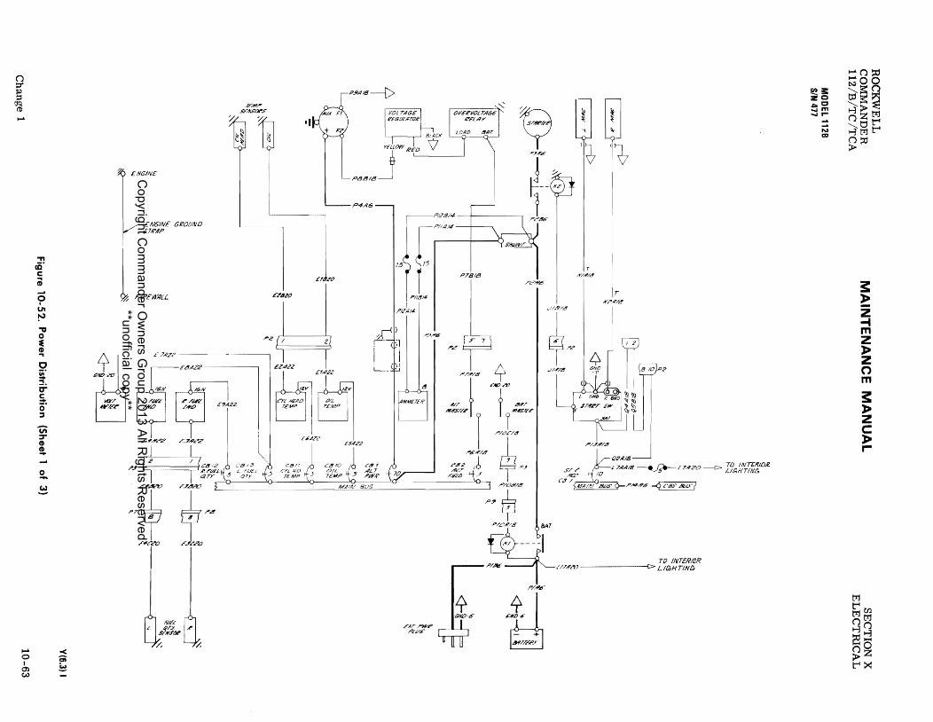
(J ::r § ~ ......
...... o I 0) c,.)
." cO' c: (i; ...... o I
U'I
~ ." o • CD ., c ~.
:::!. IT S. cr :::s
Vi' ::r CD !.
2-~
< C;; ~
{1<.. ENGINE
£' NGIN£ GeOLIND STR.4P
~ FlR£n~LL
~ MIi?';t7
" 1«/
;Y/T~
,P-,
,.,7
E)';-I""JI/f -"'.(V'6'
6#;-
n~
TO INTERltJR ~~/~:;8 __ JIT
,P/A!!' L/,l'~&? c:> LIGHTJN&
J"'/A"'.<>
~i: ze ACJ ..... m ......... -N =
...... (J-:;:;00 tJj~(')
'8~~ (JZt;tj ::st.ll:"'" .....,trjl:"'" (J::O >
trj
!: ~ Z -t m Z » z (') m !: » z c: » r-
t"" trjOO (Jtrj ....,(J
E9:j &;~ t""t><
Copyright C
omm
ander Ow
ners Group 2013 All R
ights Reserved
**unofficial copy**

...... o I
CT.I toI:>o
(') ::r ~
(Jq (I)
N
."
ii' e a; <5 I U'I ~ ." o E Q) ""I
C iii' -""I
0: 5-o· ::J
Vi ::r Q) Q) -~
o -~
)10 r-
~
GROUND
F41'/", 5V/Y.5"at".5'
%
E 7,111.:2-----------,
RADIO 8US(DPT)
·1
~PlhAI2:jP::8 3'5'\ RADIO MASTER
~/}GIIJ"f-C.D.S 8 P5CB
C.D S BUS
IIII!TRLTS o C'BSS
E.:rTPWR I"it'P6"
4 ~.",
4
~ 9 ,P.f#'''''
j ~ ~---tc r
'pC'&'>
'//B/~
+,~ ,//-1"/8
""'r ""7 rll?tflSu-r
,P/L/C,z2
STAJ!T
~ ~
"
T A'/#,/~
,r A'?#'/8
'p/JA'/.!I
Q2AI8 ~n ,P'/aD".e.?
,.!III r---lO~
n~ ?/L/#''?2 iaAT
~I ----I F3 _ rL2/A?2__t:> /NTE~/D~ LlC,HTlltlG
Ll7AAI6~5~LI7A20--t:> INTER/DR. LlGHTlN.G. )'/Af
D23AI6~D22A22--f> ELEC. CLOtK
I"/A!;I
~~~ ! ~
1:31: ee CICI mm :r-........ N .... -t N n.a:J }:og,
c .... c ~-t g,% c:::a -t C :Cc:n
~t .... w
~
~
/:IjOO t"I/:Ij /:Ij(') (')1-3 1-3-~~ &;>< t"I
s: ~ Z -4 m Z )It Z (") m s: )It z c: )It r-
......
...... N(') -"""""o::tl Il's:;o ~s:;(') ('»~ ~z~ (')t::1t"4 >~t"I
Copyright C
omm
ander Ow
ners Group 2013 All R
ights Reserved
**unofficial copy**

ti ::r ~
(JQ (t)
N
i-L o I C)
~
> '-.... i-L o I C) ~
ttl
"" fir c Ci1
9 "" ~ ." o E CD ... c ~ :::!. D'" C ::!". o :::s
v; ;:r CD ~ W
o -~
> .... ~
HO,~RA',fE')"ER <J----MIOBIB --4-MIOAI8 F6
TEMP SEAlSOR$-
'/
.:.
ENGIIIIE
FUEL qTY S'ElIIlJERS'-en.
HEAl) y MAG I~EFT '1611T
MAG
E3Ci?O
P'~ pf
E3A&&
I
E2t!J20
I EI820
P4116
£8A22 1 E6A2Z' 1 co.,. 1 E9A2Z I Er
AZZ 1 1 b R FUEL ~ l FUEL CYUlf) bOIL TEMP- ALT PW/!-
P3A6
SLK--[> rj~ S#l.JAlT-
i
.r K?AI8
EIIIGIIII£ dROtlAll)-
Flj.""Al
1l),t5
J I K/~;8 .1181.8 I
nab 6P2
t " I VIAll.'8 ( ) i J .. J
FRAM£
P2A6
-PIOC22~
L GlIbit'O I _'STA~J
1,--C(Z.I!l/8
6': STAi?T-5jqTY- 5~\' qTY- s'1 TEMP- 5'\ C812 70'\ C139 5
1
---0 C1Ui 1. C:S? o~1 01 ~!Ll ____ -I--_ MAIIII BUS
IPS P108;?2
~P. 10 1 C81,
o SMA/AI Bl.JS
~P/~AI2 ~c P588 '\ RIIDIO MJlSTliR
35'j- CBS 8-
1 P5CB
12GII, I, ~BLl5
'\WSTRLTs-0'1-- CdS5 ~
PIOA22 t KI ----1 LZIIIZ2--f>INT£lUOIC UGHTING
Ll7AA'IG~ LI7A20--f>INTEll/DE LIGI-ITlAlC,
T ~ PI,46
~P186 O&3A/6~OZ2AZ'2-----t:>EL£t!, CLOCK
6A10,(:, li
d,!)'6
EXT POW£Ii? _.... .. BATTERY RECEPTIIClE
3:31: cCl cc mm ........ -::: -N ~.!" ~s: • U'I
~~ g:c >0 ZC =: en ~ en
~
:::n~ NOO '-....;s:n ~;S:Q I-;'j><; tiZ M :3tjt-' nMt-' >::tl
tr:t
3: » 2 -I m 2 » 2 ('") m 3: » z c » r-
t-' tr:t(JJ titr:t I-jti Ea::j
~~ t-':><:
Copyright C
omm
ander Ow
ners Group 2013 All R
ights Reserved
**unofficial copy**

Copyright C
omm
ander Ow
ners Group 2013 All R
ights Reserved
**unofficial copy**

o ::r § ~ J-4
..... o I 0) 01
." <D' c til (5 I VI ~
:::s ;-""I
0' ""I
r-<D' ~ :::s
CO
en -::r CD !.
o -~
c:
~
.-------<28ZZ----------.
~::;i:~i::~f::"
"hlG'IIII:TIC t'ONPAJ".I't.T_
TU~E rOC'K'ET
~3i:: 20 01=0 0 ...,m ..., r-
TO gPTT'E£'Y CONTACTOII'.' + TE£,MIVAL-
-N m
C"48/;V PEAOIIVC LT- TO EUC -L?31l?O ,,~:;.aAG'E , .r~
(L
?4A22 .. SW-
~J,? [84B22 Ll61{ K5 22
K6 AlOTE- SG 7 !1J. gOIj!AlECT/~A/ lIl!~Lf,r"A
122£ GAiD 'E,'l1IL A&:JVE ?? 12l'2 GAIl> l2U. 1 e
I 22 l2
mor ONmVA< V 7 M" a- COP" or .-.- ... ~ l!98?2 MIP;T- '-. """ ~(:Vl> 4 12 V
1-+--------.,
5~ LMm~ [1420
£,;lI)/OOIM
"'UI~r~' _ _ ~ G'AlOM
mw1 ~
_ 3 P1! ._~$ 20.l,
r ~ '$'- ":" u",U
L20A
?'Z
1.4420
J
PI
b: ~ , , ') 1'1) G} 1#1IA1 1'If'flf') (TIle'N) NUl> IM/))
====~PO.i'T UG/o'TS' _
~ /lfIrT£' PIIII/EL-
.... '/,
H/XlA MHER POST LI~T
L39A20~ L)9B20 -
1lf.iINSTR UCi"2 1 CWSTER ...::.--...::. ..:..-br~.,Ez2li41)Z21 £4 ~""22 ~-?~J1f~
,,' L4f722' --~ , ,t~"~--
L4820
-------I.EFT--------- ----L'IGNT-
.5'Ll8 !'I!AIEL FI.OOI) I. /G#T.f'
SLl4PAA/EL
~ L21C22
""'" ---L
" .. " MO,,,," It. "'-A?2 I 'N"'''~S CO;J?!'T LT-
hOI" •
~
, .rTEP LT_ i STEP tT_
"'"'dJ-T; I'iAlO jGAIf)
'8e) J'i15/U'? ~ )
1 ' '-NUO
1 PIIW£1l DIS~
J-40::d ~oo ",s::o tJjs=~ ~>~ ozl:1j ",tj~ 1-j1:1j~ o!:U >
M
s: ~ Z -I m Z » z n m
s: » z c » r-
~ MUl OM I-jO
~g &?z ~><
Copyright C
omm
ander Ow
ners Group 2013 All R
ights Reserved
**unofficial copy**

..... o I
0'> 0'>
(') ::r § ~ N
." cO' c: iO
o I
VI ~
:::s i ""I o· ""I
.... cO' ::r ... ;.
CD
;,;; ::r CI> !. tI.)
2.. ~
J> r-
~
r-------L2822-------------.
rL2F?ZrE?:?l-ZDZZrC2,?' k"'" db ,,.'" ~",.n ~"0C2 'CO. GL.4F€SIIIELO /?,,&"F'
P#G'/JI~T/C t'ON.PA'J'f LT-
Tul!!!,F rO':C'ET· POWEll DIf:Tll
''''{' '" 1 ("O~!lJ'I,,1/,rA/I''' C.4BW .f'EA!1IJ1/G'L. r •
5 t
)J -'L?3;q?o~ "~::fr;~R
'------L 3$AZZ -----' [1,IIZ2
L?~B L?4;q22 r-j 22 1.7 -rJ<fSl?2 {l18 ~ ! __ ~ t _ ~5.-. -:!J t!lC;TE S.E'£ LI",~Z2 lI9A
6 ,,;;- L'OILWEI'''O..t/?2 / I ~ 7 :3 L _ DE "Ifli '",lJOjlE 22 1.£
I
122£ GI/IO GIllO
{2U22--.r;TI1I ... ~L}ill 2',:(:(~. ;:~:12 ~ ~L"'JlZ2--------'- !. V V I L/9!U2 _" LZIIl22 ~fO Mor 2 ~ '.l, MAP COP/~OT Y .. --_. PI! V
L7E!Z
'''''~5_66~'2~ ~ $~~ L25C22 Z2 . --$
r r ,. , 2 ":[-L jn LT-
~ ~ ... ~ '- 'I:f ~ ~ L-, L-, L,
f I) G' ) I """AI ~flf' ) ( r#t:#) rnAPI"'O) ======porr /A/rTR P.l/l/tFL
/, I10UA METER POST LlGI<IT
L39A22 L~95Z~2 RW IN5TR _ _ __ aUSTER'.~- -- - LH INSTR ,-- - CLUSTER
~- - - --
Ill'5~22 2L fll5B?,?
Ii ,,"?.? 12L ("II??
"''' ~J~_'IJ J'f, 'I '"''''¢)
T'M'''' ) "m~ I \ ~'IRCiJIT BREilK{:R LlendS (E6T INO ,: SWITeli (.I6I1TS; *" L\. SLId PAillE' FLotJl) t.IGIiTS -----------
5 ~1 -;;'815
rc----MA1-,!; 8~~S cL
ENTflAI;Cf SW
R !:TE,P, T_ STEP iT-
'* ,g SUB PflNEL LTS. - //2 B. 5"00 771l?lI 520 1/2 TCA. 131SIJ TJlKU /3It.ID
IIJ SUB PANEL lTS- IIZ8, 5Zl AND SUBS. 112 rcA. 1311:.7 liND SlJ65.
~ i:i: CtCt CJCJ mm r- r---Ei5 n" >U'I ~ c .... c w .... .... :z: g:::D ... e: iE e: -w :
MOO t"'4M M(') (')~ ~I-I
C3~ ~:>< t"'4
.....
3: l> Z -4 m Z l> z (') m 3: l> z c l> r-
..... (') NO ta-s=~ ~s=(') ('»~ ~9M (,)Mt"'4 >~t"'4
Copyright C
omm
ander Ow
ners Group 2013 All R
ights Reserved
**unofficial copy**

n ::r ~ Jq (l)
f.'.,;)
.... o • 0) 0)
» "'" .... o I 0) 0)
t:J::1
." cO' c i o I
U'I ~
:r ;-:::!. o ., ....
cO' :r ::t. ::s
CO
'Vt :r CI)
!!. w o -~
l> r-eD
~
p{
~
r- .f'ADID /JIM -,
LHLlD?~/EZ2 --.9
Lli!l22 U~-LIN'?
,.m~ .. ~'
~ ~ (D G.) 1.IMIf' "",nr) (TIL'N)
LIG#TS'
/1tIJ"T.l' p",,,,,,££
/, HOUA METER POST LlGJ.;T
..
II.~~~'CD~M'T '''22-y'''''''~, (!6J1TS' U6J1TS"
~ ~ .... ~ R /IIJSTR CiUST£R l IIIJ57R CLtJ:5TE£'
1< t§' ~' :r,~ - ~'b:' CleCUIT 8KL'Dk.~R UGkTS) (EGT IIYD I S"iAI'TCk Ll6f1T>'
SUd PPIIIEL i 'Gk TS L ..••. _____ • ______ ~--___
Pll
t?'IIl'"r-ED--- lP'''22
PILDT MIIpLT- MAPLT-
,,~.~ 2lJ."'"
7;N012(REF) Tc'~,r S"::t'k!£T ~0!-
®> It
\V <1
U?~A2Z (RE/) ~
{f:';~?/'I'H)
Jt,../WVI/cA//cAIP,<
n - U'511?D A f'~::;'~A~R :J.l mm~ I ~(SN-
~' : t, ~ ~fr~'!'~.~/IJ U6~LI::L~:A ~ I ~~J OUAfIL 4&J .1'2
GSA '2ff C:f.D G/IJO L22J: w: I .E
LZ,C?Z
,p I'T~"" LT-
11 J., .r2" ""''''' 11 ~I MTR <>-1 ",~i(- ~'------qT--3 Pl1 .. _ '$ "Ur:V ~~D '$'-~ ,,,If
nL?04??
t. 5'T£,CJ LJ'-
L22CZZ y l.o LZ~"
'N"'~~'~ I <T'
S:3l: QQ ClQ m m r- r-" ... -" ... N N -tCI:I n· -- ~~ ~~, ..... U'I
wl> NZ ::SCI l>CI) Zc CI= CI)CI) C CI:I cn
~()::O f.'.,;)OO O?~O , ~~ ~>~ nz trl
t:Jt:'"1 trjt:'"1
::0
3: » z -t m Z » z n m
3: » z c » ....
trJ t:'"1rn trjtrl nO r-31-j ::0_ -0 ("}Z > t:'"1~
Copyright C
omm
ander Ow
ners Group 2013 All R
ights Reserved
**unofficial copy**

Copyright C
omm
ander Ow
ners Group 2013 All R
ights Reserved
**unofficial copy**

..... o I m (X)
o t:r ~ ~ .....
"TI
cir c: ... CD
o I U1
~ m )C
;-... Cr ... r-cO' ::r =-. ::J
CO
'iii ::r ! to.)
o -~
:J;o
~ ?E
I " "_~IA2CJ
Lf t.:?~8I1J
I i'(i'IA/~
II :lI:AIII
,07 ,...11 PI'
II.:lSIIIII
11.1'18#
t?7CI.,
?i.2811r4
Dl YEt
~ $4'0·/.#
rt> ,;"¥O-l" rt>
6''''''''
IU'I"I' I I I NNW'
+1 UlOI., 1'1 "Nij ~"£M " .. ~ UI WIN£. TIP RN N'AI& TIP
NtW LT NAV LT
TAIL NAV LT
f ell s~ sus. '\----:rTR08.!'" LTs-
10,,- CBS;7
1 'I"p, tJ1AI8 l1'lIA/8
Lf Ips
1 ,04
O#/IIB
Ft4r#£L' 4£ACON NW4.f>SV')'ty
1.2'11111
"r IJ~CCIII
"Ht J: l .-------. '-r-' KGO
<1<)6lK
UT
It t'L!lfillll I II
lJfi,AIB
IIL'<<>I yELl 1'£0
TAIl. S'TIt~ I. r-
L. WIM!i TIP .J'""OI!IF t. T ..
.It1M.PIiIt-(?PI.HES) III&«~
~.:J1l
CAl/) -III
U~9C III 'OOW-:Jl1. J-. ;n i \l
m. ----r:;n.-, LV (1=
8LtHi
",K I REO
~ J. ~!
1 OPTIONAL A¥TI-COL t.T
(BELLY' )
AAlrt-CO£. [1'(PE.f>TlCAt. rrA4IU,rU)
1.1'8111
rt> (JiIIO"
lANDIAlG' U6'N1'~
GAIU IT SAME UU'ATltw AI' AI. TEL-NATO.e
i:i: 00 00 mm ,....,.... --S~ n· :J;ocn • c .... c W-I .... ::c IS:» -Ie: :z:cn ~t .... ~ CD CD
d Iiiii
tTlCIl t"ItTI tTl 0 O!oi 14-~~ ~:>< t"I
~ ~ Z -t m Z » z 0 m ~ » z c: » r-
....
.... 0 NO tif~~ ~s:O O>~ ~ZtTI Ol::'t"I >~t"I
Copyright C
omm
ander Ow
ners Group 2013 All R
ights Reserved
**unofficial copy**

(') ::::t'
~ ~ ....
.... o I m -1
." ir c i -~ CIt ~ rn
~ ::I. o ... r-cO· ::r =:!'. :::J
CO
U; ::r
t o -~
~ ;
P7
ILl"8.8Atl
~ GAIOI.,
til WING TIP N'AV LT
1 ,,'T tf 1.27.814
'1"7('1<11'
rt> I/u/)·/fit
l'L?lJ.814
J~
L2lD~'~;"" ""fi"""" Rli fII,JIG TIP
NAV L7
TAIL NAV LT
Pl'
" "'flll"
~c~r-it/ ~l/S J -~,f/S'T,f'tJ!!!£
." ",,}- C!lS 3
~---------"" .. ~ SI',f'OI$£ iT CI$
?£!l5"lllll
'<'9A/"
~~ FlAIflE-f' HE/ICON '-r9.8/~ I"tJWEt"J"VI"i"ty
r m---GJ1---,
~D ,U'CI8~J :;n · \J
UJ '1= lIiHE
eV! IIlED
~ ,..1:.
:l I Z
M:m
<J-ru~:: ( ) rLASNli,(' MACDA.!
II.,K. (VEL"TICAl. rrAlJltJ?EL") I!'£D "[1fT L" MMS"
PON£I.'" .l"VPPtY'-
N.m~l~L, Rio I I .n;m~&l4 WHf
~.{ MIT
I. III/Aft> TIP L. If//If/li' TIP .J'rL"08£ LT- .J'TL'OaE (T_
rAil sr,f'ME /.. r-
l !llll/1!
rt> GI/I/J16
"'nom ,-IIIIIOINt::' UGHT-
171/10 ,(1T SAM£ U1L'ATIiJA; 45: Al TE.I'lfIATOe
5ei: 20 ,..0 ...,m ..., r--....
N I:D
I-'O~
~SO ti1~~ ~~~ ';tiil£: ~~
3: J>
~
Z -I m Z J> Z o m
3: J> Z c J> r-
t"4 ~~ 0 0 ~t-i
~O >Z ~~
Copyright C
omm
ander Ow
ners Group 2013 All R
ights Reserved
**unofficial copy**

ROCKWELL COMMANDER 112/B/TC /TCA
MODEL 1128,545 AND SUBS MODEL 112TCA, 13190 AND SUBS
Change 1
MAINTENANCE MANUAL
,-
~ '3 ci3
§, 8 ~~-l " ~ ~ 011
....
SECTION X ELECTRICAL
... .... /\ ~ ~ ~ '"""C......~~ ______ ~--..... : .. (S\ I f--___________ ~-------...;.'i~~..... o::::;V ~
~ ~ ~ "
AS'.10.1)1I
Figure 10-54. Exterior Lighting (Sheet 3 of 3)
10-68A/l0-68B
Copyright C
omm
ander Ow
ners Group 2013 All R
ights Reserved
**unofficial copy**

Copyright C
omm
ander Ow
ners Group 2013 All R
ights Reserved
**unofficial copy**

(") ::r' § (Jq (1)
t-.:>
-n cir c ... (I)
-' 0 I
U1 !J'I r--C :::J Q..
:;' P4 CO
0 (I)
e » !l. c e. 0' ? "'0 0 fA 3-: 0 :::J
;-Q.. ;:;' e. 0' :::J
C :::J Q..
~ Q ... :::J :;'
CO
'" '< fA
CD 3 V; ::r (I)
!a
2.-~
..... c: 0
~ I 0) co
C,4-
A"Ce".2 --------,
,Po
f' .>'19'// c7.Y'
3
r D9C2D
'-------\----+1· -lJ.719.:'0----··-+----'
~fOC20
/b96,.;t1
/,,7
DlIA20
---2U4BlO
3 4
P2
~~O
P3~ D9A20 OIOAlO
,---1---- /PJ.B?O ----.+--<
,P~ ~~-=~~~==~~~
//l/LJIC#70,e
) I. • DIBC?O---------t
Df6C. 20
fty m,.,:: I ~) Th'eOTTlE SN-
~ ~ P31DI7A I I
~ ~D~TiI RJL4
.o/fh'd? DI7B.?O
5)":0 PRt:SS
8LU
'----~.ni <!u -c:J
(;7020 -------1
6/#/LJ
ses: ze ~CI ...... m ...... r-
.... N a:t
..... (")~ ~oo '---..a=(")
~a=~ d~~ -::sot"4 .. tr:1t"4 (")~ >-
tr:1
~ » z -t m Z » z o m
~ » z c: » ....
t"4 ~oo (")tr:1 t-j(")
~:j ~~ t"4:><
Copyright C
omm
ander Ow
ners Group 2013 All R
ights Reserved
**unofficial copy**

..o I
...::r o
n ::r ~ ~ N
." cO· c it -o I '-II !J' rC ::::J c.. :r
CC
Q CD C "'I
l> ~ c e. ir EJ ." o ~. cr ::::J
:; c.. ;:j.
C ::t. o ::::J
C ::::J c.. $£ C "'I ::::J :r cc VI '< III ar 3 U; ::sCD
!. ~
2.. w
l> i: 3 =
G/A'/LJ
DI/A2iJ 138<"1::>'-_____ ----'
TIIJ!'OTn!:' SIY-
--Pi ~P#/~lu 20462.0 Glm 4880/ A--.
(N,r) ~ .----ID/j1l2O #~ ___ I 'r ~
~6'J',..,/aJ /,7¢=~~~
t N~ .tIC Nt:~1
vl J .<:W Ur>
.lOCK £OCK
,(Err _ C/"/fl,R I"!?S//7QV /A/,O/C/fl7l7,R ( SHOWN /A/ LM/ L4'C'''''' A::I$"/T/a,v)
3!:i: QQ CICI mm ........ -- ... ... -NN ..... = C")~
'>1: _U"I Wl> ..... 2 g:C ..... en ::cc: ::a = c:en ..... W N :
;
ttl 00 t"Ittl ttl n n1-3 1-30 ~Z Q><: t"I
..-
!: ~ Z -I m Z » z n m
!: » z c: » r-
~n
~~~ ~~~ ~Z~ 1-30 ttl nttlt"l >::ot"l
Copyright C
omm
ander Ow
ners Group 2013 All R
ights Reserved
**unofficial copy**

() ::r' §
CTQ ('!)
w
....... o I
-J o > " ....... o
I -1 o to
"TI <D. c: (i) ..... <? c.n c.n
rC :s Q..
:s c.c Gl (D
c ... » !l. c: a c)" ~:s
"ti o ~ <)" :s
:s Q.. ;:;. a o· :s c :s Q..
~ c 3 :r
<C
c.n -< II>
(j) 3
Vi ::r (D
!. w
2.. w
]:a z S =
is_I ~5 ~z, C'r~f :f\f',,';" :;f:r~
(;f#,!'LJ
&/#/0
Tlt.l"OTTZe SJIY-
!:!: 00 00 m m r- r-- -....... NN -Ie:! n' )>~ ... en Wl> NZ mo l>Ct) ZC oe:! Ct) (I) C CII:I (I)
....... ()~ ~OO ,,~() b:!~~ ">~ rsZ trl "Ot""4 t-3trlt""4 ()~ >
~ ):It
Z -I m Z ):It Z o-m
~ ):It Z C ):It ....
t:zj t""4
C/)trl tr1() ()t-j
j~ ~~ ::><t""4
Copyright C
omm
ander Ow
ners Group 2013 All R
ights Reserved
**unofficial copy**

Copyright C
omm
ander Ow
ners Group 2013 All R
ights Reserved
**unofficial copy**

ROCKWELL COMMANDER 112/B/TC/TCA
MODEL 112 SIN 477
STALL WARNING
HORN
W2A20
F'-203JWZD20 1/
QND I 3-20 3 We.E lO
'1 ~ 2-20 2 W2I20
GND.C"NTAcr S"'.
[iW2L2."
14121>12.0
rEST SUI.
TE" \N~
MAINTENANCE MANUAL
STALL WA,.,NllfG 5WITCff
Figure 10-56. Flight Control Circuits (Sheet 1 of 2)
SECTION X ELECTRICAL
Y(8.1) I
10-71
Copyright C
omm
ander Ow
ners Group 2013 All R
ights Reserved
**unofficial copy**

SECTION X ELECTRICAL
MODELS 112B/TCA
10-72
GND.CONTACT Sill.
MAINTENANCE MANUAL
P7
.sTALL WAP,NfNG .sWITCff
y $:~t·/.6 ,
~~:
r rIU
l":r1 tWYJM • .<'I>''''t.
#0 L J A'f
3S· J'N: C C O'S'H'
~'" A"
Figure 10-56. Flight Control Circuits (Sheet 2 of 2)
ROCKWELL COMMANDER
112/B/TC/TCA
V(8) II
Copyright C
omm
ander Ow
ners Group 2013 All R
ights Reserved
**unofficial copy**

(') ::r § ~ .....
..... o I
..;J c,,:)
"TI cO' e ... 11) -o I U'I :"'" ~ ~.
n
~ D ::J 11)
o e III
n ::;0 n
S: III
c:;; :r 11) 11) ....
o -~
~ .... ....
tSUiJo2'(l
~lJ21.'62(J
$H °T' JNT'E~!l)I! .. L1aUTlNC.
FLEe CLOCK C/RCt//T
V--tfWiN!'2' --t> ~ OIL PRES'S' I S'WITC#-
#::1"tl1.'1.'
;<"t!/(MR LISHTER-
M2AI.'I.'-(f!!)
SIJl6U' TUSE NEAT.£k
y-GAI;:;'Z2'--t>
~ (J1i,PREfr I J'W/TC#-
M~"tlZI.'
fMU22----® M2AZZ
----- AI//Olll/CS -----------
~3l: 20 AO "",m "'" r-
..... Nt CCI
..... (')::0 :;:;00 b3-~(') ,,~~ r5~ttj "t:lt"4 ~tl:lt"4 ('):::0 >
tl:l
~ » z -I m Z » z (') m ~ » z c » r-
t"4 J:'IjOO (')tl:l 1-3(') ~~ &?~ t-t>:
Copyright C
omm
ander Ow
ners Group 2013 All R
ights Reserved
**unofficial copy**

..... o I -3 ,.j:>.
(') ::r § crq' ro t\:)
.." -, cO·, c ... (I>
0 I U1 :"I 3: in' n !!L Q :J (I> 0 C en
n =i" n ~; en
en :r (I>
!. to.)
0 -~
~ ~ r- r-- -...... t:! ...
=
sw~ CCiJS~~-] 15 '\ FuEL
r::::-;ili2
q~
I 4)liJ20
,..
PR/ME sw-~s')
;ili2 15 \ FuEL
r::::-
·r .1-fJ2 qJ
~ 4)1820 ~4)2iJ/g I
K1 --1
GUMa •• - C,~", I l' -r t)1iLJ$ . . '. . 7):,:.
a -,<'
FUEL PUMP t PRIMER CKT 4400EL·/,I.?TC40I1/LY
13/5Q TH~IJ 131.SS .....
POWB!... OlsrR:.
FiEe CiOCk ClReOIT
MOLlE!. 11213
,..---M 2' A<!!2
IfOURME'TER CIRCL/IT ( HOI3I3S" METEe)
r--MZq,?,?~
~ ___ MODEL 112B, 500THRU 531 MODEL 112TCA, 13160 THRU 13166
l D'RB /141 TEINP SYfTOI It}OlJEL /127{,4 ONLY
s:: c c rn rCI:I ... N CD
~ C":I ~
trjUJ ~tr::I trj(') (')1-3 1-3~
~~ (')>< > ~
3: ~ Z .... m Z l> Z (") m
3: "» z ·C ;» .r-
..... , t:; (')
",0::0 tD~O ~~(') ->~ i~Z~
1-3 t:,f tr::I (')tr::I~ >::o~
Copyright C
omm
ander Ow
ners Group 2013 All R
ights Reserved
**unofficial copy**

-,
ROCKWELL COMMANDER 112/B/TC/TCA
Change 1
MAINTENANCE MANUAL
~ ~ h. ~
~ v ~ ~N \IJ
~ ~Iti
III ~~ M
I/)~ ~~ C 'oil( VIi-: = ~< <;j"l
f= ~~ ::!~ =;2 ~~ 3~ ."c
11 mo
{ z· c;:; ..,-AtOT/l.A t> [lli] m cf
6117,. b n .U (;31111
ll~ ~~~ NllIlII., II!)
!o'~ II ., ~ .....
~ -' .......... == == :E:E
Figure 10-57. Miscellaneous Circuits (Sheet 3 of 3)
SECTION X ELECTRICAL
AG(12)1I
lO-74A/IO-74B
Copyright C
omm
ander Ow
ners Group 2013 All R
ights Reserved
**unofficial copy**

Copyright C
omm
ander Ow
ners Group 2013 All R
ights Reserved
**unofficial copy**

ROCKWELL COMMANDER 112/B/TC/TCA
Change 2
MAINTENANCE MANUAL
GAlt:N8
MIOt:'l1I V
MI081iJ
1 TCI ~WGA: IJIST
CI7U'UlT
IIOURM€TG"£
MODEL 1128,538 AND SUBS MODEL 112TCA, 13167 AND SUBS ~
~
STOW t£.. SEcUIiE IN CENTEI'{ WING AREA
FLUX XMTR MODEL 112B, 545 AND SUBS MODEL 112TCA, 13190 AND SUBS
Figure 10-57. Miscellaneous Circuits (Sheet 3 of 3)
SECTION X ELECTRICAL
AG(12)1I
10-75/10-76
Copyright C
omm
ander Ow
ners Group 2013 All R
ights Reserved
**unofficial copy**
Copyright C
omm
ander Ow
ners Group 2013 All R
ights Reserved
**unofficial copy**